JP2023106096A - game machine - Google Patents
game machine Download PDFInfo
- Publication number
- JP2023106096A JP2023106096A JP2022007236A JP2022007236A JP2023106096A JP 2023106096 A JP2023106096 A JP 2023106096A JP 2022007236 A JP2022007236 A JP 2022007236A JP 2022007236 A JP2022007236 A JP 2022007236A JP 2023106096 A JP2023106096 A JP 2023106096A
- Authority
- JP
- Japan
- Prior art keywords
- game
- state
- gaming machine
- combination
- mode
- Prior art date
- Legal status (The legal status is an assumption and is not a legal conclusion. Google has not performed a legal analysis and makes no representation as to the accuracy of the status listed.)
- Pending
Links
- 230000000694 effects Effects 0.000 claims description 527
- 230000005540 biological transmission Effects 0.000 claims description 56
- 238000000034 method Methods 0.000 description 1026
- 230000008569 process Effects 0.000 description 974
- 238000012545 processing Methods 0.000 description 684
- 230000007704 transition Effects 0.000 description 626
- 230000008859 change Effects 0.000 description 503
- 238000012423 maintenance Methods 0.000 description 451
- 238000012790 confirmation Methods 0.000 description 394
- 238000003860 storage Methods 0.000 description 330
- 238000003825 pressing Methods 0.000 description 281
- 230000000875 corresponding effect Effects 0.000 description 233
- 230000007246 mechanism Effects 0.000 description 214
- 238000007792 addition Methods 0.000 description 213
- 238000004891 communication Methods 0.000 description 174
- 238000012544 monitoring process Methods 0.000 description 167
- 239000002243 precursor Substances 0.000 description 137
- 238000010586 diagram Methods 0.000 description 133
- PZTQVMXMKVTIRC-UHFFFAOYSA-L chembl2028348 Chemical compound [Ca+2].[O-]S(=O)(=O)C1=CC(C)=CC=C1N=NC1=C(O)C(C([O-])=O)=CC2=CC=CC=C12 PZTQVMXMKVTIRC-UHFFFAOYSA-L 0.000 description 123
- 230000006870 function Effects 0.000 description 115
- 238000004519 manufacturing process Methods 0.000 description 113
- 241000219109 Citrullus Species 0.000 description 106
- 235000012828 Citrullus lanatus var citroides Nutrition 0.000 description 106
- 238000007726 management method Methods 0.000 description 92
- 230000005236 sound signal Effects 0.000 description 91
- 238000006243 chemical reaction Methods 0.000 description 89
- 238000001514 detection method Methods 0.000 description 68
- 239000002609 medium Substances 0.000 description 66
- 241000167854 Bourreria succulenta Species 0.000 description 60
- 235000019693 cherries Nutrition 0.000 description 60
- 230000000737 periodic effect Effects 0.000 description 58
- 238000012986 modification Methods 0.000 description 57
- 230000004048 modification Effects 0.000 description 57
- 230000003321 amplification Effects 0.000 description 49
- 230000008901 benefit Effects 0.000 description 49
- 230000015572 biosynthetic process Effects 0.000 description 49
- 238000003199 nucleic acid amplification method Methods 0.000 description 49
- 238000003786 synthesis reaction Methods 0.000 description 48
- 238000013500 data storage Methods 0.000 description 45
- 230000001965 increasing effect Effects 0.000 description 43
- 230000005856 abnormality Effects 0.000 description 41
- 238000001994 activation Methods 0.000 description 41
- 230000004913 activation Effects 0.000 description 38
- 238000003780 insertion Methods 0.000 description 36
- 230000037431 insertion Effects 0.000 description 36
- 239000000470 constituent Substances 0.000 description 35
- 238000012546 transfer Methods 0.000 description 32
- 230000003111 delayed effect Effects 0.000 description 31
- 238000012360 testing method Methods 0.000 description 30
- 230000009467 reduction Effects 0.000 description 26
- 238000002360 preparation method Methods 0.000 description 24
- 208000001613 Gambling Diseases 0.000 description 23
- 238000009792 diffusion process Methods 0.000 description 20
- 230000000630 rising effect Effects 0.000 description 20
- NCGICGYLBXGBGN-UHFFFAOYSA-N 3-morpholin-4-yl-1-oxa-3-azonia-2-azanidacyclopent-3-en-5-imine;hydrochloride Chemical compound Cl.[N-]1OC(=N)C=[N+]1N1CCOCC1 NCGICGYLBXGBGN-UHFFFAOYSA-N 0.000 description 18
- 230000007423 decrease Effects 0.000 description 18
- 230000001934 delay Effects 0.000 description 17
- 239000004973 liquid crystal related substance Substances 0.000 description 16
- 239000000758 substrate Substances 0.000 description 16
- 230000001276 controlling effect Effects 0.000 description 14
- 230000004044 response Effects 0.000 description 13
- 238000004904 shortening Methods 0.000 description 13
- 230000001186 cumulative effect Effects 0.000 description 12
- 230000001976 improved effect Effects 0.000 description 12
- 238000012937 correction Methods 0.000 description 11
- 230000009471 action Effects 0.000 description 10
- 239000002131 composite material Substances 0.000 description 10
- 230000002829 reductive effect Effects 0.000 description 10
- 238000005070 sampling Methods 0.000 description 9
- 230000008451 emotion Effects 0.000 description 8
- 238000009987 spinning Methods 0.000 description 8
- 238000013461 design Methods 0.000 description 7
- 238000013508 migration Methods 0.000 description 7
- 230000005012 migration Effects 0.000 description 7
- 230000003213 activating effect Effects 0.000 description 6
- 230000004397 blinking Effects 0.000 description 6
- 238000004364 calculation method Methods 0.000 description 6
- 230000002844 continuous effect Effects 0.000 description 6
- XDDAORKBJWWYJS-UHFFFAOYSA-N glyphosate Chemical compound OC(=O)CNCP(O)(O)=O XDDAORKBJWWYJS-UHFFFAOYSA-N 0.000 description 6
- 230000033001 locomotion Effects 0.000 description 6
- 239000011347 resin Substances 0.000 description 6
- 229920005989 resin Polymers 0.000 description 6
- 238000007789 sealing Methods 0.000 description 6
- 230000001960 triggered effect Effects 0.000 description 6
- 239000012141 concentrate Substances 0.000 description 5
- 238000010147 laser engraving Methods 0.000 description 5
- 230000002441 reversible effect Effects 0.000 description 5
- 230000000007 visual effect Effects 0.000 description 5
- 230000033228 biological regulation Effects 0.000 description 4
- 238000002788 crimping Methods 0.000 description 4
- 230000002349 favourable effect Effects 0.000 description 4
- 239000003550 marker Substances 0.000 description 4
- 238000005259 measurement Methods 0.000 description 4
- 230000002265 prevention Effects 0.000 description 4
- 230000002776 aggregation Effects 0.000 description 3
- 238000004220 aggregation Methods 0.000 description 3
- 238000005520 cutting process Methods 0.000 description 3
- 238000009795 derivation Methods 0.000 description 3
- 238000007562 laser obscuration time method Methods 0.000 description 3
- 239000000203 mixture Substances 0.000 description 3
- 206010012335 Dependence Diseases 0.000 description 2
- 230000002159 abnormal effect Effects 0.000 description 2
- 230000001133 acceleration Effects 0.000 description 2
- 230000006399 behavior Effects 0.000 description 2
- 230000001143 conditioned effect Effects 0.000 description 2
- 230000003247 decreasing effect Effects 0.000 description 2
- 238000007599 discharging Methods 0.000 description 2
- 235000012489 doughnuts Nutrition 0.000 description 2
- 230000002708 enhancing effect Effects 0.000 description 2
- 239000011521 glass Substances 0.000 description 2
- 230000006872 improvement Effects 0.000 description 2
- 239000000463 material Substances 0.000 description 2
- NJPPVKZQTLUDBO-UHFFFAOYSA-N novaluron Chemical compound C1=C(Cl)C(OC(F)(F)C(OC(F)(F)F)F)=CC=C1NC(=O)NC(=O)C1=C(F)C=CC=C1F NJPPVKZQTLUDBO-UHFFFAOYSA-N 0.000 description 2
- 230000001151 other effect Effects 0.000 description 2
- 238000005192 partition Methods 0.000 description 2
- 230000002093 peripheral effect Effects 0.000 description 2
- 230000000704 physical effect Effects 0.000 description 2
- 238000003672 processing method Methods 0.000 description 2
- 238000009877 rendering Methods 0.000 description 2
- 239000011435 rock Substances 0.000 description 2
- 239000007261 sc medium Substances 0.000 description 2
- 241000269350 Anura Species 0.000 description 1
- 206010011971 Decreased interest Diseases 0.000 description 1
- 101000742310 Homo sapiens Rab15 effector protein Proteins 0.000 description 1
- 102100038203 Rab15 effector protein Human genes 0.000 description 1
- 210000001015 abdomen Anatomy 0.000 description 1
- 238000013459 approach Methods 0.000 description 1
- 238000003491 array Methods 0.000 description 1
- 230000002238 attenuated effect Effects 0.000 description 1
- OMFRMAHOUUJSGP-IRHGGOMRSA-N bifenthrin Chemical compound C1=CC=C(C=2C=CC=CC=2)C(C)=C1COC(=O)[C@@H]1[C@H](\C=C(/Cl)C(F)(F)F)C1(C)C OMFRMAHOUUJSGP-IRHGGOMRSA-N 0.000 description 1
- 238000010924 continuous production Methods 0.000 description 1
- 238000007796 conventional method Methods 0.000 description 1
- 238000000151 deposition Methods 0.000 description 1
- 230000005284 excitation Effects 0.000 description 1
- 238000000605 extraction Methods 0.000 description 1
- PCHJSUWPFVWCPO-UHFFFAOYSA-N gold Chemical compound [Au] PCHJSUWPFVWCPO-UHFFFAOYSA-N 0.000 description 1
- 239000010931 gold Substances 0.000 description 1
- 229910052737 gold Inorganic materials 0.000 description 1
- 238000007654 immersion Methods 0.000 description 1
- 238000012905 input function Methods 0.000 description 1
- 230000001788 irregular Effects 0.000 description 1
- 230000000670 limiting effect Effects 0.000 description 1
- 230000007774 longterm Effects 0.000 description 1
- 230000007257 malfunction Effects 0.000 description 1
- 238000013507 mapping Methods 0.000 description 1
- 239000002184 metal Substances 0.000 description 1
- 229910052751 metal Inorganic materials 0.000 description 1
- 230000008450 motivation Effects 0.000 description 1
- 238000004321 preservation Methods 0.000 description 1
- 230000001681 protective effect Effects 0.000 description 1
- 230000005855 radiation Effects 0.000 description 1
- 230000008707 rearrangement Effects 0.000 description 1
- 230000003014 reinforcing effect Effects 0.000 description 1
- 230000000717 retained effect Effects 0.000 description 1
- 238000011410 subtraction method Methods 0.000 description 1
- 230000008093 supporting effect Effects 0.000 description 1
- 239000002023 wood Substances 0.000 description 1
Images


Classifications
-
- Y—GENERAL TAGGING OF NEW TECHNOLOGICAL DEVELOPMENTS; GENERAL TAGGING OF CROSS-SECTIONAL TECHNOLOGIES SPANNING OVER SEVERAL SECTIONS OF THE IPC; TECHNICAL SUBJECTS COVERED BY FORMER USPC CROSS-REFERENCE ART COLLECTIONS [XRACs] AND DIGESTS
- Y02—TECHNOLOGIES OR APPLICATIONS FOR MITIGATION OR ADAPTATION AGAINST CLIMATE CHANGE
- Y02E—REDUCTION OF GREENHOUSE GAS [GHG] EMISSIONS, RELATED TO ENERGY GENERATION, TRANSMISSION OR DISTRIBUTION
- Y02E60/00—Enabling technologies; Technologies with a potential or indirect contribution to GHG emissions mitigation
- Y02E60/10—Energy storage using batteries
Abstract
Description
本発明は、パチスロ機やパチンコ機等の遊技機に関する。 The present invention relates to gaming machines such as pachislot machines and pachinko machines.
従来の遊技機において、ART中に実際に増加したメダルの純増枚数(獲得枚数)を液晶表示装置の表示画面に表示する遊技機がある(例えば、特許文献1参照)。 Among conventional gaming machines, there is a gaming machine that displays the number of medals actually increased (the number of medals won) on the display screen of a liquid crystal display device during ART (see, for example, Patent Document 1).
ところで、遊技者に遊技を楽しませるために、メダルの純増枚数(獲得枚数)などの表示の仕方には工夫の余地がある。 By the way, in order to make the player enjoy the game, there is room for improvement in the method of displaying the net increase in number of medals (the number of medals obtained).
本発明は、このような点に鑑みてなされたものであり、遊技機において獲得した遊技価値の量を示す斬新な表示を実施可能な遊技機を提供することを目的とする。 SUMMARY OF THE INVENTION It is an object of the present invention to provide a game machine capable of implementing a novel display indicating the amount of game value acquired in the game machine.
上記目的を達成するために、本実施形態に係る遊技機によれば、以下のような構成の遊技機を提供することができる。 In order to achieve the above object, according to the gaming machine according to the present embodiment, it is possible to provide a gaming machine having the following configuration.
本実施形態に係る遊技機は、
複数種類の図柄を可変表示する可変表示列を複数有する表示手段と、遊技者の停止操作に基づいて前記可変表示列それぞれの可変表示を停止させる停止操作手段とを備え、全ての前記可変表示列が停止したときの図柄組合せに応じて遊技用価値が付与される遊技機において、
複数の役のうちのいずれの役に当籤したか否かを決定する抽籤を行う抽籤手段と、
前記抽籤手段の結果と前記停止操作手段の操作とに基づいて、前記可変表示列それぞれの停止制御を行う停止制御手段と、
全ての前記可変表示列が停止したときの図柄組合せを判定する停止図柄組合せ判定手段と、
前記停止図柄組合せ判定手段の判定結果に基づいて前記遊技用価値を付与する付与手段と、
遊技の進行に合わせて行われる音声演出の音量を設定する音量設定手段と、
遊技の進行に合わせて行われる画像演出の光量を設定する光量設定手段と、
遊技に関する情報を外部に送信する外部送信手段と
を備えることを特徴とする。
The gaming machine according to this embodiment is
Display means having a plurality of variable display columns for variably displaying a plurality of types of patterns, and stop operation means for stopping the variable display of each of the variable display columns based on a player's stop operation, all of the variable display columns. In a gaming machine in which a game value is given according to the symbol combination when is stopped,
a lottery means for performing a lottery to determine which of a plurality of roles has been won;
stop control means for performing stop control for each of the variable display columns based on the result of the lottery means and the operation of the stop operation means;
stop symbol combination determination means for determining a symbol combination when all the variable display rows are stopped;
granting means for granting the game value based on the determination result of the stop symbol combination determination means;
volume setting means for setting the volume of the sound effect performed in accordance with the progress of the game;
light amount setting means for setting the light amount of image effects performed in accordance with the progress of the game;
and external transmission means for transmitting information about a game to the outside.
本実施形態に係る遊技機によれば、遊技機において獲得した遊技価値の量を示す斬新な表示を実施可能な遊技機を提供できる。 According to the gaming machine according to the present embodiment, it is possible to provide a gaming machine capable of implementing a novel display indicating the amount of game value acquired in the gaming machine.
以下、図面を参照して、本実施形態に係る遊技機について説明する。なお、本実施形態では、遊技機としてパチスロ機を例に挙げて説明する。 A gaming machine according to the present embodiment will be described below with reference to the drawings. In this embodiment, a pachislot machine will be described as an example of a game machine.
[1.パチスロ機の構造]
まず、図1及び図2を参照して、パチスロ機1の構造について説明する。なお、図1は、パチスロ機1の外部構造を示す図であり、図2は、パチスロ機1の内部構造を示す図である。また、説明の便宜上、以下の外部構造の説明において、内部構造の一部を説明する場合があり、内部構造の説明において、外部構造の一部を説明する場合がある。
[1. Structure of pachislot machine]
First, the structure of the pachi-
[1-1.外部構造]
[1-1-1.筐体]
パチスロ機1は、矩形箱状の筐体2により構成されている。また、筐体2は、遊技機本体として前面側に矩形状の開口を有する金属製のキャビネットGと、キャビネットGの前面上部に配置された上ドア機構UDと、キャビネットGの前面下部に配置された下ドア機構DDとを有している。
[1-1. External structure]
[1-1-1. Housing]
A pachi-
キャビネットGは、中間支持板G1と、左右一対の側面壁G2と、背面壁G3と、上面壁G4と、底面壁G5とを有している。なお、図1及び図2においては、背面壁G3及び底面壁G5の図示を省略している。また、キャビネットGの上面壁G4には、左右方向に所定の間隔を空けて、上下方向に貫通する2つの開口G4aが形成されている。そして、この2つの開口G4aそれぞれを塞ぐように木製の板部材G4bが上面壁G4に取付けられている。 The cabinet G has an intermediate support plate G1, a pair of left and right side walls G2, a rear wall G3, a top wall G4, and a bottom wall G5. In addition, in FIG.1 and FIG.2, illustration of the back wall G3 and the bottom wall G5 is abbreviate|omitted. In addition, two openings G4a are formed in the upper surface wall G4 of the cabinet G so as to penetrate in the vertical direction at a predetermined interval in the horizontal direction. A wooden plate member G4b is attached to the top wall G4 so as to block the two openings G4a.
なお、板部材G4bは、パチスロ機1を遊技店に設置する際に遊技島(不図示)に固定するために用いられるが、このような固定の方法が確保される限り、金属材や樹脂材で構成することもできるし、上面壁G4と一体に形成することもできる。また、キャビネットGについて一定の強度が確保される限り、各構成部材の一部又は全部を木材や樹脂材で構成することもできる。
The plate member G4b is used to fix the pachi-
また、キャビネットGは、その内部において、中間支持板G1を挟んで上側に、前方に開口する上側開口部G101が形成されており、中間支持板G1を挟んで下側に、前方に開口する下側開口部G102が形成されている。すなわち、キャビネットG内は、中間支持板G1を挟んで上部空間と下部空間とに仕切られており、中間支持板G1は、キャビネットG内を上部空間と下部空間とに仕切る仕切板として機能している。上部空間は、キャビネットG内の上ドア機構UDの後側となる空間であり、後述のメイン表示装置210等が収容される。また、下部空間は、キャビネットG内の下ドア機構DDの後側となる空間であり、後述のリールユニットRUや主制御基板71等が収容される。
Inside the cabinet G, an upper opening G101 is formed that opens forward with the intermediate support plate G1 interposed therebetween. A side opening G102 is formed. That is, the interior of the cabinet G is partitioned into an upper space and a lower space with an intermediate support plate G1 interposed therebetween, and the intermediate support plate G1 functions as a partition plate that partitions the interior of the cabinet G into the upper space and the lower space. there is The upper space is a space on the rear side of the upper door mechanism UD inside the cabinet G, and accommodates a
なお、キャビネットGは、必ずしも中間支持板G1を含んで構成されていなくともよい。すなわち、キャビネットG内において各装置等が適切に収容される限り、上部空間と下部空間を仕切らない構成としてもよい。また、キャビネットGは、単に「箱体」や「本体」と称することもできるし、上ドア機構UD及び下ドア機構DDを支持、あるいは固定する枠体として機能するため、「本体枠」、「支持体」、「支持枠」、あるいは「固定枠」等と称することもできる。 Note that the cabinet G does not necessarily have to include the intermediate support plate G1. That is, as long as each device and the like can be properly accommodated in the cabinet G, the upper space and the lower space may not be partitioned. Further, the cabinet G can be simply referred to as a "box" or "main body", and functions as a frame for supporting or fixing the upper door mechanism UD and the lower door mechanism DD. It can also be referred to as a "support", "support frame", or "fixed frame".
[1-1-2.前面扉]
上ドア機構UD及び下ドア機構DDは、キャビネットGの開口の形状及び大きさに対応するように形成され、キャビネットGにおける開口の上部空間及び下部空間を閉塞可能に設けられている。すなわち、上ドア機構UD及び下ドア機構DDは、パチスロ機1の前面側に設けられた前面扉(フロントドア)として機能している。
[1-1-2. front door]
The upper door mechanism UD and the lower door mechanism DD are formed so as to correspond to the shape and size of the opening of the cabinet G, and are provided so as to be able to block the upper and lower spaces of the opening in the cabinet G. As shown in FIG. That is, the upper door mechanism UD and the lower door mechanism DD function as front doors provided on the front side of the pachi-
また、上ドア機構UD及び下ドア機構DDのそれぞれは、例えば、左側の側面壁G2に設けられたヒンジ等の開閉機構(不図示)によって、キャビネットGに対して開閉自在に取付けられている。なお、上ドア機構UD及び下ドア機構DDのいずれか一方については上述の開閉機構によって開閉自在とし、他方については一方のドア機構が開放状態となったときにのみ着脱可能となるように構成することもできる。 Each of the upper door mechanism UD and the lower door mechanism DD is attached to the cabinet G so as to be openable and closable, for example, by an opening/closing mechanism (not shown) such as a hinge provided on the left side wall G2. Either one of the upper door mechanism UD and the lower door mechanism DD can be opened and closed by the opening/closing mechanism described above, and the other can be attached and detached only when one of the door mechanisms is in an open state. can also
上ドア機構UDは、その中央部に設けられた演出表示窓UD1と、演出表示窓UD1の上部に設けられた上部ランプ23とを有している。演出表示窓UD1は、例えば、樹脂製の透明パネルとして構成され、その背面側に設けられた後述のメイン表示装置210を構成するスクリーン装置Cに表示された演出画像を視認可能としている。なお、本実施形態では、演出表示窓UD1を介して演出表示を行うメイン表示装置210を、メイン演出表示部21として説明する場合がある。
The upper door mechanism UD has an effect display window UD1 provided in its central portion and an
下ドア機構DDは、その上部の略中央部に設けられたメイン表示窓4と、メイン表示窓4の背面側であって、キャビネットGの内部側に取付けられたリールユニットRUとを有している。
The lower door mechanism DD has a
リールユニットRUは、3個のリール3L(左リール),3C(中リール),3R(右リール)を主体に構成されている。各リール3L,3C,3Rは、例えば、円筒状に形成されたリール本体と、リール本体の周面に装着された透光性のリール帯から構成され、リール帯には、複数(例えば、20個)の図柄がリールの回転方向に沿って所定の間隔を空けて描かれている。また、各リール3L,3C,3Rは、それぞれが縦方向に一定の速度で回転できるように並列状態(横一列)に配設される。メイン表示窓4は、例えば、樹脂製の透明パネルとして構成され、各リール3L,3C,3Rの周面上の図柄について少なくとも一部(例えば、3個)を視認可能としている。また、各リール3L,3C,3Rの内部には、少なくともメイン表示窓4から図柄が視認される位置に光源(後述のランプ・LED類に含まれるリールランプ)が設けられ、少なくとも各リール3L,3C,3Rが回転中であるときにはこれらを内部から一定の輝度で照明することで、図柄の視認性を確保している。
The reel unit RU is mainly composed of three
また、下ドア機構DDは、メイン表示窓4の左側に設けられたサブ演出表示部22と、メイン表示窓4の右側に設けられた演出用ボタン10bとを有している。サブ演出表示部22は、後述のサブ表示装置220に表示された演出画像を表示する。なお、サブ演出表示部22をタッチパネルとして構成し、演出表示を行う機能のみならず、演出用ボタンの1つとして機能させることもできる。演出用ボタン10bは、遊技者の演出用の操作(演出操作)を受付ける操作部である。
Further, the lower door mechanism DD has a sub
また、下ドア機構DDは、メイン表示窓4の下方に形成された略水平面の台座部において、左側に設けられたMAXベットボタン6a,1ベットボタン6b,精算ボタン9と、略中央部に設けられた演出用ボタン10aと、右側に設けられたメダル投入口5とを有している。
In addition, the lower door mechanism DD is provided substantially in the center of the substantially horizontal pedestal formed below the
MAXベットボタン6a及び1ベットボタン6bは、パチスロ機1の内部に預けられている(クレジットされている)メダルを使用するための遊技者の遊技操作(ベット操作。「投入操作」や「掛け操作」等と称することもできる)を受付ける操作部である。MAXベットボタン6aが操作された場合、現在のベット数が最大ベット数(例えば、3枚)未満であり、クレジットされているメダルがその差分以上ある場合には、最大ベット数のメダルがベットされる。一方、クレジットされているメダルがその差分以上ない場合には、メダルはベットされない。また、1ベットボタン6bが操作された場合、現在のベット数が最大ベット数未満であり、クレジットされているメダルが1枚以上ある場合には、1枚のメダルがベットされる。
The
精算ボタン9は、クレジットされているメダルを返却(精算)するための遊技者の遊技操作(精算操作)を受付ける操作部である。なお、クレジットされているメダルがない状態で精算ボタン9が操作された場合、投入され、あるいは払出されるメダルに関し、クレジット可能数(例えば、50枚)の範囲内において、当該メダルをクレジットするクレジットモード(Cモード)と、当該メダルをクレジットしないペイモード(Pモード)とのいずれかのモードを選択可能とするための遊技者の遊技操作(C/Pモード選択操作)を受付可能としてもよい。すなわち、精算ボタン9をいわゆるC/Pボタンとして機能させることもできる。演出用ボタン10aは、遊技者の演出用の操作(演出操作)を受付ける操作部である。
The
メダル投入口5は、遊技者によって外部からパチスロ機1に投入されるメダルを受入れる。受入れたメダルは、後述のセレクタ31によって検出されるとともに、適正なメダルであるか否かが判定される。受入れた1枚のメダルが適正なものでない場合、受入れたメダルが後述のメダル払出口11から返却される。また、受入れた1枚のメダルが適正なものである場合、現在のベット数が最大ベット数未満である場合には、1枚のメダルがベットされる。現在のベット数が最大ベット数であり、クレジットされているメダルがクレジット可能数に到達していない場合には、1枚のメダルがクレジットされる。一方、クレジットされているメダルがクレジット可能数に到達している場合には、受入れたメダルが後述のメダル払出口11から返却される。
The
また、下ドア機構DDは、メイン表示窓4と上述の台座部との間に設けられた情報表示装置14を有している。情報表示装置14は、複数のランプ(LED)や7セグメントLEDを含んで構成され、その点灯態様により遊技に関する情報を表示する。
Further, the lower door mechanism DD has an
また、下ドア機構DDは、上述の台座部の下方において、左側に設けられたスタートレバー7と、略中央部に設けられた3個のストップボタン8L,8C,8Rと、右側に設けられた施錠機構15とを有している。スタートレバー7は、所定の角度範囲で傾動自在に取付けられ、遊技を開始させるための遊技者の遊技操作(開始操作)を受付ける操作部である。各ストップボタン8L,8C,8Rは、各リール3L,3C,3Rに対応して設けられ、それぞれの回転を停止させるための遊技者の遊技操作(停止操作)を受付ける操作部である。
Further, the lower door mechanism DD includes a
施錠機構15は、例えば、キーシリンダー錠から構成され、下ドア機構DDが閉鎖状態であるとき、遊技店側の管理者(例えば、遊技店の店員等。以下同じ)が鍵穴にドアキー(不図示)を挿入した状態で右に回すと解錠し、下ドア機構DDが開放状態となる。なお、施錠機構15には、ドア機構の開閉を管理する機能のみならず、リセットスイッチとしての機能をもたせてもよい。例えば、遊技店側の管理者が鍵穴にドアキーを挿入した状態で左に回した場合には、後述のリセットスイッチ53と同様のリセット操作を検出可能としてもよい。また、本実施形態では、下ドア機構DDが開放状態となったとき、これに連動して上ドア機構UDも開放状態となるように構成することもできるし、上ドア機構UDに対応する施錠機構を別途設けるようにし、それぞれ独立して開閉を管理可能とすることもできる。
The
また、下ドア機構DDは、その下部の中央部に設けられた腰部パネル13と、腰部パネル13の下方に設けられたメダル受皿12と、メダル受皿12の上方に設けられたメダル払出口11と、メダル払出口11の左右に設けられた透音孔24a,24bとを有している。
In addition, the lower door mechanism DD includes a
腰部パネル13は、例えば、機種の名称を表すロゴやモチーフを表すキャラクタ等の機種情報が描かれた装飾パネルと、この装飾パネルを背面側から照明するための光源(後述のランプ・LED類に含まれる腰部ランプ)から構成される。メダル受皿12は、メダル払出口11から払出されたメダルを貯留する。メダル払出口11は、パチスロ機1の内部から払出される(あるいは返却される)メダルを外部に排出する。なお、メダル払出口11から排出されるメダルは、後述のホッパー装置32から払出されたものと、後述のセレクタ31からキャンセルシュート(不図示)を通って返却されたものとがある。透音孔24a,24bは、それぞれの背面側であって、キャビネットGの内部側に取付けられたスピーカ35a,35b(スピーカ35aは図2において符号省略)から出力される効果音やBGM等の音声をパチスロ機1の前面側に向かって透過する。
The
なお、本実施形態では、キャビネットG内が上部空間と下部空間とに仕切られていることに対応して上ドア機構UD及び下ドア機構DDを設けることとしているが、キャビネットGにおける開口を適切に開閉可能とする限り、単一のドア機構として構成することもできるし、3つ以上のドア機構として構成することもできる。また、前後方向に二重に構成されたドア機構(例えば、外扉と内扉等)として構成することもできる。また、上ドア機構UD及び下ドア機構DDは、単に「扉」や「ドア」と称することもできるし、キャビネットGにおける開口を開閉可能とする部材として機能するため、「開閉部材」、「扉部材」、あるいは「ドア部材」等と称することもできる。 In this embodiment, an upper door mechanism UD and a lower door mechanism DD are provided in correspondence with the fact that the inside of the cabinet G is divided into an upper space and a lower space. As long as it can be opened and closed, it can be configured as a single door mechanism, or it can be configured as three or more door mechanisms. Moreover, it can also be configured as a double door mechanism (for example, an outer door and an inner door) in the front-rear direction. Further, the upper door mechanism UD and the lower door mechanism DD can be simply referred to as "doors" or "doors", and since they function as members capable of opening and closing the opening in the cabinet G, they can be referred to as "opening/closing members" or "doors." It can also be called a "member", or a "door member" or the like.
[1-1-3.変動表示部]
上述のとおり、パチスロ機1は、各リール3L,3C,3R及びメイン表示窓4を備える。各リール3L,3C,3Rは、スタートレバー7が操作されると(遊技者によって開始操作が行われると)、後述のステッピングモータ51L,51C,51Rが駆動制御されることにより回転を開始する。これにより、メイン表示窓4に表示される図柄が変動表示される。また、各リール3L,3C,3Rは、各ストップボタン8L,8C,8Rが操作されると(遊技者によって停止操作が行われると)、後述のステッピングモータ51L,51C,51Rが駆動制御されることによりそれぞれの回転を停止する。これにより、メイン表示窓4に表示される図柄が停止表示される。
[1-1-3. Fluctuation display]
As described above, the pachi-
すなわち、各リール3L,3C,3R及びメイン表示窓4は、複数の図柄を複数列に変動表示(及び停止表示)可能な変動表示部(手段)、あるいは複数の図柄を変動表示(及び停止表示)可能な複数の変動表示部(手段)を構成する。なお、変動表示部(手段)は、「図柄表示部(手段)」や「可変表示部(手段)」等と称することもできる。また、図柄は、「絵柄」や「柄」等と称することもできるし、遊技者が視認により識別可能な情報であればよいことから、その意味において「識別情報」等と称することもできる。
That is, each of the
また、メイン表示窓4は、各リール3L,3C,3Rの回転が停止されたとき、それぞれについて連続して配置された3個の図柄がその枠内に表示されるように構成されている。すなわち、メイン表示窓4は、各列において上段、中段及び下段の各領域にそれぞれ1個の図柄(合計で3個)を表示する(メイン表示窓4の枠内には、3行×3列の態様で図柄が表示される)。なお、メイン表示窓4は、「図柄表示領域」や「窓部」等と称されることがある。
Further, the
また、メイン表示窓4には、有効ラインが定義される。有効ラインは、遊技者の停止操作に応じて全ての列の図柄が停止表示されたときに、規定された図柄の組合せが表示されたか否かを判定するためのラインである。その意味において、有効ラインは、「入賞ライン」や「判定ライン」等と称することもできる。また、有効ラインは、各列の各領域のいずれかを結ぶラインとして構成される。すなわち、メイン表示窓4が3行×3列の態様で図柄を表示するように構成される場合、最大27通りの有効ラインを定義することが可能である。もっとも、実際には、そのうちの一又は複数通りのラインを有効ラインとして定義し、他のラインは有効ラインではない無効ラインとして定義することができる。
A valid line is defined in the
なお、例えば、リール3Lの中段領域、リール3Cの中段領域、及びリール3Rの中段領域を結ぶラインは「センターライン」、リール3Lの上段領域、リール3Cの上段領域、及びリール3Rの上段領域を結ぶラインは「トップライン」、リール3Lの下段領域、リール3Cの下段領域、及びリール3Rの下段領域を結ぶラインは「ボトムライン」、リール3Lの下段領域、リール3Cの中段領域、及びリール3Rの上段領域を結ぶラインは「クロスアップライン」、リール3Lの上段領域、リール3Cの中段領域、及びリール3Rの下段領域を結ぶラインは「クロスダウンライン」等と称され、これらは各列の各領域を一直線で結ぶラインであることから、これらのうちの一又は複数通りのラインが有効ラインとして定義されることが多い。もっとも、上述のとおり、各列の各領域を折れ線で結ぶ、いわゆる変則ラインを有効ラインとして定義することもできる。
For example, the line connecting the middle area of the
また、有効ラインが有効化されるためには、遊技者の開始操作に先立って、今回の遊技に必要な分の(遊技開始可能枚数分の)メダルがベットされている必要があるが、有効化される有効ライン数は、ベット数にかかわらず同じであってもよいし、ベット数に応じて変動してもよい。例えば、上述の「センターライン」、「トップライン」、及び「ボトムライン」の3通りのラインが有効ラインとして定義されているとした場合、前者の場合には、ベット数が1~3のいずれであっても「センターライン」、「トップライン」、及び「ボトムライン」が有効化されるようにする。一方、後者の場合には、ベット数が1であれば「センターライン」のみが有効化され、ベット数が2であれば「センターライン」及び「トップライン」が有効化され、ベット数が3(最大ベット数)であれば「センターライン」、「トップライン」、及び「ボトムライン」が有効化されるようにする。 In addition, in order for the activated line to be activated, it is necessary to bet the required amount of medals for the current game (the number of medals that can be used to start the game) prior to the player's start operation. The number of activated lines to be converted may be the same regardless of the number of bets, or may vary according to the number of bets. For example, assuming that the above-mentioned three lines of "center line", "top line", and "bottom line" are defined as active lines, in the case of the former, the number of bets is any of 1 to 3. Even if the 'center line', 'top line', and 'bottom line' are enabled. On the other hand, in the latter case, if the number of bets is 1, only "center line" is activated, and if the number of bets is 2, "center line" and "top line" are activated, and the number of bets is 3. If (maximum number of bets), "center line", "top line" and "bottom line" are enabled.
なお、本実施形態では、変動表示部が、3個のリール3L,3C,3Rと、各列において3個ずつの図柄を表示可能とするメイン表示窓4とを有することで、3行×3列の態様で図柄を表示するものとしていたが、変動表示部における図柄表示態様はこれに限られない。例えば、リール数を1個、2個、あるいは4個以上とし、また、例えば、各列における図柄の表示数を1個、2個、あるいは4個以上とすることで上述の態様とは異なる態様で図柄を表示することもできる。また、この場合、定義可能な有効ライン数も適宜増減する。
In this embodiment, the variable display section has three
また、本実施形態では、変動表示部が、各リール3L,3C,3Rを回転させることによって図柄を変動表示するものとしていたが、変動表示部の構成はこれに限られない。例えば、後述のメイン表示装置210やサブ表示装置220と同様の画像表示装置を用いた構成としてもよいし、その他の表示装置(例えば、有機ELや7セグメントLED等)を用いた構成としてもよい。また、例えば、その他の物理的装置(例えば、ベルト等)を用いた構成としてもよい。また、変動表示部の配置や大きさ等は適宜変更可能である。
Further, in the present embodiment, the variable display section variably displays the symbols by rotating the
また、本実施形態では、変動表示部が、後述の主制御回路100によって制御される、遊技に直接関連するメイン側表示部として機能とするものとしていたが、これとともに、後述の副制御回路200によって制御される、遊技に直接関連しない演出に関連するサブ側表示部としての変動表示部を設けるようにしてもよい。なお、サブ側表示部は、例えば、メイン表示装置210やサブ表示装置220を用いた構成とすることができる。すなわち、遊技者の開始操作(あるいは、その他開始条件の成立)に応じて図柄を変動表示させ、遊技者の停止操作(あるいは、その他停止条件の成立)に応じて図柄を停止表示させる変動表示部として、メイン側表示部のみならず、サブ側表示部を設けるようにしてもよい。なお、この場合、遊技者が変動表示部について遊技に直接関連するものであるか否かを識別可能とするため、メイン側表示部の近傍には、「回胴」ないし「メインリール」といった文字が表示された識別表示を付しておき、当該変動表示部がメイン側表示部であることを識別可能とすればよい。なお、このような識別表示は、メイン表示装置210やサブ表示装置220において表示されるようにしてもよい。
Further, in the present embodiment, the variable display section functions as a main side display section that is directly related to the game and is controlled by the
[1-1-4.メダル投入口]
上述のとおり、パチスロ機1は、遊技者によって外部からパチスロ機1に投入されるメダルを受け入れるメダル投入口5を備える。なお、メダル投入口5及び後述のセレクタ31は、MAXベットボタン6aや1ベットボタン6bと同様に、1回の遊技に必要なメダル数をベットする機能を有することから、このような投入動作は、例えば、ベット操作と換言することもできる。したがって、メダル投入口5は、遊技者のベット操作を検出可能なベット操作検出部(手段)であるともいえる。なお、メダル投入口の形状、配置及び大きさ等は適宜変更可能である。また、パチスロ機1が、後述のメダルレス遊技機として構成される場合には、必ずしも必須の構成とはならない。
[1-1-4. Medal slot]
As described above, the pachi-
なお、本実施形態では、遊技に使用し、あるいは遊技結果に応じて付与される遊技価値として、遊技媒体としてのメダルを用いることを一例として説明しているが、このように用いられる遊技価値はこれに限られない。例えば、コイン、遊技球、遊技用のポイントデータ又はトークン等を用いることもできる。また、遊技価値は、単に「価値」、あるいは「遊技用価値」等と称することもできる。 In the present embodiment, as an example of the game value that is used in the game or given according to the game result, medals are used as game media. It is not limited to this. For example, coins, game balls, game point data or tokens, etc. may be used. Also, the game value can be simply referred to as "value" or "game value".
[1-1-5.操作部]
パチスロ機1は、遊技者が操作可能な操作部として、例えば、以下に示す各操作部を備える。なお、以下に示す各操作部はあくまで一例であって、これらとは異なる操作部を備える構成としてもよいし、これらのうち必ずしも必須のものでない操作部については、これを備えない構成としてもよい。
[1-1-5. Operation part]
The pachi-
[1-1-5-1.ベットボタン]
上述のとおり、パチスロ機1は、その内部に預けられている(クレジットされている)メダルを使用するための遊技者のベット操作を受付けるMAXベットボタン6a及び1ベットボタン6bを備える。また、このようなベット操作は、後述のベットスイッチ6Sによって検出される。したがって、MAXベットボタン6a及び1ベットボタン6b、並びにベットスイッチ6Sは、遊技者のベット操作を検出可能なベット操作検出部(手段)を構成する。なお、ベットボタンは、あくまで遊技者のベット操作を検出可能であればよく、その形状、配置及び大きさ等は適宜変更可能である。また、本実施形態では、MAXベットボタン6a及び1ベットボタン6bを設けているが、1ベットボタン6bを設けることなくMAXベットボタン6aのみを設けるようにしてもよい。また、2枚のメダルがベットされる2ベットボタンを別途設けるようにしてもよい。
[1-1-5-1. bet button]
As described above, the pachi-
[1-1-5-2.スタートレバー]
上述のとおり、パチスロ機1は、遊技を開始させるための遊技者の開始操作を受付けるスタートレバー7を備える。また、このような開始操作は、後述のスタートスイッチ7Sによって検出される。したがって、スタートレバー7及びスタートスイッチ7Sは、遊技者の開始操作を検出可能な開始操作検出部(手段)を構成する。なお、スタートレバーは、あくまで遊技者の開始操作を検出可能であればよく、その形状、配置及び大きさ等は適宜変更可能である。
[1-1-5-2. start lever]
As described above, the pachi-
[1-1-5-3.ストップボタン]
上述のとおり、パチスロ機1は、各リール3L,3C,3Rに対応して設けられ、それぞれの回転を停止させるための遊技者の停止操作を受付ける各ストップボタン8L,8C,8Rを備える。また、このような開始操作は、後述のストップスイッチ8Sによって検出される。したがって、各ストップボタン8L,8C,8R及びストップスイッチ8Sは、遊技者の停止操作を検出可能な停止操作検出部(手段)を構成する。なお、ストップボタンは、あくまで遊技者の停止操作を検出可能であればよく、その形状、配置及び大きさ等は適宜変更可能である。
[1-1-5-3. stop button]
As described above, the pachi-
[1-1-5-4.精算ボタン]
上述のとおり、パチスロ機1は、クレジットされているメダルを返却(精算)するための遊技者の精算操作(返却操作)を受付ける精算ボタン9を備える。また、このような精算操作は、後述の精算スイッチ9Sによって検出される。したがって、精算ボタン9及び精算スイッチ9Sは、遊技者の精算操作を検出可能な精算操作検出部(手段)を構成する。なお、精算ボタンは、あくまで遊技者の精算操作を検出可能であればよく、その形状、配置及び大きさ等は適宜変更可能である。
[1-1-5-4. Settlement button]
As described above, the pachi-
[1-1-5-5.演出用ボタン]
上述のとおり、パチスロ機1は、遊技者の演出操作を受付ける演出用ボタン10a,10bを備える。なお、このような演出操作は、それぞれの演出用ボタンに対応して設けられた検出スイッチ(不図示)によって検出される。したがって、演出用ボタン10a,10b及び当該検出スイッチは、遊技者の演出操作を検出可能な演出操作検出部(手段)を構成する。なお、演出用ボタンは、あくまで遊技者の演出操作を検出可能であればよく、その形状、配置及び大きさ等は適宜変更可能である。また、本実施形態では、2個の演出用ボタン10a,10bを設けているが、これらのいずれも設けることなく構成することもできるし、これらのうちいずれかのみを設けるように構成することもできる。また、3個以上の演出用ボタンを設けるように構成することもできる。
[1-1-5-5. production button]
As described above, the pachi-
なお、演出用ボタンの主な用途としては、特定の演出(例えば、後述の操作連動演出)実行時に演出態様を変化させること、後述のユーザーメニューにおいて選択・決定操作を行うこと等である。したがって、用途に応じた演出用ボタンを設けるように構成することもできる。例えば、前者の用途では演出用ボタン10a,10bが使用されるものとし、後者の用途では上述のタッチパネルを使用するように構成することもできる。なお、後者の用途で用いるために、別の演出用ボタンとして、選択・決定操作を受付可能なジョグダイヤルや十字キー等を設けるように構成することもできる。
The main uses of the production buttons are to change the production mode when executing a specific production (for example, an operation-linked production described later), and to perform a selection/decision operation in the user menu described later. Therefore, it is also possible to provide a presentation button according to the application. For example, for the former purpose, the
[1-1-6.メダル払出口]
上述のとおり、パチスロ機1は、パチスロ機1の内部から払出される(あるいは返却される)メダルを外部に排出するメダル払出口11を備える。なお、入賞が発生してメダルを払出す場合、メダル払出口11は、後述のホッパー装置32から払出されたメダルを遊技者に付与するものであることから、遊技者に特典を付与する特典付与手段の一部であるともいえる。また、メダル払出口の形状、配置及び大きさ等は適宜変更可能である。また、パチスロ機1が、後述のメダルレス遊技機として構成される場合には、必ずしも必須の構成とはならない。
[1-1-6. medal outlet]
As described above, the pachi-
[1-1-7.メダル受皿]
上述のとおり、パチスロ機1は、メダル払出口11から払出されたメダルを貯留するメダル受皿12を備える。すなわち、メダル受皿12は、付与された遊技価値を貯留可能な貯留部(手段)を構成する。なお、メダル受皿の形状、配置及び大きさ等は適宜変更可能である。また、パチスロ機1が、後述のメダルレス遊技機として構成される場合には、必ずしも必須の構成とはならない。
[1-1-7. Medal tray]
As described above, the pachi-
[1-1-8.腰部パネル]
上述のとおり、パチスロ機1は、例えば、機種情報が描かれた装飾パネルと、この装飾パネルを背面側から照明するための腰部ランプから構成される腰部パネル13を備える。なお、腰部パネル13は、基本的にはそのパチスロ機1がどういった機種であるかを遊技者にわかりやすく示すものであるが、例えば、腰部ランプの点灯態様により、あるいは、腰部パネル13そのものを画像表示装置等で構成することにより演出を実行可能な演出実行手段の1つとして構成することもできる。
[1-1-8. waist panel]
As described above, the pachi-
[1-1-9.情報表示部]
上述のとおり、パチスロ機1は、その点灯態様により遊技に関する情報を表示する情報表示装置14を備える。すなわち、情報表示装置14は、遊技に関する情報を表示可能な情報表示部(手段)を構成する。
[1-1-9. Information display]
As described above, the pachi-
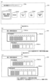
情報表示装置14は、例えば、インサートランプと、スタートランプと、リプレイランプと、ベット数ランプと、クレジットランプと、払出数ランプと、指示モニタと、リミットランプ等を含んで構成される。
The
インサートランプは、点灯することでメダルの投入が可能であることを表示する。スタートランプは、点灯することでスタートレバー7の操作にともなって遊技の開始が可能であることを表示する。リプレイランプは、点灯することで再遊技の作動によりメダルが自動投入されたことを表示する。ベット数ランプは、点灯することでベットされたメダル数を表示する。クレジットランプは、その点灯態様によりクレジットされているメダル数を表示する。払出数ランプは、その点灯態様により遊技結果に応じて払出されたメダル数(払出数)を表示する。
The insert lamp lights up to indicate that medals can be inserted. The start lamp indicates that the game can be started by operating the
また、指示モニタは、報知ランプ(停止操作表示部)と、区間ランプ(状態表示部)と、を含んで構成される。報知ランプは、遊技者に対して停止操作の情報が報知される状況下(例えば、AT状態)において、報知する停止操作の情報と一義的に対応する態様で点灯することで、停止操作の情報を表示する。なお、「報知する停止操作の情報と一義的に対応する態様」とは、例えば、押し順(本実施形態では、これを「打順」として説明する場合がある)「1st(第1停止操作をリール3Lに対して行うこと)」を報知する場合には指示モニタに数値「1」を表示し、押し順「2nd(第1停止操作をリール3Cに対して行うこと)」を報知する場合には指示モニタに数値「2」を表示し、押し順「3rd(第1停止操作をリール3Rに対して行うこと)」を報知する場合には指示モニタに数値「3」を表示する等の態様のことである。なお、報知ランプは、クレジットランプや払出数ランプとは必ずしも別に設けられていなくともよい。例えば、クレジットランプ又は払出数ランプのいずれかを用いて、停止操作の情報を表示してもよい。
Further, the instruction monitor includes a notification lamp (stop operation display section) and a section lamp (state display section). The notification lamp lights up in a manner uniquely corresponding to the information of the stop operation to be notified under a situation (for example, AT state) in which the information of the stop operation is notified to the player, so that the information of the stop operation is displayed. display. It should be noted that the "mode uniquely corresponding to the information of the stop operation to be notified" is, for example, the pressing order (in the present embodiment, this may be described as the "batting order"), the 1st (the first stop operation is In the case of announcing "2nd (perform the first stop operation to the
このように、本実施形態では、遊技者に対して停止操作の情報が報知される状況下においては、後述の副制御回路200によって制御されるサブ側報知手段(例えば、メイン演出表示部21)のみならず、後述の主制御回路100によって制御されるメイン側報知手段としての指示モニタにおいても停止操作の情報が報知される。なお、メイン側報知手段における報知の態様と、サブ側報知手段における報知の態様とは、互いに異なる態様であってもよい。すなわち、メイン側報知手段では、報知する停止操作の情報と一義的に対応する態様で報知すればよく、必ずしも、停止操作の情報を直接的に報知する必要はない。例えば、押し順「1st」を報知する場合、指示モニタにおいて数値「1」が表示されたとしても、遊技者によっては報知内容を特定できない可能性もある。一方、サブ側報知手段では、停止操作の情報を直接的に報知すればよい。例えば、押し順「1st」を報知する場合、メイン演出表示部21では、リール3Lに対して第1停止操作を行わせるための指示情報を直接的に報知すればよい。
As described above, in the present embodiment, in a situation where the information of the stop operation is notified to the player, the sub-side notification means (for example, the main effect display section 21) controlled by the
また、区間ランプは、点灯することで現在の状態が後述の有利区間中であることを表示する。区間ランプは、例えば、後述の非有利区間から有利区間に移行するとき、当該有利区間の遊技が開始されるまでの任意のタイミングで点灯し、当該有利区間が終了して非有利区間に移行するとき、当該非有利区間の遊技が開始されるまでの任意のタイミングで消灯する。なお、区間ランプの点灯タイミングはこれに限られない。例えば、非有利区間又は有利区間における後述の演出区間(通常有利区間)から最初に有利区間における後述の増加区間(AT状態)に移行するとき、当該増加区間の遊技が開始されるまでの任意のタイミングで点灯するものとしてもよい。すなわち、区間ランプは、演出区間であるか増加区間であるかを問わず有利区間中であることを報せるものであってもよいし、少なくとも最初の増加区間の開始からこれを含めた有利区間が終了するまでの期間を報せるものであってもよい。 In addition, the section lamp indicates that the current state is in an advantageous section, which will be described later, by turning on. For example, when transitioning from a non-advantageous section described later to an advantageous section, the section lamp lights at an arbitrary timing until the game in the advantageous section is started, and the advantageous section ends and shifts to the non-advantageous section. , the lights are turned off at an arbitrary timing until the game in the non-advantageous section is started. Note that the lighting timing of the section lamp is not limited to this. For example, when the production section (normal advantageous section) described later in the non-advantageous section or the advantageous section first shifts to the increased section (AT state) described later in the advantageous section, any time until the game in the increased section is started It is good also as what lights up at timing. That is, the section lamp may indicate that it is in an advantageous section regardless of whether it is a production section or an increase section, or at least the advantageous section including this from the start of the first increase section It may be one that informs the period until the end of.
また、リミットランプは、その点灯態様により後述のリミット処理が実行されたこと、あるいはその可能性を表示する。例えば、リミット処理が実行された場合に点灯することで遊技者に有利な状態(例えば、AT状態)がリミット処理の実行によって強制的に終了されたことを報せる。また、例えば、リミット処理の実行が近い場合に点滅することで当該有利な状態がリミット処理の実行によって強制的に終了される可能性が高いことを報せる。なお、これら以外にも点灯、点滅又は消灯の契機を設けることで、リミット処理に関するその他の情報を適宜報せることもできる。 In addition, the limit lamp indicates that the limit processing described later has been executed or the possibility thereof, depending on its lighting mode. For example, when the limit process is executed, the lighting informs the player that a state advantageous to the player (for example, the AT state) has been forcibly terminated by the execution of the limit process. In addition, for example, when the execution of the limit process is near, by blinking, it is reported that there is a high possibility that the advantageous state will be forcibly terminated by the execution of the limit process. In addition to these, other information related to the limit processing can be appropriately notified by providing a trigger for lighting, blinking, or extinguishing.
[1-1-10.演出表示部]
上述のとおり、パチスロ機1は、演出画像を表示するメイン演出表示部21及びサブ演出表示部22を備える。メイン演出表示部21及びサブ演出表示部22は、演出表示を行うことが可能な演出表示部(手段)を構成する。また、遊技者に対し視覚的な観点での演出を実行可能な演出実行手段の1つとして構成される。
[1-1-10. Effect display section]
As described above, the pachi-
メイン演出表示部21は、演出表示窓UD1を介して演出表示を行うメイン表示装置210を含んで構成される。また、メイン表示装置210は、キャビネットG内の中間支持板G1上に交換可能に載置された表示ユニットAと、画像表示用の照射光を出射する照射ユニットBと、照射ユニットBからの照射光が照射されることにより画像を出現させるスクリーン装置Cとを有するいわゆるプロジェクションマッピング装置として構成される。なお、本実施形態では、メイン表示装置210をこのように構成することで、高度で、かつ迫力のある演出表示を可能としているが、メイン表示装置210の構成はこれに限られない。すなわち、遊技者に対し視覚的な観点での演出を実行可能であればよく、液晶表示装置や有機EL等の画像表示装置や7セグメントLED等の表示装置として構成することもできるし、サブリール等の変動表示装置やドット表示装置として構成することもできる。また、このような観点より、その形状、配置及び大きさ等も適宜変更可能である。また、パチスロ機1が、例えば、いわゆる出目によって楽しませることを主体とする遊技性である等の場合には、メイン演出表示部21を設けないように構成することもできる(サブ演出表示部22も同様)。
The main
サブ演出表示部22は、サブ表示装置220を含んで構成される。また、サブ表示装置220は、液晶表示装置として構成される。なお、サブ表示装置220もメイン表示装置210と同様に、他の画像表示装置や表示装置として構成することができるし、変動表示装置やドット表示装置として構成することもできる。また、このような観点より、その形状、配置及び大きさ等も適宜変更可能である。また、メイン演出表示部21は、大画面で構成されていることから、押し順の報知や当り報知、あるいは連続演出等といった今回の遊技と密接に関連する演出を主として表示し、サブ演出表示部22は、小画面で構成されていることから、遊技履歴等といった今回の遊技とはそこまで密接に関連しない演出を主として表示するといったように、目的に応じて表示内容を分けて表示することが可能である。また、本実施形態では、メイン演出表示部21及びサブ演出表示部22の2個の演出表示部を設けるように構成しているが、これらのいずれも設けることなく構成することもできるし、これらのうちいずれかのみを設けるように構成することもできる。また、3個以上の演出表示部を設けるように構成することもできる。
The sub
[1-1-11.ランプ]
上述のとおり、パチスロ機1は、一例として挙げた上部ランプ23のように、その発光態様(点灯、点滅、あるいは消灯のみならず、フルカラーLEDとして構成される場合にはその輝度や発光色を含む)によって演出を行うことが可能な一又は複数のランプ(発光手段)を備える。また、このような発光手段は、遊技者に対し視覚的な観点での演出を実行可能な演出実行手段の1つとして構成される。なお、このような観点より、その数、形状、配置及び大きさ等も適宜変更可能である。
[1-1-11. lamp]
As described above, the pachi-
なお、後述のランプ・LED類に含まれるその他のランプとしては、例えば、上ドア機構UDの両側端面や下ドア機構DDの両側端面に設けられたサイドランプや各操作部内に設けられた操作部ランプ等を挙げることができる。なお、後者は、それぞれの操作部が操作可能であるか否かを遊技者に報せる機能を含むことから、このような機能を発揮させる場合には演出内容に応じて発光態様を変動させず、一義的な発光態様によって発光するように制御することができる。 Other lamps included in lamps and LEDs to be described later include, for example, side lamps provided on both side end surfaces of the upper door mechanism UD and both side end surfaces of the lower door mechanism DD, and operation units provided in each operation unit. A lamp etc. can be mentioned. The latter includes a function to inform the player whether or not each operation unit can be operated. , can be controlled to emit light according to a unique lighting mode.
[1-1-12.スピーカ]
上述のとおり、パチスロ機1は、効果音やBGM等の音声を出力するスピーカ35a,35bを備える。スピーカ35a,35bは、音声の出力によって演出を行うことが可能な音声出力手段を構成する。また、遊技者に対し聴覚的な観点での演出を実行可能な演出実行手段の1つとして構成される。なお、このような観点より、その数、形状、配置及び大きさ等も適宜変更可能である。
[1-1-12. speaker]
As described above, the pachi-
[1-1-13.その他演出装置]
なお、パチスロ機1では、上述の各種演出装置(演出実行手段)以外の演出装置を設けることもできる。例えば、いわゆる役物といった可動演出装置、振動により演出を行う振動演出装置、あるいは空気を噴射することで演出を行うエアー演出装置等の演出装置を設け、演出を実行することも可能である。すなわち、遊技者の五感(視覚、聴覚、触覚、味覚、嗅覚)のいずれかに訴えかけることができる(遊技者に演出が実行されていることを認識可能とさせる)演出を実行可能な演出装置であれば、それらのうちいずれを用いることもできる。したがって、本実施形態において「演出を実行する」とは、特段の説明がない限り、上述の各種演出装置(演出実行手段)のうち、一又は複数の演出装置のいずれの演出装置を用いて演出を実行してもよいこと示している。
[1-1-13. Other production equipment]
Incidentally, the pachi-
[1-2.内部構造]
[1-2-1.セレクタ]
セレクタ31(図2において符号省略)は、メダル投入口5から投入されたメダルの流下路であって、下ドア機構DDの背面側に設けられている。セレクタ31は、例えば、後述のメダルセンサ31Sと、振分装置とを有している。
[1-2. Internal structure]
[1-2-1. selector]
The selector 31 (not numbered in FIG. 2) is a downstream passage for medals inserted from the
メダルセンサ31Sは、メダル投入口5から投入されたメダルを検出するとともに、検出されたメダルが適切なメダルであるか否かを判定する。振分装置は、メダルセンサ31Sにより、検出されたメダルが適切なメダルであると判定された場合であって、メダルの受入れが可能な状態である場合、当該メダルが後述のホッパー装置32側に案内されるように駆動制御される。なお、この場合、ベット数あるいはクレジット数が1加算される。一方、振分装置は、メダルセンサ31Sにより、検出されたメダルが適切なメダルでないと判定された場合、及びメダルの受入れが可能な状態でない場合、当該メダルがキャンセルシュートを通ってメダル払出口11から返却されるように駆動制御される。メダルセンサ31Sによるメダルの検出に異常が発生した場合にはセレクタエラーが発生する。なお、この場合、異常の発生要因(例えば、メダル詰まり)を解消した上で、リセット操作が行われると当該エラー状態が解除される。
The
すなわち、セレクタ31は、投入された遊技媒体を検出可能な遊技媒体検出部(手段)を構成する。また、セレクタ31は、投入された遊技媒体が適正であるか否かを判定可能な判定手段を構成する。また、セレクタ31は、投入された遊技媒体が適正である場合には内部に貯留する一方、投入された遊技媒体が適正でない場合には外部に排出する振分手段を構成する。また、セレクタ31の構成、配置及び大きさ等は適宜変更可能である。また、パチスロ機1が、後述のメダルレス遊技機として構成される場合には、必ずしも必須の構成とはならない。
That is, the
[1-2-2.ホッパー装置]
ホッパー装置32は、キャビネットG内の下部空間に設けられている。ホッパー装置32は、例えば、メダル投入口5から投入され、セレクタ31によって案内されたメダルを貯留するバケット部と、バケット部の底部に設けられ、バケット部に貯留されたメダルを撹拌するとともに、1枚ずつ排出部に案内するディスク部と、ディスク部によって案内されたメダルを1枚ずつ排出する排出部と、排出部から排出されたメダルをカウントするカウントセンサとを有している。
[1-2-2. Hopper device]
The
バケット部は、一定数のメダルを貯留可能に構成される。一定数を超えたメダルは、上面側に設けられた案内通路を通って後述のメダル補助収納庫33に案内される。なお、バケット部に貯留されたメダルが空となった場合にはホッパーエンプティエラーが発生する。なお、この場合、メダルを補充した上で、リセット操作が行われると当該エラー状態が解除される。
The bucket section is configured to be able to store a fixed number of medals. Medals exceeding a certain number are guided to a medal
ディスク部は、中心から放射状にメダル形状のくり抜き部が複数形成され、駆動信号にしたがって中心軸が回転駆動されることで、くり抜き部に嵌ったメダルを1枚ずつ排出部に案内する。なお、ディスク部が回転することでバケット部に貯留されたメダルが撹拌される。また、ディスク部の回転に異常が発生した場合にはホッパージャムエラーが発生する。なお、この場合、異常の発生要因(例えば、メダル詰まり)を解消した上で、リセット操作が行われると当該エラー状態が解除される。 The disc portion has a plurality of medal-shaped cutouts radially formed from the center, and the central shaft is rotated according to a drive signal to guide the medals fitted in the cutouts one by one to the ejection portion. The medals stored in the bucket are agitated by the rotation of the disk. Also, when an abnormality occurs in the rotation of the disk portion, a hopper jam error occurs. In this case, the error state is canceled when the reset operation is performed after eliminating the cause of the abnormality (for example, medal jam).
カウントセンサは、排出部から排出されたメダルを検出するとともに、その枚数をカウントする。例えば、1枚のメダルを払出す場合、ディスク部が回転を開始し、続いてカウントセンサが1枚のメダルの払出をカウントしたことに応じてディスク部の回転が停止する。このようにして、適正枚数のメダルが払出されるようにしている。 The count sensor detects the medals discharged from the discharge section and counts the number of medals. For example, when one medal is to be paid out, the disk portion starts rotating, and then the disk portion stops rotating when the count sensor counts the payout of one medal. In this manner, an appropriate number of medals are paid out.
すなわち、ホッパー装置32は、遊技媒体を払出可能な遊技媒体払出部(手段)を構成する。また、上述のとおり、遊技者に特典を付与する特典付与手段の一部であるともいえる。また、ホッパー装置32の構成、配置及び大きさ等は適宜変更可能である。また、パチスロ機1が、後述のメダルレス遊技機として構成される場合には、必ずしも必須の構成とはならない。
That is, the
[1-2-3.メダル補助収納庫]
メダル補助収納庫33は、キャビネットG内の下部空間に設けられている。メダル補助収納庫33は、例えば、ホッパー装置32のバケット部から案内されたメダルを収納する収納部と、収納部の近傍に設けられ、収納部に収納されたメダルの容量を検出するメダル補助収納庫スイッチ33Sとを有している。
[1-2-3. Auxiliary storage for medals]
The medal
収納部は、一定数のメダルを収納可能に構成される。メダル補助収納庫スイッチ33Sにより、当該一定数以上のメダルが収納されたと判定された場合にはメダル補助収納庫エラーが発生する。なお、この場合、収納部に収納されたメダルを少なくとも一定数未満に減らした上で、リセット操作が行われると当該エラー状態が解除される。
The storage section is configured to be able to store a certain number of medals. When it is determined by the medal
すなわち、メダル補助収納庫33は、余剰の遊技媒体を貯留可能な余剰遊技媒体貯留部(手段)を構成する。なお、メダル補助収納庫33の構成、配置及び大きさ等は適宜変更可能である。また、パチスロ機1が、後述のメダルレス遊技機として構成される場合には、必ずしも必須の構成とはならない。
That is, the auxiliary
[1-2-4.電源装置]
電源装置34は、キャビネットG内の下部空間に設けられている。電源装置34は、例えば、電源基板34aと、電源スイッチ34bとを有しており、電源スイッチ34bがオンされることに応じてパチスロ機1に電力を供給する。なお、電源装置34は、家庭用電気製品等と同じく電源ケーブル(不図示)から供給された交流電圧100Vの電力を各部で必要な直流電圧の電力に変換して、変換した電力を各部へ供給する。すなわち、電源装置34は、必要な電力を遊技機に供給可能な電源部(手段)を構成する。なお、電源装置34の構成、配置及び大きさ等は適宜変更可能である。
[1-2-4. power supply]
The
なお、本実施形態では、後述の設定用鍵型スイッチ52やリセットスイッチ53が主制御基板71(より詳細には後述の主制御基板ケース上)に設けられるように構成しているが、これらのスイッチを電源装置34に設けるように構成することもできる。
In this embodiment, the setting key-
[1-2-5.基板]
パチスロ機1は、各種制御に必要な基板として、例えば、以下に示す各基板を備える。なお、以下に示す各基板はあくまで一例であって、これらとは異なる基板を備える構成としてもよいし、これらのうち必ずしも必須のものでない基板については、これを備えない構成としてもよい。
[1-2-5. substrate]
The pachi-
[1-2-5-1.主制御基板]
主制御基板71は、キャビネットG内において、リールユニットRUの背面側に取付けられている。なお、主制御基板71は、遊技に関する制御を行う遊技制御基板であり、その状態が視認可能となるように透明(あるいは略透明)に構成された樹脂製の主制御基板ケース(不図示)内に収容されている。主制御基板71の電気的構成については後述する。
[1-2-5-1. Main control board]
The
なお、主制御基板71の仕様には種々の制約があり、基本的に各種電子部品がDIP実装されて構成されるものとなっているが、各種電子部品の一部又は全部についてSMT実装(表面実装)されて構成されるものとしてもよい。また、この場合、テスターやオシロスコープを用いて動作確認を行うためのテストポイントを設けるようにしてもよい。また、各種電子部品の一部又は全部について6平方mmを超えない小さい電子部品を使用してもよい。また、主制御基板71の基板面を多層化して構成してもよい。
There are various restrictions on the specifications of the
[1-2-5-2.副制御基板]
副制御基板72は、キャビネットG内において、中間支持板G1の裏面側に取付けられている。なお、副制御基板72は、演出に関する制御を行う演出制御基板であり、樹脂製の副制御基板ケース(不図示)内に収容されている。なお、副制御基板ケースは、主制御基板ケースと同様に透明(あるいは略透明)に構成された樹脂製のケースとして構成することもできるし、不透明(あるいは略不透明)に構成された他の材料を用いたケースとして構成することもできる。副制御基板72の電気的構成については後述する。
[1-2-5-2. Sub control board]
The
[1-2-5-3.その他基板]
(主中継基板)
主中継基板73(図2において符号省略)は、キャビネットG内の特定位置(例えば、下ドア機構DDの背面側)に取付けられており、主中継基板73に接続された各種デバイス等と主制御基板71との間、及び主制御基板71と副制御基板72との間を中継するための中間制御基板である。なお、主中継基板73は、制御効率や配線効率の便宜から主制御基板71とは別の基板として構成されたものであるため、特段の支障がなければ主中継基板73の機能を全て主制御基板71にもたせ、主中継基板73を設けない構成とすることもできる。また、このような観点より、主中継基板73をさらに複数の中継基板に分割し、制御効率や配線効率の向上を図るようにしてもよい。すなわち、主中継基板として複数の基板を設けるようにしてもよい。
[1-2-5-3. Other substrates]
(main relay board)
The main relay board 73 (reference numerals omitted in FIG. 2) is attached to a specific position (for example, the back side of the lower door mechanism DD) in the cabinet G, and various devices connected to the
(副中継基板)
副中継基板74は、キャビネットG内の特定位置(例えば、下ドア機構DDの背面側)に取付けられており、副中継基板74に接続された各種デバイス等と副制御基板72との間、及び主制御基板71と副制御基板72との間を中継するための中間制御基板である。なお、副中継基板74は、制御効率や配線効率の便宜から副制御基板72とは別の基板として構成されたものであるため、特段の支障がなければ副中継基板74の機能を全て副制御基板72にもたせ、副中継基板74を設けない構成とすることもできる。また、このような観点より、副中継基板74をさらに複数の中継基板に分割し、制御効率や配線効率の向上を図るようにしてもよい。すなわち、副中継基板として複数の基板を設けるようにしてもよい。
(Secondary relay board)
The
(外部集中端子板)
外部集中端子板55は、キャビネットG内の特定位置(例えば、下部空間の奥側)に取付けられており、例えば、メダル投入信号、メダル払出信号、外部信号1~4及びセキュリティ信号等の信号をパチスロ機1の外部へ出力する。なお、外部信号1~4は、その出力開始条件及び出力終了条件を適宜設定可能であり、その遊技性に応じてパチスロ機1の内部状態(例えば、ボーナス状態やAT状態)の遷移を外部に報せることを可能としている。そして、外部集中端子板55は、通常、外部のデータ表示機やホールコンピュータに接続されることから、これらの機器においても、パチスロ機1におけるメダルの投入・払出状況やエラーの発生状況のみならず、そのような内部状態の遷移状況が認識可能となっている。
(External collective terminal board)
The external centralized
(試験機用インターフェースボード)
試験機用第1インターフェースボード301及び試験機用第2インターフェースボード302は、ともにパチスロ機1の検定試験(試射試験)において、遊技に関する各種信号を試験機に出力する際に用いられる中継基板である(なお、販売用のリリース製品としてのパチスロ機1にはこれらの中継基板は搭載されていないので、販売用の主制御基板71には、試験機用第1インターフェースボード301及び試験機用第2インターフェースボード302に接続するために必要な各種電子部品もまた実装されていない)。例えば、遊技に係る主要な動作(例えば、内部抽籤、リール停止制御等)を制御するための試験信号は、試験機用第1インターフェースボード301を介して出力され、また、主制御基板71で決定された押し順ナビに係る試験信号等は、試験機用第2インターフェースボード302を介して出力される。
(Interface board for testing machine)
The first interface board for testing
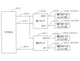
[2.パチスロ機の電気的構成]
続いて、図3を参照して、パチスロ機1の電気的構成について説明する。なお、図3は、パチスロ機1の電気的構成を示すブロック図である。
[2. Electrical Configuration of Pachislot Machine]
Next, the electrical configuration of the pachi-
上述のとおり、パチスロ機1は、主制御基板71と、副制御基板72と、主中継基板73と、副中継基板74とを有している。主制御基板71と主中継基板73、主中継基板73と副中継基板74、及び副中継基板74と副制御基板72は、それぞれ電気的に接続されている。また、主制御基板71と副制御基板72は、主中継基板73及び副中継基板74を介して、主制御基板71から副制御基板72に対して一方向のシリアル通信が可能となるように電気的に接続されている。
As described above, the pachi-
主制御基板71には、遊技に関する制御を行う遊技制御部としての主制御回路100が実装されている。主制御回路100は、例えば、メインCPU101、メインROM102、メインRAM103、クロックパルス発生回路(不図示)、乱数回路(不図示)等を含んで構成される。メインROM102には、メインCPU101により実行される各種制御プログラム、各種データテーブル、副制御回路200に対して各種制御指令(コマンド)を送信するためのデータ等が記憶される。メインRAM103には、制御プログラムの実行により決定された内部当籤役等の各種データを格納する格納領域が設けられる。クロックパルス発生回路は、メインCPU101作動用のクロックパルス信号を生成する。乱数回路は、予め定められた範囲の乱数(例えば、0~65535又は0~255等)を発生させる。メインCPU101は、生成されたクロックパルス信号に基づいて各種制御プログラムを実行する。また、発生された乱数の中から必要に応じて一又は複数の値を乱数値として抽出する。このようにして、遊技動作全般に係る制御を行う。
The main
副制御基板72には、演出に関する制御を行う演出制御部としての副制御回路200が実装されている。副制御回路200は、例えば、サブCPU201、サブRAM203等を含んで構成される。また、副制御基板72には、ロムカートリッジ基板202が接続されている。ロムカートリッジ基板202には、サブCPU201により実行される各種制御プログラム、各種データテーブル、各種演出データ(例えば、メイン表示装置210に係る映像データや駆動データ、サブ表示装置220に係る映像データ、ランプ・LED群に係るランプデータ、スピーカ群に係るサウンドデータ等)等が記憶される。サブRAM203には、制御プログラムの実行により決定された演出内容や各種演出データを登録する格納領域や、主制御基板71から送信される各種制御指令(コマンド)に係るデータを格納する格納領域等が設けられる。なお、演出に係る演出用乱数値については、予め定められた範囲の乱数(例えば、0~32767等)の中から、サブCPU201内で発生及び抽出が行われるようにしてもよいし、主制御回路100と同様に乱数回路を設けることでその発生及び抽出が行われるようにしてもよい。また、ロムカートリッジ基板202ではなく、副制御回路200内にサブROMが含まれるようにし、各種制御プログラム等はサブROMに記憶されるように構成してもよい。また、ロムカートリッジ基板202に各種演出データを記憶させ、副制御回路200内のサブROMに各種制御プログラム及び各種データテーブルを記憶させるように構成してもよい。また、副制御回路200には、GPU等の画像専用のマイクロプロセッサ(例えば、「VDP」とも称される)が含まれるようにし、これによってメイン表示装置210やサブ表示装置220で表示される映像を生成(編集)するように構成してもよい。
A
主制御基板71には、ステッピングモータ51L,51C,51R、設定用鍵型スイッチ52、リセットスイッチ53、役比モニタ装置54、外部集中端子板55、ホッパー装置32、メダル補助収納庫スイッチ33S、電源装置34が電気的に接続されている。また、主制御基板71には、主中継基板73を介して、ドア開閉監視スイッチ56、メダルセンサ31S、ベットスイッチ6S、スタートスイッチ7S、ストップスイッチ8S、精算スイッチ9S、情報表示装置14が電気的に接続されている。なお、仮に試験機用第1インターフェースボード301及び試験機用第2インターフェースボード302が搭載される場合には、例えば、主中継基板73を介して主制御基板71に電気的に接続される。
The
なお、外部集中端子板55、ホッパー装置32、メダル補助収納庫スイッチ33S、電源装置34、メダルセンサ31S、ベットスイッチ6S、スタートスイッチ7S、ストップスイッチ8S、精算スイッチ9S、情報表示装置14、試験機用第1インターフェースボード301及び試験機用第2インターフェースボード302についてはすでに説明したため、ここでの説明は省略する。
In addition, the external collective
各ステッピングモータ51L,51C,51Rは、それぞれ所定の減速比をもったギアを介して各リール3L,3C,3Rに接続され、その駆動により各リール3L,3C,3Rを回転及び停止させる。なお、各ステッピングモータ51L,51C,51Rに対して1回のパルスが出力されるごとに、各リール3L,3C,3Rが一定の角度で回転することから、メインCPU101は、各ステッピングモータ51L,51C,51Rに対してパルスを出力した回数をカウントし、このカウント結果に基づいて各リール3L,3C,3Rの図柄位置を管理する。また、各リール3L,3C,3Rには、このような管理を行うための初期位置を定めるリールインデックス(不図示)と、リールインデックスの位置を検出するためのインデックスセンサ(不図示)が設けられる。
Each stepping
設定用鍵型スイッチ52は、パチスロ機1の設定値(例えば、6段階の設定1~設定6)を変更するとき(設定変更)、もしくは、パチスロ機1の設定を確認するとき(設定確認)に使用される。ここで、設定値は、遊技に関する遊技者の有利さの度合いを示すものであり、通常は、設定値が低いほど(例えば、設定1に近いほど)遊技者の有利さの度合いが相対的に低くなり、設定値が高いほど(例えば、設定6に近いほど)遊技者の有利さの度合いが相対的に高くなる。設定用鍵型スイッチ52は、例えば、遊技店側の管理者が鍵穴に設定キー(不図示)を挿入して初期位置から左に回すとオン状態となり、左に回した状態から初期位置に戻すとオフ状態となる。なお、パチスロ機1の電源がオフ状態のとき、設定用鍵型スイッチ52をオン状態としてから電源をオン状態とすると設定変更が可能な状態となり、パチスロ機1の電源がオン状態のままで設定用鍵型スイッチ52をオン状態とすると設定確認が可能な状態となる。
The setting key-
リセットスイッチ53は、遊技店側の管理者によるリセット操作を検出可能としている。リセット操作は、各種のエラー状態を解除するための操作である。また、リセットスイッチ53は、設定変更が可能な状態において、遊技店側の管理者による設定値決定操作を検出可能としている。なお、設定変更が可能な状態においてリセットスイッチ53が操作されると、操作される度に設定値が順次1ずつ増加する(設定6まで到達すると次は設定1に戻る)。このようにして、設定値決定操作が行えるようになっている。また、このように決定された設定値は、その後スタートレバー7が1回操作されると確定する。すなわち、スタートスイッチ7Sは、遊技店側の管理者による設定値確定操作を検出可能としている。このように、設定変更を行う場合には、設定用鍵型スイッチ52をオン状態とし、リセットスイッチ53を操作して設定値を選択し、スタートレバー7を操作して選択した設定値を確定させた後、設定用鍵型スイッチ52をオフ状態とするといった設定変更操作が必要となっている。なお、これは、設定変更操作の一例であり、他の操作によって設定変更を行い得るように構成することもできる。また、設定変更や設定確認に際しては、例えば、上述のクレジットランプあるいは払出数ランプにおいて現在の設定値が表示されるものすればよい。
The
役比モニタ装置54は、例えば、4桁の7セグメントLEDにより構成され、主制御基板ケースの内部に設けられる。役比モニタ装置54は、メインCPU101によって集計・算出された遊技に関する各種割合情報を順次表示する。これらの割合情報は、遊技店の管理者がパチスロ機1に不正改造がないかを確認する際等に使用される。なお、役比モニタ装置54は、主制御基板71上に実装されるようにしてもよいし、主制御基板71に接続された他の基板(例えば、割合表示基板)上に実装されるようにしてもよい。また、キャビネットG内であれば、他の場所に設けられるようにしてもよい。例えば、主制御基板ケース上に設けられるようにしてもよい。また、役比モニタ装置54における表示を開始させ、あるいはその内容を切替えるための管理スイッチをキャビネットG内に設けるようにし、これが操作された場合に上述の各種割合情報が表示されるようにしてもよい。また、このような管理スイッチを使用することを前提として、例えば、情報表示装置14を役比モニタ装置54と兼用して用いる構成としてもよい。また、電源投入直後又は電源投入から所定時間(例えば、10秒程度。主制御回路100及び副制御回路200の立ち上げに要する時間を考慮したバッファとなる時間)の経過後に、役比モニタ装置54の4桁の7セグメントLEDが正常に機能していることを確認可能とするため、例えば、「8.8.」といったようなテストパターン(全てのセグ及びデシマルのLEDが点灯するパターン)で所定期間点灯(ないし点滅)させる構成とすることが望ましい。
The role
役比モニタ装置54では、例えば、上位2桁にはその割合情報の種類が表示され、下位2桁にはその割合情報を示す値(%)が表示される。ここで、役比モニタ装置54に表示される各種割合情報には、例えば、累計の特定区間割合情報、直近6000ゲーム間の連続役物割合情報及び役物割合情報、累計の連続役物割合情報及び役物割合情報等がある。
In the role
特定区間割合情報とは、対象の遊技数(例えば、「累計」であれば175000ゲーム。「直近6000ゲーム」であれば6000ゲーム。以下同じ)の遊技区間のうち、遊技者に有利な停止操作の情報の報知が行われていた遊技区間(例えば、AT状態)の遊技数(あるいは、単に有利区間中の遊技数であってもよい)の割合を示す情報である。また、連続役物割合情報とは、対象の遊技数の遊技区間において払出されたメダル数のうち、第一種特別役物(RB)の作動中(第一種特別役物に係る役物連続作動装置(BB)が作動している状態における第一種特別役物(RB)の作動中を含む)に払出されたメダル数の割合を示す情報である。また、役物割合情報は、対象の遊技数の遊技区間において払出されたメダル数のうち、第一種特別役物(RB)、第二種特別役物(CB)、及び普通役物(SB)の作動中に払出されたメダル数の割合を示す情報であり、ここでの第一種特別役物(RB)の作動中とは、第一種特別役物に係る役物連続作動装置(BB)が作動している状態における第一種特別役物(RB)の作動中を含む概念であり、また、第二種特別役物(CB)の作動中とは、第二種特別役物に係る役物連続作動装置(MB)が作動している状態における第二種特別役物(CB)の作動中を含む概念である。 The specific section ratio information refers to a stop operation that is advantageous to the player among the game sections of the target number of games played (for example, 175,000 games for "total"; 6,000 games for "last 6,000 games"; the same applies hereinafter). Information indicating the ratio of the number of games played in the game section (for example, AT state) (or simply the number of games in the advantageous section may be used) in which the information of . In addition, the continuous role ratio information means that among the number of medals paid out in the game section of the number of games to be played, the first type special role (RB) is in operation It is information indicating the ratio of the number of medals paid out (including during operation of the first class special bonus (RB) in the state where the operating device (BB) is operating). In addition, the accessory ratio information is the number of medals paid out in the game section of the target number of games, the first type special accessory (RB), the second type special accessory (CB), and the normal accessory (SB ) is information indicating the ratio of the number of medals paid out during the operation of the first class special bonus (RB). BB) is in operation and the first class special bonus (RB) is in operation, and the second class special bonus (CB) is in operation It is a concept that includes the operation of the second type special role product (CB) in the state where the role product continuous operation device (MB) is operating.
なお、遊技者に有利な停止操作の情報の報知が行われていた遊技区間(例えば、AT状態)を役物の作動中、あるいは役物連続作動装置の作動中としてとらえ、それぞれの割合情報において集計・算出の対象とすることもできる。すなわち、役比モニタ装置54は、必要な割合情報を適切に表示するものであればよく、表示可能な各種割合情報はこれらに限定されない。また、例えば、第一種特別役物(RB)が搭載されていない機種において連続役物割合情報を表示する場合、あるいは有利区間機能(AT機能)が搭載されていない機種において特定区間割合情報を表示する場合等、該当する数値情報(対応情報)が存在しない機種においては、当該項目の表示時に、4桁の7セグメントLEDのうちの数値情報(割合を示す%情報)を表示する下2桁の7セグメントLEDにおいて、例えば、「- -」といったように、中央の縦棒2本を点灯表示させる等の非対応情報用識別表示を行うことで、対応情報が存在しない機種である点を確認者が一目で認識可能とすることが望ましい。
In addition, the game section (for example, AT state) in which the information of the stop operation that is advantageous to the player is being treated as the operation of the accessory or the operation of the accessory continuous operation device, and in the respective ratio information It can also be subject to aggregation/calculation. That is, the role
ドア開閉監視スイッチ56は、例えば、下ドア機構DDの開閉側(右側)に設けられる。なお、下ドア機構DDの背面側に設けられるように構成してもよいし、キャビネットG側に設けられるように構成してもよい。また、上ドア機構UDにも同様のドア開閉監視スイッチが設けられるように構成してもよい。ドア開閉監視スイッチ56は、下ドア機構DDが開放状態となったときにオン状態となり、閉鎖状態となったときにオフ状態となることで、下ドア機構DDの開閉を監視する。なお、ドア開閉監視スイッチ56がオン状態となるとドア開放エラーが発生する。この場合、下ドア機構DDを閉鎖状態とすると当該エラー状態が解除される。
The door opening/
副制御基板72には、ロムカートリッジ基板202、メイン表示装置210、サブ表示装置220が電気的に接続されている。また、副制御基板72には、副中継基板74を介して、24hドア監視ユニット61、演出用ボタン10a,10b等の演出用ボタン群、上部ランプ23等のランプ・LED類、スピーカ35a,35b等のスピーカ群が電気的に接続されている。
A
なお、ロムカートリッジ基板202、メイン表示装置210、サブ表示装置220、演出用ボタン群、ランプ・LED類及びスピーカ群についてはすでに説明したため、ここでの説明は省略する。
Since the
24hドア監視ユニット61は、ドア開閉監視スイッチ56と同様に、例えば、下ドア機構DDの開閉側(右側)に設けられる。なお、下ドア機構DDの開閉を監視するという機能を有する点においてはドア開閉監視スイッチ56と同じであるが、このような監視を副制御回路200側でも行い得るようにすることで、さらに下ドア機構DDの開閉履歴を一定期間保存することができるようにしている。なお、この開閉履歴は、後述のホールメニューから確認することができる。したがって、例えば、営業時間外であって、遊技店の管理者が退出した後に開放履歴があった場合や、営業時間内において長時間にわたって開放された開閉履歴があった場合には、これにより不正行為が行われた可能性が高いことを認識できるようになっている。
The 24h
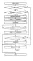
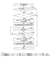
[3.パチスロ機の機能フロー]
続いて、図4を参照して、パチスロ機1の機能フローについて説明する。なお、図4は、パチスロ機1の機能フローを説明するための図である。
[3. Function Flow of Pachislot Machine]
Next, a functional flow of the pachi-
遊技者によりパチスロ機1にメダルが投入され(ベット操作が行われ)、スタートレバー7が操作される(開始操作が行われる)と、予め定められた範囲(例えば、0~65535)の乱数から1つの乱数値(本実施形態では、これを「内部抽籤用乱数値」として説明する場合がある)が抽出される。 When the player inserts medals into the pachi-slot machine 1 (performs a bet operation) and operates the start lever 7 (performs a start operation), random numbers are generated from a predetermined range (for example, 0 to 65535). One random number (in this embodiment, this may be described as an "internal lottery random number") is extracted.
内部抽籤手段(後述の内部抽籤処理を行うメインCPU101)は、抽出された乱数値に基づいて抽籤を行い、内部当籤役を決定する。内部当籤役の決定により、有効ライン上に表示されることが許可される図柄の組合せが事前に決定される。なお、図柄の組合せの種別としては、メダルの払い出し、再遊技(リプレイ)の作動、ボーナスの作動等といった特典が遊技者に与えられる「入賞」に係るものと、それ以外のいわゆる「はずれ」に係るものとが設けられる。なお、メダルの払い出しに係る役を「小役」と称し、再遊技(リプレイ)の作動に係る役を「リプレイ役」と称し、ボーナス(ボーナス状態)の作動に係る役を「ボーナス役」と称する。また、内部当籤し得る役(すなわち、成立が許可される図柄の組合せ)は、単に「役」と称されることがある。また、内部当籤役は、「当籤役」、「事前決定結果」、あるいは「導出許容条件」等と称されることがある。また、内部抽籤手段は、「役決定手段」、「当籤役決定手段」、「事前決定手段」、あるいは「導出許容条件決定手段」等と称されることがある。
The internal lottery means (the
また、スタートレバー7が操作される(開始操作が行われる)と、複数のリールの回転が行われる。その後、遊技者によりリール(各リール3L,3C,3R)に対応するストップボタン(各ストップボタン8L,8C,8R)が操作される(停止操作が行われる)と、リール停止制御手段(後述のリール停止制御処理を行うメインCPU101)は、内部当籤役とストップボタンが押されたタイミング(あるいはその押し順を含む)とに基づいて、該当するリールの回転を停止する制御を行う。なお、開始操作を行うための操作手段は、スタートレバー7のようにレバー形状をしたものに限られず、遊技者が開始操作を行うことが可能であれば、どのような操作手段であってもよい。また、停止操作を行うための操作手段は、各ストップボタン8L,8C,8Rのようにボタン形状をしたものに限られず、遊技者が停止操作を行うことが可能であれば、どのような操作手段であってもよい。
Further, when the
パチスロ機1では、基本的に、ストップボタンが押されたときから規定時間(190msec)内に、該当するリールの回転を停止する制御が行われる。本実施形態では、この規定時間内にリールの回転にともなって移動する図柄の数を「滑り駒数」という。そして、本実施形態では、規定期間が190msecである場合には、滑り駒数の最大数(最大滑り駒数)を図柄4個分に定める。
In the pachi-
リール停止制御手段は、入賞に係る図柄の組合せの表示を許可する内部当籤役が決定されているときは、通常、190msec(図柄4駒分)の規定時間内に、その図柄の組合せが有効ライン上に極力表示されるようにリールの回転を停止させる。また、リール停止制御手段は、規定時間を利用して、内部当籤役によってその表示が許可されていない図柄の組合せが有効ライン上に表示されないようにリールの回転を停止させる。なお、リールの回転が停止したときに表示された図柄は、「停止表示」、あるいは「表示結果」等と称されることがある。また、リールの回転が停止したときに図柄が表示されることは、「停止表示の導出」、あるいは「表示結果の導出」等と称されることがある。 When an internal winning combination that permits the display of a winning combination of symbols is determined, the reel stop control means normally displays the combination of symbols on the effective line within a specified time of 190 msec (for 4 symbols). Stop the rotation of the reel so that it is displayed at the top as much as possible. In addition, the reel stop control means stops the rotation of the reels by using the prescribed time so that the combination of symbols whose display is not permitted by the internal winning combination is not displayed on the effective line. The symbols displayed when the rotation of the reels is stopped are sometimes referred to as "stop display" or "display result". Also, the display of symbols when the rotation of the reels stops is sometimes referred to as "derivation of stop display" or "derivation of display result".
また、リール停止制御手段は、リールが回転してから、予め定められた自動停止時間が経過した場合には、遊技者が停止操作を行っていない場合でも、自動的に各リールを停止させる自動停止制御を行うようにしてもよい。この場合には、遊技者の停止操作を介さずにリールが停止することとなるため、いずれかの内部当籤役が決定されている場合であっても、いずれの入賞に係る図柄の組合せも有効ラインに沿って表示されていないようにリールの回転を停止させることが望ましい。 Further, the reel stop control means automatically stops each reel even if the player does not perform a stop operation when a predetermined automatic stop time elapses after the reels are rotated. Stop control may be performed. In this case, since the reels are stopped without intervention of the player's stop operation, even if any internal winning combination is determined, any winning symbol combination is valid. It is desirable to stop spinning the reels so that they are not displayed along the line.
このようにして、複数のリールの回転が全て停止されると、入賞判定手段(後述の入賞作動判定処理を行うメインCPU101)は、有効ライン上に表示された図柄の組合せが、入賞に係るもの(あるいは、その他予め定められたもの)であるか否かの判定を行う。すなわち、入賞に係る図柄の組合せ(あるいは、その他予め定められた図柄の組合せ)が成立したか否かの判定を行う。そして、表示された図柄の組合せが、入賞判定手段により入賞に係るもの(あるいは、その他予め定められたもの)である(すなわち、入賞に係る図柄の組合せ(あるいは、その他予め定められた図柄の組合せ)が成立した)と判定されると、メダルの払い出し等の特典が遊技者に与えられ、あるいは、それを契機として各種の制御が行われる。パチスロ機1では、一例として、以上のような一連の流れで1回の遊技(単位遊技)として行われる。
In this way, when the rotation of all the plurality of reels is stopped, the winning judgment means (the
なお、入賞判定手段は、有効ライン上に表示された図柄の組合せが、単に予め定められた複数の図柄の組合せのうちのいずれかの図柄の組合せに該当するか否かを判定するものであってもよいし、内部抽籤手段によって決定された内部当籤役に係る図柄の組合せに該当するか否かを判定するものであってもよい。すなわち、前者では、内部当籤役と切り離して、入賞に係る図柄の組合せであるか否かを判定するものであってもよい。この場合、リール停止制御手段によって適切に停止制御が行われる限り、誤入賞の発生の防止は十分に担保され得ることから、誤入賞検知に係る制御負担を低減させることが可能となる。一方、後者では、入賞に係る図柄の組合せが、入賞が許可されていた図柄の組合せであるか否かも判定可能とすることで、リールの不具合等により誤入賞が発生した場合に、その誤入賞を検知することができるため、セキュリティ性を向上させることが可能となる。 Note that the winning determination means simply determines whether or not the combination of symbols displayed on the activated line corresponds to any combination of symbols among a plurality of predetermined combinations of symbols. Alternatively, it may be determined whether or not the symbol combination corresponds to the internal winning combination determined by the internal lottery means. That is, in the former, it may be determined whether or not there is a winning combination of symbols separately from the internal winning combination. In this case, as long as the stop control is appropriately performed by the reel stop control means, it is possible to sufficiently ensure the prevention of the occurrence of erroneous winnings, so it is possible to reduce the control load related to erroneous winning detection. On the other hand, in the latter, by making it possible to determine whether or not the combination of symbols related to the winning is a combination of symbols for which winning was permitted, even if an erroneous winning occurs due to a problem with the reels, etc., the erroneous winning can be detected. can be detected, security can be improved.
また、パチスロでは、前述した一連の遊技動作の流れの中で、表示装置(例えば、メイン表示装置210やサブ表示装置220等)による映像の表示、各種ランプ(例えば、上部ランプ23等)による光の出力、スピーカ(例えば、スピーカ35a,35b等)による音の出力、或いは、これらの組合せを利用して様々な演出が行われる。すなわち、これらは演出を実行する演出実行手段である。なお、演出実行手段により実行される演出の内容は、主制御回路100側(メイン側)で決定される場合もあれば、副制御回路200側(サブ側)で決定される場合もある。すなわち、これらはそのいずれもが演出内容決定手段となり得る。
In addition, in pachislot, in the flow of the series of game operations described above, images are displayed by the display device (for example, the
例えば、スタートレバー7が操作される(開始操作が行われる)と、内部抽籤用乱数値とは別に、演出用乱数値が抽出される。演出用乱数値が抽出されると、演出内容決定手段は、内部当籤役に対応付けられた複数種類の演出内容の中から今回実行する演出を抽籤によって(あるいは予め定められた決定条件にしたがって)決定する。
For example, when the
次いで、演出内容決定手段により演出内容が決定されると、演出実行手段は、リールの回転開始時、各リールの回転停止時、入賞の有無の判定時等の各契機に連動させて対応する演出を実行する。このように、パチスロ機1では、例えば、内部当籤役に対応付けられた演出内容を実行することによって、決定された内部当籤役(狙うべき図柄の組合せや操作すべき押し順等と換言することもできる)を知る機会又は予想する機会が遊技者に提供され、遊技者の興味の向上を図ることができる。
Next, when the effect content is determined by the effect content determining means, the effect execution means performs a corresponding effect in conjunction with each opportunity such as when the reels start rotating, when each reel stops rotating, and when it is determined whether or not a prize is awarded. to run. In this way, in the pachi-
[4.パチスロ機の遊技性に関する基本仕様]
続いて、パチスロ機1の遊技性に関する基本仕様について説明する。
[4. Basic specifications related to playability of pachislot machines]
Next, the basic specifications of the pachi-
[4-1.図柄配置]
上述のとおり、パチスロ機1では、複数の図柄が変動表示及び停止表示されることで遊技が行われる仕様となっている。したがって、主制御回路100は、各リール3L,3C,3Rにおいて、どの図柄がどの位置に配置されているかを把握可能に構成されている必要がある。このため、メインROM102には、少なくとも各リール3L,3C,3Rそれぞれの各図柄位置にある図柄の種類を識別するためのデータが記憶されている。なお、このような目的が達成される限り、そのデータ構成は種々の構成を採用することができるが、本実施形態では、その一例として後述の図柄配置テーブル(図9参照)を用いている。
[4-1. Pattern arrangement]
As described above, the pachi-
図柄配置テーブルには、各リール3L,3C,3Rそれぞれの回転方向における各図柄位置を示す図柄位置データ(例えば、「0」~「19」)が規定されている。また、各図柄位置データに対して図柄の種類を特定するためのデータ(例えば、図柄コード)が対応付けられている。また、図柄配置テーブルでは、リールインデックスが検出されたときにメイン表示窓4の枠内における各リールの中段領域に位置する図柄の位置を「0」と規定している。なお、各列の図柄数、図柄の種類数、あるいは最大滑り駒数等は適宜変更して規定可能である。
The symbol arrangement table defines symbol position data (for example, "0" to "19") indicating each symbol position in each rotation direction of each
[4-2.図柄組合せ]
上述のとおり、パチスロ機1では、表示された図柄の組合せが遊技結果に影響を与える仕様となっている。すなわち、パチスロ機1は、表示された図柄の組合せに応じて、各種特典を付与したり、現在の状態から相対的に有利な状態に移行させたり、現在の状態から相対的に不利な状態に移行させたりすることを可能としている。したがって、主制御回路100は、このような図柄の組合せについて把握可能に構成されている必要がある。このため、メインROM102には、このような図柄の組合せを特定するためのデータが規定されている。なお、このような目的が達成される限り、そのデータ構成は種々の構成を採用することができるが、本実施形態では、その一例として後述の図柄組合せテーブル(図11~図14参照)を用いている。
[4-2. Pattern combination]
As described above, the pachi-
図柄組合せテーブルには、有効ライン上に表示され得る図柄の組合せのうちで予め定められた複数の図柄の組合せの種類を示すデータ(例えば、「表示役」あるいは「入賞作動フラグ」)が規定されている。なお、それぞれの図柄の組合せを構成する図柄は、例えば、上述の図柄コード等を用いて特定することができる。また、各図柄の組合せに対して特典等の種類を示すデータ(例えば、「払出等」)が対応付けられている。また、図柄組合せテーブルは、基本的に後述の当籤フラグ格納領域、入賞作動フラグ格納領域、及び図柄コード格納領域(図17参照)と対応するデータ構成となっている。なお、図柄の組合せの種類数、あるいは特典の付与内容等は適宜変更して規定可能である。 The symbol combination table defines data (for example, "display combination" or "winning operation flag") indicating the type of combination of a plurality of predetermined symbols among the combinations of symbols that can be displayed on the activated line. ing. It should be noted that the symbols forming each combination of symbols can be specified using, for example, the above-described symbol code or the like. In addition, data indicating the type of privilege (for example, "payout etc.") is associated with each combination of symbols. Also, the symbol combination table basically has a data structure corresponding to a winning flag storage area, a winning operation flag storage area, and a symbol code storage area (see FIG. 17), which will be described later. It should be noted that the number of types of combinations of symbols, the content of benefits to be provided, and the like can be appropriately changed and stipulated.
[4-3.内部当籤役]
上述のとおり、パチスロ機1では、いずれの図柄の組合せが表示されることが許可されるか(事前に決定されるか)が遊技結果に影響を与える仕様となっている。すなわち、パチスロ機1は、遊技者の停止操作に先立って(事前に)、内部当籤役(すなわち、表示され得る図柄の組合せの種類(あるいは、付与され得る特典の種類))を決定することを可能としている。したがって、主制御回路100は、このような内部当籤役について把握可能に構成されている必要がある。このため、メインROM102には、このような内部当籤役を特定するためのデータが規定されている。なお、このような目的が達成される限り、そのデータ構成は種々の構成を採用することができるが、本実施形態では、その一例として後述の内部抽籤テーブル(図10参照)を用いている。
[4-3. Internal winning role]
As described above, the pachi-
内部抽籤テーブルには、予め定められた複数の内部当籤役の種類を示すデータ(例えば、「No.」あるいは「当籤番号」)と、各遊技状態において各内部当籤役が決定される抽籤値とが規定される。なお、抽籤値は、設定された設定値によっても変動する場合がある。また、各内部当籤役に対して表示が許可される(対応する)図柄の組合せの種類が対応付けられている。なお、パチスロ機1では、1つの内部当籤役に対して複数の図柄の組合せを対応付けることを可能としており、このような内部当籤役が決定された場合、いずれの図柄の組合せが表示されるかは停止制御によって決定されるものとなっている。
The internal lottery table contains data indicating the types of a plurality of predetermined internal winning combinations (for example, "No." or "winning number"), and lottery values for determining each internal winning combination in each gaming state. is defined. Note that the lottery value may also vary depending on the set value. Also, each internal winning combination is associated with a type of symbol combination permitted (corresponding) to be displayed. In the pachi-
ここで、例えば、本実施形態の後述の内部抽籤処理(図26参照。より詳細には、S64の内部当籤役決定処理)では、まず、乱数回路によって予め定められた数値の範囲(例えば、0~65535)から抽出された乱数値を、各内部当籤役に対応して規定された抽籤値で順次加算更新する。次いで、抽籤結果(抽籤値+乱数値)が65535を超えたか否か(抽籤結果がオーバーフローしたか否か)の判定を行う。そして、所定の内部当籤役において、当該判定の結果が65535を超えた場合、当該内部当籤役に当籤させる(当該内部当籤役を決定する)。もっとも、全ての内部当籤役について当該判定を行っても65535を超えるものがなかった場合、今回の遊技における内部当籤役は「はずれ」となる。なお、これはあくまで内部抽籤処理の一例であり、抽籤値(当籤確率)に応じて適切な抽籤が行われる限り、その抽籤処理の手法は種々の手法を採用することができる。例えば、抽出された乱数値を、各内部当籤役に対応して規定された抽籤値で順次減算更新し、次いで、減算結果(抽籤結果)が0を下回ったか否か(抽籤結果がアンダーフローしたか否か)を判定して、内部当籤役を決定してもよい。 Here, for example, in the later-described internal lottery process (see FIG. 26; more specifically, the internal winning combination determination process in S64) of the present embodiment, first, a numerical range predetermined by a random number circuit (for example, 0 65535) is sequentially added and updated with a lottery value defined for each internal winning combination. Next, it is determined whether or not the lottery result (lottery value+random number) exceeds 65535 (whether or not the lottery result overflows). Then, in a predetermined internal winning combination, when the result of the determination exceeds 65535, the internal winning combination is won (the internal winning combination is determined). However, if none of the internal winning combinations exceeds 65535 even after the determination is performed for all the internal winning combinations, the internal winning combination in the current game is "lost". Note that this is just an example of internal lottery processing, and various methods can be employed for the lottery processing as long as an appropriate lottery is performed according to the lottery value (winning probability). For example, the extracted random numbers are sequentially subtracted and updated with the lottery values specified for each internal winning combination, and then whether or not the subtraction result (lottery result) is less than 0 (lottery result underflows). or not) to determine an internal winning combination.
このように、内部抽籤テーブルにおいては、規定されている抽籤値の数値が大きい内部当籤役ほど決定される確率(当籤確率)が高くなる。なお、各内部当籤役の当籤確率は、「各当籤番号に規定された抽籤値/抽出される可能性のある全ての乱数値の個数(乱数分母:65536)」によって表すことができる。 In this way, in the internal lottery table, the probability (winning probability) of an internal winning combination having a larger defined lottery value is higher. The winning probability of each internal winning combination can be represented by "the lottery value defined for each winning number/the number of all possible random numbers to be extracted (random number denominator: 65536)".
[4-4.停止制御]
上述のとおり、パチスロ機1では、内部当籤役の決定によって表示されることが許可された図柄の組合せのうち、遊技者の停止操作によって最終的にいずれの図柄の組合せを表示させるかが遊技結果に影響を与える仕様となっている。すなわち、パチスロ機1は、決定された内部当籤役の種類のみならず、遊技者の停止操作タイミングや押し順(「停止操作態様」や「停止操作手順」とも称される)によって最終的に表示される図柄の組合せの種類を変動させる(決定する)制御(停止制御)を行うことを可能としている。したがって、主制御回路100は、各内部当籤役に対して、遊技者の停止操作態様に応じてどのような態様で停止制御を行うかを把握可能に構成されている必要がある。このため、メインROM102には、このような停止制御の態様を特定するためのデータが規定されている。なお、このような目的が達成される限り、そのデータ構成は種々の構成を採用することができるが、本実施形態では、その一例として停止テーブルや引込優先順位テーブル(不図示)等を用いている。
[4-4. stop control]
As described above, in the pachi-
停止テーブルには、各リール3L,3C,3Rの各図柄位置データに対して、図柄の移動量を示すデータ(例えば、「滑り駒数」)が規定されている。例えば、所定の内部当籤役が決定された遊技において所定の停止テーブルが選択されたとする。次いで、回転中のリール3Lに対して停止操作が行われたとする。このとき、停止開始位置(停止操作が行われたときのリール3Lの中段領域の図柄位置データ)が「0」であったとする。そして、所定の停止テーブルにおいて、図柄位置データ「0」に規定された滑り駒数が「4」であったとする。そうすると、主制御回路100は、4図柄分移動した図柄位置(図柄位置データ「4」の位置)でリール3Lを停止させる(停止予定位置が「4」となる)ように制御を行う。このように、停止テーブルには、停止させる位置を直接的に決定することを可能とするデータ(滑り駒数)が規定されている。なお、このようなデータ構成もあくまで一例である。また、このような停止テーブルを用いて停止制御を行うことは、一般的に「テーブル制御」と称される。
In the stop table, data indicating the amount of symbol movement (for example, "number of sliding symbols") is defined for each symbol position data of each of the
引込優先順位テーブルには、表示されることが許可された図柄の組合せが複数ある場合に、いずれの図柄の組合せを優先的に表示させるか(引込むか)を示すデータ(例えば、「引込優先順位」)が規定されている。例えば、所定の内部当籤役が決定された遊技において所定の引込優先順位テーブルが選択されたとする。ここで、所定の内部当籤役は、図柄組合せAと図柄組合せBの表示を許可するものとし、所定の引込優先順位テーブルは、図柄組合せAよりも図柄組合せBを優先的に表示させるように引込優先順位が規定されているものとする。次いで、回転中のリール3Lに対して停止操作が行われたとする。このとき、停止開始位置が「0」であったとする。
In the attraction priority table, when there are a plurality of combinations of symbols permitted to be displayed, data indicating which combination of symbols should be preferentially displayed (whether to be attracted) (for example, "attraction priority ”) is stipulated. For example, assume that a predetermined attraction priority table is selected in a game in which a predetermined internal winning combination is determined. Here, it is assumed that the predetermined internal winning combination permits the display of the symbol combination A and the symbol combination B, and the predetermined pull-in priority table is such that the symbol combination B is preferentially displayed over the symbol combination A. An order of priority shall be specified. Next, it is assumed that a stop operation is performed on the
そうすると、主制御回路100は、停止開始位置を含めた最大滑り駒数(例えば、「4」)の範囲内の各図柄位置について、図柄組合せAを構成する図柄と図柄組合せBを構成する図柄があるかどうかを検索する。双方の図柄がなければ、予め定められたルール(例えば、より近い位置で停止させる、より遠い位置で停止させる等)にしたがって停止させる位置を決定する。図柄組合せAを構成する図柄のみがあれば、当該図柄に対応する位置で停止させることを決定する。図柄組合せBを構成する図柄のみがあれば、当該図柄に対応する位置で停止させることを決定する。双方の図柄があれば、図柄組合せAよりも図柄組合せBを優先的に表示させるのであるから、図柄組合せBを構成する図柄に対応する位置で停止させることを決定する。なお、引込優先順位は、選択された引込優先順位テーブルにしたがって、対象となるリールの回転中に全図柄位置について格納されるようにしてもよいし、対象となるリールに対して停止操作が行われたときに、停止開始位置を含めた最大滑り駒数の範囲内の各図柄位置について格納されるようにしてもよい。また、このようなデータ構成もあくまで一例である。また、このような引込優先順位テーブルを用いて停止制御を行うことは、一般的に「コントロール制御」と称される。
Then, the
なお、本実施形態では、「テーブル制御」のみを行うことによって停止制御を実行する構成とすることもできるし、「コントロール制御」のみを行うことによって停止制御を実行する構成とすることもできる。あるいは、まず「テーブル制御」を行うことによって停止させる位置を仮決定し、次に「コントロール制御」を行うことによってより適切な停止位置があるかを検索し、検索結果によっては停止させる位置を変更することを可能とする停止制御を実行する構成とすることもできる。 In this embodiment, it is possible to adopt a configuration in which stop control is executed by performing only "table control", or a configuration in which stop control is executed by performing only "control control". Alternatively, first perform "table control" to tentatively determine the stop position, then perform "control control" to search for a more appropriate stop position, and change the stop position depending on the search results. It can also be configured to execute stop control that enables to
このように、パチスロ機1では、最終的に有効ライン上に表示される図柄の組合せがどの図柄の組合せとなるかは、例えば、以下の3つの要素に基づいて決定される。
As described above, in the pachi-
第1の要素は、決定された内部当籤役(内部抽籤処理の抽籤結果)である。例えば、内部抽籤処理の結果が「はずれ」であった場合、いずれかのリプレイ役に係る図柄の組合せ、小役に係る図柄の組合せ又はボーナス役に係る図柄の組合せが最終的に有効ライン上に表示されることはない。なお、「はずれ」は、内部当籤役の1つであると捉えることもできるし、内部当籤役が決定されなかった抽籤結果であると捉えることもできる。 The first element is the determined internal winning combination (lottery result of internal lottery processing). For example, if the result of the internal lottery process is "lost", any combination of symbols related to the replay hand, the combination of symbols related to the small hand, or the combination of symbols related to the bonus hand will finally be on the effective line. It is never displayed. Note that "lose" can be regarded as one of the internal winning combinations, or can be regarded as a lottery result in which no internal winning combination is determined.
第2の要素は、遊技者の停止操作タイミング(遊技者がいずれかのストップボタンを操作したときの図柄の位置(押下位置))である。例えば、本実施形態においては、最大滑り駒数として図柄4個分が定められているため、内部抽籤処理の結果、いずれかの内部当籤役に当籤していたとしても、表示が許可されている図柄の組合せを構成する図柄が有効ライン(複数ある場合には各有効ライン)に対して図柄4個分を超えて配置されていた場合には、遊技者の停止操作タイミングによっては当該図柄の組合せが表示されない場合がある。これをいわゆる「取りこぼし」という。 The second factor is the timing of the player's stop operation (the position of the symbol (depression position) when the player operates any of the stop buttons). For example, in the present embodiment, the maximum number of sliding symbols is set to 4 symbols, so display is permitted even if one of the internal winning combinations is won as a result of the internal lottery process. If the symbols constituting the combination of symbols are arranged in excess of 4 symbols on the effective line (each effective line if there are more than one), the combination of the relevant symbols depends on the timing of the player's stop operation. may not be displayed. This is so-called "dropping".
第3の要素は、遊技者の押し順(遊技者がストップボタンを操作した順番)である。例えば、本実施形態においては、複数の図柄の組合せが対応付けられた内部当籤役が決定される場合があり、この場合には、遊技者の押し順に応じて最終的に有効ライン上に表示される図柄の組合せが変動する場合がある。なお、このような内部当籤役を「押し順役」といい、それがリプレイ役の場合には「押し順リプレイ」と称されることがあり、小役の場合には「押し順小役」と称されることがある。 The third element is the player's pressing order (the order in which the player operates the stop buttons). For example, in the present embodiment, there is a case where an internal winning combination associated with a combination of multiple symbols is determined, and in this case, it is finally displayed on the activated line according to the player's pressing order. The combination of symbols to be played may change. Such an internal winning combination is called a "push-order combination", and if it is a replay combination, it is sometimes called a "push-order replay", and if it is a small combination, it is called a "push-order small combination". It is sometimes called
[4-5.遊技状態]
パチスロ機1では、遊技者の有利度合いを変動させるため、あるいは企図した遊技性とするために、遊技を行う状態として種々の遊技状態を設けることが可能となっている。以下、その遊技状態の一例について説明する。
[4-5. game state]
In the pachi-
[4-5-1.ボーナス状態]
パチスロ機1では、ボーナス役に当籤し、当該ボーナス役に係る図柄の組合せが有効ライン上に表示された場合に、ボーナス状態に移行させる(ボーナス状態を作動させる)ことが可能となっている。なお、このようなボーナス状態を設けないように構成することもできる。また、複数種類のボーナス役を設けることで、複数のボーナス状態を設けるように構成することもできる。ボーナス役に当籤すると、当該ボーナス役に係る図柄の組合せが有効ライン上に表示されるまで複数回の遊技にわたって当該ボーナス役が内部当籤役として持越された状態(持越状態)が発生する。このようなボーナス役は「持越役」と称されることがある。また、このような持越状態は「(ボーナス)フラグ間」や「(ボーナス)内部中」等と称されることがある。
[4-5-1. Bonus state]
In the pachi-
ボーナス状態は、ボーナス状態が作動していない状態(非ボーナス状態)に対して小役の抽籤態様(当籤確率やその内容、あるいは停止制御の態様等も含む。以下同じ)を変動させることが可能な状態となっている(リプレイ役の抽籤態様を変動させることが可能な状態ともなっているため、ボーナス状態を後述のRT状態の一態様として捉えることもできる)。したがって、このような抽籤態様が遊技者に相対的に有利な抽籤態様となる場合には、ボーナス状態は非ボーナス状態よりも有利な遊技状態となる。一方、このような抽籤態様が遊技者に相対的に不利な抽籤態様となる場合には、ボーナス状態は非ボーナス状態よりも不利な遊技状態となる。 In the bonus state, it is possible to change the lottery mode (including the winning probability and its contents, or the mode of stop control, etc.; the same shall apply hereinafter) of the minor combination with respect to the state in which the bonus state is not activated (non-bonus state). (Because it is also possible to change the lottery mode of the replay combination, the bonus state can be regarded as one mode of the RT state described later). Therefore, when such a lottery mode becomes a relatively advantageous lottery mode for the player, the bonus state becomes a more advantageous game state than the non-bonus state. On the other hand, if such a lottery mode becomes a relatively disadvantageous lottery mode for the player, the bonus state becomes a game state more disadvantageous than the non-bonus state.
ボーナス役としては、例えば、第一種特別役物(RB)、第一種特別役物に係る役物連続作動装置(BB)、第二種特別役物(CB)(ただし持越役ではない)、第二種特別役物に係る役物連続作動装置(MB)、及び普通役物(SB)(ただし持越役ではない)等を挙げることができる。また、例えば、各ボーナス役に対応するボーナス状態は以下のように構成される。RB状態は、予め定められた任意の入賞回数(例えば、上限は8回)又は予め定められた任意の遊技回数(例えば、上限は12回)の遊技が行われた場合に終了する遊技状態として構成される。BB状態は、予め定められた任意の払出数(例えば、上限は285枚)を超えるメダルの払出があった場合に終了する遊技状態として構成される。 As a bonus role, for example, a first-class special role (RB), a first-class special role continuous operation device (BB), a second-class special role (CB) (but not a carryover role) , Accessory continuous operation device (MB) related to the second type special accessory, and ordinary accessory (SB) (but not carryover role), etc. can be mentioned. Also, for example, the bonus state corresponding to each bonus combination is configured as follows. The RB state is a gaming state that ends when a predetermined number of winnings (for example, the upper limit is 8 times) or a predetermined number of games (for example, the upper limit is 12 times) are played. Configured. The BB state is configured as a game state in which the game ends when the payout of medals exceeds an arbitrary predetermined payout number (for example, the upper limit is 285).
CB状態は、1回の遊技が行われた場合に終了する遊技状態として構成される。MB状態は、予め定められた任意の払出数(例えば、上限は153枚)を超えるメダルの払出があった場合、あるいはMB状態中にRBやSBに当籤した場合に終了する遊技状態として構成される。SB状態は、1回の遊技が行われた場合に終了する遊技状態として構成される。 The CB state is configured as a game state that ends when one game is played. The MB state is configured as a game state that ends when the payout of medals exceeds an arbitrary predetermined payout number (for example, the upper limit is 153), or when RB or SB is won during the MB state. be. The SB state is configured as a game state that ends when one game is played.
なお、ボーナス状態の作動条件は、ボーナス役に係る図柄の組合せが有効ライン上に表示されたことのみに限られない。例えば、第一種特別役物に係る役物連続作動装置(BB)の作動中においては、第一種特別役物に係る役物連続作動装置(BB)の作動開始時、第一種特別役物の作動中ではない場合の遊技開始時、あるいは第一種特別役物の作動終了時等において自動的に第一種特別役物(RB)を作動させるように構成することもできる。すなわち、RBに係る図柄の組合せを規定することなく、BBの作動中は常にRBの作動中となるように制御することもできる。ここで、BB作動中のRBは「JAC」等と称されることがあり、このように自動的にBB作動中のRBが作動する仕様は「オートJAC」等と称されることがある。また、BBの作動中においては、規定されたRBに係る図柄の組合せが有効ライン上に表示されたことをもってRBの作動中となるように制御することもできる。このように対応する図柄の組合せの表示に基づいてRBが作動する仕様は「マニュアルJAC」等と称されることがある。また、第二種特別役物に係る役物連続作動装置(MB)と、第二種特別役物(CB)との関係も同様である。すなわち、CBに係る図柄の組合せを規定することなく、MBの作動中は常にCBの作動中となるように制御することもできるし、MBの作動中においては、規定されたCBに係る図柄の組合せが有効ライン上に表示されたことをもってCBの作動中となるように制御することもできる。 Note that the operating condition of the bonus state is not limited to the fact that the combination of symbols for the bonus combination is displayed on the active line. For example, during the operation of the accessory continuous operation device (BB) related to the first class special accessory, at the start of operation of the accessory continuous operation device (BB) related to the first class special accessory, the first special role It is also possible to configure such that the first class special role (RB) is automatically activated at the start of the game when the object is not in action, or at the end of the operation of the first class special role. That is, it is possible to perform control so that RB is always in operation while BB is in operation without defining the combination of symbols related to RB. Here, the RB during BB operation is sometimes referred to as "JAC" or the like, and such a specification in which the RB during BB operation automatically operates is sometimes referred to as "auto JAC" or the like. Also, during the operation of the BB, it is possible to perform control so that the RB is in operation when the specified combination of symbols related to the RB is displayed on the activated line. The specification in which the RB operates based on the display of the combination of corresponding symbols is sometimes referred to as "manual JAC" or the like. The same applies to the relationship between the accessory continuous operating device (MB) relating to the second type special accessory and the second type special accessory (CB). That is, without specifying the combination of symbols related to the CB, it is possible to control so that the CB is always in operation during the operation of the MB, and during the operation of the MB, the specified symbols related to the CB It is also possible to control so that the CB is in operation when the combination is displayed on the effective line.
[4-5-2.RT状態]
パチスロ機1では、予め定められた移行条件が成立した場合に、RT状態に移行させる(RT状態を作動させる)ことが可能となっている。なお、このようなRT状態を設けないように構成することもできる。また、複数のRT状態を設けるように構成することもできる。RT状態は、RT状態が作動していない状態(非RT状態)に対してリプレイ役の抽籤態様を変動させることが可能な状態となっている。したがって、このような抽籤態様が遊技者に相対的に有利な抽籤態様となる場合には、RT状態は非RT状態よりも有利な遊技状態となる。一方、このような抽籤態様が遊技者に相対的に不利な抽籤態様となる場合には、RT状態は非RT状態よりも不利な遊技状態となる。また、複数のRT状態を設ける場合、当該複数のRT状態間についても同様である。なお、この場合、リプレイ役の抽籤態様(特に、当籤確率)が遊技者に相対的に有利なRT状態は「高RT状態」や「高確率再遊技状態」等と称され、リプレイ役の抽籤態様(特に、当籤確率)が遊技者に相対的に不利なRT状態は「低RT状態」や「低確率再遊技状態」等と称されることがある。
[4-5-2. RT state]
In the pachi-
RT状態は、例えば、以下のいずれの移行条件の成立によって移行させることができる。また、複数のRT状態を設ける場合、当該複数のRT状態間についても同様である。
(1)RB、BB又はMBに当籤したとき
(2)RB、BB又はMBに係る図柄の組合せが表示されたとき
(3)RB状態、BB状態又はMB状態が終了したとき
(4)RB、BB又はMBに当籤しておらず(持越されておらず)、RB状態、BB状態又はMB状態中でもない場合において、特定の図柄の組合せが表示されたとき
(5)(3)又は(4)の移行条件成立後に予め定められた回数の遊技が行われたとき
The RT state can be transitioned to, for example, when any of the following transition conditions are satisfied. Moreover, when a plurality of RT states are provided, the same applies to between the plurality of RT states.
(1) When RB, BB or MB is won (2) When a combination of symbols related to RB, BB or MB is displayed (3) When RB state, BB state or MB state ends (4) RB, (5) (3) or (4) when a specific combination of symbols is displayed when BB or MB has not been won (not carried over) and neither RB, BB or MB has been won. When a predetermined number of games have been played after the transition condition is established
[4-5-3.AT状態]
パチスロ機1では、予め定められた移行条件が成立した場合に、AT状態に移行させる(AT状態を作動させる)ことが可能となっている。なお、このようなAT状態を設けないように構成することもできる。また、複数のAT状態を設けるように構成することもできる。AT状態は、例えば、上述の押し順役に当籤したときに、遊技者に有利な停止操作の情報が報知されることにより、AT状態が作動していない状態(非AT状態)よりも有利な状態として構成される遊技状態である。
[4-5-3. AT state]
The pachi-
なお、複数のAT状態を設ける場合、それぞれのAT状態の遊技期間(当該期間の延長(あるいは「上乗せ」ともいう。以下同じ)を可能とする場合には延長のされやすさ等を含む)、停止操作の情報が報知される報知対象役の種類、あるいは停止操作の情報の報知が発生する発生確率等をそれぞれ異なるものとすることで、遊技者の有利度合いを変動させることができる。また、AT状態の移行条件及び終了条件は、遊技性に応じて適宜設定可能である(ただし後述のリミット処理の実行による終了を除く)。また、AT状態は、あたかも上述のボーナス状態と同様に扱われる場合があり、この場合には「疑似ボーナス状態」等と称されることがある。 In the case of providing multiple AT states, the game period of each AT state (including the ease of extension, etc., if the period can be extended (or "additional"; the same applies hereinafter)), The degree of advantage of the player can be varied by varying the type of the notification target combination for which the stop operation information is notified or the probability of occurrence of the notification of the stop operation information. Also, the conditions for transitioning to the AT state and the conditions for ending the game can be appropriately set according to game characteristics (however, the end due to the execution of limit processing, which will be described later, is excluded). Also, the AT state may be handled in the same way as the bonus state described above, and in this case may be referred to as a "pseudo-bonus state" or the like.
また、AT状態の遊技期間は、当該期間が適切に管理される限り、ゲーム数(遊技回数)によって管理されるようにしてもよく(ゲーム数管理)、所定ゲーム数を1セットとし、セット数によって管理されるようにしてもよい(セット数管理)。また、AT状態中の払出数や純増数(差枚数)によって管理されるようにしてもよい(払出数管理、差枚数管理)。また、AT状態においてメダルの払出に影響を与える報知(例えば、押し順小役当籤時の押し順ナビ)を行った回数(ナビ回数)によって管理されるようにしてもよい(ナビ回数管理)。また、AT状態が延長される場合も同様である。また、AT状態に移行したときに付与される遊技期間と、AT状態が延長されるときに付与される遊技期間とは異なる管理手法によって管理されるようにしてもよい。また、複数のAT状態を設ける場合、同じ管理手法によって管理されるようにしてもよく、異なる管理手法によって管理されるようにしてもよい。 Also, the AT state game period may be managed by the number of games (number of games played) as long as the period is appropriately managed (game number management). may be managed by (set number management). In addition, it may be managed by the number of payouts or the number of net increase (number of difference) during the AT state (number of payouts management, difference number management). In addition, it may be managed by the number of times (navigation count) that notification (for example, push order navigation at the time of winning a push order minor role) that affects the payout of medals in the AT state is performed (navigation count management). The same applies when the AT state is extended. Also, the game period given when shifting to the AT state and the game period given when the AT state is extended may be managed by different management methods. Moreover, when a plurality of AT states are provided, they may be managed by the same management method, or may be managed by different management methods.
[4-5-4.ART状態]
パチスロ機1では、予め定められた移行条件が成立した場合に、上述の高RT状態とAT状態を組合せたART状態に移行させる(ART状態を作動させる)ことが可能となっている。すなわち、ART状態とは、高RT状態において行われるAT状態を意味するものであるから、RT状態として少なくとも低RT状態と高RT状態とを設け、高RT状態に移行させる(あるいは低RT状態に移行することが回避される)制御が行われる点でAT状態と相違するものの、基本的な制御はAT状態と同様である(遊技者に有利な停止操作の情報が報知される結果として高RT状態に移行する(あるいは低RT状態に移行することが回避される)ものであれば、AT状態と同義であるともいえる)。なお、ART状態の移行条件が成立した場合、まずAT状態に移行し、その後高RT状態に移行することでART状態に移行するものであってもよいし、高RT状態及びAT状態に同時(あるいは略同時)に移行することでART状態に移行するものであってもよい。
[4-5-4. ART state]
In the pachi-
[4-5-5.その他遊技状態]
なお、パチスロ機1では、上述の各種遊技状態以外の遊技状態を設けることもできる。例えば、後述の有利区間中の各モード(図5及び図6参照)であるが、これらも遊技者が遊技を行う状態であって、疑似ボーナス状態としてのAT状態に移行するか否かの有利度合いを変動させ得るものであることから、これらを遊技状態として捉えることができる。また、同様の観点より、例えば、ボーナス状態に移行するか否かの有利度合いを変動させ得る遊技状態を設けることができる。例えば、ボーナス役に当籤している(持越されている)場合に、停止制御によってボーナス役に係る図柄の組合せが表示されやすい遊技状態と、これよりも当該ボーナス役に係る図柄の組合せが相対的に表示されにくい遊技状態とを設けることで、遊技者の有利度合いを変動させ得るように構成することもできる。また、例えば、ボーナス役が所定の確率で当籤する(当籤しやすい)遊技状態と、当該ボーナス役が当該所定の確率よりも低い確率で当籤する(相対的に当籤しにくい)遊技状態とを設けることで、遊技者の有利度合いを変動させ得るように構成することもできる。
[4-5-5. Other game state]
It should be noted that the pachi-
また、AT状態に移行するか否か(AT状態において当該AT状態の遊技期間を延長するか否かも含み得る。以下同じ)の有利度合いを変動させ得る手法としては、以下のような手法を採用することもできる。例えば、内部当籤役として「特定役」が決定され得るようにする。当該特定役は、遊技者の停止操作態様(停止操作タイミングであってもよいし、押し順であってもよいし、これらの組合せであってもよい)に応じて付与されるメダル数が変動するものとする(例えば、停止操作態様が適切(正解)であれば8枚の払出、不適切(不正解)であれば1枚の払出又は払出なし)。 In addition, as a method for changing the degree of advantage of whether or not to shift to the AT state (including whether or not to extend the game period of the AT state in the AT state, the same applies hereinafter), the following method is adopted. You can also For example, a "special combination" can be determined as an internal winning combination. For the specific combination, the number of medals to be awarded varies depending on the player's stop operation mode (stop operation timing, pressing order, or a combination thereof). (For example, if the stop operation mode is appropriate (correct answer), 8 coins will be paid out, and if inappropriate (wrong answer), 1 coin will be paid out or no payout will be made).
そして、特定の遊技状態において当該特定役に当籤した場合、8枚の払出があった場合には今回の遊技においてAT状態に移行するか否かの有利度合いを有利なものに変動させるか否かの決定(直接AT状態に移行させるか否か、あるいは直接当該AT状態の遊技期間を延長するか否かの決定も含み得る。以下「有利決定」として説明する)を行わない。一方、8枚の払出がなかった場合には今回の遊技において当該有利決定を行う。あるいは、上述の特定の遊技状態において当該特定役に当籤した場合、8枚の払出があった場合には今回の遊技において当該有利決定を行う。一方、8枚の払出がなかった場合には今回の遊技において当該有利決定を行わない。 Then, when the specific combination is won in a specific game state, and when 8 coins are paid out, it is determined whether or not the advantage degree of whether or not to shift to the AT state in the current game is changed to an advantageous one. decision (whether or not to directly shift to the AT state, or whether or not to directly extend the game period of the AT state, which will be described as "advantageous decision" hereinafter) is not performed. On the other hand, if there are no payouts of 8 coins, the advantageous decision is made in the current game. Alternatively, if the specific combination is won in the above-described specific game state, and 8 coins are paid out, the advantageous decision is made in the current game. On the other hand, if 8 coins are not paid out, the advantageous decision is not made in the current game.
このように、遊技者が特定の遊技方法で遊技を行った場合に、その遊技結果として今回の遊技において有利決定が行われる場合と、当該有利決定が行わない(有利決定が行われることが制限される)場合とがあるように構成することもできる。なお、今回の遊技と次回の遊技で遊技者が替わる場合もあり、このような制限が次回の遊技以降も継続する場合には、(次の)遊技者が著しい不利益を被るおそれがあることから、このような制限は今回の遊技限りとし、次回の遊技以降には継続しないものとすることが望ましい。また、このような制限は「ペナルティ」と称されることがある。 In this way, when a player plays a game in a specific game method, there are cases where an advantageous decision is made in the current game as a result of the game, and where the advantageous decision is not made (the advantageous decision is restricted). It can also be configured so that there is a case where the In addition, the player may change between the current game and the next game, and if such restrictions continue after the next game, the (next) player may suffer a significant disadvantage. Therefore, it is desirable that such restrictions be limited to the current game and not to continue after the next game. Such restrictions are also sometimes referred to as "penalties."
[4-6.遊技区間]
パチスロ機1では、射幸性が過度に高くなってしまうことを抑制するために、上述の遊技状態とは異なる概念で遊技を行う状態として種々の遊技区間を設けることが可能となっている。以下、その遊技区間の一例について説明する。なお、遊技区間は、大別すると非有利区間と有利区間から構成される。
[4-6. Game section]
In the pachi-
(非有利区間)
非有利区間は、遊技者に有利な停止操作態様の報知が可能でない遊技期間として構成され、以下の要件を備える。なお、以下の要件はあくまで一例であり、少なくともいずれかの要件について緩和ないし厳格化される場合には、それにともなって適宜変更可能である。
(Non-advantageous section)
The non-advantageous section is configured as a game period in which it is not possible to notify the player of a stop operation mode that is advantageous to the player, and has the following requirements. The following requirements are only examples, and if at least one of the requirements is relaxed or tightened, it can be changed accordingly.
(1)遊技者に対して有利な停止操作態様の報知(例えば、押し順ナビ等)を行うことはできない。したがって、上述のAT状態やART状態に制御することはできない。
(2)設定値が変更(設定変更)された場合、あるいは後述の「RAM異常」等の初期化条件が成立した場合、初期状態として非有利区間が設定される。
(3)有利区間において後述のリミット処理が実行された場合(すなわち、有利区間中の遊技の進行にともなって更新される所定値(例えば、後述の有利区間ゲーム数カウンタや有利区間払出数カウンタの値)が規定値(例えば、1500ゲームや2400枚)となった場合)、初期状態として非有利区間が設定される。なお、当該所定値を参照し、当該所定値が規定値となる前であっても特定の更新値となっている場合にはそれを条件として非有利区間が設定されるようにしてもよい。また、有利区間中に所定終了条件が成立して終了決定された場合(例えば、有利区間終了抽籤が行われるように構成した場合であって、これに当籤した場合等)にはそれを条件として非有利区間が設定されるようにしてもよい。
(4)非有利区間では、有利区間に関する処理(例えば、有利区間に移行させるか否かの判定処理等)は、決定された内部当籤役を参照した処理のみが可能であって、導出された結果表示(図柄の組合せ)や非有利区間(あるいは移行前の有利区間)中のゲーム数等の内部当籤役以外の各種パラメータを参照した処理を行うことはできない。なお、いずれの内部当籤役が決定されたかは、当籤番号等の直接的に内部当籤役を示すデータを参照することもできるし、内部当籤役のデータから生成あるいは変換されたサブフラグ(複数の役を1つの判定対象データとしたもの)等の間接的に内部当籤役を示すデータを参照することもできる。
(5)非有利区間は基本的に1の状態であり、非有利区間内で複数の状態を設定することはできない。例えば、有利区間終了後の非有利区間を非有利区間A、設定変更後の非有利区間を非有利区間Bというように異なる状態として設定することはできない。
(1) It is not possible to notify the player of advantageous stop operation modes (for example, push order navigation, etc.). Therefore, it is not possible to control to the AT state or ART state described above.
(2) When the set value is changed (changed in setting), or when an initialization condition such as "RAM abnormality" described later is met, a non-advantageous interval is set as an initial state.
(3) When the limit process described later is executed in the advantageous interval (that is, a predetermined value updated as the game progresses during the advantageous interval (for example, the advantageous interval game number counter and the advantageous interval payout counter described later) value) reaches a specified value (for example, 1500 games or 2400 sheets), a non-advantageous section is set as an initial state. Note that the predetermined value may be referred to, and if the predetermined value reaches a specific update value even before the predetermined value reaches the specified value, the non-advantageous section may be set on that condition. In addition, if a predetermined end condition is satisfied during the advantageous section and the end is determined (for example, if the configuration is such that a lottery for the end of the advantageous section is performed and the lottery is won, etc.), that condition will be used. A non-advantageous section may be set.
(4) In a non-advantageous section, processing related to an advantageous section (for example, processing for determining whether to transition to an advantageous section) can only refer to the determined internal winning combination. It is not possible to perform processing referring to various parameters other than the internal winning combination, such as result display (combination of symbols) and the number of games in the non-advantageous section (or the advantageous section before transition). To determine which internal winning combination has been determined, it is possible to refer to data directly indicating the internal winning combination, such as the winning number, or sub-flag (multiple roles) generated or converted from the data of the internal winning combination. as one piece of determination target data), it is also possible to indirectly refer to data indicating an internal winning combination.
(5) A non-advantageous section basically has one state, and multiple states cannot be set within the non-advantageous section. For example, it is not possible to set different states such that the non-advantageous section A after the end of the advantageous section is the non-advantageous section A, and the non-advantageous section B is the non-advantageous section after the setting change.
(有利区間)
有利区間は、遊技者に有利な停止操作態様の報知が可能である遊技期間として構成され、以下の要件を備える。なお、以下の要件はあくまで一例であり、少なくともいずれかの要件について緩和ないし厳格化される場合には、それにともなって適宜変更可能である。
(advantageous section)
The advantageous section is configured as a game period in which it is possible to notify the player of a stop operation mode that is advantageous to the player, and has the following requirements. The following requirements are only examples, and if at least one of the requirements is relaxed or tightened, it can be changed accordingly.
(1)遊技者に対して有利な停止操作態様の報知(例えば、押し順ナビ等)を行うことができる。したがって、上述のAT状態やART状態に制御することができる。
(2)設定値が変更(設定変更)された場合、あるいは後述の「RAM異常」等の初期化条件が成立した場合、その初期状態として有利区間を設定することはできない。
(3)有利区間において後述のリミット処理が実行された場合、当該有利区間を終了させる必要がある。
(4)有利区間では、有利区間に関する処理(例えば、有利区間中に遊技状態(モード)を移行させるか否か、あるいは特定の遊技状態(モード)を延長させるか否かの判定処理等)は、決定された内部当籤役を参照した処理のみならず、導出された結果表示(図柄の組合せ)や有利区間中のゲーム数等の内部当籤役以外の各種パラメータを参照した処理を行うことができる。なお、参照可能な各種パラメータの他の例としては、例えば、上述の各種パラメータに応じて付与可能なポイント等の特典情報、ボーナス状態の種類、RT状態の種類、いずれかのリールの停止操作タイミング、あるいは押し順等を挙げることができる。
(5)有利区間内で複数の状態を設定することができる。例えば、遊技者にとって不利な通常状態、AT状態へ移行しやすいCZ状態、あるいは報知にしたがって停止操作を行った場合にメダル増加の期待値がプラスとなるAT状態等の状態を設定可能である。また、例えば、通常状態においてCZ状態移行が決定されたことに応じ、実際にCZ状態に移行するまでの待機状態として設定され、CZ状態への移行が示唆される前兆演出が行われ得るCZ前兆状態、あるいは通常状態若しくはCZ状態においてAT状態移行が決定されたことに応じ、実際にAT状態に移行するまでの待機状態として設定され、AT状態への移行が示唆される前兆演出が行われ得るAT前兆状態等の状態も遊技性に応じて設定可能である。
(6)非有利区間及び有利区間のいずれの区間であるかを報知可能な区間ランプ(状態表示部)の点灯により、有利区間中であることを報知することができる(区間ランプが消灯していれば非有利区間中であることを報知することができる)。なお、区間ランプの点灯開始タイミングについては、上述のとおり、ある程度任意のタイミングに設定することが可能である。基本的に非有利区間から有利区間に移行したときに点灯を開始し、非有利区間に移行するまで点灯を継続するものとしてもよいし、非有利区間から有利区間に移行した(有利区間が開始された)が、移行した有利区間が通常状態であれば点灯を開始せず、最初にAT状態となったときから点灯を開始するものとしてもよい。なお、移行した有利区間がAT状態であれば、そのときから点灯を開始すればよい。
(1) It is possible to notify the player of advantageous stop operation modes (for example, push order navigation, etc.). Therefore, it is possible to control to the above-described AT state or ART state.
(2) When the set value is changed (changed in setting), or when an initialization condition such as "RAM abnormality" described later is met, the advantageous section cannot be set as the initial state.
(3) When the limit process described later is executed in an advantageous section, it is necessary to terminate the advantageous section.
(4) In the advantageous section, processing related to the advantageous section (for example, determination processing of whether to shift the game state (mode) during the advantageous section, or whether to extend a specific game state (mode), etc.) , not only processing referring to the determined internal winning combination, but also processing referring to various parameters other than the internal winning combination, such as the derived result display (combination of symbols) and the number of games in the advantageous interval. . Other examples of the various parameters that can be referred to include, for example, privilege information such as points that can be given according to the various parameters described above, the type of bonus state, the type of RT state, and the stop operation timing of one of the reels. , or the order of pressing.
(5) A plurality of states can be set within the advantageous section. For example, it is possible to set a state such as a normal state that is disadvantageous to the player, a CZ state that easily shifts to the AT state, or an AT state in which the expected value of increased medals is positive when a stop operation is performed according to the notification. In addition, for example, in response to the decision to shift to the CZ state in the normal state, the CZ precursor may be set as a standby state until the transition to the CZ state actually occurs, and a precursor effect suggesting a transition to the CZ state may be performed. In response to the decision to shift to the AT state in the state, normal state or CZ state, the state is set as a waiting state until the actual shift to the AT state, and an indication effect suggesting the shift to the AT state can be performed. A state such as an AT precursor state can also be set according to game characteristics.
(6) It is possible to notify that the area is in an advantageous section by turning on the section lamp (status display unit) that can notify whether it is a non-advantageous section or an advantageous section (the section lamp is not lit). If you do, you can notify that you are in a non-advantageous section). It should be noted that the lighting start timing of the section lamp can be set to some arbitrary timing as described above. Basically, lighting may be started when a non-advantageous section transitions to an advantageous section, and lighting may continue until the transition to a non-advantageous section. However, if the transitioned advantageous section is in the normal state, the lighting may not be started, and the lighting may be started when the AT state is first entered. If the transitioned advantageous section is in the AT state, lighting may be started from that time.
[4-7.リミッタ]
パチスロ機1では、有利区間が長く継続し過ぎることに起因して射幸性が過度に高くなってしまうことを抑制するために、有利区間が連続して継続する期間について上限(制限)を設けることが可能となっている。このような上限は「リミッタ」と称される。また、本実施形態では、このようなリミッタにより有利区間を終了することを、リミット処理の実行、あるいはリミッタの作動として説明している。以下、そのリミッタの一例について説明する。
[4-7. limiter]
In the pachi-
(ゲーム数リミッタ)
ゲーム数リミッタは、有利区間中のゲーム数(遊技回数)が「1500」回となったときにリミット処理が実行されるリミッタとして構成されている。例えば、後述の有利区間ゲーム数カウンタは、有利区間が開始されたときからカウントを開始し、1回の遊技が消化される度に1ずつカウントを加算していく。そして、有利区間ゲーム数カウンタの値が規定値(例えば、「1500」以上)となったことに基づいて(例えば、AT状態の遊技期間が残存する場合であっても)有利区間を強制的に終了させ、非有利区間に移行させる。なお、ゲーム数リミッタが作動するゲーム数は、上限である「1500」回以下のゲーム数であれば任意のゲーム数を設定可能である。また、このようなゲーム数リミッタの要件について緩和ないし厳格化される場合には、それにともなって適宜変更可能である。また、有利区間中のゲーム数に応じて段階的に射幸性を抑制していくものであってもよい。
(game number limiter)
The number-of-games limiter is configured as a limiter that executes limit processing when the number of games (the number of games played) in the advantageous interval reaches "1500". For example, the later-described advantage interval game number counter starts counting when the advantage interval starts, and increments the count by one each time one game is completed. Then, based on the value of the advantageous interval game number counter reaching a specified value (for example, "1500" or more), the advantageous interval is forcibly played (for example, even if the AT state gaming period remains). Terminate it and move to a non-advantageous section. It should be noted that the number of games for which the game number limiter is activated can be set to any number of games up to the upper limit of "1500". Also, if the requirement for such a game number limiter is relaxed or tightened, it can be changed accordingly. Also, the gambling aspect may be suppressed step by step according to the number of games in the advantageous section.
(払出数リミッタ)
払出数リミッタは、有利区間中のメダルの払出数が「2400」枚となったときにリミット処理が実行されるリミッタとして構成されている。例えば、後述の有利区間払出数カウンタは、有利区間が開始されたときからカウントを開始し、メダルの払出がある度に対応する枚数分(より詳細には、払出数からベット数を減じた純増数分)カウントを加算していく。そして、有利区間払出数カウンタの値が規定値(例えば、「2400」以上)となったことに基づいて(例えば、AT状態の遊技期間が残存する場合であっても)有利区間を強制的に終了させ、非有利区間に移行させる。なお、払出数リミッタが作動する払出数は、上限である「2400」枚以下の払出数であれば任意の払出数を設定可能である。また、このような払出数リミッタの要件について緩和ないし厳格化される場合には、それにともなって適宜変更可能である。また、有利区間中のメダルの払出数に応じて段階的に射幸性を抑制していくものであってもよい。
(Payout number limiter)
The payout number limiter is configured as a limiter that executes limit processing when the number of payout medals in the advantageous section reaches "2400". For example, the advantageous section payout counter, which will be described later, starts counting from the start of the advantageous section, and each time medals are paid out, the corresponding number of medals (more specifically, the number of payouts minus the number of bets) a few minutes) add up the count. Then, based on the fact that the value of the advantageous section payout number counter reaches a specified value (for example, "2400" or more), the advantageous section is forced (for example, even if the AT state game period remains). Terminate it and move to a non-advantageous section. The number of payouts for which the number-of-payouts limiter operates can be set to any number of payouts that is equal to or less than the upper limit of "2400". Also, if the requirements for such a payout number limiter are relaxed or tightened, it can be changed accordingly. Alternatively, the gambling aspect may be suppressed in stages according to the number of medals paid out during the advantageous section.
また、例えば、後述の有利区間払出数カウンタは、有利区間の開始時から最もメダル数の絶対値が減った地点を最下点(起点)として、直近の最下点からのプラス分をカウントする(すなわち、払出がなかった場合にはカウントを減算していく等)ように構成してもよい。すなわち、払出数リミッタは、有利区間中においてメダルが増加することとなったとき(例えば、AT状態が開始されたとき)から最大「2400」枚のメダルの払出があったときにリミット処理が実行されるリミッタとして構成することもできる。また、例えば、後述の有利区間払出数カウンタは、上述の純増数ではなく、単に実払出数(すなわち、払出数からベット数を減じないもの)をカウントするものであってもよい。 Also, for example, the advantageous section payout number counter, which will be described later, counts the positive amount from the most recent lowest point, with the lowest point (starting point) at which the absolute number of medals has decreased the most from the start of the advantageous section. (That is, if there is no payout, the count is decremented, etc.). That is, the payout count limiter executes limit processing when a maximum of "2400" medals are paid out from when the number of medals increases during the advantageous section (for example, when the AT state is started). It can also be configured as a limiter that Also, for example, the advantageous section payout number counter, which will be described later, may simply count the actual payout number (that is, the payout number without subtracting the bet number) instead of the above-described net increase.
なお、パチスロ機1は、ゲーム数リミッタのみを用いて有利区間のリミット処理を実行してもよく、払出数リミッタのみを用いて有利区間のリミット処理を実行してもよく、ゲーム数リミッタと払出数リミッタの双方を用いて有利区間のリミット処理を実行してもよい。なお、双方のリミッタを用いる場合、有利区間が開始してから何れか一方のリミッタの作動条件を満たした場合に、有利区間を終了させることが望ましい。
The pachi-
また、リミッタの種類も、上述のゲーム数リミッタ及び払出数リミッタのみに限られない。例えば、AT状態中の押し順小役のナビ回数(すなわち、メダルの払出に係る役について遊技者に有利な停止操作の情報が報知された回数)が所定回数(例えば、「400」回)となったときにリミット処理が実行されるナビ回数リミッタを設けるようにしてもよい。すなわち、射幸性を適切に抑制することができる限り、遊技に関する各種の条件を用いてリミット処理を実行することが可能である。 Also, the types of limiters are not limited to the game number limiter and payout number limiter described above. For example, the number of times of navigating the push-order minor combination during the AT state (that is, the number of times the information of the stop operation that is advantageous to the player for the combination related to the payout of medals has been notified) is a predetermined number (for example, "400" times). A navigation count limiter may be provided for executing limit processing when the number of times of navigation is reached. That is, as long as the gambling nature can be appropriately suppressed, it is possible to execute limit processing using various conditions related to the game.
[4-8.外部信号]
上述のとおり、パチスロ機1では、複数種類の外部信号を外部に出力可能な仕様となっている。例えば、ボーナス状態が開始されたことに基づいて外部信号1をオン状態とし、ボーナス状態が終了されたことに基づいて当該外部信号1をオフ状態とすれば、外部のデータ表示機においてもこれに連動したボーナス状態中演出を行うことができる。また、例えば、BB状態が開始されたことに基づいて外部信号1をオン状態とし、BB状態が終了されたことに基づいて当該外部信号1をオフ状態とし、MB状態が開始されたことに基づいて外部信号2をオン状態とし、MB状態が終了されたことに基づいて当該外部信号2をオフ状態とすれば、外部のデータ表示機においても上述のボーナス状態中演出を行うのみならず、ボーナス回数をその種類別にカウントすることができる。
[4-8. External signal]
As described above, the pachi-
また、例えば、AT状態が開始されたことに基づいて外部信号1をオン状態とし、AT状態が終了されたことに基づいて当該外部信号1をオフ状態とすれば、外部のデータ表示機においてもこれに連動したAT状態中演出を行うことができる。また、例えば、所定のAT状態が開始されたことに基づいて外部信号1をオン状態とし、所定のAT状態が終了されたことに基づいて当該外部信号1をオフ状態とし、特定のAT状態が開始されたことに基づいて外部信号2をオン状態とし、特定のAT状態が終了されたことに基づいて当該外部信号2をオフ状態とすれば、外部のデータ表示機においても上述のAT状態中演出を行うのみならず、AT回数をその種類別にカウントすることができる。
Further, for example, if the
また、例えば、AT状態をセット数管理のAT状態として構成し、最初の1セット目のAT状態が開始されたことに基づいて外部信号1をオン状態とし、2セット目以降は当該セットが開始される度に外部信号2をオン状態とすれば、外部のデータ表示機においてもAT状態の初当り回数と、AT状態の延長回数とをカウントすることができる。なお、各外部信号についてオン状態とするタイミングとオフ状態とするタイミングは適宜設定可能である。すなわち、外部のデータ表示機やホールコンピュータ等によって状況が適切に認識される限り、各外部信号の出力態様は適宜設定可能である。例えば、オフ状態からオン状態となって再度オフ状態なるまでの期間は、所定時間、1回の遊技の間、状態が変化するまで等の種々の条件を採用することができる。
Also, for example, the AT state is configured as an AT state for managing the number of sets, and when the first AT state of the first set is started, the
[4-9.コマンド]
上述のとおり、パチスロ機1では、複数種類のコマンドを主制御回路100から副制御回路200に送信可能な仕様となっている。なお、パチスロ機1では、主制御回路100と副制御回路200とが相互に通信を行うことはできず、主制御回路100から副制御回路200の一方向にのみ通信を行うことが要件となっている。したがって、主制御回路100は、パチスロ機1における状態の変化等を報せるための情報(コマンド)を適時副制御回路200に送信する必要がある。以下にこのようなコマンドの一例について説明する。
[4-9. command]
As described above, the pachi-
主制御回路100は、副制御回路200に対し、例えば、設定変更操作が行われたときには初期化コマンドを送信する。初期化コマンドは、設定値や遊技状態等を特定するパラメータを含んで構成される。また、例えば、ベット操作が行われたときにはメダル投入コマンドを送信する。メダル投入コマンドは、ベット数等を特定するためのパラメータを含んで構成される。また、例えば、開始操作が行われたときにはスタートコマンドを送信する。スタートコマンドは、内部当籤役や遊技状態等を特定するパラメータを含んで構成される。また、例えば、ロック演出が行われるときにはロックコマンドを送信する。ロックコマンドは、ロック演出の内容等を特定するパラメータを含んで構成される。また、例えば、各リール3L,3C,3Rの回転が開始するときにはリール回転開始コマンドを送信する。リール回転開始コマンドは、リールの回転が開始されたこと等を特定するパラメータを含んで構成される。
The
また、例えば、停止操作が行われたときにはリール停止コマンドを送信する。リール停止コマンドは、停止されるリールや当該リールが停止される位置等を特定するパラメータを含んで構成される。また、例えば、全てのリールが停止され、表示役(入賞作動フラグ)が確定したときには入賞作動コマンドを送信する。入賞作動コマンドは、表示役の種類や付与される特典の内容等を特定するパラメータを含んで構成される。また、例えば、有利区間を開始するときには有利区間開始コマンドを送信する。有利区間開始コマンドは、有利区間を開始することやモード(遊技状態)等を特定するパラメータを含んで構成される。また、例えば、有利区間を終了するときには有利区間終了コマンドを送信する。有利区間終了コマンドは、有利区間を終了することやその終了要因等を特定するパラメータを含んで構成される。また、例えば、精算操作が行われたときには精算コマンドを送信する。精算コマンドは、返却数等を特定するためのパラメータを含んで構成される。なお、これらはあくまで一例であり、これら以外のコマンドを必要に応じて送信することもできるし、これらのうち不要なコマンドについては送信しないようにすることもできる。 Also, for example, when a stop operation is performed, a reel stop command is transmitted. The reel stop command includes parameters specifying the reel to be stopped, the position at which the reel is to be stopped, and the like. Further, for example, when all the reels are stopped and the display combination (winning operation flag) is determined, the winning operation command is transmitted. The winning operation command includes parameters specifying the type of display combination, the content of the privilege to be given, and the like. Also, for example, when starting an advantageous interval, an advantageous interval start command is transmitted. The advantageous interval start command includes parameters for specifying the start of the advantageous interval, the mode (game state), and the like. Also, for example, when ending the advantageous section, an advantageous section end command is transmitted. The advantageous section end command includes parameters for specifying the termination of the advantageous section, the cause of the termination, and the like. Further, for example, when a settlement operation is performed, a settlement command is transmitted. The settlement command includes parameters for specifying the number of returned items and the like. Note that these are merely examples, and commands other than these can be transmitted as necessary, and unnecessary commands among these can be prevented from being transmitted.
[4-10.演出]
上述のとおり、パチスロ機1では、遊技の興趣を高めるため、有益な情報を遊技者に報せるため、あるいは企図した遊技性とするために、種々の演出を種々の演出装置を用いて実行することが可能となっている。以下、そのような演出の一例について説明する。
[4-10. staging]
As described above, in the pachi-
[4-10-1.メイン側演出]
パチスロ機1では、主制御回路100側(メイン側)の制御により、例えば、以下のような演出を行い得る。なお、上述のとおり、パチスロ機1では、指示モニタによって停止操作の情報の報知を行うことを可能としているが、これも広義の意味において演出に含まれる。
[4-10-1. Main side production]
In the pachi-
(ロック演出)
パチスロ機1では、予め定められた実行条件が成立した場合に、遊技の進行を所定期間停止させる(遊技者の遊技操作を所定期間無効にする)演出を行い得る。このような演出は、「ロック演出(あるいは単に「ロック」)」と称される他、「フリーズ演出(あるいは単に「フリーズ」)」等とも称される。なお、このようなロック演出が行われないように構成することもできるし、複数種類のロック演出を行い得るように構成することもできる。
(Rock production)
In the pachi-
また、無効とする対象の遊技操作は、例えば、開始操作であってもよいし、停止操作であってもよいし、他の操作であってもよい。例えば、開始操作が所定期間無効にされる場合には、全ての停止操作が行われた後の所定期間において遊技の進行が停止される。また、例えば、停止操作が所定期間無効にされる場合には、開始操作が行われた後の所定期間において遊技の進行が停止される。また、複数種類のロック演出を設ける場合には、ロック演出ごとに、遊技の進行が停止される期間(遊技者の遊技操作を無効にする期間)や無効とする遊技操作の種類等が設定されるようにすればよい。 Also, the game operation to be invalidated may be, for example, a start operation, a stop operation, or any other operation. For example, when the start operation is disabled for a predetermined period of time, the progress of the game is stopped for a predetermined period of time after all stop operations have been performed. Further, for example, when the stop operation is disabled for a predetermined period of time, the progress of the game is stopped for a predetermined period of time after the start operation is performed. In addition, when multiple types of lock effects are provided, the period during which the progress of the game is stopped (the period during which the player's game operation is disabled), the type of game operation to be disabled, etc. are set for each lock effect. You can do so.
(リール演出)
パチスロ機1では、予め定められた実行条件が成立した場合に、上述のロック演出の実行中において各リール3L,3C,3Rの演出表示態様(変動表示態様のみならず、停止表示態様との組合せを含む)による演出を行い得る。このような演出は、「リール演出」と称される他、「図柄演出」等とも称される。なお、このようなリール演出が行われないように構成することもできるし、複数種類のリール演出を行い得るように構成することもできる。また、「ロック演出を行う(実行する)」という場合には、これに加えてリール演出が行われる場合と行われない場合のいずれもが含まれるものとする。
(reel production)
In the pachi-
リール演出は、要するに、遊技者の遊技操作を無効とした期間中において、遊技者の遊技操作によらずして各リール3L,3C,3Rを回転させたり、停止(仮停止)させたりすることで演出を行うものである。したがって、回転速度や最大滑り駒数等を考慮することなく、このような演出動作を行わせる動作パターンを設定することができる。また、動作パターンを複数設定すれば、複数種類のリール演出を設けることができる。また、複数種類のリール演出と複数種類のロック演出との組合せによって、さらに多岐にわたる演出パターンを設定することができる。なお、リール演出に用いられるのは、各リール3L,3C,3Rのうちの任意の1個のみでもよいし、任意の2個であってもよいし、3個全てであってもよい。
The reel effect is, in short, to rotate or stop (temporarily stop) each of the
(疑似遊技)
パチスロ機1では、予め定められた実行条件が成立した場合に、上述のロック演出の実行中において疑似的な遊技を行わせる演出を行い得る。このような演出は、「疑似遊技」と称される。なお、このような疑似遊技が行われないように構成することもできるし、複数種類の疑似遊技を行い得るように構成することもできる。また、「ロック演出を行う(実行する)」という場合には、これに加えて疑似遊技が行われる場合と行われない場合のいずれもが含まれる。
(pseudo game)
In the pachi-
疑似遊技は、要するに、遊技者の遊技操作を無効とした期間中において、遊技者の遊技操作を疑似的に受付け、これによって各リール3L,3C,3Rを回転させたり、停止(仮停止)させたりすることで演出を行うものである。すなわち、上述のリール演出について、さらに遊技者の遊技操作を介在させて演出を行うものである。なお、例えば、MAXベットボタン6a、1ベットボタン6b、スタートレバー7、各ストップボタン8L,8C,8R、及び精算ボタン9等は、基本的に遊技操作に使用されること目的として設けられるものであることから、これ以外の目的で使用されることは本来的には望ましくない。しかしながら、疑似遊技においては、実際の遊技中であると遊技者が誤認しないための措置がなされることを前提として、これらの操作を受付けることを可能としている。
In short, the pseudo game accepts the player's game operation in a pseudo manner during the period in which the player's game operation is invalidated, thereby rotating or stopping (temporarily stopping) the
ここで、疑似遊技の流れについて、一例を挙げて説明する。疑似遊技は、例えば、以下のような流れで行われる。
(1)遊技者の実際の開始操作(ここで実行条件が成立して疑似遊技開始)
(2)疑似的に各リールが回転(疑似遊技中)
(3)疑似的に停止操作を受付け、これによって各リールが仮停止(疑似遊技中)
(4)ランダム遅延処理を経てから実際に各リールが回転開始(疑似遊技が終了して実際の遊技開始)
Here, an example is given and demonstrated about the flow of a pseudo-game. Pseudo-games, for example, are performed in the following flow.
(1) The player's actual start operation (where the execution condition is established and the pseudo-game starts)
(2) Pseudo-rotation of each reel (during pseudo-game)
(3) Receiving a pseudo stop operation, thereby temporarily stopping each reel (during pseudo game)
(4) After random delay processing, each reel actually starts spinning (actual game starts after simulated game ends)
なお、ランダム遅延処理とは、例えば、上述の(3)の状況で特定の図柄が並んで表示された状態となり、そのまま上述の(4)の状況で各リールが通常回転を開始すると、遊技者が特定の図柄を目印として停止操作しやすくなってしまう(いわゆる「目押し」の補助となってしまう)場合があることから、これを是正するために各リールそれぞれに対してランダムに遅延期間を発生させてから回転を開始させるための処理である(このような遅延期間は「再配置期間」とも称される)。また、上述の(3)及び(4)の状況で各リールが仮停止している場合には、完全に停止していると誤認されないように、各ステッピングモータの励磁制御における位相信号は必ず所定時間(例えば、500ms)未満としてリールを順方向と逆方向とに交互に変化させるようにすることが望ましい。 Note that the random delay process is, for example, a state in which specific symbols are displayed side by side in the above situation (3), and when each reel starts rotating normally in the above situation (4), the player can make it easier to stop using a specific symbol as a mark (it may help the so-called "eye-pressing"), so to correct this, a random delay period is set for each reel. This is a process for starting the rotation after generating it (such a delay period is also called a "rearrangement period"). In addition, when each reel is temporarily stopped in the situations (3) and (4) described above, the phase signal in the excitation control of each stepping motor must be a predetermined value so as not to misunderstand that it is completely stopped. It is desirable to alternate the reels forward and reverse for less than a period of time (eg, 500 ms).
上述の措置の1つとしては、例えば、上述の(3)の状況で任意の図柄の組合せが仮停止した場合(3個目のリールが仮停止して全てのリールが仮停止した場合)、上述の(4)の状況でランダム遅延処理が開始されるまでの間、各リールを上下に微振動させる(揺動させる)ことが挙げられる。なお、位相信号が上述の所定時間未満で変化するものである限り、1個目のリールが仮停止したとき、2個目のリールが仮停止したときには、このような揺動は行われないようにしてもよい。 As one of the measures described above, for example, when any combination of symbols is temporarily stopped in the above situation (3) (when the third reel is temporarily stopped and all the reels are temporarily stopped), Until the random delay process is started in the above situation (4), each reel may be slightly vibrated (swayed) up and down. As long as the phase signal changes in less than the above-mentioned predetermined time, when the first reel is temporarily stopped and when the second reel is temporarily stopped, such swinging is not performed. can be
また、上述の措置の1つとしては、例えば、疑似遊技中であることを報せるための疑似遊技ランプを設け、上述の(1)の状況で疑似遊技が開始されてから、上述の(4)の状況でランダム遅延処理が開始されるまでの間、当該疑似遊技ランプを点灯させることが挙げられる。なお、疑似遊技ランプは、遊技者の遊技操作を受付ける操作部よりも上方、かつ遊技中に視認可能な位置に設置されることが望ましい。また、疑似遊技ランプは、他の用途に使用しない独立したランプであり、当該疑似遊技ランプの表示部全体は単色の縁で覆われていることが望ましい。また、疑似遊技ランプは、当該疑似遊技ランプの説明部分を含めた表示範囲が一定の表面積(例えば、1辺が10mmを超え、かつ表面積が642平方mmを超えること等)を有することが望ましい。また、疑似遊技ランプの説明部分は、当該疑似遊技ランプが疑似遊技中であることを報せるためのランプであることが認識できる記載(例えば、「FREEPLAY」、「疑似遊技演出中」、あるいは「リール自動演出中」等の記載)であることが望ましく、また、このような記載部分は、表面積の1/3以上を占めることが望ましい。なお、疑似遊技ランプを制御するのは、主制御回路100であってもよいし、副制御回路200であってもよい。
In addition, as one of the above-mentioned measures, for example, a pseudo-game lamp is provided to notify that a pseudo-game is in progress, and after the pseudo-game is started in the above-mentioned (1) situation, the above-mentioned (4 ) until the random delay process is started in the situation, the pseudo-game lamp is lit. In addition, the pseudo-game lamp is preferably installed above the operation unit that receives the game operation of the player and at a position that can be visually recognized during the game. Also, the pseudo-game lamp is an independent lamp that is not used for other purposes, and it is desirable that the entire display portion of the pseudo-game lamp is covered with a monochromatic border. In addition, it is desirable that the pseudo-game lamp has a certain surface area (for example, one side exceeds 10 mm and the surface area exceeds 642 square mm, etc.) including the explanation part of the pseudo-game lamp. In addition, the description part of the pseudo-game lamp is a description that can be recognized as a lamp for notifying that the pseudo-game lamp is in the pseudo-game (for example, "FREEPLAY", "pseudo-game effect", or " It is desirable that such a description portion occupies ⅓ or more of the surface area. It should be noted that the pseudo-game lamp may be controlled by the
また、上述の措置の1つとしては、例えば、疑似遊技中であることを報せるための疑似遊技中表示を、上述の(1)の状況で疑似遊技が開始されてから、上述の(4)の状況でランダム遅延処理が開始されるまでの間、メイン表示装置210又はサブ表示装置220(あるいはその双方)で行うことが挙げられる。なお、疑似遊技中表示は、遊技者の遊技操作を受付ける操作部よりも上方、かつ遊技中に視認可能な位置に表示されることが望ましい(本実施形態では、メイン表示装置210及びサブ表示装置220のいずれもが操作部よりも上方となっているため、いずれを使用してもよい)。また、疑似遊技中表示は、その説明部分を含めた表示範囲が一定の表面積(例えば、1辺が10mmを超えること、表示画面が7インチ未満である場合には表面積が642平方mmを超えること、表示画面が7インチ以上である場合には表面積が画面全体の8.2%以上となること等)を有することが望ましい。また、疑似遊技中表示の説明部分は、当該疑似遊技中表示が疑似遊技中であることを報せるための表示であることが認識できる記載(例えば、「FREEPLAY」、「疑似遊技演出中」、あるいは「リール自動演出中」等の記載)であることが望ましく、また、隠蔽等されることなく遊技者が読み取れる大きさであることが望ましい。
In addition, as one of the above-mentioned measures, for example, after the pseudo-game is started in the above-mentioned (1) situation, the above-mentioned (4 ), the
また、例えば、疑似遊技中(例えば、上述の(1)の状況で疑似遊技が開始されてから、上述の(4)の状況でランダム遅延処理が開始されるまでの間)は、指示モニタにおいて停止操作の情報が報知されないように構成する(当該遊技で指示モニタに停止操作の情報を表示する必要がある場合には、ランダム遅延処理が開始されるタイミングで表示を開始する)ことが望ましい。このようにすれば、疑似遊技中において実際の遊技中であると遊技者が誤認してしまうことをさらに抑制することができる。なお、上述のいずれかの措置がなされていれば、疑似遊技中において、サブ側の演出装置(例えば、メイン表示装置210やサブ表示装置220)では停止操作の情報が報知されるようにしてもよい。また、同様に、疑似遊技中において、サブ側の演出装置では疑似遊技の遊技結果にしたがった(疑似的な遊技操作に連動した)演出が行われるようにしてもよい。
Also, for example, during the pseudo-game (for example, after the pseudo-game is started in the above-described (1) situation until the random delay process is started in the above-described (4) situation), the instruction monitor It is desirable to configure so that the information of the stop operation is not reported (if it is necessary to display the information of the stop operation on the instruction monitor in the game, the display is started at the timing when the random delay process is started). In this way, it is possible to further prevent the player from erroneously recognizing that the actual game is being played during the pseudo-game. It should be noted that, if any of the above measures are taken, during the pseudo-game, even if the sub-side effect device (for example, the
また、実際の遊技では、試験機用第1インターフェースボード301を介して遊技者の遊技操作、あるいは当該遊技操作が可能な状態となったことに対応する試験信号が出力されるが、疑似遊技中は、遊技者の疑似的な遊技操作あるいは当該疑似的な遊技操作が可能な状態となったことに対応する試験信号は出力されない。したがって、疑似遊技中は、試験機側で疑似遊技中であることを認識可能とするための試験信号(疑似遊技信号)が出力されるようにしてもよい。なお、試験機用第1インターフェースボード301は、主制御基板71から疑似遊技信号を受信した場合、疑似遊技進行制御用の信号を主制御基板71に出力することで、主制御基板71側で疑似遊技が進行されるようにしてもよい(すなわち、試験機用第1インターフェースボード301に疑似遊技進行機能をもたせてもよい)。また、試験機用第1インターフェースボード301にこのような疑似遊技進行機能をもたせる場合、当該機能のオン・オフを切替え可能な切替スイッチを設けるようにしてもよい。これにより、パチスロ機1の検定試験(試射試験)において、疑似遊技の演出内容を確認するか否かを任意に設定することが可能となる。
In addition, in an actual game, a test signal corresponding to the game operation of the player or the state in which the game operation becomes possible is output via the
[4-10-2.サブ側演出]
パチスロ機1では、副制御回路200側(サブ側)の制御により、例えば、以下のような演出を行い得る。なお、上述のとおり、パチスロ機1では、メイン表示装置210等によって停止操作の情報の報知を行うことを可能としているが、これも広義の意味において演出に含まれる。
[4-10-2. Sub side production]
In the pachi-
(通常演出)
パチスロ機1では、予め定められた実行条件が成立した場合に、今回の遊技において完結する(すなわち、1ゲームで終了する)演出を行い得る。このような演出は、「通常演出」と称される他、「単発演出」等とも称される。なお、このような通常演出が行われないように構成することもできるし、複数種類の通常演出を行い得るように構成することもできる。
(Normal production)
In the pachi-
(連続演出)
パチスロ機1では、予め定められた実行条件が成立した場合に、複数回の遊技にわたって連続する(すなわち、複数ゲームの間継続する)演出を行い得る。このような演出は、「連読演出」と称される他、「継続演出」等とも称される。なお、このような連続演出が行われないように構成することもできるし、複数種類の連続演出を行い得るように構成することもできる。
(Continuous production)
In the pachi-
(操作連動演出)
パチスロ機1では、予め定められた実行条件が成立した場合に、遊技者の演出操作に応じて演出内容を変化させることが可能な演出を行い得る。このような演出は、「操作連動演出」と称される他、「ボタン演出」等とも称される。なお、このような操作連動演出が行われないように構成することもできるし、複数種類の操作連動演出を行い得るように構成することもできる。また、操作連動演出は、通常演出として構成することもできるし、連続演出として構成することもできる。また、演出操作は、演出用ボタン群に対する操作のみならず、各種遊技操作を含むものとすることができる。
(Operation linked production)
In the pachi-
なお、上述の各種演出は、種々の用途に用いることができる。例えば、設定値、内部当籤役、遊技状態、遊技区間、特典の付与内容、特典が付与されるまでの期間等の示唆ないし報知を行うために用いることができる。また、これらの有利度合いの示唆ないし報知を行うために用いることができる。また、これらの用途もあくまで一例である。 Note that the various effects described above can be used for various purposes. For example, it can be used to suggest or notify a set value, an internal winning combination, a game state, a game section, details of awarding of a privilege, a period until the awarding of a privilege, and the like. Also, it can be used to suggest or notify the degree of advantage. Moreover, these applications are only examples.
(その他演出)
パチスロ機1では、上述の各種演出以外の演出を行うこともできる。例えば、上述の用途以外に用いられるものとして、遊技者又は遊技店に対する各種の報知(例えば、のめり込み防止報知や忘れ物防止報知、エラー状態報知、デモ状態報知等)も広義の意味において演出に含まれる。なお、のめり込み防止報知は、例えば、有利区間が終了したときに、その旨を示す警告等が報知されるものとすることができる。また、忘れ物防止報知は、例えば、有利区間が終了したときや精算操作が行われたときに、その旨を示す警告等が報知されるものとすることができる。また、エラー状態報知は、エラーが発生してから解消されるまで、その旨を示す警告等が報知されるものとすることができる。また、デモ状態報知は、遊技されていない期間が所定期間となったときや精算操作が行われたときに、空き台であること等が報知されるものとすることができる。
(Other performances)
The pachi-
[5.第1の遊技機]
続いて、図5~図22を参照して、パチスロ機1の遊技性に関する仕様の一具体例について、これを「第1の遊技機」として説明する。なお、本実施形態において第1の遊技機として説明する各種の仕様や機能等については、その一部又は全部を、本実施形態において他の遊技機として説明するものに適用可能であり、また、本実施形態において他の遊技機として説明する各種の仕様や機能等については、その一部又は全部を、本実施形態において第1の遊技機として説明するものに適用可能である。すなわち、これらを適宜組合せたものを本実施形態に係る発明とすることができる。
[5. First gaming machine]
Next, with reference to FIGS. 5 to 22, a specific example of the specifications relating to game characteristics of the pachi-
まず、第1の遊技機では、有効ラインが、上述の「センターライン」の1ラインのみと定義される。また、第1の遊技機では、遊技状態として、非ボーナス状態と、ボーナス状態とが設けられる。また、非ボーナス状態は、後述の「F_2BB」(2枚ベット状態でのみ当籤可能なボーナス役。以下、単に「2BB」として説明する場合がある)が持越されている2BBフラグ間と、後述の「F_3BB」(3枚ベット状態でのみ当籤可能なボーナス役。以下、単に「3BB」として説明する場合がある)が持越されている3BBフラグ間と、いずれのボーナス役も当籤していない(持越されていない)非フラグ間とを含んで構成される。また、ボーナス状態は、2BBに係る図柄の組合せが表示されたことに応じて移行する2BB状態と、3BBに係る図柄の組合せが表示されたことに応じて移行する3BB状態とを含んで構成される。 First, in the first game machine, the active line is defined as only one line of the above-mentioned "center line". In the first gaming machine, a non-bonus state and a bonus state are provided as game states. In addition, the non-bonus state is between 2BB flags in which "F_2BB" (a bonus combination that can be won only when two cards are bet. Hereinafter, it may be simply referred to as "2BB") described later, and between 2BB flags described later. Between the 3BB flags in which "F_3BB" (a bonus combination that can be won only in a 3-card bet state; hereinafter sometimes simply referred to as "3BB") is carried over not flagged). Also, the bonus state includes a 2BB state that shifts when a combination of 2BB symbols is displayed, and a 3BB state that shifts when a combination of 3BB symbols is displayed. be.
また、第1の遊技機では、2枚のメダルをベットした状態(2枚ベット状態)と、3枚のメダルをベットした状態(3枚ベット状態)とで遊技を行うことが可能となっている。なお、「ベット」とは、遊技に供するため、遊技者が2枚又は3枚のメダルをメダル投入口5に対して投入すること、遊技者がMAXベットボタン6a又は1ベットボタン6bを操作してクレジットから2枚又は3枚分のメダルを掛けること、及びリプレイ役の入賞によって自動的に2枚又は3枚分のメダルが掛けられることのいずれもが含まれる。
In addition, in the first gaming machine, it is possible to play a game with two medals bet (2 medals bet state) and with three medals bet (3 medals bet state). there is In addition, "bet" means that the player inserts two or three medals into the
[5-1.第1の遊技機の遊技性]
続いて、図5~図8を参照して、第1の遊技機における遊技の流れについて説明する。なお、図5は、第1の遊技機における非有利区間及び有利区間における遊技状態の遷移フローの一例を示す図であり、図6は、第1の遊技機における各モードの一例を説明するための図であり、図7及び図8は、第1の遊技機における各種テーブルの一例を示す図である。
[5-1. Game Features of the First Gaming Machine]
Next, the game flow in the first gaming machine will be described with reference to FIGS. 5 to 8. FIG. FIG. 5 is a diagram showing an example of a game state transition flow in a non-advantageous section and an advantageous section in the first gaming machine, and FIG. 6 is for explaining an example of each mode in the first gaming machine. FIG. 7 and FIG. 8 are diagrams showing examples of various tables in the first gaming machine.
図5に示すように、第1の遊技機では、遊技者が遊技を行う状態として、非有利区間及び有利区間に大別され、有利区間には、さらに演出区間(有利区間・通常遊技)及び増加区間(有利区間・疑似ボーナス)が設けられる。非有利区間は、遊技者にとって有利な停止操作の情報が報知されない遊技状態(非AT状態)であり、遊技者にとって不利な遊技状態である。演出区間は、遊技者にとって有利な停止操作の情報が報知されない遊技状態(非AT状態)であり、遊技者にとって不利な遊技状態である点は非有利区間と同様であるが、後述するように、モード移行が行われる点において非有利区間とは異なる。 As shown in FIG. 5, in the first gaming machine, the state in which a player plays a game is roughly divided into a non-advantageous section and an advantageous section. Increased sections (advantageous sections/pseudo bonuses) are provided. The non-advantageous section is a game state (non-AT state) in which information on a stop operation that is advantageous to the player is not notified, and is a game state that is disadvantageous to the player. The performance section is a game state (non-AT state) in which information about the stop operation that is advantageous to the player is not notified, and is similar to the non-advantageous section in that it is a game state that is disadvantageous to the player. , differs from the non-advantageous section in that mode transition is performed.
すなわち、非有利区間は、有利区間での遊技が終了したとき、設定変更操作が行われたとき、その他の初期化条件が成立したとき、あるいは工場出荷時等の場合に制御される初期状態としての制御状態であり、演出区間は、モード移行等によって増加区間移行(付与)の期待度を変動可能とし、遊技者が通常遊技を行う通常状態としての制御状態である。 That is, the non-advantageous section is the initial state that is controlled when the game in the advantageous section is completed, when a setting change operation is performed, when other initialization conditions are satisfied, or when the factory is shipped. The effect section is a control state as a normal state in which the player can play a normal game by changing the expectation level of the increase section transition (given) by mode transition or the like.
一方、増加区間は、遊技者にとって有利な停止操作の情報が報知される遊技状態(AT状態)であり、遊技者にとって有利な遊技状態である。すなわち、増加区間は、遊技者がメダルを増加させることができる有利状態としての制御状態である。なお、演出区間と増加区間とはともに有利区間であり、これらの区間を相互に移行することで一連の有利区間として構成されるものである。 On the other hand, the increasing section is a game state (AT state) in which information of a stop operation that is advantageous to the player is notified, and is a game state that is advantageous to the player. That is, the increase interval is a control state as an advantageous state in which the player can increase medals. Note that both the performance section and the increase section are advantageous sections, and a series of advantageous sections are formed by mutually shifting between these sections.
なお、第1の遊技機では、図7の(a)に示すように、非有利区間において、内部当籤役(後述の図10参照)に応じた二次情報(サブフラグ)としての非有利区間サブフラグが決定される。なお、サブフラグは、主制御回路100による遊技性に関する各種抽籤(有利区間に関連する各種処理)において、同様の役割(抽籤対象役であるか否かやその当籤確率等)を担う内部当籤役をグループ化して同じ情報を割り当てることで、そのグループを識別可能とするための情報である。これにより、内部当籤役ごとに各種データテーブルを設ける必要がなくなることから、データ量を圧縮することができ、メインROM102の容量の圧迫を回避することができる。非有利区間では、この非有利区間サブフラグを用いた抽籤が行われる。
In the first gaming machine, as shown in FIG. 7(a), in the non-advantageous section, a non-advantageous section sub-flag as secondary information (sub-flag) corresponding to the internal winning combination (see FIG. 10 described later) is determined. It should be noted that the sub-flag indicates an internal winning combination that plays a similar role (whether or not it is a lottery target combination, its winning probability, etc.) in various lotteries (various processes related to advantageous sections) related to game characteristics by the
非有利区間サブフラグ「リプベル」は、内部当籤役が「F_リプレイA」(No.「3」)、「F_リプレイB」(No.「4」)、及び「F_ベル123A1」~「F_ベル321B2」(No.「10」~No.「33」)のいずれかであるときに決定される。非有利区間サブフラグ「弱チェ」は、内部当籤役が「F_チェリー」(No.「5」)であるときに決定される。非有利区間サブフラグ「スイカ」は、内部当籤役が「F_スイカ」(No.「9」)であるときに決定される。非有利区間サブフラグ「確定役」は、内部当籤役が「F_確定チェリー」(No.「6」)及び「F_リーチ目」(No.「8」)のいずれかであるときに決定される。非有利区間サブフラグ「中チェ」は、内部当籤役が「F_中段チェリー」(No.「7」)であるときに決定される。なお、非有利区間においても、有利区間と同様に、当籤時サブフラグと入賞時サブフラグが決定され得るように構成することもできる。また、これらの対応関係も上述のものに限られない。 The non-advantageous section sub-flag “Ripbell” has internal winning combinations of “F_Replay A” (No. “3”), “F_Replay B” (No. “4”), and “F_Bell 123A1” to “F_Bell 321B2”. ” (No. “10” to No. “33”). The non-advantageous section sub-flag “Weak Che” is determined when the internal winning combination is “F_Cherry” (No. “5”). The non-advantageous section sub-flag “Watermelon” is determined when the internal winning combination is “F_Watermelon” (No. “9”). The non-advantageous section sub-flag “definite combination” is determined when the internal winning combination is either “F_definite cherry” (No. “6”) or “F_reach” (No. “8”). The non-advantageous interval sub-flag “Medium Che” is determined when the internal winning combination is “F_Middle Cherry” (No. “7”). It should be noted that, in the non-advantageous section, as in the advantageous section, the winning sub-flag and the winning sub-flag can be determined. Moreover, these correspondence relationships are not limited to those described above.
また、第1の遊技機では、図7の(a)に示すように、有利区間において、内部当籤役(後述の図10参照)に応じた二次情報(サブフラグ)としての有利区間当籤時サブフラグが決定される。さらに、有利区間においては、表示された図柄の組合せに応じた二次情報(サブフラグ)としての有利区間入賞時サブフラグが決定される。有利区間では、これらの有利区間当籤時サブフラグ及び有利区間入賞時サブフラグを用いた抽籤が行われる。 Further, in the first gaming machine, as shown in FIG. 7(a), in the advantageous section, an advantageous section winning sub-flag as secondary information (sub-flag) corresponding to an internal winning combination (see FIG. 10 described later) is determined. Further, in the advantageous section, an advantageous section winning time sub-flag is determined as secondary information (sub-flag) according to the combination of displayed symbols. In the advantageous section, a lottery is performed using these sub-flags for winning an advantageous section and sub-flags for winning an advantageous section.
有利区間当籤時サブフラグ「ベル」は、内部当籤役が「F_ベル123A1」~「F_ベル321B2」(No.「10」~No.「33」)のいずれかであるときに決定される。有利区間当籤時サブフラグ「弱チェ」は、内部当籤役が「F_チェリー」(No.「5」)であるときに決定される。有利区間当籤時サブフラグ「スイカ」は、内部当籤役が「F_スイカ」(No.「9」)であるときに決定される。有利区間当籤時サブフラグ「確定役」は、内部当籤役が「F_確定チェリー」(No.「6」)及び「F_リーチ目」(No.「8」)のいずれかであるときに決定される。有利区間当籤時サブフラグ「中チェ」は、内部当籤役が「F_中段チェリー」(No.「7」)であるときに決定される。 The sub-flag “Bell” at the time of winning the advantageous section is determined when the internal winning combination is any one of “F_Bell 123A1” to “F_Bell 321B2” (No. “10” to No. “33”). The sub-flag “Weak Che” at the time of winning an advantageous section is determined when the internal winning combination is “F_Cherry” (No. “5”). The sub-flag “Watermelon” at the time of winning the advantageous section is determined when the internal winning combination is “F_Watermelon” (No. “9”). The sub-flag “fixed combination” at the time of advantageous section winning is determined when the internal winning combination is either “F_fixed cherry” (No. “6”) or “F_reach” (No. “8”). . The sub-flag “middle che” at the time of advantageous section winning is determined when the internal winning combination is “F_middle cherry” (No. “7”).
有利区間入賞時サブフラグ「通リプ1」は、内部当籤役が「F_リプレイA」(No.「3」)及び「F_リプレイB」(No.「4」)のいずれかであるとき、「右上がりリプ」の図柄の組合せが表示された場合(すなわち、入賞役が「右上がりリプ」である場合)に決定される。有利区間入賞時サブフラグ「通リプ2」は、内部当籤役が「F_リプレイA」(No.「3」)及び「F_リプレイB」(No.「4」)のいずれかであるとき、「平行リプ」の図柄の組合せが表示された場合(すなわち、入賞役が「平行リプ」である場合)に決定される。
Advantageous section winning sub-flag "
ここで、第1の遊技機では、後述するように、内部当籤役が「F_リプレイA」(No.「3」)であるとき、3BBフラグ間では、「右上がりリプ」の図柄の組合せが表示され、2BBフラグ間及び非フラグ間では、「平行リプ」の図柄の組合せが表示されるようになっている。 Here, in the first gaming machine, as will be described later, when the internal winning combination is "F_Replay A" (No. "3"), the symbol combination of "rising to the right" is between the 3BB flags. Between the 2BB flags and between the non-flags, a combination of "parallel lips" symbols is displayed.
すなわち、内部当籤役が「F_リプレイA」(No.「3」)であるとき、3BBフラグ間では有利区間入賞時サブフラグとして「通リプ1」が決定され、2BBフラグ間及び非フラグ間では有利区間入賞時サブフラグとして「通リプ2」が決定されるようになっている。そして、第1の遊技機では、このように有利区間入賞時サブフラグが異なる場合、後述する各種抽籤(例えば、図7の(c)に示す疑似ボーナス移行抽籤テーブルを用いた疑似ボーナス移行抽籤や図8(f)に示すモード移行抽籤テーブルを用いたモード移行抽籤)における有利度合いを変動させるようにしている。
That is, when the internal winning combination is "F_Replay A" (No. "3"), "
なお、第1の遊技機では、例えば、3BBフラグ間であるか、あるいは2BBフラグ間であるかに応じて、有利区間入賞時サブフラグが変動する役として「F_リプレイA」(No.「3」)を例に挙げて説明しているが、有利区間入賞時サブフラグが変動する態様はこれに限られない。例えば、後述するように、内部当籤役が「F_ベル123B1」(No.「12」)であるとき、3BBフラグ間である場合と、2BBフラグ間である場合とで停止制御を異ならせることにしているので、このような役に当籤した場合、メダルの払出数を変動させず(あるいは変動させるようにしてもよい)、表示される図柄の組合せが異なるようにし、これによって異なる有利区間入賞時サブフラグが決定されるようにしてもよい。そして、有利区間入賞時サブフラグが異なることに応じて、後述する各種抽籤における有利度合いを変動させるようにすればよい。 In addition, in the first gaming machine, for example, depending on whether it is between 3BB flags or between 2BB flags, "F_Replay A" (No. ) has been described as an example, but the manner in which the sub-flags fluctuate at the time of winning the advantageous section is not limited to this. For example, as will be described later, when the internal winning combination is "F_Bell 123B1" (No. "12"), the stop control is made different between 3BB flags and 2BB flags. Therefore, when such a winning combination is won, the number of medals to be paid out is not changed (or may be changed), and the combination of displayed symbols is made different. A sub-flag may be determined. Then, the degree of advantage in various lotteries, which will be described later, may be changed in accordance with the difference in the sub-flag at the time of winning the advantageous section.
また、例えば、後述するように、内部当籤役が「F_スイカ」(No.「9」)であるとき、いずれのフラグ間(非フラグ間)であるかにかかわらず、押下位置(停止操作タイミング)が適切であれば「スイカ」の図柄の組合せが表示され、押下位置が適切でなければ取りこぼしが発生して「スイカこぼし」の図柄の組合せが表示されるようにしているので、このような役に当籤した場合、取りこぼしが発生することなく入賞させることができた場合と、取りこぼしが発生した場合とで異なる有利区間入賞時サブフラグが決定されるようにしてもよい。そして、有利区間入賞時サブフラグが異なることに応じて、後述する各種抽籤における有利度合いを変動させるようにすればよい。 Further, for example, as will be described later, when the internal winning combination is "F_Watermelon" (No. "9"), regardless of which flag (between non-flags) the pressed position (stop operation timing) ) is appropriate, the combination of "watermelon" symbols is displayed. When a winning combination is won, different advantageous section winning time sub-flags may be determined depending on whether a prize can be won without any omissions or when omissions occur. Then, the degree of advantage in various lotteries, which will be described later, may be changed in accordance with the difference in the sub-flag at the time of winning the advantageous section.
また、例えば、内部当籤役が「F_リプレイA」(No.「3」)であるとき、3BBフラグ間では、停止操作が特定の態様(この特定の態様は、例えば、停止操作が予め定義された打順(正解押し順)で行われる態様、押下位置(停止操作のタイミング)が適切である態様、及びこれらの組合せの態様、いずれの態様であってもよい)で行われた場合には「平行リプ」の図柄の組合せが表示され、特定の態様で行われなかった場合には「右上がりリプ」の図柄の組合せが表示されるようにし、これにより異なる有利区間入賞時サブフラグが決定されるようにしてもよい。そして、有利区間入賞時サブフラグが異なることに応じて、後述する各種抽籤における有利度合いを変動させるようにすればよい。 Further, for example, when the internal winning combination is "F_Replay A" (No. "3"), between the 3BB flags, the stop operation is in a specific manner (this particular manner is, for example, a predetermined stop operation It may be performed in any manner, such as a manner in which the hitting order (correct pressing order) is performed, a manner in which the pressing position (timing of the stop operation) is appropriate, and a manner in which these are combined), " A combination of symbols of "parallel lips" is displayed, and if it is not performed in a specific manner, a combination of symbols of "rising to the right" is displayed, thereby determining a sub-flag at the time of winning a different advantageous section You may do so. Then, the degree of advantage in various lotteries, which will be described later, may be changed in accordance with the difference in the sub-flag at the time of winning the advantageous section.
すなわち、第1の遊技機では、特定役に関し、ベット数、遊技状態、停止操作の態様、あるいはこれらのうちいずれかの組合せによって、最終的な停止表示態様が異なる場合があることを可能とし、異なった停止表示態様に応じて異なる二次情報を決定可能とし、それによって有利度合いを変動可能とする態様全てを適用することができる。 That is, in the first gaming machine, it is possible that the final stop display mode may differ depending on the number of bets, the game state, the mode of the stop operation, or a combination of any of these regarding the specific combination, It is possible to apply all modes that make it possible to determine different secondary information according to different stop display modes, thereby making it possible to vary the degree of advantage.
第1の遊技機の遊技性の説明に戻る。非有利区間では、遊技毎に、有利区間移行抽籤が行われる。具体的には、図7の(b)に示す有利区間移行抽籤テーブルが参照され、内部当籤役が決定され、当該内部当籤役に応じて非有利区間サブフラグが決定された以降の当該遊技中の所定のタイミングで、非遊技区間サブフラグに応じて、移行先モード等が決定される。なお、この決定に際しては、有利区間に移行した際のモードの種別のみが決定される場合(図5中、「有利区間開始」)と、当該モードの種別のみならず疑似ボーナスに移行することも決定される場合(図5中、「有利区間開始+疑似ボーナス開始」)とがある。もっとも、非有利区間においては、疑似ボーナスに移行することが決定されない仕様とすることもできる。 Returning to the description of the game characteristics of the first gaming machine. In the non-advantageous section, an advantageous section transition lottery is performed for each game. Specifically, the advantageous section transition lottery table shown in (b) of FIG. At a predetermined timing, a transition destination mode or the like is determined according to the non-game section sub-flag. In addition, when making this decision, if only the type of mode when shifting to the advantageous section is determined (in FIG. 5, "advantageous section start"), not only the type of the mode but also the pseudo bonus can be selected. There is a case where it is determined (in FIG. 5, “advantageous section start+pseudo bonus start”). However, in the non-advantageous section, it is also possible to adopt a specification in which it is not decided to shift to the pseudo bonus.
ここで、図6を参照して、第1の遊技機における各モードについて説明する。第1の遊技機において、モードは、演出区間(通常遊技)における増加区間(疑似ボーナス)移行(付与)の期待度を変動させるための制御情報(遊技状態や制御状態と言い換えてもよい)であり、演出区間(通常遊技)においては、このモードにしたがって、疑似ボーナス移行の有無が決定されたり、有利区間を維持させたり、有利区間を終了させて非有利区間に移行させることが決定されたりするようになっている。 Here, with reference to FIG. 6, each mode in the first game machine will be described. In the first gaming machine, the mode is control information (which may be called a game state or a control state) for varying the degree of expectation of transition (granting) to an increase section (pseudo bonus) in the performance section (normal game). Yes, in the production section (normal game), according to this mode, it is decided whether or not to transition to a pseudo bonus, or to maintain the advantageous section, or to end the advantageous section and move to the non-advantageous section It is designed to
スタートモードは、非有利区間から有利区間(演出区間)に移行するときに滞在しやすく、相対的に不利なモードとなっており、疑似ボーナスに移行する期待度は相対的に低く(後述の図7の(c)参照)、また、より有利なモードに移行する期待度も相対的に低い(後述の図8の(f)参照)。なお、図示は省略しているが、スタートモードでは、天井ゲーム数が「965ゲーム」に設定される。天井ゲーム数は、疑似ボーナスに移行しない期間が一定期間となったとき、強制的に疑似ボーナスに移行させるために用いられる。それゆえ、天井ゲーム数が少ないほど遊技者に有利であり、天井ゲーム数が多いほど遊技者に不利となる。 The start mode is a relatively disadvantageous mode because it is easy to stay when transitioning from a non-advantageous section to an advantageous section (production section), and the expectation of shifting to a pseudo-bonus is relatively low (Fig. 7 (c)), and the likelihood of shifting to a more advantageous mode is relatively low (see FIG. 8 (f), which will be described later). Although not shown, the number of ceiling games is set to "965 games" in the start mode. The number of ceiling games is used to forcibly shift to the pseudo bonus when the period during which the transition to the pseudo bonus is not made reaches a certain period. Therefore, the smaller the number of ceiling games, the more advantageous the player, and the larger the number of ceiling games, the more disadvantageous the player.
通常Aモードは、遊技者が遊技を行う上で最も滞在しやすく、相対的に不利なモードとなっており、疑似ボーナスに移行する期待度は相対的に低く(後述の図7の(c)参照)、また、より有利なモードに移行する期待度も相対的に低い(後述の図8の(f)参照)。なお、通常Aモードでは、天井ゲーム数が「965ゲーム」に設定される。また、図6中、「疑似ボーナス後約999G」とあるのは、疑似ボーナス終了後に、後述の終了Aモード又は終了Bモードに移行し、当該モードにて疑似ボーナスに移行することなく32ゲームの遊技が行われ、一度非有利区間に移行した後、非有利区間から有利区間に移行する際にこの通常Aモードが選択された場合、見かけ上の天井ゲーム数は、「965ゲーム」+終了Aモード又は終了Bモードでの遊技期間「32ゲーム」+非有利区間から有利区間に移行するのに要したゲーム数となるため、これを表現したものである。以下、通常Bモード、天国準備モード、チャンスモードにおいても同様である。 The normal A mode is the easiest mode for a player to stay in the game, and is a relatively disadvantageous mode. ), and the likelihood of shifting to a more advantageous mode is relatively low (see (f) of FIG. 8 described later). In the normal A mode, the number of ceiling games is set to "965 games". In FIG. 6, "approximately 999 G after the pseudo-bonus" means that after the pseudo-bonus is over, the game is shifted to an end A mode or an end-B mode, which will be described later, and 32 games are played in this mode without transitioning to the pseudo-bonus. After a game has been played and the normal A mode is selected when shifting from the non-advantageous section to the advantageous section after the game is played, the apparent ceiling number of games is "965 games" + end A. This is expressed because it is the game period "32 games" in the mode or the end B mode + the number of games required to shift from the non-advantageous section to the advantageous section. The same applies to the normal B mode, heaven preparation mode, and chance mode.
通常Bモードは、遊技者が遊技を行う上で比較的滞在しやすく、相対的に不利なモードではあるが、通常Aモードよりは有利なモードとなっており、疑似ボーナスに移行する期待度は相対的に低く(後述の図7の(c)参照)、また、より有利なモードに移行する期待度も相対的に低い(後述の図8の(f)参照)。なお、通常Bモードでは、天井ゲーム数が「965ゲーム」に設定される。 The normal B mode is relatively easy for the player to stay in the game and is a relatively disadvantageous mode, but it is a more advantageous mode than the normal A mode, and the expectation of shifting to the pseudo bonus is high. It is relatively low (see (c) of FIG. 7 described later), and the degree of expectation of shifting to a more advantageous mode is also relatively low (see (f) of FIG. 8 described later). In the normal B mode, the number of ceiling games is set to "965 games".
天国準備モードは、疑似ボーナスに移行する期待度は相対的に低い(後述の図7の(c)参照)ものの、天井ゲーム数は「466ゲーム」に設定され、また、疑似ボーナスに移行した場合、その終了後は天国モードに移行することが確定するため(後述の図8の(f)参照)、その意味において相対的に有利なモードとなっている。 In the heaven preparation mode, although the expectation of shifting to the pseudo-bonus is relatively low (see (c) of FIG. 7 described later), the number of ceiling games is set to "466 games", and when shifting to the pseudo-bonus , and after that, it is determined that the mode will shift to heaven mode (see (f) in FIG. 8, which will be described later), so in that sense, the mode is relatively advantageous.
チャンスモードは、疑似ボーナスに移行する期待度は相対的に高く(後述の図7の(c)参照)、天井ゲーム数は「222ゲーム」に設定されているため、その意味において相対的に有利なモードとなっている。もっとも、天国モードに移行する期待度は高いものとはなっていない(後述の図8の(f)参照)。 Chance mode has a relatively high expectation of shifting to a pseudo-bonus (see (c) of FIG. 7 described later), and the ceiling number of games is set to "222 games", so it is relatively advantageous in that sense. mode. However, the degree of expectation for shifting to heaven mode is not high (see (f) of FIG. 8 described later).
終了Aモードは、疑似ボーナスに移行した場合、その終了後に天国モード(天国準備モードを含む)に移行しない場合に滞在しやすく、相対的に不利なモードとなっており、疑似ボーナスに移行する期待度は最も低く(後述の図7の(c)参照)、また、より有利なモードに移行する期待度も相対的に低い(後述の図8の(f)参照)。当該終了Aモードでは、疑似ボーナス終了後に疑似ボーナスに移行することなく32ゲームの遊技が行われると、有利区間そのものが終了し、非有利区間に移行する。 End A mode is a relatively disadvantageous mode because it is easy to stay if you do not transition to heaven mode (including heaven preparation mode) after transitioning to a pseudo bonus, and you expect to transition to a pseudo bonus. is the lowest (see (c) of FIG. 7 described later), and the expectation of shifting to a more advantageous mode is also relatively low (see (f) of FIG. 8 described later). In the end A mode, when 32 games are played without transitioning to the pseudo bonus after the pseudo bonus is finished, the advantageous section itself ends and shifts to the non-advantageous section.
終了Bモードは、疑似ボーナスに移行した場合、その終了後に天国モード(天国準備モードを含む)に移行しない場合に滞在しやすく、相対的に不利なモードではあるが、終了Aモードよりは有利なモードとなっており、疑似ボーナスに移行する期待度は相対的に低く(後述の図7の(c)参照)、また、より有利なモードに移行する期待度も相対的に低い(後述の図8の(f)参照)。当該終了Bモードでは、終了Aモードと同様、疑似ボーナス終了後に疑似ボーナスに移行することなく32ゲームの遊技が行われると、有利区間そのものが終了し、非有利区間に移行する。なお、終了Aモード及び終了Bモードは、「終了モード」と総称することもできる。 End B mode is a relatively disadvantageous mode, but it is more advantageous than End A mode because it is easy to stay if you do not shift to Heaven mode (including Heaven preparation mode) after transitioning to a pseudo-bonus. mode, the expectation of shifting to a pseudo-bonus is relatively low (see (c) in Fig. 7 below), and the expectation of shifting to a more advantageous mode is relatively low (see the diagram below 8 (f)). In the end B mode, as in the end A mode, when 32 games are played without shifting to the pseudo bonus after the end of the pseudo bonus, the advantageous section itself ends and shifts to the non-advantageous section. Note that the end A mode and the end B mode can also be collectively referred to as "end mode".
保障モードは、天国Cモードが終了した場合に滞在するモードであり、疑似ボーナスに移行する期待度は相対的に高く(後述の図7の(c)参照)、天井ゲーム数は「32ゲーム」に設定されているため、その意味において相対的に有利なモードとなっている。もっとも、天国モードに移行する期待度は高いものとはなっていない(後述の図8の(f)参照)。すなわち、天国Cモードが終了したとき、それによる興趣の低下を防止するため、一定期間は相対的に有利な状態を維持(保障)しようするモードとして位置付けられる。 The security mode is a mode in which the player stays when Heaven C mode ends, and the degree of expectation to shift to the pseudo-bonus is relatively high (see (c) of FIG. 7 described later), and the ceiling number of games is "32 games." , so it is a relatively advantageous mode in that sense. However, the degree of expectation for shifting to heaven mode is not high (see (f) in FIG. 8 described later). That is, when Heaven C mode ends, it is positioned as a mode that maintains (guarantees) a relatively advantageous state for a certain period of time in order to prevent a decline in interest due to this.
天国Aモードは、疑似ボーナスが連荘する(AT状態が、AT状態中に延長(上乗せ)の決定が行われることによって継続する仕様の場合には、当該延長(上乗せ)することも含み得る。以下同じ)ことが期待できるモードであり、疑似ボーナスに移行する期待度は相対的に高く(後述の図7の(c)参照)、天井ゲーム数は「32ゲーム」に設定され、また、天井モードが維持される確率(天国モードループ率)が中程度に設定された相対的に有利なモードとなっている。なお、図6においては図示を省略しているが、例えば、この天井モードループ率には設定差を設けるようにすることもできる。例えば、設定値が奇数(1,3,5)であるとき、天井モードループ率が75%程度となり、設定値が偶数(2,4,6)であるとき、天井モードループ率が67%程度となるように抽籤値を設定することもできるし、単に設定値が高いほど天井モードループ率も高くなるように抽籤値を設定することもできる。後述の天国Bモード及び天国Cモードにおいても同様であり、天井モードループ率に設定差を設けることもできる。 Heaven A mode can also include the extension (addition) in the case of the specification that the pseudo bonus continues (AT state continues by determining extension (addition) during AT state. The same applies hereinafter), the degree of expectation to shift to a pseudo bonus is relatively high (see (c) of FIG. 7 described later), the number of ceiling games is set to "32 games", and the ceiling It is a relatively advantageous mode in which the probability of maintaining the mode (heaven mode loop rate) is set to a medium level. Although not shown in FIG. 6, for example, the ceiling mode loop rate may have a set difference. For example, when the set values are odd numbers (1, 3, 5), the ceiling mode loop rate is about 75%, and when the set values are even numbers (2, 4, 6), the ceiling mode loop rate is about 67%. The lottery value can also be set such that the higher the set value, the higher the ceiling mode loop rate. The same applies to heaven B mode and heaven C mode, which will be described later, and it is possible to provide a set difference in the ceiling mode loop rate.
天国Bモードは、疑似ボーナスが連荘することが期待できるモードであり、疑似ボーナスに移行する期待度は相対的に高く(後述の図7の(c)参照)、天井ゲーム数は「32ゲーム」に設定され、また、天井モードが維持される確率(天国モードループ率)が高く設定された相対的に有利なモードとなっている。すなわち、天井モードループ率の点で、天国Aモードよりもさらに有利なモードとなっている。 Heaven B mode is a mode in which a series of pseudo-bonuses can be expected. , and the probability that the ceiling mode is maintained (heaven mode loop rate) is set high, making it a relatively advantageous mode. That is, in terms of ceiling mode loop rate, this mode is more advantageous than Heaven A mode.
天国Cモードは、疑似ボーナスが連荘することが期待できるモードであり、疑似ボーナスに移行する期待度は相対的に高く(後述の図7の(c)参照)、天井ゲーム数は「32ゲーム」に設定され、また、天井モードが維持される確率(天国モードループ率)がかなり高く設定された相対的に有利なモードとなっている。すなわち、天井モードループ率の点で、天国Aモード及び天国Bモードよりもさらに有利なモードとなっている。なお、天国Aモード、天国Bモード、及び天国Cモードは、「天国モード」と総称することができる。 Heaven C mode is a mode in which a series of pseudo bonuses can be expected. ”, and the probability of maintaining the ceiling mode (heaven mode loop rate) is set to be relatively high, making it a relatively advantageous mode. That is, in terms of the ceiling mode loop rate, this mode is more advantageous than Heaven A mode and Heaven B mode. The heaven A mode, the heaven B mode, and the heaven C mode can be generically called "heaven mode".
なお、上述の各モードは、あくまでも一例を示すものであり、モードの構成はこれに限られない。上述の各モード以外のモードを設定することもできるし、上述の各モードのうち一部のモードを設定しないようにすることもできる。 Each of the modes described above is merely an example, and the configuration of the mode is not limited to this. Modes other than the above-described modes can be set, and some of the above-described modes can be set not to be set.
また、ここまで、非有利区間は有利区間に比べて相対的に有利度が低い状態として説明したが、非有利区間と有利区間との関係はこのような態様に限定されない。例えば、非有利区間である場合のほうが、有利区間において少なくとも1つ以上のモードが設定されている場合よりも増加区間への移行割合が高かったり、増加区間への移行に要する平均ゲーム数が短くしたりする等の仕様、あるいは非有利区間が最も増加区間にしやすい仕様とすることもできる。このようにすることで、設定変更後等の非有利区間であることが確定する状態においても遊技を行うインセンティブが生まれるため、開店時からでも遊技を開始する動機づけとなる。また、疑似ボーナス終了後32ゲームを経過したときに区間ランプの点灯が終了した場合であっても、最も不利な状態となることが確定しないため、このようなときでも遊技が継続される動機づけとなる。また、ここまで、演出区間は遊技者にとって有利な停止操作の情報が報知されない遊技状態であるとして説明したが、増加区間と比べて不利な態様(例えば、報知の頻度を下げたり、報知の対象となる役を変更したりする等)であれば、停止操作の情報が報知される遊技状態とすることもできる。 Further, although the non-advantageous section has been described as being relatively less advantageous than the advantageous section, the relationship between the non-advantageous section and the advantageous section is not limited to this aspect. For example, when it is a non-advantageous section, the transition rate to the increased section is higher than when at least one or more modes are set in the advantageous section, or the average number of games required to transition to the increased section is shorter. It is also possible to set the specification such that the non-advantageous section is the most likely to be the increase section. By doing so, an incentive to play a game is generated even in a state where the non-advantageous section is confirmed after a setting change or the like. In addition, even if the lighting of the section lamp ends when 32 games have passed after the end of the pseudo-bonus, the most unfavorable state is not confirmed, so even in such a case, there is a motivation to continue the game. becomes. Also, so far, the presentation section has been described as a game state in which the information of the stop operation, which is advantageous for the player, is not notified. , etc.), it is also possible to set the game state in which the information of the stop operation is notified.
第1の遊技機の遊技性の説明に戻る。演出区間(通常遊技)では、まず、遊技毎に、有利区間当籤時サブフラグを参照して、疑似ボーナス移行抽籤(当籤時)が行われる。具体的には、図7の(c)に示す疑似ボーナス移行抽籤テーブルが参照され、内部当籤役が決定され、当該内部当籤役に応じて有利区間当籤時サブフラグが決定された以降の当該遊技中の所定のタイミングで、有利区間当籤時サブフラグに応じて、疑似ボーナスに移行させるか否かが決定される。なお、図7の(c)中、「非当籤」は、疑似ボーナスに移行させないことを意味し、「当籤(今回遊技)」は、今回の遊技から疑似ボーナスに移行させることを意味し、「当籤(次回遊技)」は、次回の遊技から疑似ボーナスに移行させることを意味する。 Returning to the description of the game characteristics of the first gaming machine. In the performance section (normal game), first, a pseudo-bonus transition lottery (at the time of winning) is performed with reference to the sub-flag at the time of advantageous section winning for each game. Specifically, the pseudo bonus transition lottery table shown in (c) of FIG. 7 is referred to, the internal winning combination is determined, and during the game after the advantageous zone winning sub-flag is determined according to the internal winning combination. At a predetermined timing, it is determined whether or not to shift to a pseudo bonus according to the sub-flag at the time of advantageous section winning. In addition, in (c) of FIG. 7, "non-winning" means not to shift to the pseudo bonus, "winning (current game)" means to shift to the pseudo bonus from the current game, and " "Winning (next game)" means shifting to a pseudo bonus from the next game.
なお、第1の遊技機では、「当籤(今回遊技)」が決定された場合には今回遊技の開始時に、「当籤(次回遊技)」が決定された場合には次回遊技の開始時に、遊技操作(停止操作)が一定期間無効とされるとともに、当該無効期間において、メイン表示窓4に「赤7」図柄が揃って表示されるリール演出(「赤7揃い」演出)が行われた後、疑似ボーナスが開始され、「赤7揃い」演出が行われた遊技で、停止操作の情報を報知する必要がある場合には、少なくとも当該無効期間が終了して遊技操作(停止操作)が有効となるとき(それ以前でもよいが、上述のランダム遅延処理が開始されるよりも前のタイミングではないとき)に、停止操作の情報の報知が行われるようになっている。
In addition, in the first gaming machine, when "winning (current game)" is determined, the game is started at the start of the current game, and when "winning (next game)" is determined, the game is started at the start of the next game. After the operation (stop operation) is disabled for a certain period of time, and during the disabled period, a reel effect (“red 7 aligned” effect) is performed in which “red 7” symbols are displayed in alignment on the
演出区間(通常遊技)において、疑似ボーナス移行抽籤(当籤時)の結果、疑似ボーナスに移行させることが決定された場合、モード移行抽籤(当籤時)が行われる。具体的には、図8の(f)に示すモード移行抽籤テーブルが参照され、現在のモード及び有利区間当籤時サブフラグに応じて、移行先モードが決定される。なお、この移行先モードは、疑似ボーナス中を含めたモードであってもよいし、疑似ボーナス終了後のモードであってもよい。また、疑似ボーナス移行抽籤(当籤時)の結果、疑似ボーナスに移行させることが決定され、モード移行抽籤(当籤時)が行われた場合、後述の疑似ボーナス移行抽籤(入賞時)、モード移行抽籤(入賞時)、及びモード移行抽籤(天井時)は行われない。 In the performance section (normal game), as a result of the pseudo-bonus transition lottery (at the time of winning), when it is determined to shift to the pseudo-bonus, a mode transition lottery (at the time of winning) is performed. Specifically, the mode transition lottery table shown in (f) of FIG. 8 is referred to, and the transition destination mode is determined according to the current mode and the advantageous section winning sub-flag. Note that this transition destination mode may be a mode including a pseudo-bonus, or a mode after the pseudo-bonus is finished. Also, as a result of the pseudo-bonus transition lottery (at the time of winning), it is decided to shift to the pseudo-bonus, and if the mode transition lottery (at the time of winning) is performed, the pseudo-bonus transition lottery (at the time of winning) and mode transition lottery, which will be described later. (at the time of winning) and mode transition lottery (at the ceiling) are not performed.
演出区間(通常遊技)において、疑似ボーナス移行抽籤(当籤時)の結果、疑似ボーナスに移行させることが決定されなかった場合、遊技ごとに(より詳細には、「F_リプレイA」又は「F_リプレイB」に当籤した遊技において)、有利区間入賞時サブフラグを参照して、疑似ボーナス移行抽籤(入賞時)が行われる。具体的には、図7の(c)に示す疑似ボーナス移行抽籤テーブルが参照され、入賞役が決定され、当該入賞役に応じて有利区間入賞時サブフラグが決定された以降の当該遊技中(次回遊技開始前)の所定のタイミングで、有利区間入賞時サブフラグに応じて、疑似ボーナスに移行させるか否かが決定される。 In the production section (normal game), as a result of the pseudo-bonus transition lottery (at the time of winning), if it is not decided to move to the pseudo-bonus, for each game (more specifically, "F_replay A" or "F_replay B”), a pseudo-bonus transition lottery (at the time of winning) is performed with reference to the sub-flag at the time of winning in the advantageous section. Specifically, the pseudo-bonus transition lottery table shown in FIG. At a predetermined timing (before the start of the game), it is determined whether or not to shift to a pseudo-bonus according to the advantageous section winning time sub-flag.
なお、図7の(c)に示す疑似ボーナス移行抽籤テーブルでは、有利区間入賞時サブフラグとして「通リプ1」が決定された場合よりも、有利区間入賞時サブフラグとして「通リプ2」が決定された場合のほうが、疑似ボーナスに移行させることが決定される割合が高くなっている。もっとも、「通リプ2」を「通リプ1」よりも優遇させる態様はこれに限られない。例えば、有利区間入賞時サブフラグとして「通リプ2」が決定された場合には、所定確率で疑似ボーナスに移行させることが決定され得るが、有利区間入賞時サブフラグとして「通リプ1」が決定された場合には、疑似ボーナスに移行させることが決定され得ないようにしてもよい。
In the pseudo-bonus transition lottery table shown in (c) of FIG. 7, the sub-flag at the time of winning in the advantageous section "Tsut-
演出区間(通常遊技)において、疑似ボーナス移行抽籤(入賞時)の結果、疑似ボーナスに移行させることが決定された場合、モード移行抽籤(入賞時)が行われる。具体的には、図8の(f)に示すモード移行抽籤テーブルが参照され、現在のモード及び有利区間入賞時サブフラグに応じて、移行先モードが決定される。なお、この移行先モードは、疑似ボーナス中を含めたモードであってもよいし、疑似ボーナス終了後のモードであってもよい。また、疑似ボーナス移行抽籤(入賞時)の結果、疑似ボーナスに移行させることが決定され、モード移行抽籤(入賞時)が行われた場合、後述のモード移行抽籤(天井時)は行われない。 In the performance section (normal game), as a result of the pseudo-bonus transition lottery (at the time of winning), when it is determined to shift to the pseudo-bonus, a mode transition lottery (at the time of winning) is performed. Specifically, the mode transition lottery table shown in (f) of FIG. 8 is referred to, and the transition destination mode is determined according to the current mode and the advantageous zone winning sub-flag. Note that this transition destination mode may be a mode including a pseudo-bonus, or a mode after the pseudo-bonus is finished. As a result of the pseudo-bonus transition lottery (at the time of winning), it is decided to shift to the pseudo-bonus, and when the mode transition lottery (at the time of winning) is performed, the later-described mode transition lottery (at the ceiling) is not performed.
なお、図8の(f)に示すモード移行抽籤テーブルでは、有利区間入賞時サブフラグとして「通リプ1」が決定された場合よりも、有利区間入賞時サブフラグとして「通リプ2」が決定された場合のほうが、遊技者に相対的に有利なモードに移行させることが決定される割合が高くなっている。もっとも、「通リプ2」を「通リプ1」よりも優遇させる態様はこれに限られない。例えば、有利区間入賞時サブフラグとして「通リプ2」が決定された場合には、所定確率で遊技者に相対的に有利なモードに移行させることが決定され得るが、有利区間入賞時サブフラグとして「通リプ1」が決定された場合には、遊技者に相対的に有利なモードに移行させることが決定され得ないようにしてもよい。
In addition, in the mode transition lottery table shown in (f) of FIG. 8, "
演出区間(通常遊技)において、疑似ボーナス移行抽籤(入賞時)の結果、疑似ボーナスに移行させることが決定されなかった場合、天井ゲーム数を更新し(加算方式でも減算方式でもよい)、天井ゲーム数が現在のモードに対応付けられた(あるいは、有利区間移行時等において予め決定された)天井ゲーム数に達した場合には、疑似ボーナスに移行させることが決定される。この場合、必ず「当籤(今回遊技)」が決定されるようにすることもできるし、必ず「当籤(次回遊技)」が決定されるようにすることもできる。また、抽籤によりこれらのいずれが決定されるようにすることもできる。 In the effect section (normal game), as a result of the pseudo-bonus transition lottery (at the time of winning), if it is not decided to move to the pseudo-bonus, the number of ceiling games is updated (additional method or subtraction method), and the ceiling game When the number reaches the number of ceiling games associated with the current mode (or previously determined at the time of transition to an advantageous section, etc.), it is decided to shift to a pseudo-bonus. In this case, it is possible to make sure that the "win (current game)" is determined, or that the "win (next game)" is always determined. Alternatively, any one of these may be determined by lottery.
演出区間(通常遊技)において、天井ゲーム数の到達により、疑似ボーナスに移行させることが決定された場合、モード移行抽籤(天井時)が行われる。具体的には、図8の(f)に示すモード移行抽籤テーブルが参照され、現在のモードに応じて、移行先モードが決定される。なお、この移行先モードは、疑似ボーナス中を含めたモードであってもよいし、疑似ボーナス終了後のモードであってもよい。 In the performance section (normal game), when it is determined to shift to the pseudo bonus due to the number of ceiling games being reached, a mode transition lottery (at the ceiling) is performed. Specifically, the mode transition lottery table shown in (f) of FIG. 8 is referred to, and the transition destination mode is determined according to the current mode. Note that this transition destination mode may be a mode including a pseudo-bonus, or a mode after the pseudo-bonus is finished.
なお、疑似ボーナス移行抽籤(当籤時)及び疑似ボーナス移行抽籤(入賞時)に係る処理は、サブフラグの種類が異なるだけで、あとは同一の処理内容であることから、同一の抽籤テーブルや制御フローを用いて制御することができる。また、モード移行抽籤(当籤時)及びモード移行抽籤(入賞時)に係る処理は、サブフラグの種類が異なるだけで、あとは同一の処理内容であることから、同一の抽籤テーブルや制御フローを用いて制御することができる。 It should be noted that the processing related to the pseudo-bonus transition lottery (at the time of winning) and the pseudo-bonus transition lottery (at the time of winning) differ only in the type of sub-flag, and the rest is the same processing content, so the same lottery table and control flow can be controlled using In addition, the processing related to the mode transition lottery (at the time of winning) and the mode transition lottery (at the time of winning) differ only in the type of sub-flag, and the rest is the same processing content, so the same lottery table and control flow are used. can be controlled by
また、仮に、疑似ボーナスの当籤の種類として「当籤(今回遊技)」を設けないのであれば、有利区間入賞時サブフラグが決定されるタイミングでは、有利区間当籤時サブフラグも決定済みであり、また、天井ゲーム数も更新済みとすることができるため、疑似ボーナス移行抽籤(当籤時)、疑似ボーナス移行抽籤(入賞時)及び天井到達時の疑似ボーナス移行処理を1回の処理でまとめて行うこともできる。また、同様に、モード移行抽籤(当籤時)、モード移行抽籤(入賞時)及びモード移行抽籤(天井時)を1回の処理でまとめて行うこともできる。 Further, if "winning (current game)" is not provided as the type of winning of the pseudo-bonus, at the timing when the advantageous zone winning sub-flag is determined, the advantageous zone winning sub-flag has already been determined, Since the number of ceiling games can also be updated, the pseudo-bonus transition lottery (at the time of winning), the pseudo-bonus transition lottery (at the time of winning), and the pseudo-bonus transition process when reaching the ceiling can be performed together in one process. can. Similarly, the mode transition lottery (at the time of winning), the mode transition lottery (at the time of winning), and the mode transition lottery (at the ceiling) can be collectively performed in one process.
第1の遊技機の遊技性の説明に戻る。上述のとおり、演出区間(通常遊技)において、疑似ボーナスに移行させることが決定され、疑似ボーナスが開始された場合(図5中、「疑似ボーナス開始」)、増加区間(疑似ボーナス)に移行する。また、上述のとおり、演出区間(通常遊技)において、終了Aモード又は終了Bモードに制御され、疑似ボーナスに移行することなく32ゲームの遊技が消化された場合(図5中、「有利区間終了(終了A・B経由)」)、非有利区間に移行する。また、後述の図16に示すリミット処理の条件が成立した場合には、有利区間は強制的に終了されることになり(図5中、「有利区間終了(リミット処理)」)、その結果、非有利区間に移行する。 Returning to the description of the game characteristics of the first gaming machine. As described above, in the production section (normal game), it is decided to shift to the pseudo bonus, and when the pseudo bonus is started ("pseudo bonus start" in FIG. 5), the shift to the increase section (pseudo bonus) . Also, as described above, in the effect section (normal game), if the end A mode or the end B mode is controlled and 32 games are completed without transitioning to the pseudo bonus (in FIG. 5, "advantageous section end (Via end A/B)”) and move to a non-advantageous section. Further, when the conditions for the limit processing shown in FIG. 16, which will be described later, are met, the advantageous section is forcibly ended ("End of advantageous section (limit processing)" in FIG. 5), and as a result, Move to a non-advantageous section.
増加区間(疑似ボーナス)では、当該疑似ボーナスが開始されるときに、天井短縮抽籤が行われる。具体的には、図8の(e)に示す天井短縮抽籤テーブルが参照され、現在のモードに応じて、当該疑似ボーナス終了後の天井ゲーム数を短縮するか否かが決定される。なお、図8の(e)中、「非当籤」は、天井ゲーム数を短縮させないことを意味し、「当籤(天井ゲーム数=0更新)」は、当該疑似ボーナス終了後、モードにかかわらず、セットされる天井ゲーム数を「0」とする(短縮させる)ことを意味する。なお、天井短縮抽籤は、疑似ボーナスが開始されるときのみならず、疑似ボーナス中は毎遊技行われるようにすることもできる。 In the increasing section (pseudo-bonus), when the pseudo-bonus is started, a ceiling reduction lottery is performed. Specifically, the ceiling reduction lottery table shown in (e) of FIG. 8 is referred to, and whether or not to reduce the number of ceiling games after the end of the pseudo-bonus is determined according to the current mode. In (e) of FIG. 8, "non-winning" means that the ceiling game number is not shortened, and "winning (ceiling game number = 0 update)" means that after the pseudo bonus ends, regardless of the mode , means that the ceiling game number to be set is set to "0" (reduced). Note that the ceiling shortening lottery can be performed not only when the pseudo bonus is started, but also every game during the pseudo bonus.
天井短縮抽籤の結果、天井ゲーム数を短縮させないことが決定された場合、疑似ボーナスが終了したときに、後述の1G連ストックも保有していない場合には、現在のモードに応じて天井ゲーム数がセットされ(終了モードの場合には、32ゲーム経過後に有利区間が終了する(これにともなってクリアされる)ためセットされないが、ここで天井ゲーム数が仮セットされるようにしてもよい)、疑似ボーナスが終了し(図5中、「疑似ボーナス終了」)、演出区間(通常遊技)に移行する。一方、天井短縮抽籤の結果、天井ゲーム数を短縮させることが決定された場合、疑似ボーナスが終了したときに、天井ゲーム数として「0ゲーム」がセットされる。これにより、疑似ボーナス終了後の次回遊技から再度疑似ボーナスが開始されることとなる。なお、この場合、天井ゲーム数の到達により疑似ボーナスが開始されたことになるため、上述のモード移行抽籤(天井時)が行われる。 As a result of the ceiling reduction lottery, if it is decided not to shorten the number of ceiling games, when the pseudo bonus ends, if you do not have the 1G consecutive stock described later, the number of ceiling games will be reduced according to the current mode. is set (in the end mode, it is not set because the advantageous section ends after 32 games have passed (it is cleared accordingly), but the number of ceiling games may be temporarily set here) , the pseudo-bonus ends ("pseudo-bonus ends" in FIG. 5), and the game shifts to the production section (normal game). On the other hand, if it is decided to reduce the number of ceiling games as a result of the ceiling reduction lottery, "0 games" is set as the number of ceiling games when the pseudo-bonus ends. As a result, the pseudo bonus is started again from the next game after the pseudo bonus is finished. In this case, since the pseudo bonus is started when the ceiling game number is reached, the mode transition lottery (at the ceiling) is performed.
増加区間(疑似ボーナス)では、遊技ごとに(より詳細には、有利区間当籤時サブフラグとして「確定役」又は「中チェ」が決定された遊技において)、モード移行抽籤(当籤時)が行われる。具体的には、図8の(f)に示すモード移行抽籤テーブルが参照され、現在のモード及び有利区間当籤時サブフラグに応じて、移行先モードが決定される。なお、上記以外の有利区間当籤時サブフラグが決定された場合にも、移行先モードが決定されるようにしてもよいが、この場合、原則として現在のモードよりも相対的に不利なモードが移行先モードとして決定されないようにするため、図8の(f)に示すモード移行抽籤テーブルとは抽籤値が異なる別のモード移行抽籤テーブルが参照されるようにしてもよい。 In the increase section (pseudo bonus), a mode transition lottery (at the time of winning) is performed for each game (more specifically, in a game in which "fixed hand" or "medium check" is determined as a sub-flag at the time of advantageous section winning). . Specifically, the mode transition lottery table shown in (f) of FIG. 8 is referred to, and the transition destination mode is determined according to the current mode and the advantageous section winning sub-flag. It should be noted that the transition destination mode may be determined even when a sub-flag at the time of winning an advantageous section other than the above is determined, but in this case, in principle, a relatively disadvantageous mode than the current mode will be transitioned. In order not to be determined as the first mode, another mode transition lottery table having a lottery value different from the mode transition lottery table shown in (f) of FIG. 8 may be referred to.
増加区間(疑似ボーナス)では、遊技ごとに(より詳細には、「F_リプレイA」又は「F_リプレイB」に当籤した遊技において)、モード移行抽籤(入賞時)が行われる。具体的には、図8の(f)に示すモード移行抽籤テーブルが参照され、現在のモード及び有利区間入賞時サブフラグに応じて、移行先モードが決定される。なお、この場合、上記と同様、原則として現在のモードよりも相対的に不利なモードが移行先モードとして決定されないようにするため、図8の(f)に示すモード移行抽籤テーブルとは抽籤値が異なる別のモード移行抽籤テーブルが参照されるようにしてもよい。 In the increase section (pseudo bonus), a mode transition lottery (at the time of winning) is performed for each game (more specifically, in the game in which "F_Replay A" or "F_Replay B" is won). Specifically, the mode transition lottery table shown in (f) of FIG. 8 is referred to, and the transition destination mode is determined according to the current mode and the advantageous zone winning sub-flag. In this case, similarly to the above, in principle, the mode transition lottery table shown in FIG. A different mode transition lottery table may be referred to.
増加区間(疑似ボーナス)では、遊技ごとに、1G連抽籤が行われる。具体的には、図7の(d)に示す1G連抽籤テーブルが参照され、現在のモード及び有利区間当籤時サブフラグ又は有利区間入賞時サブフラグに応じて、1G連を発生させるか否かが決定される。なお、図7の(d)中、「非当籤」は、1G連を発生させないことを意味し、「当籤(1G連+1)」は、1G連を発生させる権利(1G連ストック)が1個付与される(1G連ストックカウンタが1加算される)ことを意味する。なお、1G連ストックは、1G連ストックカウンタによって複数個(最大255個)ストック(貯留)されることが可能となっている。したがって、1回の疑似ボーナス中に複数個の1G連ストックが付与される場合もある。また、1回の1G連抽籤で、複数個の1G連ストックが付与され得るように、1G連抽籤テーブルを構成することもできる。 In the increase section (pseudo bonus), 1G consecutive lottery is performed for each game. Specifically, the 1G run lottery table shown in (d) of FIG. 7 is referred to, and it is determined whether or not to generate the 1G run according to the current mode and the sub-flag at the time of winning the advantageous section or the sub-flag at the time of winning the advantageous section. be done. In (d) of FIG. 7, "non-winning" means that 1G-runs are not generated, and "winning (1G-runs + 1)" means that the right to generate 1G-runs (1G-run stock) is one. It means that it is granted (the 1G ream stock counter is incremented by 1). A plurality of 1G ream stocks (maximum 255) can be stocked (stored) by a 1G ream stock counter. Therefore, a plurality of 1G ream stocks may be granted during one pseudo-bonus. The 1G-run lottery table can also be configured so that a plurality of 1G-run stocks can be awarded in one 1G-run lottery.
疑似ボーナスが終了したときに、1G連ストックカウンタの値が1以上である場合(すなわち、1G連ストックを保有している場合)には、1G連ストックが1つ消化され(1G連ストックカウンタが1減算され)、疑似ボーナス終了後の次回遊技から再度疑似ボーナスが開始されることとなる。なお、この場合、1G連ストックという権利に応じた疑似ボーナスの開始となるため、上述のモード移行抽籤は行われない。一方、疑似ボーナスが終了したときに、1G連ストックカウンタの値が1以上でない場合(すなわち、1G連ストックを保有していない場合)、上述の天井短縮抽籤にも当籤していない場合には、現在のモードに応じて天井ゲーム数がセットされ(終了モードの場合には、32ゲーム経過後に有利区間が終了する(これにともなってクリアされる)ためセットされないが、ここで天井ゲーム数が仮セットされるようにしてもよい)、疑似ボーナスが終了し(図5中、「疑似ボーナス終了」)、演出区間(通常遊技)に移行する。 When the pseudo bonus ends, if the value of the 1G-run stock counter is 1 or more (that is, if you have 1G-run stock), one 1G-run stock is consumed (1G-run stock counter is 1 is subtracted), and the pseudo bonus is started again from the next game after the pseudo bonus is finished. In this case, since the pseudo bonus corresponding to the right of 1G ream stock starts, the mode transition lottery described above is not performed. On the other hand, when the pseudo-bonus ends, if the value of the 1G-run stock counter is not 1 or more (that is, if you do not own 1G-run stock), and if you have not won the above-mentioned ceiling reduction lottery, The number of ceiling games is set according to the current mode (in the end mode, the advantageous section ends after 32 games have passed (cleared accordingly), so it is not set. may be set), the pseudo-bonus ends (“pseudo-bonus ends” in FIG. 5), and the production section (normal game) is entered.
なお、天井短縮抽籤に当籤し、1G連ストックも保有している場合、天井短縮抽籤の結果が優先され、天井短縮に応じた疑似ボーナスが実行された後、1G連ストックに応じた疑似ボーナスが実行されるようにしてもよいし、1G連ストックが優先され、1G連ストックに応じた疑似ボーナスが実行された後、天井短縮に応じた疑似ボーナスが実行されるようにしてもよい。後者の場合、天井短縮があることを持越せる情報を別途記憶しておけばよい。 In addition, if you win the ceiling shortening lottery and you also have 1G consecutive stock, the result of the ceiling shortening lottery will be prioritized, and after the pseudo bonus according to the ceiling shortening is executed, the pseudo bonus according to the 1G consecutive stock will be given. Alternatively, the 1G ream stock may be given priority, and after the pseudo bonus corresponding to the 1G ream stock is executed, the pseudo bonus corresponding to the ceiling reduction may be executed. In the latter case, it is sufficient to separately store information that can carry over the fact that the ceiling is shortened.
第1の遊技機では、増加区間(疑似ボーナス)の構成として、「55ゲーム」間継続し、最大275枚獲得可能としたものを一例として挙げているが、疑似ボーナスの構成はこれに限られない。例えば、当該疑似ボーナスを「疑似BB(ビッグボーナス)」として構成し、他に「22ゲーム」間継続し、最大110枚獲得可能とした疑似ボーナスである「疑似RB(レギュラーボーナス)」を搭載するようにしてもよい。この場合、上述の疑似ボーナス移行抽籤、天井到達時、1G連抽籤において、疑似ボーナスに移行させること(権利を付与すること)が決定される際には、その種類(例えば、「疑似BB」とするのか、「疑似RB」とするのか)が所定確率(例えば、50%ずつ)で決定されるようにすればよい。なお、「疑似RB」は、「疑似BB」との間で価値が異なる(より詳細には、「疑似BB」よりも価値が低い)ものとすればよいため、例えば、継続ゲーム数は「疑似BB」と同じであるが、ベルナビ率(停止操作の情報が報知される報知確率)を低いものとすることで、最大獲得可能枚数に差をつけ、価値が異なるようにすることもできる。また、「疑似RB」を開始させる際には、メイン表示窓4に「BAR」図柄が揃って表示されるリール演出、あるいは「赤7-赤7-BAR」が表示されるリール演出が行われるようにすればよい。さらに、増加区間は疑似ボーナスとして構成されるものに限られない。例えば、継続する遊技数(遊技期間)を変化させることが可能なAT状態やART状態として構成することもできる。
In the first game machine, as an example of the configuration of the increase section (pseudo-bonus), it is possible to obtain a maximum of 275 cards by continuing for "55 games", but the configuration of the pseudo-bonus is limited to this. do not have. For example, the pseudo-bonus is configured as a "pseudo BB (big bonus)", and a "pseudo-RB (regular bonus)", which is a pseudo-bonus that continues for "22 games" and allows up to 110 cards to be obtained, is installed. You may do so. In this case, in the above-mentioned pseudo-bonus transition lottery, when reaching the ceiling, and 1G consecutive lottery, when it is decided to move to a pseudo-bonus (to grant rights), the type (for example, "pseudo BB" and or "pseudo RB") is determined with a predetermined probability (for example, each 50%). It should be noted that the value of the "pseudo RB" differs from that of the "pseudo BB" (more specifically, the value of the "pseudo BB" is lower than that of the "pseudo BB"). BB", but by lowering the bernavi rate (probability of notification of stop operation information), it is possible to make a difference in the maximum obtainable number of sheets and to make the value different. Further, when the "pseudo RB" is started, a reel effect in which "BAR" symbols are displayed together in the
また、疑似ボーナス中に、後述の図16に示すリミット処理の実行条件が成立した場合には、有利区間は強制的に終了されることになり(図5中、「リミット処理による有利区間終了」)、その結果、非有利区間に移行する。 Also, during the pseudo-bonus, if the conditions for executing limit processing shown in FIG. ), and as a result, it shifts to a non-advantageous section.
なお、第1の遊技機において、上述の遊技の流れは、基本的に3枚ベット状態で遊技が行われることを前提としたものである。したがって、2枚ベット状態で遊技が行われる場合には、例えば、図7の(a)~(d)、図8の(e)及び(f)等を用いた各種抽籤は行われず、また、天井ゲーム数も更新されない。また、疑似ボーナス中に2枚ベット状態で遊技が行われた場合、2枚ベット状態ではメダルが増加しないように構成されていることから、疑似ボーナス中が増加区間とはならない。すなわち、第1の遊技機では、2枚ベット状態で遊技を行うと基本的に遊技者は不利となるように構成されている。 In addition, in the first gaming machine, the above-described game flow is based on the premise that the game is basically played in a three-coin bet state. Therefore, when a game is played with two bets, various lotteries using, for example, (a) to (d) of FIG. 7, (e) and (f) of FIG. The number of ceiling games is not updated either. In addition, when a game is played with two coins bet during the pseudo bonus, since the number of medals is not increased in the state of two bets, the interval during the pseudo bonus is not increased. In other words, the first gaming machine is configured such that the player is basically at a disadvantage when playing a game in a two-coin bet state.
ここで、2枚ベット状態で遊技が行われる場合には、有利区間(AT)に関する抽籤(例えば、図7の(a)~(d)、図8の(e)及び(f)等を用いた各種抽籤)や処理(例えば、天井ゲーム数の更新等)は行われないものの、上述のゲーム数リミッタ用の有利区間ゲーム数カウンタや、上述の払出数リミッタ用の有利区間払出数カウンタの更新は行われるものとすることが望ましい。これらのリミッタは、有利区間の滞在ゲーム数や獲得枚数の上限を制限することで射幸性を適切に抑制する機能を有するものであることから、仮に、2枚ベット状態ではこれらのカウンタが更新されないものとすると、2枚ベット状態での遊技が介在することで設定された有利区間の滞在ゲーム数や獲得枚数の上限を超えてしまう場合が生じ、その結果適切に射幸性を抑制できない場合が生じ得るためである。それゆえ、リミッタ用のカウンタは、ベット数不問で毎ゲーム更新可能に構成されることが望ましい。 Here, when the game is played with two bets, the lottery for the advantageous section (AT) (for example, (a) to (d) in FIG. 7, (e) and (f) in FIG. 8, etc.) is used. Although various lotteries and processing (for example, updating the ceiling game number, etc.) are not performed, the advantageous section game number counter for the above-mentioned game number limiter and the advantageous section payout number counter for the above-mentioned payout number limiter are updated. should be carried out. These limiters have the function of appropriately suppressing gambling by limiting the upper limit of the number of games you can stay in the advantageous section and the number of cards you can win, so if you bet two cards, these counters will not be updated. As a result, there are cases where the upper limit of the number of staying games in the set advantageous section or the number of winning sheets is exceeded due to the intervening game with two bets, and as a result, there is a case where gambling can not be suppressed appropriately. in order to obtain Therefore, the limiter counter is desirably configured so that it can be updated every game regardless of the number of bets.
また、第1の遊技機において、上述の遊技の流れは、基本的に非ボーナス状態で遊技が行われることを前提としたものである。したがって、ボーナス状態(2BB状態及び3BB状態)で遊技が行われる場合には、例えば、図7の(a)~(d)、図8の(e)及び(f)等を用いた各種抽籤は行われず、また、天井ゲーム数も更新されない。また、疑似ボーナス中にボーナス状態となった場合、ボーナス状態は非ボーナス状態(より詳細には非ボーナス状態の3枚ベット状態)よりもメダルの増加期待値が低い状態として構成されていることから、疑似ボーナス中が増加区間とはならない場合もある。すなわち、第1の遊技機では、ボーナス状態で遊技を行うと遊技者は不利となる場合があるように構成されている。 Further, in the first gaming machine, the above-described game flow is basically based on the premise that the game is played in the non-bonus state. Therefore, when a game is played in the bonus state (2BB state and 3BB state), for example, various lotteries using (a) to (d) in FIG. 7, (e) and (f) in FIG. It is not performed, and the number of ceiling games is not updated. Also, if the bonus state occurs during the pseudo-bonus, the bonus state is configured to have a lower expected increase in medals than the non-bonus state (more specifically, the non-bonus state with three bets). , In some cases, the pseudo bonus does not become an increase section. That is, the first gaming machine is constructed so that the player may be at a disadvantage if he/she plays the game in the bonus state.
それゆえ、第1の遊技機では、2BBフラグ間の3枚ベット状態で遊技を行うことが推奨される構成となっている(本実施形態では、2BBフラグ間の3枚ベット状態を「推奨遊技状態」として説明し、その他の状態を「非推奨遊技状態」として説明する場合がある)。すなわち、第1の遊技機では、2BBは2枚ベット状態でのみ当籤するボーナス役であり、2BBフラグ間において2BBに係る図柄の組合せは2枚ベット状態でのみ入賞し、3枚ベット状態では入賞しない構成となっている。また、3BBは3枚ベット状態でのみ当籤するボーナス役であり、3BBフラグ間において3BBに係る図柄の組合せは3枚ベット状態でのみ入賞し、2枚ベット状態では入賞しない構成となっている。また、2BBフラグ間では3BBが当籤する場合はなく、3BBフラグ間では2BBが当籤する場合はない構成となっている。 Therefore, in the first gaming machine, it is recommended to play a game with a 3-card bet state between 2BB flags (in this embodiment, the 3-card bet state between 2BB flags is referred to as a "recommended game state”, and other states may be described as “non-recommended gaming states”). That is, in the first gaming machine, 2BB is a bonus combination that is won only when 2 symbols are bet, and between the 2BB flags, the combination of symbols related to 2BB wins only when 2 symbols are bet, and wins when 3 symbols are bet. It is configured not to Also, 3BB is a bonus combination that is won only when 3 symbols are bet, and between the 3BB flags, the combination of symbols related to 3BB wins only when 3 symbols are bet, and does not win when 2 symbols are bet. In addition, there is no case where 3BB wins between 2BB flags, and there is no case where 2BB wins between 3BB flags.
そして、第1の遊技機では、これらの構成を用いて、例えば、非フラグ間の2枚ベット状態で2BBを当籤させて(2BBを入賞させず)2BBフラグ間とした後、3枚ベット状態で遊技を行えば、ボーナス役を入賞させるか否かを気にすることなく、上述の推奨遊技状態で遊技を行うことが可能となっている。 Then, in the first gaming machine, using these configurations, for example, 2BB is won in the 2-card bet state between non-flags (2BB is not won), and then 3-card bet state after 2BB flags are won. , the game can be played in the above-described recommended game state without worrying about whether or not the bonus combination is won.
上述のとおり、第1の遊技機では、疑似ボーナス中において、天井短縮抽籤が行われる。ここで、図8の(e)に示す天井短縮抽籤テーブルをみると、現在のモードが、保障モード、天国Aモード、天国Bモード、及び天国Cモードのいずかのモードであるとき、1/8(32/256)の確率で天井短縮抽籤に当籤する一方、その他のモードであるときには天井短縮抽籤に当籤しないようになっている。すなわち、天井ゲーム数が「32ゲーム」であるモードの場合には、その「32ゲーム」が「0ゲーム」に短縮される場合があり、天井ゲーム数がそれよりも多いモードの場合には、天井ゲーム数が短縮される場合がないようになっている。 As described above, in the first gaming machine, the ceiling reduction lottery is performed during the pseudo bonus. Here, looking at the ceiling shortening lottery table shown in FIG. While the ceiling reduction lottery is won with a probability of /8 (32/256), the ceiling reduction lottery is not won in other modes. That is, in the case of a mode with a ceiling number of games of "32 games", the "32 games" may be shortened to "0 games", and in the case of a mode with a ceiling number of games greater than that, There is no case where the number of ceiling games is shortened.
なお、天井ゲーム数が「32ゲーム」よりも多いモードの場合であっても、天井ゲーム数が「32ゲーム」であるモードの場合よりも低い確率(例えば、1/64)で、天井ゲーム数が短縮されることが決定されるようにしてもよい。 Even in a mode with a ceiling number of games greater than "32 games", the number of ceiling games is lower than in a mode with a ceiling number of games of "32 games" may be determined to be shortened.
また、天井ゲーム数を短縮する態様も上述のものに限られない。例えば、「32ゲーム」をそれより少ない所定ゲーム(0~31ゲーム)に短縮すれば、同様の作用効果を発揮できることから、天井短縮抽籤に当籤したときに短縮するゲーム数がさらに決定されるようにしてもよいし、天井短縮抽籤において、何ゲーム分短縮するのかを予め決定するようにしてもよい。 Also, the manner in which the number of ceiling games is shortened is not limited to that described above. For example, if "32 games" is shortened to a predetermined number of games (0 to 31 games) that are smaller than that, the same effect can be exhibited, so that the number of games to be shortened will be further determined when the ceiling shortening lottery is won. Alternatively, in the ceiling reduction lottery, the number of games to be shortened may be determined in advance.
また、天井短縮抽籤が行われる契機も上述のものに限られない。例えば、疑似ボーナス中には、遊技ごとに天井短縮抽籤が行われるようにしてもよい。また、有利区間(通常遊技)において、現在のモードが、保障モード、天国Aモード、天国Bモード、及び天国Cモードのいずかのモードであるときには、遊技ごとに天井短縮抽籤が行われるようにしてもよい。これらの場合には、有利区間当籤時サブフラグや有利区間入賞時サブフラグが参照されて、天井短縮抽籤に当籤するか否かが決定されるようにすればよい。 Further, the trigger for performing the ceiling reduction lottery is not limited to the above. For example, during the pseudo-bonus, a ceiling-shortening lottery may be performed for each game. Also, in the advantageous section (normal game), when the current mode is one of the security mode, heaven A mode, heaven B mode, and heaven C mode, a ceiling shortening lottery will be performed for each game. can be In these cases, the sub-flag for advantageous section winning and the sub-flag for advantageous section winning may be referenced to determine whether or not the ceiling reduction lottery is won.
また、上述のとおり、第1の遊技機では、疑似ボーナス中において、1G連抽籤が行われる。ここで、図7の(d)に示す1G連抽籤テーブルをみると、現在のモードがいずれのモードであっても、1G連ストックが付与される場合があるようになっている。すなわち、天井ゲーム数が「32ゲーム」であるモードであるか否かにかかわらず、疑似ボーナスを継続させるための権利が付与可能となっている。 Further, as described above, in the first gaming machine, a 1G consecutive lottery is performed during the pseudo bonus. Here, looking at the 1G run lottery table shown in (d) of FIG. 7, 1G run stock may be granted regardless of the current mode. That is, the right to continue the pseudo-bonus can be granted regardless of whether the mode is the ceiling game number of "32 games" or not.
なお、当該権利を付与する態様は上述のものに限られない。例えば、天井ゲーム数が「32ゲーム」であるモードであるときには、天井短縮抽籤が行われることを考慮して1G連抽籤が行われないようにし、天井ゲーム数が「32ゲーム」よりも多いモードであるときに1G連抽籤が行われるようにすることで、遊技の射幸性が過度に高くなってしまうことを抑制してもよい。 Note that the mode of granting the right is not limited to the above. For example, when the number of ceiling games is "32 games", the 1G continuous lottery is not performed in consideration of the fact that the ceiling short lottery is performed, and the number of ceiling games is greater than that of "32 games". By performing the 1G consecutive lottery when , it is possible to prevent the gambling aspect of the game from becoming excessively high.
また、1G連抽籤が行われる契機も上述のものに限られない。例えば、疑似ボーナス以外の有利区間(演出区間)においても、1G連抽籤が行われるようにし、その結果ストックされた1G連ストックは、次の疑似ボーナスにおいて消化されるようにしてもよい。 Further, the trigger for performing the 1G consecutive lottery is not limited to the above. For example, a 1G run lottery may be performed even in an advantageous section (performance section) other than the pseudo bonus, and the 1G run stock stocked as a result may be consumed in the next pseudo bonus.
なお、図5~図8においては図示を省略しているが、第1の遊技機では、疑似ボーナスの開始時、あるいは疑似ボーナス中において、現在のモードが天国モードであるとき、有利な状態であることを示唆するための特別ボーナス中演出が所定確率で実行されるようになっている。したがって、特別ボーナス中演出が実行された場合、天井短縮抽籤が実行されることを期待させることができる。また、この特別ボーナス中演出は、天井短縮抽籤に当籤したときには100%の確率で実行されるようにしてもよい。このようにすれば、例えば、疑似ボーナスの開始時に特別ボーナス中演出が実行された場合、少なくとも天国モードに滞在していることが示唆され、さらに天井短縮抽籤にも当籤したかもしれないとの期待感を抱かせることができる。また、この特別ボーナス中演出は、疑似ボーナス中に1G連抽籤に当籤したときにも、所定確率であるいは100%の確率で実行されるようにしてもよい。このようにすれば、(1)天国モードのみ、(2)天国モード+天井短縮当籤、(3)天国モード+1G連当籤、(4)天国モード+天井短縮当籤+1G連当籤、(5)1G連当籤のみ、等の様々な可能性を示唆することでき、遊技の興趣を向上させることができる。 Although not shown in FIGS. 5 to 8, in the first gaming machine, when the current mode is heaven mode at the start of the pseudo-bonus or during the pseudo-bonus, it is in an advantageous state. A special bonus mid-effect for suggesting something is executed with a predetermined probability. Therefore, when the special bonus middle effect is executed, it is possible to expect that the ceiling reduction lottery will be executed. In addition, the effect during the special bonus may be executed with a probability of 100% when the ceiling reduction lottery is won. In this way, for example, when the special bonus mid-effect is executed at the start of the pseudo-bonus, it is suggested that the player is staying in the heaven mode at least, and furthermore, it is expected that the player may have won the ceiling reduction lottery. can make you feel. Further, the effect during the special bonus may be executed at a predetermined probability or at a probability of 100% even when the 1G consecutive lottery is won during the pseudo bonus. In this way, (1) heaven mode only, (2) heaven mode + ceiling short winning, (3) heaven mode + 1G consecutive winning, (4) heaven mode + ceiling short winning + 1G consecutive winning, (5) 1G consecutive winning Various possibilities, such as winning only, can be suggested, and the amusement of the game can be improved.
このように、第1の遊技機では、有利状態(例えば、疑似ボーナス)が終了してから所定期間(例えば、32ゲーム)内に再度有利状態に制御されることが確定している場合(例えば、天国モードの場合)、その期間をさらに短縮できる場合があることから、一連の有利区間の遊技期間が制限される場合(例えば、リミット処理が実行される場合)であっても、遊技者がなるべく有利度合いの高い状態で遊技を行えるようにして遊技の興趣の低下を防止することができる。 Thus, in the first gaming machine, when it is confirmed that the advantageous state (for example, pseudo-bonus) will be controlled again within a predetermined period (for example, 32 games) after the end of the advantageous state (for example, , heaven mode), the period can be further shortened, so even if the game period of a series of advantageous intervals is limited (for example, when limit processing is executed), the player can It is possible to prevent the loss of interest in the game by allowing the game to be played in a state in which the degree of advantage is as high as possible.
また、第1の遊技機では、有利状態が終了してから所定期間内に再度有利状態に制御されることが確定していない場合(例えば、終了モードの場合)であっても、権利(例えば、1G連ストック)の付与によって再度有利状態が開始される場合があることから、遊技者の期待感を高めて遊技の興趣を向上させることができる。 In addition, in the first gaming machine, even if it is not confirmed that the advantageous state will be controlled again within a predetermined period after the advantageous state ends (for example, in the end mode), the right (for example, , 1G ream stock) may start the advantageous state again, so the expectation of the player can be heightened and the interest in the game can be improved.
また、図5~図8においては図示を省略しているが、第1の遊技機では、有利区間当籤時サブフラグとして「確定役」が決定された場合(すなわち、「F_確定チェリー」又は「F_リーチ目」が内部当籤役として決定された場合)であって、上述のモード移行抽籤の結果、天国Cモードに移行することが決定された場合には、1/2の確率(この確率は任意である)で特別ロック演出が実行可能となっている。なお、遊技者は、有利区間当籤時サブフラグ「中チェ」が決定された場合(すなわち、「F_中段チェリー」が内部当籤役として決定された場合)にも、有利区間当籤時サブフラグとして「確定役」が決定された場合と同様の恩恵を受けることができることから、有利区間当籤時サブフラグ「中チェ」が決定された場合には、有利区間当籤時サブフラグとして「確定役」が決定された場合と同様に、特別ロック演出を実行可能としてもよい。 Further, although not shown in FIGS. 5 to 8, in the first gaming machine, when a “fixed hand” is determined as a sub-flag at the time of winning an advantageous section (that is, “F_fixed cherry” or “F_ If "reach" is determined as an internal winning combination), and as a result of the mode transition lottery described above, it is determined to shift to heaven C mode, the probability is 1/2 (this probability is arbitrary ), a special lock effect can be executed. It should be noted that even when the advantageous section winning sub-flag "middle che" is determined (that is, when "F_middle cherry" is determined as the internal winning combination), the player can set the advantageous section winning sub-flag as "fixed hand". ” is determined, so if the sub-flag “Medium Che” is determined when winning the advantageous section, it is possible to receive the same benefits as when “fixed hand” is determined as the sub-flag when winning the advantageous section. Similarly, a special lock effect may be made executable.
ここで、「確定役」は、疑似ボーナス移行も確定する役であることから(図7の(c)参照)、遊技者は特別ロック演出が実行されると、疑似ボーナス移行及び天国Cモード移行があったことが認識できるようになっており、遊技者にとって非常に興趣が高まるようになっている。特別ロック演出は、例えば、遊技開始時に約20秒間にわたって遊技操作(停止操作)が無効とされる演出として構成される。なお、この間には、各リールが振動したり、逆回転したりする特別リール演出が行われるようにしてもよいし、メイン演出表示部21において、通常は表示されない特別映像等が表示されるようにしてもよい。また、通常は出力されない特別楽曲が出力されるようにしてもよい。むろん、これらの組合せによって演出を行うこともできる。また、遊技操作は無効とされないが、遊技者が次の遊技操作を行うまで、これらの演出が行われるようにすることもできる(すなわち、演出を最後まで実行させるか、あるいは中途でキャンセルして遊技を進行させるかの決定を遊技者に委ねることもできる)。
Here, since the "fixed combination" is a combination that also confirms the transition to the pseudo-bonus (see (c) in FIG. 7), when the special lock effect is executed, the player can transition to the pseudo-bonus and heaven C mode. It is possible to recognize that there was a problem, and the interest of the player is greatly increased. The special lock effect is configured as, for example, an effect in which the game operation (stop operation) is disabled for about 20 seconds at the start of the game. During this time, a special reel effect may be performed in which each reel vibrates or rotates in the reverse direction, or a special image or the like that is not normally displayed may be displayed on the main
ただし、第1の遊技機では、後述の図16に示すように、例えば、天国Cモードに滞在していたとしても、リミット処理の実行によって有利区間が強制的に終了される場合があることから、上述の特別ロック演出を何度も実行することが望ましくない場合もある。 However, in the first gaming machine, as shown in FIG. 16, which will be described later, for example, even if the user stays in Heaven C mode, the execution of limit processing may force the advantageous section to end. , it may not be desirable to perform the special lock effect described above many times.
そこで、第1の遊技機では、同じ一連の有利区間内では、特別ロック演出は一度しか実行されないようになっている。具体的には、一連の有利区間内において、最初に特別ロック演出を実行することが決定された場合には特別ロック演出が実行されるが、それ以降同じ一連の有利区間内では、同じ条件が成立した場合であっても特別ロック演出が実行されないように制御する。なお、手法としては、一度特別ロック演出が実行された場合、その旨を示す情報を格納しておき、それ以降同じ一連の有利区間内において当該情報が格納されている場合には、そもそも特別ロック演出を実行するか否かの決定が行われないようにしてもよいし、当該決定は行われるが、当該情報が格納されている場合にはその決定結果が実行することを示すものであっても、実行しないことを示すものに書き換えるようにしてもよい。そして、格納された当該情報は、有利区間が終了するときにクリアされるようにすればよい。 Therefore, in the first gaming machine, the special lock effect is executed only once within the same series of advantageous sections. Specifically, in a series of advantageous sections, when it is decided to execute a special lock effect first, the special lock effect is executed, but after that, within the same series of advantageous sections, the same conditions apply. To control so that a special lock performance is not executed even when it is established. In addition, as a method, when the special lock effect is executed once, information indicating that fact is stored, and after that, if the information is stored in the same series of advantageous sections, the special lock effect is performed in the first place. The decision as to whether or not to execute the effect may not be made, or the decision may be made, but when the information is stored, the result of the decision indicates that the effect is to be executed. may be rewritten to indicate that it is not executed. Then, the stored information may be cleared when the advantageous section ends.
なお、特別ロック演出の実行が制限される態様は上述のものに限られない。例えば、特別ロック演出の実行が制限される上限の回数を「1回」ではなく、「2回」や「3回」として定めてもよい。すなわち、特別ロック演出の実行は制限されるが、その上限は複数回として定めてもよい。これは、特別ロック演出1回あたりの出玉の期待値に応じて適宜設定することができる。 Note that the manner in which execution of the special lock effect is restricted is not limited to the above. For example, the upper limit number of times that the execution of the special lock effect is restricted may be set as "two times" or "three times" instead of "one time". That is, the execution of the special lock effect is restricted, but the upper limit may be set as multiple times. This can be appropriately set according to the expected value of the number of balls to be released per special lock effect.
また、特別ロック演出が実行されるか否かの決定が行われる条件も上述のものに限られない。すなわち、上記では、「確定役」の当籤を契機として、モード移行が行われ、当該モードが天国Cモードであったことを条件として、特別ロック演出が実行されるか否かの決定を行うようにしているが、例えば、「確定役」の当籤以外の契機によっても天国Cモードに移行する場合があることから(図8の(f)参照)、これらの場合にも特別ロック演出が実行されるか否かの決定が行われるものとし、所定確率(「確定役」の当籤を契機とする場合と同じ確率であってもよいし、異なる確率であってもよい)で特別ロック演出が実行されることが決定されるようにしてもよい。 Further, the conditions for determining whether or not the special lock effect is to be executed are not limited to those described above. That is, in the above, the mode transition is performed with the winning of the "fixed combination" as a trigger, and on the condition that the mode is Heaven C mode, it is determined whether or not the special lock effect is to be executed. However, for example, there are cases where the transition to heaven C mode is triggered by a trigger other than the winning of the "fixed hand" (see (f) in FIG. 8), so the special lock effect is executed in these cases as well. A special lock effect is executed with a predetermined probability (the probability may be the same as in the case of winning a “fixed hand”, or the probability may be different). It may be determined that
また、例えば、「確定役」の当籤を契機として、まず、特別ロック演出が実行されるか否かの決定が行われるものとし、特別ロック演出が実行されることが決定された場合に、天国Cモードに移行させるようにしてもよい。すなわち、天国Cモードに移行することが決定されたことに応じて特別ロック演出が実行されるようにしてもよいし、特別ロック演出が実行されることが決定されたことに応じて天国Cモードに移行させるようにしてもよい。 Further, for example, when the winning of the "fixed hand" is triggered, first, it is assumed that whether or not the special lock effect is to be executed is determined. You may make it transfer to C mode. That is, the special lock effect may be executed in response to the determination to shift to the heaven C mode, or the heaven C mode may be executed in response to the determination to perform the special lock effect. You may make it shift to .
また、例えば、特別ロック演出が実行されるか否かの決定が行われる条件として、有利区間中の遊技の進行度合いを採用してもよい。例えば、後述の有利区間ゲーム数カウンタないし制御用ゲーム数カウンタの値が「750」未満であるとき、あるいは後述の有利区間払出数カウンタないし制御用払出数カウンタの値が「1201」未満であるときには、上記のように特別ロック演出が実行されるか否かの決定が行われ、後述の有利区間ゲーム数カウンタないし制御用ゲーム数カウンタの値が「750」以上となったとき、あるいは後述の有利区間払出数カウンタないし制御用払出数カウンタの値が「1201」以上となったときには、以降同じ一連の有利区間においては、特別ロック演出が実行されるか否かの決定が行われないようにすることもできる。 Further, for example, the degree of progress of the game during the advantageous section may be employed as the condition for determining whether or not the special lock effect is to be executed. For example, when the value of the advantageous section game number counter or the control game number counter, which will be described later, is less than "750", or when the value of the advantageous section payout number counter, or the control game number counter, which will be described later is less than "1201". , it is determined whether or not the special lock effect is to be executed as described above, and when the value of the advantageous section game number counter or the control game number counter described later becomes "750" or more, or when the advantageous game number counter described later becomes "750" or more When the value of the section payout number counter or the payout number counter for control reaches '1201' or more, it is not determined whether or not the special lock performance is to be executed in the same series of advantageous sections thereafter. can also
このように、第1の遊技機では、一連の有利区間の遊技期間が一定期間に制限される(後述の図16参照)。そして、同じ一連の有利区間内においては、遊技者にとって有利度合いの高い制御情報(例えば、天国Cモード)が複数回設定される場合であっても、その都度特別演出(例えば、特別ロック演出)が行われることがないように制御される。したがって、遊技の射幸性が過度に高くなってしまうことを抑制しつつも、遊技の興趣の低下を防止することができる。 Thus, in the first gaming machine, the game period of the series of advantageous sections is limited to a fixed period (see FIG. 16 described later). In the same series of advantageous sections, even if control information with a high degree of advantage for the player (for example, Heaven C mode) is set multiple times, a special effect (for example, a special lock effect) is provided each time. is controlled so that it will not occur. Therefore, it is possible to prevent the game from becoming less interesting while preventing the gambling aspect of the game from becoming excessively high.
また、第1の遊技機では、一連の有利区間内においては、特定役(例えば、「確定役」)の当籤を契機として、有利状態(例えば、疑似ボーナス)に制御されることが確定するとともに、遊技者にとって有利度合いの高い制御情報(例えば、天国Cモード)が設定される場合がある。そして、同じ一連の有利区間内においては、このような場合が複数回発生する場合であっても、その都度特別演出(例えば、特別ロック演出)が行われることがないように制御される。したがって、遊技の射幸性が過度に高くなってしまうことを抑制しつつも、遊技の興趣の低下を防止することができる。 Further, in the first gaming machine, in a series of advantageous sections, it is determined that control is performed in an advantageous state (for example, a pseudo-bonus) upon winning of a specific combination (for example, a "fixed combination"). , control information that is highly advantageous to the player (for example, Heaven C mode) may be set. Even if such a case occurs multiple times within the same series of advantageous sections, control is performed so that the special effect (for example, special lock effect) is not performed each time. Therefore, it is possible to prevent the game from becoming less interesting while preventing the gambling aspect of the game from becoming excessively high.
また、第1の遊技機では、決定された内部当籤役に応じた二次情報(例えば、有利区間当籤時サブフラグ)を決定可能であるとともに、表示される図柄の組合せに応じた二次情報(例えば、有利区間入賞時サブフラグ)を決定可能とし、それぞれ決定された二次情報に応じて、遊技者の停止操作に関する情報が報知される有利状態(例えば、疑似ボーナス)を付与するか否かを決定可能としている。 Further, in the first gaming machine, it is possible to determine secondary information (for example, a sub-flag at the time of advantageous section winning) according to the determined internal winning combination, and secondary information according to the combination of displayed symbols ( For example, it is possible to determine an advantageous zone winning sub-flag), and whether or not to give an advantageous state (for example, a pseudo bonus) in which information about the player's stop operation is notified according to the determined secondary information It is determinable.
このように、第1の遊技機では、内部当籤役が決定された際のみならず、図柄の組合せが表示された際にも有利状態の付与に関する期待感を与えることができるため、有利状態の付与に関する遊技性を多様化することができる。 As described above, in the first gaming machine, not only when the internal winning combination is determined, but also when the combination of symbols is displayed, it is possible to give a sense of expectation regarding the provision of an advantageous state. It is possible to diversify the playability related to giving.
また、第1の遊技機では、決定された内部当籤役に対応する情報と、表示された図柄の組合せに対応する情報と、をともに共通の二次情報として管理しているため、有利状態の付与に関する制御負荷や情報量が増大してしまうことを抑制することができる。 Further, in the first gaming machine, information corresponding to the determined internal winning combination and information corresponding to the combination of displayed symbols are both managed as common secondary information. It is possible to suppress an increase in the control load and the amount of information regarding provision.
また、第1の遊技機では、ベットされた遊技価値が第1の量(例えば、3枚)である場合、第1特別役(例えば3BB)を当籤可能とする一方、第2特別役(例えば、2BB)を当籤可能としない。また、ベットされた遊技価値が第2の量(例えば、2枚)である場合、第2特別役を当籤可能とする一方、第1特別役を当籤可能としない。また、特定役(例えば、「F_リプレイA」)に当籤した場合、第1特別許可状態(例えば3BBフラグ間)であれば所定図柄の組合せ(例えば、「右上がりリプ」)を表示させ、第2特別許可状態(例えば2BBフラグ間)であれば特定図柄の組合せ(例えば、「平行リプ」)を表示させることを可能としている(後述の図15参照)。 Further, in the first gaming machine, when the gaming value bet is the first amount (for example, 3 coins), the first special role (for example, 3BB) can be won, while the second special role (for example, , 2BB) are not allowed to be won. Further, when the gaming value bet is the second amount (for example, 2), the second special combination is allowed to be won, but the first special combination is not allowed to be won. Further, when a specific combination (for example, "F_replay A") is won, if the first special permission state (for example, between 3BB flags) is displayed, a combination of predetermined symbols (for example, "rising right") is displayed. If there are 2 special permission states (for example, between 2 BB flags), it is possible to display a combination of specific symbols (for example, "parallel lips") (see FIG. 15, which will be described later).
そして、第1の遊技機では、所定図柄の組合せが表示された場合と、特定図柄の組合せが表示された場合と、で異なる二次情報を決定可能としている。すなわち、第1の遊技機では、いずれの特別許可状態となっているかに応じて、同じ特定役が決定された場合であっても有利状態の付与に関する決定内容を変動させることができるため、有利状態の付与に関する制御負荷や情報量が増大してしまうことを抑制しつつ、その遊技性をさらに多様化することができる。 In the first gaming machine, different secondary information can be determined depending on whether a combination of predetermined symbols is displayed or a combination of specific symbols is displayed. That is, in the first gaming machine, even when the same special role is determined, the content of the decision regarding the granting of the advantageous state can be changed according to which special permission state is in effect. It is possible to further diversify the playability while suppressing an increase in the control load and the amount of information regarding the provision of states.
また、第1の遊技機では、少なくとも特定役に当籤した場合であって特定図柄の組合せが表示された場合に、有利状態を付与するか否かを決定可能とする。 Further, in the first gaming machine, it is possible to determine whether or not to give an advantageous state at least when a specific combination is won and a combination of specific symbols is displayed.
ここで、第1の遊技機では、所定図柄の組合せと特定図柄の組合せとは、ともに再遊技に係る図柄の組合せであることから、いずれが表示された場合であっても再遊技の作動という同じ特典が付与されることとなる。 Here, in the first gaming machine, since both the combination of the predetermined symbols and the combination of the specific symbols are combinations of symbols related to the replay, even if either one is displayed, it is called the replay operation. The same benefits will be granted.
なお、同じ特典を付与する態様は上述のものに限られない。例えば、特定役を遊技価値の付与に係る特定小役として構成する。そして、特定小役に当籤した場合、例えば、第1特別許可状態であれば、1枚(この値は任意であり、ベットされた遊技価値以下の他の値であってもよいし、ベットされた遊技価値を超える値であってもよい)の遊技価値が付与される所定図柄の組合せ(「右上がりリプ」に相当する遊技価値の付与に係る図柄の組合せ)を表示させ、第2特別許可状態であれば、所定図柄の組合せが表示された場合と同数の遊技価値が付与される特定図柄の組合せ(「平行リプ」に相当する遊技価値の付与に係る図柄の組合せ)を表示させるようにしてもよい。 Note that the manner in which the same privilege is granted is not limited to the one described above. For example, the specific winning combination is configured as a specific small winning combination for giving a game value. Then, when a specific minor combination is won, for example, in the first special permission state, one coin (this value is arbitrary, and may be another value equal to or less than the bet gaming value, or bet A combination of predetermined symbols (a combination of symbols pertaining to the granting of a game value corresponding to a "Rising Rip") to which a game value is awarded (which may be a value exceeding the value of the game value obtained by the player) is displayed, and the second special permission is displayed. If so, a combination of specific symbols (combination of symbols pertaining to the granting of game value equivalent to "parallel lip") that gives the same number of game values as when the combination of predetermined symbols is displayed is displayed. may
また、所定図柄の組合せと特定図柄の組合せとをともに「はずれ」の図柄の組合せ(もっとも、有利状態を付与するか否かを決定可能とするため、純粋な「はずれ」の場合とは異なる図柄の組合せであることは識別可能な図柄の組合せとする)として構成するようにしてもよい。この場合であっても、価値が同じである点にかわりはない。 In addition, both the combination of predetermined symbols and the combination of specific symbols are combinations of “losing” symbols (however, since it is possible to determine whether or not to give an advantageous state, a different symbol from the case of pure “losing”) A combination of identifiable symbols may be used). Even in this case, the value remains the same.
このように、第1の遊技機では、いずれの特別許可状態となっているかに応じて、同じ特定役が決定された場合であっても有利状態の付与に関する決定内容を変動させることができるため、有利状態の付与に関する制御負荷や情報量が増大してしまうことを抑制しつつ、その遊技性を多様化することができる。また、特定役が決定された遊技では、いずれの特別許可状態となっていても同じ特典が付与されることから、遊技性を変動させる場合であっても、遊技者が直接的な不利益を被ってしまうこと防止することができる。 As described above, in the first gaming machine, even when the same special combination is determined, depending on which special permission state it is in, the content of determination regarding the provision of an advantageous state can be changed. , it is possible to diversify the playability while suppressing an increase in the control load and the amount of information regarding the provision of the advantageous state. In addition, in a game in which a specific combination is determined, the same privilege is granted regardless of the special permission state, so even if the game characteristics are changed, the player will not be directly disadvantaged. It is possible to prevent it from being covered.
また、第1の遊技機では、特定役に当籤した場合、第2特別許可状態である場合に、特定の態様で停止操作が行われるときには特定図柄の組合せを表示させることを可能とし、特定の態様で停止操作が行われないときには特定図柄の組合せを表示させることを可能しないように構成してもよい。 Further, in the first gaming machine, when a specific combination is won, when the second special permission state is established, when a stop operation is performed in a specific mode, a combination of specific symbols can be displayed. It may be configured so as not to allow the combination of specific symbols to be displayed when the stop operation is not performed in the mode.
そして、少なくとも特定役に当籤した場合であって特定図柄の組合せが表示された場合に、有利状態を付与するか否かを決定可能としてもよい。特定役が内部当籤役として決定された場合、特定図柄の組合せが表示されたときと、特定図柄の組合せが表示されなかったときとで有利状態の付与に関する有利度を異ならせることを可能としてもよい。 Then, it may be possible to decide whether or not to give an advantageous state at least when a specific combination is won and a combination of specific symbols is displayed. If the specific combination is determined as an internal winning combination, even if it is possible to make the degree of advantage in giving an advantageous state different between when the combination of specific symbols is displayed and when the combination of specific symbols is not displayed. good.
また、特定役に当籤した場合、第1特別許可状態である場合には、停止操作態様にかかわらず所定図柄の組合せを表示させ、第2特別許可状態である場合に、特定の態様で停止操作が行われるときには特定図柄の組合せを表示させ、特定の態様で停止操作が行われないときには所定図柄の組合せを表示させるようにしてもよい。 Further, when a specific combination is won, if the first special permission state is established, a combination of predetermined symbols is displayed regardless of the stop operation mode, and if the second special permission state is established, the stop operation is performed in a specific mode. is performed, a combination of specific symbols may be displayed, and when a stop operation is not performed in a specific mode, a combination of predetermined symbols may be displayed.
この場合、特定役は、少なくとも1つのリールにおいて、停止操作のタイミングが適切である場合(本実施形態では、これを「押下位置○」や「押下位置正解」等として説明する場合がある)に特定図柄の組合せが表示され、停止操作のタイミングが適切でない場合(本実施形態では、これを「押下位置×」や「押下位置不正解」等として説明する場合がある)に所定図柄の組合せが表示されるものとして構成することができる。これにより、遊技者の停止操作(のタイミング)に起因して有利状態の付与に関する有利度を変動させることができるため、遊技者はより遊技に集中することとなり、遊技の興趣を向上させることができる。 In this case, the specific combination is determined when the timing of the stop operation is appropriate for at least one reel (in this embodiment, this may be described as "pressed position ○" or "correct pressed position"). When a combination of specific symbols is displayed and the timing of the stop operation is not appropriate (in this embodiment, this may be described as "pressed position x" or "incorrect pressed position"), the combination of predetermined symbols is displayed. Can be configured as displayed. As a result, the degree of advantage in giving an advantageous state can be varied due to (the timing of) the player's stop operation, so the player can concentrate more on the game, and the interest in the game can be improved. can.
また、上述のとおり、特定役は特定小役として構成することも可能であり、この場合、少なくとも1つのリールにおいて、停止操作のタイミングが適切である場合(押下位置○の場合)に特定図柄の組合せが表示されて所定数の遊技価値が付与され、停止操作のタイミングが適切でない場合(押下位置×の場合)に所定図柄の組合せが表示されて特定数の遊技価値が付与されるものとして構成することができる。なお、この場合、所定数は特定数と同じ(すなわち、同じ特典)としてもよい。また、所定数のほうが特定数よりも多い遊技価値が付与されるものとしてもよい。また、所定数のほうが特定数よりも少ない遊技価値が付与されるものとしてもよい。また、特定図柄の組合せ及び所定図柄の組合せの少なくともいずれかを取りこぼしが発生したときの図柄の組合せとしてもよい。すなわち、所定数及び特定数のいずれかを「0」に設定するようにしてもよい。これにより、遊技者の停止操作(のタイミング)に起因して有利状態の付与に関する有利度を変動させることができるのみならず、直接的な特典の内容も変動させることができるため、遊技者はより遊技に集中することとなり、また遊技性をさらに多様化させることができ、遊技の興趣を向上させることができる。 Further, as described above, the specific combination can also be configured as a specific small combination. In this case, when the timing of the stop operation is appropriate for at least one reel (in the case of the pressed position ◯), the specific symbol is displayed. A combination is displayed and a predetermined number of game values are awarded, and when the timing of the stop operation is not appropriate (in the case of the pressed position x), a combination of predetermined symbols is displayed and a specific number of game values are awarded. can do. In this case, the predetermined number may be the same as the specific number (that is, the same privilege). Also, a predetermined number of game values may be awarded that is greater than the specific number. Alternatively, a predetermined number of game values may be awarded that is smaller than the specific number. Also, at least one of the combination of the specific symbols and the combination of the predetermined symbols may be used as the combination of symbols when a failure occurs. That is, either the predetermined number or the specific number may be set to "0". As a result, it is possible not only to change the degree of advantage related to the provision of an advantageous state due to (the timing of) the player's stop operation, but also to directly change the content of the privilege, so that the player can The player can concentrate more on the game, further diversify the playability, and improve the amusement of the game.
また、特定役が1種類であると、停止操作のタイミングが適切となるタイミングも限定されてしまうため、停止操作のタイミングが適切となるタイミングが異なる複数の特定役を設けることが望ましい。例えば、1つのリールにおいて、停止操作のタイミングが第1のタイミングであるとき、適切な停止操作となって特定図柄の組合せが表示され、第1のタイミング以外のタイミングであるとき、適切な停止操作とならずに特定図柄の組合せは表示されない第1特定役と、停止操作のタイミングが第1のタイミングとは異なる第2のタイミングであるとき、適切な停止操作となって特定図柄の組合せが表示され、第2のタイミング以外のタイミングであるとき、適切な停止操作とならずに特定図柄の組合せは表示されない第2特定役と、停止操作のタイミングが第1のタイミング及び第2のタイミングとは異なる第3のタイミングであるとき、適切な停止操作となって特定図柄の組合せが表示され、第3のタイミング以外のタイミングであるとき、適切な停止操作とならずに特定図柄の組合せは表示されない第3特定役と、が設けられ、これらが同じ当籤確率で当籤するようにすればよい。 Also, if there is only one type of specific combination, the timing at which the stop operation is appropriate is limited, so it is desirable to provide a plurality of specific combinations with different timings at which the stop operation is appropriate. For example, in one reel, when the timing of the stop operation is the first timing, an appropriate stop operation is performed and a combination of specific symbols is displayed, and when the timing is other than the first timing, the appropriate stop operation is performed. When the timing of the stop operation is the second timing different from the first timing, the proper stop operation is performed and the combination of the specific symbols is displayed. When the timing is other than the second timing, there is no proper stop operation and the combination of specific symbols is not displayed, and the timing of the stop operation is the first timing and the second timing. When the third timing is different, an appropriate stop operation is performed and the combination of the specific symbols is displayed, and when the timing is other than the third timing, the appropriate stop operation is not performed and the combination of the specific symbols is not displayed. A third special combination is provided, and these may be won with the same winning probability.
また、この場合、特定役は、打順が適切である場合(正解押し順の場合)に特定図柄の組合せが表示され、打順が適切でない場合(不正解押し順の場合)に所定図柄の組合せが表示されるものとして構成することができる。これにより、遊技者の停止操作(の手順)に起因して有利状態の付与に関する有利度を変動させることができるため、遊技者はより遊技に集中することとなり、遊技の興趣を向上させることができる。 Also, in this case, for the specific combination, a combination of specific symbols is displayed when the batting order is appropriate (in the case of correct pressing order), and a combination of predetermined symbols is displayed when the batting order is not appropriate (in the case of incorrect pressing order). Can be configured as displayed. As a result, the degree of advantage in giving an advantageous state can be changed due to the player's stop operation (procedure), so the player can concentrate more on the game, and the interest in the game can be improved. can.
また、特定役は、上述のとおり特定小役として構成することも可能であり、この場合、打順が適切である場合(正解押し順の場合)に特定図柄の組合せが表示されて所定数の遊技価値が付与され、打順が適切でない場合(不正解押し順の場合)に所定図柄の組合せが表示されて特定数の遊技価値が付与されるものとして構成することができる。なお、この場合、所定数は特定数と同じ(すなわち、同じ特典)としてもよい。また、所定数のほうが特定数よりも多い遊技価値が付与されるものとしてもよい。また、所定数のほうが特定数よりも少ない遊技価値が付与されるものとしてもよい。また、特定図柄の組合せ及び所定図柄の組合せの少なくともいずれかを、取りこぼしが発生したときの図柄の組合せとしてもよい。すなわち、所定数及び特定数のいずれかを「0」に設定するようにしてもよい。これにより、遊技者の停止操作(の手順)に起因して有利状態の付与に関する有利度を変動させることができるのみならず、直接的な特典の内容も変動させることができるため、遊技者はより遊技に集中することとなり、また遊技性をさらに多様化させることができ、遊技の興趣を向上させることができる。 Further, the specific combination can be configured as a specific small combination as described above. In this case, when the batting order is appropriate (in the case of the correct order), a combination of specific symbols is displayed and a predetermined number of games are played. Values are given, and when the batting order is not appropriate (in the case of incorrect answer pressing order), a combination of predetermined symbols is displayed and a specific number of game values are given. In this case, the predetermined number may be the same as the specific number (that is, the same privilege). Also, a predetermined number of game values may be awarded that is greater than the specific number. Alternatively, a predetermined number of game values may be awarded that is smaller than the specific number. Also, at least one of the combination of the specific symbols and the combination of the predetermined symbols may be used as the combination of symbols when a drop occurs. That is, either the predetermined number or the specific number may be set to "0". As a result, it is possible not only to change the degree of advantage related to the provision of an advantageous state due to the player's stop operation (procedure), but also to directly change the content of the privilege, so that the player can The player can concentrate more on the game, further diversify the playability, and improve the amusement of the game.
また、特定役が1種類であると、適切となる打順も限定されてしまうため、適切となる打順が異なる複数の特定役を設けることが望ましい。例えば、左第1停止であるとき、適切な停止操作となって特定図柄の組合せが表示され、中・右第1停止であるとき、適切な停止操作とならずに特定図柄の組合せは表示されない第1特定役と、中第1停止であるとき、適切な停止操作となって特定図柄の組合せが表示され、左・右第1停止であるとき、適切な停止操作とならずに特定図柄の組合せは表示されない第2特定役と、右第1停止であるとき、適切な停止操作となって特定図柄の組合せが表示され、左・中第1停止であるとき、適切な停止操作とならずに特定図柄の組合せは表示されない第3特定役とが設けられ、これらが同じ当籤確率で当籤するようにすればよい。 Also, if there is only one specific combination, the appropriate batting order is also limited, so it is desirable to provide a plurality of specific combinations with different appropriate batting orders. For example, when it is the first stop on the left, an appropriate stop operation is performed and a combination of specific symbols is displayed, and when it is the first stop on the center and right, an appropriate stop operation is not performed and the combination of specific symbols is not displayed. When it is the first specific combination and the middle first stop, the combination of specific symbols is displayed as an appropriate stop operation, and when it is the left/right first stop, the specific symbols are displayed without an appropriate stop operation. The second special combination is not displayed, and when it is the first stop on the right, it is an appropriate stop operation and the combination of specific symbols is displayed, and when it is the first stop on the left and middle, it is not an appropriate stop operation. A third specific combination in which a combination of specific symbols is not displayed is provided in the third combination, and these can be won with the same winning probability.
ここまで、特定役に当籤した単位遊技において、停止操作態様(停止操作のタイミングや打順のうち、少なくとも一方又は両方)に起因して、非有利区間における有利区間への移行判定処理や、有利区間における有利状態の付与に関する判定処理(疑似ボーナス移行抽籤やモード移行抽籤、その他有利区間における遊技状況の有利度を変化させるための処理を含む)を変化させることを述べたが、このような変化のうち、遊技者に相対的に不利となる(結果的に不利となる場合がある)変化は上述のペナルティと捉えることができる。したがって、そのような変化が発生した場合には、注意喚起をするための任意の演出(警告報知)を発生可能な構成としてもよい。 Up to this point, in the unit game in which the specific role is won, due to the stop operation mode (at least one or both of the timing of the stop operation and the batting order), the transition determination process to the advantageous section in the non-advantageous section, and the advantageous section (Including pseudo-bonus transition lottery, mode transition lottery, and other processing for changing the advantage of the gaming situation in the advantageous section) regarding the granting of an advantageous state. Of these, changes that are relatively disadvantageous to the player (which may be disadvantageous as a result) can be regarded as the penalties described above. Therefore, when such a change occurs, the configuration may be such that an arbitrary effect (warning notification) for calling attention can be generated.
また、第1の遊技機では、特定役に当籤した場合、所定図柄の組合せが表示された場合よりも、特定図柄の組合せが表示された場合のほうが、有利状態が付与される可能性が高くなっている。すなわち、3枚ベットすることを前提とすれば、第2特別許可状態(例えば、2BBフラグ間)は、第1特別許可状態(例えば、3BBフラグ間)よりも有利状態の付与が優遇される状態である。 In addition, in the first gaming machine, when a specific combination is won, the possibility of providing an advantageous state is higher when a combination of specific symbols is displayed than when a combination of predetermined symbols is displayed. It's becoming That is, assuming that three cards are bet, the second special permission state (for example, between 2BB flags) is a state in which an advantageous state is given more preferentially than the first special permission state (for example, between 3BB flags). is.
また、第1の遊技機では、所定役(例えば、後述の「押し順ベルB」)に当籤した場合、第1特別許可状態であれば打順不問で付与図柄の組合せ(例えば、8枚の払出となる図柄の組合せ)が表示される一方、第2特別許可状態であれば、打順が予め定義された正解押し順であった場合には付与図柄の組合せが表示されるが、打順が予め定義された正解押し順でなかった場合には付与図柄の組合せは表示されず、遊技価値が付与されない取りこぼしとなるか、又は付与図柄の組合せが表示された場合よりも少ない量の遊技価値しか付与されない図柄の組合せ(例えば、1枚の払出となる図柄の組合せ)が表示されるように構成されている。すなわち、有利状態の作動を考慮しなければ、第1特別許可状態は、第2特別許可状態よりも遊技価値の付与が優遇される状態である。 In addition, in the first gaming machine, when a predetermined combination (for example, "push order bell B" described later) is won, if the first special permission state is met, the combination of given symbols (for example, 8 payouts) regardless of the batting order While the combination of symbols to become) is displayed, in the second special permission state, if the hitting order is the predefined correct answer pressing order, the combination of the given symbols is displayed, but the hitting order is predefined If it is not in the given correct order of pressing, the combination of given symbols is not displayed, and the game value is not given, or only a smaller amount of game value is given than when the combination of given symbols is displayed. It is configured to display a combination of symbols (for example, a combination of symbols that results in one payout). That is, if the operation of the advantageous state is not taken into consideration, the first special permission state is a state in which the provision of game value is given more preferentially than the second special permission state.
すなわち、遊技者が、非推奨遊技状態であっても3BBフラグ間の3枚ベット状態で遊技を行えば、有利状態の付与確率は優遇されないものの、有利状態が作動していないときの遊技価値の付与確率は優遇されるため、有利状態が作動しているときと作動していないときとの傾斜値の差が相対的に少ない状態で遊技を進めることができる。このように、遊技者が急激に遊技価値を増加させることができる可能性は少なくなるものの、遊技者の遊技価値が減りにくいといった状態は、例えば、「安定状態」と定義することができる。 That is, even if the player is in the non-recommended gaming state, if the player plays the game with three bets between the 3BB flags, the probability of giving the advantageous state is not favored, but the game value when the advantageous state is not activated is increased. Since the award probability is given preferential treatment, the game can be played in a state in which the difference in slope value between when the advantageous state is activated and when it is not activated is relatively small. In this way, a state in which the player's game value is less likely to decrease, although the possibility of the player's game value being able to increase rapidly decreases, can be defined as, for example, a "stable state".
一方、遊技者が、推奨遊技状態で遊技を行えば、有利状態の付与確率は優遇されるものの、有利状態が作動していないときの遊技価値の付与確率は優遇されないため、有利状態が作動しているときと作動していないときとの傾斜値の差が相対的に多い状態で遊技を進めることができる。このように、遊技者が急激に遊技価値を増加させることができる可能性は高くなるものの、遊技者の遊技価値が減りやすいといった状態は、例えば、「荒波状態」と定義することができる。 On the other hand, if the player plays the game in the recommended game state, the probability of giving the advantageous state is preferential, but the probability of giving the game value when the advantageous state is not activated is not favored, so the advantageous state is activated. The game can be played in a state in which the difference in the tilt value between when it is activated and when it is not activated is relatively large. In this way, a state in which the player is likely to be able to rapidly increase the game value, but the game value of the player is likely to decrease can be defined as, for example, a “stormy state”.
ここで、安定状態と荒波状態の2つの状態を創出する手法は上述のものに限られない。例えば、「安定状態」では、上述の疑似ボーナス移行抽籤において、疑似ボーナスの移行確率を「荒波状態」よりも高める一方、上述のモード移行抽籤において、天国モードの移行確率を「荒波状態」よりも低める。また、「荒波状態」では、上述の疑似ボーナス移行抽籤において、疑似ボーナスの移行確率を「安定状態」よりも低める一方、上述のモード移行抽籤において、天国モードの移行確率を「安定状態」よりも高める。このようにすれば、「安定状態」では、疑似ボーナスに初当りしやすいが、連荘しにくいという状態を創出でき、「荒波状態」では、疑似ボーナスに初当りしにくいが、連荘しやすいという状態を創出できる。なお、所定役の停止制御については、上述のとおり、2BBフラグ間と3BBフラグ間とで変動するものとしてもよいし、これとは異なる(すなわち、3BBフラグ間で優遇しない)ものとしてもよい。 Here, the method for creating the two states of the stable state and the rough sea state is not limited to the above. For example, in the "stable state", in the above-mentioned pseudo-bonus transition lottery, while raising the probability of transition of the pseudo-bonus more than "rough sea state", in the above-mentioned mode transition lottery, the probability of transition to heaven mode is higher than "rough sea state" Lower. In addition, in the "rough sea state", in the above-mentioned pseudo-bonus transition lottery, while lowering the transition probability of the pseudo-bonus than in the "stable state", in the above-mentioned mode transition lottery, the transition probability of heaven mode Increase. In this way, it is possible to create a state in which it is easy to hit the pseudo-bonus at the beginning in the "stable state" but it is difficult to make a succession. state can be created. As described above, the predetermined combination stop control may vary between the 2BB flags and the 3BB flags, or may be different (that is, no preferential treatment between the 3BB flags).
[5-2.第1の遊技機の図柄配置構成]
続いて、図9を参照して、第1の遊技機の図柄配置構成について説明する。図9は、第1の遊技機の図柄配置テーブルの一例を示す図である。図9に示すように、第1の遊技機では、「赤7」、「BAR」、「リプレイ」、「ベル」、「スイカ」、「チェリー」、「赤ブランク」、「黄ブランク」、「白ブランク1」及び「白ブランク2」の10種類の図柄が、各リール3L,3C,3Rそれぞれにおいて図9に示す位置に配置されている。また、図柄コード表に示すように、各図柄には図柄コード1~10が割り当てられている。
[5-2. Symbol arrangement configuration of the first gaming machine]
Next, referring to FIG. 9, the symbol arrangement configuration of the first gaming machine will be described. FIG. 9 is a diagram showing an example of the symbol arrangement table of the first gaming machine. As shown in FIG. 9, in the first gaming machine, "red 7", "BAR", "replay", "bell", "watermelon", "cherry", "red blank", "yellow blank", " 10 kinds of patterns of "white blank 1" and "white blank 2" are arranged at the positions shown in FIG. 9 on each of the
[5-3.第1の遊技機の内部当籤役構成]
続いて、図10~図15を参照して、第1の遊技機の内部当籤役構成について説明する。図10は、第1の遊技機の内部抽籤テーブルの一例を示す図である。また、図11~図14は、第1の遊技機の図柄組合せテーブルの一例を示す図である。また、図15は、第1の遊技機の内部当籤役と停止操作態様と表示役等との対応関係の一例を示す図である。すなわち、以下では、第1の遊技機において抽籤される内部当籤役の種類や、それぞれの内部当籤役に当籤した場合に停止操作態様(すなわち、打順や停止操作タイミング等)に応じていずれの図柄の組合せ(表示役、入賞役、停止表示態様、表示結果等と換言することもできる)が表示されるのか等について説明する。
[5-3. Internal Winning Combination Configuration of First Gaming Machine]
Next, with reference to FIGS. 10 to 15, the internal winning combination configuration of the first gaming machine will be described. FIG. 10 is a diagram showing an example of the internal lottery table of the first gaming machine. 11 to 14 are diagrams showing an example of the symbol combination table of the first gaming machine. Also, FIG. 15 is a diagram showing an example of the correspondence relationship between the internal winning combination, the stop operation mode, the display combination, etc., of the first gaming machine. That is, hereinafter, which symbol is selected according to the type of internal winning combination that is drawn by lottery in the first gaming machine, and the stop operation mode (that is, the batting order, stop operation timing, etc.) when each internal winning combination is won. (which can also be rephrased as a display combination, a winning combination, a stop display mode, a display result, etc.) will be displayed.
まず、第1の遊技機では、後述の内部抽籤処理(図26参照)において、図10に示す各内部当籤役が、図10に示す確率(抽籤値/確率分母:65536)で当籤する。なお、それぞれの内部当籤役に当籤した場合に表示が許可される図柄の組合せは、図10中、「対応する図柄組合せ」に示したとおりである。また、図11~図14中、「BB」はボーナス役に係る図柄の組合せを示し、「REP」は、リプレイ役に係る図柄の組合せを示し、「FRU」は、小役に係る図柄の組合せを示している。 First, in the first gaming machine, in the internal lottery process (see FIG. 26) described later, each internal winning combination shown in FIG. 10 is won with the probability shown in FIG. Combinations of symbols permitted to be displayed when each internal winning combination is won are as shown in "corresponding symbol combination" in FIG. In FIGS. 11 to 14, "BB" indicates a combination of symbols for a bonus combination, "REP" indicates a combination of symbols for a replay combination, and "FRU" indicates a combination of symbols for a minor combination. is shown.
「F_2BB」は、非ボーナス状態(より詳細には、非フラグ間)において、2枚ベット状態で遊技が行われた場合に内部当籤役として決定可能である一方、3枚ベット状態で遊技が行われた場合には内部当籤役として決定されないように構成されている。2枚ベット状態で、「F_2BB」が当籤した遊技、あるいは2BBフラグ間で「はずれ」となった遊技において、各リールについて押下位置○であれば「BB01」が表示され、2BB状態(2BBに基づくボーナス状態)に移行する。一方、2BBフラグ間であっても3枚ベット状態では「BB01」が表示される場合はない。 "F_2BB" can be determined as an internal winning combination when a game is played in a non-bonus state (more specifically, between non-flags) in a 2-coin bet state, while a game is played in a 3-coin bet state. It is configured not to be determined as an internal winning combination when the winning combination is determined. In a game in which "F_2BB" is won in a two-bet state, or in a game in which "losing" between 2BB flags, "BB01" is displayed if the pressed position is ○ for each reel, and a 2BB state (based on 2BB) is displayed. bonus state). On the other hand, even between two BB flags, "BB01" is not displayed when three cards are bet.
「F_3BB」は、非ボーナス状態(より詳細には、非フラグ間)において、3枚ベット状態で遊技が行われた場合に内部当籤役として決定可能である一方、2枚ベット状態で遊技が行われた場合には内部当籤役として決定されないように構成されている。3枚ベット状態で、「F_3BB」が当籤した遊技、あるいは3BBフラグ間で「はずれ」となった遊技において、各リールについて押下位置○であれば「BB02」が表示され、3BB状態(3BBに基づくボーナス状態)に移行する。一方、3BBフラグ間であっても2枚ベット状態では「BB02」が表示される場合はない。 "F_3BB" can be determined as an internal winning combination when a game is played in a non-bonus state (more specifically, between non-flags) in a 3-coin bet state, while a game is played in a 2-coin bet state. It is configured not to be determined as an internal winning combination when the winning combination is determined. In a game in which "F_3BB" is won in a 3-bet state, or in a game in which "losing" between 3BB flags, "BB02" is displayed if the pressed position is ○ for each reel, and the 3BB state (based on 3BB) is displayed. bonus state). On the other hand, even between the 3BB flags, "BB02" is not displayed when two cards are bet.
なお、2BB状態及び3BB状態では、図10中、「ボーナス状態」の列の抽籤値が参照され、内部当籤役が決定される(遊技開始可能枚数は3枚ベットのみ)。2BB状態及び3BB状態中は、常に第一種特別役物であるRBが作動している状態(RB状態)に制御される。なお、RB状態は、作動してから2回の入賞が発生又は2回の遊技が行われた場合に一旦終了して再び作動するといった制御が繰り返される。また、第1の遊技機において、2BB状態の終了条件は、2BB状態において1枚を超えるメダルが払出されたことと規定されており、3BB状態の終了条件は、3BB状態において176枚を超えるメダルが払出されたことと規定されている。 In the 2BB state and the 3BB state, the lottery value in the "bonus state" column in FIG. 10 is referred to determine the internal winning combination (the number of possible coins to start the game is only 3 bets). During the 2BB state and the 3BB state, it is controlled to the state (RB state) in which the RB, which is the first class special bonus, is always in operation. In addition, in the RB state, control is repeated such that when winning occurs twice or the game is played twice after activation, the control is once terminated and then activated again. In addition, in the first gaming machine, the condition for ending the 2BB state is that more than one medal has been paid out in the 2BB state, and the condition for ending the 3BB state is that more than 176 medals have been paid out in the 3BB state. has been paid out.
ここで、2BB状態又は3BB状態が終了したときには、特殊モード移行処理が行われる。例えば、ボーナス状態に移行したとき(ボーナス状態中は、モード移行が行われないため、ボーナス状態が終了したときと同義)のモード、すなわち、現在のモードが「スタートモード」であれば、移行先のモードは「スタートモード」となる。また、現在のモードが「通常Aモード」「通常Bモード」「天国準備モード」「チャンスモード」のいずれかであれば、移行先のモードは「通常Aモード」となる。また、現在のモードが「終了Aモード」「終了Bモード」のいずれかであれば、移行先のモードは「終了Aモード」となる。また、現在のモードが「保障モード」「天国Aモード」「天国Bモード」「天国Cモード」のいずれかであれば、移行先のモードは「保障モード」となる。 Here, when the 2BB state or the 3BB state ends, special mode transition processing is performed. For example, if the current mode is the "start mode", the transition destination mode is "start mode". Also, if the current mode is one of the "normal A mode", "normal B mode", "paradise preparation mode", and "chance mode", the transition destination mode is the "normal A mode". Also, if the current mode is either "end A mode" or "end B mode", the transition destination mode is "end A mode". Also, if the current mode is any one of "guaranteed mode", "heaven A mode", "heaven B mode", and "heaven C mode", the destination mode will be "guaranteed mode".
「F_リプレイA」は、非ボーナス状態において、ベット数にかかわらず内部当籤役として決定可能に構成されている。内部当籤役として決定された場合、非フラグ間及び2BBフラグ間では、停止操作態様にかかわらず「REP64」~「REP72」のいずれか(これらは、「リプレイ」図柄を下段一直線、あるいは中段一直線に表示させるものであることから、これらを「平行リプ」と総称することができる。また、「REP64」~「REP71」は、「下段リプ」と総称することができ、「REP72」は、「中段リプ」と称することができる)が表示され、再遊技が付与される。一方、3BBフラグ間では、停止操作態様にかかわらず「REP73」(これは、「リプレイ」図柄を右上がりに表示させるものであることから、これを「右上がりリプ」と称することができる)が表示され、再遊技が付与される。 "F_Replay A" is configured to be determined as an internal winning combination regardless of the number of bets in the non-bonus state. If it is determined as an internal winning combination, between non-flags and between 2BB flags, regardless of the stop operation mode, one of "REP64" to "REP72" Since these are to be displayed, they can be collectively called “parallel lips.” Also, “REP64” to “REP71” can be collectively called “lower stage lips.” ) is displayed and replay is awarded. On the other hand, between the 3BB flags, regardless of the stop operation mode, "REP73" (because this is to display the "Replay" symbol in an upward-sloping manner, this can be called an "upward-sloping lip"). It is displayed and replay is granted.
「F_リプレイB」は、非ボーナス状態において、ベット数にかかわらず内部当籤役として決定可能に構成されている。なお、3枚ベット状態では内部当籤役として決定可能であるが、2枚ベット状態では内部当籤役として決定されないように構成することもできる。内部当籤役として決定された場合、いずれの状態であっても停止操作態様にかかわらず「平行リプ」が表示され、再遊技が付与される。 "F_Replay B" is configured to be determined as an internal winning combination regardless of the number of bets in the non-bonus state. It should be noted that the internal winning combination can be determined in the 3-coin bet state, but it can be configured so that the internal winning combination is not determined in the 2-coin bet state. When the internal winning combination is determined, "parallel replay" is displayed regardless of the stop operation mode in any state, and a replay is awarded.
「F_チェリー」は、非ボーナス状態において、ベット数にかかわらず内部当籤役として決定可能に構成されている。なお、3枚ベット状態では内部当籤役として決定可能であるが、2枚ベット状態では内部当籤役として決定されないように構成することもできる。内部当籤役として決定された場合、2枚ベット状態では停止操作態様にかかわらず「中段リプ」が表示され、再遊技が付与される。3枚ベット状態では、少なくとも左リール3Lについて押下位置○であれば「REP28」、「REP60」~「REP63」のいずれか(これらは、左リール3Lにおいて「チェリー」図柄を下段に表示させるものであることから、これらを「チェリーリプ」と総称することができる)が表示され、再遊技が付与される。一方、押下位置×であれば、その他リプ(例えば、「REP57」~「REP59」)が表示され、再遊技が付与される。
"F_Cherry" is configured to be determined as an internal winning combination regardless of the number of bets in the non-bonus state. It should be noted that the internal winning combination can be determined in the 3-coin bet state, but it can be configured so that the internal winning combination is not determined in the 2-coin bet state. When the internal winning combination is determined, in the double-bet state, the "middle stage reply" is displayed regardless of the stop operation mode, and a replay is awarded. In the 3-card bet state, any one of "REP28", "REP60" to "REP63" if the pressed position is ○ for at least the
「F_確定チェリー」は、非ボーナス状態において、ベット数にかかわらず内部当籤役として決定可能に構成されている。なお、3枚ベット状態では内部当籤役として決定可能であるが、2枚ベット状態では内部当籤役として決定されないように構成することもできる。内部当籤役として決定された場合、2枚ベット状態では停止操作態様にかかわらず「中段リプ」が表示され、再遊技が付与される。3枚ベット状態では、押し順が「打順1」~「打順4」のいずれかである場合、少なくとも左リール3Lについて押下位置○であれば「REP42」~「REP56」のいずれか(これらは、左リール3Lにおいて「チェリー」図柄を下段に表示させるものであって、例えば、「REP42」のように、他のリールにおいて遊技者が期待を高めることができる図柄も表示されることから、これらを「確定チェリーリプ」と総称することができる)が表示され、再遊技が付与される。一方、押下位置×であれば、その他リプ(例えば、上述の「チェリーリプ」や「REP29」~「REP41」)が表示され、再遊技が付与される。また、押し順が「打順5」及び「打順6」のいずれかである場合、停止操作態様にかかわらず「中段リプ」が表示され、再遊技が付与される。
"F_definite cherry" is configured to be determined as an internal winning combination regardless of the number of bets in the non-bonus state. It should be noted that the internal winning combination can be determined in the 3-coin bet state, but it can be configured so that the internal winning combination is not determined in the 2-coin bet state. When the internal winning combination is determined, in the double-bet state, the "middle stage reply" is displayed regardless of the stop operation mode, and a replay is awarded. In the 3-card bet state, if the pressing order is any of "
「F_中段チェリー」は、非ボーナス状態において、ベット数にかかわらず内部当籤役として決定可能に構成されている。なお、3枚ベット状態では内部当籤役として決定可能であるが、2枚ベット状態では内部当籤役として決定されないように構成することもできる。内部当籤役として決定された場合、2枚ベット状態では停止操作態様にかかわらず「中段リプ」が表示され、再遊技が付与される。3枚ベット状態では、押し順が「打順1」~「打順4」のいずれかである場合、少なくとも左リール3Lについて押下位置○であれば「REP15」~「REP19」のいずれか(これらは、左リール3Lにおいて「チェリー」図柄を中段に表示させるものであることから、これらを「中段チェリーリプ」と総称することができる)が表示され、再遊技が付与される。一方、押下位置×であれば、その他リプ(例えば、「REP20」~「REP27」)が表示され、再遊技が付与される。また、押し順が「打順5」及び「打順6」のいずれかである場合、停止操作態様にかかわらず「中段リプ」が表示され、再遊技が付与される。
"F_middle cherry" is configured to be determined as an internal winning combination regardless of the number of bets in the non-bonus state. It should be noted that the internal winning combination can be determined in the 3-coin bet state, but it can be configured so that the internal winning combination is not determined in the 2-coin bet state. When the internal winning combination is determined, in the double-bet state, the "middle stage reply" is displayed regardless of the stop operation mode, and a replay is awarded. In the 3-card bet state, if the pressing order is any of "
「F_リーチ目」は、非ボーナス状態において、ベット数にかかわらず内部当籤役として決定可能に構成されている。なお、3枚ベット状態では内部当籤役として決定可能であるが、2枚ベット状態では内部当籤役として決定されないように構成することもできる。内部当籤役として決定された場合、2枚ベット状態では停止操作態様にかかわらず「中段リプ」が表示され、再遊技が付与される。3枚ベット状態では、押し順が「打順1」~「打順4」のいずれかである場合、停止操作態様にかかわらず「REP01」~「REP14」のいずれか(これらは、慣習上、遊技者にとって有利な状態への移行を確定報知する(ないし示唆する)ことが可能な図柄の組合せとして構成されており、これらを「リーチ目リプ」を総称することができる)が表示され、再遊技が付与される。また、押し順が「打順5」及び「打順6」のいずれかである場合、停止操作態様にかかわらず「中段リプ」が表示され、再遊技が付与される。
"F_Reach" is configured to be determined as an internal winning combination regardless of the number of bets in the non-bonus state. It should be noted that the internal winning combination can be determined in the 3-coin bet state, but it can be configured so that the internal winning combination is not determined in the 2-coin bet state. When the internal winning combination is determined, in the double-bet state, the "middle stage reply" is displayed regardless of the stop operation mode, and a replay is awarded. In the 3-bet state, if the pressing order is any of "
「F_スイカ」は、非ボーナス状態において、ベット数にかかわらず内部当籤役として決定可能に構成されている。内部当籤役として決定された場合、各リールについて押下位置○であれば、「FRU10」~「FRU12」のいずれか(これらは、「スイカ」図柄を並んで表示させるものであることから、これらを「スイカ」と総称することができる)が表示され、3枚ベット状態であれば3枚のメダルが払出され、2枚ベット状態であれば2枚のメダルが払出される。一方、押下位置×であれば、「FRU08」及び「FRU09」のいずれか(これらは、「スイカ」図柄を並んで表示されるものでないため、これらを「スイカこぼし」と総称することができる)が表示され、1枚のメダルが払出される。なお、押下位置×の場合、取りこぼしを発生させてメダルの払出が0枚となるように構成することもできる。 "F_Watermelon" is configured to be determined as an internal winning combination regardless of the number of bets in the non-bonus state. If it is determined as an internal winning combination, if the pressed position is ◯ for each reel, one of “FRU10” to “FRU12” (since these are displayed side by side with “watermelon” symbols, these are selected). "watermelon") is displayed, and three medals are paid out if three medals are bet, and two medals are paid out if two medals are bet. On the other hand, if the pressed position is x, either "FRU08" or "FRU09" (because these are not displayed with "watermelon" symbols side by side, they can be collectively called "watermelon spill"). is displayed and one medal is paid out. It should be noted that, in the case of the pressed position x, it is also possible to cause a dropout to occur so that no medals are paid out.
「F_ベル123A1」、「F_ベル123A2」、「F_ベル132A1」、「F_ベル132A2」、「F_ベル213A1」、「F_ベル213A2」、「F_ベル231A1」、「F_ベル231A2」、「F_ベル312A1」、「F_ベル312A2」、「F_ベル321A1」、及び「F_ベル321A2」は、非ボーナス状態において、ベット数にかかわらず内部当籤役として決定可能に構成されている。なお、これらは、「押し順ベルA」と総称することができる。 "F_bell 123A1", "F_bell 123A2", "F_bell 132A1", "F_bell 132A2", "F_bell 213A1", "F_bell 213A2", "F_bell 231A1", "F_bell 231A2", "F_ "Bell 312A1", "F_Bell 312A2", "F_Bell 321A1", and "F_Bell 321A2" can be determined as an internal winning combination in the non-bonus state regardless of the number of bets. It should be noted that these can be collectively referred to as "push order bell A".
図15に示すように、「押し順ベルA」は6択(「打順1」~「打順6」のうちいずれか1つの打順が正解押し順となっている)の押し順小役となっており、内部当籤役として決定された場合、対応する正解押し順で停止操作が行われた場合には、「右下がりベル」(「FRU03」)、「上段ベル」(「FRU01」及び「FRU02」)、「中段ベル」(「FRU04」)、「右上がりベル」(「FRU05」)、「小山ベル」(「FRU06」)、及び「下段ベル」(「FRU07」)のいずれかの「ベル」が表示され、3枚ベット状態であれば8枚のメダルが払出され、2枚ベット状態であれば2枚のメダルが払出される。一方、対応する正解押し順で停止操作が行われなかった場合には、第1停止操作が正解していれば、残りの停止操作において1/2の確率で押下位置○となり、押下位置○であれば当籤している「1枚役」(「FRU13」~「FRU116」)のうちいずれが表示され、1枚のメダルが払出される。一方、押下位置×であれば取りこぼしが発生してメダルは払出されない。また、第1停止操作が正解していなければ、残りの停止操作において1/8の確率で押下位置○となり、押下位置○であれば当籤している「1枚役」のうちいずれが表示され、1枚のメダルが払出される。一方、押下位置×であれば取りこぼしが発生してメダルは払出されない。
As shown in FIG. 15, "push order bell A" is a small push order combination with 6 choices (any one of "hitting
「F_ベル123B1」、「F_ベル123B2」、「F_ベル132B1」、「F_ベル132B2」、「F_ベル213B1」、「F_ベル213B2」、「F_ベル231B1」、「F_ベル231B2」、「F_ベル312B1」、「F_ベル312B2」、「F_ベル321B1」、及び「F_ベル321B2」は、非ボーナス状態において、ベット数にかかわらず内部当籤役として決定可能に構成されている。なお、これらは、「押し順ベルB」と総称することができる。 "F_bell 123B1", "F_bell 123B2", "F_bell 132B1", "F_bell 132B2", "F_bell 213B1", "F_bell 213B2", "F_bell 231B1", "F_bell 231B2", "F_ "Bell 312B1", "F_Bell 312B2", "F_Bell 321B1", and "F_Bell 321B2" can be determined as internal winning combinations regardless of the number of bets in the non-bonus state. It should be noted that these can be collectively referred to as "push order bell B".
図15に示すように、「押し順ベルB」は、2枚ベット状態、及び3枚ベット状態の3BBフラグ間においては押し順小役となっていない。内部当籤役として決定された場合、停止操作態様にかかわらず上述のいずれかの「ベル」が表示され、3枚ベット状態であれば8枚のメダルが払出され、2枚ベット状態であれば2枚のメダルが払出される。 As shown in FIG. 15, the "push order bell B" does not have a small push order win between the 3BB flags in the 2-bet state and the 3-bet state. If an internal winning combination is determined, one of the above-mentioned "bells" is displayed regardless of the stop operation mode, and if 3 medals are bet, 8 medals are paid out, and if 2 medals are bet, 2 medals are paid out. medals are paid out.
また、図15に示すように、「押し順ベルB」は、3枚ベット状態の3BBフラグ間以外の状態(3枚ベット状態の非フラグ間、3枚ベット状態の2BBフラグ間)においては押し順小役となっており、内部当籤役として決定された場合、対応する正解押し順で停止操作が行われた場合には、上述のいずれかの「ベル」が表示され、8枚のメダルが払出される。一方、対応する正解押し順で停止操作が行われなかった場合には、第1停止操作が正解していれば、残りの停止操作において1/2の確率で押下位置○となり、押下位置○であれば当籤している「1枚役」のうちいずれが表示され、1枚のメダルが払出される。一方、押下位置×であれば取りこぼしが発生してメダルは払出されない。また、第1停止操作が正解していなければ、残りの停止操作において1/8の確率で押下位置○となり、押下位置○であれば当籤している「1枚役」のうちいずれが表示され、1枚のメダルが払出される。一方、押下位置×であれば取りこぼしが発生してメダルは払出されない。 Further, as shown in FIG. 15, the "push order bell B" is pressed in states other than between the 3BB flags in the 3-bet state (between the non-flags in the 3-bet state and between the 2BB flags in the 3-bet state). If the winning combination is determined as an internal winning combination, and if the stop operation is performed in the corresponding correct order, one of the above-described "bells" will be displayed and eight medals will be awarded. paid out. On the other hand, when the stop operation is not performed in the corresponding correct order of pressing, if the first stop operation is correct, the rest of the stop operations have a probability of 1/2 at the pressed position ◯, and at the pressed position ◯. If there is, one of the winning "one-coin roles" is displayed, and one medal is paid out. On the other hand, if the pressed position is x, a drop occurs and medals are not paid out. In addition, if the first stop operation is not correct, the rest of the stop operations have a probability of 1/8 that the pressed position will be ◯, and if the pressed position is ◯, any of the winning “one-card roles” will be displayed. , one medal is paid out. On the other hand, if the pressed position is x, a drop occurs and medals are not paid out.
「F_RB役8枚」は、ボーナス状態において、内部当籤役として決定可能に構成されている。内部当籤役として決定された場合、停止操作態様にかかわらず上述のいずれかの「ベル」が表示され、8枚のメダルが払出される。
"
「F_RB役1枚」は、ボーナス状態において、内部当籤役として決定可能に構成されている。内部当籤役として決定された場合、停止操作態様にかかわらず上述のいずれかの「1枚役」(より詳細には、「FRU117」~「FRU120」が追加されている)が表示され、1枚のメダルが払出される。 "One F_RB combination" is configured to be determinable as an internal winning combination in the bonus state. When it is determined as an internal winning combination, one of the above-mentioned "one-card combinations" (more specifically, "FRU117" to "FRU120" are added) is displayed regardless of the stop operation mode, and one card is displayed. medals are paid out.
なお、図10に示す内部抽籤テーブル、図11~図14に示す図柄組合せテーブル、及び図15に示す内部当籤役と停止操作態様と表示役等との対応関係はあくまで一例であり、これらに示した態様に限定されるものではない。 The internal lottery table shown in FIG. 10, the symbol combination table shown in FIGS. 11 to 14, and the correspondence relationship between the internal winning combination, the stop operation mode, and the display combination shown in FIG. It is not limited to the embodiment.
例えば、第1の遊技機では、純粋な「はずれ」のとき、「BB01」が表示可能な2ベット状態において、「BB01」を取りこぼして「はずれ」となったとき、「BB02」が表示可能な3ベット状態において、「BB02」を取りこぼして「はずれ」となったとき、2BBフラグ間において3ベット状態であることに起因して「はずれ」となったとき、3BBフラグ間において2ベット状態であることに起因して「はずれ」となったとき、「押し順小役」を取りこぼして「はずれ」となったとき等、様々な状態で「はずれ」が発生することがある。そこで、これらのうち一部又は全部の場合にそれぞれ「はずれ」として表示される図柄の組合せを異ならせるため、これら異なる図柄の組合せを図柄組合せテーブルにおいて予め規定しておき、決定された内部当籤役に応じてこれらも「対応する図柄の組合せ」として表示が許可されるようにすることで、状態等に応じて表示される「はずれ」に係る図柄の組合せを異ならせるようにすることもできる。 For example, in the first game machine, in a 2-bet state in which ``BB01'' can be displayed when ``losing'', ``BB02'' can be displayed when ``BB01'' is missed and ``losing''. In the 3-bet state, when ``BB02'' is dropped and ``losing'' occurs, when ``losing'' occurs due to 3-betting between 2BB flags, it is 2-betting between 3BB flags. "Loss" may occur in various situations, such as when "losing" due to an event, or "losing" due to missing a "lower winning combination". Therefore, in order to make the combinations of symbols displayed as "lost" different in some or all of these cases, combinations of these different symbols are defined in advance in the symbol combination table, and the determined internal winning combinations are determined. By allowing these to be displayed as ``combination of corresponding symbols'' depending on the condition, the combination of symbols related to ``missing'' displayed according to the state etc. can be changed.
[5-4.第1の遊技機のリミット処理構成]
続いて、図16を参照して、第1の遊技機のリミット処理構成について説明する。図16は、第1の遊技機における各リミット処理の一例を説明するための図である。図16に示すように、第1の遊技機では、通常リミット処理(ゲーム数)、通常リミット処理(払出数)、特殊リミット処理(ゲーム数)、特殊リミット処理(払出数)、準リミット処理(ゲーム数)、及び準リミット処理(払出数)の各リミット処理が実行されるようになっている。なお、これは、実行可能なリミット処理の一例であり、これらの各リミット処理以外のリミット処理が実行されるようにすることもできるし、これらの各リミット処理のうち一部のリミット処理は実行されないようにすることもできる。
[5-4. Limit processing configuration of the first gaming machine]
Next, with reference to FIG. 16, the limit processing configuration of the first gaming machine will be described. FIG. 16 is a diagram for explaining an example of each limit process in the first gaming machine. As shown in FIG. 16, in the first gaming machine, normal limit processing (number of games), normal limit processing (number of payouts), special limit processing (number of games), special limit processing (number of payouts), semi-limit processing ( Number of games) and semi-limit processing (number of payouts) are executed. Note that this is an example of executable limit processing, and limit processing other than each of these limit processing can be executed. You can also prevent it from happening.
通常リミット処理(ゲーム数)は、有利区間ゲーム数カウンタの値が「1500」以上となったとき(すなわち、有利区間中の遊技が連続して1500回行われたとき)に実行される。なお、有利区間ゲーム数カウンタは、有利区間(演出区間を含む)が開始されたときから遊技回数の計数を開始し、有利区間が終了されたとき(当該リミット処理の作動による終了を含む)にその計数を終了してクリア(初期化)されるようになっている。また、有利区間ゲーム数カウンタは、ベット数が2枚及び3枚のいずれの場合にもその計数を行う。また、有利区間ゲーム数カウンタは、2BB状態及び3BB状態においてもその計数を行う。 The normal limit process (the number of games) is executed when the value of the advantageous interval game number counter becomes "1500" or more (that is, when the game in the advantageous interval is played 1500 times in succession). In addition, the advantageous section game number counter starts counting the number of games played when the advantageous section (including the effect section) starts, and when the advantageous section ends (including the end due to the operation of the limit process) It is designed to be cleared (initialized) after completing the counting. Also, the number-of-games-in-advantage-zone counter counts whether the number of bets is two or three. In addition, the advantageous section game number counter performs the counting even in the 2BB state and the 3BB state.
通常リミット処理(ゲーム数)が実行される(作動する)と、演出区間中であるか、増加区間(疑似ボーナス)中であるかにかかわらず、有利区間を強制的に終了させ、非有利区間に移行させる。また、このとき、有利区間に関する情報(例えば、演出区間や増加区間に制御するための情報、現在のモードに係る情報、疑似ボーナスの遊技期間に係る情報、天井ゲーム数や天井短縮の有無に係る情報、1G連ストックカウンタの値等の当該有利区間中に得られた各種情報や当該有利区間を制御するために必要であった各種情報)も全てクリア(初期化)される。 When the normal limit processing (number of games) is executed (activated), regardless of whether it is during the production section or during the increase section (pseudo bonus), the advantageous section is forcibly ended, and the non-advantageous section move to Also, at this time, information on the advantageous section (for example, information for controlling the effect section or the increase section, information on the current mode, information on the game period of the pseudo bonus, information on the number of ceiling games and whether or not the ceiling is shortened) Information, various information obtained during the advantageous interval such as the value of the 1G ream stock counter, and various information necessary for controlling the advantageous interval) are all cleared (initialized).
通常リミット処理(払出数)は、有利区間払出数カウンタの値が「2401」以上となったとき(すなわち、有利区間中に払出されたメダル数が2400枚を超えたとき)に実行される。なお、有利区間払出数カウンタは、有利区間(演出区間を含む)が開始されたときから払出されたメダル数(ここでは、例えば、「純増数(差枚数)」)の計数を開始し、有利区間が終了されたとき(当該リミット処理の作動による終了を含む)にその計数を終了してクリア(初期化)されるようになっている。また、有利区間払出数カウンタは、ベット数が2枚及び3枚いずれの場合にもその計数を行う。また、有利区間払出数カウンタは、2BB状態及び3BB状態においてもその計数を行う。また、有利区間払出数カウンタは、例えば、有利区間中に「はずれ」や「取りこぼし」が発生した際、実払出数(例えば、「-2枚」又は「-3枚」等)にしたがって適宜計数する値が減算される。したがって、有利区間が開始してからメダルが増加せず減少していった等の場合には、負の値となることもある(あるいは、負の値となる場合には常に「0」が維持されるように構成することもできる)。すなわち、有利区間払出数カウンタは、有利区間中の払出されたメダル数の最下点から定義された最高点(差枚数:2400枚)までを計数することが可能となっている。 The normal limit process (number of payouts) is executed when the value of the advantageous section payout number counter becomes "2401" or more (that is, when the number of medals paid out during the advantageous section exceeds 2400). The advantageous section payout number counter starts counting the number of medals paid out (here, for example, "net increase (difference number)") from the start of the advantageous section (including the performance section). When the interval ends (including the end due to the operation of the limit processing), the count is ended and cleared (initialized). Also, the advantageous section payout number counter counts both when the number of bets is 2 and 3. In addition, the advantageous section payout number counter performs the counting even in the 2BB state and the 3BB state. In addition, the advantageous section payout number counter counts appropriately according to the actual number of payouts (for example, "-2" or "-3") when, for example, "lose" or "dropout" occurs during the advantageous section. value is subtracted. Therefore, if the number of medals does not increase and decreases after the advantageous section starts, the value may be negative (or if the value is negative, "0" is always maintained). can also be configured to be That is, the advantageous section payout number counter can count the number of medals paid out in the advantageous section from the lowest point to the defined highest point (difference number: 2400 medals).
通常リミット処理(払出数)が実行される(作動する)と、演出区間中であるか、増加区間(疑似ボーナス)中であるかにかかわらず、有利区間を強制的に終了させ、非有利区間に移行させる。また、このとき、上述の有利区間に関する情報も全てクリア(初期化)される。 When the normal limit processing (number of payouts) is executed (actuated), regardless of whether it is in the production section or in the increase section (pseudo bonus), the advantageous section is forcibly terminated, and the non-advantageous section move to Also, at this time, all the information about the above-mentioned advantageous section is cleared (initialized).
特殊リミット処理(ゲーム数)は、制御用ゲーム数カウンタの値が「1445」以上となったとき(すなわち、有利区間中の遊技が連続して1445回行われたとき)に実行される。なお、制御用ゲーム数カウンタは、有利区間(演出区間を含む)が開始されたときから遊技回数の計数を開始し、有利区間が終了されたとき(当該リミット処理の作動による終了を含む)にその計数を終了してクリア(初期化)されるようになっている。また、制御用ゲーム数カウンタは、ベット数が3枚であるときにその計数を行い、ベット数が2枚であるときにはその計数を行わない。また、制御用ゲーム数カウンタは、非ボーナス状態であるときにその計数を行い、2BB状態及び3BB状態であるときにはその計数を行わない。もっとも、制御用ゲーム数カウンタを、有利区間ゲーム数カウンタと同様の構成とすることもできる。 The special limit process (the number of games) is executed when the value of the control game number counter becomes "1445" or more (that is, when the games in the advantageous section are played 1445 times in succession). In addition, the control game number counter starts counting the number of games played when the advantageous section (including the performance section) starts, and when the advantageous section ends (including the end due to the operation of the limit process) The count is finished and cleared (initialized). Also, the control game number counter counts when the number of bets is three, and does not count when the number of bets is two. In addition, the control game number counter performs the counting in the non-bonus state, and does not perform the counting in the 2BB state and 3BB state. Of course, the control game number counter may have the same configuration as the advantageous section game number counter.
特殊リミット処理(ゲーム数)が実行される(作動する)と、疑似ボーナス中であれば(すなわち、増加区間中であれば)、当該疑似ボーナスを途中で強制的に終了させることなく、疑似ボーナスが終了されたときにそれにしたがって有利区間を強制的に終了させ、非有利区間に移行させる。また、このとき、上述の有利区間に関する情報も全てクリア(初期化)される。 When the special limit processing (the number of games) is executed (activated), if it is during the pseudo bonus (that is, if it is during the increase section), the pseudo bonus is performed without forcibly ending the pseudo bonus in the middle. is terminated, the advantageous section is forcibly terminated and shifted to the non-advantageous section. Also, at this time, all the information about the above-mentioned advantageous section is cleared (initialized).
一方、疑似ボーナス中でなければ(すなわち、演出区間中であれば)、まず、疑似ボーナスに強制的に移行させる。すなわち、疑似ボーナス移行抽籤に当籤しなくとも、この特殊リミット処理(ゲーム数)の実行によって疑似ボーナスに移行させる。そして、移行させた疑似ボーナスが終了されたときにそれにしたがって有利区間を強制的に終了させ、非有利区間に移行させる。また、このとき、上述の有利区間に関する情報も全てクリア(初期化)される。 On the other hand, if it is not during the pseudo-bonus (that is, if it is during the performance section), first, it is forced to shift to the pseudo-bonus. That is, even if the pseudo-bonus transfer lottery is not won, the special limit process (the number of games) is executed to transfer to the pseudo-bonus. Then, when the transferred pseudo-bonus is finished, the advantageous section is forcibly ended and transferred to the non-advantageous section. Also, at this time, all the information about the above-mentioned advantageous section is cleared (initialized).
ここで、通常リミット処理(ゲーム数)が実行される(作動する)有利区間ゲーム数カウンタの値は「1500」であるのに対し、特殊リミット処理(ゲーム数)が実行される(作動する)制御用ゲーム数カウンタの値は「1445」である点に着目すると、第1の遊技機では、疑似ボーナス中の最大遊技数(継続可能期間)は「55ゲーム」となっていることから(図5参照)、この差は、疑似ボーナス中の遊技可能期間が考慮されたものとなっている。 Here, the value of the advantageous section game number counter for which the normal limit process (number of games) is executed (activated) is "1500", whereas the special limit process (number of games) is executed (activated). Focusing on the point that the value of the control game number counter is "1445", the maximum number of games (continuable period) during the pseudo-bonus is "55 games" in the first gaming machine (Fig. 5), this difference takes into consideration the playable period during the pseudo bonus.
すなわち、通常リミット処理(ゲーム数)は、遊技の射幸性が過度に高くなってしまう抑制するため、有利区間において予め定められた規制期間分の遊技が行われた場合に実行されるものであるが、例えば、疑似ボーナスが開始された直後やその途中にこの通常リミット処理(ゲーム数)が実行されてしまうと、遊技者は不信感や喪失感等を抱き、遊技の興趣を低下させてしまう場合がある。そこで、第1の遊技機では、通常リミット処理(ゲーム数)が実行される遊技よりも、増加区間1回あたりの継続可能期間(55ゲーム)分手前の遊技で特殊リミット処理(ゲーム数)を実行することで、疑似ボーナスが途中で終了して遊技者が不信感や喪失感等を抱いてしまうことを防止している。 That is, the normal limit processing (the number of games) is executed when the game is played for a predetermined regulation period in the advantageous section in order to suppress the gambling nature of the game from becoming excessively high. However, for example, if this normal limit processing (the number of games) is executed immediately after or during the start of the pseudo-bonus, the player will have a sense of distrust and loss, and the interest in the game will decrease. Sometimes. Therefore, in the first gaming machine, the special limit processing (the number of games) is performed in the game that is before the game in which the normal limit processing (the number of games) is executed by the continuation possible period (55 games) per increase section. By executing this, it is possible to prevent the player from having a sense of distrust or a sense of loss due to the fact that the pseudo bonus ends in the middle.
なお、このような観点からは、特殊リミット処理(ゲーム数)が実行される(作動する)タイミングは上述のものに限られない。例えば、通常リミット処理(ゲーム数)が実行される遊技よりも、増加区間2回あたりの継続可能期間(55ゲーム×2セット=110ゲーム)分手前の遊技で特殊リミット処理(ゲーム数)が実行されるようにしてもよい。また、例えば、若干の猶予期間を与えるために、通常リミット処理(ゲーム数)が実行される遊技よりも、増加区間1回あたりの継続可能期間(55ゲーム)+猶予期間(2ゲーム)分手前の遊技で特殊リミット処理(ゲーム数)が実行されるようにしてもよい。また、例えば、疑似ボーナスに移行する前に前兆状態を経由する等の仕様の場合であって、この前兆状態の最大遊技数が「4ゲーム」である場合、通常リミット処理(ゲーム数)が実行される遊技よりも、増加区間1回あたりの継続可能期間(55ゲーム)+最大前兆期間(4ゲーム)分手前の遊技で特殊リミット処理(ゲーム数)が実行されるようにしてもよい。すなわち、特殊リミット処理(ゲーム数)が実行される(作動する)タイミングは、通常リミット処理(ゲーム数)が実行されるタイミングよりも前のタイミングであればいずれのタイミングであってもよく、個別の遊技仕様等に応じて適宜設定可能であるものとする。 From this point of view, the timing at which the special limit process (the number of games) is executed (activated) is not limited to the above. For example, the special limit processing (number of games) is executed in the game that is before the normal limit processing (number of games) by the continuation possible period (55 games x 2 sets = 110 games) per two increases. may be made. In addition, for example, in order to give a slight grace period, the continuation possible period (55 games) + grace period (2 games) per increase section is before the game in which the normal limit processing (number of games) is executed. Special limit processing (the number of games) may be executed in the game of . Also, for example, in the case of specifications such as passing through a precursor state before transitioning to a pseudo bonus, and if the maximum number of games in this precursor state is "4 games", normal limit processing (number of games) is executed. The special limit process (the number of games) may be executed in a game that is before the game in which the continuation possible period (55 games) per increase section + the maximum sign period (4 games) is before the game. That is, the timing at which the special limit processing (number of games) is executed (actuated) may be any timing before the timing at which the normal limit processing (number of games) is executed. It is assumed that it can be set as appropriate according to the game specifications.
特殊リミット処理(払出数)は、制御用払出数カウンタの値が「2126」以上となったとき(すなわち、有利区間中に払出されたメダル数が2125枚を超えたとき)に実行される。なお、制御用払出数カウンタは、有利区間(演出区間を含む)が開始されたときから払出されたメダル数(ここでは、例えば、「純増数(差枚数)」)の計数を開始し、有利区間が終了されたとき(当該リミット処理の作動による終了を含む)にその計数を終了してクリア(初期化)されるようになっている。また、制御用払出数カウンタは、ベット数が3枚であるときにその計数を行い、ベット数が2枚であるときにはその計数を行わない。また、制御用払出数カウンタは、非ボーナス状態であるときにその計数を行い、2BB状態及び3BB状態であるときにはその計数を行わない。 The special limit process (number of payouts) is executed when the value of the number-of-payouts counter for control becomes "2126" or more (that is, when the number of medals paid out during the advantageous interval exceeds 2125). Note that the payout number counter for control starts counting the number of medals paid out (here, for example, "net increase (difference number)") from the start of the advantageous section (including the performance section). When the interval ends (including the end due to the operation of the limit processing), the count is ended and cleared (initialized). Also, the control payout counter counts when the number of bets is 3, and does not count when the number of bets is 2. Also, the control payout number counter performs the counting in the non-bonus state, and does not perform the counting in the 2BB state and 3BB state.
また、制御用払出数カウンタは、有利区間中に「はずれ」が発生した際、実払出数(例えば、「-3枚」等)にしたがって適宜計数する値が減算される。もっとも、制御用払出数カウンタは、有利区間中に「取りこぼし」発生した際(少なくとも、メダルの払出数の最大値から差分が発生した際)には、「取りこぼし」(あるいは、差分)が生じなかったものとして、メダルの払出数を計数する。具体的には、例えば、3枚ベットで「押し順ベルA」に当籤した遊技において、打順が適切である場合にはメダルの払出数(最大値)は「8枚」(差枚数としては「+5枚」)となる一方、打順が適切でない場合、押下位置が適切であればメダルの払出数は「1枚」(差枚数としては「-2枚」)となり、押下位置が適切でなければ取りこぼしが発生してメダルの払出数は「0枚」(差枚数としては「-3枚」)となるが、制御用払出数カウンタは、当該遊技においていずれの場合であっても、差枚数「+5枚」を計数する。 In addition, the control payout number counter is decremented by a value that is appropriately counted according to the actual payout number (for example, "-3", etc.) when a "loss" occurs during the advantageous interval. However, the control payout number counter does not cause a "dropout" (or a difference) when a "dropout" occurs during the advantageous section (at least when a difference occurs from the maximum value of the medal payout number). count the number of medals paid out. Specifically, for example, in a game in which "push order bell A" is won with a 3-coin bet, if the batting order is appropriate, the payout number (maximum value) of medals is "8" (the difference is "8"). +5”), while if the batting order is not appropriate, if the pressing position is appropriate, the number of medals paid out will be “1” (“-2” as the difference), and if the pressing position is not appropriate. The number of medals to be paid out becomes "0" ("-3" as the number of difference) due to the occurrence of a dropout, but the control payout counter indicates the number of medals to be paid out in any case. +5 sheets" are counted.
また、例えば、2BB状態や3BB状態が作動する等して、有利区間払出数カウンタの値が制御用払出数カウンタの値よりも大きくなった場合には、制御用払出数カウンタの値は、有利区間払出数カウンタの値に補正される。なお、制御用払出数カウンタを、有利区間払出数カウンタと同様の構成とすることもできる。 Further, for example, when the value of the advantageous section payout number counter becomes larger than the value of the control payout number counter due to the activation of the 2BB state or the 3BB state, etc., the value of the control payout number counter becomes the advantageous section payout number counter. Corrected to the value of the section payout number counter. It should be noted that the control payout number counter may have the same configuration as the advantageous section payout number counter.
特殊リミット処理(払出数)が実行される(作動する)と、疑似ボーナス中であれば(すなわち、増加区間中であれば)、当該疑似ボーナスを途中で強制的に終了させることなく、疑似ボーナスが終了されたときにそれにしたがって有利区間を強制的に終了させ、非有利区間に移行させる。また、このとき、上述の有利区間に関する情報も全てクリア(初期化)される。 When the special limit processing (the number of payouts) is executed (actuated), if it is during the pseudo bonus (that is, if it is during the increase section), the pseudo bonus is not forcibly terminated in the middle. is terminated, the advantageous section is forcibly terminated and shifted to the non-advantageous section. Also, at this time, all the information about the above-mentioned advantageous section is cleared (initialized).
一方、疑似ボーナス中でなければ(すなわち、演出区間中であれば)、まず、疑似ボーナスに強制的に移行させる。すなわち、疑似ボーナス移行抽籤に当籤しなくとも、この特殊リミット処理(払出数)の実行によって疑似ボーナスに移行させる。そして、移行させた疑似ボーナスが終了されたときにそれにしたがって有利区間を強制的に終了させ、非有利区間に移行させる。また、このとき、上述の有利区間に関する情報も全てクリア(初期化)される。 On the other hand, if it is not during the pseudo-bonus (that is, if it is during the performance section), first, it is forced to shift to the pseudo-bonus. That is, even if the pseudo-bonus transfer lottery is not won, the special limit process (the number of payouts) is executed to transfer to the pseudo-bonus. Then, when the transferred pseudo-bonus is finished, the advantageous section is forcibly ended and transferred to the non-advantageous section. Also, at this time, all the information about the above-mentioned advantageous section is cleared (initialized).
ここで、通常リミット処理(払出数)が実行される(作動する)有利区間払出数カウンタの値は「2401」であるのに対し、特殊リミット処理(払出数)が実行される(作動する)制御用ゲーム数カウンタの値は「2126」である点に着目すると、第1の遊技機では、疑似ボーナス中の最大獲得枚数(付与可能遊技価値量)は「275枚」となっていることから(図5参照)、この差は、疑似ボーナス中の付与可能遊技価値量が考慮されたものとなっている。 Here, the value of the advantageous section payout number counter for which the normal limit process (payout number) is executed (operated) is "2401", whereas the special limit process (payout number) is executed (operated). Focusing on the fact that the value of the number-of-control-games counter is "2126", in the first gaming machine, the maximum number of coins obtained in the pseudo bonus (amount of game value that can be given) is "275". (See FIG. 5), this difference takes into consideration the amount of game value that can be given in the pseudo bonus.
すなわち、通常リミット処理(払出数)は、遊技の射幸性が過度に高くなってしまう抑制するため、有利区間において予め定められた規制遊技価値量分の遊技価値が付与された場合に実行されるものであるが、例えば、疑似ボーナスが開始された直後やその途中にこの通常リミット処理(払出数)が実行されてしまうと、遊技者は不信感や喪失感を抱き、遊技の興趣が低下してしまう場合がある。そこで、第1の遊技機では、通常リミット処理(払出数)が実行される遊技価値量よりも、増加区間1回あたりの付与可能遊技価値量(275枚)分少ない遊技価値量が付与されたときに特殊リミット処理(払出数)を実行することで、疑似ボーナスが途中で終了して遊技者が不信感や喪失感を抱いてしまうことを防止している。 That is, the normal limit processing (the number of payouts) is performed when a predetermined amount of game value is granted in the advantageous section in order to suppress the gambling nature of the game from becoming excessively high. However, for example, if this normal limit processing (payout amount) is executed immediately after the start of the pseudo-bonus or during it, the player will have a sense of distrust and loss, and the interest in the game will decrease. may be lost. Therefore, in the first gaming machine, a game value amount that is less than the game value amount for which the normal limit processing (payout number) is executed is given by the amount of game value that can be given per increase section (275 coins). By executing special limit processing (the number of payouts) at times, it is possible to prevent the player from having a sense of distrust or loss due to the pseudo bonus ending in the middle.
なお、このような観点からは、特殊リミット処理(払出数)が実行される(作動する)タイミングは上述のものに限られない。例えば、通常リミット処理(払出数)が実行される遊技価値量よりも、増加区間2回あたりの付与可能遊技価値量(275枚×2セット=550枚)分少ない遊技価値量が付与されたときに特殊リミット処理(払出数)が実行されるようにしてもよい。また、例えば、若干の猶予期間を与えるために、通常リミット処理(払出数)が実行される遊技価値量よりも、増加区間1回あたりの付与可能遊技価値量(275枚)+猶予期間に相当する遊技価値量(8枚)分少ない遊技価値量が付与されたときに特殊リミット処理(ゲーム数)が実行されるようにしてもよい。すなわち、特殊リミット処理(払出数)が実行される(作動する)タイミングは、通常リミット処理(払出数)が実行されるタイミングよりも前のタイミングであればいずれのタイミングであってもよく、個別の遊技仕様等に応じて適宜設定可能であるものとする。 From this point of view, the timing at which the special limit process (number of payouts) is executed (actuated) is not limited to the above. For example, when a game value amount that is less than the game value amount for which normal limit processing (payout number) is executed is given by the amount of game value that can be granted per two increases (275 coins x 2 sets = 550 coins) A special limit process (number of payouts) may be executed. Also, for example, in order to give a slight grace period, the amount of game value that can be granted per increase section (275 coins) + grace period is higher than the amount of game value for which normal limit processing (number of payouts) is executed. The special limit process (the number of games) may be executed when a game value amount that is less than the game value amount (8 cards) to be played is awarded. That is, the timing at which the special limit processing (payout amount) is executed (operated) may be any timing before the timing at which the normal limit processing (payout amount) is executed. It is assumed that it can be set as appropriate according to the game specifications.
準リミット処理(ゲーム数)は、制御用ゲーム数カウンタの値に、1G連カウンタの値(天井短縮抽籤に当籤して「天井短縮あり」となっている場合にはさらに「1」を加算する)に「55」(すなわち、疑似ボーナスの継続可能期間)を乗じた値を加算し、加算結果が「1390」以上となったときに実行される。例えば、1G連カウンタの値が「1」であり、「天井短縮あり」となっている場合、後者の値は「55×2=110」となるから、制御用ゲーム数カウンタの値が「1280」となったときに準リミット処理(ゲーム数)が実行される(作動する)こととなる。 In semi-limit processing (number of games), the value of the control game number counter is added to the value of the 1G consecutive counter (if the ceiling reduction lottery is won and the result is ``with ceiling reduction'', ``1'' is added) ) is multiplied by “55” (that is, the period during which the pseudo bonus can be continued), and the result is “1390” or more. For example, if the value of the 1G run counter is "1" and "with ceiling shortening", the value of the latter is "55×2=110", so the value of the control game number counter is "1280". , semi-limit processing (number of games) is executed (activated).
準リミット処理(払出数)は、制御用払出数カウンタの値に、1G連カウンタの値(天井短縮抽籤に当籤して「天井短縮あり」となっている場合にはさらに「1」を加算する)に「275」(すなわち、疑似ボーナスの付与可能遊技価値量)を乗じた値を加算し、加算結果が「1851」以上となったときに実行される。例えば、1G連カウンタの値が「1」であり、「天井短縮あり」となっている場合、後者の値は「275×2=550」となるから、制御用払出数カウンタの値が「1301」となったときに準リミット処理(払出数)が実行される(作動する)こととなる。なお、準リミット処理(ゲーム数)と準リミット処理(払出数)とは、ともに同じ内容の規制を行うものであるから、一方の作動条件が成立して作動した後は、もう一方の作動条件が成立したとしても重複して作動する必要ないものとなっている。 In the semi-limit process (number of payouts), the value of the control payout counter is added to the value of the 1G counter (if the ceiling reduction lottery is won and the result is "with ceiling reduction", "1" is added ) is multiplied by “275” (that is, the amount of gaming value that can be imparted with the pseudo bonus), and is executed when the result of the addition becomes “1851” or more. For example, when the value of the 1G counter is ``1'' and ``with ceiling shortening'', the value of the latter is ``275×2=550'', so the value of the payout number counter for control is ``1301''. ”, the quasi-limit process (the number of payouts) is executed (activated). In addition, since the semi-limit process (number of games) and the semi-limit process (number of payouts) both regulate the same content, after one operating condition is satisfied and activated, the other operating condition Even if is established, it is not necessary to operate redundantly.
準リミット処理(ゲーム数)、又は準備リミット処理(払出数)が実行される(作動する)と、以後の一連の有利区間において、疑似ボーナス中は、上述の1G連抽籤及び天井短縮抽籤が実行されなくなる。すなわち、増加区間における遊技期間の延長が抑制される。なお、増加区間における遊技期間の延長が抑制される手法はこれに限られない。例えば、上述の1G連抽籤において、1G連の当籤確率が通常よりも低くなるようにしてもよいし、上述の天井短縮抽籤において、天井短縮の当籤確率が通常よりも低くなるようにしてもよい。すなわち、上述の1G連抽籤及び天井短縮抽籤そのものは実行されるが、これらの抽籤に当籤しにくくなるようにしてもよい。また、例えば、準リミット処理(ゲーム数)の実行後の演出区間では、疑似ボーナス移行抽籤において当籤となる抽籤値を低くして、疑似ボーナスに移行しにくくしてもよい。あるいは、モード移行抽籤において遊技者に有利なモード移行が決定される抽籤値を低くして、疑似ボーナスが連荘しにくくしてもよい。 When semi-limit processing (number of games) or preparation limit processing (number of payouts) is executed (activated), the above-mentioned 1G consecutive lottery and ceiling reduction lottery are executed during the pseudo bonus in a series of subsequent advantageous sections. will not be. That is, the extension of the game period in the increasing interval is suppressed. Note that the method of suppressing the extension of the game period in the increasing section is not limited to this. For example, in the above-mentioned 1G run lottery, the winning probability of the 1G run may be lower than usual, and in the above-mentioned ceiling reduction lottery, the winning probability of the ceiling reduction may be lower than usual. . That is, although the above-described 1G consecutive lottery and ceiling reduction lottery itself are executed, it may be made difficult to win these lotteries. Further, for example, in the effect section after execution of the semi-limit process (the number of games), the lottery value to be won in the pseudo-bonus shift lottery may be lowered to make it difficult to shift to the pseudo-bonus. Alternatively, the lottery value for determining a mode transition advantageous to the player in the mode transition lottery may be lowered to make it difficult for the pseudo bonuses to continue.
また、準リミット処理(ゲーム数)、又は準リミット処理(払出数)が実行される(作動する)と、以後の一連の有利区間において、演出区間中は、「確定役」(図7の(a)参照)の当籤時に特殊処理が行われるようになっている。以下、この特殊処理について、「確定役」が「F_確定チェリー」(以下、単に「確定チェリー」として説明する場合がある)である場合を例に挙げて説明する。 In addition, when semi-limit processing (number of games) or semi-limit processing (payout number) is executed (actuated), in a series of subsequent advantageous sections, during the production section, the "fixed hand" (( Special processing is performed when a) is won. In the following, this special processing will be described by taking as an example a case where the "fixed hand" is "F_fixed cherry" (hereinafter sometimes simply referred to as "fixed cherry").
準リミット処理(ゲーム数)及び準リミット処理(払出数)のいずれも作動していないとき、演出区間中(増加区間中であってもよい)に「確定チェリー」が当籤すると、疑似ボーナス移行抽籤において「当籤(次回遊技)」が決定される(図7の(c)参照)。また、第1の遊技機では、左リール3Lの「チェリー」図柄が遊技者にとって期待度の高い図柄となっているので、停止操作の情報が報知されない遊技にあっては、遊技者は左第1停止で、かつ「チェリー」図柄を狙って(目安として「BAR」図柄を狙って)して停止操作を行うことが一般的な手順となっている。したがって、一般的な手順で遊技が行われる場合、「確定チェリー」当籤時には、まず、左第1停止で左リール3Lの下段に「チェリー」図柄が停止される。なお、準リミット処理(ゲーム数)及び準リミット処理(払出数)のいずれも作動していないとき、「確定チェリー」が当籤した場合には、左第1停止(「打順1」及び「打順2」)をすべき旨の報知が行われるようにしてもよい。また、「当籤(次回遊技)」は、次回遊技から疑似ボーナスが開始されるものに限られず、次回遊技以降の遊技から疑似ボーナスが開始されるものであってもよい。
When neither the semi-limit process (number of games) nor the semi-limit process (number of payouts) is activated, if the "fixed cherry" is won during the production section (may be during the increase section), a pseudo-bonus transition lottery At , "winning (next game)" is determined (see (c) in FIG. 7). In addition, in the first gaming machine, since the "cherry" symbol on the
ここで、技量のある遊技者は、さらに「弱チェ」であるか「確定チェリー」であるかを判別するために、例えば、中リール3C及び右リール3Rにおいても「BAR」図柄を狙って停止操作を行う。その結果、各リールの中段に「BAR」図柄が揃い、「確定チェリー」に当籤したことが認識できる(例えば、図11中、「REP42」参照)。一方、技量のない遊技者は、例えば、中リール3C及び右リール3Rにおいて「BAR」図柄を狙って停止操作を行わない、あるいは行えないことにより、停止表示態様からは「弱チェ」であるか「確定チェリー」であるかを判別できない場合がある(例えば、図11中、「REP28」参照)。
Here, a skillful player stops aiming at the "BAR" symbol also on the
なお、第1の遊技機では、準リミット処理(ゲーム数)及び準リミット処理(払出数)のいずれも作動していないとき、「確定チェリー」に当籤した場合であって、「確定チェリーリプ」の図柄の組合せが表示された場合、特別入賞音が出力されるようになっている。また、「確定チェリー」に当籤した場合であって、「確定チェリーリプ」の図柄の組合せは表示されなかったが、「チェリーリプ」の図柄の組合せが表示された場合にも、特別入賞音が出力されるようになっている。なお、特別入賞音の出力は、100%の確率で行われるようにしてもよいし、所定確率(例えば、50%の確率)で行われるようにしてもよい。 In the first gaming machine, when neither the semi-limit process (number of games) nor the semi-limit process (number of payouts) is in operation, the "determined cherry" is won and the "determined cherry" is won. symbol combination is displayed, a special winning sound is output. In addition, when "Definite Cherry" was won, the combination of "Definite Cherry Lip" symbols was not displayed, but even if the combination of "Cherry Lip" symbols was displayed, a special winning sound was generated. It is designed to be output. Note that the special winning sound may be output with a probability of 100%, or may be output with a predetermined probability (for example, a probability of 50%).
いずれにしても、準リミット処理(ゲーム数)及び準リミット処理(払出数)のいずれも作動していないとき、「確定チェリー」に当籤した場合には、次回遊技の開始時において「赤7揃い」演出が行われて疑似ボーナスが開始されることが報知され、疑似ボーナスが開始されることとなる。 In any case, when neither semi-limit processing (number of games) nor semi-limit processing (number of payouts) is activated, if the "fixed cherry" is won, "red 7 matching" will be performed at the start of the next game. ' effect is performed to inform that the pseudo bonus is to be started, and the pseudo bonus is to be started.
一方、準リミット処理(ゲーム数)及び準リミット処理(払出数)のいずれかが作動した後、演出区間中(増加区間中であってもよい)に「確定チェリー」が当籤すると、疑似ボーナス移行抽籤において一旦、「当籤(次回遊技)」は決定されるものの(図7の(c)参照)、特殊処理の実行により、この決定結果が「当籤(今回遊技)」に書き換えられる。そして、今回遊技の開始時において「赤7揃い」演出が行われて疑似ボーナスが開始されることが報知され、疑似ボーナスが開始されることとなる。 On the other hand, after either semi-limit processing (number of games) or semi-limit processing (number of payouts) has been activated, if "fixed cherry" is won during the production section (may be during the increase section), the pseudo-bonus transition Although "winning (next game)" is determined once in the lottery (see (c) in FIG. 7), this determination result is rewritten to "winning (current game)" by executing special processing. Then, at the start of the game this time, it is notified that the pseudo bonus is started by performing the "red 7 matching" effect, and the pseudo bonus is started.
このとき、今回遊技においては、「確定チェリーリプ」の図柄の組合せ(「チェリーリプ」の図柄の組合せを含む)を表示させず、「中段リプ」の図柄の組合せを表示させるための停止操作の情報の報知(特殊報知)が行われる。例えば、第1の遊技機では、右第1停止(「打順5」及び「打順6」)をすべき旨の特殊報知が行われる(図15参照)。これにより、準リミット処理(ゲーム数)及び準リミット処理(払出数)のいずれも作動していないときには、「確定チェリーリプ」表示→次回遊技から疑似ボーナス開始といった遊技の流れであったものが、準リミット処理(ゲーム数)及び準リミット処理(払出数)のいずれかの作動後にあっては、今回遊技から疑似ボーナス開始→特殊報知にしたがって停止操作が行われることにより「中段リプ」表示という遊技の流れに変更される。なお、特殊報知は、メイン(主制御基板71)側の制御によって行われるようにしてもよいし、結果として疑似ボーナスに移行することにかわりなく遊技者が不利益を被らないという観点から、サブ(副制御基板72)側のみの制御によって行われるようにしてもよい。
At this time, in this game, the stop operation for displaying the symbol combination of "middle stage" without displaying the combination of "determined cherry lips" (including the combination of "cherry lips"). Information notification (special notification) is performed. For example, in the first gaming machine, a special notification is given to the effect that the right first stop ("
なお、準リミット処理(ゲーム数)及び準リミット処理(払出数)のいずれかが作動した後、「確定チェリー」に当籤した場合であって、特殊報知が行われたにもかかわらず、「確定チェリーリプ」の図柄の組合せが表示された場合には、特別入賞音は出力さない。 In addition, after either the semi-limit process (number of games) or the semi-limit process (number of payouts) has been activated, even if the "fixed cherry" is won, the "fixed cherry" is issued despite the special notification. When the symbol combination of "cherry lips" is displayed, no special winning sound is output.
また、第1の遊技機では、「F_リプレイA」又は「F_リプレイB」が内部当籤役として決定された場合、基本的には停止操作の手順が報知されない。このため、停止操作の手順が報知されて「中段リプ」が表示されるのが上述の特殊報知が行われた場合のみであるとすると、このような状態が発生した場合には、いずれかの準リミット処理が作動したことを遊技者に明確に認識されてしまい、その結果遊技の興趣を低下させてしまう可能性もある。したがって、有利区間中においては、いずれかの準リミット処理が作動しているか否かにかかわらず(あるいは、いずれかの準リミット処理の作動後からであってもよい)、「F_リプレイA」又は「F_リプレイB」が内部当籤役として決定された場合に、所定確率で特殊報知と同様の報知が行われるようにしてもよい。このようにすれば、特殊報知が行われることに対して遊技者が不自然に感じてしまうこと防止することができる。また、「F_リプレイA」又は「F_リプレイB」が内部当籤役として決定された場合に特殊報知と同様の報知が行われるのは、疑似ボーナス移行抽籤に当籤した場合としてもよい。また、この場合、「F_リプレイA」又は「F_リプレイB」が内部当籤役として決定された場合の疑似ボーナス移行抽籤では、所定確率で「当籤(今回遊技)」が決定され得るようにしてもよい。 Further, in the first gaming machine, when "F_Replay A" or "F_Replay B" is determined as an internal winning combination, basically, the stop operation procedure is not reported. For this reason, assuming that the stop operation procedure is notified and the "middle comment" is displayed only when the above-mentioned special notification is performed, if such a state occurs, one of the The player clearly recognizes that the quasi-limit processing has been activated, and as a result, there is a possibility that the interest in the game may be reduced. Therefore, during the advantageous section, regardless of whether any semi-limit process is in operation (or after any semi-limit process has been activated), "F_replay A" or When "F_Replay B" is determined as the internal winning combination, the same notification as the special notification may be made with a predetermined probability. By doing so, it is possible to prevent the player from feeling unnatural about the special notification. Also, when "F_Replay A" or "F_Replay B" is determined as an internal winning combination, the notification similar to the special notification may be performed when the pseudo-bonus transition lottery is won. Further, in this case, in the pseudo-bonus shift lottery when "F_Replay A" or "F_Replay B" is determined as the internal winning combination, "winning (current game)" may be determined with a predetermined probability. good.
ここまで、通常リミット処理、特殊リミット処理、及び準リミット処理を作動させるため、「ゲーム数」及び「払出数」を用いて有利区間の遊技期間を監視することを例に挙げて説明したが、各リミット処理が実行される条件は上述のものに限られず、適宜変更可能であるものとする。例えば、各リミット処理が実行されるとした、有利区間ゲーム数カウンタの値、有利区間払出数カウンタの値、制御用ゲーム数カウンタの値、制御用払出数カウンタの値、並びに1G連カウンタの値及び天井短縮の有無(すなわち、準リミット処理を作動させるための変数)等は、遊技仕様や市場動向等に応じて適宜変更可能である。 So far, in order to activate the normal limit process, the special limit process, and the semi-limit process, the example of monitoring the game period of the advantageous section using the "number of games" and the "number of payouts" has been explained. The conditions for executing each limit process are not limited to those described above, and can be changed as appropriate. For example, the value of the advantageous section game number counter, the value of the advantageous section payout number counter, the value of the control game number counter, the value of the control payout number counter, and the value of the 1G run counter, when each limit process is executed. And whether or not to shorten the ceiling (that is, variables for activating the semi-limit process) can be appropriately changed according to game specifications, market trends, and the like.
また、有利区間の遊技期間を監視するための手法も上述のものに限られない。例えば、有利区間の遊技期間を監視するために「ナビ回数」を用いるとしたならば、上記と同様に、通常リミット処理(ナビ回数)や特殊リミット処理(ナビ回数)、あるいは準リミット処理(ナビ回数)が実行されるようにすることもできる。すなわち、有利区間の遊技期間を監視するために値を計数可能な要素(パラメータ)であればどのような要素も採用することができ、採用した要素に対して、通常リミット処理が実行される値と、特殊リミット処理が実行される値と、準リミット処理が実行される値と、を規定することで、上述のものと同様に、各リミット処理が実行されるものとすることができる。 Also, the method for monitoring the game period of the advantageous section is not limited to the one described above. For example, if the "navigation count" is used to monitor the game period of the advantageous section, normal limit processing (navigation count), special limit processing (navigation count), or semi-limit processing (navigation count) number of times) can also be executed. That is, any element (parameter) can be adopted as long as it is an element (parameter) whose value can be counted in order to monitor the gaming period of the advantageous section, and the adopted element is the value for which normal limit processing is performed. , a value for which special limit processing is executed, and a value for which semi-limit processing is executed, each limit processing can be executed in the same manner as described above.
上述のとおり、第1の遊技機では、有利状態(例えば、疑似ボーナス)及び特定状態(例えば、演出区間)は一連の有利区間として制御され、この一連の有利区間における遊技期間が所定期間(例えば、有利区間ゲーム数カウンタの値が「1500」以上)となったとき、又はこの一連の有利区間において付与された遊技価値量が所定量(例えば、有利区間払出数カウンタの値が「2401」以上)となったときには、この一連の有利区間が強制的に終了されるが、この一連の有利区間における遊技期間が所定期間よりも短い特定期間(例えば、制御用ゲーム数カウンタの値が「1445」以上)となったとき、又はこの一連の有利区間において付与された遊技価値量が所定量よりも少ない特定量(例えば、制御用払出数カウンタの値が「2126」以上)となったときに、有利状態である場合には、特定状態に移行するときに、一連の有利区間を終了させるようにしている。 As described above, in the first gaming machine, the advantageous state (e.g., pseudo-bonus) and the specific state (e.g., performance section) are controlled as a series of advantageous sections, and the game period in this series of advantageous sections is a predetermined period (e.g., , the value of the advantageous interval game number counter is "1500" or more), or the gaming value given in the series of advantageous intervals reaches a predetermined amount (for example, the value of the advantageous interval payout number counter is "2401" or more). ), this series of advantageous intervals is forcibly terminated, but the game period in this series of advantageous intervals is for a specific period shorter than a predetermined period (for example, if the value of the control game number counter is "1445"). or more), or when the amount of gaming value awarded in this series of advantageous intervals becomes a specific amount smaller than a predetermined amount (for example, the value of the control payout number counter is "2126" or more), In the case of being in an advantageous state, the series of advantageous intervals is terminated when shifting to a specific state.
すなわち、第1の遊技機では、有利状態の途中で一連の有利区間が強制的に終了されることがなく、有利状態の終了にともなった自然な流れで一連の有利区間を一定期間内に終了させることを可能としている。これにより、射幸性が過度に高くなってしまうことを抑制しつつも、遊技者が不信感や喪失感等を抱くことを防止することができるので、遊技者の感情にも配慮することを可能としている。 That is, in the first game machine, the series of advantageous intervals is not forcibly ended in the middle of the advantageous state, and the series of advantageous intervals is ended within a certain period of time in a natural flow following the end of the advantageous state. It is possible to let As a result, it is possible to prevent the player from having a sense of distrust or loss while suppressing the gambling nature from becoming excessively high, so it is possible to consider the player's emotions. and
また、第1の遊技機では、有利状態(例えば、疑似ボーナス)及び特定状態(例えば、演出区間)は一連の有利区間として制御され、この一連の有利区間における遊技期間が所定期間(例えば、有利区間ゲーム数カウンタの値が「1500」以上)となったとき、又はこの一連の有利区間において付与された遊技価値量が所定量(例えば、有利区間払出数カウンタの値が「2401」以上)となったときには、この一連の有利区間が強制的に終了されるが、この一連の有利区間における遊技期間が所定期間よりも短い特定期間(例えば、制御用ゲーム数カウンタの値が「1445」以上)となったとき、又はこの一連の有利区間において付与された遊技価値量が所定量よりも少ない特定量(例えば、制御用払出数カウンタの値が「2126」以上)となったときに、有利状態でない場合には有利状態に移行させ、移行させた有利状態が終了して特定状態に移行するときに、一連の有利区間を終了させるようにしている。 In addition, in the first gaming machine, the advantageous state (for example, pseudo-bonus) and the specific state (for example, production section) are controlled as a series of advantageous sections, and the game period in this series of advantageous sections lasts for a predetermined period (for example, advantageous When the value of the section game number counter is "1500" or more), or when the amount of gaming value given in the series of advantageous sections is a predetermined amount (for example, the value of the advantageous section payout number counter is "2401" or more). When this occurs, the series of advantageous intervals is forcibly terminated, but the game period in the series of advantageous intervals is a specific period shorter than a predetermined period (for example, the value of the control game number counter is "1445" or more). , or when the amount of game value awarded in this series of advantageous intervals reaches a specific amount smaller than a predetermined amount (for example, the value of the control payout number counter is "2126" or more), the advantageous state is reached. If not, it is shifted to an advantageous state, and when the shifted advantageous state ends and shifts to a specific state, the series of advantageous sections is terminated.
すなわち、第1の遊技機では、有利状態の途中で一連の有利区間が強制的に終了されることがなく、有利状態の終了にともなった自然な流れで一連の有利区間を一定期間内に終了させることを可能としている。また、このようにして一連の有利区間を終了させる際には、有利状態でなければ有利状態に移行させた上で終了させるようにしている。これにより、射幸性が過度に高くなってしまうことを抑制しつつも、遊技者が不信感や喪失感等を抱くことを防止することができるので、遊技者の感情にも配慮することを可能としている。 That is, in the first gaming machine, the series of advantageous intervals is not forcibly ended in the middle of the advantageous state, and the series of advantageous intervals is ended within a certain period of time in a natural flow upon termination of the advantageous state. It is possible to let In addition, when ending a series of advantageous sections in this way, if it is not in an advantageous state, it is ended after shifting to an advantageous state. As a result, it is possible to prevent the player from having a sense of distrust or loss while suppressing the gambling nature from becoming excessively high, so it is possible to consider the player's emotions. and
また、第1の遊技機では、特定期間又は特定量は、有利状態の継続可能期間(例えば、「55ゲーム」)又は付与可能遊技価値量(例えば、「275枚」)を考慮して設定されているため、遊技者の感情に配慮しつつも、遊技者に付与される遊技価値量が極端に規制されることを防止することができる。 In addition, in the first gaming machine, the specific period or specific amount is set in consideration of the period in which the advantageous state can be continued (for example, "55 games") or the amount of game value that can be given (for example, "275 cards"). Therefore, it is possible to prevent the amount of game value given to the player from being extremely restricted while considering the player's emotions.
また、第1の遊技機では、有利状態は付与された権利(例えば、「1G連ストック」及び「天井短縮」)によって延長される場合があるが、一連の有利区間における遊技期間が、特定期間よりも短く、付与された権利数に応じて設定された特別期間となったとき(例えば、制御用ゲーム数カウンタの値が準リミット処理(ゲーム数)が実行される値となったとき)、又は一連の有利区間において付与された遊技価値量が、特定量よりも少なく、付与された権利数に応じて設定された特別量となったとき(例えば、制御用払出数カウンタの値が準リミット処理(払出数)が実行される値となったとき)には、以後の一連の有利区間において権利の付与が抑制されるようになっている。これにより、例えば、遊技者が消費しきれないほどの権利が付与され、このような状態で一連の有利区間が強制的に終了される結果、遊技者が不信感や喪失感等を抱いてしまうことを防止できるので、射幸性が過度に高くなってしまうことを抑制しつつも、遊技者の感情にも配慮することを可能としている。 In addition, in the first gaming machine, the advantageous state may be extended by granted rights (for example, "1G consecutive stock" and "ceiling reduction"), but the game period in a series of advantageous sections is limited to a specific period When a special period set according to the number of granted rights is reached (for example, when the value of the control game number counter reaches a value at which semi-limit processing (number of games) is executed), Or when the amount of gaming value granted in a series of advantageous sections is less than a specific amount and becomes a special amount set according to the number of rights granted (for example, the value of the payout number counter for control is a semi-limit When the processing (the number of payouts) reaches a value to be executed), granting of rights is suppressed in a series of subsequent advantageous intervals. As a result, for example, the player is given more rights than they can consume, and as a result of the forced termination of a series of advantageous sections in such a state, the player feels distrust and loss. Therefore, it is possible to prevent the gambling nature from becoming excessively high and to consider the emotions of the player.
また、第1の遊技機では、上述の「特定量」や「特別量」を計数する上では、例えば、遊技者の操作ミスや指示の無視等に起因して、本来付与されるはずであった遊技価値量と実際に付与された遊技価値量との間で差分が生じた場合であっても、この差分を考慮せず、本来付与されるはずであった遊技価値量を基準として計数が行われるようになっている。これにより、このような遊技者の行為によって一連の有利区間が必要以上に延長されてしまうことや、このような行為を行った遊技者と行っていない遊技者との間で不公平が生じてしまうことを防止することができるので、射幸性が過度に高くなってしまうことを抑制しつつも、遊技者の感情にも配慮することを可能としている。 In addition, in the first gaming machine, in counting the above-mentioned "specific amount" and "special amount", for example, due to the player's operation error or ignoring the instruction, etc. Even if there is a difference between the amount of game value that was actually given and the amount of game value that was actually given, the calculation is based on the amount of game value that was originally supposed to be given without considering this difference. It is supposed to be done. As a result, a series of advantageous intervals may be extended more than necessary due to such behavior of the player, and unfairness may arise between the player who has performed such behavior and the player who has not. Since it is possible to prevent the game from being put away, it is possible to consider the emotions of the player while suppressing the gambling nature from becoming excessively high.
また、第1の遊技機では、権利の付与が抑制されている状態(例えば、準リミット処理作動後の状態)において有利状態への移行が確定する確定役(例えば、「確定チェリー」)に当籤したときには、この確定役の当籤が明確に認識できる特別図柄の組合せ(例えば、「確定チェリーリプ」)を表示させないための特殊報知が行われるようになっている。これにより、例えば、確定役の当籤が無駄な当籤であった等といった感情を遊技者が抱いてしまうことを防止できる。すなわち、権利の付与が抑制されている状態では有利状態が開始された契機を遊技者に明確に認識させないようにすることで、射幸性が過度に高くなってしまうことを抑制しつつも、遊技者の感情にも配慮することを可能としている。なお、特殊報知を行うのはいずれの演出実行手段を用いてもよい。 In addition, in the first gaming machine, a winning combination (for example, "definite cherry") in which the transition to an advantageous state is confirmed in a state in which granting of rights is suppressed (for example, a state after semi-limit processing is activated) is won. When the game is played, a special notification is made so as not to display a combination of special symbols (for example, "determined cherry lips") that clearly recognizes the winning of the determined combination. As a result, it is possible to prevent the player from feeling that the winning of the fixed combination was a useless win, for example. That is, by preventing the player from clearly recognizing the trigger of the start of the advantageous state in a state where the granting of rights is suppressed, it is possible to prevent the gambling nature from becoming excessively high. It also makes it possible to consider people's emotions. Note that any effect executing means may be used to perform the special notification.
また、第1の遊技機では、特殊報知が行われる場合、本来次回遊技から開始されるはずであった有利状態を、今回遊技から開始するようにしている。これにより、遊技者に自然な流れで特殊報知にしたがった停止操作を行わせることができるので、このような特殊報知を行う場合であっても、遊技者が違和感等を抱いてしまうことを防止できる。 In addition, in the first game machine, when the special notification is performed, the advantageous state that should have been originally started from the next game is started from the current game. As a result, the player can naturally perform the stop operation according to the special notification, thereby preventing the player from having a sense of incongruity even when such a special notification is given. can.
また、第1の遊技機では、権利の付与が抑制されていない状態で、確定役に当籤して特別図柄の組合せが表示された場合には特別報知(例えば、特別入賞音の出力)を行うことを可能とする一方、権利の付与が抑制されている状態で、確定役に当籤して特別図柄の組合せが表示された場合には特別報知を行うことを可能としないようになっている。これにより、例えば、確定役の当籤が無駄な当籤であった等といった感情を遊技者が抱いてしまうことを防止できる。すなわち、権利の付与が抑制されている状態では有利状態が開始された契機を遊技者に明確に認識させないようにすることで、射幸性が過度に高くなってしまうことを抑制しつつも、遊技者の感情にも配慮することを可能としている。なお、特別報知を行うのはいずれの演出実行手段を用いてもよい。 Further, in the first gaming machine, when a winning combination of special symbols is displayed in a state in which granting of rights is not suppressed, a special notification (e.g., output of a special winning sound) is performed. On the other hand, in a state in which the granting of the right is suppressed, it is not possible to make a special notification when a winning combination is won and a combination of special symbols is displayed. As a result, it is possible to prevent the player from feeling that the winning of the fixed combination was a useless win, for example. In other words, by preventing the player from clearly recognizing the trigger of the start of the advantageous state in a state where the granting of rights is suppressed, it is possible to prevent the gambling nature from becoming excessively high. It also makes it possible to consider people's emotions. Note that any effect execution means may be used to perform the special notification.
また、第1の遊技機では、確定役に当籤したか否か、特別図柄の組合せが表示されたか否か、及び特殊報知が行われたか否かに応じて、特別報知を行うか否かを決定するようにしている。これにより、特別報知が行われる状況をより適切に管理することができる。 Further, in the first gaming machine, it is determined whether or not a special notification is to be made, depending on whether or not a winning combination has been won, whether or not a combination of special symbols has been displayed, and whether or not a special notification has been made. I am trying to decide. This makes it possible to more appropriately manage the situation in which the special notification is made.
また、第1の遊技機では、有利区間ゲーム数カウンタ及び有利区間払出数カウンタは、ベットされた遊技価値量にかかわらず計数を行う結果、3枚ベット状態のみならず2枚ベット状態においても、通常リミット処理(ゲーム数)及び通常リミット処理(払出数)が実行されることを可能としている。 In addition, in the first gaming machine, the advantageous interval game number counter and the advantageous interval payout number counter perform counting regardless of the amount of gaming value betted. Normal limit processing (number of games) and normal limit processing (payout number) can be executed.
また、第1の遊技機では、制御用ゲーム数カウンタ及び制御用払出数カウンタは、3枚ベット状態では計数を行うが、2枚ベット状態では計数を行わない。したがって、3枚ベット状態では、特殊リミット処理(ゲーム数)及び特殊リミット処理(払出数)が実行されることを可能としているが、2枚ベット状態では、特殊リミット処理(ゲーム数)及び特殊リミット処理(払出数)が実行されることを可能としていない。したがって、2枚ベット状態では、通常リミット処理(ゲーム数)又は通常リミット処理(払出数)の実行によって、疑似ボーナス中であっても一連の有利区間が強制的に終了してしまう場合がある。 In addition, in the first gaming machine, the control game number counter and the control payout number counter count in the three-coin bet state, but do not count in the two-coin bet state. Therefore, in the three-bet state, special limit processing (number of games) and special limit processing (payout number) can be executed, but in the two-bet state, special limit processing (number of games) and special limit It does not allow the transaction (payout number) to be performed. Therefore, in the two-coin bet state, the execution of the normal limit process (number of games) or the normal limit process (number of payouts) may forcibly end a series of advantageous intervals even during the pseudo bonus.
なお、第1の遊技機では、3枚ベット状態と2枚ベット状態とでは、例えば、小役の当籤確率、及びメダルの払出数が異なる結果(図10~図15参照)、3枚ベット状態で遊技を行う場合よりも2枚ベット状態で遊技を行う場合のほうが、遊技者に不利となっている。もっとも、このように、2枚ベット状態で遊技を行う場合のほうが遊技者に不利となる手法はこれに限られない。例えば、疑似ボーナス中に2枚ベット状態で遊技が行われた場合には、停止操作の手順が報知されないようすることで、遊技者に不利となるように構成してもよい。 In the first gaming machine, the probability of winning a small combination and the number of medals to be paid out are different between the 3-bet state and the 2-bet state (see FIGS. 10 to 15). Playing a game with two bets is more disadvantageous to the player than playing a game with . However, the method in which the player is more disadvantaged when playing the game with two bets is not limited to this. For example, if a game is played with two bets during the pseudo bonus, the procedure for the stop operation may not be reported, thereby disadvantageous to the player.
このように、第1の遊技機では、第1の量(例えば、「3枚」)の遊技価値がベットされて遊技が行われた場合には、有利状態の途中で一連の有利区間が強制的に終了されることがなく、有利状態の終了にともなった自然な流れで一連の有利区間を一定期間内に終了させることを可能としている。これにより、射幸性が過度に高くなってしまうことを抑制しつつも、遊技者が不信感や喪失感等を抱くことを防止することができるので、遊技者の感情にも配慮することを可能としている。一方、第2の量(例えば、「2枚」)の遊技価値がベットされて遊技が行われた場合には、有利状態の途中で一連の有利区間が強制的に終了される場合があることから、これによって遊技者に企図された遊技方法で遊技を行わなかったことを気付かせることができるので、遊技者に対して企図された遊技方法で遊技を行うことを促すことができる。 As described above, in the first gaming machine, when a game is played with a first amount (for example, "three") of game value betted, a series of advantageous intervals are forced to be performed in the middle of an advantageous state. A series of advantageous intervals can be ended within a certain period of time in a natural flow following the end of an advantageous state without being terminated suddenly. As a result, it is possible to prevent the player from having a sense of distrust or loss while suppressing the gambling nature from becoming excessively high, so it is possible to consider the player's emotions. and On the other hand, when a game is played with a second amount of gaming value (for example, "two") betted, a series of advantageous intervals may be forcibly terminated in the middle of an advantageous state. Therefore, it is possible to make the player realize that he or she did not play the game by the intended game method, so that the player can be urged to play the game by the intended game method.
なお、一連の有利区間において、第1の量の遊技価値がベットされて遊技が行われる場合よりも、第2の量の遊技価値がベットされて遊技が行われる場合のほうが、遊技者にとって不利となっているので、このような注意喚起を可能にすることで、遊技者により有利な状態で遊技を行うべきであることも促すことができ、遊技者が企図しない遊技方法で遊技を行うことに起因して遊技の興趣が低下してしまうことを防止することができる。 It should be noted that, in the series of advantageous intervals, the case where the game is played with the second amount of game value betted is more disadvantageous to the player than the case where the game is played with the first amount of game value betted. Therefore, by enabling such a warning, it is possible to encourage the player to play the game in a more advantageous state, and to prevent the player from playing the game in a game method not intended by the player. It is possible to prevent the interest of the game from being lowered due to.
[5-5.第1の遊技機の格納領域構成]
続いて、図17~図22を参照して、第1の遊技機の格納領域構成について説明する。図17は、第1の遊技機の当籤フラグ格納領域、入賞作動フラグ格納領域、及び図柄コード格納領域の一例を示す図である。また、図18は、第1の遊技機の持越役格納領域の一例を示す図である。また、図19は、第1の遊技機の遊技状態フラグ格納領域の一例を示す図である。また、図20は、第1の遊技機のモードフラグ格納領域の一例を示す図である。また、図21は、第1の遊技機の作動ストップボタン格納領域の一例を示す図である。また、図22は、第1の遊技機の押下順序格納領域の一例を示す図である。
[5-5. Storage area configuration of the first gaming machine]
Next, referring to FIGS. 17 to 22, the storage area configuration of the first game machine will be described. FIG. 17 is a diagram showing an example of a winning flag storage area, a winning operation flag storage area, and a symbol code storage area of the first gaming machine. Also, FIG. 18 is a diagram showing an example of the carryover combination storing area of the first gaming machine. Also, FIG. 19 is a diagram showing an example of a game state flag storage area of the first game machine. Also, FIG. 20 is a diagram showing an example of the mode flag storage area of the first gaming machine. Also, FIG. 21 is a diagram showing an example of the operation stop button storage area of the first gaming machine. Also, FIG. 22 is a diagram showing an example of the pressing order storage area of the first gaming machine.
(当籤フラグ格納領域、入賞作動フラグ格納領域、及び図柄コード格納領域)
まず、図17を参照して、当籤フラグ格納領域(内部当籤役格納領域)、入賞作動フラグ格納領域(表示役格納領域)、及び図柄コード格納領域の構成について説明する。なお、第1の遊技機では、当籤フラグ格納領域と、入賞作動フラグ格納領域と、図柄コード格納領域とが同じデータ構成となっている。
(Winning flag storage area, winning operation flag storage area, and pattern code storage area)
First, with reference to FIG. 17, the configuration of the winning flag storage area (internal winning combination storage area), winning operation flag storage area (display combination storage area), and symbol code storage area will be described. In addition, in the first game machine, the winning flag storage area, the winning operation flag storage area, and the symbol code storage area have the same data structure.
上述の各格納領域は、それぞれ1バイトのデータにより表される格納領域1~26で構成される。なお、各格納領域に格納されるデータは、図17中の「データ」欄の1バイトデータのみであるが、図17では、説明の便宜上、各格納領域のビットに対応付けられた図柄組合せを示す「コンビネーション」(図17中では、リール3Lの図柄、リール3Cの図柄及びリール3Rの図柄の順で記載)及びその内容(図11~図14参照)も併せて記載する。
Each storage area described above is composed of
当籤フラグ格納領域に格納されるデータは、メインCPU101が、内部当籤役に対応する図柄の組合せの種類(すなわち、今回の遊技において表示されることが許可された図柄の組合せの種類)を識別可能とするために用いられる。例えば、今回の遊技において2BBに当籤した場合(持越されている場合)、格納領域1のビット0に「1」が格納される。
The data stored in the winning flag storage area allows the
入賞作動フラグ格納領域に格納されるデータは、メインCPU101が、表示役に対応する図柄の組合せの種類(すなわち、今回の遊技において有効ライン上に表示された図柄の組合せの種類)を識別可能とするために用いられる。例えば、今回の遊技において2BBに係る図柄の組合せが有効ライン上に表示された場合、格納領域1のビット0に「1」が格納される。
The data stored in the winning operation flag storage area allows the
図柄コード格納領域に格納されるデータは、メインCPU101が、少なくともいずれかのリールの回転中において、今回の遊技において未だ有効ライン上に表示可能となっている図柄の組合せの種類を識別可能とするために用いられる。例えば、今回の遊技において少なくともいずれかのリールが回転しているときに、2BBに係る図柄の組合せが有効ライン上に表示され得るものとなっている場合、格納領域1のビット0に「1」が格納される。
The data stored in the symbol code storage area enables the
(持越役格納領域)
続いて、図18を参照して、持越役格納領域の構成について説明する。持越役格納領域は、1バイトのデータにより表される格納領域で構成される。
(Storage area for carryover combination)
Next, referring to FIG. 18, the configuration of the carryover combination storing area will be described. The carryover combination storage area is composed of a storage area represented by 1-byte data.
内部抽籤処理の結果、「F_2BB」(2BB)又は「F_3BB」(3BB)のボーナス役が内部当籤役として決定されたときには、これらのボーナス役は、持越役として持越役格納領域に格納される(対応するビットに「1」が格納される)。持越役格納領域に格納された持越役は、対応する図柄の組合せが有効ライン上に表示されるまでクリアされずに保持される。また、持越役格納領域に持越役が格納されている間、内部抽籤処理によって決定された内部当籤役(小役・リプレイ役)に加えて、持越役(ボーナス役)が当籤フラグ格納領域に格納される。 As a result of the internal lottery process, when a bonus combination of "F_2BB" (2BB) or "F_3BB" (3BB) is determined as an internal winning combination, these bonus combinations are stored as carryover combinations in the carryover combination storage area ( "1" is stored in the corresponding bit). The carryover combination stored in the carryover combination storage area is held without being cleared until the corresponding symbol combination is displayed on the activated line. In addition, while the carryover combination is stored in the carryover combination storage area, the carryover combination (bonus combination) is stored in the winning flag storage area in addition to the internal winning combination (small combination/replay combination) determined by the internal lottery process. be done.
(遊技状態フラグ格納領域)
続いて、図19を参照して、遊技状態フラグ格納領域の構成について説明する。遊技状態フラグ格納領域は、1バイトのデータにより表される格納領域で構成される。例えば、現在の遊技状態が2BB状態である場合、格納領域のビット0に「1」が格納される。
(Game state flag storage area)
Next, with reference to FIG. 19, the configuration of the game state flag storage area will be described. The game state flag storage area is composed of a storage area represented by 1-byte data. For example, if the current gaming state is the 2BB state, "1" is stored in
なお、第1の遊技機では、RT状態が設けられていないので、図19に示す遊技状態フラグ格納領域にはRT状態の種類を示す領域は設けられていないが、例えば、RT状態が設けられている場合には、現在のRT状態に対応する格納領域のビットに「1」が格納される。なお、第1の遊技機では、有利区間中の遊技状態(モード)の種類を示すデータを別途後述のモードフラグ格納領域に格納するものとしているが、この遊技状態フラグ格納領域において格納して管理することもできる。また、非有利区間及び有利区間の遊技区間についても同様である。図示しない有利区間フラグ格納領域を設けて管理することもできるし、この遊技状態フラグ格納領域において格納して管理することもできる。また、AT状態やART状態等の遊技状態についても同様である。図示しないAT状態(ART状態)フラグ格納領域を設けて管理することもできるし、この遊技状態フラグ格納領域において格納して管理することもできる。 In addition, since the RT state is not provided in the first gaming machine, the area indicating the type of the RT state is not provided in the game state flag storage area shown in FIG. If so, "1" is stored in the bit of the storage area corresponding to the current RT state. In the first game machine, data indicating the type of game state (mode) during the advantageous section is separately stored in a mode flag storage area, which will be described later. You can also The same applies to the non-advantageous and advantageous game sections. It can be managed by providing an advantageous section flag storage area (not shown), or it can be stored and managed in this game state flag storage area. The same applies to game states such as AT state and ART state. An AT state (ART state) flag storage area (not shown) may be provided for management, or may be stored and managed in this game state flag storage area.
(モードフラグ格納領域)
続いて、図20を参照して、モードフラグ格納領域の構成について説明する。モードフラグ格納領域は、それぞれ1バイトのデータにより表される格納領域1及び格納領域2で構成される。例えば、現在のモードがスタートモードである場合、格納領域1のビット0に「1」が格納される。また、例えば、現在のモードが天国Aモードである場合、格納領域2のビット0に「1」が格納される。なお、第1の遊技機では、疑似ボーナス状態もモードの1つとして管理している。
(mode flag storage area)
Next, the configuration of the mode flag storage area will be described with reference to FIG. The mode flag storage area is composed of a
(作動ストップボタン格納領域)
次に、図21を参照して、作動ストップボタン格納領域の構成について説明する。作動ストップボタン格納領域は、1バイトのデータにより表される格納領域で構成される。なお、作動ストップボタン格納領域のビット0~2は、すでに操作されたストップボタンの種類(停止したリールの種類)を示すデータを格納し、ビット4~6は、未だ操作されていないストップボタンの種類(回転中のリールの種類)を示すデータを格納する。
(operation stop button storage area)
Next, referring to FIG. 21, the configuration of the operation stop button storage area will be described. The operation stop button storage area is composed of a storage area represented by 1-byte data.
例えば、ストップボタン8Lが今回押されたストップボタン、すなわち、作動ストップボタンである場合には、作動ストップボタン格納領域のビット0に「1」が格納される。また、例えば、ストップボタン8Lが未だ押されていないストップボタン、すなわち、有効ストップボタンである場合には、ビット4に「1」が格納される。メインCPU101は、作動ストップボタン格納領域に格納されているデータに基づいて、今回押されたストップボタンと未だ押されていないストップボタンとを識別する。
For example, if the
(押下順序格納領域)
次に、図22を参照して、押下順序格納領域の構成について説明する。押下順序格納領域は、1バイトのデータにより表される格納領域で構成される。なお、押下順序は、ストップボタンが押された順序、すなわち、押し順(打順)を示すものである。
(Press order storage area)
Next, referring to FIG. 22, the configuration of the pressing order storage area will be described. The pressing order storage area is composed of a storage area represented by 1-byte data. The pressing order indicates the pressing order of the stop buttons, that is, the pressing order (hitting order).
例えば、全てのリールが回転中であるときには、押下順序格納領域のビット0~5に「1」が格納される。次いで、ストップボタン8Lが押されたときには(「左」第1停止であるから)、ビット0及び1には「1」が格納されたままとなるが、ビット2~5には「0」が格納されるようになる。次いで、ストップボタン8Cが押されたときには(「左」第1停止、「中」第2停止であることから)、ビット0には「1」が格納されたままとなるが、ビット1には「0」が格納されるようになる。メインCPU101は、押下順序格納領域に格納されているデータに基づいて、今回の遊技の押し順を識別する。
For example, when all the reels are rotating, "1" is stored in
[6.主制御回路による処理]
続いて、図23~図32を参照して、主制御回路100のメインCPU101が各プログラムを用いて実行する各種処理の内容について説明する。なお、以下に示す各種処理の説明では、第1の遊技機の仕様を用いてその処理内容の一具体例を説明する場合があるが、以下に示す各種処理の処理内容はこれに限定されるものではない。
[6. Processing by main control circuit]
Next, contents of various processes executed by the
[6-1.メイン処理]
まず、図23を参照して、主制御回路100のメインCPU101により実行されるメイン処理(主要動作処理)について説明する。なお、図23は、メイン処理の手順の一例を示すフローチャートである。また、図23においては、メイン処理の開始に先立って実行される電源投入時処理についても併せて示している。
[6-1. Main processing]
First, with reference to FIG. 23, main processing (main operation processing) executed by
まず、メインCPU101は、パチスロ機1に電力が供給されると(電源が投入されると)、電源投入時処理を行う(S1)。この処理では、電源投入時に必要な各種処理を行う。なお、電源投入時処理の詳細については後述する。
First, when power is supplied to the pachi-slot machine 1 (when the power is turned on), the
続いて、メインCPU101は、一遊技終了時の初期化処理を行う(S2)。この処理では、メインRAM103における指定格納領域のデータをクリアする。なお、ここでの指定格納領域は、例えば、当籤フラグ格納領域や入賞作動フラグ格納領域等の1回の単位遊技(ゲーム)ごとにデータの消去が必要な格納領域である。
Subsequently, the
続いて、メインCPU101は、メダル受付・スタートチェック処理を行う(S3)。この処理では、例えば、メダルセンサ31S、ベットスイッチ6S、及びスタートスイッチ7S等の入力状態をチェックし、遊技開始時に必要な各種処理を行う。なお、メダル受付・スタートチェック処理の詳細については後述する。
Subsequently, the
続いて、メインCPU101は、乱数値取得処理を行う(S4)。この処理では、内部抽籤用乱数値(例えば、0~65535の範囲)や遊技性に関する各種抽籤で用いられる演出用乱数値(その他抽籤用乱数値)(例えば、0~65535の範囲、あるいは0~255の範囲)等を抽出し、抽出した各種乱数値をメインRAM103に設けられた乱数値格納領域(不図示)に格納する。なお、各種乱数値の取得態様は上述のものに限られない。それぞれ予め定められた数値範囲(例えば、0~65535の範囲、0~32767の範囲、0~255の範囲、あるいは0~127の範囲等)から必要な個数の乱数値を適宜取得することができる。
Subsequently, the
続いて、メインCPU101は、内部抽籤処理を行う(S5)。この処理では、現在の遊技状態等に応じた内部抽籤テーブルや内部抽籤用乱数値に基づいて内部当籤役を決定するために必要な各種処理を行う。なお、内部抽籤処理の詳細については後述する。
Subsequently, the
続いて、メインCPU101は、遊技開始時状態制御処理を行う(S6)。この処理では、各種遊技状態について、遊技を開始するときに、(例えば、決定された内部当籤役等に基づいて)移行条件が成立する場合には成立した移行条件にしたがって遊技状態を移行させるため、あるいは現在の遊技状態の遊技期間を管理するために必要な各種処理を行う。なお、遊技開始時状態制御処理の詳細については後述する。
Subsequently, the
続いて、メインCPU101は、スタートコマンド生成格納処理を行う(S7)。この処理では、副制御回路200に送信するスタートコマンドのデータを生成し、生成したデータをメインRAM103に設けられた通信データ格納領域(不図示)に格納する。なお、通信データ格納領域に格納されたデータは、後述の通信データ送信処理(図32のS204参照)において主制御回路100から副制御回路200に送信される。また、その他のコマンドのデータの生成、格納、及び送信手法も基本的に同様である。
Subsequently, the
続いて、メインCPU101は、遊技開始時メイン側演出制御処理を行う(S8)。この処理では、遊技を開始するときに、主制御回路100側(メイン側)の制御による各種演出を行う場合、当該演出を行うために必要な各種処理を行う。例えば、遊技開始時にロック演出が行われる場合には当該ロック演出の実行を制御する。また、これが疑似遊技を含むものであれば当該疑似遊技の進行(あるいは疑似遊技に関する報知)を制御する。また、例えば、AT状態であって指示モニタによって停止操作の情報を報知する場合にはその報知態様を制御する。また、詳細は省略するが、ロック演出が行われる場合には、この処理においてロックコマンド生成格納処理が行われる。
Subsequently, the
続いて、メインCPU101は、リール停止初期設定処理を行う(S9)。この処理では、内部当籤役や遊技状態等に基づいて、今回の遊技で使用する停止テーブルの種類や引込優先順位テーブルの種類等の停止制御に必要な各種情報を設定する。
Subsequently, the
続いて、メインCPU101は、リール回転開始処理を行う(S10)。この処理では、全てのリールの回転開始を要求する。そして、全てのリールの回転開始が要求されると、後述のリール制御処理(図32のS203参照)により、各ステッピングモータ51L,51C,51Rの駆動が制御され、各リール3L,3C,3Rの回転が開始される。回転を開始した各リールは、その回転速度が一定速度に達するまで加速制御され、その後、当該一定速度が維持される。また、詳細は省略するが、この処理においてはリール回転開始コマンド生成格納処理が行われる。
Subsequently, the
続いて、メインCPU101は、引込優先順位格納処理を行う(S11)。この処理では、回転中のリール(この場合は全てのリール)の各図柄(図柄位置)に対して、設定された内部当籤役と設定された引込優先順位テーブルとを参照して引込優先順位を示すデータを取得し、引込優先順位データ格納領域(不図示)に格納する。なお、図示は省略するが、この処理に先立って後述の図柄コード格納処理が行われる。
Subsequently, the
続いて、メインCPU101は、リール停止制御処理を行う(S12)。この処理では、決定された内部当籤役(あるいはこれに応じて設定された各種停止制御に係る情報)と各ストップボタン8L,8C,8Rの停止操作態様と基づいて該当するリールの回転を停止させるために必要な各種処理を行う。なお、リール停止制御処理の詳細については後述する。
Subsequently, the
続いて、メインCPU101は、入賞作動判定処理を行う(S13)。この処理では、有効ライン上に表示された図柄の組合せが、図柄組合せテーブルに規定されたいずれかの図柄の組合せであるか否かを判定する。例えば、入賞作動フラグ格納領域において「1」が格納されているビットがあるか否かを判定する。また、詳細は省略するが、この処理においては入賞作動コマンド生成格納処理が行われる。
Subsequently, the
続いて、メインCPU101は、メダル払出・再遊技作動処理を行う(S14)。この処理では、上述の入賞作動判定処理において判定された図柄の組合せが、小役に係る図柄の組合せであればこれに対応するメダル数を払出し、リプレイ役に係る図柄の組合せであれば次回の遊技において再遊技を作動させるために必要な各種処理を行う。なお、例えば、上述の入賞作動判定処理において判定された図柄の組合せがリプレイ役に係る図柄の組合せである場合には、今回の遊技におけるベット数と同数の値を後述の自動投入メダルカウンタにセットする処理を行う。また、この処理では、払出すメダル数に応じたメダル払出信号を外部集中端子板55から出力する。
Subsequently, the
続いて、メインCPU101は、遊技終了時状態制御処理を行う(S15)。この処理では、各種遊技状態について、遊技が終了するときに、(例えば、表示された図柄の組合せ等に基づいて)移行条件が成立する場合には成立した移行条件にしたがって遊技状態を移行させるため、あるいは現在の遊技状態の遊技期間を管理するために必要な各種処理を行う。なお、遊技終了時状態制御処理の詳細については後述する。
Subsequently, the
続いて、メインCPU101は、遊技終了時メイン側演出制御処理を行う(S16)。この処理では、遊技が終了するときに、主制御回路100側(メイン側)の制御による各種演出を行う場合、当該演出を行うために必要な各種処理を行う。例えば、遊技終了時にロック演出が行われる場合には当該ロック演出の実行を制御する。また、これが疑似遊技を含むものであれば当該疑似遊技の進行(あるいは疑似遊技に関する報知)を制御する。また、詳細は省略するが、ロック演出が行われる場合には、この処理においてロックコマンド生成格納処理が行われる。
Subsequently, the
このように、パチスロ機1では、上述のS2~S16の処理が行われることで1回の単位遊技が制御され、また、これらの処理が繰り返されることで遊技の進行が制御される。なお、必要に応じてこれらの処理以外の処理が適宜行われるように構成することもできるし、これらの処理のうち一部の処理については行われないように構成することもできる。すなわち、上述の各種処理はあくまで一例である。
Thus, in the pachi-
(電源投入時処理)
続いて、図24を参照して、上述のメイン処理のS1において行われる電源投入時処理について説明する。なお、図24は、電源投入時処理の手順の一例を示すフローチャートである。
(Processing at power-on)
Next, with reference to FIG. 24, the power-on process performed in S1 of the main process described above will be described. Note that FIG. 24 is a flowchart showing an example of the procedure of the power-on process.
まず、メインCPU101は、図示しない電源投入時の初期化処理を行った後、メインRAM103の書込みテストを行い、当該テストの結果、メインRAM103への書込みが正常に行われたか否かを判定する(S21)。すなわち、メインCPU101は、メインRAM103に異常が発生していないか否かを判定する。
First, the
メインCPU101は、メインRAM103への書込みが正常に行われたと判定した場合(S21がYES)、設定用鍵型スイッチ52がオン状態であるか否かを判定する(S22)。すなわち、メインCPU101は、設定変更が可能な状態であるか否かを判定する。
When the
メインCPU101は、設定用鍵型スイッチ52がオン状態であると判定した場合(S22がYES)、設定変更時の初期化処理を行う(S23)。この処理では、メインRAM103における指定格納領域のデータをクリアする。なお、ここでの指定格納領域は、例えば、持越役格納領域、遊技状態フラグ格納領域やモードフラグ格納領域等の設定変更時にデータの消去が必要な格納領域である。
When the
続いて、メインCPU101は、初期化コマンド生成格納処理を行う(S24)。この処理では、副制御回路200に送信する設定変更処理が開始されたことを示す初期化コマンドのデータを生成し、生成したデータを通信データ格納領域に格納する。
Subsequently, the
続いて、メインCPU101は、設定変更処理を行う(S25)。この処理では、上述の設定値決定操作や設定値確定操作を受付けることにより、メインRAM103が初期化された後、新たな設定値がメインRAM103の設定値格納領域(不図示)に設定(格納)される。続いて、メインCPU101は、設定用鍵型スイッチ52がオフ状態となったか否かを判定する(S26)。すなわち、メインCPU101は、新たに設定値が設定された後、設定変更が可能な状態が終了したか否かを判定する。
Subsequently, the
メインCPU101は、設定用鍵型スイッチ52がオフ状態となっていないと判定した場合(S26がNO)、設定用鍵型スイッチ52がオフ状態となるまで処理を待機する。一方、設定用鍵型スイッチ52がオフ状態となったと判定した場合(S26がYES)、初期化コマンド生成格納処理を行う(S27)。この処理では、副制御回路200に送信する設定変更処理が終了したことを示す初期化コマンドのデータを生成し、生成したデータを通信データ格納領域に格納する。そして、メインCPU101は、この処理の後、電源投入時処理を終了する。
When the
メインCPU101は、S22において、設定用鍵型スイッチ52がオン状態でないと判定した場合(S22がNO)、バックアップデータが正常であるか否かを判定する(S28)。すなわち、メインCPU101は、パチスロ機1への電力の供給が断たれたとき(電断時)にバックアップされた各種情報が正常であるか否かを判定する。
When the
メインCPU101は、バックアップデータが正常であると判定した場合(S28がYES)、遊技復帰処理を行う(S29)。この処理では、パチスロ機1を電断前の状態に復帰させる処理を行う。そして、メインCPU101は、この処理の後、電源投入時処理を終了する。
When the
メインCPU101は、S21において、メインRAM103への書込みが正常に行わなかったと判定した場合(S21がNO)、及びS28において、バックアップデータが正常でないと判定した場合(S28がNO)、電源投入時エラー処理を行う(S30)。なお、この電源投入時エラー処理によって発生したエラーは、上述のリセット操作によっては解消されず、新たに設定値が設定されたことに応じて解消するものとなっている。したがって、メインCPU101は、電源投入時エラー処理の後、一度パチスロ機1の電源がオフとなり、その後、新たに設定値が設定されるまで(上述のS22~S26の処理が行われるまで)通常の処理(図23のS2以降)に移行しない。
If the
(メダル受付・スタートチェック処理)
続いて、図25を参照して、上述のメイン処理のS3において行われるメダル受付・スタートチェック処理について説明する。なお、図25は、メダル受付・スタートチェック処理の手順の一例を示すフローチャートである。
(Medal reception/start check processing)
Next, referring to FIG. 25, the medal acceptance/start check process performed in S3 of the main process described above will be described. Note that FIG. 25 is a flow chart showing an example of the medal reception/start check process procedure.
まず、メインCPU101は、自動投入メダルカウンタの値が「0」であるか否かを判定する(S41)。すなわち、メインCPU101は、前回の単位遊技でリプレイ役に入賞したか(再遊技が作動したか)否かを判定する。
First, the
メインCPU101は、自動投入メダルカウンタの値が「0」でないと判定した場合(S41がNO)、自動投入処理を行う(S42)。この処理では、前回の単位遊技で投入されたメダルと同数のメダルが自動投入される。また、詳細は省略するが、自動投入が行われる場合には、この処理においてメダル投入コマンド生成格納処理が行われる。また、この処理では、メダル投入信号を外部集中端子板55から出力する。
When the
メインCPU101は、S41において、自動投入メダルカウンタの値が「0」であると判定した場合(S41がYES)、及びS42の処理の後、メダル補助収納庫スイッチチェック処理を行う(S43)。この処理では、メダル補助収納庫スイッチ33Sがオン状態となっているか(すなわち、メダル補助収納庫33に一定数以上のメダルが収納されているか)否かを判定し、メダル補助収納庫スイッチ33Sがオン状態となっていると判定した場合にはメダル補助収納庫エラーを発生させる。この場合、当該エラーが解消されるまで処理が待機される。また、メダル補助収納庫スイッチ33Sがオン状態となっていないと判定した場合には、この処理を終了する。
When the
続いて、メインCPU101は、メダル投入状態チェック処理を行う(S44)。この処理では、現在のベット数やクレジット数のチェックを行うとともに、メダルの受付が禁止されているか、あるいはセレクタエラーが発生しているか等も判定し、メダルの受付が可能であれば、メダルの受付が可能な状態(ベット操作を受付可能な状態)とする(メダルの受付を許可する)。なお、セレクタエラーが発生している場合には、当該エラーが解消されるまで処理が待機される。
Subsequently, the
続いて、メインCPU101は、メダルの受付が可能な状態であるか否かを判定する(S45)。メインCPU101は、メダルの受付が可能な状態であると判定した場合(S45がYES)、メダル投入チェック処理を行う(S46)。この処理では、メダルセンサ31Sの検出結果やベットスイッチ6Sの検出結果に基づいてベット数やクレジット数を更新する。また、詳細は省略するが、ベット操作が行われた場合には、この処理においてメダル投入コマンド生成格納処理が行われる。また、この処理では、メダル投入信号を外部集中端子板55から出力する。
Subsequently, the
続いて、メインCPU101は、メダルの投入又はクレジットが可能な状態であるか否かを判定する(S47)。すなわち、メインCPU101は、ベット数が「3」枚であって、かつクレジット数も「50」枚となっていないか否かを判定する。メインCPU101は、メダルの投入又はクレジットが可能な状態でない(すなわち、ベット数が「3」枚であって、かつクレジット数も「50」枚となっている)と判定した場合(S49がNO)、メダルの受付を禁止する(S48)。すなわち、メインCPU101は、メダルの受付が可能でない状態(ベット操作を受付可能としない状態)とする。
Subsequently, the
メインCPU101は、S45において、メダルの受付が可能な状態でないと判定した場合(S45がNO)、S47において、メダルの投入又はクレジットが可能な状態であると判定した場合(S47がYES)、及びS48の処理の後、投入枚数が遊技開始可能枚数であるか否かを判定する(S49)。なお、第1の遊技機の場合、この処理では、例えば、現在のベット数が「2」又は「3」枚であるか否かが判定される。
If the
メインCPU101は、投入枚数が遊技開始可能枚数であると判定した場合(S49がYES)、スタートスイッチ7Sがオン状態となったか否かを判定する(S50)。すなわち、メインCPU101は、遊技者によって開始操作が行われたか否かを判定する。
When the
メインCPU101は、スタートスイッチ7Sがオン状態となったと判定した場合(S50がYES)、メダルの受付を禁止する(S51)。そして、メインCPU101は、この処理の後、メダル受付・スタートチェック処理を終了する。
When the
メインCPU101は、S49において、投入枚数が遊技開始可能枚数でないと判定した場合(S49がNO)、及びS50において、スタートスイッチ7Sがオン状態となっていないと判定した場合(S50がNO)、処理をS44に戻す。
When the
(内部抽籤処理)
続いて、図26を参照して、上述のメイン処理のS5において行われる内部抽籤処理について説明する。なお、図26は、内部抽籤処理の手順の一例を示すフローチャートである。
(Internal lottery process)
Next, with reference to FIG. 26, the internal lottery process performed in S5 of the main process described above will be described. Note that FIG. 26 is a flow chart showing an example of the procedure of the internal lottery process.
まず、メインCPU101は、設定値・メダル投入枚数チェック処理を行う(S61)。この処理では、今回の単位遊技における設定値及びベット数のチェックを行う。続いて、メインCPU101は、設定値、ベット数及び遊技状態等に応じた内部抽籤テーブルをセットする(S62)。続いて、メインCPU101は、乱数値格納領域から内部抽籤用乱数値を取得する(S63)。すなわち、メインCPU101は、上述のメイン処理のS4で取得した内部抽籤用乱数値のデータを取得する。なお、この処理において、設定値が「1」~「6」以外又はベット数が「1」~「3」以外であると判定された場合には、メインCPU101は、重篤なエラーが発生したと判断し、上述の電源投入時エラー処理(図24のS30参照)を実行する。
First, the
続いて、メインCPU101は、内部当籤役決定処理を行う(S64)。この処理では、取得した内部抽籤用乱数値を、セットされた内部抽籤テーブルに規定された各内部当籤役の抽籤値を用いて順次更新(例えば、加算更新)し、更新結果が所定結果となったか(例えば、オーバーフローしたか)否かを判定する。所定結果となった場合にはその内部当籤役を今回の単位遊技の内部当籤役として決定する。なお、全ての内部当籤役について判定しても所定結果とならなかった場合には、今回の単位遊技の結果は「はずれ」となる(内部当籤役として「はずれ」が決定される)。
Subsequently, the
続いて、メインCPU101は、内部当籤役が決定されたか否かを判定する(S65)。メインCPU101は、内部当籤役が決定されなかったと判定した場合(S65がNO)、処理をS64に戻す。すなわち、メインCPU101は、判定対象となる内部当籤役を順次更新し(内部抽籤用乱数値も順次更新し)、全ての内部当籤役について判定が行われるまで(あるいは、その中途で内部当籤役が決定されるまで)S64の処理を繰り返す。
Subsequently, the
メインCPU101は、内部当籤役が決定されたと判定した場合(S65がYES)、決定された内部当籤役が持越非対象役であるか(すなわち、持越役であるボーナス役でなく、小役又はリプレイ役であるか)否かを判定する(S66)。メインCPU101は、決定された内部当籤役が持越非対象役であると判定した場合(S66がYES)、当籤フラグ格納領域を更新する(S67)。この処理では、S64の処理で決定された内部当籤役に基づいて当籤フラグ格納領域のデータを更新する。すなわち、メインCPU101は、当籤フラグ格納領域において、決定された内部当籤役に対応して表示が許可される図柄の組合せに対応するデータにビットに「1」を格納する。
If the
メインCPU101は、S66において、決定された内部当籤役が持越非対象役でないと判定した場合(S66がNO)、及びS67の処理の後、決定された内部当籤役が持越対象役であるか(すなわち、持越役であるボーナス役であるか)否かを判定する(S68)。
When the
メインCPU101は、決定された内部当籤役が持越対象役であると判定した場合(S68がYES)、持越役格納領域のデータが「0」であるか否かを判定する(S69)。すなわち、メインCPU101は、未だいずれのボーナス役も持越されていないか否かを判定する。メインCPU101は、持越役格納領域のデータが「0」であると判定した場合(S69がYES)、持越役格納領域を更新する(S70)。この処理では、S64の処理で決定された内部当籤役に基づいて持越役格納領域のデータを更新する。すなわち、メインCPU101は、持越役格納領域において、決定された内部当籤役に対応して表示が許可される図柄の組合せに対応するデータにビットに「1」を格納する。
When the
メインCPU101は、S68において、決定された内部当籤役が持越対象役でないと判定した場合(S68がNO)、S69において、持越役格納領域のデータが「0」でないと判定した場合(S69がNO)、及びS70の処理の後、再度、持越役格納領域のデータが「0」であるか否かを判定する(S71)。
When the
メインCPU101は、持越役格納領域のデータが「0」でないと判定した場合(S71がNO)、当籤フラグ格納領域を更新する(S72)。この処理では、持越役格納領域に格納されているデータを当籤フラグ格納領域のデータに反映させる。すなわち、メインCPU101は、ボーナス役が持越されている(あるいは今回の単位遊技で当籤した)場合、当籤フラグ格納領域において、当該ボーナス役に対応して表示が許可される図柄の組合せに対応するデータにビットに「1」を格納する。
When the
メインCPU101は、S71において、持越役格納領域のデータが「0」であると判定した場合(S71がYES)、及びS72の処理の後、サブフラグ等設定処理を行う(S73)。なお、第1の遊技機の場合、この処理では、例えば、内部当籤役に基づいて非有利区間サブフラグや有利区間当籤時サブフラグが設定される。なお、この処理では、例えば、AT状態であるとき、指示モニタによって報知される停止操作の情報に対応する情報等が設定されるようにしてもよい。そして、メインCPU101は、この処理の後、内部抽籤処理を終了する。
When the
(遊技開始時状態制御処理)
続いて、図27を参照して、上述のメイン処理のS6において行われる遊技開始時状態制御処理について説明する。なお、図27は、遊技開始時状態制御処理の手順の一例を示すフローチャートである。
(State control process at game start)
Next, with reference to FIG. 27, the game start state control process performed in S6 of the main process described above will be described. FIG. 27 is a flow chart showing an example of the procedure of the game start state control process.
まず、メインCPU101は、遊技状態移行条件成立チェック処理を行う(S81)。この処理では、遊技を開始するときに、いずれかの遊技状態からいずれかの遊技状態に移行させるための移行条件が成立したか否かのチェックを行う。例えば、所定のボーナス役に当籤したことに基づいて所定のRT状態としてのフラグ間に移行させる場合、この処理において所定のボーナス役に当籤したか否かのチェックを行う。なお、第1の遊技機の場合、フラグ間はRT状態として(すなわち、遊技状態フラグ格納領域に格納される遊技状態として)構成されていないため、ここでのチェックは不要となる。また、例えば、特定の移行条件の成立から特定の遊技数の遊技を行ったことにより開始又は終了する特定のRT状態がある場合、この処理においてこの特定の遊技数を管理することもできる。
First, the
続いて、メインCPU101は、いずれかの遊技状態に移行させるための移行条件が成立したか否かを判定する(S82)。メインCPU101は、いずれかの遊技状態に移行させるための移行条件が成立したと判定した場合(S82がYES)、遊技状態フラグ格納領域を更新する(S83)。すなわち、メインCPU101は、成立した移行条件にしたがって遊技状態をセットする。続いて、メインCPU101は、セットされた遊技状態に応じた設定処理を行う(S84)。この処理では、遊技状態が移行したことに応じて、例えば、当該遊技状態の遊技期間を設定したり、内部抽籤処理以外の各種抽籤処理における抽籤値(抽籤テーブル)を設定したりする必要がある場合に、このような設定処理を適宜行う。
Subsequently, the
メインCPU101は、S82において、いずれかの遊技状態に移行させるための移行条件が成立していないと判定した場合(S82がNO)、及びS84の処理の後、現在の遊技区間が非有利区間であるか否かを判定する(S85)。メインCPU101は、現在の遊技区間が非有利区間であると判定した場合(S85がYES)、有利区間開始条件成立チェック処理を行う(S86)。この処理では、遊技を開始するときに、非有利区間から有利区間に移行させるための移行条件(有利区間の開始条件)が成立したか否かのチェックを行う。なお、第1の遊技機の場合、この処理では、例えば、上述の有利区間移行抽籤を行い、この抽籤結果が有利区間を開始させるものであるか否かがチェックされる。
When the
続いて、メインCPU101は、有利区間の開始条件が成立したか否かを判定する(S87)。メインCPU101は、有利区間の開始条件が成立していないと判定した場合(S87がNO)、遊技開始時状態制御処理を終了する。また、メインCPU101は、有利区間の開始条件が成立したと判定した場合(S87がYES)、有利区間開始時の設定処理を行う(S88)。すなわち、メインCPU101は、有利区間を開始させる(セットする)。この処理では、有利区間が開始したことに応じて、例えば、各種リミット処理に係る各種カウンタ(図16参照)のカウントを開始する(すなわち、一連の有利区間の遊技期間の監視を開始する)等の設定処理を適宜行う。
Subsequently, the
続いて、メインCPU101は、モードフラグ格納領域を更新する(S89)。すなわち、メインCPU101は、開始された有利区間中のモード(遊技状態)をセットする。なお、第1の遊技機の場合、この処理では、例えば、上述の有利区間移行抽籤の抽籤結果にしたがって決定された移行先モードがセットされる。
Subsequently, the
続いて、メインCPU101は、セットされたモードに応じた設定処理を行う(S90)。この処理では、セットされたモードに応じて、当該モードの遊技期間(天井ゲーム数等も含む)を設定したり、内部抽籤処理以外の各種抽籤処理における抽籤値(抽籤テーブル)を設定したりする必要がある場合に、このような設定処理を適宜行う。なお、第1の遊技機の場合、この処理では、例えば、セットされた移行先モードにしたがい、疑似ボーナスに移行する場合にはその遊技期間として「55ゲーム」が設定され、終了モードに移行する場合にはその遊技期間として「32ゲーム」が設定され、それ以外のモードに移行する場合にはそれぞれに対応する天井ゲーム数が設定される。また、各種抽籤(図7及び図8等参照)における抽籤値(抽籤テーブル)が設定される。そして、メインCPU101は、この処理の後、遊技開始時状態制御処理を終了する。
Subsequently, the
メインCPU101は、S85において、現在の遊技区間が非有利区間でない(すなわち、有利区間である)と判定した場合(S85がNO)、有利区間中遊技開始時処理を行う(S91)。なお、有利区間中遊技開始時処理の詳細については後述する。
When the
続いて、メインCPU101は、有利区間終了条件成立チェック処理を行う(S92)。この処理では、遊技を開始するときに、有利区間から非有利区間に移行させるための移行条件(有利区間の終了条件)が成立したか否かのチェックを行う。なお、第1の遊技機の場合、この処理では、例えば、有利区間中のゲーム数に基づいて各種リミット処理の作動条件を満たしたか(図16参照)、あるいは現在のモードが終了モードである場合において32ゲームが経過したか等がチェックされる。
Subsequently, the
続いて、メインCPU101は、有利区間の終了条件が成立したか否かを判定する(S93)。メインCPU101は、有利区間の終了条件が成立したと判定した場合(S93がYES)、有利区間終了時の初期化処理を行う(S94)。すなわち、メインCPU101は、有利区間を終了させて非有利区間をセットする。この処理では、有利区間が終了したことに応じて、例えば、各種リミット処理に係る各種カウンタ(図16参照)、有利区間中のモード(遊技状態)、及び当該モードの遊技期間(天井ゲーム数等も含む)等に関する情報(すなわち、有利区間に関する情報)を全てクリアする初期化処理を行う。そして、メインCPU101は、この処理の後、遊技開始時状態制御処理を終了する。また、メインCPU101は、有利区間の終了条件が成立していないと判定した場合(S93がNO)、遊技開始時状態制御処理を終了する。
Subsequently, the
(有利区間中遊技開始時処理)
続いて、図28を参照して、上述の遊技開始時状態制御処理のS91において行われる有利区間中遊技開始時処理について説明する。なお、図28は、有利区間中遊技開始時処理の手順の一例を示すフローチャートである。
(Processing at the start of the game during the advantageous section)
Next, with reference to FIG. 28, the process at the start of the game during the advantageous interval, which is performed in S91 of the above-described state control process at the time of game start, will be described. Note that FIG. 28 is a flow chart showing an example of the procedure of the process at the start of a game during an advantageous interval.
まず、メインCPU101は、各種カウンタ更新処理(遊技開始時)を行う(S101)。この処理では、例えば、有利区間中のゲーム数に基づいて各種リミット処理に係る各種カウンタ(図16参照)、有利区間中の各種モード(遊技状態)等の遊技期間を管理する各種カウンタ、あるいはその他有利度合いを管理する各種カウンタを所定の更新条件(例えば、1ゲームにつき1ずつ減算(加算)する等)にしたがって更新する。
First, the
続いて、メインCPU101は、特定モード(AT状態)中であるか否かを判定する(S102)。メインCPU101は、特定モード中であると判定した場合(S102がYES)、AT期間管理処理(遊技開始時)を行う(S103)。この処理では、例えば、遊技開始時において、AT状態の遊技期間の延長(例えば、ゲーム数延長やセット数上乗せ等)を可能とする場合に、このような延長の実行条件が成立するか否かを判定したり、この判定結果に基づいて当該遊技期間を延長したりする等の処理を行う(仮に、AT状態の遊技期間短縮を可能とする場合には当該短縮に関する処理を行う)。また、この処理では、延長されるか否かにかかわらずAT状態の遊技期間を管理してもよいし、AT状態の遊技期間は上述のS101の処理において管理し、この処理では延長に関する処理のみが行われるようにしてもよい。なお、第1の遊技機の場合、この処理では、例えば、有利区間当籤時サブフラグに基づいて上述の1G連抽籤が行われ、1G連抽籤が行われ、この抽籤結果にしたがって疑似ボーナスを延長させるための処理が行われる。
Subsequently, the
続いて、メインCPU101は、ナビ設定処理を行う(S104)。この処理では、指示モニタによって報知される停止操作の情報に対応する情報やスタートコマンドに含ませる停止操作の情報に対応する情報等を設定する。なお、この処理では、ナビを発生させるか否かを決定可能としてもよい。すなわち、AT状態において報知対象役が当籤した場合に、必ずしもナビが発生しない場合があってもよく、この処理においてナビ発生の可否を所定条件(例えば、報知対象役の種類や予め定められたナビ発生確率)にしたがって決定するようにしてもよい。
Subsequently, the
メインCPU101は、S102において、特定モード中でないと判定した場合(S102がNO)、及びS104の後、モード移行条件が成立したか否かを判定する(S105)。なお、第1の遊技機の場合、この処理では、例えば、有利区間当籤時サブフラグに基づく上述のモード移行抽籤の抽籤結果にしたがって移行先モードが決定されたか否かを判定する。
If the
メインCPU101は、モード移行条件が成立したと判定した場合(S105がYES)、モードフラグ格納領域を更新する(S106)。すなわち、メインCPU101は、移行した有利区間中のモード(遊技状態)をセットする。なお、第1の遊技機の場合、この処理では、例えば、有利区間当籤時サブフラグに基づく上述のモード移行抽籤の抽籤結果にしたがって決定された移行先モードがセットされる。
When the
続いて、メインCPU101は、セットされたモードに応じた設定処理を行う(S107)。この処理では、セットされたモードに応じて、当該モードの遊技期間(天井ゲーム数等も含む)を設定したり、内部抽籤処理以外の各種抽籤処理における抽籤値(抽籤テーブル)を設定したりする必要がある場合に、このような設定処理を適宜行う。なお、第1の遊技機の場合、この処理では、例えば、上述のS90の処理と同様の処理が行われる。そして、メインCPU101は、この処理の後、有利区間中遊技開始時処理を終了する。また、メインCPU101は、モード移行条件が成立していないと判定した場合(S105がNO)、有利区間中遊技開始時処理を終了する。
Subsequently, the
なお、図27に示す遊技開始時状態制御処理と図30に示す遊技終了時状態制御処理、及び図28に示す有利区間中遊技開始時処理と図31に示す有利区間中遊技終了時処理は、基本的にほとんど同様の処理構成となっている。これは、遊技を開始するとき、又は遊技が終了するときのいずれで処理を行ってもよいもの(例えば、遊技状態やモードの移行等、決定された内部当籤役を参照する処理であるが、処理結果が今回の遊技が終了するまで(あるいは、次回の遊技が開始されるまで)に反映されればよい処理等)については、いずれか一方で行われればよいことを意味し、双方で同様の処理が重複して行われることを意味するものではない。したがって、このような処理については、遊技を開始するとき、又は遊技が終了するときのいずれで行われるようにしてもよい。 27, the state control processing at the end of the game shown in FIG. 30, the processing at the start of the game during the advantageous interval shown in FIG. 28, and the processing at the end of the game during the advantageous interval shown in FIG. Basically, they have almost the same processing configuration. This process may be performed either when the game is started or when the game is finished (for example, a game state or mode transition, etc., which refers to a determined internal winning combination. As for the processing that should be reflected until the current game ends (or until the next game starts), it means that it can be performed on either side, and the same applies to both. It does not mean that the processing of is performed redundantly. Therefore, such processing may be performed either when the game is started or when the game is finished.
これに対し、遊技を開始するときに処理が行われる必要があるもの(例えば、上述のナビ設定処理等)については、遊技を開始するときに行われるものとし、また、遊技が終了するときに処理が行われる必要があるもの(例えば、表示された図柄の組合せを参照する処理等)については、遊技が終了するときに行われるものとすればよい。また、例えば、遊技開始後であって遊技終了前の所定時期に処理が行われる必要があるもの、あるいは処理を行ったほうがよいもの(例えば、第1停止操作の停止操作態様を参照する処理等)については、そのときに行われるものとすればよい。 On the other hand, those that need to be processed when starting the game (for example, the above-mentioned navigation setting processing, etc.) are assumed to be executed when the game starts, and when the game ends. Those that need to be processed (for example, the process of referring to the combination of displayed symbols, etc.) may be performed when the game ends. Further, for example, a process that needs to be performed at a predetermined time after the start of the game but before the end of the game, or a process that should be performed (for example, a process that refers to the stop operation mode of the first stop operation, etc.) ) can be assumed to be performed at that time.
(リール停止制御処理)
続いて、図29を参照して、上述のメイン処理のS12において行われるリール停止制御処理について説明する。なお、図29は、リール停止制御処理の手順の一例を示すフローチャートである。
(reel stop control process)
Next, referring to FIG. 29, the reel stop control process performed in S12 of the main process described above will be described. Note that FIG. 29 is a flow chart showing an example of the procedure of the reel stop control process.
まず、メインCPU101は、全てのリールの回転速度が所定の一定速度(例えば、80回転/1分)に到達したか(すなわち、定速回転しているか)否かを判定する(S111)。メインCPU101は、全てのリールが定速回転していないと判定した場合(S111がNO)、全てのリールが定速回転するまで処理を待機する。一方、全てのリールが定速回転していると判定した場合(S111がYES)、各リールの停止を許可する(S112)。すなわち、メインCPU101は、各ストップボタンを有効化する。また、これにともなって作動ストップボタン格納領域が更新される(第1の遊技機の場合、例えば、作動ストップボタン格納領域のビット4~6に「1」が格納される)。
First, the
続いて、メインCPU101は、有効なストップボタンが操作されたか否かを判定する(S113)。メインCPU101は、有効なストップボタンが操作されていないと判定した場合(S113がNO)、有効なストップボタンが操作されるまで処理を待機する。なお、自動停止制御を行う場合には、この待機時間を計測し、計測結果が所定時間となったときに自動停止制御を行うように構成することができる。
Subsequently, the
メインCPU101は、有効なストップボタンが操作されたと判定した場合(S113がYES)、作動ストップボタン格納領域及び押下順序格納領域を更新する(S114)。なお、第1の遊技機の場合、例えば、リール3Lに対して第1停止操作が行われた場合(ストップボタン8Lが押された場合)には、この処理では、作動ストップボタン格納領域のビット0に「1」が格納され、ビット4が「0」に更新される。また、押下順序格納領域のビット2~5が「0」に更新される。
When determining that a valid stop button has been operated (YES in S113), the
続いて、メインCPU101は、作動ストップボタンから制御対象リールを決定する(S115)。この処理では、例えば、ストップボタン8Lが押された場合、リール3Lを制御対象リールとして決定する。
Subsequently, the
続いて、メインCPU101は、図柄カウンタから停止開始位置を格納する(S116)。図柄カウンタは、図柄位置データ(例えば、「0」~「19」)を把握するためのカウンタとして構成される。この処理では、例えば、ストップボタン8Lが押された場合、ストップボタン8Lが押されたときのリール3Lの中段領域の図柄位置データを停止開始位置として格納する。
Subsequently, the
続いて、メインCPU101は、滑り駒数決定処理を行う(S117)。この処理では、例えば、上述の停止テーブルに規定された滑り駒数や上述の引込優先順位データ格納領域のデータ等を参照し、最も適切な滑り駒数(図柄の移動量)を決定する。
Subsequently, the
続いて、メインCPU101は、停止開始位置及び滑り駒数から停止予定位置を格納する(S118)。この処理では、上述のS116の処理で格納された停止開始位置と、上述のS117の処理で決定された滑り駒数から最終的に図柄が停止する位置の図柄位置データを停止予定位置として格納する。
Subsequently, the
続いて、メインCPU101は、リール停止コマンド生成格納処理を行う(S119)。この処理では、副制御回路200に送信するリール停止コマンドのデータを生成し、生成したデータをメインRAM103に設けられた通信データ格納領域に格納する。なお、リール停止コマンドは、停止予定位置のみならず、停止開始位置や滑り駒数が特定できるパラメータを含んで構成することができる。
Subsequently, the
続いて、メインCPU101は、図柄コード格納処理を行う(S120)。この処理では、すでに停止予定位置が決定されたリールにおける停止予定位置の図柄の種類(図柄コード)も参照しながら、図柄コード格納領域を更新する。続いて、メインCPU101は、有効なストップボタンがあるか否かを判定する(S121)。すなわち、メインCPU101は、未だ回転中のリールがあるか(全てのリールに対して停止操作が行われていないか)否かを判定する。
Subsequently, the
メインCPU101は、有効なストップボタンがあると判定した場合(S121がYES)、制御変更処理を行う(S122)。この処理では、ここまでの遊技者の停止操作態様に応じて、例えば、上述のリール停止初期設定処理で設定された停止テーブルや引込優先順位テーブル等の変更が必要である場合に、このような停止制御に必要な各種情報を再設定する。
When the
続いて、メインCPU101は、引込優先順位格納処理を行う(S123)。この処理では、回転中のリールの各図柄(図柄位置)に対して、すでに停止予定位置が決定されたリールにおける停止予定位置の図柄の種類も参照しながら、設定された内部当籤役と設定された引込優先順位テーブルとを参照して引込優先順位を示すデータを取得し、引込優先順位データ格納領域に格納する。そして、メインCPU101は、この処理の後、処理をS113に戻す。また、メインCPU101は、有効なストップボタンがないと判定した場合(S121がNO)、リール停止制御処理を終了する。
Subsequently, the
(遊技終了時状態制御処理)
続いて、図30を参照して、上述のメイン処理のS15において行われる遊技終了時状態制御処理について説明する。なお、図30は、遊技終了時状態制御処理の手順の一例を示すフローチャートである。
(State control process at game end)
Next, with reference to FIG. 30, the state control process at the end of the game, which is performed in S15 of the main process described above, will be described. Note that FIG. 30 is a flow chart showing an example of the procedure of the state control process at the end of the game.
まず、メインCPU101は、遊技状態移行条件成立チェック処理を行う(S131)。この処理では、遊技が終了するときに、いずれかの遊技状態からいずれかの遊技状態に移行させるための移行条件が成立したか否かのチェックを行う。例えば、所定の図柄の組合せが表示されたことに基づいて所定のRT状態や所定のボーナス状態に移行させる場合、この処理において所定の図柄の組合せが表示されたか否かのチェックを行う。また、所定のRT状態や所定のボーナス状態である場合、この処理においてこれらの遊技状態の終了条件が成立したか否かのチェックを行う。なお、第1の遊技機の場合、この処理では、例えば、2BB又は3BBに係る図柄の組合せが表示されたか否かのチェックを行う。また、例えば、2BB状態又は3BB状態である場合、メダルの払出によってこれらの遊技状態の終了条件が成立したか否かのチェックを行う。
First, the
続いて、メインCPU101は、いずれかの遊技状態に移行させるための移行条件が成立したか否かを判定する(S132)。メインCPU101は、いずれかの遊技状態に移行させるための移行条件が成立したと判定した場合(S132がYES)、遊技状態フラグ格納領域を更新する(S133)。すなわち、メインCPU101は、成立した移行条件にしたがって遊技状態をセットする。なお、第1の遊技機の場合、この処理では、例えば、2BB又は3BBに係る図柄の組合せが表示された場合、遊技状態フラグ格納領域のビット0又はビット1に「1」を格納し、2BB状態又は3BB状態をセットする。また、例えば、2BB状態又は3BB状態である場合に、これらの遊技状態の終了条件が成立した場合には、遊技状態フラグ格納領域のビット0又はビット1を「0」に更新する。
Subsequently, the
続いて、メインCPU101は、セットされた遊技状態に応じた設定処理を行う(S134)。この処理では、遊技状態が移行したことに応じて、例えば、当該遊技状態の遊技期間を設定したり、内部抽籤処理以外の各種抽籤処理における抽籤値(抽籤テーブル)を設定したりする必要がある場合に、このような設定処理を適宜行う。なお、第1の遊技機の場合、この処理では、例えば、2BB状態がセットされた場合であればその終了条件としての払出数に「1」を設定し、3BB状態がセットされた場合であればその終了条件としての払出数に「176」を設定する。
Subsequently, the
メインCPU101は、S132において、いずれかの遊技状態に移行させるための移行条件が成立していないと判定した場合(S132がNO)、及びS134の処理の後、現在の遊技区間が非有利区間であるか否かを判定する(S135)。メインCPU101は、現在の遊技区間が非有利区間であると判定した場合(S135がYES)、有利区間開始条件成立チェック処理を行う(S136)。なお、上述のとおり、非有利区間では決定された内部当籤役を参照した処理のみが可能となっているため、この処理は上述のS86の処理(遊技開始時状態制御処理)と同様となる。
When the
続いて、メインCPU101は、有利区間の開始条件が成立したか否かを判定する(S137)。メインCPU101は、有利区間の開始条件が成立していないと判定した場合(S137がNO)、遊技終了時状態制御処理を終了する。また、メインCPU101は、有利区間の開始条件が成立したと判定した場合(S137がYES)、有利区間開始時の設定処理を行う(S138)。なお、上述のとおり、非有利区間では決定された内部当籤役を参照した処理のみが可能となっているため、この処理は上述のS88の処理(遊技開始時状態制御処理)と同様となる。
Subsequently, the
続いて、メインCPU101は、モードフラグ格納領域を更新する(S139)。すなわち、メインCPU101は、開始された有利区間中のモード(遊技状態)をセットする。なお、上述のとおり、非有利区間では決定された内部当籤役を参照した処理のみが可能となっているため、この処理は上述のS89の処理(遊技開始時状態制御処理)と同様となる。
Subsequently, the
続いて、メインCPU101は、セットされたモードに応じた設定処理を行う(S140)。この処理では、セットされたモードに応じて、当該モードの遊技期間(天井ゲーム数等も含む)を設定したり、内部抽籤処理以外の各種抽籤処理における抽籤値(抽籤テーブル)を設定したりする必要がある場合に、このような設定処理を適宜行う。なお、上述のとおり、非有利区間では決定された内部当籤役を参照した処理のみが可能となっているため、この処理は上述のS90の処理(遊技開始時状態制御処理)と同様となる。
Subsequently, the
メインCPU101は、S135において、現在の遊技区間が非有利区間でない(すなわち、有利区間である)と判定した場合(S135がNO)、有利区間中遊技終了時処理を行う(S141)。なお、有利区間中遊技終了時処理の詳細については後述する。
When the
続いて、メインCPU101は、有利区間終了条件成立チェック処理を行う(S142)。この処理では、遊技が終了するときに、有利区間から非有利区間に移行させるための移行条件(有利区間の終了条件)が成立したか否かのチェックを行う。なお、第1の遊技機の場合、この処理では、例えば、有利区間中の払出数に基づいて各種リミット処理の作動条件を満たしたか(図16参照)、あるいは現在のモードが終了モードである場合において32ゲームが経過したか等がチェックされる。
Subsequently, the
続いて、メインCPU101は、有利区間の終了条件が成立したか否かを判定する(S143)。メインCPU101は、有利区間の終了条件が成立したと判定した場合(S143がYES)、有利区間終了時の初期化処理を行う(S144)。すなわち、メインCPU101は、有利区間を終了させて非有利区間をセットする。この処理では、有利区間が終了したことに応じて、例えば、各種リミット処理に係る各種カウンタ(図16参照)、有利区間中のモード(遊技状態)、及び当該モードの遊技期間(天井ゲーム数等も含む)等に関する情報(すなわち、有利区間に関する情報)を全てクリアする初期化処理を行う。そして、メインCPU101は、この処理の後、遊技終了時状態制御処理を終了する。また、メインCPU101は、有利区間の終了条件が成立していないと判定した場合(S143がNO)、遊技終了時状態制御処理を終了する。
Subsequently, the
(有利区間中遊技終了時処理)
続いて、図31を参照して、上述の遊技終了時状態制御処理のS141において行われる有利区間中遊技終了時処理について説明する。なお、図31は、有利区間中遊技終了時処理の手順の一例を示すフローチャートである。
(Processing at the end of the game during the advantageous section)
Next, referring to FIG. 31, the process at the end of the game during the advantageous interval performed at S141 of the above-described state control process at the time of game end will be described. Note that FIG. 31 is a flowchart showing an example of the procedure of the process at the end of the game during the advantageous interval.
まず、メインCPU101は、各種カウンタ更新処理(遊技終了時)を行う(S151)。この処理では、例えば、有利区間中の払出数に基づいて各種リミット処理に係る各種カウンタ(図16参照)、有利区間中の各種モード(遊技状態)等の遊技期間を管理する各種カウンタ、あるいはその他有利度合いを管理する各種カウンタを所定の更新条件(例えば、払出数、所定の図柄の組合せの表示回数や停止操作態様等)にしたがって更新する。
First, the
続いて、メインCPU101は、特定モード(AT状態)中であるか否かを判定する(S152)。メインCPU101は、特定モード中であると判定した場合(S152がYES)、AT期間管理処理(遊技終了時)を行う(S153)。この処理では、例えば、遊技終了時において、AT状態の遊技期間の延長(例えば、ゲーム数延長やセット数上乗せ等)を可能とする場合に、このような延長の実行条件が成立するか否かを判定したり、この判定結果に基づいて当該遊技期間を延長したりする等の処理を行う(仮に、AT状態の遊技期間短縮を可能とする場合には当該短縮に関する処理を行う)。また、この処理では、延長されるか否かにかかわらずAT状態の遊技期間を管理してもよいし、AT状態の遊技期間は上述のS151の処理において管理し、この処理では延長に関する処理のみが行われるようにしてもよい。なお、第1の遊技機の場合、この処理では、例えば、有利区間入賞時サブフラグに基づいて上述の1G連抽籤が行われ、この抽籤結果にしたがって疑似ボーナスを延長させるための処理が行われる。
Subsequently, the
メインCPU101は、特定モード中でないと判定した場合(S152がNO)、及びS153の後、モード移行条件が成立したか否かを判定する(S154)。なお、第1の遊技機の場合、この処理では、例えば、有利区間入賞時サブフラグに基づく上述のモード移行抽籤の抽籤結果にしたがって移行先モードが決定されたか否かを判定する。
When the
メインCPU101は、モード移行条件が成立したと判定した場合(S154がYES)、モードフラグ格納領域を更新する(S155)。すなわち、メインCPU101は、移行した有利区間中のモード(遊技状態)をセットする。なお、第1の遊技機の場合、この処理では、例えば、有利区間入賞時サブフラグに基づく上述のモード移行抽籤の抽籤結果にしたがって決定された移行先モードがセットされる。
When the
続いて、メインCPU101は、セットされたモードに応じた設定処理を行う(S156)。この処理では、セットされたモードに応じて、当該モードの遊技期間(天井ゲーム数等も含む)を設定したり、内部抽籤処理以外の各種抽籤処理における抽籤値(抽籤テーブル)を設定したりする必要がある場合に、このような設定処理を適宜行う。なお、第1の遊技機の場合、この処理では、例えば、上述のS140の処理と同様の処理が行われる。そして、メインCPU101は、この処理の後、有利区間中遊技終了時処理を終了する。また、メインCPU101は、モード移行条件が成立していないと判定した場合(S154がNO)、有利区間中遊技終了時処理を終了する。
Subsequently, the
[6-2.定期割込処理]
まず、図32を参照して、主制御回路100のメインCPU101により実行される定期割込処理について説明する。なお、図32は、定期割込処理の手順の一例を示すフローチャートである。
[6-2. Periodical interrupt processing]
First, with reference to FIG. 32, the periodic interrupt processing executed by the
ここで、本実施形態では、定期割込処理の周期(1割込時間)を「1.1172ms」としている。もっとも、定期割込処理の周期はこれに限られない。例えば、これとは異なる周期で定期割込処理が実行されるようにしてもよいし、あるいは、これと同じ周期が設定されていても、一部又は全部の処理について実際に処理が行われる割込回数を「2」以上とすることにより、結果的にこれとは異なる周期で定期割込処理が実行されるようにしてもよい。 Here, in the present embodiment, the periodic interrupt process cycle (one interrupt time) is set to "1.1172 ms". However, the periodic interrupt processing cycle is not limited to this. For example, the periodic interrupt processing may be executed at a cycle different from this, or even if the same cycle is set as this, some or all of the processing may be interrupted by an actual processing. By setting the number of times of interruption to "2" or more, the periodical interruption process may be executed at a period different from this.
まず、メインCPU101は、レジスタの退避処理を行う(S201)。続いて、メインCPU101は、入力ポートチェック処理を行う(S202)。この処理では、主制御基板71に接続された(主中継基板73を介して接続されたものを含む)各種センサやスイッチの入力状態(オン状態又はオフ状態)のチェックを行う。例えば、前回の割込時の入力状態と今回の割込時の入力状態とを比較し、入力状態に変化があったか否かのチェックを行い、入力状態に変化があった場合、メインRAM103の入力ポート格納領域0(不図示)にその変化を格納し、変化にかかわらない入力状態についてはそのままメインRAM103の入力ポート格納領域1(不図示)に格納する。
First, the
続いて、メインCPU101は、リール制御処理を行う(S203)。この処理では、各ステッピングモータ51L,51C,51Rの駆動を制御し、各リール3L,3C,3Rの回転及び停止を制御する。続いて、メインCPU101は、通信データ送信処理を行う(S204)。この処理では、通信データ格納領域に格納された各コマンドの各パラメータを副制御回路200に送信する。なお、この処理では、通信データ格納領域にコマンドデータが格納されていない場合、入力ポート格納領域0及び入力ポート格納領域1に格納されているデータを入力状態コマンドとして副制御回路200に送信する。
Subsequently, the
なお、本実施形態では、各種コマンドデータが一旦通信データ格納領域に格納された後、定期割込処理において副制御回路200に送信する構成としているが、例えば、各種コマンドデータを通信データ格納領域に格納することなく、主制御回路100内に設けられた通信回路(不図示)に直接格納して副制御回路200に送信する構成としてもよい。また、本実施形態では、詳細な説明は省略しているが、各種コマンドデータがシリアル通信によって副制御回路200に送信される構成としているが、例えば、各種コマンドデータがパラレル通信によって副制御回路200に送信される構成としてもよい。
In this embodiment, various command data are temporarily stored in the communication data storage area and then transmitted to the
続いて、メインCPU101は、7セグLED駆動処理を行う(S205)。この処理では、主制御基板71に接続された(主中継基板73を介して接続されたものを含む)、例えば、情報表示装置14等の表示内容を制御する。続いて、メインCPU101は、タイマ更新処理を行う(S206)。この処理では、主制御回路100で管理される各種タイマを更新する。
Subsequently, the
続いて、メインCPU101は、エラー検知処理を行う(S207)。この処理では、上述のS202でチェックされた入力状態等に基づいて、各種エラー状態が発生しているか否かを検知する。続いて、メインCPU101は、ドア開閉チェック処理を行う(S208)。この処理では、例えば、ドア開閉監視スイッチ56の入力状態に基づいて、下ドア機構DD開閉状態のチェックを行う。なお、各種エラー状態が発生している場合、及びドア開閉監視スイッチ56の入力状態が開状態(オフ状態)の場合、外部集中端子板55からセキュリティ信号が出力される。
Subsequently, the
続いて、メインCPU101は、レジスタの復帰処理を行う(S209)。そして、メインCPU101は、この処理の後、定期割込処理を終了する。
Subsequently, the
[7.副制御回路による処理]
続いて、図33を参照して、副制御回路200のサブCPU201が各プログラムを用いて実行するサブ側制御処理の概要について説明する。図33は、サブ側制御処理の概要の一例を示すフローチャートである。
[7. Processing by sub control circuit]
Next, with reference to FIG. 33, an overview of the sub-side control processing executed by the
なお、パチスロ機1では、不正行為や不正改造防止の観点より、主制御回路100側(主制御基板71及び主制御基板ケースを含む)には種々の制約が設けられているが、副制御回路200側(副制御基板72及び副制御基板ケースを含む)にはそれほどの制約は設けられていない。したがって、副制御基板72(及び副制御回路200)は、接続される演出装置の種類、その数、あるいはその演出装置によって行われる演出の種類等と、製造コスト等との兼ね合いに応じて種々の構成を用いることが可能となっている。図33において「概要」としているのはそのためである。
In the pachi-
まず、サブCPU201は、電源投入時にはメインCPU101と同様、電源投入時処理を行う(S301及びS302)。この処理では、電源投入時に異常が発生しているか否かを検知したり、サブRAM203に格納されているデータを初期化したり、また、後述の各種演出実行制御処理を行うために必要な各種タスクを起動させたりする等の処理が行われる。
First, when the power is turned on, the
また、サブCPU201は、主制御回路100から送信されたコマンドを受信した場合、コマンド受信時演出実行制御処理を行う(S303及びS304)。この処理では、例えば、初期化コマンドを受信した場合、受信した初期化コマンドのパラメータの情報を参照し、設定変更がされていればサブ側でも適宜初期化処理が実行され、設定変更されていなければサブ側でも電断前の状態に復帰させる処理が実行される。
Further, when receiving a command transmitted from the
また、例えば、スタートコマンドを受信した場合、受信したスタートコマンドのパラメータの情報を参照し、非AT状態であれば、内部当籤役や遊技状態等を示唆ないし報知する演出の内容を(必要に応じて抽籤により)決定し、決定した内容の演出が実行されるように各種演出装置を制御する。また、AT状態であれば、これに加え、有利な停止操作態様を報知する演出の内容を決定し、決定した内容の演出が実行されるように各種演出装置を制御する。 Also, for example, when a start command is received, the parameter information of the received start command is referred to, and if the non-AT state, the content of the effect that suggests or notifies the internal winning combination, game state, etc. (as necessary (by lottery), and controls various production devices so that the production of the decided content is executed. In addition, if it is in the AT state, it determines the content of the effect for notifying the advantageous stop operation mode, and controls various effect devices so that the determined content of the effect is executed.
また、例えば、ロックコマンドを受信した場合、受信したロックコマンドのパラメータの情報を参照し、ロック演出の内容と連動する演出の内容を決定し、決定した内容の演出が実行されるように各種演出装置を制御する。また、例えば、リール停止コマンドを受信した場合、受信したリール停止コマンドのパラメータの情報を参照し、停止開始位置や停止予定位置(あるいは、単に何番目の停止操作が行われたか等)と連動する演出の内容を決定し、決定した内容の演出が実行されるように各種演出装置を制御する。また、例えば、入賞作動コマンドを受信した場合、受信した入賞作動コマンドのパラメータの情報を参照し、特典が付与される場合に、付与される特典と連動する演出の内容を決定し、決定した内容の演出が実行されるように各種演出装置を制御する。 In addition, for example, when a lock command is received, the parameter information of the received lock command is referred to, the content of the effect linked with the content of the lock effect is determined, and various effects are performed so that the effect of the determined content is executed. control the device. Also, for example, when a reel stop command is received, the parameter information of the received reel stop command is referred to, and the stop start position and the planned stop position (or simply what stop operation was performed, etc.). To determine the content of performance and control various performance devices so that the performance of the determined content is executed. Further, for example, when a winning operation command is received, the parameter information of the received winning operation command is referred to, and when a privilege is granted, the content of the effect linked with the privilege to be granted is determined, and the determined content Control various production devices so that the production of is executed.
また、サブCPU201は、副制御基板72に接続された(副中継基板74を介して接続されたものを含む)、例えば、演出用ボタン10a,10bが操作された場合、演出ボタン操作時演出実行制御処理を行う(S305及びS306)。この処理では、例えば、操作連動演出の実行中に、当該演出に沿った演出用ボタンが操作された場合、操作連動演出の内容が変化するように各種演出装置を制御する。また、例えば、非遊技中に、後述のユーザーメニュー呼出のために演出用ボタンが操作された場合、ユーザーメニューを表示するための制御を行う。また、ユーザーメニューの表示中に、選択・決定操作のために演出用ボタンが操作された場合、これらの操作にしたがった制御を行う。
Further, the
また、サブCPU201は、上述の契機以外の契機が成立した場合、その他演出実行制御処理を行う(S307)。この処理では、例えば、遊技に関する操作及びユーザーメニューに関する操作が行われていない非操作期間が所定期間(例えば、30秒程度)となった場合、デモ状態報知に係る演出の内容を決定し、決定した内容の演出が実行されるように各種演出装置を制御する。
In addition, the
[8.パチスロ機のその他の機能]
上述のとおり、パチスロ機1は、遊技を制御する各種機能及び演出を制御する各種機能、並びにこれらの機能を実現するための各種構成を備えるものであるが、例えば、以下に示すようなその他の機能を備えることもできる。なお、以下では、遊技者側のその他の機能の一例と、遊技店側のその他の機能の一例について説明する。
[8. Other functions of the pachislot machine]
As described above, the pachi-
[8-1.遊技者側]
例えば、遊技者の演出操作によってユーザーメニューが表示され、当該ユーザーメニューにおいて所望のメニューが選択され、さらに、選択されたメニューについて適宜選択・決定操作が行われると、遊技者は各種情報を得たり、各種設定を行ったりすることが可能となっている。
[8-1. Player side]
For example, when a user menu is displayed by a player's performance operation, a desired menu is selected in the user menu, and further selection/decision operations are performed on the selected menu as appropriate, the player can obtain various information. , various settings can be made.
例えば、「配列・配当表」が選択・決定された場合には、パチスロ機1における図柄配列と、規定された図柄組合せ及びその入賞時の配当(特典の内容)等を示す遊技情報が確認可能となる情報画面が演出表示部において表示される。
For example, when the "arrangement/payout table" is selected and determined, it is possible to confirm the game information indicating the arrangement of symbols in the
また、例えば、「音量・光量調整」が選択・決定された場合には、パチスロ機1における各種表示装置の輝度、スピーカ群から出力される音の音量、あるいはランプ・LED群の光量等が設定可能となる設定画面が演出表示部において表示される。なお、このような設定時においては、より詳細な設定を可能とするため、あるいはより簡単に設定に係る操作の受付を可能とするため、遊技者の遊技操作を受付ける各種操作部を、当該設定に係る操作を受付ける操作部(すなわち、演出操作を受付ける操作部)の一部として使用することができるものとする。
Also, for example, when "volume/light intensity adjustment" is selected/determined, the brightness of various display devices in the
また、例えば、「カスタム」が選択・決定された場合には、パチスロ機1における演出態様(例えば、演出に用いられるキャラクタの種類(当該キャラクタ(表示態様)自体の種類、当該キャラクタに対応する音声の種類、あるいは当該キャラクタに係る衣装やアイテム(個別表示態様)の種類等も含む)、演出発生確率(演出発生時の期待度の種類等も含む)、あるいは示唆ないし報知の態様(演出実行タイミング等も含む)等)が設定可能となる設定画面が演出表示部において表示される。なお、このような設定時においては、より詳細な設定を可能とするため、あるいはより簡単に設定に係る操作の受付を可能とするため、遊技者の遊技操作を受付ける各種操作部を、当該設定に係る操作を受付ける操作部(すなわち、演出操作を受付ける操作部)の一部として使用することができるものとする。 Further, for example, when "custom" is selected and determined, the performance mode in the pachislot machine 1 (for example, the type of character used for the performance (the type of the character (display mode) itself, the voice corresponding to the character or the type of costume or item (individual display mode) related to the character), the probability of occurrence of production (including the type of expectation at the time of occurrence of production, etc.), or the mode of suggestion or notification (performance execution timing etc.) is displayed in the effect display section. In order to enable more detailed settings or to accept operations related to settings more easily at the time of such settings, various operation units for receiving the game operations of the player are can be used as a part of the operation unit that receives the operation related to (that is, the operation unit that receives the effect operation).
また、例えば、「ユニメモ」が選択・決定された場合には、遊技者の携帯端末(例えば、携帯電話やスマートフォン等)を利用した情報提供サービスを受けること可能となっている。このような情報提供サービスでは、例えば、遊技者がログイン操作して遊技を開始し(ログイン操作なしに遊技を開始させた場合でもよい)、遊技終了時にログアウト操作することで、遊技履歴情報(例えば、累計何ゲーム遊技したか、有利な遊技状態を何回発生させたか、最高獲得枚数は何枚かなど種々の遊技の結果に応じた情報)を確認、あるいは取得できる。 Also, for example, when "Unimemo" is selected and determined, it is possible to receive information providing services using the player's portable terminal (for example, mobile phone, smart phone, etc.). In such an information providing service, for example, a player performs a login operation to start a game (the game may be started without a login operation), and when the game ends, a logout operation is performed to obtain game history information (for example, , how many games have been played in total, how many times an advantageous game state has occurred, how many cards have been obtained at the maximum, etc.).
また、例えば、遊技履歴情報には、遊技の結果(開放条件の成立)に応じて、遊技中に表示可能となったキャラクタの種類や出力可能となった楽曲の種類を示す情報、遊技者の携帯端末上で表示可能となったキャラクタの種類や出力可能となった楽曲の種類を示す情報など、付帯する特典に関する情報も含まれる。 In addition, for example, the game history information includes information indicating the types of characters that can be displayed during the game and the types of music that can be output according to the result of the game (satisfaction of the release condition). It also includes information about accompanying benefits, such as information indicating the types of characters that can be displayed on the mobile terminal and the types of music that can be output.
なお、このような情報提供サービスにおけるログイン・ログアウトの手法は種々の手法を採用することができる。例えば、遊技者の端末を利用し、遊技者に演出表示部上に表示される二次元コードを読み取らせることでログイン・ログアウトが行われるようにしてもよいし、また、遊技者にパスワードを入力させ、あるいはパスワードを記憶させる(具体的には、例えば、遊技終了時のログアウト時には、二次元コードにかえて、4ケタ~10ケタ程度の文字列を次回入力用パスワードとして表示可能とし、それを遊技者が紙媒体でメモしたり、携帯端末で写真として撮影したり等によって取得可能とし、次回の遊技開始前のログイン時には、このようにして取得されたパスワードを入力可能とする)ことでログイン・ログアウトが行われるようにしてもよい。また、これらの手法を適宜組み合わせてログイン・ログアウトが行われるようにすることもできる。 It should be noted that various methods can be employed for the login/logout method in such an information providing service. For example, login/logout may be performed by using the player's terminal and having the player read a two-dimensional code displayed on the effect display unit, or the player may enter a password. or store the password (specifically, for example, when logging out at the end of the game, instead of the two-dimensional code, a character string of about 4 to 10 digits can be displayed as the password for the next input, and The password can be obtained by the player taking notes on paper or taking a picture with a mobile terminal, etc., and the password obtained in this way can be entered at the next login before the start of the game). - Logout may be performed. Further, it is also possible to perform login/logout by appropriately combining these methods.
[8-2.遊技店側]
例えば、遊技店側の管理者の設定確認操作(設定変更操作、あるいは遊技店側の管理者によるその他の操作であってもよい)によってホールメニューが表示され、当該ホールメニューにおいて所望のメニューが選択され、さらに、選択されたメニューについて適宜選択・決定操作が行われると、遊技店側の管理者は各種情報を得たり、各種設定を行ったりすることが可能となっている。
[8-2. Amusement store side]
For example, a hall menu is displayed by a setting confirmation operation (setting change operation or other operation by the amusement hall manager) by the manager of the game parlor, and a desired menu is selected in the hall menu. Furthermore, when the selection/decision operation is performed as appropriate for the selected menu, the manager of the game parlor can obtain various information and make various settings.
例えば、「時刻設定」が選択・決定された場合には、パチスロ機1における日時等が設定可能となる設定画面が演出表示部において表示される。なお、日時は、例えば、上述のサブ側電源投入時処理(図33のS302参照)において自動的に更新されるように構成することもできる。
For example, when "time setting" is selected and determined, a setting screen is displayed on the effect display section, which enables setting of the date and time in the pachi-
また、例えば、「トータルメダル情報」が選択・決定された場合には、パチスロ機1における所定期間内(例えば、7営業日分の各営業日)の投入枚数及び払出枚数等を示す履歴情報が確認可能となる情報画面が演出表示部において表示される。なお、このようなメニューは、ユーザーメニューにおけるメニューとして構成することもできる。
Further, for example, when the "total medal information" is selected and determined, history information indicating the number of inserted and the number of paid out during a predetermined period (for example, each business day for 7 business days) in the pachi-
また、例えば、「設定変更・確認履歴」が選択・決定された場合には、パチスロ機1における所定期間内(例えば、7営業日分の各営業日)の設定変更操作及び設定確認操作回数等を示す履歴情報が確認可能となる情報画面が演出表示部において表示される。また、例えば、「エラー情報履歴」が選択・決定された場合には、パチスロ機1における所定期間内(例えば、7営業日分の各営業日)のエラー発生日時やその内容等を示す履歴情報が確認可能となる情報画面が演出表示部において表示される。
Also, for example, when "setting change/confirmation history" is selected/determined, the number of setting change operations and setting confirmation operations within a predetermined period (for example, each business day for seven business days) in the
また、例えば、「監視履歴」が選択・決定された場合には、パチスロ機1における所定期間内(例えば、7営業日分の各営業日)のドア開放日時やその期間等を示す履歴情報が確認可能となる情報画面が演出表示部において表示される。また、例えば、「警告設定」が選択・決定された場合には、パチスロ機1における各種警告報知の態様や頻度等が設定可能となる設定画面が演出表示部において表示される。
Further, for example, when "monitoring history" is selected and determined, the history information indicating the date and time when the door is opened within a predetermined period (for example, each business day for seven business days) in the pachi-
また、例えば、「省電力モード設定」が選択・決定された場合には、パチスロ機1における省電力機能を作動させるか否か等が設定可能となる設定画面が演出表示部において表示される。なお、このようなメニューは、ユーザーメニューにおけるメニューとして構成することもできる。また、このような設定時においては、より詳細な設定を可能とするため、あるいはより簡単に設定に係る操作の受付を可能とするため、遊技者の遊技操作を受付ける各種操作部を、当該設定に係る操作を受付ける操作部(すなわち、演出操作を受付ける操作部)の一部として使用することができるものとする。
Further, for example, when the "power saving mode setting" is selected and determined, a setting screen is displayed on the effect display section to allow setting of whether or not to activate the power saving function of the pachi-
また、例えば、「打ち止め設定」が選択・決定された場合には、パチスロ機1における打ち止め機能を作動させるか否か等が設定可能となる設定画面が演出表示部において表示される。なお、打ち止め機能は、所定の作動条件が成立した場合に、遊技店の管理者の解除操作(例えば、リセット操作)がなされるまで遊技不能状態とする機能をいう。また、所定の作動条件は、例えば、有利区間が上述のリミット処理の実行によって強制的に終了したときに成立するようにしてもよいし、特定の状態(例えば、ボーナス状態や増加区間、あるいは有利区間(演出区間を含む)のいずれか)が終了したときに成立するようにしてもよい。また、打ち止め機能がオン状態に設定された場合、これに連動して後述の自動精算機能もオン状態に設定されるようにしてもよい。
Further, for example, when "stop setting" is selected/determined, a setting screen is displayed on the effect display section to enable setting of whether or not to activate the stop function of the pachi-
また、例えば、「自動精算設定」が選択・決定された場合には、パチスロ機1における自動精算機能を作動させるか否か等が設定可能となる設定画面が演出表示部において表示される。なお、自動精算機能は、所定の作動条件が成立した場合に、自動的にクレジットが精算される(すなわち、クレジットされていた遊技価値全てが自動的に返却される)機能をいう。また、所定の作動条件は、例えば、有利区間が上述のリミット処理の実行によって強制的に終了したときに成立するようにしてもよいし、特定の状態(例えば、ボーナス状態や増加区間、あるいは有利区間(演出区間を含む)のいずれか)が終了したときに成立するようにしてもよい。また、自動精算機能がオン状態に設定された場合、これに連動して上述の打ち止め機能もオン状態に設定されるようにしてもよい。
Further, for example, when "automatic settlement setting" is selected/determined, a setting screen is displayed in the effect display section, enabling setting of whether or not to activate the automatic settlement function in the pachi-
なお、打ち止め機能や自動精算機能の設定時においては、より詳細な設定を可能とするため、あるいはより簡単に設定に係る操作の受付を可能とするため、遊技者の遊技操作を受付ける各種操作部を、当該設定に係る操作を受付ける操作部(すなわち、演出操作を受付ける操作部)の一部として使用することができるものとする。もっとも、この場合、いたずらに受付可能とする操作部を増加させることも望ましくないので、特定の操作部(例えば、ストップボタン)のみを当該設定に係る操作を受付ける操作部の一部として使用することができるものとしてもよい。 In addition, when setting the stop function and automatic settlement function, in order to enable more detailed settings, or to enable reception of operations related to settings more easily, various operation units that accept game operations of the player can be used as part of the operation unit that receives the operation related to the setting (that is, the operation unit that receives the effect operation). However, in this case, it is not desirable to unnecessarily increase the number of operation units that can be accepted, so only a specific operation unit (for example, a stop button) should be used as part of the operation unit that accepts operations related to the setting. It is good to be able to do it.
[9.拡張例]
ここまで、本実施形態に係る発明が適用可能な遊技機として、パチスロ機1を一例に挙げて説明したが、本実施形態に係る発明が適用可能な遊技機はこれに限定されない。例えば、いわゆる「パチンコ機」や「スロットマシン」等と称される遊技機にも適用可能であり、同様の作用効果が得られる。すなわち、本実施形態に係る発明は、遊技者の遊技動作(操作)に応じて遊技を行う(遊技制御を行う)ことが可能な遊技機であれば、その全てに適用することができる。また、パチスロ機1を含む遊技機について、その構成やその機能等も上述のものに限定されず、種々の変更・拡張が可能である。以下、あくまで一例であるが、このような拡張例について説明する。
[9. Extension example]
So far, the
(パチンコ機)
パチンコ機は、例えば、遊技球が転動流下可能な遊技領域を有する遊技盤、遊技領域を外部から視認可能としつつ保護する保護ガラスを含むガラスドア、遊技領域の所定領域に設けられる演出表示装置(遊技領域外に設けられるものであってもよい)、遊技球を払出す払出ユニット、及び、遊技や演出に関する各種制御を行う各種制御基板を含む基板ユニット等を有し、これらは枠体(単に「枠」等と称される場合もある)によって支持される。
(pachinko machine)
A pachinko machine includes, for example, a game board having a game area where game balls can roll and flow down, a glass door including a protective glass that protects the game area while making it visible from the outside, and an effect display device provided in a predetermined area of the game area. (It may be provided outside the game area), a payout unit that pays out game balls, and a board unit including various control boards that perform various controls related to games and effects. (sometimes simply referred to as a “frame” or the like).
また、パチンコ機の前面側には、例えば、遊技者の操作手段の一つとしての発射ハンドル、遊技に供する遊技球を貯留可能な上皿、及び、払出された遊技球を貯留可能な下皿等が設けられている。なお、上述した演出用ボタンや可動演出装置が設けられているものも多い。また、遊技領域には、例えば、遊技球が通過可能な始動領域(「始動口」等と称される場合もある)や特定領域(「V入賞口」等と称される場合もある)、遊技球が入賞しやすい状態と入賞しにくい状態との間で変移可能な可変入賞装置(「大入賞口」等と称される場合もある)、及び、識別情報(「図柄」等と称される場合があり、「特別図柄」と「普通図柄」を含む)を可変表示可能な可変表示装置等が設けられる。 In addition, on the front side of the pachinko machine, for example, there are a shooting handle as one of the player's operation means, an upper tray capable of storing game balls to be played, and a lower tray capable of storing paid-out game balls. etc. are provided. It should be noted that many of them are provided with the above-described production buttons and movable production devices. In addition, the game area includes, for example, a starting area through which a game ball can pass (sometimes referred to as a "starting opening"), a specific area (sometimes referred to as a "V winning opening", etc.), A variable winning device (sometimes referred to as a "large winning opening") that can change between a state in which a game ball is easy to win and a state in which it is difficult to win, and identification information (referred to as "symbols" A variable display device that can variably display (including "special design" and "normal design") is provided.
そして、パチンコ機では、遊技者は発射ハンドルを操作し、遊技球を遊技領域に発射することで遊技を行う。例えば、発射された遊技球が始動領域を通過すると、可変表示が開始される。また、このとき、現在の状態(例えば、当り確率が相対的に高い確変遊技状態であるか等)や始動領域の種類等に応じた確率で、遊技状態を移行させるか否か(例えば、遊技者に有利な大当り遊技状態や小当り遊技状態に移行させるか否か)が決定される(すなわち、遊技状態を移行させるか否かが抽籤(あるいは、判定)される)。その後、可変表示の停止条件(例えば、設定された変動時間が終了したこと)が成立すると、上記決定結果に応じた停止態様で可変表示が停止する。このとき、上記決定結果が遊技状態を移行させるもの(当り)であれば、停止される停止態様も当該当りに対応する表示結果となり、当該表示結果が表示されたことに応じて当該当りに対応する遊技状態に移行する。一方、上記決定結果が遊技状態を移行させないもの(はずれ)であれば、停止される停止態様もはずれに対応する表示結果となり、遊技状態は移行しない。なお、例えば、発射された遊技球が特定領域を通過すると(特定領域は、通常は遊技球の通過が困難な状態におかれていることが多い)、可変表示装置によらず、遊技状態を移行させることが決定される。 In the pachinko machine, a player operates a shooting handle to shoot game balls into a game area to play a game. For example, when the launched game ball passes through the starting area, the variable display is started. Also, at this time, the current state (for example, whether the probability variation game state is relatively high hit probability) and the probability according to the type of the start region, etc., whether to transition the game state (for example, game It is determined whether or not to shift to a big hit game state or a small hit game state that is advantageous to the player (that is, it is determined by lottery (or determination) whether or not to shift the game state). After that, when a condition for stopping the variable display (for example, the end of the set variable time period) is established, the variable display is stopped in a stop mode according to the determination result. At this time, if the determination result is to shift the game state (hit), the stop mode to be stopped also becomes a display result corresponding to the hit, and when the display result is displayed, it corresponds to the hit. Move to the game state to play. On the other hand, if the determination result does not cause the game state to shift (loss), the stop mode to be stopped will also be a display result corresponding to the loss, and the game state will not shift. In addition, for example, when the launched game ball passes through a specific area (the specific area is usually placed in a state where it is difficult for the game ball to pass through), the game state is displayed regardless of the variable display device. It is decided to migrate.
すなわち、パチスロ機1は、必要なメダルをベットし、遊技者が開始操作することを開始契機として遊技が開始されるのに対し、パチンコ機は、遊技者が必要な遊技球を発射ハンドルの操作によって発射し、例えば、これによって始動領域を遊技球が通過したことを開始契機として遊技が開始される点においては異なるものの、ともに遊技者の遊技動作によって遊技が開始される点においては共通する。また、パチスロ機1とパチンコ機とは、その開始契機が成立したときに、最終的に表示が許可される停止態様(換言すれば、付与される特典の内容)が決定される点において共通する。
That is, in the
また、パチスロ機1は、基本的には遊技者の停止操作によって可変表示が停止されるのに対し、パチンコ機は、停止条件が成立したことによって(遊技者の停止操作によらずして)可変表示が停止される点においては異なるものの、ともに事前の決定結果にしたがって可変表示を停止させ、停止した停止態様に応じた特典を付与する点においては共通する。また、パチスロ機1とパチンコ機とは、遊技に関連する演出を実行可能な点において共通する。例えば、上記演出表示装置は、上述した演出表示部や情報表示部として機能する。また、パチンコ機においても、上述したランプ、スピーカ、あるいはその他演出装置等の演出実行手段を設け、これらによって演出を実行してもよいことはもちろんである。
In addition, in the
なお、パチンコ機では、上記演出表示装置において、装飾図柄(これも「識別情報」等と称される場合がある)が変動表示されるものが多い。上述のとおり、本来の遊技結果は上記可変表示装置にて表示されるものであるが、上記可変表示装置は小型に構成され、また、その表示結果も複数個のLEDの点灯パターンで表示されるため、遊技者が遊技結果を認識し難くなっているものが多い。このため、パチンコ機では、上記可変表示装置の可変表示に連動するように、上記演出表示装置上で装飾図柄を変動表示(及び停止表示)させることで遊技を行うようにしたものが主流である。そして、このような装飾図柄の変動表示は、(演出上、開始契機が成立したときに一定期間遅延してから変動表示を開始したり、あるいは停止条件の成立前に仮停止したりする場合もあるが)基本的には上記可変表装置と同様、遊技の進行にしたがって識別情報を変動表示あるいは停止表示するものである(例えば、当りの場合には装飾図柄が特別停止態様(例えば、図柄揃い)で停止表示される一方、はずれの場合には装飾図柄が非特別停止態様(例えば、バラケ目)で停止表示される)ことから、これを上述した変動表示部の一態様であるとして、本実施形態に係る発明を適用することも可能である。 In many pachinko machines, decorative patterns (which may also be referred to as "identification information" or the like) are variably displayed in the effect display device. As described above, the original game result is displayed on the variable display device, but the variable display device is configured to be small, and the display result is also displayed by the lighting pattern of a plurality of LEDs. Therefore, in many cases, it is difficult for the player to recognize the game result. For this reason, in pachinko machines, it is the mainstream to play a game by variably displaying (and stopping) decorative symbols on the performance display device so as to interlock with the variable display of the variable display device. . In addition, such a variable display of decorative patterns may be performed after a certain period of delay when the start opportunity is met, or may be temporarily stopped before the stop condition is met. However, basically, similar to the above-mentioned variable table device, identification information is displayed variably or stopped according to the progress of the game (for example, in the case of winning, decorative patterns are displayed in a special stop mode (for example, ) is stopped and displayed, and in the case of a failure, the decorative pattern is stopped and displayed in a non-special stop mode (for example, loose stitches)). It is also possible to apply the invention according to the embodiment.
すなわち、本実施形態において、パチスロ機1の外部構造あるいは内部構造の構成として説明する各種事項は、パチスロ機1独特の性質があるもの(例えば、メダルを必須とし、遊技球には置き換えできないもの等)を除き、パチンコ機の外部構造あるいは内部構造の構成として適用することができる。
That is, in the present embodiment, the various matters described as the configuration of the external structure or internal structure of the pachi-
また、パチンコ機においても、遊技に関する各種制御は、主制御基板に実装された遊技制御部としての主制御回路によって行われ(一部、払出に関する制御は、主制御基板に電気的に接続された払出制御基板に実装された払出制御回路によって行われる場合があるが、これを含む)、演出に関する各種制御は、副制御基板に実装された演出制御部としての副制御回路によって行われることから、パチスロ機1の電気的構成として説明する各種事項は、パチスロ機1独特の性質があるもの(例えば、停止操作に関するもの等)を除き、パチンコ機の電気的構成として適用することができる。
Also, in the pachinko machine, various controls related to the game are performed by a main control circuit as a game control unit mounted on the main control board (part of the control related to payout is (Although it may be performed by the payout control circuit mounted on the payout control board, including this), various controls related to the effect are performed by the sub control circuit as the effect control unit mounted on the sub control board. Various items described as the electrical configuration of the pachi-
また、パチスロ機1においては、上述のとおり、遊技者に相対的に有利な(あるいは、その構成内容によっては不利となる場合もあり得るが)遊技状態として、ボーナス状態、RT状態、AT状態、これらを組み合わせたART状態等を設けることが可能となっている。例えば、ボーナス状態では、小役の抽籤態様を非ボーナス状態よりも有利とすることで、メダルが付与されやすい(増加する)状態を一定期間継続させることを可能とし、RT状態では、リプレイ役の抽籤態様を非RT状態よりも有利とすることで、はずれが発生しにくい(結果として、メダルが減少しにくい)状態を一定期間継続させることを可能とし、AT状態では、有利な停止操作態様が報知されることで、メダルが付与されやすい(増加する)状態を一定期間継続させることを可能としている。
In the pachi-
これに対し、パチンコ機においても、これらと同様の性質を有する各種遊技状態を設けることが可能となっている。例えば、大当り遊技状態や小当り遊技状態では、上記可変入賞装置について通常とは異なる制御が行われることで、遊技球が入賞しやすい状態に変移することを可能とし、これによって遊技球が付与されやすい(増加する)状態を一定期間継続させることを可能としている。また、例えば、時短遊技状態(「電サポ状態」等と称される場合がある)では、普通図柄について通常とは異なる制御が行われることで、始動領域を遊技球が通過しやすい状態とすることを可能とし、これによって上記可変表示装置による抽籤頻度を高めるとともに、遊技球が減少しにくい状態を一定期間継続させることを可能としている。また、例えば、確変遊技状態では、特別図柄について通常とは異なる制御が行われることで、上記可変表示装置による当籤確率が高まる(結果として、遊技球が増加しやすい)状態を一定期間継続させることを可能としている。 On the other hand, in a pachinko machine, it is possible to provide various game states having properties similar to these. For example, in a big win game state or a small win game state, the variable winning device is controlled differently than usual, so that the game ball can be changed to a state where it is easy to win, thereby giving the game ball. It is possible to continue the state of easy (increase) for a certain period of time. Also, for example, in a time-saving game state (sometimes referred to as an "electric sapo state"), normal symbols are controlled differently than usual, making it easier for game balls to pass through the starting area. This makes it possible to increase the lottery frequency of the variable display device and to maintain a state in which the number of game balls is difficult to decrease for a certain period of time. Also, for example, in the probability variable gaming state, the special symbol is controlled differently than usual, so that the winning probability by the variable display device is increased (as a result, the number of game balls tends to increase) The state is continued for a certain period of time. is possible.
すなわち、本実施形態において、パチスロ機1の遊技性として、遊技状態の遷移(あるいは、移行)に関する制御の構成として説明する各種事項は、パチスロ機1独特の性質があるもの(例えば、遊技区間の移行をともなうもの等)を除き、パチンコ機の遊技状態の遷移(あるいは、移行)に関する制御の構成として適用することができる。また、パチスロ機1の遊技性として他に説明する各種事項についても同様である。
That is, in the present embodiment, as the game characteristics of the pachi-
なお、時短遊技状態であるが、パチンコ機においても、非時短遊技状態(通常遊技状態)中の遊技回数が規定回数となったことに応じて、時短遊技状態に移行することが可能となっている。すなわち、パチンコ機においても、天井機能(有利状態(例えば、大当り遊技状態)に移行することなく不利状態(例えば、通常遊技状態)が所定期間(例えば、900ゲーム(回転))継続した場合に、ハマリ救済として有利状態(例えば、時短遊技状態)に移行させることができる機能)を搭載することができるため、パチスロ機1の天井機能に関する構成として説明する各種事項は、パチンコ機の天井機能に関する構成として適用することができる。
In addition, although it is a time-saving game state, even in pachinko machines, it is possible to shift to a time-saving game state when the number of games during a non-time-saving game state (normal game state) reaches a specified number of times. there is That is, even in a pachinko machine, when a disadvantageous state (for example, normal game state) continues for a predetermined period (for example, 900 games (rotation)) without shifting to a ceiling function (advantageous state (for example, jackpot game state)) Since it is possible to install a function that can shift to an advantageous state (for example, a time-saving gaming state) as a remedy for addiction, various items described as the configuration related to the ceiling function of the
また、時短遊技状態であるが、パチンコ機においても、非時短遊技状態(通常遊技状態)中において、上記可変表示装置の停止態様が特定のはずれに対応する表示結果となった場合には、これを契機として時短遊技状態に移行することが可能となっている。すなわち、パチンコ機においても、特定の表示結果(特定の図柄の組合せ)の表示による(大当り遊技状態等への移行を契機としない)遊技状態の遷移(移行)が可能となっているため、例えば、パチスロ機1の特定の図柄の組合せの表示によるRT状態の遷移(移行)に関する構成として説明する各種事項は、パチンコ機の特定の表示結果の表示による時短遊技状態の遷移(移行)に関する構成として適用することができる。
In addition, although it is a time-saving game state, even in a pachinko machine, in a non-time-saving game state (normal game state), if the stop mode of the variable display device becomes a display result corresponding to a specific loss, this It is possible to shift to a time-saving game state with this as an opportunity. That is, even in pachinko machines, it is possible to transition (transition) the game state (not triggered by the transition to the jackpot game state) by displaying a specific display result (combination of specific symbols). , The various items described as the configuration related to the transition (transition) of the RT state by displaying a specific combination of symbols of the
(メダルレス遊技機)
本実施形態のパチスロ機1では、遊技者のベット操作(すなわち、手持ちのメダルをメダル投入口5に対して投入してベットする操作、あるいは、クレジットされたメダルをMAXベットボタン6a又は1ベットボタン6bを操作してベットする操作)があることを開始条件の1つとして遊技を開始し、遊技が終了したときにメダルの払出がある場合には、ホッパー装置32を駆動させてメダル払出口11からメダルを払出し、あるいは、クレジットされる形態について説明したが、パチスロ機1の構成はこれに限られない。
(Medalless machine)
In the pachi-
例えば、遊技者によって遊技に必要な遊技価値がベットされ、それに基づいて遊技が行われ、その遊技の結果に基づいて特典が付与(例えば、遊技価値が付与される)形態全てについて、本実施形態に係る発明を適用可能である。すなわち、遊技者の動作によって物理的にメダルが投入され(掛けられ)、メダルが払出される形態のみならず、パチスロ機1の内部で、遊技者が保有する遊技価値を電磁的に管理し(あるいは、電磁的でなくとも、少なくとも遊技者が遊技価値に直接接触できない態様で管理し)、メダルレスで遊技を可能とするものにも適用可能である。ここでは、このようなパチスロ機1を「メダルレス遊技機」と称する。なお、メダルレス遊技機は、「管理遊技機」や「封入式遊技機」等と称されることがある。
For example, the game player bets the game value necessary for the game, the game is played based on the bet, and a privilege is given (for example, the game value is given) based on the result of the game. The invention according to is applicable. In other words, not only is medals physically thrown in and paid out by the action of the player, but also the gaming value possessed by the player is electromagnetically managed within the pachislot machine 1 ( Alternatively, even if it is not electromagnetic, at least it is managed in a manner that prevents the player from directly contacting the game value), and it can be applied to a game that can be played without medals. Here, such a pachi-
なお、遊技者が保有する遊技価値を電磁的に管理するのは、主制御回路100(主制御基板71)自体であってもよいし、主制御回路100(主制御基板71)に装着される(接続される)遊技価値管理装置(以下では、このような管理装置を「メダル数制御基板」として説明する場合がある)であってもよい。以下では、この遊技価値管理装置が設けられる一例を説明する。 It should be noted that it may be the main control circuit 100 (main control board 71) itself that electromagnetically manages the gaming value held by the player, or it may be attached to the main control circuit 100 (main control board 71). It may be a (connected) game value management device (hereinafter, such a management device may be referred to as a "medal count control board"). An example in which this game value management device is provided will be described below.
遊技価値管理装置は、少なくともROM及びRWM(あるいは、RAM)を備え、パチスロ機1に設けられる装置であって、通信装置(以下では、このような通信装置を「接続端子板」として説明する場合がある)を介して外部の遊技価値提供装置(以下では、このような遊技価値提供装置を「通信専用ユニット」として説明する場合がある)と双方向通信可能に接続される。遊技価値管理装置は、外部の遊技価値提供装置との間で必要な通信を行うことにより、遊技価値の貸出動作(すなわち、遊技者が遊技価値のベット操作を行う上で必要な遊技価値を提供する動作)、遊技価値の付与動作(すなわち、遊技価値の付与に係る役に入賞(当該役が成立)した等の場合に遊技者に対して付与に係る遊技価値を提供する動作)、及びこれらの動作によって提供された遊技価値を電磁的に記録する動作等を行い得るものとする。なお、遊技価値提供装置は、「遊技価値(遊技媒体)取扱装置」、「遊技価値(遊技媒体)貸出装置」あるいは「サンド」等と称されることがある。
The gaming value management device comprises at least ROM and RWM (or RAM), is provided in the pachi-
また、外部の遊技価値提供装置は、外部の出玉管理装置(出玉管理サーバ)に接続されており、遊技価値管理装置は、外部の出玉管理装置に対し、通信装置及び外部の遊技価値提供装置を介して出玉管理情報を送信可能に構成される。ここで、出玉管理情報は、外部の出玉管理装置が出玉の管理を可能とするために必要な各種の情報で構成される。なお、出玉管理情報の一例については後述する。また、外部の遊技価値提供装置と外部の出玉管理装置との間は、例えば、インターネット回線によって接続される。 Also, the external game value providing device is connected to an external ball output management device (ball output management server). It is configured to be able to transmit the payout management information via the providing device. Here, the paid ball management information is composed of various kinds of information necessary for enabling an external paid ball management device to manage the paid balls. An example of the ball-out management information will be described later. Also, the external game value providing device and the external ball management device are connected via, for example, an internet line.
ここで、「出玉」とは、直接的には払出された遊技媒体数を意味するものであるが、本実施形態では、例えば、払出数からベット数を減じた差枚数(純増数)等の遊技者に対する特典の付与度合い(例えば、遊技者がどの程度プラスとなったか(遊技店がどの程度マイナスとなったか)、あるいは遊技者がどの程度マイナスとなったか(遊技店がどの程度プラスとなったか等)や、有利状態(例えば、ボーナス状態、AT状態、あるいは一連の有利区間等)の継続度合い、あるいはこれらの組合せによって想定される射幸性の程度等も含む概念となっている。 Here, "balls paid out" directly means the number of game media paid out. (for example, how much the player has become positive (how much the game store has become negative), or how much the player has become negative (how much the game store has become positive) ), the degree of continuation of advantageous states (for example, bonus state, AT state, or a series of advantageous sections, etc.), or the degree of gambling assumed by a combination of these.
また、例えば、パチスロ機1の前面側に、保有する遊技価値数を表示する保有遊技価値数表示装置(不図示)を設けることとし、遊技価値管理装置は、その遊技価値数の管理結果に基づいてこの保有遊技価値数表示装置に表示される遊技価値数を管理するようにしてもよい。すなわち、遊技価値管理装置は、遊技者が遊技の用に供することができる遊技価値の総数を電磁的方法により記録するのみならず、当該記録結果の表示を制御可能なものとして構成してもよい。なお、この場合、遊技価値管理装置は、遊技者が、記録された遊技価値数を示す信号を外部の遊技価値提供装置に対して自由に送信させることできる性能を有し、また、遊技者が直接操作する場合以外には記録された遊技価値数を減ずることができない性能を有し、また、記録された遊技価値数を示す信号は、通信装置を介してでなければ送信できない性能を有することが望ましい。
Further, for example, a possessed game value number display device (not shown) for displaying the number of possessed game values is provided on the front side of the pachi-
なお、遊技価値管理装置は、外部の遊技価値提供装置を用いて遊技者の遊技価値を電磁的に管理する機能のみならず、遊技者の物理的動作によってベットされる遊技価値数やパチスロ機1の物理的動作によって払出される遊技価値数を管理する機能を有していてもよい。すなわち、従来のパチスロ機1における実際のメダルの投入や払出の管理をも可能とするものであってもよい。このようにすれば、パチスロ機1を従来の手法によって制御することもできるし、上述のメダルレス遊技機のような手法によって制御することもできるため、パチスロ機1がいずれの仕様となった場合であっても共通の構成とすることができる。また、この場合、遊技価値管理装置が、上述のセレクタ31やホッパー装置32を直接的に制御する方式を採用することもできるし、これらが主制御回路100(主制御基板71)によって制御され、その制御結果が送信されることにより間接的に制御する方式を採用することもできる。
It should be noted that the gaming value management device not only has the function of electromagnetically managing the gaming value of the player using an external gaming value providing device, but also the number of gaming values betted by the physical actions of the player and the number of gaming values of the
また、パチスロ機1には上記の他、遊技者が操作可能な貸出操作手段や返却(精算)操作手段等のメダルレス遊技機の動作に必要な各種操作手段が設けられるものとすればよい。また、遊技価値提供装置には、紙幣等の有価価値の投入口、記録媒体(例えばICカード)の挿入口、携帯端末から電子マネー等の入金を行うための非接触通信アンテナ等の各種装置に加え、遊技者が操作可能な貸出操作手段や返却操作手段等のメダルレス遊技機の動作に必要な各種操作手段が設けられるものとすればよい(いずれも不図示)。なお、挿入可能な記録媒体には、遊技店で当日発行される非会員記録媒体のみならず、遊技店の会員が保有する会員記録媒体も含まれる。非会員記録媒体に記録された遊技価値は当日限り有効となる(翌日以降は無効となる)が、会員記録媒体に記録された遊技価値は翌日以降も有効となる。
In addition to the above, the pachi-
この場合の遊技の流れの一例を説明する。例えば、まず、遊技者は遊技価値提供装置に対しいずれかの方法で有価価値を入金する。遊技価値提供装置は、遊技者のいずれかの貸出操作手段への操作に応じて、所定数の有価価値を減算し、減算した有価価値に対応する遊技価値をパチスロ機1に提供する。そして、遊技者は遊技を行い、さらに遊技価値が必要となった場合には上記操作を繰り返し行う。その後、遊技の結果によって所定数の遊技価値を獲得してから遊技を終了する際には、遊技者はいずれかの返却操作手段を操作する。遊技価値管理装置は、遊技者のいずれかの返却操作手段への操作に応じて、遊技価値提供装置に対し遊技価値数を送信する。遊技価値提供装置は、送信された遊技価値数を記録した記録媒体を排出する。遊技価値管理装置は、遊技価値数を送信したときに自身が記憶する遊技価値数をクリアする。遊技者は、排出された記録媒体を景品に交換するために景品交換所等に持っていくこともできるし、また、排出された記録媒体を他のパチスロ機1に対応する遊技価値提供装置に挿入することで、台移動して遊技を続けることもできる。また、排出された記録媒体が会員記録媒体であれば、翌日以降も有効であるため、ここで遊技をやめることもできる。
An example of the game flow in this case will be described. For example, first, the player deposits valuable value into the game value providing device by any method. The game value providing device subtracts a predetermined number of value values in response to the operation of any of the lending operation means by the player, and provides the pachi-
なお、上記の一例では、遊技者の返却操作に応じて、遊技価値管理装置が遊技価値提供装置に対して全遊技価値数を送信するものとしていたが、遊技者の返却操作の態様により、遊技者が所望する遊技価値数のみを送信可能に構成してもよい。すなわち、遊技者が保有する遊技価値を分割できるようにしてもよい。また、遊技価値提供装置は、送信された遊技価値数を記録媒体に記録して排出するものとしていたが、上述の非接触通信アンテナ等を用いて遊技者の携帯端末にこれと同様の価値となる情報を送信してもよいし、また、同等の価値となるものを遊技者に提供するものである限り、例えば、現金又は現金等価物を排出するようにしてもよい。 In the above example, the game value management device transmits the total number of game values to the game value providing device in response to the player's return operation. Only the number of game values desired by the player may be transmitted. That is, the game value owned by the player may be divided. In addition, although the game value providing device records the transmitted game value number on a recording medium and discharges it, the above-mentioned non-contact communication antenna or the like is used to transfer the same value to the mobile terminal of the player. For example, cash or cash equivalents may be dispensed as long as it provides something of equal value to the player.
また、パチスロ機1又は遊技価値提供装置において、遊技者が操作可能なロック操作手段を設け、このロック操作手段への操作に応じて、遊技価値管理装置と遊技価値提供装置との間で通信できない状態(ロック状態)に制御可能としてもよい。なお、この場合、パチスロ機1又は遊技価値提供装置において、例えば、暗証番号の設定(及び設定した暗証番号の入力)、ワンタイムパスワードの発行(及び発行したワンタイムパスワードの入力)、あるいは生体認証等の認証処理が行い得るようにし、当該認証処理の結果が正常である場合に当該ロック状態が解除されるように構成すればよい。
Further, the pachi-
ここまで説明したメダルレス遊技機によれば、遊技媒体が物理的に遊技に供される場合と比べて、例えば、メダル投入口5やメダル払出口11等の一部の外部構造、あるいはセレクタ31やホッパー装置32等の一部の内部構造についてはこれを設ける必要がなくなることから、遊技機の原価や製造コストを削減することができるのみならず、遊技機の消費電力を減らすことができる。また、遊技機の内部にアクセスすることがより困難となることから、遊技機に対する不正行為を防止することができる。さらに、遊技者が遊技媒体に直接的に接触しないことから、遊技環境が改善し、騒音も減らすことができる。すなわち、遊技機をとりまく種々の環境を改善することができる遊技機を提供することが可能となる。
According to the medalless gaming machine described so far, compared to the case where the game medium is physically provided for the game, for example, a part of the external structure such as the
(メダルレス遊技機の構成例)
続いて、図34を参照して、パチスロ機1をメダルレス遊技機として構成した場合の構成例について説明する。図34は、メダルレス遊技機の構成の一例を示す図である。なお、以下では、主として、メダル数制御基板(遊技価値管理装置)が設けられた場合の構成例について説明する。
(Configuration example of a medalless game machine)
Next, with reference to FIG. 34, a configuration example when the pachi-
上述のとおり、メダル数制御基板は、主制御基板71に接続され、遊技者が保有するメダル数(遊技価値数)を管理する。また、メダル数制御基板は、接続端子板(通信装置)を介して通信専用ユニット(遊技価値提供装置)に接続される。また、メダル数制御基板は、接続端子板及び通信専用ユニットを介し、出玉管理装置に対して出玉管理情報を送信する。また、メダル数制御基板には、メダル数制御回路(不図示)が搭載される。また、メダル数制御回路は、例えば、メダル数制御CPU(不図示)と、メダル数制御ROM(不図示)と、メダル数制御RWM(不図示)とを含んで構成される。
As described above, the medal number control board is connected to the
なお、出玉管理装置は、例えば、遊技機メーカが加入する組合(の情報センタ)が管理する出玉管理用のサーバであり、送信された出玉管理情報が出玉管理装置に蓄積されることで、各遊技機の射幸性が適切なものであるか否か(出玉性能)を監視可能にする目的で設けられるものである。 Note that the ball-out management device is, for example, a server for management of ball-out management managed by (the information center of) an association to which the gaming machine maker joins, and the transmitted ball-out management information is accumulated in the ball-out management device. Thus, it is provided for the purpose of making it possible to monitor whether the gambling nature of each gaming machine is appropriate (ball output performance).
したがって、このような観点より、メダル数制御基板及び接続端子板は、主制御基板71と同様にパチスロ機1において重要な機能を担うものであることから、不正行為や不正改造を防止できる態様でパチスロ機1の内部に設けられている必要がある。図34に示す構成例1及び構成例2は、そのような態様の一例を示している。
Therefore, from such a point of view, the medal number control board and the connection terminal board, like the
<構成例1>
図34に示す構成例1は、メダル数制御基板及び接続端子板が、主制御基板71と同様に、主制御基板ケース内に収容されていることを示している。ここで、主制御基板ケースには、通常、その開放(あるいは取り外し)を困難とするため、あるいは開放された痕跡(あるいは開放された回数)を認識できるようにするための種々の封印処理が施されている(例えば、かしめによる封印や封印シールの貼付、あるいはかしめを切断した記録を記載するかしめシールの貼付等)。
<Configuration example 1>
Configuration example 1 shown in FIG. 34 shows that the medal number control board and the connection terminal board are accommodated in the main control board case, like the
したがって、メダル数制御基板及び接続端子板を主制御基板ケース内に収容すれば、主制御基板71と同様のセキュリティ効果を得ることができ、不正行為や不正改造を適切に防止できる。
Therefore, if the medal number control board and the connection terminal board are accommodated in the main control board case, the same security effect as that of the
<構成例2>
図34に示す構成例2は、メダル数制御基板及び接続端子板が、上述の構成例1とは異なり、主制御基板ケースとは別体に設けられたメダル数制御基板ケース内に収容されていることを示している。なお、メダル数制御基板ケースは、主制御基板ケースと同様に透明(あるいは略透明)に構成された樹脂製のケースとして構成されるものとし、その内部に収容されたメダル数制御基板及び接続端子板が、容易に視認可能な状態で収容されるものとする。
<Configuration example 2>
In configuration example 2 shown in FIG. 34, unlike configuration example 1 described above, the medal count control board and the connection terminal plate are accommodated in a medal count control board case provided separately from the main control board case. indicates that there is The medal count control board case is configured as a transparent (or substantially transparent) resin case similar to the main control board case. The plate shall be housed in a readily visible condition.
ここで、構成例2のメダル数制御基板ケースでは、主制御基板ケースと同様の封印処理が施される構成とすることもできるし、少なくともその一部の封印処理のみが施される構成とすることもできる。例えば、メダル数制御基板ケースでは、主制御基板ケースと同様にかしめによる封印は行われるが、封印シールは貼付されないといった構成としてもよい。また、例えば、主制御基板ケースでは、予め定められたかしめシールを使用することが義務付けられるが、メダル数制御基板ケースでは、かしめシールとして任意のシールを使用することができるようにしてもよい。 Here, in the medal number control board case of configuration example 2, the same sealing process as in the main control board case can be performed, or at least a part of the sealing process can be performed. can also For example, the medal number control board case may be sealed by caulking in the same manner as the main control board case, but no sealing seal is attached. Also, for example, in the main control board case, it is obligatory to use a predetermined crimped seal, but in the medal number control board case, any seal may be used as the crimped seal.
<蓄積データ例>
図34に示す蓄積データ例は、出玉管理装置に蓄積される各種データの一例を示している。すなわち、メダル数制御基板が、接続端子板及び通信専用ユニットを介して出玉管理装置に送信する出玉管理情報の一例を示している。なお、これはあくまで一例であり、図34に示す各種の情報のうち、その一部を送信しない構成とすることもできるし、図34に示す各種の情報以外の情報を送信する構成とすることもできる。
<Example of accumulated data>
The accumulated data example shown in FIG. 34 shows an example of various data accumulated in the payout management device. That is, it shows an example of the payout ball management information that the medal number control board transmits to the payout ball management device via the connection terminal board and the dedicated communication unit. It should be noted that this is only an example, and it is possible to adopt a configuration in which some of the various types of information shown in FIG. 34 are not transmitted, or a configuration in which information other than the various types of information shown in FIG. 34 is transmitted. can also
また、メダル数制御基板が通信専用ユニットに情報を送信するタイミングも任意であるし、通信専用ユニットが出玉管理装置に情報を送信するタイミングも任意である。出玉管理装置により、少なくとも一単位(例えば、遊技店の1営業日)ごとに各遊技機の出玉性能を監視可能とする態様であれば、いずれのタイミングで送信されるようにしてもよい。例えば、メダル数制御基板が通信専用ユニットに情報を送信するタイミングと、通信専用ユニットが出玉管理装置に情報を送信するタイミングとは異なるタイミングであってもよい。また、例えば、メダル数制御基板が通信専用ユニットに情報を送信するタイミングは、情報の種類に応じて異なるタイミングであってもよい。 Also, the timing for the medal count control board to transmit information to the communication dedicated unit is arbitrary, and the timing for the communication dedicated unit to transmit information to the payout management device is also arbitrary. It may be transmitted at any timing as long as the ball payout management device can monitor the ball payout performance of each gaming machine for at least one unit (for example, one business day of the game parlor). . For example, the timing at which the medal count control board transmits information to the communication-dedicated unit and the timing at which the communication-dedicated unit transmits information to the ball management apparatus may be different timings. Also, for example, the timing at which the medal number control board transmits information to the communication dedicated unit may be different timing depending on the type of information.
蓄積データ「総投入枚数」は、各遊技機の電源が投入されてからの一単位あたりの累積投入枚数である。例えば、メダル数制御基板は、再遊技の作動によってベットされたものを除き、遊技者のベット操作によってベットされた遊技価値数の情報を所定のタイミング(例えば、単位遊技ごと)で通信専用ユニットに送信し、通信専用ユニットは、当該情報の累計を所定のタイミング(例えば、遊技店の営業終了時点)で出玉管理装置に送信する。 The accumulated data “total number of inserted coins” is the accumulated number of inserted coins per unit after the power of each gaming machine is turned on. For example, the medal number control board sends information on the number of game values betted by the player's betting operation to the communication dedicated unit at a predetermined timing (for example, for each unit game), excluding the bets made by the replay operation. The dedicated communication unit transmits the cumulative total of the information to the payout management device at a predetermined timing (for example, at the end of business hours of the amusement arcade).
蓄積データ「総払出枚数」は、各遊技機の電源が投入されてからの一単位あたりの累積払出枚数である。例えば、メダル数制御基板は、再遊技の作動によって付与されたものを除き、遊技機の払出処理によって付与された遊技価値数の情報を所定のタイミング(例えば、単位遊技ごと)で通信専用ユニットに送信し、通信専用ユニットは、当該情報の累計を所定のタイミング(例えば、遊技店の営業終了時点)で出玉管理装置に送信する。 The accumulated data "total number of payouts" is the cumulative number of payouts per unit since each gaming machine was powered on. For example, the number-of-medals control board sends the information on the number of game values given by the payout process of the gaming machine to the communication dedicated unit at a predetermined timing (for example, for each unit game), excluding those given by the operation of replaying. The dedicated communication unit transmits the cumulative total of the information to the payout management device at a predetermined timing (for example, at the end of business hours of the amusement arcade).
蓄積データ「MY」は、各遊技機の電源が投入されてからの一単位中に発生した最大差枚数(要するに、一単位中において最も遊技価値が増加した期間で得られた差枚数。これを「MY」と称する)である。例えば、メダル数制御基板は、このような最大差枚数を算出し、算出した情報を所定のタイミング(例えば、遊技店の営業終了時点)で通信専用ユニットに送信し、通信専用ユニットは、当該情報を所定のタイミング(例えば、遊技店の営業終了時点)で出玉管理装置に送信する。 Accumulated data "MY" is the maximum number of difference generated in one unit after the power of each gaming machine is turned on (in other words, the number of difference obtained during the period when the game value increased most in one unit. (referred to as "MY"). For example, the medal number control board calculates such a maximum number of difference number, and transmits the calculated information to the communication dedicated unit at a predetermined timing (for example, when the amusement arcade closes), and the communication dedicated unit receives the information is transmitted to the payout management device at a predetermined timing (for example, at the end of business hours of the amusement arcade).
蓄積データ「役物総払出枚数」は、各遊技機の電源が投入されてからの一単位あたりの累積払出枚数であって、かつ、各種役物の作動中に払出された累積払出枚数である。例えば、メダル数制御基板は、各種役物の作動中に遊技機の払出処理によって付与された遊技価値数の情報を所定のタイミング(例えば、各種役物の作動中の単位遊技ごと)で通信専用ユニットに送信し、通信専用ユニットは、当該情報の累計を所定のタイミング(例えば、遊技店の営業終了時点)で出玉管理装置に送信する。 Accumulated data "total payout number of accessories" is the cumulative number of payouts per unit after the power of each gaming machine is turned on, and the cumulative number of payouts paid out during the operation of various accessories. . For example, the medal number control board is dedicated to communication of information on the number of game values given by the payout process of the gaming machine during operation of various roles at a predetermined timing (for example, for each unit game during operation of various roles). unit, and the communication-dedicated unit transmits the cumulative total of the information to the pay-out management device at a predetermined timing (for example, when the amusement arcade closes).
蓄積データ「連続役物総払出枚数」は、各遊技機の電源が投入されてからの一単位あたりの累積払出枚数であって、かつ、連続役物(RB。BB作動中のRBを含む)の作動中に払出された累積払出枚数である。例えば、メダル数制御基板は、連続役物の作動中に遊技機の払出処理によって付与された遊技価値数の情報を所定のタイミング(例えば、連続役物の作動中の単位遊技ごと)で通信専用ユニットに送信し、通信専用ユニットは、当該情報の累計を所定のタイミング(例えば、遊技店の営業終了時点)で出玉管理装置に送信する。 Accumulated data ``total number of continuous bonuses paid out'' is the cumulative number of payouts per unit since each gaming machine was powered on, and continuous bonuses (RB, including RB during BB operation). It is the cumulative number of payouts paid out during the operation of. For example, the medal number control board is dedicated to communication of information on the number of game values given by the payout process of the gaming machine during operation of the continuous role at a predetermined timing (for example, for each unit game during operation of the continuous role). unit, and the communication-dedicated unit transmits the cumulative total of the information to the pay-out management device at a predetermined timing (for example, when the amusement arcade closes).
また、メダル数制御基板は、役比モニタ装置54に表示可能な各種の情報を所定のタイミング(例えば、役比モニタ装置54での算出時点)で通信専用ユニットに送信し、通信専用ユニットは、当該情報を所定のタイミング(例えば、メダル数制御基板からの送信時点)で出玉管理装置に送信する。なお、蓄積データ「役物比率」は、例えば、上述の役物割合情報に相当し、蓄積データ「連続役物比率」は、例えば、上述の連続役物割合情報に相当し、蓄積データ「有利区間比率」は、例えば、上述の特定区間割合情報に相当し、蓄積データ「指示込役物比率」は、例えば、AT状態中も集計・算出の対象とした上述の役物割合情報に相当し、蓄積データ「役物等状態比率」は、例えば、各種役物の作動中も集計・算出の対象とした上述の特定区間割合情報に相当するものである。
In addition, the medal number control board transmits various information that can be displayed on the role
蓄積データ「遊技回数」は、各遊技機の電源が投入されてからの一単位あたりの累積遊技回数である。例えば、メダル数制御基板は、遊技が行われた遊技数の情報を所定のタイミング(例えば、単位遊技ごと)で通信専用ユニットに送信し、通信専用ユニットは、当該情報の累計を所定のタイミング(例えば、遊技店の営業終了時点)で出玉管理装置に送信する。 The accumulated data “number of times played” is the accumulated number of times played per unit since each gaming machine was powered on. For example, the medal number control board transmits information on the number of games played at a predetermined timing (for example, each unit game) to the communication dedicated unit, and the communication dedicated unit calculates the cumulative total of the information at a predetermined timing ( For example, it is transmitted to the pay-out control device at the end of business hours of the amusement arcade.
蓄積データ「主制御チップID番号」は、各遊技機の主制御回路100の個体識別番号(「CPUID」ともいう。これを「チップID番号」と称する)である。例えば、メダル数制御基板は、通信専用ユニットに各種情報を送信する際、この個体識別番号を含む情報を送信し、通信専用ユニットは、出玉管理装置に各種情報を送信する際、送信されたこの個体識別番号を含む情報を送信する。
The accumulated data "main control chip ID number" is the individual identification number (also called "CPUID", which is called "chip ID number") of the
蓄積データ「主制御チップメーカコード」は、各遊技機の主制御回路100のメインROM102の管理エリアに記録されたメーカコードである。例えば、メダル数制御基板は、通信専用ユニットに各種情報を送信する際、このメーカコードを含む情報を送信し、通信専用ユニットは、出玉管理装置に各種情報を送信する際、送信されたこのメーカコードを含む情報を送信する。
The accumulated data "main control chip manufacturer code" is a manufacturer code recorded in the management area of the
蓄積データ「主制御チップ製品コード」は、各遊技機の主制御回路100のメインROM102の管理エリアに記録された製品コードである。例えば、メダル数制御基板は、通信専用ユニットに各種情報を送信する際、この製品コードを含む情報を送信し、通信専用ユニットは、出玉管理装置に各種情報を送信する際、送信されたこの製品コードを含む情報を送信する。
The accumulated data "main control chip product code" is a product code recorded in the management area of the
蓄積データ「メダル数制御チップID番号」は、各遊技機のメダル数制御回路の個体識別番号である。例えば、メダル数制御基板は、通信専用ユニットに各種情報を送信する際、この個体識別番号を含む情報を送信し、通信専用ユニットは、出玉管理装置に各種情報を送信する際、送信されたこの個体識別番号を含む情報を送信する。なお、メダル数制御基板を設けることなく、主制御基板71によって各種情報が通信専用ユニットに送信されるように構成した場合、当該情報は「0」となる。
The accumulated data “medal number control chip ID number” is the individual identification number of the medal number control circuit of each gaming machine. For example, when the medal number control board transmits various information to the communication dedicated unit, it transmits information including this individual identification number. Information including this individual identification number is transmitted. If the
蓄積データ「メダル数制御チップメーカコード」は、各遊技機のメダル数制御回路のメダル数制御ROMの管理エリアに記録されたメーカコードである。例えば、メダル数制御基板は、通信専用ユニットに各種情報を送信する際、このメーカコードを含む情報を送信し、通信専用ユニットは、出玉管理装置に各種情報を送信する際、送信されたこのメーカコードを含む情報を送信する。なお、メダル数制御基板を設けることなく、主制御基板71によって各種情報が通信専用ユニットに送信されるように構成した場合、当該情報は「0」となる。
The accumulated data "medal number control chip maker code" is a maker code recorded in the management area of the medal number control ROM of the medal number control circuit of each gaming machine. For example, when the medal number control board transmits various information to the communication dedicated unit, it transmits information including this manufacturer code, and the communication dedicated unit transmits this transmitted information when transmitting various information to the ball management device. Send information including the manufacturer code. If the
蓄積データ「メダル数制御チップ製品コード」は、各遊技機のメダル数制御回路のメダル数制御ROMの管理エリアに記録された製品コードである。例えば、メダル数制御基板は、通信専用ユニットに各種情報を送信する際、この製品コードを含む情報を送信し、通信専用ユニットは、出玉管理装置に各種情報を送信する際、送信されたこの製品コードを含む情報を送信する。なお、メダル数制御基板を設けることなく、主制御基板71によって各種情報が通信専用ユニットに送信されるように構成した場合、当該情報は「0」となる。
The accumulated data "medal number control chip product code" is a product code recorded in the management area of the medal number control ROM of the medal number control circuit of each gaming machine. For example, when the medal number control board transmits various information to the communication dedicated unit, the information including this product code is transmitted. Send information, including product codes. If the
このように、出玉管理装置は、遊技機から送信された各種の情報(出玉管理情報)を蓄積可能としている。また、出玉管理情報には、遊技機の個体を識別可能な複数の個体識別情報(例えば、上述の「主制御チップID番号」~「メダル数制御チップ製品コード」)が含まれる。したがって、出玉管理装置は、これらの個体識別情報によって送信元の遊技機を特定することができるとともに、例えば、あるときから、「主制御チップID番号」と「メダル数制御チップID番号」との対応関係が異なるものとなった場合には、いずれかの制御基板が交換された可能性(すなわち、不正行為や不正改造が行われた可能性)を認識することができる。 In this way, the paid-out ball management device can store various information (discharged-ball management information) transmitted from the gaming machine. The ball management information also includes a plurality of pieces of individual identification information (for example, the above-described “main control chip ID number” to “medal number control chip product code”) that can identify individual gaming machines. Therefore, the ball management device can identify the gaming machine that is the transmission source by these pieces of individual identification information. are different, it is possible to recognize the possibility that one of the control boards has been replaced (that is, the possibility of fraud or unauthorized modification).
また、出玉管理情報には、一単位あたりの出玉性能を識別可能な複数の出玉情報(例えば、上述の「総投入枚数」~「遊技回数」)が含まれる。したがって、出玉管理装置は、これらの出玉情報によって送信元の遊技機の射幸性が適切な範囲のものとなっているかを認識することができる。例えば、あるときから、「総払出枚数」や「指示込役物比率」が著しく高い値となった場合には、不正行為や不正改造が行われた可能性、あるいはそもそもの仕様設計に何らかの不備があった可能性等を認識することができる。 In addition, the put-out ball management information includes a plurality of pieces of put-out ball information (for example, the above-described “total number of inserted balls” to “number of times played”) that can identify the performance of one unit of put-out balls. Therefore, the paid-out ball management device can recognize whether the gambling nature of the gaming machine of the transmission source is within an appropriate range based on the paid-out ball information. For example, if the "total number of payouts" or "instructed accessory ratio" becomes extremely high from a certain point, there is a possibility that fraudulent acts or unauthorized modifications have been made, or that there is some flaw in the specification design in the first place. It is possible to recognize the possibility that there was
そして、出玉管理装置によって上述のような可能性が認識された場合には、遊技店あるいは遊技機メーカ等にその結果が知らされ、適切な対処が行われることが期待できる。すなわち、複数の管理遊技機と、管理遊技機から送信された出玉管理情報を出玉管理装置に送信する遊技価値提供装置(通信専用ユニット)と、送信された出玉管理情報に基づいて各管理遊技機の出玉性能を管理する出玉管理装置とを含む管理システムが構築されることで、管理下にある全ての管理遊技機を適切に管理することを可能としている。 Then, when the above-mentioned possibility is recognized by the paid-out ball management device, it can be expected that the result will be notified to the game parlor or the game machine maker, and appropriate countermeasures will be taken. That is, a plurality of management gaming machines, a game value providing device (communication dedicated unit) that transmits the payout management information transmitted from the management gaming machines to the payout management device, and based on the transmitted payout management information, each By constructing a management system including a payout management device that manages the payout performance of managed gaming machines, it is possible to appropriately manage all managed gaming machines.
<変形例1>
上述のとおり、メダルレス遊技機では、メダル数制御基板によって、遊技者の保有する遊技価値数が管理されるように構成することができる。したがって、このような管理状況、あるいはその他の情報を遊技店の管理者が把握できるように、メダル数制御基板には、メダル数モニタ装置(不図示)が設けられるようにしてもよい。
<
As described above, the medalless gaming machine can be configured so that the number of game values possessed by the player is managed by the medal number control board. Therefore, the medal count control board may be provided with a medal count monitor device (not shown) so that the administrator of the game parlor can grasp such management status or other information.
メダル数モニタ装置は、例えば、4桁の7セグメントLEDにより構成され、メダル数制御基板ケースの内部に設けられる。メダル数モニタ装置は、メダル数制御CPU(あるいは、メインCPU101であってもよい)によって集計・算出された遊技価値数に関する各種の情報(例えば、上述の出玉管理情報の一部又は全部)を順次表示する。なお、メダル数モニタ装置によって役比モニタ装置54の表示内容が全て表示されるのであれば、役比モニタ装置54を設けないようにしてもよい。あるいは、役比モニタ装置54をメダル数モニタ装置と兼用して用いる構成としてもよい。
The medal number monitor device is composed of, for example, a 4-digit 7-segment LED, and is provided inside the medal number control board case. The medal number monitor device displays various information (for example, part or all of the above-described ball output management information) regarding the number of game values aggregated and calculated by the medal number control CPU (or may be the main CPU 101). Display sequentially. If the display contents of the role
また、メダル数モニタ装置は、メダル数制御基板上に実装されるようにしてもよいし、メダル数制御基板に接続された他の基板(例えば、接続端子板)上に実装されるようにしてもよい。また、キャビネットG内であれば、他の場所に設けられるようにしてもよい。例えば、メダル数制御基板ケース上に設けられるようにしてもよい。また、メダル数モニタ装置における表示を開始させ、あるいはその内容を切替えるための管理スイッチをキャビネットG内に設けるようにし、これが操作された場合に各種の情報が表示されるようにしてもよい。また、このような管理スイッチを使用することを前提として、例えば、情報表示装置14をメダル数モニタ装置と兼用して用いる構成としてもよい。
Further, the medal count monitor device may be mounted on the medal count control board, or may be mounted on another board (for example, a connection terminal board) connected to the medal count control board. good too. Moreover, as long as it is inside the cabinet G, it may be provided in another place. For example, it may be provided on the medal count control board case. Also, a management switch may be provided in the cabinet G for starting the display on the medal number monitor device or for switching the content, and various information may be displayed when this switch is operated. Further, on the premise of using such a management switch, for example, the
なお、メダル数モニタ装置は、自身に関連する各種エラー状態が発生したとき、発生したエラー状態の種類を表示するものとしてもよい。例えば、主制御基板71との通信エラーが発生した場合、接続端子板との通信エラーが発生した場合、遊技価値提供装置との通信エラーが発生した場合、あるいはメダル数制御RWMに異常が発生した場合等の場合には、これに対応する数値を表示するものとしてもよい。なお、この場合、表示された数値がいずれのエラー状態に対応するものであるかを遊技店の管理者が容易に認識可能とするため、メダル数制御基板ケース又はその近傍に、その対応関係を示す説明部(シールの貼付や印字等)を設けるようにすればよい。
The medal number monitor device may display the type of error state that has occurred when various error states related to itself have occurred. For example, when a communication error occurs with the
<変形例2>
上述のとおり、メダルレス遊技機では、メダル数制御基板は接続端子板を介して外部に出玉管理情報を送信するように構成することができる。ここで、本実施形態では、外部に情報を送信するものとして他に外部集中端子板55が設けられている。したがって、接続端子板と外部集中端子板55とを、例えば、以下のように構成することができる。
<
As described above, in the medalless game machine, the medal number control board can be configured to transmit the ball output management information to the outside via the connection terminal board. Here, in this embodiment, an external
例えば、接続端子板と外部集中端子板55とを共通の端子板として構成する。これにより、部品点数を削減することができるのみならず、外部に向けた配線も削減することができるため、セキュリティ効果を高めることができる。
For example, the connection terminal board and the external
また、例えば、接続端子板と外部集中端子板55とを1つのユニットとして構成する。また、例えば、接続端子板と外部集中端子板55とを少なくともキャビネットG内において近傍に配置する。これにより、接続時の作業効率を高めることができる。また、配線の長さを一定のものとすることができ、また、配線箇所を限定することもできるため、セキュリティ効果を高めることができる。
Also, for example, the connection terminal plate and the external
<変形例3>
上述のとおり、メダルレス遊技機では、出玉管理装置に対して出玉管理情報が送信されるように構成することができる。また、出玉管理装置では、送信された出玉管理情報によって各メダルレス遊技機の出玉性能を適切に管理することができる。したがって、このようにして出玉性能が適切に管理され得ることを前提として、上述のリミッタを設けないようにしてもよい。すなわち、一定の規制条件が成立したことに基づいて有利区間を強制的に終了させる機能を有しないものとしてもよい。
<
As described above, the medalless gaming machine can be configured to transmit the paid ball management information to the paid ball management device. In addition, in the payout management device, it is possible to appropriately manage the payout performance of each medalless game machine based on the received payout management information. Therefore, on the premise that ball output performance can be appropriately managed in this manner, the above-described limiter may not be provided. That is, it may not have the function of forcibly ending the advantageous section based on the establishment of a certain regulation condition.
また、出玉性能を適切に管理する機能をメダル数制御基板にもたせるようにし、このようにして出玉性能が適切に管理され得ることを前提として、上述のリミッタを設けないようにしてもよい。すなわち、一定の規制条件が成立したことに基づいて有利区間を強制的に終了させる機能を有しないものとしてもよい。 Alternatively, the medal number control board may be provided with a function to appropriately manage the ball payout performance, and on the premise that the ball payout performance can be appropriately managed in this manner, the above limiter may not be provided. . That is, it may not have the function of forcibly ending the advantageous section based on the establishment of a certain regulation condition.
例えば、メダル数制御基板が、出玉監視用RWM(上述のメダル数制御RWMであってもよいし、別のRWMであってもよい)を含んで構成されるようにする。出玉監視用RWMは、例えば、設定変更時には初期化されるが、有利区間終了時には初期化されないようにして出玉を監視する。そして、監視した出玉が一定の閾値を超えた場合には、例えば、有利区間自体は強制的に終了させないが、ナビ発生確率を低下させたり、AT状態が延長される確率を低下させたり、あるいはAT状態自体は終了させたりして出玉性能を低下させる制御を行い得るものとする。このようにしても、出玉性能を適切に管理することが可能となる。なお、この場合、このような制御結果を出玉管理情報として出玉管理装置に送信可能としてもよい。すなわち、メダル数制御基板と出玉管理装置との双方において、各メダルレス遊技機の出玉性能を管理し得る構成としてもよい。 For example, the medal count control board is configured to include a ball output monitoring RWM (which may be the medal count control RWM described above, or may be another RWM). The ball-out monitoring RWM is initialized, for example, when the setting is changed, but is not initialized at the end of the advantageous section to monitor the ball-out. Then, when the monitored ball output exceeds a certain threshold, for example, the advantage section itself is not forcibly terminated, but the navigation occurrence probability is lowered, the AT state is extended, the probability is lowered, Alternatively, it is assumed that the AT state itself can be terminated to reduce the performance of putting out balls. Even in this way, it is possible to appropriately manage the ball output performance. In this case, it may be possible to transmit such a control result to the paid ball management device as the paid ball management information. That is, both the medal number control board and the ball management device may be configured to manage the ball output performance of each medalless game machine.
(パチスロ機の主制御基板の構成例)
続いて、図35を参照して、パチスロ機1の主制御基板71の構成例について説明する。図35は、主制御基板71の構成の一例を示す図である。なお、以下では、主として、主制御基板71のリユース(再利用)の構成例について説明する。
(Configuration example of the main control board of a pachislot machine)
Next, a configuration example of the
上述のとおり、パチスロ機1では、主制御基板71の仕様には種々の制約があり、その1つとして、主制御基板71上には、製造業者名及び基板管理番号を印字することが必要となっている。製造業者名は、パチスロ機1を製造する遊技機メーカ名であり、管理番号は、主制御基板71の型式を特定するための番号である。
As described above, in the pachi-
<構成例1>
図35に示す構成例1は、主制御基板71において、製造業者名及び基板管理番号を従来のように文字にて印字していることを示している。ここで、図35に示す構成例1では、まず、株式会社BBによって当該主制御基板71が搭載されたパチスロ機1(以下、「機種A」として説明する)が製造されたものとする。このとき、当初は、下段の製造業者名「株式会社BB」及び基板管理番号「BB-00-11-22」しか印字されていない。その後、機種Aが遊技店から撤去され、例えば、株式会社AAが当該主制御基板71をリユースして異なるパチスロ機1(以下、「機種B」として説明する)を製造しようとした場合、株式会社AAは、印字されていた下段の製造業者名及び基板管理番号をレーザー刻印で削除し、違うスペースに自社に係る製造番号及び基板管理番号(例えば、図35に示す構成例1の上段の製造業者名「株式会社AA」及び基板管理番号「AA-00-11-22」)を新たに印字しなければならない。
<Configuration example 1>
Configuration example 1 shown in FIG. 35 indicates that the manufacturer's name and the board management number are printed in characters on the
そして、その後、機種Bが遊技店から撤去され、仮に、例えば、株式会社BBが当該主制御基板71をリユースして異なるパチスロ機1(以下、「機種C」として説明する)を製造しようとした場合、株式会社BBは、印字されていた上段の製造業者名及び基板管理番号をレーザー刻印で削除し、違うスペースに自社に係る製造番号及び基板管理番号を新たに印字しなければならないわけであるが、図35に示す構成例1ではもう空きスペースがないため、ハードウェア的にはまだ十分にリユースが可能であるにもかかわらず、上述のような制約のために当該主制御基板71をリユースできない場合があるという問題があった。
After that, model B was withdrawn from the amusement arcade, and, for example, BB Co., Ltd. attempted to reuse the
なお、これは、当初から複数の製造業者名及び基板管理番号を印字していた場合であっても同様である。例えば、株式会社AAと株式会社BBの双方に係る製造番号及び基板管理番号が予め印字されていたとしても、機種Aを製造する時点で株式会社AAに係る製造番号及び基板管理番号はレーザー刻印で削除されてしまうからである。よって、株式会社BBではリユースできる可能性はあるものの、株式会社AAではリユースできなくなってしまう。これに対し、以下の構成例2及び構成例3では上述のような問題を解消することが期待できる。すなわち、主制御基板71のような遊技の制御に用いる基板について、そのリユース性を高めることができる。
This is the same even when a plurality of manufacturer names and board control numbers are printed from the beginning. For example, even if the serial number and board control number for both AA Co., Ltd. and BB Co., Ltd. are printed in advance, the serial number and board control number for AA Co., Ltd. are laser-engraved at the time of manufacturing model A. This is because it will be deleted. Therefore, although there is a possibility that BB Co., Ltd. can reuse it, AA Co., Ltd. cannot reuse it. On the other hand, in Configuration Examples 2 and 3 described below, it can be expected that the problems described above can be resolved. That is, the reusability of a board used for game control, such as the
<構成例2>
図35に示す構成例2は、製造業者名及び基板管理番号を含む符号を印刷することを示している。なお、図35に示す構成例2では、製造業者名及び基板管理番号を含む符号の一例として、二次元コードであるQRコード(登録商標)を用いているが、JANコード(バーコード)や他のコードを用いることができる。すなわち、符号(コード)は、確認者が何らかの手段(例えば、携帯端末等)によって一義的に製造業者名及び基板管理番号を特定可能な情報を含むものであれば、どのようなものであってもよい。
<Configuration example 2>
Configuration example 2 shown in FIG. 35 indicates that a code including the manufacturer's name and board control number is printed. In configuration example 2 shown in FIG. 35, a QR code (registered trademark), which is a two-dimensional code, is used as an example of a code containing a manufacturer name and a board management number. code can be used. That is, the code may be of any kind as long as it includes information that enables the confirmer to uniquely identify the manufacturer name and board control number by some means (e.g., mobile terminal, etc.). good too.
図35に示す構成例2では、まず、株式会社BBによって機種Aが製造されたものとしたとき、右から1番目の符号が印刷される。右から1番目の符号には、株式会社BBに係る製造番号及び基板管理番号を特定可能な情報が含まれる。その後、機種Aが遊技店から撤去され、例えば、株式会社AAが機種Bを製造しようとしたとき、右から2番目の符号が印刷され、右から1番目の符号はレーザー刻印で削除される。右から2番目の符号には、株式会社AAに係る製造番号及び基板管理番号を特定可能な情報が含まれる。 In configuration example 2 shown in FIG. 35, first, assuming that model A is manufactured by BB Corporation, the first code from the right is printed. The first code from the right contains information that can identify the manufacturing number and board control number of BB Corporation. After that, when model A is withdrawn from the amusement arcade and, for example, AA Co., Ltd. intends to manufacture model B, the second code from the right is printed and the first code from the right is deleted by laser engraving. The second code from the right contains information that can identify the manufacturing number and board control number of AA Co., Ltd.
その後、機種Bが遊技店から撤去され、例えば、株式会社BBが機種Cを製造しようとしたとき、右から3番目の符号が印刷され、右から2番目の符号はレーザー刻印で削除される。右から3番目の符号には、株式会社BBに係る製造番号及び基板管理番号を特定可能な情報が含まれる。その後、機種Cが遊技店から撤去され、例えば、株式会社AAが当該主制御基板71をリユースして異なるパチスロ機1を製造しようとしたときであっても、株式会社AAは、右から3番目の符号をレーザー刻印で削除し、右から4番目の符号を印刷し、右から4番目の符号には、株式会社AAに係る製造番号及び基板管理番号を特定可能な情報が含まれるようにすれば、さらに新たなパチスロ機1に当該主制御基板71をリユースすることが可能となる。
After that, when the model B is withdrawn from the amusement arcade and, for example, BB Co., Ltd. tries to manufacture the model C, the third code from the right is printed and the second code from the right is deleted by laser engraving. The third code from the right contains information that can identify the manufacturing number and board control number of BB Corporation. After that, even when model C was withdrawn from the amusement arcade and, for example, AA Co., Ltd. reused the
すなわち、図35に示す構成例2では、製造業者名及び基板管理番号を含む符号を印刷することで、主制御基板71の表面において、製造業者名及び基板管理番号の1個あたりの印字(印刷)スペースを節約することができるので、図35に示す構成例1と比べて、そのリユース性を高めることが可能となっている。 That is, in the configuration example 2 shown in FIG. 35, by printing the code including the manufacturer name and the board control number, the manufacturer name and the board control number are printed (printed) per one on the surface of the main control board 71. ) Since the space can be saved, it is possible to improve the reusability as compared with the configuration example 1 shown in FIG.
<構成例3>
図35に示す構成例3は、上述の構成例2と同様に、製造業者名及び基板管理番号を含む符号を印刷することを示している。なお、図35に示す構成例3では、当初から複数(例えば、4個)の符号が印刷されている。例えば、株式会社AA分及び株式会社BB分がそれぞれ2個ずつ印刷されているものとする。また、主制御基板71の表面(あるいは、これに対応する主制御基板ケース上であってもよい)において、各符号に対応する箇所を、例えば、帯状部材等によってかしめることにより、符号を読み取り不可能な状態に固定することを可能としている。また、例えば、帯状部材等を切断することにより、固定を解除して符号を読み取り可能な状態とすることを可能としている。
<Configuration example 3>
Configuration example 3 shown in FIG. 35 indicates that a code including a manufacturer name and a board control number is printed in the same manner as in configuration example 2 described above. Note that, in configuration example 3 shown in FIG. 35, a plurality of (for example, four) codes are printed from the beginning. For example, it is assumed that two each of AA Co., Ltd. and BB Co., Ltd. are printed. In addition, on the surface of the main control board 71 (or on the corresponding main control board case), the code is read by crimping a portion corresponding to each code with, for example, a belt-like member. It makes it possible to fix an impossible state. Further, for example, by cutting the belt-like member or the like, it is possible to release the fixation and make the code readable.
図35に示す構成例3では、まず、株式会社BBによって機種Aが製造されたものとしたとき、右から1番目の符号のみが読み取り可能な状態とされ、右から2番目~4番目の符号は読み取り不可能な状態とされる。右から1番目の符号には、株式会社BBに係る製造番号及び基板管理番号を特定可能な情報が含まれる。その後、機種Aが遊技店から撤去され、例えば、株式会社AAが機種Bを製造しようとしたとき、右から2番目の符号のみが読み取り可能な状態とされ、右から1番目、3番目及び4番目の符号は読み取り不可能な状態とされる。右から2番目の符号には、株式会社AAに係る製造番号及び基板管理番号を特定可能な情報が含まれる。 In configuration example 3 shown in FIG. 35, first, assuming that model A is manufactured by BB Co., Ltd., only the first code from the right is readable, and the second to fourth codes from the right are readable. is rendered unreadable. The first code from the right contains information that can identify the manufacturing number and board control number of BB Corporation. After that, when model A was withdrawn from the amusement arcade, for example, when AA Co., Ltd. tried to manufacture model B, only the second code from the right was made readable, and the first, third, and fourth codes from the right were made readable. The second code is rendered unreadable. The second code from the right contains information that can identify the manufacturing number and board control number of AA Co., Ltd.
その後、機種Bが遊技店から撤去され、例えば、株式会社BBが機種Cを製造しようとしたとき、右から3番目の符号のみが読み取り可能な状態とされ、右から1番目、2番目及び4番目の符号は読み取り不可能な状態とされる。右から3番目の符号には、株式会社BBに係る製造番号及び基板管理番号を特定可能な情報が含まれる。その後、機種Cが遊技店から撤去され、例えば、株式会社AAが当該主制御基板71をリユースして異なるパチスロ機1を製造しようとしたときであっても、株式会社AAは、右から4番目の符号のみを読み取り可能な状態とし、右から1番目~3番目の符号を読み取り不可能な状態とすれば、さらに新たなパチスロ機1に当該主制御基板71をリユースすることが可能となる。
After that, when model B was withdrawn from the amusement arcade, for example, when BB Co., Ltd. tried to manufacture model C, only the third code from the right was made readable, and the first, second, and fourth codes from the right were made readable. The second code is rendered unreadable. The third code from the right contains information that can identify the manufacturing number and board control number of BB Corporation. After that, even if model C was withdrawn from the amusement arcade and, for example, AA Co., Ltd. reused the
また、図35に示す構成例3では、少なくとも1つの符号を読み取り可能な状態とし、それ以外の符号読み取り不可能な状態とすればよいのであるから、さらなるリユースも可能であり、また、より多くの遊技機メーカでリユースすることも可能である。なお、図35に示す構成例3においても、かしめ穴だけを設けておき、リユースの度にかしめ穴に対応する箇所に符号を印刷していくように構成することもできる。 Further, in the configuration example 3 shown in FIG. 35, at least one code can be read and other codes cannot be read. can be reused by game machine manufacturers. Also in the configuration example 3 shown in FIG. 35, only caulking holes may be provided, and a code may be printed at a location corresponding to the caulking holes each time the device is reused.
[10.第2の遊技機]
続いて、図36~図43を参照して、パチスロ機1の遊技性に関する仕様の他の一具体例について、これを「第2の遊技機」として説明する。なお、図36~図40の各図の説明では、適宜、図中に示すx軸及びy軸を利用して説明する。なお、図36~図40の各図の説明にないパチスロ機1の構成の全ては、図1~図35の各図で説明された実施形態が適用される。
[10. Second game machine]
Next, with reference to FIGS. 36 to 43, another specific example of the specifications relating to the playability of the pachi-
[10.1.スピーカ装置の概略構成]
第2の遊技機において使用するスピーカ装置400は、出音する音波の帯域が同じ2つのスピーカユニット(第1スピーカユニット500、第2スピーカユニット600)を同軸上に並べたスピーカ装置であり、以下、スピーカ装置400の概略について図36(a)~(c)を参照して説明する。
[10.1. Schematic configuration of speaker device]
The
スピーカ装置400は、図36(a)に示すように、図36(b)に示す円形状の開口部411が形成されている筐体(図1参照の「キャビネットG」)401に収容(取付)された第1スピーカユニット500及び第2スピーカユニット600を備える。第1スピーカユニット500と第2スピーカユニット600とは、出音する音波の帯域が同じであり、第1スピーカユニット500及び第2スピーカユニット600に同じ形状の波形を出力する同一構造のダイナミックスピーカユニットを用いる。なお、第2の遊技機では、スピーカ装置400を筐体401に収容しているが、スピーカ装置400を開口部411相当の開口部が形成されている前扉(図1参照の「上ドア機構UD」、又は、「下ドア機構DD」)に収容(取付)してもよい。
As shown in FIG. 36(a), the
第1スピーカユニット500は、一般的なダイナミックスピーカユニットの構造をしており、以下、第1スピーカユニット500の概略について図36(c)を参照して簡単に説明する。
The
第1スピーカユニット500は、中心軸501を中心軸とする円板状の部分502aと中心軸501を中心軸とする円柱状の部分502bとからなるヨーク(継鉄)502を有する。第1スピーカユニット500では、ヨーク502の部分502bに、電磁コイル(「ボイスコイル」とも称する)503が巻かれた、中心軸501を中心軸とする筒状のボビン504が配置されており、ボビン504の周囲に、それぞれが中心軸501を中心軸とする、筒状の磁石505、筒状のプレート506、及び、筒状のリング507が配置されている。また、第1スピーカユニット500には、ボビン504とリング507とに接続されたダンパー508が設けられている。また、第1スピーカユニット500には、リング507に取り付けられたフレーム509が設けられており、フレーム509は、第1スピーカユニット500を中心軸501の一の方向から見た平面視で、中心軸501を中心軸とする円環状をしている。また、第1スピーカユニット500には、ボビン504に取り付けられたコーン紙(振動板)510が設けられており、コーン紙(振動板)510は、第1スピーカユニット500を中心軸501の一の方向から見た平面視で、中心軸501を中心軸とする円環状をしている。また、第1スピーカユニット500には、センターキャップ511が設けられており、センターキャップ511は、第1スピーカユニット500を中心軸501の一の方向から見た平面視で、中心軸501を中心軸とする円形状をしている。また、第1スピーカユニット500には、フレーム509とコーン紙(振動板)510との間にエッジ512が設けられており、エッジ512は、第1スピーカユニット500を中心軸501の一の方向から見た平面視で、中心軸501を中心軸とする円環状をしている。上記構造の第1スピーカユニット500では、電磁コイル503に電流を流すと、コーン紙(振動板)510が振動して音波が出音される。
The
第2スピーカユニット600は、図36(c)に示す第1スピーカユニット500の構造と同じ、一般的なダイナミックスピーカユニットの構造をしている。
The
筐体401には、図36(a)に示すように、中心軸450を中心軸とする円筒状の部分と中心軸450を中心軸とする円錐状の部分とからなるケース402が配置されている。第1スピーカユニット500は、図36(c)の中心軸501が図36(a),(b)に示す円形状の開口部410の中心軸450に一致するように中心軸450上に配置されて、ケース402に収容されている。
As shown in FIG. 36(a), the
また、第2スピーカユニット600は、音波を放射する方向に第1スピーカユニット500が存在するように、且つ、図36(c)の中心軸501が図36(a),(b)に示す円形状の開口部410の中心軸450と一致するように、中心軸450上に配置されて、筐体401内に収容されている。
Further, the
なお、図36(a),(b)では、図示が省略されているが、第1スピーカユニット500は、筐体401に、第2スピーカユニット600が出音する音波の放射を阻害しないサイズの複数(2~6)本のフレームで支持されて固定してある。また、第2スピーカユニット600に複数(2~6)本のフレームで、第1スピーカユニット500を固定し、第1スピーカユニット500と第2スピーカユニット600とを1つのスピーカユニットとして、筐体401に収容してもよい。
Although not shown in FIGS. 36(a) and 36(b), the
第1スピーカユニット500が出音した音波は、開口部411のうち、図36(b)に示す中心軸450を中心軸とする円形状の第1開口部分412から筐体401の外部に出力されるようになっている。また、第2スピーカユニット600が出音した音波は、開口部411のうち、図36(b)に示す中心軸450を中心軸とする円環状の第2開口部分413から筐体401の外部に出力されるようになっている。
The sound wave emitted by the
なお、第2スピーカユニット600により出音される音波はスピーカ装置400の内部構造により音色が変化するため、第2スピーカユニット600側に音声信号又は音声データを出力する第2アンプ802又はサブCPU201の制御によりFIR(Finite Impulse Response)フィルタやイコライザ(Equalizer)等を使用して、第1スピーカユニット500により放射される音波と第2スピーカユニットにより放射される音波との音色の整合性を実現することが好ましい。
Since the tone color of the sound waves emitted by the
[10.2.指向性]
第2の遊技機では、スピーカ装置400は、第1スピーカユニット500と第2スピーカユニット600とのうちの音波を出音するスピーカユニットの制御、及び、第1スピーカユニット500による音波の出音タイミングと第2スピーカユニット600による音波の出音タイミングとの制御により、図37(a)~(c)の各指向性を実現可能になっている。なお、図37(a)の指向性を「収束の指向性」と記載し、図37(b)の指向性を「拡散の指向性」と記載し、図37(c)の指向性を「通常の指向性」と記載する。
[10.2. Directivity]
In the second game machine, the
なお、各指向性を実現可能とする音波の出音タイミングの制御及び音波を出音するスピーカユニットの制御は、サブCPU201により制御されるため、サブCPU201は制御手段を構成する。具体的には、図33のS304、S306、及び、S307の各演出制御実行処理のサウンド制御処理(不図示)の制御に基づいて処理が行われ、サブCPU201は、第1スピーカユニット500と第2スピーカユニット600に対して、同じ音声データを出力する。
Since the
以下では、説明の便宜上、中心軸450を含む一つの面(xy平面)でスピーカ装置400をカットした平面カットモデルにより説明する。なお、平面カットモデルにおける図36(b)の円形状の第1開口部分412に相当する部分を第1開口部分420と記載し、図36(b)の円環状の第2開口部分413に相当する部分のうちの一方を上側第2開口部分421と記載し、他方を下側第2開口部分422と記載する。また、平面カットモデルを用いた説明では、第1スピーカユニット500により出音されて第1開口部分420から筐体401の外部に出力される第1音波を第1音波550と記載し、第2スピーカユニット600により出音される第2音波を第2音波650と記載し、上側第2開口部分421から筐体401の外部に出力される第2音波650を上側第2音波651と記載し、下側第2開口部分422から筐体401の外部に出力される第2音波650を下側第2音波652と記載する。
In the following, for convenience of explanation, a plane cut model obtained by cutting the
平面カットモデルの説明では、便宜上、第1音波550は、第1スピーカユニット500の先端部分の中心でもある第1開口部分420の中心軸450上の点P101(以下、「第1音波出力点P101」と記載する。図39、図40参照)を中心にして半円状に一様に拡がるとする。また、上側第2音波651は、上側第2開口部分421のy軸方向での中心点P102(以下、「上側第2音波出力点P102」と記載する。図38~図40参照)を中心にして半円状に一様に拡がるとし、下側第2音波652は、下側第2開口部分422のy軸方向での中心点P103(以下、「下側第2音波出力点P103」と記載する。図38~図40参照)を中心にして半円状に一様に拡がるとする。なお、実際は、第1音波550は第1開口部分412から略球面状に拡がり、第2音波650は第2開口部分413から略ドーナッツ状に拡がる。また、第1音波550と第2音波650とは同一波長(同一周波数)であるとする。
In the description of the plane cut model, for convenience, the
また、スピーカ装置400が中心軸450に対して対称な構造をしているので、上側第2音波651が上側第2開口部分421から筐体401の外部に出力されるタイミングと、下側第2音波652が下側第2開口部分422から筐体401の外部に出力されるタイミングとは同じである。また、x軸の正方向で、上側第2音波651の先進面が進む距離と、下側第2音波652の先進面が進む距離とは同じである。
Further, since the
[10.2.1.指向性の概略]
以下、スピーカ装置400により実現可能な各指向性の概略について図37(a)~(c)を参照して説明する。図37(a)~(c)における各音波550,651,652の矢印の先端は、あるタイミングでの各音波550,651,652の先進面のx軸方向での先端を模式的に示している。
[10.2.1. Outline of directivity]
An outline of each directivity that can be realized by the
[10.2.1.1.収束の指向性の概略]
図37(a)の収束の指向性では、x軸の正の方向で、上側第2音波651の先進面及び下側第2音波652の先進面が、第1音波550の先進面よりも、進行するようにする。さらに、上側第2音波651の先進面と下側第2音波652の先進面とが交わる中心軸450上で、第1音波550の先進面が、上側第2音波651の先進面及び下側第2音波652の先進面に交わるようにする。
[10.2.1.1. Outline of directivity of convergence]
In the directivity of convergence in FIG. 37( a ), the leading plane of the upper
このようにすると、第1音波550が略中心軸450上で上側第2音波651及び下側第2音波652と同位相(合成)になって強め合い、この強め合う部分が、時間の経過に伴い、略中心軸450上でx軸の正方向に進むことになる(図39(a)の矢印710参照)。この場合、中心軸450付近で、音が最も大きくなる。
In this way, the
第1音波550の先進面と上側第2音波651の先進面と下側第2音波652の先進面とを繋ぐ線が、図37(a)にイメージを示す内向きの指向波面700となる。
A line connecting the leading plane of the
[10.2.1.2.拡散の指向性の概略]
図37(b)の拡散の指向性では、x軸の正の方向で、第1音波550の先進面が、上側第2音波651の先進面及び下側第2音波652の先進面よりも、進行するようにする。さらに、スピーカ装置400を中心軸450の一の方向から見た平面視で上記の上側第2音波出力点P102(上側第2開口部分421のy軸方向での中心点)のy軸の値よりもy軸の値が大きい点で、第1音波550の先進面が、上側第2音波651の先進面に交わるようにする。スピーカ装置400を中心軸450の一の方向から見た平面視で上記の下側第2音波出力点P103(下側第2開口部分422のy軸方向での中心点)のy軸の値よりもy軸の値が小さい点で、第1音波550の先進面が、下側第2音波652の先進面に交わるようにする。なお、第1音波550の先進面が上側第2音波651の先進面に交わる点と、第1音波550の先進面が下側第2音波652の先進面に交わる点とは、中心軸450に対して対称の位置関係にある。
[10.2.1.2. Diffusion directivity overview]
In the directivity of diffusion in FIG. 37( b ), the leading plane of the
このようにすると、第1音波550が第1音波550の先進面と上側第2音波651の先進面とが交わる点で上側第2音波651と同位相(合成)になって強め合い、この強め合う部分700Aが、時間の経過に伴い、x軸の値が大きくなっていき、且つ、y軸の値が大きくなっていく方向に進むことになる(図40(a)の矢印710A参照)。この強め合う部分700A付近で、音が最も大きくなる。また、第1音波550が第1音波550の先進面と下側第2音波652の先進面とが交わる点で下側第2音波652と同位相(合成)になって強め合い、この強め合う部分700Bが、時間の経過に伴い、x軸の値が大きくなっていき、且つ、y軸の値が小さくなっていく方向に進むことになる(図40(a)の矢印710B参照)。この強め合う部分700B付近で、音が最も大きくなる。
In this way, the
[10.2.1.3.通常の指向性の概略]
図37(c)の通常の指向性では、第1スピーカユニット500により第1音波550を出音して、第1音波550を第1開口部分420から筐体401の外部に出力されるようにする。一方で、第2スピーカユニット600による第2音波650の出音が行われず、上側第2開口部分421から筐体401の外部に上側第2音波651が出力されないようにし、下側第2開口部分422から筐体401の外部に下側第2音波652が出力されないようにする。
[10.2.1.3. Outline of normal directivity]
37(c), the
このようにすると、一つのダイナミックスピーカユニットによる音波の指向性と同様に、第1音波550は半円状に一様に拡がる。
By doing so, the
[10.2.2.指向性の制御]
以下、図37(a)~(c)の各指向性を実現する制御について説明する。
[10.2.2. directivity control]
Control for realizing each directivity shown in FIGS. 37(a) to 37(c) will be described below.
[10.2.2.1.2波(上側第2音波、下側第2音波)の干渉]
図37(a)~(c)の各指向性を実現する制御を説明する前に、上側第2開口部分421から筐体401の外部に出力される上側第2音波651と、下側第2開口部分422から筐体401の外部に出力される下側第2音波652との干渉について、図38を参照して説明する。なお、図38では、疎密波である第2音波650、上側第2音波651及び下側第2音波652に関して、疎密波の密に当たる部分を実線で、疎密波の疎に当たる部分を点線で図示している。
[10.2.2.1.Interference of two waves (upper second sound wave, lower second sound wave)]
37(a) to 37(c), an upper
第2スピーカユニット600により出音された第2音波650が、上側第2開口部分421と下側第2開口部分422とから筐体401の外部に出力される。同じタイミングで、上側第2開口部分421から筐体401の外部に出力される第2音波650(上側第2音波651)の位相と、下側第2開口部分422から筐体401の外部に出力される第2音波650(下側第2音波652)の位相とは同じになる。
A
上側第2音波651と下側第2音波652とが干渉し、強め合ったり、弱め合ったりする。例えば、上側第2音波651と下側第2音波652とが同位相で重なり合うと両音波651,652の合成波は最も強くなり、上側第2音波651と下側第2音波652とが逆位相で重なり合うと両音波651,652の合成波は最も弱くなる。中心軸450上の各点では、上側第2開口部分421の上側第2音波出力点P102からの距離と、下側第2開口部分422の下側第2音波出力点P103からの距離とが等しいため、上側第2音波651と下側第2音波652とは同位相で重なり合って、両音波651,652の合成波は最も強くなる。
The upper
上側第2音波651と下側第2音波652との干渉でできる干渉縞に関して、上側第2音波651と下側第2音波652とが同位相で重なり合う点P201,P203a,P203bでは、上側第2音波651と下側第2音波652との合成波のエネルギーが大きくなる(干渉縞の波形の腹となる)。また、上側第2音波651と下側第2音波652とが逆位相で重なり合う点P202a,P202bでは合成波のエネルギーが小さくなる(干渉縞の波形の節となる)。また、点P201から点P202aにかけて合成波のエネルギーが小さくなっていき、点P202aから点P203aにかけて合成波のエネルギーが大きくなっていく。また、点P201から点P202bにかけて合成波のエネルギーが小さくなっていき、点P202bから点P203bにかけて合成波のエネルギーが大きくなっていく。また、音波は進行すると減衰していくので、点P203a,P203bの合成波のエネルギーは点P201の合成波のエネルギーよりも小さくなる。
Regarding the interference fringes formed by the interference between the upper
なお、上側第2音波651と下側第2音波652とが同位相で重なり合う干渉縞の腹は、Y=n×L×λ/dで与えられる。但し、第1音波出力点P101(第1音波出力点P101は上側第2音波出力点P102と下側第2音波出力点P103との中間点となっている。)を(x,y)=(0,0)とする。Yは、腹のy軸の値である。nは整数である。dは、上側第2音波出力点P102と下側第2音波出力点P103との距離(以下、「第2開口部分間距離」と記載する。)である。Lは、干渉縞の第1音波出力点P101からのx軸の正方向の距離である。λは、上側第2音波651及び下側第2音波652の波長である。Lはdより十分大きいとする。なお、点P201,P203a,P203bそれぞれのy軸の値Yは、Y=0,L×λ/d,-L×λ/dとなる。また、第2開口部分間距離dが小さい程、干渉縞の隣り合う2つの腹の間隔が大きくなる。
The antinode of the interference fringes where the upper
[10.2.2.2.収束の指向性の制御]
図37(a)の収束の指向性に関わる制御について図39(a)を参照して説明する。
[10.2.2.2. Directivity control of convergence]
The control related to the directivity of convergence in FIG. 37(a) will be described with reference to FIG. 39(a).
第2スピーカユニット600により出音されて上側第2開口部分421から筐体401の外部に出力される第2音波650(上側第2音波651)の先進面と、第2スピーカユニット600により出音されて下側第2開口部分422から筐体401の外部に出力される第2音波650(下側第2音波652)の先進面とは、中心軸450上で交わる。中心軸450上の各点では、上側第2開口部分421の上側第2音波出力点P102からの距離と、下側第2開口部分422の下側第2音波出力点P103からの距離とが等しいため、上側第2音波651と下側第2音波652とは同位相で重なり合って、両音波651,652の合成波は最も強くなる。
A leading surface of a second sound wave 650 (upper second sound wave 651) emitted by the
上側第2音波651及び下側第2音波652と波形の形状が同じ第1音波550の先進面が、上側第2音波651の先進面と下側第2音波652の先進面とに、中心軸450上の第1波面合成点P301で交わるようにする。つまり、第1音波550が、中心軸450上の第1波面合成点P301で、上側第2音波651及び下側第2音波652と同位相で重なり合うようにする。このようにすると、第1音波550と上側第2音波651と下側第2音波652との3波の合成波は、中心軸450上の第1波面合成点P301で最も強くなる。
The leading surface of the
第1音波550の先進面と上側第2音波651の先進面と下側第2音波652の先進面とを繋ぐ線が指向波面となるため、図37(a)にイメージを示す内向きの指向波面700となり、図37(a)の収束の指向性が実現される。
Since the line connecting the forward plane of the
収束の指向性を実現する制御では、中心軸450上の第1波面合成点P301で第1音波550と上側第2音波651と下側第2音波652との3つの音波を同位相とするために、中心軸450上の第1波面合成点P301で、第1音波550の先進面が上側第2音波651の先進面及び下側第2音波652の先進面とに交わるように、言い換えると、中心軸450上の第1波面合成点P301に、第1音波550が上側第2音波651及び下側第2音波652と同時に到来するように、サブCPU201は、第1スピーカユニット500による第1音波550の出音タイミングを、第2スピーカユニット600による第2音波650の出音タイミングよりも遅延させるための制御を行う。
In the control for realizing the directivity of convergence, the three sound waves of the
第1スピーカユニット500による第1音波550の出音タイミングを、第2スピーカユニット600による第2音波650の出音タイミングよりも遅延させる遅延時間TA(ms)の一具体について図39(b)を参照して説明する。ここでは、第1音波出力点P101と、第2スピーカユニット600の先端部分のy軸方向の中心である第2音波出力点P104との距離をE(mm)とする。第1音波出力点P101と上側第2音波出力点P102との距離、及び、第1音波出力点P101と下側第2音波出力点P103との距離をD(mm)とする。
FIG. 39B shows an example of the delay time TA (ms) for delaying the sound output timing of the
第1音波出力点P101からのx軸方向での距離がF(mm)であり、y軸方向での距離が0(mm)である点を、第1音波550の先進面を上側第2音波651の先進面及び下側第2音波652の先進面に交わるようにする上記の中心軸450上の第1波面合成点P301であるとする。
The point where the distance in the x-axis direction from the first sound wave output point P101 in the x-axis direction is F (mm) and the distance in the y-axis direction is 0 (mm) is set so that the leading surface of the
第2音波650が筐体401の外部に出力されるまでに進行する距離(第2音波出力点P104と上側第2音波出力点P102との距離、第2音波出力点P104と下側第2音波出力点P103との距離)R(mm)は、R=(D2+E2)1/2となる。
The distance traveled by the
第2音波650(上側第2音波651)が筐体401の外部に出力されてから第1波面合成点P301に到達するまでに進行する距離(上側第2音波出力点P102と第1波面合成点P301との距離)S(mm)と、第2音波650(下側第2音波652)が筐体401の外部に出力されてから第1波面合成点P301に到達するまでに進行する距離(下側第2音波出力点P103と第1波面合成点P301との距離)S(mm)とは、S=(D2+F2)1/2となる。第1音波550が筐体401の外部に出力されてから第1波面合成点P301に到達するまでに進行する距離(第1音波出力点P101と第1波面合成点P301との距離)T(mm)は、T=Fとなる。このため、筐体401の外部では、上側第2音波651及び下側第2音波652は、第1音波550よりも、S-T=(D2+F2)1/2-F分多く進行する。したがって、上側第2音波651の先進面及び下側第2音波652の先進面が、第1音波550の先進面よりも、x軸の正方向に進行している距離Y(mm)は、Y=(D2+F2)1/2-Fとなる。
The second sound wave 650 (upper second sound wave 651) travels from being output to the outside of the
第1音波550の先進面を上側第2音波651の先進面及び下側第2音波652の先進面に第1波面合成点P301で交わるようにするには、第2音波650が第1音波550よりもR+Y=(D2+E2)1/2+((D2+F2)1/2-F)分多く進行する必要がある。
In order for the leading plane of the
したがって、音速をv(mm/ms)とすると、第1スピーカユニット500による第1音波550の出音タイミングを、第2スピーカユニット600による第2音波650の出音タイミングよりも遅延させる遅延時間TA(ms)は、TA=(R+Y)/v=((D2+E2)1/2+((D2+F2)1/2-F))/vとなる。なお、v=340(mm/ms)である。
Therefore, assuming that the speed of sound is v (mm/ms), a delay time TA for delaying the sound output timing of the
なお、上記の収束の指向性に関わる制御では、或る波長で第1音波550の先進面が第1波面合成点P301で上側第2音波651の先進面及び下側第2音波652の先進面に交わるようにするための遅延時間がTAである場合、他の波長で第1音波550の先進面が同一の第1波面合成点P301で上側第2音波651の先進面及び下側第2音波652の先進面に交わるようにするための上記の遅延時間は同じTAになる。このため、第1音波550及び第2音波650の帯域の各波長で同じ遅延時間TAを利用することができる。
In addition, in the control related to the directivity of convergence, at a certain wavelength, the leading plane of the
なお、図39(a)において、上側第2音波651と下側第2音波652とが同位相になって強め合う図38の干渉縞における上側第2音波651と下側第2音波652とが同位相で重なり合う点P203a,P203bでは、第1音波550が上側第2音波651及び下側第2音波652と略逆位相になる。このため、上側第2音波651及び下側第2音波652に第1音波550が加わることにより、第1音波550と上側第2音波651及び下側第2音波652との干渉でできる干渉縞の波形の腹を広くできる。
Note that in FIG. 39A, the upper
[10.2.2.3.拡散の指向性の制御]
図37(b)の拡散の指向性に関わる制御について図40(a)を参照して説明する。
[10.2.2.3. Diffusion directivity control]
The control related to the diffusion directivity in FIG. 37(b) will be described with reference to FIG. 40(a).
上側第2音波651及び下側第2音波652と波形の形状が同じ第1音波550の先進面が、上側第2音波651の先進面に、スピーカ装置400を中心軸450の一の方向から見た平面視で、上側第2音波出力点P102のy軸の値よりもy軸の値が大きい上側第2波面合成点P302Aで交わるようにする。つまり、第1音波550が、上側第2波面合成点P302Aで、上側第2音波651と同位相で重なり合うようにする。このようにすると、第1音波550と上側第2音波651との2波の合成波は、上側第2波面合成点P302Aで最も強くなる。なお、図40(a)では、上側第2音波出力点P102を通るy軸の値が一定の線を点線451で示ししている。
The leading surface of the
第1音波550の先進面が上側第2音波651の先進面に上側第2波面合成点P302Aで交わるようにした場合、第1音波550の先進面が、下側第2音波652の先進面に、スピーカ装置400を中心軸450の一の方向から見た平面視で、中心軸450に対して上側第2波面合成点P302Aと対称の位置関係にある、下側第2音波出力点P103のy軸の値よりもy軸の値が小さい下側第2波面合成点P302Bで交わる。この場合、第1音波550と下側第2音波652との2波の合成波は、下側第2波面合成点P302Bで最も強くなる。なお、図40(a)では、下側第2音波出力点P103を通るy軸の値が一定の線を点線452で示ししている。
When the leading plane of the
なお、実際のスピーカ装置400では、第1開口部分412から筐体401の外部に出力される第1音波550の先進面と、第2開口部分413から筐体401の外部に出力される第2音波650の先進面とは、スピーカ装置400を中心軸450の一の方向から見た平面視で、円環状の第2開口部分413の外周円と内周円との円状の中間線よりも外側の円状の波面合成線(中間線により形成される円の半径よりも波面合成線により形成される円の半径は大きい。)で交わることになる。この場合、第1音波550と第2音波650とは上記の波面合成線で強め合うことになる。
Note that, in the
拡散の指向性を実現する制御では、上側第2波面合成点P302Aで第1音波550と上側第2音波651との2つの音波を同位相とし、下側第2波面合成点P302Bで第1音波550と下側第2音波652との2つの音波を同位相とするために、上側第2波面合成点P302Aで第1音波550の先進面が上側第2音波651の先進面に交わり、下側第2波面合成点P302Bで第1音波550の先進面が下側第2音波652の先進面に交わるように、サブCPU201は、第1スピーカユニット500による第1音波550の出音タイミングと、第2スピーカユニット600による第2音波650の出音タイミングとを調整するための制御を行う。言い換えると、第1音波550が上側第2波面合成点P302Aに上側第2音波651と同時に到来し、第1音波550が下側第2波面合成点P302Bに下側第2音波652と同時に到来するように、サブCPU201は、第1スピーカユニット500による第1音波550の出音タイミングと、第2スピーカユニット600による第2音波650の出音タイミングとを調整するための制御を行う。
In the control for realizing the directivity of diffusion, two sound waves, the
第1スピーカユニット500による第1音波550の出音タイミングと、第2スピーカユニット600による第2音波650の出音タイミングとの調整の一具体例について図40(b)を参照して説明する。図40(b)を参照した説明では、上側第2音波651及び下側第2音波652のうち上側第2音波651を採り挙げて説明するが、下側第2音波652に関しても同様の説明が成り立つ。ここでは、第1音波出力点P101と第2音波出力点P104との距離をE(mm)とし、第1音波出力点P101と上側第2音波出力点P102との距離をD(mm)とする。
A specific example of adjusting the sound output timing of the
第1音波出力点P101からのx軸方向での距離がG(mm)であり、第1音波出力点P101からのy軸方向での距離がH(mm)である点を、第1音波550の先進面を上側第2音波651の先進面に交わるようにする上記の上側第2波面合成点P302Aであるとする。
A point where the distance in the x-axis direction from the first sound wave output point P101 is G (mm) and the distance in the y-axis direction from the first sound wave output point P101 is H (mm) is defined as the
第2音波650が筐体401の外部に出力されるまでに進行する距離(第2音波出力点P104と上側第2音波出力点P102との距離)R(mm)は、R=(D2+E2)1/2となる。
The distance (the distance between the second sound wave output point P104 and the upper second sound wave output point P102) R (mm) that the
第2音波650(上側第2音波651)が筐体401の外部に出力されてから上側第2波面合成点P302Aに到達するまでに進行する距離(上側第2音波出力点P102と上側第2波面合成点P302Aとの距離)U(mm)は、U=(G2+(H-D)2)1/2となる。第1音波550が筐体401の外部に出力されてから上側第2波面合成点P302Aに到達するまでに進行する距離(第1音波出力点P101と上側第2波面合成点P302Aとの距離)W(mm)は、W=(G2+H2)1/2となる。このため、筐体401の外部では、第1音波550は上側第2音波651よりも、W-U=((G2+H2)1/2-(G2+(H-D)2)1/2)分多く進行する。したがって、第1音波550の先進面が、上側第2音波651の先進面よりも、x軸の正方向に進行している距離Z(mm)は、Z=(G2+H2)1/2-(G2+(H-D)2)1/2となる。
The second sound wave 650 (upper second sound wave 651) travels from being output to the outside of the
第1音波550の先進面を上側第2音波651の先進面に上側第2波面合成点P302Aで交わるようにするには、R-Z<0の場合、第1音波550が第2音波650よりもZ-R=((G2+H2)1/2-(G2+(H-D)2)1/2)-(D2+E2)1/2分多く進行する必要がある。したがって、音速をv(mm/ms)とすると、第2スピーカユニット600による第2音波650の出音タイミングを、第1スピーカユニット500による第1音波550の出音タイミングよりも遅延させる遅延時間TB1(ms)は、TB1=(Z-R)/v=(((G2+H2)1/2-(G2+(H-D)2)1/2)-(D2+E2)1/2)/vとなる。
In order for the leading plane of the
R-Z>0の場合、第2音波650が第1音波550よりもR-Z=(D2+E2)1/2-((G2+H2)1/2-(G2+(H-D)2)1/2)分多く進行する必要がある。したがって、第1スピーカユニット500による第1音波550の出音タイミングを、第2スピーカユニット600による第2音波650の出音タイミングよりも遅延させる遅延時間TB2(ms)は、TB2=(R-Z)/v=((D2+E2)1/2‐((G2+H2)1/2-(G2+(H-D)2)1/2))/vとなる。
When R-Z>0, the
R-Z=0の場合、第1音波550が進む距離と第2音波650が進む距離とを同じにする必要がある。したがって、第1スピーカユニット500による第1音波550の出音タイミングと第2スピーカユニット600による第2音波650の出音タイミングとを同タイミングにする。
When RZ=0, the distance traveled by the
なお、上記の拡散の指向性に関わる制御では、或る波長で第1音波550の先進面が上側第2波面合成点P302Aで上側第2音波651の先進面に交わるようにするための第1スピーカユニット500による第1音波550の出音タイミングと第2スピーカユニット600による第2音波650の出音タイミングとの時間差が、R-Z<0の場合にはTB1、R-Z>0の場合にはTB2、R-Z=0の場合には0(時間差なし)であるとすれば、他の波長で第1音波550の先進面が同一の上側第2波面合成点P302Aで上側第2音波651の先進面に交わるようにするための時間差は、R-Z<0の場合にはTB1、R-Z>0の場合にはTB2、R-Z=0の場合には0(時間差なし)になる。このため、第1音波550及び第2音波650の帯域の各波長で同じ時間差を利用することができる。
Note that in the above-described control related to the directivity of diffusion, the leading plane of the
[10.2.2.4.通常の指向性の制御]
図37(c)の通常の指向性に関わる制御では、サブCPU201は、第1スピーカユニット500により第1音波550が出音されるようにするが、第2スピーカユニット600により第2音波650が出音されないようにするための制御を行う。
[10.2.2.4. Ordinary directivity control]
37(c), the
[10.2.3.指向性の制御に関わる回路例]
以下、図37(a)~(c)の各指向性の制御に関わる回路例について図41を参照して説明する。図41の回路例では、第2の遊技機が図36のスピーカ装置400を第2の遊技機を正面から見て左右に2つ有しており、左右のスピーカ装置400夫々は第2の遊技機で遊技を行う遊技者に向けて配置されている。なお、左側のスピーカ装置400の第1スピーカユニット500及び第2スピーカユニット600を第1スピーカユニット(左)500L及び第2スピーカユニット(左)600Lと記載し、右側のスピーカ装置400の第1スピーカユニット500及び第2スピーカユニット600を第1スピーカユニット(右)500R及び第2スピーカユニット(右)600Rと記載する。
[10.2.3. Circuit example related to directivity control]
An example of a circuit related to control of each directivity shown in FIGS. 37(a) to (c) will be described below with reference to FIG. In the circuit example of FIG. 41, the second gaming machine has two
第2の遊技機では、複数の演出のうち第1演出の実施時にスピーカ装置400の指向性を図37(a)の収束の指向性にする制御が行われ、複数の演出のうち第2演出の実施時にスピーカ装置400の指向性を図37(b)の拡散の指向性にする制御が行われ、複数の演出のうち第3演出の実施時にスピーカ装置400の指向性を図37(c)の通常の指向性にする制御が行われる。第1演出は、主に第2の遊技機で遊技を行っている遊技者に向けた演出であり、第1演出の例としてボーナス役の当選の示唆演出、AT状態での押し順ナビの演出などを挙げることができる。第2演出は、主に第2の遊技機付近にいる遊技者以外の他の人に向けた演出であり、第2演出の例としてメダルの払出が絶好調であることの報知演出、ボーナス遊技状態であることの報知演出、AT状態であることの報知演出など、遊技店が他の人にアピールすることを目的とした報知演出などを挙げることができる。第3演出は、第2の遊技機で遊技を行っている遊技者及び第2の遊技機付近にいる遊技者以外の他の人など、第2の遊技機周辺の人に向けた演出であり、第3演出の例としてメダルの払出が絶好調であることの報知演出、ボーナス遊技状態であることの報知演出、AT状態であることの報知演出などを挙げることができる。なお、第2演出と第3演出の具体例は重複しているが、例えば、メダルの払出が絶好調であることの報知演出に拡散の指向性が用いられ、ボーナス遊技状態であることの報知演出及びAT状態であることの報知演出に通常の指向性が用いられるようにする。
In the second game machine, control is performed to set the directivity of the
図41の回路例では、サブCPU201がデータ線901に音声データを出力してから第1スピーカユニット500により第1音波550が出音されるまでの時間と、サブCPU201がデータ線904に音声データを出力してから第2スピーカユニット600により第2音波650が出音されるまでの時間とは、同一であるとする。
In the circuit example of FIG. 41, the time from when the
[10.2.3.1.収束の指向性の制御]
収束の指向性の制御では、図39(a)を用いて説明したように、第1音波550の先進面が中心軸450上の第1波面合成点P301で上側第2音波651の先進面及び下側第2音波652の先進面に交わるように、第1スピーカユニット500による第1音波550の出音タイミングを、第2スピーカユニット600による第2音波650の出音タイミングよりも遅延時間TA(ms)分遅延させる。
[10.2.3.1. Directivity control of convergence]
In convergence directivity control, as described with reference to FIG. The sound output timing of the
サブCPU201は、第1アンプ800に設定する増幅度に関わる制御信号及び第2アンプ801に設定する増幅度に関わる制御信号を制御線900に出力する。これにより、第1アンプ800及び第2アンプ801に増幅度が設定される。具体的には、副制御回路200に備えられたボリュームスイッチ(不図示)、又は、遊技者が操作して音量を選択(5段階)した音量に基づいて、選択された音量をサブCPU201が、第1アンプ800及び第2アンプ801に増幅度として出力する。また、サブCPU201の起動時(電源投入時)に、予め定められた増幅度を出力して設定し、サブCPU201がデータ線901及びデータ線904に出力する音声データに増幅度を含めて送信してもよい。
The
サブCPU201は、第2の遊技機を正面から見て左側のスピーカ装置400用の第2音声データ(左)と、第2の遊技機を正面から見て右側のスピーカ装置400用の第2音声データ(右)とをデータ線904に出力する。データ線904に出力された第2音声データ(左)は第2アンプ801で増幅され、第2アンプ801は増幅等により得られた第2音声信号(左)をチャネルch0から信号線(スピーカラインL)905に出力し、第2スピーカユニット(左)600Lは信号線905に出力された第2音声信号(左)から第2音波650を出音する。また、データ線904に出力された第2音声データ(右)は第2アンプ801で増幅され、第2アンプ801は増幅等により得られた第2音声信号(右)をチャネルch1から信号線(スピーカラインR)906に出力し、第2スピーカユニット(右)600Rは信号線906に出力された第2音声信号(右)から第2音波650を出音する。
The
サブCPU201は、第2音声データ(左)と第2音声データ(右)とをデータ線904に出力してから、図39(b)で説明したモデルでは上記の遅延時間TA(ms)に相当する遅延サンプル数SampleA分経過すると、第2の遊技機を正面から見て左側のスピーカ装置400用の第1音声データ(左)と第2の遊技機を正面から見て右側のスピーカ装置400用の第1音声データ(右)をデータ線901に出力する。第1音声データ(左)は第2音声データ(左)と同じ音声データであり、第1音声データ(右)は第2音声データ(右)と同じ音声データである。ここで、遅延サンプル数SampleAは、サンプリングレートをRate(sample/ms)とすると、SampleA=TA×Rateとなる。なお、48kHzのシステムでは、Rate=48(sample/ms)である。データ線901に出力された第1音声データ(左)は第1アンプ800で増幅され、第1アンプ800は増幅等により得られた第1音声信号(左)をチャネルCH0から信号線(スピーカラインL)902に出力し、第1スピーカユニット(左)500Lは信号線902に出力された第1音声信号(左)から第1音波550を出音する。また、データ線901に出力された第1音声データ(右)は第1アンプ800で増幅され、第1アンプ800は増幅等により得られた第1音声信号(右)をチャネルCH1から信号線(スピーカラインR)903に出力し、第1スピーカユニット(右)500Rは信号線903に出力された第1音声信号(右)から第1音波550を出音する。
After outputting the second audio data (left) and the second audio data (right) to the
上記の処理により、第1スピーカユニット(左)500L及び第1スピーカユニット(右)500Rによる第1音波550の出音は、第2スピーカユニット(左)600L及び第2スピーカユニット(右)600Rによる第2音波650の出音よりも、遅延時間TA分遅れる。
With the above processing, the sound output of the
[10.2.3.2.拡散の指向性の制御]
拡散の指向性の制御では、図40(a)を用いて説明したように、第1音波550の先進面が、スピーカ装置400を中心軸450の一の方向から見た平面視で、上側第2音波出力点P102のy軸の値よりもy軸の値が大きい上側第2波面合成点P302Aで上側第2音波651の先進面に交わるように、第1スピーカユニット500による第1音波550の出音タイミングと、第2スピーカユニット600による第2音波650の出音タイミングとの調整が行われる。
[10.2.3.2. Diffusion directivity control]
In the diffusion directivity control, as described with reference to FIG. The
図40(b)を用いて説明したモデルにおいて、R-Z<0の場合は、次のようになる。サブCPU201は、第1音声データ(左)と第1音声データ(右)とをデータ線901に出力する。データ線901に出力された第1音声データ(左)は第1アンプ800で増幅され、第1アンプ800は増幅等により得られた第1音声信号(左)をチャネルCH0から信号線902に出力し、第1スピーカユニット(左)500Lは信号線902に出力された第1音声信号(左)から第1音波550を出音する。また、データ線901に出力された第1音声データ(右)は第1アンプ800で増幅され、第1アンプ800は増幅等により得られた第1音声信号(右)をチャネルCH1から信号線903に出力し、第1スピーカユニット(右)500Rは信号線903に出力された第1音声信号(右)から第1音波550を出音する。
In the model described with reference to FIG. 40(b), the following is the case when RZ<0. The
サブCPU201は、第1音声データ(左)と第1音声データ(右)とをデータ線901に出力してから、図40(b)で説明したモデルでは上記の遅延時間TB1(ms)に相当する遅延サンプル数SampleB1分経過すると、第2音声データ(左)と第2音声データ(右)とをデータ線904に出力する。第2音声データ(左)は第1音声データ(左)と同じ音声データであり、第2音声データ(右)は第1音声データ(右)と同じ音声データである。ここで、遅延サンプル数SampleB1は、サンプリングレートをRate(sample/ms)とすると、SampleB1=TB1×Rateとなる。データ線904に出力された第2音声データ(左)は第2アンプ801で増幅され、第2アンプ801は増幅等により得られた第2音声信号(左)をチャネルch0から信号線905に出力し、第2スピーカユニット(左)600Lは信号線905に出力された第2音声信号(左)から第2音波650を出音する。また、データ線904に出力された第2音声データ(右)は第2アンプ801で増幅され、第2アンプ801は増幅等により得られた第2音声信号(右)をチャネルch1から信号線906に出力し、第2スピーカユニット(右)600Rは信号線906に出力された第2音声信号(右)から第2音波650を出音する。
After outputting the first audio data (left) and the first audio data (right) to the
上記の処理により、第2スピーカユニット(左)600L及び第2スピーカユニット(右)600Rによる第2音波650の出音は、第1スピーカユニット(左)500L及び第1スピーカユニット(右)500Rによる第1音波550の出音よりも、遅延時間TB1分遅れる。
With the above processing, the sound output of the
図40(b)を用いて説明したモデルにおいて、R-Z>0の場合は、次のようになる。サブCPU201は、第2音声データ(左)と第2音声データ(右)とをデータ線904に出力する。データ線904に出力された第2音声データ(左)は第2アンプ801で増幅され、第2アンプ801は増幅等により得られた第2音声信号(左)をチャネルch0から信号線905に出力し、第2スピーカユニット(左)600Lは信号線905に出力された第2音声信号(左)から第2音波650を出音する。また、データ線904に出力された第2音声データ(右)は第2アンプ801で増幅され、第2アンプ801は増幅等により得られた第2音声信号(右)をチャネルch1から信号線906に出力し、第2スピーカユニット(右)600Rは信号線906に出力された第2音声信号(右)から第2音波650を出音する。
In the model described with reference to FIG. 40(b), when RZ>0, the following is true. The
サブCPU201は、第2音声データ(左)と第2音声データ(右)とをデータ線904に出力してから、図40(b)で説明したモデルでは上記の遅延時間TB2(ms)に相当する遅延サンプル数SampleB2分経過すると、第1音声データ(左)と第1音声データ(右)とをデータ線901に出力する。第1音声データ(左)は第2音声データ(左)と同じ音声データであり、第1音声データ(右)は第2音声データ(右)と同じ音声データである。ここで、遅延サンプル数SampleB2は、サンプリングレートをRate(sample/ms)とすると、SampleB2=TB2×Rateとなる。データ線901に出力された第1音声データ(左)は第1アンプ800で増幅され、第1アンプ800は増幅等により得られた第1音声信号(左)をチャネルCH0から信号線902に出力し、第1スピーカユニット(左)500Lは信号線902に出力された第1音声信号(左)から第1音波550を出音する。また、データ線901に出力された第1音声データ(右)は第1アンプ800で増幅され、第1アンプ800は増幅等により得られた第1音声信号(右)をチャネルCH1から信号線903に出力し、第1スピーカユニット(右)500Rは信号線903に出力された第1音声信号(右)から第1音波550を出音する。
After outputting the second audio data (left) and the second audio data (right) to the
上記の処理により、第1スピーカユニット(左)500L及び第1スピーカユニット(右)500Rによる第1音波550の出音は、第2スピーカユニット(左)600L及び第2スピーカユニット(右)600Rによる第2音波650の出音よりも、遅延時間TB2分遅れる。
With the above processing, the sound output of the
図40(b)を用いて説明したモデルにおいて、R-Z=0の場合は、次のようになる。サブCPU201は、第1音声データ(左)と第1音声データ(右)とをデータ線901に出力する。データ線901に出力された第1音声データ(左)は第1アンプ800で増幅され、第1アンプ800は増幅等により得られた第1音声信号(左)をチャネルCH0から信号線902に出力し、第1スピーカユニット(左)500Lは信号線902に出力された第1音声信号(左)から第1音波550を出音する。また、データ線901に出力された第1音声データ(右)は第1アンプ800で増幅され、第1アンプ800は増幅等により得られた第1音声信号(右)をチャネルCH1から信号線903に出力し、第1スピーカユニット(右)500Rは信号線903に出力された第1音声信号(右)から第1音波550を出音する。
In the model described using FIG. 40(b), the following is the case when RZ=0. The
サブCPU201は、第1音声データ(左)と第1音声データ(右)とをデータ線904に出力したタイミングと同じタイミングで、第2音声データ(左)と第2音声データ(右)とをデータ線904に出力する。第2音声データ(左)は第1音声データ(左)と同じ音声データであり、第2音声データ(右)は第1音声データ(右)と同じ音声データである。データ線904に出力された第2音声データ(左)は第2アンプ801で増幅され、第2アンプ801は増幅等により得られた第2音声信号(左)をチャネルch0から信号線905に出力し、第2スピーカユニット(左)600Lは信号線905に出力された第2音声信号(左)から第2音波650を出音する。また、データ線904に出力された第2音声データ(右)は第2アンプ801で増幅され、第2アンプ801は増幅等により得られた第2音声信号(右)をチャネルch1から信号線906に出力し、第2スピーカユニット(右)600Rは信号線906に出力された第2音声信号(右)から第2音波650を出音する。
The
上記の処理により、第1スピーカユニット(左)500L及び第1スピーカユニット(右)500Rによる第1音波550の出音と、第2スピーカユニット(左)600L及び第2スピーカユニット(右)600Rによる第2音波650の出音とは、同じタイミングに行われる。
Through the above processing, the
[10.2.3.3.通常の指向性の制御]
通常の指向性の制御では、第2スピーカユニット600により第2音波650が出音されず、第1スピーカユニット500により第1音波550が出音される。
[10.2.3.3. Ordinary directivity control]
In normal directivity control, the
サブCPU201は、第1音声データ(左)と第1音声データ(右)とをデータ線901に出力する。データ線901に出力された第1音声データ(左)は第1アンプ800で増幅され、第1アンプ800は増幅等により得られた第1音声信号(左)をチャネルCH0から信号線902に出力し、第1スピーカユニット(左)500Lは信号線902に出力された第1音声信号(左)から第1音波550を出音する。また、データ線901に出力された第1音声データ(右)は第1アンプ800で増幅され、第1アンプ800は増幅等により得られた第1音声信号(右)をチャネルCH1から信号線903に出力し、第1スピーカユニット(右)500Rは信号線903に出力された第1音声信号(右)から第1音波550を出音する。
The
サブCPU201により、第1音声データ(左)と同じ第2音声データ(左)、及び、第1音声データ(右)と同じ第2音声データ(右)は、データ線904に出力されることはない。これにより、第2スピーカユニット600により第2音波650が出音されることはない。
The second audio data (left) same as the first audio data (left) and the second audio data (right) same as the first audio data (right) are output to the
[10.2.4.指向性の制御に関わる回路の変形例1]
以下、図37(a)~(c)の各指向性の制御に関わる回路の変形例1について図42を参照して説明する。図42の回路の変形例1では、第2の遊技機が図36のスピーカ装置400を1つ有しており、スピーカ装置400は第2の遊技機で遊技を行う遊技者に向けて配置されている。
[10.2.4. Modified Example 1 of Circuit Related to Directivity Control]
図42の回路例では、アンプ810が信号線912に音声信号を出力してから第1スピーカユニット500により第1音波550が出音されるまでの時間と、アンプ810が信号線913に音声信号を出力してから第2スピーカユニット600により第2音波650が出音されるまでの時間とは、同一であるとする。
In the circuit example of FIG. 42, the time from when the amplifier 810 outputs the audio signal to the
[10.2.4.1.収束の指向性の制御]
サブCPU201は、アンプ810に設定する増幅度に関わる制御信号、チャネルCh0から出力する音声データを遅延させる遅延時間に相当する第1遅延サンプル数に関わる制御信号、及び、チャネルCh1から出力する音声データを遅延させる遅延時間に相当する第2遅延サンプル数に関わる制御信号を制御線910に出力する。これにより、アンプ810に、増幅度、第1遅延サンプル数、及び、第2遅延サンプル数が設定される。
[10.2.4.1. Directivity control of convergence]
The
図39(b)を用いて説明したモデルにおける収束の指向性の制御では、サブCPU201は、第1遅延サンプル数が第2遅延サンプル数よりも上記の遅延時間TAに相当する遅延サンプル数SampleA分大きくなるように、第1遅延サンプル数及び第2遅延サンプル数をアンプ810に設定する。ここで、遅延サンプル数SampleAは、サンプリングレートをRate(sample/ms)とすると、SampleA=TA×Rateとなる。 In the convergence directivity control in the model explained using FIG. The first delay sample number and the second delay sample number are set in the amplifier 810 to be large. Here, the delay sample number SampleA is SampleA=TA×Rate, where the sampling rate is Rate (sample/ms).
サブCPU201は音声データをデータ線911に出力する。データ線911に出力された音声データはアンプ810に入力され、アンプ810は入力された音声データを増幅する。
The
アンプ810は、増幅等により得られた音声信号を第2遅延サンプル数分遅延させてチャネルCh1から信号線913に出力する。第2スピーカユニット600は信号線913に出力された音声信号から第2音波650を出音する。また、アンプ810は、増幅等により得られた音声信号を第1遅延サンプル数分遅延させてチャネルCh0から信号線912に出力する。チャネルCh0から信号線912への音声信号の出力タイミングは、チャネルCh1から信号線913への音声信号の出力タイミングよりも、遅延時間TAに相当する遅延サンプル数SampleA分遅れる。第1スピーカユニット500は、信号線912に出力された音声信号から第1音波550を出音する。この処理により、第1スピーカユニット500による第1音波550の出音は、第2スピーカユニット600による第2音波650の出音よりも、遅延時間TA分遅れる。
The amplifier 810 delays the audio signal obtained by amplification or the like by the number of second delay samples, and outputs the audio signal to the
[10.2.4.2.拡散の指向性の制御]
図40(b)を用いて説明したモデルにおける拡散の指向性の制御では、R-Z<0の場合、次のようになる。サブCPU201は、第2遅延サンプル数が第1遅延サンプル数よりも上記の遅延時間TB1に相当する遅延サンプル数SampleB1分大きくなるように、第1遅延サンプル数及び第2遅延サンプル数をアンプ810に設定する。ここで、遅延サンプル数SampleB1は、サンプリングレートをRate(sample/ms)とすると、SampleB1=TB1×Rateとなる。
[10.2.4.2. Diffusion directivity control]
Diffusion directivity control in the model described with reference to FIG. 40(b) is as follows when RZ<0. The
サブCPU201は音声データをデータ線911に出力する。データ線911に出力された音声データはアンプ810に入力され、アンプ810は入力された音声データを増幅する。
The
アンプ810は、増幅等により得られた音声信号を第1遅延サンプル数分遅延させてチャネルCh0から信号線912に出力する。第1スピーカユニット500は信号線912に出力された音声信号から第1音波550を出音する。また、アンプ810は、増幅等により得られた音声信号を第2遅延サンプル数分遅延させてチャネルCh1から信号線913に出力する。チャネルCh1から信号線913への音声信号の出力タイミングは、チャネルCh0から信号線912への音声信号の出力タイミングよりも、遅延時間TB1に相当する遅延サンプル数SampleB1分遅れる。第2スピーカユニット600は信号線913に出力された音声信号から第2音波650を出音する。この処理により、第2スピーカユニット600による第2音波650の出音は、第1スピーカユニット500による第1音波550の出音よりも、遅延時間TB1分遅れる。
The amplifier 810 delays the audio signal obtained by amplification or the like by the number of first delay samples and outputs the delayed audio signal from the channel Ch0 to the
図40(b)を用いて説明したモデルにおいて、R-Z>0の場合、次のようになる。サブCPU201は、第1遅延サンプル数が第2遅延サンプル数よりも上記の遅延時間TB2に相当する遅延サンプル数SampleB2分大きくなるように、第1遅延サンプル数及び第2遅延サンプル数をアンプ810に設定する。ここで、遅延サンプル数SampleB2は、サンプリングレートをRate(sample/ms)とすると、SampleB2=TB2×Rateとなる。
In the model described using FIG. 40(b), when RZ>0, the following is true. The
サブCPU201は音声データをデータ線911に出力する。データ線911に出力された音声データはアンプ810に入力され、アンプ810は入力された音声データを増幅する。
The
アンプ810は、増幅等により得られた音声信号を第2遅延サンプル数分遅延させてチャネルCh1から信号線913に出力する。第2スピーカユニット600は信号線913に出力された音声信号から第2音波650を出音する。また、アンプ810は、増幅等により得られた音声信号を第1遅延サンプル数分遅延させてチャネルCh0から信号線912に出力する。チャネルCh0から信号線912への音声信号の出力タイミングは、チャネルCh1から信号線913への音声信号の出力タイミングよりも、遅延時間TB2に相当する遅延サンプル数SampleB2分遅れる。第1スピーカユニット500は信号線912に出力された音声信号から第1音波550を出音する。この処理により、第1スピーカユニット500による第1音波550の出音は、第2スピーカユニット600による第2音波650の出音よりも、遅延時間TB2分遅れる。
The amplifier 810 delays the audio signal obtained by amplification or the like by the number of second delay samples, and outputs the audio signal to the
図40(b)を用いて説明したモデルにおいて、R-Z=0の場合、次のようになる。サブCPU201は、同数の第1遅延サンプル数と第2遅延サンプル数とをアンプ810に設定する。
In the model explained using FIG. 40(b), when RZ=0, the following is obtained. The
サブCPU201は音声データをデータ線911に出力する。データ線911に出力された音声データはアンプ810に入力され、アンプ810は入力された音声データを増幅する。
The
アンプ810は、増幅等により得られた音声信号を第1遅延サンプル数分遅延させてチャネルCh0から信号線912に出力する。第1スピーカユニット500は信号線912に出力された音声信号から第1音波550を出音する。また、アンプ810は、増幅等により得られた音声信号を第2遅延サンプル数分遅延させてチャネルCh1から信号線913に出力する。チャネルCh1から信号線913への音声信号の出力タイミングは、チャネルCh0から信号線912への音声信号の出力タイミングと同じタイミングになる。第2スピーカユニット600は信号線913に出力された音声信号から第2音波650を出音する。この処理により、第1スピーカユニット500による第1音波550の出音と、第2スピーカユニット600による第2音波650の出音とは、同じタイミングに行われる。
The amplifier 810 delays the audio signal obtained by amplification or the like by the number of first delay samples and outputs the delayed audio signal from the channel Ch0 to the
[10.2.4.3.通常の指向性の制御]
通常の指向性の制御では、サブCPU201は音声データをデータ線911に出力する。データ線911に出力された音声データはアンプ810に入力され、アンプ810は入力された音声データを増幅し、アンプ810は、増幅等により得られた音声信号をチャネルCh0から信号線912に出力する。第1スピーカユニット500は信号線912に出力された音声信号から第1音波550を出音する。アンプ810は増幅等により得られた音声信号をチャネルCh1から信号線913に出力することはなく、第2スピーカユニット600により第2音波650が出音されることはない。
[10.2.4.3. Ordinary directivity control]
In normal directivity control, the
[10.2.5.指向性の制御に関わる回路の変形例2]
以下、図37(a)~(c)の各指向性の制御に関わる回路の変形例2について図43を参照して説明する。図43の回路の変形例2では、第2の遊技機が図36のスピーカ装置400を1つ有しており、スピーカ装置400は第2の遊技機で遊技を行う遊技者に向けて配置されている。
[10.2.5. Modified Example 2 of Circuit Related to Directivity Control]
図43の回路例では、サブCPU201がデータ線921に音声データを出力してから第1遅延回路851に入力されるまでの時間と、サブCPU201がデータ線921に音声データを出力してから第2遅延回路852に入力されるまでの時間とは、同一であるとする。また、第1遅延回路851がデータ線923に音声データを出力してから第1スピーカユニット500により第1音波550が出音されるまでの時間と、第2遅延回路852がデータ線924に音声データを出力してから第2スピーカユニット600により第2音波650が出音されるまでの時間とは、同一であるとする。
In the circuit example of FIG. 43, the time from when the
[10.2.5.1.収束の指向性の制御]
サブCPU201は、スイッチ830のオンとオフの設定に関わる制御信号、音声データを第1遅延回路851で遅延させる遅延時間に相当する第1遅延サンプル数に関わる制御信号、音声データを第2遅延回路852で遅延させる遅延時間に相当する第2遅延サンプル数に関わる制御信号、及び、第1アンプ821に設定する増幅度に関わる制御信号、第2アンプ822に設定する増幅度に関わる制御信号を制御線920に出力する。これにより、スイッチ830がオン又はオフに設定され、第1遅延回路851に第1遅延サンプル数が設定され、第2遅延回路852に第2遅延サンプル数が設定され、第1アンプ821に増幅度が設定され、第2アンプ822に増幅度が設定される。
[10.2.5.1. Directivity control of convergence]
The
図39(b)を用いて説明したモデルにおける収束の指向性の制御では、サブCPU201は、スイッチ830をオンに設定する。また、サブCPU201は、第1遅延サンプル数が第2遅延サンプル数よりも上記の遅延時間TAに相当する遅延サンプル数SampleA分大きくなるように、第1遅延サンプル数を第1遅延回路851に設定し、第2遅延サンプル数を第2遅延回路852に設定する。ここで、遅延サンプル数SampleAは、サンプリングレートをRate(sample/ms)とすると、SampleA=TA×Rateとなる。
In the convergence directivity control in the model described with reference to FIG. 39(b), the
サブCPU201は音声データをデータ線921に出力する。データ線921に出力された音声データは、第1遅延回路851に入力され、スイッチ830を介してデータ線922から第2遅延回路852に入力される。
The
第2遅延回路852は、入力された音声データを第2遅延サンプル数分遅延させてデータ線924に出力する。データ線924に出力された音声データは第2アンプ822で増幅され、第2アンプ822は増幅等により得られた音声信号を信号線926に出力し、第2スピーカユニット600は信号線926に出力された音声信号から第2音波650を出音する。また、第1遅延回路851は、入力された音声データを第1遅延サンプル数分遅延させてデータ線923に出力する。第1遅延回路851からデータ線923への音声データの出力タイミングは、第2遅延回路852からデータ線924への音声データの出力タイミングよりも、遅延時間TAに相当する遅延サンプル数SampleA分遅れる。データ線923に出力された音声データは第1アンプ821で増幅され、第1アンプ821は増幅等により得られた音声信号を信号線925に出力し、第1スピーカユニット500は信号線925に出力された音声信号から第1音波550を出音する。この処理により、第1スピーカユニット500による第1音波550の出音は、第2スピーカユニット600による第2音波650の出音よりも、遅延時間TA分遅れる。
The
[10.2.5.2.拡散の指向性の制御]
図40(b)を用いて説明したモデルにおける拡散の指向性の制御では、R-Z<0の場合、次のようになる。サブCPU201は、スイッチ830をオンに設定する。また、サブCPU201は、第2遅延サンプル数が第1遅延サンプル数よりも上記の遅延時間TB1に相当する遅延サンプル数SampleB1分大きくなるように、第1遅延サンプル数を第1遅延回路851に設定し、第2遅延サンプル数を第2遅延回路852に設定する。ここで、遅延サンプル数SampleB1は、サンプリングレートをRate(sample/ms)とすると、SampleB1=TB1×Rateとなる。
[10.2.5.2. Diffusion directivity control]
Diffusion directivity control in the model described with reference to FIG. 40(b) is as follows when RZ<0. The
サブCPU201は音声データをデータ線921に出力する。データ線921に出力された音声データは、第1遅延回路851に入力され、スイッチ830を介してデータ線922から第2遅延回路852に入力される。
The
第1遅延回路851は、入力された音声データを第1遅延サンプル数分遅延させてデータ線923に出力する。データ線923に出力された音声データは第1アンプ821で増幅され、第1アンプ821は増幅等により得られた音声信号を信号線925に出力し、第1スピーカユニット500は信号線925に出力された音声信号から第1音波550を出音する。また、第2遅延回路852は、入力された音声データを第2遅延サンプル数分遅延させてデータ線924に出力する。第2遅延回路852からデータ線924への音声データの出力タイミングは、第1遅延回路851からデータ線923への音声データの出力タイミングよりも、遅延時間TB1に相当する遅延サンプル数SampleB1分遅れる。データ線924に出力された音声データは第2アンプ822で増幅され、第2アンプ822は増幅等により得られた音声信号を信号線926に出力し、第2スピーカユニット600は信号線926に出力された音声信号から第2音波650を出音する。この処理により、第2スピーカユニット600による第2音波650の出音は、第1スピーカユニット500による第1音波550の出音よりも、遅延時間TB1分遅れる。
The first delay circuit 851 delays the input audio data by the number of first delay samples and outputs the delayed data to the
図40(b)を用いて説明したモデルにおいて、R-Z>0の場合、次のようになる。サブCPU201は、スイッチ830をオンに設定する。また、サブCPU201は、第1遅延サンプル数が第2遅延サンプル数よりも遅延時間TB2に相当する遅延サンプル数SampleB2分大きくなるように、第1遅延サンプル数を第1遅延回路851に設定し、第2遅延サンプル数を第2遅延回路852に設定する。ここで、遅延サンプル数SampleB2は、サンプリングレートをRate(sample/ms)とすると、SampleB2=TB2×Rateとなる。
In the model described using FIG. 40(b), when RZ>0, the following is true. The
サブCPU201は音声データをデータ線921に出力する。データ線921に出力された音声データは、第1遅延回路851に入力され、スイッチ830を介してデータ線922から第2遅延回路852に入力される。
The
第2遅延回路852は、入力された音声データを第2遅延サンプル数分遅延させてデータ線924に出力する。データ線924に出力された音声データは第2アンプ822で増幅され、第2アンプ822は増幅等により得られた音声信号を信号線926に出力し、第2スピーカユニット600は信号線926に出力された音声信号から第2音波650を出音する。また、第1遅延回路851は、入力された音声データを第1遅延サンプル数分遅延させてデータ線923に出力する。第1遅延回路851からデータ線923への音声データの出力タイミングは、第2遅延回路852からデータ線924への音声データの出力タイミングよりも、遅延時間TB2に相当する遅延サンプル数SampleB2分遅れる。データ線923に出力された音声データは第1アンプ821で増幅され、第1アンプ821は増幅等により得られた音声信号を信号線925に出力し、第1スピーカユニット500は信号線925に出力された音声信号から第1音波550を出音する。この処理により、第1スピーカユニット500による第1音波550の出音は、第2スピーカユニット600による第2音波650の出音よりも、遅延時間TB2分遅れる。
The
図40(b)を用いて説明したモデルにおいて、R-Z=0の場合、次のようになる。サブCPU201は、スイッチ830をオンに設定する。また、サブCPU201は、第1遅延サンプル数を第1遅延回路851に設定し、第1遅延サンプル数と同数の第2遅延サンプル数を第2遅延回路852に設定する。
In the model explained using FIG. 40(b), when RZ=0, the following is obtained. The
サブCPU201は音声データをデータ線921に出力する。データ線921に出力された音声データは、第1遅延回路851に入力され、スイッチ830を介してデータ線922から第2遅延回路852に入力される。
The
第1遅延回路851は、入力された音声データを第1遅延サンプル数分遅延させてデータ線923に出力する。データ線923に出力された音声データは第1アンプ821で増幅され、第1アンプ821は増幅等により得られた音声信号を信号線925に出力し、第1スピーカユニット500は信号線925に出力された音声信号から第1音波550を出音する。また、第2遅延回路852は、入力された音声データを第2遅延サンプル数分遅延させてデータ線924に出力する。第2遅延回路852からデータ線924への音声データの出力タイミングは、第1遅延回路851からデータ線923への音声データの出力タイミングと同じタイミングになる。データ線924に出力された音声データは第2アンプ822で増幅され、第2アンプ822は増幅等により得られた音声信号を信号線926に出力し、第2スピーカユニット600は信号線926に出力された音声信号から第2音波650を出音する。この処理により、第1スピーカユニット500による第1音波550の出音と、第2スピーカユニット600による第2音波650の出音とは、同じタイミングに行われる。
The first delay circuit 851 delays the input audio data by the number of first delay samples and outputs the delayed data to the
[10.2.5.3.通常の指向性の制御]
通常の指向性の制御では、サブCPU201はスイッチ830をオフに設定する。サブCPU201は音声データをデータ線921に出力し、データ線921に出力された音声データは第1遅延回路851に入力される。第1遅延回路851は、入力された音声データを遅延させてデータ線923に出力する。データ線923に出力された音声データは第1アンプ821で増幅され、第1アンプ821は増幅等により得られた音声信号を信号線925に出力し、第1スピーカユニット500は信号線925に出力された音声信号から第1音波550を出音する。
[10.2.5.3. Ordinary directivity control]
In normal directivity control, the
一方で、スイッチ830がオフであるので、第2遅延回路852には音声データが入力されない。これにより、第2スピーカユニット600により第2音波650が出音されることがない。
On the other hand, since the switch 830 is off, no audio data is input to the
[10.3.第2の遊技機の効果]
上記に説明した第2の遊技機によれば、中心軸450上に第1スピーカユニット500と第2スピーカユニット600とを並べた構造のスピーカ装置400は、複数個のスピーカユニットをアレイ状に配置する場合に比べて、第2の遊技機の左右方向のサイズ又は上下方向のサイズの制約を受けにくくなっている。このようなスピーカ装置400を用い、第1音波550と第2音波650とが筐体401の外部の波面合成箇所に同時に到来するように、第1スピーカユニット500による第1音波550の出音タイミングと第2スピーカユニット600による第2音波650の出音タイミングとを調整するだけの簡単な制御で、スピーカ装置400で所望の指向性を実現できる。
[10.3. Effect of Second Gaming Machine]
According to the second game machine described above, the
特に、第1音波550と第2音波650とが円形状の開口部411の中心軸450上の第1波面合成点P301に同時に到来するように、第1スピーカユニット500による第1音波550の出音タイミングを第2スピーカユニット600による第2音波650の出音タイミングより遅延させるという簡単な制御で、スピーカ装置400で収束の指向性を実現できる。
In particular, the output of the
また、第1音波550と第2音波650とが、中心軸450の一の方向から第1開口部分412及び第2開口部分413を見た平面視で第2開口部分413の内周円と外周円との間の中間線よりも外側にある円状をした波面合成線(波面合成線上には、上側第2波面合成点P302A及び下側第2波面合成点P302Bが存在する。)に、同時に到来するように、第1スピーカユニット500による第1音波550の出音タイミングと第2スピーカユニット600による第2音波650の出音タイミングとを調整するという簡単な制御で、スピーカ装置400で拡散の指向性を実現できる。
In addition, the
また、第2スピーカユニット600により第2音波は600が出音されず、第1スピーカユニット500により第1音波550が出音されるようにするという簡単な制御で、スピーカ装置400で通常の指向性を実現できる。
In addition, with a simple control such that the
また、ボーナス役の当選の示唆演出、AT状態での押し順ナビの演出など、主に第2の遊技機で遊技を行っている遊技者に向けた第1演出の実施に、収束の指向性が利用される。これにより、遊技者が集中して楽しむことを望むと思われる第1演出で、遊技者は、第2の遊技機付近にいる他の人に知られて覗かれるなど邪魔されずに、集中して第1演出を楽しむことができる。 In addition, the directivity of convergence in the execution of the first effect mainly for the player who is playing the game on the second gaming machine, such as the effect of suggesting winning of the bonus role, the effect of pushing order navigation in the AT state, etc. is used. As a result, the player can concentrate on the first performance, which the player wants to enjoy with concentration, without being disturbed by other people in the vicinity of the second gaming machine, such as being known and peeped. You can enjoy the first performance with
また、メダルの払出が絶好調であることの報知演出、ボーナス遊技状態であることの報知演出、AT状態であることの報知演出など、遊技店が第2の遊技機付近にいる遊技者以外の他の人にアピールすることを目的とした演出など、主に第2の遊技機付近にいる遊技者以外の他の人に向けた第2演出の実施に、拡散の指向性が利用される。これにより、遊技店が第2の遊技機付近にいる遊技者以外の他の人にアピールすることを目的とした第2演出の内容を効果的に他の人に伝達でき、遊技店は例えば第2の遊技機の稼働率の向上を期待できる。 In addition, a notification effect that the payout of medals is excellent, a notification effect that the bonus game state, a notification effect that it is in the AT state, etc. The directivity of diffusion is used for the execution of the second effect, such as the effect aimed at appealing to people, mainly directed to other people other than the players near the second gaming machine. As a result, the game shop can effectively transmit the content of the second effect intended to appeal to other people other than the players near the second game machine. It can be expected to improve the operating rate of the game machine of 2.
また、メダルの払出が絶好調であることの報知演出、ボーナス遊技状態であることの報知演出、AT状態であることの報知演出など、第2の遊技機で遊技を行っている遊技者及び第2の遊技機付近にいる遊技者以外の他の人などに向けた第3演出の実施に、通常の指向性が利用される。これにより、第2の遊技機付近にいる遊技者を含む人全てに第3演出の内容を伝達できる。 In addition, the player who is playing the game with the second gaming machine and the second gaming machine are provided with a notification effect that the medal payout is excellent, a bonus game state notification effect, and an AT state notification effect. Ordinary directivity is used to implement the third effect directed to other people other than the player near the gaming machine. As a result, the content of the third effect can be transmitted to all persons including players near the second gaming machine.
[10.4.第2の遊技機の変形例]
上記の図36~図43を参照して説明した第2の遊技機では、スピーカ装置400は、図37(a)の収束の指向性、図37(b)の拡散の指向性、図37(c)の拡散の指向性の3つの指向性を実現するとして説明したが、これに限定されるものではない。例えば、スピーカ装置400は、これら3つの指向性の実現に加えて、第1音波550を出音せずに、第2音波650を出音して第2開口部分413から筐体401の外部に出力されるようにし、スピーカ装置400による音波が略ドーナッツ状に拡がる指向性を実現するようにしてもよい。また、スピーカ装置400は、これら4つの指向性のうちの一部の指向性を実現するようにしてもよい。
[10.4. Modification of Second Game Machine]
In the second gaming machine described above with reference to FIGS. 36 to 43, the
また、上記の図39(a)の収束の指向性の制御では、第1波面合成点P301に、第1音波550が上側第2音波651及び下側第2音波652と同時に到来するように、第1スピーカユニット500による第1音波550の出音タイミングを、第2スピーカユニット600による第2音波650の出音タイミングよりも遅延させるとしたが、これに限定されるものではない。例えば、第1音波550と上側第2音波651及び下側第2音波652とが第1波面合成点P301に同時以外の第1時間差内で到来するように、第1スピーカユニット500による第1音波550の出音タイミングと、第2スピーカユニット600による第2音波650の出音タイミングとを調整するようにしてもよい。なお、第1時間差と後述する第2時間差は、2つの音波による音声を人間の聴覚が別の音声と認識しない最大の時間差である。
Further, in the convergence directivity control of FIG. 39(a), the
また、上記の図40(a)の拡散の指向性の制御では、上側第2波面合成点P302Aに、第1音波550が上側第2音波651と同時に到来し、下側第2波面合成点P302Bに、第1音波550が下側第2音波652と同時に到来するように、第1スピーカユニット500による第1音波550の出音タイミングと、第2スピーカユニット600による第2音波650の出音タイミングとを調整するとしたが、これに限定されるものではない。例えば、第1音波550と上側第2音波651とが上側第2波面合成点P302Aに同時以外の第2時間差内で到来し、第1音波550と下側第2音波652とが下側第2波面合成点P302Bに同時以外の第2時間差内で到来するように、第1スピーカユニット500による第1音波550の出音タイミングと第2スピーカユニット600による第2音波650の出音タイミングとを調整するようにしてもよい。
40(a), the
また、第2の遊技機が図36のスピーカ装置400を複数有する場合に、複数のスピーカ装置400を同じ期間に異なる指向性に制御するようにしてもよい。例えば、第2の遊技機が図36のスピーカ装置400を2つ有する場合に、一方を収束の指向性に制御し、他方を拡散の指向性に制御するなどである。
Also, when the second gaming machine has a plurality of
また、第2の遊技機が図36のスピーカ装置400を複数有する場合に、各スピーカ装置400での指向性の制御を、他のスピーカ装置400での指向性の制御と独立して行われるようにしてもよい。
Also, when the second gaming machine has a plurality of
[11.第3の遊技機]
続いて、図44~図59を参照して、パチスロ機1の設定変更及び設定確認に関する仕様について、これを「第3の遊技機」として説明する。なお、図44~図59の各図の説明にないパチスロ機1の構成の全ては、図1~図35の各図で説明された実施形態が適用される。
[11. Third gaming machine]
Next, with reference to FIGS. 44 to 59, specifications regarding setting change and setting confirmation of the pachi-
[11-1.コマンド]
以下、主制御回路100から副制御回路200へ送信される初期化コマンド([4-9.コマンド]などで記載されている初期化コマンド)及び周期コマンド(「無操作コマンド」と記載することもある。)について、[11.第3の遊技機]の説明に必要な部分を中心に説明し、それ以外の部分については簡単に記載するか説明を省略する。なお、周期コマンド(無操作コマンド)は上記の[6-2.定期割込処理]などでは入力状態コマンドと記載している。
[11-1. command]
Hereinafter, the initialization command (initialization command described in [4-9. Command] etc.) and the periodic command (also referred to as "no operation command") transmitted from the
[11-1-1.コマンドの構成]
主制御回路100から副制御回路200へ送信される初期化コマンド及び周期コマンド(無操作コマンド)の構成について説明する。
[11-1-1. Configuration of commands]
Configurations of the initialization command and the periodic command (no-operation command) transmitted from the
[11-1-1-1.初期化コマンドの構成]
主制御回路100から副制御回路200へ送信される初期化コマンドの構成について図44を参照して説明する。
[11-1-1-1. Configuration of Initialization Command]
The configuration of the initialization command transmitted from the
図44に示すように、初期化コマンドは、データサイズがそれぞれ1バイト(8ビット)であるビット群D00~D07を含む計8バイトで構成される。ビット群D00の種別はコマンドを識別するための「ID」であり、ビット群D00には「初期化コマンドID(01h)」がセットされる。ビット群D01の種別は「設定値」であり、ビット群D01にはメインRAM103の設定値格納領域(不図示)に記憶されている「設定値」(「0」~「5」)がセットされる。ビット群D02の種別は初期化コマンドのステータスを示す「ステータス」であり、ビット群D02には初期化コマンドのステータスを示す値(「1(01h)」(変更・開始)、「2(02h)」(変更・終了)、「3(03h)」(確認・開始)、「4(04h)」(確認・終了))がセットされる。ビット群D03の種別はクリアの種類を示す「クリア種別」であり、ビット群D03にはクリアの種類を示す値(「0(00h)」(なし)、「1(01h)」(変更時)、「2(02h)」(RWM異常時))がセットされる。ビット群D04、D05の種別は「未使用」であり、ビット群D04、D05には固定値「00h」がセットされる。ビット群D06の種別は「遊技状態」であり、ビット群D06には「遊技状態」(「通常(01h)」、「BB中(02h)」、「再遊技(80h)」など)がセットされる。ビット群D07の種別は「サム」であり、ビット群D07には「ビット群D00~D06のチェックコード」(ビット群D00~D06の加算結果)がセットされる。なお、加算結果の他に、減算、排他的論理和などの演算結果がセットされるようにしてもよい。
As shown in FIG. 44, the initialization command consists of a total of 8 bytes including bit groups D00 to D07 each having a data size of 1 byte (8 bits). The type of the bit group D00 is "ID" for identifying the command, and "initialization command ID (01h)" is set in the bit group D00. The type of the bit group D01 is "set value", and the "set value" ("0" to "5") stored in the set value storage area (not shown) of the
なお、以下では、(1)ビット群D00に「初期化コマンドID(01h)」がセットされ、ビット群D02に「1」(変更・開始)がセットされた初期化コマンドを「初期化コマンド(変更・開始)」と記載し、(2)ビット群D00に「初期化コマンドID(01h)」がセットされ、ビット群D02に「2」(変更・終了)がセットされた初期化コマンドを「初期化コマンド(変更・終了)」と記載し、(3)ビット群D00に「初期化コマンドID(01h)」がセットされ、ビット群D02に「3」(確認・開始)がセットされた初期化コマンドを「初期化コマンド(確認・開始)」と記載し、(4)ビット群D00に「初期化コマンドID(01h)」がセットされ、ビット群D02に「4」(確認・終了)がセットされた初期化コマンドを「初期化コマンド(確認・終了)」と記載する。 In the following description, (1) an initialization command in which "initialization command ID (01h)" is set in bit group D00 and "1" (change/start) is set in bit group D02 is referred to as "initialization command ( (2) An initialization command in which bit group D00 is set to "initialization command ID (01h)" and bit group D02 is set to "2" (change/end) is described as " (3) Initialization command ID (01h) is set in bit group D00 and "3" (confirmation/start) is set in bit group D02. (4) "initialization command ID (01h)" is set in bit group D00, and "4" (confirmation/end) is set in bit group D02. The set initialization command is described as "initialization command (confirm/end)".
また、(1)を第2開始コマンド、(2)を第2終了コマンド、(3)を第1開始コマンド、(4)を第1終了コマンドと称する。 Also, (1) is called a second start command, (2) is called a second end command, (3) is called a first start command, and (4) is called a first end command.
さらに、ビット分D00を「初期化コマンドID(01h)」の共通としているが、例えば、ビット群D00で分類する方法もある。例えば、「初期化コマンド(変更・開始)」の場合、ビット群D00に「設定変更・開始(F1h)」、「初期化コマンド(変更・終了)」の場合、ビット群D00に「設定変更・終了(F2h)」、「初期化コマンド(確認・開始)」の場合、ビット群D00に「設定確認・開始(F3h)」、「初期化コマンド(確認・終了)」の場合、ビット群D00に「設定確認・終了(F4h)」とすればよい。 Further, the bits D00 are common to the "initialization command ID (01h)", but there is also a method of classifying them by the bit group D00, for example. For example, in the case of "initialization command (change/start)", bit group D00 is "setting change/start (F1h)", and in the case of "initialization command (change/end)", bit group D00 is "setting change/start (F1h)". In the case of "end (F2h)" and "initialization command (confirmation/start)", set to bit group D00 "Confirm setting/End (F4h)" is sufficient.
[11-1-1-2.周期コマンド(無操作コマンド)の構成]
主制御回路100から副制御回路200へ送信される周期コマンド(無操作コマンド)の構成について図45を参照して説明する。
[11-1-1-2. Configuration of periodic command (no-operation command)]
The configuration of the periodic command (no-operation command) transmitted from the
図45(a)に示すように、周期コマンド(無操作コマンド)は、データサイズがそれぞれ1バイト(8ビット)であるビット群D10~D17を含む計8バイトで構成される。ビット群D10の種別はコマンドを識別するための「ID」であり、ビット群D10には「周期コマンドID(80h)」がセットされる。ビット群D11~D13の種別は「入力ポートP1」~「入力ポートP3」であり、ビット群D11~D13には図45(b)に示す入力ポート割り付け表に従って値がセットされる。ビット群D14、D15の種別は「未使用」であり、ビット群D14、D15には固定値「00h」がセットされる。ビット群D16の種別は「遊技状態」であり、ビット群D16には「遊技状態」(「通常」、「BB中」、「再遊技」など)がセットされる。ビット群D17の種別は「サム」であり、ビット群D17には「ビット群D10~D16のチェックコード」(ビット群D10~D16の加算結果)がセットされる。なお、加算結果の他に、減算、排他的論理和などの演算結果がセットされるようにしてもよい。 As shown in FIG. 45(a), the periodic command (no-operation command) is composed of a total of 8 bytes including bit groups D10 to D17 each having a data size of 1 byte (8 bits). The type of the bit group D10 is "ID" for identifying the command, and "periodic command ID (80h)" is set in the bit group D10. The types of the bit groups D11 to D13 are "input port P1" to "input port P3", and values are set to the bit groups D11 to D13 according to the input port assignment table shown in FIG. 45(b). The type of bit groups D14 and D15 is "unused", and a fixed value "00h" is set to bit groups D14 and D15. The type of the bit group D16 is "game state", and "game state" ("normal", "during BB", "replay", etc.) is set in the bit group D16. The type of the bit group D17 is "sum", and the "check code of the bit groups D10 to D16" (addition result of the bit groups D10 to D16) is set in the bit group D17. In addition to the result of addition, the result of subtraction, exclusive OR, or other operation may be set.
入力ポートP0に関する入力ポート割り付け表は、図45(b)に示す通りである。ビットB7にはスタートスイッチ7Sの状態(スタートレバー7の操作中のオン状態又はスタートレバー7の非操作中のオフ状態)がセットされる。ビットB6、B5、B4にはストップスイッチ8Sのうちのストップボタン8Rに対応するストップスイッチSW3の状態(オン状態又はオフ状態)、ストップボタン8Cに対応するストップスイッチSW2の状態(オン状態又はオフ状態)、ストップボタン8Lに対応するストップスイッチSW1の状態(オン状態又はオフ状態)がセットされる。ビットB3、B2にはベットスイッチ6SのうちのMAXベットボタン6aに対応するMAXベットスイッチの状態(オン状態又はオフ状態)、1ベットボタン6bに対応する1ベットスイッチの状態(オン状態又はオフ状態)がセットされる。ビットB1には精算スイッチ9Sの状態(オン状態又はオフ状態)がセットされる。ビットB0は未使用のビットである。
The input port allocation table for the input port P0 is as shown in FIG. 45(b). The state of the
入力ポートP1に関する入力ポート割り付け表は、図45(b)に示す通りである。ビットB7~B5には、リール3R,3C,3Lに対応するインデックスセンサのリールインデックスの検出結果(検出又は未検出)がセットされる。ビットB4,B3には、メダル通過センサM1,M2(不図示)の検出結果(検出又は未検出)がセットされ、ビットB2にはメダル通過スイッチ(不図示)の状態(オン状態又はオフ状態)がセットされる。ビットB1~B0は未使用のビットである。
The input port allocation table for the input port P1 is as shown in FIG. 45(b). Bits B7 to B5 are set with reel index detection results (detection or non-detection) of the index sensors corresponding to the
入力ポートP2に関する入力ポート割り付け表は、図45(b)に示す通りである。ビットB7にはドア開閉監視スイッチ56の状態(オン状態又はオフ状態)がセットされる。ビットB6には設定用鍵型スイッチ52の状態(オン状態又はオフ状態)がセットされる。ビットB5にはリセットスイッチ53の状態(オン状態又はオフ状態)がセットされる。ビットB4にはメダルの払出を検知する払出通過スイッチ(不図示)の状態(オン状態又はオフ状態)がセットされる。ビットB3にはメダル補助収納庫スイッチ33Sの状態(オン状態又はオフ状態)がセットされる。ビットB2~B0は未使用のビットである。
The input port allocation table for the input port P2 is as shown in FIG. 45(b). The state of the door opening/closing monitoring switch 56 (ON state or OFF state) is set in bit B7. The state (on state or off state) of the setting
なお、図45(b)の入力ポート割り付け表は、そのまま、メインRAM103の入力ポート格納領域0,1(不図示)のビット割り付け表となる。
The input port allocation table of FIG. 45(b) becomes the bit allocation table of the input
図45に示す無操作コマンドのデータは、メインRAM103の入力ポート格納領域0,1(不図示)の格納内容などを基に作成される。
The no-operation command data shown in FIG. 45 is created based on the contents stored in the input
また、メインRAM103の入力ポート格納領域0,1(不図示)は、図32の定期割込処理の入力ポートチェック処理(S202)により、入力ポートP0~P2のポート状態が格納される。
Input
[11-1-2.コマンドの送信タイミング]
主制御回路100から副制御回路200へ送信されるコマンドの送信タイミングについて図46を参照して説明する。
[11-1-2. Command transmission timing]
Transmission timing of commands transmitted from the
図3の主制御回路100内に内蔵されている通信回路(不図示)は、無操作コマンドや初期化コマンドなどの各コマンドのデータ(1コマンド分のデータ)を送信するのに、送信時間T1を要する。この送信時間T1は、1コマンドのデータのビット数及び通信回路(不図示)の送信ボーレート(bps)により定まり、例えば、4.6464msec(ミリ秒)である。
A communication circuit (not shown) built in the
図3の主制御回路100内に内蔵されている通信回路(不図示)は、送信周期T2に基づいてコマンドのデータを副制御回路200へ送信する。この送信周期T2は、送信時間T1と、図3の主制御回路100内に内蔵されている通信回路(不図示)が通信を行っていないレディ状態に図32の割込みにより実行される定期割込処理の実行回数などとから定めることができ、例えば、図32の割込みにより実行される定期割込処理の7回又は8回に一度のタイミングである7.8204msec(ミリ秒)又は8.9376msec(ミリ秒)となる。
A communication circuit (not shown) incorporated in the
主制御回路100のメインCPU101は図32の定期割込処理の通信データ送信処理(S204)において図3の主制御回路100内に内蔵されている通信回路(不図示)が通信を行っていないレディ状態である場合に、メインRAM103の通信データ格納領域(不図示)に遊技者や遊技店の係員などによる有効な操作に対応するメダル投入コマンドやスタートコマンドなどの遊技の進行に関するコマンドのデータ及び初期化コマンドのデータの何れも格納されていなければ、メインRAM103の入力ポート格納領域0,1(不図示)に格納されている格納内容などを基に無操作コマンドのデータを図3の主制御回路100内に内蔵されている通信回路(不図示)に格納し、メインCPU101は、送信周期T2に基づき、通信回路(不図示)を介して無操作コマンドのデータを副制御回路200へ送信する。
The
また、主制御回路100のメインCPU101は図32の定期割込処理の通信データ送信処理(S204)において図3の主制御回路100内に内蔵されている通信回路(不図示)がレディ状態である場合に、メインRAM103の通信データ格納領域(不図示)に遊技者や遊技店の係員などによる有効な操作に対応するメダル投入コマンドやスタートコマンドなどの遊技の進行に関するコマンドのデータ及び初期化コマンドのデータの何れかが格納されていれば(無操作コマンド以外のコマンドのデータが格納されていれば)、格納されている無操作コマンド以外のコマンドのデータを図3の主制御回路100内に内蔵されている通信回路(不図示)に格納し、メインCPU101は、送信周期T2に基づき、通信回路(不図示)を介して無操作コマンド以外のコマンドのデータを副制御回路200へ送信する。
Further, the
なお、通信回路(不図示)が通信中であるビジー状態である場合には図3の主制御回路100内に内蔵されている通信回路(不図示)に新たなコマンドのデータが設定されることはない。
When the communication circuit (not shown) is in a busy state during communication, new command data is set in the communication circuit (not shown) built in the
図3の主制御回路100内に内蔵されている通信回路(不図示)は、通信方式として、非同期シリアル通信方式を用いるとするが、これに限定されるものではなく、例えば、同期シリアル通信方式や、パラレル通信方式を用いることができる。
A communication circuit (not shown) built in the
また、初期化コマンドなどのデータは、一旦メインRAM103の通信データ格納領域(不図示)に格納された後に、図32の定期割込処理の通信データ送信処理(S204)において図3の主制御回路100に内蔵されている通信回路(不図示)に格納されて副制御回路200に送信される構成とするが、例えば、初期化コマンドなどのデータは、メインRAM103の通信データ格納領域(不図示)に格納することなく、主制御回路100に内蔵されている通信回路(不図示)に直接格納されて、副制御回路200に送信される構成としてもよい。
Data such as an initialization command are once stored in a communication data storage area (not shown) of the
[11-2.設定用鍵型スイッチの状態(オン状態又はオフ状態)]
設定用鍵型スイッチ52の状態(オフ状態又はオン状態)について図47を参照して説明する。
[11-2. State of key-shaped switch for setting (on state or off state)]
The state (off state or on state) of the setting key-shaped
図47(a)に示す例では、遊技店の係員などが時間TA1に設定キーを用いて設定用鍵型スイッチ52をオン状態にし、時間TB1に設定キーを用いて設定用鍵型スイッチ52をオフ状態にする。
In the example shown in FIG. 47(a), the staff of the amusement arcade or the like uses the setting key to turn on the setting key-
主制御回路100側において、メインCPU101は、図32の定期割込処理の入力ポートチェック処理(S202)において、設定用鍵型スイッチ52の状態(オン状態又はオフ状態)をチェックしてチェック結果をメインRAM103の入力ポート格納領域0,1(不図示)に反映する。時間TA1での設定用鍵型スイッチ52のオン状態がメインRAM103の入力ポート格納領域0,1(不図示)に反映されるタイミングは、図47(b)に示すように、設定用鍵型スイッチ52が実際にオン状態になった後に、割込周期T11で割込む図32の定期割込処理における入力ポートチェック処理(S202)が行われる時間TA2であり、設定用鍵型スイッチ52が実際にオン状態になってから図32の定期割込処理の入力ポートチェック処理(S202)が行われるまでの時間分遅れる。また、時間TB1での設定用鍵型スイッチ52のオフ状態がメインRAM103の入力ポート格納領域0,1(不図示)に反映されるタイミングは、図47(b)に示すように、設定用鍵型スイッチ52が実際にオフ状態になった後に、割込周期T11で割込む図32の定期割込処理における入力ポートチェック処理(S202)が行われる時間TB2であり、設定用鍵型スイッチ52が実際にオフ状態になってから図32の定期割込処理の入力ポートチェック処理(S202)が行われるまでの時間分遅れる。なお、割込周期T11を1.1172msec(ミリ秒)とするが、例えば、上記の[6-2.定期割込処理]で記載した変形例を利用することも可能である。
On the
図32の定期割込処理の通信データ送信処理(S204)において、レディ状態である図3の主制御回路100内に内蔵されている通信回路(不図示)に、メインRAM103の通信データ格納領域(不図示)に無操作コマンド以外のコマンド(初期化コマンドなど)のデータが格納されていれば無操作コマンドのデータよりも優先して格納し、当該通信回路(不図示)は無操作コマンド以外のコマンド(初期化コマンドなど)のデータを送信周期T2に基づいて副制御回路200へ送信する。また、図32の定期割込処理の通信データ送信処理(S204)において、レディ状態である図3の主制御回路100内に内蔵されている通信回路(不図示)に、メインRAM103の通信データ格納領域(不図示)に無操作コマンド以外のコマンド(初期化コマンドなど)のデータが格納されていなければメインRAM103の入力ポート格納領域0,1(不図示)に格納されている格納内容などを基に設定用鍵型スイッチ52の状態(オン状態又はオフ状態)を含む無操作コマンドのデータを図3の主制御回路100に内蔵されている通信回路(不図示)に格納し、当該通信回路(不図示)は無操作コマンドのデータを送信周期T2に基づいて副制御回路200へ送信する。
In the communication data transmission process (S204) of the periodic interrupt process in FIG. 32, the communication data storage area ( (not shown) stores data of a command other than a no-operation command (initialization command, etc.), it is stored with priority over the data of the no-operation command, and the communication circuit (not shown) stores data other than the no-operation command. The command (initialization command, etc.) data is transmitted to the
副制御回路200のサブCPU201は、主制御回路100から送信される無操作コマンドに含まれる設定用鍵型スイッチ52の状態(オン状態又はオフ状態)に基づいて、設定用鍵型スイッチ52の状態(オン状態又はオフ状態)を認識する。サブCPU201は、時間TA2でメインRAM103の入力ポート格納領域0,1(不図示)に反映された設定用鍵型スイッチ52のオン状態を、図47(c)に示すように、時間TA2より時間T12分遅れた時間TA3に認識する。また、サブCPU201は、時間TB2でメインRAM103の入力ポート格納領域0,1(不図示)に反映された設定用鍵型スイッチ52のオフ状態を、図47(c)に示すように、時間TB2より時間T13分遅れた時間TB3に認識する。時間T12、T13は、送信周期T2(図46参照)と送信時間T1(図46参照)とに起因する時間差と、送信周期T2(図46参照)に基づく送信タイミングと図32の定期割込処理の割込周期に基づく割込みの実行タイミングとの時間差などに起因する。
The
[11-3.設定変更及び設定確認に関する処理]
以下、主制御回路100により実行される設定変更及び設定確認に関する処理について説明する。ここでは、設定変更及び設定確認に関する処理として、第1パターンから第3パターンの3パターンを説明する。
[11-3. Processing related to setting change and setting confirmation]
Hereinafter, the processing related to setting change and setting confirmation executed by the
図32の定期割込処理の入力ポートチェック処理(S202)では、主制御基板71に接続された(主中継基板73を介して接続されたものを含む)各種センサや各種スイッチ(設定用鍵型スイッチ52、リセットスイッチ53、スタートスイッチ7S、ドア開閉監視スイッチ56など)に対応する入力ポートの入力状態(オン状態又はオフ状態)のチェックを行い、例えば、前回の割込時の入力状態と今回の割込時の入力状態とを比較し、入力状態に変化があったか否かのチェックを行い、入力状態に変化があった場合には、メインRAM103の入力ポート格納領域0(不図示)に入力状態の変化の内容を格納し、メインRAM103の入力ポート格納領域1(不図示)に入力状態をそのまま格納する。従って、図32の定期割込処理を1回分待つことによって、待った1回分の定期割込処理で各種センサや各種スイッチ(設定用鍵型スイッチ52、リセットスイッチ53、スタートスイッチ7S、ドア開閉監視スイッチ56など)に対応する入力ポートの入力状態(オン状態又はオフ状態)が入力ポート格納領域0,1(不図示)に反映される。なお、「図32の定期割込処理を1回分待つ」ことを、[11.第3の遊技機]の説明では、記載の簡略化のために「1割込みWaitを行う」と記載する。
In the input port check process (S202) of the periodical interrupt process in FIG. switch 52,
[11-3-1.設定変更及び設定確認に関する処理:第1パターン]
主制御回路100により実行される設定変更及び設定確認に関する処理の第1パターンについて説明する。第1パターンは、設定変更に関する処理(設定変更処理)と設定確認に関する処理(設定確認処理)とを異なるプログラムで実行するものであって、設定変更処理及び設定確認処理それぞれにおいてドア(下ドア機構DD)の開閉を条件としないものである。
[11-3-1. Processing related to setting change and setting confirmation: first pattern]
A first pattern of processing related to setting change and setting confirmation executed by the
[11-3-1-1.第1パターンの設定変更処理(設定変更処理(ドア開閉条件なし))]
第1パターンの設定変更処理(設定変更処理(ドア開閉条件なし))について図48を参照して説明する。第3の遊技機での電源投入時処理は、図24の電源投入時処理においてステップS22~S27を図48の設定変更処理(ドア開閉条件なし)に置き換えたものであり、サブルーチンとしての図48の設定変更処理(ドア開閉条件なし)を呼び出し、これにより図48の設定変更処理(ドア開閉条件なし)が実行されるようになっている。電源投入時処理において図48の設定変更処理(ドア開閉条件なし)を呼び出すときにメインRAM103の所定の領域に「設定変更」が書き込まれ、図48の設定変更処理(ドア開閉条件なし)を終了して図48の設定変更処理(ドア開閉条件なし)の呼び出し元に戻るときにメインRAM103の所定の領域から「設定変更」が消去される。
[11-3-1-1. First pattern setting change process (setting change process (no door open/close condition))]
Setting change processing of the first pattern (setting change processing (no door open/close condition)) will be described with reference to FIG. The power-on processing in the third gaming machine is obtained by replacing steps S22 to S27 in the power-on processing of FIG. 24 with the setting change processing (no door open/close condition) of FIG. 48 (no door open/close condition) is called, and the setting change process (no door open/close condition) of FIG. 48 is executed. When the setting change process (no door opening/closing condition) of FIG. 48 is called in the power-on process, "setting change" is written in a predetermined area of the
主制御基板71において、主制御回路100のメインCPU101は、メインRAM103の入力ポート格納領域1(不図示)の格納内容を参照して、設定用鍵型スイッチ52の状態がオン状態であるか否か、つまり、電源が投入された時の設定用鍵型スイッチ52の状態がオン状態であるか否かを判定する(S501)。設定用鍵型スイッチ52の状態がオン状態でない、つまり、電源が投入された時の設定用鍵型スイッチ52の状態がオフ状態であると判定された場合には(S501がNO)、図48の設定変更処理(ドア開閉条件なし)を終了して呼び出し元に戻る。
In the
設定用鍵型スイッチ52の状態がオン状態である、つまり、電源が投入された時の設定用鍵型スイッチ52の状態がオン状態であると判定された場合には(S501がYES)、メインCPU101は、副制御回路200に送信する設定変更処理が開始されたことを示す初期化コマンド(変更・開始)のデータを生成し、生成した初期化コマンド(変更・開始)のデータをメインRAM103の通信データ格納領域(不図示)に格納する初期化コマンド(変更・開始)生成格納処理を行う(S502)。メインCPU101は、図32の定期割込処理の通信データ送信処理(S204)において、メインRAM103の通信データ格納領域(不図示)に格納された初期化コマンド(変更・開始)のデータを図3の主制御回路100内に内蔵されている通信回路(不図示)に格納し、当該通信回路(不図示)は初期化コマンド(変更・開始)のデータを送信周期に基づいて副制御回路200へ送信する。
If it is determined that the setting key-shaped
ステップS502の処理に続いて、メインCPU101は、メインRAM103の設定値格納領域(不図示)から設定値を取得する設定値取得処理と、取得した設定値を払出数ランプの最下位に対応する7セグメントディスプレイに表示する表示用の設定値に変換して表示用の設定値を表示するための設定値表示処理を行い(S503)、ステップS504の処理に進む。メインRAM103の設定値格納領域(不図示)から取得した設定値を表示用の設定値に変換する処理では、取得した設定値が「0」の場合には表示用の設定値を「1」に、取得した設定値が「1」の場合には表示用の設定値を「2」に、・・・、取得した設定値が「5」の場合には表示用の設定値を「6」に変換する。図32の定期割込処理の7セグLED駆動処理(S205)において、メインCPU101は、表示用の設定値を基に払出数ランプの最下位に対応する7セグメントディスプレイの各セグメントの出力ポートに点灯用の値又は消灯用の値を設定し、これにより払出数ランプの最下位に対応する7セグメントディスプレイに表示用の設定値が表示される。なお、払出数ランプの最下位に対応する7セグメントディスプレイ以外の7セグメントディスプレイは消灯した状態である。
Following the process of step S502, the
なお、第3の遊技機では、表示用の設定値の表示に払出数ランプの最下位に対応する7セグメントディスプレイを用いるとするが、これに限定されるものではなく、例えば、クレジットランプの最下位に対応する7セグメントディスプレイを用いるようにしてもよい。 In addition, in the third gaming machine, it is assumed that a 7-segment display corresponding to the bottom of the payout number lamp is used to display the setting value for display, but the present invention is not limited to this. A 7-segment display corresponding to the lower level may be used.
メインCPU101は1割込みWaitを行い(S504)、ステップS505の処理に進む。
The
メインCPU101は、メインRAM103の入力ポート格納領域0、又は、1(不図示)の格納内容を参照して、押しボタン式のリセットスイッチ53の状態がオン状態であるか否か(オフ状態からオン状態に変化したか否か)を判定する(S505)。リセットスイッチ53の状態がオン状態でない(オフ状態からオン状態に変化していない)と判定された場合には(S505がNO)、ステップS508の処理に進む。
The
リセットスイッチ53の状態がオン状態である(オフ状態からオン状態に変化した)と判定された場合には(S505がYES)、メインCPU101は、設定値を更新する設定値更新処理を行う(S506)。設定値更新処理では、設定値が「0」の場合には設定値を「1」に、・・・・、設定値が「4」の場合には設定値を「5」に、設定値が「5」の場合には設定値を「0」に更新する。なお、この時点では、メインRAM103の設定値格納領域(不図示)に格納されている設定値は、更新されない。
If it is determined that the
ステップS506の処理に続いて、メインCPU101は、ステップS506で更新された後の設定値を払出数ランプの最下位に対応する7セグメントディスプレイに表示する表示用の設定値に変換して表示用の設定値を表示するための設定値表示処理を行い(S507)、ステップS508の処理に進む。更新された後の設定値を表示用の設定値に変換する処理では、更新された後の設定値が「0」の場合には表示用の設定値を「1」に、更新された後の設定値が「1」の場合には表示用の設定値を「2」に、・・・、更新された後の設定値が「5」の場合には表示用の設定値を「6」に変換する。図32の定期割込処理の7セグLED駆動処理(S205)において、メインCPU101は、表示用の設定値を基に払出数ランプの最下位に対応する7セグメントディスプレイの各セグメントの出力ポートに点灯用の値又は消灯用の値を設定し、これにより払出数ランプの最下位に対応する7セグメントディスプレイに表示用の設定値が表示される。
Following the process of step S506, the
メインCPU101は、メインRAM103の入力ポート格納領域0、又は、1(不図示)の格納内容を参照して、設定値の確定操作に対応するスタートスイッチ7Sの状態がオン状態であるか否かを判定する(S508)。スタートスイッチ7Sの状態がオン状態でないと判定された場合には(S508がNO)、ステップS504の処理に戻る。
The
スタートスイッチ7Sの状態がオン状態であると判定された場合には(S508がYES)、メインCPU101は、更新後の設定値(リセットスイッチ53が一度もオン状態になることなくスタートスイッチ7Sがオン状態になった場合にはステップS503で取得した設定値)をメインRAM103の設定値格納領域(不図示)に格納する設定値格納処理を行い(S509)、ステップS510の処理に進む。
If it is determined that the
メインCPU101は、図24の電源投入時処理の設定変更時の初期化処理(S23)と同じ処理内容の設定変更時の初期化処理を行い(S510)、ステップS511の処理に進む。設定変更時の初期化処理は、図24の電源投入時処理の設定変更時の初期化処理(S23)で説明したように、メインRAM103における指定格納領域のデータをクリアするものであり、ここでの指定格納領域は、例えば、持越役格納領域、遊技状態フラグ格納領域やモードフラグ格納領域等の設定変更時にデータの消去が必要な格納領域である。
The
なお、図24の電源投入時処理でメインRAM103のデータに異常があった場合には(S28がNO)、メインRAM103の設定値格納領域(不図示)及び特定の格納領域(不図示)を除いた、メインRAM103の初期化範囲の全てがクリアされる。例えば、設定値格納領域(不図示)がメインRAM103のアドレスF000Hであり、特定の格納領域(不図示)がメインRAM103のアドレスF001H~F010Hの場合、クリアされる範囲は、メインRAM103のアドレスF011H以降となる。
If there is an abnormality in the data in the
メインCPU101は、1割込みWaitを行い(S511)、ステップS512の処理に進む。
The
メインCPU101は、メインRAM103の入力ポート格納領域0、又は、1(不図示)の格納内容を参照して、設定用鍵型スイッチ52の状態がオフ状態であるか否かを判定する(S512)。設定用鍵型スイッチ52の状態がオフ状態でないと判定された場合には(S512がNO)、ステップS511の処理に戻る。
The
設定用鍵型スイッチ52の状態がオフ状態であると判定された場合には(S512がYES)、メインCPU101は、副制御回路200に送信する設定変更処理が終了したことを示す初期化コマンド(変更・終了)のデータを生成し、生成した初期化コマンド(変更・終了)のデータをメインRAM103の通信データ格納領域(不図示)に格納する初期化コマンド(変更・終了)生成格納処理を行う(S513)。メインCPU101は、図32の定期割込処理の通信データ送信処理(S204)において、メインRAM103の通信データ格納領域(不図示)に格納された初期化コマンド(変更・終了)のデータを図3の主制御回路100内に内蔵されている通信回路(不図示)に格納し、当該通信回路(不図示)は初期化コマンド(変更・終了)のデータを送信周期に基づいて副制御回路200へ送信する。
If it is determined that the setting key-
ステップS513の処理に続いて、メインCPU101は、遊技結果に応じて払い出されたメダルの払出数を格納するメインRAM103の払出数格納領域(不図示)から払出数を取得する払出数取得処理と、取得した払出数を払出数ランプに表示するための払出数表示処理を行う(S514)。図32の定期割込処理の7セグLED駆動処理(S205)において、メインCPU101は、払出数を基に払出数ランプの各位に対応する7セグメントディスプレイの各セグメントの出力ポートに点灯用の値又は消灯用の値を設定し、これにより、払出数ランプでの表示用の設定値の表示が終了し、払出数ランプに払出数が表示されることになる。ステップS514の処理の後、図48の設定変更処理(ドア開閉条件なし)を終了して呼び出し元に戻る。
Following the process of step S513, the
[11-3-1-2.第1パターンの設定確認処理(設定確認処理(ドア開閉条件なし))]
第1パターンの設定確認処理(設定確認処理(ドア開閉条件なし))について図49を参照して説明する。図49の設定確認処理(ドア開閉条件なし)は、1遊技終了後からスタートレバー7の押下条件成立前(ベットがない、前遊技でリプレイ入賞していないなど)までの間で呼び出されるものである。第3の遊技機では、メダル受付・スタートチェック処理(図25)のメダル投入チェック処理(S46)は、サブルーチンとしての図49の設定確認処理(ドア開閉条件なし)を呼び出し、これにより図49の設定確認処理(ドア開閉条件なし)が実行されるようになっている。メダル受付・スタートチェック処理のメダル投入チェック処理(S46)において図49の設定確認処理(ドア開閉条件なし)を呼び出すときにメインRAM103の所定の領域に「設定確認」が書き込まれ、図49の設定確認処理(ドア開閉条件なし)を終了して図49の設定確認処理(ドア開閉条件なし)の呼び出し元に戻るときにメインRAM103の所定の領域から「設定確認」が消去される。
[11-3-1-2. First pattern setting confirmation process (setting confirmation process (no door open/close condition))]
The setting confirmation process of the first pattern (setting confirmation process (no door open/close condition)) will be described with reference to FIG. The setting confirmation process (no door opening/closing condition) in FIG. 49 is called after the end of one game and before the condition for pressing the
主制御基板71において、主制御回路100のメインCPU101は、メインRAM103の入力ポート格納領域0(不図示)の格納内容を参照して、設定用鍵型スイッチ52の状態がオフ状態からオン状態に変化したか否か、つまり、電源投入後に設定用鍵型スイッチ52の状態がオン状態に変化したか否かを判定する(S551)。ここで、設定用鍵型スイッチ52のオフ状態からオン状態の変化とは、1回前の図32の定期割込処理での設定用鍵型スイッチ52の状態がオフ状態で、今回の図32の定期割込処理での割込みでの設定用鍵型スイッチ52の状態がオン状態であることを意味し、設定用鍵型スイッチ52に対応する入力ポートの入力状態が設定用鍵型スイッチ52のオフ状態からオン状態に変化するエッジを検出したことを意味する。なお、上述したように、図32の定期割込処理の入力ポートチェック処理(S202)では、設定用鍵型スイッチ52に対応する入力ポートの入力状態に変化があった場合にはメインRAM103の入力ポート格納領域0(不図示)に入力状態の変化の内容を格納し、メインRAM103の入力ポート格納領域1(不図示)に入力状態をそのまま格納するので、メインRAM103の入力ポート格納領域0(不図示)に設定用鍵型スイッチ52に対応してオフ状態からオン状態への変化が格納されている場合に、ステップS551の判定ステップでは設定用鍵型スイッチ52の状態がオフ状態からオン状態に変化したと判定される。
In the
設定用鍵型スイッチ52の状態がオフ状態からオン状態に変化していない、つまり、電源投入後に設定用鍵型スイッチ52の状態がオン状態に変化していないと判定された場合には(S551がNO)、図49の設定確認処理(ドア開閉条件なし)を終了して呼び出し元に戻る。
If it is determined that the state of the setting key-
一方、設定用鍵型スイッチ52の状態がオフ状態からオン状態に変化した、つまり、電源投入後に設定用鍵型スイッチ52の状態がオン状態に変化したと判定された場合には(S551がYES)、メインCPU101は、副制御回路200に送信する設定確認処理が開始されたことを示す初期化コマンド(確認・開始)のデータを生成し、生成した初期化コマンド(確認・開始)のデータをメインRAM103の通信データ格納領域(不図示)に格納する初期化コマンド(確認・開始)生成格納処理を行う(S552)。メインCPU101は、図32の定期割込処理の通信データ送信処理(S204)において、メインRAM103の通信データ格納領域(不図示)に格納された初期化コマンド(確認・開始)のデータを図3の主制御回路100内に内蔵されている通信回路(不図示)に格納し、当該通信回路(不図示)は初期化コマンド(確認・開始)のデータを送信周期に基づいて副制御回路200へ送信する。
On the other hand, if it is determined that the state of the setting key-shaped
ステップS552の処理に続いて、メインCPU101は、上記のステップS503の設定値取得処理及び設定値表示処理と同じである、メインRAM103の設定値格納領域(不図示)から設定値を取得する設定値取得処理と、取得した設定値を払出数ランプの最下位に対応する7セグメントディスプレイに表示する表示用の設定値に変換して表示用の設定値を表示するための設定値表示処理を行い(S553)、ステップS554の処理に進む。図32の定期割込処理の7セグLED駆動処理(S205)において、メインCPU101は、表示用の設定値を基に払出数ランプの最下位に対応する7セグメントディスプレイの各セグメントの出力ポートに点灯用の値又は消灯用の値を設定し、これにより払出数ランプの最下位に対応する7セグメントディスプレイに表示用の設定値が表示される。
Following the process of step S552, the
メインCPU101は、1割込みWaitを行い(S554)、ステップS555の処理に進む。
The
メインCPU101は、メインRAM103の入力ポート格納領域0、又は、1(不図示)の格納内容を参照して、設定用鍵型スイッチ52の状態がオフ状態であるか否かを判定する(S555)。設定用鍵型スイッチ52の状態がオフ状態でないと判定された場合には(S555がNO)、ステップS554の処理に戻る。
The
設定用鍵型スイッチ52の状態がオフ状態であると判定された場合には(S555がYES)、メインCPU101は、副制御回路200に送信する設定確認処理が終了したことを示す初期化コマンド(確認・終了)のデータを生成し、生成した初期化コマンド(確認・終了)のデータをメインRAM103の通信データ格納領域(不図示)に格納する初期化コマンド(確認・終了)生成格納処理を行う(S556)。メインCPU101は、図32の定期割込処理の通信データ送信処理(S204)において、メインRAM103の通信データ格納領域(不図示)に格納された初期化コマンド(確認・終了)のデータを図3の主制御回路100内に内蔵されている通信回路(不図示)に格納し、当該通信回路(不図示)は初期化コマンド(確認・終了)のデータを送信周期に基づいて副制御回路200へ送信する。
If it is determined that the setting key-shaped
ステップS556の処理に続いて、メインCPU101は、メインRAM103の払出数格納領域(不図示)から払出数を取得する払出数取得処理と、取得した払出数を払出数ランプに表示する払出数を表示するための払出数表示処理を行う(S557)。図32の定期割込処理の7セグLED駆動処理(S205)において、メインCPU101は、払出数を基に払出数ランプの各位に対応する7セグメントディスプレイの各セグメントの出力ポートに点灯用の値又は消灯用の値を設定し、これにより、払出数ランプでの表示用の設定値の表示が終了し、払出数ランプに払出数が表示されることになる。ステップS557の処理の後、図49の設定確認処理(ドア開閉条件なし)を終了して呼び出し元に戻る。
Following the process of step S556, the
[11-3-2.設定変更及び設定確認に関する処理:第2パターン]
主制御回路100により実行される設定変更及び設定確認に関する処理の第2パターンについて説明する。第2パターンは、設定変更に関する処理(設定変更処理)と設定確認に関する処理(設定確認処理)とを異なるプログラムで実行するものであって、設定変更処理及び設定確認処理それぞれにおいてドア(下ドア機構DD)の開閉を条件とするものである。
[11-3-2. Processing related to setting change and setting confirmation: second pattern]
A second pattern of processing related to setting change and setting confirmation executed by the
[11-3-2-1.第2パターンの設定変更処理(設定変更処理(ドア開閉条件あり))]
第2パターンの設定変更処理(設定変更処理(ドア開閉条件あり))について図50を参照して説明する。第3の遊技機での電源投入時処理は、図24の電源投入時処理においてステップS22~S27を図50の設定変更処理(ドア開閉条件あり)に置き換えたものであり、サブルーチンとしての図50の設定変更処理(ドア開閉条件あり)を呼び出し、これにより図50の設定変更処理(ドア開閉条件あり)が実行されるようになっている。電源投入時処理において図50の設定変更処理(ドア開閉条件あり)を呼び出すときにメインRAM103の所定の領域に「設定変更」が書き込まれ、図50の設定変更処理(ドア開閉条件あり)を終了して図50の設定変更処理(ドア開閉条件あり)の呼び出し元に戻るときにメインRAM103の所定の領域から「設定変更」が消去される。
[11-3-2-1. Second pattern setting change processing (setting change processing (with door open/close condition))]
The second pattern setting change process (setting change process (with door open/close condition)) will be described with reference to FIG. The power-on processing in the third game machine is obtained by replacing steps S22 to S27 in the power-on processing of FIG. 24 with the setting change processing (with door opening/closing condition) of FIG. 50 is called (with door opening/closing condition), and the setting change processing (with door opening/closing condition) of FIG. 50 is executed. When the setting change process (with door opening/closing condition) of FIG. 50 is called in the power-on process, "setting change" is written in a predetermined area of the
主制御基板71において、主制御回路100のメインCPU101は、メインRAM103の入力ポート格納領域1(不図示)の格納内容を参照して、ドア開閉監視スイッチ56の状態がオン状態(開状態)であるか否かを判定する(S601)。ドア開閉監視スイッチ56がオン状態(開状態)でないと判定された場合には(S601がNO)、図50の設定変更処理(ドア開閉条件あり)を終了して呼び出し元に戻る。
In the
ドア開閉監視スイッチ56がオン状態(開状態)であると判定された場合には(S601がYES)、メインCPU101は、メインRAM103の入力ポート格納領域1(不図示)の格納内容を参照して、設定用鍵型スイッチ52の状態がオン状態であるか否か、つまり、電源が投入された時の設定用鍵型スイッチ52の状態がオン状態であるか否かを判定する(S602)。設定用鍵型スイッチ52の状態がオン状態でない、つまり、電源が投入された時の設定用鍵型スイッチ52の状態がオフ状態であると判定された場合には(S602がNO)、図50の設定変更処理(ドア開閉条件あり)を終了して呼び出し元に戻る。
When it is determined that the door opening/
設定用鍵型スイッチ52の状態がオン状態である、つまり、電源が投入された時の設定用鍵型スイッチ52の状態がオン状態であると判定された場合には(S602がYES)、メインCPU101は、初期化コマンド(変更・開始)のデータを生成し、生成した初期化コマンド(変更・開始)のデータをメインRAM103の通信データ格納領域(不図示)に格納する初期化コマンド(変更・開始)生成格納処理を行う(S603)。メインCPU101は、図32の定期割込処理の通信データ送信処理(S204)において、メインRAM103の通信データ格納領域(不図示)に格納された初期化コマンド(変更・開始)のデータを図3の主制御回路100内に内蔵されている通信回路(不図示)に格納し、当該通信回路(不図示)は初期化コマンド(変更・開始)のデータを送信周期に基づいて副制御回路200へ送信する。
If it is determined that the setting key-
ステップS603の処理に続いて、メインCPU101は、上記のステップS503の設定値取得処理及び設定値表示処理と同じである、メインRAM103の設定値格納領域(不図示)から設定値を取得する設定値取得処理と、取得した設定値を払出数ランプの最下位に対応する7セグメントディスプレイに表示する表示用の設定値に変換して表示用の設定値を表示するための設定値表示処理を行い(S604)、ステップS605の処理に進む。図32の定期割込処理の7セグLED駆動処理(S205)において、メインCPU101は、表示用の設定値を基に払出数ランプの最下位に対応する7セグメントディスプレイの各セグメントの出力ポートに点灯用の値又は消灯用の値を設定し、これにより払出数ランプの最下位に対応する7セグメントディスプレイに表示用の設定値が表示される。
Following the process of step S603, the
メインCPU101は1割込みWaitを行い(S605)、ステップS606の処理に進む。
The
メインCPU101は、メインRAM103の入力ポート格納領域0、又は、1(不図示)の格納内容を参照して、リセットスイッチ53の状態がオン状態であるか否かを判定する(S606)。リセットスイッチ53の状態がオン状態でないと判定された場合には(S606がNO)、ステップS609の処理に進む。
The
リセットスイッチ53の状態がオン状態であると判定された場合には(S606がYES)、メインCPU101は、上記のステップS506の設定値更新処理と同じである、設定値を更新する設定値更新処理を行い(S607)、ステップS608の処理に進む。なお、この時点では、メインRAM103の設定値格納領域(不図示)に格納されている設定値は、更新されない。
If it is determined that the
メインCPU101は、上記のステップS507の設定値表示処理と同じである、ステップS607で更新された後の設定値を払出数ランプの最下位に対応する7セグメントディスプレイに表示する表示用の設定値に変換して表示用の設定値を表示するための設定値表示処理を行い(S608)、ステップS609の処理に進む。図32の定期割込処理の7セグLED駆動処理(S205)において、メインCPU101は、表示用の設定値を基に払出数ランプの最下位に対応する7セグメントディスプレイの各セグメントの出力ポートに点灯用の値又は消灯用の値を設定し、これにより払出数ランプの最下位に対応する7セグメントディスプレイに表示用の設定値が表示される。
The
メインCPU101は、メインRAM103の入力ポート格納領域0、又は、1(不図示)の格納内容を参照して、スタートスイッチ7Sの状態がオン状態であるか否かを判定する(S609)。スタートスイッチ7Sの状態がオン状態でないと判定された場合には(S609がNO)、ステップS605の処理に戻る。
The
スタートスイッチ7Sの状態がオン状態であると判定された場合には(S609がYES)、メインCPU101は、更新後の設定値(リセットスイッチ53が一度もオン状態になることなくスタートスイッチ7Sがオン状態になった場合にはステップS604で取得した設定値)をメインRAM103の設定値格納領域(不図示)に格納する設定値格納処理を行い(S610)、ステップS611の処理に進む。
If it is determined that the
メインCPU101は、図48の設定変更処理(ドア開閉条件なし)の設定変更時の初期化処理(S510)と同じ処理内容の設定変更時の初期化処理を行い(S611)、ステップS612の処理に進む。
The
メインCPU101は、1割込みWaitを行い(S612)、ステップS613の処理に進む。
The
メインCPU101は、メインRAM103の入力ポート格納領域0、又は、1(不図示)の格納内容を参照して、設定用鍵型スイッチ52の状態がオフ状態であるか否かを判定する(S613)。設定用鍵型スイッチ52の状態がオフ状態でないと判定された場合には(S613がNO)、ステップS612の処理に戻る。
The
設定用鍵型スイッチ52の状態がオフ状態であると判定された場合には(S613がYES)、メインCPU101は、初期化コマンド(変更・終了)のデータを生成し、生成した初期化コマンド(変更・終了)のデータをメインRAM103の通信データ格納領域(不図示)に格納する初期化コマンド(変更・終了)生成格納処理を行う(S614)。メインCPU101は、図32の定期割込処理の通信データ送信処理(S204)において、メインRAM103の通信データ格納領域(不図示)に格納された初期化コマンド(変更・終了)のデータを図3の主制御回路100内に内蔵されている通信回路(不図示)に格納し、当該通信回路(不図示)は初期化コマンド(変更・終了)のデータを送信周期に基づいて副制御回路200へ送信する。
If it is determined that the setting key-shaped
ステップS614の処理に続いて、メインCPU101は、メインRAM103の払出数格納領域(不図示)から払出数を取得する払出数取得処理と、取得した払出数を払出数ランプに表示するための払出数表示処理を行う(S615)。図32の定期割込処理の7セグLED駆動処理(S205)において、メインCPU101は、払出数を基に払出数ランプの各位に対応する7セグメントディスプレイの各セグメントの出力ポートに点灯用の値又は消灯用の値を設定し、これにより、払出数ランプでの表示用の設定値の表示が終了し、払出数ランプに払出数が表示されることになる。ステップS615の処理の後、
図50の設定変更処理(ドア開閉条件あり)を終了して呼び出し元に戻る。
Following the process of step S614, the
The setting change processing (with door open/close condition) of FIG. 50 is terminated and the caller is returned to.
[11-3-2-2.第2パターンの設定確認処理(設定確認処理(ドア開閉条件あり))]
第2パターンの設定確認処理(設定確認処理(ドア開閉条件あり))について図51を参照して説明する。図51の設定確認処理(ドア開閉条件あり)は、1遊技終了後からスタートレバー7の押下条件成立前(ベットがない、前遊技でリプレイ入賞していないなど)までの間で呼び出されるものである。第3の遊技機では、メダル受付・スタートチェック処理(図25)のメダル投入チェック処理(S46)は、サブルーチンとしての図51の設定確認処理(ドア開閉条件あり)を呼び出し、これにより図51の設定確認処理(ドア開閉条件あり)が実行されるようになっている。メダル受付・スタートチェック処理のメダル投入チェック処理(S46)において図51の設定確認処理(ドア開閉条件あり)を呼び出すときにメインRAM103の所定の領域に「設定確認」が書き込まれ、図51の設定確認処理(ドア開閉条件あり)を終了して図51の設定確認処理(ドア開閉条件あり)の呼び出し元に戻るときにメインRAM103の所定の領域から「設定確認」が消去される。
[11-3-2-2. Second pattern setting confirmation process (setting confirmation process (with door open/close condition))]
The setting confirmation process of the second pattern (setting confirmation process (with door open/close condition)) will be described with reference to FIG. The setting confirmation process (with door opening/closing condition) in FIG. 51 is called after the end of one game and before the conditions for pressing the
主制御基板71において、主制御回路100のメインCPU101は、メインRAM103の入力ポート格納領域0(不図示)の格納内容を参照して、設定用鍵型スイッチ52の状態がオフ状態からオン状態に変化したか否か、つまり、電源投入後に設定用鍵型スイッチ52の状態がオン状態に変化したか否かを判定する(S651)。ステップS651の判定の処理方法は、図49の設定確認処理(ドア開閉条件なし)のステップS551の判定の処理方法と同じである。
In the
設定用鍵型スイッチ52の状態がオフ状態からオン状態に変化していない、つまり、電源投入後に設定用鍵型スイッチ52の状態がオン状態に変化していないと判定された場合には(S651がNO)、図51の設定確認処理(ドア開閉条件あり)を終了して呼び出し元に戻る。
If it is determined that the state of the setting key-shaped
一方、設定用鍵型スイッチ52の状態がオフ状態からオン状態に変化した、つまり、電源投入後に設定用鍵型スイッチ52の状態がオン状態に変化したと判定された場合には(S651がYES)、メインCPU101は、メインRAM103の入力ポート格納領域1(不図示)の格納内容を参照して、ドア開閉監視スイッチ56の状態がオン状態(開状態)であるか否かを判定する(S652)。ドア開閉監視スイッチ56がオン状態(開状態)でないと判定された場合には(S652がNO)、図51の設定確認処理(ドア開閉条件あり)を終了して呼び出し元に戻る。
On the other hand, if it is determined that the state of the setting key-shaped
ドア開閉監視スイッチ56がオン状態(開状態)であると判定された場合には(S652がYES)、メインCPU101は、初期化コマンド(確認・開始)のデータを生成し、生成した初期化コマンド(確認・開始)のデータをメインRAM103の通信データ格納領域(不図示)に格納する初期化コマンド(確認・開始)生成格納処理を行う(S653)。メインCPU101は、図32の定期割込処理の通信データ送信処理(S204)において、メインRAM103の通信データ格納領域(不図示)に格納された初期化コマンド(確認・開始)のデータを図3の主制御回路100内に内蔵されている通信回路(不図示)に格納し、当該通信回路(不図示)は初期化コマンド(確認・開始)のデータを送信周期に基づいて副制御回路200へ送信する。
If it is determined that the door opening/
ステップS653の処理に続いて、メインCPU101は、上記のステップS503の設定値取得処理及び設定値表示処理と同じである、メインRAM103の設定値格納領域(不図示)から設定値を取得する設定値取得処理と、取得した設定値を払出数ランプの最下位に対応する7セグメントディスプレイに表示する表示用の設定値に変換して表示用の設定値を表示するための設定値表示処理を行い(S654)、ステップS655の処理に進む。図32の定期割込処理の7セグLED駆動処理(S205)において、メインCPU101は、表示用の設定値を基に払出数ランプの最下位に対応する7セグメントディスプレイの各セグメントの出力ポートに点灯用の値又は消灯用の値を設定し、これにより払出数ランプの最下位に対応する7セグメントディスプレイに表示用の設定値が表示される。
Following the process of step S653, the
メインCPU101は、1割込みWaitを行い(S655)、ステップS656の処理に進む。
The
メインCPU101は、メインRAM103の入力ポート格納領域0、又は、1(不図示)の格納内容を参照して、設定用鍵型スイッチ52の状態がオフ状態であるか否かを判定する(S656)。設定用鍵型スイッチ52の状態がオフ状態でないと判定された場合には(S656がNO)、ステップS655の処理に戻る。
The
設定用鍵型スイッチ52の状態がオフ状態であると判定された場合には(S656がYES)、メインCPU101は、初期化コマンド(確認・終了)のデータを生成し、生成した初期化コマンド(確認・終了)のデータをメインRAM103の通信データ格納領域(不図示)に格納する初期化コマンド(確認・終了)生成格納処理を行う(S657)。メインCPU101は、図32の定期割込処理の通信データ送信処理(S204)において、メインRAM103の通信データ格納領域(不図示)に格納された初期化コマンド(確認・終了)のデータを図3の主制御回路100内に内蔵されている通信回路(不図示)に格納し、当該通信回路(不図示)は初期化コマンド(確認・終了)のデータを送信周期に基づいて副制御回路200へ送信する。
If it is determined that the setting key-shaped
ステップS657の処理に続いて、メインCPU101は、メインRAM103の払出数格納領域(不図示)から払出数を取得する払出数取得処理と、取得した払出数を払出数ランプに表示する払出数を表示するための払出数表示処理を行う(S658)。図32の定期割込処理の7セグLED駆動処理(S205)において、メインCPU101は、払出数を基に払出数ランプの各位に対応する7セグメントディスプレイの各セグメントの出力ポートに点灯用の値又は消灯用の値を設定し、これにより、払出数ランプでの表示用の設定値の表示が終了し、払出数ランプに払出数が表示されることになる。ステップS658の処理の後、図51の設定確認処理(ドア開閉条件あり)を終了して呼び出し元に戻る。
Following the process of step S657, the
[11-3-3.設定変更及び設定確認に関する処理:第3パターン]
主制御回路100により実行される設定変更及び設定確認に関する処理の第3パターンについて説明する。第3パターンは、設定変更に関する処理(設定変更処理)と設定確認に関する処理(設定確認処理)とを共通のプログラムで実行するものであって、設定変更処理及び設定確認処理それぞれにおいてドア(下ドア機構DD)の開閉を条件とするものである。
[11-3-3. Processing related to setting change and setting confirmation: third pattern]
A third pattern of processing related to setting change and setting confirmation executed by the
[11-3-3-1.第3パターンの設定変更・確認処理(設定変更・確認処理(ドア開閉条件あり))]
第3パターンの設定変更・確認処理(設定変更・確認処理(ドア開閉条件あり))について図52を参照して説明する。
[11-3-3-1. Third pattern setting change/confirmation process (setting change/confirmation process (with door open/close condition))]
The setting change/confirmation process of the third pattern (setting change/confirmation process (with door open/close condition)) will be described with reference to FIG.
第3の遊技機での電源投入時処理は、図24の電源投入時処理においてステップS22~S27を図52の設定変更・確認処理(ドア開閉条件あり)に置き換えたものであり、サブルーチンとしての図52の設定変更・確認処理(ドア開閉条件あり)を呼び出し、これにより図52の設定変更・確認処理(ドア開閉条件あり)が実行されるようになっている。電源投入時処理において図52の設定変更・確認処理(ドア開閉条件あり)を呼び出すときにメインRAM103の所定の領域に「設定変更」が書き込まれ、図52の設定変更・確認処理(ドア開閉条件あり)を終了して図52の設定変更・確認処理(ドア開閉条件あり)の呼び出し元に戻るときにメインRAM103の所定の領域から「設定変更」が消去される。 The power-on processing in the third gaming machine is obtained by replacing steps S22 to S27 in the power-on processing of FIG. The setting change/confirmation process (with door opening/closing condition) of FIG. 52 is called, and thereby the setting change/confirmation process (with door opening/closing condition) of FIG. 52 is executed. When calling the setting change/confirmation process (with door open/close condition) of FIG. 52) and returns to the calling source of the setting change/confirmation process (with door open/close condition) in FIG.
また、図52の設定・変更確認処理(ドア開閉条件あり)は、1遊技終了後からスタートレバー7の押下条件成立前(ベットがない、前遊技でリプレイ入賞していないなど)までの間で呼び出されるものである。第3の遊技機では、メダル受付・スタートチェック処理(図25)のメダル投入チェック処理(S46)は、サブルーチンとしての図52の設定変更・確認処理(ドア開閉条件あり)を呼び出し、これにより図52の設定変更・確認処理(ドア開閉条件あり)が実行されるようになっている。メダル受付・スタートチェック処理のメダル投入チェック処理(S46)において図52の設定変更・確認処理(ドア開閉条件あり)を呼び出すときにメインRAM103の所定の領域に「設定確認」が書き込まれ、図52の設定変更・確認処理(ドア開閉条件あり)を終了して図52の設定確認処理(ドア開閉条件あり)の呼び出し元に戻るときにメインRAM103の所定の領域から「設定確認」が消去される。 Also, the setting/change confirmation process (with door opening/closing condition) in FIG. is called. In the third gaming machine, the medal insertion check process (S46) of the medal acceptance/start check process (FIG. 25) calls the setting change/confirmation process (with door opening/closing condition) of FIG. 52 as a subroutine. 52 setting change/confirmation processing (with door opening/closing condition) is executed. When calling the setting change/confirmation process (with door open/close condition) in FIG. When the setting change/confirmation processing (with door opening/closing condition) of FIG. .
主制御基板71において、主制御回路100のメインCPU101は、メインRAM103の入力ポート格納領域1(不図示)の格納内容を参照して、ドア開閉監視スイッチ56の状態がオン状態(開状態)であるか否かを判定する(S701)。ドア開閉監視スイッチ56がオン状態(開状態)でないと判定された場合には(S701がNO)、図52の設定変更・確認処理(ドア開閉条件あり)を終了して呼び出し元に戻る。
In the
ドア開閉監視スイッチ56がオン状態(開状態)であると判定された場合には(S701がYES)、メインCPU101は、メインRAM103の入力ポート格納領域1(不図示)の格納内容を参照して、設定用鍵型スイッチ52の状態がオン状態であるか否かを判定する(S702)。なお、電源投入時処理において図52の設定変更・確認処理(ドア開閉条件あり)が呼び出された場合、ステップS702では電源投入時の設定用鍵型スイッチ52の状態がオン状態であるか否かを判定することになる。また、メダル受付・スタートチェック処理(図25)のメダル投入チェック処理(S46)において図52の設定変更・確認処理(ドア開閉条件あり)が呼び出された場合、ステップS702では電源投入後に設定用鍵型スイッチ52の状態がオフ状態からオン状態に変化したか否かを判定することになる。
If it is determined that the door opening/
設定用鍵型スイッチ52の状態がオン状態でない(電源投入時の設定用鍵型スイッチ52の状態がオン状態でない、電源投入後に設定用鍵型スイッチ52の状態がオフ状態からオン状態に変化していない)と判定された場合には(S702がNO)、図52の設定変更・確認処理(ドア開閉条件あり)を終了して呼び出し元に戻る。
The state of the setting key-shaped
設定用鍵型スイッチ52の状態がオン状態である(電源投入時の設定用鍵型スイッチ52の状態がオン状態である、電源投入後の設定用鍵型スイッチ52の状態がオフ状態からオン状態に変化した)と判定された場合には(S702がYES)、メインCPU101は、呼出し元が電源投入時処理であるときには(メインRAM103の所定領域に「設定変更」が格納されているときには)、初期化コマンド(変更・開始)のデータを生成し、生成した初期化コマンド(変更・開始)のデータをメインRAM103の通信データ格納領域(不図示)に格納し、呼出し元がメダル受付・スタートチェック処理(図25)のメダル投入チェック処理(S46)であるときには(メインRAM103の所定領域に「設定確認」が格納されているときには)、初期化コマンド(確認・開始)のデータを生成し、生成した初期化コマンド(確認・開始)のデータをメインRAM103の通信データ格納領域(不図示)に格納する初期化コマンド(変更・開始/確認・開始)生成格納処理を行う(S703)。メインCPU101は、図32の定期割込処理の通信データ送信処理(S204)において、メインRAM103の通信データ格納領域(不図示)に格納された初期化コマンド(変更・開始)のデータ又は初期化コマンド(確認・開始)のデータを図3の主制御回路100内に内蔵されている通信回路(不図示)に格納し、当該通信回路(不図示)は初期化コマンド(変更・開始)のデータ又は初期化コマンド(確認・開始)のデータを送信周期に基づいて副制御回路200へ送信する。
The state of the setting key-shaped
ステップS703の処理に続いて、メインCPU101は、上記のステップS503の設定値取得処理及び設定値表示処理と同じである、メインRAM103の設定値格納領域(不図示)から設定値を取得する設定値取得処理と、取得した設定値を払出数ランプの最下位に対応する7セグメントディスプレイに表示する表示用の設定値に変換して表示用の設定値を表示するための設定値表示処理を行い(S704)、ステップS705の処理に進む。図32の定期割込処理の7セグLED駆動処理(S205)において、メインCPU101は、表示用の設定値を基に払出数ランプの最下位に対応する7セグメントディスプレイの各セグメントの出力ポートに点灯用の値又は消灯用の値を設定し、これにより払出数ランプの最下位に対応する7セグメントディスプレイに表示用の設定値が表示される。
Following the process of step S703, the
メインCPU101は、図52の設定変更・確認処理(ドア開閉条件あり)の呼出し元に基づいて(メインRAM103の所定領域の格納内容に基づいて)、設定変更に関する処理であるか否かを判定する(S705)。設定変更に関する処理でない(呼出し元がメダル受付・スタートチェック処理(図25)のメダル投入チェック処理(S46)である(メインRAM103の所定領域に「設定確認」が格納されている))と判定された場合には(S705がNO)、ステップS713の処理に進む。
The
設定変更に関する処理である(呼出し元が電源投入時処理である(メインRAM103の所定領域に「設定変更」が格納されている))と判定された場合には(S705がYES)、ステップS706の処理に進む。 If it is determined that the process is related to setting change (the calling source is the power-on process ("setting change" is stored in a predetermined area of the main RAM 103)) (YES in S705), step S706 is executed. Proceed to processing.
メインCPU101は1割込みWaitを行い(S706)、ステップS707の処理に進む。
The
メインCPU101は、メインRAM103の入力ポート格納領域0、又は、1(不図示)の格納内容を参照して、リセットスイッチ53の状態がオン状態であるか否かを判定する(S707)。リセットスイッチ53の状態がオン状態でないと判定された場合には(S707がNO)、ステップS710の処理に進む。
The
リセットスイッチ53の状態がオン状態であると判定された場合には(S707がYES)、メインCPU101は、上記のステップS506の設定値更新処理と同じである、設定値を更新する設定値更新処理を行い(S708)、ステップS709の処理に進む。なお、この時点では、メインRAM103の設定値格納領域(不図示)に格納されている設定値は、更新されない。
If it is determined that the
メインCPU101は、上記のステップS507の設定値表示処理と同じである、ステップS708で更新された後の設定値を払出数ランプの最下位に対応する7セグメントディスプレイに表示する表示用の設定値に変換して表示用の設定値を表示するための設定値表示処理を行い(S709)、ステップS710の処理に進む。図32の定期割込処理の7セグLED駆動処理(S205)において、メインCPU101は、表示用の設定値を基に払出数ランプの最下位に対応する7セグメントディスプレイの各セグメントの出力ポートに点灯用の値又は消灯用の値を設定し、これにより払出数ランプの最下位に対応する7セグメントディスプレイに表示用の設定値が表示される。
The
メインCPU101は、メインRAM103の入力ポート格納領域0、又は、1(不図示)の格納内容を参照して、スタートスイッチ7Sの状態がオン状態であるか否かを判定する(S710)。スタートスイッチ7Sの状態がオン状態でないと判定された場合には(S710がNO)、ステップS706の処理に戻る。
The
スタートスイッチ7Sの状態がオン状態であると判定された場合には(S710がYES)、メインCPU101は、更新後の設定値(リセットスイッチ53が一度もオン状態になることなくスタートスイッチ7Sがオン状態になった場合にはステップS704で取得した設定値)をメインRAM103の設定値格納領域(不図示)に格納する設定値格納処理を行い(S711)、ステップS712の処理に進む。
If it is determined that the
メインCPU101は、図48の設定変更処理(ドア開閉条件なし)の設定変更時の初期化処理(S510)と同じ処理内容の設定変更時の初期化処理を行い(S712)、ステップS713の処理に進む。
The
メインCPU101は、1割込みWaitを行い(S713)、ステップS714の処理に進む。
The
メインCPU101は、メインRAM103の入力ポート格納領域0、又は、1(不図示)の格納内容を参照して、設定用鍵型スイッチ52の状態がオフ状態であるか否かを判定する(S714)。設定用鍵型スイッチ52の状態がオフ状態でないと判定された場合には(S714がNO)、ステップS713の処理に戻る。
The
設定用鍵型スイッチ52の状態がオフ状態であると判定された場合には(S714がYES)、メインCPU101は、呼出し元が電源投入時処理であるときには(メインRAM103の所定領域に「設定変更」が格納されているときには)、初期化コマンド(変更・終了)のデータを生成し、生成した初期化コマンド(変更・終了)のデータをメインRAM103の通信データ格納領域(不図示)に格納し、呼出し元がメダル受付・スタートチェック処理(図25)のメダル投入チェック処理(S46)であるときには(メインRAM103の所定領域に「設定確認」が格納されているときには)、初期化コマンド(確認・終了)のデータを生成し、生成した初期化コマンド(確認・終了)のデータをメインRAM103の通信データ格納領域(不図示)に格納する初期化コマンド(変更・終了/確認・終了)生成格納処理を行う(S715)。メインCPU101は、図32の定期割込処理の通信データ送信処理(S204)において、メインRAM103の通信データ格納領域(不図示)に格納された初期化コマンド(変更・終了)のデータ又は初期化コマンド(確認・終了)のデータを図3の主制御回路100内に内蔵されている通信回路(不図示)に格納し、当該通信回路(不図示)は初期化コマンド(変更・終了)のデータ又は初期化コマンド(確認・終了)のデータを送信周期に基づいて副制御回路200へ送信する。
If it is determined that the setting key-
ステップS715の処理に続いて、メインCPU101は、メインRAM103の払出数格納領域(不図示)から払出数を取得する払出数取得処理と、取得した払出数を払出数ランプに表示するための払出数表示処理を行う(S716)。図32の定期割込処理の7セグLED駆動処理(S205)において、メインCPU101は、払出数を基に払出数ランプの各位に対応する7セグメントディスプレイの各セグメントの出力ポートに点灯用の値又は消灯用の値を設定し、これにより、払出数ランプでの表示用の設定値の表示が終了し、払出数ランプに払出数が表示されることになる。ステップS716の処理の後、図52の設定変更・確認処理(ドア開閉条件あり)を終了して呼び出し元に戻る。
Following the process of step S715, the
なお、設定変更に関する処理(設定変更処理)と設定確認に関する処理(設定確認処理)とを共通のプログラムで実行するものであって、設定変更処理及び設定確認処理それぞれにおいてドア(下ドア機構DD)の開閉を条件としない、設定変更・確認処理(ドア開閉条件なし)であってもよく、この場合、例えば、図52の設定変更・確認処理(ドア開閉条件あり)からステップS701の処理を除いた処理フローを用いることができる。 It should be noted that a common program executes a process related to setting change (setting change process) and a process related to setting confirmation (setting confirmation process). The setting change/confirmation process (without the door opening/closing condition) may be performed without the opening/closing of the door as a condition. process flow can be used.
また、第3の遊技機では、図32の定期割込処理の入力チェックポート処理(S202)で各種センサや各種スイッチそれぞれに対応する入力ポートの状態をチェックしてチェック結果を入力ポート格納領域0,1(不図示)に格納し、図48~図52などでは入力ポート格納領域0,1(不図示)の格納内容を参照して各種センサや各種スイッチの状態を確認する仕組みとしているが、これに限定されるものではなく、例えば、図48~図52などで各種センサや各種スイッチそれぞれに対応する入力ポートの状態を直接参照して各種センサや各種スイッチの状態を確認する仕組みとしてもよい。この場合は、図48~図52の1割込みWaitを行わなくてもよくなる。 In addition, in the third game machine, in the input check port processing (S202) of the periodic interrupt processing of FIG. . The present invention is not limited to this. For example, a mechanism may be used in which the states of various sensors and switches are confirmed by directly referring to the states of the input ports corresponding to the various sensors and switches in FIGS. 48 to 52. . In this case, the 1-interrupt Wait of FIGS. 48 to 52 need not be performed.
また、図50~図52では、ドア開閉監視スイッチ56がドア(下ドア機構DD)の開状態でオン状態、閉状態でオフ状態となるスイッチである場合を対象として説明したが、これに限定されるものではなく、ドア(下ドア機構DD)の閉状態でオン状態、開状態でオフ状態となるスイッチである場合を対象とすることも可能であり、この場合、図50~図52においてドア開閉監視スイッチ56に関する部分では、「オン状態」を「オフ状態」に、「オン状態」を「オフ状態」に置き換えればよい。
50 to 52, the case where the door opening/
[11-4.メンテナンスに関する処理]
以下、副制御回路200により実行されるメンテナンスに関する処理について説明する。ここでは、メンテナンスに関する処理として、第1パターンと第2パターンの2パターンを説明する。メンテナンスに関する処理は、遊技店側の係員が1又は複数の項目の内容の確認や1又は複数の項目の内容の設定を行うことを可能にする処理である。なお、第3の遊技機での「メンテナンスメニュー」は[8-2.遊技店側]のホールメニューに対応する。
[11-4. Processing related to maintenance]
The maintenance-related processing executed by the
サブRAM203は揮発性メモリ(DRAMなど)と不揮発性メモリ(SRAM、FRAM(登録商標)など)を含むように構成されている。
The
[11-4-1.メンテナンスに関する処理:第1パターン(メンテナンス処理(ドア開閉条件なし)]
副制御回路200により実行されるメンテナンスに関する処理の第1パターン(メンテナンス処理(ドア開閉条件なし))について図53を参照して説明する。図33のサブ側制御処理(概要)は、サブルーチンとしての図53のメンテナンス処理(ドア開閉条件なし)を呼び出し、これにより図53のメンテナンス処理(ドア開閉条件なし)が実行されるようになっている。
[11-4-1. Maintenance-related processing: first pattern (maintenance processing (no door open/close condition)]
A first pattern (maintenance processing (no door opening/closing condition)) of maintenance-related processing executed by the
サブRAM203の不揮発性メモリには、メンテナンス処理(ドア開閉条件なし)の実行状態を維持するための状態維持フラグが格納されており、状態維持フラグのオン状態が「メンテナンス処理(ドア開閉条件なし)の実行状態の維持」である。また、サブRAM203の不揮発性メモリには、図53のメンテナンス処理(ドア開閉条件なし)が、主制御回路100側での設定変更に関する処理及び設定確認に関する処理のいずれの処理に対応するかを示すメンテナンス種別フラグが格納されている。
The non-volatile memory of the sub-RAM 203 stores a state maintenance flag for maintaining the execution state of maintenance processing (no door opening/closing condition). maintenance of the execution state of The non-volatile memory of the
サブCPU201は、サブRAM203に格納されている状態維持フラグにオン状態がセットされているか否かを判定する(S801)。状態維持フラグにオン状態がセットされていると判定された場合には(S801がYES)、ステップS804の処理に進む。ステップS801の判定ステップで「YES」となるのは、状態維持フラグにオン状態がセットされているときに電源がオフになって図53のメンテナンス処理(ドア開閉条件あり)が途中で終了又は正常に終了しなかった場合に、電源がオンになった後に図53のメンテナンス処理(ドア開閉条件あり)が再開される場合である。
The
状態維持フラグにオン状態がセットされていないと判定された場合には(S801がNO)、サブCPU201は、初期化コマンド(変更・開始)及び初期化コマンド(確認・開始)の何れかを受信したか否かを判定する(S802)。初期化コマンド(変更・開始)及び初期化コマンド(確認・開始)の何れも受信していないと判定された場合には(S802がNO)、図53のメンテナンス処理(ドア開閉条件なし)を終了して呼出し元に戻る。
When it is determined that the ON state of the state maintenance flag is not set (NO in S801), the
初期化コマンド(変更・開始)及び初期化コマンド(確認・開始)の何れかを受信していると判定された場合には(S802がYES)、サブCPU201は、サブRAM203に格納されている状態維持フラグに「オン状態」をセットし、サブRAM203に格納されているメンテナンス種別に初期化コマンド(変更・開始)を受信していたときには「設定変更」をセットし、初期化コマンド(確認・開始)を受信していたときには「設定確認」をセットし(S803)、ステップS804の処理に進む。
If it is determined that either the initialization command (change/start) or the initialization command (confirm/start) has been received (YES in S802), the
サブCPU201は、メンテナンスメニュー画面(第3の遊技機では、図55(a)に示すメンテナンスメニュートップ画面)をサブ表示装置220に表示し(S804)、ステップS805の処理に進む。
The
サブCPU201は、主制御回路100から受信した無操作コマンドにおけるビット群D11(入力ポートP0)のビットB7(図45参照)にスタートスイッチ7Sのオン状態がセットされているか否かを判定する(S805)。当該ビット群D11(入力ポートP0)のビットB7にスタートスイッチ7Sのオン状態がセットされていると判定された場合には(S805がYES)ステップS807の処理に進み、一方、当該ビット群D11(入力ポートP0)のビットB7にスタートスイッチ7Sのオン状態がセットされていないと判定された場合には(S805がNO)ステップS806の処理に進む。
The
サブCPU201は、サブRAM203に格納されているメンテナンス種別フラグに「設定確認」がセットされているか否かを判定する(S806)。メンテナンス種別フラグに「設定確認」がセットされていると判定された場合には(S806がYES)、ステップS807の処理に進み、一方、メンテナンス種別に「設定確認」がセットされていない、つまり、「設定変更」がセットされていると判定された場合には(S806がNO)、ステップS808の処理に進む。
The
サブCPU201は、サブRAM203に格納されている状態維持フラグにオフ状態をセットし(S807)、ステップS808の処理に進む。なお、ステップS805がYES、及び、ステップS807は、主制御回路100側の設定変更に対応して実行される図53のメンテナンス処理(ドア開閉条件なし)において、後述のステップS812でスタートレバー7が操作されたこと(スタートスイッチ7Sがオン状態になったこと)をステップS812の「YES」となる条件の一つとするものである。また、ステップS805のNO、ステップS806がYES、及び、ステップS807は、主制御回路100側の設定確認に対応して実行される図53のメンテナンス処理(ドア開閉条件なし)において、メインCPU101側での設定確認に関する処理ではスタートレバー7の操作が条件とならないので、後述のステップS812でスタートレバー7が操作されたこと(スタートスイッチ7Sがオン状態になったこと)をステップS812の「YES」となる条件の一つとしないようにするものである。
The
サブCPU201は、メンテナンスメニュー画面(図55(a)に示すメンテナンスメニュートップ画面など)、並びに、メンテナンスメニュー画面の項目に対応した内容確認用の画面(図55(b)~(d)に示すトータルメダル情報画面、設定変更・確認履歴画面、エラー情報履歴画面など)及び内容設定用の画面(時刻設定用の画面など)などの画面(以下、適宜、「項目画面」と記載する。)のうちのサブ表示装置220に表示されている画面に対して係員がサブ演出表示部22を構成するタッチパネルを用いて操作を行ったか否かを判定する(S808)。係員による操作が行われていないと判定された場合には(S808がNO)、ステップS811の処理に進む。
The
なお、第3の遊技機では、メンテナンスメニュー画面や項目画面に対する係員による操作にタッチパネルを用いるとするが、これに限定されるものではなく、例えば、操作キー(十字キー及びエンタ-キー)、PUSHボタン、CHANCEボタンを用いるようにしたり、ストップボタン8L,8C,8Rを用いるようにしたりしてもよい。
In the third game machine, the touch panel is used for the operation of maintenance menu screens and item screens by staff members, but the touch panel is not limited to this. button, CHANCE button, or stop
係員による操作が行われたと判定された場合には(S808がYES)、サブCPU201は、係員による操作内容を特定する操作特定処理を行い(S809)、特定した係員による操作内容に対応する画面をサブ表示装置220に表示する操作別画面表示処理を行い(S810)、ステップS811の処理に進む。
If it is determined that an operation has been performed by the attendant (YES in S808), the
サブCPU201は、初期化コマンド(変更・終了)及び初期化コマンド(確認・終了)の何れかを受信したか否かを判定する(S811)。初期化コマンド(変更・終了)及び初期化コマンド(確認・終了)の何れかを受信したと判定された場合には(S811がYES)、ステップS813の処理に進む。
The
初期化コマンド(変更・終了)及び初期化コマンド(確認・終了)の何れも受信していないと判定された場合には(S811がNO)、サブCPU201は、サブRAM203に格納されている状態維持フラグにオフ状態がセットされており、且つ、主制御回路100から受信した無操作コマンドにおけるビット群D13(入力ポートP2)のビットB6(図45参照)に設定用鍵型スイッチ52のオフ状態がセットされているか否かを判定する(S812)。なお、ステップS812の条件は、第3の遊技機が主制御回路100側で設定変更に関する処理又は設定確認に関する処理を終了した可能性がある状態になるという第3の遊技機で所定の事象が発生していることを条件とするものである。
If it is determined that neither the initialization command (change/end) nor the initialization command (confirmation/end) has been received (NO in S811), the
状態維持フラグにオフ状態がセットされ、且つ、当該ビット群D13のビットB6に設定用鍵型スイッチ52のオフ状態がセットされていると判定された場合には(S812がYES)、ステップS813の処理に進む。一方、状態維持フラグにオフ状態がセットされていない、又は、当該ビット群D13のビットB6に設定用鍵型スイッチ52のオフ状態がセットされていないと判定された場合には(S812がNO)、ステップS805の処理に戻る。なお、状態維持フラグにオフ状態がセットされていない、又は、当該ビット群D13のビットB6に設定用鍵型スイッチ52のオフ状態がセットされていないと判定された場合に(S812がNO)、ステップS804の処理に戻るようにしてもよい。
If it is determined that the state maintenance flag is set to the OFF state and that the setting key-shaped
サブCPU201は、サブRAM203に格納されたメンテナンス種別の初期化を行ったり、メンテナンスメニュー画面及び項目画面のうちのサブ表示装置220に表示中の画面の表示を終了してメンテナンスメニュー画面及び項目画面のいずれもサブ表示装置220に表示されないようにしたりするメンテナンス終了処理を行い(S813)、図53のメンテナンス処理(ドア開閉条件なし)を終了して呼出し元に戻る。
The
ステップS811のYES及びステップS813は、主制御回路100側で設定変更に関する処理又は設定確認に関する処理の終了時に送信される初期化コマンド(変更・終了)又は初期化コマンド(確認・終了)を受信して行われる通常のメンテナンス終了処理である。
YES in step S811 and step S813 indicate that the
また、ステップS811のNO、ステップS812のYES及びステップS813は、主制御回路100側で設定変更に関する処理又は設定確認に関する処理の終了時に送信される初期化コマンド(変更・終了)又は初期化コマンド(確認・終了)を受信していないが、主制御回路100側で設定変更に関する処理又は設定確認に関する処理を終了した可能性がある状態に第3の遊技機がある場合に行われる、通信異常などの何らかの異常の発生により初期化コマンド(変更・終了)又は初期化コマンド(確認・終了)を受信できなかったと想定される場合の異常対策用のメンテナンス終了処理である。
Further, NO in step S811, YES in step S812, and step S813 correspond to an initialization command (change/end) or an initialization command (change/end) transmitted at the end of processing related to setting change or processing related to setting confirmation on the
なお、メインCPU101側で設定確認に関する処理が行われている場合、ステップS811の判定ステップで初期化コマンド(確認・終了)を受信していないと判定された場合には(S811がNO)、ステップS812の判定ステップで、メインCPU101側での設定確認に関する処理ではスタートレバー7の操作は無関係なので、サブCPU201は、主制御回路100から受信した無操作コマンドにおけるビット群D13(入力ポートP2)のビットB6(図45参照)に設定用鍵型スイッチ52のオフ状態がセットされているか否かを判定し、オフ状態がセットされていると判定された場合には(S812がYES)ステップS813の処理に進み、オフ状態がセットされていないと判定された場合には(S812がYES)ステップS805に戻るようにしてもよい。
Note that if the
[11-4-2.メンテナンスに関する処理:第2パターン(メンテナンス処理(ドア開閉条件あり)]
副制御回路200により実行されるメンテナンスに関する処理の第2パターン(メンテナンス処理(ドア開閉条件あり))について図54を参照して説明する。図33のサブ側制御処理(概要)は、サブルーチンとしての図54のメンテナンス処理(ドア開閉条件あり)を呼び出し、これにより図54のメンテナンス処理(ドア開閉条件あり)が実行されるようになっている。
[11-4-2. Processing related to maintenance: second pattern (maintenance processing (with door opening/closing condition)]
A second pattern of maintenance-related processing (maintenance processing (with door opening/closing condition)) executed by the
サブCPU201は、初期化コマンド(変更・開始)及び初期化コマンド(確認・開始)の何れかを受信したか否かを判定する(S851)。初期化コマンド(変更・開始)及び初期化コマンド(確認・開始)の何れも受信していないと判定された場合には(S851がNO)、図54のメンテナンス処理(ドア開閉条件あり)を終了して呼出し元に戻る。
The
初期化コマンド(変更・開始)及び初期化コマンド(確認・開始)の何れかを受信していると判定された場合には(S851がYES)、サブCPU201は、メンテナンスメニュー画面(第3の遊技機では、図55(a)に示すメンテナンスメニュートップ画面)をサブ表示装置220に表示し(S852)、ステップS853の処理に進む。
When it is determined that either the initialization command (change/start) or the initialization command (confirmation/start) is received (S851 is YES), the
サブCPU201は、主制御回路100から受信した無操作コマンドにおけるビット群D13(入力ポートP2)のビットB7(図45参照)にドア開閉監視スイッチ56のオフ状態(閉状態)がセットされており、且つ、主制御回路100から受信した無操作コマンドにおけるビット群D13(入力ポートP2)のビットB6(図45参照)に設定用鍵型スイッチ52のオフ状態がセットされているか否かを判定する(S853)。なお、ステップS853の条件は、第3の遊技機が主制御回路100側で設定変更に関する処理又は設定確認に関する処理を終了した可能性がある状態になるという第3の遊技機で所定の事象が発生していることを条件とするものである。
The
なお、ドア(下ドア機構DD)の開閉状態の判定に、主中継基板73を介して主制御基板71に接続されたドア開閉監視スイッチ56を用いるようにしているが、これに限定されるものではなく、副中継基板74を介して副制御基板72に接続された24hドア監視ユニット61を用いるようにしてもよい。
Although the door opening/
当該ビット群D13のビットB7にドア開閉監視スイッチ56のオフ状態(閉状態)がセットされており、且つ、当該ビット群D13のビットB6に設定用鍵型スイッチ52のオフ状態がセットされていると判定された場合には(S853がYES)、ステップS852の処理に戻る。なお、ステップS853がYESの場合、ステップS852及びステップS853の処理が繰り返し行われ、ステップS853がNOとならず、メンテナンスメニュートップ画面から項目画面に遷移することはない。一方、当該ビット群D13のビットB7にドア開閉監視スイッチ56のオフ状態(閉状態)がセットされていない、又は、当該ビット群D13のビットB6に設定用鍵型スイッチ52のオフ状態がセットされていないと判定された場合には(S853がNO)、ステップS854の処理に進む。
The OFF state (closed state) of the door opening/
サブCPU201は、メンテナンスメニュー画面及び項目画面のうちのサブ表示装置220に表示されている画面に対して係員がサブ演出表示部22を構成するタッチパネルを用いて操作を行ったか否かを判定する(S854)。操作が行われていないと判定された場合には(S854がNO)、ステップS857の処理に進む。
The
係員による操作が行われたと判定された場合には(S854がYES)、サブCPU201は、係員による操作内容を特定する操作特定処理を行い(S855)、特定した係員による操作内容に対応する画面をサブ表示装置220に表示する操作別画面表示処理を行い(S856)、ステップS857の処理に進む。
When it is determined that an operation has been performed by the attendant (YES in S854), the
サブCPU201は、初期化コマンド(変更・終了)及び初期化コマンド(確認・終了)の何れかを受信したか否かを判定する(S857)。初期化コマンド(変更・終了)及び初期化コマンド(確認・終了)の何れも受信していないと判定された場合には(S857がNO)、ステップS853の処理に戻る。
The
初期化コマンド(変更・終了)及び初期化コマンド(確認・終了)の何れかを受信したと判定された場合には(S857がYES)、サブCPU201は、メンテナンスメニュー画面及び項目画面のうちのサブ表示装置220に表示中の画面の表示を終了してメンテナンスメニュー画面及び項目画面のいずれもサブ表示装置220に表示されないようにしたりするメンテナンス終了処理を行い(S858)、図54のメンテナンス処理(ドア開閉条件あり)を終了して呼出し元に戻る。
If it is determined that either the initialization command (change/end) or the initialization command (confirmation/end) has been received (YES in S857), the
ステップS857のYES及びステップS858は、主制御回路100側で設定変更に関する処理又は設定確認に関する処理の終了時に送信される初期化コマンド(変更・終了)又は初期化コマンド(確認・終了)を受信して行われる通常のメンテナンス終了処理である。
YES in step S857 and step S858 indicate that the
また、ステップS853のYES、ステップS852は、主制御回路100側で設定変更に関する処理又は設定確認に関する処理の終了時に送信される初期化コマンド(変更・終了)又は初期化コマンド(確認・終了)を受信していないが、主制御回路100側で設定変更に関する処理又は設定確認に関する処理を終了した可能性がある状態に第3の遊技機がある場合に行われる、通信異常などの何らかの異常の発生により初期化コマンド(変更・終了)又は初期化コマンド(確認・終了)を受信できなかったと想定される場合の異常対策用の処理である。
Also, YES in step S853 and step S852 indicate that the initialization command (change/end) or the initialization command (confirmation/end) transmitted at the end of the process related to setting change or the process related to setting confirmation on the
[11-4-3.メンテナンス処理中の表示画面]
図53のメンテナンス処理(ドア開閉条件なし)中のステップS804及びステップS808~S10及び図54のメンテナンス処理(ドア開閉条件あり)中のステップS852及びステップS854~S856においてサブ表示装置220に表示されるメンテナンスメニュー画面及び項目画面について図55を参照して説明する。
[11-4-3. Display screen during maintenance processing]
Displayed on the
設定変更操作(設定用鍵型スイッチ52をオン状態で電源を投入する操作)又は設定確認操作(電源が投入されている状態で設定用鍵型スイッチ52をオン状態にする操作)が行われた場合、つまり、副制御回路200が初期化コマンド(変更・開始)又は初期化コマンド(確認・開始)を受信した場合、図53のメンテナンス処理(ドア開閉条件なし)中のステップS804又は図54のメンテナンス処理(ドア開閉条件あり)中のステップS852において、図55(a)のメンテナンスメニュートップ画面が表示される。
A setting change operation (an operation to turn on the setting key-shaped
図55(a)のメンテナンスメニュートップ画面を含むメンテナンスメニュー画面は、メンテナンスに関わる項目(遊技店側の係員が内容の確認を行い得る項目、遊技店側の係員が内容の設定を行い得る項目など)を表示するメニュー画面である。遊技店側の係員が内容の確認を行い得る項目には、「トータルメダル情報」、「設定変更・確認履歴」、「エラー情報履歴」、「監視履歴」などがある。また、遊技店側の係員が内容の設定を行い得る項目には、「時刻設定」、「警告設定」、「省電力モード設定」、「打ち止め設定」、「自動精算設定」などがある。 The maintenance menu screen including the maintenance menu top screen shown in FIG. 55(a) includes items related to maintenance (items for which the staff at the amusement center can confirm the contents, items for which the staff at the amusement center can set the contents, etc.). ) is displayed. The items whose contents can be checked by the staff at the amusement center include "total medal information", "setting change/confirmation history", "error information history", and "monitoring history". Items that can be set by the staff at the amusement arcade include "time setting", "warning setting", "power saving mode setting", "stop setting", and "automatic settlement setting".
メンテナンスメニュートップ画面には、図55(a)に示すように、現在の「年/月/日/(曜日) 時:分」を示す現在日時情報A11が表示される。現在日時情報A11は、メンテナンス処理(ドア開閉条件なし/ドア開閉条件あり)中であることが分かるように、メンテナンス処理(ドア開閉条件なし/ドア開閉条件あり)以外で呼び出されて表示されるときの表示色(例えば、白色、黒色)とは異なる表示色(例えば、赤色)で表示される。なお、後述する図56から図58の処理においてエラー状態フラグにエラー情報がセットされている場合には、現在日時情報A11を、エラー状態フラグにエラー情報がセットされていることが分かるように、他と異なる表示色で表示するようにしてもよい。 As shown in FIG. 55(a), the maintenance menu top screen displays current date/time information A11 indicating the current "year/month/day/(day of the week) hour: minute". The current date and time information A11 is called and displayed outside of maintenance processing (no door opening/closing condition/with door opening/closing condition) so that the maintenance processing (no door opening/closing condition/with door opening/closing condition) is in progress. is displayed in a display color (eg, red) different from the display color (eg, white, black) of . 56 to 58, which will be described later, when error information is set in the error status flag, the current date/time information A11 is set to It may be displayed in a display color different from the others.
メンテナンスメニュートップ画面には、図55(a)に示すように、遊技店側の係員が内容の設定を行い得る項目である「時刻設定」A12が表示され、遊技店側の係員が内容の確認を行い得る項目である「トータルメダル情報」A13、「設定変更・確認履歴」A14、「エラー情報履歴」A15、「監視履歴」A16が表示され、「次へ」A17が表示される。係員がタッチパネル上で「時刻設定」A12をタッチすると時刻設定用の時刻設定画面(不図示)が表示され、「トータルメダル情報」A13をタッチすると図55(b)のトータルメダル情報画面が表示され、「設定変更・確認履歴」A14をタッチすると図55(c)の設定変更・確認履歴画面が表示され、「エラー情報履歴」A15をタッチすると図55(d)のエラー情報履歴画面が表示され、「監視履歴」A16をタッチすると監視履歴画面(不図示)が表示される。また、係員がタッチパネル上で「次へ」A17をタッチすると、遊技店側の係員が内容の設定を行い得る他の項目や遊技店側の係員が内容の確認を行い得る他の項目が表示されるメンテナンスメニュー画面(不図示)が表示される。 On the maintenance menu top screen, as shown in FIG. 55(a), "time setting" A12, which is an item that can be set by the clerk of the amusement arcade, is displayed, and the clerk of the amusement arcade confirms the content. 'total medal information' A13, 'setting change/confirmation history' A14, 'error information history' A15, and 'monitoring history' A16 are displayed, and 'next' A17 is displayed. When the clerk touches "time setting" A12 on the touch panel, a time setting screen (not shown) for time setting is displayed, and when "total medal information" A13 is touched, the total medal information screen of FIG. 55(b) is displayed. 55(c) is displayed when "setting change/confirmation history" A14 is touched, and the error information history screen of FIG. 55(d) is displayed when "error information history" A15 is touched. , "monitoring history" A16, a monitoring history screen (not shown) is displayed. Also, when the attendant touches "next" A17 on the touch panel, other items for which the game store attendant can set the contents and other items for which the game store attendant can confirm the contents are displayed. A maintenance menu screen (not shown) is displayed.
トータルメダル情報画面には、図55(b)に示すように、「総ゲーム数」、「総投入枚数」、「総払出枚数」、「差枚数」及び「出玉率」を含む「トータルメダル情報」A21が表示される。「トータルメダル情報」A21に含まれる「総ゲーム数」、「総投入枚数」及び「総払出枚数」には、サブRAM203に格納されている総ゲーム数、総投入枚数及び総払出枚数が表示され、「トータルメダル情報」A21に含まれる「差枚数」及び「出玉率」には、トータルメダル情報画面の表示時にサブRAM203に格納されている総投入枚数と総払出枚数とを用いて算出される差枚数及び出玉率が表示される。なお、総ゲーム数、総投入枚数及び総払出枚数を電源がオフになった後も保存できるようにサブRAM203の不揮発性メモリに格納される。
As shown in FIG. 55(b), the total medal information screen displays "total medals" including "total number of games", "total number of inserts", "total number of payouts", "difference" and "percentage of balls played". Information" A21 is displayed. The total number of games, the total number of inserted coins, and the total number of paid coins stored in the
なお、単位遊技の開始時(スタートレバー7の操作時)に、例えば、主制御回路100からスタートコマンドを受信したときに、総ゲーム数を算出してサブRAM203に格納する。単位遊技のベット時に、例えば、主制御回路100からメダル投入コマンド(ベット数などを特定可能なパラメータ含む。)を受信したときに、総投入枚数を算出してサブRAM203に格納する。総払出枚数は単位遊技の終了時に、例えば、主制御回路100から入賞作動コマンド(表示役の種類や付与される特典の内容などを特定可能なパラメータを含む。)を受信したときに、総払出枚数を算出してサブRAM203に格納する。
When a unit game is started (when the
トータルメダル情報画面には、図55(b)に示すように、「戻る」A22が表示されており、係員がタッチパネル上で「戻る」A22をタッチすると図55(a)のメンテナンスメニュートップ画面の表示に戻る。 As shown in FIG. 55(b), "return" A22 is displayed on the total medal information screen, and when the attendant touches "return" A22 on the touch panel, the maintenance menu top screen of FIG. Return to display.
トータルメダル情報画面には、図55(b)に示すように、「データ クリア」A23が表示されており、係員がタッチパネル上で「データ クリア」A23をタッチするとサブRAM203に格納されている総ゲーム数、総投入枚数及び総払出枚数がクリア(消去)される。 On the total medal information screen, as shown in FIG. 55(b), "DATA CLEAR" A23 is displayed. number, the total inserted number, and the total paid-out number are cleared (deleted).
なお、トータルメダル情報画面を表示するときに差枚数と出玉率とを算出する代わりに、例えば単位遊技の終了時にサブRAM203に格納されている総投入枚数と総払出枚数とから差枚数と出玉率とを算出して算出した差枚数と出玉率とをサブRAM203に格納して、「トータルメダル情報」A21に含まれる「差枚数」及び「出玉率」にサブRAM203に格納されている差枚数及び出玉率が表示されるようにしてもよい。この場合には、差枚数及び出玉率を電源がオフになった後も保存できるようにサブRAM203の不揮発性メモリに格納し、係員により「データ クリア」A23がタッチされるとサブRAM203に格納されている差枚数及び出玉率がクリア(消去)されるようにする。
Instead of calculating the difference number and the payout rate when displaying the total medal information screen, for example, when the unit game ends, the difference number and the payout number are calculated based on the total number of inserted balls and the total number of payout balls stored in the
設定変更・確認履歴画面には、図55(c)に示すように、「No」、「設定変更・確認日時」、「操作」及び「設定」を含む「設定変更・確認履歴」A31が表示される。「設定変更・確認履歴」A31には、サブRAM203に格納されている5件分の設定変更・確認情報(設定変更・確認日時、操作内容及び設定値を含む。)が表示される。「設定変更・確認履歴」A31の「設定変更・確認日時」、「操作」及び「設定」には、設定変更・確認情報に含まれる設定変更・確認日時、操作内容及び設定値が表示される。なお、設定変更・確認情報(設定変更・確認日時、操作内容及び設定値を含む。)を電源がオフになった後も保存できるようにサブRAM203の不揮発性メモリに格納される。また、サブRAM203に格納される設定変更・確認情報の最大数は設定変更・確認情報のデータサイズとサブRAM203の設定変更・確認情報を格納する領域の容量に応じて定まり、例えば150である。
As shown in FIG. 55(c), the setting change/confirmation history screen displays "setting change/confirmation history" A31 including "No", "setting change/confirmation date and time", "operation" and "setting". be done. “Setting change/confirmation history” A31 displays five cases of setting change/confirmation information (including setting change/confirmation date and time, operation details, and setting values) stored in the
設定変更・確認情報に含まれる設定変更・確認日時は、初期化コマンド(変更・終了)又は初期化コマンド(確認・終了)を受信した時刻(受信時にRTC(リアルタイムクロック)から取得する日時(年月日 時分秒:yyyy/mm/dd hh/mm/ss))である。 The setting change/confirmation date and time included in the setting change/confirmation information is the time when the initialization command (change/end) or the initialization command (confirmation/end) was received (the date and time obtained from the RTC (real time clock) at the time of reception (year Month, day, hour, minute, second: yyyy/mm/dd hh/mm/ss)).
設定変更・確認情報に含まれる設定値は、初期化コマンド(変更・終了)又は初期化コマンド(確認・終了)のビット群D01にセットされた設定値(「0」~「5」)である。「設定変更・確認履歴」A31の「設定」には、設定変更・確認情報に含まれる設定値が「0」である場合には「1」が表示され、「1」である場合には「2」が表示され、・・・、「5」である場合には「6」が表示される。このように、「設定変更・確認履歴」A31の「設定」に表示される設定値は、主制御回路100側で払出数ランプに表示される設定値に揃えている。
The setting values included in the setting change/confirmation information are the setting values (“0” to “5”) set in the bit group D01 of the initialization command (change/end) or the initialization command (confirmation/end). . When the setting value included in the setting change/confirmation information is "0", "1" is displayed in "Setting" of "Setting change/confirmation history" A31, and "1" is displayed when the setting value is "1". 2" is displayed, and if it is "5", then "6" is displayed. In this way, the setting value displayed in the "setting" of the "setting change/confirmation history" A31 is aligned with the setting value displayed on the payout number lamp on the
設定変更・確認情報に含まれる操作内容は、「変更」、「確認」、「閲覧」の何れかである。「変更」は、設定変更に関する処理が行われ、当該設定変更に関する処理においてスタートレバー7が操作されるまでに(ビット群D11のビットB7にスタートスイッチ7Sのオン状態がセットされた無操作コマンドを受信するまでに)、少なくとも1回はリセットスイッチ53がオン状態になった場合に(少なくとも1回はビット群D13のビットB5にリセットスイッチ53のオン状態がセットされた無操作コマンドを受信した場合に)格納される。「閲覧」は、設定変更に関する処理が行われ、当該設定変更に関する処理においてスタートレバー7が操作されるまでに(ビット群D11のビットB7にスタートスイッチ7Sのオン状態がセットされた無操作コマンドを受信するまでに)、1回もリセットスイッチ53がオン状態にならなかった場合に(1回もビット群D13のビットB5にリセットスイッチ53のオン状態がセットされた無操作コマンドを受信しなかった場合に)格納される。「確認」は、設定変更に関する処理が行われた場合に格納される。
The operation content included in the setting change/confirmation information is one of "change", "confirmation", and "view". "Change" means that a process related to a setting change is performed, and a no-operation command in which the
設定変更・確認履歴画面には、図55(c)に示すように、「前ページ」A32及び「次ページ」A33が表示されており、係員がタッチパネル上で「前ページ」A32をタッチすると現在表示されている設定変更・確認情報の前の5件分の設定変更・確認情報が「設定変更・確認履歴」A31に表示され、係員がタッチパネル上で「次ページ」A33をタッチすると現在表示されている設定変更・確認情報の次の5件分の設定変更・確認情報が「設定変更・確認履歴」A31に表示される。 On the setting change/confirmation history screen, as shown in FIG. 55(c), "Previous page" A32 and "Next page" A33 are displayed. The five items of setting change/confirmation information preceding the displayed setting change/confirmation information are displayed in the "setting change/confirmation history" A31, and when the staff touches the "next page" A33 on the touch panel, the current display is displayed. The setting change/confirmation information for the next five items of the setting change/confirmation information that is stored is displayed in the "setting change/confirmation history" A31.
設定変更・確認履歴画面には、図55(c)に示すように、「戻る」A34が表示されており、係員がタッチパネル上で「戻る」A34をタッチすると図55(a)のメンテナンスメニュートップ画面の表示に戻る。 As shown in FIG. 55(c), "return" A34 is displayed on the setting change/confirmation history screen. Return to screen display.
設定変更・確認履歴画面には、図55(c)に示すように、「データ クリア」A35が表示されており、係員がタッチパネル上で「データ クリア」A35をタッチするとサブRAM203に格納されている設定変更・確認情報(設定変更・確認日時、操作内容及び設定値を含む。)がクリア(消去)される。 As shown in FIG. 55(c), "DATA CLEAR" A35 is displayed on the setting change/confirmation history screen. Setting change/confirmation information (including setting change/confirmation date and time, operation details, and setting values) is cleared (erased).
エラー情報履歴画面には、図55(d)に示すように、「No」、「エラー内容」、「発生日時」及び「解除日時」を含む「エラー情報履歴」A41が表示される。「エラー情報履歴」A41には、サブRAM203に格納されている5件分のエラー情報(エラー内容、発生日時及び解除日時)が表示される。「エラー情報履歴」A41の「エラー内容」、「発生日時」及び「解除日時」には、エラー情報に含まれるエラー内容、発生日時及び解除日時が表示される。なお、エラー情報(エラー内容、発生日時及び解除日時)を電源がオフになった後も保存できるようにサブRAM203の不揮発性メモリに格納される。また、サブRAM203に格納されるエラー情報の最大数はエラー情報のデータサイズとサブRAM203のエラー情報を格納する領域の容量に応じて定まり、例えば150である。
As shown in FIG. 55(d), the error information history screen displays "error information history" A41 including "No", "error content", "date and time of occurrence", and "date and time of release". "Error information history" A41 displays five cases of error information (error details, date and time of occurrence, and date and time of cancellation) stored in the
エラー情報に含まれるエラー内容は発生したエラーに割り当てたエラーコードである。 The error content included in the error information is the error code assigned to the error that occurred.
エラー情報に含まれる発生日時及び解除日時は、主制御基板71側のエラーの場合には、次の日時である。主制御基板71側でエラーが発生した場合にはエラー内容を特定可能なエラーコマンドが主制御回路100から副制御回路200へ送信される。エラーが解除された場合にもエラーコマンドが主制御回路100から副制御回路200され、主制御基板71側では複数のエラーが同時に発生することはなく、サブCPU201は発生中のエラーを認識しているためどのエラーが解除されたか分かる。エラー情報に含まれる発生日時及び解除日時は、エラーの発生に関わるエラーコマンドを受信した時刻(受信時にRTCから取得する日時(年月日 時分秒:yyyy/mm/dd hh/mm/ss))及びエラーの解除に関わるエラーコマンドを受信した時刻(受信時にRTCから取得する日時(年月日 時分秒:yyyy/mm/dd hh/mm/ss))である。また、エラー情報に含まれる発生日時及び解除日時は、副制御基板72側のエラーの場合には、例えば後述する図56~図58で検知されるエラーの場合には、エラーがサブ表示装置220に表示される開始時刻(開始時にRTCから取得する日時(年月日 時分秒:yyyy/mm/dd hh/mm/ss))及びエラーを解除した時刻(解除時にRTCから取得する日時(年月日 時分秒:yyyy/mm/dd hh/mm/ss))である。
The date and time of occurrence and the date and time of cancellation included in the error information are the following dates and times in the case of an error on the
エラー情報履歴画面には、図55(d)に示すように、「前ページ」A42及び「次ページ」A43が表示されており、係員がタッチパネル上で「前ページ」A42をタッチすると現在表示されているエラー情報の前の5件分のエラー情報が「エラー情報履歴」A41に表示され、係員がタッチパネル上で「次ページ」A43をタッチすると現在表示されているエラー情報の次の5件分のエラー情報が「エラー情報履歴」A41に表示される。 On the error information history screen, as shown in FIG. 55(d), "previous page" A42 and "next page" A43 are displayed. The five error information items preceding the currently displayed error information are displayed in "Error information history" A41, and when the staff touches "Next page" A43 on the touch panel, the next five error information items that are currently displayed are displayed. is displayed in the "error information history" A41.
エラー情報履歴画面には、図55(d)に示すように、「戻る」A44が表示されており、係員がタッチパネル上で「戻る」A44をタッチすると図47(a)のメンテナンスメニュートップ画面の表示に戻る。 As shown in FIG. 55(d), "return" A44 is displayed on the error information history screen, and when the staff member touches "return" A44 on the touch panel, the maintenance menu top screen of FIG. Return to display.
エラー情報履歴画面には、図55(d)に示すように、「データ クリア」A45が表示されており、係員がタッチパネル上で「データ クリア」A45をタッチするとサブRAM203に格納されているエラー情報(エラー内容、発生日時及び解除日時を含む。)がクリア(消去)される。 On the error information history screen, as shown in FIG. 55(d), "data clear" A45 is displayed. When the staff touches "data clear" A45 on the touch panel, the error information stored in the sub-RAM 203 (including error details, date and time of occurrence, and date and time of cancellation) are cleared (erased).
[11-5.設定変更及び確認に関するエラーの検出処理]
以下、副制御回路200により実行される設定変更及び確認に関するエラーの検出処理について説明する。
[11-5. Error detection processing related to setting change and confirmation]
Error detection processing related to setting change and confirmation executed by the
[11-5-1.設定変更・確認エラー検出処理]
副制御回路200により実行される設定変更・確認エラー検出処理について図56を参照して説明する。設定変更・確認エラー検出処理は、一定周期(例えば、1周期が2msec(ミリ秒)~10msec(ミリ秒)の間の何れかの時間)の割込処理で読みだされて設定変更及び確認に関するエラーを常時検出する処理である。
[11-5-1. Setting change/confirmation error detection process]
The setting change/confirmation error detection process executed by the
サブCPU201は、図57を用いて後述する設定キー情報生成処理を行い(S901)、ステップS902の処理に進む。
The
サブCPU201は、主制御回路100から受信した無操作コマンドにおけるビット群D13(入力ポートP2)のビットB6(図45参照)に設定用鍵型スイッチ52のオン状態がセットされているか否かを判定する(S902)。当該ビット群13のビットB6に設定用鍵型スイッチ52のオン状態がセットされていないと判定された場合には(S902がNO)、図56の設定変更・確認エラー検出処理を終了して呼出し元に戻る。一方、当該ビット群13のビットB6に設定用鍵型スイッチ52のオン状態がセットされていると判定された場合には(S902がYES)、ステップS903の処理に進む。
The
サブCPU201は、サブRAM203に格納されているONエッジフラグにオン状態がセットされているか否かを判定する(S903)。なお、ONエッジフラグにオン状態は、今回の設定変更・確認エラー検出処理(図56)の設定キー情報作成処理(S901)で設定用鍵型スイッチ52のオンエッジを検出した(電源投入時に設定用鍵型スイッチ52がオン状態であることを検出した、又は、電源投入後に設定用鍵型スイッチ52がオフ状態からオン状態に変化したこと検出した)ことを示す。なお、ONエッジフラグは例えばサブRAM203の不揮発性メモリに格納される。
The
ONエッジフラグにオン状態がセットされていると判定された場合には(S903がYES)、設定キーに関する(設定用鍵型スイッチ52に関する)エラーの確認及びエラー確認したエラー情報の設定を行うために、ステップS905の処理に進む。一方、ONエッジフラグにオン状態がセットされていないと判定された場合には(S903がNO)、以前のステップS903が「YES」で行われたS905~S913で設定されたエラー情報を報知するために、ステップS904の処理に進む。 If it is determined that the ON edge flag is set to the ON state (YES in S903), an error regarding the setting key (related to the setting key-type switch 52) is confirmed and the error information of the confirmed error is set. Then, the process proceeds to step S905. On the other hand, if it is determined that the ON edge flag is not set to the ON state (NO in S903), the error information set in S905 to S913 where the previous step S903 was "YES" is notified. Therefore, the process proceeds to step S904.
ステップS904において、サブCPU201は、図58を用いて後述する設定エラー報知処理を行い(S904)、図56の設定変更・確認エラー検出処理を終了して呼出し元に戻る。
In step S904, the
ステップS905において、サブCPU201は、サブRAM203に格納されているエラー状態フラグをクリアし(エラー未登録状態にし)(S905)、ステップS906の処理に進む。なお、エラー状態フラグは例えばサブRAM203の不揮発性メモリに格納される。
In step S905, the
サブCPU201は、主制御回路100から受信した無操作コマンドにおけるビット群D13(入力ポートP2)のビットB7(図45参照)にドア開閉監視スイッチ56のオフ状態(閉状態)がセットされているか否かを判定する(S906)。
The
なお、ドア(下ドア機構DD)の開閉状態の判定に、主中継基板73を介して主制御基板71に接続されたドア開閉監視スイッチ56を用いるようにしているが、これに限定されるものではなく、副中継基板74を介して副制御基板72に接続された24hドア監視ユニット61を用いるようにしてもよい。
Although the door opening/
当該ビット群D13のビットB7にドア開閉監視スイッチ56のオフ状態(閉状態)がセットされていると判定された場合には(S906がYES)、ステップS907の処理に進む。一方、当該ビット群D13のビットB7にドア開閉監視スイッチ56のオフ状態(閉状態)がセットされていないと判定された場合には(S906がNO)、ステップS910の処理に進む。
If it is determined that the door open/
ステップS907において、サブCPU201は、サブRAM203に格納されている設定キー操作フラグに「変更操作」がセットされているか否かを判定する(ステップS907)。なお、設定キー操作フラグは例えばサブRAM203の不揮発性メモリに格納される。
In step S907, the
設定キー操作フラグに「変更操作」がセットされていると判定された場合には(S907がYES)、ドア(下ドア機構DD)が閉状態で電源投入時の設定用鍵型スイッチ52のオン状態を検知するという設定キーの操作に関連するエラーを検知したので、サブCPU201はサブRAM203に格納されているエラー状態フラグに当該エラーを特定可能な「設定変更操作エラー」をセットし(S908)、ステップS914の処理に進む。
If it is determined that the setting key operation flag is set to "change operation" (YES in S907), the setting
一方、設定キー操作フラグに「変更操作」がセットされていない、つまり、「確認操作」がセットされていると判定された場合には(S907がNO)、ドア(下ドア機構DD)が閉状態で電源投入後の設定用鍵型スイッチ52のオン状態への変化を検知するという設定キーの操作に関連するエラーを検知したので、サブCPU201は、サブRAM203に格納されるエラー状態フラグに当該エラーを特定可能な「設定キーエラー」をセットし(S909)、ステップS914の処理に進む。
On the other hand, if it is determined that the "change operation" is not set in the setting key operation flag, that is, if it is determined that the "confirmation operation" is set (NO in S907), the door (lower door mechanism DD) is closed. The
ステップS910において、初期化コマンド(変更・開始)及び初期化コマンド(確認・開始)の何れも受信していないか否かを判定する(S910)。初期化コマンド(変更・開始)及び初期化コマンド(確認・開始)の何れかを受信したと判定された場合には(S910がNO)、ステップS914の処理に進む。 In step S910, it is determined whether or not neither the initialization command (change/start) nor the initialization command (confirmation/start) has been received (S910). If it is determined that either the initialization command (change/start) or the initialization command (confirm/start) has been received (NO in S910), the process proceeds to step S914.
初期化コマンド(変更・開始)及び初期化コマンド(確認・開始)の何れも受信していないと判定された場合には(S910がYES)、サブCPU201は、サブRAM203に格納されている設定キー操作フラグに「変更操作」がセットされているか否かを判定する(ステップS911)。
If it is determined that neither the initialization command (change/start) nor the initialization command (confirm/start) has been received (YES in S910), the
設定キー操作フラグに「変更操作」がセットされていると判定された場合には(S911がYES)、初期化コマンド(変更・開始)を受信していない状態で電源投入時の設定用鍵型スイッチ52のオン状態を検知するという設定キーの操作に関連するエラーを検知したので、サブCPU201は、サブRAM203に格納されるエラー状態フラグに当該エラーを特定可能な「現在設定変更不可エラー」をセットし(S912)、ステップS914の処理に進む。
If it is determined that the "change operation" is set in the setting key operation flag (YES in S911), the setting key type at power-on without receiving the initialization command (change/start). Since an error related to the operation of the setting key is detected by detecting the ON state of the
一方、設定キー操作フラグに「変更操作」がセットされていない、つまり、「確認操作」がセットされていると判定された場合には(S911がNO)、初期化コマンド(変更・開始)を受信していない状態で電源投入後の設定用鍵型スイッチ52のオン状態への変化を検知するという設定キーの操作に関連するエラーを検知したので、
サブCPU201は、サブRAM203に格納されるエラー状態フラグに当該エラーを特定可能な「設定確認エラー」をセットし(S913)、ステップS914の処理に進む。
On the other hand, if it is determined that "change operation" is not set in the setting key operation flag, that is, if it is determined that "confirmation operation" is set (NO in S911), an initialization command (change/start) is issued. Since an error related to the operation of the setting key was detected by detecting the change to the ON state of the setting key-shaped
The
ステップS914において、サブCPU201はONエッジフラグにオフをセットし(S914)、図56の設定変更・確認エラー検出処理を終了して呼出し元に戻る。
In step S914, the
[11-5-1-1.設定キー情報作成処理]
図56の設定変更・確認エラー検出処理における設定キー情報作成処理(S901)について図57を参照して説明する。
[11-5-1-1. Setting key information creation process]
The setting key information creation process (S901) in the setting change/confirmation error detection process of FIG. 56 will be described with reference to FIG.
サブCPU201は、主制御回路100から電源投入後に送信される無操作コマンドを初めて受信し、当該初めて受信した無操作コマンドにおけるビット群D13(入力ポートP2)のビットB6(図45参照)に設定用鍵型スイッチ52のオン状態がセットされているか否かを判定する(S951)。
The
主制御回路100から電源投入後に送信される無操作コマンドを初めて受信し、当該初めて受信した無操作コマンドにおけるビット群D13(入力ポートP2)のビットB6(図45参照)に設定用鍵型スイッチ52のオン状態がセットされていると判定された場合には(S951がYES)、ステップS953の処理に進む。一方、主制御回路100から電源投入後に送信される無操作コマンドを初めて受信し、当該初めて受信した無操作コマンドにおけるビット群D13(入力ポートP2)のビットB6(図45参照)に設定用鍵型スイッチ52のオン状態がセットされていると判定されなかった場合には(S951がNO)、ステップS952の処理に進む。
A no-operation command transmitted from the
ステップS952において、サブCPU201は、連続して受信した2つの無操作コマンドのペアにおいて、先に受信した無操作コマンドにおけるビット群D13(入力ポートP2)のビットB6(図45参照)に設定用鍵型スイッチ52のオフ状態がセットされ、後に受信した無操作コマンドにおけるビット群D13(入力ポートP2)のビットB6(図45参照)に設定用鍵型スイッチ52のオン状態がセットされているか否か(設定用鍵型スイッチ52の状態がオフ状態からオン状態に変化したか否か)を判定する(S952)。
In step S952, the
設定用鍵型スイッチ52の状態がオフ状態からオン状態に変化したと判定された場合には(S952がYES)、ステップS953の処理に進む。一方、設定用鍵型スイッチ52の状態がオフ状態からオン状態に変化したと判定されなかった場合には(S952がNO)、図57の設定キー情報作成処理を終了して図56の設定変更・確認エラー検出処理に戻る。
If it is determined that the state of the setting key-shaped
ステップS953において、サブCPU201は、サブRAM203に格納されているONエッジフラグにオン状態をセットし(S953)、ステップS954の処理に進む。
In step S953, the
サブCPU201は、主制御回路100から電源投入後に送信される無操作コマンドを初めて受信し、当該初めて受信した無操作コマンドにおけるビット群D13(入力ポートP2)のビットB6(図45参照)に設定用鍵型スイッチ52のオン状態がセットされているか否かを判定する(S954)。
The
主制御回路100から電源投入後に送信される無操作コマンドを初めて受信し、当該初めて受信した無操作コマンドにおけるビット群D13(入力ポートP2)のビットB6(図45参照)に設定用鍵型スイッチ52のオン状態がセットされていると判定された場合には(S954がYES)、ステップS955の処理に進む。一方、主制御回路100から電源投入後に送信される無操作コマンドを初めて受信し、当該初めて受信した無操作コマンドにおけるビット群D13(入力ポートP2)のビットB6(図45参照)に設定用鍵型スイッチ52のオン状態がセットされていると判定されなかった場合には(S954がNO)、ステップS956の処理に進む。
A no-operation command transmitted from the
ステップS955において、サブCPU201は、サブRAM203に格納されている設定キー操作フラグに「変更操作」をセットし(S955)、図57の設定キー情報作成処理を終了して図56の設定変更・確認エラー検出処理に戻る。
In step S955, the
ステップS956において、サブCPU201は、連続して受信した2回分の無操作コマンドにおいて、先に受信した無操作コマンドにおけるビット群D13(入力ポートP2)のビットB6(図45参照)に設定用鍵型スイッチ52のオフ状態がセットされ、後に受信した無操作コマンドにおけるビット群D13(入力ポートP2)のビットB6(図45参照)に設定用鍵型スイッチ52のオン状態がセットされているか否か(設定用鍵型スイッチ52の状態がオフ状態からオン状態に変化したか否か)を判定する(S956)。
In step S956, the
設定用鍵型スイッチ52の状態がオフ状態からオン状態に変化したと判定された場合には(S956がYES)、ステップS957の処理に進む。一方、設定用鍵型スイッチ52の状態がオフ状態からオン状態に変化したと判定されなかった場合には(S956がNO)、図57の設定キー情報作成処理を終了して図56の設定変更・確認エラー検出処理に戻る。
If it is determined that the state of the setting key-shaped
ステップS957において、サブCPU201は、サブRAM203に格納されている設定キー操作フラグに「確認操作」をセットし(S957)、図57の設定キー情報作成処理を終了して図56の設定変更・確認エラー検出処理に戻る。
In step S957, the
[11-5-1-2.設定エラー報知処理]
図56の設定変更・確認エラー検出処理における設定エラー報知処理(S904)について図58を参照して説明する。
[11-5-1-2. Setting error notification process]
The setting error notification process (S904) in the setting change/confirmation error detection process of FIG. 56 will be described with reference to FIG.
サブCPU201は、設定用鍵型スイッチ52の状態がオン状態で予め定められた時間(第3の遊技機では、2秒とするが、これに限定されるものではない。)以上経過したか否かを判定する(S971)。設定変更に関しては、電源が投入されて最初に受信した無操作コマンドにおけるビット群D13(入力ポートP2)のビットB6(図45参照)に設定用鍵型スイッチ52のオン状態がセットされており、且つ、電源が投入されて最初に無操作コマンドを受信してから2秒以上経過するまでの間に受信する各無操作コマンドにおけるビット群D13(入力ポートP2)のビットB6(図45参照)に設定用鍵型スイッチ52のオン状態がセットされている場合に、設定用鍵型スイッチ52の状態がオン状態で2秒以上経過したと判定される。また、設定変更に関しては、図57の設定キー情報作成処理のステップS953でONエッジフラグにオン状態がセットされてから2秒以上経過するまでの間に受信する各無操作コマンドにおけるビット群D13(入力ポートP2)のビットB6(図45参照)に設定用鍵型スイッチ52のオン状態がセットされている場合に、設定用鍵型スイッチ52の状態がオン状態で2秒以上経過したと判定される。なお、2秒以上の時間の計測に、一定周期で送られてくる無操作コマンドの受信回数に基づく計測、サブCPU201のソフトタイマによる計測、一定周期で行われる設定変更・確認エラー検出処理(図56)の実行回数に基づく計測などを用いることができる。
The
設定用鍵型スイッチ52の状態がオン状態で2秒以上経過していないと判定された場合には(S971がNO)、図58の設定エラー報知処理を終了して図56の設定変更・確認エラー検出処理に戻る。
If it is determined that two seconds or more have not passed while the setting key-shaped
設定用鍵型スイッチ52の状態がオン状態で2秒以上経過したと判定された場合には(S971がYES)、サブCPU201は、サブRAM203に格納されているエラー状態フラグにエラー情報(「設定変更操作エラー」、「設定キーエラー」、「現在設定変更不可エラー」、「設定確認エラー」)がセットされているか否かを判定する(S972)。エラー状態フラグにエラー情報がセットされていないと判定された場合には(S972がNO)、図58の設定エラー報知処理を終了して図56の設定変更・確認エラー検出処理に戻る。
If it is determined that two seconds or more have passed while the setting key-shaped
エラー状態フラグにエラー情報がセットされていると判定された場合には(S972がYES)、サブCPU201は、エラー状態フラグにセットされているエラー情報を報知するための図59に示す設定操作異常のエラー画面をサブ表示装置220に表示し(S973)、ステップS974の処理に進む。
If it is determined that the error information is set in the error status flag (YES in S972), the
設定操作異常のエラー画面には、図59に示すように、「係員をお呼びください。」A51、及び、「エラー状態フラグの内容」」A52が表示される。「エラー状態フラグの内容」にはエラー状態フラグにセットされているエラー情報(「設定変更操作エラー」、「設定キーエラー」、「現在設定変更不可エラー」、「設定確認エラー」)が表示される。 As shown in FIG. 59, on the setting operation error error screen, "Please call the person in charge." A51 and "Contents of error status flag" A52 are displayed. The error information set in the error status flag ("setting change operation error", "setting key error", "current setting change impossible error", and "setting confirmation error") is displayed in "Contents of error status flag". be.
なお、設定操作異常のエラー画面は、設定操作系エラー専用の異常報知(警告)画面であり、通常エラーの異常報知(警告)画面とは異なる。通常エラーの場合、副制御基板72側での表示だけではなく、主制御基板71側でもエラーの発生と発生中のエラーを表すコードを表示し、主制御基板71側でのエラーであれば、払出数ランプ(情報表示装置14)にコードを表示し、副制御基板72側の演出用のランプ・LED類(上部ランプ23等)をエラー発生中を意味する発光パターンで発光させ、スピーカ35a,35bからエラー発生用のエラー音を出音する。一方で、設定操作異常のエラー画面は、払出数ランプの表示がないなど主制御基板71側での表示はなく、副制御基板72側での演出用のランプ・LED類(上部ランプ23等)の発光やスピーカ35a,35bの音声出力もない。なお、副制御基板72側で演出用のランプ・LED類(上部ランプ23等)を通常エラーと同じ発光パターンで発光させ、スピーカ35a,35bから同じエラー音を出音するようにしてもよいし、演出用のランプ・LED類(上部ランプ23等)を専用の発光パターンで発光させ、スピーカ35a,35bから専用のエラー音を出力するようにしてもよい。
Note that the setting operation error error screen is an error notification (warning) screen dedicated to setting operation errors, and is different from the abnormality notification (warning) screen for normal errors. In the case of a normal error, not only is the display on the
サブCPU201は、サブRAM203に格納されているエラー情報履歴(図55(d)に示すエラー情報履歴画面のエラー情報履歴A41に表示される内容)に、エラー状態フラグにセットされたエラー情報と当該エラー情報の表示開始時刻(開始時にRTCから取得する日時(年月日 時分秒:yyyy/mm/dd hh/mm/ss))とを対応付けて登録し(S974)、図58の設定エラー報知処理を終了して図56の設定変更・確認エラー検出処理に戻る。
The
なお、図54及び図56では、ドア開閉監視スイッチ56がドア(下ドア機構DD)の開状態でオン状態、閉状態でオフ状態となるスイッチである場合を対象として説明したが、これに限定されるものではなく、ドア(下ドア機構DD)の閉状態でオン状態、開状態でオフ状態となるスイッチである場合を対象とすることも可能であり、この場合、図46及び図56においてドア開閉監視スイッチ56に関する部分では、「オン状態」を「オフ状態」に、「オン状態」を「オフ状態」に置き換えればよい。
54 and 56, the case where the door opening/
[11-6.効果]
[11-6-1.メンテナンス処理(ドア開閉条件あり)の効果]
図54のメンテナンス処理(ドア開閉条件あり)によれば、主制御基板71の主制御回路100のメインCPU101側での設定確認に関する処理及び設定変更に関する処理のそれぞれの終了により、副制御基板72の副制御回路200のサブCPU201側でメニュー画面及び項目画面の何れも表示部に表示されないようにしてメンテナンス処理(ドア開閉条件あり)を終了するので、設定確認に関する処理及び設定変更に関する処理のそれぞれの終了後に項目画面の内容の不正な閲覧や項目画面の内容の不正な設定などを防止できる。
[11-6. effect]
[11-6-1. Effects of maintenance processing (with door opening/closing conditions)]
According to the maintenance process (with door open/close condition) of FIG. The
ところで、サブCPU201が通信異常などの何らかの異常の発生により主制御基板71側から送信された初期化コマンド(変更・終了)又は初期化コマンド(確認・終了)を受信できない場合、何らの対策も施さなければ、サブCPU210はメニュー画面及び項目画面の何れも表示部に表示されないようにして、メンテナンス処理を終了することができない。このように、メインCPU101が設定確認に関する処理及び設定変更に関する処理のそれぞれの終了後も項目画面の内容の不正な閲覧や項目画面の内容の不正な設定などを行うことが可能になるという問題が発生する。図54のメンテナンス処理(ドア開閉条件あり)では、所定の事象(第3の遊技機では、主制御回路100側で設定変更に関する処理又は設定確認に関する処理を終了した可能性がある状態に第3の遊技機がなっている状況)を、ドア開閉監視スイッチ56の状態がオフ状態(閉状態)であり、且つ、設定用鍵型スイッチ52の状態がオフ状態である状況とし、ドア開閉監視スイッチ56の状態がオフ状態(閉状態)であり、且つ、設定用鍵型スイッチ52の状態がオフ状態であるか否かを判定し(S852)、ドア開閉監視スイッチ56の状態がオフ状態(閉状態)であり、且つ、設定用鍵型スイッチ52の状態がオフ状態であれば(S853がYES)、メンテナンスメニュートップ画面の表示を行い(S852)、ステップS852、ステップS853、ステップS853が「YES」を繰り返す。これにより、メンテナンスメニュートップ画面での操作を受け付けないようになり(操作を無効にし)、サブCPU201が通信異常などの何らかの異常の発生により主制御基板71側から初期化コマンド(変更・終了)又は初期化コマンド(確認・終了)を受信できなくても、通信異常などの何らかの異常の発生時に項目画面の内容の不正な閲覧や項目画面の内容の不正な設定などを回避可能にすることができる。
By the way, if the
なお、所定の事象は、主制御回路100側で設定変更に関する処理又は設定確認に関する処理を終了した可能性がある状態に第3の遊技機がなっている状況であれば、ドア開閉監視スイッチ56の状態がオフ状態(閉状態)であり、且つ、設定用鍵型スイッチ52の状態がオフ状態である状況以外の第3の遊技機の状況であってもよい。
It should be noted that the predetermined event is that if the third game machine is in a state in which there is a possibility that the
また、サブCPU201は、ドア開閉監視スイッチ56の状態がオフ状態(閉状態)であり、且つ、設定用鍵型スイッチ52の状態がオフ状態であるか否かを判定し(S852)、ドア開閉監視スイッチ56の状態がオフ状態(閉状態)であり、且つ、設定用鍵型スイッチ52がオフ状態であると判定すれば(S853がYES)、メンテナンスメニュートップ画面の表示を行い(S852)、ステップS852、ステップS853、ステップS853が「YES」を繰り返すという簡易な処理及び制御で項目画面の内容の不正な閲覧や項目画面の内容の不正な設定を防止できる。
Further, the
また、サブCPU201が、ドア(下ドア機構DD)の開閉状態の検知に、メインCPU101がドア(下ドア機構DD)の開閉状態の検知に使用する主制御基板71に接続されているドア開閉監視スイッチ56を用いることにより、図54のメンテナンス処理(ドア開閉条件あり)に起因する部品点数の増大を抑えることが可能になる。
The
また、主制御基板71側から副制御基板72側へ主制御基板71に接続されたドア開閉監視スイッチ56の状態(オン状態又はサブ状態)を含む無操作コマンド(図45参照)を送信するという簡易な仕組みで、サブCPU201は主制御基板71に接続されたドア開閉監視スイッチ56の状態(オン状態又はサブ状態)を認識可能になる。
Also, a no-operation command (see FIG. 45) including the state (ON state or sub-state) of the door opening/
また、サブCPU201は、ドア(下ドア機構DD)の開閉状態の検知に、主制御基板71に接続されているドア開閉監視スイッチ56を用いる代わりに、副制御基板72に接続されている24hドア監視ユニット61を用いるようにしてもよく、この場合、サブCPU201がドア(下ドア機構DD)の開閉状態を取得するためにメインCPU101など他の制御部との通信に異常があってもドア(下ドア機構DD)の開閉状態を取得することができる。
In addition, instead of using the door opening/
また、主制御基板71側から副制御基板72側へ主制御基板71に接続された設定用鍵型スイッチ52の状態(オン状態又はサブ状態)を含む無操作コマンド(図45参照)を送信するという簡易な仕組みで、サブCPU201が、主制御基板71に接続された設定用鍵型スイッチ52の状態(オフ状態又はオン状態)を認識可能になる。
Also, a no-operation command (see FIG. 45) including the state (ON state or sub-state) of the setting key-shaped
[11-6-2.メンテナンス処理(ドア開閉条件なし)の効果]
図53のメンテナンス処理(ドア開閉条件なし)によれば、主制御基板71の主制御回路100のメインCPU101側での設定確認に関する処理及び設定変更に関する処理のそれぞれの終了により、副制御基板72の副制御回路200のサブCPU201側でメニュー画面及び項目画面の何れも表示部に表示されないようにしてメンテナンス処理(ドア開閉条件あり)を終了するので、設定確認に関する処理及び設定変更に関する処理のそれぞれの終了後に項目画面の内容の不正な閲覧や項目画面の内容の不正な設定などを防止できる。
[11-6-2. Effect of maintenance processing (no door opening/closing condition)]
According to the maintenance process (no door opening/closing condition) of FIG. The
ところで、サブCPU201が通信異常などの何らかの異常の発生により主制御基板71側から送信された初期化コマンド(変更・終了)又は初期化コマンド(確認・終了)を受信できない場合、何らの対策も施さなければ、サブCPU210はメニュー画面及び項目画面の何れも表示部に表示されないようにして、メンテナンス処理を終了することができない。このように、メインCPU101が設定確認に関する処理及び設定変更に関する処理のそれぞれの終了後も項目画面の内容の不正な閲覧や項目画面の内容の不正な設定などを行うことが可能になるという問題が発生する。図53のメンテナンス処理(ドア開閉条件なし)では、所定の事象(第3の遊技機では、主制御回路100側で設定変更に関する処理又は設定確認に関する処理を終了した可能性がある状態に第3の遊技機がなっている状況)を、状態維持フラグがオフ状態であり、且つ、設定用鍵型スイッチ52の状態がオフ状態である状況とし、状態維持フラグがオフ状態であり、且つ、設定用鍵型スイッチ52の状態がオフ状態であるか否かを判定し(S812)、状態維持フラグがオフ状態であり、且つ、設定用鍵型スイッチ52の状態がオフ状態であれば(S812がYES)、メニュー画面及び項目画面の何れも表示部に表示されないようにして図53のメンテナンス処理(ドア開閉条件なし)を終了する(S813)。これにより、サブCPU201が通信異常などの何らかの異常の発生により主制御基板71側から初期化コマンド(変更・終了)又は初期化コマンド(確認・終了)を受信できなくても、通信異常などの何らかの異常の発生時に項目画面の内容の不正な閲覧や項目画面の内容の不正な設定などを回避可能にすることができる。
By the way, if the
なお、所定の事象は、主制御回路100側で設定変更に関する処理又は設定確認に関する処理を終了した可能性がある状態に第3の遊技機がなっている状況であれば、状態維持フラグがオフ状態であり、且つ、設定用鍵型スイッチ52の状態がオフ状態である状況以外の第3の遊技機の状況であってもよい。
The predetermined event is that if the third game machine is in a state where the
また、サブCPU201は、状態維持フラグにオフ状態が設定されており、且つ、設定用鍵型スイッチ52の状態がオフ状態であるか否かを判定し(S812)、状態維持フラグにオフ状態が設定されており、且つ、設定用鍵型スイッチ52の状態がオフ状態であると判定すれば(S812がYES)、メンテナンスメニュー画面及び項目画面の何れもサブ表示部220に表示されないようにしてメンテナンス処理(ドア開閉条件なし)を終了する(S813)という簡易な処理及び制御で項目画面の内容の不正な閲覧や項目画面の内容の不正な設定を防止できる。
Further, the
また、主制御基板71側から副制御基板72側へ主制御基板71に接続されたスタートスイッチ7Sの状態(オン状態又はサブ状態)を含む無操作コマンド(図45参照)を送信するという簡易な仕組みで、サブCPU201が、主制御基板71に接続されたスタートスイッチ7Sの状態(オフ状態又はオン状態)を認識可能になる。
In addition, a simple operation of transmitting a no-operation command (see FIG. 45) including the state (ON state or sub state) of the
また、主制御基板71側から副制御基板72側へ主制御基板71に接続された設定用鍵型スイッチ52の状態(オン状態又はサブ状態)を含む無操作コマンド(図45参照)を送信するという簡易な仕組みで、サブCPU201が、主制御基板71に接続された設定用鍵型スイッチ52の状態(オフ状態又はオン状態)を認識可能になる。
Also, a no-operation command (see FIG. 45) including the state (ON state or sub-state) of the setting key-shaped
また、状態維持フラグを用いることにより、設定値の確認に係る処理に対応する所定の事象の発生の判定処理と設定値の変更に係る処理に対応する所定の事象の発生の判定処理とを共通化しながら、設定値の変更に係る処理に対応する所定の事象が発生したとの判定にスタートスイッチ7Sの状態がオン状態になったことを含め、設定値の確認に関する処理に対応する所定の事象が発生したとの判定にスタートスイッチ7Sの状態がオン状態になったことを含めないようにすることができる。
Further, by using the state maintenance flag, the predetermined event occurrence determination processing corresponding to the setting value confirmation processing and the predetermined event occurrence determination processing corresponding to the setting value change processing can be performed in common. In addition, when it is determined that a predetermined event corresponding to the process related to the change of the set value has occurred, a predetermined event corresponding to the process related to the confirmation of the set value, including that the state of the
また、状態維持フラグを用いることにより、電源がオフになって中断したメンテナンス処理(ドア開閉条件なし)を、電源が投入された後に改めて行うことが可能になる。 Further, by using the state maintenance flag, it becomes possible to perform maintenance processing (without door opening/closing conditions) that was interrupted when the power was turned off, again after the power is turned on.
[11-7.付記]
[11-7-1.付記1]
従来の遊技機において、主制御基板側で係員が設定キーを用いて設定用鍵型スイッチをオン状態にした後に電源投入することにより設定変更処理が開始されると、又は、係員が電源投入された状態で設定キーを用いて設定用鍵型スイッチをオン状態にすることにより設定確認処理が開始されると、これに連動して副制御基板側で液晶表示器の表示領域にメンテナンスのためのメニュー画面が表示され、係員が操作キーを操作してメニュー画面に表示された「エラー情報履歴」項目を選択することで液晶表示器の表示領域にエラー情報履歴画面が表示される遊技機がある(例えば、特許文献(特開2014-30542号公報(例えば、段落0124、図82、83など)参照)。
[11-7. Note]
[11-7-1. Appendix 1]
In the conventional game machine, when the setting change process is started by turning on the power after the clerk turns on the setting key type switch using the setting key on the main control board side, or the clerk turns on the power. When the setting confirmation process is started by turning on the key type switch for setting using the setting key in the state where the There is a game machine where a menu screen is displayed, and an error information history screen is displayed in the display area of the liquid crystal display by the attendant operating the operation keys and selecting the "error information history" item displayed on the menu screen. (For example, see the patent document (Japanese Patent Application Laid-Open No. 2014-30542 (eg, paragraph 0124, FIGS. 82, 83, etc.)).
しかしながら、主制御基板側で設定変更処理又は設定確認処理が終了した後も、副制御基板側でメニュー画面に含まれる項目に対応する項目画面の内容の閲覧を継続して行うことができるのは、不正の観点から好ましくない。 However, even after the setting change process or setting confirmation process is completed on the main control board side, it is possible to continue browsing the contents of the item screen corresponding to the items included in the menu screen on the sub control board side. , is undesirable from the point of view of fraud.
付記1に係る遊技機は、このような点に鑑みてなされたものであり、遊技制御部側で設定値表示処理又は設定値変更処理が終了した後に、メニュー画面に含まれる項目に対応する項目画面の内容の不正な閲覧を防止可能な遊技機を提供することを目的とする。
The game machine according to
付記1に係る遊技機(a1)は、
遊技の進行に関する制御を行う遊技制御部(71)と、前記遊技制御部の進行状態に応じて演出に関する制御を行う演出制御部(72)と、前記遊技制御部に接続された第1スイッチ(52)と、前記遊技制御部に接続された第2スイッチ(53)と、前記演出制御部に接続された表示部(220)と、前記演出制御部に接続された操作部(22)とを備える遊技機において、
前記遊技制御部は、
遊技に関する遊技者の有利さの度合いを示す設定値が格納される設定値格納部(103)を備え、
電源が投入された後に前記第1スイッチの状態が変化することを条件に前記設定値格納部に格納されている前記設定値に関わる表示を行う設定値表示処理(図51、図52、S205)と、
電源投入時に前記第1スイッチが前記設定値格納部に格納されている前記設定値を変更することが可能な状態であることを条件に前記設定値格納部に格納されている前記設定値の変更を前記第2スイッチの状態の変化に基づいて行う設定値変更処理(図50、図52、S205)と
を行い、
前記遊技制御部は、
前記設定値表示処理において、
前記設定値に関わる表示を開始するときに第1開始コマンドを前記演出制御部へ送信し(S653、S703、S204)、
前記設定値に関わる表示を終了するときに第1終了コマンドを前記演出制御部へ送信し(S657、S715、S204)、
前記設定値変更処理において、
当該設定値変更処理において行われる前記設定値に関わる表示を開始するときに第2開始コマンドを前記演出制御部へ送信し(S603、S703、S204)、
前記設定値に関わる表示を終了するときに第2終了コマンドを前記演出制御部へ送信し(S614、S715、S204)、
前記演出制御部は、前記操作部を用いて選択可能な複数の項目を含むメニュー画面を前記表示部に表示し、前記複数の項目それぞれに対応して設けられた項目画面のうち、前記メニュー画面において前記操作部を用いて選択された前記項目に対応する前記項目画面を前記表示部に表示する画面表示処理を行い(図54)、
前記演出制御部は、
前記画面表示処理において、
前記第1開始コマンド又は前記第2開始コマンドを受信したことを契機として、前記メニュー画面の表示を開始し(S852)、
前記第1終了コマンド又は前記第2終了コマンドの受信により、前記メニュー画面及び前記項目画面の何れも前記表示部に表示されないようにする(S858)
ことを特徴としている。
The gaming machine (a1) according to
A game control unit (71) for controlling the progress of the game, an effect control unit (72) for controlling the effect according to the progress of the game control unit, and a first switch (72) connected to the game control unit 52), a second switch (53) connected to the game control unit, a display unit (220) connected to the performance control unit, and an operation unit (22) connected to the performance control unit In a game machine equipped with
The game control unit is
A setting value storage unit (103) for storing a setting value indicating the degree of the player's advantage in the game,
Setting value display processing for displaying the setting values stored in the setting value storage section on condition that the state of the first switch is changed after the power is turned on (FIGS. 51, 52, S205) and,
Changing the set value stored in the set value storage unit on condition that the first switch is in a state capable of changing the set value stored in the set value storage unit when power is turned on is performed based on the change in the state of the second switch (FIGS. 50, 52, S205);
The game control unit is
In the setting value display process,
When starting the display related to the setting value, a first start command is transmitted to the effect control unit (S653, S703, S204),
When ending the display related to the set value, a first end command is transmitted to the effect control unit (S657, S715, S204),
In the setting value change process,
When starting the display related to the set value performed in the set value change process, a second start command is transmitted to the effect control unit (S603, S703, S204),
When ending the display related to the set value, a second end command is transmitted to the effect control unit (S614, S715, S204),
The effect control unit displays a menu screen including a plurality of items selectable using the operation unit on the display unit, and among the item screens provided corresponding to the plurality of items, the menu screen performing screen display processing for displaying on the display unit the item screen corresponding to the item selected using the operation unit (FIG. 54);
The production control unit is
In the screen display process,
Triggered by the reception of the first start command or the second start command, the display of the menu screen is started (S852),
By receiving the first end command or the second end command, neither the menu screen nor the item screen is displayed on the display unit (S858).
It is characterized by
これによれば、遊技制御部側での設定値表示処理及び設定値変更処理のそれぞれの終了により演技制御部側でメニュー画面及び項目画面の何れも表示部に表示されないようにするので、設定値表示処理及び設定値変更処理のそれぞれの終了後に項目画面の内容の不正な閲覧を防止できる。 According to this, when the set value display processing and the set value change processing on the game control unit side are completed, neither the menu screen nor the item screen is displayed on the display unit on the performance control unit side. Unauthorized browsing of the contents of the item screen can be prevented after the display process and the setting value change process are completed.
遊技機(a2)は、上記の遊技機(a1)において、
前記演出制御部は、前記画面表示処理において、前記第1終了コマンド又は前記第2終了コマンドの受信とは異なる所定の事象の発生により、前記項目画面が前記表示部に表示されないように前記項目画面の表示を制限する表示制限処理を行う(S853,S853がYES,S852)
としてもよい。
The gaming machine (a2) is the gaming machine (a1) described above,
In the screen display process, the effect control unit controls the item screen so that the item screen is not displayed on the display unit due to the occurrence of a predetermined event different from the reception of the first end command or the second end command. (S853, S853 is YES, S852)
may be
ところで、演出制御部が通信異常などの何らかの異常の発生により遊技制御部から送信された第1終了コマンド又は第2終了コマンドを受信できない場合には、演出制御部は画面表示処理を終了することができず、遊技制御部側での設定値表示処理又は設定値変更処理の終了後も項目画面の内容の不正な閲覧を行うことが可能になるという問題が発生する。 By the way, when the effect control unit cannot receive the first end command or the second end command transmitted from the game control unit due to the occurrence of some abnormality such as a communication error, the effect control unit can terminate the screen display process. Therefore, even after the set value display process or the set value change process on the game control unit side is completed, the contents of the item screen can be viewed illegally.
上記の遊技機(a2)によれば、演出制御部は所定の事象の発生により項目画面が表示部に表示されないように項目画面の表示を制限するため、演出制御部が通信異常などの何らかの異常の発生により遊技制御部から送信された第1終了コマンド又は第2終了コマンドを受信できなくても、通信異常などの何らかの異常の発生時に項目画面の内容の不正な閲覧を回避可能にすることができる。 According to the game machine (a2), the effect control unit restricts the display of the item screen so that the item screen is not displayed on the display unit due to the occurrence of a predetermined event. Even if the first end command or the second end command transmitted from the game control unit cannot be received due to the occurrence of, it is possible to avoid unauthorized viewing of the contents of the item screen when some abnormality such as communication abnormality occurs. can.
遊技機(a3)は、上記の遊技機(a2)において、
前記演出制御部は、前記表示制限処理において、前記所定の事象の発生により、前記メニュー画面を前記表示部に表示し、当該演出制御部を当該メニュー画面での前記操作部を用いた前記項目の選択操作を受け付けない状態に制御する(S853,S853がYES,S852)
としてもよい。
The gaming machine (a3) is the gaming machine (a2) described above,
In the display restriction process, the effect control unit displays the menu screen on the display unit when the predetermined event occurs, and causes the effect control unit to display the item on the menu screen using the operation unit. Control to a state in which selection operation is not accepted (S853, S853 is YES, S852)
may be
これによれば、簡易な処理及び制御で項目画面の内容の不正な閲覧を防止できる。 According to this, unauthorized viewing of the contents of the item screen can be prevented with simple processing and control.
遊技機(a4)は、上記の遊技機(a2)又は(a3)において、
前記演出制御部は、遊技機本体(G)に開閉自在に取り付けられた前扉(DD)の開状態又は閉状態を検知する開閉検知センサ(56,61)の検知結果に基づいて前記所定の事象が発生しているか否かを判定する(S853)
としてもよい。
The gaming machine (a4) is the gaming machine (a2) or (a3) above,
The effect control unit detects the open state or closed state of the front door (DD) attached to the main body of the game machine (G) to detect the opening or closing detection sensor (56, 61) based on the detection result of the predetermined Determine whether or not an event has occurred (S853)
may be
これによれば、演出制御部は前扉の開閉状態に関わる所定の事象の発生により項目画面が表示部に表示されないように項目画面の表示を制限するため、演出制御部が通信異常などの何らかの異常の発生により遊技制御部から送信された第1終了コマンド又は第2終了コマンドを受信できなくても、通信異常などの何らかの異常の発生時に項目画面の内容の不正な閲覧を回避可能にすることができる。 According to this, the effect control unit restricts the display of the item screen so that the item screen is not displayed on the display unit due to the occurrence of a predetermined event related to the opening/closing state of the front door. To avoid illegal viewing of the contents of an item screen when some abnormality such as communication abnormality occurs even if a first end command or a second end command transmitted from a game control part cannot be received due to the occurrence of the abnormality. can be done.
遊技機(a5)は、上記の遊技機(a4)において、
前記開閉検知センサ(56)は前記遊技制御部に接続されているとしてもよい。
The gaming machine (a5) is the gaming machine (a4) described above,
The opening/closing detection sensor (56) may be connected to the game control section.
これによれば、演出制御部が前扉の開閉状態の検知に、遊技制御部が前扉の開閉状態の検知に使用する当該遊技制御部に接続された開閉検知センサを用いることにより、部品点数の増大を抑えることが可能になる。 According to this, the effect control unit detects the opening/closing state of the front door, and the game control unit uses the opening/closing detection sensor connected to the game control unit to detect the opening/closing state of the front door. It is possible to suppress the increase in
遊技機(a6)は、上記の遊技機(a5)において、
前記遊技制御部は、前記開閉検知センサ(56)により検知された前記前扉の開状態又は閉状態を示す前扉開閉情報を含む入力状態コマンドを前記演出制御部へ送信するとしてもよい。
The gaming machine (a6) is the gaming machine (a5) described above,
The game control unit may transmit an input state command including front door open/close information indicating the open state or closed state of the front door detected by the open/close detection sensor (56) to the effect control unit.
これによれば、遊技制御部から演出制御部へ前扉開閉情報を含む入力状態コマンドを送信するという簡易な仕組みで、演出制御部は遊技制御部に接続された開閉検知センサにより検知された前扉の状態(開状態又は閉状態)を認識可能になる。 According to this, with a simple mechanism of transmitting the input state command including the front door opening/closing information from the game control unit to the effect control unit, the effect control unit is detected by the open/close detection sensor connected to the game control unit. It becomes possible to recognize the state of the door (open state or closed state).
遊技機(a7)は、上記の遊技機(a4)において、
前記開閉検知センサ(61)は前記演出制御部に接続されているとしてもよい。
The gaming machine (a7) is the gaming machine (a4) described above,
The opening/closing detection sensor (61) may be connected to the effect control section.
これによれば、演出制御部が前扉の開閉状態の検知に当該演出制御部に接続された開閉検知センサを用いることにより、遊技制御部など他の制御部との通信に異常が発生しても前扉の開閉状態を取得できる。 According to this, the effect control unit uses the opening and closing detection sensor connected to the effect control unit to detect the open/closed state of the front door, so that an abnormality occurs in communication with other control units such as the game control unit. can also acquire the open/closed state of the front door.
遊技機(a8)は、上記の遊技機(a2)乃至(a7)の何れかにおいて、
前記演出制御部は、前記第1スイッチの状態に基づいて前記所定の事象が発生しているか否かを判定する(S853)
としてもよい。
The game machine (a8) is any one of the above game machines (a2) to (a7),
The effect control unit determines whether or not the predetermined event has occurred based on the state of the first switch (S853).
may be
これによれば、演出制御部は第1スイッチの状態に関わる所定の事象の発生により項目画面が表示部に表示されないように項目画面の表示を制限するため、演出制御部が通信異常などの何らかの異常の発生により遊技制御部から送信された第1終了コマンド又は第2終了コマンドを受信できなくても、通信異常などの何らかの異常の発生時に項目画面の内容の不正な閲覧を回避可能にすることができる。 According to this, the effect control unit restricts the display of the item screen so that the item screen is not displayed on the display unit due to the occurrence of a predetermined event related to the state of the first switch. To avoid illegal viewing of the contents of an item screen when some abnormality such as communication abnormality occurs even if a first end command or a second end command transmitted from a game control part cannot be received due to the occurrence of the abnormality. can be done.
遊技機(a9)は、上記の遊技機(a6)に従属する上記の遊技機(a8)において、
前記遊技制御部は、前記第1スイッチの状態を示す第1スイッチ状態情報を含む前記入力状態コマンドを前記演出制御部へ送信するとしてもよい。
The gaming machine (a9) is the gaming machine (a8) subordinate to the gaming machine (a6),
The game control unit may transmit the input state command including first switch state information indicating the state of the first switch to the effect control unit.
これによれば、遊技制御部から演出制御部へ第1スイッチ状態情報を含む入力状態コマンドを送信するという簡易な仕組みで、演出制御部は遊技制御部に接続された第1スイッチの状態を認識可能になる。 According to this, with a simple mechanism of transmitting an input state command including the first switch state information from the game control unit to the effect control unit, the effect control unit recognizes the state of the first switch connected to the game control unit. be possible.
遊技機(a10)は、上記の遊技機(a6)、上記の遊技機(a6)に従属する上記の遊技機(a8)、又は、上記の遊技機(a9)において、
前記遊技制御部は前記入力状態コマンドを周期的に送信するとしてもよい。
The gaming machine (a10) is the gaming machine (a6), the gaming machine (a8) subordinate to the gaming machine (a6), or the gaming machine (a9),
The game control unit may periodically transmit the input state command.
これによれば、演出制御部は周期的に入力状態コマンドに含まれる情報を取得可能になる。 According to this, the production control section can acquire information included in the input state command periodically.
付記1に係る遊技機によれば、設定値の確認と設定値の変更の履歴をホール店員等の閲覧権限を有する人以外の人が不正に閲覧することを防止できる遊技機を提供できる。
According to the gaming machine according to
[11-7-2.付記2]
従来の遊技機において、主制御基板側で係員が設定キーを用いて設定用鍵型スイッチをオン状態にした後に電源投入することにより設定変更処理が開始されると、又は、係員が電源投入された状態で設定キーを用いて設定用鍵型スイッチをオン状態にすることにより設定確認処理が開始されると、これに連動して副制御基板側で液晶表示器の表示領域にメンテナンスのためのメニュー画面が表示され、係員が操作キーを操作してメニュー画面に表示された「エラー情報履歴」項目を選択することで液晶表示器の表示領域にエラー情報履歴画面が表示される遊技機がある(例えば、特許文献(特開2014-30542号公報(例えば、段落0124、図82、83など)参照)。
[11-7-2. Appendix 2]
In the conventional game machine, when the setting change process is started by turning on the power after the clerk turns on the setting key type switch using the setting key on the main control board side, or the clerk turns on the power. When the setting confirmation process is started by turning on the key type switch for setting using the setting key in the state where the There is a game machine where a menu screen is displayed, and an error information history screen is displayed in the display area of the liquid crystal display by the attendant operating the operation keys and selecting the "error information history" item displayed on the menu screen. (For example, see the patent document (Japanese Patent Application Laid-Open No. 2014-30542 (eg, paragraph 0124, FIGS. 82, 83, etc.)).
しかしながら、主制御基板側で設定変更処理又は設定確認処理が終了した後も、副制御基板側でメニュー画面に含まれる項目に対応する項目画面の内容の閲覧を継続して行うことができるのは、不正の観点から好ましくない。 However, even after the setting change process or setting confirmation process is completed on the main control board side, it is possible to continue browsing the contents of the item screen corresponding to the items included in the menu screen on the sub control board side. , is undesirable from the point of view of fraud.
付記2に係る遊技機は、このような点に鑑みてなされたものであり、遊技制御部側で設定値表示処理又は設定値変更処理が終了した後に、メニュー画面に含まれる項目に対応する項目画面の内容の不正な閲覧を防止可能な遊技機を提供することを目的とする。
The game machine according to
本実施形態に係る遊技機(b1)は、
遊技の進行に関する制御を行う遊技制御部(71)と、前記遊技制御部の進行状態に応じて演出に関する制御を行う演出制御部(72)と、前記遊技制御部に接続された第1スイッチ(52)と、前記遊技制御部に接続された第2スイッチ(53)と、前記演出制御部に接続された表示部(220)と、前記演出制御部に接続された操作部(22)とを備える遊技機において、
前記遊技制御部は、
遊技に関する遊技者の有利さの度合いを示す設定値が格納される設定値格納部(103)を備え、
電源が投入された後に前記第1スイッチの状態が変化することを条件に前記設定値格納部に格納されている前記設定値に関わる表示を行う設定値表示処理(図49、S205)と、
電源投入時に前記第1スイッチが前記設定値格納部に格納されている前記設定値を変更することが可能な状態であることを条件に前記設定値格納部に格納されている前記設定値の変更を前記第2スイッチの状態の変化に基づいて行う設定値変更処理(図48、S205)と
を行い、
前記遊技制御部は、
前記設定値表示処理において、
前記設定値に関わる表示を開始するときに第1開始コマンドを前記演出制御部へ送信し(S552、S204)、
前記設定値に関わる表示を終了するときに第1終了コマンドを前記演出制御部へ送信し(S556、S204)、
前記設定値変更処理において、
当該設定値変更処理において行われる前記設定値に関わる表示を開始するときに第2開始コマンドを前記演出制御部へ送信し(S503、S204)、
前記設定値に関わる表示を終了するときに第2終了コマンドを前記演出制御部へ送信し(S513、S204)、
前記演出制御部は、前記操作部を用いて選択可能な複数の項目を含むメニュー画面を前記表示部に表示し、前記複数の項目それぞれに対応して設けられた項目画面のうち、前記メニュー画面において前記操作部を用いて選択された前記項目に対応する前記項目画面を前記表示部に表示する画面表示処理を行い(図53)、
前記演出制御部は、
前記画面表示処理において、
前記第1開始コマンド又は前記第2開始コマンドを受信したことを契機として、前記メニュー画面の表示を開始し(S804)、
前記第1終了コマンド又は前記第2終了コマンドの受信により、前記メニュー画面及び前記項目画面の何れも前記表示部に表示されないようにする(S813)
ことを特徴としている。
The gaming machine (b1) according to the present embodiment is
A game control unit (71) for controlling the progress of the game, an effect control unit (72) for controlling the effect according to the progress of the game control unit, and a first switch (72) connected to the game control unit 52), a second switch (53) connected to the game control unit, a display unit (220) connected to the performance control unit, and an operation unit (22) connected to the performance control unit In a game machine equipped with
The game control unit is
A setting value storage unit (103) for storing a setting value indicating the degree of the player's advantage in the game,
setting value display processing (FIG. 49, S205) for displaying the setting values stored in the setting value storage section on condition that the state of the first switch is changed after the power is turned on;
Changing the set value stored in the set value storage unit on condition that the first switch is in a state capable of changing the set value stored in the set value storage unit when power is turned on is performed based on the change in the state of the second switch (FIG. 48, S205);
The game control unit is
In the setting value display process,
When starting the display related to the set value, a first start command is transmitted to the effect control unit (S552, S204),
When ending the display related to the set value, a first end command is transmitted to the effect control unit (S556, S204),
In the setting value change process,
When starting the display related to the set value performed in the set value change process, a second start command is transmitted to the effect control unit (S503, S204),
When ending the display related to the set value, a second end command is transmitted to the effect control unit (S513, S204),
The effect control unit displays a menu screen including a plurality of items selectable using the operation unit on the display unit, and among the item screens provided corresponding to the plurality of items, the menu screen performs screen display processing for displaying the item screen corresponding to the item selected using the operation unit on the display unit (FIG. 53);
The production control unit is
In the screen display process,
Triggered by the reception of the first start command or the second start command, the display of the menu screen is started (S804),
By receiving the first end command or the second end command, neither the menu screen nor the item screen is displayed on the display unit (S813).
It is characterized by
これによれば、遊技制御部側での設定値表示処理及び設定値変更処理のそれぞれの終了により演技制御部側でメニュー画面及び項目画面の何れも表示部に表示されないようにするので、設定値表示処理及び設定値変更処理のそれぞれの終了後に項目画面の内容の不正な閲覧を防止できる。 According to this, when the set value display processing and the set value change processing on the game control unit side are completed, neither the menu screen nor the item screen is displayed on the display unit on the performance control unit side. Unauthorized browsing of the contents of the item screen can be prevented after the display process and the setting value change process are completed.
遊技機(b2)は、上記の遊技機(b1)において、
前記演出制御部は、前記画面表示処理において、前記第1終了コマンド又は前記第2終了コマンドの受信とは異なる所定の事象の発生により、前記項目画面が前記表示部に表示されないように前記項目画面の表示を制限する表示制限処理を行う(S812,S812がYES,S813)
としてもよい。
The gaming machine (b2) is the gaming machine (b1) described above,
In the screen display process, the effect control unit controls the item screen so that the item screen is not displayed on the display unit due to the occurrence of a predetermined event different from the reception of the first end command or the second end command. (S812, S812 is YES, S813)
may be
ところで、演出制御部が通信異常などの何らかの異常の発生により遊技制御部から送信された第1終了コマンド又は第2終了コマンドを受信できない場合には、演出制御部は画面表示処理を終了することができず、遊技制御部側での設定値表示処理又は設定値変更処理の終了後も項目画面の内容の不正な閲覧を行うことが可能になるという問題が発生する。 By the way, when the effect control unit cannot receive the first end command or the second end command transmitted from the game control unit due to the occurrence of some abnormality such as a communication error, the effect control unit can terminate the screen display process. Therefore, even after the set value display process or the set value change process on the game control unit side is completed, the contents of the item screen can be viewed illegally.
上記の遊技機(b2)によれば、演出制御部は所定の事象の発生により項目画面が表示部に表示されないように項目画面の表示を制限するため、演出制御部が通信異常などの何らかの異常の発生により遊技制御部から送信された第1終了コマンド又は第2終了コマンドを受信できなくても、通信異常などの何らかの異常の発生時に項目画面の内容の不正な閲覧を回避可能にすることができる。 According to the game machine (b2), the effect control unit restricts the display of the item screen so that the item screen is not displayed on the display unit due to the occurrence of a predetermined event. Even if the first end command or the second end command transmitted from the game control unit cannot be received due to the occurrence of, it is possible to avoid unauthorized viewing of the contents of the item screen when some abnormality such as communication abnormality occurs. can.
遊技機(b3)は、上記の遊技機(b2)において、
前記演出制御部は、前記表示制限処理において、前記所定の事象の発生により、前記メニュー画面及び前記項目画面の何れも前記表示部に表示されないようにして当該画面表示処理を終了する(S813)
としてもよい。
The gaming machine (b3) is the gaming machine (b2) described above,
In the display restriction processing, the effect control unit causes neither the menu screen nor the item screen to be displayed on the display unit due to the occurrence of the predetermined event, and terminates the screen display processing (S813).
may be
これによれば、簡易な処理及び制御で項目画面の内容の不正な閲覧を防止できる。 According to this, unauthorized viewing of the contents of the item screen can be prevented with simple processing and control.
遊技機(b4)は、上記の遊技機(b2)又は(b3)において、前記第2開始コマンドの受信による前記画面表示処理での前記表示制御処理では、前記遊技制御部に接続され、遊技者の操作開始を受け付けるスタートレバー(7)に対する操作を検知するスタートスイッチ(7S)の状態に基づいて前記所定の事象が発生しているか否かを判定する(S811)
としてもよい。
The gaming machine (b4) is connected to the game control unit in the display control process in the screen display process upon reception of the second start command in the gaming machine (b2) or (b3), Based on the state of the start switch (7S) that detects the operation of the start lever (7) that accepts the start of the operation, it is determined whether the predetermined event has occurred (S811).
may be
これによれば、演出制御部はスタートレバーの操作状態に関わる所定の事象の発生により項目画面が表示部に表示されないように項目画面の表示を制限するため、演出制御部が通信異常などの何らかの異常の発生により遊技制御部から送信された第2終了コマンドを受信できなくても、通信異常などの何らかの異常の発生時に項目画面の内容の不正な閲覧を回避可能にすることができる。 According to this, the production control unit restricts the display of the item screen so that the item screen is not displayed on the display unit due to the occurrence of a predetermined event related to the operating state of the start lever. Even if a second end command transmitted from a game control part cannot be received due to the occurrence of an abnormality, it is possible to avoid illegal browsing of the contents of an item screen when some abnormality such as communication abnormality occurs.
遊技機(b5)は、上記の遊技機(b4)において、
前記遊技制御部は、前記スタートスイッチの状態を示すスタートスイッチ情報を含む入力状態コマンドを前記演出制御部へ送信するとしてもよい。
The gaming machine (b5) is the gaming machine (b4) described above,
The game control unit may transmit an input state command including start switch information indicating the state of the start switch to the effect control unit.
これによれば、遊技制御部から演出制御部へスタートスイッチ情報を含む入力状態コマンドを送信するという簡易な仕組みで、演出制御部は遊技制御部に接続されたスタートスイッチの状態を認識可能になる。 According to this, with a simple mechanism of transmitting an input state command including start switch information from the game control unit to the effect control unit, the effect control unit can recognize the state of the start switch connected to the game control unit. .
遊技機(b6)は、上記の遊技機(b2)乃至(b5)の何れかにおいて、
前記演出制御部は、前記第1スイッチの状態に基づいて前記所定の事象が発生しているか否かを判定する(S853)
としてもよい。
The game machine (b6) is any one of the above game machines (b2) to (b5),
The effect control unit determines whether or not the predetermined event has occurred based on the state of the first switch (S853).
may be
これによれば、演出制御部は第1スイッチの状態に関わる所定の事象の発生により項目画面が表示部に表示されないように項目画面の表示を制限するため、演出制御部が通信異常などの何らかの異常の発生により遊技制御部から送信された第1終了コマンド又は第2終了コマンドを受信できなくても、通信異常などの何らかの異常の発生時に項目画面の内容の不正な閲覧を回避可能にすることができる。 According to this, the effect control unit restricts the display of the item screen so that the item screen is not displayed on the display unit due to the occurrence of a predetermined event related to the state of the first switch. To avoid illegal viewing of the contents of an item screen when some abnormality such as communication abnormality occurs even if a first end command or a second end command transmitted from a game control part cannot be received due to the occurrence of the abnormality. can be done.
遊技機(b7)は、上記の遊技機(b5)に従属する上記の遊技機(b6)において、
前記遊技制御部は、前記第1スイッチの状態を示す第1スイッチ状態情報を含む前記入力状態コマンドを前記演出制御部へ送信するとしてもよい。
The gaming machine (b7) is the gaming machine (b6) subordinate to the gaming machine (b5),
The game control unit may transmit the input state command including first switch state information indicating the state of the first switch to the effect control unit.
これによれば、遊技制御部から演出制御部へ第1スイッチ状態情報を含む入力状態コマンドを送信するという簡易な仕組みで、演出制御部は遊技制御部に接続された第1スイッチの状態を認識可能になる。 According to this, with a simple mechanism of transmitting an input state command including the first switch state information from the game control unit to the effect control unit, the effect control unit recognizes the state of the first switch connected to the game control unit. be possible.
遊技機(a8)は、上記の遊技機(b5)、上記の遊技機(b5)に従属する上記の遊技機(b6)、又は、上記の遊技機(b7)において、
前記遊技制御部は前記入力状態コマンドを周期的に送信するとしてもよい。
The gaming machine (a8) is the gaming machine (b5), the gaming machine (b6) subordinate to the gaming machine (b5), or the gaming machine (b7),
The game control unit may periodically transmit the input state command.
これによれば、演出制御部は周期的に入力状態コマンドに含まれる情報を取得可能になる。 According to this, the production control section can acquire information included in the input state command periodically.
前記遊技機(b9)は、上記の遊技機(b4)乃至(b8)の何れかにおいて、
前記演出制御部は、第1情報を格納する第1情報格納部(203)と、第2情報を格納する第2情報格納部(203)とを備え、
前記演出制御部は、前記画面表示処理において、
前記第1開始コマンド又は前記第2開始コマンドを受信したか否かを判定し(S802)、
前記第1開始コマンドを受信したと判定すると、前記第1情報格納部に格納されている前記第1情報に当該画面表示処理の維持を設定し、前記第2情報格納部に格納されている前記第2情報に前記設定値表示処理に関わる設定値表示情報を設定し(S802がYES、S802、S803がYES、S803)、
前記第2開始コマンドを受信したと判定すると、前記第1情報格納部に格納されている前記第1情報に当該画面表示処理の維持を設定し、前記第2情報格納部に格納されている前記第2情報に前記設定値変更処理に関わる設定値変更情報を設定し(S802がYES、S802、S803がYES、S803)、
前記スタートスイッチの状態が前記スタートレバーに対する操作を検知する状態になると前記第1情報格納部に格納されている前記第1情報に前記画面表示処理を維持しないことを設定し(S805、S805がYES、S807)、
前記第2情報格納部に格納されている前記第2情報に前記設定値表示処理が設定されていれば前記第1情報格納部に格納されている前記第1情報に前記画面表示処理を維持しないことを設定し(S806、S806がYES、S807)、
前記スタートスイッチの状態に基づいて前記所定の事象が発生しているか否かの判定に前記第1情報格納部に格納されている前記第1情報を用いる(S812)
としてもよい。
The game machine (b9) is any one of the above game machines (b4) to (b8),
The effect control unit includes a first information storage unit (203) that stores first information and a second information storage unit (203) that stores second information,
The effect control unit, in the screen display process,
determining whether the first start command or the second start command has been received (S802);
When it is determined that the first start command has been received, the first information stored in the first information storage unit is set to maintain the screen display process, and the screen display processing stored in the second information storage unit is set. setting the setting value display information related to the setting value display process to the second information (YES in S802, YES in S802 and S803, S803);
When it is determined that the second start command has been received, the first information stored in the first information storage unit is set to maintain the screen display process, and the screen display processing stored in the second information storage unit is set. setting the set value change information related to the set value change process to the second information (YES in S802, YES in S802 and S803, S803);
When the state of the start switch reaches the state of detecting the operation of the start lever, the first information stored in the first information storage unit is set not to maintain the screen display processing (S805, YES in S805). , S807),
If the set value display process is set in the second information stored in the second information storage section, the screen display process is not maintained in the first information stored in the first information storage section. (S806, S806 is YES, S807),
The first information stored in the first information storage unit is used to determine whether the predetermined event has occurred based on the state of the start switch (S812).
may be
これによれば、設定値表示処理に対応する所定の事象の発生の判定処理と設定値変更処理に対応する所定の事象の発生の判定処理とを共通化しながら、設定値変更処理に対応する所定の事象が発生したとの判定にスタートスイッチの状態がスタートレバーに対する操作を検知したことを含め、設定値表示処理に対応する所定の事象が発生したとの判定にスタートスイッチの状態がスタートレバーに対する操作を検知したことを含めないようにすることができる。 According to this, while the determination processing of occurrence of the predetermined event corresponding to the set value display processing and the determination processing of occurrence of the predetermined event corresponding to the set value change processing are common, Including that the state of the start switch has detected the operation to the start lever in the determination that the event has occurred It is possible not to include the fact that the operation was detected.
前記遊技機(b10)は、上記の遊技機(b9)において、
前記第1情報格納手段は不揮発性のメモリで構成されており、
前記演出制御部は、前記画面表示処理において、
前記第1開始コマンド又は前記第2開始コマンドを受信したか否かを判定する前に、前記第1情報格納手段に格納されている前記第1情報に前記画面表示処理の維持が設定されているか否かを判定し(S801)、
前記第1情報格納手段に格納されている前記第1情報に前記画面表示処理の維持が設定されていると判定した場合には、前記メニュー画面の表示を開始する(S801がYES、S804)
としてもよい。
The gaming machine (b10) is the gaming machine (b9) described above,
The first information storage means is composed of a non-volatile memory,
The effect control unit, in the screen display process,
Before determining whether or not the first start command or the second start command is received, whether the first information stored in the first information storage means is set to maintain the screen display process determine whether or not (S801),
When it is determined that the first information stored in the first information storage means is set to maintain the screen display processing, the display of the menu screen is started (YES in S801, S804).
may be
これによれば、電源がオフになって中断した画面表示処理を、電源が投入された後に改めて行うことが可能になる。 According to this, it is possible to restart the screen display process that was interrupted when the power was turned off after the power was turned on.
付記2に係る遊技機によれば、設定値の確認と設定値の変更の履歴をホール店員等の閲覧権限を有する人以外の人が不正に閲覧することを防止できる遊技機を提供できる。
According to the gaming machine according to
[11-8.第3の遊技機の変形例1の遊技機]
続いて、図60~図72を参照して、パチスロ機1の設定変更及び設定確認に関する仕様の変形例について、これを「第3の遊技機の変形例1の遊技機」(以下では、単に、「変形例1の遊技機」と記載することもある。)として説明する。なお、図60~図72の各図の説明にないパチスロ機1の構成の全ては、図1~図35の各図で説明された実施形態が適用される。
[11-8. Game machine of
Next, with reference to FIGS. 60 to 72, a modified example of the specifications for changing and confirming settings of the pachi-
[11-8-1.変形例1の遊技機の構成]
以下、変形例1の遊技機の構成について図60を参照して説明する。
[11-8-1. Configuration of Gaming Machine of Modified Example 1]
Hereinafter, the configuration of the gaming machine of
第1の遊技機には下ドア機構DDの開閉状態の監視に用いられるドア開閉監視スイッチ56が設けられているが、上ドア機構UDの開閉状態の監視に用いられるスイッチは設けられていない(図3参照)。これに対して、変形例1の遊技機には、図60(a)に示すように、下ドア機構DDの開閉状態の監視に用いられる下ドア開閉監視スイッチ56dが設けられているとともに、上ドア機構UDの開閉状態の監視に用いられる上ドア開閉監視スイッチ56uが設けられており、下ドア開閉監視スイッチ56d及び上ドア開閉監視スイッチ56uの各々は、主中継基板73を介して主制御基板71に電気的に接続されている。
The first game machine is provided with a door opening/
下ドア開閉監視スイッチ56dは、例えば、下ドア機構DDの開閉側(右側)に設けられる。なお、下ドア機構DDの背面側に設けられるように構成してもよいし、キャビネットG側に設けられるように構成してもよい。下ドア開閉監視スイッチ56dは、下ドア機構DDが開放状態(開状態)となったときにオン状態となり、閉鎖状態(閉状態)となったときにオフ状態となることで、下ドア機構DDの開閉状態を監視する。なお、下ドア開閉監視スイッチ56dがオン状態となると下ドア開放エラーが発生する。この場合、下ドア機構DDを閉鎖状態とすると当該エラー状態が解除される。なお、上述したように、設定用鍵型スイッチ52やリセットスイッチ53は主制御基板71(より詳細には主制御基板ケース上)に設けられるように構成し、キャビネットG内の下ドア機構DDの後側となる下部空間に主制御基板71が収容されている。
The lower door opening/closing monitoring switch 56d is provided, for example, on the opening/closing side (right side) of the lower door mechanism DD. In addition, it may be configured to be provided on the back side of the lower door mechanism DD, or may be configured to be provided on the cabinet G side. The lower door opening/closing monitoring switch 56d is turned on when the lower door mechanism DD is opened (opened), and turned off when the lower door mechanism DD is closed (closed). monitor the open/close status of When the lower door open/close monitoring switch 56d is turned on, a lower door open error occurs. In this case, the error state is canceled when the lower door mechanism DD is closed. As described above, the setting key-shaped
上ドア開閉監視スイッチ56uは、例えば、上ドア機構UDの開閉側(右側)に設けられる。なお、上ドア機構UDの背面側に設けられるように構成してもよいし、キャビネットG側に設けられるように構成してもよい。上ドア開閉監視スイッチ56uは、上ドア機構UDが開放状態(開状態)となったときにオン状態となり、閉鎖状態(閉状態)となったときにオフ状態となることで、上ドア機構UDの開閉状態を監視する。なお、上ドア開閉監視スイッチ56uがオン状態となると上ドア開放エラーが発生する。この場合、上ドア機構UDを閉鎖状態とすると当該エラー状態が解除される。
The upper door opening/
変形例1の遊技機は、上ドア機構UDの開閉状態と下ドア機構DDの開閉状態の組み合わせとして、
(ドア開閉組み合わせ1)上ドア機構UDが開放状態(開状態)且つ下ドア機構DDが開放状態(開状態)、
(ドア開閉組み合わせ2)上ドア機構UDが閉鎖状態(閉状態)且つ下ドア機構DDが開放状態(開状態)、及び、
(ドア開閉組み合わせ3)上ドア機構UDが閉鎖状態(閉状態)且つ下ドア機構DDが閉鎖状態(閉状態)
の3通りとなるように、構成されている。なお、下ドア機構DDが開放状態(開状態)である場合に、設定用鍵型スイッチ52やリセットスイッチ53に対する操作が可能になっている。
In the gaming machine of
(Door opening/closing combination 1) The upper door mechanism UD is in an open state (open state) and the lower door mechanism DD is in an open state (open state),
(Door opening/closing combination 2) The upper door mechanism UD is in a closed state (closed state) and the lower door mechanism DD is in an open state (open state), and
(Door opening/closing combination 3) The upper door mechanism UD is closed (closed state) and the lower door mechanism DD is closed (closed state).
It is configured to be three types. Note that when the lower door mechanism DD is in the open state (open state), the setting key-
第1の遊技機には、スピーカ35a,35b等のスピーカ群が設けられている(図3参照)。これに対して、変形例1の遊技機には、図60(a)に示すように、音声の出力によって演出を行うことが可能な音声出力手段を構成するスピーカ35a,35b,35c,35d等のスピーカ群が設けられており、スピーカ35a,35b,35c,35d等のスピーカ群は、副中継基板74を介して副制御基板72に電気的に接続されている。
The first game machine is provided with a group of speakers such as
変形例1の遊技機は、図60(a)に示すように、第1の遊技機には設けられていない選択用ボタン40l,40r等の選択用ボタン群を備えており、選択用ボタン40l,40r等の選択用ボタン群は、副中継基板74を介して副制御基板72に電気的に接続されている。選択用ボタン40l,40rは、例えば、演出用ボタン10aとともに、後述する図66~図72の各画面における操作に用いられるものであり、選択用ボタン40l,40r及び演出用ボタン10aの一構成例を図60(b)に示す。なお、後述する図66~図72の各画面における選択用ボタン40l,40rと演出用ボタン10aとの操作内容の詳細については後述する。
As shown in FIG. 60(a), the gaming machine of
変形例1の遊技機は、図60(a)に示すように、第1の遊技機には設けられていない可動役物41を備える。可動役物41は、副中継基板74を介して副制御基板72に電気的に接続されて副制御基板72のサブCPU201により可動制御が行われるものであり、例えばボーナス当選の示唆演出などの演出に用いられる。
As shown in FIG. 60(a), the gaming machine of
[11-8-2.コマンド]
以下、主制御回路100から副制御回路200へ送信される初期化コマンド([4-9.コマンド]などで記載されている初期化コマンド)及び周期コマンド(「無操作コマンド」と記載することもある。)について、[11-8.第3の遊技機の変形例1の遊技機]の説明に必要な部分を中心に説明し、それ以外の部分については簡単に記載するか説明を省略する。なお、周期コマンド(無操作コマンド)は上記の[6-2.定期割込処理]などでは入力状態コマンドと記載している。
[11-8-2. command]
Hereinafter, the initialization command (initialization command described in [4-9. Command] etc.) and the periodic command (also referred to as "no operation command") transmitted from the
初期化コマンドは、コマンドを識別するためのIDであって初期化コマンドに割り当てられた初期化コマンドID、メインRAM103の設定値格納領域(不図示)に記憶されている設定値、及び、初期化コマンドのステータスなどを含み、ステータスとして、「変更・開始」、「変更・終了」、「確認・開始」、「確認・終了」がある。なお、以下では、(1)IDに「初期化コマンドID」がセットされ、ステータスに「変更・開始」がセットされたコマンドを「初期化コマンド(変更・開始)」と記載し、(2)IDに「初期化コマンドID」がセットされ、ステータスに「変更・終了」がセットされたコマンドを「初期化コマンド(変更・終了)」と記載し、(3)IDに「初期化コマンドID」がセットされ、ステータスに「確認・開始」がセットされたコマンドを「初期化コマンド(確認・開始)」と記載し、(4)IDに「初期化コマンドID」がセットされ、ステータスに「確認・終了」がセットされたコマンドを「初期化コマンド(確認・終了)」と記載する。
The initialization command is an ID for identifying a command, and includes an initialization command ID assigned to the initialization command, setting values stored in a setting value storage area (not shown) of the
周期コマンド(無操作コマンド)は、コマンドを識別するためのIDであって周期コマンド(無操作コマンド)に割り当てられた周期コマンドID、入力ポート(入力ポートP0~P3)に関わる各種センサや各種スイッチ(設定用鍵型スイッチ52、リセットスイッチ53、スタートスイッチ7S、下ドア開閉監視スイッチ56d、上ドア開閉監視スイッチ56uなど)の入力状態(検出又は未検出、オン状態又はオフ状態)、及び、遊技状態などを含み、遊技状態として、「通常」、「BB中」、「再遊技」などがある。
A periodic command (no-operation command) is an ID for identifying a command. (Setting
メインRAM103の入力ポート格納領域0,1(不図示)には、図32の定期割込処理の入力ポートチェック処理(S202)により、入力ポートP0~P2のポート状態(各種センサや各種スイッチ(設定用鍵型スイッチ52、リセットスイッチ53、スタートスイッチ7S、下ドア開閉監視スイッチ56d、上ドア開閉監視スイッチ56uなど)の入力状態(検出又は未検出、オン状態又はオフ状態))が格納される。周期コマンド(無操作コマンド)は、メインRAM103の入力ポート格納領域0,1(不図示)に格納されている入力ポートP0~P2のポート状態(各種センサや各種スイッチ(設定用鍵型スイッチ52、リセットスイッチ53、スタートスイッチ7S、下ドア開閉監視スイッチ56d、上ドア開閉監視スイッチ56uなど)の入力状態(検出又は未検出、オン状態又はオフ状態))などを基に作成される。
The input
図60(a)の主制御回路100内に内蔵されている通信回路(不図示)は、送信周期に基づいてコマンドのデータを副制御回路200へ送信する。
A communication circuit (not shown) incorporated in the
主制御回路100のメインCPU101は図32の定期割込処理の通信データ送信処理(S204)において図60(a)の主制御回路100内に内蔵されている通信回路(不図示)が通信を行っていないレディ状態である場合に、メインRAM103の通信データ格納領域(不図示)に遊技者や遊技店の係員などによる有効な操作に対応するメダル投入コマンドやスタートコマンドなどの遊技の進行に関するコマンドのデータ及び初期化コマンドのデータの何れも格納されていなければ、メインRAM103の入力ポート格納領域0,1(不図示)に格納されている格納内容などを基に無操作コマンドのデータを図60(a)の主制御回路100内に内蔵されている通信回路(不図示)に格納し、メインCPU101は、送信周期に基づき、通信回路(不図示)を介して無操作コマンドのデータを副制御回路200へ送信する。
The
また、主制御回路100のメインCPU101は図32の定期割込処理の通信データ送信処理(S204)において図60(a)の主制御回路100内に内蔵されている通信回路(不図示)がレディ状態である場合に、メインRAM103の通信データ格納領域(不図示)に遊技者や遊技店の係員などによる有効な操作に対応するメダル投入コマンドやスタートコマンドなどの遊技の進行に関するコマンドのデータ及び初期化コマンドのデータの何れかが格納されていれば(無操作コマンド以外のコマンドのデータが格納されていれば)、格納されている無操作コマンド以外のコマンドのデータを図60(a)の主制御回路100内に内蔵されている通信回路(不図示)に格納し、メインCPU101は、送信周期に基づき、通信回路(不図示)を介して無操作コマンド以外のコマンドのデータを副制御回路200へ送信する。
Further, the
なお、通信回路(不図示)が通信中であるビジー状態である場合には図60(a)の主制御回路100内に内蔵されている通信回路(不図示)に新たなコマンドのデータが設定されることはない。
When the communication circuit (not shown) is in a busy state during communication, new command data is set in the communication circuit (not shown) built in the
初期化コマンドなどのデータは、一旦メインRAM103の通信データ格納領域(不図示)に格納された後に、図32の定期割込処理の通信データ送信処理(S204)において図60(a)の主制御回路100に内蔵されている通信回路(不図示)に格納されて副制御回路200に送信される構成とするが、例えば、初期化コマンドなどのデータは、メインRAM103の通信データ格納領域(不図示)に格納することなく、主制御回路100に内蔵されている通信回路(不図示)に直接格納されて、副制御回路200に送信される構成としてもよい。
Data such as the initialization command is temporarily stored in a communication data storage area (not shown) of the
[11-8-3.設定変更及び設定確認に関する処理]
以下、主制御回路100により実行される設定変更及び設定確認に関する処理について説明する。変形例1の遊技機は、設定変更に関する処理(設定変更処理)と設定確認に関する処理(設定確認処理)とを異なるプログラムで実行するものであって、設定変更処理及び設定確認処理それぞれにおいてドア(下ドア機構DD、上ドア機構UD)の開閉状態を条件とするものである。
[11-8-3. Processing related to setting change and setting confirmation]
Hereinafter, the processing related to setting change and setting confirmation executed by the
図32の定期割込処理の入力ポートチェック処理(S202)では、主制御基板71に接続された(主中継基板73を介して接続されたものを含む)各種センサや各種スイッチ(設定用鍵型スイッチ52、リセットスイッチ53、スタートスイッチ7S、下ドア開閉監視スイッチ56d、上ドア開閉監視スイッチ56uなど)に対応する入力ポートの入力状態(検出又は未検出、オン状態又はオフ状態)のチェックを行い、例えば、前回の割込時の入力状態と今回の割込時の入力状態とを比較し、入力状態に変化があったか否かのチェックを行い、入力状態に変化があった場合には、メインRAM103の入力ポート格納領域0(不図示)に入力状態の変化の内容を格納し、メインRAM103の入力ポート格納領域1(不図示)に入力状態をそのまま格納する。従って、図32の定期割込処理を1回分待つことによって、待った1回分の定期割込処理で各種センサや各種スイッチ(設定用鍵型スイッチ52、リセットスイッチ53、スタートスイッチ7S、下ドア開閉監視スイッチ56d、上ドア開閉監視スイッチ56uなど)に対応する入力ポートの入力状態(検出又は未検出、オン状態又はオフ状態)が入力ポート格納領域0,1(不図示)に反映される。なお、「図32の定期割込処理を1回分待つ」ことを、[11-8.第3の遊技機の変形例1]の説明では、記載の簡略化のために「1割込みWaitを行う」と記載する。
In the input port check process (S202) of the periodical interrupt process in FIG. switch 52,
[11-8-3-1.設定変更処理]
変形例1の設定変更に関する処理(設定変更処理)について図61を参照して説明する。変形例1での電源投入処理は、図24の電源投入時処理においてステップS22~S27を図61の設定変更処理に置き換えたものであり、サブルーチンとしての図61の設定変更処理を呼び出し、これにより図61の設定変更処理が実行されるようになっている。
[11-8-3-1. Setting change process]
A process (setting change process) related to the setting change of
変形例1の遊技機での上ドア機構UDの開閉状態と下ドア機構DDの開閉状態の組み合わせは上記した(ドア開閉組み合わせ1)~(ドア開閉組み合わせ3)の3通りである。主制御基板71において、主制御回路100のメインCPU101は、メインRAM103の入力ポート格納領域1(不図示)の格納内容を参照して、(1)上ドア開閉監視スイッチ56uの状態がオフ状態(上ドア閉)且つ下ドア開閉監視スイッチ56dの状態がオン状態(下ドア開)、及び、(2)上ドア開閉監視スイッチ56uの状態がオン状態(上ドア開)且つ下ドア開閉監視スイッチ56dの状態がオン状態(下ドア開)の何れかであるか否かを判定する(S1001)。(1)上ドア開閉監視スイッチ56uの状態がオフ状態(上ドア閉)且つ下ドア開閉監視スイッチ56dの状態がオン状態(下ドア開)、及び、(2)上ドア開閉監視スイッチ56uの状態がオン状態(上ドア開)且つ下ドア開閉監視スイッチ56dの状態がオン状態(下ドア開)の何れでもないと判定された場合には(S1001がNO)、図61の設定変更処理を終了して呼び出し元に戻る。一方、(1)上ドア開閉監視スイッチ56uの状態がオフ状態(上ドア閉)且つ下ドア開閉監視スイッチ56dの状態がオン状態(下ドア開)、及び、(2)上ドア開閉監視スイッチ56uの状態がオン状態(上ドア開)且つ下ドア開閉監視スイッチ56dの状態がオン状態(下ドア開)の何れかであると判定された場合には(S1001がYES)、ステップS1002の処理に進む。なお、「ステップS1001がYES」となるのは、上ドア機構UDと下ドア機構DDとが取り得る開閉状態の組み合わせ(上記した(ドア開閉組み合わせ1)~(ドア開閉組み合わせ3))のうちの上ドア機構UDが閉状態で下ドア機構DDが閉状態である組み合わせ(上記した(ドア開閉組み合わせ3))以外の組み合わせ(上記した(ドア開閉組み合わせ1)~(ドア開閉組み合わせ2))の場合である。ここで、上記した(ドア開閉組み合わせ3)以外の組み合わせの場合に設定変更処理を進める理由は、両方のドア(上ドア機構UD、下ドア機構DD)が閉められている状態で設定変更が行われる状態は、店側が本来所持しているドアキーが使用されていない状態で設定用鍵型スイッチ52が操作されている状態が考えられ、遊技機のキャビネットに穴があけられて設定用鍵型スイッチ52が操作されるゴト行為の可能性があり、ゴト行為を未然に防ぐためである。
Combinations of the open/closed state of the upper door mechanism UD and the open/closed state of the lower door mechanism DD in the game machine of
なお、変形例1の遊技機での上ドア機構UDの開閉状態と下ドア機構DDの開閉状態の組み合わせは上記した(ドア開閉組み合わせ1)~(ドア開閉組み合わせ3)の3通りである。このため、ステップS1001の判定処理に関する部分を、メインCPU101は、メインRAM103の入力ポート格納領域1(不図示)の格納内容を参照して、下ドア開閉監視スイッチ56dの状態がオン状態(下ドア開)であるか否かを判定し、下ドア開閉監視スイッチ56dの状態がオフ状態(下ドア閉)であると判定された場合に図61の設定変更処理を終了して呼び出し元に戻り、下ドア開閉監視スイッチ56dの状態がオン状態(下ドア開)であると判定された場合にステップS1002の処理に進む処理に置き換えることが可能である。
In the gaming machine of
メインCPU101は、メインRAM103の入力ポート格納領域1(不図示)の格納内容を参照して、設定用鍵型スイッチ52の状態がオン状態であるか否か、つまり、電源が投入された時の設定用鍵型スイッチ52の状態がオン状態であるか否かを判定する(S1002)。設定用鍵型スイッチ52の状態がオン状態でない、つまり、電源が投入された時の設定用鍵型スイッチ52の状態がオフ状態であると判定された場合には(S1002がNO)、図61の設定変更処理を終了して呼び出し元に戻る。なお、設定用鍵型スイッチ52の状態がオン状態であることが「設定値の変更を許容する状態であること」に相当する。
The
設定用鍵型スイッチ52の状態がオン状態である、つまり、電源が投入された時の設定用鍵型スイッチ52の状態がオン状態であると判定された場合には(S1002がYES)、メインCPU101は、初期化コマンド(変更・開始)のデータを生成し、生成した初期化コマンド(変更・開始)のデータをメインRAM103の通信データ格納領域(不図示)に格納する初期化コマンド(変更・開始)生成格納処理を行う(S1003)。メインCPU101は、図32の定期割込処理の通信データ送信処理(S204)において、メインRAM103の通信データ格納領域(不図示)に格納された初期化コマンド(変更・開始)のデータを図60(a)の主制御回路100内に内蔵されている通信回路(不図示)に格納し、当該通信回路(不図示)は初期化コマンド(変更・開始)のデータを送信周期に基づいて副制御回路200へ送信する。
If it is determined that the setting key-shaped
また、ステップS1002がYESであると判定された場合、メインCPU101は、ベットボタン(例えば、MAXベットボタン6a又は1ベットボタン6b)と対応して配置された発光手段(例えば、LED)の発光制御として、ステップS1002がYESとなってからステップS1014がYESとなるまでの状態と後述するステップS1051がYESとなってからステップS1056がYESとなるまでの状態などを除く、遊技者がMAXベットボタン6a又は1ベットボタン6bに対する操作やスタートレバーに対する操作などを受け付けて遊技者が遊技を行い得る状態(遊技可能な状態)での発光手段の発光制御と異なる発光制御を用い、当該異なる発光制御によりベットボタンと対応して配置された発光手段を発光させる。例えば、遊技可能な状態での発光制御で発光しない色(例えば、赤色)で発光させる。
Further, when step S1002 is determined to be YES, the
ステップS1003の処理に続いて、メインCPU101は、メインRAM103の設定値格納領域(不図示)から設定値を取得する設定値取得処理と、取得した設定値を払出数ランプの最下位に対応する7セグメントディスプレイに表示する表示用の設定値に変換して表示用の設定値を表示するための設定値表示処理を行い(S1004)、ステップS1005の処理に進む。メインRAM103の設定値格納領域(不図示)から取得した設定値を表示用の設定値に変換する処理では、取得した設定値が「0」の場合には表示用の設定値を「1」に、取得した設定値が「1」の場合には表示用の設定値を「2」に、・・・、取得した設定値が「5」の場合には表示用の設定値を「6」に変換する。図32の定期割込処理の7セグLED駆動処理(S205)において、メインCPU101は、表示用の設定値を基に払出数ランプの最下位に対応する7セグメントディスプレイの各セグメントの出力ポートに点灯用の値又は消灯用の値を設定し、これにより払出数ランプの最下位に対応する7セグメントディスプレイに表示用の設定値が表示される。なお、払出数ランプの最下位に対応する7セグメントディスプレイ以外の7セグメントディスプレイは消灯した状態である。
Following the processing of step S1003, the
メインCPU101は1割込みWaitを行い(S1005)、ステップS1006の処理に進む。
The
メインCPU101は、メインRAM103の入力ポート格納領域0、又は、1(不図示)の格納内容を参照して、リセットスイッチ53の状態がオン状態であるか否かを判定する(S1006)。リセットスイッチ53の状態がオン状態でないと判定された場合には(S1006がNO)、ステップS1009の処理に進む。
The
リセットスイッチ53の状態がオン状態であると判定された場合には(S1006がYES)、メインCPU101は、設定値を更新する設定値更新処理を行い(S1007)、ステップS1008の処理に進む。設定値更新処理では、設定値が「0」の場合には設定値を「1」に、・・・・、設定値が「4」の場合には設定値を「5」に、設定値が「5」の場合には設定値を「0」に更新する。なお、この時点では、メインRAM103の設定値格納領域(不図示)に格納されている設定値は、更新されない。
If it is determined that the
メインCPU101は、ステップS1007で更新された後の設定値を払出数ランプの最下位に対応する7セグメントディスプレイに表示する表示用の設定値に変換して表示用の設定値を表示するための設定値表示処理を行い(S1008)、ステップS1009の処理に進む。更新された後の設定値を表示用の設定値に変換する処理では、更新された後の設定値が「0」の場合には表示用の設定値を「1」に、更新された後の設定値が「1」の場合には表示用の設定値を「2」に、・・・、更新された後の設定値が「5」の場合には表示用の設定値を「6」に変換する。図32の定期割込処理の7セグLED駆動処理(S205)において、メインCPU101は、表示用の設定値を基に払出数ランプの最下位に対応する7セグメントディスプレイの各セグメントの出力ポートに点灯用の値又は消灯用の値を設定し、これにより払出数ランプの最下位に対応する7セグメントディスプレイに表示用の設定値が表示される。
The
メインCPU101は、メインRAM103の入力ポート格納領域0、又は、1(不図示)の格納内容を参照して、スタートスイッチ7Sの状態がオン状態であるか否かを判定する(S1009)。スタートスイッチ7Sの状態がオン状態でないと判定された場合には(S1009がNO)、ステップS1005の処理に戻る。
The
スタートスイッチ7Sの状態がオン状態であると判定された場合には(S1009がYES)、メインCPU101は、更新後の設定値(リセットスイッチ53が一度もオン状態になることなくスタートスイッチ7Sがオン状態になった場合にはステップS1004で取得した設定値)をメインRAM103の設定値格納領域(不図示)に格納する設定値格納処理を行い(S1010)、ステップS1011の処理に進む。
When it is determined that the
メインCPU101は、図24の電源投入時処理の設定変更時の初期化処理(S23)と同じ処理内容の設定変更時の初期化処理を行い(S1011)、ステップS1012の処理に進む。
The
メインCPU101は、1割込みWaitを行い(S1012)、ステップS1013の処理に進む。
The
メインCPU101は、メインRAM103の入力ポート格納領域0、又は、1(不図示)の格納内容を参照して、設定用鍵型スイッチ52の状態がオフ状態であるか否かを判定する(S1013)。設定用鍵型スイッチ52の状態がオフ状態でないと判定された場合には(S1013がNO)、ステップS1012の処理に戻る。
The
設定用鍵型スイッチ52の状態がオフ状態であると判定された場合には(S1013がYES)、メインCPU101は、初期化コマンド(変更・終了)のデータを生成し、生成した初期化コマンド(変更・終了)のデータをメインRAM103の通信データ格納領域(不図示)に格納する初期化コマンド(変更・終了)生成格納処理を行う(S1014)。メインCPU101は、図32の定期割込処理の通信データ送信処理(S204)において、メインRAM103の通信データ格納領域(不図示)に格納された初期化コマンド(変更・終了)のデータを図60(a)の主制御回路100内に内蔵されている通信回路(不図示)に格納し、当該通信回路(不図示)は初期化コマンド(変更・終了)のデータを送信周期に基づいて副制御回路200へ送信する。
If it is determined that the setting key-shaped
また、ステップS1013がYESであると判定された場合、メインCPU101は、ベットボタンに対応する発光手段の発光制御として、上記した遊技可能な状態での発光手段の発光制御を用い、当該発光制御によりベットボタンと対応して配置された発光手段を発光させる。
Further, when step S1013 is determined to be YES, the
ステップS1015の処理に続いて、メインCPU101は、メインRAM103の払出数格納領域(不図示)から払出数を取得する払出数取得処理と、取得した払出数を払出数ランプに表示するための払出数表示処理を行う(S1015)。図32の定期割込処理の7セグLED駆動処理(S205)において、メインCPU101は、払出数を基に払出数ランプの各位に対応する7セグメントディスプレイの各セグメントの出力ポートに点灯用の値又は消灯用の値を設定し、これにより、払出数ランプでの表示用の設定値の表示が終了し、払出数ランプに払出数が表示されることになる。ステップS1015の処理の後、図61の設定変更処理を終了して呼び出し元に戻る。
Following the process of step S1015, the
[11-8-3-2.設定確認処理]
変形例1の設定確認に関する処理(設定確認処理)について図62を参照して説明する。図62の設定確認処理は、1遊技終了後からスタートレバー7の押下条件成立前(ベットがない、前遊技でリプレイ入賞していないなど)までの間で呼び出されるものである。変形例1の遊技機では、メダル受付・スタートチェック処理(図25)のメダル投入チェック処理(S46)は、サブルーチンとしての図62の設定確認処理を呼び出し、これにより図62の設定確認処理が実行されるようになっている。
[11-8-3-2. Setting confirmation process]
A process (setting confirmation process) related to setting confirmation in
主制御基板71において、主制御回路100のメインCPU101は、メインRAM103の入力ポート格納領域0(不図示)の格納内容を参照して、設定用鍵型スイッチ52の状態がオフ状態からオン状態に変化したか否か、つまり、電源投入後に設定用鍵型スイッチ52の状態がオン状態に変化したか否かを判定する(S1051)。なお、上述したように、図32の定期割込処理の入力ポートチェック処理(S202)では、設定用鍵型スイッチ52に対応する入力ポートの入力状態に変化があった場合にはメインRAM103の入力ポート格納領域0(不図示)に入力状態の変化の内容を格納し、メインRAM103の入力ポート格納領域1(不図示)に入力状態をそのまま格納するので、メインRAM103の入力ポート格納領域0(不図示)に設定用鍵型スイッチ52に対応してオフ状態からオン状態への変化が格納されている場合に、ステップS1051の判定ステップでは設定用鍵型スイッチ52の状態がオフ状態からオン状態に変化したと判定される。なお、設定用鍵型スイッチ52の状態がオフ状態からオン状態に変化することが「設定用鍵型スイッチ52(設定キースイッチ)の状態が他の表示手段(払出数ランプ)に設定値の表示を許容する状態に変化すること」に相当する。
In the
設定用鍵型スイッチ52の状態がオフ状態からオン状態に変化していない、つまり、電源投入後に設定用鍵型スイッチ52の状態がオン状態に変化していないと判定された場合には(S1051がNO)、図62の設定確認処理を終了して呼び出し元に戻る。一方、設定用鍵型スイッチ52の状態がオフ状態からオン状態に変化した、つまり、電源投入後に設定用鍵型スイッチ52の状態がオン状態に変化したと判定された場合には(S1051がYES)、ステップS1052の処理に進む。
If it is determined that the state of the setting key-shaped
変形例1の遊技機での上ドア機構UDの開閉状態と下ドア機構DDの開閉状態の組み合わせは上記した(ドア開閉組み合わせ1)~(ドア開閉組み合わせ3)の3通りである。メインCPU101は、メインRAM103の入力ポート格納領域1(不図示)の格納内容を参照して、(1)上ドア開閉監視スイッチ56uの状態がオフ状態(上ドア閉)且つ下ドア開閉監視スイッチ56dの状態がオン状態(下ドア開)、及び、(2)上ドア開閉監視スイッチ56uの状態がオン状態(上ドア開)且つ下ドア開閉監視スイッチ56dの状態がオン状態(下ドア開)の何れかであるか否かを判定する(S1052)。(1)上ドア開閉監視スイッチ56uの状態がオフ状態(上ドア閉)且つ下ドア開閉監視スイッチ56dの状態がオン状態(下ドア開)、及び、(2)上ドア開閉監視スイッチ56uの状態がオン状態(上ドア開)且つ下ドア開閉監視スイッチ56dの状態がオン状態(下ドア開)の何れでもないと判定された場合には(S1052がNO)、図62の設定確認処理を終了して呼び出し元に戻る。一方、(1)上ドア開閉監視スイッチ56uの状態がオフ状態(上ドア閉)且つ下ドア開閉監視スイッチ56dの状態がオン状態(下ドア開)、及び、(2)上ドア開閉監視スイッチ56uの状態がオン状態(上ドア開)且つ下ドア開閉監視スイッチ56dの状態がオン状態(下ドア開)の何れかであると判定された場合には(S1052がYES)、ステップS1053の処理に進む。なお、「ステップS1052がYES」となるのは、上ドア機構UDと下ドア機構DDとが取り得る開閉状態の組み合わせ(上記した(ドア開閉組み合わせ1)~(ドア開閉組み合わせ3))のうちの上ドア機構UDが閉状態で下ドア機構DDが閉状態である組み合わせ(上記した(ドア開閉組み合わせ3))以外の組み合わせ(上記した(ドア開閉組み合わせ1)~(ドア開閉組み合わせ2))の場合である。
Combinations of the open/closed state of the upper door mechanism UD and the open/closed state of the lower door mechanism DD in the game machine of
なお、変形例1の遊技機での上ドア機構UDの開閉状態と下ドア機構DDの開閉状態の組み合わせは上記した(ドア開閉組み合わせ1)~(ドア開閉組み合わせ3)の3通りである。このため、ステップS1052の判定処理に関する部分を、メインCPU101は、メインRAM103の入力ポート格納領域1(不図示)の格納内容を参照して、下ドア開閉監視スイッチ56dの状態がオン状態(下ドア開)であるか否かを判定し、下ドア開閉監視スイッチ56dの状態がオフ状態(下ドア閉)であると判定された場合に図62の設定確認処理を終了して呼び出し元に戻り、下ドア開閉監視スイッチ56dの状態がオン状態(下ドア開)であると判定された場合にステップS1053の処理に進む処理に置き換えることが可能である。
In the gaming machine of
メインCPU101は、初期化コマンド(確認・開始)のデータを生成し、生成した初期化コマンド(確認・開始)のデータをメインRAM103の通信データ格納領域(不図示)に格納する初期化コマンド(確認・開始)生成格納処理を行う(S1053)。メインCPU101は、図32の定期割込処理の通信データ送信処理(S204)において、メインRAM103の通信データ格納領域(不図示)に格納された初期化コマンド(確認・開始)のデータを図60(a)の主制御回路100内に内蔵されている通信回路(不図示)に格納し、当該通信回路(不図示)は初期化コマンド(確認・開始)のデータを送信周期に基づいて副制御回路200へ送信する。
The
また、ステップS1052がYESであると判定された場合、メインCPU101は、ベットボタンに対応する発光手段の発光制御として、上記した遊技可能な状態での発光手段の発光制御と異なる発光制御を用い、当該異なる発光制御によりベットボタンと対応して配置された発光手段を発光させる。例えば、遊技可能な状態での発光制御で発光しない色(例えば、赤色)で発光させる。
Further, when step S1052 is determined to be YES, the
ステップS1053の処理に続いて、メインCPU101は、メインRAM103の設定値格納領域(不図示)から設定値を取得する設定値取得処理と、取得した設定値を払出数ランプの最下位に対応する7セグメントディスプレイに表示する表示用の設定値に変換して表示用の設定値を表示するための設定値表示処理を行い(S1054)、ステップS1055の処理に進む。メインRAM103の設定値格納領域(不図示)から取得した設定値を表示用の設定値に変換する処理では、取得した設定値が「0」の場合には表示用の設定値を「1」に、取得した設定値が「1」の場合には表示用の設定値を「2」に、・・・、取得した設定値が「5」の場合には表示用の設定値を「6」に変換する。図32の定期割込処理の7セグLED駆動処理(S205)において、メインCPU101は、表示用の設定値を基に払出数ランプの最下位に対応する7セグメントディスプレイの各セグメントの出力ポートに点灯用の値又は消灯用の値を設定し、これにより払出数ランプの最下位に対応する7セグメントディスプレイに表示用の設定値が表示される。なお、払出数ランプの最下位に対応する7セグメントディスプレイ以外の7セグメントディスプレイは消灯した状態である。
Following the processing of step S1053, the
メインCPU101は、1割込みWaitを行い(S1055)、ステップS1056の処理に進む。
The
メインCPU101は、メインRAM103の入力ポート格納領域0、又は、1(不図示)の格納内容を参照して、設定用鍵型スイッチ52の状態がオフ状態であるか否かを判定する(S1056)。設定用鍵型スイッチ52の状態がオフ状態でないと判定された場合には(S1056がNO)、ステップS1055の処理に戻る。
The
設定用鍵型スイッチ52の状態がオフ状態であると判定された場合には(S1056がYES)、メインCPU101は、初期化コマンド(確認・終了)のデータを生成し、生成した初期化コマンド(確認・終了)のデータをメインRAM103の通信データ格納領域(不図示)に格納する初期化コマンド(確認・終了)生成格納処理を行う(S1057)。メインCPU101は、図32の定期割込処理の通信データ送信処理(S204)において、メインRAM103の通信データ格納領域(不図示)に格納された初期化コマンド(確認・終了)のデータを図60(a)の主制御回路100内に内蔵されている通信回路(不図示)に格納し、当該通信回路(不図示)は初期化コマンド(確認・終了)のデータを送信周期に基づいて副制御回路200へ送信する。
If it is determined that the setting key-shaped
また、ステップS1056がYESであると判定された場合、メインCPU101は、ベットボタンに対応する発光手段の発光制御として、上記した遊技可能な状態での発光手段の発光制御を用い、当該発光制御によりベットボタンと対応して配置された発光手段を発光させる。
Further, if step S1056 is determined to be YES, the
ステップS1057の処理に続いて、メインCPU101は、メインRAM103の払出数格納領域(不図示)から払出数を取得する払出数取得処理と、取得した払出数を払出数ランプに表示する払出数を表示するための払出数表示処理を行う(S1058)。図32の定期割込処理の7セグLED駆動処理(S205)において、メインCPU101は、払出数を基に払出数ランプの各位に対応する7セグメントディスプレイの各セグメントの出力ポートに点灯用の値又は消灯用の値を設定し、これにより、払出数ランプでの表示用の設定値の表示が終了し、払出数ランプに払出数が表示されることになる。ステップS1058の処理の後、図62の設定確認処理を終了して呼び出し元に戻る。
Following the process of step S1057, the
なお、変形例1の遊技機では、図32の定期割込処理の入力チェックポート処理(S202)で各種センサや各種スイッチそれぞれに対応する入力ポートの状態をチェックしてチェック結果を入力ポート格納領域0,1(不図示)に格納し、図61~図62などでは入力ポート格納領域0,1(不図示)の格納内容を参照して各種センサや各種スイッチの状態を確認する仕組みとしているが、これに限定されるものではなく、例えば、図61~図62などで各種センサや各種スイッチそれぞれに対応する入力ポートの状態を直接参照して各種センサや各種スイッチの状態を確認する仕組みとしてもよい。この場合は、図61~図62の1割込みWaitを行わなくてもよくなる。
In addition, in the game machine of
[11-8-4.メンテナンスに関する処理]
以下、副制御回路200により実行されるメンテナンスに関する処理について説明する。変形例1の遊技機は、設定変更中に実施するメンテナンスに関する処理(設定変更中メンテナンス処理)と設定確認中に実施するメンテナンス処理(設定確認中メンテナンス処理)とを異なるプログラムで実行するものである。メンテナンスに関する処理は、遊技店側の係員が1又は複数の項目の内容の確認や1又は複数の項目の内容の設定などを行うことを可能にする処理である。なお、変形例1の遊技機での「メンテナンスメニュー」は[8-2.遊技店側]のホールメニューに対応する。
[11-8-4. Processing related to maintenance]
The maintenance-related processing executed by the
[11-8-4-1.設定変更中メンテナンス処理]
副制御回路200により実行される設定変更中メンテナンス処理(所定のメンテナンス処理)について図63を参照して説明する。図33のサブ側制御処理(概要)は、サブルーチンとしての図63の設定変更中メンテナンス処理を呼び出し、これにより図63の設定変更中メンテナンス処理が実行されるようになっている。
[11-8-4-1. Maintenance process during setting change]
The setting change maintenance process (predetermined maintenance process) executed by the
サブCPU201は、初期化コマンド(変更・開始)を受信したか否かを判定する(S1101)。初期化コマンド(変更・開始)を受信していないと判定された場合には(S1101がNO)、図63の設定変更中メンテナンス処理を終了して呼出し元に戻る。一方、初期化コマンド(変更・開始)を受信したと判定された場合には(S1101がYES)、ステップS1102の処理に進む。ここで、初期化コマンド(変更・開始)を受信するのは、(a)電源が投入された時の設定用鍵型スイッチ52の状態がオン状態であり、且つ、(b)上ドア機構UDと下ドア機構DDとが取り得る開閉状態の組み合わせ(上記した(ドア開閉組み合わせ1)~(ドア開閉組み合わせ3))のうちの上ドア機構UDが閉状態で下ドア機構DDが閉状態である組み合わせ(上記した(ドア開閉組み合わせ3))以外の組み合わせ(上記した(ドア開閉組み合わせ1)~(ドア開閉組み合わせ2))であるときである。
The
サブCPU201は、設定変更中であることを報知するための設定変更中画面(図65に具体例を示す文字「設定変更中」210aが表示されている設定変更中画面)をメイン表示装置210に表示し(S1102)、ステップS1103の処理に進む。
The
サブCPU201は、初期化コマンド(変更・終了)を受信したか否かを判定する(S1103)。初期化コマンド(変更・終了)を受信していないと判定された場合には(S1103がNO)、ステップS1105の処理に進む。一方、初期化コマンド(変更・終了)を受信したと判定された場合には(S1103がYES)、サブCPU201は、設定変更中画面の表示を終了して、最初のステップS1102で設定変更中画面が表示される前の通常画面をメイン表示装置210に表示したりする設定変更中画面表示終了処理を行い(S1104)、図63の設定変更中メンテナンス処理を終了して呼出し元に戻る。
The
変形例1の遊技機での上ドア機構UDの開閉状態と下ドア機構DDの開閉状態の組み合わせは上記した(ドア開閉組み合わせ1)~(ドア開閉組み合わせ3)の3通りである。サブCPU201は、主制御回路100から受信した無操作コマンドに含まれる、下ドア開閉監視スイッチ56dの状態(オン状態、オフ状態)をセットするビット(以下、適宜、「下ドア開閉監視スイッチ状態セット用ビット」と記載する。)のセット内容、及び、上ア開閉監視スイッチ56uの状態(オン状態、オフ状態)をセットするビット(以下、適宜、「上ドア開閉監視スイッチ状態セット用ビット」と記載する。)のセット内容を参照して、上ドア開閉監視スイッチ56uの状態がオフ状態(上ドア閉)且つ下ドア開閉監視スイッチ56dの状態がオフ状態(下ドア閉)であるか否かを判定する(S1105)。上ドア開閉監視スイッチ56uの状態がオフ状態(上ドア閉)且つ下ドア開閉監視スイッチ56dの状態がオフ状態(下ドア閉)であると判定されなかった場合には(S1105がNO)、ステップS1103の処理に戻る。一方、上ドア開閉監視スイッチ56uの状態がオフ状態(上ドア閉)且つ下ドア開閉監視スイッチ56dの状態がオフ状態(下ドア閉)であると判定された場合には(S1105がYES)、ステップS1106の処理に進む。
Combinations of the open/closed state of the upper door mechanism UD and the open/closed state of the lower door mechanism DD in the game machine of
なお、変形例1の遊技機での上ドア機構UDの開閉状態と下ドア機構DDの開閉状態の組み合わせは上記した(ドア開閉組み合わせ1)~(ドア開閉組み合わせ3)の3通りである。このため、ステップS1105の判定処理に関する部分を、サブCPU201は、主制御回路100から受信した無操作コマンドに含まれる下ドア開閉監視スイッチ状態セット用ビットのセット内容を参照して、下ドア開閉監視スイッチ56dの状態がオフ状態(下ドア閉)であるか否かを判定し、下ドア開閉監視スイッチ56dの状態がオフ状態(下ドア閉)であると判定されなかった場合にはステップS1103の処理に戻り、下ドア開閉監視スイッチ56dの状態がオフ状態(下ドア閉)であると判定された場合には、ステップS1106の処理に進む処理に置き換えることが可能である。
In the gaming machine of
ステップS1106において、サブCPU201は、変形例1の遊技機で実施可能なメンテナンスのうちの設定変更中に実施するように設定されているメンテナンス(所定のメンテナンス:以下、適宜、「設定変更中メンテナンス」と記載する。)に対応するメンテナンスメニュー画面(所定のメンテナンスメニュー画面:図66(a)に具体例を示すメンテナンスメニュー画面:以下、適宜、「設定変更中メンテナンスメニュー画面」と記載する。)をメイン表示装置210に表示し(S1106)、ステップS1107の処理に進む。設定変更中メンテナンスメニュー画面(図66(a))の表示は、初期化コマンド(変更・開始)を受信した後に、下ドア機構DDの状態が開放状態(開状態)から閉鎖状態(閉状態)になったときに開始される。
In step S<b>1106 , the
サブCPU201は、設定変更中メンテナンスメニュー画面(変形例1の遊技機では、図66(a)~(d))のうちのメイン表示装置210に表示されている設定変更中メンテナンスメニュー画面に対して係員が選択用ボタン40l,40r及び演出用ボタン10aの何れかを用いて操作を行ったか否かを判定する(S1107)。選択用ボタン40l,40r及び演出用ボタン10aの何れかを用いた操作が行われていないと判定された場合には(S1107がNO)、ステップS1110の処理に進む。一方、選択用ボタン40l,40r及び演出用ボタン10aの何れかを用いた操作が行われたと判定された場合には(S1107がYES)、サブCPU201は、係員による操作内容を特定する操作特定処理を行い(S1108)、特定した係員による操作内容に対応するメンテナンス(設定変更中)処理を行い(S1109)、ステップS1110の処理に進む。なお、ステップS1106~S1109の処理の詳細については図66を用いて後述する。
The
変形例1の遊技機での上ドア機構UDの開閉状態と下ドア機構DDの開閉状態の組み合わせは上記した(ドア開閉組み合わせ1)~(ドア開閉組み合わせ3)の3通りである。サブCPU201は、主制御回路100から受信した無操作コマンドに含まれる下ドア開閉監視スイッチ状態セット用ビットのセット内容、及び、上ドア開閉監視スイッチ状態セット用ビットのセット内容を参照して、(1)上ドア開閉監視スイッチ56uの状態がオフ状態(上ドア閉)且つ下ドア開閉監視スイッチ56dの状態がオン状態(下ドア開)、及び、(2)上ドア開閉監視スイッチ56uの状態がオン状態(上ドア開)且つ下ドア開閉監視スイッチ56dの状態がオン状態(下ドア開)の何れかであるか否かを判定する(S1110)。(1)上ドア開閉監視スイッチ56uの状態がオフ状態(上ドア閉)且つ下ドア開閉監視スイッチ56dの状態がオン状態(下ドア開)、及び、(2)上ドア開閉監視スイッチ56uの状態がオン状態(上ドア開)且つ下ドア開閉監視スイッチ56dの状態がオン状態(下ドア開)の何れでもないと判定された場合には(S1110がNO)、ステップS1111の処理に進む。一方、(1)上ドア開閉監視スイッチ56uの状態がオフ状態(上ドア閉)且つ下ドア開閉監視スイッチ56dの状態がオン状態(下ドア開)、及び、(2)上ドア開閉監視スイッチ56uの状態がオン状態(上ドア開)且つ下ドア開閉監視スイッチ56dの状態がオン状態(下ドア開)の何れかであると判定された場合には(S1110がYES)、ステップS1102の処理に進む。なお、「ステップS1110がYES」となるのは、上ドア機構UDと下ドア機構DDとが取り得る開閉状態の組み合わせ(上記した(ドア開閉組み合わせ1)~(ドア開閉組み合わせ3))のうちの上ドア機構UDが閉状態で下ドア機構DDが閉状態である組み合わせ(上記した(ドア開閉組み合わせ3))以外の組み合わせ(上記した(ドア開閉組み合わせ1)~(ドア開閉組み合わせ2))の場合である。
Combinations of the open/closed state of the upper door mechanism UD and the open/closed state of the lower door mechanism DD in the game machine of
設定変更中メンテナンスメニュー画面(図66(a)~(d))がメイン表示装置210に表示されているときに、下ドア機構DDが閉鎖状態(閉状態)から解放状態(開状態)になると、メイン表示装置210の表示内容は設定変更中メンテナンスメニュー画面(図66(a)~(d))から設定変更中画面(図65)に切り替わる。
When the setting change maintenance menu screen (FIGS. 66A to 66D) is displayed on the
なお、変形例1の遊技機での上ドア機構UDの開閉状態と下ドア機構DDの開閉状態の組み合わせは上記した(ドア開閉組み合わせ1)~(ドア開閉組み合わせ3)の3通りである。このため、ステップS1110の判定処理に関する部分を、サブCPU201は、主制御回路100から受信した無操作コマンドに含まれる下ドア開閉監視スイッチ状態セット用ビットのセット内容を参照して、下ドア開閉監視スイッチ56dの状態がオン状態(下ドア開)であるか否かを判定し、下ドア開閉監視スイッチ56dの状態がオン状態(下ドア開)でないと判定された場合にはステップS1111の処理に進み、下ドア開閉監視スイッチ56dの状態がオン状態(下ドア開)であると判定された場合にはステップS1102の処理に戻る処理に置き換えることが可能である。
In the gaming machine of
サブCPU201は、初期化コマンド(変更・終了)を受信したか否かを判定する(S1111)。初期化コマンド(変更・終了)を受信していないと判定された場合には(S1111がNO)、ステップS1107の処理に戻る。一方、初期化コマンド(変更・終了)を受信したと判定された場合には(S1111がYES)、サブCPU201は、設定変更中メンテナンスメニュー画面(図66(a)~(d))のうちのメイン表示装置210に表示中の設定変更中メンテナンスメニュー画面の表示を終了して、最初のステップS1102で設定変更中画面(図65)が表示される前の通常画面をメイン表示装置210に表示したりする設定変更中メンテナンス終了処理を行い(S1112)、図63の設定変更中メンテナンス処理を終了して呼出し元に戻る。
The
[11-8-4-2.設定確認中メンテナンス処理]
副制御回路200により実行される設定確認中メンテナンス処理(特定のメンテナンス処理)について図64を参照して説明する。図33のサブ側制御処理(概要)は、サブルーチンとしての図64の設定確認中メンテナンス処理を呼び出し、これにより図64の設定確認中メンテナンス処理が実行されるようになっている。
[11-8-4-2. Checking settings maintenance process]
The maintenance processing during setting confirmation (specific maintenance processing) executed by the
サブCPU201は、初期化コマンド(確認・開始)を受信したか否かを判定する(S1151)。初期化コマンド(確認・開始)を受信していないと判定された場合には(S1151がNO)、図64の設定確認中メンテナンス処理を終了して呼出し元に戻る。一方、初期化コマンド(確認・開始)を受信したと判定された場合には(S1151がYES)、ステップS1152の処理に進む。ここで、初期化コマンド(確認・開始)を受信するのは、(a)電源が投入された後に設定用鍵型スイッチ52の状態がオフ状態からオン状態に変化し、且つ、(b)上ドア機構UDと下ドア機構DDとが取り得る開閉状態の組み合わせ(上記した(ドア開閉組み合わせ1)~(ドア開閉組み合わせ3))のうちの上ドア機構UDが閉状態で下ドア機構DDが閉状態である組み合わせ(上記した(ドア開閉組み合わせ3))以外の組み合わせ(上記した(ドア開閉組み合わせ1)~(ドア開閉組み合わせ2))であるときである。
The
サブCPU201は、変形例1の遊技機で実施可能なメンテナンスのうちの設定確認中に実施するように設定されているメンテナンス(特定のメンテナンス:以下、適宜、「設定確認中メンテナンス」と記載する。)に対応するメンテナンスメニュー画面(特定のメンテナンスメニュー画面:図67(a)に具体例を示すメンテナンスメニュー画面:以下、適宜、「設定確認中メンテナンスメニュー画面」と記載する。)をメイン表示装置210に表示し(S1152)、ステップS1153の処理に進む。ここで、ステップS1152の処理による設定確認中メンテナンスメニュー画面(図67(a))の表示は、初期化コマンド(確認・開始)を受信すれば下ドア機構DDの開閉状態の変化を条件とすることなく開始される。
The
サブCPU201は、設定確認中メンテナンスメニュー画面(図67~図71の各(a))及び設定確認中に実施可能なメンテナンスの実施又は確認を行う画面(図67の各(b)~(c)、図68の各(b)~(d)、図69~図71の各(b)に具体例を示す画面:以下、適宜、「設定確認中メンテナンス画面」と記載する。)のうちのメイン表示装置210に表示されている画面に対して係員が選択用ボタン40l,40r及び演出用ボタン10aの何れかを用いて操作を行ったか否かを判定する(S1153)。選択用ボタン40l,40r及び演出用ボタン10aの何れかを用いた操作が行われていないと判定された場合には(S1153がNO)、ステップS1156の処理に進む。一方、選択用ボタン40l,40r及び演出用ボタン10aの何れかを用いた操作が行われたと判定された場合には(S1153がYES)、サブCPU201は、係員による操作内容を特定する操作特定処理を行い(S1154)、特定した係員による操作内容に対応するメンテナンス(設定確認中)処理を行い(S1155)、ステップS1156の処理に進む。なお、ステップS1152~S1155の処理の詳細については図67から図71を用いて後述する。
The
サブCPU201は、初期化コマンド(確認・終了)を受信したか否かを判定する(S1156)。初期化コマンド(確認・終了)を受信していないと判定された場合には(S1156がNO)、ステップS1153の処理に戻る。一方、初期化コマンド(確認・終了)を受信したと判定された場合には(S1156がYES)、サブCPU201は、設定確認中メンテナンスメニュー画面(図67~図71の各(a))及び設定確認中メンテナンス画面(図67の各(b)~(c)、図68の各(b)~(d)、図69~図71の各(b))のうちのメイン表示装置210に表示されている画面の表示を終了して、ステップS1152で設定確認中メンテナンスメニュー画面(図67(a))が表示される前の通常画面をメイン表示装置210に表示したりする設定確認中メンテナンス終了処理を行い(S1157)、図64の設定確認中メンテナンス処理を終了して呼出し元に戻る。
The
[11-8-4-3.設定変更中メンテナンス処理の具体例]
以下、図63の設定変更中メンテナンス処理の具体例について図66を参照して説明する。ここで説明する主な内容は、図63の設定変更中メンテナンス処理におけるステップS1106~S1109での係員の操作内容と当該操作内容に対応するサブCPU201による処理内容である。なお、メイン表示装置210に図65から図66に示す各画面を表示するための画像データがロムカートリッジ基板202に記憶されており、サブCPU201はロムカートリッジ基板202に記憶されている画像データを用いてメイン表示装置210への画面表示を行う。なお、以下では、適宜、選択用ボタン40lを「左選択用ボタン40l」と記載し、選択用ボタン40rを「右選択用ボタン40r」と記載する。
[11-8-4-3. Concrete example of maintenance processing during setting change]
A specific example of the maintenance process during setting change in FIG. 63 will be described below with reference to FIG. The main contents to be explained here are the contents of operations performed by the staff in steps S1106 to S1109 in the maintenance process during setting change in FIG. 63 and the contents of processing by the
図63の設定変更中メンテナンス処理では、サブCPU201は、初期化コマンド(変更・開始)を受信すると(S1101、S1101がYES)、図65に示す文字「設定変更中」210aが表示されている設定変更中画面をメイン表示装置210に表示する(S1102)。また、「設定変更中」210aの背景画像は、エラーが発生した場合と同じ背景画像が使用される。なお、エラーが発生した場合と同じ背景画像を使用する必要はなく、別途「設定変更中」210a専用の背景画像を使用するようにしてもよい。
In the maintenance process during setting change in FIG. 63, when the
メイン表示装置210に図65の設定変更中画面が表示されている状態で、上ドア機構UDの状態が閉状態で下ドア機構DDの状態が閉状態になれば(S1105、S1105がYES)、サブCPU201は、メイン表示装置210の表示内容を、図65に示す設定変更中画面から、図66(a)に示す設定変更中メンテナンスメニュー画面に切り替える(S1106)。
65 is displayed on the
図66(a)及び後述する図66(b)~(d)に示す各設定変更中メンテナンスメニュー画面には、設定変更中メンテナンスメニュー画面であることを報知するための文字「設定変更中メンテナンスメニュー」210bが表示されているとともに、設定変更中メンテナンスに関する選択可能な項目として「スピーカ確認ON」210b1(第1の所定のメンテナンス)、「スピーカ確認OFF」210b2、「演出用ボタン確認」210b3(第2の所定のメンテナンス)、「可動役物確認」210b4が含まれている。 On each setting-changing maintenance menu screen shown in FIG. 66(a) and FIGS. 66(b) to 66(d) to be described later, the characters "setting-changing maintenance menu" for notifying that the setting-changing maintenance menu screen is displayed 210b is displayed, and selectable items related to maintenance during setting change are ``speaker confirmation ON'' 210b1 (first predetermined maintenance), ``speaker confirmation OFF'' 210b2, and ``effect button confirmation'' 210b3 (second 2 predetermined maintenance), and "Movable accessory confirmation" 210b4 is included.
図65の設定変更中画面から切り換わる図66(a)の設定変更中メンテナンスメニュー画面では、「スピーカ確認ON」210b1が選択中であり、強調表示(拡大表示)されている。なお、強調表示は拡大表示に限定されるものではなく、例えば反転表示であってもよい。 On the maintenance menu screen during setting change shown in FIG. 66A, which is switched from the screen during setting change shown in FIG. 65, "speaker confirmation ON" 210b1 is being selected and highlighted (enlarged). Note that the highlighted display is not limited to enlarged display, and may be reversed display, for example.
「スピーカ確認ON」210b1が選択中の設定変更中メンテナンスメニュー画面(図66(a))で係員が演出用ボタン10aを用いて決定操作を行う。この場合、サブCPU201は、演出用ボタン10aの操作を検知し(S1107~S1108)、メンテナンス(設定変更中)処理(S1109)として、スピーカ35a~35dから正常に音声が出力されるか否かを確認するためのスピーカ出力確認処理を行う。スピーカ出力確認処理では、例えば、(1)スピーカ35aから所定時間(例えば1秒間)音を出力してその後音の出力が停止し、(2)スピーカ35bから所定時間(例えば1秒間)音を出力してその後音の出力を停止し、(3)スピーカ35cから所定時間(例えば1秒間)音を出力してその後音の出力を停止し、(4)スピーカ35dから所定時間(例えば1秒間)音を出力してその後音の出力を停止し、(5)スピーカ35cおよびスピーカ35dの両方から所定時間(例えば20秒間)の音楽を繰り返し出力する、(1)~(5)の処理を順次行う。スピーカ出力確認処理でスピーカ35a~35dからの音声出力中に、左選択用ボタン40lや右選択用ボタン40rが係員に操作されて選択中の項目が移動してもスピーカ35a~35dからの音声出力は継続される。
On the setting changing maintenance menu screen (FIG. 66(a)) in which "speaker confirmation ON" 210b1 is being selected, the attendant performs a decision operation using the
「スピーカ確認ON」210b1が選択中の設定変更中メンテナンスメニュー画面(図66(a))で係員が右選択用ボタン40rを操作する。この場合、サブCPU201は、右選択用ボタン40rの操作を検知し(S1107~S1108)、メンテナンス(設定変更中)処理(S1109)として、「スピーカ確認OFF」210b2を選択中とし、カーソル(選択対象)を「スピーカ確認OFF」210b2に移動して拡大表示した図66(b)に示す設定変更中メンテナンスメニュー画面をメイン表示装置210に表示する。また、「スピーカ確認ON」210b1が選択中の設定変更中メンテナンスメニュー画面(図66(a))で係員が左選択用ボタン40lを操作すると、サブCPU201の処理により、「可動役物確認」210b4が選択中とされ、後述する図66(d)に示す設定変更中メンテナンスメニュー画面がメイン表示装置210に表示される。
The staff member operates the
「スピーカ確認OFF」210b2が選択中の設定変更中メンテナンスメニュー画面(図66(b))で係員が演出用ボタン10aを用いて決定操作を行う。この場合、サブCPU201は、演出用ボタン10aの操作を検知し(S1107~S1108)、メンテナンス(設定変更中)処理(S1109)として、上記したスピーカ出力確認処理を終了する処理を行う。これにより、スピーカ35a~35dの出力確認のための音声出力が終了する。なお、(1)~(5)のいずれの処理中であっても演出用ボタン10aが操作されたタイミングでスピーカ出力確認処理が終了する。
On the setting changing maintenance menu screen (FIG. 66(b)) in which "speaker confirmation OFF" 210b2 is being selected, the attendant performs a decision operation using the
「スピーカ確認OFF」210b2が選択中の設定変更中メンテナンスメニュー画面(図66(b))で係員が右選択用ボタン40rを操作する。この場合、サブCPU201は、右選択用ボタン40rの操作を検知し(S1107~S1108)、メンテナンス(設定変更中)処理(S1109)として、「演出用ボタン確認」210b3を選択中にし、カーソルを「演出用ボタン確認」210b3に移動して拡大表示した図66(c)に示す設定変更中メンテナンスメニュー画面をメイン表示装置210に表示する。なお、「スピーカ確認OFF」210b2が選択中の設定変更中メンテナンスメニュー画面(図66(b))で係員が左選択用ボタン40lを操作した場合には、サブCPU201の処理により、「スピーカ確認ON」210b1が選択中とされ、図66(a)に示す設定変更中メンテナンスメニュー画面がメイン表示装置210に表示される。
The staff member operates the
「演出用ボタン確認」210b3が選択中の設定変更中メンテナンスメニュー画面(図66(c))で係員が演出用ボタン10aを用いて決定操作を行う。この場合、サブCPU201は、演出用ボタン10aの操作を検知し(S1107~S1108)、メンテナンス(設定変更中)処理(S1109)として、演出用ボタン10aのバイブレーション機能が正常に動作するか否かを確認するために、演出用ボタン10aを所定時間(例えば3秒間)振動させるボタンバイブレーション作動処理を行う。バイブレーション機能とは、演出用ボタン10aを小刻みに振動させる機能であり、例えば、ボーナス当選の示唆演出中に演出用ボタン10aを振動させて遊技者にボーナスに当選している可能性が高いことをボーナス確定報知前に報知する機能である。なお、ボタンバイブレーション作動処理はスピーカ出力確認処理中であっても実行可能になっている。例えば、スピーカ35a~35dからの音声出力中に「演出用ボタン確認」210b3が選択中の状態で演出用ボタン10aが操作された場合に、スピーカ35a~35dからの音声出力を継続したまま、演出用ボタン10aを振動させるようにする。
On the setting changing maintenance menu screen (FIG. 66(c)) in which "confirm effect button" 210b3 is being selected, the attendant performs a decision operation using the
「演出用ボタン確認」210b3が選択中の設定変更中メンテナンスメニュー画面(図66(c))で係員が右選択用ボタン40rを操作する。この場合、サブCPU201は、右選択用ボタン40rの操作を検知し(S1107~S1108)、メンテナンス(設定変更中)処理(S1109)として、「可動役物確認」210b4を選択中にし、カーソルを「可動役物確認」210b4に移動して拡大表示した図66(d)に示す設定変更中メンテナンスメニュー画面をメイン表示装置210に表示する。なお、「演出用ボタン確認」210b3が選択中になっている設定変更中メンテナンスメニュー画面(図66(c))で係員が左選択用ボタン40lを操作した場合には、サブCPU201の処理により、「スピーカ確認OFF」210b2が選択中とされ、図66(b)に示す設定変更中メンテナンスメニュー画面がメイン表示装置210に表示される。
The clerk operates the
「可動役物確認」210b4が選択中の設定変更中メンテナンスメニュー画面(図66(d))で係員が演出用ボタン10aを用いて決定操作を行う。この場合、サブCPU201は、演出用ボタン10aの操作を検知し(S1107~S1108)、メンテナンス(設定変更中)処理(S1109)として、可動役物41が正常に動作するか否かを確認するための可動役物テスト作動処理を行う。可動役物41は電源投入時に所定のシーケンスに基づく動作を行うようになっており、可動役物テスト作動処理では、例えば、当該所定のシーケンスに基づいて可動役物41を動作させる。可動役物41は、遊技演出に用いられる役物で、例えば、ボーナス当選の示唆演出中の所定のタイミングで可動役物を作動させることで、遊技者にボーナスに当選している可能性が高いことをボーナス確定報知前に報知するものである。なお、可動役物テスト作動処理はスピーカ出力確認処理中であっても実行可能になっている。例えば、スピーカ35a~35dからの音声出力中に「可動役物確認」210b4が選択中の状態で演出用ボタン10aが操作された場合に、スピーカ35a~35dからの音声出力を継続したまま、可動役物41を動作させるようにする。
The clerk performs a decision operation using the
「可動役物確認」210b4が選択中の設定変更中メンテナンスメニュー画面(図66(d))で係員が左選択用ボタン40lを操作した場合、サブCPU201の処理により、「演出用ボタン確認」210b3が選択中とされ、図66(c)に示す設定変更中メンテナンスメニュー画面がメイン表示装置210に表示され、係員が右選択用ボタン40rを操作した場合、サブCPU201の処理により、「スピーカ確認ON」210b1が選択中とされ、図66(a)に示す設定変更中メンテナンスメニュー画面がメイン表示装置210に表示される。
When the clerk operates the left selection button 40l on the setting change maintenance menu screen (Fig. 66(d)) in which the ``confirm movable accessory'' 210b4 is being selected, the
なお、サブCPU201は、設定変更中メンテナンスメニュー画面(図66(a)~(d))が表示されている状態で、上ドア機構UDと下ドア機構DDの取り得る開閉状態の組み合わせ((ドア開閉組み合わせ1)~(ドア開閉組み合わせ3))のうちのドア開閉組み合わせ2(上ドア機構UDが閉状態で下ドア機構DDが開状態)又はドア開閉組み合わせ1(上ドア機構UDが開状態で下ドア機構DDが開状態)になった場合には、メイン表示装置210の表示内容は、設定変更中メンテナンスメニュー画面(図66(a)~(d))から設定変更中画面(図65)に切り替わる(S1110、S1102)。したがって、設定変更中では、ドア開閉組み合わせ3(上ドア機構UDが閉状態で下ドア機構DDが閉状態)でなければ、設定変更中メンテナンスメニュー画面は表示されず、設定変更中メンテナンスメニュー画面を用いた設定変更中メンテナンスは行えないようになっている。
It should be noted that the
[11-8-4-4.設定確認中メンテナンス処理の具体例]
以下、図64の設定確認中メンテナンス処理の具体例について図67~図71を参照して説明する。ここで説明する主な内容は、図64の設定確認中メンテナンス処理におけるステップS1152~S1155での係員の操作内容と当該操作内容に対応するサブCPU201による処理内容である。なお、メイン表示装置210に図67から図71に示す各画面を表示するための画像データがロムカートリッジ基板202に記憶されており、サブCPU201はロムカートリッジ基板202に記憶されている画像データを用いてメイン表示装置210への画面表示を行う。
[11-8-4-4. Concrete example of maintenance processing during setting confirmation]
A specific example of the maintenance process during setting confirmation in FIG. 64 will be described below with reference to FIGS. 67 to 71. FIG. The main contents to be explained here are the contents of operations performed by the staff in steps S1152 to S1155 in the maintenance process during setting confirmation in FIG. Image data for displaying each screen shown in FIGS. 67 to 71 on the
図64の設定確認中メンテナンス処理では、サブCPU201は、初期化コマンド(確認・開始)を受信すると(S1501、S1501がYES)、サブCPU201は、図67(a)に示す設定確認中メンテナンスメニュー画面をメイン表示装置210に表示する(S1152)。
In the setting-confirming maintenance process in FIG. 64, when the
図67(a)及び後述する図67から図71の各(a)に示す各設定確認中メンテナンスメニュー画面には、設定確認中メンテナンスメニュー画面であることを報知するための文字「設定確認中メンテナンスメニュー」210cが表示されているとともに、設定確認中メンテナンスに関する選択可能な項目として「最大・標準音量設定」210c1、「時刻設定」210c2、「エコモード設定」210c3、「エラー履歴」210c4、「設定変更履歴」210c5が含まれている。 On each of the setting-confirming maintenance menu screens shown in FIG. 67(a) and each of FIGS. Menu" 210c is displayed, and selectable items related to setting confirmation maintenance are "maximum/standard volume setting" 210c1, "time setting" 210c2, "eco mode setting" 210c3, "error history" 210c4, and "setting change history” 210c5.
初期化コマンド(確認・開始)の受信により表示される図67(a)に示す設定確認中メンテナンスメニュー画面では、「最大・標準音量設定」210c1が選択中であり、「最大・標準音量設定」210c1が選択中であることを報知するために「最大・標準音量設定」210c1が強調表示(拡大表示)されている。なお、強調表示は拡大表示に限定されるものではなく、例えば反転表示であってもよい。 In the setting confirmation maintenance menu screen shown in FIG. 67(a) displayed upon receipt of the initialization command (confirm/start), the "maximum/standard volume setting" 210c1 is being selected, and the "maximum/standard volume setting" is displayed. The "maximum/standard volume setting" 210c1 is highlighted (enlarged) to notify that the 210c1 is being selected. Note that the highlighted display is not limited to enlarged display, and may be reversed display, for example.
「最大・標準音量設定」210c1が選択中の設定確認中メンテナンスメニュー画面(図67(a))で係員が演出用ボタン10aを用いて決定操作を行う。この場合、サブCPU201は、演出用ボタン10aの操作を検知し(S1153~S1154)、メンテナンス(設定確認中)処理(S1155)として、メイン表示装置210の表示内容を、図67(a)に示す設定確認中メンテナンスメニュー画面から図67(b)に示す最大・標準音量設定画面(設定確認中メンテナンス画面の一つ)に切り替える。
On the setting confirmation maintenance menu screen (FIG. 67(a)) in which the "maximum/standard volume setting" 210c1 is being selected, the attendant performs a decision operation using the
図67(b)及び後述する図67(c)に示す各最大・標準音量設定画面には、スピーカ35a,35b,35c,35dの最大音量及び標準音量の設定用の画面であることを報知するための文字「最大・標準音量設定」210c1aが表示されているとともに、最大音量を設定するための「最大音量設定」210c1b(第1の特定のメンテナンス)の領域及び標準音量を設定するための「標準音量設定」210c1c(第2の特定のメンテナンス)の領域が含まれている。「最大音量設定」210c1bの領域は、係員が後述する図72(b)の音量設定画面でユーザー(遊技者)が設定できる最大音量を音量レベル1から音量レベル6の中から設定するための領域であり、音量レベルの値が大きい程音量が大きい。「最大音量設定」210c1bの領域では、四角内の値(「1」~「6」)が音量レベルの値であり、設定される最大音量の音量レベルは、その下の四角内の斜線なし又は斜線あり表示により、具体的には、設定される音量レベル以下の音量レベルに対応する四角内が斜線あり、設定される音量レベルを超える音量レベルに対応する四角内が斜線なしになるようにして表示される。例えば、設定される音量レベルが音量レベル3の場合、図67(b)に示すように、音量レベル1から音量レベル3それぞれに対応する四角内が斜線あり、音量レベル4から音量レベル6それぞれに対応する四角内が斜線なしになるように表示される。また、「標準音量設定」210c1cの領域は、一定時間遊技されなかった場合や設定変更時に設定される音量(以下、「標準音量」と記載する。)を音量レベル1から音量レベル6の中から設定するための領域であり、音量レベルの値が大きい程音量が大きい。「標準音量設定」210c1cの領域では、四角内の値(「1」~「6」)が音量レベルの値であり、設定される標準音量の音量レベルは、その下の四角内の斜線なし又は斜線あり表示により、具体的には、設定される音量レベル以下の音量レベルに対応する四角内が斜線あり、設定される音量レベルを超える音量レベルに対応する四角内が斜線なしになるようにして表示される。例えば、設定される音量レベルが音量レベル2の場合、図67(c)に示すように、音量レベル1から音量レベル2それぞれに対応する四角内が斜線あり、音量レベル3から音量レベル6それぞれに対応する四角内が斜線なしになるように表示される。なお、最大音量及び標準音量夫々の音量レベルは音量レベル1から音量レベル6以外であってもよい。
In each maximum/standard volume setting screen shown in FIG. 67(b) and FIG. 67(c) described later, it is notified that it is a screen for setting the maximum volume and standard volume of the
図67(a)の設定確認中メンテナンスメニュー画面から切り換わる図67(b)の最大・標準音量設定画面では、「最大音量設定」210c1bの領域が選択中であり、強調表示(拡大かつ太枠表示)されている。なお、強調表示は拡大かつ太枠表示に限定されるものではなく、例えば拡大表示であってもよい。また、「最大音量設定」210c1bに表示される最大音量の音量レベルは当該画面の切り替わり時にサブRAM203の最大音量記憶領域(不図示)に記憶されている音量レベル(図67(b)の例では音量レベル3)であり、「標準音量設定」210c1cに表示される標準音量の音量レベルは切り替わり時にサブRAM203の標準音量記憶領域(不図示)に記憶されている音量レベル(図67(b)の例では音量レベル2)である。 On the maximum/standard volume setting screen of FIG. 67(b), which is switched from the setting confirmation maintenance menu screen of FIG. displayed). Note that the highlighted display is not limited to enlarged and bold frame display, and may be, for example, enlarged display. The volume level of the maximum volume displayed in the "maximum volume setting" 210c1b is the volume level stored in the maximum volume storage area (not shown) of the sub-RAM 203 when the screen is switched (in the example of FIG. 67(b), volume level 3), and the volume level of the standard volume displayed in the "standard volume setting" 210c1c is the volume level stored in the standard volume storage area (not shown) of the sub-RAM 203 (not shown in FIG. 67(b)) at the time of switching. An example is volume level 2).
「最大音量設定」210c1bが選択中の最大・標準音量設定画面(図67(b))で係員が左選択用ボタン40lを操作する。この場合、サブCPU201は、左選択用ボタン40lの操作を検知し(S1153~S1154)、メンテナンス(設定確認中)処理(S1155)として、最大音量の音量レベルを1段階下げて音量レベル2とし、「最大音量設定」210c1bの領域における音量レベルの表示が音量レベル2である最大・標準音量設定画面をメイン表示装置210に表示する。また、「最大音量設定」210c1bが選択中の最大・標準音量設定画面(図67(b))で係員が右選択用ボタン40rを操作する。この場合、サブCPU201は、右選択用ボタン40rの操作を検知し(S1153~S1154)、メンテナンス(設定確認中)処理(S1155)として、最大音量の音量レベルを1段階上げて音量レベル4とし、「最大音量設定」210c1bの領域における音量レベルの表示が音量レベル4である最大・標準音量設定画面をメイン表示装置210に表示する。
The clerk operates the left selection button 40l on the maximum/standard volume setting screen (FIG. 67(b)) in which the "maximum volume setting" 210c1b is being selected. In this case, the
「最大音量設定」210c1bが選択中の最大・標準音量設定画面(図67(b))で係員が演出用ボタン10aを用いて決定操作を行う。この場合、サブCPU201は、演出用ボタン10aの操作を検知し(S1153~S1154)、メンテナンス(設定確認中)処理(S1155)として、サブRAM203の最大音量記憶領域(不図示)に格納されている最大音量の音量レベルを、左選択用ボタン40lや右選択用ボタン40rを用いて選択された最大音量の音量レベル(左選択用ボタン40lや右選択用ボタン40rに対する係員の操作が行われることなく演出用ボタン10aが操作された場合は設定確認中メンテナンスメニュー画面から最大・標準音量設定画面に切り替わる前のサブRAM203の最大音量記憶領域(不図示)に格納されている最大音量の音量レベル)に更新する。また、サブCPU201は、メンテナンス(設定確認中)処理(S1155)として、「標準音量設定」210c1cを選択中とし、「標準音量設定」210c1cを拡大かつ太枠表示した図67(c)に示す最大・標準音量設定画面をメイン表示装置210に表示する。なお、係員が演出用ボタン10aを用いて決定操作を行う前に、初期化コマンド(確認・終了)を受信したかの確認を行うようにして、係員が演出用ボタン10aを用いて決定操作を行う前に、初期化コマンド(確認・終了)を受信した場合は、最大音量の音量レベルを更新せずにメンテナンス(設定変更中)処理を終了するようにしてもよい。
On the maximum/standard volume setting screen (FIG. 67(b)) in which the "maximum volume setting" 210c1b is being selected, the attendant performs a decision operation using the
「標準音量設定」210c1cが選択中の最大・標準音量設定画面(図67(c))で係員が左選択用ボタン40lを操作する。この場合、サブCPU201は、左選択用ボタン40lの操作を検知し(S1153~S1154)、メンテナンス(設定確認中)処理(S1155)として、標準音量の音量レベルを1段階下げて音量レベル1とし、「標準音量設定」210c1cの領域における音量レベルの表示が音量レベル1である最大・標準音量設定画面をメイン表示装置210に表示する。また、「標準音量設定」210c1cが選択中の最大・標準音量設定画面(図67(c))で係員が右選択用ボタン40rを操作する。この場合、サブCPU201は、右選択用ボタン40rの操作を検知し(S1153~S1154)、メンテナンス(設定確認中)処理(S1155)として、標準音量の音量レベルを1段階上げて音量レベル3とし、「標準音量設定」210c1cの領域における音量レベルの表示が音量レベル3である最大・標準音量設定画面をメイン表示装置210に表示する。
The clerk operates the left selection button 40l on the maximum/standard volume setting screen (FIG. 67(c)) in which the "standard volume setting" 210c1c is being selected. In this case, the
「標準音量設定」210c1cが選択中の最大・標準音量設定画面(図67(c))で係員が演出用ボタン10aを用いて決定操作を行う。この場合、サブCPU201は、演出用ボタン10aの操作を検知し(S1153~S1154)、メンテナンス(設定確認中)処理(S1155)として、サブRAM203の標準音量記憶領域(不図示)に格納されている標準音量の音量レベルを、左選択用ボタン40lや右選択用ボタン40rを用いて選択された標準音量の音量レベル(左選択用ボタン40lや右選択用ボタン40rに対する係員の操作が行われることなく演出用ボタン10aが操作された場合は設定確認中メンテナンスメニュー画面から最大・標準音量設定画面に切り替わる前のサブRAM203の標準音量記憶領域(不図示)に格納されている標準音量の音量レベル)に更新する。また、サブCPU201は、メンテナンス(設定確認中)処理(S1155)として、メイン表示装置210の表示内容を、図67(c)に示す最大・標準音量設定画面から図67(a)に示す設定確認中メンテナンスメニュー画面に切り替える。
On the maximum/standard volume setting screen (FIG. 67(c)) in which the "standard volume setting" 210c1c is being selected, the attendant performs a decision operation using the
「最大・標準音量設定」210c1が選択中の設定確認中メンテナンスメニュー画面(図67(a))で係員が右選択用ボタン40rを操作する。この場合、サブCPU201は、右選択用ボタン40rの操作を検知し(S1153~S1154)、メンテナンス(設定確認中)処理(S1155)として、「時刻設定」210c2を選択中とし、カーソルを「時刻設定」210c2に移動して拡大表示した図68(a)に示す設定確認中メンテナンスメニュー画面をメイン表示装置210に表示する。また、「最大・標準音量設定」210c1が選択中の設定確認中メンテナンスメニュー画面(図67(a))で係員が左選択用ボタン40lを操作すると、サブCPU201の処理により、「設定変更履歴」210c5が選択中とされ、後述する図71(a)に示す設定確認中メンテナンスメニュー画面がメイン表示装置210に表示される。
The staff member operates the
「時刻設定」210c2が選択中の設定確認中メンテナンスメニュー画面(図68(a))で係員が演出用ボタン10aを用いて決定操作を行う。この場合、サブCPU201は、演出用ボタン10aの操作を検知し(S1153~S1154)、メンテナンス(設定確認中)処理(S1155)として、メイン表示装置210の表示内容を、図68(a)に示す設定確認中メンテナンスメニュー画面から図68(b)に示す時刻設定画面(設定確認中メンテナンス画面の一つ)に切り替える。
On the setting confirmation maintenance menu screen (FIG. 68(a)) in which the "time setting" 210c2 is selected, the attendant performs a decision operation using the
図68(b)及び後述する図68(c)~(d)に示す各時刻設定画面には、時刻設定用の画面であることを報知するための文字「時刻設定」210c2aが表示されているとともに、変形例1の遊技機が有する時計の時刻を設定するための「時刻設定」210c2bの領域、時計の時刻の設定の際に操作される「決定」210c2c、時計の時刻の設定のキャンセルの際に操作される「キャンセル」210c2dが含まれている。「時刻設定」210c2bの領域では、時計の設定時刻として、「年(西暦の下2桁)」、「月」、「日」、「時」、「分」を設定可能になっている。 On each time setting screen shown in FIG. 68(b) and FIGS. 68(c) to (d) to be described later, characters "time setting" 210c2a are displayed to notify that the screen is for time setting. In addition, an area of "time setting" 210c2b for setting the time of the clock of the gaming machine of the modified example 1, "determine" 210c2c operated when setting the time of the clock, and canceling the setting of the time of the clock. "Cancel" 210c2d is included which is operated when In the area of "time setting" 210c2b, "year (lower two digits of the Christian calendar)", "month", "day", "hour" and "minute" can be set as the set time of the clock.
図68(a)の設定確認中メンテナンスメニュー画面から切り換わる図68(b)の時刻設定画面では、「時刻設定」210c2bの領域の時刻は当該画面の切り替わり時の時計の時刻であり、年(西暦の下2桁)が選択中となっており、四角で囲まれている。また、この画面が切り替わった直後は左・右選択用ボタン40l,40rを用いて「時刻設定」210c2bの領域の「年(西暦の下2桁)」などや「決定」210c2c、「キャンセル」210c2dなどの項目を選択する状態になっている。
In the time setting screen of FIG. 68(b), which is switched from the setting confirmation maintenance menu screen of FIG. The last two digits of the Christian era) are being selected and surrounded by a square. Immediately after this screen is switched, the left and
「年(西暦の下2桁)」が選択中で項目を選択する状態にある図68(b)の時刻設定画面で、係員が演出用ボタン10aを用いて決定操作を行う。この場合、サブCPU201は、演出用ボタン10aの操作を検知し(S1153~S1154)、メンテナンス(設定確認中)処理(S1155)として、選択中の「年(西暦の下2桁)」の値を設定する状態にする。「年(西暦の下2桁)」を設定する状態にある図68(b)の時刻設定画面で、係員が左選択用ボタン40l又は右選択用ボタン40rを操作し、サブCPU201は、左選択用ボタン40l又は右選択用ボタン40rの操作を検知し(S1153~S1154)、メンテナンス(設定確認中)処理(S1155)として、左選択用ボタン40lであれば「年(西暦の下2桁)」の値を1小さくし、右選択用ボタン40rであれば「年(西暦の下2桁)」の値を1大きくする。「年(西暦の下2桁)」を設定する状態にある図68(b)の時刻設定画面で、係員が演出用ボタン10aを操作し、サブCPU201は、演出用ボタン10aの操作を検知し(S1153~S1154)、メンテナンス(設定確認中)処理(S1155)として、項目を選択する状態に戻し、このときの選択中の項目は「年(西暦の下2桁)」である。
On the time setting screen of FIG. 68(b) in which "Year (lower two digits of the Christian era)" is being selected and items are being selected, the attendant performs a decision operation using the
「年(西暦の下2桁)」が選択中で項目を選択する状態にある図68(b)の時刻設定画面で、係員が右選択用ボタン40rを操作する。この場合、サブCPU201は、右選択用ボタン40rの操作を検知し(S1153~S1154)、メンテナンス(設定確認中)処理(S1155)として、「時刻設定」210c2bの領域の「月」を選択中とし、カーソルを「月」に移動して四角の枠で囲んだ図68(c)に示す時刻設定画面をメイン表示装置210に表示する。また、「年(西暦の下2桁)」が選択中で項目を選択する状態にある図68(b)の時刻設定画面で、係員が左選択用ボタン40lを操作する。この場合、サブCPU201は、左選択用ボタン40lの操作を検知し(S1153~S1154)、メンテナンス(設定確認中)処理(S1155)として、「キャンセル」210c2dを選択中とし、カーソルを「キャンセル」210c2dに移動して強調表示(拡大表示)した時刻設定画面をメイン表示装置210に表示する。なお、強調表示は拡大表示に限定されるものではなく、例えば反転表示であってもよい。
On the time setting screen of FIG. 68(b) in which "Year (lower two digits of the Christian era)" is being selected and an item is being selected, the staff operates the
「月」が選択中の図68(c)の時刻設定画面、「日」が選択中の図68(c)の時刻設定画面、「時」が選択中の時刻設定画面、「分」が選択中の時刻設定画面での演出用ボタン10a、左・右選択用演出ボタン0l,40rの操作に対するサブCPU201の処理内容は、「年(西暦の下2桁)」で説明した演出用ボタン10a、左・右選択用演出ボタン0l,40rの操作に対するサブCPU201の処理内容に対応している。なお、「月」が選択中で項目を選択する状態にある図68(c)の時刻設定画面で、左選択用ボタン40lが操作された場合には「年(西暦の下2桁)」が選択対象となり、右選択用ボタン40rが操作された場合には「日」が選択対象となる。また、「日」が選択中で項目を選択する状態にある時刻設定画面で、左選択用ボタン40lが操作された場合には「月」が選択対象となり、右選択用ボタン40rが操作された場合には「時」が選択対象となる。また、「時」が選択中で項目を選択する状態にある時刻設定画面で、左選択用ボタン40lが操作された場合には「日」が選択対象となり、右選択用ボタン40rが操作された場合には「分」が選択対象となる。また、「分」が選択中で項目を選択する状態にある時刻設定画面で、左選択用ボタン40lが操作された場合には「時」が選択対象となり、右選択用ボタン40rが操作された場合には「決定」210c2cが選択対象となり拡大表示される(図68(d)参照)。
Time setting screen of FIG. 68(c) with "month" selected, time setting screen of FIG. 68(c) with "day" selected, time setting screen with "hour" selected, "minute" selected The processing contents of the
「決定」210c2cが選択中の時刻設定画面(図68(d))で係員が演出用ボタン10aを用いて決定操作を行う。この場合、サブCPU201は、演出用ボタン10aの操作を検知し(S1153~S1154)、メンテナンス(設定確認中)処理(S1155)として、「時刻設定」210c2bの領域に設定されている時刻(年月日時分)を時計にセットし、メイン表示装置210の表示内容を、図68(d)に示す時刻設定画面から図68(a)に示す設定確認中メンテナンスメニューに切り替える。
On the time setting screen (Fig. 68(d)) where "determine" 210c2c is being selected, the attendant performs a determination operation using the
「決定」210c2cが選択中の時刻設定画面(図68(d))で係員が右選択用ボタン40rを操作する。この場合、サブCPU201は、「キャンセル」210c2dを選択中とし、カーソルを「キャンセル」210c2dに移動して拡大表示した時刻設定画面をメイン表示装置210に表示する。また、「決定」210c2cが選択中の時刻設定画面(図68(d))で係員により左選択用ボタン40lが操作されると、「時刻設定」210c2bの領域の「分」が選択対象となる。
The staff member operates the
「キャンセル」210c2dが選択中の時刻設定画面で係員が演出用ボタン10aを用いて決定操作を行う。この場合、サブCPU201は、演出用ボタン10aの操作を検知し(S1153~S1154)、メンテナンス(設定確認中)処理(S1155)として、「時刻設定」210c2bの領域に設定されている時刻(年月日時分)を時計にセットすることなく、メイン表示装置210の表示内容を、時刻設定画面から図68(a)に示す設定確認中メンテナンスメニューに切り替える。
On the time setting screen where "cancel" 210c2d is being selected, the attendant performs a decision operation using the
「キャンセル」210c2dが選択中の時刻設定画面(図68(d))で係員により左選択用ボタン40lが操作されると「決定」210c2cが選択対象となり(図68(d)参照)、係員により右選択用ボタン40rが操作されると「時刻設定」210c2bの領域の「年(西暦の下2桁)」が選択対象となる(図68(b)参照)。
When the clerk operates the left selection button 40l on the time setting screen (FIG. 68(d)) where 'cancel' 210c2d is being selected, 'determine' 210c2c becomes the selection target (see FIG. 68(d)), and the clerk When the
「時刻設定」210c2が選択中の設定確認中メンテナンスメニュー画面(図68(a))で係員が右選択用ボタン40rを操作する。この場合、サブCPU201は、右選択用ボタン40rの操作を検知し(S1153~S1154)、メンテナンス(設定確認中)処理(S1155)として、「エコモード設定」210c3を選択中とし、カーソルを「エコモード設定」210c3に移動して拡大表示した図69(a)に示す設定確認中メンテナンスメニュー画面をメイン表示装置210に表示する。また、「時刻設定」210c2が選択中の設定確認中メンテナンスメニュー画面(図68(a))で係員が左選択用ボタン40lを操作すると、サブCPU201の処理により、「最大・標準音量設定」210c1が選択中とされ、図67(a)に示す設定確認中メンテナンスメニュー画面がメイン表示装置210に表示される。
The staff member operates the
「エコモード設定」210c3が選択中の設定確認中メンテナンスメニュー画面(図69(a))で係員が演出用ボタン10aを用いて決定操作を行う。この場合、サブCPU201は、演出用ボタン10aの操作を検知し(S1153~S1154)、メンテナンス(設定確認中)処理(S1155)として、メイン表示装置210の表示内容を、設定確認中メンテナンスメニュー画面から図69(b)に示すエコモード設定画面(設定確認中メンテナンス画面の一つ)に切り替える。
On the setting confirmation maintenance menu screen (FIG. 69(a)) in which the "eco mode setting" 210c3 is being selected, the attendant uses the
図69(b)に示すエコモード設定画面には、エコモードの設定用の画面であることを報知するための文字「エコモード設定」210c3aや処理内容を問う文字(例えば、「エコモードをONにしますか?」210c3b)が表示されているとともに、エコモードを設定にするための「ON」210c3cと「OFF」210c3dとが含まれている。 The eco mode setting screen shown in FIG. 69(b) includes text "set eco mode" 210c3a for notifying that the screen is for setting the eco mode, and text asking about the content of processing (for example, "turn on eco mode"). Do you want to turn it on?" 210c3b) is displayed, and "ON" 210c3c and "OFF" 210c3d for setting the eco mode are included.
エコモードは、変形例1の遊技機の消費電力を抑える機能であり、エコモードがONに設定されると、遊技中や待機中に所定の条件を満たすと、例えば、メイン表示装置210、リールランプ、下パネル照明などが消灯または減灯される。変形例1の遊技機はエコモード記憶領域(不図示)の記憶内容が「ON」である場合にエコモードとなり、「OFF」である場合にエコモードとならない(消費電力を抑えないモードとなる)。
The eco mode is a function of reducing the power consumption of the gaming machine of the first modification. Lamps, lower panel lighting, etc. are turned off or dimmed. The game machine of
図69(a)の設定確認中メンテナンスメニュー画面から切り換わる図69(b)のエコモード設定画面では、サブRAM203のエコモード記憶領域(不図示)の記憶内容が「OFF」である場合、「エコモードをONにしますか?」210c3bが表示され、「OFF」210c3dが選択中であり、強調表示(拡大表示)されている。なお、サブRAM203のエコモード記憶領域(不図示)の記憶内容が「ON」である場合、「エコモードをOFFにしますか?」が表示され、「ON」210c3cが選択中であり、強調表示(拡大表示)されたものとなる。なお、強調表示は拡大表示に限定されるものではなく、例えば反転表示であってもよい。
On the eco mode setting screen of FIG. 69(b), which is switched from the maintenance menu screen during setting confirmation of FIG. Do you want to turn on eco mode?" 210c3b is displayed, and "OFF" 210c3d is being selected and highlighted (enlarged). When the content stored in the eco mode storage area (not shown) of the
「OFF」210c3dが選択中のエコモード設定画面(図69(b))で係員が左・右選択ボタン40l,40rの何れかを操作する。この場合、サブCPU201は、左・右選択ボタン40l,40rの何れかの操作を検知し(S1153~S1154)、メンテナンス(設定確認中)処理(S1155)として、「ON」210c3cを選択中とし、カーソルを「ON」210c3cに移動して拡大表示し、「エコモードをOFFにしますか?」を表示したエコモード設定画面をメイン表示装置210に表示する。
The staff member operates either the left or
「ON」210c3cが選択中のエコモード設定画面で係員が左・右選択ボタン40l,40rの何れかを操作する。この場合、サブCPU201は、左・右選択ボタン40l,40rの何れかの操作を検知し(S1153~S1154)、メンテナンス(設定確認中)処理(S1155)として、「OFF」210c3dを選択中とし、カーソルを「OFF」210c3dに移動して拡大表示し、「エコモードをONにしますか?」を表示したエコモード設定画面(図69(b))をメイン表示装置210に表示する。
The staff member operates either the left or
「OFF」210c3dが選択中のエコモード設定画面(図69(b))で係員が演出用ボタン10aを用いて決定操作を行う。この場合、サブCPU201は、演出用ボタン10aの操作を検知し(S1153~S1154)、メンテナンス(設定確認中)処理(S1155)として、サブRAM203のエコモード記憶領域(不図示)の記憶内容を「OFF」にし、メイン表示装置210の表示内容を、図69(b)に示すエコモード設定画面から図69(a)に示す設定確認中メンテナンスメニュー画面に切り替える。
On the eco mode setting screen (FIG. 69(b)) in which "OFF" 210c3d is being selected, the attendant uses the
「ON」210c3cが選択中のエコモード設定画面で係員が演出用ボタン10aを用いて決定操作を行う。この場合、サブCPU201は、演出用ボタン10aの操作を検知し(S1153~S1154)、メンテナンス(設定確認中)処理(S1155)として、サブRAM203のエコモード記憶領域(不図示)の記憶内容を「ON」にし、メイン表示装置210の表示内容を、エコモード設定画面から図69(a)に示す設定確認中メンテナンスメニュー画面に切り替える。
On the eco mode setting screen in which "ON" 210c3c is being selected, the attendant uses the
「エコモード設定」210c3が選択中の設定確認中メンテナンスメニュー画面(図69(a))で係員が右選択用ボタン40rを操作する。この場合、サブCPU201は、右選択用ボタン40rの操作を検知し(S1153~S1154)、メンテナンス(設定確認中)処理(S1155)として、「エラー履歴」210c4を選択中とし、カーソルを「エラー履歴」210c4に移動して拡大表示した図70(a)に示す設定確認中メンテナンスメニュー画面をメイン表示装置210に表示する。また、「エコモード設定」210c3が選択中の設定確認中メンテナンスメニュー画面(図69(a))で係員が左選択用ボタン40lを操作すると、サブCPU201の処理により、「時刻設定」210c2が選択中とされ、図68(a)に示す設定確認中メンテナンスメニュー画面がメイン表示装置210に表示される。
The staff member operates the
「エラー履歴」210c4が選択中の設定確認中メンテナンスメニュー画面(図70(a))で係員が演出用ボタン10aを用いて決定操作を行う。この場合、サブCPU201は、演出用ボタン10aの操作を検知し(S1153~S1154)、メンテナンス(設定確認中)処理(S1155)として、メイン表示装置210の表示内容を、図70(a)に示す設定確認中メンテナンスメニュー画面から図70(b)に示すエラー履歴画面(設定確認中メンテナンス画面の一つ)に切り替える。
On the setting confirmation maintenance menu screen (FIG. 70(a)) in which the "error history" 210c4 is selected, the attendant performs a determination operation using the
図70(b)に示すエラー履歴画面には、エラー履歴確認用の画面であることを報知するための文字「エラー履歴」210c4aが表示されているとともに、エラー履歴表示領域210c4bが含まれている。エラー履歴表示領域210c4bには、6回分のエラー情報(エラーコード、エラー名、エラー日時)が表示される。なお、6回分のエラー情報が表示されるとしたが、さらに多くのエラー情報が表示されるようにしてもよい。 The error history screen shown in FIG. 70(b) displays characters "error history" 210c4a for notifying that the screen is for error history confirmation, and includes an error history display area 210c4b. . The error history display area 210c4b displays six error information (error code, error name, error date and time). Although the error information for six times is displayed, more error information may be displayed.
図70(a)の設定確認中メンテナンスメニュー画面から切り換わる図70(b)のエラー履歴画面では、サブCPU201は、サブRAM203のエラー格納領域(不図示)に格納されている直近6回分のエラー情報をエラー履歴表示領域210c4bに記憶される。なお、サブCPU201はメインCPU101からのエラー情報を含むエラーコマンドを受信した場合に、当該エラーコマンドに含まれるエラー情報をサブRAM203のエラー格納領域(不図示)に格納する。なお、左選択用ボタン40lが操作された場合には表示中のエラー情報より前の6回分のエラー情報が、右選択用ボタン40rが操作された場合には表示中のエラー情報より後の6回分のエラー情報が、サブRAM203のエラー格納領域(不図示)から読み出されてエラー履歴表示領域210c4bに表示される。また、サブRAM203のエラー格納領域(不図示)には最大150回分のエラー情報が記憶可能になっており、記憶可能な最大回数は150以外であってもよい。
On the error history screen of FIG. 70B, which is switched from the maintenance menu screen during setting confirmation of FIG. The information is stored in the error history display area 210c4b. When receiving an error command including error information from the
図70(b)のエラー履歴画面で係員が演出用ボタン10aを用いて決定操作を行う。この場合、サブCPU201は、演出用ボタン10aの操作を検知し(S1153~S1154)、メンテナンス(設定確認中)処理(S1155)として、メイン表示装置210の表示内容を、図70(b)に示すエラー履歴画面から図70(a)に示す設定確認中メンテナンスメニュー画面に切り替える。
On the error history screen shown in FIG. 70(b), the attendant uses the
「エラー履歴」210c4が選択中の設定確認中メンテナンスメニュー画面(図70(a))で係員が右選択用ボタン40rを操作する。この場合、サブCPU201は、右選択用ボタン40rの操作を検知し(S1153~S1154)、メンテナンス(設定確認中)処理(S1155)として、「設定変更履歴」210c5を選択中とし、カーソルを「設定変更履歴」210c5に移動して拡大表示した図71(a)に示す設定確認中メンテナンスメニュー画面をメイン表示装置210に表示する。また、「エラー履歴」210c4が選択中の設定確認中メンテナンスメニュー画面(図70(a))で係員が左選択用ボタン40lを操作すると、サブCPU201の処理により、「エコモード」210c3が選択中とされ、図69(a)に示す設定確認中メンテナンスメニュー画面がメイン表示装置210に表示される。
The staff member operates the
「設定変更履歴」210c5が選択中の設定確認中メンテナンスメニュー画面(図71(a))で係員が演出用ボタン10aを用いて決定操作を行う。この場合、サブCPU201は、演出用ボタン10aの操作を検知し(S1153~S1154)、メンテナンス(設定確認中)処理(S1155)として、メイン表示装置210の表示内容を、図71(a)に示す設定確認中メンテナンスメニュー画面から図71(b)に示す設定変更履歴画面(設定確認中メンテナンス画面の一つ)に切り替える。
On the setting confirmation maintenance menu screen (FIG. 71(a)) in which the "setting change history" 210c5 is being selected, the attendant performs a decision operation using the
図71(b)に示す設定変更履歴画面には、設定変更履歴の確認用の画面であることを報知するための文字「設定変更履歴」210c5aが表示されているとともに、設定変更履歴表示領域210c5bが含まれている。設定変更履歴表示領域210c5bには、6回分の設定変更情報(変更後設定値、変更日時)が表示される。なお、6回分の設定変更情報が表示されるとしたが、さらに多くのエラー情報が表示されるようにしてもよい。 On the setting change history screen shown in FIG. 71(b), characters "setting change history" 210c5a are displayed to notify that the screen is for confirmation of the setting change history, and a setting change history display area 210c5b is displayed. It is included. The setting change history display area 210c5b displays setting change information for six times (setting values after change, date and time of change). In addition, although setting change information for six times is displayed, more error information may be displayed.
図71(a)の設定確認中メンテナンスメニュー画面から切り換わる図71(b)の設定変更履歴画面では、サブCPU201は、サブRAM203の設定変更格納領域(不図示)に格納されている直近6回分の設定変更情報を設定変更履歴表示領域210c5bに記憶される。なお、サブCPU201はメインCPU101からの初期化コマンド(変更・終了)を受信した場合に、当該初期化コマンド(変更・終了)に含まれる設定値を変更後設定値とし、当該初期化コマンド(変更・終了)を受信した日時を変更日時としてサブRAM203の設定変更格納領域(不図示)に格納する。なお、左選択用ボタン40lが操作された場合には表示中の設定変更情報より前の6回分の設定変更情報が、右選択用ボタン40rが操作された場合には表示中の設定変更情報より後の6回分の設定変更情報が、サブRAM203の設定変更履歴表示領域210c5bから読み出されて設定変更履歴表示領域210c5bに表示される。また、サブRAM203の設定変更格納領域(不図示)には最大30回分の設定変更情報が記憶可能になっており、記憶可能な最大回数は30以外であってもよい。
On the setting change history screen of FIG. 71B, which is switched from the setting confirmation maintenance menu screen of FIG. is stored in the setting change history display area 210c5b. When the
設定変更履歴画面(図71(b))で係員が演出用ボタン10aを用いて決定操作を行う。この場合、サブCPU201は、演出用ボタン10aの操作を検知し(S1153~S1154)、メンテナンス(設定確認中)処理(S1155)として、メイン表示装置210の表示内容を、図71(b)に示す設定変更履歴画面から図71(b)に示す設定確認中メンテナンスメニュー画面に切り替える。
On the setting change history screen (FIG. 71(b)), the attendant uses the
「設定変更履歴」210c5が選択中の設定確認中メンテナンスメニュー画面(図71(a))で係員が左選択用ボタン40lを操作した場合、サブCPU201の処理により、「エラー履歴」210c4が選択中とされ、図70(c)に示す設定確認中メンテナンスメニュー画面がメイン表示装置210に表示され、係員が右選択用ボタン40rを操作した場合、サブCPU201の処理により、「最大・標準音量設定」210c1が選択中とされ、図67(a)に示す設定確認中メンテナンスメニュー画面がメイン表示装置210に表示される。
When the staff member operates the left selection button 40l on the setting confirmation maintenance menu screen (FIG. 71(a)) in which the "setting change history" 210c5 is being selected, the "error history" 210c4 is being selected by the processing of the
[11-8-5.ユーザーメニュー等の具体例]
以下、変形例1の遊技機でのユーザーメニュー画面及び当該ユーザーメニューから遷移する音量調整画面の具体例について図72を参照して説明する。
[11-8-5. Specific examples of user menus, etc.]
A specific example of the user menu screen and the volume adjustment screen transitioned from the user menu in the gaming machine of
例えば、遊技者が遊技を終了してから所定時間(例えば、5秒)経過した後に演出ボタン10aを操作する。サブCPU201は、演出ボタン10aの操作を検知して、メイン表示装置210の表示内容を、通常画面から、ユーザーによる確認又は設定などの項目を含む図72(a)に示すユーザーメニュー画面に切り替える。
For example, the player operates the
図72(a)に示すユーザーメニュー画面には、ユーザーメニュー画面であること報知するための文字「ユーザーメニュー」210dが表示されているとともに、各リール3L,3C,3Rの図柄配列210d1と遊技履歴210d2とが表示され、ユーザーにより音量調整の際に操作される「音量調整」210d3とユーザーによりユーザーメニュー画面から通常画面に切り替える際に用いられる「終了」210d4の項目とが含まれている。
On the user menu screen shown in FIG. 72(a), characters "user menu" 210d for notifying that it is the user menu screen are displayed, and symbol arrays 210d1 of the
図72(a)に示すように、図柄配列210d1はメイン表示装置210の画面の左側に表示され、左リール3L、中リール3C,右リール3Rそれぞれの所定個(例えば、20個)の図柄が表示される。また、遊技履歴210d2は、メイン表示装置210の画面の中央部に表示され、遊技履歴の表示内容としては、例えば、遊技回数、大当り回数(ボーナス回数)、大当り確率(ボーナス確率)などの情報である。メイン表示装置210の遊技履歴の表示領域の下方には、「音量調整」210d3と、「終了」210d4とが横並びに表示される。
As shown in FIG. 72(a), the pattern array 210d1 is displayed on the left side of the screen of the
通常画面から切り替わる図72(a)のユーザーメニュー画面では、「音量調整」210d3が選択中であり、強調表示(拡大表示)されている。なお、強調表示は拡大表示に限定されるものではなく、例えば反転表示であってもよい。 In the user menu screen of FIG. 72(a), which is switched from the normal screen, "volume adjustment" 210d3 is being selected and highlighted (enlarged). Note that the highlighted display is not limited to enlarged display, and may be reversed display, for example.
「音量調整」210d3が選択中のユーザーメニュー画面(図72(a))で遊技者が演出用ボタン10aを用いて決定操作を行う。この場合、サブCPU201は、演出用ボタン10aの操作を検知し、メイン表示装置210の表示内容を、図72(a)に示すユーザーメニュー画面から図72(b)に示す音量調整画面に切り替える。
On the user menu screen (Fig. 72(a)) in which "volume adjustment" 210d3 is being selected, the player performs a determination operation using the
図72(b)に示す音量調整画面はスピーカ35a,35b,35c,35dから出力される音声の音量をユーザーが調整できる画面であり、音量調整画面にはスピーカ35a,35b,35c,35dの出力音量の設定用の画面であることを報知するための文字「音量調整」210d3aが表示されているとともに、出力音量を設定するための「出力音量設定」210d3bの領域が含まれ、「出力音量設定」210d3bの領域の上側に最大・標準音量設定画面(図67(b))で設定された最大音量を指し示すマーカー210d3c及び「出力音量設定」210d3bの領域の下側に最大・標準音量設定画面(図67(b))で設定された標準音量を指し示すマーカー210d3dが表示されている。「出力音量設定」210d3bの領域は、遊技者がスピーカ35a,35b,35c,35dの出力音量を音量レベル1から最大・標準音量設定画面(図67(b))で設定された最大音量の音量レベルの中から設定するための領域であり、音量レベルの値が大きい程音量が大きい。「出力音量設定」210d3bの領域では、四角内の値(「1」~「6」)が音量レベルの値であり、設定される出力音量の音量レベルは、その下の四角内の斜線なし又は斜線あり表示により、具体的には、設定される音量レベル以下の音量レベルに対応する四角内が斜線あり、設定される音量レベルを超える音量レベルに対応する四角内が斜線なしになるようにして表示される。例えば、設定される音量レベルが音量レベル3の場合、図72(b)に示すように、音量レベル1から音量レベル3それぞれに対応する四角内が斜線あり、音量レベル4から音量レベル6それぞれに対応する四角内が斜線なしになるように表示される。
The volume adjustment screen shown in FIG. 72(b) is a screen on which the user can adjust the volume of sounds output from the
図72(a)のユーザーメニュー画面から切り換わる図72(b)の音量調整では、「出力音量設定」210c1bに表示される出力音量の音量レベルは当該画面の切り替わり時にサブRAM203の出力音量記憶領域(不図示)に記憶されている音量レベル(図72(b)の例では音量レベル3)であり、マーカー210d3cが指し示す最大音量の音量レベルは当該画面の切り替わり時にサブRAM203の最大音量記憶領域(不図示)に記憶されている音量レベル(図72(b)の例では音量レベル3)であり、マーカー210d3dが指し示す標準音量の音量レベルは当該画面の切り替わり時にサブRAM203の標準音量記憶領域(不図示)に記憶されている音量レベル(図72(b)の例では音量レベル3)である。
In the volume adjustment of FIG. 72(b), which is switched from the user menu screen of FIG. 72(a), the volume level of the output volume displayed in the "output volume setting" 210c1b is changed to the output volume storage area of the
出力音量の音量レベルが音量レベル3である音量調整画面(図72(b))で遊技者が左選択用ボタン40lを操作する。この場合、サブCPU201は、左選択用ボタン40lの操作を検知し、出力音量の音量レベルを1段階下げて音量レベル2とし、「出力音量設定」210d3bの領域における音量レベルの表示が音量レベル2である音量調整画面をメイン表示装置210に表示する。なお、出力音量の音量レベルが音量レベル1である音量調整画面でサブCPU201が遊技者による左選択用ボタン40lの操作を検知した場合、出力音量の音量レベルを1段階下げることなく音量レベル1のままにする。
The player operates the left selection button 40l on the volume adjustment screen (FIG. 72(b)) where the volume level of the output volume is
出力音量の音量レベルが最大音量の音量レベル未満である音量調整画面でサブCPU201が遊技者による右選択用ボタン40rの操作を検知した場合、出力音量の音量レベルを1段階上げ、「出力音量設定」210d3bの領域における音量レベルの表示が音量レベルを1段階上げた音量レベルとなった音量調整画面をメイン表示装置210に表示する。また、出力音量の音量レベルが最大音量の音量レベル3である音量調整画面(図72(b))で遊技者が右選択用ボタン40rを操作する。この場合、サブCPU201は、右選択用ボタン40rの操作を検知し、出力音量の音量レベルを1段階上げると最大音量の音量レベル3を超えてしまうので、出力音量の音量レベルを1段階上げることなく音量レベル3のままにする。
When the
音量調整画面(図72(b))で遊技者が演出用ボタン10aを用いて決定操作を行う。この場合、サブCPU201は、演出用ボタン10aの操作を検知し、サブRAM203の出力音量記憶領域(不図示)に格納されている出力音量の音量レベルを、左選択用ボタン40lや右選択用ボタン40rを用いて選択された出力音量の音量レベル(左選択用ボタン40lや右選択用ボタン40rに対する遊技者の操作が行われることなく演出用ボタン10aが操作された場合はユーザーメニューから音量調整画面に切り替わる前のサブRAM203の出力音量記憶領域(不図示)に格納されている出力音量の音量レベル)に更新する。また、サブCPU201は、メイン表示装置210の表示内容を、図72(b)に示す音量調整画面から、「音量調整」210d3を選択中とし、「音量調整」210d3を拡大表示した図72(a)に示すユーザーメニュー画面に切り替える。
The player performs a decision operation using the
「音量調整」210d3が選択中のユーザーメニュー画面(図72(a))で遊技者が左選択用ボタン40lまたは右選択用ボタン40rを操作する。この場合、サブCPU201は、左選択用ボタン40lまたは右選択用ボタン40rの操作を検知し、「終了」210d4を選択中とし、カーソルを「終了」210d4に移動して拡大表示したユーザーメニュー画面をメイン表示装置210に表示する。
The player operates the left selection button 40l or the
「終了」210d4が選択中のユーザーメニュー画面で遊技者が演出用ボタン10aを用いた決定操作を行う。この場合、サブCPU201は、演出用ボタン10aの操作を検知し、メイン表示装置210の表示内容を、ユーザーメニュー画面から通常画面に切り替える。なお、ユーザーメニュー画面で演出用ボタン10a等の操作が特定時間(例えば、30秒)行われなかった場合、ユーザーメニュー画面から通常画面に切り替えるようにしてもよく、また、通常画面に切り替えるのではなくデモ画面に切り替えるようにしてもよい。
On the user menu screen in which "end" 210d4 is being selected, the player performs a determination operation using the
なお、ユーザーメニュー画面は、遊技が終了して所定時間(例えば、5秒)経過した後であって、次の遊技の開始操作があるまでは表示可能であり、例えば、ベットの待機中やベット後も表示可能である。また、再遊技役に当籤した後であって、次の遊技(リプレイ遊技)の開始待ち状態でも表示可能である。なお、次の遊技の開始操作があった場合は、ユーザーによる通常画面への切り替え操作がなくても、強制的に通常画面に切り替えられる。 The user menu screen can be displayed after a predetermined period of time (for example, 5 seconds) has passed since the end of the game and until the next game start operation is performed. can be displayed later. Also, it can be displayed even after the replay combination has been won and in the state of waiting for the start of the next game (replay game). It should be noted that when there is an operation to start the next game, the screen is forcibly switched to the normal screen even if the user does not perform an operation to switch to the normal screen.
ここで、サブCPU201によるスピーカ35a~35dの出力音量の音量レベルの制御について記載する。サブCPU201の制御によるスピーカ35a~35dの出力音量の音量レベルはサブRAM203の出力音量記憶領域(不図示)に格納された出力音量の音量レベルである。
Here, the control of the volume level of the output volume of the speakers 35a to 35d by the
サブCPU201は、遊技者により上述した図72(b)の音量調整画面を用いて出力音量の調整が行われた場合、スピーカ35a~35dの出力音量の音量レベルを、図72(b)の音量調整画面を用いた出力音量の調整によりサブRAM203の出力音量記憶領域(不図示)に格納された出力音量の音量レベル(遊技者が設定した音量レベル)に制御する。
When the player adjusts the output sound volume using the sound volume adjustment screen shown in FIG. By adjusting the output volume using the adjustment screen, the output volume is controlled to the volume level (volume level set by the player) stored in the output volume storage area (not shown) of the
また、サブCPU201は、遊技が一定時間行われなかった場合、サブRAM203の出力音量記憶領域(不図示)に格納されている出力音量の音量レベルを、図67(c)の最大・標準音量設定画面を用いた標準音量の設定によりサブRAM203の標準音量記憶領域(不図示)に格納された標準音量の音量レベルに更新し、スピーカ35a~35dの出力音量の音量レベルを更新後のサブRAM203の出力音量記憶領域(不図示)に格納された出力音量の音量レベル(係員が設定した標準音量の音量レベル)に制御する。
Further, when the game has not been played for a certain period of time, the
また、サブCPU201は、電源投入時に、初期化コマンド(変更・開始)を受信した場合(主制御基板71側で、電源投入時に行われる図61の設定変更処理でステップS1001がYESとなり、ステップS1002がYESとなって、リセットスイッチ53の状態変化を受け付けて設定値の変更を行える状態(設定変更状態)になった場合)、サブRAM203の出力音量記憶領域(不図示)に格納されている出力音量の音量レベルを、図67(c)の最大・標準音量設定画面を用いた標準音量の設定によりサブRAM203の標準音量記憶領域(不図示)に格納された標準音量の音量レベルに更新し、スピーカ35a~35dの出力音量の音量レベルをサブRAM203の出力音量記憶領域(不図示)に格納された更新後の出力音量の音量レベル(係員が設定した標準音量の音量レベル)に制御する。
Further, when the
また、サブCPU201は、電源投入時に、初期化コマンド(変更・開始)を受信しなかった場合(主制御基板71側で、電源投入時に行われる図61の設定変更処理でステップS1001がNO、及びステップS1002がNOのいずれかとなって、リセットスイッチ53の状態変化を受け付けて設定値の変更を行える設定変更状態にならなかった場合)、サブRAM203の出力音量記憶領域(不図示)に格納された出力音量の音量レベルを、サブRAM203の標準音量記憶領域(不図示)に格納された標準音量の音量レベルに更新せずに、維持する。この場合、電源投入後のスピーカ35a~35dの出力音量の音量レベルは、電断前のスピーカ35a~35dの出力音量の音量レベルと同じになる。
Further, when the
[11-8-6.効果]
上記の変形例1の遊技機によれば、係員は、下ドア機構DDを開放にする作業と設定用鍵型スイッチ52をオン状態にしてから電源投入する作業とを行うと設定値を変更することができ、さらにドア機構(下ドア機構DD、上ドア機構UD)が閉鎖する作業を行うと設定変更中メンテナンスメニュー画面が表示されて設定変更中メンテナンスを実施することができるので、係員は設定値の変更と設定変更中メンテナンスの実施とを連続して行うことができ、これらの作業効率の向上を図ることができる。
[11-8-6. effect]
According to the gaming machine of
また、係員は、下ドア機構DDを開放する作業と電源が投入されてから設定用鍵型スイッチ52をオン状態にする作業とを行うと設定値を確認することができるとともに、設定確認中メンテナンスメニュー画面が表示されて設定確認中メンテナンスを実施することができるので、係員は設定値の確認と設定確認中メンテナンスの実施とを連続して行うことができ、これらの作業効率の向上を図ることができる。
Also, the staff member can check the setting values by opening the lower door mechanism DD and turning on the setting key-
変形例1の遊技機で実施可能なメンテナンスのうちの設定変更中メンテナンスに対応する設定変更中メンテナンスメニュー画面のメイン表示装置210への表示の条件に、初期化コマンド(変更・開始)を受信するという受信条件を含めている。当該受信条件の成立に基づいて、メイン表示装置210にメンテナンスメニュー画面として遊技機において実施可能な複数種類のメンテナンスのうちの一部である設定変更中メンテナンスに対応する設定変更中メンテナンスメニュー画面が表示されるので、表示される情報を少なくしてメンテナンスメニュー画面を見やすくさせることができる。
An initialization command (change/start) is received as a condition for displaying on the
また、何らかの不具合や何らかの不正によってメインCPU101が電源投入時の設定用鍵型スイッチ52の状態がオン状態であると認識してしまっても上ドア機構UDが閉状態で下ドア機構DDが閉状態と認識していれば、主制御回路71から副制御回路72へ初期化コマンド(変更・開始)が送信されることはなく、サブCPU201が初期化コマンド(変更・開始)を受信したと判定することはない、このため、何らかの不具合や何らかの不正によってメインCPU101が電源投入時の設定用鍵型スイッチ52の状態がオン状態であると認識したことに起因してサブCPU201が設定変更中メンテナンスメニュー画面をメイン表示装置210に表示しまうことを防止できる。
Further, even if the
また、設定変更中メンテナンスメニュー画面のメイン表示装置210への表示の条件に、初期化コマンド(変更・開始)を受信するという受信条件に加えて、ドア機構(上ドア機構UD、下ドア機構DD)の状態が閉状態になるというドア開閉条件を含めるようにしている。このため、何らかの不具合や何らかの不正により、サブCPU201が、初期化コマンド(変更・開始)を受信したと認識してしまっても、上ドア機構UDが閉状態で下ドア機構DDが閉状態の組み合わせ以外であると認識していれば、設定変更中メンテナンスメニュー画面をメイン表示装置210に表示してしまうことを防止できる。
In addition to the conditions for displaying the setting change maintenance menu screen on the
また、変形例1の遊技機で実施可能なメンテナンスのうちの設定確認中メンテナンスに対応する設定変更中メンテナンスメニュー画面のメイン表示装置210への表示の条件に、初期化コマンド(確認・開始)を受信するという受信条件を含めている。当該受信条件の成立に基づいて、メイン表示装置210にメンテナンスメニュー画面として遊技機において実施可能な複数種類のメンテナンスのうちの一部であって設定変更中メンテナンスと異なる設定確認中メンテナンスに対応する設定確認中メンテナンスメニュー画面が表示されるので、表示される情報を少なくしてメンテナンスメニュー画面を見やすくさせることができる。
In addition, the initialization command (confirmation/start) is set as a condition for displaying the setting change maintenance menu screen corresponding to the setting confirmation maintenance among the maintenances that can be performed on the gaming machine of the modified example 1 on the
また、何らかの不具合や何らかの不正によってメインCPU101が電源投入後に設定用鍵型スイッチ52がオフ状態からオン状態に変化したと認識してしまっても上ドア機構UDが閉状態で下ドア機構DDが閉状態と認識していれば、主制御回路71から副制御回路72へ初期化コマンド(確認・開始)が送信されることはなく、サブCPU201が初期化コマンド(確認・開始)を受信したと判定することはない、このため、何らかの不具合や何らかの不正によってメインCPU101が電源投入後に設定用鍵型スイッチ52がオフ状態からオン状態に変化したと認識したことに起因してサブCPU201が設定確認中メンテナンスメニュー画面をメイン表示装置210に表示しまうことを防止できる。
Further, even if the
また、設定確認中メンテナンスメニュー画面のメイン表示装置210への表示条件に、初期化コマンド(確認・開始)を受信するという受信条件を含めるが、初期化コマンド(確認・開始)の受信後のドア機構(上ドア機構UD、下ドア機構DD)の開閉状態の変化を含めないようにしている。このため、メンテナンスメニュー画面の表示条件を所定のメンテナンスメニュー画面と特定のメンテナンスメニュー画面とで異ならせるようにすることで、どちらのメンテナンスメニュー画面を用いてメンテナンスが行われているか分かりやすくすることができる。
In addition, the reception condition of receiving the initialization command (confirmation/start) is included in the display condition of the maintenance menu screen during setting confirmation on the
また、初期化コマンド(変更・開始)の受信に基づく設定変更中メンテナンスメニュー画面と初期化コマンド(確認・開始)の受信に基づく設定確認中メンテナンスメニュー画面とを用意することにより、一つのメンテナンスメニュー画面(設定変更中メンテナンスメニュー画面、設定確認中メンテナンスメニュー画面)で表示されるメンテナンスの数を減らすことができ、係員は、設定変更中メンテナンスメニュー画面や設定確認中メンテナンスメニュー画面を用いて実施したいメンテナンス(設定変更中メンテナンス、設定確認中メンテナンス)を容易に実施できる。 In addition, by preparing a setting changing maintenance menu screen based on the reception of the initialization command (change/start) and a setting confirmation maintenance menu screen based on the reception of the initialization command (confirmation/start), one maintenance menu can be configured. It is possible to reduce the number of maintenance items displayed on the screen (maintenance menu screen during setting change, maintenance menu screen during setting confirmation). Maintenance (maintenance during setting change, maintenance during setting confirmation) can be easily performed.
また、上ドア機構UD及び下ドア機構DDの両方が閉められている状態で設定変更が行われる状態は、店側が本来所持しているドアキーが使用されていない状態で設定用鍵型スイッチ52が操作されている状態が考えられ、遊技機のキャビネットに穴があけられて設定用鍵型スイッチ52が操作されているゴト行為の可能性があることが考えられるが、電源投入時の設定用鍵型スイッチ52の状態がオン状態であると認識してしまっても、上ドア機構UDと下ドア機構DDの何れもが閉状態になっていると認識していることにより、ゴト行為による設定値の変更を防止できる。
In addition, when the setting is changed while both the upper door mechanism UD and the lower door mechanism DD are closed, the
また、上述のように遊技機のキャビネットに穴があけられて設定キースイッチが操作されるゴト行為により電源投入後に設定用鍵型スイッチ52の状態がオフ状態からオン状態に変化したと認識してしまっても、上ドア機構DD及び下ドア機構UDの何れもが閉状態になっていると認識することにより、ゴト行為による設定値の表示(設定値の確認)を防止できる。
In addition, it recognizes that the state of the setting key-
また、ベットボタン(例えば、MAXベットボタン6a又は1ベットボタン6b)と対応して配置された発光手段(例えば、LED)の発光状態を確認することにより、係員は遊技機が設定変更状態(電源投入時に行われる図61の設定変更処理でステップS1001がYESとなり、ステップS1002がYESとなって、リセットスイッチ53の状態変化を受け付けて設定値の変更を行える状態になってから、ステップS1014がYESとなるまでの状態)にあることを把握できる。
Also, by checking the light emission state of the light emitting means (for example, LED) arranged corresponding to the bet button (for example,
これによれば、スピーカの出力確認に関するメンテナンス(スピーカ確認)と演出用ボタン10aの動作確認に関するメンテナンス(演出用ボタン確認)を並行して行うことにより、係員による設定変更中メンテナンスに関する作業時間を短縮することができる。
According to this, maintenance related to speaker output confirmation (speaker confirmation) and maintenance related to operation confirmation of the
また、遊技者が設定可能な最大音量を設定することで、遊技者間で発生し得る音量の問題を未然に防止できるとともに、一定時間遊技されなかった場合や設定変更状態(主制御基板71側で、電源投入時に行われる図61の設定変更処理でステップS1001がYESとなり、ステップS1002がYESとなって、リセットスイッチ53の状態変化を受け付けて設定値の変更を行える状態)になった場合に設定可能な標準音量を設定することで、これらの場合になった後に店側が所望する標準音量に自動で設定できる。 In addition, by setting the maximum sound volume that can be set by the player, it is possible to prevent the problem of sound volume that may occur between players. In the setting change processing of FIG. 61, which is performed when the power is turned on, step S1001 becomes YES and step S1002 becomes YES. By setting the standard volume that can be set, the standard volume desired by the store can be automatically set after these cases occur.
また、主制御基板71側で、電源投入時に行われる図61の設定変更処理でステップS1001がNO及びステップS1002がNOのいずれかとなって、リセットスイッチ53の状態変化を受け付けて設定値の変更を行える設定変更状態にならなかった場合には標準音量に設定しないので、停電やエラーを処理するために一度電源を落とす必要が発生した場合などで、遊技者が、電断が発生する前の設定音量に再度設定し直すなどの煩わしい作業を遊技者にかすことを防止できる。
Further, on the
[11-8-7.第3の遊技機の変形例1の遊技機の変形例]
上述した変形例1の遊技機を例えば下記の(A)~(E)のように変形してもよい。
[11-8-7. Modification of gaming machine of
The gaming machine of
(A)設定変更中メンテナンス処理は、図63の設定変更中メンテナンス処理からステップS1110を削除し、ステップS1107の判定処理において「YES」であるときの行き先、及び、ステップS1109の処理後の行き先をステップS1111とするものであってもよい。変形した当該設定変更中メンテナンス処理では、図63の設定変更中メンテナンス処理とは異なり、一旦設定変更中メンテナンス画面(図66)が表示されると設定変更中メンテナンス処理の終了まで設定変更中メンテナンス画面(図66)の表示が継続されることになる。このため、設定変更中に実施可能なメンテナンスの実施が可能な遊技機の状態が多くなって、係員に対してメンテナンスの実施に関する便宜を図ることができる。 (A) During setting change maintenance processing, step S1110 is deleted from the during setting change maintenance processing of FIG. It may be set to step S1111. In the modified setting-changing maintenance process, unlike the setting-changing maintenance process of FIG. 63, once the setting-changing maintenance screen (FIG. 66) is displayed, the setting-changing maintenance screen is displayed until the setting-changing maintenance process ends. (FIG. 66) is continued. As a result, the state of the game machine in which maintenance can be performed during the setting change is increased, and it is possible to provide convenience to the attendant regarding the implementation of the maintenance.
(B)変形例1の遊技機では、上ドア機構UDの開閉状態と下ドア機構DDの開閉状態の組み合わせとして、上記した(ドア開閉組み合わせ1)~(ドア開閉組み合わせ3)の3通りであるとしたが、これに限定されず、例えば、上記した(ドア開閉組み合わせ1)~(ドア開閉組み合わせ3)と、(ドア開閉組み合わせ4)上ドア機構UDが開放状態(開状態)且つ下ドア機構DDが閉鎖状態(閉状態)との4通りがあるとしてもよい。この場合、図61~図64の処理は例えば次の(B-1)、(B-2)であってもよい。 (B) In the gaming machine of Modified Example 1, there are three combinations of the above-mentioned (door opening/closing combination 1) to (door opening/closing combination 3) as combinations of the open/close state of the upper door mechanism UD and the open/close state of the lower door mechanism DD. However, it is not limited to this, and for example, the above-described (door opening/closing combination 1) to (door opening/closing combination 3) and (door opening/closing combination 4) the upper door mechanism UD in the open state (open state) and the lower door mechanism DD may be in the closed state (closed state) in four ways. In this case, the processing of FIGS. 61 to 64 may be, for example, the following (B-1) and (B-2).
(B-1)図61の設定変更処理において、ステップS1001の判定処理を、「上ドア開閉監視スイッチ56uがオフ状態(上ドア閉)且つ下ドア開閉監視スイッチ56dがオフ状態(下ドア閉)であるか否かを判定する」判定処理に置き換え、上ドア開閉監視スイッチ56uがオフ状態(上ドア閉)且つ下ドア開閉監視スイッチ56dがオフ状態(下ドア閉)であると判定されなかった場合にステップS1002の処理に進み、上ドア開閉監視スイッチ56uがオフ状態(上ドア閉)且つ下ドア開閉監視スイッチ56dがオフ状態(下ドア閉)であると判定された場合に設定変更処理を終了して呼び出し元に戻るようにしてもよい。また、図62の設定確認処理において、ステップS1052の判定処理を、「上ドア開閉監視スイッチ56uがオフ状態(上ドア閉)且つ下ドア開閉監視スイッチ56dがオフ状態(下ドア閉)であるか否かを判定する」判定処理に置き換え、上ドア開閉監視スイッチ56uがオフ状態(上ドア閉)且つ下ドア開閉監視スイッチ56dがオフ状態(下ドア閉)であると判定されなかった場合にステップS1053の処理に進み、上ドア開閉監視スイッチ56uがオフ状態(上ドア閉)且つ下ドア開閉監視スイッチ56dがオフ状態(下ドア閉)であると判定された場合に設定確認処理を終了して呼び出し元に戻るようにしてもよい。また、図63の設定変更中メンテナンス処理において、ステップS1110の判定処理を、「上ドア開閉監視スイッチ56uがオフ状態(上ドア閉)且つ下ドア開閉監視スイッチ56dがオフ状態(下ドア閉)であるか否かを判定する」判定処理に置き換え、上ドア開閉監視スイッチ56uがオフ状態(上ドア閉)且つ下ドア開閉監視スイッチ56dがオフ状態(下ドア閉)であると判定されなかった場合にステップS1102の処理に戻り、上ドア開閉監視スイッチ56uがオフ状態(上ドア閉)且つ下ドア開閉監視スイッチ56dがオフ状態(下ドア閉)であると判定された場合にステップS1111の処理に進むようにしてもよい。なお、図63の設定変更中メンテナンス処理において、ステップS1105の判定処理を変更しないようにしてもよい。
(B-1) In the setting change process of FIG. 61, the determination process in step S1001 is performed by determining that the upper door opening/
(B-2)図61の設定変更処理のステップS1001の判定処理の内容、図62の設定確認処理のステップS1052の判定処理の内容、図63の設定変更中メンテナンス処理のステップS1105の判定処理、ステップS1110の判定処理の内容を変更せずに、図61の設定変更処理、図62の設定確認処理、図63の設定変更中メンテナンス処理をそのまま用いるようにしてもよい。 (B-2) Details of determination processing in step S1001 of setting change processing in FIG. 61, details of determination processing in step S1052 of setting confirmation processing in FIG. 62, determination processing in step S1105 of maintenance processing during setting change in FIG. The setting change process in FIG. 61, the setting confirmation process in FIG. 62, and the maintenance process during setting change in FIG. 63 may be used as they are without changing the contents of the determination process in step S1110.
(C)図61~図63では、下ドア開閉監視スイッチ56dが下ドア機構DDの開状態でオン状態、閉状態でオフ状態となるスイッチであり、上ドア開閉監視スイッチ56uが上ドア機構UDの開状態でオン状態、閉状態でオフ状態となるスイッチである場合を対象として説明したが、これに限定されるものではなく、下ドア機構DDの閉状態でオン状態、開状態でオフ状態となるスイッチであり、上ドア機構UDの閉状態でオン状態、開状態でオフ状態となるスイッチである場合を対象とすることも可能であり、この場合、図61~図63において下ドア開閉監視スイッチ56dに関する部分及び上ドア開閉監視スイッチ56uに関する部分では、「オン状態」を「オフ状態」に、「オン状態」を「オフ状態」に置き換えればよい。
(C) In FIGS. 61 to 63, the lower door opening/closing monitoring switch 56d is turned on when the lower door mechanism DD is open and turned off when the lower door mechanism DD is closed. Although the switch is turned on when the lower door mechanism DD is open and turned off when it is closed, the present invention is not limited to this. It is also possible to target a switch that is turned on when the upper door mechanism UD is closed and turned off when the upper door mechanism UD is opened. In this case, in FIGS. In the portion relating to the monitoring switch 56d and the portion relating to the upper door opening/
(D)サブCPU201は、設定変更中であることを報知するための設定変更中画面をメイン表示装置210に表示している場合に、「ドアを閉めたらメンテナンスメニューを表示します」等を同時に表示させるようにしてもよい。また、スピーカ35a~35dから出力する音声によりドアを閉めたらメンテナンスメニューが表示されることを報知するようにしてもよい。
(D) When the
(E)設定確認中メンテナンス処理で行える設定確認中メンテナンスは上述したものに限られず、例えば、(E-1)光量設定等を含むようなものであってもよい。例えば、光量設定では、「最大・標準音量設定」と同様に、遊技者が設定できる最大光量を設定する最大光量設定と、一定時間遊技されなかった場合や設定変更時に設定される標準光量を設定する標準光量とを設けるようにしてもよい。 (E) During setting confirmation maintenance The maintenance during setting confirmation that can be performed in the processing is not limited to the above, and may include, for example, (E-1) light intensity setting. For example, in the light intensity setting, similarly to the "maximum/standard volume setting", the maximum light intensity setting that sets the maximum light intensity that the player can set, and the standard light intensity that is set when the game is not played for a certain period of time or when the settings are changed are set. A standard amount of light to be used may be provided.
(E-2)設定確認中メンテナンス処理で行える設定確認中メンテナンスとして、遊技者が音量の設定をできなくなるように音量切替不可設定を設けるようにしてもよい。音量切替不可設定で遊技者による音量の設定をできなくした場合に、ユーザーメニュー画面で「音量設定」210d3の項目を表示させないようにするのが好ましい。 (E-2) During Setting Confirmation Maintenance As the maintenance during setting confirmation that can be performed in the processing during setting confirmation, a setting for disabling sound volume switching may be provided so that the player cannot set the sound volume. When the player cannot set the volume due to the volume switch disable setting, it is preferable not to display the item "volume setting" 210d3 on the user menu screen.
[11-8-8.付記]
従来の遊技機において、係員が設定キーを用いて設定用鍵型スイッチ(設定キースイッチ)をオン状態にした後に電源投入することにより、又は、係員が電源投入された状態で設定キーを用いて設定用鍵型スイッチ(設定キースイッチ)をオン状態にすることにより、これに連動して液晶表示装置の表示領域に遊技機において実施可能なメンテナンスに関わるメンテナンスメニュー画面が表示される遊技機がある(例えば、特開2018-183205号公報(例えば、段落0997~1059、図132~137など)参照)。
[11-8-8. Note]
In a conventional game machine, an attendant uses a setting key to turn on a setting key-type switch (setting key switch) and then turns on the power, or an attendant uses the setting key while the power is turned on. There is a game machine in which a maintenance menu screen related to maintenance that can be performed in the game machine is displayed in the display area of the liquid crystal display device in conjunction with turning on a setting key-type switch (setting key switch). (For example, see Japanese Patent Application Laid-Open No. 2018-183205 (eg, paragraphs 0997 to 1059, FIGS. 132 to 137, etc.)).
ところで、遊技機において実施可能なメンテナンスは多岐にわたり、メンテナンスの効率等を考えると現状のメンテナンスの処理制御には改善の余地がある。 By the way, there is a wide variety of maintenance that can be performed in a game machine, and considering the efficiency of maintenance, etc., there is room for improvement in the current processing control of maintenance.
付記の遊技機は、このような点に鑑みてなされたものであり、遊技機において実施可能なメンテナンスの処理制御が向上した遊技機を提供することを目的とする。 The gaming machine described in the appendix has been made in view of these points, and aims to provide a gaming machine with improved processing control of maintenance that can be performed in the gaming machine.
上記目的を達成するために、付記に係る遊技機によれば、以下のような構成の遊技機を提供することができる。 In order to achieve the above object, according to the gaming machine according to the appendix, it is possible to provide a gaming machine having the following configuration.
付記に係る遊技機(1)は、
表示手段(210)と、
前記遊技機において実施可能なメンテナンスに関わるメンテナンス処理を実施するメンテナンス処理手段(101)と
を備え、
前記メンテナンス処理手段は、前記メンテナンス処理において、所定の条件の成立に基づいて、前記表示手段にメンテナンスメニュー画面として前記遊技機において実施可能な複数種類のメンテナンスのうちの一部である所定のメンテナンスに対応する所定のメンテナンスメニュー画面を表示する所定のメンテナンス処理を行う(図63又は図4)
ことを特徴としている。
The game machine (1) according to the supplementary note is
display means (210);
Maintenance processing means (101) for performing maintenance processing related to maintenance that can be performed in the game machine,
In the maintenance processing, the maintenance processing means displays a maintenance menu screen on the display means based on the establishment of a predetermined condition, and performs predetermined maintenance, which is a part of a plurality of types of maintenance that can be performed on the gaming machine. A predetermined maintenance process for displaying a corresponding predetermined maintenance menu screen is performed (FIG. 63 or FIG. 4).
It is characterized by
これによれば、所定の条件の成立に基づいて、表示手段にメンテナンスメニュー画面として遊技機において実施可能な複数種類のメンテナンスのうちの一部である所定のメンテナンスに対応する所定のメンテナンスメニュー画面が表示されるので、表示される情報を少なくしてメンテナンスメニュー画面を見やすくさせることができる。 According to this, based on the establishment of a predetermined condition, a predetermined maintenance menu screen corresponding to predetermined maintenance, which is a part of a plurality of types of maintenance that can be performed in the game machine, is displayed on the display means as a maintenance menu screen. Since it is displayed, it is possible to reduce the displayed information and make the maintenance menu screen easier to see.
遊技機(2)は、上記の遊技機(1)において、
前記メンテナンス処理手段は、前記メンテナンス処理において、特定の条件の成立に基づいて、前記表示手段に前記メンテナンスメニュー画面として前記遊技機において実施可能な複数種類のメンテナンスのうちの一部であり、前記所定のメンテナンスとは異なる特定のメンテナンスに対応する特定のメンテナンスメニュー画面を表示する特定のメンテナンス処理を行う(図64又は図63)
としてもよい。
The gaming machine (2) is the gaming machine (1) described above,
In the maintenance processing, the maintenance processing means is a part of a plurality of types of maintenance that can be performed in the game machine as the maintenance menu screen on the display means based on the establishment of a specific condition, and the predetermined maintenance processing is performed. perform specific maintenance processing for displaying a specific maintenance menu screen corresponding to specific maintenance different from the maintenance of (Fig. 64 or Fig. 63)
may be
これによれば、特定の条件の成立に基づいて、表示手段にメンテナンスメニュー画面として遊技機において実施可能な複数種類のメンテナンスのうちの一部であり、所定のメンテナンスとは異なる特定のメンテナンスに対応する特定のメンテナンスメニュー画面が表示されるので、表示される情報を少なくしてメンテナンスメニュー画面を見やすくさせることができる。また、所定の条件の成立に基づいて表示される所定のメンテナンスに対応する所定のメンテナンスメニュー画面と特定の条件の成立に基づいて表示される特定のメンテナンスに対応する特定のメンテナンスメニュー画面とを用意することにより、一つのメンテナンスメニュー画面(所定のメンテナンスメニュー画面、特定のメンテナンスメニュー画面)で表示されるメンテナンスの数を減らすことができ、係員は所定のメンテナンスメニュー画面や特定のメンテナンスメニュー画面を用いて実施したいメンテナンスを容易に実施できる。 According to this, based on the establishment of a specific condition, a maintenance menu screen is displayed on the display means, which is a part of a plurality of types of maintenance that can be performed in the game machine, and corresponds to specific maintenance different from the predetermined maintenance. Since a specific maintenance menu screen is displayed, it is possible to reduce the displayed information and make the maintenance menu screen easier to see. Further, a predetermined maintenance menu screen corresponding to predetermined maintenance displayed based on establishment of predetermined conditions and a specific maintenance menu screen corresponding to specific maintenance displayed based on establishment of specific conditions are prepared. By doing so, the number of maintenance items displayed on one maintenance menu screen (predetermined maintenance menu screen, specific maintenance menu screen) can be reduced, and the staff can use the predetermined maintenance menu screen or the specific maintenance menu screen. You can easily perform the maintenance you want to perform.
遊技機(3)は、上記の遊技機(1)または上記の遊技機(2)において、
遊技機本体に開閉自在に取り付けられたドア機構(DD)と、
前記ドア機構の開閉状態を検知する開閉検知手段(56d)と
をさらに備え、
前記メンテナンス処理手段は、前記所定のメンテナンス処理において、
前記所定の条件が成立していても、前記開閉検知手段による検知結果が前記ドア機構の開状態である場合には、前記所定のメンテナンスメニュー画面を前記表示手段に表示せず(S1101、S1101がYES、S1105、S1105がNO)、
前記所定の条件が成立しており、前記開閉検知手段による検知結果が前記ドア機構の閉状態である場合には、前記所定のメンテナンスメニュー画面を前記表示手段に表示する(S1101、S1101がYES、S1105、S1105が、YES、S1106)
としてもよい。
The game machine (3) is the above game machine (1) or the above game machine (2),
a door mechanism (DD) attached to the main body of the game machine so that it can be opened and closed;
and open/close detection means (56d) for detecting the open/closed state of the door mechanism,
The maintenance processing means, in the predetermined maintenance processing,
Even if the predetermined condition is satisfied, if the detection result by the opening/closing detection means indicates that the door mechanism is open, the predetermined maintenance menu screen is not displayed on the display means (S1101, S1101 is YES, S1105, S1105 is NO),
When the predetermined condition is satisfied and the detection result by the opening/closing detection means indicates that the door mechanism is closed, the predetermined maintenance menu screen is displayed on the display means (S1101, S1101 is YES, S1105, S1105 is YES, S1106)
may be
これによれば、メンテナンス処理手段が何らかの不具合や何らかの不正によって所定の条件が成立していると認識してしまっても、ドア機構が開状態であると認識していれば、所定のメンテナンスメニュー画面を表示手段に表示してしまうことを防止できる。 According to this, even if the maintenance processing means recognizes that the predetermined condition is established due to some trouble or fraud, if it recognizes that the door mechanism is in the open state, the predetermined maintenance menu screen is displayed. can be prevented from being displayed on the display means.
遊技機(4)は、上記の遊技機(2)に従属する上記の遊技機(3)において、
前記メンテナンス処理手段は、前記特定のメンテナンス処理において、前記特定の条件が成立していれば、前記ドア機構の開閉状態の変化を条件とすることなく、前記特定のメンテナンスメニュー画面を前記表示手段に表示する(S1151、S1151がYES、S1152)
としてもよい。
The gaming machine (4) is the gaming machine (3) subordinate to the gaming machine (2),
In the specific maintenance process, if the specific condition is satisfied, the maintenance processing means displays the specific maintenance menu screen on the display means without using a change in the open/closed state of the door mechanism as a condition. Display (S1151, S1151 is YES, S1152)
may be
これによれば、メンテナンスメニュー画面の表示条件を所定のメンテナンス画面と特定のメンテナンス画面とで異ならせるようにすることで、どちらのメンテナンスが行われているか分かりやすくすることができる。 According to this, by making the display condition of the maintenance menu screen different between the predetermined maintenance screen and the specific maintenance screen, it is possible to easily understand which maintenance is being performed.
遊技機(5)は、上記の遊技機(3)または上記の遊技機(4)において、
遊技機本体に開閉自在に取り付けられた他のドア機構(UD)と、
前記他のドア機構の開閉状態を検知する他の開閉検知手段(56u)と、
遊技に関する遊技者の有利さの度合いを示す設定値を格納する設定値格納部(103)と、
前記設定値格納部に格納されている前記設定値の変更に関わる設定値変更処理(図61)を行う設定値変更手段(101)と、
設定キースイッチ(52)と、
設定値変更スイッチ(53)と
を備え、
前記所定の条件は、電源投入時に前記設定キースイッチの状態が前記設定値の変更を許容する状態であること、かつ、前記ドア機構と前記他のドア機構とが取り得る開閉状態の組み合わせのうち、前記開閉検知手段による検知結果が前記ドア機構の閉状態で前記他の開閉検知手段による検知結果が前記他のドア機構の閉状態である組み合わせ以外の組み合わせであることであり、
前記設定値変更手段は、前記設定値変更処理において、
前記設定値変更スイッチの状態変化に基づいて前記設定値の変更を行い(S1001、S1001がYES、S1002、S1002がYES、S1004~1010)、
前記所定の条件が成立していない場合には前記設定値変更スイッチの状態変化に基づく前記設定値の変更を行わない(S1001、S1001がNO、S1002、S1002がNO)
としてもよい。
The gaming machine (5) is the gaming machine (3) or the gaming machine (4),
Another door mechanism (UD) attached to the game machine main body so as to be freely opened and closed,
another opening/closing detection means (56u) for detecting the opening/closing state of the other door mechanism;
a setting value storage unit (103) for storing a setting value indicating the degree of the player's advantage in a game;
setting value changing means (101) for performing setting value change processing (FIG. 61) related to changing the setting values stored in the setting value storage unit;
a setting key switch (52);
A set value change switch (53) and
The predetermined condition is that the state of the setting key switch is in a state that permits the change of the set value when the power is turned on, and that the door mechanism and the other door mechanism are in a combination of open/closed states that can be taken. a combination other than a combination in which the detection result by the opening/closing detection means is the closed state of the door mechanism and the detection result by the other opening/closing detection means is the closed state of the other door mechanism;
The setting value changing means, in the setting value changing process,
The set value is changed based on the state change of the set value change switch (S1001, S1001: YES, S1002, S1002: YES, S1004 to 1010),
If the predetermined condition is not satisfied, the set value is not changed based on the state change of the set value change switch (NO in S1001 and S1001, NO in S1002 and S1002).
may be
ドア機構及び他のドア機構の両方が閉められている状態で設定変更が行われる状態は、店側が本来所持しているドアキーが使用されていない状態で設定キースイッチが操作されている状態が考えられ、遊技機のキャビネットに穴があけられて設定キースイッチが操作されているゴト行為の可能性があることが考えられるが、これによれば、設定値変更手段が電源投入時の設定キースイッチの状態が設定値の変更を許容する状態であると認識してしまっても、ドア機構及び他のドア機構の何れもが閉状態であると認識することにより、ゴト行為による設定値の変更を防止できる。 The state in which the setting is changed while both the door mechanism and other door mechanisms are closed is considered to be the state in which the setting key switch is operated while the door key originally possessed by the store is not being used. It is conceivable that there is a possibility that a hole is made in the cabinet of the game machine and the setting key switch is operated. Even if it recognizes that the state of is a state in which the change of the set value is permitted, by recognizing that both the door mechanism and other door mechanisms are in the closed state, the change of the set value due to the act of goto is prevented. can be prevented.
遊技機(6)は、上記の遊技機(2)に従属する上記の遊技機(3)、または、上記の遊技機(4)において、
他の表示手段(14)と、
遊技機本体に開閉自在に取り付けられた他のドア機構(UD)と、
前記他のドア機構の開閉状態を検知する他の開閉検知手段(56u)と、
遊技に関する遊技者の有利さの度合いを示す設定値を格納する設定値格納部(103)と、
前記設定値格納部に格納されている前記設定値の前記他の表示手段への表示に関わる設定値表示処理(図61)を行う設定値表示手段(101)と、
設定キースイッチと
を備え、
前記特定の条件は、電源が投入された後に前記設定キースイッチの状態が前記他の表示手段に前記設定値の表示を許容する状態に変化すること、かつ、前記ドア機構と前記他のドア機構とが取り得る開閉状態の組み合わせのうち、前記開閉検知手段による検知結果が前記ドア機構の閉状態で前記他の開閉検知手段による検知結果が前記他のドア機構の閉状態である組み合わせ以外の組み合わせであることであり、
前記設定値表示手段は、前記設定値表示処理において、
前記特定の条件が成立している場合に前記設定値に関わる前記他の表示手段への表示を行い(S1051、S1051がYES、S1052、S1052がYES、S1054)、
前記特定の条件が成立していない場合には前記設定値に関わる前記他の表示手段への表示を行わない(S1051、S1051がNO、S1052、S1052がNO)
としてもよい。
The gaming machine (6) is the gaming machine (3) subordinate to the gaming machine (2) or the gaming machine (4),
other display means (14);
Another door mechanism (UD) attached to the game machine main body so as to be freely opened and closed,
another opening/closing detection means (56u) for detecting the opening/closing state of the other door mechanism;
a setting value storage unit (103) for storing a setting value indicating the degree of the player's advantage in a game;
setting value display means (101) for performing setting value display processing (FIG. 61) relating to display of the setting values stored in the setting value storage unit on the other display means;
Equipped with a setting key switch and
The specific condition is that the state of the setting key switch changes to a state that permits display of the set value on the other display means after the power is turned on, and the door mechanism and the other door mechanism. of the combinations of open/closed states that can be taken by the above, any combination other than the combination in which the detection result by the open/close detection means is the closed state of the door mechanism and the detection result by the other open/close detection means is the closed state of the other door mechanism. is to be
The setting value display means, in the setting value display process,
displaying on the other display means related to the set value when the specific condition is satisfied (YES in S1051 and S1051, YES in S1052 and S1052, S1054);
When the specific condition is not satisfied, the setting value is not displayed on the other display means (NO in S1051 and S1051, NO in S1052 and S1052).
may be
これによれば、上述のように遊技機のキャビネットに穴があけられて設定キースイッチが操作されるゴト行為により電源投入後に設定キースイッチの状態が他の表示手段に設定値の表示を許容する状態に変化したと認識してしまっても、ドア機構及び他のドア機構の何れもが閉状態になっていると認識することにより、ゴト行為による設定値の表示を防止できる。 According to this, the state of the setting key switch allows the setting value to be displayed on other display means after the power is turned on by the act of opening the hole in the cabinet of the game machine and operating the setting key switch as described above. By recognizing that both the door mechanism and the other door mechanisms are in the closed state even if it is recognized that the state has changed, it is possible to prevent the display of the set value due to the tampering.
遊技機(7)は、上記の遊技機(1)ないし上記の遊技機(6)のいずれかの遊技機において、
遊技者が遊技でのベット数を設定する際に用いるベットボタン(6aまたは6b)と、
前記ベットボタンに対応する発光手段と、
前記発光手段の発光制御を行う発光制御手段(101)と
をさらに備え、
前記発光制御手段は、前記所定の条件の成立に基づいて、遊技可能な状態での前記発光手段の発光制御とは異なる、前記発光手段の発光制御を用いる
としてもよい。
The game machine (7) is any one of the game machine (1) to the game machine (6) above,
a bet button (6a or 6b) used by the player to set the number of bets in the game;
a light emitting means corresponding to the bet button;
further comprising light emission control means (101) for controlling light emission of the light emission means,
The light emission control means may use light emission control of the light emission means that is different from light emission control of the light emission means in a playable state based on the establishment of the predetermined condition.
これによれば、ベットボタンに対応する発光手段の発光状態を確認することにより係員は遊技機が所定の条件を満たした状態にあることを把握できる。 According to this, by confirming the light emitting state of the light emitting means corresponding to the bet button, the attendant can grasp that the gaming machine is in a state where the predetermined condition is satisfied.
遊技機(8)は、上記の遊技機(1)ないし上記の遊技機(7)のいずれかの遊技機において、
スピーカ(35a~35d)と、
遊技者の演出用の操作を受付ける演出用ボタン(10a)と
をさらに備え、
前記所定のメンテナンスには、前記スピーカの出力確認に関する第1の所定のメンテナンス(210b1)と前記演出用ボタンの動作確認に関する第2の所定のメンテナンス(210b3)とが少なくとも含まれており、
前記メンテナンス処理手段は、前記第1の所定のメンテナンスの実行中に前記第2の所定のメンテナンスの実行が可能である
としてもよい。
The game machine (8) is any one of the game machine (1) to the game machine (7),
speakers (35a to 35d);
further comprising a production button (10a) for receiving a player's production operation,
The predetermined maintenance includes at least a first predetermined maintenance (210b1) regarding confirmation of the output of the speaker and a second predetermined maintenance (210b3) regarding operation confirmation of the production button,
The maintenance processing means may be capable of performing the second predetermined maintenance while the first predetermined maintenance is being performed.
これによれば、スピーカの出力確認に関する第1の所定のメンテナンスと演出用ボタンの動作確認に関する第2の所定のメンテナンスを並行して行うことにより、係員による所定のメンテナンスに関する作業時間を短縮することができる。 According to this, the work time for the predetermined maintenance by the clerk can be shortened by performing the first predetermined maintenance regarding the confirmation of the output of the speaker and the second predetermined maintenance regarding the operation confirmation of the effect button in parallel. can be done.
遊技機(9)は、上記の遊技機(2)、または、上記の遊技機(2)に従属する遊技機(3)、または、上記の遊技機(4)、または、上記の遊技機(6)において、
スピーカ(35a~35d)をさらに備え、
前記特定のメンテナンスには、遊技者が設定可能な前記スピーカの最大音量の設定に関する第1の特定のメンテナンス(210c1b)と、特別の条件の成立により前記スピーカの出力音量として用いられる標準音量の設定に関する第2の特定のメンテナンス(210c1c)とが含まれている
としてもよい。
The gaming machine (9) is the gaming machine (2), or the gaming machine (3) subordinate to the gaming machine (2), the gaming machine (4), or the gaming machine ( 6),
Further comprising speakers (35a to 35d),
The specific maintenance includes a first specific maintenance (210c1b) relating to the setting of the maximum volume of the speaker that can be set by the player, and the setting of the standard volume used as the output volume of the speaker upon establishment of a special condition. and a second specific maintenance (210c1c) relating to
これによれば、遊技者が設定可能な最大音量を設定することで、遊技者間で発生し得る音量の問題を未然に防止できるとともに、特別の条件が成立した場合に設定可能な標準音量を設定することで、特別の条件が成立した場合に店側が所望する音量に自動で設定できる。 According to this, by setting the maximum volume that can be set by the player, it is possible to prevent the volume problem that may occur between the players, and the standard volume that can be set when a special condition is satisfied. By setting, when a special condition is satisfied, the volume desired by the store can be automatically set.
遊技機(10)は、上記の遊技機(9)において、
前記スピーカから出力する音量を設定する出力音量設定手段(201)をさらに備え、
前記出力音量設定手段は、電源が投入された時に前記所定の条件を満たしていれば前記スピーカの出力を前記標準音量に新たに設定し、電源が投入された際に前記所定の条件を満たしていなければ前記スピーカの出力を前記標準音量に新たに設定しない
としてもよい。
The gaming machine (10) is the gaming machine (9) described above,
Further comprising output volume setting means (201) for setting the volume output from the speaker,
The output volume setting means newly sets the output of the speaker to the standard volume if the predetermined condition is satisfied when the power is turned on, and the predetermined condition is satisfied when the power is turned on. If not, the output of the speaker may not be newly set to the standard volume.
これによれば、電源が投入された際に所定の条件を満たしていなければ標準音量に設定しないので、停電やエラーを処理するために一度電源を落とす必要が発生した場合などで、遊技者が、電断が発生する前の設定音量に再度設定し直すなどの煩わしい作業を遊技者にかすことを防止できる。 According to this, if the predetermined conditions are not satisfied when the power is turned on, the standard volume will not be set, so in the event that it is necessary to turn off the power once in order to handle a power failure or error, the player can , it is possible to prevent the player from having to perform troublesome work such as resetting the set sound volume to the one before the power failure occurred.
付記に係る遊技機によれば、遊技機において実施可能なメンテナンスの処理制御が向上した遊技機を提供できる。 According to the gaming machine according to the supplementary note, it is possible to provide a gaming machine with improved processing control of maintenance that can be performed in the gaming machine.
[12.第4の遊技機]
続いて、図73~図210を参照して、パチスロ機1の別仕様について、これを「第4の遊技機」として説明する。なお、図73~図210の各図の説明にないパチスロ機1の構成の全ては、図1~図35の各図で説明された実施形態が適用される。
[12. Fourth gaming machine]
Next, with reference to FIGS. 73 to 210, another specification of the pachi-
第4の遊技機であるパチスロ機1では、メイン表示窓4の枠内に表示される3行×3列の図柄を結ぶ擬似的なラインのうち、クロスアップラインを有効ラインとして用い、その他のラインを疑似ラインとして用いる。すなわち、パチスロ機1は、メイン表示窓4において各リールの一つの図柄を表示する3行×3列の単位図柄表示領域のうちの、左リール3Lの下段の単位図柄表示領域、中リール3Cの中段の単位図柄表示領域、及び右リール3Rの上段の単位図柄表示領域を夫々結ぶことにより形成されるクロスダウンラインを有効ラインとして用い、それ以外の単位図柄表示領域を結ぶことにより形成されるラインを疑似ラインとして用いる。なお、疑似ラインとしては、例えば、各リールの上段の単位図柄表示領域を結ぶトップライン、各リールの中段の単位図柄表示領域を結ぶセンターライン、各リールの下段の単位図柄表示領域を結ぶボトムライン、及び左リール3Lの上段、中リール3Cの中段及び右リール3Rの下段の単位図柄表示領域を結ぶクロスダウンラインがある。
Pachi-
[12-1.遊技状態の遷移フロー]
初めに、図73を参照しながら、第4の遊技機であるパチスロ機1の主制御回路100(メインCPU101)により管理される各種遊技状態及びその遷移フローについて説明する。
[12-1. Game state transition flow]
First, with reference to FIG. 73, various game states managed by the main control circuit 100 (main CPU 101) of the pachi-
[12-1-1.基本的な遊技状態の遷移フロー]
第4の遊技機であるパチスロ機1では、ボーナスゲームの種類として、ビッグボーナス(以下、「BB」と記す)が設けられる。BBは、第1種特別役物と呼ばれるレギュラーボーナス(以下、「RB」と記す)に係る役物連続作動装置であり、RBを連続して作動させる。また、第4の遊技機であるパチスロ機1では、ボーナスゲームの種類として、BB以外に、普通役物と呼ばれるシングルボーナス(以下、「SB」と記す)が設けられている。
[12-1-1. Basic game state transition flow]
Pachi-
それゆえ、第4の遊技機であるパチスロ機1では、ビッグボーナス役の当籤/作動(入賞)の有無、及び、シングルボーナス役の当籤/作動の有無などに基づいて遊技状態を管理する。
Therefore, the pachi-
具体的には、図73に示すように、主制御回路100は、ビッグボーナス役(後述の名称「F_赤7同色」「F_白同色」「F_赤異色」「F_白異色」の内部当籤役)の当籤/作動(入賞)の有無、及び、シングルボーナス役(後述の名称「F_SIN1」~「F_SIN32」の内部当籤役)の当籤/作動(入賞)の有無などに基づいて、「一般状態」、「ビッグボーナスフラグ間状態(BBフラグ間状態)」、「ビッグボーナス状態(BB状態)」、「シングルボーナス状態(SB状態)」と称する4種類の遊技状態を管理する。
Specifically, as shown in FIG. 73, the
なお、一般状態は、ビッグボーナスに非当籤であり、かつ、ビッグボーナスが作動(入賞)しておらず、シングルボーナスに非当籤であり、かつ、シングボーナスが作動(入賞)していない状態である。また、ビッグボーナス状態(BB状態)は、ビッグボーナスが作動している状態であり、シングルボーナス状態(SB状態)は、シングルボーナスが作動している状態である。また、本実施形態では、ビッグボーナス役が内部当籤役として決定されると、ビッグボーナスが入賞するまで複数回の遊技に渡りビッグボーナス役が内部当籤役として持ち越された状態が発生する。ビッグボーナスフラグ間状態(BBフラグ間状態)は、ビッグボーナス役が内部当籤役として持ち越されている状態、すなわち、ビッグボーナス役が当籤し、かつ、ビッグボーナスが作動していない状態である。なお、シングルボーナス役はビッグボーナス役と異なり、シングルボーナス役が内部当籤役として決定された遊技でシングルボーナスが作動(入賞)しない場合、シングルボーナス役は内部当籤役として持ち越されることはない。 The general state is a state in which the big bonus has not been won, the big bonus has not been activated (awarded), the single bonus has not been won, and the single bonus has not been activated (awarded). be. The big bonus state (BB state) is a state in which the big bonus is activated, and the single bonus state (SB state) is a state in which the single bonus is activated. Further, in this embodiment, when a big bonus combination is determined as an internal winning combination, a state occurs in which the big bonus combination is carried over over a plurality of games as an internal winning combination until the big bonus is won. The state between big bonus flags (state between BB flags) is a state in which a big bonus combination is carried over as an internal winning combination, that is, a state in which the big bonus combination is won and the big bonus is not activated. The single bonus combination differs from the big bonus combination in that if the single bonus combination does not operate (win) in the game in which the single bonus combination is determined as the internal winning combination, the single bonus combination is not carried over as the internal winning combination.
また、図73に示すように、主制御回路100は、BB状態において、レギュラーボーナス役(後述の名称「F_BBRB」の内部当籤役)の当籤/作動(入賞)の有無などに基づいて、「ビッグボーナス一般状態(BB一般状態)」、「レギュラーボーナスフラグ間状態(BBRBフラグ間状態)」、「レギュラーボーナス状態(RB状態)」と称する3種類の遊技状態を管理する。
Further, as shown in FIG. 73, the
なお、ビッグボーナス状態(BB状態)において、ビッグボーナス一般状態(BB一般状態)は、レギュラーボーナスに非当籤であり、かつ、レギュラーボーナスが作動(入賞)していない状態である。また、レギュラーボーナス状態(RB状態)は、レギュラーボーナスが作動している状態である。また、本実施形態では、レギュラーボーナス役が内部当籤役として決定されると、レギュラーボーナスが入賞するまで複数回の遊技に渡りレギュラーボーナス役が内部当籤役として持ち越された状態が発生する。レギュラーボーナスフラグ間状態(BBRBフラグ間状態)は、レギュラーボーナス役が内部当籤役として持ち越されている状態、すなわち、レギュラーボーナス役が当籤し、かつ、レギュラーボーナスが作動していない状態である。 In the big bonus state (BB state), the big bonus general state (BB general state) is a state in which the regular bonus is not won and the regular bonus is not activated (wined). Also, the regular bonus state (RB state) is a state in which the regular bonus is activated. Further, in the present embodiment, when the regular bonus combination is determined as the internal winning combination, a state occurs in which the regular bonus combination is carried over as the internal winning combination over a plurality of games until the regular bonus is won. The state between regular bonus flags (state between BBRB flags) is a state in which the regular bonus combination is carried over as an internal winning combination, that is, a state in which the regular bonus combination is won and the regular bonus is not activated.
また、本実施形態では、リプレイに係る内部当籤役の種別及びその当籤確率が互いに異なる、一般状態中のRT0~RT3、RT6遊技状態と、SB状態中のRT0~RT3、RT6遊技状態と、BBフラグ間状態中のRT5と、BB状態でのBB一般状態中のRT4遊技状態、RB状態中のRT4遊技状態、BBRBフラグ間状態中のRT7遊技状態と、の13種類の状態が設けられる。なお、以下では、「RT×××遊技状態」を「RT×××状態」という。 Further, in the present embodiment, the types of internal winning combinations related to replay and the winning probabilities thereof are different from each other; There are provided 13 types of states: RT5 during flag state, RT4 game state during BB general state in BB state, RT4 game state during RB state, and RT7 game state during BBRB state between flags. In addition, hereinafter, "RTxxx game state" is referred to as "RTxxx state".
また、一般状態中のRT0~RT3、RT6状態は、リプレイに係る内部当籤役の当籤確率だけでなく、自身から他の一般状態中のRT0~RT3、RT6状態に移行することになる移行契機に応じて、無限RT状態又は有限RT状態に区別される。無限RT状態は、他のRT状態への移行契機として遊技回数を用いることのないRT状態であり、本実施形態では、一般状態中のRT0、RT3、RT6状態が該当する。有限RT状態は、他のRT状態への移行契機として遊技回数を用いるRT状態であり、本実施形態では、一般状態中のRT1、RT2状態が該当する。 In addition, RT0 to RT3 and RT6 states in the normal state are not only the winning probability of the internal winning combination related to replay, but also the transition trigger to shift from itself to the RT0 to RT3 and RT6 states in other normal states. Depending, a distinction is made between an infinite RT state or a finite RT state. The infinite RT state is an RT state in which the number of games is not used as a trigger for transition to another RT state, and in this embodiment, RT0, RT3, and RT6 states among general states correspond. The finite RT state is an RT state that uses the number of games played as a trigger for transition to another RT state, and in this embodiment, the RT1 and RT2 states in the general state correspond to it.
図73に示すように、一般状態中のRT1状態又はRT2状態において、規定回数の遊技が行われると(移行条件(1)が成立すると)、主制御回路100は、遊技状態を一般状態中のRT1状態又はRT2状態から一般状態中のRT0状態に移行させる。なお、一般状態中のRT1状態の規定回数は、12回であり、また、一般状態中のRT2状態の規定回数は、60回である。
As shown in FIG. 73, in the RT1 state or the RT2 state in the normal state, when the game is played a specified number of times (when the transition condition (1) is established), the
また、一般状態中のRT0状態又はRT6状態において、略称「RT1移行リプ図柄」に係る図柄組合せ(後述の図105~図114参照)及び略称「RT1移行ベル図柄」に係る図柄組合せ(後述の図105~図114参照)が有効ライン上に表示されると(移行条件(2)が成立すると)、主制御回路100は、遊技状態を一般状態中のRT0状態又はRT6状態から一般状態中のRT1状態に移行させる。
In addition, in the RT0 state or RT6 state in the normal state, the symbol combination related to the abbreviated name "RT1 transfer lip symbol" (see FIGS. 105 to 114 described later) and the symbol combination related to the abbreviated name "RT1 transition bell pattern" (see later) 105 to FIG. 114) is displayed on the activated line (when the transition condition (2) is satisfied), the
また、一般状態中のRT0状態において、略称「RT2移行リプ図柄」に係る図柄組合せ(後述の図105~図114参照)が有効ライン上に表示されると(移行条件(3)が成立すると)、主制御回路100は、遊技状態を一般状態中のRT0状態から一般状態中のRT2状態に移行させる。
In addition, in the RT0 state in the normal state, when a symbol combination (see FIGS. 105 to 114 described later) related to the abbreviated "RT2 transitional pattern" is displayed on the active line (transition condition (3) is established). , the
また、一般状態中のRT0状態又はRT6状態において、略称「RT3移行リプ図柄」に係る図柄組合せ(後述の図105~図114参照)が有効ライン上に表示されると(移行条件(4)が成立すると)、主制御回路100は、遊技状態を一般状態中のRT0状態又はRT6状態から一般状態中のRT3状態に移行させる。
In addition, in the RT0 state or RT6 state in the normal state, when a symbol combination (see FIGS. 105 to 114 described later) related to the abbreviation "RT3 transitional pattern" is displayed on the active line (transition condition (4) is established), the
また、一般状態中のRT0状態又はRT3状態において、略称「RT6移行リプ図柄」に係る図柄組合せ(後述の図105~図114参照)が有効ライン上に表示されると(移行条件(5)が成立すると)、主制御回路100は、遊技状態を一般状態中のRT0状態又はRT3状態から一般状態中のRT6状態に移行させる。
In addition, in the RT0 state or RT3 state in the normal state, when a symbol combination (see FIGS. 105 to 114 described later) related to the abbreviation "RT6 transitional pattern" is displayed on the active line (transition condition (5) is established), the
ここで、パチスロ機1では、他の一般状態中のRT状態への移行条件として、有効ライン上に表示される図柄組合せを用いる場合、無限RT状態中は、当該図柄組合せが有効ライン上に表示されると、対応する一般状態中のRT状態に移行させなければならない。略称「RT1移行リプ図柄」「RT1移行ベル図柄」「RT2移行リプ図柄」「RT3移行リプ図柄」「RT6移行リプ図柄」は、無限RT状態中に有効ライン上に表示されると、対応するRT状態に移行することになる図柄組合せである。
Here, in the pachi-
一方、一般状態中の有限RT状態では、略称「RT1移行リプ図柄」「RT1移行ベル図柄」「RT2移行リプ図柄」「RT3移行リプ図柄」「RT6移行リプ図柄」が有効ライン上に表示されても、対応する一般状態中のRT状態に移行させない制御が可能である。そのため、本実施形態のパチスロ機1では、一般状態中の有限RT状態であるRT1状態又はRT2状態では、略称「RT1移行リプ図柄」「RT1移行ベル図柄」「RT2移行リプ図柄」「RT3移行リプ図柄」「RT6移行リプ図柄」が有効ライン上に表示されてもRT状態を移行させることなく、規定回数の遊技が行われることを契機にRT状態を移行させることで、図73に示す遊技状態の遷移フローを実現している。
On the other hand, in the finite RT state in the normal state, the abbreviations "RT1 transitional pattern", "RT1 transitional bell pattern", "RT2 transitional pattern", "RT3 transitional pattern", and "RT6 transitional pattern" are displayed on the active line. Also, it is possible to control not to shift to the RT state in the corresponding general state. Therefore, in the pachi-
一方で、一般状態中の無限RT状態では、対応する図柄組合せが有効ライン上に表示されると他の一般状態中のRT状態に移行しなければならないため、遊技性の観点から移行させたくないRT状態が存在する場合には、対応するRT状態中に、当該移行させたくないRT状態への移行契機となっている図柄組合せが有効ライン上に表示されないように制御することで、図73に示す遊技状態の遷移フローを実現している。 On the other hand, in the infinite RT state in the general state, when the corresponding symbol combination is displayed on the active line, it is necessary to shift to the RT state in another general state. When the RT state exists, the symbol combination that triggers the transition to the RT state that is not desired to be shifted is controlled so as not to be displayed on the activated line during the corresponding RT state, as shown in FIG. The game state transition flow shown is realized.
また、一般状態においてビッグボーナス役が内部当籤役として決定されると、主制御回路100は、遊技状態を一般状態からBBフラグ間状態に移行させる。具体的には、ビッグボーナス役として名称「F_赤7同色」「F_白7同色」「F_赤7異色」「F_白7異色」に係る内部当籤役が決定されると(移行条件(6)が成立すると)、主制御回路100は、遊技状態を一般状態からBBフラグ間状態中のRT5状態に移行させる。
Further, when the big bonus combination is determined as the internal winning combination in the general state, the
また、BBフラグ間状態においてビッグボーナス役が入賞すると、主制御回路100は、遊技状態をBBフラグ間状態からBB状態に移行させる。具体的には、名称「F_赤7同色」「F_白7同色」「F_赤7異色」又は「F_白7異色」の内部当籤役が入賞する(当該内部構成役に関わる略称「BB」に係る図柄組合せ(後述の図105~図114参照)が有効ライン上に表示される)と(移行条件(7)が成立すると)、主制御回路100は、遊技状態をBBフラグ間状態中のRT5状態からBB一般状態中のRT4状態に移行させる。
Further, when the big bonus combination is won in the between-BB-flags state, the
また、BB状態において規定枚数を超えるメダルが払い出され、BB状態が終了すると(移行条件(8)が成立すると)、主制御回路100は、遊技状態をBB状態から一般状態中のRT3状態に移行させる。ここで、本実施形態では、BB状態の終了契機となる規定枚数は、「179枚」である。
In addition, when the BB state ends with the number of tokens exceeding the specified number being paid out (when the transition condition (8) is satisfied), the
また、BB一般状態において、レギュラーボーナス役が内部当籤役として決定されると、主制御回路100は、遊技状態をBB一般状態からBBRBフラグ間状態に移行させる。具体的には、レギュラーボーナス役として名称「F_BBRB」に係る内部当籤役が決定されると(移行条件(9)が成立すると)、主制御回路100は、遊技状態をBB一般状態中のRT4状態からBBRBフラグ間状態中のRT7状態に移行させる。
Further, in the BB general state, when the regular bonus combination is determined as the internal winning combination, the
また、BBRBフラグ間状態において、レギュラーボーナス役が入賞すると、主制御回路100は、遊技状態をBBRBフラグ間状態からRB状態に移行させる。具体的には、名称「F_BBRB」の内部当籤役が入賞する(当該内部構成役に関わる略称「RB」に係る図柄組合せ(後述の図105~図114参照)が有効ライン上に表示される)と(移行条件(10)が成立すると)、主制御回路100は、遊技状態をBBRBフラグ間状態中のRT7状態からRB状態中のRT4状態に移行させる。
Further, when the regular bonus combination is won in the state between BBRB flags, the
また、RB状態において、規定回数の遊技が行われる、又は、名称「F_JAC役1」~「F_JAC役3」の内部当籤役(後述の図78~図104参照)の入賞回数が規定入賞回数に達すると(移行条件(11)が成立すると)、主制御回路100は、遊技状態をRB状態中のRT4状態からBB一般状態中のRT4状態に移行させる。なお、RB状態中のRT4状態の規定回数は、12回であり、また、規定入賞回数は、8回である。
In addition, in the RB state, the prescribed number of games are played, or the number of wins of the internal winning combinations with the names "
また、一般状態においてシングルボーナス役が内部当籤役として決定され、シンボル役が入賞すると、主制御回路100は、遊技状態を一般状態からSB状態に移行させる。具体的には、シングルボーナス役として名称「F_SIN1」~「F_SIN32」の内部当籤役が決定され、当該内部当籤役に入賞する(当該内部構成役に関わる略称「SB」に係る図柄組合せ(後述の図105~図114参照)が有効ライン上に表示される)と(移行条件(12)が成立すると)、主制御回路100は、遊技状態を一般状態中のRT0状態からSB状態中のRT0状態に移行させ、又は、一般状態中のRT1状態からSB状態中のRT1状態に移行させ、一般状態中のRT2状態からSB状態中のRT2状態に移行させ、一般状態中のRT3状態からSB状態中のRT3状態に移行させ、又は、一般状態中のRT6状態からSB状態中のRT6状態に移行させる。ここで、SB状態中のRT0状態、RT1状態、RT2状態、RT3状態、及び、RT6状態は、それぞれ、略称「SB」に係る図柄組合せ毎に(名称「C_SIN1」~「C_SIN32」の図柄組合せ毎に)RT状態が設けられており、例えば、一般状態中のRT0状態で名称「C_SIN1」の図柄組合せが表示されると、主制御回路100は、遊技状態を一般状態中のRT0状態からSB状態中の名称「C_SIN1」の図柄組合せに対応するRT0状態に移行させる。
Further, when the single bonus combination is determined as the internal winning combination in the normal state and the symbol combination is won, the
また、SB状態において、規定回数の遊技が行われると(移行条件(13)が成立すると)、主制御回路100は、遊技状態をSB状態から一般状態に移行させる。なお、SB状態の規定回数は、1回である。なお、SB状態から一般状態に戻る際、「RT1移行リプ図柄」「RT1移行ベル図柄」「RT2移行リプ図柄」「RT3移行リプ図柄」「RT6移行リプ図柄」の表示に基づいて、一般状態中のRT状態間の遷移と同じ遷移が、SB状態中のRT状態と一般状態中のRT状態間でも行われる。なお、SB遊技においてシングルボーナス役が内部当籤役として決定され、シンボル役が入賞すると、主制御回路100は、遊技状態をSB状態からSB状態に移行させる。
Further, when the game is played a specified number of times in the SB state (when the transition condition (13) is established), the
[12-2.メインROMに記憶されているデータテーブルの構成]
次に、メインROM102に記憶されている各種データテーブルの構成について説明する。
[12-2. Configuration of data table stored in main ROM]
Next, configurations of various data tables stored in the
[12-2-1.図柄配置テーブル]
まず、図74を参照して、図柄配置テーブルについて説明する。図柄配置テーブルは、左リール3L、中リール3C及び右リール3Rのそれぞれの回転方向における各図柄の位置と、各位置に配置された図柄の種類(各位置に配置された図柄の種類を特定するデータ(以下、図柄コードと記す場合もある。))との対応関係を規定する。
[12-2-1. Design placement table]
First, referring to FIG. 74, the symbol arrangement table will be described. The symbol arrangement table specifies the position of each symbol in the rotation direction of each of the
なお、第4の遊技機であるパチスロ機1では、各リールには、図柄「赤セブン」「白セブン」「BAR」「リプレイ」「ベルA」「ベルB」「スイカA」「スイカB」「チェリー」及び「ブランク」の10種類の図柄が表示されている。
In the pachi-
[12-2-1.内部抽籤テーブル]
次に、図75~図77を参照して、内部当籤役を決定する際に参照される内部抽籤テーブルについて説明する。内部抽籤テーブルは、遊技状態毎に設けられ、各種内部当籤役と、各内部当籤役が決定されるときの抽籤値との対応関係を規定する。
[12-2-1. Internal lottery table]
Next, with reference to FIGS. 75 to 77, the internal lottery table referred to when determining the internal winning combination will be described. The internal lottery table is provided for each gaming state, and defines correspondence between various internal lottery combinations and lottery values when each internal lottery combination is determined.
なお、一般状態中のRT0状態では、図75のRT0用の内部抽籤テーブルが参照され、一般状態中のRT1状態では、図75のRT1用の内部抽籤テーブルが参照され、一般状態中のRT2状態では、図75のRT2用の内部抽籤テーブルが参照され、一般状態中のRT3状態では、図75のRT3用の内部抽籤テーブルが参照され、一般状態中のRT6状態では、図75のRT6用の内部抽籤テーブルが参照される。 In the RT0 state among the general states, the internal lottery table for RT0 in FIG. 75 is referenced, in the RT1 state among the general states, the internal lottery table for RT1 in FIG. 75 is referenced, and in the RT2 state among the general states. 75, the internal lottery table for RT2 in FIG. 75 is referenced, the internal lottery table for RT3 in FIG. An internal lottery table is referenced.
また、BBフラグ間状態中のRT5状態では、図75のRT5用の内部抽籤テーブルが参照される。 In addition, in the RT5 state during the state between BB flags, the internal lottery table for RT5 in FIG. 75 is referred to.
RT5状態においては、「はずれ」「小役」「再遊技役」が抽籤された場合、「持越中のボーナス役との重複当籤役と扱われる。例えば、赤同色BB役(「F_赤同色」)の持越中のRT5状態において内部抽籤テーブルを用いた抽籤で「はずれ」が選択された場合は赤同色BB役の単独当籤である「F_赤同色」が最終的な内部当籤役として決定される。また、同抽籤で「F_強べルA」が選択された場合は「F_赤同色十F_強ベルA」が最終的な内部当籤役として決定される。 In the RT5 state, if a "lose", "small hand", or "replay hand" is drawn, it is treated as a "duplicate winning hand with the bonus hand being carried over." ), if "lost" is selected in the lottery using the internal lottery table in the RT5 state during carryover, "F_red same color", which is the single winning of the red same color BB combination, is determined as the final internal winning combination. . Further, when "F_Strong Bell A" is selected in the same lottery, "F_Same color as red + F_Strong Bell A" is determined as the final internal winning combination.
また、RT5状態においては、「ボーナス役+小役」「ボーナス役+再遊技役」の重複役の抽籤値に応じた内部当籤役が選択される場合は、「持ち越し中のボーナス役+小役」「ボーナス役+再遊技役」が最終的な内部当籤役として決定される。例えば、赤同色BB役(「F_赤同色」)の持越中のRT5状態において内部抽籤テーブルを用いた抽籤で「F_白異色十F_強チェリプ」が選択された場合は、既に赤同色BB役が持ち越されており白異色BB役に新たに当籤することがないため、「F_赤同色+F_強チェリプ」が最終的な内部当籤役として決定される。 In addition, in the RT5 state, when an internal winning combination is selected according to the lottery value of the overlapping combination of "bonus combination + small combination" and "bonus combination + replay combination", the "bonus combination + small combination being carried over" is selected. ' and 'bonus combination + replay combination' are determined as final internal winning combinations. For example, in the RT5 state in which the red same color BB role ("F_red same color") is carried over, if "F_white different color + F_strong cherry" is selected in the lottery using the internal lottery table, the red same color BB role has already been selected. Since it is carried over and there is no new win for the unique white BB combination, "F_red same color + F_strong Cherip" is determined as the final internal winning combination.
また、RT5状態においては、既にいずれかのBB役が持ち越されている状態であるため、持越中のボーナス役と異なるボーナス役(持越中のBB役と異なるBB役及びシングルボーナス役)が新たな内部当籤役として決定されることがない。内部抽籤テーブルを用いた抽籤で「持越中のボーナス役と異なるボーナス役」の単独成立が選択された場合は、持越中のボーナスの単独当籤役が最終的な内部当籤役として決定される。例えば、赤同色BB役(「F_赤同色」)の持越中のRT5状態において内部抽籤テーブルを用いた抽籤でシングルボーナス役(「F_SIN1」~「F_SIN32」のいずれか。図75の最下段参照)が選択された場合は、「F_赤同色」が最終的な内部当籤役として決定され、赤同色BB役に対応する図柄組合せの停止が許容される。 In addition, in the RT5 state, since one of the BB roles has already been carried over, a bonus role different from the bonus role being carried over (a BB role different from the BB role being carried over and a single bonus role) are newly added. It is never determined as an internal winning combination. When the single formation of ``a bonus combination different from the bonus combination in carry-over" is selected in the lottery using the internal lottery table, the single winning combination of the bonus in carry-over is determined as the final internal winning combination. For example, a single bonus role (one of "F_SIN1" to "F_SIN32" in a lottery using the internal lottery table in the RT5 state in which the red same color BB role ("F_red same color") is carried over). is selected, "F_red same color" is determined as the final internal winning combination, and the symbol combination corresponding to the red same color BB combination is allowed to stop.
本実施形態の遊技機は、再遊技役及び小役に係る図柄組合せをボーナス役にかかる図柄組合せよりも優先的に停止させるいわゆる小役優先制御のリール停止制御となっている。図75のRT5用の抽籤値は、一見すると「はずれ」の抽籤値が「39」と少なく、持越中のボーナス役の入賞が困難にも見える。しかし、シングルボーナス役の抽籤値の合計が1080×32=34560であり抽籤分母は65536であるため、約1/1.896(=65536÷34560)とおおよそ2ゲームに1回程度の割合で、シングルボーナス分の抽籤値で持越中のボーナス役の入賞が許容される。そのため、遊技者はボーナス持越中でボーナス入賞不能な状態を長期間遊技することなく速やかにボーナス役を入賞させることが可能となっている。なお、「赤同色_BB」の抽籤値相当分(抽籤値8)も同様にボーナス入賞が許容される場合に含まれるが、詳細な計算はここでは割愛する。 The gaming machine according to the present embodiment employs reel stop control of so-called minor combination priority control, in which symbol combinations related to replay combinations and minor combinations are stopped with priority over symbol combinations related to bonus combinations. At first glance, the lottery value for RT5 in FIG. 75 has a low lottery value of "39" for "lost", and it seems difficult to win the bonus combination that is being carried over. However, since the total lottery value for the single bonus role is 1080×32=34560 and the lottery denominator is 65536, it is about 1/1.896 (=65536÷34560), roughly once every two games. Winning of the bonus combination being carried over is allowed with the lottery value for the single bonus. Therefore, the player can quickly win the bonus combination without playing for a long time in a state in which the bonus is carried over and the bonus cannot be won. Incidentally, the lottery value equivalent to "red same color_BB" (lottery value 8) is also included when a bonus prize is allowed, but detailed calculations are omitted here.
また、SB状態中のRT0状態では、図76のSB(RT0)用の内部抽籤テーブルが参照され、SB状態中のRT1状態では、図76のSB(RT1)用の内部抽籤テーブルが参照され、SB状態中のRT2状態では、図76のSB(RT2)用の内部抽籤テーブルが参照され、SB状態中のRT3状態では、図76のSB(RT3)用の内部抽籤テーブルが参照され、SB状態中のRT6状態では、図76のSB(RT6)用の内部抽籤テーブルが参照される。 Also, in the RT0 state in the SB state, the internal lottery table for SB (RT0) in FIG. 76 is referenced, and in the RT1 state in the SB state, the internal lottery table for SB (RT1) in FIG. 76 is referenced, In the RT2 state in the SB state, the internal lottery table for SB (RT2) in FIG. 76 is referenced, and in the RT3 state in the SB state, the internal lottery table for SB (RT3) in FIG. In the RT6 state inside, the internal lottery table for SB (RT6) in FIG. 76 is referenced.
また、BB一般状態中のRT4状態では、図77のBB一般(RT4)用の内部抽籤テーブルが参照され、BBRBフラグ間状態中のRT7では、図77のRT7用の内部抽籤テーブルが参照され、RB状態中のRT4では、図77のRB(RT4)用の内部抽籤テーブルが参照される。 In addition, in the RT4 state in the BB general state, the internal lottery table for BB general (RT4) in FIG. 77 is referenced, and in RT7 in the BBRB inter-flag state, the internal lottery table for RT7 in FIG. 77 is referenced, At RT4 in the RB state, the internal lottery table for RB (RT4) in FIG. 77 is referenced.
[12-2-2.内部当籤役と図柄組合せとの対応表(図柄組合せ決定テーブル)]
次に、図78~図104を参照して、内部当籤役と図柄組合せとの対応表(図柄組合せ決定テーブル)について説明する。図柄組合せ決定テーブルは、各種内部当籤役と、各内部当籤役に対応付けられた、有効ライン上に表示可能な図柄組合せ(コンビネーション)との対応関係を規定する。すなわち、内部当籤役が決定されると、有効ライン上に表示可能な図柄組合せの種別(入賞可能な表示役の種別)が一義的に決定される。
[12-2-2. Correspondence table between internal winning combination and symbol combination (symbol combination determination table)]
Next, referring to FIGS. 78 to 104, a correspondence table (symbol combination determination table) between internal winning combinations and symbol combinations will be described. The symbol combination determination table defines correspondence relationships between various internal winning combinations and symbol combinations that can be displayed on the activated line and are associated with each internal winning combination. That is, when the internal winning combination is determined, the type of symbol combination that can be displayed on the activated line (type of winnable display combination) is uniquely determined.
各図柄組合せ決定テーブル中の図柄組合せ欄に記載の各種データは、左リール3L、中リール3C及び右リール3Rに渡って設定された有効ラインに沿って表示を許可する図柄組合せを識別するためのデータである。なお、図柄組合せ(表示役)欄に記載の各名称と、具体的な図柄組合せとの関係は、図105~図114において後述する。
Various data described in the symbol combination column in each symbol combination determination table are used for identifying symbol combinations that are permitted to be displayed along the effective lines set over the
また、図柄組合せ決定テーブル中に記載の「○」印は、決定された内部当籤役において、有効ライン上に表示可能な図柄組合せ(コンビネーション)、すなわち、入賞可能となる表示役を示す。なお、図柄組合せ決定テーブルには、「内部当籤役」が「はずれ」となる場合が規定されていないが、これは、図105~図114に示した図柄組合せ決定テーブルにより規定されている全ての図柄組合せの表示が許可されないことを示す。 In addition, the "○" mark described in the symbol combination determination table indicates the symbol combination that can be displayed on the activated line in the determined internal winning combination, that is, the display combination that can be won. The symbol combination determination table does not define the case where the "internal winning combination" is "lost", but this applies to all the symbol combination determination tables stipulated by the symbol combination determination tables shown in FIGS. Indicates that display of symbol combinations is not permitted.
第4の遊技機であるパチスロ機1では、主制御回路100(メインCPU101)は、内部当籤役及び遊技状態に応じて停止制御を異ならせ、所定の役が内部当籤役として決定された場合に、図105~図114に示す対応関係の図柄組合せ(コンビネーション)を表示可能とするように左リール3L、中リール3C及び右リール3Rの回転停止制御を行う。なお、図105~図114に示す対応表では、決定された内部当籤役に対して表示可能な全ての図柄組合せを「○」印で列挙しているが、優先して引き込む図柄の関係上、「○」印が付された図柄組合せであっても表示されないことがある。
In the pachi-
[12-3.図柄組合せの内容]
次に、図105~図114を参照して、図柄組合せの具体的な内容について説明する。図105~図114において、コンビネーション欄は、各リール3L、3C、3Rが停止した場合に、有効ラインに沿って表示される各リール3L、3C、3Rの図柄を示し、名称欄は、コンビネーション欄が示す図柄の組合せの名称を意味する。また、払出欄は、対応する図柄の組合せ(コンビネーション)が表示された際に払い出されるメダルの枚数を規定する。また、略称欄は、それぞれの図柄の組合せの役割や、それぞれの図柄の組合せの特徴からつけられた略称を示す。なお、コンビネーション欄のうちの左欄は左リール3Lに対応し、中央欄は中リール3Cに対応し、右欄は右リール3Rに対応する。
[12-3. Contents of the pattern combination]
Next, specific contents of the symbol combination will be described with reference to FIGS. In FIGS. 105 to 114, the combination column shows the symbols of each
コンビネーション名「BB一般中制御用」は、略称「BB一般中制御用出目」であり、有効ラインに沿って表示されると、0枚のメダルが払い出される。説明の便宜上0枚の払出と述べたが、これは特に払い出し処理は行われないことを意味する。後の段落においても同様である。「BB一般中制御用」「SB制御用」及び「T-停止制御○○」のコンビネーションは、内部当籤役に対応する入賞を構成する図柄組合せではなく、停止したとしてもいずれの役も入賞していない「はずれ目(小役やボーナスの取りこぼし目を含む)」と扱われる。本実施形態ではリール停止制御の効率化のために停止が許容される「はずれ目」や制御用図柄組合せを制御用出目として定義している。なお、これらの制御用出目については実際に有効ライン上に停止表示されるものであってもよいし、少なくとも一部または全部がリール停止制御の処理内で参照されうるのみで実際に有効ライン上に停止されない図柄組合せとしてもよい。本実施形態では、「BB一般中制御用」の図柄組合せはBB一般中において停止不能となっているが、停止可能なものと構成してBB一般中の「はずれ日」として遊技者に認識されうるものとしてもよい。 The combination name "BB general medium control" is abbreviated as "BB general medium control output", and when displayed along the effective line, 0 medals are paid out. For the convenience of explanation, the payout of 0 coins is described, but this means that no special payout processing is performed. The same applies to the subsequent paragraphs. The combination of "BB general medium control", "SB control" and "T-stop control XX" is not a symbol combination that constitutes a prize corresponding to an internal winning combination. It is treated as a "missing eye (including small winnings and bonuses)". In the present embodiment, the control symbol combination is defined as a "missing eye" that allows the reels to be stopped in order to improve the efficiency of the reel stop control. It should be noted that these control symbols may be actually stopped and displayed on the active line, or at least some or all of them may be referred to in reel stop control processing, and may actually be displayed on the active line. A symbol combination that does not stop at the top may be used. In this embodiment, the symbol combination "for general control during BB" cannot be stopped during general BB, but is configured to be stoppable and is recognized by the player as a "missing date" during general BB. It may be possible.
コンビネーション名「SB制御用」は、略称「SB制御用出目」であり、有効ラインに沿って表示されると、0枚のメダルが払い出される。本実施形態では、「SB制御用」の図柄組合せはSB作動中において停止不能となっている。具体的には、図80の上から2行目にある通り、再遊技役に含まれる図柄組合せであるが、実際には停止しないリール停止制御用の図柄組合せであり条件装置としては存在しないものである。つまり、SB中のリール停止制御変更のために存在する。もっとも、停止可能なものと構成して、停止した場合にSB作動中の「はずれ目」として遊技者に認識されうるものとしてもよい。 The combination name "for SB control" is an abbreviated name "for SB control", and when displayed along the effective line, 0 medals are paid out. In this embodiment, the symbol combination "for SB control" cannot be stopped during SB operation. Specifically, as shown in the second line from the top in FIG. 80, the symbol combination included in the replay combination is a symbol combination for reel stop control that does not actually stop, and does not exist as a conditional device. is. That is, it exists for changing reel stop control during SB. However, it may be configured to be stoppable so that when it stops, the player can recognize it as a "missing eye" during SB operation.
コンビネーション名「T_停止制御A_01」~「T_停止制御A_24」「T_停止制御B_01」~「T_停止制御B_03」「T_停止制御C」「T_停止制御D_01」~「T_停止制御D_12」「T_停止制御E_01」~「T_停止制御E_08」「T_停止制御F_01」~「T_停止制御F_24」「T_停止制御G_01」~「T_停止制御G_32」「T_停止制御H_01」~「T_停止制御H_08」は、略称「制御用出目」であり、有効ラインに沿って表示されると、0枚のメダルが払い出される。前述の通り、これらの図柄組合せは実際に停止するものであっても、停止しないものであってもよい。 Combination name "T_Stop control A_01" to "T_Stop control A_24" "T_Stop control B_01" to "T_Stop control B_03" "T_Stop control C" "T_Stop control D_01" to "T_Stop control D_12" "T_Stop Control E_01" ~ "T_Stop Control E_08" "T_Stop Control F_01" ~ "T_Stop Control F_24" "T_Stop Control G_01" ~ "T_Stop Control G_32" "T_Stop Control H_01" ~ "T_Stop Control H_08" , which is abbreviated as “control roll”, and when displayed along the effective line, 0 medals are paid out. As mentioned above, these symbol combinations may or may not actually stop.
また、コンビネーション名「C_赤7同色」「C_XU白同色」「C_CT白同色」「C_赤7異色」「C_XU白異色」「C_CT白異色」は、第一種特別役物の連続作動装置(BB)に係る図柄組合せであり、略称を「BB」とする。略称「BB」の図柄組合せが有効ラインに沿って表示されると、遊技状態がBB一般状態中のRT4状態に移行する(図73参照)。
In addition, the combination names "
また、コンビネーション名「C_BBRB」は、RBに係る図柄組合せであり、略称を「RB」とする。略称「RB」の図柄組合せが有効ラインに沿って表示されると、遊技状態がRB状態中のRT4状態に移行する(図73参照)。 Also, the combination name "C_BBRB" is a symbol combination related to RB, and is abbreviated as "RB". When the symbol combination with the abbreviation "RB" is displayed along the activated line, the game state shifts to the RT4 state in the RB state (see FIG. 73).
また、コンビネーション名「C_SIN32」~「C_SIN01」は、SBに係る図柄組合せであり、略称を「SB」とする。略称「SB」の図柄組合せが有効ラインに沿って表示されると、遊技状態がSB状態に移行する(図73参照)。 Also, the combination names “C_SIN32” to “C_SIN01” are symbol combinations related to SB, and are abbreviated as “SB”. When the symbol combination with the abbreviation "SB" is displayed along the activated line, the game state shifts to the SB state (see FIG. 73).
また、コンビネーション名「C_BARリプ」は、略称「BAR揃いリプ」であり、有効ラインに沿って表示されると、再遊技の作動が行われる。なお、略称「BAR揃いリプ」に係る図柄組合せは、3行×3列の図柄を結ぶ擬似的なラインのうちのセンターラインに図柄「BAR」が表示される図柄組合せである。 Also, the combination name "C_BAR Lip" is abbreviated as "BAR Alignment Lip", and when displayed along the activated line, a replay operation is performed. The symbol combination associated with the abbreviated name "BAR Matching Lip" is a symbol combination in which the symbol "BAR" is displayed on the center line of the pseudo lines connecting the symbols of 3 rows×3 columns.
また、コンビネーション名「C_BARフェイクA」は、略称「BARフェイクリプ」であり、有効ラインに沿って表示されると、再遊技の作動が行われる。なお、略称「BARフェイクリプ」に係る図柄組合せは、3行×3列の図柄を結ぶ擬似的なラインのうちのセンターラインに図柄「リプレイ」「BAR」「BAR」が表示される図柄組合せである。 Also, the combination name "C_BAR Fake A" is abbreviated as "BAR Fake Rip", and when displayed along the activated line, a replay operation is performed. The symbol combination associated with the abbreviation "BAR fake clip" is a symbol combination in which the symbols "Replay", "BAR" and "BAR" are displayed on the center line of the pseudo lines connecting the symbols of 3 rows x 3 columns. .
また、コンビネーション名「C_フェイクB_01」~「C_フェイクB_04」は、略称「Bフェイクリプ」であり、有効ラインに沿って表示されると、再遊技の作動が行われる。 Also, the combination names "C_fake B_01" to "C_fake B_04" are abbreviated as "B fake clip", and when displayed along the activated line, a replay operation is performed.
また、コンビネーション名「C_弱チェリプA_01」~「C_弱チェリプA_03」「C_弱チェリプB」「C_弱チェリプC」は、略称「弱チェリプ」であり、有効ラインに沿って表示されると、再遊技の作動が行われる。 Also, the combination names "C_Weak Cherip A_01" to "C_Weak Cherip A_03", "C_Weak Cherip B", and "C_Weak Cherip C" are abbreviations "Weak Cherip", and when displayed along the effective line, A game operation is performed.
また、コンビネーション名「C_XUリプ」は、略称「右上がりリプ」であり、有効ラインに沿って表示されると、再遊技の作動が行われる。なお、略称「右上がりリプ」に係る図柄組合せは、3行×3列の図柄を結ぶ擬似的なラインのうちのクロスアップラインに図柄「リプレイ」揃いが表示される図柄組合せである。なお、コンビネーション名「C_XUリプ」は、上記の「RT1移行リプ図柄」の一部を構成する。 Also, the combination name "C_XU Lip" is an abbreviated name "Right Rising Lip", and when displayed along the activated line, a replay operation is performed. The symbol combination associated with the abbreviated name "upper right" is a symbol combination in which the symbol "replay" alignment is displayed on the cross-up line of the pseudo lines connecting the symbols of 3 rows×3 columns. In addition, the combination name "C_XU Lip" constitutes a part of the above-mentioned "RT1 migration Lip Design".
また、コンビネーション名「C_XDリプ_01」~「C_XDリプ_06」は、略称「右下がりリプ」であり、有効ラインに沿って表示されると、再遊技の作動が行われる。なお、略称「右上がりリプ」に係る図柄組合せは、3行×3列の図柄を結ぶ擬似的なラインのうちのクロスダウンラインに図柄「リプレイ」揃いが表示される図柄組合せである。なお、コンビネーション名「C_XDリプ_01」~「C_XDリプ_06」は、上記の「RT1移行リプ図柄」の一部を構成する。 Also, the combination names "C_XD Lip_01" to "C_XD Lip_06" are abbreviated as "Right-down Lip", and when displayed along the activated line, a replay operation is performed. The symbol combination associated with the abbreviated name "upper right" is a symbol combination in which the symbol "replay" alignment is displayed on the cross-down line of the pseudo lines connecting the symbols of 3 rows×3 columns. The combination names "C_XD Lip_01" to "C_XD Lip_06" form part of the above "RT1 shift Lip pattern".
また、コンビネーション名「C_BTリプ_01」~「C_BTリプ_06」は、略称「下段リプ」であり、有効ラインに沿って表示されると、再遊技の作動が行われる。なお、略称「下段リプ」に係る図柄組合せは、3行×3列の図柄を結ぶ擬似的なラインのうちのボトムラインに図柄「リプレイ」揃いが表示される図柄組合せである。なお、コンビネーション名「C_BTリプ_01」~「C_BTリプ_06」は、上記の「RT2移行リプ図柄」の一部を構成する。 Also, the combination names "C_BT Lip_01" to "C_BT Lip_06" are abbreviated as "Lower Stage Lip", and when displayed along the activated line, a replay operation is performed. The symbol combination associated with the abbreviated name "lower row" is a symbol combination in which the symbol "replay" is displayed on the bottom line of the pseudo lines connecting the symbols of 3 rows×3 columns. The combination names "C_BT Lip_01" to "C_BT Lip_06" form part of the above "RT2 migration leaf pattern".
また、コンビネーション名「C_CTリプ_01」~「C_CTリプ_20」は、略称「中段リプ」であり、有効ラインに沿って表示されると、再遊技の作動が行われる。なお、略称「中段リプ」に係る図柄組合せは、3行×3列の図柄を結ぶ擬似的なラインのうちのセンターラインに図柄「リプレイ」揃いが表示される図柄組合せである。なお、コンビネーション名「C_CTリプ_01」~「C_CTリプ_20」は、上記の「RT2移行リプ図柄」の一部を構成する。 Also, the combination names "C_CT Lip_01" to "C_CT Lip_20" are abbreviated as "Middle Stage Lip", and when displayed along the activated line, a replay operation is performed. Incidentally, the symbol combination associated with the abbreviated name "Middle Rip" is a symbol combination in which the symbol "Replay" alignment is displayed on the center line of the pseudo lines connecting the symbols of 3 rows×3 columns. The combination names "C_CT Lip_01" to "C_CT Lip_20" form part of the above "RT2 migration leaf pattern".
また、コンビネーション名「C_TPリプ_01」~「C_TPリプ_04」は、略称「上段リプ」であり、有効ラインに沿って表示されると、再遊技の作動が行われる。なお、略称「上段リプ」に係る図柄組合せは、3行×3列の図柄を結ぶ擬似的なラインのうちのトップラインに図柄「リプレイ」揃いが表示される図柄組合せである。なお、コンビネーション名「C_TPリプ_01」~「C_TPリプ_04」は、上記の「RT2移行リプ図柄」の一部を構成する。 Also, the combination names "C_TP Lip_01" to "C_TP Lip_04" are abbreviated as "Upper Stage Lip", and when displayed along the activated line, a replay operation is performed. The symbol combination associated with the abbreviated name "upper stage" is a symbol combination in which the symbol "replay" is displayed on the top line of the pseudo lines connecting the symbols of 3 rows x 3 columns. The combination names "C_TP Lip_01" to "C_TP Lip_04" form part of the above "RT2 migration leaf pattern".
また、コンビネーション名「C_強チェリプA_01」~「C_強チェリプA_06」「C_強チェリプB」「C_強チェリプC_01」~「C_強チェリプC_03」「C_強チェリプD_01」~「C_強チェリプD_02」「C_強チェリプE_01」~「C_強チェリプE_08」は、略称「強チェリプ」であり、有効ラインに沿って表示されると、再遊技の作動が行われる。なお、「C_強チェリプA_01」~「C_強チェリプA_06」「C_強チェリプB」「C_強チェリプC_01」~「C_強チェリプC_03」「C_強チェリプD_01」~「C_強チェリプD_02」「C_強チェリプE_01」~「C_強チェリプE_08」は、上記の「RT3移行リプ図柄」の一部を構成する。 In addition, combination names "C_Strong Cherip A_01" ~ "C_Strong Cherip A_06" "C_ Strong Cherip B" "C_ Strong Cherip C_01" ~ "C_ Strong Cherip C_03" "C_ Strong Cherip D_01" ~ "C_ Strong Cherip D_02" " C_Strong Cherip E_01" to "C_Strong Cherip E_08" are abbreviated as "strong Cherip", and when displayed along the activated line, a replay operation is performed. In addition, "C_strong cherip A_01" ~ "C_strong cherip A_06" "C_strong cherip B" "C_strong cherip C_01" ~ "C_strong cherip C_03" "C_strong cherip D_01" ~ "C_strong cherip D_02" "C_strong Chelip E_01” to “C_Strong Chelip E_08” constitute a part of the above “RT3 shift slip pattern”.
また、コンビネーション名「C_山リプ_01」~「C_山リプ_03」は、略称「小山リプ」であり、有効ラインに沿って表示されると、再遊技の作動が行われる。なお、略称「小山リプ」に係る図柄組合せは、3行×3列の図柄を結ぶ擬似的なラインのうちの左リール3Lの下段、中リール3Cの中段、右リール3Rの下段を結ぶ疑似的なラインに図柄「リプレイ」揃いが表示される図柄組合せである。なお、コンビネーション名「C_山リプ_01」~「C_山リプ_03」は、上記の「RT3移行リプ図柄」の一部を構成する。
Also, the combination names "C_Mountain Lip_01" to "C_Mountain Lip_03" are abbreviated as "Oyama Lip", and when displayed along the activated line, a replay operation is performed. In addition, the symbol combination related to the abbreviation “Koyama Rip” is a pseudo line that connects the lower row of the
また、コンビネーション名「C_Vリプ_01」~「C_Vリプ_02」は、略称「小Vリプ」であり、有効ラインに沿って表示されると、再遊技の作動が行われる。なお、略称「小Vリプ」に係る図柄組合せは、3行×3列の図柄を結ぶ擬似的なラインのうちの左リール3Lの上段、中リール3Cの中段、右リール3Rの上段を結ぶ疑似的なラインに図柄「リプレイ」揃いが表示される図柄組合せである。なお、コンビネーション名「C_Vリプ_01」~「C_Vリプ_02」は、上記の「RT3移行リプ図柄」の一部を構成する。
Also, the combination names "C_V Lip_01" to "C_V Lip_02" are abbreviated as "Small V Lip", and when displayed along the activated line, a replay operation is performed. In addition, the symbol combination related to the abbreviation “small V-lip” is a pseudo line that connects the upper stage of the
また、コンビネーション名「C_赤7リプ_01」~「C_赤7リプ_03」は、略称「赤7リプ」であり、有効ラインに沿って表示されると、再遊技の作動が行われる。 Also, the combination names "C_Red7 Lip_01" to "C_Red7 Lip_03" are abbreviated as "Red7 Lip", and when displayed along the activated line, a replay operation is performed.
また、コンビネーション名「C_赤フォローリプ_01」~「C_赤フォローリプ_06」は、略称「赤フォローリプ」であり、有効ラインに沿って表示されると、再遊技の作動が行われる。 Also, the combination names "C_red follow-up_01" to "C_red follow-up_06" are abbreviated as "red follow-up", and when displayed along the activated line, a replay operation is performed.
また、コンビネーション名「C_赤7フェイクリプ_01」~「C_赤7フェイクリプ_02」は、略称「赤7フェイクリプ」であり、有効ラインに沿って表示されると、再遊技の作動が行われる。
Also, the combination names "
また、コンビネーション名「C_XUBARリプ」は、略称「右上がりBAR揃いリプ」であり、有効ラインに沿って表示されると、再遊技の作動が行われる。なお、略称「右上がりBAR揃い」に係る図柄組合せは、3行×3列の図柄を結ぶ擬似的なラインのうちのクロスアップラインに図柄「BAR」揃いが表示される図柄組合せである。 Also, the combination name "C_XUBAR" is abbreviated as "Right Rising BAR Alignment", and when displayed along the activated line, a replay operation is performed. The symbol combination associated with the abbreviated name "RIGHT RIGHT BAR Alignment" is a symbol combination in which the symbol "BAR" alignment is displayed on the cross-up line of the pseudo lines connecting the symbols of 3 rows×3 columns.
また、コンビネーション名「C_XUBフォローリプA_01」~「C_XUBフォローリプA_03」「C_XUBフォローリプB_01」~「C_XUBフォローリプB_02」は、略称「Bフォローリプ」であり、有効ラインに沿って表示されると、再遊技の作動が行われる。 In addition, the combination names "C_XUB Follow Rep A_01" to "C_XUB Follow Rep A_03" "C_XUB Follow Rep B_01" to "C_XUB Follow Rep B_02" are abbreviated as "B Follow Rep" and are displayed along the effective line. , a replay operation is performed.
また、コンビネーション名「C_SPリプA_01」~「C_SPリプA_08」「C_SPリプB_01」~「C_SPリプB_08」「C_SPリプC_01」~「C_SPリプC_04」「C_SPリプD_01」~「C_SPリプD_04」「C_SPリプDE_01」~「C_SPリプE_04」は、略称「SPリプ」であり、有効ラインに沿って表示されると、再遊技の作動が行われる。 Also, combination names "C_SP Lip A_01" ~ "C_SP Lip A_08" "C_SP Lip B_01" ~ "C_SP Lip B_08" "C_SP Lip C_01" ~ "C_SP Lip C_04" "C_SP Lip D_01" ~ "C_SP Lip D_04" "C_SP Lips DE_01" to "C_SP Lips E_04" are abbreviated as "SP Lips", and when displayed along the activated line, a replay operation is performed.
また、コンビネーション名「C_折れリプA_01」~「C_折れリプAリプ_12」「C_折れリプB_01」~「C_折れリプBリプ_24」は、略称「折れリプ」であり、有効ラインに沿って表示されると、再遊技の作動が行われる。なお、コンビネーション名「C_折れリプA_01」~「C_折れリプAリプ_12」「C_折れリプB_01」~「C_折れリプBリプ_24」は、上記の「RT6移行リプ図柄」の一部を構成する。 In addition, the combination names "C_Folded Lip A_01" to "C_Folded Lip A_12" "C_Folded Lip B_01" to "C_Folded Lip B_24" are abbreviated as "Folded Lip" and are displayed along the effective line. Then, a replay operation is performed. In addition, the combination names "C_Folded Lip A_01" to "C_Folded Lip A_12" "C_Folded Lip B_01" to "C_Folded Lip B_24" form part of the above-mentioned "RT6 Transition Lip Design". .
また、コンビネーション名「C_XUベルA_01」~「C_XUベルA_04」は、略称「右上がりベルA」であり、有効ラインに沿って表示されると、15枚のメダルが払い出される。なお、略称「右上がりベルA」に係る図柄組合せは、3行×3列の図柄を結ぶ擬似的なラインのうちのクロスアップラインに図柄「ベル(「ベルA」「ベルB」)」揃いが表示される図柄組合せである。 Also, the combination names "C_XU Bell A_01" to "C_XU Bell A_04" are abbreviated as "Right Rising Bell A", and when displayed along the effective line, 15 medals are paid out. In addition, the pattern combination related to the abbreviation "Bell A rising to the right" is the pattern "Bell ("Bell A", "Bell B") on the cross-up line of the pseudo lines connecting the patterns of 3 rows x 3 columns. is a symbol combination displayed.
また、コンビネーション名「C_BTベルA_01」~「C_BTベルA_02」は、略称「下段ベルA」であり、有効ラインに沿って表示されると、15枚のメダルが払い出される。なお、略称「下段ベルA」に係る図柄組合せは、3行×3列の図柄を結ぶ擬似的なラインのうちのボトムラインに図柄「ベル(「ベルA」「ベルB」)」揃いが表示される図柄組合せである。 Also, the combination names "C_BT Bell A_01" to "C_BT Bell A_02" are abbreviated as "Lower Bell A", and when displayed along the activated line, 15 medals are paid out. In addition, the pattern combination related to the abbreviation "lower bell A" is displayed with the pattern "Bell ("Bell A", "Bell B") on the bottom line of the pseudo line connecting the patterns of 3 rows x 3 columns. It is a symbol combination to be done.
また、コンビネーション名「C_XDベルA_01」~「C_XDベルA_24」は、略称「右下がりベルA」であり、有効ラインに沿って表示されると、15枚のメダルが払い出される。なお、略称「右下がりベルA」に係る図柄組合せは、3行×3列の図柄を結ぶ擬似的なラインのうちのクロスダウンラインに図柄「ベル(「ベルA」「ベルB」)」揃いが表示される図柄組合せである。 Also, the combination names "C_XD Bell A_01" to "C_XD Bell A_24" are abbreviated as "Right-down Bell A", and when displayed along the activated line, 15 medals are paid out. In addition, the pattern combination related to the abbreviation "Right-down Bell A" is the pattern "Bell ("Bell A", "Bell B") on the cross-down line of the pseudo lines connecting the patterns of 3 rows x 3 columns. is a symbol combination displayed.
また、コンビネーション名「C_XDベルB_01」~「C_XDベルB_06」は、略称「右下がりベルB」であり、有効ラインに沿って表示されると、15枚のメダルが払い出される。なお、略称「右下がりベルB」に係る図柄組合せは、3行×3列の図柄を結ぶ擬似的なラインのうちのクロスダウンラインに図柄「ベル(「ベルA」「ベルB」)」揃いが表示される図柄組合せである。 Also, the combination names "C_XD Bell B_01" to "C_XD Bell B_06" are abbreviated as "Right-down Bell B", and when displayed along the effective line, 15 medals are paid out. In addition, the pattern combination related to the abbreviated name "Right-down Bell B" is the pattern "Bell ("Bell A", "Bell B") on the cross-down line of the pseudo lines connecting the patterns of 3 rows x 3 columns. is a symbol combination displayed.
また、コンビネーション名「C_TPベルA_01」~「C_TPベルB_03」は、略称「上段ベルA」であり、有効ラインに沿って表示されると、15枚のメダルが払い出される。なお、略称「上段ベルA」に係る図柄組合せは、3行×3列の図柄を結ぶ擬似的なラインのうちのトップラインに図柄「ベル(「ベルA」「ベルB」)」揃いが表示される図柄組合せである。 Also, the combination names "C_TP Bell A_01" to "C_TP Bell B_03" are abbreviated as "upper bell A", and when displayed along the activated line, 15 medals are paid out. In addition, the pattern combination related to the abbreviation "upper bell A" is displayed with the pattern "Bell ("Bell A", "Bell B") on the top line of the pseudo line connecting the patterns of 3 rows x 3 columns. It is a symbol combination to be done.
また、コンビネーション名「C_CTベルA_01」~「C_CTベルA_04」は、略称「中段ベルA」であり、有効ラインに沿って表示されると、15枚のメダルが払い出される。なお、略称「中段ベルA」に係る図柄組合せは、3行×3列の図柄を結ぶ擬似的なラインのうちのセンターラインに図柄「ベル(「ベルA」「ベルB」)」揃いが表示される図柄組合せである。 Also, the combination names "C_CT Bell A_01" to "C_CT Bell A_04" are abbreviated as "middle bell A", and when displayed along the effective line, 15 medals are paid out. In addition, the pattern combination related to the abbreviation "middle bell A" is displayed with the pattern "Bell ("Bell A", "Bell B") on the center line of the pseudo lines connecting the patterns of 3 rows x 3 columns. It is a symbol combination to be done.
また、コンビネーション名「C_XUベルB_01」~「C_XUベルB_04」は、略称「右下がりベルB」であり、有効ラインに沿って表示されると、15枚のメダルが払い出される。なお、略称「右下がりベルB」に係る図柄組合せは、3行×3列の図柄を結ぶ擬似的なラインのうちのクロスダウンラインに図柄「ベル(「ベルA」「ベルB」)」揃いが表示される図柄組合せである。 Also, the combination names "C_XU Bell B_01" to "C_XU Bell B_04" are abbreviated as "Right-down Bell B", and when displayed along the effective line, 15 medals are paid out. In addition, the pattern combination related to the abbreviated name "Right-down Bell B" is the pattern "Bell ("Bell A", "Bell B") on the cross-down line of the pseudo lines connecting the patterns of 3 rows x 3 columns. is a symbol combination displayed.
また、コンビネーション名「C_TPベルB_01」~「C_TPベルB_02」は、略称「上段ベルB」であり、有効ラインに沿って表示されると、15枚のメダルが払い出される。なお、略称「上段ベルB」に係る図柄組合せは、3行×3列の図柄を結ぶ擬似的なラインのうちのトップラインに図柄「ベル(「ベルA」「ベルB」)」揃いが表示される図柄組合せである。 Also, the combination names "C_TP Bell B_01" to "C_TP Bell B_02" are abbreviated as "upper bell B", and when displayed along the activated line, 15 medals are paid out. In addition, the pattern combination related to the abbreviation "upper bell B" displays the pattern "Bell ("Bell A", "Bell B") on the top line of the pseudo line connecting the patterns of 3 rows x 3 columns. It is a symbol combination to be done.
また、コンビネーション名「C_BTベルB_01」~「C_BTベルB_08」は、略称「下段ベルB」であり、有効ラインに沿って表示されると、4枚のメダルが払い出される。なお、略称「下段ベルB」に係る図柄組合せは、3行×3列の図柄を結ぶ擬似的なラインのうちのボトムラインに図柄「ベル(「ベルA」「ベルB」)」揃いが表示される図柄組合せである。 Also, the combination names "C_BT Bell B_01" to "C_BT Bell B_08" are abbreviated as "Lower Bell B", and when displayed along the activated line, four medals are paid out. In addition, the pattern combination related to the abbreviation "lower bell B" is displayed with the pattern "Bell ("Bell A", "Bell B") on the bottom line of the pseudo lines connecting the patterns of 3 rows x 3 columns. It is a symbol combination to be done.
また、コンビネーション名「C_CTベルB_01」~「C_CTベルB_04」は、略称「中段ベルB」であり、有効ラインに沿って表示されると、4枚のメダルが払い出される。なお、略称「中段ベルB」に係る図柄組合せは、3行×3列の図柄を結ぶ擬似的なラインのうちのセンターラインに図柄「ベル(「ベルA」「ベルB」)」揃いが表示される図柄組合せである。 Also, the combination names "C_CT Bell B_01" to "C_CT Bell B_04" are abbreviated as "middle bell B", and when displayed along the effective line, four medals are paid out. In addition, the pattern combination related to the abbreviation "middle bell B" is displayed with the pattern "Bell ("Bell A", "Bell B") on the center line of the pseudo lines connecting the patterns of 3 rows x 3 columns. It is a symbol combination to be done.
また、コンビネーション名「C_XUスイカ_01」~「C_XUスイカ_04」は、略称「右上がりスイカ」であり、有効ラインに沿って表示されると、4枚のメダルが払い出される。なお、略称「右上がりスイカ」に係る図柄組合せは、3行×3列の図柄を結ぶ擬似的なラインのうちのクロスアップラインに図柄「スイカ(「スイカA」「スイカB」)」揃いが表示される図柄組合せである。 Also, the combination names "C_XU watermelon_01" to "C_XU watermelon_04" are abbreviated as "right rising watermelon", and when displayed along the effective line, four medals are paid out. In addition, the pattern combination related to the abbreviation "Right rising watermelon" is the pattern "Watermelon ("Watermelon A" "Watermelon B") on the cross-up line of the pseudo lines connecting the patterns of 3 rows x 3 columns. This is the symbol combination to be displayed.
また、コンビネーション名「C_XDスイカ_01」~「C_XDスイカ_02」は、略称「右下がりスイカ」であり、有効ラインに沿って表示されると、4枚のメダルが払い出される。なお、略称「右下がりスイカ」に係る図柄組合せは、3行×3列の図柄を結ぶ擬似的なラインのうちのクロスダウンラインに図柄「スイカ(「スイカA」「スイカB」)」揃いが表示される図柄組合せである。 Also, the combination names "C_XD watermelon_01" to "C_XD watermelon_02" are abbreviated as "downward-sloping watermelon", and when displayed along the effective line, four medals are paid out. In addition, the pattern combination related to the abbreviated name "watermelon falling to the right" is the pattern "watermelon ("watermelon A" "watermelon B") on the crossdown line of the pseudo lines connecting the patterns of 3 rows x 3 columns This is the symbol combination to be displayed.
また、コンビネーション名「C_山スイカ_01」~「C_山スイカ_02」は、略称「小山スイカ」であり、有効ラインに沿って表示されると、4枚のメダルが払い出される。 Also, the combination names "C_mountain watermelon_01" to "C_mountain watermelon_02" are abbreviated as "mountain watermelon", and when displayed along the effective line, four medals are paid out.
また、コンビネーション名「C_Vスイカ_01」~「C_Vスイカ_04」は、略称「小Vスイカ」であり、有効ラインに沿って表示されると、4枚のメダルが払い出される。 Also, the combination names "C_V Watermelon_01" to "C_V Watermelon_04" are abbreviated as "Small V Watermelon", and when displayed along the effective line, four medals are paid out.
また、コンビネーション名「C_CTスイカ_01」~「C_CTスイカ_06」は、略称「中段スイカ」であり、有効ラインに沿って表示されると、4枚のメダルが払い出される。 Also, the combination names "C_CT watermelon_01" to "C_CT watermelon_06" are abbreviated as "middle watermelon", and when displayed along the effective line, four medals are paid out.
また、コンビネーション名「C_チャンス役_01」~「C_チャンス役_24」は、略称「単チェリー」であり、有効ラインに沿って表示されると、4枚のメダルが払い出される。 Also, the combination names "C_chance combination_01" to "C_chance combination_24" are abbreviated as "single cherry", and when displayed along the activated line, four medals are paid out.
また、コンビネーション名「C_制御チャンスA_01」~「C_制御チャンスA_06」「C_制御チャンスB_01」~「C_制御チャンスB_02」「C_制御チャンスC」「C_制御チャンスD_01」~「C_制御チャンスD_08」は、略称「チャンス目制御用」であり、有効ラインに沿って表示されると、1枚のメダルが払い出される。 Also, the combination names "C_Control Chance A_01" to "C_Control Chance A_06" "C_Control Chance B_01" to "C_Control Chance B_02" "C_Control Chance C" "C_Control Chance D_01" to "C_Control Chance D_08" are , abbreviated as "for chance eye control", and when displayed along the effective line, one medal is paid out.
また、コンビネーション名「C_維持山ベル_01」~「C_維持山ベル_04」は、略称「維持小山ベル」であり、有効ラインに沿って表示されると、1枚のメダルが払い出される。 Also, the combination names "C_maintain mountain bell_01" to "C_maintain mountain bell_04" are abbreviated as "maintain mountain bell_04", and when displayed along the effective line, one medal is paid out.
また、コンビネーション名「C_維持Vベル_01」~「C_維持Vベル_06」は、略称「維持小Vベル」であり、有効ラインに沿って表示されると、1枚のメダルが払い出される。 Also, the combination names "C_maintenance V-bell_01" to "C_maintenance V-bell_06" are abbreviated as "maintenance small V-bell", and when displayed along the effective line, one medal is paid out.
また、コンビネーション名「C_RT1山ベル_01」~「C_RT1山ベル_16」は、略称「移行小山ベル」であり、有効ラインに沿って表示されると、1枚のメダルが払い出される。なお、略称「移行小山ベル」に係る図柄組合せは、3行×3列の図柄を結ぶ擬似的なラインのうちの左リール3Lの下段、中リール3Cの中段、右リール3Rの下段を結ぶ疑似的なラインに図柄「ベル(「ベルA」「ベルB」)」揃いが表示される図柄組合せである。なお、コンビネーション名「C_RT1山ベル_01」~「C_RT1山ベル_16」は、上記の「RT1移行ベル図柄」の一部を構成する。
Also, the combination names "C_RT1 mountain bell_01" to "C_RT1 mountain bell_16" are abbreviated as "transition small mountain bell", and when displayed along the effective line, one medal is paid out. In addition, the symbol combination related to the abbreviated name “transition small mountain bell” is a pseudo line that connects the lower stage of the
また、コンビネーション名「C_RT1Vベル_01」~「C_RT1Vベル_06」は、略称「移行小Vベル」であり、有効ラインに沿って表示されると、1枚のメダルが払い出される。なお、略称「移行小Vベル」に係る図柄組合せは、3行×3列の図柄を結ぶ擬似的なラインのうちの左リール3Lの上段、中リール3Cの中段、右リール3Rの上段を結ぶ疑似的なラインに図柄「ベル(「ベルA」「ベルB」)」揃いが表示される図柄組合せである。なお、コンビネーション名「C_RT1Vベル_01」~「C_RT1Vベル_06」は、上記の「RT1移行ベル図柄」の一部を構成する。
Also, the combination names "C_RT1V Bell_01" to "C_RT1V Bell_06" are abbreviated as "Transition Small V Bell", and when displayed along the effective line, one medal is paid out. In addition, the symbol combination related to the abbreviation “transition small V bell” connects the upper stage of the
また、コンビネーション名「C_特殊役1st_01」~「C_特殊役1st_04」「C_特殊役213A_01」~「C_特殊役213A_06」「C_特殊役213B_01」~「C_特殊役213B_12」「C_特殊役231A_01」~「C_特殊役231A_08」「C_特殊役231B_01」~「C_特殊役231B_08」「C_特殊役312_01」~「C_特殊役312_04」「C_特殊役321_01」~「C_特殊役312_04」は、略称「チャンス目」であり、有効ラインに沿って表示されると、1枚のメダルが払い出される。 In addition, combination names "C_Special role 1st_01" ~ "C_Special role 1st_04" "C_Special role 213A_01" ~ "C_Special role 213A_06" "C_Special role 213B_01" ~ "C_Special role 213B_12" "C_Special role 231A_01" ~ "C_Special role 231A_08" "C_Special role 231B_01" ~ "C_Special role 231B_08" "C_Special role 312_01" ~ "C_Special role 312_04" "C_Special role 321_01" ~ "C_Special role 312_04" are abbreviations "Chance , and when displayed along the activated line, one medal is paid out.
また、コンビネーション名「C_特殊役A_01」~「C_特殊役A_02」「C_特殊役B_01」~「C_特殊役B_02」「C_特殊役C_01」~「C_特殊役C_02」「C_特殊役D_01」~「C_特殊役D_06」「C_特殊役E_01」~「C_特殊役E_06」「C_特殊役F_01」~「C_特殊役F_06」「C_特殊役G_01」~「C_特殊役G_06」「C_特殊役H_01」~「C_特殊役H_06」「C_特殊役I_01」~「C_特殊役I_08」「C_特殊役J」「C_特殊役K_01」~「C_特殊役K_04」「C_特殊役M_01」~「C_特殊役M_03」は、略称「リーチ目」であり、有効ラインに沿って表示されると、1枚のメダルが払い出される。 In addition, combination names "C_special role A_01" ~ "C_special role A_02" "C_special role B_01" ~ "C_special role B_02" "C_special role C_01" ~ "C_special role C_02" "C_special role D_01" ~ "C_Special role D_06" "C_Special role E_01" ~ "C_Special role E_06" "C_Special role F_01" ~ "C_Special role F_06" "C_Special role G_01" ~ "C_Special role G_06" "C_Special role H_01 ” ~ “C_Special role H_06” “C_Special role I_01” ~ “C_Special role I_08” “C_Special role J” “C_Special role K_01” ~ “C_Special role K_04” “C_Special role M_01” ~ “C_Special The combination M_03" is an abbreviated name of "ready to win", and when displayed along the effective line, one medal is paid out.
[12-4.報知(AT)機能の作動の有無を考慮した遊技状態の遷移フロー]
続いて、図115~図118を参照して報知(AT)機能の作動の有無を考慮した遊技状態の遷移フローについて説明する。なお、図115および図116は、それぞれ遊技状態の遷移フローであり、図117および図118は、図115および図116の各遷移条件をリスト表示したものである。
[12-4. Game state transition flow considering the presence or absence of operation of the notification (AT) function]
Next, the game state transition flow considering whether or not the notification (AT) function is activated will be described with reference to FIGS. 115 to 118. FIG. 115 and 116 show transition flows of game states, respectively, and FIGS. 117 and 118 list the transition conditions of FIGS. 115 and 116, respectively.
本実施形態では、主制御回路100(メインCPU101)により、押し順によって有利/不利が生じる押し順役(例えば「F_ベル123」等)に当籤したときに有利な押し順を報知する機能の作動の有無が決定される。したがって、本実施形態では、ボーナス非作動状態(RT0~RT3、RT5、RT6)においてAT機能の作動/非作動状態も遊技状態として管理する。ただし、通常/AT中エクストラBBでは、AT機能を作動させることにより疑似的にボーナス遊技状態を形成する、いわゆる疑似ボーナスとしていることから、AT機能を作動状態として管理する。
In this embodiment, the main control circuit 100 (main CPU 101) has a function of notifying an advantageous pushing order when winning a pushing order (for example, "
また、この実施形態では、主制御回路100(メインCPU101)により、再遊技役の抽籤対象と抽選データなどが異なる遊技状態(RT0~RT7)間の遷移のみならず、押し順役(例えば「F_ベル123」等)に当籤したときに有利な押し順を報知することを許容する有利区間と、当該報知を禁止する非有利区間との間の遷移が管理される。したがって、AT機能の作動は、有利区間に限られ、非有利区間では常にAT機能が非作動の状態となる。
In addition, in this embodiment, the main control circuit 100 (main CPU 101) not only transitions between different game states (RT0 to RT7) such as the lottery target of the replay role and the lottery data, but also the pushing order role (for example, "
本実施形態では、主制御回路100は、非ボーナス作動状態において、報知(AT機能)の有無に基づいて「通常」「CZ(チャンスゾーン)」、「AT状態」、「エクストラBB」を個別の遊技状態として管理する(より詳細には、図115に示すように、それぞれの遊技状態への前兆期間や準備期間も個別の遊技状態として管理する。)。
In this embodiment, the
(通常(非有利区間))
「通常」は、非有利区間の「通常(非有利区間)」と、有利区間の「通常(有利区間)」とで構成される。いずれも押し順役に当籤しても有利な押し順が報知されない遊技状態であり、遊技者にとって不利な遊技状態に設定されている。なお、「通常(非有利区間)」および「通常(有利区間)」は、一般状態(図73参照)としてはRT0~RT3、RT6のいずれかで構成されている。
(Normal (non-advantageous section))
"Normal" consists of "Normal (non-advantageous section)" which is a non-advantageous section and "Normal (advantageous section)" which is an advantageous section. In both cases, even if a winning combination is won, an advantageous pushing order is not notified, and the game state is set to be disadvantageous to the player. "Normal (non-advantageous section)" and "Normal (advantageous section)" are composed of any of RT0 to RT3 and RT6 as a general state (see FIG. 73).
通常(非有利区間)では、毎遊技で有利区間移行抽籤が、有利区間移行・CZモード抽籤テーブル(図126)を用いて行われる。具体的には、通常(非有利区間)において、「中チェリプ(F_中チェリプ)」「6択ベル(F_ベル123、F_ベル132、F_ベル213、F_ベル231、F_ベル312、F_ベル321)」「スラベル(F_スラベル123、F_スラベル132、F_スラベル213、F_スラベル231、F_スラベル312、F_スラベル321)」「共通ベル(F_共通ベルA、F_共通ベルB)」「弱スイカ(F_弱スイカ)」「強スイカ(F_強スイカA、F_強スイカB)」「強チェリー(F_強チェリー)」「SP役(F_SP役)」「強ベル(F_強ベルA、F_強ベルB」「SB(F_SIN1~F_SIN32)」およびボーナスの単独当籤(F_赤7同色)のいずれかの役(図75参照)に当籤したときに有利区間移行抽籤が行われる。ただし、当籤したボーナスの持ち越し状態であるRT5のときは有利区間移行抽籤が行われない。また、BB状態中(通常BB(非有利区間))の「6択ベル」「スラベル」「共通ベル」以外の当選時にも有利区間移行抽籤が行われない。 Normally (non-advantageous section), an advantageous section transition lottery is performed in each game using an advantageous section transition/CZ mode lottery table (FIG. 126). Specifically, in the normal (non-advantageous section), "Middle Cherip (F_ Middle Cherip)" "Six Choice Bells (F_ Bell 123, F_ Bell 132, F_ Bell 213, F_ Bell 231, F_ Bell 312, F_bell 321)" "Slave (F_slave 123, F_slave 132, F_slave 213, F_slave 231, F_slave 312, F_slave 321)" "Common bell (F_common Bell A, F_ Common Bell B)” “Weak Watermelon (F_ Weak Watermelon)” “Strong Watermelon (F_ Strong Watermelon A, F_ Strong Watermelon B)” “Strong Cherry (F_ Strong Cherry)” “SP Role (F_SP role)" "strong bell (F_ strong bell A, F_ strong bell B" "SB (F_SIN1 to F_SIN32)" and bonus single winning (F_ red 7 same color) either role (see Figure 75 ), the advantageous section transition lottery is performed.However, the advantageous section transition lottery is not performed when RT5, which is the carry-over state of the winning bonus.In addition, during the BB state (usually BB (non-advantageous section) ), the lottery for transition to the advantageous section is not performed even when winning other than "6-choice bell", "slave bell", and "common bell".
なお、通常(非有利区間)で有利区間移行抽籤に当籤した場合は、次の遊技から有利区間に移行する。 In addition, when the lottery for transition to the advantageous section is won in the normal (non-advantageous section), the next game is shifted to the advantageous section.
また、この実施形態では、有利区間移行抽籤時に、CZモード抽籤も併せて行われる。CZモードは、モードA~Dの4種類設定されており、この実施形態では後述するBB間ゲーム数カウンタに加算するゲーム数を決定するBB間ゲーム加算数抽籤に用いられる。なお、CZモードは、例えばCZ移行抽籤(例えば、CZ当選前小役CZ抽籤)での当籤のし易さなど、CZ(チャンスゾーン)に関連する各種抽籤に影響を及ぼすようにしてもよい。CZ(チャンスゾーン)は、通常(非有利区間/有利区間)よりもATに移行し易い遊技状態であり、詳しくは後述する。 Further, in this embodiment, a CZ mode lottery is also performed at the time of the advantageous section transition lottery. Four types of CZ modes, modes A to D, are set, and in this embodiment, it is used for a BB game addition number lottery for determining the number of games to be added to a BB game number counter, which will be described later. Note that the CZ mode may affect various lotteries related to the CZ (chance zone), such as ease of winning in a CZ transition lottery (for example, a CZ winning small combination CZ lottery). CZ (chance zone) is a gaming state in which AT is easier to shift to than normal (non-advantageous section/advantageous section), which will be described later in detail.
また、有利区間移行抽籤に当籤した遊技において、当籤役に応じてCZ移行抽籤が行われる。ただし、「ベル」の当選時の有利区間移行抽籤に当籤した場合は、CZ移行抽籤が行われる前に、CZ移行抽籤を行うか否かの予備抽籤である小役CZ予備抽籤が、小役CZ予備抽籤テーブル(図130)を用いて行われる。小役CZ予備抽籤テーブル(図130)は、CZモードの種類に応じて設けられており、抽籤時のCZモードに応じた抽籤テーブルを用いて当該抽籤が行われる。なお、「ベル」の当選時の有利区間移行抽籤に当籤した場合は、当該抽籤での当籤を条件としてCZ移行抽籤が行われる。その他の役で有利区間移行抽籤に当籤した場合は、当該予備抽籤を経ずにCZ移行抽籤が行われる。 Also, in the game in which the advantageous zone transition lottery is won, a CZ transition lottery is performed according to the winning combination. However, if you win the advantageous zone transition lottery at the time of winning "Bell", before the CZ transition lottery is performed, the small winning CZ preliminary lottery, which is a preliminary lottery to determine whether or not to perform the CZ transition lottery, will be performed. This is done using the CZ preliminary lottery table (Fig. 130). The small combination CZ preliminary lottery table (FIG. 130) is provided according to the type of CZ mode, and the lottery is performed using the lottery table corresponding to the CZ mode at the time of lottery. In addition, when winning the advantageous zone transition lottery when "Bell" is won, the CZ transition lottery is performed on the condition of winning in the lottery. When winning the advantageous section transition lottery with other combinations, the CZ transition lottery is performed without going through the preliminary lottery.
なお、CZに移行するか否か、ATに移行するか否かは後述するVストックの数で管理されており、基本的にVストックが1つ以上ある場合は初当たりCZに移行し、Vストックが2つ以上ある場合はCZでAT移行抽籤に非当籤になっても、抽籤結果を当籤に書き換えてATに移行する。CZ移行抽籤ではVストックの付与数が決定される。 Whether or not to shift to CZ and whether to shift to AT is managed by the number of V stocks described later. If there are two or more stocks, even if the AT shift lottery is not won in CZ, the lottery result is rewritten as a win and shifted to AT. In the CZ transfer lottery, the number of V stocks to be given is determined.
この実施形態では、通常(有利区間)において、CZ移行抽籤などの抽籤の当籤に影響する複数の滞在状態が設定されている。この実施形態では、滞在状態として、低確状態、高確状態、超高確状態が設定されており、通常(有利区間)では、いずれかの状態に滞在している。そして、通常(有利区間)では、それぞれ滞在状態の種類および出玉率を規定する設定値に応じた抽籤テーブル(CZ当籤前小役CZ抽籤テーブル(図131~図133))を用いてCZ移行抽籤が行われる。滞在状態ごとのCZ移行抽籤テーブルは、低確用、高確用、超高確用の順にCZ移行抽籤が有利となるように各抽籤データが設定されている。また、通常(非有利区間)においてはATに関する抽籤用のパラメータを通常(非有利区間)に滞在し続ける場合に保持することができない。したがって、通常(非有利区間)については、低確・高確・超高確といった状態は存在しない。そのため、通常(非有利区間)において滞在状態を参照したAT関連抽籤(CZ移行抽籤など)が行われる場合は、基本状態である低確状態の扱いで図131の抽籤テーブルを参照したCZ移行抽籤を行うこととしている。なお、通常(非有利区間)においてCZ移行抽籤を行うよりも前に滞在状態移行抽籤を行い、高確・超高確への移行が決定された場合は、移行先の状態(例えば、高確)の扱いでCZ移行抽籤を行うものとしてもよい。 In this embodiment, usually (advantageous section), a plurality of stay states are set that affect the winning of a lottery such as the CZ shift lottery. In this embodiment, as the stay state, a low probability state, a high probability state, and a super high probability state are set, and usually (advantageous section) stays in one of the states. Then, in the normal (advantageous section), CZ transition using the lottery table (CZ lottery previous small combination CZ lottery table (FIGS. 131 to 133)) corresponding to the set value that defines the type of stay state and the ball output rate, respectively A lottery is held. In the CZ shift lottery table for each stay state, each lottery data is set so that the CZ shift lottery is advantageous in the order of low probability, high probability, and super high probability. Also, in the normal (non-advantageous section), the lottery parameters for AT cannot be held when staying in the normal (non-advantageous section). Therefore, for normal (non-advantageous section), there is no state such as low accuracy, high accuracy, and super high accuracy. Therefore, when an AT-related lottery (such as a CZ shift lottery) that refers to the stay state is usually performed (non-advantageous section), the CZ shift lottery that refers to the lottery table in FIG. is to be carried out. In addition, if the stay state transition lottery is performed before performing the CZ transition lottery in the normal (non-advantageous section), and the transition to high certainty / super high certainty is decided, the state of the transition destination (for example, high certainty ) may be treated as CZ shift lottery.
ボーナス当籤により有利区間移行抽籤に当籤した場合、BB当籤時CZ抽籤テーブル(図135)を用いてCZ移行抽籤が行われる。この場合も、小役当選時のCZ移行抽籤と同様に滞在状態に応じて抽籤テーブルが設けられており、低確用、高確用、超高確用の順にCZ移行抽籤が有利となるように各抽籤データが設定されている。 If the bonus lottery wins the advantageous zone transition lottery, the CZ transition lottery is performed using the BB lottery CZ lottery table (FIG. 135). In this case, as well as the CZ transition lottery when winning a small role, a lottery table is provided according to the stay state, so that the CZ transition lottery is advantageous in the order of low probability, high probability, and super high probability. Each lottery data is set in .
通常(非有利区間)で「F_白7同色+F_中チェリプ」に当籤した場合は、滞在状態によらずにVストックが1つ付与される。なお、「F_白7同色+F_中チェリプ」に当籤した場合は、以下に示す各種遊技状態(滞在状態を含む)とは無関係にVストックが1つ付与される共通処理となっている。
If you win "
通常(非有利区間)のみならず、通常(有利区間)、初当たりCZ、継続CZ、上乗せ特化ゾーン(SZ)、一般AT(NAT)、ストックチャンス(SC)、エクストラBBなどにおいて、一般遊技状態(RT0~RT3、RT6)、かつ、CZモードがDモードのときに、初めてVストックが0個から1個以上になった場合は、Vストックが追加で1個加算される。 Not only normal (non-advantageous section), but also normal (advantageous section), first hit CZ, continuous CZ, special special zone (SZ), general AT (NAT), stock chance (SC), extra BB, etc., general games In the state (RT0 to RT3, RT6) and when the CZ mode is the D mode, when the V stock changes from 0 to 1 or more for the first time, 1 V stock is additionally added.
通常(非有利区間)において有利区間移行抽籤に当籤した遊技であって、「F_赤7同色」、「F_白7同色+F_中チェリプ」に当籤した遊技では、フリーズ抽籤が行われる。フリーズ抽籤に当籤した場合は、フリーズ制御が実行される。フリーズ制御では、例えば、通常の遊技の開始操作(例えばスタートレバー7ON)したときに、一定時間リールが回転せずに、当該一定期間を経過後に通常の制御に戻すリール制御であり、稀にしか発生しない特別な制御となる。また、フリーズ抽籤に当籤した場合は、Vストックが6個加算されるとともに、ボーナス(通常BB(有利区間))終了後に後述する上乗せ特化ゾーン(SZ)に移行する。このとき、SZ種別が「5」に設定される。以下に示す有利区間の各種遊技状態のうち、一般遊技状態(RT0~RT3、RT6)で、「F_赤7同色」、「F_白7同色+F_中チェリプ」に当籤した遊技においても同様のフリーズ抽籤が行われ、ボーナス(通常BB(有利区間)、エクストラBB)終了後に上乗せ特化ゾーン(SZ)に移行する(図115中では省略)。なお、フリーズ抽籤に当籤したことにより移行するボーナス(通常BB(有利区間))をエピソードボーナスという場合もある。なお、フリーズ制御の代わりに又は、フリーズ制御と併用して、リール動作演出を行ってもよい。ここでリール動作演出とは定速回転前のリール加速中にリール3L,3C,3Rの順回転・逆回転などを行う演出のことである。リール動作演出の一態様として停止操作に応じてリール動作演出中のリールが疑似停止する疑似遊技を含むものとしてもよい。なお、「リール演出を行う」と記載した場合はフリーズ制御演出と、リール動作演出の両方が適宜実行されるもの、または、少なくともいずれか一方の演出が行われる状況を指すものとする。
Freeze lottery is performed in the game in which the advantageous zone transition lottery is won in the normal (non-advantageous zone), and in the game in which "F_red 7 same color" and "F_white 7 same color + F_chelip" are won. When the freeze lottery is won, freeze control is executed. In freeze control, for example, when a normal game start operation (eg,
通常(非有利区間)において、有利区間移行抽籤に当籤したが、CZ移行抽籤で非当籤となった場合は、通常(非有利区間)から通常(有利区間)に移行する。一方、通常(非有利区間)において、有利区間移行抽籤に当籤し、かつ、CZ移行抽籤で当籤となった場合は、CZ前兆に移行する(図117のA2)。 In the normal (non-advantageous section), the advantageous section transition lottery is won, but if the CZ transition lottery is not won, the normal (non-advantageous section) shifts to the normal (advantageous section). On the other hand, in the normal (non-advantageous section), if the advantageous section transition lottery is won and the CZ transition lottery is won, the transition to the CZ precursor occurs (A2 in FIG. 117).
CZ前兆は、CZ移行抽籤に当籤してから実際にCZ(チャンスゾーン)に移行するまでの間の期間であり、CZに移行する可能性があることを示唆する演出(CZ前兆演出)が実行される。ここで、通常(非有利区間)では有利区間移行抽籤の当選時でなければCZ移行抽籤が行われないことから、CZ前兆は有利区間に属する。なお、CZ移行抽籤で非当籤になった場合であっても、CZ前兆(フェイク前兆)に移行してCZ前兆演出が行われる場合があるが、図115では図示省略している。フェイク前兆が終了すると、基本的に初当たりCZには移行せず、通常有利区間に戻る(移行する)。 The CZ omen is the period between winning the CZ transition lottery and actually moving to the CZ (chance zone), and the production (CZ omen production) that suggests the possibility of moving to the CZ is executed. be done. Here, in normal (non-advantageous section), the CZ transition lottery is not performed unless the advantageous section transition lottery is won, so the CZ precursor belongs to the advantageous section. It should be noted that even if the CZ transition lottery is not won, there is a case where the CZ precursor (fake precursor) is performed and the CZ precursor effect is performed, but this is omitted in FIG. When the fake sign ends, basically it does not shift to the first hit CZ, and returns (shifts) to the normal advantageous section.
CZ前兆の期間は、5ゲーム~36ゲームの範囲で設定される期間であり、CZ移行抽籤の当選時に、CZ前兆ゲーム数抽籤テーブル(図136)を用いて決定される。なお、通常(有利区間)において、CZ移行抽籤に当籤した場合も、CZ移行抽籤の当選時に、通常(非有利区間)と同じCZ前兆ゲーム数抽籤テーブル(図136)を用いて前兆期間が決定される。決定された前兆ゲーム数はCZ前兆カウンタに設定され、CZ前兆中に1ゲーム消化するたびにCZ前兆カウンタが1つディクリメントされる。CZ前兆カウンタの値が0になる次のゲームからCZに移行する。 The period of the CZ omen is a period set in the range of 5 games to 36 games, and is determined using the CZ omen game number lottery table (FIG. 136) when the CZ transition lottery is won. In addition, even if the CZ shift lottery is won in the normal (advantageous section), the predictive period is determined using the same CZ precursor game number lottery table (Fig. 136) as the normal (non-advantage section) when the CZ transition lottery is won. be done. The determined number of precursor games is set in a CZ precursor counter, and the CZ precursor counter is decremented by one each time one game is played during the CZ precursor. From the next game in which the value of the CZ omen counter becomes 0, the game shifts to CZ.
通常(非有利区間/有利区間)は、毎遊技、当籤役に応じて、滞在状態をより上位に上げる通常中高確移行抽籤が、通常高確移行抽籤テーブル(図138)を用いて行われる。通常高確移行抽籤テーブル(図138)は、当該遊技の滞在状態(低確、高確、超高確)と、当籤役の種類(抽籤フラググループ)とに応じて設けられている。この実施形態では高確移行抽籤に当籤した場合は、移行先の滞在状態の維持を保障するゲーム数も併せて決定される。例えば、10ゲーム、20ゲーム、30ゲームのいずれかに高確保障ゲーム数が決定され、高確保障カウンタに当該ゲーム数が設定される。高確保障カウンタは、1ゲームごとに1つディクリメントされ、0になるまで下位の滞在状態に移行しないように構成されている。また、通常(非有利区間)において、当該遊技の有利区間移行抽籤でいずれかの有利区間(図126参照、移行十CZモードA~Dのいずれか)に当籤し、次遊技から有利区間へ移行する旨が決定されている場合は、通常中高確移行抽籤の抽籤結果である移行先及び保障ゲーム数の情報は、次遊技以降も保持されるが、当該遊技の有利区間移行抽籤で非当籤となり次遊技も通常(非有利区間)となる場合は、通常中高確移行抽籤の結果は破棄される。これは、規則上、非有利区間において複数のAT抽籤パラメータ(低確・高確などの状態やモード等)を持つことが許容されないためである。なお、通常(非有利区間)において、有利区間移行抽籤で非当籤となり、次遊技も通常(非有利区間)となる場合は通常中高確移行抽籤を行わないものとしてもよい。 Normally (non-advantageous section/advantageous section), in each game, according to the winning combination, a normal medium-to-high accuracy transition lottery that raises the stay state to a higher rank is performed using a normal high-accuracy transition lottery table (FIG. 138). The normal high-probability transition lottery table (Fig. 138) is provided according to the stay state of the game (low-probability, high-probability, super-high-probability) and the type of winning combination (lottery flag group). In this embodiment, when the high-probability transfer lottery is won, the number of games to guarantee the maintenance of the stay state of the transfer destination is also determined. For example, one of 10 games, 20 games, and 30 games is determined as the number of high-retention obstacle games, and the number of games is set in the high-retention obstacle counter. The high security failure counter is decremented by one for each game, and is configured so as not to shift to a lower stay state until it reaches zero. Also, in the normal (non-advantageous section), one of the advantageous sections (see FIG. 126, any of the transition ten CZ modes A to D) is won in the advantageous section transition lottery of the game, and the next game transitions to the advantageous section If it is decided to do so, the information of the transition destination and the number of guaranteed games, which are the lottery results of the normal medium-to-high probability transition lottery, will be retained even after the next game, but will not be won in the advantageous section transition lottery of the game. If the next game is also normal (non-advantageous section), the result of the normal medium-to-high accuracy transition lottery is discarded. This is because it is not allowed to have multiple AT lottery parameters (states and modes such as low probability and high probability) in the non-advantageous section. In the normal (non-advantageous section), when the advantageous section transition lottery is non-winning and the next game is also normal (non-advantageous section), the normal medium-to-high accuracy transition lottery may not be performed.
この実施形態では、後述する通常(有利区間)と一般ATでは高確状態の滞在中に高確転落抽籤が行われる。高確転落抽籤は、役抽選結果が「ハズレ」となったときに行われ、抽籤結果が「低確」になった場合は、滞在状態が高確状態から低確状態に移行する。高確転落抽籤は、通常(有利区間)と一般ATとで異なる抽籤テーブル(図139)を用いて行われる。ただし、高確状態で役抽選結果が「ハズレ」となった場合であっても、高確保障カウンタが0になるまで(高確状態が保障されている期間)は、高確転落抽籤が行われない。 In this embodiment, a high-probability falling lottery is performed during a stay in a high-probability state in normal (advantageous section) and general AT, which will be described later. A high-probability drop lottery is performed when the combination lottery result is "loss", and when the lottery result is "low-probability", the staying state shifts from a high-probability state to a low-probability state. The high-probability falling lottery is performed using different lottery tables (FIG. 139) for normal (advantageous section) and general AT. However, even if the role lottery result is "losing" in the high probability state, the high probability fall lottery will be performed until the high probability counter reaches 0 (the period in which the high probability state is guaranteed). can't break
また、有利区間移行抽籤に当籤したとき、または、ボーナス開始時には、BB間ゲーム数カウンタに設定する初期値を決定するBB間ゲーム数初期値抽籤が、BB間ゲーム数初期値抽籤テーブル(図129)を用いて行われる。この実施形態においてBB間ゲーム数初期値抽籤テーブル(図129)は、出玉率を規定する設定値に応じて設けられており、0ゲームか500ゲームのいずれかにそれぞれ決定される。詳しくは後述するが、BB間ゲーム数はいわゆる天井機能(一定期間BBやATなどの当たりが来なかった場合にAT等が付与される救済機能)の発動条件として用いられる。BB間ゲーム数が所定閾値を充足した場合(例えば、1000になった場合)に、所定の天井特典が付与可能となる。本実施形態では、天井特典としてAT確定CZへの移行が決定される。そのため、BB間ゲーム数の初期値として0が選ばれた場合は、最大1000G消化しないと天井に到達しないが、初期値として500が選ばれた場合は、最大500G消化で天井到達となるため遊技者にとって相対的に天井までの期間が短縮された状況となる。また、初期値500は高設定ほど選択率が高いため、500ゲームで天井発動となった場合には高設定の期待度も高まるゲーム性となっている。なお、有利な初期値(本実施例での500)の選択率は図129のように高設定ほど高いものとしてもよいし、偶数設定の方が奇数設定よりも選ばれやすい、奇数設定の方が偶数設定よりも選ばれやすい、または低設定ほうが選ばれやすい、あるいは設定6など特定の設定のみ選ばれやすいなどとしてもよい。 In addition, when the advantageous section transition lottery is won or when the bonus is started, the BB game number initial value lottery for determining the initial value to be set in the BB game number counter is set in the BB game number initial value lottery table (Fig. 129). ). In this embodiment, the BB game count initial value lottery table (FIG. 129) is provided according to set values that define the payout rate, and is determined to be either 0 games or 500 games. Although the details will be described later, the number of games between BBs is used as a condition for activating a so-called ceiling function (relief function in which an AT or the like is awarded when no BB or AT wins for a certain period of time). When the number of games between BBs satisfies a predetermined threshold value (for example, when it reaches 1000), a predetermined ceiling privilege can be given. In this embodiment, the transition to the AT fixed CZ is determined as the ceiling privilege. Therefore, if 0 is selected as the initial value for the number of games between BBs, the ceiling will not be reached unless a maximum of 1000G is consumed, but if 500 is selected as the initial value, the ceiling will be reached after a maximum of 500G is consumed. It is a situation in which the period to the ceiling is relatively shortened for the person. In addition, since the higher the initial value of 500, the higher the selection rate, the higher the setting, the higher the expectation of the game when the ceiling is activated at the 500th game. The selection rate of the advantageous initial value (500 in this embodiment) may be higher as the setting is higher as shown in FIG. is more likely to be chosen than the even setting, or the low setting is more likely to be chosen, or only certain settings, such as setting 6, are more likely to be chosen.
通常(非有利区間)において、有利区間移行抽籤の当選時には次回CZR発動抽籤が次回CZR発動抽籤テーブル(図128)を用いて行われる。当該抽籤に当籤した場合、次回のCZが最も有利なCZ(チャンスゾーン)であるCZRとなる。後述するように、CZ(チャンスゾーン)には、通常のCZであるNCZと、NCZよりも有利なCZであるACZと、最も有利なCZRとがある。NCZは、Vストックが2個以上ない限り、継続CZにおけるCZ成功抽籤に当籤しなければ通常(有利区間)に移行するチャンスゾーンである。ACZは、継続CZにおいてCZ成功抽籤に当籤しなかった場合であっても、Vストックが1個以上であれば、1つVストックを消費してCZ成功抽籤を当籤に書き換えて一般ATに移行させるチャンスゾーンである。CZRは、継続CZにおいてCZ成功抽籤に当籤しなかった場合にVストックを消費することなく、CZ成功抽籤を当籤に書き換えて一般ATに移行させるチャンスゾーンである。このときCZ種別がCZRからACZに変更される。 In the normal (non-advantageous section), when the advantageous section transition lottery is won, the next CZR activation lottery is performed using the next CZR activation lottery table (FIG. 128). If the lottery is won, the next CZ will be CZR, which is the most advantageous CZ (chance zone). As will be described later, the CZ (chance zone) includes NCZ, which is a normal CZ, ACZ, which is a CZ more advantageous than the NCZ, and CZR, which is the most advantageous. NCZ is a chance zone that shifts to normal (advantageous section) unless the CZ success lottery in the continuation CZ is won unless there are two or more V stocks. Even if the CZ success lottery is not won in the continuation CZ, if the V stock is 1 or more, the ACZ consumes 1 V stock and rewrites the CZ success lottery as a win and shifts to the general AT. It is a chance zone for The CZR is a chance zone in which if the CZ success lottery is not won in the continuation CZ, the CZ success lottery is rewritten as a win without consuming the V stock, and shifts to a general AT. At this time, the CZ type is changed from CZR to ACZ.
また、通常(非有利区間)で有利区間移行抽籤に当籤したときは、通常中レゾナンスポイント獲得数抽籤テーブル(図140)を用いた抽籤(通常中レゾナンスポイント獲得数抽籤)により、有利区間移行時に獲得する初期的なレゾナンスポイントを決定する。レゾナンスポイントは、有利区間中などに行われる各種抽籤に用いられるポイントであり、後述する。通常中レゾナンスポイント獲得数抽籤テーブルは、出玉率を規定する設定値に応じて設けられており、具体的には、設定1,2共通の抽籤テーブル、設定3、4共通の抽籤テーブル、設定5、6共通の抽籤テーブルがある(図140)。 Also, when you win the advantageous section transition lottery in the normal (non-advantageous section), the lottery (normal medium resonance point acquisition lottery) using the normal medium resonance point acquisition lottery table (Fig. 140) Determines the initial Resonance Points earned. Resonance points are points used for various lotteries that are held during advantageous sections, and will be described later. The lottery table for the number of normal medium resonance points obtained is provided according to the set value that defines the ball payout rate. There is a lottery table common to 5 and 6 (Fig. 140).
(通常(有利区間))
通常(非有利区間)において、有利区間移行抽籤に当籤し、かつ、そのときのCZ移行抽籤に非当籤となった場合は、通常(有利区間)に移行する(図117のA1)。通常(有利区間)は、押し順役に当籤したときに、有利な押し順が報知されるのが許容される有利区間に属するが、特別な場合を除き、押し順役に当籤しても有利な押し順が報知されない不利な遊技状態に設定されている。特別な場合とは、レゾナンスポイントが所定値(例えば200ポイント以上)のときに「6択スラベル(「F_スラベル123」、「F_スラベル132」、「F_スラベル213」、「F_スラベル231」、「F_スラベル312」、「F_スラベル321」)」のいずれかに当籤した場合であり、詳しくは後述する。
(Normal (advantageous section))
In the normal (non-advantageous section), if the advantageous section shift lottery is won and the CZ shift lottery at that time is not won, the game shifts to the normal (advantageous section) (A1 in FIG. 117). Normally (advantageous section) belongs to the advantageous section where it is allowed to be notified of an advantageous pushing order when winning the pushing order, but except for special cases, it is advantageous even if winning the pushing order It is set to a disadvantageous game state in which the wrong pressing order is not notified. A special case is that when the resonance point is a predetermined value (for example, 200 points or more), "six-choice label ("
通常(有利区間)では、毎遊技で当籤役に応じてCZ移行抽籤(CZ当選前小役CZ抽籤)が行われる。ただし、「ベル」の当選時の有利区間移行抽籤に当籤した場合は、通常(非有利区間)の場合と同様に、CZ移行抽籤が行われる前に、CZ移行抽籤を行うか否かの予備抽籤である小役CZ予備抽籤が行われ、当該抽籤での当籤を条件としてCZ移行抽籤が行われる。その他の役で有利区間移行抽籤に当籤した場合は、当該予備抽籤を経ずにCZ移行抽籤が行われる。小役CZ予備抽籤テーブル(図130)と、CZ当選前小役CZ抽籤テーブル(図6~図8)の構成は、通常(非有利区間)のときと同じであるため説明を省略する。 In the normal (advantageous section), a CZ shift lottery (small combination CZ lottery before CZ winning) is performed in each game according to the winning combination. However, if you win the advantageous section transition lottery at the time of winning "Bell", as in the case of normal (non-advantageous section), before the CZ transition lottery is held A small win CZ preliminary lottery, which is a lottery, is performed, and a CZ transition lottery is performed on the condition that the player wins in the lottery. When winning the advantageous section transition lottery with other combinations, the CZ transition lottery is performed without going through the preliminary lottery. The configurations of the small combination CZ preliminary lottery table (FIG. 130) and the small combination CZ lottery table before CZ winning (FIGS. 6 to 8) are the same as those in the normal (non-advantageous section), and thus the description thereof is omitted.
通常(有利区間)において、CZ移行抽籤に当籤した場合は、次の遊技からCZ前兆に移行する(図117のB1)。また、CZ移行抽籤に当籤した場合は、CZ前兆ゲーム数抽籤テーブルを用いてCZ前兆ゲーム数抽籤が行われ、CZ前兆期間が決定される。CZ前兆ゲーム数抽籤により決定されたゲーム数はCZ前兆カウンタに設定され、CZ前兆中に1遊技消化するたびにCZ前兆カウンタの値が1つディクリメントされる。通常(有利区間)のCZ前兆ゲーム数抽籤については、通常(非有利区間)で用いた抽籤テーブル(図136)と同じものが用いられる。CZ前兆カウンタの値が0になると、初当たりCZに移行する(図117のB2)。 In the normal (advantageous section), when the CZ shift lottery is won, the next game shifts to the CZ precursor (B1 in FIG. 117). Further, when the CZ shift lottery is won, a CZ precursor game number lottery is performed using a CZ precursor game number lottery table, and a CZ precursor period is determined. The number of games determined by lottery for the number of CZ precursor games is set in the CZ precursor counter, and the value of the CZ precursor counter is decremented by one each time one game is played during the CZ precursor. For the normal (advantageous section) CZ precursor game number lottery, the same lottery table (FIG. 136) used for the normal (non-advantageous section) is used. When the value of the CZ precursor counter reaches 0, the game shifts to CZ for the first time (B2 in FIG. 117).
CZ前兆では、毎遊技で当籤役に応じてVストック抽籤(CZ当籤後小役CZ抽籤)がCZ当籤後小役CZ抽籤テーブル(図134)を用いて行われる。上記したように、CZ当籤前小役CZ抽籤は、CZに移行させるか否かを決定するCZ移行抽籤である。一方、CZ当籤後小役CZ抽籤は、CZに移行することが決定している遊技状態(CZ前兆)であるため、同じ抽選テーブルを用いるものの、その後に移行する初当たりCZで行われるAT移行抽籤(第1、第2CZ成功抽籤)で有利となるVストックを獲得するための抽籤となる。この実施形態におけるCZ当籤後小役CZ抽籤テーブル(図134)は、CZ当籤前小役CZ抽籤テーブル(図131~図133)のような設定値や滞在状態によって異なる抽籤テーブルは設定されておらず、設定値および滞在状態共通の抽籤テーブルになっているが、設定値や滞在状態に応じて異なる抽籤テーブルを用いてもよい。 In CZ Omen, a V stock lottery (small win CZ lottery after CZ win) is carried out according to a winning combination in each game using a small win CZ lottery table (FIG. 134) after CZ win. As described above, the CZ lottery before the CZ winning small combination is a CZ shift lottery for determining whether or not to shift to the CZ. On the other hand, since the CZ lottery after the CZ lottery is a game state (CZ sign) in which it is determined to shift to CZ, the same lottery table is used, but the AT shift performed in the first hit CZ that shifts after that It is a lottery to acquire V stock that is advantageous in the lottery (1st and 2nd CZ success lottery). In this embodiment, the post-CZ winning small win CZ lottery table (FIG. 134) does not include a lottery table that differs depending on set values and stay states like the CZ winning small win CZ lottery table (FIGS. 131 to 133). First, the lottery table is common to set values and stay states, but different lottery tables may be used according to set values and stay states.
通常(有利区間)において、ボーナスに当籤した場合、BB当籤時CZ抽籤テーブル(図135)を用いてCZ移行抽籤(BB当籤時CZ抽籤)が行われる。この場合も、小役当選時のCZ移行抽籤と同様に滞在状態に応じて抽籤テーブルが設けられており、低確用、高確用、超高確用の順にVストック抽籤が有利となるように各抽籤データが設定されている。 In the normal (advantageous section), when a bonus is won, a CZ shift lottery (CZ lottery when BB is won) is performed using a CZ lottery table (FIG. 135) when BB is won. In this case, as well as the CZ transition lottery when winning a small role, a lottery table is provided according to the stay state, and the V stock lottery is advantageous in the order of low probability, high probability, and super high probability. Each lottery data is set in .
なお、CZ前兆でボーナスに当籤した場合も、同じBB当籤時CZ抽籤テーブル(図135)を用いてVストック抽籤が行われる。この場合は、CZ移行が確定している状態であるため、CZ移行抽籤というよりは、その後に移行する初当たりCZで行われるAT移行抽籤(第1、第2CZ成功抽籤)で有利となるVストックを獲得するための抽籤となる。 Even when the bonus is won with the CZ omen, the V stock lottery is performed using the same BB lottery CZ lottery table (FIG. 135). In this case, since the CZ transition is confirmed, rather than the CZ transition lottery, it is advantageous in the AT transition lottery (first and second CZ success lottery) that is performed in the first CZ that shifts after that. It will be a lottery to acquire stock.
通常(有利区間)であって、一般遊技状態(RT0~RT3、RT6)のときに、F_JAC3に当籤した場合は、BB間ゲーム数カウンタに加算するゲーム数を決定するBB間ゲーム加算数抽籤がBB間ゲーム加算数抽籤テーブル(図142)を用いて行われる。BB間ゲーム加算数抽籤テーブルは、CZモードの種類に応じて設けられており、F_JAC役3に当籤したときに設定されているCZモードの種類に応じたBB間ゲーム加算数抽籤テーブルを用いて抽選が行われる。加算するゲーム数が決定した場合は、当該ゲーム数がBB間ゲーム数カウンタに加算される。なお、BB間ゲーム数カウンタは、BB間ゲーム加算数抽籤による加算とは別に、一般遊技状態(RT0~RT3、RT6)で1遊技消化するたびに1つ加算される。
If F_JAC3 is won in the normal (advantageous section) and in the normal gaming state (RT0-RT3, RT6), a BB game addition number lottery that determines the number of games to be added to the BB game number counter is performed. It is carried out using the inter-BB game addition number lottery table (FIG. 142). The between-BB game addition number lottery table is provided according to the type of CZ mode, and the between-BB game addition number lottery table corresponding to the type of CZ mode set when the
また、上記したように、通常(有利区間)では、毎遊技で当籤役に応じて滞在状態を上位に移行させるか否かを決定する通常中高確移行抽籤が行われる。また、役抽籤結果が「ハズレ」となった場合には、滞在状態を下位に転落させるか否かの高確転落抽籤が行われる。 Also, as described above, in the normal (advantageous section), a normal middle/high accuracy shift lottery is performed to determine whether or not to shift the stay state to a higher rank according to the winning combination in each game. Further, when the result of the lottery is "lost", a high-probability drop lottery is performed to determine whether or not the staying state is lowered.
また、通常(有利区間)では、Vストックが0個の状態でF_JAC役3に当籤した場合は、CZモードを維持させるか1つ上位のモードに移行させるか否かを決定するCZモード移行抽籤がCZモード移行抽籤テーブル(図141)を用いて行われる。CZモードは、モードDが最上位モードで、モードC、モードB、モードAの順に下位モードになる。CZモード移行抽籤テーブル(図141)は、CZモードの種類に応じて設けられており、CZモード移行抽籤が行われるときに設定されているCZモードの種類に応じた抽籤テーブルを用いてCZモード移行抽籤が行われる。
Also, in normal (advantageous section), when
また、通常(有利区間)では、F_JAC役3に当籤したか、あるいは、中チェリプに当籤した遊技の毎遊技で、付与するレゾナンスポイントの値を決定する通常中レゾナンスポイント獲得数抽籤が通常中レゾナンスポイント獲得数抽籤テーブル(図140)を用いて行われる。通常中レゾナンスポイント獲得数抽籤テーブル(図140)は、当籤役の種類および出玉率を規定する設定値に応じて設けられている。具体的には、通常中レゾナンスポイント獲得数抽籤テーブルとして、設定1、2共通のF_JAC役3当籤用の抽籤テーブル、設定1、2共通の中チェリプ当籤用の抽籤テーブル、設定3、4共通のF_JAC役3当籤用の抽籤テーブル、設定3、4共通の中チェリプ当籤用の抽籤テーブル、設定5、6共通のF_JAC役3当籤用の抽籤テーブル、設定5、6共通の中チェリプ当籤用の抽籤テーブルが設けられている。付与するレゾナンスポイントが決定した場合は、その値がレゾナンスポイントカウンタ(図示省略)に加算される。
In addition, in the normal (advantageous section), in each game of the game in which the
また、通常(有利区間)では、ボーナスの当籤時にリミット状態に移行させるか否かを決定するLI移行抽籤がLI移行抽籤テーブル(図143)を用いて行われる。リミット状態は、6択ベルの当選時に有利な押し順を報知するか否かが抽籤により決定されることにより、若干所持メダルが増加する微増区間に設定されている。LI移行抽籤テーブル(図143)は、出玉率を規定する設定値に応じて設けられており、当該抽籤に当籤した場合は、次の遊技からリミット状態に移行する。また、LI移行抽籤は、通常(有利区間)において、CZモードが「A」であって、かつ、Vストックが「0」の状態でボーナスに当籤した遊技で行われる。 Also, in the normal (advantageous section), an LI transition lottery for determining whether or not to shift to the limit state when a bonus is won is performed using the LI transition lottery table (FIG. 143). The limit state is set to a slight increase section in which the possessed medals are slightly increased by determining by lottery whether or not an advantageous pressing order is notified when the 6-choice bell is won. The LI transition lottery table (FIG. 143) is provided according to the set value that defines the payout rate, and when the lottery is won, the next game is shifted to the limit state. In addition, the LI transition lottery is normally (advantageous section) performed in a game in which a bonus is won in a state where the CZ mode is "A" and the V stock is "0".
通常(有利区間)のみならず、有利区間中の各種遊技状態において、(i)「F_7揃いリプ」に当籤した場合、(ii)RT6でボーナスに当籤した場合、(iii)エクストラBB中にボーナスに当籤した場合の、(i)~(iii)のいずかに該当した場合は、直撃ATが発生する。直撃ATとは、初当たりCZを経由せずに一般AT(NAT)に移行するATで、その前に上乗せ特化ゾーン(SZ)を経由する(図117のB4)。 Not only in the normal (advantageous section), but also in various game states during the advantageous section, (i) If you win the "F_7 Matching Rip", (ii) If you win a bonus at RT6, (iii) Bonus during extra BB If any of (i) to (iii) is met when winning, a direct hit AT occurs. A direct hit AT is an AT that shifts to a general AT (NAT) without going through a CZ for the first time, and goes through a special zone (SZ) before that (B4 in FIG. 117).
このとき、通常(有利区間)で直撃ATが発生した場合は、Vストックが1個加算され、後述するCZ報酬抽籤において「リプチェ」に当籤したときと同じ抽籤テーブル(図146(b))を用いてCZ種別等が決定される。また、チャンスゾーン(初当たりCZ、継続CZ)で(i)~(iii)の場合が発生したときは、Vストックが1個加算される。また、通常エクストラBBで(i)~(iii)の場合が発生したときは、Vストックが1個加算されるとともに、CZ報酬抽籤において「リプチェ」に当籤したときと同じ抽籤テーブル(図146(b))を用いてCZ種別等が決定される。また、AT中エクストラBBで(i)~(iii)の場合が発生したときは、Vストックが1個加算される。有利区間のその他の遊技状態で(i)~(iii)の場合が発生したときは、Vストックが1個加算される。 At this time, if a direct hit AT occurs in the normal (advantageous section), one V stock is added, and the same lottery table (Fig. is used to determine the CZ type and the like. Also, when the cases (i) to (iii) occur in the chance zone (initial hit CZ, continuous CZ), one V stock is added. In addition, when cases (i) to (iii) occur in the normal extra BB, one V stock is added and the same lottery table as when "Lipche" wins in the CZ reward lottery (Fig. 146 ( b)) is used to determine the CZ type and the like. Also, when cases (i) to (iii) occur in the extra BB during AT, one V stock is added. When cases (i) to (iii) occur in other game states in the advantageous section, one V stock is added.
なお、「F_7揃いリプ」は、RT3またはRT6のときにしか役抽籤の対象となっていないため、RT3またはRT6のときにしか(i)の場合が発生しない。RT3は、主にボーナス(通常BB、AT中BB)終了後に移行する遊技状態であり、通常エクストラBBでは、RT3を維持する押し順が報知されるとともに、RT6移行リプレイに当籤した場合はRT6に移行する押し順が報知される。また、RT6はRT3と比較して「F_7揃いリプ」の当選確率が飛躍的に上がるため、通常エクストラBBでRT6に移行させることが直撃ATへの最大の移行契機となる。 It should be noted that "F_7 Matching Rip" is subject to the winning lottery only at RT3 or RT6, so case (i) occurs only at RT3 or RT6. RT3 is a game state that mainly transitions after the bonus (normal BB, BB during AT) ends, and in normal extra BB, the pushing order to maintain RT3 is notified, and if the RT6 transition replay is won, RT6 The pushing order to shift is notified. In addition, since RT6 has a dramatically higher winning probability of "F_7 matching reply" compared to RT3, moving to RT6 with normal extra BB is the greatest opportunity to shift to direct hit AT.
(初当たりCZ、継続CZ)
この実施形態では、一般AT(NAT)とCZとをループさせてメダルを増加させるゲーム性となっている。初当たりCZは、このループの中で初めに移行したCZ(チャンスゾーン)である。すなわち、一般ATに初めて移行する契機となったCZ(チャンスゾーン)である。また、継続CZは、このループの中で2回目以降に移行したCZ(チャンスゾーン)である。CZの種別としては、初当たりCZにおいては、上記した最も不利なNCZと最も有利なCZRとがある。一方、継続CZでは、NCZよりも有利なACZと最も有利なCZRとがある。
(first hit CZ, continued CZ)
In this embodiment, the gameplay is such that the general AT (NAT) and CZ are looped to increase medals. The first hit CZ is the first CZ (chance zone) in this loop. That is, it is the CZ (chance zone) that triggered the shift to general AT for the first time. Further, the continuous CZ is the CZ (chance zone) that has been shifted to after the second time in this loop. As for the types of CZ, there are the above-described most disadvantageous NCZ and most advantageous CZR in the first CZ. Continuing CZ, on the other hand, has an ACZ that is more favorable than NCZ and a CZR that is most favorable.
初当たりCZは、11遊技で構成され、その毎遊技でAT移行抽籤(第1CZ成功抽籤、第2CZ成功抽籤)が行われる。この実施形態では、AT移行抽籤において、いわゆるレア役(弱稀役、強稀役、中チェ、BB)に当籤した場合は必ずAT移行抽籤に当籤し、その他の場合は非当籤となるように第1CZ成功抽籤テーブル(図144)が構成されている。ここで、弱稀役には、「F_RT1リプ」「F_弱チェリプ」「F_弱Cリプ」「6択弱Cリプ」「F_弱スイカ」「F_7フェイクリプ」「F_7揃いリプ」「F_JAC役3」が含まれる。強稀役には、「F_強スイカA」「F_強スイカB」「F_強チェリプ」「F_強Cリプ」「F_強チェリー」「F_SP役」「F_強ベルA」「F_強ベルB」「6択強Cリプ」が含まれる。中チェには、「F_中チェリプ」が含まれる。BBには、BBと、弱稀役、強稀役などとの重複当籤役が含まれる。
The first hit CZ consists of 11 games, and AT shift lottery (first CZ success lottery, second CZ success lottery) is performed in each game. In this embodiment, in the AT transition lottery, when a so-called rare role (weak rare role, strong rare role, medium chore, BB) is won, the AT transition lottery is always won, and in other cases, it is not won. A first CZ success lottery table (FIG. 144) is configured. Here, for the weak role, "F_RT1 Lip", "F_Weak Cherip", "F_Weak C Lip", "6 Choice Weak C Lip", "F_Weak Watermelon", "F_7 Fake Lip", "F_7 Matching Lip", "F_JAC"
また、この実施形態では、レア役(弱稀役、強稀役、中チェ、BB)以外に当籤した場合は、AT移行抽籤(第1CZ成功抽籤)で必ず非当籤となる。ただし、第1CZ成功抽籤に非当籤になった遊技の毎遊技で、第2CZ成功抽籤が行われる。すなわち、CZの毎遊技で最大2回のAT移行抽籤のチャンスが設けられている。また、図145に示すように、第2CZ成功抽籤では、CZの種別(NCZ、ACZ、CZR)に応じた抽籤テーブルが設けられるとともに、さらにCZの最終遊技とそれ以前の遊技とで異なる抽籤テーブルが設けられている。 Also, in this embodiment, if a win is made in a combination other than a rare combination (a rare combination, a very rare combination, a medium choise, or a BB), the AT shift lottery (first CZ success lottery) is always non-winning. However, the second CZ success lottery is performed in each game of the game in which the first CZ success lottery is not won. That is, a maximum of two chances of AT transition lottery are provided in each game of CZ. Also, as shown in FIG. 145, in the second CZ success lottery, lottery tables corresponding to the types of CZ (NCZ, ACZ, CZR) are provided, and different lottery tables are provided for the final game of CZ and the games before it. is provided.
また、第1CZ成功抽籤では、Vランクを上位ランクに上げるか否かの抽籤も併せて行われる(図144)。 In addition, in the first CZ success lottery, a lottery as to whether or not the V rank is raised to a higher rank is also conducted (Fig. 144).
CZ種別がNCZであって、CZ期間(例えば11遊技)のAT移行抽籤の全てに非当籤(失敗)となった場合、Vストックが2個以上であった場合は、AT移行抽籤結果が当籤に書き換えられた上で、Vストックの個数が1つ消費される(1つ減算される)。また、CZ種別がACZであって、CZ期間(例えば11遊技)のAT移行抽籤の全てに非当籤(失敗)となった場合、Vストックが1個以上あった場合は、AT移行抽籤結果が当籤に書き換えられた上で、Vストックの個数が1つ消費される(1つ減算される)。また、CZ種別がCZRであって、CZ期間(例えば11遊技)のAT移行抽籤の全てに非当籤(失敗)となった場合、CZ種別がACZに変更された上でVストックが消費されずにAT移行抽籤結果が当籤に書き換えられる。 If the CZ type is NCZ and all of the AT transition lotteries during the CZ period (for example, 11 games) are not won (failure), if the V stock is 2 or more, the AT transition lottery result is won. , and the number of V stocks is consumed by one (subtracted by one). In addition, if the CZ type is ACZ and all of the AT transition lotteries during the CZ period (for example, 11 games) are not won (failure), if there is one or more V stocks, the AT transition lottery result is After being rewritten as winning, the number of V stocks is consumed by one (subtracted by one). In addition, if the CZ type is CZR and all of the AT transition lotteries during the CZ period (for example, 11 games) are not won (failure), the CZ type is changed to ACZ and V stock is not consumed. , the AT transition lottery result is rewritten as winning.
継続CZの場合も、初当たりCZの場合と同様に毎遊技でAT移行抽籤(第1CZ成功抽籤、第2CZ成功抽籤)が行われ、当籤した場合は上乗せ特化ゾーン(SZ)を経由して再度一般AT(NAT)に移行する(図117のF2)。 In the case of continuous CZ, as in the case of CZ for the first time, AT transition lottery (1st CZ success lottery, 2nd CZ success lottery) is performed in each game, and if you win, go through the special zone (SZ) It shifts to general AT (NAT) again (F2 in FIG. 117).
AT移行抽籤に当籤した場合は、上乗せ特化ゾーン(SZ)の種別を決定するCZ報酬抽籤がCZ報酬抽籤テーブル(図146)を用いて行われる。CZ報酬抽籤テーブル(図146)は、AT移行抽籤に当籤した遊技の当籤役(リプチェとその他)およびそのときのCZランクの種別ごとに個別に設けられている。また、当該抽籤ではレゾナンスポイントが付与される場合もある。SZ種別によって上乗せ特化ゾーンの上乗せ(一般ATの初期ゲーム数の上乗せ)態様とVストック付与の態様とが異なる。 When the AT transfer lottery is won, a CZ reward lottery for determining the type of special zone (SZ) is performed using the CZ reward lottery table (Fig. 146). The CZ reward lottery table (FIG. 146) is individually provided for each winning combination (Lipche and others) of the game won in the AT shift lottery and the type of CZ rank at that time. Resonance points may also be given in the lottery. Depending on the SZ type, the mode of adding the special zone (adding the number of initial games of general AT) and the mode of giving V stock are different.
AT移行抽籤に当選し、CZ報酬抽籤によりSZ種別が決定した次の遊技から上乗せ特化ゾーン(SZ)に移行する(図117のC1)。ただし、AT移行抽籤に当籤したときの遊技状態がRT3以外であった場合は、AT準備に移行する(図117のC2)。AT準備は、遊技状態がRT3に移行するまで準備期間であり、当該期間において、RT3移行リプに誘導すべく押し順が報知される。その結果、遊技状態がRT3に移行した場合は、AT準備から上乗せ特化ゾーン(SZ)に移行する(図117のC3)。 After winning the AT shift lottery, the next game in which the SZ type is determined by the CZ reward lottery shifts to the additional special zone (SZ) (C1 in FIG. 117). However, if the gaming state when the AT shift lottery is won is other than RT3, the game shifts to AT preparation (C2 in FIG. 117). The AT preparation is a preparation period until the gaming state shifts to RT3, and during this period, the pressing order is notified to guide the RT3 shift reply. As a result, when the game state shifts to RT3, it shifts from AT preparation to a special addition zone (SZ) (C3 in FIG. 117).
初当たりCZの期間内でAT移行抽籤(第1CZ成功抽籤、第2CZ成功抽籤)に当籤せず、かつ、当該抽選結果の書き換えがない場合であって、通常(有利区間)移行条件に合致しなかった場合は、通常(非有利区間)に移行する(図117のC4)。また、初当たりCZの期間内でAT移行抽籤(第1CZ成功抽籤、第2CZ成功抽籤)に当籤しなかった場合であって、通常(有利区間)移行条件に合致した場合は、通常(有利区間)に移行する(図117のB3)。なお、通常(有利区間)移行条件は、例えば、初当たりCZの期間内でAT移行抽籤(第1CZ成功抽籤、第2CZ成功抽籤)に当籤せず、かつ、当該抽選結果の書き換えがないときの有利区間の継続遊技数が上限に近い値(例えば、上限が3000遊技に対して500遊技少ない2500遊技)よりも少ないことである。 If you do not win the AT transition lottery (1st CZ success lottery, 2nd CZ success lottery) within the period of the first CZ and there is no rewriting of the lottery result, the normal (advantageous section) transition conditions are met. If not, it shifts to normal (non-advantageous section) (C4 in FIG. 117). Also, if the AT transition lottery (1st CZ success lottery, 2nd CZ success lottery) is not won within the period of the first CZ, and the normal (advantageous section) transition conditions are met, the normal (advantageous section ) (B3 in FIG. 117). In addition, the normal (advantageous section) transition condition is, for example, when the AT transition lottery (1st CZ success lottery, 2nd CZ success lottery) is not won within the period of the first CZ, and the lottery result is not rewritten. The number of continuous games in the advantageous section is smaller than a value close to the upper limit (for example, the upper limit is 2500 games, which is 500 games less than 3000 games).
また、継続CZの期間内でAT移行抽籤(第1CZ成功抽籤、第2CZ成功抽籤)に当籤せず、かつ、当該抽籤結果の書き換えがない場合は、通常(非有利区間)に移行する(図117のF3)。 Also, if the AT transition lottery (1st CZ success lottery, 2nd CZ success lottery) is not won within the period of the continuous CZ, and the lottery result is not rewritten, it will shift to normal (non-advantageous section) (Fig. 117 F3).
初当たりCZまたは継続CZの期間内でAT移行抽籤(第1CZ成功抽籤、第2CZ成功抽籤)に当籤せず、通常(有利区間)に移行する場合は、移行先の通常(有利区間)の初期のCZモードを決定するCZ失敗時CZモード抽籤が、CZ失敗時CZモード抽籤テーブル(図147)を用いて行われる。CZ失敗時CZモード抽籤テーブル(図147)は、出玉率を規定する設定値に応じて設けられている。具体的にはCZ失敗時CZモード抽籤テーブル(図147)として、設定1、2共通のCZ失敗時CZモード抽籤テーブルと、設定3、4共通のCZ失敗時CZモード抽籤テーブルと、設定5、6共通のCZ失敗時CZモード抽籤テーブルとが設けられている。
If you do not win the AT transition lottery (1st CZ success lottery, 2nd CZ success lottery) within the period of the first CZ or continuation CZ and shift to normal (advantageous section), the normal (advantageous section) initial of the transition destination A CZ failure CZ mode lottery for determining the CZ mode is performed using the CZ failure CZ mode lottery table (FIG. 147). The CZ failure time CZ mode lottery table (FIG. 147) is provided according to the set value that defines the payout rate. Specifically, as the CZ failure CZ mode lottery table (FIG. 147), the CZ failure CZ mode lottery table common to
初当たりCZまたは継続CZの期間内でAT移行抽籤(第1CZ成功抽籤、第2CZ成功抽籤)に当籤せず、かつ、当該抽籤結果の書き換えがない場合、次回のCZがCZRになるか否かを決定する次回CZR発動抽籤が、次回CZR発動抽籤テーブル(図128)を用いて行われる。当該抽籤の構成は、通常(非有利区間)において有利区間移行抽籤の当籤時に行った抽籤と同じであるため、説明を省略する。 If the AT transition lottery (1st CZ success lottery, 2nd CZ success lottery) is not won within the period of the initial CZ or continuation CZ, and the lottery result is not rewritten, whether the next CZ will be CZR is determined using the next CZR activation lottery table (FIG. 128). The configuration of the lottery is the same as the lottery performed at the time of winning the lottery for moving to the advantageous interval in the normal (non-advantageous interval), so the explanation is omitted.
(上乗せ特化ゾーン(SZ))
上乗せ特化ゾーン(SZ)は、CZ(初当たりCZまたは継続CZ)においてAT移行抽籤(第1、第2CZ成功抽籤)に当籤するか、抽籤結果が当籤に書き換えられた場合に、移行する遊技期間であり、続く一般AT(NAT)の初期ゲーム数を決定するゾーンである。また、上乗せ特化ゾーン(SZ)では、Vストックを付与するか否かの抽籤も併せて行われる。上乗せ特化ゾーン(SZ)が終了すると、次の遊技から一般AT(NAT)に移行する(図117のD)。
(Additional special zone (SZ))
The additional special zone (SZ) wins the AT transition lottery (1st, 2nd CZ success lottery) in CZ (first hit CZ or continuation CZ), or when the lottery result is rewritten as winning, the game to move It is a period and a zone that determines the number of initial games of the following general AT (NAT). In addition, in the special zone (SZ), a lottery is also held to determine whether or not V stock is given. When the special zone (SZ) ends, the next game shifts to general AT (NAT) (D in FIG. 117).
AT移行抽籤に当籤したとき、または、上記した直撃ATが発生した場合は、CZ報酬抽籤によりSZ種別が決定される。上乗せ特化ゾーン(SZ)では、当該抽籤で決定されたSZ種別に基づいて一般AT(NAT)の初期遊技数(継続遊技数)とVストックの付与抽籤(Vストック獲得数抽籤)が行われる。以下、SZ種別ごとに一般AT(NAT)の上乗せ態様とVストックの付与態様を説明する。 When the AT transition lottery is won, or when the above-described direct hit AT occurs, the SZ type is determined by the CZ reward lottery. In the special zone (SZ), the initial number of general AT (NAT) games (number of continuous games) and V stock grant lottery (V stock acquisition number lottery) are performed based on the SZ type determined by the lottery. . Hereinafter, the manner of adding general AT (NAT) and the manner of giving V stock for each SZ type will be described.
SZ種別1は、1遊技で終了する上乗せ特化ゾーン(SZ)であり、当該1遊技で一般AT(NAT)の継続遊技数を決定するNATゲーム加算数抽籤がNATゲーム加算数(1、5~8用)抽籤テーブル(図148)を用いて行われる。NATゲーム加算数(1、5~8用)抽籤テーブル(図148)は、当籤役の種類に応じて設けられている。当該抽籤で決定された遊技数が、当該上乗せ特化ゾーン(SZ)の次に始まる一般AT(NAT)の初期的な継続遊技数になる。
また、同じ遊技において、Vストックの獲得数を加算させるか否かを決定するVストック獲得数抽籤が、Vストック獲得数(SZ種別1用)抽籤テーブル(図149)を用いて行われる。Vストック獲得数(SZ種別1用)抽籤テーブル(図149)は、当該遊技の当籤役の種類(抽籤フラググループ)に応じて設けられている。当該抽籤の抽選結果が当籤の場合は、所持するVストックが1個加算される。 Also, in the same game, a V stock acquisition number lottery for determining whether or not to add the V stock acquisition number is performed using the V stock acquisition number (for SZ type 1) lottery table (FIG. 149). The V stock acquisition number (for SZ type 1) lottery table (FIG. 149) is provided according to the type of winning combination (lottery flag group) of the game. If the lottery result of the lottery is a win, one owned V stock is added.
SZ種別2は、所定のSZ種別2終了条件が成立するまでは継続する上乗せ特化ゾーン(SZ)である。SZ種別2の上乗せ特化ゾーン(SZ)では、一般AT(NAT)の継続遊技数として、開始時に20遊技数を設定した上で、毎遊技においてこれに加算する遊技数(加算数)を決定する一般AT(NAT)NATゲーム加算数抽籤がNATゲーム加算数(SZ種別2用)抽籤テーブル(図150)を用いて行われる。NATゲーム加算数(SZ種別2用)抽籤テーブル(図150)は、当該遊技の当籤役の種類(抽籤フラググループの種類)に応じて設けられている。当該上乗せ特化ゾーン(SZ)が終了するまでに決定された遊技数の合計が、当該ゾーン終了後に移行する一般AT(NAT)の初期的な継続ゲーム数となる。
この実施形態において、所定のSZ種別2終了条件は、役抽籤結果が「SB(F_SIN1~F_SIN32)」になるか、「ハズレ」となるかであるが、適宜変更可能である。
In this embodiment, the
これにより、役抽籤結果が、「SB(F_SIN1~F_SIN32)」になるか、「ハズレ」になるまでは、上乗せ特化ゾーンが継続することになるが、SZ種別2では、5遊技以上継続した場合は、それ以降の毎遊技でVストックが1個付与される。 As a result, the additional special zone continues until the result of the role lottery becomes ``SB (F_SIN1 to F_SIN32)'' or ``Loss''. In that case, one V stock is given in every game after that.
SZ種別3は、基本的に5遊技継続する上乗せ特化ゾーン(SZ)で、この5遊技中の毎遊技で一般AT(NAT)の継続遊技数を上乗せ(加算)する遊技数を決定するNATゲーム加算数抽籤がNATゲーム加算数(SZ種別3用)抽籤テーブル(図151)を用いて行われる。NATゲーム加算数(SZ種別3用)抽籤テーブル(図151)は、当籤役の種類(抽籤フラググループの種類)に応じて設けられている。当該上乗せ特化ゾーン(SZ)が終了するまでに決定された遊技数の合計が、当該ゾーン終了後に移行する一般AT(NAT)の初期的な継続ゲーム数となる。
なお、SZ種別3では、5遊技を消化する前に、所定のリロード条件が成立すると残り遊技数を初期の5遊技に戻す処理が行われる。所定のリロード条件は、残り上乗せ回数リロード抽籤に当籤することであり、毎遊技で残り上乗せ回数リロード(SZ種別3用)抽籤テーブル(図152)を用いて行われる。残り上乗せ回数リロード(SZ種別3用)抽籤テーブル(図152)は、当籤役の種類(抽籤フラググループの種類)に応じて設けられている。
In addition, in the
SZ種別3では、NATゲーム加算数抽籤により加算された遊技数の合計が100遊技につき1個ずつVストックが付与される。
In the
SZ種別4は、5遊技継続する上乗せ特化ゾーン(SZ)であり、この5遊技中のうち残りの1遊技(最終遊技)になるまでは、毎遊技で、一般AT(NAT)の継続遊技数の加算数と最終遊技で使用するSZ種別4レベルのアップ数とを併せて決定するSZ種別4レベルアップ・NATゲーム加算数抽籤がSZ種別4レベルアップ・NATゲーム加算数(SZ種別4用)抽籤テーブル(図153)を用いて行われる。SZ種別4レベルアップ・NATゲーム加算数(SZ種別4用)抽籤テーブル(図153)は、当籤役の種類(抽籤フラググループの種類)に応じて設けられている。なお、SZ種別4レベルの初期値はレベル0に設定される。
SZ種別4の上乗せ特化ゾーン(SZ)の最終遊技では、一般AT(NAT)の継続遊技数に加算するベースとなる遊技数を決定するNATゲーム加算数抽籤がNATゲーム加算数(SZ種別4用)抽籤テーブル(図155)を用いて行われる。NATゲーム加算数(SZ種別4用)抽籤テーブル(図155)は、当籤役の種類(抽籤フラググループの種類)に応じて設けられている。また、最終遊技では、NATゲーム加算数抽籤に加えて、当該抽籤により決定されたベースの遊技数に加算する遊技数を決定するNATゲーム加算数ループ抽籤がNATゲーム加算数(SZ種別4用)ループ抽籤テーブル(図154)を用いて行われる。
In the final game of the special zone (SZ) of
NATゲーム加算数(SZ種別4用)ループ抽籤テーブル(図154)は、SZ種別4の上乗せ特化ゾーン(SZ)の最終遊技までにアップさせたSZ種別4レベルの値に応じて設けられている。この実施形態では、SZ種別4レベルの最大レベルは「5」で、これ以上は上がらないように構成されている。NATゲーム加算数ループ抽籤は、非当籤になるまでは継続し、当籤するたびに一般AT(NAT)の継続遊技数が1ずつ加算される。
The NAT game addition number (for SZ type 4) loop lottery table (Fig. 154) is provided according to the value of the
SZ種別4の上乗せ特化ゾーン(SZ)では、最終遊技までにSZ種別4レベルアップ・NATゲーム加算数抽籤により加算された遊技数(NATゲーム数)の合計と、最終遊技でNATゲーム加算数抽籤により決定したベースとなる遊技数(NATゲーム数)と、NATゲーム加算数ループ抽籤で非当籤になるまでに加算された遊技(NATゲーム数)の合計とを合わせた遊技数が、続いて行われる一般AT(NAT)の初期的な遊技数になる。
In the
SZ種別5~8は、それぞれの開始遊技において、SZ種別1で行った一般AT(NAT)の継続遊技数を決定するNATゲーム加算数抽籤がNATゲーム加算数(1、5~8用)抽籤テーブル(図148)を用いて行われる。その後は、所定のSZ種別5~8終了条件が成立するまでの間、SZモード3以下であって、ボーナスに非当籤の遊技の毎遊技で、Vストックを付与するか否か、および、疑似遊技を行うか否か、並びに、次遊技のSZモードを決定する狙え演出・Vストック・SZモード移行抽籤が、狙え演出・Vストック・SZモード移行(SZ種別5~8用)抽籤テーブル(図156)を用いて行われる。
For
狙え演出・Vストック・SZモード移行(SZ種別5~8用)抽籤テーブル(図156)は、抽籤時のSZモードの種類および当籤役の種類(抽籤フラググループの種類)に応じて設けられている。SZモードはSZモード1~SZモード4の4種類設けられており、SZモード4の場合は、狙え演出・Vストック・SZモード移行抽籤が行われず、無抽籤でVストックが1個付与される。ただし、当該遊技において、ボーナスに非当籤、かつ、役抽籤結果が「ハズレ」「F_RTリプ」「F_RT2ベル」「F_BARフェイクリプ」「6択ベル」などのベル役のいずれかであった場合は、SZモード4からSZモード3に変更される。
Aim effect, V stock, SZ mode transition (for
なお、SZ種別5の上乗せ特化ゾーン(SZ)では、開始時にSZモード4に設定されることから、少なくとも1個のVストックが付与されることになる。
In addition, in the special zone (SZ) of
狙え演出・Vストック・SZモード移行抽籤は、抽籤結果として、「狙え演出を行わない」(第1パターン)、「狙え演出を行うがVストックは付与されず、赤7が非揃いとなる」(第2パターン)、「狙え演出を行い、赤7が揃ってVストックが付与される」(第3パターン)と概ね3パターンに分かれる(図156)。 Aim effect/V stock/SZ mode transition lottery will have the following lottery results: "Aim effect will not be performed" (first pattern), "Aim effect will be performed but V stock will not be awarded, and red 7 will not be aligned." (2nd pattern), ``Aim effect is performed, red 7s are aligned, and V stock is awarded'' (3rd pattern).
(疑似遊技)
「狙え演出」は、狙え演出・Vストック・SZモード移行抽籤が行われた遊技の第3リールが停止した後(全リール停止)、スタート操作が行われるか、あるいは、所定時間が経過したときリールの回転が自動的に開始し、液晶画面に「右から赤7を狙え!!」などの文字が表示されて遊技者に逆押しで赤7を揃えるように促される演出である。なお、疑似遊技中の停止操作については、最初は特定のリール3L,3C,3Rのみを停止操作可能受付可能としておき、該特定のリール3L,3C,3Rに対応するストップボタン8L,8C,8Rが押下された後あるいは、特定のリール3L,3C,3Rが仮停止した後に、残りのリール3L,3C,3Rを仮停止できるものとしてもよい。例えば、「右から7を狙え!!」という演出が発生する疑似遊技の場合は、最初に仮停止できる右リール3Rのみであり、左リール3Lと中リール3Cに対応するストップボタン8L,8Cは、右リール3Rのストップボタン8Rを押下するまで(あるいは右リール3Rの仮停止までは)押下しても無効となるものとしてもよい。このように疑似遊技において有効なストップボタンが限定される場合に、有効なストップボタン8Rと無効なストップボタン8C,8Lがある旨を示唆する演出も合わせて行うことが望ましい。例えば、有効なストップボタン8Rのランプを点灯させ、それ以外のストップボタン8L,8Cのランプを消灯させる。停止可能なリールである右リール3R上部のランプを点滅させ、停止不能なリールである他リール3L,3C上部のランプを消灯させる。画面にて左・中リール3L,3Cは右リール3R停止後に仮停止可能となる旨を表示するなどとしてもよい。また、右リール3Rのストップボタン8Rが押下された後又は第1仮停止として右リール3Rが仮停止された後は、左・中リール3L,3Cの仮停止が可能であることを示唆する演出を発生させることが望ましい。なお、第1仮停止後(例えば、右リール3R仮停止後)に、第2仮停止のリールをいずれかのリール(例えば、中リール3C)に限定して、他のリール(例えば、左リール3L)を第2停止としては仮停止できない状況としてもよい。
(pseudo game)
"Aim effect" is when the start operation is performed after the third reel of the game where the aim effect/V stock/SZ mode transition lottery was performed has stopped (all reels stopped), or when a predetermined time has elapsed. The rotation of the reels automatically starts, and characters such as "Aim for the red 7 from the right!" Regarding the stop operation during the pseudo-game, only the
このとき、第2パターンの場合は、「F_7フェイクリプ」と同じリール制御が行われる。すなわち、赤7図柄を目押しすると中段ラインに赤7図柄がテンパイするが、左リールの中段に赤7図柄が停止せずに赤7図柄が非揃いになる(疑似遊技)。一方、第3パターンの場合は、「F_7揃いリプ」と同じリール制御が行われる。すなわち、赤7図柄を目押しすると中段ラインに赤7図柄が揃う(疑似遊技)。なお、第1、第2パターンの場合は、Vストックが付与されず、第3パターンの場合はVストックが付与される。 At this time, in the case of the second pattern, the same reel control as "F_7 Fake Rip" is performed. That is, when the red 7 symbols are pressed, the red 7 symbols tend to appear on the middle line, but the red 7 symbols do not stop in the middle row of the left reel and the red 7 symbols are not aligned (pseudo-game). On the other hand, in the case of the third pattern, the same reel control as "F_7 matching reps" is performed. That is, when the red 7 symbols are pressed, the red 7 symbols are arranged on the middle line (pseudo-game). In the case of the first and second patterns, the V stock is not provided, and in the case of the third pattern, the V stock is provided.
なお、「F_7フェイクリプ」の当籤遊技で、全リール3L,3C,3R又はいずれかのリールに赤7図柄を目押ししない場合は、「C_小山リプ」「C_Vリプ」「C_赤フォロー」など(図89参照)の図柄組合せが停止され得る。疑似遊技の第2パターンにおいて赤7図柄を目押ししない場合は、同様のリール制御となる。なお、疑似遊技においては停止操作から図柄の仮停止までの滑りコマ数に制限がないため、どの位置で停止操作をしても、赤7図柄を枠内に引き込んでテンパイさせる停止制御としてもよい。この場合は、目押しの不得意な遊技者であっても赤7図柄が揃うかどうかを楽しむことができるものとなる。
In addition, in the winning game of "F_7 Fake Rip", if all
なお、狙え演出・Vストック・SZモード移行抽籤の抽籤結果が第2パターンの場合(狙え演出が実行されるが赤7が非揃いであってVストックの付与がない場合)であっても、当該遊技でSB(「F_SIN1」~「F_SIN32」)に入賞した場合は、Vストックが付与される抽籤結果に書き換えられる。このとき、疑似遊技のリール制御が「F_7フェイクリプ」から「F_7揃いリプ」に変更される。ただし、移行先のSZモードの種別は変更されない。 In addition, even if the lottery result of the aim effect/V stock/SZ mode transition lottery is the second pattern (when the aim effect is executed but the red 7s are not aligned and the V stock is not given), If the player wins the SB (“F_SIN1” to “F_SIN32”) in the game, the lottery results are changed to give V stock. At this time, the reel control of the pseudo-game is changed from "F_7 fake rip" to "F_7 matching rip". However, the type of SZ mode of the transition destination is not changed.
なお、「F_7揃いリプ」の当籤遊技で、全リール3L,3C,3R又はいずれかのリールに赤7図柄を目押ししない場合は、「C_小山リプ」「C_Vリプ」「C_赤フォロー」など(図88参照)の図柄組合せが停止され得る。疑似遊技の第2パターンにおいてSBに入賞した場合及び疑似遊技の第3パターンにおいて、赤7図柄を目押ししない場合は、同様のリール制御となる。なお、疑似遊技においては停止操作から図柄の仮停止までの滑りコマ数に制限がないため、どの位置で停止操作をしても、赤7図柄を枠内に引き込んでテンパイさせ、揃えさせる停止制御としてもよい。この場合は、目押しの不得意な遊技者であっても赤7図柄が揃う状況を楽しむことができるものとなる。また、疑似遊技での赤7揃い(仮停止)が実遊技での入賞と遊技者に誤認されないように、疑似遊技での仮停止中はリールが上下動するなど実遊技と異なる態様とすることが望ましい。また、疑似遊技はあくまでリール加速中のリール演出の一態様であるため、始時点(スタートレバー7オン操作時点)から一定の制限時間があり、時間経過まで操作しない場合に自動的に仮停止と再変動(実遊技用の回転開始)が順次行われる。時間経過で仮停止する場合は、自動的に赤7揃いが発生するものとしてもよいし、時間経過時点の回転位置で停止操作が行われたとしてリール3L,3C,3Rが停止するものとしてもよい。なお、自動的に赤7揃いが発生するとしても、再変動の開始時に各リール3L,3C,3Rの順回転開始のタイミングをランダムに遅延させるため、目押しの補助とはならないようにしている。
In addition, in the winning game of "F_7 Matching Lip", if you do not press the red 7 pattern on all
狙え演出・Vストック・SZモード移行抽籤の抽籤結果が、第3パターンの場合および、第2パターンであったが当該遊技でSB(「F_SIN1」~「F_SIN32」)に入賞した場合は、付与するVストックの個数を決定するVストック獲得数抽籤がVストック獲得数(SZ種別5~8用)抽籤テーブル(図157)を用いて行われる。当該抽籤で決定された数が、所持しているVストックの個数に加算される。
If the lottery result of the aim effect / V stock / SZ mode transition lottery is the 3rd pattern, or if it was the 2nd pattern but won the SB ("F_SIN1" to "F_SIN32") in the game, it will be awarded. A V stock acquisition number lottery for determining the number of V stocks is performed using a V stock acquisition number (for
なお、SZ種別6~8のいずれかの上乗せ特化ゾーン(SZ)の開始遊技、または、SZ種別5の上乗せ特化ゾーン(SZ)でボーナスに当籤した遊技では、SZモードを設定するSZモード設定抽籤がSZモード設定(SZ種別5~8用)抽籤テーブル(図158)を用いて行われる。SZモード設定(SZ種別5~8用)抽籤テーブル(図158)は、SZ種別6~8の開始時に使用する抽籤テーブルと、SZ種別5でボーナスに当籤したときに使用する抽籤テーブルとがある。また、SZ種別5でボーナスに当籤したときに使用する抽籤テーブルは、ボーナス当選時のSZモードの種類に応じて設けられている。
In addition, in the start game of any of
SZ種別1~8において、ボーナスに当籤した場合は、以下の処理が実行される。SZ種別1の場合は、毎遊技の上乗せ特化ゾーン(SZ)の実行可能遊技数の減算が行われない。SZ種別2の場合は、特別な処理は行われない。SZ種別3の場合は、残りの遊技数が5にリセットされる。SZ種別4の場合は、残り遊技数が「5」にリセットされる。SZ種別5~8の場合は、Vストックが1個付与され、SZモード設定抽籤が行われる。
In SZ
SZ種別5~8の所定のSZ種別5~8終了条件は、SZモード1であって、「6択ベル」のいずれかに当籤したときの払出が1枚であることである。すなわち、SZ種別5~8のいずれかの上乗せ特化ゾーン(SZ)は、SZモード1のときに「6択ベル」に当籤して押し順が不正解の場合に終了する。なお、SZ種別5~8の場合、SZレベル2以上の場合は「6択ベル」の当選時に正解の押し順(15枚の払い出しがある押し順)が報知されるが、SZレベル1の場合は「6択ベル」の当選時に正解の押し順(15枚の払い出しがある押し順)が報知されない。
The
なお、狙え演出・Vストック・SZモード移行抽籤の抽籤結果が第2パターンの場合(狙え演出が実行されるが赤7が非揃いであってVストックの付与がない場合)であっても、当該遊技でSBに入賞した場合は、Vストックが付与される抽籤結果に書き換えられるように構成したが、SB状態中はAT関連抽籤が有利になることにより、結果として疑似遊技の発生確率が高くなったり、第3パターンの抽籤結果に決定される割合が高くなるようにしてもよい。 In addition, even if the lottery result of the aim effect/V stock/SZ mode transition lottery is the second pattern (when the aim effect is executed but the red 7s are not aligned and the V stock is not given), If the player wins the SB in the game, the result of the lottery will be rewritten to give V stock. Alternatively, the ratio of the lottery results of the third pattern may be increased.
(一般AT(NAT))
一般AT(NAT)は、「6択ベル」に当籤したときに、15枚のメダルの払い出しが得られる有利な押し順(正解の押し順)が報知される有利な遊技状態である。一般AT(NAT)は、移行前の上乗せ特化ゾーン(SZ)で獲得したNATゲーム数を初期的な継続遊技数とし、当該遊技数を消化すると一般AT(NAT)が終了して継続CZに移行する(図117のF1)。
(General AT (NAT))
General AT (NAT) is an advantageous game state in which an advantageous pressing order (correct pressing order) for obtaining a payout of 15 medals is announced when "6-choice bell" is won. For general AT (NAT), the number of NAT games acquired in the special zone (SZ) before the transition is the initial number of continuous games, and when the number of games is consumed, the general AT (NAT) ends and becomes a continuous CZ. Move (F1 in FIG. 117).
一般AT(NAT)での遊技においても、通常(有利区間)のように、低確、高確、超高確の滞在状態の管理が行われる。一般AT(NAT)の開始遊技では、滞在状態の維持または移行先を決定するNAT開始時高確移行抽籤が、NAT開始時高確移行抽籤テーブル(図159)を用いて行われる。NAT開始時高確移行抽籤テーブル(図159)は、滞在状態の種類に応じて設けられており、一般AT(NAT)の開始時の滞在状態に応じた抽籤テーブルを用いて抽籤が行われる。なお、当該抽籤で高確状態に移行することが決定した場合は、当該高確状態を維持する遊技数が併せて決定される(高確保障カウンタの加算)。高確保障カウンタは、一般AT(NAT)が1遊技行われるたびに1つ減算され、当該カウンタが0になるまで高確転落抽籤は行われない。 Also in the game in general AT (NAT), like normal (advantageous section), management of low probability, high probability, super high probability staying state is performed. In the start game of general AT (NAT), a high-precision transition lottery at the start of NAT for determining the maintenance of the stay state or the transition destination is performed using a high-probability transition lottery table at the start of NAT (FIG. 159). The high-probability transition lottery table at the start of NAT (FIG. 159) is provided according to the type of stay state, and lottery is performed using the lottery table corresponding to the stay state at the start of general AT (NAT). In addition, when it is determined by the lottery to shift to a high-probability state, the number of games to maintain the high-probability state is also determined (addition of a high-guaranteed obstacle counter). The high-probability failure counter is decremented by one each time one game of general AT (NAT) is played, and the high-probability drop lottery is not performed until the counter reaches zero.
また、一般AT(NAT)の開始遊技では、当該一般AT(NAT)の終了後に移行する継続CZにおいて、AT移行抽籤(第1、第2CZ成功抽籤)で非当籤だった場合に、通常(有利区間)または通常(非有利区間)に移行させずに、後述する特殊AT(SAT)に移行させるか否かを決定する次回CZ失敗時SAT発動抽籤が、次回CZ失敗時SAT発動抽籤テーブル(図160)を用いて行われる。次回CZ失敗時SAT発動抽籤テーブル(図160)は、出玉率を規定する設定値に応じて設けられており、抽籤時の設定値に応じた抽籤テーブルを用いて次回CZ失敗時SAT発動抽籤が行われる。 Also, in the start game of the general AT (NAT), in the continuation CZ that shifts after the end of the general AT (NAT), if the AT transition lottery (first, second CZ success lottery) is not won, normally (advantageous section) or normal (non-advantageous section), the next time CZ failure SAT activation lottery that determines whether to transition to a special AT (SAT) described later is based on the next CZ failure SAT activation lottery table (Fig. 160). The next CZ failure SAT activation lottery table (Fig. 160) is provided according to the setting value that defines the ball output rate, and the next time CZ failure SAT activation lottery using the lottery table according to the setting value at the time of lottery is done.
当該抽籤に当籤した場合は、例えば、特殊AT発動フラグがオンに設定される。そして、継続CZのAT移行抽籤(第1、第2CZ成功抽籤)で非当籤だったときに、特殊AT発動フラグがオンの場合は、特殊AT(SAT)に移行する(図118の(L))。 When the lottery is won, for example, a special AT activation flag is set to ON. Then, when the continuation CZ AT transition lottery (first, second CZ success lottery) is not won, if the special AT activation flag is on, the special AT (SAT) transitions ((L) in FIG. 118 ).
一般AT(NAT)において、後述するSC前兆ゲーム数カウンタの値が0の遊技の毎遊技において、ストックチャンス(SC)に移行させるかと、Vストックを1個付与するか否かを併せて決定するSC発生・Vストック獲得数抽籤が、SC発生・Vストック獲得数抽籤テーブル(図161)を用いて行われる。SC発生・Vストック獲得数抽籤テーブル(図161)は、滞在状態の種類と、当籤役の種類(抽籤フラググループ)との応じて設けられており、抽籤時の滞在状態と、当籤役の種類に応じた抽籤テーブルを用いて抽籤が行われる。 In general AT (NAT), for each game in which the value of the SC precursor game number counter described later is 0, it is also determined whether to shift to a stock chance (SC) and whether to give one V stock. An SC generation/V stock acquisition number lottery is performed using an SC generation/V stock acquisition number lottery table (FIG. 161). The SC generation/V stock acquisition number lottery table (Fig. 161) is provided according to the type of stay state and the type of winning combination (lottery flag group). A lottery is performed using a lottery table corresponding to the
SC発生・Vストック獲得数抽籤の抽籤結果が「ストックチャンスに移行させる」、または、「ストックチャンスに移行させつつVストックを1個付与する」であった場合は、
SC前兆ゲーム数を決定するSC前兆ゲーム数抽籤がSC前兆ゲーム数抽籤テーブル(図162)を用いて行われる。SC前兆ゲーム数抽籤テーブル(図162)は、SC発生・Vストック獲得数抽籤の抽籤結果に応じて設けられており、SC発生・Vストック獲得数抽籤の抽籤結果に応じた抽籤テーブルを用いて当該抽籤が行われる。SC前兆ゲーム数抽籤により決定された遊技数は、SC前兆ゲーム数カウンタに設定される。なお、SC前兆ゲーム数カウンタに前兆ゲーム数が設定された場合は、SC前兆に移行する(図117のE1)。
If the lottery result of the SC occurrence/V stock acquisition number lottery is "shift to stock chance" or "shift to stock chance and give 1 V stock",
An SC precursor game number lottery for determining the number of SC precursor games is performed using an SC precursor game number lottery table (FIG. 162). The SC precursor game number lottery table (Fig. 162) is provided according to the lottery result of the SC occurrence/V stock acquisition number lottery. The lottery is held. The number of games determined by the SC precursor game number lottery is set in the SC precursor game number counter. When the number of precursory games is set in the number-of-SC precursory-games counter, the SC precursory state is entered (E1 in FIG. 117).
また、SC発生・Vストック獲得数抽籤の抽籤結果が「ストックチャンスに移行させる」、または、「ストックチャンスに移行させつつVストックを1個付与する」であった場合は、そのときの滞在状態(低確、高確、超高確)に応じてSCレベル(SCレベル1~3)が設定される。
Also, if the lottery result of the SC occurrence/V stock acquisition number lottery is "Move to stock chance" or "Give 1 V stock while moving to stock chance", the stay status at that time SC levels (
SC前兆中は1遊技行うたびにSC前兆ゲーム数カウンタの値が1つ減算され、SC前兆ゲーム数カウンタの値が0になるとストックチャンス(SC)に移行する(図117のE2)。SC前兆中は、ストックチャンス(SC)に移行する可能性があることを示唆する演出が行われる。 During the SC precursor, the value of the SC precursor game number counter is decremented by one every time one game is played, and when the SC precursor game number counter reaches 0, the stock chance (SC) is entered (E2 in FIG. 117). During the SC precursor, an effect is performed to suggest that there is a possibility of shifting to a stock chance (SC).
SC発生・Vストック獲得数抽籤が行われる毎遊技において、滞在状態を高確状態または超高確状態に移行させるか否か、および、高確状態に移行させる場合に当該状態の維持を保障する遊技数を決定するNAT中高確移行抽籤が、NAT中高確移行抽籤テーブル(図163)を用いて行われる。NAT中高確移行抽籤テーブル(図163)は、滞在状態と、当籤役の種類(抽籤フラググループ)とに応じて設けられており、当該抽籤が行われる遊技の滞在状態と、当籤役の種類に応じた抽籤テーブルを用いて抽籤が行われる。高確状態を維持する遊技数が決定された場合は、当該遊技数の分だけ高確保障カウンタに加算される。 In each game where SC generation/V stock acquisition number lottery is performed, whether or not the stay state is shifted to a high probability state or a super high probability state, and when shifting to a high probability state, guarantees the maintenance of the state A NAT intermediate/high probability transition lottery for determining the number of games is performed using a NAT intermediate/high probability transition lottery table (FIG. 163). The NAT middle/high probability transition lottery table (Fig. 163) is provided according to the stay state and the type of winning combination (lottery flag group). A lottery is performed using the corresponding lottery table. When the number of games to maintain the high-probability state is determined, the number of games is added to the high-guaranteed obstacle counter.
一般AT(NAT)で高確状態に滞在し、かつ、高確保障カウンタの値が0の遊技の毎遊技において、滞在状態を高確状態に維持するか低確状態に移行させるか否かの高確転落抽籤が、高確転落抽籤テーブル(図139)を用いて行われる。 In each game of the game where the general AT (NAT) stays in a high probability state and the value of the high securing failure counter is 0, it is determined whether the stay state is maintained in a high probability state or shifted to a low probability state. A high-probability drop lottery is performed using a high-probability drop lottery table (FIG. 139).
一般AT(NAT)では、毎遊技(AT中BBなどの遊技状態を除く)で、Vストックを1個付与するか否かのNAT中Vストック獲得数抽籤が、NAT中Vストック獲得数抽籤テーブル(図164)を用いて行われる。NAT中Vストック獲得数抽籤テーブル(図164)は、当籤役の種類(抽籤フラググループ)に応じて設けられており、当該抽籤時の当籤役の種類に応じた抽籤テーブルを用いて当該抽籤が行われる。 In general AT (NAT), in each game (excluding game states such as BB during AT), the number of V stock acquired during NAT lottery of whether to grant one V stock is the V stock acquisition number lottery table during NAT (FIG. 164). The lottery table for the number of acquired V stocks in NAT (Fig. 164) is provided according to the type of winning combination (lottery flag group). done.
また、一般AT(NAT)の毎遊技で、付与するレゾナンスポイントを決定するNAT中レゾナンスポイント獲得数抽籤がNAT中レゾナンスポイント獲得数抽籤テーブル(図166)を用いて行われる。NAT中レゾナンスポイント獲得数抽籤テーブル(図166)は、当籤役の種類(抽籤フラググループ)に応じて設けられており、当該抽籤時の当籤役の種類に応じた抽籤テーブルを用いて当該抽籤が行われる。 In addition, in each general AT (NAT) game, a NAT resonance point win lottery for determining resonance points to be given is performed using a NAT resonance point win lottery table (FIG. 166). The lottery table for the number of acquired resonance points during NAT (Fig. 166) is provided according to the type of winning combination (lottery flag group). done.
また、一般AT(NAT)において、ボーナスに当籤した場合は、当該ボーナスに当籤したことを報知するまでのNAT中BB前兆ゲーム数を決定するNAT中BB前兆ゲーム数抽籤を、NAT中BB前兆ゲーム数抽籤テーブル(図165)を用いて行われる。一般AT(NAT)でボーナスに当籤した場合は、AT中フラグ間に移行するが、NAT中BB前兆ゲーム数を消化するまではボーナス当籤は報知されない。NAT中BB前兆ゲーム数を消化した後は、当該ボーナスの当籤が報知され遊技者に入賞が促される。 In general AT (NAT), when a bonus is won, a lottery for the number of BB precursor games during NAT to determine the number of BB precursor games during NAT until notification of winning the bonus is performed. A number lottery table (Fig. 165) is used. When the bonus is won in the general AT (NAT), the transition is made between the flags during AT, but the bonus award is not notified until the number of BB precursor games in NAT is consumed. After the number of BB precursor games in NAT has been consumed, the winning of the bonus is notified and the player is encouraged to win.
(ストックチャンス(SC))
ストックチャンス(SC)は、一般AT(NAT)よりもVストックを獲得しやすいVストック上乗せ特化ゾーンである。ストックチャンス(SC)は、所定の継続遊技数を消化すると終了し、終了後は一般AT(NAT)に移行する。また、ストックチャンス(SC)は、3種類ありそれぞれ継続遊技数が異なる。継続遊技数は、SC発生・Vストック獲得数抽籤の当選時に決定されたSCレベルの応じて異なり、この実施形態では、SCレベル1の場合は、ストックチャンス(SC)の継続遊技数として2遊技付与され、SCレベル2の場合は、ストックチャンス(SC)の継続遊技数として3遊技付与され、SCレベル3の場合は、ストックチャンス(SC)の継続遊技数として4遊技付与される。ストックチャンス(SC)中は、毎遊技でVストックを付与するか否かの抽籤が行われることから、継続遊技数が多いほど有利になる。
(Stock Chance (SC))
Stock Chance (SC) is a zone specializing in adding V stock that makes it easier to acquire V stock than general AT (NAT). The stock chance (SC) ends when a predetermined number of continuous games is played, and shifts to general AT (NAT) after the end. There are three types of stock chances (SC), each of which has a different number of continuous games. The number of continuous games differs depending on the SC level determined at the time of winning the SC generation/V stock acquisition number lottery. In the case of
ストックチャンス(SC)中は、毎遊技でVストックを付与するか否かを決定するVストック獲得数抽籤が、Vストック獲得数抽籤テーブル(図168、図169)を用いて行われる。ただし、当該ストックチャンス(SC)においてVストックを獲得する前と、Vストックを獲得した後とでは異なる抽籤テーブルが用いられる。 During the stock chance (SC), a V stock acquisition number lottery for determining whether or not V stock is given in each game is performed using a V stock acquisition number lottery table (FIGS. 168 and 169). However, different lottery tables are used before acquiring V stock in the stock chance (SC) and after acquiring V stock.
Vストック獲得数抽籤に当籤する前(Vストックの獲得前)に使用されるSC中Vストック獲得前Vストック獲得数抽籤テーブル(図168)では、抽籤時のSCレベル1~3の種類と、当籤役(抽籤フラググループ)とに応じて設けられている。Vストック獲得数抽籤に当籤した後(Vストックの獲得後)に使用されるSC中Vストック獲得後Vストック獲得数抽籤テーブル(図168)では、SCレベルによらず、抽籤時の当籤役(抽籤フラググループ)に応じて設けられている。Vストック獲得数抽籤で当籤した場合は、所持するVストックの個数が1つ加算される。
In the SC pre-V stock acquisition V stock lottery table (Fig. 168) used before the V stock acquisition lottery is won (before acquiring V stock), the types of
また、ストックチャンス(SC)中は、毎遊技で付与するレゾナンスポイントの値を決定するSC中レゾナンスポイント獲得数抽籤が、SC中レゾナンスポイント獲得数抽籤テーブル(図167)を用いて行われる。SC中レゾナンスポイント獲得数抽籤テーブル(図167)は、抽籤時の当籤役(抽籤フラググループ)の種類に応じて設けられており、当該抽籤により決定されたレゾナンスポイントの値の分だけ、所持するレゾナンスポイントに加算される。 Also, during the stock chance (SC), a lottery for the number of resonance points acquired during SC, which determines the value of resonance points to be given in each game, is performed using the number of resonance points acquired during SC lottery table (FIG. 167). The lottery table for the number of acquired resonance points during SC (Fig. 167) is provided according to the type of winning combination (lottery flag group) at the time of lottery, and the amount of resonance points determined by the lottery is possessed. Added to resonance points.
ストックチャンス(SC)が終了すると滞在状態が高確状態に設定され、一般AT(NAT)に移行する(図117のE3)。そして、ストックチャンス(SC)の最終遊技では、終了後の移行先である一般AT(NAT)の滞在状態である高確状態の継続遊技数の保障ゲーム数を決定するSC後高確保障ゲーム数抽籤がSC後高確保障ゲーム数抽籤テーブル(図170)を用いて行われる。決定された遊技数は、高確保障ゲーム数カウンタにセットされる。移行先である一般AT(NAT)では、1遊技を消化するたびに高確保障ゲーム数カウンタの値が1つ減算されるが、高確保障ゲーム数カウンタの値が1以上の場合は、高確転落抽籤(図139)が行われない。 When the stock chance (SC) ends, the stay state is set to the high probability state and shifts to general AT (NAT) (E3 in FIG. 117). Then, in the final game of the stock chance (SC), the number of post-SC high securing failure games that determines the number of guaranteed games of the number of continuous games in the high-probability state, which is the stay state of the general AT (NAT) that is the transition destination after the end A lottery is performed using a post-SC high securing obstacle game number lottery table (FIG. 170). The determined number of games is set in the high-retention obstacle game number counter. In the general AT (NAT), which is the transition destination, the value of the high security obstacle game number counter is decremented by one each time one game is completed. The sure fall lottery (Fig. 139) is not performed.
ストックチャンス(SC)中にボーナスに当籤した場合は、当該遊技のVストック獲得数抽籤は行われないが、当該ボーナス(AT中BBまたはAT中エクストラBB)の終了後にストックチャンス(SC)に移行して、初めからストックチャンス(SC)がやり直される(継続遊技数のリセット)。 If a bonus is won during the stock chance (SC), the lottery for the number of V stock acquired in the game will not be performed, but after the bonus (BB during AT or extra BB during AT) ends, the stock chance (SC) will be entered. Then, the stock chance (SC) is redone from the beginning (the number of continuous games is reset).
(特殊AT(SAT))
特殊AT(SAT)は、所定の特殊AT移行条件が成立すると移行する特殊なATであり、差枚数が+50枚を1セットとし、セット終了時に行われる継続抽籤(SAT継続抽籤)に当籤すると次のセットに移行する継続抽籤管理のATになっている。
(Special AT (SAT))
Special AT (SAT) is a special AT that shifts when a predetermined special AT transition condition is satisfied. One set is +50 sheets with a difference number, and if you win the continuation lottery (SAT continuation lottery) that is performed at the end of the set, you will be next. It is an AT for continuous lottery management that shifts to the set of.
特殊AT(SAT)へは、特定状態Eから移行する。ここで、特定状態Eとは、(i)有利区間での継続遊技数が所定の特殊AT(SAT)移行遊技数に到達した場合、(ii)MYカウンタが1800枚を超えた場合、(iii)一般AT(NAT)の消化セット数が「12」の状態で、CZ成功抽籤の抽籤結果が当籤(次セットのATを獲得)となった場合、(iv)一般AT(NAT)の開始時に行われる次回CZ失敗時SAT発動抽籤に当籤し、次回の継続CZのCZ成功抽籤(第2CZ成功抽籤)で非当籤になった場合、(v)BB終了時であって、エクストラBBの残り遊技数が0であり、特殊AT(SAT)の差枚カウンタの値が「1」以上であった場合、の(i)~(v)の特殊AT(SAT)の移行条件が成立したときの遊技状態である。特殊AT(SAT)の移行条件が成立した場合は、次の遊技から特殊AT(SAT)に移行する(図118の(L))。 From the specific state E, the special AT (SAT) is entered. Here, the specific state E is (i) when the number of continuous games in the advantageous section reaches a predetermined number of special AT (SAT) transition games, (ii) when the MY counter exceeds 1800, (iii) ) When the number of general AT (NAT) digested sets is "12" and the lottery result of the CZ success lottery is a win (acquiring the next set of AT), (iv) at the start of the general AT (NAT) If the next CZ failure time SAT activation lottery is won and the next continuation CZ CZ success lottery (second CZ success lottery) is not won, (v) at the end of the BB, the remaining game of the extra BB When the number is 0 and the value of the special AT (SAT) difference counter is "1" or more, the game when the transition conditions of (i) to (v) of the special AT (SAT) are satisfied state. When the special AT (SAT) shift condition is established, the next game is shifted to the special AT (SAT) ((L) in FIG. 118).
また、特殊AT(SAT)の初回のセットでは、レゾナンスポイントの1ポイントを1枚に換算して初回セットの差枚数+50枚に加算する。また、エクストラBBの残り遊技数や一般AT(NAT)の残り遊技数も、それぞれの項目に応じた値が差枚カウンタの初期の値である50枚に加算される。 Also, in the first set of the special AT (SAT), 1 resonance point is converted into 1 card and added to the difference number of the first set + 50 cards. In addition, the number of remaining games of extra BB and the number of remaining games of general AT (NAT) are also added to the initial value of 50 cards of the differential card counter according to each item.
特殊AT(SAT)は、設定された差枚数(初回セット=+50枚+加算数、以降セットは+50枚)のメダルの増加があった場合は、当該セットを終了し、次のセットに継続させるか否かを決定するSAT継続抽籤が、SAT継続抽籤テーブル(図171)を用いて行われる。SAT継続抽籤テーブル(図171)は、出玉率を規定する設定値に応じて設けられ、例えば、設定1、2、3共通用の抽籤テーブルと、設定4、5共通用の抽籤テーブルと、設定6用の抽籤テーブルとがある。 Special AT (SAT) will end the set and continue to the next set if there is an increase in the set number of medals (initial set = +50 medals + additional number, subsequent sets +50 medals). The SAT continuation lottery for determining whether or not is performed using the SAT continuation lottery table (FIG. 171). The SAT continuation lottery table (FIG. 171) is provided according to the set value that defines the ball payout rate. There is a lottery table for setting 6.
特殊AT(SAT)では、毎遊技で差枚カウンタに加算するメダル数を決定するSAT差枚上乗せ抽籤が、SAT差枚上乗せ抽籤テーブル(図172)を用いて行われる。SAT差枚上乗せ抽籤テーブル(図172)は、抽籤時の当籤役(抽籤フラググループ)の種類に応じて設けられている。SAT差枚上乗せ抽籤によりメダル数が決定された場合は、その値が差枚カウンタの値に加算される。 In the special AT (SAT), the SAT difference extra lottery for determining the number of medals to be added to the difference counter in each game is performed using the SAT difference extra lottery table (Fig. 172). The SAT difference extra lottery table (FIG. 172) is provided according to the type of winning combination (lottery flag group) at the time of lottery. When the number of medals is determined by the SAT difference extra lottery, the value is added to the value of the difference counter.
SAT継続抽籤で当籤した場合は、特殊AT(SAT)の次のセットに移行し、再度差枚数が+50枚にセットされる。一方、SAT継続抽籤で非当籤になった場合は、SAT終了準備に移行する(図118のM1)。 When winning the SAT continuation lottery, the special AT (SAT) moves to the next set, and the difference number is set to +50 again. On the other hand, if the SAT continuation lottery results in non-winning, the process shifts to SAT end preparation (M1 in FIG. 118).
SAT終了準備は、1遊技で終了するが、当該1遊技でSAT継続抽籤の抽籤結果の書き換えを行うか否かを決定するSAT継続抽籤結果書き換え抽籤が行われる。SAT継続抽籤結果書き換え抽籤により、SAT継続抽籤結果の書き換えを行うと決定された場合は、SAT継続抽籤結果が当籤に書き換えられて特殊AT(SAT)の次のセットに移行する(図118のM2)。一方、SAT継続抽籤結果書き換え抽籤により、SAT継続抽籤結果の書き換えを行わないと決定された場合は、SAT終了準備から通常(非有利区間)に移行する(図118のP1)。 The preparation for ending the SAT ends after one game, but a SAT continuation lottery result rewrite lottery for determining whether or not to rewrite the lottery result of the SAT continuation lottery is performed in the one game. If it is decided to rewrite the SAT continuation lottery result by the SAT continuation lottery result rewriting lottery, the SAT continuation lottery result is rewritten as a win and the special AT (SAT) moves to the next set (M2 in FIG. 118). ). On the other hand, when it is determined by the SAT continuation lottery result rewrite lottery that the SAT continuation lottery result is not to be rewritten, the SAT end preparation shifts to the normal (non-advantageous section) (P1 in FIG. 118).
SAT継続抽籤の抽籤結果が当籤となった場合であっても、遊技状態がAT中フラグ間(ボーナスの持ち越し状態)であった場合は、抽選結果が非当籤に書き換えられる。すなわち、ボーナスに当籤した場合は、当該セットで特殊AT(SAT)が終了する。この場合、特殊AT(SAT)の終了後は、後述するリミット(LI)に移行する(図118のN)。リミット(LI)の終了後は、有利区間から非有利区間に移行した上で持ち越したボーナス(通常BB(非有利区間))が行われる(当該ボーナスをエンディングボーナスという場合もある)。 Even if the lottery result of the SAT continuation lottery is a win, the lottery result is rewritten to a non-win when the game state is between AT flags (bonus carried over state). That is, when the bonus is won, the special AT (SAT) ends in the set. In this case, after the end of special AT (SAT), the process shifts to limit (LI), which will be described later (N in FIG. 118). After the end of the limit (LI), a carry-over bonus (usually BB (non-advantageous section)) is given after shifting from the advantageous section to the non-advantageous section (this bonus is sometimes called an ending bonus).
なお、SAT継続抽籤結果書き換え抽籤テーブル(図示せず)では、例えば、抽籤時の当籤役の種類(抽籤フラググループ)に応じて設けられており、ボーナスやいわゆる稀役に当籤した場合は、当籤(SAT継続抽籤結果の書き換え)になるように構成されている。 In addition, in the SAT continuation lottery result rewriting lottery table (not shown), for example, it is provided according to the type of winning combination (lottery flag group) at the time of lottery. (rewriting of SAT continuation lottery results).
(リミット(LI))
リミット(LI)は、メダルの増加区間(有利区間)のエンディング(エンディングボーナス)に繋がる遊技区間であり、例えば「6択ベル」の当選時に有利な押し順(正解の押し順)を報知するか否かが抽籤により決定されることでにより、所持メダルが微増する遊技状態になっている。リミット(LI)へは、特定状態Fから移行する。特定状態Fとは、(a)特殊AT(SAT)でボーナスに当籤し、当該ボーナスの入賞を持ち越している状態(AT中フラグ間)で当該セットが終了した場合(差枚カウンタが0になった場合)、(b)通常(有利区間)において、LI移行抽籤に当籤した場合、の(a)~(b)のリミット移行条件が成立した遊技状態である。リミット移行条件が成立した場合は、次の遊技からリミット(LI)に移行する(図118の(O))。
(Limit (LI))
Limit (LI) is a game section that leads to the ending (ending bonus) of the medal increase section (advantageous section). Whether or not is determined by lottery, the game state is set in which the number of possessed medals is slightly increased. From the specific state F, the limit (LI) is entered. The specific state F is (a) when a special AT (SAT) wins a bonus and the bonus win is carried over (between the AT flags) and the set ends (the difference counter becomes 0) case), (b) when the LI transition lottery is won in the normal (advantageous section), the game state in which the limit transition conditions (a) to (b) are satisfied. When the limit shift condition is established, the next game is shifted to the limit (LI) ((O) in FIG. 118).
ここで、エンディングについて説明すると、この実施形態では、遊技者のメダルの獲得数がリミット(MY=2400枚)にある程度近づいたところで、特殊AT(SAT)に移行し、特殊AT(SAT)での遊技を行いながらボーナスの当籤を待つ。そして、ボーナスに当籤した場合は、リミット(LI)に移行し、リミット(LI)において、ボーナスに当籤した旨を特定可能な情報が遊技者に報知される。遊技者はリミット(LI)でボーナスに当籤させずに有利区間の上限(MY=2400枚または上限継続遊技数=3000遊技)までメダルの微増区間を楽しんだのち、当該ボーナスに入賞させるか、直ちにボーナスに入賞させるかの選択が可能になっている。 Here, the ending will be explained. In this embodiment, when the number of medals acquired by the player approaches the limit (MY=2400) to some extent, the special AT (SAT) is entered and the special AT (SAT) is played. The player waits for the winning of the bonus while playing the game. Then, when the bonus is won, the game shifts to the limit (LI), and in the limit (LI), the player is notified of information that can specify that the bonus has been won. The player does not win the bonus at the limit (LI) and enjoys the slightly increased medal section up to the upper limit of the advantageous section (MY = 2400 or the maximum number of continuous games played = 3000 games). It is possible to select whether or not to win a bonus.
また、有利区間の上限(MY=2400枚または上限継続遊技数=3000遊技)に到達した場合は、有利区間から通常(非有利区間)に移行し、その後、持ち越したボーナスに入賞することになる。一方、有利区間の上限(MY=2400枚または上限継続遊技数=3000遊技)に到達する前にボーナスに入賞させた場合も、有利区間から非有利区間(通常BB(非有利区間))に移行し、ボーナス開始時には非有利区間になる。いずれにせよ、リミットで持ち越しているボーナスに入賞した場合は、エンディングボーナスに移行する。 Also, when the upper limit of the advantageous section (MY = 2400 or the upper limit continuous game number = 3000 games) is reached, the advantageous section will shift to normal (non-advantageous section), and then the carried over bonus will be won. . On the other hand, if the bonus is won before reaching the upper limit of the advantageous section (MY = 2400 or the maximum number of continuous games played = 3000 games), the advantageous section will shift to the non-advantageous section (usually BB (non-advantageous section)). However, when the bonus starts, it becomes a non-advantageous section. In any case, if you win a bonus that is carried over in the limit, it will shift to the ending bonus.
エンディングボーナス中は、演出が通常のボーナス中の演出とは異なり、出玉区間(メダルの増加区間)が有利区間の上限に到達するなどの有利区間終了条件が成立して、継続していた出玉区間が一旦終了することを報知する特殊な演出が行われる。 During the ending bonus, the effect is different from the effect during the normal bonus. A special effect is performed to notify that the ball section will end once.
なお、エンディングボーナス中は、有利区間への移行抽籤が行われるため、当該抽籤に当籤すると、エンディングボーナス中に有利区間に移行して、例えば、通常BB(有利区間)から通常エクストラBBに移行する可能性がある。そして通常エクストラBBで直撃ATなどが付与されると、その後上乗せ特化ゾーン(SZ)を経由して一般AT(NAT)に移行する。すなわち、非有利区間を跨いで出玉区間が継続することも可能な仕様になっている。 During the ending bonus, a lottery to move to the advantageous section is performed, so if you win the lottery, you will transition to the advantageous section during the ending bonus, for example, from normal BB (advantageous section) to normal extra BB. there is a possibility. Then, when a direct hit AT or the like is given with a normal extra BB, it then shifts to a general AT (NAT) via an additional special zone (SZ). In other words, the specifications allow the ball-out section to continue across the non-advantageous section.
リミット(LI)は、毎遊技で「6択ベル」のいずれかに当籤したときに、有利な押し順を報知するか否かの決定に影響するナビ発生モードを決定するナビ発生モード抽籤が、ナビ発生モード抽籤テーブル(図173)を用いて行われる。ナビ発生モード抽籤テーブル(図173)は、ナビ発生モードの種類と、出玉率を規定する設定値の種類とに応じて設けられており、抽籤時のナビ発生モードの種類と、設定値とに応じた抽籤テーブルを用いて当該抽籤が行われる。なお、リミット(LI)に移行したときは、初期のナビ発生モードとして、「低」モードが設定される。 The limit (LI) determines the navigation generation mode lottery that determines the navigation generation mode that affects the decision of whether or not to notify the advantageous pushing order when one of the "6-choice bells" is won in each game. This is done using the navigation generation mode lottery table (Fig. 173). The navigation generation mode lottery table (FIG. 173) is provided according to the type of navigation generation mode and the type of set value that defines the ball payout rate. The lottery is performed using the lottery table corresponding to the number. It should be noted that when shifting to the limit (LI), the "low" mode is set as the initial navigation generation mode.
リミット(LI)において、「6択ベル」のいずれかに当籤した遊技では、15枚のメダルの払い出しがある有利な押し順を報知するか否かのナビ発生抽籤が、ナビ発生抽籤テーブル(図174)を用いて行われる。当該抽籤で当籤した遊技では、当籤役である「6択ベル」の種類に応じて設定された有利な押し順が報知される。一方、当該抽籤で非当籤となった遊技では、「6択ベル」に当籤しても有利な押し順は報知されない。 In the limit (LI) game in which one of the "6-choice bells" is won, the navigation generation lottery to determine whether or not to announce an advantageous pressing order with the payout of 15 medals is performed on the navigation generation lottery table (Fig. 174). In the game in which the player wins the lottery, an advantageous pressing order set according to the type of "6-choice bell", which is the winning combination, is reported. On the other hand, in the game in which the lottery is not won, even if the "6-choice bell" is won, the advantageous pressing order is not notified.
リミット(LI)において、ボーナスに入賞した場合、または、有利区間の継続ゲーム数の上限に到達した場合は、遊技状態が通常(非有利区間)に移行する(図118のP2)。 In the limit (LI), when a bonus is won or when the upper limit of the number of continuous games in the advantageous interval is reached, the gaming state shifts to normal (non-advantageous interval) (P2 in FIG. 118).
(非有利区間→BB当籤→BB入賞)
通常(非有利区間)でボーナスに当籤した遊技した遊技で、当該ボーナスに入賞しなかった場合は、次の遊技から通常フラグ間(非有利区間)に移行する(図117のG3)。通常フラグ間(非有利区間)では、基本的に通常(非有利区間)で行われる抽籤と同じ抽籤が行われる。
(Unfavorable section → BB winning → BB winning)
In a game in which a bonus is won in a normal (non-advantageous section), if the bonus is not won, the next game is shifted to between normal flags (non-advantageous section) (G3 in FIG. 117). Between the normal flags (non-advantageous section), basically the same lottery as the lottery performed in the normal (non-advantageous section) is performed.
通常フラグ間(非有利区間)において、有利区間移行抽籤(有利区間移行・CZモード抽籤)に当籤した場合は、通常フラグ間(有利区間)に移行する(図117のG4)。 If the advantageous section transition lottery (advantageous section transition/CZ mode lottery) is won between normal flags (non-advantageous section), the game moves to between normal flags (advantageous section) (G4 in FIG. 117).
通常フラグ間(非有利区間)において、内部当籤として持ち越しているボーナスに入賞した場合は、通常BB(非有利区間)に移行する(図117のG2)。 If a bonus carried over as an internal winning is won between normal flags (non-advantageous section), the game shifts to a normal BB (non-advantageous section) (G2 in FIG. 117).
通常BB(非有利区間)は、通常(非有利区間)や通常(有利区間)などよりもメダルが増加する有利な遊技状態である。この実施形態では、BB(通常BB(非有利区間)、通常(有利区間)、AT中BB)では、まず、BB開始時に、BBの初期的な継続遊技数(初期ゲーム数)が決定される。初期継続遊技数は、後述するエクストラBB(通常エクストラBB、AT中エクストラBB)への移行に繋がる遊技数である。継続遊技数は、BB中に延長される場合がある。また、BB(通常BB(非有利区間)、通常(有利区間)、AT中BB)は、メダルの払い出し枚数が、所定数(例えば、179枚)を超えると終了する枚数終了条件が設定されている。 Normal BB (non-advantageous section) is an advantageous game state in which medals increase more than normal (non-advantageous section) or normal (advantageous section). In this embodiment, in BB (normal BB (non-advantageous section), normal (advantageous section), BB during AT), first, at the start of BB, the initial number of continuous games (initial number of games) of BB is determined. . The number of initial continuous games is the number of games leading to a shift to extra BB (normal extra BB, AT extra BB), which will be described later. The number of continuous games may be extended during BB. In addition, BB (normal BB (non-advantageous section), normal (advantageous section), BB during AT) has a number-of-number end condition that ends when the number of medals paid out exceeds a predetermined number (for example, 179). there is
この構成によると、決定された継続遊技数(延長された場合は延長遊技数も含む)を消化する前に、枚数終了条件が成立する場合がある。そこで、この実施形態では、BBの継続遊技数を消化する前に、枚数終了条件が成立した場合は、遊技状態がBB(通常BB(非有利区間)、通常(有利区間)、AT中BB)からエクストラBB(通常エクストラBB、AT中エクストラBB)に移行する(図118のH4、J4)。 According to this configuration, there is a case where the number-of-games end condition is satisfied before the determined number of continuous games (including the number of extended games if extended) is completed. Therefore, in this embodiment, when the condition for ending the number of sheets is satisfied before the number of continuous games of BB is consumed, the game state is BB (normal BB (non-advantageous section), normal (advantageous section), BB during AT). to extra BB (ordinary extra BB, AT extra BB) (H4, J4 in FIG. 118).
なお、BB(通常BB(非有利区間)、通常(有利区間)、AT中BB)終了後は、必ず遊技状態(RT状態)がRT3に移行するため、エクストラBBも遊技状態(RT状態)がRT3に滞在している状態で実行される。エクストラBBは、このRT3(その後に移行可能性があるRT6での遊技を含む)において押し順役(例えば「6択ベル」など)の当選時に有利な押し順が報知されることでメダルが増加する出玉区間が創出される、いわゆる疑似ボーナスで構成される。 In addition, after BB (normal BB (non-advantageous section), normal (advantageous section), BB during AT), the game state (RT state) always shifts to RT3, so the extra BB is also in the game state (RT state). It is executed while staying in RT3. Extra BB increases the number of medals by announcing an advantageous pushing order when winning a pushing role (for example, "6-choice bell") in this RT3 (including games at RT6 that may be shifted thereafter). It consists of a so-called pseudo bonus in which a ball output section is created.
通常BB(非有利区間)の終了条件(179枚を超えるメダルの払い出し)が成立した場合(通常エクストラBBに移行せずに終了した場合)、遊技状態が通常(非有利区間)に移行する(図117のG1)。 If the normal BB (non-advantageous section) end condition (payout of more than 179 medals) is satisfied (if the game ends without transitioning to the normal extra BB), the game state shifts to normal (non-advantageous section) ( G1 in FIG. 117).
また、通常BB(非有利区間)中において有利区間移行抽籤に当籤した場合は、遊技状態が通常BB(有利区間)に移行する(図117のG5)。 Also, when winning the advantageous zone shift lottery during the normal BB (non-advantageous zone), the game state shifts to the normal BB (advantageous zone) (G5 in FIG. 117).
通常(非有利区間)でボーナスに当籤した遊技では、通常エクストラBBへの移行にかかる初期継続遊技数を決定するエクストラBB初期ゲーム数抽籤が、エクストラBB初期ゲーム数抽籤テーブル(図175)を用いて行われる。エクストラBB初期ゲーム数抽籤テーブル(図175)は、抽籤時のCZモードの種類と、当籤したボーナスの種類とに応じて設けられている。 In the game in which the bonus is won in the normal (non-advantageous section), the extra BB initial game number lottery that determines the initial number of continuous games required to shift to the normal extra BB is performed using the extra BB initial game number lottery table (Fig. 175). is done. The extra BB initial game number lottery table (FIG. 175) is provided according to the type of CZ mode at the time of lottery and the type of bonus won.
また、通常BB(非有利区間)中は、毎遊技で当該ボーナスの当選時に決定した初期継続遊技数に加算する遊技数を決定するエクストラBBゲーム加算数抽籤が、エクストラBBゲーム加算数抽籤テーブル(図176)を用いて行われる。エクストラBBゲーム加算数抽籤テーブル(図176)は、抽籤時における初期継続遊技数(加算された場合は加算後の継続遊技数)に対する残りの遊技数と、当籤役(抽籤フラググループ)の種類とに応じて設けられている。決定された遊技数は、初期継続遊技数に加算される。 In addition, during the normal BB (non-advantageous section), an extra BB game addition number lottery that determines the number of games to be added to the initial continuous game number determined when the bonus is won in each game is an extra BB game addition number lottery table ( 176). The extra BB game addition number lottery table (FIG. 176) shows the number of remaining games with respect to the initial number of continuous games at the time of lottery (the number of continuous games after addition if added), and the type of winning combination (lottery flag group). are provided accordingly. The determined number of games is added to the initial number of continuous games.
また、通常BB(非有利区間)中は、毎遊技で付与するレゾナンスポイントの値を決定するBB・エクストラBB中レゾナンスポイント獲得数抽籤が、BB・エクストラBB中レゾナンスポイント獲得数抽籤テーブル(図177)を用いて行われる。BB・エクストラBB中レゾナンスポイント獲得数抽籤テーブル(図177)は、当籤役(抽籤フラググループ)の種類に応じて設けられており、抽籤時の当籤役(抽籤フラググループ)の種類に応じた抽籤テーブルを用いて当該抽籤が行われる。決定されたレゾナンスポイントの数は、所持しているレゾナンスポイントの数に加算される。 In addition, during the normal BB (non-advantageous section), the lottery for the number of resonance points acquired during the BB/extra BB that determines the value of the resonance points to be given in each game is based on the lottery table for the number of resonance points acquired during the BB/extra BB (Fig. 177). ). The BB/Extra BB Resonance Point Acquisition Lottery Table (Fig. 177) is provided according to the type of winning combination (lottery flag group). The lottery is performed using a table. The determined number of resonance points is added to the number of owned resonance points.
(有利区間→BB当籤→BB入賞)
特定状態Bでボーナスに当籤した遊技で、当該ボーナスに入賞しなかった場合は、次の遊技から通常フラグ間(有利区間)に移行する(図118のH3)。ここで、特定状態Bとは、例えば、通常(有利区間)、CZ前兆、または初当たりCZである。通常フラグ間(有利区間)では、基本的に通常(有利区間)で行われる抽籤と同じ抽籤が行われる。なお、初当たりCZ中にボーナスに当籤した場合は、CZ成功抽籤で当籤となるため、当該ボーナス(通常BB(有利区間)、または、通常エクストラBB)の終了後に上乗せ特化ゾーン(SZ)に移行する。
(Advantageous section → BB winning → BB winning)
If the bonus is not won in the game in which the bonus is won in the specific state B, the next game is shifted to between the normal flags (advantageous section) (H3 in FIG. 118). Here, the specific state B is, for example, normal (advantageous section), CZ precursor, or CZ for the first time. Between the normal flags (advantageous section), basically the same lottery as the lottery performed in the normal (advantageous section) is performed. In addition, if you win the bonus during the first CZ, it will be won in the CZ success lottery, so after the bonus (normal BB (advantageous section), or normal extra BB) ends, you will enter the special zone (SZ). Transition.
通常フラグ間(有利区間)において、内部当籤として持ち越しているボーナスに入賞した場合は、通常BB(有利区間)に移行する(図118のH2)。 If a bonus carried over as an internal winning is won between normal flags (advantageous section), the game shifts to the normal BB (advantageous section) (H2 in FIG. 118).
通常(有利区間)でボーナスに当籤した遊技では、通常(非有利区間)の場合と同様に、通常エクストラBBへの移行にかかる初期継続遊技数を決定するエクストラBB初期ゲーム数抽籤が、エクストラBB初期ゲーム数抽籤テーブル(図175)を用いて行われる。エクストラBB初期ゲーム数抽籤テーブル(図175)は、抽籤時のCZモードの種類と、当籤したボーナスの種類とに応じて設けられている。 In the game in which the bonus is won in the normal (advantageous section), as in the case of the normal (non-advantageous section), the extra BB initial game number lottery that determines the initial number of continuous games required to shift to the normal extra BB is the extra BB. This is done using the initial game number lottery table (FIG. 175). The extra BB initial game number lottery table (FIG. 175) is provided according to the type of CZ mode at the time of lottery and the type of bonus won.
また、通常BB(有利区間)中は、通常(非有利区間)の場合と同様に、毎遊技で当該ボーナスの当選時に決定した初期継続遊技数に加算する遊技数を決定するエクストラBBゲーム加算数抽籤が、エクストラBBゲーム加算数抽籤テーブル(図176)を用いて行われる。エクストラBBゲーム加算数抽籤テーブル(図176)は、抽籤時における初期継続遊技数(加算された場合は加算後の継続遊技数)に対する残りの遊技数と、当籤役(抽籤フラググループ)の種類とに応じて設けられている。決定された遊技数は、初期継続遊技数に加算される。 In addition, during the normal BB (advantageous section), as in the case of the normal (non-advantageous section), the extra BB game addition number that determines the number of games to be added to the initial number of continuous games determined when the bonus is won in each game A lottery is conducted using an extra BB game addition number lottery table (FIG. 176). The extra BB game addition number lottery table (FIG. 176) shows the number of remaining games with respect to the initial number of continuous games at the time of lottery (the number of continuous games after addition if added), and the type of winning combination (lottery flag group). are provided accordingly. The determined number of games is added to the initial number of continuous games.
初期継続遊技数と、当該抽籤により決定された加算遊技数との合計の遊技数を消化する前に、BBの枚数終了条件が成立した場合は、通常BB(有利区間)から通常エクストラBBに移行する(図118のH4)。 If the conditions for ending the number of BBs are satisfied before the total number of games of the initial number of continuous games and the number of additional games determined by the lottery is completed, shift from normal BB (advantageous section) to normal extra BB (H4 in FIG. 118).
また、通常BB(有利区間)中は、通常(非有利区間)の場合と同様に、毎遊技で付与するレゾナンスポイントの値を決定するBB・エクストラBB中レゾナンスポイント獲得数抽籤が、BB・エクストラBB中レゾナンスポイント獲得数抽籤テーブル(図177)を用いて行われる。BB・エクストラBB中レゾナンスポイント獲得数抽籤テーブル(図177)は、当籤役(抽籤フラググループ)の種類に応じて設けられており、抽籤時の当籤役(抽籤フラググループ)の種類に応じた抽籤テーブルを用いて当該抽籤が行われる。決定されたレゾナンスポイントの数は、所持しているレゾナンスポイントの数に加算される。 In addition, during the normal BB (advantageous section), as in the case of the normal (non-advantageous section), the lottery for the number of resonance points acquired during the BB/extra BB that determines the value of the resonance points to be given in each game is BB/extra. This is done using the lottery table for the number of resonance points obtained during BB (FIG. 177). The BB/Extra BB Resonance Point Acquisition Lottery Table (Fig. 177) is provided according to the type of winning combination (lottery flag group). The lottery is performed using a table. The determined number of resonance points is added to the number of owned resonance points.
初期継続遊技数と、加算遊技数との合計の遊技数の全てを消化した状態で通常BB(有利区間)の枚数終了条件(179枚を超えるメダルの払い出し)が成立した場合は、通常エクストラBBに移行せずに、特定状態Aに移行する(図118のH1)。特定状態Aとは、当該ボーナスの当籤前の遊技状態が通常(有利区間)であれば、通常(有利区間)であり、当該ボーナスの当籤前の遊技状態がCZ前兆であった場合は、CZ前兆である。すなわち、元の遊技状態に戻る。 If the number of normal BB (advantageous section) end condition (payout of more than 179 medals) is satisfied in a state where all the total number of games including the number of initial continuous games and the number of added games have been consumed, normal extra BB to the specific state A (H1 in FIG. 118). The specific state A is normal (advantageous section) if the gaming state before winning the bonus is normal (advantageous section), and if the gaming state before winning the bonus is CZ omen, CZ It is an omen. That is, it returns to the original game state.
(AT中→BB当籤→BB入賞)
特定状態Dでボーナスに当籤し、当該遊技でボーナスに入賞しなかった場合、次の遊技からAT中フラグ間に移行する(図118のJ3)。特定状態Dとは、AT準備、上乗せ特化ゾーン(SZ)、一般AT(NAT)、SC前兆、ストックチャンス(SC)のいずれかである。AT中フラグ間では、基本的に当該ボーナスの当選時の遊技状態と同じ抽籤が行われる。例えば、一般AT(NAT)でボーナスに当籤した場合は、一般AT(NAT)で行われる抽籤と同じ抽籤が行われる。なお、継続CZ中にボーナスに当籤した場合は、CZ成功抽籤で当籤となるため、当該ボーナス(AT中BB、または、AT中エクストラBB)の終了後に上乗せ特化ゾーン(SZ)に移行する。
(During AT → BB winning → BB winning)
If the bonus is won in the specific state D and the bonus is not won in the game, the next game is shifted to the AT-in-progress flag (J3 in FIG. 118). The specific state D is any one of AT preparation, additional specialized zone (SZ), general AT (NAT), SC precursor, and stock chance (SC). Between the AT-in-progress flags, basically the same lottery as in the game state when the bonus is won is performed. For example, when the bonus is won with the general AT (NAT), the same lottery as the general AT (NAT) is performed. If the bonus is won during the continuous CZ, the win is won by the CZ success lottery, so after the bonus (BB during AT or extra BB during AT) ends, it shifts to an additional special zone (SZ).
AT中フラグ間において、内部当籤として持ち越しているボーナスに入賞した場合は、AT中BBに移行する(図118のJ2)。 If the bonus carried over as the internal winning is won between the flags during AT, the game shifts to BB during AT (J2 in FIG. 118).
特定状態Dでボーナスに当籤した遊技では、通常(非有利区間、有利区間)の場合と同様に、AT中エクストラBBへの移行にかかる初期継続遊技数を決定するエクストラBB初期ゲーム数抽籤が、エクストラBB初期ゲーム数抽籤テーブル(図175)を用いて行われる。エクストラBB初期ゲーム数抽籤テーブル(図175)は、抽籤時のCZモードの種類と、当籤したボーナスの種類とに応じて設けられている。 In the game in which the bonus is won in the specific state D, as in the case of normal (non-advantageous section, advantageous section), the extra BB initial game number lottery that determines the initial number of continuous games required for transition to extra BB during AT, This is performed using the extra BB initial game number lottery table (FIG. 175). The extra BB initial game number lottery table (FIG. 175) is provided according to the type of CZ mode at the time of lottery and the type of bonus won.
また、AT中BB中は、通常(非有利区間、有利区間)の場合と同様に、毎遊技で当該ボーナスの当選時に決定した初期継続遊技数に加算する遊技数を決定するエクストラBBゲーム加算数抽籤が、エクストラBBゲーム加算数抽籤テーブル(図176)を用いて行われる。エクストラBBゲーム加算数抽籤テーブル(図176)は、抽籤時における初期継続遊技数(加算された場合は加算後の継続遊技数)に対する残りの遊技数と、当籤役(抽籤フラググループ)の種類とに応じて設けられている。決定された遊技数は、初期継続遊技数に加算される。 In addition, during BB during AT, as in the case of normal (non-advantageous section, advantageous section), the extra BB game addition number that determines the number of games to be added to the initial number of continuous games determined when the bonus is won in each game A lottery is conducted using an extra BB game addition number lottery table (FIG. 176). The extra BB game addition number lottery table (FIG. 176) shows the number of remaining games with respect to the initial number of continuous games at the time of lottery (the number of continuous games after addition if added), and the type of winning combination (lottery flag group). are provided accordingly. The determined number of games is added to the initial number of continuous games.
初期継続遊技数と、当該抽籤により決定された加算遊技数との合計の遊技数を消化する前に、BBの枚数終了条件が成立した場合は、AT中BBからAT中エクストラBBに移行する(図118のJ4)。 If the conditions for ending the number of BBs are satisfied before the total number of games, which is the number of initial continuous games and the number of additional games determined by the lottery, is satisfied, the BB during AT shifts to the extra BB during AT ( J4 in FIG. 118).
また、AT中BB中は、通常(非有利区間、有利区間)の場合と同様に、毎遊技で付与するレゾナンスポイントの値を決定するBB・エクストラBB中レゾナンスポイント獲得数抽籤が、BB・エクストラBB中レゾナンスポイント獲得数抽籤テーブル(図177)を用いて行われる。BB・エクストラBB中レゾナンスポイント獲得数抽籤テーブル(図177)は、当籤役(抽籤フラググループ)の種類に応じて設けられており、抽籤時の当籤役(抽籤フラググループ)の種類に応じた抽籤テーブルを用いて当該抽籤が行われる。決定されたレゾナンスポイントの数は、所持しているレゾナンスポイントの数に加算される。 Also, during BB during AT, as in the case of normal (non-advantageous section, advantageous section), the number of resonance points acquired during BB/extra BB lottery that determines the value of resonance points to be given in each game is BB/extra This is done using the lottery table for the number of resonance points obtained during BB (FIG. 177). The BB/Extra BB Resonance Point Acquisition Lottery Table (Fig. 177) is provided according to the type of winning combination (lottery flag group). The lottery is performed using a table. The determined number of resonance points is added to the number of owned resonance points.
初期継続遊技数と、加算遊技数との合計の遊技数の全てを消化した状態でAT中BBの枚数終了条件(179枚を超えるメダルの払い出し)が成立した場合は、AT中エクストラBBに移行せずに、特定状態Cに移行する(図118のJ1)。特定状態Cとは、(i)当該ボーナスの入賞時の遊技状態が、継続CZまたは上乗せ特化ゾーン(SZ)の場合は上乗せ特化ゾーン(SZ)であり、(ii)当該ボーナスの終了時のVA種別が「1」以上の場合は上乗せ特化ゾーン(SZ)であり、(iii)当該ボーナスの入賞時の遊技状態が一般AT(NAT)かつSCレベルが「0」の場合、は一般(AT)であり、(iv)当該ボーナスの入賞時の遊技状態がストックチャンス(SC)の場合、または、当該ボーナス入賞時の遊技状態が一般AT(NAT)、かつ、SCレベルが「1」以上の場合はストックチャンス(SC)である。 If the conditions for ending the number of BB during AT (payout of more than 179 medals) are met while all of the total number of games, including the number of initial continuous games and the number of added games, is satisfied, shift to Extra BB during AT. Without doing so, it shifts to the specific state C (J1 in FIG. 118). The specific state C is (i) if the gaming state at the time of winning the bonus is a continuous CZ or an additional specialized zone (SZ), it is an additional specialized zone (SZ), and (ii) at the end of the relevant bonus. If the VA type is “1” or more, it is a special zone (SZ), and (iii) if the gaming state at the time of winning the bonus is general AT (NAT) and the SC level is “0”, general (AT), and (iv) the gaming state at the time of winning the bonus is stock chance (SC), or the gaming state at the time of winning the bonus is normal AT (NAT) and the SC level is "1". The above case is a stock chance (SC).
(通常エクストラBB)
通常エクストラBBは、通常BB(有利区間)から移行する疑似ボーナスであり、メダルが増加する出玉区間(有利な遊技状態)として設けられている。通常エクストラBBでは、基本的にRT状態がRT3の状態で行われるボーナスで、「6択ベル」の当選時には15枚のメダルの払い出しが得られる有利な押し順が報知される。また、「F_弱Cリプ123」「F_弱Cリプ132」「F_弱Cリプ213」「F_弱Cリプ231」「F_弱Cリプ312」「F_弱Cリプ321」(「6択弱Cリプ」)のいずれかに当籤した場合は、RT3を維持するための有利な押し順が報知される。また、「F_強Cリプ123」「F_強Cリプ132」「F_強Cリプ213」「F_強Cリプ231」「F_強Cリプ312」「F_強Cリプ321」(「6択強Cリプ」)のいずれかに当籤した場合は、RT状態がRT6に移行する有利な押し順が報知される。
(usually extra BB)
The normal extra BB is a pseudo-bonus that shifts from the normal BB (advantageous section), and is provided as a payout section (advantageous gaming state) in which medals increase. In the normal Extra BB, basically, the RT state is a bonus performed in the state of RT3, and when the "6-choice bell" is won, an advantageous pressing order that 15 medals can be paid out is notified. Also, "
また、BB中(RT4、RT7、BB中(RB))またはSBを除く一般遊技状態において、RT3とRT6のみが「F_7揃いリプ」を役抽籤の対象としており、「F_7揃いリプ」の当籤は、直撃ATになることから、RT3とRT6は他のRT状態よりも有利な遊技状態である。また、RT6はRT3よりも「F_7揃いリプ」の当籤確率が高いことから、一般遊技状態の中でRT6が最も有利となる。 Also, during BB (RT4, RT7, during BB (RB)) or in the normal game state excluding SB, only RT3 and RT6 are subject to the role lottery for "F_7 matching lips", and the winning of "F_7 matching lips" is , RT3 and RT6 are game states more advantageous than other RT states because they are direct hits AT. In addition, since RT6 has a higher winning probability of "F_7 Matching Rip" than RT3, RT6 is the most advantageous in the general game state.
したがって、通常エクストラBBでは、「6択ベル」の当選時に有利押し順が報知されることにより、出玉(メダル)を増やす傍ら、ボーナスの当籤または「F_7揃いリプ」の当籤により直撃ATを目指す。また、RT6への移行可能性ある「6択強Cリプ」のいずれかに当籤した場合は、有利な押し順の報知により容易にRT6に移行することから、RT3からさらに有利なRT6への移行を目指し、移行先のRT6において直撃ATとなる「F_7揃いリプ」への当籤を目指す、というゲーム性になっている。 Therefore, in the normal Extra BB, by notifying the advantageous pushing order when winning the "6-choice bell", while increasing the number of balls (medals), aiming for a direct hit AT by winning a bonus or winning the "F_7 Matching Rip" . Also, if you win any of the "6-choice strong C-rep" with the possibility of moving to RT6, you can easily move to RT6 by announcing the advantageous pushing order, so you can move from RT3 to RT6, which is even more advantageous. The aim is to aim for the "F_7 Matching Rip", which will be a direct hit AT at the transition destination RT6.
なお、通常エクストラBBにおいて、「F_7揃いリプ」に当籤した遊技、または、「F_7フェイクリプ」に当籤した遊技では、例えば、液晶表示器の表示画面に、「逆押しで赤7を狙え!」などの文字が表示される。したがって、遊技者が当該表示に従って赤7図柄を目押しすると、「F_7揃いリプ」の場合は中段ラインに赤7図柄が揃い、直撃ATが付与されたことが遊技者に報知される。一方、「F_7フェイクリプ」の場合は、右リールと中リールでは赤7図柄が中段ラインにテンパイするが、左リールは中段に赤7図柄が停止せず、直撃ATが付与されなかったことが遊技者に報知される。また、「F_7揃いリプ」に当籤した遊技で、目押しミスや押し順ミスなどにより赤7図柄が揃わなかった場合であっても直撃ATが付与された旨を報知する演出が発生することが望ましい。なお、「F_7揃いリプ」に当籤した遊技で赤7図柄が揃わなかった場合は赤7揃い時の演出音(ファンファーレや特別なAT確定音や確定テンパイ音など)は発生しないが、直撃ATが付与された旨を報知する演出は発生するものとして、赤7図柄狙いの方が演出をより楽しめるものとしてもよい。また、「F_7揃いリプ」に当籤した遊技で赤7図柄が揃わなかった場合は当該遊技で直撃ATが付与された旨の演出を発生させず7フェイクリプ時と同じ7揃いせずという状況と同じ演出(例えば、画面暗転など)を発生されておいて、次ゲームで画面にてAT当籤演出を発生させて、実は「F_7揃いリプ」が成立していたと遊技者に察知させるような演出パターンを備えるものとしてもよい。 In addition, in normal extra BB, in a game that wins "F_7 matching lips" or a game that wins "F_7 fake lips", for example, "Reverse press to aim for red 7!" characters are displayed. Therefore, when the player presses the 7 red symbols according to the display, the 7 red symbols are aligned on the middle line in the case of "F_7 Aligned Rep", and the player is informed that the direct hit AT has been granted. On the other hand, in the case of "F_7 Fake Rip", the red 7 symbols appear on the middle line on the right reel and the middle reel, but the red 7 symbols do not stop on the middle line on the left reel, and the direct hit AT was not given. person is notified. In addition, in the game where "F_7 Alignment Rip" is won, even if the red 7 symbols are not aligned due to a mistake in pressing or a mistake in the order of pressing, there may be an effect to notify that a direct hit AT has been given. desirable. In addition, if the red 7 symbols are not aligned in the game that won the "F_7 Matching Rip", the production sound (fanfare, special AT confirmation sound, confirmation tenpai sound, etc.) at the time of red 7 matching will not occur, but the direct hit AT will not occur. Assuming that an effect informing that the bonus has been granted is generated, the effect may be more enjoyable when aiming at the red 7 symbols. Also, if the red 7 symbols are not aligned in the game that won the "F_7 Matching Rip", the effect that the direct hit AT was given in the game will not be generated, and it will be the same situation as when the 7 fake clip is not aligned. After generating an effect (for example, blacking out the screen), an AT winning effect is generated on the screen in the next game. It may be provided.
通常エクストラBBで、ボーナスに当籤した場合は直撃ATとなり、当該ボーナス(エクストラBB)が終了し、残りの通常エクストラBBを消化した後に上乗せ特化ゾーン(SZ)に移行する(図118のI2)。また、通常エクストラBBで「F_7揃いリプ」に当籤した場合も、直撃ATとなり、残りの通常エクストラBBを消化した後に上乗せ特化ゾーン(SZ)に移行する(図118のI2)。 If the bonus is won with the normal extra BB, it becomes a direct hit AT, the bonus (extra BB) ends, and after the remaining normal extra BB is consumed, the player moves to the special zone (SZ) (I2 in FIG. 118). . Also, when "F_7 Matching Rip" is won with the normal extra BB, it becomes a direct hit AT, and after the remaining normal extra BB is consumed, it shifts to the special zone (SZ) (I2 in FIG. 118).
なお、通常エクストラBBでボーナスに当籤した場合において、上乗せ特化ゾーン(SZ)への経路は、通常フラグ間(有利区間)(図118のI4)→通常BB(有利区間)→上乗せ特化ゾーン(SZ)の経路と、通常フラグ間(有利区間)(図118のI3)→通常BB(有利区間)→通常エクストラBB→上乗せ特化ゾーン(SZ)の経路(図118のI2)とがある。 In addition, when the bonus is won with the normal extra BB, the route to the special zone (SZ) is between normal flags (advantageous section) (I4 in FIG. 118) → normal BB (advantageous section) → special zone (SZ) and a route between normal flags (advantageous section) (I3 in FIG. 118) → normal BB (advantageous section) → normal extra BB → special zone (SZ) (I2 in FIG. 118). .
直撃ATの権利がなく通常エクストラBBの終了条件が成立した場合、つまり、直撃ATの権利がなく、通常BBで消化した遊技数と、通常エクストラBBで消化した遊技数の合計が、初期継続遊技数と加算遊技数との合計に到達した場合において、当該ボーナスの入賞時の遊技状態が通常(有利区間)であって、初当たりCZへの移行条件に合致していなかった場合は、通常(有利区間)に移行する(図118のI1)。CZへの移行条件に合致しない場合とは、例えば、Vストックの所持数が「0」の場合などである。 If there is no direct hit AT right and the end condition of normal extra BB is satisfied, that is, there is no direct hit AT right, the total number of games digested with normal BB and the number of games digested with normal extra BB is the initial continuous game When the sum of the number and the number of added games is reached, if the game state at the time of winning the bonus is normal (advantageous section) and does not meet the conditions for transition to CZ for the first time, normal ( Advantageous section) (I1 in FIG. 118). A case where the condition for transition to CZ is not met is, for example, a case where the number of V stocks possessed is "0".
直撃ATの権利がなく通常エクストラBBの終了条件が成立した場合において、当該ボーナスの入賞時の遊技状態がCZ前兆であった場合は、CZ前兆に移行する(図118のI3)。 When there is no right of direct hit AT and the end condition of the normal extra BB is met, if the game state at the time of winning the bonus is CZ precursor, it shifts to CZ precursor (I3 in FIG. 118).
(AT中エクストラBB)
AT中エクストラBBは、AT中BBから移行する疑似ボーナスであり、メダルが増加する出玉区間(有利な遊技状態)として設けられている。通常エクストラBBでは、基本的にRT状態がRT3の状態で行われるボーナスで、「6択ベル」の当選時には15枚のメダルの払い出しが得られる有利な押し順が報知される。また、「6択弱Cリプ」のいずれかに当籤した場合は、RT3を維持するための有利な押し順が報知される。また、「6択強Cリプ」のいずれかに当籤した場合は、RT状態がRT6に移行する有利な押し順が報知される。
(Extra BB during AT)
Extra BB during AT is a pseudo-bonus that shifts from BB during AT, and is provided as a payout section (advantageous game state) in which medals increase. In the normal Extra BB, basically, the RT state is a bonus performed in the state of RT3, and when the "6-choice bell" is won, an advantageous pressing order that 15 medals can be paid out is announced. Also, if any of the "six-choice weak C-lip" is won, an advantageous pressing order for maintaining RT3 is reported. In addition, when any of the "6-choice strong C-reply" is won, an advantageous pressing order in which the RT state shifts to RT6 is notified.
通常エクストラBBで直撃ATになる事象が、AT中エクストラBBで発生した場合は、Vストックが1個付与される(Vストックの上乗せ)。この事象とは、ボーナスに当籤すること、「F_7揃いリプ」に当籤すること、である。したがって、AT中エクストラBBでは、「6択ベル」の当選時に有利押し順が報知されることにより、出玉(メダル)を増やす傍ら、ボーナスの当籤または「F_7揃いリプ」の当籤によりVストックの上乗せを目指す。また、RT6への移行可能性ある「6択強Cリプ」のいずれかに当籤した場合は、有利な押し順の報知により容易にRT6に移行することから、RT3からさらに有利なRT6への移行を目指し、移行先のRT6においてVストックの上乗せとなる「F_7揃いリプ」への当籤を目指す、というゲーム性になっている。なお、AT中エクストラBBでボーナスに当籤した場合は、遊技状態がAT中フラグ間に移行する(図118のK4)。 If an event that normally becomes a direct hit AT with extra BB occurs with extra BB during AT, 1 V stock is given (addition of V stock). This event is winning a bonus and winning "F_7 Matching Lip". Therefore, in the AT extra BB, by notifying the advantageous pushing order at the time of winning the "6-choice bell", while increasing the number of balls (medals), the bonus winning or "F_7 matching lip" winning V stock Aim to rise. Also, if you win any of the "6-choice strong C-rep" with the possibility of moving to RT6, you can easily move to RT6 by announcing the advantageous pushing order, so you can move from RT3 to RT6, which is even more advantageous. The aim is to aim for the "F_7 Matching Lip" that will be added to the V stock in the transition destination RT6. When the bonus is won with the extra BB during AT, the game state shifts to the flag during AT (K4 in FIG. 118).
なお、AT中エクストラBBにおいて、「F_7揃いリプ」に当籤した遊技、または、「F_7フェイクリプ」に当籤した遊技では、例えば、液晶表示器の表示画面に、「逆押しで赤7を狙え!」などの文字が表示される。したがって、遊技者が当該表示に従って赤7図柄を目押しすると、「F_7揃いリプ」の場合は中段ラインに赤7図柄が揃い、Vストックが1個付与されたことが遊技者に報知される。一方、「F_7フェイクリプ」の場合は、右リールと中リールでは赤7図柄が中段ラインにテンパイするが、左リールは中段に赤7図柄が停止せず、Vストックが付与されなかったことが遊技者に報知される。 In addition, in the game in which "F_7 Matching Rip" is won or the game in which "F_7 Fake Rip" is won in the extra BB during AT, for example, "Aim for red 7 with reverse push!" characters are displayed. Therefore, when the player presses the 7 red symbols according to the display, the player is informed that the 7 red symbols are aligned on the middle line and one V stock is provided in the case of "F_7 Alignment Lip". On the other hand, in the case of "F_7 Fake Rip", the red 7 symbols appear on the middle line on the right reel and the middle reel, but the left reel does not stop the red 7 symbols on the middle line, and the V stock was not awarded. person is notified.
AT中エクストラBBが終了した場合は、基本的に当該ボーナスの当籤時の遊技状態に戻る。すなわち、当該ボーナスが上乗せ特化ゾーン(SZ)中に当籤したものであった場合は、AT中エクストラBBの終了後は上乗せ特化ゾーン(SZ)に移行する(図118のK3)。また、当該ボーナスが一般AT(NAT)中に当籤したものであった場合は、AT中エクストラBBの終了後は一般AT(NAT)に移行する(図118のK1)。また、当該ボーナスがストックチャンス(SC)中に当籤したものであった場合は、AT中エクストラBBの終了後はストックチャンス(SC)に移行する(図118のK2)。 When the extra BB during AT ends, the game basically returns to the game state at the time of winning the bonus. That is, if the bonus is won in the additional special zone (SZ), after the end of the extra BB during AT, it shifts to the additional special zone (SZ) (K3 in FIG. 118). Also, if the bonus is won during general AT (NAT), after the end of extra BB during AT, the game shifts to general AT (NAT) (K1 in FIG. 118). Also, if the bonus was won during the stock chance (SC), after the end of the extra BB during AT, the game shifts to the stock chance (SC) (K2 in FIG. 118).
[12-5.当籤役と停止表示される図柄組合せとの対応関係]
続いて、図119を参照して、内部当籤役と停止表示される図柄組合せとの対応関係について説明する。なお、図119は、決定され得る各種内部当籤役と、各内部当籤役の決定時に停止表示される図柄組合せとの対応関係を示す図である。
[12-5. Correspondence between Winning Combinations and Symbol Combinations Stopped and Displayed]
Next, with reference to FIG. 119, the correspondence relationship between the internal winning combinations and the symbol combinations to be stop-displayed will be described. FIG. 119 is a diagram showing correspondence relationships between various internal winning combinations that can be determined and symbol combinations that are stop-displayed when each internal winning combination is determined.
役抽籤に当籤した当籤役では、当該当籤役に属する図柄組合せ(構成図柄組合せ)(図78~図104)の全てが停止表示されることが許容された状態になる。また、当籤時のストップボタン8L,8C,8Rのタイミングによって当該当籤役に属する図柄組合せの中で複数の図柄組合せを入賞ライン(右上がりライン)に引き込むことができる場合は、予め定められた図柄組合せを優先的に引き込む(停止させる)ようにリール3L,3C,3Rの停止制御が行われる。
In a winning combination that is won in the winning combination, all of the symbol combinations (composition symbol combinations) (FIGS. 78 to 104) belonging to the winning combination are allowed to be stopped and displayed. Further, when a plurality of symbol combinations belonging to the winning combination can be pulled into the winning line (upward rightward line) by the timing of the
ところで、停止制御が行われるときには、引き込み可能な範囲が設定されており、通常、最大で図柄4コマ分である。なお、厳密には押下位置から1コマも滑らずに停止するいわゆるビタ止まりのコマと、1~4コマ滑りで引き込み得るコマとがあるので、押下位置のコマに対して停止可能なコマ数は、ビタ止まり分を含めると最大5コマ分ともいえる。したがって、ストップボタン8L,8C,8Rの操作タイミングによっては、当籤役に属するいずれの図柄組合せも入賞ライン(右上がりライン)引き込むことができない(停止表示されない)場合があり、この場合は、当籤したにも関わらずいずれの構成図柄組合せも停止表示されない、いわゆる取りこぼしが発生する。取りこぼしが発生し得る当籤役としては、例えば、BBボーナスの単独当籤役(「F_赤7同色」)、SBボーナスの単独当籤役(「F_SIN1」~「F_SIN32」)、「F_SP役」である。BBボーナスの単独当籤役である「F_赤7同色」は、取りこぼしが発生すると、次の遊技からBBフラグ間状態(RT5)に移行して、当籤したボーナスが持ち越される。一方、SBボーナスの単独当籤役である「F_SIN1」~「F_SIN32」と「F_SP役」の場合は、取りこぼしが発生しても持ち越しはなされない。
By the way, when the stop control is performed, the pull-in range is set, and normally the maximum is four frames. Strictly speaking, there are so-called beat-stopping frames that stop without slipping even one frame from the pressed position, and frames that can be pulled in by sliding 1 to 4 frames, so the number of frames that can be stopped is the number of frames that can be stopped from the pressed position frame. , It can be said that it is a maximum of 5 frames including the bit stop. Therefore, depending on the operation timing of the
なお、ボーナス役(「F_赤7同色」「F_白7同色」「F_赤7異色」「F_白7異色」)は、一部の小役(「F_強ベルA」「F_強ベルB」「F_強スイカA」「F_強スイカB」「F_弱スイカ」「F_強チェリー」「F_SP役」)や、一部の再遊技役(リプレイ役)(「F_強チェリプ」「F_弱Cリプ」「F_弱チェリプ」「F_RT2リプ」「F_強Cリプ」「F_中チェリプ」)との重複当籤役が設定されている。このような重複当籤役に当籤した遊技では、ボーナス役よりも小役や再遊技役にかかる図柄組合せが優先して引き込まれる停止制御が行われるため、当籤した遊技ではボーナス役にかかる図柄組合せが停止表示されない場合がある。この場合も、次の遊技からBBフラグ間状態(RT5)に移行して、当籤したボーナスが持ち越される。 In addition, bonus roles ("F_ red 7 same color", "F_ white 7 same color", "F_ red 7 different color", "F_ white 7 different color") are some small roles ("F_ strong bell A" " F_strong bell B" "F_strong watermelon A" "F_strong watermelon B" "F_weak watermelon" "F_strong cherry" "F_SP role") and some replay roles (replay roles) ( "F_Strong Cherip", "F_Weak C Cherip", "F_Weak Cherip", "F_RT2 Cherip", "F_Strong C Cherip", "F_Middle Cherip") are set. In a game in which such a double winning combination is won, a stop control is performed in which the symbol combination of a minor combination or a replay combination is preferentially drawn over the bonus combination. Stop may not be displayed. Also in this case, the next game is shifted to the state between BB flags (RT5), and the winning bonus is carried over.
また、この実施形態では、当籤時のストップボタン8L,8C,8Rの操作順序(押し順)によって、優先的に停止させる図柄組合せが異なる押し順役と、ストップボタン8L,8C,8Rの押し順によって停止させる図柄組合せの優先順序が変わらない非押し順役とが設けられている。
In addition, in this embodiment, according to the operation order (pressing order) of the
押し順役の例としては、例えば、「F_7揃いリプ」、「F_7フェイクリプ」、「F_弱Cリプ123」、「F_弱Cリプ132」、「F_弱Cリプ213」、「F_弱Cリプ231」、「F_弱Cリプ312」、「F_弱Cリプ321」、「F_強Cリプ123」、「F_強Cリプ132」、「F_強Cリプ213」、「F_強Cリプ231」、「F_強Cリプ312」、「F_強Cリプ321」、「F_スラベル123」、「F_スラベル132」、「F_スラベル213」、「F_スラベル231」、「F_スラベル312」、「F_スラベル321」、「F_ベル123」、「F_ベル132」、「F_ベル213」、「F_ベル231」、「F_ベル312」、「F_ベル321」がある。以下、「F_弱Cリプ123」、「F_弱Cリプ132」、「F_弱Cリプ213」、「F_弱Cリプ231」、「F_弱Cリプ312」、「F_弱Cリプ321」をまとめて「6択弱Cリプ」と称し、「F_強Cリプ123」、「F_強Cリプ132」、「F_強Cリプ213」、「F_強Cリプ231」、「F_強Cリプ312」、「F_強Cリプ321」をまとめて「6択強Cリプ」と称し、「F_スラベル123」、「F_スラベル132」、「F_スラベル213」、「F_スラベル231」、「F_スラベル312」、「F_スラベル321」をまとめて「6択スラベル」と称し、「F_ベル123」、「F_ベル132」、「F_ベル213」、「F_ベル231」、「F_ベル312」、「F_ベル321」をまとめて「6択ベル」と称する場合もある。
Examples of the pushing order are, for example, "F_7 Matching Lip", "F_7 Fake Lip", "
図78~図104に示すように、「6択弱Cリプ」は、いずれも構成図柄組合せの中に、「RT1移行リプ」と「RT3移行リプ」とがある。ここで「RT1移行リプ」は、「C_XUリプ」(右上がりリプ)、「C_XDリプ_01」~「C_XDリプ_06」(右下がりリプ)の図柄組合せをまとめて称したものであり、当該図柄組合せのいずれかが停止表示された場合は、RT状態がRT1に移行または維持される。また、「RT3移行リプ」は、「C_山リプ_01」~「C_山リプ_03」(小山リプレイ)、「C_Vリプ_01」~「C_Vリプ_02」(小Vリプレイ)の図柄組合せをまとめて称したものであり、当該図柄組合せのいずれかが停止表示された場合は、RT状態がRT3に移行または維持される。 As shown in FIGS. 78 to 104, "6-choice weak C descriptor" includes "RT1 transition descriptor" and "RT3 transition descriptor" in the constituent symbol combinations. Here, "RT1 transition letter" is a collective term for the combination of symbols of "C_XU letter" (rising letter), "C_XD letter _01" to "C_XD letter _06" (falling letter). When any one of the symbol combinations is stop-displayed, the RT state is shifted to or maintained at RT1. In addition, "RT3 transition reply" is "C_Mountain reply_01" to "C_Mountain reply_03" (small mountain replay), "C_V reply_01" to "C_V reply_02" (small V replay) It collectively refers to symbol combinations, and when any of the symbol combinations is stop-displayed, the RT state is shifted to or maintained at RT3.
図119に示すように、「6択弱Cリプ」の一つである「F_弱Cリプ123」は、BB非内部中で当籤したときに押し順(1→2→3)の場合は、「RT3移行リプレイ」に係る図柄組合せが優先的に停止表示されるようにリール3L,3C,3Rの停止制御が行われる。一方、その他の押し順の場合は、「RT1移行リプレイ」に係る図柄組合せが優先的に停止表示されるようにリール3L,3C,3Rの停止制御が行われる。「RT1移行リプレイ」と「RT3移行リプレイ」とは、いずれも取りこぼしが発生しない図柄組合せのグループになっている。したがって、「F_弱Cリプ123」の当選時の押し順が押し順(1→2→3)の場合は、図柄組合せ「C_山リプ_01」~「C_山リプ_03」(小山リプレイ)、「C_Vリプ_01」~「C_Vリプ_02」(小Vリプレイ)のいずれかが必ず入賞ラインに停止表示される。また、「F_弱Cリプ123」の当選時の押し順が押し順(1→2→3)の以外の場合は、「C_XUリプ」(右上がりリプ)、「C_XDリプ_01」~「C_XDリプ_06」(右下がりリプ)のいずれかが必ず入賞ラインに停止表示される。なお、BB非内部中とは、RT0、RT1、RT2、RT3、RT6のいずれかの遊技状態を指す。
As shown in FIG. 119, "
ここで、押し順(1→2→3)は、第1停止リールが左リール3L、第2停止リールが中リール3C、第3停止リールが右リール3Rであることを意味する。また、押し順(1→3→2)は、第1停止リールが左リール3L、第2停止リールが右リール3R、第3停止リールが中リール3Cであることを意味する。また、押し順(2→1→3)は、第1停止リールが中リール3C、第2停止リールが左リール3L、第3停止リールが右リール3Rであることを意味する。また、押し順(2→3→1)は、第1停止リールが中リール3C、第2停止リールが右リール3R、第3停止リールが左リール3Lであることを意味する。また、押し順(3→1→2)は、第1停止リールが右リール3R、第2停止リールが左リール3L、第3停止リールが中リール3Cであることを意味する。また、押し順(3→2→1)は、第1停止リールが右リール3R、第2停止リールが中リール3C、第3停止リールが左リール3Lであることを意味する。
Here, the pressing order (1→2→3) means that the first stop reel is the
なお、RT3の遊技状態は、直撃ATへの移行にかかる「F_7揃いリプレイ」が役抽籤の対象となっており、当該役が役抽籤の対象となっていないRT1と比較して有利な遊技状態である。したがって、「F_弱Cリプ123」は、RT3に移行する「RT3移行リプレイ」の図柄組合せが停止表示される押し順(1→2→3)が正解の押し順となる。
In addition, in the game state of RT3, the "F_7 matching replay", which is the transition to the direct hit AT, is subject to the role lottery, and the game state is advantageous compared to RT1, in which the role is not subject to the role lottery. is. Therefore, for "
他の「6択弱Cリプ」も同様のリール3L,3C,3Rの停止制御が行われる。すなわち、「F_弱Cリプ132」は、押し順(1→3→2)が正解の押し順に設定されている。「F_弱Cリプ213」は、押し順(2→1→3)が正解の押し順に設定されている。「F_弱Cリプ231」は、押し順(2→3→1)が正解の押し順に設定されている。「F_弱Cリプ312」は、押し順(3→1→2)が正解の押し順に設定されている。「F_弱Cリプ321」は、押し順(3→2→1)が正解の押し順に設定されている。そして、当籤時に正解の押し順の場合は、「RT3移行リプレイ」のいずれかの図柄組合せが入賞ラインに停止表示され、その他の押し順の場合は「RT1移行リプレイ」のいずれかの図柄組合せが入賞ラインに停止表示される。
Similar stop control of the
なお、「6択弱Cリプ」は、いずれも構成図柄組合せの中に、RT状態がRT6への移行に係る「RT6移行リプレイ」がさらある。ここで「RT6移行リプレイ」は、図柄組合せ「C_折れリプA_01」~「C_折れリプA_12」をまとめて称したものである。この実施形態では、「6択弱Cリプ」を優先的に引き込むリール3L,3C,3Rの停止制御が行われる場合(SB作動時)があるが、詳しくは後述する。
It should be noted that all of the "weak 6-choice C lips" further include "RT6 transition replay" relating to the transition of the RT state to RT6 in the constituent symbol combinations. Here, "RT6 transition replay" collectively refers to the symbol combination "C_folded rib A_01" to "C_folded rib A_12". In this embodiment, the
図78~図104に示すように、「6択強Cリプ」は、いずれも構成図柄組合せの中に、「RT1移行リプ」と「RT6移行リプ」とがある。ここで「RT1移行リプ」は、「C_XUリプ」(右上がりリプ)、「C_XDリプ_01」~「C_XDリプ_06」(右下がりリプ)の図柄組合せをまとめて称したものであり、当該図柄組合せのいずれかが停止表示された場合は、RT状態がRT1に移行または維持される。また、「RT6移行リプ」は、図柄組合せ「C_折れリプA_01」~「C_折れリプA_12」、「C_折れリプB_01」~「C_折れリプB_24」をまとめて称したものであり、当該図柄組合せのいずれかが停止表示された場合は、RT状態がRT6に移行または維持される。 As shown in FIGS. 78 to 104, the "strong 6-choice C descriptor" includes "RT1 transition descriptor" and "RT6 transition descriptor" in the constituent symbol combinations. Here, "RT1 transition letter" is a collective term for the combination of symbols of "C_XU letter" (rising letter), "C_XD letter _01" to "C_XD letter _06" (falling letter). When any one of the symbol combinations is stop-displayed, the RT state is shifted to or maintained at RT1. In addition, "RT6 Transition Lip" is a collective name for the symbol combinations "C_Folded Lip A_01" to "C_Folded Lip A_12" and "C_Folded Lip B_01" to "C_Folded Lip B_24". , the RT state is shifted or maintained to RT6 when any one of the symbol combinations is stop-displayed.
図119に示すように、「6択強Cリプ」の一つである「F_強Cリプ123」は、BB非内部中で当籤したときに押し順(1→2→3)の場合は、「RT6移行リプレイ」に係る図柄組合せが優先的に停止表示されるようにリール3L,3C,3Rの停止制御が行われる。一方、その他の押し順の場合は、「RT1移行リプレイ」に係る図柄組合せが優先的に停止表示されるようにリール3L,3C,3Rの停止制御が行われる。「RT1移行リプレイ」と「RT6移行リプレイ」とは、いずれも取りこぼしが発生しない図柄組合せのグループになっている。したがって、「F_強Cリプ123」の当籤時の押し順が押し順(1→2→3)の場合は、図柄組合せ「C_折れリプA_01」~「C_折れリプA_12」、「C_折れリプB_01」~「C_折れリプB_24」のいずれかが必ず入賞ラインに停止表示される。また、「F_強Cリプ123」の当選時の押し順が押し順(1→2→3)の以外の場合は、「C_XUリプ」(右上がりリプ)、「C_XDリプ_01」~「C_XDリプ_06」(右下がりリプ)のいずれかが必ず入賞ラインに停止表示される。なお、BB非内部中とは、RT0、RT1、RT2、RT3、RT6のいずれかの遊技状態を指す。
As shown in FIG. 119, "F_
なお、RT6の遊技状態は、直撃ATへの移行にかかる「F_7揃いリプレイ」が役抽籤の対象となっており、当該役が役抽籤の対象となっていないRT1と比較して有利な遊技状態である。したがって、「F_強Cリプ123」は、RT6への移行にかかる「RT6移行リプレイ」の図柄組合せが停止表示される押し順(1→2→3)が正解の押し順となる。
In addition, in the game state of RT6, "F_7 matching replay", which is related to the transition to direct hit AT, is subject to the role lottery, and the game state is advantageous compared to RT1, in which the role is not subject to the role lottery. is. Therefore, for "
他の「6択強Cリプ」も同様のリール3L,3C,3Rの停止制御が行われる。すなわち、「F_強Cリプ132」は、押し順(1→3→2)が正解の押し順に設定されている。「F_強Cリプ213」は、押し順(2→1→3)が正解の押し順に設定されている。「F_強Cリプ231」は、押し順(2→3→1)が正解の押し順に設定されている。「F_強Cリプ312」は、押し順(3→1→2)が正解の押し順に設定されている。「F_強Cリプ321」は、押し順(3→2→1)が正解の押し順に設定されている。そして、当籤時に正解の押し順の場合は、「RT6移行リプレイ」のいずれかの図柄組合せが入賞ラインに停止表示され、その他の押し順の場合は「RT1移行リプレイ」のいずれかの図柄組合せが入賞ラインに停止表示される。
Similar stop control of the
図78~図104に示すように、「6択スラベル」は、いずれも構成図柄組合せの中に、「15枚ベル」と「チャンス目」とがある。ここで「15枚ベル」は、「C_XUベルB_01」~「C_XUベルB_04」(右上がりベル)、「C_TPベル_01」~「C_TPベル_02」(上段ベル)の図柄組合せをまとめて称したものであり、当該図柄組合せのいずれかが停止表示された場合は、15枚のメダルの払い出しが得られる。また、「チャンス目」は、図柄組合せ「C_特殊役1st_01」~「C_特殊役1st_04」、「C_特殊役213A_01」~「C_特殊役213A_06」、「C_特殊役213B_01」~「C_特殊役213B_12」、「C_特殊役231A_01」~「C_特殊役231A_08」、「C_特殊役231B_01」~「C_特殊役231B_08」、「C_特殊役312_01」~「C_特殊役312_04」をまとめて称したものである。当該図柄組合せのいずれかが停止表示された場合は、「15枚ベル」の図柄組合せが停止表示された場合よりも少ない1枚のメダルの払い出しが得られるものの、AT関連抽籤(例えば、小役CZ抽籤、CZ成功抽籤など)において、「弱稀役」の抽籤フラググループでの抽籤を受けることができ、AT関連抽籤という意味では「15枚ベル」よりも有利となる。 As shown in FIGS. 78 to 104, "6-choice label" includes "15 bells" and "chance eye" in the constituent symbol combinations. Here, "15 bells" is collectively referred to as a combination of "C_XU Bell B_01" to "C_XU Bell B_04" (right rising bell), "C_TP Bell_01" to "C_TP Bell_02" (upper bell). When one of the symbol combinations is stopped and displayed, 15 medals are paid out. In addition, "chance eyes" are symbol combinations "C_special role 1st_01" to "C_special role 1st_04", "C_special role 213A_01" to "C_special role 213A_06", "C_special role 213B_01" to "C_Special role 213B_12", "C_Special role 231A_01" ~ "C_Special role 231A_08", "C_Special role 231B_01" ~ "C_Special role 231B_08", "C_Special role 312_01" ~ "C _Special role 312_04” is collectively called. If any of the symbol combinations are stopped and displayed, the payout of one medal, which is less than when the symbol combination of "15 bells" is stopped and displayed, can be obtained. CZ lottery, CZ success lottery, etc.), it is possible to receive a lottery with the lottery flag group of "weak hand", which is more advantageous than "15 bells" in terms of AT-related lottery.
図119に示すように、「6択スラベル」の一つである「F_スラベル123」は、BB非内部中で当籤したときに押し順(1→2→3)の場合は、「チャンス目」に係る図柄組合せが優先的に停止表示されるようにリール3L,3C,3Rの停止制御が行われる。一方、その他の押し順の場合は、「15枚ベル」に係る図柄組合せが優先的に停止表示されるようにリール3L,3C,3Rの停止制御が行われる。「15枚ベル」と「チャンス目」とは、いずれも取りこぼしが発生しない図柄組合せのグループになっている。したがって、「F_スラベル123」の当籤時の押し順が押し順(1→2→3)の場合は、図柄組合せ「C_特殊役1st_01」~「C_特殊役1st_04」、「C_特殊役213A_01」~「C_特殊役213A_06」、「C_特殊役213B_01」~「C_特殊役213B_12」、「C_特殊役231A_01」~「C_特殊役231A_08」、「C_特殊役231B_01」~「C_特殊役231B_08」、「C_特殊役312_01」~「C_特殊役312_04」のいずれかが必ず入賞ラインに停止表示される。また、「F_スラベル123」の当籤時の押し順が押し順(1→2→3)の以外の場合は、「C_XUベルB_01」~「C_XUベルB_04」(右上がりベル)、「C_TPベル_01」~「C_TPベル_02」(上段ベル)のいずれかが必ず入賞ラインに停止表示される。なお、BB非内部中とは、RT0、RT1、RT2、RT3、RT6のいずれかの遊技状態を指す。
As shown in FIG. 119, "
なお、後述するように、「6択スラベル」は、当籤時に「チャンス目」に係る図柄組合せが停止表示される押し順(チャンス目出現押し順)を特定可能な情報が報知される場合がある。この場合、遊技者は、チャンス目出現押し順を選択してAT関連抽籤で有利な抽籤を受けるか、「15枚ベル」の図柄組合せが停止表示される押し順を選択してより多くのメダルを取得するか、の2択を選択する遊技となる。 As will be described later, the "6-choice label" may provide information that can specify the pressing order (chance appearance pressing order) in which symbol combinations related to the "chance eye" are stopped and displayed at the time of winning. . In this case, the player selects the order of pressing the chance item to receive an advantageous lottery in the AT-related lottery, or selects the order of pressing in which the symbol combination of "15 bells" is stopped and displayed to obtain more medals. It is a game to select two options, either to acquire .
他の「6択スラベル」も同様のリール3L,3C,3Rの停止制御が行われる。すなわち、「F_スラベル132」は、押し順(1→3→2)がチャンス目出現押し順に設定されている。「F_スラベル213」は、押し順(2→1→3)がチャンス目出現押し順に設定されている。「F_スラベル231」は、押し順(2→3→1)がチャンス目出現押し順に設定されている。「F_スラベル312」は、押し順(3→1→2)がチャンス目出現押し順に設定されている。「F_スラベル321」は、押し順(3→2→1)がチャンス目出現押し順に設定されている。そして、当籤時にチャンス目出現押し順の場合は、「チャンス目」のいずれかの図柄組合せが入賞ラインに停止表示され、その他の押し順の場合は「15枚ベル」のいずれかの図柄組合せが入賞ラインに停止表示される。
Similar stop control of the
図119では図示省略している押し順役である「6択ベル」についても、他の押し順役と同様のリール3L,3C,3Rの停止制御が行われる。すなわち、当選時に正解の押し順の場合は、「15枚ベル」に係る図柄組合せが停止表示され、その他の押し順の場合は、「1枚ベル」に係る図柄組合せが停止表示される。ここで、「15枚ベル」は、「C_XUベルA_01」~「C_XUベルA_04」(右上がりベル)、「C_BTベルA_01」~「C_BTベルA_02」(下段ベル)、「C_XDベルA_01」~「C_XDベルA_24」(右下がりベルA)、「C_XDベルB_01」~「C_XDベルB_06」(右下がりベルB)、「C_TPベルA_01」~「C_TPベルA_03」(上段ベルA)、「C_CTベルA_01」~「C_CTベルA_04」(中段ベルA)をまとめて称したものであり、当該図柄組合せのいずれかが停止表示された場合は、15枚のメダルの払い出しが得られる。「1枚ベル」は、「C_維持山ベル_01」~「C_維持山ベル_04」(維持小山ベル)、「C_維持Vベル_01」~「C_維持Vベル_06」(維持小Vベル)、「C_RT1山ベル_01」~「C_RT1山ベル_16」(移行小山ベル:RT1移行ベル)、「C_RT1Vベル_01」~「C_RT1Vベル_06」(移行小Vベル:RT1移行ベル)をまとめて称したものであり、当該図柄組合せのいずれかが停止表示された場合は、1枚のメダルの払い出しが得られる。
In FIG. 119, the stopping control of the
なお、「6択ベル」のうち、「F_ベル123」は、押し順(1→2→3)が正解の押し順に設定されている。「F_ベル132」は、押し順(1→3→2)が正解の押し順に設定されている。「F_ベル213」は、押し順(2→1→3)が正解の押し順に設定されている。「F_ベル231」は、押し順(2→3→1)が正解の押し順に設定されている。「F_ベル312」は、押し順(3→1→2)が正解の押し順に設定されている。「F_ベル321」は、押し順(3→2→1)が正解の押し順に設定されている。そして、当籤時に正解の押し順の場合は、「15枚ベル」のいずれかの図柄組合せが入賞ラインに停止表示され、その他の押し順の場合は「1枚ベル」のいずれかの図柄組合せが入賞ラインに停止表示される。なお、「1枚ベル」のうち、「C_RT1山ベル_01」~「C_RT1山ベル_16」(移行小山ベル:RT1移行ベル)、「C_RT1Vベル_01」~「C_RT1Vベル_06」(移行小Vベル:RT1移行ベル)のいずれかの図柄組合せが入賞ラインに停止表示されると、遊技状態(RT状態)がRT1に維持または移行される。
Of the "6-choice bells", "
図78~図104に示すように、「F_7揃いリプ」は、構成図柄組合せの中に、「RT3移行リプ」と「赤7リプ」とがある。ここで「RT3移行リプ」は、「C_山リプ_01」~「C_山リプ_03」(小山リプレイ:RT3移行リプレイ)、「C_Vリプ_01」~「C_Vリプ_02」(小Vリプレイ:RT3移行リプレイ)の図柄組合せをまとめて称したものであり、当該図柄組合せのいずれかが停止表示された場合は、RT状態がRT3に移行または維持される。また、「赤7リプ」は、「C_赤7リプ_01」~「C_赤7リプ_03」(赤7リプレイ)の図柄組合せをまとめて称したものである。当該図柄組合せのいずれかが停止表示された場合は、直撃ATが付与されるか、Vストックが1個付与される。
As shown in FIGS. 78 to 104, "F_7 Matching Lip" includes "RT3 Transition Lip" and "
図119に示すように、「F_7揃いリプ」は、BB非内部中で当籤したときに第1停止リールが中リール3Cまたは右リール3Rとなる押し順の場合は、「赤7リプ」に係る図柄組合せが優先的に停止表示されるようにリール3L,3C,3Rの停止制御が行われる。一方、その他の押し順の場合は、「RT3移行リプ」に係る図柄組合せが優先的に停止表示されるようにリール3L,3C,3Rの停止制御が行われる。「赤7リプ」のうち、「C_赤7リプ_01」は、中段ラインに赤7図柄が揃う停止表示態様であり、「F_7揃いリプ」の当籤時に、第1停止リールが中リール3Cまたは右リール3Rの押し順で赤7図柄を目押しすると、中段ラインに赤7図柄が揃う。一方、「F_7揃いリプ」の当籤時に、第1停止リールが左リール3Lの場合は、「C_山リプ_01」~「C_山リプ_03」(小山リプレイ:RT3移行リプレイ)、「C_Vリプ_01」~「C_Vリプ_02」(小Vリプレイ:RT3移行リプレイ)のいずれかの図柄組合せが入賞ラインに停止表示される。なお、BB非内部中とは、RT0、RT1、RT2、RT3、RT6のいずれかの遊技状態を指す。
As shown in FIG. 119, "F_7 aligned ribs" relates to "
「F_7揃いリプ」に当籤した場合、「赤7リプ」に係る図柄組合せが停止表示される押し順が報知されるときがあり、この場合は、直撃ATが付与されるか、Vストックが1個付与されるが、詳しくは後述する。
If you win "F_7 Matching Rip", you may be notified of the pressing order in which the symbol combination related to "
図78~図104に示すように、「F_7フェイクリプ」は、構成図柄組合せの中に、「RT3移行リプ」と「赤7フェイク」とがある。ここで「RT3移行リプ」は、「C_山リプ_01」~「C_山リプ_03」(小山リプレイ:RT3移行リプレイ)、「C_Vリプ_01」~「C_Vリプ_02」(小Vリプレイ:RT3移行リプレイ)の図柄組合せをまとめて称したものであり、当該図柄組合せのいずれかが停止表示された場合は、RT状態がRT3に移行または維持される。また、「赤7フェイク」は、「C_赤7フェイク_01」~「C_赤7フェイク_02」(赤7フェイク)の図柄組合せをまとめて称したものである。当該図柄組合せのいずれかが停止表示された場合は、何も付与されない。
As shown in FIGS. 78 to 104, "F_7 Fake Rip" includes "RT3 Transfer Rip" and "
図119に示すように、「F_7フェイクリプ」は、BB非内部中で当籤したときに押し順(3→2→1)の場合は、「赤7フェイク」に係る図柄組合せが優先的に停止表示されるようにリール3L,3C,3Rの停止制御が行われる。一方、その他の押し順の場合は、「RT3移行リプ」に係る図柄組合せが優先的に停止表示されるようにリール3L,3C,3Rの停止制御が行われる。「赤7フェイク」に係る図柄組合せは、いずれも中リール3Cと右リール3Rでは、中段に赤7図柄が停止して赤7図柄がテンパイ状態になるが、左リール3Lでは中段に赤7図柄が停止しない停止表示態様である。したがって、「F_7フェイクリプ」の当籤時に、押し順(3→2→1)で赤7図柄を目押しすると、第2停止リールまでは、赤7図柄が中段ラインにテンパイするが第3停止が終了すると、中段ラインに赤7図柄が揃わない停止表示態様になる。一方、「F_7揃いリプ」の当籤時に、第1停止リールが左リール3Lの場合は、「C_山リプ_01」~「C_山リプ_03」(小山リプレイ:RT3移行リプレイ)、「C_Vリプ_01」~「C_Vリプ_02」(小Vリプレイ:RT3移行リプレイ)のいずれかの図柄組合せが入賞ラインに停止表示される。なお、BB非内部中とは、RT0、RT1、RT2、RT3、RT6のいずれかの遊技状態を指す。
As shown in FIG. 119, when "F_7 Fake Rip" is won in the BB non-inside, if the pressing order is (3→2→1), the symbol combination related to "
「F_7フェイクリプ」に当籤した場合、「赤7フェイク」に係る図柄組合せが停止表示される押し順が報知されるときがあり、この場合は、何も付与されない思わせぶりな報知になるが、詳しくは後述する。
If you win "F_7 Fake Rip", you may be notified of the pressing order in which the symbol combination related to "
なお、「F_7フェイクリプ」は、構成図柄組合せの中に、AT直撃またはVストックが1個付与される「赤7リプ」がさらある。この実施形態では、「赤7リプ」を優先的に引き込むリール3L,3C,3Rの停止制御が行われる場合(SB作動時)があるが、詳しくは後述する。
In addition, "F_7 Fake Rip" has a "
次に、非押し順役について説明する。 Next, the non-push starting hand will be described.
図78~図104に示すように、「F_強チェリプ」は、構成図柄組合せの中に、「強チェリプ」がある。ここで、「強チェリプ」は、「C_強チェリプA_01」~「C_強チェリプA_06」、「C_強チェリプB」、「C_強チェリプC_01」~「C_強チェリプC_03」、「C_強チェリプD_01」~「C_強チェリプD_02」、「C_強チェリプE_01」~「C_強チェリプE_08」の図柄組合せをまとめて称したものであり、BB非内部中で当籤したときには、押し順に関わらず「強チェリプ」に係る図柄組合せが入賞ラインに停止表示されるように、リール3L,3C,3Rの停止制御が行われる(図119)。当該図柄組合せのいずれかが停止表示された場合は、当籤役の種別が「強稀役」のカテゴリーでAT関連抽籤が行われる。また、「強チェリプ」は、RT状態がRT2に移行または維持されるRT2移行リプレイとしの役割も備える。
As shown in FIGS. 78 to 104, "F_strong cherip" includes "strong cherip" in the constituent symbol combinations. Here, "strong cherip" is "C_strong cherip A_01" to "C_strong cherip A_06", "C_strong cherip B", "C_strong cherip C_01" to "C_strong cherip C_03", " C_ Strong Cherip D_01” ~ “C_ Strong Cherip D_02”, “C_ Strong Cherip E_01” ~ “C_ Strong Cherip E_08” are collectively referred to, and when winning in non-BB , the
図78~図104に示すように、「F_強Cリプ」は、構成図柄組合せの中に、「RT6移行リプ」がある。ここで、「RT6移行リプ」は、「C_折れリプA_01」~「C_折れリプA_12」、「C_折れリプB_01」~「C_折れリプB_24」(折れリプレイ)の図柄組合せをまとめて称したものであり、BB非内部中で当籤したときには、押し順に関わらず「RT6移行リプ」に係る図柄組合せが入賞ラインに停止表示されるように、リール3L,3C,3Rの停止制御が行われる(図119)。当該図柄組合せのいずれかが停止表示された場合は、RT状態がRT6に移行または維持されるRT6移行リプレイの役割を備える。また、「F_強Cリプ」に当籤した場合は、当籤役の種別(抽籤フラググループ)が「強稀役」のカテゴリーでAT関連抽籤が行われる。
As shown in FIGS. 78 to 104, "F_Strong C Lip" has "RT6 Shift Lip" in the constituent symbol combinations. Here, "RT6 Transition Lip" summarizes the pattern combinations of "C_Folded Lip A_01" to "C_Folded Lip A_12" and "C_Folded Lip B_01" to "C_Folded Lip B_24" (folded replay). The
図78~図104に示すように、「F_中チェリプ」は、構成図柄組合せの中に、「中チェリプ」がある。ここで、「中チェリプ(SPリプ)」は、「C_SPリプA_01」~「C_SPリプA_08」、「C_SPリプB_01」~「C_SPリプB_08」、「C_SPリプC_01」~「C_SPリプC_04」、「C_SPリプD_01」~「C_SPリプD_04」、「C_SPリプE_01」~「C_SPリプE_04」の図柄組合せをまとめて称したものであり、BB非内部中で当籤したときには、押し順に関わらず「中チェリプ(SPリプ)」に係る図柄組合せが入賞ラインに停止表示されるように、リール3L,3C,3Rの停止制御が行われる(図119)。当該図柄組合せのいずれかが停止表示された場合は、当籤役の種別が「中チェ」のカテゴリーでAT関連抽籤が行われる。
As shown in FIGS. 78 to 104, "F_Medium Cherip" includes "Medium Cherip" in the constituent symbol combination. Here, "Middle Cherip (SP Lip)" is "C_SP Lip A_01" ~ "C_SP Lip A_08", "C_SP Lip B_01" ~ "C_SP Lip B_08", "C_SP Lip C_01" ~ "C_SP Lip C_04", " "C_SP Lip D_01" ~ "C_SP Lip D_04", "C_SP Lip E_01" ~ "C_SP Lip E_04" are collectively referred to as a combination of symbols. The
図78~図104に示すように、「F_RT1リプ」は、構成図柄組合せの中に、「RT1移行リプ」がある。ここで、「RT1移行リプ」は、「C_XUリプ」(右上がりリプ)、「C_XDリプ_01」~「C_XDリプ_06」(右下がりリプ)の図柄組合せをまとめて称したものであり、BB非内部中で当籤したときには、押し順に関わらず「RT1移行リプ」に係る図柄組合せが入賞ラインに停止表示されるように、リール3L,3C,3Rの停止制御が行われる(図119)。当該図柄組合せのいずれかが停止表示された場合は、RT状態がRT1に移行または維持される。
As shown in FIGS. 78 to 104, "F_RT1 Lip" includes "RT1 Transfer Lip" in the constituent symbol combinations. Here, "RT1 transfer Lip" is a collective term for the combination of "C_XU Lip" (upper right Lip), "C_XD Lip_01" to "C_XD Lip_06" (lower right Lip). When winning is won in non-BB, the
なお、「F_RT1リプ」は、構成図柄組合せの中に、RT3への移行または維持に係る「RT3移行リプ」がさらある。ここで、「RT3移行リプ」は、「C_山リプ_01」~「C_山リプ_03」(小山リプレイ)、「C_Vリプ_01」~「C_Vリプ_02」(小Vリプレイ)の図柄組合せをまとめて称したものである。この実施形態では、「RT3移行リプ」を優先的に引き込むリール3L,3C,3Rの停止制御が行われる場合(SB作動時)があるが、詳しくは後述する。
In addition, "F_RT1 reply" further includes "RT3 transition reply" related to transition to or maintenance of RT3 in the constituent symbol combinations. Here, "RT3 transition reply" is "C_Mountain reply_01" to "C_Mountain reply_03" (small mountain replay), "C_V reply_01" to "C_V reply_02" (small V replay) It is a collective term for the symbol combination of. In this embodiment, the stop control of the
図78~図104に示すように、「F_RT2リプ」は、構成図柄組合せの中に、「RT2移行リプ」がある。ここで、「RT2移行リプ」は、「C_BTリプ_01」~「C_BTリプ_06」、「C_CTリプ_01」~「C_CTリプ_20」、「C_TPリプ_01」~「C_TPリプ_04」の図柄組合せをまとめて称したものであり、BB非内部中で当籤したときには、押し順に関わらず「RT2移行リプ」に係る図柄組合せが入賞ラインに停止表示されるように、リール3L,3C,3Rの停止制御が行われる(図119)。当該図柄組合せのいずれかが停止表示された場合は、RT状態がRT2に移行または維持される。
As shown in FIGS. 78 to 104, "F_RT2 Lip" includes "RT2 Transition Lip" in the constituent symbol combination. Here, "RT2 transition reply" is "C_BT reply_01" to "C_BT reply_06", "C_CT reply_01" to "C_CT reply_20", "C_TP reply_01" to "C_TP reply_04 , and when the winning is done outside of the BB, the
なお、「F_RT2リプ」は、構成図柄組合せの中に、各種抽籤において、当籤役の種別(抽籤フラググループ)が「強稀役」のカテゴリーで行われる「強チェリプ」がさらある。ここで、「強チェリプ」は、「C_強チェリプA_01」~「C_強チェリプA_06」、「C_強チェリプB」、「C_強チェリプC_01」~「C_強チェリプC_03」、「C_強チェリプD_01」~「C_強チェリプD_02」、「C_強チェリプE_01」~「C_強チェリプE_08」の図柄組合せをまとめて称したものである。この実施形態では、「強チェリプ」を優先的に引き込むリール3L,3C,3Rの停止制御が行われる場合(SB作動時)があるが、詳しくは後述する。
It should be noted that "F_RT2 Lip" further includes "Strong Cherip", which is performed in the category of "strong combination" in the type of winning combination (lottery flag group) in various lotteries. Here, "strong cherip" is "C_strong cherip A_01" to "C_strong cherip A_06", "C_strong cherip B", "C_strong cherip C_01" to "C_strong cherip C_03", " It collectively refers to the symbol combinations of C_Strong Cherip D_01” to “C_Strong Cherip D_02” and “C_Strong Cherip E_01” to “C_Strong Cherip E_08”. In this embodiment, the
図78~図104に示すように、「F_弱チェリプ」は、構成図柄組合せの中に、「弱チェリプ」がある。ここで、「弱チェリプ」は、「C_弱チェリプA_01」~「C_弱チェリプA_03」、「C_弱チェリプB」、「C_弱チェリプC」の図柄組合せをまとめて称したものであり、BB非内部中で当籤したときには、押し順に関わらず「弱チェリプ」に係る図柄組合せが入賞ラインに停止表示されるように、リール3L,3C,3Rの停止制御が行われる(図119)。当該図柄組合せのいずれかが停止表示された場合は、各種抽籤において、当籤役の種別(抽籤フラググループ)が「弱稀リプ」のカテゴリーで抽籤される。
As shown in FIGS. 78 to 104, "F_weak cherip" includes "weak cherip" in the constituent symbol combinations. Here, "weak cherip" collectively refers to the symbol combination of "C_weak cherip A_01" to "C_weak cherip A_03", "C_weak cherip B", and "C_weak cherip C". There is, and when a win is won while not inside the BB, the
なお、「F_弱チェリプ」は、構成図柄組合せの中に、各種抽籤において、当籤役の種別(抽籤フラググループ)が「強稀役」のカテゴリーで行われる「強チェリプ」がさらある。ここで、「強チェリプ」は、「C_強チェリプA_01」~「C_強チェリプA_06」、「C_強チェリプB」、「C_強チェリプC_01」~「C_強チェリプC_03」、「C_強チェリプD_01」~「C_強チェリプD_02」、「C_強チェリプE_01」~「C_強チェリプE_08」の図柄組合せをまとめて称したものである。この実施形態では、「強チェリプ」を優先的に引き込むリール3L,3C,3Rの停止制御が行われる場合(SB作動時)があるが、詳しくは後述する。
"F_weak cherip" further includes "strong cherip" which is performed in the category of "strong rarity combination" in various lotteries in various lotteries. Here, "strong cherip" is "C_strong cherip A_01" to "C_strong cherip A_06", "C_strong cherip B", "C_strong cherip C_01" to "C_strong cherip C_03", " It collectively refers to the symbol combinations of C_Strong Cherip D_01” to “C_Strong Cherip D_02” and “C_Strong Cherip E_01” to “C_Strong Cherip E_08”. In this embodiment, the
図78~図104に示すように、「F_弱Cリプ」は、構成図柄組合せの中に、「RT3移行リプ」がある。ここで、「RT3移行リプ」は、「C_山リプ_01」~「C_山リプ_03」(小山リプレイ)、「C_Vリプ_01」~「C_Vリプ_02」(小Vリプレイ)の図柄組合せをまとめて称したものであり、BB非内部中で当籤したときには、押し順に関わらず「RT3移行リプ」に係る図柄組合せが入賞ラインに停止表示されるように、リール3L,3C,3Rの停止制御が行われる(図119)。当該図柄組合せのいずれかが停止表示された場合は、RT状態がRT3に移行または維持される。
As shown in FIGS. 78 to 104, "F_Weak C Lip" has "RT3 Shift Lip" in the constituent symbol combination. Here, "RT3 transition reply" is "C_Mountain reply_01" to "C_Mountain reply_03" (small mountain replay), "C_V reply_01" to "C_V reply_02" (small V replay) When winning outside the BB, the
なお、「F_弱Cリプ」は、構成図柄組合せの中に、RT6への移行または維持に係る「RT6移行リプ」がさらある。ここで、「RT6移行リプ」は、「C_折れリプA_01」~「C_折れリプA_12」の図柄組合せをまとめて称したものである。この実施形態では、「RT6移行リプ」を優先的に引き込むリール3L,3C,3Rの停止制御が行われる場合(SB作動時)があるが、詳しくは後述する。
In addition, "F_Weak C Lip" further includes "RT6 Transition Lip" related to transition to or maintenance of RT6 in the constituent symbol combinations. Here, "RT6 shift lips" collectively refers to the symbol combination of "C_folded lips A_01" to "C_folded lips A_12". In this embodiment, the stop control of the
図78~図104に示すように、「F_共通ベルA」は、構成図柄組合せの中に、「4枚ベル」がある。ここで、「4枚ベル」は、「C_BTベルB_01」~「C_BTベルB_08」(下段ベルB)、「C_CTベルB_01」~「C_CTベルB_04」(中段ベルB)の図柄組合せをまとめて称したものであり、BB非内部中で当籤したときには、押し順に関わらず「4枚ベル」に係る図柄組合せが入賞ラインに停止表示されるように、リール3L,3C,3Rの停止制御が行われる(図119)。
As shown in FIGS. 78 to 104, "F_common bell A" has "four bells" in its constituent symbol combinations. Here, "4 bells" collectively refer to the combination of "C_BT Bell B_01" to "C_BT Bell B_08" (lower bell B) and "C_CT Bell B_01" to "C_CT Bell B_04" (middle bell B). When winning is won outside the BB, the
図78~図104に示すように、「F_共通ベルB」は、構成図柄組合せの中に、「4枚ベル」がある。ここで、「4枚ベル」は、「C_BTベルB_01」~「C_BTベルB_08」(下段ベルB)、「C_CTベルB_01」~「C_CTベルB_04」(中段ベルB)の図柄組合せをまとめて称したものであり、BB非内部中で当籤したときには、押し順に関わらず「4枚ベル」に係る図柄組合せが入賞ラインに停止表示されるように、リール3L,3C,3Rの停止制御が行われる(図119)。
As shown in FIGS. 78 to 104, "F_common bell B" includes "four bells" in the constituent symbol combinations. Here, "4 bells" collectively refer to the combination of "C_BT Bell B_01" to "C_BT Bell B_08" (lower bell B) and "C_CT Bell B_01" to "C_CT Bell B_04" (middle bell B). When winning is won outside the BB, the
図78~図104に示すように、「F_弱スイカ」は、構成図柄組合せの中に、「スイカ」と「1枚役」とがある。ここで、「スイカ」は、「C_XUスイカ_01」~「C_XUスイカ_04」(右上がりスイカ)、「C_XDスイカ_01」~「C_XDスイカ_02」(右下がりスイカ)、「C_山スイカ_01」~「C_山スイカ_02」(小山スイカ)、「C_Vスイカ_01」~「C_Vスイカ_04」(小Vスイカ)の図柄組合せをまとめて称したものであり、「1枚役」は、「C_制御チャンスA_01」~「C_制御チャンスA_06」(チャンス目制御用)の図柄組合せをまとめて称したものである。「F_弱スイカ」は、BB非内部中で当籤したときには、押し順に関わらず優先的に「スイカ」に係る図柄組合せが入賞ラインに停止表示されるように、リール3L,3C,3Rの停止制御が行われる(図119)。
As shown in FIGS. 78 to 104, "F_weak watermelon" includes "watermelon" and "single hand" in the constituent symbol combinations. Here, "watermelon" is "C_XU watermelon_01" to "C_XU watermelon_04" (right rising watermelon), "C_XD watermelon_01" to "C_XD watermelon_02" (right falling watermelon), "C_mountain Watermelon_01” ~ “C_Mountain Watermelon_02” (Oyama Watermelon), “C_V Watermelon_01” ~ “C_V Watermelon_04” (Small V Watermelon) are collectively referred to as “1 "Tips" collectively refers to symbol combinations of "C_Control Chance A_01" to "C_Control Chance A_06" (for chance control). The
「スイカ」は、ストップボタン8L,8C,8Rの操作タイミングによっては、入賞ラインに図柄を引き込めない場合があり、この場合は、次の優先入賞図柄組合せとして「1枚役」に係る図柄組合せが入賞ラインに停止表示されるように、リール3L,3C,3Rの停止制御が行われる(図119)。「スイカ」に係るいずれかの図柄組合せが入賞ラインに停止表示されると、4枚のメダルの払い出しが得られる。一方、「1枚役」に係るいずれかの図柄組合せが入賞ラインに停止表示されると、1枚のメダルの払い出しが得られる。
Depending on the operation timing of the
なお「F_弱スイカ」に当籤した場合は、各種抽籤において、主に当籤役の種別(抽籤フラググループ)が「弱稀役」のカテゴリーで抽籤される。 When "F_weak watermelon" is won, in various lotteries, the type of winning combination (lottery flag group) is mainly drawn in the category of "weak combination".
図78~図104に示すように、「F_強スイカA」は、構成図柄組合せの中に、「スイカ」と「1枚役」とがある。ここで、「スイカ」は、「C_XUスイカ_01」~「C_XUスイカ_04」(右上がりスイカ)、「C_XDスイカ_01」~「C_XDスイカ_02」(右下がりスイカ)、「C_山スイカ_01」~「C_山スイカ_02」(小山スイカ)、「C_Vスイカ_01」~「C_Vスイカ_04」(小Vスイカ)の図柄組合せをまとめて称したものであり、「1枚役」は、「C_制御チャンスA_01」~「C_制御チャンスA_06」(チャンス目制御用)の図柄組合せをまとめて称したものである。「F_強スイカA」は、BB非内部中で当籤したときには、押し順に関わらず優先的に「スイカ」に係る図柄組合せが入賞ラインに停止表示されるように、リール3L,3C,3Rの停止制御が行われる(図119)。
As shown in FIGS. 78 to 104, "F_strong watermelon A" has "watermelon" and "single hand" in its constituent symbol combinations. Here, "watermelon" is "C_XU watermelon_01" to "C_XU watermelon_04" (right rising watermelon), "C_XD watermelon_01" to "C_XD watermelon_02" (right falling watermelon), "C_mountain Watermelon_01” ~ “C_Mountain Watermelon_02” (Oyama Watermelon), “C_V Watermelon_01” ~ “C_V Watermelon_04” (Small V Watermelon) are collectively referred to as “1 "Tips" collectively refers to symbol combinations of "C_Control Chance A_01" to "C_Control Chance A_06" (for chance control). When "F_strong watermelon A" is won outside the BB, the
「スイカ」は、ストップボタン8L,8C,8Rの操作タイミングによっては、入賞ラインに図柄を引き込めない場合があり、この場合は、次の優先入賞図柄組合せとして「1枚役」に係る図柄組合せが入賞ラインに停止表示されるように、リール3L,3C,3Rの停止制御が行われる(図119)。「スイカ」に係るいずれかの図柄組合せが入賞ラインに停止表示されると、4枚のメダルの払い出しが得られる。一方、「1枚役」に係るいずれかの図柄組合せが入賞ラインに停止表示されると、1枚のメダルの払い出しが得られる。
Depending on the operation timing of the
なお「F_強スイカA」に当籤した場合は、各種抽籤において、主に当籤役の種別(抽籤フラググループ)が「強スイカ」のカテゴリーで抽籤される。 When "F_strong watermelon A" is won, lotteries are made mainly in the category of "strong watermelon" for the type of winning combination (lottery flag group) in various lotteries.
図78~図104に示すように、「F_強スイカB」は、構成図柄組合せの中に、「スイカ」と「1枚役」とがある。ここで、「スイカ」は、「C_XUスイカ_01」~「C_XUスイカ_04」(右上がりスイカ)、「C_XDスイカ_01」~「C_XDスイカ_02」(右下がりスイカ)、「C_山スイカ_01」~「C_山スイカ_02」(小山スイカ)、「C_Vスイカ_01」~「C_Vスイカ_04」(小Vスイカ)、「C_CTスイカ_01」~「C_CTスイカ_06」(中段スイカ)の図柄組合せをまとめて称したものであり、「1枚役」は、「C_制御チャンスA_01」~「C_制御チャンスA_06」(チャンス目制御用)、「C_制御チャンスB_01」~「C_制御チャンスB_02」(チャンス目制御用)の図柄組合せをまとめて称したものである。「F_強スイカA」は、BB非内部中で当籤したときには、押し順に関わらず優先的に「スイカ」に係る図柄組合せが入賞ラインに停止表示されるように、リール3L,3C,3Rの停止制御が行われる(図119)。
As shown in FIGS. 78 to 104, "F_strong watermelon B" includes "watermelon" and "single hand" in the constituent symbol combinations. Here, "watermelon" is "C_XU watermelon_01" to "C_XU watermelon_04" (right rising watermelon), "C_XD watermelon_01" to "C_XD watermelon_02" (right falling watermelon), "C_mountain Watermelon_01" ~ "C_Mountain Watermelon_02" (Mountain Watermelon), "C_V Watermelon_01" ~ "C_V Watermelon_04" (Small V Watermelon), "C_CT Watermelon_01" ~ "C_CT Watermelon_06" (Middle stage watermelon) symbol combination is collectively called, and "one piece role" is "C_control chance A_01" to "C_control chance A_06" (for chance control), "C_control chance B_01” to “C_Control Chance B_02” (for chance control) are collectively referred to. When "F_strong watermelon A" is won outside the BB, the
「スイカ」は、ストップボタン8L,8C,8Rの操作タイミングによっては、入賞ラインに図柄を引き込めない場合があり、この場合は、次の優先入賞図柄組合せとして「1枚役」に係る図柄組合せが入賞ラインに停止表示されるように、リール3L,3C,3Rの停止制御が行われる(図119)。「スイカ」に係るいずれかの図柄組合せが入賞ラインに停止表示されると、4枚のメダルの払い出しが得られる。一方、「1枚役」に係るいずれかの図柄組合せが入賞ラインに停止表示されると、1枚のメダルの払い出しが得られる。
Depending on the operation timing of the
なお「F_強スイカB」に当籤した場合は、各種抽籤において、主に当籤役の種別(抽籤フラググループ)が「強スイカ」のカテゴリーで抽籤される。 When "F_strong watermelon B" is won, lotteries are made mainly in the category of "strong watermelon" for the type of winning combination (lottery flag group) in various lotteries.
図78~図104に示すように、「F_強チェリー」は、構成図柄組合せの中に、「単チェリー」と「1枚役」とがある。ここで、「単チェリー」は、「C_チャンス役_01」~「C_チャンス役_24」の図柄組合せをまとめて称したものであり、「1枚役」は、「C_制御チャンスD_01」~「C_制御チャンスD_08」(チャンス目制御用)の図柄組合せをまとめて称したものである。「F_強チェリー」は、BB非内部中で当籤したときには、押し順に関わらず優先的に「単チェリー」に係る図柄組合せが入賞ラインに停止表示されるように、リール3L,3C,3Rの停止制御が行われる(図119)。
As shown in FIGS. 78 to 104, "F_strong cherry" has "single cherry" and "single hand" among its constituent symbol combinations. Here, "single cherry" collectively refers to the symbol combination of "C_chance role_01" to "C_chance role_24", and "one card role" is "C_control chance D_01” to “C_Control Chance D_08” (for chance control) are collectively called. When "F_strong cherry" is won outside the BB, the
「単チェリー」は、ストップボタン8L,8C,8Rの操作タイミングによっては、入賞ラインに図柄を引き込めない場合があり、この場合は、次の優先入賞図柄組合せとして「1枚役」に係る図柄組合せが入賞ラインに停止表示されるように、リール3L,3C,3Rの停止制御が行われる(図119)。「単チェリー」に係るいずれかの図柄組合せが入賞ラインに停止表示されると、4枚のメダルの払い出しが得られる。一方、「1枚役」に係るいずれかの図柄組合せが入賞ラインに停止表示されると、1枚のメダルの払い出しが得られる。
Depending on the operation timing of the
なお「F_強チェリー」に当籤した場合は、各種抽籤において、主に当籤役の種別(抽籤フラググループ)が「強稀役」のカテゴリーで抽籤される。 When "F_strong cherry" is won, in various lotteries, the type of winning combination (lottery flag group) is mainly drawn in the category of "strong combination".
図78~図104に示すように、「F_強ベルA」は、構成図柄組合せの中に、「15枚ベル」がある。ここで、「15枚ベル」は、「C_XUベルA_01」~「C_XUベルA_04」(右上がりベルA)、「C_BTベルA_01」~「C_BTベルA_02」(下段ベルA)、「C_XDベルA_01」~「C_XDベルA_24」(右下がりベルA)、「C_TPベルA_01」~「C_TPベルA_03」(上段ベルA)の図柄組合せをまとめて称したものであり、BB非内部中で当籤したときには、押し順に関わらず「15枚ベル」に係る図柄組合せが入賞ラインに停止表示されるように、リール3L,3C,3Rの停止制御が行われる(図119)。
As shown in FIGS. 78 to 104, "F_strong bell A" has "15 bells" in the constituent symbol combinations. Here, "15 bells" are "C_XU bell A_01" to "C_XU bell A_04" (right rising bell A), "C_BT bell A_01" to "C_BT bell A_02" (lower bell A), "C_XD bell A_01" ~ "C_XD Bell A_24" (downward bell A), "C_TP Bell A_01" ~ "C_TP Bell A_03" (upper bell A). The
なお「F_強ベルA」に当籤した場合は、各種抽籤において、主に当籤役の種別(抽籤フラググループ)が「強稀役」のカテゴリーで抽籤される。 When "F_Strong Bell A" is won, in various lotteries, the type of winning combination (lottery flag group) is mainly drawn in the category of "strong combination".
図78~図104に示すように、「F_強ベルB」は、構成図柄組合せの中に、「15枚ベル」がある。ここで、「15枚ベル」は、「C_XDベルB_01」~「C_XDベルB_06」(右下がりベルB)、「C_CTベルA_01」~「C_CTベルA_04」(中段ベルA)の図柄組合せをまとめて称したものであり、BB非内部中で当籤したときには、押し順に関わらず「15枚ベル」に係る図柄組合せが入賞ラインに停止表示されるように、リール3L,3C,3Rの停止制御が行われる(図119)。
As shown in FIGS. 78 to 104, "F_strong bell B" has "15 bells" in its constituent symbol combinations. Here, "15 bells" is a combination of "C_XD bell B_01" to "C_XD bell B_06" (downright bell B), "C_CT bell A_01" to "C_CT bell A_04" (middle bell A). When a win is won outside the BB, the
なお「F_強ベルB」に当籤した場合は、各種抽籤において、主に当籤役の種別(抽籤フラググループ)が「強稀役」のカテゴリーで抽籤される。 When "F_strong bell B" is won, in various lotteries, the type of winning combination (lottery flag group) is mainly drawn in the category of "strong combination".
図78~図104に示すように、「F_SP役」は、構成図柄組合せの中に、「リーチ目」がある。ここで、「リーチ目」は、「C_特殊役A_01」~「C_特殊役A_02」、「C_特殊役B_01」~「C_特殊役B_02」、「C_特殊役C_01」~「C_特殊役C_02」、「C_特殊役D_01」~「C_特殊役D_06」、「C_特殊役E_01」~「C_特殊役E_06」、「C_特殊役F_01」~「C_特殊役F_06」、「C_特殊役G_01」~「C_特殊役G_06」、「C_特殊役H_01」~「C_特殊役H_06」、「C_特殊役I_01」~「C_特殊役I_08」、「C_特殊役J」、「C_特殊役K_01」~「C_特殊役K_03」、「C_特殊役L_01」~「C_特殊役L_04」、「C_特殊役M_01」~「C_特殊役M_03」の図柄組合せをまとめて称したものである。「F_SP役」は、BB非内部中で当籤したときには、押し順に関わらず優先的に「リーチ目」に係る図柄組合せが入賞ラインに停止表示されるように、リール3L,3C,3Rの停止制御が行われる(図119)。
As shown in FIGS. 78 to 104, the "F_SP role" has a "reach number" in the constituent symbol combinations. Here, the "reach eyes" are "C_special role A_01" to "C_special role A_02", "C_special role B_01" to "C_special role B_02", "C_special role C_01" to " C_Special role C_02", "C_Special role D_01" ~ "C_Special role D_06", "C_Special role E_01" ~ "C_Special role E_06", "C_Special role F_01" ~ "C_ Special role F_06", "C_Special role G_01" ~ "C_Special role G_06", "C_Special role H_01" ~ "C_Special role H_06", "C_Special role I_01" ~ "C_Special role I_08", "C_Special role J", "C_Special role K_01" to "C_Special role K_03", "C_Special role L_01" to "C_Special role L_04", "C_Special role M_01" ~ "C_special role M_03" is collectively referred to as a combination of symbols. The ``F_SP role'' is controlled to stop the
「リーチ目」は、ストップボタン8L,8C,8Rの操作タイミングによっては、入賞ラインに図柄を引き込めない場合があり、この場合は、「F_SP役」に当籤したにも関わらず、いずれの構成図柄組合せも入賞ラインに停止表示されない、取りこぼしが発生する。「リーチ目」に係るいずれかの図柄組合せが入賞ラインに停止表示されると、1枚のメダルの払い出しが得られる。
Depending on the operation timing of the
なお「F_SP役」に当籤した場合は、各種抽籤において、主に当籤役の種別(抽籤フラググループ)が「強稀役」のカテゴリーで抽籤される。 When the "F_SP combination" is won, the type of the winning combination (lottery flag group) is mainly determined in the category of "strong combination" in various lotteries.
(SB作動中の各当籤役の取り扱い)
図73に示すように、「F_SIN1」~「F_SIN32」(シングルボーナス)に当籤し、当該遊技で入賞に係る図柄組合せが入賞ラインに停止表示された場合は、次の遊技の遊技状態がSB作動中(SB状態)に移行する(図73の(13))。シングルボーナスは1遊技で終了し、終了後は入賞時に滞在していた遊技状態に戻る(図73の(12))。
(Handling of each winning combination during SB operation)
As shown in FIG. 73, when "F_SIN1" to "F_SIN32" (single bonus) are won and the symbol combination related to winning in the game is stopped and displayed on the winning line, the game state of the next game is SB operation. It shifts to middle (SB state) ((13) in FIG. 73). The single bonus ends after one game, and after the end, it returns to the game state in which it stayed at the time of winning ((12) in FIG. 73).
「F_SIN1」~「F_SIN32」(シングルボーナス)は、RT状態が、RT0、RT1、RT2、RT3、RT6の場合に役抽籤の対象になっており、これらの遊技状態に滞在しているときに入賞し得る(図73、図75)。なお、図75ではRT5の遊技状態のときもシングルボーナスに抽籤値(各1080)が設定されているが、RT5はボーナスを持ち越している状態であるため、これらに当籤した場合は抽籤結果が「ハズレ」として取り扱われる。 "F_SIN1" to "F_SIN32" (single bonus) are subject to lottery when the RT state is RT0, RT1, RT2, RT3, or RT6, and a prize is won when staying in these gaming states. (Fig. 73, Fig. 75). In FIG. 75, the lottery value (1080 each) is set for the single bonus even in the RT5 game state, but since the bonus is carried over in RT5, if these are won, the lottery result will be " treated as a "failure".
SB作動中は、一般遊技状態(RT0、RT1、RT2、RT3、RT6)とは異なる内部抽籤テーブルを用いて役抽籤が行われる。さらに、SB作動中は、入賞したときの遊技状態(RT0、RT1、RT2、RT3、RT6)に応じた抽籤テーブルが設けられている(図76)。 During the SB operation, a combination lottery is performed using an internal lottery table different from the normal game state (RT0, RT1, RT2, RT3, RT6). Furthermore, during the SB operation, a lottery table corresponding to the game state (RT0, RT1, RT2, RT3, RT6) at the time of winning is provided (FIG. 76).
つまり、遊技状態がRT0のときにシングルボーナスのいずれかに入賞した場合は、次の遊技(SB状態)では、SB(RT0)用の内部抽籤テーブル(図76)を用いて役抽籤が行われる。また、遊技状態がRT1のときにシングルボーナスのいずれかに入賞した場合は、次の遊技(SB状態)では、SB(RT1)用の内部抽籤テーブル(図76)を用いて役抽籤が行われる。また、遊技状態がRT2のときにシングルボーナスのいずれかに入賞した場合は、次の遊技(SB状態)では、SB(RT2)用の内部抽籤テーブル(図76)を用いて役抽籤が行われる。また、遊技状態がRT3のときにシングルボーナスのいずれかに入賞した場合は、次の遊技(SB状態)では、SB(RT3)用の内部抽籤テーブル(図76)を用いて役抽籤が行われる。また、遊技状態がRT6のときにシングルボーナスのいずれかに入賞した場合は、次の遊技(SB状態)では、SB(RT6)用の内部抽籤テーブル(図76)を用いて役抽籤が行われる。 In other words, if one of the single bonuses is won when the game state is RT0, in the next game (SB state), the internal lottery table (FIG. 76) for SB (RT0) is used to draw a winning combination. . In addition, if any one of the single bonuses is won when the game state is RT1, in the next game (SB state), the internal lottery table (Fig. 76) for SB (RT1) is used to draw a winning combination. . Also, if any of the single bonuses is won when the game state is RT2, in the next game (SB state), a role lottery is performed using the internal lottery table for SB (RT2) (Fig. 76). . In addition, if any one of the single bonuses is won when the game state is RT3, in the next game (SB state), the internal lottery table (Fig. 76) for SB (RT3) is used to draw a winning combination. . In addition, if any one of the single bonuses is won when the game state is RT6, in the next game (SB state), the internal lottery table (Fig. 76) for SB (RT6) is used to draw a winning combination. .
「F_SIN1」~「F_SIN32」それぞれの構成図柄組合せは、ストップボタン8L,8C,8Rの操作タイミングによっては、入賞ラインに停止表示させることができない場合がある。この場合は、当籤したにも関わらず、構成図柄組合せが入賞ラインに停止表示されない、取りこぼしが発生する。ただし、「F_SIN1」~「F_SIN32」(シングルボーナス)の場合は、ビッグボーナス(「F_赤7同色」、「F_赤7異色」、「F_白7同色」、「F_白7異色」)のように、フラグ間状態(RT5)に移行して内部当籤役を持ち越すことはない。したがって、シングルボーナスの場合は、当籤した遊技で入賞させることができなければ、SB作動中(SB状態)には移行しない。
Depending on the operation timing of the
なお、遊技状態がRT0のときは、役抽籤の対象として、「F_RT1リプ」、「F_RT2移行リプ」、「F_弱チェリプ」、「F_弱Cリプ」があり、当該RT状態(RT0)のときにシングルボーナスに入賞すると移行するSB状態(図76のSB(RT0)の内部抽籤テーブル)のときも、これらの全てが役抽籤の対象になっている(図75、図76)。 When the game state is RT0, there are "F_RT1 reply", "F_RT2 transition reply", "F_weak support", and "F_weak C reply" as targets for the role lottery, and the relevant RT state (RT0) Even in the SB state (internal lottery table of SB (RT0) in FIG. 76) that shifts when a single bonus is won in the case of , all of these are subject to the role lottery (FIGS. 75 and 76).
また、遊技状態がRT1のときは、役抽籤の対象として、「F_RT1リプ」、「F_RT2移行リプ」、「F_弱チェリプ」、「F_弱Cリプ」があり、当該RT状態(RT1)のときにシングルボーナスに入賞すると移行するSB状態(図76のSB(RT1)の内部抽籤テーブル)のときも、これらの全てが役抽籤の対象になっている(図75、図76)。 In addition, when the game state is RT1, there are "F_RT1 reply", "F_RT2 transition reply", "F_weak support", and "F_weak C reply" as objects of the role lottery, and the relevant RT state (RT1) Even in the SB state (internal lottery table of SB (RT1) in FIG. 76) that shifts when a single bonus is won at , all of these are subject to the role lottery (FIGS. 75 and 76).
また、遊技状態がRT2のときは、役抽籤の対象として、「F_RT2移行リプ」があり、当該RT状態(RT1)のときにシングルボーナスに入賞すると移行するSB状態(図76のSB(RT1)の内部抽籤テーブル)のときも、当該役(「F_RT2移行リプ」)が役抽籤の対象になっている(図75、図76)。 In addition, when the game state is RT2, there is a "F_RT2 transition reply" as a target of the role lottery, and when the RT state (RT1) wins a single bonus, the transition to the SB state (SB (RT1) in FIG. 76 (internal lottery table), the relevant combination ("F_RT2 transfer letter") is also the object of the lottery (Figs. 75 and 76).
また、遊技状態がRT3のときは、役抽籤の対象として、「F_7揃いリプ」、「6択弱Cリプ」、「6択強Cリプ」があり、当該RT状態(RT3)のときにシングルボーナスに入賞すると移行するSB状態(図76のSB(RT3)の内部抽籤テーブル)のときも、これらの全てが役抽籤の対象になっている(図75、図76)。 In addition, when the game state is RT3, there are "F_7 matching lip", "6-choice weak C lip", and "6-choice strong C lip" as targets for the role lottery, and when the RT state (RT3) is single Even in the SB state (internal lottery table of SB (RT3) in FIG. 76) that shifts when a bonus is won, all of these are subject to the role lottery (FIGS. 75 and 76).
また、遊技状態がRT6のときは、役抽籤の対象として、「F_7揃いリプ」、「F_7フェイクリプ」があり、当該RT状態(RT6)のときにシングルボーナスに入賞すると移行するSB状態(図76のSB(RT6)の内部抽籤テーブル)のときも、これらの全てが役抽籤の対象になっている(図75、図76)。 In addition, when the game state is RT6, there are "F_7 match rip" and "F_7 fake rip" as targets for the role lottery, and the SB state (Fig. 76 SB (RT6) internal lottery table), all of them are subject to the role lottery (FIGS. 75 and 76).
なお、この実施形態では、一般遊技状態(RT0、RT1、RT2、RT3、RT6)で当籤した場合よりも、当該一般遊技状態で入賞したシングルボーナスに基づくSB状態で当籤した場合の方が、遊技状態の移行や各種抽籤で有利となるように当籤役(抽籤フラググループ)の変換が行われる。当該変換は、全てのストップボタン8L,8C,8Rの停止操作が終わった後に行われるのではなく、スタートレバー7が操作された時点で行われる。なお、この実施形態では、有利となる当籤役(抽籤フラググループ)に係る図柄組合せが停止表示されるように、リール3L,3C,3Rの停止制御が行われることから、当該変換は、全てのストップボタン8L,8C,8Rの停止操作が終わった後に行われるようにすることもできる。
Incidentally, in this embodiment, winning in the SB state based on the single bonus won in the normal gaming state is better than winning in the normal gaming state (RT0, RT1, RT2, RT3, RT6). The winning combination (lottery flag group) is changed so as to be advantageous in state transitions and various lotteries. The conversion is not performed after all the
例えば、RT0で「F_RT1リプ」に当籤した場合は、当籤役(抽籤フラググループ)が「リプ」のカテゴリーで各種抽籤が行われるが、当該遊技状態でシングルボーナスに入賞したことにより移行するSB状態(SB(RT0))で「F_RT1リプ」に当籤した場合は、当籤役(抽籤フラググループ)が「リプ」よりも有利な「弱稀リプ」のカテゴリーで各種抽籤が行われる。 For example, if "F_RT1 RIP" is won at RT0, various lotteries are held in the category of "RIP" in the winning combination (lottery flag group), but the SB state that shifts due to winning a single bonus in the game state When "F_RT1 Lip" is won at (SB (RT0)), various lotteries are held in the category of "weakly rare Lip" whose winning combination (lottery flag group) is more advantageous than "lip".
また、RT0で「F_RT1リプ」に当籤した場合と、SB状態(SB(RT0))で「F_RT1リプ」に当籤した場合とで、リール3L,3C,3Rの停止制御も変更される。具体的には、上記したように、「F_RT1リプ」は、構成図柄組合せとして、「RT1移行リプ(図119)」のみならず「RT3移行リプ」の図柄組合せを含んでいる。そして、RT0で「F_RT1リプ」に当籤した場合は、押し順とは関係なく「RT1移行リプ」に係る図柄組合せが優先的に入賞ラインに停止表示されるように、リール3L,3C,3Rの停止制御が行われる。これに対して、SB状態(SB(RT0))で「F_RT1リプ」に当籤した場合は、押し順に関係なく「RT3移行リプ」に係る図柄組合せが優先的に入賞ラインに停止表示されるように、リール3L,3C,3Rの停止制御が行われる。
Also, the stop control of the
したがって、RT0で「F_RT1リプ」に当籤した場合は、「RT1移行リプ(図119)」のいずれかの図柄組合せが停止表示されることにより、遊技状態がRT1に移行するが、SB状態(RT0)で「F_RT1リプ」に当籤した場合は、「RT3移行リプ(図119)」のいずれかの図柄組合せが停止表示されることにより、SB状態(RT0)の終了後に、遊技状態がRT1よりも有利なRT3に移行する。 Therefore, when "F_RT1 reply" is won in RT0, one of the symbol combinations of "RT1 transition reply (Fig. 119)" is stopped and displayed, and the game state shifts to RT1, but SB state (RT0 ), one of the symbol combinations of the "RT3 Transition Lip (Fig. 119)" is stopped and displayed, so that after the SB state (RT0) ends, the game state becomes higher than RT1. Move to favorable RT3.
SB状態(SB(RT1))で「F_RT1リプ」に当籤した場合も同様に、RT1で「F_RT1リプ」に当籤した場合よりも有利になるように当籤役(抽籤フラググループ)の変換(「リプ」→「弱稀リプ」)およびリール3L,3C,3Rの停止制御の変更(「RT1移行リプ」→「RT3移行リプ」)が行われる。
Similarly, when "F_RT1 Lip" is won in the SB state (SB (RT1)), the winning combination (lottery flag group) is converted ("Rep '' → ``Weakness lip'') and the stop control of the
また、例えば、RT0で「F_RT2リプ」に当籤した場合は、当籤役(抽籤フラググループ)が「リプ」のカテゴリーで各種抽籤が行われるが、当該遊技状態でシングルボーナスに入賞したことにより移行するSB状態(SB(RT0))で「F_RT2リプ」に当籤した場合は、当籤役(抽籤フラググループ)が「リプ」よりも有利な「強稀役」のカテゴリーで各種抽籤が行われる。 Also, for example, when "F_RT2 Rip" is won at RT0, various lotteries are held in the category of "Rip" in the winning role (lottery flag group), but the transition is made by winning a single bonus in the game state. When "F_RT2 Lip" is won in the SB state (SB(RT0)), various lotteries are held in the category of "strong combination" in which the winning combination (lottery flag group) is more advantageous than "Rep".
また、RT0で「F_RT2リプ」に当籤した場合と、SB状態(SB(RT0))で「F_RT2リプ」に当籤した場合とで、リール3L,3C,3Rの停止制御も変更される。具体的には、上記したように、「F_RT2リプ」は、構成図柄組合せとして、「RT2移行リプ(図119)」のみならず「強チェリプ」の図柄組合せを含んでいる。そして、RT0で「F_RT2リプ」に当籤した場合は、押し順とは関係なく「RT2移行リプ」に係る図柄組合せが優先的に入賞ラインに停止表示されるように、リール3L,3C,3Rの停止制御が行われる。これに対して、SB状態(SB(RT0))で「F_RT2リプ」に当籤した場合は、押し順に関係なく「強チェリプ」に係る図柄組合せが優先的に入賞ラインに停止表示されるように、リール3L,3C,3Rの停止制御が行われる。
Also, the stop control of the
したがって、RT0で「F_RT2リプ」に当籤した場合は、「RT2移行リプ(図119)」のいずれかの図柄組合せが停止表示されることにより、遊技状態がRT2に移行する。一方、SB状態(RT0)で「F_RT2リプ」に当籤した場合は、「強チェリプ(図119)」のいずれかの図柄組合せが停止表示される。「強チェリプ」はRT2移行リプレイとして機能するため、SB状態(RT0)で「F_RT2リプ」に当籤した場合も、SB状態(RT0)の終了後に、遊技状態がRT2に移行する。 Therefore, when "F_RT2 reply" is won at RT0, the game state shifts to RT2 by stop-displaying one of the symbol combinations of "RT2 shift reply (Fig. 119)". On the other hand, when "F_RT2 Lip" is won in the SB state (RT0), one of the symbol combinations of "Strong Chelip (Fig. 119)" is stopped and displayed. Since "strong Chelip" functions as a replay transitioning to RT2, even if "F_RT2 replay" is won in the SB state (RT0), the game state shifts to RT2 after the SB state (RT0) ends.
SB状態(SB(RT1))またはSB状態(SB(RT2))で「F_RT2リプ」に当籤した場合も同様に、RT1またはRT2で「F_RT2リプ」に当籤した場合よりも有利になるように当籤役(抽籤フラググループ)の変換(「リプ」→「強稀役」)およびリール3L,3C,3Rの停止制御の変更(「RT2移行リプ」→「強チェリプ」)が行われる。
Similarly, when "F_RT2 Lip" is won in SB state (SB (RT1)) or SB state (SB (RT2)), the winning is made more advantageous than when "F_RT2 Lip" is won in RT1 or RT2. The combination (lottery flag group) is changed (“Rip”→“Rare combination”) and the stop control of the
また、例えば、RT0で「F_弱Cリプ」に当籤した場合は、当籤役(抽籤フラググループ)が「弱稀リプ」のカテゴリーで各種抽籤が行われるが、当該遊技状態でシングルボーナスに入賞したことにより移行するSB状態(SB(RT0))で「F_弱チェリプ」に当籤した場合は、当籤役(抽籤フラググループ)が「弱稀リプ」よりも有利な「強稀役」のカテゴリーで各種抽籤が行われる。
Also, for example, when "F_Weak C Lip" is won at
また、RT0で「F_弱Cリプ」に当籤した場合と、SB状態(SB(RT0))で「F_弱Cリプ」に当籤した場合とで、リール3L,3C,3Rの停止制御も変更される。具体的には、上記したように、「F_弱Cリプ」は、構成図柄組合せとして、「RT3移行リプ(図119)」のみならず「RT6移行リプ」の図柄組合せを含んでいる。そして、RT0で「F_弱Cリプ」に当籤した場合は、押し順とは関係なく「RT3移行リプ」に係る図柄組合せが優先的に入賞ラインに停止表示されるように、リール3L,3C,3Rの停止制御が行われる。これに対して、SB状態(SB(RT0))で「F_弱Cリプ」に当籤した場合は、押し順に関係なく「RT6移行リプ」に係る図柄組合せが優先的に入賞ラインに停止表示されるように、リール3L,3C,3Rの停止制御が行われる。
In addition, the stop control of the
したがって、RT0で「F_弱Cリプ」に当籤した場合は、「RT3移行リプ(図119)」のいずれかの図柄組合せが停止表示されることにより、遊技状態(RT状態)がRT3に移行する。一方、SB状態(RT0)で「F_弱Cリプ」に当籤した場合は、「RT6移行リプ(図119)」のいずれかの図柄組合せが停止表示され、SB状態(RT0)の終了後に、遊技状態がRT3よりも有利なRT6に移行する。 Therefore, when "F_Weak C Lip" is won at RT0, the game state (RT state) shifts to RT3 by stopping and displaying one of the symbol combinations of "RT3 Transition Lip (Fig. 119)". do. On the other hand, if "F_Weak C Lip" is won in SB state (RT0), one of the symbol combinations of "RT6 Transition Lip (Fig. 119)" will be stopped and displayed, and after SB state (RT0) ends, The game state shifts to RT6, which is more advantageous than RT3.
SB状態(SB(RT1))で「F_弱Cリプ」に当籤した場合も同様に、RT1で「F_弱Cリプ」に当籤した場合よりも有利になるように当籤役(抽籤フラググループ)の変換(「弱稀リプ」→「強稀役」)およびリール3L,3C,3Rの停止制御の変更(「RT3移行リプ」→「RT6移行リプ」)が行われる。
Similarly, when "F_weak C-rep" is won in the SB state (SB (RT1)), the winning combination (lottery flag group ) is changed (“weak riff”→“strong rarity”) and the stop control of the
また、例えば、RT3で「6択弱Cリプ:「F_弱Cリプ123」、「F_弱Cリプ132」、「F_弱Cリプ213」、「F_弱Cリプ231」、「F_弱Cリプ312」、「F_弱Cリプ321」」のいずれかに当籤した場合は、正解の押し順であった場合は、当籤役(抽籤フラググループ)が「弱稀リプ」のカテゴリーで各種抽籤が行われ、それ以外の押し順であった場合は、当籤役(抽籤フラググループ)が「リプ」のカテゴリーで各種抽籤が行われる。一方、当該遊技状態でシングルボーナスに入賞したことにより移行するSB状態(SB(RT3))で「6択弱Cリプ」のいずれかに当籤した場合は、押し順に関係なく当籤役(抽籤フラググループ)が「リプ」よりも「弱稀リプ」よりも有利な「強稀役」のカテゴリーで各種抽籤が行われる。
Also, for example, at RT3, "6-choice weak C-phrase: 'F_weak C-phrase 123', 'F_weak C-phrase 132', 'F_weak C-phrase 213', 'F_weak C-phrase 231', ' If you win either "F_
また、RT3で「6択弱Cリプ」に当籤した場合と、SB状態(SB(RT3))で「6択弱Cリプ」に当籤した場合とで、リール3L,3C,3Rの停止制御も変更される。具体的には、上記したように、「6択弱Cリプ」は、いずれも構成図柄組合せとして、「RT1移行リプ(図119)」、「RT3移行リプ(図119)」のみならず「RT6移行リプ(図119)」の図柄組合せを含んでいる。そして、RT3で「6択弱Cリプ」のいずれかに当籤した場合は、正解の押し順であった場合は「RT3移行リプ」に係る図柄組合せが優先的に入賞ラインに停止表示されるように、リール3L,3C,3Rの停止制御が行われ、それ以外の押し順であった場合は「RT1移行リプ」に係る図柄組合せが優先的に入賞ラインに停止表示されるように、リール3L,3C,3Rの停止制御が行われる。これに対して、SB状態(SB(RT3))で「6択弱Cリプ」のいずれかに当籤した場合は、押し順に関係なく「RT6移行リプ(図119)」に係る図柄組合せが優先的に入賞ラインに停止表示されるように、リール3L,3C,3Rの停止制御が行われる。
In addition, the stop control of the
したがって、RT3で「6択弱Cリプ」のいずれかに当籤した際、正解の押し順であった場合は「RT3移行リプ(図119)」のいずれかの図柄組合せが停止表示されることにより、遊技状態がRT3に維持され、その他の押し順であった場合は「RT1移行リプ(図119)」のいずれかの図柄組合せが停止表示されることにより、遊技状態がRT3よりも不利なRT1に移行する。一方、SB状態(RT3)で「6択弱Cリプ」のいずれかに当籤した場合は、「RT6移行リプ(図119)」のいずれかの図柄組合せが停止表示されることにより、SB状態(RT3)の終了後に、遊技状態がRT3よりも有利なRT6に移行する。 Therefore, when one of the "6-choice weak C descriptor" is won in RT3, if the correct order is pressed, one of the symbol combinations of "RT3 transition descriptor (Fig. 119)" will be stopped and displayed. , the game state is maintained at RT3, and in the case of other pressing orders, one of the symbol combinations of "RT1 shift reply (FIG. 119)" is stopped and displayed, so that the game state is RT1, which is more disadvantageous than RT3. transition to On the other hand, in the SB state (RT3), if any of the "6-choice weak C descriptor" is won, one of the symbol combinations of the "RT6 transition descriptor (Fig. 119)" will be stopped and displayed, and the SB status ( After RT3) ends, the game state shifts to RT6, which is more advantageous than RT3.
また、例えば、RT3で「6択強Cリプ:「F_強Cリプ123」、「F_強Cリプ132」、「F_強Cリプ213」、「F_強Cリプ231」、「F_強Cリプ312」、「F_強Cリプ321」」のいずれかに当籤した場合は、正解の押し順であった場合は、当籤役(抽籤フラググループ)が「強稀役」のカテゴリーで各種抽籤が行われ、それ以外の押し順であった場合は、当籤役(抽籤フラググループ)が「リプ」のカテゴリーで各種抽籤が行われる。一方、当該遊技状態でシングルボーナスに入賞したことにより移行するSB状態(SB(RT3))で「6択強Cリプ」のいずれかに当籤した場合は、押し順に関係なく当籤役(抽籤フラググループ)が、正解の押し順であった場合と同様の「強稀役」のカテゴリーで各種抽籤が行われる。
Also, for example, at RT3, "6-choice strong C-phrase: 'F_strong C-phrase 123', 'F_strong C-phrase 132', 'F_strong C-phrase 213', 'F_strong C-phrase 231', ' If you win either "F_
また、RT3で「6択強Cリプ」に当籤した場合と、SB状態(SB(RT3))で「6択強Cリプ」に当籤した場合とで、リール3L,3C,3Rの停止制御も変更される。具体的には、上記したように、「6択強Cリプ」は、いずれも構成図柄組合せとして、「RT1移行リプ(図119)」、「RT6移行リプ(図119)」の図柄組合せを含んでいる。そして、RT3で「6択強Cリプ」のいずれかに当籤した場合は、正解の押し順であった場合は「RT6移行リプ」に係る図柄組合せが優先的に入賞ラインに停止表示されるように、リール3L,3C,3Rの停止制御が行われ、それ以外の押し順であった場合は「RT1移行リプ」に係る図柄組合せが優先的に入賞ラインに停止表示されるように、リール3L,3C,3Rの停止制御が行われる。これに対して、SB状態(SB(RT3))で「6択強Cリプ」のいずれかに当籤した場合は、押し順に関係なく「RT6移行リプ(図119)」に係る図柄組合せが優先的に入賞ラインに停止表示されるように、リール3L,3C,3Rの停止制御が行われる。
In addition, the stop control of the
したがって、RT3で「6択強Cリプ」のいずれかに当籤した際、正解の押し順であった場合は「RT6移行リプ(図119)」のいずれかの図柄組合せが停止表示されることにより、遊技状態がRT3よりも有利なRT6に移行し、その他の押し順であった場合は「RT1移行リプ(図119)」のいずれかの図柄組合せが停止表示されることにより、遊技状態がRT3よりも不利なRT1に転落(移行)する。一方、SB状態(RT3)で「6択強Cリプ」のいずれかに当籤した場合は、「RT6移行リプ(図119)」のいずれかの図柄組合せが停止表示されることにより、SB状態(RT3)の終了後に、遊技状態がRT3よりも有利なRT6に移行する。 Therefore, when one of the "6-choice strong C descriptor" is won in RT3, if the correct order is pressed, one of the symbol combinations of "RT6 shift descriptor (Fig. 119)" is stopped and displayed. , the game state shifts to RT6, which is more advantageous than RT3, and in the case of another pressing order, one of the symbol combinations of "RT1 shift reply (Fig. 119)" is stopped and displayed, and the game state shifts to RT3. fall (transition) to RT1, which is more disadvantageous than On the other hand, in the SB state (RT3), if you win any of the "strong 6-choice C descriptors", one of the symbol combinations of the "RT6 transition descriptors (Fig. After RT3) ends, the game state shifts to RT6, which is more advantageous than RT3.
また、例えば、RT3で「F_7揃いリプ」に当籤した場合は、押し順に関係なく直撃ATまたはVストックが1個付与される。一方、当該遊技状態でシングルボーナスに入賞したことにより移行するSB状態(SB(RT3))で「F_7揃いリプ」に当籤した場合も、押し順に関係なく直撃ATまたはVストックが1個付与される。 Also, for example, if you win "F_7 Align Lip" at RT3, you will be given one direct hit AT or V stock regardless of the pressing order. On the other hand, if you win the "F_7 Matching Rip" in the SB state (SB (RT3)) that transitions due to winning a single bonus in the game state, you will be given 1 direct hit AT or V stock regardless of the order of pressing. .
また、RT3で「F_7揃いリプ」に当籤した場合と、SB状態(SB(RT3))で「F_7揃いリプ」に当籤した場合とで、リール3L,3C,3Rの停止制御が変更される。具体的には、上記したように、「F_7揃いリプ」は、構成図柄組合せとして、「RT3移行リプ(図119)」、「赤7リプ(図119)」の図柄組合せを含んでいる。そして、RT3で「F_7揃いリプ」に当籤した場合は、第1停止リールが中リール3Cまたは右リール3Rとなる押し順であった場合は「赤7リプ(図119)」に係る図柄組合せが優先的に入賞ラインに停止表示されるように、リール3L,3C,3Rの停止制御が行われ、それ以外の押し順(第1停止リールが左リール3L)であった場合は「RT3移行リプ」に係る図柄組合せが優先的に入賞ラインに停止表示されるように、リール3L,3C,3Rの停止制御が行われる。これに対して、SB状態(SB(RT3))で「F_7揃いリプ」に当籤した場合は、押し順に関係なく「RT6移行リプ(図119)」に係る図柄組合せが優先的に入賞ラインに停止表示されるように、リール3L,3C,3Rの停止制御が行われる。
In addition, the stop control of the
したがって、RT3で「F_7揃いリプ」に当籤した際、第1停止リールが中リール3Cまたは右リール3Rとなる押し順であった場合は、赤7図柄を目押しすると、中段ラインに赤7図柄が揃う停止表示態様になり、直撃ATまたはVストックが1個付与される。また、RT3で「F_7揃いリプ」に当籤した際、第1停止リールが左リール3Lとなる押し順であった場合は、赤7図柄を目押ししても中段ラインに赤7図柄が揃うことはなく、「RT3移行リプ(図119)」のいずれかの図柄組合せが停止表示されるものの、直撃ATまたはVストックが1個付与される。このときのRT状態は、RT3が維持される。一方、SB状態(RT3)で「F_7揃いリプ」に当籤した場合は、押し順に関係なく、赤7図柄を目押しすると、中段ラインに赤7図柄が揃う停止表示態様になり、直撃ATまたはVストックが1個付与される。
Therefore, when "F_7 Matching Lip" is won in RT3, if the first stop reel is the
SB状態(SB(RT6))で「F_7揃いリプ」に当籤した場合も同様にリール3L,3C,3Rの停止制御の変更(第1停止リールが中リール3Cまたは右リール3Rの場合にのみ「赤7リプ」→押し順に関係なく「赤7リプ」)が行われる。
Similarly, when "F_7 aligned reel" is won in the SB state (SB (RT6)), the stop control of the
また、例えば、RT6で「F_7フェイクリプ」に当籤した場合は、押し順に関係なく直撃ATおよびVストックのいずれも付与されない。一方、当該遊技状態でシングルボーナスに入賞したことにより移行するSB状態(SB(RT6))で「F_7揃いリプ」に当籤した場合は、押し順に関係なく直撃ATまたはVストックが1個付与される。 Also, for example, when "F_7 Fake Rip" is won at RT6, neither direct hit AT nor V stock is given regardless of the pressing order. On the other hand, if you win "F_7 Matching Rip" in the SB state (SB (RT6)) that transitions due to winning a single bonus in the game state, 1 direct hit AT or V stock will be given regardless of the order of pressing. .
また、RT6で「F_7フェイクリプ」に当籤した場合と、SB状態(SB(RT6))で「F_7フェイクリプ」に当籤した場合とで、リール3L,3C,3Rの停止制御が変更される。具体的には、上記したように、「F_7フェイクリプ」は、構成図柄組合せとして、「RT3移行リプ(図119)」、「赤7フェイク(図119)」、「赤7リプ(図119)」の図柄組合せを含んでいる。そして、RT6で「F_7フェイクリプ」に当籤した場合は、押し順(3→2→1)であった場合は「赤7フェイク(図119)」に係る図柄組合せが優先的に入賞ラインに停止表示されるように、リール3L,3C,3Rの停止制御が行われ、それ以外の押し順であった場合は「RT3移行リプ」に係る図柄組合せが優先的に入賞ラインに停止表示されるように、リール3L,3C,3Rの停止制御が行われる。これに対して、SB状態(SB(RT6))で「F_7フェイクリプ」に当籤した場合は、押し順に関係なく「赤7リプ(図119)」に係る図柄組合せが優先的に入賞ラインに停止表示されるように、リール3L,3C,3Rの停止制御が行われる。
Further, the stop control of the
したがって、RT6で「F_7フェイクリプ」に当籤した際、押し順(3→2→1)であった場合は、赤7図柄を目押しすると、中段ラインの中リール3Cと右リール3Rとに赤7図柄が揃って赤7図柄のテンパイ状態になるが、左リール3Lに赤7図柄を目押ししても中段に赤7図柄が停止しない停止表示態様になり、直撃ATおよびVストックのいずれも付与されない。また、RT6で「F_7フェイクリプ」に当籤した際、押し順(3→2→1)以外であった場合は、赤7図柄を目押ししても中段ラインに赤7図柄が揃うことはなく、「RT3移行リプ(図119)」のいずれかの図柄組合せが停止表示され、直撃ATおよびVストックのいずれも付与されない。このときのRT状態は、RT6から不利なRT3に転落(移行)する。一方、SB状態(RT6)で「F_7フェイクリプ」に当籤した場合は、押し順に関係なく、赤7図柄を目押しすると、中段ラインに赤7図柄が揃う停止表示態様になり、直撃ATまたはVストックが1個付与される。
Therefore, when "F_7 fake clip" is won at RT6, if the order is (3 → 2 → 1), if the red 7 pattern is pressed, red 7 will be placed on the
なお、SB状態(SB(RT0)、SB(RT1)、SB(RT2)、SB(RT3)、SB(RT6))では、それぞれシングルボーナスが役抽籤の対象になっているが、当該遊技で入賞した場合は、次の遊技も引き続きSB状態(SB(RT0)、SB(RT1)、SB(RT2)、SB(RT3)、SB(RT6))になる。 In the SB state (SB (RT0), SB (RT1), SB (RT2), SB (RT3), SB (RT6)), the single bonus is the target of the role lottery, but the player wins the game. If so, the next game will continue to be in the SB state (SB (RT0), SB (RT1), SB (RT2), SB (RT3), SB (RT6)).
また、上記した実施形態では、SB状態中に有利な役に変換される再遊技役に当籤した場合は、押し順や目押しタイミングに関わらず、変換後の有利な役に係る図柄組合せが停止表示されるように、リール3L,3C,3Rの停止制御が行われるように構成したが、特定の押し順や特定の目押しタイミングのときだけ、変換後の有利な役に係る図柄組合せが停止表示されるようにしてもよい。
Further, in the above-described embodiment, when a replaying combination that is converted to an advantageous combination is won during the SB state, the symbol combination related to the advantageous combination after conversion is stopped regardless of the order of pressing or the timing of eye pressing. As shown, the
ここまで(SB作動中の各当籤役の取り扱い)の項目内でSB状態の恩恵として、当籤役の少なくとも一部について遊技者に有利な方向での抽籤フラググループの変換が行われることでAT等の付与に関する判定が、SB状態を他の所定の状態(例えば、通常(有利区間)のSB非作動中など)と比べて有利なものとする点を説明した。もっとも、SB状態を有利な状態とする手法はこれに限定されず、他の所定の状態よりも遊技者にとって有利な判定が実行可能であればよい。例えば、SB状態中のAT関連抽籤の抽籤テーブルとして他の所定の状態よりも有利な抽籤係数(抽籤値)が設定された抽籤テーブルを設け、SB中はその抽籤テーブルを参照することで有利な判定が行われるものとしてもよい。このような別テーブルを設ける手法とフラグ変換の手法とを組合せてもよい。さらに、SB状態中のみ高確や超高確など上位の状態と扱うものとしたり、有利なモードに滞在しているものとしてAT関連の判定を実行可能としたりしても良い。これまでに例示された手法を1つ用いてもよいし、複数の手法を適宜組み合わせて用いても良い。なお、本実施形態の上記説明述べたフラグ変換の手法によると、SB状態専用の抽籤テーブルを設けた場合よりも抽籤に係るプログラムの容量を節約できるというメリットもある。 In the items described so far (handling of each winning combination during SB operation), as a benefit of the SB state, at least part of the winning combination is converted in a direction that is advantageous to the player, such as AT, etc. It has been described that the determination regarding the provision of SB makes the SB state more advantageous than other predetermined states (for example, during normal (advantageous section) SB non-operation). However, the method of making the SB state an advantageous state is not limited to this, as long as it is possible to execute a determination that is more advantageous to the player than other predetermined states. For example, a lottery table in which a lottery coefficient (lottery value) more advantageous than other predetermined states is set is provided as a lottery table for AT-related lottery during the SB state, and the lottery table can be referred to during SB to obtain an advantageous lottery. A determination may be made. The technique of providing such a separate table and the technique of flag conversion may be combined. Furthermore, only during the SB state may be treated as a higher state such as high accuracy or super high accuracy, or AT-related determination may be executed assuming that the player is staying in an advantageous mode. One of the methods exemplified so far may be used, or a plurality of methods may be used in combination as appropriate. Note that, according to the above-described flag conversion method of the present embodiment, there is also the advantage that the capacity of the lottery-related program can be saved more than when a lottery table dedicated to the SB state is provided.
また、SB状態ではリール停止制御の変更が行われるものとして説明したが、リール停止制御を行わず、SBが作動していない遊技と同様のリール停止制御としてもよい。 Further, although it has been described that the reel stop control is changed in the SB state, the reel stop control may be performed in the same manner as in the game in which the SB is not activated without performing the reel stop control.
また、シングルボーナス役(「F_SIN1」~「F_SIN32」)が入賞した場合にその旨を示唆又は報知する演出(例えば、特別入賞音や次ゲームはチャンスである旨を示唆する演出)を行ってもよい。また、SB状態の遊技においてSB状態である旨または少なくとも何らかのチャンス状態である旨を示唆又は報知する演出を行うものとしてもよい。 In addition, if a single bonus combination ("F_SIN1" to "F_SIN32") wins, an effect to suggest or notify that fact (for example, a special winning sound or an effect to suggest that the next game is a chance) may be performed. good. Further, in the game in the SB state, an effect may be performed to suggest or notify that the game is in the SB state or at least some kind of chance state.
ここまでシングルボーナス作動中における当籤役の格上げ(有利な役への変換)とリール制御変更について説明したが、これらの処理についてはシングルボーナス作動中(SB状態)以外の所定の状態で行っても良い。遊技の進行の中で発生し得る所定の状態中において格上げ処理又は/及びリール制御変更が行われるものとすることにより、当籤役に対する期待感が該所定の状態と比べて変化し、ゲーム性を多彩なものとすることができる。ここで所定の状態とは、例えば以下のような状態が考えられる。
・RB作動中(1種特別役物作動中)
・BB作動中の一般中(1種役物連動作動装置作動中の1種特別役物非作動中)
・BB中RB作動中(1種役物連動作動装置作動中の1種特別役物作動中)
・CB作動中(2種特別役物作動中)
・MB作動中の一般中(2種役物連動作動装置作動中の2種特別役物非作動中)
・MB作動中のCB作動中(2種役物連動作動装置作動中の2種特別役物作動中)
・いずれのボーナス役のフラグ間
・ボーナスフラグ間を基本的な状態とする機種での、ボーナス非フラグ間
また、これら以外の状態において同様の処理を行ってもよい。
Up to this point, the winning hand upgrade (conversion to an advantageous hand) and reel control change during single bonus operation have been explained. good. By performing upgrade processing and/or changing reel control in a predetermined state that can occur during the course of the game, the expectation for the winning combination changes compared to the predetermined state, thereby enhancing the game. It can be versatile. Here, the predetermined state may be, for example, the following states.
・RB in operation (
・In general while BB is in operation
・RB in operation during BB
・ CB in operation (2 types of special accessories in operation)
・In general while MB is in operation
・MB is in operation, CB is in operation
-Between non-bonus flags in a machine model that has a basic state between flags of any bonus combination and between bonus flags. Similar processing may be performed in states other than these.
[12-6.内部当籤役と抽籤フラグとの対応関係、抽籤フラグと抽籤フラググループとの対応関係]
続いて、第4の遊技機であるパチスロ機1における遊技の流れの詳細について説明する。ここで、パチスロ機1では、内部当籤役などに基づき各種の抽籤を行うが、以下では、内部当籤役を抽籤フラグに変換して各種抽籤を行ったり、さらに、抽籤フラグを抽籤フラググループに変換して各種の抽籤を行ったりする。
[12-6. Correspondence Between Internal Winning Combinations and Lottery Flags, Correspondence Between Lottery Flags and Lottery Flag Groups]
Next, the details of the game flow in the pachi-
図120及び図121は、内部当籤役と抽籤フラグとの対応関係を示す図である。第4の遊技機であるパチスロ機1では、各種の抽籤をスタートレバー7の操作時(スタート時)又はストップボタン8L,8C,8Rのうちの3停(第3停止、最終停止)に対応するストップボタンを離した時(3off時)に行うことがある。図120は、スタートレバー7の操作時に行う各種の抽籤に用いる内部当籤役と抽籤フラグとの対応関係を示し、図121は、3off時に行う各種の抽籤に用いる内部当籤役と抽籤フラグとの対応関係を示す。図120では、SB状態での内部当籤役と抽籤フラグとの対応関係を「■」で示し、BB一般状態での内部当籤役と抽籤フラグとの対応関係を「◆」で示し、図190のナビ種別「1」~「6」時での内部当籤役と抽籤フラグとの対応関係を「※」で示し、その他の状態での内部当籤役と抽籤フラグとの対応関係を「●」で示している。また、図121では、内部当籤役と抽籤フラグとの対応関係を「●」で示している。
120 and 121 are diagrams showing the correspondence between internal winning combinations and lottery flags. In the pachi-
図122から図125は、抽籤フラグと抽籤フラググループとの対応関係を示す図であり、図122~図125の抽籤フラググループ1~5、8~14、16~23は、夫々、抽籤フラグを複数の抽籤フラググループに分類したものであり、各種の抽籤に利用される。ここで、図122の抽籤フラググループ1において、「●」印が記された抽籤フラグが対応する抽籤フラググループに属するように分類される。つまり、抽籤フラググループ1は、抽籤フラグ「はずれ」「中チェ」「弱スイカ」「強スイカ」「強稀役A」「強稀役B」が抽籤フラググループ「その他」に分類され、抽籤フラグ「ベル」が抽籤フラググループ「ベル」に分類される。なお、抽籤フラググループ1において、「●」印が記されていない抽籤フラグは、抽籤フラググループ1を用いる抽籤の対象外である。
122 to 125 are diagrams showing the correspondence between lottery flags and lottery flag groups.
D1の抽籤フラググループ1と同様に、図122~図125の抽籤フラググループ2~5、8~14、16~23の夫々において、「●」印が記された抽籤フラグが対応する抽籤フラググループに属するように分類される。なお、抽籤フラググループ2~5、8~14、16~23それぞれにおいて、「●」印が記されていない抽籤フラグは、抽籤フラググループ2~5、8~14、16~23それぞれを用いる抽籤の対象外である。
As with
[12-7.各種データテーブル]
続いて、図126~図177を参照して、メインROM102に記憶される各種のデータテーブルについて説明する。なお、主制御回路100は、0~255の範囲の乱数値(すなわち、確率分母256)を用いて以下に示すデータテーブルを用いた抽籤を行う。なお、図126~図177の一部の図面では、図面を見やすくするために、抽籤テーブルの表などで係数0となっているマスの一部を黒く塗りつぶしたものとしている。
[12-7. Various data tables]
Next, various data tables stored in the
[12-7-1.有利区間移行・CZモード抽籤テーブル]
続いて、図126は、有利区間への移行抽籤(有利区間移行抽籤)と、有利区間移行抽籤の当籤時にCZモードの抽籤(CZモード抽籤)とを一つの抽籤で行う有利区間移行・CZモード抽籤に用いる有利区間移行・CZモード抽籤テーブルである。図126(a)は、図122の抽籤フラググループ1での抽籤フラググループが「その他」である場合に参照される有利区間移行・CZモード抽籤テーブルであり、図126(b)は、図122の抽籤フラググループ1での抽籤フラググループが「ベル」である場合に参照される有利区間移行・CZモード抽籤テーブルである。
[12-7-1. Advantageous section transition/CZ mode lottery table]
Next, FIG. 126 shows an advantageous section transition/CZ mode in which a lottery for transition to an advantageous section (advantageous section transition lottery) and a lottery for CZ mode (CZ mode lottery) when the advantageous section transition lottery is won are performed in one lottery. It is an advantageous section transition/CZ mode lottery table used for lottery. FIG. 126(a) is an advantageous section transition/CZ mode lottery table referred to when the lottery flag group in the
図126(a)の有利区間移行・CZモード抽籤テーブルは、設定(「設定1」~「設定6」)毎に有利区間移行・CZモード抽籤の抽籤結果(「非当籤」「移行+CZモードA」「移行+CZモードB」「移行+CZモードC」「移行+CZモードD」)についての抽籤値の情報を規定する。また、図126(b)の有利区間移行・CZモード抽籤テーブルは、設定(「設定1」~「設定6」)毎に有利区間移行・CZモード抽籤の抽籤結果(「非当籤」「移行+CZモードD」)についての抽籤値の情報を規定する。 The advantageous section transition/CZ mode lottery table in FIG. ”, “Transition + CZ mode B”, “Transition + CZ mode C”, “Transition + CZ mode D”). In addition, the advantageous section transition/CZ mode lottery table in FIG. 126(b) shows the lottery results (“non-winning”, “shift + CZ Mode D”) defines lottery value information.
[12-7-2.初期レゾナンスポイント抽籤テーブル]
続いて、図127は、有利区間移行時に所持するレゾナンスポイントの初期値を決定する初期レゾナンスポイント抽籤に用いる初期レゾナンスポイント抽籤テーブルである。
[12-7-2. Initial Resonance Point Lottery Table]
Next, FIG. 127 is an initial resonance point lottery table used for the initial resonance point lottery for determining the initial value of the resonance points possessed at the time of transition to the advantageous section.
図127の初期レゾナンスポイント抽籤テーブルは、設定(「設定2,4」「設定1,6」「設定3,5」)毎に初期レゾナンスポイント抽籤の抽籤結果(「0ポイント」「50ポイント」「100ポイント」)についての抽籤値の情報を規定する。 The initial resonance point lottery table in FIG. 127 shows the lottery results of the initial resonance point lottery ("0 points", "50 points", " 100 points”).
[12-7-3.次回CZR発動抽籤テーブル]
続いて、図128は、次回CZのCZ種別を「CZR」にするか否か(CZRを発動するか否か)を決定する次回CZR発動抽籤に用いる次回CZR発動抽籤テーブルである。
[12-7-3. Next time CZR activation lottery table]
Next, FIG. 128 is a next CZR activation lottery table used for the next CZR activation lottery for determining whether or not the CZ type of the next CZ should be “CZR” (whether to activate CZR).
図128の次回CZR発動抽籤テーブルは、次回CZR発動抽籤の抽籤結果(「非当籤」「当籤」)についての抽籤値の情報を規定する。 The next CZR activation lottery table in FIG. 128 defines lottery value information for the next CZR activation lottery lottery results (“non-winning” and “winning”).
[12-7-4.BB間ゲーム数初期値抽籤テーブル]
続いて、図129は、BB間ゲーム数カウンタに設定するゲーム数の初期値を決定するBB間ゲーム数初期値抽籤に用いるBB間ゲーム数初期値抽籤テーブルである。
[12-7-4. Number of games between BB initial value lottery table]
Next, FIG. 129 is a between-BB game number initial value lottery table used for the between-BB game number initial value lottery for determining the initial value of the game number to be set in the between-BB game number counter.
図129のBB間ゲーム数初期値抽籤テーブルは、設定(「設定1」~「設定6」)毎にBB間ゲーム数初期値抽籤の抽籤結果(「0G」「500G」)についての抽籤値の情報を規定する。 The between-BB game number initial value lottery table of FIG. Define information.
[12-7-5.小役CZ予備抽籤テーブル]
続いて、図130は、CZ当籤前小役CZ抽籤(後述)を実施するか否かを決定する小役CZ予備抽籤に用いる小役CZ予備抽籤テーブルである。
[12-7-5. Small Win CZ Preliminary Lottery Table]
Next, FIG. 130 is a small combination CZ preliminary lottery table used for a minor combination CZ preliminary lottery for determining whether or not to implement a small combination CZ lottery before the CZ winning combination (described later).
図130の小役CZ予備抽籤テーブルは、CZモード(「モードA」「モードB」「モードC」「モードD」)毎に小役CZ予備抽籤の抽籤結果(「小役CZ抽籤実施なし」「小役CZ抽籤実施あり」)についての抽籤値の情報を規定する。 The small winning combination CZ preliminary lottery table in FIG. Lottery value information for "small combination CZ lottery is implemented") is defined.
[12-7-6.CZ当籤前小役CZ抽籤テーブル]
続いて、図131~図133は、Vストックの個数が「0個」である場合に行われる、CZへの移行抽籤(CZ移行抽籤)と、CZ移行抽籤の当籤時にVストックの獲得個数の抽籤(Vストック獲得数抽籤)と、CZ前兆のゲーム数などに関わるフェイクパターンの抽籤(フェイクパターン抽籤)とを一つの抽籤で行うCZ当籤前小役CZ抽籤に用いるCZ当籤前小役CZ抽籤テーブルである。図131(a)は、設定が「設定1,3」であり、かつ、滞在状態が「低確」である場合に参照されるCZ当籤前小役CZ抽籤テーブルであり、図131(b)は、設定が「設定2,5」であり、かつ、滞在状態が「低確」である場合に参照されるCZ当籤前小役CZ抽籤テーブルであり、図131(c)は、設定が「設定4,6」であり、かつ、滞在状態が「低確」である場合に参照されるCZ当籤前小役CZ抽籤テーブルである。また、図132(d)は、設定が「設定1,3」であり、かつ、滞在状態が「高確」である場合に参照されるCZ当籤前小役CZ抽籤テーブルであり、図132(e)は、設定が「設定2,5」であり、かつ、滞在状態が「高確」である場合に参照されるCZ当籤前小役CZ抽籤テーブルであり、図132(f)は、設定が「設定4,6」であり、かつ、滞在状態が「高確」である場合に参照されるCZ当籤前小役CZ抽籤テーブルである。図133(g)は、設定が「設定1,3」であり、かつ、滞在状態が「超高確」である場合に参照されるCZ当籤前小役CZ抽籤テーブルであり、図133(h)は、設定が「設定2,5」であり、かつ、滞在状態が「超高確」である場合に参照されるCZ当籤前小役CZ抽籤テーブルであり、図133(i)は、設定が「設定4,6」であり、かつ、滞在状態が「超高確」である場合に参照されるCZ当籤前小役CZ抽籤テーブルである。
[12-7-6. CZ lottery table before small win CZ lottery]
Next, FIGS. 131 to 133 show a lottery to shift to CZ (CZ shift lottery), which is performed when the number of V stocks is "0", and the number of V stocks acquired at the time of winning the CZ shift lottery. A lottery (lottery for the number of V stock acquisitions) and a lottery for a fake pattern (fake pattern lottery) related to the number of games of CZ omen are performed in one lottery. is a table. FIG. 131(a) is a CZ lottery table before small winning combination CZ that is referenced when the setting is "setting 1, 3" and the stay state is "low probability", and FIG. 131(b) is a CZ lottery table with a small winning combination CZ lottery table that is referenced when the setting is "setting 2, 5" and the stay state is "low probability", and FIG. It is a CZ lottery table for small combination before CZ lottery to be referenced when the setting is 4, 6” and the stay state is “low probability”. Also, FIG. 132(d) is a CZ lottery table with small combination before CZ lottery that is referred to when the setting is “setting 1, 3” and the stay state is “high probability”, and FIG. Fig. 132(f) is a CZ lottery table with a small winning combination CZ lottery table referred to when the setting is "setting 2, 5" and the stay state is "high accuracy"; is "
図131~図133のCZ当籤前小役CZ抽籤テーブルは、図122の抽籤フラググループ2での抽籤フラググループ(「その他」「ベル」「弱稀リプ」「弱スイカ」「強スイカ」「強稀役」)毎にCZ当籤前小役CZ抽籤の抽籤結果(「非当籤(フェイク非当籤)」「非当籤(フェイクパターン1)」「Vストック1個獲得(フェイクパターン1)」「Vストック2個獲得(フェイクパターン1)」「非当籤(フェイクパターン2)」「Vストック1個獲得(フェイクパターン2)」「Vストック2個獲得(フェイクパターン2)」)についての抽籤値の情報を規定する。ここで、抽籤結果「〇〇〇(□□□)」における「〇〇〇」は、CZ移行抽籤及びVストック獲得数抽籤に関する部分であり、「Vストック1個獲得」及び「Vストック2個獲得」の場合がCZ移行抽籤の当籤(CZへの移行)である。また、抽籤結果「〇〇〇(□□□)」における「□□□」は、フェイクパターン抽籤に関する部分である。 The CZ lottery tables before the CZ winning small combination in FIGS. Rare role"), the lottery results of the CZ winning previous small role CZ lottery Lottery value information for 2 acquisition (fake pattern 1), non-winning (fake pattern 2), 1 V stock acquisition (fake pattern 2), and 2 V stock acquisition (fake pattern 2) stipulate. Here, “〇〇〇” in the lottery result “〇〇〇 (□□□)” is the part related to the CZ migration lottery and the number of V stock acquisition lottery, and “1 V stock acquired” and “2 V stock The case of "acquisition" is the winning of the CZ shift lottery (transition to CZ). In addition, “□□□” in the lottery result “〇〇〇 (□□□)” is a part related to the fake pattern lottery.
[12-7-7.CZ当籤後小役CZ抽籤テーブル]
続いて、図134は、Vストックの個数が「1個」以上である場合に行われる、Vストックの獲得個数の抽籤(Vストック獲得数抽籤)である、CZ当籤後小役CZ抽籤に用いるCZ当籤後小役CZ抽籤テーブルである。
[12-7-7. CZ lottery table for small wins after winning CZ]
Next, FIG. 134 is used for a small win CZ lottery after CZ winning, which is a lottery for the number of acquired V stocks (V stock acquired number lottery) performed when the number of V stocks is "1" or more. It is a small combination CZ lottery table after CZ winning.
図134のCZ当籤後小役CZ抽籤テーブルは、図122の抽籤フラググループ3での抽籤フラググループ(「弱稀役」「強スイカ」「強稀役」「中チェ」)毎にCZ当籤後小役CZ抽籤の抽籤結果(「非当籤」「Vストック1個獲得」「Vストック2個獲得」)についての抽籤値の情報を規定する。 The post-CZ winning small combination CZ lottery table in FIG. It defines the lottery value information for the lottery results of the small win CZ lottery (“not winning”, “1 V stock acquired”, “2 V stock acquired”).
[12-7-8.BB当籤時CZ抽籤テーブル]
続いて、図135は、Vストックの獲得個数の抽籤(Vストック獲得数抽籤)と、CZ前兆のゲーム数などに関わるフェイクパターンの抽籤(フェイクパターン抽籤)とを一つの抽籤で行うBB当籤時CZ抽籤に用いるBB当籤時CZ抽籤テーブルである。Vストックの個数が「0個」の場合に行われるBB当籤時CZ抽籤は、CZへの移行抽籤(CZ移行抽籤)の機能を兼ねる。図135(a)は、Vストックが「0個」である場合に参照されるBB当籤時CZ抽籤テーブルであり、図135(b)は、Vストックが「1個」以上である場合に参照されるBB当籤時CZ抽籤テーブルである。
[12-7-8. BB lottery CZ lottery table]
Next, FIG. 135 shows the lottery for the number of acquired V stocks (lottery for the number of acquired V stocks) and the lottery for fake patterns related to the number of games of CZ precursors (fake pattern lottery) in one lottery at the time of BB lottery. This is a CZ lottery table for BB lottery used for CZ lottery. The CZ lottery at the time of BB winning, which is performed when the number of V stocks is "0", also functions as a transition lottery to CZ (CZ transition lottery). FIG. 135(a) is a BB winning CZ lottery table to be referred to when the V stock is "0", and FIG. 135(b) is to be referred to when the V stock is "1" or more. It is a CZ lottery table at the time of BB winning.
図135(a)のBB当籤時CZ抽籤テーブルは、滞在状態(「低確」「高確」「超高確」)毎にBB当籤時CZ抽籤の抽籤結果(「非当籤(フェイク非当籤)」「非当籤(フェイクパターン1)」「Vストック1個獲得(フェイククリア」「Vストック1個獲得(フェイクパターン1)」「Vストック2個獲得(フェイククリア)」)についての抽籤値の情報を規定する。図135(b)のBB当籤時CZ抽籤テーブルは、滞在状態(「低確」「高確」「超高確」)毎にBB当籤時CZ抽籤の抽籤結果(「非当籤(フェイク非当籤)」「非当籤(フェイククリア)」「Vストック1個獲得(フェイククリア)」「Vストック2個獲得(フェイククリア)」)についての抽籤値の情報を規定する。ここで、抽籤結果「〇〇〇(□□□)」における「〇〇〇」は、Vストック獲得数抽籤に関する部分であり、Vストックの個数が「0個」の場合に行われるBB当籤時CZ抽籤における「Vストック1個獲得」及び「Vストック2個獲得」の場合はCZ移行抽籤の当籤(CZへの移行)である。また、抽籤結果「〇〇〇(□□□)」における「□□□」は、フェイクパターン抽籤に関する部分である。なお、「フェイククリア」当戦時にCZ前兆カウンタは初期化される(「0」にされる)。 The CZ lottery table at the time of BB winning in FIG. Lottery value information for "No winning (fake pattern 1)", "1 V stock acquisition (fake clear", "1 V stock acquisition (fake pattern 1)", "2 V stock acquisition (fake clear)") The CZ lottery table for BB winning in FIG. (fake non-win)”, “non-win (fake clear)”, “obtain 1 V stock (fake clear)”, “obtain 2 V stock (fake clear)”). "〇〇〇" in the result "〇〇〇 (□□□)" is the part related to the lottery for the number of V stocks acquired, and " In the case of "1 V stock acquisition" and "2 V stock acquisition", it is a CZ shift lottery win (shift to CZ).Also, in the lottery result "〇〇〇 (□□□) ' relates to the fake pattern lottery.The CZ precursor counter is initialized (set to '0') at the time of the 'fake clear' match.
[12-7-9.CZ前兆ゲーム数抽籤テーブル]
続いて、図136は、CZ前兆のゲーム数を決定するCZ前兆ゲーム数抽籤に用いるCZ前兆ゲーム数抽籤テーブルである。
[12-7-9. CZ omen game number lottery table]
Next, FIG. 136 is a CZ portent game number lottery table used for the CZ portent game number lottery for determining the number of CZ portent games.
図136のCZ前兆ゲーム数抽籤テーブルは、フェイクバターン(「フェイクパターン1」~「フェイクパターン3」)から生成されるフェイクテーブル(「テーブル1」~「テーブル8」)毎にCZ前兆ゲーム数抽籤の抽籤結果(「5~8G」「9~12G」「13~16G」「17~20G」「21~24G」「25~28G」「29~32G」「33~36G」)についての抽籤値の情報を規定する。なお、CZ前兆ゲーム数抽籤テーブルの抽籤結果にはCZ前兆のゲーム数に範囲を持たせており、CZ前兆のゲーム数はその範囲内で均等に決定される。
The CZ precursor game number lottery table in FIG. 136 is a CZ precursor game number lottery table for each fake table (“table 1” to “table 8”) generated from a fake pattern (“
[12-7-10.BB前兆ゲーム数抽籤テーブル
続いて、図137は、BB前兆のゲーム数を決定するBB前兆ゲーム数抽籤に用いるBB前兆ゲーム数抽籤テーブルである。
[12-7-10. BB Omen Game Number Lottery Table Next, FIG. 137 is a BB omen game number lottery table used for the BB omen game number lottery for determining the number of BB omen games.
図137のBB前兆ゲーム数抽籤テーブルは、BB前兆ゲーム数抽籤の抽籤結果(「1G」~「8G」)についての抽籤値の情報を規定する。 The BB precursor game number lottery table in FIG. 137 defines lottery value information for the lottery results (“1G” to “8G”) of the BB precursor game number lottery.
[12-7-11.通常中高確移行抽籤テーブル]
続いて、図138は、滞在状態の移行抽籤(滞在状態移行抽籤)と、滞在状態「高確」の当籤時の高確保障ゲームの加算ゲーム数の抽籤(高確保障加算ゲーム数抽籤)を一つの抽籤で行う通常中高確移行抽籤に用いる通常中高確移行抽籤テーブルである。図138(a)は、滞在状態が「低確」である場合に参照される通常中高確移行抽籤テーブルであり、図138(b)は、滞在状態が「高確」である場合に参照される通常中高確移行抽籤テーブルであり、図138(c)は、滞在状態が「超高確」である場合に参照される通常中高確移行抽籤テーブルである。
[12-7-11. Regular medium-to-high probability transition lottery table]
Next, FIG. 138 shows a stay state transition lottery (stay state transition lottery) and a lottery for the number of games to be added to the high security obstacle game when winning the stay state “high probability” (high security obstacle addition game number lottery). It is a normal middle-to-high probability transition lottery table used for a normal middle-to-high probability transition lottery performed by one lottery. Figure 138 (a) is a normal medium-high probability transition lottery table referred to when the stay state is "low probability", and Figure 138 (b) is referred to when the stay state is "high probability" FIG. 138(c) is a normal medium-to-high probability transition lottery table referred to when the stay state is "ultra-high probability".
図138(a),(b)の通常中高確移行抽籤テーブルは、図122の抽籤フラググループ4での抽籤フラググループ(「弱稀リプ」「スイカ」「強稀役」)毎に通常中高確移行抽籤の抽籤結果(「移行なし」「高確+高確保障カウンタ10加算」「高確+高確保障カウンタ20加算」「高確+高確保障カウンタ30加算」「超高確」)についての抽籤値の情報を規定する。図138(c)の通常中高確移行抽籤テーブルは、図122の抽籤フラググループ4での抽籤フラググループ(「弱稀リプ」「スイカ」「強稀役」)毎に通常中高確移行抽籤の抽籤結果(「移行なし」「高確+高確保障カウンタ10加算」)についての抽籤値の情報を規定する。抽籤結果の「移行なし」「高確」「超高確」は滞在状態移行抽籤に関連する部分である。また抽籤結果の「+高確保障カウンタ○○○加算」は高確保障加算ゲーム数抽籤に関連する部分である。
138(a) and (b), the normal medium-to-high probability transition lottery tables are normal medium-to-high probability for each lottery flag group (“Weak Rip”, “Watermelon”, “High Rare Role”) in
[12-7-12.高確転落抽籤テーブル]
続いて、図139は、滞在状態を「高確」から「低確」に転落させるか否かを決定する高確転落抽籤に用いる高確転落抽籤テーブルである。
[12-7-12. High probability falling lottery table]
Next, FIG. 139 is a high-probability drop lottery table used for a high-probability drop lottery that determines whether or not to drop the stay state from "high-probability" to "low-probability".
図139の高確転落抽籤テーブルは、遊技状態(「通常(有利区間中)」「NAT」)毎に高確転落抽籤の抽籤結果(「低確」「高確」)についての抽籤値の情報を規定する。 The high-probability drop lottery table in FIG. 139 provides lottery value information about the lottery results ("low probability", "high probability") of the high-probability drop lottery for each game state ("normal (advantageous section)", "NAT"). stipulate.
[12-7-13.通常中レゾナンスポイント獲得数抽籤テーブル]
続いて、図140は、レゾナンスポイントの獲得数を決定する通常中レゾナンスポイント獲得数抽籤に用いる通常中レゾナンスポイント獲得数抽籤テーブルである。図140(a)は、設定が「設定1,2」である場合に参照される通常中レゾナンスポイント獲得数抽籤テーブルであり、図140(b)は、設定が「設定3,4」である場合に参照される通常中レゾナンスポイント獲得数抽籤テーブルであり、図140(c)は、設定が「設定5,6」である場合に参照される通常中レゾナンスポイント獲得数抽籤テーブルである。
[12-7-13. Normal Medium Resonance Point Acquisition Lottery Table]
Next, FIG. 140 is a normal medium resonance point acquisition number lottery table used for the normal medium resonance point acquisition number lottery for determining the acquisition number of resonance points. FIG. 140(a) is a normal medium resonance point acquisition number lottery table referred to when the setting is "setting 1, 2", and FIG. 140(b) is the setting "setting 3, 4". Fig. 140(c) is a normal medium resonance point acquisition number lottery table referred to when the setting is "setting 5, 6".
図140の通常中レゾナンスポイント獲得数抽籤テーブルは、図122の抽籤フラググループ5での抽籤フラググループ(「JAC役3」「中チェ」)毎に通常中レゾナンスポイント獲得数抽籤の抽籤結果(「0ポイント」「1ポイント」「3ポイント」「5ポイント」「10ポイント」「20ポイント」「30ポイント」「50ポイント」「100ポイント」)についての抽籤値の情報を規定する。 The normal medium resonance point acquisition number lottery table in FIG. 140 shows the lottery result of the normal medium resonance point acquisition number lottery (" Lottery value information for 0 points, 1 point, 3 points, 5 points, 10 points, 20 points, 30 points, 50 points, and 100 points.
[12-7-14.CZモード移行抽籤テーブル]
続いて、図141は、通常(有利区間中)中に行うCZモードの1段階アップの当否を決定するCZモード移行抽籤に用いるCZモード移行抽籤テーブルである。
[12-7-14. CZ mode transition lottery table]
Next, FIG. 141 is a CZ mode transition lottery table used for a CZ mode transition lottery that determines whether the CZ mode is increased by one step during normal (during the advantageous section).
図141のCZモード移行抽籤テーブルは、CZモード(「モードA」~「モードD」)毎にCZモード移行抽籤の抽籤結果(「モード維持」「1段階アップ」)についての抽籤値の情報を規定する。 The CZ mode transition lottery table in FIG. 141 contains lottery value information for the lottery results of the CZ mode transition lottery ("maintenance of mode", "one step up") for each CZ mode ("mode A" to "mode D"). stipulate.
[12-7-15.BB間ゲーム加算数抽籤テーブル]
続いて、図142は、BB間ゲーム数カウンタに加算する加算ゲーム数を決定するBB間ゲーム加算数抽籤に用いるBB間ゲーム加算数抽籤テーブルである。
[12-7-15. BB game addition number lottery table]
Next, FIG. 142 is a between-BB game addition number lottery table used for the between-BB game addition number lottery for determining the number of addition games to be added to the between-BB game number counter.
図142のBB間ゲーム加算数抽籤テーブルは、CZモード(「モードA」~「モードD」)毎にBB間ゲーム加算数抽籤の抽籤結果(「1000加算」「3加算」「5加算」「10加算」「20加算」「30加算」「50加算」「100加算」)についての抽籤値の情報を規定する。 The inter-BB game addition number lottery table of FIG. Lottery value information for 10 additions, 20 additions, 30 additions, 50 additions, and 100 additions is defined.
[12-7-16.LI移行抽籤テーブル]
続いて、図143は、リミット(LI)への移行抽籤であるLI移行抽籤に用いるLI移行抽籤テーブルである。
[12-7-16. LI migration lottery table]
Next, FIG. 143 is an LI transition lottery table used for the LI transition lottery, which is the transition lottery to the limit (LI).
図143のLI移行抽籤テーブルは、設定(「設定1」~「設定6」)毎にLI移行抽籤の抽籤結果(「非当籤」「当籤」)についての抽籤値の情報を規定する。 The LI transition lottery table in FIG. 143 defines lottery value information for the lottery results (“non-winning” and “winning”) of the LI transition lottery for each setting (“setting 1” to “setting 6”).
[12-7-17.第1CZ成功抽籤テーブル]
続いて、図144は、上乗せ特化ゾーン(SZ)への移行抽籤(CZ成功抽籤)と、CZ成功抽籤の当籤時のVランクのアップ数の抽籤(Vランクアップ抽籤)とを一つの抽籤で行う第1CZ成功抽籤に用いる第1CZ成功抽籤テーブルである。図144(a)は、BB非重複の場合に参照される第1CZ成功抽籤テーブルであり、図144(b)は、BB重複の場合に参照される第1CZ成功抽籤テーブルである。
[12-7-17. 1st CZ success lottery table]
Next, FIG. 144 shows a lottery for moving to the additional special zone (SZ) (CZ success lottery) and a lottery for the number of V rank increases at the time of winning the CZ success lottery (V rank up lottery) as one lottery. It is a first CZ success lottery table used for the first CZ success lottery performed in . FIG. 144(a) is the first CZ success lottery table referred to in the case of BB non-overlapping, and FIG. 144(b) is the first CZ success lottery table referred to in the case of BB overlap.
図144の第1CZ成功抽籤テーブルは、図123の抽籤フラググループ8での抽籤フラググループ(「その他」「弱稀役」「強稀役」「中チェ」)毎に第1CZ成功抽籤の抽籤結果(「非当籤」「当籤」「当籤+CZランク1up」「当籤+CZランク2up」)についての抽籤値の情報を規定する。抽籤結果の「当籤」はCZ成功抽籤に関連する部分である。また抽籤結果の「当籤」を除く部分はVランクアップ抽籤に関連する部分である。
The first CZ success lottery table in FIG. 144 shows the lottery results of the first CZ success lottery for each lottery flag group (“Other”, “weak combination”, “strong combination”, and “medium check”) in
[12-7-18.第2CZ成功抽籤テーブル]
続いて、図145は、上乗せ特化ゾーン(SZ)への移行抽籤(CZ成功抽籤)である第2CZ成功抽籤に用いる第2CZ成功抽籤テーブルである。図145(a)は、CZ種別が「NCZ」の場合に参照される第2CZ成功抽籤テーブルであり、図145(b)は、CZ種別が「ACZ」の場合に参照される第2CZ成功抽籤テーブルであり、図145(c)は、CZ種別が「CZR」の場合に参照される第2CZ成功抽籤テーブルである。
[12-7-18. Second CZ Success Lottery Table]
Next, FIG. 145 is a second CZ success lottery table used for a second CZ success lottery, which is a lottery (CZ success lottery) for moving to the additional specialization zone (SZ). FIG. 145(a) is a second CZ success lottery table referred to when the CZ type is "NCZ", and FIG. 145(b) is a second CZ success lottery table referred to when the CZ type is "ACZ". FIG. 145(c) is the second CZ success lottery table referred to when the CZ type is "CZR".
図145の第2CZ成功抽籤テーブルは、CZの何ゲーム目(「1~最終2G前」「最終1G前」)毎に第2CZ成功抽籤の抽籤結果(「非当籤」「当籤」)についての抽籤値の情報を規定する。 The second CZ success lottery table in FIG. 145 is a lottery for the lottery result (“non-winning”, “winning”) of the second CZ success lottery for each CZ game number (“1 to final 2G”, “final 1G”) Specifies value information.
[12-7-19.CZ報酬抽籤テーブル]
続いて、図146は、設定するSZ種別の抽籤(SZ種別抽籤)と、レゾナンスポイントの獲得数の抽籤(レゾナンスポイント獲得数抽籤)とを一つで行うCZ報酬抽籤に用いるCZ報酬抽籤テーブルである。図146(a)は、図123の抽籤フラググループ9での抽籤フラググループが「その他」の場合に参照されるCZ報酬抽籤テーブルであり、図146(b)は、抽籤フラググループ9での抽籤フラググループが「リプチェ」の場合に参照されるCZ報酬抽籤テーブルである。
[12-7-19. CZ Reward Lottery Table]
Next, FIG. 146 is a CZ reward lottery table used for a CZ reward lottery that performs a lottery for the type of SZ to be set (SZ type lottery) and a lottery for the number of resonance points acquired (lottery for the number of resonance points acquired). be. FIG. 146(a) is a CZ reward lottery table referred to when the lottery flag group in
図146(a)のCZ報酬抽籤テーブルは、Vランク(「ランク1」~「ランク4」)毎にCZ報酬抽籤の抽籤結果(「SZ種別1」~「SZ種別5」)についての抽籤値の情報を規定する。図146(b)のCZ報酬抽籤テーブルは、Vランク(「ランク1」~「ランク4」)毎にCZ報酬抽籤の抽籤結果(「SZ種別5」「SZ種別6」「SZ種別7+レゾナンスポイント50」「SZ種別8+レゾナンスポイント100」)についての抽籤値の情報を規定する。
The CZ reward lottery table in FIG. 146(a) shows the lottery values for the lottery results (“
[12-7-20.CZ失敗時CZモード抽籤テーブル]
続いて、図147は、上乗せ特化ゾーン(SZ)への移行に成功せず(CZ失敗で)通常(有利区間)に戻る際に設定するCZモードの抽籤であるCZ失敗時CZモード抽籤に用いるCZ失敗時CZモード抽籤テーブルである。
[12-7-20. CZ failure time CZ mode lottery table]
Subsequently, FIG. 147 is a CZ failure time CZ mode lottery that is a CZ mode lottery that is set when returning to normal (advantageous section) without succeeding in shifting to the additional special zone (SZ) (in CZ failure) It is a CZ failure time CZ mode lottery table to be used.
図147のCZ失敗時CZモード抽籤テーブルは、設定(「設定1,2」「設定3,4」「設定5,6」)毎にCZ失敗時CZモード抽籤の抽籤結果(「CZモードA」~「CZモードD」)についての抽籤値の情報を規定する。 The CZ mode lottery table at CZ failure in FIG. ~ "CZ mode D") defines the lottery value information.
[12-7-21.NATゲーム加算数(SZ種別1,5~8用)抽籤テーブル]
続いて、図148は、一般AT(NAT)のゲームの加算ゲーム数を決定するNATゲーム加算数(SZ種別1,5~8時)抽籤に用いるNATゲーム加算数(SZ種別1,5~8用)抽籤テーブルである。
[12-7-21. NAT game addition number (for
Next, FIG. 148 shows the NAT game addition number (
図148のNATゲーム加算数(SZ種別1,5~8用)抽籤テーブルは、図123の抽籤フラググループ10での抽籤フラググループ(「はずれ」「小役」「弱稀役」「強スイカ」「強稀役」)毎にNATゲーム加算数(SZ種別1,5~8時)抽籤の抽籤結果(「+20G」「+30G」「+50G」)についての抽籤値の情報を規定する。
The NAT game addition number (for
[12-7-22.Vストック獲得数(SZ種別1用)抽籤テーブル]
続いて、図149は、Vストック1個の獲得の当否を決定するVストック獲得数(SZ種別1用)抽籤に用いるVストック獲得数(SZ種別1用)抽籤テーブルである。
[12-7-22. V stock acquisition number (for SZ type 1) lottery table]
Next, FIG. 149 is a V stock acquisition number (for SZ type 1) lottery table used for the V stock acquisition number (for SZ type 1) lottery for determining the propriety of acquiring one V stock.
図149のVストック獲得数(SZ種別1用)抽籤テーブルは、図123の抽籤フラググループ10での抽籤フラググループ(「はずれ」「小役」「弱稀役」「強スイカ」「強稀役」)毎にVストック獲得数(SZ種別1時)抽籤の抽籤結果(「非当籤」「Vストック1個獲得」)についての抽籤値の情報を規定する。 The V stock acquisition number (for SZ type 1) lottery table in FIG. ), the information of the lottery value for the lottery result of the lottery (“no win”, “1 V stock acquired”) for the number of V stocks acquired (SZ type 1:00) is defined.
[12-7-23.NATゲーム加算数(SZ種別2用)抽籤テーブル]
続いて、図150は、一般AT(NAT)のゲームの加算ゲーム数を決定するNATゲーム加算数(SZ種別2用)抽籤に用いるNATゲーム加算数(SZ種別2用)抽籤テーブルである。
[12-7-23. NAT game addition number (for SZ type 2) lottery table]
Next, FIG. 150 is a NAT game addition number (for SZ type 2) lottery table used for the NAT game addition number (for SZ type 2) lottery for determining the addition game number for general AT (NAT) games.
図150のNATゲーム加算数(SZ種別2用)抽籤テーブルは、図125の抽籤フラググループ22での抽籤フラググループ(「その他」、「弱稀役」「強スイカ」「強稀役」)毎にNATゲーム加算数(SZ種別2用)抽籤の抽籤結果(「+5G」「+10G」「+20G」「+30G」)についての抽籤値の情報を規定する。 The NAT game addition number (for SZ type 2) lottery table in FIG. 2 defines the lottery value information for the lottery results (“+5G”, “+10G”, “+20G”, “+30G”) of the NAT game addition number (for SZ type 2) lottery.
[12-7-24.NATゲーム加算数(SZ種別3用)抽籤テーブル]
続いて、図151は、一般AT(NAT)のゲームの加算ゲーム数を決定するNATゲーム加算数(SZ種別3用)抽籤に用いるNATゲーム加算数(SZ種別3用)抽籤テーブルである。
[12-7-24. NAT game addition number (for SZ type 3) lottery table]
Next, FIG. 151 is a NAT game addition number (for SZ type 3) lottery table used for a NAT game addition number (for SZ type 3) lottery for determining the addition game number of a general AT (NAT) game.
図151のNATゲーム加算数(SZ種別3用)抽籤テーブルは、図123の抽籤フラググループ11での抽籤フラググループ(「はずれ」「リプ」「ベル」「弱稀役」「強スイカ」「強稀役」)毎にNATゲーム加算数(SZ種別3用)抽籤の抽籤結果(「+5G」「+10G」「+20G」「+30G」「+50G」)についての抽籤値の情報を規定する。 The NAT game addition number (for SZ type 3) lottery table in FIG. Lottery value information for the lottery results (“+5G”, “+10G”, “+20G”, “+30G”, “+50G”) of the NAT game addition number (for SZ type 3) lottery is defined for each “rare combination”).
[12-7-25.残り上乗せ回数リロード(SZ種別3用)抽籤テーブル]
続いて、図152は、一般AT(NAT)のゲームの加算ゲーム数を上乗せする残り上乗せ回数(NATゲーム加算数(SZ種別3用)抽籤の残り抽籤回数)を元の値(初期値:ここでは、「5」)に戻すか否かを決定する残り上乗せ回数リロード(SZ種別3用)抽籤に用いる残り上乗せ回数リロード(SZ種別3用)抽籤テーブルである。
[12-7-25. Reloading number of remaining additions (for SZ type 3) lottery table]
Next, FIG. 152 shows that the number of remaining additions to the number of added games of general AT (NAT) games (NAT game addition number (for SZ type 3) lottery remaining number of lotteries) is set to the original value (initial value: here Then, it is a remaining number of addition reload (for SZ type 3) lottery table used for the remaining number of addition number reload (for SZ type 3) lottery for determining whether to return to "5").
図152の残り上乗せ回数リロード(SZ種別3用)抽籤テーブルは、図125の抽籤フラググループ21での抽籤フラググループ(「リプ」「稀役」)毎に残り上乗せ回数リロード抽籤テーブル(「非当籤」、「残り上乗せ回数を元に戻す」)についての抽籤値の情報を規定する。 The remaining number of additions reload (for SZ type 3) lottery table in FIG. ”, “Restore remaining number of additions”).
[12-7-26.SZ種別4レベルアップ・NATゲーム加算数(SZ種別4用)抽籤テーブル]
続いて、図153は、SZ種別4レベルのアップ数の抽籤(SZ種別4レベルアップ抽籤)と、一般AT(NAT)のゲームの加算ゲーム数の抽籤(NATゲーム加算数抽籤)を一つの抽籤で行うSZ種別4レベルアップ・NATゲーム加算数(SZ種別4用)抽籤に用いるSZ種別4レベルアップ・NATゲーム加算数(SZ種別4用)抽籤テーブルである。
[12-7-26.
Next, FIG. 153 shows a lottery for the number of
図153のSZ種別4レベルアップ・NATゲーム加算数(SZ種別4用)抽籤テーブルは、図123の抽籤フラググループ10での抽籤フラググループ(「はずれ」「小役」「稀稀役」「強スイカ」「強稀役」)毎にSZ種別4レベルアップ・NATゲーム加算数(SZ種別4用)抽籤の抽籤結果(「非当籤」「SZ種別4レベル+1、NATゲーム数+5」「SZ種別4レベル+2、NATゲーム数+10」「SZ種別4レベル+3、NATゲーム数+20」)についての抽籤値の情報を規定する。
The
[12-7-27.NATゲーム加算数ループ(SZ種別4用)抽籤テーブル]
続いて、図154は、一般AT(NAT)のゲームの加算ゲーム数「1」の当否の抽籤を「非当籤」になるまで繰り返すNATゲーム加算数ループ(SZ種別4用)抽籤に用いるNATゲーム加算数ループ(SZ種別4用)抽籤テーブルである。
[12-7-27. NAT game addition number loop (for SZ type 4) lottery table]
Next, FIG. 154 shows a NAT game used for a NAT game addition number loop (for SZ type 4) lottery that repeats the lottery for the number of added games "1" in a general AT (NAT) game until "no winning". It is an addition number loop (for SZ type 4) lottery table.
図154のNATゲーム加算数ループ(SZ種別4用)抽籤テーブルは、SZ種別4レベル(「レベル0」~「レベル5」)毎にNATゲーム加算数ループ(SZ種別4用)抽籤の抽籤結果(「非当籤」「当籤(+1G)」)についての抽籤値の情報を規定する。 The NAT game addition number loop (for SZ type 4) lottery table in FIG. Lottery value information for (“non-winning” and “winning (+1G)”) is defined.
[12-7-28.NATゲーム加算数(SZ種別4用)抽籤テーブル]
続いて、図155は、一般AT(NAT)のゲームの加算ゲーム数の抽籤であるNATゲーム加算数(SZ種別4用)抽籤に用いるNATゲーム加算数(SZ種別4用)抽籤テーブルである。
[12-7-28. NAT game addition number (for SZ type 4) lottery table]
Next, FIG. 155 is a NAT game addition number (for SZ type 4) lottery table used for a NAT game addition number (for SZ type 4) lottery, which is a lottery for the addition game number of general AT (NAT) games.
図155のNATゲーム加算数(SZ種別4用)抽籤テーブルは、図123の抽籤フラググループ10での抽籤フラググループ(「はずれ」「小役」「弱稀役」「強スイカ」「強稀役」)毎にNATゲーム加算数(SZ種別4用)抽籤の抽籤結果(「30G」「40G」「50G」)についての抽籤値の情報を規定する。 The NAT game addition number (for SZ type 4) lottery table in FIG. ”), the lottery value information for the lottery results (“30G”, “40G”, “50G”) of the NAT game addition number (for SZ type 4) lottery is defined.
[12-7-29.狙え演出・Vストック獲得・SZモード移行(SZ種別5~8用)抽籤テーブル]
続いて、図156は、狙え演出の発生の当否の抽籤(狙え演出発生抽籤)と、Vストックの獲得の当否の抽籤(Vストック獲得抽籤)と、SZモードの移行先の抽籤(SZモード移行先抽籤)とを一つの抽籤で行う狙え演出・Vストック獲得・SZモード移行(SZ種別5~8用)抽籤に用いる狙え演出・Vストック獲得・SZモード移行(SZ種別5~8用)抽籤テーブルである。図156(a)は、SZモードが「SZモード1」である場合に参照される狙え演出・Vストック獲得・SZモード移行(SZ種別5~8用)抽籤テーブルであり、図156(b)は、SZモードが「SZモード2」である場合に参照される狙え演出・Vストック獲得・SZモード移行(SZ種別5~8用)抽籤テーブルであり、図156(c)は、SZモードが「SZモード3」である場合に参照される狙え演出・Vストック獲得・SZモード移行(SZ種別5~8用)抽籤テーブルである。
[12-7-29. Aim production, V stock acquisition, SZ mode transition (for
Next, FIG. 156 shows a lottery for the occurrence of the aiming effect (aim effect generation lottery), a lottery for the acquisition of V stock (V stock acquisition lottery), and a lottery for the transition destination of the SZ mode (shift to SZ mode). First lottery) in one lottery ・V stock acquisition ・SZ mode transition (for
図156(a)~(c)の狙え演出・Vストック獲得・SZモード移行(SZ種別5~8用)抽籤テーブルは、図123の抽籤フラググループ12での抽籤フラググループ(「はずれ」「リプ」「ベル」「弱稀役」「強スイカ」「強稀役」)毎に狙え演出・Vストック・SZモード移行抽籤の抽籤結果(「狙えなし_SZモード1」「狙えなし_SZモード2」「狙えなし_SZモード3」「狙えあり(非揃い)_SZモード1」「狙えあり(非揃い)_SZモード2」「狙えあり(非揃い)_SZモード3」「狙えあり(揃い)+Vストック_SZモード1」「狙えあり(揃い)+Vストック_SZモード2」「狙えあり(揃い)+Vストック_SZモード3」)についての抽籤値の情報を規定する。
156(a)-(c) for aim effect/V stock acquisition/SZ mode transition (for
[12-7-30.Vストック獲得数(SZ種別5~8用)抽籤テーブル]
続いて、図157は、Vストックの獲得数を決定するVストック獲得数(SZ種別5~8用)抽籤に用いるVストック獲得数(SZ種別5~8用)抽籤テーブルである。
[12-7-30. V stock acquisition number (for
Next, FIG. 157 is a V stock acquisition number (for
図157のVストック獲得数(SZ種別5~8用)抽籤テーブルは、Vストック獲得数(SZ種別5~8用)抽籤の抽籤結果(「1個」「2個」)についての抽籤値の情報を規定する。
The lottery table for the number of acquired V stocks (for
[12-7-31.SZモード設定(SZ種別5~8用)抽籤テーブル]
続いて、図158は、SZモードのモードアップ数の決定を行うSZモード設定(SZ種別5~8用)抽籤に用いるSZモード設定(SZ種別5~8用)抽籤テーブルである。
[12-7-31. SZ mode setting (for
Next, FIG. 158 is an SZ mode setting (for
図158のSZモード設定(SZ種別5~8用)抽籤テーブルは、契機(「SZ種別6~SZ種別8開始時」「BB当籤時_SZモード1」「BB当籤時_SZモード2」「BB当籤時_SZモード3」「BB当籤時_SZモード4」)毎に、SZモード設定(SZ種別5~8用)抽籤の抽籤結果(「SZモード0段階up」「SZモード1段階up」「SZモード2段階up」「SZモード3段階up」)についての抽籤値の情報を規定する。
The SZ mode setting (for
[12-7-32.NAT開始時高確移行抽籤テーブル]
続いて、図159は、滞在状態の移行抽籤(滞在状態移行抽籤)と、滞在状態「高確」の当籤時の高確保障ゲームの加算ゲーム数の抽籤(高確保障加算ゲーム数抽籤)を一つの抽籤で行うNAT開始時高確移行抽籤に用いるNAT開始時高確移行抽籤テーブルである。
[12-7-32. High probability transfer lottery table at the start of NAT]
Next, FIG. 159 shows a stay state transition lottery (stay state transition lottery) and a lottery for the number of games to be added to the high-security obstacle game when the stay state “high probability” is won (lottery for the number of games to be added to the high-security obstacle game). It is a high-probability transfer lottery table at the start of NAT used for a high-probability transfer lottery at the start of NAT performed in one lottery.
図159のNAT開始時高確移行抽籤テーブルは、滞在状態(「低確」「高確」「超高確」)毎にNAT開始時高確移行抽籤の抽籤結果(「移行なし」「高確+高確保障カウンタ10加算」「高確+高確保障カウンタ20加算」「高確+高確保障カウンタ30加算」「超高確」)についての抽籤値の情報を規定する。抽籤結果の「移行なし」「高確」「超高確」は滞在状態移行抽籤に関連する部分である。また抽籤結果の「+高確保障カウンタ○○○加算」は高確保障加算ゲーム数抽籤に関連する部分である。 The high-probability transition lottery table at the start of NAT in FIG. 159 shows the lottery results of the high-probability transition lottery at the start of NAT Lottery value information for +10 addition of high security failure counter", "high accuracy + 20 addition of high security failure counter", "high accuracy + 30 addition of high security failure counter", and "super high accuracy"). The lottery results "no transition", "high probability", and "super high probability" are related to the staying state transition lottery. Also, the lottery result "+ high security obstacle counter ○○○ addition" is a part related to the high security obstacle addition game number lottery.
[12-7-33.次回CZ失敗時SAT発動抽籤テーブル]
続いて、図160は、特殊AT(SAT)を発動するか否かを決定する次回CZ失敗時SAT発動抽籤に用いる次回CZ失敗時SAT発動抽籤テーブルである。
[12-7-33. Next time CZ failure SAT activation lottery table]
Next, FIG. 160 is a next CZ failure SAT activation lottery table used for the next CZ failure SAT activation lottery for determining whether or not to activate the special AT (SAT).
図160の次回CZ失敗時SAT発動抽籤テーブルは、設定(「設定1」~「設定6」)毎に次回CZ失敗時SAT発動抽籤の抽籤結果(「非当籤」「当籤」)についての抽籤値の情報を規定する。 The SAT activation lottery table at the next CZ failure in FIG. provide information on
[12-7-34.SC発生・Vストック獲得数抽籤テーブル]
続いて、図161は、ストックチャンス(SC)への移行抽籤(SC発生抽籤)と、Vストックの「1個」獲得の当否の抽籤(Vストック獲得数抽籤)とを一つの抽籤で行うSC発生・Vストック獲得数抽籤に用いるSC発生・Vストック獲得数抽籤テーブルである。図161(a)は、滞在状態が「低確」である場合に参照されるSC発生・Vストック獲得数抽籤テーブルであり、図161(b)は、滞在状態が「高確」である場合に参照されるSC発生・Vストック獲得数抽籤テーブルであり、図161(c)は、滞在状態が「超高確」である場合に参照されるSC発生・Vストック獲得数抽籤テーブルである。
[12-7-34. SC Occurrence / V Stock Acquisition Number Lottery Table]
Next, FIG. 161 shows an SC that performs a lottery to move to a stock chance (SC) (SC occurrence lottery) and a lottery for whether or not to acquire "1" V stock (V stock acquisition number lottery) in one lottery. It is an SC occurrence/V stock acquisition number lottery table used for the occurrence/V stock acquisition number lottery. FIG. 161(a) is a lottery table for the number of SC occurrences/V stock acquisitions that is referenced when the stay state is "low probability", and FIG. 161(b) is for the case where the stay state is "high probability". FIG. 161(c) is the SC occurrence/V stock acquisition number lottery table referred to when the stay state is "super high probability".
図161(a)~(c)のSC発生・Vストック獲得数抽籤テーブルは、図124の抽籤フラググループ13での抽籤フラググループ(「その他」「弱稀役」「弱スイカ」「強スイカ」「強稀役」)毎にSC発生・Vストック獲得数抽籤の抽籤結果(「非当籤」「SC当籤」「SC当籤+Vストック1個獲得」)についての抽籤値の情報を規定する。
161 (a) to (c) SC generation/V stock acquisition number lottery table is based on lottery flag groups (“Other”, “Weak role”, “Weak watermelon”, “Strong watermelon”) in
[12-7-35.SC前兆ゲーム数抽籤テーブル]
続いて、図162は、SC前兆のゲーム数を決定するSC前兆ゲーム数抽籤に用いるSC前兆ゲーム数抽籤テーブルである。
[12-7-35. SC precursor game number lottery table]
Next, FIG. 162 is an SC precursor game number lottery table used for the SC precursor game number lottery for determining the number of SC precursor games.
図162のSC前兆ゲーム数抽籤テーブルは、SC発生・Vストック獲得数抽籤の抽籤結果(「SC当籤」「SC当籤+Vストック1個獲得」毎にSC前兆ゲーム数抽籤の抽籤結果(「1G」「2G」「3G」「4G」「5G」)についての抽籤値の情報を規定する。 The SC precursor game number lottery table in FIG. "2G", "3G", "4G", and "5G").
[12-7-36.NAT中高確移行抽籤テーブル]
続いて、図163は、滞在状態の移行抽籤(滞在状態移行抽籤)と、滞在状態「高確」の当籤時の高確保障ゲームの加算ゲーム数の抽籤(高確保障加算ゲーム数抽籤)を一つの抽籤で行うNAT中高確移行抽籤に用いるNAT中高確移行抽籤テーブルである。図163(a)は、滞在状態が「低確」である場合に参照されるNAT中高確移行抽籤テーブルであり、図163(b)は、滞在状態が「高確」である場合に参照されるNAT中高確移行抽籤テーブルであり、図163(c)は、滞在状態が「超高確」である場合に参照されるNAT中高確移行抽籤テーブルである。
[12-7-36. NAT medium/high probability transfer lottery table]
Next, FIG. 163 shows a stay state transition lottery (stay state transition lottery) and a lottery for the number of games to be added to the high-security obstacle game when the stay state “high probability” is won (lottery for the number of games to be added to the high-security obstacle game). It is a NAT middle-to-high probability transition lottery table used for the NAT middle-to-high probability transition lottery performed by one lottery. FIG. 163(a) is a NAT middle/high probability transition lottery table referred to when the stay state is “low probability”, and FIG. 163(b) is referred to when the stay state is “high probability”. FIG. 163(c) is the NAT medium-to-high probability transition lottery table referred to when the stay state is "ultra-high probability".
図163のNAT中高確移行抽籤テーブルは、図124の抽籤フラググループ14での抽籤フラググループ(「はずれ」「弱稀リプ」「スイカ」「強稀役」)毎にNAT中高確移行抽籤の抽籤結果(「移行なし」「高確+高確保障カウンタ10加算」「高確+高確保障カウンタ20加算」「高確+高確保障カウンタ30加算」「超高確」)についての抽籤値の情報を規定する。抽籤結果の「移行なし」「高確」「超高確」は滞在状態移行抽籤に関連する部分である。また抽籤結果の「+高確保障カウンタ○○○加算」は高確保障加算ゲーム数抽籤に関連する部分である。 The NAT medium-to-high probability transition lottery table in FIG. The lottery value for the result (“no transition”, “high probability + high security failure counter 10 addition”, “high probability + high security failure counter 20 addition”, “high probability + high security failure counter 30 addition”, “ultra high probability”) Define information. The lottery results "no transition", "high probability", and "super high probability" are related to the staying state transition lottery. Also, the lottery result "+ high security obstacle counter ○○○ addition" is a part related to the high security obstacle addition game number lottery.
[12-7-37.NAT中Vストック獲得数抽籤テーブル]
続いて、図164は、Vストック1個獲得の当否を決定するNAT中Vストック獲得数抽籤に用いるNAT中Vストック獲得数抽籤テーブルである。
[12-7-37. Lottery table for the number of V stock acquired during NAT]
Next, FIG. 164 is a NAT V stock acquisition number lottery table used for the NAT V stock acquisition number lottery for determining the propriety of acquiring one V stock.
図164のNAT中Vストック獲得数抽籤テーブルは、図122の抽籤フラググループ3での抽籤フラググループ(「弱稀役」「強スイカ」「強稀役」「中チェ」)毎にNAT中Vストック獲得数抽籤の抽籤結果(「非当籤」「Vストック1個獲得」)についての抽籤値の情報を規定する。 The lottery table for the number of acquired V stock during NAT in FIG. Lottery value information for the lottery result of the lottery for the number of stocks to be acquired (“no lottery”, “1 V stock acquired”) is defined.
[12-7-38.NAT中BB前兆ゲーム数抽籤テーブル]
続いて、図165は、BB前兆のゲーム数を決定するNAT中BB前兆ゲーム数抽籤に用いるNAT中BB前兆ゲーム数抽籤テーブルである。
[12-7-38. Lottery table for the number of BB precursor games in NAT]
Next, FIG. 165 is a NAT-during BB precursor game number lottery table used for the NAT-during BB precursor game number lottery for determining the number of BB precursor games.
図165のNAT中BB前兆ゲーム数抽籤テーブルは、NAT中BB前兆ゲーム数抽籤の抽籤結果(「2G」「3G」「4G」「5G」)についての抽籤値の情報を規定する。 The NAT-during BB precursor game number lottery table in FIG. 165 defines lottery value information for the lottery results (“2G”, “3G”, “4G”, and “5G”) of the NAT-during BB precursor game number lottery.
[12-7-39.NAT中レゾナンスポイント獲得数抽籤テーブル]
続いて、図166は、レゾナンスポイントの獲得数を決定するNAT中レゾナンスポイント獲得数抽籤に用いるNAT中レゾナンスポイント獲得数抽籤テーブルである。
[12-7-39. Lottery table for the number of resonance points acquired during NAT]
Next, FIG. 166 is a NAT resonance point acquisition lottery table used for the NAT resonance point acquisition lottery for determining the acquisition number of resonance points.
図166のNAT中レゾナンスポイント獲得数抽籤テーブルは、図125の抽籤フラググループ23での抽籤フラググループ(「ベル」「JAC3」「中チェ」)毎にレゾナンスポイント獲得数抽籤の抽籤結果(「0ポイント」「3ポイント」「5ポイント」「10ポイント」「20ポイント」「30ポイント」「50ポイント」「100ポイント」)についての抽籤値の情報を規定する。 The lottery table for the number of acquired resonance points during NAT in FIG. 166 shows the lottery results ("0 Lottery value information for "point", "3 points", "5 points", "10 points", "20 points", "30 points", "50 points", and "100 points").
[12-7-40.SC中レゾナンスポイント獲得数抽籤テーブル]
続いて、図167は、レゾナンスポイントの獲得数を決定するSC中レゾナンスポイント獲得数抽籤に用いるSC中レゾナンスポイント獲得数抽籤テーブルである。
[12-7-40. Lottery table for the number of resonance points acquired during SC]
Next, FIG. 167 is an SC resonance point acquisition number lottery table used for the SC resonance point acquisition number lottery for determining the acquisition number of resonance points.
図167のSC中レゾナンスポイント獲得数抽籤テーブルは、図124の抽籤フラググループ16での抽籤フラググループ(「強稀役」「中チェ」)毎にSC中レゾナンスポイント獲得数抽籤の抽籤結果(「10ポイント」「20ポイント」「30ポイント」「50ポイント」「100ポイント」)についての抽籤値の情報を規定する。 The SC medium resonance point acquisition number lottery table in FIG. 167 shows the lottery result of the SC medium resonance point acquisition number lottery (" Lottery value information for 10 points, 20 points, 30 points, 50 points, and 100 points is defined.
[12-7-41.SC中Vストック獲得前Vストック獲得数抽籤テーブル]
続いて、図168は、Vストック1個の獲得の当否を決定するSC中Vストック獲得前Vストック獲得数抽籤に用いるSC中Vストック獲得前Vストック獲得数抽籤である。図168(a)は、「SCレベル1」の場合に参照されるSC中Vストック獲得前Vストック獲得数抽籤テーブルであり、図168(b)は、「SCレベル2」の場合に参照されるSC中Vストック獲得前Vストック獲得数抽籤テーブルであり、図168(c)は、「SCレベル3」の場合に参照されるSC中Vストック獲得前Vストック獲得数抽籤テーブルである。
[12-7-41. Lottery table for the number of acquired V stock before acquiring V stock during SC]
Next, FIG. 168 is a V stock acquisition number lottery during SC before V stock acquisition used for the V stock acquisition number lottery before V stock acquisition during SC to determine the propriety of acquiring one V stock. FIG. 168(a) is a pre-acquisition V stock acquisition lottery table during SC that is referred to in the case of "
図168(a)~(c)のSC中Vストック獲得前Vストック獲得数抽籤テーブルは、図124の抽籤フラググループ17での抽籤フラググループ(「ベル」「稀役」)毎にSC中Vストック獲得前Vストック獲得数抽籤の抽籤結果(「非当籤」「Vストック1個獲得」)についての抽籤値の情報を規定する。
168(a) to (c) V stock acquisition number lottery table before acquisition of V stock during SC is V stock during SC for each lottery flag group (“Bell”, “rare combination”) in
[12-7-42.SC中Vストック獲得後Vストック獲得数抽籤テーブル]
続いて、図169は、Vストック1個の獲得の当否を決定するSC中Vストック獲得後Vストック獲得数抽籤に用いるSC中Vストック獲得後Vストック獲得数抽籤テーブルである。
[12-7-42. Lottery table for the number of acquired V stocks after acquiring V stocks during SC]
Next, FIG. 169 is a post-acquisition V stock acquisition number lottery table during SC used for post-acquisition V stock acquisition number lottery during SC for determining the propriety of acquisition of one V stock.
図169のSC中Vストック獲得後Vストック獲得数抽籤テーブルは、図124の抽籤フラググループ17での抽籤フラググループ(「ベル」「稀役」)毎にSC中Vストック獲得前Vストック獲得数抽籤の抽籤結果(「非当籤」「Vストック1個獲得」)についての抽籤値の情報を規定する。 The V stock acquisition number lottery table after acquiring V stock during SC in FIG. It defines lottery value information for lottery results (“not won”, “1 V stock acquired”).
[12-7-43.SC後高確保障ゲーム数抽籤テーブル]
続いて、図170は、ストックチャンス(SC)終了時の高確保障ゲーム数を決定するSC後高確保障ゲーム数抽籤に用いるSC後高確保障ゲーム数抽籤テーブルである。
[12-7-43. Number of games lottery table for high security after SC]
Next, FIG. 170 is a post-SC high-retention obstacle game number lottery table used for a post-SC high-retention obstacle game number lottery for determining the number of high-retention obstacle games at the end of the stock chance (SC).
図170のSC後高確保障ゲーム数抽籤テーブルは、SC後高確保障ゲーム数抽籤の抽籤結果(「10G」、「20G」)についての抽籤値の情報を規定する。 The post-SC high-retention obstacle game number lottery table in FIG. 170 defines information of lottery values for the lottery results (“10G”, “20G”) of the post-SC high-retention obstacle game number lottery.
[12-7-44.SAT継続抽籤テーブル]
続いて、図171は、特殊AT(SAT)の次セットの継続の当否を決定するSAT継続抽籤に用いるSAT継続抽籤テーブルである。
[12-7-44. SAT continuation lottery table]
Next, FIG. 171 is a SAT continuation lottery table used for the SAT continuation lottery for determining whether the next set of special AT (SAT) should be continued.
図171のSAT継続抽籤テーブルは、設定値(「設定1,2,3」「設定4,5」「設定6」)毎にSAT継続抽籤の抽籤結果(「非継続」、「継続」)についての抽籤値の情報を規定する。
The SAT continuation lottery table in FIG. 171 shows the lottery results (“non-continuation”, “continuation”) of the SAT continuation lottery for each setting value (“
[12-7-45.SAT差枚上乗せ抽籤テーブル]
続いて、図172は、特殊AT(SAT)で獲得可能なメダルの上乗せ枚数を決定するSAT差枚上乗せ抽籤に用いるSAT差枚上乗せ抽籤テーブルである。
[12-7-45. SAT difference lottery table]
Next, FIG. 172 is a SAT bonus lottery table used for the SAT bonus bonus lottery that determines the number of medals that can be acquired in the special AT (SAT).
図172のSAT差枚上乗せ抽籤テーブルは、図124の抽籤フラググループ18での抽籤フラググループ(「弱稀役」「弱スイカ」「強スイカ」「強稀役」「中チェ」)毎にSAT差枚上乗せ抽籤の抽籤結果(「+0枚」「+10枚」「+20枚」「+30枚」「+50枚」「+100枚」)についての抽籤値の情報を規定する。 172. The SAT differential extra lottery table in FIG. Lottery value information for the lottery results of the extra lottery (“+0”, “+10”, “+20”, “+30”, “+50”, “+100”) is defined.
[12-7-46.ナビ発生モード抽籤テーブル]
続いて、図173は、ナビ発生モード(「高」、「低」)を抽籤するナビ発生モード抽籤に用いるナビ発生モード抽籤テーブルである。図173(a)は、ナビ発生モードが「高」の場合に参照されるナビ発生モード抽籤テーブルであり、図173(b)は、ナビ発生モードが「低」の場合に参照されるナビ発生モード抽籤テーブルである。
[12-7-46. Navigation generation mode lottery table]
Next, FIG. 173 is a navigation generation mode lottery table used for the navigation generation mode lottery for selecting the navigation generation mode (“high”, “low”). FIG. 173(a) is a navigation occurrence mode lottery table referred to when the navigation occurrence mode is "high", and FIG. 173(b) is a navigation occurrence mode reference when the navigation occurrence mode is "low". It is a mode lottery table.
図173(a)、(b)のナビ発生モード抽籤テーブルは、設定値(「設定1」~「設定6」)毎にナビ発生モード抽籤の抽籤結果(「高」「低」)についての抽籤値の情報を規定する。 The navigation generation mode lottery tables of FIGS. 173(a) and (b) show lottery results (“high” and “low”) of the navigation generation mode lottery for each set value (“setting 1” to “setting 6”). Specifies value information.
[12-7-47.ナビ発生抽籤テーブル]
続いて、図174は、ナビ発生の当否を決定するナビ発生抽籤に用いるナビ発生抽籤テーブルである。
[12-7-47. Navigation occurrence lottery table]
Next, FIG. 174 is a navigation generation lottery table used for a navigation generation lottery for determining whether navigation generation is appropriate.
図174のナビ発生抽籤テーブルは、ナビ発生モード(「高」「低」)毎にナビ発生抽籤の抽籤結果(「ナビなし」「ナビあり」)についての抽籤値の情報を規定する。 The navigation generation lottery table in FIG. 174 defines lottery value information for the navigation generation lottery lottery results (“no navigation”, “with navigation”) for each navigation generation mode (“high”, “low”).
[12-7-48.エクストラBB初期ゲーム数抽籤テーブル]
続いて、図175は、BB及びエクストラBBの初期ゲーム数を決定するエクストラBB初期ゲーム数抽籤に用いるエクストラBB初期ゲーム数抽籤テーブルである。図175(a)は、同色BB当籤時に参照されるエクストラBB初期ゲーム数抽籤テーブルであり、図175(b)は、異色BB当籤時に参照されるエクストラBB初期ゲーム数抽籤テーブルである。
[12-7-48. Extra BB initial game number lottery table]
Next, FIG. 175 is an extra BB initial game number lottery table used for an extra BB initial game number lottery for determining the initial numbers of BB and extra BB games. FIG. 175(a) is an extra BB initial game number lottery table referred to when the same color BB is won, and FIG. 175(b) is an extra BB initial game number lottery table referred to when a different color BB is won.
図175(a)、(b)のエクストラBB初期ゲーム数抽籤テーブルは、CZモード(「モードA」~「モードD」)毎にエクストラBB初期ゲーム数抽籤の抽籤結果(「20G」「30G」「24G」「50G」「70G」)についての抽籤値の情報を規定する。 The extra BB initial game number lottery table in FIGS. 175(a) and (b) shows the lottery results of the extra BB initial game number lottery ("20G", "30G") for each CZ mode ("mode A" to "mode D"). "24G", "50G", and "70G").
[12-7-49.エクストラBBゲーム加算数抽籤テーブル]
続いて、図176は、BB及びエクストラBBのゲームの加算ゲーム数を決定するエクストラBBゲーム加算数抽籤に用いるエクストラBBゲーム加算数抽籤テーブルである。図176(a)は、遊技で1減算後のエクストラBBのゲームの残り回数が0である場合に参照されるエクストラBBゲーム加算数抽籤テーブルであり、図176(b)は、遊技で1減算後のエクストラBBのゲームの残り回数が1以上である場合に参照されるエクストラBBゲーム加算数抽籤テーブルである。
[12-7-49. Extra BB game addition number lottery table]
Next, FIG. 176 is an extra BB game addition number lottery table used for an extra BB game addition number lottery for determining the addition game numbers of BB and extra BB games. FIG. 176(a) is an extra BB game addition number lottery table referred to when the remaining number of extra BB games after subtraction of 1 in the game is 0, and FIG. This is an extra BB game addition number lottery table referred to when the remaining number of subsequent extra BB games is 1 or more.
図176(a)、(b)のエクストラBBゲーム加算数抽籤テーブルは、図125の抽籤フラググループ19での抽籤フラググループ(「BARリプ」「弱稀役」「強スイカ」「強稀役」)毎にエクストラBBゲーム加算数抽籤の抽籤結果(「0」「5G」「10G」「20G」「30G」)についての抽籤値の情報を規定する。
The extra BB game addition number lottery table of FIGS. 176(a) and 176(b) includes the lottery flag groups (“BAR Rip”, “weak hand”, “strong watermelon”, “strong hand”) in the
[12-7-50.BB・エクストラBB中レゾナンスポイント獲得数抽籤テーブル]
続いて、図177は、レゾナンスポイントの獲得数を決定するBB・エクストラBB中レゾナンスポイント獲得数抽籤に用いるBB・エクストラBB中レゾナンスポイント獲得数抽籤テーブルである。
[12-7-50. Lottery table for the number of resonance points acquired during BB/Extra BB]
Next, FIG. 177 is a BB/extra BB medium resonance point acquisition lottery table used for the BB/extra BB resonance point acquisition number lottery for determining the acquisition number of resonance points.
図177のBB・エクストラBB中レゾナンスポイント獲得抽籤テーブルは、図125の抽籤フラググループ20での抽籤フラググループ(「はずれ」「JAC役3」「弱稀役」「強稀役」「中チェ」)毎にBB・エクストラBB中レゾナンスポイント獲得数抽籤の抽籤結果(「0ポイント」「3ポイント」「10ポイント」「20ポイント」「30ポイント」「50ポイント」「100ポイント」)についての抽籤値の情報を規定する。 The BB/Extra BB middle resonance point acquisition lottery table in FIG. ), the lottery value for the lottery result of the lottery for the number of resonance points acquired during BB/Extra BB provide information on
[12-8.主制御回路の動作説明]
次に、図178~図189を参照して、主制御回路100のメインCPU101が、プログラムを用いて実行する各種処理の内容について説明する。なお、第1の遊技機であるパチスロ機1と同様の処理については説明を省略又は簡略に説明する。
[12-8. Explanation of the operation of the main control circuit]
Next, with reference to FIGS. 178 to 189, the contents of various processes executed by the
[12-8-1.メインCPUの制御によるパチスロのメイン処理]
初めに、図178を参照して、メインCPU101の制御により実行されるパチスロ1のメイン処理(主要動作処理)について説明する。
[12-8-1. Pachislot main processing controlled by main CPU]
First, referring to FIG. 178, the main processing (main operation processing) of pachi-
まず、メインCPU101は、一遊技終了時の初期化処理を行う(ステップS2001)。この処理では、メインRAM103における指定格納領域のデータをクリアする。なお、ここでの指定格納領域は、例えば、当籤フラグ格納領域や入賞作動フラグ格納領域等の1回の単位遊技(ゲーム)ごとにデータの消去が必要な格納領域である。
First, the
続いて、メインCPU101は、メダル受付・スタートチェック処理を行う(ステップS2002)。この処理では、例えば、メダルセンサ31S、ベットスイッチ6S、及びスタートスイッチ7S等の入力状態をチェックし、遊技開始時に必要な各種処理を行う。
Subsequently, the
続いて、メインCPU101は、乱数値取得処理を行う(ステップS2003)。この処理では、内部抽籤用乱数値(例えば、0~65535の範囲)や遊技性に関する各種抽籤で用いられる演出用乱数値(その他抽籤用乱数値)(例えば、0~65535の範囲、あるいは0~255の範囲)等を抽出し、抽出した各種乱数値をメインRAM103に設けられた乱数値格納領域(不図示)に格納する。なお、各種乱数値の取得態様は上述のものに限られない。それぞれ予め定められた数値範囲(例えば、0~65535の範囲、0~32767の範囲、0~255の範囲、あるいは0~127の範囲等)から必要な個数の乱数値を適宜取得することができる。
Subsequently, the
続いて、メインCPU101は、内部抽籤処理を行う(ステップS2004)。この処理では、現在の遊技状態等に応じた内部抽籤テーブルや内部抽籤用乱数値に基づいて内部当籤役を決定するために必要な各種処理を行う。
Subsequently, the
続いて、メインCPU101は、遊技開始時状態制御処理を行う(ステップS2005)。この処理では、各種遊技状態について、遊技を開始するときに、(例えば、決定された内部当籤役等に基づいて)移行条件が成立する場合には成立した移行条件にしたがって遊技状態を移行させるため、あるいは現在の遊技状態の遊技期間を管理するために必要な各種処理を行う。
Subsequently, the
続いて、メインCPU101は、スタートコマンド生成格納処理を行う(ステップS2006)。この処理では、副制御回路200に送信するスタートコマンドのデータを生成し、生成したデータをメインRAM103に設けられた通信データ格納領域(不図示)に格納する。なお、通信データ格納領域に格納されたデータは、通信データ送信処理(図32のS204参照)において主制御回路100から副制御回路200に送信される。また、その他のコマンドのデータの生成、格納、及び送信手法も基本的に同様である。
Subsequently, the
続いて、メインCPU101は、遊技開始時メイン側演出制御処理を行う(ステップS2007)。この処理では、遊技を開始するときに、主制御回路100側(メイン側)の制御による各種演出を行う場合、当該演出を行うために必要な各種処理を行う。例えば、遊技開始時にロック演出が行われる場合には当該ロック演出の実行を制御する。また、これが疑似遊技を含むものであれば当該疑似遊技の進行(あるいは疑似遊技に関する報知)を制御する。また、例えば、AT状態であって指示モニタによって停止操作の情報を報知する場合にはその報知態様を制御する。また、詳細は省略するが、ロック演出が行われる場合には、この処理においてロックコマンド生成格納処理が行われる。
Subsequently, the
続いて、メインCPU101は、リール停止初期設定処理を行う(ステップS2008)。この処理では、内部当籤役や遊技状態等に基づいて、今回の遊技で使用する停止テーブルの種類や引込優先順位テーブルの種類等の停止制御に必要な各種情報を設定する。
Subsequently, the
続いて、メインCPU101は、リール回転開始処理を行う(ステップS2009)。この処理では、全てのリールの回転開始を要求する。そして、全てのリールの回転開始が要求されると、リール制御処理(図32のステップS203参照)により、各ステッピングモータ51L,51C,51Rの駆動が制御され、各リール3L,3C,3Rの回転が開始される。回転を開始した各リールは、その回転速度が一定速度に達するまで加速制御され、その後、当該一定速度が維持される。また、詳細は省略するが、この処理においてはリール回転開始コマンド生成格納処理が行われる。
Subsequently, the
続いて、メインCPU101は、引込優先順位格納処理を行う(ステップS2010)。この処理では、回転中のリール(この場合は全てのリール)の各図柄(図柄位置)に対して、設定された内部当籤役と設定された引込優先順位テーブルとを参照して引込優先順位を示すデータを取得し、引込優先順位データ格納領域(不図示)に格納する。なお、図示は省略するが、この処理に先立って図柄コード格納処理が行われる。
Subsequently, the
続いて、メインCPU101は、リール停止制御処理を行う(ステップS2011)。この処理では、決定された内部当籤役(あるいはこれに応じて設定された各種停止制御に係る情報)と各ストップボタン8L,8C,8Rの停止操作態様と基づいて該当するリールの回転を停止させるために必要な各種処理を行う。
Subsequently, the
続いて、メインCPU101は、入賞作動判定処理を行う(ステップS2012)。この処理では、有効ライン上に表示された図柄の組合せが、図柄組合せテーブルに規定されたいずれかの図柄の組合せであるか否かを判定する。例えば、入賞作動フラグ格納領域において「1」が格納されているビットがあるか否かを判定する。また、詳細は省略するが、この処理においては入賞作動コマンド生成格納処理が行われる。
Subsequently, the
続いて、メインCPU101は、メダル払出・再遊技作動処理を行う(ステップS2013)。この処理では、上述の入賞作動判定処理において判定された図柄の組合せが、小役に係る図柄の組合せであればこれに対応するメダル数を払出し、リプレイ役に係る図柄の組合せであれば次回の遊技において再遊技を作動させるために必要な各種処理を行う。なお、例えば、上述の入賞作動判定処理において判定された図柄の組合せがリプレイ役に係る図柄の組合せである場合には、今回の遊技におけるベット数と同数の値を後述の自動投入メダルカウンタにセットする処理を行う。また、この処理では、払出すメダル数に応じたメダル払出信号を外部集中端子板55から出力する。
Subsequently, the
続いて、メインCPU101は、遊技終了時状態制御処理を行う(ステップS2014)。この処理では、各種遊技状態について、遊技が終了するときに、(例えば、表示された図柄の組合せ等に基づいて)移行条件が成立する場合には成立した移行条件にしたがって遊技状態を移行させるため、あるいは現在の遊技状態の遊技期間を管理するために必要な各種処理を行う。
Subsequently, the
続いて、メインCPU101は、遊技終了時メイン側演出制御処理を行う(ステップS2015)。この処理では、遊技が終了するときに、主制御回路100側(メイン側)の制御による各種演出を行う場合、当該演出を行うために必要な各種処理を行う。例えば、遊技終了時にロック演出が行われる場合には当該ロック演出の実行を制御する。また、これが疑似遊技を含むものであれば当該疑似遊技の進行(あるいは疑似遊技に関する報知)を制御する。また、詳細は省略するが、ロック演出が行われる場合には、この処理においてロックコマンド生成格納処理が行われる。
Subsequently, the
このように、パチスロ機1では、上述のS2001~S2015の処理が行われることで1回の単位遊技が制御され、また、これらの処理が繰り返されることで遊技の進行が制御される。なお、必要に応じてこれらの処理以外の処理が適宜行われるように構成することもできるし、これらの処理のうち一部の処理については行われないように構成することもできる。すなわち、上述の各種処理はあくまで一例である。
Thus, in the pachi-
図178のステップS2001~S2015の各処理は、図23のステップS2~S16の各処理と基本的に同様であるが、第4の遊技機であるパチスロ機1の仕様に合うように図23のステップS2~S16の各処理を変更したものである。 Each process of steps S2001 to S2015 in FIG. 178 is basically the same as each process of steps S2 to S16 in FIG. Each process of steps S2 to S16 is modified.
なお、メイン制御回路100(メインCPU101)からサブ制御回路200(サブCPU201)へ送信される内部当籤役の情報は、図179(a)、(b)に一例を示す通りである。特賞フラグ(「非当籤」「F_赤7同色」「F_白同色」「F_赤7異色」「F_白異色」では図179(a)に示すように特賞番号がそのままメイン制御回路100(メインCPU101)からサブ制御回路200(サブCPU201)へ送信される。一方で、メインフラグ(図78~図104の当籤役(「内部当籤役」と記載する場合もある)では図179(a)に示すようにサブフラグ番号に変換されてメイン制御回路100(メインCPU101)からサブ制御回路200(サブCPU201)へ送信される。
Examples of internal winning combination information transmitted from the main control circuit 100 (main CPU 101) to the sub-control circuit 200 (sub-CPU 201) are shown in FIGS. In the case of the special prize flags (“non-winning”, “
なお、遊技開始時メイン側演出制御処理において実行が制御されるロックコマンドが発生するロック演出又は遊技終了時メイン側演出制御処理において実行が制御されるロックコマンドが発生するロック演出として、例えば、次のようなものが用意されている。一般AT(NAT)非継続後のチャンスゾーン(CZ種別「ACZ」)終了時の3off(払出)後、特殊AT(SAT)非継続時の3off(払出)後に発生するロック時間「3000ms」のロック演出がある。また、名称「F_赤7同色」単独当籤時、且つ、フリーズ抽籤当籤時のスタートレバー7操作時に発生するロック時間「63766.67ms」のロック演出がある。また、名称「F_白同色」+「F_中チェリプ」当籤時、且つ、フリーズ抽籤当籤後のBBフラグ間中、内部当籤役「はずれ」のスタートレバー7操作時に発生するロック時間「58433.33ms」のロック演出がある。また、BB間ゲーム数カウンタの値が「1000」到達時の3off(払出)後に発生するロック時間「11239ms」のロック演出がある。また、次ゲームから特殊AT(SAT)の遊技となる遊技の3off(払出)後に発生するロック時間「11232ms」のロック演出がある。BB作動時に発生するロック時間「7200ms」のロック演出がある。また、BB終了時(エクストラBBへ移行するBB終了時を除く)またはエクストラBB終了時に発生するロック時間「4300ms」のロック演出がある。なお、ロック時間は一例であって、これに限定されるものではない。
As a lock effect in which a lock command whose execution is controlled in the main-side effect control process at the start of the game or a lock command whose execution is controlled in the main-side effect control process at the end of the game is generated, for example, Something like this is provided. After 3off (payout) at the end of the chance zone (CZ type "ACZ") after discontinuation of general AT (NAT), lock with lock time "3000ms" that occurs after 3off (payout) when special AT (SAT) is discontinued There is a performance. In addition, there is a lock effect with a lock time of "63766.67 ms" that occurs when the
また、ロックコマンドが発生しない遊技ウェイトとして、次のようなものが用意されている。上乗せ特化ゾーン(SZ)移行時、又は、BB終了後上乗せ特化ゾーン(SZ)開始時のスタートレバー7操作時に発生するウェイト時間「4000ms」の移行ウェイトがある。上乗せ特化ゾーン(SZ)移行時、又は、BB終了後上乗せ特化ゾーン(SZ)開始時のBET時に発生するウェイト時間「4000ms」の移行ウェイトがあり、当該移行ウェイト中もスタートレバー7の操作は受け付けられる。なお、ウェイト時間は一例であって、これに限定されるものではない。
Also, the following are prepared as game waits that do not generate a lock command. There is a transition wait of "4000 ms", which occurs when the
[12-8-2.遊技状態毎の各種抽籤を含む各種処理の内容]
続いて、図180~図189を参照して、主制御回路100のメインCPU101が、遊技状態毎に行う各種抽籤を含む各種処理の詳細について説明する。なお、図115~図118を用いた報知(AT)機能の作動の有無を考慮した遊技状態の遷移フローの説明において、各遊技状態間の遷移の詳細について説明したため、ここでは、各遊技状態間の遷移については説明を省略又は簡略に説明する。また、図115~図118で説明したフリーズ抽籤やそれに関連する処理など一部の抽籤を含む一部の処理については省略する。
[12-8-2. Contents of various processes including various lotteries for each game state]
Next, with reference to FIGS. 180 to 189, details of various processes including various lotteries performed by the
なお、メインCPU101は、有利区間状態が非有利区間から有利区間への移行で有利区間での消化ゲーム数を管理する有利区間消化ゲーム数カウンタ(遊技数カウンタ)を「0」に初期化し、有利区間状態が有利区間である遊技毎に有利区間消化ゲーム数カウンタに「+1」加算する。また、有利区間状態が非有利区間から有利区間への移行で有利区間でのメダルの獲得枚数を管理するMYカウンタを「0」に初期化し、有利区間状態が有利区間である遊技毎にMYカウンタに「+獲得枚数(=払出枚数-投入枚数)」を加算し、加算後のMYカウンタの値が0未満である場合にはMYカウンタの値を「0」に補正する。有利区間消化ゲーム数カウンタの値が「3000」(「3000」は一例であって、規則に適合するように設定される値である。)に達すると有利区間状態を有利区間から非有利区間へ移行し、MYカウンタの値が「2400」(「2400」は一例であって、規則に適合するように設定される値である。)に達すると有利区間状態を有利区間から非有利区間へ移行する制御を行う。
It should be noted that the
[12-8-2-1.通常(非有利区間)において行う各種の抽籤を含む各種の処理]
初めに、図180を参照して、主制御回路100のメインCPU101が通常(非有利区間)において行う各種の抽籤を含む各種の処理の詳細について説明する。なお、図180の各種抽籤はスタートレバー7の操作時に行われ、内部当籤役を抽籤フラグに変換する場合には図120の内部当籤役と抽籤フラグとの対応関係が用いられる。
[12-8-2-1. Various processes including various lotteries performed normally (non-advantageous section)]
First, with reference to FIG. 180, details of various processes including various lotteries performed by the
主制御回路100のメインCPU101は、毎遊技、図120を参照して内部当籤役を抽籤フラグに変換し、図122の抽籤フラググループ1を参照して決定結果の抽籤フラグに変換する。メインCPU101は、変換結果の抽籤フラググループが「その他」「ベル」である場合に、図126(a)、(b)の有利区間移行・CZモード抽籤テーブルのうちの変換結果の抽籤フラググループに対応する有利区間移行・CZモード抽籤テーブルを参照して有利区間移行・CZモード抽籤を行う。メインCPU101は、抽籤結果が「移行」を含む場合は有利区間への移行に当籤であり、同時に、抽籤結果のCZモードをCZモードカウンタにセットする。
For each game, the
変換結果の抽籤フラググループが「その他」である場合、図126(a)の一例では、必ず有利区間への移行に当籤する。一方、変換結果の抽籤フラググループが「ベル」である場合、図126(b)の一例では、有利区間への移行に非当籤となる場合があるが、当籤すれば遊技に最も有利な「CZモードD」となることが決定する。 When the lottery flag group of the conversion result is "Others", in the example of FIG. 126(a), the transition to the advantageous section is always won. On the other hand, if the lottery flag group of the conversion result is "bell", in the example of FIG. Mode D" is determined.
メインCPU101は、有利区間への移行に当籤した場合には、図127の初期レゾナンスポイント抽籤テーブルを参照して現時点の設定に基づいて初期レゾナンスポイント抽籤を行い、当籤した初期レゾナンスポイント数をレゾナンスポイントカウンタにセットする。
When the
メインCPU101は、有利区間への移行に当籤した場合には、図128の次回CZR発動抽籤テーブルを参照して次回CZR発動抽籤を行う。メインCPU101は、次回CZR発動抽籤に当籤した場合、次に行うCZのCZ種別が「CZR」になるように管理するとともに、Vストックを1個獲得する。ただし、通常(有利区間)に移行する場合を除いて、通常(非有利区間)の終了時にVストックカウンタの値を「+1」加算する。一方、通常(有利区間)に移行する場合には、後のCZへの移行に当籤したときにVストックカウンタの値を「+1」加算する。
The
メインCPU101は、有利区間移行に当籤した場合には、図129のBB間ゲーム数初期値抽籤テーブルを参照して現時点の設定に基づいてBB間ゲーム数初期値抽籤を行い、抽籤結果の初期ゲーム数をBB間ゲーム数カウンタにセットする。なお、図129の一例では、高設定ほどBB間ゲーム数の初期値が大きくなる。
When the transition to the advantageous section is won, the
なお、BB間ゲーム数初期値抽籤は、特殊AT(SAT)中以外にBB(名称「F_赤7同色」「F_白同色」「F_赤異色」「F_白異色」)に当籤し、BB(名称「F_赤7同色」「F_白同色」「F_赤異色」「F_白異色」)に入賞してBBが開始される場合にも実施される。
In addition, during the BB game number initial value lottery, BB (name "
メインCPU101は、有利区間への移行に当籤した場合、Vストックカウンタが管理するVストックの個数は「0」個であるので、図120を参照して内部当籤役を抽籤フラグに変換し、図122の抽籤フラググループ2を参照して変換結果の抽籤フラグを抽籤フラググループに変換する。メインCPU101は、変換結果の抽籤フラググループが「その他」「ベル」「弱稀リプ」「弱スイカ」「強スイカ」「強稀役」である場合に、図131~図133のCZ当籤前小役CZ抽籤テーブルのうちの現時点の設定及び滞在状態カウンタが管理する現時点の滞在状態に対応するCZ当籤前小役CZ抽籤テーブルを参照して変換結果の抽籤フラググループに基づいてCZ当籤前小役CZ抽籤を行う。CZ当籤前小役CZ抽籤の抽籤結果が「Vストック1個獲得」又は「Vストック2個獲得」を含む場合は、CZへの移行に当籤であり、抽籤結果のVストックの獲得個数をVストックカウンタの値に加算する。また、メインCPU101は、抽籤結果が「フェイクパターン1」又は「フェイクパターン2」又は「フェイクパターン3」を含む場合は、抽籤結果をフェイクパターンカウンタにセットする。なお、図131~図133の一例では、滞在状態「低確」、滞在状態「高確」、滞在状態「高確」の順に、CZへの移行の期待値が高くなる。
When the transition to the advantageous section is won, the number of V stocks managed by the V stock counter is "0". The
メインCPU101は、BB当籤遊技で有利区間移行に当籤した場合、図135(a)、(b)のBB当籤時CZ抽籤テーブルのうちのVストックカウンタが管理する現時点のVストックの個数に対応するBB当籤時CZ抽籤テーブルを参照して滞在状態カウンタが管理する現時点の滞在状態に基づいてBB当籤時CZ抽籤を行う。CZ当籤前小役CZ抽籤後のVストックカウンタの値が「0」であるときのBB当籤時CZ抽籤の抽籤結果が「Vストック1個獲得」又は「Vストック2個獲得」を含む場合は、CZへの移行に当籤であり、抽籤結果のVストックの獲得個数をVストックカウンタの値に加算する。また、メインCPU101は、抽籤結果が「フェイクパターン1」を含む場合は抽籤結果をフェイクパターンカウンタにセットする。なお、図135(a)、(b)の一例では、滞在状態「低確」、滞在状態「高確」、滞在状態「高確」の順に、Vストックの獲得個数の期待値が高くなる。
When the
メインCPU101は、有利区間移行に当籤した場合、フェイクパターンカウンタが管理するフェイクパターンが「フェイクパターン1」又は「フェイクパターン2」又は「フェイクパターン3」であるときには、フェイクパターンに対して所定の変換処理を行ってフェイクテーブル(「テーブル1」~「テーブル8」)を生成する。そして、メインCPU101は図136のCZ前兆ゲーム数抽籤テーブルを参照してフェイクテーブルに基づいてCZ前兆ゲーム数抽籤を行い、抽籤結果のゲーム数の範囲内で均等化するようにCZ前兆のゲーム数を決定して決定したCZ前兆ゲーム数をCZ前兆カウンタにセットする。CZ前兆カウンタは、CZ前兆中に1ゲーム消化する度に「1」減算される。ただし、BBフラグ間(図115の通常フラグ間(非有利区間))ではCZ前兆ゲーム数抽籤は行われない。
When the
メインCPU101は、BB当籤遊技で、図137のBB前兆ゲーム数抽籤テーブルを参照してBB前兆ゲーム数抽籤を行い、抽籤結果のBB前兆のゲーム数をBB前兆カウンタにセットする。BB前兆カウンタは、BB前兆中に1ゲーム消化する度に「1」減算される。
In a BB winning game, the
メインCPU101は、毎遊技、図138(a)~(c)の通常中高確移行抽籤テーブルのうちの滞在状態カウンタが管理する現時点の滞在状態に対応する通常中高確移行抽籤テーブルを参照して通常中高確移行抽籤を行う。通常中高確移行抽籤の抽籤結果が「移行なし」の場合には滞在状態カウンタ及び高確保障カウンタの更新を行わず、「高確+高確保障カウンタ10加算」「高確+高確保障カウンタ20加算」「高確+高確保障カウンタ30加算」の場合には「高確」を滞在状態カウンタにセットするとともに加算値を高確保障カウンタに加算し、「超高確」の場合には「超高確」を滞在状態カウンタにセットする。高確保障カウンタは、1ゲーム消化する度に「1」減算され、高確保障カウンタが「1」から「0」になると滞在状態カウンタの値は下位の「低確」に変更される。
Each game, the
なお、メインCPU101は、有利区間への移行に当籤し、CZ前兆カウンタが「0」の場合には、通常(非有利区間)から通常(有利区間)へ移行する。有利区間への移行に当籤し、CZ前兆カウンタが「0」以外の場合には、通常(非有利区間)からCZ前兆へ移行する。なお、CZ前兆カウンタは、CZへの移行に当籤していない場合でも「0」以外の値となることがあるが、図115~図118を用いた説明ではCZへの移行に当籤していなくてもCZ前兆カウンタに「0」以外がセットされる場合を省略しており、通常(非有利区間)からCZ前兆への移行では必ずVストックが1個以上あるものとして説明している。
It should be noted that the
なお、通常フラグ間(非有利区間)及び通常BB(非有利区間)においても、通常(非有利区間)と同様に、有利区間への移行抽籤やCZへの移行抽籤などが行われる。 Between normal flags (non-advantageous section) and normal BB (non-advantageous section), a lottery for transition to an advantageous section, a lottery for transition to CZ, and the like are performed in the same manner as for normal (non-advantageous section).
[12-8-2-2.通常(有利区間)及びCZ前兆において行う各種の抽籤を含む各種の処理]
続いて、図181を参照して、主制御回路100のメインCPU101が通常(有利区間)及びCZ前兆において行う各種の抽籤を含む各種の処理の詳細について説明する。ただし、図181の内容は、通常(有利区間)及びCZ前兆の他、通常フラグ間(有利区間)(図115参照)でも行われる場合がある。なお、図181の小役CZ予備抽籤、CZ当籤前小役CZ抽籤、CZ当籤後小役CZ抽籤、BB当籤時CZ抽籤、CZ前兆ゲーム数抽籤、BB前兆ゲーム数抽籤、通常中高確移行抽籤、高確転落抽籤、CZモード移行抽籤、LI移行抽籤の各種抽籤はスタートレバー7の操作時に行われ、内部当籤役を抽籤フラグに変換する場合には図120の内部当籤役と抽籤フラグとの対応関係が用いられる。また、通常中レゾナンスポイント獲得数抽籤、BB間加算ゲーム数抽籤、CZ報酬抽籤の各種抽籤は3off時に行われ、内部当籤役を抽籤フラグに変換する場合には図121の内部当籤役と抽籤フラグとの対応関係が用いられる。
[12-8-2-2. Various processes including various lotteries performed in normal (advantageous section) and CZ omen]
Next, with reference to FIG. 181, details of various processes including various lotteries performed by the
通常(有利区間)では遊技開始時のVストックカウンタが管理するVストックの個数は「0」であり、CZ前兆ではVストックカウンタが管理するVストックの個数は「0」又は「1」以上である。なお、図115~図118を用いた説明では、CZ前兆の最初のゲームの開始時にVストックが「0」個の場合もあるが、当該場合を省略している。 Normally (advantageous zone), the number of V stocks managed by the V stock counter at the start of the game is "0", and in the CZ precursor, the number of V stocks managed by the V stock counter is "0" or "1" or more. be. In the explanation using FIGS. 115 to 118, the V stock may be "0" at the start of the first game of the CZ precursor, but this case is omitted.
メインCPU101は、毎遊技、Vストックカウンタが管理するゲーム開始時のVストックの個数が「0」である場合に、図120を参照して内部当籤役を抽籤フラグに変換し、変換結果の抽籤フラグが「ベル」「JAC役3」であるときには、図130の小役CZ予備抽籤テーブルを参照してCZモードカウンタが管理する現時点のCZモードに基づいて小役CZ予備抽籤を行う。なお、図130の一例では、CZモードの「モードA」、「モードB」、「モードC」、「モードD」の順に、「小役CZ抽籤実施あり」に当籤の期待値が高くなっている。そして、抽籤フラグが「ベル」「JAC役3」である場合には「小役CZ抽籤実施あり」に当籤のときにCZへの移行の抽籤(CZ当籤前小役CZ抽籤)が行われることになる。このため、CZモードの「モードA」、「モードB」、「モードC」、「モードD」の順に、CZへの移行の期待値が高くなる。
Each game, when the number of V stocks managed by the V stock counter at the start of the game is "0", the
メインCPU101は、ゲーム開始時のVストックの個数が「0」である場合に、(1)変換結果の抽籤フラグが「ベル」「JAC役3」以外であるとき、又は、(2)変換結果の抽籤フラグが「ベル」「JAC役3」であり且つ小役CZ予備抽籤の抽籤結果が「小役CZ抽籤実施あり」であるとき、図122の抽籤フラググループ2を参照して変換結果の抽籤フラグを抽籤フラググループに変換する。メインCPU101は、変換結果の抽籤フラググループが「その他」「ベル」「弱稀リプ」「弱スイカ」「強スイカ」「強稀役」である場合に、図131~図133のCZ当籤前小役CZ抽籤テーブルのうちの現時点の設定及び滞在状態カウンタが管理する現時点の滞在状態に対応するCZ当籤前小役CZ抽籤テーブルを参照して変換結果の抽籤フラググループに基づいてCZ当籤前小役CZ抽籤を行う。CZ当籤前小役CZ抽籤の抽籤結果が「Vストック1個獲得」又は「Vストック2個獲得」を含む場合は、CZへの移行に当籤であり、抽籤結果のVストックの獲得個数をVストックカウンタの値に加算する。また、メインCPU101は、抽籤結果が「フェイクパターン1」又は「フェイクパターン2」又は「フェイクパターン3」を含む場合は、抽籤結果をフェイクパターンカウンタにセットする。なお、図131~図133の一例では、滞在状態の「低確」、「高確」、「超高確」の順に、CZへの移行の期待値が高くなる。
When the number of V stocks at the start of the game is "0", the main CPU 101 (1) when the lottery flag of the conversion result is other than "Bell" and "
メインCPU101は、BB当籤遊技で、図135(a)、(b)のBB当籤時CZ抽籤テーブルのうちのVストックカウンタが管理する現時点のVストックの個数に対応するBB当籤時CZ抽籤テーブルを参照して滞在状態カウンタが管理する現時点の滞在状態に基づいてBB当籤時CZ抽籤(A)を行う。BB当籤時CZ抽籤(A)開始前のVストックの個数が「0」であるときのBB当籤時CZ抽籤(A)の抽籤結果が「Vストック1個獲得」又は「Vストック2個獲得」を含む場合は、CZへの移行に当籤であり、抽籤結果のVストックの獲得個数をVストックカウンタの値に加算する。また、メインCPU101は、抽籤結果が「フェイクパターン1」を含む場合は抽籤結果をフェイクパターンカウンタにセットする。
In the BB winning game, the
メインCPU101は、フェイクパターンカウンタが管理するフェイクパターンが「フェイクパターン1」又は「フェイクパターン2」又は「フェイクパターン3」であるときには、フェイクパターンに対して所定の変換処理を行ってフェイクテーブル(「テーブル1」~「テーブル8」)を生成する。そして、メインCPU101は図136のCZ前兆ゲーム数抽籤テーブルを参照してフェイクテーブルに基づいてCZ前兆ゲーム数抽籤を行い、抽籤結果のゲーム数の範囲内で均等化するようにCZ前兆のゲーム数を決定し、決定したCZ前兆のゲーム数が、CZ前兆カウンタが管理する当該ゲームで「1」減算後のCZ前兆のゲーム数より大きい場合には当該決定したCZ前兆のゲーム数をCZ前兆カウンタにセットする。CZ前兆カウンタは、CZ前兆中に1ゲーム消化する度に「1」減算される。
When the fake pattern managed by the fake pattern counter is "
メインCPU101は、Vストックカウンタが管理する現時点のVストックの個数が「0」である場合に、図120を参照して内部当籤役を抽籤フラグに変換し、変換結果の抽籤フラグが「JAC役3」であるときに、図141のCZモード移行抽籤テーブルを参照してCZモードが管理する現時点のCZモードに基づいてCZモード移行抽籤を行う。抽籤結果が「モード維持」の場合にはCZモードカウンタを更新せず、抽籤結果が「1段階アップ」の場合には1段階アップしたCZモードをCZモードカウンタにセットする(「CZモードA」→「CZモードB」、「CZモードB」→「CZモードC」、「CZモードC」→「CZモードD」、「CZモードD」→「CZモードD」)。
When the current number of V stocks managed by the V stock counter is "0", the
メインCPU101は、CZモードカウンタが管理する現時点のCZモードが「モードA」であり、Vストックカウンタが管理する現時点のVストックの個数が「0」である場合のBB当籤遊技で、図143のLI移行抽籤テーブルを参照して現時点の設定に基づいてLI移行抽籤を行う。抽籤結果が「当籤」の場合、通常(有利区間)からリミット(LI)に移行することになる。なお、図143の一例では、高設定ほど、LI移行抽籤に当籤してリミット(LI)に移行する確率が高くなっている。
The
メインCPU101は、毎遊技、Vストックカウンタが管理するゲーム開始時のVストックの個数が「1」以上である場合、図120を参照して内部当籤役を抽籤フラグに変換し、図122の抽籤フラググループ3を参照して変換結果の抽籤フラグを抽籤フラググループに変換する。メインCPU101は、変換結果の抽籤フラググループが「弱稀役」「強スイカ」「強稀役」「中チェ」である場合には、図134のCZ当籤後小役CZ抽籤テーブルを参照して変換結果の抽籤フラググループに基づいてCZ当籤後小役CZ抽籤を行い、抽籤結果が「Vストック1個獲得」又は「Vストック2個獲得」である場合は、抽籤結果のVストックの獲得個数をVストックカウンタの値に加算する。CZ当籤後小役CZ抽籤によりVストックの個数が「1」個から「2」個以上になった場合において、CZ前兆カウンタの値が「3」以上である場合には、CZ前兆カウンタの値を「+2」加算する。
Every game, when the number of V stocks at the start of the game managed by the V stock counter is "1" or more, the
メインCPU101は、BBに当籤した場合に、図135(a)、(b)のBB当籤時CZ抽籤テーブルのうちのVストックカウンタが管理する現時点のVストックの個数に対応するBB当籤時CZ抽籤テーブルを参照して滞在状態カウンタが管理する現時点の滞在状態に基づいてBB当籤時CZ抽籤(B)を行う。抽籤結果のVストックの獲得個数をVストックカウンタの値に加算する。また、メインCPU101は、抽籤結果が「フェイククリア」を含む場合はCZ前兆カウンタの値を初期値に戻す(「0」に戻す)。
When a BB is won, the
LI移行抽籤又はBB当籤時CZ抽籤(B)に続いて、メインCPU101は、RT6以外のBB当籤遊技で、図137のBB前兆ゲーム数抽籤テーブルを参照してBB前兆ゲーム数抽籤を行い、抽籤結果のBB前兆のゲーム数をBB前兆カウンタにセットする。BB前兆カウンタは、BB前兆中に1ゲーム消化する度に「1」減算される。
Following the LI transition lottery or the BB lottery CZ lottery (B), the
メインCPU101は、毎遊技、図138(a)~(c)の通常中高確移行抽籤テーブルのうちの滞在状態カウンタが管理する現時点の滞在状態に対応する通常中高確移行抽籤テーブルを参照して通常中高確移行抽籤を行う。通常中高確移行抽籤の抽籤結果が「移行なし」の場合には滞在状態カウンタ及び高確保障カウンタの更新を行わず、「高確+高確保障カウンタ10加算」「高確+高確保障カウンタ20加算」「高確+高確保障カウンタ30加算」の場合には「高確」を滞在状態カウンタにセットするとともに加算値を高確保障カウンタに加算し、「超高確」の場合には「超高確」を滞在状態カウンタにセットする。高確保障カウンタは、1ゲーム消化する度に「1」減算され、高確保障カウンタが「1」から「0」になると滞在状態カウンタは下位の「低確」に変更される。
Each game, the
メインCPU101は、滞在状態カウンタが管理する滞在状態が「高確」であり、且つ、高確保障カウンタが管理するゲーム開始時の高確保障ゲームの残り回数が「1」であり(当該ゲームで高確保障カウンタの値が「1」から「0」になり)、且つ、図120を参照して内部当籤役を変換した結果の抽籤フラグが「はずれ」である遊技で、図139の高確転落抽籤テーブルを参照して遊技状態「通常(有利区間)」に基づいて高確転落抽籤を行い、抽籤結果を滞在状態カウンタにセットする。
The
メインCPU101は、毎遊技、図121を参照して内部当籤役を抽籤フラグに変換し、図122の抽籤フラググループ5を参照して変換結果の抽籤フラグを抽籤フラググループに変換する。メインCPU101は、変換結果の抽籤フラググループが「JAC3」「中チェ」である場合、図140(a)~(c)の通常中レゾナンスポイント獲得数抽籤テーブルのうち現時点の設定に対応する通常中レゾナンスポイント獲得数抽籤テーブルを参照して変換結果の抽籤フラググループに基づいて通常中レゾナンスポイント獲得数抽籤を行い、抽籤結果のレゾナンスポイントの獲得ポイント数をレゾナンスポイントカウンタの値に加算する。
For each game, the
メインCPU101は、一般AT(NAT)に移行することが確定していない状態、且つ、一般遊技状態(RT0~R3、RT6)(BB当籤遊技を除く)、且つ、内部当籤役を図121を参照して変換した抽籤フラグが「JAC役3」である遊技で、図142のBB間ゲーム加算数抽籤テーブルを参照してCZモードカウンタが管理する現時点のCZモードに基づいてBB間ゲーム加算数抽籤を行い、抽籤結果の加算ゲーム数をBB間ゲーム数カウンタの値に加算する。なお、BB間ゲーム数カウンタは、一般遊技状態(RT0~R3、RT6)(BB当籤遊技を除く)の毎遊技「+1」加算される。
The
有利区間中の各種遊技状態において、(1)「F_7揃いリプ」に当籤するという条件、又は、(2)RT6でBBに当籤するという条件、又は、(3)エクストラBB中にBBに当籤するという条件のいずれかの条件の成立により(これらの条件を「特殊直撃処理条件」と記載する、)、特殊直撃処理が行われる。メインCPU101は、通常(有利区間)又はCZ前兆において発生し得る特殊直撃処理条件の成立により、Vストックカウンタの値を「+1」加算するとともに、CZ報酬抽籤を行い、次遊技から上乗せ特化ゾーン(SZ)に移行する。CZ報酬抽籤では、メインCPU101は、図146(b)のCZ報酬抽籤テーブルを参照してVランクカウンタが管理する現時点のVランクに基づいてCZ報酬抽籤を行い、抽籤結果のSZ種別をSZ種別カウンタにセットする。なお、レゾナンスポイントカウンタへの獲得ポイント数の加算処理は行われない。
In various game states during the advantageous section, (1) the condition of winning "F_7 Matching Rip", or (2) the condition of winning BB at RT6, or (3) winning BB during extra BB (these conditions are described as "special direct hit processing conditions"), special direct hit processing is performed. The
メインCPU101は、通常(有利区間)においてCZ前兆ゲーム数抽籤によりCZ前兆カウンタに「0」以外の値がセットされた場合、通常(有利区間)からCZ前兆へ移行する。なお、CZ前兆カウンタはCZへの移行に当籤していない場合でも「0」以外の値となることがあるが、図115~図118を用いた説明ではCZへの移行に当籤していなくてもCZ前兆カウンタに「0」以外がセットされる場合を省略しており、通常(有利区間)からCZ前兆への移行では必ずVストックが1個以上あるものとして説明している。
The
また、メインCPU101は、CZ前兆においてCZ前兆のゲーム数を消化した場合(当該ゲームで、CZ前兆カウンタの値が「1」→「0」となった場合)、Vストックカウンタが管理するVストックの個数が「1」以上であれば、CZ前兆から初当たりCZへ移行し、Vストックの個数が「0」であれば、CZ前兆から通常(有利区間)へ移行する。なお、図115~図118を用いた説明では後者(CZ前兆から通常(有利区間)への移行)を省略している。
In addition, when the number of games of the CZ omen is completed in the CZ omen (when the value of the CZ omen counter changes from "1" to "0" in the game), the
[12-8-2-3.チャンスゾーン(CZ)において行う各種の抽籤を含む各種の処理]
続いて、図182を参照して、主制御回路100のメインCPU101がチャンスゾーン(CZ)において行う各種の抽籤を含む各種の処理の詳細について説明する。ただし、図182では、初当たりCZと継続CZとをまとめ説明する。なお、後述の第1CZ成功抽籤及び第2CZ成功抽籤はスタートレバー7の操作時に行われ、内部当籤役を抽籤フラグに変換する場合には図120の内部当籤役と抽籤フラグとの対応関係が用いられ、CZ報酬抽籤、CZ失敗時CZモード抽籤、次回CZR発動抽籤は3off時に行われ、内部当籤役を抽籤フラグに変換する場合には図121の内部当籤役と抽籤フラグとの対応関係が用いられる。
[12-8-2-3. Various processes including various lotteries performed in the chance zone (CZ)]
Next, with reference to FIG. 182, details of various processes including various lotteries performed by the
チャンスゾーン(CZ)には3つのCZ種別「NCZ」「ACZ」「CZR」が設けられており、初当たりCZは次回CZR発動抽籤でCZ種別「CZR」の発動に当籤しなかった場合にはCZ種別「NCZ」である。CZ種別の「CZR」、「ACZ」、「NCZ」の順に、上乗せ特化ゾーン(SZ)への移行に関して有利になっている。 The chance zone (CZ) has three CZ types "NCZ", "ACZ", and "CZR". The CZ type is "NCZ". The CZ types "CZR", "ACZ", and "NCZ" are advantageous in the order of transition to the additional specialization zone (SZ).
CZ種別「NCZ」のCZである場合、CZ種別「ACZ」の初回のCZである場合、CZ種別「CZR」である場合、CZのゲームの残り回数であるCZゲーム数「11」をCZゲーム数カウンタにセットする。また、CZ種別「ACZ」の2回目以降のCZである場合、前回のCZでの最終1ゲーム前のゲームで第2CZ成功抽籤の抽籤結果が「非当籤」から「当籤」へ書き換えが発生しているときにはCZゲーム数「6」をCZゲーム数カウンタにセットし、それ以外の場合にはCZゲーム数「11」をCZゲーム数カウンタにセットする。CZゲーム数カウンタは、CZ中に1ゲーム消化する度に「1」減算される。 If it is CZ of CZ type "NCZ", if it is the first CZ of CZ type "ACZ", if it is CZ type "CZR", the number of CZ games "11", which is the remaining number of CZ games, is CZ game Set a number counter. Also, if it is the second or subsequent CZ of the CZ type "ACZ", the lottery result of the second CZ success lottery will be rewritten from "non-winning" to "winning" in the game one game before the final game in the previous CZ. If so, the CZ game number "6" is set in the CZ game number counter; otherwise, the CZ game number "11" is set in the CZ game number counter. The CZ game number counter is decremented by "1" every time one game is played during CZ.
1ゲーム目から最終2ゲーム前のゲーム(CZゲーム数カウンタのゲーム開始時の値が「2」であるゲーム)までのゲームで、メインCPU101は、図120を参照して内部当籤役を抽籤フラグに変換し、図123の抽籤フラググループ8を参照して変換結果の抽籤フラグを抽籤フラググループに変換する。メインCPU101は、BB当籤の場合、又は、BB非当籤で変換結果の抽籤フラググループが「弱稀役」「強稀役」である場合、後述の第1CZ成功抽籤を行う。なお、第4の遊技機におけるパチスロ機1では、BB非当籤の場合に変換結果の抽籤フラググループが「中チェ」になることはない。また、メインCPU101は、BB非当籤且つ変換結果の抽籤フラググループが「その他」である場合、後述の第2CZ成功抽籤を行う。
In the game from the first game to the game two games before the final game (the game in which the value of the CZ game number counter at the start of the game is "2"), the
第1CZ成功抽籤では、メインCPU101は、BB重複当籤の場合には、図144(a)の第1CZ成功抽籤テーブルを参照して変換結果の抽籤フラググループに基づいて第1CZ成功抽籤を行い、BB非当籤で変換結果の抽籤フラググループが「弱稀役」「強稀役」である場合、図144(b)の第1CZ成功抽籤テーブルを参照して変換結果の抽籤フラググループに基づいて第1CZ成功抽籤を行う。そして、メインCPU101は、上乗せ特化ゾーン(SZ)への移行に当籤した場合(抽籤結果が「当籤」を含む場合)、抽籤結果が「当籤+Vランク1up」の場合にはVランクカウンタが管理するVランクを1段階アップし(「Vランク1」→「Vランク2」、「Vランク2」→「Vランク3」、「Vランク3」→「Vランク4」、「Vランク4」→「Vランク4」)、抽籤結果が「当籤+Vランク2up」の場合にはVランクカウンタが管理するVランクを2段階アップする(「Vランク1」→「Vランク3」、「Vランク2」→「Vランク4」、「Vランク3」→「Vランク4」、「Vランク4」→「Vランク4」)。なお、Vランクカウンタは有利区間移行の当籤時に「Vランク1」が設定される。
In the first CZ success lottery, in the case of BB double winning, the
なお、図144(a)、(b)の一例では、第4の遊技機であるパチスロ機1では、第1CZ成功抽籤では必ずSZへの移行に当籤することになる。つまり、BB当籤、又は、抽籤フラググループ8での抽籤フラググループ「弱稀役」「強稀役」(稀役)になる内部当籤役の当籤により、必ずSZへの移行に当籤することになる。
In the example of FIGS. 144(a) and 144(b), in the pachi-
1ゲーム目から最終2ゲーム前のゲーム(CZゲーム数カウンタのゲーム開始時の値が「3」であるゲーム)までのゲームでの第2CZ成功抽籤では、メインCPU101は、図145(a)~(c)の第2CZ成功抽籤テーブルのうちのCZ種別カウンタが管理する現時点のCZ種別に対応する第2CZ成功抽籤テーブルを参照して何ゲーム目(「1~最終2G前」)に基づいて第2CZ成功抽籤を行う。なお、図145(a)~(c)の一例では、第2CZ成功抽籤は、CZ種別「NCZ」「ACZ」よりもCZ種別「CZR」の方がSZへの移行の当籤確率が高くなっている。
In the second CZ success lottery in the games from the first game to the game two games before the final game (the game in which the value of the CZ game number counter at the start of the game is "3"), the
1ゲーム目から最終3ゲーム前のゲーム(CZゲーム数カウンタのゲーム開始時の値が「4」であるゲーム)までのゲームでCZからSZへの移行に当籤しなかった場合には、2ゲーム目から最終2ゲーム前のゲーム(CZゲーム数カウンタのゲーム開始時の値が「3」であるゲーム)までのゲームで、前述の第1CZ成功抽籤又は前述の第2CZ成功抽籤が行われる。
If the transition from CZ to SZ is not won in the games from the 1st game to the
最終2ゲーム前のゲーム(CZゲーム数カウンタのゲーム開始時の値が「3」であるゲーム)でCZからSZへの移行に当籤しなかった場合には、最終1ゲーム前のゲーム(CZゲーム数カウンタのゲーム開始時の値が「2」であるゲーム)で、メインCPU101は、図120を参照して内部当籤役を抽籤フラグに変換し、図123の抽籤フラググループ8を参照して変換結果の抽籤フラグを抽籤フラググループに変換する。メインCPU101は、BB当籤の場合、又は、BB非当籤で変換結果の抽籤フラググループが「弱稀役」「強稀役」である場合、前述の第1CZ成功抽籤を行う。また、メインCPU101は、BB非当籤且つ変換結果の抽籤フラググループが「その他」である場合、後述の第2CZ成功抽籤を行う。
If you do not win the transition from CZ to SZ in the game two games before the final (the game where the value of the CZ game number counter at the start of the game is "3"), the game one game before the final (CZ game 120), the
最終1ゲーム前のゲーム(CZゲーム数カウンタのゲーム開始時の値が「2」であるゲーム)での第2CZ成功抽籤では、メインCPU101は、図145(a)~(c)の第2CZ成功抽籤テーブルのうちのCZ種別カウンタが管理する現時点のCZ種別に対応する第2CZ成功抽籤テーブルを参照して何ゲーム目(「最終1G前」)に基づいて第2CZ成功抽籤を行う。なお、図145(a)~(c)の一例では、第2CZ成功抽籤は、CZ種別「NCZ」「ACZ」よりもCZ種別「CZR」の方がSZへの移行の当籤確率が高くなっている。
In the second CZ success lottery in the game one game before the final game (the game in which the value of the CZ game number counter at the start of the game is "2"), the
最終1ゲーム前のゲーム(CZゲーム数カウンタのゲーム開始時の値が「2」であるゲーム)での第2CZ成功抽籤でCZからSZへの移行に非当籤の場合には、メインCPU101は、CZ種別「NCZ」且つVストック個数「2」以上の場合、又は、CZ種別「ACZ」且つVストック個数「1」以上の場合、Vストックを1個消費して(Vストックカウンタの値を「1」減算して)、最終1ゲーム前の第2CZ成功抽籤の抽籤結果を「非当籤」から「当籤」に書き換える。
When the transition from CZ to SZ is not won in the second CZ success lottery in the game one game before the final game (the game in which the value of the CZ game number counter at the start of the game is "2"), the
また、最終1ゲーム前のゲーム(CZゲーム数カウンタのゲーム開始時の値が「2」であるゲーム)での第2CZ成功抽籤でCZからSZへの移行に非当籤の場合には、メインCPU101は、CZ種別「CZR」の場合、CZ種別カウンタを「CZR」から「ACZ」に変更し、最終1ゲーム前の第2CZ成功抽籤の抽籤結果を「非当籤」から「当籤」に書き換える。なお、CZ種別「NCZ」、「ACZ」の場合のように、Vストック「1個」を消費しない。
Also, in the second CZ success lottery in the game one game before the final game (the game in which the value of the CZ game number counter at the start of the game is "2"), if the transition from CZ to SZ is not won, the
最終1ゲーム前のゲーム(CZゲーム数カウンタのゲーム開始時の値が「2」であるゲーム)で第1CZ成功抽籤または第2CZ成功抽籤の抽籤結果が「当籤」(書き換えによる「当籤」を含む)とならなかった場合には、最終ゲーム(CZゲーム数カウンタのゲーム開始時の値が「1」であるゲーム)で、メインCPU101は、図120を参照して内部当籤役を抽籤フラグに変換し、図123の抽籤フラググループ8を参照して変換結果の抽籤フラグを抽籤フラググループに変換する。メインCPU101は、BB当籤の場合、又は、BB非当籤で変換結果の抽籤フラググループが「弱稀役」「強稀役」である場合、前述の第1CZ成功抽籤を行う。なお、最終ゲーム(CZゲーム数カウンタのゲーム開始時の値が「1」であるゲーム)では第2CZ成功抽籤は行われない。
The lottery result of the 1st CZ success lottery or the 2nd CZ success lottery in the game one game before the final game (the game in which the value of the CZ game number counter at the start of the game is "2") is "winning" (including rewritten "winning") ), the
最終ゲーム(CZゲーム数カウンタのゲーム開始時の値が「1」であるゲーム)で第1CZ成功抽籤が実施されずに通常(有利区間)に戻る場合には、メインCPU101は、CZからSZに移行できずに通常(有利区間)に戻る場合のCZモードを決定するために、図147のCZ失敗時CZモード抽籤テーブルを参照して現時点の設定に基づいてCZ失敗時CZモード移行抽籤を行い、抽籤結果をCZモードカウンタにセットする。なお、図147の一例では、「設定1,2」、「設定3,4」、「設定5,6」の順に、遊技に有利なCZモードに当籤する確率が高い。
In the final game (the game in which the value of the CZ game number counter at the start of the game is "1"), when the first CZ success lottery is not performed and the game returns to normal (advantageous section), the
メインCPU101は、最終ゲーム(CZゲーム数カウンタのゲーム開始時の値が「1」であるゲーム)で第1CZ成功抽籤が実施されずに通常(有利区間)に戻る場合には、図128の次回CZR発動抽籤テーブルを参照して次回CZR発動抽籤を行う。メインCPU101は、次回CZR発動抽籤に当籤した場合、次に行うCZのCZ種別がCZ種別「CZR」になるように管理するとともに、Vストックを1個獲得する。ただし、後のCZへの移行に当籤したときにVストックカウンタの値を「+1」加算する。
In the final game (the game in which the value of the CZ game number counter at the start of the game is "1"), the
1ゲーム目のゲームから最終ゲーム(CZゲーム数カウンタのゲーム開始時の値が「1」であるゲーム)までのゲームで第1CZ成功抽籤の抽籤結果が「当籤」を含む場合、又は、1ゲーム目から最終1ゲーム前のゲーム(CZゲーム数カウンタのゲーム開始時の値が「2」であるゲーム)までのゲームで第2CZ成功抽籤の抽籤結果が「当籤」(書き換えによる「当籤」は含まない)を含む場合、メインCPU101は、図121を参照して内部当籤役を抽籤フラグに変換し、図123の抽籤フラググループ9を参照して変換結果の抽籤フラグを抽籤フラググループに変換する。メインCPU101は、変換結果の抽籤フラググループが「その他」である場合、図146(a)のCZ報酬抽籤テーブルを参照してVランクカウンタが管理する現時点のVランクに基づいてCZ報酬抽籤を行い、抽籤結果のSZ種別をSZ種別カウンタにセットする。また、メインCPU101は、変換結果の抽籤フラググループが「リプチェ」の場合、図146(b)のCZ報酬抽籤テーブルを参照してVランクカウンタが管理する現時点のVランクに基づいてCZ報酬抽籤を行い、抽籤結果のSZ種別をSZ種別カウンタにセットし、抽籤結果のレゾナンスポイントの獲得ポイント数をレゾナンスポイントカウンタに加算する。
If the lottery result of the first CZ success lottery includes "winning" in the games from the first game to the final game (the game in which the value of the CZ game number counter at the start of the game is "1"), or one game The lottery result of the 2nd CZ success lottery in the game from the second to the game one game before the final game (the game where the value of the CZ game number counter at the start of the game is "2") is "winning" ("winning" by rewriting is not included) 121),
また、最終1ゲーム前のゲーム(CZゲーム数カウンタのゲーム開始時の値が「2」であるゲーム)で第2CZ成功抽籤の抽籤結果が「非当籤」から「当籤」に書き換えられた場合、メインCPU101は、抽籤フラググループが「その他」「リプチェ」にかかわらず、図146(a)のCZ報酬抽籤テーブルを参照してVランクカウンタが管理する現時点のVランクに基づいてCZ報酬抽籤を行い、抽籤結果のSZ種別をSZ種別カウンタにセットする。なお、第4の遊技機であるパチスロ機1では、抽籤結果が「非当籤」から「当籤」に書き換えられた場合には、図146(a)の一例では、SZ種別「SZ種別6」~「SZ種別8」の上乗せ特化ゾーン(SZ)に移行せず、レゾナンスポイントも付与されないようになっている。
In addition, if the lottery result of the second CZ success lottery is rewritten from "non-winning" to "winning" in the game one game before the final game (the game in which the value of the CZ game number counter at the start of the game is "2"), The
メインCPU101は、CZにおいて発生し得る特殊直撃処理条件の成立により、Vストックカウンタの値を「+1」加算する。
The
メインCPU101は、CZ失敗であり(1ゲーム目ゲームからCZゲーム数カウンタが「1」から「0」になる最終ゲームまでのゲーム区間に上乗せ特化ゾーン(SZ)への移行に当籤(非当籤から書き換えられた当籤を含む)せず)、且つ、通常(有利区間)移行条件に合致しない場合、通常(非有利区間)に移行する。
The
メインCPU101は、CZ失敗であり、且つ、CZ種別が「NCZ」である場合(通常(有利区間)移行条件)、通常(有利区間)に移行する。
When the CZ has failed and the CZ type is "NCZ" (normal (advantageous section) transition condition), the
メインCPU101は、CZ成功の場合(上乗せ特化ゾーン(SZ)への移行に当籤(非当籤から当籤に書き換えられた場合を含む)した場合)、AT準備を経由して上乗せ特化ゾーン(SZ)へ移行し、又は、上乗せ特化ゾーン(SZ)へ移行する。
In the case of CZ success (when the transition to the special zone (SZ) is won (including the case where non-winning is rewritten to winning)), the
また、メインCPU101は、遊技数カウンタの値が特殊AT(SAT)に移行させる値(SAT移行遊技数)となった場合、又は、MYカウンタの値が特殊AT(SAT)に移行させる(SAT移行遊技数メダル数、例えば1800)に到達した場合など、特殊AT(SAT)へ移行する。 In addition, when the value of the number-of-games counter reaches a value for shifting to special AT (SAT) (the number of games played for SAT shift), or the value of the MY counter shifts to special AT (SAT) (shift to SAT). When the number of game medals (for example, 1800) is reached, the game shifts to a special AT (SAT).
[12-8-2-4.上乗せ特化ゾーン(SZ)において行う各種の抽籤を含む各種の処理]
続いて、図183を参照して、主制御回路100のメインCPU101が上乗せ特化ゾーン(SZ)において行う各種の抽籤を含む各種の処理の詳細について説明する。ただし、図183の内容は、上乗せ特化ゾーン(SZ)の他、AT中フラグ間(図115参照)でも行われる場合がある。なお、図183の各種抽籤は、スタートレバー7操作時に行われ、内部当籤役を抽籤フラグに変換する場合には図120の内部当籤役と抽籤フラグとの対応関係が用いられる。なお、上乗せ特化ゾーン(SZ)の各種の抽籤を含む各種の処理と、上乗せ特化ゾーン(SZ)から移行するAT中フラグ間の各種の抽籤を含む各種の処理とを合わせて説明する。
[12-8-2-4. Various processes including various lotteries performed in the special zone (SZ)]
Next, with reference to FIG. 183, details of various processes including various lotteries performed by the
SZには8つのSZ種別「SZ種別1」~「SZ種別8」が設けられており、SZ種別「SZ種別1」~「SZ種別8」のSZは終了条件や一般AT(NAT)で行うゲームのゲーム数(NATのゲームの残り回数)の抽籤方法が異なっている。
Eight SZ types "
SZ突入時にはCZ報酬抽籤によりSZ種別が決まっており、メインCPU101は、初期処理として、
SZ種別カウンタが「SZ種別1」である場合、SZのゲームの残り回数を管理するSZゲーム数カウンタに「1」をセットし、
「SZ種別2」である場合、一般AT(NAT)のゲームの残り回数を管理するNATゲーム数カウンタに「20」をセットし、
「SZ種別3」である場合、NATのゲームの残り回数に加算ゲーム数を上乗せする残り上乗せ回数(NATゲーム加算数(SZ種別3用)抽籤を行う残り抽籤回数)を管理する上乗せ回数カウンタに「5」をセットし、
「SZ種別4」である場合、SZゲーム数カウンタに「5」をセットし、
「SZ種別5」である場合、SZモードカウンタに「SZモード4」をセットし、
「SZ種別6」~「SZ種別8」の場合にはSZモードカウンタにSZモード設定(SZ種別5~8用)抽籤の抽籤結果に基づくSZモードをセットする。
At the time of entering the SZ, the SZ type is determined by the CZ reward lottery, and the
If the SZ type counter is "
If it is "
If it is "
If it is "
If it is "
In the case of "
「SZ種別6」~「SZ種別8」の場合に初期処理として行われるSZモード設定(SZ種別5~8用)抽籤では、メインCPU101は、図158のSZモード設定(SZ種別5~8用)抽籤テーブルを参照して契機(「SZ種別6~SZ種別8開始時」)に基づいてSZモード設定(SZ種別5~8用)抽籤を行い、「SZモード1」を抽籤結果のアップ段階分アップさせたSZモード(抽籤結果が「SZモード0段階up」の場合は「SZモード1」、「SZモード1段階up」の場合は「SZモード2」、「SZモード2段階up」の場合は「SZモード3」、「SZモード3段階up」の場合は「SZモード4」)をSZモードカウンタにセットする。
In the SZ mode setting (for
メインCPU101は、BBに当籤した場合、BB前兆カウンタに「0」をセットし、SZ種別に応じて、
「SZ種別1」である場合には、SZゲーム数カウンタを「1」減算する処理を行わず、
「SZ種別3」である場合、上乗せ回数カウンタに「5」をセットし、
「SZ種別4」である場合、SZゲーム数カウンタに「5」をセットし、
「SZ種別5」~「SZ種別8」である場合、Vストックカウンタの値を「+1」加算し、SZモードカウンタが管理するSZモードをSZモード設定(SZ種別5~8用)抽籤の抽籤結果に基づいて更新し、さらに図120を参照して内部当籤役を変換した抽籤フラグが「中チェ」であり且つSZモードカウンタが管理するSZモードが「SZモード2」以下である場合にはSZモードカウンタに「SZモード3」を設定する。
When the BB is won, the
If it is "
If it is "
If it is "
If it is "
「SZ種別5」~「SZ種別8」の場合にBB当籤時の処理として行われるSZモード設定(SZ種別5~8用)抽籤では、メインCPU101は、図158のSZモード設定(SZ種別5~8用)抽籤テーブルを参照して契機(「BB当籤時_SZモード1」「BB当籤時_SZモード2」「BB当籤時_SZモード3」「BB当籤時_SZモード4」)に基づいてSZモード設定(SZ種別5~8用)抽籤を行い、SZモードカウンタが管理するSZモードをSZモード設定(SZ種別5~8用)抽籤の抽籤結果に基づいて更新する。ただし、更新後のSZモードが「SZモード4」を超えるような場合には、「SZモード4」がSZモードカウンタにセットされる。
In the SZ mode setting (for
SZゲーム数カウンタは、「SZ種別1」「SZ種別4」のSZ、及び、「SZ種別1」「SZ種別4」のSZでは、1ゲーム消化する度に「1」減算される。ただし、SZのBB当籤遊技及びAT中フラグ間ではSZゲーム数カウンタの減算は行われない。
The SZ game number counter is decremented by "1" every time one game is played in "
SZ種別「SZ種別1」のSZでは、メインCPU101は、毎遊技、図120を参照して内部当籤役を抽籤フラグに変換し、図123の抽籤フラググループ10を参照して変換結果の抽籤フラグを抽籤フラググループに変換する。メインCPU101は、変換結果の抽籤フラググループが「はずれ」「小役」「弱稀役」「強スイカ」「強稀役」である場合、図148のNATゲーム加算数(SZ種別1,5~8用)抽籤テーブルを参照して変換結果の抽籤フラググループに基づいてNATゲーム加算数(SZ種別1,5~8用)抽籤を行い、抽籤結果の加算ゲーム数をNATゲーム数カウンタに加算する。
In the SZ of SZ type "
SZ種別「SZ種別1」のSZでは、メインCPU101は、毎遊技、図120を参照して内部当籤役を抽籤フラグに変換し、図123の抽籤フラググループ10を参照して変換結果の抽籤フラグを抽籤フラググループに変換する。メインCPU101は、変換結果の抽籤フラググループが「はずれ」「小役」「弱稀役」「強スイカ」「強稀役」である場合、図149のVストック獲得数(SZ種別1用)抽籤テーブルを参照して変換結果の抽籤フラググループに基づいてVストック獲得数(SZ種別1用)抽籤を行い、抽籤結果のVストックの獲得個数「1個」をVストックカウンタの値に加算する。
In the SZ of SZ type "
SZ種別「SZ種別1」のSZでは、SZゲーム数カウンタの値が「1」減算されて「0」になった(「SZ種別1」用SZ終了条件が成立した)遊技で、SZを終了して一般AT(NAT)に移行する。
In the SZ of SZ type "
SZ種別「SZ種別2」のSZでは、メインCPU101は、終了役(SB、はずれ(BB重複を除く))以外に当籤した遊技で、図120を参照して内部当籤役を抽籤フラグに変換し、図125の抽籤フラググループ22を参照して変換結果の抽籤フラグを抽籤フラググループに変換する。メインCPU101は、変換結果の抽籤フラググループが「その他」、「弱稀役」「強スイカ」「強稀役」である場合、図150のNATゲーム加算数(SZ種別2用)抽籤テーブルを参照して変換結果の抽籤フラググループに基づいてNATゲーム加算数(SZ種別2用)抽籤を行い、抽籤結果の加算ゲーム数をNATゲーム数カウンタに加算する。さらに、メインCPU101は、終了役(SB、はずれ(BB重複を除く))以外に当籤し、SZ種別「SZ種別2」のSZでの5ゲーム以降の各ゲームの場合、Vストックカウンタを「+1」加算する。
In the SZ of the SZ type “
SZ種別「SZ種別2」のSZでは、終了役に当籤した(「SZ種別2」用SZ終了条件が成立した)遊技で、SZを終了して一般AT(NAT)に移行する。
In the SZ of the SZ type “
SZ種別「SZ種別3」のSZでは、メインCPU101は、図120を参照して内部当籤役を抽籤フラグに変換し、図123の抽籤フラググループ11を参照して変換結果の抽籤フラグを抽籤フラググループに変換する。メインCPU101は、変換結果の抽籤フラググループが「はずれ」「リプ」「ベル」「弱稀役」「強スイカ」「強稀役」である場合、上乗せ回数カウンタを「1」減算し、続いて、図151のNATゲーム加算数(SZ種別3用)抽籤テーブルを参照して変換結果の抽籤フラググループに基づいてNATゲーム加算数(SZ種別3用)抽籤を行い、抽籤結果の加算ゲーム数をNATゲーム数カウンタに加算する。さらに、メインCPU101は、トータルの加算ゲーム数(上乗せゲーム数)が100ゲームに達する度にVストックカウンタを「+1」加算する。
In the SZ of the SZ type “
SZ種別「SZ種別3」のSZでは、NATゲーム加算数(SZ種別3用)抽籤に続いて、図120を参照して内部当籤役を抽籤フラグに変換し、図125の抽籤フラググループ21を参照して変換結果の抽籤フラグを抽籤フラググループに変換する。メインCPU101は、変換結果の抽籤フラググループが「リプ」「稀役」である場合、図152の残り上乗せ回数リロード(SZ種別3用)抽籤テーブルを参照して変換結果の抽籤フラググループに基づいて残り上乗せ回数リロード(SZ種別3用)抽籤を行い、抽籤結果が「残り上乗せ回数を元に戻す」であれば残り上乗せ回数カウンタの値を元の値(初期値:「5」)に戻す。
In the SZ of the SZ type "
SZ種別「SZ種別3」のSZでは、残り上乗せ回数リロード(SZ種別3用)抽籤に基づく残り上乗せ回数カウンタの更新後の値が「0」である(「SZ種別3」用SZ終了条件が成立した)遊技で、SZを終了して一般AT(NAT)に移行する。
In the SZ of the SZ type “
SZ種別「SZ種別4」のSZでは、メインCPU101は、SZゲーム数カウンタが管理するSZのゲームの残り回数(当該ゲームを含む)が「2」以上である場合、図120を参照して内部当籤役を抽籤フラグに変換し、図123の抽籤フラググループ10を参照して変換結果の抽籤フラグを抽籤フラググループに変換する。メインCPU101は、変換結果の抽籤フラググループが「はずれ」「小役」「稀稀役」「強スイカ」「強稀役」である場合、図153のSZ種別4レベルアップ・NATゲーム加算数(SZ種別4用)抽籤テーブルを参照して変換結果の抽籤フラググループに基づいてSZ種別4レベルアップ・NATゲーム加算数(SZ種別4用)抽籤を行う。SZ種別4レベルは「レベル0」~「レベル5」の5段階あり、後述のNATゲーム加算数ループ(SZ種別4用)抽籤で利用され、SZ種別4レベルのレベル値が大きい程、遊技者に有利となっている。また、SZ種別4レベルカウンタはSZの開始時に「レベル0」にセットされている。メインCPU101は、SZ種別4レベルカウンタが管理するSZ種別4レベルをSZ種別4レベルアップ・NATゲーム加算数(SZ種別4用)抽籤の抽籤結果に基づいて維持又は更新し、NATゲーム数カウンタが管理するNATのゲームの残り回数をSZ種別4レベルアップ・NATゲーム加算数(SZ種別4用)抽籤の抽籤結果に基づいて維持又は更新する。なお、抽籤結果に基づく更新後のSZ種別4レベルが「レベル5」を超える場合にはSZ種別4レベルカウンタに「レベル5」がセットされる。
In the SZ of the SZ type “
SZ種別「SZ種別4」のSZでは、メインCPU101は、SZゲーム数カウンタが管理するSZのゲームの残り回数(当該ゲームを含む)が「1」であり、且つ、BB非当籤である場合、図154のNATゲーム加算数ループ(SZ種別4用)抽籤テーブルを参照してSZ種別4レベルカウンタで管理されている現時点のSZ種別4レベルに基づいてNATゲーム加算数ループ(SZ種別4用)抽籤を行い、抽籤結果が「当籤(+1G)」である場合にはNATゲーム数カウンタに「+1」加算し、NATゲーム加算数ループ(SZ種別4用)抽籤を繰り返し行う。抽籤結果が「非当籤」である場合にはNATゲーム加算数ループ(SZ種別4用)抽籤を繰り返し行わずに終了する。なお、図154の一例では、SZ種別4レベルのレベル値が大きい程、抽籤結果が「当籤」となって一般AT(NAT)での1ゲーム獲得できる確率が高くなる。
In the SZ of the SZ type "
SZ種別「SZ種別4」のSZでは、メインCPU101は、SZゲーム数カウンタが管理するSZのゲームの残り回数(当該ゲームを含む)が「1」である場合、図120を参照して内部当籤役を抽籤フラグに変換し、図123の抽籤フラググループ10を参照して変換結果の抽籤フラグを抽籤フラググループに変換する。メインCPU101は、変換結果の抽籤フラググループが「はずれ」「小役」「稀稀役」「強スイカ」「強稀役」である場合、図155のNATゲーム加算数(SZ種別4用)抽籤テーブルを参照して変換結果の抽籤フラググループに基づいてNATゲーム加算数(SZ種別4用)抽籤を行い、抽籤結果の加算ゲーム数をNATゲーム数カウンタに加算する。
In the SZ of the SZ type “
SZ種別「SZ種別4」のSZでは、SZゲーム数カウンタの値が「1」減算されて「0」になった(「SZ種別4」用SZ終了条件が成立した)遊技で、SZを終了して一般AT(NAT)に移行する。
In the SZ of the SZ type "
「SZ種別5」~「SZ種別8」のSZでは、メインCPU101は、SZの最初のゲームで、図120を参照して内部当籤役を抽籤フラグに変換し、図123の抽籤フラググループ10を参照して変換結果の抽籤フラグを抽籤フラググループに変換する。メインCPU101は、変換結果の抽籤フラググループが「はずれ」「小役」「弱稀役」「強スイカ」「強稀役」である場合、図149のNATゲーム加算数(SZ種別1,5~8用)抽籤テーブルを参照して変換結果の抽籤フラググループに基づいてNATゲーム加算数(SZ種別1,5~8用)抽籤を行い、獲得した加算ゲーム数をNATゲーム数カウンタに加算する。
In the SZs of "
「SZ種別5」~「SZ種別8」のSZでは、メインCPU101は、SZモードカウンタが管理する現時点のSZモードが「SZモード1」~「SZモード3」であり、且つ、BB非当籤である遊技では、図120を参照して内部当籤役を抽籤フラグに変換し、図123の抽籤フラググループ12を参照して変換結果の抽籤フラグを抽籤フラググループに変換する。メインCPU101は、変換結果の抽籤フラググループが「はずれ」「リプ」「ベル」「弱稀役」「強スイカ」「強稀役」である場合、図156(a)~(c)の狙え演出・Vストック獲得・SZモード移行(SZ種別5~8用)抽籤テーブルのうちのSZモードカウンタが管理している現時点のSZモードに対応する狙え演出・Vストック獲得・SZモード移行(SZ種別5~8用)抽籤テーブルを参照して変換結果の抽籤フラググループに基づいて狙え演出・Vストック獲得・SZモード移行(SZ種別5~8用)抽籤を行い、抽籤結果のSZモードをSZモードカウンタにセットする。
In the SZ of "
ただし、SZモードカウンタが管理する現時点のSZモードが「SZモード4」である場合、前述の狙え演出・Vストック獲得・SZモード移行(SZ種別5~8用)抽籤を行わずに、
(1)BB当籤・非当籤に関らずVストックカウンタを「+1」加算し、
(2)BB非当籤且つ抽籤フラググループ8での抽籤フラググループが「はずれ」の場合にはCZモードカウンタを「CZモード4」から「CZモード3」に書き換える。
However, if the current SZ mode managed by the SZ mode counter is "
(1) Add "+1" to the V stock counter regardless of whether the BB is won or not,
(2) When the BB is not won and the lottery flag group in the
「SZ種別5」~「SZ種別8」のSZでは、
(1)狙え演出・Vストック獲得・SZモード移行(SZ種別5~8用)抽籤の抽籤結果が「狙えあり(揃い)+Vストック_SZモード1」「狙えあり(揃い)+Vストック_SZモード2」「狙えあり(揃い)+Vストック_SZモード3」である場合、又は、
(2)狙え演出・Vストック獲得・SZモード移行(SZ種別5~8用)抽籤の抽籤結果が「狙えあり(非揃い)_SZモード1」「狙えあり(非揃い)_SZモード2」「狙えあり(非揃い)_SZモード3」であり、且つ、SBに入賞した場合、又は、
(3)SZモードカウンタが管理するSZモードが「SZモード4」であり、かつ、BB非当籤の場合、
のいずれかとなった遊技の次遊技で図157のVストック獲得数(VZ種別5~8用)抽籤テーブルを参照してVストック獲得数(VZ種別5~8用)抽籤を行い、抽籤結果のVストックの獲得個数をVストックカウンタに加算する。
In SZ of "
(1) Aim effect, V stock acquisition, SZ mode transition (for
(2) Aim effect, V stock acquisition, SZ mode transition (for
(3) If the SZ mode managed by the SZ mode counter is "
In the next game of the game in which one of the following occurs, the V stock acquisition number (for
SZ種別「SZ種別5」~「SZ種別8」のSZでは、遊技の開始時のCZモードが「CZモード1」且つ「F_ベル123~F_ベル321」当籤且つ払出枚数が「1」である(「SZ種別5~SZ種別8」用SZ終了条件が成立した)遊技で、SZを終了して一般AT(NAT)に移行する。
In the SZ of the SZ types "
メインCPU101は、SZにおいて発生し得る特殊直撃処理条件の成立により、Vストックカウンタの値を「+1」加算する。
The
また、メインCPU101は、遊技数カウンタの値が特殊AT(SAT)に移行させる値(SAT移行遊技数)となった場合、又は、MYカウンタの値が特殊AT(SAT)に移行させる(SAT移行遊技数メダル数、例えば1800)に到達した場合など、特殊AT(SAT)へ移行する。 In addition, when the value of the number-of-games counter reaches a value for shifting to special AT (SAT) (the number of games played for SAT shift), or the value of the MY counter shifts to special AT (SAT) (shift to SAT). When the number of game medals (for example, 1800) is reached, the game shifts to a special AT (SAT).
[12-8-2-5.一般AT(NAT)及びSC前兆において行う各種の抽籤を含む各種の処理]
続いて、図184を参照して、主制御回路100のメインCPU101が一般AT(NAT)及びSC前兆において行う各種の抽籤を含む各種の処理の詳細について説明する。ただし、図184の内容は、一般AT(NAT)及びSC前兆の他、AT中フラグ間(図115参照)でも行われる場合がある。なお、後述のNAT開始時高確移行抽籤及び次回CZ失敗時SAT発動抽籤は3off時に行われ、内部当籤役を抽籤フラグに変換する場合には図121の内部当籤役と抽籤フラグとの対応関係が用いられる。また、後述のSC発生・Vストック獲得数抽籤、SC前兆ゲーム数抽籤、NAT中高確移行抽籤、SC前兆中Vストック獲得数抽籤、NAT中BB前兆ゲーム数抽籤、NAT中レゾナンスポイント獲得数抽籤及びナビ発生抽籤はスタートレバー7操作時に行われ、内部当籤役を抽籤フラグに変換する場合には図120の内部当籤役と抽籤フラグとの対応関係が用いられる。
[12-8-2-5. Various processes including various lotteries performed in general AT (NAT) and SC precursor]
Next, with reference to FIG. 184, details of various processes including various lotteries performed by the
NATゲーム数カウンタは、NAT中及びSC前兆中では1ゲーム消化する度に「1」減算される。ただし、AT中フラグ間ではNATゲーム数カウンタの減算は行われない。 The number-of-NAT-games counter is decremented by "1" every time one game is played during NAT and SC precursor. However, the NAT game number counter is not decremented between the AT in-progress flags.
NATの開始時に初期差枚としての初期値をNAT差枚カウンタにセットする。 At the start of NAT, an initial value as an initial difference sheet is set in the NAT difference sheet counter.
NAT差枚カウンタの更新は、NAT、SC前兆、ストックチャンス(SC)、及び、AT中フラグ間で行われ、内部当籤役が、
(1)リプレイの場合、NAT差枚カウンタに対して加減算を行わず、
(2)「F_ベル123」~「F_ベル321」「F_スラベル123」~「F_スラベル321」「F_JAC役1」の場合、指示番号1~6(図190参照)の場合は「ベル配当-3」(ベル配当は指示番号1~6の指示に従った場合の払出枚数)をNAT差枚カウンタから減算し、それ以外の場合は差枚数をNAT差枚カウンタから減算し、
(3)上記以外の場合、差枚数をNAT差枚カウンタから減算する。
The NAT balance counter is updated between the NAT, SC precursor, stock chance (SC), and AT flags, and the internal winning combination is
(1) In the case of replay, addition and subtraction are not performed for the NAT difference counter.
(2) In the case of "
(3) In cases other than the above, the difference number is subtracted from the NAT difference number counter.
ただし、AT中BB間はNAT差枚カウンタの更新を行わない。 However, the NAT difference sheet counter is not updated between BBs during AT.
まず、NATの開始時(次ゲームからNATに移行することになるゲームでの3off時)において行う各種の抽籤を含む各種の処理の詳細について説明する。 First, the details of various processes including various lotteries to be performed at the start of NAT (at the time of 3 off in a game that will shift to NAT from the next game) will be described.
NATの開始時、メインCPU101は、図159のNAT開始時高確移行抽籤テーブルを参照して滞在状態カウンタが管理する現時点の滞在状態に基づいてNAT開始時高確移行抽籤を行う。メインCPU101は、抽籤結果が「移行なし」の場合には滞在状態カウンタ及び高確保障カウンタの更新を行わず、抽籤結果が「高確+高確保障カウンタ10加算」「高確+高確保障カウンタ20加算」「高確+高確保障カウンタ30加算」の場合には抽籤結果の「高確」を滞在状態カウンタにセットするとともに、抽籤結果の加算ゲーム数を高確保障カウンタに加算し、抽籤結果が「超高確」の場合には抽籤結果の「超高確」を滞在状態カウンタにセットする。
At the start of NAT, the
NATの開始時、メインCPU101は、図160の次回CZ失敗時SAT発動抽籤テーブルを参照して現時点の設定(「設定1」~「設定6」)に基づいて次回CZ失敗時SAT発動抽籤を行い、抽籤結果が「当籤」であれば次回突入時のCZがVストックなし且つ当該次回突入時のCZでの最終ゲームで第1CZ成功抽籤が行われずSZへの移行に当籤しなかった場合に特殊AT(SAT)を発動する(当該次回突入時のCZからSATに移行する)ように管理する。当該抽籤の抽籤結果が1回でも「当籤」となれば当該有利区間中は特殊AT(SAT)の発動は有効となる。なお、図160の一例では、高設定ほど、抽籤結果が「当籤」となる確率が高くなる。
At the start of NAT, the
続いて、一般AT(NAT)、SC前兆及びAT中フラグ間のスタートレバー7操作時において行う各種の抽籤を含む各種の処理の詳細について説明する。
Subsequently, details of various processes including various lotteries performed when the
メインCPU101は、ゲーム開始時のSC前兆のゲーム数を管理するSC前兆カウンタが「0」且つゲーム開始時のBB前兆のゲーム数を管理するBB前兆カウンタが「0」である場合、図120を参照して内部当籤役を抽籤フラグに変換し、図124の抽籤フラググループ13を参照して変換結果の抽籤フラグを抽籤フラググループに変換する。メインCPU101は、変換結果の抽籤フラググループが「その他」「弱稀役」「弱スイカ」「強スイカ」「強稀役」である場合、図161(a)~(c)のSC発生・Vストック獲得数抽籤テーブルのうちの滞在状態カウンタが管理する現時点の滞在状態に対応するSC発生・Vストック獲得数抽籤テーブルを参照して変換結果の抽籤フラググループに基づいてSC発生・Vストック獲得数抽籤を行う。抽籤結果が「非当籤」の場合、ストックチャンス(SC)への移行に非当籤である。一方、抽籤結果が「SC当籤」「SC当籤+Vストック1個獲得」の場合、SCへの移行に当籤であり、抽籤結果が「SC当籤+Vストック1個獲得」の場合、抽籤結果のVストックの獲得個数「1個」をVストックカウンタに加算する。なお、図161(a)~(c)の一例では、滞在状態の「低確」、「高確」、「超高確」の順に、SCへの移行に当籤する期待値が高くなっており、Vストックを1個獲得する期待値も高くなっている。
If the SC precursor counter that manages the number of SC precursor games at the start of the game is "0" and the BB precursor counter that manages the number of BB precursor games at the start of the game is "0", the
SC発生・Vストック獲得数抽籤の抽籤結果がSCへの移行に当籤の場合(抽籤結果が「SC当籤」「SC当籤+Vストック1個獲得」である場合)、メインCPU101は、滞在状態カウンタが管理する現時点の滞在状態が「低確」の場合には「SCレベル1」をSCレベルカウンタにセットし、現時点の滞在状態が「高確」の場合には「SCレベル2」をSCレベルカウンタにセットし、現時点の滞在状態が「超高確」の場合には「SCレベル3」をSCレベルカウンタにセットする。
When the lottery result of the lottery for the number of SC occurrences and the number of V stocks acquired is a win for moving to SC (when the lottery result is "SC win" or "SC win + 1 V stock acquisition"), the
SC発生・Vストック獲得数抽籤の抽籤結果がSCへの移行に当籤の場合(抽籤結果が「SC当籤」「SC当籤+Vストック1個獲得」である場合)、メインCPU101は、図162のSC前兆ゲーム数抽籤テーブルを参照してSC発生・Vストック獲得抽籤の抽籤結果に基づいてSC前兆ゲーム数抽籤を行い、抽籤結果のSC前兆のゲーム数をSC前兆カウンタにセットする。ただし、抽籤結果のSC前兆のゲーム数が、NATゲーム数カウンタが管理する当該ゲームで1減算後の値より大きい場合には、SC前兆カウンタの値を、NATゲーム数カウンタが管理する当該ゲームで1減算後の値に書き換える。なお、図162の一例では、「SC当籤+Vストック1個獲得」の場合のSC前兆の方が、「SC当籤」の場合のSC前兆よりもゲーム数が長くなる傾向がある。
When the lottery result of the lottery for the number of SC occurrences and the number of V stocks acquired is a win for transition to SC (when the lottery result is "SC win" or "SC win + 1 V stock acquisition"), the
SC発生・Vストック獲得数抽籤が行われた場合、メインCPU101は、図163(a)~(c)のNAT中高確移行抽籤テーブルのうちの滞在状態カウンタが管理する現時点の滞在状態に対応するNAT中高確移行抽籤テーブルを参照して変換結果の抽籤フラググループに基づいてNAT中高確移行抽籤を行う。メインCPU101は、抽籤結果が「移行なし」の場合には滞在状態カウンタ及び高確保障カウンタの更新を行わず、抽籤結果が「高確+高確保障カウンタ10加算」「高確+高確保障カウンタ20加算」「高確+高確保障カウンタ30加算」の場合には抽籤結果の「高確」を滞在状態カウンタにセットするとともに、抽籤結果の加算ゲーム数を高確保障カウンタに加算し、抽籤結果が「超高確」の場合には抽籤結果の「超高確」を滞在状態カウンタにセットする。
When the SC occurrence/V stock acquisition number lottery is performed, the
メインCPU101は、ゲームの開始時のSC前兆カウンタ及びBB前兆カウンタの何れかが「1」以上である場合、図120を参照して内部当籤役を抽籤フラグに変換し、図122の抽籤フラググループ3を参照して変換結果の抽籤フラグを抽籤フラググループに変換する。メインCPU101は、変換結果の抽籤フラググループが「弱稀役」「強スイカ」「強稀役」「中チェ」である場合、図164のNAT中Vストック獲得数抽籤テーブルを参照して変換結果の抽籤フラググループに基づいてNAT中Vストック獲得数抽籤を行い、抽籤結果のVストックの獲得個数「1個」をVストックカウンタに加算する。
If either the SC omen counter or the BB omen counter at the start of the game is equal to or greater than "1", the
なお、ゲーム開始時のSC前兆カウンタが「0」且つBB前兆カウンタが「0」である場合に行われるSC発生・Vストック獲得数抽籤と、ゲームの開始時のSC前兆カウンタ及びBB前兆カウンタの何れかが「1」以上である場合に行われるNAT中Vストック獲得数抽籤とを図161及び図164の一例において比較すると、後者の方が前者よりもVストック「1個」を獲得できる期待値が高い。 In addition, when the SC precursor counter is "0" and the BB precursor counter is "0" at the start of the game, the SC occurrence/V stock acquisition number lottery, and the SC precursor counter and the BB precursor counter at the start of the game. 161 and 164, the latter is expected to acquire "1" more V stock than the former. High value.
メインCPU101は、AT中フラグ間、かつ、BB前兆カウンタの値が「1」以上である場合、図174のナビ発生抽籤テーブルにおけるナビ発生モード「高」の部分を参照してナビ発生抽籤を行い、抽籤結果が「ナビあり」であればナビが実施され、「ナビなし」であればナビが実施されないように制御する。
The
NAT中高確移行抽籤又はナビ発生抽籤に続いて、メインCPU101は、図120を参照して内部当籤役を抽籤フラグに変換し、滞在状態カウンタが管理する現時点の滞在状態が「高確」であり、且つ、高確保障カウンタが管理するゲーム開始時の高確保障ゲームの残り回数が「1」であり(当該ゲームで高確保障カウンタの値が「1」から「0」になり)、且つ、抽籤フラグが「はずれ」である遊技で、図139の高確転落抽籤テーブルを参照して遊技状態「NAT」に基づいて高確転落抽籤を行い、抽籤結果(「低確」「高確」)を滞在状態カウンタにセットする。
Following the NAT middle/high probability transition lottery or navigation generation lottery, the
メインCPU101は、RT6を除くBB当籤遊技で、図40のNAT中BB前兆ゲーム数抽籤テーブルを参照してNAT中BB前兆ゲーム数抽籤を行い、抽籤結果のBB前兆のゲーム数をBB前兆カウンタにセットする。なお、RT6を除くBB入賞時に、BB前兆カウンタの値を初期値(「0」)に戻す。
The
メインCPU101は、毎遊技、図120を参照して内部当籤役を抽籤フラグに変換し、図125の抽籤フラググループ23を参照して変換結果の抽籤フラグを抽籤フラググループに変換する。メインCPU101は、変換結果の抽籤フラググループが「ベル」「JAC3」「中チェ」である場合、図166のNAT中レゾナンスポイント獲得数抽籤テーブルを参照して変換結果の抽籤フラググループに基づいてNAT中レゾナンスポイント獲得数抽籤を行い、抽籤結果の獲得ポイント数をレゾナンスポイントカウンタに加算する。
For each game, the
メインCPU101は、NAT、SC前兆、AT中フラグ間において発生し得る特殊直撃処理条件の成立により、Vストックカウンタの値を「+1」加算する。
The
SCへの移行に当籤した場合(SC発生・Vストック獲得数抽籤の抽籤結果が「SC当籤」「SC当籤+Vストック1個獲得」である場合)に行われるSC前兆ゲーム数抽籤ではSC前兆のゲーム数が1以上に決定される。メインCPU101は、NATにおいて、SCへの移行に当籤した場合(SC発生・Vストック獲得数抽籤の抽籤結果が「SC当籤」「SC当籤+Vストック1個獲得」である場合)、NATからSC前兆に移行する。
When the transition to SC is won (when the lottery result of the SC occurrence / V stock acquisition number lottery is "SC win" or "SC win + 1 V stock acquisition"), the SC precursor game number lottery is performed. The number of games is determined to be one or more. When the transition to SC is won in the NAT (when the lottery result of the SC generation/V stock acquisition number lottery is "SC win" or "SC win +
メインCPU101は、SC前兆において、SC前兆のゲーム数を消化した場合(当該ゲームで、SC前兆カウンタの値が「1」→「0」となった場合)、SC前兆からストックチャンス(SC)へ移行する。
The
また、メインCPU101は、遊技数カウンタの値が特殊AT(SAT)に移行させる値(SAT移行遊技数)となった場合、又は、MYカウンタの値が特殊AT(SAT)に移行させる(SAT移行遊技数メダル数、例えば1800)に到達した場合など、特殊AT(SAT)へ移行する。 In addition, when the value of the number-of-games counter reaches a value for shifting to special AT (SAT) (the number of games played for SAT shift), or the value of the MY counter shifts to special AT (SAT) (shift to SAT). When the number of game medals (for example, 1800) is reached, the game shifts to a special AT (SAT).
メインCPU101は、NAT又はSC前兆において、NATのゲーム数を消化した場合(当該ゲームで、NATゲーム数カウンタの値が「1」→「0」となった場合)、NATから継続CZへ移行する。メインCPU101は、NATから継続CZへの移行時に、NAT差枚数カウンタの値が初期値以上の場合(獲得枚数が増加しなかった場合)、レゾナンスポイントカウンタの値を「+50」加算する。
The
[12-8-2-6.ストックチャンス(SC)において行う各種の抽籤を含む各種の処理]
続いて、図185を参照して、主制御回路100のメインCPU101がストックチャンス(SC)において行う各種の抽籤を含む各種の処理の詳細について説明する。ただし、図185の内容は、ストックチャンス(SC)の他、AT中フラグ間(図115参照)でも行われる場合がある。なお、後述のSC中レゾナンスポイント獲得数抽籤、SC中Vストック獲得前Vストック獲得数抽籤、SC中Vストック獲得後Vストック獲得数抽籤はスタートレバー7操作時に行われ、内部当籤役を抽籤フラグに変換する場合には図120の内部当籤役と抽籤フラグとの対応関係が用いられる。また、後述のSC後高確保障ゲーム数抽籤は3off時に行われ、内部当籤役を抽籤フラグに変換する場合には図121の内部当籤役と抽籤フラグとの対応関係が用いられる。
[12-8-2-6. Various processes including various lotteries performed in Stock Chance (SC)]
Subsequently, with reference to FIG. 185, details of various processes including various lotteries performed by the
SCとして、ゲーム数及びトータルでのVストックの獲得数の期待値が異なる3種類のSCレベル(「SCレベル1」~「SCレベル3」)が用意されており、SCレベルは後述のSC中Vストック獲得前Vストック獲得数抽籤でVストックを1個獲得するかどうかに影響を及ぼし、SCレベルのレベル値が高い程Vストックを1個獲得する期待値が高くなっている(図168参照)。
As SC, there are three types of SC levels ("
SCレベルは、上述したように、前述のSC発生・Vストック獲得数抽籤でSC発生に当籤したときの(SC発生・Vストック獲得数抽籤の抽籤結果が「SC当籤」「SC当籤+Vストック1個獲得」であるときの)滞在状態カウンタが管理する滞在状態に基づいて決定され、SCレベルカウンタにセットされている。メインCPU101は、SC開始時に、SCレベルカウンタが管理するSCレベルが「SCレベル1」である場合SCのゲームの残り回数を管理するSCゲーム数カウンタに「1」をセットし、「SCレベル2」である場合SCゲーム数カウンタに「2」をセット、「SCレベル3」である場合SCゲーム数カウンタに「4」をセットする。SCゲーム数カウンタは、SC中の1ゲーム消化する度に「1」減算される。なお、SC中及び当該SCから遷移するAT中フラグ間ではNATゲーム数カウンタの値の「1」減算は行われない。
As described above, the SC level is determined by the SC occurrence/V stock acquisition number lottery (the lottery result of the SC occurrence/V stock acquisition number lottery is "SC winning", "SC winning +
メインCPU101は、毎遊技、図120を参照して内部当籤役を抽籤フラグに変換し、図124の抽籤フラググループ16を参照して変換結果の抽籤フラグを抽籤フラググループに変換する。メインCPU101は、変換結果の抽籤フラググループが「強稀役」「中チェ」である場合、図167のSC中レゾナンスポイント獲得数抽籤テーブルを参照して変換結果の抽籤フラググループに基づいてSC中レゾナンスポイント獲得数抽籤を行い、抽籤結果の獲得ポイント数をレゾナンスポイントカウンタに加算する。
Each game, the
メインCPU101は、BB非当籤の遊技で、SC発生・Vストック獲得数抽籤で現遊技中のSCの発生に当籤した後に1個もVストックを獲得していない場合、図120を参照して内部当籤役を抽籤フラグに変換し、図124の抽籤フラググループ17を参照して変換結果の抽籤フラグを抽籤フラググループに変換する。メインCPU101は、変換結果の抽籤フラググループが「ベル」「稀役」である場合、図168(a)~(c)のSC中Vストック獲得前Vストック獲得数抽籤テーブルのうちのSCレベルカウンタが管理する現時点のSCレベルに対応するSC中Vストック獲得前Vストック獲得数抽籤テーブルを参照して変換結果の抽籤フラググループに基づいてSC中Vストック獲得前Vストック獲得数抽籤を行い、抽籤結果が「Vストック1個獲得」の場合にVストックの獲得個数「1個」をVストックカウンタに加算する。なお、図168(a)~(c)の一例では、抽籤フラググループが「稀役」の場合、SCレベルのレベル値を問わず100%の確率で抽籤結果が「Vストック1個獲得」となる(Vストック「1個」を獲得する)。また、図168(a)~(c)の一例では、抽籤フラググループが「ベル」の場合、抽籤結果が「Vストック1個獲得」となる(Vストック「1個」を獲得する)確率は、SCレベルのレベル値が大きい程、高くなっている。
120, the
メインCPU101は、当該ゲームがBB非当籤のゲームである場合、SC発生・Vストック獲得数抽籤で現遊技中のSCの発生に当籤した後にVストックを1個以上獲得している場合、図120を参照して内部当籤役を抽籤フラグに変換し、図124の抽籤フラググループ17を参照して変換結果の抽籤フラグを抽籤フラググループに変換する。メインCPU101は、変換結果の抽籤フラググループが「ベル」「稀役」である場合、図169のSC中Vストック獲得後Vストック獲得数抽籤テーブルを参照して変換結果の抽籤フラググループに基づいてSC中Vストック獲得後Vストック獲得数抽籤を行い、抽籤結果が「Vストック1個獲得」の場合にVストックの獲得個数「1個」をVストックカウンタに加算する。なお、図169の一例では、抽籤フラググループが「稀役」の場合、100%の確率で抽籤結果が「Vストック1個獲得」となる(Vストック「1個」を獲得する)。
If the game is a game in which BB is not won, the
メインCPU101は、当該ゲームがBBに当籤したゲームである場合、SC中Vストック獲得前Vストック獲得数抽籤及びSC中Vストック獲得後Vストック獲得数抽籤を行わず、Vストックを1個獲得してVストックカウンタの値を「+1」加算し、BB前兆のゲーム数を管理するBB前兆ゲーム数カウンタに「1」をセットする。これにより、次遊技からBB確定画面になる。なお、AT中フラグ間→AT中BB→SCとなった場合、メインCPU101は、SCレベルカウンタが管理する現時点のSCレベルが「SCレベル1」の場合には「2」を、「SCレベル2」の場合には「3」を、「SCレベル3」の場合には「4」をSCゲーム数カウンタにセットし、SCを初めからやり直す。
When the game is a game in which BB is won, the
メインCPU101は、SCゲーム数カウンタが「1」から「0」になるゲーム(SCからNATに移行するSCの最終ゲーム)で、滞在状態カウンタを「高確」にセットするとともに、図170のSC後高確保障ゲーム数抽籤テーブルを参照してSC後高確保障ゲーム数抽籤を行い、抽籤結果の高確保障ゲーム数を高確保障カウンタにセットする。なお、書き換え前の高確保障カウンタの値が抽籤結果の高確保障ゲーム数より大きい場合であっても、高確保障カウンタの値の書き換えが行われる。
The
メインCPU101は、SCにおいて発生し得る特殊直撃処理条件の成立により、Vストックカウンタの値を「+1」加算する。
The
メインCPU101は、SCにおいて、SCゲーム数を消化した場合(当該ゲームで、SCゲーム数カウンタのカウント値が「1」→「0」となった場合)、SCからNATに移行し、NATゲーム数カウンタのカウント値が「0」の場合「1」に書き換える。
When the number of SC games is completed in SC (when the count value of the SC game number counter changes from "1" to "0" in the game), the
また、メインCPU101は、遊技数カウンタの値が特殊AT(SAT)に移行させる値(SAT移行遊技数)となった場合、又は、MYカウンタの値が特殊AT(SAT)に移行させる(SAT移行遊技数メダル数、例えば1800)に到達した場合など、特殊AT(SAT)へ移行する。 In addition, when the value of the number-of-games counter reaches a value for shifting to special AT (SAT) (the number of games played for SAT shift), or the value of the MY counter shifts to special AT (SAT) (shift to SAT). When the number of game medals (for example, 1800) is reached, the game shifts to a special AT (SAT).
[12-8-2-7.特殊AT(SAT)及び特殊AT(SAT)準備状態において行う各種の抽籤を含む各種の処理]
続いて、図186を参照して、主制御回路100のメインCPU101が特殊AT(SAT)及び特殊AT(SAT)準備状態において行う各種の抽籤を含む各種の処理の詳細について説明する。ただし、図186の内容は、特殊AT(SAT)及び特殊AT(SAT)準備状態の他、AT中フラグ間(図115参照)やAT中BB(図115参照)でも行われる場合がある。AT中フラグ間はSATでBB当選により移行する場合に発生し、AT中BBは、例えば、AT中フラグ間でBB入賞する場合に発生し、遊技数カウンタの値が特殊AT(SAT)に移行させる値(SAT移行遊技数)となった場合に発生し、MYカウンタの値が特殊AT(SAT)に移行させる(SAT移行遊技数メダル数、例えば1800)に到達した場合などに発生する。なお、後述のSAT継続抽籤及びSAT差枚上乗せ抽籤はスタートレバー7操作時に行われ、内部当籤役を抽籤フラグに変換する場合には図120の内部当籤役と抽籤フラグとの対応関係が用いられる。
[12-8-2-7. Various processes including special AT (SAT) and various lotteries performed in the special AT (SAT) preparation state]
Next, with reference to FIG. 186, details of various processes including various lotteries performed by the
SATの開始時(1セット目の開始時)及びSATの継続時(2セット目以降の開始時)、初期差枚としてSAT差枚カウンタに「50」をセットする。 At the start of the SAT (at the start of the first set) and at the continuation of the SAT (at the start of the second and subsequent sets), "50" is set in the SAT difference sheet counter as an initial difference sheet.
また、SATの開始時(1セット目の開始時)には、
(1)Vストックカウンタが管理しているVストックの個数を1個につき差枚数「50」に変換してSAT差枚カウンタの値に加算し、さらに、CZ種別カウンタが管理するCZ種別が「CZR」である場合には当該「CZR」をVストック1個に換算してSAT差枚カウンタの値に「50」を加算し、
(2)レゾナンスポイントカウンタが管理するレゾナンスポイント数を1ポイントにつき差枚数「1」に変換してSAT差枚カウンタの値に加算し、
(3)Vランクカウンタが管理しているVランクのランク値から1減算した値に50乗算した乗算結果(=(ランク値-1)×50)をSAT差枚カウンタの値に加算し、
(4)エクストラBBゲーム数カウンタが管理するエクストラBBのゲームの残り回数を1ゲームにつき差枚数「2」に変換してSAT差枚カウンタの値に加算し、
(5)NATゲーム数カウンタが管理するNATのゲームの残り回数を1ゲームにつき差枚数「2」に変換してSAT差枚カウンタの値に加算する。
Also, at the start of the SAT (at the start of the first set),
(1) Convert the number of V stocks managed by the V stock counter to "50" for each piece of V stock, add it to the value of the SAT difference counter, and further add the CZ type managed by the CZ type counter to "CZR", convert the "CZR" into one V stock and add "50" to the value of the SAT difference sheet counter,
(2) converting the number of resonance points managed by the resonance point counter into the difference number of sheets "1" per point and adding it to the value of the SAT difference counter;
(3) adding 50 to the value obtained by subtracting 1 from the V-rank value managed by the V-rank counter (=(rank value-1)×50), and adding the result to the value of the SAT difference sheet counter;
(4) converting the remaining number of extra BB games managed by the extra BB game number counter into the difference number "2" per game and adding it to the value of the SAT difference counter;
(5) Convert the remaining number of NAT games managed by the NAT game number counter into the difference number "2" per game and add it to the value of the SAT difference counter.
SAT差枚カウンタの更新は、SAT、SAT準備状態、AT中フラグ間やAT中BBで行われ、内部当籤役が、
(1)リプレイの場合、SAT差枚カウンタに対して加減算を行わず、
(2)「F_ベル123」~「F_ベル321」「F_スラベル123」~「F_スラベル321」「F_JAC役1」の場合、指示番号1~6(図190参照)の場合は「ベル配当-3」(ベル配当は指示番号1~6の指示に従った場合の払出枚数)をSAT差枚カウンタから減算し、それ以外の場合は差枚数をSAT差枚カウンタに対して減算し、
(3)「F_弱スイカ」「F_強スイカA」「F_強スイカB」「F_強チェリー」「F_強ベルA」「F_強ベルB」「F_SP役」の場合、AT中BB中は差枚数をSAT差枚カウンタから減算し、それ以外の場合はSAT差枚カウンタに対して加減算を行わず、
(4)上記以外の場合、差枚数をSAT差枚カウンタから減算する。
The SAT difference counter is updated between the SAT, the SAT preparation state, the flag during AT, and the BB during AT.
(1) In the case of replay, addition and subtraction are not performed for the SAT difference sheet counter,
(2) In the case of "
(3) In the case of "F_Weak Watermelon", "F_Strong Watermelon A", "F_Strong Watermelon B", "F_Strong Cherry", "F_Strong Bell A", "F_Strong Bell B", and "F_SP Role", there is a difference during BB during AT Subtract the number of sheets from the SAT difference sheet counter, otherwise do not add or subtract to the SAT difference sheet counter,
(4) In cases other than the above, the difference sheet count is subtracted from the SAT difference sheet counter.
SATのセット開始時、メインCPU101は、図171のSAT継続抽籤テーブルを参照して現時点の設定に基づいてSAT継続抽籤を行う。
At the start of the SAT setting, the
メインCPU101は、毎遊技、当該遊技で差枚数を減算した後のSAT差枚カウンタのカウント値が「1」以上であるかを確認してSAT差枚カウンタが「1」以上である場合、図120を参照して内部当籤役を抽籤フラグに変換し、図124の抽籤フラググループ18を参照して変換結果の抽籤フラグを抽籤フラググループに変換する。メインCPU101は、変換結果の抽籤フラググループが「弱稀役」「弱スイカ」「強スイカ」「強稀役」「中チェ」である場合、図172のSAT差枚上乗せ抽籤テーブルを参照して変換結果の抽籤フラググループに基づいてSAT差枚上乗せ抽籤を行い、抽籤結果の上乗せ枚数をSAT差枚カウンタに加算する。
For each game, the
メインCPU101は、SAT又はAT中BBフラグ間において発生し得る特殊直撃処理条件の成立により、SAT差枚カウンタの値を「+50」加算する。
The
メインCPU101は、SAT差枚カウンタが差枚数の減算により「0」になった時点で、SATの場合にはSAT継続抽籤の抽籤結果が「継続」であればSATの次セットに移行し、抽籤結果が「非継続」であればSAT終了準備状態に移行する。
The
SAT終了準備状態は、1ゲームで終了し、この1ゲームで(1)BB当籤である場合、又は、(2)3off時の抽籤フラグ(図121を用いて内部当選役を変換した抽籤フラグ)が「はずれ」「リプ」「ベル」以外の場合、SAT継続抽籤の抽籤結果を「非継続」から「継続」に書き換え、SATの次セットを行う。一方、上記以外の場合(BB非当籤且つ3off時の抽籤フラグが「はずれ」「リプ」「ベル」の場合)、通常(非有利区間)へ移行する。 The SAT end preparation state is the lottery flag when (1) BB win is achieved in this one game, or (2) 3-off (lottery flag obtained by converting the internal winning combination using FIG. 121). is other than "lost", "reply", and "bell", the lottery result of the SAT continuation lottery is rewritten from "non-continuing" to "continuing", and the next set of SAT is performed. On the other hand, in cases other than the above (when BB is not won and the lottery flag at 3 off is "loss", "reply", or "bell"), the game shifts to normal (non-advantageous section).
メインCPU101は、SAT差枚カウンタが差枚数の減算により「0」になった時点で、AT中BBフラグ間の場合にはリミット(LI)に移行する。
The
メインCPU101は、SAT差枚カウンタが差枚数の減算により「0」になった時点で、AT中BBの場合には通常(非有利区間)に移行する。
The
[12-8-2-8.リミット(LI)において行う各種の抽籤を含む各種の処理]
続いて、図187を参照して、主制御回路100のメインCPU101がリミット(LI)において行う各種の抽籤を含む各種の処理の詳細について説明する。なお、後述のナビ発生モード抽籤及びベル発生抽籤はスタートレバー7操作時に行われ、内部当籤役を抽籤フラグに変換する場合には図120の内部当籤役と抽籤フラグとの対応関係が用いられる。
[12-8-2-8. Various processes including various lotteries performed in the limit (LI)]
Next, with reference to FIG. 187, details of various processes including various lotteries performed by the
メインCPU101は、LI突入時にナビ発生モード「低」をナビ発生モードカウンタに設定する。
The
メインCPU101は、毎遊技、図173(a),(b)のナビ発生モード抽籤テーブルのうちのナビ発生モードカウンタが管理する現時点のナビ発生モードに対応するナビ発生モード抽籤テーブルを参照して現時点の設定に基づいてナビ発生モード抽籤を行い、抽籤結果(「高」「低」)をナビ発生モードカウンタにセットする。
Each game, the
ナビ発生モード抽籤に続いて、メインCPU101は、「F_ベル123」~「F_321」に当籤の場合、図174のナビ発生抽籤テーブルを参照してナビ発生モードカウンタで管理している現時点のナビ発生モードに基づいてナビ発生抽籤を行う。抽籤結果が「ナビあり」であればナビが実施され、「ナビなし」であればナビが実施されない。
Following the navigation occurrence mode lottery, when "
メインCPU101は、LI中に、BB(名称「F_赤7同色」「F_白同色」「F_赤異色」「F_白異色」)に入賞したとき、又は、有利区間遊技数を消化したとき(有利区間消化ゲーム数カウンタの値が「3000」に達したとき)、通常(非有利区間中)に移行する。なお、メインCPU101は、MYカウンタが「2400」に達したときも、通常(非有利区間中)に移行する。
During the LI, the
[12-8-2-9.BBにおいて行う各種の抽籤を含む各種の処理]
続いて、図188を参照して、主制御回路100のメインCPU101がBBにおいて行う各種の抽籤を含む各種の処理の詳細について説明する。ただし、BBは図115の通常BB(非有利区間)、通常BB(有利区間)、AT中BBが該当する。なお、BBにおいて行う各種抽籤はスタートレバー7操作時に行われ、内部当籤役を抽籤フラグに変換する場合には図120の内部当籤役と抽籤フラグとの対応関係が用いられる。
[12-8-2-9. Various processes including various lotteries performed at BB]
Next, with reference to FIG. 188, details of various processes including various lotteries performed by the
メインCPU101は、
(1)BB前兆カウンタの値が「8」以下である、又は、
(2)Vストックカウンタが管理するVストックの個数が「2」以上である、又は、
(3)Vストックカウンタが管理するVストックの個数が「1」且つ次回CZR発動抽籤に当籤している場合、
BB前兆カウンタの値をクリアする(「0」にする)。
The
(1) the value of the BB precursor counter is "8" or less, or
(2) The number of V stocks managed by the V stock counter is "2" or more, or
(3) If the number of V stocks managed by the V stock counter is "1" and the next CZR activation lottery is won,
Clear the value of the BB precursor counter (to "0").
BB中及びエクストラBB中の夫々で1ゲームを消化する毎にエクストラBBゲーム数カウンタの値を「1」減算する。 The value of the extra BB game counter is decremented by "1" each time one game is played during BB and extra BB.
BB終了時にエクストラBBゲーム数カウンタの値が「1」以上である場合にエクストラBBへ移行する。BB終了時、エクストラBBゲーム数カウンタの値が「1」以上である場合、エクストラBBゲーム数カウンタの値を5の場合に切り上げて書き換える。例えば、「8」の場合には5の場合の「10」に切り上げる。 If the value of the extra BB game counter is equal to or greater than "1" at the end of BB, the game shifts to extra BB. At the end of BB, if the value of the extra BB game number counter is "1" or more, the value of the extra BB game number counter is rounded up to 5 and rewritten. For example, in the case of "8", it is rounded up to "10" in the case of 5.
メインCPU101は、特殊AT(SAT)中及びリミット(LI)中以外のBB当籤遊技で、当籤したBBが同色BB(名称「F_赤7同色」「F_白同色」)である場合には図175(a)のエクストラBB初期ゲーム数抽籤テーブルを参照し、当籤したBBが異色BB(名称「F_赤異色」「F_白異色」)である場合には図175(b)のエクストラBB初期ゲーム数抽籤テーブルを参照し、CZモードカウンタが管理している現時点のCZモードに基づいて、エクストラBB初期ゲーム数抽籤を行い、抽籤結果の初期ゲーム数をエクストラBB初期ゲーム数カウンタに加算する。但し、加算後のエクストラBB初期ゲーム数カウンタの値は、エクストラBB初期ゲーム数カウンタの値が「1」以上の「N」のときにBB初期ゲーム数抽籤が行われた場合には「N+抽籤結果の初期ゲーム数」となる。なお、図175(a)、(b)の一例では、CZモードの「モードA」、「モードB」、「モードC」、「モードD」の順に、エクストラBBの初期ゲーム数が多くなる傾向があり、異色BBよりも同色BBの方がエクストラBBの初期ゲーム数が多くなる傾向がある。
In a BB winning game other than during special AT (SAT) and during limit (LI), if the winning BB is the same color BB (name "
メインCPU101は、特殊AT(SAT)中以外のBB当籤遊技で、図129のBB間ゲーム数初期値抽籤テーブルを参照して現時点の設定に基づいてBB間ゲーム数初期値抽籤を行い、抽籤結果の初期ゲーム数をBB間ゲーム数カウンタにセットする。
The
メインCPU101は、特殊AT(SAT)中以外のBB中の毎遊技(但し、通常BB(非有利区間)中に通常BB(非有利区間)から通常BB(有利区間)に移行した場合の当該通常BB(有利区間)を除く)、図120を参照して内部当籤役を抽籤フラグに変換し、図125の抽籤フラググループ19を参照して変換結果の抽籤フラグを抽籤フラググループに変換する。メインCPU101は、変換結果の抽籤フラググループが「BARリプ」「弱稀役」「強スイカ」「強稀役」である場合、図175(a)、(b)のエクストラBBゲーム加算数抽籤テーブルのうち当該遊技で1減算された後のエクストラBBゲーム数カウンタの値に対応するエクストラBBゲーム加算数抽籤テーブルを参照してエクストラBBゲーム加算数抽籤を行い、抽籤結果の加算ゲーム数をエクストラBBゲーム数カウンタの値に加算する。
The
メインCPU101は、特殊AT(SAT)中以外のBB中の毎遊技、図120を参照して内部当籤役を抽籤フラグに変換し、図125の抽籤フラググループ20を参照して変換結果の抽籤フラグを抽籤フラググループに変換する。メインCPU101は、変換結果の抽籤フラググループが「はずれ」「JAC役3」「弱稀役」「強稀役」「中チェ」である場合、図177のBB・エクストラBB中レゾナンスポイント獲得数抽籤テーブルを参照して変換結果の抽籤フラググループに基づいてBB・エクストラBB中レゾナンスポイント獲得数抽籤を行い、抽籤結果の獲得ポイント数をレゾナンスポイントカウンタに加算する。
The
メインCPU101は、毎遊技、当該遊技で差枚数の加減算がされた後のSAT差枚カウンタが「1」以上であるかを確認してSAT差枚カウンタが「1」以上である場合、図120を参照して内部当籤役を抽籤フラグに変換し、図124の抽籤フラググループ18を参照して変換結果の抽籤フラグを抽籤フラググループに変換する。メインCPU101は、変換結果の抽籤フラググループが「弱稀役」「弱スイカ」「強スイカ」「強稀役」「中チェ」である場合、図172のSAT差枚上乗せ抽籤テーブルを参照して変換結果の抽籤フラググループに基づいてSAT差枚上乗せ抽籤を行い、抽籤結果の上乗せ枚数をSAT差枚カウンタに加算する。
For each game, the
メインCPU101は、一般AT(NAT)になることが確定していない状態でのBBでは、BBにおいて発生し得る特殊直撃処理条件の成立により、Vストックカウンタの値を「+1」加算するとともに、CZ報酬抽籤を行う。CZ報酬抽籤では、メインCPU101は、図146(b)のCZ報酬抽籤テーブルを参照してVランクカウンタが管理する現時点のVランクに基づいてCZ報酬抽籤を行い、抽籤結果のSZ種別をSZ種別カウンタにセットする。なお、レゾナンスポイントカウンタへの獲得ポイント数の加算処理は行われない。
The
また、メインCPU101は、一般AT(NAT)になることが確定した以降の状態でのBBでは、BBにおいて発生し得る特殊直撃処理条件の成立により、Vストックカウンタの値を「+1」加算する。
In addition, in the BB in the state after it has been determined that the general AT (NAT) will be established, the
[12-8-2-10.エクストラBBにおいて行う各種の抽籤を含む各種の処理]
続いて、図189を参照して、主制御回路100のメインCPU101がエクストラBBにおいて行う各種の抽籤を含む各種の処理の詳細について説明する。ただし、エクストラBBには図115の通常エクストラBB、AT中エクストラBBが該当する。なお、後述のエクストラBBゲーム加算数抽籤、BB・エクストラBB中レゾナンスポイント獲得数抽籤はスタートレバー7操作時に行われ、内部当籤役を抽籤フラグに変換する場合には図120の内部当籤役と抽籤フラグとの対応関係が用いられる。
[12-8-2-10. Various processes including various lotteries performed in Extra BB]
Subsequently, with reference to FIG. 189, details of various processes including various lotteries performed by the
メインCPU101は、特殊AT(SAT)中以外のエクストラBB中の毎遊技、図120を参照して内部当籤役を抽籤フラグに変換し、図125の抽籤フラググループ19を参照して変換結果の抽籤フラグを抽籤フラググループに変換する。メインCPU101は、変換結果の抽籤フラググループが「BARリプ」「弱稀役」「強スイカ」「強稀役」である場合、図175(a)、(b)のエクストラBBゲーム加算数抽籤テーブルのうち当該遊技で1減算された後のエクストラBBゲーム数カウンタの値に対応するエクストラBBゲーム加算数抽籤テーブルを参照してエクストラBBゲーム加算数抽籤を行い、抽籤結果の加算ゲーム数をエクストラBBゲーム数カウンタの値に加算する。
The
メインCPU101は、特殊AT(SAT)中以外のエクストラBB中の毎遊技、図120を参照して内部当籤役を抽籤フラグに変換し、図125の抽籤フラググループ20を参照して変換結果の抽籤フラグを抽籤フラググループに変換する。メインCPU101は、変換結果の抽籤フラググループが「はずれ」「JAC役3」「弱稀役」「強稀役」「中チェ」である場合、図177のBB・エクストラBB中レゾナンスポイント獲得数抽籤テーブルを参照して変換結果の抽籤フラググループに基づいてBB・エクストラBB中レゾナンスポイント獲得数抽籤を行い、抽籤結果の獲得ポイント数をレゾナンスポイントカウンタに加算する。
The
メインCPU101は、一般AT(NAT)になることが確定していない状態でのエクストラBBでは、エクストラBBにおいて発生し得る特殊直撃処理条件の成立により、Vストックカウンタの値を「+1」加算するとともに、CZ報酬抽籤を行う。CZ報酬抽籤では、メインCPU101は、図146(b)のCZ報酬抽籤テーブルを参照してVランクカウンタが管理する現時点のVランクに基づいてCZ報酬抽籤を行い、抽籤結果のSZ種別をSZ種別カウンタにセットする。なお、レゾナンスポイントカウンタへの獲得ポイント数の加算処理は行われない。
The
また、メインCPU101は、一般AT(NAT)になることが確定した以降の状態でのエクストラBBでは、エクストラBBにおいて発生し得る特殊直撃処理条件の成立により、Vストックカウンタの値を「+1」加算する。
In addition, the
[12-9.各遊技状態の押し順ナビ態様]
次に、図190および図191を参照して、各遊技状態で押し順役に当籤した場合の報知態様(ナビ態様)について説明する。
[12-9. Push order navigation mode of each game state]
Next, with reference to FIG. 190 and FIG. 191, a notification mode (navigation mode) in the case of winning a pushing winning combination in each game state will be described.
主制御回路100(メインCPU101)は、押し順役に当籤したときに、以下の「ナビ種別「0」~「12」の中から遊技者に報知する一のナビ種別を決定する。図190に示すように、ナビ種別「0」は、遊技者の押し順に関する報知を行わない報知態様である。ナビ種別「1」は、押し順(1→2→3)を指示する報知態様である。すなわち、第1停止リールを左リール3L、第2停止リールを中リール3C、第3停止リールを右リール3Rとする押し順を指示する報知態様である。ナビ種別「2」は、押し順(1→3→2)を指示する報知態様である。すなわち、第1停止リールを左リール3L、第2停止リールを右リール3R、第3停止リールを中リール3Cとする押し順を指示する報知態様である。ナビ種別「3」は、押し順(2→1→3)を指示する報知態様である。すなわち、第1停止リールを中リール3C、第2停止リールを左リール3L、第3停止リールを右リール3Rとする押し順を指示する報知態様である。ナビ種別「4」は、押し順(2→3→1)を指示する報知態様である。すなわち、第1停止リールを中リール3C、第2停止リールを右リール3R、第3停止リールを左リール3Lとする押し順を指示する報知態様である。ナビ種別「5」は、押し順(3→1→2)を指示する報知態様である。すなわち、第1停止リールを右リール3R、第2停止リールを左リール3L、第3停止リールを中リール3Cとする押し順を指示する報知態様である。ナビ種別「6」は、押し順(3→2→1)を指示する報知態様である。すなわち、第1停止リールを右リール3R、第2停止リールを中リール3C、第3停止リールを左リール3Lとする押し順を指示する報知態様である。
The main control circuit 100 (main CPU 101) determines one navigation type to be notified to the player from among the following "navigation types '0' to '12'" when the winning order is won. As shown in FIG. 190, the navigation type "0" is a notification mode in which the player's pressing order is not notified. The navigation type "1" is a notification mode that indicates the pressing order (1→2→3). That is, this is a notification mode for instructing the pressing order in which the first stop reel is the
また、ナビ種別「7」は、押し順(1→2→3)を選択するか、あるいは、それ以外の押し順を選択するかを遊技者に指示する報知態様である。すなわち、第1停止リールを左リール3L、第2停止リールを中リール3C、第3停止リールを右リール3Rとする押し順を選択するか、あるいは、それ以外の押し順を選択するかを遊技者に指示する報知態様である。ナビ種別「8」は、押し順(1→3→2)を選択するか、あるいは、それ以外の押し順を選択するかを遊技者に指示する報知態様である。すなわち、第1停止リールを左リール3L、第2停止リールを右リール3R、第3停止リールを中リール3Cとする押し順を選択するか、あるいは、それ以外の押し順を選択するかを遊技者に指示する報知態様である。ナビ種別「9」は、押し順(2→1→3)を選択するか、あるいは、それ以外の押し順を選択するかを遊技者に指示する報知態様である。すなわち、第1停止リールを中リール3C、第2停止リールを左リール3L、第3停止リールを右リール3Rとする押し順を選択するか、あるいは、それ以外の押し順を選択するかを遊技者に指示する報知態様である。ナビ種別「10」は、押し順(2→3→1)を選択するか、あるいは、それ以外の押し順を選択するかを遊技者に指示する報知態様である。すなわち、第1停止リールを中リール3C、第2停止リールを右リール3R、第3停止リールを左リール3Lとする押し順を選択するか、あるいは、それ以外の押し順を選択するかを遊技者に指示する報知態様である。ナビ種別「11」は、押し順(3→1→2)を選択するか、あるいは、それ以外の押し順を選択するかを遊技者に指示する報知態様である。すなわち、第1停止リールを右リール3R、第2停止リールを左リール3L、第3停止リールを中リール3Cとする押し順を選択するか、あるいは、それ以外の押し順を選択するかを遊技者に指示する報知態様である。ナビ種別「12」は、押し順(3→2→1)を選択するか、あるいは、それ以外の押し順を選択するかを遊技者に指示する報知態様である。すなわち、第1停止リールを右リール3R、第2停止リールを中リール3C、第3停止リールを左リール3Lとする押し順を選択するか、あるいは、それ以外の押し順を選択するかを遊技者に指示する報知態様である。
Further, the navigation type "7" is a notification mode for instructing the player to select the pressing order (1→2→3) or to select another pressing order. That is, the player selects a pressing order in which the first stop reel is the
なお、主制御回路100(メインCPU101)で決定されたナビ種別は、例えば、2桁の7セグLEDランプに表示することで遊技者に報知可能である。また、当該ナビ種別に関する情報をコマンド形式で副制御回路200(サブCPU201)に送信し、副制御回路200(サブCPU201)が液晶表示器などの表示画面に当該正解の押し順を特定可能な情報を併せて表示させるようにしてもよい。 The navigation type determined by the main control circuit 100 (main CPU 101) can be notified to the player by displaying it on a two-digit seven-segment LED lamp, for example. In addition, information about the navigation type is transmitted to the sub-control circuit 200 (sub-CPU 201) in the form of a command, and the sub-control circuit 200 (sub-CPU 201) displays information on the display screen such as a liquid crystal display that can specify the order of pressing the correct answer. may be displayed together.
なお、押し順役は、「6択弱Cリプ」に属する「F_弱Cリプ123」、「F_弱Cリプ132」、「F_弱Cリプ213」、「F_弱Cリプ231」、「F_弱Cリプ312」、「F_弱Cリプ321」と、「6択強Cリプ」に属する「F_強Cリプ123」、「F_強Cリプ132」、「F_強Cリプ213」、「F_強Cリプ231」、「F_強Cリプ312」、「F_強Cリプ321」と、「6択ベル」に属する「F_ベル123」、「F_ベル132」、「F_ベル213」、「F_ベル231」、「F_ベル312」、「F_ベル321」と、「6択スラベル」に属する「F_スラベル123」、「F_スラベル132」、「F_スラベル213」、「F_スラベル231」、「F_スラベル312」、「F_スラベル321」とがある。
In addition, the pushing order is "
「6択弱Cリプ」は、RT3状態およびSB状態(SB(RT3))で役抽籤の対象となっている(図75、図76)。上記したように、「6択弱Cリプ」の各役は、いずれも6択の押し順のうちの1つの押し順が正解の押し順に設定されており、当籤時に正解の押し順でストップボタン8L,8C,8Rが操作された場合は、RT状態がRT3で維持される「RT3移行リプ」に属するいずれかの図柄組合せが停止表示され、その他の押し順(不正解の押し順)の場合は、RT状態がRT1に移行(転落)する「RT1移行リプ」に属するいずれかの図柄組合せが停止表示される。 "6-choice weak C-lip" is the object of lottery in the RT3 state and the SB state (SB (RT3)) (FIGS. 75 and 76). As described above, for each combination of "6-choice weak C-lip", one of the 6-choice pushing orders is set to the correct pushing order, and when winning, the stop button is selected according to the correct pushing order. If 8L, 8C, or 8R is operated, one of the symbol combinations belonging to the "RT3 shift reply" in which the RT state is maintained at RT3 is stopped and displayed, and in the case of other pressing order (incorrect pressing order) , any symbol combination belonging to "RT1 shift reply" in which the RT state shifts (falls) to RT1 is stopped and displayed.
図191に示すように、遊技状態がエクストラBB(通常エクストラBB、AT中エクストラBB)であるときには、「6択弱Cリプ」のいずれかに当籤した遊技の毎遊技で、正解の押し順が報知される。エクストラBB(通常エクストラBB、AT中エクストラBB)は、通常BB(有利区間)またはAT中BBから移行する遊技状態で、開始時のRT状態はRT3である。したがって、エクストラBB(通常エクストラBB、AT中エクストラBB)中に、「6択弱Cリプ」のいずれかに当籤したときに、指示された押し順に従っていれば、RT状態がRT3に維持され、RT1に転落(移行)することはない。 As shown in FIG. 191, when the gaming state is Extra BB (Normal Extra BB, AT Extra BB), in each game in which one of the "6-choice weak C-rep" is won, the order of pressing the correct answer is be notified. Extra BB (normal extra BB, AT extra BB) is a game state that shifts from normal BB (advantageous section) or BB during AT, and the RT state at the start is RT3. Therefore, when one of the "six-choice weak C-lip" is won during extra BB (normal extra BB, AT extra BB), if the instructed pushing order is followed, the RT state is maintained at RT3, There is no fall (shift) to RT1.
なお、図191に示すその他の遊技状態では、「6択弱Cリプ」のいずれかに当籤しても正解の押し順は報知されない。したがって、押し順が正解してRT状態がRT3に維持されるか、押し順が不正解となってRT状態がRT1に移行(転落)するかは、運次第となる。 In other game states shown in FIG. 191, even if one of the "6-choice weak C-lip" is won, the correct pressing order is not notified. Therefore, whether the pressing order is correct and the RT state is maintained at RT3 or the pressing order is incorrect and the RT state shifts to RT1 (falling) depends on luck.
「6択強Cリプ」は、RT3状態およびSB状態(SB(RT3))で役抽籤の対象となっている(図75、図76)。上記したように、「6択強Cリプ」の各役は、いずれも6択の押し順のうちの1つの押し順が正解の押し順に設定されており、当籤時に正解の押し順でストップボタン8L,8C,8Rが操作された場合は、RT状態がRT6に移行する「RT6移行リプ」に属するいずれかの図柄組合せが停止表示され、その他の押し順(不正解の押し順)の場合は、RT状態がRT1に移行(転落)する「RT1移行リプ」に属するいずれかの図柄組合せが停止表示される。 The "strong 6-choice C-lip" is the object of lottery in the RT3 state and the SB state (SB (RT3)) (FIGS. 75 and 76). As described above, for each combination of "6-choice strong C-lip", one of the 6-choice pushing orders is set to the correct pushing order, and when winning, the stop button is selected according to the correct pushing order. If 8L, 8C, or 8R is operated, one of the symbol combinations belonging to the "RT6 shift reply" where the RT state shifts to RT6 will be stopped and displayed. , Any symbol combination belonging to "RT1 shift reply" in which the RT state shifts (falls) to RT1 is stopped and displayed.
図191に示すように、遊技状態がエクストラBB(通常エクストラBB、AT中エクストラBB)であるときには、「6択強Cリプ」のいずれかに当籤した遊技の毎遊技で、正解の押し順が報知される。エクストラBB(通常エクストラBB、AT中エクストラBB)は、通常BB(有利区間)またはAT中BBから移行する遊技状態で、開始時のRT状態はRT3である。したがって、エクストラBB(通常エクストラBB、AT中エクストラBB)中に、「6択強Cリプ」のいずれかに当籤したときに、指示された押し順に従っていれば、RT状態がRT3~RT6に移行し、RT1に転落(移行)することはない。 As shown in FIG. 191, when the game state is Extra BB (Normal Extra BB, AT Extra BB), in each game of the game in which one of the "6-choice strong C-rep" is won, the correct order is be notified. Extra BB (normal extra BB, AT extra BB) is a game state that shifts from normal BB (advantageous section) or BB during AT, and the RT state at the start is RT3. Therefore, when one of the "6-choice strong C-lip" is won during extra BB (normal extra BB, AT extra BB), if the instructed pushing order is followed, the RT state shifts to RT3 to RT6 and does not fall (shift) to RT1.
なお、RT3は、当籤すると直撃ATまたはVストックが1個付与される「F_7揃いリプ」が役抽籤の対象となっているため、一般遊技状態(RT0、RT1、RT2、RT3、RT6)の中では有利な遊技状態といえる。また、RT6は、当籤すると直撃ATまたはVストックが1個付与される「F_7揃いリプ」の当選確率が、RT3よりも大幅に上がるため、さらに有利な遊技状態である。したがって、通常エクストラBBは、RT3で直撃ATが付与される「F_7揃いリプ」に当籤するか、あるいは、ATが付与されるボーナスの当籤を待ちつつ、「6択強Cリプ」の当籤でRT状態をRT6の上げ、さらに直撃ATが付与される確率を上げるのを目指す遊技性となっている。 In addition, since RT3 is the target of lottery, "F_7 Matching Rip", which gives one direct hit AT or V stock when winning, is the target of lottery, It can be said that it is an advantageous game state. In addition, RT6 is a more advantageous game state because the winning probability of "F_7 Matching Rip", which gives one direct hit AT or V stock when winning, is significantly higher than RT3. Therefore, the extra BB usually wins the "F_7 matching lip" that gives a direct hit AT at RT3, or waits for the bonus win that gives the AT, and RT It is a game property aiming to raise the state to RT6 and to raise the probability of being given a direct hit AT.
なお、図191に示すその他の遊技状態では、「6択強Cリプ」に当籤しても正解の押し順は報知されない。したがって、押し順が正解してRT状態がRT6に移行するか、押し順が不正解となってRT状態がRT1に移行(転落)するかは、運次第となる。 In other game states shown in FIG. 191, even if "6-choice strong C-lip" is won, the correct pressing order is not notified. Therefore, whether the pressing order is correct and the RT state shifts to RT6 or the pressing order is incorrect and the RT state shifts to RT1 (falling) depends on luck.
「6択ベル」は、RT0、RT1~RT7で役抽籤の対象となっている(図75~図77)。上記したように、「6択ベル」の各役は、いずれも6択の押し順のうちの1つの押し順が正解の押し順に設定されており、当籤時に正解の押し順でストップボタン8L,8C,8Rが操作された場合は、15枚のメダルの払い出しが得られる図柄組合せが停止表示され、その他の押し順(不正解の押し順)の場合は、1枚のメダルの払い出しが得られる図柄組合せが停止表示される。不正解の押し順の場合は、RT1移行ベルである「C_RT1山ベル_01」~「C_RT1山ベル_16」、「C_RT1Vベル_01」~「C_RT1Vベル_06」のいずれかが停止表示される場合があり、この場合は、遊技状態がRT1に維持または移行(転落)する。 "6-choice bell" is the object of lottery for RT0, RT1 to RT7 (FIGS. 75 to 77). As described above, for each combination of "6-choice bell", the pressing order of one of the six-choice pressing order is set as the correct pressing order. When 8C and 8R are operated, a symbol combination that gives 15 medals is stopped and displayed, and in the case of another pressing order (incorrect pressing order), 1 medal is paid out. The symbol combination is stopped and displayed. In the case of an incorrect pressing order, any of the RT1 transition bells "C_RT1 mountain bell_01" to "C_RT1 mountain bell_16" or "C_RT1V bell_01" to "C_RT1V bell_06" will be stopped and displayed. In this case, the game state is maintained or shifted (fall) to RT1.
図191に示すように、「6択ベル」は、遊技状態が継続CZ(ACZ)、初当たりCZ(CZR)、継続CZ(CZR)、上乗せ特化ゾーン(SZ)、一般AT(NAT)、ストックチャンス(SC)、特殊AT(SAT)、リミット(LI)、エクストラBB(通常エクストラBB、AT中エクストラBB)、BBのいずれかの場合には、基本的に当選時の毎遊技で正解の押し順が報知される。したがって、これらの遊技状態で、「6択ベル」のいずれかに当籤したときに、指示された押し順に従っていれば、15枚のメダルを獲得できる。これにより、所持メダルが増加する出玉区間が形成される。 As shown in FIG. 191, "6-choice bell" has a gaming state of continuous CZ (ACZ), initial hit CZ (CZR), continuous CZ (CZR), special zone (SZ), general AT (NAT), In the case of stock chance (SC), special AT (SAT), limit (LI), extra BB (normal extra BB, AT extra BB), or BB, basically every game at the time of winning Pressing order is reported. Therefore, when one of the "6-choice bells" is won in these game states, 15 medals can be obtained if the instructed pushing order is followed. As a result, a ball-out section is formed in which the number of possessed medals increases.
なお、遊技状態が継続CZ(ACZ)、初当たりCZ(CZR)、継続CZ(CZR)、上乗せ特化ゾーン(SZ)、一般AT(NAT)、ストックチャンス(SC)、特殊AT(SAT)、リミット(LI)、エクストラBB(通常エクストラBB、AT中エクストラBB)、BBのいずれかのときに、「6択ベル」のいずれかに当籤した遊技であっても、正解の押し順が報知されない例外がある。以下に正解の押し順が報知されない例外のケースを説明する。 In addition, the game state is continuous CZ (ACZ), first hit CZ (CZR), continuous CZ (CZR), additional specialized zone (SZ), general AT (NAT), stock chance (SC), special AT (SAT), In any of limit (LI), extra BB (ordinary extra BB, AT extra BB), and BB, even if one of the "6-choice bells" is won, the order of pressing the correct answer is not reported. There are exceptions. An exception case in which the order of pressing the correct answer is not reported will be described below.
図191に示すように、継続CZ(ACZ)、初当たりCZ(CZR)、SZ種別1~SZ種別4の上乗せ特化ゾーン(SZ)、ストックチャンス(SC)のいずれかの遊技状態で、RT状態RT6の場合は、「6択ベル」のいずれかに当籤しても、正解の押し順が報知されない(ナビ種別「0」)。これは、「6択ベル」は押し順が不正解になると、RT移行ベルの図柄組合せが停止表示してRT1に移行する場合があることから、有利なRT6の長期に継続しにくくするためである。 As shown in FIG. 191, RT In the case of state RT6, even if one of the "6-choice bells" is won, the correct order of pressing is not notified (navigation type "0"). This is because if the pressing order of the "6-choice bell" is incorrect, the pattern combination of the RT transition bell may stop displaying and shift to RT1, so it is difficult to continue the advantageous RT6 for a long time. be.
また、SZ種別5~8の上乗せ特化ゾーン(SZ)であって、SZモードが「1」場合は、「6択ベル」のいずれかに当籤しても、正解の押し順が報知されない(ナビ種別「0」)。これは、SZ種別5~8の上乗せ特化ゾーン(SZ)の終了条件が、「6択ベル」の当選時に不正解の押し順(1枚のメダルの払い出し)であることであるため、正解の押し順を報知して、SZ種別5~8の上乗せ特化ゾーン(SZ)が長期に継続するのを防止するためである。
Also, if it is a special zone (SZ) with SZ
また、リミット(LI)で「6択ベル」のいずれかに当籤した場合は、ナビ発生抽籤の抽籤結果が「ナビあり」の場合は、正解の押し順が報知されるが、抽籤結果が「ナビなし」の場合は、正解の押し順が報知されない(ナビ種別「0」)。これは、リミット(LI)はメダルが微増する区間として設定されているためである。 Also, if one of the "6-choice bells" is won in the limit (LI), if the lottery result of the navigation generation lottery is "with navigation", the order of pressing the correct answer will be notified, but the lottery result will be " In the case of "no navigation", the order of pressing the correct answer is not notified (navigation type "0"). This is because the limit (LI) is set as a section in which medals increase slightly.
また、BB(通常BB(有利区間)、AT中BB)では、「6択ベル」のいずれかに当籤したときの遊技状態がBB一般状態(RT4)またはRB状態(RT4)の場合は、正解の押し順が報知されるが、BBRBフラグ間状態(RT7)の場合は、「6択ベル」のいずれかに当籤しても、正解の押し順が報知されない(ナビ種別「0」)。 Also, in BB (normal BB (advantageous section), BB during AT), if the game state is BB general state (RT4) or RB state (RT4) when one of the "6-choice bells" is won, the correct answer However, in the case of the state between BBRB flags (RT7), even if one of the "6-choice bells" is won, the correct order of pressing is not notified (navigation type "0").
また、一般AT(NAT)では、RT状態がRT6のときに「6択ベル」に当籤しても、正解の押し順は報知されない(ナビ種別「0」)。これは、有利なRT6の長期に継続しにくくするためである。また、一般AT(NAT)でボーナスに当籤したことにより移行したAT中フラグ間では、ナビ発生抽籤の抽籤結果が「ナビあり」の場合には正解の押し順が報知されるが、抽籤結果が「ナビなし」の場合は、正解の押し順が報知されない(ナビ種別「0」)。 Also, in the general AT (NAT), even if the "6-choice bell" is won when the RT state is RT6, the order of pressing the correct answer is not notified (navigation type "0"). This is to make it difficult to continue the advantageous RT6 for a long period of time. In addition, between AT flags that have been shifted due to winning a bonus in general AT (NAT), if the lottery result of the navigation generation lottery is "with navigation", the correct order of pressing will be notified, but the lottery result will be In the case of "no navigation", the pressing order of the correct answer is not notified (navigation type "0").
「6択スラベル」は、RT0、RT1~RT7で役抽籤の対象となっている(図75~図77)。上記したように、「6択スラベル」の各役は、いずれも6択の押し順のうちの1つの押し順(特定の押し順)の場合は、上記したように「チャンス目」に属する図柄組合せが停止表示され、特定の押し順以外の場合は、15枚のメダルの払い出しが得られる図柄組合せ(「15枚ベル」)が停止表示される。ここで、「チャンス目」の図柄組合せが停止表示された場合は、「15枚ベル」の図柄組合せが停止表示された場合よりも少ない1枚のメダルの払い出しが得られるものの、各種抽籤(例えば、小役CZ抽籤、CZ成功抽籤など)において、「弱稀役」の抽籤フラググループでの抽籤を受けることができ、AT関連抽籤という意味では「15枚ベル」よりも有利となる。 "6-choice slab" is the object of lottery for RT0, RT1 to RT7 (FIGS. 75 to 77). As described above, each combination of the "6-choice slab" is a pattern belonging to the "chance eye" as described above if it is one of the six-choice pushing orders (a specific pushing order). Combinations are stopped and displayed, and if the combination is not in a specific pressing order, a symbol combination ("15 bells") with which 15 medals can be paid out is stopped and displayed. Here, when the "chance eye" symbol combination is stopped and displayed, one medal can be paid out less than when the "15 bell" symbol combination is stopped and displayed, but various lotteries (e.g. , small win CZ lottery, CZ success lottery, etc.), it is possible to receive a lottery with the lottery flag group of "weak hand", which is more advantageous than "15 bells" in terms of AT-related lottery.
図191に示すように、遊技状態がエクストラBB(通常エクストラBB、AT中エクストラBB)または特殊AT(SAT)であるときには、「6択スラベル」のいずれかに当籤した遊技の毎遊技で、「15枚ベル」の図柄組合せが停止表示される一の押し順が報知される。例えば、これらの遊技状態で「F_スラベル123」に当籤した場合は、押し順(2→1→3:ナビ種別「3」)が報知される。また、「F_スラベル132」に当籤した場合は、押し順(2→3→1:ナビ種別「4」)が報知される。また、「F_スラベル213」に当籤した場合は、押し順(3→1→2:ナビ種別「5」)が報知される。また、「F_スラベル231」に当籤した場合は、押し順(3→2→1:ナビ種別「6」)が報知される。また、「F_スラベル312」に当籤した場合は、押し順(1→2→3:ナビ種別「1」)が報知される。また、「F_スラベル321」に当籤した場合は、押し順(1→3→2:ナビ種別「2」)が報知される。
As shown in FIG. 191, when the gaming state is Extra BB (Normal Extra BB, Extra BB during AT) or Special AT (SAT), in each game of the game in which one of the "6-choice slabs" is won, " One pressing order in which the symbol combination of "15 bells" is stopped and displayed is informed. For example, when "
つまり、遊技状態がエクストラBB(通常エクストラBB、AT中エクストラBB)または特殊AT(SAT)であるときに「6択スラベル」のいずれかに当籤した遊技では、各種抽籤で有利となる「チャンス目」の図柄組み合わせが停止表示される押し順が特定できないようにしつつ、「6択ベル」の当選時に正解の押し順が報知される場合と同様の報知が行われる。なお、この場合に報知されるナビ種別は、「15枚ベル」の図柄組合せが停止表示される押し順に対応するものであれば、適宜変更可能である。 In other words, when the game state is Extra BB (Normal Extra BB, Extra BB during AT) or Special AT (SAT), in a game in which one of the "6-choice Slavel" is won, a "Chance Eye" is advantageous in various lotteries. '' symbol combination is stopped and displayed, the same notification as in the case of notifying the pressing order of the correct answer at the time of winning the ``6-choice bell'' is performed. It should be noted that the navigation type notified in this case can be appropriately changed as long as it corresponds to the pressing order in which the symbol combination of "15 bells" is stopped and displayed.
一方、図191に示すように、遊技状態が通常(有利区間)であるときには、「6択スラベル」のいずれかに当籤した場合は、所持しているレゾナンスポイントが所定値(例えば200ポイント)以上である場合は、「チャンス目」の図柄組合せが停止表示される押し順、あるいは、「15枚ベル」の図柄組合せが停止表示される押し順のいずれかを選択することを指示する報知が行われる。したがって、通常(有利区間)においてレゾナンスポイントが所定値以上である場合、遊技者は、「6択スラベル」の当籤時に、「チャンス目」に係る図柄組合せが停止表示される押し順を選択して小役CZ抽籤、CZ成功抽籤などのAT関連抽籤で有利となるか、あるいは、「15枚ベル」に係る図柄組合せが停止表示される押し順を選択してより多くのメダルの払い出しを得るのかを選ぶことができる。 On the other hand, as shown in FIG. 191, when the game state is normal (advantageous section), if one of the "six-choice slab" is won, the possessed resonance points are a predetermined value (for example, 200 points) or more. In the case of , an instruction to select either the pressing order in which the symbol combination of "chance eye" is stopped and displayed, or the pressing order in which the symbol combination of "15 bells" is stopped and displayed is performed. will be Therefore, when the resonance point is equal to or higher than a predetermined value in the normal (advantageous section), the player selects the pressing order in which the symbol combination related to the "chance eye" is stopped and displayed when the "6-choice slab" is won. Is it advantageous in AT-related lotteries such as small win CZ lottery, CZ success lottery, etc., or is it possible to pay out more medals by selecting the pressing order in which the symbol combination related to "15 bells" is stopped and displayed? can choose.
なお、通常(有利区間)においてレゾナンスポイントが所定値よりも小さい場合や、通常(非有利区間)、チャンスゾーン(NCZ、ACZ、CZR)、上乗せ特化ゾーン(SZ)、一般AT(NAT)、SAT終了準備、リミット(LI)、ボーナス(通常BB(非有利区間)、通常BB(有利区間)、AT中BB)では、「6択スラベル」のいずれかに当籤しても、押し順等は報知されない(ナビ種別「0」)。 In addition, when the resonance point is smaller than a predetermined value in normal (advantageous section), normal (non-advantageous section), chance zone (NCZ, ACZ, CZR), additional specialized zone (SZ), general AT (NAT), In the SAT end preparation, limit (LI), bonus (normal BB (non-advantageous section), normal BB (advantageous section), BB during AT), even if you win any of the "6-choice label", the pushing order etc. Not notified (Navi type "0").
[12-9-1.6択スラベルに当籤したときの選択指示演出]
次に、「6択スラベル」のいずれかに当籤したときに、液晶表示器の表示画面に表示される選択指示演出について、図192を参照して説明する。なお、図192では、「6択スラベル」の一つである「F_スラベル231」に当籤した遊技を例として説明する。
[12-9-1. Selection instruction effect when winning 6-choice label]
Next, the selection instruction effect displayed on the display screen of the liquid crystal display when any one of the "six-choice label" is won will be described with reference to FIG. In addition, in FIG. 192, a game in which "
「F_スラベル231」は、当選したときの押し順が押し順(2→3→1)の場合は、「チャンス目」のいずれかの図柄組合せが停止表示され、その他の押し順の場合は、「15枚ベル」のいずれかの図柄組合せが停止表示される。
For "
そこで、例えば、通常(有利区間)で所持するレゾナンスポイントが所定値以上のときに、スタートスイッチ7Sが操作されて「F_スラベル231」に当籤した場合、図192に示すように、第1停止操作前の時点では、液晶画面の左リール3Lの上方に位置する領域に、六角形の枠の中に「ベル」の文字が表示され、中リール3Cの上方に位置する領域に五角形の枠の中に「NEXT」の文字が表示され、右リール3Lの上方に位置する領域に、六角形の枠の中に「ベル」の文字が表示される。また、左リール3Lの上方に位置する領域の六角形の枠の色が例えば「黄色」で、右リール3Rの上方に位置する領域の六角形の枠の色が左リール3Lに対応する色とは異なる色(例えば「紫色」)で表示される。
Therefore, for example, when the resonance point possessed in the normal (advantageous section) is a predetermined value or more, when the
この表示によれば、遊技者は第1停止リールが中リール3Cとすると、「チャンス目」に係る図柄組合せが停止表示可能な押し順であること、第1停止リールが左リール3Lまたは右リール3Rとすると、「15枚ベル」に係る図柄組合せが停止表示可能な押し順であることを理解できる。すなわち、「チャンス目」に係る図柄組合せを停止表示させるか、あるいは、「15枚ベル」に係る図柄組合せを停止表示させるかを遊技者が選択可能になる。また、右リール3Rの上方に位置する領域の六角形の枠の色が、通常では使用されにくい「紫色」で表示されることから、「チャンス目」に係る図柄組合せが停止表示されるための第2停止リールも予測可能である。なお、左リール3Lの上方に位置する領域の六角形の枠に使用される「黄色」は、ベルと同じ色であり比較的目立たない色が用いられている。
According to this display, if the first stop reel is the
当該画面表示をもとに、遊技者が「チャンス目」を選択すべく第1停止シールが中リール3Cになる中ストップボタン8Cを押下したとする。この場合、中リール3Cでは、中ストップボタン8Cの押下タイミングに応じて、引き込み可能な「チャンス目」の構成図柄が入賞ラインに停止するようにリール3L,3C,3Rの停止制御が行われる。また、液晶画面では、選択した中リール3Cの上方領域の「NEXT」表示が消え、左リール3Lの上方に位置する領域に、六角形状の枠の中に「ベル」の文字が表示され、右リール3Lの上方に位置する領域に、六角形状の枠の中に「CHANCE」の文字が表示される。
Based on the screen display, it is assumed that the player presses the middle stop button 8C so that the first stop seal becomes the
この表示によれば、遊技者は、第2停止リールが左リール3Lとなる押し順を選択すると、「15枚ベル」のいずれかの図柄組合せが停止表示され、第2停止リールが右リール3Rとなる押し順を選択すると、「チャンス目」のいずれかの図柄組合せが停止表示されることが分かる。
According to this display, when the player selects the pressing order in which the second stop reel is the
当該画面表示(図192(b))をもとに、遊技者が「チャンス目」を選択すべく第2停止シールが右リール3Rになる右ストップボタン8Rを押下すると、右リール3Rでは、右ストップボタン8Rの押下タイミングに応じて、引き込み可能な「チャンス目」の構成図柄が入賞ラインに停止するように右リール3Rの停止制御が行われる。第3停止リールは残り1つのリールである左リール3Lを停止させればよいので、第3停止で左ストップボタン8Lを押下すると、「チャンス目」のいずれかの図柄組合せが停止表示される。
Based on the screen display (FIG. 192(b)), when the player presses the right stop button 8R, which turns the second stop seal into the
なお、第1停止リールで「チャンス目」の図柄組合せが停止表示可能な中ストップボタン8Cが押下された場合であっても、第2停止リールが右リール3Rでなければ、「15枚ベル」に係る図柄組合せが停止表示される。そこで、当該画面表示(図192(b))をもとに、遊技者が「ベル」を選択すべく第2停止シールが左リール3Lになる左ストップボタン8Lを押下すると、左リール3Lでは、左ストップボタン8Lの押下タイミングに応じて、引き込み可能な「15枚ベル」の構成図柄が入賞ラインに停止するように左リール3Lの停止制御が行われる。第3停止リールは残り1つのリールである右リール3Rを停止させればよいので、第3停止で右ストップボタン8Rを押下すると、「15枚ベル」のいずれかの図柄組合せが停止表示される。
Even if the middle stop button 8C capable of stop-displaying the "chance eye" symbol combination on the first stop reel is pressed, if the second stop reel is not the
このように、通常(有利区間)でレゾナンスポイントが所定値以上の場合に、「F_スラベル231」に当籤した遊技では、7セグメントLEDにおいて、ナビ種別「10」を示す「10」が表示されるとともに、液晶画面では、リール3L,3C,3Rの第1停止前と第1停止後のタイミングで「チャンス目」の図柄組合せを停止表示させるか、「15枚ベル」の図柄組合せを停止表示させるかを選択可能な画面(図192)が表示される。
In this way, when the resonance point is equal to or higher than a predetermined value in the normal (advantageous section), in the game in which "
なお、その他の「6択スラベル」についても同様に、通常(有利区間)でレゾナンスポイントが所定値以上であるときに当籤した場合は、「チャンス目」の図柄組合せを停止表示させるか、「15枚ベル」の図柄組合せを停止表示させるかを選択可能な画面が液晶画面に表示される。 Similarly, for other "6-choice slabs", if you win when the resonance point is equal to or higher than a predetermined value in the normal (advantageous section), the symbol combination of "chance eye" is stopped or displayed or "15 A screen is displayed on the liquid crystal screen where the user can select whether or not to stop displaying the symbol combination of "Single Bell".
[12-10.総獲得枚数に関連する表示処理]
続いて、サブCPU201により行われる総獲得枚数に関連する表示処理について説明する。
[12-10. Display processing related to total acquired number]
Next, display processing related to the total number of winning cards performed by the
総獲得枚数の表示処理は、総獲得枚数を管理する総獲得枚数カウンタを用いて行われる。当該総獲得枚数カウンタのカウントを開始する条件(カウント開始条件)は、図193の図示に記す通り、「BB開始又は上乗せ特化ゾーン(SZ)開始又は特殊AT(SAT)開始」である。サブCPU201は、上記のカウント開始条件の成立により、総獲得枚数カウンタのカウントを開始する。また、当該総獲得枚数カウンタのカウントを終了する条件(カウント終了条件)は、図193の図示に記す通り、「出玉継続区間終了」であり、出玉継続区間は出玉区間(BB又は一般AT(NAT))の終了後の規定遊技数のゲーム区間であり、ここでの「出玉継続区間終了」は出玉区間終了後の規定遊技数のゲーム区間内で新たにBB開始又は上乗せ特化ゾーン(SZ)開始又は特殊AT(SAT)開始とならずに出玉継続区間を終了する場合である。サブCPU201は、上記のカウント終了条件の成立により、総獲得枚数カウンタのカウントを終了して、総獲得枚数カウンタを初期化する(「0」にする)。なお、BB終了後の規定遊技数は「100ゲーム」であり、一般AT(NAT)終了後の規定遊技数は「100ゲーム」である。出玉区間中にBB又は一般AT(NAT)に移行することが決まった際は新たな出玉区間(BB又は一般AT(NAT))終了後に出玉継続区間(規定遊技数のゲーム区間)がセットされる。ただし、出玉継続区間は、規定遊技回数到達時に本前兆、フェイク前兆問わず前兆中だった場合当該前兆区間終了をもって出玉継続区間は終了するものとする。なお、BB終了後の規定遊技数及び一般AT(NAT)終了後の規定遊技数は「100ゲーム」以外であってもよく、BB終了後の規定遊技数と一般AT(NAT)終了後の規定遊技数とが異なっていてもよい。
The processing for displaying the total number of acquired cards is performed using a total acquired number counter that manages the total number of acquired cards. The condition (count start condition) for starting the counting of the total acquired number counter is "start of BB, start of special zone (SZ) or start of special AT (SAT)" as shown in FIG. The
総獲得枚数カウンタの更新タイミングは、図194の図示に記す通り、減算の場合はスタートレバー7操作時であり、加算の場合は3off時である。ただし、再遊技図柄が揃った遊技では3off時に加算による総獲得枚数カウンタの更新は行われず、再遊技図柄が揃った遊技の次遊技ではスタートレバー7操作時に減算による総獲得枚数カウンタの更新は行われない。
As shown in FIG. 194, the update timing of the total acquired number counter is when the
総獲得枚数カウンタのカウント上限及びカウント下限は、図195の図示に記す通り、「32767」及び「-32768」である。 The count upper limit and count lower limit of the total acquired number counter are "32767" and "-32768" as shown in FIG.
表示装置(第4の遊技機であるパチスロ機1では、メイン表示装置210)に表示する総獲得枚数の表現上限及び表現下限は、図196の図示に記す通り、「2400(2400到達後は「Congratulations」を表示)」及び「0」である。総獲得枚数カウンタでカウントされた総獲得枚数が負であっても、総獲得枚数情報として負の値が表示されずに「0」が表示される。総獲得枚数の表示から「Congratulations」の表示への切り換えを総獲得枚数カウンタのカウント値の「2400」到達としたのは、1回の有利区間においてMYカウンタのカウント値が「2400」到達により(1回の有利区間内でのメダル獲得の最下点を基準として2400枚増加到達により)当該1回の有利区間が終了することを考慮したものである。なお、Congratulations表示カウンタが設けられており、総獲得枚数カウンタの値が「2400」到達により、Congratulations表示カウンタに「Congratulations表示情報」がセットされる。また、Congratulations表示カウンタにセットされた「Congratulations表示情報」は、当該「Congratulations表示情報」セット中の出玉継続区間終了(出玉区間終了後の規定遊技数のゲーム区間内で新たにBB開始又は上乗せ特化ゾーン(SZ)開始又は特殊AT(SAT)開始とならずに出玉継続区間を終了する場合)により、又は、当該「Congratulations表示情報」セット中の上乗せ特化ゾーン(SZ)又は特殊AT(SAT)又はBB。エピソードBB(エンディングBB除く)移行により、クリアされる(消去される)。
The upper limit and lower limit of the total winning number displayed on the display device (the
総獲得枚数カウンタのカウントの値の「0」への補正(以下、適宜、「0補正」と記載する。)は、図197の図示に示す表において「〇」の場合に、3offの更新タイミングで更新された総獲得枚数カウンタの値が「0」未満であるときに、行われる。状態が移行しない遊技では、当該遊技の状態に対応する「毎遊技」で「〇」になっていれば総獲得枚数カウンタの値を「0」に補正する。また、状態が移行する遊技(今回の遊技の状態と次の遊技の状態が異なる場合の今回の遊技)では、当該遊技(今回の遊技)の状態に対応する「毎遊技」及び次の遊技の状態に対応する「突入時」の少なくとも一方で「〇」であれば総獲得枚数カウンタの値を「0」に補正する。なお、図197中の「通常」は、メイン制御回路100側の図115、図116の「通常(非有利区間)+CZ前兆」、「通常(有利区間)+CZ前兆」に対応する。また、図197中の「CZ」は、メイン制御回路100側の図115の「初当たりCZ+AT準備」、「継続CZ」に対応する。また、図197中の「SZ」は、メイン制御回路100側の図115の「SZ」に対応する。また、図197中の「NAT」は、メイン制御回路100側の図115の「NAT+SC前兆」に対応する。また、図197中の「SC」は、図115の「SC」に対応する。また、図197中の「SAT」は、メイン制御回路100側の図115の「SAT+SAT準備状態」に対応する。また、図197中の「BBフラグ間」は、メイン制御回路100側の図115の「通常フラグ間(非有利区間)」、「通常フラグ間(有利区間)」、「AT中フラグ間」、図116の「LI」に対応する。また、図197中の「BB(非有利区間)」は、メイン制御回路100側の図115の通常BB(非有利区間)」に対応する。また、図197中の「BB(有利区間)」は、メイン制御回路100側の図115の「通常BB(有利区間)」、「AT中BB」が対応する。また、図197中の「EXBB」は、メイン制御回路100側の図115の「通常エクストラBB」、「AT中エクストラBB」に対応する。
Correction of the count value of the total number counter to "0" (hereinafter referred to as "correction to 0" as appropriate) is 3off update timing in the case of "O" in the table shown in FIG. is less than "0". In a game in which the state does not change, if the "every game" corresponding to the state of the game is "O", the value of the total acquired number counter is corrected to "0". In addition, in the game where the state transitions (this game when the state of the game this time and the state of the next game are different), the state of the game (this game) "every game" and the next game If at least one of the "at the time of entry" corresponding to the state is "O", the value of the total acquired number counter is corrected to "0". "Normal" in FIG. 197 corresponds to "Normal (unadvantageous section)+CZ precursor" and "Normal (advantageous section)+CZ precursor" in FIGS. 115 and 116 on the
なお、第4の遊技機であるパチスロ機1では、BB(メイン制御回路側の図115の通常BB(非有利区間)、通常BB(有利区間)、AT中BB)中では、「0補正」されずに、正確な増加枚数が表示されるようになっている。
In the pachi-
サブCPU201は、上記のカウント開始条件の成立により、総獲得枚数カウンタのカウントを開始する。当該総獲得枚数カウンタのカウントでは、サブCPU201は、スタートレバー7操作時、前回の遊技で再遊技図柄が揃って今回の遊技が再遊技である場合を除いて、総獲得枚数カウンタを投入枚数(第4の遊技機のパチスロ機1では「3」)減算する。3off時、サブCPU201は、今回の遊技で再遊技図柄が揃って次遊技が再遊技となる場合を除いて、総獲得枚数カウンタを払出枚数加算する。そして、サブCPU201は、払出枚数加算後の総獲得枚数カウンタの値が「0」未満である場合に、図197の0補正を行う条件を満たすときには、総獲得枚数カウンタの値を「0」に補正する。
The
サブCPU201は、スタートレバー7操作時、総獲得枚数に関する情報として投入枚数減算後の総獲得枚数カウンタの値に基づく総獲得枚数を示す総獲得枚数情報(例えば、「TOTAL○○○枚」)をメイン表示装置210に表示する。また、3off時、サブCPU201は、総獲得枚数に関する情報として払出枚数加算及び必要に応じての0補正後の総獲得枚数カウンタに基づく総獲得枚数を示す総獲得枚数情報(例えば、「TOTAL△△△枚」)をメイン表示装置210に表示する。ただし、投入枚数減算後の総獲得枚数カウンタの値又は払出枚数加算及び必要に応じての0補正後の総獲得枚数カウンタの値が0以上の場合には総獲得枚数情報として「総獲得枚数カウンタの値」を表示し、「0」未満の場合には総獲得枚数情報として「0」を表示する。また、サブCPU201は総獲得枚数カウンタの値が「0」から更新されていって「2400」を超えたかを判定して超えたと判定した場合には、Congratulations表示カウンタに「Congratulations表示情報」をセットして総獲得枚数に関する情報として総獲得枚数情報(例えば、「TOTAL△△△枚」)に代えて総獲得枚数自体を直接示さない総獲得枚数代替情報「Congratulations」をメイン表示装置210に表示する。「Congratulations」の表示はその後のゲームで総獲得枚数に増減が発生しても維持可能とされている。なお、サブCPU201は、後述するように、総獲得枚数代替情報「Congratulations」を表示するのに合わせて総獲得枚数が2400枚突破したことを示唆・報知する2400枚突破情報「太陽」アイコンをメイン表示装置210に表示する。
When the
図198(a)は、ビッグボーナス開始時の1ゲーム目から3ゲーム目までの総獲得枚数の一例であって、1ゲーム目が小役「ベル(9枚)」、2ゲーム目が「リプ」、3ゲーム目が「ベル(9枚)」である場合である。なお、図197に示す通り、ビッグボーナス中のゲームでは「0補正」が行われない。 FIG. 198(a) shows an example of the total winning number from the 1st game to the 3rd game at the start of the big bonus. , and the case where the third game is "Bell (9 pieces)". Incidentally, as shown in FIG. 197, "0 correction" is not performed in the game during the big bonus.
サブCPU201は、スタートレバー7操作時、総獲得枚数カウンタを投入枚数「3」減算して「-3」になり、総獲得枚数として「0」を表示する。また、3off時、サブCPU201は、総獲得枚数カウンタを払出枚数「9」加算して「6」となり、総獲得枚数として「6」を表示する。
When the
サブCPU201は、スタートレバー7操作時、総獲得枚数カウンタを投入枚数「3」減算して「3」になり、総獲得枚数として「3」を表示する。また、3off時、サブCPU201は、今回の遊技で再遊技図柄が揃って次遊技が再遊技となる場合であるため、総獲得枚数カウンタを更新せず「3」のままであり、総獲得枚数として「3」を表示する。
When the
サブCPU201は、スタートレバー7操作時、今回の遊技が再遊技である場合であるため総獲得枚数カウンタを更新せず「3」のままであり、総獲得枚数として「3」を表示する。また、3off時、サブCPU201は、総獲得枚数カウンタを払出枚数「9」加算して「12」となり、総獲得枚数として「12」を表示する。
When the
図198(b)は、ビッグボーナス開始時の1ゲーム目から3ゲーム目までの総獲得枚数の一例であって、1ゲーム目が小役「リプ」、2ゲーム目が「ベル(9枚)」、3ゲーム目が「ベル(9枚)」である場合である。なお、図197に示す通り、ビッグボーナス中のゲームでは「0補正」が行われない。 FIG. 198(b) shows an example of the total winning number from the 1st game to the 3rd game at the start of the big bonus. , and the case where the third game is "Bell (9 pieces)". Incidentally, as shown in FIG. 197, "0 correction" is not performed in the game during the big bonus.
サブCPU201は、スタートレバー7操作時、総獲得枚数カウンタを投入枚数「3」減算して「-3」になり、総獲得枚数として「0」を表示する。また、3off時、サブCPU201は、今回の遊技で再遊技図柄が揃って次遊技が再遊技となる場合であるため、総獲得枚数カウンタを更新せず「-3」のままであり、総獲得枚数として「0」を表示する。
When the
サブCPU201は、スタートレバー7操作時、今回の遊技が再遊技である場合であるため総獲得枚数カウンタを更新せず「-3」のままであり、総獲得枚数として「0」を表示する。また、3off時、サブCPU201は、総獲得枚数カウンタを払出枚数「9」加算して「6」となり、総獲得枚数として「6」を表示する。
When the
サブCPU201は、スタートレバー7操作時、総獲得枚数カウンタを投入枚数「3」減算して「3」になり、総獲得枚数として「3」を表示する。また、3off時、サブCPU201は、総獲得枚数カウンタを払出枚数「9」加算して「12」となり、総獲得枚数として「12」を表示する。
When the
総獲得枚数が2400枚突破したことを示唆・報知する2400枚突破情報「太陽」アイコンのメイン表示装置210への表示を開始する条件(太陽アイコン表示開始条件)は、図199の図示に記す通り、「Congratulations表示開始」(Congratulations表示カウンタへの「Congratulations表示情報」のセット時)である。サブCPU201は、総獲得枚数カウンタの値を「0」から更新していって「2400」を超えた場合には、Congratulations表示カウンタに「Congratulations表示情報」をセットして総獲得枚数情報(例えば、「TOTAL△△△枚」)に代えて総獲得枚数代替情報「Congratulations」の表示を開始するとともに、太陽アイコン表示開始条件の成立により太陽アイコン表示カウンタに「太陽アイコン表示情報」をセットして2400枚突破情報「太陽」アイコンを総獲得枚数代替情報「Congratulations」にあわせてメイン表示装置210に対する表示を開始する。また、後述の獲得枚数リセット条件の成立により総獲得枚数カウンタはリセットされて(「0」にされて)総獲得枚数代替情報「Congratulations」から総獲得枚数情報(例えば、「TOTAL×××枚」)に切り換わることになるが、この場合も、サブCPU201は、2400枚突破情報「太陽」アイコンを総獲得枚数情報(例えば、「TOTAL×××枚」)にあわせてメイン表示装置210に表示する。ここで、2400枚突破情報「太陽」アイコンの総獲得枚数代替情報「Congratulations」又は総獲得枚数情報(例えば、「TOTAL△△△枚」)にあわせての表示は、2400枚突破情報「太陽」アイコンが総獲得枚数代替情報「Congratulations」又は総獲得枚数情報(例えば、「TOTAL△△△枚」)と関連する情報であることが分かるような表示であることが好ましい。
The conditions for starting the display of the 2400-card breakthrough information "sun" icon that suggests/informs that the total number of obtained cards has exceeded 2400 on the main display device 210 (sun icon display start conditions) are as shown in FIG. , "Congratulations display start" (when "Congratulations display information" is set to the Configurations display counter). When the value of the total acquired number counter is updated from "0" and exceeds "2400", the
第4の遊技機であるパチスロ機1では2400枚突破情報「太陽」アイコンと総獲得枚数代替情報「Congratulations」又は総獲得枚数情報(例えば、「TOTAL△△△枚」)とを左右に並べて表示する。なお、これに限定されるものではなく、例えば、2400枚突破情報「太陽」アイコンと総獲得枚数代替情報「Congratulations」又は総獲得枚数情報(例えば、「TOTAL△△△枚」)とを上下に並べるようにしてもよい。
Pachi-
太陽アイコン表示開始条件を「Congratulations表示開始」としたのは、1回の有利区間においてMYカウンタのカウント値が「2400」到達により(1回の有利区間内でのメダル獲得の最下点を基準として2400枚増加到達により)当該1回の有利区間が終了することを考慮したものである。 The reason why the sun icon display start condition is "Congratulations display start" is that the count value of the MY counter reaches "2400" in one advantageous section (based on the lowest point of medal acquisition in one advantageous section As a result of reaching 2400 sheets increase), it is considered that the one advantageous section ends.
総獲得枚数カウンタをリセットする条件(総獲得枚数リセット条件)は、図200の図示に記す通り、「Congratulations表示カウンタにCongratulations表示情報セット中の上乗せ特化ゾーン(SZ)又は特殊AT(SAT)又はBB・エンディングBB(エンディングBB除く)移行」である。サブCPU201は、総獲得枚数リセット条件の成立により、総獲得枚数カウンタの値をリセットするとともに(「0」にするとともに)、Congratulations表示カウンタにセットされている「Congratulations表示情報」をクリアし(削除し)、総獲得枚数代替情報「Congratulations」の表示から総獲得枚数情報(例えば、「TOTAL×××枚」)の表示に切り替える。なお、この場合、後述する太陽アイコン表示情報クリア条件を満たさずに太陽アイコン表示カウンタに「太陽アイコン表示情報」がセットされたままであり、2400枚突破情報「太陽」アイコンは引き続き表示される。総獲得枚数リセット条件が成立する場合として、例えば、Congratulations表示カウンタにCongratulations表示情報をセット中の出玉継続区間に上乗せ特化ゾーン(SZ)又は特殊AT(SAT)又はBB・エンディングBB(エンディングBB除く)に移行する場合、出玉継続区間以外のCongratulations表示カウンタにCongratulations表示情報をセット中の一般AT(NAT))中に新たなBB入賞によるBBに移行するなど出玉継続区間以外のCongratulations表示カウンタにCongratulations表示情報をセット中に上乗せ特化ゾーン(SZ)又は特殊AT(SAT)又はBB・エンディングBB(エンディングBB除く)に移行する場合などがある。なお、出玉継続区間以外のCongratulations表示カウンタにCongratulations表示情報をセット中の区間で新たなATに移行することが可能な仕様の場合には、当該新たなATの移行により総獲得枚数リセット条件を満たすことになる。
As shown in FIG. 200, the condition for resetting the total acquired number counter (total acquired number reset condition) is "Additional special zone (SZ) or special AT (SAT) or BB/ending BB (excluding ending BB) transition". The
なお、上述したように、総獲得枚数カウンタは、「出玉継続区間終了」をカウント終了条件としており、また、「Congratulations表示カウンタにCongratulations表示情報セット中の上乗せ特化ゾーン(SZ)又は特殊AT(SAT)又はBB・エンディングBB(エンディングBB除く)移行」を総獲得枚数リセット条件としていることから、総獲得枚数カウンタは、出玉継続区間中に初期化されない場合と出玉継続区間中に初期化される場合がある。 In addition, as described above, the total winning number counter is set to end the count when the "end of continuous ball output period" is set, and the "additional special zone (SZ) or special AT (SAT) or BB/Ending BB (excluding Ending BB)” is set as a condition for resetting the total number of winnings. may be changed.
太陽アイコン表示カウンタにセットされた「太陽アイコン表示情報」をクリアする条件(太陽アイコン表示情報クリア条件)は、図201の図示に記す通り、「出玉継続区間終了」であり、ここでの「出玉継続区間終了」は出玉区間終了後の規定遊技数のゲーム区間内で新たにBB開始又は上乗せ特化ゾーン(SZ)開始又は特殊AT(SAT)開始とならずに出玉継続区間を終了する場合である。サブCPU201は、太陽アイコン表示情報クリア条件の成立により、太陽アイコン表示カウンタにセットされた「太陽アイコン表示情報」をクリアする。上述したように、カウント終了条件も「出玉継続区間終了」であるので、太陽アイコン表示カウンタにセットされた「太陽アイコン表示情報」がクリアされる場合、総獲得枚数カウンタのカウントは終了して総獲得枚数カウンタの値は初期化される(「0」にされる)。
The condition for clearing the "sun icon display information" set in the sun icon display counter (sun icon display information clear condition) is, as shown in FIG. "End of the continuous ball output period" means that the continuous ball output period will be continued without the start of a new BB, the start of the special zone (SZ), or the start of the special AT (SAT) within the game period of the specified number of games after the end of the ball output period. This is the case for termination. The
サブCPU201は、総獲得枚数カウンタのカウント値が所定の値(例えば、「500」、「1000」、「1500」、「2000」、「2400」)に到達すると、所定数を突破したことを告知するカットイン画面を表示する。「500」、「1000」、「1500」、「2000」突破時のカットイン画面では、例えば、斜めにした大きい文字「500枚突破」、「1000枚突破」、「1500枚突破」、「2000枚突破」を表示し、「2400」突破時の、カットイン画面では、例えば、斜めにした大きい文字「Congratulations」を表示する。
When the count value of the total acquired number counter reaches a predetermined value (for example, "500", "1000", "1500", "2000", "2400"), the
続いて、サブCPU201により行われる総獲得枚数に関連する表示処理の一例について図202~図206を参照しつつ説明する。
Next, an example of display processing related to the total number of winning cards performed by the
N-1ゲーム目のゲームまでは総獲得枚数カウンタのカウントはされておらず、総獲得枚数情報(例えば、「TOTAL□□□枚」)、総獲得枚数代替情報「Congratulations」、2400枚突破情報「太陽」アイコンがメイン表示装置210に表示されていないとする。そして、N-1ゲーム目のゲームで初当たりチャンスゾーン(初当たりCZ)が終了してNゲーム目のゲームから上乗せ特化ゾーン(SZ)が開始されるとする。
Up to the N-1th game, the total number-of-acquisitions counter is not counted, and the total number-of-acquisitions information (for example, "TOTAL □□□"), substitute information for the total number of acquisitions, "Congratulations," and information exceeding 2,400. Assume that the “sun” icon is not displayed on the
サブCPU201は、Nゲーム目のゲームから総獲得枚数カウンタのカウントを開始し、総獲得枚数情報(例えば、「TOTAL□□□枚」)の表示を開始する。
The
Nゲーム目のゲームで、サブCPU201は、スタートレバー7操作時、上記した総獲得枚数カウンタの減算処理を行い、総獲得枚数カウンタの値に基づく総獲得枚数情報(例えば、「TOTAL〇〇枚」)をメイン表示装置210に表示する。また、サブCPU201は、3off時、上記した総獲得枚数カウンタの加算処理及び必要に応じて0補正処理を行い、総獲得枚数カウンタに基づく総獲得枚数情報(例えば、「TOTAL△△枚」)をメイン表示装置210に表示する。ただし、総獲得枚数カウンタに基づく総獲得枚数情報(例えば、「TOTAL〇〇枚」、「TOTAL△△枚」)の表示では、総獲得枚数カウンタの値が0以上の場合には「(総獲得枚数カウンタの値)枚」が表示され、0未満の場合には「0枚」が表示される。なお、他の部分についても同様である。
In the N-th game, when the
N+M-1ゲーム目のゲームで上乗せ特化ゾーン(SZ)が終了してN+Mゲーム目のゲームから一般AT(NAT)のゲームが開始されるとする。 Assume that the special zone (SZ) ends in the N+M-1th game, and the normal AT (NAT) game starts in the N+Mth game.
N+1ゲーム目のゲーム(上乗せ特化ゾーン(SZ)の2ゲーム目のゲーム)からN+M-1ゲーム目のゲーム(上乗せ特化ゾーン(SZ)の最終ゲーム)までのゲーム区間では、サブCPU201は、スタートレバー操作時及び3off時の夫々で、総獲得枚数カウンタのカウントを引き続き行い、総獲得枚数カウンタの値に基づく総獲得枚数情報(例えば、「TOTAL〇〇枚」、「TOTAL△△枚」)の表示を引き続き行う。 In the game section from the N+1th game (the second game in the additional specialization zone (SZ)) to the N+M−1th game (the final game in the additional specialization zone (SZ)), the sub CPU 201: When the start lever is operated and when 3 off, the total acquired number counter continues to count, and the total acquired number information based on the value of the total acquired number counter (e.g., "TOTAL XX sheets", "TOTAL △△ sheets") continues to be displayed.
N+M+L-1ゲーム目のゲームで一般AT(NAT)が終了してN+M+Lゲーム目のゲームから継続チャンスゾーン(継続CZ)のゲームが開始されるとする。 It is assumed that the normal AT (NAT) ends in the N+M+L-1th game, and the continuous chance zone (continuous CZ) game is started from the N+M+Lth game.
N+Mゲーム目のゲーム(一般AT(NAT)の最初のゲーム)からN+M+L-1ゲーム目のゲーム(一般AT(NAT)の最終ゲーム)までのゲーム区間において、サブCPU201は、スタートレバー操作時及び3off時の夫々で、総獲得枚数カウンタのカウントを引き続き行い、総獲得枚数カウンタの値に基づく総獲得枚数情報(例えば、「TOTAL〇〇枚」、「TOTAL△△枚」)の表示を引き続き行う。
In the game interval from the N+Mth game (first game of general AT (NAT)) to the N+M+L-1th game (last game of general AT (NAT)), the
N+M+L+K-1ゲーム目のゲームで継続チャンスゾーン(継続CZ)が終了し、N+M+L+Kゲーム目のゲームで通常(非有利区間)のゲームが開始されるとする。 It is assumed that the continuation chance zone (continuation CZ) ends in the N+M+L+K−1th game, and the normal (non-advantageous zone) game starts in the N+M+L+Kth game.
N+M+Lゲーム目のゲーム(継続チャンスゾーン(継続CZ)の最初のゲーム)からN+M+L+K-1ゲーム目のゲーム(継続チャンスゾーン(継続CZ)の最終ゲーム)までのゲーム区間において、サブCPU201は、スタートレバー操作時及び3off時の夫々で、総獲得枚数カウンタのカウントを引き続き行い、総獲得枚数カウンタの値に基づく総獲得枚数情報(例えば、「TOTAL〇〇枚」、「TOTAL△△枚」)の表示を引き続き行う。
In the game section from the N+M+Lth game (the first game of the continuation chance zone (continuation CZ)) to the N+M+L+K-1th game (the last game of the continuation chance zone (continuation CZ)), the
N+M+L+Kゲーム目のゲームから出玉継続区間が終了するまでに初当たりチャンスゾーン(初当たりCZ)に当籤して上乗せ特化ゾーン(SZ)が開始されるとする。ここでは、上乗せ特化ゾーン(SZ)の開始ゲームはHゲーム目のゲームであるとする。 It is assumed that the first win chance zone (first win CZ) is won from the N+M+L+Kth game to the end of the ball-out continuation section, and the additional special zone (SZ) is started. Here, it is assumed that the start game of the special zone (SZ) is the Hth game.
N+M+L+Kゲーム目のゲーム(通常(非有利区間)の最初のゲーム)からH-1ゲーム目のゲーム(初当たりチャンスゾーン(初当たりCZ)の最終ゲーム)までのゲーム区間では、サブCPU201は、スタートレバー操作時及び3off時の夫々で、総獲得枚数カウンタのカウントを引き続き行うが、総獲得枚数カウンタの値に基づく総獲得枚数情報(例えば、「TOTAL〇〇枚」、「TOTAL△△枚」)の表示を行わない。
In the game section from the N+M+L+Kth game (the first game in the normal (non-advantage section)) to the H−1th game (the last game in the first chance zone (first win CZ)), the
サブCPU201は、上乗せ特化ゾーン(SZ)の開始ゲームであるHゲーム目のゲームで、サブCPU201は、スタートレバー7操作時、上記した総獲得枚数カウンタの減算処理を行い、総獲得枚数カウンタの値に基づく総獲得枚数情報(例えば、「TOTAL〇〇枚」)をメイン表示装置210に表示し、3off時、上記した総獲得枚数カウンタの加算処理及び必要に応じて0補正処理を行い、総獲得枚数カウンタの値に基づく総獲得枚数情報(例えば、「TOTAL△△枚」)をメイン表示装置210に表示する。
The
H+G-1ゲーム目のゲームで上乗せ特化ゾーン(SZ)が終了してH+Gゲーム目のゲームから一般AT(NAT)のゲームが開始されるとする。 Assume that the special zone (SZ) ends in the H+G-1th game, and the general AT (NAT) game starts in the H+Gth game.
H+1ゲーム目のゲーム(上乗せ特化ゾーン(SZ)の2ゲーム目のゲーム)からH+G-1ゲーム目のゲーム(上乗せ特化ゾーン(SZ)の最終ゲーム)までのゲーム区間において、サブCPU201は、スタートレバー操作時及び3off時の夫々で、総獲得枚数カウンタのカウントを引き続き行い、総獲得枚数カウンタの値に基づく総獲得枚数情報(例えば、「TOTAL〇〇枚」、「TOTAL△△枚」)の表示を引き続き行う。 In the game section from the H+1th game (the second game in the additional specialization zone (SZ)) to the H+G-1th game (the final game in the additional specialization zone (SZ)), the sub CPU 201: When the start lever is operated and when 3 off, the total acquired number counter continues to count, and the total acquired number information based on the value of the total acquired number counter (e.g., "TOTAL XX sheets", "TOTAL △△ sheets") continues to be displayed.
H+Gゲーム以降のAゲーム目のゲームで総獲得枚数カウンタの値が「2400」に到達したとする。H+Gゲーム目のゲーム(一般AT(NAT)の最初のゲーム)からA-1ゲーム目のゲームまでのゲーム区間では、サブCPU201は、スタートレバー操作時及び3off時の夫々で、総獲得枚数カウンタのカウントを引き続き行い、総獲得枚数カウンタの値に基づく総獲得枚数情報(例えば、「TOTAL〇〇枚」、「TOTAL△△枚」)の表示を引き続き行う。
It is assumed that the value of the total winning number counter reaches "2400" in the A-th game after the H+G game. In the game section from the H+Gth game (the first game of the general AT (NAT)) to the A-1th game, the
Aゲーム目のゲームで、サブCPU201は、スタートレバー7操作時、上記した総獲得枚数カウンタの減算処理を行い、総獲得枚数カウンタの値に基づく総獲得枚数情報(例えば、「TOTAL〇〇枚」)をメイン表示装置210に表示する。また、サブCPU201は、3off時、上記した総獲得枚数カウンタの加算処理及び必要に応じて0補正処理を行い、総獲得枚数カウンタの値が「2400」に到達したか否かを判定して「2400」に到達したと判定して、2400枚突破を告知するカットイン画面(例えば、斜めにした大きい文字「Congratulations」を表示した画面)を表示し、Congratulations表示カウンタに「Congratulations表示情報」をセットして総獲得枚数情報(例えば、「TOTAL△△枚」)の代わりに総獲得枚数代替情報「Congratulations」を表示し、さらに、太陽アイコン表示カウンタに「太陽アイコン表示情報」をセットして2400枚突破情報「太陽」アイコンを総獲得枚数代替情報「Congratulations」と左右に並べて表示する。なお、図中では、表記サイズの関係上「Congratulations」を「Congratulation」と表記している。
In the A-th game, when the
A+B-1ゲーム目のゲームで一般AT(NAT)が終了してA+Bゲーム目のゲームから継続チャンスゾーン(継続CZ)のゲームが開始されるとする。 Assume that the normal AT (NAT) ends in the A+B-1th game, and the continuation chance zone (continuation CZ) game starts in the A+Bth game.
総獲得枚数カウンタの値が「2400」に到達したゲームの次ゲームであるA+1ゲーム目のゲームからA+B-1ゲーム目のゲーム(一般AT(NAT)の最終ゲーム)までのゲーム区間では、サブCPU201は、スタートレバー操作時及び3off時の夫々で、総獲得枚数カウンタのカウントを引き続き行い、Congratulations表示カウンタに「Congratulations表示情報」がセットされていることに基づく総獲得枚数代替情報「Congratulations」の表示、及び、太陽アイコン表示カウンタに「太陽アイコン表示情報」がセットされていることに基づく2400枚突破情報「太陽」アイコンの表示を引き続き行う。ここで、総獲得枚数代替情報「Congratulations」の表示中のゲームで総獲得枚数カウンタのカウント値に変化が生じても維持されるようになっている。
In the game interval from the A+1th game, which is the next game after the game in which the value of the total acquired number counter has reached "2400", to the A+B-1th game (the final game of the general AT (NAT)), the
A+B+C-1ゲーム目のゲームで継続チャンスゾーン(継続CZ)が終了し、A+B+Cゲーム目のゲームで通常(非有利区間)のゲームが開始されるとする。 Assume that the continuation chance zone (continuation CZ) ends in the A+B+C-1th game, and the normal (unadvantageous section) game starts in the A+B+Cth game.
A+Bゲーム目のゲーム(継続チャンスゾーン(継続CZ)の最初のゲーム)からA+B+C-1ゲーム目のゲーム(継続チャンスゾーン(継続CZ)の最終ゲーム)までのゲーム区間において、サブCPU201は、スタートレバー操作時及び3off時の夫々で、総獲得枚数カウンタのカウントを引き続き行い、Congratulations表示カウンタに「Congratulations表示情報」がセットされていることに基づく総獲得枚数代替情報「Congratulations」の表示、及び、太陽アイコン表示カウンタに「太陽アイコン表示情報」がセットされていることに基づく2400枚突破情報「太陽」アイコンの表示を引き続き行う。ここで、総獲得枚数代替情報「Congratulations」の表示中のゲームで総獲得枚数カウンタのカウント値に変化が生じても維持されるようになっている。
In the game section from the A+Bth game (the first game of the continuation chance zone (continuation CZ)) to the A+B+C-1th game (the last game of the continuation chance zone (continuation CZ)), the
A+B+Cゲーム目のゲームから出玉継続区間が終了するまでに初当たりチャンスゾーン(初当たりCZ)に当籤して上乗せ特化ゾーン(SZ)が開始されたとする。ここでは、上乗せ特化ゾーン(SZ)の開始ゲームはFゲーム目のゲームであるとする。 It is assumed that the first winning chance zone (first winning CZ) is won and the additional special zone (SZ) is started from the A+B+C game to the end of the ball-out continuation section. Here, it is assumed that the starting game of the special zone (SZ) is the F-th game.
A+B+Cゲーム目のゲーム(通常(非有利区間)の最初のゲーム)からF-1ゲーム目のゲーム(初当たりチャンスゾーン(初当たりCZ)の最終ゲーム)までのゲーム区間では、サブCPU201は、スタートレバー操作時及び3off時の夫々で、総獲得枚数カウンタのカウントを引き続き行うが、Congratulations表示カウンタに「Congratulations表示情報」がセットされていることに基づく総獲得枚数代替情報「Congratulations」の表示、及び、太陽アイコン表示カウンタに「太陽アイコン表示情報」がセットされていることに基づく2400枚突破情報「太陽」アイコンの表示を行わない。
In the game section from the A+B+Cth game (the first game in the normal (non-advantage section)) to the F-1th game (the last game in the first chance zone (first win CZ)), the
サブCPU201は、Congratulations表示カウンタに「Congratulations表示情報」セット中の上乗せ特化ゾーンの開始であるので、上乗せ特化ゾーン(SZ)の開始ゲームであるFゲーム目のゲームでは、スタートレバー7操作時に、総獲得枚数カウンタの値をリセットする(「0」にする)とともに、Congratulations表示カウンタにセットされている「Congratulations表示情報」をクリアし、さらに、上記した総獲得枚数カウンタの減算処理を行い、総獲得枚数カウンタの値に基づく総獲得枚数情報(例えば、「TOTAL〇〇枚」)をメイン表示装置210に表示し、太陽アイコン表示カウンタに「太陽アイコン表示情報」がセットされていることに基づく2400枚突破情報「太陽」アイコンを総獲得枚数情報(例えば、「TOTAL〇〇枚」)と左右に並べてメイン表示装置210に表示する。サブCPU201は、3off時、上記した総獲得枚数カウンタの加算処理及び必要に応じて0補正処理を行い、総獲得枚数カウンタの値に基づく総獲得枚数情報(例えば、「TOTAL△△枚」)をメイン表示装置210に表示し、太陽アイコン表示カウンタに「太陽アイコン表示情報」がセットされていることに基づく2400枚突破情報「太陽」アイコンを総獲得枚数情報(例えば、「TOTAL△△枚」)と左右にメイン表示装置210に並べて表示する。
Since the
F+J-1ゲーム目のゲームで上乗せ特化ゾーン(SZ)が終了してF+Jゲーム目のゲームから一般AT(NAT)のゲームが開始されるとする。 Assume that the special zone (SZ) ends in the F+J-1th game, and the normal AT (NAT) game starts in the F+Jth game.
F+1ゲーム目のゲーム(上乗せ特化ゾーン(SZ)の2ゲーム目のゲーム)からF+J-1ゲーム目のゲーム(上乗せ特化ゾーン(SZ)の最終ゲーム)までのゲーム区間では、サブCPU201は、スタートレバー操作時及び3off時の夫々で、総獲得枚数カウンタのカウントを引き続き行い、総獲得枚数カウンタの値に基づく総獲得枚数情報(例えば、「TOTAL〇〇枚」、「TOTAL△△枚」)の表示と、太陽アイコン表示カウンタに「太陽アイコン表示情報」がセットされていることに基づく2400枚突破情報「太陽」アイコンの表示を引き続き行う。 In the game section from the F+1th game (the second game of the additional specialization zone (SZ)) to the F+J−1th game (the final game of the additional specialization zone (SZ)), the sub CPU 201: When the start lever is operated and when 3 off, the total acquired number counter continues to count, and the total acquired number information based on the value of the total acquired number counter (e.g., "TOTAL XX sheets", "TOTAL △△ sheets") and the display of the 2400-sheet breakthrough information 'sun' icon based on the fact that 'sun icon display information' is set in the sun icon display counter.
F+J+R-1ゲーム目のゲームで一般AT(NAT)が終了してF+J+Rゲーム目のゲームから継続チャンスゾーン(継続CZ)のゲームが開始されるとする。 Assume that the general AT (NAT) ends in the F+J+R-1th game, and the continuous chance zone (continuous CZ) game is started from the F+J+Rth game.
F+J+Rゲーム目のゲーム(一般AT(NAT)の最初のゲーム)からF+J+R-1ゲーム目のゲーム(一般AT(NAT)の最終ゲーム)までのゲーム区間では、サブCPU201は、スタートレバー操作時及び3off時の夫々で、総獲得枚数カウンタのカウントを引き続き行い、総獲得枚数カウンタの値に基づく総獲得枚数情報(例えば、「TOTAL〇〇枚」、「TOTAL△△枚」)の表示と、太陽アイコン表示カウンタに「太陽アイコン表示情報」がセットされていることに基づく2400枚突破情報「太陽」アイコンの表示を引き続き行う。
In the game section from the F+J+Rth game (the first game of the general AT (NAT)) to the F+J+R-1th game (the final game of the general AT (NAT)), the
F+J+R+S-1ゲーム目のゲームで継続チャンスゾーン(継続CZ)が終了し、F+J+R+Sゲーム目のゲームで通常(非有利区間)のゲームが開始されるとする。 Assume that the continuation chance zone (continuation CZ) ends in the F+J+R+S-1th game, and the normal (non-advantageous zone) game starts in the F+J+R+Sth game.
F+J+Rゲーム目のゲーム(継続チャンスゾーン(継続CZ)の最初のゲーム)からF+J+R+S-1ゲーム目のゲーム(継続チャンスゾーン(継続CZ)の最終ゲーム)までのゲーム区間では、サブCPU201は、スタートレバー操作時及び3off時の夫々で、総獲得枚数カウンタのカウントを引き続き行い、総獲得枚数カウンタの値に基づく総獲得枚数情報(例えば、「TOTAL〇〇枚」、「TOTAL△△枚」)と、太陽アイコン表示カウンタに「太陽アイコン表示情報」がセットされていることに基づく2400枚突破情報「太陽」アイコンの表示を引き続き行う。
In the game section from the F+J+Rth game (the first game of the continuation chance zone (continuation CZ)) to the F+J+R+S-1th game (the last game of the continuation chance zone (continuation CZ)), the
F+J+R+Sゲーム目のゲームから出玉継続区間が終了するまでに初当たりチャンスゾーン(初当たりCZ)に当籤して上乗せ特化ゾーン(SZ)が開始されず、BBも開始されず、特殊AT(SAT)も開始されないとする。ここでは、出玉継続区間の終了ゲームはPゲーム目のゲームであるとする。 From the F + J + R + S game to the end of the continuous ball output section, the first hit chance zone (first hit CZ) will be won, the special zone (SZ) will not start, the BB will not start, and the special AT (SAT ) is also not started. Here, it is assumed that the ending game of the ball-out continuous section is the P-th game.
F+J+R+Sゲーム目のゲームの最初のゲームからPゲーム目のゲーム(出玉継続区間の最終ゲーム)までのゲーム区間では、サブCPU201は、スタートレバー操作時及び3off時の夫々で、総獲得枚数カウンタのカウントを引き続き行うが、総獲得枚数カウンタの値に基づく総獲得枚数情報(例えば、「TOTAL〇〇枚」、「TOTAL△△枚」)の表示と、太陽アイコン表示カウンタに「太陽アイコン表示情報」がセットされていることに基づく2400枚突破情報「太陽」アイコンの表示を行わない。
In the game period from the first game of the F+J+R+Sth game to the Pth game (the final game of the ball-out continuous period), the
サブCPU201は、出玉継続区間の最終ゲームの終了時に、総獲得枚数カウンタのカウントを終了して総獲得枚数カウンタのカウント値をリセットし(「0」にし)、太陽アイコン表示カウンタにセットされている「太陽アイコン表示情報」をクリアする(消去する)。
At the end of the last game in the continuous ball-out period, the
(総獲得枚数カウンタと有利区間終了)
ここまでに説明した総獲得枚数カウンタは、有利区間終了後も値を保持し続けることが可能である。つまり、1の増加区間終了から所定の初期化条件(例えば、増加区間終了から100ゲーム経過)を満たす前に次の増加区間が開始される場合に、当該次の増加区間の開始までに有利区間が一旦終了して次の有利区間が開始されていたとしても前の増加区間からの値を引き継ぐことが可能となる。例えば、AT終了時に合わせて有利区間が終了し、100ゲーム以内に新たな有利区間内でATが開始された場合は、前の有利区間から総獲得枚数カウンタの値を引き継ぐことが可能となる。このような表示制御とすることで、有利区間の終了を挟んだとしても増加状態が短い期間で発生した場合に、合計で獲得した遊技価値の量を遊技者が認識しやすくなるという効果を奏する。
(Total Acquisition Counter and Advantageous Section End)
The total number-of-acquisitions counter described so far can continue to hold the value even after the advantageous section ends. In other words, when the next increase interval starts before a predetermined initialization condition (for example, 100 games have elapsed since the end of the increase interval) is satisfied after the end of one increase interval, the advantageous interval is reached before the start of the next increase interval. is once finished and the next advantageous interval has started, it is possible to take over the value from the previous increase interval. For example, when the advantageous section ends at the same time as the AT ends, and AT starts within a new advantageous section within 100 games, it is possible to take over the value of the total acquired number counter from the previous advantageous section. Such display control has the effect of making it easier for the player to recognize the amount of game value acquired in total when the increase state occurs in a short period even after the end of the advantageous section. .
また、同様にAT終了時に有利区間が終了し、そこから非有利区間のまま100ゲーム以内にメダルが増加するリアルボーナス(役物)に当籤し、ビッグボーナス作動中など非有利区間のままでメダル増加区間となった場合にも総獲得枚数カウンタの値を引きつぐものとしてもよい。 Similarly, when the AT ends, the advantageous section ends, and within 100 games of the non-advantageous section, you win a real bonus (accessory) that increases the number of medals, and you can win medals while the big bonus is in operation. The value of the total acquired number counter may be carried over even when the increase interval is reached.
なお、別の仕様として、有利区間の終了時に総獲得枚数カウンタの値も合わせて初期化してもよい。この場合は、有利区間の終了タイミングが遊技者にとって分かり易いものとなる。いわゆる有利区間ランプ(有利区間滞在を報知するランプ)が搭載されていない実機構成としてもよく、そのような実機構成では有利区間終了で総獲得枚数カウンタの値を初期化する仕様だと有利区間の終了タイミングを遊技者が獲得枚数の表示から推測することが可能となる。 As another specification, the value of the total acquired number counter may also be initialized at the end of the advantageous section. In this case, the player can easily understand the end timing of the advantageous section. It is also possible to have a real machine configuration that does not have a so-called advantageous section lamp (a lamp that notifies you of staying in an advantageous section). It is possible for the player to guess the end timing from the display of the acquired number.
(打止と獲得枚数表示)
後述の打止機能により打止状態となった場合、総獲得枚数カウンタの値に関わらず、画面やセグ等の獲得枚数表示を行わないものとしてもよい。打止状態は大量のメダルを獲得した状態で射幸性を抑制するための機能なので、そのような状態でメダルの獲得を遊技者に意識させるのはふさわしくないからである。
(Stop and display number of wins)
When the game is stopped by the stop function, which will be described later, regardless of the value of the total win count counter, the number of wins may not be displayed on the screen or in a segment. This is because the stop state is a function for suppressing gambling in a state in which a large number of medals have been won, and it is not appropriate to make the player aware of the medal acquisition in such a state.
また、後述の打止機能により打止状態となった場合、あるいは、打止となる蓋然性が高い状況(例えば、打止まで後100枚など所定の閾値に達した場合や、所定の閾値到達、かつ、100枚以上獲得可能なATの残り期間があり打止濃厚な場合など)では、獲得枚数表示についてcongratulationsの表示を行うものとしてもよい。このような局面では、もはや打止となり遊技終了となる流れであるため、congratulationsと合わせて太陽アイコンを表示するものとしてもよいし、表示しないものとしてもよい。また、これまでで打止条件達成可能性が高い局面でのcongratulations表示は他の状況で発生しうるcongratulations表示とは異なる専用の表示態様(例えば、文字色が虹色や金色など)として、希少性のある演出としてもよい。 In addition, when it is in a stop state by the stop function described later, or in a situation where there is a high probability of being stopped (for example, when a predetermined threshold such as 100 sheets is reached before stopping, or when a predetermined threshold is reached, In addition, when there is a remaining period of AT that can acquire 100 or more cards and it is likely to be stopped, for example, the display of the number of acquired cards may display configurations. In such a situation, the game is stopped and the game ends. Therefore, the sun icon may be displayed together with the configurations, or may not be displayed. In addition, until now, the display of congratulations in situations where the possibility of achieving the stop condition is high is a special display mode (for example, the text color is rainbow or gold) that is different from the display of congratulations that can occur in other situations. It may be a production with a sense of character.
[12-11.効果]
遊技者にメダルの獲得枚数の減少を強調して表示すると遊技意欲の低下につながるが、上記の第4の遊技機であるパチスロ機1では、メイン表示装置210に表示する総獲得枚数に負の値が表示されないようにすることで、当該遊技意欲の低下を防止できる。
[12-11. effect]
Emphasizing the reduction in the number of won medals to the player and displaying it leads to a decrease in the player's desire to play. By preventing the value from being displayed, it is possible to prevent the player from losing the desire to play the game.
また、総獲得枚数カウンタのカウント値が「2400」に到達すると、総獲得枚数情報(例えば、「TOTAL○〇枚」)の代わりに総獲得枚数代替情報「Congratulations」を表示し、さらに2400枚突破情報「太陽」アイコンを表示することにより、2400枚突破の達成感を味わうことができる。 Also, when the count value of the total number of acquisition counter reaches "2400", instead of the total number of acquisition information (for example, "TOTAL ○○"), substitute information for the total number of acquisition "Congratulations" will be displayed, further exceeding 2400. By displaying the information "sun" icon, the user can enjoy a sense of accomplishment of exceeding 2400 sheets.
また、2400枚突破後に総獲得枚数代替情報「Congratulations」の表示を維持することで、2400枚突破後に遊技者にメダルの総獲得枚数の増減を見せないようにすることができ、例えば遊技者が2400枚突破後のメダルの総獲得枚数の減少により抱く不快感を防止できる。 Further, by maintaining the display of the substitute information "Congratulations" for the total number of medals obtained after exceeding 2400 medals, it is possible to prevent the player from seeing the increase or decrease in the total number of medals obtained after exceeding 2400 medals. It is possible to prevent discomfort caused by a decrease in the total number of acquired medals after exceeding 2400 medals.
また、一般AT(NAT)やBB終了後の出玉継続区間内は総獲得枚数リセット条件が成立しなければ総獲得枚数カウンタのカウント値がリセットされずに引き続きカウンタされ、出玉継続区間より短いゲーム間隔で連続するメダルの増加遊技状態を一つの増加遊技状態と感じる遊技者の感覚にあったメダルの総獲得枚数の表示が可能になる。 In addition, during the period after the end of general AT (NAT) or BB, the count value of the total winning number counter is not reset unless the conditions for resetting the total number of winning balls are satisfied, and the counter continues to count. It is possible to display the total number of acquired medals in accordance with the feeling of the player who perceives the increasing game state of consecutive medals at game intervals as one increasing game state.
また、一般AT(NAT)やBB終了後の出玉継続区間終了時に、総獲得枚数カウンタのカウントを終了してリセットし(「0」にし)、太陽アイコン表示カウンタにセットされている「太陽アイコン表示情報」をクリアして2400枚突破情報「太陽」アイコンが表示されないようにするため、出玉継続区間より長いゲーム間隔で連続するメダルの増加遊技状態は別々の増加遊技状態と感じる遊技者の感覚にあったメダルの総獲得枚数の表示及び2400枚突破情報「太陽」アイコンの表示が可能になる。 Also, at the end of the continuation period after general AT (NAT) or BB, the count of the total winning number counter is ended and reset (to "0"), and the "sun icon" set in the sun icon display counter In order to clear the "display information" and prevent the "sun" icon, which is information for breaking through 2400 coins, from being displayed, players who feel that the increasing game state of consecutive medals at a game interval longer than the continuous interval of winning balls is a separate increasing game state. It is possible to display the total number of medals acquired and the 'sun' icon for information on exceeding 2400 medals.
また、Congratulations表示カウンタに「Congratulations表示情報」をセット中の上乗せ特化ゾーン(SZ)又は特殊AT(SAT)又はBB・エピソードBB(エンディングBB除く)移行時に総獲得枚数カウンタのカウント値はリセットされるので、遊技者は上乗せ特化ゾーン(SZ)又は特殊AT(SAT)又はBB・エピソードBB(エンディングBB除く)後に獲得したメダルの総獲得枚数を把握可能になる。 In addition, the count value of the total acquired number counter will be reset when the "Congratulations display information" is set in the Configurations display counter and the addition special zone (SZ) or special AT (SAT) or BB/episode BB (excluding ending BB) transitions. Therefore, the player can grasp the total number of medals obtained after the special zone (SZ), special AT (SAT), or BB/episode BB (excluding ending BB).
また、総獲得枚数情報(例えば、「TOTAL〇〇枚」)と2400枚突破情報「太陽」アイコンとを左右に並べて表示することで遊技者は両者が関連する情報であることを容易に認識でき、総獲得枚数代替情報「Congratulations」と2400枚突破情報「太陽」アイコンとを左右に並べて表示することで遊技者は両者が関連する情報であることを容易に認識できる。 In addition, by displaying the total acquired number information (for example, "TOTAL XX") and the 2400 number breakthrough information "sun" icon side by side, the player can easily recognize that the two are related information. The player can easily recognize that the substitute information "Congratulations" for the total number of obtained cards and the "sun" icon for the breakthrough of 2400 cards are displayed side by side.
また、左右に並べられた総獲得枚数情報(例えば、「TOTAL〇〇枚」)と2400枚突破情報「太陽」アイコンとから、最初のBB開始又は上乗せ特化ゾーン(SZ)又は特殊AT(SAT)の開始からのメダルの総獲得枚数の概算を推測できる。 Also, from the total acquired number information (for example, "TOTAL XX") and the 2400 breakthrough information "Sun" icon arranged on the left and right, the first BB start or special zone (SZ) or special AT (SAT ) to estimate the total number of medals won since the start of
また、一般遊技状態(RT0、RT1、RT2、RT3、RT6)で再遊技役(例えば、「F_弱チェリプ」)に当籤した場合と、SB状態で当該再遊技役に当籤した場合とで、リール3L,3C,3Rの停止制御が異なるため、遊技の多様化を図ることができる。
In addition, when a replaying role (for example, "F_Weak Cherip") is won in the normal gaming state (RT0, RT1, RT2, RT3, RT6), and when the replaying role is won in the SB state, Since the
また、一般遊技状態(RT0、RT1、RT2、RT3、RT6)で再遊技役(例えば、「F_弱チェリプ」)に当籤した場合よりも、SB状態で当該再遊技役に当籤した場合の方が、AT関連抽籤(小役CZ抽籤、CZ成功抽籤)などを含む各種抽籤で有利になるため、SB状態の興趣が向上する。 In addition, the case of winning the replay role in the SB state is more favorable than the case of winning the replay role (for example, "F_Weak Cherip") in the normal gaming state (RT0, RT1, RT2, RT3, RT6). However, since it is advantageous in various lotteries including AT-related lotteries (small win CZ lottery, CZ success lottery), etc., the interest in the SB state is improved.
また、SB状態で当該再遊技役に当籤した場合は、当該再遊技役とは異なる有利な役に当籤した場合と同様のリール3L,3C,3Rの停止制御が行われる(例えば、「F_弱チェリプ」の場合は「F_強チェリプ」)ため、図柄組合せのグループである「強チェリプ」が停止表示され易くなり、SB状態の興趣が向上する。
Further, when the replay combination is won in the SB state, the same stop control of the
また、リール3L,3C,3Rの停止制御が有利な役の停止制御に変更される役(例えば、「F_弱チェリプ」)は、一般遊技状態(RT0、RT1、RT2、RT3、RT6)と、当該一般遊技状態で入賞したことにより移行するSB(RT0で入賞したSBではSB(RT0))状態とで当選確率が同じである。すなわち、例えば、RT状態がRT0のときの「F_弱チェリプ」の当選確率と、RT0で入賞したことにより移行するSB状態での「F_弱チェリプ」の当籤確率が同じである。このようにすると、SB状態で有利な役に変換される再遊技役(例えば、「F_弱チェリプ」)の当籤確率を変化させずに、実質的に有利な役(例えば、「F_強チェリプ」)の入賞確率を上げることで、遊技状態に応じた遊技性の多様化を図りつつ、役抽籤データが増加するのを抑制できる。
Also, the winning combination (for example, "F_Weak Cherip") in which the stopping control of the
また、RT状態が変化すると、有利な役に変換される再遊技役が異なる場合があり、その変化される有利な役の種類も異なる。例えば、RT状態がRT0のときは、「F_RT1リプ」が役抽籤の対象となっており、当該役がSB状態(SB(RT0))で当籤した場合は、「RT3移行リプ」の図柄組合せが停止表示される有利な役に変換される。一方、RT状態がRT3のときは、RT0のときに役抽籤の対象となっていない「6択弱Cリプ」(例えば「F_弱Cリプ123」)が役抽籤の対象となっており、当該役がSB状態(SB(RT3))で当籤した場合は、「RT6移行リプ」の図柄組合せが停止表示される有利な役に変換される。「RT3移行リプ」よりも「RT6移行リプ」の方が有利なである。このように、RT状態の種類によって、有利な役に変換される役の種類も、変換後の有利な役の有利度も異なるため、遊技性のさらなる多様化を図ることができる。
Further, when the RT state changes, there are cases where the replay combination that is converted into an advantageous combination is different, and the type of the changed advantageous combination is also different. For example, when the RT state is RT0, "F_RT1 Lip" is the target of the role lottery, and when the role is won in the SB state (SB (RT0)), the symbol combination of "RT3 Transition Lip" is It is converted into a winning combination that is displayed as a stop. On the other hand, when the RT state is RT3, the "6-choice weak C-rep" (for example, "F_weak C-
また、例えば、RT状態がRT3のときに「6択弱Cリプ」のいずれかに当籤した場合は、押し順が正解の場合は「RT3移行リプ」に係る図柄組合せが停止表示されるが、押し順が不正解の場合は「RT1移行リプ」に係る図柄組合せが停止表示される。また、RT3のときに入賞したSB状態(SB(RT3))で「6択弱Cリプ」に当籤した場合は、押し順に関わらず「RT6移行リプ」に係る図柄組合せが停止表示される。これによると、一般遊技状態では押し順によって有利な停止図柄にならない場合があるが、当該一般遊技状態で入賞したことによるSB状態では押し順に関わらず有利な停止図柄になるため、有利な停止図柄になる可能性が高まり、SB状態の興趣が向上する。 Also, for example, when the RT state is RT3, if one of the "6-choice weak C description" is won, if the pressing order is correct, the symbol combination related to "RT3 shift description" is stopped and displayed, If the pressing order is incorrect, the symbol combination related to the "RT1 shift reply" is stopped and displayed. In addition, when the ``6-choice weak C-reply'' is won in the SB state (SB (RT3)) won at RT3, the symbol combination related to the ``RT6 shifting reply'' is stop-displayed regardless of the pressing order. According to this, in the normal game state, there are cases where the stopping symbol is not advantageous depending on the pressing order, but in the SB state due to winning in the normal gaming state, the stopping symbol is advantageous regardless of the pressing order, so the stopping symbol is advantageous. becomes more likely, and the interest in the SB state increases.
また、この実施形態では、SZ種別5~8の上乗せ特化ゾーン(SZ)において、Vストックが付与される可能性がある疑似遊技である「狙え演出」を行うか否かが狙え演出・Vストック獲得・SZモード移行抽籤で決定され、抽籤結果が「狙えなし」あるいは「狙えあり(非揃い)」の場合はVストックが付与されず、「狙え演出(揃い)」の場合はVストックが付与される(図156)。ただし、狙え演出・Vストック獲得・SZモード移行抽籤において、抽籤結果が「狙えあり(非揃い)」の場合であっても、当該遊技でシングルボーナス(SB)に入賞していた場合は、必ずVストックが付与される抽籤結果「狙えあり(揃い)」に変換される。この場合、SB状態への移行が疑似遊技でも有利になるため、SB(シングルボーナス)の興趣がさらに向上する。 In addition, in this embodiment, in the special zone (SZ) in which SZ types 5 to 8 are added, it is possible to perform a "target effect", which is a pseudo-game in which V stock may be awarded. Stock Acquisition / SZ Mode Transition Determined by lottery, if the lottery result is "no aim" or "with aim (non-aligned)", V stock will not be given, and if it is "aimed (aligned)", V stock will be given. (Fig. 156). However, even if the lottery result is "with aim (non-matching)" in the lottery for aiming, V stock acquisition, and SZ mode transition lottery, if you win a single bonus (SB) in the game, The lottery result that V stock is given is converted to "with aim (matched)". In this case, since the transition to the SB state is advantageous even in a pseudo-game, the interest in SB (single bonus) is further improved.
また、疑似遊技の中には、赤7図柄が中段ラインに停止表示さ、Vストックが付与される第1疑似遊技(「狙えあり(揃い)」)と、赤7図柄が中段ラインに停止表示されずにVストックが付与されない第2疑似遊技(狙えあり(非揃い))とがあるため、疑似遊技が行われると必ずVストックが付与される場合と比較して、疑似遊技が単調になるのを防止できる。 In addition, among the pseudo-games, the red 7 symbols are displayed stopped on the middle line, the first pseudo-game (“with aim (aligned)”) in which V stock is given, and the red 7 symbols are displayed stopped on the middle line. Since there is a second pseudo-game (with aim (non-aligned)) in which V stock is not given without being played, pseudo-game becomes monotonous compared to the case where V stock is always given when pseudo-game is performed can prevent
また、「狙えあり(揃い)」の第1疑似遊技では、「F_7揃いリプ」の当籤時と同じリール3L,3C,3Rの停止制御が行われ、「狙えあり(非揃い)」の第2疑似遊技では、「F_7フェイクリプ」の当籤時と同じリール3L,3C,3Rの停止制御が行われる。
狙え演出・Vストック獲得・SZモード移行抽籤において、抽籤結果が「狙えあり(非揃い)」の場合であっても、当該遊技でシングルボーナス(SB)に入賞によりVストックの付与の抽籤結果に変換された場合は、第1疑似遊技のときと同じ「F_7揃いリプ」の当籤時の停止制御に変更される。これによると、Vストックが付与されることが確定するシングルボーナスの入賞時に第2疑似遊技が実行されるという違和感を解消することができる。
In addition, in the first pseudo-game of "with aim (aligned)", the same stop control of
Even if the lottery result is "with aim (non-aligned)" in the lottery for aiming, V stock acquisition, and SZ mode transition lottery, the lottery result of V stock will be given by winning a single bonus (SB) in the game. If it is converted, it is changed to the stop control at the time of winning the same "F_7 matching lips" as in the first pseudo-game. According to this, it is possible to eliminate the sense of incongruity that the second pseudo-game is executed at the time of winning the single bonus in which it is determined that the V stock is awarded.
また、この実施形態では、RT状態がRT3やRT6のときに「F_7揃いリプ」が役抽籤の対象となっており、当籤するとVストックが1個付与されるが、上乗せ特化ゾーン(SZ)においても疑似遊技(第1疑似遊技)で「F_7揃いリプ」の当籤時のリール3L,3C,3Rの停止制御が行われ、中段ラインに赤7図柄が停止するように構成されている。これによると、RT3やRT6に移行できれば「F_7揃いリプ」が当籤するチャンスというゲーム性を備えつつ、RT状態の移行を待たなくても、上乗せ特化ゾーンで赤7図柄が中段ラインに揃ってVストックが付与される機会が設けられる。すなわち、赤7図柄揃いの機会がより多くなり、遊技者の興趣が向上する。
In addition, in this embodiment, when the RT state is RT3 or RT6, "F_7 Matching Lip" is the target of the role lottery, and if you win, you will be given one V stock, but the special zone (SZ) Also in the pseudo-game (first pseudo-game), the stop control of the
[12-12.その他]
上記した第4の遊技機であるパチスロ機1において、サブ制御回路200側で、特殊AT(SAT)中やBB中の獲得可能な残りのメダル枚数をメイン表示装置210に表示するようにしてもよい。この場合、残り枚数のカウントを開始する条件(カウント開始条件)をBB開始又はSATの開始とし、カウントを終了する条件(カウント終了条件)をBB開始によるカウント開始の場合にはBBの終了とし、SAT開始によるカウント開始の場合にはSATの終了とする。カウントの更新タイミングは、減算の場合は小役入賞時の3off時であり、再遊技図柄が揃った遊技では減算されない。加算の場合は上乗せ時のスタートレバー7の操作時である。メイン表示装置210に表示する表現上減算は小役入賞時の3off時であり、再遊技図柄が揃った遊技では減算されない。表現上加算ははずれ時の3off及び上乗せ告知遊技の次の遊技の操作レバー操作時である。
[12-12. others]
In the pachi-
上記の総獲得枚数情報の表示に関して、次の機能を追加するようにしてもよく、図207を参照して説明する。サブCPU201は、メイン表示装置210にレゾナンスポイントの獲得ポイント数を表すインジケータを表示するとともに、総獲得枚数情報(「TOTAL○○枚」)を表示する。
The following function may be added to the display of the total acquired number information, which will be described with reference to FIG. The
サブCPU201は、一般AT(NAT)中及びストックチャンス(SC)中において、3off時に、
総獲得枚数が一般AT(NAT)開始時の総獲得枚数を下回っていない場合、又は、
総獲得枚数が一般AT(NAT)開始時の総獲得枚数を下回った場合において、見た目上の一般AT(NAT)のゲームの残り回数が15以上であり、且つ、レゾナンスポイントの値が250以上のときには、図207(a)に示すように、総獲得枚数情報(例えば「TOTAL○○枚」)を常時点灯表示させる。
The
If the total number of acquisitions is not less than the total number of acquisitions at the start of general AT (NAT), or
When the total number of cards acquired is less than the total number of cards acquired at the start of general AT (NAT), the number of remaining games of general AT (NAT) is apparently 15 or more, and the value of resonance points is 250 or more. Sometimes, as shown in FIG. 207(a), the total acquired number information (for example, "TOTAL XX sheets") is always lit up.
サブCPU201は、一般AT(NAT)中及びストックチャンス(SC)中においては、3off時に、総獲得枚数が一般AT(NAT)開始時の総獲得枚数以下となった場合において、見た目上の一般AT(NAT)のゲームの残り回数が15未満のときには、又は、レゾナンスポイントの値が250未満のときには、図207(b)に示すように、総獲得枚数情報(例えば「TOTAL○○枚」)を点滅表示させる。なお、点滅表示に限らず、両者の表示態様が異なるようにする。
During general AT (NAT) and during stock chance (SC), when the total number of acquired cards is equal to or less than the total number of acquired cards at the start of general AT (NAT) at 3 off, the
一旦、総獲得枚数情報(例えば「TOTAL○○枚」)が点滅表示された後に、3off時に、
総獲得枚数が一般AT(NAT)開始時の総獲得枚数以下とならなくなった場合、又は、
総獲得枚数が一般AT(NAT)開始時の総獲得枚数以下となっているが、見た目上の一般AT(NAT)のゲームの残り回数が15以上であり、且つ、レゾナンスポイントの値が250以上となったときには、図207(a)に示すように、総獲得枚数情報(例えば「TOTAL○○枚」)を常時点灯表示させる。
Once, after the total number of acquired information (eg "TOTAL ○○ number") is blinking, at the time of 3 off,
If the total number of acquisitions is no longer equal to or less than the total number of acquisitions at the start of general AT (NAT), or
The total number of acquired cards is equal to or less than the total number of acquired cards at the start of general AT (NAT), but the number of remaining games of general AT (NAT) is apparently 15 or more, and the value of resonance points is 250 or more. When it becomes , as shown in FIG. 207(a), the total obtained number information (for example, "TOTAL XX sheets") is always lit up.
一般AT(NAT)の最終ゲームのスタートレバー7操作時に最終ゲームであることを告知する内容(例えば、「LASTゲーム」)と表示し、最終ゲームの3off時に、総獲得枚数が一般AT(NAT)開始時の総獲得枚数を下回っており、かつ、レゾナンスポイントの値が250未満である場合には、インジケータを用いてレゾナンスポイントを50加算した表示を行う。
When the
ただし、見た目上の一般AT(NAT)のゲームの残り回数は、一般AT(NAT)中に1ゲームにつき1減算し、ストックチャンス(SC)中も1ゲームにつき1減算したときの残り回数である。なお、実際の一般AT(NAT)のゲームの残り回数は、一般AT(NAT)中に1ゲームにつき1減算するが、ストックチャンス(SC)中は1ゲームにつき1減算しないときの残り回数である。 However, the remaining number of games for general AT (NAT) on the surface is the remaining number of times when 1 is subtracted per game during general AT (NAT) and 1 is subtracted per game during Stock Chance (SC). . The actual remaining number of games for general AT (NAT) is the number of remaining games when 1 is subtracted per game during general AT (NAT), but 1 is not subtracted per game during stock chance (SC). .
このようにすれば、総獲得枚数情報(例えば「TOTAL○○枚」)の点滅表示により遊技者に特典の付与(レゾナンスポイント「50」の獲得)を示唆・報知できて遊技性が高まる。 In this way, the blinking display of the total acquired number information (for example, "TOTAL XX") can suggest/notify the player of the awarding of a privilege (acquisition of resonance points of "50"), thereby enhancing the gameplay.
上記の第4の遊技機であるパチスロ機1に、次の機能を追加するようにしてもよく、図208を参照して説明する。
The following function may be added to the pachi-
サブCPU201は、特殊AT(SAT)中の毎遊技、3off時に(MYカウンタやSAT差枚カウンタの更新後に)、有利区間終了までの残り枚数(MYカウンタの上限値-MYカウンタの値)と特殊AT(SAT)で獲得できる残り差枚数(SAT差枚カウンタの値)とを比較する。 Sub CPU201, every game during the special AT (SAT), at the time of 3 off (after updating the MY counter and SAT difference counter), the remaining number of sheets until the end of the advantageous section (upper limit value of MY counter - value of MY counter) and special It is compared with the remaining difference number of sheets that can be obtained in AT (SAT) (the value of the SAT difference number counter).
サブCPU201は、特殊AT(SAT)の残り差枚数が有利区間終了までの残り枚数を超えていない場合には、図208(a)に示すように、特殊AT(SAT)の残り差枚数を示すSAT差枚情報を表示装置(メイン表示装置210)に表示する。
When the remaining difference number of special ATs (SAT) does not exceed the remaining number of sheets until the end of the advantageous section, the
一方、特殊AT(SAT)の残り差枚数が有利区間終了までの残り枚数を超えている場合には、図208(b)に示すように、有利区間終了までの残り枚数を示す有利区間残り枚数情報を表示装置(メイン表示装置210)に表示する。 On the other hand, if the remaining differential number of special AT (SAT) exceeds the remaining number of sheets until the end of the advantageous section, as shown in FIG. The information is displayed on the display device (main display device 210).
なお、特殊AT(SAT)の残り差枚数と有利区間終了までの残り枚数とが等しい場合には、特殊AT(SAT)の残り差枚数を示すSAT差枚情報を表示するとしたが、有利区間終了までの残り枚数を示す有利区間残り枚数情報を表示するとしてもよい。 It should be noted that when the remaining difference number of special AT (SAT) is equal to the remaining number of sheets until the end of the advantageous section, the SAT difference number information indicating the remaining difference number of special AT (SAT) is displayed. Advantageous section remaining number information indicating the remaining number of sheets up to is displayed.
このようにすれば、遊技者に獲得可能な枚数の誤認を防止できる。 In this way, it is possible to prevent the player from erroneously recognizing the number of coins that can be obtained.
上記の第4の遊技機であるパチスロ機1において、サブCPU201は、有利区間の終了までの残りゲーム数が例えば「99」以下になると、有利区間の終了までの残り回数をサブ表示装置220に表示し、有利区間の終了により当該表示を消すようにしてもよい。このようにすれば、遊技者に有利区間終了までの目安を提供できる。
In the pachi-
上記の第4の遊技機であるパチスロ機1において、有利区間を終了するまでの残り枚数(MYカウンタの上限値に達するまでの残り枚数)が例えば「99」以下になると、サブ表示装置220に表示し、残り枚数が例えば「99」を超えると当該表示を終了し、有利区間の終了により当該表示を消すようにしてもよい。このようにすれば、遊技者に有利区間終了までの目安を提供できる。
In the pachi-
上記の第4の遊技機であるパチスロ機1では、総獲得枚数(総獲得枚数カウンタの値)が2400に到達した場合に総獲得枚数情報(「TOTAL○○枚」)の代わりに総獲得枚数代替情報「Congratulations」を表示するとしたが、これに限定されるものではなく、例えば、次のようにしてもよく、図209を参照して説明する。
In the pachi-
有利区間終了までの残り枚数(MYカウンタの上限値-MYカウンタの値)と特殊AT(SAT)で獲得できる残り差枚数(SAT差枚カウンタの値)とを比較する。また、サブCPU201は、特殊AT(SAT)の残り差枚数が有利区間終了までの残り枚数を超えていない場合には、総獲得枚数(総獲得枚数カウンタの値)と特殊AT(SAT)の残り差枚数(SAT差枚カウンタの値)との加算値が2400に到達したか否かを確認する。
The number of sheets remaining until the end of the advantageous section (upper limit value of MY counter - value of MY counter) is compared with the number of remaining sheets that can be obtained in special AT (SAT) (value of SAT difference sheet counter). Further, when the remaining number of special ATs (SAT) does not exceed the remaining number of sheets until the end of the advantageous section, the
サブCPU201は、特殊AT(SAT)の残り差枚数が有利区間終了までの残り枚数を超えておらず、総獲得枚数と特殊AT(SAT)の残り差枚数との加算値が2400に到達していない場合には、図209(a)に示すように、特殊AT(SAT)の残り差枚数を示すSAT差枚情報(SAT差枚カウンタの値)と、総獲得枚数情報(総獲得枚数カウンタの値)とを表示する。
The
ゲーム開始時に図209(a)の表示例であるゲームで、特殊AT(SAT)の差枚数の上乗せがされ、特殊AT(SAT)の残り差枚数が有利区間終了までの残り枚数を超えていないが、総獲得枚数と特殊AT(SAT)の残り差枚数との加算値が2400に到達したとする。サブCPU201は、図209(b)に示すように、特殊AT(SAT)の残り差枚数を示すSAT差枚情報(SAT差枚カウンタの値)と、総獲得枚数代替情報(「Congratulations」)とを表示し、さらに、2400枚突破情報「太陽」アイコンを表示する。
In the game shown in FIG. 209(a) at the start of the game, the differential number of special AT (SAT) is added, and the remaining differential number of special AT (SAT) does not exceed the remaining number until the end of the advantageous section. However, it is assumed that the sum of the total number of acquired cards and the remaining difference number of special AT (SAT) reaches 2,400. As shown in FIG. 209(b), the
ゲーム開始時に図209(a)の表示例であるゲームで、特殊AT(SAT)の差枚数の上乗せがされ、特殊AT(SAT)の残り差枚数が有利区間終了までの残り枚数を超え、総獲得枚数と有利区間終了までの残り枚数との加算値が2400に到達したことを確認する。サブCPU201は、図209(c)に示すように、有利区間終了までの残り枚数を示す有利区間残り枚数情報(MYカウンタの上限値-MYカウンタの値)と、総獲得枚数代替情報(「Congratulations」)とを表示し、さらに、2400枚突破情報(「太陽」アイコン)を表示する。
In the game shown in FIG. 209(a) at the start of the game, the difference in the number of special AT (SAT) is added, the remaining difference in the number of special AT (SAT) exceeds the remaining number until the end of the advantageous section, and the total Confirm that the sum of the acquired number and the remaining number until the end of the advantageous section has reached 2400. As shown in FIG. 209(c), the
ゲーム開始時に図209(b)の表示例であるゲームで、特殊AT(SAT)の差枚数の上乗せがされ、特殊AT(SAT)の残り差枚数が有利区間終了までの残り枚数を超え、総獲得枚数と有利区間終了までの残り枚数との加算値が2400に到達しているとする。サブCPU201は、図209(c)に示すように、有利区間終了までの残り枚数を示す有利区間残り枚数情報(MYカウンタの上限値-MYカウンタの値)と、総獲得枚数代替情報(「Congratulations」)とを表示し、さらに、2400枚突破情報(「太陽」アイコン)を表示する。
In the game shown in FIG. 209(b) at the start of the game, the difference number of special AT (SAT) is added, the remaining difference number of special AT (SAT) exceeds the remaining number until the end of the advantageous section, and the total Assume that the sum of the acquired number of coins and the remaining number of coins until the end of the advantageous section has reached 2,400. As shown in FIG. 209(c), the
なお、特殊AT(SAT)の残り差枚数と有利区間終了までの残り枚数とが等しい場合には、特殊AT(SAT)の残り差枚数を示すSAT差枚情報を表示するとしたが、有利区間終了までの残り枚数を示す有利区間残り枚数情報を表示するとしてもよい。 It should be noted that when the remaining difference number of special AT (SAT) is equal to the remaining number of sheets until the end of the advantageous section, the SAT difference number information indicating the remaining difference number of special AT (SAT) is displayed. Advantageous section remaining number information indicating the remaining number of sheets up to is displayed.
上記の第4の遊技機であるパチスロ機1では、総獲得枚数情報(例えば、「TOTAL○○枚」)の表示から総獲得枚数代替情報(例えば、「Congratulations」)の表示に切り換える条件として、総獲得枚数(総獲得枚数カウンタの値)が「2400」に到達することしたが、これに限定されるものではなく、総獲得枚数(総獲得枚数カウンタの値)がMYカウンタの上限値「2400」よりも小さい例えば「2200」に到達することとしてもよい。
In the pachi-
また、総獲得枚数情報(例えば、「TOTAL○○枚」)の表示から総獲得枚数代替情報(例えば、「Congratulations」)の表示に切り換える条件に、総獲得枚数と特殊AT(SAT)の残りの差枚数との加算値、又は、総獲得枚数と有利区間終了までの残り枚数との加算値を利用する上記の変形例において、総獲得枚数情報(例えば、「TOTAL○○枚」)の表示から総獲得枚数代替情報(例えば、「Congratulations」)の表示に切り換える条件として、総獲得枚数と特殊AT(SAT)の残りの差枚数との加算値がMYカウンタの上限値「2400」に到達すること、又は、総獲得枚数と有利区間終了までの残り枚数との加算値がMYカウンタの上限値「2400」に到達することとしたが、これに限定されるものではなく、例えば、総獲得枚数と特殊AT(SAT)の残りの差枚数との加算値がMYカウンタの上限値「2400」よりも小さい例えば「2200」に到達すること、又は、総獲得枚数と有利区間終了までの残り枚数との加算値がMYカウンタの上限値「2400」よりも小さい例えば「2200」に到達することとしてもよい。 In addition, the condition for switching from the display of the total number of acquisitions information (for example, "TOTAL XX sheets") to the display of the total number of acquisitions substitute information (for example, "Congratulations") is the total number of acquisitions and the remaining special AT (SAT) In the above modification using the added value with the difference number, or the added value between the total acquired number and the remaining number until the end of the advantageous section, from the display of the total acquired number information (for example, "TOTAL XX sheets") As a condition for switching to the display of substitute information for the total number of acquisitions (for example, "Congratulations"), the sum of the total number of acquisitions and the remaining differential number of special AT (SAT) must reach the upper limit of "2400" of the MY counter. Alternatively, the sum of the total number of cards acquired and the remaining number of cards until the end of the advantageous period reaches the upper limit of the MY counter "2400", but it is not limited to this. The additional value with the remaining difference number of special AT (SAT) reaches, for example, "2200" which is smaller than the upper limit of the MY counter "2400", or the total acquisition number and the remaining number until the end of the advantageous section The added value may reach, for example, "2200" which is smaller than the upper limit of the MY counter "2400".
上記した第4の遊技機であるパチスロ機1では、「太陽」アイコンの表示個数を1個としているが、これに限定されるものではなく、2400獲得毎に「太陽」アイコンを1個ずつ表示する(例えば、4800枚到達で「太陽」アイコンが2個表示されることになる)ようにしてもよい。このようにすれば、遊技者は「太陽」アイコンの表示個数が増加することで一層の優越感を感じることができる。
In the pachi-
上記した第4の遊技機であるパチスロ機1では、「太陽」アイコンの表示開始条件を、総獲得枚数情報(例えば「TOTAL〇〇枚」)の表示から総獲得枚数代替情報「Congratulations」の表示に切り替えるタイミング(総獲得枚数カウンタのカウント値が「2400」に到達するタイミング)としているが、これに限定されるものではなく、総獲得枚数情報(例えば「TOTAL〇〇枚」)の表示から総獲得枚数代替情報「Congratulations」の表示に切り替えるタイミングと関係のない、総獲得枚数カウンタのカウント値が例えば「1000」に到達するタイミング、及び、総獲得枚数情報の最大表示を超えるタイミング(例えば、総獲得枚数情報の表示桁が4桁の場合には「9999」を超えるタイミング)などとしてもよい。
In the pachi-
上記した第4の遊技機であるパチスロ機1では、総獲得枚数が「2400」に到達すると、総獲得枚数情報(例えば、「TOTAL○○枚」)の表示から祝福のニュアンスのある総獲得枚数代替情報「Congratulations」の表示に切り換えるとしたが、これに限定されるものではなく、総獲得枚数情報から表示を切り換える総獲得枚数代替情報は、例えば、祝福のニュアンスのある他の総獲得枚数代替情報(例えば、「おめでとう」)であってもよいし、祝福のニュアンスのない他の総獲得枚数代替情報であってもよい。
In the pachi-
上記した第4の遊技機であるパチスロ機1では、2400枚突破情報として「太陽」アイコンを表示するとしたが、これに限定されるものではなく、他のアイコン(例えば、「V」アイコン)を表示したり、AT開始時の効果音や演出を派手にした演出を行うようにしたり、BGMを変化させたりなど、他の状況で発生する演出を用いて総獲得枚数2400突破を示唆・報知にしたり、専用の演出を用いて総獲得枚数2400突破を示唆・報知したりしてもよい。
In the pachi-
上記した第4の遊技機であるパチスロ機1では、総獲得枚数情報(例えば「TOTAL○○枚」)と2400枚突破情報(例えば、「太陽」アイコン)とをあわせて(第4の遊技機であるパチスロ機1では左右に並べて)表示するとしたが、これに限定されるものではなく、例えば、「太陽」アイコンなどの専用のアイコンを表示せずに、総獲得枚数情報(例えば、「TATAL○○枚」)の表示文字の態様(例えば、表示色、表示サイズなど)を2400到達前と、総獲得枚数リセット条件の成立により総獲得枚数カウンタのカウント値が初期化された後とで異なるようにして、2400枚突破情報としての役割を果たすようにしてもよい。
In the pachi-
上記した第4の遊技機であるパチスロ機1における、上記の総獲得枚数情報(例えば、「TOTAL○○枚」)、総獲得枚数代替情報(例えば、「Congratulations」)、2400枚突破情報(例えば、「太陽」アイコン)などの各種情報の表示などに、液晶表示器やセグで構成される表示装置などを利用することができる。
In the pachi-
上記した第4の遊技機であるパチスロ機1では、2400枚突破情報としての「太陽」アイコンを表示する太陽アイコン表示条件を、総獲得枚数の2400到達により表示される総獲得枚数代替情報「Congrations」の表示としたが、これに限定されるものではなく、総獲得枚数の2400到達より後(総獲得枚数代替情報「Congrations」の表示より後)のタイミングとしてもよい。
In the pachi-
上記した第4の遊技機であるパチスロ機1では、有利区間の終了条件の一つとして、有利区間内のメダルの増減の最下点を基準として当該最下点からのメダルの純増枚数をカウントするMYカウンタの値が「2400」に到達することとしているが、この代わりに、有利区間開始時を基準として当該有利区間開始時からのメダルの純増枚数をカウントする有利区間差枚数カウンタの値が「2400」に到達することとしてもよい。なお、「2400」は一例であって、規則に適合するように設定される値である。
In the pachi-
次に、図210を参照して、ボーナスに当籤したことを報知するボーナス確定画面について説明する。 Next, with reference to FIG. 210, the bonus confirmation screen for notifying that the bonus has been won will be described.
BB(通常BB(非有利区間)、通常BB(有利区間)、AT中BB)に当籤した場合は、所定遊技数の経過後に遊技者に当該ボーナスに当籤していることを報知するボーナス確定画面がメイン表示装置210(メイン液晶)およびサブ表示装置220(サブ液晶)に表示される。例えば、通常(有利区間)や一般AT(NAT)中にボーナスに当籤した場合は、メイン表示装置210に「BONUS 777」の文字が表示されるとともに、サブ表示装置220には、右上がりラインに赤7図柄が揃ったリール3L,3C,3Rのイメージ画面が表示される(図210(a):通常ボーナス確定画面)。この確定画面は、BB(F_赤7同色)に当籤していることを報知するとともに、右上がりラインに赤7図柄を目押しすべきことを指示することを意図する画面である。
When BB (normal BB (non-advantageous section), normal BB (advantageous section), BB during AT) is won, a bonus confirmation screen notifying the player that the bonus has been won after a predetermined number of games has been played. is displayed on the main display device 210 (main liquid crystal) and the sub display device 220 (sub liquid crystal). For example, when a bonus is won during normal (advantageous section) or general AT (NAT), the characters "BONUS 777" are displayed on the
また、通常ボーナス確定画面の変形例としては、図210(b)に示すように、メイン表示装置210に「7(赤色)を狙え!!」の文字が表示される。このとき、サブ表示装置220には、特別な表示を行わない。この確定画面は、BB(F_赤7同色)に当籤していることを報知するとともに、赤7図柄を目押しすべきことを指示することを意図する画面である。
In addition, as a modification of the normal bonus determination screen, as shown in FIG. At this time, no special display is performed on the
一方、特殊AT(SAT)でボーナスに当籤した場合は、リミット(LI)に移行することが確定する。リミット(LI)は、当籤しているボーナスを持ち越している状態であるとともに、メダルが微増する区間である。このとき、メイン表示装置210に「BONUS 777」の文字が表示されるとともに、サブ表示装置220には、「WIN!」の文字が表示される(図210(c):リミット確定画面)。リミット確定画面は、通常ボーナス確定画面とは異なり、BB(F_赤7同色)に当籤していることを報知するが、赤7図柄を目押しして入賞させるまでは指示しないことを意図する画面である。つまり、リミット確定画面では、遊技者に直ちに持ち越しているボーナスに入賞させて短期的なメダルの増加を得るのか、長期的に得なAT状態を引き延ばすのかを選択可能であることを報知する画面となる。
On the other hand, when the special AT (SAT) wins the bonus, it is determined that the game is shifted to the limit (LI). The limit (LI) is a section in which the winning bonus is carried over and the number of medals increases slightly. At this time, the characters "BONUS 777" are displayed on the
なお、ここまでボーナス役とARTによりメダルを増加させるいわゆるA+ART機と呼ばれる仕様を前提に説明を行ったが、各発明はその趣旨に反しない限り他の出玉仕様の機種においても実施可能である。例えば、ボーナス(1種BB等)は遊技の進行上入賞させることがなくボーナス持越状態で遊技を進めるAT機や、リプレイ確率の大きな変動を伴うRTの遷移がない又はほとんどないRT構成で主にATでメダルを増加させるとともにメダルが増加するボーナス役を備えるA+AT機で、ここまで説明した発明を適宜実施するものとしてもよい。 In addition, the explanations so far have been made on the premise of a so-called A+ART machine that increases medals with bonus hands and ART, but each invention can be implemented on machines with other ball payout specifications as long as they do not violate the gist of the invention. . For example, bonuses (1 type BB, etc.) are mainly used in AT machines that advance the game in a bonus carry-over state without winning during the game progress, or in RT configurations that have no or almost no RT transitions with large fluctuations in replay probability. The invention described so far may be implemented as appropriate in an A+AT machine that increases the number of medals in AT and has a bonus combination in which the number of medals increases.
[12-13.追加機能]
[12-13-1.追加機能1]
第4の遊技機であるパチスロ機1に下記に説明する表示器(例えば、液晶表示器)にガイドメニュー画面及び機能操作画面等を表示する表示機能を備えるようにしてもよい。例えば、当該表示機能の処理は、副制御回路200(サブCPU201)により実現される。
[12-13. Additional functions]
[12-13-1. Additional function 1]
The pachi-
ガイドメニューの表示操作が行われると、ガイドメニュートップ画面が表示器に表示される。このガイドメニュートップ画面には、「音量光量」アイコン、「ユニメモ(登録商標)」アイコンが含まれている。 When the display operation of the guide menu is performed, the guide menu top screen is displayed on the display. The guide menu top screen includes a "volume/light intensity" icon and a "Unimemo (registered trademark)" icon.
「音量光量」アイコンの選択・決定操作が行われると、スピーカの出力音量レベルを調節するための音量調節機能画面が表示器に表示され、当該音量調節機能画面には、スピーカの出力音量レベルを調節するのに用いられる「音量調節」領域と、「光量調整へ」アイコンと、遊技に戻る際に選択・決定操作が行われる「遊技に戻る」アイコンとが含まれている。音量調節機能画面の「音量調節」領域を利用してスピーカの出力音量レベルを調節することができる。 When the "volume/light level" icon is selected/determined, a volume control function screen for adjusting the output volume level of the speaker is displayed on the display, and the output volume level of the speaker is displayed on the volume control function screen. It includes a "volume control" area used for adjustment, a "light intensity adjustment" icon, and a "return to game" icon for selection/decision operation when returning to the game. The "volume control" area of the volume control function screen can be used to adjust the output volume level of the speaker.
「光量調整へ」アイコンの選択・決定操作が行われると、ランプの光量レベルを調節するための光量調節機能画面が表示器に表示され、当該光量調節機能画面には、ランプの光量レベルを調節するのに用いられる「光量調節」領域と、音量機能画面へ遷移する際に選択・決定操作がされる「音量調節へ」アイコンと、遊技に戻る際に選択・決定操作が行われる「遊技に戻る」アイコンとが含まれている。光量調節機能画面の「光量調節」領域を利用してランプの光量レベルを調節することができる。 When the "to light intensity adjustment" icon is selected/determined, a light intensity adjustment function screen for adjusting the light intensity level of the lamp is displayed on the display. The "light intensity adjustment" area used to do this, the "to volume control" icon that is selected and determined when transitioning to the volume function screen, and the "to the game" icon that is selected and determined when returning to the game back icon. The light level of the lamp can be adjusted using the "light control" area of the light control function screen.
このようにすれば、所望の出力音量レベルや光量レベルを容易に行うことができる。 In this way, a desired output sound volume level and light amount level can be easily achieved.
なお、ガイドメニュートップ画面に「音量光量」アイコンを表示する代わりに、例えば、「音量」アイコンと「光量」アイコンとに分けて表示するようにしてもよい。 Instead of displaying the "volume/light intensity" icon on the guide menu top screen, for example, the "volume" icon and the "light intensity" icon may be displayed separately.
ユニメモ(登録商標)は、パチスロ機1と携帯端末とを連携させる、パチスロ機1の携帯端末連携機能の一例であり、当該機能を使用すると、遊技者が行った遊技に関する詳細な情報を記録したり、所定の条件を満たすことによりパチスロ機1の遊技結果に与えない機能をカスタマイズしたりすることができる。
Unimemo (registered trademark) is an example of a mobile terminal link function of the pachi-
ユニメモ(登録商標)には特典が得られる複数のミッションが用意されており、複数のミッションの中に「「太陽」アイコン表示中に一般AT(NAT)突入」」を達成条件とするミッション、「「太陽」アイコン表示中に一般AT(NAT)の4セット目突入」」を達成条件とするミッション、「「太陽」アイコン表示中に一般AT(NAT)の7セット目突入」」を達成条件とするミッション、「「太陽」アイコン表示中に一般AT(NAT)の10セット目突入」」を達成条件とするミッション、「「太陽」アイコン表示中に特殊AT(SAT)移行」」を達成条件とするミッションを含まるようにしてもよい。 Unimemo (registered trademark) has multiple missions that give you special benefits. A mission whose achievement condition is "Push into the 4th set of general AT (NAT) while the "sun" icon is displayed", and "Push into the 7th set of general AT (NAT) while the "sun" icon is displayed" is the achievement condition. Mission to be achieved, Mission with the achievement condition of "Entering the 10th set of general AT (NAT) while the 'sun' icon is displayed", Mission with the achievement condition of 'Transfer to special AT (SAT) while the 'sun' icon is displayed' may include a mission to
「ユニメモ(登録商標)」アイコンの選択・操作が行われると、ユニメモ(登録商標)用メニュー画面が表示器に表示される。ユニメモ(登録商標)用メニュー画面には、遊技に戻る際に選択・決定操作が行われる「遊技に戻る」アイコンと、「初回スタート」アイコンと、「ログイン」アイコンと、「途中記録を見る」アイコンと、「記録して終了」アイコンと、「ユニメモ(登録商標)クリア」アイコンと、「会員登録」アイコンと、「Webサイト」アイコンと、「キャラ選択」アイコンと、「推し歌カスタム」アイコンと、「ランクアップ」アイコンと、「遊技データ」アイコンとが含まれている。 When the "Unimemo (registered trademark)" icon is selected/operated, a menu screen for Unimemo (registered trademark) is displayed on the display. On the menu screen for Unimemo (registered trademark), there are a "return to game" icon, a "first start" icon, a "login" icon, and a "view intermediate record" icon, which is used to select and decide when returning to the game. Icon, "Record and end" icon, "Unimemo (registered trademark) clear" icon, "Membership registration" icon, "Web site" icon, "Character selection" icon, and "Recommended song custom" icon , a “rank up” icon, and a “game data” icon.
「初回スタート」アイコンの選択・決定操作が行われると、1回又は複数回の画面遷移で、初回キャラ選択・決定用の初回キャラ機能画面、及び、初回推し歌選択・決定用の初回推し歌機能画面が表示器に表示される。初回キャラ機能画面を利用して初回のキャラを選択・決定することができ、初回推し歌機能画面を利用して初回の押し歌を選択・決定することができる。 When the selection/decision operation of the "first start" icon is performed, the screen transition is performed once or multiple times, the first character function screen for selecting and deciding the first character, and the first song for selecting and deciding the first song A function screen appears on the display. The first character function screen can be used to select and determine the first character, and the first push song function screen can be used to select and determine the first push song.
「ログイン」アイコンの選択・決定操作が行われると、「パスワード入力」アイコンと、「パスワードなし」アイコンと、ユニメモ(登録商標)用メニュー画面に戻る際に選択・決定操作が行われる「MENUへ」アイコンとを含むログイン機能画面が表示器に表示される。「パスワード入力」アイコンが選択・操作されると、パスワードの入力を行うためのパスワード入力機能画面に遷移してパスワードの入力が可能になり、「パスワードなし」アイコンが選択・操作されると、会員登録するための会員登録機能画面に遷移して会員登録が可能になる。 When the "Login" icon is selected and determined, the "Enter password" icon, the "No password" icon, and the "To MENU" icon, which is selected and determined when returning to the menu screen for Unimemo (registered trademark) icon is displayed on the display. When the "password input" icon is selected/operated, the screen transitions to the password input function screen for entering the password, and the password can be entered, and when the "no password" icon is selected/operated, the member It will be possible to register as a member by transitioning to the member registration function screen for registering.
「途中記録を見る」アイコンの選択・決定操作が行われると、「登録コード」等を含む登録コード表示機能画面が表示器に表示される。携帯端末で登録コードを読み取ると、ユニメモ(登録商標)を開始してから現在までに行った遊技に関する遊技データの途中記録を閲覧するためのウェブページのURLが取得される。当該URLのウェブページにアクセスすると、遊技データの途中記録を確認できる。なお、当該登録コード及び他の登録コードの例として、QRコード(登録商標)を挙げることができる。 When the "view intermediate recording" icon is selected/determined, a registration code display function screen including "registration code" and the like is displayed on the display. When the registration code is read by the portable terminal, the URL of the web page for viewing the interim record of the game data related to the game played from the start of Unimemo (registered trademark) to the present is obtained. By accessing the web page of the URL, the intermediate record of the game data can be confirmed. A QR code (registered trademark) can be cited as an example of the registration code and other registration codes.
「記録して終了」アイコンの選択・決定操作が行われると、「登録コード」等を含む登録コード表示機能画面が表示器に表示される。携帯端末で登録コードを読み取ると、遊技データの管理を行っているウェブサイトのURLが取得される。当該URLのウェブサイトにアクセスすると、遊技データの記録を行うことができる。 When the "record and end" icon is selected/determined, a registration code display function screen including "registration code" and the like is displayed on the display. When the mobile terminal reads the registration code, the URL of the website managing the game data is obtained. The game data can be recorded by accessing the website of the URL.
「ユニメモ(登録商標)クリア」アイコンの選択・決定操作が行われると、「ユニメモ(登録商標)クリア」アイコンなどを含むユニメモ(登録商標)クリア機能画面が表示器に表示され、「ユニメモ(登録商標)クリア」アイコンが選択・操作がされると、遊技データの管理を行っているウェブサイトから遊技データがクリアされる(消去される)。 When the "Unimemo (registered trademark) clear" icon is selected/determined, the Unimemo (registered trademark) clear function screen including the "Unimemo (registered trademark) clear" icon is displayed on the display unit. When the "clear (trademark)" icon is selected and operated, the game data is cleared (erased) from the website that manages the game data.
「会員登録」アイコンの選択・決定操作が行われると、「登録コード」等を含む登録コード表示機能画面が表示器に表示される。携帯端末で登録コードを読み取ると、会員情報の登録を行うためのウェブページのURLが取得される。当該URLのウェブページにアクセスすると、会員登録を行うことができる。 When the "member registration" icon is selected/determined, a registration code display function screen including "registration code" etc. is displayed on the display. When the registration code is read by the portable terminal, the URL of the web page for registering member information is acquired. Membership registration can be performed by accessing the web page of the URL.
「Webサイト」アイコンの選択・決定操作が行われると、「専用サイト」アイコンなど複数のウェブサイトそれぞれに対応する「ウェブサイト」アイコンを含むWebサイト機能画面が表示器に表示される。そして、「専用サイト」アイコンなどの「ウェブサイト」アイコンが選択・決定されると、「登録コード」等を含む登録コード表示機能画面が表示器に表示される。携帯端末で登録コードを読み取ると、選択・決定した「ウェブサイト」アイコンに対応するウェブサイトのURLが取得される。当該URLのウェブサイトにアクセスすると、当該ウェブサイトで管理している情報を閲覧したりなどすることができる。 When the 'website' icon is selected/determined, a website function screen including 'website' icons such as a 'dedicated site' icon corresponding to each of a plurality of websites is displayed on the display. Then, when a "website" icon such as a "dedicated site" icon is selected and determined, a registration code display function screen including "registration code" and the like is displayed on the display. When the mobile terminal reads the registration code, the URL of the website corresponding to the selected/determined "website" icon is acquired. When the website of the URL is accessed, information managed by the website can be browsed.
「キャラ選択」アイコンの選択・決定操作が行われると、キャラ選択・決定用のキャラ選択・決定機能画面が表示器に表示され、キャラ選択・決定機能画面には複数のキャラが表示されており、当該複数のキャラの中からキャラを選択して決定することができる。なお、キャラ選択・決定機能画面では、ランクに応じて選択できないキャラが含まれているようにしてもよい。 When the selection/decision operation of the "character selection" icon is performed, the character selection/decision function screen for character selection/decision is displayed on the display device, and multiple characters are displayed on the character selection/decision function screen. , a character can be selected and determined from the plurality of characters. Note that the character selection/decision function screen may include characters that cannot be selected according to rank.
「推し歌カスタム」アイコンの選択・決定操作が行われると、推し歌カスタム用の推し歌カスタム機能画面が表示器に表示され、推し歌カスタム機能画面には複数の楽曲が表示されており、当該複数の楽曲の中から推し歌をカスタムすることができる。なお、推し歌カスタム機能画面では、ランクに応じてカスタム対象の楽曲の数が変化する。 When the "Oshi-song custom" icon is selected and confirmed, the Oshi-song custom function screen for the Oshi-song custom is displayed on the display, and multiple songs are displayed on the Oshi-song custom function screen. You can customize your favorite song from among multiple songs. Note that the number of songs that can be customized on the Oshika custom function screen changes according to the rank.
「ランクアップ」アイコンの選択・決定操作が行われると、ランクアップを行うためのランクアップ機能画面が表示器に表示され、ランクアップを行うことが可能になる。 When the "Rank Up" icon is selected/determined, a rank up function screen for raising the rank is displayed on the display device, and it becomes possible to raise the rank.
「遊技データ」アイコンの選択・決定操作が行われると、パチスロ機1での総遊技数やビッグボーナス回数などの遊技データを閲覧することができる。
When the "game data" icon is selected/determined, game data such as the total number of games played on the
このようにすれば、遊技者は、ユニメモ(登録商標)で提供されるサービスを容易に受けることができる。 In this way, the player can easily receive the services provided by Unimemo (registered trademark).
[12-13-2.追加機能2]
パチスロ機1に下記に説明する打ち止め機能を備えるようにしてもよい。
[12-13-2. Additional function 2]
The pachinko-
まず、メインCPU101の制御により実行されるパチスロ機1のメイン処理(主要動作処理)中に、打ち止め機能に関する処理を挿入する部分について図211を参照して説明する。
First, a portion for inserting processing relating to the stop function into the main processing (main operation processing) of the pachi-
メインCPU101は、遊技終了時メイン側演出制御処理(ステップS2015)を終了してから所定時間経過するとメダルの投入を受け付ける状態にする(ステップS2017)。
The
メインCPU101は、遊技終了時メイン側演出制御処理(ステップS2015)を終了してからメダルの投入を受け付ける状態になる(ステップS2017)までの間に、打ち止め監視処理を行う(ステップS2018)。
The
続いて、図211のメイン処理中に行われる打ち止め監視処理(ステップS2018)について図212を参照して説明する。この打ち止め監視処理では、メダルの獲得枚数(払出枚数から投入枚数)を監視するための差枚数カウンタが用意されており、電源投入(RWM異常時の電源投入、設定変更時の電源投入を含む)に差枚数カウンタは0に初期化される。 Next, the stop monitoring process (step S2018) performed during the main process of FIG. 211 will be described with reference to FIG. In this stop monitoring process, a differential number counter is provided for monitoring the number of won medals (the number of medals paid out to the number of medals inserted), and power is turned on (including power on when RWM is abnormal and power on when settings are changed). The difference number counter is initialized to zero.
なお、この差枚数カウンタは、電源投入後、最もメダルが減ったところを起点として起点からの増加枚数をカウントするMYカウンタとして構成される。詳しくは後述するが、例えば、電源投入時から2000枚メダルを吸い込んだ状態からATが開始した場合、マイナス2000枚が起点となるため、電源投入時の±0枚のところから見てプラス1万7000枚の閾値に到達した場合に打止処理が行われる。もっとも、この差枚数カウンタをMYカウンタとして構成せずに、電源投入時を起点として19000枚の閾値に到達した場合に打止処理が行われる純増枚数カウンタとして構成してもよい。なお、上記説明におけるマイナスとプラスは遊技者から見た差枚数を示すものである。 This differential number counter is configured as a MY counter that counts the number of medals increased from the starting point where the number of medals has decreased the most after the power is turned on. Details will be described later, but for example, if the AT starts with 2,000 medals sucked in when the power is turned on, the starting point will be minus 2,000. When the threshold value of 7000 sheets is reached, stop processing is performed. However, the difference number counter may not be configured as a MY counter, but may be configured as a net increase number counter that performs stopping processing when the threshold value of 19000 sheets is reached from power-on. It should be noted that minus and plus in the above description indicate the number of difference from the player's point of view.
打ち止め監視処理(ステップS2018)では、メインCPU101は、再遊技作動図柄か否かを判定する(S2101)。再遊技作動図柄である場合には(ステップS2101がYES)、ステップS2103の処理に進み、一方、再遊技作動図柄でない場合には(S2101がNO)、ステップS2102の処理に進む。
In the stop monitoring process (step S2018), the
メインCPU101は、払出枚数から投入枚数を減算し、減算結果を差枚数カウンタに加算し、加算後の差枚数カウンタの値が負の値の場合には差枚数カウンタの値を0に補正し(ステップS2102)、ステップS2103の処理に進む。なお、再遊技作動図柄の場合にはステップS2102の処理が行われないので、再遊技作動図柄のゲームの次のゲームでステップS2102の処理が行われる場合、当該ステップS2102の処理での投入枚数を再遊技作動図柄のゲームでの投入枚数と同数とする。
The
メインCPU101は、BB又はRB中かを判定する(ステップS2103)。BB又はRB中である場合には(ステップS2103がYES)、打ち止め監視処理を終了して図211のメイン処理に戻る。一方、BB中でもRB中でもない場合には(ステップS2103がNO)、ステップS2104の処理に進む。
The
メインCPU101は差枚数カウンタの値が19000(一例であって、これに限定されるものではない。)を超えたか否かを判定する(ステップS2104)。差枚数カウンタの値が19000を超えていない場合には(ステップS2104がNO)、打ち止め監視処理を終了して図211のメイン処理に戻る。一方、差枚数カウンタの値が19000を超えている場合には(ステップS2104がYES)、メインCPU101は打ち止め処理を行う(ステップS2105)。
The
なお、ステップS2101の判定処理を設けないようにしてもよいし、ステップS2103の判定処理を設けないようにしてもよい。 Note that the determination processing in step S2101 may not be provided, and the determination processing in step S2103 may not be provided.
続いて、メダルを使用するパチスロ機1での図212の打ち止め監視処理中に行われる打ち止め処理(ステップS2105)について図213を参照して説明する。
Next, the stopping process (step S2105) performed during the stopping monitoring process of FIG. 212 in the pachi-
打ち止め処理(ステップS2105)では、メインCPU101は、投入、各種ボタン(精算ボタン9を除く)、及び、スタートレバー7の受付を無効とする打ち止め開始処理を行う(ステップS2111)。この打ち止め開始処理では精算ボタン9の操作の受付を無効とせず、精算ボタン9の操作の受付は有効のままで遊技者などは精算ボタン9を操作してメダルの精算を行うことができる。なお、打ち止め開始処理で精算ボタン9の受付を無効とし、打ち止め開始処理にあわせてメダルの自動精算を行うようにしてもよい。
In stop processing (step S2105), the
メインCPU101は、差枚数カウンタの値が19000を超えた旨の信号をセキュリティ信号として外部出力し(ステップS2112)、打ち止め処理を終了する。
The
続いて、メダルを使用しない図34(a),(b)のメダルレス遊技機などのメダルレス遊技機での図212の打ち止め監視処理中に行われる打ち止め処理(ステップS2105)について図214を参照して説明する。メダルレス遊技機では、メダル数制御基板でメダル枚数に対応する遊技価値の量を管理しており、管理している遊技価値の量をメダル数制御基板から通信専用ユニットに移し替える際に計数ボタンが操作される。 Next, referring to FIG. 214 for the stopping process (step S2105) performed during the stopping monitoring process of FIG. explain. In the medalless game machine, the game value corresponding to the number of medals is managed by the medal control board, and the counting button is pressed when transferring the managed game value from the medal control board to the dedicated communication unit. manipulated.
打ち止め処理(ステップS2105)では、メインCPU101は、投入、各種ボタン(計数ボタンを除く)、及び、スタートレバー7の受付を無効とする打ち止め開始処理を行う(ステップS2131)。この打ち止め開始処理では計数ボタンの操作の受付を無効とせず、計数ボタンの操作の受付は有効のままで遊技者などは計数ボタンを操作して遊技価値の量をメダル数制御基板から通信専用ユニットに移し替えることができる。
In stop processing (step S2105), the
メインCPU101は、差枚数カウンタの値が19000を超えた旨の信号を不正検知信号として外部出力し(ステップS2132)、打ち止め処理を終了する。
The
図213又は図214中の打ち止め開始処理で行われた受付の無効の解除は、例えば、設定変更時に行われる。 Cancellation of invalidity of the acceptance performed in the stop start process in FIG. 213 or 214 is performed, for example, when setting is changed.
上記の打ち止め機能をパチスロ機1に設けることにより、過度な射幸性を防止できる。
By providing the pachinko-
メインCPU101が図213又は図214の打ち止め処理を行う場合、メインCPU101は打ち止め処理が作動したことを示すコマンドをサブCPU201へ送信し、サブCPU201はメイン表示装置210又はサブ表示装置220に打ち止め処理の作動(コンプリート機能の作動)を報知する内容(例えば、「コンプリート機能が作動しました。」、「コンプリート機能が作動しましたので遊技停止中です。」)を表示するようにしてもよい。また、スピーカ35a,35b等から打ち止め処理の作動(コンプリート機能の作動)を報知する内容(例えば、「コンプリート機能が作動しました。」、「コンプリート機能が作動しましたので遊技停止中です。」)を音声出力するようにしてもよいし、ランプ・LED群23等を打ち止め処理の作動(コンプリート機能の作動)を報知する発光パターンで発光させるようにしてもよい。また、メインCPU101は7セグに打ち止め処理が作動したことを示すコードを表示するようにしてもよい。
213 or 214, the
上記の打ち止め処理の作動(コンプリート機能の作動)を報知することにより、遊技者によるパチスロ機1が故障しているかの誤認を防止できるとともに、遊技者に達成感を抱かせることができる。
By informing the operation of the stop processing (the operation of the complete function), it is possible to prevent the player from erroneously recognizing whether the pachi-
なお、メインCPU101は、差枚数カウンタの値が19000より500(一例であって、これに限定されるものではない。)小さい18500を超えたか否かを判定し、18500を超えた場合に打ち止め処理(コンプリート機能)がまもなく作動することを報知するための打ち止め事前報知処理を行うようにしてもよい。打ち止め事前報知処理では、メインCPU101は打ち止め事前報知をすることを示すコマンドをサブCPU201へ送信し、サブCPU201はメイン表示装置210又はサブ表示装置220に打ち止め処理(コンプリート機能)がまもなく作動することを報知する内容(例えば、「まもなくコンプリート機能が作動します。」、「コンプリート機能作動まで残り500枚です。」)を表示するようにしてもよい。また、スピーカ35a,35b等から打ち止め処理(コンプリート機能)がまもなく作動することを報知する内容(例えば、「まもなくコンプリート機能が作動します。」、「コンプリート機能作動まで残り500枚です。」)を音声出力するようにしてもよいし、ランプ・LED群23等を打ち止め処理(コンプリート機能)がまもなく作動することを報知する発光パターンで発光させるようにしてもよい。また、メインCPU101は7セグに打ち止め処理(コンプリート機能)がまもなく作動することを示すコードを表示するようにしてもよい。
The
上記の打ち止め事前報知により、遊技者に打ち止めまでもう少し遊技を続けようというやる気を出させることができる。 The advance notification of the stop can motivate the player to continue the game until the game is stopped.
[12-14.付記]
[12-14-1.付記1]
従来の遊技機において、ART中に実際に増加したメダルの純増枚数(獲得枚数)を液晶表示装置の表示画面に表示する遊技機がある(例えば、特開2013-90643号公報(例えば、段落0520、図55など))。
[12-14. Note]
[12-14-1. Appendix 1]
In conventional gaming machines, there is a gaming machine that displays the number of medals actually increased (the number of medals won) on the display screen of the liquid crystal display device (for example, JP-A-2013-90643 (for example, paragraph 0520 , FIG. 55, etc.)).
ところで、遊技者に遊技を楽しませるために、メダルの純増枚数(獲得枚数)などの表示の仕方には工夫の余地がある。 By the way, in order to make the player enjoy the game, there is room for improvement in the method of displaying the net increase in number of medals (the number of medals obtained).
付記1に係る遊技機は、このような点に鑑みてなされたものであり、遊技機において獲得した遊技価値の量を示す斬新な表示を実施可能な遊技機を提供することを目的とする。
The gaming machine according to
付記1に係る遊技機(1)は、
遊技機において、
所定の情報を表示可能な表示手段(210)と、
遊技価値の獲得に関して特定条件が満たされたか否かを判定する特定条件判定手段(220)と、
特定区間における遊技価値の獲得量をカウントする獲得カウント手段(220)と
を備え、
前記表示手段は、前記獲得カウント手段によりカウントされた遊技価値の獲得量に関わる獲得情報(総獲得情報)を表示可能であり、
前記表示手段に表示される前記獲得情報として負の値が表示されない(図196)
ことを特徴とする。
The gaming machine (1) according to
In gaming machines,
a display means (210) capable of displaying predetermined information;
Specific condition determination means (220) for determining whether or not a specific condition regarding the acquisition of gaming value is satisfied;
Acquisition counting means (220) for counting the amount of game value acquired in a specific section,
The display means can display acquisition information (total acquisition information) related to the amount of game value acquired counted by the acquisition counting means,
A negative value is not displayed as the obtained information displayed on the display means (FIG. 196)
It is characterized by
これによれば、遊技者に遊技価値の量の減少を強調して表示すると遊技意欲の低下につながるが、獲得情報として負の値が表示されないようにすることで、当該遊技意欲の低下を防止できる。 According to this, emphasizing the reduction of the amount of game value to the player and displaying it leads to a decrease in the desire to play, but by not displaying a negative value as the acquired information, the decrease in the desire to play is prevented. can.
付記1に係る遊技機(2)は、
上記の遊技機(1)において、
前記表示手段は、前記特定条件判定手段により前記特定条件が満たされたと判定された場合に、前記獲得情報に代えて特別情報(「Congratulations」)を表示可能であり、
前記特別情報の表示内容は、前記遊技価値の獲得量の増減が発生した場合でも、更新されることなく維持可能である(図204)
ことを特徴とする。
The gaming machine (2) according to
In the gaming machine (1) above,
The display means can display special information ("Configurations") instead of the obtained information when the specific condition determination means determines that the specific condition is satisfied;
The display contents of the special information can be maintained without being updated even when the amount of the game value obtained increases or decreases (Fig. 204).
It is characterized by
これによれば、遊技者は遊技価値の獲得に関する特定条件の達成感を味わうことができるとともに、特定条件達成後に遊技者に遊技価値の獲得量の増減を見せないようにすることができ、例えば遊技者が特定条件達成後の遊技価値の獲得量の減少により抱く不快感を防止できる。 According to this, the player can enjoy a sense of accomplishment of the specific condition related to the acquisition of the game value, and it is possible to prevent the player from seeing the increase or decrease in the amount of the game value acquired after the specific condition is achieved. It is possible to prevent a player from feeling uncomfortable due to a decrease in the amount of acquired game value after the achievement of a specific condition.
付記1に係る遊技機(3)は、
上記の遊技機(1)又は上記の遊技機(2)において、
前記遊技機は、遊技状態として、前記特定区間に関わる、前記遊技価値の獲得量の増加期待値がプラスである増加遊技状態を備えており、
前記獲得カウント手段は、一の増加遊技状態が終了した後の遊技であっても、所定期間の間(出玉継続区間)は、初期化されない場合がある(図193、図200)
ことを特徴とする。
The gaming machine (3) according to
In the above gaming machine (1) or above gaming machine (2),
The gaming machine has, as a gaming state, an increasing gaming state in which an expected value for increasing the amount of game value acquired is positive in relation to the specific section,
The acquisition counting means may not be initialized for a predetermined period (ball output continuation period) even after the end of one increasing game state (Fig. 193, Fig. 200).
It is characterized by
これによれば、間隔が所定期間内の連続する増加遊技状態を一つの増加遊技状態と感じる遊技者の感覚にあった遊技価値の獲得量の表示が可能になる。 According to this, it is possible to display the acquired amount of the game value that matches the feeling of the player who perceives the continuous increase game state within the predetermined period as one increase game state.
付記1に係る遊技機(4)は、
上記の遊技機(3)において、
前記一の増加遊技状態が終了した後の前記所定期間のうちに、新たな増加遊技状態が開始されない場合は、当該所定期間の経過に基づき前記獲得カウント手段のカウント値が初期化される(図193)
ことを特徴とする。
The gaming machine (4) according to
In the gaming machine (3) above,
If a new increase game state is not started within the predetermined period after the end of the one increase game state, the count value of the acquisition counting means is initialized based on the elapse of the predetermined period (Fig. 193)
It is characterized by
これによれば、間隔が所定期間を超える連続する増加遊技状態は別々の増加遊技状態と感じる遊技者の感覚にあった遊技価値の獲得量の表示が可能になる。 According to this, it is possible to display the amount of acquired game value that matches the feeling of the player who perceives that successive increase game states with an interval exceeding a predetermined period are separate increase game states.
付記1に係る遊技機(5)は、
上記の遊技機(2)に従属する上記の遊技機(3)に従属する上記の遊技機(4)において、
前記特別情報の表示後に、前記一の増加遊技状態中又は前記一の増加遊技状態が終了した後の前記所定期間内に新たな増加遊技状態になることに基づき前記獲得カウント手段のカウント値が初期化され(図200)、
前記表示手段は、前記獲得カウント手段によりカウントされた遊技価値の獲得量に関わる獲得情報の表示を行う(図205)
ことを特徴とする。
The gaming machine (5) according to
In the gaming machine (4) subordinate to the gaming machine (3) subordinate to the gaming machine (2),
After the display of the special information, the count value of the acquisition counting means is initialized on the basis that a new increase game state is entered during the one increase game state or within the predetermined period after the end of the one increase game state. (Fig. 200),
The display means displays acquisition information related to the amount of game value acquired counted by the acquisition counting means (FIG. 205).
It is characterized by
これによれば、遊技者は新たな増加遊技状態後に獲得した遊技価値の獲得量を把握可能になる。 According to this, the player can grasp the acquired amount of the game value acquired after the new increased game state.
付記1に係る遊技機(6)は、
上記の遊技機(5)において、
前記特定条件は、前記遊技価値の獲得量が特定閾値(総獲得枚数カウンタのカウント値が「2400」に到達)以上となること(図204)、及び、前記遊技価値の獲得量と前記遊技価値の獲得予定量との合計が特定閾値(総獲得枚数カウンタのカウント値と特殊AT(SAT)で獲得できる残り差枚数の合計が「2400」に到達)以上となること(図209)の少なくともいずれか一方である
ことを特徴とする。
The gaming machine (6) according to
In the gaming machine (5) above,
The specific condition is that the game value acquisition amount is equal to or greater than a specific threshold value (the count value of the total number of acquired number counter reaches "2400") (FIG. 204), and that the game value acquisition amount and the game value At least one of the above (Figure 209) that the sum of the expected amount of acquisition and the total amount of acquisition is a specific threshold (the total of the count value of the total acquisition number counter and the remaining difference number that can be acquired with the special AT (SAT) reaches "2400") (Figure 209) It is characterized by being either
これによれば、遊技者は遊技価値を特定閾値以上獲得できたこと、又は、特定閾値以上獲得できることを把握できて、遊技価値の獲得の達成感を味わうことができる。 According to this, the player can grasp that the game value equal to or greater than the specific threshold value has been obtained or can be obtained equal to or greater than the specific threshold value, and can enjoy a sense of accomplishment in obtaining the game value.
付記1に係る遊技機(7)は、
上記の遊技機(1)乃至上記の遊技機(6)のいずれかにおいて、
前記表示手段は、前記特定条件判定手段により前記特定条件が満たされたと判定された場合に、前記特定条件を満たした旨を報知する特殊情報(「太陽」アイコン)を表示可能である(図196、図199)
ことを特徴とする。
The gaming machine (7) according to
In any of the gaming machines (1) to (6) above,
When the specific condition determining means determines that the specific condition is satisfied, the display means is capable of displaying special information ("sun" icon) notifying that the specific condition is satisfied (Fig. 196). , Fig. 199)
It is characterized by
これによれば、遊技者は特殊情報を見て遊技価値の獲得に関する特定条件の達成感を味わうことができる。 According to this, the player can see the special information and feel a sense of fulfillment of the specific condition regarding the acquisition of the game value.
付記1に係る遊技機(8)は、
上記の遊技機(7)において、
前記特殊情報は、前記獲得情報が表示されている状況において当該獲得情報と合わせて表示されることがある(図205、図206)
ことを特徴とする。
The gaming machine (8) according to
In the gaming machine (7) above,
The special information may be displayed together with the acquired information in a situation where the acquired information is displayed (FIGS. 205 and 206).
It is characterized by
これによれば、遊技者は特殊情報と獲得情報とが関連していることを理解できる。 According to this, the player can understand that the special information and the acquired information are related.
付記1に係る遊技機(9)は、
上記の遊技機(5)乃至上記の遊技機(6)のいずれかに従属する上記の遊技機(7)、又は、上記の遊技機(5)乃至上記の遊技機(6)のいずれかに従属する上記の遊技機(7)に従属する上記の遊技機(8)において、
前記特殊情報は、前記新たな増加遊技状態の開始に基づき前記獲得カウント手段が初期化される場合であっても、当該新たな増加遊技状態において継続して表示可能である(図201、図205)
ことを特徴とする。
The gaming machine (9) according to
The game machine (7) subordinate to any one of the game machine (5) to the game machine (6), or any of the game machine (5) to the game machine (6) In the above gaming machine (8) subordinate to the above subordinate gaming machine (7),
The special information can be continuously displayed in the new increase game state even when the acquisition counting means is initialized based on the start of the new increase game state (FIGS. 201 and 205). )
It is characterized by
これによれば、特殊情報と獲得情報との両者から遊技価値の獲得量の概算を推測できる。 According to this, it is possible to roughly estimate the acquisition amount of the game value from both the special information and the acquisition information.
付記1に係る遊技機(10)は、
上記の遊技機(9)において、
前記表示手段は、前記特殊情報の表示中の増加遊技状態が終了した後の前記所定期間の経過に基づき前記特殊情報を表示されないようにする(図201、図205~図206)
ことを特徴とする。
The gaming machine (10) according to
In the gaming machine (9) above,
The display means prevents the special information from being displayed based on the elapse of the predetermined period after the end of the increased game state during the display of the special information (FIGS. 201, 205 and 206).
It is characterized by
これによれば、間隔が所定期間を超える連続する増加遊技状態は別々の増加遊技状態と感じる遊技者の感覚にあった特殊情報が表示されないようにすることができる。 According to this, it is possible to prevent the display of the special information suitable for the feeling of the player who perceives that the continuous increase game states with an interval exceeding the predetermined period are separate increase game states.
付記1に係る遊技機によれば、遊技機において獲得した遊技価値の量を示す斬新な表示を実施可能な遊技機を提供できる。
According to the gaming machine according to
[12-14-2.付記2]
従来の遊技機において、押し順によって有利/不利が生じる押し順役が設定されるとともに、所定の条件が成立した場合は押し順役の当選時に有利な押し順が報知されるいわゆるAT機能が搭載された遊技機がある。例えば、特許文献1に記載の遊技機では、入賞すると低RT(リプレイ低確率遊技状態)に移行するリプレイ1と、入賞すると高RT(リプレイ高確率遊技状態)に移行するリプレイ2と、遊技状態の移行を伴わないリプレイ3などの複数の役が設定される。また、抽籤の対象となる役として、リプレイ1~3の重複当籤役が設定されており、当該重複当籤役に当籤した場合は、押し順によって入賞する役が異なるように構成されている。そして、所定の条件が成立した場合には、当該重複当籤役に当籤したときに、有利な役(リプレイ2)が入賞する押し順が報知されるAT遊技が実行される(例えば、特開2015-91506号公報(例えば、段落0997~1059、図132~137など))。
[12-14-2. Appendix 2]
Conventional game machines are equipped with a so-called AT function that not only sets the pushing order that gives advantages/disadvantages depending on the pushing order, but also informs the advantageous pushing order when the pushing order is won if a predetermined condition is met. There is a game machine that has been For example, in the gaming machine described in
ところで、上記した従来の遊技機では、AT遊技の遊技数を設定する際に、遊技者の選択により当該遊技数が変動するダブルアップゲームが採用されている。具体的には、ダブルアップゲームは、重複当籤役の当選時に行われる。重複当籤役は、第1停止のリールの種類によって、リプレイ1に入賞するか、リプレイ2に入賞するか、リプレイ3に入賞するかが決まっており、ダブルアップゲームでは、高RTに移行するリプレイ2に入賞する押し順を特定可能な情報のみ遊技者に報知される。遊技者はリプレイ2に入賞する押し順を選択した場合は、AT遊技の遊技数として所定数が付与される。一方、リプレイ2に入賞する押し順以外は報知されていないため、リプレイ1とリプレイ3に入賞する押し順については遊技者は分からない。そこで、ダブルアップゲームでは、リプレイ2に入賞する押し順以外の押し順を遊技者に選択させ、遊技者が一方の押し順(リプレイ1が入賞する押し順)を選択した場合は、本来与えられる予定の遊技数(前記所定数)が0にクリアされ、他方の押し順(リプレイ3が入賞する押し順)を選択した場合は、本来与えられる予定の遊技数(前記所定数)の倍の遊技数が付与されるように構成している。このようにすると、AT遊技が単調になるのが防止されて遊技の興趣が向上するが、遊技の多様性の観点からは改善の余地がある。
By the way, the above-described conventional gaming machine adopts a double-up game in which the number of games to be played varies according to the player's selection when setting the number of games to be played in AT games. Specifically, the double-up game is performed when a double winning combination is won. In the double winning combination, it is decided whether to win
付記2に係る遊技機は、このような点に鑑みてなされたものであり、遊技機において、変動図柄の停止制御を工夫することで遊技性の多様化を図ることを目的とする。
The gaming machine according to
付記2に係る遊技機(1)は、
遊技機において、
複数の図柄を変動表示可能な図柄表示手段(リール3L,3C,3R)と、
特定ボーナス役を含む複数の役の中から当籤役を決定可能な当籤役決定手段(メインCPU101)と、
前記図柄表示手段による変動表示を停止するための操作を検出可能な停止操作検出手段(ストップボタン8L,8C,8R)と、
前記当籤役決定手段により決定された当籤役と、前記停止操作検出手段により検出された停止操作態様とに基づいて前記変動表示の停止制御を行う停止制御手段(メインCPU101)と、
前記特定ボーナス役(シングルボーナス役:「F_SIN1」~「F_SIN32」)に対応する図柄組合せが停止表示された場合に、特定ボーナス作動状態(SB状態)を開始させ、所定の終了条件(入賞遊技の次の遊技を消化)を満たした場合に当該特定ボーナス作動状態を終了させる特定ボーナス制御手段(メインCPU101)と、
を備え、
前記当籤役決定手段は、前記特定ボーナス作動状態と、ボーナス非作動の状態であるボーナス非作動状態(例えば、RT0,RT1など)とのいずれの状態においても所定役(例えば、「F_弱Cリプ」)を当籤役として決定可能であり、
前記特定ボーナス作動状態で前記所定役に当籤した場合と、前記ボーナス非作動状態で前記所定役に当籤した場合とで前記停止制御手段によって停止表示可能な図柄組合せの少なくとも一部が異なる
ことを特徴とする。
The gaming machine (1) according to
In gaming machines,
Symbol display means (
a winning combination determination means (main CPU 101) capable of determining a winning combination from among a plurality of combinations including a specific bonus combination;
stop operation detection means (
stop control means (main CPU 101) for controlling stop of the variable display based on the winning combination determined by the winning combination determination means and the stop operation mode detected by the stop operation detection means;
When the symbol combination corresponding to the specific bonus combination (single bonus combination: "F_SIN1" to "F_SIN32") is stopped and displayed, the specific bonus operation state (SB state) is started, and a predetermined end condition (the winning game is completed). specific bonus control means (main CPU 101) for ending the specific bonus operating state when the next game is satisfied;
with
The winning combination determination means determines a predetermined combination (eg, "F_Weak C Lip") can be determined as the winning role,
At least part of the combination of symbols that can be stopped and displayed by the stop control means differs between when the predetermined combination is won in the specific bonus operating state and when the predetermined combination is won in the bonus non-operating state. and
これによれば、所定役に当籤したときに、特定ボーナス作動状態とボーナス非作動状態とで停止制御手段による停止制御が異なるため、遊技の多様化を図ることができる。 According to this, when the predetermined combination is won, the stop control by the stop control means is different between the specific bonus operating state and the bonus non-operating state, so that it is possible to diversify the game.
付記2に係る遊技機(2)は、
上記の遊技機(1)において、
前記ボーナス非作動状態で前記所定役に当籤した場合よりも、前記特定ボーナス作動状態で前記所定役に当籤した場合の方が、前記特典(例えば、有利なRT状態への移行、Vストックなど)の付与に関する有利度合いが高くなる
ことを特徴とする。
The gaming machine (2) according to
In the gaming machine (1) above,
Winning the predetermined combination in the specific bonus operating state is better than winning the predetermined combination in the bonus non-operating state (e.g., transition to advantageous RT state, V stock, etc.). It is characterized by the fact that the degree of advantage regarding the grant of is high.
これによれば、ボーナス非作動状態で所定役に当籤した場合よりも、特定ボーナス作動状態で所定役に当籤した場合の方が特典の付与に関する有利度合いが高まるため、特定ボーナス作動状態の興趣が向上する。 According to this, the degree of advantage in granting benefits is higher when the predetermined bonus is won in the specific bonus activated state than when the predetermined bonus is won in the bonus non-activated state, so the interest in the specific bonus activated state increases. improves.
付記2に係る遊技機(3)は、
上記の遊技機(2)において、
前記停止制御手段は、前記特定ボーナス作動状態で前記所定役(例えば、「F_弱チェリプ」)に当籤した場合は、前記所定役とは異なる特定役(所定役が「F_弱チェリプ」の場合は「F_強チェリプ」、図119参照)に当籤した場合と同様の停止制御を行う
ことを特徴とする。
The gaming machine (3) according to
In the gaming machine (2) above,
The stop control means, when the predetermined combination (for example, "F_Weak Cherip") is won in the specific bonus operating state, a specific combination different from the predetermined combination (the predetermined combination is "F_Weak Cherip"). In this case, it is characterized in that the same stop control as in the case of winning "F_Strong Cherip" (see FIG. 119) is performed.
これによれば、停止制御手段による停止制御を変更することにより、有利な役(特定役)の停止図柄組合せが出やすくなるため、特定ボーナス作動状態の興趣が向上する。 According to this, by changing the stop control by the stop control means, a stop symbol combination of an advantageous combination (specific combination) is likely to come out, so that the interest of the specific bonus operating state is improved.
付記2に係る遊技機(4)は、
上記の遊技機(3)において、
前記特定ボーナス作動状態と、前記ボーナス非作動状態とで、前記所定役の当籤確率が同じである(図75、図76参照)
ことを特徴とする。
The gaming machine (4) according to
In the gaming machine (3) above,
The winning probability of the predetermined combination is the same between the specific bonus activated state and the bonus non-activated state (see FIGS. 75 and 76).
It is characterized by
これによれば、所定役の当籤確率を変化させずに、実質的に有利な役(特定役)の入賞確率を上げることで、状態に応じた遊技性の多様化を図りつつ、役抽選データが増加するのを抑制できる。 According to this, by increasing the winning probability of a substantially advantageous combination (specific combination) without changing the winning probability of the predetermined combination, the combination lottery data can be diversified according to the state. increase can be suppressed.
付記2に係る遊技機(5)は、
上記の遊技機(4)において、
少なくとも一部の再遊技役の抽籤値データが異なる遊技状態(例えば、RT0、RT1、RT3など)が複数あり、
前記所定役は、第1所定役(例えば、「F_RT1リプ」)と第2所定役(例えば、「F_弱Cリプ123」)とを含む複数種類あり、
前記複数の遊技状態は、第1遊技状態(例えば、RT1)と第2遊技状態(例えば、RT3)とを含み、
前記第1遊技状態では前記第1所定役に当籤可能であり、
前記第2遊技状態では前記第2所定役に当籤可能であり、
前記特定ボーナス作動状態で前記第1所定役に当籤した場合よりも、前記特定ボーナス作動状態で前記第2所定役に当籤した場合の方が、前記特典に関する有利度合いが高くなる
ことを特徴とする。
The gaming machine (5) according to
In the gaming machine (4) above,
There are a plurality of game states (for example, RT0, RT1, RT3, etc.) in which the lottery value data of at least some of the replay hands are different,
There are multiple types of predetermined combinations, including a first predetermined combination (eg, "F_RT1 Lip") and a second predetermined combination (eg, "
The plurality of gaming states include a first gaming state (eg, RT1) and a second gaming state (eg, RT3),
The first predetermined combination can be won in the first gaming state,
In the second gaming state, the second predetermined combination can be won,
The degree of advantage with respect to the privilege is higher when the second predetermined combination is won in the specific bonus operating state than in the case where the first predetermined combination is won in the specific bonus operating state. .
これによれば、特定ボーナス状態で当籤した場合はどちらも有利度合いが高まる所定役であっても、その種類によってさらに有利度合いが異なるため、遊技性のさらなる多様化を図ることができる。 According to this, even if the winning in the specific bonus state is a predetermined combination in which the degree of advantage increases, the degree of advantage differs depending on the type of the combination, so that further diversification of game characteristics can be achieved.
付記2に係る遊技機(6)は、
上記の遊技機(5)において、
前記第2所定役(例えば、「F_弱Cリプ123」、図119参照)は、当籤したときに停止操作検出手段により検出した停止操作態様が第1操作態様(押し順(1→2→3)、図119参照)であった場合は、第1図柄組合せ(「RT3移行リプ」、図119参照)が停止可能であるが、第2操作態様(押し順(1→2→3)以外の押し順、図119参照)であった場合は、前記第1図柄組合せとは有利度合いが異なる第2図柄組合せ(「RT1移行リプ」、図119参照)が停止可能であり、
前記特定ボーナス作動状態で前記第2所定役に当籤した場合は、停止操作検出手段により検出した停止操作態様が前記第1操作態様および前記第2操作態様のいずれであっても特定図柄組合せ(「RT6移行リプ」、図119参照)が停止可能である
ことを特徴とする。
The gaming machine (6) according to
In the gaming machine (5) above,
For the second predetermined combination (for example, "F_Weak
When the second predetermined combination is won in the specific bonus operating state, the specific symbol combination (" RT6 Transition Lip", see FIG. 119) can be stopped.
これによれば、第2所定役はボーナス非作動状態では停止操作態様によって有利な停止図柄組合せとならない場合があるが、特定ボーナス作動状態では停止操作態様によらず有利な停止図柄組合せ(特定図柄組合せ)になるように停止制御を行うことで、有利な停止図柄組合せとなる可能性が高まり、特定ボーナス作動状態の興趣が向上する。 According to this, the second predetermined combination may not be an advantageous stop symbol combination (specific symbol combination) regardless of the stop operation mode when the bonus is not activated, but the specific bonus operation mode may not be an advantageous stop symbol combination (specific symbol combination). By performing stop control so as to achieve a combination), the possibility of obtaining an advantageous stop symbol combination is increased, and the interest in the specific bonus operating state is improved.
付記2に係る遊技機(7)は、
上記の遊技機(1)ないし上記の遊技機(6)のいずれかの遊技機において、
特典の付与に関連して発生可能な疑似遊技(「狙え演出」、図156参照)があり、
前記特定ボーナス作動状態では、前記疑似遊技の発生に関連する前記特典の付与に関する有利度合いが高まる
ことを特徴とする。
The gaming machine (7) according to
In any one of the game machines (1) to (6) above,
There is a pseudo-game that can occur in relation to the granting of benefits (“Aim effect”, see FIG. 156),
It is characterized in that, in the specific bonus operating state, the degree of advantage in granting the privilege associated with the occurrence of the pseudo-game increases.
これによれば、特定ボーナスが作動した場合は、疑似遊技に基づく特定の付与に関する有利度合いが高まるため、特定ボーナスの興趣が向上する。 According to this, when the specific bonus is activated, the degree of advantage regarding the specific grant based on the pseudo-game increases, so the interest of the specific bonus is improved.
付記2に係る遊技機(8)は、
上記の遊技機(7)において、
前記疑似遊技には、特典が付与される場合に発生する第1疑似遊技(「狙えあり(揃い)」、図156参照)と、前記特典が必ずしも付与されない場合に発生する第2疑似遊技(「狙えあり(非揃い)」、図156参照)とがある
ことを特徴とする。
The gaming machine (8) according to
In the gaming machine (7) above,
The pseudo-game includes the first pseudo-game that occurs when the privilege is granted ("with aim (aligned)", see FIG. 156), and the second pseudo-game that occurs when the privilege is not necessarily granted (" Aimed (non-aligned)", see Fig. 156).
これによれば、疑似遊技が発生しても特典が付与されない場合があるため、疑似遊技が単調になるのを防止できる。 According to this, even if the pseudo-game occurs, there is a case where the privilege is not given, so it is possible to prevent the pseudo-game from becoming monotonous.
付記2に係る遊技機(9)は、
上記の遊技機(8)において、
発生させる前記疑似遊技の種別を選択する種別選択手段(メインCPU101)をさらに備え、
前記特定ボーナス作動状態では、前記種別選択手段により前記第2疑似遊技が選択された場合でも前記特典の付与が確定する
ことを特徴とする。
The gaming machine (9) according to
In the gaming machine (8) above,
Further comprising type selection means (main CPU 101) for selecting the type of the pseudo-game to be generated,
In the specific bonus operating state, even when the second pseudo-game is selected by the type selection means, the provision of the privilege is determined.
これによれば、特定ボーナス作動状態では、所定役に当籤した場合のみならず疑似遊技は発生しても特典の付与に関する有利度合いが高まるため、特定ボーナス作動状態の興趣がさらに向上する。 According to this, in the specific bonus operating state, not only when a predetermined combination is won, but also when a pseudo game occurs, the degree of advantage in granting a privilege increases, so the interest in the specific bonus operating state is further improved.
付記2に係る遊技機(10)は、
上記の遊技機(9)において、
前記種別選択手段により前記第2疑似遊技が選択されたが、前記特定ボーナス作動状態への移行に基づいて前記特典の付与が確定した場合は、前記第1疑似遊技のリール停止制御データ(「F_7揃いリプ」の当籤時のリール停止制御データ)が参照された前記疑似遊技が行われる
ことを特徴とする。
The gaming machine (10) according to
In the gaming machine (9) above,
Although the second pseudo-game is selected by the type selection means, when the provision of the privilege is confirmed based on the transition to the specific bonus operating state, the reel stop control data of the first pseudo-game ("F_7 It is characterized in that the pseudo-game is performed with reference to the reel stop control data at the time of winning of "matching lips".
これによれば、特典の付与が確定する特定ボーナスの作動時に第2疑似遊技が実行されるという違和感を解消することができる。 According to this, it is possible to eliminate the sense of incongruity that the second pseudo-game is executed at the time of operation of the specific bonus in which the provision of the privilege is determined.
なお、上記した実施形態に限定されるものではなく、その趣旨を逸脱しない限りにおいて種々の変更を行うことが可能である。 It should be noted that the present invention is not limited to the above-described embodiment, and various modifications can be made without departing from the scope of the present invention.
例えば、上記した各実施形態では、スロットマシンを対象として説明したが、これに限定されるものではなく、パチンコ機などの他の遊技機にも適用できる。 For example, in each of the above-described embodiments, slot machines have been described, but the present invention is not limited to this, and can be applied to other gaming machines such as pachinko machines.
また、上記の実施形態及び上記の変形例等の内容を適宜組み合わせることができる。 Also, the contents of the above embodiment and the above modifications can be combined as appropriate.
本実施形態は、遊技店などの遊技場に設置される遊技機に広く適用することができる。 The present embodiment can be widely applied to game machines installed in game arcades such as game shops.
71 …主制御基板
100…主制御回路
101…メインCPU
72 …副制御基板
200…副制御回路
201…サブCPU
210…メイン表示装置
71
72 ...
210... Main display device
Claims (1)
複数の役のうちのいずれの役に当籤したか否かを決定する抽籤を行う抽籤手段と、
前記抽籤手段の結果と前記停止操作手段の操作とに基づいて、前記可変表示列それぞれの停止制御を行う停止制御手段と、
全ての前記可変表示列が停止したときの図柄組合せを判定する停止図柄組合せ判定手段と、
前記停止図柄組合せ判定手段の判定結果に基づいて前記遊技用価値を付与する付与手段と、
遊技の進行に合わせて行われる音声演出の音量を設定する音量設定手段と、
遊技の進行に合わせて行われる画像演出の光量を設定する光量設定手段と、
遊技に関する情報を外部に送信する外部送信手段と
を備えることを特徴とする遊技機。
Display means having a plurality of variable display columns for variably displaying a plurality of types of patterns, and stop operation means for stopping the variable display of each of the variable display columns based on a player's stop operation, all of the variable display columns. In a gaming machine in which a game value is given according to the symbol combination when is stopped,
a lottery means for performing a lottery to determine which of a plurality of roles has been won;
stop control means for performing stop control for each of the variable display columns based on the result of the lottery means and the operation of the stop operation means;
stop symbol combination determination means for determining a symbol combination when all the variable display rows are stopped;
granting means for granting the game value based on the determination result of the stop symbol combination determination means;
volume setting means for setting the volume of the sound effect performed in accordance with the progress of the game;
light amount setting means for setting the light amount of image effects performed in accordance with the progress of the game;
and external transmission means for transmitting information about a game to the outside.
Priority Applications (1)
| Application Number | Priority Date | Filing Date | Title |
|---|---|---|---|
| JP2022007236A JP2023106096A (en) | 2022-01-20 | 2022-01-20 | game machine |
Applications Claiming Priority (1)
| Application Number | Priority Date | Filing Date | Title |
|---|---|---|---|
| JP2022007236A JP2023106096A (en) | 2022-01-20 | 2022-01-20 | game machine |
Publications (1)
| Publication Number | Publication Date |
|---|---|
| JP2023106096A true JP2023106096A (en) | 2023-08-01 |
Family
ID=87473066
Family Applications (1)
| Application Number | Title | Priority Date | Filing Date |
|---|---|---|---|
| JP2022007236A Pending JP2023106096A (en) | 2022-01-20 | 2022-01-20 | game machine |
Country Status (1)
| Country | Link |
|---|---|
| JP (1) | JP2023106096A (en) |
Cited By (10)
| Publication number | Priority date | Publication date | Assignee | Title |
|---|---|---|---|---|
| JP2023053387A (en) * | 2022-02-04 | 2023-04-12 | 株式会社三洋物産 | game machine |
| JP2023053388A (en) * | 2018-03-08 | 2023-04-12 | 株式会社三洋物産 | game machine |
| JP2023054227A (en) * | 2018-02-15 | 2023-04-13 | 株式会社三洋物産 | game machine |
| JP2023054222A (en) * | 2019-03-28 | 2023-04-13 | 株式会社三洋物産 | game machine |
| JP2023054226A (en) * | 2017-12-29 | 2023-04-13 | 株式会社三洋物産 | game machine |
| JP2023054223A (en) * | 2019-03-28 | 2023-04-13 | 株式会社三洋物産 | game machine |
| JP2023060269A (en) * | 2022-04-01 | 2023-04-27 | 株式会社三洋物産 | game machine |
| JP2023060270A (en) * | 2022-04-01 | 2023-04-27 | 株式会社三洋物産 | game machine |
| JP2023063369A (en) * | 2022-01-07 | 2023-05-09 | 株式会社三洋物産 | game machine |
| JP2023071934A (en) * | 2019-02-15 | 2023-05-23 | 株式会社三洋物産 | game machine |
-
2022
- 2022-01-20 JP JP2022007236A patent/JP2023106096A/en active Pending
Cited By (10)
| Publication number | Priority date | Publication date | Assignee | Title |
|---|---|---|---|---|
| JP2023054226A (en) * | 2017-12-29 | 2023-04-13 | 株式会社三洋物産 | game machine |
| JP2023054227A (en) * | 2018-02-15 | 2023-04-13 | 株式会社三洋物産 | game machine |
| JP2023053388A (en) * | 2018-03-08 | 2023-04-12 | 株式会社三洋物産 | game machine |
| JP2023071934A (en) * | 2019-02-15 | 2023-05-23 | 株式会社三洋物産 | game machine |
| JP2023054222A (en) * | 2019-03-28 | 2023-04-13 | 株式会社三洋物産 | game machine |
| JP2023054223A (en) * | 2019-03-28 | 2023-04-13 | 株式会社三洋物産 | game machine |
| JP2023063369A (en) * | 2022-01-07 | 2023-05-09 | 株式会社三洋物産 | game machine |
| JP2023053387A (en) * | 2022-02-04 | 2023-04-12 | 株式会社三洋物産 | game machine |
| JP2023060269A (en) * | 2022-04-01 | 2023-04-27 | 株式会社三洋物産 | game machine |
| JP2023060270A (en) * | 2022-04-01 | 2023-04-27 | 株式会社三洋物産 | game machine |
Similar Documents
| Publication | Publication Date | Title |
|---|---|---|
| JP2023106096A (en) | game machine | |
| JP2023013431A (en) | game machine | |
| JP7320871B1 (en) | game machine | |
| JP7320870B1 (en) | game machine | |
| JP7268915B2 (en) | game machine | |
| JP7306748B2 (en) | game machine | |
| JP7268911B2 (en) | game machine | |
| JP7268910B2 (en) | game machine | |
| JP7268912B2 (en) | game machine | |
| JP7268913B2 (en) | game machine | |
| JP7268914B2 (en) | game machine | |
| JP7279968B2 (en) | game machine | |
| JP7306747B2 (en) | game machine | |
| JP7306745B2 (en) | game machine | |
| JP7306746B2 (en) | game machine | |
| JP2023106097A (en) | game machine | |
| JP2023106105A (en) | game machine | |
| JP2023106109A (en) | game machine | |
| JP2023106110A (en) | game machine | |
| JP2023106090A (en) | game machine | |
| JP2023106089A (en) | game machine | |
| JP2023106092A (en) | game machine | |
| JP2023106111A (en) | game machine | |
| JP2023106095A (en) | game machine | |
| JP2023106106A (en) | game machine |