以下、添付図面を参照して本開示の好適な実施の形態を詳しく説明する。尚、以下の実施の形態は本開示事項を限定するものでなく、また本実施の形態で説明されている特徴の組み合わせすべてが本開示の解決手段に必須のものとは限らない。尚、同一の構成要素には同一の参照番号を付す。本実施形態では、液体を吐出する吐出素子として、電熱変換素子により気泡を発生させて液体を吐出するサーマル方式を採用した例を用いて説明するが、これに限られない。圧電素子(ピエゾ)を用いて液体を吐出する吐出方式、または、他の吐出方式が採用された液体吐出ヘッドにも適用することができる。さらに、以下に説明するポンプ及び圧力調整手段等も、実施形態及び図面に記載されている構成自体に限定されるものではない。以下の説明では、まず、本開示の基本的構成を述べ、その後、本開示の特徴部について説明を行う。
Preferred embodiments of the present disclosure will be described in detail below with reference to the accompanying drawings. It should be noted that the following embodiments do not limit the matters disclosed, and not all combinations of features described in the embodiments are essential for the solution of the present disclosure. The same reference numbers are given to the same components. In the present embodiment, an example in which a thermal method is employed in which liquid is ejected by generating air bubbles with an electrothermal conversion element will be described as an ejection element that ejects liquid, but the present invention is not limited to this. The present invention can also be applied to a liquid ejection head that employs an ejection method that ejects liquid using a piezoelectric element (piezo) or another ejection method. Furthermore, the pumps, pressure adjusting means, etc. described below are not limited to the configurations themselves described in the embodiments and drawings. In the following description, first, the basic configuration of the present disclosure will be described, and then the features of the present disclosure will be described.
<液体吐出装置>
本発明は、後述する共通供給流路および共通回収流路の延在方向に特徴を有する。この点を説明する為に、まずは液体吐出装置の全体について説明する。図1は、液体吐出装置を説明するための図であり、液体吐出装置の液体吐出ヘッド及びその周辺の拡大図である。まず、本実施形態における液体吐出装置50の概略構成を、図1を参照しつつ説明する。図1(a)は、液体吐出ヘッド1を用いる液体吐出装置を模式的に示す斜視図である。本実施形態の液体吐出装置50は、液体吐出ヘッド1を走査しつつ液体としてのインクを吐出して記録媒体Pへの記録を行うシリアル型のインクジェット記録装置を構成している。
<Liquid ejection device>
The present invention is characterized by extending directions of a common supply channel and a common recovery channel, which will be described later. In order to explain this point, first, the entire liquid ejecting apparatus will be explained. FIG. 1 is a diagram for explaining a liquid ejection device, and is an enlarged view of a liquid ejection head of the liquid ejection device and its surroundings. First, a schematic configuration of the liquid ejection device 50 according to the present embodiment will be described with reference to FIG. FIG. 1A is a perspective view schematically showing a liquid ejection apparatus using the liquid ejection head 1. FIG. The liquid ejection apparatus 50 of this embodiment constitutes a serial type inkjet printing apparatus that ejects ink as liquid while scanning the liquid ejection head 1 to perform printing on the printing medium P. FIG.
液体吐出ヘッド1は、キャリッジ60に搭載されている。キャリッジ60は、ガイド軸51に沿って主走査方向(X方向)に沿って往復移動する。記録媒体Pは、搬送ローラ55、56、57、58によって、主走査方向と交差(本例の場合は、直交)する副走査方向(Y方向)に搬送される。尚、以下で参照する各図において、Z方向は鉛直方向を示しており、X方向及びY方向によって規定されるX-Y平面と交差(本例の場合は、直交)している。Z方向は、液体の吐出方向でもある。液体吐出ヘッド1は、ユーザによって、キャリッジ60に対し取り外し及び取り付けが可能に構成されている。
The liquid ejection head 1 is mounted on the carriage 60 . The carriage 60 reciprocates along the guide shaft 51 along the main scanning direction (X direction). The recording medium P is transported by transport rollers 55 , 56 , 57 , 58 in a sub-scanning direction (Y direction) that intersects (perpendicularly in this example) the main scanning direction. In each drawing referred to below, the Z direction indicates the vertical direction and intersects (perpendicularly in this example) the XY plane defined by the X and Y directions. The Z direction is also the liquid ejection direction. The liquid ejection head 1 is configured to be detachable from and attachable to the carriage 60 by the user.
液体吐出ヘッド1は、循環ユニット54と、後述する吐出ユニット3(図2参照)とを含み構成されている。具体的な構成については後述するが、吐出ユニット3には、複数の吐出口と、各吐出口から液体を吐出するための吐出エネルギーを発するエネルギー発生素子(以下、吐出素子と称す)とが設けられている。
The liquid ejection head 1 includes a circulation unit 54 and an ejection unit 3 (see FIG. 2), which will be described later. Although the specific configuration will be described later, the ejection unit 3 is provided with a plurality of ejection ports and an energy generating element (hereinafter referred to as an ejection element) that emits ejection energy for ejecting liquid from each ejection port. It is
また、液体吐出装置50には、インクの供給源であるインクタンク2及び外部ポンプ21が設けられており、インクタンク2に貯留されたインクは、外部ポンプ21の駆動力によってインク供給チューブ59を介して循環ユニット54に供給される。
The liquid ejection device 50 is also provided with an ink tank 2 and an external pump 21 as ink supply sources. It is supplied to the circulation unit 54 via.
液体吐出装置50は、キャリッジ60に搭載された液体吐出ヘッド1が主走査方向へと移動しつつインクを吐出して記録を行う記録走査と、記録媒体Pを副走査方向へと搬送する搬送動作とを繰り返すことにより、記録媒体Pに所定の画像を形成する。尚、本実施形態における液体吐出ヘッド1は、ブラック(K)、シアン(C)、マゼンタ(M)、イエロー(Y)の4種類のインクを吐出可能としており、これらのインクによってフルカラー画像を記録することが可能である。但し、液体吐出ヘッド1から吐出可能とするインクは、上記の4種類のインクに限定されない。他の種類のインクを吐出するための液体吐出ヘッドにも本開示は適用可能である。すなわち、液体吐出ヘッドから吐出するインクの種類及びその数は限定されない。
The liquid ejection device 50 performs a recording scan in which the liquid ejection head 1 mounted on the carriage 60 moves in the main scanning direction and ejects ink to perform printing, and a transport operation in which the recording medium P is transported in the sub-scanning direction. A predetermined image is formed on the recording medium P by repeating the above. The liquid ejection head 1 in this embodiment can eject four types of ink, black (K), cyan (C), magenta (M), and yellow (Y), and a full-color image is printed with these inks. It is possible to However, the ink that can be ejected from the liquid ejection head 1 is not limited to the four types of ink described above. The present disclosure is also applicable to liquid ejection heads for ejecting other types of ink. That is, the types and number of inks ejected from the liquid ejection head are not limited.
また、液体吐出装置50には記録媒体Pの搬送路からX方向に外れた位置に、液体吐出ヘッドの吐出口が形成された吐出口面を覆うことが可能なキャップ部材(不図示)が設けられている。キャップ部材は、非記録動作時において液体吐出ヘッド1の吐出口面を覆い、吐出口の乾燥防止や保護、吐出口からのインク吸引動作等に使用される。
Further, the liquid ejection device 50 is provided with a cap member (not shown) capable of covering the ejection port surface on which the ejection ports of the liquid ejection head are formed, at a position away from the transport path of the recording medium P in the X direction. It is The cap member covers the ejection port surface of the liquid ejection head 1 during non-recording operations, and is used to prevent and protect the ejection ports from drying out and to suck ink from the ejection ports.
尚、図1(a)に示す液体吐出ヘッド1は、4種類のインクに応じた4つの循環ユニット54が液体吐出ヘッド1に備えられている例を示しているが、吐出する液体の種類に応じた循環ユニット54が備えられていればよい。また、同種類の液体に対して複数の循環ユニット54が備えられていてもよい。即ち、液体吐出ヘッド1は、1つ以上の循環ユニットを備える構成とすることができる。4種類のインク全てを循環せず、少なくとも1つのインクのみ循環する構成でもよい。
Note that the liquid ejection head 1 shown in FIG. 1A shows an example in which the liquid ejection head 1 is provided with four circulation units 54 corresponding to four types of ink. An appropriate circulation unit 54 may be provided. Also, a plurality of circulation units 54 may be provided for the same type of liquid. That is, the liquid ejection head 1 can be configured to include one or more circulation units. It is also possible to circulate only at least one type of ink without circulating all four types of ink.
図1(b)は、液体吐出装置50の制御系を示すブロック図である。CPU103は、ROM101に格納された処理手順等のプログラムに基づいて液体吐出装置50の各部の動作を制御する制御手段としての機能を果す。RAM102は、CPU103が処理を実行する際のワークエリア等として用いられる。CPU103は、液体吐出装置50の外部のホスト装置400からの画像データを受信してヘッドドライバ1Aを制御し、吐出ユニット3に設けられた吐出素子の駆動を制御する。また、CPU103は、液体吐出装置に設けられた種々のアクチュエータのドライバの制御も行う。例えば、CPU103は、キャリッジ60を移動させるためのキャリッジモータ105のモータドライバ105A、及び、記録媒体Pを搬送させるための搬送モータ104のモータドライバ104A等の制御を行う。さらに、CPU103は、後述の循環ポンプ500の駆動を行うポンプドライバ500A、及び、外部ポンプ21のポンプドライバ21A等の制御を行う。尚、図1(b)では、ホスト装置400からの画像データを受信した処理を行う形態を示しているが、ホスト装置400からのデータに拠らずに液体吐出装置50で処理が行われてもよい。
FIG. 1B is a block diagram showing the control system of the liquid ejection device 50. As shown in FIG. The CPU 103 functions as control means for controlling the operation of each part of the liquid ejecting apparatus 50 based on programs such as processing procedures stored in the ROM 101 . The RAM 102 is used as a work area or the like when the CPU 103 executes processing. The CPU 103 receives image data from the host device 400 external to the liquid ejection device 50 , controls the head driver 1</b>A, and controls driving of ejection elements provided in the ejection unit 3 . The CPU 103 also controls drivers of various actuators provided in the liquid ejecting apparatus. For example, the CPU 103 controls a motor driver 105A of the carriage motor 105 for moving the carriage 60, a motor driver 104A of the transport motor 104 for transporting the recording medium P, and the like. Further, the CPU 103 controls a pump driver 500A that drives a circulation pump 500, which will be described later, and a pump driver 21A for the external pump 21, and the like. Note that FIG. 1B shows a mode in which image data is received from the host device 400 and processing is performed. good too.
<液体吐出ヘッドの基本構成>
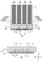
図2は、本実施形態の液体吐出ヘッド1の分解斜視図である。図3は図2に示す液体吐出ヘッド1のIIIa-IIIa線断面図である。図3(a)は液体吐出ヘッド1の全体的な縦断面図、図3(b)は図3(a)に示す吐出モジュールの拡大図である。以下、図2及び図3を中心に、図1を適宜参照しつつ、本実施形態における液体吐出ヘッド1の基本構成を説明する。
<Basic Configuration of Liquid Ejection Head>
FIG. 2 is an exploded perspective view of the liquid ejection head 1 of this embodiment. FIG. 3 is a cross-sectional view of the liquid ejection head 1 shown in FIG. 2 taken along line IIIa-IIIa. FIG. 3(a) is an overall longitudinal sectional view of the liquid ejection head 1, and FIG. 3(b) is an enlarged view of the ejection module shown in FIG. 3(a). Hereinafter, the basic configuration of the liquid ejection head 1 according to the present embodiment will be described with appropriate reference to FIG. 1, mainly FIG. 2 and FIG.
図2に示すように、液体吐出ヘッド1は、循環ユニット54と、循環ユニット54から供給されたインクを記録媒体Pに吐出するための吐出ユニット3とを含み構成されている。本実施形態における液体吐出ヘッド1は、液体吐出装置50のキャリッジ60に設けられている不図示の位置決め手段及び電気的接点によってキャリッジ60に固定支持される。液体吐出ヘッド1は、キャリッジ60と共に図1に示す主走査方向(X方向)に移動しながらインクを吐出し、記録媒体Pへの記録を行う。
As shown in FIG. 2, the liquid ejection head 1 includes a circulation unit 54 and an ejection unit 3 for ejecting the ink supplied from the circulation unit 54 onto the recording medium P. As shown in FIG. The liquid ejection head 1 in this embodiment is fixedly supported by the carriage 60 by positioning means (not shown) and electrical contacts provided on the carriage 60 of the liquid ejection device 50 . The liquid ejection head 1 performs printing on the printing medium P by ejecting ink while moving in the main scanning direction (X direction) shown in FIG.
インクの供給源となるインクタンク2に接続された外部ポンプ21には、インク供給チューブ59が設けられている(図1参照)。このインク供給チューブ59の先端には、不図示の液体コネクタが設けられている。液体吐出装置50に液体吐出ヘッド1が搭載された際、液体吐出ヘッド1のヘッド筐体53に設けられた、液体の導入口である液体コネクタ挿入口53aに、インク供給チューブ59の先端に設けられた液体コネクタが気密接続される。これにより、インクタンク2から外部ポンプ21を経て液体吐出ヘッド1に至るインク供給路が形成される。本実施形態では、4種類のインクを用いるため、インクタンク2、外部ポンプ21、インク供給チューブ59、及び循環ユニット54が、それぞれのインクに対応して4組設けられており、各インクに対応した4本のインク供給路が独立して形成されている。このように、本実施形態の液体吐出装置50には、液体吐出ヘッド1の外部に設けられたインクタンク2からインクが供給されるインク供給系が備えられている。尚、本実施形態の液体吐出装置50には、液体吐出ヘッド1内のインクをインクタンク2に回収するようなインク回収系は備えられていない。従って、液体吐出ヘッド1には、インクタンク2のインク供給チューブ59を接続するための液体コネクタ挿入口53aは設けられているが、液体吐出ヘッド1のインクをインクタンク2に回収するためのチューブを接続させるコネクタ挿入口は設けられていない。尚、液体コネクタ挿入口53aは、インク毎に設けられている。
The external pump 21 connected to the ink tank 2 serving as an ink supply source is provided with an ink supply tube 59 (see FIG. 1). A liquid connector (not shown) is provided at the tip of the ink supply tube 59 . When the liquid ejection head 1 is mounted on the liquid ejection apparatus 50, the ink supply tube 59 is provided at the tip of the ink supply tube 59 in the liquid connector insertion port 53a, which is the introduction port of the liquid, provided in the head housing 53 of the liquid ejection head 1. A liquid connector is connected airtightly. Thus, an ink supply path is formed from the ink tank 2 to the liquid discharge head 1 via the external pump 21 . In this embodiment, since four types of ink are used, four sets of the ink tank 2, the external pump 21, the ink supply tube 59, and the circulation unit 54 are provided corresponding to each ink. The four ink supply paths are formed independently. As described above, the liquid ejection device 50 of this embodiment includes an ink supply system that supplies ink from the ink tank 2 provided outside the liquid ejection head 1 . Note that the liquid ejection apparatus 50 of this embodiment does not include an ink recovery system for recovering the ink in the liquid ejection head 1 to the ink tank 2 . Therefore, although the liquid ejection head 1 is provided with a liquid connector insertion port 53a for connecting the ink supply tube 59 of the ink tank 2, the tube for collecting the ink of the liquid ejection head 1 to the ink tank 2 is provided. is not provided. A liquid connector insertion port 53a is provided for each ink.
図3において、54Bはブラックインク用の循環ユニットを、54Cはシアンインク用の循環ユニットを、54Mはマゼンタインク用の循環ユニットを、54Yはイエローインク用のインク循環ユニットを、それぞれ示している。各循環ユニットは略同様の構成を有しており、本実施形態において各循環ユニットを特に区別しない場合には、いずれも循環ユニット54と表記する。
In FIG. 3, 54B denotes a black ink circulation unit, 54C a cyan ink circulation unit, 54M a magenta ink circulation unit, and 54Y a yellow ink circulation unit. Each circulation unit has substantially the same configuration, and in the present embodiment, each circulation unit is referred to as a circulation unit 54 unless otherwise distinguished.
図2及び図3(a)において、吐出ユニット3は、2つの吐出モジュール300、第1支持部材4、第2支持部材7、電気配線部材(電気配線テープ)5、及び電気コンタクト基板6を備える。図3(b)に示すように、吐出モジュール300は、厚さ0.5~1mmのシリコン基板310と、シリコン基板310の片面に設けられた複数の吐出素子15とを備えている。本実施形態における吐出素子15は、液体を吐出するための吐出エネルギーとして熱エネルギーを発生する電気熱変換素子(ヒータ)により構成されている。各吐出素子15には、シリコン基板310上に成膜技術によって形成された電気配線を介して電力が供給される。
2 and 3(a), the discharge unit 3 comprises two discharge modules 300, a first support member 4, a second support member 7, an electrical wiring member (electrical wiring tape) 5, and an electrical contact substrate 6. . As shown in FIG. 3B, the ejection module 300 includes a silicon substrate 310 with a thickness of 0.5 to 1 mm, and a plurality of ejection elements 15 provided on one side of the silicon substrate 310 . The ejection element 15 in this embodiment is composed of an electrothermal conversion element (heater) that generates thermal energy as ejection energy for ejecting liquid. Electric power is supplied to each ejection element 15 through an electric wiring formed on the silicon substrate 310 by a film forming technique.
また、シリコン基板310の表面(図3(b)において下面)には、吐出口形成部材320が形成されている。吐出口形成部材320には、複数の吐出素子15に対応する複数の圧力室12と、インクを吐出する複数の吐出口13とがフォトリソグラフィ技術によってそれぞれ形成されている。さらに、シリコン基板310には、共通供給流路18と共通回収流路19とが形成されている。また、シリコン基板310には、共通供給流路18と各圧力室12とを連通する供給接続流路323と、共通回収流路19と各圧力室12とを連通する回収接続流路324が形成されている。本実施形態では、1つの吐出モジュール300が、2種類のインクの吐出を行うように構成されている。即ち、図3(a)に示す2つの吐出モジュールのうち、図中の左側に位置する吐出モジュール300は、ブラックインクとシアンインクの吐出を行い、図中の右側に位置する吐出モジュール300は、マゼンタインクとイエローインクの吐出を行う。尚、この組み合わせは一例であり、インクの組み合わせはいずれであってもよい。1つの吐出モジュールが1種類のインクを吐出する構成でもよいし、3種類以上のインクを吐出する構成としてもよい。2つの吐出モジュール300が同じ種類数のインクを吐出するものでなくてもよい。1つの吐出モジュール300が備えられる構成としてもよいし、3つ以上の吐出モジュール300が備えらえる構成としてもよい。さらに、図3に示す例では、1色のインクに対して、Y方向に延在する2つの吐出口列が形成されている。各吐出口列を構成する複数の吐出口13の各々に対し、圧力室12、共通供給流路18及び共通回収流路19がそれぞれ形成されている。
In addition, an ejection port forming member 320 is formed on the surface of the silicon substrate 310 (lower surface in FIG. 3B). A plurality of pressure chambers 12 corresponding to the plurality of ejection elements 15 and a plurality of ejection ports 13 for ejecting ink are formed in the ejection port forming member 320 by photolithography. Further, a common supply channel 18 and a common recovery channel 19 are formed in the silicon substrate 310 . In the silicon substrate 310, a supply connection channel 323 communicating the common supply channel 18 and each pressure chamber 12 and a recovery connection channel 324 communicating the common recovery channel 19 and each pressure chamber 12 are formed. It is In this embodiment, one ejection module 300 is configured to eject two types of ink. That is, of the two ejection modules shown in FIG. 3A, the ejection module 300 located on the left side in the figure ejects black ink and cyan ink, and the ejection module 300 located on the right side in the figure Magenta ink and yellow ink are ejected. Note that this combination is an example, and any combination of inks may be used. One ejection module may eject one type of ink, or may eject three or more types of ink. The two ejection modules 300 do not have to eject the same number of types of ink. A configuration in which one ejection module 300 is provided, or a configuration in which three or more ejection modules 300 are provided may be employed. Furthermore, in the example shown in FIG. 3, two ejection port arrays extending in the Y direction are formed for one color of ink. A pressure chamber 12, a common supply channel 18, and a common recovery channel 19 are formed for each of the plurality of ejection ports 13 forming each ejection port array.
シリコン基板310の裏面(図3(b)において上面)側には、後述するインク供給口及びインク回収口が形成されている。インク供給口は複数の共通供給流路18にインク供給流路48からインクを供給し、インク回収口は複数の共通回収流路19からインク回収流路49にインクを回収する。
An ink supply port and an ink recovery port, which will be described later, are formed on the back surface (upper surface in FIG. 3B) of the silicon substrate 310 . The ink supply port supplies ink from the ink supply channel 48 to the plurality of common supply channels 18 , and the ink recovery port recovers ink from the plurality of common recovery channels 19 to the ink recovery channel 49 .
尚、ここでいうインク供給口及びインク回収口は、後述する順方向のインク循環時においてインクの供給及び回収を行う開口を指す。すなわち、順方向へのインク循環時にはインク供給口から各共通供給流路18にインクが供給されると共に、各共通回収流路19からインク回収口へとインクが回収される。但し、逆方向へインクを流すインク循環を行う場合もある。この場合には、上記で説明したインク回収口から共通回収流路19にインクが供給されると共に、共通供給流路18からインク供給口へとインクが回収されることになる。
The ink supply port and the ink recovery port referred to here refer to openings for supplying and recovering ink during forward ink circulation, which will be described later. That is, during ink circulation in the forward direction, ink is supplied from the ink supply port to each common supply channel 18, and ink is recovered from each common recovery channel 19 to the ink recovery port. However, there are cases where ink is circulated to flow in the opposite direction. In this case, ink is supplied from the ink recovery port described above to the common recovery channel 19, and ink is recovered from the common supply channel 18 to the ink supply port.
図3(a)に示すように、吐出モジュール300は、その裏面(図3(a)における上面)が、第1支持部材4の一方の面(図3(a)において下面)に接着固定されている。第1支持部材4には、その一方の面から他方の面に亘って貫通するインク供給流路48とインク回収流路49とが形成されている。インク供給流路48の一方の開口はシリコン基板310における前述のインク供給口に、インク回収流路49の一方の開口はシリコン基板310における前述のインク回収口に、それぞれ連通している。尚、インク供給流路48及びインク回収流路49は、インクの種類毎に独立して設けられている。
As shown in FIG. 3(a), the ejection module 300 has its back surface (upper surface in FIG. 3(a)) adhesively fixed to one surface (lower surface in FIG. 3(a)) of the first support member 4. ing. An ink supply channel 48 and an ink recovery channel 49 are formed through the first support member 4 from one surface to the other surface. One opening of the ink supply channel 48 communicates with the above-described ink supply port in the silicon substrate 310, and one opening of the ink recovery channel 49 communicates with the above-described ink recovery port in the silicon substrate 310, respectively. The ink supply channel 48 and the ink recovery channel 49 are provided independently for each type of ink.
また、第1支持部材4の一方の面(図3(a)における上面)には、吐出モジュール300を挿通させる開口7a(図2参照)を有する第2支持部材7が接着固定されている。第2支持部材7には、吐出モジュール300に対して電気的に接続される電気配線部材5が保持されている。電気配線部材5は、インクを吐出するための電気信号を吐出モジュール300に印加するための部材である。吐出モジュール300と電気配線部材5との電気接続部分は、封止材(不図示)により封止され、インクによる腐食や外的衝撃から保護されている。
A second support member 7 having an opening 7a (see FIG. 2) through which the ejection module 300 is inserted is adhesively fixed to one surface of the first support member 4 (upper surface in FIG. 3A). The second support member 7 holds an electric wiring member 5 electrically connected to the ejection module 300 . The electric wiring member 5 is a member for applying an electric signal for ejecting ink to the ejection module 300 . An electrical connection portion between the ejection module 300 and the electrical wiring member 5 is sealed with a sealing material (not shown) to protect it from corrosion due to ink and external impact.
また、電気配線部材5の端部5a(図2参照)には、不図示の異方性導電フィルムを用いて電気コンタクト基板6が熱圧着され、電気配線部材5と電気コンタクト基板6とは電気的に接続されている。電気コンタクト基板6は、液体吐出装置50からの電気信号を受け取るための外部信号入力端子(不図示)を有している。
An electrical contact substrate 6 is thermocompression bonded to the end portion 5a (see FIG. 2) of the electrical wiring member 5 using an anisotropic conductive film (not shown), and the electrical wiring member 5 and the electrical contact substrate 6 are electrically connected. properly connected. The electrical contact substrate 6 has external signal input terminals (not shown) for receiving electrical signals from the liquid ejection device 50 .
さらに、第1支持部材4と循環ユニット54との間にはジョイント部材8(図3(a))が設けられている。ジョイント部材8には、供給口88と回収口89とがインクの種類毎に形成されている。供給口88及び回収口89は、第1支持部材4のインク供給流路48及びインク回収流路49と循環ユニット54に形成される流路とを連通させる。尚、図3(a)において、供給口88B及び回収口89Bはブラックインクに対応し、供給口88C及び回収口89Cはシアンインクに対応する。また、供給口88M及び回収口89Mはマゼンタインクに対応し、供給口88Y及び回収口89Yはイエローインクに対応している。
Further, a joint member 8 (FIG. 3(a)) is provided between the first support member 4 and the circulation unit 54. As shown in FIG. A supply port 88 and a recovery port 89 are formed in the joint member 8 for each type of ink. The supply port 88 and the recovery port 89 allow the ink supply channel 48 and the ink recovery channel 49 of the first support member 4 to communicate with the channels formed in the circulation unit 54 . In FIG. 3A, the supply port 88B and recovery port 89B correspond to black ink, and the supply port 88C and recovery port 89C correspond to cyan ink. Also, the supply port 88M and the recovery port 89M correspond to magenta ink, and the supply port 88Y and the recovery port 89Y correspond to yellow ink.
尚、第1支持部材4のインク供給流路48及びインク回収流路49のそれぞれの一端部の開口は、シリコン基板310におけるインク供給口及びインク回収口に合わせた小さな開口面積を有している。これに対し、第1支持部材4のインク供給流路48及びインク回収流路49のそれぞれの他端部の開口は、循環ユニット54の流路に合わせて形成されたジョイント部材8の大きな開口面積と同一の開口面積にまで拡大させた形状を有している。このような構成を採ることにより、各回収流路から集められたインクに対する流路抵抗の上昇を抑制することができる。但し、インク供給流路48及びインク回収流路49のそれぞれの一端部及び他端部の開口の形状は、上記の例に限定されない。
The openings at one end of each of the ink supply channel 48 and the ink recovery channel 49 of the first support member 4 have a small opening area corresponding to the ink supply port and the ink recovery port of the silicon substrate 310. . On the other hand, the openings at the other ends of the ink supply channel 48 and the ink recovery channel 49 of the first support member 4 have a large opening area of the joint member 8 formed in accordance with the channel of the circulation unit 54. It has a shape expanded to the same opening area as the . By adopting such a configuration, it is possible to suppress an increase in flow path resistance to the ink collected from each recovery flow path. However, the shape of the openings at one end and the other end of each of the ink supply channel 48 and the ink recovery channel 49 is not limited to the above example.
上記構成を有する液体吐出ヘッド1において、循環ユニット54に供給されたインクは、ジョイント部材8の供給口88及び第1支持部材4のインク供給流路48を経て、吐出モジュール300のインク供給口から共通供給流路18に流入する。続いてインクは共通供給流路18から供給接続流路323を介して圧力室12に流入し、圧力室内に流入したインクの一部は、吐出素子15の駆動によって吐出口13から吐出される。吐出されなかった残りのインクは、圧力室12から回収接続流路324、共通回収流路19を経てインク回収口から第1支持部材4のインク回収流路49に流入する。そして、インク回収流路49に流入したインクは、ジョイント部材8の回収口89を経て循環ユニット54へと流入し、回収される。
In the liquid ejection head 1 having the above configuration, the ink supplied to the circulation unit 54 passes through the supply port 88 of the joint member 8 and the ink supply channel 48 of the first support member 4, and then from the ink supply port of the ejection module 300. It flows into the common supply channel 18 . Subsequently, the ink flows from the common supply channel 18 into the pressure chamber 12 via the supply connection channel 323 , and part of the ink that has flowed into the pressure chamber is ejected from the ejection port 13 by driving the ejection element 15 . The remaining ink that has not been ejected flows from the pressure chamber 12 into the ink recovery channel 49 of the first support member 4 through the recovery connection channel 324 and the common recovery channel 19 from the ink recovery port. The ink that has flowed into the ink recovery channel 49 flows through the recovery port 89 of the joint member 8 into the circulation unit 54 and is recovered.
<循環ユニットの構成要素>
図4は、本実施形態の記録装置に適用される1種類のインクに対応する1つの循環ユニット54の外観概略図である。循環ユニット54には、フィルタ110、第1圧力調整手段120、第2圧力調整手段150、及び循環ポンプ500が配置されている。これらの構成要素は、図5及び図6に示すように各流路によって接続され、液体吐出ヘッド1内において、吐出モジュール300に対してインクの供給及び回収を行う循環経路を構成している。
<Constituent elements of circulation unit>
FIG. 4 is a schematic external view of one circulation unit 54 corresponding to one type of ink applied to the printing apparatus of this embodiment. A filter 110 , a first pressure adjusting means 120 , a second pressure adjusting means 150 and a circulation pump 500 are arranged in the circulation unit 54 . As shown in FIGS. 5 and 6 , these components are connected by respective flow paths to form circulation paths for supplying and recovering ink to and from the ejection modules 300 in the liquid ejection head 1 .
<液体吐出ヘッド内の循環経路>
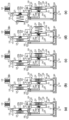
図5は、液体吐出ヘッド1内に構成される1種類のインク(1色のインク)の循環経路を模式的に示す縦断面図である。循環経路をより明確に説明するため、図5における各構成(第1圧力調整手段120、第2圧力調整手段150、循環ポンプ500等)の相対位置は簡略化している。そのため各構成の相対位置は後述する図16の構成とは異なる。また、図6は、図5に示した循環経路を模式的に示すブロック図である。図5及び図6に示すように、第1圧力調整手段120は、第1バルブ室121及び第1圧力制御室122を備えている。第2圧力調整手段150は、第2バルブ室151及び第2圧力制御室152を備えている。第1圧力調整手段120は、第2圧力調整手段150よりも相対的に制御圧力が高くなるように構成されている。本実施形態では、この二つの圧力調整手段120、150を用いることで、循環経路内において一定の圧力範囲での循環を実現している。また、第1圧力調整手段120と第2圧力調整手段150との圧力差に応じた流量で圧力室12(吐出素子15)をインクが流れるように構成されている。以下、図5及び図6を参照しつつ、液体吐出ヘッド1における循環経路及び循環経路内におけるインクの流れを説明する。尚、各図中の矢印はインクの流れる方向を示している。
<Circulation path in liquid ejection head>
FIG. 5 is a longitudinal sectional view schematically showing a circulation path for one type of ink (one color ink) configured in the liquid ejection head 1. As shown in FIG. In order to explain the circulation path more clearly, the relative position of each component (the first pressure adjusting means 120, the second pressure adjusting means 150, the circulation pump 500, etc.) in FIG. 5 is simplified. Therefore, the relative position of each configuration is different from the configuration of FIG. 16, which will be described later. 6 is a block diagram schematically showing the circulation route shown in FIG. 5. As shown in FIG. As shown in FIGS. 5 and 6, the first pressure regulating means 120 has a first valve chamber 121 and a first pressure control chamber 122 . The second pressure adjusting means 150 has a second valve chamber 151 and a second pressure control chamber 152 . The first pressure regulating means 120 is configured to have a relatively higher control pressure than the second pressure regulating means 150 . In this embodiment, by using these two pressure adjusting means 120 and 150, circulation within a constant pressure range is realized in the circulation path. In addition, the ink is configured to flow through the pressure chamber 12 (ejection element 15 ) at a flow rate corresponding to the pressure difference between the first pressure adjustment means 120 and the second pressure adjustment means 150 . The circulation path in the liquid ejection head 1 and the flow of ink in the circulation path will be described below with reference to FIGS. 5 and 6. FIG. The arrows in each drawing indicate the direction of ink flow.
まず、液体吐出ヘッド1における各構成要素の接続状態を説明する。
First, the connection state of each component in the liquid ejection head 1 will be described.
液体吐出ヘッド1の外部に設けられたインクタンク2(図6)に収容されたインクを液体吐出ヘッド1へ送る外部ポンプ21は、インク供給チューブ59(図1)を介して循環ユニット54と接続されている。循環ユニット54の上流側に位置するインク流路にはフィルタ110が設けられている。フィルタ110の下流側に位置するインク供給路は、第1圧力調整手段120の第1バルブ室121に接続されている。第1バルブ室121は、図5に示すバルブ190Aにより開閉可能な連通口191Aを介して第1圧力制御室122に連通している。
An external pump 21 for sending ink contained in an ink tank 2 (FIG. 6) provided outside the liquid ejection head 1 to the liquid ejection head 1 is connected to the circulation unit 54 via an ink supply tube 59 (FIG. 1). It is A filter 110 is provided in the ink flow path located upstream of the circulation unit 54 . An ink supply path located downstream of the filter 110 is connected to the first valve chamber 121 of the first pressure regulating means 120 . The first valve chamber 121 communicates with the first pressure control chamber 122 via a communication port 191A that can be opened and closed by a valve 190A shown in FIG.
第1圧力制御室122は、供給流路130、バイパス流路160、及び循環ポンプ500のポンプ出口流路180に接続されている。供給流路130は、吐出モジュール300に設けられた前述のインク供給口を介して共通供給流路18に接続されている。また、バイパス流路160は、第2圧力調整手段150に設けられた第2バルブ室151に接続されている。第2バルブ室151は、図5に示すバルブ190Bによって開閉する連通口191Bを介して第2圧力制御室152に連通している。尚、図5及び図6では、バイパス流路160の一端を第1圧力調整手段120の第1圧力制御室122に接続し、且つバイパス流路160の他端を第2圧力調整手段150の第2バルブ室151に接続した例を示している。しかし、バイパス流路160の一端を供給流路130に接続し、バイパス流路の他端を第2バルブ室151に接続してもよい。
The first pressure control chamber 122 is connected to the supply channel 130 , the bypass channel 160 and the pump outlet channel 180 of the circulation pump 500 . The supply channel 130 is connected to the common supply channel 18 via the aforementioned ink supply port provided in the ejection module 300 . Also, the bypass flow path 160 is connected to a second valve chamber 151 provided in the second pressure adjusting means 150 . The second valve chamber 151 communicates with the second pressure control chamber 152 through a communication port 191B that is opened and closed by a valve 190B shown in FIG. 5 and 6, one end of the bypass flow path 160 is connected to the first pressure control chamber 122 of the first pressure adjustment means 120, and the other end of the bypass flow path 160 is connected to the second pressure control chamber 122 of the second pressure adjustment means 150. An example of connection to a two-valve chamber 151 is shown. However, one end of the bypass channel 160 may be connected to the supply channel 130 and the other end of the bypass channel may be connected to the second valve chamber 151 .
第2圧力制御室152は、回収流路140に接続されている。回収流路140は、吐出モジュール300に設けられた前述のインク回収口を介して共通回収流路19に接続されている。さらに、第2圧力制御室152は、ポンプ入口流路170を介して循環ポンプ500に接続されている。尚、図5において、170aはポンプ入口流路170の流入口を示している。
The second pressure control chamber 152 is connected to the recovery passageway 140 . The recovery channel 140 is connected to the common recovery channel 19 via the aforementioned ink recovery port provided in the ejection module 300 . Furthermore, the second pressure control chamber 152 is connected to the circulation pump 500 via the pump inlet channel 170 . 5, 170a indicates the inlet of the pump inlet channel 170. As shown in FIG.
次に、上記構成を有する液体吐出ヘッド1におけるインクの流れについて説明する。図6に示すように、インクタンク2に収容されているインクは、液体吐出装置50に設けられた外部ポンプ21によって加圧され、正圧のインク流となって液体吐出ヘッド1の循環ユニット54に供給される。
Next, the flow of ink in the liquid ejection head 1 having the above configuration will be described. As shown in FIG. 6, the ink contained in the ink tank 2 is pressurized by the external pump 21 provided in the liquid ejection device 50 to become a positive pressure ink flow, and the circulation unit 54 of the liquid ejection head 1 flows. supplied to
循環ユニット54に供給されたインクは、フィルタ110を通過することにより塵埃などの異物や気泡が除去された後、第1圧力調整手段120に設けられた第1バルブ室121に流入する。フィルタ110を通過する際の圧力損失によってインクの圧力は低下するが、この段階でのインクの圧力は正圧の状態にある。その後、第1バルブ室121に流入したインクは、バルブ190Aが開状態にあるとき、連通口191Aを通過して第1圧力制御室122に流入する。連通口191Aを通過する際の圧力損失によって、第1圧力制御室122に流入したインクは、正圧から負圧へと切り替わる。
The ink supplied to the circulation unit 54 passes through the filter 110 to remove foreign matter such as dust and air bubbles, and then flows into the first valve chamber 121 provided in the first pressure adjusting means 120 . Although the pressure of the ink decreases due to the pressure loss when passing through the filter 110, the pressure of the ink at this stage is in a positive pressure state. After that, the ink that has flowed into the first valve chamber 121 flows into the first pressure control chamber 122 through the communication port 191A when the valve 190A is in the open state. Due to the pressure loss when passing through the communication port 191A, the ink flowing into the first pressure control chamber 122 switches from positive pressure to negative pressure.
次に、循環経路内におけるインクの流れを説明する。循環ポンプ500は、その上流側となるポンプ入口流路170から吸引したインクを下流側となるポンプ出口流路180へとインクを送り出すように動作する。従って、ポンプが駆動されることにより、第1圧力制御室122に供給されたインクは、ポンプ出口流路180から送液されたインクと共に、供給流路130及びバイパス流路160に流入する。尚、詳細は後述するが、本実施形態では送液可能な循環ポンプとして、ダイヤフラムに貼り付けた圧電素子を駆動源とする圧電ダイヤフラムポンプを用いている。圧電ダイヤフラムポンプは、圧電素子に駆動電圧を入力することでポンプ室内の容積を変化させ、圧力変動によって2つの逆止弁が交互に動くことにより送液を行うポンプである。
Next, the flow of ink within the circulation path will be described. The circulation pump 500 operates to pump ink sucked from the pump inlet channel 170 on the upstream side to the pump outlet channel 180 on the downstream side. Therefore, by driving the pump, the ink supplied to the first pressure control chamber 122 flows into the supply channel 130 and the bypass channel 160 together with the ink sent from the pump outlet channel 180 . Although the details will be described later, in this embodiment, a piezoelectric diaphragm pump driven by a piezoelectric element attached to a diaphragm is used as a circulation pump capable of feeding liquid. A piezoelectric diaphragm pump is a pump that changes the volume in a pump chamber by inputting a drive voltage to a piezoelectric element, and feeds liquid by alternately moving two check valves due to pressure fluctuations.
供給流路130に流入したインクは、吐出モジュール300のインク供給口から共通供給流路18を介して圧力室12に流入し、その一部のインクは吐出素子15の駆動(発熱)によって吐出口13から吐出される。また、吐出に使用されなかった残りのインクは、圧力室12を流動し、共通回収流路19を通過した後、吐出モジュール300に接続されている回収流路140に流入する。回収流路140に流入したインクは、第2圧力調整手段150の第2圧力制御室152に流入する。
The ink that has flowed into the supply channel 130 flows from the ink supply port of the ejection module 300 through the common supply channel 18 into the pressure chamber 12 . 13 is discharged. Also, the remaining ink that has not been used for ejection flows through the pressure chamber 12 , passes through the common recovery channel 19 , and then flows into the recovery channel 140 connected to the ejection module 300 . The ink that has flowed into the recovery channel 140 flows into the second pressure control chamber 152 of the second pressure adjusting means 150 .
一方、第1圧力制御室122からバイパス流路160に流入したインクは、第2バルブ室151に流入した後、連通口191Bを通過して第2圧力制御室152に流入する。バイパス流路160を経由して第2圧力制御室152に流入したインクと回収流路140から回収されたインクとは、循環ポンプ500の駆動によってポンプ入口流路170を経て循環ポンプ500内に吸引される。そして、循環ポンプ500内に吸引されたインクは、ポンプ出口流路180へと送られ、第1圧力制御室122に再び流入する。以降では、第1圧力制御室122から供給流路130を介して吐出モジュール300を経て第2圧力制御室152に流入したインクと、バイパス流路160を介して第2圧力制御室152に流入したインクとが、循環ポンプ500に流入する。そして、循環ポンプ500から第1圧力制御室122に送られる。このようにして循環経路内でのインクの循環が行われることになる。
On the other hand, the ink that has flowed from the first pressure control chamber 122 into the bypass channel 160 flows into the second valve chamber 151 and then flows into the second pressure control chamber 152 through the communication port 191B. The ink that has flowed into the second pressure control chamber 152 through the bypass channel 160 and the ink that has been recovered from the recovery channel 140 are sucked into the circulation pump 500 through the pump inlet channel 170 by driving the circulation pump 500 . be done. The ink sucked into the circulation pump 500 is sent to the pump outlet channel 180 and flows into the first pressure control chamber 122 again. After that, the ink that flows from the first pressure control chamber 122 through the ejection module 300 through the supply channel 130 into the second pressure control chamber 152 and the ink that flows into the second pressure control chamber 152 through the bypass channel 160 are described. Ink flows into circulation pump 500 . Then, it is sent from the circulation pump 500 to the first pressure control chamber 122 . In this way, the ink is circulated in the circulation path.
以上のように、本実施形態では、循環ポンプ500によって、液体吐出ヘッド1内に形成した循環経路に沿って液体を循環させることが可能になる。このため、吐出モジュール300内でのインクの増粘や色材のインクの沈降成分の堆積を抑制することが可能となり、吐出モジュール300におけるインクの流動性および吐出口における吐出特性を良好な状態に保つことが可能になる。
As described above, in this embodiment, the circulation pump 500 can circulate the liquid along the circulation path formed in the liquid ejection head 1 . Therefore, it is possible to suppress the thickening of the ink in the ejection module 300 and the deposition of the sedimentation component of the ink of the coloring material, and improve the fluidity of the ink in the ejection module 300 and the ejection characteristics of the ejection openings. be possible to keep.
また本実施形態における循環経路は、液体吐出ヘッド1内で完結する構成を採るため、液体吐出ヘッドの外部に設けられたインクタンク2と液体吐出ヘッド1との間でインクの循環を行う場合に比べ、循環経路長を大幅に短縮することができる。このため、インクの循環を小型な循環ポンプで行うことが可能になる。
In addition, since the circulation path in the present embodiment adopts a configuration that is completed within the liquid ejection head 1, when the ink is circulated between the ink tank 2 provided outside the liquid ejection head and the liquid ejection head 1, In comparison, the circulation path length can be significantly shortened. Therefore, it is possible to circulate the ink with a small circulation pump.
更に、液体吐出ヘッド1とインクタンク2との接続流路としては、インクを供給する流路のみを備える構成となっている。即ち、液体吐出ヘッド1からインクタンク2へとインクを回収するための流路を不要とする構成を採る。このため、インクタンク2と液体吐出ヘッド1との接続にはインク供給用のチューブのみを設ければよく、インク回収用のチューブを設ける必要はない。従って、液体吐出装置50の内部を、チューブの本数が削減された簡潔な構成とすることができ、装置全体の小型化を実現することができる。更にチューブの本数が削減されることにより、液体吐出ヘッド1の主走査に伴うチューブの揺動に起因するインクの圧力変動を軽減することが可能になる。また、液体吐出ヘッド1の主走査時におけるチューブの揺動は、キャリッジ60を駆動するキャリッジモータの駆動負荷となる。このため、チューブの本数削減によってキャリッジモータの駆動負荷が低減され、キャリッジモータ等を含む主走査機構の簡略化を図ることが可能になる。更に、液体吐出ヘッドからインクタンクへのインクの回収が不要となるため、外部ポンプ21の小型化も可能となる。このように、本実施形態によれば、液体吐出装置50の小型化及びコスト低減を実現することができる。
Furthermore, as a connection channel between the liquid ejection head 1 and the ink tank 2, only a channel for supplying ink is provided. That is, a configuration is adopted in which a flow path for collecting ink from the liquid ejection head 1 to the ink tank 2 is not required. Therefore, it is sufficient to provide only an ink supply tube for connection between the ink tank 2 and the liquid ejection head 1, and it is not necessary to provide an ink recovery tube. Therefore, the inside of the liquid ejecting device 50 can be configured simply with a reduced number of tubes, and the miniaturization of the entire device can be achieved. Furthermore, by reducing the number of tubes, it is possible to reduce ink pressure fluctuations caused by the oscillation of the tubes accompanying the main scanning of the liquid ejection head 1 . Further, the swinging of the tube during main scanning of the liquid ejection head 1 becomes a driving load of the carriage motor that drives the carriage 60 . As a result, the reduction in the number of tubes reduces the driving load on the carriage motor, making it possible to simplify the main scanning mechanism including the carriage motor and the like. Furthermore, since it is not necessary to collect ink from the liquid ejection head to the ink tank, the size of the external pump 21 can be reduced. As described above, according to the present embodiment, it is possible to reduce the size and cost of the liquid ejection device 50 .
<圧力調整手段>
図7は、圧力調整手段の例を示す図である。図7を参照して、上述の液体吐出ヘッド1に内蔵される圧力調整手段(第1圧力調整手段120、第2圧力調整手段150)の構成及び作用を、より詳細に説明する。尚、第1圧力調整手段120と第2圧力調整手段150とは、実質的に同一の構成を有している。このため、以下では、第1圧力調整手段120を例に採り説明し、第2圧力調整手段150については、図7において第1圧力調整手段に対応する部分の符号を併記するにとどめる。第2圧力調整手段150の場合には、以下で説明する第1バルブ室121を第2バルブ室151と読み替え、第1圧力制御室122を第2圧力制御室152と読み替えることとする。
<Pressure adjustment means>
FIG. 7 is a diagram showing an example of pressure adjusting means. With reference to FIG. 7, the configuration and action of the pressure adjusting means (first pressure adjusting means 120, second pressure adjusting means 150) built in the liquid ejection head 1 will be described in more detail. The first pressure adjusting means 120 and the second pressure adjusting means 150 have substantially the same configuration. For this reason, the first pressure adjusting means 120 will be described below as an example, and the second pressure adjusting means 150 will only be described with reference numerals corresponding to the first pressure adjusting means in FIG. In the case of the second pressure regulating means 150 , the first valve chamber 121 and the first pressure control chamber 122 described below will be read as the second valve chamber 151 and the second pressure control chamber 152, respectively.
第1圧力調整手段120は、円筒状の筐体125内に形成された第1バルブ室121と第1圧力制御室122とを有する。第1バルブ室121と第1圧力制御室122とは、円筒状の筐体125内に設けられた隔壁123によって隔てられている。但し、第1バルブ室121は、隔壁123に形成された連通口191を介して第1圧力制御室122に連通している。第1バルブ室121には、連通口191における第1バルブ室121と第1圧力制御室122との連通及び遮断を切り替えるバルブ190が設けられている。バルブ190は、バルブばね200によって、連通口191に対向する位置に保持されており、バルブばね200の付勢力によって隔壁123と密接可能な構成を有している。バルブ190が隔壁123に密接することにより、連通口191におけるインクの流通は遮断される。尚、隔壁123との密接性を高めるため、バルブ190の隔壁123との接触部分は弾性部材によって形成されることが好ましい。また、バルブ190の中央部には連通口191に挿通されるバルブシャフト190aが突設されている。このバルブシャフト190aをバルブばね200の付勢力に抗して押圧することにより、バルブ190は隔壁123から離間し、連通口191におけるインクの流通が可能になる。以下、バルブ190によって連通口191におけるインクの流通が遮断される状態を「閉状態」、連通口191におけるインクの流通が可能な状態を「開状態」と称す。
The first pressure regulating means 120 has a first valve chamber 121 and a first pressure control chamber 122 formed within a cylindrical housing 125 . The first valve chamber 121 and the first pressure control chamber 122 are separated by a partition wall 123 provided inside a cylindrical housing 125 . However, the first valve chamber 121 communicates with the first pressure control chamber 122 through a communication port 191 formed in the partition wall 123 . The first valve chamber 121 is provided with a valve 190 that switches communication and disconnection between the first valve chamber 121 and the first pressure control chamber 122 at the communication port 191 . The valve 190 is held at a position facing the communication port 191 by the valve spring 200 and has a configuration that allows it to come into close contact with the partition wall 123 by the biasing force of the valve spring 200 . The close contact of the valve 190 with the partition wall 123 blocks the flow of ink through the communication port 191 . Incidentally, in order to increase the close contact with the partition wall 123, the contact portion of the valve 190 with the partition wall 123 is preferably formed of an elastic member. Also, a valve shaft 190 a that is inserted into the communication port 191 is projected from the central portion of the valve 190 . By pressing the valve shaft 190a against the urging force of the valve spring 200, the valve 190 is separated from the partition wall 123 and ink can flow through the communication port 191. FIG. Hereinafter, a state in which the valve 190 blocks the flow of ink through the communication port 191 is referred to as a "closed state," and a state in which the communication port 191 allows the flow of ink is referred to as an "open state."
円筒状の筐体125の開口部は、可撓性部材230と圧力板210とにより閉塞されている。この可撓性部材230と、圧力板210と、筐体125の周壁と、隔壁123とにより、第1圧力制御室122が形成されている。圧力板210は、可撓性部材230の変位に伴って変位可能に構成されている。圧力板210及び可撓性部材230の材質は、特に限定されないが、例えば、圧力板210を樹脂成形部品で構成し、可撓性部材230を樹脂フィルムで構成することが可能である。この場合、圧力板210は可撓性部材230に熱溶着によって固定することができる。
The opening of cylindrical housing 125 is closed by flexible member 230 and pressure plate 210 . A first pressure control chamber 122 is formed by the flexible member 230 , the pressure plate 210 , the peripheral wall of the housing 125 and the partition wall 123 . Pressure plate 210 is configured to be displaceable as flexible member 230 is displaced. Although the materials of the pressure plate 210 and the flexible member 230 are not particularly limited, for example, the pressure plate 210 can be made of resin molded parts, and the flexible member 230 can be made of a resin film. In this case, the pressure plate 210 can be fixed to the flexible member 230 by heat welding.
圧力板210と隔壁123との間には、圧力調整ばね220(付勢部材)が設けられている。圧力調整ばね220の付勢力によって、圧力板210及び可撓性部材230は、図7(a)に示すように、第1圧力制御室122の内容積が広がる方向に付勢されている。また、第1圧力制御室122内の圧力が減少すると、圧力板210及び可撓性部材230は、圧力調整ばね220の圧力に抗して、第1圧力制御室122の内容積が減少する方向に変位する。そして、第1圧力制御室122の内容積が一定量まで減少すると、圧力板210がバルブ190のバルブシャフト190aに当接する。その後、さらに第1圧力制御室122の内容積が減少すると、バルブばね200の付勢力に抗してバルブシャフト190aと共にバルブ190が移動し、隔壁123から離間する。これにより、連通口191が開状態(図7(b)の状態)となる。
A pressure adjusting spring 220 (biasing member) is provided between the pressure plate 210 and the partition wall 123 . The biasing force of the pressure adjusting spring 220 biases the pressure plate 210 and the flexible member 230 in the direction in which the internal volume of the first pressure control chamber 122 expands, as shown in FIG. 7(a). Also, when the pressure in the first pressure control chamber 122 decreases, the pressure plate 210 and the flexible member 230 move against the pressure of the pressure adjusting spring 220 in the direction in which the inner volume of the first pressure control chamber 122 decreases. is displaced to Then, when the internal volume of the first pressure control chamber 122 decreases to a certain amount, the pressure plate 210 comes into contact with the valve shaft 190a of the valve 190 . After that, when the internal volume of the first pressure control chamber 122 further decreases, the valve 190 moves together with the valve shaft 190 a against the biasing force of the valve spring 200 and separates from the partition wall 123 . As a result, the communication port 191 is opened (the state shown in FIG. 7B).
本実施形態では、連通口191が開状態となったときの第1バルブ室121の圧力を第1圧力制御室122の圧力よりも高くなるように、循環経路内における接続設定をする。これにより、連通口191が開状態となると、第1バルブ室121から第1圧力制御室122へとインクが流入する。このインク流入により、第1圧力制御室122の内容積が増加する方向へ可撓性部材230及び圧力板210が変位する。その結果、圧力板210がバルブ190のバルブシャフト190aから離間し、バルブ190はバルブばね200の付勢力によって隔壁123に密接し、連通口191は閉状態(図7(c)の状態)となる。
In this embodiment, the connection in the circulation path is set so that the pressure in the first valve chamber 121 becomes higher than the pressure in the first pressure control chamber 122 when the communication port 191 is opened. As a result, when the communication port 191 is opened, ink flows from the first valve chamber 121 into the first pressure control chamber 122 . This inflow of ink displaces the flexible member 230 and the pressure plate 210 in the direction in which the internal volume of the first pressure control chamber 122 increases. As a result, the pressure plate 210 is separated from the valve shaft 190a of the valve 190, the valve 190 is brought into close contact with the partition wall 123 by the biasing force of the valve spring 200, and the communication port 191 is closed (state shown in FIG. 7(c)). .
このように、本実施形態における第1圧力調整手段120では、第1圧力制御室122内の圧力が一定圧力以下まで減少すると(例えば負圧が強くなると)、第1バルブ室121から連通口191を介してインクが流入する。これにより、第1圧力制御室122の圧力がそれ以上減少しないように構成されている。従って、第1圧力制御室122は一定範囲内の圧力に保たれるよう制御される。
As described above, in the first pressure regulating means 120 according to the present embodiment, when the pressure in the first pressure control chamber 122 decreases to a certain level or less (for example, when the negative pressure becomes stronger), the pressure from the first valve chamber 121 to the communication port 191 increases. Ink flows through the This prevents the pressure in the first pressure control chamber 122 from decreasing further. Therefore, the first pressure control chamber 122 is controlled to keep the pressure within a certain range.
次に、第1圧力制御室122の圧力についてより詳細に説明する。
Next, the pressure in the first pressure control chamber 122 will be explained in more detail.
前述のように第1圧力制御室122の圧力に応じて可撓性部材230及び圧力板210が変位し、圧力板210がバルブシャフト190aに当接して連通口191が開状態となった状態(図7(b)の状態)を考える。このとき、圧力板210に働く力の関係は、次の式1によって表される。
As described above, the flexible member 230 and the pressure plate 210 are displaced according to the pressure in the first pressure control chamber 122, the pressure plate 210 abuts against the valve shaft 190a, and the communication port 191 is opened ( Consider the state of FIG. 7(b). At this time, the relationship between the forces acting on the pressure plate 210 is represented by the following Equation 1.
P2×S2+F2+(P1-P2)×S1+F1=0・・・式1
さらに、式1をP2について整理すると、
P2=-(F1+F2+P1×S1)/(S2-S1)・・・式2
となる。
P1:第1バルブ室121の圧力(ゲージ圧)
P2:第1圧力制御室122の圧力(ゲージ圧)
F1:バルブばね200のばね力
F2:圧力調整ばね220のばね力
S1:バルブ190の受圧面積
S2:圧力板210の受圧面積
P2×S2+F2+(P1-P2)×S1+F1=0 Formula 1
Furthermore, rearranging Equation 1 with respect to P2 yields
P2=-(F1+F2+P1×S1)/(S2-S1) Equation 2
becomes.
P1: pressure in the first valve chamber 121 (gauge pressure)
P2: pressure of the first pressure control chamber 122 (gauge pressure)
F1: Spring force of valve spring 200 F2: Spring force of pressure adjusting spring 220 S1: Pressure receiving area of valve 190 S2: Pressure receiving area of pressure plate 210
ここで、バルブばね200のばね力F1及び圧力調整ばね220のばね力F2は、バルブ190及び圧力板210を押す方向を正(図7において右方向)とする。また、第1バルブ室121の圧力P1及び第1圧力制御室122の圧力P2に関し、P1が、P1≧P2の関係となるように構成する。
Here, for the spring force F1 of the valve spring 200 and the spring force F2 of the pressure adjusting spring 220, the direction in which the valve 190 and the pressure plate 210 are pushed is positive (to the right in FIG. 7). Further, regarding the pressure P1 in the first valve chamber 121 and the pressure P2 in the first pressure control chamber 122, P1 is configured to satisfy the relationship of P1≧P2.
連通口191が開状態となるときの第1圧力制御室122の圧力P2は、式2によって決定され、連通口191が開状態となると、P1≧P2の関係に構成したことにより、第1バルブ室121から第1圧力制御室122へインクが流入する。その結果、第1圧力制御室122の圧力P2はそれ以上減少せず、P2は一定範囲内の圧力に保たれる。
The pressure P2 in the first pressure control chamber 122 when the communication port 191 is opened is determined by Equation 2, and when the communication port 191 is opened, the relationship of P1≧P2 is established. Ink flows from the chamber 121 into the first pressure control chamber 122 . As a result, the pressure P2 in the first pressure control chamber 122 does not decrease any more, and P2 is kept within a certain range.
一方、図7(c)に示すように、圧力板210がバルブシャフト190aと非当接状態となり、連通口191が閉状態となったときの圧力板210に働く力の関係は、式3のようになる。
On the other hand, as shown in FIG. 7(c), when the pressure plate 210 is in a non-contact state with the valve shaft 190a and the communication port 191 is in a closed state, the force acting on the pressure plate 210 is expressed by Equation 3. become.
P3×S3+F3=0・・・式3
P3×S3+F3=0 Expression 3
ここで、式3をP3について整理すると
P3=-F3/S3・・・式4
となる。
F3:圧力板210とバルブシャフト190aとが非当接状態にあるときの圧力調整ばね220のばね力
P3:圧力板210とバルブシャフト190aとが非当接状態にあるときの第1圧力制御室122の圧力(ゲージ圧)
S3:圧力板210とバルブ190が非当接状態にあるときの圧力板210の受圧面積
Here, if formula 3 is rearranged with respect to P3, P3=-F3/S3 Formula 4
becomes.
F3: Spring force of pressure adjusting spring 220 when pressure plate 210 and valve shaft 190a are in non-contact state P3: First pressure control chamber when pressure plate 210 and valve shaft 190a are in non-contact state 122 pressure (gauge pressure)
S3: pressure receiving area of the pressure plate 210 when the pressure plate 210 and the valve 190 are in a non-contact state
ここで図7(c)では、圧力板210及び可撓性部材230が変位可能な限界まで図右方向へ変位した状態を表している。圧力板210及び可撓性部材230が図7(c)の状態へと変位する間の変位量に応じて、第1圧力制御室122の圧力P3、圧力調整ばね220のばね力F3、圧力板210の受圧面積S3は変化する。具体的には、図7(c)よりも圧力板210及び可撓性部材230が図7において左方向にあるとき、圧力板210の受圧面積S3は小さくなり、圧力調整ばね220のばね力F3は大きくなる。その結果、式4の関係により第1圧力制御室122の圧力P3は小さくなる。従って、式2及び式4により、図7(b)の状態から図7(c)の状態になるまでの間に、第1圧力制御室122の圧力は徐々に上昇していく(つまり、負圧が弱くなり、正圧側に近づく値になる)。即ち、連通口191が開状態となっている状態から、圧力板210及び可撓性部材230が右方向に徐々に変位していき、最終的に第1圧力制御室122の内容積が変位可能な限界に達するまでの間に、第1圧力制御室の圧力は徐々に上昇していく。つまり、負圧が弱まっていくことになる。
Here, FIG. 7(c) shows a state in which the pressure plate 210 and the flexible member 230 are displaced to the right in the drawing up to their displaceable limits. The pressure P3 of the first pressure control chamber 122, the spring force F3 of the pressure adjusting spring 220, the pressure plate The pressure receiving area S3 of 210 varies. Specifically, when the pressure plate 210 and the flexible member 230 are in the left direction in FIG. 7, the pressure receiving area S3 of the pressure plate 210 becomes smaller and the spring force F3 becomes larger. As a result, the pressure P3 in the first pressure control chamber 122 decreases according to the relationship of Equation 4. Therefore, according to Equations 2 and 4, the pressure in the first pressure control chamber 122 gradually increases (that is, negative The pressure becomes weaker, and the value approaches the positive pressure side). That is, the pressure plate 210 and the flexible member 230 are gradually displaced rightward from the state where the communication port 191 is open, and finally the internal volume of the first pressure control chamber 122 can be displaced. The pressure in the first pressure control chamber gradually increases until it reaches the limit. That is, the negative pressure becomes weaker.
<循環ポンプ>
次に、図8及び図9を参照して、上述の液体吐出ヘッド1に内蔵される循環ポンプ500の構成及び作用を詳細に説明する。
<Circulation pump>
Next, with reference to FIGS. 8 and 9, the configuration and action of the circulation pump 500 incorporated in the liquid ejection head 1 will be described in detail.
図8は、循環ポンプ500の外観斜視図である。図8(a)は循環ポンプ500の正面側を示す外観斜視図、図8(b)は循環ポンプ500の背面側を示す外観斜視図である。循環ポンプ500の外殻は、ポンプ筐体505と、ポンプ筐体505に固定されたカバー507とにより構成されている。ポンプ筐体505は、筐体部本体505aと、筐体部本体505aの外面に接着固定された流路接続部材505bとにより構成されている。筐体部本体505aと流路接続部材505bとの各々には、互いに連通する一対の貫通孔が異なる2つの位置に設けられている。一方の位置に設けられた一対の貫通孔はポンプ供給孔501を形成し、他方の位置に設けられた一対の貫通孔はポンプ排出孔502を形成している。ポンプ供給孔501は、第2圧力制御室152に接続されたポンプ入口流路170に接続され、ポンプ排出孔502は、第1圧力制御室122に接続されたポンプ出口流路180に接続されている。ポンプ供給孔501から供給されたインクは、後述のポンプ室503(図9参照)を通過してポンプ排出孔502から排出される。
FIG. 8 is an external perspective view of circulation pump 500 . 8A is an external perspective view showing the front side of the circulation pump 500, and FIG. 8B is an external perspective view showing the back side of the circulation pump 500. FIG. The outer shell of circulation pump 500 is composed of pump housing 505 and cover 507 fixed to pump housing 505 . The pump housing 505 is composed of a housing main body 505a and a channel connection member 505b adhesively fixed to the outer surface of the housing main body 505a. A pair of through holes that communicate with each other are provided at two different positions in each of the housing body 505a and the flow path connecting member 505b. A pair of through holes provided at one position form a pump supply hole 501 , and a pair of through holes provided at the other position form a pump discharge hole 502 . The pump supply hole 501 is connected to the pump inlet channel 170 connected to the second pressure control chamber 152, and the pump discharge hole 502 is connected to the pump outlet channel 180 connected to the first pressure control chamber 122. there is Ink supplied from the pump supply hole 501 passes through a pump chamber 503 (see FIG. 9), which will be described later, and is discharged from the pump discharge hole 502 .
図9は、図8(a)に示した循環ポンプ500のIX-IX線断面図である。ポンプ筐体505の内面にはダイヤフラム506が接合されており、このダイヤフラム506とポンプ筐体505の内面に形成された凹部との間にポンプ室503が形成されている。ポンプ室503は、ポンプ筐体505に形成されたポンプ供給孔501及びポンプ排出孔502に連通している。また、ポンプ供給孔501の中間部分には、逆止弁504aが設けられ、ポンプ排出孔502の中間部分には、逆止弁504bが設けられている。具体的には、逆止弁504aは、その一部がポンプ供給孔501の中間部分に形成されている空間512aにおいて図中の左方へと移動し得るように配置されている。また、逆止弁504bは、その一部がポンプ排出孔502の中間部分に形成されている空間512bにおいて図中の右方へと移動し得るように配置されている。
FIG. 9 is a cross-sectional view of the circulation pump 500 taken along the line IX-IX shown in FIG. 8(a). A diaphragm 506 is joined to the inner surface of the pump housing 505 , and a pump chamber 503 is formed between the diaphragm 506 and a recess formed in the inner surface of the pump housing 505 . The pump chamber 503 communicates with a pump supply hole 501 and a pump discharge hole 502 formed in a pump housing 505 . A check valve 504a is provided in the intermediate portion of the pump supply hole 501, and a check valve 504b is provided in the intermediate portion of the pump discharge hole 502. As shown in FIG. Specifically, the check valve 504a is arranged so as to be able to move leftward in the figure in a space 512a partly formed in the middle portion of the pump supply hole 501 . Also, the check valve 504b is arranged so as to be able to move rightward in the figure in a space 512b, a part of which is formed in the middle portion of the pump discharge hole 502. As shown in FIG.
ダイヤフラム506が変位してポンプ室503の容積が増加することでポンプ室503が減圧されると、逆止弁504aは空間512a内のポンプ供給孔501の開口から離間する(つまり、図中の左方へと移動する)。逆止弁504aが空間512a内のポンプ供給孔501の開口から離間することで、ポンプ供給孔501におけるインクの流通を可能とする開状態となる。また、ダイヤフラム506が変位してポンプ室503の容積が減少することでポンプ室503が加圧されると、逆止弁504aはポンプ供給孔501の開口の周囲の壁面に密接する。この結果、ポンプ供給孔501におけるインクの流通を遮断する閉状態となる。
When the diaphragm 506 is displaced to increase the volume of the pump chamber 503 and the pressure of the pump chamber 503 is reduced, the check valve 504a moves away from the opening of the pump supply hole 501 in the space 512a (that is, the left side in the figure). move toward). When the check valve 504a is separated from the opening of the pump supply hole 501 in the space 512a, the pump supply hole 501 is opened to allow the ink to flow. Further, when the diaphragm 506 is displaced and the volume of the pump chamber 503 is reduced and the pump chamber 503 is pressurized, the check valve 504 a comes into close contact with the wall surface around the opening of the pump supply hole 501 . As a result, the pump supply hole 501 is closed to block the flow of ink.
一方、逆止弁504bは、ポンプ室503が減圧されると、ポンプ筐体505の開口の周囲の壁面に密接して、ポンプ排出孔502におけるインクの流通を遮断する閉状態となる。また、ポンプ室503が加圧されると、逆止弁504bは、ポンプ筐体505の開口から離間して空間512b側に移動し(つまり、図中の右方へと移動し)、ポンプ排出孔502におけるインクの流通を可能とする。
On the other hand, when the pressure in the pump chamber 503 is reduced, the check valve 504b comes into close contact with the wall surface surrounding the opening of the pump housing 505 and shuts off the flow of ink in the pump discharge hole 502 . Further, when the pump chamber 503 is pressurized, the check valve 504b moves away from the opening of the pump housing 505 and moves toward the space 512b (that is, moves rightward in the drawing) to discharge the pump. It allows the ink to flow through the holes 502 .
尚、各逆止弁504a、504bの材質は、ポンプ室503内の圧力に応じて変形可能なものであればよく、例えば、EPDMやエラストマ等の弾性部材やポリプロピレン等のフィルムや薄板で形成することが可能である。但し、これらに限定されるものではない。
The check valves 504a and 504b may be made of any material that can be deformed according to the pressure in the pump chamber 503. For example, the check valves 504a and 504b may be made of an elastic member such as EPDM or elastomer, or a film or thin plate such as polypropylene. Is possible. However, it is not limited to these.
前述のように、ポンプ室503はポンプ筐体505とダイヤフラム506との接合によって形成されている。従って、ダイヤフラム506が変形することによりポンプ室503の圧力は変化する。例えば、ダイヤフラム506がポンプ筐体505側に変位して(図中、右側に変位して)ポンプ室503の容積が減少すると、ポンプ室503内の圧力は上昇する。これによりポンプ排出孔502に対向して配置した逆止弁504bが開状態となり、ポンプ室503のインクが排出される。このとき、ポンプ供給孔501に対向して配置された逆止弁504aは、ポンプ供給孔501の周囲の壁面に密接するためポンプ室503からポンプ供給孔501へのインクの逆流は抑制される。
As described above, pump chamber 503 is formed by joining pump housing 505 and diaphragm 506 . Therefore, the pressure in the pump chamber 503 changes as the diaphragm 506 deforms. For example, when the diaphragm 506 is displaced toward the pump housing 505 (displaced to the right in the drawing) to reduce the volume of the pump chamber 503, the pressure in the pump chamber 503 increases. As a result, the check valve 504b arranged facing the pump discharge hole 502 is opened, and the ink in the pump chamber 503 is discharged. At this time, the check valve 504a arranged to face the pump supply hole 501 is in close contact with the wall surface surrounding the pump supply hole 501, so that the backflow of ink from the pump chamber 503 to the pump supply hole 501 is suppressed.
また逆に、ダイヤフラム506がポンプ室503が広がる方向に変位した場合にはポンプ室503の圧力は減少する。これにより、ポンプ供給孔501に対向して配置された逆止弁504aが開状態となり、ポンプ室503にインクが供給される。このとき、ポンプ排出孔502に配置された逆止弁504bは、ポンプ筐体505に形成された開口の周囲の壁面に密接して当該開口を閉塞する。このため、ポンプ排出孔502からポンプ室503へのインクの逆流は抑制される。
Conversely, when the diaphragm 506 is displaced in the direction in which the pump chamber 503 expands, the pressure in the pump chamber 503 decreases. As a result, the check valve 504a arranged to face the pump supply hole 501 is opened, and ink is supplied to the pump chamber 503. As shown in FIG. At this time, the check valve 504b arranged in the pump discharge hole 502 comes into close contact with the wall surrounding the opening formed in the pump housing 505 to block the opening. Therefore, backflow of ink from the pump discharge hole 502 to the pump chamber 503 is suppressed.
このように循環ポンプ500では、ダイヤフラム506が変形し、ポンプ室503内の圧力を変化させることにより、インクの吸引と排出を行う。この際、ポンプ室503内に泡が混入すると、ダイヤフラム506が変位しても、泡の膨張・収縮によってポンプ室503内の圧力変化が小さくなり送液量が低下する。そこでポンプ室503を重力と平行に配置してポンプ室503に混入した泡をポンプ室503の上方に集まりやすくすると共に、ポンプ排出孔502をポンプ室503の中心よりも上方に配置する。これにより、ポンプ内の泡の排出性を向上させることが可能となり、流量の安定化を図ることができる。
In this way, in the circulation pump 500, the diaphragm 506 is deformed to change the pressure in the pump chamber 503, thereby sucking and discharging ink. At this time, if bubbles enter the pump chamber 503, even if the diaphragm 506 is displaced, the expansion and contraction of the bubbles will reduce the pressure change in the pump chamber 503 and reduce the amount of liquid to be fed. Therefore, the pump chamber 503 is arranged parallel to the gravity so that bubbles mixed in the pump chamber 503 can be easily collected above the pump chamber 503, and the pump discharge hole 502 is arranged above the center of the pump chamber 503. As a result, it is possible to improve the discharge performance of bubbles in the pump, and to stabilize the flow rate.
<液体吐出ヘッド内のインクの流れ>
図10は、液体吐出ヘッド内のインクの流れを説明する図である。図10を参照しつつ液体吐出ヘッド1内で行われるインクの循環について説明する。インク循環経路をより明確に説明するため、図10における各構成(第1圧力調整手段120、第2圧力調整手段150、循環ポンプ500等)の相対位置は簡略化している。そのため各構成の相対位置は後述する図19の構成とは異なる。図10(a)は吐出口13からインクを吐出して記録を行う記録動作を行っているときのインクの流れを模式的に示したものである。尚、図中の矢印はインクの流れを示している。本実施形態において、記録動作を行う際には外部ポンプ21及び循環ポンプ500の両方が駆動を開始する。尚、記録動作に関わらず、外部ポンプ21及び循環ポンプ500が駆動していてもよい。また、外部ポンプ21と循環ポンプ500との駆動は、連動して行われなくてもよく、別個に独立して駆動されてもよい。
<Flow of ink in liquid ejection head>
FIG. 10 is a diagram for explaining the flow of ink within the liquid ejection head. The circulation of ink within the liquid ejection head 1 will be described with reference to FIG. In order to explain the ink circulation path more clearly, the relative positions of the components (the first pressure adjusting means 120, the second pressure adjusting means 150, the circulation pump 500, etc.) in FIG. 10 are simplified. Therefore, the relative position of each configuration is different from the configuration of FIG. 19, which will be described later. FIG. 10A schematically shows the flow of ink during a printing operation in which ink is ejected from the ejection port 13 to perform printing. The arrows in the drawing indicate the flow of ink. In this embodiment, both the external pump 21 and the circulation pump 500 start driving when performing the printing operation. Note that the external pump 21 and the circulation pump 500 may be driven regardless of the printing operation. Further, the external pump 21 and the circulation pump 500 may not be driven in conjunction with each other, and may be driven independently.
記録動作中は循環ポンプ500がONの状態(駆動状態)となっており、第1圧力制御室122から流出したインクは供給流路130及びバイパス流路160に流入する。供給流路130に流入したインクは、吐出モジュール300を通過した後、回収流路140に流入し、その後、第2圧力制御室152に供給される。
During the printing operation, the circulation pump 500 is in the ON state (driving state), and the ink flowing out from the first pressure control chamber 122 flows into the supply channel 130 and the bypass channel 160 . The ink that has flowed into the supply channel 130 passes through the ejection module 300 , flows into the recovery channel 140 , and is then supplied to the second pressure control chamber 152 .
一方、第1圧力制御室122からバイパス流路160に流入したインクは、第2バルブ室151を経て第2圧力制御室152に流入する。第2圧力制御室152に流入したインクは、ポンプ入口流路170、循環ポンプ500、及びポンプ出口流路180を通過した後、再び第1圧力制御室122に流入する。このとき、第1バルブ室121による制御圧力は、前述した式2の関係に基づいて、第1圧力制御室122の制御圧力よりも高く設定されている。従って、第1圧力制御室122内のインクは、第1バルブ室121に流れずに再度供給流路130を介して吐出モジュール300に供給される。吐出モジュール300に流入したインクは、回収流路140、第2圧力制御室152、ポンプ入口流路170、循環ポンプ500、及びポンプ出口流路180を経て、再び第1圧力制御室122に流入する。以上により液体吐出ヘッド1内で完結するインク循環が行われる。
On the other hand, the ink that has flowed from the first pressure control chamber 122 into the bypass channel 160 flows into the second pressure control chamber 152 via the second valve chamber 151 . The ink that has flowed into the second pressure control chamber 152 flows through the pump inlet channel 170, the circulation pump 500, and the pump outlet channel 180, and then flows into the first pressure control chamber 122 again. At this time, the control pressure of the first valve chamber 121 is set higher than the control pressure of the first pressure control chamber 122, based on the relationship of Equation 2 described above. Therefore, the ink in the first pressure control chamber 122 does not flow into the first valve chamber 121 and is supplied to the ejection module 300 again through the supply channel 130 . The ink that has flowed into the ejection module 300 passes through the recovery channel 140, the second pressure control chamber 152, the pump inlet channel 170, the circulation pump 500, and the pump outlet channel 180, and flows into the first pressure control chamber 122 again. . Ink circulation completed within the liquid ejection head 1 is thus performed.
以上のインク循環において、吐出モジュール300内のインクの循環量(流量)は第1圧力制御室122及び第2圧力制御室152の制御圧力の差圧によって決定される。そして、この差圧は、吐出モジュール300内の吐出口近傍のインクの増粘を抑制可能な循環量となるように設定される。また、記録によって消費された分のインクは、インクタンク2からフィルタ110、第1バルブ室121を介して第1圧力制御室122に供給される。消費されたインクが供給される仕組みを、詳細に説明する。記録によって消費されたインクの分だけ循環経路内からインクが減ることで、第1圧力制御室内の圧力が減少し、結果として第1圧力制御室122内のインクも減少する。第1圧力制御室122内のインクの減少に伴い、第1圧力制御室122の内容積が減少する。この第1圧力制御室122の内容積の減少により、連通口191Aが開状態となり、第1バルブ室121から第1圧力制御室122にインクが供給される。この供給されるインクには、第1バルブ室121から連通口191Aを通過する際に圧力損失が発生し、第1圧力制御室122に流入することで、正圧のインクは、負圧の状態に切り替わる。そして、第1圧力制御室122に第1バルブ室121からインクが流入することで、第1圧力制御室内の圧力が上昇することで第1圧力制御室の内容積が増加し、連通口191Aが閉状態となる。このように、インクの消費に応じて連通口191Aは、開状態と閉状態とを繰り返すことになる。また、インクが消費されない場合には、連通口191Aは、閉状態に維持される。
In the ink circulation described above, the circulation amount (flow rate) of ink in the ejection module 300 is determined by the differential pressure between the control pressures of the first pressure control chamber 122 and the second pressure control chamber 152 . This differential pressure is set so as to be a circulation amount that can suppress thickening of the ink in the vicinity of the ejection port in the ejection module 300 . Also, the ink consumed by printing is supplied from the ink tank 2 to the first pressure control chamber 122 via the filter 110 and the first valve chamber 121 . The mechanism by which the consumed ink is supplied will be described in detail. Since the amount of ink in the circulation path is reduced by the amount of ink consumed by printing, the pressure in the first pressure control chamber is reduced, and as a result, the ink in the first pressure control chamber 122 is also reduced. As the amount of ink in the first pressure control chamber 122 decreases, the internal volume of the first pressure control chamber 122 decreases. Due to the decrease in the internal volume of the first pressure control chamber 122 , the communication port 191 A is opened, and ink is supplied from the first valve chamber 121 to the first pressure control chamber 122 . The supplied ink experiences a pressure loss when passing through the communication port 191A from the first valve chamber 121, and flows into the first pressure control chamber 122, thereby changing the positive pressure ink to a negative pressure state. switch to When ink flows into the first pressure control chamber 122 from the first valve chamber 121, the pressure in the first pressure control chamber rises, the internal volume of the first pressure control chamber increases, and the communication port 191A opens. Closed. In this manner, the communication port 191A alternates between the open state and the closed state as the ink is consumed. Also, when the ink is not consumed, the communication port 191A is kept closed.
図10(b)は、記録動作が終了し、循環ポンプ500がOFFの状態(停止状態)となった直後のインクの流れを模式的に示したものである。記録動作が終了し、循環ポンプ500がOFFとなった時点では、第1圧力制御室122の圧力及び第2圧力制御室152の圧力は、いずれも記録動作中の制御圧となっている。このため、第1圧力制御室122の圧力と第2圧力制御室152の圧力との差圧に応じて、図10(b)に示すようなインクの移動が生じる。具体的には第1圧力制御室122から供給流路130を介して吐出モジュール300に供給され、その後、回収流路140を経て第2圧力制御室152に至るインクの流れが引き続き発生する。また、第1圧力制御室122からバイパス流路160及び第2バルブ室151を経て第2圧力制御室152に至るインクの流れも引き続き発生する。
FIG. 10B schematically shows the flow of ink immediately after the printing operation is completed and the circulation pump 500 is turned off (stopped state). When the recording operation ends and the circulation pump 500 is turned off, the pressure in the first pressure control chamber 122 and the pressure in the second pressure control chamber 152 are both the control pressures during the recording operation. Therefore, the movement of ink occurs as shown in FIG. Specifically, ink continues to flow from the first pressure control chamber 122 to the ejection module 300 via the supply channel 130 and then to the second pressure control chamber 152 via the recovery channel 140 . Further, the ink continues to flow from the first pressure control chamber 122 to the second pressure control chamber 152 via the bypass channel 160 and the second valve chamber 151 .
これらのインクの流れによって第1圧力制御室122から第2圧力制御室152へ移動したインク量が、インクタンク2からフィルタ110及び第1バルブ室121を経て第1圧力制御室122に供給される。このため第1圧力制御室122内の内容量は一定に保たれる。前述した式2の関係から、第1圧力制御室122の内容量が一定の時は、バルブばね200のばね力F1、圧力調整ばね220のばね力F2、バルブ190の受圧面積S1、圧力板210の受圧面積S2は一定に保たれる。このため、第1バルブ室121の圧力(ゲージ圧)P1の変化に応じて第1圧力制御室122の圧力が決定される。よって第1バルブ室121の圧力P1の変化がない場合には、第1圧力制御室122の圧力P2は記録動作中の制御圧と同じ圧力に保たれる。
The amount of ink moved from the first pressure control chamber 122 to the second pressure control chamber 152 by these ink flows is supplied from the ink tank 2 to the first pressure control chamber 122 via the filter 110 and the first valve chamber 121. . Therefore, the internal volume of the first pressure control chamber 122 is kept constant. From the relationship of Equation 2 described above, when the internal volume of the first pressure control chamber 122 is constant, the spring force F1 of the valve spring 200, the spring force F2 of the pressure adjusting spring 220, the pressure receiving area S1 of the valve 190, the pressure plate 210 is kept constant. Therefore, the pressure in the first pressure control chamber 122 is determined according to the change in the pressure (gauge pressure) P1 in the first valve chamber 121 . Therefore, when the pressure P1 in the first valve chamber 121 does not change, the pressure P2 in the first pressure control chamber 122 is maintained at the same pressure as the control pressure during the recording operation.
一方、第2圧力制御室152の圧力は、第1圧力制御室122からのインクの流入に伴う内容量の変化に応じて経時的に変化する。具体的には、図10(b)の状態から、図10(c)に示すように、連通口191が閉状態となって第2バルブ室151と第2圧力制御室152とが非連通状態となるまでの間は、式2に従って第2圧力制御室152の圧力は変化する。その後、圧力板210とバルブシャフト190aとが非当接状態となって連通口191が閉状態となる。そして、図10(d)に示すように、回収流路140から第2圧力制御室152へインクが流入する。このインク流入によって圧力板210及び可撓性部材230が変位し、第2圧力制御室152の内容積が最大に達するまでの間は、式4に従って第2圧力制御室152の圧力は変化する。即ち上昇する。
On the other hand, the pressure in the second pressure control chamber 152 changes with time according to the change in the internal volume caused by the inflow of ink from the first pressure control chamber 122 . Specifically, from the state of FIG. 10(b), as shown in FIG. 10(c), the communication port 191 is closed and the second valve chamber 151 and the second pressure control chamber 152 are in a non-communication state. The pressure in the second pressure control chamber 152 changes according to Equation 2 until . Thereafter, the pressure plate 210 and the valve shaft 190a are brought into a non-contact state, and the communication port 191 is closed. Then, as shown in FIG. 10(d), the ink flows from the recovery channel 140 into the second pressure control chamber 152. Then, as shown in FIG. This inflow of ink displaces the pressure plate 210 and the flexible member 230, and the pressure in the second pressure control chamber 152 changes according to Equation 4 until the internal volume of the second pressure control chamber 152 reaches its maximum. That is, it rises.
尚、図10(c)の状態になると、第1圧力制御室122からバイパス流路160及び第2バルブ室151を経て第2圧力制御室152に至るインクの流れは発生しない。従って、第1圧力制御室122内のインクが、供給流路130を介して吐出モジュール300に供給された後、回収流路140を経て第2圧力制御室152に至る流れのみが生じる。前述のように、第1圧力制御室122から第2圧力制御室152へのインクの移動は、第1圧力制御室122内の圧力と第2圧力制御室152内の圧力との差圧に応じて生じる。このため、第2圧力制御室152内の圧力が第1圧力制御室122内の圧力と等しくなるとインクの移動は停止する。
In the state of FIG. 10(c), no ink flows from the first pressure control chamber 122 to the second pressure control chamber 152 via the bypass channel 160 and the second valve chamber 151. FIG. Therefore, only the ink in the first pressure control chamber 122 flows to the second pressure control chamber 152 through the recovery channel 140 after being supplied to the ejection module 300 through the supply channel 130 . As described above, the movement of ink from the first pressure control chamber 122 to the second pressure control chamber 152 depends on the pressure difference between the pressure in the first pressure control chamber 122 and the pressure in the second pressure control chamber 152. occur. Therefore, when the pressure in the second pressure control chamber 152 becomes equal to the pressure in the first pressure control chamber 122, the ink stops moving.
また、第2圧力制御室152内の圧力が第1圧力制御室122内の圧力と等しくなる状態においては、第2圧力制御室152が、図10(d)に示す状態まで拡張する。図10(d)に示すように第2圧力制御室152が拡張した場合、第2圧力制御室152には、インクを貯留できる貯留部が形成される。尚、循環ポンプ500の停止から図10(d)の状態に移行するまでは、流路の形状及びサイズ並びにインクの性質に応じて変わり得るが、概ね1~2分程度の時間で移行する。貯留部にインクを貯留した図10(d)に示す状態から循環ポンプ500を駆動すると、貯留部のインクは循環ポンプ500によって第1圧力制御室122に供給される。これにより図10(e)に示すように第1圧力制御室122のインク量は増加し、可撓性部材230及び圧力板210は拡張方向へと変位する。そして、循環ポンプ500の駆動が引き続き行われると、図10(a)に示すように、循環経路内の状態が変化することになる。
When the pressure in the second pressure control chamber 152 becomes equal to the pressure in the first pressure control chamber 122, the second pressure control chamber 152 expands to the state shown in FIG. 10(d). When the second pressure control chamber 152 expands as shown in FIG. 10(d), the second pressure control chamber 152 is formed with a storage portion capable of storing ink. It should be noted that the transition from the stop of the circulation pump 500 to the transition to the state of FIG. 10(d) may vary depending on the shape and size of the flow path and the properties of the ink, but the transition takes about 1 to 2 minutes. When the circulation pump 500 is driven from the state shown in FIG. 10D in which the ink is stored in the reservoir, the ink in the reservoir is supplied to the first pressure control chamber 122 by the circulation pump 500 . As a result, the amount of ink in the first pressure control chamber 122 increases as shown in FIG. 10(e), and the flexible member 230 and the pressure plate 210 are displaced in the expanding direction. Then, when the circulation pump 500 continues to be driven, the state in the circulation path changes as shown in FIG. 10(a).
尚、上記説明においては、図10(a)は、記録動作時の例として説明したが、前述したように、記録動作を伴わずにインクの循環が行われてもよい。この場合であっても、循環ポンプ500の駆動及び停止に応じて、図10(a)~(e)に示すようなインクの流れが生じることになる。
In the above description, FIG. 10A was described as an example during the printing operation, but as described above, the ink may be circulated without accompanying the printing operation. Even in this case, depending on whether the circulation pump 500 is driven or stopped, the ink flows as shown in FIGS.
また上述したように、本実施形態では、第2圧力調整手段150における連通口191Bは、循環ポンプ500が駆動されてインクの循環が行われる場合に開状態になり、インクの循環が停止すると、閉状態になる例を用いるが、これに限られない。第2圧力調整手段150における連通口191Bは、循環ポンプ500が駆動されてインクの循環が行われている場合であっても、閉状態であるように制御圧力を設定してもよい。以下、バイパス流路160の役割と併せて具体的に説明する。
Further, as described above, in the present embodiment, the communication port 191B in the second pressure adjusting means 150 is opened when the circulation pump 500 is driven to circulate ink, and when the circulation of ink stops, An example of a closed state is used, but the present invention is not limited to this. The control pressure may be set so that the communication port 191B in the second pressure adjusting means 150 is closed even when the circulation pump 500 is driven to circulate the ink. A detailed description will be given below together with the role of the bypass channel 160 .
第1圧力調整手段120と第2圧力調整手段150とを接続するバイパス流路160は、例えば循環経路内に生じた負圧が既定値よりも強まる場合に、その影響を吐出モジュール300に及ぼさないようにするために設けられている。また、バイパス流路160は、供給流路130及び回収流路140の両側から圧力室12にインクを供給するためにも設けられている。
The bypass flow path 160 connecting the first pressure regulating means 120 and the second pressure regulating means 150 does not affect the discharge module 300 when, for example, the negative pressure generated in the circulation path becomes stronger than a predetermined value. is provided to ensure that The bypass channel 160 is also provided to supply ink to the pressure chamber 12 from both sides of the supply channel 130 and the recovery channel 140 .
まず、負圧が既定値よりも強まる場合に、バイパス流路160を設けていることで、その影響を吐出モジュール300に及ぼさないようにする例を説明する。例えば、環境温度の変化によりインクの特性(例えば粘度)が変化することがある。インクの粘度が変化すると、循環経路内の圧力損失も変化する。例えば、インクの粘性が下がると、循環経路内の圧力損失分が減少する。この結果、一定の駆動量で駆動している循環ポンプ500の流量が増加し、吐出モジュール300を流れる流量が増えることになる。一方で、吐出モジュール300は、不図示の温度調整機構により一定温度に保たれるため、吐出モジュール300内のインクの粘度は、環境温度が変化しても一定に維持される。吐出モジュール300内のインクの粘度に変化がない一方で吐出モジュール300内を流れるインクの流量が増加する分、流抵抗により、吐出モジュール300における負圧が強まる。このようにして、吐出モジュール300における負圧が既定値よりも強まると、吐出口13のメニスカスが破壊され、外部の空気が循環経路内に引き込まれて、正常な吐出が行えなくなる虞がある。また、メニスカスが破壊されないとしても、圧力室12の負圧が所定よりも強まり、吐出に影響を及ぼす虞がある。
First, an example will be described in which the discharge module 300 is not affected by the provision of the bypass channel 160 when the negative pressure becomes stronger than the predetermined value. For example, changes in ambient temperature may change ink properties (eg, viscosity). When the ink viscosity changes, the pressure loss in the circulation path also changes. For example, when the viscosity of the ink is lowered, the pressure loss in the circulation path is reduced. As a result, the flow rate of the circulation pump 500 driven at a constant driving amount increases, and the flow rate of the discharge module 300 increases. On the other hand, since the ejection module 300 is kept at a constant temperature by a temperature adjustment mechanism (not shown), the viscosity of the ink in the ejection module 300 is kept constant even if the environmental temperature changes. While the viscosity of the ink in the ejection module 300 does not change, the flow resistance increases the negative pressure in the ejection module 300 because the flow rate of the ink flowing in the ejection module 300 increases. If the negative pressure in the ejection module 300 becomes stronger than the predetermined value in this way, the meniscus of the ejection port 13 is destroyed, and outside air is drawn into the circulation path, which may prevent normal ejection. Moreover, even if the meniscus is not destroyed, the negative pressure in the pressure chamber 12 may become stronger than the predetermined pressure, which may affect ejection.
このため、本実施形態では、バイパス流路160を循環経路内に形成している。バイパス流路160を設けることで、負圧が既定値よりも強まる場合には、バイパス流路160にもインクが流れるため、吐出モジュール300の圧力を一定に保つことができる。従って、例えば第2圧力調整手段150における連通口191Bは、循環ポンプ500を駆動中の場合であっても、閉状態を維持するような制御圧力で構成してもよい。そして、既定値よりも負圧が強まる場合に、第2圧力調整手段150における連通口191が開状態となるように、第2圧力調整手段における制御圧力を設定してもよい。つまり、環境変化などの粘度変化によるポンプの流量変化によってもメニスカスが崩壊しないか、または、所定の負圧が維持されるのであれば、循環ポンプ500が駆動している場合に、連通口191Bが閉状態であってもよい。
For this reason, in this embodiment, the bypass channel 160 is formed in the circulation route. By providing the bypass flow path 160, ink flows through the bypass flow path 160 when the negative pressure becomes stronger than the predetermined value, so that the pressure of the ejection module 300 can be kept constant. Therefore, for example, the communication port 191B in the second pressure adjusting means 150 may be configured with a control pressure that maintains the closed state even when the circulation pump 500 is being driven. Then, the control pressure in the second pressure regulating means may be set so that the communication port 191 in the second pressure regulating means 150 is opened when the negative pressure becomes stronger than the predetermined value. In other words, if the meniscus does not collapse due to a change in the flow rate of the pump due to a change in viscosity due to a change in the environment, or if a predetermined negative pressure is maintained, the communication port 191B is closed when the circulation pump 500 is driven. It may be closed.
次に、バイパス流路160が、供給流路130及び回収流路140の両側から圧力室12にインクを供給するために設けられている例を説明する。循環経路内の圧力変動は、吐出素子15による吐出動作によっても生じ得る。吐出動作に伴い、圧力室にインクを引き込む力が生じるからである。
Next, an example in which the bypass channel 160 is provided to supply ink to the pressure chamber 12 from both sides of the supply channel 130 and the recovery channel 140 will be described. Pressure fluctuations in the circulation path can also be caused by the ejection operation of the ejection element 15 . This is because a force that draws ink into the pressure chamber is generated with the ejection operation.
以下、高いデューティの記録を続ける場合に、圧力室12に供給されるインクが、供給流路130側と回収流路140側との両側供給となる点を説明する。尚、デューティは、各種条件によって定義が変わり得るが、ここでは、1200dpi格子に4plのインク滴を1発記録した状態を100%として扱うものとする。高いデューティの記録とは、例えば100%のデューティで記録が行われるものとする。
In the following, it will be described that the ink supplied to the pressure chamber 12 is supplied from both the supply channel 130 side and the recovery channel 140 side when high-duty printing is continued. The definition of the duty may change depending on various conditions, but here, the state in which one 4 pl ink droplet is printed on a 1200 dpi grid is treated as 100%. High-duty printing means printing with a duty of 100%, for example.
高いデューティの記録を続けると、圧力室12から回収流路140を通じて第2圧力制御室152内に流入するインク量が減る。一方で、循環ポンプ500は一定量でインクの流出を行うため、第2圧力制御室152内での流入と流出とのバランスが崩れ、第2圧力制御室152内のインクが減少し、第2圧力制御室152内の負圧が強くなり、第2圧力制御室152が縮小する。そして、第2圧力制御室152内の負圧が強くなることで、バイパス流路160を介して第2圧力制御室152へ流入するインクの流入量が増え、流出と流入とがバランスした状態で第2圧力制御室152が安定する。このように、結果的に、デューティに応じて第2圧力制御室152内の負圧は強くなっていく。また、上述したように、循環ポンプ500が駆動している場合に、連通口191Bが閉状態である構成においては、デューティに応じて連通口191Bが開状態となり、バイパス流路160から第2圧力制御室152にインクが流入することになる。
If high-duty printing continues, the amount of ink that flows into the second pressure control chamber 152 from the pressure chamber 12 through the recovery channel 140 decreases. On the other hand, since the circulation pump 500 discharges a constant amount of ink, the balance between the inflow and outflow in the second pressure control chamber 152 is lost, the ink in the second pressure control chamber 152 decreases, and the ink in the second pressure control chamber 152 decreases. The negative pressure inside the pressure control chamber 152 increases, and the second pressure control chamber 152 contracts. As the negative pressure in the second pressure control chamber 152 increases, the amount of ink flowing into the second pressure control chamber 152 via the bypass channel 160 increases, and the outflow and the inflow are balanced. The second pressure control chamber 152 stabilizes. Thus, as a result, the negative pressure inside the second pressure control chamber 152 increases according to the duty. Further, as described above, in the configuration in which the communication port 191B is closed when the circulation pump 500 is driven, the communication port 191B is opened according to the duty, and the second pressure is discharged from the bypass flow path 160. Ink will flow into the control chamber 152 .
そして、更に高いデューティの記録を続けると、圧力室12から回収流路140を通じて第2圧力制御室152に流入する量が減り、代わりに、バイパス流路160を経由して連通口191Bから第2圧力制御室152内に流入する量が増えていく。この状態が更に進むと、圧力室12から回収流路140を通じて第2圧力制御室152に流入するインク量が、ゼロになり、循環ポンプ500に流出するインクは全て連通口191Bから流入するインクとなる。この状態が更に進むと、今度は第2圧力制御室152から回収流路140を通じて圧力室12にインクが逆流する。この状態では、第2圧力制御室152から循環ポンプ500に流出するインクと圧力室12に流出するインクとが、バイパス流路160を通じて連通口191Bから第2圧力制御室152に流入することになる。この場合、圧力室12には、供給流路130のインク及び回収流路140のインクが充填されて、吐出されることになる。
Then, if the recording with a higher duty is continued, the amount of flow from the pressure chamber 12 to the second pressure control chamber 152 through the recovery channel 140 decreases, and instead, the second The amount that flows into the pressure control chamber 152 increases. If this state progresses further, the amount of ink flowing into the second pressure control chamber 152 from the pressure chamber 12 through the recovery channel 140 becomes zero, and all the ink flowing out to the circulation pump 500 is the ink flowing in from the communication port 191B. Become. As this state progresses further, the ink flows backward from the second pressure control chamber 152 to the pressure chamber 12 through the recovery passage 140 . In this state, the ink flowing out from the second pressure control chamber 152 to the circulation pump 500 and the ink flowing out to the pressure chamber 12 flow into the second pressure control chamber 152 from the communication port 191B through the bypass flow path 160. . In this case, the pressure chamber 12 is filled with the ink in the supply channel 130 and the ink in the recovery channel 140, and is discharged.
尚、この記録デューティが高い場合に生じるインクの逆流は、バイパス流路160を設けていることで生じる現象である。また、上記では、インクの逆流に応じて第2圧力調整手段における連通口191Bが開状態となる例を説明したが、第2圧力調整手段における連通口191Bが開状態となっている状態においてインクの逆流が生じることもある。また、第2圧力調整手段を設けない構成においても、バイパス流路160を設けていることで、上記のインクの逆流は発生し得るものである。
It should be noted that the reverse flow of ink that occurs when the print duty is high is a phenomenon that occurs due to the provision of the bypass flow path 160 . In the above description, an example in which the communication port 191B of the second pressure adjustment means is opened in response to the backflow of ink has been described. regurgitation may also occur. Also, even in a configuration in which the second pressure adjusting means is not provided, the provision of the bypass flow path 160 may cause the backflow of the ink described above.
<吐出ユニットの構成>
図11は 、本実施形態の吐出ユニット3におけるインク1色分の循環経路を示した模式図である。図11(a)は、吐出ユニット3を第1支持部材4側から見た分解斜視図であり、図11(b)は、吐出ユニット3を吐出モジュール300側から見た分解斜視図である。尚、図中のIN、OUTで示した矢印はインクの流れを示しており、インクの流れは1色分のみ説明するが、他の色も同様の流れである。また、図11では第2支持部材7と電気配線部材5との記載を省略し、以下の吐出ユニットの構成の説明においてもその省略している。また、図11(a)における第1支持部材4については、図3のXI-XIにおける断面を示している。吐出モジュール300は、吐出素子基板340と開口プレート330とを備えている。図12は、開口プレート330を示した図であり、図13は、吐出素子基板340を示した図である。
<Structure of discharge unit>
FIG. 11 is a schematic diagram showing a circulation path for one color of ink in the ejection unit 3 of this embodiment. 11(a) is an exploded perspective view of the discharge unit 3 as seen from the first support member 4 side, and FIG. 11(b) is an exploded perspective view of the discharge unit 3 as seen from the discharge module 300 side. The arrows indicated by IN and OUT in the figure indicate the flow of ink, and although the flow of ink for one color will be described, the flow of other colors is the same. Further, the second support member 7 and the electric wiring member 5 are omitted in FIG. 11, and are also omitted in the following description of the configuration of the ejection unit. Also, the first support member 4 in FIG. 11(a) shows a cross section along XI-XI in FIG. The ejection module 300 comprises an ejection element substrate 340 and an aperture plate 330 . 12 is a diagram showing the aperture plate 330, and FIG. 13 is a diagram showing the ejection element substrate 340. As shown in FIG.
吐出ユニット3には、循環ユニット54からジョイント部材8(図3参照)を介してインクが供給される。インクがジョイント部材8を通過した後から、ジョイント部材8に戻るまでのインクの経路について説明する。尚、以下の図面では、ジョイント部材8の記載を省略する。
Ink is supplied to the ejection unit 3 from the circulation unit 54 through the joint member 8 (see FIG. 3). The path of the ink after passing through the joint member 8 until returning to the joint member 8 will be described. Note that the description of the joint member 8 is omitted in the following drawings.
吐出モジュール300は、シリコン基板310である吐出素子基板340と開口プレート330とを備えており、更に、吐出口形成部材320を備えている。吐出素子基板340と開口プレート330と吐出口形成部材320とは、各インクの流路が連通するように重なり接合されることで吐出モジュール300となり、第1支持部材4に支持される。吐出モジュール300が第1支持部材4に支持されることで、吐出ユニット3が形成される。吐出素子基板340は、吐出口形成部材320を備えており、吐出口形成部材320は、複数の吐出口13が列を成した複数の吐出口列を備えており、吐出モジュール300内のインク流路を介して供給されたインクの一部を吐出口13から吐出する。吐出されなかったインクは、吐出モジュール300内のインク流路を介して回収される。
The ejection module 300 includes an ejection element substrate 340 that is a silicon substrate 310 and an aperture plate 330 , and further includes an ejection port forming member 320 . The ejection element substrate 340 , the opening plate 330 , and the ejection port forming member 320 are overlapped and joined together so that the respective ink flow paths communicate with each other to form the ejection module 300 , which is supported by the first support member 4 . The ejection unit 3 is formed by supporting the ejection module 300 on the first support member 4 . The ejection element substrate 340 includes an ejection port forming member 320 , and the ejection port forming member 320 includes a plurality of ejection port rows in which a plurality of ejection ports 13 are arranged in a row. Part of the ink supplied through the path is ejected from the ejection port 13 . Ink that has not been ejected is collected through the ink flow path in the ejection module 300 .
図11及び図12に示すように、開口プレート330は、複数の配列されたインク供給口311と複数の配列されたインク回収口312とを備えている。図13及び図14に示すように、吐出素子基板340は、複数の配列された供給接続流路323と、複数の配列された回収接続流路324とを備えている。更に吐出素子基板340は、複数の供給接続流路323と連通する共通供給流路18と、複数の回収接続流路324と連通する共通回収流路19とを備えている。吐出ユニット3内のインク流路は、第1支持部材4に設けられたインク供給流路48やインク回収流路49(図3参照)と、吐出モジュール300に設けられた流路と、を連通させることで形成されている。支持部材供給口211は、インク供給流路48を形成している断面開口であり、支持部材回収口212は、インク回収流路49を形成している断面開口である。
As shown in FIGS. 11 and 12, the aperture plate 330 has a plurality of arranged ink supply ports 311 and a plurality of arranged ink recovery ports 312 . As shown in FIGS. 13 and 14, the ejection element substrate 340 includes a plurality of arranged supply connection channels 323 and a plurality of arranged recovery connection channels 324 . Further, the ejection element substrate 340 includes a common supply channel 18 that communicates with the plurality of supply connection channels 323 and a common recovery channel 19 that communicates with the plurality of recovery connection channels 324 . The ink channel in the ejection unit 3 communicates the ink supply channel 48 and the ink recovery channel 49 (see FIG. 3) provided in the first support member 4 with the channel provided in the ejection module 300. It is formed by letting The support member supply port 211 is a cross-sectional opening forming the ink supply channel 48 , and the support member recovery port 212 is a cross-sectional opening forming the ink recovery channel 49 .
吐出ユニット3に供給されるインクは、循環ユニット54(図3(a)参照)側から第1支持部材4のインク供給流路48(図3(a)参照)に供給される。インク供給流路48内の支持部材供給口211を経て流れたインクは、インク供給流路48(図3(a)参照)と開口プレート330のインク供給口311とを介して吐出素子基板340の共通供給流路18に供給され、供給接続流路323に入る。ここまでが供給側流路となる。その後、インクは、吐出口形成部材320の圧力室12(図3(b)参照)を経て回収側流路の回収接続流路324へと流れる。圧力室12におけるインクの流れの詳細は後述する。
Ink supplied to the ejection unit 3 is supplied from the circulation unit 54 (see FIG. 3A) side to the ink supply channel 48 (see FIG. 3A) of the first support member 4 . The ink that has flowed through the support member supply port 211 in the ink supply channel 48 passes through the ink supply channel 48 (see FIG. 3A) and the ink supply port 311 of the opening plate 330 to the ejection element substrate 340 . It is supplied to the common supply channel 18 and enters the supply connection channel 323 . The flow path up to this point is the supply side flow path. After that, the ink flows through the pressure chamber 12 (see FIG. 3B) of the ejection port forming member 320 and into the recovery connection channel 324 of the recovery side channel. The details of the ink flow in the pressure chamber 12 will be described later.
回収側流路において、回収接続流路324に入ったインクは、共通回収流路19に流れる。その後、インクは、共通回収流路19から開口プレート330のインク回収口312を介して第1支持部材4のインク回収流路49に流れ、支持部材回収口212を経て、循環ユニット54に回収される。
In the recovery channel, the ink that has entered the recovery connection channel 324 flows into the common recovery channel 19 . After that, the ink flows from the common recovery channel 19 to the ink recovery channel 49 of the first support member 4 through the ink recovery port 312 of the opening plate 330, passes through the support member recovery port 212, and is recovered by the circulation unit 54. be.
開口プレート330におけるインク供給口311やインク回収口312が無い領域は、第1支持部材4において支持部材供給口211及び支持部材回収口212を仕切るための領域と対応している。また、当該領域は、第1支持部材4も開口を有さない。そのような領域は、吐出モジュール300と第1支持部材4とを接着する場合の接着領域として使用される。
A region of the aperture plate 330 without the ink supply port 311 and the ink recovery port 312 corresponds to a region of the first support member 4 for partitioning the support member supply port 211 and the support member recovery port 212 . Also, the first support member 4 does not have an opening in this area. Such an area is used as a bonding area when bonding the dispensing module 300 and the first support member 4 .
図12において開口プレート330は、X方向に配列された複数の開口の列が、Y方向に複数列設けられており、供給用(IN)の開口と回収用(OUT)の開口とが、X方向に半ピッチずれるように 、Y方向に交互に配列されている。図13において吐出素子基板340は、Y方向に配列された複数の供給接続流路323と連通する共通供給流路18と、Y方向に配列された複数の回収接続流路324と連通する共通回収流路19と、がX方向に交互に配列されている。共通供給流路18、共通回収流路19はインクの種類毎に分かれており、更に、各色の吐出口列の数に応じて共通供給流路18及び共通回収流路19の配置数が決まる。また、供給接続流路323及び回収接続流路324も吐出口13に対応した数だけ配置される。尚、必ずしも1対1対応していなくてもよく、複数の吐出口13に対して一つの供給接続流路323及び回収接続流路324が対応してもよい。
In FIG. 12, the aperture plate 330 has a plurality of rows of apertures arranged in the X direction and a plurality of rows in the Y direction. They are alternately arranged in the Y direction so as to be shifted by half a pitch in the direction. 13, the ejection element substrate 340 includes a common supply channel 18 that communicates with a plurality of supply connection channels 323 arranged in the Y direction, and a common recovery channel 18 that communicates with a plurality of recovery connection channels 324 arranged in the Y direction. , are alternately arranged in the X direction. The common supply channel 18 and the common recovery channel 19 are separated for each type of ink, and the number of common supply channel 18 and common recovery channel 19 to be arranged is determined according to the number of ejection port arrays for each color. Also, the number of supply connection channels 323 and recovery connection channels 324 corresponding to the number of discharge ports 13 are arranged. Note that the one-to-one correspondence is not necessarily required, and one supply connection channel 323 and one recovery connection channel 324 may correspond to a plurality of discharge ports 13 .
このような開口プレート330と、吐出素子基板340とが各インクの流路が連通するように重なり接合されることで吐出モジュール300となり、第1支持部材4に支持されることで、上記のような供給流路と回収流路とを備えたインク流路が形成される。
The opening plate 330 and the ejection element substrate 340 are overlapped and joined so that each ink channel communicates with each other to form the ejection module 300. By being supported by the first support member 4, the above-mentioned An ink flow path having a supply flow path and a recovery flow path is formed.
図14(a)から(c)は、吐出ユニット3の異なる部分におけるインク流れを示した断面図である。図14(a)は、図11(a)のXIVa-XIVaで示す断面であり、吐出ユニット3におけるインク供給流路48とインク供給口311とが連通した部分の断面を示している。また、図14(b)は、図11(a)のXIVb-XIVbで示す断面であり、吐出ユニット3におけるインク回収流路49とインク回収口312とが連通した部分の断面を示している。また、図14(c)は、図11(a)のXIVc-XIVcで示す断面であり、インク供給口311とインク回収口312とが第1支持部材4の流路と連通していない部分の断面を示している。
14A to 14C are sectional views showing ink flow in different parts of the ejection unit 3. FIG. FIG. 14(a) is a cross section taken along line XIVa-XIVa in FIG. 11(a), and shows a cross section of a portion where the ink supply channel 48 and the ink supply port 311 in the discharge unit 3 communicate with each other. 14(b) is a cross section taken along line XIVb-XIVb in FIG. 11(a), and shows a cross section of a portion where the ink recovery channel 49 and the ink recovery port 312 in the ejection unit 3 communicate with each other. 14(c) is a cross section taken along line XIVc-XIVc of FIG. 11(a), showing the portion where the ink supply port 311 and the ink recovery port 312 do not communicate with the flow path of the first support member 4. It shows a cross section.
インクを供給する供給流路では、図14(a)のように、第1支持部材4のインク供給流路48と開口プレート330のインク供給口311とが重なり連通した部分からインクが供給される。また、インクを回収する回収流路では、図14(b)のように、第1支持部材4のインク回収流路49と開口プレート330のインク回収口312とが重なり連通した部分からインクが回収される。また、図14(c)のように、吐出ユニット3では、部分的に開口プレート330に開口が設けられていない領域もある。そのような領域では、吐出素子基板340と第1支持部材4間でのインクの供給や回収は成されない。図14(a)のようにインク供給口311が設けられた領域でインクの供給が成され、図14(b)のようにインク回収口312が設けられた領域でインクの回収が成される。尚、本実施形態では、開口プレート330を用いた構成を例に説明したが、開口プレート330を用いない形態としてもよい。例えば、インク供給流路48及びインク回収流路49に対応した流路を第1支持部材4に形成し、第1支持部材4に吐出素子基板340を接合する構成であってもよい。
As shown in FIG. 14A, in the supply channel for supplying ink, the ink is supplied from a portion where the ink supply channel 48 of the first support member 4 and the ink supply port 311 of the opening plate 330 overlap and communicate with each other. . 14(b), ink is recovered from a portion where the ink recovery channel 49 of the first support member 4 and the ink recovery port 312 of the opening plate 330 overlap and communicate with each other. be done. Further, as shown in FIG. 14(c), in the discharge unit 3, there is a region where the opening plate 330 is partially provided with no opening. In such a region, ink is neither supplied nor recovered between the ejection element substrate 340 and the first support member 4 . Ink is supplied in the area where the ink supply port 311 is provided as shown in FIG. 14(a), and ink is recovered in the area where the ink recovery port 312 is provided as shown in FIG. 14(b). . In this embodiment, the configuration using the aperture plate 330 has been described as an example, but a configuration without the aperture plate 330 may be employed. For example, the configuration may be such that channels corresponding to the ink supply channel 48 and the ink recovery channel 49 are formed in the first support member 4 and the ejection element substrate 340 is joined to the first support member 4 .
図15(a)、(b)は、シアン(C)、マゼンタ(M)、イエロー(Y)の3色のインクに対応した液体吐出ヘッド1の流路構成を示した図である。液体吐出ヘッド1には、図15(a)のようにインクの種類ごとに循環流路が設けられている。圧力室12は、液体吐出ヘッド1の主走査方向であるX方向に沿って設けられている。また、図15(b)のように、共通供給流路18と共通回収流路19とは、吐出口13が配列された吐出口列に沿って設けられており、共通供給流路18と共通回収流路19とで吐出口列を挟むようにY方向に延在して設けられている。
FIGS. 15A and 15B are diagrams showing the flow path configuration of the liquid ejection head 1 corresponding to three colors of ink, cyan (C), magenta (M), and yellow (Y). As shown in FIG. 15A, the liquid ejection head 1 is provided with circulation channels for each type of ink. The pressure chambers 12 are provided along the X direction, which is the main scanning direction of the liquid ejection head 1 . Further, as shown in FIG. 15B, the common supply channel 18 and the common recovery channel 19 are provided along the ejection port row in which the ejection ports 13 are arranged, and are common to the common supply channel 18. It is provided extending in the Y direction so as to sandwich the ejection port array with the recovery flow path 19 .
<本体部と液体吐出ヘッドとの接続>
図16は、本実施形態の液体吐出装置50の本体部に設けられたインクタンク2及び外部ポンプ21と液体吐出ヘッド1との接続状態、及び循環ポンプ等の配置をより詳細に示す概略構成図である。本実施形態における液体吐出装置50は、液体吐出ヘッド1に不具合が発生した際に、液体吐出ヘッド1のみを簡単に交換できるような構成を備える。具体的には、外部ポンプ21に接続されているインク供給チューブ59と液体吐出ヘッド1との接続、離脱を簡単に行い得る液体接続部700を有している。これにより、液体吐出装置50に対し液体吐出ヘッド1のみを簡単に着脱することが可能になっている。
<Connection between main unit and liquid ejection head>
FIG. 16 is a schematic configuration diagram showing in more detail the connection state between the ink tank 2 and the external pump 21 provided in the main body of the liquid ejection device 50 of the present embodiment and the liquid ejection head 1, and the arrangement of the circulation pump and the like. is. The liquid ejection apparatus 50 according to the present embodiment has a configuration such that only the liquid ejection head 1 can be easily replaced when a problem occurs in the liquid ejection head 1 . Specifically, it has a liquid connecting portion 700 that allows easy connection and disconnection between the ink supply tube 59 connected to the external pump 21 and the liquid ejection head 1 . This makes it possible to easily attach and detach only the liquid ejection head 1 to and from the liquid ejection device 50 .
液体接続部700は、図16に示すように、液体吐出ヘッド1のヘッド筐体53に突設された液体コネクタ挿入口53aと、この液体コネクタ挿入口53aを差し込むことが可能な円筒状の液体コネクタ59aとを有する。液体コネクタ挿入口53aは液体吐出ヘッド1内に形成されたインク供給流路に流体的に接続されており、前述のフィルタ110を介して第1圧力調整手段120に接続されている。また、液体コネクタ59aは、インクタンク2のインクを液体吐出ヘッド1に加圧供給する外部ポンプ21に接続されたインク供給チューブ59の先端に設けられている。
As shown in FIG. 16, the liquid connecting portion 700 includes a liquid connector insertion port 53a projecting from the head housing 53 of the liquid ejection head 1 and a cylindrical liquid connector into which the liquid connector insertion port 53a can be inserted. and a connector 59a. The liquid connector insertion port 53a is fluidly connected to an ink supply channel formed in the liquid ejection head 1, and is connected to the first pressure adjusting means 120 via the filter 110 described above. The liquid connector 59 a is provided at the tip of an ink supply tube 59 connected to an external pump 21 for pressurizing and supplying the ink in the ink tank 2 to the liquid ejection head 1 .
上記のように図16に示す液体吐出ヘッド1は、液体接続部700によって、液体吐出ヘッド1の着脱及び交換作業を容易に行うことが可能となっている。但し、液体コネクタ挿入口53aと液体コネクタ59aとのシール性が低下した場合、外部ポンプ21によって加圧供給されたインクが液体接続部700から漏出する虞がある。液漏出したインクが循環ポンプ500等に付着した場合、電気系統に不具合が発生する可能性がある。そこで、本実施形態では、以下のように循環ポンプ等を配置している。
As described above, the liquid ejection head 1 shown in FIG. 16 can be easily attached, detached, and replaced by the liquid connecting portion 700 . However, if the sealing performance between the liquid connector insertion port 53a and the liquid connector 59a is deteriorated, there is a risk that the ink pressurized and supplied by the external pump 21 may leak from the liquid connection portion 700. FIG. If the leaked ink adheres to the circulation pump 500 or the like, there is a possibility that a malfunction will occur in the electrical system. Therefore, in this embodiment, the circulation pumps and the like are arranged as follows.
<循環ポンプ等の配置>
図16に示すように、本実施形態では、液体接続部700から漏出したインクが循環ポンプ500に付着するのを避けるため、液体接続部700より重力方向上方に循環ポンプ500を配置している。つまり循環ポンプ500を、液体吐出ヘッド1の液体の導入口である液体コネクタ挿入口53aより重力方向における上方に配置している。さらに、循環ポンプ500が、液体接続部700を構成する部材と非接触となる位置に配置されている。これにより、液体接続部700からインクが漏出したとしても、インクは液体コネクタ59aの開口方向である水平方向または重力方向下方に流れていくため、重力方向上方にある循環ポンプ500にインクが到達するのを抑制することができる。また、循環ポンプ500を、液体接続部700から離れた位置に配置されているため、インクが部材を伝って循環ポンプ500に到達する可能性も低減される。
<Arrangement of circulation pumps, etc.>
As shown in FIG. 16, in this embodiment, the circulation pump 500 is arranged above the liquid connection portion 700 in the gravitational direction in order to prevent ink leaking from the liquid connection portion 700 from adhering to the circulation pump 500 . That is, the circulation pump 500 is arranged above the liquid connector insertion port 53a, which is the liquid introduction port of the liquid ejection head 1, in the direction of gravity. Furthermore, the circulation pump 500 is arranged at a position where it does not come into contact with the members forming the liquid connection portion 700 . As a result, even if ink leaks from the liquid connection portion 700, the ink flows in the horizontal direction, which is the opening direction of the liquid connector 59a, or downward in the gravitational direction, so that the ink reaches the circulation pump 500 above in the gravitational direction. can be suppressed. In addition, since the circulation pump 500 is arranged at a position distant from the liquid connection portion 700, the possibility of ink reaching the circulation pump 500 along the members is reduced.
また、循環ポンプ500と電気コンタクト基板6とをフレキシブル配線部材514を介して電気的に接続する電気接続部515を、液体接続部700より重力方向上方に設けている。このため、液体接続部700からインクによる電気的なトラブルを起こす可能性を低減することができる。
Further, an electrical connection portion 515 for electrically connecting the circulation pump 500 and the electrical contact substrate 6 via a flexible wiring member 514 is provided above the liquid connection portion 700 in the gravitational direction. Therefore, it is possible to reduce the possibility of causing electrical troubles due to ink from the liquid connection portion 700 .
また、本実施形態では、ヘッド筐体53の壁部52bが設けられているため、液体接続部700の開口59bからインクが噴出したとしても、そのインクを遮断し、循環ポンプ500や電気接続部515に到達する可能性を低減することができる。
Further, in the present embodiment, since the wall portion 52b of the head housing 53 is provided, even if ink is ejected from the opening 59b of the liquid connection portion 700, the ink is blocked and the circulation pump 500 and the electrical connection portion are prevented from flowing. The probability of reaching 515 can be reduced.
本件の特徴部について以下説明する。
The features of this case will be described below.
図17(a)、(b)は、吐出モジュール300における吐出口13の近傍を示した断面図であり、図18は、比較例として共通供給流路18と共通回収流路19とをX方向に広げた構成の吐出モジュールを示した断面図である。尚、図17、図18における共通供給流路18、共通回収流路19内に示した太矢印は、シリアル型の液体吐出装置50を用いる形態におけるインクの揺動を示すものである。
17A and 17B are cross-sectional views showing the vicinity of the ejection port 13 in the ejection module 300, and FIG. Fig. 10 is a cross-sectional view showing the dispensing module in a widened configuration; The thick arrows shown in the common supply channel 18 and the common recovery channel 19 in FIGS. 17 and 18 indicate the fluctuation of the ink in the mode using the serial type liquid ejection device 50 .
本開示では、共通供給流路18および共通回収流路19は共に、主走査方向(X方向)及び液体の吐出方向(図17のγ方向)に対して交差する方向に延在している。ここでは、垂直方向(Y方向)に延在している。そのように配置することで、主走査方向(X方向)に対する各流路幅を小さくすることができ、図17に示すようなキャリッジ走査方向と反対側に働く慣性力(図中黒太矢印)によるインクの揺動影響を抑えることができる。そのため、吐出への揺動影響を抑えることができる。共通供給流路18および共通回収流路19は共に、主走査方向(X方向)及び液体の吐出方向(γ方向)に対して、その延在方向が±45度の範囲にあることが好ましい。より好ましくは、共通供給流路18および共通回収流路19は共に、主走査方向(X方向)及び液体の吐出方向(γ方向)に対して直交する方向に延在している。
In the present disclosure, both the common supply channel 18 and the common recovery channel 19 extend in a direction intersecting the main scanning direction (X direction) and the liquid ejection direction (γ direction in FIG. 17). Here, it extends in the vertical direction (Y direction). By arranging them in this way, the width of each flow path in the main scanning direction (X direction) can be reduced, and the inertial force acting in the opposite direction to the carriage scanning direction as shown in FIG. It is possible to suppress the influence of ink fluctuation due to Therefore, it is possible to suppress the influence of the oscillation on ejection. Both the common supply channel 18 and the common recovery channel 19 preferably extend in a range of ±45 degrees with respect to the main scanning direction (X direction) and the liquid ejection direction (γ direction). More preferably, both the common supply channel 18 and the common recovery channel 19 extend in a direction orthogonal to the main scanning direction (X direction) and the liquid ejection direction (γ direction).
また、上述したように、本構成においては、共通供給流路18と共通回収流路19がそれぞれ別流路になっており、共通供給流路18には各吐出口13へインクを供給する供給接続流路323と、各吐出口13からインクを回収する回収接続流路324がある。つまり供給接続流路323と回収接続流路324をつなぐ経路内に吐出口13がある。そのため吐出口13近傍の圧力室12には供給接続流路323側から回収接続流路324側へ流れるインク流れが発生するため、循環効率も非常に良くなる。また、このような構成とすることで、キャリッジ往復運動時であっても、吐出口13近傍のインク流れは常に発生するためインク循環を維持することができる。吐出口13からのインク蒸発による影響を最も受けやすい圧力室12のインクも常にフレッシュな状態に保つことができる。また、共通供給流路18および共通回収流路19の2流路と圧力室13が連通していることで、もし高流量で印字が必要になった場合には、両方の流路からインクを供給することも可能(供給可能)となる。つまり、供給と回収を1流路だけで構成する場合に比べ循環だけでなく、高流量対応といった面でもメリットが生じる。
Further, as described above, in this configuration, the common supply channel 18 and the common recovery channel 19 are separate channels, and the common supply channel 18 supplies ink to the ejection ports 13 . There are a connection channel 323 and a recovery connection channel 324 for recovering ink from each ejection port 13 . In other words, the discharge port 13 is in the path connecting the supply connection channel 323 and the recovery connection channel 324 . Therefore, in the pressure chamber 12 near the ejection port 13, an ink flow is generated from the side of the supply connection channel 323 to the side of the recovery connection channel 324, so that the circulation efficiency is greatly improved. In addition, with such a configuration, even when the carriage reciprocates, the ink flows in the vicinity of the ejection port 13 at all times, so that the ink circulation can be maintained. The ink in the pressure chamber 12, which is most susceptible to ink evaporation from the ejection port 13, can always be kept fresh. Further, since the pressure chamber 13 communicates with the two channels of the common supply channel 18 and the common recovery channel 19, ink can be supplied from both channels when printing is required at a high flow rate. It is also possible to supply (can be supplied). In other words, compared to the case where supply and recovery are configured with only one channel, there is an advantage not only in terms of circulation but also in terms of handling high flow rates.
また、共通供給流路18と共通回収流路19が主走査方向(X方向)に対して重なる位置に配置されていることで吐出口列方向におけるどの位置でも、図17に示すように主走査時のインク揺動が共通供給流路18側と共通回収流路19側でほぼ同等となる。そのため、吐出口13近傍で生じている共通供給流路18側と共通回収流路19側の圧力差が大きくばらつくことは無い。また、共通供給流路18と共通回収流路19はX方向においてなるべく近いほうが、よりインク揺動影響の差が生じにくい。流路間が75μm以上100μm以下であることが好ましい。
Further, since the common supply flow path 18 and the common recovery flow path 19 are arranged at positions overlapping the main scanning direction (X direction), any position in the direction of the ejection port array can be controlled as shown in FIG. The fluctuation of the ink at the time becomes substantially equal on the common supply channel 18 side and the common recovery channel 19 side. Therefore, the pressure difference between the common supply channel 18 side and the common recovery channel 19 side occurring in the vicinity of the discharge port 13 does not vary greatly. In addition, the closer the common supply channel 18 and the common recovery channel 19 are to each other in the X direction, the less the difference in ink fluctuation effect occurs. It is preferable that the distance between the flow paths is 75 μm or more and 100 μm or less.
また、共通供給流路18と共通回収流路19の断面形状について説明すると、各流路ともにZ方向に縦長であることがより好ましい。一つは、流路圧損を低減させるため断面積を増やすことが目的であるが、主走査方向(X方向)に広げてしまうと、色同士の距離を広げなくてはならなくなり、印刷効率が落ちる可能性がある。また、図18に示すように主走査方向(X方向)に広げてしまうと主走査方向にインクが慣性力を受けやすくなってしまう為、主走査時の揺動影響を受けやすくなってしまう。そのため、共通供給流路18および共通回収流路19は共に、図17に示すようにZ方向に縦長であることが好ましい。
Further, when explaining the cross-sectional shape of the common supply channel 18 and the common recovery channel 19, it is more preferable that both channels are vertically long in the Z direction. One purpose is to increase the cross-sectional area in order to reduce the flow path pressure loss. may fall. Further, if the ink is spread in the main scanning direction (X direction) as shown in FIG. 18, the ink is more likely to be subjected to inertial force in the main scanning direction, so that it is more likely to be affected by swing during main scanning. Therefore, both the common supply channel 18 and the common recovery channel 19 are preferably elongated in the Z direction as shown in FIG.
図19は、比較例としての吐出素子基板340を示した図である。尚、図19では、供給接続流路323と回収接続流路324との記載を省略している。共通回収流路19には圧力室を経由したインクが流れ込むため、共通供給流路18に対して比較的温度の高いインクが存在することになる。このとき、共通回収流路19に対して比較的温度の低い共通供給流路18が共通回収流路19に隣接していると、その近傍は吐出モジュール全体の温度上昇が少なからず抑えられる。それに対し、共通回収流路19のみしか存在しない箇所があると(例えば図19のα部)局所的に温度が高まり、吐出モジュール内に温度ムラが生じ、吐出に影響を与える可能性がある。そのため、共通供給流路18と共通回収流路19は同じ長さでお互いに主走査方向(X方向)において重なり合う位置に存在していることが好ましい。
FIG. 19 is a diagram showing an ejection element substrate 340 as a comparative example. 19, the description of the supply connection channel 323 and the recovery connection channel 324 is omitted. Since the ink flows into the common recovery channel 19 via the pressure chamber, ink having a relatively high temperature relative to the common supply channel 18 exists. At this time, if the common supply channel 18 having a relatively low temperature relative to the common recovery channel 19 is adjacent to the common recovery channel 19, the temperature rise of the entire ejection module in the vicinity thereof can be suppressed to some extent. On the other hand, if there is a portion where only the common recovery channel 19 exists (for example, the α portion in FIG. 19), the temperature rises locally, temperature unevenness occurs in the ejection module, and ejection may be affected. Therefore, it is preferable that the common supply flow path 18 and the common recovery flow path 19 have the same length and are positioned to overlap each other in the main scanning direction (X direction).
このように本実施形態では、共通供給流路18と共通回収流路19とがそれぞれ別流路として設けられており、吐出口13と対応して圧力室12が設けられている。共通供給流路18から供給されたインクが供給接続流路323を経て圧力室12に供給され、圧力室12から回収接続流路324を経て共通回収流路19へと回収される。また、共通供給流路18および共通回収流路19は共に、主走査方向(X方向)及び液体の吐出方向(γ方向)に対して交差する方向に延在している。
Thus, in this embodiment, the common supply channel 18 and the common recovery channel 19 are provided as separate channels, and the pressure chambers 12 are provided corresponding to the discharge ports 13 . Ink supplied from the common supply channel 18 is supplied to the pressure chamber 12 through the supply connection channel 323 and is recovered from the pressure chamber 12 to the common recovery channel 19 through the recovery connection channel 324 . Both the common supply channel 18 and the common recovery channel 19 extend in a direction intersecting the main scanning direction (X direction) and the liquid ejection direction (γ direction).
このような構成によって、圧力室12では供給側と回収側とで圧力差が生じやすくなっており、圧力室12では、インクの高い循環効率を得ることができる。また、圧力室12に設けられた吐出素子15が駆動されることで、インクが循環する圧力室12内のインクの多くが吐出口13から吐出されるため、吐出口13内のインクを効率よく入れ替えることができる。
With such a configuration, a pressure difference is likely to occur between the supply side and the recovery side in the pressure chamber 12, and high ink circulation efficiency can be obtained in the pressure chamber 12. FIG. Further, by driving the ejection element 15 provided in the pressure chamber 12, most of the ink in the pressure chamber 12 in which the ink circulates is ejected from the ejection port 13, so that the ink in the ejection port 13 can be efficiently discharged. can be replaced.
従って、本実施形態における液体吐出ヘッド1では、共通供給流路18と共通回収流路19とをそれぞれ別流路として設け、それぞれが圧力室12と接続されることで、吐出口近傍におけるインク循環効率の低下を抑制することができる。尚、ここでいう吐出口近傍とは、吐出口13および圧力室12を含む領域とする。
Therefore, in the liquid ejection head 1 according to the present embodiment, the common supply channel 18 and the common recovery channel 19 are provided as separate channels, and are connected to the pressure chambers 12, thereby circulating ink in the vicinity of the ejection ports. A decrease in efficiency can be suppressed. It should be noted that the vicinity of the ejection port referred to here is an area including the ejection port 13 and the pressure chamber 12 .
(その他の実施形態)
図20は、その他の実施形態における吐出モジュール300における吐出素子基板340の配置を示した図である。本実施形態の吐出モジュール300では、上記実施形態に対して吐出モジュール300の配置が異なっており、同一面に複数の吐出モジュール300がX方向に対して一部が重なるように配置している。つまり図のように吐出素子基板340はY方向にずらして配置されている。このように、吐出モジュール300をY方向にずらして配置することで、吐出口列の長さを伸ばしたように吐出を行うことができ、一度の走査で吐出するインクの幅を広くすることができる。図20では、2つの吐出モジュール300における吐出素子基板340を示しているが、これに限定するものではない。つまり、2つ以上の複数の、吐出モジュール300をX方向に対してずらして配置してもよい。これにより、更に幅を広くインクを吐出することができる。
(Other embodiments)
FIG. 20 is a diagram showing the arrangement of ejection element substrates 340 in an ejection module 300 according to another embodiment. In the ejection module 300 of this embodiment, the arrangement of the ejection modules 300 is different from that of the above-described embodiment, and a plurality of ejection modules 300 are arranged on the same surface so as to partially overlap in the X direction. That is, the ejection element substrates 340 are shifted in the Y direction as shown in the drawing. In this way, by arranging the ejection modules 300 shifted in the Y direction, ejection can be performed as if the length of the ejection port row is extended, and the width of the ink ejected in one scan can be widened. can. Although FIG. 20 shows ejection element substrates 340 in two ejection modules 300, the present invention is not limited to this. In other words, two or more ejection modules 300 may be arranged with being shifted in the X direction. As a result, the ink can be ejected with a wider width.
尚、複数の吐出モジュール300において、共通供給流路18と共通回収流路19とは、X方向に対して重なる位置に配置しなくてもよい。つまり、同一吐出モジュール300内で、共通供給流路18と共通回収流路19とがX方向に対して重なる位置に配置されていればよい。これによって、吐出口13への揺動影響の抑制や、温度ムラの影響を抑えることができる。
In addition, in the plurality of discharge modules 300, the common supply channel 18 and the common recovery channel 19 do not have to be arranged at positions overlapping each other in the X direction. In other words, it is sufficient that the common supply channel 18 and the common recovery channel 19 are arranged at overlapping positions in the X direction within the same ejection module 300 . As a result, it is possible to suppress the effect of swinging on the ejection port 13 and the effect of temperature unevenness.