JP2023089366A - rolling bearing - Google Patents
rolling bearing Download PDFInfo
- Publication number
- JP2023089366A JP2023089366A JP2021203820A JP2021203820A JP2023089366A JP 2023089366 A JP2023089366 A JP 2023089366A JP 2021203820 A JP2021203820 A JP 2021203820A JP 2021203820 A JP2021203820 A JP 2021203820A JP 2023089366 A JP2023089366 A JP 2023089366A
- Authority
- JP
- Japan
- Prior art keywords
- rolling bearing
- rolling
- spherical surface
- rolling elements
- outer ring
- Prior art date
- Legal status (The legal status is an assumption and is not a legal conclusion. Google has not performed a legal analysis and makes no representation as to the accuracy of the status listed.)
- Pending
Links
Images


Classifications
-
- F—MECHANICAL ENGINEERING; LIGHTING; HEATING; WEAPONS; BLASTING
- F16—ENGINEERING ELEMENTS AND UNITS; GENERAL MEASURES FOR PRODUCING AND MAINTAINING EFFECTIVE FUNCTIONING OF MACHINES OR INSTALLATIONS; THERMAL INSULATION IN GENERAL
- F16C—SHAFTS; FLEXIBLE SHAFTS; ELEMENTS OR CRANKSHAFT MECHANISMS; ROTARY BODIES OTHER THAN GEARING ELEMENTS; BEARINGS
- F16C19/00—Bearings with rolling contact, for exclusively rotary movement
- F16C19/02—Bearings with rolling contact, for exclusively rotary movement with bearing balls essentially of the same size in one or more circular rows
- F16C19/14—Bearings with rolling contact, for exclusively rotary movement with bearing balls essentially of the same size in one or more circular rows for both radial and axial load
- F16C19/16—Bearings with rolling contact, for exclusively rotary movement with bearing balls essentially of the same size in one or more circular rows for both radial and axial load with a single row of balls
-
- F—MECHANICAL ENGINEERING; LIGHTING; HEATING; WEAPONS; BLASTING
- F16—ENGINEERING ELEMENTS AND UNITS; GENERAL MEASURES FOR PRODUCING AND MAINTAINING EFFECTIVE FUNCTIONING OF MACHINES OR INSTALLATIONS; THERMAL INSULATION IN GENERAL
- F16C—SHAFTS; FLEXIBLE SHAFTS; ELEMENTS OR CRANKSHAFT MECHANISMS; ROTARY BODIES OTHER THAN GEARING ELEMENTS; BEARINGS
- F16C33/00—Parts of bearings; Special methods for making bearings or parts thereof
- F16C33/30—Parts of ball or roller bearings
- F16C33/38—Ball cages
- F16C33/41—Ball cages comb-shaped
Landscapes
- Engineering & Computer Science (AREA)
- General Engineering & Computer Science (AREA)
- Mechanical Engineering (AREA)
- Rolling Contact Bearings (AREA)
Abstract
Description
本発明は転がり軸受に関する。 The present invention relates to rolling bearings.
車輪、機械装置の回転軸等を支持するための転がり軸受として深溝玉軸受、アンギュラ玉軸受、ころ軸受等の転がり軸受が広く用いられている。転がり軸受は、主に外輪、前記外輪の内方に位置する内輪、複数の転動体及び保持器から構成されている。前記転がり軸受は、外輪の内周面及び内輪の外周面に形成されている軌道面間に複数の転動体が収容されている。また、前記転がり軸受は、複数の転動体同士を一定のピッチで保持する保持器によって回転自在に保持されている。前記転がり軸受の内部には、外輪、内輪、転動体及び保持器の間の摩擦及び摩耗の低減のために潤滑剤であるグリースが封入されていることがある。このような転がり軸受の保持器において、転動体を保持するポケット部の径方向端部にグリースを取り込み易くする円筒面部(面取り部)を径方向端部に有するものがある。例えば特許文献1のごとくである。
Rolling bearings such as deep groove ball bearings, angular contact ball bearings, and roller bearings are widely used as rolling bearings for supporting wheels, rotating shafts of mechanical devices, and the like. A rolling bearing mainly includes an outer ring, an inner ring positioned inside the outer ring, a plurality of rolling elements, and a retainer. In the rolling bearing, a plurality of rolling elements are housed between raceway surfaces formed on the inner peripheral surface of the outer ring and the outer peripheral surface of the inner ring. Further, the rolling bearing is rotatably held by a cage that holds a plurality of rolling elements at a constant pitch. Grease, which is a lubricant, is sometimes sealed inside the rolling bearing to reduce friction and wear between the outer ring, inner ring, rolling elements and cage. Some cages for such rolling bearings have cylindrical surface portions (chamfered portions) at the radial end portions of the pocket portions that hold the rolling elements so that grease can be easily taken in. For example, it is like
特許文献1に記載の転がり軸受の保持器は、一対の弾性片と環状部材の凹部とによって構成されるポケットの内面に、転動体の曲率半径よりも僅かに大きな曲率半径を有する球面部と、この球面部の端縁から連続する円筒面部とを設けている。前記ポケットは、球面部によって転動体における周方向の側面の一部、径方向外方の側面の一部、径方向内方の側面の一部を覆う。前記保持器は、円筒面部によってポケットにおける径方向の開口面積が増大するので、ポケット内への潤滑剤の取り込みが円滑に行うことができる。これにより、特許文献1に記載の転がり軸受は、転動体と保持器との円滑な回転を促進し、転動体と保持器との衝突音の低減を図っている。
A retainer for a rolling bearing described in
特許文献1に記載の転がり軸受は、保持器が有するポケットの内面の球面部に転動体の転動面が接触している。前記球面部の曲率半径と転動体の転動面の曲率半径とが異なっている場合、前記球面部は、点接触によって転動体を支持している。このような前記転動体を点接触で支持している保持器は、転動体の回転速度が速くなるにつれて支持点での相対速度が増大する。また、前記保持器は、転動体の回転速度が速くなるにつれて潤滑剤であるグリースまたは潤滑油が遠心力によりポケットから拡散される。これにより、特許文献1に記載の転がり軸受は、高速回転時に保持器の摩耗、発熱及等が生じる可能性があった。
In the rolling bearing disclosed in
本発明は以上の如き状況に鑑みてなされたものであり、高速回転時において保持器に加わる転動体からの負荷を低減し、且つ潤滑性を維持することができる転がり軸受の提供を目的とする。 SUMMARY OF THE INVENTION It is an object of the present invention to provide a rolling bearing capable of reducing the load from the rolling elements applied to the retainer during high-speed rotation and maintaining lubricity. .
本発明に係る転がり軸受は、内周面に外輪軌道面を有する外輪と、前記外輪の内方に位置し、外周面に内輪軌道面を有する内輪と、前記外輪軌道面と前記内輪軌道面との間に介在する複数の転動体と、円環状の基部の軸方向端面に円周方向に所定の間隔で突出する一対の爪部及び前記一対の爪部間に設けられた半円状の凹部から構成されるポケット部を備える保持器と、を有する転がり軸受である。前記保持器のポケット部は、前記転動体が接触する隣り合う複数の曲面を内周面に有し、前記隣り合う複数の曲面のそれぞれの曲率中心位置及び曲率半径のうち少なくとも一つが異なり、前記隣り合う曲面における前記転動体との接触点の前記軸線方向の間隔が前記転動体の直径に対して20パーセント以上40パーセント未満である。 A rolling bearing according to the present invention comprises an outer ring having an outer ring raceway surface on its inner peripheral surface, an inner ring positioned inside the outer ring and having an inner ring raceway surface on its outer peripheral surface, the outer ring raceway surface and the inner ring raceway surface. A plurality of rolling elements interposed therebetween, a pair of claws protruding from the axial end face of the annular base at predetermined intervals in the circumferential direction, and a semicircular recess provided between the pair of claws A rolling bearing comprising: a retainer comprising a pocket portion comprising: The pocket portion of the retainer has a plurality of adjacent curved surfaces on an inner peripheral surface with which the rolling elements contact, and at least one of a curvature center position and a curvature radius of each of the adjacent curved surfaces is different, and the The distance in the axial direction between contact points with the rolling elements on adjacent curved surfaces is 20% or more and less than 40% of the diameter of the rolling elements.
転動体の外表面の周速は、外表面の任意の位置から自転軸までの垂線の長さによって決まる。本発明の転がり軸受の保持器は、ポケット部が有する複数の曲面のうち隣り合う曲面に転動体が接触する。前記保持器は、転動体が接触する隣り合う曲面における接触点の間隔を転動体の直径に対して20パーセント以上40パーセント未満になるように曲面が位置している。よって、前記保持器は、転動体の周速が最大になる転動体上の軌道が前記隣り合う曲面における接触点の間に位置する。よって、前記接触点には、前記転動体の周速が最大になる軌道が通過しない。また、前記保持器は、転動体が爪部に乗り上げないように接触点の最大間隔が設定されている。よって、前記保持器は、複数の接触点で転動体を支持することで接触点の面圧を低減しつつ、接触点での転動体の周速が抑制される。更に、前記保持器は、隣り合う曲面によって転動体を保持することにより保持器と転動体との間に隙間が構成されるので、潤滑剤が接触点の周囲から掻き出されない。これにより、高速回転時において保持器に加わる転動体からの負荷を低減し、且つ潤滑性を維持することができる。 The peripheral speed of the outer surface of the rolling element is determined by the length of the perpendicular line from an arbitrary position on the outer surface to the rotation axis. In the retainer of the rolling bearing of the present invention, the rolling elements contact adjacent curved surfaces among the plurality of curved surfaces of the pocket portion. The retainer has curved surfaces positioned so that the distance between contact points on adjacent curved surfaces with which the rolling elements contact is 20% or more and less than 40% of the diameter of the rolling elements. Therefore, in the retainer, the raceways on the rolling elements that maximize the peripheral speed of the rolling elements are located between the contact points on the adjacent curved surfaces. Therefore, the trajectory that maximizes the peripheral speed of the rolling element does not pass through the contact point. Further, the retainer has a maximum interval between the contact points so that the rolling elements do not run over the claws. Therefore, the retainer supports the rolling elements at a plurality of contact points, thereby reducing the surface pressure of the contact points and suppressing the peripheral speed of the rolling elements at the contact points. Furthermore, since the cage retains the rolling elements by the adjacent curved surfaces, a gap is formed between the cage and the rolling elements, so that the lubricant is not scraped out from around the contact points. As a result, the load from the rolling elements applied to the retainer during high-speed rotation can be reduced, and lubricity can be maintained.
本発明の転がり軸受は、以下の構成を含むことが好ましい。前記外輪または前記内輪が周方向に回転する際に前記隣り合う複数の曲面における前記転動体との接触点の前記軸線方向の間隔が前記転動体の直径に対して20パーセント以上40パーセント未満である。 The rolling bearing of the present invention preferably includes the following configuration. When the outer ring or the inner ring rotates in the circumferential direction, the distance in the axial direction between contact points with the rolling elements on the plurality of adjacent curved surfaces is 20% or more and less than 40% of the diameter of the rolling elements. .
このように構成することで、本発明の転がり軸受の保持器は、転動体が転動する際、ポケット部が有する複数の曲面のうち隣り合う曲面に転動体が接触する。前記保持器は、転動体が転動する際に転動体が接触する隣り合う曲面における接触点の間隔を転動体の直径に対して2620パーセント以上40パーセント未満になるように曲面が位置している。よって、前記保持器は、転動体の周速が最大になる転動体上の軌道が前記隣り合う曲面における接触点の間に位置する。これにより、高速回転時において保持器に加わる転動体からの負荷を低減し、且つ潤滑性を維持することができる。 With this configuration, in the retainer of the rolling bearing of the present invention, when the rolling elements roll, the rolling elements come into contact with adjacent curved surfaces among the plurality of curved surfaces of the pocket portion. The retainer has curved surfaces positioned so that the distance between contact points on adjacent curved surfaces with which the rolling elements contact when they roll is 2620% or more and less than 40% of the diameter of the rolling elements. . Therefore, in the retainer, the raceways on the rolling elements that maximize the peripheral speed of the rolling elements are located between the contact points on the adjacent curved surfaces. As a result, the load from the rolling elements applied to the retainer during high-speed rotation can be reduced, and lubricity can be maintained.
本発明の転がり軸受は、以下の構成を含むことが好ましい。前記外輪または前記内輪が周方向に回転する際に前記転動体が接触する前記隣り合う複数の曲面における前記転動体との接触点の前記軸線方向の間隔は、前記外輪及び前記内輪が停止している際に前記転動体が接触する前記隣り合う複数の曲面における前記転動体との接触点の間隔であって、前記基部の周方向の間隔よりも広い。 The rolling bearing of the present invention preferably includes the following configuration. The distance in the axial direction between contact points with the rolling elements on the plurality of adjacent curved surfaces with which the rolling elements come into contact when the outer ring or the inner ring rotates in the circumferential direction is The interval between the contact points with the rolling elements on the plurality of adjacent curved surfaces with which the rolling elements come into contact when the base portion is in contact with the rolling elements, and is wider than the interval in the circumferential direction of the base.
このように構成することで、本発明の転がり軸受の保持器は、転動体が停止している際に前記転動体が接触する前記複数の隣り合う曲面における前記転動体の接触点の間隔であって、前記基部の周方向の間隔を、転動体が転動する際に前記転動体が接触する前記複数隣り合う曲面における前記転動体の接触点の軸方向の間隔よりも狭くすることで、前記軸方向の間隔をより広くすることができる。これにより、接触点での前記転動体の周速がより抑制される。更に、転動体が転動する際の接触点間における保持器と転動体との隙間が大きくなるので回転時に潤滑剤が接触点の周囲から掻き出されない。これにより、高速回転時において保持器に加わる転動体からの負荷を低減し、且つ潤滑性を維持することができる。 With this configuration, the retainer of the rolling bearing according to the present invention has a distance between the contact points of the rolling elements on the plurality of adjacent curved surfaces with which the rolling elements come into contact when the rolling elements are stopped. By making the interval in the circumferential direction of the base portion narrower than the interval in the axial direction of the contact points of the rolling elements on the plurality of adjacent curved surfaces with which the rolling elements contact when the rolling elements roll, Larger axial spacing is possible. Thereby, the peripheral speed of the rolling element at the contact point is further suppressed. Furthermore, since the gap between the cage and the rolling elements between the contact points when the rolling elements roll is large, the lubricant is not scraped out from around the contact points during rotation. As a result, the load from the rolling elements applied to the retainer during high-speed rotation can be reduced, and lubricity can be maintained.
本発明の転がり軸受は、以下の構成を含むことが好ましい。前記曲面は、球面、円筒面及び楕円面のうち少なくとも一つを含む。このように構成することで、保持器は、転がり軸受の形状、運転条件等に応じた適切な接触位置を設定することができる。これにより、高速回転時において保持器に加わる転動体からの負荷を低減し、且つ潤滑性を維持することができる。 The rolling bearing of the present invention preferably includes the following configuration. The curved surface includes at least one of a spherical surface, a cylindrical surface and an ellipsoidal surface. With this configuration, the retainer can set an appropriate contact position according to the shape of the rolling bearing, operating conditions, and the like. As a result, the load from the rolling elements applied to the retainer during high-speed rotation can be reduced, and lubricity can be maintained.
本発明の転がり軸受は、以下の構成を含むことが好ましい。前記ポケット部は、前記外輪または前記内輪が周方向に回転する際に前記転動体が接触する前記隣り合う複数の曲面が前記軸線方向に隣り合って位置する。このように構成することで、前記転がり軸受の保持器は、転動体が転動する際、転動体が接触する曲面の接触点によって転動体の周速が最大となる転動体の外表面上の軌道を挟むように曲面を位置させやすい。これにより、高速回転時において保持器に加わる転動体からの負荷を低減し、且つ潤滑性を維持することができる。 The rolling bearing of the present invention preferably includes the following configuration. In the pocket portion, the plurality of adjacent curved surfaces with which the rolling elements contact when the outer ring or the inner ring rotates in the circumferential direction are positioned adjacent to each other in the axial direction. By configuring in this way, the retainer of the rolling bearing is provided on the outer surface of the rolling element where the peripheral speed of the rolling element is maximized by the contact point of the curved surface with which the rolling element contacts when the rolling element rolls. It is easy to position the curved surface so as to sandwich the track. As a result, the load from the rolling elements applied to the retainer during high-speed rotation can be reduced, and lubricity can be maintained.
本発明の転がり軸受は、以下の構成を含むことが好ましい。前記ポケット部は、前記外輪または前記内輪が周方向に回転する際に前記転動体が接触する前記隣り合う複数の曲面の境界である接続線が径方向外方に向かうにつれて前記爪部の先端に近づく方向に延び、且つ前記軸線に垂直な平面に対して1度以上30度以下の角度を有する。このように構成することで、予圧によって転動体の自転軸が傾いている転がり軸受において、保持器は、傾いた自転軸を挟んだ両側にそれぞれ曲率中心または曲率半径が異なる曲面が隣り合って位置している。よって、前記保持器は、転動体が周方向に転動する際、転動体の自転軸が傾いていても自転軸を挟んで隣り合う曲面に転動体がそれぞれ接触する。前記保持器には、転動体からの力が接触点に分散して加わる。これにより、高速回転時において前記保持器に加わる前記転動体からの負荷を低減し、且つ潤滑性を維持することができる。 The rolling bearing of the present invention preferably includes the following configuration. The pocket portion is formed at the tip of the pawl portion as the connecting line, which is the boundary between the plurality of adjacent curved surfaces with which the rolling elements come into contact when the outer ring or the inner ring rotates in the circumferential direction, extends radially outward. It extends in an approaching direction and has an angle of 1 degree or more and 30 degrees or less with respect to a plane perpendicular to the axis. With this configuration, in a rolling bearing in which the rotation axis of the rolling element is tilted by preload, the cage has curved surfaces with different centers of curvature or different radii of curvature adjacent to each other on both sides of the tilted rotation axis. are doing. Therefore, in the retainer, when the rolling elements roll in the circumferential direction, the rolling elements come into contact with curved surfaces adjacent to each other across the rotation axis even if the rotation axis of the rolling elements is tilted. A force from the rolling elements is applied to the retainer in a distributed manner at the contact points. As a result, the load from the rolling elements applied to the retainer during high-speed rotation can be reduced, and lubricity can be maintained.
本発明の転がり軸受は、以下の構成を含むことが好ましい。前記ポケット部は、前記外輪または前記内輪が周方向に回転する際に前記転動体が接触する前記隣り合う複数の曲面が径方向に隣り合って位置する。このように構成することで、転がり軸受の保持器は、転動体が周方向に転動する際、軸線方向に並ぶ複数の接触点だけでなく径方向に並ぶ複数の接触点によって転動体を支持する。また、前記保持器は、隣り合う曲面同士の接続線が増えることにより潤滑剤が掻き出されにくい。これにより、高速回転時において保持器に加わる転動体からの負荷を低減し、且つ潤滑性を維持することができる。 The rolling bearing of the present invention preferably includes the following configuration. In the pocket portion, the plurality of adjacent curved surfaces with which the rolling elements come into contact when the outer ring or the inner ring rotates in the circumferential direction are positioned adjacent to each other in the radial direction. With this configuration, when the rolling elements roll in the circumferential direction, the retainer of the rolling bearing supports the rolling elements not only by the plurality of contact points aligned in the axial direction but also by the plurality of contact points aligned in the radial direction. do. In addition, since the number of connection lines between the adjacent curved surfaces of the retainer increases, the lubricant is less likely to be scraped out. As a result, the load from the rolling elements applied to the retainer during high-speed rotation can be reduced, and lubricity can be maintained.
本発明の転がり軸受は、以下の構成を含むことが好ましい。前記ポケット部は、前記隣り合う複数の曲面の境界に沿って延びる溝を有する。前記保持器は、接触点と接触点との間に溝によって潤滑剤が溜まる空間が構成される。前記保持器は、接触点の近傍に潤滑剤を保持することで接触点での潤滑状態を向上させる。これにより、高速回転時において保持器に加わる転動体からの負荷を低減し、且つ潤滑性を維持することができる。 The rolling bearing of the present invention preferably includes the following configuration. The pocket portion has grooves extending along boundaries between the plurality of adjacent curved surfaces. In the retainer, a groove is formed between the contact points to form a space in which the lubricant is accumulated. The cage improves lubrication at the contact points by retaining lubricant in the vicinity of the contact points. As a result, the load from the rolling elements applied to the retainer during high-speed rotation can be reduced, and lubricity can be maintained.
本発明の転がり軸受は、高速回転時において保持器に加わる転動体からの負荷を低減し、且つ潤滑性を維持することができる。 ADVANTAGE OF THE INVENTION The rolling bearing of this invention can reduce the load from a rolling element which is applied to a retainer at the time of high-speed rotation, and can maintain lubricity.
(実施形態1)
以下に、図1と図2とを用いて、本発明に係る転がり軸受の一実施形態である転がり軸受1について説明する。図1は、本発明の実施形態1に係る転がり軸受1の構成を示す軸線方向断面図である。図2は、転がり軸受1におけるボール4を保持する保持器5の斜視図である。
(Embodiment 1)
A rolling
図1に示すように、転がり軸受1は、深溝玉軸受である。転がり軸受1は、外輪2、内輪3、保持器5、複数の転動体であるボール4を有する。ここで、軸線方向とは、転がり軸受1の回転軸に沿った方向または保持器5の基部6の軸線方向を示す。径方向とは、転がり軸受1の軸線または保持器5の基部6の軸線に垂直な方向を表す。周方向とは、転がり軸受1または保持器5の回転方向に沿った方向を表す。径方向内方とは、任意の位置を基準として径方向における軸線に近い側を表す。径方向外方とは、任意の位置を基準として径方向における軸線に遠い側を表す。
As shown in FIG. 1, the rolling
外輪2は、内輪3に対して相対回転する部材である。外輪2は、円筒状の部材である。外輪2は、例えば、高炭素クロム軸受鋼SUJ2等の軸受鋼または浸炭鋼等から構成される。また、外輪2は、熱処理によって58~62HRC程度の硬化処理が施されている。外輪2の内周面は、複数の転動体が転動する周方向に環状の外輪軌道面2aを有する。外輪軌道面2aは、軸線方向断面視で径方向外方に円弧上に凹む溝である。
The
内輪3は、外輪2に対して相対回転する部材である。内輪3は、円筒状の部材である。内輪3は、例えば、高炭素クロム軸受鋼SUJ2等の軸受鋼または浸炭鋼等から構成される。また、内輪3は、熱処理によって58~62HRC程度の硬化処理が施されている。内輪3の外周面は、複数の転動体が転動する周方向に環状の内輪軌道面3aを有する。内輪軌道面3aは、軸線方向断面視で径方向内方に円弧上に凹む溝である。内輪3は、外輪2の径方向の内方に位置している。また、内輪3は、内輪軌道面3aが外輪2の外輪軌道面2aと向かい合っている。
The
転動体であるボール4は、外輪2と内輪3とを互いに回転可能に支持する部材である。ボール4は、球体である。ボール4は、例えば、高炭素クロム軸受鋼SUJ2からなる鋼球、ステンレス鋼球(SUS440C)、セラミック球(Si3N4)等から構成されている。ボール4は、材質により熱処理によって60~64HRC程度の硬化処理が施されている。ボール4は、外輪2の外輪軌道面2aと内輪3の内輪軌道面3aとの間に周方向に並んで複数収容されている。複数のボール4は、外輪軌道面2a及び内輪軌道面3a上を転動可能に構成されている。よって、複数のボール4は、内輪3に対して外輪2を周方向に回転可能に支持している。また、複数のボール4は、外輪2に対して内輪3を周方向に回転可能に支持している。
The
図1と図2に示すように、保持器5は、ボール4を保持するものである。保持器5は、例えば、耐油性、耐摩耗性、潤滑性に優れた樹脂材料であるポリアミド46(PA46)、ポリアミド66(PA66)、ポリアミド9T(PA9T)、ポリエーテルエーテルケトン(PEEK)、ポリフェニレンサルファイド(PPS)等から構成されている。また、補強材として、樹脂の中にグラスファイバ(GF)、カーボンファイバ(CF)が混練されてもよい。保持器5は、外輪軌道面2aと内輪軌道面3aとの間に収容されている複数のボール4を周方向に一定の間隔で保持する。また、保持器5は、複数のボール4の転動によって外輪2と内輪3との間で軸線を回転軸として周方向に回転可能に保持されている。この際、保持器5の軸線は、外輪2または内輪3の軸線と一致している。外輪2と内輪3との間には、摩擦を低減するための潤滑剤であるグリースが注入されていてもよい。
As shown in FIGS. 1 and 2, the
このように構成される転がり軸受1は、外輪2または内輪3のうち一方を固定輪、他方を回転輪として軸受の機能を発揮するように構成されている。転がり軸受1は、外輪2と内輪3とのうち少なくとも一方にトルクが加わると外輪軌道面2aと内輪軌道面3aとの間に介在しているボール4が転動して外輪2と内輪3とが軸線を回転中心として相対回転する。合わせて、複数のボール4と保持器5とは、ボール4の外輪軌道面2aまたは内輪軌道面3a上の移動(いわゆる公転)に伴って軸線を中心として回転する。この際、複数のボール4は、外輪2とボール4との接触点およびボール4と内輪3との接触点を通る円周を含む平面に垂直でボール4の中心を通る直線を回転軸として回転(いわゆる自転)する。
The rolling
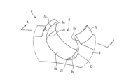
次に、図3と図4とを用いて、保持器5について詳細に説明する。図3は、転がり軸受1におけるボール4を保持する保持器5の部分斜視図である。図4は、図3におけるA矢視断面図である。
Next, the
図3と図4に示すように、保持器5は、基部6、複数の一対の爪部7及び基部6と複数の一対の爪部7とから構成される複数のポケット部8を有する冠型の保持器である。保持器5には、複数のポケット部8内にそれぞれボール4が収容されている。保持器5は、複数のボール4を周方向に等間隔で保持する。
As shown in FIGS. 3 and 4, the
基部6は、爪部7を支持する。基部6は、円環状の部材である。基部6の軸線方向両端面のうち、一方の端面である先端面6a(図4参照)には、一対の爪部7が複数位置している。一対の爪部7は、先端面6aから軸線方向に突出している。一対の爪部7は、周方向一側の爪部7aと周方向他側の爪部7bとを有している。周方向一側の爪部7aは、先端に向かうにつれて周方向他側に向かう、周方向他側の爪部7bは、先端に向かうにつれて周方向一側に向かう。複数の一対の爪部7は、周方向に沿って一定の間隔で位置している。よって、一対の爪部7と一対の爪部7との間は、基部6の先端面6aを構成している。
The
保持器5は、複数の一対の爪部7と複数の一対の爪部7の間の基部6によってボール4を保持する複数のポケット部8を構成している。基部6は、一対の爪部7の間にポケット部の一部を構成する凹部を有している。基部6の凹部は、径方向に見て半円状の凹みである。一対の爪部7は、基部6の凹部の周方向両端部から軸線方向に延びている。ポケット部8は、基部6の凹部と一対の爪部7において互いに対向する側面とから構成される内周面によってボール4を保持する。ポケット部8は、内周面にボール4に接触する凹んだ曲面である第1球面8a、第2球面8b、第3球面8c及び第4球面8dを有している。複数のポケット部8は、一対の爪部7によってボール4に対する軸線方向の移動及び周方向の移動を抑制している。
The
第1球面8aは、一対の爪部7における周方向一側の爪部7aの周方向他側の側面に位置する曲面である。第1球面8aは、曲率中心Ca、曲率半径Daの球面の一部である。第2球面8bは、一対の爪部7の間の基部6における凹部の周方向一側の側面に位置する曲面である。第2球面8bは、曲率中心Cb、曲率半径Dbの球面の一部である。第2球面8bの爪部7側端は、第1球面8aの基部6側端に接続している。第3球面8cは、一対の爪部7の間の基部6における周方向他側の側面に位置する曲面である。第3球面8cは、曲率中心Cc、曲率半径Dcの球面の一部である。第3球面8cの基部6側端は、第2球面8bの基部6側端に接続している。第4球面8dは、一対の爪部7における周方向他側の側面に位置する爪部7aの周方向一側の曲面である。第4球面8dは、曲率中心Cd、曲率半径Ddの球面の一部である。第4球面8dの基部6側端は、第3球面8cの爪部7側端に接続している。
The first
本実施形態において、ポケット部8は、軸線方向において爪部7側に位置する曲面として第1球面8aと第4球面8dとを有している。ポケット部8は、軸線方向に見て基部6側に位置する曲面として、第2球面8bと第3球面8cとを有している。また、ポケット部8の周方向一側の側面には、第1球面8aと第2球面8bとが軸線方向に隣り合って位置している。ポケット部8の周方向他側の側面には、第3球面8cと第4球面8dとが軸線方向に隣り合って位置している。よって、ポケット部8内のボール4は、周方向一側に転動する際、ポケット部8の周方向一側の側面に軸線方向に隣り合って位置する第1球面8aと第2球面8bとに接触する。また、ポケット部8内のボール4は、周方向他側に転動する際、ポケット部8の周方向他側の側面に軸線方向に隣り合って位置する第3球面8cと第4球面8dとに接触する。
In this embodiment, the
第1球面8aの曲率中心Ca、第2球面8bの曲率中心Cb、第3球面8cの曲率中心Cc及び第4球面8dの曲率中心Cdは、全て異なる位置である。よって、第1球面8aと第2球面8bとのそれぞれの境界の接続部分には、第1接続線J1が構成される。第2球面8bと第3球面8cとのそれぞれの境界の接続部分には、第2接続線J2が構成される。第3球面8cと第4球面8dとのそれぞれの境界の接続部分には、第3接続線J3が構成される。また、第1球面8aの曲率半径Da、第2球面8bの曲率半径Db、第3球面8cの曲率半径Dc及び第4球面8dの曲率半径Ddは、全てボール4の曲率半径Dよりも大きい。よって、第1球面8a、第2球面8b、第3球面8c及び第4球面8dは、ボール4の外表面の曲面と一致しない。つまり、第1球面8a、第2球面8b、第3球面8c及び第4球面8dは、各曲面においてボール4の外表面と点接触する。
The center of curvature Ca of the first
次に、図5と図6とを用いて、転がり軸受1が周方向一側に回転している場合におけるボール4と保持器5との状態を説明する。図5は、転がり軸受1が周方向一側に回転した場合においてボール4を保持する保持器5の径方向厚みの略中央での断面図である。図6は、図5におけるB部分の拡大図である。図7は、転がり軸受1における保持器5の別実施形態での保持器5の径方向厚みの略中央での断面図である。
Next, the state of the
転がり軸受1は、外輪2または内輪3の軸線を回転軸として、外輪2または内輪3のいずれか一方が他方に対して周方向一側に回転するものとする(図1参照)。複数のボール4は、外輪2または内輪3の周方向一側への回転により、外輪軌道面2a上または内輪軌道面3a上を周方向一側に転動する。なお、転がり軸受1が周方向他側に回転している場合におけるボール4と保持器5との状態についての説明は、転がり軸受1が周方向一側に回転している場合と略同一であるため省略する。
In the rolling
図5と図6とに示すように、保持器5のポケット部8内に収容されているボール4は、ポケット部8内において周方向一側に転動する。ポケット部8内で自転するボール4の周速は、ボール4の中心Cを通過し、且つボール4の自転軸Rに垂直な線とボール4の外表面との交点がボール4の外表面上を通過する軌道Tにおいて最大になる。通常、ボールの自転軸Rは、保持器5の軸線に対して略平行である。状況により、ボール4の自転軸Rは、保持器5の軸線に対して第1自転軸角θ1だけ傾くことがある。その場合、ボール4の周速が最大になる軌道Tは、軸線に垂直な方向に対して第1自転軸角θ1だけ傾いている。
As shown in FIGS. 5 and 6, the
周方向一側に転動した際、ボール4は、ポケット部8の周方向一側に位置し、軸線方向に隣り合う第1球面8aと第2球面8bとに接触する。保持器5は、ポケット部8内において第1球面8a上の第1接触点P1と第2球面8b上の第2接触点P2との2か所がボール4の外表面に接触する。第1接触点P1と第2接触点P2との軸線方向の間隔である軸線方向長さL1は、第1球面8aの曲率中心Ca及び曲率半径Daと第2球面8bの曲率中心Cb及び曲率半径Dbとによってボール4の直径に対して20パーセントよりも大きく40パーセント未満になるように調整されている(図4参照)。軸線方向長さL1は、ボール4が爪部7に乗り上げないようにボール4の直径に対して40パーセントの長さである最大間隔L2未満に設定されている。
When rolling to one side in the circumferential direction, the
また、外輪2及び内輪3が停止している際、ボール4の外表面は、隣り合う曲面である第2球面8bと第3球面8cとに接触している。外輪2及び内輪3が周方向一側に転動した際の第1接触点P1と第2接触点P2との軸線方向長さL1は、第2球面8bにおけるボール4の接触点と第3球面8cにおけるボール4の接触点との周方向の間隔である周方向長さL3よりも長い。周方向長さL3を軸線方向長さL1よりも短くすることで、軸線方向長さL1をより長くすることができる。これにより、接触点でのボール4の周速がより抑制される。更に、ボール4が転動する際の接触点間における保持器5とボール4との隙間Gが大きくなるので回転時に潤滑剤が接触点の周囲から掻き出されない。これにより、高速回転時において保持器5に加わるボール4からの負荷を低減し、且つ潤滑性を維持することができる。
Further, when the
軌道Tが第1接触点P1と第2接触点P2との間に位置する場合、第1接触点P1または第2接触点P2におけるボール4の周速は、最大周速よりも小さくなる。軌道Tは、ボール4の自転軸Rが第1接触点P1と第2接触点P2との間に位置する。よって、第1接触点P1と第2接触点P2には、軌道Tが重ならない。また、第1接触点P1と第2接触点P2との軸線方向長さL1がボール4の直径に対して40パーセント未満である最大間隔L2未満の場合、ボール4は、保持器5の一対の爪部7に乗り上げない。
When the trajectory T is located between the first contact point P1 and the second contact point P2, the peripheral speed of the
よって、ポケット部8は、第1球面8aの曲率中心Ca及び曲率半径Daと第2球面8bの曲率中心Cb及び曲率半径Dbとの調整によって第1接触点P1と第2接触点P2との軸線方向長さL1がボール4の直径に対して20パーセントよりも大きく40パーセント未満になるように設定することで第1接触点P1と第2接触点P2とにおける転動体の周速が抑制される。第3球面8cにおける図示しない第3接触点P3と第4球面8dにおける図示しない第4接触点P4との軸線方向長さについても同様である。
Therefore, the
また、ポケット部8は、ボール4を支持している第1接触点P1と第2接触点P2とのそれぞれの境界に沿う第1接続線J1が位置している。ボール4と第1接続線J1との間には、隙間Gが生じている。ボール4と第1接続線J1との隙間Gには、グリースまたは潤滑油が保持される。よって、ポケット部8は、ボール4が高速回転してもボール4と第1接続線J1との隙間Gからグリースまたは潤滑油が掻き出されない。これにより、高速回転時において保持器5に加わるボール4からの負荷を低減し、且つ潤滑性を維持することができる。
In addition, the
なお、図7に示すように、保持器5は、第1球面8aと第2球面8bとのそれぞれの境界の接続部分、第2球面8bと第3球面8cとのそれぞれの境界の接続部分及び第3球面8cと第4球面8dとのそれぞれの境界の接続部分に溝8eをそれぞれ設けてもよい。保持器5は、各溝8eにグリースが保持される。よって、ポケット部8は、ボール4が高速回転しても第1球面8a及び第2球面8bよりも凹んだ溝8eからグリースが掻き出されない。これにより、高速回転時において潤滑性を維持することができる。
Note that, as shown in FIG. 7, the
(実施形態2)
以下に、図8と図9とを用いて、本発明に係る転がり軸受の例示的な実施形態2である転がり軸受1Aについて説明する。図8は、転がり軸受1Aにおけるボール4を保持する保持器5Aの部分斜視図である。図9は、図8におけるC矢視断面図である。以下の説明において、実施形態1と同様の構成には同一の符号を付して説明を省略し、実施形態1と異なる部分についてのみ説明する。
(Embodiment 2)
A rolling
図8と図9とに示すように、転がり軸受1Aは、保持器5Aを有する。保持器5Aは、基部6、複数の一対の爪部7及びポケット部8Aを有する。ポケット部8Aは、一対の爪部7において互いに対向する側面と、一対の爪部7の間に位置する基部6の凹部とにボール4を保持するための凹んだ曲面である第1球面8Aa、第2球面8Ab、第3球面8Ac及び第4球面8Adを有している。
As shown in FIGS. 8 and 9, the rolling
第1球面8Aaは、一対の爪部7における周方向一側の爪部7aの周方向他側の側面に位置する曲面である。第2球面8Abは、一対の爪部7の間の基部6における凹部の周方向一側の側面に位置する曲面である。第2球面8Abの爪部7側端は、第1球面8Aaの基部6側端に接続している。第3球面8Acは、一対の爪部7の間の基部6における凹部の周方向他側の側面に位置する曲面である。第3球面8Acの基部6側端は、第2球面8Abの基部6側端に接続している。第4球面8Adは、一対の爪部7における周方向他側の爪部7aの周方向一側の側面に位置する曲面である。第4球面8Adの基部6側端は、第3球面8Acの爪部7側端に接続している。第1球面8Aaと第2球面8Abとのそれぞれの境界の接続部分には、第1接続線JA1が構成される。第2球面8Abと第3球面8Acとのそれぞれの境界の接続部分には、第2接続線JA2が構成される。第3球面8Acと第4球面8Adとのそれぞれの境界の接続部分には、第3接続線JA3が構成される。
The first
転がり軸受1において、ボール4に予圧が加わっている場合、ボール4の自転軸Rは、第2自転軸角θ2として軸線方向断面視において軸線の垂線に対して1度から最大30度傾く。ポケット部8Aは、第1接続線JA1がボール4の自転軸Rに沿うように第1球面8Aaと第2球面8Abとを有している。第1接続線JA1は、第2自転軸角θ2の自転軸Rに沿うように径方向外方に向かうにつれて爪部7の先端に近づく方向に延びている。第3接続線JA3についても同様である。つまり、ポケット部8Aは、ボール4の自転軸Rを挟んだ両側にそれぞれ曲率中心または曲率半径が異なる第1球面8Aaと第2球面8Abとが軸線方向に隣り合って位置している。よって、保持器5Aは、ボール4が周方向一側に転動する際、ボール4の自転軸Rが傾いていても自転軸Rを軸方向に挟んで隣り合う第1球面8Aaと第2球面8Abとにボール4がそれぞれ接触する。保持器5Aには、ボール4からの力が第1球面8Aaと第2球面8Abとの接触点に分散して加わる。これにより、高速回転時において保持器5Aに加わるボール4からの負荷を低減し、且つ潤滑性を維持することができる。
In the rolling
(実施形態3)
以下に、図10と図11とを用いて、本発明に係る転がり軸受の例示的な実施形態3である転がり軸受1Bについて説明する。図10は、転がり軸受1Bにおけるボール4を保持する保持器5Bの部分斜視図である。図11は、転がり軸受1Bにおけるボール4を保持する保持器5Bの爪部7の部分平断面面図である。
(Embodiment 3)
A rolling
図10と図11とに示すように、転がり軸受1Bは、保持器5Bを有する。保持器5Bは、基部6、複数の一対の爪部7及びポケット部8Bを有する。ポケット部8Bは、一対の爪部7において互いに対向する側面と、一対の爪部7の間に位置する基部6の凹部とにボール4を保持するための凹んだ曲面である第1球面8Ba、第2球面8Bb、第3球面8Bc、第4球面8Bd、第5球面8Be、第6球面8Bf、第7球面8Bg、第8球面8Bhを有している。
As shown in FIGS. 10 and 11, the rolling
第1球面8Baは、一対の爪部7における周方向一側の爪部7aの周方向他側であって径方向外方の側面に位置する曲面である。第2球面8Bbは、一対の爪部7の間の基部6における凹部の周方向一側であって径方向外方の側面に位置する曲面である。第3球面8Bcは、一対の爪部7の間の基部6における凹部の周方向他側であって径方向外方の側面に位置する曲面である。第4球面8Bdは、一対の爪部7における周方向他側の爪部7aの周方向一側であって径方向外方の側面に位置する曲面である。
The first spherical surface 8Ba is a curved surface located on the radially outer side surface of the
第5球面8Beは、一対の爪部7における周方向一側の爪部7aの周方向他側であって径方向内方の側面に位置する曲面である。第6球面8Bfは、一対の爪部7の間の基部6における凹部の周方向一側であって径方向内方の側面に位置する曲面である。第7球面8Bgは、一対の爪部7の間の基部6における凹部の周方向他側であって径方向内方の側面に位置する曲面である。第8球面8Bhは、一対の爪部7における周方向他側の爪部7aの周方向一側であって径方向内方の側面に位置する曲面である。
The fifth spherical surface 8Be is a curved surface located on the radially inner side surface of the
第1球面8Baと第5球面8Beとは、周方向一側の爪部7aに径方向に並んで位置している。第2球面8Bbと第6球面8Bfとは、基部6における周方向一側に径方向に並んで位置している。第3球面8Bcと第7球面8Bgとは、基部6における周方向他側に径方向に並んで位置している。第4球面8Bdと第8球面8Bhとは、周方向他側の爪部7bに径方向に並んで位置している。
The first spherical surface 8Ba and the fifth spherical surface 8Be are located side by side in the radial direction on the
外輪2または内輪3の周方向一側への回転によりポケット部8B内において周方向一側に転動したボール4は、ポケット部8の周方向一側の爪部7aに位置する第1球面8Baと第5球面8Be及び基部6における周方向一側に位置する第2球面8Bbと第6球面8Bfに接触する。保持器5は、ポケット部8内において第1球面8Ba上の第1接触点P1、第2球面8Bb上の第2接触点P2、第5球面8Be上の第3接触点P3及び第6球面8Bf上の第4接触点P4の4か所がボール4の外表面に接触することで、ボール4に対するポケット部8Bの位置が定まる。
The
このように構成することで、保持器5Bは、爪部7側の第1球面8Ba上の第1接触点P1と基部6側の第2球面8Bb上の第2接触点P2とのように軸線方向に並ぶ複数の接触点だけでなく、径方向に並ぶ第1球面8Ba上の第1接触点P1と第5球面8Be上の第3接触点P3とによってボール4を支持する。よって、保持器5Bには、軸線方向の複数の接触点と径方向の複数の接触点とにボール4からの力が分散して加わる。また、保持器5は、隣り合う曲面同士の接続線の増加に伴い、ボール4と接続線との間に保持されるグリースが増加する。これにより、高速回転時において保持器5に加わるボール4からの負荷を低減し、且つ潤滑性を維持することができる。
By configuring in this way, the
(その他の実施形態)
上述の実施形態では、転がり軸受1、1A、1Bは、深溝玉軸受として構成されている。しかしながら、転がり軸受は、外輪軌道面と内輪軌道面とに収容された複数のボールを保持器で保持する冠型の転がり軸受であればよい。転がり軸受は、例えば、アンギュラ玉軸受、車輪用軸受装置でもよい。
(Other embodiments)
In the embodiments described above, the rolling
上述の実施形態では、転がり軸受1、1Aの保持器5、5Aは、ポケット部8、8A内に4つの球面を有している。また、転がり軸受1Bの保持器5Bは、ポケット部8B内に8つの球面を有している。しかしながら、転がり軸受の保持器は、球面または曲面の数を実施形態に限定するものではない。転がり軸受の保持器は、転動体が周方向に転動する際、前記転動体が接触する隣り合う球面または曲面を有する構成であればよい。
In the embodiments described above, the
上述の実施形態では、保持器5、5A、5Bは、樹脂によって構成されている。保持器を構成する樹脂は、ガラス転移温度が120度以上の合成樹脂であることが望ましい。これにより、保持器は、回転時の昇温による軟化が抑制される。よって、転がり軸受は、昇温時に遠心力によって保持器に弾性変形が生じても転動体と保持器との干渉を抑制することができる。
In the above-described embodiments, the
上述の実施形態では、保持器5、5A、5Bは、樹脂によって構成されている。保持器は、射出成型によって形成されてもよい。この場合、保持器は、ウェルド部が基部に位置するように射出成形されることが望ましい。保持器は、爪部に比べて強度が高い基部にウェルド部が位置するので、ウェルド部による爪部の強度低下を抑制することができる。
In the above-described embodiments, the
上述の実施形態では、保持器5、5A、5Bのポケット部8、8A、8Bは、複数の曲率中心の位置または曲率半径のうち少なくとも一つが異なる球面によってボール4を保持している。しかしながら、ポケット部は、球面、円筒面及び楕円面のうち少なくとも一つを含む複数の曲面を有し、前記複数の球面によって転動体を保持する構成でもよい。ポケット部は、例えば、一対の爪部が円筒面からなる曲面を有し、基部が球面からなる曲面を有していてもよい。このように構成することで、保持器は、転がり軸受の予圧の有無、回転速度、運転環境、運転状態、転がり軸受の構造に応じた適切なポケット部の形状を有することができる。
In the above-described embodiments, the
以上、本発明の実施の形態について説明を行ったが、本発明はこうした実施の形態に何等限定されるものではなく、あくまで例示であって、本発明の要旨を逸脱しない範囲内において、さらに種々なる形態で実施し得ることは勿論のことであり、本発明の範囲は、特許請求の範囲の記載によって示され、さらに特許請求の範囲に記載の均等の意味、および範囲内のすべての変更を含む。 Although the embodiments of the present invention have been described above, the present invention is not limited to such embodiments in any way, and is merely an example. Of course, the scope of the present invention is indicated by the description of the claims, and the meaning of equivalents described in the claims and all changes within the scope include.
1、1A、1B 転がり軸受
2 外輪
2a 外輪軌道面
3 内輪
3a 内輪軌道面
4 ボール
5、5A、5b 保持器
6 基部
6a 先端面
6b 基端面
7 一対の爪部
8、8A、8B ポケット部
8a、8Aa、8Ba 第1球面
8b、8Ab、8Bb 第2球面
8c、8Ac、8Bc 第3球面
8d、8Ad、8Bd 第4球面
Ca、Cb、Cc、Cd 曲率中心
Da、Db、Dc、Dd 曲率半径
1, 1A, 1B Rolling bearing 2
Claims (8)
前記外輪の内方に位置し、外周面に内輪軌道面を有する内輪と、
前記外輪軌道面と前記内輪軌道面との間に介在する複数の転動体と、
円環状の基部の軸線方向端面に円周方向に所定の間隔で突出する一対の爪部及び前記一対の爪部間に設けられた半円状の凹部から構成されるポケット部を備える保持器と、を有する、転がり軸受であって、
前記保持器のポケット部は、
前記転動体が接触する隣り合う複数の曲面を内周面に有し、前記隣り合う複数の曲面のそれぞれの曲率中心位置及び曲率半径のうち少なくとも一つが異なり、前記隣り合う複数の曲面における前記転動体との接触点の前記軸線方向の間隔が前記転動体の直径に対して2620パーセント以上40パーセント未満である、
転がり軸受。 an outer ring having an outer ring raceway surface on its inner peripheral surface;
an inner ring positioned inside the outer ring and having an inner ring raceway surface on its outer peripheral surface;
a plurality of rolling elements interposed between the outer ring raceway surface and the inner ring raceway surface;
a retainer comprising a pocket portion composed of a pair of claw portions protruding at predetermined intervals in the circumferential direction from the axial end face of the annular base portion and a semicircular recess provided between the pair of claw portions; A rolling bearing having
The pocket portion of the retainer is
An inner peripheral surface has a plurality of adjacent curved surfaces with which the rolling elements contact, at least one of a curvature center position and a curvature radius of each of the adjacent multiple curved surfaces is different, and the rolling elements on the adjacent multiple curved surfaces are different. The axial distance between the contact points with the moving body is 2620% or more and less than 40% with respect to the diameter of the rolling body,
rolling bearing.
前記外輪または前記内輪が周方向に回転する際に前記隣り合う複数の曲面における前記転動体との接触点の前記軸線方向の間隔が前記転動体の直径に対して20パーセント以上40パーセント未満である、
転がり軸受。 A rolling bearing according to claim 1,
When the outer ring or the inner ring rotates in the circumferential direction, the distance in the axial direction between contact points with the rolling elements on the plurality of adjacent curved surfaces is 20% or more and less than 40% of the diameter of the rolling elements. ,
rolling bearing.
前記外輪または前記内輪が周方向に回転する際に前記転動体が接触する前記隣り合う複数の曲面における前記転動体との接触点の前記軸線方向の間隔は、前記外輪及び前記内輪が停止している際に前記転動体が接触する前記隣り合う複数の曲面における前記転動体との接触点の間隔であって、前記基部の周方向の間隔よりも広い、
転がり軸受。 In the rolling bearing according to claim 1 or claim 2,
The distance in the axial direction between contact points with the rolling elements on the plurality of adjacent curved surfaces with which the rolling elements come into contact when the outer ring or the inner ring rotates in the circumferential direction is The interval between the contact points with the rolling elements on the plurality of adjacent curved surfaces with which the rolling elements contact when the rolling element is in contact with the rolling element, which is wider than the interval in the circumferential direction of the base.
rolling bearing.
前記曲面は、球面、円筒面及び楕円面のうち少なくとも一つを含む、
転がり軸受。 In the rolling bearing according to any one of claims 1 to 3,
the curved surface includes at least one of a spherical surface, a cylindrical surface and an ellipsoidal surface;
rolling bearing.
前記ポケット部は、
前記外輪または前記内輪が周方向に回転する際に前記転動体が接触する前記隣り合う複数の曲面が前記軸線方向に隣り合って位置する、
転がり軸受。 In the rolling bearing according to any one of claims 1 to 4,
The pocket portion
The plurality of adjacent curved surfaces with which the rolling elements contact when the outer ring or the inner ring rotates in the circumferential direction are positioned adjacent to each other in the axial direction,
rolling bearing.
前記ポケット部は、
前記外輪または前記内輪が周方向に回転する際に前記転動体が接触する前記隣り合う複数の曲面の境界の接続線が径方向外方に向かうにつれて前記爪部の先端に近づく方向に延び、且つ前記軸線に垂直な平面に対して1度以上30度以下の角度を有する、
転がり軸受。 A rolling bearing according to claim 5,
The pocket portion
connecting lines of boundaries of the plurality of adjacent curved surfaces with which the rolling elements come into contact when the outer ring or the inner ring rotates in the circumferential direction extend in a direction approaching the tips of the claw portions as they extend radially outward; having an angle of 1 degree or more and 30 degrees or less with respect to a plane perpendicular to the axis;
rolling bearing.
前記ポケット部は、
前記外輪または前記内輪が周方向に回転する際に前記転動体が接触する前記隣り合う複数の曲面が径方向に隣り合って位置する、
転がり軸受。 A rolling bearing according to claim 5,
The pocket portion
The plurality of adjacent curved surfaces with which the rolling elements contact when the outer ring or the inner ring rotates in the circumferential direction are positioned adjacent to each other in the radial direction,
rolling bearing.
前記ポケット部は、
前記隣り合う複数の曲面の境界に沿って延びる溝を有する、
転がり軸受。 In the rolling bearing according to any one of claims 1 to 7,
The pocket portion
having grooves extending along boundaries of the plurality of adjacent curved surfaces;
rolling bearing.
Priority Applications (2)
| Application Number | Priority Date | Filing Date | Title |
|---|---|---|---|
| JP2021203820A JP2023089366A (en) | 2021-12-16 | 2021-12-16 | rolling bearing |
| PCT/JP2022/043309 WO2023112625A1 (en) | 2021-12-16 | 2022-11-24 | Rolling bearing |
Applications Claiming Priority (1)
| Application Number | Priority Date | Filing Date | Title |
|---|---|---|---|
| JP2021203820A JP2023089366A (en) | 2021-12-16 | 2021-12-16 | rolling bearing |
Publications (2)
| Publication Number | Publication Date |
|---|---|
| JP2023089366A true JP2023089366A (en) | 2023-06-28 |
| JP2023089366A5 JP2023089366A5 (en) | 2023-07-12 |
Family
ID=86774153
Family Applications (1)
| Application Number | Title | Priority Date | Filing Date |
|---|---|---|---|
| JP2021203820A Pending JP2023089366A (en) | 2021-12-16 | 2021-12-16 | rolling bearing |
Country Status (2)
| Country | Link |
|---|---|
| JP (1) | JP2023089366A (en) |
| WO (1) | WO2023112625A1 (en) |
Family Cites Families (7)
| Publication number | Priority date | Publication date | Assignee | Title |
|---|---|---|---|---|
| JPS57124617U (en) * | 1981-01-28 | 1982-08-03 | ||
| JP2005226738A (en) * | 2004-02-13 | 2005-08-25 | Nsk Ltd | Retainer for rolling bearing, rolling bearing with the retainer, and fan motor using the rolling bearing |
| JP2007120687A (en) * | 2005-10-31 | 2007-05-17 | Nsk Ltd | Self-aligning roller bearing with retainer |
| JP2007278406A (en) * | 2006-04-07 | 2007-10-25 | Nsk Ltd | Roller bearing with cage |
| JP2010071386A (en) * | 2008-09-18 | 2010-04-02 | Ntn Corp | Retainer for rolling bearing and rolling bearing with same |
| JP5978578B2 (en) * | 2011-09-21 | 2016-08-24 | 株式会社ジェイテクト | Ball bearings and cages for ball bearings |
| US9546682B2 (en) * | 2014-12-09 | 2017-01-17 | Aktiebolaget Skf | Cage of a rolling bearing, rolling bearing comprising such a cage and apparatus comprising such a rolling bearing |
-
2021
- 2021-12-16 JP JP2021203820A patent/JP2023089366A/en active Pending
-
2022
- 2022-11-24 WO PCT/JP2022/043309 patent/WO2023112625A1/en unknown
Also Published As
| Publication number | Publication date |
|---|---|
| WO2023112625A1 (en) | 2023-06-22 |
Similar Documents
| Publication | Publication Date | Title |
|---|---|---|
| US8556519B2 (en) | Radial roller bearing, in particular single track ball roller bearing | |
| US7938585B2 (en) | Radial antifriction bearing, especially single-row grooved antifriction bearing | |
| JP2007502953A (en) | Self-aligning rolling bearing and cage for self-aligning rolling bearing | |
| TW201819790A (en) | Rolling bearing cage and rolling bearing | |
| US11255381B2 (en) | Rolling bearing and cage | |
| US20030021506A1 (en) | Angular contact ball-bearing cage with lubricant pockets | |
| JP2008057762A (en) | Ball bearing | |
| JP2004245251A (en) | Automatic centering rolling bearing | |
| JP4722822B2 (en) | Tandem type double row angular contact ball bearing | |
| JP2010048374A (en) | Cylindrical roller bearing | |
| JP2020041605A (en) | Wheel bearing device | |
| WO2023112625A1 (en) | Rolling bearing | |
| JP2008267400A (en) | Ball bearing | |
| CN111623033A (en) | Thrust roller bearing | |
| WO2023095639A1 (en) | Rolling bearing | |
| WO2012173046A1 (en) | Cylindrical roller bearing | |
| JP7314701B2 (en) | deep groove ball bearing | |
| CN213954169U (en) | Ball bearing | |
| JP6141606B2 (en) | Spherical roller bearing | |
| JP4680169B2 (en) | Tandem type double row angular contact ball bearing | |
| JP2010025191A (en) | Self-aligning roller bearing | |
| WO2020255990A1 (en) | Angular contact ball bearing and bearing device for vehicle wheel | |
| JP2021004665A (en) | Inner ring unit and tapered roller bearing | |
| JP2014206266A (en) | Bearing device for wheel | |
| JP4424092B2 (en) | Synthetic resin crown cage |
Legal Events
| Date | Code | Title | Description |
|---|---|---|---|
| A521 | Request for written amendment filed |
Free format text: JAPANESE INTERMEDIATE CODE: A523 Effective date: 20230704 |