JP2023033796A - Wooden framework building - Google Patents

Wooden framework building Download PDF

Info

Publication number
JP2023033796A
JP2023033796A JP2021139704A JP2021139704A JP2023033796A JP 2023033796 A JP2023033796 A JP 2023033796A JP 2021139704 A JP2021139704 A JP 2021139704A JP 2021139704 A JP2021139704 A JP 2021139704A JP 2023033796 A JP2023033796 A JP 2023033796A
Authority
JP
Japan
Prior art keywords
panel
panels
shaft
frame
joint
Prior art date
Legal status (The legal status is an assumption and is not a legal conclusion. Google has not performed a legal analysis and makes no representation as to the accuracy of the status listed.)
Granted
Application number
JP2021139704A
Other languages
Japanese (ja)
Other versions
JP7005070B1 (en
Inventor
出 橋詰
Izuru Hashizume
Current Assignee (The listed assignees may be inaccurate. Google has not performed a legal analysis and makes no representation or warranty as to the accuracy of the list.)
ACT Co Ltd
Original Assignee
ACT Co Ltd
Priority date (The priority date is an assumption and is not a legal conclusion. Google has not performed a legal analysis and makes no representation as to the accuracy of the date listed.)
Filing date
Publication date
Application filed by ACT Co Ltd filed Critical ACT Co Ltd
Priority to JP2021139704A priority Critical patent/JP7005070B1/en
Application granted granted Critical
Publication of JP7005070B1 publication Critical patent/JP7005070B1/en
Publication of JP2023033796A publication Critical patent/JP2023033796A/en
Active legal-status Critical Current
Anticipated expiration legal-status Critical

Links

Images

Landscapes

  • Panels For Use In Building Construction (AREA)
  • Joining Of Building Structures In Genera (AREA)

Abstract

To provide a skeleton easy to construct, causing little dispersion and forming a wooden framework building with a sense of unity as a whole.SOLUTION: In a wooden framework building, panels 13 are formed by assembling shaft materials S forming a wooden frame work and frame materials T thinner than the shaft materials S, and a floor panel 13A forming a floor surface, exterior wall panels 13B forming wall faces and partitioning panels 13C, tie panels 13D forming roof frames on the wall faces, and roof panels forming roof faces are provided. The panels are formed of multiple panels, respectively, and are formed by selecting among three kinds of panels of shaft panels Pa having only a shaft material S on joint sides 13s of the panels, frame panels Pb having only a frame material T on the joint sides 13s, and shaft frame panels Pc having a shaft material S to at least one out of the joint sides 13s and the frame material T to others. A joint metal is provided to a panel joint part, and the shaft material S and the frame material T are mutually jointed and fixed.SELECTED DRAWING: Figure 4

Description

この発明は、パネルを用いて構成される木造軸組建築物に関し、より詳しくは、木造軸組を構成する軸材をパネル化したパネルで構成される木造軸組建築物に関する。 TECHNICAL FIELD The present invention relates to a wooden framework building constructed using panels, and more particularly to a wooden framework building constructed of panels obtained by paneling shaft members that constitute the wooden framework.

木造軸組を構成する軸材をパネル化したパネルで構成される木造軸組建築物として、下記特許文献1に開示のものを案出した。この木造軸組建築物は、外周に位置する外周フレームの内側に、水平に延びる水平補強部と、水平補強部を支える垂直補強部を設けた耐力パネルを用いて構成される。耐力パネルの水平補強部を構成する横に延びる横軸材と、垂直補強部を構成する縦に延びる縦軸材は、軸組を構成する線部材の太さと同等の太さの材で構成され、面材と組み合わせて強度を高めた構成である。外周フレームは、軸組の線部材の太さよりも薄い材か、横軸材や縦軸材のように軸組の線部材の太さと同等の太さの材で構成される。 As a wooden framework building composed of panels obtained by paneling the shaft members that constitute the wooden framework, the one disclosed in Patent Document 1 below has been devised. This wooden framework building is constructed by using a load-bearing panel provided with a horizontal reinforcing portion extending horizontally inside an outer peripheral frame located on the outer periphery and a vertical reinforcing portion supporting the horizontal reinforcing portion. The horizontally extending horizontal shaft members that make up the horizontal reinforcing portion of the load-bearing panel and the vertically extending vertical shaft members that make up the vertical reinforcing portion are made of materials with the same thickness as the wire members that make up the framework. , the strength is increased by combining with the face material. The outer frame is made of a material that is thinner than the wire members of the framework, or a material that has the same thickness as the wire members of the framework, such as horizontal and vertical shaft members.

特許第6484752号公報Japanese Patent No. 6484752

特許文献1の構成によれば、耐力パネルの配設によって強度の高い木造軸組建築物を得られる。 According to the configuration of Patent Literature 1, a high-strength wooden framework building can be obtained by arranging load-bearing panels.

しかし、床組や小屋組を含む木造軸組建築物の全体の構成については考慮されていない。 However, no consideration is given to the overall composition of the wooden frame building including the floor trusses and roof trusses.

また、耐力パネルの外周フレームを軸組の線部材の太さと同等の太さの材で構成する場合と、それより薄い材で構成する場合があり、接合の態様が画一化されていない。このため、接合金物の態様やパネルの組合せの点で、接合しにくい場合があり、施工にばらつきが生じるおそれがあった。 In addition, the outer frame of the load-bearing panel may be made of a material having the same thickness as the wire members of the framework, or may be made of a material thinner than that, and the joining mode is not uniform. For this reason, it may be difficult to join depending on the aspect of the joining hardware and the combination of panels, and there is a risk of variation in construction.

この発明は、施工しやすいうえにばらつきが生じにくく、木造軸組建築物の全体としてまとまりのある躯体を構成できるようにすることを主な目的とする。 The main object of the present invention is to enable construction to be easily performed, variation to be less likely to occur, and a framework of a wooden framework building as a whole to be cohesive.

そのための手段は、木造軸組を構成する軸材と前記軸材より薄い枠材を組んでパネルを構成し、床面を構成する床パネルと、壁面を構成する外壁パネル及び間仕切りパネルと、壁面の上に小屋組を構成する小屋パネルと、屋根面を構成する屋根パネルで構成した木造である。これら各種のパネルは、それぞれ複数のパネルで構成するとともに、パネル同士の接合辺に軸材のみを有する軸パネルと、接合辺に枠材のみを有する枠パネルと、接合辺のうちの少なくとも一つに軸材を、他に枠材を有する軸枠パネルの3種類のパネルから選択して構成する。そして、床パネル、外壁パネル、間仕切りパネル、小屋パネル、屋根パネル同士の接合箇所、及びこれらパネルと他のパネルとの接合箇所に接合金物を備え、各部のパネル同士は軸材と枠材を相互に接合して固定する。 The means for that purpose is to construct a panel by assembling shaft members that constitute a wooden frame and a frame member that is thinner than the shaft members, a floor panel that constitutes a floor surface, an exterior wall panel and a partition panel that constitute a wall surface, and a wall surface. It is a wooden structure composed of a roof panel that forms a roof frame and a roof panel that forms a roof truss on top of the roof. These various panels are each composed of a plurality of panels, and at least one of a shaft panel having only a shaft member on the joint side of the panels, a frame panel having only a frame member on the joint side, and a joint side. First, the shaft member is selected from three types of panels, namely, a shaft frame panel having a frame member. Joining metal fittings are provided at joints between floor panels, exterior wall panels, partition panels, shed panels, and roof panels, and joints between these panels and other panels, and each panel is made of shafts and frames. and fix it.

この構成によれば、各部のパネル同士は接合辺の軸材と枠材が互いに画一的に接合して一つの平面や立体面を構成する。各パネルに備えられた接合金物は、接合作業を容易にするとともに、均質な接合を可能にする。 According to this configuration, the panels of each part are uniformly joined together by the shaft member and the frame member on the joining sides to form one plane or three-dimensional plane. Joining hardware provided on each panel facilitates joining work and enables uniform joining.

この発明によれば、軸材からなる接合辺と枠材からなる接合辺を画一的に接合できる構成であるので、熟練工でなくとも施工しやすく、用いる接合金物は備えられているので、この点からも施工性がよい。しかも、パネルの軸材は、パネル同士の接合によって位置規制されながら接合金物によって接合されるので、ばらつきが生じにくく、木造軸組建築物の全体がまとまりのある躯体となり、強度も得られる。 According to the present invention, since the joint side made of the shaft material and the joint side made of the frame material can be uniformly joined, construction is easy even for non-skilled workers, and since the joining hardware to be used is provided, this construction is possible. Good workability from the point of view. Moreover, since the shaft members of the panels are joined by joint metals while the positions of the panels are regulated by joining the panels together, variations are less likely to occur, and the entire wooden framework building has a coherent framework and strength.

木造軸組建築物の軸材部分での縦断面図。A vertical cross-sectional view of a shaft member of a wooden framework building. パネルの概念を示す説明図。Explanatory drawing which shows the concept of a panel. パネルの概念を示す説明図。Explanatory drawing which shows the concept of a panel. 基礎と外壁パネル等を対応させて示した平面図。The top view which made the foundation, the outer wall panel, etc. correspond, and showed them. 床パネルの斜視図。A perspective view of a floor panel. 床パネル同士の接合部分を示す一部断面正面図。FIG. 3 is a partial cross-sectional front view showing a joint portion between floor panels. 床パネルの一部破断平面図。The partially broken top view of a floor panel. 外壁パネルの正面図。The front view of an outer wall panel. コーナ接合金物の斜視図。4 is a perspective view of a corner joining hardware; FIG. 軸端接合金物の斜視図。FIG. 3 is a perspective view of a shaft-end joint metal fitting; 図10の軸端接合金物の正面図。A front view of the shaft-end joining hardware of FIG. 円筒接合金物の斜視図。The perspective view of a cylindrical joint metal fitting. 中間接合金物の斜視図。The perspective view of an intermediate joint alloy. 受金物の斜視図。The perspective view of a receiving object. 外壁パネルと床パネルの接合部分の分離状態の断面図。Sectional drawing of the separated state of the joint part of an outer wall panel and a floor panel. 間仕切りパネルの正面図。The front view of a partition panel. 間仕切りパネルの正面図。The front view of a partition panel. 図17の間仕切りパネルの上に固定される梁パネルの正面図。FIG. 18 is a front view of a beam panel secured over the partition panel of FIG. 17; 軸端接合金物の斜視図。FIG. 3 is a perspective view of a shaft-end joint metal fitting; 小屋パネルの正面図。Front view of the shed panel. 小屋パネルの正面図。Front view of the shed panel. 屋根パネル同士の接合状態の正面図。The front view of the joint state of roof panels. 屋根パネルの正面図。Front view of the roof panel. 基礎に外壁パネルと床パネルを固定する際の状態を示す斜視図。The perspective view which shows the state at the time of fixing an outer wall panel and a floor panel to a foundation. 基礎の上に床パネルを固定した状態の平面図。The top view of the state which fixed the floor panel on the foundation. 間仕切りパネルを固定する際の状態を示す斜視図。The perspective view which shows the state at the time of fixing a partition panel. 間仕切りパネルの固定状態を示す正面図。The front view which shows the fixed state of a partition panel. 小屋パネルを固定する際の状態を示す斜視図。The perspective view which shows the state at the time of fixing a hut panel. 小屋パネルを固定した状態を示す斜視図。The perspective view which shows the state which fixed the hut panel. 小屋パネルと屋根パネルの固定状態を示す側面図。The side view which shows the fixed state of a hut panel and a roof panel.

この発明を実施するための一形態を、以下図面を用いて説明する。 One mode for carrying out the present invention will be described below with reference to the drawings.

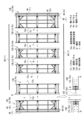
図1に、この発明の木造軸組建築物11における躯体の要部を断面図で示す。図1は軸材を有する位置で切断した断面図である。この木造軸組建築物11は、基礎12や床束を除く床、壁、梁など建物の構造を支える骨組みである躯体を構成するおおよそすべての部材をパネル13で構成している。すなわち、基礎12の上に所定のパネル13を順に固定すると、木造軸組建築物11が得られる構造である。躯体のすべてがパネル13のみで構成されるのが好ましい。 FIG. 1 shows a cross-sectional view of a main part of a skeleton of a wooden framework building 11 of the present invention. FIG. 1 is a cross-sectional view cut at a position having a shaft member. In this wooden framework building 11, panels 13 are used for almost all of the members that constitute the framework that supports the structure of the building, such as floors, walls, beams, etc., except for the foundation 12 and floor trusses. That is, it is a structure in which a wooden framework building 11 is obtained by fixing predetermined panels 13 on a foundation 12 in order. It is preferable that the entire frame is composed only of the panels 13 .

パネル13は、木造軸組を構成する軸材Sと、軸材Sより薄い枠材Tを組んで構成される。このパネル13には、床面を構成する床パネル13Aと、壁面を構成する外壁パネル13B及び間仕切りパネル13Cと、壁面の上に小屋組を構成する小屋パネル13Dと、屋根面を構成する屋根パネル13Eという、適用部位に応じた種類がある。 The panel 13 is constructed by assembling a shaft member S that constitutes a wooden framework and a frame member T that is thinner than the shaft member S. The panel 13 includes a floor panel 13A that forms the floor surface, an outer wall panel 13B and a partition panel 13C that form the wall surface, a shed panel 13D that forms a roof truss on the wall surface, and a roof panel that forms the roof surface. There is a type called 13E according to the application site.

軸材Sとは、軸組を構成する柱や横架材など荷重を支持し伝達する線部材の太さと同等の太さの材であり、換言すれば線部材の横断面に相応する横断面を有した材であり、角材で構成される。「相応する横断面」とは、横断面の形状と大きさが同じもの、同じようなもの、又はそれ以上の大きさのものである他、横断面のたてよこのいずれか一方の値が同じであって、線部材と同様の荷重支持能力を有するものであることをいう。 The shaft member S is a member having a thickness equivalent to that of a wire member that supports and transmits a load, such as a pillar or horizontal member that constitutes the framework. It is a timber with a square timber. "Comparable cross-section" means a cross-section with the same shape and size, similar or larger, and with the same value for either the length or width of the cross-section. It has the same load bearing capacity as a wire member.

軸材Sよりも薄い枠材Tは、横断面形状が長方形であり、その長辺が軸材Sの横断面形状の対応する辺と同一長さであり、短辺がそれより短い。 The frame member T, which is thinner than the shaft member S, has a rectangular cross-sectional shape, the long sides of which are the same length as the corresponding sides of the cross-sectional shape of the shaft member S, and the short sides of which are shorter.

適用部位ごとのパネル13は、それぞれ複数のパネル13で構成されており、形態に応じて3種類のパネルから選択して構成される。3種類のパネルは、図2、図3に模式的に示したように、軸パネルPaと、枠パネルPbと、軸枠パネルPcである。 The panel 13 for each application site is composed of a plurality of panels 13, and is configured by selecting from three types of panels according to the form. The three types of panels are, as schematically shown in FIGS. 2 and 3, a shaft panel Pa, a frame panel Pb, and a shaft frame panel Pc.

軸パネルPaは、パネル同士の接合辺13sに軸材Sのみを有するものである。つまり軸パネルPaは、たとえば接合辺13sが図2に示したように2辺あれば、それら2辺の接合辺13sが共に軸材Sで構成されている。接合辺13sが1辺であればその辺が軸材Sで構成されている。 The shaft panel Pa has only the shaft member S on the joint side 13s between the panels. That is, if the shaft panel Pa has two joint sides 13s as shown in FIG. If the joint side 13s is one side, that side is made of the shaft member S.

枠パネルPbは、接合辺13sに枠材Tのみを有するものである。つまり枠パネルPbは、たとえば接合辺13sが図2に示したように2辺あれば、それら2辺の接合辺13sが共に枠材Tで構成されている。接合辺13sが1辺であればその辺が枠材Tで構成されている。 The frame panel Pb has only the frame member T on the joint side 13s. That is, if the frame panel Pb has two joint sides 13s as shown in FIG. If the joint side 13s is one side, that side is made of the frame material T. As shown in FIG.

軸枠パネルPcは、接合辺13sのうちの少なくとも一つに軸材Sを、他に枠材Tを有するものである。つまり軸枠パネルPcは、たとえば接合辺13sが図2に示したように2辺あれば、それら2辺の接合辺13sのうち一辺が軸材Sで、他の一辺が枠材Tで構成されている。 The shaft frame panel Pc has a shaft member S on at least one of the joint sides 13s and a frame member T on the other. That is, if the shaft frame panel Pc has two joint sides 13s as shown in FIG. ing.

同一適用部位のパネル同士の接合辺13sは、両側の辺に限定されるものではなく、例えば図3に示したように、パネル13の幅方向の中間部位も接合辺13sとなり得る。パネル13が構成すべき面が広い場合には、3辺又は4辺も接合辺13sとなる場合がある。 The joint sides 13s between the panels of the same application site are not limited to the sides on both sides. For example, as shown in FIG. When the panel 13 has a wide surface, three or four sides may also be the joining sides 13s.

同一適用部位のパネル同士の接合辺13s以外の辺は、接合する対象に応じて、軸材Sで構成するか、枠材Tで構成するか、軸材Sの長手方向の端面で構成するか、その他の材で構成するかなど、適宜設定される。 Sides other than the joint side 13s between panels of the same application site are formed of the shaft member S, the frame member T, or the longitudinal end face of the shaft member S, depending on the object to be joined. , whether or not to be composed of other materials, etc., are set as appropriate.

また、床パネル13A、外壁パネル13B、間仕切りパネル13C、小屋パネル13D、屋根パネル13E同士の接合箇所、及びこれらパネルと他のパネルとの接合箇所には接合金物15が備えられる。 Joining hardware 15 is provided at joints between the floor panel 13A, the outer wall panel 13B, the partition panel 13C, the hut panel 13D, and the roof panel 13E, and at the joints between these panels and other panels.

接合金物15のうち、外壁パネル13B、間仕切りパネル13C、小屋パネル13D、屋根パネル13Eに備えられる接合金物15はパネル13に内蔵される。また接合金物15が、結合のための締結ボルト51を有する雄型接合金物15x、又は雄型接合金物15xの締結ボルト51が螺合される雌ねじ52を有する雌型接合金物15yである。 Among the joint metal fittings 15, the joint metal fittings 15 provided in the outer wall panel 13B, the partition panel 13C, the shed panel 13D, and the roof panel 13E are incorporated in the panel 13. The joint metal 15 is a male joint 15x having a fastening bolt 51 for coupling, or a female joint 15y having a female screw 52 into which the fastening bolt 51 of the male joint 15x is screwed.

前述のような形態に基づいて分けられる3種類のパネル(Pa,Pb,Pc)について、各適用部位のパネル、すなわち床パネル13A、外壁パネル13B、間仕切りパネル13C、小屋パネル13D、屋根パネル13Eごとに、接合金物15と共にその形態を具体的にみる。なお、基礎12は、形状を単純化して、図4に表したような平面視長方形の場合を例に説明する。この図4では、基礎12の周囲に位置を合わせて外壁パネル13Bと小屋パネル13Dを寝かせた状態をあらわしている。 For the three types of panels (Pa, Pb, Pc) classified based on the form as described above, the panels of each application site, that is, the floor panel 13A, the outer wall panel 13B, the partition panel 13C, the hut panel 13D, and the roof panel 13E Next, its form will be specifically seen together with the joining hardware 15 . It should be noted that the base 12 will be described as an example in which the shape is simplified and is rectangular in plan view as shown in FIG. FIG. 4 shows a state in which the outer wall panel 13B and the hut panel 13D are positioned around the foundation 12 and laid down.

床パネル13Aは、基礎12より上に一つの水平な平面を構成するもので、図5に示したように、平面視長方形の基礎12とおおよそ同じ長方形を長手方向に6分割した態様の6枚の床パネル13Aで構成される。すべての床パネル13Aは長方形である。 The floor panel 13A constitutes one horizontal plane above the foundation 12, and as shown in FIG. is constructed of a floor panel 13A. All floor panels 13A are rectangular.

両端に配置される2枚の床パネル13Aを除く4枚の床パネル13Aは、床パネル同士の接合辺13sを2辺有し、これら2辺とも軸材Sで構成した2枚の軸パネルPaと、枠材Tで構成した2枚の枠パネルPbである。 The four floor panels 13A, excluding the two floor panels 13A arranged at both ends, have two joint sides 13s between the floor panels. and two frame panels Pb made of the frame material T. As shown in FIG.

すなわち、軸パネルPaからなる床パネル13Aは、断面正方形の角材からなる2本の軸材Sを、間隔をあけて平行に配設するとともに、これらの間に軸材Sと直交する方向に延びる複数の連結材31が配設されている。連結材31は、軸材Sに相応する横断面の角材で構成される。軸材Sは、土台の間にかけ渡される大引となり、連結材31は大引間に横架される小引となる。 That is, the floor panel 13A made of the shaft panel Pa includes two shaft members S each made of square members having a square cross section, which are arranged in parallel with each other with an interval therebetween and extend in a direction orthogonal to the shaft member S between them. A plurality of connecting members 31 are arranged. The connecting member 31 is composed of a square member having a cross section corresponding to the shaft member S. As shown in FIG. The shaft member S serves as a large pull that is stretched between the bases, and the connecting member 31 serves as a small pull that is laid horizontally between the large pulls.

軸材Sと連結材31の上面には、パネル13の面を塞ぐ面材として構造用合板等からなる面材32が張り付けられている。面材32は、軸材Sの太さの半分までを覆う大きさである。 A face member 32 made of structural plywood or the like is attached to the upper surface of the shaft member S and the connecting member 31 as a face member covering the surface of the panel 13 . The face member 32 is sized to cover up to half the thickness of the shaft member S.

枠パネルPbからなる床パネル13Aは、軸材Sに相応する横断面の角材で構成された複数の連結材31を、軸パネルPaからなる床パネル13Aと同様に間隔をあけて床パネル13Aの長手方向に沿って配設している。また、これら連結材31を挟み、また連結材31に挟まれる、枠材Tからなる基本的に四角い複数の枠体33を設けている。連結材31は大引間に横架される小引となる。この例の床パネル13Aは、連結材31を3本備え、枠体を4個備えている。 The floor panel 13A made up of the frame panel Pb has a plurality of connecting members 31 each made up of square members having a cross section corresponding to the shaft member S, and is spaced apart from the floor panel 13A in the same way as the floor panel 13A made up of the shaft panel Pa. It is arranged along the longitudinal direction. In addition, a plurality of basically square frames 33 made of frame members T are provided to sandwich the connecting members 31 and to be sandwiched between the connecting members 31 . The connecting member 31 serves as a kobiki installed horizontally between the ohiki. The floor panel 13A of this example includes three connecting members 31 and four frames.

連結材31と枠体33の上面には、構造用合板等からなる面材32が張り付けられている。面材32は、枠体33の端から外側に、軸材Sの太さの半分の長さの張り出し部32aを有している。 A surface material 32 made of structural plywood or the like is attached to the upper surfaces of the connecting member 31 and the frame 33 . The face member 32 has an overhanging portion 32a extending outward from the end of the frame 33 and having a length half the thickness of the shaft member S.

両端に配される2枚の床パネル13Aのうち、軸パネルPaかなる床パネル13Aに隣接する床パネル13Aは枠パネルPbであり、前述した枠パネルPbと同様に連結材31と枠体33を有している。このため接合辺13sを含む全周に枠材Tが備えられている。また、この連結材31は土台と大引きとの間に横架される小引となる。 Of the two floor panels 13A arranged at both ends, the floor panel 13A adjacent to the floor panel 13A consisting of the axis panel Pa is the frame panel Pb. have. For this reason, the frame member T is provided on the entire periphery including the joint side 13s. Also, this connecting member 31 serves as a small pull horizontally between the base and the large pull.

上面に張り付けられる面材32は、接合辺13sにおいて軸材Sの太さの半分の長さの張り出し部32aを有している。 The face material 32 attached to the upper surface has an overhang part 32a having a length half the thickness of the shaft material S at the joint side 13s.

両端に配される2枚の床パネル13Aのうち、枠パネルPbかなる床パネル13Aに隣接する床パネル13Aは軸パネルPaであり、前述した軸パネルPaと同様に軸材Sと連結材31を有している。このため接合辺13sは軸材Sで構成されることになるが、接合辺13sの反対側の辺には、連結材31の長手方向の端面が表れることになる。この連結材31は土台と大引きとの間に横架される小引となる。 Of the two floor panels 13A arranged at both ends, the floor panel 13A adjacent to the floor panel 13A consisting of the frame panel Pb is the shaft panel Pa, and the shaft member S and the connecting member 31 are similar to the shaft panel Pa described above. have. For this reason, the joint side 13s is composed of the shaft member S, but the longitudinal end face of the connecting member 31 appears on the side opposite to the joint side 13s. This connecting member 31 serves as a small pull horizontally between the base and the large pull.

上面に張り付けられる面材32は、接合辺13sにおいては軸材Sの太さの半分までを覆う大きさである。 The face material 32 attached to the upper surface has a size that covers up to half the thickness of the shaft material S at the joint side 13s.

図示は省略するが、床パネル13Aの厚み内、すなわち軸材Sや連結材31を有する空間や枠体33で囲まれた空間には、断熱材が備えられ、上面の面材32とは反対側の下面にも構造用合板等からなる面材が張り付けられている。 Although illustration is omitted, a heat insulating material is provided within the thickness of the floor panel 13A, that is, the space having the shaft member S and the connecting member 31 and the space surrounded by the frame 33, and is opposite to the surface member 32 on the upper surface. A face material made of structural plywood or the like is attached to the lower surface of the side.

床パネル13Aの接合金物15は、図6に示したように束金物17の一部として構成されており、軸パネルPaとしての床パネル13Aに固定されている。束金物17は基礎12の内部で大引を支えるものであって、設置面12aに置かれる基台部71と、基台部71に立設された支持部72と、支持部72の上で大引、つまりこの例では床パネル13Aの軸材Sを受ける受け部73を有している。受け部73が接合金物15として機能する。 The joint metal 15 of the floor panel 13A is configured as a part of the metal bundle 17 as shown in FIG. 6, and is fixed to the floor panel 13A as the shaft panel Pa. The bundle of hardware 17 supports the pulley inside the foundation 12, and includes a base portion 71 placed on the installation surface 12a, a support portion 72 erected on the base portion 71, and a support portion 72 on the support portion 72. In this example, it has a receiving portion 73 for receiving the shaft member S of the floor panel 13A. The receiving portion 73 functions as the joining hardware 15 .

基台部71は全周方向での角調節可能に構成されており、支持部72は丸棒状に形成されて基台部71上で相対回転可能である。支持部72の外周面における下方から上端にかけての部分には雄ねじ72aが形成されている。 The base portion 71 is configured to be angularly adjustable in all circumferential directions, and the support portion 72 is formed in the shape of a round bar and is relatively rotatable on the base portion 71 . A male thread 72a is formed on the outer peripheral surface of the support portion 72 from the bottom to the upper end.

受け部73は、図7にも示したように軸材Sを受ける中間部73aから、軸材Sの長手方向と直交する方向に向けて突出して連結材31を受ける突出部73bが形成されている。受け部73の中間部73aと突出部73bの間には軸材Sを挟む起立壁73cが設けられている。中間部73aの中央には円筒軸部74が下方に突設され、円筒軸部74の内周面には支持部72の雄ねじ72aに螺合する雌ねじ74aが形成されている。 As shown in FIG. 7, the receiving portion 73 is formed with a protruding portion 73b that protrudes in a direction perpendicular to the longitudinal direction of the shaft S from an intermediate portion 73a that receives the shaft S and receives the connecting member 31. there is An upright wall 73c sandwiching the shaft member S is provided between the intermediate portion 73a of the receiving portion 73 and the projecting portion 73b. A cylindrical shaft portion 74 protrudes downward from the center of the intermediate portion 73 a , and a female thread 74 a is formed on the inner peripheral surface of the cylindrical shaft portion 74 to be screwed with the male thread 72 a of the support portion 72 .

軸材Sには上下方向に貫通し支持部72を通す貫通穴81を有し、貫通穴81より上方には貫通穴81から突出する支持部72に螺合した2個のナット75を納める座彫り部82が形成されている。 The shaft member S has a through hole 81 passing through it in the vertical direction and through which the support portion 72 is passed. A carved portion 82 is formed.

また軸材S内には突出部73bが形成される方向に延びる円筒形状の埋め込みナット76が設けられる。埋め込みナット76の長さは軸材Sの太さに対応しており、長手方向の中間位置には貫通穴76aを有して、束金物17の支持部72を挿通させている。埋め込みナット76の両端部には、起立壁73cの外側から挿入されるボルト77が螺合する。 A cylindrical embedded nut 76 extending in the direction in which the projecting portion 73b is formed is provided in the shaft S. The embedded nut 76 has a length corresponding to the thickness of the shaft member S, and has a through hole 76a at an intermediate position in the longitudinal direction, through which the supporting portion 72 of the metal bundle 17 is inserted. Both ends of the embedded nut 76 are screwed with bolts 77 inserted from the outside of the standing wall 73c.

突出部73bの中央には貫通穴73dが設けられ、その下にはナット78が備えられている。このナット78には、突出部73bに載置された連結材31に上から挿入した締結ボルト79が螺合する。 A through hole 73d is provided in the center of the projecting portion 73b, and a nut 78 is provided below it. The nut 78 is screwed with a fastening bolt 79 inserted from above into the connecting member 31 placed on the projecting portion 73b.

軸パネルPaからなる床パネル13Aのうち、軸材Sの長手方向の端部と連結材31の長手方向の端部には、図7に示したように中央において上下に貫通する貫通穴83と、端面において上下に延びる縦溝部84が形成されている。枠パネルPbからなる床パネル13Aの連結材31における長手方向の端部についても同様に、貫通穴83と縦溝部84が形成されている。貫通穴83は軸材Sや連結材31を固定するためのボルト79を挿通するためのものであり、縦溝部84は固定相手方にあるボルト77の頭部との干渉を防ぐためものである。 In the floor panel 13A made up of the shaft panel Pa, the longitudinal ends of the shaft members S and the longitudinal ends of the connecting members 31 are provided with through holes 83 penetrating vertically at the center as shown in FIG. , vertical grooves 84 extending vertically are formed in the end faces. A through hole 83 and a longitudinal groove 84 are also formed in the longitudinal end of the connecting member 31 of the floor panel 13A made of the frame panel Pb. The through hole 83 is for inserting the bolt 79 for fixing the shaft member S and the connecting member 31, and the longitudinal groove 84 is for preventing interference with the head of the bolt 77 which is the fixed counterpart.

外壁パネル13Bは、木造軸組建築物11の周りを取り囲む4つの垂直面を構成するもので、図8に示したような3種類のパネルで構成される。また、すべての外壁パネル13Bは縦長の長方形である。 The outer wall panel 13B constitutes four vertical planes surrounding the wooden framework building 11, and is composed of three types of panels as shown in FIG. All the outer wall panels 13B are vertically long rectangles.

すなわち、軸パネルPaからなる外壁パネル13Bは、図8の(a)に示したように、外壁パネル13B同士の接合辺13sである左右両側に軸材Sが配設されている。外壁パネル13Bは基礎12の上に建てられ小屋パネル13Dを支持するので、下端には基礎12の上に固定される土台34が設けられ、上端には梁材35が設けられている。これら土台34と梁材35は、軸材Sに相応する横断面の角材で構成される。 That is, as shown in FIG. 8A, the outer wall panel 13B made of the shaft panel Pa has the shaft members S on both the left and right sides of the joint sides 13s of the outer wall panels 13B. Since the outer wall panel 13B is built on the foundation 12 and supports the hut panel 13D, a base 34 fixed on the foundation 12 is provided at the lower end and a beam member 35 is provided at the upper end. The base 34 and the beams 35 are made of rectangular timbers having cross sections corresponding to the shafts S. As shown in FIG.

土台34の内側面には、床パネル13Aの面材32を受ける角材からなる受け材34aが図8の(b)にも示したように適宜形成されている。 On the inner surface of the base 34, a receiving member 34a made of a square member for receiving the face member 32 of the floor panel 13A is appropriately formed as shown in FIG. 8(b).

梁部の剛性を高めるため梁材35の下方に副梁36が間隔を隔てて平行に設けられ、梁材35と副梁36との間には縦に延びる束材37がかけ渡されている。副梁36と束材37は、軸材Sに相応する横断面の角材で構成される。また、梁材35と副梁36と束材37で挟まれる部分には空間を塞ぐように面材38が設けられている。面材38構造用合板等の板材で構成され、梁材35等の厚み方向の中間に位置して、面材38の外周部は軸材Sよりも細い角材からなる挟持材38aで内外に挟み込まれている。挟持材38aと梁材35等は面一である。なお、束材37は外壁パネル13Bの幅が小さい場合には省略できる。 In order to increase the rigidity of the beam portion, sub-beams 36 are provided below the beams 35 at intervals in parallel, and a vertically extending bundle 37 is bridged between the beams 35 and the sub-beams 36. . The sub-beam 36 and the bundle material 37 are composed of a square material having a cross section corresponding to the shaft material S. As shown in FIG. In addition, a face member 38 is provided so as to close the space between the beam member 35, the sub-beam 36, and the bundle member 37. As shown in FIG. The face member 38 is made of a plate material such as structural plywood, and is positioned in the middle of the beam member 35 in the thickness direction. is The sandwiching member 38a and the beam members 35 and the like are flush with each other. The bundle material 37 can be omitted when the width of the outer wall panel 13B is small.

副梁36より下には、枠材Tが適宜設けられるとともに、必要な開口が形成され、少なくとも外側面には、図8の(b)に示したように、面を塞ぐ面材39が張り付けられている。面材39も構造用合板等の板材で構成される。 Below the sub-beam 36, a frame member T is appropriately provided and necessary openings are formed, and at least on the outer surface, as shown in FIG. It is The face material 39 is also made of a plate material such as structural plywood.

図示は省略するが、外壁パネル13Bの厚み内、すなわち軸材Sや枠材Tで囲まれた空間には、断熱材が備えられ、外側面の面材39とは反対側の内側面にも構造用合板等からなる面材が張り付けられてもよい。面材39を張った場合、面材39における雄型接合金物15xなどの接合金物15における締結のための操作を行う部位には切り欠きが形成される。 Although illustration is omitted, a heat insulating material is provided within the thickness of the outer wall panel 13B, that is, in a space surrounded by the shaft member S and the frame member T, and is also provided on the inner surface opposite to the surface member 39 on the outer surface. A face material made of structural plywood or the like may be attached. When the face material 39 is stretched, a notch is formed in a portion of the face material 39 at which a fastening operation is performed on the joining metal fitting 15 such as the male joining metal fitting 15x.

枠パネルPbからなる外壁パネル13Bは、図8の(c)に示したように、外壁パネル13B同士の接合辺13sである左右両側に枠材Tが配設されている。下端の土台34、上端の梁材35及び面材39等が備えられるのは、軸パネルPaからなる外壁パネル13Bの場合と同じである。 As shown in FIG. 8(c), the outer wall panel 13B made of the frame panel Pb has frame members T on both left and right sides of the joint sides 13s of the outer wall panels 13B. The base 34 at the lower end, the beam member 35 at the upper end, the face member 39, and the like are provided in the same manner as in the case of the outer wall panel 13B composed of the shaft panel Pa.

軸枠パネルPcからなる外壁パネル13Bは、図8の(d)に示したように、外壁パネル13B同士の接合辺13sである左右両側のうちの一方に軸材Sが、他方に枠材Tが配設されている。下端の土台34、上端の梁材35及び面材39が備えられるのは、軸パネルPaからなる外壁パネル13Bの場合と同じである。 As shown in FIG. 8(d), the outer wall panel 13B made up of the shaft frame panel Pc has a shaft member S on one of the left and right sides, which are joint sides 13s of the outer wall panels 13B, and a frame member T on the other. are arranged. The base 34 at the lower end, the beam member 35 at the upper end, and the face member 39 are provided in the same manner as in the case of the outer wall panel 13B composed of the shaft panel Pa.

外壁パネル13Bの接合金物15には、他のパネル13の場合と同様、多くの種類がある。 As with the other panels 13, there are many types of joint hardware 15 for the outer wall panel 13B.

接合金物15には前述のように同じパネル同士を接合するものと、他のパネルとの接合を行うものがあり、これらのうちには、両者を兼用するものがあり、またパネル自体の組立て機能も有するものがある。形態の上からは、接合金物15前述した雄型接合金物15xと雌型接合金物15yに分けることができる。 As described above, the joining metal fittings 15 include those for joining the same panels together and those for joining with other panels. There is also something that has In terms of form, the metal fitting 15 can be divided into the male metal fitting 15x and the female metal fitting 15y.

外壁パネル13Bの部位ごとに接合金物15の説明を行う。また、後の他のパネル13についての説明において、先に説明した接合金物15と同じ構成の接合金物15については同一の符号を付してその詳しい説明を省略する。 The joint hardware 15 will be explained for each part of the outer wall panel 13B. Further, in the subsequent description of the other panel 13, the metal fittings 15 having the same configuration as the metal fittings 15 described above are denoted by the same reference numerals, and detailed description thereof will be omitted.

接合辺13sの長手方向の両端には、接合金物15としてのコーナ接合金物15Aを用いる(図8参照)。このコーナ接合金物15Aは軸材Sからなる接合辺13sに備えられるものであり、雌型接合金物15yである。 Corner joint metal fittings 15A as joint metal fittings 15 are used at both ends of the joint side 13s in the longitudinal direction (see FIG. 8). This corner joint metal 15A is provided on the joint side 13s made of the shaft member S, and is a female joint metal 15y.

図9はコーナ接合金物15Aの斜視図であり、この図に示すようにコーナ接合金物15Aは、直方体形状に形成された本体部53の6個の面のうち必要な面に、軸材S等の角材の端面から差し込まれる差し込み片54が形成されている。本体部53における差し込み片54が形成されない他の面に、ボルトが挿通する貫通穴55、又は締結ボルト51が螺合する雌ねじ52を有している。 FIG. 9 is a perspective view of the corner joint metal 15A. As shown in this figure, the corner joint metal 15A is provided with necessary surfaces among six surfaces of a main body portion 53 formed in a rectangular parallelepiped shape. An insertion piece 54 is formed to be inserted from the end face of the rectangular bar. A through hole 55 through which a bolt is inserted or an internal thread 52 into which a fastening bolt 51 is screwed is provided on the other surface of the body portion 53 where the insertion piece 54 is not formed.

具体的には、本体部53は中空であり、縦方向に延びる4つの角部が切り欠かれている。角部の切欠き幅は、貫通穴55の上に入れたナットを回転できる大きさである。 Specifically, the body portion 53 is hollow, and has four longitudinally extending corners that are notched. The notch width of the corner is large enough to allow rotation of the nut placed on the through hole 55 .

差し込み片54は角材内に収まる長方形板状であり、複数の貫通穴54aが形成されている。これらの貫通穴54aには、角材から差し込まれたドリフトピン56が挿入される。このような差し込み片54は、本体部53の上面と、これに連なる一つの縦面に形成される。 The inserting piece 54 has a rectangular plate-like shape that fits inside the square bar, and is formed with a plurality of through holes 54a. Drift pins 56 inserted from rectangular bars are inserted into these through holes 54a. Such an insertion piece 54 is formed on the upper surface of the main body portion 53 and one vertical surface connected thereto.

本体部53における差し込み片54が備えられた上面とは反対側の下面の中央に、前述した貫通穴55が形成されている。この貫通穴55は、コーナ接合金物15Aが外壁パネル13Bの下端に設けられる場合、基礎12に設けられたアンカーボルト12b(図1、図4参照)が挿通される部分であり、アンカーボルト12bに螺合するナットによって基礎12に締結される。コーナ接合金物15Aが外壁パネル13Bの上端に設けられる場合には他のボルトが挿通される。 The above-described through hole 55 is formed in the center of the lower surface of the body portion 53 opposite to the upper surface provided with the insertion piece 54 . The through hole 55 is a portion through which the anchor bolt 12b (see FIGS. 1 and 4) provided on the foundation 12 is inserted when the corner joint hardware 15A is provided at the lower end of the outer wall panel 13B. It is fastened to the base 12 by a threaded nut. Another bolt is inserted when the corner joint hardware 15A is provided at the upper end of the outer wall panel 13B.

本体部53における差し込み片54が備えられた縦面の反対側の面と、これと隣り合う2面の中央に前述の雌ねじ52が形成され、この雌ねじ52は各面の貫通穴の裏側にナットが固定されることによって形成される。 The internal thread 52 is formed on the surface opposite to the vertical surface provided with the insertion piece 54 in the body portion 53 and the center of the two adjacent surfaces. is formed by fixing

このような構成のコーナ接合金物15Aでは、接合辺13sを構成する軸材Sと土台34又は梁材35が結合一体化されるとともに、雌型接合金物15yとして、雌ねじ52が他の外壁パネル13Bや適用個所が異なる他のパネル13との接合に利用される。また雌型接合金物15yであるコーナ接合金物15Aは外壁パネル13Bに対して全体が完全に埋設された状態となる。 In the corner joint metal 15A having such a configuration, the shaft member S and the base 34 or the beam member 35 constituting the joint side 13s are integrally connected, and the female screw 52 is connected to the outer wall panel 13B as the female joint metal 15y. and other panels 13 with different application locations. Further, the corner joint metal fitting 15A, which is the female joint metal fitting 15y, is completely embedded in the outer wall panel 13B.

枠材Tからなる接合辺13sの長手方向の両端には、接合金物15としての軸端接合金物15Bを用いる(図8参照)。この軸端接合金物15Bは雄型接合金物15xである。 At both longitudinal ends of the joint side 13s made of the frame material T, axial end joint metals 15B are used as joint metals 15 (see FIG. 8). This axial end joint 15B is a male joint 15x.

図10は軸端接合金物15Bの斜視図であり、図11はその正面図である。図10には、向きを異にした2つの図、(a)と(b)を示している。 FIG. 10 is a perspective view of the shaft end joint metal fitting 15B, and FIG. 11 is a front view thereof. FIG. 10 shows two views with different orientations, (a) and (b).

これらの図に示したように、軸端接合金物15Bは、直接には、接合辺13sを構成する枠材Tではなく、その枠材Tに結合する軸材Sに相応する横断面の角材(土台34、梁材35)の端部に固定されるものである。この軸端接合金物15Bは、コーナ接合金物15Aと同様に、中空箱状の本体部53と、本体部53から突設された差し込み片54を有している。 As shown in these figures, the shaft-end joint metal fitting 15B is not directly a frame member T that constitutes the joint side 13s, but a rectangular member ( It is fixed to the end of the base 34 and the beam 35). This shaft-end joining metal fitting 15B has a hollow box-shaped main body portion 53 and an insertion piece 54 protruding from the main body portion 53, similarly to the corner joining metal fitting 15A.

本体部53は、軸材Sの端面に対応する正方形の後面板57を有し、後面板57に差し込み片54が立設されている。差し込み片54は長方形板状であり、ドリフトピン56が挿入される複数の貫通穴54aを有している。 The body portion 53 has a square rear plate 57 corresponding to the end face of the shaft member S, and the insertion piece 54 is erected on the rear plate 57 . The insertion piece 54 has a rectangular plate shape and has a plurality of through holes 54a into which the drift pins 56 are inserted.

本体部53の後面板57の中央には貫通穴57aが形成され、差し込み片54の基部における貫通穴57aの近傍には、四角い切欠き54bが形成されている。この切欠き54bは締結ボルト51の存在を許容する部分である。 A through-hole 57a is formed in the center of the rear plate 57 of the body portion 53, and a square notch 54b is formed in the vicinity of the through-hole 57a in the base of the insertion piece 54. As shown in FIG. This notch 54b is a portion that allows the fastening bolt 51 to exist.

後面板57とは反対側の前面板58も正方形であり、その中央にも貫通穴58aが形成されている。 The front plate 58 on the opposite side of the rear plate 57 is also square, and a through hole 58a is also formed in the center thereof.

本体部53の後面板57と前面板58を除く4つの側面のうち、差し込み片54の面と平行な2面には操作窓部59が形成されている。操作窓部59は、締結ボルト51等を回転操作するための空間であり、前述した接合金物15の締結のための操作を行う部位である。 Operation window portions 59 are formed on two of the four side surfaces of the body portion 53 excluding the rear plate 57 and the front plate 58 that are parallel to the surface of the insertion piece 54 . The operation window portion 59 is a space for rotating the fastening bolt 51 and the like, and is a portion for performing an operation for fastening the joint hardware 15 described above.

後面板57と前面板58の貫通穴57a,58aには、それらの間の距離よりも長い締結ボルト51が回転自在に保持される。締結ボルト51における後面板57と前面板58との間の部位には、締結ボルト51と一体で相対回転不可能なナット形状の回転入力部51aが形成されている。本体部53内の締結ボルト51における回転入力部51aよりも後面板57側の部位には、締結ボルト51に対して回転自在な2個のナット60,61が螺合されている。2個のナットのうち後面板側のナットは下ナット60であり、他のナットは上ナット61である。これら下ナット60と上ナット61は、一般的なナットで構成され、後面板57側に締め付けられたあと、いわゆるダブルナットとして機能する。 Through-holes 57a and 58a of rear plate 57 and front plate 58 rotatably hold fastening bolt 51 longer than the distance between them. A portion of the fastening bolt 51 between the rear plate 57 and the front plate 58 is formed with a nut-shaped rotation input portion 51 a that is integral with the fastening bolt 51 and cannot rotate relative to the fastening bolt 51 . Two nuts 60 and 61 that are rotatable with respect to the fastening bolt 51 are screwed to a portion of the fastening bolt 51 in the body portion 53 that is closer to the rear plate 57 than the rotation input portion 51 a. Of the two nuts, the nut on the rear plate side is the lower nut 60 and the other nut is the upper nut 61 . These lower nut 60 and upper nut 61 are composed of general nuts, and function as a so-called double nut after being tightened to the rear plate 57 side.

前述のように枠材Tではなくその背後に位置する軸材Sの端部に固定される軸端接合金物15Bは、締結ボルト51における前面板58から突出する部分が接合辺13sを構成する枠材Tの厚み内に位置している。締結ボルト51は回転して突出することにより、雌型接合金物15yに螺合する。常態では締結ボルト51が枠材T内に収まるので、雄型接合金物15xである軸端接合金物15Bは外壁パネル13Bに対して全体が完全に埋設されることになる。 As described above, the shaft end joint hardware 15B fixed not to the frame member T but to the end portion of the shaft member S positioned behind it is a portion of the fastening bolt 51 protruding from the front plate 58 forming the joint side 13s. It is located within the thickness of the material T. The fastening bolt 51 rotates and protrudes to be screwed into the female joint fitting 15y. Since the fastening bolt 51 is accommodated in the frame member T in the normal state, the shaft end joint metal fitting 15B, which is the male joint metal fitting 15x, is entirely embedded in the outer wall panel 13B.

図11に示した雌型接合金物15yは、前述した円筒状の埋め込みナット76(図6参照)と同じ構成であり、軸材Sの太さに対応した長さの円筒形であり、内周面に雌ねじ52が形成された円筒接合金物15Cである。また、円筒接合金物15Cの長手方向の中間部にはドリフトピンやボルトを挿通可能にする貫通穴62を有している。この円筒接合金物15Cは軸材Sに対して全体が完全に埋設されることになる。 The female joint metal fitting 15y shown in FIG. 11 has the same configuration as the cylindrical embedded nut 76 (see FIG. 6) described above, and has a cylindrical shape with a length corresponding to the thickness of the shaft member S. It is a cylindrical metal fitting 15C having a female thread 52 formed on its surface. In addition, a through hole 62 is provided in a longitudinally intermediate portion of the cylindrical joint metal fitting 15C so that a drift pin or a bolt can be inserted therethrough. The cylindrical joint metal 15C is completely embedded in the shaft member S as a whole.

接続方向が多く、前述した円筒接合金物15Cでは足りない部位では、図12に示したような円筒接合金物15Cを使用できる。すなわち、この円筒接合金物15Cは、貫通穴62に相当する部位に雌ねじ部62aを有しており、必要に応じて雌ねじ部62aに、雌ねじ52を有する追加型雌ねじ軸部材63を備えることができる。追加型雌ねじ軸部材63は、一端が閉じた略円筒形状であり、雌ねじ部62aに螺合する凸部63aと、締結ボルト51が螺合する雌ねじ52を有している。 A cylindrical joint metal 15C as shown in FIG. 12 can be used in a portion where there are many connection directions and the cylindrical joint metal 15C described above is insufficient. That is, this cylindrical joint metal 15C has a female screw portion 62a at a portion corresponding to the through hole 62, and if necessary, the female screw portion 62a can be provided with an additional type female screw shaft member 63 having the female screw 52. . The add-on female threaded shaft member 63 has a substantially cylindrical shape with one end closed, and has a convex portion 63a screwed onto the female threaded portion 62a and a female thread 52 with which the fastening bolt 51 is screwed.

前述した構成の軸端接合金物15Bは、土台34や梁材35における接合辺13sを構成する枠材T側の端に備えられて、枠パネルPbからなる外壁パネル13Bや軸枠パネルPcからなる外壁パネル13Bが構成される(図8(c)(d)参照)。このほか、副梁36の端に備えて、外壁パネル13Bの組立てや他の外壁パネル13Bとの接合にも利用される(図8(c)(d)参照)。 The shaft end joint metal 15B having the above-described structure is provided at the end of the frame material T side constituting the joint side 13s of the base 34 and the beam member 35, and is composed of the outer wall panel 13B made of the frame panel Pb and the shaft frame panel Pc. An outer wall panel 13B is constructed (see FIGS. 8(c) and 8(d)). In addition, it is provided at the end of the sub-beam 36 and used for assembly of the outer wall panel 13B and joining with other outer wall panels 13B (see FIGS. 8(c) and 8(d)).

接合辺13sの長手方向の中間部には、接合金物15としての中間接合金物15Dを用いる(図8(c)参照)。この中間接合金物15Dは雄型接合金物15xである。 An intermediate metal alloy 15D is used as the joining hardware 15 in the longitudinal intermediate portion of the joint side 13s (see FIG. 8(c)). This intermediate metal fitting 15D is the male joint metal fitting 15x.

図13は中間接合金物15Dと、これと組みをなす円筒接合金物15Cの斜視図であり、この図に示すように中間接合金物15Dは、本体部53が中空の直方体形状であり、接合辺13sを構成する枠材Tの内側面に固定できるように構成されている。すなわち、本体部53における枠材Tに接する前面板58と、これとは反対側の後面板57は、枠材Tの側面に収まる大きさの長方形である。前面板58と後面板57の平面視形状は正方形であってもよい。 FIG. 13 is a perspective view of an intermediate metal alloy 15D and a cylindrical joint metal 15C forming a pair with this. It is configured to be fixed to the inner surface of the frame member T that constitutes the . That is, the front plate 58 in contact with the frame member T in the main body 53 and the rear plate 57 on the opposite side thereof are rectangular in size to fit on the side surface of the frame member T. As shown in FIG. The planar shape of the front plate 58 and the rear plate 57 may be square.

長方形をなす前面板58と後面板57の4辺のうち、長辺を有する部分に操作窓部59が形成され、短辺側に側壁53aが形成されている。 Of the four sides of the front plate 58 and the rear plate 57 forming a rectangle, an operation window portion 59 is formed on the long side, and a side wall 53a is formed on the short side.

前面板58における側壁53aを有する側には、外方に突出する固定片53bが延設されている。固定片53bは前面板58と面一である。この固定片53bは、固定対象に対する固定のため、釘やねじなどの固着部材を挿入するための複数の貫通穴53cを有している。 A fixed piece 53b protrudes outward from the side of the front plate 58 having the side wall 53a. The fixed piece 53b is flush with the front plate 58. As shown in FIG. The fixing piece 53b has a plurality of through holes 53c for inserting fixing members such as nails and screws for fixing to the object to be fixed.

前面板58と後面板57には締結ボルト51を挿通保持するための貫通穴58a,57aが形成される。締結ボルト51には、前述の軸端接合金物15Bと同様に、回転入力部51aが形成されるとともに下ナット60と上ナット61が保持されている。 The front plate 58 and the rear plate 57 are formed with through-holes 58a and 57a through which the fastening bolts 51 are inserted and held. The fastening bolt 51 is formed with a rotation input portion 51a and holds a lower nut 60 and an upper nut 61, similarly to the above-described shaft end joining hardware 15B.

枠材Tに固定された中間接合金物15Dは、締結ボルト51における前面板58から突出する部分は、接合辺13sを構成する枠材Tの厚み内に位置し、回転して突出することにより雌型接合金物15yに螺合する。 The intermediate metal alloy 15D fixed to the frame material T is such that the portion of the fastening bolt 51 protruding from the front plate 58 is located within the thickness of the frame material T constituting the joint side 13s, and rotates to protrude into the female joint. It is screwed to the die joining hardware 15y.

この雌型接合金物15yは、図13に示したとおり、前述の円筒接合金物15Cを利用できる。締結ボルト51が螺合する雌ねじを有するならばその他の構造の雌型接合金物15y、例えば図9に例示したコーナ接合金物15Aであってもよい。 As shown in FIG. 13, this female joint metal 15y can utilize the aforementioned cylindrical joint metal 15C. As long as the fastening bolt 51 has a female thread, the female joint metal fitting 15y having another structure, for example, the corner joint metal fitting 15A illustrated in FIG. 9 may be used.

接合辺13s以外の辺における長手方向の中間部には、雄型接合金物15xとして前述の中間接合金物15Dや雌型接合金物15yとして前述の円筒接合金物15Cが使用できる。 In the longitudinal intermediate portions of the sides other than the joining side 13s, the above-described intermediate metal alloy 15D can be used as the male joining metal 15x, and the cylindrical joining metal 15C can be used as the female joining metal 15y.

また、土台34の長手方向の中間部における大引や小引が接合される箇所、すなわち他のパネル、具体的には床パネル13Aとの接合箇所には、図14に示したような接合金物15としての受金物19が備えられる。この受金物19は前述した雄型接合金物15x又は雌型接合金物15yとは異なる種類の金具であり、外壁パネル13Bの土台34と床パネル13Aの大引又は小引との間の接合を行うものである。 In addition, a joining metal fitting such as shown in FIG. A receptacle 19 as 15 is provided. This receiving metal fitting 19 is a metal fitting different in type from the male joint metal fitting 15x or the female joint metal fitting 15y described above, and performs joint between the base 34 of the outer wall panel 13B and the large pull or small pull of the floor panel 13A. It is.

受金物19は側面視略L字型に形成され縦に延びる縦片19aが外壁パネル13Bにおける土台34となる角材の縦面にボルト77で固定される。固定は、図15にも示したように土台34に内蔵された円筒状の埋め込みナット76を利用して行える。水平に延びる水平片19bは中央に貫通穴19cを有し、貫通穴19cの下にナット19dが保持されている。水平片19bの基部には、縦片19aよりも背面側に突出して土台の下面に係止する係止片19eが形成されている。 The metal fitting 19 is formed in a substantially L-shape when viewed from the side, and a vertically extending vertical piece 19a is fixed by a bolt 77 to the vertical surface of the rectangular lumber serving as the base 34 of the outer wall panel 13B. Fixing can be performed using a cylindrical embedded nut 76 built into the base 34 as shown in FIG. A horizontally extending horizontal piece 19b has a through hole 19c in the center, and a nut 19d is held under the through hole 19c. At the base of the horizontal piece 19b, an engaging piece 19e is formed which protrudes further to the rear side than the vertical piece 19a and engages with the lower surface of the base.

間仕切りパネル13Cは、外壁パネル13Bで囲まれた内部空間に、大小さまざまな垂直面を構成するもので、図16、図17に示したような3種類のパネルで構成される。また、間仕切りパネル13Cもすべて縦長の長方形に形成される。 The partition panel 13C constitutes vertical surfaces of various sizes in the interior space surrounded by the outer wall panel 13B, and is composed of three types of panels as shown in FIGS. Moreover, all the partition panels 13C are also formed in vertically long rectangles.

すなわち、軸パネルPaからなる間仕切りパネル13Cは、図16、図17の(a)に示したように、外壁パネル13Bとの、又は間仕切りパネル13C同士の接合辺13s、あるいは他のパネルとは接合されない端となる左右両側に軸材Sが配設されている。間仕切りパネル13Cは床パネル13Aの上に建てられて小屋パネル13Dを支持するので、下端は、枠材Tからなる下枠40が設けられ、上端には、枠材Tからなる上枠41が設けられている。 16 and 17A, the partition panel 13C made of the shaft panel Pa is not connected to the outer wall panel 13B, or to the connection side 13s between the partition panels 13C, or to other panels. A shaft member S is arranged on both the left and right sides of the ends that are not crossed. Since the partition panel 13C is erected on the floor panel 13A and supports the hut panel 13D, the lower end is provided with the lower frame 40 made of the frame material T, and the upper end is provided with the upper frame 41 made of the frame material T. It is

図16の間仕切りパネル13Cは、上端部の剛性を高めるため梁材35の下方に副梁36が間隔を隔てて平行に設けられ、梁材35と副梁36との間には縦に束材37がかけ渡されている。梁材35と副梁36と束材37は、軸材Sに相応する横断面の角材で構成される。また、梁材35と副梁36と束材37で挟まれる部分には空間を塞ぐように面材38が設けられている。面材38は軸材Sの厚み方向の中間に位置して、面材38の外周部は軸材Sよりも細い角材からなる挟持材38aで内外に挟み込まれている。 In the partition panel 13C of FIG. 16, sub-beams 36 are provided under the beams 35 at intervals in parallel in order to increase the rigidity of the upper end portion. 37 is over. The beams 35, the sub-beams 36, and the bundles 37 are composed of rectangular timbers having cross sections corresponding to the shaft members S. As shown in FIG. In addition, a face member 38 is provided so as to close the space between the beam member 35, the sub-beam 36, and the bundle member 37. As shown in FIG. The face member 38 is positioned in the middle of the shaft member S in the thickness direction, and the outer peripheral portion of the face member 38 is sandwiched inside and outside by a clamping member 38a made of a rectangular member thinner than the shaft member S.

図17の間仕切りパネル13Cは、剛性を高めるための構造を省略して、図16の間仕切りパネル13Cよりも高さを低くしたものである。 A partition panel 13C in FIG. 17 has a lower height than the partition panel 13C in FIG. 16 by omitting a structure for increasing rigidity.

副梁36より下には、枠材Tが適宜設けられるとともに、必要な開口が形成され、必要に応じてパネル面には、図示を省略するが、面を塞ぐ面材が張り付けられる。 A frame member T is appropriately provided below the secondary beam 36, and necessary openings are formed. If necessary, a face member is attached to the panel surface to cover the surface, although illustration is omitted.

間仕切りパネル13Cには、床パネル13Aに直接固定されるものではなく、床パネル13Aの上方に横架されて間接的に固定されるタイプのものある。 Some of the partition panels 13C are of a type that is not directly fixed to the floor panel 13A but is indirectly fixed by being horizontally laid above the floor panel 13A.

間仕切りパネル13Cの厚み内、すなわち軸材Sや枠材Tで囲まれた空間には、断熱材が備えられてもよい。面材を張った場合、面材における雄型接合金物15xなどの接合金物15における締結のための操作を行う部位には切り欠きが形成される。 A heat insulating material may be provided within the thickness of the partition panel 13C, that is, in the space surrounded by the shaft member S and the frame member T. When the face material is stretched, a notch is formed in a portion of the face material to be operated for fastening in the joint metal fitting 15 such as the male joint metal fitting 15x.

枠パネルPbからなる間仕切りパネル13Cは、図16、図17の(b)に示したように、外壁パネル13Bとの、又は間仕切りパネル13C同士の接合辺13sである左右両側に枠材Tが配設されている。下端の下枠40、上端の梁材35や上枠41、必要に応じて面材が備えられるのは、軸パネルPaからなる間仕切りパネル13Cの場合と同じである。 As shown in FIGS. 16 and 17(b), the partition panel 13C made of the frame panel Pb has frame members T on both the left and right sides of the joint sides 13s of the outer wall panel 13B or between the partition panels 13C. is set. The lower frame 40 at the lower end, the beam member 35 and the upper frame 41 at the upper end, and the face member as necessary are provided in the same manner as in the case of the partition panel 13C composed of the shaft panel Pa.

軸枠パネルPcからなる間仕切りパネル13Cは、図16、図17の(c)に示したように、外壁パネル13Bとの、又は間仕切りパネル13C同士の接合辺13sである左右両側のうちの一方に軸材Sが、他方に枠材Tが配設されている。下端の下枠40、上端の梁材35や上枠41、必要に応じて面材が備えられるのは、軸パネルPaからなる間仕切りパネル13Cの場合と同じである。 As shown in FIGS. 16 and 17(c), the partition panel 13C made of the shaft frame panel Pc is arranged on one of the left and right sides of the joint edge 13s with the outer wall panel 13B or between the partition panels 13C. A shaft member S and a frame member T are arranged on the other side. The lower frame 40 at the lower end, the beam member 35 and the upper frame 41 at the upper end, and the face member as necessary are provided in the same manner as in the case of the partition panel 13C composed of the shaft panel Pa.

間仕切りパネル13Cの接合金物15は、前述したコーナ接合金物15A(図9参照)と受金物19(図13参照)を用いない点以外は、基本的に外壁パネル13Bに使用された接合金物15と同じものが使用できる。特筆すべき点は、図17の(a),(c)に示したように、接合辺13sが軸材Sで構成される部分は、その軸材Sの上下両端に軸端接合金物15B(図10、図11参照)を固定することであり、このとき、締結ボルト51を上下方向に向ける。 The joint metal fittings 15 of the partition panel 13C are basically the same as the joint metal fittings 15 used for the outer wall panel 13B, except that the corner joint metal fittings 15A (see FIG. 9) and the receiving metal fittings 19 (see FIG. 13) are not used. The same can be used. It should be noted that, as shown in FIGS. 17(a) and 17(c), the portion where the joint side 13s is formed by the shaft material S has shaft end joint metal fittings 15B ( 10 and 11), and at this time, the fastening bolt 51 is oriented vertically.

図18に、図17に示したような構成の間仕切りパネル13Cの上に固定される梁パネル13Fを示す。 FIG. 18 shows beam panel 13F secured above partition panel 13C configured as shown in FIG.

この梁パネル13Fも、長方形であり、躯体を構成する部材(パネル13)の一つである。梁パネル13Fは、前述の床パネル13Aや外壁パネル13B等と同様に、木造軸組を構成する軸材Sを用いて構成されており、上下に間隔をあけて平行に並設された軸材Sからなる梁材35及び副梁36を有している。上下の軸材Sで囲まれた空間、つまり梁材35と副梁36の間には面材38が固定されている。面材38は、外周端のうち上下の2辺が軸材Sに当接した状態で軸材Sの太さの中間位置に嵌められており、面材38の外周縁における表裏両面には、軸材Sより細い角材からなる挟持材38aで挟み付けられて固定される。 This beam panel 13F is also rectangular and is one of the members (panels 13) that constitute the frame. The beam panel 13F, like the floor panel 13A and the outer wall panel 13B described above, is constructed using shaft members S that form a wooden framework. It has a beam member 35 made of S and a sub-beam 36 . A face member 38 is fixed in a space surrounded by the upper and lower shaft members S, that is, between the beam member 35 and the sub-beam 36 . The face material 38 is fitted in the intermediate position of the thickness of the shaft material S in a state where two upper and lower sides of the outer peripheral edge are in contact with the shaft material S. It is sandwiched and fixed by a clamping member 38a made of a square member thinner than the shaft member S.

図18(a)の梁パネル13Fは、長さが短いので軸材Sと面材38で構成されるが、図18(b)の梁パネル13Fは、中間部に適宜間隔おきに上下の軸材Sを縦に連結する軸材からなる束材37を備えており、これに伴い面材38も複数備えられている。中間部に配設された束材37は、他の梁パネル13F等が接合される接合辺13sとなり得る。 The beam panel 13F of FIG. 18(a) is short in length and is therefore composed of a shaft member S and a face member 38. However, the beam panel 13F of FIG. A bundle 37 made of a shaft member for vertically connecting the members S is provided, and a plurality of face members 38 are also provided along with this. The bundle material 37 disposed in the intermediate portion can serve as a joint side 13s to which another beam panel 13F or the like is joined.

梁パネル13Fに備えられる接合金物15には、前述した軸端接合金物15Bを使用できる。 The joint metal fittings 15 provided on the beam panel 13F can use the shaft end joint metal fittings 15B described above.

このほか、図19に示したような軸端接合金物15Eを使用することも可能である。この軸端接合金物15Eは、前述した図10、図11の軸端接合金物15Bとは異なり、雌型接合金物15yである。 In addition, it is also possible to use shaft-end joint metal fittings 15E as shown in FIG. This shaft end joint metal 15E is a female type joint metal 15y unlike the shaft end joint metal 15B of FIGS. 10 and 11 described above.

すなわち、本体部53は軸材Sの断面形状より細い長方形であり、軸材Sの端面と面一になる前面板58と、前面板58に対して平行で適宜の間隔を隔てて設けられる後面板57と、これらの間に一体化されたブロック状の雌ねじ部材64を有している。この本体部53には、後面板57側に、軸材Sに差し込まれる差し込み片54が形成されている。差し込み片54は前述の差し込み片54と同様にドリフトピン56を挿入する貫通穴54aを有している。この雌型接合金物15yである軸端接合金物15Eは軸材Sに対して全体が完全に埋設されることになる。 That is, the main body portion 53 has a rectangular shape narrower than the cross-sectional shape of the shaft member S, and has a front plate 58 that is flush with the end surface of the shaft member S, and a rear plate 58 that is parallel to the front plate 58 and is provided at an appropriate interval. It has a face plate 57 and a block-shaped female screw member 64 integrated therebetween. An insertion piece 54 to be inserted into the shaft member S is formed on the rear plate 57 side of the body portion 53 . The insertion piece 54 has a through hole 54a into which the drift pin 56 is inserted, like the insertion piece 54 described above. The shaft end joint metal 15E, which is the female joint metal 15y, is completely embedded in the shaft member S as a whole.

本体部53の雌ねじ部材64の雌ねじ52には、他のパネル13の軸材Sに外側面から挿入されるボルトや、他の接合金物15の締結ボルト51が螺合される。 A bolt inserted from the outer surface of the shaft member S of another panel 13 or a fastening bolt 51 of another joint metal fitting 15 is screwed into the female thread 52 of the female thread member 64 of the main body 53 .

軸端接合金物15Eのほか、図18に示したように、軸材Sの長手方向の必要箇所には、雌型接合金物15yとしての前述した円筒接合金物15Cが内蔵される。 In addition to the shaft end joint metal 15E, as shown in FIG. 18, the above-described cylindrical joint metal 15C as the female joint 15y is incorporated at a necessary portion in the longitudinal direction of the shaft member S.

図示は省略するが、パネル面を塞ぐ面材が必要に応じて張り付けられる。面材を張った場合、面材における雄型接合金物15xなどの接合金物15における締結のための操作を行う部位には切り欠きが形成される。 Although not shown, a face material covering the panel surface is attached as necessary. When the face material is stretched, a notch is formed in a portion of the face material to be operated for fastening in the joint metal fitting 15 such as the male joint metal fitting 15x.

小屋パネル13Dは、外壁パネル13Bと間仕切りパネル13Cの上に立つ垂直面を構成するもので、小屋パネル13Dも、軸パネルPa、枠パネルPb、軸枠パネルPcの3種類のパネルから選択して構成される。 The shed panel 13D constitutes a vertical surface standing on the outer wall panel 13B and the partition panel 13C, and the shed panel 13D is also selected from three types of panels: shaft panel Pa, frame panel Pb, and shaft frame panel Pc. Configured.

なお、この例では説明の簡素化のため、片流れ屋根を示すが、その他の形態の屋根であってもよい。 In this example, a shed roof is shown for simplification of explanation, but other types of roofs may be used.

片流れ屋根であるため、小屋パネル13Dは桁側に位置する長方形の小屋パネル13Dと、妻側と平行の直角三角形の小屋パネル13Dが用いられる。いずれの小屋パネル13Dも複数の小屋パネル13Dを接合して構成するものとしてもよい。 Since it is a shed roof, a rectangular hut panel 13D located on the girder side and a right-angled triangular hut panel 13D parallel to the gable side are used as the hut panel 13D. Any one of the shed panels 13D may be configured by joining a plurality of shed panels 13D.

図20は、長方形の小屋パネル13Dの正面図である。この小屋パネル13Dにおけるパネル同士の接合辺13sは、左右両端と中間部の一部であり、左右両側の接合辺13sの一方に軸材Sを、他方に枠材Tを有し、中間部の接合辺13sにはもちろん軸材Sを有している。つまり、図20に例示した小屋パネル13Dは軸枠パネルPcであり、小屋パネル13D同士の接合辺13sではなく、他のパネルとの接合辺となる下端には枠材Tからなる下枠42を、上端には軸材Sからなる上枠43を有している。下枠42と上枠43との間には、枠材Tと軸材Sが平行に適宜備えられる。 FIG. 20 is a front view of rectangular shed panel 13D. The joint sides 13s between the panels in this shed panel 13D are both the left and right ends and a part of the intermediate part. Of course, the joint side 13s has the shaft member S. That is, the shed panel 13D illustrated in FIG. 20 is the shaft frame panel Pc, and the lower frame 42 made of the frame material T is provided at the lower end of the joint side with another panel, not at the joint side 13s between the shed panels 13D. , and has an upper frame 43 made of a shaft material S at its upper end. Between the lower frame 42 and the upper frame 43, a frame member T and a shaft member S are appropriately provided in parallel.

図示は省略するが、接合辺13sが左右両側のみであり、それらの接合辺13sを軸材Sで構成した場合は軸パネルPaであり、枠材Tで構成した場合は枠パネルPbとなる。 Although illustration is omitted, only the left and right joint sides 13s are provided.

図21は、直角三角形の小屋パネル13Dの正面図である。この小屋パネル13Dにおけるパネル同士の接合辺13sは、一端において垂直に立つ辺である。中間部も接合辺13sになり得るが、この例では接合辺13sを一端のみとする。一端の接合辺13sに枠材Tを有しているので、図21に例示した小屋パネル13Dは枠パネルPbである。小屋パネル同士の接合辺13sではなく、他のパネルとの接合辺となる下端には枠材Tからなる下枠42を、傾斜する上端には枠材Tからなる上枠44を有している。下枠42と上枠44の間には、軸材Sと枠材Tが適宜縦横に備えられる。 FIG. 21 is a front view of a right triangular hut panel 13D. A joint side 13s between the panels in this shed panel 13D is a side that stands vertically at one end. Although the intermediate portion can also be the joint side 13s, in this example, the joint side 13s is only one end. Since the joint side 13s of one end has the frame material T, the hut panel 13D illustrated in FIG. 21 is the frame panel Pb. A lower frame 42 made of a frame material T is provided at the lower end, which is not a joint side 13s of the hut panels but a joint side with another panel, and an upper frame 44 made of the frame material T is provided at an inclined upper end. . Between the lower frame 42 and the upper frame 44, a shaft member S and a frame member T are appropriately provided vertically and horizontally.

図示は省略するが、接合辺13sが一端の垂直辺のみであり、その接合辺13sを軸材Sで構成した場合は軸パネルPaである。接合辺13sを一端の垂直辺のほかに中間部にも有する場合で、垂直辺を枠材Tで構成し中間部の接合辺13sを軸材Sで構成した場合は軸枠パネルPcとなる。 Although illustration is omitted, when the joint side 13s is only one vertical side and the joint side 13s is composed of the shaft member S, the joint side 13s is the shaft panel Pa. In the case where the joint side 13s is provided not only at one vertical side but also in the middle part, and the vertical side is composed of the frame material T and the joint side 13s of the middle part is composed of the shaft material S, the shaft frame panel Pc is obtained.

小屋パネル13Dの接合金物15には、前述した接合金物15を適宜使用できる。例えば、図20の右上に示したように枠材Tからなる接合辺13sの端部には、雄型接合金物15xの軸端接合金物15Bを内蔵することができる。また、図21の左に示したように枠材Tからなる接合辺13sの中間部に当接される軸材Sに、雄型接合金物15xの軸端接合金物15Bを内蔵することができる。さらに、図21の左に示したように、枠材Tかなる接合辺13sの中間部に雄型接合金物15xの中間接合金物15Dを備えることができる。 The joint metal 15 described above can be appropriately used for the joint metal 15 of the shed panel 13D. For example, as shown in the upper right of FIG. 20, the shaft end joint metal 15B of the male joint 15x can be built in the end of the joint side 13s made of the frame material T. As shown in FIG. Further, as shown in the left side of FIG. 21, the shaft end joint metal 15B of the male joint 15x can be incorporated in the shaft member S that abuts on the intermediate portion of the joint side 13s made of the frame member T. Further, as shown on the left side of FIG. 21, an intermediate metal alloy 15D of the male joint metal 15x can be provided at the intermediate portion of the joint side 13s of the frame material T. As shown in FIG.

他のパネルとの接合を行うため、図20の左下に示したように軸材Sの下端には、雄型接合金物15xの軸端接合金物15Bが内蔵される。図21の下に示したように、雄型接合金物15xの中間接合金物15Dを下枠42に固定して他のパネルとの接合をはかることもできる。 In order to join with other panels, the lower end of the shaft member S incorporates a shaft end joining metal fitting 15B of a male joining metal fitting 15x as shown in the lower left of FIG. As shown in the lower part of FIG. 21, the intermediate metal fitting 15D of the male joint metal fitting 15x can be fixed to the lower frame 42 for jointing with other panels.

また、小屋パネル13Dの構成のため、図21の中央部に示したように、枠材Tに固定した雄型接合金物15xの中間接合金物15Dを軸材Sの雌型接合金物15yである円筒接合金物15Cに結合する。図20の左上に示したように、雌型接合金物15yの軸端接合金物15Eに軸材Sの外側から締結ボルト51を結合することもできる。 Further, for the structure of the shed panel 13D, as shown in the central part of FIG. It couples to the joining hardware 15C. As shown in the upper left of FIG. 20, the fastening bolt 51 can be connected to the shaft end joint metal fitting 15E of the female joint metal fitting 15y from the outside of the shaft S.

図示は省略するが、パネル面を塞ぐ面材が必要に応じて張り付けられる。小屋パネル13Dの両面に面材を張り付けると、界壁パネルとすることができる。面材を張った場合、面材における雄型接合金物15xなどの接合金物15における締結のための操作を行う部位には切り欠きが形成される。 Although not shown, a face material covering the panel surface is attached as necessary. A parting wall panel can be formed by sticking face materials on both sides of the hut panel 13D. When the face material is stretched, a notch is formed in a portion of the face material to be operated for fastening in the joint metal fitting 15 such as the male joint metal fitting 15x.

屋根パネル13Eは、小屋パネル13Dの上で一つの傾斜した平面を構成するもので、軸パネルPa、枠パネルPb、軸枠パネルPcの3種類のパネルから選択して構成される。 The roof panel 13E constitutes one inclined plane on the hut panel 13D, and is constructed by selecting from three types of panels, ie, the shaft panel Pa, the frame panel Pb, and the shaft frame panel Pc.

図22は、接合されて一つの面を形成した屋根パネル13Eの正面図であり、図23は各屋根パネル13Eを分離した状態の正面図である。 FIG. 22 is a front view of the roof panels 13E joined to form one surface, and FIG. 23 is a front view of the roof panels 13E separated.

これらの図に示したように屋根パネル13Eは長方形に形成されており、長辺を、屋根パネル13E同士を接合する接合辺13sとしている。両端に位置する屋根パネル13Eは接合辺13sが一つであり、それらの内側に位置する屋根パネル13Eは左右の2辺が接合辺13sである。 As shown in these figures, the roof panel 13E is formed in a rectangular shape, and the long side is the joint side 13s that joins the roof panels 13E. The roof panels 13E positioned at both ends have one joint edge 13s, and the roof panel 13E positioned inside them has two joint edges 13s on the left and right sides.

中間側に位置する一つの屋根パネル13Eは、左右の接合辺13sを軸材Sで構成した軸パネルPaであり、この軸パネルPaとしての屋根パネル13Eの両側には、軸枠パネルPcとしての屋根パネル13Eが配置される。このため、両端に位置する屋根パネル13Eはいずれも枠パネルPbとしての屋根パネル13Eが配置されることになる。 One roof panel 13E located on the intermediate side is a shaft panel Pa in which the left and right joint sides 13s are formed of shaft members S. On both sides of the roof panel 13E as the shaft panel Pa, there are a shaft frame panel Pc. A roof panel 13E is placed. Therefore, the roof panels 13E as the frame panels Pb are arranged on both the roof panels 13E located at both ends.

各屋根パネル13Eの接合辺13s以外の部分には、軸材Sに相応する横断面の角材からなる支持材45と、枠材Tに相応する横断面の角材からなる支持材46が縦横に組まれている。特に軸材Sに相応する横断面の角材は、接合辺13sと直角に備えられる。 In the portions other than the joint sides 13s of each roof panel 13E, support members 45 made of square timbers having a cross section corresponding to the shaft members S and support members 46 made of square timbers having a cross section corresponding to the frame members T are assembled vertically and horizontally. It is rare. In particular, a square member with a cross section corresponding to the shaft member S is provided at right angles to the joining edge 13s.

屋根パネル13Eの接合金物15には、前述した接合金物15を適宜使用できる。例えば、図23に示したように、枠材Tからなる接合辺13sに組まれる軸材Sに相応する横断面の角材の端部に、前述した雄型接合金物15xである軸端接合金物15Bを内蔵する。一方、この部分と接合される軸材Sからなる接合辺13sに組まれる軸材Sに相応する横断面の角材の端部にも同様に、前述した雄型接合金物15xである軸端接合金物15Bを内蔵する。この部分の軸材Sからなる接合辺13sには、雌型接合金物15yとしての円筒接合金物15Cを埋設して軸端接合金物15Bの締結ボルト51を結合する。互いに接合される屋根パネル13E同士は、軸端接合金物15Bの締結ボルト51を接合対象の接合辺13sに埋設された円筒接合金物15Cに結合することで接合できる。 The joint metal 15 described above can be appropriately used for the joint metal 15 of the roof panel 13E. For example, as shown in FIG. 23, shaft end joint metal fittings 15B, which are the male joint metal fittings 15x described above, are attached to the ends of the square members of the cross section corresponding to the shaft members S assembled to the joint sides 13s made of the frame member T. built-in. On the other hand, on the end of the square member of the cross section corresponding to the shaft member S assembled on the joint side 13s composed of the shaft member S joined to this portion, the shaft end joint metal fitting 15x is similarly applied. 15B is built in. A cylindrical joint metal piece 15C as a female joint metal piece 15y is embedded in the joint side 13s made of the shaft member S of this portion, and the fastening bolt 51 of the shaft end joint metal piece 15B is coupled. The roof panels 13E to be joined to each other can be joined by joining the fastening bolts 51 of the shaft-end joining metal fittings 15B to the cylindrical joining metal fittings 15C embedded in the joint edges 13s to be joined.

図示は省略するが、面を塞ぐ面材が必要に応じて張り付けられる。面材を張った場合、面材における雄型接合金物15xなどの接合金物15における締結のための操作を行う部位には切り欠きが形成される。 Although illustration is omitted, a surface material covering the surface is attached as necessary. When the face material is stretched, a notch is formed in a portion of the face material to be operated for fastening in the joint metal fitting 15 such as the male joint metal fitting 15x.

以上のように構成された接合金物15付きの各パネル13は、次のようにして順に固定されて木造軸組建築物11が構成される。すなわち、まず外壁パネル13Bを基礎12の上に建てるとともに、隣接する外壁パネル13B同士を、それらの軸材Sと枠材Tを内蔵された接合金物15で相互に接合して固定する。この外壁パネル13Bの固定を行いつつ、外壁パネル13Bで囲まれる内側に床パネル13Aを設置し、隣接する床パネル13A同士は、それらの軸材Sと枠材Tを相互に接合して固定する。 The panels 13 with the joint metal fittings 15 configured as described above are sequentially fixed as follows to configure the wooden framework building 11 . That is, first, the outer wall panel 13B is erected on the foundation 12, and the adjacent outer wall panels 13B are joined and fixed to each other by the joining hardware 15 in which the shaft member S and the frame member T are incorporated. While fixing the outer wall panel 13B, the floor panel 13A is installed in the inner side surrounded by the outer wall panel 13B, and the adjacent floor panels 13A are fixed by joining the shaft member S and the frame member T to each other. .

固定された床パネル13Aの上には、間仕切りパネル13Cが建てられるとともに、隣接する間仕切りパネル13C同士、また間仕切りパネル13Cと外壁パネル13Bは、それらの軸材Sと枠材Tを相互に接合して固定する。間仕切りパネル13Cの固定を外壁パネル13Bの固定と平行して行ってもよい。 A partition panel 13C is erected on the fixed floor panel 13A, and the adjacent partition panels 13C, and the partition panel 13C and the outer wall panel 13B are connected to each other by jointing their shaft members S and frame members T. to fix it. The fixing of the partition panel 13C may be performed in parallel with the fixing of the outer wall panel 13B.

立設された外壁パネル13B及び間仕切りパネル13Cの上に小屋パネル13Dを建てて、隣接する小屋パネル13D同士はそれらの軸材Sと枠材Tを相互に接合して固定する。 A hut panel 13D is erected on the erected outer wall panel 13B and the partition panel 13C, and the adjacent hut panels 13D are fixed by joining their shaft members S and frame members T to each other.

最後に、小屋パネル13Dの上に屋根パネル13Eを設置し、隣接する屋根パネル13E同士はそれらの軸材Sと枠材Tを相互に接合して固定する。 Finally, the roof panel 13E is installed on the shed panel 13D, and the adjacent roof panels 13E are fixed by joining their shaft members S and frame members T together.

具体的には、図24に示したように、基礎12の上に基礎パッキン(図示せず)を介して外壁パネル13Bを所定の位置に固定する。固定は、アンカーボルト12bに対して外壁パネル13Bのコーナ接合金物15Aの貫通穴55を挿嵌して、ナット(図示せず)で締め付ける。 Specifically, as shown in FIG. 24, the outer wall panel 13B is fixed at a predetermined position on the foundation 12 via a foundation packing (not shown). For fixing, the anchor bolt 12b is inserted into the through hole 55 of the corner joint metal fitting 15A of the outer wall panel 13B and tightened with a nut (not shown).

隣接する外壁パネル13B同士は、前述のように接合金物15が内蔵され、突出しないで埋設されているので、外壁パネル13Bの固定は順番を問わずに上から降ろして行える。 Adjacent outer wall panels 13B have the joint hardware 15 built therein as described above and are embedded without protruding, so that the fixing of the outer wall panels 13B can be performed by lowering them from above in any order.

床パネル13Aは、その大引や小引となる軸材S又は連結材31を外壁パネル13Bの土台34に固定して行う。このとき、前述した床パネル13Aにおいては、まず図6に示したように、大引となる軸材Sを有した軸パネルPaとしての床パネル13Aを束金物17で支持しながら固定する。このとき、束金物17の支持部72は回転可能であり雄ねじ72aを有しており、支持部72の回転により受け部73が上下動可能である。支持部72の回転はその上端部に備えたナット75で行える。このため、大引、つまり床パネル13Aの高さ調節は、床パネル13Aの上からでも行える。 The floor panel 13A is constructed by fixing the shaft member S or the connecting member 31, which serves as the large and small pulls, to the base 34 of the outer wall panel 13B. At this time, in the floor panel 13A described above, first, as shown in FIG. At this time, the support portion 72 of the metal bundle 17 is rotatable and has a male screw 72a, and the rotation of the support portion 72 allows the receiving portion 73 to move up and down. Rotation of the support 72 is achieved by a nut 75 provided at its upper end. Therefore, the lifting, that is, the height adjustment of the floor panel 13A can be performed even from above the floor panel 13A.

床パネル13Aの大引となる軸材Sや小引となる連結材31の端部は、図15に示したように、外壁パネル13Bの内側に上から降ろして、受金物19の上に載置して、ボルト79で締結する。 As shown in FIG. 15, the ends of the shaft members S and connecting members 31 that serve as large pulls of the floor panel 13A are lowered inside the outer wall panel 13B from above and placed on the metal fittings 19. and fastened with bolts 79.

軸パネルPaとしての床パネル13Aを固定した後、枠パネルPbとしての床パネル13Aの連結材31を図15に示したように外壁パネル13Bの土台34に固定する。 After fixing the floor panel 13A as the axis panel Pa, the connection member 31 of the floor panel 13A as the frame panel Pb is fixed to the base 34 of the outer wall panel 13B as shown in FIG.

このように、床パネル13Aは大引と共に上から固定でき、高さ調節も上からできることと相まって、作業性がきわめて良い。 In this manner, the floor panel 13A can be fixed from above together with the drawers, and the height can be adjusted from above, resulting in extremely good workability.

図25に、固定された床パネル13Aの平面図を示す。この図と図4に示したように、外壁パネル13Bの軸材Sを有する部位に大引が固定され、大引間や大引と土台34との間には小引が固定されている。特に床パネル13Aの大引となる軸材は外壁パネル13Bの軸材Sと対応させている。このため、基礎12のアンカーボルト12bに直結された外壁パネル13Bの土台34と床パネル13Aの一体性は高い。 FIG. 25 shows a plan view of the fixed floor panel 13A. As shown in this figure and FIG. 4 , the ohiki is fixed to the portion of the outer wall panel 13B having the shaft S, and the kobiki is fixed between the ohiki and the base 34 . In particular, the shaft member for the floor panel 13A is made to correspond to the shaft member S for the outer wall panel 13B. Therefore, the base 34 of the outer wall panel 13B directly connected to the anchor bolt 12b of the foundation 12 and the floor panel 13A are highly integrated.

つづいて、図26に示したように間仕切りパネル13Cを固定する。間仕切りパネル13Cのうち、梁材35と副梁36の高剛性構造を有しない間仕切りパネル13Cの上には、別途に梁パネル13Fを固定する。 Next, the partition panel 13C is fixed as shown in FIG. Of the partition panels 13C, the beam panel 13F is separately fixed on the partition panel 13C that does not have the high-rigidity structure of the beams 35 and the sub-beams 36 .

図27に示したように、間仕切りパネル13Cの軸材Sには雄型接合金物15xや雌型接合金物15yが内蔵されている。これら接合金物15は、接合対象の間仕切りパネル13Cや外壁パネル13B、梁パネル13Fの軸材Sに内蔵された雌型接合金物15y又は雄型接合金物15xと締結ボルト51で結合される。 As shown in FIG. 27, the shaft member S of the partition panel 13C incorporates a male joint 15x and a female joint 15y. These joining metal fittings 15 are joined with fastening bolts 51 to female joining metal fittings 15y or male joining metal fittings 15x built in shaft members S of partition panels 13C, outer wall panels 13B, and beam panels 13F to be joined.

このように各パネル13の軸材Sと枠材Tが内蔵された接合金物15によって互いに接合される。 In this manner, the shaft member S and the frame member T of each panel 13 are joined to each other by the joining hardware 15 having the built-in joint members.

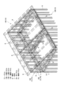
外壁パネル13Bと間仕切りパネル13Cの上には、図28に示したように小屋パネル13Dが固定される。長方形の小屋パネル13Dの軸材Sは、外壁パネル13Bの軸材Sと直線状に並べて固定される。同様に、直角三角形の小屋パネル13Dも、外壁パネル13Bや梁パネル13Fの上に対応する軸材S同士を直線状に並べて固定されるとともに、長方形の小屋パネル13Dに対しても固定される。図28中の矢印は、小屋パネル13Dの外壁パネル13Bと間仕切りパネル13Cに対する固定箇所を示している。 A hut panel 13D is fixed on the outer wall panel 13B and the partition panel 13C as shown in FIG. The shaft member S of the rectangular hut panel 13D is fixed in line with the shaft member S of the outer wall panel 13B. Similarly, the right-angled triangular hut panel 13D is also fixed to the rectangular hut panel 13D while the corresponding shaft members S are arranged in a straight line on the outer wall panel 13B and the beam panel 13F. Arrows in FIG. 28 indicate fixing points of the hut panel 13D to the outer wall panel 13B and the partition panel 13C.

このようにして小屋パネル13Dが固定されると、図29に示したように外壁パネル13Bと間仕切りパネル13Cの軸材Sの上に、小屋パネル13Dの軸材Sが直線状に並んで一体となる。この上に、仮想線で示したように屋根パネル13Eが固定される。このとき、屋根パネル13Eの軸材Sを小屋パネル13Dの軸材Sと対応させる。 When the shed panel 13D is fixed in this manner, the shaft members S of the shed panel 13D are aligned linearly on the shaft members S of the outer wall panel 13B and the partition panel 13C as shown in FIG. Become. A roof panel 13E is fixed thereon as indicated by the phantom lines. At this time, the shaft member S of the roof panel 13E is made to correspond to the shaft member S of the hut panel 13D.

図30に、小屋パネル13Dと屋根パネル13Eの接合部分を示す。小屋パネル13Dと屋根パネル13Eの軸材Sには雄型接合金物15xや雌型接合金物15yが内蔵されている。これら接合金物15は、接合対象である別の小屋パネル13Dや屋根パネル13E、外壁パネル13B、梁パネル13Fの軸材Sに内蔵された雌型接合金物15y又は雄型接合金物15xに対して締結ボルト51で結合される。 FIG. 30 shows the joint between the shed panel 13D and the roof panel 13E. A male joint metal fitting 15x and a female joint metal fitting 15y are built in the axial member S of the shed panel 13D and the roof panel 13E. These joint metal fittings 15 are fastened to female joint metal fittings 15y or male joint metal fittings 15x built in shaft members S of another shed panel 13D, roof panel 13E, outer wall panel 13B, and beam panel 13F to be joined. They are connected with bolts 51 .

屋根パネル13Eの勾配下においては、小屋パネル13Dに対して固定するのではなく、外壁パネル13Bの軸材Sに対して固定する。 Under the slope of the roof panel 13E, it is not fixed to the hut panel 13D, but fixed to the shaft member S of the outer wall panel 13B.

このようにして各パネル13が固定されて構築される木造軸組建築物11では、図1に示したように外壁パネル13Bと間仕切りパネル13Cの軸材Sは小屋パネル13Dと屋根パネル13Eの軸材Sや床パネル13Aの軸材とひとつながりになる。 In the wooden framework building 11 constructed by fixing each panel 13 in this way, as shown in FIG. It is connected with the material S and the shaft material of the floor panel 13A.

以上のように各部のパネル13同士は接合辺の軸材と枠材が互いに接合して一つの平面や立体面を構成し、雄型接合金物15xと雌型接合金物15yという一定のタイプの接合金物15で接合可能な、画一的に接合が行える構成である。このため熟練工でなくとも施工が行える。 As described above, the panels 13 of each part are connected to each other by the shaft member and the frame member on the joint side to form one plane or three-dimensional plane, and the male joint metal fitting 15x and the female joint metal fitting 15y are joints of a certain type. It is the structure which can be uniformly joined by the metal fittings 15 . Therefore, construction can be performed even by non-skilled workers.

しかも、すべてのパネル13には接合金物15が備えられているので、パネル13を組んで接合金物15による接合を行えばよく、施工は容易で施工性がよい。特に、施工時に吊り下げたりする必要のある主要なパネルに備えた接合金物15は、パネル13内に内蔵・埋設され、締結ボルト51が突出することもない。このため、パネルを用いた木造軸組建築物では、従来、枠の中にパネルを嵌め込むことが行われていたが、この発明では枠内に嵌め込むというような作業を不要にでき、単にパネルを並べるように固定することで構築できる。 Moreover, since all the panels 13 are provided with the joining metal fittings 15, it is sufficient to assemble the panels 13 and join them by the joining metal fittings 15, so that the construction is easy and has good workability. In particular, the joint metal fittings 15 provided on the main panels that need to be suspended during construction are built in and embedded in the panel 13, and the fastening bolts 51 do not protrude. For this reason, in a wooden framework building using panels, conventionally, the panels are fitted into the frame. It can be constructed by fixing the panels side by side.

そのうえ、すべてのパネル13は長方形、又はそれに準じた細長い形態であるので、横に長い幅広のパネルに比べて現場への搬入が容易であり、施工性の向上に資する。 In addition, since all the panels 13 are rectangular or elongated, they are easier to carry into the site compared to laterally long and wide panels, which contributes to the improvement of workability.

また、接合金物15はパネル13に備えられており、それを利用して接合が行われるので、接合金物15を固定する段階から行う場合に比して、接合作業が容易になるうえに、作業員によらず均質な接合も行える。 In addition, since the joining hardware 15 is provided on the panel 13 and is used for joining, the joining work is easier than in the case where the joining hardware 15 is fixed. Homogeneous joining can be achieved regardless of the member.

さらに、パネル13の軸材Sは、パネル13同士の接合によって位置規制されながら接合金物15によって接合されるので、この点からも施工にばらつきが生じにくく、木造軸組建築物11の全体がまとまりのある躯体となり、強度も得られる。 Furthermore, since the shaft member S of the panel 13 is joined by the joining hardware 15 while the position of the panel 13 is regulated by joining the panels 13 to each other, the construction is less likely to vary from this point, and the wooden framework building 11 as a whole is united. It becomes a frame with a certain strength, and strength is also obtained.

躯体のすべてがパネル13のみで構成できるので、施工の単純化と簡素化の両立がはかれる。 Since the entire building frame can be composed only of the panels 13, both simplification and simplification of construction can be achieved.

パネルの少なくとも片面に、面を塞ぐ面材が固定されると、作業性をより良くすることができる。 Workability can be further improved by fixing a face material that closes the face to at least one side of the panel.

間仕切りパネル13Cの上に梁パネル13Fを固定する構造にするとともに、間仕切りパネル13Cと梁パネル13Fを別個に設計すると、より高強度の躯体を得られる。すなわち、間仕切りパネル13Cの配置とは別に、外壁パネル13Bの内側の空間強度を持たせるように梁パネル13Fを設計すると、梁パネル13F部分を間仕切りパネル13Cと一体形成した場合に比べて、耐力を有する部分をバランスよく配置できる。 When the beam panel 13F is fixed on the partition panel 13C and the partition panel 13C and the beam panel 13F are designed separately, a higher-strength skeleton can be obtained. In other words, if the beam panel 13F is designed so as to provide the space strength inside the outer wall panel 13B, apart from the arrangement of the partition panel 13C, the yield strength is increased compared to the case where the beam panel 13F portion is integrally formed with the partition panel 13C. You can arrange the parts you have in a well-balanced manner.

加えて、木造軸組建築物11はパネル13とこれに備えた接合金物15で構成でき、しかも接合金物15は締結ボルト51によって接合する構造であるので、締結ボルト51を緩めて分離できる。すなわち、構築した木造軸組建築物11を解体することができ、移動や再構築、パネルの再利用も可能である。特に、再利用に際しては、パネルとその接合を規格化でき画一化できる構成であるので、パネルを組み替えたり、交換したりして有用な再利用を実現できる。 In addition, the wooden framework building 11 can be composed of the panels 13 and the joint metal fittings 15 provided therewith, and since the joint metal fittings 15 are joined by the fastening bolts 51, they can be separated by loosening the fastening bolts 51. That is, the constructed wooden framework building 11 can be dismantled, moved, reconstructed, and the panels reused. In particular, when reusing, since the panels and their joints can be standardized and unified, the panels can be rearranged or exchanged for useful reuse.

以上の構成はこの発明を実施するための一形態であって、この発明は前述の構成のみに限定されるものではなく、その他の構成を採用することもできる。 The above configuration is one mode for carrying out the present invention, and the present invention is not limited to the configuration described above, and other configurations can be employed.

例えば、各種のパネル13A,13B,13C,13D,13Eは3種類のパネルPa,Pb,Pcのすべてではなく、1種類又は2種類のパネルのみで構成することもできる。 For example, the various panels 13A, 13B, 13C, 13D, and 13E can be composed of only one or two types of panels, not all of the three types of panels Pa, Pb, and Pc.

11…木造軸組建築物
12…基礎
13…パネル
13A…床パネル
13B…外壁パネル
13C…間仕切りパネル
13D…小屋パネル
13E…屋根パネル
13F…梁パネル
13s…接合辺
32,39…面材
15…接合金物
15x…雄型接合金物
15y…雌型接合金物
51…締結ボルト
52…雌ねじ
S…軸材
T…枠材
Pa…軸パネル
Pb…枠パネル
Pc…軸枠パネル
DESCRIPTION OF SYMBOLS 11... Wooden framework building 12... Foundation 13... Panel 13A... Floor panel 13B... Exterior wall panel 13C... Partition panel 13D... Hut panel 13E... Roof panel 13F... Beam panel 13s... Joint side 32, 39... Face material 15... Joint Hardware 15x Male joint metal 15y Female joint 51 Fastening bolt 52 Female screw S Shaft material T Frame material Pa Shaft panel Pb Frame panel Pc Shaft frame panel

そのための手段は、木造軸組を構成する軸材と前記軸材より薄い枠材を組んでパネルを構成し、床面を構成する床パネルと、壁面を構成する外壁パネル及び間仕切りパネルと、壁面の上に小屋組を構成する小屋パネルと、屋根面を構成する屋根パネルで構成した木造である。これら各種のパネルは、それぞれ複数のパネルで構成するとともに、パネル同士の接合辺に軸材のみを有する軸パネルと、接合辺に枠材のみを有する枠パネルと、接合辺のうちの少なくとも一つに軸材を、他に枠材を有する軸枠パネルの3種類のパネルから選択して構成する。そして、床パネル、外壁パネル、間仕切りパネル、小屋パネル、屋根パネル同士の接合箇所、及びこれらパネルと他のパネルとの接合箇所に接合金物を備え、各部のパネル同士は軸材と枠材を相互に接合して固定する。接合金物のうち、外壁パネル、間仕切りパネル、小屋パネル、屋根パネルに備えられる接合金物はパネルに内蔵されるとともに、接合金物が、結合のための締結ボルトを有する雄型接合金物、又は雄型接合金物の締結ボルトが螺合される雌ねじを有する雌型接合金物である。 The means for that purpose is to construct a panel by assembling shaft members that constitute a wooden frame and a frame member that is thinner than the shaft members, a floor panel that constitutes a floor surface, an exterior wall panel and a partition panel that constitute a wall surface, and a wall surface. It is a wooden structure composed of a roof panel that forms a roof frame and a roof panel that forms a roof truss on top of the roof. These various panels are each composed of a plurality of panels, and at least one of a shaft panel having only a shaft member on the joint side of the panels, a frame panel having only a frame member on the joint side, and a joint side. First, the shaft member is selected from three types of panels, namely, a shaft frame panel having a frame member. Joining metal fittings are provided at joints between floor panels, exterior wall panels, partition panels, shed panels, and roof panels, and joints between these panels and other panels, and each panel is made of shafts and frames. and fix it. Among the joint metal fittings, the joint metal fittings provided in the exterior wall panel, the partition panel, the shed panel, and the roof panel are built into the panel, and the joint metal fittings are male joint metal fittings having fastening bolts for coupling, or male joint metal fittings. It is a female joint metal fitting having a female thread into which a fastening bolt of the metal fitting is screwed.

Claims (7)

パネルを用いた木造軸組建築物であって、
前記パネルが木造軸組を構成する軸材と前記軸材より薄い枠材を組んで構成され、
前記パネルのうち床面を構成する床パネルと、壁面を構成する外壁パネル及び間仕切りパネルと、前記壁面の上に小屋組を構成する小屋パネルと、屋根面を構成する屋根パネルが複数のパネルで構成されるとともに、パネル同士の接合辺に前記軸材のみを有する軸パネルと、前記接合辺に前記枠材のみを有する枠パネルと、前記接合辺のうちの少なくとも一つに前記軸材を、他に前記枠材を有する軸枠パネルの3種類のパネルから選択して構成され、
前記床パネル、前記外壁パネル、前記間仕切りパネル、前記小屋パネル、前記屋根パネル同士の接合箇所、及びこれらパネルと他のパネルとの接合箇所に接合金物が備えられ、
前記外壁パネルが基礎の上に建てられるとともに、隣接する前記外壁パネル同士がそれらの前記軸材と前記枠材を相互に接合して固定され、
前記外壁パネルで囲まれる内側に前記床パネルが設置されるとともに、隣接する前記床パネル同士がそれらの前記軸材と前記枠材を相互に接合して固定され、
前記床パネルの上に前記間仕切りパネルが建てられるとともに、隣接する前記間仕切りパネル同士及び前記間仕切りパネルに隣接する前記外壁パネルがそれらの前記軸材と前記枠材を相互に接合して固定され、
前記外壁パネル及び前記間仕切りパネルの上に前記小屋パネルが建てられるとともに、隣接する小屋パネル同士がそれらの前記軸材と前記枠材を相互に接合して固定され、
前記小屋パネルの上に前記屋根パネルが設置されるとともに、隣接する屋根パネル同士がそれらの前記軸材と前記枠材を相互に接合して固定された
木造軸組建築物。
A wooden framework building using panels,
The panel is configured by combining a shaft member that constitutes a wooden framework and a frame member that is thinner than the shaft member,
Among the panels, a floor panel constituting a floor surface, an outer wall panel and a partition panel constituting a wall surface, a shed panel constituting a roof truss on the wall surface, and a roof panel constituting a roof surface are composed of a plurality of panels. A shaft panel having only the shaft member on the joint side between the panels, a frame panel having only the frame member at the joint side, and the shaft member on at least one of the joint sides, In addition, it is configured by selecting from three types of panels of the shaft frame panel having the frame material,
Joining hardware is provided at joints between the floor panel, the outer wall panel, the partition panel, the shed panel, and the roof panels, and at the joints between these panels and other panels,
The exterior wall panels are erected on a foundation and the adjacent exterior wall panels are fixed by mutually joining the shaft members and the frame members,
The floor panel is installed on the inside surrounded by the outer wall panel, and the adjacent floor panels are fixed by joining the shaft member and the frame member to each other,
The partition panel is erected on the floor panel, and the adjacent partition panels and the outer wall panel adjacent to the partition panel are fixed by joining the shaft member and the frame member to each other,
The shed panel is built on the outer wall panel and the partition panel, and the adjacent shed panels are fixed by joining the shaft member and the frame member to each other,
A wooden framework building in which the roof panel is installed on the hut panel, and the adjacent roof panels are fixed by joining the shaft member and the frame member to each other.
躯体が前記パネルで構成された
請求項1に記載の木造軸組建築物。
2. The wooden framework building according to claim 1, wherein the framework is composed of the panels.
前記接合金物のうち、前記外壁パネル、前記間仕切りパネル、前記小屋パネル、前記屋根パネルに備えられる前記接合金物は前記パネルに内蔵されるとともに、
前記接合金物が、結合のための締結ボルトを有する雄型接合金物、又は前記雄型接合金物の前記締結ボルトが螺合される雌ねじを有する雌型接合金物である
請求項1または請求項2に記載の木造軸組建築物。
Among the joint metal fittings, the joint metal fittings provided in the outer wall panel, the partition panel, the shed panel, and the roof panel are incorporated in the panel,
3. The joint metal fitting is a male joint metal fitting having a fastening bolt for coupling, or a female joint fitting having a female thread into which the fastening bolt of the male joint fitting is screwed. A wooden frame building as described.
前記雄型接合金物の前記締結ボルトが、前記パネル内に収まるものである
請求項3に記載の木造軸組建築物。
4. The wooden framework building according to claim 3, wherein said fastening bolts of said male joint hardware are accommodated within said panels.
前記パネルの少なくとも片面に、面を塞ぐ面材が固定された
請求項1から請求項4のうちいずれか一項に記載の木造軸組建築物。
5. The wooden framework building according to any one of claims 1 to 4, wherein at least one surface of said panel is fixed with a face member covering the surface.
木造軸組を構成する軸材を用いて構成され、上下に間隔をあけて並設された前記軸材を有するとともに、前記軸材で囲まれた空間に面材が固定された梁パネルが備えられ、
前記間仕切りパネルの上に前記梁パネルが固定されるとともに、
前記梁パネルの上下に並ぶ前記軸材の両端部が、隣接する前記パネルの前記軸材に接合された
請求項1から請求項5のうちいずれか一項に記載の木造軸組建築物。
A beam panel is provided, which is constructed using shaft members that constitute a wooden frame, has the shaft members arranged side by side with a gap in the vertical direction, and has a face material fixed in a space surrounded by the shaft members. be
The beam panel is fixed on the partition panel, and
The wooden framework building according to any one of claims 1 to 5, wherein both ends of the shaft members arranged above and below the beam panel are joined to the shaft members of the adjacent panels.
請求項1から請求項6のうちいずれか一項に記載の木造軸組建築物に用いられる
パネル。
A panel for use in a wooden frame building according to any one of claims 1 to 6.
JP2021139704A 2021-08-30 2021-08-30 Wooden frame building Active JP7005070B1 (en)

Priority Applications (1)

Application Number Priority Date Filing Date Title
JP2021139704A JP7005070B1 (en) 2021-08-30 2021-08-30 Wooden frame building

Applications Claiming Priority (1)

Application Number Priority Date Filing Date Title
JP2021139704A JP7005070B1 (en) 2021-08-30 2021-08-30 Wooden frame building

Publications (2)

Publication Number Publication Date
JP7005070B1 JP7005070B1 (en) 2022-02-14
JP2023033796A true JP2023033796A (en) 2023-03-13

Family

ID=80912336

Family Applications (1)

Application Number Title Priority Date Filing Date
JP2021139704A Active JP7005070B1 (en) 2021-08-30 2021-08-30 Wooden frame building

Country Status (1)

Country Link
JP (1) JP7005070B1 (en)

Families Citing this family (1)

* Cited by examiner, † Cited by third party
Publication number Priority date Publication date Assignee Title
JP7385326B1 (en) * 2023-06-08 2023-11-22 株式会社アクト Conventional framework construction method and shaft construction panels used therein

Family Cites Families (3)

* Cited by examiner, † Cited by third party
Publication number Priority date Publication date Assignee Title
JP2001049674A (en) * 1999-08-09 2001-02-20 Misawa Homes Co Ltd Anchor bolt
JP2003090080A (en) * 2001-09-18 2003-03-28 Akuto:Kk Framework panel and building using this panel
JP6687681B2 (en) * 2018-07-10 2020-04-28 クリ英ター永和株式会社 Wooden unit type building structure and its construction method

Also Published As

Publication number Publication date
JP7005070B1 (en) 2022-02-14

Similar Documents

Publication Publication Date Title
JP4858921B2 (en) Attached structures and unit buildings
JP2023033796A (en) Wooden framework building
US6076311A (en) Floor frame assembly for a manufactured home
JP7385326B1 (en) Conventional framework construction method and shaft construction panels used therein
JP5123602B2 (en) Unit type building and construction method of unit type building
JPH07180221A (en) Construction method for unit building
JP2010126896A (en) Unit building
JPH06346515A (en) Unit building
JP6860354B2 (en) Building structure
JP4660009B2 (en) Building structure
JP6994281B1 (en) Shafted panel members, wall panels and beam structures
JP3596455B2 (en) Connection structure between composite beams and wooden columns
JP2007146404A (en) Connecting mechanism of container house
WO2022029989A1 (en) Building and method for constructing building
JP7005066B1 (en) Roof structure
JP5000881B2 (en) Unit type building and construction method of the unit type building
JP2001262701A (en) Junction hardware, and wooden framework
JP2008266961A (en) Unit building
JP3359417B2 (en) Building unit, unit building and construction method of unit building
JPH08199689A (en) Reinforced construction of unit box frame
JPH0921178A (en) Joining structure between post and beam
JP3538151B2 (en) Frame structure, frame structure
JP3152066B2 (en) Joint structure between columns and horizontal members
JP2024035048A (en) building
JPH0688381A (en) Structural unit body for unit house

Legal Events

Date Code Title Description
A621 Written request for application examination

Free format text: JAPANESE INTERMEDIATE CODE: A621

Effective date: 20210830

A871 Explanation of circumstances concerning accelerated examination

Free format text: JAPANESE INTERMEDIATE CODE: A871

Effective date: 20210831

A521 Request for written amendment filed

Free format text: JAPANESE INTERMEDIATE CODE: A523

Effective date: 20210902

A131 Notification of reasons for refusal

Free format text: JAPANESE INTERMEDIATE CODE: A131

Effective date: 20211109

A521 Request for written amendment filed

Free format text: JAPANESE INTERMEDIATE CODE: A523

Effective date: 20211206

TRDD Decision of grant or rejection written
A01 Written decision to grant a patent or to grant a registration (utility model)

Free format text: JAPANESE INTERMEDIATE CODE: A01

Effective date: 20211221

A61 First payment of annual fees (during grant procedure)

Free format text: JAPANESE INTERMEDIATE CODE: A61

Effective date: 20211223

R150 Certificate of patent or registration of utility model

Ref document number: 7005070

Country of ref document: JP

Free format text: JAPANESE INTERMEDIATE CODE: R150