JP2023021252A - game machine - Google Patents
game machine Download PDFInfo
- Publication number
- JP2023021252A JP2023021252A JP2022196122A JP2022196122A JP2023021252A JP 2023021252 A JP2023021252 A JP 2023021252A JP 2022196122 A JP2022196122 A JP 2022196122A JP 2022196122 A JP2022196122 A JP 2022196122A JP 2023021252 A JP2023021252 A JP 2023021252A
- Authority
- JP
- Japan
- Prior art keywords
- slide
- base
- displacement
- display
- unit
- Prior art date
- Legal status (The legal status is an assumption and is not a legal conclusion. Google has not performed a legal analysis and makes no representation as to the accuracy of the status listed.)
- Pending
Links
- 230000000694 effects Effects 0.000 claims description 1850
- 238000003860 storage Methods 0.000 claims description 260
- 238000004519 manufacturing process Methods 0.000 claims description 113
- 238000000034 method Methods 0.000 description 1161
- 230000008569 process Effects 0.000 description 1141
- 238000012545 processing Methods 0.000 description 689
- 238000006073 displacement reaction Methods 0.000 description 575
- 238000003825 pressing Methods 0.000 description 454
- 238000012546 transfer Methods 0.000 description 377
- 230000005540 biological transmission Effects 0.000 description 351
- 230000000875 corresponding effect Effects 0.000 description 339
- 239000000872 buffer Substances 0.000 description 331
- 238000010586 diagram Methods 0.000 description 211
- 230000033001 locomotion Effects 0.000 description 114
- 230000008859 change Effects 0.000 description 111
- 230000007704 transition Effects 0.000 description 97
- 238000013461 design Methods 0.000 description 84
- 230000003028 elevating effect Effects 0.000 description 77
- 230000001965 increasing effect Effects 0.000 description 76
- 230000002829 reductive effect Effects 0.000 description 72
- 238000009877 rendering Methods 0.000 description 65
- 230000009471 action Effects 0.000 description 50
- 150000001875 compounds Chemical class 0.000 description 48
- 230000006870 function Effects 0.000 description 41
- 230000036544 posture Effects 0.000 description 37
- 238000001514 detection method Methods 0.000 description 29
- 230000005484 gravity Effects 0.000 description 29
- 230000004048 modification Effects 0.000 description 29
- 238000012986 modification Methods 0.000 description 29
- 239000002131 composite material Substances 0.000 description 28
- 230000002093 peripheral effect Effects 0.000 description 25
- 230000006378 damage Effects 0.000 description 23
- 230000007246 mechanism Effects 0.000 description 22
- 238000012790 confirmation Methods 0.000 description 20
- 230000005856 abnormality Effects 0.000 description 19
- 230000007423 decrease Effects 0.000 description 19
- 210000003128 head Anatomy 0.000 description 18
- 238000012544 monitoring process Methods 0.000 description 18
- 238000011161 development Methods 0.000 description 17
- 241000283973 Oryctolagus cuniculus Species 0.000 description 15
- 238000003780 insertion Methods 0.000 description 13
- 230000037431 insertion Effects 0.000 description 13
- 230000008901 benefit Effects 0.000 description 12
- 239000004973 liquid crystal related substance Substances 0.000 description 12
- 230000036961 partial effect Effects 0.000 description 12
- 238000011084 recovery Methods 0.000 description 10
- 230000009467 reduction Effects 0.000 description 10
- 230000003247 decreasing effect Effects 0.000 description 9
- 238000009826 distribution Methods 0.000 description 9
- 238000010304 firing Methods 0.000 description 9
- 230000001276 controlling effect Effects 0.000 description 8
- 239000002184 metal Substances 0.000 description 8
- 238000002156 mixing Methods 0.000 description 8
- 230000000149 penetrating effect Effects 0.000 description 8
- 230000004044 response Effects 0.000 description 8
- 230000002730 additional effect Effects 0.000 description 7
- 238000005034 decoration Methods 0.000 description 7
- 230000009291 secondary effect Effects 0.000 description 7
- 241000270708 Testudinidae Species 0.000 description 6
- 230000002708 enhancing effect Effects 0.000 description 6
- 230000007935 neutral effect Effects 0.000 description 6
- 230000000717 retained effect Effects 0.000 description 6
- 238000007789 sealing Methods 0.000 description 6
- 230000000737 periodic effect Effects 0.000 description 5
- 238000002360 preparation method Methods 0.000 description 5
- 238000004904 shortening Methods 0.000 description 5
- 241001596784 Pegasus Species 0.000 description 4
- 241000270666 Testudines Species 0.000 description 4
- 230000001174 ascending effect Effects 0.000 description 4
- 238000005452 bending Methods 0.000 description 4
- 239000000284 extract Substances 0.000 description 4
- 230000004043 responsiveness Effects 0.000 description 4
- 230000015572 biosynthetic process Effects 0.000 description 3
- 230000004397 blinking Effects 0.000 description 3
- 238000004364 calculation method Methods 0.000 description 3
- 239000003086 colorant Substances 0.000 description 3
- 238000012937 correction Methods 0.000 description 3
- 230000001186 cumulative effect Effects 0.000 description 3
- 230000002950 deficient Effects 0.000 description 3
- 230000006866 deterioration Effects 0.000 description 3
- 239000011521 glass Substances 0.000 description 3
- 238000009434 installation Methods 0.000 description 3
- 239000000463 material Substances 0.000 description 3
- 239000000725 suspension Substances 0.000 description 3
- 230000001360 synchronised effect Effects 0.000 description 3
- 206010048909 Boredom Diseases 0.000 description 2
- 230000003213 activating effect Effects 0.000 description 2
- 230000004913 activation Effects 0.000 description 2
- 230000000903 blocking effect Effects 0.000 description 2
- 239000003990 capacitor Substances 0.000 description 2
- 230000002844 continuous effect Effects 0.000 description 2
- 230000003111 delayed effect Effects 0.000 description 2
- 238000005286 illumination Methods 0.000 description 2
- 230000001771 impaired effect Effects 0.000 description 2
- 230000005764 inhibitory process Effects 0.000 description 2
- 230000010354 integration Effects 0.000 description 2
- 230000002452 interceptive effect Effects 0.000 description 2
- 238000005304 joining Methods 0.000 description 2
- 238000007726 management method Methods 0.000 description 2
- 230000001151 other effect Effects 0.000 description 2
- 239000011347 resin Substances 0.000 description 2
- 229920005989 resin Polymers 0.000 description 2
- 230000002441 reversible effect Effects 0.000 description 2
- 238000010079 rubber tapping Methods 0.000 description 2
- 239000000126 substance Substances 0.000 description 2
- 230000008961 swelling Effects 0.000 description 2
- 230000001052 transient effect Effects 0.000 description 2
- 230000001960 triggered effect Effects 0.000 description 2
- KNMAVSAGTYIFJF-UHFFFAOYSA-N 1-[2-[(2-hydroxy-3-phenoxypropyl)amino]ethylamino]-3-phenoxypropan-2-ol;dihydrochloride Chemical compound Cl.Cl.C=1C=CC=CC=1OCC(O)CNCCNCC(O)COC1=CC=CC=C1 KNMAVSAGTYIFJF-UHFFFAOYSA-N 0.000 description 1
- VYZAMTAEIAYCRO-UHFFFAOYSA-N Chromium Chemical compound [Cr] VYZAMTAEIAYCRO-UHFFFAOYSA-N 0.000 description 1
- JOYRKODLDBILNP-UHFFFAOYSA-N Ethyl urethane Chemical compound CCOC(N)=O JOYRKODLDBILNP-UHFFFAOYSA-N 0.000 description 1
- 241001465754 Metazoa Species 0.000 description 1
- 235000010842 Sarcandra glabra Nutrition 0.000 description 1
- 240000004274 Sarcandra glabra Species 0.000 description 1
- 230000001133 acceleration Effects 0.000 description 1
- 229920000122 acrylonitrile butadiene styrene Polymers 0.000 description 1
- 238000013459 approach Methods 0.000 description 1
- 230000002238 attenuated effect Effects 0.000 description 1
- 230000006399 behavior Effects 0.000 description 1
- 238000007664 blowing Methods 0.000 description 1
- 230000000295 complement effect Effects 0.000 description 1
- 238000007596 consolidation process Methods 0.000 description 1
- 230000008602 contraction Effects 0.000 description 1
- 238000007796 conventional method Methods 0.000 description 1
- 125000004122 cyclic group Chemical group 0.000 description 1
- 230000007547 defect Effects 0.000 description 1
- 230000000593 degrading effect Effects 0.000 description 1
- 238000007599 discharging Methods 0.000 description 1
- 230000005489 elastic deformation Effects 0.000 description 1
- 239000013013 elastic material Substances 0.000 description 1
- 238000005265 energy consumption Methods 0.000 description 1
- 230000005284 excitation Effects 0.000 description 1
- 230000003631 expected effect Effects 0.000 description 1
- 238000000605 extraction Methods 0.000 description 1
- 238000001914 filtration Methods 0.000 description 1
- 239000005357 flat glass Substances 0.000 description 1
- 230000006872 improvement Effects 0.000 description 1
- 230000009191 jumping Effects 0.000 description 1
- 238000011068 loading method Methods 0.000 description 1
- 230000007257 malfunction Effects 0.000 description 1
- 239000007769 metal material Substances 0.000 description 1
- 230000002265 prevention Effects 0.000 description 1
- 230000001681 protective effect Effects 0.000 description 1
- 230000008439 repair process Effects 0.000 description 1
- 230000000452 restraining effect Effects 0.000 description 1
- 230000035945 sensitivity Effects 0.000 description 1
- 239000000758 substrate Substances 0.000 description 1
- 238000010408 sweeping Methods 0.000 description 1
- 230000002195 synergetic effect Effects 0.000 description 1
- 230000002194 synthesizing effect Effects 0.000 description 1
- 238000013519 translation Methods 0.000 description 1
- 230000003313 weakening effect Effects 0.000 description 1
- 238000004804 winding Methods 0.000 description 1
- 239000002023 wood Substances 0.000 description 1
Images


Classifications
-
- Y—GENERAL TAGGING OF NEW TECHNOLOGICAL DEVELOPMENTS; GENERAL TAGGING OF CROSS-SECTIONAL TECHNOLOGIES SPANNING OVER SEVERAL SECTIONS OF THE IPC; TECHNICAL SUBJECTS COVERED BY FORMER USPC CROSS-REFERENCE ART COLLECTIONS [XRACs] AND DIGESTS
- Y02—TECHNOLOGIES OR APPLICATIONS FOR MITIGATION OR ADAPTATION AGAINST CLIMATE CHANGE
- Y02E—REDUCTION OF GREENHOUSE GAS [GHG] EMISSIONS, RELATED TO ENERGY GENERATION, TRANSMISSION OR DISTRIBUTION
- Y02E60/00—Enabling technologies; Technologies with a potential or indirect contribution to GHG emissions mitigation
- Y02E60/10—Energy storage using batteries
Landscapes
- Display Devices Of Pinball Game Machines (AREA)
Abstract
Description
本発明は、パチンコ機などの遊技機に関するものである。 The present invention relates to gaming machines such as pachinko machines.
パチンコ機等の遊技機において、表示装置に表示される演出態様として複数の演出モードを設定可能にし、特定の演出モードが設定されている場合に遊技者に所定の得点を付与し、付与された得点の累積値に基づいた演出が実行される遊技機が知られている(特許文献1)。 In a game machine such as a pachinko machine, a plurality of performance modes can be set as a performance mode displayed on a display device, and when a specific performance mode is set, a predetermined score is given to a player and given. A game machine is known in which an effect based on an accumulated score is executed (Patent Document 1).
しかしながら、上述したパチンコ機において、更なる興趣の向上が求められていた。 However, in the pachinko machine described above, there has been a demand for further enhancement of interest.
本発明は、上記例示した問題点等を解決するためになされたものであり、遊技の興趣を向上することを目的とする。 SUMMARY OF THE INVENTION The present invention has been made to solve the problems exemplified above, and an object of the present invention is to improve the enjoyment of games.
この目的を達成するために請求項1記載の遊技機は、複数の演出態様のうち何れかの演出態様を設定可能な演出態様設定手段と、その演出態様設定手段により設定された前記演出態様を表示可能な表示手段と、その表示手段に複数段階の段階情報を表示する段階情報表示手段と、その段階情報表示手段によって表示される前記段階情報を可変させる段階情報可変手段と、その段階情報可変手段により前記段階情報が所定の段階情報へと可変された場合に特定の演出を実行する特定演出実行手段と、前記段階情報表示手段により表示される段階情報の表示態様を、前記演出態様設定手段により設定される前記演出態様に対応した表示態様に切り替える切替手段と、を有するものである。
In order to achieve this object, the game machine according to
請求項2記載の遊技機は、請求項1記載の遊技機において、前記段階情報表示手段により表示される前記段階情報を記憶する段階情報記憶手段を有し、前記段階情報表示手段は、前記切替手段により前記表示態様が切り替えられた場合に、前記段階情報記憶手段に記憶された前記段階情報に基づいて、前記段階情報を表示するものである。
A gaming machine according to
請求項3記載の遊技機は、請求項2記載の遊技機において、前記段階情報記憶手段は、少なくとも前記所定の段階情報を記憶するものである。
A gaming machine according to
請求項4記載の遊技機は、請求項2または3記載の遊技機において、前記段階情報記憶手段は、少なくとも前記所定の段階情報に近似する近似段階情報を記憶するものである。
A gaming machine according to
請求項5記載の遊技機は、請求項1から4のいずれかに記載の遊技機において、前記演出態様設定手段は、前記段階情報表示手段により特定の前記段階情報が表示された場合に、特定の前記演出態様を設定する特定演出態様設定手段を有するものである。
5. The gaming machine according to
請求項1記載の遊技機によれば、演出態様設定手段により複数の演出態様のうち何れかの演出態様が設定され、その設定された演出態様が表示手段に表示される。その表示手段には段階情報表示手段により複数段階の段階情報が段階情報可変手段により可変可能に表示され、その段階情報が所定の段階情報へと可変された場合に特定演出実行手段により特定の演出が実行される。そして、段階情報表示手段により表示される段階情報の表示態様が、演出態様設定手段により設定される演出態様に対応した表示態様に切替手段により切り替えられる。
According to the gaming machine of
これにより、異なる演出態様が設定されたとしても、段階情報を現在設定されている演出態様に対応した表示態様で表示することできる。よって、遊技者が遊技に早期に飽きてしまうことを抑制し、遊技の興趣を向上することができるという効果がある。 Thereby, even if a different presentation mode is set, the stage information can be displayed in a display mode corresponding to the presently set presentation mode. Therefore, there is an effect that it is possible to prevent the player from getting tired of the game early, and to improve the interest of the game.
請求項2記載の遊技機によれば、請求項1記載の遊技機の奏する効果に加え、次の効果を奏する。即ち、段階情報表示手段により表示される段階情報が段階情報記憶手段により記憶される。そして、切替手段により表示態様が切り替えられた場合に、段階情報記憶手段に記憶された段階情報に基づいて、段階情報表示手段により段階情報が表示される。
According to the gaming machine of
これにより、切替手段により表示態様が切り替わった場合であっても、段階情報記憶手段に記憶されている段階情報に基づいた段階情報を表示することが可能となる。よって、遊技者が遊技に早期に飽きてしまうことを抑制することができるという効果がある。 Thereby, even when the display mode is switched by the switching means, it is possible to display the step information based on the step information stored in the step information storage means. Therefore, there is an effect that it is possible to prevent the player from becoming bored with the game early.
請求項3記載の遊技機によれば、請求項2記載の遊技機の奏する効果に加え、次の効果を奏する。即ち、少なくとも所定の段階情報が段階情報記憶手段により記憶される。
According to the gaming machine of
これにより、所定の段階情報が表示されている状態において異なる演出態様が設定され、表示態様が切り替わったとしても、切り替わった後の表示態様において所定の段階情報を表示することが可能となる。よって、遊技者に分かりやすい演出を提供することができるという効果がある。 Thus, even if a different presentation mode is set in a state where the predetermined step information is displayed and the display mode is switched, the predetermined step information can be displayed in the display mode after the switching. Therefore, there is an effect that it is possible to provide an effect that is easy for the player to understand.
請求項4記載の遊技機によれば、請求項2または3記載の遊技機の奏する効果に加え、次の効果を奏する。即ち、少なくとも所定の段階情報に近似する近似段階情報が段階情報記憶手段により記憶される。
According to the gaming machine of
これにより、近似段階情報が表示されている状態において異なる演出態様が設定され、表示態様が切り替わったとしても、切り替わった後の表示態様において近似段階情報を表示することが可能となる。よって、遊技者の遊技意欲が低下してしまうことを抑制することができるという効果がある。 Thus, even if a different presentation mode is set while the approximation level information is being displayed and the display mode is switched, the approximation level information can be displayed in the display mode after the switching. Therefore, there is an effect that it is possible to suppress the player's desire to play.
請求項5記載の遊技機によれば、請求項1から4のいずれかに記載の遊技機の奏する効果に加え、次の効果を奏する。即ち、段階情報表示手段により特定の段階情報が表示された場合に、特定演出態様設定手段により特定の演出態様が設定される。
According to the gaming machine according to
これにより、表示される段階情報によって演出態様を切り替えることが可能となるため、段階情報を表示する演出の演出効果を高めることができるという効果がある。 As a result, it is possible to switch the presentation mode according to the stage information to be displayed, so that there is an effect that the presentation effect of displaying the stage information can be enhanced.
以下、本発明の実施形態について、添付図面を参照して説明する。まず、図1から図42を参照し、第1実施形態として、本発明をパチンコ遊技機(以下、単に「パチンコ機」という)1に適用した場合の一実施形態について説明する。図1は、第1実施形態におけるパチンコ機1の正面図であり、図2はパチンコ機1の遊技盤13の正面図であり、図3はパチンコ機1の背面図である。
BEST MODE FOR CARRYING OUT THE INVENTION Hereinafter, embodiments of the present invention will be described with reference to the accompanying drawings. First, referring to FIGS. 1 to 42, as a first embodiment, an embodiment in which the present invention is applied to a pachinko game machine (hereinafter simply referred to as "pachinko machine") 1 will be described. FIG. 1 is a front view of a
図1に示すように、パチンコ機1は、略矩形状に組み合わせた木枠により外殻が形成される外枠2と、その外枠2と略同一の外形形状に形成され外枠2に対して開閉可能に支持された内枠4とを備えている。外枠2には、内枠4を支持するために正面視(図1参照)左側の上下2カ所に金属製のヒンジ18が取り付けられ、そのヒンジ18が設けられた側を開閉の軸として内枠4が正面手前側へ開閉可能に支持されている。
As shown in FIG. 1, the
内枠4には、多数の釘や入賞口63,64等を有する遊技盤13(図2参照)が裏面側から着脱可能に装着される。この遊技盤13の前面を球(遊技球)が流下することにより弾球遊技が行われる。なお、内枠4には、球を遊技盤13の前面領域に発射する球発射ユニット112a(図4参照)やその球発射ユニット112aから発射された球を遊技盤13の前面領域まで誘導する発射レール(図示せず)等が取り付けられている。
A game board 13 (see FIG. 2) having a large number of nails, winning
内枠4の前面側には、その前面上側を覆う前扉5と、その下側を覆う下皿ユニット15とが設けられている。前扉5および下皿ユニット15を支持するために正面視(図1参照)左側の上下2カ所に金属製のヒンジ19が取り付けられ、そのヒンジ19が設けられた側を開閉の軸として前扉5および下皿ユニット15が正面手前側へ開閉可能に支持されている。なお、内枠4の施錠と前扉5の施錠とは、シリンダ錠20の鍵穴21に専用の鍵を差し込んで所定の操作を行うことでそれぞれ解除される。
On the front side of the
前扉5は、装飾用の樹脂部品や電気部品等を組み付けたものであり、その略中央部には略楕円形状に開口形成された窓部5cが設けられている。前扉5の裏面側には2枚の板ガラス8を有するガラスユニット16が配設され、そのガラスユニット16を介して遊技盤13の前面がパチンコ機1の正面側に視認可能となっている。
The
前扉5には、球を貯留する上皿17が前方へ張り出して上面を開放した略箱状に形成されており、この上皿17に賞球や貸出球などが排出される。上皿17の底面は正面視(図1参照)右側に下降傾斜して形成され、その傾斜により上皿17に投入された球が球発射ユニット112a(図4参照)へと案内される。また、上皿17の上面には、枠ボタン22が設けられている。この枠ボタン22は、例えば、第3図柄表示装置81(図2参照)で表示される演出のステージを変更したり、スーパーリーチの演出内容を変更したりする場合などに、遊技者により操作される。
An
前扉5には、その周囲(例えばコーナー部分)に各種ランプ等の発光手段が設けられている。これら発光手段は、大当たり時や所定のリーチ時等における遊技状態の変化に応じて、点灯又は点滅することにより発光態様が変更制御され、遊技中の演出効果を高める役割を果たす。窓部5cの周縁には、LED等の発光手段を内蔵した電飾部29~33が設けられている。パチンコ機1においては、これら電飾部29~33が大当たりランプ等の演出ランプとして機能し、大当たり時やリーチ演出時等には内蔵するLEDの点灯や点滅によって各電飾部29~33が点灯または点滅して、大当たり中である旨、或いは大当たり一歩手前のリーチ中である旨が報知される。また、前扉5の正面視(図1参照)左上部には、LED等の発光手段が内蔵され賞球の払い出し中とエラー発生時とを表示可能な表示ランプ34が設けられている。
Light-emitting means such as various lamps are provided around the front door 5 (for example, at corners). These light emitting means are controlled to change the light emitting mode by lighting or blinking in response to changes in the game state such as when a big win is made or when a predetermined ready-to-win state is reached, and play a role of enhancing the effect during the game.
また、右側の電飾部32下側には、前扉5の裏面側を視認できるように裏面側より透明樹脂を取り付けて小窓35が形成され、遊技盤13前面の貼着スペースK1(図2参照)に貼付される証紙等がパチンコ機1の前面から視認可能とされている。また、パチンコ機1においては、より煌びやかさを醸し出すために、電飾部29~33の周りの領域にクロムメッキを施したABS樹脂製のメッキ部材36が取り付けられている。
In addition, a
窓部5cの下方には、貸球操作部40が配設されている。貸球操作部40には、度数表示部41と、球貸しボタン42と、返却ボタン43とが設けられている。パチンコ機1の側方に配置されるカードユニット(球貸しユニット)(図示せず)に紙幣やカード等を投入した状態で貸球操作部40が操作されると、その操作に応じて球の貸出が行われる。具体的には、度数表示部41はカード等の残額情報が表示される領域であり、内蔵されたLEDが点灯して残額情報として残額が数字で表示される。球貸しボタン42は、カード等(記録媒体)に記録された情報に基づいて貸出球を得るために操作されるものであり、カード等に残額が存在する限りにおいて貸出球が上皿17に供給される。返却ボタン43は、カードユニットに挿入されたカード等の返却を求める際に操作される。なお、カードユニットを介さずに球貸し装置等から上皿17に球が直接貸し出されるパチンコ機、いわゆる現金機では貸球操作部40が不要となるが、この場合には、貸球操作部40の設置部分に飾りシール等を付加して部品構成は共通のものとしても良い。カードユニットを用いたパチンコ機と現金機との共通化を図ることができる。
A ball
上皿17の下側に位置する下皿ユニット15には、その中央部に上皿17に貯留しきれなかった球を貯留するための下皿50が上面を開放した略箱状に形成されている。下皿50の右側には、球を遊技盤13の前面へ打ち込むために遊技者によって操作される操作ハンドル51が配設される。
In the
操作ハンドル51の内部には、球発射ユニット112aの駆動を許可するためのタッチセンサ51aと、押下操作している期間中には球の発射を停止する発射停止スイッチ51bと、操作ハンドル51の回動操作量(回動位置)を電気抵抗の変化により検出する可変抵抗器(図示せず)などが内蔵されている。操作ハンドル51が遊技者によって右回りに回動操作されると、タッチセンサ51aがオンされると共に可変抵抗器の抵抗値が回動操作量に対応して変化し、その可変抵抗器の抵抗値に対応した強さ(発射強度)で球が発射され、これにより遊技者の操作に対応した飛び量で遊技盤13の前面へ球が打ち込まれる。また、操作ハンドル51が遊技者により操作されていない状態においては、タッチセンサ51aおよび発射停止スイッチ51bがオフとなっている。
Inside the operating
下皿50の正面下方部には、下皿50に貯留された球を下方へ排出する際に操作するための球抜きレバー52が設けられている。この球抜きレバー52は、常時、右方向に付勢されており、その付勢に抗して左方向へスライドさせることにより、下皿50の底面に形成された底面口が開口して、その底面口から球が自然落下して排出される。この球抜きレバー52の操作は、通常、下皿50の下方に下皿50から排出された球を受け取る箱(一般に「千両箱」と称される)を置いた状態で行われる。下皿50の右方には、上述したように操作ハンドル51が配設され、下皿50の左方には灰皿53が取り付けられている。
A
図2に示すように、遊技盤13は、正面視略正方形状に切削加工したベース板60に、球案内用の多数の釘(図示せず)や風車の他、レール76,77、一般入賞口63、第1入賞口64、第2入賞口140、可変入賞装置65、第1スルーゲート66、可変表示装置ユニット80等を組み付けて構成され、その周縁部が内枠4(図1参照)の裏面側に取り付けられる。ベース板60は薄い板材を張り合わせた木材からなり、その正面側からベース板60の背面側に配設された各種構造体を遊技者に目視できないように形成される。一般入賞口63、第1入賞口64、第2入賞口140、可変入賞装置65、可変表示装置ユニット80は、ルータ加工によってベース板60に形成された貫通穴に配設され、遊技盤13の前面側からタッピングネジ等により固定されている。
As shown in FIG. 2, the
遊技盤13の前面中央部分は、前扉5の窓部5c(図1参照)を通じて内枠4の前面側から視認することができる。以下に、主に図2を参照して、遊技盤13の構成について説明する。
The central portion of the front surface of the
遊技盤13の前面には、帯状の金属板を略円弧状に屈曲加工して形成した外レール77が植立され、その外レール77の内側位置には外レール77と同様に帯状の金属板で形成した円弧状の内レール76が植立される。この内レール76と外レール77とにより遊技盤13の前面外周が囲まれ、遊技盤13とガラスユニット16(図1参照)とにより前後が囲まれることにより、遊技盤13の前面には、球の挙動により遊技が行われる遊技領域が形成される。遊技領域は、遊技盤13の前面であって2本のレール76,77とレール間を繋ぐ樹脂製の外縁部材73とにより区画して形成される領域(入賞口等が配設され、発射された球が流下する領域)である。
An
2本のレール76,77は、球発射ユニット112a(図4参照)から発射された球を遊技盤13上部へ案内するために設けられたものである。内レール76の先端部分(図2の左上部)には戻り球防止部材68が取り付けられ、一旦、遊技盤13の上部へ案内された球が再度球案内通路内に戻ってしまうといった事態が防止される。外レール77の先端部(図2の右上部)には、球の最大飛翔部分に対応する位置に返しゴム69が取り付けられ、所定以上の勢いで発射された球は、返しゴム69に当たって、勢いが減衰されつつ中央部側へ跳ね返される。
The two
遊技領域の正面視左側下部(図2の左側下部)には、発光手段である複数のLEDおよび7セグメント表示器を備える第1図柄表示装置37A,37Bが配設されている。第1図柄表示装置37A,37Bは、主制御装置110(図4参照)で行われる各制御に応じた表示がなされるものであり、主にパチンコ機1の遊技状態の表示が行われる。本実施形態では、第1図柄表示装置37A,37Bは、球が、第1入賞口64へ入賞したか、第2入賞口140へ入賞したかに応じて使い分けられるように構成されている。具体的には、球が、第1入賞口64へ入賞した場合には、第1図柄表示装置37Aが作動し、一方で、球が、第2入賞口140へ入賞した場合には、第1図柄表示装置37Bが作動するように構成されている。
First
また、第1図柄表示装置37A,37Bは、LEDにより、パチンコ機1が確変中か時短中か通常中であるかを点灯状態により示したり、変動中であるか否かを点灯状態により示したり、停止図柄が確変大当たりに対応した図柄か普通大当たりに対応した図柄か外れ図柄であるかを点灯状態により示したり、保留球数を点灯状態により示すと共に、7セグメント表示装置により、大当たり中のラウンド数やエラー表示を行う。なお、複数のLEDは、それぞれのLEDの発光色(例えば、赤、緑、青)が異なるよう構成され、その発光色の組み合わせにより、少ないLEDでパチンコ機1の各種遊技状態を示唆することができる。
In addition, the first
なお、本パチンコ機1では、第1入賞口64,第2入賞口140のいずれかに入賞があったことを契機として抽選が行われる。パチンコ機1は、その抽選において、大当たりか否かの当否判定(大当たり抽選)を行うと共に、大当たりと判定した場合はその大当たり種別の判定も行う。ここで判定される大当たり種別としては、15R確変大当たり、4R確変大当たり、15R通常大当たりが用意されている。第1図柄表示装置37A,37Bには、変動終了後の停止図柄として抽選の結果が大当たりであるか否かが示されるだけでなく、大当たりである場合はその大当たり種別に応じた図柄が示される。
Incidentally, in the
ここで、「15R確変大当たり」とは、最大ラウンド数が15ラウンドの大当たりの後に高確率状態へ移行する確変大当たりのことであり、「4R確変大当たり」とは、最大ラウンド数が4ラウンドの大当たりの後に高確率状態へ移行する確変大当たりのことである。また、「15R通常大当たり」は、最大ラウンド数が15ラウンドの大当たりの後に、低確率状態へ移行すると共に、所定の変動回数の間(例えば、100変動回数)は時短状態となる大当たりのことである。 Here, the “15R probability variable jackpot” is a probability variable jackpot that shifts to a high probability state after the maximum number of rounds is 15 rounds, and the “4R probability variable jackpot” is a jackpot with a maximum number of rounds of 4 rounds. It is a variable jackpot that shifts to a high probability state after . In addition, "15R normal jackpot" is a jackpot that shifts to a low probability state after a jackpot with a maximum number of rounds of 15 rounds, and a time-saving state during a predetermined number of fluctuations (for example, 100 fluctuations). be.
また、「高確率状態」とは、大当たり終了後に付加価値としてその後の大当たり確率がアップした状態、いわゆる確率変動中(確変中)の時をいい、換言すれば、特別遊技状態へ移行し易い遊技の状態のことである。本実施形態における高確率状態(確変中)は、後述する第2図柄の当たり確率がアップして第2入賞口140へ球が入賞し易い遊技の状態を含む。「低確率状態」とは、確変中でない時をいい、大当たり確率が通常の状態、即ち、確変の時より大当たり確率が低い状態をいう。また、「低確率状態」のうちの時短状態(時短中)とは、大当たり確率が通常の状態であると共に、大当たり確率がそのままで第2図柄の当たり確率のみがアップして第2入賞口140へ球が入賞し易い遊技の状態のことをいう。一方、パチンコ機1が通常中とは、確変中でも時短中でもない遊技の状態(大当たり確率も第2図柄の当たり確率もアップしていない状態)である。
In addition, the "high probability state" refers to a state in which the probability of a subsequent jackpot is increased as an added value after the end of the jackpot, a time during so-called probability fluctuation (probability change), in other words, a game that is easy to shift to a special game state It is the state of The high-probability state (during variable probability) in the present embodiment includes a game state in which the probability of winning a second symbol, which will be described later, is increased and the ball is likely to enter the second winning
確変中や時短中は、第2図柄の当たり確率がアップするだけではなく、第2入賞口140に付随する第1電動役物140aが開放される時間も変更され、通常中と比して長い時間が設定される。第1電動役物140aが開放された状態(開放状態)にある場合は、その第1電動役物140aが閉鎖された状態(閉鎖状態)にある場合と比して、第2入賞口140へ球が入賞しやすい状態となる。よって、確変中や時短中は、第2入賞口140へ球が入賞し易い状態となり、大当たり抽選が行われる回数を増やすことができる。
During the probability change or the time reduction, not only the winning probability of the second symbol is increased, but also the time during which the first
なお、確変中や時短中において、第2入賞口140に付随する第1電動役物140aの開放時間を変更するのではなく、または、その開放時間を変更することに加えて、1回の当たりで第1電動役物140aが開放する回数を通常中よりも増やす変更を行うものとしてもよい。また、確変中や時短中において、第2図柄の当たり確率は変更せず、第2入賞口140に付随する第1電動役物140aが開放される時間および1回の当たりで第1電動役物140aが開放する回数の少なくとも一方を変更するものとしてもよい。また、確変中や時短中において、第2入賞口140に付随する第1電動役物140aが開放される時間や、1回の当たりで第1電動役物140aおよび第2電動役物82を開放する回数はせず、第2図柄の当たり確率だけを、通常中と比してアップするよう変更するものであってもよい。
In addition, instead of changing the opening time of the first
遊技領域には、球が入賞することにより5個から15個の球が賞球として払い出される複数の一般入賞口63が配設されている。また、遊技領域の中央部分には、可変表示装置ユニット80が配設されている。可変表示装置ユニット80には、第1入賞口64、第2入賞口140のいずれかの入賞(始動入賞)をトリガとして、第1図柄表示装置37A,37Bにおける変動表示と同期させながら、第3図柄の変動表示を行う液晶ディスプレイ(以下単に「表示装置」と略す)で構成された第3図柄表示装置81と、第1スルーゲート66の球の通過をトリガとして第2図柄を変動表示するLEDで構成される第2図柄表示装置(図示せず)とが設けられている。
The game area is provided with a plurality of general winning
また、可変表示装置ユニット80には、第3図柄表示装置81の外周を囲むようにして、センターフレーム86が配設されている。このセンターフレーム86の中央に開口される開口部から第3図柄表示装置81が視認可能とされる。
A
第3図柄表示装置81は9インチサイズの大型の液晶ディスプレイで構成されるものであり、表示制御装置114(図4参照)によって表示内容が制御されることにより、例えば上、中および下の3つの図柄列が表示される。各図柄列は複数の図柄(第3図柄)によって構成され、これらの第3図柄が図柄列毎に横スクロールして第3図柄表示装置81の表示画面上にて第3図柄が可変表示されるようになっている。本実施形態の第3図柄表示装置81は、主制御装置110(図4参照)の制御に伴った遊技状態の表示が第1図柄表示装置37A,37Bで行われるのに対して、その第1図柄表示装置37A,37Bの表示に応じた装飾的な表示を行うものである。なお、表示装置に代えて、例えばリール等を用いて第3図柄表示装置81を構成するようにしても良い。
The third
第2図柄表示装置は、球が第1スルーゲート66を通過する毎に表示図柄(第2図柄(図示せず))としての「○」の図柄と「×」の図柄とを所定時間交互に点灯させる変動表示を行うものである。パチンコ機1では、球が第1スルーゲート66を通過したことが検出されると、当たり抽選が行われる。その当たり抽選の結果、当たりであれば、第2図柄表示装置において、第2図柄の変動表示後に「○」の図柄が停止表示される。また、当たり抽選の結果、外れであれば、第2図柄表示装置において、第3図柄の変動表示後に「×」の図柄が停止表示される。
The second symbol display device alternately displays a symbol "O" and a symbol "X" as a display symbol (second symbol (not shown)) for a predetermined time each time the ball passes through the first through
パチンコ機1は、第2図柄表示装置における変動表示が所定図柄(本実施形態においては「○」の図柄)で停止した場合に、第2入賞口140に付随された第1電動役物140aが所定時間だけ作動状態となる(開放される)よう構成されている。
In the
第2図柄の変動表示にかかる時間は、遊技状態が通常中の場合よりも、確変中または時短中の方が短くなるように設定される。これにより、確変中および時短中は、第2図柄の変動表示が短い時間で行われるので、当たり抽選を通常中よりも多く行うことができる。よって、当たり抽選において当たりとなる機会が増えるので、第2入賞口140の第1電動役物140aが開放状態となる機会を遊技者に多く与えることができる。よって、確変中および時短中は、第2入賞口140へ球が入賞しやすい状態とすることができる。
The time required for the variable display of the second symbol is set so as to be shorter during the variable probability or during the time reduction than during the normal game state. As a result, the variable display of the second symbol is performed in a short time during the probability change and the time reduction, so that more winning lotteries can be performed than during normal times. Therefore, since the chance of winning in the winning lottery increases, it is possible to give the player more chances of opening the first
なお、確変中または時短中において、当たり確率を高める、1回に当たりに対する第1電動役物140aの開放時間や開放回数を増やすなど、その他の方法によっても、確変中または時短中に第2入賞口140および第3入賞口へ球が入賞しやすい状態としている場合は、第2図柄の変動表示にかかる時間を遊技状態にかかわらず一定としてもよい。一方、第2図柄の変動表示にかかる時間を、確変中または時短中において通常中よりも短く設定する場合は、当たり確率を遊技状態にかかわらず一定にしてもよいし、また、1回の当たりに対する第1電動役物140aの開放時間や開放回数を遊技状態にかかわらず一定にしてもよい。
In addition, during the probability change or the time reduction, other methods such as increasing the winning probability, increasing the opening time and the number of openings of the first
第1スルーゲート66は、可変表示装置ユニット80の右側の領域において遊技盤に組み付けられる。第1スルーゲート66は、遊技盤に発射された球のうち、遊技盤を流下する球の一部が通過可能に構成されている。第1スルーゲート66を球が通過すると、第2図柄の当たり抽選が行われる。当たり抽選の後、第2図柄表示装置にて変動表示を行い、当たり抽選の結果が当たりであれば、変動表示の停止図柄として「○」の図柄を表示し、当たり抽選の結果が外れであれば、変動表示の停止図柄として「×」の図柄を表示する。
The first through
球の第1スルーゲート66の通過回数は、合計で最大4回まで保留され、その保留球数が上述した第1図柄表示装置37A,37Bにより表示されると共に第2図柄保留ランプ(図示せず)においても点灯表示される。第2図柄保留ランプは、最大保留数分の4つ設けられ、第3図柄表示装置81の下方に左右対称に配設されている。
The number of times the ball passes through the first through
なお、第2図柄の変動表示は、本実施形態のように、第2図柄表示装置において複数のランプの点灯と非点灯を切り換えることにより行うものの他、第1図柄表示装置37A,37Bおよび第3図柄表示装置81の一部を使用して行うようにしても良い。同様に、第2図柄保留ランプの点灯を第3図柄表示装置81の一部で行うようにしても良い。また、第1スルーゲート66の球の通過に対する最大保留球数は4回に限定されるものでなく、3回以下、又は、5回以上の回数(例えば、8回)に設定しても良い。また、スルーゲートの組み付け数は2つに限定されるものではなく、3つ以上の複数であっても良い。また、スルーゲートの組み付け位置は可変表示装置ユニット80の左右両側に限定されるものではなく、例えば、可変表示装置ユニット80の下方でも良い。また、第1図柄表示装置37A,37Bにより保留球数が示されるので、第2図柄保留ランプにより点灯表示を行わないものとしてもよい。
In addition, the variable display of the second pattern is performed by switching lighting and non-lighting of a plurality of lamps in the second pattern display device as in the present embodiment. A part of the
可変表示装置ユニット80の下方には、球が入賞し得る第1入賞口64が配設されている。この第1入賞口64へ球が入賞すると遊技盤13の裏面側に設けられる第1入賞口スイッチ(図示せず)がオンとなり、その第1入賞口スイッチのオンに起因して主制御装置110(図4参照)で大当たりの抽選がなされ、その抽選結果に応じた表示が第1図柄表示装置37Aで示される。
Below the variable
一方、第1入賞口64の正面視下方には、球が入賞し得る第2入賞口140が配設されている。第2入賞口140へ球が入賞すると遊技盤13の裏面側に設けられる第2入賞口スイッチ(図示せず)がオンとなり、その第2入賞口スイッチのオンに起因して主制御装置110(図4参照)で大当たりの抽選がなされ、その抽選結果に応じた表示が第1図柄表示装置37Bで示される。
On the other hand, below the first
また、第1入賞口64,第2入賞口140は、それぞれ、球が入賞すると5個の球が賞球として払い出される入賞口の1つにもなっている。なお、本実施形態においては、第1入賞口64へ球が入賞した場合に払い出される賞球数と第2入賞口140へ球が入賞した場合に払い出される賞球数とを同じに構成したが、第1入賞口64へ球が入賞した場合に払い出される賞球数と第2入賞口140へ球が入賞した場合に払い出される賞球数とを異なる数、例えば、第1入賞口64へ球が入賞した場合に払い出される賞球数を3個とし、第2入賞口140へ球が入賞した場合に払い出される賞球数を5個として構成してもよい。
Also, the first
第2入賞口140には第1電動役物140aが付随されている。この第1電動役物140aは開閉可能に構成されており、通常は第1電動役物140aが閉鎖状態(縮小状態)となって、球が第2入賞口140へ入賞しにくい状態となっている。一方、第1スルーゲート66への球の通過を契機として行われる第2図柄の変動表示の結果、「○」の図柄が第2図柄表示装置に表示された場合、第1電動役物140aが開放状態(拡大状態)となり、球が第2入賞口140へ入賞しやすい状態となる。
A first
上述した通り、確変中および時短中は、通常中と比して第2図柄の当たり確率が高く、また、第2図柄の変動表示にかかる時間も短いので、第2図柄の変動表示において「○」の図柄が表示され易くなって、第1電動役物140aが開放状態(拡大状態)となる回数が増える。更に、確変中または時短中は、第1電動役物140aが開放される時間も、通常中より長くなる。よって、確変中または時短中は、通常時と比して、第2入賞口140へ球が入賞しやすい状態を作ることができる。
As described above, during the variable probability and during the time saving, the probability of hitting the second symbol is higher than during normal, and the time required for the variable display of the second symbol is short, so in the variable display of the second symbol "○ , and the number of times the first
ここで、第1入賞口64に球が入賞した場合と第2入賞口140へ球が入賞した場合とで、大当たりとなる確率は、低確率状態であっても高確率状態でも同一である。しかしながら、大当たりとなった場合に選定される大当たりの種別として15R確変大当たりとなる確率は、第2入賞口140へ球が入賞した場合のほうが第1入賞口64へ球が入賞した場合よりも高く設定されている。一方、第1入賞口64は、第2入賞口140にあるような第1電動役物140aは有しておらず、球が常時入賞可能な状態となっている。
Here, when the ball enters the first
よって、通常中においては、第2入賞口140に付随する電動役物が閉鎖状態にある場合が多く、第2入賞口140に入賞しづらいので、電動役物のない第1入賞口64へ向けて、可変表示装置ユニット80の左方を球が通過するように球を発射し(所謂「左打ち」)、第1入賞口64への入賞によって大当たり抽選の機会を多く得て、大当たりとなることを狙った方が、遊技者にとって有利となる。
Therefore, during normal operation, the electric accessory attached to the second
一方、確変中や時短中は、第1スルーゲート66に球を通過させることで、第2入賞口140に付随する第1電動役物140aが開放状態となりやすく、第2入賞口140に入賞しやすい状態であるので、第2入賞口140へ向けて、可変表示装置ユニット80の右方を球が通過するように球を発射し(所謂「右打ち」)、第1スルーゲート66を通過させて第1電動役物140aを開放状態にすると共に、第2入賞口140への入賞によって15R確変大当たりとなることを狙った方が、遊技者にとって有利となる。
On the other hand, during the probability change or the time reduction, by passing the ball through the first through
このように、本実施形態のパチンコ機1は、パチンコ機1の遊技状態(確変中であるか、時短中であるか、通常中であるか)に応じて、遊技者に対し、球の発射の仕方を「左打ち」と「右打ち」とに変えさせることができる。よって、遊技者に対して、球の打ち方に変化をもたらすことができるので、遊技を楽しませることができる。
As described above, the
第1入賞口64の右側には可変入賞装置65が配設されており、その略中央部分に横長矩形状の特定入賞口(大開放口)65aが設けられている。パチンコ機1においては、第1入賞口64,第2入賞口140のいずれかの入賞に起因して行われた大当たり抽選が大当たりとなると、所定時間(変動時間)が経過した後に、大当たりの停止図柄となるよう第1図柄表示装置37A又は第1図柄表示装置37Bを点灯させると共に、その大当たりに対応した停止図柄を第3図柄表示装置81に表示させて、大当たりの発生が示される。その後、球が入賞し易い特別遊技状態(大当たり)に遊技状態が遷移する。この特別遊技状態として、通常時には閉鎖されている特定入賞口65aが、所定時間(例えば、30秒経過するまで、或いは、球が10個入賞するまで)開放される。
A variable
この特定入賞口65aは、所定時間が経過すると閉鎖され、その閉鎖後、再度、その特定入賞口65aが所定時間開放される。この特定入賞口65aの開閉動作は、最高で例えば15回(15ラウンド)繰り返し可能にされている。この開閉動作が行われている状態が、遊技者にとって有利な特別遊技状態の一形態であり、遊技者には、遊技上の価値(遊技価値)の付与として通常時より多量の賞球の払い出しが行われる。
The
可変入賞装置65は、具体的には、特定入賞口65aを覆う横長矩形状の開閉板と、その開閉板の下辺を軸として前方側に開閉駆動するための大開放口ソレノイド(図示せず)とを備えている。特定入賞口65aは、通常時は、球が入賞できないか又は入賞し難い閉状態になっている。大当たりの際には大開放口ソレノイドを駆動して開閉板を前面下側に傾倒し、球が特定入賞口65aに入賞しやすい開状態を一時的に形成し、その開状態と通常時の閉状態との状態を交互に繰り返すように作動する。
Specifically, the variable
なお、上記した形態に特別遊技状態は限定されるものではない。特定入賞口65aとは別に開閉される大開放口を遊技領域に設け、第1図柄表示装置37A,37Bにおいて大当たりに対応したLEDが点灯した場合に、特定入賞口65aが所定時間開放され、その特定入賞口65aの開放中に、球が特定入賞口65a内へ入賞することを契機として特定入賞口65aとは別に設けられた大開放口が所定時間、所定回数開放される遊技状態を特別遊技状態として形成するようにしても良い。また、特定入賞口65aは1つに限るものではなく、1つ若しくは2以上の複数(例えば3つ)配置しても良く、また配置位置も第1入賞口64の右側に限らず、例えば、可変表示装置ユニット80の左方でも良い。
Incidentally, the special game state is not limited to the form described above. A large opening that is opened and closed separately from the specific winning
遊技盤13の下側における右隅部には、証紙や識別ラベル等を貼着するための貼着スペースK1が設けられ、貼着スペースK1に貼られた証紙等は、前扉5の小窓35(図1参照)を通じて視認することができる。
An affixing space K1 for affixing a certificate stamp, an identification label, etc. is provided at the right corner of the lower side of the
遊技盤13には、第1アウト口71が設けられている。遊技領域を流下する球であって、いずれの入賞口63,64,65a,140,82,にも入賞しなかった球は、第1アウト口71を通って図示しない球排出路へと案内される。第1アウト口71は、第1入賞口64の下方に配設される。
The
遊技盤13には、球の落下方向を適宜分散、調整等するために多数の釘が植設されているとともに、風車等の各種部材(役物)とが配設されている。
The
図3に示すように、パチンコ機1の背面側には、制御基板ユニット90,91と、裏パックユニット94とが主に備えられている。制御基板ユニット90は、主基板(主制御装置110)と音声ランプ制御基板(音声ランプ制御装置113)と表示制御基板(表示制御装置114)とが搭載されてユニット化されている。制御基板ユニット91は、払出制御基板(払出制御装置111)と発射制御基板(発射制御装置112)と電源基板(電源装置115)とカードユニット接続基板116とが搭載されてユニット化されている。
As shown in FIG. 3, the back side of the
裏パックユニット94は、保護カバー部を形成する裏パック92と払出ユニット93とがユニット化されている。また、各制御基板には、各制御を司る1チップマイコンとしてのMPU、各種機器との連絡をとるポート、各種抽選の際に用いられる乱数発生器、時間計数や同期を図る場合などに使用されるクロックパルス発生回路等が、必要に応じて搭載されている。
The
なお、主制御装置110、音声ランプ制御装置113および表示制御装置114、払出制御装置111および発射制御装置112、電源装置115、カードユニット接続基板116は、それぞれ基板ボックス100~104に収納されている。基板ボックス100~104は、ボックスベースと該ボックスベースの開口部を覆うボックスカバーとを備えており、そのボックスベースとボックスカバーとが互いに連結されて、各制御装置や各基板が収納される。
また、基板ボックス100(主制御装置110)および基板ボックス102(払出制御装置111および発射制御装置112)は、ボックスベースとボックスカバーとを封印ユニット(図示せず)によって開封不能に連結(かしめ構造による連結)している。また、ボックスベースとボックスカバーとの連結部には、ボックスベースとボックスカバーとに亘って封印シール(図示せず)が貼着されている。この封印シールは、脆性な素材で構成されており、基板ボックス100,102を開封するために封印シールを剥がそうとしたり、基板ボックス100,102を無理に開封しようとすると、ボックスベース側とボックスカバー側とに切断される。よって、封印ユニット又は封印シールを確認することで、基板ボックス100,102が開封されたかどうかを知ることができる。
In addition, the board box 100 (main controller 110) and the board box 102 (dispensing
払出ユニット93は、裏パックユニット94の最上部に位置して上方に開口したタンク130と、タンク130の下方に連結され下流側に向けて緩やかに傾斜するタンクレール131と、タンクレール131の下流側に縦向きに連結されるケースレール132と、ケースレール132の最下流部に設けられ、払出モータ216(図4参照)の所定の電気的構成により球の払出を行う払出装置133とを備えている。タンク130には、遊技ホールの島設備から供給される球が逐次補給され、払出装置133により必要個数の球の払い出しが適宜行われる。タンクレール131には、当該タンクレール131に振動を付加するためのバイブレータ134が取り付けられている。
The dispensing
また、払出制御装置111には状態復帰スイッチ120が設けられ、発射制御装置112には可変抵抗器の操作つまみ121が設けられ、電源装置115にはRAM消去スイッチ122が設けられている。状態復帰スイッチ120は、例えば、払出モータ216(図4参照)部の球詰まり等、払出エラーの発生時に球詰まりを解消(正常状態への復帰)するために操作される。操作つまみ121は、発射ソレノイドの発射力を調整するために操作される。RAM消去スイッチ122は、パチンコ機1を初期状態に戻したい場合に電源投入時に操作される。
The
次に、図4を参照して、本パチンコ機1の電気的構成について説明する。図4は、パチンコ機1の電気的構成を示すブロック図である。
Next, the electrical configuration of the
主制御装置110には、演算装置である1チップマイコンとしてのMPU201が搭載されている。MPU201には、該MPU201により実行される各種の制御プログラムや固定値データを記憶したROM202と、そのROM202内に記憶される制御プログラムの実行に際して各種のデータ等を一時的に記憶するためのメモリであるRAM203と、そのほか、割込回路やタイマ回路、データ送受信回路などの各種回路が内蔵されている。主制御装置110では、MPU201によって、大当たり抽選や第1図柄表示装置37A,37Bおよび第3図柄表示装置81における表示の設定、第2図柄表示装置における表示結果の抽選といったパチンコ機1の主要な処理を実行する。
The
なお、払出制御装置111や音声ランプ制御装置113などのサブ制御装置に対して動作を指示するために、主制御装置110から該サブ制御装置へ各種のコマンドがデータ送受信回路によって送信されるが、かかるコマンドは、主制御装置110からサブ制御装置へ一方向にのみ送信される。
In addition, various commands are transmitted from the
RAM203は、各種エリア、カウンタ、フラグのほか、MPU201の内部レジスタの内容やMPU201により実行される制御プログラムの戻り先番地などが記憶されるスタックエリアと、各種のフラグおよびカウンタ、I/O等の値が記憶される作業エリア(作業領域)とを有している。なお、RAM203は、パチンコ機1の電源の遮断後においても電源装置115からバックアップ電圧が供給されてデータを保持(バックアップ)できる構成となっており、RAM203に記憶されるデータは、すべてバックアップされる。
The
停電などの発生により電源が遮断されると、その電源遮断時(停電発生時を含む。以下同様)のスタックポインタや、各レジスタの値がRAM203に記憶される。一方、電源投入時(停電解消による電源投入を含む。以下同様)には、RAM203に記憶される情報に基づいて、パチンコ機1の状態が電源遮断前の状態に復帰される。RAM203への書き込みはメイン処理(図示せず)によって電源遮断時に実行され、RAM203に書き込まれた各値の復帰は電源投入時の立ち上げ処理(図示せず)において実行される。なお、MPU201のNMI端子(ノンマスカブル割込端子)には、停電等の発生による電源遮断時に、停電監視回路252からの停電信号SG1が入力されるように構成されており、その停電信号SG1がMPU201へ入力されると、停電時処理としてのNMI割込処理(図示せず)が即座に実行される。
When power is interrupted due to power failure or the like, the
主制御装置110のMPU201には、アドレスバスおよびデータバスで構成されるバスライン204を介して入出力ポート205が接続されている。入出力ポート205には、払出制御装置111、音声ランプ制御装置113、第1図柄表示装置37A,37B、第2図柄表示装置、第2図柄保留ランプ、特定入賞口65aの開閉板の下辺を軸として前方側に開閉駆動するための大開放口ソレノイドや電動役物を駆動するためのソレノイドなどからなるソレノイド209が接続され、MPU201は、入出力ポート205を介してこれらに対し各種コマンドや制御信号を送信する。
An input/
また、入出力ポート205には、図示しないスイッチ群およびスライド位置検出センサSや回転位置検出センサRを含むセンサ群などからなる各種スイッチ208、電源装置115に設けられた後述のRAM消去スイッチ回路253が接続され、MPU201は各種スイッチ208から出力される信号や、RAM消去スイッチ回路253より出力されるRAM消去信号SG2に基づいて各種処理を実行する。
The input/
払出制御装置111は、払出モータ216を駆動させて賞球や貸出球の払出制御を行うものである。演算装置であるMPU211は、そのMPU211により実行される制御プログラムや固定値データ等を記憶したROM212と、ワークメモリ等として使用されるRAM213とを有している。
The
払出制御装置111のRAM213は、主制御装置110のRAM203と同様に、MPU211の内部レジスタの内容やMPU211により実行される制御プログラムの戻り先番地などが記憶されるスタックエリアと、各種のフラグおよびカウンタ、I/O等の値が記憶される作業エリア(作業領域)とを有している。RAM213は、パチンコ機1の電源の遮断後においても電源装置115からバックアップ電圧が供給されてデータを保持(バックアップ)できる構成となっており、RAM213に記憶されるデータは、すべてバックアップされる。なお、主制御装置110のMPU201と同様、MPU211のNMI端子にも、停電等の発生による電源遮断時に停電監視回路252から停電信号SG1が入力されるように構成されており、その停電信号SG1がMPU211へ入力されると、停電時処理としてのNMI割込処理(図示せず)が即座に実行される。
The
払出制御装置111のMPU211には、アドレスバスおよびデータバスで構成されるバスライン214を介して入出力ポート215が接続されている。入出力ポート215には、主制御装置110や払出モータ216、発射制御装置112などがそれぞれ接続されている。また、図示はしないが、払出制御装置111には、払い出された賞球を検出するための賞球検出スイッチが接続されている。なお、該賞球検出スイッチは、払出制御装置111に接続されるが、主制御装置110には接続されていない。
An input/
発射制御装置112は、主制御装置110により球の発射の指示がなされた場合に、操作ハンドル51の回動操作量に応じた球の打ち出し強さとなるよう球発射ユニット112aを制御するものである。球発射ユニット112aは、図示しない発射ソレノイドおよび電磁石を備えており、その発射ソレノイドおよび電磁石は、所定条件が整っている場合に駆動が許可される。具体的には、遊技者が操作ハンドル51に触れていることをタッチセンサ51aにより検出し、球の発射を停止させるための発射停止スイッチ51bがオフ(操作されていないこと)を条件に、操作ハンドル51の回動操作量(回動位置)に対応して発射ソレノイドが励磁され、操作ハンドル51の操作量に応じた強さで球が発射される。
The
音声ランプ制御装置113は、音声出力装置(図示しないスピーカなど)226における音声の出力、ランプ表示装置(電飾部29~33、表示ランプ34など)227における点灯および消灯の出力、変動演出(変動表示)や予告演出といった表示制御装置114で行われる第3図柄表示装置81の表示態様の設定などを制御するものである。演算装置であるMPU221は、そのMPU221により実行される制御プログラムや固定値データ等を記憶したROM222と、ワークメモリ等として使用されるRAM223とを有している。
The audio
音声ランプ制御装置113のMPU221には、アドレスバスおよびデータバスで構成されるバスライン224を介して入出力ポート225が接続されている。入出力ポート225には、主制御装置110、表示制御装置114、音声出力装置226、ランプ表示装置227、その他装置228、枠ボタン22などがそれぞれ接続されている。その他装置228には、駆動モータ441,475,476が含まれる。
An input/
音声ランプ制御装置113は、主制御装置110から受信した各種のコマンド(変動パターンコマンド、停止種別コマンド等)に基づいて、第3図柄表示装置81の表示態様を決定し、決定した表示態様をコマンド(表示用変動パターンコマンド、表示用停止種別コマンド等)によって表示制御装置114へ通知する。また、音声ランプ制御装置113は、枠ボタン22からの入力を監視し、遊技者によって枠ボタン22が操作された場合は、第3図柄表示装置81で表示されるステージを変更したり、スーパーリーチ時の演出内容を変更したりするように、表示制御装置114へ指示する。ステージが変更される場合は、変更後のステージに応じた背面画像を第3図柄表示装置81に表示させるべく、変更後のステージに関する情報を含めた背面画像変更コマンドを表示制御装置114へ送信する。ここで、背面画像とは、第3図柄表示装置81に表示させる主要な画像である第3図柄の背面側に表示される画像のことである。表示制御装置114は、この音声ランプ制御装置113から送信されるコマンドに従って、第3図柄表示装置81に各種の画像を表示する。
Sound
また、音声ランプ制御装置113は、表示制御装置114から第3図柄表示装置81の表示内容を表すコマンド(表示コマンド)を受信する。音声ランプ制御装置113では、表示制御装置114から受信した表示コマンドに基づき、第3図柄表示装置81の表示内容に合わせて、その表示内容に対応する音声を音声出力装置226から出力し、また、その表示内容に対応させてランプ表示装置227の点灯および消灯を制御する。
Also, the sound
表示制御装置114は、音声ランプ制御装置113および第3図柄表示装置81が接続され、音声ランプ制御装置113より受信したコマンドに基づいて、第3図柄表示装置81における第3図柄の変動演出などの表示を制御するものである。また、表示制御装置114は、第3図柄表示装置81の表示内容を通知する表示コマンドを適宜音声ランプ制御装置113へ送信する。音声ランプ制御装置113は、この表示コマンドによって示される表示内容にあわせて音声出力装置226から音声を出力することで、第3図柄表示装置81の表示と音声出力装置226からの音声出力とをあわせることができる。
The
電源装置115は、パチンコ機1の各部に電源を供給するための電源部251と、停電等による電源遮断を監視する停電監視回路252と、RAM消去スイッチ122(図3参照)が設けられたRAM消去スイッチ回路253とを有している。電源部251は、図示しない電源経路を通じて、各制御装置110~114等に対して各々に必要な動作電圧を供給する装置である。その概要としては、電源部251は、外部より供給される交流24ボルトの電圧を取り込み、各種スイッチ208などの各種スイッチや、ソレノイド209などのソレノイド、モータ等を駆動するための12ボルトの電圧、ロジック用の5ボルトの電圧、RAMバックアップ用のバックアップ電圧などを生成し、これら12ボルトの電圧、5ボルトの電圧およびバックアップ電圧を各制御装置110~114等に対して必要な電圧を供給する。
The power supply device 115 includes a
停電監視回路252は、停電等の発生による電源遮断時に、主制御装置110のMPU201および払出制御装置111のMPU211の各NMI端子へ停電信号SG1を出力するための回路である。停電監視回路252は、電源部251から出力される最大電圧である直流安定24ボルトの電圧を監視し、この電圧が22ボルト未満になった場合に停電(電源断、電源遮断)の発生と判断して、停電信号SG1を主制御装置110および払出制御装置111へ出力する。停電信号SG1の出力によって、主制御装置110および払出制御装置111は、停電の発生を認識し、NMI割込処理を実行する。なお、電源部251は、直流安定24ボルトの電圧が22ボルト未満になった後においても、NMI割込処理の実行に充分な時間の間、制御系の駆動電圧である5ボルトの電圧の出力を正常値に維持するように構成されている。よって、主制御装置110および払出制御装置111は、NMI割込処理(図示せず)を正常に実行し完了することができる。
The power
RAM消去スイッチ回路253は、RAM消去スイッチ122(図3参照)が押下された場合に、主制御装置110へ、バックアップデータをクリアさせるためのRAM消去信号SG2を出力するための回路である。主制御装置110は、パチンコ機1の電源投入時に、RAM消去信号SG2を入力した場合に、バックアップデータをクリアすると共に、払出制御装置111においてバックアップデータをクリアさせるための払出初期化コマンドを払出制御装置111に対して送信する。
The RAM erase
次いで、図5から図98を参照して、動作ユニット200の概略構成について説明する。図5は、動作ユニット200の正面斜視図であり、図6は、動作ユニット200の分解正面斜視図である。また、図7から図9は、動作ユニット200の正面図である。
Next, a schematic configuration of the
なお、図7では、左スライド部材430及び右スライド部材450が互いに離間する方向へ最大に後退されると共に、上変位部材530、下変位部材640、回転部材730及び昇降部材820がそれぞれ退避位置に変位された状態が、図8では、図7に示す状態から、左スライド部材430が右スライド部材450側へスライド変位されると共に、上変位部材530及び下変位部材640が張出位置に変位された状態が、図9では、図7に示す状態から、回転部材730及び昇降部材820が張出位置に変位された状態が、それぞれ図示される。
In FIG. 7, the
図5及び図6に示すように、動作ユニット200は、箱状に形成される背面ケース300を備え、その背面ケース300の内部空間に、スライドユニット400、上合体ユニット500、下合体ユニット600、突出ユニット700及び昇降ユニット800が回転可能に収容される。
As shown in FIGS. 5 and 6, the
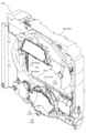
背面ケース300は、正面視略矩形の底壁部301と、その底壁部301の4辺の外縁から正面へ向けて立設される外壁部302とを備え、それら各壁部301,302により一面側(正面側)が開放された箱状に形成される。底壁部301には、その中央に正面視矩形の開口301aが開口形成され、その開口301aを通じて、底壁部301の背面に配設される第3図柄表示装置81(図2参照)が視認可能とされる。
The
スライドユニット400は、背面ケース300の底壁部301のうちの開口301aの上側部分に配設される正面視矩形横長のベース部材410と、そのベース部材410に上端部分がスライド変位可能に配設される左スライド部材430及び右スライド部材450とを備え、背面ケース300の開口301a(即ち、第3図柄表示装置81)の正面側で、各スライド部材430をそれぞれ独立して左右方向(ベース部材410の長手方向)にスライド変位させる演出を実行可能に形成される。
The
この場合、左スライド部材430と右スライド部材450とが当接可能に形成されるところ、本実施形態では、左スライド部材430及び右スライド部材450の当接の際に、それらが破損することを抑制する構造が採用される。かかる構造の詳細については後述する。
In this case, the
背面ケース300の底壁部301のうちの開口301aの下側部分には、正面視矩形横長の案内部材419がベース部材410と平行な姿勢で配設され、左スライド部材430及び右スライド部材450が左右方向にスライド変位される際には、それら各スライド部材430,450の下端が、案内部材419と底壁部301との対向間を摺動され案内される。これにより、各スライド部材430,450の下端側が前後方向へがたつくことを抑制できる。
A horizontally
上合体ユニット500は、スライドユニット400におけるベース部材410の正面に配設される正面視矩形横長のベース部材510と、そのベース部材510に変位可能に配設される上変位部材530とを備える。一方、下合体ユニット600は、背面ケース300の底壁部301のうちの開口301aの左側部分および下側部分に配設される正面視略L字形状のベース部材610と、その下ベース部材610に変位可能に配設される下変位部材640とを備える。
The upper combined
上変位部材530は、ベース部材510の背面側に退避される退避位置と背面ケース300の開口301aの正面側へ張り出す張出位置との間で変位可能に形成されると共に、下変位部材640は、ベース部材610の正面側に退避される退避位置と背面ケース300の開口301aの正面側へ張り出す張出位置との間で変位可能に形成され、上変位部材530及び下変位部材640が張出位置に張り出されると、これら両変位部材530,640の側面どうし(上当接部533及び下当接部643)が互いに当接(合体)される。
The
この場合、互いに近接する方向へ変位した上変位部材530及び下変位部材640が当接される際に、衝撃が発生して、互いが跳ね返されるなど、姿勢が不安定になるおそれがあるところ、本実施形態では、かかる当接時の衝撃を抑制する構造が採用される。かかる構造の詳細については後述する。
In this case, when the
突出ユニット700は、背面ケース300の底壁部301のうちの開口301aの下側部分に配設される正面視横長矩形のベース部材710と、そのベース部材710に昇降可能に配設される昇降ベース720と、その昇降ベース720に回転可能に配設される回転部材730とを備え、昇降ベース720は、回転部材730と共に、ベース部材710の正面側に退避される退避位置と背面ケース300の開口301aの正面側へ張り出す張出位置との間で変位(昇降)可能に形成される。
The protruding
また、突出ユニット700は、回転部材730に出没可能(スライド変位)に配設される突出部材735と、回転部材730に揺動可能に配設される揺動部材732と、これら突出部材735及び揺動部材732を駆動する駆動モータ763(図37参照)とを備える。
The protruding
突出ユニット700は、突出部材735及び揺動部材732の駆動を1の駆動モータ763により行う。そのため、突出部材735の駆動に必要な駆動力と揺動部材732に必要な駆動力とが重複するため、負荷が大きくなり、駆動モータ763の耐久性の低下を招くおそれがあるところ、本実施形態では、駆動モータ763の負荷を抑制する構造が採用される。かかる構造については後述する。
The protruding
昇降ユニット800は、上合体ユニット500におけるベース部材510の正面に配設される正面視矩形横長のベース部材810と、そのベース部材810に昇降可能に配設される昇降部材820とを備える。昇降部材820は、ベース部材810の正面側に退避される退避位置と背面ケース300の開口301aの正面側へ張り出す張出位置との間で変位(昇降)可能に形成される。
The elevating
次いで、図10から図18を参照して、スライドユニット400の詳細構成を説明する。まず、図10から図12を参照して、左スライド部材430及び右スライド部材450をベース部材410に対してスライド変位させる構造について説明する。
Next, the detailed configuration of the
図10は、スライドユニット400の正面図である。また、図11は、スライドユニット400の分解正面斜視図であり、図12は、スライドユニット400の分解背面斜視図である。なお、図10から図12では、左スライド部材430が退避位置(右スライド部材450から最も離間された位置)に配置された状態が図示される。
10 is a front view of the
図10から図12に示すように、スライドユニット400は、背面ケース300の底壁部301(図6参照)に配設されるベース部材410と、そのベース部材410に配設される摺動棒部材420と、その摺動棒部材420に摺動可能に連結される左スライド部材430及び右スライド部材450と、それら左スライド部材430及び右スライド部材450を摺動棒部材420に沿ってスライド変位させるための駆動機構とを主に備える。
As shown in FIGS. 10 to 12, the
ベース部材410は、正面視横長矩形に形成され、その長手方向に沿って摺動棒部材420が正面側に配設される。また、ベース部材410には、摺動棒部材420の下方部分から板状の突出板部411が正面側へ向けて水平に突出され、その突出板部411の上面(摺動棒部材420に対面する側)にベース側ラックギヤ412が刻設されると共に、突出板部411の下面に左回転伝達ラックギヤ413及び右回転伝達ラックギヤ414が刻設される。
The
摺動棒部材420は、左スライド部材430及び右スライド部材450のスライド変位を案内するための断面円形の金属製の棒状体であり、左スライド部材430及び右スライド部材450の摺動孔に挿通されることで、これら両スライド部材430,450を摺動可能に保持する。なお、摺動棒部材420は、その両端が一対の保持部材415によってベース部材410に固定される。
The sliding
ベース側ラックギヤ412、左回転伝達ラックギヤ413及び右回転伝達ラックギヤ414は、摺動棒部材420の長手方向(即ち、左スライド部材430及び右スライド部材450のスライド方向)に沿って延設されるラックギヤであり、ベース側ラックギヤ412には、左スライド部材430の第1側ピニオンギヤ432が歯合されると共に、左回転伝達ラックギヤ413及び右回転伝達ラックギヤ414は、左スライド部材430及び右スライド部材450の伝達ギヤ437a,457a(図13から図16参照)がそれぞれ歯合される。
The base-
左スライド部材430は、正面視矩形横長の第1部材431と、その第1部材431に回転可能に配設される第1側ピニオンギヤ432と、その第1側ピニオンギヤ432が歯合される第2側ラックギヤ433aを有する正面視矩形横長の第2部材433と、その第2部材433の先端側から下方に垂下される正面視矩形縦長の基部材434と、その基部材434の正面側に回転可能に配設される回転部材435と、その回転部材435の背面側に可能に配設される変位部材436と、基部材434のベース部材410に対する運動(スライド変位)を回転部材435に伝達する伝達ギヤ437a~437fと、を主に備える。
The
第1部材431は、その第1部材431の長手方向に沿って延設され断面円形の内周面を有する摺動孔を備え、その摺動孔に摺動棒部材420が挿通されることで、摺動棒部材420の軸方向(長手方向)に沿って摺動(スライド変位)可能とされる。即ち、第1部材431は、摺動棒部材420を介して、ベース部材410にスライド変位可能に配設される。
The
第1部材431には、その上面に第1側ラックギヤ431aが刻設される。第1側ラックギヤ431aは、後述する左駆動ギヤ471が歯合されるラックギヤであり、第1部材431の長手方向に沿って延設される。よって、後述するように、左駆動ギヤ471が回転駆動されると、その回転運動が第1側ラックギヤ431aによって直線運動に変換され、第1部材431が摺動棒部材420に沿ってスライド変位される。
A first
なお、第1部材431には、上述したように、第1側ピニオンギヤ432が回転可能に配設(軸支)され、この第1側ピニオンギヤ432の配設部分(第1部材431の正面側)には、正面視矩形板状のカバー431bが配設される。即ち、カバー431bの背面側に覆設された状態で、第1側ピニオンギヤ432が配設される。
In addition, as described above, the first
第1側ピニオンギヤ432は、ベース部材410のベース側ラックギヤ412に歯合される。よって、第1部材431が、摺動棒部材420に沿ってスライド変位される、即ち、ベース部材410に対してスライド変位されると、そのスライド変位に伴って、ベース側ラックギヤ412から作用を受けて、第1側ピニオンギヤ432が回転される。
The first
第2部材433は、第1部材431に変位可能に配設(連結)されると共に、先端側の摺動孔に摺動棒部材420が挿通されることで、第1部材431に対して相対変位しつつ、摺動棒部材420に沿って摺動(スライド変位)可能とされる。なお、摺動孔は、断面円形の内周面を備え、第2部材433の長手方向に沿って延設される。
The
この場合、第2部材433には、その下面に第2側ラックギヤ433aが刻設され、かかる第2側ラックギヤ433aは、第1側ピニオンギヤ432に歯合されている。よって、上述したように、第1部材431のスライド変位に伴って、第1側ピニオンギヤ432が回転されると、その第1側ピニオンギヤ432から作用を受ける(即ち、第1側ピニオンギヤ432の回転が第2側ラックギヤ433aによって直線運動に変換された上で、第2部材433に伝達される)ことで、かかる第2部材433が第1部材431に対して相対変位される。
In this case, a second
即ち、ベース部材410のベース側ラックギヤ412と第2部材433の第2側ラックギヤ433aとの両者に、第1部材431の第1側ピニオンギヤ432を歯合させるので、第2部材433に対して、第1部材431の直線運動に伴う駆動力と、第1側ピニオンギヤ432の回転運動に伴う駆動力とを付与することができる。その結果、ベース部材410に対して第1部材431をスライド変位させた場合に、第2部材433を、第1部材431よりも増速された状態で、ベース部材410に対してスライド変位させることができる。
That is, since the first
なお、摺動棒部材420には、左スライド部材430と右スライド部材450とが摺動可能に配設され、これら両スライド部材430,450の可動範囲が重複して設定される。よって、左スライド部材430と右スライド部材450とが当接可能とされる。この場合、本実施形態では、左スライド部材430と右スライド部材450とは、第1部材431とラック部材451とが当接され、第2部材433はラック部材451に当接されないように形成される。
A
右スライド部材450は、正面視矩形横長のラック部材451と、そのラック部材451の基端側から下方に垂下される正面視矩形縦長の基部材454と、その基部材454の正面側に回転可能に配設される回転部材455と、その回転部材455の背面側に可能に配設される変位部材456と、基部材454のベース部材410に対する運動(スライド変位)を回転部材455に伝達するための伝達ギヤ457a~457fと、を主に備える。
The
ラック部材451は、そのラック部材451の長手方向に沿って延設され断面円形の内周面を有する摺動孔を基端側に備え、その摺動孔に摺動棒部材420が挿通されることで、摺動棒部材420の軸方向(長手方向)に沿って摺動(スライド変位)可能とされる。即ち、ラック部材451は、摺動棒部材420を介して、ベース部材410にスライド変位可能に配設される。
The
ラック部材451には、その上面にラックギヤ451aがラック部材451の長手方向に沿って刻設される。ラックギヤ451aには、後述する右駆動ギヤ472が歯合される。よって、後述するように、右駆動ギヤ472が回転駆動されると、その回転運動がラックギヤ451aによって直線運動に変換され、ラック部材451が摺動棒部材420に沿ってスライド変位される。
A
駆動機構は、ベース部材410の正面に回転可能に軸支される左駆動ギヤ471及び右駆動ギヤ472と、それら各駆動ギヤ471,472にそれぞれ歯合される左ピニオンギヤ473及び右ピニオンギヤ474と、それら各ピニオンギヤ473,474に駆動軸が接続される左駆動モータ475及び右駆動モータ476と、を主に備える。
The drive mechanism includes a
左駆動ギヤ471及び右駆動ギヤ472は、それぞれ左スライド部材430(第1部材431)の第1側ラックギヤ431a及び右スライド部材450(ラック部材451)のラックギヤ451aにそれぞれ歯合される。よって、左駆動モータ475及び右駆動モータ476によって、左ピニオンギヤ473及び右ピニオンギヤ474を介して、左駆動ギヤ471及び右駆動ギヤ472を回転駆動することで、第1側ラックギヤ431a及びラックギヤ451aを介して、左スライド部材430(第1部材431)及び右スライド部材450(ラック部材451)をそれぞれ独立してスライド変位させることができる。
The
なお、ベース部材410の正面には、カバー部材416が配設され、それらベース部材410及びカバー部材416の対向面間に各駆動ギヤ471,472及び各ピニオンギヤ473,474が回転可能に保持される。また、各駆動モータ475,476は、カバー部材416の正面側に締結固定される。この場合、カバー部材416には、挿通孔が穿設されており、その挿通孔を介して、各駆動モータ475,476の駆動軸が各ピニオンギヤ473,474に接続される。
A
次いで、図13から図16を参照して、左スライド部材430及び右スライド部材450のスライド変位に伴って回転部材435,455を回転させる構造について説明する。
Next, with reference to FIGS. 13 to 16, a structure for rotating the
図13は、左スライド部材430の分解正面斜視図であり、図14は、左スライド部材430の分解背面斜視図である。
13 is an exploded front perspective view of
図13及び図14に示すように、基部材434は、第2部材433に連結される背面側基部材434aと、その背面側基部材434aの正面側に配設(覆設)される正面側基部材434bとを備え、それら背面側基部材434a及び正面側基部材434bの対向面間(内部空間)に伝達ギヤ437a~437fが回転可能に保持(軸支)される。正面側基部材434bには、正面視円形の軸支孔434b1が穿設される。
As shown in FIGS. 13 and 14, the
伝達ギヤ437a~437fは、上述したように、基部材434のベース部材410に対する運動(スライド変位)を回転部材435に伝達するための歯車群であり、直列に連結(歯合)し合うことで、伝達ギヤ437aを先頭とし伝達ギヤ437fを後尾とする1のギヤトレーン(歯車列)を形成する。
The transmission gears 437a to 437f are a group of gears for transmitting the movement (sliding displacement) of the
上述したように、先頭の伝達ギヤ437aは、ベース部材410の左回転伝達ラックギヤ413に歯合され、後尾の伝達ギヤ437fには、回転部材435の回転軸435aが同軸に固着される。
As described above, the
よって、ベース部材410に対して左スライド部材430(基部材434)をスライド変位させることで、ベース部材410の左回転伝達ラックギヤ413からの作用によって先頭の伝達ギヤ437aを回転させ、その回転を、伝達ギヤ437b~437eを介して、後尾の伝達ギヤ437fに伝達し、かかる後尾の伝達ギヤ437fの回転により、回転部材435を回転させることができる。
Therefore, by slidingly displacing the left slide member 430 (base member 434) with respect to the
回転部材435は、背面から同軸に突設される回転軸435a及び支持軸435bを備える。回転軸435aは、回転部材435が基部材434に対して回転する際の回転軸となる部位であり、正面側基部材434bの軸支孔434b1に回転可能に軸支される。この場合、回転軸435aには、伝達ギヤ437fが相対回転不能に同軸に連結される。よって、後述するように、伝達ギヤ437fが回転されることで、回転部材435が基部材434に対して回転される。
The rotating
支持軸435bは、変位部材436を回転部材435の背面側に回転可能に軸支する部位であり、変位部材436の軸支孔436aに回転可能に挿通される。なお、支持軸435bの先端に凹設された嵌合溝にEリングが嵌合されることで、支持軸435bからの変位部材436の抜け止めが形成される。
The
変位部材436は、回転部材435の背面側に変位可能に配設される部材であり、軸支孔436aと、逃げ孔436bと、湾曲ラックギヤ436cとを備える。軸支孔436aには、上述したように、回転部材435の支持軸435bが挿通され、これにより、変位部材436が回転部材435に回転可能に軸支される。
The
逃げ孔436bは、軸支孔436aの軸心を中心とする円環形状を所定の中心角で分断することで円弧状に湾曲した溝状の開口として形成され、その溝幅が回転部材435の回転軸435aの直径よりも若干大きな寸法に設定される。よって、回転部材435に対して変位部材436が変位(軸支孔436aを中心として回転)される際には、回転軸435aを逃げ孔436bに沿って変位させることができ、回転部材435と変位部材436との間の干渉を回避できる。
The
湾曲ラックギヤ436cは、軸支孔436aの軸心を中心とする周面に沿って刻設されたラックギヤとして形成される。ここで、回転部材435の背面には、駆動モータ441が配設されると共に、その駆動モータ441の駆動軸にはピニオンギヤ442が固着され、かかるピニオンギヤ442が湾曲ラックギヤ436cに歯合される。よって、駆動モータ441によってピニオンギヤ442を正方向または逆方向に回転させることで、変位部材436を回転部材435に対して軸支孔436a(支持軸435b)を回転中心として一方向または他方向へ回転させることができる。
The
この場合、回転部材435は、その正面視形状が、幅方向の寸法に対して長さ方向の寸法が大きな略長尺状の形状に形成され、長さ方向および幅方向の略中心となる位置に回転軸435aが配置される。変位部材436の正面視形状は、回転部材435をその長さ方向の中心で略二分割した形状に形成される。よって、変位部材436を軸支孔436a(支持軸435b)を回転中心として一方向へ回転させることで、かかる変位部材436を回転部材435の背面側に隠して、遊技者から視認し難くすることができる。
In this case, the rotating
また、回転部材435には、支持軸435bを挟んで変位部材436と反対側に駆動モータ441が配設されるので、回転部材435に変位部材436及び駆動モータ441が配設された構造体の重心位置を、回転部材435の回転軸435aに近接させることができる。よって、かかる構造体の基部材434に対する回転を安定化させることができる。
Further, since the driving
なお、本実施形態では、軸支孔436a(支持軸435b)を回転中心として変位部材436が一方向へ回転された状態(変位部材436が回転部材435の背面側に隠れる状態)では、回転部材435に変位部材436及び駆動モータ441が配設された構造体の重心位置が、回転部材435の回転軸435aに略一致される。よって、構造体の基部材434に対する回転を安定化させることができる。
In this embodiment, when the
一方、軸支孔436a(支持軸435b)を回転中心として変位部材436が他方向へ回転された状態(変位部材436が回転部材435の側方に視認可能に張り出された状態)では、その変位部材436の張り出しの分、上述した構造体の重心位置を、回転部材435の回転軸435aから離間させることができる。これにより、回転部材435の回転方向に応じて、重心位置を調整して、初期動作をスムーズに行わせることができる。
On the other hand, in a state in which the
即ち、左スライド部材430のスライド変位を停止状態から開始させる際には、慣性力の影響により、駆動力が大きくなる。この場合、変位部材436を回転部材435の側方に張り出した状態における上述した構造体の重心が、左スライド部材430のスライド変位(即ち、回転部材435の回転)の開始時に、重力方向下方へ変位する側に位置する場合には、変位部材436を回転部材435の側方に張り出させておく(一方向へ回転させておく)ことで、上述した構造体の自重による回転作用により、その回転を補助することができる。これにより、左駆動モータ475(図11参照)の負担を軽減して、左スライド部材430の停止状態からのスライド変位をスムーズに開始させることができる。
That is, when starting the sliding displacement of the
一方、変位部材436を回転部材435の側方に張り出した状態における上述した構造体の重心が、左スライド部材430のスライド変位(即ち、回転部材435の回転)の開始時に、重力方向上方へ変位する側に位置する場合には、変位部材436を回転部材435の背面に隠しておく(他方向へ回転させておく)ことで、上述した構造体の重心を回転軸435aに近接(一致)させて、左駆動モータ475の負荷(図11参照)が嵩むことを抑制できる。これにより、左スライド部材430の停止状態からのスライド変位をスムーズに開始させることができる。
On the other hand, the center of gravity of the structure described above with the
また、変位部材436を回転部材435の側方に張り出した状態における上述した構造体の重心が、左スライド部材430のスライド変位(即ち、回転部材435の回転)の停止時に、重力方向上方へ変位する側に位置する場合には、上述した構造体の自重により、その回転を停止させやすくすることができる。これにより、左駆動モータ475(図11参照)の駆動を停止した際に、左スライド部材430を速やかに停止させることができる。
Further, the center of gravity of the structure described above with the
図15は、右スライド部材450の分解正面斜視図であり、図16は、右スライド部材450の分解背面斜視図である。基部材454は、ラック部材451に連結される背面側基部材454aと、その背面側基部材454aの正面側に配設(覆設)される正面側基部材454bとを備え、それら背面側基部材454a及び正面側基部材454bの対向面間(内部空間)に伝達ギヤ457a~457fが回転可能に保持(軸支)される。正面側基部材454bには、正面視円形の軸支孔454b1が穿設される。
15 is an exploded front perspective view of the
伝達ギヤ457a~457fは、上述したように、基部材454のベース部材410に対する運動(スライド変位)を回転部材455に伝達するための歯車群であり、直列に連結(歯合)し合うことで、伝達ギヤ457aを先頭とし伝達ギヤ457fを後尾とする1のギヤトレーン(歯車列)を形成する。
The transmission gears 457a to 457f are a group of gears for transmitting the movement (sliding displacement) of the
上述したように、先頭の伝達ギヤ457aは、ベース部材410の右回転伝達ラックギヤ414に歯合され、後尾の伝達ギヤ457fには、回転部材455の回転軸455aが同軸に固着される。
As described above, the
よって、ベース部材410に対して右スライド部材450(基部材454)をスライド変位させることで、ベース部材410の右回転伝達ラックギヤ414からの作用によって先頭の伝達ギヤ457aを回転させ、その回転を、伝達ギヤ457b~457eを介して、後尾の伝達ギヤ457fに伝達し、かかる後尾の伝達ギヤ457fの回転により、回転部材455を回転させることができる。
Therefore, by slidingly displacing the right slide member 450 (base member 454) with respect to the
回転部材455は、背面から同軸に突設される回転軸455a及び支持軸455bを備える。回転軸455aは、回転部材455が基部材454に対して回転する際の回転軸となる部位であり、正面側基部材454bの軸支孔454b1に回転可能に軸支される。この場合、回転軸435aには、伝達ギヤ457fが相対回転不能に同軸に連結される。よって、後述するように、伝達ギヤ457fが回転されることで、回転部材455が基部材454に対して回転される。
The rotating
支持軸455bは、変位部材456を回転部材455の背面側に回転可能に軸支する部位であり、変位部材456の軸支孔456aに回転可能に挿通される。なお、支持軸455bの先端に凹設された嵌合溝にEリングが嵌合されることで、支持軸455bからの変位部材456の抜け止めが形成される。
The
変位部材456は、回転部材455の背面側に変位可能に配設される部材であり、軸支孔456aと、逃げ孔456bと、湾曲ラックギヤ456cとを備える。軸支孔456aには、上述したように、回転部材455の支持軸455bが挿通され、これにより、変位部材456が回転部材455に回転可能に軸支される。
The
逃げ孔456bは、軸支孔456aの軸心を中心とする円環形状を所定の中心角で分断することで円弧状に湾曲した溝状の開口として形成され、その溝幅が回転部材455の回転軸455aの直径よりも若干大きな寸法に設定される。よって、回転部材455に対して変位部材456が変位(軸支孔456aを中心として回転)される際には、回転軸455aを逃げ孔456bに沿って変位させることができ、回転部材455と変位部材456との間の干渉を回避できる。
The
湾曲ラックギヤ456cは、軸支孔456aの軸心を中心とする周面に沿って刻設されたラックギヤとして形成される。ここで、回転部材455の背面には、駆動モータ461が配設されると共に、その駆動モータ461の駆動軸にはピニオンギヤ452が固着され、かかるピニオンギヤ452が湾曲ラックギヤ456cに歯合される。よって、駆動モータ461によってピニオンギヤ452を正方向または逆方向に回転させることで、変位部材456を回転部材455に対して軸支孔456a(支持軸455b)を回転中心として一方向または他方向へ回転させることができる。
The
この場合、回転部材455は、その正面視形状が、幅方向の寸法に対して長さ方向の寸法が大きな略長尺状の形状に形成され、その長さ方向の一端側に回転軸455aが配設されると共に他端側に駆動モータ461が配設される。また、回転部材455には、支持軸455bを挟んで駆動モータ461と反対側に変位部材456が配設されるので、回転部材455に変位部材456及び駆動モータ461が配設された構造体の重心位置を、回転部材455の一端側に偏心した位置(回転軸455aから離間した位置)に配置することができる。
In this case, the rotating
よって、右スライド部材450のスライド変位(即ち、回転部材455の回転)の開始時には、回転部材455に変位部材456及び駆動モータ461が配設された構造体の重心を、重力方向下方へ変位する側に位置させることで、その構造体の自重を、構造体自身を回転させる方向に作用させることができる。これにより、右駆動モータ476(図11参照)の負担を軽減して、右スライド部材450の停止状態からのスライド変位をスムーズに開始させることができる。
Therefore, at the start of sliding displacement of the right slide member 450 (that is, rotation of the rotating member 455), the center of gravity of the structure in which the rotating
一方、右スライド部材450のスライド変位(即ち、回転部材455の回転)の停止時には、上述した構造体の重心を、重力方向上方へ変位する側に位置させることで、構造体の自重を抵抗として作用させ、構造値の回転を停止させやすくすることができる。これにより、右駆動モータ476(図11参照)の駆動を停止した際に、右スライド部材450を速やかに停止させることができる。
On the other hand, when the sliding displacement of the right slide member 450 (that is, the rotation of the rotating member 455) is stopped, the center of gravity of the above-described structure is positioned on the side to be displaced upward in the direction of gravity, so that the weight of the structure itself acts as a resistance. can be acted upon to help stop the rotation of structure values. As a result, the
また、後述するように、左スライド部材430(第1部材431)が右スライド部材450(ラック部材451)に当接(衝突)されることで、右スライド部材450が後退される(図10右側へ変位される)際には、上述した構造体の重心を、重力方向上方へ変位する側に位置させることで、構造体の自重を抵抗として作用させ、その構造値の回転による緩衝作用を発揮させることができる。
Further, as will be described later, the left slide member 430 (first member 431) abuts (collides) with the right slide member 450 (rack member 451), causing the
次いで、図17及び図18を参照して、スライドユニット400の動作について説明する。図17及び図18は、スライドユニット400の正面図であり、左スライド部材430がスライド変位される際の遷移状態が図示される。なお、図17及び図18では、カバー部材416、案内部材419、左駆動モータ475及び右駆動モータ476が取り外された状態が図示される。
Next, operations of the
図17(a)に示すように、左スライド部材430が退避位置に配置された状態では、第1部材431に対して第2部材433が伸長方向へ最大に相対変位され、基部材434が可動範囲の左端(図17(a)左側、右スライド部材450から最も離間される位置)に配置される。かかる状態から左駆動モータ475(図11参照)が正方向へ駆動されると、左駆動ギヤ471及び第1側ラックギヤ431aの作用により、第1部材431がベース部材410に対して右方向(図17(a)右側、右スライド部材450へ近接する方向)へスライド変位される。
As shown in FIG. 17A, when the
この場合、上述したように、第2部材433の第2側ラックギヤ433aとベース部材410のベース側ラックギヤ412とが互いに平行な姿勢で向い合せに配設され、それら第2側ラックギヤ433a及びベース側ラックギヤ412の両者に歯合された状態で、第1部材431に軸支された第1側ピニオンギヤ432が介設されるので、ベース部材410に対して第1部材431がスライド変位されると、ベース側ラックギヤ412の作用により第1側ピニオンギヤ432が第1部材431と共にスライド変位されつつ回転され、その第1側ピニオンギヤ432の回転が第2側ラックギヤ433aへ作用されることで、第2部材433が第1部材431と同じ方向へスライド変位される。即ち、第2部材433が、第1部材431よりも増速された状態で、ベース部材410に対してスライド変位される。
In this case, as described above, the second
その結果、図17(b)に示すように、スライド変位の速度が第1部材431よりも相対的に速い第2部材433が、第1部材431に追いつき、第1部材431に対して第2部材433が部分的に重ねられる(第1部材431及び第2部材433の長手方向の全長が短縮される)。
As a result, as shown in FIG. 17(b), the
この状態から左駆動モータ475(図11参照)が正方向へ更に駆動され、第1部材431がベース部材410に対して更に右方向(図17(a)右側、右スライド部材450へ近接する方向)へスライド変位されると、図18(a)に示すように、第1部材431に対して第2部材433が短縮方向へ最大に相対変位され、基部材434が可動範囲の右端(図18(a)右側、右スライド部材450に最も近接される位置)、即ち、張出位置に配置される。
From this state, the left driving motor 475 (see FIG. 11) is further driven in the forward direction, and the
一方、図18(a)に示すように、左スライド部材430が張出位置に配置された状態から左駆動モータ475(図11参照)が上述の場合とは逆の逆方向へ駆動されると、左駆動ギヤ471及び第1側ラックギヤ431aの作用により、第1部材431がベース部材410に対して左方向(図18(a)左側、右スライド部材450から離間する方向)へスライド変位される。
On the other hand, as shown in FIG. 18(a), when the left drive motor 475 (see FIG. 11) is driven in the direction opposite to the above case from the state in which the
この場合にも、上述した場合と同様に、第2部材433の第2側ラックギヤ433a及びベース部材410のベース側ラックギヤ412と、第1部材431に軸支された第1側ピニオンギヤ432との作用により、第2部材433が、第1部材431よりも増速された状態で、ベース部材410に対してスライド変位される。
Also in this case, as in the case described above, the actions of the second
その結果、図17(b)に示すように、スライド変位の速度が第1部材431よりも相対的に速い第2部材433が、第1部材431よりも先行し、第1部材431に対して第2部材433が伸長方向へ相対変位される(第1部材431及び第2部材433の長手方向の全長が張出位置における全長よりも伸長される)。
As a result, as shown in FIG. 17(b), the
この状態から左駆動モータ475(図11参照)が逆方向へ更に駆動され、第1部材431がベース部材410に対して更に左方向(図17(b)左側、右スライド部材450から離間する方向)へスライド変位されると、図17(a)に示すように、第1部材431に対して第2部材433が伸長方向へ最大に相対変位され、基部材434が可動範囲の左端(図17(a)左側、右スライド部材450に最も離間される位置)、即ち、張出位置に配置される。
From this state, the left drive motor 475 (see FIG. 11) is further driven in the opposite direction, and the
なお、本実施形態では、第2部材431の先端に被検出部が形成されると共にその被検出を検出する検出センサがベース部材410に配設される(いずれも図示せず)。この場合、検出センサは、第2部材431(左スライド部材430)が退避位置に配置され際にその第2部材431の被検出部を検出可能な位置に配設され、検出センサによって被検出部が検出された場合に、左スライド部材430が退避位置に配置されたとして、左駆動モータ475の駆動が停止される。
In addition, in the present embodiment, a detected portion is formed at the tip of the
一方、張出位置における左駆動モータ475の駆動の停止は、退避位置から張出位置へ向けての左スライド部材430のスライド変位を開始してからの左駆動モータ475の駆動ステップ数を累積加算することにより行われる。即ち、累積加算値が所定値に達した場合に、左スライド部材430が張出位置に配置されたとして、左駆動モータ475の駆動が停止される。
On the other hand, stopping the driving of the
ここで、本実施例では、左スライド部材430のスライド変位の可動範囲(退避位置から張出位置までの範囲)が、右スライド部材450のスライド変位の可動範囲と重複する部分を有する。そのため、両者の可動範囲を大きくして、演出効果を高めることができる。
Here, in this embodiment, the movable range of slide displacement of the left slide member 430 (the range from the retracted position to the extended position) overlaps the movable range of the slide displacement of the
しかしながら、このように、可動範囲が重複されていると、部品寸法・組立のばらつきや公差に基づくがたつき(隙間)の分の変位量のばらつきに起因して、或いは、制御不良(例えば、駆動ステップ数の累積加算のエラー)の発生に起因して、張出位置までスライド変位された左スライド部材430が右スライド部材450に当接して、破損を招くおそれがある。一方で、破損を抑制するために、左スライド部材430のスライド変位の速度を遅くしたのでは、そのスライド変位に伴う演出効果が損なわれる。
However, if the movable ranges overlap in this way, it may be caused by fluctuations in the amount of displacement due to fluctuations in the dimensions and assembly of parts and tolerances (gap), or due to poor control (for example, The
これに対し、本実施形態によれば、左スライド部材430のスライド変位に伴う演出効果を確保しつつ、左スライド部材430及び右スライド部材450の破損を抑制することができるように形成される。
On the other hand, according to the present embodiment, it is possible to prevent damage to the
即ち、上述したように、第2部材433の第2側ラックギヤ433a及びベース部材410のベース側ラックギヤ412と、第1部材431に軸支された第1側ピニオンギヤ432との作用により、第2部材433を、第1部材431よりも増速された状態で、ベース部材410に対してスライド変位させることができ、かかる第2部材433に、遊技者から視認される基部材434(回転部材435及び変位部材436)を連結するので、かかる基部材434のスライド変位の速度を速くして、そのスライド変位に伴う演出効果を確保することができる。
That is, as described above, due to the action of the second
一方で、左スライド部材430は、上述したように、第2部材433よりもスライド変位の速度が相対的に遅くされる第1部材431を右スライド部材450(ラック部材451)に当接させるので、その当接の際の衝撃を弱めて、両者の破損を抑制することができる。
On the other hand, the
なお、本実施形態では、右スライド部材450を、左スライド部材430の張出位置よりも退避位置に近い側に待機(停止)させておき、左スライド部材430を張出位置へ向けてスライド変位させる際に、かかる左スライド部材430を右スライド部材450に当接させると共に左スライド部材430によって右スライド部材450をスライド変位の方向へ押させて、両者を一体の状態でスライド変位させる演出を行うことができる。この場合にも、第2部材433よりもスライド変位の速度が相対的に遅くされる第1部材431を右スライド部材450(ラック部材451)に当接させることができるので、その当接の際の衝撃を弱めて、両者の破損を抑制することができる。
In this embodiment, the
右スライド部材450は、ベース部材410にスライド変位可能に配設されるところ、その右スライド部材450のスライド変位の方向は、左スライド部材430のスライド変位の方向と平行な方向とされる。即ち、右スライド部材450は、張出位置に配置された左スライド部材430と当接可能な位置に配置された状態では(図18(a)参照)、その左スライド部材430から離間する方向(図18(a)右側)へスライド変位するための可動範囲を有しており、その右スライド部材450がスライド変位可能な方向は、左スライド部材430が当接された際にその左スライド部材430のスライド変位を許容する方向とされる。
The
よって、左スライド部材430が右スライド部材450に当接された際に(図18(a)参照)、左スライド部材430のスライド変位を受け止めつつ右スライド部材450を後退させる(後方へ逃がす)ことで、緩衝作用を発揮させることができる(図18(b)参照)。その結果、左スライド部材430及び右スライド部材450の破損を抑制しやすくできる。
Therefore, when the
特に、本実施形態では、左スライド部材430と右スライド部材450とのスライド変位の方向が平行とされるので、左スライド部材430が右スライド部材450に当接された際に、右スライド部材450の逃げる動作をスムーズに行わせることができる。よって、緩衝作用を確実に発揮して、両者の破損を抑制しやすくできる。
In particular, in the present embodiment, the directions of sliding displacement of the
また、この場合、左スライド部材430と右スライド部材450とで摺動棒部材420を共用することにより、両者のスライド変位の方向を平行とする構成なので、全体としての小型化を図ることができる。即ち、左スライド部材430を案内するための摺動棒部材と、右スライド部材450を案内するための摺動棒部材とを、スライド変位の方向に直交する方向に位置を違えて並設する場合には、その分、スペースが嵩み、大型化を招く。これに対し、本実施形態によれば、1の摺動棒部材420を両スライド部材430,450が兼用することで、スペース効率を向上して、小型化を図ることができる。
Further, in this case, by sharing the sliding
右スライド部材450は、上述したように、張出位置に配置された左スライド部材430から離間する方向(図18(a)右側)への可動範囲を有しており、左スライド部材430と非当接となる位置に配置可能とされる。即ち、左スライド部材430を右スライド部材450に当接させない状態を形成することができる。
As described above, the
よって、左スライド部材430を比較的高速でスライド変位させる場合には、上述したばらつきや制御不良に起因して、左スライド部材430の停止位置が目標位置よりも延びることが想定されやすいので、左スライド部材430に右スライド部材450を積極的に当接させる(ストッパとして機能させる)一方で、左スライド部材430を比較的低速でスライド変位させる場合には、その停止位置を目標位置に一致させやすいことから、右スライド部材450を左スライド部材430と非当接となる位置に配置しておくことで、当接回数を減らし、当接に伴う疲労を低減させることができる。その結果、両スライド部材430,450の寿命の向上を図ることができる。
Therefore, when the
ここで、左スライド部材430は、第1部材431に対して、第2部材433を増速させたるために、これら両部材431,433を別々に設けると共に、ベース側ラックギヤ412及び第2側ラックギヤ433aの間に第1側ピニオンギヤ432を介在させるなどが必要となり、部品点数および摺動部分が嵩むため、重量や駆動抵抗が大きくなる。そのため、その左スライド部材430の駆動に必要な力が比較的大きくなる。
Here, since the
特に、左スライド部材430の初期動作時(停止状態からスライド変位を開始する際)には、慣性力の影響により、駆動に必要な力が最大となる。よって、初期動作(停止状態からスライド変位が開始される際の初速度)が遅くなるため、そのスライド変位に伴う演出効果が阻害されるおそれがある。 In particular, during the initial operation of the left slide member 430 (when starting the slide displacement from the stopped state), the force required for driving becomes maximum due to the influence of the inertial force. As a result, the initial motion (initial speed when the slide displacement is started from the stopped state) is slowed down, so there is a possibility that the rendering effect associated with the slide displacement will be hindered.
この場合、本実施形態では、右スライド部材450が、左スライド部材430に当接可能に形成されると共に、その当接された状態から左スライド部材430を退避位置へ押し返す方向(図18(a)左方向)へスライド変位可能に形成される。よって、左スライド部材430の初期動作(停止状態からスライド変位を開始する動作)を右スライド部材450のスライド変位によって補助することができる。これにより、左スライド部材430を停止状態から速やかにスライド変位させることができる。その結果、初期動作(初速度)を速くして、そのスライド変位に伴う演出効果の向上を図ることができる。
In this case, in this embodiment, the
また、右スライド部材450は、左スライド部材430を退避位置へ押し返す方向(図18(a)左方向)へスライド変位される際には、左スライド部材430のうちの第1部材431に当接される(第1部材431を押し返す)ので、左スライド部材430の初期動作を補助する効率を高めることができる。
Further, the
即ち、右スライド部材450は、左スライド部材430のうちの第2部材433よりもスライド変位の速度が遅い第1部材431に当接されて、その第1部材431を押し返すので、右スライド部材450から左スライド部材430(第1部材431)へ補助力が作用している時間(即ち、停止状態の左スライド部材430を押し返し始めてから、左スライド部材430の速度が右スライド部材450の速度を超えて、左スライド部材430の変位が右スライド部材450変位に先行するまでの時間)をより長くすることができ、その結果、左スライド部材430の初期動作を補助する効率を高めることができる。
That is, the
ここで、左駆動モータ475の回転駆動力を直線運動に変換して、左スライド部材430(第1部材431)をスライド変位させる機構(左ピニオンギヤ473、左駆動ギヤ471及び第1側ラックギヤ431a)のギヤ比と、右駆動モータ476の回転駆動力を直線運動に変換して、右スライド部材450(ラック部材451)をスライド変位させる機構(右ピニオンギヤ474、右駆動ギヤ472及びラックギヤ451a)のギヤ比とは、異なるギヤ比に設定され、本実施形態では、前者(左スライド部材430)におけるギヤ比が後者(右スライド部材450)におけるギヤ比よりも大きなギヤ比に設定される。
Here, a mechanism (the
なお、本実施形態では、左ピニオンギヤ473は右ピニオンギヤ474と、第1側ラックギヤ431aはラックギヤ451aと、それぞれ同一の形状に形成されるので、左駆動ギヤ471の歯数が右駆動ギヤ472の歯数よりも多い歯数に設定される。即ち、ギヤ比が大きいとは、駆動モータ(左駆動モータ475又は右駆動モータ476)の駆動軸が1回転する際のラックギヤ(第1側ラックギヤ431a又はラックギヤ451a)のスライド変位の方向への変位量が大きいことを意味する。
In the present embodiment, the
これにより、左スライド部材430を停止状態から速やかにスライド変位させやすくできると共に、そのスライド変位の開始後は、左スライド部材450(第2部材433)のスライド変位の速度を高めることができ、その結果、そのスライド変位に伴う演出効果の向上を図ることができる。
As a result, the
即ち、右スライド部材450におけるギヤ比が相対的に小さなギヤ比に設定されることで、より大きな駆動力が発揮可能となるので、右スライド部材450が左スライド部材430を押し返す力を強くして、かかる左スライド部材430の初期動作(停止状態からのスライド変位の開始)を確実に補助することができる。よって、左スライド部材430を停止状態から速やかに直線変位させることができる。
That is, by setting the gear ratio of the
一方、左スライド部材430におけるギヤ比が相対的に大きなギヤ比に設定されていることで、左スライド部材430(第1部材431)のスライド変位の速度を速くすることができるので、その分、第2部材433のスライド変位の速度を高めることができる。よって、そのスライド変位に伴う演出効果の向上を図ることができる。
On the other hand, since the gear ratio of the
なお、左スライド部材430の初期動作(停止状態からのスライド変位の開始)をスムーズに行うために、左スライド部材430におけるギヤ比を小さくすると、初期動作はスムーズとなるが、その初期動作の終了後の定常状態において、左スライド部材430(第2部材433)のスライド変位の速度(最大速度)が低くなる。一方、初期動作後の定常状態における左スライド部材430(第2部材433)のスライド変位の速度(最大速度)を高めるために、左スライド部材430におけるギヤ比を大きくすると、最大速度は速くできるが、初期動作(停止状態からのスライド変位の開始)が阻害される(遅くなる)。即ち、左スライド部材430の初期動作をスムーズに行うことと、その初期動作後の定常状態における左スライド部材430(第2部材433)のスライド変位の速度(最大速度)を高めることとの両立は、従来は不可能であったところ、右スライド部材450が左スライド部材430を押し返す構造を採用したことで、かかる両立が初めて可能となったものである。
If the gear ratio of the
次いで、図19から図30を参照して、上合体ユニット500及び下合体ユニット600の詳細構成を説明する。まず、図19から図23を参照して、上合体ユニット500について説明する。
Next, detailed configurations of the
図19(a)は、上合体ユニット500の正面図であり、図19(b)は、上合体ユニット500の背面図である。また、図20は、上合体ユニット500の分解正面斜視図であり、図21は、上合体ユニット500の分解背面斜視図である。なお、図19では、上変位部材530が退避位置に配置された状態が図示される。
19(a) is a front view of the upper combined
図19から図21に示すように、上合体ユニット500は、ベース部材510と、そのベース部材510の内部空間にスライド変位可能に配設されるラック部材520と、そのラック部材520に連結される上変位部材530と、ラック部材520をスライド変位させるための駆動機構と、を備える。
As shown in FIGS. 19 to 21, the upper combined
ベース部材510は、正面視矩形横長の背面ベース511と、その背面ベース511の正面側に配設(覆設)される正面視矩形横長の正面ベース512とを備え、それら背面ベース511及び正面ベース512の対向面間(内部空間)にラック部材520がスライド変位可能に収容される。
The
背面ベース511は、直線状に延設される溝状の開口として形成される連結孔511aと、円弧状に湾曲する溝状の開口として形成される案内孔511bと、正面側へ突出されラック部材520の案内溝522に挿通される支持軸511cと、を備える。
The
連結孔511aは、ラック部材520と上変位部材530とを連結するための開口であり、背面ベース511の長手方向(即ち、ラック部材520のスライド方向)に沿って(平行に)形成される。なお、連結孔511aには、上変位部材530の連結軸531が摺動可能に挿通される。
The connecting
案内孔511bは、上変位部材530の案内ピン532が摺動可能に挿通される部位であり、ラック部材520のスライド変位に伴って上変位部材530が変位される際に、上変位部材530の案内ピン532が案内孔511bに沿って摺動されることで、上変位部材530の姿勢(向き)が変化される。
The
ラック部材520は、上変位部材530の連結軸531を回転可能に軸支するための正面視円形の孔である軸支孔521と、直線状に延設される溝状の開口として形成される案内溝522と、その案内溝522の延設方向と平行な方向に沿って刻設されるラックギヤ523とを備え、矩形横長の板状体として形成される。
The
案内溝522には、背面ベース511の支持軸511cが摺動可能に挿通される。案内溝522に背面ベース511の支持軸511cが挿通されると共に、軸支孔521に上変位部材530の案内ピン532が軸支されると、案内溝522の延設方向が、背面ベース511の連結孔511aの延設方向と平行とされる。よって、ラック部材520のスライド変位の方向が背面ベース511の連結孔511aの延設方向に規定される。
The
上変位部材530は、正面側から突設される連結軸531及び案内ピン532とを備える。連結軸531は、背面ベース511の連結孔511aを介して、ラック部材520の軸支孔521に回転可能に軸支される断面円形の円柱状体であり、案内ピン532は、背面ベース511の案内孔511bに沿って摺動される断面円形の円柱状体である。
The
なお、これら連結軸531及び案内ピン532の先端には、軸支孔521よりも大径のカラーC1及び案内孔511bの溝幅よりも大径のカラーC2がそれぞれ固着され、抜け止めとされる。また、上変位部材530には、その側面に上当接部533が形成される。上当接部533は、下変位部材640の下当接部643(図25及び図26参照)に当接される部位であり、連結軸531及び案内ピン532と反対側(先端側)の側面に形成される。
A collar C1 having a larger diameter than the
駆動機構は、背面ベース511の正面に回転可能に軸支される駆動ギヤ541と、その駆動ギヤ541に歯合されるピニオンギヤ542と、そのピニオンギヤ542に駆動軸が接続される駆動モータ543と、備える。駆動ギヤ541は、ラック部材520のラックギヤ523に歯合される。よって、駆動モータ543によって、ピニオンギヤ542を介して、駆動ギヤ541を回転駆動することで、ラックギヤ523を介して、ラック部材520を連結孔511aの延設方向に沿ってスライド変位させることができる。
The drive mechanism includes a
次いで、図22及び図23を参照して、上合体ユニット500の動作について説明する。図22及び図23は、上合体ユニット500の正面図および背面図であり、上変位部材530が退避位置と張出位置との間で変位される際の遷移状態が図示される。
Next, the operation of the upper combined
図22(a)及び図23(a)に示すように、上変位部材530が退避位置に配置された状態では、連結軸531及び案内ピン532が、連結孔511a及び案内孔511bの一端側(図23右側)に位置し、上変位部材530が水平姿勢を形成しベース部材510の背面側に隠れた状態で配置される。
As shown in FIGS. 22(a) and 23(a), in the state where the
かかる状態から駆動モータ543が正方向へ駆動されると、ラック部材520のスライド変位に伴って、連結軸531が連結孔511aに沿って水平方向に変位されると共に、案内ピン532が案内孔511bに沿って案内されることで、図22(b)及び図23(b)に示すように、上変位部材530は、斜めに傾斜されつつ(連結軸531を中心に回転されつつ)、水平方向へ変位される。即ち、上変位部材530の先端側(上当接部533)が曲線状の軌跡を描きつつ下降される。
When the driving
駆動モータ543が正方向へ更に駆動されると、上変位部材530は、更に斜めに傾斜されつつ(連結軸531を中心に回転されつつ)、水平方向へ変位され、図22(c)及び図23(c)に示すように、その先端側(上当接部533)を下方へ向けた縦姿勢を形成する。即ち、張出位置(第1位置)に配置される。
When the
次いで、図24から図29を参照して、下合体ユニット600について説明する。
Next, the lower combined
図24は、下合体ユニット600の正面図である。また、図25は、下合体ユニット600の分解正面斜視図であり、図26は、下合体ユニット600の分解背面斜視図である。なお、図23では、下変位部材640が退避位置に配置された状態が図示される。
24 is a front view of the lower combined
図24から図26に示すように、下合体ユニット600は、ベース部材610と、そのベース部材610の正面側下方に配設される駆動アーム保持部材620と、その駆動アーム保持部材620に基端側が回転可能に保持される駆動アーム630と、その駆動アーム630の先端側が連結される下変位部材640と、その下変位部材640をベース部材610に連結する連結アーム650と、駆動アーム630に付勢力を付与するための付勢ばね660と、駆動アーム630に駆動力を付与する駆動機構と、を備える。
As shown in FIGS. 24 to 26, the lower combined
ベース部材610は、正面視略L字の板状体として形成され、その略L字形状の下端における正面から突設される突設基部611と、略L字形状の上端部分における正面から突設される連結軸612とを備える。突設基部611は、駆動アーム保持部材620をベース部材610の正面から突出させた(正面側へ嵩上げした)位置に配設するための部位であり、ベース部材610の下端における縁部に沿って突設される。
The
駆動アーム保持部材620は、ベース部材610の突設基部611に配設される背面側保持部材621と、その背面側保持部材621の正面側に配設(覆設)される正面側保持部材622とを備え、それら背面側保持部材621及び正面側保持部材622の対向面間(内部空間)に駆動アーム630及び伝達ギヤ671a~671cが回転可能に保持(軸支)される。
The drive
なお、駆動アーム保持部材620は、その背面側保持部材621の背面側が、ベース部材610の突設基部611の突設先端に配設されるので、突設基部611の突設高さの分、駆動アーム保持部材620(背面側保持部材621)の背面とベース部材610の正面との間に所定の空間を形成することができる。本実施形態では、かかる空間に、退避位置に配置された下変位部材640が収容可能に形成されるので、その分、下合体ユニット600の外形を小さくできる。
In the driving
駆動アーム630は、駆動アーム保持部材620に回転可能に軸支される軸支孔631と、その軸支孔631と同心となる円柱状部分の外周面に沿って複数の歯が刻設される歯車部632と、その歯車部632と反対側の端部に形成される連結孔633とを備え、軸支孔631と連結孔633との間が所定距離だけ離間された長尺状の部材として形成される。
The
下変位部材640は、正面側から突設される駆動アーム連結軸641及び連結アーム連結軸642を備える。駆動アーム連結軸641は、駆動アーム630の連結孔633に回転可能に連結される断面円形の円柱状体であり、連結アーム連結軸642は、連結アーム650の連結孔651に回転可能に連結される断面円形の円柱状体である。下変位部材640は、駆動アーム630と連結アーム650との間に介設され、駆動アーム630が回転されることで、ベース部材610に対して変位される。
The
なお、下変位部材640には、その側面に下当接部643が形成される。下当接部643は、上変位部材530の上当接部533(図20及び図21参照)に当接される部位であり、駆動アーム連結軸641及び連結アーム連結軸642を結んだ仮想線から張出方向側(図24右側)へ離間した側の側面に形成される。本実施形態では、下当接部643は、駆動アーム連結軸641及び連結アーム連結軸642を結んだ仮想線と略直交する向きの面として形成される。
A
連結アーム650は、一端側および他端側に形成される連結孔651,652を備え、これら連結孔651,652には、下変位部材640の連結アーム連結軸642及びベース部材610の連結軸612がそれぞれ回転可能に連結される。よって、駆動アーム630が回転され下変位部材640がベース部材610に対して変位される際には、下変位部材640の連結アーム連結軸642部分における変位軌跡を、ベース部材610の連結軸612を中心とする円弧形状に規定することができる。
The connecting
付勢ばね660は、金属製のねじりばねであり、巻回部から延びる一方の脚部を駆動アーム保持部材620に係合させると共に他方の脚部を駆動アーム630に係合させ、駆動アーム630を退避位置から張出位置へ向かう回転方向へ付勢する。即ち、下変位部材640が退避位置に配置されると(図27(a)参照)、付勢ばね660の弾性変形(ねじり変形)が最大となり、その弾性回復力により駆動アーム630を、変位部材640を退避位置から張出位置へ変位させる回転方向(図27(a)右回転)へ付勢する。これにより、駆動モータ672の駆動力が補助され、下変位部材640の張り出し方向への初期動作をスムーズに行わせることができる。
The biasing
駆動機構は、駆動アーム保持部材620の内部に配設される伝達ギヤ671a~671cと、伝達ギヤ671aに駆動軸が接続されると共に駆動アーム保持部材620(正面側保持部材622)の正面に配設される駆動モータ672と、備える。伝達ギヤ671a~671cは、駆動モータ672の駆動力を駆動アーム630へ伝達するための歯車群であり、直列に連結(歯合)し合うことで、伝達ギヤ671aを先頭とし伝達ギヤ671cを後尾とする1のギヤトレーン(歯車列)を形成する。
The drive mechanism includes
後部の伝達ギヤ671cは、駆動アーム630の歯車部632に歯合される。駆動モータ672が回転駆動されると、その回転駆動力が先頭の伝達ギヤ671aから後尾の伝達ギヤ671cに伝達され、かかる後尾の伝達ギヤ671cが回転される。これにより、伝達ギヤ671cの回転が歯車部632に作用されることで、駆動アーム630が回転される。
The
次いで、図27を参照して、下合体ユニット600の動作について説明する。図27は、下合体ユニット600の正面図であり、下変位部材640が退避位置と張出位置との間で変位される際の遷移状態が図示される。
Next, referring to FIG. 27, the operation of the lower combined
図27(a)に示すように、下変位部材640が退避位置に配置された状態では、駆動アーム630が、正面視反時計まわり(図27(a)左回転方向)に最大に回転された回転位置(以下「退避回転位置」と称す)に位置し、基端側(回転中心、即ち、軸支孔631)から先端側(連結孔633)へ向けて下降傾斜する傾倒姿勢とされる。また、連結アーム650は、連結孔651,652を結ぶ方向が鉛直方向に略平行となる縦姿勢とされる。よって、下変位部材640は、水平方向位置が最左方(張出位置から水平方向に最も離間する位置、図27(a)左側)となる位置に配置されると共に、上下方向位置が最下方(張出位置から上下方向に最も離間する位置、図27(a)下側)となる位置に配置される。
As shown in FIG. 27(a), when the
かかる状態から駆動モータ672が正方向へ駆動されると、駆動アーム630の正面視時計まわりの回転に伴って、図27(b)に示すように、下変位部材640の駆動アーム連結軸641近傍が上方(図27(b)上側)へ変位されると共に、下変位部材640の連結アーム連結軸642近傍が右方(図27(a)右側)へ変位される。
When the
図27(b)に示す状態から、駆動モータ672が正方向へ更に駆動されると、駆動アーム630の正面視時計まわりの回転に伴って、下変位部材640の駆動アーム連結軸641近傍が更に上方へ変位されると共に、下変位部材640の連結アーム連結軸642近傍が右方へ更に変位される。その結果、図27(c)に示すように、下変位部材640が張出位置に配置される。
When the
なお、張出位置では、駆動アーム630が、正面視時計まわり(図27(c)右回転方向)に最大に回転された回転位置(以下「張出回転位置」と称す)に位置し、この回転位置では、駆動アーム630は、その先端側(連結孔633)が、基端側(回転中心、即ち、軸支孔631)を通る鉛直線を越えた位置に配置される。また、連結アーム650は、連結孔651を最も上方に持ち上げた傾倒姿勢とされる。よって、下変位部材640は、水平方向位置が最右方(退避位置から水平方向に最も離間する位置、図27(c)右側)となる位置に配置されると共に、上下方向位置が最上方(退避位置から上下方向に最も離間する位置、図27(a)上側)から若干下方に下がった位置に配置される。
In the extended position, the
ここで、図28及び図29を参照して、下合体ユニット600の変位速度について説明する。図28は、退避回転位置、水平回転位置、垂直回転位置および張出回転位置における駆動アーム630の正面模式図である。また、図29(a)から図29(d)は、退避回転位置から張出回転位置まで回転される際の駆動アーム630の部分拡大正面模式図である。
Here, the displacement speed of the lower combined
ここで、駆動アーム630は、上述したように、退避回転位置と張出回転位置との間を回転されるところ、以下においては、退避回転位置から角度θ1だけ回転されて駆動アーム630が水平姿勢(軸支孔631及び連結孔633の軸心どうしを結ぶ仮想線が水平方向に対して平行な姿勢)となる回転位置を「水平回転位置」と称すると共に、その水平回転位置から角度θ2だけ回転されて駆動アーム630が起立姿勢(軸支孔631及び連結孔633の軸心どうしを結ぶ仮想線が鉛直方向に対して平行な姿勢)となる回転位置を「鉛直回転位置」と称す。なお、張出回転位置は、鉛直回転位置から角度θ3だけ回転された位置とされる。
Here, as described above, the
この場合、図29(a)は、退避回転位置と水平回転位置との間の区間(角度θ1の範囲)における駆動アーム630に対応し、図29(b)は、水平回転位置における駆動アーム630に対応し、図29(c)は、水平回転位置と垂直回転位置との間の区間(角度θ2の範囲)における駆動アーム630に対応し、図29(d)は、垂直回転位置における駆動アーム630に対応し、図29(e)は、垂直回転位置と退避回転位置との間の区間(角度θ3の範囲)における駆動アーム630に対応する。
In this case, FIG. 29(a) corresponds to the
なお、駆動モータ672の駆動状態(供給電力)は一定に維持され、よって、駆動アーム630の回転速度は一定とされる。この場合、駆動アーム630が停止状態から回転を介して一定の回転速度に達するまでの過渡期間は十分に小さく、過渡応答はないものと仮定できるものとする。
The drive state (supplied power) of the
図28、図29(a)及び図29(b)に示すように、退避回転位置と水平回転位置との間の区間(角度θ1の範囲)では、駆動アーム630は、連結孔633を軸支孔631よりも下方に位置させる傾斜姿勢とされ、退避位置から水平回転位置へ向けて回転されるに従って、連結孔633を上方へ変位させるので、連結孔633の速度V(連結孔633の円弧状の変位軌跡における接線方向の速度)は、上方へ向かう速度成分(速度Vv)が徐々に増加され、水平回転位置で最大とされる。即ち、かかる区間(角度θ1の範囲)では、下変位部材640は、上方へ向けて変位されると共に、その上方へ向かう速度が徐々に増加される。
As shown in FIGS. 28, 29(a), and 29(b), the
図28、図29(b)から図29(d)に示すように、水平回転位置と鉛直回転位置との間の区間(角度θ2の範囲)では、駆動アーム630は、連結孔633を軸支孔631よりも上方に位置させる傾斜姿勢とされ、水平回転位置から鉛直回転位置へ向けて回転されるに従って、連結孔633を更に上方へ変位させるので、連結孔633の速度Vは、上方へ向かう速度成分(速度Vv)が徐々に減少され、鉛直回転位置において0とされる。即ち、かかる区間(角度θ2の範囲)では、下変位部材640は、上方へ向けて変位されると共に、その上方へ向かう速度が徐々に減少される。
As shown in FIGS. 28 and 29(b) to 29(d), the
図28、図29(d)及び図29(e)に示すように、鉛直回転位置と張出回転位置との間の区間(角度θ3の範囲)では、駆動アーム630は連結孔633を軸支孔631よりも上方に位置させる傾斜姿勢とされ、駆動アーム630が水平回転位置から鉛直回転位置へ向けて回転されるに従って、連結孔633を下方へ変位させるので、連結孔633の速度Vは、下方へ向かう速度成分(速度Vv)を有する。即ち、かかる区間(角度θ1の範囲)では、下変位部材640は、下方へ向けて変位される。
As shown in FIGS. 28, 29(d), and 29(e), the
このように、下変位部材640の上方へ向かう速度成分Vvが退避位置の近傍において減少されるの、後述するように、退避位置において、下変位部材640が上変位部材530と当接(合体)される際に、その衝撃の発生を抑制できる。よって、下変位部材640が上変位部材530とが互いに跳ね返されることを抑制でき、これら両変位部材530、640の姿勢を安定化できる。
In this way, the upward velocity component Vv of the
ここで、図28、図29(a)から図29(d)に示すように、退避回転位置と水平回転位置との間の区間(角度θ1の範囲)では、連結孔633の速度Vは、左方へ向かう速度成分Vhが徐々に増加される一方、水平回転位置と鉛直回転位置の間の区間(角度θ2の範囲)では、連結孔633の速度Vは、右方へ向かう速度成分Vhが徐々に増加される。
Here, as shown in FIGS. 28 and 29(a) to 29(d), the speed V of the connecting
これにより、下変位部材640は、連結孔633近傍が、退避回転位置と水平回転位置との間の区間(角度θ1の範囲)では、左方へ向けて変位される一方、その変位方向を水平回転位置において反転させ、水平回転位置と鉛直回転位置の間の区間(角度θ2の範囲)では、右方(退避位置へ向かう方向)へ向けて変位される。
As a result, the vicinity of the connecting
即ち、下変位部材640を左方へ向けて水平変位させると共に、最左方で一端停止させた後(水平方向の速度成分Vhを0とした後)、その水平変位の方向を反転させ、右方へ向けて徐々に加速状態で水平変位させることができる。その結果、下変位部材640を水平方向に屈伸させる動作を現出させ、その下変位部材640の動作に躍動感を付与した演出を行うことができる。
That is, the
特に、本実施形態によれば、水平方向の速度成分Vhを減少させる区間(角度θ1の範囲)では、鉛直方向の速度成分Vvを増加させる一方、水平方向の速度成分Vhを増加させる区間(角度θ2の範囲)では、鉛直方向の速度成分Vvを減少させるので、上述した水平方向に屈伸させる動作を際立たせることができ、その結果、下変位部材640の躍動感をより強いものとして遊技者に印象付けることができる。 In particular, according to the present embodiment, in the section (angle θ1 range) where the horizontal velocity component Vh is decreased, the vertical velocity component Vv is increased, while the horizontal velocity component Vh is increased (angle θ2 range), the vertical velocity component Vv is reduced, so that the above-described horizontal bending and stretching motion can be emphasized. can impress.
一方で、上述したように、下変位部材640が上変位部材530と当接(合体)される際の衝撃を抑制するために、水平回転位置から鉛直回転位置の間の区間(角度θ2の範囲)において、下変位部材640の上方へ向かう速度成分Vvを0まで減少させる構成では、下変位部材640の変位に伴う演出効果が阻害されるおそれがある。これに対し、かかる区間(角度θ2の範囲)では、水平方向の速度成分Vhを増加させることができるので、上方への変位に代えて、水平方向(右方)への変位により、下変位部材640の演出を行うことができ、その結果、演出効果を確保することができる。
On the other hand, as described above, in order to suppress the impact when the
この場合、本実施形態によれば、下変位部材640は、駆動アーム630の連結される部分(駆動アーム連結軸641)から上方に離間された部分(連結アーム連結軸642)に連結アーム650が連結されるので、下変位部材640の上方部分(連結アーム連結軸642近傍)を、連結アーム650の連結孔652を回転中心とする回転に伴って、右方へ向けて水平変位させることができる。よって、上述したように、下変位部材640を水平方向に屈伸させる動作を現出させる際には、連結アーム650の回転に伴う右方への水平変位の分、屈伸させる動作を大きくして、下変位部材640の躍動感をより大きなものとすることができる。また、上方への変位に代えて、水平方向(右方)への変位により、下変位部材640の演出を行う際には、その水平方向(右方)への変位を大きくして、演出効果を確保しやすくできる。
In this case, according to the present embodiment, the
次いで、図30を参照して、上合体ユニット500及び下合体ユニット600における上変位部材530及び下変位部材640の張出位置における当接(合体)動作について説明する。
Next, with reference to FIG. 30, the abutting (merging) operation of the upper
図30は、上合体ユニット500及び下合体ユニット600の正面図であり、上変位部材530及び下変位部材640が退避位置と張出位置との間で変位される際の遷移状態が図示される。
FIG. 30 is a front view of the upper combined
図30(a)から図30(c)に示すように、上変位部材530は、ベース部材510の背面側に隠れた状態とされる退避位置から、駆動モータ543の駆動に伴って、先端側(上当接部533)が曲線状の軌跡を描きつつ下降され、その先端側(上当接部533)を下方へ向けた縦姿勢を形成した状態で、張出位置に配置される。一方、下変位部材640は、水平方向位置が最左方であって、かつ、上下方向位置が最下方となる退避位置から、駆動モータ672の駆動に伴って、駆動アーム630によって押し上げられ、張出位置に配置される。
As shown in FIGS. 30(a) to 30(c), the
その結果、張出位置に配置された上変位部材530と下変位部材640とが、それらの上当接部533と下当接部643とを当接させた状態で合体される。これにより、両者が一体化して、所定のキャラクターを形成することができる。なお、本実施形態では、上変位部材530が馬の頭の形状に形成されると共に、下変位部材640が馬の胴体の形状に形成とされ、連結アーム650が馬の脚の形状に形成される。これにより、退避位置において、跳躍する馬のキャラクターが形成される。
As a result, the
ここで、退避位置において、下降する上変位部材530と上昇する下変位部材640とが当接されると、その当接の際に発生する衝撃により、互いが離間する方向へ跳ね返され、それらの姿勢(即ち、キャラクターの形状)が不安定になる。一方で、当接の際の衝撃を弱めるために、上変位部材530及び変位部材640の変位速度を遅くすると、これら両変位部材530,640を一体化させて一つのキャラクターを形成するまでの時間が嵩み、間延びするため、演出の効果が阻害される。
Here, when the descending
これに対し、本実施形態によれば、下変位部材640が張出位置へ変位される際には、その下変位部材640の速度成分のうちの上方(即ち、上変位部材530)へ向かう速度成分Vvを、張出位置に近接する際に減少させるので、下変位部材640が上変位部材530に当接される際の衝撃の発生を抑制できる。よって、下変位部材640及び上変位部材530が互いに離間する方向へ跳ね返されることを抑制でき、これら両変位部材530,640の姿勢を安定化できる。
On the other hand, according to the present embodiment, when the
また、下変位部材640の上方へ向かう速度成分Vvの減少は、水平回転位置から鉛直回転位置までの間の区間(角度θ2の範囲)において、徐々に行われるので、全体として、下変位部材640の上方へ向かう速度成分Vvを確保することができる。よって、上変位部材530及び下変位部材640を一体化させて一つのキャラクターを形成するまでの時間を短縮して、間延びすることを抑制できる。その結果、演出の効果を高めることができる。
In addition, since the upward velocity component Vv of the
更に、本実施形態によれば、駆動アーム630の先端(連結孔633)を下変位部材640に連結し、その駆動アーム630の回転により下変位部材640を持ち上げる際に、連結部分(連結孔633)に円弧状の軌跡を描かせることで、上方へ向かう速度成分Vvを徐々に減少させる構成なので、かかる下変位部材640の上方へ向かう速度成分Vvの減少を、駆動モータ672の駆動状態を一定として行うことができる。即ち、下変位部材640の位置に応じて駆動モータ672の駆動状態を増減させるなどの複雑な制御を行う必要がない。よって、駆動モータ672の制御を簡素化して、制御コストの削減と信頼性の向上とを図ることができる。
Furthermore, according to this embodiment, when the tip of the drive arm 630 (connection hole 633) is connected to the
ここで、本実施形態では、駆動アーム630の張出回転位置(即ち、下変位部材640が上変位部材530に当接される張出位置)は、垂直回転位置から更に回転された位置に設定される(図28参照)。よって、下変位部材640の速度成分のうちの上方(即ち、上変位部材530)へ向かう速度成分Vvを、張出位置において、マイナス値とすることができる。即ち、鉛直回転位置から張出回転位置の間の区間(角度θ3の範囲)では、下変位部材640の上下方向の速度成分Vvを、下方(上変位部材530から離間する方向)へ向かう方向の成分とすることができる。
Here, in the present embodiment, the extended rotational position of the drive arm 630 (that is, the extended position where the
これにより、上変位部材530及び下変位部材640が、退避位置において当接される際には、下変位部材640を上変位部材530から下方へ逃がす(後退させる)ことができるので、衝撃の発生をより確実に抑制できる。よって、両変位部材530,640が互いに離間される方向へ跳ね返されることを抑制でき、それらの姿勢を安定化することができる。
As a result, when the
また、このように、下変位部材640の速度成分のうちの上方(即ち、上変位部材530)へ向かう速度成分Vvがマイナス値となる状態で、下変位部材640が張出位置に配置される構成とすることで、下変位部材640或いは上変位部材530の駆動機構における寸法公差・組立公差や制御のばらつきなどに起因して、当接(合体)する位置に位置ずれが生じる場合でも、下変位部材640の上方へ向かう速度成分Vvが減少されている範囲を広くできるので、衝撃が抑制できる範囲で、上変位部材530と当接させやすくすることができる。
Further, in this manner, the
次いで、図31から図42を参照して、突出ユニット700について説明する。図31は、突出ユニット700の分解正面斜視図であり、図32は、突出ユニット700の分解背面斜視図である。また、図33は、ベース部材710及び昇降ベース720の正面図であり、ベース部材710に対して昇降ベース720が昇降される際の遷移状態が図示される。
Next, the projecting
突出ユニット700は、ベース部材710と、そのベース部材710に昇降可能に配設される昇降ベース720と、その昇降ベース720に回転可能に配設される回転部材730と、ベース部材710に対して昇降ベース720を昇降させるための駆動機構と、昇降ベース720に対して回転部材730を回転させるための駆動機構と、を主に備える。
The protruding
まず、図31から図33を参照して、ベース部材710に対して昇降ベース720を昇降させる構造について説明する。
First, referring to FIGS. 31 to 33, a structure for raising and lowering the
図31から図33に示すように、ベース部材710は、横幅方向略中央に正面視円形の孔として開口される挿通孔711と、正面から突設される支持軸712と、背面から突設される2本の支持軸713、714と、を備える。挿通孔711には、駆動アーム771の回転軸771aが回転可能に挿通される。また、正面の支持軸712には、連結アーム719の軸支孔719aが回転可能に軸支され、背面の支持軸713,714には、伝達ギヤ772b,772cがそれぞれ回転可能に軸支される。
As shown in FIGS. 31 to 33, the
昇降ベース720は、背面ベース721と、その背面ベース721の正面に位置する正面ベース722と、それら背面ベース721及び正面ベースの下端側に介設される中間ベース723とを備える(図34及び図35参照)。昇降ベース720には、中間ベース723の厚み寸法の分、背面ベース721と正面ベース722とが所定の間隔を隔てて対向され、それら背面ベース721と正面ベース722との対向面間に回転部材730が回転可能に収容(配設)される。
The elevating
背面ベース721は、幅方向一側がスライドレールSLを介してベース部材710に連結される。スライドレールSLは、伸縮式の直線案内機構であり、その伸縮方向を鉛直方向に沿わせた縦姿勢で配設される。スライドレールSLは、ベース部材710の正面に配設される基端レールと、昇降ベース720(背面ベース721)の背面に配設される先端レールと、それら基端レール及び先端レールの間に介設され基端レール及び先端レールを互いに長手方向へ相対変位可能とする中間レールとを備える。よって、スライドレールSLが伸縮されることで、ベース部材710に対して昇降ベース720を鉛直方向に沿って昇降させることができる。
One side in the width direction of the
昇降ベース720の背面ベース721には、幅方向に沿って直線状に延設される摺動溝721aと、回転部材730の回転軸731aを回転可能に軸支するための軸支孔721bとが開口形成される。摺動溝721aには、連結アーム719の摺動ピン719bがカラーCを介して摺動可能に挿通される。後述するように、連結アーム719が駆動アーム771によって駆動され、連結アーム719の摺動ピン719bが摺動溝721aに沿って摺動されることで、昇降ベース720(背面ベース721)が昇降される。
A
連結アーム719は、ベース部材710の支持軸712に回転可能に軸支される軸支孔719aと、その軸支孔719aと反対側の端部における正面から突設され昇降ベース720(背面ベース721)の摺動溝721aに摺動可能に挿通される摺動ピン719bと、それら軸支孔719a及び摺動ピン719bを結ぶ方向に沿って直線状に延設される被駆動溝719cとを備える。被駆動溝719cには、駆動アーム771の駆動ピン771bがカラーCを介して摺動可能に挿通される。後述するように、駆動アーム771が回転駆動されることで、連結アーム719が軸支孔719aを回転中心として回転される。
The connecting
ベース部材710に対して昇降ベース720を昇降させるための駆動機構は、ベース部材710の挿通孔711に回転軸771aが回転可能に軸支される駆動アーム771と、その駆動アーム771の回転軸771aに後尾の伝達ギヤ772dが接続される伝達ギヤ772a~772dと、それら伝達ギヤ772a~772dのうちの先頭の伝達ギヤ772aに駆動軸が接続されると共にベース部材710の正面に配設される駆動モータ773と、備える。
A driving mechanism for raising and lowering the
なお、伝達ギヤ772a~772dは、駆動モータ773の駆動力を駆動アーム771へ伝達するための歯車群であり、直列に連結(歯合)し合うことで、伝達ギヤ772aを先頭とし伝達ギヤ772dを後尾とする1のギヤトレーン(歯車列)を形成する。
The transmission gears 772a to 772d are a group of gears for transmitting the driving force of the
よって、例えば、昇降ベース720が最下方(退避位置)に配置された状態から(図21(a)参照)、駆動モータ773が正方向へ回転駆動されると、その回転駆動力が先頭の伝達ギヤ772aから後尾の伝達ギヤ772dに伝達され、かかる後尾の伝達ギヤ772dが一方向へ回転される。これにより、後尾の伝達ギヤ772dに接続された駆動アーム771が回転軸771aを回転中心として正方向(図33(a)時計まわり)に回転される。その結果、連結アーム719が軸支孔719aを回転中心として起立方向(図33(a)時計まわり)に回転され、昇降ベース720が最上方(張出位置)へ上昇される(図21(c)参照)。
Therefore, for example, when the
一方、昇降ベース720が最上方(張出位置)に配置された状態(図21(c)参照)から、駆動モータ773が逆方向へ回転駆動されると、その回転駆動力が先頭の伝達ギヤ772aから後尾の伝達ギヤ772dに伝達され、かかる後尾の伝達ギヤ772dが他方向へ回転される。これにより、後尾の伝達ギヤ772dに接続された駆動アーム771が回転軸771aを回転中心として逆方向(図33(c)反時計まわり)に回転される。その結果、連結アーム719が軸支孔719aを回転中心として傾倒方向(図33(c)反時計まわり)に回転され、昇降ベース720が最下方(退避位置)へ下降される(図21(a)参照)。
On the other hand, when the
次いで、図34から図36を参照して、昇降ベース720に対して回転部材730を回転させる構造について説明する。
Next, a structure for rotating the rotating
図34は、昇降ベース720及び回転部材730の分解正面斜視図であり、図35は、昇降ベース720及び回転部材730の分解背面斜視図である。また、図36は、昇降ベース720及び回転部材730の正面図であり、昇降ベース720に対して回転部材730が回転される際の遷移状態が図示される。
34 is an exploded front perspective view of the
図34から図36に示すように、昇降ベース720は、背面ベース721及び正面ベース722と、それら背面ベース721及び正面ベース722の下端側に介設される中間ベース723とを備え、上述したように、背面ベース721の軸支孔721bに回転軸731aが軸支されることで、回転部材730が背面ベース721及び正面ベース722の対向面間に回転可能に収容(配設)される。
As shown in FIGS. 34 to 36, the elevating
回転部材730は、その背面に配設される湾曲ラックギヤ731bを備える。湾曲ラックギヤ731bは、回転軸731aの軸心を中心とする中心角略90度の周面に沿って刻設されたラックギヤとして形成され、伝達ギヤ781aが歯合される。よって、後述するように、伝達ギヤ781aが回転されることで、回転部材730が昇降ベース720に対して回転される。
The rotating
昇降ベース720に対して回転部材730を回転させるための駆動機構は、昇降ベース720における背面ベース721と中間ベース723の対向間に回転可能に保持される伝達ギヤ781a,781bと、伝達ギヤ781bに駆動軸が接続されると中間ベース723の正面に配設される駆動モータ782と、備える。
A driving mechanism for rotating the
ここで、伝達ギヤ781aが湾曲ラックギヤ731bの周方向中央に歯合された状態では、回転部材730は、突出部材735のスライド変位の方向(出没する際の突出または没入の方向)を鉛直方向とする回転位置(以下「中央回転位置)と称す)に配置される(図36(b)参照)。
Here, when the
よって、中央回転位置から、駆動モータ782が正方向へ回転駆動され、伝達ギヤ781a,781bが回転されると、その回転が湾曲ラックギヤ731bに伝達され、回転部材730が回転軸731aを回転中心として正方向(図36(b)時計まわり)に回転される。その結果、回転部材730は、突出部材735のスライド変位の方向を一方(図36(c)右側)へ傾倒させた姿勢に配置される(図36(c)参照)。
Therefore, when the
この状態(図36(c)参照)から、駆動モータ782が逆方向へ回転駆動され、伝達ギヤ781a,782bが回転されると、その回転が湾曲ラックギヤ731bに伝達され、回転部材730が回転軸731aを回転中心として逆方向(図36(c)反時計まわり)に回転される。その結果、回転部材730は、中央回転位置を経た後、突出部材735のスライド変位の方向を他方(図36(a)左側)へ傾倒させた姿勢に配置される(図36(a)参照)。
From this state (see FIG. 36(c)), when the
次いで、図37から図42を参照して、回転部材730における突出部材735及び揺動部材732を変位させるための構造について説明する。
Next, a structure for displacing the projecting
まず、図37から図39を参照して、回転部材730の全体構成について説明する。図37は、回転部材730の分解正面斜視図であり、図38は、回転部材730の分解背面斜視図である。また、図39は、回転部材730の正面図であり、突出部材735が回転部材730から出没されると共に揺動部材732が揺動される際の遷移状態が図示される。
First, referring to FIGS. 37 to 39, the overall configuration of rotating
図37から図39に示すように、回転部材730は、背面ベース731と、その背面ベース731の正面に揺動可能に配設される揺動部材732と、それら揺動部材732及び背面ベース731の間に介設される介設部材733と、背面ベース731の正面に配設される正面ベース734と、その正面ベース734の背面にスライド変位可能に配設される突出部材735と、正面ベース734及び背面ベース731に対して突出部材735及び揺動部材732を変位(スライド変位および揺動)させるための駆動機構と、を備える。
As shown in FIGS. 37 to 39, the rotating
背面ベース731は、正面が開放された正面視略円形の容器状に形成され、外周壁の一部(上方に位置する外周壁)が欠落されると共に、その外周壁が欠落された部分から底壁の一部が上方へ突出される。背面ベース731の背面には、上述したように、昇降ベース720の軸支孔721b(図35参照)に軸支される回転軸731aと、伝達ギヤ781a(図35参照)に歯合される湾曲ラックギヤ731bとが配設される。
The
また、背面ベース731には、揺動部材732の回転軸732aを回転可能に軸支する一対の軸支孔731cと、揺動部材732の被作用軸732bの先端が摺動可能に挿通される一対の案内孔731dと、介設部材733のスライドピン733bが摺動可能に挿通されるスライド孔731eとが形成される。
In addition, a pair of shaft support holes 731c for rotatably supporting a
軸支孔731cは、断面円形の開口として形成され、案内孔731dは、軸支孔731cの軸心を中心として円弧状に湾曲した溝状の開口として形成され、一端側と他端側との上下方向位置が異なる位置に設定される。よって、案内孔731dに沿って揺動部材732の被作用軸732dの先端が摺動されることで、揺動部材732をその先端側が上下動するように揺動(回転)させることができる。
The
スライド孔731eは、直線状に延設される溝状の開口として形成され、その延設方向の延長線上に回転軸731aの軸心が位置されると共に、後述する正面ベース734のスライド孔734aと平行に形成される。なお、軸支孔731c及び案内孔731dは、それぞれ一対が、スライド孔731eの延設方向に沿う仮想線に対して対称に配置される。
The
揺動部材732は、円柱状の軸体として形成される回転軸732a及び被作用軸732bを備え、それら回転軸732a及び被作用軸732bが配設される基端側どうしを対向させた姿勢で一対が配設される。回転軸732aは、背面ベース731の軸支孔731cに回転可能に軸支され、被作用軸732bは、介設部材733の作用孔733aと背面ベース731の案内孔731dとに摺動可能に挿通される。
The rocking
なお、回転軸732aの先端には、カラーCが締結固定され、カラーCのフランジ部が回転軸732aの抜け止めとされると共に、カラーCの胴部が回転軸732aと軸支孔731cとの間に摺動可能に介在される。同様に、被作用軸732dの先端には、カラーCが締結固定され、カラーCのフランジ部が被作用軸732dの抜け止めとされると共に、カラーCの胴部が被作用軸732dと案内孔731d及び作用孔733aとの間に摺動可能に介在される。
A collar C is fastened and fixed to the tip of the
介設部材733は、背面ベース731と揺動部材732との間に介設される板状の部位であり、作用孔733aと、スライドピン733bと、摺動壁733cとを備える。作用孔733aは、介設部材733の昇降(上下方向へのスライド変位)を揺動部材732の被作用軸732bへ伝達するための孔であり、一対が正面視ハの字状となる向きで線対称に配設される。
The interposed
後述するように、介設部材733が上昇(上方へスライド変位)されると、作用孔733aの内周面が被作用軸732bを上方へ押し上げて、揺動部材732がその先端側を持ち上げる方向へ揺動(回転)される一方、介設部材733が下降(下方へスライド変位)されると、作用孔733aの内周面が被作用軸732bを下方へ押し下げて、揺動部材732がその先端側を振り下ろす方向へ揺動(回転)される。
As will be described later, when the intervening
スライドピン733bは、背面ベース731のスライド孔731eに摺動可能に挿通される円柱状の部位であり、複数本(本実施形態では2本)が、介設部材733の背面から突設されると共に、所定間隔を隔てつつ上述した一対の作用孔733aの対称線上に配置される。よって、介設部材733は、スライドピン733bを介して、背面ベース731のスライド孔731eの延設方向に沿って昇降される。
The slide pins 733b are columnar portions that are slidably inserted into the slide holes 731e of the
摺動壁733cは、水平方向(介設部材733のスライド変位の方向に直交する方向)に沿って延設される底面を有する板状の部位として介設部材733の正面から張り出して形成され、その摺動壁733cの底面には、後述する駆動機構における駆動体761のカム部761bが当接される。
The sliding
よって、駆動体761が回転され、摺動壁733cの底面をカム部761bが摺動されると、カム部761bのカム径(駆動体761の回転中心から摺動壁733cの底面までの距離)の変化(増減)に応じて、介設部材733が昇降(上方または下方へスライド変位)される。即ち、駆動体761の回転に伴って、カム径が増加される際には、介設部材733は、カム部761bによって上方へ押し上げられる一方、カム径が減少される際には、介設部材733は、自重で下降される。
Therefore, when the driving
なお、背面ベース731と介設部材733との間には、金属製のコイルスプリングからなる付勢ばね791が弾性的に伸長された状態で介設され、その付勢ばね791の弾性回復力は、介設部材733を下降(下方へスライド変位)させる方向への付勢力として作用される。即ち、介設部材733の下降(下方へのスライド変位)は、重力の作用(介設部材733の自重)に加え、付勢ばね791の付勢力によっても補助される。これにより、後述するように、揺動部材732の傾倒方向(先端を下降させる方向)への揺動(回転)を素早く行わせることができる。
Between the
正面ベース734は、正面視円形の板状体であり、背面ベース731の正面(外周壁の端面)に配設される。正面ベース734には、突出部材735のスライドピン735aが摺動可能に挿通されるスライド孔734aが形成される。スライド孔734aは、直線状に延設される溝状の開口として形成され、背面ベース731のスライド孔731eと平行に形成される。
The
突出部材735は、正面ベース734の背面側にスライド変位可能に配設される長尺板状体であり、スライドピン735aと、摺動孔735bとを備える。スライドピン735aは、正面ベース734のスライド孔734aに摺動可能に挿通される円柱状の部位であり、複数本(本実施形態では2本)が、突出部材735の正面から突設されると共に、所定間隔を隔てつつ突出部材735の長手方向に沿って配置される。よって、突出部材735は、スライドピン735aを介して、正面ベース734のスライド孔734aの延設方向に沿って昇降される。なお、スライドピン735aの先端には、保持板736が締結固定され、スライドピン735aの抜け止めとされる。
The protruding
摺動孔735bは、突出部材735の長手方向一端側(基端側)に形成される溝状の開口であり、後述する駆動機構における駆動体761の摺動ピン761cが摺動可能に挿通される。よって、駆動体761が回転され、摺動ピン761cが摺動孔735bに沿って摺動されると、その摺動ピン761cによって摺動孔735bの内周面が上方へ押し上げられる又は下方へ押し下げられることで、突出部材735がスライド孔734aに沿って昇降(上方または下方へのスライド変位)される。
The sliding
なお、正面ベース734と突出部材735との間には、金属製のねじりばねからなる付勢ばね792が弾性的にねじり変形された状態で介設され、その付勢ばね792の弾性回復力は、突出部材735を下降(下方へスライド変位)させる方向への付勢力として作用される。
Between the
突出部材735及び揺動部材732を変位(スライド変位および揺動)させるための駆動機構は、背面ベース731の正面に回転可能に配設される駆動体761と、その駆動体761の被駆動ギヤ761aに後尾の伝達ギヤ762dが接続される伝達ギヤ762a~762eと、それら伝達ギヤ762a~762eのうちの先頭の伝達ギヤ762aに駆動軸が接続されると共に背面ベース731の背面に配設される駆動モータ763と、備える。
A drive mechanism for displacing (sliding and swinging) the protruding
駆動体761のカム部761bは、駆動体761の回転位置に対応した曲面が外周面に形成される円板カムとして形成される部位であり、上述したように、その外周面(カム面)を介設部材733の摺動壁733cの底面に摺動させることで、介設部材733を駆動する(スライド変位させる)。また、駆動体761の摺動ピン761cは、駆動体761の回転中心から偏心する位置に形成され、上述したように、突出部材735の摺動孔735bの内周面に作用することで、突出部材735を駆動する(スライド変位させる)。
The
なお、伝達ギヤ762a~762eは、駆動モータ763の駆動力を駆動体761へ伝達するための歯車群であり、直列に連結(歯合)し合うことで、伝達ギヤ762aを先頭とし伝達ギヤ762eを後尾とする1のギヤトレーン(歯車列)を形成する。
The transmission gears 762a to 762e are a group of gears for transmitting the driving force of the driving
よって、例えば、図39(a)に示す状態から、駆動モータ763が正方向へ回転駆動されると、その回転駆動力が先頭の伝達ギヤ762aから後尾の伝達ギヤ762eに伝達され、かかる後尾の伝達ギヤ762eに被駆動ギヤ761aが歯合される駆動体761が一方向へ回転される。
Therefore, for example, when the
駆動体761が一方向へ回転されると、カム部761bのカム径が減少され、介設部材733が自重によって下降される。これに伴って、介設部材733の作用孔733aに支持されている揺動部材732の被作用軸732bも下降が可能となることで、揺動部材732が、自重によって、その先端側を下方へ変位させる方向へ揺動(回転)される(図39(b)及び図39(c)参照)。
When the driving
また、上述した駆動体761が一方向へ回転される際には、摺動ピン761cが上下方向位置が上昇される。これにより、摺動ピン761cによって突出部材735の摺動孔735bが押し上げられ、突出部材735が上昇(上方へスライド変位)される(図39(b)及び図39(c)参照)。
Further, when the driving
一方、図39(c)に示す状態から、駆動モータ763が逆方向へ回転駆動されると、駆動体761が他方向へ回転される。この場合には、カム部761bのカム径が増加され、介設部材733が上昇されることで、その介設部材733の作用孔733aによって揺動部材732の被作用軸732bが押し上げられ、揺動部材732がその先端側を上方へ変位させる方向へ揺動(回転)される。
On the other hand, when the
また、上述した駆動体761が他方向へ回転される際には、摺動ピン761cの上下方向位置が下降される。これにより、摺動ピン761cによって突出部材735の摺動孔735bが押し下げられ、突出部材735が下降(下方へスライド変位)される。
Further, when the driving
次いで、図40から図42を参照して、回転部材730における突出部材735及び揺動部材732を変位させる構造の詳細について説明する。
Next, details of the structure for displacing the projecting
図40(a)は、第1回転位置に配置された状態における駆動体761の正面図であり、図40(b)は、第2回転位置に配置された状態における駆動体761の正面図である。なお、図40(a)及び図40(b)では、駆動体761が第1回転位置または第2回転位置に配置された状態における介設部材733の摺動壁733c及び突出部材735の摺動孔735bが二点鎖線により模式的に図示される。
40(a) is a front view of the
図40(a)及び図40(b)に示すように、駆動体761のカム部761bは、駆動体761が第1回転位置に配置された状態において摺動壁733cに当接されるカム面(位置P1)におけるカム径(半径R1)が最大径に設定されると共に、駆動体761が第2回転位置に配置された状態において摺動壁733cに当接されるカム面(位置P2)におけるカム径(半径R2)が最小径に設定され、位置P1から位置P2へ向かうに従ってカム径が連続的に減少するように形成される。
As shown in FIGS. 40(a) and 40(b), the
摺動壁733cは、上述したように、その底面(図40(a)及び図40(b)下側の面)が水平方向(介設部材733のスライド変位の方向に直交する方向、図40(a)及び図40(b)左右方向)に沿う直線状に形成される。よって、摺動壁733c(即ち、介設部材733)の上下方向位置は、カム部761bの作用により、駆動体761が第1回転位置から第2回転位置へ回転されると、最上方から最下方まで連続的に下降され、駆動体761が第2回転位置から第1回転位置へ回転されると、最下方から最上方まで連続的に上昇される。
As described above, the sliding
摺動孔735bは、その摺動孔735bの一端側(図40(a)右側)から所定の範囲に延設される湾曲部735b1と、その湾曲部735b1の終端から摺動孔735bの他端側(図40(a)左側)までの範囲に延設される直線部735b2とから形成される。
The
湾曲部735b1は、駆動体761が第1回転位置に配置された状態において、駆動体761の回転中心と同心の円弧状に湾曲して形成される。また、第1回転位置では、摺動ピン761cが摺動孔735bの一端側に位置される。よって、駆動体761が第1回転位置から第2回転位置へ向けて所定の回転角度だけ回転される間(即ち、摺動ピン761cが湾曲部735b1を通過する間)は、駆動体761から摺動孔735b(即ち、突出部材735)へ駆動力が伝達されない。即ち、摺動孔735bの上下方向位置は変化されず、よって、突出部材735は、最下方に停止された状態に維持される。
The curved portion 735b1 is curved in an arc concentric with the rotation center of the driving
なお、駆動体761が第1回転位置から所定の回転角度だけ回転された回転位置(即ち、摺動ピン761cが湾曲部735b1を通過して直線部735b2に到達した回転位置)を「所定回転位置」と称す。
The rotational position where the driving
直線部735b2は、水平方向(突出部材735のスライド変位の方向に直交する方向、図40(a)及び図40(b)左右方向)に沿う直線状に形成される。よって、摺動孔735b(即ち、突出部材735)の上下方向位置は、摺動ピン761cが直線部735b2を通過する間は、その摺動ピン761cの作用により、駆動体761が第2回転位置へ向けて回転されると、最下方から最上方まで連続的に上昇され、駆動体761が第1回転位置へ向けて回転されると、最上方から最下方まで連続的に下降される。
The linear portion 735b2 is formed in a linear shape along the horizontal direction (the direction perpendicular to the direction of sliding displacement of the protruding
ここで、本実施形態では、駆動体761が第2回転位置に配置された状態では(図40(b)参照)、摺動ピン761cは湾曲部735b1に進入せず、直線部735b2上の所定位置(湾曲部735b1との接続側の端部)に位置される。
Here, in the present embodiment, when the driving
即ち、駆動体761が第1回転位置から第2回転位置まで回転される場合、摺動ピン761cは、湾曲部735b1を通過した後、直線部735b2に進入し、その直線部735b2の終端(摺動孔735bの他端側(図40(a)左側))へ向かって摺動した後、終端で方向転換し、直線部735b2を湾曲部735b1へ向かって摺動されるが、湾曲部735b1に進入する直前(即ち、直線部735b2上)で停止される。これにより、後述するように、駆動モータ763に必要とされる駆動力を抑制できる。
That is, when the driving
図41及び図42は、回転部材730の正面模式図であり、突出部材735がスライド変位されると共に揺動部材732が揺動される際の遷移状態が図示される。なお、図41及び図42では、回転部材730の一部の構成のみが模式的に図示される。また、図41(a)では、駆動体761が第1回転位置に配置された状態が、図41(b)では、駆動体761が所定回転位置に配置された状態が、図42(a)では、駆動体761が所定回転位置および第2回転位置の間の回転位置に配置された状態が、図42(b)では、駆動体761が第2回転位置に配置された状態が、それぞれ図示される。
41 and 42 are schematic front views of the rotating
図41(a)に示す状態(即ち、駆動体761が第1回転位置に配置された状態)では、揺動部材732の先端が最上方に位置されると共に、突出部材735が最下方に位置される。この状態から駆動体761が所定回転位置まで回転されると、図41(b)に示すように、カム部761bにおけるカム径が最大径である半径R1から徐々に減少されることで(図40(a)参照)、介設部材733が自重により下降され、これに伴って、揺動部材732がその先端を下降させる方向へ自重により回転される。
In the state shown in FIG. 41(a) (that is, the state in which the driving
一方、突出部材735は、図41(b)に示すように、駆動体761が第1回転位置から所定回転位置まで回転される間、摺動ピン761cが摺動孔735bの湾曲部735b1を通過することから、駆動体761からの駆動力が伝達されず、最下方となる位置(即ち、図41(a)と同じ位置)において停止状態に維持される。
On the other hand, as shown in FIG. 41(b), the protruding
所定回転位置に到達した駆動体761が(図41(b)参照)、第2回転位置へ向けて更に回転されると、図42(a)に示すように、カム部761bにおけるカム径が更に減少されることで(図40(a)参照)、介設部材733が自重により下降され、これに伴って、揺動部材732がその先端を下降させる方向へ自重により更に回転される。一方、突出部材735は、摺動孔735bの直線部735b2を通過する摺動ピン761cが、駆動体761の回転に伴って、直線部735b2の内周面を押し上げることで、上方へスライド変位される。
When the driving
図41(b)に示す状態から駆動体761が第2回転位置まで回転されると、図42(b)に示すように、カム部761bにおけるカム径が最少径である半径R2まで減少されることで(図40(b)参照)、介設部材733が自重により最下方まで下降され、これに伴って、揺動部材732が自重により更に回転されその先端が最下方に位置される。一方、突出部材735は、直線部735b2が摺動ピン761cによって最上方まで押し上げられることで、最上方に位置される。
When the driving
上述した場合とは逆に、図42(b)に示す状態(即ち、駆動体761が第2回転位置に配置された状態)から駆動体761が逆方向に回転されると、図42(a)に示すように、カム部761bにおけるカム径が最小径である半径R2から徐々に増加されることで(図40(b)参照)、介設部材733(摺動壁733c)が上方へ持ち上げられ、これに伴って、揺動部材732がその先端を上昇させる方向へ回転される。一方、突出部材735は、摺動孔735bの直線部735b2を通過する摺動ピン761cが、駆動体761の回転に伴って、直線部735b2の内周面を押し下げることで、下方へスライド変位される。
Contrary to the case described above, when the driving
図42(a)に示す状態から駆動体761が所定回転位置まで回転されると、図41(b)に示すように、カム部761bにおけるカム径は最大径r1に未だ達していないので、介設部材733(摺動壁733c)の上方への持ち上げ動作が継続され、これに伴って、揺動部材732がその先端を上昇させる方向へ回転される動作も継続される。一方、突出部材735は、直線部735b2が摺動ピン761cによって最下方まで押し下げられることで、最下方に位置される。
When the driving
図41(b)に示す状態から駆動体761が第1回転位置まで回転されると、図41(a)に示すように、カム部761bにおけるカム径が最大径である半径R1まで増加されることで(図40(a)参照)、介設部材733が最上方まで押し上げられ、これに伴って、揺動部材732の先端が最上方に位置される。一方、突出部材735は、摺動ピン761cが摺動孔735bの湾曲部735b1を通過することから、駆動体761からの駆動力が伝達されず、最下方となる位置(即ち、図41(b)と同じ位置)において停止状態に維持される。
When the driving
以上のように、回転部材730によれば、1の駆動モータ763により2の部材(揺動部材732及び突出部材735)を変位させることができる。
As described above, according to the rotating
ここで、従来品では、1の駆動モータにより2の部材を変位させる場合、2の部材をそれぞれ駆動するための駆動力が重複されるため、駆動モータの負荷が大きくなり、その耐久性の低下を招くという問題点があった。一方で、2の部材を交互に(片方ずつ)変位させる構成では、駆動モータの負荷は低減できるが、2の部材が共に変位する状態を形成できず、変位による演出効果が阻害される。 Here, in the conventional product, when two members are displaced by one drive motor, the driving force for driving each of the two members is duplicated, so the load on the drive motor increases and the durability decreases. There was a problem of inviting On the other hand, in the configuration in which the two members are alternately displaced (one by one), the load on the drive motor can be reduced, but the state in which the two members are displaced together cannot be formed, and the presentation effect by the displacement is hindered.
これに対し、回転部材730によれば、駆動モータ763の駆動力を揺動部材732へ伝達する第1伝達手段(カム部761b及び介設部材733)は、揺動部材732の先端を下降させる区間(駆動体761を第1回転位置から第2回転位置へ回転させる区間)における駆動モータ763の負荷を、揺動部材732の先端を上昇させる区間(駆動体761を第2回転位置から第1回転位置へ回転させる区間)における駆動モータ763の負荷よりも小さくすることができる。
On the other hand, according to the rotating
一方、駆動モータ763の駆動力を突出部材735へ伝達する第2伝達手段(摺動ピン761c及び摺動孔735b)は、突出部材735を下方へスライド変位させる区間(駆動体761を第2回転位置から第1回転位置へ回転させる区間)における駆動モータ763の負荷を、突出部材735を上方へスライド変位させる区間(駆動体761を第1回転位置から第2回転位置へ回転させる区間)における駆動モータ763の負荷よりも小さくすることができる。
On the other hand, the second transmission means (
即ち、回転部材730によれば、第1伝達手段が比較的高負荷とされる場合には、第2伝達手段を比較的低負荷とし、第1伝達手段が比較的高負荷とされる場合には、第2伝達手段を比較的低負荷とすることができる。よって、駆動モータ763の負荷を分散することができるので、駆動モータ763の負荷を低減して、その耐久性の向上を図ることができる。
That is, according to the rotating
更に、揺動部材732及び突出部材735を交互に(片方ずつ)変位させる必要がなく、これら揺動部材732及び突出部材735が共に変位する状態を形成できるので、駆動モータ763の負荷の低減を図りつつ、両部材732,735の変位による演出効果の向上を図ることができる。
Furthermore, since it is not necessary to alternately displace the swinging
また、第1伝達手段は、カム部761b及び摺動壁733cの連動により揺動部材732を変位させると共に、第2伝達手段は、摺動ピン761c及び摺動孔735bの連動により突出部材735を変位させるものであり、カム部761bのカム径や摺動孔735bの形状に応じて、カム部761b及び摺動ピン761cの単位変位量あたり(即ち、駆動体761の単位回転あたり)の揺動部材732及び突出部材735の変位量を変化させられる。言い換えると、駆動モータ763の負荷を変化させられる。よって、駆動モータ763の駆動状態(供給電力)を一定に維持した場合でも、揺動部材732及び突出部材735の変位の速度に変化を付与することができる。その結果、駆動モータ763の負荷の抑制を図りつつ、演出効果を高めることができる。
The first transmission means displaces the swinging
また、駆動モータ763の負荷を小さくする区間(第1伝達手段では、揺動部材732の先端を下降させる区間(駆動体761を第1回転位置から第2回転位置へ回転させる区間)であり、第2伝達手段では、突出部材735を下方へスライド変位させる区間(駆動体761を第2回転位置から第1回転位置へ回転させる区間))は、揺動部材732又は突出部材735の変位に重力方向下方への変位成分を持たせる、即ち、揺動部材732又は突出部材735の自重による変位を利用することで形成される。よって、カム部761bのカム径や摺動孔735bの形状が複雑化されることを抑制できる。これにより、部品コストの削減を図ることができる。また、カム部761bのカム径や摺動孔735bの形状の複雑化が抑制されることで、揺動部材732又は突出部材735の変位の速度を一定としやすくでき、その分、駆動モータ763の負担を抑制できる。
Also, it is a section in which the load on the
この場合、本実施形態では、第1伝達手段におけるカム部761bと第2伝達手段における摺動ピン761cとが一体に形成されるので、それらカム部761bと摺動ピン761cとを別々に配置するためのスペースを不要とでき、その分、回転部材730の小型化を図ることができる。また、カム部761bと摺動ピン761cとが別々に形成される場合と比較して、揺動部材732及び突出部材735の変位のずれを抑制して、両部材732,735の同期の精度を高めることができる。
In this case, since the
ここで、駆動体761を第1位回転位置から回転させる際、即ち、停止状態にある突出部材735の上方へのスライド変位を開始する際には、慣性力の影響を受けて、駆動モータ763の負荷が大きくなるため、初速が遅くなり、演出効果が阻害されるおそれがある。これに対し、本実施形態では、突出部材735の摺動孔735bに湾曲部735b1が形成され、かかる湾曲部735b1においては、駆動体761(摺動ピン761c)から突出部材735(摺動孔735b)への駆動力の伝達が非伝達とできる。よって、摺動ピン761cが湾曲部735b1を通過する間、駆動モータ763の負荷を軽減して、その分、駆動体761の回転に勢いを付けることができるので、停止状態にある突出部材735の上方へのスライド変位をスムーズに開始させることができる。
Here, when the driving
一方、摺動ピン761cが湾曲部735b1を通過している間(即ち、駆動体761が第1回転位置から所定回転位置へ回転されている間)は、突出部材735が停止状態に維持されるところ、揺動部材732は、先端を下方へ下降させる方向へ自重により回転される(図41(a)及び図41(b)参照)。よって、突出部材735を停止状態に維持しつつ、揺動部材732を揺動させる場合に、その揺動に必要な駆動モータ763の駆動力(負荷)を抑制できる。その結果、駆動体761の回転に勢いをより強くすることができるので、停止状態にある突出部材735の上方へのスライド変位をスムーズに開始させることができる。
On the other hand, while the
また、このように、突出部材735を停止状態に維持している間も、揺動部材732を揺動させることができることで、これら突出部材735及び揺動部材732の両者が停止状態とされることを回避して、変位による演出効果の向上を図ることができる。
In addition, since the swinging
上述の通り、本実施形態では、摺動孔735bに湾曲部735b1を設け、突出部材735の上方へのスライド変位を開始する際には、かかる湾曲部735b1を利用して、駆動体761の回転に勢いを付与することで、突出部材735を停止状態からスムーズに変位させる。
As described above, in the present embodiment, the sliding
この場合、本実施形態では、突出部材735のスライド変位が開始された後は、摺動ピン761cが湾曲部735b1に進入する前に、駆動体761の回転駆動が停止される。即ち、駆動体761が第2回転位置に配置された状態では、摺動ピン761cは湾曲部735b1に進入せず、直線部735b2上の所定位置(湾曲部735b1との接続側の端部)に位置される(図40(b)及び図42(b)参照)。これにより、駆動モータ763の負荷が過大となることを回避できる。
In this case, in the present embodiment, after the protruding
即ち、クランク擦接部材の案内溝をクランク部材の回転中心と同心の円弧状に形成することで、駆動手段の駆動力を非伝達とできる(非伝達区間を形成できる)ところ、クランク部材のピン部が案内溝を往復する構造では、ピン部が、非伝達区間を通過して、所定位置で方向転換した状態からは、非伝達区間の形状が、クランク部材の回転中心に向かって凸の円弧となる。そのため、方向転換した後のピン部が非伝達区間を通過する際には、摺動抵抗が大きくなるだけでなく、駆動体761の単位回転あたりの突出部材735の上方へのスライド変位量が急激に大きくなり、駆動モータ763の負荷が過大となる。よって、摺動ピン761cが湾曲部735b1に到達する前に、駆動体761の回転を停止することで、駆動モータ763の負荷が過大となることを回避できる。
That is, by forming the guide groove of the crank friction contact member in an arc concentric with the rotation center of the crank member, the driving force of the driving means can be non-transmitted (a non-transmission section can be formed), whereas the pin of the crank member In the structure in which the portion reciprocates in the guide groove, when the pin portion passes through the non-transmission section and changes direction at a predetermined position, the shape of the non-transmission section becomes a convex arc toward the rotation center of the crank member. becomes. Therefore, when the pin portion passes through the non-transmission section after the direction change, not only does the sliding resistance increase, but also the amount of upward sliding displacement of the protruding
次いで、図43から図52を参照して、昇降ユニット800について詳しい説明をする。
Next, the
まず、図43から図45を参照して、昇降ユニット800の全体構成について説明する。図43(a)は、昇降ユニット800の正面図であり、図43(b)は、昇降ユニット800の背面図であり、図43(c)は、昇降ユニット800の側面図である。図44は、昇降ユニット800の分解正面斜視図であり、図45は、昇降ユニット800の分解背面斜視図である。
First, the overall configuration of the
図43から図45に示すように、昇降ユニット800は、上合体ユニット500におけるベース部材510の正面に配設される正面視横長矩形のベース部材810と、そのベース部材810に昇降可能に配設される昇降部材820と、その昇降部材820に駆動力を付与する駆動モータ891と、その駆動モータ891の回転の駆動力を伝達する伝達ギヤ840と、ベース部材810に一端が軸支されると共に伝達ギヤ840の回転により軸支部を中心に回転可能に配設されるリンク部材850と、そのリンク部材850に連結されリンク部材850の変位によりスライド変位可能に配設されるスライド部材860と、そのスライド部材860のスライド変位を昇降部材820に伝達する伝達部材870とを主に備えて形成される。
As shown in FIGS. 43 to 45, the
ベース部材810は、左右方向(図43(b)左右方向)中央部に前後方向に貫通形成される摺動孔811,812,813と、背面側に円柱状に突出する軸支ピン814~817とを主に備えて形成される。
The
各摺動孔811,812,813は、内部に後述するスライド部材860の各摺動ピン861,862,863を挿通して、スライド部材860のスライド方向を規制する孔であり、重力方向(図43(b)上下方向)に長く開口する長孔状に形成される。従って、スライド部材860を、各摺動孔811,812,813の長手方向に沿って摺動可能に配設できる。
Each
各摺動孔811,812,813は、左右に並んで形成されており、中央部に摺動孔811が、その摺動孔811の両隣に摺動孔812及び摺動孔813が形成される。言い変えると、摺動孔812及び摺動孔813の間に摺動孔811が形成される。
The sliding
軸支ピン814~816は、後述する伝達ギヤ840の各ギヤ842~844の軸に挿通されて各ギヤ842~844を回転可能に軸支する突起であり、各ギヤの842~844の軸に貫通形成される孔の内径よりも、小さい外径の円柱状に形成される。
The shaft support pins 814 to 816 are protrusions that are inserted through the shafts of the
軸支ピン817は、後述するリンク部材850の一端に貫通形成される貫通孔851に挿通されて、リンク部材850を回転可能に軸支する突起であり、貫通孔851の内径よりも小さい外径の円柱状に形成される。
The
駆動モータ891は、上述したように、昇降部材820に駆動力を付与する駆動源である。駆動モータ891は、ベース部材810の背面側に板状体から形成される背面カバー892を介してベース部材810に配設される。駆動モータ891の軸は、背面カバー892に貫通形成される貫通孔892aに挿通され、貫通孔892aを介して伝達ギヤ840のギヤ841の軸に内嵌される。よって、駆動モータ891に回転の駆動力が作用されると、駆動モータ891の軸に連結されるギヤ841が回転される。
The
伝達ギヤ840は、ギヤ841~844を連結して構成されるギヤ列であり、上述したように、ギヤ842~844は、ベース部材810の背面側に突出する軸支ピン814~816に回転可能に軸支される。よって、ギヤ841が回転されると、その駆動力が、ギヤ842及びギヤ843を介して、終端のギヤ844に伝達される。従って、駆動モータ891を駆動させることで終端のギヤ844を回転させることができる。
ギヤ844には、背面側に円柱形状に突出する突起844aが形成される。突起844aは、後述するリンク部材850にその駆動力を伝達するための突起であり、先端がリンク部材850と前後方向(図43左右方向)に重なる距離に突出形成される。
The
リンク部材850は、横長矩形の板状体から形成される。リンク部材850は、一端に円形に貫通する貫通孔851と、他端にリンク部材850の長手方向と略同一方向の長孔状に貫通される伝達側摺動溝854と、貫通孔851及び伝達側摺動溝854の間に形成される連結側摺動溝853と、を主に備えて形成される。
The
貫通孔851は、上述したように、内側にベース部材810の軸支ピン817を挿通して、リンク部材850をベース部材810に対して回転可能に軸支するための貫通孔であり、軸支ピン817の外径よりも大きい内径に形成される。よって、リンク部材850は、貫通孔851にベース部材810の軸支ピン817が挿通されると共に背面側からカラーC3が挿通されてねじ等で締結されることで、ベース部材810に脱落不能に連結される。
As described above, the through
リンク部材850における貫通孔851の縁部には、正面側(図43(b)紙面奥側)に円環形状に突出する円環部852が形成される。円環部852は、ベース部材810とリンク部材850との間に所定の隙間を形成して、その隙間に伝達ギヤ840を回転可能に収容するための隙間形成部材であり、伝達ギヤ840の各ギヤ841~844の厚み幅よりも大きい突出寸法に設定される。
At the edge of the through
また、円環部852には、外周側にねじりばねSP1が配設される。ねじりばねSP1は、金属材料からなる針金を円柱状の螺旋に重ね巻いて形成されており、周方向に付勢力を作用させることができる。円環部852の外径は、ねじりばねSP1の螺旋に重ね巻いた内縁部の内径よりも少し小さく設定される。これにより、ねじりばねSP1がねじれる際に、ねじりばねSP1の螺旋に重ね巻いた状態が崩れて、ねじりばねSP1の付勢力が、ねじりばねSP1の螺旋部分の軸方向(円環部852の軸方向)に作用することを抑制できる。従って、円柱状の螺旋部分が比較的に大きいねじりばねSP1であっても、円環部852により、その螺旋状態が崩れることを抑制して、付勢方向を安定させることができる。
A torsion spring SP<b>1 is arranged on the outer peripheral side of the
即ち、円環部852は、ベース部材810とリンク部材850との間に伝達ギヤ840を配設するスペースを形成するだけでなく、ねじりばねSP1の付勢方向を安定させる役割とを兼用させることができる。
That is, the
ねじりばねSP1は、一端がリンク部材850の正面側から鉤状に突出する係止部855に係合されると共に、他端がベース部材810の背面側から鉤状に突出する係止部818に係合される。よって、ねじりばねSP1は、リンク部材850の回転変位により、その形状を弾性変形して、リンク部材850に回転軸の軸周りの方向に付勢力を作用させることができる。
One end of the torsion spring SP1 is engaged with a locking
連結側摺動溝853は、ギヤ844の突起844aが内部に挿通される長孔であり、内周面の短手方向の幅寸法が、突起844aの外径よりも小さく形成される。よって、突起844aは、ギヤ844の回転により変位した際に、連結側摺動溝853の内側を摺動して変位することができる。これにより、リンク部材850は、突起844aの変位に伴って、貫通孔851を中心に回転変位することができる。なお、リンク部材850の詳しい変位様態については後述する。
The connection-
伝達側摺動溝854は、内部にスライド部材860の摺動ピン861を挿通して、リンク部材850の回転変位に伴って、スライド部材860を変位させる孔であり、その短手方向の幅寸法が、摺動ピン861の外径よりも小さく形成される。よって、伝達側摺動溝854の内部にベース部材810の摺動孔811を挿通されたスライド部材860の摺動ピン861を挿通できる。
The transmission
また、軸支ピン816の先端にリンク部材850の背面側からカラーC3をねじ等で締結することで、リンク部材850とスライド部材860とを間にベース部材810を介した状態で連結できる。従って、ベース部材810の背面側に配設されるリンク部材850の回転変位により、ベース部材810の正面側に配設されるスライド部材860をスライド変位させることができる。
Further, by fastening the collar C3 to the tip of the
スライド部材860は、正面視縦長矩形の板状体に形成され、重力方向の長さ寸法が、ベース部材810の重力方向の長さ寸法よりも小さく設定される。よって、スライド部材860とベース部材810とを前後方向に重ね合わせた際に、スライド部材860がベース部材810の外縁部から外側に張り出すことを抑制できる。これにより、正面視における昇降ユニット800の全体の外形を小さくすることができる。
The
スライド部材860は、背面側から円柱状に突出形成される複数の摺動ピン861~863と、前後方向に貫通形成された複数のスライド側摺動孔864~866と、正面側に突出する円柱状の2つの突起867とを主に備えて形成される。
The
摺動ピン861は、上述したように、リンク部材850の伝達側摺動溝854に挿通されており、伝達側摺動溝854の変位に伴って変位できる。摺動ピン862及び摺動ピン863は、スライド部材860の変位方向を規制する突起であり、ベース部材810の摺動孔812及び摺動孔813に挿通されると共に、その摺動ピン862及び摺動ピン863の先端に、ベース部材810の背面側からカラーC3がねじ等によりそれぞれ締結される。
As described above, the
よって、スライド部材860の摺動ピン862及び摺動ピン863は、ベース部材810に直線の長孔状に貫通形成された摺動孔812及び摺動孔813に挿通されるので、スライド部材860がベース部材810に対して回転不能にされると共に、摺動孔812及び摺動孔813の長孔方向にスライド可能に連結される。その結果、リンク部材850が貫通孔851を軸に回転変位されることで、スライド部材860を重力方向(摺動孔812及び摺動孔813の長孔方向)に変位させることができる。
Therefore, the
複数のスライド側摺動孔864~866は、後述する第2スライド部材871の突起871a~871cが挿入される孔であり、重力方向に長い長穴状に形成され、短手方向の幅寸法が突起871a~871cの外径よりも小さく形成される。
The plurality of slide-side slide holes 864 to 866 are holes into which
伝達部材870は、スライド部材860の正面側に配設される部材であり、重力方向に延設されると共に対象に一対配設されるラック872と、その各ラック872にのラックギヤに歯合する各ピニオンギヤ873と、その各ピニオンギヤ873の間に配設される第2スライド部材871とを主に備えて形成される。
The
ラック872は、正面視縦長矩形に形成され、ベース部材810の正面側に締結固定される。また、ラック872は、ベース部材810の中央部を中心に左右対称に一対配設される。各ラック872の対向側の側面には、ラックギヤ872aが刻設されており、後述するピニオンギヤ873と歯合される。
The
ピニオンギヤ873は、スライド部材860の突起867に回転可能に軸支されると共に、ラック872のラックギヤ872aに歯合される。よって、スライド部材860が重力方向にスライド変位されると、ピニオンギヤ873も同様に重力方向に変位される。この際、ピニオンギヤ873は、スライド部材860に回転可能に軸支されると共に、ラックギヤ872aに歯合されるので、スライド部材860の変位に伴って回転される。
The
第2スライド部材871は、正面視縦長矩形に形成され、下方側の端部に正面側に屈曲して立設する立設部871eと、左右方向両側の側面に刻設されるラックギヤ871dと、背面側に円柱状に突出する複数の突起871a~871cとを主に備えて形成される。
The
立設部871eは、その立設先端面に後述する昇降部材820が締結される壁部であり、その先端部に内部にねじを挿通して昇降部材820と締結するための連結孔871e1が貫通形成される。よって、第2スライド部材871と昇降部材820とを締結することができる。
The
また、立設部871eは、昇降部材820とベース部材810の間に隙間を形成して、その隙間に後述する装飾部材830を配設するための隙間形成部であり、装飾部材830の前後方向の厚みよりも、大きい立設寸法に設定される。これにより、昇降部材820とベース部材810との間に装飾部材830を配設することができる。
The standing
ラックギヤ871dは、上述したピニオンギヤ873と歯合する歯合面であり、第2スライド部材871の左右両側面に刻設される。即ち、第2スライド部材871の左右方向の長さ寸法は、2つのピニオンギヤ873の間の距離寸法と略同一に設定される。
The
複数の突起871a~871cは、上述したように、スライド部材860の各スライド側摺動孔864~866に挿通されると共に、その突起871a~871cの先端側にスライド部材860の背面側から各スライド側摺動孔864~866の内側にカラーC4が挿通されてねじ等で締結される。これにより、第2スライド部材871は、スライド部材860に対して回転可能とされると共に、各スライド側摺動孔864~866の長手方向に沿ってスライド可能に保持される。
As described above, the plurality of
よって、スライド部材860が変位されると、上述したように、ピニオンギヤ873が回転されるので、その回転に伴って、ピニオンギヤ873と歯合する第2スライド部材871をスライド変位させることができる。従って、第2スライド部材871は、スライド部材860に対して重力方向にスライド変位するので、ベース部材810に対して、スライド部材860の変位速度よりも速い変位速度で変位させることができると共に、スライド部材860よりも変位する距離を大きくすることができる。従って、昇降ユニット800のユニットとしての大きさを小型化できると共に、第2スライド部材871に締結される昇降部材820の変位速度および変位距離が小さくなることを抑制することができる。
Therefore, when the
昇降部材820は、上述したように第2スライド部材871の変位伴って、上下に変位する部材であり、正面視略台形に形成される。昇降部材820は、背面側に突出する突起821を備える。
The elevating
突起821は、第2スライド部材871の立設部871eと連結される突起であり、立設部の連結孔871e1と対向する位置に突出形成される。また、突出先端面には、ねじ止め用の締結孔821aが形成されており、連結孔871e1の内部に挿通したねじを締結孔821aで締結することができる。これにより、第2スライド部材871と昇降部材820とを締結固定することができる。
The
伝達部材870の正面側には、カバー部材880及び装飾部材830が配設される。カバー部材880は、伝達部材870が正面側に変位することを規制する板部材であり、これにより、伝達部材870が、正面側に変位して装飾部材830に衝突することを抑制できる。
A
装飾部材830は、遊技機のタイトルやロゴを模した形状に形成されており、背面側に光を発光するLEDが配設される。これにより、遊技者側にタイトルやロゴ等から光を出射して遊技者に興趣を与えることができる。
The
次いで、図46から図52を参照して、昇降ユニット800の可動様態について説明する。
Next, with reference to FIGS. 46 to 52, a movable mode of the
図46は、第1状態における昇降ユニット800の正面図であり、図47は、第2状態における昇降ユニット800の正面図であり、図48は、第3状態における昇降ユニット800の正面図である。図49は、第1状態における昇降ユニット800の背面図であり、図50は、第2状態における昇降ユニット800の背面図であり、図51は、第3状態における昇降ユニット800の背面図である。図52(a)は、第1状態における伝達部材870とスライド部材860とリンク部材850との正面図であり、図52(b)は、第2状態における伝達部材870とスライド部材860とリンク部材850との正面図であり、図52(c)は、第3状態における伝達部材870とスライド部材860とリンク部材850との正面図である。
46 is a front view of the
なお、昇降ユニット800の第1状態とは、昇降部材820が最上方に位置し装飾部材830及びベース部材810の正面側に配設される状態であり、第3状態とは、昇降部材820が最下方に位置し装飾部材830及びベース部材810の下方に配設される状態であり、第2状態とは、昇降部材820が第1状態と第3状態の中間位置に配設された状態である。
The first state of the elevating
また、図51には、回転部材435,455の回転軸から最も離間した端部に置ける回転部材435,455の変位軌跡が2点鎖線で図示されると共に、仮想線KS3の符号が付与される。
In addition, in FIG. 51, the displacement trajectory of the
図46、図49及び図52(a)に示すように、昇降ユニット800が第1状態に位置する際には、リンク部材850の他端側(伝達側摺動溝854が形成される側)が、一端側(貫通孔851が形成される側)よりも重力方向上方に位置される。この場合、伝達部材870は、ラック872の上端部にピニオンギヤ873が歯合されると共に、第2スライド部材の下端部にピニオンギヤ873が歯合される。即ち、第2スライド部材871は、上方に位置された状態とされる。従って、第2スライド部材871に連結される昇降部材820も同様に上方に位置した状態とされる。
As shown in FIGS. 46, 49, and 52(a), when the
また、第1状態では、リンク部材850に駆動モータ891からの駆動力を伝達する伝達ギヤ840の終端のギヤ844の軸および突起844aを結ぶ仮想線KS1と、リンク部材850の貫通孔851の軸および連結側摺動溝853の短手方向の中間位置とを結んだ仮想線KS2とが直交する位置とされる(図49参照)。
In the first state, an imaginary line KS1 connecting the shaft of the
即ち、第1状態では、リンク部材850と伝達ギヤ840の終端のギヤ844が、死点の関係とされる。よって、昇降部材820をリンク部材850の連結側摺動溝853とギヤ844の突起844aで保持することができる。従って、駆動モータ891の駆動力をオフにしても、昇降部材820の荷重でリンク部材850が変位することを抑制できる。その結果、第1状態における昇降ユニット800に電力を付与することなく、第1状態を保持することができるので、消費エネルギーを少なくできる。
That is, in the first state, the
図46、図49及び図52(a)に示す状態から駆動モータ891に電力が付与され回転の駆動力が作用すると、上述したように、伝達ギヤ840の各ギヤ841~844が回転してその駆動力が伝達される。終端のギヤ844の突起844aは、回転の駆動に伴って、その位置が変位させられる。突起844aは、リンク部材850の連結側摺動溝853の内部に挿入して連結される。よって、リンク部材850は、突起844aの変位に伴って貫通孔851の軸を中心に回転変位させられる。
46, 49 and 52(a), when electric power is applied to the driving
リンク部材850が回転変位されると、リンク部材850の伝達側摺動溝854に摺動ピン861が挿入されて連結されるスライド部材860が、スライド変位される。これにより、スライド部材860の突起867に軸支される伝達部材870のピニオンギヤ873を変位させることができる。よって、ピニオンギヤ873は、その変位に従って、ラック872に形成されるラックギヤ872aにより回転できる。従って、2つのピニオンギヤ873の間に配設される第2スライド部材871をスライド変位させることができる。その結果、昇降部材820を変位させることができる。
When the
図47、図50及び図52(b)に示すように、第2状態における昇降ユニット800は、駆動モータ891が回転されることで、リンク部材850が貫通孔851の軸を中心に回転変位された状態とされる。よって、昇降部材820をベース部材810に対して、第1状態よりも下方に変位させることができる。
As shown in FIGS. 47, 50 and 52(b), the
次に、図48、図51及び図52(c)に示すように。第3状態における昇降ユニット800は、第2状態からさらに駆動モータ891が回転され、リンク部材850が貫通孔851の軸を中心に回転変位された状態とされる。よって、第1状態から第2状態への変位と同様に、昇降部材820をベース部材810に対して、第2状態よりも下方に変位させることができる。
Next, as shown in FIGS. 48, 51 and 52(c). In the
この場合、昇降部材820は、装飾部材830の下方に隣接した位置に配置される。よって、装飾部材830に形成される遊技機のタイトルやロゴを遊技者に視認させることができる。また、昇降部材820は、装飾部材830の下方に隣接されることで、昇降部材820と装飾部材830とを組み合わせて1つの模様(キャラクター)を形成することができる。即ち、昇降ユニット800を初期位置の第1状態から第3状態に変位させることで、遊技領域の前方に昇降ユニット800の昇降部材820と装飾部材830を組み合わせた模様(キャラクター)を表示することができる。
In this case, the elevating
さらに、第3状態では、スライド部材860の各摺動ピン861~863が、ベース部材810の各摺動孔811~813の下降端に位置される。従って、昇降部材820の荷重を3つの各摺動ピン861~863で保持することができるので、伝達ギヤ840におけるギヤ844の突起844aに昇降部材820の荷重が作用することを抑制できる。その結果、ギヤ844が破損することを抑制することができる。
Furthermore, in the third state, the slide pins 861-863 of the
次いで、図53から図61を参照して、各可動ユニット(スライドユニット400、突出ユニット700及び昇降ユニット800)の合体状態について説明する。
Next, with reference to FIGS. 53 to 61, the combined state of each movable unit (
初めに、図53及び図54を参照して、各可動ユニットが変位して各可動ユニットが遊技盤13の中央部に変位された状態について説明をする。図53は、合体状態における動作ユニット200の正面図である。図54は、図53のLIV-LIV線における動作ユニット200の模式断面図である。
First, referring to FIGS. 53 and 54, a state in which each movable unit is displaced to the central portion of the
なお、図53に示す合体状態とは、突出ユニット700の昇降ベース720がベース部材710に対して昇降し、スライドユニット400の回転部材435,455が中央部に変位し、昇降ユニット800の昇降部材820がベース部材810に対して下方に変位した状態である。このように、各可動ユニット(突出ユニット700、スライドユニット400及び昇降ユニット800)の各部材(昇降ベース720、回転部材435,455及び昇降部材820)を互いに、近接させることで、1つの模様(遊技機10のタイトル、ロゴ又はキャラクターなど)として遊技者に視認させることができる。
The combined state shown in FIG. 53 means that the elevating
また、各可動ユニットは、それぞれ各部材が模様を模した形状に形成される。例えば、スライドユニット400の回転部材435,455は、動物の羽根を模した形状に形成され、突出ユニット700の昇降ベース720及び回転部材730は、弓の形をした形状に形成され、昇降ユニット800の昇降部材820には、遊技機のタイトルを模した形状に形成される。
Each member of each movable unit is formed in a pattern-like shape. For example, the rotating
さらに、上述したように、昇降ユニット800は、昇降部材820と装飾部材830とを組み合わせて1つの模様(キャラクター)を形成できるので、合体(張出状態)において、昇降ベース720、回転部材435,455、昇降部材820及び装飾部材830を組み合わせて1の模様(キャラクター)を形成できる。
Furthermore, as described above, the
即ち、昇降ユニット800は、昇降ベース820と装飾部材830とを組み合わせて1つの表示面を形成するだけでなく、動作ユニット200に配設される他の可動ユニット(突出ユニット700及びスライドユニット400)と組み合わせて1つの表示面とすることができる。その結果、動作ユニット200に配設される各可動ユニット(昇降ユニット800、突出ユニット700及びスライドユニット400)の変位状態の異ならせることで複数の表示形態を形成することができ、遊技者に興趣を与えることができる。
That is, the
図53及び図54に示すように、合体状態における動作ユニット200は、昇降ユニット800の昇降部材820にスライドユニット400の各回転部材435,455の一部が、前後方向(図54左右方向)に重なる位置に配置される。即ち、昇降部材820と各回転部材435,455とが前後方向に異なる位置に配設される。なお、昇降部材820は、各回転部材435,455の前方側(図54左側)に配設される(図54参照)。
As shown in FIGS. 53 and 54 , the
言い変えると、動作ユニット200は、退避位置および合体(張出)位置で変位可能に形成される突出ユニット700、スライドユニット400及び昇降ユニット800を備えて形成されており、昇降部材820は、突出ユニット700及びスライドユニット400と前後方向に位置を異ならせて配設される。よって、3つの可動ユニットの突出ユニット700、スライドユニット400及び昇降ユニット800をそれぞれ変位させて1つの模様を形成できるので、より大型の模様(キャラクター)を形成でき、その分演出効果を高めることができる。
In other words, the
この場合、昇降ユニット800の昇降部材820は、突出位置において、突出ユニット700の回転部材730及びスライドユニット400の回転部材435,455と前後方向位置を異ならせて配置されるので、張出位置において回転部材730及び回転部材435,455と当接しない。即ち、張出位置において、部材同士を当接する場合、或いは、当接する可能性がある場合、当接時の衝撃による破損を考慮して設定する必要があるところ、昇降部材820は、回転部材730及び回転部材435,455と当接されないので、その変位速度を比較的早くすることができる。その結果、例えば、後発の昇降部材820を先発の回転部材730及び回転部材435,455に張出位置で追いつくように変位させるなどの様態を形成でき、模様(キャラクター)を形成する際に演出効果を高めることができる。
In this case, the lifting
また、突出ユニット700の突出部材735は、スライドユニット400における各スライド部材430,450の各回転部材435,455よりも背面側に配設される。よって、各スライド部材430,450が変位された際に、故障や誤作動により本来の停止位置で停止することなく変位動作が継続された場合に、各回転部材435,455が、突出部材735に当接することを抑制できる。その結果、突出部材735及び各回転部材435,455が破損することを抑制できる。
Also, the protruding
ここで、複数の可動ユニット(昇降ユニット800、スライドユニット400及び突出ユニット700)が、可動して遊技機の中央部(第3図柄表示装置81の前方)のスペースで合体する際に、その側面同士を衝突させて合体する遊技機がある。しかしながら、側面を衝突させて合体する場合、その衝突により衝突面に傷が形成され易い。そのため、可動ユニットの意匠性が損なわれやすいという問題点がある。
Here, when a plurality of movable units (elevating
また、衝突面に傷が形成されることを抑制するために、衝突の速度を遅くすることが考えられるが、可動ユニットの変位速度を落とす必要があるために、役物の合体動作の速度が下がってしまい。遊技者の興趣が損なわれるという問題点がある。 Also, in order to suppress the formation of scratches on the collision surface, it is conceivable to slow down the speed of collision, but since it is necessary to slow down the displacement speed of the movable unit, the speed of the uniting operation of the character is slowed down. I went down. There is a problem that the player's interest is spoiled.
これに対し、本実施形態では、上述したように複数の可動ユニット(昇降ユニット800、スライドユニット400及び突出ユニット700)が、それぞれ、前後方向に位置が異なって配設されるので、可動ユニットを遊技機の中央のスペースに変位させて合体させた際に互いの側面が衝突しない。よって、可動ユニットに傷が形成されることを抑制して、可動ユニットの意匠性が損なわれることを抑制できる。
In contrast, in this embodiment, as described above, the plurality of movable units (elevating
さらに、可動ユニットを遊技機の中央のスペースに変位させて合体させた際に互いの側面が衝突しないので、合体の変位時に変位の速度を一定にすることができる。その結果、役物の合体動作の速度が下がることを抑制して、遊技者の興趣が損なわれることを抑制できる。 Furthermore, when the movable units are displaced to the central space of the game machine and combined, the side surfaces do not collide with each other, so that the speed of displacement can be made constant during the combined displacement. As a result, it is possible to prevent the player's interest from being spoiled by suppressing the slowdown of the combination motion of the accessory.
また、本実施形態では、上述したように、昇降ユニット800及びスライドユニット400の左スライド部材430が、2段式のラック(昇降ユニット800は、ラック872と第2スライド部材871との間にピニオンギヤ873を介した形態、スライドユニット400は、第1部材431と第2部材433との間に第1側ピニオンギア432を介した形態(図13参照)により構成される。よって、従来の1段式のラック(ラックとピニオンのみで構成される形態)よりも変位動作の速度を向上できる。従って、変位速度を向上することで、各動作ユニット(昇降ユニット800、スライドユニット400及び突出ユニット700)の合体動作を早くできる。その結果、遊技者が合体の動作を視認できる時間を短くすることができるので、遊技者の興趣が損なわれることを抑制できる。
Further, in the present embodiment, as described above, the
ここで、各可動ユニット(昇降ユニット800、スライドユニット400及び突出ユニット700)を前後方向に異なる位置に配設すると前後方向寸法が嵩み大型化する。かかる前後方向寸法を抑制するために、回転部材730及び回転部材435,455との前後方向寸法をそれぞれ小さく(薄く)すると、構成の確保が困難となる。
Here, if each movable unit (elevating
これに対し、昇降部材820は、回転部材730及び回転部材435,455と前後方向位置を同じとする側に張りだして形成される第2スライド部材871を備えるので、全体(昇降部材820、回転部材730及び回転部材435,455との合計)としての前後方向寸法を抑制して、遊技機10の前後方向における小型化を図りつつ、昇降部材820の前後方向寸法を大きくして、その剛性を確保することができる。
On the other hand, the lifting
また、昇降ユニット800の昇降部材820は、第2スライド部材871により、正面側に突出した位置に配設され、第2スライド部材871とスライドユニット400の各回転部材435,455とが前後方向に重なる位置に配設される。これにより、昇降ユニット800の昇降部材820の背面側のスペースを大きくできると共に、前後方向(図54左右方向)に嵩む幅を小さくすることができる。即ち、スライドユニット400の回転部材435,455を、左右方向(図53左右方向)の幅寸法が小さい第2スライド部材871と前後方向同一の位置に配置することで、昇降ユニット800とスライドユニット400とが干渉することを抑制しつつ、前後方向に嵩む幅を小さくすることができる(図54参照)。なお、第2スライド部材871は、左右方向の幅が小さく形成されるので、回転部材435,455が変位する変位軌跡と交差しないようにできるので、第2スライド部材871と回転部材871とが、変位の際に衝突することを抑制できる(図51の仮想線KS3参照)。
In addition, the lifting
次に、図55から図58を参照して各可動ユニット(スライドユニット400、突出ユニット700及び昇降ユニット800)が合体状態に変位する際の変位様態について説明する。図55から図58は、動作ユニット200の正面図である。なお、図55から図58は、図55を初期位置として各可動ユニットが合体状態に変位する際の変位様態が順に図示される。
Next, with reference to FIGS. 55 to 58, a description will be given of how the movable units (the
なお、動作ユニット200に配設する各可動ユニットの動作は、3つの所定のタイミングで切替られる。本実施形態では、図55に示す初期位置から順に第1動作、第2動作、第3動作として説明する。
The operation of each movable unit arranged in the
第1動作では、突出ユニット700の昇降ベース720がベース部材710に対して、上方にスライド変位される。第2動作では、突出ユニット700が第1動作から引き続きその動作が継続され、スライドユニット400の基部材434,435が遊技機10の中央部へスライド変位して回転部材435,455が45度程度回転変位され、昇降ユニット800の昇降部材820が下方にスライド変位される。第3動作では、突出ユニット800の突出部材835が上方にスライド変位されると共に、揺動部材832の先端が下方に回転変位される。
In the first operation, the elevating
初めに、図55及び図56に示すように、第1動作は、突出ユニット700が、昇降ベース720をベース部材710に対してスライド変位させることで行われる。これにより、突出ユニット700の昇降ベース720及び回転部材730が上方に変位される。なお、昇降ベース720の変位の詳しい説明は上述した通りであるのでその詳しい説明は省略する。
First, as shown in FIGS. 55 and 56 , the
図56及び図57に示すように、第2動作は、スライドユニット400及び昇降ユニット800を変位させることで行われる。この際、左右のスライド部材450(基部材434,454)のスライド変位距離は同一に設定される。
As shown in FIGS. 56 and 57, the second motion is performed by displacing the
なお、第2動作は、突出ユニット700の昇降ベース720がベース部材710に対して変位の途中で行われる。よって、突出ユニット700の昇降ベース720がベース部材710対して変位する変位動作の終了タイミングと、回転部材435,455及び昇降部材720の変位動作の終了タイミングとを略同一にすることができる。
The second operation is performed while the elevating
各スライド部材430,450は、上述したように、スライド変位されるに伴って、各回転部材435,455が回転変位されるので、各回転部材435及び455の回転角度を遊技盤13の中心位置(図57左右方向中央位置)を挟んで対称の角度に回転変位される。
As the
ここで、退避位置および合体(張出)位置の間で、それぞれ直線変位可能に形成される第1部材および第2部材を備え、第1部材および第2部材を、それぞれ合体位置へ変位させて近接または当接させることで、第1部材および第2部材を関連付けて(一体化して)、1つのキャラクターとして遊技者に視認させる演出をする遊技機がある。 Here, the first member and the second member are provided so as to be linearly displaceable between the retracted position and the united (extended) position, and the first member and the second member are displaced to the united position. There is a game machine that associates (integrates) the first member and the second member by bringing them close to each other or bringing them into contact with each other so that the player can see them as one character.
この場合、演出効果を高めるためには、第1部材および第2部材が張出位置へ変位された際に、より大型のキャラクターが形成可能であることが有効である。そのためには、第1部材および第2部材を大型に形成する必要がある。 In this case, in order to enhance the presentation effect, it is effective that a larger character can be formed when the first member and the second member are displaced to the extended position. For that purpose, it is necessary to form the first member and the second member to be large.
しかしながら、第1部材および第2部材がそれぞれ直線変位により合体(張出)位置へ変位される構造であると、第1部材および第2部材を大型化させると、合体位置へ変位させる途中で互いが干渉するおそれがある。よって、第1部材の変位と第2部材との変位とを同時に行うことができず、それぞれの変位をずらして行う必要があるため、キャラクターが形成されるまでに時間が嵩み、間延びするため、演出効果が阻害される。 However, if the structure is such that the first member and the second member are each displaced to the united (overhanging) position by linear displacement, if the first member and the second member are made larger, they may be displaced to the united position while being displaced to the united position. may interfere. Therefore, the displacement of the first member and the displacement of the second member cannot be performed at the same time, and it is necessary to perform the respective displacements at different times. , the production effect is hindered.
これに対し、本実施形態では、突出ユニット700の昇降ベース720がベース部材710に対して昇降する直線変位とされることで、合体位置に配設されると共に、スライドユニット400の回転部材435,455が、退避位置から回転変位されることで合体位置に配置されるので、合体位置への変位の途中で、昇降ベース720に配設される回転部材730及び回転部材435,455が互いに干渉することを抑制できる。よって、突出ユニット700の昇降ベース720の変位とスライドユニット400の回転部材435,455の変位とを同時に行うことができるので、キャラクターが、形成されるまでの時間を短縮して、演出効果を高めることができる。
On the other hand, in the present embodiment, the elevating
また、回転部材435,455の変位軌跡は、直線変位される昇降ベース720の変位軌跡と交わらない回転軌跡とされると共に、その回転部材435,455の回転軌跡の終端位置が昇降ベース720の変位軌跡の終端位置と隣り合う位置に設定される。即ち、昇降ベース720の直線上の変位軌跡に対して、回転部材435,455の回転軌跡は、少なくとも昇降ベース720の変位方向の変位成分を有する回転軌跡とされ、その回転軌跡は合体(張出)位置に変位されるに従って、昇降ベース720の変位方向の変位成分が減少されるように設定される。
Further, the displacement trajectory of the
これにより、回転部材435,455の変位軌跡を、昇降ベース720の変位軌跡に対して外側から回り込む変位軌跡とすることができる。よって、スライドユニット400の回転部材435,455を回転変位させることで、回転部材435,455の変位軌跡を昇降の直線変位をする突出ユニット700の昇降ベース720の変位軌跡を避けた変位軌跡とすることができる。従って、回転部材435,455及び昇降ベース720の変位タイミングがずれたとしても、互いの軌跡が交わらないので、互いの部材が干渉することを抑制できる。その結果、突出ユニット700の昇降ベース720の変位とスライドユニット400の回転部材435,455の変位とを同時に行うことができるので、模様(キャラクター)が、形成されるまでの時間を短縮して、演出効果を高めることができる。
As a result, the displacement trajectories of the
さらに、回転部材435,455の変位軌跡を、昇降ベース720の変位軌跡に対して外側から回り込む変位軌跡となることで、直線変位するスライドユニット700の昇降ベース720の変位方向と直交する方向の外形を大きくしても、回転部材435,455と干渉することを抑制しやすくできる。よって、昇降ベース720を大型化することができる。
Further, the displacement trajectory of the
上述したように、スライドユニット400の回転部材435,455は、スライド変位可能な基部材434,454に配設される。即ち、スライドユニット400の回転部材435,455は、回転変位と直線変位とが組み合わされた様態で変位されて、合体(張出)位置に変位される。よって、回転部材435,455に曲線状の軌跡を形成させやすくできる。その結果、回転部材435,455が合体位置への変位の途中で、回転部材730と干渉することを抑制しやすくできる。
As described above, the rotating
即ち、回転部材435,455は、基部材434,454の直線変位により合体(張出)位置へ移動しつつ、突出ユニット700との関係で回転を行うことができるので、回転を合体位置への移動ではなく突出ユニット700との干渉を回避するための変位として使用でき、その結果、互いの干渉を抑制しやすくできる。
That is, the rotating
ここで、回転部材435,455を回転変位させるのみの場合には、回転軸の位置が固定されるので、回転部材435,455の回転軸を回転部材435,455の端部に設定される場合には、回転部材435,455が回転された際に、回転軸と反対側の端部が回転変位するのみであるために、昇降ベース720の変位距離を大きく設定し難い。また、回転部材435,455の回転軸を回転部材435,455の中央に設定する場合には、退避位置から張出位置に変位する際に、回転部材の先端が背面ケース300と衝突するために、回転部材を退避位置に配設し難い。
Here, when the rotating
これに対して、本実施形態では、回転部材435,455の回転軸は、回転部材435,455の中央位置に形成されると共に、その回転軸がスライド変位可能とされる基部材434,454に連結されるので、回転部材435,455を直線変位と回転変位とを組み合わせた動作とさせることができる。よって、回転部材435,455を回転させる際に、直線変位を加えることで、退避位置に配設される回転部材435,455が回転変位した際に背面ケース300と衝突することを抑制しつつ、変位距離を大きく設定することができる。
On the other hand, in this embodiment, the rotation shafts of the
また、スライドユニット400の回転部材435,455は、回転変位と直線変位とが組み合わされた様態で変位されるので、回転部材435,455の退避位置での姿勢を、合体位置での姿勢とは独立して規定できる。即ち、回転部材435,455が回転のみで、退避位置と合体位置とで変位する場合では、回転部材435,455の退避位置での姿勢が、張出位置からの回転角度により規定されるところ、回転部材435,455は、回転変位と直線変位とが組み合わされるので、直線変位できる分、退避位置での姿勢を合体位置での姿勢とは独立して規定できる。よって、退避位置での回転部材435,455の姿勢の自由度を高めることができる。
Further, since the rotating
言い変えると、回転部材435,455は、退避位置(基部材434,454が外側に配置された位置)ではその長手方向を、退避位置における退避スペースの長手方向と平行な方向にされる。一方、合体位置(基部材434,454が中央に変位した位置)では、回転することで、第3図柄表示装置81の長手方向と略同一の方向にされる。これにより、退避位置での回転部材435,455の姿勢の自由度を高めることができると共に、合体位置では、遊技盤13の中央部により張りだすことができる。
In other words, the
さらに、ここで、遊技機10(動作ユニット200)の中央部には、横長矩形に形成される第3図柄表示装置81が配設されるため、第3図柄表示装置81が大型化されるに従って、左右両側のスペースが小さくなる。そのため、回転部材435,455を横長の形状に形成し、合体(張出)位置において、横長の姿勢で配置して、突出ユニット700ともにキャラクターを形成する構成では、大型のキャラクターを形成できず、演出効果を十分に発揮できない。即ち、遊技領域は、縦長に形成される一方、第3図柄表示装置81は、横長に形成されるため、遊技領域の幅方向における第3図柄表示装置の一側および他側は比較的狭くされ、部材の配設スペースの確保が困難である。よって退避位置で回転部材435,455が第3図柄表示装置81の表示領域にはみ出さないためには、かかる第2部材を小型に形成する必要があった。
Furthermore, here, since the third
これに対し、本実施形態では、回転部材435,455は、合体(張出)位置では、横長となる姿勢で配設される一方、退避位置では、縦長となる姿勢で配設されるので、第3図柄表示装置81の一側または他側における部材の配設スペースを有効に活用して、その分、回転部材435,455を大型化でき、その結果、合体位置において突出ユニット700と共に形成する模様(キャラクター)をより大型化できる。
On the other hand, in the present embodiment, the rotating
即ち、回転部材435,455が退避する退避スペースを小さくして、遊技機10の中央部(第3図柄表示装置81)のスペースを確保すると共に、合体位置では、その遊技機10の中央部への張出量を確保できる。よって、回転部材435,455と突出ユニット700とで形成される模様(キャラクター)を大型化できる。
That is, the retraction space in which the
また、上述したように、回転部材435,455は、基部材434,454に回転変位可能に連結されており、回転部材435,455の回転変位と基部材434,454の直線変位とを同期させられるので、突出ユニット700に対する回転部材の相対的な位置精度を高められる。その結果、回転部材435,455が張出位置への変位の途中で、突出ユニット700と干渉することを抑制しやすくできる。
Further, as described above, the rotating
さらに、回転部材435,455を回転させるための駆動手段を別途設けることを不要とできるので、その分、回転部材435,455を大型に形成でき、合体(張出)位置において、突出ユニット700と共に形成するキャラクターをより大型化できる。例えば、遊技領域の幅方向における第3図柄表示装置81の一側および他側のように、比較的狭く部材の配設スペースの確保が困難である領域であっても、かかる領域に回転部材435,455の退避位置を設定しつつ、回転部材435,455を大型に形成できる。
Furthermore, since it is not necessary to separately provide a drive means for rotating the
また、突出ユニット700は、回転部材730に揺動部材732を備える。第2動作において、揺動部材732は、回転部材730に対して上方に変位された状態とされるので、スライドユニット400の回転部材435,455に近づけて当接させることができる。よって、回転部材435,455の変位を揺動部材732への当接により停止させることができる。この場合、揺動部材732は、その先端が上方に変位された状態とされるので、回転部材435,455を確実に揺動部材732へ当接させることができる。なお、揺動部材732への回転部材435,455への当接の詳しい説明は後述する。
The
次に、図57及び図58に示すように、第3動作は、突出ユニット700の突出部材735を変位させることで行われる。即ち、突出ユニット700の突出部材735の変位のみ、各可動ユニット(スライドユニット400、突出ユニット700及び昇降ユニット800)の動作の最後に行われる。上述したように、突出ユニット700の突出部材735は、その変位に伴って、揺動部材732を変位させることができる。
Next, as shown in FIGS. 57 and 58, the third operation is performed by displacing the projecting
よって、突出ユニット700の突出部材735を変位させることで、突出部材735の先端が、昇降ユニット800の昇降部材820の背面側に変位される。従って、突出ユニット700と昇降ユニット800とが連結されるので、遊技者に、各可動ユニットが一体(合体状態)にされた状態を視認させて役物の変位による興趣を与えることができる。
Therefore, by displacing the protruding
さらに、突出部材735の変位に伴って、揺動部材732を下方に変位させることができるので、スライドユニット400における各スライド部材430,450の回転部材435,455と揺動部材732との間の隙間(スペース)を第2動作時よりも大きくすることができる。
Furthermore, since the swinging
これにより、回転部材435,455(スライド部材430,450)が合体状態の際に、変位可能なスペースを確保できる。その結果、合体状態における動作ユニット200において、回転部材435,455(スライド部材430,450)を更に回転させる変位をすることができ、動作ユニット200の合体状態における変位様態のバリエーションを増やすことができる。
As a result, when the
即ち、突出ユニット700の昇降ベース720が張出位置へ変位される際は、揺動部材732を回転部材730から離間した状態とし、回転部材435,455の変位を受け止める役割を発揮させつつ、その後は、回転部材730へ近接する方向へ揺動部材732を変位させ、その変位に伴い形成されたスペースを回転部材435,455の変位スペースとして活用でき、回転部材435,455の変位により、演出効果を高めることができる。
That is, when the elevating
ここで、各動作ユニット(スライドユニット400,突出ユニット700及び昇降ユニット800)の合体により形成される模様(キャラクター)の一例を示す。例えば、各動作ユニットの各部材(回転部材435,455、昇降ベース720(回転部材730)、昇降部材820)が合体されると弓および矢を模した形状が形成される。この場合、回転部材435,455を弓を模した形状とすることで、上述した揺動部材732と回転部材435,455との隙間を利用して、回転部材435,455を動作させ、弓が矢に引かれてしなった状態や、弓から矢が放たれてしなりが解除された状態を形成できる。なお、回転部材435,455は、弓部分の両端部の一部とされ、昇降ベース720(回転部材730)は、矢の後端側(矢じりと反対側)の一部とされ、昇降部材820は、弓の中央分とされ、昇降ユニット800の装飾部材820が、矢の先端側(矢じり側)の一部とされる。
Here, an example of a pattern (character) formed by uniting each operation unit (
次いで、図59を参照して、スライドユニット400の左スライド部材430の停止位置が超過方向にずれた場合の説明をする。図59(a)及び(b)は、スライドユニット400の各回転部材435,455と突出ユニット700の昇降ベース720及び回転部材730との正面図である。なお、図59(a)及び(b)は、左スライド部材430の停止位置が超過方向にずれて左回転部材435と揺動部材732とが衝突した際の遷移状態が図示される。
Next, referring to FIG. 59, the case where the stop position of the
また、図59(a)及び(b)では、左回転部材435が、揺動部材732に衝突する場合のみを説明し、右回転部材455が揺動部材732に衝突する場合は、左回転部材435が動作ユニット200の左右方向(図6左右方向)中央位置を中心に対称に配設された場合と同一として考え、その詳しい説明は省略する。
59A and 59B, only the case where the left rotating
ここで、合体状態におけるスライドユニット400の各スライド部材430,450は、制御不良、各部材のがたつき又はセンサの取り付け位置の誤差の不具合により、図59(a)に示すように、本来の合体状態の停止位置では停止されず、突出ユニット700の揺動部材732に各回転部材435,455の側面が衝突する可能性があった。そのため、揺動部材732と各回転部材435,455とが衝突して部品が破損する恐れがあった。
Here, the
これに対し、本実施形態では、上述したように、揺動部材732が配設される回転部材730は、昇降ベース720に対して回転可能に配設されるので、図59(b)に示すように、回転部材730を昇降ベース720に対して回転させることで、回転部材435が揺動部材732に衝突した際の衝撃を緩和することができる。よって、揺動部材732及び各回転部材435,455が破損することを抑制できる。
On the other hand, in the present embodiment, as described above, the rotating
即ち、突出ユニット700の回転部材730は、昇降ベース720に対して回転することで、突出ユニット700の変位様態のバリエーションを増加させられるだけでなく、左回転部材435及び揺動部材732が衝突して破損することを抑制することができる。
That is, by rotating the rotating
また、図59(b)に示すように、左回転部材435の側面が突出ユニット700の揺動部材732に衝突して、回転部材730が昇降ベース720に対して回転変位された際には、回転部材435と衝突する揺動部材732と一対に配設される揺動部材732が回転して右スライド部材450の回転部材455と当接する。
Further, as shown in FIG. 59(b), when the side surface of the left rotating
よって、回転部材730を回転させて回転部材435と揺動部材732との衝突の衝撃を緩和した後に、回転部材435が更に回転しようとする駆動力を右スライド部材450の回転部材455に作用させることができる。従って、回転部材730が更に回転させられることを規制することができる。
Therefore, after rotating the rotating
即ち、揺動部材732及び回転部材435(回転部材455)は、左右に2組形成され、一方の組において揺動部材732に回転部材435(回転部材455)が当接されると、その当接に伴い、他方の組において揺動部材732が、回転部材455(回転部材435)に変位されるように形成されるので、例えば、一方の組において、回転部材435(回転部材455)が、基準の位置を超えて、変位されて揺動部材732に当接された際に、その当接に伴って、他方の組において、揺動部材732を回転部材455(回転部材435)へ向けて変位させることができる。よって、他方の組において、揺動部材732が回転部材455(回転部材435)に当接されることで、一方の組における揺動部材732への回転部材435(回転部材455)の当接による衝撃を、揺動部材732(回転部材730)のみで受け止めるのではなく、他方の組における回転部材455(回転部材435)にも受け止めさせることができる。これにより、運動エネルギーを分散させることができ、一方の組における回転部材435(回転部材455)の変位を停止させやすくできると共に、各部材の破損を抑制できる。
That is, the rocking
また、この場合、揺動部材732は、回転部材455(回転部材435)の回転軸よりも重力方向上側(図07(b)上側)の部分の側面と衝突されるので、回転部材455(回転部材435)に当接した際に、回転部材455(回転部材435)の回転軸の軸周りに作用する回転モーメントと反対方向に駆動力を作用させることができるので、回転部材455(回転部材435)の回転モーメントを利用して回転部材730の回転を規制することができる。よって、その分、回転部材730の回転を規制するために電力を供給する必要がないので、駆動エネルギーを抑制できる。
Also, in this case, the
次いで、図60を参照して、スライドユニット400の各スライド部材430,450の停止位置が超過方向にずれた場合を説明する。図60(a)及び(b)は、スライドユニット400の各回転部材435,455と突出ユニット700の昇降ベース720及び回転部材730との正面図である。なお、図60(a)及び(b)は、各スライド部材430,450の停止位置がずれて各回転部材435,455と揺動部材732とが衝突した際の遷移状態が図示される。
Next, referring to FIG. 60, a case where the stop positions of the
ここで、各スライド部材430,450の停止位置が超過方向にずれた際には、揺動部材732と各回転部材435,455とが衝突して、揺動部材732又は各回転部材435,455が破損する恐れがあった。
Here, when the stop positions of the
これに対し、本実施形態では、上述した第3動作を第2動作の終了タイミング(回転部材435,455の変位動作の終了タイミング)で行うことで、揺動部材732が下方へ変位される。よって、各回転部材435,455と揺動部材732が衝突した際に、揺動部材732を下方へ変位させてその衝突の衝撃を緩和することができる。その結果、揺動部材732又は各回転部材435,455が破損することを抑制できる。
In contrast, in the present embodiment, the rocking
また、この場合、揺動部材732と各回転部材435,455とが衝突した際の衝撃を、突出部材735を突出させる駆動力にすることができるので、突出部材735を駆動させる駆動モータ763の負荷を軽減させることができる。即ち、揺動部材732と各回転部材435,455とが衝突した際の衝撃を、摺動壁733cを介して駆動体761のカム部761bに伝達させることで、駆動体761(図40参照)が回転する方向に作用させることができる。その結果、突出部材735を駆動させる駆動モータ763の負荷を軽減することができる。
Further, in this case, the impact when the swinging
なお、第3動作を第2動作が終了した後に所定の時間をおいてさせても良い。この場合、各スライド部材430,450の停止位置が超過方向にずれて、揺動部材732と各回転部材435,455とが衝突した際には、揺動部材732及び突出部材735を変位させる駆動モータ763の回転抵抗により、揺動部材732を変位させつつ回転部材435,455の変位を停止させ易くできる。
It should be noted that the third action may be performed after a predetermined period of time after the second action is completed. In this case, when the stop positions of the sliding
さらに、回転部材435,455の負荷を駆動モータ763の回転方向に作用させることができるので、駆動モータ763を駆動させる際の駆動エネルギーを小さくできる。
Furthermore, since the load of the
次いで、図61を参照して、第3動作における各回転部材435,455の変位について説明する。図61(a)及び(b)は、第3動作におけるスライドユニット400の各回転部材435,455と突出ユニット700の昇降ベース720及び回転部材730との正面図である。なお、図61(b)では、第3動作における各回転部材435,455を変位させた状態が図示される。
Next, referring to FIG. 61, the displacement of each rotating
図61(a)に示すように、第3動作における各回転部材435,455及びスライドユニット400の回転部材730との間の隙間は、第3動作の変位がされる際に、回転部材730の揺動部材732が突出部材735の変位に伴って下方(図61(a)下方向)に変位することで大きくされる。よって、第3動作における回転部材435,455は、第2動作よりもさらに変位可能とされる。
As shown in FIG. 61(a), the gaps between the
よって、図61(b)示すように、左右のスライド部材430,450の基部材434,454を更に遊技機10の中央部にスライド変位させることで、回転部材435,455を回転させられると共に、遊技機10の中央部へ変位させることができる。これにより、遊技者から視認される昇降部材820及び各回転部材435,455の合体(張出)状態にさらに一体感を出すことができる。
Therefore, as shown in FIG. 61(b), by further sliding the
次いで、図62から図68を参照して、動作ユニット200の第2合体状態について説明する。
Next, with reference to FIGS. 62 to 68, the second combined state of
初めに、図62から図64を参照して、動作ユニット200の第2合体状態へ変位について説明する。図62から図64は、動作ユニット200の正面図である。なお、図62から図64は、動作ユニット200の各可動ユニットが第2合体状態の位置へ張り出される遷移状態がそれぞれ図示される。また、図62には退避(初期)位置における動作ユニット200が、図64には第2合体位置における動作ユニット200が、図63には退避位置と第2合体位置との中間位置における動作ユニット200が、それぞれ図示される。
First, the displacement of the
さらに、図53~図61を参照して説明した動作ユニット200の各可動ユニット(スライドユニット400、突出ユニット700及び昇降ユニット800)の各部材(回転部材435,455、昇降ベース720(回転部材730)及び昇降部材820)の合体(張出)位置における状態を以下では、第1合体状態と称して説明する。また、第1合体状態では、第1の可動ユニット群(スライドユニット400、突出ユニット700及び昇降ユニット800)の各可動ユニットを関連付けて(一体化して)、1つの模様を第1の演出態様として遊技者に認識させることができる。
Furthermore, each member (rotating
図62に示すように、動作ユニット200が退避位置に配置された状態では、スライドユニット400が退避位置(図17(a)に示す位置)に、上合体ユニット500が退避位置(図22(a)に示す位置)に、下合体ユニット600が退避位置に(図27(a)に示す位置)にそれぞれ配置された状態となる。動作ユニット200による第2合体状態の形成は、図62に示す状態から、まず、スライドユニット400の基部材434が遊技盤13の中央部にスライド変位され、上合体ユニット500の上変位部材530が下方に変位され、下合体ユニット600の下変位部材640が上方に変位されることで、図63に示す状態が形成される。次いで、スライドユニット400が張出位置(図18(a)に示す位置)に、上合体ユニット500が張出位置(図22(a)に示す位置)に、下合体ユニット600が張出位置(図27(c)に示す位置)にそれぞれ変位されることで、図64に示す第2合体状態とされる。
As shown in FIG. 62, when the
第2合体状態では、第2の可動ユニット群(スライドユニット400、上合体ユニット500及び下合体ユニット600)の各可動ユニットを関連づけて(一体化して)、1つの模様を第2の演出態様として遊技者に認識させることができる。なお、第2の演出態様で形成される模様(キャラクター)は、例えば、ペガサス(馬の胴体に羽が生えた空想上の生物)等を模した模様(キャラクター)とされる。この場合、ペガサスの胴体部分を形成する部品が下合体ユニット600とされ、ペガサスの頭を形成する部品が上合体ユニット500とされ、ペガサスの羽を形成する部品がスライドユニット400とされる。
In the second combined state, each movable unit of the second group of movable units (
第2合体状態におけるスライドユニット400の左スライド部材430は、スライド変位可能に配設される基部材434が、スライド終端位置の張出位置(図18(a)に示す位置)に変位される。即ち、第1合体状態における基部材434と、第2合体状態における基部材434とは、退避位置からスライド変位される距離が異なって配置される。また、回転部材435は、基部材434に連結されるので、第1合体状態と第2合体状態とで回転部材435の配置する位置を異ならせることができる。
In the
さらに、上述したように、回転部材435の回転変位は、基部材434のスライド変位に連動(同期)されているので、第1合体状態と第2合体状態とで、基部材434が退避位置からスライド変位する距離が異なる分、回転部材435の回転角度(姿勢)が異なって配置される。なお、本実施形態では、回転部材435の回転角度(姿勢)は、第1合体状態と第2合体状態とで、回転軸を中心に略180度異なった姿勢で配設される。
Furthermore, as described above, the rotational displacement of the rotating
動作ユニット200は、上述したように各動作ユニット(スライドユニット400、突出ユニット700及び昇降ユニット800)の各部材(回転部材435,455、昇降ベース720(回転部材730)及び昇降部材820)の張出位置への変位により、各部材が合体して1つの模様(キャラクター)を形成できる。
As described above, the
即ち、動作ユニット200は、第1の演出態様として、動作ユニット200の中央のスペース(第3図柄表示装置81の前方のスペース)に各部材を合体させて1つの模様(キャラクター)を形成するだけでなく、第2の演出態様として、動作ユニット200の中央のスペースに各部材を合体させて、第1の演出態様と異なる模様を形成することができる。
In other words, the
よって、第1の演出態様と第2の演出態様とで、異なる模様を形成することができるので、演出や時間等により第1の演出態様と第2の演出態様とのそれぞれを遊技者に視認させることができる。従って、演出のバリエーションを増やすことができるので、遊技者に様々な演出を見せて興趣を与えることができる。 Therefore, since different patterns can be formed in the first effect mode and the second effect mode, the player can visually recognize each of the first effect mode and the second effect mode depending on the effect, time, etc. can be made Therefore, it is possible to increase the variation of effects, so that the players can be entertained by showing various effects.
ここで、退避位置および合体(張出)位置の間で変位可能に形成される複数の可動ユニットからなる第1の可動ユニット群と、退避位置および張出位置の間で変位可能に形成される複数の可動ユニットからなる第2の可動ユニット群とを備えた遊技機が知られている。 Here, a first movable unit group composed of a plurality of movable units displaceably formed between the retracted position and the combined (extended) position, and a first movable unit group displaceably formed between the retracted position and the extended position A gaming machine is known that includes a second movable unit group consisting of a plurality of movable units.
この遊技機によれば、第1の可動ユニット群の可動ユニットが張出位置に配置されると、それら第1の可動ユニット群の各可動ユニットを関連付けて(一体化して)、1つの模様(キャラクター)を第1の演出態様として遊技者に認識させる一方、第2の可動ユニット群の各可動ユニットが張出位置に配置されると、それら第2の可動ユニット群の各可動ユニットを関連付けて(一体化して)、別の模様(キャラクター)を第2の演出態様として遊技者に認識させるという演出が行われる。即ち、第1の演出態様では、第2の可動ユニット群の各可動ユニットを退避位置へ退避させる一方、第1の可動ユニット群の各可動ユニットを張出位置へ配置することで、それら第1の可動ユニット群の各可動ユニット群により第1の模様(キャラクター)を遊技領域に形成し、第2の遊技状態では、第1の各可動ユニットを退避位置へ退避させる一方、第2の可動ユニット群の各可動ユニットを張出位置へ配置することで、それら第2の可動ユニット群の各可動ユニットにより第2のキャラクターを遊技領域に形成するという演出が行われる。 According to this game machine, when the movable units of the first movable unit group are arranged in the extended position, the movable units of the first movable unit group are associated (integrated) to form one pattern ( character) is recognized by the player as the first presentation mode, and when each movable unit of the second movable unit group is arranged in the projecting position, each movable unit of the second movable unit group is associated with each other. (Integrated), an effect is performed in which the player recognizes another pattern (character) as the second effect mode. That is, in the first effect mode, each movable unit of the second movable unit group is retracted to the retracted position, while each movable unit of the first movable unit group is arranged to the overhanging position, so that the first A first pattern (character) is formed in the game area by each movable unit group of the movable unit group, and in the second game state, each first movable unit is retracted to the retracted position, while the second movable unit is retracted to the retracted position. By arranging each movable unit of the group at the projecting position, an effect is performed in which each movable unit of the second movable unit group forms the second character in the game area.
この場合、演出効果を高めるためには、より大きな模様(キャラクター)が形成可能であることが有効となる。そのためには、第1の可動ユニット群の各可動ユニットおよび第2の可動ユニット郡の各可動ユニットをそれぞれ大型に形成する必要がある。 In this case, it is effective to be able to form a larger pattern (character) in order to enhance the presentation effect. For this purpose, each movable unit in the first movable unit group and each movable unit in the second movable unit group must be formed large.
しかしながら、上述した従来の技術のように、複数のキャラクター(演出態様)を形成すると、その分、複数のキャラクターを形成するために必要となる可動ユニットの総数も多くなるところ、各可動ユニットを退避させておくための領域(スペース)は限られているため、各可動ユニットを大型化することが困難であるという問題点があった。そのため、各キャラクター(演出態様)をそれぞれ大きくすることが困難である。 However, forming a plurality of characters (drawing modes) as in the above-described conventional technique increases the total number of movable units required to form a plurality of characters, and each movable unit is retracted. There is a problem that it is difficult to increase the size of each movable unit because the area (space) for keeping them is limited. Therefore, it is difficult to make each character (drawing mode) larger.
これに対し、本実施形態によれば、第1の可動ユニット群(スライドユニット400、突出ユニット700及び昇降ユニット800)うちの1つの可動ユニットと第2の可動ユニット群(スライドユニット400、上合体ユニット500、下合体ユニット600)のうちの可動ユニットの1つの可動ユニットとが兼用されるので、その分、複数(第1及び第2)の演出態様を形成するために必要となる可動ユニットの総数を減らすことができ、各可動ユニットを大型化することができる。その結果、各模様(キャラクター)をそれぞれ大きくすることができる。
In contrast, according to the present embodiment, one movable unit in the first movable unit group (
即ち、本実施形態では、スライドユニット400の回転部材435が、第1の演出態様として遊技者に視認させる模様(キャラクター)の一部と第2の演出態様として遊技者に視認させる模様(キャラクター)の一部として兼用されるので、その分、第1の演出態様または第2の演出態様を形成するための可動ユニットを減らすことができる。よって、背面ケース300の内側縁部の退避スペース(図62に示す退避状態の中央のスペース(第3図柄表示装置81の前方のスペース)以外のスペース)にスペースができるので、各可動ユニット(スライドユニット400、上合体ユニット500、下合体ユニット600、突出ユニット700及び昇降ユニット800)を大型化することができる。
That is, in the present embodiment, the rotating
また、各可動ユニットの各部材(回転部材435,455、上変位部材530、下変位部材640、昇降ベース720(回転部材730)及び昇降部材820)を大型化することができるので、第1の演出態様と第2の演出態様とで形成される模様(キャラクター)を大型化することができる。
In addition, since each member of each movable unit (rotating
ここで、上述したように、スライドユニット400の回転部材435が、第1の演出態様として遊技者に視認させる模様(キャラクター)の一部と第2の演出態様として遊技者に視認させる模様(キャラクター)の一部として兼用される場合に、第1の演出態様と第2の演出態様とで、同じ位置に配置されていると、第1の演出態様と第2の演出態様とで共通の可動ユニットの部材(回転部材435)が使用されていることを遊技者が視認しやすくなり、興趣を阻害する。
Here, as described above, the rotating
また、同じ位置に配置された部材(回転部材435)を使用して、第1の演出態様と第2の演出態様とをそれぞれ形成する必要があると、その分、自由度が低下して、第1の演出態様と第2の演出態様との相違(形状や配設位置)を形成し難くなる。 In addition, if it is necessary to use the member (rotating member 435) arranged at the same position to form the first rendering mode and the second rendering mode, respectively, the degree of freedom is reduced accordingly. It becomes difficult to form a difference (shape or arrangement position) between the first presentation mode and the second presentation mode.
これに対し、本実施形態では、回転部材435は、第1の演出態様を形成する際に配置される合体(張出)位置と第2の演出態様を形成する際に配置される合体(張出位置)とが異なる位置とされるので、かかる回転部材435が、第1の演出態様と第2の演出態様とで兼用されていることを遊技者に視認させ難くでき、興趣が阻害されることを抑制できる。
On the other hand, in the present embodiment, the rotating
言い変えると、第1の演出態様と第2の演出態様とでは、回転部材435の配置される位置が異なるので、第1の演出態様と第2の演出態様とで形成される模様(キャラクター)に、回転部材435が兼用されていることを遊技者に視認させ難くできる。よって、遊技者の興趣が阻害されることを抑制できる。
In other words, since the position where the rotating
また、第1の演出態様と第2の演出態様とで回転部材435を異なる位置(張出位置)に配置できる分、自由度を高めることができ、第1の演出態様と第2の演出態様との相違(形状や配設位置)を形成しやすくできる。
In addition, since the
ここで、第1合体状態と第2合体状態とで、回転部材435が同じ姿勢で配設されると、第1の演出態様と第2の演出態様とで、回転部材435が兼用されていることを遊技者が視認しやすくなり、興趣を阻害する。また、同じ姿勢の回転部材435を使用して、第1の演出態様と第2の演出態様とをそれぞれ形成する必要があると、その分、自由度が低下して、第1の演出態様と第2の演出態様との相違(形状や配設位置)を形成し難くなる。
Here, when the rotating
これに対し、本実施形態では、回転部材435が、第1の演出態様を形成する際の姿勢と、第2の演出態様を形成する際の姿勢とが、異なる姿勢とされるので、かかる回転部材435が、第1の演出態様と第2の演出態様とで兼用されていることを遊技者に認識されにくくでき、興趣が阻害されることを抑制できる。また、第1の演出態様と第2の演出態様との相違(形状や配設位置)を形成しやすくできる。
On the other hand, in the present embodiment, the rotating
よって、上述したように、回転部材435は、第1の演出態様と第2の演出態様とで、配置される位置が異なると共に、配置される姿勢(回転角度)が異なる姿勢とされるので、第1の演出態様と第2の演出態様とで兼用されていることを遊技者に視認されにくくでき、興趣が阻害されることを抑制できる。
Therefore, as described above, the
即ち、第1の演出態様と第2の演出態様とで兼用される回転部材435は、第1の演出態様と第2の演出態様とで配置される位置又は姿勢のどちらか一方が異なる状態とされるのみでは、第1の演出態様と第2の演出態様とで、回転部材435を兼用していることを遊技者に認識させる可能性があるところ、かかる回転部材435は、第1の演出態様と第2の演出態様とで、配置される位置および姿勢のどちらも異なる態様とされるので、第1合体状態と第2合体状態とで回転部材435が兼用されていることを遊技者に視認されにくくできる。
In other words, the rotating
また、回転部材435は、直線変位する基部材434に回転可能に配設されることで、回転変位と直線変位とが組み合わされた態様で変位される。よって、第1の演出態様又は第2の演出態様を形成する際の張出位置および姿勢(回転角度)の自由度を高めることができる。
Further, the rotating
さらに、回転部材435は、上述したように基部材434のスライド変位と連動(同期)されるので、基部材434に対する回転部材435の相対的な位置精度(姿勢)を高められる。よって、上変位部材530及び下変位部材640とを関連付けて(一体化して)、全体を所定の模様(キャラクター)として遊技者に認識させることができる。
Furthermore, since the rotating
また、回転部材435を回転させるための駆動手段を別途設けることを不要とできるので、その分、回転部材345を大型に形成でき、第2の演出態様において形成される模様(キャラクター)をより大型化できる。例えば、遊技領域の幅方向における第3図柄表示装置81の一側および他側のように、比較的狭く、部材の配設スペースの確保が困難である領域があっても、かかる領域に回転部材435の退避状態の位置を設定しつつ、回転部材435を大型に形成できる。
In addition, since it is not necessary to separately provide a driving means for rotating the rotating
この場合、伝達ギヤ437a~437fは、基部材434の打ちの回転部材435が退避位置において正面視で重なるよう領域に配置されるので、その分、基部材434のうちの他の領域(変換機構が配置されない領域)の前後方向を寸法を小さくできる。よって、下変位部材640及び基部材434が直線変位される際に、下変位部材640が基部材434の側面に当接することを抑制できる。
In this case, the transmission gears 437a to 437f are arranged in a region so that the striking
次に、図65から図68を参照して、第2合体状態を形成する動作ユニット200の変位態様について詳しく説明する。図65(a)から図66(b)は、スライドユニット400、上合体ユニット500及び下合体ユニット600の正面図である。図67(a)は、図65(a)の矢印LXVIIa方向視におけるスライドユニット400、上合体ユニット500及び下合体ユニット600の模式図であり、図67(b)は、図65(b)の矢印LXVIIb方向視におけるスライドユニット400、上合体ユニット500及び下合体ユニット600の模式図である。図68(a)は、図66(a)の矢印LXVIIIa方向視におけるスライドユニット400、上合体ユニット500及び下合体ユニット600の模式図であり、図68(b)は、図66(b)の矢印LXVIIIb方向視におけるスライドユニット400、上合体ユニット500及び下合体ユニット600の模式図である。
Next, with reference to FIGS. 65 to 68, a detailed description will be given of how the
なお、図65(a)から図66(b)は順に、退避状態から第2合体状態への変位態様が図示されている。図65(a)は、退避状態におけるスライドユニット400が、図65(b)は第1状態におけるスライドユニット400が、図66(a)は第2状態におけるスライドユニット400が、図66(b)は退避状態におけるスライドユニット400がそれぞれ図示される。
Note that FIGS. 65(a) to 66(b) sequentially illustrate the manner of displacement from the retracted state to the second combined state. 65(a) shows the
また、図65(a)から図65(b)に示す第1状態までの変位は、スライドユニット400の基部材434がスライド変位されることで行われる。即ち、退避位置から第2合体状態への初期の変位動作は、上合体ユニット500及び下合体ユニット600は停止状態とされ、スライドユニット400が第1状態に変位される。
Further, the displacement from FIG. 65(a) to the first state shown in FIG. 65(b) is performed by sliding displacement of the
図66(a)は、図65(b)に示す第1状態から図66(b)に示す第2合体状態への変位の中間位置におけるスライドユニット400、上合体ユニット500及び下合体ユニット600の正面図である。また、図66(a)に示す第2状態への遷移は、第1状態からスライドユニット400の左スライド部材430のスライド変位が継続されつつ、上合体ユニット500及び下合体ユニット600が変位されることで行われる。即ち、第1状態から第2状態への遷移は、第2の演出態様の模様(キャラクター)を形成するスライドユニット400、上合体ユニット500及び下合体ユニット600が変位されることで行われる。また、第2状態から第2合体状態への遷移は、第1状態から第2状態への変位動作が継続されることで行われる。
FIG. 66(a) shows the
さらに、図65から図68では、理解を容易とするために上合体ユニット500のベース部材510、下合体ユニット600のベース部材610及びスライドユニット400の回転部材536が鎖線で図示される。
Furthermore, in FIGS. 65 to 68, the
図65(a)及び図67(a)に示すように、退避状態(退避位置に配置された状態)において、上合体ユニット500は、上変位部材530がベース部材510の内部に収容された状態とされ、下合体ユニット600は、下変位部材640が下ベース部材610と前後方向に重なる位置に配設される。また、スライドユニット400の左スライド部材430は、基部材434の一部が下変位部材640の背面側に配置され、回転部材435が下変位部材640の前方に配置される。即ち、下変位部材640は、左スライド部材430の回転部材435と基部材434との間に配置される。
As shown in FIGS. 65(a) and 67(a), in the retracted state (located at the retracted position), the upper combined
左スライド部材430の基部材434は、上述したように正面側に配設される正面側基部材434bと背面側に配設される背面側基部材434a(図13参照)とから形成されており、正面側基部材434bの軸支孔434b1の下側(図67(b)下側)に背面側に窪む段部434b2が形成される。
The
段部434b2は、基部材434と下合体ユニット600の下変位部材640とが干渉することを抑制するための窪みを形成する部位であり、基部材434の段部434b2よりも下側が全体に背面側に窪むことで、回転部材435と基部材434との間の隙間を大きくできる。
The stepped portion 434b2 is a portion that forms a recess for suppressing interference between the
即ち、基部材434の段部434b2よりも下方側は、背面側に窪んで形成されるので、基部材434と回転部材435との間の隙間を大きくでき、その隙間に下合体ユニット600の下変位部材640を配設することができる。
That is, since the lower side of the stepped portion 434b2 of the
また、基部材434の下方側の前後方向の厚みが小さくされるので、下変位部材640との対向間の隙間を大きくできる。よって、後述する第1状態(図65(b)に示す状態)に基部材434がスライド変位される際に、下変位部材640と基部材434とが当接することを抑制できる。
Further, since the thickness of the lower side of the
一方、基部材434の段部434b2よりも上側は、前後方向の厚みを厚くすることで、回転部材435へ駆動を伝達する伝達手段となる伝達ギヤ437a~437f(図13参照)が配設可能とされる。
On the other hand, transmission gears 437a to 437f (see FIG. 13) serving as transmission means for transmitting drive to the rotating
基部材434は、上述したようにベース部材410に対してスライド変位可能に上端側(図65上側)が連結されて垂下された状態とされ、下端側(図65下側)が背面ケース300と案内部材419との対向間に摺動可能に挿入される(図6参照)ので、基部材434の上側ほど左右方向(図65(a)左右方向)にスライド変位させた際に力が作用されやすいところ、基部材434の上方における前後方向の厚みを厚くすることができるので、基部材434が変形することを抑制できる。
As described above, the
また、退避位置(図65(a)の位置)では、段部434b2と軸支孔434b1との間の平面に、下合体ユニット600の連結アーム650の背面側が当接される。よって、退避状態における下合体ユニット600が前後方向に倒れることを抑制することができる。
At the retracted position (the position shown in FIG. 65(a)), the rear side of the connecting
即ち、下合体ユニット600は、下変位部材640が上下方向に長く形成されるので、上端部が前後方向に倒れやすいところ、下変位部材640の上方に連結される連結アーム650と基部材434とを当接した状態とすることで、下変位部材640の上端部が前後方向に倒れることを抑制して、退避位置における下合体ユニット600の前後方向の位置を安定させることができる。よって、基部材434が第1状態にスライド変位する際に下変位部材640と当接することを抑制できる。
That is, in the lower combined
図65(b)及び図67(b)に示すように、左スライド部材430が第1状態の位置に変位されると、基部材434の変位に伴って回転部材435が回転変位される。これにより、基部材434が所定量変位されることで回転部材435が回転して、回転部材435と下合体ユニット600とが前後方向に重ならない位置とすることができると共に、基部材434と下合体ユニット600とが前後方向に重ならない位置とすることができる。
As shown in FIGS. 65(b) and 67(b), when the
即ち、正面視において基部材434と回転部材435と下合体ユニット600の下ベース部材610とに囲まれる領域K2(図65(b)参照)の内側に、下ベース部材610と前後方向に重ならない部分の下変位部材640が配置される。
That is, in front view, the area K2 surrounded by the
上述したように下合体ユニット600の下変位部材640は、上下方向に長く形成されるので、上端部が前後方向に傾倒しやすいところ、領域K2の内部に下変位部材640を配置することができるので、下変位部材640と基部材434及び回転部材435とが衝突することを抑制できる。
Since the
第1状態では、基部材434が、上合体ユニット500の上変位部材530を変位させる(回転駆動力を)伝達するための連結軸531から離間した側(上当接部533側)の上変位部材530と前後方向に重なる位置に配置される。これにより、第2状態に変位する際に、上合体ユニット500の上変位部材530が基部材434と回転部材435とを連結する回転軸435aと衝突することを抑制できる。
In the first state, the
即ち、退避位置からスライドユニット400及び上合体ユニット500が同じ開始時間(タイミング)で変位される場合では、上変位部材530と回転部材435の回転軸435bとが衝突するところ、上変位部材530が下降変位を開始する開始時間を左スライド部材430が変位を開始する開始時間よりも遅らせることで、上合体ユニット500の上変位部材530が回転軸435aと衝突することを抑制できる。
That is, when the
また、上変位部材530の張出位置への下降変位は、上変位部材630の背面側に基部材434が位置する際に始動される。これにより、上変位部材630が変位する際に基部材434の側面に衝突することを抑制できる。
Further, the downward displacement of the
即ち、上変位部材530は、ベース部材510に一端側のみ連結されるので、他端側(上当接部533側)が前後方向に変位しやすい。また、上述したように上変位部材530は、動作ユニット200の左右方向(図66(b)左右方向中央部)にスライド変位するに従って下方に回転して張り出し変位される。よって、基部材434が上変位部材530よりも中央側にスライド変位された状態で上変位部材530が変位されると、上変位部材530の他端側が基部材434の正面よりも背面側に変位して、基部材434の側面に衝突するところ、上変位部材530の背面側に基部材434が位置する際に上変位部材530の変位が行われるので、上変位部材530が変位する際に基部材434の側面に衝突することを抑制できる。
That is, since the
図66(a)及び図68(a)に示すように、第1状態と第2合体状態との間の第2状態では、左スライド部材430の基部材434が第1状態よりもさらに左右方向右側(図66(a)右側)にスライド変位される。よって、基部材434のスライド変位に従って(連動して)回転変位される回転部材435も回転変位される。これにより、回転軸435aよりも下合体ユニット600側(図65(b)左側)に位置する回転部材435の一端を回転させて回転軸435aの上方に位置させることできる。従って、基部材434をスライド変位させることで領域K2の左右方向(図66(a)左右方向)の幅を大きくすると共に、回転部材435を回転させることで、領域K2の上下方向(図66(a)上下方向)の幅を大きくすることができる。
As shown in FIGS. 66(a) and 68(a), in a second state between the first state and the second combined state, the
これにより、下合体ユニット600の下変位部材640が変位する際に、下変位部材640の上端部が前後方向に傾倒した際に基部材434及び回転部材435に衝突することを抑制できる。
Accordingly, when the
また、上合体ユニット500の上変位部材530は、基部材434と前後方向に重なる状態を維持しつつ変位される。即ち、第1状態から第2状態への変位の際には、上変位部材530の背面側に基部材434を配置した状態とできるので、上述したように、上変位部材530の他端部(上当接部533側)が前後方向に変位して基部材434の側面に衝突することを抑制できる。
Also, the
言い変えると、上変位部材530は、第1状態から第2合体状態に変位される間において、基部材434と正面視において重なる位置に配置されるので、第2合体状態を形成する位置に変位されるまでの間に、上変位部材530が基部材434の側面に当接されることを抑制できる。
In other words, while the
さらに、上変位部材530の張り出し位置は、基部材434と回転部材435との対向間に設置されるので、回転部材435をより前面側に位置させて、遊技者に視認させやすくしつつ、上変位部材530と回転部材435とを関連付けて(一体化して)、全体を所定の模様(キャラクター)として遊技者に視認させやすくできる。
Furthermore, since the projecting position of the
図66(b)及び図68(b)に示すように、第2合体状態では、上合体ユニット500の上変位部材530と下合体ユニット600の下当接部643とが当接した状態とされると共に、回転部材435の一部が上変位部材530と下合体ユニット600の前方側(図68(b)左側)に配置された状態とされる。
As shown in FIGS. 66(b) and 68(b), in the second combined state, the
これにより、回転部材435、上変位部材530及び下変位部材640を近接した位置に配設して遊技者に1つの模様(キャラクター)として視認させることができる。
As a result, the rotating
ここで、回転部材435は、第1の演出態様と第2の演出態様とで異なる張出位置および異なる姿勢(回転角度)とされ、複数の停止状態を形成する必要があるため、制御または、構造が複雑となり、その分、停止状態(配設位置および姿勢)にばらつきが生じ易い。そのため、第2の演出態様を形成する際に、上合体ユニット500の上変位部材530及び下合体ユニット600の下変位部材640に、スライドユニット400の回転部材435が当接する場合、回転部材435の配置位置や姿勢が目標位置に達していないと、上合体ユニット500及び下合体ユニット600との間に隙間が形成される一方、回転部材435の配置位置や姿勢が目標位置を超えると、上合体ユニット500及び下合体ユニット600を押し出して位置ずれを生じさせる。従って、合体状態における上合体ユニット500及び下合体ユニット600との関係性を維持することが困難となる。
Here, the rotating
これに対して、本実施形態では、回転部材435が、第1の演出態様と第2の演出態様とにおいて、各可動ユニット(スライドユニット400、上合体ユニット500、下合体ユニット600、突出ユニット700、昇降ユニット800)の可動部材(上変位部材530、下変位部材640、昇降ベース720(回転部材730)、昇降部材820)と前後方向に異なる位置に配設されると共に正面視において各可動ユニットの可動部材の一部と重なるので、第1の演出態様および第2の演出態様での停止状態(張出置または姿勢)にばらつきが生じた場合でも、各可動ユニットの各可動部材との関連性を維持しやすくできる。即ち、正面視で一部が重なることで、回転部材435の変位が不足した場合でも、各可動ユニットの各可動部材との間に隙間が形成されることを抑制できると共に、前後方向に位置が異なることで、回転部材435の変位が過大となった場合でも、各可動ユニットの各可動部材が押し出されて位置ずれが生じることを抑制できる。その結果、合体状態において各可動ユニットの各可動部材との関連性を維持しやすくできる。
On the other hand, in the present embodiment, the rotating
また、第2の演出態様では、上変位部材530の上当接部533と下変位部材640の下当接部643とが当接されて配置され、その前方に回転部材435が配置されるので、上変位部材530と下変位部材640と回転部材435とを関連付けて(一体化して)、第2合体状態において形成される模様(キャラクター)を遊技者に認識させやすくできる。
Further, in the second rendering mode, the
即ち、第2の演出態様では、上変位部材530と下変位部材640とを前後方向に同じ位置とすることができるので、合体(張出)状態における上変位部材530と下変位部材640とを一体化して遊技者に視認させやすくできる分、第2の演出態様で形成される模様(キャラクター)を遊技者に視認しやすくできる。
That is, in the second effect mode, the
この場合、回転部材435は、上述したように、停止状態(配置位置および姿勢)にばらつきが生じ易いところ、かかる回転部材435が第2の演出態様を形成する際の停止位置において、上変位部材530及び下変位部材640に当接する構造では、回転部材435の配置位置や姿勢が目標位置に達しないと、上変位部材530及び下変位部材640の間に隙間が形成されて、関連づけ(一体化)が阻害される。
In this case, as described above, the rotating
同様に、回転部材435の配置位置や姿勢が目標位置を超えても、上変位部材530及び下変位部材640を押し出して位置ずれを生じさせることから、関連付け(一体化)が阻害される。即ち、第2の演出態様では、上変位部材530及び下変位部材640が当接されるので、回転部材435が上変位部材530及び下変位部材640と当接されるものであると、回転部材435の配置位置や姿勢が目標位置を超えた場合に、上変位部材530又は下変位部材640を押し出す。この場合、互いが当接された状態の上変位部材530と下変位部材640とが位置ずれするので、回転部材435に対して上変位部材530及び下変位部材640が位置ずれするだけでなく、各部材が位置ずれされる。従って、上変位部材530と下変位部材640とが合体(張出)位置において互いに当接される場合には、回転部材435を上変位部材530と下変位部材640との前方に配置する構成が特に有効となる。
Similarly, even if the arrangement position or posture of the rotating
また、この場合、回転部材435の一部は、上変位部材530の当接部533及び下変位部材640の当接部643が当接した部分の少なくとも一部の前方側に配設されるので、上変位部材530と下変位部材との当接部分を回転部材435により遊技者から視認し難くできる。よって、上変位部材530と下変位部材640と回転部材435とを1つの模様として遊技者に認識させやすくできる。その結果、遊技者が第2の演出態様の模様(キャラクター)として認識できず興趣が損なわれることを抑制できる。
Also, in this case, a part of the rotating
次いで、図69から図73を参照して、第2実施形態におけるスライドユニット2400について説明する。
Next, a
まず、第2実施形態におけるスライドユニット2400の全体構成について、図69から図71を参照して説明する。図69は、第2実施形態におけるスライドユニット2400の分解正面斜視図である。図70は、スライドユニット2400の分解背面斜視図ある。
First, the overall configuration of the
第1実施形態では、左スライド部材430及び右スライド部材450のスライド変位に伴って回転部材435及び回転部材455を回転させる場合を説明したが、第2実施形態における左スライド部材2430及び右スライド部材2450は、そのスライド変位に伴って回転部材435及び回転部材455を回転させる状態と非回転の状態とに切り換えられる。なお、上記各実施形態と同一の部分には同一の符号を付してその説明は省略する。
In the first embodiment, the case where the
図69及び図70に示すように、第2実施形態におけるベース部材2410は、本体ベース部材2480と、その本体ベース部材2480に対して回転可能に配置される回転伝達部材2485とを主に備えて構成される。
As shown in FIGS. 69 and 70, the
本体ベース部材2480は、正面視矩形横長の板状体から形成されると共に、下側縁部に突出板部411が遊技盤正面側に立設される。また、本体ベース部材2480には、長手方向両端部の下面側に突出部2481が突出形成される。
The main
突出板部411は、上面側に第1部材431のスライド変位に伴って第1部材431に配置した第1側ピニオンギヤ432に回転を付与するためのベース側ラックギヤ412が刻設される。
A base-
突出部2481は、上述したように、本体ベース部材2480の長手方向両端に形成される。突出部2481は、後述する回転伝達部材2485の軸部2486が挿入される円形状の軸受穴2481aが凹設される。また、本体ベース部材2480の長手方向一端側(遊技機機右側)に形成された突出部2481には、貫通孔2481bが左右方向に貫通形成される。
The
軸受穴2481aは、本体ベース部材2480の長手方向中央から外方に向かって本体ベース部材2480の両側に凹設され、両端部に形成される互いの軸心が同心に形成される。
The bearing
回転伝達部材2485は、断面略矩形に形成され、本体ベース部材2480の長手方向の距離寸法よりもやや小さい寸法に設定された角柱形状に形成される。回転伝達部材2485の両端部には、側面視略円形に形成されると共に所定の厚みを有する回転部2487が形成され、かかる回転部2487の軸心から長手方向外側に軸状体の軸部2486が突出形成される。
The
また、回転伝達部材2485の下面側には、その長手方向他端側(遊技盤左側)に左回転伝達ラックギヤ413と、その長手方向一側(遊技盤右側)に右回転伝達ラックギヤ414とが刻設される。
In addition, on the lower surface side of the
回転伝達部材2485の両端に形成された軸部2486は、互いの軸心が同心に形成される。また、上述したように、軸部2486は、突出部2481に形成された軸受穴2481aの内側に挿入されるので、軸部2486の径寸法が軸受穴2481aよりも小さく形成される。
これにより、回転伝達部材2485は、軸部2486が突出部2481の軸受穴2481aに挿入されて、本体ベース部材2480に配置されると、軸部2486の軸を中心に回転することができる。
Accordingly, when the
回転伝達部材2485の一側(遊技盤右側)に形成された回転部2487の側面には、円形ラック2487aが刻設される。回転伝達部材2485は、円形ラック2487aが、本体ベース部材2480の長手方向一側(正面視右側)に配置されたピニオンギヤ2488と歯合した状態で本体ベース部材2480に配置される。
A
ピニオンギヤ2488は、回転駆動モータ2489の駆動力を回転伝達部材2485に伝達するためのギヤであり、軸心が回転駆動モータ2489に締結される。回転駆動モータ2489は、その回転軸が突出部2481の貫通孔2481bに挿通されると共に、突出部2481の反対面からピニオンギヤ2488が締結される。
The
よって、回転駆動モータ2489に回転の駆動力を付与することで、ピニオンギヤ2488が回転され、回転伝達部材2485の回転部2487に形成された円形ラック2487aに駆動力が付与される。これにより、回転伝達部材2485が、軸部2486を中心に回転することができる。
Therefore, by applying a rotational driving force to the
左回転伝達ラックギヤ413は、左スライド部材2430に配置される伝達ギヤ2437aと歯合する。伝達ギヤ2437aは、伝達ギヤ437bと歯合しており、伝達ギヤ2437aが回転することにより、複数の伝達ギヤ437b~437fに駆動力が伝達される。これにより、左スライド部材2430のスライド変位に伴って回転部材435に回転の駆動を付与することができる。
Left rotation
右回転伝達ラックギヤ414は、右スライド部材2450に配置される伝達ギヤ2457aと歯合する。伝達ギヤ2457aは、伝達ギヤ437bと歯合しており、伝達ギヤ2457aが回転することにより、複数の伝達ギヤ457b~457fに駆動が伝達される。これにより、右スライド部材2450のスライド変位に伴って回転部材455に回転の駆動力を付与することができる。
Right rotation
次に、図71を参照して、伝達ギヤ2437a及び伝達ギヤ2457aについて説明をする。なお、伝達ギヤ2437a及び伝達ギヤ2457aは、その形状は同一であるので、伝達ギヤ2457aの詳しい説明を省略する。
Next, the
図71(a)は、伝達ギヤ2437aの背面図であり、図71(b)は、伝達ギヤ2437aの側面図である。
FIG. 71(a) is a rear view of the
図3に示すように、伝達ギヤ2437aは、一定の歯厚を有する歯部2437a1と歯厚が背面側に向かうに従って漸次小さくなる膨出部2437a2とを備えて形成される。
As shown in FIG. 3, the
歯部2437a1は、左回転伝達ラックギヤ413及び伝達ギヤ437bと歯合する部分であり、左回転伝達ラックギヤ413及び伝達ギヤ437bの歯部の厚み寸法(前後方向の寸法)と略同一の厚み寸法に形成される。
The tooth portion 2437a1 is a portion that meshes with the left rotation
膨出部2437a2は、歯厚が背面側に向かうほど歯厚中央部に向かって漸次小さくなる形状に膨出した部位である。膨出部2437a2が歯部2437a1から背面側に膨出する距離寸法は、歯部2437a1の前後方向の距離寸法と略同一、又は、歯部2437a1の前後方向の距離寸法よりも小さく設定される。これにより、膨出部2437a2の剛性が低下することを抑制でき、膨出部2437a2が破損することを抑制できる。 The swollen portion 2437a2 is a swollen portion having a shape in which the tooth thickness gradually decreases toward the center portion of the tooth thickness toward the rear side. The distance dimension by which the bulging portion 2437a2 bulges from the tooth portion 2437a1 toward the rear side is set to be substantially the same as the distance dimension of the tooth portion 2437a1 in the front-rear direction or smaller than the distance dimension of the tooth portion 2437a1 in the front-rear direction. As a result, it is possible to suppress a decrease in rigidity of the swelling portion 2437a2, and it is possible to suppress damage to the swelling portion 2437a2.
次に、図72及び図73を参照して、回転伝達部材2485の動作について説明する。なお、以下については、左スライド部材2430を代表例として説明し、右スライド部材2450についての説明は省略する。
Next, operation of the
図72(a)は、回転伝達部材2485と伝達ギヤ2437aとが歯合した状態におけるスライドユニット2400を正面視した模式図であり、図72(b)は、回転伝達部材2485と伝達ギヤ2437aとの歯合が解除された状態におけるスライドユニット2400正面視した模式図である。図73(a)は、図72(a)のLXXIIIa-LXXIIIa線におけるスライドユニット2400の断面模式図であり、図73(b)は、図72(b)のLXXIIIb-LXXIIIb線におけるスライドユニット2400の断面模式図である。
FIG. 72(a) is a schematic front view of the
なお、図72では、理解を容易とするために、回転伝達部材2485の一部が破線で図示される。また、伝達ギヤ2437a及び伝達ギヤ437b~437fが透視状態で図示される。
In addition, in FIG. 72, part of the
図72(a)及び図73(a)に示すように、回転伝達部材2485の左回転伝達ラックギヤ413が下方(図72及び図73の下方)に位置する状態では、左回転伝達ラックギヤ413と伝達ギヤ2437aとが歯合した状態が形成される。
As shown in FIGS. 72(a) and 73(a), when the left rotation
よって、左スライド部材2430がベース部材2410に対してスライド変位することで、左回転伝達ラックギヤ413と歯合した伝達ギヤ2437aが回転する。これにより、伝達ギヤ2437aの回転の駆動力が伝達ギヤ437b~437fに伝達されることで、回転部材435が回転する。
Therefore, the
一方、上述したように、回転駆動モータ2489に回転の駆動力を付与して、回転伝達部材2485を背面側上方に回転させると、左回転伝達ラックギヤ413と伝達ギヤ2437aとの歯合が解除される。
On the other hand, as described above, when a rotational driving force is applied to the
即ち、図72(b)及び図73(b)に示すように、回転伝達部材2485が軸部2486を中心に回転すると、回転伝達部材2485に形成された左回転伝達ラックギヤ413が回転伝達部材2485の回転に伴って上方に変位する。これにより、左回転伝達ラックギヤ413と伝達ギヤ2437aとの歯合が解除される。
72(b) and 73(b), when the
よって、左スライド部材2430がベース部材2410に対してスライド変位しても、左回転伝達ラックギヤ413と伝達ギヤ2437aとの歯合が解除されているので、伝達ギヤ2437aは回転しない。その結果、回転部材435には、伝達ギヤ437b~437fから駆動力が伝達されないので、左スライド部材2430が変位したとしても、回転しない形態とすることができる。
Therefore, even if the
即ち、左スライド部材2430のスライド変位が回転部材435の回転運動に変換されて、左スライド部材2430のスライド変位に伴って回転部材435が回転される第1駆動状態と、左スライド部材2430のスライド変位が回転部材435の回転運動に変換されず、回転部材435が非回転のままで左スライド部材2430がスライド変位される第2駆動状態と、左スライド部材2430のスライド変位を停止させて、回転部材435の回転をその慣性力により継続させる第3駆動状態とを形成することができる。
That is, a first driving state in which the sliding displacement of the
これにより、左スライド部材2430及び回転部材435の運動(直線運動および回転運動)の組み合わせの数を増やすことができるので、その分、演出効果を高めることができる。
As a result, the number of combinations of motions (linear motion and rotary motion) of the
ここで、左スライド部材2430に回転部材435を回転運動させるための駆動力を付与する駆動モータを配置することも考えられる。しかしながら、左スライド部材2430に駆動モータが配置されると、左スライド部材2430の重量が嵩んで、左スライド部材2430を駆動する(スライド変位させる)ための左駆動モータ475の付加が大きくなるという問題点があった。
Here, it is also conceivable to dispose a drive motor that imparts driving force to the
これに対し、第2実施形態によれば、左スライド部材2430のスライド変位が回転部材435の回転運動に変換されない第2駆動状態を、ベース部材2410に配置した回転駆動モータ2489によって形成することができる。即ち、回転部材435を回転駆動させるための駆動手段を左スライド部材2430に配設する必要がないので、その分、左スライド部材2430を駆動するための左駆動モータ475の負荷を抑制することができる。
In contrast, according to the second embodiment, the second driving state in which the sliding displacement of the
また、伝達ギヤ2437aに駆動力を伝達する左回転伝達ラックギヤ413を備えた回転伝達部材2485が、左回転伝達ラックギヤ413の歯面に平行な回転軸に沿って回転されることで、左回転伝達ラックギヤ413と伝達ギヤ2437aとの歯合を解除するものであると、歯合を解除した第2駆動状態から歯合した第1駆動状態へと切り替わる際に、ギヤが歯合できず側面同士が衝突して左回転伝達ラックギヤ413と伝達ギヤ2437aとの歯合ができないという問題があった。
In addition, the
これに対し、第2実施形態によれば、伝達ギヤ2437aに膨出部2437a2が形成されるので、伝達ギヤ2437aの側面の面積を小さくできる。よって、歯合を解除した第2駆動状態から歯合した第1駆動状態へと切り替わる際に、左回転伝達ラックギヤ413の歯部を伝達ギヤ2437aの歯部と歯部との間に挿入しやすくできる。
In contrast, according to the second embodiment, since the
また、膨出部2437a2は、伝達ギヤ2437aの背面側に向かうに従って、歯厚が漸次小さく形成されるので、漸次小さくなる傾斜面に沿って左回転伝達ラックギヤ413の歯部を歯部2437a1へ案内することができる。
In addition, since the tooth thickness of the bulging portion 2437a2 is formed to gradually decrease toward the rear side of the
即ち、伝達ギヤ2437aに膨出部2437a2が形成されることで、歯合を解除した第2駆動状態から歯合した第1駆動状態へと切り替わる際の歯合をスムーズに行うことができる。
That is, by forming the bulging portion 2437a2 in the
なお、第2実施形態における軸部2486は、その軸心が第1駆動状態の左回転伝達ラックギヤ413及び右回転伝達ラックギヤ414の前面の平面上に形成されることが好ましい。よって、回転伝達部材2485が回転して、第1駆動状態から第2駆動状態に切り替わる際に、左回転伝達ラックギヤ413及び右回転伝達ラックギヤ414が、伝達ギヤ2437a、2457a側に変位することを抑制できる。従って、回転伝達部材2485の第1駆動状態から第2駆動状態への切り替わりをスムーズに行うことができる。
In addition, it is preferable that the axial center of the
次に、図74から図76を参照して、第3実施形態におけるスライドユニット3400について説明する。図74は、第3実施形態におけるスライドユニット3400の分解正面斜視図である。
Next, a
第1実施形態では、左スライド部材430及び右スライド部材450のスライド変位に伴って回転部材435及び回転部材455を回転させる場合を説明したが、第3実施形態における左スライド部材430及び右スライド部材450は、そのスライド変位に伴って回転部材435及び回転部材455を回転させる状態と非回転の状態とに切り換えられる。なお、上記各実施形態と同一の部分には同一の符号を付してその説明は省略する。
In the first embodiment, the case where the
図74に示すように、第3実施形態におけるベース部材3410は、本体ベース部材3480と、その本体ベース部材3480の前方に配置される収容部材3490とを主に備える。
As shown in FIG. 74, the
本体ベース部材3480は、正面視略矩形の板状体に形成されると共に、縁部に突出板部3411が立設される。
The main
突出板部3411の下側には、下面側に長手方向他端側(遊技盤左側)に左回転伝達ラックギヤ413と、その長手方向一側(遊技盤右側)に右回転伝達ラックギヤ414とが刻設される。一方、上面側の突出板部3411には、挿通孔3481cが上下方向に貫通形成される。
On the lower side of the protruding
収容部材3490は、左スライド部材430の第1部材431及び第2部材433と、右スライド部材450のラック部材451とが配置される部材であり、正面視矩形状の板状体に形成されると共に、縁部から遊技機正面側に突出した突出壁3491が形成され、その突出壁3491の内周面に第1部材431、第2部材433及びラック部材451が配置される。
The
また、収容部材3490は、正面視における外形形状が、本体ベース部材3480の突出板部3411の内周面の形状よりも小さく形成される。これにより、収容部材3490を本体ベース部材3480の突出板部3411の内側に配置することができる。
In addition, the
収容部材3490の下側の突出壁3491には、その内面にベース側ラックギヤ412が刻設される。一方、収容部材3490の上側の突出壁3491には、上下方向に貫通する貫通孔3491aが形成される。
A base-
貫通孔3491aは、後述する伸縮式のシリンダー3495の軸部と収容部材3490とを締結するために、収容部材3490の内側からボルト(図示しない)を挿通するため穴であり、シリンダー3495の軸部の直径よりも直径が小さく形成される。
The through
シリンダー3495は、その駆動により収容部材3490を上下にスライド変位をさせる部材であり、電力を付与することで、シリンダー3495の内部から突出した軸部がシリンダー3495の内部に挿入されて、その軸部の突出する距離を変位させる部材(ソレノイド)である。
The
シリンダー3495は、その軸部が本体ベース部材3480の突出板部3411に形成された挿通孔3481cの内側に挿通された状態で収容部材3490と締結される。また、シリンダー3495の本体側は、本体ベース部材3480の突出板部3411aに締結固定される。
The
よって、シリンダー3495に電力を付与すると、シリンダー3495の軸部が上下に変位して、シリンダー3495の軸部に締結された収容部材3490が上下に変位できる。即ち、収容部材3490を、本体ベース部材3480に対して、上下方向に変位させることができる。
Therefore, when electric power is applied to the
次に、図75及び図76を参照して、収容部材3490の動作について説明する。また、以下については、左スライド部材430を代表例として説明し、右スライド部材450についての説明は省略する。
Next, operation of the
図75(a)は、本体ベース部材3480の左回転伝達ラックギヤ413と伝達ギヤ437aとが歯合した状態におけるスライドユニット3400を正面視した模式図であり、図75(b)は、収容部材3490が変位して本体ベース部材3480の左回転伝達ラックギヤ413と伝達ギヤ437aとの歯合が解除された状態におけるスライドユニット3400を正面視した模式図である。図76(a)は、図75(a)のLXXVIa-LXXVIa線におけるスライドユニット3400の断面模式図であり、図76(b)は、図75(b)のLXXVIb-LXXVIb線におけるスライドユニット3400の断面模式図である。なお、図75では、理解を容易とするために、収容部材3490の一部および本体ベース部材3480の一部が破線で図示される。また、伝達ギヤ437a~437fが透視状態で図示される。
FIG. 75(a) is a schematic front view of the
図75(a)及び図76(a)に示すように、収容部材3490が上方に位置する状態では、収容部材3490の底面と本体ベース部材3480の突出板部3411の内面との距離寸法L1が十分に確保された状態で配置されると共に、本体ベース部材3480の左回転伝達ラックギヤ413と伝達ギヤ437aとが歯合した状態を形成する。
As shown in FIGS. 75(a) and 76(a), when the
よって、左スライド部材430がベース部材3410に対してスライド変位することで、左回転伝達ラックギヤ413と歯合する伝達ギヤ437aが回転する。これにより、伝達ギヤ437aの回転の駆動力が伝達ギヤ437b~437fに伝達されるので、回転部材435が回転する。
Therefore, when the
一方、上述したように、シリンダー3495の軸部を、シリンダー3495の内部から突出した状態に変位させると、左回転伝達ラックギヤ413と伝達ギヤ437aとの歯合が解除される。
On the other hand, as described above, when the shaft portion of the
即ち、収容部材3490が下方に位置する状態では、収容部材3490の底面と本体ベース部材3480の突出板部3411の内面との距離寸法L2が距離寸法L1よりも小さくされた状態で配置され、本体ベース部材3480の左回転伝達ラックギヤ413と伝達ギヤ437aとの歯合が解除した状態を形成する(距離寸法L1>L2)。
That is, when the
よって、左スライド部材430がベース部材3410に対して、スライド変位しても、左回転伝達ラックギヤ413と伝達ギヤ437aとの歯合が解除されているので、伝達ギヤ437aが回転しない。その結果、回転部材435には、伝達ギヤ437b~437fからの駆動力が伝達されないので、左スライド部材430が変位したとしても、回転しない形態を形成することができる。
Therefore, even if the
即ち、左スライド部材430のスライド変位が回転部材435の回転運動に変換されて、左スライド部材430のスライド変位に伴って回転部材435が回転する第1駆動状態と、左スライド部材430のスライド変位が回転部材435の回転運動に変換されず、回転部材435が非回転のままで左スライド部材430がスライド変位される第2駆動状態と、左スライド部材430のスライド変位を停止させて、回転部材435の回転をその慣性力により継続させる第3駆動状態とを形成することができる。これにより、左スライド部材430の運動(直線運動及び回転運動)の組み合わせの数を増やすことができるので、その分、演出効果を高めることができる。
That is, a first driving state in which the sliding displacement of the
また、第3実施形態では、左スライド部材430に配置される伝達ギヤ437aを、本体ベース部材3480に形成される左回転伝達ラックギヤ413の歯面に対して垂直な方向に変位させることで、第1駆動状態と第2駆動状態とを切り替えることができる。
Further, in the third embodiment, the
よって、第2駆動状態から第1駆動状態へと切り替わる際に、左回転伝達ラックギヤ413と伝達ギヤ437aとの歯合をスムーズに行うことができる。
Therefore, when switching from the second drive state to the first drive state, the left rotation
即ち、伝達ギヤ437aの歯部と左回転伝達ラックギヤ413の歯部との位相がずれた状態では、その位相を合わせる必要がある。しかしながら、伝達ギヤ437aが、左回転伝達ラックギヤ413の歯面に対して垂直な方向に変位する場合は、位相がずれた状態で伝達ギヤ437aを左回転伝達ラックギヤ413に近づけると、左回転伝達ラックギヤ413の歯面と伝達ギヤ437aの歯面とが当接しつつ、左回転伝達ラックギヤ413の歯面に沿って伝達ギヤ437aが回転しながら歯合するので、左回転伝達ラックギヤ413及び伝達ギヤ437aの位相を合わせる必要がなく、歯合をスムーズに行うことができる。
That is, when the teeth of the
次いで、図77及び図78を参照して、第4実施形態におけるスライドユニット4400について説明する。図77は、第4実施形態におけるベース部材4410の正面図である。
Next, a
第1実施形態では、左スライド部材430及び右スライド部材450のスライド変位に伴って回転部材435及び回転部材455を回転させる場合を説明したが、第4実施形態における左スライド部材430及び右スライド部材450は、そのスライド変位に伴って回転部材435及び回転部材455を回転させる状態と非回転の状態とに切り換えられる。なお、上記各実施形態と同一の部分には同一の符号を付してその説明は省略する。
In the first embodiment, the case where the rotating
図77に示すように、第4実施形態におけるベース部材4410は、正面視矩形横長の板状体から形成されると共に、下側縁部に突出板部411が遊技盤正面側に立設される。突出板部411の底面側には、回転部材435に回転の駆動力を付与する左回転伝達ラックギヤ4413と、回転部材455に回転の駆動力を付与する右回転伝達ラックギヤ4414とが形成される。
As shown in FIG. 77, the
左回転伝達ラックギヤ4413は、ベース部材4410の長手方向左側に位置して形成される。また、左回転伝達ラックギヤ4413の両端部および中央部には、その歯面を切り欠いた切欠き部4413aが形成される。さらに、切欠き部4413aに隣接する左回転伝達ラックギヤ4413の歯は、切欠き部4413aに隣接しない歯に比べて外形が小さい小型歯部4413bを備える。
The left rotation
一方、右回転伝達ラックギヤ4414は、ベース部材4410の長手方向右側に位置して形成される。また、右回転伝達ラックギヤ4414の両端部には、その歯面を切り欠いた切欠き部4414aが形成される。さらに、切欠き部4414aに隣接する右回転伝達ラックギヤ4414の歯は、隣接していない歯に比べて外形が小さい小型歯部4414bを備える。
On the other hand, the right rotation
次に、図78を参照して、スライドユニット4400の動作について説明する。また、以下については、左スライド部材430を代表例として説明し、右スライド部材450についての説明は省略する。
Next, referring to FIG. 78, the operation of
図78(a)は、ベース部材4410の左回転伝達ラックギヤ4413と伝達ギヤ437aとが歯合した状態におけるスライドユニット4400を正面視した模式図であり、図78(b)は、ベース部材4410の左回転伝達ラックギヤ4413と伝達ギヤ437aとの歯合が解除された状態におけるスライドユニット4400を正面視した模式図である。なお、図78では、理解を容易とするために、ベース部材4410の一部が破線で図示される。また、伝達ギヤ437a~437fが透視状態で図示される。
FIG. 78(a) is a schematic front view of the
図78(a)に示すように左スライド部材430が変位して、伝達ギヤ437aが、切欠き部4413a以外の左回転伝達ラックギヤ4413の下側に位置する際には、伝達ギヤ437aが左回転伝達ラックギヤ4413と歯合した状態を形成する。
As shown in FIG. 78(a), when the
一方、図78(b)に示すように、左スライド部材430が変位して、伝達ギヤ437aが、左回転伝達ラックギヤ4413の切欠き部4413aの下側に位置する際には、伝達ギヤ437aが左回転伝達ラックギヤ4413と歯合を解除した状態を形成する。
On the other hand, as shown in FIG. 78(b), when the
即ち、左回転伝達ラックギヤ4413のうちの歯が欠落した切欠き部4413aに伝達ギヤ437aが到達するまでの間は、左スライド部材430のスライド変位に伴って、回転部材435を回転させることができる。一方、左回転伝達ラックギヤ4413のうちの歯が欠落した切欠き部4413aに伝達ギヤ437aが到達した際に、左スライド部材430のスライド変位を停止させることで、回転部材435の回転をその慣性力により継続させることができる。
That is, until the
よって、左スライド部材430のスライド変位が回転部材435の回転運動に変換されて、左スライド部材430のスライド変位に伴って回転部材435が回転する第1駆動状態と、左スライド部材430のスライド変位が回転部材435の回転運動に変換されず、回転部材435が非回転のままで左スライド部材430がスライド変位される第2駆動状態と、左スライド部材430のスライド変位を停止させて、回転部材435の回転をその慣性力により継続させる第3駆動状態とを形成することができる。これにより、左スライド部材430の運動(直線運動及び回転運動)の組み合わせの数を増やすことができるので、その分、演出効果を高めることができる。
Therefore, the sliding displacement of the
また、第1駆動状態と第3駆動状態との切り換えを、左回転伝達ラックギヤ4413の一部の歯を欠落することで、左回転伝達ラックギヤ4413と伝達ギヤ437aとの歯合を解除する構成であるので、左回転伝達ラックギヤ4413と伝達ギヤ437aとの歯合を解除するための駆動モータ等を左スライド部材430に配置する必要がないので、その分、左スライド部材430の重量を軽くできる。その結果、左スライド部材430をスライド変位させるための左駆動モータ475の負荷を抑制することができる。
Further, switching between the first drive state and the third drive state is performed by removing some teeth of the left rotation
さらに、左回転伝達ラックギヤ4413には、小型歯部4413bが形成されるので、第3駆動状態から第1駆動状態へ切り替わる際に、切欠き部4413aに隣接した左回転伝達ラックギヤ4413の歯が破損することを防止でき、左回転伝達ラックギヤ4413の耐久性を向上することができる。
Furthermore, since the left rotation
即ち、切欠き部4413aに隣接した左回転伝達ラックギヤ4413の歯は、切欠き部4413aを通過した伝達ギヤ437aの歯が衝突するため損傷しやすい。
That is, the teeth of the left rotation
この場合、左回転伝達ラックギヤ4413に小型歯部4413bが形成されるので、第3駆動状態から第1駆動状態へ切り替わる際に、左回転伝達ラックギヤ4413と伝達ギヤ437aとの歯合をスムーズに行うことができる。
In this case, since the
即ち、小型歯部4413bを備えない左回転伝達ラックギヤ4413では、第3駆動状態から第1駆動状態へ切り替わる際に、伝達ギヤ437aとの回転の位相がずれていると、伝達ギヤ437aの歯と左回転伝達ラックギヤ4413との歯とが噛み合ってしまい歯合できないおそれがある。
That is, in the left rotation
この場合、切欠き部4413aに隣接した左回転伝達ラックギヤ4413の歯を他の歯よりも小さい外形に形成することで、左回転伝達ラックギヤ4413と伝達ギヤ437aとの回転の位相がずれている場合でも、小型歯部4413bと伝達ギヤ437aとが当接した際に互いの歯が噛み合うことを抑制して、伝達ギヤ437aを回転させてその位相を調整することができる。その結果、左回転伝達ラックギヤ4413と伝達ギヤ437aとの歯合をスムーズに行うことができる。
In this case, when the left rotation
次いで、図79から図81を参照して、第5実施形態における左スライド部材5430について説明する。図79は、第5実施形態における左スライド部材5430の分解斜視正面図である。図80は、左スライド部材5430の分解背面斜視図である。なお、以下については、左スライド部材5430を代表例として説明し、左スライド部材5430についての説明は省略する。
Next, the
第1実施形態では、左スライド部材430及び右スライド部材450のスライド変位に伴って回転部材435及び回転部材455を回転させる場合を説明したが、第5実施形態における左スライド部材5430及び右スライド部材5450は、そのスライド変位に伴って回転部材5435及び回転部材5455を回転させる状態と非回転の状態とに切り換えられる。なお、上記各実施形態と同一の部分には同一の符号を付してその説明は省略する。
In the first embodiment, the case where the
図79及び図80に示すように、第5実施形態における左スライド部材5430は、回転部材5435の回転軸5435aにワンウェイクラッチ5439が配置される。
As shown in FIGS. 79 and 80, the
ワンウェイクラッチ5439は、伝達ギヤ5437fの軸心に円形に貫通形成された軸孔5437f1に連結される外輪5439bと、回転部材5435の回転軸5435aに連結される内輪5439cと、内輪5439cの各カム面に配設される複数のローラ5439dと、それら各ローラ5439dを保持する保持器5439eと、保持器5439eに連結されカム面に対するローラ5439dの位相を切り替えるスイッチングプレート5439aとを主に備えて構成される。
The one-way clutch 5439 includes an
スイッチングプレート5439aには、長穴形状に貫通した摺動溝5439a1が形成されており、その摺動溝5439a1の内周面に後述する変位部材5436の正面側に突出した突出部5436dが挿入される。
The
次に、図81を参照して、ワンウェイクラッチ5439の動作について説明する。図81(a)は、スイッチングプレート5439aが操作される前の状態における左スライド部材5430を正面視した模式図であり、図81(b)は、スイッチングプレート5439aが操作された後の状態における左スライド部材5430を正面視した模式図である。なお、図81では、理解を容易とするために、図面を簡略化すると共に、ワンウェイクラッチ5439及び変位部材5436の一部が破線で図示される。
Next, referring to FIG. 81, the operation of one-way clutch 5439 will be described. FIG. 81(a) is a schematic front view of the
図81(a)に示すように、回転部材5435の背面側に変位部材5436が配置されている状態では、ワンウェイクラッチ5439のローラ5439dが、カム面の端部に配置され、内輪5439c及び外輪5439bの間に形成されるくさびにかみ込まれる。これにより、ワンウェイクラッチ5439が駆動状態とされる。その結果、伝達ギヤ437aの回転が回転部材5435に伝達される。
As shown in FIG. 81(a), when the
一方、図81(b)に示すように、変位部材5436が、回転部材5435に対して変位した場合は、その変位に伴って、変位部材5436に形成された突出部5436dの位置が回転部材5435に対して変位する。これにより、スイッチングプレート5439aが切り替えられる。
On the other hand, as shown in FIG. 81(b), when the
スイッチングプレート5439aが切り換えられると、ローラ5439dがカム面の中立位置に配置され、内輪5439c及び外輪5439bの噛み合い空間から離れる。これにより、ワンウェイクラッチ5439が中立空転状態とされる。その結果、伝達ギヤ437aの回転が回転部材5435に伝達されない。
When the
よって、回転部材5435に連結された変位部材5436を変位させることで、ワンウェイクラッチ5439が回転の伝達を許容する状態と、回転の伝達を遮断する状態とを形成することができる。
Therefore, by displacing the
即ち、左スライド部材5430のスライド変位が、回転部材5435の回転運動に変換されて、左スライド部材5430の変位に伴って回転部材5435が回転する第1駆動状態と、左スライド部材5430のスライド変位が回転部材5435の回転運動に変換されず、回転部材5435が非回転のままで左スライド部材5430がスライド変位される第2駆動状態と、左スライド部材5430のスライド変位を停止させる際にワンウェイクラッチ5439が回転の伝達を許容する状態から遮断する状態に変更されることで、左スライド部材5430が停止された状態で回転部材5435の回転がその慣性力により継続される第3駆動状態を形成することができる。
That is, a first driving state in which the sliding displacement of the
よって、第1駆動状態、第2駆動状態および第3駆動状態を形成することができ、左スライド部材5430および回転部材5435の運動(直線運動および回転運動)の組み合わせの数を増やすことができる。その結果、演出効果を高めることができる。
Therefore, a first drive state, a second drive state and a third drive state can be formed, and the number of combinations of motions (linear motion and rotary motion) of the
また、左スライド部材5430及び回転部材5435の運動(直線運動および回転運動)に加え、変位部材5436の変位を組み合わせることができるので、その組み合わせの数を増やすことができる。その結果、演出効果を高めることができる。
In addition to the motion (linear motion and rotary motion) of the
この場合、ワンウェイクラッチ5439のスイッチングプレート5439aが、変位された変位部材5436によって操作されるので、変位により演出を行う役割とスイッチングプレート5439aを操作する役割とを変位部材5436に兼用させることができる。即ち、ワンウェイクラッチ5439のスイッチングプレート5439aを操作するための駆動モータ等を左スライド部材5430に別途設ける必要がないので、その分、スライド部材全体としての重量を軽くできる。その結果、左スライド部材5430を駆動するための左駆動モータ475の負荷を抑制することができる。
In this case, since the
次いで、図82から図85を参照して、第6実施形態における左スライド部材6430について説明する。
Next, the
まず、図82及び図83を参照して、左スライド部材6430の全体構成について説明する。図82は、第6実施形態における左スライド部材6430の分解正面斜視図である。図83は、左スライド部材6430の分解背面斜視図である。なお、以下については、左スライド部材6430を代表例として説明し、右スライド部材6450についての説明は省略する。
First, the overall configuration of the
第1実施形態では、左スライド部材430及び右スライド部材450のスライド変位に伴って回転部材435及び回転部材455を回転させる場合を説明したが、第6実施形態における左スライド部材6430及び右スライド部材6450は、ワンウェイクラッチ5439切替により、左スライド部材6430及び右スライド部材6450のスライド変位に伴って回転部材5435及び回転部材5455を回転させる状態と非回転の状態とに切り換えられる。なお、上記各実施形態と同一の部分には同一の符号を付してその説明は省略する。
In the first embodiment, the case where the
図82及び図83に示すように、第6実施形態における左スライド部材6430は、ワンウェイクラッチ5439が背面側基部材434aの貫通孔6434a1に挿通された状態で回転部材5435の回転軸5435aに配置される。
As shown in FIGS. 82 and 83, the
背面側基部材434aに形成された貫通孔6434a1は、ワンウェイクラッチ5439を背面側から前方側に挿通させるための孔であり、その穴径が、ワンウェイクラッチ5439の外径よりも大きく形成される。
A through-hole 6434a1 formed in the back
ワンウェイクラッチ5439は、外輪5439bが伝達ギヤ5437fの軸孔5437f1に連結され、内輪5439cが回転部材5437の回転軸5435aに連結され、スイッチングプレート5439aの摺動溝5439a1が後述する操作子6438に連結される。
The one-way clutch 5439 has an
操作子6438は、正面視矩形縦長の棒状体に形成される。操作子6438は、下方側の端部に前方に突出した連結ピン6438aが形成されると共に、上下方向中央部よりもやや上方に、前後方向に貫通した貫通孔6438bが形成される。
The
貫通孔6438bは、背面側基部材434aの背面側から後方に円柱状に突出した挿通ピン6434a2に挿通される孔であり、挿通ピン6434a2の外径よりも大きい孔径に形成される。
The through-
よって、操作子6438の貫通孔6438bが、背面側基部材434aの挿通ピン6434a2に挿通されてボルトT(図示しない)が挿通ピン6434a2の先端に締結されると、操作子6438は、貫通孔6438bを軸心として回転可能な状態で背面側基部材434aの背面に配置される。
Therefore, when the through-
連結ピン6438aは、ワンウェイクラッチ5439の摺動溝5439a1に挿通される円柱体であり、その外径寸法が摺動溝5439a1の溝幅の寸法よりも小さく形成される。
The connecting
よって、操作子6438の連結ピン6438aが、ワンウェイクラッチ5439の摺動溝5439a1に挿通された状態で、操作子6438が貫通孔6438bを軸心に回転すると、連結ピン6438aの位置が変わることでワンウェイクラッチ5439のスイッチングプレート5439aを変位させることができる。
Therefore, when the connecting
また、貫通孔6438bと挿通ピン6434a2との間には、ねじりバネ(図示しない)が配置される。ねじりバネは、一端が背面側基部材434aに係止され、他端が操作子6438に係止される。これにより、操作子6438は、正面視において貫通孔6438bを軸心に常に右回転方向に付勢される。その結果、操作子6438に外部の力が作用していない状態では、ワンウェイクラッチ5439を常に駆動状態(左スライド部材6430のスライド変位を回転部材5435の回転に伝達する状態)にすることができる。
A torsion spring (not shown) is arranged between the through
次に、図84及び図85を参照して、ワンウェイクラッチ5439の動作について説明する。 Next, operation of the one-way clutch 5439 will be described with reference to FIGS. 84 and 85. FIG.
図84(a)は、スイッチングプレート5439aが操作される前の状態におけるスライドユニット6400を正面視した模式図であり、図84(b)は、スイッチングプレート5439aが操作された後の状態におけるスライドユニット6400を正面視した模式図である。図85(a)は、図84(a)のLXXXVa-LXXXVa線におけるスライドユニット6400の断面模式図であり、図85(b)は、図84(a)のLXXXVb-LXXXVb線におけるスライドユニット6400の断面模式図である。なお、図84では、理解を容易とするために、ワンウェイクラッチ5439及び操作子6438が破線で図示される。
FIG. 84(a) is a schematic front view of the
図84(a)及び(b)に示すように、ベース部材6410には、左スライド部材6430のスライド終端部に、ベース部材6410の突出板部411の底面側から突出した突起6411aが形成される。
As shown in FIGS. 84(a) and 84(b), the
図84(a)及び図85(a)に示すように、操作子6438に外部の力が作用していない状態では、操作子6438は、その長手方向が基部材434の長手方向と一致する状態で配置される。
As shown in FIGS. 84( a ) and 85 ( a ), when no external force is applied to the
この場合、ワンウェイクラッチ5439のローラ5439dが、カム面の端部に配置され、内輪5439c及び外輪5439bの間に形成されるくさびにかみ込まれる。これにより、ワンウェイクラッチ5439が駆動状態とされる。その結果、伝達ギヤ437aの回転が回転部材5435に伝達される。
In this case, the
一方、図84(b)及び図85(b)に示すように、左スライド部材6430がスライド変位して、スライド変位の終端部直前に、左スライド部材6430に配置された操作子6438の他端側(上方側)の正面視右側の側面がベース部材6410の突起6411aと当接する。
On the other hand, as shown in FIGS. 84(b) and 85(b), the
操作子6438の側面とベース部材6410とが当接したあと、左スライド部材6430がさらに終端部まで移動すると、操作子6438が貫通孔6438bを中心に正面視左回転方向に変位される。
After the side surface of the
よって、操作子6438の連結ピン6438aに連結したワンウェイクラッチ5439のスイッチングプレート5439aが回転させられて、ワンウェイクラッチ5439の駆動状態が切り換えられる。
Accordingly, the
スイッチングプレート5439aが切り換えられると、ローラ5439dがカム面の中立位置に配置され、内輪5439c及び外輪5439bの噛み合い空間から離れる。これにより、ワンウェイクラッチ5439が中立空転状態とされる。その結果、伝達ギヤ437aの回転が回転部材5435に伝達されない状態を形成できる。
When the
よって、左スライド部材6430の変位量に伴って、操作子6438に外力を作用させることで、ワンウェイクラッチ5439の回転の伝達を許容する状態と、回転の伝達を遮断する状態とを形成することができる。
Therefore, by applying an external force to the
即ち、左スライド部材6430のスライド変位が、回転部材5435の回転運動に変換されて、左スライド部材6430の変位に伴って回転部材5435が回転する第1駆動状態と、左スライド部材6430のスライド変位を停止させる際にワンウェイクラッチ5439が回転の伝達を許容する状態から遮断する状態に変更されることで、左スライド部材6430が停止された状態で回転部材5435の回転がその慣性力により継続される第3駆動状態を形成することができる。
That is, a first driving state in which the sliding displacement of the
よって、第1駆動状態および第3駆動状態を形成することができ、左スライド部材6430および、回転部材5435の運動(直線運動および回転運動)の組み合わせの数を増やすことができる。その結果、演出効果を高めることができる。
Therefore, the first driving state and the third driving state can be formed, and the number of combinations of motion (linear motion and rotary motion) of the
また、ワンウェイクラッチ5439のスイッチングプレート5439aの操作が、左スライド部材6430のスライド変位によって行われるので、ワンウェイクラッチ5439の状態を切り替えるためのモータ等を左スライド部材6430に配置する必要がないので、その分、左スライド部材6430の重量を軽くできる。その結果、左スライド部材6430を駆動するための駆動手段の負荷を軽くすることができる。
Further, since the
次に、図86から図89を参照して、第7実施形態について説明する。まず、図86を参照して、第7実施形態におけるスライドユニット7400について説明する。図86は、第7実施形態におけるスライドユニット7400の分解背面斜視図である。なお、以下については、左スライド部材7430を代表例として説明し、右スライド部材7450についての説明は省略する。
Next, a seventh embodiment will be described with reference to FIGS. 86 to 89. FIG. First, referring to FIG. 86, a
第1実施形態では、左スライド部材430及び右スライド部材450のスライド変位に伴って回転部材435及び回転部材455を回転させる場合を説明したが、第7実施形態における左スライド部材7430及び右スライド部材7450は、ワンウェイクラッチ5439切替により、左スライド部材7430及び右スライド部材7450のスライド変位に伴って回転部材5435及び回転部材5455を回転させる状態と非回転の状態とに切り換えられる。なお、上記各実施形態と同一の部分には同一の符号を付してその説明は省略する。
In the first embodiment, the case where the
図86に示すように、ベース部材7410の背面には、後述する第2スライド部材7460が配置される凹溝7417が形成される。
As shown in FIG. 86, the rear surface of the
第2スライド部材7460は、上面にギヤ歯面が形成されたラックギヤ7461と、ラックギヤ7461の前後の側面に対向して配置される2つの板部材7462と、2つの板部材7462に挟持されて保持される軸部7463と、軸部7463を挿通した状態で配置されるローラ7465と、ラックギヤ7461の上方に配置されてラックギヤ7461の歯面と歯合する駆動ギヤ7464とを主に備えて形成される。
The
ラックギヤ7461は、正面視横長矩形に形成されると共に、上面側にギヤの歯面7461aが形成される。また、正面視における長手方向の略中央位置には、前後方向に貫通した止め穴7461bが形成される。
The
板部材7462は、後述するローラ7465を保持するための部材であり、正面視縦長矩形の板状体に形成される。板部材7462は、ラックギヤ7461側に位置する摺動溝7462aが側面に上下方向に長く凹設され、その摺動溝7462aの上方に前後方向に貫通孔7462bが貫通形成される。
The
貫通孔7462bは、ラックギヤ7461と締結するための貫通孔である。貫通孔7462bにねじ(図示せず)を挿通して、そのねじをラックギヤ7461の止め穴7461bと締結することで、板部材7462が固定される。
The through
軸部7463は、板部材7462の摺動溝7462aの内部に挿入される円柱状の部材であり、摺動溝7462aの幅寸法よりも、小さい外径に形成される。また、軸方向寸法は、ラックギヤ7461の厚み(前後方向)寸法よりも大きく形成される。
The
これにより、軸部7463が、2つの板部材7462に挟持されて保持されると、摺動溝7462aが上下方向に長く凹設される分、軸部7463を上下方向にスライド変位させることができる。
As a result, when the
ローラ7465は、外形が円柱状に形成されると共に、その軸心に前後方向に貫通した軸孔が形成される。ローラ7465は、軸孔に軸部7463が挿通され、2つの板部材7462の間に配置される。
The
駆動ギヤ7464は、ラックギヤ7461の歯面7461aと歯合してラックギヤ7461を左右方向にスライド変位する駆動力を作用させるための部材であり、後述するモータ7466と連結される。
The
モータ7466は、ラックギヤ7461に駆動力を付与する部材であり、モータ取付板7467の貫通孔7467aにモータ7466の軸を挿通した状態で、モータ取付板7467に取着される。
The
よって、モータ7466に回転力を付与すると、モータ7466に連結された駆動ギヤ7464が回転して、ラックギヤ7461を左右方向にスライド変位させることができる。
Therefore, when a rotational force is applied to the
また、2枚の板部材7462のうち、前方に配設される板部材7462には、その前方側に配置される平面に装飾(図柄などの表示)が施される。これにより、第2スライド部材7460は、左スライド部材7430と前後方向に重なる位置から重ならない位置までスライド変位することで、遊技者からその装飾面を視認可能にすることができる。
In addition, of the two
次に、図87から図89を参照して、左スライド部材7430の状態遷移を説明する。図87から図89は、スライドユニット7400を正面視した模式図である。
Next, state transitions of the
まず、図87を参照して左スライド部材7430について説明する。図87に示すように、左スライド部材7430は、第6実施形態における左スライド部材6430と、ワンウェイクラッチ5439のスイッチングプレート5439aの可動域、操作子6438の変位前の位置および貫通孔6438bと挿通ピン6434a2との間に付勢ばねを配置しないという点で異なるのみであるので、その詳しい説明は省略する。
First, the
次に、図87から図89を参照して、ワンウェイクラッチ5439の動作について説明する。 The operation of one-way clutch 5439 will now be described with reference to FIGS. 87-89.
初めに、図87(a)に示すように、左スライド部材7430がスライド変位する前の状態では、操作子6438の連結ピン6438aは、貫通孔6438bよりも左右方向左側に配置される。即ち、操作子6438の他端側(上端側)が右側に傾倒した状態で配置される。
First, as shown in FIG. 87(a), before the
この場合、ワンウェイクラッチ5439のローラ5439dが、カム面の端部に配置され、内輪5439c及び外輪5439bの間に形成されるくさびにかみ込まれる。これにより、ワンウェイクラッチ5439が駆動状態とされる。その結果、伝達ギヤ437aの回転が回転部材5435に伝達される。
In this case, the
よって、左スライド部材7430をスライド変位させて、操作子6438の他端側(上端側)がローラ7465と当接する位置(図87(b)に図示する位置)まで変位する間、左スライド部材7430の変位に伴って、回転部材5435を回転運動させることができる。
Therefore, while the
また、図87(b)に示すように、操作子6438は、ローラ7465と当接した際に、操作子6438の他端側(上端側)が、ローラ7465の軸心よりも上方の側面と当接する。よって、操作子6438の他端側(上端側)が右側に傾倒した状態であるため、左スライド部材7430をさらにスライド変位させると、そのスライド変位によりローラ7465を下方に付勢しつつ、操作子6438を貫通孔6438bを軸心として回転させることができる。
Further, as shown in FIG. 87(b), when the
図88(a)に示すように、操作子6438の長手方向が、第2部材の長手方向と略一致する位置まで回転させられると、操作子6438の他端側(上端側)は、ローラ7465の軸心と略同一の高さに位置するローラ7465の側面と当接する。
As shown in FIG. 88( a ), when the
よって、左スライド部材7430をさらにスライド変位させると、そのスライド変位により、ローラ7465を右方向に付勢しつつ、操作子6438を貫通孔6438bを軸心として回転させることができる。
Therefore, when the
図88(b)に示すように、操作子6438の他端側(上端側)が右側に傾倒した状態に配置されると、操作子6438の連結ピン6438aが、貫通孔6438bよりも左側に配置される。
As shown in FIG. 88(b), when the other end side (upper end side) of the
よって、操作子6438の連結ピン6438aに連結したワンウェイクラッチ5439のスイッチングプレート5439aが回転させられて、ワンウェイクラッチ5439の駆動状態が切り換えられる。
Accordingly, the
これにより、ワンウェイクラッチ5439のローラ5439dがカム面の中立位置に配置され、内輪5439c及び外輪5439bの噛み合い空間から離れる。これにより、ワンウェイクラッチ5439が中立空転状態とされる。その結果、伝達ギヤ437aの回転が回転部材5435に伝達されない状態を形成できる。
As a result, the
また、操作子6438の他端側(上端側)が左側に傾倒した状態まで回転させられると、操作子6438の他端側(上端側)は、ローラ7465の軸心よりも下方の側面と当接する。よって、操作子6438の他端側(上端側)が左側に傾倒した状態であるため、左スライド部材7430をさらにスライド変位させると、そのスライド変位によりローラ7465を上方に付勢させることができる。
Further, when the other end (upper end) of the
よって、図89(a)に示すように、ローラ7465を挿通した軸部7463が上方にスライド変位される。その結果、ローラ7465が、操作子6438よりも上方に位置するので、操作子6438をローラ7465よりも右側に変位させることができる。よって、左スライド部材7430を図89(b)に示す位置まで変位させることができる。
Therefore, as shown in FIG. 89(a), the
また、左スライド部材7430がローラ7465よりも右側に位置する際の回転部材5435の回転は、上述したように、ワンウェイクラッチ5439が回転伝達を遮断している状態であるので、ローラ7465よりも左側をスライド変位した際の回転部材5435の回転の慣性力によりその回転を継続する状態にできる。
Further, the rotation of the rotating
よって、左スライド部材7430の変位量に伴って、操作子6438に外力を作用させることで、ワンウェイクラッチ5439の回転の伝達を許容する状態と、回転の伝達を遮断する状態とを形成することができる。
Therefore, by applying an external force to the
即ち、左スライド部材7430のスライド変位が、回転部材5435の回転運動に変換されて、左スライド部材7430の変位に伴って回転部材5435が回転する第1駆動状態と、左スライド部材7430の変位が停止された状態で、回転部材5435の回転がその慣性力により、継続される第3駆動状態を形成することができる。
That is, a first driving state in which the sliding displacement of the
よって、第1駆動状態および第3駆動状態を形成することができ、左スライド部材7430および、回転部材5435の運動(直線運動および回転運動)の組み合わせの数を増やすことができる。その結果、演出効果を高めることができる。
Therefore, the first driving state and the third driving state can be formed, and the number of combinations of motion (linear motion and rotary motion) of the
また、この場合、第3駆動状態の慣性力を停止させる(例えば、慣性力が作用しなくなる時間まで待つ)ことで、左スライド部材7430のスライド変位が回転部材5435の回転運動に作用されず、回転部材5435が非回転のままで左スライド部材7430がスライド変位される第2駆動状態を形成することができる。
Further, in this case, by stopping the inertial force in the third drive state (for example, waiting until the inertial force stops acting), the sliding displacement of the
よって、第1駆動状態、第2駆動状態および第3駆動状態を形成することができ、左スライド部材7430および、回転部材5435の運動(直線運動および回転運動)の組み合わせの数を増やすことができる。その結果、演出効果を高めることができる。
Therefore, a first drive state, a second drive state, and a third drive state can be formed, and the number of combinations of motion (linear motion and rotary motion) of the
また、ワンウェイクラッチ5439のスイッチングプレート5439aの操作が、左スライド部材7430のスライド変位によって行われるので、ワンウェイクラッチ5439の状態を切り替えるためのモータ等を左スライド部材7430に配置する必要がないので、その分、左スライド部材7430の重量を軽くできる。その結果、左スライド部材7430を駆動するための駆動手段の負荷を軽くすることができる。
Further, since the
また、第7実施形態では、第2スライド部材7460が左スライド部材7430のスライド方向に沿って変位可能に配置されるので、ワンウェイクラッチ5439の状態が切替られる位置、即ち、回転部材5435の回転が許容される許容状態から規制状態に又は許容状態から規制状態に変更される位置を変更することができる。これにより、左スライド部材7430が、スライド変位される際に回転部材5435の回転状態が変更される位置や、左スライド部材7430のスライド変位が停止された状態で回転部材5435が回転される位置を遊技状態などに応じて変更することができ、その結果、演出効果を高めることができる。
In addition, in the seventh embodiment, the
また、左スライド部材7430のスライド変位に加え、第2スライド部材7460もスライド変位が可能とされることで、その分、演出効果を高めることができるところ、かかる第2スライド部材7460が、変位により演出を行う役割とワンウェイクラッチ5439の状態を切り替える役割とを兼用するので、ワンウェイクラッチ5439の状態を切り替える位置を変更するための手段を別途設ける必要がない。よって、部品点数を削減して、その分、製品コストの削減を図ることができる。
In addition to the sliding displacement of the
また、第7実施形態では、第2スライド部材7460が左スライド部材7430のスライド方向に沿って変位可能に配置されるので、第2スライド部材7460を変位させることで、ワンウェイクラッチ5439の状態を切り替えることができる。
Further, in the seventh embodiment, the
即ち、左スライド部材7430の左右方向のどちらか一方に第2スライド部材7460が配置された状態から、左スライド部材7430を停止させた状態で、第2スライド部材7460を左右方向のどちらか他方へ変位させることで、ワンウェイクラッチ5439の状態を切り替えることができる。
That is, from a state in which the
よって、左スライド部材7430をスライド変位させることなく、ワンウェイクラッチ5439の状態を切り替えて、左スライド部材7430のスライド変位が回転部材5435の回転運動に変換されて、左スライド部材7430の変位に伴って回転部材5435が回転する第1駆動状態と、左スライド部材7430のスライド変位が回転部材5435の回転運動に作用されず、回転部材5435が非回転のままで左スライド部材7430がスライド変位される第2駆動状態を形成することができる。
Therefore, the state of the one-way clutch 5439 is switched without causing the
次いで、図90から図95を参照して、第8実施形態におけるスライドユニット8400について説明する。
Next, a
まず、第8実施形態におけるスライドユニット8400の全体構成について、図90から図92を参照して説明する。図90は、第8実施形態におけるスライドユニット8400の正面図である。図91は、スライドユニット8400の分解正面斜視図である。図92は、スライドユニット8400の分解背面斜視図である。なお、上記各実施形態と同一の部分には同一の符号を付してその説明は省略する。
First, the overall configuration of the
図90から図92に示すように、第8実施形態におけるスライドユニット8400は、背面ケース300の底壁部301に配設されるベース部材8410と、そのベース部材8410に配設される摺動棒部材420と、その摺動棒部材420に摺動可能に連結される左スライド部材8430と、その左スライド部材8430を摺動棒部材420に沿ってスライド変位させるための駆動機構とを主に備える。
As shown in FIGS. 90 to 92, the
ベース部材8410は、正面視横長矩形に形成され、その長手方向に沿って摺動棒部材420が正面側に配設される。また、ベース部材8410には、突出板部411が形成され、その突出板部411の上面側に、ベース側ラックギヤ8412が形成される。
The
ベース側ラックギヤ8412は、摺動棒部材420の長手方向に沿って延設されるラックギヤであり、左スライド部材8430の第1側ピニオンギヤ432及び第2側ピニオンギヤ8433dが歯合される。
The base-
左スライド部材8430は、正面視矩形横長の第1部材8431と、その第1部材8431に垂下される正面視矩形縦長の基部材8431bと、第1部材8431に回転可能に配設される第1側ピニオンギヤ432と、その第1側ピニオンギヤ432が歯合される第2側ラックギヤ433aを有する正面視矩形縦長の第2部材8433と、その第2部材8433に垂下される正面視矩形縦長の基部材8434と、第2部材8433に回転可能に配設される第2側ピニオンギヤ8433dと、その第2側ピニオンギヤ8433dが歯合される第3側ラックギヤ8445aを有する正面視矩形横長の第3部材8445と、その第3部材8445に垂下される正面視矩形横長の基部材8446と、を主に備えて構成される。
The
第1部材8431は、その第1部材8431の長手方向に沿って延設された断面円形の内周面を有する摺動孔を備え、その摺動孔に摺動棒部材420が挿通されることで、摺動棒部材420の軸方向に沿って摺動可能とされる。即ち、第1部材8431は、摺動棒部材420を介して、ベース部材8410にスライド可能に配設される。
The
第1側ピニオンギヤ432は、ベース部材8410のベース側ラックギヤ8412に歯合される。よって、第1部材8431が、ベース部材8410に対してスライド変位されると、そのスライド変位に伴って、ベース側ラックギヤ8412から作用を受けて、第1側ピニオンギヤ432が回転される。
The first
第2部材8433は、第1部材8431に変位可能に配設されると共に、上端部の摺動孔に摺動棒部材420が挿通されることで、第1部材8431に対して相対変位しつつ、摺動棒部材420に沿って摺動可能とされる。
The
この場合、第2部材8433には、その下面に第2側ラックギヤ433aが刻設される。よって、第2部材8433が、第1部材8431に対して相対変位される。
In this case, the second
また、第2側ピニオンギヤ8433dは、ベース部材8410のベース側ラックギヤ8412に歯合される。よって、第2部材8433が、ベース部材8410に対してスライド変位されると、そのスライド変位に伴って、ベース側ラックギヤ8412から作用を受けて、第2側ピニオンギヤ8433dが回転される。
Also, the second
第3部材8445は、第2部材8433に変位可能に配設されると共に、上端部の摺動孔に摺動棒部材420が挿通されることで、第2部材8433に対して相対変位しつつ、摺動棒部材420に沿って摺動可能とされる。
The
この場合、第3部材8445には、その下面に第3側ラックギヤ8445aが刻設される。また、第3側ラックギヤ8445aは、第2側ピニオンギヤ8433dに歯合されている。よって、上述したように、第2部材8433の変位に伴って、第2側ピニオンギヤ8433dが回転されると、その第2側ピニオンギヤ8433dから作用を受けることで、かかる第3部材8445が第2部材8433に対して相対変位される。
In this case, the third
即ち、ベース部材8410のベース側ラックギヤ8412と第2部材8433の第2側ラックギヤ433aとの両者に、第1部材8431の第1側ピニオンギヤ432を歯合させるので、第2部材8433に対して、第1部材8431の直線運動に伴う駆動力と、第1側ピニオンギヤ432の回転運動に伴う駆動力とを付与することができる。その結果、ベース部材8410に対して、第1部材8431をスライド変位させた場合に、第2部材8433を第1部材8431よりも増速された状態で、ベース部材8410に対してスライド変位させることができる。
That is, since the first
また、ベース部材8410のベース側ラックギヤ8412と第3部材8445の第3側ラックギヤ8445aとの両者に、第2部材8433の第2側ピニオンギヤ8433dを歯合させるので、第3部材8445に対して、第2部材8433の直線運動に伴う駆動力と、第2側ピニオンギヤ8433dの回転運動に伴う駆動力とを付与することができる。その結果、ベース部材8410に対して、第2部材8433をスライド変位させた場合に、第3部材8445を第2部材8433よりも増速された状態で、ベース部材8410に対してスライド変位させることができる。
Further, since the second
次いで、図93及び図94を参照して、スライドユニット8400の動作について説明する。図93(a)から図93(c)は、スライドユニット8400を正面視した模式図であり、左スライド部材8430がスライド変位される際の遷移状態が図示される。図94(a)は、図93(a)のXCIVa-XCIVa線におけるスライドユニット8400の模式断面図であり、図94(b)は、図93(b)のXCIVb-XCIVb線におけるスライドユニット8400の模式断面図であり、図94(c)は、図93(c)のXCIVc-XCIVc線におけるスライドユニット8400の模式断面図である。なお、図93では、カバー部材416、案内部材419、駆動モータ475が取り外された状態が図示される。
Next, the operation of
図93(a)及び図94(a)に示すように、左スライド部材8430が退避位置に配置された状態では、第1部材8431の内側に第2部材8433が配設され、第2部材8433の内側に第3部材8445が配設される。
As shown in FIGS. 93(a) and 94(a), when the
この場合、第1部材8431に垂下された基部材8431bの前方に、第2部材8433に垂下された基部材8434が位置し、その基部材8434の前方に第3部材8445の基部材8446が配置される。
In this case, the
即ち、基部材8431b、基部材8434及び基部材8446は、前後方向に異なる位置に(前後方向に重なった状態で)配置される(図5(a)参照)。よって、第1部材8431と第2部材8433と第3部材8445とが、それぞれスライド変位した際に、基部材8431b、基部材8434及び基部材8446が、それぞれ干渉することなくスライド変位することができる。また、第1部材8431、第2部材8433及び第3部材8445を配設するためのスペースを抑制して小型化を図ることができる。
That is, the
さらに、第1部材8431、第2部材8433及び第3部材8445を配設するためのスペースを抑制できる分、遊技盤中央部に形成される演出領域K(図93(a)では、ベース部材8410の下側と基部材8446の左側との重なった領域)を確保することができる。
Furthermore, the effect area K (the
左スライド部材8430が退避位置に配置された状態から、左駆動モータ475(図91参照)が正方向に駆動されると、左駆動モータ475に連結された左ピニオンギヤ473が、回転させられ、左ピニオンギヤ473と歯合した左駆動ギヤ471が回転させられる。
When the left drive motor 475 (see FIG. 91) is driven in the forward direction from the state where the
左駆動ギヤ471が回転させられると、その回転が左駆動ギヤ471と歯合する第1部材8431の第1側ラックギヤ431aに伝達され、第1部材8431がスライド変位される。
When the
この場合、上述したように、第2部材8433の第2側ラックギヤ433aとベース部材8410のベース側ラックギヤ412とが互いに平行な姿勢で向い合せに配設され、それら第2側ラックギヤ433a及びベース側ラックギヤ412の両者に歯合された状態で第1部材8431に軸支された第1側ピニオンギヤ432が介設されるので、ベース部材8410のベース側ラックギヤ8412と第2部材8433の第2側ラックギヤ433aとの両者に、第1部材8431の第1側ピニオンギヤ432を歯合させるので、第2部材8433に対して、第1部材8431の直線運動に伴う駆動力と、第1側ピニオンギヤ432の回転運動に伴う駆動力とを付与することができる。その結果、ベース部材8410に対して、第1部材8431をスライド変位させた場合に、第2部材8433を第1部材8431よりも増速された状態で、ベース部材8410に対してスライド変位させることができる。
In this case, as described above, the second
これにより、スライドユニット8400の第1部材8431および第2部材8433を演出領域Kにスライド変位させる(遮蔽状態)又は、演出領域Kから退避させる(開放状態)際に要する時間を短縮して、遮蔽状態および開放状態の切替を迅速に行うことができる。
As a result, the time required for sliding the
また、第3部材8445の第3側ラックギヤ8445aとベース部材8410のベース側ラックギヤ412とが互いに平行な姿勢で向い合せに配設され、それら第3側ラックギヤ8445a及びベース側ラックギヤ412の両者に歯合された状態で第2部材8433に軸支された第2側ピニオンギヤ8433dが介設されるので、ベース部材8410のベース側ラックギヤ8412と第3部材8445の第3側ラックギヤ8445aとの両者に、第2部材8433の第2側ピニオンギヤ8433dを歯合させるので第3部材8445に対して、第2部材8433の直線運動に伴う駆動力と、第2側ピニオンギヤ8433dの回転運動に伴う駆動力とを付与することができる。その結果、ベース部材8410に対して、第2部材8433をスライド変位させた場合に、第3部材8445を第2部材8433よりも増速された状態で、ベース部材8410に対してスライド変位させることができる。
Further, the third
その結果、図93(b)に示すように、第2部材8433は、第1部材8431に対して相対的にスライド変位することができる。また、第3部材8445は、第2部材8433に対して相対的にスライド変位することができる。
As a result, the
これにより、スライドユニット8400の第2部材8433および第3部材8445を演出領域Kにスライド変位させる(遮蔽状態)又は、演出領域Kから退避させる(開放状態)際に要する時間を短縮して、遮蔽状態および開放状態の切替を迅速に行うことができる。
As a result, the time required to slide the
図93(c)及び図94(c)に示すように、左スライド部材8430が、張出位置に配置された状態では、第2部材8433が第1部材8431の内側から一部の重なりを残して突出し、第3部材8445が第2部材8433の内側から一部の重なりを残して突出した状態に配置される。
As shown in FIGS. 93(c) and 94(c), when the
この場合、本実施形態では、第1部材8431に垂下された基部材8431bの正面視左側の側面と第2部材8433に垂下された基部材8434の正面視右側の側面とが、前後方向に略同一の位置に配置される。また、第2部材8433に垂下された基部材8434の正面視左側の側面と第3部材8445に垂下された基部材8446の正面視右側の側面とが、前後方向に略同一の位置に配置される。
In this case, in the present embodiment, the left side surface of the
即ち、基部材との間に隙間が形成されない。よって、演出領域Kの全域に、基部材8431b、基部材8434及び基部材8446を配置させることができる。
That is, no gap is formed with the base member. Therefore, the
次いで、図95から図98を参照して、第9実施形態におけるスライドユニット9400について説明する。
Next, a
まず、第9実施形態におけるスライドユニット9400の全体構成について、図95及び図96を参照して説明する。図95は、第9実施形態におけるスライドユニット9400の分解正面斜視図である。図96は、左スライド部材9430の分解正面斜視図である。
First, the overall configuration of a
第1実施形態では、基部材434が第2部材433に垂下される場合を説明したが、第9実施形態におけるスライドユニット9400は、第1部材431に基部材9431bが垂下され、第2部材8433に垂下された基部材9434が配設される。なお、上記各実施形態と同一の部分には同一の符号を付してその説明は省略する。
In the first embodiment, the case where the
図95及び図96に示すように、第9実施形態におけるスライドユニット9400は、背面ケース300の底壁部301に配設されるベース部材8410と、そのベース部材8410に配設される摺動棒部材420と、その摺動棒部材420に摺動可能に連結される左スライド部材9430と、その左スライド部材9430を摺動案内溝に沿ってスライド変位させるための駆動機構とを主に備える。
As shown in FIGS. 95 and 96, a
左スライド部材9430は、正面視矩形横長の第1部材8431と、その第1部材8431に垂下される正面視矩形縦長の基部材9431bと、第1部材8431に回転可能に配設される第1側ピニオンギヤ432と、その第1側ピニオンギヤ432が歯合される第2側ラックギヤ433aを有する正面視矩形縦長の第2部材9433と、その第2部材9433に垂下される正面視矩形縦長の基部材9434と、その基部材9434に配設されるスライドレール9443と、そのスライドレール9443に連結される正面視矩形縦長の基部材9446と、自在に変形可能な糸状のワイヤ9444と、を主に備えて構成される。
The
第1部材8431は、その第1部材8431の長手方向に沿って延設された断面円形の内周面を有する摺動孔を備え、その摺動孔に摺動棒部材420が挿通されることで、摺動棒部材420の軸方向に沿って摺動可能とされる。即ち、第1部材8431は、摺動棒部材420を介して、ベース部材9410にスライド可能に配設される。
The
基部材9431bには、その上端側の正面視左側の側面に背面側から凹設された凹溝が形成され、その凹溝の内側に上下方方向に延設された円柱状の連結軸9431b1が形成される(図98参照)。
The
第2部材9433は、第1部材8431に変位可能に配設されると共に、上端部の摺動孔に摺動棒部材420が挿通されることで、第1部材8431に対して相対変位しつつ、摺動棒部材420に沿って摺動可能とされる。
The
この場合、ベース部材9410のベース側ラックギヤ9412と第2部材9433の第2側ラックギヤ433aとの両者に、第1部材8431の第1側ピニオンギヤ432を歯合させるので、第2部材9433に対して、第1部材8431の直線運動に伴う駆動力と、第1側ピニオンギヤ432の回転運動に伴う駆動力とを付与することができる。その結果、ベース部材8410に対して、第1部材8431をスライド変位させた場合に、第2部材9433を第1部材8431よりも増速された状態で、ベース部材8410に対してスライド変位させることができる。
In this case, the first
基部材9434には、その上端側の正面視右側面が前後方向に切り欠かれた切欠き9434cが形成され、その切欠き9434cの内側に回転可能に円盤状のローラ9434dが配置される。また、基部材9434には、その上端側正面に、後述するスライドレール9443が、その伸縮方向を左右方向にした状態で配設される。
A notch 9434c is formed in the
ローラ9434dは、後述するワイヤ9444の変位を補助するための部材であり、その上下方向の位置が、第1部材8431の連結軸9431b1と略同一の位置に配置される。
The
スライドレール9443は、第3部材をスライド可能に保持するための部材であり、2枚の板から形成されると共に、互いの板がスライド変位可能に形成される。また、スライドレール9443は、内部にコイルばね(図示せず)が配設されており、互いの板が離れる方向に付勢される。
The
基部材9437は、の背面側がスライドレール9443に締結されることで、第2部材9433に対してスライド可能に配設される。
The base member 9437 is arranged slidably with respect to the
基部材9437には、その上端部の正面視右側の側面に背面側から凹設された凹溝が形成され、その凹溝の内側に上下方向に延設された円柱状の連結軸9446aが形成される。また、連結軸9446aは、その上下方向の位置が、第1部材8431の連結軸9431b1と略同一の位置に配置される。
The base member 9437 has a recessed groove recessed from the back side on the right side surface of the upper end in front view, and a cylindrical connecting
ワイヤ9444は、基部材9437を第1部材8431及び第2部材9433の変位に伴って変位させるための部材であり、ピアノ線や釣り糸等から形成される。ワイヤ9444は、一端が第1部材の連結軸9431b1に連結されると共に、他端が第3部材9533の連結軸9446aに連結される。また、ワイヤ9444は、その一端と他端を連結する連結経路が、第1部材8431の基部材9431bと第2部材9433の基部材9434との間に位置すると共に、第2部材9433のローラ9434dの側面と一部が当接した状態で配置される(図9参照)。
The
次に、図97及び図98を参照して、スライドユニット9400の動作について説明する。図97(a)から図97(c)は、スライドユニット9400の正面図であり、左スライド部材9430がスライド変位される際の遷移状態が図示される。図98(a)は、図97(a)のXCVIIIa-XCVIIIa線におけるスライドユニット9400の模式断面図であり、図98(b)は、図97(b)のXCVIIIb-XCVIIIb線におけるスライドユニット9400の模式断面図であり、図98(c)は、図97(c)のXCVIIIc-XCVIIIc線におけるスライドユニット9400の模式断面図である。なお、図93では、カバー部材416、案内部材419、駆動モータ475が取り外された状態が図示される。
Next, operation of the
図97(a)及び図98(a)に示すように、左スライド部材9430が、退避位置に配置された状態では、基部材9431bと基部材9434と基部材9446とが、前後方向に異なる位置に配置される。よって、基部材9431bと基部材9446と基部材9446とが、それぞれ干渉することなくスライド変位することができる。基部材9431bと基部材9434と基部材9446とを配設するためのスペースを抑制して小型化を図ることができる。
As shown in FIGS. 97(a) and 98(a), when the
さらに、基部材9431bと基部材9434と基部材9446とを配設するためのスペースを抑制できる分、遊技盤中央に形成される演出領域Kを確保することができる。
Furthermore, since the space for arranging the
また、左スライド部材9430が、退避位置に配置した状態では、基部材9434と基部材9446との間に配設したスライドレールの付勢力により、基部材9446に基部材9434に対して左方向にスライドする力が作用するが、ワイヤ9444を連結軸9431b1と連結軸9438とを連結すると共に、その連結経路を基部材9431bと基部材9434との間とすることで、基部材9434により、基部材9446が基部材9434に対して左方向にスライド変位することを抑制できる。
Further, when the
即ち、ワイヤ9444の長さ寸法を、基部材9434の左右方向の長さ寸法と、基部材9431b、基部材9434及び基部材9446の厚み方向の寸法とを合わせた寸法とすることで、基部材9431b、基部材9434及び基部材9446とが前後方向に重なった状態を維持できる。
That is, the length dimension of the
左スライド部材9430が退避位置に配置された状態から、左駆動モータ475(図95参照)が正方向に駆動されると、左駆動モータ475に連結された左ピニオンギヤ473が回転させられ、左ピニオンギヤ473と連結した左駆動ギヤ471が回転させられる。
When the left drive motor 475 (see FIG. 95) is driven in the forward direction from the state where the
左駆動ギヤ471が回転させられると、その回転が左駆動ギヤ471と歯合する第1部材8431の第1側ラックギヤ431aに伝達され、第1部材8431がスライド変位される。
When the
この場合、上述したように、第2部材9433の第2側ラックギヤ433aとベース部材8410のベース側ラックギヤ412の両者に歯合された状態で第1部材8431に軸支された第1側ピニオンギヤ432が介設されるので、第2部材9433に対して、第1部材8431の直線運動に伴う駆動力と、第1側ピニオンギヤ432の回転運動に伴う駆動力とを付与することができる。その結果、ベース部材8410に対して、第1部材8431をスライド変位させた場合に、第2部材9433を第1部材8431よりも増速された状態で、ベース部材8410に対してスライド変位させることができる。
In this case, as described above, the first
これにより、スライドユニット9400の第1部材8431及び第2部材9433を演出領域Kにスライド変位させる(遮蔽状態)又は、演出領域Kから退避させる(開放状態)際に要する時間を短縮して、遮蔽状態および開放状態の切替を迅速に行うことができる。
As a result, the
また、この場合、基部材9431bと基部材9434との前後方向の位置がずれた位置に配置される。即ち、基部材9431bと基部材9434との前後方向の重なり寸法が、図9(a)に示す重なり寸法L3から、図9(b)に示す重なり寸法L4に変位される。
Further, in this case, the
よって、基部材9431bと基部材9434との前後方向の重なり寸法がL3からL4に変位された分、ワイヤ9444を緩ませることができる(L3>L4)。よって、ワイヤ9444が緩んだ分、基部材9446を基部材9434に対してスライドレール9443の付勢力によりスライド変位させることができる。その結果、ベース部材8410に対して、基部材9431bをスライド変位させた場合に、基部材9446を基部材9434よりも増速された状態で、基部材9434に対してスライド変位させることができる。
Therefore, the
これにより、スライドユニット9400の基部材9434及び基部材9446を演出領域Kにスライド変位させる(遮蔽状態)又は、演出領域Kから退避させる(開放状態)際に要する時間を短縮して、遮蔽状態および開放状態の切替を迅速に行うことができる。
As a result, the time required for sliding the
図93(c)及び図94(c)に示すように、左スライド部材9430が、張出位置に配置された状態では、基部材9431bの正面視左側の側面と基部材9434の正面視右側の側面とが、前後方向に略同一の位置に配置される。また、基部材9434の正面視左側の側面と基部材9446の正面視右側の側面とは、前後方向に略同一の位置に配置される。
As shown in FIGS. 93(c) and 94(c), when the
即ち、基部材との間に隙間が形成されない。よって、演出領域Kの全域に、基部材8431b、基部材8434及び基部材8446を配置させることができる。
That is, no gap is formed with the base member. Therefore, the
また、第9実施形態では、基部材9446のスライド変位を、スライドレール9443とワイヤ9444で行うことができるので、第8実施形態のように、基部材8446の上部に第3部材8445を配設する必要がない。よって、第3部材8445を配置しない分、ベース部材8410及び摺動棒部材420の長手方向の距離寸法を小さくすることができ、ベース部材8410を配設するためのスペースを抑制して小型化を図ることができる。
In addition, in the ninth embodiment, the
次いで、図99から図102を参照して、第10実施形態における昇降ユニット800について説明する。
Next, an elevating
まず、第10実施形態における昇降ユニット10800の全体構成について、図99及び図100を参照して説明する。図99(a)は、第10実施形態における昇降ユニット10800の正面図であり、図99(b)は、昇降ユニット10800の背面図であり、図99(c)は、昇降ユニット10800の側面図である。図100は、昇降ユニット10800の分解正面斜視図である。
First, the overall configuration of the
第1実施形態では、動作ユニット200に配設される各可動ユニット(スライドユニット400、突出ユニット700及び昇降ユニット800)が、合体(張出)位置において互いに非連結とされる場合を説明したが、第10実施形態では、動作ユニット10200に配設される各可動ユニット((スライドユニット400、突出ユニット700及び昇降ユニット10800)が、合体状態において互いに連結される。なお、上記各実施形態と同一の部分には同一の符号を付してその説明は省略する。
In the first embodiment, the movable units (the
図99及び図100に示すように、第10実施形態における昇降ユニット10800は、ベース部材810に昇降可能に配設される昇降部材10820を備えて形成される。昇降部材10820は、正面視略台形に形成され、背面側に突出する突起821と、背面側から突出して形成される係合部10822とを主に備えて形成される。
As shown in FIGS. 99 and 100, an elevating
係合部10822は、動作ユニット200が合体状態に変位された際に、スライドユニット400の各回転部材435,455及び突出ユニット700の突出部材735が係合させる長方形状の突起であり、昇降部材10820の背面側から突出して形成される。係合部10822は、その左右方向寸法が、合体状態における各回転部材435,455の対向間の距離寸法と略同一又はやや大きく設定されると共に、スライドユニット400の各回転部材435,455よりも背面側に突出した状態に形成される。よって、動作ユニット200が合体状態に変位された際に各回転部材435,455と係合部10822とを当接させることができる(図102(a)参照)。
The engaging
また、係合部10822は、昇降部材10820の背面側から、長方形状に突出して形成され、重力方向に貫通する貫通孔10822aを備える。貫通孔10822aは、内部に突出ユニット700の突出部材735を挿通させる部材であり、上面視における突出部材735の先端部よりも大きい開口に形成される。これにより、動作ユニット200を合体状態に変位させた際に突出部材735の先端部を貫通孔10822aの内部に挿通させることができる(図102(b)参照)。
Further, the engaging
次いで、図101及び図102を参照して、合体状態における動作ユニット10200について説明する。図101は、合体状態における動作ユニット10200であり、図102(a)は、図101のCIIa-CIIa線における動作ユニット10200の模式断面図であり、図102(b)は、図101のCIIb-CIIb線における動作ユニット10200の模式断面図である。
Next, the
図101及び図102に示すように、合体状態における動作ユニット10200の昇降ユニット10800(昇降部材10820)には、係合部10822の側面にスライドユニット400の各回転部材435,455が当接される(図102(a)参照)。
As shown in FIGS. 101 and 102, the
なお、係合部10822は、背面視においてその外形が下方に向かうに従って幅寸法が小さくされる略台形に形成される。即ち、係合部10822の左右(図99(b)左右)の側面は、下方に向かうに従って左右方向中央部に傾斜して形成される。
In addition, the engaging
また、上述したように、係合部10822の貫通孔10822aには、突出部材735が挿入される。この場合、突出部材735の背面側には、下方に向かうに従って突出距離が大きく形成される傾斜部10735aが形成されており、貫通孔10822aの内壁と傾斜部10735aとが当接可能に形成される。
Further, as described above, the projecting
よって、係合部10822により、昇降ユニット10800と、スライドユニット400及び突出ユニット700とが、当接(連結)された状態とすることができるので、合体状態における各可動ユニット(昇降ユニット10800、スライドユニット400及び突出ユニット700)の配置にずれが発生することを抑制できる。その結果、合体状態における各可動ユニットの一体感を遊技者に与えることができるので、遊技者の興趣を向上することができる。
Therefore, the
また、各可動ユニットどうしが連結されるので、昇降部材10820の周期的な変位を、スライドユニット400の各回転部材435,455及び突出ユニット700の突出部材735に伝達することができる。
Also, since the movable units are connected to each other, the periodic displacement of the lifting
詳しく説明すると、昇降部材10820を駆動させる駆動モータ891に比較的小さい回転駆動を往復で繰り返し作用させることで、昇降部材10820は、比較的小さい距離で上下に変位される(振動する)。
More specifically, the driving
この場合、スライドユニット400の各回転部材435,455は、係合部10822の左右(図99(b)左右)の側面と当接された状態とされるので、左右の側面の傾斜形状により係合部10822と当接した側を動作ユニット10200の左右方向(図101左右方向)外側に向かって変位させることができる。
In this case, the rotating
なお、回転部材435,455は、合体(張出)位置において、その重心により係合部10822と当接した側を動作ユニット10200の左右方向内側に向かって変位させる方向に回転モーメントが付与される。よって、昇降部材10820の変位により回転変位された回転部材435,455は、回転モーメントにより再び係合部10822と当接することができる。その結果、昇降部材10820が周期的な繰り返しの変位をされることで、回転部材435,455に周期的な繰り返しの変位をさせることができる。
In addition, when the rotating
一方、突出ユニット700の突出部材735は、傾斜部10735aが係合部10822の貫通孔10822aに当接されるので、昇降部材10820に周期的な繰り返しの変位が付与されることで、傾斜部10735の傾斜面を係合部10822の貫通孔10822aの内面が摺動する。よって、傾斜面10735aの傾斜により、突出部材735が前方(図102(b)左方向)に押し出される距離が周期的に変位される。その結果、昇降部材10820が周期的な繰り返しの変位をされることで、突出部材735に周期的な繰り返しの変位をさせることができる。従って、他の駆動モータ763,475,476に駆動力を作用する必要がない分、駆動エネルギーを抑制することができる。
On the other hand, the
即ち、合体(張出)位置において、回転部材730及び回転部材435,455に当接可能に形成される昇降部材10820を備え、昇降部材10820は、周期的な変位が可能に形成されるので、昇降部材10820の周期的な変位を利用して回転部材730及び回転部材435,455を周期的に変位させることができる。言い変えると、回転部材730(昇降ベース720)と回転部材435,455と昇降部材10820とにより形成される模様(キャラクター)を振動させることができ、これにより、演出的な効果を高めることができる。また、この場合、互いを当接させることで、昇降部材10820の周期的な変位を強制的に変位させる構成であり、回転部材730及び回転部材435,455を周期的に変位させる機構をそれぞれ設ける必要がない。よって、その分、製品コストの削減を図ることができる。
That is, at the united (overhanging) position, the rotating
また、回転部材730及び回転部材435,455は、互いに離間した(非当接の)状態とされるので、互いの影響を受けることなく昇降部材10820から、周期的な変位を作用されることができる。即ち、昇降部材10820の周期的な変位を回転部材730及び回転部材435,455のそれぞれへ伝達し易くできる。
Further, since the rotating
さらに、回転部材730及び回転部材435,455を関連させず、これらを互いに異なる様態で周期的に変位(振動)させることができる。即ち、回転部材730及び回転部材435,455は、互いに異なる構成(部品点数や各部品の形状)であるため、同じ振動が昇降部材10820から伝達されても、互いに異なる様態で振動される。よって、1のキャラクターのうち回転部材730が形成する部分と回転部材435,455が形成する部分とを異なる様態で振動させることができる。よって、その分、演出効果を高めることができる。
Further, rotating
例えば、第10実施形態の場合、回転部材435,455は、基部材434,454に対して回転可能に配設されるので、昇降部材10820の周期的な変位により、回転軸を中心に周方向に回転変位する動作を周期的に繰り返す様態とでき、回転部材730は、と突出部材735の傾斜部10735の傾斜により、前後方向に押しだされる動作を周期的に繰り返す様態とできる。
For example, in the case of the tenth embodiment, since the rotating
また、各回転部材435,455及び突出部材735は、変位(振動)する駆動源に直接連結されるので、駆動力の伝達を効率よく行うことができる。
In addition, since the rotating
即ち、突出部材735が各回転部材435,455に連結される場合では、突出部材735を変位(振動)させる駆動力が各回転部材435,455を介して伝達されるので、突出部材735に伝達される駆動力が小さくされるところ、第10実施形態では、各回転部材435,455及び突出部材735は、変位(振動)する駆動源に直接連結されるので、駆動力の伝達を効率よく行うことができる。
That is, when the protruding
さらに、昇降部材10820は、合体(張出)位置における前後方向位置が、回転部材730及び回転部材435,455よりも、前方となる位置に配置されるので、遊技者に近い側に配設される昇降部材10820を周期的に変位(振動)させることができる。即ち、遊技者が視認しやすい手前側の昇降部材10820が振動源として模様(キャラクター)が振動されるので、振動による迫力を遊技者に伝えやすい演出を行うことができる。
Furthermore, the lifting
次いで、図103から図107を参照して、第11実施形態における動作ユニット200について説明する。
Next, the
まず、第11実施形態における駆動体11761について図103を参照して説明する。図103(a)は、第11実施形態における駆動体11761が第1回転位置に配設された状態の駆動体11761の正面図であり、図103(b)は、駆動体11761が第2回転位置に配置された状態の駆動体761の正面図である。
First, the
第1実施形態では、突出部材735を張出位置(回転部材730から突出した状態)へ変位させる駆動体761の回転に伴って、介設部材733が下降するように、駆動体761のカム部761bが形成される場合を説明したが、第11実施形態では、突出部材735を張出位置(回転部材730から突出した状態)へ変位させる駆動体11761の回転に伴って、介設部材733が上昇するように、駆動体11761のカム部11761bが形成される。なお、上記各実施形態と同一の部分には同一の符号を付してその説明は省略する。
In the first embodiment, the cam portion of the driving
図103(a)及び図103(b)に示すように、第11実施形態の駆動体11761のカム部11761bは、駆動体11761が第1回転位置に配置された状態において、摺動壁733cに当接されるカム面(位置P1)におけるカム径(半径R3)が最小径に設定されると共に、駆動体11761が第2回転位置に配置された状態において摺動壁733cに当接されるカム面(位置P2)におけるカム径(半径R4)が最大径に設定され、位置P1から位置P2へ向かうに従ってカム径が連続的に増加するように形成される。
As shown in FIGS. 103(a) and 103(b), the
よって、摺動壁733c(即ち、介設部材733)の上下方向位置は、カム部761bの作用により、駆動体761が第1回転位置から第2回転位置へ回転されると、最下方から最上方まで連続的に上昇され、駆動体761が第2回転位置から第1回転位置へ回転されると、最下方から最上方まで連続的に下降される。
Therefore, the vertical position of the sliding
従って、駆動体761が第1回転位置から第2回転位置まで回転されると、カム部11761bにおけるカム径が最大径である位置P2まで増加されることで、介設部材733が最上方に押し上げられ、これに伴って、揺動部材732の先端が最上方に位置される。
Therefore, when the driving
次に、図104から図107を参照して各可動ユニット(スライドユニット400、突出ユニット11700及び昇降ユニット800)が合体状態に変位する際に変位様態について説明する。図104から図107は、動作ユニット200の正面図である。なお、図104から図107は、図104を初期位置として各可動ユニットが合体(張出)状態に変位する際の変位様態が順に図示される。
Next, with reference to FIGS. 104 to 107, the displacement mode when each movable unit (
なお、動作ユニット200に配設する各可動ユニットの動作は、3つの所定のタイミングで切替られる。第10実施形態では、図104に示す初期位置から順に第1動作、第2動作、第3動作として説明する。
The operation of each movable unit arranged in the
第1動作では、突出ユニット700の昇降ベース720がベース部材710に対して、上方にスライド変位される。第2動作では、突出ユニット11700が第1動作から引き続きその動作が継続され、スライドユニット400の基部材434,435が遊技機10の中央部へスライド変位して回転部材435,455が45度程度回転変位され、昇降ユニット800の昇降部材820が下方にスライド変位される。第3動作では、突出ユニット800の突出部材835が上方にスライド変位されると共に、揺動部材832の先端が上方に回転変位される。
In the first operation, the elevating
初めに、図104に示すように初期位置における動作ユニット200の突出ユニット11700は、揺動部材732の先端が、回転部材11730に近接した状態で配設される。よって、退避状態における動作ユニット200の中央部に形成されるスペースを大きくできる。即ち、退避状態での、各可動ユニットの配置スペースを小さくして、張出動作時の張出量を大きくできる。
First, as shown in FIG. 104, the protruding unit 11700 of the
次に、図104及び図105に示すように、第1動作は、突出ユニット11700の変位が行われる。図105に示すように、第1動作における突出ユニット11700の変位は、昇降ベース720をベース部材710に対してスライド変位させることで行われる。これにより、突出ユニット700の昇降ベース720及び回転部材730が合体位置に変位される。なお、昇降ベース720の変位の詳しい説明は第1実施形態と同様であるため、その詳しい説明は省略する。
Next, as shown in FIGS. 104 and 105, the first action is to displace the projecting unit 11700 . As shown in FIG. 105, the projection unit 11700 is displaced in the first operation by sliding the
図105及び図106に示すように、第2動作は、スライドユニット400及び昇降ユニット800を変位させることで行われる。この際、左右のスライド部材430,450(基部材434,454)のスライド変位距離は同一距離に設定される。
As shown in FIGS. 105 and 106, the second operation is performed by displacing the
第2動作の変位により、突出ユニット11700の昇降ベース720がベース部材710に対して昇降し、スライドユニット400の回転部材435,455が中央部に変位し、昇降ユニット800の昇降部材820が、ベース部材810に対して下方に変位した状態とされる。なお、第3状態では、突出ユニット1170の突出部材735は、回転部材11730の内部に収容された状態とされる。
Due to the displacement of the second operation, the elevating
また、この場合、回転部材11730の揺動部材732の先端は、回転部材11730に対して近接した下降位置とされる。よって、回転部材11730は、合体(張出位置)へ配置されるまでの間は、揺動部材732が回転部材11730に近接された状態に維持されるので、合体位置への変位の途中で回転部材435,455が揺動部材732に干渉することを抑制できる。よって、各可動ユニット(昇降部材820、回転部材435,455及び回転部材11730により形成される模様(キャラクター)が形成されるまでの時間を短縮して演出効果を高めることができる。
Also, in this case, the tip of the swinging
さらに、揺動部材732の先端は、回転部材11730に対して近接した下降位置とされるので、回転部材435,455と揺動部材732との隙間を大きくすることができるので、回転部材435,455を大きく形成できる。よって、各可動ユニット(スライドユニット400、突出ユニット11700及び昇降ユニット800)の各部材(回転部材435,455、昇降ベース11720(回転部材11730)及び昇降部材820)が合体して形成する模様(キャラクター)を大きくすることができる。
Furthermore, since the tip of the swinging
次に、図106及び図107に示すように、第3動作は、突出ユニット11700の突出部材735を変位させる(駆動体11761を回転させる)ことで行われる。即ち、突出ユニット11700の突出部材735の変位のみ、各動作ユニット(スライドユニット400及び昇降ユニット800)の動作の最後に行われる。上述したように、突出ユニット11700の突出部材735は、その変位に伴って、揺動部材732を変位させることができる。
Next, as shown in FIGS. 106 and 107, the third operation is performed by displacing the projecting
よって、突出ユニット11700の突出部材735の変位に伴って、揺動部材732の先端を回転部材11730から離間させる方向に上昇させることができる。従って、動作ユニット200が合体(張出)位置とされる際には、揺動部材732の先端を回転部材11730から離間させることで、昇降部材820、回転部材435,455及び回転部材11730(昇降ベース720)により形成される模様(キャラクター)をより大型化することができる。
Therefore, the distal end of the swinging
以上、上記実施形態に基づき本発明を説明したが、本発明は上記形態に何ら限定されるものではなく、本発明の趣旨を逸脱しない範囲内で種々の変形改良が可能であることは容易に推察できるものである。 Although the present invention has been described based on the above embodiments, the present invention is by no means limited to the above embodiments, and it will be easily understood that various modifications and improvements are possible without departing from the scope of the present invention. It can be inferred.
上記各実施形態において、1の実施形態の一部または全部を他の1又は複数の実施形態の一部または全部と入れ替えて又は組み合わせて、遊技機を構成しても良い。 In each of the above embodiments, a gaming machine may be configured by replacing or combining part or all of one embodiment with part or all of another one or more embodiments.
上記第1実施形態では、スライドユニット400において、左スライド部材430(第1部材431)を右スライド部材450(ラック部材451)に当接(衝突)させる場合を説明したが、必ずしもこれに限られるものではなく、左スライド部材430(第1部材431)をベース部材410に当接させるように形成しても良い。
In the first embodiment described above, in the
この場合には、ベース部材410に被当接部を設けると共に、かかる被当接部を、左スライド部材430(第1部材431)のスライド変位範囲の一端(終点)に配設し、各部品の寸法のばらつきや左駆動モータ475の制御のばらつきなどに起因して、左スライド部材430(第1部材431)の停止位置が目標位置よりも延びた場合に、第1部材431を被当接部材に当接させる(即ち、被当接部材を左スライド部材430の変位を規制するストッパとして機能させる)。第2部材433よりもスライド変位の速度が相対的に遅くされる第1部材431を被当接部材に当接させることで、その当接の際の衝撃を弱めて、両者の破損を抑制することができる。
In this case, a contact portion is provided on the
上記第1実施形態では、スライドユニット400において、左スライド部材430(第1部材431)の当接対象(第1部材431が当接される部材)である右スライド部材450(ラック部材451)の変位が、スライド変位(直線運動)であり、かつ、その変位の方向が、左スライド部材430(第1部材431)のスライド変位の方向と平行とされる場合を説明したが、必ずしもこれに限られるものではなく、左スライド部材430(第1部材431)の当接対象は、少なくとも左スライド部材430(第1部材431)のスライド変位の方向と平行な方向への変位成分を有していれば、その変位の形態は任意である。よって、当接対象の変位は、回転運動や曲線に沿った運動であっても良い。
In the above-described first embodiment, in the
このように、当接対象が、少なくとも左スライド部材430(第1部材431)のスライド変位の方向と平行な方向への変位成分を有していれば、左スライド部材430(第1部材431)が当接された際に、上述した平行な変位成分により、当接対象を後退させる(逃がす)ことができ、その分、緩衝作用を発揮させることができる。また、当接の場合とは逆方向に当接対象を変位させることで、上述した平行な変位成分により、左スライド部材430(第1部材431)を押し返して、左スライド部材430の初期動作(停止状態からスライド変位を開始する動作)を補助することができる。 In this way, if the contact target has at least a displacement component in a direction parallel to the direction of sliding displacement of the left slide member 430 (first member 431), the left slide member 430 (first member 431) is displaced. , the parallel displacement component described above can cause the abutting object to retreat (releasing), and the cushioning effect can be exerted accordingly. Further, by displacing the abutment target in the direction opposite to the abutment, the left slide member 430 (first member 431) is pushed back by the above-described parallel displacement component, and the initial operation of the left slide member 430 ( operation to start sliding displacement from a stopped state).
なお、当接対象は、駆動手段により駆動されるものである必要はない。駆動手段による駆動に代えて、或いは、駆動手段による駆動に加えて、付勢手段(ゴムやウレタンなどの弾性素材、コイルスプリングやねじりばねなどのばね等)により付勢されるように形成しても良い。この場合には、左スライド部材430(第1部材431)が当接された際に、付勢手段を弾性変形させることで、上述した緩衝作用を発揮させることができると共に、その弾性回復力に左スライド部材430(第1部材431)を押し返すことで、左スライド部材430の初期動作を補助することができる。
Note that the abutment target need not be driven by the drive means. Instead of being driven by the driving means, or in addition to being driven by the driving means, it is formed so as to be biased by a biasing means (elastic material such as rubber or urethane, springs such as coil springs or torsion springs, etc.). Also good. In this case, when the left slide member 430 (first member 431) is brought into contact with the left slide member 430 (the first member 431), by elastically deforming the biasing means, the above-described cushioning action can be exhibited, and the elastic recovery force can By pushing back the left slide member 430 (the first member 431), the initial movement of the
上記第1実施形態では、上合体ユニット500及び下合体ユニット600において、上変位部材530と下変位部材640とが、張出位置へ略同時に配置される場合を説明したが、必ずしもこれに限られるものではない。例えば、上変位部材530が先に張出位置に配置され、その後、下変位部材640が張出位置に配置される(即ち、停止状態の上当接部533に対して下当接部643が当接される)ものであっても良い。この場合であっても、上記実施形態の場合と同様に、下変位部材640の当接対象へ向かう方向の速度成分の変化(減少)によって、当接(衝突)時の衝撃を弱めて、跳ね返りを抑制することができる。
In the above-described first embodiment, the
上記第1実施形態では、上合体ユニット500及び下合体ユニット600において、下変位部材640の当接対象(下変位部材640が張出位置において当接(合体)される対象)である上変位部材530が変位可能に形成される場合を説明したが、必ずしもこれに限られるものではなく、当接対象は停止されているもの(変位不能なもの)であっても良い。この場合であっても、上記実施形態の場合と同様に、下変位部材640の当接対象へ向かう方向の速度成分の変化(減少)によって、当接(衝突)時の衝撃を弱めて、跳ね返りを抑制することができる。
In the above-described first embodiment, in the upper combined
上記第1実施形態では、下合体ユニット600において、下変位部材640が張出位置に配置される際の駆動アーム630の回転位置が張出回転位置とされる場合を説明したが、必ずしもこれに限られるものではない。
In the first embodiment described above, in the lower combined
例えば、下変位部材640が張出位置に配置される際の駆動アーム630の回転位置を、垂直回転位置としても良い。即ち、駆動アーム630が垂直回転位置まで回転された状態を、下変位部材640の張出位置とし、その張出位置において、下変位部材640が上変位部材530に当接されるように形成しても良い。
For example, the rotational position of the
或いは、下変位部材640が張出位置に配置される際の駆動アーム630の回転位置を、水平回転位置と垂直回転位置との間の回転位置(例えば、水平回転位置から駆動アーム630が80度回転された回転位置)としても良い。即ち、駆動アーム630が水平回転位置と垂直回転位置との間の回転位置まで回転された状態を、下変位部材640の張出位置とし、その張出位置において、下変位部材640が上変位部材530に当接されるように形成しても良い。
Alternatively, the rotational position of the
これらいずれの構成であっても、下変位部材640の当接対象へ向かう方向の速度成分の変化(減少)によって、当接(衝突)時の衝撃を弱めて、跳ね返りを抑制することができる。
In any of these configurations, the change (decrease) in the velocity component of the
上記第1実施形態では、下合体ユニット600において、駆動アーム630の回転によって下変位部材640が変位される場合を説明したが、必ずしもこれに限られるものではなく、他の構造を採用しても良い。他の構造としては、例えば、下変位部材640の背面(駆動アーム連結軸641に対応する位置の背面)から円柱状の案内ピンを突設すると共に、その案内ピンが摺動可能な案内溝をベース部材610に延設し、案内ピンを案内溝に沿って摺動させることで、下変位部材640を退避位置および張出位置の間で変位させる構造が例示される。
In the first embodiment, the case where the
かかる構造の場合には、下変位部材640の変位(速度)成分のうちの少なくとも当接対象(下変位部材640が張出位置において当接(合体)される対象)へ向かう方向の成分が、少なくとも張出位置の近傍において減少するように、案内溝の形状を設定する。これによって、上記第1実施形態の場合と同様に、下変位部材640の当接対象へ向かう方向の速度成分の変化(減少)によって、当接(衝突)時の衝撃を弱めて、跳ね返りを抑制することができる。
In the case of such a structure, of the displacement (velocity) components of the
上記第1実施形態では、上合体ユニット500及び下合体ユニット600において、下合体ユニット600(下変位部材640)のみが、当接対象へ向かう方向の速度成分が減少可能に形成される場合を説明したが、必ずしもこれに限られるものではなく、これに代えて、或いは、これに加えて、上合体ユニット500(上変位部材530)が、当接対象へ向かう方向の速度成分が減少可能に形成されても良い。この場合、下合体ユニット600を上下反転したものを上合体ユニット500として配設しても良い。
In the above-described first embodiment, in the upper combined
上記第1実施形態では、上合体ユニット500及び下合体ユニット600において、駆動モータ543,672の駆動状態(供給電力)が一定(即ち、ラック部材520の変位速度および駆動アーム630の回転速度が一定)に維持される場合を説明したが、必ずしもこれに限られるものではなく、かかる駆動モータ543,672の駆動状態(供給電力)を増減(即ち、ラック部材520の変位速度および駆動アーム630の回転速度を増減)させても良い。例えば、張出位置の近傍において上変位部材530又は下変位部材640の速度成分のうちの少なくとも相手へ向かう方向の成分が減少するように、駆動モータ543,672への供給電力を減少させて、ラック部材520の変位速度および駆動アーム630の回転速度を減少させる形態が例示される。なお、供給電力を減少させる対象は、駆動モータ543,672の一方のみでも良く、両方で良い。
In the above-described first embodiment, in the upper combined
上記第1実施形態では、突出ユニット700において、介設部材733における摺動壁733cの底面と駆動体761におけるカム部761bのカム面とが当接する位置が、正面視において、駆動体761の回転中心を通過する鉛直線上に位置する場合を説明したが(図40参照)、必ずしもこれに限られるものではなく、上述した底面とカム面とが当接する位置を、駆動体761の回転中心を通過する鉛直線から水平方向一側へ離間した位置に設定しても良い。この場合には、揺動部材732及び介設部材733が自重により下降される際には、突出部材735を上昇させる回転方向へ駆動体761が回転されるように、揺動部材732及び介設部材733の重量が駆動体761に作用され、突出部材735が自重により下降される際には、揺動部材732及び介設部材733を上昇させる回転方向へ駆動体761が回転されるように、揺動部材732及び介設部材733の重量が駆動体761に作用されるように形成することが好ましい。これら揺動部材732及び介設部材733と突出部材735の自重を利用して、駆動モータ763の負荷を抑制できるからである。
In the above-described first embodiment, in the projecting
上記第1実施形態では、突出ユニット700において、駆動体761のカム部761bのカム径が半径R1の最大径から半径R2の最少径まで連続的に減少される場合を説明したが、必ずしもこれに限られるものではない。例えば、駆動体761が第1回転位置に配置された状態における位置P1から所定の範囲におけるカム径が、半径R1と同一の半径に設定されていても良い。この所定の範囲の中心角は、駆動体761の摺動ピン761cが、突出部材735の摺動孔735bにおける湾曲部735b1を通過するのに要する角度に対応して設定されることが好ましい。揺動部材732の変位が開始されるタイミングを、突出部材735の変位が開始されるタイミングと一致させることができ、演出効果を高めることができる。
In the first embodiment described above, in the projecting
上記第1実施形態では、突出ユニット700において、揺動部材732又は突出部材735の一方が鉛直(重力)方向上方への変位(速度)成分を有している間は、他方が鉛直(重力)方向下方への変位(速度)成分を有し、揺動部材732又は突出部材735の一方が鉛直(重力)方向下方への変位(速度)成分を有している間は、他方が鉛直(重力)方向上方への変位(速度)成分を有するように形成することで、駆動モータ763の負担を均一化する場合を説明したが、必ずしもこれに限られるものではなく、駆動体761のカム部761bにおけるカム形状(カム径)と突出部材735の摺動孔735bにおける形状(駆動体761の回転中心からの距離)とを組み合わせて、駆動モータ763の負荷を均一化しても良い。
In the first embodiment, in the
即ち、摺動壁733cに対してカム部761bから作用を及ぼすために必要な負荷が相対的に大きい領域では、摺動孔735bに対して摺動ピン761cから作用を及ぼすために必要な負荷が相対的に小さくなるように、摺動孔735bの形状を設定し、逆に、摺動孔735bに対して摺動ピン761cから作用を及ぼすために必要な負荷が相対的に大きい領域では、摺動壁733cに対してカム部761bから作用を及ぼすために必要な負荷が相対的に小さくなるように、カム部761bの形状を設定する。
That is, in a region where the load required for the
上記第1実施形態では、突出ユニット700において、付勢ばね792の弾性回復力が突出部材735を下降(下方へスライド変位)させる方向への付勢力として作用される場合を説明したが、必ずしもこれに限られるものではなく、付勢ばね792の弾性回復力が突出部材735を上昇(上方へスライド変位)させる方向への付勢力として作用されるようにしても良い。この場合には、上述した摺動孔735bにおける湾曲部735b1との相乗効果により、突出部材735が停止状態から上方へスライド変位される際の初速を速くすることができる。
In the first embodiment described above, in the projecting
上記第2実施形態では、スライドユニット2400において、伝達ギヤ2437aが歯部2437a1と膨出部2437a2とを備える場合を説明したが、必ずしもこれに限られるものではなく、例えば、回転伝達部材2485の左回転伝達ラックギヤ413及び右回転伝達ラックギヤ414に歯厚が漸次小さくなる膨出部が形成されていても良い。この場合も第2実施形態と同様に、歯合を解除した第2駆動状態から歯合した第1駆動状態へと切り替わる際の歯合をスムーズに行うことができる。
In the second embodiment, the
さらに、伝達ギヤ2437aと左回転伝達ラックギヤ413及び右回転伝達ラックギヤ414との上下方向に配置されたギヤの両側に膨出部を形成しても良い。この場合、第2駆動状態から第1駆動状態へと切り替わる際に歯合する互いのギヤに、膨出部が形成されるので、歯合を解除した第2駆動状態から歯合した第1駆動状態への切り替わりをよりスムーズに行うことができる。
Further, the
また、この場合、歯合するギヤの両側に歯厚が漸次小さくなる膨出部を形成することで、膨出部の厚み寸法(ギヤの歯幅方向の寸法)を小さく形成することができる。 In this case, by forming bulging portions with gradually decreasing tooth thickness on both sides of the meshing gear, the thickness dimension of the bulging portion (dimension in the tooth width direction of the gear) can be made small.
上記第2及び第3実施形態では、スライドユニット2400及びスライドユニット3400において、左スライド部材430、2430が退避位置(遊技機左側の位置)から張出位置(遊技機中央の位置)に変位した際に、第1駆動状態から第2駆動状態へ変位する場合を説明したが、必ずしもこれに限られるものではなく、左スライド部材430、430が退避位置(遊技機左側の位置)から張出位置(遊技機中央の位置)に変位した際に、第2駆動状態から第1駆動状態へと変位をさせるものであってもよい。
In the second and third embodiments, in the
上記第4実施形態では、スライドユニット4400において、左回転伝達ラックギヤ4413及び右回転伝達ラックギヤ4414の切欠き部4413a,4414aに隣接する歯を、小型に形成した小型歯部とすることでその剛性を高くする場合を説明したが、必ずしもこれに限られるものではなく、切欠き部4413a,4414aに隣接する歯の歯幅の寸法を大きく形成して、その剛性を高くしても良い。
In the fourth embodiment, in the
この場合も、第4実施形態と同様に、第3駆動状態から第1駆動状態に切り替わる際に、切欠き部4413a,4414aに隣接した左回転伝達ラックギヤ4413及び右回転伝達ラックギヤ4414の歯が破損することを防止でき、左回転伝達ラックギヤ4413及び右回転伝達ラックギヤ4414の耐久性を向上することができる。
Also in this case, similarly to the fourth embodiment, when switching from the third drive state to the first drive state, the teeth of the left rotation
上記第6実施形態では、スライドユニット6400において、操作子6438に変位を与える突起6411aをベース部材6411に形成する場合を説明したが、必ずしもこれに限られるものではなく、突起6411aを、背面ケース300に形成して操作子6438と当接するように配設してもよい。即ち、突起6411aを形成する位置は、ベース部材6411に限られるものではなく、操作子6438の変位軌跡上の部材に形成されていれば良い。
In the sixth embodiment described above, in the
上記第6及び第7実施形態では、スライドユニット6400及びスライドユニット7400において、左スライド部材6430、7430が退避位置(遊技機左側の位置)から張出位置(遊技機中央の位置)に変位した際に、第1駆動状態から第2駆動状態もしくは第3駆動状態へ変位する場合を説明したが、必ずしもこれに限られるものではなく、左スライド部材6430、7430が退避位置(遊技機左側の位置)から張出位置(遊技機中央の位置)に変位した際に、第2駆動状態から第1駆動状態へと変位をさせるものであってもよい。
In the sixth and seventh embodiments, in the
上記第7実施形態では、スライドユニット7400において、操作子6438に変位を与えるローラ7465が第2スライド部材7640に配設される場合を説明したが、必ずしもこれに限られるものではなく、操作子6438に変位を与えるローラ7645をベース部材7410に配設して、ベース部材7410に配設した第2スライド部材7640のスライド変位に伴って、ローラ7645を左スライド部材6430の変位方向に変位させるものであっても良い。
In the seventh embodiment described above, in the
上記第8実施形態では、スライドユニット8400において、第2側ピニオンギア8533dの外形を、第1側ピニオンギヤ432の外形と略同一に形成することで、第1部材8431に対して第2部材8433が相対変位する距離と、第2部材8433に対して第3部材8445が相対変位する距離とを略同一に形成しているが、必ずしもこれに限ったものではなく、第2側ピニオンギヤ8583dの外形を第1側ピニオンギヤ432の外形より小さく、もしくは、大きく形成して、第1部材8431に対して第2部材8433が相対変位する距離と、第2部材8433に対して第3部材8445が相対変位する距離とが異なって形成されていても良い。
In the eighth embodiment, in the
上記第8及び第9実施形態では、スライドユニット8400,9400において、第1部材8431,9431、第2部材8432,9432及び第3部材8445,9445が演出領域Kにスライド変位されると、演出領域Kが視認不能とされる場合を説明したが、必ずしもこれに限られるものではなく、例えば、第1部材8431,9431、第2部材8432,9432及び第3部材8445,9445の一部または全部を、光透過性材料から形成し、演出領域Kの一部または全部を透視可能としても良い。
In the eighth and ninth embodiments, in the
上記第8及び第9実施形態では、スライドユニット8400及びスライドユニット9400において、基部材8431b,9431bの正面視左側の側面と基部材8434,9434の正面視右側の側面とが、前後方向に略同一の位置に配置され、基部材8434,9434の正面視左側の側面と基部材8446,9446の正面視右側の側面とが、前後方向に略同一の位置に配置される場合を説明したが、基部材8431b,9431bの正面視左側の側面と基部材8434,9434の正面視右側の側面とが、前後方向に重なって配置されていても良く、基部材8434,9434の正面視左側の側面と基部材8446,9446の正面視右側の側面とが、前後方向に重なって配置されていても良い。
In the eighth and ninth embodiments, in the
上記第1実施形態では、スライドユニット400及び突出ユニット700が合体(張出)位置に変位する際に、回転部材435,455と揺動部材732とが当接される様態を、制御や寸法のばらつきに起因して両者が基準位置よりも近づいた場合に回転部材435,455が揺動部材732に衝突する場合を説明したが、必ずしもこれに限られるものではない。例えば、回転部材435,455と揺動部材732とが合体位置に変位された際には、定常的に両者が衝突する位置としてもよい。
In the first embodiment described above, when the
この場合、回転部材435,455の変位を揺動部材に衝突させて停止できる分、回転部材435,455の変位動作を素早く停止させることができる。即ち、回転部材435,455は、基部材434,454の変位に伴って変位されるので、駆動モータ475,476からの駆動の伝達経路が長くされる。よって、駆動モータ475,476の停止動作の伝達に時間がかかるところ、回転部材435,455を揺動部材732に当接させて変位動作を停止させることで、合体(張出)位置で素早く停止することができる。
In this case, the displacement of the
上記第1実施形態では、スライドユニット400及び突出ユニット700が合体(張出)位置に変位した際に、回転部材435,455と揺動部材732との間に形成されるスペースを利用して、回転部材435,455を更に変位させる場合を説明したが、必ずしもこれに限られるものではない。例えば、回転部材435,455と揺動部材732との間に形成されるスペースに、回転部材435,455に配設される第2部材436,456を第1実施形態とは反対側に回転させて張出してもよい。
In the first embodiment, the space formed between the
この場合、回転部材435,455と揺動部材732との間に形成されるスペースに第2部材436,456を配設して、回転部材435,455と回転部材730(昇降ベース720)と昇降部材820とを合体位置に変位させて形成される模様(キャラクター)の大きさを大型化しやすくできる。
In this case, the
上記第11実施形態では、昇降ユニット800、スライドユニット400及び突出ユニット11700が合体(張出)位置に変位した際に、回転部材435,455及び回転部材11730(昇降ベース720)が、離間された状態に配設される場合を説明したが、必ずしもこれに限られるものではなく、回転部材435,455及び回転部材11730(昇降ベース720)が、当接された状態に配設されていても良い。この場合、回転部材435,455及び回転部材11730を当接して配設するので、回転部材435,455と回転部材11730(昇降ベース720)と昇降部材820とを合体位置に変位させて形成される模様(キャラクター)の大きさを大型化しやすくできる。
In the eleventh embodiment, when the
上記第1実施形態では、スライドユニット400及び突出ユニット700が合体(張出)位置に変位し、回転部材435,455と揺動部材732とが当接した際に、回転部材730が回転して、回転部材435,455が揺動部材732に衝突した際の衝撃を吸収する場合を説明したが、必ずしもこれに限られるものではない。例えば、昇降ベース720をベース部材710に対して回転変位させるものであっても良い。
In the first embodiment described above, when the
この場合、回転部材730は、昇降ベース720に対して回転させるための駆動を伝達する伝達経路が連結されるので、昇降ベース720に対して回転し難いところ、昇降ベース720をベース部材710に対して回転させることで、回転部材435,455が揺動部材732に当接した際に回転させ易くできるので、回転部材435,455が揺動部材732に衝突した際の衝撃を吸収しやすくできる。
In this case, the
上記第1実施形態では、第2演出様態を形成した際に、回転部材435が上変位部材530の当接部533及び下変位部材640の当接部643の当接した部分の少なくとも一部の前方側に配設される場合したが、必ずしもこれに限られるものではなく、回転部材435が上変位部材530の当接部533及び下変位部材640の当接部643の当接した部分の全体の前方側を覆う態様で配設されていてもよい。また、これを超える領域の前方側に配設されていてもよい。
In the first embodiment, when the second effect mode is formed, the rotating
この場合、回転部材435により、上変位部材530と下変位部材640との当接部分を遊技者から視認できなくできるので、上変位部材530と下変位部材640と回転部材435とを1つの模様として遊技者に認識させやすくできる。その結果、遊技者が第2の演出態様の模様(キャラクター)として認識できず興趣が損なわれることを抑制できる。
In this case, the contact portion between the
<第1制御例>
次いで、上述した各実施形態における第1制御例について図108~図156を参照して説明する。本制御例に示すパチンコ機10は、図2に示す通り遊技盤13の略中央領域に可変表示装置ユニット80が設けられており、その下方に第1入賞口64が設けられている。さらに、外レール77に沿って可変表示装置ユニット80の上方を飛び越えるように発射された球が流下する遊技盤13の右側の領域(以下、右側領域と称す。)には、スルーゲート66と、第2入賞口140と、その第2入賞口140に付随し第2入賞口140に球が入球可能な開放状態とその開放状態よりも球の入球を困難にする閉鎖状態とに可変される電動役物140aと、特定入賞口65aと、その特定入賞口65aに付随し特定入賞口65aに球が入球可能な開放状態とその開放状態よりも球の入球を困難にする閉鎖状態とに可変される可変入賞装置65が設けられている。
<First control example>
Next, a first control example in each of the above-described embodiments will be described with reference to FIGS. 108 to 156. FIG. As shown in FIG. 2, the
上述したように遊技盤13が構成されている本制御例のパチンコ機10は、第1入賞口64に球が入球したことに基づいて特別図柄の抽選が実行され、その抽選結果に基づいて第3図柄表示装置81にて第3図柄の変動表示(動的表示)が実行される。そして、変動表示されている第3図柄が所定の停止表示態様(例えば「7.7.7」)で停止表示されると遊技者に有利となる大当り遊技(特典遊技)が実行される。
In the
大当たり遊技が実行されると、可変入賞装置65の特定入賞口65aが所定回数(例えば15回)開放状態となる動作が実行されるため、遊技者は遊技盤13の右側領域を狙う遊技(以下、右打ち遊技と称す。)を行い可変入賞装置65の特定入賞口65aに球を入球させる。この特定入賞口65aに球が1個入球すると、賞球として15個の球が払い出されるよう構成されているため遊技者は大当たり遊技中に多くの賞球を獲得することができる。
When the jackpot game is executed, the specific winning
上述したように、大当り遊技が実行されていない遊技状態である通常遊技状態では第1入賞口64に球を入球させる遊技を行い、大当たり遊技が実行される大当たり遊技状態では右打ち遊技で可変入賞装置65を狙うことになる。よって、遊技状態に応じて球を発射させる領域を異ならせることにより、遊技者に対して遊技を行っていることを実感させることができる。
As described above, in the normal game state, which is a game state in which the big win game is not executed, a game is performed in which the ball is entered into the first winning
さらに、大当たり遊技中に開放動作が実行される可変入賞装置65には、特定入賞口65aに入球した球が通過可能な確変スイッチ65e3が設けられている。詳細については、図108~図110を参照して後述するが、可変入賞装置65内には入球した球が通過可能な経路が2つ設けられており、そのうち一方の経路を流下した球が確変スイッチ65e3を通過するように構成されている。そして、大当たり遊技中に確変スイッチ65e3を球が通過することで、大当たり遊技終了後に遊技者に有利な遊技状態として特別図柄の抽選結果が大当たりとなりやすい遊技状態である確変遊技状態(以下、確変状態と称す)が付与される。
Further, the variable
さらに、本制御例のパチンコ機10には右打ち遊技によって発射され、遊技盤13の右側領域に設けられたスルーゲート66を通過した球が流入する右側領域ユニット(図示せず)が設けられている。この右側領域ユニットには流入した球を複数経路に振り分ける振分手段として球が通過可能な3つの排出穴が形成されているクルーンが設けられている。このクルーンに形成された3つの排出穴のうち、1の排出穴を通過した球は第1経路を流下し第2入賞口140へと導かれる。そして第2入賞口140に入球しなかった球は第1経路のさらに下流側に設けられた特定一般入賞口(図示せず)に導かれる。一方、クルーンに形成された3つの排出穴のうち他の2つの排出穴を通過した球は第2経路を流下し可変入賞装置65へと導かれる。そして可変入賞装置65の特定入賞口65aに入球しなかった球はそのまま第2経路から排出され第1アウト口71を通過してパチンコ機10の裏面側から排出される。
Furthermore, the
このように構成することで、例えば大当たり遊技中に第2入賞口140または特定一般入賞口に入球可能な球と、可変入賞装置65の特定入賞口65aに入球可能な球とを同時に発生させることが可能となるため、大当たり遊技中の球の流れを複雑にすることが可能となり遊技の興趣を向上させることができるという効果がある。さらに、第2入賞口140または特定一般入賞口への入球に対して賞球を払い出す構成であれば、大当たり遊技中に複数の入賞口への入球に対する賞球の払い出しを受けることが可能となるため、大当たり中に遊技者が獲得可能な賞球数を増加させることができ、遊技者に対して意欲的に遊技を行わせることができるという効果がある。
By configuring in this way, for example, a ball that can enter the second winning
さらに、大当たり遊技中に特定一般入賞口に入球した球に基づいた演出を実行してもよく、例えば、大当たり遊技中に特定一般入賞口に入球した球数が所定数を超えたことに基づいて演出を実行するとよい。この場合、大当たり遊技が実行される期間が長い大当たり(ラウンド数が多い大当たり、または特定入賞口65aに入賞しにくい大当たり)のほうが特定一般入賞口に入球する球数を増加させることができるため、大当たり遊技中に特定入賞口65aに球が入賞し難い状態が発生したとしても遊技者に特典を付与することができるという効果がある。
Furthermore, an effect may be executed based on the balls that enter the specific general winning slot during the jackpot game. It is preferable to perform the production based on this. In this case, the number of balls entering the specific general winning opening can be increased in the case of a long winning jackpot (a jackpot with a large number of rounds, or a jackpot in which it is difficult to win the specific winning
加えて、大当たり遊技中において特定入賞口65aに球が入球し難い期間、即ち、可変入賞装置65が閉鎖状態となる期間(オープニング期間やインターバル期間やエンディング期間)中に特定一般入賞口に球が入球したことに基づいて演出が実行されるように構成してもよい。これにより、遊技者に対して大当たり遊技中に継続して球を発射させる遊技を実行させることができ、遊技機の稼働が低下してしまうことを抑制することができる。
In addition, during a period during which it is difficult for the ball to enter the specific winning
上述したように、大当たり遊技中において特定一般入賞口に球が入球したことに基づく演出以外に、大当たり遊技中において特定一般入賞口に球が入球しなかった場合に演出(報知)を実行するようにしてもよく、例えば、大当たり遊技中に右打ち遊技を行うことで所定の割合(例えば3対1)で特定入賞口65aに入球可能な球と特定一般入賞口に入球可能な球とが振り分けられる振分部材を設けた場合において、大当たり遊技中または、大当たり遊技中における1回のラウンド遊技中に特定一般入賞口に球が入球しなかったと判別された場合に、その旨を報知するようにしてもよい。これにより、正常の右打ち遊技によって大当たり遊技が実行されていない場合や、遊技盤13に設けられる各種装置(振分部材等)の異常を早期に発見することができる。
As described above, in addition to the effect based on the ball entering the specific general winning hole during the jackpot game, the effect (notification) is executed when the ball does not enter the specific general winning hole during the jackpot game. For example, by performing a right-handed game during a jackpot game, a ball that can enter the specific winning
また、右側領域ユニット(図示せず)に流入した球がクルーンに到達するまでの経路の途中には、球がクルーンに落下する位置を不定にするための落下位置変更手段として、球が通過可能な経路を有した移動部材が設けられている。この移動部材は、図示しないモータによって遊技盤13の左右方向(図2の視点で左右方向)の所定範囲(約5センチ)を往復移動するよう構成されており、移動部材に球が流入したタイミングによって排出される位置(クルーンに落下する位置)を異ならせることができる。このように、振分手段であるクルーンの上方に落下位置変更手段である移動部材を設けることにより、クルーン上での球の動きを複雑にすることが可能となる。なお、上述した移動部材の移動速度は連続して発射された球がクルーン上に落下した際に、その落下位置が10mm以上離れる程度の速度に設定するとよい。このように設定することで、クルーン上に連続して落下した球同士が衝突し跳ね返ることによる装置の破損を抑制することが可能となる。さらに、クルーンと移動部材との離間距離を短くしたとしても(例えば、15ミリ程度)、先に落下した球と後に落下した球とが干渉し球詰まりを発生してしまう事態を抑制することが可能となる。 In addition, a sphere can pass through the path of the sphere that has flowed into the right area unit (not shown) until it reaches the kurun as falling position changing means for making the position where the sphere lands on the kurun indeterminate. A moving member having a path is provided. This moving member is configured to reciprocate within a predetermined range (approximately 5 cm) in the left-right direction of the game board 13 (left-right direction from the viewpoint of FIG. 2) by a motor (not shown). It is possible to vary the position to be discharged (the position to drop into the clone). Thus, by providing the moving member, which is the falling position changing means, above the cloon, which is the distribution means, it is possible to complicate the movement of the ball on the cloon. It should be noted that the moving speed of the moving member described above is preferably set to such a speed that, when the continuously shot balls fall on the Kroon, the falling positions are separated from each other by 10 mm or more. By setting in this way, it is possible to suppress damage to the apparatus due to collision and rebounding of the balls continuously falling on the Kroon. Furthermore, even if the distance between the cloon and the moving member is shortened (for example, about 15 mm), it is possible to suppress the situation in which the ball that falls first and the ball that falls later interfere with each other and cause ball clogging. It becomes possible.
なお、本制御例のパチンコ機10では振分手段としてクルーン形状の機構を用いたが、球を複数の経路に振り分けることができる構成であればよく、例えば、流下する球の自重によって次に流下する球の流下方向が切り替わる流路切替部材を用いたり、電気的に球の流路を切り替える切替部材を用いてもよい。さらに、本制御例では球がクルーンに落下する位置が一定箇所にならないように落下位置変更手段として移動部材を用いたが、球の落下位置を変更することができる構成であればよく、例えば、クルーン自体を移動させる構成にしてもよい。
In addition, in the
次に、大当たり遊技状態が終了すると、その大当たり遊技中に可変入賞装置65内に設けられた確変スイッチ65e3を球が通過した場合には上述した確変状態となり、一方、大当たり遊技中に可変入賞装置65に確変スイッチ65e3を球が通過しない場合は、第1入賞口64を狙う通常遊技状態となる。
Next, when the jackpot game state ends, when the ball passes through the probability variable switch 65e3 provided in the variable
ここで、本制御例における確変状態では上述したように特別図柄の抽選の結果が大当たりとなる確率が高くなるとともに、スルーゲート66を通過することにより抽選が実行される普通図柄が当たりとなる抽選確率も高くなるように設定されている。さらに、特別図柄および普通図柄の抽選結果が確定するまでの時間(以下、変動時間と称す。)も通常の遊技状態に比べて短くなるように設定されている。また、本制御例における確変状態は、大当たり遊技終了後、特別図柄の抽選の結果が100回連続で大当たり以外の抽選結果となるまで継続するように設定されており、その特別図柄の抽選が100回連続して大当たり以外となった後には確変状態から通常の遊技状態へと移行するように設定されている。このように遊技者に有利となる確変状態が継続する期間に制限を設けることにより、遊技者に対して大当たりとなるよう意欲的に遊技を行わせることができ、遊技の興趣を向上させることができるという効果がある。なお、確変状態が継続する期間についてはこれ以外の内容に設定してもよく、例えば、次回の大当たりに当選するまで継続させてもよいし、特別図柄の抽選が実行されるタイミングと同じタイミングで確変状態を通常の遊技状態へと移行させる移行抽選を行っても良い。また、確変状態が継続する期間を時間で設定してもよい。
Here, in the variable probability state in this control example, as described above, the probability that the result of the special symbol lottery will be a big win is high, and the lottery that the normal symbol that the lottery is executed by passing through the through
さらに、本制御例の確変状態では、スルーゲート66を球が通過することで実行される普通図柄の抽選において当たりに当選した場合に開放駆動される電動役物140aの開放パターンが通常の遊技状態よりも遊技者に有利な開放パターンとなるよう設定されている。詳細内容については図125を参照して後述するが、確変状態中に設定される電動役物140aの開放パターンは通常の遊技状態中に設定される開放パターンよりも第2入賞口140に球が入球可能となる開放状態の期間が長くなるように設定されている。
Furthermore, in the probability variable state of this control example, the opening pattern of the
以上、説明をしたように、本制御例におけるパチンコ機10は確変状態では右打ち遊技を実行し、スルーゲート66および第2入賞口を狙うことで効率よく遊技が実行することができるように構成されている。よって、大当たり遊技が開始されてから確変状態が終了するまでの期間は右打ち遊技を継続して実行すればよく、遊技者に分かりやすい遊技性を提供することができる。
As described above, the
<本制御例における可変入賞装置について>
ここで、上述した可変入賞装置65の構成について図108から図110を参照して説明をする。図108は、この可変入賞装置65の分解斜視図である。可変入賞装置65は、図108に示すように、遊技盤13の前面側に突出して配置される開口部形成部材65b、その開口部形成部材65bの背面側に組み合わされて、可変入賞装置65を遊技盤13にビス留めするためのベース部材65cと、そのベース部材65cの背面側に配置されてベース部材65cの背面側よりパチンコ機10の前面側に対してLEDを点灯させるためのLEDが複数配置されたLED基板65dと、そのLED基板65dをベース部材65cと狭持する裏カバー体65eと、開口部形成部材65bに形成されている特定入賞口65aを開閉するための開閉扉65f1を有した開閉ユニット65fと、裏カバー体65eの背面側に組み合わされて流路を形成する流路カバー体65gと、裏カバー体65eと流路カバー体65gとで形成された流路に突出して遊技球の流路を切り替える切替部材65hと、その切替部材65hと係止されるリンク部材65iと、流路カバー体65gの背面側に配置される背面カバー体65jと、その背面カバー体65jの背面側に固定されて、リンク部材65iを作動させる流路ソレノイド65kと、その流路ソレノイド65kを背面側から覆って背面カバー体65jにビスにより固定するための固定用カバー体65mとで構成されている。
<Regarding the variable winning device in this control example>
Here, the configuration of the variable winning
図109は、可変入賞装置65の断面図である。図109(c)は可変入賞装置65の上面図であり、図109(b)は、可変入賞装置65のLb-Lb断面図である。図109(b)に示すように、可変入賞装置65には、遊技球が入球可能な開口部である特定入賞口65aが形成されている。特定入賞口65aは、パチンコ機10の上方を略長方形状の開口が形成されており、その開口を通過した遊技球が図109(b)の左方向に誘導されるように左下方に傾斜した底面が形成されている。底面の左端部には、遊技球の入賞を検知するための磁気センサー65c1で構成された検出口65a1が配置されている。この検出口65a1を通過した遊技球は、図110(b)で示す裏カバー体65eの背面側に形成された振り分け流路へと誘導される。
109 is a sectional view of the variable winning
なお、図109(b)に示すように特定入賞口65aの開口は、遊技盤13側より出没可能なシャッター機構で構成された開閉扉65f1により遊技球が入球可能な開放状態と入球不可能(入球困難)な閉鎖状態とに可変される。閉鎖状態では、開口が完全に開閉扉65f1によって覆われ、開閉扉の上部を遊技球が転動可能に構成される。また、開放状態では、開閉扉65f1は、ベース部材65cの内側(遊技盤13の内部)に退避されることにより特定入賞口65a内から退避されるように構成されている。
Incidentally, as shown in FIG. 109(b), the opening of the specific winning
このように構成することで、可変入賞装置65の開口が閉鎖されている場合には、遊技球が可変入賞装置65の上面を転動して、第2入賞口140側へと誘導されるように構成されている。よって、時短遊技中(確変遊技中含む)にも、右打ちした状態のまま、第2入賞口140へと遊技球を入球させることが可能となり、大当たり遊技後に直ちに左打ちへと遊技方法を変更させる手間を軽減できる。従って、より楽に遊技を行うことができる。
By configuring in this way, when the opening of the variable winning
また、開放状態においては、遊技球が流下する方向と直交する面を可変入賞装置65の開口として構成できるので、より多くの遊技球が効率よく特定入賞口65a内に入賞できる。よって、大当たり遊技に要する時間を短くすることができ、遊技の効率化をはかることができる。
In addition, in the open state, since the surface perpendicular to the direction in which the game balls flow down can be configured as the opening of the variable winning
図109(a)は、図109(b)に示すLa-La断面図である。図109(a)に示すように検出口65a1を有する磁気センサー65c1は、裏カバー体65eの振り分け流路側へと検出口65a1が傾くようにベース部材65cに固定されている。
FIG. 109(a) is a cross-sectional view along La-La shown in FIG. 109(b). As shown in FIG. 109(a), the magnetic sensor 65c1 having the detection port 65a1 is fixed to the
図110を参照して、裏カバー体65eの振り分け流路に誘導された遊技球が後述する通常排出流路65e1と特別排出流路65e2とに振り分けられる構成について説明する。
With reference to FIG. 110, a description will be given of a configuration for distributing game balls guided to distribution channels of the
図110(a)は、遊技球が特別排出流路65e2に振り分けられるように切替部材65hが作動された状態を示す裏カバー体65eの背面図である。図110(a)に示すように、切替部材65hは、リンク部材65iの突部が挿入される係止穴65h1と遊技球を誘導する誘導片65h2とを有しており、流路カバー体65gに背面側より回動可能に軸支されている。ここで、流路カバー体65gには、この誘導片65h2を挿通することが可能な開口部が設けられており、流路カバー体65gの背面側より振り分け流路内に誘導片65h2を回動可能に配置することが可能に構成されている。
FIG. 110(a) is a rear view of the
図110(a)に示すように、検出口65a1より振り分け流路内に誘導された遊技球は、左斜め下方に配置された誘導片65h2の上面に誘導されて特別排出流路65e2に誘導される。特別排出流路65e2を通過した遊技球は特別排出流路65e2に設けられた遊技球の通過を検出可能な磁気センサーで構成された確変スイッチ65e3により検出されてアウト球としてパチンコ機10外へ排出される。
As shown in FIG. 110(a), the game ball guided into the sorting channel from the detection port 65a1 is guided to the upper surface of the guide piece 65h2 arranged diagonally downward to the left and guided to the special discharge channel 65e2. be. A game ball that has passed through the special discharge channel 65e2 is detected by a variable probability switch 65e3 that is configured by a magnetic sensor capable of detecting the passage of the game ball provided in the special discharge channel 65e2, and is discharged out of the
ここで、詳細については後述するが、本実施形態におけるパチンコ機10では、大当たり遊技中に上記した確変スイッチ65e3を遊技球が通過することにより、大当たり遊技後の遊技状態が高確率遊技状態(確変遊技状態)に設定される。即ち、確変スイッチ65e3は、確変遊技状態を付与するための入賞口として構成されている。また、切替部材65hは、大当たり後の遊技状態を低確率遊技状態(通常遊技状態)か確変遊技状態かに振り分けるための構成となる。
Here, although the details will be described later, in the
このように、大当たり遊技中に特定入賞口65aに入賞した遊技球の流下ルートにより大当たり遊技後に設定される遊技状態が可変されるので、大当たり遊技中にも遊技者の興趣を向上させることができる。なお、可変入賞装置65の開口から特別排出流路65e2の入り口(切替部材65hの誘導片65h2により閉鎖さる開口面)を通過するのに必要な時間は、最短でも1秒で構成されている。切替部材65hの作動は、大当たり種別により作動タイミングと作動時間が設定されている。本実施形態では、大当たりAに当選した場合には、13ラウンド目の開始における可変入賞装置65の開放タイミングに合わせて切替部材65hが5秒間作動されるように構成されている。また、大当たりBに当選した場合には、13ラウンド目の開始における可変入賞装置65の開放タイミングに合わせて切替部材65hが0.5秒間作動されるように構成されている。
In this way, the game state set after the big win game is varied according to the downflow route of the game balls that have entered the specific winning
よって、大当たりAでは、可変入賞装置65に入賞した遊技球が確変スイッチ65e3を通過することが可能に構成されているが、大当たりBでは、確変スイッチ65e3を通過することが不可能に構成されている。よって、大当たり種別により確変付与割合を制御することができ、過剰に有利不利が発生してしまわないように構成できる。
Therefore, in the jackpot A, the winning game ball of the variable winning
図110(b)を参照して、通常排出流路65e1に遊技球が誘導される場合について説明する。図110(b)は、流路ソレノイド65kが非作動であり、特別排出流路65e2の入り口の開口面を切替部材65hの誘導片65h2が塞いでいる状態を示す図である。
With reference to FIG. 110(b), the case where the game ball is guided to the normal discharge channel 65e1 will be described. FIG. 110(b) shows a state in which the
検出口65a1より振り分け流路に誘導された遊技球は、切替部材65hの誘導片65h2の上面に誘導されて通常排出流路65e1に誘導される。この通常排出流路65e1の端部には遊技球の通過を検出可能な磁気センサーで構成された排出確認スイッチ65e4が設けられている。これにより、可変入賞装置65内に入球した遊技球が全て排出されたかを排出確認スイッチ65e4と確変スイッチ65e3との合計により判別できる。
The game ball guided to the distribution channel from the detection port 65a1 is guided to the upper surface of the guide piece 65h2 of the switching
よって、13ラウンド前に入賞した遊技球が排出されていない状態で13ラウンド目に入賞して、大当たりBであっても確変スイッチ65e3に入賞する不具合を抑制できる。 Therefore, it is possible to suppress the problem that the player wins in the 13th round in a state in which the game ball that won before the 13th round is not discharged, and wins even if the jackpot B is the variable probability switch 65e3.
このように、可変入賞装置65内に特定入賞口65aに入賞した遊技球が磁気センサー65c1により検出され、それに基づいて、遊技者に特典として賞球(本実施形態では1球入賞に対して15個の賞球)を払い出すことができる。また、その検出された後の遊技球を利用して、確変スイッチ65e3に通過するか否かを振り分け可能に構成することで、確変遊技状態を付与するか否かの抽選も実行することができる。よって、確変遊技状態を付与するための専用の入賞口を可変入賞装置65とは別に設ける必要がなく、遊技盤13のスペースを有効に利用することができる。
In this way, the game ball that has entered the specific winning
次に、図111を参照して、第3図柄表示装置81の表示内容について説明する。図111は、第3図柄表示装置81の表示画面を説明するための図面であり、図111(a)は、表示画面の領域区分設定と有効ライン設定とを模式的に示した図であり、図111(b)は、実際の表示画面を例示した図である。
Next, the display contents of the third
第3図柄は、「0」から「9」の数字を付した10種類の主図柄により構成されている。各主図柄は、木箱よりなる後方図柄の上に「0」から「9」の数字を付して構成され、そのうち奇数番号(1,3,5,7,9)を付した主図柄は、木箱の前面ほぼ一杯に大きな数字が付加されている。これに対し、偶数番号(0,2,4,6,8)を付した主図柄は、木箱の前面ほぼ一杯にかんな、風呂敷、ヘルメット等のキャラクタを模した付属図柄が付加されており、付属図柄の右下側に偶数の数字が緑色で小さく、且つ、付属図柄の前側に表示されるように付加されている。 The third pattern consists of 10 types of main patterns numbered from "0" to "9". Each main design consists of a back design made of a wooden box with a number from "0" to "9". , Large numbers are added to almost the entire front of the wooden box. On the other hand, the main designs with even numbers (0, 2, 4, 6, 8) have attached designs that imitate characters such as planes, wrapping cloths, helmets, etc. that fill the front of the wooden box. An even number is added to the lower right side of the accessory pattern in a small green color so as to be displayed in front of the accessory pattern.
また、本実施形態のパチンコ機10においては、後述する主制御装置110(図4参照)により行われる特別図柄の抽選結果が大当たりであった場合に、同一の主図柄が揃う変動表示が行われ、その変動表示が終わった後に大当たりが発生するよう構成されている。一方、特別図柄の抽選結果が外れであった場合は、同一の主図柄が揃わない変動表示が行われる。
In addition, in the
例えば、特別図柄の抽選結果が「大当たりB」であれば、偶数番号である「0,2,4,6,8」が付加された主図柄が揃う変動表示が行われる。また、「大当たりA」であれば、奇数番号である「1,3,5,7,9」が付加された主図柄が揃う変動表示が行われる。尚、詳細については後述するが、本実施形態では、小当たりを示す所定の主図柄の組み合わせ(例えば、有効ラインL1上に、主図柄の組み合わせが左図柄列Z1から順に「3」「4」「1」)であるが表示される。 For example, if the lottery result of the special symbols is "big win B", a variable display is performed in which main symbols with even numbers "0, 2, 4, 6, 8" are added. In addition, if it is a "jackpot A", a variable display is performed in which the main symbols to which the odd numbers "1, 3, 5, 7, 9" are added are aligned. Although the details will be described later, in this embodiment, a combination of predetermined main symbols indicating a small win (for example, on the activated line L1, the combination of the main symbols is "3", "4" in order from the left symbol row Z1). "1") is displayed.
図111(a)に示すように、第3図柄表示装置81の表示画面は、大きくは上下に2分割され、下側の2/3が第3図柄を変動表示する主表示領域Dm、それ以外の上側の1/3が予告演出、キャラクタおよび保留球数などを表示する副表示領域Dsとなっている。
As shown in FIG. 111(a), the display screen of the third
主表示領域Dmは、左・中・右の3つの表示領域Dm1~Dm3に区分けされており、その3つの表示領域Dm1~Dm3に、それぞれ3つの図柄列Z1,Z2,Z3が表示される。各図柄列Z1~Z3には、上述した第3図柄が規定の順序で表示される。即ち、各図柄列Z1~Z3には、数字の昇順または降順に主図柄が配列され、各図柄列Z1~Z3毎に周期性をもって上から下へとスクロールして変動表示が行われる。特に、左図柄列Z1においては主図柄の数字が降順に現れるように配列され、中図柄列Z2及び右図柄列Z3においては主図柄の数字が昇順に現れるように配列されている。 The main display area Dm is divided into three left, middle and right display areas Dm1 to Dm3, and three pattern rows Z1, Z2 and Z3 are displayed in the three display areas Dm1 to Dm3, respectively. The above-described third symbols are displayed in a prescribed order in each of the symbol rows Z1 to Z3. That is, the main symbols are arranged in ascending or descending numerical order in each of the symbol rows Z1 to Z3, and each of the symbol rows Z1 to Z3 is periodically scrolled from top to bottom to perform variable display. In particular, the left symbol row Z1 is arranged so that the numbers of the main symbols appear in descending order, and the middle symbol row Z2 and the right symbol row Z3 are arranged so that the numbers of the main symbols appear in ascending order.
また、主表示領域Dmには、各図柄列Z1~Z3毎に上・中・下の3段に第3図柄が表示される。この主表示領域Dmの中段部が有効ラインL1として設定されており、毎回の遊技に際して、左図柄列Z1→右図柄列Z3→中図柄列Z2の順に、有効ラインL1上に第3図柄が停止表示される。その第3図柄の停止時に有効ラインL1上に大当たり図柄の組合せ(本実施形態では、同一の主図柄の組合せ)で揃えば大当たりとして大当たり動画が表示される。 Further, in the main display area Dm, the third symbols are displayed in three stages of upper, middle and lower stages for each of the symbol rows Z1 to Z3. The middle part of the main display area Dm is set as the activated line L1, and the third symbols stop on the activated line L1 in the order of the left symbol row Z1→right symbol row Z3→middle symbol row Z2 in each game. Is displayed. When the third symbol is stopped, if a combination of big winning symbols (combination of the same main symbols in this embodiment) is aligned on the activated line L1, a big winning moving image is displayed as a big winning.
一方、副表示領域Dsは、主表示領域Dmよりも上方に横長に設けられており、さらに左右方向に3つの小領域Ds1~Ds3に等区分されている。このうち、小領域Ds1は、第1入賞口64に入球された球のうち変動が未実行である球(保留球)の数である保留球数を表示する領域であり、小領域Ds2およびDs3は、予告演出画像を表示する領域である。
On the other hand, the sub-display area Ds is provided horizontally above the main display area Dm, and is evenly divided into three small areas Ds1 to Ds3 in the horizontal direction. Of these, the small area Ds1 is an area for displaying the number of held balls, which is the number of balls (held balls) that have not been changed among the balls that entered the first winning
実際の表示画面では、図111(b)に示すように、主表示領域Dmに第3図柄の主図柄が合計9個表示される。副表示領域Dsにおいては、右の小領域Ds3に動画が表示され、通常より大当たりへ遷移し易い状態であることが遊技者に示唆される。中央の小領域Ds2では、通常は、所定のキャラクタ(本実施形態ではハチマキを付けた少年)が所定動作をし、時として所定動作とは別の特別な動作をしたり、別のキャラクタが現出する等して予告演出が行われる。 On the actual display screen, as shown in FIG. 111(b), a total of nine main patterns of the third pattern are displayed in the main display area Dm. In the secondary display area Ds, a moving image is displayed in the right small area Ds3, suggesting to the player that the state is more likely to transition to a big win than usual. In the central small area Ds2, a predetermined character (in this embodiment, a boy wearing a headband) normally performs a predetermined action, and sometimes performs a special action other than the predetermined action, or another character appears. A notice effect is performed by putting out.
一方、第3図柄表示装置81(第1図柄表示装置37)にて変動表示が行われている間に球が第1入賞口64へ入球した場合、その入球回数は最大4回まで保留され、その保留球数は第1図柄表示装置37により示されると共に、副表示領域Dsの小領域Ds1においても示される。小領域Ds1には、保留球数1球につき1つの保留球数図柄が表示され、その保留球数図柄の表示数に応じて、保留球数が表示される。即ち、小領域Ds1に1つの保留球数図柄が表示されている場合は、保留球数が1球であることを示し、4つの保留球数図柄が表示されている場合は、保留球数が4球であることを示す。また、小領域Ds1に保留球数図柄が表示されていない場合は、保留球数が0球である、即ち、保留球が存在しないことを示す。
On the other hand, when the ball enters the first winning
なお、本制御例においては、第1入賞口64への入球は、最大4回まで保留されるように構成したが、最大保留球数は4回に限定されるものでなく、3回以下、又は、5回以上の回数(例えば、8回)に設定しても良い。また、小領域Ds1における保留球数図柄の表示に代えて、保留球数を第3図柄表示装置81の一部に数字で、或いは、4つに区画された領域を保留球数分だけ異なる態様(例えば、色や点灯パターン)にして表示するようにしても良い。また、第1図柄表示装置37により保留球数が示されるので、第3図柄表示装置81に保留球数を表示させないものとしてもよい。更に、可変表示装置ユニット80に、保留球数を示す保留ランプを最大保留数分の4つ設け、点灯状態の保留ランプの数に応じて、保留球数を表示するものとしてもよい。
In this control example, the ball entering the first winning
また、本制御例では、第3図柄表示装置81の表示形態が実行される演出表示によって異なるように構成されている。よって、後述する各演出の説明において同一の符号を付す場合は、同一の機能を有する表示または領域であることを示すものであり、その表示または領域が配置される箇所(表示形態)が異なる場合も同一の符号を付して説明するものとする。
Further, in this control example, the display form of the third
続けて、図112および図113を参照して、本パチンコ機10の第3図柄表示装置81の表示領域にて実行される演出の表示態様について説明する。図112(a)は、第3図柄の変動パターンとして所定の変動パターン(スーパーリーチまたはスペシャルリーチ)が選択された場合に実行されるリーチナビ演出の表示例を示した図であり、図112(a)および図113(a)~(c)は、リーチナビ演出の演出表示態様の一例を示した図である。このリーチナビ演出は、所定の変動パターン(スーパーリーチまたはスペシャルリーチ)によって実行される演出(主演出)の態様の進行状況を、遊技者が視覚的に把握できるようにし、段階的に報知または示唆する演出(副演出)である。このように、第3図柄表示装置81にて実行される主演出の内容(主演出の演出説明や変動時間や大当たりとなる期待度)を、副演出を用いて表示することにより、遊技者に分かりやすい遊技を提供することができる。
Subsequently, with reference to FIGS. 112 and 113, the display mode of the effect executed in the display area of the third
次に、図112(a)を参照して、リーチナビ演出について具体的に説明をする。図112(a)に示すように、第3図柄表示装置81にて所定の変動パターン(スーパーリーチまたはスペシャルリーチ)が選択されると、第3図柄が主表示領域Dmの右上側に設けられた小領域Dm5に縮小されて変動表示され、変動パターンに基づく主演出が主表示領域Dmにて実行される。そして、主表示領域Dmの左下側に設けられた小領域Dm4に副演出であるリーチナビ演出が実行される。
Next, referring to FIG. 112(a), the reach-navi effect will be specifically described. As shown in FIG. 112(a), when a predetermined variation pattern (super reach or special reach) is selected on the third
この小領域Dm4には、リーチナビ演出を構成する画像として、主演出が実行される期間を示すタイムゲージDm4aと、主演出の進行度合いを視覚的に示す移動表示部としてキャラクタDm4bと、主演出の演出結果の少なくとも一部を報知する報知部Dm4cと、主演出の演出結果の少なくとも一部を案内する案内表示部Dm4d,Dm4eが表示されている。 In this small area Dm4, as images constituting the reach-navi effect, a time gauge Dm4a indicating the period during which the main effect is executed, a character Dm4b as a movement display portion visually indicating the progress of the main effect, and the main effect A notification portion Dm4c for informing at least part of the effect result, and guide display portions Dm4d and Dm4e for guiding at least part of the effect result of the main effect are displayed.
タイムゲージDm4aは、主演出が実行される期間を示すためのゲージであり、図112の視点で左側から右側に向けて移動表示部であるキャラクタDm4bが進行するように表示される。このタイムゲージDm4aの右端には報知部Dm4cは表示されており、主表示領域Dmにて実行される主演出に対応して移動するキャラクタDm4bが報知部Dm4cに到達すると、報知部Dm4cに報知内容が停止表示される。なお、本制御例では、主演出が実行される期間を示すための期間表示部としてタイムゲージDm4aを用いたが、それ以外の表示を用いても良く、例えば、所定の完成物(例えば、建築物や料理)を作成する過程を表示可能な構成にしてもよい。 The time gauge Dm4a is a gauge for indicating the period during which the main effect is executed, and is displayed so that the character Dm4b, which is a moving display portion, advances from the left side to the right side from the viewpoint in FIG. A notification part Dm4c is displayed at the right end of the time gauge Dm4a. appears stopped. In this control example, the time gauge Dm4a is used as the period display section for indicating the period during which the main effect is executed, but other displays may be used. The process of creating a product or dish) may be displayed.
キャラクタDm4bは、主演出の進行具合に対応して移動する移動表示部であり、一定の速度でタイムゲージDm4a上を図112の視点で左側から右側に向けて移動するよう表示される。このように、タイムゲージDm4a上を一定の速度でキャラクタDm4bが移動することにより、タイムゲージDm4aのゴール(右端)にキャラクタDm4bが到達するまでの時間を遊技者に予測させることができる。なお図112(a)に示す図ではキャラクタDm4bとしてウサギを模した画像のみが表示されているが、実際には、タイムゲージDm4a上を移動する速度を異ならせた複数のキャラクタ画像が格納されており、選択された主演出の長さ(変動時間の長さ)に基づいて、タイムゲージDm4aの長さおよび選択されるキャラクタが設定されるように制御される。 The character Dm4b is a movement display portion that moves according to the progress of the main effect, and is displayed to move from the left side to the right side of the viewpoint in FIG. 112 on the time gauge Dm4a at a constant speed. In this way, by moving the character Dm4b on the time gauge Dm4a at a constant speed, the player can predict the time until the character Dm4b reaches the goal (right end) of the time gauge Dm4a. In the diagram shown in FIG. 112(a), only an image imitating a rabbit is displayed as the character Dm4b. The length of the time gauge Dm4a and the selected character are set based on the length of the selected main effect (length of variable time).
このように構成することで、変動時間の異なる複数の変動パターン(主演出)を有するパチンコ機10において副演出を表示するための画像データ量を削減することができる。なお、移動表示部であるキャラクタDm4bの表示態様(例えば、色)や、そのキャラクタに付随させるエフェクトを変更させることで実行されている主演出に対応する特別図柄の抽選結果が大当たりである期待度を示しても良いし、選択されたキャラクタの表示態様によって主演出の進行先を示唆するように構成してもよい。これにより、主演出の進行度合いを報知する機能と主演出の結果を示唆する機能とを両方兼ね備えることが可能となり演出効果の高い演出表示を実行することができるという効果がある。
By configuring in this way, it is possible to reduce the amount of image data for displaying the sub effects in the
報知部Dm4cは、主演出の演出結果を報知するためのものであり、小領域Dm4上で左右方向に回転する回転表示(図112(b)参照)が行われる。報知部Dm4cはその両面に主演出の演出結果を示す指標が表示可能に構成されており、報知部Dm4cの回転表示が停止した際に小領域Dm4に停止表示される指標により主演出の演出結果が報知される。 The notification unit Dm4c is for notifying the effect result of the main effect, and a rotating display (see FIG. 112(b)) that rotates in the horizontal direction is performed on the small area Dm4. The notification part Dm4c is configured to be able to display an index indicating the effect result of the main effect on both sides thereof. is reported.
本パチンコ機10では主演出の演出結果を報知するための指標として、大当たりであることを示す指標である「V」と、外れであったことを示す指標である「×」と、主演出の演出が更に継続して実行されることを示す指標である「発展」と、主演出の演出結果を報知しないことを示す指標である「?」とが設定されており、これら指標のうち2つの指標が選択され報知部Dm4cの一面側に1の指標(例えば「V」)が、多面側に他の指標(例えば「?」)が表示された状態で回転表示される。
In the
このように構成することで、例えば、報知部Dm4cの両面に「V」の指標と「×」の指標が表示されている状態で報知部Dm4cが回転表示されている場合は、キャラクタDm4bが報知部Dm4cに到達した時点でそれ以上の発展が無いことを事前に報知することとなる、つまり、今回の主演出の演出時間(主演出に対応する特別図柄の変動時間)を事前に把握することができるため、遊技者が分かりやすい主演出を表示することができる。また、報知部Dm4cの両面に「V」の指標と「発展」の指標が表示されている状態で報知部Dm4cが回転表示されている場合は、キャラクタDm4bが報知部Dm4cに到達した時点で大当たりとなるか、そこから更に主演出が発展するかの何れかであることを事前に報知することとなるため、遊技者が所定のタイミング(キャラクタDm4bが報知部Dm4cに到達するタイミング)に期待しながら安心して主演出を見ることができる。 By configuring in this way, for example, when the notification part Dm4c is rotated and displayed with the "V" indicator and the "X" indicator displayed on both sides of the notification part Dm4c, the character Dm4b is notified. When the part Dm4c is reached, it is notified in advance that there will be no further development, that is, to grasp in advance the production time of the main production this time (variation time of the special symbol corresponding to the main production). Therefore, it is possible to display main effects that are easy for the player to understand. In addition, when the notification part Dm4c is rotated and displayed in a state where the indicator of "V" and the indicator of "development" are displayed on both sides of the notification part Dm4c, the jackpot is won when the character Dm4b reaches the notification part Dm4c. or the main effect will develop further from there. You can watch the main performance with peace of mind.
なお、本制御例では、複数の指標を回転表示させることで遊技者が把握可能な構成を用いているが、それ以外の構成を用いて複数の指標を遊技者に把握させるようにしてもよく、例えば、報知部Dm4cに複数の指標が切り替わって表示される構成や、報知部Dm4cに複数の指標が同時に表示され、時間経過とともに今回の演出で選択されたい指標が削除されていく構成を用いても良い。 In this control example, a configuration is used in which a plurality of indicators are rotated and displayed so that the player can comprehend them. For example, a configuration in which a plurality of indicators are switched and displayed in the notification part Dm4c, or a configuration in which a plurality of indicators are displayed in the notification part Dm4c at the same time, and the indicator desired to be selected in the present effect is deleted over time is used. can be
案内表示部Dm4d,Dm4eは、タイムゲージDm4aが示す期間の途中に設けられており、キャラクタDm4bが到達した場合に、今回の主演出の演出内容を示唆する案内表示が実行されるものである。この案内表示部Dm4d,Dm4eにキャラクタDm4bが到達すると、例えば、今回の主演出の結果が大当たりとなる結果を示すことを示唆する演出として、「チャンス」の文字が表示されたり、回転表示されている報知部Dm4cに付されている指標を切り替えたりする。このように、主演出が進行している途中段階に案内表示部Dm4d,Dm4eを設けることにより、主演出の結果に基づく情報を段階的に遊技者に報知することが可能となるため、遊技者に対して第3図柄表示装置81にて表示される表示内容を常に注視させることができる。
The guide display portions Dm4d and Dm4e are provided in the middle of the period indicated by the time gauge Dm4a, and when the character Dm4b arrives, a guide display suggesting the content of the current main performance is executed. When the character Dm4b reaches the guidance display portions Dm4d and Dm4e, for example, the characters "Chance" are displayed or rotated to indicate that the result of the current main effect is a big win. The indicator attached to the reporting unit Dm4c is switched. In this way, by providing the guidance display portions Dm4d and Dm4e in the middle stage of the main effect, it is possible to notify the player of the information based on the result of the main effect step by step. In contrast, the display contents displayed by the third
さらに、本パチンコ機10では案内表示部において、主演出の結果を示唆する案内表示と、主演出の期間を示唆する案内表示とをキャラクタDm4bが案内表示部Dm4d,Dm4eに到達したタイミングで報知可能な構成としているため、遊技者に対して案内表示部にて報知される情報を多様化することができるという効果がある。なお、本パチンコ機10では、案内表示部を2つ設けているが、1つでもよいし3つ以上設けてもよい。
Further, in the
次に、図112(b)および図113(a)~(c)を参照して、上述したリーチナビ演出の各タイミングにおける表示態様について説明する。図112(b)は、リーチナビ演出が開始された後の小領域Dm4の一例を示す図であり、図113(a)は、リーチナビ演出においてキャラクタDm4bが報知部Dm4cに到達したタイミングの小領域Dm4の一例を示す図であり、図113(b)は、リーチナビ演出が更に継続することを示す表示態様の一例を示す図であり、図113(c)は、リーチナビ演出において主演出が継続した後の表示態様の一例を示す図である。 Next, with reference to FIG. 112(b) and FIGS. 113(a) to (c), a display mode at each timing of the above-described reach-navi effect will be described. FIG. 112(b) is a diagram showing an example of the small area Dm4 after the reach-navi effect has started, and FIG. Fig. 113(b) is a diagram showing an example of a display mode indicating that the reach-navi effect is further continued; is a diagram showing an example of a display mode of .
まず、図112(b)に示すように、リーチナビ演出が実行されるとタイムゲージDm4a上をキャラクタDm4bが左側から右側へと(始点から終点へと)移動する移動表示が実行される。また、報知部Dm4cは、その両面に表示されている指標を遊技者が視認できるようにする回転表示が実行される。このようにリーチナビ演出を実行することで、主表示領域Dmにて実行される主演出の途中段階で、主演出の演出期間やその主演出に対応する特別図柄の抽選結果に関する情報を遊技者に対して事前に(特別図柄の抽選結果が表示される前に)報知することが可能となる。 First, as shown in FIG. 112(b), when the reach-navi effect is executed, a moving display is executed in which the character Dm4b moves from left to right (from the start point to the end point) on the time gauge Dm4a. In addition, the notification unit Dm4c performs rotating display so that the player can visually recognize the indicators displayed on both sides thereof. By executing the reach-navi effect in this way, information on the effect period of the main effect and the lottery result of the special symbols corresponding to the main effect is provided to the player in the middle of the main effect executed in the main display area Dm. On the other hand, it is possible to notify in advance (before the lottery result of the special symbol is displayed).
さらに、図112(b)では、キャラクタDm4bが、案内表示部Dm4dの下方にチャンス!!」の文字が表示されている。これは、今回の特別図柄の抽選結果が大当たりであることの期待度を示す表示であり、上述したようにキャラクタDm4bが案内表示部Dm4cに到達したタイミングで小領域Dm4に表示される。このように、タイムゲージDm4a上に案内表示部Dm4dを設けることで、遊技者に対して今回の特別図柄の抽選結果が大当たりであることの期待度を示す表示がどのタイミングで実行されるのかを事前に報知することが可能となる。よって、遊技者に分かりやすい演出を提供することができる。 Furthermore, in FIG. 112(b), the character Dm4b is displayed below the guidance display section Dm4d. ! ” is displayed. This is a display indicating the degree of expectation that the current special symbol lottery result will be a big win, and is displayed in the small area Dm4 at the timing when the character Dm4b reaches the guidance display portion Dm4c as described above. In this way, by providing the guide display part Dm4d on the time gauge Dm4a, it is possible to tell the player at what timing the display indicating the degree of expectation that the result of the lottery of the special symbol this time is a big win will be executed. It is possible to notify in advance. Therefore, it is possible to provide an effect that is easy for the player to understand.
また、本パチンコ機10では、上述したようにキャラクタDm4bが案内表示部Dm4d,Dm4eに到達したタイミングで報知部Dm4cに表示される指標の表示内容も変更可能に構成されている。これにより、例えば、リーチナビ演出が実行されたタイミングでは報知部Dm4cにて「V」と「×」との2つの指標が表示されていたが、キャラクタDm4bが案内表示部Dm4dに到達したタイミングで、報知部Dm4cに表示されている指標を「V」と「発展」との2つの指標の表示に切り替えることが可能となる。このように所定のタイミング(キャラクタDm4bが案内表示部Dm4dに到達したタイミング)で報知部Dm4cの表示内容を変えることにより、副演出であるリーチナビ演出の演出内容を多様化することが可能となり遊技に早期に飽きてしまうことを抑制するこことができるという効果がある。
Further, in the
次に、図113(a)を参照して、リーチナビ演出のうちキャラクタDm4bが報知部Dm4cに到達した場合について説明する。図113(a)に示す通り、キャラクタDm4bが報知部Dm4cに到達すると、報知部Dm4cの回転表示が停止され、報知部Dm4cの一の面に表示されていた指標「?」が小領域Dm4に停止表示される。この「?」の指標が表示されると、次に、図113(b)に示す通り、キャラクタDm4bが弾き飛ばされタイミゲージDm4a上の案内表示部Dm4dが設けられた地点に戻される演出が実行される。 Next, with reference to FIG. 113(a), the case where the character Dm4b reaches the notification unit Dm4c in the reach-navi effect will be described. As shown in FIG. 113(a), when the character Dm4b reaches the notification portion Dm4c, the rotating display of the notification portion Dm4c is stopped, and the indicator "?" Stop is displayed. When the "?" indicator is displayed, next, as shown in FIG. 113(b), an effect is executed in which the character Dm4b is flipped away and returned to the point where the guidance display section Dm4d on the time gauge Dm4a is provided. be.
報知部Dm4cにて表示される指標「?」は、主演出がこのタイミングで終了するのか、継続するのかを遊技者が把握できないようする指標であり、今回の主演出が発展しない場合は図113(b)の演出表示の後、キャラクタDm4bが起き上がること無く演出が終了する。一方、今回の主演出が発展してさらに継続する場合は、図113(c)に示すようにキャラクタDm4bが起き上がり、再度、タイムゲージDm4a上を移動するリーチナビ演出が実行される。この場合、発展後の主演出に対応したリーチナビ演出が実行されていることを遊技者が把握できるようにキャラクタDm4bの表示態様(キャラクタDm4bの周辺エフェクトの表示態様)が変更される。 The indicator "?" displayed in the notification section Dm4c is an indicator that prevents the player from grasping whether the main effect ends at this timing or continues. After the effect display of (b), the effect ends without the character Dm4b getting up. On the other hand, if the current main effect develops and continues, as shown in FIG. 113(c), the character Dm4b stands up and moves again on the time gauge Dm4a to execute the reach-navi effect. In this case, the display mode of the character Dm4b (the display mode of the peripheral effects of the character Dm4b) is changed so that the player can understand that the reach-navigation effect corresponding to the developed main effect is being executed.
なお、図113(b)に示すキャラクタDm4bが戻される位置は、発展後の主演出の期間に基づいて決定されている。具体的にはキャラクタDm4bがタイムゲージDm4a上を移動し報知部Dm4cに到達するまでの時間が20秒で、発展後の主演出の時間(主演出の残期間が10秒)の場合は、タイムゲージDm4aの真ん中の位置に戻される。このように構成することで、発展後の主演出に対応するリーチナビ演出を、発展前の主演出に対応したタイムゲージDm4aおよびキャラクタDm4bの移動速度を用いて表示することが可能となり、副演出であるリーチナビ演出を実行するためのデータ量を削減することが可能となる。 Note that the position where the character Dm4b shown in FIG. 113(b) is returned is determined based on the period of the main effect after development. Specifically, if the time required for the character Dm4b to move on the time gauge Dm4a and reach the notification unit Dm4c is 20 seconds, and the time for the main effect after development (the remaining period of the main effect is 10 seconds), the time It is returned to the middle position of the gauge Dm4a. By configuring in this way, it is possible to display the reach-navi effect corresponding to the main effect after development using the moving speed of the time gauge Dm4a and the character Dm4b corresponding to the main effect before development, and the sub-effect It becomes possible to reduce the amount of data for executing a certain reach-navi effect.
さらに、遊技者に対しては、キャラクタDm4bが戻された位置によって、発展後の主演出の期間を予測させることが可能となる。本パチンコ機10では特別図柄の抽選が大当たりに当選した場合に長い変動時間が選択され易く構成されているため、キャラクタDm4bがタイムゲージDm4aの始点側に近い位置に戻されれば戻されるほど大当たりに当選したと思わせることができ、遊技の興趣を向上させることができるという効果がある。また、報知部Dm4cに表示されている指標が「?」の場合では、遊技者に対して今回の主演出が発展するか否かを報知していないため、遊技者はキャラクタDm4bが戻された位置を確認した後に(発展した場合の演出期間を予想させた後に)、キャラクタDm4bが立ち上がるか否かの演出を注視することになる。よって、リーチナビ演出の演出効果を高めることができるという効果がある。
Furthermore, it is possible for the player to predict the period of the main effect after development based on the position to which the character Dm4b is returned. Since this
以上、説明をしたように本実施形態で用いられるリーチナビ演出では、特別図柄の抽選結果を示す演出である主演出に関する情報を事前に遊技者に報知することが可能となるため、遊技者に対して主演出の進行先を予測させた状態で主演出を注視させることができるという効果がある。また、主演出に関する情報を段階的に表示することで、遊技者に演出を継続して注視させることができるため、演出効果をより向上させることができるという効果がある。 As described above, in the reach-navi effect used in the present embodiment, it is possible to notify the player in advance of information related to the main effect, which is the effect indicating the lottery result of the special symbol. There is an effect that it is possible to make the main effect to be watched while predicting the progress destination of the main effect. In addition, by displaying the information about the main effect in stages, the player can continue to watch the effect, so that the effect of the effect can be further improved.
なお、図112および図113を参照して説明をしたリーチナビ演出はあくまでも一例であり、本制御例で用いられるリーチナビ演出は他に様々な演出表示が実行されるものである。例えば、上述したリーチナビ演出では移動表示部としてウサギを模したキャラクタが用いられているが、それ以外のキャラクタとして、カメを模したキャラクタや人を模したキャラクタが表示可能に構成されている。このように複数のキャラクタの中から今回のリーチナビ演出で用いるキャラクタを選択する際には、特別図柄の抽選結果や実行される主演出の演出内容に基づいて決定される。これにより、主演出と副演出との表示内容に関連性を持たせることが可能となり、遊技者に違和感の無い演出を提供することができるという効果がある。また、この場合、主演出にてキャラクタが表示される前に副演出であるリーチナビ演出にてキャラクタが表示されるようにするとよい。これにより、リーチナビ演出を見ることで主演出の内容を事前に把握することができ、より演出効果を高めることができるという効果がある。 The reach-navigation effect described with reference to FIGS. 112 and 113 is merely an example, and the reach-navigation effect used in this control example is one in which various other effects are displayed. For example, in the reach-navi effect described above, a rabbit-like character is used as the movement display unit, but other characters such as a turtle-like character and a human-like character can be displayed. When selecting a character to be used in this reach-navi effect from among a plurality of characters in this way, it is determined based on the lottery result of the special symbol and the effect content of the main effect to be executed. As a result, it is possible to make the display contents of the main effect and the sub-effect related to each other, and it is possible to provide the player with an effect that does not make the player feel uncomfortable. Also, in this case, it is preferable that the character is displayed in the reach-navi effect, which is the sub-effect, before the character is displayed in the main effect. As a result, the content of the main production can be grasped in advance by watching the reach-navi production, and there is an effect that the production effect can be further enhanced.
さらに、発展前の主演出に対応して実行されるリーチナビ演出におけるキャラクタDm4bの移動速度と、発展後の主演出に対応して実行されるリーチナビ演出におけるキャラクタDm4bの移動速度は異ならせても良い。これにより、キャラクタが戻された位置とキャラクタDm4bの移動速度に基づいて発展後の主演出の期間が報知されることになるため、発展後の主演出の演出期間が容易に把握されてしまうことを抑制することができるという効果がある。 Furthermore, the movement speed of the character Dm4b in the reach-navi effect executed corresponding to the pre-development main effect may be different from the movement speed of the character Dm4b in the reach-navi effect executed corresponding to the post-development main effect. . As a result, the period of the main effect after development is notified based on the position where the character is returned and the moving speed of the character Dm4b, so that the effect period of the main effect after development is easily grasped. has the effect of being able to suppress
また、キャラクタDm4bが戻される位置によって主演出が発展する期待度を示すようにしてもよい。具体的には、タイムゲージDm4a上に発展期待度が高い領域と低い領域とを設け、キャラクタDm4bが発展期待度の高い領域に戻された場合は高確率で主演出が発展するようにしてもよい。これにより、遊技者に対してキャラクタDm4bが戻される位置に注目させることが可能となり、演出効果を更に高めることができるという効果がある。 Also, the degree of expectation for development of the main effect may be indicated by the position to which the character Dm4b is returned. Specifically, an area with a high development expectation and a low development expectation area are provided on the time gauge Dm4a, and when the character Dm4b is returned to the high development expectation area, the main effect is developed with a high probability. good. As a result, it is possible to make the player pay attention to the position to which the character Dm4b is returned, and there is an effect that the performance effect can be further enhanced.
次に、図114を参照して、各カウンタについて詳しく説明する。第1当たり乱数カウンタC1は、所定の範囲(例えば、0~299)内で順に1ずつ加算され、最大値(例えば、0~299の値を取り得るカウンタの場合は299)に達した後0に戻る構成となっている。特に、第1当たり乱数カウンタC1が1周した場合、その時点の第1初期値乱数カウンタCINI1の値が当該第1当たり乱数カウンタC1の初期値として読み込まれる。 Next, with reference to FIG. 114, each counter will be described in detail. The first hit random number counter C1 is incremented by 1 in order within a predetermined range (for example, 0 to 299). It is configured to return to In particular, when the first winning random number counter C1 completes one cycle, the value of the first initial value random number counter CINI1 at that time is read as the initial value of the first winning random number counter C1.
また、第1初期値乱数カウンタCINI1は、第1当たり乱数カウンタC1と同一範囲で更新されるループカウンタとして構成される。即ち、例えば、第1当たり乱数カウンタC1が0~299の値を取り得るループカウンタである場合には、第1初期値乱数カウンタCINI1もまた、0~299の範囲のループカウンタである。この第1初期値乱数カウンタCINI1は、タイマ割込処理(図121参照)の実行毎に1回更新されると共に、メイン処理(図129参照)の残余時間内で繰り返し更新される。 The first initial value random number counter CINI1 is configured as a loop counter updated within the same range as the first random number counter C1. That is, for example, if the first random number counter C1 is a loop counter that can take values from 0 to 299, the first initial value random number counter CINI1 is also a loop counter that ranges from 0 to 299. The first initial value random number counter CINI1 is updated once each time the timer interrupt processing (see FIG. 121) is executed, and is repeatedly updated within the remaining time of the main processing (see FIG. 129).
第1当たり乱数カウンタC1の値は、例えば定期的に(本制御例ではタイマ割込処理毎に1回)更新され、球が第1入賞口64に入賞したタイミングでRAM203の特別図柄1保留球格納エリア203aに格納される。そして、特別図柄の大当たりとなる乱数の値は、主制御装置110のROM202に格納される第1当たり乱数テーブル202aによって設定されており、第1当たり乱数カウンタC1の値が、第1当たり乱数テーブル202aによって設定された大当たりとなる乱数の値と一致する場合に、特別図柄の大当たりと判定する。また、この第1当たり乱数テーブルは、特別図柄の低確率時(特別図柄の低確率状態である期間)用と、その低確率時より特別図柄の大当たりとなる確率の高い高確率時(特別図柄の高確率状態である期間)用との2種類に分けられ、それぞれに含まれる大当たりとなる乱数の個数が異なって設定されている。このように、大当たりとなる乱数の個数を異ならせることにより、特別図柄の低確率時と特別図柄の高確率時とで、大当たりとなる確率が変更される。尚、特別図柄の高確率時用の第1当たり乱数テーブル202aと、特別図柄の低確率時用の第1当たり乱数テーブル202aとは、主制御装置110のROM202内に設けられている。
The value of the first hit random number counter C1 is, for example, periodically updated (once per timer interrupt processing in this control example), and at the timing when the ball enters the first winning
ここで、第1当たり乱数テーブル202aについて説明する。第1当たり乱数テーブル202aは、第1特別図柄または第2特別図柄の抽選において、各遊技状態で当たりと判定される乱数値(判定値)が設定されたテーブルである。具体的には、遊技状態が高確率遊技状態である場合には、第1特別図柄または第2特別図柄の抽選において、取得した第1当たり乱数カウンタC1の値が「0~9」のいずれであるか判別されて、「0~9」のいずれかであれば、大当たりであると判別される。また、遊技状態が通常遊技状態である場合には、取得した第1当たり乱数カウンタC1の値が「9」であるか判別されて、「9」であれば大当たりであると判別される。 Here, the first winning random number table 202a will be described. The first winning random number table 202a is a table in which random numbers (determination values) determined as winning in each game state are set in the lottery of the first special symbol or the second special symbol. Specifically, when the game state is a high probability game state, in the lottery of the first special symbol or the second special symbol, the value of the acquired first random number counter C1 is any of "0 to 9" It is determined whether there is any, and if it is one of "0 to 9", it is determined to be a big hit. Also, when the game state is the normal game state, it is determined whether or not the value of the acquired first winning random number counter C1 is "9".
第1当たり種別カウンタC2は、特別図柄の大当たりとなった場合に、第1図柄表示装置37の表示態様を決定するものであり、所定の範囲(例えば、0~99)内で順に1ずつ加算され、最大値(例えば、0~99の値を取り得るカウンタの場合は99)に達した後0に戻る構成となっている。第1当たり種別カウンタC2の値は、例えば、定期的に(本制御例ではタイマ割込処理毎に1回)更新され、球が第1入賞口64に入賞したタイミングでRAM203の特別図柄1保留球格納エリア203aに格納される。
The first win type counter C2 determines the display mode of the first symbol display device 37 when a special symbol jackpot is won, and adds 1 in order within a predetermined range (for example, 0 to 99). and returns to 0 after reaching the maximum value (for example, 99 in the case of a counter that can take values from 0 to 99). The value of the first winning type counter C2 is, for example, periodically updated (once per timer interrupt processing in this control example), and at the timing when the ball enters the first winning
ここで、特別図柄1保留球格納エリア203aに格納された第1当たり乱数カウンタC1の値が、特別図柄の大当たりとなる乱数でなければ、即ち、特別図柄の外れとなる乱数であれば、第1図柄表示装置37に表示される停止図柄に対応した表示態様は、特別図柄の外れ時のものとなる。
Here, if the value of the first winning random number counter C1 stored in the
一方で、特別図柄1保留球格納エリア203aに格納された第1当たり乱数カウンタC1の値が、特別図柄の大当たりとなる乱数であれば、第1図柄表示装置37に表示される停止図柄に対応した表示態様は、特別図柄の大当たり時のものとなる。この場合、その大当たり時の具体的な表示態様は、同じ特別図柄1保留球格納エリア203aに格納されている第1当たり種別カウンタC2の値が示す表示態様となる。
On the other hand, if the value of the first winning random number counter C1 stored in the
本制御例のパチンコ機10における第1当たり乱数カウンタC1は、0~399の範囲の2バイトのループカウンタとして構成されている。この第1当たり乱数カウンタC1において、第1特別図柄、第2特別図柄の低確率時に、特別図柄の大当たりとなる乱数値は1個あり、その乱数値である「0」は、低確率時用の第1当たり乱数テーブルに格納されている。このように特別図柄の低確率時には、乱数値の総数が400ある中で、大当たりとなる乱数値の総数が1なので、特別図柄の大当たりとなる確率は、「1/400」となる。
The first winning random number counter C1 in the
一方で、特別図柄の高確率時に、特別図柄の大当たりとなる乱数値は10個あり、その値である「0~9」は、高確率時用の第1当たり乱数テーブルに格納されている。このように特別図柄の高確率時には、乱数値の総数が400ある中で、大当たりとなる乱数値の総数が10なので、特別図柄の大当たりとなる確率は、「1/40」となる。 On the other hand, when the probability of special symbols is high, there are 10 random numbers for the special symbol jackpot, and the values "0 to 9" are stored in the first winning random number table for high probability. In this way, when the probability of the special symbol is high, the total number of random numbers that become a big hit is 10 among the total number of random numbers of 400, so the probability of a big win of the special symbol is "1/40".
尚、低確率時用の第1当たり乱数テーブルに格納されている大当たりとなる乱数値と、高確率時用の第1当たり乱数テーブルに格納されている大当たりとなる乱数値とで、重複した値とならないように、それぞれの大当たりとなる乱数値を設定してもよい。大当たりとなる乱数値としてパチンコ機10の状況にかかわらず常に用いられる値が存在すれば、その乱数値が外部より入力されて、不正に大当たりを引き当てられやすくなるおそれがある。これに対して、状況に応じて(即ち、パチンコ機10が特別図柄の高確率状態か、特別図柄の低確率状態かに応じて)、大当たりとなる乱数値を変えることで、特別図柄の大当たりとなる乱数値が予測され難くすることができるので、不正に対する抑制を図ることができる。
It should be noted that the random value for the jackpot stored in the first random number table for low probability and the random number for the jackpot stored in the first random number table for high probability are duplicate values. You may set a random value for each jackpot so that it does not become. If there is a value that is always used as a random number value for a big win regardless of the state of the
また、本制御例のパチンコ機10における第1当たり種別カウンタC2の値は、0~99の範囲のループカウンタとして構成されている。そして、この第1当たり種別カウンタC2において、乱数値が「0~29」のいずれかであった場合の大当たり種別は、「大当たりA」となる。また、乱数値が「30~99」のいずれかであった場合の大当たり種別は、「大当たりB」となる。なお、本制御例では、大当たりの種類は2種類としたが、それに限らず、1種類でもよいし、2種類以上設けるように構成してもよい。また、第1特別図柄と第2特別図柄とで、同じ第1当たり種別カウンタC2の値であっても、異なる大当たり種別が選択されるように構成してもよい。このように構成することで、例えば、第2特別図柄で大当たりした場合に、よりラウンド数が多く実行される大当たり種別を設定しておくことで、第2特別図柄での当たりをより遊技者に期待させることができる。よって、高確率遊技状態での当たりをより遊技者に有利にすることができ、高確率状態中における遊技の趣向性を向上させることができる。従って、高確率状態へ移行させたいと遊技者に強く思わせることができ、より長く遊技を行わせることができる。
Further, the value of the first win type counter C2 in the
停止種別選択カウンタC3は、例えば0~99の範囲内で順に1ずつ加算され、最大値(つまり99)に達した後0に戻る構成となっている。本制御例では、停止種別選択カウンタC3によって、第3図柄表示装置81で表示される外れ時の停止種別が選択され、リーチが発生した後、最終停止図柄がリーチ図柄以外で停止する「外れリーチ」(例えば90~99の範囲)と、リーチ発生しない「完全外れ」(例えば0~89の範囲)との2つの停止(演出)パターンが選択される。停止種別選択カウンタC3の値は、例えば定期的に(本制御例ではタイマ割込処理毎に1回)更新され、球が第1入賞口64に入賞したタイミングでRAM203の特別図柄1保留球格納エリア203aに格納され。球が第2入賞口140に入賞したタイミングでRAM203の特別図柄2保留球格納エリア203bに格納される。
The stop type selection counter C3 is, for example, incremented by one within a range of 0 to 99, and returns to 0 after reaching the maximum value (that is, 99). In this control example, the stop type at the time of loss displayed on the third
尚、停止種別選択カウンタC3の値(乱数値)から、特別図柄の停止種別を決定するための乱数値は、停止種別選択テーブル(図示せず)により設定されており、このテーブルは、主制御装置110のROM202内に設けられている。また、本制御例ではこのテーブルを、特別図柄の高確率時用と、特別図柄の低確率時用とに分けており、テーブルに応じて、外れの停止種別ごとに設定される乱数値の範囲を変えている。これは、パチンコ機10が特別図柄の高確率状態であるか、特別図柄の低確率状態であるか等に応じて、停止種別の選択比率を変更するためである。
In addition, from the value (random number) of the stop type selection counter C3, the random value for determining the stop type of the special symbol is set by a stop type selection table (not shown), and this table is used by the main control It is provided in
例えば、高確率状態では、大当たりが発生し易いため必要以上にリーチ演出が選択されないように、「完全外れ」の停止種別に対応した乱数値の範囲が0~89と広い高確率時用のテーブルが選択され、「完全外れ」が選択され易くなる。また、低確率状態であれば、第1入賞口64への球の入球時間を確保するために「完全外れ」の停止種別に対応した乱数値の範囲が0~79と狭い低確率時用のテーブルが選択され、「完全外れ」が選択され難くなる。
For example, in a high-probability state, a table for high-probability situations with a wide random number range of 0 to 89 corresponding to the stop type of "complete failure" so that the reach effect is not selected more than necessary because the jackpot is likely to occur. is selected, making it easier for "completely out" to be selected. In addition, in the low probability state, the range of the random number corresponding to the stop type of "completely out" is narrow, 0 to 79, in order to secure the time for the ball to enter the first winning
変動種別カウンタCS1は、例えば0~198の範囲内で順に1ずつ加算され、最大値(つまり198)に達した後0に戻る構成となっている。変動種別カウンタCS1によって、いわゆる短時間はずれ、長時間はずれ、ノーマルリーチ、スーパーリーチ等の大まかな表示態様が決定される。表示態様の決定は、具体的には、図柄変動の変動時間の決定である。変動種別カウンタCS1により決定された変動時間に基づいて、音声ランプ制御装置113や表示制御装置114により第3図柄表示装置81で表示される第3図柄のリーチ種別や細かな図柄変動態様が決定される。変動種別カウンタCS1の値は、後述するメイン処理(図129参照)が1回実行される毎に1回更新され、当該メイン処理内の残余時間内でも繰り返し更新される。尚、変動種別カウンタCS1の値(乱数値)から、図柄変動の変動時間を一つ決定する乱数値を格納した変動パターン選択テーブル202d(図117(a)参照)は、主制御装置110のROM202内に設けられている。
The fluctuation type counter CS1 is configured to be incremented by 1 in order within the range of 0 to 198, for example, and return to 0 after reaching the maximum value (that is, 198). The variation type counter CS1 determines a rough display mode such as so-called short-time lag, long-time lag, normal reach, super reach, and the like. Determination of the display mode is, specifically, determination of the variation time of the symbol variation. Based on the variation time determined by the variation type counter CS1, the reach type of the third symbol displayed on the third
変動パターン選択テーブル202dには、例えば、外れ用の変動パターンとして、「外れ(長時間用)」、「外れ(短時間用)」、「外れノーマルリーチ」各種、「外れスーパーリーチ」各種が規定され、大当たりAの変動パターンとして、「ノーマルリーチ」各種、「スーパーリーチ」各種が規定されている。そして、変動パターン選択テーブル202dに規定された各種変動パターンから、予測された抽選結果や、予測された停止種別(大当たりの場合には大当たり種別)に応じて変動パターンが選定される。なお、図示は省略したが、音声ランプ制御装置113にも変動パターン選択テーブル222aが設定されており、主制御装置110が出力する変動パターンコマンドが示す変動パターンの種別に対応して更に詳細な変動パターン内容が変動パターン選択テーブル222aより選択される。
In the fluctuation pattern selection table 202d, for example, as fluctuation patterns for failure, "loss (for long time)", "loss (for short time)", various types of "loss normal reach", and various types of "loss super reach" are defined. As fluctuation patterns of the jackpot A, various types of "normal reach" and various types of "super reach" are defined. Then, a variation pattern is selected from various variation patterns defined in the variation pattern selection table 202d according to the predicted lottery result and the predicted stop type (jackpot type in the case of a jackpot). Although illustration is omitted, the variation pattern selection table 222a is also set in the sound
第2当たり乱数カウンタC4は、例えば0~239の範囲内で順に1ずつ加算され、最大値(つまり239)に達した後0に戻るループカウンタとして構成されている。また、第2当たり乱数カウンタC4が1周した場合、その時点の第2初期値乱数カウンタCINI2の値が当該第2当たり乱数カウンタC4の初期値として読み込まれる。第2当たり乱数カウンタC4の値は、本制御例ではタイマ割込処理毎に、例えば定期的に更新され、球が普通図柄始動口(スルーゲート)66を通過したことが検知された時に取得され、RAM203の普通図柄保留球格納エリア203cに格納される。
The second hit random number counter C4 is configured as a loop counter that increments by 1 in order within the range of 0 to 239, for example, and returns to 0 after reaching the maximum value (that is, 239). Further, when the second winning random number counter C4 completes one cycle, the value of the second initial value random number counter CINI2 at that time is read as the initial value of the second winning random number counter C4. The value of the second hit random number counter C4 is updated, for example, periodically for each timer interrupt process in this control example, and is acquired when it is detected that the ball has passed through the normal symbol starting port (through gate) 66. , is stored in the normal symbol reserved
そして、普通図柄の当たりとなる乱数の値は、主制御装置のROM202に格納される普通図柄当たり乱数テーブル(図示せず)によって設定されており、第2当たり乱数カウンタC4の値が、普通図柄当たり乱数テーブルによって設定された当たりとなる乱数の値と一致する場合に、普通図柄の当たりと判定する。また、この普通図柄当たり乱数テーブルは、普通図柄の低確率時(普通図柄の通常状態である期間)用と、その低確率時より普通図柄の当たりとなる確率の高い高確率時(普通図柄の時短状態である期間)用との2種類に分けられ、それぞれに含まれる大当たりとなる乱数の個数が異なって設定されている。このように、当たりとなる乱数の個数を異ならせることにより、普通図柄の低確率時と普通図柄の高確率時とで、当たりとなる確率が変更される。なお、本制御例では、特別図柄が高確率状態に移行するタイミングに合わせて普通図柄も高確率に設定され、特別図柄が低確率状態に移行するタイミングに合わせて普通図柄も低確率に設定されるよう規定されている。つまり、特別図柄は低確率状態で普通図柄が高確率となる遊技状態が無い。
Then, the value of the random number that becomes the normal symbol win is set by a normal symbol random number table (not shown) stored in the
図116(c)に示すように、普通図柄の低確率時に、普通図柄の当たりとなる乱数値は24個あり、その範囲は「5~28」となっている。これら乱数値は、低確率時用の普通図柄当たり乱数テーブルに格納されている。このように普通図柄の低確率時には、乱数値の総数が240ある中で、大当たりとなる乱数値の総数が24なので、普通図柄の当たりとなる確率は、「1/10」となる。 As shown in FIG. 116(c), when the probability of normal symbols is low, there are 24 random numbers that will win normal symbols, and the range is "5 to 28". These random numbers are stored in a random number table per normal symbol for low probability. In this way, when the probability of normal symbols is low, the total number of random numbers that become a big hit is 24 among the total number of random numbers of 240, so the probability of winning a normal symbol is "1/10".
パチンコ機10が普通図柄の低確率時である場合に、球がスルーゲート66を通過すると、第2当たり乱数カウンタC4の値が取得されると共に、第2図柄表示装置において普通図柄の変動表示が30秒間実行される。そして、取得された第2当たり乱数カウンタC4の値が「5~28」の範囲であれば当選と判定されて、第2図柄表示装置における変動表示が終了した後に、停止図柄(第2図柄)として「○」の図柄が点灯表示されると共に、第2入賞口140に付随する電動役物140aが「0.2秒間×1回」だけ開放される。尚、本制御例では、パチンコ機10が普通図柄の低確率時である場合に、普通図柄の当たりとなったら第2入賞口140に付随する電動役物140aが「0.2秒間×1回」だけ開放されるが、開放時間や回数は任意に設定すれば良い。例えば、「0.5秒間×2回」開放しても良い。
When the
一方で、普通図柄の高確率時に、普通図柄の当たりとなる乱数値は200個あり、その範囲は「5~204」となっている。これらの乱数値は、高確率時用の普通図柄当たり乱数テーブルに格納されている。このように普通図柄の低確率時には、乱数値の総数が240ある中で、当たりとなる乱数値の総数が200なので、普通図柄の当たりとなる確率は、「1/1.2」となる。 On the other hand, when the probability of normal symbols is high, there are 200 random numbers for normal symbols, and the range is "5 to 204". These random numbers are stored in a random number table per normal symbol for high probability. Thus, when the probability of normal symbols is low, the total number of winning random numbers is 200 out of 240 random numbers, so the probability of winning normal symbols is "1/1.2".
パチンコ機10が普通図柄の高確率時である場合に、球がスルーゲート66を通過すると、第2当たり乱数カウンタC4の値が取得されると共に、第2図柄表示装置において普通図柄の変動表示が3秒間実行される。そして、取得された第2当たり乱数カウンタC4の値が「5~204」の範囲であれば当選と判定されて、第2図柄表示装置における変動表示が終了した後に、停止図柄(第2図柄)として「○」の図柄が点灯表示されると共に、第2入賞口140に付随する電動役物140aが「1秒間×2回」開放される。このように、普通図柄の高確率時には、普通図柄の低確率時と比較して、変動表示の時間が「30秒→3秒」と非常に短くなり、更に、第2入賞口140に付随する電動役物140aの解放期間が「0.2秒×1回→1秒間×2回」と非常に長くなるので、第2入賞口140へ球が入球し易い状態となる。尚、第2当たり乱数カウンタC4の値(乱数値)から、普通図柄の当たりか否かを判定する乱数値を格納したテーブル(図示せず)は、ROM202内に設けられている。尚、本制御例では、パチンコ機10が普通図柄の高確率時である場合に、普通図柄の当たりとなったら第2入賞口140に付随する電動役物140aが「1秒間×2回」だけ開放されるが、開放時間や回数は任意に設定すれば良い。例えば、「3秒間×3回」開放しても良い。
When the
第2初期値乱数カウンタCINI2は、第2当たり乱数カウンタC4と同一範囲で更新されるループカウンタとして構成され(値=0~239)、タイマ割込処理(図121参照)毎に1回更新されると共に、メイン処理(図129参照)の残余時間内で繰り返し更新される。 The second initial value random number counter CINI2 is configured as a loop counter that is updated within the same range as the second random number counter C4 (value = 0 to 239), and is updated once per timer interrupt processing (see FIG. 121). In addition, it is repeatedly updated within the remaining time of the main processing (see FIG. 129).
このように、RAM203には種々のカウンタ等が設けられており、主制御装置110では、このカウンタ等の値に応じて大当たり抽選や第1図柄表示装置37および第3図柄表示装置81における表示の設定、第2図柄表示装置(図示せず)における表示結果の抽選といったパチンコ機10の主要な処理を実行することができる。
In this way, the
次に、図115~図117を参照して、本制御例における主制御装置110内のROM202の内容と、RAM203の内容とについて説明する。
Next, contents of the
図115(a)は、主制御装置110に設けられているROM202の内容を模式的に示した図である。図115(a)に示した通り、ROM202には、第1当たり乱数テーブル202aと、第1当たり種別選択テーブル202bと、第2当たり乱数テーブル202cと、変動パターン選択テーブル202dとが少なくとも設けられている。
FIG. 115(a) is a diagram schematically showing the contents of the
ここで、図116(a)を参照して、第1当たり乱数テーブル202aの内容について説明する。図116(a)は、第1当たり乱数テーブル202aの内容を模式的に示した図である。第1当たり乱数テーブル202a(図116(a)参照)は、上述した通り、特別図柄の大当たりとなる乱数の値が規定されたテーブルである。この第1当たり乱数テーブル202aに規定されている乱数値と、第1当たり乱数カウンタC1の値とが一致する場合に、特別図柄の大当たりと判定する。 Here, the contents of the first winning random number table 202a will be described with reference to FIG. 116(a). FIG. 116(a) is a diagram schematically showing the contents of the first winning random number table 202a. The first winning random number table 202a (see FIG. 116(a)) is, as described above, a table in which values of random numbers that are special symbol jackpots are defined. When the random value defined in the first winning random number table 202a and the value of the first winning random number counter C1 match, it is determined that the special symbol is a jackpot.
この第1当たり乱数テーブル202aには、特別図柄の低確率時に特別図柄の大当たりか否かを判別するための大当たり判定値(低確率時の大当たり判定値)と、特別図柄の高確率時に特別図柄の大当たりか否かを判別するための大当たり判定値(高確率時の大当たり判定値)とが設けられており、それぞれの大当たりとなる判定値(乱数)の個数が異なっている。このように、大当たりとなる判定値(乱数)の個数を異ならせることにより、特別図柄の低確率時と特別図柄の高確率時とで、大当たりとなる確率が変更される。 This first hit random number table 202a contains a jackpot determination value (jackpot determination value at a low probability) for determining whether or not a special pattern is a jackpot when the probability of a special symbol is low, and a special symbol when the probability of a special symbol is high. A jackpot determination value (high-probability jackpot determination value) for determining whether or not a jackpot is provided, and the number of jackpot determination values (random numbers) is different. In this way, by varying the number of determination values (random numbers) that result in a big hit, the probability of a big hit is changed between when the probability of special symbols is low and when the probability of special symbols is high.
次に、図116(b)を参照して、第1当たり種別選択テーブル202bの内容について説明する。図116(b)は、第1当たり種別選択テーブル202bの内容を模式的に示した図である。第1当たり種別選択テーブル202b(図116(b)参照)は、特別図柄の種類(特別図柄1、特別図柄2)に対応して、大当たりAと大当たりBとがそれぞれ選択可能となるように設定されている。具体的には、特別図柄1では大当たりAの判定値として第1当たり種別カウンタC2の値「0~49」が、大当たりBの判定値として「50~99」が設定され、特別図柄2では大当たりAの判定値として第1当たり種別カウンタC2の値(0~99)が設定されている。
Next, with reference to FIG. 116(b), the contents of the first winning type selection table 202b will be described. FIG. 116(b) is a diagram schematically showing the contents of the first win type selection table 202b. The first hit type selection table 202b (see FIG. 116(b)) is set so that the jackpot A and jackpot B can be selected in correspondence with the types of special symbols (
ここで、上述したように、「大当たりA」は、可変入賞装置65に入賞した遊技球が確変スイッチ65e3を通過することが可能に構成されている(即ち、確変状態となるか否かの判別を実行する)が、「大当たりB」では、確変スイッチ65e3を通過することが不可能(または困難)に構成されている(即ち、確変状態となるか否かの判別を実行しない)。
Here, as described above, the "jackpot A" is configured so that the game ball that has won the variable winning
さらに、特別図柄1と特別図柄2とで大当たり種別の振分けが異なるように規定されており、特別図柄1では大当たりのうち「大当たりA」が選択される割合が50%で、特別図柄2では大当たりのうち「大当たりA」が100%選択されるように構成されている。ここで、特別図柄2は上述したように第2入賞口140に球が入球することで抽選が実行される図柄であり、通常の遊技状態では殆ど抽選が実行されることが無く、第2入賞口140に球が入球しやすくなる確変状態において抽選が実行されるものである。本制御例では確変状態に移行してから一度も大当たりすることなく特別図柄の抽選が100回実行されると、通常の遊技状態へと移行するように構成されているため、確変状態に移行してから特別図柄の抽選が100回行われるまでに再度大当たりに当選し続けることで確変状態での遊技を繰り返し実行することが可能となる。よって、遊技者は確変状態に移行した後も早く次の大当たりに当選させようと意欲的に遊技を行うこととなるため、遊技の興趣を向上させることができる。
Furthermore, the
次に、図116(c)を参照して、第2当たり乱数テーブル202cの内容について説明する。図116(c)は、第2当たり乱数テーブル202cの内容を模式的に示した図である。第2当たり乱数テーブル202c(図116(c)参照)は、普通図柄の当たり判定値が記憶されているデータテーブルである。図116(c)に示した通り、普通図柄の低確率時(普通図柄の通常状態中)は、第2当たり乱数カウンタバッファに格納された第2当たり乱数カウンタC4の値が5~28の範囲の場合に普通図柄の当たりと判定される。なお、上述の通り、普通図柄の当たりと判定された場合は、第2図柄表示装置(図示せず)における変動表示が終了した後に、停止図柄(第2図柄)として「○」の図柄が点灯表示されると共に、第2入賞口140に付随する電動役物140aが「0.2秒間×1回」だけ開放される。
Next, the contents of the second winning random number table 202c will be described with reference to FIG. 116(c). FIG. 116(c) is a diagram schematically showing the contents of the second winning random number table 202c. The second hit random number table 202c (see FIG. 116(c)) is a data table in which hit determination values for normal symbols are stored. As shown in FIG. 116(c), when the probability of the normal design is low (during the normal state of the normal design), the value of the second winning random number counter C4 stored in the second winning random number counter buffer is in the range of 5 to 28. In the case of , it is determined that it is a hit of the normal design. In addition, as described above, when it is determined that the normal symbol hits, after the fluctuation display in the second symbol display device (not shown) is completed, the symbol "○" is lit as the stop symbol (second symbol). Along with being displayed, the
次に、図117を参照して、変動パターン選択テーブル202dの内容について説明する。変動パターン選択テーブル202d(図117(a)参照)は、変動パターンの表示態様を決定するために用いられるデータテーブルであり、変動種別カウンタCS1の値毎に表示態様が規定されている。 Next, referring to FIG. 117, the contents of the variation pattern selection table 202d will be described. The variation pattern selection table 202d (see FIG. 117(a)) is a data table used to determine the display mode of the variation pattern, and the display mode is defined for each value of the variation type counter CS1.
この変動パターン選択テーブル202dには、特別図柄の抽選結果に対応した複数の異なるテーブルが規定されている。具体的には、図117(a)に示すように、大当たり用変動パターンテーブル202d1(図117(b)参照)と、外れ用(通常)変動パターンテーブル202d2(図117(c)参照)と、外れ用(確変)変動パターンテーブル202d3(図117(d)参照)とが少なくとも規定されている。 In this variation pattern selection table 202d, a plurality of different tables corresponding to the special symbol lottery results are defined. Specifically, as shown in FIG. 117(a), a big hit variation pattern table 202d1 (see FIG. 117(b)), a losing (normal) variation pattern table 202d2 (see FIG. 117(c)), At least a deviation (variable probability) variation pattern table 202d3 (see FIG. 117(d)) is defined.
図117(b)参照して、大当たり用変動パターンテーブル202d1について説明する。図117(b)は、この大当たり用変動パターンテーブル202d1の内容を模式的に示した模式図である。大当たり用変動パターンテーブル202d1は、特別図柄の抽選結果が大当たりである場合に、選択される変動パターンの種別(変動時間)が設定されたデータテーブルである。大当たりの変動パターンとしては、ノーマルリーチ各種(30秒)、スーパーリーチ各種(60秒)、スペシャルリーチ(90秒)がそれぞれ設定されている。各変動パターンに対して、それぞれ変動種別カウンタCS1の値が判定値として設定されている。 With reference to FIG. 117(b), the big winning variation pattern table 202d1 will be described. FIG. 117(b) is a schematic diagram schematically showing the contents of this big winning variation pattern table 202d1. The large winning variation pattern table 202d1 is a data table in which the type of variation pattern (variation time) to be selected when the lottery result of the special symbol is a large winning is set. Various types of normal reach (30 seconds), various types of super reach (60 seconds), and special reach (90 seconds) are set as variation patterns of the jackpot. For each variation pattern, the value of the variation type counter CS1 is set as the determination value.
具体的には、ノーマルリーチ各種(30秒)の変動パターンについては、「0~50」が、スーパーリーチ各種(60秒)の変動パターンについては、「51~179」が、スペシャルリーチ各種(90秒)の変動パターンについては、「180~198」がそれぞれ変動種別カウンタCS1の判定値として設定される。主制御装置110のMPU201は、特別図柄の抽選結果が大当たりとなる場合の変動パターンを選択する時には、取得している変動種別カウンタCS1の値に対応する判定値が設定されている変動パターンを大当たり用変動パターンテーブル202d1より選択する。
Specifically, for the variation pattern of various normal reach (30 seconds), "0 to 50", for the variation pattern of various super reach (60 seconds), "51 to 179", various special reach (90 seconds ), “180 to 198” are set as determination values of the variation type counter CS1. When the
図117(c)は、外れ用(通常)変動パターンテーブル202d2の内容を模式的に示した模式図である。外れ用(通常)変動パターンテーブル202d2は、特別図柄の抽選結果が外れである場合に、選択される変動パターンの種別(変動時間)が設定されたデータテーブルである。特別図柄の抽選結果が外れである場合には、上述したように、図示しない停止種別選択テーブルより停止種別が完全外れ(非リーチ)であるか、リーチ外れ(リーチ共通)であるかが停止種別選択カウンタC3の値によって決定される。具体的には、停止種別選択カウンタC3の値が「0~79」の範囲にあれば、完全外れを設定し、「80~99」の範囲にあれば外れリーチを設定する。 FIG. 117(c) is a schematic diagram schematically showing the contents of the deviation (normal) variation pattern table 202d2. The (normal) variation pattern table 202d2 for loss is a data table in which the type (variation time) of the variation pattern to be selected when the special symbol lottery result is loss is set. If the lottery result of the special symbol is out, as described above, the stop type is completely out (non-reach) from the stop type selection table (not shown) or the out of reach (common reach). It is determined by the value of the selection counter C3. Specifically, if the value of the stop type selection counter C3 is in the range of "0 to 79", complete failure is set, and if it is in the range of "80 to 99", failure reach is set.
ここで、変動パターン種別が、完全外れである場合には、変動時間の比較的に短い短外れ(7秒)と変動時間の長い長外れ(10秒)が設定されている。短外れ(7秒)に対しては、「0~98」が、長外れ(10秒)に対しては、「99~198」が変動種別カウンタCS1の判定値として設定されている。 Here, when the variation pattern type is complete failure, a short failure (7 seconds) with a relatively short variation time and a long failure (10 seconds) with a long variation time are set. "0 to 98" is set as the determination value of the variation type counter CS1 for short deviation (7 seconds), and "99 to 198" is set for long deviation (10 seconds).
また、外れリーチに対しては、外れのノーマルリーチ各種(30秒)に対して「0~149」が、外れのスーパーリーチ各種(60秒)に対して「150~197」が、外れのスペシャルリーチ各種(90秒)に対して「198」が、変動種別カウンタCS1の判定値として設定されている。 In addition, for outlier reach, "0 to 149" for different normal reach (30 seconds), "150 to 197" for different super reach (60 seconds), and special reach "198" is set as the determination value of the variation type counter CS1 for each type (90 seconds).
このように、主制御装置110のMPU201は、通常遊技状態時に特別図柄の抽選結果が外れである場合には、停止種別が決定され、外れ用(通常)変動パターンテーブル202d2より取得している変動種別選択カウンタCS1の値に基づいて、外れ用(通常)変動パターンテーブル202d2より変動パターンを選択する。
In this way, the
図117(d)は、外れ用(確変)変動パターンテーブル202d3の内容を模式的に示した模式図である。この外れ用(確変)変動パターンテーブル202d3は、遊技状態が確変遊技状態である場合に、外れとなる特別図柄の変動パターンを選択するためのデータテーブルである。この外れ用(確変)変動パターンテーブル202d3では、設定されている変動種別選択カウンタCS1の値が、上述した外れ用(通常)変動パターンテーブル202d2とは異なる点で相違する。 FIG. 117(d) is a schematic diagram schematically showing the contents of the deviation (variable probability) variation pattern table 202d3. This deviation (probability variation) variation pattern table 202d3 is a data table for selecting a variation pattern of a special symbol to be a deviation when the gaming state is the probability variation gaming state. This deviation (probable variation) variation pattern table 202d3 differs from the aforementioned deviation (normal) variation pattern table 202d2 in that the set value of the variation type selection counter CS1 is different.
なお、上述したように、遊技状態が確変遊技状態である場合には、図示しない停止種別選択テーブルにより停止種別選択カウンタC3の値が「0~89」の範囲にあれば、完全外れが決定され、「90~99」の範囲にあれば外れリーチが決定される。 In addition, as described above, when the gaming state is the probability variable gaming state, if the value of the stop type selection counter C3 is in the range of "0 to 89" according to the stop type selection table (not shown), complete loss is determined. , "90-99", the out-reach is determined.
このように、通常遊技状態よりも確変遊技状態である場合には、外れである場合にリーチとなる確率が低く設定されている。よって、確変時に外れの変動時間が長くなってしまい、大当たりとなるまでの期間が長くなってしまうことを抑制できる。よって、大当たりし易い確変遊技状態時に遊技が間延びしてしまい、遊技者が退屈に感じる不具合を抑制できる。 In this way, when the probability variation gaming state is higher than the normal gaming state, the probability of becoming a reach when it is out is set low. Therefore, it is possible to suppress the fact that the variation time of the loss becomes longer at the time of probability variation, and the period until the big win becomes longer. Therefore, it is possible to suppress the problem that the game is slowed down in the probability variable game state in which a big win is likely to occur, and the player feels bored.
図115に戻り、説明を続ける。図115(b)は、主制御装置110内のRAM203の内容を模式的に示した模式図である。RAM203は、図115(b)に示すように、特別図柄1保留球格納エリア203a、特別図柄2保留球格納エリア203b、普通図柄保留球格納エリア203c、特別図柄1保留球数カウンタ203d、特別図柄2保留球数カウンタ203e、普通図柄保留球数カウンタ203f、確変設定フラグ203h、確変通過カウンタ203i、入賞個数カウンタ203j、動作カウンタ203k、報知カウンタ203m、残球タイマフラグ203n、残球タイマ203p、確変有効フラグ203q、確変有効タイマ203r、排出個数カウンタ203s、確変カウンタ203t、その他メモリエリア203zを少なくとも有している。
Returning to FIG. 115, the description continues. FIG. 115(b) is a schematic diagram schematically showing the contents of the
特別図柄1保留球格納エリア203aは、1つの実行エリアと、4つの保留エリア(保留第1エリア~保留第4エリア)とを有しており、これらの各エリアには、第1入賞口64に入賞したことに基づいて取得された第1当たり乱数カウンタC1、第1当たり種別カウンタC2の各値がそれぞれ格納される。
The
より具体的には、球が第1入賞口64へ入賞(始動入賞)したタイミングで、各カウンタC1~C3の各値が取得され、その取得されたデータが、4つの保留エリア(保留第1エリア~保留第4エリア)の空いているエリアの中で、エリア番号(第1~第4)の小さいエリアから順番に記憶される。つまり、エリア番号の小さいエリアほど、時間的に古い入賞に対応するデータが記憶され、保留第1エリアには、時間的に最も古い入賞に対応するデータが記憶される。尚、4つの保留エリアの全てにデータが記憶されている場合には、新たに何も記憶されない。 More specifically, at the timing when the ball enters the first winning port 64 (start winning), each value of each counter C1 to C3 is acquired, and the acquired data is stored in four holding areas (holding first area to reserved fourth area) are stored in order from the area with the smallest area number (first to fourth). That is, the smaller the area number, the data corresponding to the oldest winning is stored, and the first reserved area stores the data corresponding to the oldest winning. If data is stored in all four holding areas, nothing is newly stored.
その後、主制御装置110において、特別図柄の抽選が行われる場合には、特別図柄1保留球格納エリア203aの保留第1エリアに記憶されている各カウンタC1~C3の各値が、実行エリアへシフトされ(移動させられ)、その実行エリアに記憶された各カウンタC1~C3の各値に基づいて、特別図柄の抽選などの判定が行われる。
After that, in the
尚、保留第1エリアから実行エリアへデータをシフトすると、保留第1エリアが空き状態となる。そこで、他の保留エリア(保留第2エリア~保留第4エリア)に記憶されている入賞のデータを、エリア番号の1小さい保留エリア(保留第1エリア~保留第3エリア)に詰めるシフト処理が行われる。本制御例では、特別図柄1保留球格納エリア203aにおいて、入賞のデータが記憶されている保留エリア(第2保留エリア~第4保留エリア)についてのみデータのシフトが行われる。
When data is shifted from the first reservation area to the execution area, the first reservation area becomes empty. Therefore, there is a shift process that packs the winning data stored in other reservation areas (second reservation area to fourth reservation area) to reservation areas (first reservation area to third reservation area) with an area number smaller by 1. done. In this control example, in the
特別図柄2保留球格納エリア203bは、特別図柄1保留球格納エリア203aと同様に、4つの保留エリア(特図2保留第1エリア~第4エリア)を有している。これらの各エリアには、第1当たり乱数カウンタC1、第1当たり種別カウンタC2、停止種別選択カウンタC3の各値が格納される。第2入賞口140(第2特別図柄)用の記憶エリアであり、上述した特別図柄1保留球格納エリア203aに対して、第1入賞口64(第1特別図柄)が第2入賞口140(第2特別図柄)に変更される点で相違するのみであるので、その詳細な説明は省略する。
Like the
普通図柄保留球格納エリア203cは、特別図柄1保留球格納エリア203aと同様に、1つの実行エリアと、4つの保留エリア(保留第1エリア~保留第4エリア)とを有している。これらの各エリアには、第2当たり乱数カウンタC4が格納される。
Like the
より具体的には、球がスルーゲート66を通過したタイミングで、第2当たり乱数カウンタC4の値が取得され、その取得されたデータが、4つの保留エリア(保留第1エリア~保留第4エリア)の空いているエリアの中で、エリア番号(第1~第4)の小さいエリアから順番に記憶される。つまり、特別図柄1保留球格納エリア203aと同様に、入賞した順序が保持されつつ、入賞に対応するデータが格納される。尚、4つの保留エリアの全てにデータが記憶されている場合には、新たに何も記憶されない。
More specifically, at the timing when the ball passes through the through
その後、主制御装置110において、普通図柄の当たりの抽選が行われる場合には、普通図柄保留球格納エリア203cの保留第1エリアに記憶されているカウンタC4の値が、実行エリアへシフトされ(移動させられ)、その実行エリアに記憶されたカウンタC4の値に基づいて、普通図柄の当たりの抽選などの判定が行われる。
After that, in the
尚、保留第1エリアから実行エリアへデータをシフトすると、保留第1エリアが空き状態となるので、特別図柄1保留球格納エリア203aの場合と同様に、他の保留エリアに記憶されている入賞のデータを、エリア番号の1小さい保留エリアに詰めるシフト処理が行われる。また、データのシフトも、入賞のデータが記憶されている保留エリアについてのみ行われる。 In addition, when the data is shifted from the first reserved area to the execution area, the first reserved area becomes vacant. is shifted to a reserved area with an area number smaller by one. Also, the data shift is performed only for the reserved areas in which the winning data are stored.
特別図柄1保留球数カウンタ203dは、第1入賞口64への入球(始動入賞)に基づいて第1図柄表示装置37で行われる第1特別図柄(第1図柄)の変動表示(第3図柄表示装置81で行われる変動表示)の保留球数(待機回数)を最大4回まで計数するカウンタである。この特別図柄1保留球数カウンタ203dは、初期値がゼロに設定されており、第1入賞口64へ球が入球して変動表示の保留球数が増加する毎に、最大値4まで1加算される(図124のS404参照)。一方、特別図柄1保留球数カウンタ203dは、新たに特別図柄の変動表示が実行される毎に、1減算される(図122のS210参照)。
The
特別図柄2保留球数カウンタ203eは、第2入賞口140への入球(始動入賞)に基づいて第1図柄表示装置37で行われる第2特別図柄(第2図柄)の変動表示(第3図柄表示装置81で行われる変動表示)の保留球数(待機回数)を最大4回まで計数するカウンタである。この特別図柄2保留球数カウンタ203eは、初期値がゼロに設定されており、第2入賞口140へ球が入球して変動表示の保留球数が増加する毎に、最大値4まで1加算される(図124のS410参照)。一方、特別図柄1保留球数カウンタ203dは、新たに特別図柄の変動表示が実行される毎に、1減算される(図122のS205参照)。
The
この特別図柄1保留球数カウンタ203dの値(第1特別図柄における変動表示の保留回数N1)または、特別図柄2保留球数カウンタ203eの値(第1特別図柄における変動表示の保留回数N2)は、保留球数コマンドによって音声ランプ制御装置113に通知される(図122のS206,S211、図124のS405,S411参照)。保留球数コマンドは、特別図柄1保留球数カウンタ203dまたは特別図柄2保留球数カウンタ203eの値が変更される度に、主制御装置110から音声ランプ制御装置113に対して送信されるコマンドである。
The value of this
音声ランプ制御装置113は、特別図柄1保留球数カウンタ203dまたは特別図柄2保留球数カウンタ203eの値が変更される度に、主制御装置110より送信される保留球数コマンドによって、主制御装置110に保留された変動表示の保留球数そのものの値を取得することができる。これにより、音声ランプ制御装置113の特別図柄1保留球数カウンタ223bおよび特別図柄2保留球数カウンタ223cによって管理される変動表示の保留球数が、ノイズ等の影響によって、主制御装置110に保留された実際の変動表示の保留球数からずれてしまった場合であっても、次に受信する保留球数コマンドによって、そのずれを修正することができる。
The voice
尚、音声ランプ制御装置113は、保留球数コマンドに基づいて保留球数を管理し、保留球数が変化する度に表示制御装置114に対して、保留球数を通知するための表示用保留球数コマンドを送信する。表示制御装置114は、この表示用保留球数コマンドによって通知された保留球数を基に、第3図柄表示装置81の保留球数図柄(保留図柄)を表示する。
In addition, the voice
普通図柄保留球数カウンタ203fは、スルーゲート66における球の通過に基づいて第2図柄表示装置(図示せず)で行われる普通図柄(第2図柄)の変動表示の保留球数(待機回数)を最大4回まで計数するカウンタである。この普通図柄保留球数カウンタ203fは、初期値がゼロに設定されており、球が普通図柄始動口66を通過して変動表示の保留球数が増加する毎に、最大値4まで1加算される(図126のS604参照)。一方、普通図柄保留球数カウンタ203fは、新たに普通図柄(第2図柄)の変動表示が実行される毎に、1減算される(図125のS505参照)。
The normal design reserved
球がスルーゲート66を通過した場合に、この普通図柄保留球数カウンタ203fの値(普通図柄における変動表示の保留回数M)が4未満であれば、第2当たり乱数カウンタC4の値が取得され、その取得されたデータが、普通図柄保留球格納エリア203cに記憶される(図126のS605参照)。一方、球がスルーゲート66を通過した場合に、この普通図柄保留球数カウンタ203fの値が4であれば、普通図柄保留球格納エリア203cには新たに何も記憶されない(図126のS603:No)。
When the ball passes through the through
確変設定フラグ203hは、大当たり遊技後に遊技状態を確変遊技状態に移行させるか否かを示すフラグである。本パチンコ機10では、遊技状態が確変遊技状態に設定されるか否かは、大当たり遊技中に可変入賞装置65内の確変スイッチ65e3に遊技球が通過したか否かにより決定される。ここで、この確変スイッチ65e3に遊技球が通過すると確変設定フラグ203hがオンに設定される(図134のS1412参照)。一方、図示は省略するが確変カウンタ203tがオンに設定されるのに基づいて、オフに設定される。なお、この確変設定フラグ203hは、電源断時にはバックアップされ、復帰時(電源投入時)には電源断直前の状態に設定される。また、初期化された状態ではオフに設定される。
The variable
なお、電源投入時に確変設定フラグ203hがオンに設定されている場合には、確変スイッチ65e3に電源断前に通過したかを判別して、通過していると判別できた場合に、確変設定フラグ203hを正式にオンに設定して復帰するように構成してもよい。この場合、電源断前に確変スイッチ65e3を通過しているかの判別は、後述する確変通過カウンタ203iが0より大きい値であるかにより判別できる。このように構成することで、電源断されている状態で、確変設定フラグ203hのみをオンに書き換えて電源を再投入されるような不正を判別して、遊技店側の被害を低減することができる。
It should be noted that, when the probability
確変通過カウンタ203iは、大当たり遊技中の1つのラウンド(本制御例では、大当たりAでの13ラウンド)で確変スイッチ65e3(図110参照)を通過した遊技球の数をカウントするためのカウンタである。なお、この確変通過カウンタ203iと後述する排出個数カウンタ203sとの合計により特定入賞口65aに入賞した遊技球が全て排出されたかを判別することができる。この確変通過カウンタ203iは、確変スイッチ65e3を通過した場合に1ずつ加算されて更新される(図1348のS1411参照)。また、可変入賞装置65に入賞した遊技球の数と排出個数が一致するかの処理を実行した後に、初期値である「0」にリセットされる(図135のS1511参照)。なお、この確変通過カウンタ203iは、電源断時にはバックアップされる。また、初期化された状態では、0に設定される。
The variable
入賞個数カウンタ203jは、大当たり遊技における1つのラウンドで可変入賞装置65の特定入賞口65aに入賞した遊技球の数をカウントするためのカウンタである。具体的には、可変入賞装置65に設けられた検出スイッチ65c1(図134参照)を遊技球が通過したと検出されることに基づいて、1ずつ加算されて更新される(図134のS1403参照)。一方、1つのラウンドが終了した場合に、可変入賞装置65に入賞した個数(入賞個数カウンタ203jの値)と排出された個数(排出個数カウンタ203sと確変通過カウンタ203iとの合計値)とが一致しているか判別された後に、初期値である「0」にリセットされる。なお、この入賞個数カウンタ203jの値は、電源断時にはバックアップされる。また、初期化された状態では、0に設定される。
The winning number counter 203j is a counter for counting the number of game balls that have won in the specific winning
動作カウンタ203kは、流路ソレノイド(確変ソレノイド)65kがオン(励磁)に設定される時間を計時(カウント)するためのカウンタである。本パチンコ機10では、大当たりAでは、13ラウンドの開始に基づいて流路ソレノイド65kが5秒間オンに設定され、大当たりBでは13ラウンドの開始に基づいて流路ソレノイド65kが0.5秒間オンに設定される。動作カウンタ203kには、大当たりAでは、13ラウンドの開始データとして5秒に対応するカウンタ値が設定され、大当たりBでは0.5秒に対応するカウンタ値が設定される。一方、主制御装置110のMPU201の実行する入賞処理において1ずつ減算されて更新される。また、この動作カウンタ203kの値が0と判別されることに基づいて、流路ソレノイド65kがオフに設定される。なお、この動作カウンタ203kは、電源断時にはバックアップされ、初期化された状態では、初期値である0が設定される。このように、動作カウンタ203kを設定して流路ソレノイド65kを制御することで、確変スイッチ65e3への入賞を大当たり種別に応じて制御できる。
The
報知カウンタ203mは、遊技者の注意を惹きつけるための報知演出(本制御例では、「液晶を見て」という音声)を出力するタイミングを判別するためのカウンタである。本制御例では12ラウンド目の終了タイミング(可変入賞装置65に10球入賞か30秒が経過)に1秒間に対応する報知カウンタ203mが設定される。この報知カウンタ203mは、主制御装置110の報知処理(図133参照)のS1302の処理により1ずつ減算されて更新される。報知カウンタ203mが0となることに基づいて、音声ランプ制御装置113に対して出力される報知コマンドが設定される。音声ランプ制御装置113では、このコマンドを受信すると上記した音声を出力する為の処理が実行される。
The
このように構成することで、流路ソレノイド65kが動作される13ラウンド目の開始前に「液晶を見て」という音声が出力されるので、遊技者は、液晶に相当する第3図柄表示装置81を注視する。ここで、詳細については後述するが、大当たり遊技の12ラウンド目は、第3図柄表示装置81では、例えば、女の子のキャラクタが表示されて、第3図柄表示装置81を遊技者に見るように促す報知である「注目」の文字が表示されている。13ラウンド目には、流路ソレノイド65kが作動するので、その作動を遊技者に注視されると、実行されている大当たり種別を流路ソレノイド65kの動作期間により判別されてしまう。そこで、遊技者には大当たり遊技の終了まで確変遊技状態が付与されることへの期待を持ち続けさせるために、可変入賞装置65内の切替部材65h(流路ソレノイド65k)の動きを遊技者が見え難くするような報知演出が実行されている。しかしながら、12ラウンド目が終了した場合に、インターバル表示中に切替部材65hを遊技者が見てしまう虞があるので、そのインターバル期間中に、音声により第3図柄表示装置81を注視するように報知する報知演出が実行される。これにより、インターバル演出が実行された後に、表示される表示内容に遊技者の注意を惹きつけることができ、切替部材65hの動作から遊技者の注意をそらすことができる。
With this configuration, the sound "Look at the liquid crystal" is output before the start of the 13th round in which the
なお、本制御例では、第3図柄表示装置81を見せるように報知することで、切替部材65hから遊技者の注意をそらすように構成したが、それに限らず、13ラウンド開始前に、可変入賞装置65に遊技者の手をかざすように報知することで、切替部材65hの動きを遊技者の手によって隠れるように報知してもよい。また、第3図柄表示装置81に限らず、装飾ランプ34等を遊技者に見るように報知することで、遊技者の注意をそらすように構成してもよい。さらに、12ラウンド中に、3次元コード等を表示させて、携帯電話で読み取るように促す報知をすることで、遊技者の注意をそらすように構成してもよい。本制御例では、注意をそらす演出は、切替部材65hの動作が終了するまでの最長時間(13ラウンド開始から5秒間)が設定される。これにより、報知時間により大当たりAであるか大当たりBであるかが判別される不具合を抑制できる。
In this control example, the player's attention is diverted from the switching
残球タイマフラグ203nは、1のラウンドで可変入賞装置65の開閉扉65f1が閉鎖し、後述する異常処理が実行可能となったことを示すフラグである。この残球タイマフラグ203nがオンに設定されることで、後述する残球タイマ203pが1ずつ加算されて更新される。残球タイマ203pは、開閉扉65f1が閉鎖されてからの時間を判別するためのカウンタであり、可変入賞装置65内の遊技球が排出されるのに必要な時間が経過したかを判別するためのカウンタである。
The remaining
残球タイマ203pは、予め設定されている1のラウンドが終了して可変入賞装置65の開閉扉65f1が閉鎖した場合に、可変入賞装置65に入賞した遊技球が排出されるのに必要な時間が経過したかを判別するためのカウンタである。本制御例では、可変入賞装置65に入賞した遊技球が排出されるまでに必要な時間は2秒であり、本制御例では、予め3秒に対応するカウンタ値が残球タイマ203pの上限値として設定されている。この残球タイマ203pの上限値(本制御例では、3秒)となったことに基づいて、可変入賞装置65への入賞個数とその排出個数とが一致しているかの判別が実行される(図135のS1507)。一致しない場合には、エラーコマンドが設定されて、その旨が報知される。よって、可変入賞装置65内に遊技球が詰まっていることを早期に知らせることができる。よって、不正に可変入賞装置65内に遊技球を残存させておき、13ラウンドの開始タイミングで衝撃等を与えて、実際よりも早く切替部材65hまで遊技球を到達させて、大当たりBであっても確変スイッチ65e3に遊技球を通過させる不正を抑制できる。この残球タイマ203pは、次のラウンドが開始されるまでのインターバル時間よりも短い時間が設定されているため、残球タイマ203pが上限値に到達するまでに次のラウンド遊技が実行され新たな入賞が発生してしまうことが無い。
The remaining
なお、入賞個数と排出個数が一致しない場合には、専用のフラグをオンに設定しておき、そのフラグがオンである場合には確変スイッチ65e3を遊技球が通過しても確変設定フラグ203hをオンに設定しない構成にしてもよい。このように構成することで、不正に確変遊技状態が付与されることを抑制できる。
In addition, if the winning number and the discharge number do not match, a dedicated flag is set to ON, and if the flag is ON, the probability
確変有効フラグ203qは、流路ソレノイド65kがオフに設定された後に、遊技球が確変スイッチ65e3に通過した場合に、その通過を有効とするか否かを判別するためのフラグである。この確変有効フラグ203qがオンに設定されている場合には、流路ソレノイド65kがオンであることに基づいて、最後に特定入賞口65aへ入賞した遊技球が確変スイッチ65e3を通過するのに必要な時間が経過していないことを示している。即ち、確変スイッチ65e3に遊技球が通過することが有り得る期間であることを示している。
Probability variation effective flag 203q is a flag for determining whether or not to validate the passage when the game ball passes through the probability variation switch 65e3 after the
確変有効タイマ203rは、上述した確変有効フラグ203qがオンに設定されてからの時間をカウントする為のカウンタである。この確変有効タイマ203rにより流路ソレノイド65kがオフとなった後に、確変スイッチ65e3を正常に通過するのに必要な期間を判別することができる。本制御例では、特定入賞口65aに入球した遊技球が確変スイッチ65e3を通過するのに要する時間は1秒である。確変有効タイマ203rの上限値は1.2秒に対応するカウンタ値に設定されており、それ以後に確変スイッチ65e3を通過しても不正と判別して通過と判別しない。
The variable probability
これにより、不正に切替部材65hを可変させて、確変スイッチ65e3に遊技球を通過させたり、確変スイッチ65e3の下方よりピアノ線等で遊技球を押し上げて確変スイッチ65e3に遊技球を通過させたり、電波等により磁気センサーを通過と誤検出させたりする不正による被害を抑制できる。
As a result, the switching
排出個数カウンタ203sは、1のラウンドで排出確認スイッチ65e4(図110参照)を通過した遊技球の数をカウントするためのカウンタである。この排出個数カウンタ203sは、可変入賞装置65に入賞した遊技球の数と排出個数とが判別された後に初期値である0にリセットされる(図135のS1511)。
The
確変カウンタ203tは、確変状態における残りの特別図柄の変動回数をカウントするためのカウンタである。この確変カウンタ203tは、大当たり遊技終了時に確変設定フラグがオンである場合に100が設定され(図132のS1203)、特別図柄の抽選を行う際に参照する大当たり乱数テーブルを選択する際に参照され(図123のS213)、特別図柄の変動が停止した場合に1減算される(図122のS221)。
The
その他メモリエリア203zは、遊技に必要なその他のデータや、カウンタ、フラグ等が設定(記憶)される。
The
図4に戻って説明を続ける。主制御装置110のMPU201には、アドレスバス及びデータバスで構成されるバスライン204を介して入出力ポート205が接続されている。入出力ポート205には、払出制御装置111、音声ランプ制御装置113、第1図柄表示装置37、第2図柄表示装置83、第2図柄保留ランプ84、特定入賞口65aの開閉板の下辺を軸として前方側に開閉駆動するための大開放口ソレノイドや電動役物を駆動するためのソレノイドなどからなるソレノイド209が接続され、MPU201は、入出力ポート205を介してこれらに対し各種コマンドや制御信号を送信する。
Returning to FIG. 4, the description continues. An input/
また、入出力ポート205には、図示しないスイッチ群やセンサー群などからなる各種スイッチ208や、電源装置115に設けられた後述のRAM消去スイッチ回路253が接続され、MPU201は各種スイッチ208から出力される信号や、RAM消去スイッチ回路253より出力されるRAM消去信号SG2に基づいて各種処理を実行する。
The input/
払出制御装置111は、払出モータ216を駆動させて賞球や貸出球の払出制御を行うものである。演算装置であるMPU211は、そのMPU211により実行される制御プログラムや固定値データ等を記憶したROM212と、ワークメモリ等として使用されるRAM213とを有している。
The
払出制御装置111のRAM213は、主制御装置110のRAM203と同様に、MPU211の内部レジスタの内容やMPU211により実行される制御プログラムの戻り先番地などが記憶されるスタックエリアと、各種のフラグおよびカウンタ、I/O等の値が記憶される作業エリア(作業領域)とを有している。RAM213は、パチンコ機10の電源の遮断後においても電源装置115からバックアップ電圧が供給されてデータを保持(バックアップ)できる構成となっており、RAM213に記憶されるデータは、すべてバックアップされる。なお、主制御装置110のMPU201と同様、MPU211のNMI端子にも、停電等の発生による電源遮断時に停電監視回路252から停電信号SG1が入力されるように構成されており、その停電信号SG1がMPU211へ入力されると、停電時処理としてのNMI割込処理(図127参照)が即座に実行される。
The
払出制御装置111のMPU211には、アドレスバス及びデータバスで構成されるバスライン214を介して入出力ポート215が接続されている。入出力ポート215には、主制御装置110や払出モータ216、発射制御装置112などがそれぞれ接続されている。また、図示はしないが、払出制御装置111には、払い出された賞球を検出するための賞球検出スイッチが接続されている。なお、該賞球検出スイッチは、払出制御装置111に接続されるが、主制御装置110には接続されていない。
An input/
発射制御装置112は、主制御装置110により球の発射の指示がなされた場合に、操作ハンドル51の回転操作量に応じた球の打ち出し強さとなるよう球発射ユニット112aを制御するものである。球発射ユニット112aは、図示しない発射ソレノイドおよび電磁石を備えており、その発射ソレノイドおよび電磁石は、所定条件が整っている場合に駆動が許可される。具体的には、遊技者が操作ハンドル51に触れていることをタッチセンサ51aにより検出し、球の発射を停止させるための打ち止めスイッチ51bがオフ(操作されていないこと)を条件に、操作ハンドル51の回動量に対応して発射ソレノイドが励磁され、操作ハンドル51の操作量に応じた強さで球が発射される。
The
音声ランプ制御装置113は、音声出力装置(図示しないスピーカなど)226における音声の出力、ランプ表示装置(電飾部29~33、装飾ランプ34など)227における点灯および消灯の出力、変動演出(変動表示)や予告演出といった表示制御装置114で行われる第3図柄表示装置81の表示態様の設定などを制御するものである。演算装置であるMPU221は、そのMPU221により実行される制御プログラムや固定値データ等を記憶したROM222と、ワークメモリ等として使用されるRAM223とを有している。
The audio
音声ランプ制御装置113のMPU221には、アドレスバス及びデータバスで構成されるバスライン224を介して入出力ポート225が接続されている。入出力ポート225には、主制御装置110、表示制御装置114、音声出力装置226、ランプ表示装置227、枠ボタン22、その他装置228などがそれぞれ接続されている。
An input/
音声ランプ制御装置113は、枠ボタン22からの入力を監視し、遊技者によって枠ボタン22が操作された場合は、第3図柄表示装置81で表示されるステージを変更したり、スーパーリーチ時の演出内容を変更したりするように、音声出力装置226、ランプ表示装置227を制御し、また、表示制御装置114へ指示する。ステージが変更される場合は、変更後のステージに応じた背面画像を第3図柄表示装置81に表示させるべく、変更後のステージに関する情報を含めた背面画像変更コマンドを表示制御装置114へ送信する。ここで、背面画像とは、第3図柄表示装置81に表示させる主要な画像である第3図柄の背面側に表示される画像のことである。
The sound
音声ランプ制御装置113は、主制御装置110からのコマンドや、音声ランプ制御装置113に接続された各種装置等の状況に応じてエラーを判定し、そのエラーの種別を含めてエラーコマンドを表示制御装置114へ送信する。表示制御装置114では、受信したエラーコマンドによって示されるエラー種別(例えば、振動エラー)に応じたエラーメッセージ画像を第3図柄表示装置81に遅滞無く表示させる制御が行われる。
The audio
次に、図118から図119を参照して、音声ランプ制御装置113内のROM222とRAM223との内容について説明する。
Next, contents of the
音声ランプ制御装置113のROM222には、図118(a)に示すように、変動パターン選択テーブル222a、ナビ演出選択テーブル222b、その他、遊技の制御に必要な各種データやプログラム等が記憶されている。
As shown in FIG. 118(a), the
変動パターン選択テーブル222aは、図示しない変動パターン選択用のカウンタ値に各変動パターンの種別(外れ、リーチ外れ、リーチ各種等)の変動パターンがそれぞれ設定されている。音声ランプ制御装置113は、主制御装置110より受信した変動パターンコマンドが示す変動パターン種別、当否判定結果、取得した選択用のカウンタ値に基づいて、詳細な変動パターンを選択する。これにより、変動時間や変動パターンの種別等の大まかな情報は厳守しつつ、音声ランプ制御装置113が多種多様の変動態様を選択することができる。よって、同じ変動表示態様等が頻繁に表示されることが防止でき、遊技者が早期に飽きてしまう不具合を抑制できる。
In the variation pattern selection table 222a, variation patterns of each variation pattern type (off, reach out, various reach, etc.) are set in counter values for variation pattern selection (not shown). The sound
ナビ演出選択テーブル222bは、図112および図113を参照して説明をしたリーチナビ演出にて用いられる演出情報を選択するためのテーブルである。ここで、図119を参照して、ナビ演出選択テーブル222bの詳細について説明する。図119(a)は、ナビ演出選択テーブル222bの内容を模式的に示した模式図である。ナビ演出選択テーブル222bは、所定の変動パターン(スーパーリーチ又はスペシャルリーチ)が設定された際に実行されるリーチナビ演出を設定するために用いられるテーブルである。 The navigation effect selection table 222b is a table for selecting effect information used in the reach-navi effect described with reference to FIGS. Details of the navigation effect selection table 222b will now be described with reference to FIG. FIG. 119(a) is a schematic diagram schematically showing the contents of the navigation effect selection table 222b. The navigation effect selection table 222b is a table used for setting a reach navigation effect to be executed when a predetermined variation pattern (super reach or special reach) is set.
図119(a)に示す通り、ナビ演出選択テーブル222bには、第1ナビ演出選択テーブル222b1と、第2ナビ演出選択テーブル222b2とが設けられている。ここで、リーチナビ演出について簡単に説明をする。リーチナビ演出は図112および図113に示した通り、変動パターンの主演出(主表示領域Dmの中央部で実行されている演出)の内容を示唆、報知する演出であり、小領域Dm4(図112参照)にて実行される副演出である。このリーチナビ演出は、主演出の演出期間を示すタイムゲージDm4aと、主演出における演出の進行度合いを示す移動表示部(キャラクタDm4b)と、主演出の内容を示唆、報知する報知部Dm4cおよび案内表示部Dm4d,Dm4eとから構成される演出表示である。 As shown in FIG. 119(a), the navigation effect selection table 222b is provided with a first navigation effect selection table 222b1 and a second navigation effect selection table 222b2. Here, the reach-navi effect will be briefly explained. As shown in FIGS. 112 and 113, the reach-navi effect is an effect that suggests and notifies the content of the main effect of the variation pattern (the effect executed in the center of the main display area Dm). See) is a secondary production that is executed. This reach-navi effect includes a time gauge Dm4a that indicates the effect period of the main effect, a moving display portion (character Dm4b) that indicates the degree of progress of the effect in the main effect, a notification portion Dm4c that suggests and notifies the content of the main effect, and a guidance display. This is an effect display composed of parts Dm4d and Dm4e.
上述したリーチナビ演出はキャラクタDm4bがタイムゲージDm4a上を複数回移動可能に設定されており、そのうち、1回目の移動に関する演出が第1ナビ演出であり、2回目移行の移動に関する演出が第2ナビ演出として設定される。第1ナビ演出および第2ナビ演出は、ナビ演出選択テーブル222bによって異なる時間が選択可能に構成されており、ナビ演出選択テーブル222bによって選択される第1ナビ演出および第2ナビ演出を組み合わせることで多彩な演出パターンを設定可能に構成されている。 The reach-navi effect described above is set so that the character Dm4b can move a plurality of times on the time gauge Dm4a. set as a performance. The first navigation effect and the second navigation effect are configured so that different times can be selected by the navigation effect selection table 222b. By combining the first navigation effect and the second navigation effect selected by the navigation effect selection table 222b, It is configured so that various production patterns can be set.
第1ナビ演出選択テーブル222b1は、第1ナビ演出を選択する際に参照されるテーブルである。図119(b)に示すように、第1ナビ演出が実行時の残変動時間および演出カウンタ223fの値に第1ナビ演出の演出パターンが選択される。具体的には、本制御例ではリーチナビ演出が実行されるタイミングが変動開始から30秒後に固定されているため、特別図柄の変動パターンとしてスーパーリーチ(変動時間60秒)が設定されている場合は、第1ナビ演出を選択する際の残変動時間が30秒となり、特別図柄の変動パターンとしてスペシャルリーチ(変動時間90秒)が設定されている場合は、第1ナビ演出を選択する際の残変動時間が60秒となる。
The first navigation effect selection table 222b1 is a table referred to when selecting the first navigation effect. As shown in FIG. 119(b), the effect pattern of the first navigation effect is selected for the remaining variation time when the first navigation effect is executed and the value of the
そして、残時間格納エリア223hの残変動時間が30秒であって、演出カウンタ223fの値が「0~99」であれば、第1ナビ演出として20秒の演出パターンが選択され、「100~199」であれば、第1ナビ演出として30秒の演出パターンが選択される。また、残時間格納エリア223hの残変動時間が60秒であって、演出カウンタ223fの値が「0~69」であれば、第1ナビ演出として20秒の演出パターンが選択され、「70~199」であれば、第1ナビ演出として30秒の演出パターンが選択される。
Then, if the remaining variation time in the remaining
このように、第1ナビ演出で異なる時間の演出パターンを選択可能に構成することで、後述する第2ナビ演出を選択する際の残変動時間を異ならせることができるため、リーチナビ演出の演出パターンをより複雑に設定することができる。さらに、特別図柄の変動パターンとして特別図柄の抽選が大当たりに当選している期待度が高いスペシャルリーチが設定された場合(残変動時間が60秒の場合)は、スーパーリーチが設定されている場合(残変動時間が30秒の場合)よりも第1ナビ演出として30秒の変動パターンが設定される割合が多くなるように第1ナビ演出選択テーブルを規定しているため、遊技者は第1演出ナビの進行度合いを見ることで今回の変動がスペシャルリーチに発展するのでは?と予測しながら遊技を行うことができる。 In this way, by making it possible to select production patterns of different times in the first navigation production, it is possible to change the remaining fluctuation time when selecting the second navigation production described later, so that the production pattern of the reach navigation production can be set more complex. Furthermore, when the special reach with high expectation that the lottery of the special design wins the big hit is set as the variation pattern of the special design (when the remaining variation time is 60 seconds), when the super reach is set Since the first navigation effect selection table is defined so that the ratio of setting the variation pattern of 30 seconds as the first navigation effect is higher than (when the remaining variation time is 30 seconds), the player can By looking at the progress of the production navigation, will this change develop into a special reach? You can play the game while predicting that.
なお、第1ナビ演出では同一のタイムゲージDm4a(図112参照)を用い、移動表示部であるキャラクタDm4bの移動速度を変更することで、20秒の演出パターンと30秒の演出パターンとを設定可能にしている。具体的には、30秒の演出パターンではキャラクタDm4bとしてカメを模したキャラクタが設定され、20秒の演出パターンではウサギを模したキャラクタが設定される。このように、同一のタイムゲージDm4aを用いて、そのタイムゲージDm4a上を移動するキャラクタの移動速度を変更することで複数の演出パターンを設定可能にすることにより、リーチナビ演出のデータ容量を削減することができる。 In the first navigation effect, the same time gauge Dm4a (see FIG. 112) is used, and by changing the movement speed of the character Dm4b, which is the movement display portion, a 20-second effect pattern and a 30-second effect pattern are set. making it possible. Specifically, in the production pattern for 30 seconds, a character imitating a turtle is set as the character Dm4b, and in the production pattern for 20 seconds, a character imitating a rabbit is set. In this way, by using the same time gauge Dm4a and changing the movement speed of the character moving on the time gauge Dm4a, it is possible to set a plurality of performance patterns, thereby reducing the data capacity of the reach-navigation performance. be able to.
また、本制御例では上述したように、タイムゲージDm4a上の移動速度に応じて移動表示部であるキャラクタDm4bの表示態様を変更しているため、リーチナビ演出にて表示されたキャラクタを見るだけで大当たりの期待度を予測可能な構成にしているが、同一のキャラクタを用いて移動速度を異ならせるように設定してもよい。このように構成することで、リーチナビ演出を複数回体験した遊技者に対してのみ今回のリーチナビ演出のキャラクタの移動速度が前回のリーチナビ演出のキャラクタの移動速度と異なることを把握させることができるため、長時間遊技を行っている遊技者に対して演出効果を高めることができるという効果がある。 Further, in this control example, as described above, the display mode of the character Dm4b, which is the movement display section, is changed according to the movement speed on the time gauge Dm4a. Although it is configured such that the degree of expectation for a big win can be predicted, the same character may be used with different moving speeds. By configuring in this way, only the player who has experienced the reach-navigation effect a plurality of times can understand that the movement speed of the character in the current reach-navigation effect is different from the movement speed of the character in the previous reach-navigation effect. , there is an effect that the performance effect can be enhanced for the player who has been playing the game for a long time.
さらに、本制御例では第1ナビ演出中にキャラクタDm4bの移動速度が途中で変更されることが無いように設定されている。これは、遊技者に対して、第1ナビ演出の長さを予測させやすくするためである。なお、これに限られることなく第1ナビ演出中にキャラクタDm4bの移動速度を途中で変更してもよい。このように設定することで第1ナビ演出の長さを予測させ難くすることができる。 Furthermore, in this control example, the moving speed of the character Dm4b is set so as not to be changed during the first navigation effect. This is to make it easier for the player to predict the length of the first navigation effect. Note that the movement speed of the character Dm4b may be changed during the first navigation effect without being limited to this. By setting in this way, it is possible to make it difficult to predict the length of the first navigation effect.
第2ナビ演出選択テーブル222b2は、第1ナビ演出の演出パターンが選択された後の残変動時間を用いた第2ナビ演出を選択する際に参照されるテーブルであって、残時間格納エリア223hに格納されている残変動時間と、演出カウンタ223fの下一桁の値に基づいて第2ナビ演出の演出パターンが選択される。
The second navigation effect selection table 222b2 is a table referred to when selecting the second navigation effect using the remaining variation time after the effect pattern of the first navigation effect is selected, and is the remaining
具体的には、図119(c)に示すように、残変動時間が10秒の場合、つまり、特別図柄の変動パターンとしてスーパーリーチ(60秒)が選択され、さらに、第1ナビ演出で20秒の演出パターンが選択された場合は、残変動時間が10秒となるため、演出カウンタの値に関わらず第2ナビ演出として「2回目 10秒」が選択される。この2回目とは、第1演出でタイムゲージDm4aの終点に設けられた報知部Dm4cにキャラクタDm4bが到達し(図113(a)参照)、その後、再度キャラクタDm4bがタイムゲージDm4a上を移動する演出が開始する(図113(b)参照)ことを示している。なお、本制御例では、最大で3回目の移動演出まで設定可能に構成している。 Specifically, as shown in FIG. 119(c), when the remaining variation time is 10 seconds, that is, super reach (60 seconds) is selected as the variation pattern of the special symbols, and furthermore, 20 seconds is selected in the first navigation effect. When the effect pattern of seconds is selected, the remaining variation time is 10 seconds, so "2nd 10 seconds" is selected as the second navigation effect regardless of the value of the effect counter. This second time means that the character Dm4b reaches the notification section Dm4c provided at the end point of the time gauge Dm4a in the first effect (see FIG. 113(a)), and then the character Dm4b moves again on the time gauge Dm4a. This indicates that the effect will start (see FIG. 113(b)). In addition, in this control example, it is configured such that up to the third moving effect can be set.
次に、残変動時間が30秒の場合、即ち、特別図柄の変動パターンとしてスペシャルリーチ(90秒)が選択され、さらに、第1ナビ演出で30秒の演出パターンが選択された場合であって、演出カウンタ223fの下一桁の値が「0~3」であれば、第2ナビ演出として「2回目 10秒、3回目 20秒」が選択され、「4~6」であれば、第2ナビ演出として「2回目 20秒、3回目 10秒」が選択され、「7~9」であれば、第2ナビ演出として「2回目 30秒」が選択される。
Next, when the remaining variation time is 30 seconds, that is, when the special reach (90 seconds) is selected as the variation pattern of the special symbols, and further, the 30-second effect pattern is selected in the first navigation effect. , if the value of the last digit of the
そして、残変動時間が40秒の場合、即ち、特別図柄の変動パターンとしてスペシャルリーチ(90秒)が選択され、さらに、第1ナビ演出で20秒の演出パターンが選択された場合であって、演出カウンタ223fの下一桁の値が「0~3」であれば、第2ナビ演出として「2回目 10秒、3回目 30秒」が選択され、「4~6」であれば、第2ナビ演出として「2回目 20秒、3回目 20秒」が選択され、「7~9」であれば、第2ナビ演出として「2回目 30秒、3回目 10秒」が選択される。
Then, when the remaining variation time is 40 seconds, that is, when the special reach (90 seconds) is selected as the variation pattern of the special symbols, and further, when the 20-second effect pattern is selected in the first navigation effect, If the value of the last digit of the
以上説明をしたように、リーチナビ演出の演出パターン設定する際に、第1ナビ演出と第2ナビ演出とに演出期間を分けて選択可能にすることで、複雑な演出パターンを容易に作成することができる。また、本制御例では第2ナビ演出の演出パターンを選択する際に演出カウンタ223fの値のうち下一桁の値のみを参照するように構成している。これにより、1つの演出カウンタを用いて1つの処理内で複数の演出パターンを独立して選択することが可能とすることができるため、演出パターンを設定する際の処理負荷を軽減することができるという効果がある。
As described above, when setting a production pattern for a reach-navi production, by dividing the production period into the first navigation production and the second navigation production and making it selectable, a complicated production pattern can be easily created. can be done. Further, in this control example, when selecting the effect pattern of the second navigation effect, only the value of the last digit of the value of the
図118に戻り、説明を続ける。図118(b)を参照して、音声ランプ制御装置113のMPU221のRAM223について説明する。図118(b)に示すように、音声ランプ制御装置113のRAM223には、入賞情報格納エリア223a、特別図柄1保留球数カウンタ223b、特別図柄2保留球数カウンタ223c、変動開始フラグ223d、停止種別選択フラグ223e、演出カウンタ223f、ラウンド数カウンタ223g、残時間格納エリア223h、変動パターン一時格納エリア223i、その他メモリエリア223zと、が少なくとも設けられている。
Returning to FIG. 118, the description is continued. The
入賞情報格納エリア223aは、1つの実行エリアと、4つのエリア(第1エリア~第4エリア)とを有しており、これらの各エリアには、入賞情報がそれぞれ格納される。この入賞情報格納エリア223aに格納される情報により、保留球の抽選結果等が変動開始前に音声ランプ制御装置113により判別できる。
The winning
特別図柄1保留球数カウンタ223bは、主制御装置110の特別図柄1保留球数カウンタ203dと同様に、第1図柄表示装置37(および第3図柄表示装置81)で行われる変動演出(変動表示)であって、主制御装置110において保留されている変動演出の保留球数(待機回数)を最大4回まで計数するカウンタである。即ち、第1特別図柄に対応する保留球の数が、主制御装置110より出力される保留球数コマンドに基づいて設定される。
The
上述したように、音声ランプ制御装置113は、主制御装置110に直接アクセスして、主制御装置110のRAM203に格納されている特別図柄1保留球数カウンタ203dの値を取得することができない。よって、音声ランプ制御装置113では、主制御装置110から送信される保留球数コマンドに基づいて保留球数をカウントし、特別図柄1保留球数カウンタ223bにて、その保留球数を管理するようになっている。
As described above, the voice
具体的には、主制御装置110では、第1入賞口64への入球によって変動表示の保留球数が加算された場合、又は、主制御装置110において特別図柄における変動表示が実行されて保留球数が減算された場合に、加算後または減算後の特別図柄1保留球数カウンタ203dの値を示す保留球数コマンドを、音声ランプ制御装置113へ送信する。
Specifically, in the
音声ランプ制御装置113は、主制御装置110より送信される保留球数コマンドを受信すると、その保留球数コマンドから、主制御装置110の特別図柄1保留球数カウンタ203dの値を取得して、特別図柄1保留球数カウンタ223bに格納する(図138のS1708参照)。このように、音声ランプ制御装置113では、主制御装置110より送信される保留球数コマンドに従って、特別図柄1保留球数カウンタ223bの値を更新するので、主制御装置110の特別図柄1保留球数カウンタ203dと同期させながら、その値を更新することができる。
When the voice
特別図柄1保留球数カウンタ223bの値は、第3図柄表示装置81における保留球数図柄の表示に用いられる。即ち、音声ランプ制御装置113は、保留球数コマンドの受信に応じて、そのコマンドにより示される保留球数を特別図柄1保留球数カウンタ223bに格納すると共に、格納後の特別図柄1保留球数カウンタ223bの値を表示制御装置114に通知するべく、表示用保留球数コマンドを表示制御装置114に対して送信する。
The value of the
表示制御装置114では、この表示用保留球数コマンドを受信すると、そのコマンドにより示される保留球数の値、即ち、音声ランプ制御装置113の特別図柄1保留球数カウンタ223bの値分の保留球数図柄を第3図柄表示装置81の小領域Ds1に表示するように、画像の描画を制御する。上述したように、特別図柄1保留球数カウンタ223bは、主制御装置110の特別図柄保留球数カウンタ203aと同期しながら、その値が変更される。従って、第3図柄表示装置81に表示される保留球数図柄の数も、主制御装置110の特別図柄保留球数カウンタ203aの値に同期させながら、変化させることができる。よって、第3図柄表示装置81には、変動表示が保留されている保留球の数を正確に表示させることができる。
When the
特別図柄2保留球数カウンタ223cは、特別図柄1保留球数カウンタ223bに対して、主制御装置110の特別図柄2保留球数カウンタ203eに対応するカウンタである点で異なるのみであるので、その詳細な説明を省略する。
The
変動開始フラグ223dは、主制御装置110から送信される変動パターンコマンドを受信した場合にオンされ(図138のS1702参照)、第3図柄表示装置81における変動表示の設定がなされるときにオフされる(図140のS1902参照)。変動開始フラグ223dがオンになると、受信した変動パターンコマンドから抽出された変動パターンに基づいて、表示用変動パターンコマンドが設定される。
The
ここで設定された表示用変動パターンコマンドは、RAM223に設けられたコマンド送信用のリングバッファに記憶され、MPU221により実行されるメイン処理(図137参照)のコマンド出力処理(S1602)の中で、表示制御装置114に向けて送信される。表示制御装置114では、この表示用変動パターンコマンドを受信することによって、この表示用変動パターンコマンドによって示される変動パターンで、第3図柄表示装置81において第3図柄の変動表示が行われるように、その変動演出の表示制御が開始される。
The display variation pattern command set here is stored in the command transmission ring buffer provided in the
停止種別選択フラグ223eは、主制御装置110から送信される停止種別コマンドを受信した場合にオンされ(図138のS1705参照)、第3図柄表示装置81における停止種別の設定がなされるときにオフされる(図140のS2008参照)。停止種別選択フラグ223eがオンになると、受信した停止種別コマンドから抽出された停止種別(大当たりの場合には大当たり種別)に基づいて、停止種別がそのまま設定される。
The stop
演出カウンタ223fは、予告演出や、各種抽選に使用される0~199の範囲で繰り返し更新されるカウンタである。図示は省略したが、音声ランプ制御装置113のMPU221が実行するメイン処理(図137参照)が実行される毎に1ずつ更新される。
The
ラウンド数カウンタ223gは、大当たり遊技におけるラウンドが実行された回数を判別するためのカウンタである。このラウンド数カウンタ223gは、主制御装置110よりラウンド数コマンドを受信した場合に1加算され(図139のS1804参照)、エンディングコマンドを受信した場合に0に初期化される(図139のS1808参照)。ラウンド数カウンタ223gの値は、大当たり遊技中に所定のラウンド遊技を判別する際に用いられる。
The
残時間格納エリア223hは、リーチナビ演出の演出パターンを選択する際に参照される残変動時間を格納するための記憶領域である。残時間格納エリア223hは、リーチナビ演出設定処理(図141のS2005)が実行される場合に、取得した変動パターンに基づいた変動時間が設定され(図141のS2102)、その後、第1ナビ演出を設定した後の残変動時間に更新され(図141のS2104)、リーチナビ演出の設定が完了するとクリアされる(図141のS2109)。
The remaining
この残時間格納エリア223hを用いることで、特別図柄の変動パターン(変動時間)に対応した演出を、複数の期間に分けて選択することが可能となる。具体的には、特別図柄の変動時間として60秒が設定された場合、はじめに残時間格納エリア223hに残変動時間が60秒であることを示す情報を設定する。次に、第1の演出として20秒~50秒の演出期間を有する複数の演出パターンから何れか1つの演出パターンを選択する。そして、第1演出の演出パターンとして40秒の演出パターンが選択されると、残時間格納エリア223hに設定されている情報を更新し、残変動時間として20秒を設定する。その後、残変動時間に基づいて残り期間を利用して第2の演出を選択することが可能となる。これにより、変動パターンに対応する演出パターンを選択する際の処理を軽減させることができるという効果がある。
By using the remaining
変動パターン一時格納エリア223iは、変動パターンを段階的に選択していくリーチナビ演出において、選択された演出パターンを一時的に格納するための記憶領域である。変動パターン一時格納エリア223iは、リーチナビ設定処理(図141のS2005)が実行される場合に、変動パターンに対応して選択された主演出が設定され(図141のS2101)、そして、選択された第1ナビ演出の演出パターンが設定され(図141のS2103)、その後、選択された第2ナビ演出の演出パターンが設定される(図141のS2106)。
The variation pattern
その他メモリエリア223zは、その他、主制御装置110より受信したコマンドを、そのコマンドに対応した処理が行われるまで一時的に記憶するコマンド記憶領域(図示せず)などを有している。なお、コマンド記憶領域はリングバッファで構成され、FIFO(First In First Out)方式によってデータの読み書きが行われる。音声ランプ制御装置113のコマンド判定処理(図138参照)が実行されると、コマンド記憶領域に記憶された未処理のコマンドのうち、最初に格納されたコマンドが読み出され、コマンド判定処理によって、そのコマンドが解析されて、そのコマンドに応じた処理が行われる。
The
次に、図120を参照して、表示制御装置114の電気的構成について説明する。表示制御装置114は、音声ランプ制御装置113及び第3図柄表示装置81などが接続され、音声ランプ制御装置113より受信したコマンドに基づいて、第3図柄表示装置81における第3図柄の変動表示(変動演出)や予告演出を制御するものである。
Next, referring to FIG. 120, the electrical configuration of the
図120は、表示制御装置114の電気的構成を示すブロック図である。表示制御装置114は、MPU231と、ワークRAM233と、キャラクタROM234と、常駐用ビデオRAM235と、通常用ビデオRAM236と、画像コントローラ237と、入力ポート238と、出力ポート239と、バスライン240,241とを有している。
FIG. 120 is a block diagram showing the electrical configuration of the
入力ポート238の入力側には音声ランプ制御装置113の出力側と接続され、入力ポート238の出力側には、MPU231、ワークRAM233、キャラクタROM234、画像コントローラ237がバスライン240を介して接続されている。画像コントローラ237には、常駐用ビデオRAM235及び通常用ビデオRAM236が接続されると共に、バスライン241を介して出力ポート239が接続されている。また、出力ポート239の出力側には、第3図柄表示装置81が接続されている。
The input side of the
なお、パチンコ機10は、特別図柄の大当たりとなる抽選確率や、1回の特別図柄の大当たりで払い出される賞球数が異なる別機種であっても、第3図柄表示装置81で表示される図柄構成が全く同じ仕様の機種があるので、表示制御装置114は共通部品化されコスト低減が図られている。
Even if the
以下では、先にMPU231、キャラクタROM234、画像コントローラ237、常駐用ビデオRAM235、通常用ビデオRAM236について説明し、次いで、ワークRAM233について説明する。
The
まず、MPU231は、主制御装置110の変動パターンコマンドに基づく音声ランプ制御装置113から出力された表示用変動パターンコマンドに基づいて、第3図柄表示装置81の表示内容を制御するものである。MPU231は、命令ポインタ231aを内蔵しており、命令ポインタ231aで示されるアドレスに格納された命令コードを読み出してフェッチし、その命令コードに従って各種処理を実行する。MPU231には、電源投入(停電からの復電を含む。以下、同じ。)直後に、電源装置115からシステムリセットがかけられるようになっており、そのシステムリセットが解除されると、命令ポインタ231aは、MPU231のハードウェアによって自動的に「0000H」に設定される。そして、命令コードがフェッチされる度に、命令ポインタ231aは、その値が1ずつ加算される。また、MPU231が命令ポインタの設定命令を実行した場合は、その設定命令により指示されたポインタの値が命令ポインタ231aにセットされる。
First, the
なお、詳細については後述するが、本制御例において、MPU231によって実行される制御プログラムや、その制御プログラムで使用される各種の固定値データは、従来の遊技機のように専用のプログラムROMを設けて記憶させるのではなく、第3図柄表示装置81に表示させる画像のデータを記憶させるために設けられたキャラクタROM234に記憶させている。
Although the details will be described later, in this control example, the control program executed by the
詳細については後述するが、キャラクタROM234は、小面積で大容量化を図ることが可能なNAND型フラッシュメモリ234aによって構成されている。これにより、画像データだけでなく制御プログラム等を十分に記憶させておくことができる。そして、キャラクタROM234に制御プログラム等を記憶させておけば、制御プログラム等を記憶する専用のプログラムROMを設ける必要がない。よって、表示制御装置114における部品点数を削減することができ、製造コストを削減できるほか、部品数増加による故障発生率の増加を抑制することができる。
Although the details will be described later, the
一方で、NAND型フラッシュメモリは、特にランダムアクセスを行う場合において読み出し速度が遅くなるという問題点がある。例えば、複数のページに連続して並んだデータの読み出しを行う場合において、2ページ目以降のデータは高速読み出しが可能であるが、最初の1ページ目のデータの読み出しには、アドレスが指定されてからデータが出力されるまでに大きな時間を要する。また、連続していないデータを読み出す場合は、そのデータを読み出す度に大きな時間を要する。このように、NAND型フラッシュメモリは、その読み出しに係る速度が遅いため、MPU231が直接キャラクタROM234から制御プログラムを読み出して各種処理を実行するように構成すると、制御プログラムを構成する命令の読み出しに時間がかかる場合が発生し、MPU231として高性能のプロセッサを用いても、表示制御装置114の処理性能を悪化させてしまうおそれがある。
On the other hand, the NAND flash memory has a problem that the read speed becomes slow especially when performing random access. For example, when reading data continuously arranged in a plurality of pages, the data of the second and subsequent pages can be read at high speed. It takes a long time before the data is output. Also, when reading discontinuous data, a long time is required each time the data is read. As described above, since the NAND flash memory has a slow read speed, if the
そこで、本制御例では、MPU231のシステムリセットが解除されると、まず、キャラクタROM234のNAND型フラッシュメモリ234aに記憶されている制御プログラムを、各種データの一時記憶用に設けたワークRAM233に転送して格納する。そして、MPU231はワークRAM233に格納された制御プログラムに従って、各種処理を実行する。ワークRAM233は、後述するようにDRAM(Dynamic RAM)によって構成され、高速でデータの読み書きが行われるので、MPU231は遅滞なく制御プログラムを構成する命令の読み出しを行うことができる。よって、表示制御装置114において高い処理性能を保つことができ、第3図柄表示装置81を用いて、多様化、複雑化させた演出を容易に実行することができる。
Therefore, in this control example, when the system reset of the
キャラクタROM234は、MPU231において実行される制御プログラムや、第3図柄表示装置81に表示される画像のデータを記憶したメモリであり、MPU231とバスライン240を介して接続されている。MPU231は、バスライン240を介してシステムリセット解除後にキャラクタROM234に直接アクセスし、そのキャラクタROM234の後述する第2プログラム記憶エリア234a1に記憶された制御プログラムを、ワークRAM233のプログラム格納エリア233aへ転送する。また、バスライン240には画像コントローラ237も接続されており、画像コントローラ237はキャラクタROM234の後述するキャラクタ記憶エリア234a2に格納された画像データを、画像コントローラ237に接続されている常駐用ビデオRAM235や通常用ビデオRAM236へ転送する。
The
このキャラクタROM234は、NAND型フラッシュメモリ234a、ROMコントローラ234b、バッファRAM234c、NOR型ROM234dをモジュール化して構成されている。
The
NAND型フラッシュメモリ234aは、キャラクタROM234におけるメインの記憶部として設けられる不揮発性のメモリであり、MPU231によって実行される制御プログラムの大部分や第3図柄表示装置81を駆動させるための固定値データを記憶する第2プログラム記憶エリア234a1と、第3図柄表示装置81に表示させる画像(キャラクタ等)のデータを格納するキャラクタ記憶エリア234a2とを少なくとも有している。
The NAND
ここで、NAND型フラッシュメモリは、小さな面積で大きな記憶容量が得られる特徴を有しており、キャラクタROM234を容易に大容量化することができる。これにより、本パチンコ機において、例えば2ギガバイトの容量を持つNAND型フラッシュメモリ234aを用いることにより、第3図柄表示装置81に表示させる画像として、多くの画像をキャラクタ記憶エリア234a2に記憶させることができる。よって、遊技者の興趣をより高めるために、第3図柄表示装置81に表示される画像を多様化、複雑化することができる。
Here, the NAND type flash memory has a feature that a large storage capacity can be obtained in a small area, and the capacity of the
また、NAND型フラッシュメモリ234aは、多くの画像データをキャラクタ記憶エリア234a2に記憶させた状態で、更に、制御プログラムや固定値データも第2プログラム記憶エリア234a1に記憶させることができる。このように、制御プログラムや固定値データを、従来の遊技機のように専用のプログラムROMを設けて記憶させることなく、第3図柄表示装置81に表示させる画像のデータを記憶させるために設けられたキャラクタROM234に記憶させることができるので、表示制御装置114における部品点数を削減することができ、製造コストを削減できるほか、部品数増加による故障発生率の増加を抑制することができる。
In addition, the
ROMコントローラ234bは、キャラクタROM234の動作を制御するためのコントローラであり、例えば、バスライン240を介してMPU231や画像コントローラ237から伝達されたアドレスに基づいて、NAND型フラッシュメモリ234a等から該当するデータを読み出し、バスライン240を介してMPU231又は画像コントローラ237へ出力する。
The
ここで、NAND型フラッシュメモリ234aは、その性質上、データの書き込み時にエラービット(誤ったデータが書き込まれたビット)が比較的多く発生したり、データを書き込むことができない不良データブロックが発生したりする。そこで、ROMコントローラ234bは、NAND型フラッシュメモリ234aから読み出したデータに対して公知の誤り訂正を施し、また、不良データブロックを避けてNAND型フラッシュメモリ234aへのデータの読み書きが行われるように公知のデータアドレスの変換を実行する。
Here, the NAND
このROMコントローラ234bにより、エラービットを含むNAND型フラッシュメモリ234aから読み出されたデータに対して誤り訂正が行われるので、キャラクタROM234としてNAND型フラッシュメモリ234aを用いたとしても、誤ったデータに基づいてMPU231が処理を行ったり、画像コントローラ237が各種画像を生成したりすることを抑制することができる。
The
また、ROMコントローラ234bによってNAND型フラッシュメモリ234aの不良データブロックが解析され、その不良データブロックへのアクセスが回避されるので、MPU231や画像コントローラ237は、個々のNAND型フラッシュメモリ234aで異なる不良データブロックのアドレス位置を考慮することなく、キャラクタROM234へのアクセスを容易に行うことができる。よって、キャラクタROM234にNAND型フラッシュメモリ234aを用いても、キャラクタROM234へのアクセス制御が複雑化することを抑制することができる。
In addition, the
バッファRAM234cは、NAND型フラッシュメモリ234aから読み出したデータを一時的に記憶するバッファとして用いられるメモリである。MPU231や画像コントローラ237からバスライン240を介してキャラクタROM234に割り振られたアドレスが指定されると、ROMコントローラ234bは、その指定されたアドレスに対応するデータを含む1ページ分(例えば、2キロバイト)のデータがバッファRAM234cにセットされているか否かを判断する。そして、セットされていなければ、その指定されたアドレスに対応するデータを含む1ページ分(例えば、2キロバイト)のデータをNAND型フラッシュメモリ234a(またはNOR型ROM234d)より読み出してバッファRAM234cに一旦セットする。そして、ROMコントローラ234bは、公知の誤り訂正処理を施した上で、指定されたアドレスに対応するデータを、バスライン240を介してMPU231や画像コントローラ237に出力する。
The
このバッファRAM234cは、2バンクで構成されており、1バンク当たりNAND型フラッシュメモリ234aの1ページ分のデータがセットできるようになっている。これにより、ROMコントローラ234bは、例えば、一方のバンクにデータをセットした状態のまま他方のバンクを使用して、NAND型フラッシュメモリ234aのデータを外部に出力したり、MPU231や画像コントローラ237より指定されたアドレスに対応するデータを含む1ページ分のデータをNAND型フラッシュメモリ234aから一方のバンクに転送してセットする処理と、MPU231や画像コントローラ237によって指定されたアドレスに対応するデータを他方のバンクから読み出してMPU231や画像コントローラ237に対して出力する処理とを、並列して処理したりすることができる。よって、キャラクタROM234の読み出しにおける応答性を向上させることができる。
The
NOR型ROM234dは、キャラクタROM234におけるサブの記憶部として設けられる不揮発性のメモリであり、NAND型フラッシュメモリ234aを補完することを目的にそのNAND型フラッシュメモリ234aよりも極めて小容量(例えば、2キロバイト)に構成されている。このNOR型ROM234dには、キャラクタROM234に記憶される制御プログラムのうち、NAND型フラッシュメモリ234aの第2プログラム記憶エリア234a1に記憶されていないプログラム、具体的には、MPU231においてシステムリセット解除後に最初に実行されるブートプログラムの一部を格納する第1プログラム記憶エリア234d1が少なくとも設けられている。
The NOR
ブートプログラムは、第3図柄表示装置81に対する各種制御が実行可能となるように表示制御装置114を起動するための制御プログラムであり、システムリセット解除後にMPU231が先ずこのブートプログラムを実行する。これにより、表示制御装置114において各種制御が実行可能に状態とすることができる。第1プログラム記憶エリア234d1は、このブートプログラムのうち、バッファRAM234cの1バンク分(即ち、NAND型フラッシュメモリ234aの1ページ分)の容量の範囲で、システムリセット解除後にMPU231によって最初に処理すべき命令から所定数の命令(例えば、1ページの容量が2キロバイトであれば、1024ワード(1ワード=2バイト)分の命令)を格納する。なお、第1プログラム記憶エリア234d1に格納されるブートプログラムの命令数は、バッファRAM234cの1バンク分の容量以下に収まっていればよく、表示制御装置114の仕様に合わせて適宜設定されるものであってもよい。
The boot program is a control program for activating the
MPU231は、システムリセットが解除されると、ハードウェアによって命令ポインタ231aの値を「0000H」に設定すると共に、バスライン240に対して命令ポインタ231aにて示されるアドレス「0000H」を指定するように構成されている。一方、キャラクタROM234のROMコントローラ234bは、バスライン240にアドレス「0000H」が指定されたことを検知すると、NOR型ROM234dの第1プログラム記憶エリア234d1に記憶されたブートプログラムをバッファRAM234cの一方のバンクにセットして、対応するデータ(命令コード)をMPU231へ出力する。
When the system reset is released, the
MPU231は、キャラクタROM234から受け取った命令コードをフェッチすると、そのフェッチした命令コードに従って各種処理を実行するとともに、命令ポインタ231aを1だけ加算し、命令ポインタ231aにて示されるアドレスをバスライン240に対して指定する。そして、キャラクタROM234のROMコントローラ234bは、バスライン240によって指定されたアドレスがNOR型ROM234dに記憶されたプログラムを指し示すアドレスである間、先にNOR型ROM234dからバッファRAM234cにセットされたプログラムの中から、対応するアドレスの命令コードをバッファRAM234cより読み出して、MPU231に対して出力する。
When the
ここで、本制御例において、制御プログラムを全てNAND型フラッシュメモリ234aに格納するのではなく、ブートプログラムのうち、システムリセット解除後にMPU231によって最初に処理すべき命令から所定数の命令をNOR型ROM234dに格納するのは、次の理由による。即ち、NAND型フラッシュメモリ234aは、上述したように、最初の1ページ目のデータの読み出しにおいて、アドレスを指定してからデータが出力されるまでに大きな時間を要する、というNAND型フラッシュメモリ特有の問題がある。
Here, in this control example, instead of storing all the control programs in the
このようなNAND型フラッシュメモリ234aに対して制御プログラムを全て格納すると、システムリセット解除後にMPU231が最初に実行すべき命令コードをフェッチするためにMPU231からバスライン240を介してアドレス「0000H」が指定された場合、キャラクタROM234はアドレス「0000H」に対応するデータ(命令コード)を含む1ページ分のデータをNAND型フラッシュメモリ234aから読み出してバッファRAM234cにセットしなければならい。そして、NAND型フラッシュメモリ234aの性質上、その読み出しからバッファRAM234cへのセットに多大な時間を要することになるので、MPU231は、アドレス「0000H」を指定してからアドレス「0000H」に対応する命令コードを受け取るまでに多くの待ち時間を消費する。よって、MPU231の起動にかかる時間が長くなるので、結果として、表示制御装置114における第3図柄表示装置81の制御が即座に開始されないおそれがあるという問題点が生じる。
When all the control programs are stored in the
これに対し、NOR型ROMは高速にデータを読み出すことが可能なメモリであるので、ブートプログラムのうち、システムリセット解除後にMPU231によって最初に処理すべき命令から所定数の命令をNOR型ROM234dに格納することによって、システムリセット解除後にMPU231からバスライン240を介してアドレス「0000H」が指定されると、キャラクタROM234は即座にNOR型ROM234dの第1プログラム記憶エリア234d1に記憶されたブートプログラムをバッファRAM234cにセットして、対応するデータ(命令コード)をMPU231へ出力することができる。よって、MPU231は、アドレス「0000H」を指定してから短い時間でアドレス「0000H」に対応する命令コードを受け取ることができ、MPU231の起動を短時間で行うことができる。従って、読み出し速度の遅いNAND型フラッシュメモリ234aで構成されたキャラクタROM234に制御プログラムを格納しても、表示制御装置114における第3図柄表示装置81の制御を即座に開始することができる。
On the other hand, since the NOR type ROM is a memory from which data can be read at high speed, a predetermined number of instructions from the boot program to be processed first by the
さて、ブートプログラムは、NAND型フラッシュメモリ234aの第2プログラム記憶エリア234a1に記憶されている制御プログラム、即ち、NOR型ROM234dの第1プログラム記憶エリア234d1に記憶されているブートプログラムを除く制御プログラムや、その制御プログラムで用いられる固定値データ(例えば、後述する表示データテーブル、転送データテーブルなど)を、所定量(例えば、NAND型フラッシュメモリ234aの1ページ分の容量)ずつワークRAM233のプログラム格納エリア233aやデータテーブル格納エリア233bへ転送するようにプログラミングされている。そして、MPU231は、まず、システムリセット解除後に第1プログラム記憶エリア234d1から読み出したブートプログラムに従って、第2プログラム記憶エリア234a1に記憶されている制御プログラムを、第1プログラム記憶エリア234d1のブートプログラムがセットされているバッファRAM234cのバンクとは異なるバンクを使用しながら、所定量だけプログラム格納エリア233aに転送し、格納する。
The boot program is a control program stored in the second program storage area 234a1 of the
ここで、第1プログラム記憶エリア234d1に記憶されているブートプログラムは、上述したように、バッファRAM234cの1バンク分に相当する容量で構成されているので、内部バスのアドレスが「0000H」に指定されたことを受けて第1プログラム記憶エリア234d1のブートプログラムがバッファRAM234cにセットされる場合、そのブートプログラムはバッファRAM234cの一方のバンクにのみセットされる。よって、第1プログラム記憶エリア234d1のブートプログラムに従って、第2プログラム記憶エリア234a1に記憶されている制御プログラムをプログラム格納エリア233aに転送する場合は、バッファRAM234cの一方のバンクにセットされた第1プログラム記憶エリア234d1のブートプログラムを残したまま、他方のバンクを使用してその転送処理を実行することができる。従って、その転送処理後に、第1プログラム記憶エリア234d1のブートプログラムを再度バッファRAM234cにセットし直すといった処理が不要であるので、ブート処理に係る時間を短くすることができる。
Here, since the boot program stored in the first program storage area 234d1 has a capacity corresponding to one bank of the
第1プログラム記憶エリア234d1に記憶されているブートプログラムは、第2プログラム記憶エリア234a1に記憶されている制御プログラムを所定量だけプログラム格納エリア233aに転送すると、命令ポインタ231aをプログラム格納エリア233a内の第1の所定番地に設定するようにプログラミングされている。これにより、システムリセット解除後、MPU231によって第2プログラム記憶エリア234a1に記憶されている制御プログラムが所定量だけプログラム格納エリア233aに転送されると、命令ポインタ231aがプログラム格納エリア233aの第1の所定番地に設定される。
When a predetermined amount of the control program stored in the second program storage area 234a1 is transferred to the
よって、第2プログラム記憶エリア234a1に記憶されている制御プログラムのうち所定量のプログラムがプログラム格納エリア233aに格納されると、MPU231は、そのプログラム格納エリア233aに格納された制御プログラムを読み出して、各種処理を実行することができる。即ち、MPU231は、第2プログラム記憶エリア234a1を有するNAND型フラッシュメモリ234aから制御プログラムを読み出して命令フェッチするのではなく、プログラム格納エリア233aを有するワークRAM233に転送された制御プログラムを読み出して命令フェッチし、各種処理を実行することになる。後述するように、ワークRAM233はDRAMによって構成されるため、高速に読み出し動作が行われる。よって、制御プログラムの殆どを読み出し速度の遅いNAND型フラッシュメモリ234aに記憶させた場合であっても、MPU231は高速に命令をフェッチし、その命令に対する処理を実行することができる。
Therefore, when a predetermined amount of the control programs stored in the second program storage area 234a1 are stored in the
ここで、第2プログラム記憶エリア234a1に記憶されている制御プログラムには、第1プログラム記憶エリア234d1に記憶されていない残りのブートプログラムが含まれている。一方、第1プログラム記憶エリア234d1に記憶されているブートプログラムは、ワークRAM233のプログラム格納エリア233aに所定量だけ第2プログラム記憶エリア234a1から転送される制御プログラムの中に、その残りのブートプログラムが含まれるようにプログラミングされていると共に、プログラム格納エリア233aに格納されたその残りのブートプログラムの先頭アドレスを第1の所定番地として命令ポインタ231aを設定するようにプログラミングされている。
Here, the control programs stored in the second program storage area 234a1 include remaining boot programs that are not stored in the first program storage area 234d1. On the other hand, the boot program stored in the first program storage area 234d1 is transferred to the
これにより、MPU231は、第1プログラム記憶エリア234d1に記憶されているブートプログラムによって、第2プログラム記憶エリア234a1に記憶されている制御プログラムを所定量だけプログラム格納エリア233aに転送した後、その転送した制御プログラムに含まれる残りのブートプログラムを実行する。
As a result, the
この残りのブートプログラムでは、プログラム格納エリア233aに転送されていない残りの制御プログラムやその制御プログラムで用いられる固定値データ(例えば、後述する表示データテーブル、転送データテーブルなど)を全て第2プログラム記憶エリア234a1から所定量ずつプログラム格納エリア233a又はデータテーブル格納エリア233bに転送する処理を実行する。また、ブートプログラムの最後で、命令ポインタ231aをプログラム格納エリア233a内の第2の所定番地に設定する。具体的には、この第2の所定番地として、プログラム格納エリア233aに格納された、ブートプログラムによるブート処理(図109のS2601参照)の終了後に実行される初期化処理(図34のS1702参照)に対応するプログラムの先頭アドレスを設定する。
In this remaining boot program, the remaining control programs that have not been transferred to the
MPU231は、この残りのブートプログラムを実行することによって、第2プログラム記憶エリア234a1に記憶されている制御プログラムや固定値データが全てプログラム格納エリア233a又はデータテーブル格納エリア233bに転送される。そして、ブートプログラムがMPU231により最後まで実行されると、命令ポインタ231aが第2の所定番地に設定され、以後、MPU231は、NAND型フラッシュメモリ234aを参照することなく、プログラム格納エリア233aに転送された制御プログラムを用いて各種処理を実行する。
By executing the remaining boot program, the
よって、制御プログラムの殆どを読み出し速度の遅いNAND型フラッシュメモリ234aによって構成されるキャラクタROM234に記憶させた場合であっても、システムリセット解除後にその制御プログラムをワークRAM233のプログラム格納エリア233aに転送することで、MPU231は、読み出し速度が高速なDRAMによって構成されるワークRAMから制御プログラムを読み出して各種制御を行うことができる。従って、表示制御装置114において高い処理性能を保つことができ、第3図柄表示装置81を用いて、多様化、複雑化させた演出を容易に実行することができる。
Therefore, even if most of the control program is stored in the
また、上述したように、NOR型ROM234dにブートプログラムを全て格納せずに、システムリセット解除後にMPU231によって最初に処理すべき命令から所定数の命令を格納しておき、残りのブートプログラムについては、NAND型フラッシュメモリ234aの第2プログラム記憶エリア234a1に記憶させても、第2プログラム記憶エリア234a1に記憶されている制御プログラムを確実にプログラム格納エリア233aに転送することができる。よって、キャラクタROM234は、極めて小容量のNOR型ROM234dを追加するだけで、MPU231の起動を短時間で行うことができるようになるので、その短時間化に伴うキャラクタROM234のコスト増加を抑制することができる。
Further, as described above, instead of storing all the boot programs in the NOR
画像コントローラ237は、画像を描画し、その描画した画像を所定のタイミングで第3図柄表示装置81に表示させるデジタル信号プロセッサ(DSP)である。画像コントローラ237は、MPU231から送信される後述の描画リスト(図示せず)に基づき1フレーム分の画像を描画して、後述する第1フレームバッファ236bおよび第2フレームバッファ236cのいずれか一方のフレームバッファに描画した画像を展開すると共に、他方のフレームバッファにおいて先に展開された1フレーム分の画像情報を第3図柄表示装置81へ出力することによって、第3図柄表示装置81に画像を表示させる。画像コントローラ237は、この1フレーム分の画像の描画処理と1フレーム分の画像の表示処理とを、第3図柄表示装置81における1フレーム分の画像表示時間(本制御例では、20ミリ秒)の中で並列処理する。
The
画像コントローラ237は、1フレーム分の画像の描画処理が完了する20ミリ秒毎に、MPU231に対して垂直同期割込信号(以下、「V割込信号」と称す)を送信する。MPU231は、このV割込信号を検出する度に、V割込処理(図111(b)参照)を実行し、画像コントローラ237に対して、次の1フレーム分の画像の描画を指示する。この指示により、画像コントローラ237は、次の1フレーム分の画像の描画処理を実行すると共に、先に描画によって展開された画像を第3図柄表示装置81に表示させる処理を実行する。
The
このように、MPU231は、画像コントローラ237からのV割込信号に伴ってV割込処理を実行し、画像コントローラ237に対して描画指示を行うので、画像コントローラ237は、画像の描画処理および表示処理間隔(20ミリ秒)毎に、画像の描画指示をMPU231より受け取ることができる。よって、画像コントローラ237では、画像の描画処理や表示処理が終了していない段階で、次の画像の描画指示を受け取ることがないので、画像の描画途中で新たな画像の描画を開始したり、表示中の画像情報が格納されているフレームバッファに、新たな描画指示に伴って画像が展開されたりすることを防止することができる。
In this manner, the
画像コントローラ237は、また、MPU231からの転送指示や、描画リストに含まれる転送データ情報に基づいて、画像データをキャラクタROM234から常駐用ビデオRAM235や通常用ビデオRAM236に転送する処理も実行する。
The
尚、画像の描画は、常駐用ビデオRAM235および通常用ビデオRAM236に格納された画像データを用いて行われる。即ち、描画の際に必要となる画像データは、その描画が行われる前に、MPU231からの指示に基づき、キャラクタROM234から常駐用ビデオRAM235または通常用ビデオRAM236へ転送される。
Image drawing is performed using image data stored in the
ここで、NAND型フラッシュメモリは、ROMの大容量化を容易にする一方、読み出し速度がその他のROM(マスクROMやEEPROMなど)と比して遅い。これに対し、表示制御装置114では、MPU231が、キャラクタROM234に格納されている画像データのうち一部の画像データを電源投入後に常駐用ビデオRAM235に転送するように、画像コントローラ237に対して指示するよう構成されている。そして、後述するように、常駐用ビデオRAM235に格納された画像データは、上書きされることなく常駐されるように制御される。
Here, the NAND type flash memory makes it easy to increase the capacity of the ROM, but its read speed is slower than other ROMs (mask ROM, EEPROM, etc.). On the other hand, in the
これにより、電源が投入されてから常駐用ビデオRAM235に常駐すべき画像データの転送が終了した後は、常駐用ビデオRAM235に常駐された画像データを使用しながら、画像コントローラ237にて画像の描画処理を行うことができる。よって、描画処理に使用する画像データが常駐用ビデオRAM235に常駐されていれば、画像描画時に読み出し速度の遅いNAND型フラッシュメモリ234aで構成されたキャラクタROM234から対応する画像データを読み出す必要がないため、その読み出しにかかる時間を省略でき、画像の描画を即座に行って第3図柄表示装置81に描画した画像を表示することができる。
Thus, after the transfer of the image data to be resident in the
特に、常駐用ビデオRAM235には、頻繁に表示される画像の画像データや、主制御装置110または表示制御装置114によって表示が決定された後、即座に表示すべき画像の画像データを常駐させるので、キャラクタROM234をNAND型フラッシュメモリ234aで構成しても、第3図柄表示装置81に何らかの画像を表示させるまでの応答性を高く保つことができる。
In particular, image data of frequently displayed images and image data of images to be displayed immediately after display is determined by
また、表示制御装置114は、常駐用ビデオRAM235に非常駐の画像データを用いて画像の描画を行う場合は、その描画が行われる前に、キャラクタROM234から通常用ビデオRAM236に対して描画に必要な画像データを転送するように、MPU231が画像コントローラ237に対して指示するよう構成されている。後述するように、通常用ビデオRAM236に転送された画像データは、画像の描画に用いられた後、上書きによって削除される可能性はあるものの、画像描画時には、読み出し速度の遅いNAND型フラッシュメモリ234aで構成されたキャラクタROM234から対応する画像データを読み出す必要がなく、その読み出しにかかる時間を省略できるので、画像の描画を即座に行って第3図柄表示装置81に描画した画像を表示することができる。
Further, when the
また、通常用ビデオRAM236にも画像データを格納することによって、全ての画像データを常駐用ビデオRAM235に常駐させておく必要がないため、大容量の常駐用ビデオRAM235を用意する必要がない。よって、常駐用ビデオRAM235を設けたことによるコスト増大を抑えることができる。
Further, by storing the image data in the
画像コントローラ237は、NAND型フラッシュメモリ234aの1ブロック分の容量である132キロバイトのSRAMによって構成されたバッファRAM237aを有している。
The
MPU231が、転送指示や描画リストの転送データ情報によって画像コントローラ237に対して行う画像データの転送指示には、転送すべき画像データが格納されているキャラクタROM234の先頭アドレス(格納元先頭アドレス)と最終アドレス(格納元最終アドレス)、転送先の情報(常駐用ビデオRAM235及び通常用ビデオRAM236のいずれに転送するかを示す情報)、及び転送先(常駐用ビデオRAM235又は通常用ビデオRAM236)の先頭アドレスが含まれる。なお、格納元最終アドレスに代えて、転送すべき画像データのデータサイズを含めてもよい。
The image data transfer instruction given to the
画像コントローラ237は、この転送指示の各種情報に従って、キャラクタROM234の所定アドレスから1ブロック分のデータを読み出して一旦バッファRAM237aに格納し、常駐用ビデオRAM235または通常用ビデオRAM236の未使用時に、バッファRAM237aに格納された画像データを常駐用ビデオRAM235または通常用ビデオRAM236に転送する。そして、転送指示により示された格納元先頭アドレスから格納元最終アドレスに格納された画像データが全て転送されるまで、その処理を繰り返し実行する。
The
これにより、キャラクタROM234から時間をかけて読み出された画像データを一旦そのバッファRAM237aに格納し、その後、その画像データをバッファRAM237aから常駐用ビデオRAM235又は通常用ビデオRAM236へ短時間で転送することができる。よって、キャラクタROM234から画像データが常駐用ビデオRAM235又は通常用ビデオRAM236へ転送される間に、常駐用ビデオRAM235又は通常用ビデオRAM236が、その画像データの転送で長時間占有されるのを防止することができる。従って、画像データの転送により常駐用ビデオRAM235や通常用ビデオRAM236が占有されることで、画像の描画処理にそれらのビデオRAM235,236が使用できず、結果として必要な時間までに画像の描画や、第3図柄表示装置81への表示が間に合わないことを防止することができる。
As a result, the image data read out from the
また、バッファRAM234cから常駐用ビデオRAM235又は通常用ビデオRAM236への画像データへの転送は、画像コントローラ237によって行われるので、常駐用ビデオRAM235及び通常用ビデオRAM236が画像の描画処理や第3図柄表示装置81への表示処理に未使用である期間を容易に判定することができ、処理の単純化を図ることができる。
In addition, since image data is transferred from the
常駐用ビデオRAM235は、キャラクタROM234より転送された画像データが、電源投入中、上書きされることがなく保持され続けるように用いられ、電源投入時主画像エリア235a、背面画像エリア235c、キャラクタ図柄エリア235e、エラーメッセージ画像エリア235fが設けられているほか、電源投入時変動画像エリア235b、第3図柄エリア235dが少なくとも設けられている。
The
電源投入時主画像エリア235aは、電源が投入されてから常駐用ビデオRAM235に常駐すべき全ての画像データが格納されるまでの間に第3図柄表示装置81に表示する電源投入時主画像に対応するデータを格納する領域である。また、電源投入時変動画像エリア235bは、第3図柄表示装置81に電源投入時主画像が表示されている間に遊技者によって遊技が開始され、第1入賞口64または第2入賞口140への入球が検出された場合に、主制御装置110において行われた抽選結果を変動演出によって表示する電源投入時変動画像に対応する画像データを格納する領域である。
The power-on
MPU231は、電源部251から電源供給が開始されたときに、キャラクタROM234から電源投入時主画像および電源投入時変動画像に対応する画像データを電源投入時主画像エリア235aへ転送するように、画像コントローラ237へ転送指示を送信する(図123のS4704参照)。
The
図79に戻って、説明を続ける。背面画像エリア235cは、第3図柄表示装置81に表示される背面画像に対応する画像データを格納する領域である。キャラクタROM234に用意されている背面画像(例えば、「街中ステージ」に対応する背面A、「空ステージ」に対応する背面B、「島ステージ」に対応する背面C)はいずれも第3図柄表示装置81において表示される表示領域よりも水平方向に長い画像であり、画像コントローラ237によって、その背面画像が水平方向に左から右へスクロールさせながら第3図柄表示装置81に表示されるように、画像の描画が行われる。これにより、第3図柄表示装置81にスムーズなつながりで背面画像がスクロール表示されるようになっている。
Returning to FIG. 79, the description is continued. The
第3図柄エリア235dは、第3図柄表示装置81に表示される変動演出において使用される第3図柄を常駐するためのエリアである。即ち、第3図柄エリア235dには、第3図柄である「0」から「9」の数字を付した上述の10種類の主図柄(図5参照)に対応する画像データが常駐される。これにより、第3図柄表示装置81にて変動演出を行う場合、逐一キャラクタROM234から画像データを読み出す必要がないので、キャラクタROM234にNAND型フラッシュメモリ234aを用いても、第3図柄表示装置81において素早く変動演出を開始することができる。よって、第1入賞口64または第2入賞口140への入球が発生してから、第1図柄表示装置37では変動演出が開始されているにも関わらず、第3図柄表示装置81において変動演出が即座に開始されないような状態が発生するのを抑制することができる。
The
また、第3図柄エリア235dには、「0」から「9」の数字が付されていない主図柄として、木箱といった後方図柄からなる主図柄や、後方図柄とかんな,風呂敷,ヘルメット等のキャラクタを模した付属図柄とからなる主図柄に対応する画像データも常駐される。これらの画像データは、一の変動演出が停止してから所定時間経過しても、始動入賞に伴う次の変動演出が開始されない場合に、第3図柄表示装置81に表示されるデモ演出に用いられる。これにより、デモ演出が第3図柄表示装置81に表示されると、そのデモ演出において、第3図柄として数字の付されていない主図柄が表示される。よって、遊技者は、数字の付されていない主図柄を第3図柄表示装置81の表示画像から視認することによって、当該パチンコ機10がデモ状態にあることを容易に認識することができる。
In addition, in the
キャラクタ図柄エリア235eは、第3図柄表示装置81に表示される各種演出で使用されるキャラクタ図柄に対応する画像データを格納する領域である。本パチンコ機10では、「少年」をはじめとする様々なキャラクタが各種演出にあわせて表示されるようになっており、これらに対応するデータがキャラクタ図柄エリア235eに常駐されることにより、表示制御装置114は、音声ランプ制御装置113より受信したコマンドの内容に基づいてキャラクタ図柄を変更する場合、キャラクタROM234から対応の画像データを新たに読み出すのではなく、常駐用ビデオRAM235のキャラクタ図柄エリア235eに予め常駐されている画像データを読み出すことによって、画像コントローラ237にて所定の画像を描画できるようになっている。これにより、キャラクタROM234から対応の画像データを読み出す必要がないので、キャラクタROM234に読み出し速度の遅いNAND型フラッシュメモリ234aを用いても、キャラクタ図柄を即座に変更することができる。
The
エラーメッセージ画像エリア235fは、パチンコ機10内にエラーが発生した場合に表示されるエラーメッセージに対応する画像データを格納する領域である。本パチンコ機10では、例えば、遊技盤13の裏面に取り付けられた振動センサ(図示せず)の出力から、音声ランプ制御装置113によって振動を検出すると、音声ランプ制御装置113は振動エラーの発生をエラーコマンドによって表示制御装置114に通知する。また、音声ランプ制御装置113により、その他のエラーの発生が検出された場合にも、音声ランプ制御装置113は、エラーコマンドによって、そのエラーの発生をそのエラー種別と共に表示制御装置114へ通知する。表示制御装置114では、エラーコマンドを受信すると、その受信したエラーに対応するエラーメッセージを第3図柄表示装置81に表示させるように構成されている。
The error
ここで、エラーメッセージは、遊技者の不正防止やエラーに対する遊技者の保護の観点から、エラーの発生とほぼ同時に表示されることが求められる。本パチンコ機10では、エラーメッセージ画像エリア235fに、各種エラーメッセージに対応する画像データが予め常駐されているので、表示制御装置114は、受信したエラーコマンドに基づいて、常駐用ビデオRAM235のエラーメッセージ画像エリア235fに予め常駐されている画像データを読み出すことによって、画像コントローラ237にて各エラーメッセージ画像を即座に描画できるようになっている。これにより、キャラクタROM234から逐次エラーメッセージに対応する画像データを読み出す必要がないので、キャラクタROM234に読み出し速度の遅いNAND型フラッシュメモリ234aを用いても、エラーコマンドを受信してから対応するエラーメッセージを即座に表示させることができる。
Here, the error message is required to be displayed almost simultaneously with the occurrence of the error from the standpoint of preventing fraud by the player and protecting the player against errors. In the
通常用ビデオRAM236は、データが随時上書きされ更新されるように用いられるもので、画像格納エリア236a、第1フレームバッファ236b、第2フレームバッファ236cが少なくとも設けられている。
The
画像格納エリア236aは、第3図柄表示装置81に表示させる画像の描画に必要な画像データのうち、常駐用ビデオRAM235に常駐されていない画像データを格納するためのエリアである。画像格納エリア236aは、複数のサブエリアに分割されており、各サブエリア毎に、そのサブエリアに格納される画像データの種別が予め定められている。
The
MPU231は、常駐用ビデオRAM235に常駐されていない画像データのうち、その後の画像の描画で必要となる画像データを、キャラクタROM234から通常用ビデオRAM236の画像格納エリア236aに設けられたサブエリアのうち、その画像データの種別を格納すべき所定のサブエリアに転送するように、画像コントローラ237に対して指示をする。これにより画像コントローラ237は、MPU231により指示された画像データをキャラクタROM234から読み出し、バッファRAM237aを介して、画像格納エリア236aの指定された所定のサブエリアにその読み出した画像データを転送する。
The
尚、画像データの転送指示は、MPU231が画像コントローラ237に対して画像の描画を指示する後述の描画リストの中に、転送データ情報を含めることによって行われる。これにより、MPU231は、画像の描画指示と、画像データの転送指示とを、描画リストを画像コントローラ237に送信するだけで行うことができるので、処理負荷を低減することができる。
The transfer instruction of the image data is performed by including transfer data information in a later-described drawing list in which the
第1フレームバッファ236bおよび第2フレームバッファ236cは、第3図柄表示装置81に表示すべき画像を展開するためのバッファである。画像コントローラ237は、MPU231からの指示に従って描画した1フレーム分の画像を、第1フレームバッファ236bおよび第2フレームバッファ236cのいずれか一方のフレームバッファに書き込むことによって、そのフレームバッファに1フレーム分の画像を展開すると共に、その一方のフレームバッファに画像を展開している間、他方のフレームバッファから先に展開された1フレーム分の画像情報を読み出し、駆動信号と共に第3図柄表示装置81に対してその画像情報を送信することによって、第3図柄表示装置81に、その1フレーム分の画像を表示させる処理を実行する。
The
このように、フレームバッファとして、第1フレームバッファ236bおよび第2フレームバッファ236cの2つを設けることによって、画像コントローラ237は、一方のフレームバッファに描画した1フレーム分の画像を展開しながら、同時に、他方のフレームバッファから先に展開された1フレーム分の画像を読み出して、第3図柄表示装置81にその読み出した1フレーム分の画像を表示させることができる。
In this way, by providing two frame buffers, the
そして、1フレーム分の画像を展開するフレームバッファと、第3図柄表示装置81に画像を表示させるために1フレーム分の画像情報が読み出されるフレームバッファとは、1フレーム分の画像の描画処理が完了する20ミリ秒毎に、MPU231によって、それぞれ第1フレームバッファ236bおよび第2フレームバッファ236cのいずれかが交互に入れ替えて指定される。
A frame buffer for developing an image for one frame and a frame buffer for reading image information for one frame for displaying an image on the third
即ち、あるタイミングで、1フレーム分の画像を展開するフレームバッファとして第1フレームバッファ236bが指定され、1フレーム分の画像情報が読み出されるフレームバッファとして第2フレームバッファ236cが指定されて、画像の描画処理および表示処理が実行されると、1フレーム分の画像の描画処理が完了する20ミリ秒後に、1フレーム分の画像を展開するフレームバッファとして第2フレームバッファ236cが指定され、1フレーム分の画像情報が読み出されるフレームバッファとして第1フレームバッファ236bが指定される。これにより、先に第1フレームバッファ236bに展開された画像の画像情報が読み出されて第3図柄表示装置81に表示させることができると同時に、第2フレームバッファ236cに新たな画像が展開される。
That is, at a certain timing, the
そして、更に次の20ミリ秒後には、1フレーム分の画像を展開するフレームバッファとして第1フレームバッファ236bが指定され、1フレーム分の画像情報が読み出されるフレームバッファとして第2フレームバッファ236cが指定される。これにより、先に第2フレームバッファ236cに展開された画像の画像情報が読み出されて第3図柄表示装置81に表示させることができると同時に、第1フレームバッファ236bに新たな画像が展開される。以後、1フレーム分の画像を展開するフレームバッファと、1フレーム分の画像情報が読み出されるフレームバッファとを、20ミリ秒毎に、それぞれ第1フレームバッファ236bおよび第2フレームバッファ236cのいずれかを交互に入れ替えて指定することによって、1フレーム分の画像の描画処理を行いながら、1フレーム分の画像の表示処理を20ミリ秒単位で連続的に行わせることができる。
After the next 20 milliseconds, the
ワークRAM233は、キャラクタROM234に記憶された制御プログラムや固定値データを格納したり、MPU231による各種制御プログラムの実行時に使用されるワークデータやフラグを一時的に記憶するためのメモリであり、DRAMによって構成される。このワークRAM233は、プログラム格納エリア233a、データテーブル格納エリア233b、簡易画像表示フラグ233c、表示データテーブルバッファ233d、転送データテーブルバッファ233e、ポインタ233f、描画リストエリア233g、計時カウンタ233h、格納画像データ判別フラグ233j、描画対象バッファフラグ233k、禁止領域格納エリア233m、デモ表示フラグ233y、確定表示フラグ223zを少なくとも有している。
The
プログラム格納エリア233aは、MPU231によって実行される制御プログラムを格納するためのエリアである。MPU231は、システムリセットが解除されると、キャラクタROM234から制御プログラムを読み出してワークRAM233へ転送し、このプログラム格納エリア233aに格納する。そして、全ての制御プログラムをプログラム格納エリア233aに格納すると、以後、MPU231はプログラム格納エリア233aに格納された制御プログラムを用いて各種制御を実行する。上述したように、ワークRAM233はDRAMによって構成されるため、高速に読み出し動作が行われる。よって、制御プログラムを読み出し速度の遅いNAND型フラッシュメモリ234aによって構成されるキャラクタROM234に記憶させた場合であっても、表示制御装置114において高い処理性能を保つことができ、第3図柄表示装置81を用いて、多様化、複雑化させた演出を容易に実行することができる。
The
データテーブル格納エリア233bは、主制御装置110からのコマンドに基づき表示させる一の演出に対し、時間経過に伴い第3図柄表示装置81に表示すべき表示内容を記載した表示データテーブルと、表示データテーブルにより表示される一の演出において使用される画像データのうち常駐用ビデオRAM235に常駐されていない画像データの転送データ情報ならびに転送タイミングを規定した転送データテーブルとが格納される領域である。
The data
これらのデータテーブルは、通常、キャラクタROM234のNAND型フラッシュメモリ234aに設けられた第2プログラム記憶エリア434に固定値データの一種として記憶されており、システムリセット解除後にMPU231によって実行されるブートプログラムに従って、これらのデータテーブルがキャラクタROM234からワークRAM233へ転送され、このデータテーブル格納エリア233bに格納される。そして、全てのデータテーブルがデータテーブル格納エリア233bに格納されると、以後、MPU231は、データテーブル格納エリア233bに格納されたデータテーブルを用いて第3図柄表示装置81の表示を制御する。上述したように、ワークRAM233はDRAMによって構成されるため、高速に読み出し動作が行われる。よって、各種データテーブルを読み出し速度の遅いNAND型フラッシュメモリ234aによって構成されるキャラクタROM234に記憶させた場合であっても、表示制御装置114において高い処理性能を保つことができ、第3図柄表示装置81を用いて、多様化、複雑化させた演出を容易に実行することができる。
These data tables are normally stored as a type of fixed value data in the second
ここで、各種データテーブルの詳細について説明する。まず、表示データテーブルは、主制御装置110からのコマンドに基づいて第3図柄表示装置81に表示される各演出の演出態様毎に1つずつ用意されるもので、例えば、変動演出、大当たり関連コマンドに関わる表示、ラウンド演出、デモ演出に対応する表示データテーブルが用意されている。
Here, details of various data tables will be described. First, the display data table is prepared one by one for each effect mode of each effect displayed on the third
変動演出は、音声ランプ制御装置113からの表示用変動パターンコマンドを受信した場合に、第3図柄表示装置81おいて開始される演出である。尚、表示用変動パターンコマンドが受信される場合には、変動演出の停止種別を示す表示用停止種別コマンドも受信される。例えば、変動演出が開始された場合に、その変動演出の停止種別が外れであれば、外れを示す停止図柄が最終的に停止表示される一方、その変動演出の停止種別が大当たりA、大当たりBのいずれかであれば、それぞれの大当たり示す停止図柄が最終的に停止表示される。遊技者は、この変動演出における停止図柄を視認することで大当たり種別を認識でき、大当たり種別に応じて付与される遊技価値を容易に判断することができる。
The variation effect is an effect that is started in the third
エンディング演出において普通図柄の時短期間を報知することによって、遊技者は、普通図柄の時短期間を容易に認識することができる。この普通図柄の時短期間が長ければ長い程、球が普通図柄始動口66を通過する機会が多くなるので、普通図柄の抽選が行われる機会が多くなり、普通図柄の当たりになる機会も多くなる。よって、普通図柄の大当たりとなって電動役物が開放される機会も多くなるので、球が第2入賞口140へ入球し易くなり、特別図柄の抽選が行われ易くなる。従って、表示される普通図柄の時短期間が長いほど、特別図柄の大当たりになるという期待感を強く、遊技者に対して持たせることができるので、遊技者の遊技への参加意欲を高めることができる。故に、遊技者に遊技への参加意欲を継続して持たせることができる。
A player can easily recognize the time period of normal symbols by informing the time period of normal symbols in the ending performance. The longer the time period of the normal pattern is, the more chances the ball passes through the normal
また、第2入賞口140は、球が入球すると5個の球が賞球として払い出される入賞口であるので、普通図柄の大当たりとなって電動役物が開放され、球が第2入賞口140へ入り易くなると賞球が多くなる。これにより、パチンコ機10は、遊技を行っても、持ち玉が減りにくい状態、又は、持ち玉が減らない状態になるので、遊技者は、持ち玉が減りにくい状態、又は、持ち玉が減らない状態で特別図柄の大当たりを得られるという期間感を得ることができる。従って、遊技者の遊技への参加意欲を高めることができるので、遊技者に遊技への参加意欲を継続して持たせることができる。
In addition, since the second
また、エンディング演出において、保留されている特別図柄の抽選のうち何れかの抽選結果が特別図柄の大当たりになることを報知することによって、遊技者は、保留されている特別図柄の抽選において特別図柄の大当たりになることを認識できるので、確実に特別図柄の大当たりになるという期待感を、遊技者に対して持たせることができる。よって、遊技者の遊技への参加意欲を高めることができるので、遊技者に遊技への参加意欲を継続して持たせることができる。 In addition, in the ending effect, by notifying that any one of the pending special symbol lotteries will result in a special symbol jackpot, the player can receive special symbols in the reserved special symbol lottery. Since it is possible to recognize that a big win will occur, it is possible to make the player have a sense of expectation that the special symbol will surely win a big win. Therefore, since the player's desire to participate in the game can be enhanced, the player can continue to have the desire to participate in the game.
尚、デモ演出は、上述したように、一の変動演出が停止してから所定時間経過しても、始動入賞に伴う次の変動演出が開始されない場合に、第3図柄表示装置81に表示される演出であり、「0」から「9」の数字が付されていない主図柄からなる第3図柄が停止表示されると共に、背面画像のみが変化する。第3図柄表示装置81にデモ演出が表示されていれば、遊技者やホール関係者が、当該パチンコ機10において遊技が行われていないことを認識することができる。
In addition, as described above, the demonstration effect is displayed on the third
データテーブル格納エリア233bには、遊技情報関連コマンドに関わる表示、大当たり関連コマンドに関わる表示、ラウンド演出およびデモ演出に対応する表示データテーブルをそれぞれ1つずつ格納する。また、変動演出用の表示データテーブルである変動表示データテーブルは、設定される変動演出パターンが32パターンあれば、1変動演出パターンに1テーブル、合計で32テーブルが用意される。
The data
ここで、表示データテーブルの詳細について説明する。表示データテーブルは、第3図柄表示装置81において1フレーム分の画像が表示される時間(本制御例では、20ミリ秒)を1単位として表したアドレスに対応させて、その時間に表示すべき1フレーム分の画像の内容(描画内容)を詳細に規定したものである。
Details of the display data table will now be described. The display data table should be displayed at that time in association with an address that represents the time (in this control example, 20 milliseconds) for which one frame of image is displayed on the third
描画内容には、1フレーム分の画像を構成する表示物であるスプライト毎に、そのスプライトの種別を規定すると共に、そのスプライトの種別に応じて、表示位置座標、拡大率、回転角度、半透明値、αブレンディング情報、色情報、フィルタ指定情報といった、スプライトを第3図柄表示装置81に描画させるための描画情報が規定されている。
The drawing contents specify the type of sprite for each sprite that is a display object that constitutes an image for one frame, and display position coordinates, enlargement ratio, rotation angle, and translucency according to the type of sprite. Rendering information for causing the third
スプライトの種別は、表示すべきスプライトを特定するための情報である。表示位置座標は、そのスプライトを表示すべき第3図柄表示装置81上の座標を特定するための情報である。拡大率は、そのスプライトに対して予め設定された標準的な表示サイズに対する拡大率を指定するための情報で、その拡大率に従って表示されるスプライトの大きさが特定される。尚、拡大率が100%より大きい場合は、そのスプライトが標準的な大きさよりも拡大されて表示され、拡大率が100%未満の場合は、そのスプライトが標準的な大きさもよりも縮小されて表示される。
The sprite type is information for specifying the sprite to be displayed. The display position coordinates are information for specifying the coordinates on the third
回転角度は、スプライトを回転させて表示させる場合の回転角度を特定するための情報である。半透明値は、スプライト全体の透明度を特定するためのものであり、半透明値が高いほど、スプライトの背面側に表示される画像が透けて見えるように画像が表示される。αブレンディング情報は、他のスプライトとの重ね合わせ処理を行う場合に用いられる既知のαブレンディング係数を特定するための情報である。色情報は、表示すべきスプライトの色調を指定するための情報である。そして、フィルタ指定情報は、指定されたスプライトを描画する場合に、そのスプライトに対して施すべき画像フィルタを指定するための情報である。 The rotation angle is information for specifying the rotation angle when rotating and displaying the sprite. The translucency value is for specifying the transparency of the entire sprite, and the higher the translucency value, the more the image displayed behind the sprite can be seen through. The α-blending information is information for specifying known α-blending coefficients used when performing superimposition processing with other sprites. Color information is information for designating the color tone of the sprite to be displayed. The filter designation information is information for designating an image filter to be applied to the sprite when rendering the designated sprite.
変動表示データテーブルでは、各アドレスに対応して規定される1フレーム分の描画内容として、1つの背面画像、9個の第3図柄(図柄1,図柄2,・・・)、その画像において光の差し込みなどを表現するエフェクト、少年画像や文字などの各種演出に用いられるキャラクタといった各スプライトに対する描画情報が、アドレス毎に規定されている。尚、エフェクトやキャラクタに関する情報は、そのフレームに表示すべき内容に合わせて、1つ又は複数規定される。
In the variable display data table, the drawing contents for one frame defined corresponding to each address are one rear image, nine third patterns (
ここで、背面画像は、表示位置は第3図柄表示装置81の画面全体に固定され、拡大率、回転角度、半透明値、αブレンディング情報、色情報およびフィルタ指定情報は、時間経過に対して一定とされるので、変動表示データテーブルでは、背面画像の種別を特定するための情報である背面種別のみが規定されている。この背面種別は、遊技者によって選択されているステージ(「街中ステージ」、「空ステージ」、「島ステージ」のいずれか)に対応する背面A~Cのいずれかを表示させるか、背面A~Cとは異なる背面画像を表示させるかを特定する情報が記載されている。また、背面種別は、背面A~Cとは異なる背面画像を表示させることを特定する場合、どの背面画像を表示させるかを特定する情報も合わせて記載されている。
Here, the display position of the rear image is fixed to the entire screen of the third
MPU231は、この背面種別によって、背面A~Cのいずれかを表示させることが特定される場合は、背面A~Cのうち遊技者によって指定されたステージに対応する背面画像を描画対象として特定し、また、そのフレームに対して表示すべき背面画像の範囲を時間経過に合わせて特定する。一方、背面A~Cとは異なる背面画像を表示させることが特定される場合は、背面種別から表示させるべき背面画像を特定する。
When the type of back face specifies that one of the back faces A to C is to be displayed, the
尚、本制御例では、表示データテーブルにおいて、背面画像の描画内容として背面種別のみを規定する場合について説明するが、これに代えて、背面種別と、その背面種別に対応する背面画像のどの範囲を表示すべきかを示す位置情報とを規定するようにしてもよい。この位置情報は、例えば、初期位置に対応する範囲の背面画像が表示されてからの経過時間を示す情報であってもよい。この場合、MPU231は、そのフレームに対して表示すべき背面画像の範囲を、位置情報により示される初期位置に対応する範囲の背面画像が表示されてからの経過時間に基づいて特定する。
In this example of control, only the back surface type is specified as the drawing content of the back surface image in the display data table. may be defined as position information indicating whether the should be displayed. This position information may be, for example, information indicating the elapsed time since the rear image in the range corresponding to the initial position was displayed. In this case, the
また、位置情報は、この表示データテーブルに基づく画像の描画(もしくは、第3図柄表示装置81の表示)が開始されてからの経過時間を示す情報であってもよい。この場合、MPU231は、そのフレームに対して表示すべき背面画像の範囲を、表示用データベースに基づき画像の描画(もしくは、第3図柄表示装置81の表示)が開始された段階で表示されていた背面画像の位置と、位置情報により示される該画像の描画(もしくは、第3図柄表示装置81の表示)が開始されてからの経過時間とに基づいて特定する。
Further, the position information may be information indicating the elapsed time since the drawing of the image based on this display data table (or the display of the third pattern display device 81) was started. In this case, the
更に、位置情報は、背面種別に応じて、初期位置に対応する範囲の背面画像が表示されてからの経過時間を示す情報および表示データテーブルに基づく画像の描画(もしくは、第3図柄表示装置81の表示)が開始されてからの経過時間を示す情報のいずれかを示すものであってもよいし、背面種別および位置情報とともに、その位置情報の種別情報(例えば、初期位置に対応する範囲の背面画像が表示されてからの経過時間を示す情報であるか、表示用データベースに基づく画像の描画(もしくは、第3図柄表示装置81の表示)が開始されてからの経過時間を示す情報であるかを示す情報)を、背面画像の描画内容として規定してもよい。その他、位置情報は、経過時間を示す情報ではなく、表示すべき背面画像の範囲が格納されたアドレスを示す情報であってもよい。 Furthermore, the position information is information indicating the elapsed time since the back image in the range corresponding to the initial position was displayed, and the image drawing based on the display data table (or the third pattern display device 81) according to the back surface type. display) may indicate any of the information indicating the elapsed time since the start of the display, or along with the back surface type and position information, the type information of the position information (for example, the range corresponding to the initial position It is information indicating the elapsed time since the back image was displayed, or information indicating the elapsed time since the drawing of the image based on the display database (or the display of the third pattern display device 81) was started. information indicating whether or not the background image is drawn) may be defined as the drawing content of the back image. Alternatively, the position information may be information indicating an address in which the range of the rear image to be displayed is stored, instead of information indicating the elapsed time.
第3図柄(図柄1,図柄2,・・・)は、表示すべき第3図柄を特定するための図柄種別情報として、図柄種別オフセット情報が記載されている。このオフセット情報は、各第3図柄に付された数字の差分を表す情報である。第3図柄の種別を直接特定するのではなく、オフセット情報を特定するのは、変動演出における第3図柄の表示は、1つ前に行われた変動演出の停止図柄および今回行われる変動演出の停止図柄に応じて変わるためであり、変動が開始されてから所定時間経過するまでの図柄オフセット情報では、1つ前に行われた変動演出の停止図柄からのオフセット情報を記載する。これにより、1つ前の変動演出における停止図柄から変動演出が開始される。
The third symbols (
一方、変動が開始されてから所定時間経過後は、音声ランプ制御装置113を介して主制御装置110より受信した停止種別コマンド(表示用停止種別コマンド)に応じて設定される停止図柄からのオフセット情報を記載する。これにより、変動演出を、主制御装置110より指定された停止種別に応じた停止図柄で停止させることができる。
On the other hand, after a predetermined time has passed since the start of the fluctuation, the offset from the stop pattern set according to the stop type command (stop type command for display) received from the
なお、各第3図柄には固有の数字が付されているので、1つ前の変動演出における変動図柄や、主制御装置110より指定された停止種別に応じた停止図柄を、その第3図柄に付された数字で管理し、また、オフセット情報を、各第3図柄に付された数字の差分で表すことにより、そのオフセット情報から容易に表示すべき第3図柄を特定することができる。
In addition, since a unique number is attached to each third symbol, the variable symbol in the previous variable effect or the stop symbol corresponding to the stop type specified by the
また、図柄オフセット情報において、1つ前に行われた変動演出の停止図柄のオフセット情報から今回行われている変動演出の停止図柄のオフセット情報に切り替えられる所定時間は、第3図柄が高速に変動表示されている時間となるように設定されている。第3図柄が高速に変動表示されている間は、その第3図柄が遊技者に視認不能な状態であるので、その間に、図柄オフセット情報を1つ前に行われた変動演出の停止図柄のオフセット情報から今回行われている変動演出の停止図柄のオフセット情報に切り替えることによって、第3図柄の数字の連続性が途切れても、その数字の連続性の途切れを遊技者に認識させないようにすることができる。 In addition, in the pattern offset information, the third pattern fluctuates at high speed during the predetermined time when the offset information of the stop pattern of the variable performance performed immediately before is switched to the offset information of the stop pattern of the variable performance performed this time. It is set to be the displayed time. While the third pattern is being variably displayed at high speed, the third pattern is invisible to the player. By switching from the offset information to the offset information of the stop pattern of the variable performance being performed this time, even if the continuity of the numbers of the third pattern is interrupted, the player does not recognize the interruption of the continuity of the numbers. be able to.
表示データテーブルの先頭アドレスである「0000H」には、データテーブルの開始を示す「Start」情報が記載され、表示データテーブルの最終アドレス(図21の例では、「02F0H」)には、データテーブルの終了を示す「End」情報が記載されている。そして、「Start」情報が記載されたアドレス「0000H」と「End」情報が記載されたアドレスとの間の各アドレスに対して、その表示データテーブルで規定すべき演出態様に対応させた描画内容が記載されている。 "Start" information indicating the start of the data table is described at "0000H", which is the top address of the display data table, and the last address of the display data table ("02F0H" in the example of FIG. 21) is the data table. "End" information indicating the end of is described. Then, for each address between the address "0000H" in which the "Start" information is described and the address in which the "End" information is described, the drawing contents corresponding to the presentation mode to be defined in the display data table are displayed. is described.
MPU231は、主制御装置110からのコマンド等に基づき音声ランプ制御装置113から送信されるコマンド(例えば、表示用変動パターンコマンド)等に応じて、使用する表示データテーブルを選定し、その選定した表示データテーブルをデータテーブル格納エリア233bから読み出して、表示データテーブルバッファ233dに格納すると共に、ポインタ233fを初期化する。そして、1フレーム分の描画処理が完了する度にポインタ233fを1加算し、表示データテーブルバッファ233dに格納された表示データテーブルにおいて、ポインタ233fが示すアドレスに規定された描画内容に基づき、次に描画すべき画像内容を特定して後述する描画リストを作成する。この描画リストを画像コントローラ237に送信することで、その画像の描画指示を行う。これにより、ポインタ233fの更新に従って、表示データテーブルで規定された順に描画内容が特定されるので、その表示データテーブルで規定された通りの画像が第3図柄表示装置81に表示される。
The
このように、本パチンコ機10では、表示制御装置114において、主制御装置110からのコマンド等に基づき音声ランプ制御装置113から送信されるコマンド(例えば、表示用変動パターンコマンド)等に応じて、MPU231により実行すべきプログラムを変更するのではなく、表示データテーブルを表示データテーブルバッファ233dに適宜置き換えるという単純な操作だけで、第3図柄表示装置81に表示すべき演出画像を変更することができる。
Thus, in the
ここで、従来のパチンコ機のように、第3図柄表示装置81に表示させる演出画像を変更する度にMPU231で実行されるプログラムを起動するように構成した場合、演出画像の多種多様化に伴って複雑かつ膨大化するプログラムの起動や実行の処理に多大な負荷がかかるため、表示制御装置114における処理能力が制限となって、制御可能な演出画像の多様化に限界が生じてしまうおそれがあった。これに対し、本パチンコ機10では、表示データテーブルを表示データテーブルバッファ233dに適宜置き換えるという単純な操作だけで、第3図柄表示装置81に表示すべき演出画像を変更することができるので、表示制御装置114の処理能力に関係なく、多種態様な演出画像を第3図柄表示装置81に表示させることができる。
Here, as in a conventional pachinko machine, if a program to be executed by the
また、このように各演出態様に対応して表示データテーブルを用意し、表示すべき演出態様に応じた表示データテーブルバッファを設定して、その設定されたデータテーブルに従い、1フレームずつ描画リストを作成することができるのは、パチンコ機10では、始動入賞に基づいて行われる抽選の結果に基づいて、予め第3図柄表示装置81に表示させる演出が決定されるためである。これに対し、パチンコ機といった遊技機を除くゲーム機などでは、ユーザの操作に基づいてその場その場で表示内容が変わるため、表示内容を予測することができず、よって、上述したような各演出態様に対応する表示データテーブルを持たせることはできない。このように、各演出態様に対応して表示データテーブルを用意し、表示すべき演出態様に応じた表示データテーブルバッファを設定して、その設定されたデータテーブルに従い、1フレームずつ描画リストを作成する構成は、パチンコ機10が、始動入賞に基づいて行われる抽選の結果に基づき予め第3図柄表示装置81に表示させる演出態様を決定する構成であることに基づいて初めて実現できるものである。
In this way, a display data table is prepared corresponding to each effect mode, a display data table buffer is set according to the effect mode to be displayed, and a drawing list is created frame by frame according to the set data table. The reason why it can be created is that the effect to be displayed on the third
次いで、転送データテーブルの詳細について説明する。転送データテーブルは、各演出毎に用意された表示データテーブルに対応して用意されるもので、上述したように、表示データテーブルで規定されている演出において使用されるスプライトの画像データのうち、常駐用ビデオRAM235に常駐されていない画像データをキャラクタROM234から通常用ビデオRAM236の画像格納エリア236aに転送するための転送データ情報ならびにその転送タイミングが規定されている。
Next, details of the transfer data table will be described. The transfer data table is prepared corresponding to the display data table prepared for each effect. Transfer data information for transferring image data not resident in the
尚、表示データテーブルに規定された演出において使用されるスプライトの画像データが、全て常駐用ビデオRAM235に格納されていれば、その表示データテーブルに対応する転送データテーブルは用意されていない。これにより、データテーブル格納エリア233bの容量増大を抑制することができる。
If all the image data of the sprites used in the effects specified in the display data table are stored in the
転送データテーブルは、表示データテーブルにおいて規定されるアドレスに対応させて、そのアドレスで示される時間に転送を開始すべきスプライトの画像データ(以下、「転送対象画像データ」と称す)の転送データ情報が記載されている。ここで、表示データテーブルに従って所定のスプライトの描画が開始されるまでに、その所定のスプライトに対応する画像データが画像格納エリア236aに格納されるように、その転送対象画像データの転送開始タイミングが設定されており、転送データテーブルでは、その転送開始タイミングに対応するアドレスに対応させて、転送対象画像データの転送データ情報が規定される。
The transfer data table contains transfer data information of sprite image data (hereinafter referred to as "transfer target image data") to be transferred at the time indicated by the address specified in the display data table in correspondence with the address. is described. Here, the transfer start timing of the transfer target image data is set so that the image data corresponding to the predetermined sprite is stored in the
一方、表示データテーブルにおいて規定されるアドレスで示される時間に、転送を開始すべき転送対象画像データが存在しない場合は、そのアドレスに対応して転送を開始すべき転送対象画像データが存在しないことを意味するNullデータが規定される。 On the other hand, if there is no transfer target image data to start transferring at the time indicated by the address defined in the display data table, there is no transfer target image data to start transferring corresponding to that address. Null data is defined.
転送データ情報としては、その転送対象画像データが格納されているキャラクタROM234の先頭アドレス(格納元先頭アドレス)と最終アドレス(格納元最終アドレス)、及び、転送先(通常用ビデオRAM236)の先頭アドレスが含まれる。
The transfer data information includes the start address (storage source start address) and end address (storage source end address) of the
尚、転送データテーブルの先頭アドレスである「0000H」には、表示データテーブルと同様に、データテーブルの開始を示す「Start」情報が記載され、転送データテーブルの最終アドレス(図15の例では、「02F0H」)には、データテーブルの終了を示す「End」情報が記載されている。そして、「Start」情報が記載されたアドレス「0000H」と「End」情報が記載されたアドレスとの間の各アドレスに対して、その転送データテーブルで規定すべき転送対象画像データの転送データ情報が記載されている。 It should be noted that, similarly to the display data table, "Start" information indicating the start of the data table is described in "0000H", which is the top address of the transfer data table, and the end address of the transfer data table (in the example of FIG. 15, "02F0H") describes "End" information indicating the end of the data table. Then, for each address between the address "0000H" in which the "Start" information is described and the address in which the "End" information is described, the transfer data information of the transfer target image data to be defined in the transfer data table is described.
MPU231は、主制御装置110からのコマンド等に基づき音声ランプ制御装置113から送信されるコマンド(例えば、表示用変動パターンコマンド)等に応じて、使用する表示データテーブルを選定すると、その表示データテーブルに対応する転送データテーブルが存在する場合は、その転送データテーブルをデータテーブル格納エリア233bから読み出して、後述するワークRAM233の転送データテーブルバッファ233eに格納する。そして、ポインタ233fの更新毎に、表示データテーブルバッファ233dに格納された表示データテーブルから、ポインタ233fが示すアドレスに規定された描画内容を特定して、後述する描画リストを作成すると共に、転送データテーブルバッファ233eに格納された転送データテーブルから、その時点において転送を開始すべき所定のスプライトの画像データの転送データ情報を取得して、その転送データ情報を作成した描画リストに追加する。
When the
例えば、ポインタ233fが「0001H」や「0097H」となった場合に、MPU231は、転送データテーブルの当該アドレスに規定された転送データ情報を、表示データテーブルに基づいて作成した描画リストに追加して、その追加後の描画リストを画像コントローラ237へ送信する。一方、ポインタ233fが「0002H」である場合、転送データテーブルのアドレス「0002H」には、Nullデータが規定されているので、転送を開始すべき転送対象画像データが存在しないと判断し、生成した描画リストに転送データ情報を追加せずに、描画リストを画像コントローラ237へ送信する。
For example, when the
そして、画像コントローラ237は、MPU231より受信した描画リストに転送データ情報が記載されていた場合、その転送データ情報に従って、転送対象画像データを、キャラクタROM234から画像格納エリア236aの所定のサブエリアに転送する処理を実行する。
When transfer data information is described in the drawing list received from the
ここで、上述したように、表示データテーブルに従って所定のスプライトの描画が開始されるまでに、その所定のスプライトに対応する画像データが画像格納エリア236aに格納されるように、転送データテーブルでは、転送対象画像データの転送データ情報が所定のアドレスに対して規定されているので、この転送データテーブルに規定された転送データ情報に従って、画像データをキャラクタROM234から画像格納エリア236aに転送することにより、表示データテーブルに従って所定のスプライトを描画する場合に、そのスプライトの描画に必要な常駐用ビデオRAM235に常駐されていない画像データを、必ず画像格納エリア236aに格納させておくことができる。そして、その画像格納エリア236aに格納された画像データを用いて、表示データテーブルに基づき、所定のスプライトの描画を行うことができる。
Here, as described above, in the transfer data table, the image data corresponding to the predetermined sprite is stored in the
これにより、読み出し速度の遅いNAND型フラッシュメモリ234aによってキャラクタROM234を構成しても、遅滞なく表示に必要な画像を予めキャラクタROM234から読み出し、通常用ビデオRAM236へ転送しておくことができるので、表示データテーブルで指定された各スプライトの画像を描画しながら、対応する演出を第3図柄表示装置81に表示させることができる。また、転送データテーブルの記載によって、常駐用ビデオRAM235に非常駐の画像データだけを容易に且つ確実にキャラクタROM234から通常用ビデオRAM236へ転送することができる。
As a result, even if the
また、本パチンコ機10では、表示制御装置114において、主制御装置110からのコマンド等に基づき音声ランプ制御装置113から送信されるコマンド(例えば、表示用変動パターンコマンド)等に応じて、表示データテーブルを表示データテーブルバッファ233dに設定するのに合わせて、その表示データテーブルに対応する転送データテーブルが転送データテーブルバッファ233eに設定されるので、その表示データテーブルで用いられるスプライトの画像データを、所望のタイミングで確実にキャラクタROM234から通常用ビデオRAM236へ転送することができる。
In addition, in the
また、転送データテーブルでは、スプライトに対応する画像データ毎にキャラクタROM234から通常用ビデオRAM236へ画像データが転送されるように、その転送データ情報を規定する。これにより、その画像データの転送をスプライト毎に管理し、また、制御することができるので、その転送に係る処理を容易に行うことができる。そして、スプライト単位でキャラクタROM234から通常用ビデオRAM236への画像データの転送を制御することにより、その処理を容易にしつつ、詳細に画像データの転送を制御できる。よって、転送にかかる負荷の増大を効率よく抑制することができる。
The transfer data table defines transfer data information so that image data is transferred from the
また、転送データテーブルは、表示データテーブルと同様のデータ構造を有し、表示データテーブルにおいて規定されるアドレスに対応させて、そのアドレスで示される時間に転送を開始すべき転送対象画像データの転送データ情報が規定されているので、表示データテーブルバッファ233dに設定された表示データテーブルに基づいて所定のスプライトの画像データが用いられる前に、確実にその画像データが通常用ビデオRAM236へ格納されるように、転送開始のタイミングを指示することができるので、読み出し速度の遅いNAND型フラッシュメモリ234aによってキャラクタROM234を構成しても、多種多様な演出画像を容易に第3図柄表示装置81に表示させることができる。
The transfer data table has a data structure similar to that of the display data table, and is associated with an address defined in the display data table. Since the data information is defined, the image data is reliably stored in the
簡易画像表示フラグ233cは、第3図柄表示装置81に、電源投入時画像(電源投入時主画像および電源投入時変動画像)を表示するか否かを示すフラグである。この簡易画像表示フラグ233cは、電源投入時主画像および電源投入時変動画像に対応する画像データが常駐用ビデオRAMの電源投入時主画像エリア235a又は電源投入時変動画像エリア235bに転送された後に、MPU231により実行されるメイン処理(図109参照)の中でオンに設定される(図109のS2605参照)。そして、画像転送処理の常駐画像転送処理によって、全ての常駐対象画像データが常駐用ビデオRAM235に格納された段階で、第3図柄表示装置81に電源投入時画像以外の画像を表示させるために、オフに設定される(図123(b)のS4705参照)。
The simple
この簡易画像表示フラグ233cは、画像コントローラ237から送信されるV割込信号を検出する毎にMPU231によって実行されるV割込処理の中で参照され(図111(b)のS2901参照)、簡易画像表示フラグ233cがオンである場合は、電源投入時画像が第3図柄表示装置81に表示されるように、簡易コマンド判定処理(図111(b)のS2911参照)および簡易表示設定処理(図111(b)のS2912参照)が実行される。一方、簡易画像表示フラグ233cがオフである場合は、主制御装置110からのコマンド等に基づき音声ランプ制御装置113から送信されるコマンドに応じて、種々の画像が表示されるように、コマンド判定処理(図112~図118参照)および表示設定処理(図119~図122参照)が実行される。
The simple
また、簡易画像表示フラグ233cは、V割込処理の中でMPU231により実行される転送設定処理の中で参照され(図123(a)のS4601参照)、簡易画像表示フラグ233cがオンである場合は、常駐用ビデオRAM235に格納されていない常駐対象画像データが存在するため、常駐対象画像データをキャラクタROM234から常駐用ビデオRAM235へ転送する常駐画像転送設定処理(図123(b)参照)を実行し、簡易画像表示フラグ233cがオフである場合は、描画処理に必要な画像データをキャラクタROM234から通常用ビデオRAM236へ転送する通常画像転送設定処理(図124参照)を実行する。
Further, the simple
表示データテーブルバッファ233dは、主制御装置110からのコマンド等に基づき音声ランプ制御装置113から送信されるコマンド等に応じて第3図柄表示装置81に表示させる演出態様に対応する表示データテーブルを格納するためのバッファである。MPU231は、その音声ランプ制御装置113から送信されるコマンド等に基づいて、第3図柄表示装置81に表示させる演出態様を判断し、その演出態様に対応する表示データテーブルをデータテーブル格納エリア233bから選定して、その選定された表示データテーブルを表示データテーブルバッファ233dに格納する。そして、MPU231は、ポインタ233fを1ずつ加算しながら、表示データテーブルバッファ233dに格納された表示データテーブルにおいてそのポインタ233fで示されるアドレスに規定された描画内容に基づき、1フレーム毎に画像コントローラ237に対する画像描画の指示内容を記載した後述の描画リストを生成する。これにより、第3図柄表示装置81には、表示データテーブルバッファ233dに格納された表示データテーブルに対応する演出が表示される。
The display
MPU231は、ポインタ233fを1ずつ加算しながら、表示データテーブルバッファ233dに格納された表示データテーブルにおいてそのポインタ233fで示されるアドレスに規定された描画内容に基づき、1フレーム毎に画像コントローラ237に対する画像描画の指示内容を記載した後述の描画リストを生成する。これにより、第3図柄表示装置81には、表示データテーブルに対応する演出が表示される。
While incrementing the
転送データテーブルバッファ233eは、主制御装置110からのコマンド等に基づき音声ランプ制御装置113から送信されるコマンド等に応じて、表示データテーブルバッファ233dに格納された表示データテーブルに対応する転送データテーブルを格納するためのバッファである。MPU231は、表示データテーブルバッファ233dに表示データテーブルを格納するのに合わせて、その表示データテーブルに対応する転送データテーブルをデータテーブル格納エリア233bから選定して、その選定された転送データテーブルを転送データテーブルバッファ233eに格納する。尚、表示データテーブルバッファ233dに格納される表示データテーブルにおいて用いられるスプライトの画像データが全て常駐用ビデオRAM235に格納されている場合は、その表示データテーブルに対応する転送データテーブルが用意されていないので、MPU231は、転送データテーブルバッファ233eに転送対象画像データが存在しないことを意味するNullデータを書き込むことで、その内容をクリアする。
The transfer
そして、MPU231は、ポインタ233fを1ずつ加算しながら、転送データテーブルバッファ233eに格納された転送データテーブルにおいてそのポインタ233fで示されるアドレスに規定された転送対象画像データの転送データ情報が規定されていれば(即ち、Nullデータが記載されていなければ)、1フレーム毎に生成される画像コントローラ237に対する画像描画の指示内容を記載した後述の描画リストに、その転送データ情報を追加する。
While incrementing the
これにより、画像コントローラ237は、MPU231より受信した描画リストに転送データ情報が記載されていた場合、その転送データ情報に従って、転送対象画像データを、キャラクタROM234から画像格納エリア236aの所定のサブエリアに転送する処理を実行する。ここで、上述したように、表示データテーブルに従って所定のスプライトの描画が開始されるまでに、その所定のスプライトに対応する画像データが画像格納エリア236aに格納されるように、転送データテーブルでは、転送対象画像データの転送データ情報が所定のアドレスに対して規定されている。よって、この転送データテーブルに規定された転送データ情報に従って、画像データをキャラクタROM234から画像格納エリア236aに転送することにより、表示データテーブルに従って所定のスプライトを描画する場合に、そのスプライトの描画に必要な常駐用ビデオRAM235に常駐されていない画像データを、必ず画像格納エリア236aに格納させておくことができる。
As a result, when the transfer data information is described in the drawing list received from the
これにより、読み出し速度の遅いNAND型フラッシュメモリ234aによってキャラクタROM234を構成しても、遅滞なく表示に必要な画像を予めキャラクタROM234から読み出し、通常用ビデオRAM236へ転送しておくことができるので、表示データテーブルで指定された各スプライトの画像を描画しながら、対応する演出を第3図柄表示装置81に表示させることができる。また、転送データテーブルの記載によって、常駐用ビデオRAM235に非常駐の画像データだけを容易に且つ確実にキャラクタROM234から通常用ビデオRAM236へ転送することができる。
As a result, even if the
ポインタ233fは、表示データテーブルバッファ233dおよび転送データテーブルバッファ233eの各バッファにそれぞれ格納された表示データテーブルおよび転送データテーブルから、対応する描画内容もしくは転送対象画像データの転送データ情報を取得すべきアドレスを指定するためのものである。MPU231は、表示データテーブルバッファ233dに表示データテーブルが格納されるのに合わせて、ポインタ233fを一旦0に初期化する。そして、画像コントローラ237から1フレーム分の画像の描画処理が完了する20ミリ秒ごとに送信されるV割込信号に基づいてMPU231により実行されるV割込処理の表示設定処理(図111(b)のS2903参照)の中で、ポインタ更新処理(図119のS4205参照)が実行され、ポインタ233fの値が1ずつ加算される。
The
MPU231は、このようなポインタ233fの更新が行われる毎に、表示データテーブルバッファ233dに格納された表示データテーブルから、ポインタ233fが示すアドレスに規定された描画内容を特定して、後述する描画リストを作成すると共に、転送データテーブルバッファ233eに格納された転送データテーブルから、その時点において転送を開始すべき所定のスプライトの画像データの転送データ情報を取得して、その転送データ情報を作成した描画リストに追加する。
Every time the
これにより、表示データテーブルバッファ233dに格納された表示データテーブルに対応する演出が第3図柄表示装置81に表示される。よって、表示データテーブルバッファ233dに格納する表示データテーブルを変更するだけで、容易に第3図柄表示装置81に表示させる演出を変更することができる。従って、表示制御装置341の処理能力に関わらず、多種多様な演出を表示させることができる。
As a result, an effect corresponding to the display data table stored in the display
また、転送データテーブルバッファ233eに格納された転送データテーブルが格納されている場合は、その転送データテーブルに基づいて、対応する表示データテーブルによって所定のスプライトの描画が開始されるまでに、そのスプライトの描画で用いられる常駐用ビデオRAM235に常駐されていない画像データを、必ず画像格納エリア236aに格納させておくことができる。これにより、読み出し速度の遅いNAND型フラッシュメモリ234aによってキャラクタROM234を構成しても、遅滞なく表示に必要な画像を予めキャラクタROM234から読み出し、通常用ビデオRAM236へ転送しておくことができるので、表示データテーブルで指定された各スプライトの画像を描画しながら、対応する演出を第3図柄表示装置81に表示させることができる。また、転送データテーブルの記載によって、常駐用ビデオRAM235に非常駐の画像データだけを容易に且つ確実にキャラクタROM234から通常用ビデオRAM236へ転送することができる。
In addition, when the transfer data table stored in the transfer
描画リストエリア233gは、表示データテーブルバッファ233dに格納された表示データテーブル、及び、転送データテーブルバッファ233eに格納された転送データテーブルに基づいて生成される、1フレーム分の画像の描画を画像コントローラ237に指示する描画リストを格納するためのエリアである。
The
ここで、描画リストの詳細について説明する。描画リストは、画像コントローラ237に対して、1フレーム分の画像の描画を指示する指示表であり、図16に示すように、1フレームの画像で使用する背面画像、第3図柄(図柄1,図柄2,・・・)、エフェクト(エフェクト1,エフェクト2,・・・)、キャラクタ(キャラクタ1,キャラクタ2,・・・,保留球数図柄1,保留球数図柄2,・・・,エラー図柄)といった各スプライト毎に、そのスプライトの詳細な描画情報(詳細情報)を記述したものである。また、描画リストには、画像コントローラ237に対して所定の画像データをキャラクタROM234から通常用ビデオRAM236へ転送させるための転送データ情報もあわせて記述される。
Details of the drawing list will now be described. The drawing list is an instruction table for instructing the
各スプライトの詳細な描画情報(詳細情報)には、対応するスプライト(表示物)の画像データが格納されているRAM種別(常駐用ビデオRAM235か、通常用ビデオRAM236か)を示す情報と、そのアドレスとが記述されており、画像コントローラ237は、そのRAM種別およびアドレスによって指定されるメモリ領域から、当該スプライトの画像データを取得する。また、その詳細な描画情報(詳細情報)には、表示位置座標、拡大率、回転角度、半透明値、αブレンディング情報、色情報およびフィルタ指定情報が含まれており、画像コントローラ237は、各種ビデオRAMより読み出した当該スプライトの画像データにより生成される標準的な画像に対し、拡大率に応じて拡大縮小処理を施し、回転角度に応じて回転処理を施し、半透明値に応じて半透明化処理を施し、αブレンディング情報に応じて他のスプライトとの合成処理を施し、色情報に応じて色調補正処理を施し、フィルタ指定情報に応じてその情報により指定された方法でフィルタリング処理を施した上で、表示位置座標に示される表示位置に各種処理を施して得られた画像を描画する。そして、描画した画像は、画像コントローラ237によって、描画対象バッファフラグ233kで指定される第1フレームバッファ236b又は第2フレームバッファ236cのいずれかに展開される。
The detailed drawing information (detailed information) of each sprite includes information indicating the type of RAM (
MPU231は、表示データテーブルバッファ233dに格納された表示データテーブルにおいて、ポインタ233fによって示されるアドレスに規定された描画内容と、その他の描画すべき画像の内容(例えば、保留球数図柄を表示する保留画像や、エラーの発生を通知する警告画像など)とに基づき、1フレーム分の画像の描画に用いられる全スプライトに対する詳細な描画情報(詳細情報)を生成すると共に、その詳細情報をスプライト毎に並び替えることによって描画リストを作成する。
In the display data table stored in the display
ここで、各スプライトの詳細情報のうち、スプライト(表示物)のデータの格納RAM種別とアドレスとは、表示データテーブルに規定されるスプライト種別や、その他の画像の内容から特定されるスプライト種別に応じて生成される。即ち、スプライト毎に、そのスプライトの画像データが格納される常駐用ビデオRAM235のエリア、又は、通常用ビデオRAM236の画像格納エリア236aのサブエリアが固定されているので、MPU231は、スプライト種別に応じて、そのスプライトの画像データが格納されている格納RAM種別とアドレスとを即座に特定し、それらの情報を描画リストの詳細情報に容易に含めることができる。
Here, among the detailed information of each sprite, the RAM type and address for storing the data of the sprite (display object) are the sprite type defined in the display data table or the sprite type specified from the contents of other images. generated accordingly. That is, since the area of the
また、MPU231は、各スプライトの詳細情報のうち、その他の情報(表示位置座標、拡大率、回転角度、半透明値、αブレンディング情報、色情報およびフィルタ指定情報)について、表示データテーブルに規定されるそれらの情報をそのままコピーする。
In addition, the
また、MPU231は、描画リストを生成するにあたり、1フレーム分の画像の中で、最も背面側に配置すべきスプライトから前面側に配置すべきスプライト順に並び替えて、それぞれのスプライトに対する詳細な描画情報(詳細情報)を記述する。即ち、描画リストでは、一番最初に背面画像に対応する詳細情報が記述され、次いで、第3図柄(図柄1,図柄2,・・・)、エフェクト(エフェクト1,エフェクト2,・・・)、キャラクタ(キャラクタ1,キャラクタ2,・・・,保留球数図柄1,保留球数図柄2,・・・,エラー図柄)の順に、それぞれのスプライトに対応する詳細情報が記述される。
Further, in generating the drawing list, the
画像コントローラ237では、描画リストに記述された順番に従って、各スプライトの描画処理を実行し、フレームバッファにその描画されたスプライトを上書きによって展開していく。従って、描画リストによって生成した1フレーム分の画像において、最初に描画したスプライトが最も背面側に配置させ、最後に描画したスプライトが最も前面側に配置させることができるのである。
The
また、MPU231は、転送データテーブルバッファ233eに格納された転送データテーブルにおいて、ポインタ233fによって示されるアドレスに転送データ情報が記載されている場合、その転送データ情報(転送対象画像データが格納されたキャラクタROM234における格納元先頭アドレスおよび格納元最終アドレスと、その転送対象画像データを格納すべき画像格納エリア236aに設けられたサブエリアの格納先先頭アドレス)を、描画リストの最後に追加する。画像コントローラ237は、描画リストにこの転送データ情報が含まれていれば、その転送データ情報に基づいて、キャラクタROM234の所定の領域(格納元先頭アドレスおよび格納元最終アドレスによって示される領域)から画像データを読み出して、通常用ビデオRAM236の画像格納エリア236aに設けられた所定のサブエリア(格納先アドレス)に、転送対象となる画像データを転送する。
In the transfer data table stored in the transfer
計時カウンタ233hは、表示データテーブルバッファ233dに格納された表示データテーブルにより第3図柄表示装置81にて表示される演出の演出時間をカウントするカウンタである。MPU231は、表示データテーブルバッファ233dに一の表示データテーブルを格納するのに合わせて、その表示データテーブルに基づいて表示される演出の演出時間を示す時間データを設定する。この時間データは、演出時間を第3図柄表示装置81における1フレーム分の画像表示時間(本制御例では、20ミリ秒)で割った値である。
The
そして、1フレーム分の画像の描画処理および表示処理が完了する20ミリ秒毎に画像コントローラ237から送信されるV割込信号に基づいて、MPU231により実行されるV割込処理(図111(b)参照)の表示設定処理が実行される度に、計時カウンタ233hが1ずつ減算される(図119のS4208参照)。その結果、計時カウンタ233hの値が0以下となった場合、MPU231は、表示データテーブルバッファ233dに格納された表示データテーブルにより表示される演出が終了したことを判断し、演出終了に合わせて行うべき種々の処理を実行する。
Then, based on the V interrupt signal transmitted from the
格納画像データ判別フラグ233jは、対応する画像データが常駐用ビデオRAM235に常駐されない全てのスプライトに対して、それぞれ、そのスプライトに対応する画像データが通常用ビデオRAM236の画像格納エリア236aに格納されているか否かを表す格納状態を示すフラグである。
The stored image
この格納画像データ判別フラグ233jは、電源投入時にメイン処理の中でMPU231により実行される初期設定処理(図109のS2602参照)によって生成される。ここで生成される格納画像データ判別フラグ233jは、全てのスプライトに対する格納状態が、画像格納エリア236aに格納されていないことを示す「オフ」に設定される。
This stored image
そして、格納画像データ判別フラグ233jの更新は、MPU231により実行される通常画像転送設定処理(図124参照)の中で、一のスプライトに対応する転送対象画像データの転送指示を設定した場合に行われる。この更新では、転送指示が設定された一のスプライトに対応する格納状態を、対応する画像データが画像格納エリア236aに格納されていることを示す「オン」に設定する。また、その一のスプライトと同じ画像格納エリア236aのサブエリアに格納されることになっているその他のスプライトの画像データは、一のスプライトの画像データが格納されることによって必ず未格納状態となるので、その他のスプライトに対応する格納状態を「オフ」に設定する。
The stored image
また、MPU231は、常駐用ビデオRAM235に画像データが常駐されていないスプライトの画像データをキャラクタROM234から通常用ビデオRAM236へ転送する際に、格納画像データ判別フラグ233jを参照し、転送対象のスプライトの画像データが、既に通常用ビデオRAM235の画像格納エリア236aに格納されているか否かを判断する(図124のS4813参照)。そして、転送対象のスプライトに対応する格納状態が「オフ」であり、対応する画像データが画像格納エリア236aに格納されていなければ、その画像データの転送指示を設定し(図124のS4814参照)、画像コントローラ237に対して、その画像データをキャラクタROM234から画像格納エリア236aの所定サブエリアに転送させる。一方、転送対象のスプライトに対応する格納状態が「オン」であれば、既に対応する画像データが画像格納エリア236aに格納されているので、その画像データの転送処理を中止する。これにより、無駄にキャラクタROM234から通常用ビデオRAM236に対して転送されるのを抑制することができ、表示制御装置114の各部における処理負担の軽減や、バスライン240におけるトラフィックの軽減を図ることができる。
Also, when transferring the image data of a sprite whose image data is not resident in the
描画対象バッファフラグ233kは、2つのフレームバッファ(第1フレームバッファ236bおよび第2フレームバッファ236c)の中から、画像コントローラ237によって描画された画像を展開するフレームバッファ(以下、「描画対象バッファ」と称す)を指定するためのフラグで、描画対象バッファフラグ233kが0である場合は描画対象バッファとして第1フレームバッファ236bを指定し、1である場合は第2フレームバッファ236cを指定する。そして、この指定された描画対象バッファの情報は、描画リストと共に画像コントローラ237に送信される(図126のS5002参照)。
The drawing
これにより、画像コントローラ237は、描画リストに基づいて描画した画像を、指定された描画対象バッファ上に展開する描画処理を実行する。また、画像コントローラ237は、描画処理と同時並列的に、描画対象バッファとは異なるフレームバッファから先に展開済みの描画画像情報を読み出し、駆動信号と共に第3図柄表示装置81に対して、その画像情報を転送することで、第3図柄表示装置81に画像を表示させる表示処理を実行する。
As a result, the
描画対象バッファフラグ233kは、描画対象バッファ情報が描画リストと共に画像コントローラ237に対して送信されるのに合わせて、更新される。この更新は、描画対象バッファフラグ233kの値を反転させることにより、即ち、その値が「0」であった場合は「1」に、「1」であった場合は「0」に設定することによって行われる。これにより、描画対象バッファは、描画リストが送信される度に、第1フレームバッファ236bと第2フレームバッファ236cとの間で交互に設定される。また、描画リストの送信は、1フレーム分の画像の描画処理および表示処理が完了する20ミリ秒毎に画像コントローラ237から送信されるV割込信号に基づいて、MPU231により実行されるV割込処理(図111(b)参照)の描画処理が実行される度に、行われる(図126のS5002参照)。
The drawing
即ち、あるタイミングで、1フレーム分の画像を展開するフレームバッファとして第1フレームバッファ236bが指定され、1フレーム分の画像情報が読み出されるフレームバッファとして第2フレームバッファ236cが指定されて、画像の描画処理および表示処理が実行されると、1フレーム分の画像の描画処理が完了する20ミリ秒後に、1フレーム分の画像を展開するフレームバッファとして第2フレームバッファ236cが指定され、1フレーム分の画像情報が読み出されるフレームバッファとして第1フレームバッファ236bが指定される。これにより、先に第1フレームバッファ236bに展開された画像の画像情報が読み出されて第3図柄表示装置81に表示させることができると同時に、第2フレームバッファ236cに新たな画像が展開される。
That is, at a certain timing, the
そして、更に次の20ミリ秒後には、1フレーム分の画像を展開するフレームバッファとして第1フレームバッファ236bが指定され、1フレーム分の画像情報が読み出されるフレームバッファとして第2フレームバッファ236cが指定される。これにより、先に第2フレームバッファ236cに展開された画像の画像情報が読み出されて第3図柄表示装置81に表示させることができると同時に、第1フレームバッファ236bに新たな画像が展開される。以後、1フレーム分の画像を展開するフレームバッファと、1フレーム分の画像情報が読み出されるフレームバッファとを、20ミリ秒毎に、それぞれ第1フレームバッファ236bおよび第2フレームバッファ236cのいずれかを交互に入れ替えて指定することによって、1フレーム分の画像の描画処理を行いながら、1フレーム分の画像の表示処理を20ミリ秒単位で連続的に行わせることができる。
After the next 20 milliseconds, the
禁止領域格納エリア233mは、ポイント演出においてキャラクタ図柄およびポイント図柄が表示される期間において、キャラクタ図柄およびポイント図柄の表示を禁止する表示領域(小領域Dm11~Dm33)を設定するための格納エリアである。ポイント演出では、キャラクタ図柄およびポイント図柄が表示される期間が計3回設定されている演出であるので、その各期間(第1期間~第3期間)に応じて第1~第3の禁止領域格納エリア223mが設けられている。これにより、各期間において異なる禁止領域を設定することができるので、演出のバリエーションを増やすことができる。
The prohibited
デモ表示フラグ233yは、デモ演出中であるか否かを示すフラグである。このデモ表示フラグ233yがオンであればデモ演出中であることを意味し、オフであればデモ演出中でないことを意味する。このデモ表示フラグ233yは、表示設定処理(図119参照)において、デモ表示データテーブルを表示データテーブルバッファ233dに設定した場合にオンに設定され(図119のS4222参照)、デモ表示データテーブル以外の他の表示データテーブルが表示データテーブルバッファ233dに対して設定された場合にオフに設定される(図115(a)のS3405など参照)。このデモ表示フラグ233yにより、現在がデモ演出中であるか否かを容易に判別することができる。
The
確定表示フラグ233zは、確定表示演出の実行中であるか否かを示すフラグである。ここで、確定表示演出とは、変動パターン後に停止図柄を所定期間(例えば、1秒)停止表示(確定表示)する演出を示す。この確定表示フラグ233zがオンであれば、確定表示演出中であることを意味し、オフであれば、確定表示演出中でないことを意味する。確定表示フラグ233zは、表示設定処理(図119参照)の中で、確定表示データテーブルを表示データテーブルバッファ233dに設定した場合にオンに設定され(図119のS4215)、確定表示データテーブル以外の他の表示データテーブルが表示データテーブルバッファ233dに対して設定された場合にオフに設定される(図115(a)のS3405など参照)。この確定表示フラグ233zにより、現在が確定表示演出中であるか否かを容易に判別することができる。
The fixed
<第1制御例における主制御装置110により実行される制御処理について>
次に、図121から図135のフローチャートを参照して、主制御装置110内のMPU201により実行される各制御処理を説明する。かかるMPU201の処理としては大別して、電源投入に伴い起動される立ち上げ処理と、その立ち上げ処理後に実行されるメイン処理と、定期的に(本制御例では2m秒間隔で)起動されるタイマ割込処理と、NMI端子への停電信号SG1の入力により起動されるNMI割込処理とがあり、説明の便宜上、はじめにタイマ割込処理とNMI割込処理とを説明し、その後、立ち上げ処理とメイン処理とを説明する。
<Control processing executed by
Next, each control process executed by
図121は、主制御装置110内のMPU201により実行されるタイマ割込処理を示すフローチャートである。タイマ割込処理は、例えば2ミリ秒毎に実行される定期処理である。タイマ割込処理では、まず各種入賞スイッチの読み込み処理を実行する(S101)。即ち、主制御装置110に接続されている各種スイッチの状態を読み込むと共に、当該スイッチの状態を判定して検出情報(入賞検知情報)を保存する。
FIG. 121 is a flow chart showing timer interrupt processing executed by
次に、第1初期値乱数カウンタCINI1と第2初期値乱数カウンタCINI2の更新を実行する(S102)。具体的には、第1初期値乱数カウンタCINI1を1加算すると共に、そのカウンタ値が最大値(本制御例では299)に達した際、0にクリアする。そして、第1初期値乱数カウンタCINI1の更新値を、RAM203の該当するバッファ領域に格納する。同様に、第2初期値乱数カウンタCINI2を1加算すると共に、そのカウンタ値が最大値(本制御例では239)に達した際、0にクリアし、その第2初期値乱数カウンタCINI2の更新値をRAM203の該当するバッファ領域に格納する。
Next, the first initial value random number counter CINI1 and the second initial value random number counter CINI2 are updated (S102). Specifically, the first initial value random number counter CINI1 is incremented by 1 and cleared to 0 when the counter value reaches the maximum value (299 in this control example). Then, the updated value of the first initial value random number counter CINI1 is stored in the corresponding buffer area of the RAM203. Similarly, 1 is added to the second initial random number counter CINI2, and when the counter value reaches the maximum value (239 in this control example), it is cleared to 0, and the updated value of the second initial random number counter CINI2 is is stored in the corresponding buffer area of the
更に、第1当たり乱数カウンタC1、第1当たり種別カウンタC2、停止種別選択カウンタC3、第2当たり乱数カウンタC4の更新を実行する(S103)。具体的には、第1当たり乱数カウンタC1、第1当たり種別カウンタC2、停止種別選択カウンタC3及び第2当たり乱数カウンタC4をそれぞれ1加算すると共に、それらのカウンタ値が最大値(本制御例ではそれぞれ、399,99、239)に達した際、それぞれ0にクリアする。そして、各カウンタC1~C4の更新値を、RAM203の該当するバッファ領域に格納する。
Further, the first winning random number counter C1, the first winning type counter C2, the stop type selection counter C3, and the second winning random number counter C4 are updated (S103). Specifically, the first hit random number counter C1, the first hit type counter C2, the stop type selection counter C3, and the second hit random number counter C4 are each incremented by 1, and their counter values are the maximum values (in this control example, 399, 99, 239), respectively, are cleared to 0 respectively. Then, the updated values of the respective counters C1 to C4 are stored in the corresponding buffer areas of the
次に、第1図柄表示装置37A,37Bにおいて表示を行うための処理であると共に、第3図柄表示装置81による第3図柄の変動パターンなどを設定する特別図柄変動処理を実行する(S104)。その後、第1入賞口64または第2入賞口140への入賞(始動入賞)に伴う始動入賞処理を実行する(S105)。尚、特別図柄変動処理、始動入賞処理の詳細は、図122~図124を参照して後述する。
Next, a special symbol variation process for setting the variation pattern of the third symbol by the third
始動入賞処理を実行した後は、第2図柄表示装置において表示を行うための処理である普通図柄変動処理を実行し(S106)、普通図柄始動口(スルーゲート)66における球の通過に伴うスルーゲート通過処理を実行する(S107)。尚、普通図柄変動処理、及び、スルーゲート通過処理の詳細は、図125および図126を参照して後述する。スルーゲート通過処理を実行した後は、発射制御処理を実行し(S108)、更に、定期的に実行すべきその他の処理を実行して(S109)、タイマ割込処理を終了する。なお、発射制御処理は、遊技者が操作ハンドル51に触れていることをタッチセンサ51aにより検出し、且つ、発射を停止させるための発射停止スイッチ51bが操作されていないことを条件に、球の発射のオン/オフを決定する処理である。主制御装置110は、球の発射がオンである場合に、発射制御装置112に対して球の発射指示をする。
After the start winning process is executed, the normal symbol variation process, which is the process for displaying on the second symbol display device, is executed (S106), and the normal symbol start port (through gate) 66 is opened as the ball passes through. A gate passage process is executed (S107). The details of the normal symbol variation processing and the through gate passage processing will be described later with reference to FIGS. 125 and 126. FIG. After executing the through gate passage processing, the firing control processing is executed (S108), and other processing to be periodically executed is executed (S109), and the timer interrupt processing ends. Note that the shooting control process is performed on the condition that the
次に、図122を参照して、主制御装置110内のMPU201により実行される特別図柄変動処理(S104)について説明する。図122は、この特別図柄変動処理(S104)を示すフローチャートである。この特別図柄変動処理(S104)は、タイマ割込処理(図121参照)の中で実行され、第1図柄表示装置37A,37Bにおいて行う特別図柄(第1図柄)の変動表示や、第3図柄表示装置81において行う第3図柄の変動表示などを制御するための処理である。
Next, with reference to FIG. 122, the special symbol variation process (S104) executed by
この特別図柄変動処理では、まず、今現在が、特別図柄の大当たり中であるか否かを判定する(S201)。特別図柄の大当たり中としては、第1図柄表示装置37A,37B及び第3図柄表示装置81において特別図柄の大当たり(特別図柄の大当たり遊技中も含む)を示す表示がなされている最中と、特別図柄の大当たり遊技終了後の所定時間の最中とが含まれる。判定の結果、特別図柄の大当たり中であれば(S201:Yes)、そのまま本処理を終了する。
In this special symbol variation process, first, it is determined whether or not the special symbol is in the midst of a big hit at the moment (S201). During the special symbol jackpot, the first
特別図柄の大当たり中でなければ(S201:No)、第1図柄表示装置37A,37Bの表示態様が変動中であるか否かを判定し(S202)、第1図柄表示装置37A,37Bの表示態様が変動中でなければ(S202:No)、特別図柄2保留球数カウンタ203eの値(特別図柄における変動表示の保留回数N2)を取得する(S203)。次に、特別図柄2保留球数カウンタ203eの値(N2)が0よりも大きいか否かを判別する(S204)。
If the special symbol jackpot is not in progress (S201: No), it is determined whether or not the display modes of the first
特別図柄2保留球数カウンタ203eの値(N2)が0でなければ(S204:Yes)、特別図柄2保留球数カウンタ203eの値(N2)を1減算し(S205)、演算により変更された特別図柄2保留球数カウンタ203eの値を示す保留球数コマンド(特図2保留球数コマンド)を設定する(S206)。ここで設定された保留球数コマンドは、RAM203に設けられたコマンド送信用のリングバッファに記憶され、MPU201により実行される後述のメイン処理(図129参照)の外部出力処理(S1001)の中で、音声ランプ制御装置113に向けて送信される。音声ランプ制御装置113は、保留球数コマンドを受信すると、その保留球数コマンドから特別図柄1保留球数カウンタ203d、特別図柄2保留球数カウンタ203eの値を抽出し、抽出した値をRAM223の特別図柄1保留球数カウンタ223b、特別図柄2保留球数カウンタ223cにそれぞれ格納する。
If the value (N2) of the
S206の処理により特図2保留球数コマンドを設定した後は、特別図柄2保留球格納エリア203bに格納されたデータをシフトする(S207)。S207の処理では、特別図柄2保留球格納エリア203bの保留第1エリア~保留第4エリアに格納されているデータを、実行エリア側に順にシフトさせる処理を行う。より具体的には、保留第1エリア→実行エリア、保留第2エリア→保留第1エリア、保留第3エリア→保留第2エリア、保留第4エリア→保留第3エリアといった具合に各エリア内のデータをシフトする。データをシフトした後は、第1図柄表示装置37A,37Bにおいて変動表示を開始するための特別図柄変動開始処理を実行する(S213)。なお、特別図柄変動開始処理については、図123を参照して後述する。
After setting the special figure 2 reserved ball number command by the processing of S206, the data stored in the
一方、S204の処理において、特別図柄2保留球数カウンタ203eの値(N2)が0であると判別された場合には(S204:No)、特別図柄1保留球数カウンタ203dの値(N1)の値を取得する(S208)。特別図柄1保留球数カウンタ203dの値(N1)が0より大きいか判別する(S209)。特別図柄1保留球数カウンタ203dの値(N1)が0であると判別された場合には(S209:No)、この処理を終了する。
On the other hand, in the process of S204, when it is determined that the value (N2) of the
一方、特別図柄1保留球数カウンタ203dの値(N1)が0でなければ(S209:Yes)、特別図柄1保留球数カウンタ203dの値(N1)を減算し(S270)、演算により変更された特別図柄1保留球数カウンタ203dの値(N1)を示す保留球数コマンド(特図1保留球数コマンド)を設定する(S211)。S211の処理により特図1保留球数コマンドを設定した後は、特別図柄1保留球格納エリア203aに格納されたデータをシフトする(S212)。その後、S213の処理が実行される。
On the other hand, if the value (N1) of the
S202の処理において、第1図柄表示装置37A,37Bの表示態様が変動中であれば(S202:Yes)、第1図柄表示装置37A,37Bにおいて実行している変動表示の変動時間が経過したか否かを判別する(S214)。第1図柄表示装置37A,37Bにおいて実行される変動表示の変動時間は、変動種別カウンタCS1により選択された変動パターンに応じて決められており(変動パターンコマンドに応じて決められており)、この変動時間が経過していなければ(S214:No)、本処理を終了する。
In the processing of S202, if the display modes of the first
一方、S214の処理において、実行している変動表示の変動時間が経過していれば(S214:Yes)、第1図柄表示装置37A,37Bの停止図柄に対応した表示態様を設定する(S215)。停止図柄の設定は、図123を参照して後述する特別図柄変動開始処理(S213)によって予め行われる。この特別図柄変動開始処理が実行されると、特別図柄1保留球格納エリア203aまたは特別図柄2保留球格納エリア203bの実行エリアに格納された各種カウンタの値に基づいて、特別図柄の抽選が行われる。より具体的には、第1当たり乱数カウンタC1の値に応じて特別図柄の大当たりか否かが決定されると共に、特別図柄の大当たりである場合には、第1当たり種別カウンタC2の値に応じて大当たりAとなるか、大当たりBとなるかが決定される。
On the other hand, in the processing of S214, if the variation time of the variable display being executed has passed (S214: Yes), the display mode corresponding to the stop symbols of the first
尚、本制御例では、大当たりAになる場合には、第1図柄表示装置37A,37Bにおいて青色のLEDを点灯させる。また、大当たりBである場合には、赤色のLEDを点灯させ、外れである場合には赤色のLEDと緑色のLEDとを点灯させる。なお、各LEDの表示は、次の変動表示が開始される場合に点灯が解除されるが、変動の停止後数秒間のみ点灯させるものとしても良い。
In this control example, when the jackpot A is reached, the blue LEDs are lit in the first
S215の処理が終了した後は、第1図柄表示装置37A,37Bにおいて実行中の変動表示が開始されたときに、特別図柄変動開始処理によって行われた特別図柄の抽選結果(今回の抽選結果)が、特別図柄の大当たりであるかを判定する(S216)。今回の抽選結果が特別図柄の大当たりであれば(S216:Yes)、大当たり種別に基づいて、特定入賞口の開放シナリオを設定し(S217)、その後、大当たりの開始の設定(16ラウンド等の大当たりの設定)を実行し(S218)、S219の処理へ移行する。
After the process of S215 is completed, when the variable display being executed in the first
一方、S216の処理において、今回の抽選結果が外れであれば(S216:No)、確変カウンタ203tの値が1以上であるか判別する(S220)。確変カウンタ203tの値が0であると判別された場合には(S220:No)、この処理を終了する。一方、確変カウンタ203tが1以上であると判別された場合には(S220:Yes)、確変カウンタ203tの値を1減算する(S221)。そして、上述したS218の処理またはS221の処理を終えると、停止コマンドを設定し(S219)、本処理を終了する。
On the other hand, in the processing of S216, if the lottery result of this time is out (S216: No), it is determined whether the value of the
次に、図123を参照して、主制御装置110内のMPU201により実行される特別図柄変動開始処理(S213)について説明する。図123は、特別図柄変動開始処理(S213)を示したフローチャートである。この特別図柄変動開始処理(S213)は、タイマ割込処理(図121参照)の特別図柄変動処理(図122参照)の中で実行される処理であり、特別図柄1保留球格納エリア203aと特別図柄2保留球格納エリア203bとの共通の実行エリアに格納された各種カウンタの値に基づいて、「特別図柄の大当たり」又は「特別図柄の外れ」の抽選(当否判定)を行うと共に、第1図柄表示装置37A,37Bおよび第3図柄表示装置81で行われる変動演出の演出パターン(変動演出パターン)を決定するための処理である。
Next, with reference to FIG. 123, the special symbol variation start process (S213) executed by
特別図柄変動開始処理では、まず、特別図柄1保留球格納エリア203aと特別図柄2保留球格納エリア203bとの共通の実行エリアに格納されている第1当たり乱数カウンタC1、第1当たり種別カウンタC2、停止種別選択カウンタC3、及び、停止種別カウンタCN1の各値を取得する(S301)。次に、RAM203の確変カウンタ203tの値が0よりも大きいかを判定する(S302)。
In the special symbol variation start process, first, the first winning random number counter C1 and the first winning type counter C2 stored in the common execution area of the
確変カウンタ203tの値が0よりも大きい場合、つまり、現在が確変状態である場合は(S302:Yes)、S301の処理で取得した第1当たり乱数カウンタC1の値と、高確率時用の特別図柄大当たり乱数テーブルとに基づいて、特別図柄の大当たりか否かの抽選結果を第1当たり乱数テーブル202a(図116(a)参照)より取得する(S303)。具体的には、第1当たり乱数カウンタC1の値を、第1当たり乱数テーブル202a(図116(a)参照)に設定された10の乱数値と1つ1つ比較する。上述したように、特別図柄の大当たりとなる乱数値としては、「0~9」の10個が設定されており、第1当たり乱数カウンタC1の値と、これらの当たりとなる乱数値とが一致する場合に、特別図柄の大当たりであると判定する。特別図柄の抽選結果を取得したら、S305の処理へ移行する。
If the value of the
なお、本制御例では、第1特別図柄と第2特別図柄とでは、大当たりと判定される判定値を同じとしたが、それに限らず、異なる乱数値としてもよい。このように構成することで、第1特別図柄では外れと判定される乱数値が第2特別図柄では、当たりと判定されるように構成され、大当たりの偏りを抑制できる。 In this control example, the first special symbol and the second special symbol have the same judgment value for judging a big hit, but they may be different random numbers. By constructing in this way, a random number determined to be out of the first special symbol is determined to be a hit in the second special symbol, and bias in the jackpot can be suppressed.
また、本制御例では、第1特別図柄と第2特別図柄とで、大当たり乱数値の個数を同じに設定したが、それに限らず、第1特別図柄と第2特別図柄とで大当たりと判定される乱数値の数を異なるように設定してもよい。このように、構成することで、第1特別図柄と第2特別図柄とで大当たりの確率を異ならせることができ、大当たり確率の高い方の特別図柄で抽選が実行される場合には、遊技者により大当たりへの期待を持たせることができる。 In addition, in this control example, the number of the jackpot random number values is set to be the same for the first special symbol and the second special symbol. You may set the number of random values to be different. By constructing in this way, the probability of big win can be made different between the first special symbol and the second special symbol, and when the lottery is executed with the special symbol with the higher probability of big win, the player is allowed to win. It is possible to have expectations for a big hit.
一方、S302の処理において、確変カウンタ203tの値が0よりも大きくない(0である)場合、つまり、現在が確変状態ではない場合は(S302:No)、パチンコ機10が特別図柄の通常状態(低確率遊技状態)であるので、S301の処理で取得した第1当たり乱数カウンタC1の値と、低確率時用の第1当たり乱数テーブル202a(図116(a)参照)とに基づいて、特別図柄の大当たりか否かの抽選結果を取得する(S304)。具体的には、第1当たり乱数カウンタC1の値を、低確率時用の第1当たり乱数テーブル202aに格納されている1の乱数値と比較する。特別図柄の大当たりとなる乱数値としては、「0」の1個が設定されており、第1当たり乱数カウンタC1の値と、この当たりとなる乱数値とが一致する場合に、特別図柄の大当たりであると判定する。特別図柄の抽選結果を取得したら、S305の処理へ移行する。
On the other hand, in the process of S302, if the value of the
そして、S303またはS304の処理によって取得した特別図柄の抽選結果が、特別図柄の大当たりであるかを判定し(S305)、特別図柄の大当たりであると判定された場合には(S305:Yes)、大当たりを示す大当たり時の表示態様を設定する(S306)。 Then, it is determined whether or not the special symbol lottery result obtained by the processing of S303 or S304 is a special symbol jackpot (S305), and when it is determined to be a special symbol jackpot (S305: Yes), A display mode at the time of a big win indicating a big win is set (S306).
このS306の処理では、判定された大当たり種別(大当たりAまたは大当たりB)に応じて、第1図柄表示装置37A、37Bの表示態様が設定される。また、大当たり種別に対応した停止図柄を、第3図柄表示装置81において停止表示させるべく、大当たり種別が停止種別として設定される。次に、大当たり時の変動パターンを変動種別カウンタCS1の値に基づいて、変動パターン選択テーブル202d(図117(a)参照)より変動パターンを決定する(S307)。
In the process of S306, the display modes of the first
一方、S305の処理において、特別図柄の外れであると判定された場合には(S305:No)、特別図柄に対応した外れ時の表示様態を設定する(S308)。このS308の処理では、判定された外れに応じて、第1図柄表示装置37A,37Bの表示態様が設定される。次に、外れ時の変動パターンを、現在の保留球数に基づいて決定する(S309)。その後、この処理を終了する。
On the other hand, in the process of S305, when it is determined that the special symbol is out (S305: No), the display mode at the time of the deviation corresponding to the special symbol is set (S308). In the process of S308, the display modes of the first
なお、図示は省略したが、決定した各変動パターンを音声ランプ制御装置113へ通知するための変動パターンコマンドが生成される。この処理が終わると、特別図柄変動処理へ戻る。
Although not shown, a variation pattern command is generated for notifying the audio
次に、始動入賞処理(S105)を説明する。まず、図124のフローチャートを参照して、主制御装置110内のMPU201により実行される始動入賞処理(S105)を説明する。図124は、この始動入賞処理(S105)を示すフローチャートである。この始動入賞処理(S105)は、タイマ割込処理(図121参照)の中で実行され、第1入賞口64または第2入賞口140への入賞(始動入賞)の有無を判断し、始動入賞があった場合に、各種乱数カウンタを取得し、その値の保留処理を実行するための処理である。
Next, the starting winning process (S105) will be described. First, the starting winning process (S105) executed by the
始動入賞処理(図124,S105)が実行されると、まず、球が第1入賞口64に入賞(始動入賞)したか否かを判定する(S401)。ここでは、第1入賞口64への入球を3回のタイマ割込処理にわたって検出する。そして、球が第1入賞口64に入賞したと判別されると(S401:Yes)、特別図柄1保留球数カウンタ203dの値(特別図柄における変動表示の保留回数N1)を取得する(S402)。そして、特別図柄1保留球数カウンタ203dの値(N1)が上限値(本制御例では4)未満であるか否かを判定する(S403)。
When the starting winning process (FIG. 124, S105) is executed, first, it is determined whether or not the ball has won the first winning hole 64 (starting winning) (S401). Here, the ball entering the first winning
そして、第1入賞口64への入賞がないか(S401:No)、或いは、第1入賞口64への入賞があっても特別図柄1保留球数カウンタ203dの値(N1)が4未満でなければ(S403:No)、S407の処理へ移行する。一方、第1入賞口64への入賞があり(S401:Yes)、且つ、特別図柄1保留球数カウンタ203dの値(N1)が4未満であれば(S403:Yes)、特別図柄1保留球数カウンタ203dの値(N1)を1加算する(S404)。そして、演算により変更された特別図柄1保留球数カウンタ203dの値を示す保留球数コマンド(特図1保留球数コマンド)を設定する(S405)。
Then, if there is no winning to the first winning port 64 (S401: No), or even if there is a winning to the first winning
ここで設定された保留球数コマンドは、RAM203に設けられたコマンド送信用のリングバッファに記憶され、MPU201により実行される後述のメイン処理(図129参照)の外部出力処理(S1001)の中で、音声ランプ制御装置113に向けて送信される。音声ランプ制御装置113は、保留球数コマンドを受信すると、その保留球数コマンドから特別図柄1保留球数カウンタ203dの値を抽出し、抽出した値をRAM223の特別図柄1保留球数カウンタ223bに格納する。
The reserved ball number command set here is stored in a ring buffer for command transmission provided in the
S405の処理により保留球数コマンドを設定した後は、上述したタイマ割込処理のS103で更新した第1当たり乱数カウンタC1、第1当たり種別カウンタC2、停止種別選択カウンタC3の各値を、RAM203の特別図柄1保留球格納エリア203aの空き保留エリア(保留第1エリア~保留第4エリア)のうち最初のエリアに格納する(S406)。尚、S406の処理では、特別図柄1保留球数カウンタ203dの値を参照し、その値が0であれば、保留第1エリアを最初のエリアとする。同様に、その値が1であれば保留第2エリアを、その値が2であれば保留第3エリアを、その値が3であれば保留第4エリアを、それぞれ最初のエリアとする。
After setting the pending ball number command by the process of S405, the values of the first hit random number counter C1, the first hit type counter C2, and the stop type selection counter C3 updated in S103 of the timer interrupt process described above are stored in the
次いで、S407~S412までの処理では、S401~S406までの処理に対して、同様の処理が第2入賞口140の入賞に対しても実行される。第2入賞口140の入賞に対して、第2特別図柄に対する保留処理が実行される点で異なるのみで、その他の処理については同一であるので、その詳細な説明は省略する。そして、S407の処理において球が第2入賞口へ入賞していないと判定された場合(S407:No)と、S412の処理の後、先読み処理を実行する(S413)。その後、この処理を終了する。
Next, in the processing from S407 to S412, the same processing as in the processing from S401 to S406 is executed for the winning of the second winning
次に、図125を参照して、主制御装置110内のMPU201により実行される普通図柄変動処理(S106)について説明する。図125は、この普通図柄変動処理(S106)を示すフローチャートである。この普通図柄変動処理(S106)は、タイマ割込処理(図121参照)の中で実行され、第2図柄表示装置において行う第2図柄の変動表示や、第2入賞口140に付随する電動役物140aの開放時間などを制御するための処理である。
Next, referring to FIG. 125, the normal symbol variation process (S106) executed by
この普通図柄変動処理(125,S106)では、まず、今現在が、普通図柄(第2図柄)の当たり中であるか否かを判定する(S601)。普通図柄(第2図柄)の当たり中としては、第2図柄表示装置において当たりを示す表示がなされている最中と、第2入賞口140に付随する電動役物140aの開閉制御がなされている最中とが含まれる。判定の結果、普通図柄(第2図柄)の当たり中であれば(S601:Yes)、そのまま本処理を終了する。
In the normal symbol variation process (125, S106), first, it is determined whether or not the normal symbol (second symbol) is currently hitting (S601). During the winning of the normal symbol (second symbol), the opening and closing control of the
一方、普通図柄(第2図柄)の当たり中でなければ(S601:No)、第2図柄表示装置の表示態様が変動中であるか否かを判定し(S602)、第2図柄表示装置の表示態様が変動中でなければ(S602:No)、普通図柄保留球数カウンタ203fの値(普通図柄における変動表示の保留回数M)を取得する(S603)。次に、普通図柄保留球数カウンタ203fの値(M)が0よりも大きいか否かを判別し(S604)、普通図柄保留球数カウンタ203fの値(M)が0であれば(S604:No)、そのまま本処理を終了する。一方、普通図柄保留球数カウンタ203fの値(M)が0でなければ(S604:Yes)、普通図柄保留球数カウンタ203fの値(M)を1減算する(S605)。
On the other hand, if the normal symbol (second symbol) is not hit (S601: No), it is determined whether or not the display mode of the second symbol display device is fluctuating (S602), and the second symbol display device is displayed. If the display mode is not fluctuating (S602: No), the value of the normal symbol reserved
次に、普通図柄保留球格納エリア203cに格納されたデータをシフトする(S606)。S606の処理では、普通図柄保留球格納エリア203cの保留第1エリア~保留第4エリアに格納されているデータを、実行エリア側に順にシフトさせる処理を行う。より具体的には、保留第1エリア→実行エリア、保留第2エリア→保留第1エリア、保留第3エリア→保留第2エリア、保留第4エリア→保留第3エリアといった具合に各エリア内のデータをシフトする。データをシフトした後は、普通図柄保留球格納エリア203cの実行エリアに格納されている第2当たり乱数カウンタC4の値を取得する(S607)。
Next, the data stored in the normal symbol reserved
次に、パチンコ機10が普通図柄の時短状態であるか否かを判定する(S608)。
Next, it is determined whether or not the
パチンコ機10が普通図柄の時短状態である場合は(S608:Yes)、今現在が、特別図柄の大当たり中であるか否かを判定する(S609)。特別図柄の大当たり中としては、第1図柄表示装置37A,37B及び第3図柄表示装置81において特別図柄の大当たり(特別図柄の大当たり遊技中も含む)を示す表示がなされている最中と、特別図柄の大当たり遊技終了後の所定時間の最中とが含まれる。判定の結果、特別図柄の大当たり中であれば(S609:Yes)、S611の処理に移行する。
When the
S609の処理において、特別図柄の大当たり中でなければ(S609:No)、パチンコ機10が特別図柄の大当たり中でなくて、パチンコ機10が普通図柄の時短状態であるので、S607の処理で取得した第2当たり乱数カウンタC4の値と、高確率時用の第2図柄当たり乱数テーブル202cと基づいて、普通図柄の当たりか否かの抽選結果を取得する(S610)。具体的には、第2当たり乱数カウンタC4の値と、高確率時用の第2図柄当たり乱数テーブル202cに格納されている乱数値と比較する。上述したように、第2当たり種別カウンタC4の値が「5~204」の範囲にあれば、普通図柄の当たりであると判定し、「0~4,205~239」の範囲にあれば、普通図柄の外れであると判定する(図116(c)参照)。
In the process of S609, if the special symbol jackpot is not in progress (S609: No), the
S608の処理において、パチンコ機10が普通図柄の時短状態である場合は(S608:No)、S611の処理へ移行する。S611の処理では、パチンコ機10が特別図柄の大当たり中であるか、又は、パチンコ機10が普通図柄の通常状態であるので、S607の処理で取得した第2当たり乱数カウンタC4の値と、低確率時用の第2当たり乱数テーブル202cとに基づいて、普通図柄の当たりか否かの抽選結果を取得する(S611)。具体的には、第2当たり乱数カウンタC4の値と、低確率時用の第2当たり乱数テーブル202cに格納されている乱数値と比較する。上述したように、第2当たり種別カウンタC4の値が「5~28」の範囲にあれば、普通図柄の当たりであると判定し、「0~4,29~239」の範囲にあれば、普通図柄の外れであると判定する(図116(c)参照)。
In the process of S608, when the
次に、S610またはS611の処理によって取得した普通図柄の抽選結果が、普通図柄の当たりであるかを判定し(S612)、普通図柄の当たりであると判定された場合には(S612:Yes)、当たり時の表示態様を設定する(S613)。このS613の処理では、第2図柄表示装置における変動表示が終了した後に、停止図柄(第2図柄)として「○」の図柄が点灯表示されるように設定する。 Next, it is determined whether or not the lottery result of the normal symbol acquired by the process of S610 or S611 is the normal symbol win (S612), and when it is determined that the normal symbol win is determined (S612: Yes) , set the display mode at the time of winning (S613). In the process of S613, after the variable display on the second symbol display device is completed, the symbol "o" is lit and displayed as the stop symbol (second symbol).
そして、パチンコ機10が普通図柄の時短状態であるかを判定し(S614)、パチンコ機10が普通図柄の時短状態であれば(S614:Yes)、今現在が、特別図柄の大当たり中であるか否かを判定する(S615)。判定の結果、特別図柄の大当たり中であれば(S615:Yes)、S617の処理に移行する。本制御例では、特別図柄の大当たり中は、球が第1入賞口64に入ることをできるだけ抑制するために、普通図柄の当たりになった場合でも、普通図柄の外れとなった場合と同様に、電動役物140aの開放回数および開放時間が設定される。
Then, it is determined whether or not the
S615の処理において、特別図柄の大当たり中でなければ(S615:No)、パチンコ機10が特別図柄の大当たり中でなくて、パチンコ機10が普通図柄の時短状態であるので、第2入賞口140に付随する電動役物140aの開放期間を1秒間に設定すると共に、その開放回数を2回に設定し(S616)、S619の処理へ移行する。S614の処理において、パチンコ機10が普通図柄の時短状態でない場合は(S614:No)、S617の処理へ移行する。S617の処理では、パチンコ機10が特別図柄の大当たり中であるか、又は、パチンコ機10が普通図柄の通常状態であるので、第2入賞口140に付随する電動役物140aの開放期間を0.2秒間に設定すると共に、その開放回数を1回に設定し(S617)、S619の処理へ移行する。
In the processing of S615, if the special symbol jackpot is not in progress (S615: No), the
S612の処理において、普通図柄の外れであると判定された場合には(S612:No)、外れ時の表示態様を設定する(S618)。このS618の処理では、第2図柄表示装置における変動表示が終了した後に、停止図柄(第2図柄)として「×」の図柄が点灯表示されるように設定する。外れ時の表示態様の設定が終了したら、S619の処理へ移行する。 In the processing of S612, when it is determined that the symbol is out of the normal pattern (S612: No), the display mode at the time of out is set (S618). In the process of S618, after the variable display on the second symbol display device is finished, the symbol "x" is set to be lit and displayed as the stop symbol (second symbol). After the setting of the display mode at the time of detachment is completed, the process proceeds to S619.
S619の処理では、パチンコ機10が普通図柄の時短状態であるかを判定し(S619)、パチンコ機10が普通図柄の時短状態であれば(S619:Yes)、第2図柄表示装置における変動表示の変動時間を3秒間に設定して(S620)、本処理を終了する。一方、パチンコ機10が普通図柄の時短状態でない場合は(S619:No)、第2図柄表示装置における変動表示の変動時間を30秒間に設定して(S621)、本処理を終了する。このように、特別図柄の大当たり中を除き、普通図柄の高確率時には、普通図柄の低確率時と比較して、変動表示の時間が「30秒→3秒」と非常に短くなり、更に、第2入賞口140の解放期間が「0.2秒×1回→1秒間×2回」と非常に長くなるので、第2入賞口140へ球が入球し易い状態となる。
In the processing of S619, it is determined whether the
S602の処理において、第2図柄表示装置の表示態様が変動中であれば(S602:Yes)、第2図柄表示装置において実行している変動表示の変動時間が経過したか否かを判別する(S622)。尚、ここでの変動時間は、第2図柄表示装置において変動表示が開始される前に、S620の処理またはS621の処理によって予め設定された時間である。 In the processing of S602, if the display mode of the second pattern display device is fluctuating (S602: Yes), it is determined whether or not the fluctuation time of the fluctuation display executed in the second pattern display device has passed ( S622). It should be noted that the variable time here is the time set in advance by the processing of S620 or S621 before the variable display is started on the second symbol display device.
S622の処理において、変動時間が経過していなければ(S622:No)、本処理を終了する。一方、S622の処理において、実行している変動表示の変動時間が経過していれば(S622:Yes)、第2図柄表示装置の停止表示を設定する(S623)。S623の処理では、普通図柄の抽選が当たりとなって、S613の処理により表示態様が設定されていれば、第2図柄としての「○」図柄が、第2図柄表示装置において停止表示(点灯表示)されるように設定される。一方、普通図柄の抽選が外れとなって、S618の処理により表示態様が設定されていれば、第2図柄としての「×」図柄が、第2図柄表示装置において停止表示(点灯表示)されるように設定される。S623の処理により、停止表示が設定されると、次にメイン処理(図129参照)の第2図柄表示更新処理(S1007参照)が実行された場合に、第2図柄表示装置における変動表示が終了し、S613の処理またはS618の処理で設定された表示態様で、停止図柄(第2図柄)が第2図柄表示装置に停止表示(点灯表示)される。 In the process of S622, if the variable time has not elapsed (S622: No), this process is terminated. On the other hand, in the processing of S622, if the variation time of the variation display being executed has passed (S622: Yes), the stop display of the second symbol display device is set (S623). In the process of S623, if the normal symbol lottery is won, and the display mode is set by the process of S613, the "○" symbol as the second symbol is displayed stopped (lighted display) on the second symbol display device. ). On the other hand, if the lottery for the normal symbol is lost and the display mode is set by the processing of S618, the "x" symbol as the second symbol is stopped (lighted up) on the second symbol display device. is set as When the stop display is set by the process of S623, when the second symbol display update process (see S1007) of the main process (see FIG. 129) is executed next, the variable display on the second symbol display device ends. Then, the stop symbol (second symbol) is stop-displayed (lit display) on the second symbol display device in the display mode set in the process of S613 or the process of S618.
次に、第2図柄表示装置において実行中の変動表示が開始されたときに、普通図柄変動処理(図125,S106)によって行われた普通図柄の抽選結果(今回の抽選結果)が、普通図柄の当たりであるかを判定する(S624)。今回の抽選結果が普通図柄の当たりであれば(S624:Yes)、第2入賞口140に付随する電動役物140aの開閉制御開始を設定し(S625)、本処理を終了する。S625の処理によって、電動役物140aの開閉制御開始が設定されると、次にメイン処理(図129参照)の電動役物開閉処理(S1005参照)が実行された場合に、電動役物の開閉制御が開始され、S616の処理またはS617の処理で設定された開放時間および開放回数が終了するまで電動役物の開閉制御が継続される。一方、S624の処理において、今回の抽選結果が普通図柄の外れであれば(S624:No)、S625の処理をスキップして、本処理を終了する。
Next, when the variation display being executed in the second symbol display device is started, the normal symbol lottery result (this lottery result) performed by the normal symbol variation process (FIG. 125, S106) is the normal symbol. It is determined whether it is a hit (S624). If the result of the lottery this time is a normal symbol hit (S624: Yes), the start of opening/closing control of the
次に、図126のフローチャートを参照して、主制御装置110内のMPU201により実行されるスルーゲート通過処理(S107)を説明する。図126は、このスルーゲート通過処理(S107)を示すフローチャートである。このスルーゲート通過処理(S107)は、タイマ割込処理(図121参照)の中で実行され、普通図柄始動口(スルーゲート)66における球の通過の有無を判断し、球の通過があった場合に、第2当たり乱数カウンタC4が示す値を取得し保留するための処理である。
Next, the through gate passage processing (S107) executed by
スルーゲート通過処理(図126,S107)では、まず、球が普通図柄始動口(スルーゲート)66を通過したか否かを判定する(S701)。ここでは、普通図柄始動口(スルーゲート)66における球の通過を3回のタイマ割込処理にわたって検出する。そして、球が普通図柄始動口(スルーゲート)66を通過したと判定されると(S701:Yes)、普通図柄保留球数カウンタ203fの値(普通図柄における変動表示の保留回数M)を取得する(S702)。そして、普通図柄保留球数カウンタ203fの値(M)が上限値(本制御例では4)未満であるか否かを判定する(S703)。
In the through gate passing process (FIG. 126, S107), first, it is determined whether or not the ball has passed through the normal symbol start opening (through gate) 66 (S701). Here, the passage of the ball in the normal symbol starting port (through gate) 66 is detected over three times of timer interrupt processing. Then, when it is determined that the ball has passed through the normal symbol start opening (through gate) 66 (S701: Yes), the value of the normal symbol reserved
球が普通図柄始動口(スルーゲート)66を通過していないか(S701:No)、或いは、球が普通図柄始動口(スルーゲート)66を通過していても普通図柄保留球数カウンタ203fの値(M)が4未満でなければ(S703:No)、本処理を終了する。一方、球が普通図柄始動口(スルーゲート)66を通過し(S701:Yes)、且つ、普通図柄保留球数カウンタ203fの値(M)が4未満であれば(S703:Yes)、普通図柄保留球数カウンタ203fの値(M)を1加算する(S704)。そして、上述したタイマ割込処理のS103で更新した第2当たり乱数カウンタC4の値を、RAM203の普通図柄保留球格納エリア203cの空き保留エリア(保留第1エリア~保留第4エリア)のうち最初のエリアに格納して(S705)、本処理を終了する。尚、S705の処理では、普通図柄保留球数カウンタ203fの値を参照し、その値が0であれば、保留第1エリアを最初のエリアとする。同様に、その値が1であれば保留第2エリアを、その値が2であれば保留第3エリアを、その値が3であれば保留第4エリアを、それぞれ最初のエリアとする。
Whether the ball has not passed through the normal symbol starting port (through gate) 66 (S701: No), or even if the ball has passed through the normal symbol starting port (through gate) 66, the normal symbol holding
図127は、主制御装置110内のMPU201により実行されるNMI割込処理を示すフローチャートである。NMI割込処理は、停電の発生等によるパチンコ機10の電源遮断時に、主制御装置110のMPU201により実行される処理である。このNMI割込処理により、電源断の発生情報がRAM203に記憶される。即ち、停電の発生等によりパチンコ機10の電源が遮断されると、停電信号SG1が停電監視回路252から主制御装置110内のMPU201のNMI端子に出力される。すると、MPU201は、実行中の制御を中断してNMI割込処理を開始し、電源断の発生情報の設定として、電源断の発生情報をRAM203に記憶し(S801)、NMI割込処理を終了する。
FIG. 127 is a flow chart showing NMI interrupt processing executed by
なお、上記のNMI割込処理は、払出制御装置111でも同様に実行され、かかるNMI割込処理により、電源断の発生情報がRAM213に記憶される。即ち、停電の発生等によりパチンコ機10の電源が遮断されると、停電信号SG1が停電監視回路252から払出制御装置111内のMPU211のNMI端子に出力され、MPU211は実行中の制御を中断して、NMI割込処理を開始するのである。
The above NMI interrupt processing is also executed in the
次に、図128を参照して、主制御装置110に電源が投入された場合に主制御装置110内のMPU201により実行される立ち上げ処理について説明する。図128は、この立ち上げ処理を示すフローチャートである。この立ち上げ処理は電源投入時のリセットにより起動される。立ち上げ処理では、まず、電源投入に伴う初期設定処理を実行する(S901)。例えば、スタックポインタに予め決められた所定値を設定する。次いで、サブ側の制御装置(音声ランプ制御装置113、払出制御装置111等の周辺制御装置)が動作可能な状態になるのを待つために、ウエイト処理(本制御例では1秒)を実行する(S902)。そして、RAM203のアクセスを許可する(S903)。
Next, referring to FIG. 128, startup processing executed by
その後は、電源装置115に設けたRAM消去スイッチ122(図3参照)がオンされているか否かを判別し(S904)、オンされていれば(S904:Yes)、処理をS912へ移行する。一方、RAM消去スイッチ122がオンされていなければ(S904:No)、更にRAM203に電源断の発生情報が記憶されているか否かを判別し(S905)、記憶されていなければ(S905:No)、前回の電源遮断時の処理が正常に終了しなかった可能性があるので、この場合も、処理をS912へ移行する。
After that, it is determined whether or not the RAM erase switch 122 (see FIG. 3) provided in the power supply 115 is turned on (S904), and if it is turned on (S904: Yes), the process proceeds to S912. On the other hand, if the
RAM203に電源断の発生情報が記憶されていれば(S905:Yes)、RAM判定値を算出し(S906)、算出したRAM判定値が正常でなければ(S907:No)、即ち、算出したRAM判定値が電源遮断時に保存したRAM判定値と一致しなければ、バックアップされたデータは破壊されているので、かかる場合にも処理をS912へ移行する。なお、図129のS1014の処理で後述する通り、RAM判定値は、例えばRAM203の作業領域アドレスにおけるチェックサム値である。このRAM判定値に代えて、RAM203の所定のエリアに書き込まれたキーワードが正しく保存されているか否かによりバックアップの有効性を判断するようにしても良い。
If power failure occurrence information is stored in the RAM 203 (S905: Yes), the RAM determination value is calculated (S906). If the judgment value does not match the RAM judgment value saved at the time of power shutdown, the backed-up data is destroyed. As will be described later in the processing of S1014 in FIG. 129, the RAM judgment value is, for example, a checksum value in the work area address of the
S912の処理では、サブ側の制御装置(周辺制御装置)となる払出制御装置111を初期化するために払出初期化コマンドを送信する(S912)。払出制御装置111は、この払出初期化コマンドを受信すると、RAM213のスタックエリア以外のエリア(作業領域)をクリアし、初期値を設定して、遊技球の払い出し制御を開始可能な状態となる。主制御装置110は、払出初期化コマンドの送信後は、RAM203の初期化処理(S913,S914)を実行する。
In the processing of S912, a payout initialization command is transmitted in order to initialize the
上述したように、本パチンコ機10では、例えばホールの営業開始時など、電源投入時にRAMデータを初期化する場合にはRAM消去スイッチ122を押しながら電源が投入される。従って、立ち上げ処理の実行時にRAM消去スイッチ122が押されていれば、RAMの初期化処理(S913,S914)を実行する。また、電源断の発生情報が設定されていない場合や、RAM判定値(チェックサム値等)によりバックアップの異常が確認された場合も同様に、RAM203の初期化処理(S913,S914)を実行する。RAMの初期化処理(S913,S914)では、RAM203の使用領域を0クリアし(S913)、その後、RAM203の初期値を設定する(S914)。RAM203の初期化処理の実行後は、S910の処理へ移行する。
As described above, in the
一方、RAM消去スイッチ122がオンされておらず(S904:No)、電源断の発生情報が記憶されており(S905:Yes)、更にRAM判定値(チェックサム値等)が正常であれば(S907:Yes)、RAM203にバックアップされたデータを保持したまま、電源断の発生情報をクリアする(S908)。次に、サブ側の制御装置(周辺制御装置)を駆動電源遮断時の遊技状態に復帰させるための復電時の払出復帰コマンドを送信し(S909)、S910の処理へ移行する。払出制御装置111は、この払出復帰コマンドを受信すると、RAM213に記憶されたデータを保持したまま、遊技球の払い出し制御を開始可能な状態となる。
On the other hand, if the
S910の処理では、演出許可コマンドを音声ランプ制御装置113へ送信し、音声ランプ制御装置113および表示制御装置114に対して各種演出の実行を許可する。次いで、割込みを許可して(S911)、後述するメイン処理に移行する。
In the processing of S910, an effect permission command is transmitted to the sound
次に、図129を参照して、上記した立ち上げ処理後に主制御装置110内のMPU201により実行されるメイン処理について説明する。図129は、このメイン処理を示すフローチャートである。このメイン処理では遊技の主要な処理が実行される。その概要として、4m秒周期の定期処理としてS1001~S1007の各処理が実行され、その残余時間でS1010,S1011のカウンタ更新処理が実行される構成となっている。
Next, with reference to FIG. 129, main processing executed by
メイン処理(図129参照)においては、まず、タイマ割込処理(図121参照)の実行中に、RAM203に設けられたコマンド送信用のリングバッファに記憶されたコマンド等の出力データをサブ側の各制御装置(周辺制御装置)に送信する外部出力処理を実行する(S1001)。具体的には、タイマ割込処理(図121参照)におけるS101のスイッチ読み込み処理で検出した入賞検知情報の有無を判別し、入賞検知情報があれば払出制御装置111に対して獲得球数に対応する賞球コマンドを送信する。また、特別図柄変動処理(図122参照)や始動入賞処理(図124参照)で設定された保留球数コマンドを音声ランプ制御装置113に送信する。更に、この外部出力処理により、第3図柄表示装置81による第3図柄の変動表示に必要な変動パターンコマンド、停止種別コマンド等を音声ランプ制御装置113に送信する。また、大当たり制御処理(図130参照)で設定されたオープニングコマンド、ラウンド数コマンド、エンディングコマンド、報知コマンド、エラーコマンドを音声ランプ制御装置113へ送信する。加えて、球の発射を行う場合には、発射制御装置112へ球発射信号を送信する。
In the main process (see FIG. 129), first, during execution of the timer interrupt process (see FIG. 121), output data such as commands stored in the ring buffer for command transmission provided in the
次に、変動種別カウンタCS1の値を更新する(S902)。具体的には、変動種別カウンタCS1を1加算すると共に、そのカウンタ値が最大値(本制御例では198)に達した際、0にクリアする。そして、変動種別カウンタCS1の更新値を、RAM203の該当するバッファ領域に格納する。 Next, the value of the fluctuation type counter CS1 is updated (S902). Specifically, the variation type counter CS1 is incremented by 1 and cleared to 0 when the counter value reaches the maximum value (198 in this control example). Then, the updated value of the fluctuation type counter CS1 is stored in the corresponding buffer area of the RAM203.
変動種別カウンタCS1の更新が終わると、払出制御装置111より受信した賞球計数信号や払出異常信号を読み込み(S903)、次いで、特別図柄の大当たり状態である場合に、大当たり演出の実行や、可変入賞装置65の特定入賞口(大開放口)65aを開放又は閉鎖するための大当たり制御処理を実行する(S904)。大当たり制御処理では、大当たり状態のラウンド毎に特定入賞口65aを開放し、特定入賞口65aの最大開放時間が経過したか、又は特定入賞口65aに球が規定数入賞したかを判定する。そして、これら何れかの条件が成立すると特定入賞口65aを閉鎖する。この特定入賞口65aの開放と閉鎖とを所定ラウンド数繰り返し実行する。尚、本制御例では、大当たり制御処理(S904)をメイン処理(図129参照)において実行しているが、タイマ割込処理(図121参照)において実行しても良い。
When the update of the variation type counter CS1 is finished, the prize ball counting signal and the payout abnormality signal received from the
次に、第2入賞口140に付随する電動役物140aの開閉制御を行う電動役物開閉処理を実行する(S905)。電動役物開閉処理では、普通図柄変動処理(図125参照)のS525の処理によって電動役物の開閉制御開始が設定された場合に、電動役物の開閉制御を開始する。尚、この電動役物の開閉制御は、普通図柄変動処理におけるS516の処理またはS517の処理で設定された開放時間および開放回数が終了するまで継続される。
Next, an electric role product opening/closing process for controlling the opening/closing of the
次に、第1図柄表示装置37A,37Bの表示を更新する第1図柄表示更新処理を実行する(S906)。第1図柄表示更新処理では、特別図柄変動開始処理(図123参照)のS307の処理またはS309の処理によって変動パターンが設定された場合に、その変動パターンに応じた変動表示を、第1図柄表示装置37A,37Bにおいて開始する。本制御例では、第1図柄表示装置37A,37BのLEDの内、変動が開始されてから変動時間が経過するまでは、例えば、現在点灯しているLEDが赤であれば、その赤のLEDを消灯すると共に緑のLEDを点灯させ、緑のLEDが点灯していれば、その緑のLEDを消灯すると共に青のLEDを点灯させ、青のLEDが点灯していれば、その青のLEDを消灯すると共に赤のLEDを点灯させる。
Next, a first symbol display update process for updating the display of the first
なお、メイン処理は4ミリ秒毎に実行されるが、そのメイン処理の実行毎にLEDの点灯色を変更すると、LEDの点灯色の変化を遊技者が確認することができない。そこで、遊技者がLEDの点灯色の変化を確認することができるように、メイン処理が実行される毎にカウンタ(図示せず)を1カウントし、そのカウンタが100に達した場合に、LEDの点灯色の変更を行う。即ち、0.4s毎にLEDの点灯色の変更を行う。尚、カウンタの値は、LEDの点灯色が変更されたら、0にリセットされる。 Note that the main process is executed every 4 milliseconds, but if the lighting color of the LED is changed each time the main process is executed, the player cannot confirm the change in the lighting color of the LED. Therefore, a counter (not shown) is counted by 1 each time the main process is executed so that the player can confirm the change in the lighting color of the LED, and when the counter reaches 100, the LED change the lighting color of That is, the lighting color of the LED is changed every 0.4 seconds. Note that the value of the counter is reset to 0 when the lighting color of the LED is changed.
また、第1図柄表示更新処理では、特別図柄変動開始処理(図123参照)のS307,S309の処理によって設定された変動パターンに対応する変動時間が終了した場合に、第1図柄表示装置37A,37Bにおいて実行されている変動表示を終了し、特別図柄変動開始処理(図123参照)のS306,S310の処理によって設定された表示態様で、停止図柄(第1図柄)を第1図柄表示装置37A,37Bに停止表示(点灯表示)する。
Further, in the first symbol display update process, when the variation time corresponding to the variation pattern set by the processes of S307 and S309 of the special symbol variation start process (see FIG. 123) has ended, the first
次に、第2図柄表示装置の表示を更新する第2図柄表示更新処理を実行する(S907)。第2図柄表示更新処理では、普通図柄変動処理(図125参照)のS520の処理またはS521の処理によって第2図柄の変動時間が設定された場合に、第2図柄表示装置において変動表示を開始する。これにより、第2図柄表示装置では、第2図柄としての「○」の図柄と「×」の図柄とを交互に点灯させる変動表示が行われる。また、第2図柄表示更新処理では、普通図柄変動処理(図125参照)のS523の処理によって第2図柄表示装置の停止表示が設定された場合に、第2図柄表示装置において実行されている変動表示を終了し、普通図柄変動処理(図125参照)のS513の処理またはS518の処理によって設定された表示態様で、停止図柄(第2図柄)を第2図柄表示装置に停止表示(点灯表示)する。 Next, a second symbol display update process for updating the display of the second symbol display device is executed (S907). In the second symbol display update process, when the variation time of the second symbol is set by the process of S520 or the process of S521 of the normal symbol variation process (see FIG. 125), the variation display is started on the second symbol display device. . As a result, in the second pattern display device, a variable display is performed in which the second pattern "O" pattern and the "X" pattern are alternately lit. Further, in the second symbol display update process, when the stop display of the second symbol display device is set by the process of S523 of the normal symbol variation process (see FIG. 125), the variation being executed in the second symbol display device The display is ended, and the stop pattern (second pattern) is stopped and displayed (lighting display) on the second pattern display device in the display mode set by the processing of S513 or the processing of S518 of the normal pattern variation processing (see FIG. 125). do.
その後は、RAM203に電源断の発生情報が記憶されているか否かを判別し(S908)、RAM203に電源断の発生情報が記憶されていなければ(S908:No)、停電監視回路252から停電信号SG1は出力されておらず、電源は遮断されていない。よって、かかる場合には、次のメイン処理の実行タイミングに至ったか否か、即ち今回のメイン処理の開始から所定時間(本制御例では4m秒)が経過したか否かを判別し(S909)、既に所定時間が経過していれば(S909:Yes)、処理をS901へ移行し、上述したS901以降の各処理を繰り返し実行する。 After that, it is determined whether power failure occurrence information is stored in the RAM 203 (S908). SG1 is not output and the power is not cut off. Therefore, in such a case, it is determined whether or not it is time to execute the next main process, that is, whether or not a predetermined time (4 ms in this control example) has elapsed since the start of the main process (S909). If the predetermined time has already passed (S909: Yes), the process proceeds to S901, and the above-described processes after S901 are repeatedly executed.
一方、今回のメイン処理の開始から未だ所定時間が経過していなければ(S909:No)、所定時間に至るまで間、即ち、次のメイン処理の実行タイミングに至るまでの残余時間内において、第1初期値乱数カウンタCINI1、第2初期値乱数カウンタCINI2及び変動種別カウンタCS1の更新を繰り返し実行する(S910,S911)。 On the other hand, if the predetermined time has not yet passed since the start of the main processing this time (S909: No), the next main processing is executed until the predetermined time, that is, within the remaining time until the execution timing of the next main processing. The first initial value random number counter CINI1, the second initial value random number counter CINI2, and the variation type counter CS1 are repeatedly updated (S910, S911).
まず、第1初期値乱数カウンタCINI1と第2初期値乱数カウンタCINI2との更新を実行する(S910)。具体的には、第1初期値乱数カウンタCINI1と第2初期値乱数カウンタCINI2を1加算すると共に、そのカウンタ値が最大値(本制御例では299、239)に達した際、0にクリアする。そして、第1初期値乱数カウンタCINI1と第2初期値乱数カウンタCINI2の更新値を、RAM203の該当するバッファ領域にそれぞれ格納する。次に、変動種別カウンタCS1の更新を、S902の処理と同一の方法によって実行する(S911)。
First, the first initial value random number counter CINI1 and the second initial value random number counter CINI2 are updated (S910). Specifically, the first initial value random number counter CINI1 and the second initial value random number counter CINI2 are incremented by 1, and when the counter values reach the maximum values (299 and 239 in this control example), they are cleared to 0. . Then, the updated values of the first initial value random number counter CINI1 and the second initial value random number counter CINI2 are stored in the corresponding buffer areas of the
ここで、S901~S907の各処理の実行時間は遊技の状態に応じて変化するため、次のメイン処理の実行タイミングに至るまでの残余時間は一定でなく変動する。故に、かかる残余時間を使用して第1初期値乱数カウンタCINI1と第2初期値乱数カウンタCINI2の更新を繰り返し実行することにより、第1初期値乱数カウンタCINI1と第2初期値乱数カウンタCINI2(即ち、第1当たり乱数カウンタC1の初期値、第2当たり乱数カウンタC4の初期値)をランダムに更新することができ、同様に変動種別カウンタCS1についてもランダムに更新することができる。 Here, since the execution time of each process of S901 to S907 changes according to the state of the game, the remaining time until the execution timing of the next main process is not constant and fluctuates. Therefore, by repeatedly updating the first initial value random number counter CINI1 and the second initial value random number counter CINI2 using the remaining time, the first initial value random number counter CINI1 and the second initial value random number counter CINI2 (that is, , the initial value of the first winning random number counter C1, and the initial value of the second winning random number counter C4) can be randomly updated, and similarly, the fluctuation type counter CS1 can also be randomly updated.
また、S908の処理において、RAM203に電源断の発生情報が記憶されていれば(S908:Yes)、停電の発生または電源のオフにより電源が遮断され、停電監視回路252から停電信号SG1が出力された結果、図127のNMI割込処理が実行されたということなので、S912以降の電源遮断時の処理が実行される。まず、各割込処理の発生を禁止し(S912)、電源が遮断されたことを示す電源断コマンドを他の制御装置(払出制御装置111や音声ランプ制御装置113等の周辺制御装置)に対して送信する(S913)。そして、RAM判定値を算出して、その値を保存し(S914)、RAM203のアクセスを禁止して(S915)、電源が完全に遮断して処理が実行できなくなるまで無限ループを継続する。ここで、RAM判定値は、例えば、RAM203のバックアップされるスタックエリア及び作業エリアにおけるチェックサム値である。
In addition, in the process of S908, if the
なお、S98の処理は、S901~S907で行われる遊技の状態変化に対応した一連の処理の終了時、又は、残余時間内に行われるS910とS911の処理の1サイクルの終了時となるタイミングで実行されている。よって、主制御装置110のメイン処理において、各設定が終わったタイミングで電源断の発生情報を確認しているので、電源遮断の状態から復帰する場合には、立ち上げ処理の終了後、処理をS901の処理から開始することができる。即ち、立ち上げ処理において初期化された場合と同様に、処理をS901の処理から開始することができる。よって、電源遮断時の処理において、MPU201が使用している各レジスタの内容をスタックエリアへ退避したり、スタックポインタの値を保存しなくても、初期設定の処理(S801)において、スタックポインタが所定値(初期値)に設定されることで、S901の処理から開始することができる。従って、主制御装置110の制御負担を軽減することができると共に、主制御装置110が誤動作したり暴走したりすることなく正確な制御を行うことができる。
The processing of S98 is performed at the end of a series of processing corresponding to the game state change performed in S901 to S907, or at the end of one cycle of the processing of S910 and S911 performed within the remaining time. It is running. Therefore, in the main processing of the
次に、図130のフローチャートを参照して、主制御装置110内のMPU201により実行される大当たり制御処理(S904)を説明する。図130は、この大当たり制御処理(S904)を示すフローチャートである。この大当たり制御処理(S904)は、メイン処理(図129参照)の中で実行され、パチンコ機10が特別図柄の大当たり状態である場合に、大当たりに応じた各種演出の実行や、特定入賞口(大開放口)65aを開放又は閉鎖するための処理である。
Next, the jackpot control process (S904) executed by the
大当たり制御処理(図130,S904)では、まず、特別図柄の大当たりが開始されるかを判定する(S1001)。具体的には、特別図柄変動処理(図122参照)のS218の処理が実行され、特別図柄の大当たりの開始が設定されていれば、特別図柄の大当たりが開始されると判定する。S1001の処理において、特別図柄の大当たりが開始される場合には(S1001:Yes)、オープニングコマンドを設定して(S1002)、本処理を終了する。 In the jackpot control process (FIG. 130, S904), first, it is determined whether or not the jackpot of the special symbol is started (S1001). Specifically, the process of S218 of the special symbol variation process (see FIG. 122) is executed, and if the start of the special symbol jackpot is set, it is determined that the special symbol jackpot is started. In the process of S1001, when the special symbol jackpot is started (S1001: Yes), an opening command is set (S1002), and this process is finished.
一方、S1001の処理において、特別図柄の大当たりが開始されない場合には(S1001:No)、特別図柄の大当たり中であるかを判定する(S1003)。特別図柄の大当たり中としては、第1図柄表示装置37及び第3図柄表示装置81において特別図柄の大当たり(特別図柄の大当たり遊技中も含む)を示す表示がなされている最中と、特別図柄の大当たり遊技終了後の所定時間の最中とが含まれる。S1003の処理において、特別図柄の大当たり中でなければ(S1003:No)、そのまま本処理を終了する。
On the other hand, in the process of S1001, when the special symbol jackpot is not started (S1001: No), it is determined whether the special symbol jackpot is in progress (S1003). During the special symbol jackpot, the first symbol display device 37 and the third
一方、S1003の処理において、特別図柄の大当たり中であると判別した場合には(S1003:Yes)、S1004の処理を実行する。S1004の処理では、新たなラウンドの開始タイミングであるか判別する(S1004)。S1004の処理において、新たなラウンドの開始タイミングであると判別した場合には(S1004:Yes)、大当たり動作設定処理を実行する(S1005)。 On the other hand, in the process of S1003, when it is determined that the special symbol is in the middle of winning (S1003: Yes), the process of S1004 is executed. In the process of S1004, it is determined whether it is time to start a new round (S1004). In the process of S1004, when it is determined that it is time to start a new round (S1004: Yes), a big hit operation setting process is executed (S1005).
ここで、図131を参照して、大当たり動作設定処理について説明する(S1005)。図131は、この大当たり動作設定処理(S1005)の内容を示したフローチャートである。大当たり動作設定処理(図131、S1005)では、まず、開始する大当たりのラウンド数に対応した開放動作を設定されている開放シナリオから読み込む(S1101)。流路ソレノイド(確変ソレノイド)65kの開放動作をS1101で読み込んだデータに基づいて設定する(S1102)。可変入賞装置65の開閉扉65f1の開放動作をS1101の処理で読み込んだデータにより設定する。その後、この処理を終了する。なお、S1102の処理では、1ラウンド毎の流路ソレノイド65kの動作、開閉扉65f1の動作が設定される。
Here, with reference to FIG. 131, the jackpot operation setting process will be described (S1005). FIG. 131 is a flow chart showing the contents of this jackpot operation setting process (S1005). In the jackpot action setting process (FIG. 131, S1005), first, the opening action corresponding to the number of rounds of the jackpot to be started is read from the set opening scenario (S1101). The opening operation of the flow path solenoid (probability variable solenoid) 65k is set based on the data read in S1101 (S1102). The opening operation of the opening/closing door 65f1 of the variable winning
そして、入賞個数カウンタ203jの値を0にリセットし(S1104)、ラウンド数ラウンド数コマンドを設定して(S1105)、本処理を終了する。なお、本制御例ではラウンド数コマンドとして新たなラウンドが開始されたことを示すコマンドを設定するように構成している。そして、音声ランプ制御装置113側にラウンド数コマンドを受信する度にそのラウンド数コマンドを加算していくことで現在のラウンド数を把握できるようにしている。これにより、主制御装置110から出力されるコマンドのデータ量を減らすことができるという効果がある。なお、ラウンド数コマンドとして設定される内容はこれに限られるものではなく、例えば、新たに開始されるラウンドのラウンド数情報を含むコマンドを設定してもよい。このようにすることで、音声ランプ制御装置113側でラウンド数に関わるデータに不具合(停電等で記憶していたデータが消去された)が発生したとしても新たなラウンドが開始される度に最新のラウンド情報を受信することができるため、遊技者に違和感を与えることがない。
Then, the value of the winning number counter 203j is reset to 0 (S1104), the round number command is set (S1105), and this process is finished. In this control example, a command indicating that a new round has started is set as the round number command. Each time a round number command is received on the audio
このように、各ラウンドの開始毎に、可変入賞装置65の各動作が設定されるので、予期せぬ電源断が大当たり遊技中に発生しても、大当たり遊技が途中で終了してしまうような不具合を抑制できる。
In this way, each operation of the variable
図130に戻って説明を続ける。S1004の処理において、新たなラウンドの開始タイミングでないと判別した場合には(S1004:No)、次いで、確変ソレノイド65kの動作タイミングであるか判別する(S1006)。確変ソレノイド65kの動作タイミングであると判別した場合には(S1006:Yes)、確変ソレノイド65kをオンに設定し(S1007)、本処理を終了する。
Returning to FIG. 130, the description continues. In the process of S1004, if it is determined that it is not the start timing of a new round (S1004: No), then it is determined whether it is the operation timing of the
一方、S1006の処理において、開放動作のタイミングでないと判別した場合には(S1006:No)、エンディング演出の開始タイミングであるか判別する(S1008)。エンディング演出の開始タイミングは、15ラウンドが終了して開閉扉65f1が閉状態にされ、球はけ時間である待機時間(本制御例では、3秒)が経過した場合に、エンディング演出の開始タイミングとして判別する。エンディング演出の開始タイミングであると判別した場合には(S1008:Yes)、確変ソレノイド65kをオフに設定し(S1009)、エンディング処理を実行する(S1010)。その後、この処理を終了する。なお、図示は省略したが、本制御例では、確変スイッチ65e3を遊技球が1球通過すると、確変ソレノイド65kがオフに設定される。しかし、確変スイッチ65e3を遊技球が通過することなく大当たり遊技が終了する場合を考慮して、S1009の処理において念のため、確変ソレノイド65kをオフに設定するようにしている。なお、本制御例ではエンディン演出の開始タイミングを最終ラウンドの遊技が終了(開閉扉65f1が閉鎖)してから待機時間経過後(本制御例では3秒)としているが、最終ラウンドの遊技が終了した直後にエンディング演出を実行してもよい。この場合、可変入賞装置65内に入賞した球に対する異常処理をエンディング期間中に実行すればよい。
On the other hand, in the process of S1006, when it is determined that it is not the timing of the opening operation (S1006: No), it is determined whether it is the timing of starting the ending effect (S1008). The start timing of the ending effect is when 15 rounds are completed, the opening/closing door 65f1 is closed, and the standby time (three seconds in this control example), which is the time for throwing the ball, elapses. Determined as When it is determined that it is time to start the ending effect (S1008: Yes), the
ここで、図132を参照して、このエンディング処理(S1010)の詳細について説明する。図132は、このエンディング処理(図132、S1010)の内容を示したフローチャートである。エンディング処理(図32、S1010)では、まず、エンディングの開始を示すエンディングコマンドを設定する(S1201)。そして、確変設定フラグ203hはオンであるか判別する(S1202)。S1202の処理において、確変設定フラグ203hがオンであると判別された場合は(S1202:Yes)、確変カウンタ203tに100を設定し(S1203)、本処理を終了する。
Details of this ending process (S1010) will now be described with reference to FIG. FIG. 132 is a flow chart showing the content of this ending process (FIG. 132, S1010). In the ending process (FIG. 32, S1010), first, an ending command indicating the start of the ending is set (S1201). Then, it is determined whether the variable
一方、S1202の処理において、確変設定フラグ203hがオフであると判別された場合は(S1202:No)、S1203の処理をスキップして、本処理を終了する。
On the other hand, in the process of S1202, when it is determined that the variable
このように、本制御例では、大当たり遊技の終了時に、確変設定フラグ203hがオンであるか判別されて、オンであれば、確変カウンタ203tに100が設定される。よって、大当たり遊技の終了時に、確変スイッチ65e3を遊技球が通過しているかを判別して確変を設定できる。よって、大当たり遊技が終了するまで、確変遊技状態へ移行することを遊技者に期待させ続けることができる。さらには、確変スイッチ65e3に遊技球が大当たり遊技中に通過させることができれば、確変遊技状態が大当たり遊技後に付与されるので、大当たり遊技中にも確変スイッチ65e3に遊技球が通過するか否かに関心を持って遊技を行うことができる。
Thus, in this control example, at the end of the jackpot game, it is determined whether the variable
図130に戻って説明を続ける。S1008の処理において、エンディング演出の開始タイミングでないと判別した場合には(S1008:No)、報知処理を実行する(S1011)。ここで、図133を参照して、報知処理(S1011)の詳細について説明する。図133は、この報知処理(S1011)の内容を示したフローチャートである。 Returning to FIG. 130, the description continues. In the process of S1008, when it is determined that it is not the start timing of the ending effect (S1008: No), the notification process is executed (S1011). Details of the notification process (S1011) will now be described with reference to FIG. FIG. 133 is a flow chart showing the content of this notification process (S1011).
報知処理(S1011)では、まず、報知カウンタ203mの値が0より大きい値であるか判別する(S1301)。報知カウンタ203mの値が0であると判別した場合には(S1301:No)、12ラウンド目の終了タイミングであるか判別する(S1305)。12ラウンド目の終了タイミングの判別は、12ラウンド目において、10球入賞したことを検知した場合または30秒が経過したと判別した場合によって判別を行う。12ラウンド目の終了タイミングであると判別した場合には(S1305:Yes)、報知カウンタ203mに2秒に対応するカウンタ値を設定する。その後、この処理を終了する。一方、S1305処理において、12ラウンド目の終了タイミングでないと判別した場合には(S1305:No)、この処理を終了する。ここで、S1305で2秒のカウンタが設定されることで、12ラウンドが終了した後の球はけ時間であるインターバル時間の3秒間中に報知カウンタ203mが0となり、液晶を見てという音声が出力される。よって、13ラウンド目に流路ソレノイド65kが動作するが、遊技者は12ラウンド終了後のインターバル時間より液晶に注意が惹きつけられるので、可変入賞装置65の切替部材65hの動きを識別されて、大当たり種別を遊技者に識別されてしまうことを抑制できる。よって、遊技者は、大当たり遊技の終了まで、確変遊技状態が付与されることを期待して遊技を行うことができる。
In the notification process (S1011), first, it is determined whether the value of the
なお、本制御例では、報知カウンタ203mを設けることにより、インターバル時間の終了1秒前より13ラウンド目に跨って液晶に注意を惹きつける演出を行うようにしたがそれに限らず、12ラウンド目より継続的に実行してもよい。
In this control example, by providing the
一方、S1301の処理において、報知カウンタ203mの値が0より大きい値であると判別した場合には(S1301:Yes)、報知カウンタ203mの値を-1して更新する(S1302)。そして、更新された報知カウンタ203mの値が0であるか否かを判別し(S1303)、報知カウンタ203mの値が0であると判別した場合には(S1303:Yes)、報知コマンドを設定する(S1304)。その後、この処理を終了する。この報知コマンドにより音声ランプ制御装置113により、「液晶を見て」という音声の出力の設定が実行される。
On the other hand, in the process of S1301, when it is determined that the value of the
S1303の処理において、報知カウンタ203mの値が0でないと判別された場合は(S1303:No)、S1304の処理をスキップして、本処理を終了する。
In the process of S1303, when it is determined that the value of the
図130に戻って説明を続ける。報知処理(図132、S1011)が実行されると、入賞処理を実行する(S1112)。ここで、図134を参照して、この入賞処理(S1012)について詳細に説明する。図134は、この入賞処理(S1012)の内容を示したフローチャートである。 Returning to FIG. 130, the description continues. When the notification process (FIG. 132, S1011) is executed, the winning process is executed (S1112). Here, with reference to FIG. 134, the winning process (S1012) will be described in detail. FIG. 134 is a flow chart showing the contents of this winning process (S1012).
入賞処理(図134、S1012)では、まず、ラウンド有効期間であるか判別する(S1401)。ラウンド有効期間とは、ラウンド遊技が設定されている期間、即ち、開閉扉65f1の開放状態からインターバル期間(3秒)が終了するまでの期間である。ラウンド有効期間外であると判別した場合には(S1401:No)、この処理を終了する。一方、ラウンド有効期間内であると判別した場合には(S1401:Yes)、特定入賞口65aの検出スイッチ65c1を通過したか判別される。特定入賞口65aの検出スイッチ65c1を通過したと判別した場合には(S1402:Yes)、入賞個数カウンタ203jを1加算して更新し、その更新した入賞個数カウンタ203jの値を示す入賞個数コマンドを設定する。その後、S1404の処理を実行する。一方、検出スイッチ65c1を通過していないと判別した場合には(S1402:No)、S1404の処理を実行する。
In the winning process (FIG. 134, S1012), first, it is determined whether or not it is the round valid period (S1401). The round valid period is the period during which the round game is set, that is, the period from the open state of the opening/closing door 65f1 to the end of the interval period (3 seconds). If it is determined that it is outside the round valid period (S1401: No), this process is terminated. On the other hand, when it is determined that it is within the round valid period (S1401: Yes), it is determined whether the detection switch 65c1 of the specific winning
S1404の処理では、入賞個数カウンタ203jの値が10以上であるか判別する(S1404)。入賞個数カウンタ203jの値が10以上であると判別した場合には(S1404:Yes)、特定入賞口65aの開閉扉65f1の閉鎖を設定する(S1406)。その後、残球タイマフラグ203nをオンに設定する(S1407)。その後、S1408の処理を実行する。この残球タイマフラグ203nがオンに設定されることで、開閉扉65f1が閉鎖されてから球はけ時間中であることが判別できる。
In the processing of S1404, it is determined whether or not the value of the winning number counter 203j is 10 or more (S1404). When it is determined that the value of the winning number counter 203j is 10 or more (S1404: Yes), the opening/closing door 65f1 of the specific winning
一方、S1404の処理において、入賞個数カウンタ203jの値が10未満であると判別した場合には、ラウンド時間(本制御例では、30秒)が経過したか判別する(S1405)。ラウンド時間が経過したと判別した場合には(S1405:Yes)、S1406の処理を実行する。一方、ラウンド時間が経過していないと判別した場合には(S1405:No)、S1408の処理を実行する。 On the other hand, if it is determined in the process of S1404 that the value of the winning number counter 203j is less than 10, it is determined whether the round time (30 seconds in this control example) has elapsed (S1405). When it is determined that the round time has elapsed (S1405: Yes), the process of S1406 is executed. On the other hand, if it is determined that the round time has not elapsed (S1405: No), the process of S1408 is executed.
S1408の処理では、動作カウンタ203kの値が0より大きい値であるか判別する(S1408)。動作カウンタ203kの値が0より大きい値であると判別した場合には(S1408:Yes)、動作カウンタ203kの値を-1して更新する(S1409)。確変スイッチ65e3を遊技球が通過したか判別する(S1410)。確変スイッチ65e3を遊技球が通過したと判別した場合には(S1410:Yes)、確変通過カウンタ203iの値に1加算して更新する(S1411)。確変設定フラグ203hをオンに設定する(S1412)。その後、S1413の処理を実行する。一方、S1410の処理において、確変スイッチ65e3を遊技球が通過していないと判別した場合には(S1410:No)、S1413の処理を実行する。S1413の処理では、動作カウンタ203kが0であるか判別する(S1413)。動作カウンタ203kが0であると判別した場合には、流路ソレノイド65kをオフに設定する(S1414)。確変有効フラグ203qをオンに設定する(S1415)。その後、この処理を終了する。ここで、確変有効フラグ203qがオンに設定されることで、切替部材65hが切り替えられた後も、特別排出流路65e2に残存している遊技球が確変スイッチ65e3を通過した場合には、確変遊技が設定されるように制御できる。
In the process of S1408, it is determined whether the value of the
一方、S1408の処理において、動作カウンタ203kが0であると判別した場合には(S1408:No)、確変有効フラグ203qがオンであるか判別する(S1416)。確変有効フラグ203qがオフである場合には(S1416:No)、この処理を終了する。一方、確変有効フラグ203qがオンであると判別した場合には(S1416:Yes)、確変有効タイマ203rに1加算して更新する(S1417)。確変有効タイマの値が上限値(本制御例では、1.2s)であるか判別する(S1418)。確変有効タイマ203rが上限値であると判別した場合には(S1418:Yes)、確変有効フラグ203qをオフに設定し(S1419)。確変有効タイマ203rを初期値である0にリセットして(S1420)、本処理を終了する。一方、S1418の処理において、確変有効タイマ203rが上限値でないと判別した場合には(S1418:No)、S1410の処理を実行する。
On the other hand, in the process of S1408, when it is determined that the
これにより、確変有効タイマ203rが上限値でないと、確変スイッチ65e3を遊技球が通過したか判別されるので、球はけの時間を考慮して確変遊技状態を設定できる。また、有効と判別される時間に上限があるので、不正に確変スイッチ65e3に遊技球を通過させて確変遊技状態が付与されることを抑制できる。
As a result, if the variable probability
図130に戻って説明を続ける。入賞処理(図134、S1012)が実行されると、異常処理を実行する(S1013)。その後、この処理を終了する。ここで、この異常処理(S1013)について、図135を参照して、詳細を説明する。図135は、この異常処理(S1013)の内容を示したフローチャートである。異常処理(S1013)では、不正に確変スイッチ65e3を通過させられていないかを監視する処理を実行する。 Returning to FIG. 130, the description continues. When the winning process (FIG. 134, S1012) is executed, an abnormality process is executed (S1013). After that, this process ends. Here, details of this abnormality processing (S1013) will be described with reference to FIG. FIG. 135 is a flow chart showing the contents of this abnormality processing (S1013). In the abnormality process (S1013), a process of monitoring whether or not the variable probability switch 65e3 is illegally passed is executed.
異常処理(図135、S1013)では、まず、ラウンド有効期間であるか判別する(S1501)。ラウンド有効期間外である場合には(S1501:No)、この処理を終了する。一方、ラウンド有効期間内であると判別した場合には(S1501:Yes)、排出確認スイッチ65e4を遊技球が通過したか判別する(S1502)。排出確認スイッチ65e4を遊技球が通過したと判別した場合には(S1502:Yes)、排出個数カウンタ203sの値を1加算して更新する(S1503)。その後、S1504の処理を実行する。一方、排出確認スイッチ65e4を遊技球が通過していないと判別した場合には(S1502:No)、S1504の処理を実行する。
In the abnormality processing (FIG. 135, S1013), first, it is determined whether or not it is the round effective period (S1501). If it is outside the round valid period (S1501: No), this process is terminated. On the other hand, if it is determined that it is within the round validity period (S1501: Yes), it is determined whether the game ball has passed through the discharge confirmation switch 65e4 (S1502). When it is determined that the game ball has passed through the ejection confirmation switch 65e4 (S1502: Yes), the value of the
S1504の処理では、残球タイマフラグ203nがオンであるか判別する(S1504)。残球タイマフラグ203nがオフであると判別した場合には(S1504:No)、この処理を終了する。一方、残球タイマフラグ203nがオンであると判別した場合には(S1504:Yes)、球はけ時間の期間中であるので、残球タイマ203pを1加算して更新する(S1505)。残球タイマ203pは上限値(本制御例では、3秒)が経過したか判別する(S1506)。上限値でないと判別した場合には(S1506:No)、この処理を終了する。一方、上限値であると判別した場合には(S1506:Yes)、排出個数(確変通過カウンタ203iと排出個数カウンタ203sとの合計値)と入賞個数(入賞個数カウンタ203jの値)とが一致するか判別する(S1507)。
In the process of S1504, it is determined whether the remaining
一致すると判別した場合には(S1507:Yes)、S1509の処理を実行する。一方、一致しないと判別した場合には(S1507:No)、エラーコマンドを設定する(S1508)。その後、S1509の処理を実行する。エラーコマンドを音声ランプ制御装置113が受信することにより、エラー表示(例えば、入賞個数不一致エラーの文字を表示)がされ、ホールコンピュータに対して、エラー信号の出力がされる。よって、可変入賞装置65内に不正に遊技球を残存させて、大当たりBであっても確変スイッチ65e3に遊技球を通過させる不正を抑制できる。
If it is determined that they match (S1507: Yes), the process of S1509 is executed. On the other hand, if it is determined that they do not match (S1507: No), an error command is set (S1508). After that, the process of S1509 is executed. When the error command is received by the audio
S1509の処理では、残球タイマフラグ203nをオフに設定し(S1509)、残球タイマ203pを初期値である0にリセットする(S1510)。その後、入賞個数カウンタ203j、排出個数カウンタ203s、確変通過カウンタ203iが初期値にそれぞれリセットされ(S1511)、その後、この処理を終了する。
In the process of S1509, the remaining
<第1制御例における音声ランプ制御装置113により実行される制御処理>
次に、図136から図141を参照して、音声ランプ制御装置113内のMPU221により実行される各制御処理を説明する。かかるMPU221の処理としては大別して、電源投入に伴い起動される立ち上げ処理と、その立ち上げ処理後に実行されるメイン処理とがある。
<Control Processing Executed by Audio
Next, each control process executed by the
まず、図136を参照して、音声ランプ制御装置113内のMPU221により実行される立ち上げ処理を説明する。図136は、この立ち上げ処理を示したフローチャートである。この立ち上げ処理は電源投入時に起動される。
First, with reference to FIG. 136, start-up processing executed by
立ち上げ処理が実行されると、まず、電源投入に伴う初期設定処理を実行する(S1601)。具体的には、スタックポインタに予め決められた所定値を設定する。その後、電源断処理中フラグがオンしているか否かによって、今回の立ち上げ処理が瞬間的な電圧降下(瞬間的な停電、所謂「瞬停」)によって、S1716の電源断処理(図137参照)の実行途中に開始されたものであるか否かが判断される(S1602)。図137を参照して後述する通り、音声ランプ制御装置113は、主制御装置110から電源断コマンドを受信すると(図137のS1715参照)、S1716の電源断処理を実行する。かかる電源断処理の実行前に、電源断処理中フラグがオンされ、該電源断処理の終了後に、電源断処理中フラグはオフされる。よって、S1714の電源断処理が実行途中であるか否かは、電源断処理中フラグの状態によって判断できる。
When the start-up process is executed, first, an initial setting process is executed upon power-on (S1601). Specifically, a predetermined value is set in the stack pointer. After that, depending on whether or not the power-off processing flag is ON, the power-off processing in S1716 (see FIG. ) is started during execution (S1602). As will be described later with reference to FIG. 137, when the audio
電源断処理中フラグがオフであれば(S1602:No)、今回の立ち上げ処理は、電源が完全に遮断された後に開始されたか、瞬間的な停電が生じた後であってS1714の電源断処理の実行を完了した後に開始されたか、或いは、ノイズなどによって音声ランプ制御装置113のMPU221にのみリセットがかかって(主制御装置110からの電源断コマンドを受信することなく)開始されたものである。よって、これらの場合には、RAM223のデータが破壊されているか否かを確認する(S1603)。
If the power-off processing flag is off (S1602: No), the current start-up process was started after the power was completely shut off, or after a momentary power failure occurred and the power was shut off in S1714. Either it was started after the execution of the process was completed, or it was started when only the
RAM223のデータ破壊の確認は、次のように行われる。即ち、RAM223の特定の領域には、S1606の処理によって「55AAh」のキーワードとしてのデータが書き込まれている。よって、その特定領域に記憶されるデータをチェックし、該データが「55AAh」であればRAM223のデータ破壊は無く、逆に「55AAh」でなければRAM223のデータ破壊を確認することができる。RAM223のデータ破壊が確認されれば(S1603:Yes)、S1604へ移行して、RAM223の初期化を開始する。一方、RAM223のデータ破壊が確認されなければ(S1603:No)、S1608へ移行する。
Destruction of data in the
なお、今回の立ち上げ処理が、電源が完全に遮断された後に開始された場合には、RAM223の特定領域に「55AAh」のキーワードは記憶されていないので(電源断によってRAM223の記憶は喪失するから)、RAM223のデータ破壊と判断され(S1603:Yes)、S1604へ移行する。一方、今回の立ち上げ処理が、瞬間的な停電が生じた後であってS1716の電源断処理の実行を完了した後に開始されたか、或いは、ノイズなどによって音声ランプ制御装置113のMPU221にのみリセットがかかって開始された場合には、RAM223の特定領域には「55AAh」のキーワードが記憶されているので、RAM223のデータは正常と判断されて(S1603:No)、S1608へ移行する。
It should be noted that if the startup process this time is started after the power is completely cut off, the keyword "55AAh" is not stored in the specific area of the RAM 223 (the memory of the
電源断処理中フラグがオンであれば(S1602:Yes)、今回の立ち上げ処理は、瞬間的な停電が生じた後であって、S1716の電源断処理の実行途中に、音声ランプ制御装置113のMPU221にリセットがかかって開始されたものである。かかる場合は電源断処理の実行途中なので、RAM223の記憶状態は必ずしも正しくない。よって、かかる場合には制御を継続することはできないので、処理をS1604へ移行して、RAM223の初期化を開始する。
If the power-off processing flag is on (S1602: Yes), the startup process this time is after a momentary power failure occurs, and during execution of the power-off process of S1716, the sound
S1604の処理では、RAM223の全範囲の記憶領域をチェックする(S1604)。チェック方法としては、まず、1バイト毎に「0FFh」を書き込み、それを1バイト毎に読み出して「0FFh」であるか否かを確認し、「0FFh」であれば正常と判別する。かかる1バイト毎の書き込み及び確認を、「0FFh」に次いで、「55h」、「0AAh」、「00h」の順に行う。このRAM223の読み書きチェックにより、RAM223のすべての記憶領域が0クリアされる。
In the processing of S1604, the storage area of the entire range of
RAM223のすべての記憶領域について、読み書きチェックが正常と判別されれば(S1605:Yes)、RAM223の特定領域に「55AAh」のキーワードを書き込んで、RAM破壊チェックデータを設定する(S1606)。この特定領域に書き込まれた「55AAh」のキーワードを確認することにより、RAM223にデータ破壊があるか否かがチェックされる。一方、RAM223のいずれかの記憶領域で読み書きチェックの異常が検出されれば(S1605:No)、RAM223の異常を報知して(S1607)、電源が遮断されるまで無限ループする。RAM223の異常は、装飾ランプ34により報知される。なお、音声出力装置226により音声を出力してRAM223の異常報知を行うようにしても良いし、表示制御装置114にエラーコマンドを送信して、第3図柄表示装置81にエラーメッセージを表示させるようにしてもよい。
If it is determined that the read/write check is normal for all storage areas of the RAM 223 (S1605: Yes), the keyword "55AAh" is written in the specific area of the
S1608の処理では、電源断フラグがオンされているか否かを判別する(S1608)。電源断フラグはS1716の電源断処理の実行時にオンされる(図137のS1715参照)。つまり、電源断フラグは、S1716の電源断処理が実行される前にオンされるので、電源断フラグがオンされた状態でS1608の処理に至るのは、今回の立ち上げ処理が、瞬間的な停電が生じた後であってS1716の電源断処理の実行を完了した状態で開始された場合である。従って、かかる場合には(S1608:Yes)、音声ランプ制御装置113の各処理を初期化するためにRAMの作業エリアをクリアし(S1609)、RAM223の初期値を設定した後(S1610)、割込み許可を設定して(S1611)、メイン処理へ移行する。なお、RAM223の作業エリアとしては、主制御装置110から受信したコマンド等を記憶する領域以外の領域をいう。
In the processing of S1608, it is determined whether or not the power-off flag is turned on (S1608). The power-off flag is turned on when the power-off process of S1716 is executed (see S1715 in FIG. 137). That is, since the power-off flag is turned on before the power-off processing of S1716 is executed, the process of S1608 is reached with the power-off flag turned on because the startup processing this time is instantaneous. This is the case where the process is started after the power failure has occurred and the execution of the power-off process in S1716 has been completed. Therefore, in such a case (S1608: Yes), the work area of the RAM is cleared to initialize each process of the sound lamp control device 113 (S1609), and after setting the initial value of the RAM 223 (S1610), an interrupt Permission is set (S1611), and the process proceeds to the main process. The work area of the
一方、電源断フラグがオフされた状態でS1608の処理に至るのは、今回の立ち上げ処理が、例えば電源が完全に遮断された後に開始されたためにS1604からS1606の処理を経由してS1608の処理へ至ったか、或いは、ノイズなどによって音声ランプ制御装置113のMPU221にのみリセットがかかって(主制御装置110からの電源断コマンドを受信することなく)開始された場合である。よって、かかる場合には(S1608:No)、RAM223の作業領域のクリア処理であるS1609をスキップして、処理をS1610へ移行し、RAM223の初期値を設定した後(S1610)、割込み許可を設定して(S1611)、メイン処理へ移行する。
On the other hand, the reason why the process of S1608 is reached with the power-off flag turned off is that the current start-up process was started after, for example, the power supply was completely shut off. This is the case where the processing has been reached, or only the
なお、S1609のクリア処理をスキップするのは、S1604からS1606の処理を経由してS1608の処理へ至った場合には、S1604の処理によって、既にRAM223のすべての記憶領域はクリアされているし、ノイズなどによって音声ランプ制御装置113のMPU221にのみリセットがかかって、立ち上げ処理が開始された場合には、RAM223の作業領域のデータをクリアせず保存しておくことにより、音声ランプ制御装置113の制御を継続できるからである。
The reason why the clearing process of S1609 is skipped is that when the process of S1608 is reached from S1604 via the process of S1606, all the storage areas of the
次に、図137を参照して、音声ランプ制御装置113の立ち上げ処理後に音声ランプ制御装置113内のMPU221により実行されるメイン処理について説明する。図137は、このメイン処理を示したフローチャートである。メイン処理が実行されると、まず、メイン処理が開始されてから、又は、今回のS1701の処理が実行されてから1m秒以上が経過したか否かが判別され(S1701)、1m秒以上経過していなければ(S1701:No)、S1702~S1811の処理を行わずにS1712の処理へ移行する。S1701の処理で、1m秒経過したか否かを判別するのは、S1702~S1811が主に表示(演出)に関する処理であり、短い周期(1m秒以内)で編集する必要がないのに対して、S1712の変動表示設定処理や、S1711のコマンド判定処理を短い周期で実行する方が好ましいからである。S1711の処理が短い周期で実行されることにより、主制御装置110から送信されるコマンドの受信洩れを防止でき、S1712の処理が短い周期で実行されることにより、コマンド判定処理によって受信されたコマンドに基づき、変動演出に関する設定を遅滞なく行うことができる。
Next, referring to FIG. 137, the main processing executed by the
S1701の処理で1m秒以上経過していれば(S1701:Yes)、まず、S1703~S1712の処理によって設定された、表示制御装置114に対する各種コマンドを、表示制御装置114に対して送信する(S1702)。次いで、装飾ランプ34の点灯態様の設定や後述するS1708の処理で編集されるランプの点灯態様となるよう各ランプの出力を設定し(S1703)、その後電源投入報知処理を実行する(S1704)。電源投入報知処理は、電源が投入された場合に所定の時間(例えば30秒)電源が投入されたことを知らせる報知を行うものであり、その報知は音声出力装置226やランプ表示装置227により行われる。また、第3図柄表示装置81の画面において電源が供給されたことを報知するようコマンドを表示制御装置114に送信するものとしても良い。なお、電源投入時でなければ、電源投入報知処理による報知は行わずにS1705の処理へ移行する。
If 1 millisecond or more has elapsed in the processing of S1701 (S1701: Yes), first, various commands for the
S1705の処理では客待ち演出処理が実行され、その後、保留個数表示更新処理が実行される(S1706)。客待ち演出処理では、パチンコ機10が遊技者により遊技されない時間が所定時間経過した場合に、第3図柄表示装置81の表示をタイトル画面に切り替える設定などが行われ、その設定がコマンドとして表示制御装置114に送信される。保留個数表示更新処理では、特別図柄1保留球数カウンタ223bの値に応じて保留ランプ(図示せず)を点灯させる処理が行われる。
In the process of S1705, the customer waiting effect process is executed, and then the pending number display update process is executed (S1706). In the customer waiting effect process, when the
その後、枠ボタン入力監視・演出処理が実行される(S1707)。この枠ボタン入力監視・演出処理は、演出効果を高めるために遊技者に操作される枠ボタン22が押されたか否かの入力を監視し、枠ボタン22の入力が確認された場合に対応した演出を行うよう設定する処理である。この処理では、枠ボタン22の遊技者による操作が検出されると、表示制御装置114に対して枠ボタン22の操作に対応する表示用コマンドを設定する。また、第3図柄表示装置81に対してタッチ操作が行われたか否かの入力の監視も行う。
After that, frame button input monitoring/effect processing is executed (S1707). This frame button input monitoring/performance processing monitors input as to whether or not the
枠ボタン入力監視・演出処理が終わると、ランプ編集処理を実行し(S1708)、その後音編集・出力処理を実行する(S1709)。ランプ編集処理では、第3図柄表示装置81で行われる表示に対応するよう電飾部29~33の点灯パターンや、サブLED290の点灯パターンなどが設定される。音編集・出力処理では、第3図柄表示装置81で行われる表示に対応するよう音声出力装置226の出力パターンなどが設定され、その設定に応じて音声出力装置226から音が出力される。
When the frame button input monitoring/effect processing is completed, the lamp editing processing is executed (S1708), and then the sound editing/output processing is executed (S1709). In the lamp editing process, the lighting pattern of the
S1709の処理後、液晶演出実行管理処理が実行される(S1710)。液晶演出実行管理処理では、主制御装置110から送信される変動パターンコマンドに基づいて第3図柄表示装置81で行われる変動表示に要する時間と同期した時間が設定される。
After the processing of S1709, liquid crystal effect execution management processing is executed (S1710). In the liquid crystal effect execution management process, based on the variation pattern command transmitted from the
S1710の処理を終えると、主制御装置110より受信したコマンドに応じた処理を行うコマンド判定処理を行う(S1711)。このコマンド判定処理の詳細については、図138を参照して後述する。 After completing the processing of S1710, command determination processing is performed to perform processing according to the command received from the main controller 110 (S1711). Details of this command determination process will be described later with reference to FIG.
次に、S1712の処理へ移行する。S1712の処理では、変動表示設定処理が実行される(S1712)。変動表示設定処理では、第3図柄表示装置81において変動演出を実行させるために、主制御装置110より受信した変動パターンコマンドに基づいて表示用変動パターンコマンドが生成されて設定される。その結果、そのコマンドが表示制御装置114に送信される。尚、この変動表示設定処理の詳細については、図140を参照して後述する。
Next, the process proceeds to S1712. In the process of S1712, a variable display setting process is executed (S1712). In the variable display setting process, a variable pattern command for display is generated and set based on the variable pattern command received from the
そして、変動表示設定処理が終わると、ワークRAM233に電源断の発生情報が記憶されているか否かを判別する(S1713)。電源断の発生情報は、主制御装置110から電源断コマンドを受信した場合に記憶される。S1713の処理で電源断の発生情報が記憶されていれば(S1713:Yes)、電源断フラグ及び電源断処理中フラグを共にオンして(S1715)、電源断処理を実行する(S1716)。電源断処理の実行後は、電源断処理中フラグをオフし(S1717)、その後、処理を、無限ループする。電源断処理では、割込処理の発生を禁止すると共に、各出力ポートをオフして、音声出力装置226およびランプ表示装置227からの出力をオフする。また、電源断の発生情報の記憶も消去する。
Then, when the variable display setting process is completed, it is determined whether or not information on occurrence of power failure is stored in the work RAM 233 (S1713). The power-off occurrence information is stored when a power-off command is received from
一方、S1713の処理で電源断の発生情報が記憶されていなければ(S1713:No)、RAM223に記憶されるキーワードに基づき、RAM223が破壊されているか否かが判別され(S1714)、RAM223が破壊されていなければ(S1714:No)、S1701の処理へ戻り、繰り返しメイン処理が実行される。一方、RAM223が破壊されていれば(S1714:Yes)、以降の処理の実行を停止させるために、処理を無限ループする。ここで、RAM破壊と判別されて無限ループするとメイン処理が実行されないので、その後、第3図柄表示装置81による表示が変化しない。よって、遊技者は、異常が発生したことを知ることができるので、ホールの店員などを呼びパチンコ機10の修復などを頼むことができる。また、RAM223が破壊されていると確認された場合に、音声出力装置226やランプ表示装置227によりRAM破壊の報知を行うものとしても良い。
On the other hand, if the power-off occurrence information is not stored in the process of S1713 (S1713: No), it is determined whether or not the
次に、図138を参照して、音声ランプ制御装置113内のMPU221により実行されるコマンド判定処理(S1711)について説明する。図138は、このコマンド判定処理(S1711)を示したフローチャートである。このコマンド判定処理(S1711)は、音声ランプ制御装置113内のMPU221により実行されるメイン処理(図137参照)の中で実行され、上述したように、主制御装置110から受信したコマンドを判定する。また、この処理では、主制御装置110から保留球数コマンドを受信した場合に、第3図柄表示装置81による連続予告演出の開始の決定も行う。
Next, the command determination process (S1711) executed by the
コマンド判定処理(図138,S1711)では、まず、RAM223に設けられたコマンド記憶領域から、未処理のコマンドのうち主制御装置110より受信した最初のコマンドを読み出し、解析して、主制御装置110より変動パターンコマンドを受信したか否かを判定する(S1801)。変動パターンコマンドを受信した場合には(S1801:Yes)、RAM223に設けられた変動開始フラグ223dをオンし(S1802)、また、受信した変動パターンコマンドから変動パターン種別を抽出して(S1803)、メイン処理に戻る。ここで抽出された変動パターン種別は、RAM223に記憶され、後述の変動表示設定処理(図140参照)が実行される場合に参照される。そして、表示制御装置114に対して変動演出の開始とその変動パターン種別を通知する表示用変動パターンコマンドを設定するために用いられる。
In the command determination process (FIG. 138, S1711), first, among the unprocessed commands, the first command received from the
一方、変動パターンコマンドを受信していない場合には(S1801:No)、次いで、主制御装置110より停止種別コマンドを受信したか否かを判定する(S1804)。そして、停止種別コマンドを受信した場合には(S1804:Yes)、RAM223の停止種別選択フラグ223eをオンに設定し(S1805)、受信した停止種別コマンドから停止種別を抽出して(S1806)、メイン処理に戻る。ここで抽出された停止種別は、RAM223に記憶され、後述の変動表示設定処理(図140参照)が実行される場合に参照される。そして、表示制御装置114に対して変動演出の停止種別を通知する表示用停止種別コマンドを設定するために用いられる。
On the other hand, if no variation pattern command has been received (S1801: No), then it is determined whether or not a stop type command has been received from main controller 110 (S1804). When the stop type command is received (S1804: Yes), the stop
一方、停止種別コマンドを受信していない場合には(S1804:No)、次いで、主制御装置110より保留球数コマンドを受信したか否かを判定する(S1807)。そして、保留球数コマンドを受信した場合には(S1807:Yes)、受信した保留球数コマンドが特図1保留球数コマンドであるか、特図2保留球数コマンドであるかを判別して、そのコマンドに含まれている値、即ち、主制御装置110の特別図柄1保留球数カウンタ203dの値(特別図柄における変動表示の保留回数N1)を抽出し、主制御装置110の特別図柄2保留球数カウンタ203eの値(特別図柄における変動表示の保留回数N2)を抽出し、これを音声ランプ制御装置113の特別図柄2保留球数カウンタ223cに格納する(S1808)。また、S1808の処理では、更新された特別図柄1保留球数カウンタ223b、特別図柄2保留球数カウンタ223cの値をそれぞれ表示制御装置114へ通知するための表示用保留球数コマンドを設定する。S1808の処理の終了後は、メイン処理に戻る。
On the other hand, if the stop type command has not been received (S1804: No), then it is determined whether or not the pending ball number command has been received from the main controller 110 (S1807). Then, when the pending ball number command is received (S1807: Yes), it is determined whether the received pending ball number command is the special figure 1 pending ball number command or the special figure 2 pending ball number command. , the value contained in the command, that is, the value of the
ここで、特図1保留球数コマンド又は特図2保留球数コマンドは、球が第1入賞口64又は第2入賞口140に入賞(始動入賞)したとき、又は、特別図柄の抽選が行われたときに主制御装置110から送信されるので、始動入賞が検出される毎に、又は、特別図柄の抽選が行われる毎に、S1808の処理によって音声ランプ制御装置113の特別図柄1保留球数カウンタ223b、特別図柄2保留球数カウンタ223cの値を主制御装置110の特別図柄1保留球数カウンタ203d、特別図柄2保留球数カウンタ203eの値に合わせることができる。よって、ノイズなどの影響により、音声ランプ制御装置113の特別図柄1保留球数カウンタ223bまたは特別図柄2保留球数カウンタ223cの値が主制御装置110の特別図柄1保留球数カウンタ203dまたは特別図柄2保留球数カウンタ203eの値とずれても、始動入賞の検出時や特別図柄の抽選時に、音声ランプ制御装置113の特別図柄1保留球数カウンタ223bまたは特別図柄2保留球数カウンタ223cの値を修正し、主制御装置110の特別図柄1保留球数カウンタ203dまたは特別図柄2保留球数カウンタ203eの値に合わせることができる。尚、S1808の処理が実行されると、更新された特別図柄1保留球数カウンタ223b、特別図柄2保留球数カウンタ223cの値を表示制御装置114へ通知するための表示用保留球数コマンドが設定される。これにより、表示制御装置114では、保留球数に応じた保留球数図柄が第3図柄表示装置81に表示される。
Here, the special figure 1 reserved ball number command or the special figure 2 reserved ball number command is when the ball wins the first winning
S1807の処理において、保留球数コマンドを受信していない場合には(S1807:No)、次いで、大当たり関連のコマンドを受信したか否かを判別する(S1809)。S1809の処理において、大当たり関連のコマンドを受信したと判別した場合には(S1809:Yes)、大当たり関連処理を実行して(S1810)、S1811の処理へ移行する。なお、大当たり関連処理(S1810)の詳細については、図139を参照して後述する。 In the processing of S1807, if the command for the number of pending balls has not been received (S1807: No), then it is determined whether or not a command related to the big win has been received (S1809). In the process of S1809, when it is determined that a jackpot-related command has been received (S1809: Yes), the jackpot-related process is executed (S1810), and the process proceeds to S1811. Details of the jackpot related process (S1810) will be described later with reference to FIG.
一方、S1809の処理において、大当たり関連のコマンドを受信していないと判別した場合には、そのままS1811の処理へ移行する。 On the other hand, in the process of S1809, when it is determined that the jackpot-related command has not been received, the process proceeds to S1811 as it is.
S1811の処理では、その他のコマンドを受信したか否かを判定し、その受信したコマンドに応じた処理を実行して(S1811)、メイン処理に戻る。その他のコマンドが、音声ランプ制御装置113で用いるコマンドであればそのコマンドに対応した処理を行い、処理結果をRAM223に記憶し、表示制御装置114で用いるコマンドであればそのコマンドを表示制御装置114に送信するように、コマンドの設定を行うものである。
In the process of S1811, it is determined whether or not another command has been received, the process corresponding to the received command is executed (S1811), and the process returns to the main process. If the other command is a command used by the sound
このS1811の処理により、主制御装置110から出力される報知コマンドを受信したと判別した場合には、受信したコマンドに対応した報知音声(本制御例では、「液晶を見て」)を選択し、報知用の表示用コマンドを設定する。
If it is determined by the processing of S1811 that the notification command output from the
次に、図139を参照して、音声ランプ制御装置113内のMPU221により実行される大当たり関連処理(S1810)について説明する。図139は、大当たり関連処理(S1810)を示すフローチャートである。この大当たり関連処理(S1810)は、コマンド判定処理(図138参照)において大当たり関連のコマンドを受信したと判別された場合に実行される処理である。
Next, with reference to FIG. 139, the jackpot-related processing (S1810) executed by the
大当たり関連処理では、まずオープニングコマンドを受信したか否かを判定する(S1901)。オープニングコマンドを受信したと判別された場合(S1901:Yes)、表示用オープニングコマンドを設定し(S1902)、本処理を終了する。ここで設定される表示用オープニングコマンドは、RAM223に設けられたコマンド送信用のリングバッファに記憶され、MPU221により実行されるメイン処理(図137参照)のコマンド出力処理(S1702)の中で、表示制御装置114に向けて送信される。表示制御装置114は、表示用オープニングコマンドを受信すると、大当たりの開始を示唆する演出を第3図柄表示装置81に表示する。
In the jackpot-related process, first, it is determined whether or not an opening command has been received (S1901). If it is determined that an opening command has been received (S1901: Yes), an opening command for display is set (S1902), and this processing ends. The display opening command set here is stored in a command transmission ring buffer provided in the
一方、オープニングコマンドを受信していないと判別された場合は(S1901:No)、次いで、ラウンド数コマンドを受信したか否かを判別する(S1903)。S1903の処理において、ラウンド数コマンドを受信したと判別された場合(S1903:Yes)、ラウンド数カウンタ223gに1を加算する(S1904)。その後、ラウンド数カウンタ223gに基づいて表示用ラウンド数コマンドを設定し(S1905)、本処理を終了する。
On the other hand, if it is determined that the opening command has not been received (S1901: No), then it is determined whether or not the round number command has been received (S1903). In the processing of S1903, if it is determined that the round number command has been received (S1903: Yes), 1 is added to the
S1903の処理において、ラウンド数コマンドを受信していないと判別された場合は(S1903:No)、エンディングコマンドを受信したか否かを判定する(S1906)。S1906の処理において、エンディングコマンドを受信したと判別された場合は(S1906:Yes)、表示用エンディングコマンドを設定し(S1907)、ラウンド数カウンタ223gを0に設定して(S1908)、本処理を終了する。
In the processing of S1903, if it is determined that the round number command has not been received (S1903: No), it is determined whether or not the ending command has been received (S1906). In the process of S1906, if it is determined that the ending command has been received (S1906: Yes), the ending command for display is set (S1907), the
S1906の処理において、エンディングコマンドを受信していないと判別された場合は(S1906:No)、V通過コマンドを受信したか否かを判別する(S1909)。S1909の処理において、V通過コマンドを受信したと判別された場合は(S2016:Yes)、確変スイッチ65e3を遊技球が通過し、確変遊技状態が付与されることを示唆する演出を実行するため、表示用V演出コマンドを設定し(S1910)、本処理を終了する。 In the processing of S1906, if it is determined that the ending command has not been received (S1906: No), it is determined whether or not the V passage command has been received (S1909). In the process of S1909, if it is determined that the V passing command is received (S2016: Yes), the game ball passes through the probability variation switch 65e3, and the probability variation gaming state is given. A V effect command for display is set (S1910), and the process ends.
次に、図140を参照して、音声ランプ制御装置113内のMPU221により実行される変動表示設定処理(S1712)について説明する。図140は、この変動表示設定処理(S1712)を示したフローチャートである。この変動表示設定処理(S1712)は、音声ランプ制御装置113内のMPU221により実行されるメイン処理(図137参照)の中で実行され、第3図柄表示装置81において変動演出を実行させるために、主制御装置110より受信した変動パターンコマンドに基づいて表示用変動パターンコマンドを生成し設定する。
Next, the variable display setting process (S1712) executed by the
変動表示設定処理では、まず、RAM223に設けられた変動開始フラグ223dがオンか否かを判別する(S2001)。そして、変動開始フラグ223dがオンではない(即ち、オフである)と判別された場合(S2001:No)、主制御装置110より変動パターンコマンドを受信していない状態であるので、S2007の処理へ移行する。一方、変動開始フラグ223dがオンであると判別された場合(S2001:Yes)、変動開始フラグ223dをオフし(S2002)、次いで、コマンド判定処理(図138参照)のS1803の処理において、変動パターンコマンドから抽出した変動演出における変動パターン種別を、RAM223より取得する(S2003)。
In the variable display setting process, first, it is determined whether or not the
そして、取得した変動パターン種別がスーパーリーチまたはスペシャルリーチに対応する変動パターン種別であるかを判別する(S2004)。S2004の処理において、取得した変動パターン種別がスーパーリーチまたはスペシャルリーチに対応する変動パターン種別であると判別された場合は(S2004:Yes)、次いで、リーチナビ演出設定処理を実行する(S2005)。このリーチナビ演出設定処理(S2005)は、詳細は図141を参照して後述するが、取得した変動パターン種別がスーパーリーチまたはスペシャルリーチに対応する変動パターン種別である場合に、第3図柄表示装置81において実行される主の変動演出(主演出)を案内するリーチナビ演出(副演出)を設定するための処理である。 Then, it is determined whether the acquired variation pattern type is a variation pattern type corresponding to super reach or special reach (S2004). In the process of S2004, when it is determined that the acquired variation pattern type corresponds to super reach or special reach (S2004: Yes), next reach navigation effect setting process is executed (S2005). This reach navigation effect setting process (S2005) will be described in detail later with reference to FIG. This is a process for setting a reach-navi effect (secondary effect) that guides the main variable effect (main effect) executed in .
一方、S2004の処理において、取得した変動パターン種別がスーパーリーチまたはスペシャルリーチに対応する変動パターン種別ではない、即ち、取得した変動パターン種別が外れまたはノーマルリーチに対応する変動パターン種別である場合は(S2004:No)、取得した変動パターン種別に基づいて、表示制御装置114へ通知するための表示用変動パターンコマンドを生成して、そのコマンドを表示制御装置114へ送信するために設定する(S2006)。表示制御装置114では、この表示用変動パターンコマンドを受信することによって、この表示用変動パターンコマンドによって示される変動パターンで、第3図柄表示装置81において第3図柄の変動表示が行われるように、その変動演出の表示制御が開始される。
On the other hand, in the process of S2004, if the acquired variation pattern type is not a variation pattern type corresponding to Super Reach or Special Reach, that is, if the acquired variation pattern type is out or a variation pattern type corresponding to Normal Reach (S2004 : No), based on the obtained variation pattern type, generate a display variation pattern command for notification to the
ここで、図141を参照して、上述したリーチナビ演出設定処理(S2005)について説明する。図141は、このリーチナビ演出設定処理(S2005)を示したフローチャートである。このリーチナビ演出設定処理(S2005)では、取得した変動パターン種別に基づいて第3図柄表示装置81で実行される主演出と、その主演出の演出内容(期待度、演出期間)を遊技者に案内する副演出とが設定される。
Here, with reference to FIG. 141, the above-described reach-navi effect setting process (S2005) will be described. FIG. 141 is a flow chart showing this reach-navi effect setting process (S2005). In this reach-navi effect setting process (S2005), the player is guided to the main effect executed by the third
リーチナビ演出設定処理(S2005)が実行されると、まず、取得した変動パターン種別に基づいて、第3図柄表示装置81にて実行される主演出に対応した表示用変動パターン情報を選択して、変動パターン一時格納エリア223iに設定する(S2101)。ここで、主演出とは、取得した変動パターン種別に対応した演出期間を用いて特別図柄の抽選結果を報知するための演出であって、第3図柄表示装置81の主表示領域Dm(図112参照)の中央部で実行される演出である。
When the reach-navi effect setting process (S2005) is executed, first, based on the acquired variation pattern type, the display variation pattern information corresponding to the main effect executed by the third
S2101の処理を終えると、次いで、取得した変動パターンに基づいて、残時間格納エリア223hを設定する(S2102)。このリーチナビ演出設定処理(S2005)は、取得した変動パターン種別に対応した変動時間に基づいて副演出を段階的に設定する処理が実行される。よって、本処理により今回取得した変動パターンに対応した変動時間が残時間格納エリア223hに設定される。具体的には、今回取得した変動パターン種別がスペシャルリーチに対応する変動パターン種別(変動時間90秒)であれば、本処理により残時間格納エリア223hに90秒が設定される。
After the processing of S2101 is completed, the remaining
なお、図示はしないが、本制御例ではリーチナビ演出(副演出)が表示されるタイミングが変動開始後30秒経過時であるため、変動時間が90秒の変動パターン種別を取得し、残時間格納エリア223hに90秒が設定された後に、副演出実行不可期間である30秒が減算する処理が行われる。よって、残時間格納エリア223hに設定される設定時間は60秒となる。
Although not shown, in this control example, the timing at which the reach-navi effect (secondary effect) is displayed is 30 seconds after the start of the variation, so the variation pattern type with a variation time of 90 seconds is acquired and the remaining time is stored. After 90 seconds are set in the
次に、第1ナビ演出選択テーブル222b1より第1ナビ演出を選択し、変動パターン一時格納エリア223iを更新する(S2103)。この第1ナビ演出は、図119(b)に示す第1ナビ演出選択テーブル222b1を用いて選択されるものであって、残時間格納エリア223hに設定されている値および取得した演出カウンタ223fの値に基づいて第1ナビ演出期間を設定し、設定された第1ナビ演出期間に基づいて、第3図柄表示装置81にて実行される副演出の一部に対応した変動パターン情報を選択して、変動パターン一時格納エリア223iを更新する。具体的には、第1ナビ演出を選択する際に残時間格納エリア223hに設定されている残変動時間が60秒あって、取得した演出カウンタ223fの値が「80」の場合は、第1ナビ演出期間として「30秒」が選択される。そして、第1ナビ演出期間「30秒」に対応する演出パターン情報を選択し変動パターン一時格納エリア223iに設定する。
Next, the first navigation effect is selected from the first navigation effect selection table 222b1, and the variation pattern
S2103の処理を終えると、次いで、第1ナビ演出で選択された第1ナビ演出期間に基づいて残時間格納エリア223hの残変動時間を更新する(S2104)。これにより、副演出であるリーチナビ演出を設定すべき残変動時間が算出されることになる。具体的には、残時間格納エリア223hに残変動時間として「60秒」が設定されている状態で第1ナビ演出期間「30秒」が選択された場合は、本処理によって残時間格納エリア223hの残変動時間が「30秒」に更新される。
After completing the processing of S2103, the remaining variable time in the remaining
そして、残時間格納エリア223hに設定されている残変動時間が0よりも大きいかを判別し(S2105)、残変動時間が0であると判別された場合は(S2105:No)、リーチナビ演出の設定を完了し、S2107の処理へ移行する。つまり、第1ナビ演出が実行される第1ナビ演出期間として、残時間格納エリア223hに設定されている残変動時間と同一の期間が設定された場合は、第1ナビ演出のみでリーチナビ演出が設定されることになる。具体的には、今回取得した変動パターン種別がスーパーリーチに対応する変動パターン種別(変動時間60秒)であって、残時間格納エリア223hに残変動時間として「30秒」が設定されている状態で第1ナビ演出期間「30秒」が選択された場合が該当する。
Then, it is determined whether or not the remaining variable time set in the remaining
一方、S2105の処理において、残時間格納エリア223hの残変動時間が0よりも大きいと判別された場合は(S2105:Yes)、第2ナビ演出選択テーブルより第2ナビ演出を選択し、変動パターン一時格納エリアに更新する。この第2ナビ演出は、図119(c)に示す第2ナビ演出選択テーブル222b2を用いて選択されるものであって、残時間格納エリア223hに設定されている値および取得した演出カウンタ223fの値に基づいて、第3図柄表示装置81にて実行される副演出の一部に対応した変動パターン情報選択して、変動パターン一時格納エリア223iを更新する。具体的には、第2ナビ演出を選択する際に残時間格納エリア223hに設定されている残変動時間が30秒であって、取得した演出カウンタ223fの下一桁の値が「0」の場合は、第2ナビ演出期間「30秒」に対応する演出パターンとして、「2回目 10秒」、「3回目 20秒」の演出パターン情報を選択し、変動パターン一時格納エリア223iを更新する。
On the other hand, in the process of S2105, if it is determined that the remaining variable time in the remaining
このように、第2ナビ演出は、第1ナビ演出を設定した後の残変動時間を用いて演出パターンを生成するように構成されている。よって、リーチナビ演出を設定可能な期間全てに対して一括で演出パターンを設定するよりも、リーチナビ演出を設定可能な期間を第1ナビ演出期間と第2ナビ演出期間とに分けてそれぞれで演出パターンを設定した後に、組み合わせることで、リーチナビ演出の演出パターンを多様化することができ、遊技者が飽きてしまうことを抑制することができるという効果がある。 Thus, the second navigation effect is configured to generate the effect pattern using the remaining variation time after setting the first navigation effect. Therefore, rather than collectively setting a production pattern for all periods in which reach-navigation production can be set, the period in which reach-navigation production can be set is divided into a first navigation production period and a second navigation production period, and each production pattern is set. By combining after setting , it is possible to diversify the production pattern of the reach-navi production, and there is an effect that it is possible to suppress the player from becoming bored.
なお、本制御例では、リーチナビ演出を設定可能な期間を第1ナビ演出期間と、それ以外の期間とで分けて構成しているが、それ以上に分けても良い。この場合、第2ナビ演出を設定する処理(S2016)において、残変動期間全てを使用しない演出パターンを選択可能にし、S2016の処理を実行した後に残時間格納エリア223hに設定されている残変動時間が0であるかを再度判別する(S2105)ように構成するとよい。これにより、第2ナビ演出を設定する処理と同じ処理で第2ナビ演出設定後の残変動時間に対応したリーチナビ演出を設定することが可能となり、処理を簡素化することができる。
In this control example, the period in which the reach-navi effect can be set is divided into the first navigation effect period and other periods, but it may be divided into more periods. In this case, in the process of setting the second navigation effect (S2016), it is possible to select an effect pattern that does not use the entire remaining variation period, and the remaining variation time set in the remaining
図141に戻り説明を続ける。S2105の処理にて残変動時間が0であると判別された場合(S2105:No)またはS2106の処理を終えた場合は、次に、変動パターン一時格納エリアの情報に基づいて、表示用変動パターンコマンドを設定する(S2107)。ここで、変動パターン一時格納エリアに格納されている情報としては、S2101の処理にて設定された第3図柄表示装置81にて実行される主演出に対応した表示用変動パターンコマンドと、副演出であるリーチナビ演出を構成するS2103の処理にて設定された第1演出ナビの演出パターンに対応した表示用変動パターンコマンドと、S2106の処理にて設定された第2演出ナビの演出パターンに対応した表示用変動パターンコマンドとなる。
Returning to FIG. 141, the description continues. If it is determined that the remaining variation time is 0 in the process of S2105 (S2105: No) or if the process of S2106 is finished, then the variation pattern for display is displayed based on the information in the variation pattern temporary storage area. A command is set (S2107). Here, the information stored in the variation pattern temporary storage area includes the display variation pattern command corresponding to the main effect executed by the third
S2107の処理を終えると、変動パターン一時格納エリアに設定されている情報をクリアし(S2108)、残時間格納エリアに設定される残変動時間に関する情報をクリアし(S2109)、本処理を完了する。 When the processing of S2107 is completed, the information set in the fluctuation pattern temporary storage area is cleared (S2108), the information regarding the remaining fluctuation time set in the remaining time storage area is cleared (S2109), and this processing is completed. .
なお、本制御例では、取得した変動パターンに基づいて実行される第3図柄表示装置81にて実行される主演出と、副演出とを1つの表示用変動パターンコマンドとして設定し、出力されるコマンド数を削減する構成を用いているが、表示用主演出変動パターンコマンドと表示用副演出変動パターンコマンドとをそれぞれ別々のコマンドで出力するようにしてもよい。これにより、例えば、表示制御装置114によって第3図柄表示装置81の背面側のレイヤに主演出を表示し、その主演出が表示されるレイヤよりも手前側のレイヤに副演出が表示可能となるように制御し、遊技者が枠ボタン22を操作することで、副演出を表示させたり消去させたりするといった制御を容易に実行することができる。
In this control example, the main effect executed by the third
さらに、上述した構成を用いることにより、副演出に対して追加コマンドを出力し、主演出が変動表示されている最中に副演出の演出パターンを切り替えるといった制御も容易に行うことができる。具体的には、主演出が実行されてから副演出が実行されるまでの期間(本制御例では30秒)の間に、実行された枠ボタン22の操作内容に基づいて、副演出に用いられるキャラクタDm4b(図112参照)を変更したり、報知部Dm4cに表示される指標の内容を変更したりすることが可能となり、遊技者の遊技意欲を高めることができるという効果がある。
Furthermore, by using the above-described configuration, it is possible to easily perform control such as outputting an additional command for the sub-effect and switching the effect pattern of the sub-effect while the main effect is being variably displayed. Specifically, during the period (30 seconds in this control example) from when the main effect is executed until when the secondary effect is executed, based on the operation content of the
<第1制御例における表示制御装置が実行する制御処理について>
次に、図142から図156を参照して、表示制御装置114のMPU231により実行される各制御について説明する。かかるMPU231の処理としては大別して、電源投入後から繰り返し実行されるメイン処理と、音声ランプ制御装置113よりコマンドを受信した場合に実行されるコマンド割込処理と、画像コントローラ237より1フレーム分の画像の描画処理が完了する20ミリ秒毎に送信されるV割込信号をMPU231が検出した場合に実行されるV割込処理とがある。MPU231は、通常、メイン処理を実行し、コマンドの受信やV割込信号の検出に合わせて、コマンド割込処理やV割込処理を実行する。尚、コマンドの受信とV割込信号の検出とが同時に行われた場合は、コマンド受信処理を優先的に実行する。これにより、音声ランプ制御装置113より受信したコマンドの内容を素早く反映して、V割込処理を実行させることができる。
<Regarding control processing executed by the display control device in the first control example>
Next, each control executed by the
まず、図142を参照して、表示制御装置114内のMPU231により実行されるメイン処理について説明する。図142は、このメイン処理を示したフローチャートである。メイン処理は、電源投入時の初期化処理を実行するものである。
First, with reference to FIG. 142, main processing executed by the
このメイン処理の起動は、具体的には、以下の流れに従って行われる。電源装置115から表示制御装置114に対して電源が投入され、システムリセットが解除されると、MPU231は、そのハードウェア構成によって、MPU231内に設けられた命令ポインタ231aを「0000H」に設定すると共に、命令ポインタ231aにて示されるアドレス「0000H」をバスライン240に対して指定する。キャラクタROM234のROMコントローラ234bは、バスライン240に指定されたアドレスが「0000H」であることを検知すると、NOR型ROM234dの第1プログラム記憶エリア234d1に記憶されたブートプログラムをバッファRAM234cにセットして、対応するデータ(命令コード)をMPU231へ出力する。そして、MPU231は、キャラクタROM234から受け取った命令コードをフェッチし、そのフェッチした命令に応じた処理の実行を開始することで、メイン処理を起動する。
Activation of this main process is specifically performed according to the following flow. When power is turned on from the power supply device 115 to the
ここで、仮にシステムリセット解除後にMPU231によって最初に処理されるブートプログラムを全てNAND型フラッシュメモリ234aに記憶させた場合、キャラクタROM234は、バスライン240に指定されたアドレスが「0000H」であることを検知すると、アドレス「0000H」に対応するデータ(命令コード)を含む1ページ分のデータをNAND型フラッシュメモリ234aから読み出してバッファRAM234cにセットしなければならない。そして、NAND型フラッシュメモリ234aの性質上、その読み出しからバッファRAM234cへのセットに多大な時間を要するので、MPU231は、アドレス「0000H」を指定してからアドレス「0000H」に対応する命令コードを受け取るまでに多くの待ち時間を消費することとなる。よって、MPU231の起動にかかる時間が長くなるので、結果として、表示制御装置114における第3図柄表示装置81の制御が即座に開始されないおそれがあるという問題点が生じる。
Here, if all the boot programs to be processed first by the
これに対し、本制御例のように、ブートプログラムのうち、システムリセット解除後にMPU231によって最初に処理すべき命令から所定数の命令がNOR型ROM234dに格納されることにより、NOR型ROMは高速にデータを読み出すことが可能なメモリであるため、システムリセット解除後にMPU231からバスライン240を介してアドレス「0000H」が指定されると、キャラクタROM234は即座にNOR型ROM234dの第1プログラム記憶エリア234d1に記憶されたブートプログラムをバッファRAM234cにセットして、対応するデータ(命令コード)をMPU231へ出力することができる。よって、MPU231は、アドレス「0000H」を指定してから短い時間でアドレス「0000H」に対応する命令コードを受け取ることができるので、MPU231においてメイン処理の起動を短時間で行うことができる。従って、読み出し速度の遅いNAND型フラッシュメモリ234aで構成されたキャラクタROM234に制御プログラムを格納しても、表示制御装置114における第3図柄表示装置81の制御を即座に開始することができる。
On the other hand, as in the present control example, the NOR
以上のようにしてメイン処理が実行されると、まず、ブートプログラムによって実行されるブート処理を実行し(S2201)、第3図柄表示装置81に対する各種制御が実行可能となるように表示制御装置114を起動する。
When the main process is executed as described above, first, the boot process executed by the boot program is executed (S2201), and the
ここで、図143を参照して、ブート処理(S2201)について説明する。図143は、表示制御装置114のMPU231において、メイン処理の中で実行されるブート処理(S2201)を示すフローチャートである。
Here, referring to FIG. 143, the boot processing (S2201) will be described. FIG. 143 is a flowchart showing boot processing (S2201) executed in the main processing in the
上述したように、本制御例では、MPU231によって実行される制御プログラムや固定値データは、従来の遊技機のように専用のプログラムROMを設けて記憶させるのではなく、第3図柄表示装置81に表示させる画像のデータを記憶させるために設けられたキャラクタROM234に記憶させている。そしてキャラクタROM234は、小面積で大容量化を図ることが可能なNAND型フラッシュメモリ234aによって構成されているため、画像データだけでなく制御プログラム等を十分に記憶させておくことができる一方、制御プログラム等を記憶する専用のプログラムROMを設ける必要がない。よって、表示制御装置114における部品点数を削減することができ、製造コストを削減できるほか、部品数増加による故障発生率の増加を抑制することができる。
As described above, in this control example, the control program and fixed value data executed by the
一方、NAND型フラッシュメモリは、特にランダムアクセスを行う場合において読み出し速度が遅いため、MPU231がNAND型フラッシュメモリ234aに格納された制御プログラムや固定値データを直接読み出して処理していては、MPU231として高性能のプロセッサを用いても、表示制御装置114の処理性能を悪化させてしまうおそれがある。そこで、本ブート処理では、NAND型フラッシュメモリ234aの第2プログラム記憶エリア234a1に記憶されている制御プログラム及び固定値データを、DRAMによって構成されるワークRAM233に設けられたプログラム格納エリア233aやデータテーブル格納エリア233bへ転送し格納する処理を実行する。
On the other hand, the NAND flash memory has a slow read speed, especially when performing random access. Even if a high-performance processor is used, the processing performance of the
具体的には、まず、上述のMPU231及びキャラクタROM234のハードウェアによる動作に基づき、システムリセット解除後にNOR型ROM234dの第1プログラム記憶エリア234d1より読み出されバッファRAM234cにセットされたブートプログラムに従って、第2プログラム記憶エリア234a1に記憶されている制御プログラムのうち、所定量だけプログラム格納エリア233aへ転送する(S2301)。ここで転送される所定量の制御プログラムには、第1プログラム記憶エリア234d1に記憶されていない残りのブートプログラムが含まれる。
Specifically, first, based on the hardware operations of the
そして、命令ポインタ231aをプログラム格納エリア233aの第1の所定番地、即ち、プログラム格納エリア233aに格納されたその残りのブートプログラムの先頭アドレスを設定する(S2302)。これにより、MPU231は、S2301の処理によってプログラム格納エリア233aに転送され格納された制御プログラムに含まれる残りのブートプログラムの実行を開始する。
Then, the
また、S2302の処理により命令ポインタ231aをプログラム格納エリア233aの所定番地に設定することで、MPU231は、そのワークRAM233のプログラム格納エリア233aに格納された制御プログラムを読み出しながら、各種処理を実行することになる。即ち、MPU231は、第2プログラム記憶エリア234a1を有するNAND型フラッシュメモリ234aから制御プログラムを読み出して命令フェッチするのではなく、プログラム格納エリア233aを有するワークRAM233に転送された制御プログラムを読み出して命令フェッチし、各種処理を実行する。上述したように、ワークRAM233はDRAMによって構成されるため、高速に読み出し動作が行われる。よって、制御プログラムを読み出し速度の遅いNAND型フラッシュメモリ234aによって構成されるキャラクタROM234に記憶させた場合であっても、MPU231は高速に命令をフェッチし、その命令に対する処理を実行することができる。
By setting the
S2302の処理により命令ポインタ231aが設定されると、続いて、その設定された命令ポインタ231aによって実行が開始される残りのブートプログラムに従って、NAND型フラッシュメモリ234aの第2プログラム記憶エリア234a1に記憶されている制御プログラムのうちプログラム格納エリア233aに未転送である残りの制御プログラムと固定値データとを、所定量ずつプログラム格納エリア233a又はデータテーブル格納エリア233bへ転送する(S2303)。具体的には、制御プログラムおよび一部の固定データを、ワークRAM233のプログラム格納エリア233aに格納し、また、固定値データのうち上述の各種データテーブル(表示データテーブル、転送データテーブル)をデータテーブル格納エリア233bに転送する。
After the
そして、ブート処理に必要なその他の処理を実行(S2304)した後、命令ポインタ231aをプログラム格納エリア233aの第2の所定番地、即ち、このブート処理(図142のS2201参照)の終了後に実行すべき初期化処理(図142のS2202参照)に対応するプログラムの先頭アドレスを設定することで(S2305)、ブートプログラムの実行を終え、本ブート処理を終了する。
After executing other processes necessary for the boot process (S2304), the
このように、ブート処理(S2201)が実行されることによって、NAND型フラッシュメモリ234aの第2プログラム記憶エリア234a1に記憶されている制御プログラム及び固定値データは、全てDRAMによって構成されたワークRAM233のプログラム格納エリア233a及びデータテーブル格納エリア233bに転送され、格納される。そして、ブート処理の終了時に、命令ポインタ231aが上述の第2の所定番地に設定され、以後、MPU231は、NAND型フラッシュメモリ234aを参照することなく、プログラム格納エリア233aに転送された制御プログラムを用いて各種処理を実行する。
By executing the boot process (S2201) in this way, the control program and fixed value data stored in the second program storage area 234a1 of the
よって、制御プログラムを読み出し速度の遅いNAND型フラッシュメモリ234aによって構成されるキャラクタROM234に記憶させた場合であっても、システムリセット解除後にその制御プログラムや固定値データをワークRAM233のプログラム格納エリア233a及びデータテーブル格納エリア233bに転送することで、MPU231は、読み出し速度が高速なDRAMによって構成されるワークRAMから制御プログラムや固定値データを読み出して各種制御を行うことができるので、表示制御装置114において高い処理性能を保つことができ、補助演出部を用いて、多様化、複雑化させた演出を容易に実行することができる。
Therefore, even if the control program is stored in the
一方、NOR型ROM234dにブートプログラムを全て格納せずに、システムリセット解除後にMPU231によって最初に処理すべき命令から所定数の命令を格納しておき、残りのブートプログラムについては、NAND型フラッシュメモリ234aの第2プログラム記憶エリア234a1に記憶させても、第2プログラム記憶エリア234a1に記憶されている制御プログラムを確実にプログラム格納エリア233aに転送することができる。よって、キャラクタROM234は、極めて小容量のNOR型ROM234dを追加するだけで、MPU231の起動を短時間で行うことができるようになるので、その短時間化に伴うキャラクタROM234のコスト増加を抑制することができる。
On the other hand, without storing the entire boot program in the NOR
尚、図143に示すブート処理では、S2301の処理によってプログラム格納エリア233aに転送される所定量の制御プログラムに、第1プログラム記憶エリア234d1に記憶されていない残りのブートプログラムが全て含まれるように構成されているが、必ずしもこれに限られるものではなく、S2301の処理によってプログラム格納エリア233aに転送される所定量の制御プログラムは、S2302の処理に続いて処理すべきブート処理を実行するブートプログラムの一部としてもよい。ここで転送されるブートプログラムは、残りのブートプログラムを全て含む制御プログラムを所定量だけプログラム格納エリア233aに転送し、更に、これによりプログラム格納エリア233aに格納されたブートプログラムの先頭アドレスを命令ポインタ231aに設定する処理を実行するものであってもよい。そして、プログラム格納エリア233aに格納された残り全てのブートプログラムによって、S2303~S2305の処理を実行するようにしてもよい。
In the boot process shown in FIG. 143, the predetermined amount of control programs transferred to the
また、S2301の処理によって転送されるブートプログラムは、残りのブートプログラムの一部を更に所定量だけプログラム格納エリア233aに転送し、続いて、これによりプログラム格納エリア233aに格納されたブートプログラムの先頭アドレスを命令ポインタ231aに設定する処理を実行するものであってもよい。また、この処理によってプログラム格納エリア233aに格納された一部のブートプログラムは、更に残りのブートプログラムの一部を所定量だけプログラム格納エリア233aに転送し、続いて、これによりプログラム格納エリア233aに格納されたブートプログラムの先頭アドレスを命令ポインタ231aに設定する処理を実行するものであってもよい。そして、残りのブートプログラムの一部を所定量だけプログラム格納エリア233aに転送し、続いて、これによりプログラム格納エリア233aに格納されたブートプログラムの先頭アドレスを命令ポインタ231aに設定する処理を、S2301及びS2302の処理を含めて複数回繰り返した後、S2303~S2305の処理を実行するようにしてもよい。
In addition, the boot program transferred by the process of S2301 transfers a part of the remaining boot program by a predetermined amount to the
これにより、ブートプログラムのプログラムサイズが大きく、第1プログラム記憶エリア234d1に記憶されていない残りのブートプログラムが一度にプログラム格納エリア233aへ転送できなくても、MPU231はプログラム格納エリア233aに既に格納されたブートプログラムを使用して、所定量ずつプログラム格納エリア233aに転送することができる。
As a result, even if the program size of the boot program is large and the rest of the boot program not stored in the first program storage area 234d1 cannot be transferred to the
また、本制御例では、第1プログラム記憶エリア234d1に、ブートプログラムのうち、システムリセット解除時にまずMPU231によって実行されるブートプログラムの一部を記憶させる場合について説明したが、全てのブートプログラムを第1プログラム記憶エリア234d1に記憶させてもよい。この場合、MPU231は、ブート処理を開始すると、S2301及びS2302の処理を行わずに、S2303~S2305の処理を実行してもよい。これにより、ブートプログラムをプログラム格納エリア233aへ転送する処理が不要となるので、キャラクタROM234かプログラム格納エリア233aへのプログラムの転送処理回数が減るため、ブート処理の処理時間を減らすことができる。よって、ブート処理後に可能となるMPU231における補助演出部の制御の開始をより早く行うことができる。
Further, in this control example, the first program storage area 234d1 stores a part of the boot program that is first executed by the
ここで、図142の説明に戻る。ブート処理を終了すると、次いで、ワークRAM233のプログラム格納エリア233aに転送され格納された制御プログラムに従って、初期設定処理を実行する(S2202)。具体的には、スタックポインタの値をMPU231内に設定すると共に、MPU231内のレジスタ群や、I/O装置等に対する各種の設定などを行う。また、ワークRAM233、常駐用ビデオRAM235、通常用ビデオRAM236の記憶をクリアする処理などが行われる。更に、ワークRAM233に各種フラグを設け、それぞれのフラグに初期値を設定する。尚、各フラグの初期値として、特に明示した場合を除き、「オフ」又は「0」が設定される。
Now, return to the description of FIG. 142 . After the boot process is completed, the initial setting process is executed according to the control program transferred and stored in the
更に、初期設定処理では、画像コントローラ237の初期設定を行った後、第3図柄表示装置81に特定の色の画像が画面全体に表示されるように、画像コントローラ237に対して、画像の描画および表示処理の実行を指示する。これにより、電源投入直後において、第3図柄表示装置81には、まず、特定の色の画像が画面全体に表示される。ここで、電源投入直後に第3図柄表示装置81の画面全体に表示される画像の色が、パチンコ機の機種に応じて異なる色となるように設定されている。これにより、製造時の工場等における動作チェックにおいて、電源投入直後に、その機種に応じた色の画像が第3図柄表示装置81に表示されるか否かを検査することで、パチンコ機10が正常に起動開始できるか否かを簡易かつ即座に判断することができる。
Further, in the initial setting process, after initializing the
次いで、電源投入時主画像に対応する画像データを常駐用ビデオRAM235の電源投入時主画像エリア235aへ転送するように、画像コントローラ237に対して転送指示を送信する(S2203)。この転送指示には、電源投入時主画像に対応する画像データが格納されているキャラクタROM234の先頭アドレスおよび最終アドレスと、転送先の情報(ここでは、常駐用ビデオRAM235)と、転送先である電源投入時主画像エリア235aの先頭アドレスとが含まれており、画像コントローラ237は、この転送指示に従って、電源投入時主画像に対応する画像データがキャラクタROM234から常駐用ビデオRAM235の電源投入時主画像エリア235aに転送される。
Next, a transfer instruction is transmitted to the
そして、転送指示により示された画像データの転送が全て完了すると、画像コントローラ237は、MPU231に対して転送終了を示す転送終了信号を送信する。MPU231はこの転送終了信号を受信することにより、転送指示で指定した画像データの転送が終了したことを把握することができる。なお、画像コントローラ237は、転送指示により示された画像データの転送を全て完了した場合、画像コントローラ237の内部に設けられたレジスタまたは内蔵メモリの一部領域に、転送終了を示す転送終了情報を書き込むようにしてもよい。そして、MPU231は随時このレジスタまたは内蔵メモリの一部領域の情報を読み出し、画像コントローラ237による転送終了情報の書き込みを検出することによって、転送指示で指定した画像データの転送が終了したことを把握するようにしてもよい。
Then, when the transfer of all the image data indicated by the transfer instruction is completed, the
電源投入時主画像エリア235aに転送された画像データは、電源が遮断されるまで上書きされないように保持される。S2203の処理により画像コントローラ237に対して送信された転送指示に基づき、電源投入時主画像に対応する画像データの電源投入時主画像エリア235aへの転送が終了すると、次いで、電源投入時変動画像に対応する画像データを常駐用ビデオRAM235の電源投入時変動画像エリア235bへ転送するように、画像コントローラに対して転送指示を送信する(S2204)。この転送指示には、電源投入時変動画像に対応する画像データが格納されているキャラクタROM234の先頭アドレスと、その画像データのデータサイズと、転送先の情報(ここでは、常駐用ビデオRAM235)と、転送先である電源投入時変動画像エリア235bの先頭アドレスとが含まれており、画像コントローラは、この転送指示に従って、電源投入時変動画像に対応する画像データがキャラクタROM234から常駐用ビデオRAM235の電源投入時変動画像エリア235bに転送される。そして、電源投入時変動画像エリア235bに転送された画像データは、電源が遮断されるまで上書きされないように保持される。
The image data transferred to the
S2204の処理により画像コントローラ237に対して送信された転送指示に基づき、電源投入時変動画像に対応する画像データの電源投入時変動画像エリア235bへの転送が終了すると、次いで、簡易画像表示フラグ233cをオンする(S2205)。これにより、簡易画像表示フラグ233cがオンの間は、後述する転送設定処理(図154(a)参照)において、常駐用ビデオRAM235に常駐すべき全ての画像データをキャラクタROM234から常駐用ビデオRAM235へ転送するように画像コントローラ237へ転送を指示する常駐画像転送設定処理が実行される(図154(a)のS3302参照)。
When the transfer of the image data corresponding to the power-on variation image to the power-on
また、簡易画像表示フラグ233cは、この常駐画像転送設定処理による画像コントローラ237への転送指示に基づき、常駐用ビデオRAM235に常駐すべき全ての画像データのキャラクタROM234から常駐用ビデオRAM235への転送が終了するまでの間、オンに維持される。これにより、その間は、V割込処理(図144(b)参照)において、電源投入時画像である電源投入時主画像や電源投入時変動画像(図示せず)が描画されるように、簡易コマンド判定処理(図144(b)のS2508参照)および簡易表示設定処理(図144(b)のS2509参照)が実行される。
Further, the simple
上述したように、本パチンコ機10では、キャラクタROM234にNAND型フラッシュメモリ234aを用いているため、その読み出し速度が遅いことに起因して、常駐用ビデオRAM235に格納すべき全ての画像データが、キャラクタROM234から常駐用ビデオRAM235に転送されるまでに多くの時間を要する。そこで、本メイン処理のように、電源が投入された後、まず先に電源投入時主画像および電源投入時変動画像をキャラクタROM234から常駐用ビデオRAM235へ転送し、電源投入時主画像を第3図柄表示装置81に表示することで、残りの常駐すべき画像データが常駐用ビデオRAM235に転送されている間、遊技者やホール関係者は、第3図柄表示装置81に表示された電源投入時主画像を確認することができる。よって、表示制御装置114は、電源投入時主画像を第3図柄表示装置81に表示させている間に、時間をかけて残りの常駐すべき画像データをキャラクタROM234から常駐用ビデオRAM235に転送することができる。一方、遊技者等は、電源投入時主画像が第3図柄表示装置81に表示されている間、何らかの初期化処理が行われていることを認識できるので、残りの常駐用ビデオRAM235に常駐すべき画像データがキャラクタROM234から常駐用ビデオRAM235に転送されるまでの間、動作が停止していないか、といった不安を持つことなく、初期化が完了するまで待機することができる。
As described above, the
また、製造時の工場等における動作チェックにおいても、電源投入時主画像がすぐに第3図柄表示装置81に表示されることによって、第3図柄表示装置81が電源投入によって問題なく動作が開始されていることをすぐに確認することができ、キャラクタROM234に読み出し速度の遅いNAND型フラッシュメモリ234aを用いることにより動作チェックの効率が悪化することを抑制できる。
Also, in an operation check at a factory or the like during manufacturing, since the main image is immediately displayed on the third
また、パチンコ機10の表示制御装置114では、電源投入後に電源投入時主画像とあわせて電源投入時変動画像もキャラクタROM234から常駐用ビデオRAM235へ転送するので、電源投入時主画像が第3図柄表示装置81に表示されている間に遊技者が遊技を開始したことにより、第1入賞口64へ入球(始動入賞)があり、変動演出の開始指示が主制御装置110より音声ランプ制御装置113を介してあった場合、即ち、表示用変動パターンコマンドを受信した場合は、電源投入時変動画像(図示せず)をその変動演出期間中に即座に表示させ、簡単な変動演出を行うことができる。よって、遊技者は、電源投入時主画像が第3図柄表示装置81に表示されている間であっても、その簡単な変動演出によって確実に抽選が行われたことを確認することができる。
In the
また、上述したように、残りの常駐すべき画像データがキャラクタROM234から常駐用ビデオRAM235に転送されている間は、第3図柄表示装置81に電源投入時主画像が表示され続けるが、キャラクタROM234は読み出し速度の遅いNAND型フラッシュメモリ234aによって構成されているので、その転送に時間がかかるので、電源投入後、電源投入時主画像が表示され続ける時間も長くなる。しかしながら、本パチンコ機10では、電源投入後に常駐用ビデオRAM235に転送された電源投入時変動画像を用いて簡易的な変動演出を行うことができるので、電源が投入された直後、例えば、停電復帰直後などにおいて、電源投入時主画像が表示されている間であっても、遊技者に安心して遊技を行わせることができる。
Further, as described above, while the remaining image data to be resident is being transferred from the
S2205の処理の後、割込許可を設定する(S2206)。その後、メイン処理は電源が切断されるまで、無限ループ処理を実行する。これにより、S2206の処理によって割込許可が設定されて以降、コマンドの受信およびV割込信号の検出に従って、コマンド割込処理およびV割込処理を実行する。 After the processing of S2205, interrupt permission is set (S2206). After that, the main process executes an infinite loop process until the power is turned off. Accordingly, after the interrupt permission is set by the process of S2206, the command interrupt process and the V interrupt process are executed according to the reception of the command and the detection of the V interrupt signal.
次いで、図144(a)を参照して、表示制御装置114のMPU231で実行されるコマンド割込処理について説明する。図144(a)は、そのコマンド割込処理を示すフローチャートである。上述したように、音声ランプ制御装置113からコマンドを受信すると、MPU231によってコマンド割込処理が実行される。
Next, command interrupt processing executed by the
このコマンド割込処理では、受信したコマンドデータを抽出し、ワークRAM233に設けられたコマンドバッファ領域に、その抽出したコマンドデータを順次格納して(S2401)、終了する。このコマンド割込処理によってコマンドバッファ領域に格納された各種コマンドは、後述するV割込処理のコマンド判定処理または簡易コマンド判定処理によって読み出され、そのコマンドに応じた処理が行われる。 In this command interrupt process, the received command data is extracted, and the extracted command data is sequentially stored in the command buffer area provided in the work RAM 233 (S2401), and the process ends. Various commands stored in the command buffer area by this command interrupt processing are read out by command determination processing or simple command determination processing of V interrupt processing to be described later, and processing corresponding to the command is performed.
次いで、図144(b)を参照して、表示制御装置114のMPU231で実行されるV割込処理について説明する。図144(b)は、そのV割込処理を示すフローチャートである。このV割込処理では、コマンド割込処理によってコマンドバッファ領域に格納されたコマンドに対応する各種処理を実行すると共に、第3図柄表示装置81に表示させる画像を特定した上で、その画像の描画リストを作成し、その描画リストを画像コントローラ237に送信することで、画像コントローラ237に対し、その画像の描画処理および表示処理の実行を指示するものである。
Next, V interrupt processing executed by the
上述したように、このV割込処理は、画像コントローラ237からのV割込信号が検出されることによって実行が開始される。このV割込信号は、画像コントローラ237において、1フレーム分の画像の描画処理が完了する20ミリ秒毎に生成され、MPU231に対して送信される信号である。よって、このV割込信号に同期させてV割込処理を実行することにより、画像コントローラ237に対して描画指示が、1フレーム分の画像の描画処理が完了する20ミリ秒毎に行われることになる。よって、画像コントローラ237では、画像の描画処理や表示処理が終了していない段階で、次の画像の描画指示を受け取ることがないので、画像の描画途中で新たな画像の描画を開始したり、表示中の画像情報が格納されているフレームバッファに、新たな描画指示に伴って画像が展開されたりすることを防止することができる。
As described above, this V interrupt process is started when the V interrupt signal from the
ここでは、まず、V割込処理のフローの概略について説明し、次いで、各処理の詳細について他の図面を参照して説明する。このV割込処理では、図144(b)に示すように、まず、簡易画像表示フラグ233cがオンであるか否かを判別し(S2501)、簡易画像表示フラグ233cがオンではない、即ち、オフであれば(S2501:No)、常駐用ビデオRAM235に常駐すべき全ての画像データの転送が完了していることを意味するので、電源投入時画像(図示せず)ではなく、通常の演出画像を第3図柄表示装置81に表示させるべく、コマンド判定処理(S2502)を実行し、次いで、表示設定処理(S2503)を実行する。
Here, first, the outline of the flow of V interrupt processing will be described, and then the details of each processing will be described with reference to other drawings. In this V interrupt process, as shown in FIG. 144(b), first, it is determined whether or not the simple
コマンド判定処理(S2502)では、コマンド割込処理によってコマンドバッファ領域に格納された音声ランプ制御装置113からのコマンドの内容を解析し、そのコマンドに応じた処理を実行すると共に、表示用デモコマンドや表示用変動パターンコマンドが格納されていた場合は、デモ用表示データテーブル又は変動パターン種別に応じた変動表示データテーブルを表示データテーブルバッファ233dに設定すると共に、設定された表示データテーブルに対応する転送データテーブルを転送データテーブルバッファ233eに設定する。
In the command determination process (S2502), the content of the command from the sound
このコマンド判定処理では、その時点でコマンドバッファ領域に格納されている全てのコマンドを解析して、処理を実行する。これは、コマンド判定処理が、V割込処理の実行される20ミリ秒間隔で行われるため、その20ミリ秒の間に複数のコマンドがコマンドバッファ領域に格納されている可能性が高いためである。特に、主制御装置110において、変動演出の開始が決定された場合、表示用変動パターンコマンドや表示用停止種別コマンドなどが同時にコマンドバッファ領域に格納されている可能性が高い。従って、これらのコマンドを一度に解析して実行することによって、主制御装置110や音声ランプ制御装置113によって選定された変動演出の態様や停止種別を素早く把握し、その態様に応じた演出画像を第3図柄表示装置81に表示させるように、画像の描画を制御することができる。尚、このコマンド判定処理の詳細については、図145~図150を参照して後述する。
In this command determination process, all commands stored in the command buffer area at that time are analyzed and processed. This is because command determination processing is performed at intervals of 20 milliseconds when V interrupt processing is executed, and there is a high possibility that multiple commands are stored in the command buffer area during those 20 milliseconds. be. In particular, when
表示設定処理(S2503)では、コマンド判定処理(S2502)などによって表示データテーブルバッファ233dに設定された表示データテーブルの内容に基づき、第3図柄表示装置81において次に表示すべき1フレーム分の画像の内容を具体的に特定する。また、処理の状況などに応じて、第3図柄表示装置81に表示すべき演出態様を決定し、その決定した演出態様に対応する表示データテーブルを表示データテーブルバッファ233dに設定する。尚、この表示設定処理の詳細については、図151~図153を参照して後述する。
In the display setting process (S2503), based on the contents of the display data table set in the display
表示設定処理が実行された後、次いで、タスク処理を実行する(S2504)。このタスク処理では、表示設定処理(S2503)もしくは簡易表示設定処理(S2509)によって特定された、第3図柄表示装置81に表示すべき次の1フレーム分の画像の内容に基づき、その画像を構成するスプライト(表示物)の種別を特定すると共に、スプライト毎に、表示座標位置や拡大率、回転角度といった描画に必要な各種パラメータを決定する。
After the display setting process is executed, task processing is executed (S2504). In this task processing, the image is configured based on the contents of the image for the next one frame to be displayed on the third
次に、転送設定処理を実行する(S2505)。この転送設定処理では、簡易画像表示フラグ233cがオンである間は、画像コントローラ237に対して、常駐用ビデオRAM235に常駐すべき画像データをキャラクタROM234から常駐用ビデオRAM235の所定エリアへ転送させる転送指示を設定する。また、簡易画像表示フラグ233cがオフである間は、転送データテーブルバッファ233eに設定される転送データテーブルの転送データ情報に基づき、画像コントローラ237に対して、所定の画像データをキャラクタROM234から通常用ビデオRAM236の画像格納エリア236aの所定サブエリアへ転送させる転送指示を設定すると共に、音声ランプ制御装置113から連続予告コマンドや背面画像変更コマンドを受信した場合にも、画像コントローラ237に対して、連続予告演出で使用する連続予告画像の画像データや変更後の背面画像の画像データをキャラクタROM234から通常用ビデオRAM236の画像格納エリア236aの所定サブエリアへ転送させる転送指示を設定する。尚、転送設定処理の詳細については、図154および図155を参照して後述する。
Next, transfer setting processing is executed (S2505). In this transfer setting process, while the simple
次いで、描画処理を実行する(S2506)。この描画処理では、タスク処理(S2504)で決定された、1フレームを構成する各種スプライトの種別やそれぞれのスプライトの描画に必要なパラメータと、転送設定処理(S2505)により設定された転送指示とから、描画リストを生成し、描画対象バッファ情報と共に、その描画リストを画像コントローラ237に対して送信する。これにより、画像コントローラ237では、描画リストに従って、画像の描画処理を実行する。尚、描画処理の詳細については、図156を参照して後述する。
Next, drawing processing is executed (S2506). In this drawing process, based on the types of sprites that make up one frame determined in the task process (S2504) and the parameters necessary for drawing each sprite, and the transfer instruction set in the transfer setting process (S2505), , generates a drawing list, and transmits the drawing list to the
次いで、表示制御装置114に設けられた各種カウンタの更新処理を実行する(S2507)。S2507の処理によって更新されるカウンタとしては、例えば、停止図柄を決定するための停止図柄カウンタ(図示せず)がある。この停止図柄カウンタの値は、ワークRAM233に格納され、V割込処理が実行される度に、更新処理が行われる。そして、コマンド判定処理において、表示用停止種別コマンドの受信が検出されると、表示用停止種別コマンドにより示される停止種別(大当たりA、大当たりB、前後外れリーチ、前後外れ以外リーチ、完全外れ、チャンス目)に対応する停止種別テーブルと停止種別カウンタとが比較され、第3図柄表示装置81に表示される変動演出後の停止図柄が最終的に設定され、V割込処理を終了する。
Next, update processing of various counters provided in the
一方、S2501の処理において、簡易画像表示フラグ233cがオンであると判別されると(S2501:Yes)、常駐用ビデオRAM235に常駐すべき全ての画像データの転送が完了していないことを意味するので、電源投入時画像(図示せず)を第3図柄表示装置81に表示させるべく、簡易コマンド判定処理(S2508)を実行し、次いで、簡易表示設定処理(S2509)を実行して、S2504の処理へ移行する。
On the other hand, in the process of S2501, if it is determined that the simple
次いで、図145~図150を参照して、表示制御装置114のMPU231で実行されるV割込処理の一処理である上述のコマンド判定処理(S2502)の詳細について説明する。まず、図145は、このコマンド判定処理を示すフローチャートである。
Next, with reference to FIGS. 145 to 150, the details of the command determination process (S2502), which is one process of the V interrupt process executed by the
このコマンド判定処理では、図145に示すように、まず、コマンドバッファ領域に未処理の新規コマンドがあるか否かを判別し(S2601)、未処理の新規コマンドがなければ(S2601:No)、コマンド判定処理を終了してV割込処理に戻る。一方、未処理の新規コマンドがあれば(S2601:Yes)、オン状態で新規コマンドを処理したことを表示設定処理(S2503)に通知する新規コマンドフラグをオンに設定し(S2602)、次いで、コマンドバッファ領域に格納されている未処理のコマンドすべてについて、そのコマンドの種別を解析する(S2603)。 In this command determination process, as shown in FIG. 145, first, it is determined whether or not there is an unprocessed new command in the command buffer area (S2601). After completing the command determination process, the process returns to the V interrupt process. On the other hand, if there is an unprocessed new command (S2601: Yes), the new command flag for notifying the display setting process (S2503) that the new command has been processed in the ON state is set to ON (S2602). All unprocessed commands stored in the buffer area are analyzed for their command types (S2603).
そして、未処理のコマンドの中に、まず、表示用変動パターンコマンドがあるか否かを判別し(S2604)、表示用変動パターンコマンドがあれば(S2604:Yes)、変動パターンコマンド処理を実行して(S2605)、S2601の処理へ戻る。 Then, among the unprocessed commands, first, it is determined whether or not there is a variation pattern command for display (S2604), and if there is a variation pattern command for display (S2604: Yes), variation pattern command processing is executed. (S2605) and returns to the processing of S2601.
ここで、図146(a)を参照して、変動パターンコマンド処理(S2605)の詳細について説明する。図146(a)は、変動パターンコマンド処理を示すフローチャートである。この変動パターンコマンド処理は、音声ランプ制御装置113より受信した表示用変動パターンコマンドに対応する処理を実行するものである。
Details of the variation pattern command process (S2605) will now be described with reference to FIG. 146(a). FIG. 146(a) is a flowchart showing variation pattern command processing. In this variation pattern command processing, processing corresponding to the display variation pattern command received from the sound
変動パターンコマンド処理では、まず、表示用変動パターンコマンドによって示される変動演出パターンに対応した変動表示データテーブルを決定し、その決定した変動表示データテーブルをデータテーブル格納エリア233bから読み出して、表示データテーブルバッファ233dに設定する(S2701)。
In the variation pattern command process, first, the variation display data table corresponding to the variation effect pattern indicated by the variation pattern command for display is determined, and the determined variation display data table is read out from the data
ここで、主制御装置110において変動の開始の判断は、必ず数秒以上離れて行われるので、20ミリ秒以内に2以上の表示用変動パターンコマンドを受信することはなく、したがって、コマンド判定処理を実行する場合に、コマンドバッファ領域に2以上の表示用変動パターンコマンドが格納されている場合はあり得ないが、ノイズ等の影響によってコマンドの一部が変化し、別のコマンドが誤って表示用変動パターンコマンドとして解釈されるおそれもあり得る。S2701の処理では、このような場合に備え、2以上の表示用変動パターンコマンドがコマンドバッファ領域に格納されていると判断される場合は、変動時間が最も短い変動パターンに対応する変動表示データテーブルを表示データテーブルバッファ233dに設定する。
Here, since the
仮に、変動時間の長い変動パターンに対応する変動表示データテーブルを表示データテーブルバッファ233dに設定してしまうと、実際には、設定した表示データテーブルよりも短い変動時間を有する変動演出が主制御装置110によって指示されていた場合に、設定された変動表示データテーブルに従った変動演出を第3図柄表示装置81に表示させている最中に主制御装置110から次の表示用変動パターンコマンドを受信することとなり、別の変動表示が急に開始されてしまうので、遊技者に対して違和感を持たせるおそれがあった。
If a variation display data table corresponding to a variation pattern with a long variation time is set in the display
これに対し、本制御例のように、変動時間が最も短い変動パターンに対応する変動表示データテーブルを表示データテーブルバッファ233dに設定することで、実際には、設定した表示データテーブルよりも長い変動時間を有する変動演出が主制御装置110によって指示されていた場合であっても、後述するように、表示データテーブルバッファ233dに従った変動演出が終了したのち、主制御装置110から次の表示用パターンコマンドを受信するまでの間、デモ演出が表示されるように、表示設定処理によって、第3図柄表示装置81の表示が制御されるので、遊技者は違和感なく第3図柄表示装置81における第3図柄の変動を見続けることができる。
On the other hand, as in this control example, by setting the variation display data table corresponding to the variation pattern with the shortest variation time in the display
次いで、S2701で設定された表示データテーブルに対応する転送データテーブルを決定してデータテーブル格納エリア233bから読み出し、それを転送データテーブルバッファ233eに設定する(S2702)。そして、各変動パターンに対応する変動表示データテーブル毎に設けられたデータテーブル判別フラグのうち、S2701の処理によって設定された変動表示データテーブルに対応するデータテーブル判別フラグをオンすると共に、その他の変動表示データテーブルに対応するデータテーブル判別フラグをオフに設定する(S2703)。表示設定処理では、S2703の処理によって設定されるデータテーブル判別フラグを参照することによって、表示データテーブルバッファ233dに設定された変動表示データテーブルが、どの変動パターンに対応するものであるかを容易に判断することができる。
Next, a transfer data table corresponding to the display data table set in S2701 is determined, read from the data
次いで、S2701の処理によって表示データテーブルバッファ233dに設定された変動表示データテーブルに対応する変動パターンの変動時間を基に、その変動時間を表す時間データを計時カウンタ233hに設定し(S2704)、ポインタ233fを0に初期化する(S2705)。そして、デモ表示フラグ233yおよび確定表示フラグ233zをいずれもオフに設定して(S2706)、変動パターンコマンドを終了し、コマンド判定処理に戻る。
Next, based on the fluctuation time of the fluctuation pattern corresponding to the fluctuation display data table set in the display
この変動パターンコマンド処理が実行されることにより、表示設定処理では、S2705の処理によって初期化されたポインタ233fを更新しながら、S2701の処理によって表示データテーブルバッファ233dに設定された変動表示データテーブルから、ポインタ233fに示されるアドレスに規定された描画内容を抽出し、第3図柄表示装置81において次に表示すべき1フレーム分の画像の内容を特定すると同時に、S2702の処理によって転送データテーブルバッファ233eに設定された転送データテーブルから、ポインタ233fに示されるアドレスに規定された転送データ情報を抽出し、設定された変動表示データテーブルにおいて必要なスプライトの画像データが、予めキャラクタROM234から通常用ビデオRAM236の画像格納エリア236aに転送されるように、画像コントローラ237を制御する。
By executing this variation pattern command process, in the display setting process, while updating the
また、表示設定処理では、S2704の処理によって時間データが設定された計時カウンタ233hを用いて、変動表示データテーブルで規定された変動演出の時間を計時し、変動表示データテーブルにおける変動演出が終了すると判断された場合、主制御装置110からの表示用停止種別コマンドに応じた停止図柄を第3図柄表示装置81に表示するように、その停止表示の設定を制御する。
Also, in the display setting process, the
ここで、図145の説明に戻る。S2604の処理において、表示用変動パターンコマンドがないと判別されると(S2604:No)、次いで、未処理のコマンドの中に、表示用停止種別コマンドがあるか否かを判別し(S2606)、表示用変動種別コマンドがあれば(S2606:Yes)、停止種別コマンド処理を実行して(S2607)、S2601の処理へ戻る。 Now, return to the description of FIG. 145 . In the process of S2604, if it is determined that there is no display variation pattern command (S2604: No), then it is determined whether or not there is a display stop type command in the unprocessed commands (S2606), If there is a display variation type command (S2606: Yes), stop type command processing is executed (S2607), and the process returns to S2601.
ここで、図146(b)を参照して、停止種別コマンド処理(S2607)の詳細について説明する。図146(b)は、停止種別コマンド処理を示すフローチャートである。この停止種別コマンド処理は、音声ランプ制御装置113より受信した表示用変動種別コマンドに対応する処理を実行するものである。
Details of the stop type command process (S2607) will now be described with reference to FIG. 146(b). FIG. 146(b) is a flowchart showing stop type command processing. This stop type command processing is for executing processing corresponding to the display variation type command received from the sound
停止種別コマンド処理では、まず、表示用停止種別コマンドによって示される停止種別情報(大当たりA、大当たりB、前後外れリーチ、前後外れ以外リーチ、完全外れ、チャンス目のいずれか)に対応する停止種別テーブルを決定し(S2801)、その停止種別テーブルと、V割込処理(図144(b)参照)が実行されるたびに更新される停止種別カウンタの値とを比較して、第3図柄表示装置81に表示される変動演出後の停止図柄を最終的に設定する(S2802)。 In the stop type command processing, first, a stop type table corresponding to the stop type information indicated by the stop type command for display (jackpot A, jackpot B, front-rear loss reach, reach other than front-rear loss, complete loss, or chance number) is determined (S2801), and the stop type table is compared with the value of the stop type counter updated each time the V interrupt process (see FIG. 144(b)) is executed, and the third symbol display device Finally, the stop symbol after the variable effect displayed in 81 is set (S2802).
そして、停止図柄毎に設けられた停止図柄判別フラグのうち、S2802の処理によって設定された停止図柄に対応する停止図柄判別フラグをオンすると共に、その他の停止図柄に対応する停止図柄判別フラグをオフに設定し(S2803)、この停止種別コマンド処理を終了し、コマンド判定処理に戻る。 Then, among the stop symbol discrimination flags provided for each stop symbol, the stop symbol discrimination flag corresponding to the stop symbol set by the process of S2802 is turned on, and the stop symbol discrimination flags corresponding to the other stop symbols are turned off. (S2803), the stop type command process is terminated, and the process returns to the command determination process.
ここで、上述したように、変動表示データテーブルでは、そのデータテーブルに基づく変動が開始されてから所定時間経過後において、第3図柄表示装置81に表示すべき第3図柄を特定する種別情報として、S2802の処理によって設定された停止図柄からのオフセット情報(図柄オフセット情報)が記載されている。上述のタスク処理(S2504)では、変動が開始されてから所定時間が経過した後、S2803によって設定された停止図柄判別フラグからS2802の処理によって設定された停止図柄を特定すると共に、その特定した停止図柄に対して表示設定処理により取得された図柄オフセット情報を加算することによって、実際に表示すべき第3図柄を特定する。そして、この特定された第3図柄に対応する画像データが格納されたアドレスを特定する。尚、第3図柄に対応する画像データは、上述したように、常駐用ビデオRAM235の第3図柄エリア235dに格納されている。
Here, as described above, in the variation display data table, the type information for specifying the third symbol to be displayed on the third
上述したように、本制御例では、キャラクタROM234を、読み出し速度の遅いNAND型フラッシュメモリ234aで構成しているが、第3図柄表示装置81において描画が行われる前に、キャラクタROM234から通常用ビデオRAM236に対して描画に必要な画像データを転送することができる。よって、キャラクタROM234をNAND型フラッシュメモリ234aで構成しても、第3図柄表示装置81における描画の応答性を高く保つことができる。
As described above, in this control example, the
尚、主制御装置110において変動の開始の判断は、必ず数秒以上離れて行われるので、20ミリ秒以内に2以上の表示用停止種別コマンドを受信することはなく、したがって、コマンド判定処理を実行する場合に、コマンドバッファ領域に2以上の表示用停止種別コマンドが格納されている場合はあり得ないが、ノイズ等の影響によってコマンドの一部が変化し、別のコマンドが誤って表示用停止種別コマンドとして解釈されるおそれもあり得る。S2801の処理では、このような場合に備え、2以上の表示用停止種別コマンドがコマンドバッファ領域に格納されていると判断される場合は、停止種別が完全外れであると仮定して、停止種別テーブルを決定する。これにより、完全外れに対応する停止図柄がS2802の処理によって設定される。
It should be noted that since the
仮に、「特別図柄の大当たり」に対応する停止図柄が設定されてしまうと、実際には、「特別図柄の外れ」であった場合であっても、第3図柄表示装置81には「特別図柄の大当たり」に対応する停止図柄が表示されることとなり、遊技者にパチンコ機10が「特別図柄の大当たり」となったと勘違いさせてしまい、パチンコ機10の信頼性を低下させるおそれがあった。これに対し、本制御例のように、完全外れに対応する停止図柄が設定されることで、実際には、「特別図柄の大当たり」であれば、第3図柄表示装置81に完全外れの停止図柄が表示されても、パチンコ機10が「特別図柄の大当たり」になるので、遊技者を喜ばせることができる。
If a stop symbol corresponding to the "special symbol jackpot" is set, the third
ここで、図145の説明に戻る。S2606の処理において、表示用停止種別コマンドがないと判別されると(S2606:No)、次いで、未処理のコマンドの中に、大当たり関連のコマンドがあるか否かを判別し(S2608)、大当たり関連のコマンドがあれば、表示用大当たり関連コマンド処理を実行して(S2609)、S2601の処理へ戻る。 Now, return to the description of FIG. 145 . In the process of S2606, if it is determined that there is no stop type command for display (S2606: No), then it is determined whether or not there is a jackpot-related command among the unprocessed commands (S2608). If there is a related command, the display jackpot related command process is executed (S2609), and the process returns to S2601.
ここで、図147~図149を参照して、表示制御装置114のMPU231で実行されるコマンド判定処理(S2502、図145参照)の一処理である上述の表示用大当たり関連コマンド処理(S2609)の詳細について説明する。まず、図147は、この表示用大当たり関連コマンド処理を示すフローチャートである。
Here, referring to FIGS. 147 to 149, the command determination processing (S2502, see FIG. 145) executed by the
この表示用大当たり関連コマンド処理では、図147に示すように、まず、未処理のコマンドの中に、表示用オープニングコマンドがあるか否かを判別し(S2901)、表示用オープニングコマンドがあれば(S2901:Yes)、オープニングコマンド処理を実行して(S2902)、S2903の処理へ移行する。 In this display jackpot-related command processing, as shown in FIG. 147, first, it is determined whether or not there is a display opening command among unprocessed commands (S2901), and if there is a display opening command ( S2901: Yes), the opening command process is executed (S2902), and the process proceeds to S2903.
ここで、図148(a)を参照して、オープニングコマンド処理(S2902)の詳細について説明する。図148(a)は、オープニングコマンド処理を示すフローチャートである。このオープニングコマンド処理は、音声ランプ制御装置113より受信したオープニングコマンドに対応する処理を実行するものである。
Details of the opening command process (S2902) will now be described with reference to FIG. 148(a). FIG. 148(a) is a flow chart showing the opening command process. This opening command processing is to execute processing corresponding to the opening command received from the sound
オープニングコマンド処理では、まず、コマンドに対応したオープニング表示データテーブルを決定して、表示データテーブルバッファ233dに設定する(S3001)。その後、オープニング表示データテーブルに対応する転送データテーブルを転送データテーブルバッファ233eに設定し(S3002)、設定したオープニング表示データテーブルを基に、時間データを計時カウンタ233hに設定する(S3003)。その後、ポインタ233fを0に初期化する(S3004)。そして、デモ表示フラグ233y、および確定表示フラグ233zをいずれもオフに設定して(S3005)、オープニングコマンドを終了し、表示用大当たり関連コマンド処理に戻る。
In the opening command process, first, an opening display data table corresponding to the command is determined and set in the display
図147に戻り、説明を続ける。S2901の処理において、表示用オープニングコマンドがないと判別されると(S2901:No)、次いで、未処理のコマンドの中に、表示用ラウンド数コマンドがあるか否かを判別し(S2903)、表示用ラウンド数コマンドがあれば(S2903:Yes)、ラウンド数コマンド処理を実行して(S2904)、S2905の処理へ移行する。 Returning to FIG. 147, the description is continued. In the process of S2901, if it is determined that there is no display opening command (S2901: No), then it is determined whether or not there is a display round number command in the unprocessed commands (S2903), and the If there is a round number command for use (S2903: Yes), the round number command process is executed (S2904), and the process proceeds to S2905.
ここで、図148(b)を参照して、ラウンド数コマンド処理(S2904)の詳細について説明する。図148(b)は、ラウンド数コマンド処理を示すフローチャートである。このラウンド数コマンド処理は、音声ランプ制御装置113より受信した表示用ラウンド数コマンドに対応する処理を実行するものである。
Details of the round number command process (S2904) will now be described with reference to FIG. 148(b). FIG. 148(b) is a flowchart showing round number command processing. The number-of-rounds command processing is to execute processing corresponding to the number-of-rounds command for display received from the sound
ラウンド数コマンド処理では、まず、表示用ラウンド数コマンドによって示されるラウンド数に対応したラウンド数表示データテーブルを決定し、その決定したラウンド数表示データテーブルをデータテーブル格納エリア233bから読み出して、表示データテーブルバッファ233dに設定する(S3101)。次いで、転送データテーブルバッファ233eにNullデータを書き込むことで、その内容をクリアする(S3102)。
In the round number command processing, first, the round number display data table corresponding to the number of rounds indicated by the display round number command is determined, and the determined round number display data table is read out from the data
そして、S3101の処理によって表示データテーブルバッファ233dに設定されたラウンド数表示データテーブルを基に、その演出時間を表す時間データを計時カウンタ233hに設定し(S3103)、ポインタ233fを0に初期化する(S3104)。そして、デモ表示フラグ233y、および確定表示フラグ233zをいずれもオフに設定して(S3105)、ラウンド数コマンド処理を終了し、表示用大当たり関連コマンド処理に戻る。
Then, based on the number-of-rounds display data table set in the display
図147に戻って説明を続ける。S2903の処理において、表示用ラウンド数コマンドがないと判別されると(S2903:No)、次いで、未処理のコマンドの中に、表示用エンディングコマンドがあるか否かを判別し(S2905)、表示用エンディングコマンドがあれば(S2905:Yes)、エンディングコマンド処理を実行して(S2906)、S2907の処理へ移行する。 Returning to FIG. 147, the description continues. In the processing of S2903, if it is determined that there is no command for the number of rounds for display (S2903: No), then it is determined whether or not there is an ending command for display among the unprocessed commands (S2905). If there is an ending command for (S2905: Yes), ending command processing is executed (S2906), and the process proceeds to S2907.
ここで、図149(a)を参照して、エンディングコマンド処理(S2906)の詳細について説明する。図149(a)は、エンディングコマンド処理を示すフローチャートである。このエンディングコマンド処理は、音声ランプ制御装置113より受信した表示用エンディングコマンドに対応する処理を実行するものである。
Details of the ending command process (S2906) will now be described with reference to FIG. FIG. 149(a) is a flow chart showing the ending command process. This ending command process is to execute the process corresponding to the display ending command received from the sound
エンディングコマンド処理では、まず、表示用エンディングコマンドによって示されるエンディング演出の表示態様に対応したエンディング表示データテーブルを決定し、その決定したエンディング表示データテーブルをデータテーブル格納エリア233bから読み出して、表示データテーブルバッファ233dに設定する(S3201)。次いで、転送データテーブルバッファ233eにNullデータを書き込むことで、その内容をクリアする(S3202)。
In the ending command process, first, the ending display data table corresponding to the display mode of the ending effect indicated by the display ending command is determined, the determined ending display data table is read from the data
次いで、S3201の処理によって表示データテーブルバッファ233dに設定されたエンディング表示データテーブルを基に、その演出時間を表す時間データを計時カウンタ233hに設定し(S3203)、ポインタ233fを0に初期化する(S3204)。そして、デモ表示フラグ233y、および確定表示フラグ233zをいずれもオフに設定して(S3205)、エンディングコマンド処理を終了し、表示用大当たり関連コマンド処理に戻る。
Next, based on the ending display data table set in the display
ここで、図147の説明に戻る。S2905の処理において、表示用エンディングコマンドがないと判別されると(S2905:No)、次いで、未処理のコマンドの中に、表示用V演出コマンドがあるか否かを判別し(S2907)、表示用V演出コマンドがあれば(S2907:Yes)、V演出コマンド処理を実行して(S2908)、表示用大当たり関連コマンド処理を終了する。 Now, return to the description of FIG. 147 . In the process of S2905, if it is determined that there is no ending command for display (S2905: No), then it is determined whether or not there is a V effect command for display among the unprocessed commands (S2907), and the command is displayed. If there is a V effect command for use (S2907: Yes), V effect command processing is executed (S2908), and the jackpot related command processing for display ends.
ここで、図149(b)を参照して、V演出コマンド処理(S2908)の詳細について説明する。図149(b)は、V演出コマンド処理を示すフローチャートである。このV演出コマンド処理は、音声ランプ制御装置113より受信した表示用V演出コマンドに対応する処理を実行するものである。
Details of the V effect command process (S2908) will now be described with reference to FIG. 149(b). FIG. 149(b) is a flow chart showing V effect command processing. In this V effect command processing, a process corresponding to the display V effect command received from the sound
V演出コマンド処理では、まず、表示用V演出コマンドによって示されるV演出の表示態様に対応したV演出表示データテーブルを決定し、その決定したV演出表示データテーブルをデータテーブル格納エリア233bから読み出して、表示データテーブルバッファ233dに設定する(S3301)。次いで、転送データテーブルバッファ233eにNullデータを書き込むことで、その内容をクリアする(S3302)。
In the V effect command processing, first, the V effect display data table corresponding to the display mode of the V effect indicated by the display V effect command is determined, and the determined V effect display data table is read from the data table storage area 233b. , is set in the display
次いで、S3301の処理によって表示データテーブルバッファ233dに設定されたV演出表示データテーブルを基に、その演出時間を表す時間データを計時カウンタ233hに設定し(S3303)、ポインタ233fを0に初期化する(S3304)。そして、デモ表示フラグ233y、および確定表示フラグ233zをいずれもオフに設定して(S3805)、V演出コマンド処理を終了し、表示用大当たり関連コマンド処理に戻る。
Next, based on the V effect display data table set in the display
ここで、図147の説明に戻る。S2907の処理において、表示用V演出コマンドがないと判別されると(S2907:No)、そのまま表示用大当たり関連コマンド処理を終了する。 Now, return to the description of FIG. 147 . In the processing of S2907, if it is determined that there is no display V effect command (S2907: No), the display jackpot-related command processing is terminated.
図145に戻り、説明を続ける。S2608の処理において、大当たり関連コマンドがないと判別されると(S2608:No)、次いで、未処理のコマンドの中に背面画像変更コマンドがあるか否かを判別し(S2610)、背面画像変更コマンドがあれば(S2610:Yes)、背面画像変更コマンド処理を実行して(S2611)、S2601の処理へ戻る。 Returning to FIG. 145, the description is continued. In the processing of S2608, if it is determined that there is no jackpot-related command (S2608: No), then it is determined whether or not there is a back image change command among the unprocessed commands (S2610), and a back image change command is issued. If there is (S2610: Yes), the back image change command process is executed (S2611), and the process returns to S2601.
ここで、図150(a)を参照して、背面画像変更コマンド処理(S2611)の詳細について説明する。図150(a)は、背面画像変更コマンド処理を示すフローチャートである。この背面画像変更コマンド処理は、音声ランプ制御装置113より受信した背面画像変更コマンドに対応する処理を実行するものである。
Here, with reference to FIG. 150(a), details of the back image change command process (S2611) will be described. FIG. 150(a) is a flow chart showing back image change command processing. The back image change command processing is to execute processing corresponding to the back image change command received from the sound
背面画像変更コマンド処理では、まず、オン状態で背面画像変更コマンドを受信したことに伴う背面画像の変更を通常画像転送設定処理(S3903)に通知する背面画像変更フラグをオンに設定する(S3401)。そして、背面画像種別(背面A~C)毎に設けられた背面画像判別フラグのうち、背面画像変更コマンドによって示された背面画像種別に対応する背面画像判別フラグをオンすると共に、その他の背面画像種別に対応する背面画像判別フラグをオフに設定して(S3402)、この背面画像変更コマンド処理を終了し、コマンド判定処理に戻る。 In the back image change command processing, first, the back image change flag for notifying the normal image transfer setting processing (S3903) of the change in the back image accompanying the reception of the back image change command in the ON state is set to ON (S3401). . Then, among the back image determination flags provided for each back image type (back surfaces A to C), the back image determination flag corresponding to the back image type indicated by the back image change command is turned on, and the other back image is turned on. The back image determination flag corresponding to the type is set to off (S3402), the back image change command processing is terminated, and the command determination processing is returned to.
通常画像転送設定処理では、S3401の処理により設定される背面画像変更フラグがオンされていることを検出すると、S3402の処理によって設定される背面画像判別フラグから、変更後の背面画像種別を特定する。そして、その特定された背面画像種別が背面B又は背面Cである場合は、上述したように、それらの背面画像に対応する画像データの一部が常駐用ビデオRAM235の背面画像エリア235cに常駐されていないので、所定の範囲の背面画像に対応する画像データをキャラクタROM234から通常用ビデオRAM236の画像格納エリア236aの所定のサブエリアに転送するよう、画像コントローラ237に対する転送指示の設定を行う。
In the normal image transfer setting process, when it is detected that the back image change flag set by the process of S3401 is turned on, the back image type after change is specified from the back image discrimination flag set by the process of S3402. . Then, when the identified back image type is back B or C, part of the image data corresponding to those back images is resident in the
また、タスク処理では、表示データテーブルに規定された背面画像の背面種別によって、背面A~Cのいずれかを表示させることが規定されていた場合、S3402によって設定された背面画像判別フラグから、その時点において表示すべき背面画像種別を特定し、更に、表示すべき背面画像の範囲を時間経過に合わせて特定して、その背面画像の範囲に対応する画像データが格納されているRAM種別(常駐用ビデオRAM235か、通常用ビデオRAM236か)と、そのRAMのアドレスを特定する。
Further, in the task processing, if any of the back faces A to C is specified to be displayed according to the back face type of the back face image defined in the display data table, the back face image discrimination flag set in S3402 is used to determine the back face image discrimination flag. The type of the background image to be displayed at the time is specified, the range of the background image to be displayed is specified according to the passage of time, and the RAM type (
尚、遊技者が枠ボタン22を20ミリ秒以下で連続して操作することはないので、20ミリ秒以内に2以上の背面画像変更コマンドを受信することはなく、したがって、コマンド判定処理を実行する場合に、コマンドバッファ領域に2以上の背面画像変更コマンドが格納されている場合はないはずであるが、ノイズ等の影響によってコマンドの一部が変化し、別のコマンドが誤って背面画像変更コマンドとして解釈されるおそれもあり得る。S3402の処理では、2以上の背面画像コマンドがコマンドバッファ領域に格納されていると判断される場合、先に受信した背面画像コマンドによって示される背面画像種別に対応する背面画像判別フラグをオンしてもよいし、後に受信した背面画像コマンドによって示される背面画像種別に対応する背面画像判別フラグをオンしてもよい。また、任意の1の背面画像変更コマンドを抽出し、そのコマンドによって示される背面画像種別に対応する背面画像判別フラグをオンしてもよい。この背面画像の変更は、パチンコ機10における遊技価値の直接影響を与えるものではないので、パチンコ機10の特性や操作性に応じて、適宜設定するのが好ましい。
Since the player does not continuously operate the
ここで、図145の説明に戻る。S2610の処理において、背面画像変更コマンドがないと判別されると(S2610:No)、次いで、未処理のコマンドの中に、エラーコマンドがあるか否かを判別し(S2612)、エラーコマンドがあれば(S2612:Yes)、エラーコマンド処理を実行して(S2613)、S2601の処理へ戻る。 Now, return to the description of FIG. 145 . In the process of S2610, if it is determined that there is no back image change command (S2610: No), then it is determined whether or not there is an error command among the unprocessed commands (S2612). Otherwise (S2612: Yes), the error command process is executed (S2613), and the process returns to S2601.
ここで、図150(b)を参照して、エラーコマンド処理(S2613)の詳細について説明する。図150(b)は、エラーコマンド処理を示すフローチャートである。このエラーコマンド処理は、音声ランプ制御装置113より受信したエラーコマンドに対応する処理を実行するものである。
Details of the error command processing (S2613) will now be described with reference to FIG. 150(b). FIG. 150(b) is a flowchart showing error command processing. In this error command processing, processing corresponding to the error command received from the sound
エラーコマンド処理では、まず、オン状態でエラーが発生していることを示すエラー発生フラグをオンに設定する(S3501)。そして、エラー種別毎に設けられたエラー判別フラグのうち、エラーコマンドによって示されるエラー種別に対応するエラー判別フラグをオンすると共に、その他のエラー判別フラグをオフに設定して(S3502)、エラーコマンド処理を終了し、コマンド判定処理に戻る。 In the error command process, first, an error occurrence flag indicating that an error has occurred in the ON state is set to ON (S3501). Then, among the error determination flags provided for each error type, the error determination flag corresponding to the error type indicated by the error command is turned on, and the other error determination flags are set to off (S3502). End the processing and return to the command determination processing.
エラーコマコマンド処理では、S3501の処理によって設定されたエラー発生フラグに基づいて、エラーの発生を検出すると、S3502の処理によって設定されたエラー判別フラグから発生したエラー種別を判断し、そのエラー種別に対応する警告画像を第3図柄表示装置81に表示させるように処理を実行する。
In the error frame command processing, when the occurrence of an error is detected based on the error occurrence flag set by the processing of S3501, the type of error that has occurred is determined from the error determination flag set by the processing of S3502, and the error type is determined. A process is executed to cause the third
尚、2以上のエラーコマンドがコマンドバッファ領域に格納されていると判断される場合、S3502に処理では、それぞれのエラーコマンドによって示される全てのエラー種別に対応するエラー判別フラグをオンに設定する。これにより、全てのエラー種別に対応する警告画像が第3図柄表示装置81に表示されるので、遊技者やホール関係者が、エラーの発生状況を正しく把握することができる。
If it is determined that two or more error commands are stored in the command buffer area, in the process of S3502, error discrimination flags corresponding to all error types indicated by the respective error commands are set to ON. As a result, the warning images corresponding to all the error types are displayed on the third
各コマンドの処理が実行された後に再び実行されるS2601の処理では、再度、コマンドバッファ領域に未処理の新規コマンドがあるか否かを判別し、未処理の新規コマンドがあれば(S2601:Yes)、再びS2602~S2613の処理を実行する。そして、コマンドバッファ領域に未処理の新規コマンドがなくなるまで、S2601~S2613の処理が繰り返し実行され、S2601の処理で、コマンドバッファ領域に未処理の新規コマンドがないと判別されると、このコマンド判定処理を終了する。 In the process of S2601, which is executed again after each command has been processed, it is again determined whether or not there is an unprocessed new command in the command buffer area, and if there is an unprocessed new command (S2601: Yes ), and the processing of S2602 to S2613 is executed again. Then, the processing of S2601 to S2613 is repeatedly executed until there is no unprocessed new command in the command buffer area. End the process.
尚、V割込処理(図144(b)参照)において簡易画像表示フラグ233cがオンの場合に実行される簡易コマンド判定処理(S2508)も、コマンド判定処理と同様の処理が行われる。ただし、簡易コマンド判定処理では、コマンドバッファ領域に格納されている未処理のコマンドから、電源投入時画像(図示せず)を表示するのに必要なコマンド、即ち、表示用変動パターンコマンドおよび表示用停止種別コマンドだけを抽出して、それぞれのコマンドに対応する処理である、変動パターンコマンド処理(図146(a)参照)および停止種別コマンド処理(図146(b)参照)を実行すると共に、その他のコマンドについては、そのコマンドに対応する処理を実行せずに破棄する処理を行う。
The simple command determination process (S2508) executed when the simple
ここで、この場合に実行される、変動パターンコマンド処理(図146(a)参照)では、S2701の処理で、電源投入時変動画像の表示に対応した表示データテーブルバッファが表示データテーブルバッファ233dに設定され、また、その場合に必要となる電源投入時主画像および電源投入時変動画像の画像データは常駐用ビデオRAM235の電源投入時主画像エリア235aおよび電源投入時変動画像エリア235bに格納されているので、S2702の処理では、転送データテーブルバッファ233eにはNullデータを書き込み、その内容をクリアする処理が行われる。
Here, in the variation pattern command process (see FIG. 146(a)) executed in this case, in the process of S2701, the display data table buffer corresponding to the display of the power-on variation image is stored in the display
次いで、図151~図153を参照して、表示制御装置114のMPU231で実行されるV割込処理の一処理である上述の表示設定処理(S2503)の詳細について説明する。図151は、この表示設定処理を示すフローチャートである。
Next, with reference to FIGS. 151 to 153, the details of the display setting process (S2503), which is one process of the V interrupt process executed by the
この表示設定処理では、図145に示すように、新規コマンドフラグがオンであるか否かを判別し(S3601)、新規コマンドフラグがオンではない、即ち、オフであれば(S3601:No)、先に実行されるコマンド判定処理おいて新規コマンドが処理されていないと判断して、S3602~S3604の処理をスキップし、S3605の処理へ移行する。一方、新規フラグがオンであれば(S3601:Yes)、先に実行されるコマンド判定処理おいて新規コマンドが処理されたと判断し、新規コマンドフラグをオフに設定した後(S3602)、S3603~S3604の処理によって、新規コマンドに対応する処理を実行する。 In this display setting process, as shown in FIG. 145, it is determined whether or not the new command flag is on (S3601). It is determined that the new command has not been processed in the command determination processing to be executed first, the processing of S3602 to S3604 is skipped, and the processing proceeds to S3605. On the other hand, if the new flag is ON (S3601: Yes), it is determined that the new command has been processed in the previously executed command determination processing, and after setting the new command flag to OFF (S3602), S3603-S3604 , the process corresponding to the new command is executed.
S3603の処理では、エラー発生フラグがオンであるか否かを判別する(S3603)。そして、エラー発生フラグがオンであれば(S3603:Yes)、警告画像設定処理を実行する(S3604)。 In the processing of S3603, it is determined whether or not the error occurrence flag is ON (S3603). Then, if the error occurrence flag is on (S3603: Yes), warning image setting processing is executed (S3604).
ここで、図152を参照して、警告画像設定処理の詳細について説明する。図152は、警告画像設定処理を示すフローチャートである。この処理は、発生したエラーに対応する警告画像を第3図柄表示装置81に表示させる画像データを展開するための処理で、まず、エラー判別フラグを参照し、オンが設定された全てのエラー判別フラグに対応したエラーの警告画像を第3図柄表示装置81に表示させる警告画像データを展開する(S3701)。
Here, with reference to FIG. 152, details of the warning image setting process will be described. FIG. 152 is a flowchart showing warning image setting processing. This process is a process for developing image data for displaying a warning image corresponding to an error that has occurred on the third
タスク処理では、この展開された警告画像データを元に、その警告画像を構成するスプライト(表示物)の種別を特定すると共に、スプライト毎に、表示座標位置や拡大率、回転角度といった描画に必要な各種パラメータを決定する。 Based on this expanded warning image data, task processing identifies the type of sprites (display objects) that make up the warning image, and for each sprite, the display coordinate position, enlargement ratio, and rotation angle necessary for drawing. determine various parameters.
そして、警告画像設定処理では、S3701の処理の後、エラー発生フラグをオフに設定して(S3702)、表示設定処理に戻る。 Then, in the warning image setting process, after the process of S3701, the error occurrence flag is set to OFF (S3702), and the process returns to the display setting process.
ここで、図151の説明に戻る。警告画像設定処理(S3604)の後、又は、S3603の処理において、エラー発生フラグがオンではない、即ち、オフであると判別されると(S3603:No)、次いで、S3605の処理へ移行する。 Now, return to the description of FIG. 151 . After the warning image setting process (S3604), or if it is determined in the process of S3603 that the error occurrence flag is not ON, that is, it is OFF (S3603: No), then the process proceeds to S3605.
S3605では、ポインタ更新処理を実行する(S3605)。ここで、図153を参照して、ポインタ更新処理の詳細について説明する。図153は、ポインタ更新処理を示すフローチャートである。このポインタ更新処理は、表示データテーブルバッファ233dおよび転送データテーブルバッファ233eの各バッファにそれぞれ格納された表示データテーブルおよび転送データテーブルから、対応する描画内容もしくは転送対象画像データの転送データ情報を取得すべきアドレスを指定するポインタ233fの更新を行う処理である。
In S3605, pointer update processing is executed (S3605). Here, the details of the pointer update processing will be described with reference to FIG. 153 . FIG. 153 is a flowchart showing pointer update processing. This pointer updating process acquires the transfer data information of the corresponding drawing contents or transfer target image data from the display data table and the transfer data table stored in the respective buffers of the display
このポインタ更新処理では、まず、ポインタ233fに1を加算する(S3801)。即ち、ポインタ233fは、原則、V割込処理が実行される度に1だけ加算されるように更新処理が行われる。また、上述したように、各種データテーブルは、アドレス「0000H」には、Start情報が記載されており、それぞれのデータの実体はアドレス「0001H」以降に規定されているところ、表示データテーブルが表示データテーブルバッファ233dに格納されるのに合わせてポインタ233fの値が0に初期化された場合は、このポインタ更新処理によってその値が1に更新されるので、アドレス「0001H」から順に、それぞれのデータテーブルから実体的なデータを読み出すことができる。
In this pointer update process, first, 1 is added to the
S3801の処理によって、ポインタ233fの値を更新した後、次いで、表示データテーブルバッファ233dに設定された表示データテーブルにおいて、その更新後のポインタ233fで示されるアドレスのデータがEnd情報であるか否かを判別する(S3802)。その結果、End情報であれば(S3802:Yes)、表示データテーブルバッファ233dに設定された表示データテーブルにおいて、その実体データが記載されたアドレスを過ぎてポインタ233fが更新されたことを意味する。
After the value of the
そこで、表示データテーブルバッファ233dに格納されている表示データテーブルがデモ用表示データテーブルであるか否かを判別して(S3803)、デモ用表示データテーブルであれば(S3803:Yes)、表示データテーブルバッファ233dに設定されているデモ用表示データテーブルの演出時間に対応する時間データを計時カウンタ233hに設定し(S3804)、ポインタ233fを1に設定して初期化し(S3805)、本処理を終了し、表示設定処理に戻る。これにより、表示設定処理では、デモ用表示データテーブルの先頭から順に描画内容を展開することができるので、第3図柄表示装置81には、デモ演出を繰り返し表示させることができる。
Therefore, it is determined whether or not the display data table stored in the display
一方、S3803の処理において、表示データテーブルバッファ233dに格納されている表示データテーブルがデモ用表示データテーブルでないと判別された場合は(S3803:No)、ポインタ233fの値を1だけ減算して(S3806)、本処理を終了し、表示設定処理に戻る。これにより、表示設定処理では、表示データテーブルバッファ233dにデモ用表示データテーブル以外の表示データテーブル、例えば、変動表示データテーブルが設定されている場合は、End情報が記載された1つ前のアドレスの描画内容が常に展開されるので、第3図柄表示装置81には、その表示データテーブルで規定される最後の画像を停止させた状態で表示させることができる。一方、S3802の処理において、更新後のポインタ233fで示されるアドレスのデータがEnd情報でなければ(S3802:No)、本処理を終了し、表示設定処理に戻る。
On the other hand, in the process of S3803, if it is determined that the display data table stored in the display
ここで、図151に戻り説明を続ける。ポインタ更新処理の後、表示データテーブルバッファ233dに設定されている表示データテーブルから、ポインタ更新処理によって更新されたポインタ233fで示されるアドレスの描画内容を展開する(S3606)。タスク処理では、先に展開された警告画像などと共に、S3606の処理で展開された描画内容を元に、画像を構成するスプライト(表示物)の種別を特定すると共に、スプライト毎に、表示座標位置や拡大率、回転角度といった描画に必要な各種パラメータを決定する。
Here, return to FIG. 151 to continue the description. After the pointer update process, the drawing contents of the address indicated by the
次いで、計時カウンタ233hの値を1だけ減算し(S3607)、減算後の計時カウンタ233hの値が0以下であるか否かを判別する(S3608)。そして、計時カウンタ233hの値が1以上である場合は(S3608:No)、そのまま表示設定処理を終了してV割込処理に戻る。一方、計時カウンタ233hの値が0以下である場合は(S3608:Yes)、表示データテーブルバッファ233dに設定されている表示データテーブルに対応する演出の演出時間が経過したことを意味する。このとき、表示データテーブルバッファ233dに変動表示データテーブルが設定されている場合は、その変動表示を終了すると共に停止表示を行うタイミングであるので、確定表示フラグ233zがオンであるか否かを確認する(S3609)。
Next, the value of the
その結果、確定表示フラグ233zがオフであれば(S3609:Yes)、まだ確定表示の演出を行っておらず、確定表示の演出を行うタイミングなので、まず、確定表示データテーブルを表示データテーブルバッファ233dに設定し(S3610)、次いで、転送データテーブルバッファ233eにNullデータを書き込むことで、その内容をクリアする(S3611)。そして、確定表示データテーブルの演出時間に対応する時間データを計時カウンタ233hに設定し(S3612)、更に、ポインタ233fの値を0に初期化する(S3613)。そして、オン状態で確定表示演出中であることを示す確定表示フラグ233zをオンに設定した後(S3614)、停止図柄判別フラグの内容をそのままワークRAM233に設けられた前回停止図柄判別フラグにコピーして(S3615)、V割込処理に戻る。
As a result, if the confirmed
これにより、表示データテーブルバッファ233dに変動表示データテーブルが設定されている場合などにおいて、その演出の終了に合わせて、変動演出における停止図柄の確定表示演出が第3図柄表示装置81に表示されるように、その描画内容を設定することができる。また、表示データテーブルバッファ233dに設定される表示データテーブルを確定表示データテーブルに変更するだけで、容易に、第3図柄表示装置81に表示させる演出を確定表示演出に変更することができる。そして、従来のように、別のプログラムを起動させることによって表示内容を変更する場合と比較して、プログラムが複雑かつ肥大化することなく、よって、MPU231に多大な負荷がかかることがないので、表示制御装置114の処理能力に関係なく、多種態様な演出画像を第3図柄表示装置81に表示させることができる。
Thus, when the variable display data table is set in the display
尚、S3615の処理によって設定された前回停止図柄判別フラグは、次に行われる変動演出において第3図柄表示装置81に表示すべき第3図柄を特定するために用いられる。即ち、上述したように、変動演出における第3図柄の表示は、1つ前に行われた変動演出の停止図柄に応じて変わるためであり、変動表示データテーブルでは、そのデータテーブルに基づく変動が開始されてから所定時間経過するまでは、1つ前に行われた変動演出の停止図柄からの図柄オフセット情報が記載されている。タスク処理(S2504)では、変動が開始されてから所定時間が経過するまで、S3615によって設定された前回停止図柄判別フラグから、1つ前に行われた変動演出の停止図柄を特定すると共に、その特定した停止図柄に対して表示設定処理により取得された図柄オフセット情報を加算することによって、実際に表示すべき第3図柄を特定する。これにより、1つ前の変動演出における停止図柄から変動演出が開始される。
Incidentally, the last stop symbol determination flag set by the processing of S3615 is used to specify the third symbol to be displayed on the third
一方、S3609の処理において、確定表示フラグ233zがオンではなくオフであれば(S3609:No)、デモ表示フラグ233yがオンであるか否かを判別する(S3616)。そして、デモ表示フラグ233yがオフであれば(S3616:Yes)、確定表示演出の終了に伴って計時カウンタ233hの値が0以下になったことを意味するので、デモ用表示データテーブルを表示データテーブルバッファ233dに設定し(S3617)、次いで、転送データテーブルバッファ233eにNullデータを書き込むことで、その内容をクリアする(S3618)。そして、デモ表示データテーブルの演出時間に対応する時間データを計時カウンタ233hに設定する(S3619)。そして、ポインタ233fを0に初期化し(S3620)、オン状態でデモ演出中であることを示すデモ表示フラグ233yをオンに設定して(S3621)、本処理を終了し、V割込処理に戻る。
On the other hand, in the processing of S3609, if the fixed
これにより、確定表示演出が終了した後に、次の変動演出開始を示す表示用変動パターンコマンドを受信しなかった場合には、自動的に、第3図柄表示装置81にデモ演出が表示されるように、その描画内容を設定することができる。 As a result, when the display variation pattern command indicating the start of the next variation effect is not received after the fixed display effect is completed, the demonstration effect is automatically displayed on the third pattern display device 81.例文帳に追加, you can set its drawing contents.
S3616の処理において、デモ表示フラグ233yがオンであれば(S3616:Yes)、確定表示演出が終了した後にデモ演出が行われ、そのデモ演出が終了したことを意味するので、そのまま表示設定処理を終了し、V割込処理に戻る。そして、この場合、次回のV割込処理の中で実行されるポインタ更新処理によって、上述したように、再びデモ演出が開始されるように、各種設定が行われるので、音声ランプ制御装置113より新たな表示用変動パターンコマンドを受信するまでは、デモ演出を繰り返し第3図柄表示装置81に表示させることができる。
In the process of S3616, if the
尚、V割込処理(図144(b)参照)において簡易画像表示フラグ233cがオンの場合に実行される簡易表示設定処理(S2509)でも、表示設定処理と同様の処理が行われる。ただし、簡易表示設定処理では、電源投入時変動画像による変動演出の演出時間が終了した後、所定時間、表示用停止種別コマンドに基づいて設定された停止図柄に応じた電源投入時変動画像(図示せず)を停止表示させることを規定した表示データテーブルを、表示データテーブルバッファ233dに設定する処理が行われる。
The simple display setting process (S2509) executed when the simple
次いで、図154及び図155を参照して、表示制御装置114のMPU231で実行されるV割込処理の一処理である上述の転送設定処理(S2505)の詳細について説明する。まず、図154(a)は、この転送設定処理を示すフローチャートである。
Next, with reference to FIGS. 154 and 155, the details of the transfer setting process (S2505), which is one process of the V interrupt process executed by the
この転送設定処理では、まず、簡易画像表示フラグ233cがオンか否かを判別する(S3901)。そして、簡易画像表示フラグ233cがオンであれば、(S3901:Yes)、常駐用ビデオRAM235に常駐すべき全ての画像データがキャラクタROM234から常駐用ビデオRAM235に転送されていないので、常駐画像転送設定処理を実行して(S3902)、転送設定処理を終了し、V割込処理へ戻る。これにより、画像コントローラ237に対して、常駐用ビデオRAM235に常駐すべき画像データをキャラクタROM234から常駐用ビデオRAM235へ転送させるための転送指示が設定される。なお、常駐画像転送設定処理の詳細については、図154(b)を参照して後述する。
In this transfer setting process, first, it is determined whether or not the simple
一方、S3901の処理の結果、簡易画像表示フラグ233cがオンではない、即ち、オフであれば、(S3901:No)、常駐用ビデオRAM235に常駐すべき全ての画像データがキャラクタROM234から常駐用ビデオRAM235に転送されている。この場合は、通常画像転送設定処理を実行し(S3903)、転送設定処理を終了して、V割込処理へ戻る。これにより、以後のキャラクタROM234からの画像データの転送は、通常用ビデオRAM236に対して行われるように転送指示が設定される。なお、通常画像転送設定処理の詳細については、図155を参照して後述する。
On the other hand, if the simple
次いで、図154(b)を参照して、表示制御装置114のMPU231で実行される転送設定処理(S2505)の一処理である常駐画像転送設定処理(S3902)について説明する。図154(b)は、この常駐画像転送設定処理(S3902)を示すフローチャートである。
Next, resident image transfer setting processing (S3902), which is part of the transfer setting processing (S2505) executed by the
この常駐画像転送設定処理では、まず、画像コントローラ237に対して、未転送の画像データの転送指示をしているか否かを判別し(S4001)、転送指示を送信していれば(S4001:Yes)、更に、その転送指示に基づき画像コントローラ237により行われる画像データの転送処理が終了したか否かを判別する(S4002)。このS4002の処理では、画像コントローラ237に対して画像データの転送指示を行った後、画像コントローラ237から、転送処理の終了を示す転送終了信号を受信した場合に、転送処理が終了したと判断する。そして、S4002の処理により、転送処理が終了していないと判別される場合(S4002:No)、画像コントローラ237において画像の転送処理が継続して行われているので、この常駐画像転送設定処理を終了する。一方、転送処理が終了したと判別される場合(S4002:Yes)、S4003の処理へ移行する。また、S4001の処理の結果、画像コントローラ237に対して、未転送の画像データの転送指示を送信していない場合も(S4001:No)、S4003の処理へ移行する。
In this resident image transfer setting process, first, it is determined whether or not an instruction to transfer untransferred image data has been given to the image controller 237 (S4001). ), and further determines whether or not the image data transfer processing performed by the
S4003の処理では、常駐用ビデオRAM235に常駐すべき全ての常駐対象画像データを転送したか否かを判別し(S4003)、未転送の常駐対象画像データがあれば(S4003:No)、その未転送の常駐対象画像データをキャラクタROM234から常駐用ビデオRAM235へ転送するように、画像コントローラ237に対する転送指示を設定し(S4004)、常駐画像転送設定処理を終了する。
In the process of S4003, it is determined whether or not all resident target image data to be resident in the
これにより、描画処理において画像コントローラ237に対して送信される描画リストに、未転送の常駐対象画像データに関する転送データ情報が含められることになり、画像コントローラ237は、その描画リストに記載された転送データ情報を基に、常駐対象画像データをキャラクタROM234から常駐用ビデオRAM235へ転送することができる。尚、転送データ情報には、常駐対象画像データが格納されているキャラクタROM234の先頭アドレスと最終アドレス、転送先の情報(この場合は、常駐用ビデオRAM235)、及び転送先(ここで転送される常駐対象画像データを格納すべき常駐用ビデオRAM235に設けられたエリア)の先頭アドレスが含められる。画像コントローラ237は、この転送データ情報に基づいて画像転送処理を実行し、転送処理で指定された画像データをキャラクタROM234から読み出して一旦バッファRAM237aに格納した後、常駐用ビデオRAM235の未使用期間中に、常駐用ビデオRAM235の指定されたアドレスに転送する。そして、転送が完了すると、MPU231に対して、転送終了信号を送信する。
As a result, the transfer data information about the untransferred resident target image data is included in the drawing list transmitted to the
S4003の処理の結果、全ての常駐対象画像データが転送されていれば(S4003:Yes)、簡易画像表示フラグ233cをオフに設定して(S4005)、常駐画像転送設定処理を終了する。これにより、V割込処理(図144(b)参照)において、簡易コマンド判定処理(図144(b)のS2508参照)および簡易表示設定処理(図144(b)のS2509参照)ではなく、コマンド判定処理(図145~図150参照)および表示設定処理(図151~図153参照)が実行されるので、通常時の画像の描画が設定されることになり、第3図柄表示装置81には通常時の画像が表示される。また、以後のキャラクタROM234からの画像データの転送は、通常画像転送設定処理(図155参照)により、通常用ビデオRAM236に対して行われる(図154(a)のS3901:No参照)。
As a result of the process of S4003, if all the resident image data have been transferred (S4003: Yes), the simple
MPU231は、この常駐画像転送設定処理を実行することにより、既にメイン処理の中で転送されている電源投入時主画像および電源投入時変動画像を除く、常駐用ビデオRAM235に常駐すべき全ての常駐対象画像データをキャラクタROM234から常駐用ビデオRAM235に対して転送することができる。そして、MPU231は、常駐用ビデオRAM235に転送された画像データを、電源投入中、上書きすることなく保持され続けるよう制御する。これにより、常駐画像転送設定処理によって常駐用ビデオRAM235に転送された画像データは、電源投入中、常駐用ビデオRAM235に常駐されることになる。
By executing this resident image transfer setting process, the
よって、常駐用ビデオRAM235に常駐すべき全ての画像データが常駐用ビデオRAM235に転送された後、表示制御装置114は、この常駐用ビデオRAM235に常駐された画像データを使用しながら、画像コントローラ237にて画像の描画処理を行うことができる。これにより、描画処理に使用する画像データが常駐用ビデオRAM235に常駐されていれば、画像描画時に読み出し速度の遅いNAND型フラッシュメモリ234aで構成されたキャラクタROM234から対応する画像データを読み出す必要がないため、その読み出しにかかる時間を省略でき、画像の描画を即座に行って第3図柄表示装置81に描画した画像を表示することができる。
Therefore, after all the image data to be resident in the
特に、常駐用ビデオRAM235には、背面画像や、第3図柄、キャラクタ図柄、エラーメッセージといった、頻繁に表示される画像の画像データや、主制御装置110、音声ランプ制御装置113や表示制御装置114などによって表示が決定された後、即座に表示すべき画像の画像データを常駐させるので、キャラクタROM234をNAND型フラッシュメモリ234aで構成しても、遊技者によって任意のタイミングで行われる種々の操作から、第3図柄表示装置81に何らかの画像を表示させるまでの応答性を高く保つことができる。
In particular, the
次いで、図155を参照して、表示制御装置114のMPU231で実行される転送設定処理(S2505)の一処理である通常画像転送設定処理(S3903)について説明する。図155は、この通常画像転送設定処理(S3903)を示すフローチャートである。
Next, with reference to FIG. 155, the normal image transfer setting process (S3903), which is one process of the transfer setting process (S2505) executed by the
この通常画像転送設定処理では、まず、転送データテーブルバッファ233eに設定されている転送データテーブルから、先に実行された表示設定処理(S2503)のポインタ更新処理(S3605)によって更新されたポインタ233fで示されるアドレスに記載された情報を取得する(S4101)。そして、取得した情報が転送データ情報であるか否かを判別し(S4102)、転送データ情報であれば(S4102:Yes)、その転送データ情報から、転送対象画像データが格納されているキャラクタROM234の先頭アドレス(格納元先頭アドレス)と最終アドレス(格納元最終アドレス)、及び、転送先(通常用ビデオRAM236)の先頭アドレスを抽出して、ワークRAM233に設けられた転送データバッファに格納し(S4103)、更に、ワークRAM233に設けられ、オン状態で転送開始すべき画像データが存在することを示す転送開始フラグをオンに設定して(S4104)、S4105の処理へ移行する。
In this normal image transfer setting process, first, from the transfer data table set in the transfer
また、S4102の処理において、取得した情報が転送データ情報ではなく、Nullデータであれば(S4102:No)、S4103及びS4104の処理をスキップして、S4105の処理へ移行する。S4105の処理では、画像コントローラ237に対して、前回行われた画像データの転送が終了した後に、新たに画像データの転送指示を設定したか否かを判別し(S4105)、転送指示を設定していれば(S4105:Yes)、更に、その転送指示に基づき画像コントローラ237により行われる画像データの転送が終了したか否かを判別する(S4106)。
Also, in the processing of S4102, if the acquired information is not the transfer data information but Null data (S4102: No), the processing of S4103 and S4104 is skipped and the processing proceeds to S4105. In the process of S4105, it is determined whether or not a new image data transfer instruction has been set for the
このS4106の処理では、画像コントローラ237に対して画像データの転送指示を設定した後、画像コントローラ237から、転送処理の終了を示す転送終了信号を受信した場合に、転送処理が終了したと判断する。そして、S4106の処理により、転送処理が終了していないと判別される場合(S4106:No)、画像コントローラ237において画像の転送処理が継続して行われているので、この通常画像転送設定処理を終了する。一方、転送処理が終了したと判別される場合(S4106:Yes)、S4107の処理へ移行する。また、S4105の処理の結果、前回の転送処理の終了後に、画像コントローラ237に対して画像データの転送指示を設定していない場合も(S4105:No)、S4107の処理へ移行する。
In the process of S4106, after setting an image data transfer instruction to the
S4107の処理では、転送開始フラグがオンか否かを判別し(S4107)、転送開始フラグがオンであれば(S4107:Yes)、転送開始すべき画像データが存在しているので、転送開始フラグをオフにし(S4108)、S4103の処理によって転送データバッファに格納した各種情報によって示されるスプライトの画像データを転送対象画像データに設定した上で、S4113の処理へ移行する。一方、転送開始フラグがオンではなく、オフであれば(S4107:No)、次いで、背面画像変更フラグはオンか否かを判別する(S4109)。そして、背面画像変更フラグがオンではなく、オフであれば(S4109:No)、転送開始すべき画像データが存在していないので、そのまま通常画像転送設定処理を終了する。 In the processing of S4107, it is determined whether or not the transfer start flag is on (S4107). is turned off (S4108), the image data of the sprite indicated by the various information stored in the transfer data buffer by the processing of S4103 is set as the image data to be transferred, and then the processing proceeds to S4113. On the other hand, if the transfer start flag is not on, but off (S4107: No), then it is determined whether or not the back image change flag is on (S4109). If the back image change flag is not on, but off (S4109: No), there is no image data to start transferring, so the normal image transfer setting process ends.
一方、背面画像変更フラグがオンであれば(S4109:Yes)、背面画像の変更を意味するので、背面画像変更フラグをオフに設定した後(S4110)、背面画像種別毎に設けられた背面画像判別フラグのうち、オン状態にある背面画像判別フラグに対応する背面画像の画像データを特定し、その画像データを転送対象画像データに設定する(S4111)。更に、オン状態にある背面画像判別フラグに対応する背面画像の画像データが格納されているキャラクタROM234の先頭アドレス(格納元先頭アドレス)と最終アドレス(格納元最終アドレス)、及び、転送先(通常用ビデオRAM236)の先頭アドレスを取得し(S4112)、S4113の処理へ移行する。
On the other hand, if the back image change flag is on (S4109: Yes), it means that the back image has been changed. Of the discrimination flags, the image data of the back image corresponding to the back image discrimination flag that is in the ON state is specified, and the image data is set as the image data to be transferred (S4111). Furthermore, the head address (storage source head address) and the end address (storage source end address) of the
尚、オン状態にある背面画像判別フラグが背面Aのものである場合、対応する画像データは全て常駐用ビデオRAM235の背面画像エリア235cに常駐されているので、通常用ビデオRAM236に転送すべき画像データが存在しない。よって、S4113の処理では、オン状態にある背面画像判別フラグが背面Aのものであれば、そのまま通常画像転送処理を終了する。
When the back image discrimination flag in the ON state is for the back A, all the corresponding image data are resident in the
S4113の処理では、転送対象画像データが通常用ビデオRAM236に既に格納されているか否かを判別する(S4113)。このS4113の処理における判別では、格納画像データ判別フラグ233jを参照することによって行われる。即ち、転送対象画像データとされたスプライトに対応する格納状態を格納画像データ判別フラグ233jより読み出して、その格納状態が「オン」であれば、転送対象となったスプライトの画像データが通常用ビデオRAM236に格納されていると判断し、格納状態が「オフ」であれば、転送対象となったスプライトの画像データが通常用ビデオRAM236に格納されていないと判断する。
In the process of S4113, it is determined whether or not the image data to be transferred has already been stored in the normal video RAM 236 (S4113). The determination in the process of S4113 is performed by referring to the stored image
そして、S4113の処理の結果、転送対象画像データが通常用ビデオRAM236に格納されていれば(S4113:Yes)、キャラクタROM234から通常用ビデオRAM236に対して、その画像データを転送する必要がないので、そのまま通常画像転送設定処理を終了する。これにより、無駄に画像データがキャラクタROM234から通常用ビデオRAM236に対して転送されるのを抑制することができ、表示制御装置114の各部における処理負担の軽減や、バスライン240におけるトラフィックの軽減を図ることができる。
If the image data to be transferred is stored in the
一方、S4113の処理の結果、転送対象画像データが通常用ビデオRAM236に格納されていなければ(S4113:No)、その転送対象画像データの転送指示を設定する(S4114)。これにより、描画処理において画像コントローラ237に対して送信される描画リストに、転送対象画像データの転送データ情報が含められることになり、画像コントローラ237は、その描画リストに記載された転送データ情報を基に、転送対象画像の画像データをキャラクタROM234から通常用ビデオRAM236へ転送することができる。尚、転送データ情報には、転送対象画像の画像データが格納されているキャラクタROM234の先頭アドレスと最終アドレス、転送先の情報(この場合は、通常用ビデオRAM236)、及び転送先(ここで転送される転送対象画像の画像データを格納すべき通常用ビデオRAM236の画像格納エリア236aに設けられたサブエリア)の先頭アドレスが含められる。画像コントローラ237は、この転送データ情報に基づいて画像転送処理を実行し、転送処理で指定された画像データをキャラクタROM234から読み出して、指定されたビデオRAM(ここでは、通常用ビデオRAM236)の指定されたアドレスに転送する。そして、転送が完了すると、MPU231に対して、転送終了信号を送信する。
On the other hand, if the image data to be transferred is not stored in the
S4114の処理の後、格納画像データ判別フラグ233jを更新し(S4115)、この通常用転送設定処理を終了する。格納画像データ判別フラグ233jの更新は、上述したように、転送対象画像データとなったスプライトに対応する格納状態を「オン」に設定し、また、その一のスプライトと同じ画像格納エリア236aのサブエリアに格納されることになっているその他のスプライトに対応する格納状態を「オフ」に設定することによって行われる。
After the process of S4114, the stored image
このように、この通常用画像転送処理を実行することによって、先に実行されたコマンド判定処理の中で背面画像変更コマンドの受信に基づいて背面画像の変更が行われた場合は、その背面画像で用いられる画像データのうち、常駐用ビデオRAM235の背面画像エリア235cに格納されていない画像データを、遅滞なく、キャラクタROM234から通常用ビデオRAM236に転送させることができる。
In this way, by executing the normal image transfer processing, if the rear image is changed based on the reception of the rear image change command in the previously executed command determination processing, the rear image is changed. Of the image data used in , image data not stored in the
また、本制御例では、主制御装置110からのコマンド等に基づき音声ランプ制御装置113から送信されるコマンド(例えば、表示用変動パターンコマンド)等に応じて、表示データテーブルが表示データテーブルバッファ233dに設定されるのに合わせて、その表示データテーブルに対応する転送データテーブルが転送データテーブルバッファ233eに設定される。そして、MPU231は、通常画像転送設定処理を実行することにより、転送データテーブルバッファ233eに設定された転送データテーブルのポインタ233fで示されるエリアに記載されている転送データ情報に従って、画像コントローラ237に対し転送対象画像データの転送指示を設定するので、表示データテーブルバッファ233dに設定された表示データテーブルで用いられるスプライトの画像データを、所望のタイミングで確実にキャラクタROM234から通常用ビデオRAM236へ転送することができる。
Further, in this control example, the display data table is stored in the display
ここで、表示データテーブルに従って所定のスプライトの描画が開始されるまでに、その所定のスプライトに対応する画像データが画像格納エリア236aに格納されるように、転送データテーブルでは、転送対象画像データの転送データ情報が所定のアドレスに対して規定されているので、この転送データテーブルに規定された転送データ情報に従って、画像データをキャラクタROM234から画像格納エリア236aに転送することにより、表示データテーブルに従って所定のスプライトを描画する場合に、そのスプライトの描画に必要な常駐用ビデオRAM235に常駐されていない画像データを、必ず画像格納エリア236aに格納させておくことができる。
Here, the transfer data table stores the image data to be transferred so that the image data corresponding to the given sprite is stored in the
これにより、読み出し速度の遅いNAND型フラッシュメモリ234aによってキャラクタROM234を構成しても、遅滞なく表示に必要な画像を予めキャラクタROM234から読み出し、通常用ビデオRAM236へ転送しておくことができるので、表示データテーブルで指定された各スプライトの画像を描画しながら、対応する演出を第3図柄表示装置81に表示させることができる。また、転送データテーブルの記載によって、常駐用ビデオRAM235に非常駐の画像データだけを容易に且つ確実にキャラクタROM234から通常用ビデオRAM236へ転送することができる。
As a result, even if the
また、転送データテーブルでは、スプライトに対応する画像データ毎にキャラクタROM234から通常用ビデオRAM236へ画像データが転送されるように、その転送データ情報を規定する。これにより、その画像データの転送をスプライト毎に管理し、また、制御することができるので、その転送に係る処理を容易に行うことができる。そして、スプライト単位でキャラクタROM234から通常用ビデオRAM236への画像データの転送を制御することにより、その処理を容易にしつつ、詳細に画像データの転送を制御できる。よって、転送にかかる負荷の増大を効率よく抑制することができる。
The transfer data table defines transfer data information so that image data is transferred from the
次いで、図156を参照して、表示制御装置114のMPU231で実行されるV割込処理の一処理である上述の描画処理(S2506)の詳細について説明する。図156は、この描画処理を示すフローチャートである。
Next, with reference to FIG. 156, details of the drawing process (S2506), which is one process of the V interrupt process executed by the
描画処理では、タスク処理(S2504)で決定された1フレームを構成する各種スプライトの種別ならびにそれぞれのスプライトの描画に必要なパラメータ(表示位置座標、拡大率、回転角度、半透明値、αブレンディング情報、色情報、フィルタ指定情報)、及び、転送設定処理(S2505)により設定された転送指示から、描画リストを生成する(S4201)。即ち、S4201の処理では、タスク処理(S2504)で決定された1フレームを構成する各種スプライトの種別から、スプライト毎に、そのスプライトの画像データが格納されている格納RAM種別とアドレスとを特定し、その特定された格納RAM種別とアドレスとに対して、タスク処理で決定されたそのスプライトに必要なパラメータを対応付ける。そして、各スプライトを、1フレーム分の画像の中で最も背面側に配置すべきスプライトから前面側に配置すべきスプライト順に並び替えた上で、その並び替え後のスプライト順に、それぞれのスプライトに対する詳細な描画情報(詳細情報)として、スプライトの画像データが格納されている格納RAM種別ならびにアドレスおよびそのスプライトの描画に必要なパラメータを記述することで、描画リストを生成する。また、転送設定処理(S2505)により転送指示が設定された場合は、その描画リストの末尾に、転送データ情報として、転送対象画像データが格納されているキャラクタROM234の先頭アドレス(格納元先頭アドレス)と最終アドレス(格納元最終アドレス)、及び、転送先(通常用ビデオRAM236)の先頭アドレスを追記する。
In the drawing process, the types of sprites that make up one frame determined in task processing (S2504) and the parameters necessary for drawing each sprite (display position coordinates, enlargement ratio, rotation angle, translucency value, α blending information , color information, filter designation information) and the transfer instruction set by the transfer setting process (S2505), a drawing list is generated (S4201). That is, in the processing of S4201, the type and address of the storage RAM in which the image data of the sprite is stored are specified for each sprite from the types of various sprites forming one frame determined in the task processing (S2504). , parameters necessary for the sprite determined by task processing are associated with the specified storage RAM type and address. Then, each sprite is rearranged in order from the sprite that should be placed on the backmost side to the sprite that should be placed on the front side in the image for one frame. As drawing information (detailed information), a drawing list is generated by describing the storage RAM type and address in which sprite image data is stored and the parameters necessary for drawing the sprite. When a transfer instruction is set by the transfer setting process (S2505), the top address (storage source top address) of the
尚、上述したように、スプライト毎に、そのスプライトの画像データが格納される常駐用ビデオRAM235のエリア、又は、通常用ビデオRAM236の画像格納エリア236aのサブエリアが固定されているので、MPU231は、スプライト種別に応じて、そのスプライトの画像データが格納されている格納RAM種別とアドレスとを即座に特定し、それらの情報を描画リストの詳細情報に容易に含めることができる。
As described above, since the area of the
描画リストを生成すると、その生成した描画リストと、描画対象バッファフラグ233kによって特定される描画対象バッファ情報とを画像コントローラへ送信する(S4202)。ここでは、描画対象バッファフラグ233kが0である場合は、描画対象バッファ情報として第1フレームバッファ236bに描画された画像を展開するよう指示する情報を含め、描画対象バッファフラグ233kが1である場合は、描画対象バッファ情報として第2フレームバッファ236cに描画された画像を展開するよう指示する情報を含める。
When the drawing list is generated, the generated drawing list and the drawing target buffer information specified by the drawing
画像コントローラ237は、MPU231より受信した描画リストに基づいて、その描画リストの先頭に記述されたスプライトから順に画像を描画し、それを描画対象バッファ情報によって指示されたフレームバッファに上書きによって展開する。これにより、描画リストによって生成された1フレーム分の画像において、最初に描画したスプライトが最も背面側に配置させ、最後に描画したスプライトが最も前面側に配置させることができる。
Based on the drawing list received from the
また、描画リストに転送データ情報が含まれている場合は、その転送データ情報から、転送対象画像データが格納されているキャラクタROM234の先頭アドレス(格納元先頭アドレス)と最終アドレス(格納元最終アドレス)、及び、転送先(通常用ビデオRAM236)の先頭アドレスを抽出し、その格納元先頭アドレスから格納元最終アドレスまでに格納された画像データを順にキャラクタROM234から読み出してバッファRAM237aに一時的に格納した後、通常用ビデオRAM236が未使用状態にあるときを見計らって、バッファRAM237aに格納した画像データを通常用ビデオRAM236の転送先先頭アドレスによって示されるエリアに順次転送する。そして、この通常用ビデオRAM236に格納された画像データは、その後にMPU231より送信される描画リストに基づいて使用され、描画リストに従った画像の描画が行われる。
When transfer data information is included in the drawing list, the transfer data information is used to determine the start address (storage source start address) and end address (storage source end address) of the
尚、画像コントローラ237は、描画対象バッファ情報によって指示されたフレームバッファとは異なるフレームバッファから、先に展開された画像の画像情報を読み出して、駆動信号と共にその画像情報を第3図柄表示装置81に送信する。これにより、第3図柄表示装置81に対して、フレームバッファに展開した画像を表示させることができる。また、一方のフレームバッファに描画した画像を展開しながら、一方のフレームバッファから展開した画像を第3図柄表示装置81に表示させることができ、描画処理と表示処理とを同時並列的に処理することができる。
The
描画処理は、S4202の処理の後、描画対象バッファフラグ233kを更新する(S4203)。そして、描画処理を終了して、V割込処理に戻る。描画対象バッファフラグ233kの更新は、その値を反転させることにより、即ち、値が「0」であった場合は「1」に、「1」であった場合は「0」に設定することによって行われる。これにより、描画対象バッファは、描画リストが送信される度に、第1フレームバッファ236bと第2フレームバッファ236cとの間で交互に設定される。
In the rendering process, after the process of S4202, the rendering
ここで、描画リストの送信は、1フレーム分の画像の描画処理および表示処理が完了する20ミリ秒毎に画像コントローラ237から送信されるV割込信号に基づいて、MPU231により実行されるV割込処理(図144(b)参照)の描画処理が実行される度に、行われることになる。これにより、あるタイミングで、1フレーム分の画像を展開するフレームバッファとして第1フレームバッファ236bが指定され、1フレーム分の画像情報が読み出されるフレームバッファとして第2フレームバッファ236cが指定されて、画像の描画処理および表示処理が実行されると、1フレーム分の画像の描画処理が完了する20ミリ秒後に、1フレーム分の画像を展開するフレームバッファとして第2フレームバッファ236cが指定され、1フレーム分の画像情報が読み出されるフレームバッファとして第1フレームバッファ236bが指定される。よって、先に第1フレームバッファ236bに展開された画像の画像情報が読み出されて第3図柄表示装置81に表示させることができると同時に、第2フレームバッファ236cに新たな画像が展開される。
Here, the transmission of the drawing list is executed by the
そして、更に次の20ミリ秒後には、1フレーム分の画像を展開するフレームバッファとして第1フレームバッファ236bが指定され、1フレーム分の画像情報が読み出されるフレームバッファとして第2フレームバッファ236cが指定される。よって、先に第2フレームバッファ236cに展開された画像の画像情報が読み出されて第3図柄表示装置81に表示させることができると同時に、第1フレームバッファ236bに新たな画像が展開される。以後、1フレーム分の画像を展開するフレームバッファと、1フレーム分の画像情報が読み出されるフレームバッファとを、20ミリ秒毎に、それぞれ第1フレームバッファ236bおよび第2フレームバッファ236cのいずれかを交互に指定することによって、1フレーム分の画像の描画処理を行いながら、1フレーム分の画像の表示処理を20ミリ秒単位で連続的に行わせることができる。
After the next 20 milliseconds, the
<第2制御例について>
次に、図157から図186を参照して、本パチンコ機10の第2制御例について説明する。上述した第1制御例では、第3図柄表示装置81にて実行される演出表示としてリーチナビ演出が実行される遊技機について説明した。
<Regarding the second control example>
Next, a second control example of the
これに対し、本制御例では、第3図柄表示装置81にて実行される演出表示として、枠ボタン22を連続して押下する(連打する)操作と、タイミング良く押下する操作とで演出を進行させる複合押下演出と、第3図柄表示装置81にて変動表示される疑似図柄を、枠ボタン22を押下することで停止させるスロット演出が所定期間(本制御例では30秒)で連続スロット演出と、第3図柄表示装置81に所定の価値(ポイント)を表示させ、そのポイントが所定数貯まることで特定の演出(リーチ演出)が実行されるポイント演出とが実行されるように構成した。これにより、遊技者に対して様々な演出を提供することができ、遊技者が早期に遊技に飽きてしまうことを抑制することができるとともに、遊技者の興趣を向上することができる。
On the other hand, in the present control example, as the effect display executed by the third
この第2制御例では、第1制御例に対して、音声ランプ制御装置113内のROM222およびRAM223の内容を一部変更した点と、表示制御装置114内のRAM233およびキャラクタROM234の内容を一部変更した点と、音声ランプ制御装置113のMPU221により実行される処理とを一部変更した点と、表示制御装置114のMPU231により実行される処理とを一部変更した点とで相違する。その他の点については、第1制御例と同一である。以下、第1制御例と同一の要素には同一の符号を付し、その図示と説明とを省略する。
In this second control example, the contents of the
ここで、本制御例で実行される演出のうち、複合押下演出について図157~図159を参照して説明する。図157(a)は、第3図柄表示装置81において複合押下演出が開始された時点の一例を示した図であり、図157(b)は、実行中の複合押下演出が演出報知タイミングD3bに到達した時点の一例を示した図であり、図158(a)は、実行中の複合押下演出がタイミング押し期間Db1に到達した時点の一例を示した図であり、図158(b)は、実行中の複合押下演出がタイミング押し期間Db1に到達した時点の別例を示した図であり、図159(a)は、実行中の複合押下演出のタイミング押し期間中に枠ボタン22を操作した際の一例を示した図であり、図159(b)は、実行中の複合押下演出が第2連打期間Dcに到達した時点の一例を示した図である。
Here, among the effects executed in this control example, the composite pressing effect will be described with reference to FIGS. 157 to 159. FIG. FIG. 157(a) is a diagram showing an example of the point in time when the compound pressing effect is started in the third
この複合押下演出は、3つの押下演出期間が複合して表示される押下演出であり、それぞれの押下演出期間にて遊技者が枠ボタン22を操作した操作結果に基づいて主表示領域Dmの左上側に表示されるメータ表示部D1のメータが溜まる演出が実行される。このメータ表示部D1に所定量のメータが溜まった場合に遊技者に有利な特典が付与される。 This composite pressing effect is a pressing effect in which three pressing effect periods are combined and displayed. An effect in which the meter of the meter display portion D1 displayed on the side is accumulated is executed. When a predetermined amount of meter is accumulated in the meter display portion D1, a privilege advantageous to the player is given.
複合押下演出が実行されるとまず、図157(a)に示す通り第1連打期間に対応する押下演出が実行される。第3図柄表示装置81には、上述したメータ表示部D1と、遊技者に対して枠ボタン22の操作を促すボタン表示D2と、複合押下演出を案内するための演出ゲージD3とが表示され、主表示領域Dmの下方領域に演出内容を文字で案内するコメント欄が表示される。
When the compound pressing effect is executed, first, as shown in FIG. 157(a), the pressing effect corresponding to the first repeated hitting period is executed. The third
メータ表示部D1は、複合押下演出の演出結果を最終的に表示する表示部であり、各押下演出における枠ボタン22操作に基づいてメータが溜まるよう制御されている(図157(b)参照)。そして、メータ表示部D1には遊技者に対して遊技への参加を促すためのコメントとして「メータを溜めろ」のコメントが表示される。このメータ表示部D1は、初期段階においてメータの右端部に「V」が表示されており、この「V」までメータが溜まることで遊技者に有利となる特典として特別図柄の大当たりに当選したことが報知される。また、複合押下演出の遊技結果および特別図柄の抽選結果に基づいて、メータ表示部D1のメータ領域が延長されるように設定されている(図159(a)参照)。図159(a)に示すようにメータ領域が延長された場合にはその右端に「VV」が表示され、この「VV」までメータが溜まることで遊技者に更に有利となる特典(例えば、2回の大当たりに当選)が付与されることが報知される。
The meter display section D1 is a display section that finally displays the effect result of the compound pressing effect, and is controlled so that the meter accumulates based on the operation of the
なお、複合押下演出によって付与される特典としては、上述した内容に限られるものではなく、例えば、第3図柄表示装置81にて通常では表示されない画像が表示されたり、遊技者が収集している価値情報(ポイント)が付与されたりするものでもよい。また、「V」および「VV」で表示している表示態様もこれに限定されるものではなく、遊技者に対して特典が付与される条件を視認可能に表示されていればよい。さらに、「V」に到達した時点で付与される特典と「VV」に到達した時点で付与される特典に有利度合いを設定しなくてもよく、異なる特典が付与されるように設定されていればよい。 Note that the privilege provided by the multiple pressing effect is not limited to the contents described above. Value information (points) may be given. Also, the display mode indicated by "V" and "VV" is not limited to this, and it is sufficient that the conditions for awarding the privilege to the player are displayed so as to be visually recognizable. Furthermore, it is not necessary to set the degree of advantage for the benefits granted when reaching "V" and the benefits granted when reaching "VV", and it is set so that different benefits are granted. Just do it.
ボタン表示D2は、枠ボタン22に対する操作内容を遊技者に報知するための表示部であって、図157(a)に示す第1連打期間においては、枠ボタン22を連打させるための模式的な表示と、「連打!!」のコメントが表示される。このような表示を行うことで、遊技者に分かりやすい演出を実行することができる。なお、このボタン表示D2は、遊技者による枠ボタン22の操作状況によって表示態様が変化するように設定されており、例えば、遊技者が枠ボタン22を操作していない場合はボタン表示を点滅させたり、拡大させたりすることで強調表示し、遊技者が枠ボタン22を操作している場合は、縮小させたり、消去させたりすることで強調しない表示へと変化する。これにより、遊技者への遊技案内表示が過度にされることを抑制することができる。さらに、遊技者が枠ボタン22を操作しない期間が所定期間(例えば10秒)経過した場合にもボタン表示D2を強調させない表示へと変化させるとよい。これにより、枠ボタン操作を行いたくない遊技者に対して継続して強調表示が為されてしまうことを防ぐことが可能となり、遊技者に不満感を与えてしまうことを抑制することができる。
The button display D2 is a display unit for notifying the player of the operation content of the
演出ゲージD3は、複合押下演出の全体の流れを示す表示部であり、演出ゲージD3の左側から右側(図157(a)の視点で左側から右側)に向けて複合押下演出を時系列的に表示している。この演出ゲージD3は押下演出が実行される順に、第1連打期間Da、タイミング押し期間Db1、第2連打期間Dcと区画表示されており、演出ゲージD3上を移動する移動体D3aの位置によって現在の状況を遊技者が把握可能に構成されている。このように、枠ボタン22の操作方法が異なる押下演出が連続して実行される複合押下演出において、複合押下演出全体および各押下演出の状況を遊技者に把握可能な表示を行うことで、遊技者に分かりやすい演出を実行することができる。
The effect gauge D3 is a display unit that shows the overall flow of the compound pressing effect. it's shown. This effect gauge D3 is divided into a first repeated hitting period Da, a timing pressing period Db1, and a second repeated hitting period Dc in the order in which the pressing effect is executed. is configured so that the player can grasp the situation. In this way, in the composite pressing effect in which the pressing effects with different operation methods of the
また、移動体D3aは演出ゲージD3上を一定の速度で移動するように構成されているため、複合押下演出全体の期間を移動体D3aの移動状況に基づいて把握することが可能となっている。 Further, since the moving object D3a is configured to move on the effect gauge D3 at a constant speed, it is possible to grasp the period of the entire compound pressing effect based on the movement status of the moving object D3a. .
さらに、この演出ゲージD3のうち、第1連打期間Da内に演出報知タイミングD3bが設定されている。この演出報知タイミングD3bは、第1連打期間Daが経過した後に実行されるタイミング押し期間Db1中に実行される押下演出の内容を事前に報知するものである。複合押下演出中に移動体D3aが演出報知タイミングD3bに到達することにより、後述するコメント欄に次の押下演出期間にて実行される押下演出の案内が表示される。これにより、複合押下演出中に急に押下演出の態様(枠ボタン操作22の操作内容)が変更され、意図しない操作をしてしまうといった不具合を抑制している。なお、この演出報知タイミングD3bに到達した時点において枠ボタン22に対する遊技者の操作状況を判別し、次の押下演出期間の演出態様を設定するようにしてもよい。
Further, in the effect gauge D3, the effect notification timing D3b is set within the first repeated hitting period Da. This effect notification timing D3b notifies in advance of the contents of the pressing effect to be executed during the timing pressing period Db1 which is executed after the first repeated hitting period Da has passed. When the moving body D3a reaches the effect notification timing D3b during the multiple pressing effect, guidance of the pressing effect to be executed in the next pressing effect period is displayed in the comment column described later. As a result, it is possible to prevent an unintended operation caused by suddenly changing the state of the pressing effect (operation contents of the frame button operation 22) during the compound pressing effect. It should be noted that it is also possible to determine the state of operation of the
主表示領域Dmの下方領域に設けられたコメント欄には、複合押下演出の遊技内容を説明するコメントや演出結果を報知するコメントが表示される。図157(a)では「ボタン長押しでオート連打が実行されます」とコメントが表示されている。オート連打とは、枠ボタン22を連打操作する押下演出中に遊技者が所定の操作(2秒間以上の長押し操作)を行うことで、擬似的に枠ボタン22が連打されているものとする制御処理のことである。このオート連打が実行されることにより、枠ボタン22を複数回押下することが困難な遊技者に対しても連打演出を楽しませることができる。
In the comment column provided in the lower area of the main display area Dm, a comment explaining the game content of the composite pressing effect and a comment notifying the effect result are displayed. In FIG. 157(a), a comment is displayed that reads, "By pressing the button for a long time, automatic continuous tapping will be executed." Auto repeated hitting means that the
次に、図157(b)を参照して、複合押下演出が演出報知タイミングD3bに到達した場合について説明をする。複合押下演出が演出報知タイミングD3bに到達すると、第1連打期間Daによる押下演出を継続しながら次の押下演出期間であるタイミング押し期間Db1の遊技案内が開始される。具体的には、主表示領域Dmにタイミング押し期間Db1の領域が引き延ばされたタイミングゲージDb2が表示され、そのタイミングゲージ内にタイミング押し演出で狙うことになるターゲットが表示される。そして、コメント欄には次の押下演出期間であるタイミング押し期間Db1の遊技案内の一部として「×印の中心を狙ってボタンを・・・」と表示される。 Next, with reference to FIG. 157(b), the case where the composite pressing effect reaches the effect notification timing D3b will be described. When the composite pressing effect reaches the effect notification timing D3b, the game guidance of the timing pressing period Db1, which is the next pressing effect period, is started while continuing the pressing effect of the first repeated hitting period Da. Specifically, a timing gauge Db2 is displayed in the main display area Dm by extending the area of the timing pressing period Db1, and the target to be aimed at by the timing pressing effect is displayed in the timing gauge. Then, in the comment column, "Aim at the center of the x mark and press the button..." is displayed as part of the game guidance for the timing pressing period Db1, which is the next pressing effect period.
タイミングゲージDb2は、タイミング押し期間Db1と同じ期間を引き伸ばして表示したものである。よって、タイミング押し期間Db1上を移動体D3aが移動する時間と、同一の時間で移動体D3aがタイミングゲージDb2を移動するように表示される。ここで、タイミングゲージDb2は、タイミング押し期間Db1よりも長く表示されていることから、移動体D3aが移動する速度が演出ゲージ上を移動体D3aが移動する速度よりも速く設定することが可能となる。また、長さの異なる複数のタイミングゲージDb2から何れか1つを選択して表示させることで、移動体D3aが移動する速度を異ならせることができる。このように構成することで、演出ゲージD3とその演出ゲージD3上を一定の速度で移動する移動体D3aとを用いて遊技者に複合押下演出の期間を報知する表示を行う際に、遊技者に違和感を与えること無く且つタイミング表示の演出を多様化することができるという効果がある。 The timing gauge Db2 displays the same period as the timing pressing period Db1 by extending it. Therefore, the moving body D3a is displayed to move on the timing gauge Db2 in the same time as the moving body D3a moves on the timing pressing period Db1. Here, since the timing gauge Db2 is displayed longer than the timing pressing period Db1, it is possible to set the moving speed of the moving object D3a faster than the moving speed of the moving object D3a on the production gauge. Become. Further, by selecting and displaying one of a plurality of timing gauges Db2 having different lengths, it is possible to vary the moving speed of the moving object D3a. By configuring in this way, when performing a display informing the player of the period of the compound pressing effect using the effect gauge D3 and the moving body D3a moving on the effect gauge D3 at a constant speed, the player can There is an effect that it is possible to diversify the performance of the timing display without giving a sense of incongruity.
さらに、演出報知タイミングD3bに到達した時点でタイミングゲージDb2を表示させることで今回実行されるタイミング押し演出における移動体D3aの速度を予測することが可能となり、タイミングを図りやすくすることができるという効果がある。 Furthermore, by displaying the timing gauge Db2 at the time when the effect notification timing D3b is reached, it becomes possible to predict the speed of the moving body D3a in the timing push effect to be executed this time, and it is possible to easily determine the timing. There is
なお、図157(b)ではタイミング押し演出で枠ボタンを操作する対象となるターゲットDb3がタイミングゲージDb2の中心に表示されているが、表示される位置をタイミングゲージDb2の端に寄せてタイミング押し演出の難易度を設定できるようにしてもよい。また、ターゲットDb3がタイミングゲージDb2上を移動する構成にしても良いし、ターゲットDb3を複数表示してもよい。 In FIG. 157(b), the target Db3 for which the frame button is operated in the timing press effect is displayed in the center of the timing gauge Db2. You may enable it to set the difficulty level of production|presentation. Also, the target Db3 may move on the timing gauge Db2, or a plurality of targets Db3 may be displayed.
次に、図158(a)および(b)を参照して、複合押下演出がタイミング押し演出期間に到達した場合について説明をする。図158(a)はタイミング押し演出期間に到達した際にオート連打が実行されていない場合の一例を示す図である。図158(a)に示す通り、タイミングゲージDb2の左端から移動体D3aを示す画像が右方向に向けて移動し始める。なお、上述したようにタイミングゲージDb2はタイミング押し期間Db1の領域を引き延ばした表示であるため、タイミング押し期間Db1を移動体D3aが通過するのに要する時間と、タイミングゲージDb2を移動体D3aが通過するのに要する時間は同一である。図158(a)に示す例では、タイミング押し期間Db1の約8倍の長さでタイミングゲージDb2が表示されているため、タイミングゲージDb2を通過する移動体の速度はタイミング押し期間Db1を通過する移動体D3aの速度の約8倍となる。 Next, with reference to FIGS. 158(a) and 158(b), the case where the composite pressing effect reaches the timing pressing effect period will be described. FIG. 158(a) is a diagram showing an example of a case where the automatic continuous hitting is not executed when the timing pressing effect period is reached. As shown in FIG. 158(a), the image showing the moving body D3a starts to move rightward from the left end of the timing gauge Db2. As described above, the timing gauge Db2 is a display in which the area of the timing push period Db1 is extended. The time required to do so is the same. In the example shown in FIG. 158(a), since the timing gauge Db2 is displayed with a length approximately eight times longer than the timing push period Db1, the speed of the moving object passing through the timing gauge Db2 passes through the timing push period Db1. The speed is approximately eight times the speed of the moving object D3a.
またタイミング押し演出で枠ボタン22を押すタイミングを示すターゲットDb3が点滅して強調表示されている。さらに、コメント欄には、タイミング押し演出として枠ボタン22を押すことを示すコメントおよび枠ボタン22を押すことを模式的に示した図が表示される。
Also, the target Db3 indicating the timing of pressing the
一方、図158(b)は、タイミング押し演出期間に到達した際にオート連打が実行されている場合の一例を示す図である。上述した図158(a)と相違する点は、第3図柄表示装置81に現在がオート連打中であることを示す表示がされている点と、コメント欄に表示される遊技内容を示すコメントが「はなせ」に変更されている点である。つまり、オート連打中の場合は、遊技者はボタンを押下している状態でタイミング押し演出に到達しているものであるため、その状態でボタンを押す行為を行うことができない。
On the other hand, FIG. 158(b) is a diagram showing an example of a case where automatic continuous hitting is being executed when the timing pressing effect period is reached. The difference from FIG. 158(a) described above is that the third
よって、タイミング押し演出期間に到達した際にオート連打が実行されている(枠ボタン22が押下されている)と判別された場合は、コメント欄に表示される遊技案内の内容を「押せ」から「はなせ」に変更するとともに、タイミング押し演出にて検知する枠ボタン22の操作を、押下されたタイミング(枠ボタン22の操作信号がオンになるタイミング)から離したタイミング(枠ボタン22の操作信号がオフになるタイミング)に変更する。これにより、複合押下演出において、前の押下演出(第1連打演出Da)にてオート連打操作がされた状態でタイミング押し演出が実行されたとしても、遊技者に支障を与えることなく演出を実行することができる。
Therefore, when it is determined that the automatic repeated hits are being executed (the
図158(a)または図158(b)にて説明をしたタイミング押し演出期間Db1において、ターゲットDb3の中心に移動体D3cが到達したタイミングで枠ボタン22が操作(図158(a)の場合は押下操作、図158(b)の場合は離す操作)されると、図159(a)に示すように、タイミングゲージDb2上の移動体D3cがターゲットDb3の中心に停止表示され、コメント欄にタイミング良く枠ボタン22を操作してことを報知する「完璧!!」のコメントが表示される。さらに、タイミング押し演出に成功した特典としてメータ表示部D1が延長表示されるとともに、その旨がコメント欄で報知される。
158(a) or 158(b), the
なお、このタイミングにおいても、演出ゲージD3上の移動体D3cは一定の速度で移動している。これにより、タイミング押し演出の結果をタイミングゲージDb2にて停止表示させながら、複合押下演出の進行具合を演出ゲージD3にて表示することができる。よって、遊技者に対してタイミング押し演出の結果と複合押下演出の進行具合とを何れも分かりやすく報知することができるという効果がある。 Also at this timing, the moving object D3c on the production gauge D3 is moving at a constant speed. As a result, while the timing gauge Db2 stops displaying the result of the timing pressing effect, the progress of the compound pressing effect can be displayed on the effect gauge D3. Therefore, there is an effect that both the result of the timing pressing effect and the progress of the combined pressing effect can be notified to the player in an easy-to-understand manner.
次に、タイミング押し演出期間Db1が経過して第2連打期間Dcに到達した場合について図159(b)を参照して説明する。第2連打期間Dcに到達すると、第1連打期間同様に枠ボタン22を連打させるための表示が実行される。上述した第1連打期間の表示と異なる点は、演出ゲージD3のタイミング押し期間Db1の領域にタイミング押し演出の遊技結果が表示されている点と、メータ表示部D1がタイミング押し演出の遊技結果に基づく特典が付与された状態になっている点である。その他の表示内容については、同一であるためその説明を省略する。
Next, with reference to FIG. 159(b), the case where the timing pressing effect period Db1 has passed and the second consecutive hitting period Dc has been reached will be described. When the second repeated hitting period Dc is reached, a display for repeatedly hitting the
そして、第2連打期間が経過すると、複合押下演出結果報知期間D3dに到達し、今回の複合押下演出の結果が報知される。これにより複合押下演出が終了する。以上、説明をしたように、本実施形態の複合押下演出では、枠ボタン22の操作として枠ボタン22を連続して押下する連打操作を行う連打演出と、枠ボタン22をタイミング良く操作するタイミング押し操作を行うタイミング押し演出とが連続して実行されるように設定されており、夫々の押下演出の結果に基づいて複合押下演出全体の結果が決定されるように設定されている。よって、演出の結果を十分なものにするために、複数種類の枠ボタン操作を実行する必要があるため遊技者に対して遊技に意欲的に参加させることができるという効果がある。
Then, when the second repeated hitting period elapses, the composite pressing effect result notification period D3d is reached, and the result of the present composite pressing effect is notified. As a result, the composite pressing effect ends. As described above, in the composite pressing effect of the present embodiment, the
また、連打操作を補助するためのオート連打機能を有しているために、遊技者が枠ボタン操作を行いやすくすることができる。ここで、連打演出中にオート連打機能を実行している遊技者が枠ボタン22を押下した状態でタイミング押し演出に突入してしまうと、タイミング押し演出が開始された直後にオート連打によって枠ボタン22を押下する状況が発生してしまうという問題が浮上した。そこで、オート連打機能が有効な期間と無効の期間とを設け、タイミング押し演出中はオート連打機能を無効に設定するようにした。これにより、タイミング押し演出中においてオート連打により枠ボタン22が押下される状況が発生することを防ぐことができ、遊技者が意図しない演出が発生することができるという効果がある。
In addition, since it has an auto repeated hitting function for assisting the repeated hitting operation, it is possible for the player to easily operate the frame button. Here, if the player who is executing the automatic repeated hitting function during the repeated hitting effect enters the timing pressing effect while pressing the
さらに、上述した解決策だけでは、オート連打機能を実行している状態、つまり、枠ボタン22を押下している状態でタイミング押し演出に突入した遊技者に対して、オート連打による誤押下を防ぐだけであり、タイミング押し演出に参加させることができないという問題があった。具体的には、オート連打機能を無効にするだけで通常と同じタイミング押し演出を実行した場合、枠ボタン22を既に押下している遊技者に対して「タイミング良くボタンを押せ」といった内容の遊技案内が表示されることになってしまい、遊技者はその表示内容に困惑してしまい、タイミング押し演出を楽しむことができないという問題があった。
Furthermore, with the above-described solution alone, it is possible to prevent erroneous pressing due to automatic repeated hitting for the player who enters the timing push effect while the auto repeated hitting function is being executed, that is, while the
そこで、本制御例では、タイミング押し演出が実行されるタイミングにおいて、枠ボタン22の操作状況を判別し、オート連打機能がオンに設定されている場合には、タイミング押し演出の内容を、タイミング良くボタンを離す演出に変更するようにした。これにより既に枠ボタン22を押下している遊技者は枠ボタン22をタイミング良く離せばよいことを容易に理解することができ枠ボタン22の操作をタイミングに合わせて実行する演出に参加することができ、遊技の興趣を向上させることができるという効果がある。
Therefore, in this control example, the operation status of the
なお、本制御例では複合押下演出にて枠ボタン22の操作有効期間を継続させた状態で押下演出を切り替えているが、押下演出が切り替わる間に枠ボタン22の操作が無効となる操作無効期間を設けても良い。この場合、操作無効期間内で次の押下演出の内容を遊技者に報知するとよい。これにより、実行中の押下演出に関する情報表示と、次に実行される押下演出に関する情報表示とが同時に表示されることを抑制することができるため、遊技者に分かりやすい演出を提供することができるという効果がある。
In this control example, the pressing effect is switched while the operation effective period of the
次に、本制御例で実行される演出のうち、連続スロット演出について図160および図161を参照して説明する。図160は、本制御例で実行される連続スロット演出の流れを示すタイミングチャートである。この連続スロット演出とは、遊技者が枠ボタン22を操作することで回転表示されている疑似図柄が停止表示されるスロット演出が所定期間内(30秒間)に複数回実行される演出であって、その複数回実行されるスロット演出のそれぞれにおいて停止表示された疑似図柄の組み合わせを合わせて演出の結果が表示されるものである。具体的には、連続スロット演出中に所定の図柄の組み合わせ(「AAA」「BBB」「CCC」)が全て停止表示されることで、遊技者に特典(大当たり遊技)が付与される演出である。
Next, among the effects executed in this control example, continuous slot effects will be described with reference to FIGS. 160 and 161. FIG. FIG. 160 is a timing chart showing the flow of continuous slot effects executed in this control example. The continuous slot effect is a effect in which a slot effect in which rotating pseudo symbols are stopped and displayed by the player operating the
図160に示すように、連続スロット演出が実行されると、まずスロット演出1(初回スロット演出)が実行される。このスロット演出1(初回スロット演出)は、演出期間が15秒の演出であり、そのうち間の11秒間(連続スロット演出が実行されてから2~13秒の間)が枠ボタン22の操作を有効とする枠ボタン操作有効期間(BT)として設定されている。このスロット演出1(初回スロット演出)の枠ボタン操作有効期間(BT)のうち後半の5秒間(連続スロット演出が実行されてから8~13秒の間)に枠ボタン22が操作(操作1-2)されると、スロット演出1の枠ボタン操作有効期間(BT)経過後(連続スロット演出が実行されてから13~15秒の間)に疑似図柄が停止表示され(有効ライン1列の停止表示)、その後、スロット演出4(通常スロット演出)に移行し、2回目のスロット演出が実行される。
As shown in FIG. 160, when the continuous slot effect is executed, slot effect 1 (initial slot effect) is first executed. This slot effect 1 (initial slot effect) is a effect whose effect period is 15 seconds, during which 11 seconds (between 2 and 13 seconds after the continuous slot effect is executed) the operation of the
一方、スロット演出1(初回スロット演出)の枠ボタン操作有効期間(BT)のうち前半の6秒間(連続スロット演出が実行されてから2秒~8秒の間)に枠ボタン22が操作(操作1-1)されると、連続スロット演出が実行されてから8~9秒の間に疑似図柄が停止表示され(有効ライン1列の停止表示)、その後、スロット演出2(第1短縮スロット演出)が実行される。そして、スロット演出1(初回スロット演出)の枠ボタン操作有効期間(BT)中に遊技者が枠ボタン22を操作しなかった場合は、疑似図柄が停止表示されることなくそのまま特殊スロット演出に移行する。
On the other hand, the
この特殊スロット演出は、枠ボタン操作有効期間(BT)が設定されない演出であって、遊技者の操作に関わらず回転表示されていた疑似図柄が停止表示される演出が実行されるものであり、有効ライン1列~3列のうち何れかの表示態様がランダム(それぞれの表示態様を1/3に設定)に決定され、連続スロット演出が終了する。 This special slot effect is a effect in which the frame button operation effective period (BT) is not set, and an effect is executed in which the rotating pseudo symbols are stopped and displayed regardless of the player's operation. The display mode of any of the 1st to 3rd rows of activated lines is randomly determined (each display mode is set to 1/3), and the continuous slot effect is completed.
上述した特殊スロット演出に枠ボタン操作有効期間(BT)が設定されていないのは、スロット演出1(初回スロット演出)において、11秒間もの枠ボタン操作有効期間を設定しているにも関わらず枠ボタン22を操作していない遊技者は、枠ボタン22の操作を嫌がる遊技者である可能性があるため、スロット連続演出中に再度枠ボタン22を操作させる演出が表示されないようにするためのものである。このような演出を設定することにより、遊技者が演出に対して不満を覚えることを抑制することが可能となる。よって、遊技に早期に飽きてしまうことを抑制することができるという効果がある。
The reason why the frame button operation effective period (BT) is not set in the above-mentioned special slot effect is that in the slot effect 1 (initial slot effect), the frame button operation effective period is set for 11 seconds. Since a player who does not operate the
なお、本制御例では、枠ボタン操作有効期間を設定しない演出として自動的に疑似図柄の回転表示が停止する特殊スロット演出を実行するように構成しているが、枠ボタン22の操作を不要とする演出が実行されていればよく、例えば、スロット演出を終了させ、異なる演出を実行してもよい。 In this control example, a special slot effect is executed in which the rotating display of the pseudo symbols is automatically stopped as an effect in which the frame button operation effective period is not set. For example, the slot effect may be terminated and a different effect may be executed.
次に、スロット演出2(第1短縮スロット演出)について説明をする。スロット演出2(第1短縮スロット演出)は、演出期間が10秒の演出であり、そのうち間の6秒間(連続スロット演出が実行されてから12~18秒の間)が枠ボタン22の操作を有効とする枠ボタン操作有効期間(BT)として設定されている。このスロット演出2(第1短縮スロット演出)は、スロット演出1(初回スロット演出)にて所定期間内(連続スロット演出が実行されてから8秒以内)に枠ボタン22が操作された場合にのみ実行されるスロット演出である。
Next, slot effect 2 (first shortened slot effect) will be described. The slot effect 2 (first shortened slot effect) is a effect whose effect period is 10 seconds, during which 6 seconds (between 12 and 18 seconds after the continuous slot effect is executed) the
このスロット演出2(第1短縮スロット演出)の枠ボタン操作有効期間(BT)中に枠ボタン22が操作されると、枠ボタン操作有効期間(BT)経過後(連続スロット演出が実行されてから18~20秒)の間に疑似図柄が停止表示され(有効ライン1列の停止表示)、その後、スロット演出3(第2短縮スロット演出)に移行する。
When the
一方、スロット演出2(第1短縮スロット演出)の枠ボタン操作有効期間(BT)内に枠ボタン22が操作されなかった場合は、疑似図柄を停止させることなく延長スロット演出が実行される。この延長スロット演出は、演出期間が10秒の演出であり、そのうち間の6秒間(連続スロット演出が実行されてから22~28秒の間)が枠ボタン22の操作を有効とする枠ボタン操作有効期間(BT)として設定されている。
On the other hand, when the
この延長スロット演出中の枠ボタン操作有効期間(BT)中に枠ボタン22が操作されると、枠ボタン操作有効期間(BT)経過後(連続スロット演出が実行されてから28~30秒)の間に疑似図柄が停止表示され(有効ライン2列の停止表示)、連続スロット演出が終了する。
When the
続いて、スロット演出3(第2短縮スロット演出)について説明をする。スロット演出3(第2短縮スロット演出)は、演出期間が10秒の演出であり、そのうち間の6秒間(連続スロット演出が実行されてから22~28秒の間)が枠ボタン22の操作を有効とする枠ボタン操作有効期間(BT)として設定されている。このスロット演出3(第2短縮スロット演出)は、スロット演出2(第1短縮スロット演出)にて枠ボタン操作有効期間(BT)中に枠ボタン22が操作された場合に実行されるスロット演出である。
Next, the slot effect 3 (second shortened slot effect) will be described. The slot effect 3 (second shortened slot effect) is an effect whose effect period is 10 seconds, during which 6 seconds (between 22 and 28 seconds after the continuous slot effect is executed) the
このスロット演出3(第2短縮スロット演出)の枠ボタン操作有効期間(BT)中に枠ボタン22が操作されると、枠ボタン操作有効期間(BT)経過後(連続スロット演出が実行されてから28~30秒)の間に疑似図柄が停止表示され(有効ライン1列の停止表示)、連続スロット演出が終了する。
When the
また、スロット演出3(第2短縮スロット演出)の枠ボタン操作有効期間(BT)内に枠ボタン22が操作されなかった場合も、枠ボタン操作有効期間(BT)経過後(連続スロット演出が実行されてから28~30秒)の間に疑似図柄が停止表示され(有効ライン1列の停止表示)、連続スロット演出が終了する。なお、スロット演出3(第2短縮スロット演出)において、枠ボタン操作有効期間(BT)内に枠ボタン22を操作した場合と操作しない場合とでは停止表示される疑似図柄の組み合わせが所定の組み合わせ(「AAA」「BBB」「CCC」の何れか)となる割合が異なるよう設定されており、枠ボタン22を操作した場合のほうが上述した所定の組み合わせが停止表示されやすく設定されている。よって、遊技者に対して意欲的に枠ボタン22を操作させることが可能となる。
Also, even if the
最後に、スロット演出4(通常スロット演出)について説明をする。スロット演出4(通常スロット演出)は、演出期間が15秒の演出であり、そのうち間の11秒間(連続スロット演出が実行されてから17~28秒の間)が枠ボタン22の操作を有効とする枠ボタン操作有効期間(BT)として設定されている。このスロット演出4(通常スロット演出)は、スロット演出1(初回スロット演出)にて枠ボタン操作有効期間(BT)のうち、後半の5秒間(連続スロット演出が実行されてから8~13秒の間)に枠ボタン22が操作された場合に実行されるスロット演出である。
Finally, the slot effect 4 (normal slot effect) will be explained. The slot effect 4 (normal slot effect) is an effect with an effect period of 15 seconds, during which the operation of the
このスロット演出4(通常スロット演出)の枠ボタン操作有効期間(BT)のうち、後半の9秒間(連続スロット演出が実行されてから19~28秒の間)に枠ボタン22が操作されると、枠ボタン操作有効期間(BT)経過後(連続スロット演出が実行されてから28~30秒)の間に疑似図柄が停止表示され(有効ライン1列または2列の停止表示)、連続スロット演出が終了する。
When the
一方、枠ボタン操作有効期間(BT)のうち、前半の2秒間(連続スロット演出が実行されてから17~19秒の間)に枠ボタン22が操作されると、連続スロット演出が実行されてから19秒経過直後に疑似図柄が停止表示され(有効ライン1列の停止表示)、上述したスロット演出3(第2短縮スロット演出)に移行する。
On the other hand, when the
また、スロット演出4(通常スロット演出)の枠ボタン操作有効期間(BT)内に枠ボタン22が操作されなかった場合も、枠ボタン操作有効期間(BT)経過後(連続スロット演出が実行されてから28~30秒)の間に疑似図柄が停止表示され(有効ライン1列の停止表示)、連続スロット演出が終了する。なお、スロット演出4(通常スロット演出)において、枠ボタン操作有効期間(BT)内に枠ボタン22を操作した場合において、疑似図柄の停止表示が有効ライン1列になるか2列になるかは抽選で決定されるよう設定されており、1:1の割合で何れかが選択される。
Also, even if the
次に、図161を参照して、上述した連続スロット演出の表示態様について説明をする。図161(a)~(e)は連続スロット演出にて表示される表示態様の一例を示した図である。まず、図161(a)を参照して、連続スロット演出のうち最初に実行される初回スロット演出を説明する。図161(a)に示す通り、初回スロット演出は複数の疑似図柄を有する疑似図柄列が3列回転表示しており、その下方には枠ボタン22を押下させることを案内する枠ボタン22を模式化した案内図と、枠ボタン有効操作期間を示すタイムゲージが表示される。さらに、タイムゲージの下方には今回の連続スロット演出で停止表示した所定の疑似図柄の組み合わせ(「AAA」「BBB」「CCC」)を表示する履歴表示部が表示される。
Next, with reference to FIG. 161, the display mode of the above-described continuous slot effect will be described. FIGS. 161(a) to (e) are diagrams showing an example of the display mode displayed in the continuous slot effect. First, with reference to FIG. 161(a), the initial slot effect that is executed first among the continuous slot effects will be described. As shown in FIG. 161(a), in the initial slot effect, three rows of pseudo-symbols having a plurality of pseudo-symbols are rotated and displayed, and a
この状態で遊技者が枠ボタン22を操作することで、図161(b)に示す状態へと移行する。この図161(b)は、遊技者が枠ボタン22を操作し、3つの疑似図柄列が停止表示された状態を示す図である。図161(b)に示す通り、回転表示されていた3つの疑似図柄列が停止表示(「AAA」)する共に、案内図とタイムゲージが消去される。そして、今回停止表示された図柄が上述した所定の疑似図柄の組み合わせである場合は、履歴表示部の対応した位置に「ゲット」と表示される。
When the player operates the
次に、初回スロット演出にて遊技者が枠ボタンを操作したタイミングが図160に示す操作1-2の範囲である場合は、図161(c)に移行し、通常スロット演出が開始される。この通常スロット演出も上述した初回スロット演出と同様に3つの疑似図柄列が回転表示され、遊技者が枠ボタン22を操作することにより回転表示されていた3つの疑似図柄列が停止表示される演出である。初回スロット演出と異なる点は、疑似図柄列が停止する停止表示態様として図161(c)に示すように有効ラインが2列となる停止表示態様が選択される点である。具体的には、3つの疑似図柄列のうち左右の図柄列は通常スロット演出が開始されてから2秒後に停止し、遊技者は枠ボタン22を操作することで中の図柄列を停止させる。
Next, when the timing at which the player operates the frame button in the initial slot effect is within the range of operation 1-2 shown in FIG. 160, the process shifts to FIG. 161(c) and the normal slot effect is started. In this normal slot effect, three pseudo symbol rows are rotated and displayed in the same manner as the first slot effect described above, and when the player operates the
そして、通常スロット演出にて停止表示された疑似図柄の組み合わせが所定の疑似図柄の組み合わせである場合は履歴表示部に「ゲット」が表示される。ここで、履歴表示部に表示される「A」「B」「C」の全てを獲得した場合は、連続スロット演出終了後に特典(大当たり遊技)が付与される。 Then, when the combination of pseudo symbols stopped and displayed in the normal slot effect is a predetermined combination of pseudo symbols, "get" is displayed in the history display section. Here, when all of "A", "B", and "C" displayed in the history display section are obtained, a privilege (jackpot game) is provided after the continuous slot effect is completed.
このように、連続スロット演出を通常の枠ボタン操作で実行した場合は、2回のスロット演出(初回スロット演出および通常スロット演出)が行われ、そのスロット演出により所定の疑似図柄の組み合わせを3つ獲得するゲーム性が提供される。 Thus, when the continuous slot effect is executed by normal frame button operation, two slot effects (initial slot effect and normal slot effect) are performed, and three combinations of predetermined pseudo symbols are produced by the slot effect. The gameplay to be acquired is provided.
一方、初回スロット演出にて遊技者が枠ボタン22を操作したタイミングが図160に示す操作1-1の範囲である場合は、図161(d)に移行し、第1短縮スロット演出が開始される。この第1短縮スロット演出は、通常スロット演出も上述した初回スロット演出と同様に3つの疑似図柄列が回転表示され、遊技者が枠ボタン22を操作することにより回転表示されていた3つの疑似図柄列が停止表示される演出であり、遊技者が枠ボタン22を操作することで、3つの疑似図柄列が有効ライン1列で停止表示(「BBB」)される。そして、その後図161(e)に示す第2短縮スロット演出が実行される。
On the other hand, when the timing at which the player operates the
この第2短縮スロット演出は、上述した第1短縮スロット演出と同様の演出であるため、その詳細な説明を省略する。 Since this second shortened slot effect is the same effect as the above-described first shortened slot effect, detailed description thereof will be omitted.
以上、説明をしたように、本制御例における連続スロット演出では、特定期間内(30秒以内)に連続して実行されるスロット演出において、遊技者が枠ボタン22を操作するタイミングによって、次に実行されるスロット演出の演出態様が選択されるよう構成されている。具体的には、連続スロット演出中に実行されるスロット演出の回数が変更されるように構成されている。これにより、遊技者に意欲的に枠ボタン22を操作させることができ、遊技の興趣を向上させることができるという効果がある。
As described above, in the continuous slot effect in this control example, in the slot effect that is continuously executed within a specific period (within 30 seconds), depending on the timing at which the player operates the
また、連続スロット演出の演出結果が連続スロット演出中に実行される複数回のスロット演出のそれぞれにおいて停止表示された疑似図柄の組み合わせを合わせた内容で表示され、さらに、連続スロット演出中に実行されるスロット演出の回数が多い程連続スロット演出の演出結果が遊技者に有利な結果になるようにした。これにより、より遊技者に意欲的に枠ボタン22を操作させることができ、遊技の興趣を向上させることができるという効果がある。
In addition, the effect result of the continuous slot effect is displayed by combining the combination of the pseudo symbols stopped and displayed in each of the plurality of slot effects executed during the continuous slot effect, and furthermore, the effect is executed during the continuous slot effect. The effect result of the continuous slot effect is more advantageous to the player as the number of slot effect is increased. As a result, it is possible to motivate the player to operate the
また、連続スロット演出において1回目に実行されるスロット演出(初回スロット演出)において、遊技者が枠ボタン22を早期に操作できなかったとしても、スロット演出を3回実行可能にしているため、最後まで遊技者に意欲的に遊技を行わせることが可能となる。さらに、例え、連続スロット演出中に実行されるスロット演出の回数が少なかったとしても、1回のスロット演出にて所定の疑似図柄の組み合わせを複数停止表示可能にしているため、遊技者に対して最後まで期待を持たせることができる。
Further, even if the player cannot operate the
なお、枠ボタン22を操作することを拒否する遊技者に対しては、初回スロット演出終了後に、枠ボタン操作を必要としない特殊スロット演出が実行されるため、遊技者に不満感を与えることがない。
For a player who refuses to operate the
次に、本制御例で実行される演出のうち、ポイント演出について図162および図163を参照して説明する。図162(a)は、「通常モード」が選択されている場合における第3図柄表示装置81の表示例を示した図であり、図162(b)は、「さいころモード」が選択されている場合における第3図柄表示装置81の表示例を示した図である。
Next, among the effects executed in this control example, the point effects will be described with reference to FIGS. 162 and 163. FIG. FIG. 162(a) is a diagram showing a display example of the third
本制御例のパチンコ機10は、詳細な説明は省略するが、本制御例では所定条件が成立した場合(遊技モードを移行させる枠ボタン操作が行われた場合、音声ランプ制御装置113により遊技モード移行抽選に当選した場合)に、第3図柄表示装置81の表示態様が異なる2つの遊技モード(「通常モード」「さいころモード」)間を移行するように構成されている。
The
「通常モード」は、第3図柄の変動が主表示領域Dmで実行される遊技モードであって、第3図柄がリーチになった場合に、所定のキャラクタ(「ウサギ」「カメ」「勇者」)の何れかまたは全部が登場する演出が実行される遊技モードである。そして、主表示領域Dmの右下領域には、本制御例において実行されるポイント演出によって獲得したポイントを累積して表示するインジケータ(P1~P3)が3つ表示され、そのうち何れかのインジケータ(P1,P2,P3の何れか)において累積ポイントが所定数(7ポイント)以上になると遊技者に特典(リーチ演出)が付与されるよう構成されている。 "Normal mode" is a game mode in which the variation of the third pattern is executed in the main display area Dm, and when the third pattern becomes ready-to-win, a predetermined character ("rabbit", "turtle", "brave man") ) is a game mode in which an effect is executed in which any or all of the above appear. In the lower right area of the main display area Dm, three indicators (P1 to P3) for accumulating and displaying the points acquired by the point effects executed in this control example are displayed. P1, P2, or P3), when the accumulated points reach a predetermined number (7 points) or more, a privilege (ready-to-win effect) is given to the player.
一方、「さいころモード」は、第3図柄の変動表示が小領域Dm5で縮小表示され、主表示領域ではさいころを用いたゲーム(図示せず)の進展によって特別図柄の抽選結果を遊技者に報知する演出が実行される遊技モードである。そして、上述した「通常モード」と同様に、本制御例において実行されるポイント演出によって獲得したポイントを累積して表示されるインジケータ(P4~P5)が2つ表示され、そのうち何れかのインジケータ(P4またはP5)において累積ポイントが所定数(6ポイント)になると遊技者に特典(リーチ演出)が付与されるよう構成されている。 On the other hand, in the "dice mode", the variable display of the third symbol is reduced in the small area Dm5, and in the main display area the player is informed of the lottery result of the special symbol according to the progress of the game (not shown) using the dice. This is a game mode in which an effect to be executed is executed. Two indicators (P4 to P5) that are displayed by accumulating the points acquired by the point effect executed in this control example are displayed in the same manner as in the above-described "normal mode". In P4 or P5), when the accumulated points reach a predetermined number (6 points), the player is provided with a privilege (ready-to-win effect).
まず、図162(a)を参照して「通常モード」において実行されるポイント演出について説明をする。図162(a)は「通常モード」における表示例を示した図である。図162(a)に示すように、「通常モード」では、3つのインジケータが表示されておりそれぞれのインジケータに「うさぎ」、「かめ」、「勇者」が対応付けられている。これは、ポイント演出において遊技者に付与される(第3図柄表示装置81に表示される)ポイントにはそれぞれのキャラクタに対応付けた種別が設定されており、遊技者に付与されたポイントの種別に応じて各インジケータ(P1~P3)にポイントが付与される。 First, with reference to FIG. 162(a), the point effect performed in the "normal mode" will be described. FIG. 162(a) is a diagram showing a display example in the "normal mode". As shown in FIG. 162(a), in the "normal mode", three indicators are displayed, and "rabbit", "tortoise", and "hero" are associated with the respective indicators. This is because the points (displayed on the third symbol display device 81) that are awarded to the player in the point effect (displayed on the third symbol display device 81) are set with types corresponding to the respective characters, and the types of points that are awarded to the player are set. Points are given to each indicator (P1 to P3) according to the .
なお、各インジケータ(P1~P3)に対応付けられているキャラクタ「うさぎ」、「かめ」、「勇者」は、「通常モード」において実行される第3図柄変動演出や保留図柄表示(図示せず)に登場するキャラクタであり、第3図柄変動演出にキャラクタが表示されることに基づいてそのキャラクタに対応するポイント種別が表示されやすく設定されている。よって、第3図柄変動演出の表示態様と、ポイント演出におけるポイントが蓄積する状況とを関連付けることが可能となる。なお、ポイント演出において付与されるポイントの全てを第3図柄演出表示と関連付ける必要はなく、ランダムでポイント種別が決定されるようにしてもよい。これにより、第3図柄演出表示にて表示されるキャラクタ以外のキャラクタに対応付けられたポイントが所定量(7ポイント)に到達し、遊技者に意外性を与えることが可能となる。 The characters "Rabbit", "Tortoise", and "Hero" associated with each indicator (P1 to P3) are the third symbol variation effect and reserved symbol display (not shown) executed in the "normal mode". ), and based on the character being displayed in the third symbol variation effect, the point type corresponding to the character is set to be easily displayed. Therefore, it is possible to associate the display mode of the third symbol variation effect with the situation in which points are accumulated in the point effect. Note that it is not necessary to associate all the points given in the point effect with the third symbol effect display, and the point type may be determined at random. As a result, the points associated with the characters other than the characters displayed in the third symbol effect display reach a predetermined amount (7 points), making it possible to provide the player with surprise.
さらに、本制御例ではポイント演出として第3図柄変動演出に登場する複数のキャラクタ(「うさぎ」、「かめ」、「勇者」)のうち何れかを表示し、その表示されたキャラクタが、その時点で第3図柄変動表示の主体として表示されているキャラクタと一致している場合に高ポイントが付与されるように設定されている。 Furthermore, in this control example, one of a plurality of characters ("Rabbit", "Tortoise", "Hero") appearing in the third symbol variation effect is displayed as a point effect, and the displayed character is displayed at that point. It is set so that a high point is given when it matches with the character displayed as the subject of the third symbol variation display.
また、ポイント演出としてキャラクタを表示させる期間が1回のポイント演出中に3回設定されており、それぞれのタイミングにおいて、ポイントが付与されるよう設定されている。これにより、第3図柄変動演出の進行状況(主体となるキャラクタの有無またはそのキャラクタの種類)とポイント演出とをより関連付けることが可能となり、複合的な演出を遊技者にわかりやすくすることができるという効果がある。 Also, the character is displayed as the point effect three times during one point effect, and points are given at each timing. As a result, the progress of the third symbol variation effect (presence or absence of the main character or the type of the character) can be more associated with the point effect, and the complex effect can be easily understood by the player. has the effect of
なお、本制御例では第3図柄変動演出にて表示されるキャラクタと同一のキャラクタをポイント演出にて表示させているが、それ以外に第3図柄変動演出にて表示されるキャラクタと関連付けられた表示物(例えば、「勇者」に関連している「剣」等)を用いても良い。このようにすることで、遊技者はポイント演出にて表示される表示物と第3図柄変動演出の内容とを見比べて関連性の有無を予想しながら遊技を行うことができるという効果がある。 In addition, in this control example, the same character as the character displayed in the third pattern variation effect is displayed in the point effect, but other than that, the character associated with the character displayed in the third pattern variation effect is displayed. Indications (eg, "sword" associated with "brave", etc.) may also be used. By doing so, there is an effect that the player can play the game while anticipating the presence or absence of relevance by comparing the displayed object displayed in the point effect and the content of the third symbol variation effect.
なお、ポイント演出を第3図柄変動演出以外と関連付けてもよく、例えば保留図柄表示をキャラクタに変化させた場合に、変化後に表示されるキャラクタと関連付けても良いし、音声出力装置から出力されるキャラクタの声と関連付けてもよい。このように遊技者に提供される何らかの演出とポイント演出とを関連付けることにより、遊技者に分かりやすい演出を提供することができるという効果がある。 In addition, the point effect may be associated with anything other than the third pattern variation effect, for example, when the pending pattern display is changed to the character, it may be associated with the character displayed after the change, or output from the voice output device It may be associated with the character's voice. By associating some effect provided to the player with the point effect in this way, there is an effect that an effect that is easy for the player to understand can be provided.
また、本制御例では、特別図柄の変動表示中(第3図柄変動中)の様々なタイミングでインジケータにポイントが累積されるよう構成されており、ポイント数が最大値(図162では7段階目)に到達した場合は、少なくともその時点で実行されている第3図柄の変動演出よりも大当り期待度が高い演出が実行される。 In addition, in this control example, points are accumulated in the indicator at various timings during the variable display of the special symbol (during the third symbol variation), and the number of points is the maximum value (7th stage in FIG. 162) ) is reached, a performance with a higher expectation for a big hit than at least the variation performance of the third symbol being executed at that time is executed.
よって、遊技者はポイント演出によって何れかのインジケータが最大値に到達するか否かを楽しむとともに、インジケータが最大値に到達するタイミングに期待しながら遊技を実行することができるという効果がある。 Therefore, the player can enjoy whether or not one of the indicators reaches the maximum value by the point effect, and can execute the game while anticipating the timing when the indicator reaches the maximum value.
なお、ポイント演出においてポイントが表示される態様については図163を参照して後述する。 Incidentally, the manner in which the points are displayed in the point effect will be described later with reference to FIG.
以上、説明をしたように、本制御例では、複数の演出態様として「通常モード」と「さいころモード」が演出態様設定手段である音声ランプ制御装置114により設定される。この設定は、音声ランプ制御装置114により実行される後述する変動表示設定処理により選択された変動パターンに基づいて演出態様を示すコマンドが選択されることにより設定される。なお、枠ボタン22を操作することにより複数の演出態様を設定可能に構成してもよい。
As described above, in this control example, the "normal mode" and the "dice mode" are set by the sound
そして、複数段階の段階情報としてインジケータ(P1~P5)が第3図柄表示装置81に表示され、その段階情報が第3図柄表示装置81に可変情報であるポイントが表示されることにより可変表示される。
Indicators (P1 to P5) are displayed on the third
次に、図162(b)を参照して「さいころモード」において実行されるポイント演出について説明をする。図162(b)は「さいころモード」における表示例を示した図である。図162(b)に示すように、「さいころモード」では、さいころを模した2つのインジケータが表示されており、さいころの目によってポイントの累積値が表示されるよう構成されている。この各インジケータに対応付けられている2つのさいころは、「さいころモード」において実行される「さいころ演出」によって用いられるさいころと同様の表示態様で構成されている。 Next, with reference to FIG. 162(b), the point effect performed in the "dice mode" will be described. FIG. 162(b) is a diagram showing a display example in the "dice mode". As shown in FIG. 162(b), in the "dice mode", two dice-like indicators are displayed, and the number of dice rolls is configured to display the accumulated points. The two dice associated with each indicator are configured in the same manner as the dice used in the "dice effect" executed in the "dice mode".
以上、説明をしたように本制御例のポイント演出では実行されている遊技モードに関連した表示態様でインジケータが表示されるため、各演出において遊技者に違和感を与える表示がされることを抑制することができる。 As described above, in the point effect of this control example, the indicator is displayed in a display mode related to the game mode being executed, so display that gives the player a sense of discomfort is suppressed in each effect. be able to.
また、各遊技モードにおいて、ポイント演出により蓄積されるポイントの種類と上限値とが異なるように設定されているため、遊技モード毎に異なるポイント演出を楽しむことができる。なお、ポイント演出において付与されるポイントについては、予め付与するポイント基準値を決定し、そのポイント基準値を現在実行されている遊技モードのインジケータ表示に対応するように変換し、その変換したポイントを遊技者に付与するように構成するとよい。これにより、ポイントを付与する制御を簡略化することができる。 Also, in each game mode, since the type of points accumulated by the point effect and the upper limit value are set differently, different point effects can be enjoyed for each game mode. Regarding the points to be given in the point production, the point reference value to be given is determined in advance, the point reference value is converted so as to correspond to the indicator display of the game mode currently being executed, and the converted points are converted. It may be configured to be given to the player. This makes it possible to simplify control for giving points.
さらに、ポイント演出が実行されている間に遊技モードが切り替わる場合は、既にインジケータに貯められているポイントを移行先の遊技モードに対応するポイントに変換して表示するとよい。この場合、ポイント演出中に既に付与したポイントに対応するポイント基準値を段階情報記憶手段である音声ランプ制御装置114のRAM223に形成される記憶領域(図示せず)に記憶しておき、遊技モードが移行するタイミングで記憶されているポイント基準値を移行先の遊技モードのインジケータ表示に対応するように変換し、表示を行うよう制御すると良い。これにより、遊技モードに対応したインジケータ表示を実行することができる。
Furthermore, when the game mode is switched while the point effect is being executed, it is preferable to convert the points already stored in the indicator into points corresponding to the game mode of the shift destination and display them. In this case, the point reference value corresponding to the points already given during the point presentation is stored in a storage area (not shown) formed in the
次に、図163を参照して、ポイント演出において第3図柄表示装置81の主表示領域Dmに表示されるポイントについて説明をする。図163(a)は主表示領域Dmを示す模式図であり、図163(b)は主表示領域Dmにて実行される演出表示の一例を示す図である。本制御例では、ポイント演出によって遊技者に付与するポイント(主表示領域Dmに表示するポイント)の表示箇所を、主表示領域Dmにて実行されている第3図柄変動演出の表示態様に基づいて決定している。これにより、主表示領域Dmに表示されるポイントと、第3図柄変動演出とが重複してしまい遊技者に違和感を与えてしまうことを抑制している。
Next, with reference to FIG. 163, the points displayed in the main display area Dm of the third
まず、図163(a)に示す通り、本制御例のパチンコ機10では、主表示領域Dmが座標軸に基づいて複数の小領域(小領域Dm11~13、Dm21~23、Dm31~33)に区分けされている。この区分けされた小領域単位でポイントが表示される箇所を決定する。なお、本制御例では各小領域単位でポイントを表示する表示態様が予め記憶されているため、第3図柄変動演出の演出態様に基づいて今回ポイント表示が実行される小領域が決定されると、その小領域に対応して予め記憶されているポイント表示画像が主表示領域Dmに表示されるよう構成されている。よって、ポイント表示を実行する場合に表示箇所を決定する処理のみ実行すればよく、処理の簡素化を図ることができるという効果がある。
First, as shown in FIG. 163(a), in the
なお、本制御で用いたポイント表示制御以外の方法を用いてもよく、例えば、まず、今回のポイント表示にて実行するポイント表示画像を決定し、その後ポイント表示を行う小領域を決定する制御でもよい。 It should be noted that a method other than the point display control used in this control may be used. good.
また、本制御例では、主表示領域Dmを9分割しているが、それ以上の数に分割してもよいし、1つの小領域内でポイント表示を実行するのではなく、複数の小領域を用いてポイント表示を実行してもよい。 Also, in this control example, the main display area Dm is divided into 9 areas, but it may be divided into more than 9 areas. may be used to perform point display.
次に、図163(b)を参照して、ポイント表示の具体例について説明をする。第3図柄変動演出として、図163(b)に示す演出が実行されている間にポイント表示を行う場合は、まず、第3図柄変動演出にて使用している小領域と使用していない小領域とが判別され、その判別の結果として第3図柄変動演出に使用していない小領域(小領域Dm11~Dm13)、つまりポイント表示を許容する許容領域を設定する。 Next, a specific example of point display will be described with reference to FIG. 163(b). As the third symbol variation effect, when displaying points while the effect shown in FIG. 163(b) is being executed, As a result of the determination, small areas (small areas Dm11 to Dm13) not used for the third symbol variation effect, that is, allowable areas for allowing point display are set.
そして、許容領域に設定された小領域(小領域Dm11~Dm13)のうち選択された小領域Dm12に今回ポイントが付与されるインジケータを示すキャラクタとして「勇者」に関わる画像を表示する。そして、残る許容領域(小領域Dm11およびDm13)のうち選択された小領域Dm11にて2ポイントの表示が実行される。この場合、第3図柄変動演出の主体となる画像として勇者Dc1が表示されているため、図162(a)に示すインジケータのうち、勇者に対応するインジケータのポイントが2つ貯まることになる。 Then, an image related to "brave man" is displayed as a character indicating an indicator to which points are given this time in the small area Dm12 selected from the small areas (small areas Dm11 to Dm13) set as the allowable area. Then, 2-point display is performed in the small region Dm11 selected from the remaining allowable regions (small regions Dm11 and Dm13). In this case, since the hero Dc1 is displayed as the main image of the third symbol variation effect, two points are accumulated for the indicator corresponding to the hero among the indicators shown in FIG. 162(a).
本制御例では、第3図柄変動演出の主体となるキャラクタと同一またはそれに関連する画像が表示されることで、その他の画像が表示されるよりも遊技者が獲得可能なポイントが高くなるように設定されている。よって、遊技者はポイントが表示される前にポイント演出で表示されたキャラクタ画像と第3図柄変動演出の主体となるキャラクタ画像とを見比べて、今回のポイント演出で獲得できるポイントが高いか否かを予測することができる。よって、演出の続きを期待しながら見ることができ遊技の興趣を向上させることができる。 In this control example, by displaying an image that is the same as or related to the character that is the subject of the third symbol variation effect, the points that the player can acquire are higher than when other images are displayed. is set. Therefore, before the points are displayed, the player compares the character image displayed in the point effect with the character image that is the subject of the third symbol variation effect, and determines whether the points that can be obtained in this point effect are high. can be predicted. Therefore, it is possible to watch the game while anticipating the continuation of the performance, thereby improving the interest in the game.
なお、本制御例では、ポイント演出においてキャラクタ画像を表示させ、そのキャラクタ画像に対応したインジケータにポイントを付与するように構成しているが、それ以外の構成でもよく例えば、ポイント表示がされたタイミングにおいて第3図柄変動演出の主体となるキャラクタに対応したインジケータにポイントが貯まるようにしてもよい。 In this control example, a character image is displayed in the point effect, and points are given to the indicator corresponding to the character image. , points may be accumulated in the indicator corresponding to the character that is the subject of the third symbol variation effect.
さらに、例えば保留表示部に表示されている保留画像をポイント演出として表示されるキャラクタ画像に変化させるようにしてもよい。この場合、保留画像が変化した要因がポイント演出によるものなのか、変化した保留画像に対応する特別図柄の抽選結果が大当りとなる期待度を示しているのかを把握困難にすることで、遊技者に対して後に実行される演出を注視させることができる。 Furthermore, for example, the pending image displayed in the pending display section may be changed to a character image displayed as a point effect. In this case, by making it difficult for the player to grasp whether the factor of the change of the reserved image is the point performance or whether the lottery result of the special pattern corresponding to the changed reserved image indicates the degree of expectation for the big win. can be made to pay attention to the production that will be executed later.
以上説明をしたように、第3図柄変動演出の演出表示態様に応じて、ポイントの表示箇所を設定し、さらに、第3図柄変動演出に表示されるキャラクタに基づいてポイントが振り分けられるため、遊技者に分かりやすいポイント演出を実行することができる。 As described above, according to the effect display mode of the third symbol variation effect, the point display location is set, and furthermore, the points are distributed based on the characters displayed in the third symbol variation effect, so the game It is possible to execute a point production that is easy for a person to understand.
なお、ポイント表示が可能な小領域が複数ある場合は、付与されるポイント数や第3図柄変動演出の演出結果(特別図柄の抽選結果)に基づいてポイント表示をする箇所を選択可能にしてもよい。例えば、図163(b)の場合において、今回の表示されるポイントが1ポイント(低ポイント)または今回の特別図柄の抽選結果が外れの場合は、ポイント表示可能な小領域Dm11~Dm13のうち、第3図柄変動演出の主体として敵役である「怪獣」の近傍である小領域Dm13にポイント表示を行い、今回の表示されるポイントが2ポイント(高ポイント)または今回の特別図柄の抽選結果が当たりの場合は、ポイント表示可能な小領域Dm11~Dm13のうち、第3図柄変動演出の主体として主役である「勇者」の近傍である小領域Dm11にポイント表示を行うようにするとよい。これにより、遊技者がポイント表示される箇所を把握することで、今回の特別図柄の抽選が大当りであるかを事前に予測することが可能となる。よって、遊技の興趣を向上させることができるという効果がある。 In addition, if there are multiple small areas where points can be displayed, even if it is possible to select the location where points are displayed based on the number of points given and the result of the third symbol variation effect (lottery result of special symbols) good. For example, in the case of FIG. 163(b), if the point displayed this time is 1 point (low point) or the lottery result of the special symbol this time is out, among the small areas Dm11 to Dm13 that can display points, Points are displayed in the small area Dm13 near the enemy "Monster" as the subject of the third pattern variation effect, and the points displayed this time are 2 points (high points) or the lottery result of this special pattern wins. In the case of , it is preferable to display the points in the small area Dm11, which is in the vicinity of the "hero" who is the main character of the third symbol variation effect, among the small areas Dm11 to Dm13 in which the points can be displayed. As a result, the player can predict in advance whether or not the lottery for the special symbol this time will be a big hit by grasping the position where the points are displayed. Therefore, there is an effect that the amusement of the game can be improved.
また、本制御例では、第3図柄変動演出にて使用されている小領域はポイント表示がされない領域として設定しているが、例えば、1の小領域の中で第3図柄変動演出の主体となる画像が専有している割合を算出し、その割合が所定量以下(1割以下)の場合は、その小領域をポイント表示可能な領域と判別するようにしてもよい。これにより、第3図柄変動演出にて表示される主体画像の近傍にポイント表示を実行することが可能となる。よって、第3図柄変動演出を注視している遊技者がポイント表示を見逃してしまうといった不具合を抑制することができる。 In addition, in this control example, the small area used in the third pattern variation effect is set as an area in which the points are not displayed. A ratio occupied by each image may be calculated, and if the ratio is equal to or less than a predetermined amount (10% or less), the small area may be determined as a point displayable area. As a result, it is possible to execute the point display in the vicinity of the main image displayed in the third symbol variation effect. Therefore, it is possible to suppress the problem that the player watching the third symbol variation effect misses the point display.
<第2制御例における電気的構成について>
次に、図164から図168を参照して、本第2制御例におけるパチンコ機10の電気的構成について説明する。まず、図164から図167を参照して、本第2制御例における音声ランプ制御装置113に設けられているROM222とRAM223の内容について説明する。
<Regarding the electrical configuration in the second control example>
Next, the electrical configuration of the
図164(a)は、音声ランプ制御装置113に設けられているROM222の内容を模式的に示した模式図である。図164(a)に示す通り、本制御例におけるROM222は、第1制御例におけるROM222に対し、押下シナリオテーブル222c、キャラクタ選択テーブル222d、および、ポイント選択テーブル222eが追加された点で相違し、その他の点は同一である。同一の部分には、同一の符号を付して、その詳細な説明を省略する。
FIG. 164(a) is a schematic diagram schematically showing the contents of the
ここで、図165を参照して、押下シナリオテーブル222cの詳細について説明する。図165(a)は、押下シナリオテーブル222cの内容を模式的に示した模式図である。図165(a)に示すように、押下シナリオテーブル222cには、通常押下シナリオ222c1、長押し押下シナリオ222c2、複合押下シナリオ222c3が設定されている。 Details of the press scenario table 222c will now be described with reference to FIG. FIG. 165(a) is a schematic diagram schematically showing the contents of the press scenario table 222c. As shown in FIG. 165(a), a normal press scenario 222c1, a long press scenario 222c2, and a compound press scenario 222c3 are set in the press scenario table 222c.
図165(b)は、通常押下シナリオ222c1の内容を模式的に示した模式図である。通常押下シナリオ222c1は、押下演出シナリオカウンタ223kの値(即ち、変動表示が開始されてからの経過時間)に応じて、通常のボタン押下が有効となる期間(通常押下期間)が定められているシナリオである。この通常押下シナリオ222c1の情報は、変動パターンとして通常押下演出が選択された場合に押下シナリオ格納エリア223mに設定され、設定された押下シナリオ格納エリア223mの情報に基づいて、通常押下期間であることが判別される。
FIG. 165(b) is a schematic diagram schematically showing the content of the normal press scenario 222c1. In the normal pressing scenario 222c1, the period during which normal button pressing is effective (normal pressing period) is determined according to the value of the pressing
また、ボタン押下が有効となる期間には、それぞれタイミング種別が設定されている。このタイミング種別に応じた演出を実行(表示)することによって、枠ボタン22の押下タイミングに応じた演出を実行(表示)することができる。
Also, the timing type is set for each period during which the button press is valid. By executing (displaying) an effect corresponding to the timing type, an effect corresponding to the pressing timing of the
具体的に、通常押下シナリオ222c1には、押下演出シナリオカウンタ223kの値「5001~9000」に対して、押下期間種別として通常押下期間が設定され。タイミング種別として「OK」が設定されている。詳細は後述するが、押下演出シナリオカウンタ223kの値は変動表示が開始される際は0であり、その後1ms毎に1加算されるので、変動開始から5001ms~9000msの期間が通常押下期間として判別されることになる。
Specifically, in the normal pressing scenario 222c1, the normal pressing period is set as the pressing period type for the value "5001 to 9000" of the pressing
そして、押下演出シナリオカウンタ223kの値「15001」に対して、押下シナリオの終了を示す「END」の情報が格納されている。即ち、変動開始から15001ms経過時に、この「END」の情報が取得され、押下演出の終了処理が実行されることになる。
Information of "END" indicating the end of the pressing scenario is stored for the value "15001" of the pressing
なお、押下演出シナリオカウンタ223kの値「0~5000」、「9001~15000」の場合には、押下期間種別の設定が無く、ボタン押下が無効の期間となる。
When the values of the pressing
次に、図165(c)は、長押し押下シナリオ222c2の内容を模式的に示した模式図である。長押し押下シナリオ222c2は、押下演出シナリオカウンタ223kの値(即ち、変動表示が開始されてからの経過時間)に応じて、長押しのボタン押下が有効となる期間(長押し押下期間)が定められているシナリオである。この長押し押下シナリオ222c2の情報は、変動パターンとして長押し押下演出が選択された場合に押下シナリオ格納エリア223mに設定され、設定された押下シナリオ格納エリア223mの情報に基づいて、長押し押下期間であることが判別される。
Next, FIG. 165(c) is a schematic diagram schematically showing the contents of the long press scenario 222c2. In the long-press scenario 222c2, the period during which the long-press button is valid (long-press press period) is determined according to the value of the press
具体的に、長押し押下シナリオ222c2には、押下演出シナリオカウンタ223kの値「5001~12000」に対して、押下期間種別として長押し押下期間が設定され、タイミング種別として「OK」が設定されている。即ち、変動開始から5001ms~12000msの期間が長押し押下期間として判別されることになる。長押し押下期間は、枠ボタン22が所定期間(本制御例では2秒以上)押下されたか(長押しされたか)否かを判別する期間である。長押し押下演出では、長押し押下期間において長押し操作が行われたことに基づいて、所定の演出(例えば、「長押し成功!」との文字が表示される演出)が実行される。
Specifically, in the long-press scenario 222c2, the long-press pressing period is set as the pressing period type for the value "5001 to 12000" of the pressing
そして、押下演出シナリオカウンタ223kの値「15001」に対して、押下シナリオの終了を示す「END」の情報が格納されている。即ち、変動開始から15001ms経過時に、この「END」の情報が取得され、押下演出の終了処理が実行されることになる。
Information of "END" indicating the end of the pressing scenario is stored for the value "15001" of the pressing
なお、押下演出シナリオカウンタ223kの値「0~5000」、「9001~15000」の場合には、押下期間種別の設定が無く、ボタン押下が無効の期間となる。
When the values of the pressing
次に、図165(d)は、複合押下シナリオ222c3の内容を模式的に示した模式図である。複合押下シナリオ222c3は、押下演出シナリオカウンタ223kの値(即ち、変動表示が開始されてからの経過時間)に応じて、複数種類のボタン押下が有効となる期間が定められているシナリオである。この複合押下シナリオ222c3の情報は、変動パターンとして複合押下演出が選択された場合に押下シナリオ格納エリア223mに設定され、設定された押下シナリオ格納エリア223mの情報に基づいて、各種押下期間であることが判別される。なお、本実施形態では、複合押下シナリオを1種類のみとしたが、これに限られず、2種類以上設けるようにしてもよい。
Next, FIG. 165(d) is a schematic diagram that schematically shows the contents of the composite pressing scenario 222c3. The composite pressing scenario 222c3 is a scenario in which a period during which multiple types of button pressing are valid is determined according to the value of the pressing
具体的に、複合押下シナリオ222c3には、押下演出シナリオカウンタ223kの値「5001~12000」に対して、押下期間種別としてオート押下期間が設定され、タイミング種別として「OK」が設定されている。即ち、変動開始から5001ms~12000msの期間がオート押下期間として判別されることになる。オート押下期間は、枠ボタン22が所定期間(本制御例では2秒以上)押下されたことに基づいて、オート押下を実行する期間である。オート押下演出では、オート押下期間において長押し操作が行われたことに基づいて、長押し操作が継続している間、枠ボタン22が1秒毎に押下されたものとして演出(例えば、枠ボタン22の連打によりゲージが増える演出)が実行される。
Specifically, in the composite pressing scenario 222c3, the pressing period type is set to auto-pressing period and the timing type is set to "OK" for the value "5001 to 12000" of the pressing
押下演出シナリオカウンタ223kの値「12001~13200」に対して、押下期間種別としてオート押下中の場合にはリリース期間が設定され、非オート押下中の場合には通常押下演出が設定されており、タイミング種別として「NG」が設定されている。
For the value "12001 to 13200" of the pressing
押下演出シナリオカウンタ223kの値「13201~13800」に対して、押下期間種別としてオート押下中の場合にはリリース期間が設定され、非オート押下中の場合には通常押下演出が設定されており、タイミング種別として「OK」が設定されている。
For the value "13201 to 13800" of the pressing
押下演出シナリオカウンタ223kの値「13801~15000」に対して、押下期間種別としてオート押下中の場合にはリリース期間が設定され、非オート押下中の場合には通常押下演出が設定されており、タイミング種別として「NG」が設定されている。
For the value "13801 to 15000" of the pressing
即ち、オート押下中の場合は、枠ボタン22を離す演出であるリリース演出が表示され、変動開始から13201ms~13800msの期間に枠ボタン22を離すことで、「OK」のタイミング種別に基づく演出(例えば、「グッドタイミング!」との文字)が表示される。一方、12001ms~13200msまたは13801ms~15000msの間に枠ボタン22を離すと、「NG」のタイミング種別に基づく演出(例えば、「バッドタイミング!」との文字)が表示される。
That is, when the auto-pressing is in progress, a release effect, which is the effect of releasing the
非オート押下中の場合は、枠ボタン22を押下する演出である通常押下演出が表示され、変動開始から13201ms~13800msの期間に枠ボタン22を押下することで、「OK」のタイミング種別に基づく演出(例えば、「グッドタイミング!」との文字)が表示される。一方、12001ms~13200msまたは13801ms~15000msの間に枠ボタン22を押下すると、「NG」のタイミング種別に基づく演出(例えば、「バッドタイミング!」との文字)が表示される。
During non-auto-pressing, the normal pressing effect, which is the effect of pressing the
押下演出シナリオカウンタ223kの値「15001~18000」に対して、オート押下演出が設定されており、タイミング種別として「OK」が設定されている。
An auto press effect is set for the values "15001 to 18000" of the press
そして、押下演出シナリオカウンタ223kの値「20001」に対して、押下シナリオの終了を示す「END」の情報が格納されている。即ち、変動開始から20001ms経過時に、この「END」の情報が取得され、複合押下演出の終了処理が実行されることになる。
Information of "END" indicating the end of the pressing scenario is stored for the value "20001" of the pressing
次に、図166を参照して、本制御例におけるROM222に設けられているキャラクタ選択テーブル222dの詳細について説明する。図166(a)は、キャラクタ選択テーブル222dの内容を模式的に示した模式図である。
Next, with reference to FIG. 166, details of the character selection table 222d provided in the
キャラクタ選択テーブル222dには、図166(a)に示すように、当たり用キャラクタ選択テーブル222d1と、外れ用キャラクタ選択テーブル222d2とが設けられている。 As shown in FIG. 166(a), the character selection table 222d is provided with a winning character selection table 222d1 and a losing character selection table 222d2.
まず、図166(b)を参照して、当たり用キャラクタ選択テーブル222d1の内容について説明する。図166(b)は、大当たりの判別結果が大当たりである場合のポイント演出の第1期間~第3期間に表示するキャラクタを決定するためのテーブルであり、演出カウンタ223fの値に対応してキャラクタが規定されたテーブルである。 First, the contents of the winning character selection table 222d1 will be described with reference to FIG. 166(b). FIG. 166(b) is a table for determining characters to be displayed in the first period to the third period of the point effect when the judgment result of the big win is a big win. is a table in which
なお、演出カウンタ223fは、図示は省略したが、3種類の独立したカウンタを有しており、各期間においてキャラクタを選択する際には、異なるカウンタを用いて選択が行われる。これにより、第1期間~第3期間で表示されるキャラクタのバリエーションを増やすことができ、遊技者の興趣を向上できる。
Although not shown, the
具体的に、当たり用キャラクタ選択テーブル222d1には、演出カウンタ223fの値「0~49」に対応するキャラクタとして「勇者」が規定されており、演出カウンタ223fの値「50~100」に対応するキャラクタとして「うさぎ」が規定されており、演出カウンタ223fの値「101~149」に対応するキャラクタとして「かめ」が規定されている。演出カウンタ223fの値「150~199」に対応するキャラクタとしては、「ポイント演出の種別と同じキャラクタ」が規定されており、ポイント演出において主となる演出を行うキャラクタ(勇者、うさぎ、かめ)と同一のキャラクタが選択されることになる。
Specifically, in the winning character selection table 222d1, "hero" is defined as a character corresponding to the values "0 to 49" of the
即ち、大当たりの判別結果が大当たりの場合に実行されるポイント演出では、ポイント演出において主となる演出を行うキャラクタと同一のキャラクタが、第1~第3期間において表示され易くなる、これにより、遊技者は第1~第3期間においてポイント演出において主となる演出を行うキャラクタと同一のキャラクタが表示されることを期待して遊技を行うため、遊技者の興趣を向上できる。 That is, in the point effect executed when the determination result of the big win is a big win, the same character as the character performing the main effect in the point effect is likely to be displayed in the first to third periods. Since the player expects to display the same character as the character performing the main effect in the point effect during the first to third periods, the interest of the player can be improved.
次に、図166(c)を参照して、外れ用キャラクタ選択テーブルの内容について説明する。図166(c)は、大当たりの判別結果が外れである場合のポイント演出の第1期間~第3期間に表示するキャラクタを決定するためのテーブルであり、演出カウンタ223fの値に対応してキャラクタが規定されたテーブルである。 Next, with reference to FIG. 166(c), the contents of the outlier character selection table will be described. FIG. 166(c) is a table for determining the characters to be displayed in the first period to the third period of the point effect when the judgment result of the big win is a loss. is a table in which
具体的に、外れ用キャラクタ選択テーブル222d2には、演出カウンタ223fの値「0~65」に対応するキャラクタとして「勇者」が規定されており、演出カウンタ223fの値「66~132」に対応するキャラクタとして「うさぎ」が規定されており、演出カウンタ223fの値「133~199」に対応するキャラクタとして「かめ」が規定されている。
Specifically, in the out character selection table 222d2, "hero" is defined as a character corresponding to the values "0 to 65" of the
次に、図167を参照して、本制御例におけるROM222に設けられているポイント選択テーブル222eの詳細について説明する。図167(a)は、ポイント選択テーブル222eの内容を模式的に示した模式図である。
Next, with reference to FIG. 167, details of the point selection table 222e provided in the
ポイント選択テーブル222eには、図167(a)に示すように、当たり用ポイント選択テーブル222e1と、外れ用ポイント選択テーブル222e2とが設けられている。 As shown in FIG. 167(a), the point selection table 222e is provided with a winning point selection table 222e1 and a losing point selection table 222e2.
まず、図167(b)を参照して、当たり用ポイント選択テーブル222e1の内容について説明する。図167(b)は、大当たりの判別結果が大当たりである場合のポイント演出の第1期間~第3期間に表示するポイントを決定するためのテーブルであり、演出カウンタ223fの値に対応してポイントが規定されたテーブルである。なお、各期間においてポイントを選択する際には、キャラクタ選択を行う場合と同様に、それぞれ異なるカウンタを用いて選択が行われる。これにより、第1期間~第3期間で表示されるポイントのバリエーションを増やすことができ、遊技者の興趣を向上できる。 First, the contents of the winning point selection table 222e1 will be described with reference to FIG. 167(b). FIG. 167(b) is a table for determining the points to be displayed in the first period to the third period of the point effect when the judgment result of the big win is a big win. is a table in which When points are selected in each period, different counters are used for selection in the same manner as character selection. As a result, it is possible to increase the variation of the points displayed in the first period to the third period, thereby enhancing the interest of the player.
具体的に、当たり用ポイント選択テーブル222e1には、演出カウンタ223fの下一桁の値「0~2」に対応するポイントとして「1」が規定されており、演出カウンタ223fの下一桁の値「3~6」に対応するポイントとして「2」が規定されており、演出カウンタ223fの下一桁の値「7~9」に対応するポイントとして「3」が規定されている。
Specifically, in the winning point selection table 222e1, "1" is defined as a point corresponding to the value "0 to 2" of the last digit of the effect counter 223f. "2" is defined as the point corresponding to "3-6", and "3" is defined as the point corresponding to the last digit value "7-9" of the
一方、図167(c)に示すように、外れ用ポイント選択テーブル222e1には、演出カウンタ223fの下一桁の値「0~4」に対応するポイントとして「1」が規定されており、演出カウンタ223fの下一桁の値「5~7」に対応するポイントとして「2」が規定されており、演出カウンタ223fの下一桁の値「8~9」に対応するポイントとして「3」が規定されている。
On the other hand, as shown in FIG. 167(c), the out-of-range point selection table 222e1 defines "1" as a point corresponding to the value "0 to 4" of the last digit of the effect counter 223f. "2" is defined as the point corresponding to the last digit value "5-7" of the
よって、当たり用ポイント選択テーブル222e1のほうが、外れ用ポイント選択テーブル222e2よりも高いポイントが選択され易く構成されている。即ち、大当たりの判別結果が大当たりである場合のほうが、ポイント演出の第1~第3期間において、高いポイントが表示され易くなる。これにより、遊技者はポイント演出の第1~第3期間において高いポイントが表示されることを期待して遊技を行うため、遊技者の興趣を向上することができる。 Therefore, the winning point selection table 222e1 is configured such that higher points are more likely to be selected than the losing point selection table 222e2. That is, when the determination result of the big win is a big win, it is easier to display high points in the first to third periods of the point presentation. As a result, the player plays the game expecting that high points will be displayed in the first to third periods of the point effect, so that the player's interest can be improved.
図164に戻り、説明を続ける。図164(b)は、本制御例における音声ランプ制御装置113のRAM223の内容を模式的に示した模式図である。図142に示す通り、本制御例におけるRAM223は、第1制御例におけるRAM223に対し、押下演出中フラグ223j、押下演出シナリオカウンタ223k、押下シナリオ格納エリア223m、スロット演出中フラグ223n、スロット演出カウンタ223p、スロット演出状態223qが追加された点で相違し、その他の点は同一である。同一の部分には、同一の符号を付して、その詳細な説明を省略する。
Returning to FIG. 164, the description continues. FIG. 164(b) is a schematic diagram schematically showing the contents of the
押下演出中フラグ223jは、押下演出の実行(表示)中であるかを判別するためのフラグであり、オンの場合は押下演出の実行(表示)中であることを示し、オフの場合は押下演出が実行(表示)されていないことを示す。この押下演出中フラグ223jは変動表示設定処理2(図170参照)において、取得した変動パターンが押下演出であると判別された場合(図170のS2031:Yes)にオンに設定される(図170のS2031参照)。そして、押下演出設定処理(図172参照)において押下演出中であるか否かを判別するために参照され(図172のS4401参照)、押下演出の終了時にオフに設定される(図172のS4416参照)。
The
押下演出シナリオカウンタ223kは、押下演出の設定された変動表示が開始されてからの経過時間を計数するためのカウンタである。この押下演出シナリオカウンタ223kは、押下演出設定処理(図172参照)において押下演出中であると判別される毎に1ずつ加算され(図172のS4402参照)、押下演出の終了時に0に初期化される(図172のS4415参照)。押下演出設定処理は、メイン処理2(図169参照)において1ms毎に実行される処理であるため、押下演出シナリオカウンタ223kの値は1ms毎に1ずつ加算される。この押下演出シナリオカウンタ223kの値(変動表示が開始されてからの経過時間)と、後述する押下シナリオ格納エリア223mに格納されている押下シナリオとに基づいて、ボタン押下が有効な期間であるか否かが判別される。
The pressing
押下シナリオ格納エリア223mは、上述した押下シナリオテーブル222cに記憶されている押下シナリオを格納するための領域である。この押下シナリオ格納エリア223mは、変動表示設定処理2(図170参照)において押下演出が設定されている変動パターンを取得した場合に、その設定されている押下演出に対応した押下シナリオが設定される(図170のS2033参照)。押下シナリオ格納エリア223mに設定された押下シナリオと、上述した押下演出シナリオカウンタ223kの値とに基づいて、ボタン押下が有効な期間であるか否かが判別される。
The press
スロット演出中フラグ223nは、スロット演出の実行(表示)中であるかを判別するためのフラグであり、オンの場合はスロット演出の実行(表示)中であることを示し、オフの場合はスロット演出が実行(表示)されていないことを示す。このスロット演出中フラグ223nは変動表示設定処理2(図170参照)において、取得した変動パターンがスロット演出であると判別された場合(図172のS2034:Yes)にオンに設定される(図170のS2305参照)。そして、スロット演出設定処理(図174参照)において、スロット演出中であるか否かを判別するために参照され(図174のS4601参照)、スロット演出が終了される場合にオフに設定される(図174のS4617参照)。
The slot effect in-
スロット演出カウンタ223pは、スロット演出の設定された変動表示が開始されてからの経過時間を計数するためのカウンタである。このスロット演出カウンタ223pは、スロット演出設定処理(図174参照)において、スロット演出中であると判別される場合(図174のS4601:Yes)に1加算される(図174のS4603)。スロット演出設定処理は、メイン処理2(図169参照)において1ms毎に実行される処理であるため、スロット演出カウンタ223pの値は1ms毎に1ずつ加算される。スロット演出カウンタ223pの値は、スロット演出設定処理(図174参照)、初回スロット演出中処理(図175参照)、通常スロット演出中処理(図176参照)、第1短縮スロット演出中処理(図177参照)、第2短縮スロット演出中処理(図178参照)、延長スロット演出中処理(図179参照)において参照される。
The
スロット演出状態223qは、スロット演出の状態を示す情報が格納される領域であり、初回スロット演出中、通常スロット演出中、第1短縮スロット演出中、第2短縮スロット演出中、延長スロット演出中に対応する値が格納される。このスロット演出状態223qは、変動表示設定処理2(図170参照)において、取得した変動パターンにスロット演出が設定されていると判別された場合(図170のS2034:Yes)に初回スロット演出が設定される(図170のS2036参照)。初回スロット演出中処理(図175参照)において、通常スロット演出が選択された場合に通常スロット演出が設定され(図175のS4705参照)、第1短縮スロット演出が選択された場合に第1短縮スロット演出が設定され(図175のS4707参照)、特殊スロット演出が選択された場合に特殊スロット演出が設定される(図175のS4712参照)。通常スロット演出中処理(図176参照)において、2図柄が揃う停止態様の表示用スロット停止コマンドが設定された場合に、終了待ち状態が設定され(図176のS4805参照)、第2短縮スロット演出に対応した表示用スロット演出コマンドを設定する場合に第2短縮スロット演出が設定される(図176のS4807参照)。第1短縮スロット演出中処理(図177参照)において、第2短縮スロット演出が選択された場合に第2短縮スロット演出が設定され(図177のS4904参照)、延長スロット演出が選択された場合に延長スロット演出が設定される(図177のS4908参照)。第2短縮スロット演出中処理(図178参照)において、1図柄が揃う停止態様の表示用スロット停止演出コマンドを設定する場合に、終了待ち状態に設定される(図178のS5005参照)。延長スロット演出中処理(図179参照)において、2図柄が揃う停止態様の表示用スロット停止演出コマンドを設定する場合に、終了待ち状態に設定される(図179のS5105参照)。そして、スロット演出設定処理(図174参照)において、いずれのスロット演出が実行(表示)中であるかを判別するために参照され、スロット演出の終了時にクリアされる(図174のS4619参照)。
The
次に、図168を参照して、本制御例における表示制御装置114の電気的構成について説明する。本制御例における表示制御装置114は、第1制御例に対して、ワークRAM233とキャラクタROM234の内容が一部変更された点で相違し、その他の点は同一である。同一の部分には同一の符号を付して、その詳細な説明を省略する。
Next, with reference to FIG. 168, the electrical configuration of the
図168に示すように、本制御例におけるワークRAM233は、第1制御例に対して禁止領域格納エリア233mが追加されている。禁止領域格納エリア233mは、第3図柄表示装置81の表示画面を上下に3分割、左右に3分割した計9個の領域で構成される表示領域の小領域(Dm11~Dm31、図163参照)を示す情報が格納され、その格納された情報に対応する表示領域にはキャラクタ図柄およびポイント図柄が表示されないように制御される。具体的には、禁止領域格納エリア233mに表示領域を示す情報として、例えば、Dm11、Dm12、Dm13が格納されている場合、禁止領域格納エリア233mに格納されている表示領域に該当しない(Dm11、Dm12、Dm13に表示されない)キャラクタ図柄、ポイント図柄を選択して、ポイント演出を実行する。また、キャラクタ図柄が選択された後に、選択されたキャラクタ図柄の表示される表示領域に基づいて、禁止領域格納エリア233mを更新し、その後、ポイント図柄が選択される。これにより、キャラクタ図柄とポイント図柄とが同一の表示領域に重複して表示されてしまうことを防止できる。なお、ポイント図柄を選択する際に、禁止領域格納エリア233mに全ての表示領域が格納されている場合には、キャラクタ図柄とポイント図柄との画像データを合成(または縮小)することで重複表示を防ぐようにしてもよいし、キャラクタ図柄とポイント図柄とのうちいずれか一方を表示しないようにしてもよい。
As shown in FIG. 168, the
本制御例におけるキャラクタROM234は、第1制御例に対してキャラクタデータテーブル234a3とポイントデータテーブル234a4とが追加されている。
The
キャラクタデータテーブル234a3は、上述したポイント演出においてキャラクタ図柄を表示するための画像データが格納されているテーブルである。このキャラクタデータテーブル234a3は、ポイント演出における第1期間~第3期間において表示されるキャラクタ図柄の表示情報が格納されており、ポイント演出コマンド処理(図186参照)において、受信したコマンドのキャラクタ情報に対応するキャラクタ図柄の表示情報が表示データテーブルバッファ233dに設定される。
The character data table 234a3 is a table that stores image data for displaying character designs in the point effect described above. This character data table 234a3 stores the display information of the character pattern displayed in the first period to the third period in the point effect. Display information of the corresponding character pattern is set in the display
キャラクタ図柄の表示情報には、第3図柄表示装置81において表示される小領域(Dm11~Dm33)に関する情報が含まれており、禁止領域格納エリア233mに格納されている小領域(Dm11~Dm33)と一致する表示情報は選択されないように処理される。これにより、禁止領域格納エリア233mに格納されている表示領域に、キャラクタ図柄が表示されることがないようにできるので、例えば、ポイント演出において表示されるポイント図柄とキャラクタ図柄が重複して表示されることがないようにできる。
The character pattern display information includes information about the small areas (Dm11 to Dm33) displayed on the third
ポイントデータテーブル234a4は、上述したポイント演出においてポイント図柄を表示するための画像データが格納されているテーブルである。このポイントデータテーブル234a4は、ポイント演出における第1期間~第3期間において表示されるポイント図柄の表示情報が格納されており、ポイント演出コマンド処理(図186参照)において、受信したコマンドのポイント情報に対応するポイント図柄の表示情報が表示データテーブルバッファ233dに設定される。
The point data table 234a4 is a table that stores image data for displaying point symbols in the point effect described above. This point data table 234a4 stores the display information of the point symbols displayed in the first period to the third period of the point effect. Display information of the corresponding point pattern is set in the display
ポイント図柄の表示情報には、第3図柄表示装置81において表示される小領域(Dm11~Dm33)に関する情報が含まれており、禁止領域格納エリア233mに格納されている小領域(Dm11~Dm33)と一致する表示情報は選択されないように処理される。これにより、禁止領域格納エリア233mに格納されている表示領域に、ポイント図柄が表示されることがないようにできるので、例えば、ポイント演出において表示されるポイント図柄とキャラクタ図柄が重複して表示されることがないようにできる。
The display information of the point pattern includes information about the small areas (Dm11 to Dm33) displayed in the third
<第2制御例における主制御装置110により実行される制御処理について>
次に、図169から図179を参照して、本第2制御例における音声ランプ制御装置113内のMPU221により実行される各制御処理を説明する。本制御例では、上述した第1制御例に対し、メイン処理2(図169参照)において押下演出設定処理(S1731)と、スロット演出設定処理(S1732)とを実行するように変更した点、変動表示設定処理(図140参照)に代えて変動表示設定処理2(図169参照)を実行する点で相違し、その他の点は同一である。同一の部分には同一の符号を付して、その詳細な説明を省略する。
<Control processing executed by
Next, with reference to FIGS. 169 to 179, each control process executed by the
まず、図169のフローチャートを参照して、本制御例における音声ランプ制御装置113内のMPU221により実行されるメイン処理2について説明する。メイン処理2では、上述した第1制御例におけるメイン処理(図101参照)と同様に、S1701~S1710の処理を実行する。
First, the
S1710の処理を終えると、押下演出設定処理を実行し(S1731)、スロット演出設定処理を実行して(S1732)、S1711の処理へ移行する。そして、コマンド判定処理を実行し(S1711)、変動表示設定処理2を実行して(S1712)、S1713の処理へ移行する。S1713以降は、上述した第1制御例と同様にS1713~S1717の処理を実行する。
When the process of S1710 is completed, the pressing effect setting process is executed (S1731), the slot effect setting process is executed (S1732), and the process proceeds to S1711. Then, command determination processing is executed (S1711), variable
ここで、図170のフローチャートを参照して、変動表示設定処理2(S1712)の詳細について説明する。この変動表示設定処理2(S1712)は、第1制御例の変動表示設定処理(図140参照)に対し、リーチナビ演出に代えて、押下演出、スロット演出およびポイント演出を実行するための処理を追加した点で相違し、その他の点は同一である。同一の部分には同一の符号を付して、その詳細な説明を省略する。 Details of the variable display setting process 2 (S1712) will now be described with reference to the flowchart of FIG. This variable display setting process 2 (S1712) adds a process for executing a press effect, a slot effect, and a point effect instead of the reach-navi effect to the variable display setting process (see FIG. 140) of the first control example. The other points are the same. The same parts are denoted by the same reference numerals, and detailed descriptions thereof are omitted.
変動表示設定処理2(S1712)では、まず、第1制御例と同様にS2001からS2003の処理を実行し、その後、表示用変動パターンコマンドを設定する(S2006)。 In the variation display setting process 2 (S1712), first, the processes from S2001 to S2003 are executed in the same manner as in the first control example, and then the variation pattern command for display is set (S2006).
S2006の処理を終えると、設定された変動パターンコマンドが押下演出を実行するものであるか否かを判別する(S2031)。S2031の処理において、押下演出を実行すると判別された場合には(S2031)、押下演出中フラグ223jをオンに設定し(S2032)、取得した変動パターンに対応した押下演出シナリオを押下シナリオ格納エリア223mへ設定して(S2033)、S2007の処理へ移行する。
When the processing of S2006 is completed, it is determined whether or not the set variation pattern command is for executing a pressing effect (S2031). In the processing of S2031, when it is determined that the pressing effect is to be executed (S2031), the pressing effect in
S2033の処理では、例えば、取得した変動パターンが通常押下演出を実行するものであれば、押下シナリオテーブル222cから通常押下シナリオを取得して、押下シナリオ格納エリア223mへ設定する。これにより、押下シナリオ格納エリア223mと押下演出シナリオカウンタ223kとに基づいて、ボタン有効期間を演出の表示に合わせることができる。
In the process of S2033, for example, if the acquired variation pattern is for executing a normal press effect, the normal press scenario is acquired from the press scenario table 222c and set in the press
一方、S2031の処理において、押下演出を実行するものでないと判別された場合は(S2031:No)、次いで、スロット演出を実行するものであるか否かを判別する(S2034)。 On the other hand, when it is determined in the process of S2031 that the pressing effect is not to be executed (S2031: No), it is then determined whether or not the slot effect is to be executed (S2034).
S2034の処理において、設定された変動パターンコマンドがスロット演出を実行するものであると判別された場合は(S2034:Yes)、スロット演出中フラグ223nをオンに設定し(S2035)、スロット演出状態223qを初回スロット演出に設定して(S2036)、S2007の処理へ移行する。
In the processing of S2034, when it is determined that the set variation pattern command is for executing the slot effect (S2034: Yes), the
一方、S2034の処理において、スロット演出を実行するものでないと判別された場合は(S2034:No)、次いで、ポイント演出を実行するものであるか否かを判別する(S2037)。 On the other hand, when it is determined in the process of S2034 that the slot effect is not to be executed (S2034: No), it is then determined whether or not the point effect is to be executed (S2037).
S2037の処理において、設定された変動パターンコマンドがポイント演出を実行するものであると判別された場合は(S2037:Yes)、ポイント演出設定処理を実行して(S2038)、S2007の処理へ移行する。一方、S2037の処理において、ポイント演出を実行するものでないと判別された場合は(S2037:No)、S2038の処理をスキップして、S2007の処理へ移行する。 In the process of S2037, when it is determined that the set variation pattern command is for executing the point effect (S2037: Yes), the point effect setting process is executed (S2038), and the process proceeds to the process of S2007. . On the other hand, in the process of S2037, when it is determined that the point effect is not executed (S2037: No), the process of S2038 is skipped and the process proceeds to S2007.
S2007移行は、第1制御例と同様に、S2007からS2011の処理を実行して、本処理を終了する。 As for the transition to S2007, the processing from S2007 to S2011 is executed in the same manner as in the first control example, and this processing ends.
次に、図174を参照して、変動表示設定処理2(図170参照)において実行されるポイント演出設定処理(S1837)の詳細について説明する。ポイント演出設定処理(S1837)は、ポイント演出の表示態様を決定して、決定した表示態様のポイント演出を実行するための表示用ポイント演出コマンドを表示制御装置114に対して送信するための処理である。 Next, with reference to FIG. 174, details of the point effect setting process (S1837) executed in the variable display setting process 2 (see FIG. 170) will be described. The point effect setting process (S1837) is a process for determining the display mode of the point effect and transmitting to the display control device 114 a display point effect command for executing the point effect in the determined display mode. be.
ポイント演出設定処理(S1837)では、まず、当否判定結果が大当たりであるか否かを判別する(S4301)。そして、ポイント演出の種別と、演出カウンタ223fの値と、当たり用キャラクタ選択テーブル222d1とに基づいて、第1から第3のキャラクタ情報を決定する(S4302)。第1から第3のキャラクタ情報は、上述したように、ポイント演出に設定されているキャラクタ図柄およびポイント図柄が表示される3つの期間において、キャラクタ図柄を表示するための情報である。第1のキャラクタ情報は3つの期間のうち最も早い(変動表示が開始されてからの経過時間が最も短い)第1期間において表示するキャラクタ図柄の情報であり、第2のキャラクタ情報は第1期間の次の期間である第2期間において表示するキャラクタ図柄の情報であり、第3のキャラクタ情報は第2期間の次の期間である第3期間において表示するキャラクタ図柄の情報である。
In the point effect setting process (S1837), first, it is determined whether or not the win/loss determination result is a jackpot (S4301). Then, the first to third character information is determined based on the type of point effect, the value of the
当たり用キャラクタ選択テーブル222d1、上述したように、ポイント演出において予め定められているキャラクタと同一のキャラクタ図柄が選択され易く構成されている。これにより、ポイント演出において主として表示されるキャラクタと、第1から第3の期間において表示されるキャラクタ図柄とが同一のキャラクタである場合には、その後、大当たりとなることを遊技者に期待させることができる。 As described above, the winning character selection table 222d1 is configured so that the same character pattern as the predetermined character can be easily selected in the point effect. As a result, when the character mainly displayed in the point performance and the character pattern displayed in the first to third periods are the same character, the player expects a big win thereafter. can be done.
S4302の処理を終えると、演出カウンタ223fの下一桁の値と、当たり用ポイント選択テーブル222e1とに基づいて第1から第3のポイント情報を決定し(S4303)、S4306の処理へ移行する。第1から第3のポイント情報は、上述した第1から第3のキャラクタ情報と同様に、ポイント演出に設定されている第1から第3の期間においてポイント図柄を表示させるための情報である。
After completing the processing of S4302, the first to third point information is determined based on the value of the last digit of the
当たり用ポイント選択テーブル222e1は、上述したように、外れ用ポイント選択テーブル222e2よりも高ポイントのポイント図柄が選択され易く構成されている。これにより、ポイント演出において高ポイントのポイント図柄が多く表示されることで、その後、大当たりとなることを遊技者に期待させることができる。 As described above, the win point selection table 222e1 is configured so that point symbols with higher points are more likely to be selected than the losing point selection table 222e2. As a result, many point symbols with high points are displayed in the point effect, so that the player can expect a big win after that.
一方、S4301の処理において、当否判定結果が外れであると判別された場合(S4301:No)、演出カウンタ223fの値と、外れ用キャラクタ選択テーブル222d2とに基づいて、第1から第3のキャラクタ情報を決定する(S4304)。そして、演出カウンタ223fの下一桁の値と、外れ用ポイント選択テーブル222e2とに基づいて、第1から第3のポイント情報を決定し(S4305)、S4306の処理へ移行する。
On the other hand, in the process of S4301, if the result of the win/loss determination is determined to be a loss (S4301: No), the first to third characters are selected based on the value of the
S4303またはS4305の処理を終えると、ポイント演出の種別と、決定されたキャラクタ情報とポインタ情報とに基づいて、表示用ポイント演出コマンドを生成して設定する。ここで設定された表示用ポイント演出コマンドは、RAM223に設けられたコマンド送信用のリングバッファに記憶され、MPU221により実行されるメイン処理2(図169参照)のコマンド出力処理(S1702)の中で、表示制御装置114に向けて送信される。表示制御装置114は、表示用ポイント演出コマンドを受信することで、受信したコマンドのポイント演出種別と、第1から第3のキャラクタ情報と、第1から第3のポイント情報とに基づいてポイント演出を設定し、第3図柄表示装置81にポイント演出を表示する。
After the processing of S4303 or S4305 is completed, a display point effect command is generated and set based on the type of point effect and the determined character information and pointer information. The display point effect command set here is stored in a command transmission ring buffer provided in the
次に、図172および図173を参照して、メイン処理2(図169参照)において実行される押下演出設定処理(S1731)の詳細について説明する。この押下演出設定処理(S1731)は、実行(表示)されている押下演出に応じて、枠ボタン22の押下(通常押下、長押し押下など)を検知し、その押下に応じたコマンドを表示制御装置114に対して送信するための処理である。
Next, details of the pressing effect setting process (S1731) executed in the main process 2 (see FIG. 169) will be described with reference to FIGS. 172 and 173. FIG. This pressing effect setting process (S1731) detects pressing (normal pressing, long pressing, etc.) of the
押下演出設定処理(S1731)では、まず、押下演出中フラグ223jがオンであるか否か(即ち、押下演出中であるか否か)を判別する(S4401)。S4401の処理において、押下演出中フラグ223jがオフであると判別された場合は(S4401:No)、押下演出に関する設定を行う必要がないため、そのまま本処理を終了する。一方、S4401の処理において、押下演出中フラグ223jがオンであると判別された場合は(S4401:Yes)、押下演出に関する処理を実行するためにS4402の処理へ移行する。
In the pressing effect setting process (S1731), first, it is determined whether or not the pressing effect in-
S4402の処理では、押下演出シナリオカウンタ223kを1加算して(S4402)、S4403の処理へ移行する。押下演出設定処理(S1731)は、メイン処理2(図169参照)において1ms毎に実行される処理であるので、押下演出が実行されている間は、押下演出シナリオカウンタ223kの値が1ms毎に1ずつ加算される。
In the process of S4402, 1 is added to the pressing
S4403の処理では、S4402の処理において更新された押下演出シナリオカウンタ223kの値と、押下シナリオ格納エリア223mに設定されている押下シナリオとに基づいて、現在の期間が通常の枠ボタン22の押下を検知する期間(通常押下期間)であるか否かを判別する(S4403)。
In the process of S4403, based on the value of the press
S4403の処理において、現在の期間が通常押下期間であると判別された場合は(S4403)、枠ボタン22が押下されたか否かを判別する(S4404)。S4404の処理において、枠ボタン22が押下されたと判別された場合は(S4404:Yes)、通常押下期間において枠ボタン22が押下されたことを示す表示用押下コマンドをタイミング種別に基づいて設定して(S4405)、本処理を終了する。一方、S4404の処理において、枠ボタン22が押下されていないと判別された場合は(S4404:No)、S4405の処理をスキップして、本処理を終了する。
In the processing of S4403, if it is determined that the current period is the normal pressing period (S4403), it is determined whether or not the
S4405の処理では、押下演出シナリオカウンタ223kの値に基づいて、押下シナリオ格納エリア223mに設定されている押下シナリオからタイミング種別を取得し、そのタイミング種別に応じた表示用押下コマンドが設定される。これにより、枠ボタン22の押下タイミングによって異なる演出を実行する場合に、どのタイミングで枠ボタン22が押下されたかを判別することができ、押下タイミングに応じた演出を実行することができる。
In the process of S4405, the timing type is obtained from the press scenario set in the press
S4403の処理において、現在の期間が通常押下期間でないと判別された場合は(S4403:No)、次いで、枠ボタン22の長押しを検知する期間(長押し押下期間)であるか否かを判別する(S4406)。S4406の処理において、現在の期間が長押し押下期間であると判別された場合は(S4406:Yes)、枠ボタン22が長押しされているか否かを判別する(S4407)。具体的には、枠ボタン22が継続して押下されている期間が2秒以上になった場合に、枠ボタン22が長押しされていると判別する。
In the processing of S4403, if it is determined that the current period is not the normal pressing period (S4403: No), then it is determined whether or not it is the period for detecting long pressing of the frame button 22 (long pressing period). (S4406). In the processing of S4406, if it is determined that the current period is the long pressing period (S4406: Yes), it is determined whether or not the
S4407の処理において、枠ボタン22が長押しされていると判別された場合は(S4407)、長押し押下期間において枠ボタン22が長押しされたことを示す表示用長押しコマンドを設定して(S4408)、本処理を終了する。一方、S4407の処理において、枠ボタン22が長押しされていないと判別された場合は(S4407:No)、S4408の処理をスキップして、本処理を終了する。
In the process of S4407, if it is determined that the
S4407の処理において、現在の期間が長押し押下期間でないと判別された場合は(S4406:No)、次いで、現在の期間がオート押下期間であるか否かを判別する(S4409)。S4409の処理において、現在の期間がオート押下期間であると判別された場合は(S4409:Yes)、オート押下演出設定処理を実行して(S4410)、本処理を終了する。オート押下演出設定処理(S4410)の詳細については、図173を参照して後述する。 If it is determined in the process of S4407 that the current period is not the long press period (S4406: No), then it is determined whether the current period is the auto press period (S4409). In the process of S4409, if it is determined that the current period is the auto press period (S4409: Yes), the auto press effect setting process is executed (S4410), and this process ends. Details of the auto press effect setting process (S4410) will be described later with reference to FIG.
S4409の処理において、現在の期間がオート押下期間でないと判別された場合は(S4409:No)、次いで、現在の期間がリリース期間であるか否かを判別する(S4411)。S4410の処理において。現在の期間がリリース期間であると判別された場合は(S4411:Yes)、枠ボタン22がリリースされたか否か(押下状態から非押下状態へと変化したか否か)を判別する(S4412)。
In the process of S4409, if it is determined that the current period is not the auto-press period (S4409: No), then it is determined whether the current period is the release period (S4411). In the process of S4410. If it is determined that the current period is the release period (S4411: Yes), it is determined whether or not the
S4412の処理において、枠ボタン22がリリースされたと判別された場合は(S4412:Yes)、リリース期間中に枠ボタン22がリリースされたことを示す表示用リリースコマンドを設定して、本処理を終了する。一方、S4412の処理において、枠ボタン22がリリースされていないと判別された場合は(S4412:No)、S4413の処理をスキップして、本処理を終了する。
In the process of S4412, if it is determined that the
S4411の処理において、現在の期間がリリース期間でないと判別された場合は(S4411:No)、次いで、押下演出期間の終了タイミングであるか否か(押下演出シナリオカウンタ223kの値に基づいて取得した押下シナリオの押下期間種別が「END」の情報であるか否か)を判別する(S4414)。 In the process of S4411, if it is determined that the current period is not the release period (S4411: No), then it is determined whether it is the end timing of the pressing effect period (acquired based on the value of the pressing effect scenario counter 223k). (S4414).
S4414の処理において、押下演出期間の終了タイミングであると判別された場合は(S4414:Yes)、押下演出シナリオカウンタ223kの値を0に初期化し(S4415)、押下演出中フラグ223jをオフに設定して(S4416)、本処理を終了する。一方、S4414の処理において、押下演出期間の終了タイミングでないと判別された場合は(S4414:No)、S4415およびS4416の処理をスキップして、本処理を終了する。
In the process of S4414, if it is determined that it is time to end the pressing effect period (S4414: Yes), the value of the pressing
次に、図173のフローチャートを参照して、押下演出設定処理(図172参照)において、オート押下期間であると判別された場合に実行されるオート押下演出設定処理(S4410)の詳細について説明する。このオート押下演出設定処理(S4410)は、オート押下期間において枠ボタン22が長押し押下されたことに基づいて、その長押し押下されている期間は一定期間毎(1秒毎)的に枠ボタン22が押下されたことを示すコマンドを表示制御装置114に対して送信するための処理である。即ち、オート押下演出では、枠ボタン22を長押し押下することで、自動的に(オートで)枠ボタン22が押下されることになる。
Next, with reference to the flowchart of FIG. 173, the details of the auto press effect setting process (S4410) executed when it is determined that it is the auto press period in the press effect setting process (see FIG. 172) will be described. . This auto-press effect setting process (S4410) is based on the fact that the
オート押下演出設定処理(S4410)では、まず、枠ボタン22の長押しが開始されたか否かを判別する(S4501)。具体的には、枠ボタン22が継続して2秒以上押下された場合に、枠ボタン22の長押しが開始されたと判別する。S4501の処理において、枠ボタン22の長押しが開始されたと判別された場合は(S4501:Yes)、押下シナリオ格納エリア223mに格納されている押下シナリオをオート押下中用の押下シナリオに変更する(S4502)。そして、オート押下期間において枠ボタン22の長押しが開始された(オート押下が開始された)ことを示すオート押下開始コマンドを設定して(S4503)、本処理を終了する。S4502の処理において押下シナリオがオート押下中用の押下シナリオに変更されることで、その後表示される演出態様を枠ボタン22が押下されていることを前提とした演出態様に変更して表示することができる(例えば、ボタンを押せという演出を、ボタンを離せという演出に変更できる)。
In the auto press effect setting process (S4410), first, it is determined whether or not the long press of the
一方、S4501の処理において、枠ボタン22の長押しが開始されていないと判別された場合は(S4501:No)、枠ボタン22の長押し中であるか否かを判別する(S4504)。S4504の処理において、枠ボタン22の長押し中であると判別された場合は(S4504:Yes)、枠ボタン22の長押しによって開始されるオート押下が実行されている期間において、前回のオート押下が実行されてから一定期間(本実施形態では1秒)が経過したか否かを判別する(S4505)。
On the other hand, if it is determined in the process of S4501 that the long pressing of the
S4504の処理において、前回のオート押下が実行されてから一定期間(1秒)が経過したと判別された場合には(S4504:Yes)、表示用オート押下コマンドを設定して(S4506)、本処理を終了する。一方、S4504の処理において、前回のオート押下が実行されてから一定期間(1秒)が経過していないと判別された場合は(S4504:No)、S4506の処理をスキップして、本処理を終了する。 In the process of S4504, if it is determined that a certain period of time (one second) has passed since the last auto-press was performed (S4504: Yes), the display auto-press command is set (S4506), and this End the process. On the other hand, in the processing of S4504, if it is determined that the certain period of time (1 second) has not passed since the previous auto-press was executed (S4504: No), the processing of S4506 is skipped and the present processing is executed. finish.
S4504の処理において、枠ボタン22の長押し中でないと判別された場合は(S4504:No)、次いで、枠ボタン22の長押しが終了したか否かを判別する(S4507)。具体的には、枠ボタン22が長押しされた後、5ms以上継続して枠ボタン22が押下されていない状態となった場合に、枠ボタン22の長押しが終了したと判別する。これにより、ノイズ等の影響により一時的(例えば1ms間)に枠ボタン22が押下されていない状態と判別されてしまう場合に、枠ボタン22の長押しが終了したと誤って判別することを防止できる。
If it is determined in the processing of S4504 that the
S4507の処理において、枠ボタン22の長押しが終了したと判別された場合は(S4507:Yes)、押下シナリオ格納エリア223mに格納されている押下シナリオを非オート押下中用の押下シナリオに変更する(S4508)。そして、オート押下期間において枠ボタン22の長押しが終了された(オート押下が開始された)ことを示す表示用オート押下終了コマンドを設定して(S4509)、本処理を終了する。
In the process of S4507, if it is determined that the long pressing of the
一方、S4507の処理において、枠ボタン22の長押しが終了した場合ではないと判別された場合は(S4507:No)、次いで、枠ボタン22が通常押下されたか否かを判別する(S4510)。
On the other hand, if it is determined in the process of S4507 that the long pressing of the
S4510の処理において、枠ボタン22が通常押下されたと判別された場合は(S4510:Yes)、オート連打期間において手動で枠ボタン22が押下(連打)されている場合であるので、タイミング種別に基づく表示用押下コマンドを設定して(S4511)、本処理を終了する。
In the process of S4510, if it is determined that the
S4510の処理において、枠ボタン22が通常押下されていないと判別された場合は(S4510:No)、そのまま本処理を終了する。
In the process of S4510, if it is determined that the
次に、図174から図179を参照して、メイン処理2(図169参照)において実行されるスロット演出設定処理(S1732)の詳細について説明する。このスロット演出設定処理(S1732)は、スロット演出における枠ボタン22の押下などに対応した処理を行うための処理である。
Next, details of the slot effect setting process (S1732) executed in the main process 2 (see FIG. 169) will be described with reference to FIGS. 174 to 179. FIG. This slot effect setting process (S1732) is a process for performing a process corresponding to pressing of the
スロット演出設定処理(S1732)では、まず、スロット演出中フラグ223nがオンであるか否か(スロット演出中であるか否か)を判別する(S4601)。S4601の処理において、スロット演出中フラグ223nがオフであると判別された場合(S4601:No)、スロット演出が実行(表示)されていない場合であるので、そのまま本処理を終了する。
In the slot effect setting process (S1732), first, it is determined whether or not the slot effect in
一方、S4601の処理において、スロット演出中フラグ223nがオンであると判別された場合(S4601:Yes)、スロット演出を実行(表示)するために、S4602の処理へ移行する。S4602の処理では、スロット演出カウンタ223pの値を1加算して(S4602)、S4603の処理へ移行する。スロット演出設定処理(S1732)は、メイン処理2(図169参照)において1ms毎に実行されるので、スロット演出カウンタ223pの値は、スロット演出の実行(表示)中において1ms毎に1ずつ加算される。
On the other hand, in the process of S4601, when it is determined that the
S4603の処理では、スロット演出状態223qが初回スロット演出を示す値であるかを判別する(S4603)。S4603の処理において、スロット演出状態223qが初回スロット演出を示す値であると判別された場合は(S4603)、スロット演出において初回のスロット演出(初回スロット演出)が実行されている場合であるので、初回スロット演出における処理を実行するために初回スロット演出中処理を実行して(S4604)、S4613の処理へ移行する。
In the processing of S4603, it is determined whether or not the
ここで、図175のフローチャートを参照して、初回スロット演出中処理(S4604)の詳細について説明する。初回スロット演出中処理(S4604)は、スロット演出設定処理(図174参照)において実行される処理であり、スロット演出の初回スロット演出における枠ボタン22の押下などに対応した処理を行うための処理である。
Here, the details of the initial slot effect processing (S4604) will be described with reference to the flowchart of FIG. The processing during the initial slot effect (S4604) is a process executed in the slot effect setting process (see FIG. 174), and is a process for performing processing corresponding to pressing of the
初回スロット演出中処理(S4604)では、まず、枠ボタン22の押下が有効なボタン押下有効期間であるか否かを判別する(S4701)。具体的には、スロット演出カウンタ223pの値が2000から13000の値である場合(即ち、スロット演出が開始されてから2秒から13秒経過するまでの間)にボタン押下有効期間であると判別する。
In the initial slot effect processing (S4604), first, it is determined whether or not the pressing of the
S4701の処理においてボタン押下有効期間であると判別された場合は(S4701:Yes)、枠ボタン22が押下されたか否かを判別する(S4702)。S4702の処理において枠ボタン22が押下されていないと判別された場合は(S4702:No)、そのまま本処理を終了する。
If it is determined in the process of S4701 that it is the valid period for pressing the button (S4701: Yes), it is determined whether or not the
一方、S4701の処理において、枠ボタン22が押下されたと判別された場合は(S4702:Yes)、スロット演出カウンタ223pの値が2000から8000の間の値であるか否かを判別する(S4703)。S4703の処理において、スロット演出カウンタ223pの値が2000から8000の値であると判別された場合は(S4703:Yes)、ボタン押下有効期間(2秒から13秒の間)において早期(2秒から8秒の間)に枠ボタン22が押下され、スロット押下演出の残演出時間が多い場合であるので、第1短縮スロット演出を実行するためにS4706の処理へ移行する。
On the other hand, if it is determined in the process of S4701 that the
S4706の処理では、第1短縮スロット演出を選択し(S4706)、スロット演出状態223qを第1短縮スロット演出に設定して(S4707)、S4708の処理へ移行する。
In the process of S4706, the first shortened slot effect is selected (S4706), the
一方、スロット演出カウンタ223pの値が2000から8000の値でない(即ち、80001以上の値である)と判別された場合は(S4703:Yes)、通常のスロット演出を実行するためのS4704の処理へ移行する。
On the other hand, when it is determined that the value of the
S4704の処理では、通常スロット演出を選択し(S4704)、スロット演出状態223qを通常スロット演出に設定して(S4705)、S4708の処理へ移行する。
In the process of S4704, the normal slot effect is selected (S4704), the
S4708の処理では、1図柄が揃う停止態様の表示態様スロット停止演出コマンドを設定して(S4708)、選択した演出に応じた表示用スロット演出コマンドを設定して(S4709)、本処理を終了する。 In the processing of S4708, a display mode slot stop effect command for a stop mode in which one symbol is aligned is set (S4708), a display slot effect command corresponding to the selected effect is set (S4709), and this process ends. .
一方、S4701の処理において、ボタン押下有効期間でないと判別された場合は(S4701:No)、次いで、スロット演出カウンタ223pの値が13000よりも大きい値であるか否かを判別する(S4710)。
On the other hand, if it is determined in the process of S4701 that the button pressing valid period is not reached (S4701: No), then it is determined whether or not the value of the
S4710の処理において、スロット演出カウンタ223pの値が13000よりも大きいと判別された場合は(S4701:Yes)、ボタン押下有効期間において枠ボタン22が押下されなかった場合である。この場合、特殊スロット演出を選択し(S4711)、スロット演出状態223qを終了待ち状態に設定して(S4712)、S4709の処理へ移行する。
In the process of S4710, when it is determined that the value of the
一方、S4710の処理においてスロット演出カウンタ223pの値が13000以下であると判別された場合は(S4710:No)、そのまま本処理を終了する。
On the other hand, when it is determined in the process of S4710 that the value of the
図174に戻り、説明を続ける。S4603の処理において、スロット演出状態223qに初回スロット演出が設定されていないと判別された場合は(S4603:No)、次いで、スロット演出状態223qに通常スロット演出が設定されているか否かを判別する(S4605)。S4605の処理において、通常スロット演出が設定されていると判別された場合は(S4605:Yes)、通常スロット演出中処理に移行する(S4606)。
Returning to FIG. 174, the description continues. In the processing of S4603, if it is determined that the initial slot effect is not set in the
この通常スロット演出中処理は、通常スロット演出中における枠ボタン22の押下などに対応した処理を行うための処理である。通常スロット演出中処理(S4606)では、まず、枠ボタン22の押下が有効なボタン押下有効期間であるか否かを判別する(S4801)。具体的には、スロット演出カウンタ223pの値が17000から28000の値である場合(即ち、スロット演出が開始されてから17秒から28秒が経過するまでの間)にボタン押下有効期間であると判別する。
This normal slot effect process is a process for performing a process corresponding to pressing of the
S4801の処理において、ボタン押下有効期間でないと判別された場合は(S4801:No)、そのまま本処理を終了する。一方、S4801の処理において、ボタン押下有効期間であると判別された場合は(S4801:Yes)、枠ボタン22が押下されたか否かを判別する(S4802)。
In the process of S4801, if it is determined that the valid period for pressing the button is not reached (S4801: No), this process ends. On the other hand, if it is determined in the process of S4801 that the valid period for pressing the button has expired (S4801: Yes), it is determined whether or not the
S4802の処理において、枠ボタン22が押下されていないと判別された場合は(S4802:No)、そのまま本処理を終了する。一方、S4802の処理において、枠ボタン22が押下されたと判別された場合は(S4802:Yes)、スロット演出カウンタ223pの値が19000よりも大きいか否かを判別する(S4803)。
In the process of S4802, if it is determined that the
S4803の処理において、スロット演出カウンタ223pの値が19000以下であると判別された場合は(S4803:No)、通常スロット演出の実行(表示)中に早期に枠ボタン22が押下され、その後、演出時間が10秒間である第2短縮スロット演出を実行することが可能な場合である。この場合、1図柄が揃う停止態様の表示用スロット停止演出コマンドを設定し(S4808)、スロット演出状態223qを第2短縮スロット演出に設定し(S4809)、第2短縮スロット演出に対応した表示用スロット演出コマンドを設定して(S4810)、本処理を終了する。
In the processing of S4803, when it is determined that the value of the
一方、S4803の処理において、スロット演出カウンタ223pの値が19000よりも大きいと判別された場合は(S4803:Yes)、スロット演出を終了させるためにS4804の処理へ移行する。
On the other hand, in the process of S4803, when it is determined that the value of the
S4804の処理では、演出カウンタ223fの値が偶数であるか否かを判別し(S4804)、偶数であると判別された場合には(S4804:Yes)、2図柄が揃う停止態様の表示用スロット停止演出コマンドを設定して、S4807の処理へ移行する。
In the process of S4804, it is determined whether or not the value of the
一方、S4804の処理において、演出カウンタ223fの値が奇数であると判別された場合は(S4804:No)、1図柄が揃う停止態様の表示用スロット停止演出コマンドを設定して、S4807の処理へ移行する。
On the other hand, in the process of S4804, when it is determined that the value of the
S4807の処理では、スロット演出状態223qを終了待ち状態に設定して(S4807)、本処理を終了する。
In the processing of S4807, the
このように、通常スロット演出では、枠ボタン22の押下が早期に行われた場合は、1図柄が停止表示され、その後、第2短縮スロット演出において1図柄が停止表示されることになり、初回スロット演出における停止表示と合わせて3図柄が停止表示されることになる。これに対し、枠ボタン22の押下が遅くなると、演出カウンタの値によって2図柄が停止表示されるか1図柄が停止表示されるかが決定される。よって、枠ボタン22の押下を早期に行うことで、2図柄が停止表示される可能性が高くなるため、遊技者を積極的に遊技に参加させることができる。
Thus, in the normal slot effect, when the
図174に戻り、説明を続ける。S4605の処理においてスロット演出状態223qに通常スロット演出が設定されていないと判別された場合は(S4605:No)、次いで、スロット演出状態223qに第1短縮スロット演出が設定されているか否かを判別する(S4607)。
Returning to FIG. 174, the description continues. If it is determined in the processing of S4605 that the normal slot effect is not set in the
S4607の処理において、第1短縮スロット演出中が設定されていると判別された場合は(S4607:Yes)、第1短縮スロット演出中処理を実行して(S4608)、S4613の処理へ移行する。 In the process of S4607, when it is determined that the first shortened slot effect is set (S4607: Yes), the first shortened slot effect process is executed (S4608), and the process proceeds to S4613.
ここで、図177のフローチャートを参照して、第1短縮スロット演出中処理の詳細について説明する。第1短縮スロット演出中処理(S4608)は、スロット演出設定処理(図174参照)において実行される処理であり、スロット演出の第1短縮スロット演出における枠ボタン22の押下などに対応した処理を行うための処理である。
Now, with reference to the flowchart of FIG. 177, the details of the processing during the first shortening slot effect will be described. The processing during the first shortened slot effect (S4608) is a process executed in the slot effect setting process (see FIG. 174), and performs processing corresponding to pressing of the
第1短縮スロット演出中処理(S4608)では、まず、第1短縮スロット演出におけるボタン押下有効期間であるか否かを判別する(S4901)。具体的には、スロット演出カウンタ223pの値が12000から18000の値である場合は、第1短縮スロット演出におけるボタン押下有効期間であると判別する。
In the process during the first shortened slot effect (S4608), first, it is determined whether or not it is the button pressing valid period in the first shortened slot effect (S4901). Specifically, when the value of the
S4901の処理において、第1短縮スロット演出におけるボタン押下有効期間であると判別された場合は(S4901:Yes)、枠ボタン22が押下されたか否かを判別する(S4902)。
In the process of S4901, when it is determined that the button pressing valid period in the first shortened slot effect is valid (S4901: Yes), it is determined whether or not the
S4902の処理において、枠ボタン22が押下されていないと判別された場合は(S4902:No)、そのまま本処理を終了する。一方、S4902の処理において、枠ボタン22が押下されたと判別された場合は(S4902:Yes)、第2短縮スロット演出を選択し(S4902)、スロット演出状態223qを第2短縮スロット演出に設定する(S4904)。そして、1図柄が揃う停止態様の表示用スロット停止演出コマンドを設定して(S4905)、S4909の処理へ移行する。
In the process of S4902, if it is determined that the
一方、S4901の処理において、ボタン押下有効期間でないと判別された場合は(S4901:No)、スロット演出カウンタ223pの値が18000よりも大きいか否かを判別する(S4906)。
On the other hand, in the process of S4901, if it is determined that the button pressing valid period is not reached (S4901: No), it is determined whether or not the value of the
S4906の処理において、スロット演出カウンタ223pの値が18000以下であると判別された場合は(S4906:No)、そのまま本処理を終了する。一方、S4906の処理において、スロット演出カウンタ223pの値が18000より大きいと判別された場合は(S4906:Yes)、第1短縮スロット演出におけるボタン押下有効期間において枠ボタン22が押下されなかった場合である。この場合、延長スロット演出を選択し(S4907)、スロット演出状態223qを延長スロット演出に設定して(S4908)、S4909の処理へ移行する。
In the process of S4906, when it is determined that the value of the
S4905またはS4908の処理を終えると、選択した演出に応じた表示用スロット演出コマンドを設定して(S4909)、本処理を終了する。 After completing the processing of S4905 or S4908, the display slot effect command corresponding to the selected effect is set (S4909), and this process ends.
図174に戻り、説明を続ける。S4607の処理において、スロット演出状態223qに第1短縮スロット演出が設定されていないと判別された場合は(S4607:No)、次いで、スロット演出状態223qに第2短縮スロット演出が設定されているか否かを判別する(S4609)。
Returning to FIG. 174, the description continues. In the process of S4607, if it is determined that the first shortened slot effect is not set in the
S4609の処理において、第2短縮スロット演出中が設定されていると判別された場合は(S4609:Yes)、第2短縮スロット演出中処理を実行し(S4610)、S4613の処理へ移行する。 In the process of S4609, when it is determined that the second shortened slot effect is set (S4609: Yes), the second shortened slot effect process is executed (S4610), and the process proceeds to S4613.
ここで、図178のフローチャートを参照して、第2短縮スロット演出中処理(S4610)の詳細について説明する。第2短縮スロット演出中処理(S4610)は、スロット演出設定処理(図174参照)において実行される処理であり、第2短縮スロット演出の実行(表示)中における枠ボタン22の押下などに対応した処理を行うための処理である。
Now, with reference to the flowchart of FIG. 178, the details of the process during the second shortened slot effect (S4610) will be described. The process during the second shortened slot effect (S4610) is a process executed in the slot effect setting process (see FIG. 174), and corresponds to pressing of the
第2短縮スロット演出中処理(S4610)では、まず、第2短縮スロット演出におけるボタン押下有効期間であるか否かを判別する(S5001)。具体的には、スロット演出カウンタ223pの値が22000から28000の値であれば、ボタン押下有効期間であると判別する。
In the process during the second shortened slot effect (S4610), first, it is determined whether or not it is the button pressing valid period in the second shortened slot effect (S5001). Specifically, if the value of the
S5001の処理において、ボタン押下有効期間でないと判別された場合は(S5001:No)、そのまま本処理を終了する。一方、S5001の処理において、ボタン押下有効期間であると判別された場合は(S5001:Yes)、枠ボタン22が押下されたか否かを判別する(S5002)。
In the processing of S5001, if it is determined that the valid period for pressing the button is not reached (S5001: No), this processing ends. On the other hand, if it is determined in the process of S5001 that it is the valid period for pressing the button (S5001: Yes), it is determined whether or not the
S5002の処理において、枠ボタン22が押下されていないと判別された場合は(S5002:No)、そのまま本処理を終了する。一方、S5002の処理において、枠ボタン22が押下されたと判別された場合は(S5002:Yes)、1図柄が揃う停止態様の表示用スロット停止演出コマンドを設定し(S5003)、スロット演出状態223qを終了待ち状態に設定して(S5004)、本処理を終了する。
If it is determined in the process of S5002 that the
図174に戻り、説明を続ける。S4609の処理において、スロット演出状態223qに第2短縮スロット演出が設定されていないと判別された場合は(S4609:No)、次いで、スロット演出状態223qに延長スロット演出が設定されているか否かを判別する(S4611)。
Returning to FIG. 174, the description continues. In the process of S4609, if it is determined that the second shortened slot effect is not set in the
S4611の処理において、延長スロット演出中が設定されていると判別された場合は(S4611:Yes)、延長スロット演出中処理を実行して(S4612)、S4613の処理へ移行する。 In the process of S4611, when it is determined that the extension slot effect is set (S4611: Yes), the extension slot effect process is executed (S4612), and the process proceeds to S4613.
ここで、図179のフローチャートを参照して、延長スロット演出中処理(S4612)の詳細について説明する。延長スロット演出中処理(S4612)は、スロット演出設定処理(図174参照)において実行される処理であり、延長スロット演出の実行(表示)中における枠ボタン22の押下などに対応した処理を行うための処理である。
Now, with reference to the flowchart of FIG. 179, the details of the process during extended slot effect (S4612) will be described. The extension slot effect in progress process (S4612) is a process executed in the slot effect setting process (see FIG. 174), and is for performing a process corresponding to pressing of the
延長スロット演出中処理(S4612)では、まず、延長スロット演出におけるボタン押下有効期間であるか否かを判別する(S5101)。具体的には、スロット演出カウンタ223pの値が22000から28000の値であれば、ボタン押下有効期間であると判別する。
In the extended slot effect processing (S4612), first, it is determined whether or not it is the button pressing valid period in the extended slot effect (S5101). Specifically, if the value of the
S5101の処理において、ボタン押下有効期間でないと判別された場合は(S5101:No)、そのまま本処理を終了する。一方、S5101の処理において、ボタン押下有効期間であると判別された場合は(S5101:Yes)、枠ボタン22が押下されたか否かを判別する(S5102)。
In the process of S5101, if it is determined that the valid period for pressing the button is not reached (S5101: No), the process ends. On the other hand, if it is determined in the process of S5101 that it is the valid period for pressing the button (S5101: Yes), it is determined whether or not the
S5102の処理において、枠ボタン22が押下されていないと判別された場合は(S5102:No)、そのまま本処理を終了する。一方、S5102の処理において、枠ボタン22が押下されたと判別された場合は(S5102:Yes)、1図柄が揃う停止態様の表示用スロット停止演出コマンドを設定し(S5103)、スロット演出状態223qを終了待ち状態に設定して(S5104)、本処理を終了する。
If it is determined in the process of S5102 that the
図174に戻り、説明を続ける。S4611の処理において、スロット演出状態223qに延長スロット演出が設定されていないと判別された場合は(S4611:No)、S4613の処理へ移行する。
Returning to FIG. 174, the description continues. In the process of S4611, when it is determined that the extended slot effect is not set in the
S4613の処理では、スロット演出の終了タイミングであるか否かを判別するために、スロット演出カウンタ223pの値が28000よりも大きいか否かを判別する(S4613)。S4613の処理において、スロット演出カウンタ223pの値が28000以下であると判別された場合は(S4613:No)、スロット演出の終了タイミングではないので、そのまま本処理を終了する。
In the processing of S4613, it is determined whether or not the value of the
一方、S4613の処理において、スロット演出カウンタ223pの値が28000よりも大きいと判別された場合は(S4613:Yes)、スロット演出の終了タイミングであるので、次いで、スロット演出状態223qが終了待ち状態であるか否かを判別する(S4614)。
On the other hand, in the processing of S4613, when it is determined that the value of the
S4614の処理において、スロット演出状態223qが終了待ち状態である場合には(S4614:Yes)、枠ボタン22の操作によって既にスロット演出が停止表示されている場合か、枠ボタン22の操作が不要な特殊スロット演出が実行されている場合である。この場合には、表示用スロット演出終了コマンドを設定して、S4617の処理へ移行する。
In the process of S4614, if the
一方、S4614の処理において、スロット演出状態223qが終了待ち状態でない場合には(S4614:Yes)、スロット演出における演出態様が停止表示されていない場合である。この場合、スロット演出における演出態様を停止表示してからスロット演出を終了させるために、表示用スロット演出強制終了コマンドを設定して(S4616)、S4617の処理へ移行する。
On the other hand, in the process of S4614, when the
S4617の処理では、スロット演出中フラグ223nをオフに設定し(S4617)、スロット演出カウンタ223pを0に初期化し(S4618)、スロット演出状態223qをクリアして(S4619)、本処理を終了する。
In the process of S4617, the slot effect in
<第2制御例における表示制御装置により実行される制御処理について>
次に、図180から図186を参照して、本第2制御例における表示制御装置114のMPU231により実行される各制御処理について説明する。本制御例では、上述した第1制御例に対し、コマンド判定処理2(図180参照)において、押下演出関連コマンド処理、スロット演出コマンド処理、ポイント演出コマンド処理を追加した点で相違し、その他の点は同一である。同一の部分には同一の符号を付して、その詳細な説明を省略する。
<Regarding control processing executed by the display control device in the second control example>
Next, each control process executed by the
まず、図180のフローチャートを参照して、本制御例における表示制御装置114内のMPU221により実行されるコマンド判定処理2について説明する。コマンド判定処理2では、上述した第1制御例におけるコマンド判定処理(図145参照)と同様に、S2601~S2613の処理を実行する。
First, the
そして、S2612の処理において、エラーコマンドを受信していないと判別された場合(S2612:No)、次いで、押下演出関連のコマンドを受信したか否かを判別する(S2631)。 Then, if it is determined in the process of S2612 that an error command has not been received (S2612: No), then it is determined whether or not a command related to the pressing effect has been received (S2631).
S2631の処理において、押下演出関連のコマンドを受信したと判別された場合は(S2631:Yes)、押下演出関連コマンド処理を実行して(S2632)、S2601の処理へ戻る。押下演出関連コマンド処理(S2632)の詳細については、図181から図184を参照して後述する。 In the process of S2631, if it is determined that a command related to the pressing effect has been received (S2631: Yes), the command process related to the pressing effect is executed (S2632), and the process returns to the process of S2601. Details of the pressing effect related command process (S2632) will be described later with reference to FIGS. 181 to 184. FIG.
一方、S2631の処理において、押下演出関連のコマンドを受信していないと判別された場合は(S2631:No)、次いで、スロット演出コマンドを受信したか否かを判別する(S2633)。 On the other hand, if it is determined in the process of S2631 that the command related to the pressing effect has not been received (S2631: No), then it is determined whether or not the slot effect command has been received (S2633).
S2633の処理において、スロット演出コマンドを受信したと判別された場合には(S2633:Yes)、スロット演出コマンド処理を実行して(S2634)、S2601の処理へ戻る。スロット演出コマンド処理(S2634)の詳細については、図185を参照して後述する。 In the process of S2633, when it is determined that the slot effect command has been received (S2633: Yes), the slot effect command process is executed (S2634), and the process returns to S2601. Details of the slot effect command process (S2634) will be described later with reference to FIG.
一方、S2633の処理において、スロット演出コマンドを受信していないと判別された場合には(S2633:No)、次いで、ポイント演出コマンドを受信したか否かを判別する(S2635)。 On the other hand, in the processing of S2633, if it is determined that the slot effect command has not been received (S2633: No), then it is determined whether or not the point effect command has been received (S2635).
S2635の処理において、ポイント演出コマンドを受信したと判別された場合には(S2635:Yes)、ポイント演出コマンド処理を実行して(S2635)、S2601の処理へ戻る。ポイント演出コマンド処理(S2635)の詳細については、図186を参照して後述する。 In the process of S2635, when it is determined that the point effect command has been received (S2635: Yes), the point effect command process is executed (S2635), and the process returns to S2601. Details of the point effect command process (S2635) will be described later with reference to FIG.
一方、S2635の処理において、ポイント演出コマンドを受信していないと判別された場合には(S2635:No)、第1制御例と同様にその他のコマンド処理を実行して(S2614)、S2601の処理へ戻る。 On the other hand, in the processing of S2635, if it is determined that the point effect command has not been received (S2635: No), other command processing is executed as in the first control example (S2614), and the processing of S2601 is executed. back to
次に、図181から図184を参照して、押下演出関連コマンド処理(S2632)の詳細について説明する。押下演出関連コマンド処理(S2632)は、押下演出を表示(実行)するための各種コマンドに対応した処理を行うための処理である。 Next, details of the pressing effect related command process (S2632) will be described with reference to FIGS. 181 to 184. FIG. The pressing effect related command process (S2632) is a process for performing processing corresponding to various commands for displaying (executing) a pressing effect.
押下演出関連コマンド処理(S2632)では、まず、表示用押下コマンドを受信したか否かを判別する(S5201)。S5201の処理において、表示用押下コマンドを受信したと判別された場合には(S5201:Yes)、押下コマンド処理を実行して(S5202)、S5203の処理へ移行する。 In the press effect related command process (S2632), first, it is determined whether or not a display press command has been received (S5201). In the process of S5201, if it is determined that the display press command has been received (S5201: Yes), the press command process is executed (S5202), and the process proceeds to S5203.
ここで、図182(a)を参照して、押下コマンド処理(S5202)の詳細について説明する。図182(a)は、押下コマンド処理を示すフローチャートである。この押下コマンド処理は、音声ランプ制御装置113より受信した表示用押下コマンドに対応する処理を実行するものである。
Details of the press command process (S5202) will now be described with reference to FIG. 182(a). FIG. 182(a) is a flow chart showing the press command process. This press-down command process is for executing a process corresponding to the display press-down command received from the sound
押下コマンド処理では、まず、表示用押下コマンドによって示されるタイミング種別に対応した押下表示データテーブルを決定し、その決定した押下表示データテーブルをデータテーブル格納エリア233bから読み出して、表示データテーブルバッファ233dに設定する(S5301)。次いで、転送データテーブルバッファ233eにNullデータを書き込むことで、その内容をクリアする(S5302)。
In the press command process, first, the press display data table corresponding to the timing type indicated by the display press command is determined, the determined press display data table is read from the data
そして、S5301の処理によって表示データテーブルバッファ233dに設定された押下表示データテーブルを基に、その演出時間を表す時間データを計時カウンタ233hに設定し(S5303)、ポインタ233fを0に初期化する(S5304)。そして、デモ表示フラグ233y、および確定表示フラグ233zをいずれもオフに設定して(S5305)、押下コマンド処理を終了し、押下演出関連コマンド処理に戻る。
Then, based on the press display data table set in the display
図181に戻り、説明を続ける。S5201の処理において、表示用押下コマンドを受信していないと判別された場合には(S5201:No)、次いで、表示用長押しコマンドを受信したか否かを判別する(S5203)。 Returning to FIG. 181, the description is continued. In the processing of S5201, if it is determined that the display press-down command has not been received (S5201: No), then it is determined whether or not the display long-press command has been received (S5203).
S5203の処理において、表示用長押しコマンドを受信したと判別された場合には(S5203:Yes)、長押しコマンド処理を実行して(S5204)、S5205の処理へ移行する。 In the process of S5203, if it is determined that the long press command for display has been received (S5203: Yes), the long press command process is executed (S5204), and the process proceeds to the process of S5205.
ここで、図182(b)を参照して、長押しコマンド処理(S5204)の詳細について説明する。図182(b)は、長押しコマンド処理を示すフローチャートである。この長押しコマンド処理は、音声ランプ制御装置113より受信した表示用長押しコマンドに対応する処理を実行するものである。
Details of the long press command process (S5204) will be described below with reference to FIG. 182(b). FIG. 182(b) is a flowchart showing long press command processing. This long-press command process is for executing a process corresponding to the display long-press command received from the sound
長押しコマンド処理では、まず、表示用長押しコマンドによって示されるタイミング種別に対応した長押し表示データテーブルを決定し、その決定した長押し表示データテーブルをデータテーブル格納エリア233bから読み出して、表示データテーブルバッファ233dに設定する(S5401)。次いで、転送データテーブルバッファ233eにNullデータを書き込むことで、その内容をクリアする(S5402)。
In the long-press command processing, first, the long-press display data table corresponding to the timing type indicated by the display long-press command is determined, and the determined long-press display data table is read out from the data
そして、S5401の処理によって表示データテーブルバッファ233dに設定された長押し表示データテーブルを基に、その演出時間を表す時間データを計時カウンタ233hに設定し(S5403)、ポインタ233fを0に初期化する(S5404)。そして、デモ表示フラグ233y、および確定表示フラグ233zをいずれもオフに設定して(S5405)、長押しコマンド処理を終了し、押下演出関連コマンド処理に戻る。
Then, based on the long-press display data table set in the display
図181に戻り、説明を続ける。S5203の処理において、表示用長押しコマンドを受信していないと判別された場合には(S5203:No)、次いで、表示用オート押下開始コマンドを受信したか否かを判別する(S5205)。 Returning to FIG. 181, the description is continued. In the process of S5203, if it is determined that the display long-press command has not been received (S5203: No), then it is determined whether or not the display auto-press start command has been received (S5205).
S5205の処理において、表示用オート押下開始コマンドを受信したと判別された場合には(S5205:Yes)、オート押下開始コマンド処理を実行して(S5206)、S5207の処理へ移行する。 In the process of S5205, if it is determined that the display auto-press start command has been received (S5205: Yes), the auto-press start command process is executed (S5206), and the process proceeds to S5207.
ここで、図183(a)を参照して、オート押下開始コマンド処理(S5206)の詳細について説明する。図183(a)は、オート押下開始コマンド処理を示すフローチャートである。このオート押下開始コマンド処理は、音声ランプ制御装置113より受信した表示用オート押下開始コマンドに対応する処理を実行するものである。
Here, with reference to FIG. 183(a), the details of the auto press start command processing (S5206) will be described. FIG. 183(a) is a flow chart showing auto press start command processing. This auto-press start command process is for executing a process corresponding to the display auto-press start command received from the sound
オート押下開始コマンド処理では、まず、表示用オート押下開始コマンドによって示されるタイミング種別に対応したオート押下開始表示データテーブルを決定し、その決定したオート押下開始表示データテーブルをデータテーブル格納エリア233bから読み出して、表示データテーブルバッファ233dに設定する(S5501)。次いで、転送データテーブルバッファ233eにNullデータを書き込むことで、その内容をクリアする(S5502)。
In the auto-press start command processing, first, the auto-press start display data table corresponding to the timing type indicated by the display auto-press start command is determined, and the determined auto-press start display data table is read from the data table storage area 233b. and set in the display
そして、S5501の処理によって表示データテーブルバッファ233dに設定されたオート押下開始表示データテーブルを基に、その演出時間を表す時間データを計時カウンタ233hに設定し(S5503)、ポインタ233fを0に初期化する(S5504)。そして、デモ表示フラグ233y、および確定表示フラグ233zをいずれもオフに設定して(S5505)、オート押下開始コマンド処理を終了し、押下演出関連コマンド処理に戻る。
Then, based on the auto-press start display data table set in the display
図181に戻り、説明を続ける。S5205の処理において、表示用オート押下開始コマンドを受信していないと判別された場合には(S5205:No)、次いで、表示用オート押下コマンドを受信したか否かを判別する(S5207)。 Returning to FIG. 181, the description is continued. In the process of S5205, if it is determined that the display auto-press start command has not been received (S5205: No), then it is determined whether or not the display auto-press command has been received (S5207).
S5207の処理において、表示用オート押下コマンドを受信したと判別された場合には(S5207:Yes)、オート押下コマンド処理を実行して(S5208)、S5209の処理へ移行する。 In the process of S5207, if it is determined that the display auto-press command has been received (S5207: Yes), the auto-press command process is executed (S5208), and the process proceeds to S5209.
ここで、図183(b)を参照して、オート押下コマンド処理(S5208)の詳細について説明する。図183(b)は、オート押下コマンド処理を示すフローチャートである。このオート押下コマンド処理は、音声ランプ制御装置113より受信した表示用オート押下コマンドに対応する処理を実行するものである。
Here, with reference to FIG. 183(b), the details of the auto press command process (S5208) will be described. FIG. 183(b) is a flowchart showing auto press command processing. This auto-press command processing is to execute processing corresponding to the display auto-press command received from the sound
オート押下コマンド処理では、まず、表示用オート押下コマンドによって示されるタイミング種別に対応したオート押下表示データテーブルを決定し、その決定したオート押下表示データテーブルをデータテーブル格納エリア233bから読み出して、表示データテーブルバッファ233dに設定する(S5601)。次いで、転送データテーブルバッファ233eにNullデータを書き込むことで、その内容をクリアする(S5602)。
In the auto-press command processing, first, an auto-press display data table corresponding to the timing type indicated by the display auto-press command is determined, and the determined auto-press display data table is read out from the data
そして、S5601の処理によって表示データテーブルバッファ233dに設定されたオート押下表示データテーブルを基に、その演出時間を表す時間データを計時カウンタ233hに設定し(S5603)、ポインタ233fを0に初期化する(S5604)。そして、デモ表示フラグ233y、および確定表示フラグ233zをいずれもオフに設定して(S5605)、オート押下コマンド処理を終了し、押下演出関連コマンド処理に戻る。
Then, based on the auto-press display data table set in the display
図181に戻り、説明を続ける。S5207の処理において、表示用オート押下コマンドを受信していないと判別された場合には(S5207:No)、次いで、表示用オート押下終了コマンドを受信したか否かを判別する(S5209)。 Returning to FIG. 181, the description is continued. If it is determined in the process of S5207 that the display auto-press command has not been received (S5207: No), then it is determined whether or not the display auto-press end command has been received (S5209).
S5209の処理において、表示用オート押下終了コマンドを受信したと判別された場合には(S5209:Yes)、オート押下終了コマンド処理を実行して(S5210)、S5211の処理へ移行する。 In the process of S5209, if it is determined that the display auto-press end command has been received (S5209: Yes), the auto-press end command process is executed (S5210), and the process proceeds to S5211.
ここで、図184(a)を参照して、オート押下終了コマンド処理(S5210)の詳細について説明する。図184(a)は、オート押下終了コマンド処理を示すフローチャートである。このオート押下終了コマンド処理は、音声ランプ制御装置113より受信した表示用オート押下終了コマンドに対応する処理を実行するものである。
Here, with reference to FIG. 184(a), the details of the auto press end command process (S5210) will be described. FIG. 184(a) is a flow chart showing auto press end command processing. This auto-press end command process is for executing a process corresponding to the display auto-press end command received from the sound
オート押下終了コマンド処理では、まず、表示用オート押下終了コマンドによって示されるタイミング種別に対応したオート押下終了表示データテーブルを決定し、その決定したオート押下終了表示データテーブルをデータテーブル格納エリア233bから読み出して、表示データテーブルバッファ233dに設定する(S5701)。次いで、転送データテーブルバッファ233eにNullデータを書き込むことで、その内容をクリアする(S5702)。
In the auto-press end command processing, first, an auto-press end display data table corresponding to the timing type indicated by the display auto-press end command is determined, and the determined auto-press end display data table is read from the data table storage area 233b. and set in the display
そして、S5701の処理によって表示データテーブルバッファ233dに設定されたオート押下終了表示データテーブルを基に、その演出時間を表す時間データを計時カウンタ233hに設定し(S5703)、ポインタ233fを0に初期化する(S5704)。そして、デモ表示フラグ233y、および確定表示フラグ233zをいずれもオフに設定して(S5705)、オート押下終了コマンド処理を終了し、押下演出関連コマンド処理に戻る。
Then, based on the auto press end display data table set in the display
図181に戻り、説明を続ける。S5209の処理において、表示用オート押下終了コマンドを受信していないと判別された場合には(S5209:No)、次いで、表示用リリースコマンドを受信したか否かを判別する(S5211)。 Returning to FIG. 181, the description is continued. In the processing of S5209, if it is determined that the display auto-press end command has not been received (S5209: No), then it is determined whether or not the display release command has been received (S5211).
S5211の処理において、表示用リリースコマンドを受信したと判別された場合には(S5211:Yes)、リリースコマンド処理を実行して(S5212)、本処理を終了する。 In the processing of S5211, if it is determined that the release command for display has been received (S5211: Yes), release command processing is executed (S5212), and this processing ends.
ここで、図184(b)を参照して、リリースコマンド処理(S5212)の詳細について説明する。図184(b)は、リリースコマンド処理を示すフローチャートである。このリリースコマンド処理は、音声ランプ制御装置113より受信した表示用リリースコマンドに対応する処理を実行するものである。
Details of the release command process (S5212) will now be described with reference to FIG. 184(b). FIG. 184(b) is a flowchart showing release command processing. This release command process is for executing a process corresponding to the display release command received from the sound
リリースコマンド処理では、まず、表示用リリースコマンドによって示されるタイミング種別に対応したリリース表示データテーブルを決定し、その決定したリリース表示データテーブルをデータテーブル格納エリア233bから読み出して、表示データテーブルバッファ233dに設定する(S5801)。次いで、転送データテーブルバッファ233eにNullデータを書き込むことで、その内容をクリアする(S5802)。
In the release command process, first, the release display data table corresponding to the timing type indicated by the display release command is determined, the determined release display data table is read from the data
そして、S5801の処理によって表示データテーブルバッファ233dに設定されたリリース表示データテーブルを基に、その演出時間を表す時間データを計時カウンタ233hに設定し(S5803)、ポインタ233fを0に初期化する(S5804)。そして、デモ表示フラグ233y、および確定表示フラグ233zをいずれもオフに設定して(S5805)、リリースコマンド処理を終了し、押下演出関連コマンド処理に戻る。
Then, based on the release display data table set in the display
図181に戻り、説明を続ける。S5211の処理において、表示用リリースコマンドを受信していないと判別された場合には(S5211:No)、本処理を終了する。 Returning to FIG. 181, the description is continued. If it is determined in the process of S5211 that the release command for display has not been received (S5211: No), this process ends.
次に、図185を参照して、スロット演出コマンド処理(S2634)の詳細について説明する。図185は、スロット演出コマンド処理を示すフローチャートである。このスロット演出コマンド処理は、音声ランプ制御装置113より受信した表示用スロット演出コマンドに対応する処理を実行するものである。
Next, with reference to FIG. 185, details of the slot effect command process (S2634) will be described. FIG. 185 is a flowchart showing slot effect command processing. In this slot effect command processing, a process corresponding to the display slot effect command received from the sound
スロット演出コマンド処理では、まず、表示用スロット演出コマンドによって示されるタイミング種別に対応したスロット演出表示データテーブルを決定し、その決定したスロット演出表示データテーブルをデータテーブル格納エリア233bから読み出して、表示データテーブルバッファ233dに設定する(S5901)。次いで、転送データテーブルバッファ233eにNullデータを書き込むことで、その内容をクリアする(S5902)。
In the slot effect command process, first, the slot effect display data table corresponding to the timing type indicated by the slot effect command for display is determined, and the determined slot effect display data table is read out from the data
そして、S5901の処理によって表示データテーブルバッファ233dに設定されたスロット演出表示データテーブルを基に、その演出時間を表す時間データを計時カウンタ233hに設定し(S5903)、ポインタ233fを0に初期化する(S5904)。そして、デモ表示フラグ233y、および確定表示フラグ233zをいずれもオフに設定して(S5905)、スロット演出コマンド処理を終了し、コマンド判定処理2に戻る。
Based on the slot effect display data table set in the display
次に、図186を参照して、ポイント演出コマンド処理(S2636)の詳細について説明する。図186は、ポイント演出コマンド処理を示すフローチャートである。このポイント演出コマンド処理は、音声ランプ制御装置113より受信した表示用ポイント演出コマンドに対応する処理を実行するものである。
Next, with reference to FIG. 186, details of the point effect command process (S2636) will be described. FIG. 186 is a flowchart showing point effect command processing. In this point effect command processing, a process corresponding to the display point effect command received from the sound
ポイント演出コマンド処理では、まず、表示用ポイント演出コマンドによって示されるポイント演出の種別に対応したポイント演出表示データテーブルを決定し、その決定したスロット演出表示データテーブルをデータテーブル格納エリア233bから読み出して、表示データテーブルバッファ233dに設定する(S6001)。
In the point effect command processing, first, the point effect display data table corresponding to the type of point effect indicated by the display point effect command is determined, and the determined slot effect display data table is read out from the data
次いで、S5901の処理において決定されたポイント演出データテーブルに対応した禁止領域の情報を、第1~第3の禁止領域格納エリア233mに設定する(S6002)。
Next, the prohibited area information corresponding to the point effect data table determined in the process of S5901 is set in the first to third prohibited
S6002の処理において設定された禁止領域格納エリア233mの情報と、受信したコマンドによって示される第1~第3のキャラクタ情報とに基づいて、第1から第3の期間において表示させるキャラクタ図柄のキャラクタデータテーブルを決定して、表示データテーブルバッファ233dを更新し、決定したキャラクタデータテーブルに対応した禁止領域の情報で、第1~第3の禁止領域格納エリア233mを更新する(S6003)。
Based on the information of the prohibited
S6003の処理において更新された禁止領域格納エリア233mの情報と、受信したコマンドによって示される第1~第3のポイント情報とに基づいて、第1から第3の期間において表示させるポイント図柄のポイントデータテーブルを決定して、表示データテーブルバッファ233dを更新する(S6004)。
Based on the information in the prohibited
そして、転送データテーブルバッファ233eにNullデータを書き込むことで、その内容をクリアする(S6005)。
By writing Null data in the transfer
そして、S6001の処理によって表示データテーブルバッファ233dに設定されたポイント演出表示データテーブルを基に、その演出時間を表す時間データを計時カウンタ233hに設定し(S6006)、ポインタ233fを0に初期化する(S6007)。そして、デモ表示フラグ233y、および確定表示フラグ233zをいずれもオフに設定して(S6008)、ポイント演出コマンド処理を終了し、コマンド判定処理2に戻る。
Based on the point effect display data table set in the display
以上、本第2制御例で説明をした複合押下演出は、遊技者が枠ボタン22に対して異なる操作態様(連打、タイミング押し)を連続して実行させる演出であるため、遊技者の演出に対しての参加意欲を高めることができるものである。さらに、遊技者が複合押下演出中にオート押下機能を実行していたと判別した場合に、実行される複合押下演出の押下演出態様を切り替えるため、遊技者に対して違和感の無い演出を提供することができる。
As described above, the compound pressing effect described in the second control example is an effect in which the player continuously executes different operation modes (continuous pressing, timing pressing) on the
なお、本制御例では、複合押下演出として通常であれば、枠ボタン22を連打させる押下演出(連打演出)の後に枠ボタン22をタイミング良く押す演出(タイミング押し演出)が実行されるように設定されており、その連打演出からタイミング押し演出に演出が切り替わるタイミングにおいてオート押下機能が実行されている場合は、上述したタイミング押し演出をタイミング良くボタンを離すリリース演出に切り替えるよう構成されているが、それ以外の構成を用いても良い。
In this control example, if it is normal as a composite pressing effect, it is set so that the effect of pressing the
例えば、その連打演出からタイミング押し演出に演出が切り替わるタイミングにおいてオート押下機能が実行されている場合は、タイミング押し演出中に押下操作されるタイミングを自動的に決定するようにしてもよいし、連打演出が継続して実行されるようにしてもよい。このように構成したとしても、オート押下機能を実行している遊技者に対して違和感を与えることの無い演出を提供することが可能となる。 For example, when the auto press function is executed at the timing when the effect is switched from the repeated hitting effect to the timing pressing effect, the timing of the pressing operation during the timing pressing effect may be automatically determined, or the repeated pressing effect may be performed. You may make it continue and perform production|presentation. Even with such a configuration, it is possible to provide an effect that does not make the player who is executing the auto press function feel uncomfortable.
また、本第2制御例では、複合押下演出として、通常押下演出とタイミング押し演出とリリース演出とが表示可能に構成されているが、それ以外の構成を用いてもよい。例えば、複合押下演出の一部に長押し演出が実行される長押し期間を設けても良い。 Further, in the second control example, the normal pressing effect, the timing pressing effect, and the release effect can be displayed as the compound pressing effect, but other structures may be used. For example, a long press period during which a long press effect is executed may be provided as part of the compound press effect.
さらに、本第2制御例では複合押下演出の各押下演出態様を変更されるタイミングを、押下演出が切り替わるタイミングとしているが、前の押下演出が実行されているタイミングで次回の押下演出の演出態様を決定するようにしてもよい。これにより、複合押下演出中に枠ボタン22の操作態様が異なることを遊技者に事前に報知することが可能となる。
Furthermore, in the second control example, the timing at which each pressing effect mode of the compound pressing effect is changed is the timing at which the pressing effect is switched. may be determined. As a result, it is possible to notify the player in advance that the operation mode of the
また、本第2制御例で実行される複合押下演出の演出期間中は枠ボタン22の操作を継続的に受け付けるよう構成しているが、途中で枠ボタン22の操作を受け付けない無効期間を設けても良い。このように構成することで、複合押下演出が実行されている期間のうち枠ボタン22の操作が無効となる無効期間を用いて複合押下演出に関する案内を行うことができるため、遊技者に分かりやすい演出を提供することができる。
In addition, while the operation of the
本第2制御例で上述した複合押下演出では、複合押下演出中に実行される各押下演出に対する操作結果全てに基づいて複合押下演出の結果を表示する構成としている。このように構成することにより、各押下演出に対する遊技者への遊技意欲を高めることができる。なお、複合押下演出の演出結果を表示する方法はこれに限定されるものではなく、複合押下演出中にそれぞれ実行される各押下演出に対して独立して演出結果を表示してもよい。 In the compound pressing effect described above in the second control example, the result of the compound pressing effect is displayed based on all the operation results for each pressing effect executed during the compound pressing effect. By configuring in this way, it is possible to increase the player's willingness to play with respect to each pressing effect. Note that the method of displaying the effect result of the compound pressing effect is not limited to this, and the effect result may be displayed independently for each pressing effect executed during the compound pressing effect.
以上、説明をしたように、本制御例における連続スロット演出では、特定期間内(30秒以内)に連続して実行されるスロット演出において、遊技者が枠ボタン22を操作するタイミングによって、次に実行されるスロット演出の演出態様が選択されるよう構成されている。具体的には、連続スロット演出中に実行されるスロット演出の回数が変更されるように構成されている。これにより、遊技者に意欲的に枠ボタン22を操作させることができ、遊技の興趣を向上させることができるという効果がある。
As described above, in the continuous slot effect in this control example, in the slot effect that is continuously executed within a specific period (within 30 seconds), depending on the timing at which the player operates the
また、連続スロット演出の演出結果が連続スロット演出中に実行される複数回のスロット演出のそれぞれにおいて停止表示された疑似図柄の組み合わせを合わせた内容で表示され、さらに、連続スロット演出中に実行されるスロット演出の回数が多い程連続スロット演出の演出結果が遊技者に有利な結果になるようにした。これにより、より遊技者に意欲的に枠ボタン22を操作させることができ、遊技の興趣を向上させることができるという効果がある。
In addition, the effect result of the continuous slot effect is displayed by combining the combination of the pseudo symbols stopped and displayed in each of the plurality of slot effects executed during the continuous slot effect, and furthermore, the effect is executed during the continuous slot effect. The effect result of the continuous slot effect is more advantageous to the player as the number of slot effect is increased. As a result, it is possible to motivate the player to operate the
さらに、連続スロット演出において1回目に実行されるスロット演出(初回スロット演出)において、遊技者が枠ボタン22を早期に操作できなかったとしても、スロット演出を3回実行可能にしているため、最後まで遊技者に意欲的に遊技を行わせることが可能となる。さらに、例え、連続スロット演出中に実行されるスロット演出の回数が少なかったとしても、1回のスロット演出にて所定の疑似図柄の組み合わせを複数停止表示可能にしているため、遊技者に対して最後まで期待を持たせることができる。
Furthermore, even if the player cannot operate the
さらに、枠ボタン22を操作することを拒否する遊技者に対しては、初回スロット演出終了後に、枠ボタン操作を必要としない特殊スロット演出が実行されるため、遊技者に不満感を与えることがない。
Furthermore, for a player who refuses to operate the
なお、本第2制御例では、特定期間実行される連続演出中に実行される複数の操作演出としてスロット演出を用いているが、連続演出中に実行される1の操作演出に対する操作結果に基づいて、連続演出中に実行される他の操作演出の演出態様や回数を変更可能な構成であれば、スロットを用いた演出以外を用いても良い。 In addition, in the second control example, slot effects are used as a plurality of operation effects that are executed during the continuous effect that is executed during the specific period. In addition, effects other than those using slots may be used as long as the effect mode and the number of times of other operation effects executed during the continuous effect can be changed.
以上説明をしたように、本第2制御例のポイント演出によれば、第3図柄変動演出の演出表示態様に応じて、ポイントの表示箇所を設定し、さらに、第3図柄変動演出に表示されるキャラクタに基づいてポイントが振り分けられるため、遊技者に分かりやすいポイント演出を実行することができる。 As described above, according to the point effect of the second control example, the point display location is set according to the effect display mode of the third symbol variation effect, and furthermore, the point is displayed in the third symbol change effect. Since the points are distributed based on the character that is playing, it is possible to execute a point presentation that is easy for the player to understand.
なお、ポイント表示が可能な小領域が複数ある場合は、付与されるポイント数や第3図柄変動演出の演出結果(特別図柄の抽選結果)に基づいてポイント表示をする箇所を選択可能にしてもよい。例えば、図163(b)の場合において、今回の表示されるポイントが1ポイント(低ポイント)または今回の特別図柄の抽選結果が外れの場合は、ポイント表示可能な小領域Dm11~Dm13のうち、第3図柄変動演出の主体として敵役である「怪獣」の近傍である小領域Dm13にポイント表示を行い、今回の表示されるポイントが2ポイント(高ポイント)または今回の特別図柄の抽選結果が当たりの場合は、ポイント表示可能な小領域Dm11~Dm13のうち、第3図柄変動演出の主体として主役である「勇者」の近傍である小領域Dm11にポイント表示を行うようにするとよい。これにより、遊技者がポイント表示される箇所を把握することで、今回の特別図柄の抽選が大当りであるかを事前に予測することが可能となる。よって、遊技の興趣を向上させることができるという効果がある。 In addition, if there are multiple small areas where points can be displayed, even if it is possible to select the location where points are displayed based on the number of points given and the result of the third symbol variation effect (lottery result of special symbols) good. For example, in the case of FIG. 163(b), if the point displayed this time is 1 point (low point) or the lottery result of the special symbol this time is out, among the small areas Dm11 to Dm13 that can display points, Points are displayed in the small area Dm13 near the enemy "Monster" as the subject of the third pattern variation effect, and the points displayed this time are 2 points (high points) or the lottery result of this special pattern wins. In the case of , it is preferable to display the points in the small area Dm11, which is in the vicinity of the "hero" who is the main character of the third symbol variation effect, among the small areas Dm11 to Dm13 in which the points can be displayed. As a result, the player can predict in advance whether or not the lottery for the special symbol this time will be a big hit by grasping the position where the points are displayed. Therefore, there is an effect that the amusement of the game can be improved.
さらに、ポイント演出として表示されるキャラクタ(図163(b)のDm12に表示されるキャラクタ)の表示態様を、後に実行されるポイント表示の箇所(小領域)を案内する表示態様にするとよい。具体的には、キャラクタの目線によりポイント表示の箇所(小領域)を案内する表示態様にするとよい。 Furthermore, the display mode of the character displayed as the point effect (the character displayed in Dm12 in FIG. 163(b)) may be changed to a display mode that guides the location (small area) of the point display to be executed later. Specifically, it is preferable to adopt a display mode in which the location (small area) of the point display is guided by the line of sight of the character.
また、本制御例では、第3図柄変動演出にて使用されている小領域はポイント表示がされない領域として設定しているが、例えば、1の小領域の中で第3図柄変動演出の主体となる画像が専有している割合を算出し、その割合が所定量以下(1割以下)の場合は、その小領域をポイント表示可能な領域と判別するようにしてもよい。これにより、第3図柄変動演出にて表示される主体画像の近傍にポイント表示を実行することが可能となる。よって、第3図柄変動演出を注視している遊技者がポイント表示を見逃してしまうといった不具合を抑制することができる。 In addition, in this control example, the small area used in the third pattern variation effect is set as an area in which the points are not displayed. A ratio occupied by each image may be calculated, and if the ratio is equal to or less than a predetermined amount (10% or less), the small area may be determined as a point displayable area. As a result, it is possible to execute the point display in the vicinity of the main image displayed in the third symbol variation effect. Therefore, it is possible to suppress the problem that the player watching the third symbol variation effect misses the point display.
なお、第3図柄変動演出が表示されている箇所に基づいてポイント演出の表示箇所を設定する構成として、次のような構成を用いても良い。つまり、表示制御装置114側ではポイントを表示するためのコマンドを受信した場合に全ての小領域にそれぞれポイント表示を行うように制御し、実際に遊技者にポイント表示を視認させる小領域以外の小領域に表示されるポイント表示を遊技者視認できないようにマスクする制御を行っても良い。このように構成することで、例えば、第3図柄変動演出中にその第3図柄変動演出にて表示される主体画像の表示位置が様々な小領域に移動し、禁止領域と許容領域とが入れ替わる場合の処理を容易にすることができる。
The following configuration may be used as a configuration for setting the display location of the point presentation based on the location where the third symbol variation presentation is displayed. In other words, when the
また、同様の処理として、ポイントを表示するためのポイント表示画像レイヤには全ての小領域にポイント表示をさせ、そのポイント表示画像レイヤよりも前面に第3図柄変動演出を表示する演出表示画像レイヤを設け、その演出表示画像レイヤに対し第3図柄変動演出にて使用しない小領域の1つを透過させる処理を実行するとよい。 In addition, as a similar process, the point display image layer for displaying the points is made to display the points in all the small areas, and the effect display image layer for displaying the third pattern variation effect in front of the point display image layer. is provided, and a process of transmitting one of the small areas not used in the third symbol variation effect to the effect display image layer may be executed.
さらに、本第2制御例では、ポイント表示を禁止する禁止領域として第3図柄変動演出が実行されている小領域を設定しているが、それ以外の表示が実行されている小領域を禁止領域として設定してもよく、例えば、保留数の表示といった遊技情報が表示される小領域や、パチンコ機10に設けられ、所定条件(所定の変動パターン選択)が成立することにより駆動することで第3図柄表示装置81の前面の一部(特定の小領域)を覆う装飾役物を有した遊技機において、所定条件が成立した場合における上述した特定の小領域や、異常を検出した場合に異常情報が表示される所定の小領域を有した遊技機において、異常を検出した場合における所定の小領域を禁止領域にしてもよい。
Furthermore, in the second control example, the small area where the third symbol variation effect is executed is set as the prohibited area where the point display is prohibited. For example, it is provided in a small area where game information such as display of the number of reservations is displayed, or in the
さらに、本第2制御例では1つの表示装置(第3図柄表示装置81)の表示領域を用いた制御例を記載しているが、複数の表示装置を用いて同様の制御を実行してもよく、例えば移動(回転)可能なサブ表示装置が所定位置に配置された場合は禁止領域に設定し、それ以外の位置に配置された場合は許容領域に設定するようにしてもよい。 Furthermore, in the second control example, a control example using the display area of one display device (the third pattern display device 81) is described, but similar control may be performed using a plurality of display devices. For example, if a movable (rotatable) sub-display device is placed at a predetermined position, it may be set as a prohibited area, and if it is placed at any other position, it may be set as a permitted area.
<第2制御例の第1変形例>
次に、図187から図189を参照して、第2制御例の第1変形例について説明する。第2制御例の第1変形例は、上述した第2制御例に対し、音声ランプ制御装置113のROM203およびRAM223の内容を一部変更した点と、スロット演出設定処理(図174参照)に代えてスロット演出設定処理2(図189)を実行するようにした点で相違し、その他の点は同一である。同一の部分には同一の符号を付して、その詳細な説明を省略する。
<First Modification of Second Control Example>
Next, a first modification of the second control example will be described with reference to FIGS. 187 to 189. FIG. In the first modification of the second control example, the contents of the
第2制御例の第1変形例では、3種類のオート押下期間(A,B,C)を設け、それぞれのオート押下期間において押下間隔が異なるように構成した。これにより、例えば、ボタン押下期間において複数回の枠ボタン22の押下が必要な演出(連打演出)や、ボタン押下期間においてタイミング良く枠ボタン22を1度だけ押下する(タイミング押下演出)などの、押下演出の種別に応じて適切な押下を行うことができる。
In the first modification of the second control example, three types of auto-press periods (A, B, and C) are provided, and the pressing intervals are different in each auto-press period. As a result, for example, effects such as pressing the
また、本第1変形例では、スロット演出としてスロットの回転・停止が行われる回転演出が3回実行される演出態様が表示され、枠ボタン22の押下に基づいてスロットの回転が停止される。回転演出において枠ボタン22の押下が早期に行われた場合には、次の回転演出の回転速度が遅くなり、枠ボタン22の押下が遅くなるにつれ、次の回転演出の回転速度が早くなる。即ち、枠ボタン22の押下を早期に行えば、次の回転演出での回転速度が遅くなり、狙いの図柄を揃えることが容易となるのに対し、枠ボタン22の押下が遅くなれば、次の回転演出での回転速度が早くなり、狙いの図柄を揃えることが困難となる。これにより、遊技者に対して枠ボタン22を早期に押下することで狙いの図柄を揃えやすくなるとの特典を付与することができ、遊技への参加意欲を向上できる。
In addition, in the first modified example, an effect mode is displayed in which a rotation effect in which the slot is rotated and stopped is executed three times as the slot effect, and the rotation of the slot is stopped based on the pressing of the frame button 22.例文帳に追加When the
<第2制御例の第1変形例における電気的構成について>
まず、図187を参照して、本第1変形例の音声ランプ制御装置113のROM222の内容について説明する。本第1変形例の音声ランプ制御装置113のROM222は、上述した第2制御例に対し、押下シナリオテーブル222cの内容が変更された点で相違し、その他の点は同一である。同一の部分には同一の符号を付して、その詳細な説明を省略する。
<Regarding the electrical configuration in the first modified example of the second control example>
First, referring to FIG. 187, the contents of the
図187(a)は、押下シナリオテーブル222cの内容を模式的に示した模式図である。図187(a)に示す通り、本第1変形例における押下シナリオテーブル222cは、上述した第2制御例における押下シナリオテーブル222cに対し、複合押下シナリオ222c3に代えて、第1複合押下シナリオ222c4および第2複合押下シナリオ222c5が設けられている点で相違し、その他の点は同一である。同一の部分には同一の符号を付して、その詳細な説明を省略する。 FIG. 187(a) is a schematic diagram schematically showing the contents of the press scenario table 222c. As shown in FIG. 187(a), the press scenario table 222c in the first modified example has a first compound press scenario 222c4 and a first compound press scenario 222c4 and The difference is that the second compound press scenario 222c5 is provided, and the other points are the same. The same parts are denoted by the same reference numerals, and detailed descriptions thereof are omitted.
ここで、図187(b)を参照して、第1複合押下シナリオ222c4の内容について説明する。図187(b)は、第1複合押下シナリオ222c4の内容を模式的に示した模式図である。第1複合押下シナリオ222c4は、上述した第2制御例の複合押下シナリオ222c3に対して、オート押下期間中の押下間隔を異ならせた点で相違しており、その他の点は同一である。同一の点についてはその説明を省略する。 Here, with reference to FIG. 187(b), the contents of the first compound press scenario 222c4 will be described. FIG. 187(b) is a schematic diagram schematically showing the content of the first compound press scenario 222c4. The first compound press scenario 222c4 is different from the compound press scenario 222c3 of the second control example described above in that the press intervals during the auto press period are different, but other points are the same. Description of the same points will be omitted.
第1複合押下シナリオ222c4は、図187(b)に示す通り、押下演出シナリオカウンタ223kの値「5001~12000」に対して、押下期間種別としてオート押下期間A(押下間隔1秒)が設定され、押下演出シナリオカウンタ223kの値「15001~18000」に対して、オート押下期間B(押下間隔0.5秒)が設定されている。
In the first compound press scenario 222c4, as shown in FIG. 187(b), the value "5001 to 12000" of the press
このように、押下演出シナリオカウンタ223kの値によって異なる期間に設定されているオート押下期間に対して押下間隔を異ならせることにより、オート押下機能を実行している遊技者が、オート押下機能が実行されていることに基づく演出に早期に飽きてしまうことを抑制することができる。
In this way, by varying the pressing interval with respect to the auto-pressing period set to a different period depending on the value of the pressing
なお、本変形例では、各オート押下期間に対して予め押下間隔を設定しているが、それ以外の構成を用いてもよく、例えば、所定条件が成立した場合として押下演出シナリオカウンタ223kの値がオート押下期間に到達した際に、押下間隔が異なるオート押下パターンが複数記憶されているオート押下パターン選択テーブルから1のオート押下パターンを選択し、その選択されたオート押下パターンに基づいて押下間隔を設定してもよい。このように構成することにより、同一の複合押下シナリオに基づく複合押下演出が実行されたとしても、押下間隔が異なるオート押下機能が実行されることになるため、遊技者が遊技に早期に飽きてしまうことを抑制することができる。 In this modified example, the pressing interval is set in advance for each auto-pressing period, but other configurations may be used. reaches the auto-press period, one auto-press pattern is selected from an auto-press pattern selection table storing a plurality of auto-press patterns with different press intervals, and the press interval is based on the selected auto-press pattern. may be set. By configuring in this way, even if the multiple pressing effect based on the same multiple pressing scenario is executed, the automatic pressing function with different pressing intervals is executed, so that the player gets tired of the game early. It can be suppressed.
また、上述したオート押下パターン選択テーブルから、特別図柄の判別結果に基づいて所定のオート押下パターンを選択するようにしてもよい。具体的には、押下回数に応じて進行度合いが大きくなる演出が実行される場合において、特別図柄の判別結果が大当りに当選していると判別されると、オート押下パターン選択テーブルに記憶されているオート押下パターンのうち、押下間隔が最も短いオート押下パターンが選択されるようにするとよい。これにより、特別図柄の判別結果が大当たりに当選している場合に演出の進行度合いを大きくすることが可能となる。よって、オート押下機能を実行している遊技者に対して演出の進行度合いにより特別図柄の判別結果を予測させることができる。 Further, a predetermined auto-pressing pattern may be selected from the above-described auto-pressing pattern selection table based on the determination result of the special symbol. Specifically, in the case where an effect is executed in which the degree of progress increases according to the number of times of pressing, when it is determined that the determination result of the special symbol is a big hit, it is stored in the auto pressing pattern selection table. It is preferable to select the auto press pattern with the shortest press interval among the available auto press patterns. As a result, it is possible to increase the degree of progress of the performance when the determination result of the special symbol is a big win. Therefore, it is possible to make the player who is executing the auto-pressing function predict the determination result of the special symbol according to the degree of progress of the performance.
さらに、オート押下機能が実行されている間、第3図柄表示装置81に押下間隔を報知するよう構成するとよい。これにより、遊技者は今回実行されているオート押下機能の押下間隔を視覚的に把握することが可能となる。
Furthermore, it is preferable to configure so that the pressing interval is notified to the third
次に、図187(c)を参照して、第2複合押下シナリオ222c5の内容について説明する。図187(c)は、第2複合押下シナリオ222c5の内容を模式的に示した模式図である。第2複合押下シナリオ222c5は、上述した第1複合押下シナリオ222c4に対して、タイミング押し期間Db1(図157(a)参照)に対応する期間である押下演出シナリオカウンタ223kの値「12001」~「15000」にもオート押下期間が設定されている点で相違しており、その他の点は同一である。同一の点についてはその説明を省略する。 Next, with reference to FIG. 187(c), the contents of the second compound press scenario 222c5 will be described. FIG. 187(c) is a schematic diagram schematically showing the contents of the second compound press scenario 222c5. The second compound press scenario 222c5 has a value of "12001" to " 15000" is different in that the auto-press period is set, and other points are the same. Description of the same points will be omitted.
第2複合押下シナリオ222c5は、図187(c)に示す通り、押下演出シナリオカウンタ223kの値「12001」~「15000」に対して、オート押下期間C(押下間隔2秒)が設定されている。このようにタイミング押し期間Db1(図157(a)参照)として3秒の期間が設定されている期間中に押下間隔が2秒のオート押下機能が実行されることで、実質所定期間内に所定タイミングでボタン押下する状況を実現することができる。
As shown in FIG. 187(c), the second compound press scenario 222c5 has an auto press period C (press interval of 2 seconds) set for the values "12001" to "15000" of the press
具体的には、例えば、オート押下期間A中の押下演出シナリオカウンタ223kの値が「14000」のタイミングでオート押下機能により押下された演出が実行された場合は、オート押下期間C中の押下演出シナリオカウンタ223kの値が「16000」のタイミング、即ち、前回の押下演出から2秒後のタイミングで次の押下演出が実行される。よって、上述した場合であれば、タイミング押し期間Db1(図157(a)参照)が開始されてから1秒後のタイミングに押下演出が実行されることになる。
Specifically, for example, when the press
このように、異なる押下間隔をオート押下中に設定することで、オート押下機能を実行した状態で(枠ボタン22を長押ししたままの状態で)異なる遊技性のボタン押下演出を好適に実行することが可能となる。
In this way, by setting different pressing intervals during auto-pressing, it is possible to suitably execute button-pressing effects with different game characteristics while the auto-pressing function is being executed (while the
次に、図188を参照して、本第1変形例の音声ランプ制御装置113のRAM223について説明する。本第1変形例の音声ランプ制御装置113のRAM223は、上述した第2制御例に対し、押下回数カウンタ223rが設けられた点で相違し、その他の点は同一である。同一の部分には同一の符号を付して、その詳細な説明を省略する。
Next, with reference to FIG. 188, the
押下回数カウンタ223rは、スロット演出の実行(表示)中において、枠ボタン22が押下された回数を判別するためのカウンタである。この押下回数カウンタ223rは、スロット演出設定処理2(図189参照)において、枠ボタン22が押下された場合と、ボタン押下有効期間の終了タイミングが到来した場合とに1加算される(図189のS6108参照)。そして、押下回数カウンタ223rの値が2以下の場合には、次の回転演出の設定が実行され、押下回数カウンタ223rの値が3の場合にはスロット演出の終了が設定される。また、この押下回数カウンタ223rの値に基づいて、ボタン押下有効期間が設定される。
The
<第2制御例の第1変形例における音声ランプ制御装置により実行される制御処理について>
次に、図189を参照して、本第2制御例の第1変形例における音声ランプ制御装置113により実行される制御処理について説明する。本第1変形例における制御処理は、上述した第2制御例に対し、スロット演出設定処理(図174参照)に代えてスロット演出設定処理2(図189)を実行するようにした点で相違し、その他の点は同一である。同一の部分には同一の符号を付して、その詳細な説明を省略する。
<Regarding control processing executed by the sound ramp control device in the first modification of the second control example>
Next, referring to FIG. 189, control processing executed by the audio
図189は、スロット演出設定処理2(S1732)を示したフローチャートである。このスロット演出設定処理2(S1732)は、スロット演出としてスロットの回転・停止が行われる回転演出が3回実行される演出態様を表示し、枠ボタン22の押下に基づいてスロットの回転を停止させる処理を行う。また、各回転演出での回転回数は同一となるように、枠ボタン22の押下が早期に行われた場合には、次の回転演出での回転速度を遅くするように処理を行う。即ち、枠ボタン22の押下を早期に行えば、次の回転演出での回転速度が遅くなり、狙いの図柄を揃えることが容易となる。
FIG. 189 is a flow chart showing the slot effect setting process 2 (S1732). This slot effect setting process 2 (S1732) displays an effect mode in which a rotation effect in which the slot is rotated and stopped is executed three times as a slot effect, and rotation of the slot is stopped based on pressing of the
スロット演出設定処理2(S1732)では、まず、スロット演出中フラグ223nがオンであるか否かを判別することで、スロット演出が実行(表示)中であるか否かを判別する(S6101)。
In the slot effect setting process 2 (S1732), first, it is determined whether or not the slot effect in
S6101の処理において、スロット演出中フラグ223nがオフであると判別された場合は(S6101:No)、スロット演出が実行(表示)されていない場合であるので、そのまま本処理を終了する。
In the process of S6101, if it is determined that the slot effect in
一方、S6101の処理において、スロット演出中フラグ223nがオンであると判別された場合は(S6101:Yes)、スロット演出の実行(表示)中であるので、スロット演出カウンタ223pを1加算して(S6102)、S6103の処理へ移行する。
On the other hand, in the processing of S6101, if it is determined that the slot effect in
S6103の処理では、ボタン押下有効期間であるか否かを判別する(S6103)。具体的に、ボタン押下有効期間は、後述するS6115の処理によって設定され、例えば、押下回数カウンタ223rが0である場合(即ち、スロット演出における初回の回転演出)は、スロット演出カウンタ223pの値が2001から8000の値である場合(即ち、スロット演出が開始されてから2001ms経過してから8000msが経過するまで)がボタン押下有効期間となる。
In the process of S6103, it is determined whether or not it is the valid period for pressing the button (S6103). Specifically, the button pressing valid period is set by the processing of S6115 described later. For example, when the
S6103の処理において、ボタン有効期間でないと判別された場合は(S6103:No)、そのまま本処理を終了する。 In the process of S6103, if it is determined that the button valid period has not expired (S6103: No), this process ends.
一方、S6103の処理において、ボタン有効期間であると判別された場合は(S6103:Yes)、次いで、枠ボタン22の押下があるか否かを判別する(S6104)。S6104の処理において、枠ボタン22が押下されたと判別された場合には(S6104:Yes)、回転演出において回転している図柄を停止させるための表示用スロット停止演出コマンドを設定して(S6105)、S6108の処理へ移行する。
On the other hand, if it is determined in the process of S6103 that the button valid period has expired (S6103: Yes), then it is determined whether or not the
S6104の処理において、枠ボタン22が押下されていないと判別された場合には(S6104:No)、ボタン押下有効期間の終了タイミングであるか否かを判別する(S6106)。具体的には、押下回数カウンタ223rが0である場合には、スロット演出カウンタ223pの値が8000であるか否かを判別する。
In the process of S6104, if it is determined that the
S6106の処理において、ボタン押下有効期間の終了タイミングでないと判別された場合は(S6106:No)、そのまま本処理を終了する。一方、S6106の処理において、ボタン押下有効期間の終了タイミングであると判別された場合は(S6106:Yes)、回転演出において回転している図柄を強制的に停止させるために表示用スロット停止演出コマンドを設定し(S6107)、S6108の処理へ移行する。 In the process of S6106, if it is determined that it is not the end timing of the valid period for pressing the button (S6106: No), this process ends. On the other hand, in the process of S6106, if it is determined that it is time to end the effective period of pressing the button (S6106: Yes), a display slot stop effect command is issued to forcibly stop the rotating symbol in the rotation effect. is set (S6107), and the process proceeds to S6108.
S6108の処理では、押下回数カウンタ223rを1加算して(S6108)、加算された押下回数カウンタ223rの値が3であるか否かを判別する(S6109)。 In the processing of S6108, 1 is added to the number-of-presses counter 223r (S6108), and it is determined whether or not the added value of the number-of-presses counter 223r is 3 (S6109).
S6109の処理において、押下回数カウンタ223rの値が3以下であると判別された場合は(S6109:No)、スロット演出における回転演出が3回実行されていない場合であるので、次の回転演出を設定するためのS6113の処理へ移行する。 In the process of S6109, when it is determined that the value of the number-of-presses counter 223r is 3 or less (S6109: No), it means that the rotation effect in the slot effect has not been executed three times, so the next rotation effect is executed. The process proceeds to S6113 for setting.
S6113の処理では、押下回数カウンタ223rの値に対応する上限時間までの残時間を算出する(S6113)。具体的には、押下回数カウンタ223rの値が1である場合には、上限時間はスロット演出カウンタ223pの値として18000となり、押下回数カウンタ223rの値が2である場合には、上限時間はスロット演出カウンタ223pの値として28000となり、その上限時間となるスロット演出カウンタ223pの値から、現在のスロット演出カウンタ223pの値を減算したものが残時間となる。
In the process of S6113, the remaining time up to the upper limit time corresponding to the value of the number-of-presses counter 223r is calculated (S6113). Specifically, when the value of the
S6113の処理において算出された残時間で10回転する回転速度となる表示態様の表示用スロット演出コマンドを設定して(S6114)、押下回数カウンタ223rの値に対応するボタン押下有効期間を設定して(S6115)、本処理を終了する。
A slot effect command for display is set (S6114), and a button press effective period corresponding to the value of the
S6115の処理は、具体的に、押下回数カウンタ223rの値が1の場合には、スロット演出カウンタ223pの値が12001から18000の値となる期間がボタン押下有効期間として設定され、押下回数カウンタ223rの値が2の場合には、スロット演出カウンタ223pの値が22001から18000の値となる期間がボタン押下有効期間として設定される。
Specifically, in the process of S6115, when the value of the number-of-presses counter 223r is 1, the period during which the value of the
一方、S6109の処理において、押下回数カウンタ223rの値が3であると判別された場合は(S6109:Yes)、スロット演出の最後の回転演出において枠ボタン22が押下された(または、ボタン押下有効期間が過ぎた)場合である。この場合には、表示用スロット演出終了コマンドを設定し(S6110)、押下回数カウンタ223rの値を0に初期化して(S6111)、スロット演出カウンタ223pの値を0に初期化して(S6112)、本処理を終了する。
On the other hand, in the processing of S6109, if it is determined that the value of the number-of-presses counter 223r is 3 (S6109: Yes), the
以上説明したように、本第1変形例では、3回の回転演出が行われるスロット演出において、枠ボタン22の押下を早期に行えば次の回転演出での回転速度が遅くなり、狙いの図柄を揃えることが容易となるのに対し、枠ボタン22の押下が遅くなれば次の回転演出での回転速度が早くなり、狙いの図柄を揃えることが困難となる。これにより、遊技者に対して枠ボタン22を早期に押下することで狙いの図柄を揃えやすくなるとの特典を付与することができ、遊技への参加意欲を向上できる。
As described above, in the first modification, when the
なお、上述したものに限られず、ボタン押下有効期間における枠ボタン22の押下タイミングに応じて、次に設定されるボタン押下有効期間の短長を可変させるようにするものであってもよい。具体的には、初回の回転演出において早期に枠ボタン22が押下された場合には、次の回転演出においてボタン押下期間が長くなるようにすればよい。これにより、次の回転演出においてボタン押下期間が長く設定されるため、回転演出の回転速度が変化しないとしても、狙いの図柄を停止させるタイミングが多く訪れる(即ち、チャンスが増加する)との特典を付与することができるので、遊技への参加意欲を向上できる。
It should be noted that the present invention is not limited to the above, and it is also possible to vary the length of the button-press valid period to be set next according to the timing at which the
<第2制御例の第2変形例>
次に、図189から図191を参照して、第2制御例の第2変形例について説明する。本第2変形例では、上述した第2制御例に対し、枠ボタン22の押下状態がオート押下中の場合には、音声ランプ制御装置113に対して一定周期毎に押下信号を出力し、枠ボタン22の押下状態が非オート押下中の場合には、音声ランプ制御装置113に対して枠ボタン22の押下に基づいて押下信号を出力する枠ボタン制御装置290を設けた点で相違し、その他の点は同一である。同一の部分には同一の符号を付して、その詳細な説明を省略する。
<Second Modification of Second Control Example>
Next, a second modification of the second control example will be described with reference to FIGS. 189 to 191. FIG. In the second modification, in contrast to the above-described second control example, when the pressing state of the
本第2変形例では、上述した枠ボタン制御装置290において、所定の操作(枠ボタン22を2秒間押下)が行われたことに基づいて、オート押下中の状態となる。オート押下中には、枠ボタン22を操作せずとも、枠ボタン22が押下されたことに基づいて出力される押下信号が一定周期毎に音声ランプ制御装置113に対して送信される。よって、枠ボタン22を連打する演出が表示された場合でも、遊技者は枠ボタン22を操作しなくても枠ボタン22を連打する演出を楽しむことができ、遊技者の操作負担を軽減することができる。
In the second modified example, the frame button control device 290 enters an auto-pressing state based on a predetermined operation (pressing the
<第2制御例の第2変形例における電気的構成>
まず、図189および図190を参照して、本第2変形例における電気的構成について説明する。図189は、本第2変形例における電気的構成を模式的に示した模式図である。
<Electrical configuration in the second modification of the second control example>
First, with reference to FIGS. 189 and 190, the electrical configuration of the second modification will be described. FIG. 189 is a schematic diagram schematically showing an electrical configuration in the second modified example.
図189に示す通り、本第2変形例における音声ランプ制御装置113の入出力ポート225には、枠ボタン制御装置290を介して枠ボタン22が接続される。枠ボタン制御装置290には、図示しないMPU291が設けられており、このMPU291の処理によって枠ボタン22の押下が検出され、その検出結果が音声ランプ制御装置113へと通知される。
As shown in FIG. 189, the
MPU291には、RAM293が設けられており、枠ボタン22の押下状態を判別するための情報が格納される。ここで、図191を参照して、RAM293の詳細について説明する。図191は、本変形例における音声ランプ制御装置113のRAM293の内容を模式的に示した模式図である。
The MPU 291 is provided with a
RAM293には、オート押下中フラグ293a、押下時間カウンタ293b、期間カウンタ293cが少なくとも設けられている。
The
オート押下中フラグ293aは、枠ボタン22をオート押下する状態(枠ボタン22の押下有無に関わらず、一定期間毎に押下信号を出力する状態)であるか否かを判別するフラグであり、オンである場合にはオート押下する状態(オート押下中)であると判別され、オフである場合にはオート押下しない状態(非オート押下中)であると判別される。
The auto-pressing
このオート押下中フラグ293aは、タイマ割込処理(図192参照)において、枠ボタン22が2秒以上押下されたと判別された場合にオフからオンに(またはオンからオフに)設定される。オート押下中フラグ293aは、タイマ割込処理(図192参照)において、オート押下中の状態であるか否かが判別される際に参照される。
The auto-
押下時間カウンタ293bは、枠ボタン22が押下されている時間を計測するためのカウンタである。この押下時間カウンタ293bは、タイマ割り込み処理(図192参照)において、枠ボタン22が押下中であると判別された場合に1加算される。タイマ割り込み処理(図192参照)は、1ms毎に実行される処理であるので、枠ボタン22が押下中の場合には、押下時間カウンタ293bの値が1ms毎に1ずつ加算される。そして、押下時間カウンタ293bの値が所定値(本変形例では2000)になると、枠ボタン22が長押しされたと判別されて、オート押下中フラグ293aの設定が変更される。押下時間カウンタ293bは、枠ボタン22の押下が終了したと判別された場合に0に初期化される。
The pressed
期間カウンタ293cは、オート押下中において経過時間を計測するためのカウンタである。この期間カウンタ293cは、タイマ割込処理(図192参照)において、オート押下中フラグ293aがオンであると判別された場合(即ち、オート押下中の状態である場合)に、1加算される。タイマ割込処理(図192参照)は、1ms毎に実行される処理であるため、オート押下中において期間カウンタ293cは1ms毎に1ずつ加算される。オート押下中フラグ293aがオンである場合には、期間カウンタ293cのカウントが行われ、期間カウンタ293cの値が所定値(本変形例では1000)となった場合に、ボタン押下信号が音声ランプ制御装置113へと送信される。期間カウンタ293cは、所定値(1000)になると0に初期化されるため、期間カウンタ293cの値が所定値(1000)となる度に(即ち、1秒が経過する度に)、ボタン押下信号が音声ランプ制御装置113へと送信されることになる。
The
なお、上述した所定値を変更することにより、オート押下中にボタン押下信号が音声ランプ制御装置113へと送信される間隔を可変させることができる。例えば、所定値を500にしてもよいし、2000にしてもよいし、可変させるタイミングは所定の操作(再度の長押し、連打、その他のボタン押下など)が実行されたタイミングでも良いし、演出が切り替わるタイミングとすればよい。演出が切り替わるタイミングは音声ランプ制御装置113より通知されるようにしてもよいし、主制御装置110または表示制御装置114から通知されるようにしてもよい。
By changing the above-described predetermined value, it is possible to vary the interval at which the button depression signal is transmitted to the audio
<第2制御例の第2変形例における枠ボタン制御装置による制御処理について>
次に、図192を参照して、本第2変形例における枠ボタン制御装置290内のMPU291により実行される制御処理について説明する。図192は、MPU291により定期的に(本変形例では1ms毎)に実行されるタイマ割込処理を示すフローチャートである。このタイマ割込処理は、枠ボタン22の押下を検出し、その検出結果に基づいて枠ボタン22の押下を示す信号(押下信号)を音声ランプ制御装置113へと出力するための処理である。また、枠ボタン22の長押しが検出された場合には、オート押下機能を実行し、所定期間(本変形例では1秒)毎に枠ボタン22の押下信号を音声ランプ制御装置113へと出力する処理である。
<Regarding control processing by the frame button control device in the second modification of the second control example>
Next, referring to FIG. 192, control processing executed by MPU 291 in frame button control device 290 in the second modification will be described. FIG. 192 is a flow chart showing timer interrupt processing that is periodically (every 1 ms in this modification) executed by the MPU 291 . This timer interrupt processing is processing for detecting pressing of the
タイマ割込処理は、まず、枠ボタン22が押下されているか否かを判別する(S6201)。S6201の処理において、枠ボタン22が押下されていると判別された場合には(S6201:Yes)、押下時間カウンタ293bの値を1加算して(S6202)、加算した押下時間カウンタ293bの値が2000であるか否かを判別する(S6203)。
In the timer interrupt processing, first, it is determined whether or not the
S6203の処理において、押下時間カウンタ293bの値が2000であると判別された場合は(S6203:Yes)、枠ボタン22が押下されてから2秒が経過した場合であるので、オート押下中フラグ293aがオンであるか否かを判別する(S6204)。
In the process of S6203, if it is determined that the value of the
S6204の処理において、オート押下中フラグ293aがオフであると判別された場合は(S6204:Yes)、オート押下機能が実行されていない場合であるので、オート押下機能の実行を開始させるために、オート押下中フラグ293aをオンに設定し(S6205)、枠ボタン22の押下を示す押下信号を音声ランプ制御装置113へ出力し(S6206)、S6212の処理へ移行する。S6206の処理により押下信号が音声ランプ制御装置113へ出力され、音声ランプ制御装置113により押下信号を受信したことに基づく演出が実行されるので、遊技者に対してオート押下が設定されたことを容易に認識させることができる。なお、押下信号を出力することに限られず、オート押下が設定されたことを通知し、その通知に基づいて音声ランプ制御装置113によってオート押下が設定されたことを示す演出が実行されるようにしてもよい。
In the process of S6204, if it is determined that the auto-pressing
一方、S6204の処理において、オート押下中フラグ293aがオンであると判別された場合は(S6204:No)、オート押下機能が実行されている場合であるので、オート押下機能の実行を終了させるために、オート押下中フラグ293aをオフに設定して(S6207)、S6212の処理へ移行する。
On the other hand, if it is determined in the process of S6204 that the auto-pressing
S6203の処理において、押下時間カウンタ293bの値が2000でないと判別された場合には(S6203:No)、S6204からS6207の処理をスキップして、S6212の処理へ移行する。
In the process of S6203, when it is determined that the value of the
S6201の処理において、枠ボタン22が押下されていないと判別された場合には(S6201:No)、押下時間カウンタ293bの値が5よりも大きいか否かを判別する(S6208)。
In the process of S6201, if it is determined that the
S6208の処理において、押下時間カウンタ293bの値が5よりも大きいと判別された場合は(S6208:Yes)、枠ボタン22が押下された場合であるので、枠ボタン22の押下を示す押下信号を出力するためにS6209の処理へ移行する。S6208の処理によって押下時間カウンタ293bの値が5よりも大きい場合(枠ボタン22が5ms押下された場合)に、枠ボタン22が押下されたと判別されるので、ノイズ等によって、枠ボタン22が短期間(例えば1ms)押下されたと判別されてしまう場合であっても、枠ボタン22の押下を正確に検知することができる。
In the process of S6208, if it is determined that the value of the
S6209の処理は、押下時間カウンタ293bの値が2000よりも小さいか否かを判別する(S6209)。S6209の処理において、押下時間カウンタ293bの値が2000よりも小さいと判別された場合には(S6209:Yes)、枠ボタン22が通常押下された場合であるので、押下信号を音声ランプ制御装置113へ出力して(S6210)、S6211の処理へ移行する。
In the processing of S6209, it is determined whether or not the value of the
一方、S6209の処理において、押下時間カウンタ293bの値が2000以上であると判別された場合は(S6209:No)、枠ボタン22が長押しされた場合であるので、S6210の処理をスキップして、S6211の処理へ移行する。
On the other hand, if it is determined in the processing of S6209 that the value of the
S6211の処理では、押下時間カウンタ293bの値を0に初期化して(S6211)、S6212の処理へ移行する。
In the process of S6211, the value of the
S6212の処理では、オート押下中フラグ293aがオンであるか否かを判別する(S6212)。S6212の処理において、オート押下中フラグ293aがオンであると判別された場合には(S6212:Yes)、オート押下機能が実行されている場合であるので、期間カウンタ293cの値を1加算して(S6213)、加算した期間カウンタ293cの値が所定値(本変形例では1000)以上であるか否かを判別する(S6214)。
In the processing of S6212, it is determined whether or not the
S6214の処理において、期間カウンタ293cの値が所定値(1000)以上であると判別された場合は(S6214:Yes)、枠ボタン22の押下を示す押下信号を音声ランプ制御装置113へ出力し(S6215)、次の所定期間をカウントするために期間カウンタ293cを0に初期化して(S6216)、本処理を終了する。
In the process of S6214, if it is determined that the value of the
一方、S6214の処理において、期間カウンタ293cの値が所定値(1000)よりも小さいと判別された場合には(S6214:No)、S6215およびS6216の処理をスキップして、本処理を終了する。
On the other hand, in the processing of S6214, when it is determined that the value of the
S6212の処理において、オート押下中フラグ293aがオフであると判別された場合は(S6212:No)、オート押下機能が実行されていない場合であるので、S6213からS6216の処理を実行して、本処理を終了する。
In the processing of S6212, if it is determined that the auto-pressing
このように、本第2制御例の第2変形例では、所定の操作(枠ボタン22の長押し)を実行することで、オート押下機能のオンオフを切り替えることができる。よって、オート押下機能を実行するために、枠ボタン22を継続して長押しする必要がないため、遊技者の操作負担を軽減することができる。
As described above, in the second modified example of the second control example, by performing a predetermined operation (long pressing of the frame button 22), it is possible to switch between ON and OFF of the auto press function. Therefore, since it is not necessary to keep pressing the
本第2変形例では、オート押下機能の実行が開始される場合にも、押下信号を音声ランプ制御装置113へ送信するように構成している。これにより、遊技者に対してオート押下が設定されたことを容易に認識させることができる。なお、押下信号を出力することに限られず、オート押下が設定されたことを通知し、その通知に基づいて音声ランプ制御装置113によりオート押下が設定されたことを示す演出が実行されるようにしてもよい。
The second modified example is configured to transmit a push-down signal to the audio
本第2変形例では、オート押下機能が実行されている場合であっても、枠ボタン22の通常押下を検出し、音声ランプ制御装置113へ押下信号を出力するように構成している。これにより、オート押下機能が実行されている場合であっても、遊技者が任意に枠ボタン22を操作することで、演出態様が可変されるので、遊技者の遊技への参加意欲を向上できる。なお、これに限られず、オート押下機能が実行されている場合には、枠ボタン22の通常押下を検出しないようにしてもよい。また、オート押下機能が実行されている場合に、枠ボタン22が通常押下されることに基づいて、オート押下機能の実行が終了するように構成してもよい。これにより、オート押下機能の実行を容易に終了させることができ、遊技者にとって操作の容易な遊技機を提供できる。
The second modification is configured to detect normal depression of the
なお、本第2変形例では、枠ボタン22が押下されている時間をMPUの処理によって計測するように構成したが、これに限られるものではない。例えば、枠ボタン22が押下されている間、コンデンサに充電されるように電気回路を設け、コンデンサの電圧が所定値(例えば5V)以上となった場合に長押しされたと判別するように構成してもよい。
In addition, in the second modified example, the time during which the
<各制御例にて実行される他の演出例>
次に、上述した各制御例にて実行されるその他の演出について説明する。なお、上述した各制御例にて用いた構成と同一の点については同一の符号を付してその説明を省略する。
<Other production examples executed in each control example>
Next, other effects executed in each control example described above will be described. It should be noted that the same reference numerals are given to the same points as those of the configuration used in each control example described above, and the description thereof will be omitted.
<ミッション演出>
上述した各制御例では、音声ランプ制御装置113の処理によって変動パターン選択テーブル202dより特定の変動パターン(例えば、スーパーリーチ(60秒))が選択された場合に、ミッション演出が実行される。このミッション演出は、第3図柄表示装置81に特定の指令(ミッション)が表示され、その後に実行される演出内容が指令を満たした場合に特典(例えば大当たり)を付与する演出である。
<Mission production>
In each control example described above, when a specific variation pattern (for example, super reach (60 seconds)) is selected from the variation pattern selection table 202d by the processing of the sound
上述した各制御例では、第3図柄表示装置81に表示される指令表示を、指令内容(第1指令情報)と指令者(第2指令情報)とから構成している。そして、過去の指令表示を指令履歴として記憶可能に構成している。このように構成することで、ミッション演出が実行された場合には、今回の指令表示と過去(前回)の指令表示とが同時に表示されることになる。ここで、今回の指令表示と過去(前回)の指令表示との関連性に基づいて、今回のミッション演出が成功するか否かを遊技者に示唆するように構成している。
In each control example described above, the command display displayed on the third
具体的には、今回と前回の指令表示(第1指令情報および第2指令情報)が同一の場合は、今回のミッション演出が成功する可能性が高いことを示唆し、異なる場合には今回のミッション演出が成功する可能性が低いことを示唆する。さらに、指令表示の一部が一致(例えば、第2指令情報である指令者が一致)する場合は、ミッション演出が後半まで進展した場合は成功する可能性が高くなることを示唆するよう設定される。 Specifically, if the current and previous command display (first command information and second command information) are the same, it suggests that the mission production this time is likely to succeed. Suggests that the mission production is unlikely to succeed. Furthermore, if part of the command display matches (for example, the commander, which is the second command information, matches), it is set to suggest that the probability of success increases if the mission production progresses to the second half. be.
このように、過去のミッション演出と今回のミッション演出との内容が重複することにより大当たりの期待度が高くなるように設定しているため、同様の演出が繰り返し実行され、遊技者が遊技に飽きやすい状況を大当たりに期待が持てる状況にすることが可能となる。よって、遊技者が遊技に早期に飽きてしまうことを抑制することができる。 In this way, since the contents of the past mission effects and the current mission effects are set to increase the expectation of a big win, similar effects are repeatedly executed, and the player gets bored with the game. It is possible to turn an easy situation into a situation where one can expect a big win. Therefore, it is possible to prevent the player from becoming bored with the game early.
さらに、本ミッション演出では、指令内容として、例えば「人を集めろ」という指令が表示されると、演出の結果が「0人」の場合は指令失敗となり、「1人」~「100人」が指令成功となり、指令成功となった場合に指令達成率(例えば「1人」だと指令達成率1%で「100人」だと指令達成率100%)が設定される。この指令達成率を設けることで、大当たりとなる期待度をより詳細に設定することが可能となる。また、今回と前回の指令表示が、第1指令情報である指令内容が同一で第2指令情報である指令者が異なる場合は、指令達成率を引き継いだ状態で演出が実行されるように構成されている。これにより、同じ指令内容の演出が繰り返し実行されたとしても、その演出の内容を変化させることが可能となる。よって、遊技者が遊技に早期に飽きてしまうことを抑制することができる。 Furthermore, in this mission production, if a command such as "Gather people" is displayed as the command content, the command will fail if the result of the production is "0 people", and "1 person" to "100 people" will be displayed. When the command is successful, the command achievement rate is set (for example, "1 person" means the command achievement rate is 1%, and "100 people" means the command achievement rate is 100%). By setting the command achievement rate, it becomes possible to set the degree of expectation for the big win in more detail. In addition, when the current command display and the previous command display have the same command content as the first command information but the commander as the second command information is different, the effect is executed while the command achievement rate is inherited. It is This makes it possible to change the content of the presentation even if the presentation of the same command content is repeatedly executed. Therefore, it is possible to prevent the player from becoming bored with the game early.
なお、上述した説明では、前回の指令表示履歴と今回の指令表示とに基づいた演出を実行しているが、例えば、過去に表示された複数個の指令表示を記憶可能な手段を設け、その中から遊技者が任意の指令表示を選択する選択手段を設ける。その選択手段によって選択された指令表示を表示画面(第3図柄表示装置81)に表示し、選択手段によって選択された指示表示と今回の指示表示とに基づいて演出が実行されるようにしてもよい。また、過去の指示表示に該当する情報をパチンコ機10の表示画面に2次元コードで表示し、遊技者がその情報を取得可能にし、その取得した情報を次に遊技を実行する際にパチンコ機10に入力可能にすることで、過去(例えば、前日)に実行された指令指示を引き継いで表示できるようにしてもよい。
In the above explanation, the effect is executed based on the previous command display history and the current command display. A selection means is provided for the player to select an arbitrary instruction display from among them. The instruction display selected by the selection means may be displayed on the display screen (third pattern display device 81), and an effect may be executed based on the instruction display selected by the selection means and the current instruction display. good. Further, information corresponding to the past instruction display is displayed on the display screen of the
<チャンスアップ演出>
上述した各制御例では、変動中の特別図柄が大当たりに当選している期待度を示すために、第3図柄表示装置81にて実行される演出の一部表示態様(例えば、コメント表示やリーチのタイトル名表示や背景の色等)の色柄を異なる色柄に変更する演出が実行される。これにより、遊技者は同様の演出が実行された場合に、その演出の一部表示態様がどの色柄で表示されるのかを期待しながら演出を注視することになり遊技に早期に飽きてしまうことを抑制している。
<Chance up performance>
In each control example described above, in order to show the degree of expectation that the fluctuating special symbols are winning the jackpot, a partial display mode of the effect executed by the third symbol display device 81 (for example, comment display and reach title name display, background color, etc.) is changed to a different color pattern. As a result, when the same performance is executed, the player watches the performance while expecting in which color pattern the partial display mode of the performance will be displayed, and soon gets tired of the game. It is restrained.
しかしながら、1の演出(例えば60秒)において様々なタイミングで上述した一部表示態様が表示されることから、遊技者はその一部表示態様の変化に気づかなかったり、期待して演出を見た結果大当たりの期待度が高い色柄で表示されなかったりすることで不満感を覚えてしまうという問題があった。 However, since the above-described partial display mode is displayed at various timings in one effect (for example, 60 seconds), the player may not notice the change in the partial display mode, or may expect to see the effect. As a result, there is a problem that the player feels dissatisfied when the color pattern is not displayed with a high degree of expectation for the big win.
それに対して上述した各制御例では、演出が実行されると、今回の演出において表示される色柄を事前に遊技者に報知可能な色柄事前報知手段を有している。これにより、遊技者は今回の演出で提供される色柄を事前に把握することができる。 On the other hand, each of the control examples described above has a color pattern advance notification means capable of notifying the player in advance of the color pattern to be displayed in the current effect when the effect is executed. As a result, the player can grasp in advance the colors and patterns to be provided in this production.
また、上述した各制御例では、色柄事前報知手段として、表示される複数の色柄の中から特定の色柄が自動的に選択される構成にした。これにより、一旦表示された複数の色柄の中に大当り期待度が高い色柄が表示されることで、その色柄が選択されることを期待して色柄事前報知手段による色柄を選択する演出を注視することが可能となる。 Further, in each of the control examples described above, as the color pattern advance notification means, a specific color pattern is automatically selected from among the plurality of color patterns displayed. As a result, a color pattern having a high degree of expectation for a big hit is displayed among the plurality of color patterns once displayed, and the color pattern is selected by the color pattern advance notification means in anticipation that the color pattern will be selected. It is possible to pay attention to the performance to do.
さらに、色柄事前報知手段では、上述した一部表示態様が変更する数に基づいて色柄を複数個報知できるようにした。これにより、大当り期待度の高い色柄が複数個事前報知された場合に遊技者は演出を注視すればよくなり、毎回の演出に過度の期待を持つことにより発生する遊技に対する不信感を抑制することができる。 Further, in the color/pattern advance notification means, it is possible to notify a plurality of color/patterns based on the number of partial display mode changes described above. As a result, when a plurality of color patterns with a high degree of expectation for a big hit are notified in advance, the player only needs to pay attention to the performance, suppressing distrust of the game caused by having excessive expectations for each performance. be able to.
また、上述した複数の一部表示態様は、同一の色柄に変更された場合の大当たり期待度を異ならせているので、色柄事前報知手段により事前報知された色柄がどの一部表示態様に用いられるのかを楽しみながら演出を注視することができる。 In addition, since the plurality of partial display modes described above differ in the degree of expectation for a big hit when the color pattern is changed to the same color pattern, the color pattern pre-announced by the color pattern pre-notification means is the partial display mode. You can watch the production while enjoying whether it will be used for.
<保留変化演出>
上述した各制御例では、第3図柄表示装置81にて特別図柄の変動が実行される権利の数を示す情報(以下、保留数情報と称す。)が表示される領域(以下、保留表示エリアと称す。)と、現在変動が実行されている特別図柄に対応した情報(以下、実行情報と称す)が表示される領域(以下、実行表示エリアと称す。)と、が表示される。そして、保留表示エリアに表示される保留数情報を図柄の数で表す保留図柄の表示態様をその保留図柄に対応する特別図柄の抽選結果を先読みした情報に基づいて変化させる、所謂、保留先読み演出を実行可能に構成している。
<Holding change effect>
In each of the control examples described above, information indicating the number of rights in which the variation of the special symbol is executed in the third symbol display device 81 (hereinafter referred to as pending number information) is displayed area (hereinafter, pending display area ) and an area (hereinafter referred to as an execution display area) in which information (hereinafter referred to as execution information) corresponding to the special symbols currently being varied are displayed. Then, the display mode of the reserved pattern representing the reserved number information displayed in the reserved display area by the number of symbols is changed based on the information obtained by prefetching the lottery result of the special pattern corresponding to the reserved pattern, so-called reserved prefetch effect. is configured to be executable.
この保留先読み演出は、従来、特別図柄の新たな変動が開始される場合に保留図柄の表示態様を変化させるように構成されていた。この場合、所定数以上の保留数情報が表示されている状態であれば保留先読み演出を遊技者に楽しませることが可能であったが、保留数が少ない場合においては演出を十分に楽しませることができないという問題があった。 This pending look-ahead effect has conventionally been configured to change the display mode of the pending symbol when a new variation of the special symbol is started. In this case, it was possible to entertain the player with the pending read-ahead performance when the reserved number information of a predetermined number or more was displayed, but when the pending number is small, the performance should be sufficiently enjoyed. There was a problem that it was not possible to
それに対して、上述した各制御例の保留変化演出では、保留図柄に対応する特別図柄の抽選結果を先読みした情報に基づいて、その保留図柄が実行表示エリアに移行するまでに要する時間を用いて保留図柄の表示態様を変化させるようにしている。これにより、例え、保留数が少ない状態であっても、少なくとも、現在実行されている特別図柄の変動が終了するまでの時間を用いて保留図柄を変化させる演出を実行することが可能となる。 On the other hand, in the pending change effect of each control example described above, based on the information obtained by prefetching the lottery results of the special symbols corresponding to the pending design, the time required for the pending design to move to the execution display area is used. He is trying to change the display mode of the reserved pattern. As a result, even if the reserved number is small, at least the performance of changing the reserved pattern can be executed by using the time until the variation of the currently executed special pattern is finished.
具体的には、保留変化の対象となる保留図柄(例えば保留3に表示される保留図柄)がキャラクタに変化させ、そのキャラクタに変化した保留図柄が所定の保留表示エリア(例えば、保留2が表示されるエリア)に表示された(移行した)場合に保留変化演出が開始される(例えば、バトル演出)。そして、その保留変化演出が終了するまでの時間がながければ長いほど保留変化が進行していく。 Specifically, the pending pattern subject to the pending change (for example, the pending pattern displayed in the pending 3) is changed to a character, and the pending pattern changed to the character is a predetermined pending display area (for example, the pending 2 is displayed. A pending change effect is started when displayed (shifted) to the area where the area is displayed (for example, a battle effect). The longer the time until the end of the pending change effect, the more the pending change progresses.
つまり、保留変化の対象となる保留図柄が保留2に移行した場合において、実行中の特別図柄の変動時間と、保留1に表示されている保留図柄の変動時間とに基づいて保留変化演出の長さが決定される。これにより、保留1の状態で保留変化演出が開始されたとしても、現在変動中の特別図柄の変動時間が長ければ、保留変化演出によって保留変化を十分に進行することができる。
In other words, when the reserved pattern to be subjected to the reserved change shifts to the reserved 2, the length of the reserved change production is based on the fluctuation time of the special pattern being executed and the fluctuation time of the reserved pattern displayed in the
また、この保留変化演出の終了は、保留変化演出の対象となる保留図柄が実行表示エリアに移行したタイミングとしてもよいし、その前に終了してもよい。 Also, the end of this pending change effect may be at the timing when the pending symbol targeted for the pending change effect moves to the execution display area, or may be ended before that.
さらに、上述した各制御例では、保留変化演出の対象となる保留図柄が実行表示エリアに移行した際に、その実行表示エリアの近傍にキャラクタ画像を表示するように構成している。そして、そのキャラクタ画像が保留変化演出の対象となる保留図柄が実行表示エリアに表示されている状態において保留表示エリアに表示されている保留図柄の先読み演出に用いられる。 Furthermore, in each of the above-described control examples, when the pending symbol to be subjected to the pending change effect moves to the execution display area, the character image is displayed in the vicinity of the execution display area. Then, the character image is used for the look-ahead effect of the pending pattern displayed in the pending display area in a state where the pending pattern to be subjected to the pending change effect is displayed in the execution display area.
具体的には、保留変化演出の対象となる保留図柄が変化したキャラクタと、実行表示エリアの近傍に表示されるキャラクタとが上述したバトル演出を実行することになる。このように構成することで、保留数が少ない状態で保留図柄がキャラクタに変化した場合に、そのキャラクタが後の保留図柄の保留変化演出に用いられるため、遊技の興趣を向上することが可能となる。 Specifically, the character whose pending pattern has changed and the character displayed in the vicinity of the execution display area execute the above-described battle effect. By configuring in this way, when the reserved pattern changes to a character in a state where the reserved number is small, the character is used for the pending change effect of the subsequent reserved pattern, so that the interest of the game can be improved. Become.
なお、上述したバトル演出においては、対決するキャラクタの組み合わせで期待度を示唆するようにしてもよい。また、実行表示エリアの近傍に表示されるキャラクタの種類によって、保留先読み演出の頻度と大当たりの期待度とが異なるように設定するとよい。 In addition, in the above-described battle presentation, the expectation level may be suggested by a combination of characters to be confronted. Further, it is preferable to set the frequency of the reserved look-ahead effect and the degree of expectation for the big win to be different depending on the type of character displayed near the execution display area.
<ボタン演出設定>
上述した各制御例では、音声ランプ制御装置114により設定される変動パターンとして、枠ボタン22を操作可能な枠ボタン操作演出を複数実行可能に構成されている。さらに、詳細な説明は省略しているが、上述した各制御例には様々な枠ボタン操作演出がさらに多く設定されている(例えば、第3図柄が変動中において枠ボタン22を連打することで、今回変動している第3図柄に対応している特別図柄の期待度をパチンコ機10に設けられる複数の発光部において発光される色を変化させることで遊技者に報知する演出や、音声ランプ制御操作114により設定される変動パターンに基づくこと無く、枠ボタン22を連打することで、装飾態様を変化させる演出等)。このように、複数の枠ボタン操作演出を実行可能に構成した場合において、枠ボタン演出が頻繁に実行されてしまい、遊技者が枠ボタン22を操作する行為が煩雑になるという問題があった。
<Button effect settings>
In each of the control examples described above, as the variation pattern set by the sound
これに対して、枠ボタン22を用いる各種枠ボタン操作演出が複数設定されているかを判別する手段と、枠ボタン操作演出が複数設定されていると判別された場合に、設定されている複数の枠ボタン操作演出の間隔を判別する間隔判別手段と、その間隔判別手段により複数の枠ボタン操作演出の間隔が所定間隔となった場合に、その所定間隔においても枠ボタン22の操作を有効にする枠ボタン操作演出設定手段を設けた。これにより、複数の枠ボタン操作演出が所定間隔で実行される場合に、枠ボタン22の操作を有効にする期間を複数の枠ボタン操作演出を跨ぐように設定することが可能となる。よって、遊技者が枠ボタン22を継続して操作することができ、遊技者の枠ボタン22に対する操作が煩雑になってしまうことを抑制することができる。
On the other hand, means for determining whether or not a plurality of various frame button operation effects using the
なお、上述した間隔判別手段としては、具体的には、実際に複数の枠ボタン操作演出が実行されている期間を設定し、その設定された期間に基づいて複数の枠ボタン操作演出の間隔を判別するものや、複数の枠ボタン操作演出が実行される間隔が所定量未満となる枠ボタン操作演出の組み合わせを記憶する記憶手段を設け、その記憶手段に記憶されている枠ボタン操作演出の組み合わせが設定されるか否かを判別するものがある。 As the above-described interval determining means, specifically, a period during which a plurality of frame button operation effects are actually executed is set, and the intervals between the plurality of frame button operation effects are determined based on the set period. A storage means is provided for storing a combination of frame button operation performances in which an interval at which a plurality of frame button operation performances are executed is less than a predetermined amount, and a combination of the frame button operation performances stored in the storage means is provided. is set or not.
さらに、上述した枠ボタン操作演出設定手段としては、具体的には、先に実行されている枠ボタン操作演出の操作有効期間が延長されるように設定する場合と、後に実行される枠ボタン操作演出の操作有効期間を前倒しするように設定する場合と、新たな枠ボタン操作演出が設定される場合とがある。 Further, as the above-described frame button operation effect setting means, specifically, there are cases where setting is performed such that the operation valid period of the frame button operation effect executed earlier is extended, and where frame button operation effect executed later is set. There are cases in which the effect operation effective period is set to be brought forward, and cases in which a new frame button operation effect is set.
先に実行されている枠ボタン操作演出の操作有効期間が延長されるように設定する場合は、先に実行されている枠ボタン操作演出を予め操作有効期間が延長された態様で第3図柄表示装置81に表示してもよいし、枠ボタン操作演出を通常の操作有効期間が設定されている態様として第3図柄表示装置81に表示し、その設定されている操作有効期間の残期間が所定期間(残り2秒や残り0秒)となった場合に操作有効期間が延長される表示を実行してもよい。このようにすることで、先に実行されている枠ボタン操作演出が終了する直前まで、新たな枠ボタン操作演出が設定されていないかを判別することが可能となるため、より遊技者が枠ボタン22を継続して操作することができ、遊技者の枠ボタン22に対する操作が煩雑になってしまうことを抑制することができる。
When setting so that the operation effective period of the frame button operation effect executed earlier is extended, the frame button operation effect executed earlier is displayed as the third pattern in a mode in which the operation effective period is extended in advance. It may be displayed on the
また、通常の操作有効期間が完了したタイミングで先に実行されている枠ボタン操作演出の演出結果を第3図柄表示装置81に表示し、延長した操作有効期間中に対する枠ボタン22の操作によって、第3図柄表示装置81に表示されている先に実行された枠ボタン操作演出の演出結果の表示態様を変化させるようにしてもよい。
Further, at the timing when the normal operation effective period is completed, the effect result of the previously executed frame button operation effect is displayed on the third
後に実行される枠ボタン操作演出の操作有効期間を前倒しするように設定する場合は、後に実行される枠ボタン操作演出自体を前倒しして実行してもよいし、後に実行される枠ボタン操作演出はそのままで、後に実行される枠ボタン操作演出が開始されるまでの準備期間として前倒して設定された操作有効期間を用いてもよい。例えば、後に実行される枠ボタン操作演出として枠ボタン22を連打する枠ボタン操作演出が実行される場合は、準備期間中に連打操作を実行することで連打操作の程度を示す表示をしたり、その準備期間中を用いてオート連打機能をオンに設定したりすることができる。
When the operation effective period of the frame button operation effect to be executed later is set to be advanced, the frame button operation effect itself to be executed later may be moved forward, or the frame button operation effect to be executed later may be advanced. may be left as it is, and an operation valid period that is set forward may be used as a preparation period until the start of the frame button operation effect that will be executed later. For example, when a frame button operation effect of repeatedly hitting the
さらに、新たな枠ボタン操作演出が設定される場合は、先に実行される枠ボタン操作演出や後に実行される枠ボタン操作演出とは関係のない枠ボタン操作演出が実行される。 Further, when a new frame button operation effect is set, the frame button operation effect is executed which is unrelated to the frame button operation effect to be executed first and the frame button operation effect to be executed later.
以上、説明をしたように、複数の枠ボタン操作演出が所定間隔で設定される場合には、その複数の枠ボタン操作演出において設定される操作有効期間が継続するように枠ボタン操作演出を設定することで、遊技者が枠ボタン22を継続して操作することができるようにしているため、遊技者の枠ボタン22に対する操作が煩雑になってしまうことを抑制することができる。
As described above, when a plurality of frame button operation effects are set at predetermined intervals, the frame button operation effects are set so that the operation effective period set for the plurality of frame button operation effects continues. By doing so, since the player can continue to operate the
なお、枠ボタン操作演出の設定方法としては、1の演出を設定する際に複数の枠ボタン操作演出を設定するものでもよいし、実行時期が近接する可能性がある個々の演出に対してそれぞれ枠ボタン操作演出を設定するものでもよい。例えば、特別図柄の変動に基づく第3図柄の変動が所定の動的表示態様(例えばSPリーチ)となるまでの期間、枠ボタン22を連打操作することで、今回の特別図柄が大当たりである期待度がパチンコ機10に設けられた装飾ランプの発光色で表示される構成を有し、さらに、所定の動的表示態様(例えばSPリーチ)を設定する場合において、第3図柄が所定の動的表示態様(例えばSPリーチ)となるパターンを複数(例えば3つ)から選択可能に構成し、その所定の動的表示態様のうち枠ボタン操作演出が設定されるパターンが選択された場合に、2つの枠ボタン操作演出が実行される間隔が所定間隔となるようにしてもよい。
As a method of setting the frame button operation effects, it is possible to set a plurality of frame button operation effects when setting one effect, or to set each effect for each effect that may be close to each other. A frame button operation presentation may be set. For example, by repeatedly hitting the
また、上述した各制御例では、遊技者が操作可能な操作手段として枠ボタン22を用いているが、これに限ること無く、例えば遊技者が手を近づけることで操作可能な近接センサを設ける操作手段や、遊技者が触れることで反応する(感圧、静電容量の変化を検知)操作手段や、遊技者が前後左右に傾ける操作や、回動操作が可能な操作手段等、遊技者が操作可能な構成であればよい。さらに、上述した内容では枠ボタン22単体で操作手段を構成しているが、複数の装置を用いて操作手段を構成してもよい。
In addition, in each of the control examples described above, the
さらに、上述した各制御では、自動的に操作手段が操作されている状態への設定方法として枠ボタン22を所定期間以上押下する設定方法を用いているが、それに限られること無く、例えば、所定の操作として所定のタイミングで操作手段が操作された場合に設定されるようにしてもよいし、所定の手順で操作手段が操作された場合に設定されるようにしてもよい。また、自動的に操作手段が操作されている状態へと切り替えるための専用の装置を設けても良い。
Furthermore, in each control described above, a setting method in which the
<第3制御例>
次いで、上述した各実施形態における第3制御例について図195~図218を参照して説明する。上述した第2制御例では、第3図柄表示装置81にて実行される演出表示として、第3図柄表示装置81にインジケータP1~P5(図162参照)を表示し、その各インジケータP1~P5の表示態様が所定の態様(例えば、インジケータP3がMAXを示す表示態様)となった場合に特定の演出(例えば、SPリーチ)が実行されるポイント演出と、ポイント演出において各インジケータの表示態様を変化させる所定の価値(例えば、ポイント)を第3図柄表示装置81に表示させるポイント表示の制御について説明した。
<Third control example>
Next, a third control example in each embodiment described above will be described with reference to FIGS. 195 to 218. FIG. In the second control example described above, indicators P1 to P5 (see FIG. 162) are displayed on the third
これに対し、本制御例では、上述した第2制御例にて説明をしたポイント演出の別例およびポイント表示の別例について説明をする。この第3制御例では、第2制御例に対して、音声ランプ制御装置113内のROM222およびRAM223の内容を一部変更した点と、表示制御装置114内のRAM233およびキャラクタROM234の内容を一部変更した点と、音声ランプ制御装置113のMPU221により実行される処理とを一部変更した点と、表示制御装置114のMPU231により実行される処理とを一部変更した点とで相違する。その他の点については、第2制御例と同一である。以下、第2制御例と同一の要素には同一の符号を付し、その図示と説明とを省略する。
On the other hand, in this control example, another example of the point effect and another example of the point display described in the second control example will be described. In this third control example, the contents of the
ここで、本制御例で実行されるポイント演出について、上述した第2制御例との相違点について説明をする。上述した第2制御例ではポイント演出に用いられるモードが2種類(「通常モード」、「さいころモード」)であったのに対し、本制御例ではポイント演出に用いられるモードを4種類(図195参照)にした点で相違している。 Here, regarding the point effect executed in this control example, differences from the above-described second control example will be described. In the second control example described above, there were two types of modes ("normal mode" and "dice mode") used for the point effect. reference).
さらに、上述した第2制御例では「通常モード」にて表示される各インジケータP1~P3に対して均等にポイントが割り振られる構成であったのに対し、本制御例では、「通常モードA」にて表示される各インジケータP1~P3に対して特別図柄の抽選結果に応じてポイントの振分けを異ならせている点で相違している。また、本制御例では上述した第2制御例でも実行されるポイント演出中のモード移行に関する処理について詳細な説明を追加している。 Furthermore, in the second control example described above, points are evenly allocated to the indicators P1 to P3 displayed in the "normal mode", whereas in the present control example, the points are allocated in the "normal mode A". The difference is that points are assigned differently according to the lottery result of special symbols for the indicators P1 to P3 displayed in . Further, in this control example, a detailed description is added of the processing related to the mode transition during the point effect, which is also executed in the second control example described above.
次に、図195~図197を参照して、本制御例のポイント演出について詳細に説明する。図195は第3制御例におけるポイント演出に用いられる各モードを説明する模式図である。ここで、本制御例のポイント演出は、特別図柄の変動が1~4回実行される間に行われる演出であり、上述した第2制御例で実行されるポイント演出と同様にインジケータの表示態様に応じて遊技者に特典(大当たり期待度の高い演出や大当たり)が付与されることを報知する演出である。 Next, with reference to FIGS. 195 to 197, the point effect of this control example will be described in detail. FIG. 195 is a schematic diagram for explaining each mode used for the point effect in the third control example. Here, the point effect of this control example is a effect that is performed while the variation of the special symbol is executed 1 to 4 times, and the display mode of the indicator is the same as the point effect that is executed in the second control example described above. It is an effect that notifies the player that a privilege (a highly expected effect or a big hit) will be given to the player according to.
本制御例におけるポイント演出は、図195に示す通り「通常モードA」、「通常モードB」、「さいころモード」、「ビンゴモード」の4種類のモードから構成されている。この各モードでは、それぞれ異なるインジケータが表示されており、ポイント演出中に実行されるモード移行の際に、移行前のモードで表示されていたインジケータの表示態様を引き継いだ表示態様でインジケータが表示されるよう構成されている。具体的には、ポイント演出のモード移行前に特典2(例えば、大当たり期待度の高い演出)が付与されることが確定している表示態様(例えば、「通常モードA」において、うさぎに対応するインジケータP1が最大値(MAX)を示す表示態様)の場合、モード移行後のインジケータの表示態様も特典2(大当たり期待度の高い演出)が付与されることが確定している表示態様(例えば、「さいころモード」においてゾロ目を示す表示態様)が表示されるように構成されている。 As shown in FIG. 195, the point effect in this control example consists of four types of modes: "Normal Mode A", "Normal Mode B", "Dice Mode", and "Bingo Mode". A different indicator is displayed in each of these modes, and when the mode transition is performed during the point effect, the indicator is displayed in a display mode that inherits the display mode of the indicator that was displayed in the mode before the transition. It is configured as follows. Specifically, a display mode in which it is confirmed that the privilege 2 (for example, a production with a high degree of expectation for a big hit) will be given before the transition to the point production mode (for example, in the "normal mode A", the rabbit corresponding to When the indicator P1 is in a display mode indicating the maximum value (MAX)), the display mode of the indicator after the mode transition is also a display mode in which it is determined that the privilege 2 (a highly expected jackpot effect) is given (for example, In the "dice mode", a display mode showing a double roll) is displayed.
具体的には、インジケータにて表示されている表示態様を複数段階(特典1表示態様(大当たり確定表示態様)、特典2表示態様(大当たり期待度の高い演出が付与されることが確定している表示態様)、高基準表示態様(もう少しで何れかの特典が付与される高基準状態を示す表示態様))に分けて判別記憶可能に構成し、モード移行する際には、判別記憶された表示態様の段階に対応した表示態様をモード移行後の初期表示態様としている。
Specifically, the display mode displayed on the indicator is changed to multiple levels (
このように構成することで、ポイント演出中にモード移行が発生した場合に、これまでのポイント演出で獲得した特典が失われていないことを遊技者が容易に把握することができるとともに、ポイント演出中に異なるインジケータへと移行することで演出を多様化させ遊技者が早期に飽きてしまうことを抑制することができる。 By configuring in this way, when a mode shift occurs during the point production, the player can easily grasp that the benefits obtained in the previous point production are not lost, and the point production is possible. It is possible to diversify the performance by shifting to a different indicator during the game, and to prevent the player from getting bored early.
ここで、ポイント演出に用いられる各モードの詳細について図196および図197を参照して説明する。図196(a)は第3制御例におけるポイント演出に用いられる「通常モードA」を示す模式図である。この「通常モードA」は上述した第2制御例にて説明をしたポイント演出の「通常モード」と同様の表示態様であり、ここでは、上述した「通常モード」と相違する点のみ説明をし、その他の説明は省略する。 Here, details of each mode used for the point effect will be described with reference to FIGS. 196 and 197. FIG. FIG. 196(a) is a schematic diagram showing the "normal mode A" used for the point effect in the third control example. This "normal mode A" has the same display mode as the "normal mode" of the point effect explained in the above-described second control example, and only the points different from the above-mentioned "normal mode" will be explained here. , and other explanations are omitted.
「通常モードA」では、上述した第2制御例のポイント演出で用いられる「通常モード」と同様に3つのインジケータP1~P3が用いられる。本制御例では上述した第2制御例とは異なり、「うさぎ」、「かめ」に対応したインジケータP1,P2に対し、「勇者」に対応したインジケータP3の価値が高くなるように設定されている。具体的には、インジケータの値が最大(MAX)に到達した際に遊技者に付与される特典が異なっており、「うさぎ」、「かめ」に対応したインジケータP1,P2はそれぞれインジケータの値が最大(MAX)になると、特典2として、大当たり期待度の高い演出(主演出)へ移行することを報知し、「勇者」に対応したインジケータP3の値が最大(MAX)になると、特典1として、変動中の特別図柄が大当たりに当選していることを報知するよう構成されている。
In the "normal mode A", three indicators P1 to P3 are used in the same manner as in the "normal mode" used in the point effect of the second control example. In this control example, unlike the above-described second control example, the value of indicator P3 corresponding to "brave man" is set to be higher than indicators P1 and P2 corresponding to "rabbit" and "turtle". . Specifically, the benefits given to the player when the indicator value reaches the maximum (MAX) are different. When the value of the indicator P3 corresponding to the "brave man" reaches the maximum (MAX), as a
また、もう少しで特典が付与される高基準状態を示す表示態様(高基準表示態様)として、各インジケータP1~P3のいずれかの表示態様が6段階目を示す表示態様が設定されている。これにより、インジケータP1~P3のいずれかのインジケータが6段階目を示す表示態様である場合にモード移行した場合において、モード移行後のインジケータの表示態様が高基準状態を示す表示態様で表示されることになる。 Further, as a display mode (high standard display mode) indicating a high standard state in which a privilege is almost awarded, a display mode is set in which any one of the indicators P1 to P3 indicates the sixth level. As a result, when the mode is shifted when any one of the indicators P1 to P3 is in the display state indicating the sixth level, the display state of the indicator after the mode shift is displayed in the display state indicating the high reference state. It will be.
なお、ポイント演出として「通常モードA」が設定されている場合は、第3図柄変動演出(主演出)として、「うさぎ」、「かめ」、「勇者」が表示される演出が実行される。これにより、主演出の演出内容とポイント演出におけるインジケータの表示態様とに関連性を持たせ、遊技者に違和感を与えること無く、主演出(第3図柄変動演出)と副演出(ポイント演出)とを表示(実行)することができる。 When "normal mode A" is set as the point effect, the effect of displaying "rabbit", "tortoise", and "brave man" is executed as the third pattern variation effect (main effect). As a result, the effect content of the main effect and the display mode of the indicator in the point effect are related to each other, and the main effect (third symbol variation effect) and the sub effect (point effect) can be combined without giving a sense of discomfort to the player. can be displayed (executed).
次に、図196(b)を参照して「さいころモード」について説明をする。図196(b)は第3制御例におけるポイント演出に用いられる「さいころモード」を示す模式図である。この「さいころモード」は上述した第2制御例にて説明をしたポイント演出の「さいころモード」と同様の表示形態であり、ここでは、上述した「さいころモード」と相違する点のみ説明をし、その他の説明は省略する。 Next, the "dice mode" will be described with reference to FIG. 196(b). FIG. 196(b) is a schematic diagram showing the "dice mode" used for the point effect in the third control example. This "dice mode" has the same display form as the "dice mode" of the point effect explained in the above-described second control example. Other descriptions are omitted.
「さいころモード」では、上述した第2制御例のポイント演出で用いられる「さいころモード」と同様にさいころを模した2つのインジケータP4およびP5が用いられる。本制御例ではインジケータP4およびP5の表示態様の組み合わせが所定の表示態様(例えば、ゾロ目)となった場合に遊技者に特典(特典1、特典2)が付与されるように設定されている。具体的には、インジケータP4およびP5が同じ数字を示す表示態様(即ち、ゾロ目表示態様)が表示された場合に、特典2として、大当たりの期待度が高い演出が付与され、ゾロ目表示態様のうち「6.6」の場合に、特典1として、大当たりに当選したことが報知される。
In the "dice mode", two dice-like indicators P4 and P5 are used as in the "dice mode" used in the point effect of the second control example described above. In this control example, it is set so that the privilege (
なお、「さいころモード」中では、さいころを模したインジケータP4およびP5が回転される回転表示を行い、ゾロ目表示態様が停止表示された場合は、その後の回転表示にてインジケータP4およびP5が異なる数字を示す表示態様(即ち、非ゾロ目表示態様)になることはなく、ゾロ目表示態様で停止表示される数字が上がるか否かを示唆する回転表示が行われる。このように構成することで、一度、ゾロ目表示態様が停止表示された後に、非ゾロ目表示態様が停止表示されてしまうことを抑制できるため、遊技者に付与される特典を分かりやすく報知することができる。 In the "dice mode", the indicators P4 and P5 imitating the dice are rotated and displayed, and when the doublet display mode is stopped and displayed, the indicators P4 and P5 are different in the subsequent rotation display. It does not change to the display mode for showing numbers (that is, the non-double eyes display mode), and a rotating display is performed to suggest whether or not the numbers stopped and displayed in the double eyes display mode will increase. By configuring in this way, it is possible to prevent the non-double eyes display mode from being stopped and displayed after the double eyes display mode is stopped and displayed once, so that the privilege given to the player is notified in an easy-to-understand manner. be able to.
また、「さいころモード中」においては高基準表示態様としてインジケータP4の数字が「5」の場合が設定されている。例えば、「通常モードA」において高基準(例えば、うさぎに対応するインジケータP1の値が「6」)の表示態様が表示されている状態で「さいころモード」に移行する場合には、インジケータP4の表示態様を「5」に固定し、インジケータP5のみが回転表示される演出を実行する。これにより、ポイント演出中にモード移行を行ったとしても、モード移行後のインジケータの表示態様が高基準状態を示す表示態様で表示されることになる。よって、モード移行前のインジケータの表示態様が維持されていることを遊技者に容易に把握させることができる。 In addition, in the "dice mode", a case where the number of the indicator P4 is "5" is set as the high standard display mode. For example, when shifting to the "dice mode" in a state in which the display mode of the high standard (for example, the value of the indicator P1 corresponding to the rabbit is "6") is displayed in the "normal mode A", the indicator P4 The display mode is fixed to "5", and an effect is executed in which only the indicator P5 is rotated and displayed. As a result, even if the mode is changed during the point effect, the display mode of the indicator after the mode shift is displayed in the display mode indicating the high standard state. Therefore, it is possible for the player to easily grasp that the display state of the indicator before the mode transition is maintained.
さらに、インジケータP4の表示態様を「5」で停止表示させているため、ゾロ目表示態様が表示された場合には「5.5」が停止表示されることになる。よって、ゾロ目表示態様が停止表示された後に、大当たりに当選していることを報知するゾロ目表示態様「6.6」が近いと予測させることができ、演出効果を高めることができる。 Furthermore, since the display mode of the indicator P4 is statically displayed at "5", "5.5" is statically displayed when the doublet display mode is displayed. Therefore, after the double roll display mode is stop-displayed, it can be predicted that the double roll display mode "6.6" for notifying that the jackpot is won is near, and the performance effect can be enhanced.
なお、ポイント演出として「さいころモード」が設定されている場合は、第3図柄変動演出(主演出)として、さいころを用いた演出が実行される。これにより、主演出の演出内容とポイント演出におけるインジケータの表示態様とに関連性を持たせ、遊技者に違和感を与えること無く、主演出(第3図柄変動演出)と副演出(ポイント演出)とを表示(実行)することができる。 Incidentally, when the "dice mode" is set as the point effect, the effect using the dice is executed as the third symbol variation effect (main effect). As a result, the effect content of the main effect and the display mode of the indicator in the point effect are related to each other, and the main effect (third symbol variation effect) and the sub effect (point effect) can be combined without giving a sense of discomfort to the player. can be displayed (executed).
次に、図197(a)を参照して「通常モードB」について説明をする。図197(a)は第3制御例におけるポイント演出に用いられる「通常モードB」を示す模式図である。この「通常モードB」には全体を100%で表す1つのインジケータP6が用いられており、インジケータP6の表示態様が所定の表示態様(例えば、50%や100%を示す表示態様)となった場合に遊技者に特典(特典1、特典2)が付与されるように設定されている。具体的には、インジケータP6が50%を示す表示態様が表示された場合に、特典2として、大当たりの期待度が高い演出が付与され、インジケータP6が100%を示す表示態様が表示された場合に、特典1として、大当たりに当選したことが報知される。
Next, "normal mode B" will be described with reference to FIG. 197(a). FIG. 197(a) is a schematic diagram showing the "normal mode B" used for the point effect in the third control example. In this "normal mode B", one indicator P6 representing 100% of the whole is used, and the display mode of the indicator P6 is a predetermined display mode (for example, a display mode indicating 50% or 100%). It is set so that the privilege (
また、「通常モードB」においては高基準表示態様としてインジケータP6が40%を示す表示態様が設定されている。例えば、「通常モードA」において高基準(例えば、うさぎに対応するインジケータの値が「6」)の表示態様が表示されている状態で「通常モードB」に移行する場合には、移行後のインジケータP6の表示態様を、40%を示す表示態様に設定する。これにより、ポイント演出中にモード移行を行ったとしても、モード移行後のインジケータの表示態様が高基準状態を示す表示態様で表示されることになる。よって、モード移行前のインジケータの表示態様が維持されていることを遊技者に容易に把握させることができる。 Further, in the "normal mode B", a display mode in which the indicator P6 indicates 40% is set as the high reference display mode. For example, in the case of shifting to "normal mode B" in a state in which a high-standard display mode (for example, the value of the indicator corresponding to the rabbit is "6") is displayed in "normal mode A", The display mode of the indicator P6 is set to the display mode showing 40%. As a result, even if the mode is changed during the point effect, the display mode of the indicator after the mode shift is displayed in the display mode indicating the high standard state. Therefore, it is possible for the player to easily grasp that the display state of the indicator before the mode transition is maintained.
次に、図197(b)を参照して「ビンゴモード」について説明をする。図197(b)は第3制御例におけるポイント演出に用いられる「ビンゴモード」を示す模式図である。この「ビンゴモード」には1~9の数字が付された9マスのインジケータP7が用いられており、ポイント演出により表示された数字に対応するインジケータP7に付された数字が消去(指定)されていく演出が実行される。そして、消去(指定)された数字が直線状に揃った表示態様が表示された場合に遊技者に特典(特典1、特典2)が付与されるように設定されている。
Next, the "bingo mode" will be described with reference to FIG. 197(b). FIG. 197(b) is a schematic diagram showing the "bingo mode" used for the point effect in the third control example. In this "bingo mode", an indicator P7 of 9 squares with
具体的には、インジケータP7が2ライン揃ったことを示す表示態様が表示された場合に、特典2として、大当たりの期待度が高い演出が付与され、インジケータP7が3ライン以上揃ったことを示す表示態様が表示された場合に、特典1として、大当たりに当選したことが報知される。
Specifically, when a display mode indicating that two lines of the indicators P7 are aligned is displayed, an effect with a high degree of expectation for a big win is provided as the
また、「ビンゴモード」においては高基準表示態様としてインジケータP7が1ライン揃ったことを示す表示態様が設定されている。例えば、「通常モードA」において高基準(例えば、うさぎに対応するインジケータP1の値が「6」)の表示態様が表示されている状態で「ビンゴモード」に移行する場合には、移行後のインジケータP7の表示態様を、1ライン揃ったことを示す高基準表示態様に設定する。これにより、ポイント演出中にモード移行を行ったとしても、モード移行後のインジケータの表示態様が高基準状態を示す表示態様で表示されることになる。よって、モード移行前のインジケータの表示態様が維持されていることを遊技者に容易に把握させることができる。 Further, in the "bingo mode", a display mode is set as a high standard display mode to indicate that one line of indicators P7 has been completed. For example, when shifting to the "bingo mode" in a state in which a high-standard display mode (for example, the value of the indicator P1 corresponding to the rabbit is "6") is displayed in the "normal mode A", The display mode of the indicator P7 is set to the high standard display mode indicating that one line is aligned. As a result, even if the mode is changed during the point effect, the display mode of the indicator after the mode shift is displayed in the display mode indicating the high standard state. Therefore, it is possible for the player to easily grasp that the display state of the indicator before the mode transition is maintained.
以上、説明をしたように本制御例におけるポイント演出に用いられる複数のモードにはそれぞれ表示形態(外観、数)や表示態様(遊技者に特典を付与することを報知する表示態様)が異なるインジケータ(P1~P7)が用いられており、ポイント演出実行中にモード移行することで単調であったポイント演出の演出効果を高めることができる。 As described above, indicators with different display forms (appearance, number) and display forms (display forms for informing the player that a privilege is given) are used for the plurality of modes used for the point effect in this control example. (P1 to P7) are used, and by switching the mode during execution of the point effect, the effect of the monotonous point effect can be enhanced.
また、ポイント演出中にモード移行した場合であっても、モード移行前の表示態様に対応した表示態様でモード移行後のポイント演出が実行されるため、遊技者に分かりやすいポイント演出を提供することができる。 Also, even when the mode is shifted during the point performance, the point performance after the mode shift is executed in a display mode corresponding to the display mode before the mode shift, so that the player can easily understand the point performance. can be done.
さらに、詳細は後述するが、所定のモード(例えば、「通常モードA」)においては、特典が付与される期待度が低い低基準値を示す表示態様(例えば、インジケータP1~P3が「4.4.4」を示す表示態様)ではあるが、その表示態様が表示されている状態で異なるモード(例えば、「さいころモード」)に移行することで、モード移行後のインジケータの表示態様として遊技者に特典(例えば、特典2)が付与されることを示す表示態様(例えば、インジケータP4およびP5が「4.4」を示す表示態様)が表示されるように設定している。 Furthermore, although the details will be described later, in a predetermined mode (for example, "normal mode A"), a display mode indicating a low reference value with a low degree of expectation that a privilege will be granted (for example, indicators P1 to P3 are "4. 4.4”), but by shifting to a different mode (for example, “dice mode”) while the display mode is displayed, the player can change the display mode of the indicator after the mode shift. is set to display a display mode (for example, a display mode in which the indicators P4 and P5 indicate "4.4") indicating that a privilege (for example, privilege 2) is given.
このように、遊技者に対して特典を付与することを示すインジケータの表示態様が異なるモードへ移行させることで、特典が付与される期待度が低い低基準値を示す表示態様から特典が付与される表示態様(又は、特典が付与される期待度が高い高基準表示態様)へと違和感なく変化させることができる。 In this way, by shifting to a mode in which the display mode of the indicator indicating that the privilege is to be granted to the player is different, the privilege is granted from the display mode indicating the low reference value with the low expectation that the privilege is granted. (or a high-standard display mode in which the degree of expectation that a privilege is given is high) can be changed without discomfort.
さらに、ポイント演出中の終盤(例えば、ポイント演出中に特別図柄が3回変動した状態)において、現在のモードでは特典が付与される表示態様となる期待が低い状態(例えば、「通常モードA」において各インジケータP1~P3が低い数値を示す表示態様である状態)であったとしても、特典が付与される期待度が低い低基準値を示す表示態様から特典が付与される表示態様(又は、特典が付与される期待度が高い高基準表示態様)へとモード移行する可能性があるため、遊技者に対して最後まで演出を楽しませることができる。 Furthermore, in the final stage of the point production (for example, the state where the special symbol fluctuates three times during the point production), the current mode is in a state where there is a low expectation that the privilege will be given (for example, "normal mode A" In the display mode in which each indicator P1 to P3 indicates a low numerical value), the display mode in which the privilege is granted from the display mode indicating a low reference value with a low expectation for the privilege to be granted (or Since there is a possibility that the mode shifts to a high-standard display mode in which a privilege is given with a high degree of expectation, the player can be entertained with the performance until the end.
次に、図195に戻り、本制御例におけるポイント演出のモード移行について説明をする。本制御例のポイント演出は「通常モードA」から開始されるように設定されており、ポイント演出中に実行されるモード移行抽選の結果、モード移行すると判別された場合にモード移行が実行される(以下、第1モード移行と称す)。また、上述したモード移行の判別とは別に、当否判定結果およびインジケータの表示態様に基づいてモード移行が実行される(以下、第2モード移行と称す)。 Next, returning to FIG. 195, mode transition of the point effect in this control example will be described. The point effect of this control example is set to start from "normal mode A", and the mode change is executed when it is determined that the mode will change as a result of the mode change lottery executed during the point effect. (hereinafter referred to as first mode transition). In addition to the mode transition determination described above, the mode transition is executed based on the result of the suitability determination and the display mode of the indicator (hereinafter referred to as second mode transition).
さらに、モード移行先についても、当否判定結果やインジケータの表示態様に基づいて制限(即ち、禁則処理)を設定しており、モード移行が実行されることによりポイント演出の演出効果が低くなってしまう事態が発生することを抑制している。 Furthermore, restrictions (i.e., prohibition processing) are set for mode transition destinations based on the result of judgment and display mode of the indicator, and the effect of the point presentation is reduced by executing the mode transition. Prevents incidents from occurring.
まず、「通常モードA」では、第1モード移行の移行先として図195に示す通り「さいころモード」、「通常モードB」、「ビンゴモード」が設定されており、モード移行抽選に当選した場合に、移行先として設定されたモードに移行する。つまり、ポイント演出が実行される場合に最初のモードとして設定される「通常モードA」は、第1モード移行として残りの3つのモードのどのモードにも移行可能に設定されている。 First, in "normal mode A", "dice mode", "normal mode B", and "bingo mode" are set as transition destinations of the first mode transition as shown in FIG. to the mode set as the transition destination. That is, the "normal mode A", which is set as the first mode when the point effect is executed, is set so as to be able to shift to any of the remaining three modes as the first mode shift.
ここで上述した第1モード移行が実行され、モード移行前の表示態様が特典2を付与することを報知する表示態様の場合は、モード移行後の表示態様も特典2を付与することを報知する表示態様で表示され、モード移行前の表示態様が高基準を示す表示態様(高基準表示態様)の場合は、モード移行後の表示態様も高基準を示す表示態様(高基準表示態様)で表示される。これにより、ポイント演出の途中でモード移行が実行された場合であっても遊技者に分かりやすくインジケータの状況(表示態様)を報知することができる。
Here, the above-described first mode shift is executed, and if the display mode before the mode shift is the display mode for notifying that the
また、この「通常モードA」は、第2モード移行として、インジケータP1~P3の全てが同じ表示態様となる所定の表示態様(例えば、「4.4.4」)の場合に、「さいころモード」に移行可能に構成されている。この場合、モード移行後の「さいころモード」ではインジケータP4およびP5が同一の出目(即ち、ゾロ目)の表示態様(例えば、「3.3」)で表示される。このように、モード移行抽選により実行される第1モード移行と、表示態様に基づいて実行される第2モード移行との両方が実行されることにより、ポイント演出において様々な状況でモード移行を実行することが可能となり、遊技の興趣を向上させることができる。 Further, this "normal mode A" is a second mode transition, in the case of a predetermined display mode (for example, "4.4.4") in which all of the indicators P1 to P3 are in the same display mode, the "dice mode ” is configured so that it can be migrated to In this case, in the "dice mode" after the mode shift, the indicators P4 and P5 are displayed in the same display mode (eg, "3.3") with the same result (that is, double rolls). In this way, by executing both the first mode transition executed by the mode transition lottery and the second mode transition executed based on the display mode, the mode transition is executed in various situations in the point effect. This makes it possible to improve the amusement of the game.
なお、「通常モードA」において第1モード移行の移行条件と第2モード移行の移行条件が同時に成立した場合は第2モード移行が優先されて実行されるように構成している。これは、演出効果を高めるための第1モード移行に対し、第2モード移行は特別図柄の当否判定結果に基づくモード移行が設定され易いためである。詳細な説明は後述するが、本制御例では、「通常モードA」において、特別図柄の抽選結果(当否判定結果)が大当たりに当選していると第2モード移行の移行条件が成立しやすいように構成されている。つまり、第2モード移行条件が成立した状態は大当たりに期待が持てる状態となるため、第2モード移行条件を第1モード移行条件よりも優先して実行させることで、遊技者に対して大当たりの期待を持たせるモード移行を実行することが可能となる。 In the "normal mode A", when the transition condition for the first mode transition and the transition condition for the second mode transition are satisfied at the same time, the second mode transition is preferentially executed. This is because the mode transition based on the judgment result of the special symbol is likely to be set as the second mode transition, in contrast to the first mode transition for enhancing the effect. Although detailed description will be given later, in this control example, in the "normal mode A", if the lottery result of the special symbol (result of winning or not judging) wins a jackpot, the transition condition for transitioning to the second mode is likely to be established. is configured to In other words, when the second mode transition condition is established, a big win can be expected. It becomes possible to execute a mode transition that gives hope.
このように、複数のモードを移行可能なポイント演出において、複数のモード移行条件の成立条件を大当たりの当選期待度が異なるように設定し、さらに、モード移行条件が同時に複数成立した場合に大当たりの当選期待度が高い方のモード移行条件の成立に基づいてモード移行を実行させることで、ポイント演出中のモード移行を遊技者が大当たりを期待する演出として実行することが可能となり、演出効果を高めることができるという効果がある。 In this way, in the point effect capable of switching between a plurality of modes, the establishment conditions of the plurality of mode transition conditions are set so that the expectation of winning the jackpot is different, and furthermore, when a plurality of mode transition conditions are satisfied at the same time, the jackpot is awarded. By executing the mode transition based on the establishment of the mode transition condition with the higher winning expectation, the mode transition during the point performance can be executed as a performance in which the player expects a big win, and the performance effect is enhanced. It has the effect of being able to
次に、ポイント演出中に設定されるモードが「さいころモード」の場合は、第1モード移行として「通常モードA」または「ビンゴモード」が設定されている。つまり、「さいころモード」からは「通常モードB」に移行しないように設定されている。これは、予め設定されている禁則処理であり、遊技者に対してモード移行前のインジケータの表示態様とモード移行後のインジケータの表示態様とに関連性をもたせ難いモードに対しては第1モード移行の移行条件が成立した場合(モード移行抽選に当選した場合)であってもモード移行しないように設定されている。これにより、ポイント演出中にモード移行が実行されたとしても、遊技者に違和感を与えることがない。 Next, when the mode set during the point effect is the "dice mode", the "normal mode A" or the "bingo mode" is set as the transition to the first mode. That is, the "dice mode" is set so as not to shift to the "normal mode B". This is a preset prohibition processing, and for a mode in which it is difficult for the player to associate the display state of the indicator before the mode transition with the display state of the indicator after the mode transition, the first mode is used. It is set so that mode transition is not performed even when the transition condition for transition is satisfied (when the mode transition lottery is won). As a result, even if the mode transition is executed during the point presentation, the player does not feel uncomfortable.
また、「さいころモード」から、「通常モードA」に移行する場合は、今回のポイント演出において、「通常モードA」から「さいころモード」へと移行する際に表示されていた「通常モードA」のインジケータP1~P3の表示態様よりも、インジケータP1~P3の表示態様が低くならないように(各インジケータの数値が下がらないように)設定されている。具体的には、モード移行時における各インジケータの表示態様を記憶しておき、その記憶されている各インジケータの表示態様に基づいて、モード移行先の表示態様を設定可能に構成している。 Also, when shifting from "dice mode" to "normal mode A", in this point effect, "normal mode A" that was displayed when shifting from "normal mode A" to "dice mode" The display mode of the indicators P1 to P3 is set so as not to be lower than the display mode of the indicators P1 to P3 (so that the numerical value of each indicator does not decrease). Specifically, the display mode of each indicator at the time of mode transition is stored, and the display mode of the mode transition destination can be set based on the stored display mode of each indicator.
これにより、1回のポイント演出中に複数回モード移行が実行され、当初設定されていたモードに再度移行した場合に遊技者に違和感を与えてしまうことを抑制することができる。なお、1回のポイント演出中に実行されるモード移行の回数に制限(例えば1回)を設け、1回のポイント演出中に既に表示されたモードへとモード移行しないようにしてもよい。 As a result, it is possible to prevent the player from feeling uncomfortable when the mode transition is executed a plurality of times during one point presentation and the mode is transitioned again to the initially set mode. A limit (for example, one time) may be set on the number of mode transitions executed during one point presentation so that the mode transition to the already displayed mode is not performed during one point presentation.
「通常モードB」が設定されている場合は、第1モード移行の移行条件が成立した場合(モード移行抽選に当選した場合)の移行先として「通常モードA」のみが設定されており、「ビンゴモード」が設定されている場合は、第1モード移行の移行条件が成立した場合の移行先として「通常モードB」のみが設定されている。 If "Normal Mode B" is set, only "Normal Mode A" is set as the transition destination when the transition conditions for the first mode transition are satisfied (when the mode transition lottery is won), and " When "Bingo Mode" is set, only "Normal Mode B" is set as the transition destination when the transition condition for transition to the first mode is satisfied.
以上、説明をしたように、本制御例におけるポイント演出に実行されるモード移行は、複数のモード移行条件と様々な禁則処理とにより遊技者に分かりやすく、さらに、期待を持たせる演出となる。 As described above, the mode transition executed for the point effect in this control example is an effect that is easy for the player to understand due to a plurality of mode transition conditions and various prohibition processes, and also gives the player expectations.
なお、本制御例では第2モード移行(特別図柄の当否判定結果およびインジケータの表示態様に基づくモード移行)を「通常モードA」のみに設定しているが、それ以外のモードにおいて設定してもよい。また、モード移行条件を更に多く設定してもよいし、1回のポイント演出において実行されるモード移行の回数に上限(例えば、1回)を設けても良い。このように構成することで、ポイント演出中におけるモード移行の演出効果をより高めることができるという効果がある。 In addition, in this control example, the second mode transition (mode transition based on the judgment result of the special symbol and the display mode of the indicator) is set only to "normal mode A", but even if it is set in other modes good. Further, more mode transition conditions may be set, and an upper limit (for example, once) may be set for the number of mode transitions executed in one point presentation. By configuring in this way, there is an effect that it is possible to further enhance the presentation effect of the mode transition during the point presentation.
次に、図198を参照して、ポイント演出においてインジケータの表示態様を変化させるポイントの表示方法について説明をする。図198はポイントの表示方法を模式的に示した模式図である。本制御例のパチンコ機10では第3図柄表示装置81に表示される画像を作成する際に、複数のレイヤを重ね合わせて作成している(図206~図208参照)。図198(a)は、複数のレイヤのうち第3図柄変動演出(主演出)のキャラクタ画像を表示するレイヤを模式的に示した模式図であり、図198(b)は、複数のレイヤのうちポイント画像(副演出)を表示するレイヤを模式的に示した模式図であり、図198(c)は、複数のレイヤ(キャラクタ画像を表示するレイヤと、ポイント画像を表示するレイヤ)を合成した画像を模式的に示した模式図である。
Next, with reference to FIG. 198, a point display method for changing the display mode of the indicator in the point effect will be described. FIG. 198 is a schematic diagram schematically showing a point display method. In the
図198(a)に示す通り、キャラクタ画像を表示するレイヤは座標に基づいて複数の小領域(Dm11~Dm13,Dm21~Dm23,Dm31~Dm33)に区分けされており、キャラクタが表示される小領域(Dm12およびDm13,Dm21~Dm23,Dm31~Dm33)とキャラクタが表示されない小領域(Dm11)とが判別され、キャラクタが表示されない小領域(Dm11)が透過するように画像処理が実行される。 As shown in FIG. 198(a), the layer for displaying character images is divided into a plurality of small areas (Dm11 to Dm13, Dm21 to Dm23, Dm31 to Dm33) based on the coordinates, and the small areas where the characters are displayed are (Dm12 and Dm13, Dm21 to Dm23, Dm31 to Dm33) and a small area (Dm11) where no character is displayed are discriminated, and image processing is performed so that the small area (Dm11) where no character is displayed is transparent.
また、図198(b)に示す通り、ポイント画像を表示するレイヤもキャラクタ画像を表示するレイヤと同様に、座標に基づいて複数の小領域(Dm11~Dm13,Dm21~Dm23,Dm31~Dm33)に区分けされており、全ての小領域に対してポイントを表示するポイント表示処理が実行される。なお、このポイント表示処理は、音声ランプ制御装置113から出力されるポイント数を示すコマンドを受信することで、対応するポイント数を示すポイント画像が全ての小領域に対して表示される。
Further, as shown in FIG. 198(b), the layer displaying the point image is also divided into a plurality of small areas (Dm11 to Dm13, Dm21 to Dm23, Dm31 to Dm33) based on the coordinates, similarly to the layer displaying the character image. A point display process is executed to display points for all the small areas. In this point display process, a command indicating the number of points output from the sound
そして、各レイヤの画像を作成することにより、図198(c)に示すようにキャラクタ画像のうちキャラクタが表示されていない小領域(Dm11)のみ、キャラクタ画像を表示するレイヤの背面に合成されるポイント画像を表示するレイヤが視認可能となり、キャラクタ画像に干渉しない位置にポイントを表示することが可能となる。 Then, by creating an image for each layer, only a small area (Dm11) in which no character is displayed in the character image is synthesized behind the layer displaying the character image, as shown in FIG. 198(c). The layer displaying the point image becomes visible, and the point can be displayed at a position that does not interfere with the character image.
上述した画像作成処理を実行することにより、ポイント表示を実行する際にポイントの表示位置を判別する処理を実行する必要が無くなるため、制御負荷を軽減することができる。 By executing the image creation process described above, it is not necessary to execute the process of determining the display position of the point when executing the point display, so the control load can be reduced.
なお、図198を用いて説明したポイント表示方法では、キャラクタが表示されない小領域(Dm11)、つまり、ポイント表示が可能となる許容領域が1つであったため、そのまま、その小領域を透過する処理を実行したが、キャラクタが表示されない小領域が複数ある場合は、その中から1つの小領域を選択する処理を実行するとよい。例えば、第3図柄変動演出(主演出)として表示されるキャラクタ画像(主体画像)の種別を判別し、特定のキャラクタ(例えば、ポイント演出のインジケータに対応付けられているキャラクタとして勇者を模したキャラクタDc1)が表示される小領域(図198(a)の場合では小領域Dm21,Dm22,Dm31,Dm32)に隣接する許容領域から1つを選択するようにするとよい。これにより、第3図柄変動演出(主演出)にて表示される主体画像の近傍にポイント表示を実行することが可能となる。よって、第3図柄変動演出(主演出)を注視している遊技者がポイント表示を見逃してしまうといった不具合を抑制することができる。 In the point display method described with reference to FIG. 198, there is only one small area (Dm11) in which the character is not displayed, that is, the allowable area where point display is possible. is executed, but if there are a plurality of small areas in which the character is not displayed, a process of selecting one small area from among them should be executed. For example, the type of the character image (main image) displayed as the third pattern variation effect (main effect) is determined, and a specific character (for example, a character imitating a hero as a character associated with the point effect indicator) Dc1) is displayed (small areas Dm21, Dm22, Dm31, Dm32 in the case of FIG. 198(a)) adjacent to the allowable area. This makes it possible to execute the point display in the vicinity of the main image displayed in the third symbol variation effect (main effect). Therefore, it is possible to suppress the problem that the player watching the third symbol variation effect (main effect) misses the point display.
また、キャラクタ画像を表示するレイヤのうちキャラクタ画像が表示されない小領域である許容領域の1つを透過させることでポイント表示を遊技者に視認させていたが、他の制御方法を用いても良い。例えば、今回作成する画像ではキャラクタが表示されるが後にキャラクタが表示されなくなる小領域を判別し、その小領域にキャラクタが表示されなくなったタイミングで透過処理を施すようにしてもよい。このように構成することで、ポイント表示に対するコマンドを受信してから実際にポイントが表示されるまでにタイムラグを持たせることができポイント表示の演出効果を高めることができる。さらに、第3図柄変動演出にて移動するキャラクタの動きに基づいてポイント表示がなされるため、主演出である第3図柄変動演出と副演出であるポイント演出とに関連性を持たせた表示(演出)を実行することができ、演出効果をより高めることができる。 Also, the point display is made visible to the player by making one of the allowable areas, which are small areas in which the character image is not displayed, transparent among the layers displaying the character image, but other control methods may be used. . For example, in the image to be created this time, a small area in which a character is displayed but will not be displayed later may be discriminated, and transparency processing may be performed at the timing when the character is not displayed in that small area. By configuring in this way, a time lag can be provided between the reception of a command for point display and the actual display of points, and the presentation effect of point display can be enhanced. Furthermore, since the points are displayed based on the movement of the moving character in the third symbol variation effect, the display ( production) can be executed, and the production effect can be further enhanced.
なお、このような制御方法を用いる場合は第3図柄変動演出(主演出)において、2種類のキャラクタが対決する演出を実行させ、味方となるキャラクタ(例えば、図198のキャラクタDc1)が攻撃を行うとポイントが表示され、敵となるキャラクタ(例えば、図198のキャラクタDc2)が攻撃を行うとポイントが表示されない、或いは、味方が攻撃を行う場合に表示されるポイントよりも価値が低い(数値が少ない)ポイントが表示されるようにするとよい。これにより、より主演出である第3図柄変動演出と副演出であるポイント演出とに関連性を持たせた表示を実行することができ、演出効果をより高めることができる。 In the case of using such a control method, in the third symbol variation effect (main effect), an effect in which two types of characters face each other is executed, and a friendly character (for example, character Dc1 in FIG. 198) attacks. Points are displayed when the attack is performed, and points are not displayed when the enemy character (for example, character Dc2 in FIG. 198) attacks, or the value is lower than the points displayed when an ally attacks (the numerical value less) points should be displayed. As a result, it is possible to execute a display in which the third symbol variation effect as the main effect and the point effect as the sub-effect are more related, and the effect of the effect can be further enhanced.
なお、上述した本制御例では各小領域に同じ値のポイント数を表示する構成にしているが、異なるポイントを表示するようにしてもよい。また、上述した第2制御例にて説明をしたポイント表示の方法を用いても良い。 In the control example described above, the number of points having the same value is displayed in each small area, but different points may be displayed. Also, the point display method described in the second control example may be used.
<第3制御例における電気的構成について>
次に、図199から図208を参照して、本第3制御例におけるパチンコ機10の電気的構成について説明する。まず、図199から図205を参照して、本第3制御例における音声ランプ制御装置113に設けられているROM222とRAM223の内容について説明する。
<Regarding the electrical configuration in the third control example>
Next, the electrical configuration of the
図199(a)は、音声ランプ制御装置113に設けられているROM222の内容を模式的に示した模式図である。図199(a)に示す通り、本制御例におけるROM222は、上述した各制御例におけるROM222に対し、内部レベル選択テーブル222aa、内部得点選択テーブル222ab、回数選択テーブル222ac、使用得点選択テーブル222ad、最終表示態様選択テーブル222ae、キャラクタ選択テーブル222af、モード選択テーブル222ag、表示形態選択テーブル222aeが追加された点で相違し、その他の点は同一である。同一の部分には、同一の符号を付して、その詳細な説明を省略する。
FIG. 199(a) is a schematic diagram schematically showing the contents of the
ここで、図200(a)を参照して、内部レベル選択テーブル222aaの詳細について説明する。図200(a)は、内部レベル選択テーブル222aaの内容を模式的に示した模式図である。図200(a)に示すように、内部レベル選択テーブル222aaは、今回の特図変動の当否判定結果および現在保留記憶されている入賞情報の当否判定結果と、演出カウンタ223fの値とに基づいて内部レベルを選択するテーブルである。なお、今回の特図変動における当否判定結果は主制御装置110から出力される変動パターンコマンドに基づいて判定され、現在保留記憶されている入賞情報の当否判定結果は主制御装置110から出力される入賞コマンドに基づいて判定される。
Details of the internal level selection table 222aa will now be described with reference to FIG. 200(a). FIG. 200(a) is a schematic diagram schematically showing the contents of the internal level selection table 222aa. As shown in FIG. 200(a), the internal level selection table 222aa is based on the result of determination of the current special figure variation, the result of determination of the winning information currently retained and stored, and the value of the
この内部レベル選択テーブル222aaは、後述するポイント演出設定処理2(図210のS2053)にて実行されるポイント演出初回設定処理(図211のS6303)にて参照される(図211のS6351)。具体的には、今回の当否判定結果が「当たり」、且つ、保留内の当否判定結果が「当たり」であって、演出カウンタ223fの値が「0~149」であれば、内部レベル「3」が選択され、「150~198」であれば、内部レベル「2」が選択され、今回の当否判定結果が「当たり」、且つ、保留内の当否判定結果が「外れ」であって、演出カウンタ223fの値が「0~149」であれば、内部レベル「2」が選択され、「150~198」であれば、内部レベル「1」が選択される。また、今回の当否判定結果が「外れ」、且つ、保留内の当否判定結果が「当たり」であって、演出カウンタ223fの値が「0~149」であれば、内部レベル「2」が選択され、「150~198」であれば、内部レベル「1」が選択され、今回の当否判定結果が「外れ」、且つ、保留内の当否判定結果が「外れ」であって、演出カウンタ223fの値が「0~149」であれば、内部レベル「1」が選択され、「150~198」であれば、内部レベル「2」が選択される。
This internal level selection table 222aa is referenced in the point effect initial setting process (S6303 in FIG. 211) executed in the later-described point effect setting process 2 (S2053 in FIG. 210) (S6351 in FIG. 211). Specifically, if the current success/failure determination result is "hit", the success/failure determination result in the pending state is "hit", and the value of the
上述したように、この内部レベル選択テーブル222aaで選択される内部レベルは、遊技状態が遊技に有利となる有利状態(例えば、大当たりに当選している状態)に応じて高い数値が選択されるように構成されている。このように遊技状態に応じた指標(内部レベル)を設け、その指標に基づいた演出を実行することにより、実行される各演出に対して遊技状態が有利状態となる期待度を容易に設定することができる。 As described above, the internal level selected by the internal level selection table 222aa is such that a high numerical value is selected according to an advantageous state (for example, a state in which a jackpot has been won) in which the game state is advantageous to the game. is configured to By thus providing an index (internal level) corresponding to the game state and executing the performance based on the index, the degree of expectation that the game state will be in an advantageous state for each performance to be executed can be easily set. be able to.
次に、図200(b)を参照して、内部得点選択テーブル222abの詳細について説明する。図200(b)は、内部得点選択テーブル222abの内容を模式的に示した模式図である。図200(b)に示すように、内部得点選択テーブル222abは、内部レベルと演出カウンタ223fの値とに基づいて、ポイント演出を実行する場合に用いられる内部得点を選択する際に参照されるテーブルである。 Next, details of the internal score selection table 222ab will be described with reference to FIG. 200(b). FIG. 200(b) is a schematic diagram schematically showing the contents of the internal score selection table 222ab. As shown in FIG. 200(b), the internal score selection table 222ab is a table referred to when selecting an internal score to be used when executing a point effect based on the internal level and the value of the effect counter 223f. is.
具体的には、内部レベルの値が「3」であって、演出カウンタ223fの値が「0~198」の場合は、ポイント演出にて用いられる内部得点として「7」が選択され、内部レベルの値が「2」であって、演出カウンタ223fの値が「0~99」の場合は内部得点として「5」が、「100~198」の場合は内部得点として「6」が選択される。また、内部レベルの値が「1」であって、演出カウンタ223fの値が「0~149」の場合は内部得点として「4」が、「150~198」の場合は内部得点として「5」が選択される。
Specifically, when the value of the internal level is "3" and the value of the
上述したように、本制御例では、ポイント演出が実行される場合に用いられる内部得点が、遊技状態に対応して設定される内部レベルの値に基づいて選択されるため、遊技者に期待感を与えるポイント演出を実行することができる。 As described above, in this control example, the internal score used when the point effect is executed is selected based on the value of the internal level set corresponding to the game state. It is possible to execute a point production that gives
次いで、図201(a)を参照して、回数選択テーブル222acについて説明する。図201(a)は、回数選択テーブル222acの内容を模式的に示した模式図である。図201(a)に示すように、回数選択テーブル222acには、当たり用回数選択テーブル222ac1、外れ用回数選択テーブル222ac2が設定されている。この回数選択テーブル222acは、ポイント演出が実行される回数(即ち、ポイント演出が継続して実行される特別図柄の変動回数)を設定する際に参照されるテーブルであり、今回の特別図柄変動の当否判定結果または保留記憶されている入賞情報に対する当否判定結果によって、異なる選択テーブルが参照されるよう構成されている。 Next, the frequency selection table 222ac will be described with reference to FIG. 201(a). FIG. 201(a) is a schematic diagram schematically showing the contents of the frequency selection table 222ac. As shown in FIG. 201(a), in the number of times selection table 222ac, a number of times selection table for win 222ac1 and a number of times for loss selection table 222ac2 are set. This frequency selection table 222ac is a table that is referred to when setting the number of times the point effect is executed (that is, the number of times the special symbol fluctuates in which the point effect is continuously executed). Different selection tables are referred to depending on the result of the win/fail determination or the result of the win/fail determination for the winning information that has been reserved and stored.
図201(b)は、当たり回数選択テーブル222ac1の内容を模式的に示した模式図である。この当たり回数選択テーブル222ac1は、当否判定結果が当たりの場合に実行されるポイント演出の回数を選択するためのテーブルであり、当否判定結果が当たりとなる特別図柄の変動にてポイント演出が終了するようポイント演出の回数が選択される。具体的には、今回の特別図柄変動の当否判定結果が当たりの場合はポイント演出の回数として「1回」が、1回転後の特別図柄変動(即ち、今回の特別図柄変動の終了後に実行される保留記憶)の当否判定結果が当たりの場合はポイント演出の回数として「2回」が、2回転後の特別図柄変動の当否判定結果が当たりの場合は「3回」が選択される。 FIG. 201(b) is a schematic diagram schematically showing the contents of the number-of-wins selection table 222ac1. The number-of-wins selection table 222ac1 is a table for selecting the number of times of the point production to be executed when the result of the win/fail judgment is a win, and the point production ends when the special symbol changes as the result of the win/fail judgment. The number of point effects is selected. Specifically, if the result of the determination of whether or not this special symbol variation is a win, the number of point effects is "1 time", and the special symbol variation after one rotation (that is, after the end of this special symbol variation). When the result of the judgment of whether the game is a win, "twice" is selected as the number of point effects, and when the result of the judgment of the special symbol variation after two rotations is a win, "three times" is selected.
このように、当たりとなる特別図柄変動が実行されるタイミングに基づいてポイント演出の回数を設定することにより、ポイント演出の途中で当たり遊技が開始されてしまうことを抑制することができ、ポイント演出の演出効果を高めることができる。 In this way, by setting the number of times of the point performance based on the timing at which the special pattern variation to be the winning is executed, it is possible to suppress the start of the winning game in the middle of the point performance, thereby reducing the point performance. It is possible to enhance the performance effect of.
図201(c)は、外れ回数選択テーブル222ac2の内容を模式的に示した模式図である。この外れ回数選択テーブル222ac2は、当否判定結果が外れの場合(即ち、今回の特別図柄変動の当否判定結果も保留記憶されている入賞情報に対応する当否判定結果も当たりでは無い場合)に実行されるポイント演出の回数を選択するためのテーブルであって、保留記憶されている入賞情報の数(以下、保留球数と称す)に基づいてポイント演出の回数が選択される。 FIG. 201(c) is a schematic diagram schematically showing the contents of the number-of-outliers selection table 222ac2. This loss frequency selection table 222ac2 is executed when the result of winning/failure determination is a failure (that is, when the result of winning/failing determination corresponding to the winning information that is stored withholding the winning/failure determination result of this special symbol variation is not hit). A table for selecting the number of times of point effects, wherein the number of times of point effects is selected based on the number of winning prize information retained and stored (hereinafter referred to as the number of retained balls).
具体的には、保留球数が「0」の場合は、ポイント演出の回数として「-」が設定される。これは、設定された変動パターンコマンドがポイント演出を実行するコマンドであったとしても、ポイント演出が実行されないようにするためのものである。このように構成することで、当否判定結果が外れであり、さらに、保留球数が「0」の状態において複数回の特別図柄変動に跨いで実行可能なポイント演出が実行されることを抑制することができるため、実行されるポイント演出の演出効果を高めることができる。なお、本制御例では当否判定結果が外れであり、さらに、保留球数が「0」の状態においてポイント演出が実行されないように構成しているが、それ以外の構成を用いてもよく、例えば、所定の割合(10%)でポイント演出が実行されるようにしてもよい。 Specifically, when the number of pending balls is "0", "-" is set as the number of point effects. This is for preventing the execution of the point effect even if the set variation pattern command is a command for executing the point effect. By configuring in this way, it is possible to suppress the execution of the point performance that can be executed across multiple special symbol variations in a state where the result of the judgment is wrong and the number of reserved balls is "0". Therefore, the performance effect of the point performance to be executed can be enhanced. In addition, in this control example, the winning/failure determination result is out, and furthermore, the point effect is not executed in the state where the number of pending balls is "0", but other configurations may be used, for example. , the point effect may be executed at a predetermined ratio (10%).
そして、保留球数が「1」の場合は、ポイント演出の回数として「2」が、保留球数が「2」の場合は、ポイント演出の回数として「3」が、保留球数が「3」の場合は、ポイント演出の回数として「4」が設定される。このように、ポイント演出が実行される際における保留球数を用いてポイント演出の回数を選択することで、当否判定結果が外れの場合のポイント演出と当否判定結果が当たりの場合のポイント演出とを遊技者にポイント演出の回数で判別されることを抑制することができる。 When the number of pending balls is "1", the number of point effects is "2", and when the number of pending balls is "2", the number of point effects is "3" and the number of pending balls is "3". , "4" is set as the number of point effects. In this way, by selecting the number of point effects using the number of pending balls when the point effect is executed, the point effect when the result of the hit/fail judgment is wrong and the point effect when the result of the hit/fail decision is hit. can be suppressed from being judged by the player based on the number of point presentations.
なお、本制御例ではポイント演出の回数を当否判定結果が当たりの場合は、当否判定結果が当たりである特別図柄変動が実行されるタイミングに基づいて選択され、当否判定結果が外れの場合は、ポイント演出が実行される際の保留球数に基づいて選択されるように構成しているが他の構成を用いても良い。例えば、当否判定結果が外れの場合のポイント演出では保留球数をポイント演出の最大回数とし、その範囲内で抽選によって回数を選択してもよい。このように構成することでポイント演出の回数をより複雑に設定することができる。 In addition, in this control example, if the success/failure determination result is hit, the number of point effects is selected based on the timing at which the special symbol variation that the success/failure determination result is hit is executed. Although it is configured to be selected based on the number of pending balls when the point effect is executed, another configuration may be used. For example, in the point effect when the success/failure determination result is out, the number of pending balls may be set as the maximum number of point effects, and the number of times may be selected by lottery within that range. By configuring in this way, the number of point presentations can be set more complicatedly.
次に、図202(a)を参照して、使用得点選択テーブル222adについて説明する。図202(a)は、使用得点選択テーブル222adの内容を模式的に示した模式図である。この使用得点選択テーブル222adは、ポイント演出の各回で使用される得点を選択するためのものであり、図202(a)に示すように、使用得点選択テーブル222adはポイント演出の回数(残り回数)と、内部得点の残得点とに基づいて使用得点が選択される。 Next, the used score selection table 222ad will be described with reference to FIG. 202(a). FIG. 202(a) is a schematic diagram schematically showing the contents of the used score selection table 222ad. This use score selection table 222ad is for selecting the score to be used in each round of the point presentation, and as shown in FIG. and the remaining internal score.
具体的には、演出回数カウンタ223acのカウンタ値が「4」であって、残得点が「4」の場合は、使用得点として「1」が、残得点が「5」の場合は、使用得点として「2」が、残得点が「6」の場合は、使用得点として「3」が、残得点が「7」の場合は、使用得点として「-」が選択される。また、演出回数カウンタ223acのカウンタ値が「3」であって、残得点が「3」の場合は、使用得点として「1」が、残得点が「4」の場合は、使用得点として「2」が、残得点が「5」の場合は、使用得点として「3」が、残得点が「6」の場合は、使用得点として「4」が選択され、残得点が「7」の場合は、使用得点として「-」が選択される。 Specifically, when the counter value of the effect number counter 223ac is "4" and the remaining score is "4", the used score is "1", and when the remaining score is "5", the used score is When the remaining score is "6", "3" is selected as the used score, and when the remaining score is "7", "-" is selected as the used score. In addition, when the counter value of the effect number counter 223ac is "3" and the remaining score is "3", the used score is "1", and when the remaining score is "4", the used score is "2". , if the remaining score is "5", "3" is selected as the used score, if the remaining score is "6", "4" is selected as the used score, and if the remaining score is "7", , "-" is selected as the use score.
さらに、演出回数カウンタ223acのカウンタ値が「2」であって、残得点が「2」の場合は、使用得点として「1」が、残得点が「3」の場合は、使用得点として「2」が、残得点が「4」の場合は、使用得点として「3」が、残得点が「5」の場合は、使用得点として「4」が、残得点が「6」の場合は、使用得点として「5」が、残得点が「7」の場合は、使用得点として「-」が選択される。また、演出回数カウンタ223acのカウンタ値が「1」であって、残得点が「1」の場合は、使用得点として「1」が、残得点が「2」の場合は、使用得点として「2」が、残得点が「3」の場合は、使用得点として「3」が、残得点が「4」の場合は、使用得点として「4」が選択され、残得点が「5」の場合は、使用得点として「5」が、残得点が「6」の場合は、使用得点として「6」が選択され、残得点が「7」の場合は、使用得点として「7」が選択される。 Furthermore, when the counter value of the effect number counter 223ac is "2" and the remaining score is "2", the used score is "1", and when the remaining score is "3", the used score is "2". , if the remaining score is "4", the used score is "3"; if the remaining score is "5", the used score is "4"; if the remaining score is "6", use When the score is "5" and the remaining score is "7", "-" is selected as the used score. In addition, when the counter value of the effect number counter 223ac is "1" and the remaining score is "1", the used score is "1", and when the remaining score is "2", the used score is "2". , if the remaining score is "3", "3" is selected as the used score, if the remaining score is "4", "4" is selected as the used score, and if the remaining score is "5", , when the used score is "5" and the remaining score is "6", "6" is selected as the used score, and when the remaining score is "7", "7" is selected as the used score.
このように、ポイント演出の残り回数と残得点に基づいて今回の特別図柄変動中に実行されるポイント演出にて用いる使用得点を選択することで、ポイント演出が継続する回数(特別図柄の変動回数)を遊技者に事前に把握される事態を抑制している。 In this way, based on the remaining number of point effects and the remaining score, the number of times the point effect continues (the number of times the special symbol changes ) is suppressed from being grasped in advance by the player.
次いで、図202(b)を参照して、最終表示態様選択テーブル222aeについて説明する。図202(b)は、最終表示態様選択テーブル222aeの内容を模式的に示した模式図である。図202(b)に示すように、最終表示態様選択テーブル222aeには、最終第1表示態様選択テーブル222ae1、最終第2表示態様選択テーブル222ae2、最終第3表示態様選択テーブル222ae3、最終第4表示態様選択テーブル222ae4が設定されている。 Next, the final display mode selection table 222ae will be described with reference to FIG. 202(b). FIG. 202(b) is a schematic diagram schematically showing the contents of the final display mode selection table 222ae. As shown in FIG. 202(b), the final display mode selection table 222ae includes a final first display mode selection table 222ae1, a final second display mode selection table 222ae2, a final third display mode selection table 222ae3, and a final fourth display mode. A mode selection table 222ae4 is set.
この最終表示態様選択テーブル222aeは、ポイント演出において最終的に表示されるインジケータの表示態様を選択する際に参照されるテーブルであって、ポイント演出が実行される際に各モードの最終表示態様を予め選択しておき、ポイント演出の最終段階(ポイント演出が実行される最後の特別図柄の変動)にて設定されているモードに対応した最終表示態様が表示されるよう構成されている。 This final display mode selection table 222ae is a table that is referred to when selecting the display mode of the indicator that is finally displayed in the point effect, and is a table that selects the final display mode of each mode when the point effect is executed. It is configured to display the final display mode corresponding to the mode selected in advance and set in the final stage of the point production (fluctuation of the final special symbol in which the point production is executed).
図203(a)は、最終第1表示態様選択テーブル222ae1の内容を模式的に示した模式図である。この最終第1表示態様選択テーブル222ae1は、「通常モードA」における最終表示態様を選択するためのテーブルであり、ポイント演出が実行される際に設定された内部得点と演出カウンタ223fの値とに基づいて、各インジケータP1~P3の最終表示態様が選択される。
FIG. 203(a) is a schematic diagram schematically showing the contents of the final first display mode selection table 222ae1. This final first display mode selection table 222ae1 is a table for selecting the final display mode in the "normal mode A", and the internal score set when the point effect is executed and the value of the
具体的には、内部得点が「7」であって、演出カウンタ223fの値が「0~49」の場合には、インジケータP1~P3が「4.7.7」を示す表示態様が選択され、「50~99」の場合には、インジケータP1~P3が「5.6.7」を示す表示態様が選択され、「100~149」の場合には、インジケータP1~P3が「4.4.4」を示す表示態様が選択され、「150~198」の場合には、インジケータP1~P3が「7.7.7」を示す表示態様が選択される。つまり、今回の特別図柄変動が大当たりに当選している場合にのみ選択される内部得点「7」が選択された場合は、最終表示態様として他のインジケータ(インジケータP1およびP2)よりも高い価値の得点が付与されるインジケータ(インジケータP3)が最大値となる最終表示態様が選択されるよう設定されている。
Specifically, when the internal score is "7" and the value of the
次に、内部得点が「6」であって、演出カウンタ223fの値が「0~49」の場合には、インジケータP1~P3が「7.6.5」を示す表示態様が選択され、「50~99」の場合には、インジケータP1~P3が「4.7.4」を示す表示態様が選択され、「100~149」の場合には、インジケータP1~P3が「5.4.7」を示す表示態様が選択され、「150~198」の場合には、インジケータP1~P3が「4.4.4」を示す表示態様が選択され、内部得点が「5」であって、演出カウンタ223fの値が「0~49」の場合には、インジケータP1~P3が「6.3.1」を示す表示態様が選択され、「50~99」の場合には、インジケータP1~P3が「5.5.3」を示す表示態様が選択され、「100~149」の場合には、インジケータP1~P3が「5.6.2」を示す表示態様が選択され、「150~198」の場合には、インジケータP1~P3が「4.4.4」を示す表示態様が選択される。
Next, when the internal score is "6" and the value of the
そして、内部得点が「4」であって、演出カウンタ223fの値が「0~49」の場合には、インジケータP1~P3が「4.3.2」を示す表示態様が選択され、「50~99」の場合には、インジケータP1~P3が「5.5.1」を示す表示態様が選択され、「100~149」の場合には、インジケータP1~P3が「5.4.3」を示す表示態様が選択され、「150~198」の場合には、インジケータP1~P3が「4.4.4」を示す表示態様が選択される。
Then, when the internal score is "4" and the value of the
このように、ポイント演出が実行される際に選択される内部得点の値に基づいて最終表示態様を選択することで、「通常モードA」における各インジケータの表示態様の変化具合に差を持たせることが可能となり、特定のインジケータ(インジケータP3)が高い値を示す表示態様に変化することで当たりの期待度を高めさせることができる。 In this way, by selecting the final display mode based on the value of the internal score selected when the point effect is executed, the change in the display mode of each indicator in the "normal mode A" is differentiated. By changing the display mode so that the specific indicator (indicator P3) shows a higher value, the expectation of winning can be increased.
なお、本制御例のポイント演出において、途中段階におけるインジケータの表示態様は、最終表示態様選択テーブル222aeにより選択された最終表示態様と、現在の表示態様と、ポイント演出の残回数と、今回使用する得点によって選択されるため、最終表示態様の数値が高い(最大値に近い表示態様になるほど)インジケータは、途中段階で値が上昇しやすくなる。よって、ポイント演出の途中段階におけるインジケータの上昇具合を把握することで、最終表示態様を予測させることができるためポイント演出を継続して注視させることができる。 In addition, in the point effect of this control example, the display mode of the indicator in the middle stage includes the final display mode selected by the final display mode selection table 222ae, the current display mode, the remaining number of point effects, and the Since the indicator is selected based on the score, the value of the indicator with the higher numerical value of the final display mode (the closer the display mode is to the maximum value), the easier the value increases in the middle stage. Therefore, by grasping the degree of rise of the indicator in the middle stage of the point presentation, the final display mode can be predicted, so that the point presentation can be continuously observed.
図203(b)は、最終第2表示態様選択テーブル222ae2の内容を模式的に示した模式図である。この最終第2表示態様選択テーブル222ae2は、「さいころモード」における最終表示態様を選択するためのテーブルであり、ポイント演出が実行される際に設定された内部得点と演出カウンタ223fの値とに基づいて、各インジケータP4およびP5の最終表示態様が選択される。
FIG. 203(b) is a schematic diagram schematically showing the contents of the final second display mode selection table 222ae2. The final second display mode selection table 222ae2 is a table for selecting the final display mode in the "dice mode", and is based on the internal score set when the point effect is executed and the value of the
具体的には、内部得点が「7」であって、演出カウンタ223fの値が「0~49」の場合には、インジケータP4およびP5が「5.5」を示す表示態様が選択され、「50~99」の場合には、インジケータP4およびP5が「3.3」を示す表示態様が選択され、「100~149」の場合には、インジケータP4およびP5が「4.4」を示す表示態様が選択され、「150~198」の場合には、インジケータP4およびP5が「6.6」を示す表示態様が選択される。つまり、今回の特別図柄変動が大当たりに当選している場合にのみ選択される内部得点「7」が選択された場合は、最終表示態様として高い価値の得点が付与されるインジケータの表示態様である「6.6」が選択されるよう設定されている。
Specifically, when the internal score is "7" and the value of the
次に、内部得点が「6」であって、演出カウンタ223fの値が「0~49」の場合には、インジケータP4およびP5が「5.3」を示す表示態様が選択され、「50~99」の場合には、インジケータP4およびP5が「6.3」を示す表示態様が選択され、「100~149」の場合には、インジケータP4およびP5が「1.1」を示す表示態様が選択され、「150~198」の場合には、インジケータP4およびP5が「2.2」を示す表示態様が選択され、内部得点が「5」であって、演出カウンタ223fの値が「0~49」の場合には、インジケータP4およびP5が「3.2」を示す表示態様が選択され、「50~99」の場合には、インジケータP4およびP5が「6.2」を示す表示態様が選択され、「100~149」の場合には、インジケータP4およびP5が「2.4」を示す表示態様が選択され、「150~198」の場合には、インジケータP4およびP5が「1.1」を示す表示態様が選択される。
Next, when the internal score is "6" and the value of the
そして、内部得点が「4」であって、演出カウンタ223fの値が「0~49」の場合には、インジケータP4およびP5が「1.4」を示す表示態様が選択され、「50~99」の場合には、インジケータP4およびP5が「2.3」を示す表示態様が選択され、「100~149」の場合には、インジケータP4およびP5が「3.2」を示す表示態様が選択され、「150~198」の場合には、インジケータP4およびP5が「4.1」を示す表示態様が選択される。
Then, when the internal score is "4" and the value of the
このように、ポイント演出が実行される際に選択される内部得点の値に基づいて最終表示態様を選択することで、内部得点に応じて「さいころモード」における各インジケータの表示態様の組み合わせがゾロ目になるか否かに差を持たせることが可能となる。 In this way, by selecting the final display mode based on the value of the internal score selected when the point effect is executed, the combination of the display modes of the indicators in the "dice mode" is determined according to the internal score. It is possible to make a difference as to whether or not it becomes an eye.
図204は、最終第3表示態様選択テーブル222ae3の内容を模式的に示した模式図である。この最終第3表示態様選択テーブル222ae3は、「通常モードB」における最終表示態様を選択するためのテーブルであり、ポイント演出が実行される際に設定された内部得点と演出カウンタ223fの値とに基づいて、インジケータP6の最終表示態様が選択される。
FIG. 204 is a schematic diagram schematically showing the contents of the final third display mode selection table 222ae3. This final third display mode selection table 222ae3 is a table for selecting the final display mode in the "normal mode B", and the internal score set when the point effect is executed and the value of the
具体的には、内部得点が「7」であって、演出カウンタ223fの値が「0~149」の場合には、インジケータP6が「100%」を示す表示態様が選択され、「150~198」の場合には、インジケータP6が「90%」を示す表示態様が選択される。つまり、今回の特別図柄変動が大当たりに当選している場合にのみ選択される内部得点「7」が選択された場合は、最終表示態様として高い価値の得点が付与されるインジケータの表示態様である「100%」が選択されるよう設定されている。
Specifically, when the internal score is "7" and the value of the
次に、内部得点が「6」であって、演出カウンタ223fの値が「0~49」の場合には、インジケータP6が「70%」を示す表示態様が選択され、「50~149」の場合には、インジケータP6が「80%」を示す表示態様が選択され、「150~198」の場合には、インジケータP6が「90%」を示す表示態様が選択され、内部得点が「5」であって、演出カウンタ223fの値が「0~49」の場合には、インジケータP6が「50%」を示す表示態様が選択され、「50~99」の場合には、インジケータP6が「60%」を示す表示態様が選択され、「100~149」の場合には、インジケータP6が「70%」を示す表示態様が選択され、「150~198」の場合には、インジケータP6が「80%」を示す表示態様が選択される。
Next, when the internal score is "6" and the value of the
そして、内部得点が「4」であって、演出カウンタ223fの値が「0~49」の場合には、インジケータP6が「40%」を示す表示態様が選択され、「50~99」の場合には、インジケータP6が「50%」を示す表示態様が選択され、「100~149」の場合には、インジケータP6が「60%」を示す表示態様が選択され、「150~198」の場合には、インジケータP6が「80%」を示す表示態様が選択される。
When the internal score is "4" and the value of the
このように、ポイント演出が実行される際に選択される内部得点の値に基づいて最終表示態様を選択することで、内部得点に応じて「通常モードB」におけるインジケータの表示態様が最終的にどこまで上昇するかに差を持たせることが可能となる。 In this way, by selecting the final display mode based on the value of the internal score selected when the point effect is executed, the display mode of the indicator in "normal mode B" is finally changed according to the internal score. It is possible to make a difference in how far it rises.
次いで、図205を参照して、キャラクタ表示選択テーブル222afについて説明をする。このキャラクタ表示選択テーブル222afは、ポイント演出が「通常モードA」で実行されている場合に参照されるテーブルであって、インジケータP1~P3のうち表示態様が変化するインジケータを示唆するために出現させるキャラクタ(副演出用のミニキャラクタ(図163参照))を選択するためのテーブルである。 Next, the character display selection table 222af will be described with reference to FIG. This character display selection table 222af is a table that is referred to when the point effect is being executed in the "normal mode A", and it appears to suggest which of the indicators P1 to P3 changes the display mode. This is a table for selecting characters (mini-characters for sub-effect (see FIG. 163)).
具体的には、内部得点が「7」であって、演出カウンタ223fの値が「0~149」の場合には、キャラクタとして「勇者」が選択され、「150~198」の場合には、キャラクタとして「かめ」が選択される。つまり、今回の特別図柄変動が大当たりに当選している場合にのみ選択される内部得点「7」が選択された場合は、勇者に対応するインジケータP3の表示態様が必ず変化するためキャラクタとして「勇者」が選択されやすく設定されている。
Specifically, when the internal score is "7" and the value of the
次に、内部得点が「6」であって、演出カウンタ223fの値が「0~99」の場合には、キャラクタとして「勇者」が選択され、「100~149」の場合には、キャラクタとして「うさぎ」が選択され、「150~198」の場合には、キャラクタとして「かめ」が選択され、内部得点が「5」であって、演出カウンタ223fの値が「0~49」の場合には、キャラクタとして「勇者」が選択され、「50~99」の場合には、キャラクタとして「うさぎ」が選択され、「100~198」の場合には、キャラクタとして「かめ」が選択される。
Next, when the internal score is "6" and the value of the
さらに、内部得点が「4」であって、演出カウンタ223fの値が「0~99」の場合には、キャラクタとして「うさぎ」が選択され、「100~198」の場合には、キャラクタとして「かめ」が選択される。
Furthermore, when the internal score is "4" and the value of the
このように、ポイント演出が実行される際に選択される内部得点の値に基づいてインジケータP1~P3のうち表示態様が変化するインジケータを示唆するキャラクタを選択することで、表示されるキャラクタによって今回のポイント演出が、当否判定結果が当たりである場合に実行されるポイント演出であるか否かを予測させることが可能となり、遊技の興趣を高めることができる。 In this way, by selecting a character that suggests an indicator whose display mode changes among the indicators P1 to P3 based on the value of the internal score selected when the point effect is executed, the character displayed this time is selected. It is possible to predict whether or not the point effect of is the point effect to be executed when the result of winning/failure determination is a win, and the amusement of the game can be enhanced.
なお、「通常モードA」が設定されているポイント演出の途中段階において、インジケータの表示態様を変化させる場合は、キャラクタ表示選択テーブル222afにて選択されたキャラクタのインジケータが変化するように設定されている。これにより、キャラクタの表示とインジケータの表示態様の変化とを関連付けることが可能となり演出効果を高めることができる。 In addition, when changing the display mode of the indicator in the middle stage of the point effect in which the "normal mode A" is set, the indicator of the character selected in the character display selection table 222af is set to change. there is As a result, it is possible to associate the display of the character with the change in the display mode of the indicator, thereby enhancing the presentation effect.
図199に戻り説明を続ける。モード選択テーブル222agは、ポイント演出中においてモード移行先を選択する際に参照されるテーブルである。このモード選択テーブル222agは、モード移行処理(図212参照)において、モード移行フラグ223aiがオンであると判別された場合に(図212のS6406:Yes)、参照される(図212のS6406)。 Returning to FIG. 199, the description continues. The mode selection table 222ag is a table referred to when selecting a mode transition destination during the point effect. This mode selection table 222ag is referred to (S6406 in FIG. 212) when it is determined that the mode transition flag 223ai is on (S6406 in FIG. 212: Yes) in the mode transition processing (see FIG. 212).
このモード選択テーブル222agには、現在設定されているモードと、演出カウンタ223fの値とに基づいてそれぞれ移行先のモードが設定されている。なお、図195を参照して上述したように、モード移行先として禁則が施されているモードは選択されないように設定されている。これにより、各モードに対応して表示されるインジケータの表示態様に関係性が見出しにくいモード間でのモード移行が実行されないようにすることができる。
In this mode selection table 222ag, destination modes are set based on the currently set mode and the value of the
表示形態選択テーブル222ahは、モード移行時に表示されるモード移行先のインジケータの表示形態(色、柄等)を選択するためのテーブルである。この表示形態選択テーブル222ahは、モード移行処理(図212参照)にて実行される表示態様選択処理(図213のS6408)において、表示形態を決定する際に参照される(図213のS6451)。 The display form selection table 222ah is a table for selecting the display form (color, pattern, etc.) of the indicator to be displayed at the mode transition destination. The display mode selection table 222ah is referred to when determining the display mode in the display mode selection process (S6408 in FIG. 213) executed in the mode transition process (see FIG. 212) (S6451 in FIG. 213).
この表示形態選択テーブル222ahでは、今回のポイント演出において設定された内部得点と演出カウンタの値とに基づいて、表示形態を「期待度高形態」に変更するか否かが選択される。この「期待度高形態」とは、遊技者に対して今回のポイント演出が大当たり期待度の高いポイント演出であることを報知するための表示形態である。 In this display mode selection table 222ah, it is selected whether or not to change the display mode to the "high expectation mode" based on the internal score set in the current point presentation and the value of the presentation counter. This "high expectation form" is a display form for informing the player that the current point effect is a point effect with a high degree of expectation for a big win.
具体的には、各モードにて表示されるインジケータ(P1~P7)の外形が「特別な色(赤色)」や「特別な柄(魚柄)」に変更されて表示される表示形態である。なお、この「期待度高形態」は、各インジケータ(P1~P7)で共通の内容を設定するとよい。これにより、どのポイント演出でどのモードに移行したとしても「期待度高形態」が表示されたことを遊技者に分かりやすく報知することができる。 Specifically, it is a display form in which the outer shape of the indicators (P1 to P7) displayed in each mode is changed to "special color (red)" or "special pattern (fish pattern)". . It should be noted that it is preferable to set common contents for each indicator (P1 to P7) for this "high expectation mode". As a result, the player can be notified in an easy-to-understand manner that the "high expectation mode" is displayed regardless of which mode the game is shifted to in which point presentation.
このように、モード移行が実行された場合に表示されるインジケータに対してのみ表示形態を変更可能とすることで、遊技者に対してポイント演出中にモード移行が実行されることを期待させることができ、演出効果を高めることができるという効果がある。 In this way, by making it possible to change the display form of only the indicator that is displayed when the mode transition is executed, the player expects that the mode transition will be executed during the point presentation. There is an effect that it is possible to enhance the production effect.
図199に戻り説明を続ける。図199(b)は、本制御例における音声ランプ制御装置113のRAM223の内容を模式的に示した模式図である。図199(b)に示す通り、本制御例におけるRAM223は、第2制御例におけるRAM223に対し、内部レベル格納エリア223aa、連続演出開始フラグ223ab、演出回数カウンタ223ac、得点情報格納エリア223ad、残得点情報格納エリア223ae、表示情報格納エリア223af、得点演出一時格納エリア223ag、モード情報格納エリア223ah、モード移行フラグ223ai、キャラクタ情報格納エリア223ajが追加された点で相違し、その他の点は同一である。同一の部分には、同一の符号を付して、その詳細な説明を省略する。なお、本制御例では演出カウンタ223fとして複数のカウンタを有しており、それぞれのカウンタが独立して値の更新を行っているが、その説明は省略し、総称として演出カウンタ223fを用いて説明をする。よって、1回の制御処理ルーチンの複数箇所において、演出カウンタ223fの値を参照する処理が実行される場合であっても、実際は、各処理において異なるカウンタの値が取得される。
Returning to FIG. 199, the description continues. FIG. 199(b) is a schematic diagram schematically showing the contents of the
内部レベル格納エリア223aaは、ポイント演出に対して設定される内部レベルを格納するための領域である。この内部レベル格納エリア223aaには、ポイント演出初回設定処理(図211参照)において、当否判定結果と内部レベル選択テーブル222aaとに基づいて決定された内部レベルが設定される(図211のS6351)。そして、設定された内部レベルは、ポイント演出に対して設定される内部得点を決定する際に参照され(図211のS6352)、ポイント演出設定処理2(図210参照)において、ポイント演出が終了すると判別された場合に(図210のS6307:Yes)、格納されている内部レベルに関する情報が初期化される(図210のS6312)。 The internal level storage area 223aa is an area for storing the internal level set for the point effect. In the internal level storage area 223aa, the internal level determined based on the win/loss determination result and the internal level selection table 222aa in the initial point effect setting process (see FIG. 211) is set (S6351 in FIG. 211). Then, the set internal level is referred to when determining the internal score set for the point effect (S6352 in FIG. 211), and in the point effect setting process 2 (see FIG. 210), when the point effect ends If so (S6307 in FIG. 210: Yes), the stored information about the internal level is initialized (S6312 in FIG. 210).
連続演出開始フラグ223abは、連続演出であるポイント演出の実行中であるかを判別するためのフラグであり、オンの場合はポイント演出の実行中であることを示し、オフの場合はポイント演出が実行されていないことを示す。この連続演出開始フラグ223abはポイント演出設定処理2(図210参照)において、オンに設定される(図210のS6302)。そして、次回以降のポイント演出設定処理2(図210参照)において、連続演出を開始する際に実行するポイント演出初回設定処理(図211のS6303)を実行するか否かを判別する際に参照され(図210のS6301)、ポイント演出が終了すると判別された場合に(図210のS6307:Yes)、オフに設定される(図210のS6313)。 The continuous effect start flag 223ab is a flag for determining whether or not the point effect, which is a continuous effect, is being executed. When it is on, it indicates that the point effect is being executed. Indicates that it is not running. This continuous effect start flag 223ab is set to ON in the point effect setting process 2 (see FIG. 210) (S6302 in FIG. 210). Then, in the point effect setting process 2 (see FIG. 210) after the next time, it is referred to when determining whether or not to execute the point effect initial setting process (S6303 in FIG. 211) executed when starting the continuous effect. (S6301 in FIG. 210), when it is determined that the point effect is finished (S6307 in FIG. 210: Yes), it is set to OFF (S6313 in FIG. 210).
演出回数カウンタ223acは、今回実行される連続演出(ポイント演出)の回数を計数するためのカウンタである。この演出回数カウンタ223acは、ポイント演出初回設定処理(図211参照)において、決定された演出回数に対応する値が設定され(図211のS6351)、変動表示設定処理3(図209参照)にて実行されるポイント演出設定処理2(図210参照)が実行される毎に1減算される(図210のS6306)。この演出回数カウンタ223acの値は、変動表示設定処理3(図209参照)において、連続演出であるポイント演出中であるかを判別する際に参照され(図209のS2051)、ポイント演出設定処理(図210参照)において、連続演出が終了するか否かを判別する際に参照され(図210のS6307)、ポイント演出態様設定処理(図214参照)において、今回の変動で使用する使用得点を決定する際に参照され(図214のS6501)る。 The number-of-effects counter 223ac is a counter for counting the number of consecutive effects (point effects) to be executed this time. This number-of-effects counter 223ac is set to a value corresponding to the determined number of times of effect in the initial point effect setting process (see FIG. 211) (S6351 in FIG. 211). 1 is subtracted each time the point effect setting process 2 (see FIG. 210) is executed (S6306 in FIG. 210). The value of the number-of-effects counter 223ac is referred to in the variable display setting process 3 (see FIG. 209) when it is determined whether point effects, which are continuous effects, are being performed (S2051 in FIG. 209), and the point effect setting process ( 210), it is referenced when determining whether or not the continuous effect ends (S6307 in FIG. 210), and in the point effect mode setting process (see FIG. 214), the use score to be used in this change is determined It is referred to when doing so (S6501 in FIG. 214).
得点情報格納エリア223adは、上述した内部得点選択テーブル222abにて選択された内部得点、および、上述した使用得点選択テーブル222adにて選択された使用得点を格納するための領域である。この得点情報格納エリア223adは、ポイント演出初回設定処理(図211参照)において、決定された内部得点が設定され(図211のS6351)、ポイント演出態様設定処理(図214参照)において、決定された使用得点が設定される(図214のS6501)。この得点情報格納エリア223adに格納された(設定された)内部得点は、ポイント演出初回設定処理(図211参照)において、最終表示態様を決定する場合に参照され(図211のS6355)、キャラクタを決定する場合に参照され(図211のS6356)、モード移行処理(図212参照)において、モード移行先を判別する際に参照される(図212のS6404)。また、この得点情報格納エリア223adに格納された(設定された)使用得点は、ポイント演出態様設定処理(図214参照)において、残得点情報を更新する際に参照され(図214のS6502)、演出回数カウンタ223acの値が1よりも大きい場合(図214のS6503:No)における表示態様を決定する際に参照される(図214のS6507)。そして、ポイント演出が終了すると判別された場合に(図210のS6307:Yes)、格納されている情報が初期化される(図210のS6308)。 The score information storage area 223ad is an area for storing internal scores selected in the internal score selection table 222ab and used scores selected in the used score selection table 222ad. This score information storage area 223ad is set with the internal score determined in the point effect initial setting process (see FIG. 211) (S6351 in FIG. 211), and determined in the point effect mode setting process (see FIG. 214). A use score is set (S6501 in FIG. 214). The internal score stored (set) in the score information storage area 223ad is referred to when determining the final display mode (S6355 in FIG. 211) in the initial point effect setting process (see FIG. 211), and the character is displayed. It is referred to when determining (S6356 in FIG. 211), and is referred to when determining the mode transition destination in the mode transition process (see FIG. 212) (S6404 in FIG. 212). Also, the use score stored (set) in the score information storage area 223ad is referred to when the remaining score information is updated in the point presentation mode setting process (see FIG. 214) (S6502 in FIG. 214). When the value of the number-of-effects counter 223ac is greater than 1 (S6503 in FIG. 214: No), it is referred to when determining the display mode (S6507 in FIG. 214). Then, when it is determined that the point effect is finished (S6307 in FIG. 210: Yes), the stored information is initialized (S6308 in FIG. 210).
残得点情報格納エリア223aeは、今回実行されている連続演出(ポイント演出)に設定された内部得点から既に使用した使用得点を差し引いた残りの得点を格納するための領域である。この残得点情報格納エリア223aeは、ポイント演出態様設定処理(図214参照)において、使用得点を決定する際に参照され(図214のS6501)、ポイント演出が終了すると判別された場合に(図210のS6307:Yes)、格納されている情報が初期化される(図210のS6309)。 The remaining score information storage area 223ae is an area for storing the remaining score obtained by subtracting the used score already used from the internal score set for the continuous effect (point effect) currently being executed. This remaining score information storage area 223ae is referred to when determining the use score (S6501 in FIG. 214) in the point effect mode setting process (see FIG. 214), and when it is determined that the point effect is finished (FIG. 210). S6307: Yes), the stored information is initialized (S6309 in FIG. 210).
表示情報格納エリア223afは、連続演出であるポイント演出の最終表示態様および今回表示される表示態様を格納するための領域である。表示情報格納エリア223afは、ポイント演出初回設定処理(図211参照)において決定された最終表示態様が設定され(図211のS6355)、ポイント演出態様設定処理(図214参照)において決定された表示態様が設定される(図214のS6508)。そして、ポイント演出が終了すると判別された場合に(図210のS6307:Yes)、格納されている情報が初期化される(図210のS6310)。なお、この表示情報格納エリア223afは、現在設定されているモード以外のモードに対する表示態様も設定可能に構成されており、ポイント演出中にモード移行実行された場合であっても、円滑にインジケータを表示することができるよう構成されている。 The display information storage area 223af is an area for storing the final display mode of the point effect, which is a continuous effect, and the display mode to be displayed this time. In the display information storage area 223af, the final display mode determined in the point effect initial setting process (see FIG. 211) is set (S6355 in FIG. 211), and the display mode determined in the point effect mode setting process (see FIG. 214). is set (S6508 in FIG. 214). Then, when it is determined that the point effect is finished (S6307 in FIG. 210: Yes), the stored information is initialized (S6310 in FIG. 210). This display information storage area 223af is configured so that a display mode for a mode other than the currently set mode can be set. configured to be displayed.
得点演出一時格納エリア223agは、ポイント演出において設定される各種演出を1回の表示用コマンドで表示制御装置114へ出力するために一時的に格納するための領域である。得点演出一時格納エリア223agは、表示態様変更処理(図213参照)において、決定された表示形態(インジケータの色や柄等)に関する情報を一時的に格納し(図213のS6451)、決定された表示態様(モード移行後に表示される表示態様)に関する情報を一時的に格納し(図213のS6454,S6456,S6457)、ポイント演出態様設定処理(図214参照)において、決定された表示態様に関する情報を一時的に格納し(図214のS6504、S6507)、表示用ポイント演出コマンドを設定する際に参照され(図214のS6505)、その後、格納されていた各種演出に関する情報が初期化される(図214のS6506)。
The score effect temporary storage area 223ag is an area for temporarily storing various effects set in the point effect in order to output them to the
モード情報格納エリア223ahは、現在設定されているモードに対応する情報を格納するための領域である。このモード情報格納エリア223ahは、モード移行処理(図212参照)において、モード移行が行われる場合に移行後のモードに対応する情報に更新され(図212のS6409)、表示用背景コマンドを設定する際に参照され(図212のS6410)、ポイント演出態様設定処理(図214参照)において、表示態様を決定する際に参照され(図214のS6504、S6507)る。そして、ポイント演出が終了すると判別された場合に(図210のS6307:Yes)、格納されている情報が初期化される(図210のS6311)。なお、本制御例ではポイント演出が「通常モードA」から開始されるよう予め設定されているため、ポイント演出が実行された際にはモード情報格納エリア223ahに「通常モードA」に対応する情報が格納される。 The mode information storage area 223ah is an area for storing information corresponding to the currently set mode. This mode information storage area 223ah is updated to the information corresponding to the mode after the transition (S6409 in FIG. 212) when the mode transition is performed in the mode transition processing (see FIG. 212), and the background command for display is set. (S6410 in FIG. 212), and in the point effect mode setting process (see FIG. 214), it is referred to when determining the display mode (S6504 and S6507 in FIG. 214). Then, when it is determined that the point effect is finished (S6307 in FIG. 210: Yes), the stored information is initialized (S6311 in FIG. 210). In this control example, since the point effect is preset to start from "normal mode A", when the point effect is executed, information corresponding to "normal mode A" is stored in the mode information storage area 223ah is stored.
モード移行フラグ223aiは、連続演出であるポイント演出中にモード移行条件(第1モード移行が成立する条件)が成立しているかを判別するためのフラグであり、オンの場合はモード移行条件が成立していることを示し、オフの場合はモード移行条件が成立していないことを示す。このモード移行フラグ223aiは、ポイント演出態様設定処理(図214参照)において、モード移行ありと判別された場合に(図214のS6509:Yes)、オンに設定され(図214のS6510)、モード移行処理(図212参照)において、モード移行条件が成立しているかを判別するために参照され(図212のS6406)、モード移行に関する処理(図212のS6402~S6410)が終了した場合に、オフに設定される。 The mode transition flag 223ai is a flag for determining whether or not a mode transition condition (a condition for establishing a first mode transition) is established during point production, which is a continuous production. If it is OFF, it indicates that the mode transition condition is not satisfied. This mode transition flag 223ai is set to ON (S6510 in FIG. 214) when it is determined that there is a mode transition in the point effect mode setting process (see FIG. 214) (S6509 in FIG. 214: Yes). In the processing (see FIG. 212), it is referred to determine whether the mode transition condition is satisfied (S6406 in FIG. 212), and when the processing related to mode transition (S6402 to S6410 in FIG. 212) is completed, the switch is turned off. set.
ここで、本制御例のポイント演出におけるモード移行の流れを説明する。ポイント演出が実行されると、まず、今回の特別図柄変動において表示されるインジケータの表示態様が設定される(図214のS6507)。その後、モード移行を実行するか否かの抽選が行われ(図214のS6509)、モード移行を実行すると判別された(モード移行抽選に当選した)場合に(図214のS6509:Yes)、モード移行フラグ223aiがオンに設定される。そして、次の特別図柄変動が開始される場合に実行される変動表示設定処理3(図209参照)にて実行されるモード移行処理(図212参照)において、モード移行フラグ223aiがオンに設定されているかを判別し(図212のS6406)、オンに設定されていると判別された場合に(図212のS6406:Yes)、モード移行に関する処理(図212のS6407~S6410)が実行される。 Here, the flow of mode transition in the point effect of this control example will be described. When the point effect is executed, first, the display mode of the indicator displayed in this special symbol variation is set (S6507 in FIG. 214). After that, a lottery is performed as to whether or not the mode transition is to be executed (S6509 in FIG. 214). The transition flag 223ai is set to ON. Then, in the mode transition processing (see FIG. 212) executed in the variation display setting processing 3 (see FIG. 209) executed when the next special symbol variation is started, the mode transition flag 223ai is set to ON. (S6406 in FIG. 212), and if it is determined that it is set to ON (S6406 in FIG. 212: Yes), processing related to mode transition (S6407 to S6410 in FIG. 212) is executed.
つまり、本制御例におけるポイント演出では、次の特別図柄変動が実行される場合にモード移行されるよう構成しているため、例えば、モード移行を実行するか否かの抽選を今回の特別図柄変動により表示される各インジケータの表示態様に基づいて抽選するように構成することで、遊技者に対して特別図柄変動終了時の各インジケータの表示態様を認識させ、次の特別図柄変動にてモード移行が実行されることを期待させることができる。 That is, in the point effect in this control example, since it is configured so that the mode shift is performed when the next special symbol variation is executed, for example, the lottery of whether to execute the mode transition is selected for this special symbol variation. By constructing a lottery based on the display mode of each indicator displayed by, the player is made to recognize the display mode of each indicator at the end of the special symbol variation, and the mode shifts at the next special symbol variation. can be expected to be executed.
キャラクタ情報格納エリア223ajは、上述したキャラクタ選択テーブル222afにより選択されたキャラクタに関するキャラクタ情報を格納するための領域である。このキャラクタ情報格納エリア223ajに格納されるキャラクタ情報は、「通常モードA」が設定されている状態においてインジケータP1~P3のいずれのインジケータの表示態様が変化するかを示唆するために表示されるキャラクタである。このキャラクタ情報格納エリア223ajは、ポイント演出初回設定処理(図211参照)において決定されたキャラクタに関する情報が設定され、ポイント演出態様設定処理(図214参照)において、表示用ポイント演出コマンドを設定する際に参照され(図214のS6505)、ポイント演出が終了すると判別された場合に(図210のS6307:Yes)、格納されている情報が初期化される(図210のS6314)。なお、本制御例では「通常モードA」のみインジケータの表示態様が変化するかを示唆するためのキャラクタを表示するように構成しているが、各モードに対してインジケータの表示態様が変化するかを示唆する演出を実行するようにしてもよいし、モード移行するか否かを示唆するためにキャラクタ情報を用いてもよい。この場合、例えば、「通常モードA」以外のモードが設定されている場合に、キャラクタ情報格納エリア223ajに格納されているキャラクタを表示させるようにすればよい。これにより、遊技者に対して、ポイント演出において設定されているモードが「通常モードA」に移行することを示唆することが可能となる。 The character information storage area 223aj is an area for storing character information about the character selected by the character selection table 222af described above. The character information stored in the character information storage area 223aj is a character displayed to suggest which of the indicators P1 to P3 changes its display mode when the "normal mode A" is set. is. This character information storage area 223aj is set with information related to the character determined in the point effect initial setting process (see FIG. 211), and is used when setting the display point effect command in the point effect mode setting process (see FIG. 214). (S6505 in FIG. 214), and when it is determined that the point effect is finished (S6307 in FIG. 210: Yes), the stored information is initialized (S6314 in FIG. 210). In this control example, a character is displayed to indicate whether the display mode of the indicator changes only in "normal mode A". Alternatively, character information may be used to suggest whether or not to switch modes. In this case, for example, if a mode other than "normal mode A" is set, the characters stored in the character information storage area 223aj may be displayed. As a result, it is possible to suggest to the player that the mode set in the point effect will shift to the "normal mode A".
次に、図206から図208を参照して、本第3制御例における表示制御装置114の電気的構成について上述した各制御例と相違する点について説明する。なお、上述した各制御例と同一の箇所については同一の符号を付しその説明を省略する。
Next, with reference to FIGS. 206 to 208, the electrical configuration of the
本制御例における表示制御装置114のMPU231は、図206に示すように描画リストを生成するにあたり、1フレーム分の画像の中で、キャラクタよりも背面側にポイントに対応する詳細情報が記述されるように設定している点で相違している。このように描画リストを生成することにより、図198を参照して上述したポイント表示画像を作成することが可能となる。
The
<第3制御例における音声ランプ御装置113により実行される制御処理について>
次に、図209から図214を参照して、本第3制御例における音声ランプ制御装置113内のMPU221により実行される各制御処理を説明する。本制御例では、上述した第1制御例に対し、変動表示設定処理2(図170参照)に代えて変動表示設定処理3(図209参照)を実行する点で相違し、その他の点は同一である。同一の部分には同一の符号を付して、その詳細な説明を省略する。
<Control Processing Executed by Sound
Next, with reference to FIGS. 209 to 214, each control process executed by the
まず、図209を参照して、本制御例における音声ランプ制御装置113内のMPU221により実行される変動表示設定処理3について説明する。図209は本第3制御例における変動表示設定処理3を示すフローチャートである。この変動表示設定処理3では、上述した第2制御例における変動表示設定処理2と同様に、S2001~S2006の処理を実行する。
First, with reference to FIG. 209, variable
S2006の処理を終えると、演出回数カウンタ223acの値が0よりも大きいかを判別し(S2051)、0よりも大きくない(0である)と判別された場合は(S2051:No)、設定された変動パターンコマンドがポイント演出を実行するものであるかを判別する(S2052)。ここで、ポイント演出を実行するものであると判別された場合には(S2052:Yes)、ポイント演出設定処理2が実行され(S2053)、S2053の処理を終えるとS2007の処理に移行する。
When the processing of S2006 is finished, it is determined whether the value of the effect number counter 223ac is greater than 0 (S2051), and if it is determined that it is not greater than 0 (is 0) (S2051: No), the set It is determined whether or not the received variation pattern command is for executing a point effect (S2052). Here, when it is determined that the point effect is to be executed (S2052: Yes), the point
一方、S2051の処理において、演出回数カウンタ223acの値が0よりも大きいと判別された場合(S2051:Yes)、つまり、既にポイント演出が実行中である場合は、S2052の処理を行わずにS2053の処理へ移行する。これにより、ポイント演出が実行されている間に、新たなポイント演出が実行される事態を防止している。 On the other hand, in the process of S2051, if it is determined that the value of the effect number counter 223ac is greater than 0 (S2051: Yes), that is, if the point effect is already being executed, the process of S2052 is not performed and S2053 is performed. to process. This prevents a new point effect from being executed while the point effect is being executed.
また、S2052の処理において、変動パターンコマンドがポイント演出を実行するものではないと判別された場合(S2052:No)、および、S2053の処理を終えた場合には、上述した第2制御例における変動表示設定処理2と同様に、S2007~S2011の処理を実行し、本処理を終了する。
Also, in the process of S2052, if it is determined that the variation pattern command does not execute the point effect (S2052: No), and if the process of S2053 is finished, the variation in the second control example described above As in the
次に、図210を参照して、変動表示設定処理3(図209参照)において実行されるポイント演出設定処理2(S2053)について説明する。図210はポイント演出設定処理2(S2053)を示すフローチャートである。このポイント演出設定処理2(S2053)は、ポイント演出の表示態様を決定して、決定した表示態様のポイント演出を実行するための表示用ポイント演出コマンドを表示制御装置114に対して送信するための処理である。 Next, with reference to FIG. 210, the point effect setting process 2 (S2053) executed in the variable display setting process 3 (see FIG. 209) will be described. FIG. 210 is a flow chart showing the point effect setting process 2 (S2053). This point effect setting process 2 (S2053) determines the display mode of the point effect, and transmits to the display control device 114 a display point effect command for executing the point effect in the determined display mode. processing.
ポイント演出設定処理2(S2053)では、まず連続演出開始フラグ223abがオンであるかを判別する(S6301)。オフであると判別された場合は(S6301:No)、連続演出開始フラグ223abをオンに設定し(S6302)、ポイント演出初回設定処理を実行する(S6303)。一方、S6301の処理にて連続演出開始フラグ223abがオンに設定されていると判別された場合は(S6301:Yes)、すでに連続演出であるポイント演出が実行されている場合であるため、ポイント演出初回設定処理(S6303)をスキップしてS6304の処理に移行する。 In the point effect setting process 2 (S2053), first, it is determined whether or not the continuous effect start flag 223ab is ON (S6301). When it is determined to be OFF (S6301: No), the continuous effect start flag 223ab is set to ON (S6302), and the point effect initial setting process is executed (S6303). On the other hand, when it is determined that the continuous effect start flag 223ab is set to ON in the process of S6301 (S6301: Yes), since the point effect which is the continuous effect is already executed, the point effect The initial setting process (S6303) is skipped and the process proceeds to S6304.
ここで、図211を参照して、ポイント演出初回設定処理(S6303)について説明する。図211はポイント演出初回設定処理(S6303)を示すフローチャートである。ポイント演出初回設定処理(S6303)は、変動表示設定処理3(図209のS1712)において設定された変動パターンコマンドがポイント演出を実行するものであると判別され、ポイント演出が実行される場合の各種初期設定を実行するための処理である。 Here, with reference to FIG. 211, the point effect initial setting process (S6303) will be described. FIG. 211 is a flow chart showing the point effect initial setting process (S6303). In the point effect initial setting process (S6303), it is determined that the variation pattern command set in the variable display setting process 3 (S1712 in FIG. 209) is for executing the point effect, and various This is a process for executing initial settings.
ポイント演出初回設定処理(S6303)が実行されると、まず、内部レベル選択テーブル222aaを参照して現在の内部レベルを決定し、内部レベル格納エリア223aaに設定する(S6351)。これにより、今回実行されるポイント演出が特別図柄の当たりに繋がるポイント演出なのか否かが決定される。 When the point effect initial setting process (S6303) is executed, first, the current internal level is determined by referring to the internal level selection table 222aa and set in the internal level storage area 223aa (S6351). As a result, it is determined whether or not the point effect to be executed this time is the point effect leading to the winning of the special symbol.
次いで、S6351にて内部レベル格納エリア223aaに設定された内部レベルと、演出カウンタ223fの値に基づいて内部得点選択テーブル222abを参照して今回実行されるポイント演出にて用いられる内部得点を決定し、得点情報格納エリア223adに設定する(S6352)。この処理において設定される内部得点は、上述したようにポイント演出における最終表示態様の設定や、キャラクタの設定に用いられる。また、ポイント演出が継続している間に特別図柄の変動が開始される毎に使用される使用得点の設定や、残得点の設定にも用いられる。
Next, at S6351, the internal score selection table 222ab is referenced based on the internal level set in the internal level storage area 223aa and the value of the
S6352の処理を終えると、回数選択テーブル222acに基づいて今回のポイント演出の演出回数を決定し(S6353)、決定した演出回数に対応する値を演出回数カウンタ223acに設定する(S6354)。上述したように、回数選択テーブル222acは当否判定結果が当たりの場合と外れの場合で異なるテーブルが参照される。 When the processing of S6352 is completed, the number of times of effect of the present point effect is determined based on the number of times selection table 222ac (S6353), and the value corresponding to the determined number of times of effect is set in the number of times of effect counter 223ac (S6354). As described above, the number-of-times selection table 222ac refers to different tables depending on whether the result of the win/loss determination is a win or a loss.
具体的には、3回転後に実行される保留記憶に対応する入賞情報が当たりである場合には、当たり用回数選択テーブル222ac1が参照され、演出回数として「4」を決定する。そして、演出回数「4」に対応する値として、演出回数カウンタ223acに4を設定する。この演出回数カウンタ223acの値はポイント演出設定処理2(図210のS2053)が実行される毎に1減算され、カウンタの値が「0」となるまで減算される。 Specifically, when the winning prize information corresponding to the pending storage executed after three rotations is a win, the number-of-wins selection table 222ac1 is referred to, and "4" is determined as the number of effects. Then, as a value corresponding to the number of times of effect "4", 4 is set in the number of times of effect counter 223ac. The value of this number-of-effects counter 223ac is decremented by 1 each time the point effect setting process 2 (S2053 in FIG. 210) is executed, and is decremented until the value of the counter becomes "0".
次に、S6352の処理により設定された内部得点と最終表示態様選択テーブル222aeとに基づいて今回のポイント演出にて最終的に表示される各インジケータの表示態様を決定し、表示情報格納エリア223afに設定する(S6355)。 Next, based on the internal score set by the process of S6352 and the final display mode selection table 222ae, the display mode of each indicator to be finally displayed in this point presentation is determined, and the display information storage area 223af Set (S6355).
この最終表示態様選択テーブル222aeはポイント演出中に移行する4つのモード(「通常モードA」、「さいころモード」、「通常モードB」、「ビンゴモード」)に対応した4つのテーブルを有しており、本処理において、全てのモードに対して最終表示態様を決定し表示情報格納エリア223afに設定する。これにより、ポイント演出中がどのモードで終了したとしても内部得点に基づいた適切な最終表示態様を表示することができる。 This final display mode selection table 222ae has four tables corresponding to four modes ("normal mode A", "dice mode", "normal mode B", and "bingo mode") to be shifted during the point presentation. In this process, the final display mode is determined for all modes and set in the display information storage area 223af. As a result, an appropriate final display mode based on the internal score can be displayed regardless of which mode the point presentation ends.
S6355の処理を終えると、S6352の処理により設定された内部得点とキャラクタ選択テーブル222afとに基づいてポイント演出のモードが「通常モードA」に設定される場合に用いられるキャラクタを決定し、キャラクタ情報格納エリア223ajに設定し(S6356)、本処理を終了する。 After the processing of S6355 is finished, the character to be used when the point presentation mode is set to "normal mode A" is determined based on the internal score set by the processing of S6352 and the character selection table 222af, and the character information is displayed. It is set in the storage area 223aj (S6356), and this processing ends.
以上説明をしたように、ポイント演出初回設定処理(S6303)では、今回実行されるポイント演出の最終表示態様を含め殆どの態様が設定される。このように予めポイント演出の態様を設定しておくことで、途中段階におけるポイント演出の態様を最終表示態様に合わせて進行させることが可能となり、遊技者に違和感を与えることを抑制した好適な演出を実行することができる。 As described above, in the point effect initial setting process (S6303), most aspects including the final display aspect of the point effect to be executed this time are set. By setting the mode of the point performance in advance in this way, it is possible to proceed with the mode of the point performance in the middle stage in accordance with the final display mode, thereby suppressing the sense of incompatibility given to the player. can be executed.
なお、本制御例では、最終表示態様として各インジケータ全ての最終表示態様を設定しているが、例えば、遊技者に特典を付与することを報知する表示態様に関係するインジケータのみ最終表示態様を設定し、その他のインジケータの表示態様をランダムに設定してもよい。これにより、ポイント演出における各インジケータの表示態様をより多彩にすることができ遊技に早期に飽きてしまうことを抑制することができる。この場合、ランダムに設定される表示態様が実際には付与されない特典を付与する報知がされないように禁則処理を実行するとよい。これにより、遊技者に違和感を与えないポイント演出を実行することができる。 In this control example, the final display mode of all the indicators is set as the final display mode. However, the display mode of other indicators may be set randomly. As a result, the display mode of each indicator in the point effect can be made more diverse, and it is possible to prevent the player from quickly becoming bored with the game. In this case, it is preferable to execute a prohibition process so as not to notify that a privilege that is not actually given in a randomly set display mode is given. As a result, it is possible to execute a point effect that does not give the player a sense of discomfort.
また、本制御例では、ポイント演出が実行される場合に当否判定結果に基づいて内部レベルを設定しているが、当否判定結果に基づく内部レベルを音声ランプ制御装置113のMPU221により常時設定する構成にしてもよい。このように構成することで、ポイント演出以外の演出の演出態様を設定する際にも内部レベルを用いることができ、特別図柄の遊技状態に対応した演出を容易に設定することができるという効果がある。 In addition, in this control example, the internal level is set based on the result of winning/failure determination when the point effect is executed. can be By configuring in this way, the internal level can be used even when setting the effect mode of the effect other than the point effect, and the effect that the effect corresponding to the game state of the special symbol can be easily set. be.
さらに、本制御例では今回実行される特別図柄だけではなく保留記憶されている入賞情報も参照して当否判定結果を決定しているが、今回実行される特別図柄の抽選結果のみに基づいて当否判定結果を決定し、内部レベルを設定してもよい。 Furthermore, in this control example, the success/failure determination result is determined by referring not only to the special symbol to be executed this time but also to the winning information retained and stored. A decision result may be determined and an internal level may be set.
図210に戻り説明を続ける。ポイント演出初回設定処理(S6303)を終えると、次いで、モード移行処理(S6304)が実行される。このモード移行処理(S6304)では、ポイント演出中にモード移行するかを判別する処理と、モード移行した場合におけるインジケータの表示態様を変更する処理とが実行される。 Returning to FIG. 210, the description continues. When the point effect initial setting process (S6303) is finished, then mode transition process (S6304) is executed. In this mode transition process (S6304), a process of determining whether the mode is to be transitioned during the point effect and a process of changing the display mode of the indicator when the mode is transitioned are executed.
ここで、図212を参照して、モード移行処理(S6304)について説明する。図212はモード移行処理(S6304)を示すフローチャートである。本制御例におけるポイント演出では、所定の抽選(後述するポイント演出態様設定処理(図214のS6305)において実行されるS6509の処理)の結果、モード移行すると判別された場合(モード移行フラグ223aiがオンに設定された場合)にモード移行する場合と、設定されているモードや現在の表示態様や内部得点数に基づいてモード移行する場合と、2つのモード移行条件を有している。 Here, the mode transition processing (S6304) will be described with reference to FIG. FIG. 212 is a flow chart showing mode transition processing (S6304). In the point effect in this control example, as a result of a predetermined lottery (the process of S6509 executed in the point effect mode setting process (S6305 in FIG. 214) to be described later), when it is determined that the mode will be changed (the mode change flag 223ai is turned on) , and mode transition based on the set mode, current display mode, or internal score.
このように、抽選によりランダムに行われるモード移行と、モード移行条件(例えば、表示態様)が成立した場合に行われるモード移行とを複合的に実行することで、ポイント演出中に実行されるモード移行に対して遊技者に期待感を持たせることが可能となる。 In this way, the mode transition that is randomly performed by lottery and the mode transition that is performed when the mode transition condition (for example, the display mode) is satisfied are performed in combination, so that the mode that is performed during the point effect It is possible to give the player a sense of expectation for the transition.
なお、詳細は後述するが本制御例では、当否判定結果が当たりの可能性が高い場合(内部得点が6点以上)に、「通常モードA」において、各インジケータP1~P3の表示態様がゾロ目(「2.2.2」や「4.4.4」)となった場合に、「さいころモード」に移行するよう構成されている。これは「通常モードA」において遊技者に有利となる特典(例えば、大当たりの期待度が高い演出が実行されることの報知、大当たりに当選していることの報知)が付与され難い状況、つまり、インジケータP1~P3の表示態様が最大値に到達していない状態であったとしても、所定の表示態様(ゾロ目表示態様)となった場合に、遊技者に有利となる特典が付与されやすい状態にするためである。これにより、ポイント演出においてインジケータの表示態様が良くない状況(例えば、「通常モードA」であれば、ポイントが上昇していない状況)であっても、モード移行により遊技者に有利となる特典が付与される期待度を高めることが可能となるため、遊技者に対して最後まで演出を楽しませることができる。 Although the details will be described later, in this control example, when the probability of winning is high (the internal score is 6 points or more), the display mode of each indicator P1 to P3 is displayed in the "normal mode A". It is configured to shift to the "dice mode" when it becomes a die ("2.2.2" or "4.4.4"). This is a situation in which benefits that are advantageous to the player in the "normal mode A" (for example, notification that a performance with high expectations for a big win will be executed, notification that a big win has been won) are difficult to be given. Even if the display modes of the indicators P1 to P3 have not reached the maximum value, when a predetermined display mode (double display mode) is achieved, benefits that are advantageous to the player are likely to be given. This is to make the state. As a result, even when the display state of the indicator is not good in the point effect (for example, in the case of "normal mode A", the points do not increase), the mode transition provides benefits that are advantageous to the player. Since it is possible to raise the given degree of expectation, the player can be entertained with the performance until the end.
さらに、本制御例では、「通常モードA」において各インジケータP1~P3の表示態様がゾロ目となった場合に、ゾロ目の表示態様が遊技者に有利となる特典が付与される「さいころモード」に移行可能にしているため、モード移行によるインジケータの表示態様の変化に対して遊技者に違和感を与えることがなく、分かりやすい演出を提供することができる。 Furthermore, in this control example, when the display mode of each of the indicators P1 to P3 is double in the "normal mode A", the player is given a privilege that the display mode of the double is advantageous to the player. , it is possible to provide an easy-to-understand presentation without making the player feel uncomfortable with the change in the display mode of the indicator due to the mode transition.
図212に戻り説明を続ける。モード移行処理(S6304)が実行されると、まず、モード情報格納エリア223ahより現在設定されているモード情報を読み出し(S6401)、現在設定されているモードが「通常モードA」であるかを判別する(S6402)。現在設定されているモードが「通常モードA」であると判別された場合には(S6402:Yes)、次に、表示情報格納エリア223afに設定されている現在の表示態様が「2.2.2」または「4.4.4」であるかを判別する(S6403)。 Returning to FIG. 212, the description continues. When the mode transition processing (S6304) is executed, first, the currently set mode information is read from the mode information storage area 223ah (S6401), and it is determined whether the currently set mode is "normal mode A". (S6402). If it is determined that the currently set mode is "normal mode A" (S6402: Yes), then the current display mode set in the display information storage area 223af is "2.2. 2” or “4.4.4” (S6403).
S6403の処理において、現在の表示態様が「2.2.2」または「4.4.4」であると判別された場合は(S6403:Yes)、内部得点が「6」以上であるかを判別し(S6404)、「6」以上であると判別された場合は(S6404:Yes)、「さいころモード」が設定され(S6405)、S6408の処理へ移行する。一方、S6404の処理において、「6」以上ではない(「5」以下)であると判別された場合は(S6404:No)、モード移行フラグ223iをオフに設定し(S6411)、本処理を終了する。
In the process of S6403, if it is determined that the current display mode is "2.2.2" or "4.4.4" (S6403: Yes), it is determined whether the internal score is "6" or higher. It is determined (S6404), and if it is determined to be "6" or more (S6404: Yes), the "dice mode" is set (S6405), and the process proceeds to S6408. On the other hand, in the process of S6404, if it is determined that the number is not "6" or more ("5" or less) (S6404: No), the
また、S6402の処理において、現在設定されているモードが「通常モードA」ではないと判別された場合(S6402:No)、または、S6403の処理において、現在の表示態様が「2.2.2」または「4.4.4」ではないと判別された場合は(S6403:No)、次に、モード移行フラグ223aiがオンに設定されているかを判別する(S6406)。 If it is determined in the process of S6402 that the currently set mode is not "normal mode A" (S6402: No), or in the process of S6403, if the current display mode is "2.2.2 or "4.4.4" (S6403: No), then it is determined whether the mode transition flag 223ai is set to ON (S6406).
このモード移行フラグ223aiは、後述するポイント演出態様設定処理(S6305)において設定されるフラグであり、このモード移行フラグ223aiがオンに設定されると、次回のポイント演出設定処理2(図210のS2053)のモード移行処理(図212のS6304)において参照され、モード移行が実行される。 This mode transition flag 223ai is a flag that is set in the point effect mode setting process (S6305), which will be described later. ) in the mode transition processing (S6304 in FIG. 212), and the mode transition is executed.
S6406の処理において、モード移行フラグ223aiがオンに設定されていると判別された場合は(S6406:Yes)、モード選択テーブル222agに基づいて移行先のモードが選択される(S6407)。一方、S6406の処理において、モード移行フラグ223aiがオンに設定されていない(オフに設定されている)と判別された場合は(S6409:No)、そのまま本処理を終了する。 In the processing of S6406, if it is determined that the mode transition flag 223ai is set to ON (S6406: Yes), the transition destination mode is selected based on the mode selection table 222ag (S6407). On the other hand, if it is determined in the process of S6406 that the mode transition flag 223ai is not set to ON (it is set to OFF) (S6409: No), this process ends.
ここで、S6407の処理において参照されたモード選択テーブル222agについて説明をする。このモード選択テーブル222agは、現在設定されているモードと演出カウンタ223fとに基づいて移行先のモードが選択されるものである。なお、このモード移行にはモードの移行を制限するための禁則が設けられており(図195参照)、例えば、「さいころモード」が設定されている状態では、「通常モードB」へモード移行されないように設定され、「ビンゴモード」が設定されている状態では「さいころモード」へモード移行されないように設定されている。
Here, the mode selection table 222ag referred to in the process of S6407 will be described. This mode selection table 222ag selects a destination mode based on the currently set mode and the
この禁則処理は、ポイント演出中において、モード移行することによりインジケータの表示態様が変更され、遊技者にわかりにくい演出となることを抑制するためのものである。このように構成することで、ポイント演出においてモード移行することのメリット(モード移行に合わせてインジケータの表示態様を変更させることで演出の最後まで遊技者に期待を持たせることができる点)を活かしながら、デメリット(モード移行に基づくインジケータの表示態様変化により遊技者に分かり難い演出となる点)を抑制することができる。 This prohibition process is intended to prevent the display state of the indicator from being changed due to the mode transition during the point presentation, resulting in an presentation that is difficult for the player to understand. By configuring in this way, the advantage of mode transition in the point production (the point that the player can have expectations until the end of the production by changing the display mode of the indicator according to the mode transition) is utilized. On the other hand, it is possible to suppress the demerit (the effect that the player cannot understand due to the change in the display mode of the indicator based on the mode transition).
図212に戻り説明を続ける。S6405の処理またはS6407の処理を終えると、表示態様変更処理(S6408)を実行する。この表示態様変更処理(S6408)はモード移行に基づいてインジケータの表示態様を変更するための処理である。 Returning to FIG. 212, the description continues. After the process of S6405 or the process of S6407 is finished, the display mode change process (S6408) is executed. This display mode change processing (S6408) is processing for changing the display mode of the indicator based on the mode transition.
次に、この表示態様変更処理(S6408)について図213を参照して説明する。図213は表示態様変更処理(S6408)を示すフローチャートである。この表示態様変更処理(S6408)では、モード移行前のインジケータの表示態様に基づいてモード移行後に表示されるインジケータの表示態様を設定するための処理であり、モード移行前のインジケータの表示態様が所定の表示態様(遊技者に特典が付与されることを報知する表示態様や、遊技者に特典が付与されることを報知する表示態様に近似する表示態様)であるかを判別し、その判別結果に基づいてモード移行後の表示態様を設定する。 Next, this display mode change processing (S6408) will be described with reference to FIG. FIG. 213 is a flowchart showing display mode change processing (S6408). This display mode change process (S6408) is a process for setting the display mode of the indicator to be displayed after mode transition based on the display mode of the indicator before mode transition. display mode (display mode for informing the player that a privilege is granted or a display mode similar to the display mode for informing the player that a privilege is granted), and the determination result The display mode after mode transition is set based on.
表示態様変更処理(S6408)が実行されると、まず表示形態選択テーブル222ahに基づいて表示形態を決定し、得点演出一時格納エリア223agに設定する(S6451)。この表示形態選択テーブル222ahは、今回のポイント演出で設定された内部得点と演出カウンタ223fとの値に基づいてモード移行後のインジケータの表示形態(色、柄)を設定するためのテーブルである。これにより、ポイント演出においてモード移行された場合にはモード移行後のインジケータの表示態様だけではなく表示形態(色、柄)にも遊技者を注視させることができ、より演出効果を高めることができる。
When the display mode change process (S6408) is executed, first, the display mode is determined based on the display mode selection table 222ah and set in the score effect temporary storage area 223ag (S6451). This display form selection table 222ah is a table for setting the display form (color, pattern) of the indicator after mode transition based on the value of the internal score set in the current point effect and the
また、ポイント演出の序盤、つまり、インジケータの表示態様が最終表示態様から大きく離れている状態においてモード移行が実行された場合であっても、ポイント演出にて設定された内部得点に基づいてインジケータの表示形態が設定されるため、大当たりの期待度を高める演出を実行することが可能となる。 In addition, even if the mode transition is executed in the early stage of the point production, that is, in a state where the display mode of the indicator is significantly different from the final display mode, the indicator is displayed based on the internal score set in the point production. Since the display form is set, it is possible to execute an effect that raises the expectation of a big win.
S6451の処理を終えると、表示情報格納エリア223afより現在設定されている表示態様を読み出し(S6452)、現在の表示態様がSPリーチ対応であるかを判別する(S6453)。このSPリーチ対応とは、大当たり期待度が高い演出(SPリーチ)が実行されることを報知する表示態様であり、具体的には「通常モードA」であればインジケータP1,P2のいずれかの表示態様が最大値(MAX)である表示態様で、「さいころモード」であればインジケータP4,P5が「ゾロ目(6.6除く)」である表示態様で、「通常モードB」であればインジケータP6が「50%~90%」である表示態様で、「ビンゴモード」であればインジケータP7が「2ライン成立」である表示態様である。 After the processing of S6451 is finished, the currently set display mode is read from the display information storage area 223af (S6452), and it is determined whether the current display mode is compatible with SP reach (S6453). This SP reach correspondence is a display mode for notifying that an effect (SP reach) with a high degree of expectation for a big hit will be executed. If the display mode is the maximum value (MAX) and if it is "dice mode", if the display mode is "normal mode B" if the indicators P4 and P5 are "double (excluding 6.6)" In the display mode, the indicator P6 is "50% to 90%", and if the "bingo mode", the indicator P7 is the display mode "2 lines established".
S6453の処理において、現在の表示態様がSPリーチ対応であると判別された場合は(S6453:Yes)、SPリーチ対応の表示態様を決定し、得点演出一時格納エリア223agに設定し(S6454)、本処理を終了する。つまり、モード移行前の表示態様がSPリーチ対応の表示態様の場合は、モード移行後の表示態様もSPリーチ対応の表示態様が設定されることになる。これにより、モード移行前に表示された特典(SPリーチが実行される報知)がモード移行後に消滅する(SPリーチ非対応の表示態様が表示される)といった事態を抑制することができ、遊技者に不満を与えることのない好適な演出を実行することができる。 In the processing of S6453, when it is determined that the current display mode is compatible with SP reach (S6453: Yes), the display mode corresponding to SP reach is determined and set in the score effect temporary storage area 223ag (S6454), End this process. That is, if the display mode before the mode shift is the display mode corresponding to the SP reach, the display mode after the mode shift is also set to the display mode corresponding to the SP reach. As a result, it is possible to suppress a situation in which the benefit (announcement that SP reach is executed) displayed before the mode shift disappears after the mode shift (a display mode that does not support SP reach is displayed). It is possible to execute a suitable production that does not dissatisfy the customer.
一方、S6453の処理において、現在の表示態様がSPリーチ対応では無いと判別された場合には(S6453:No)、次に、現在の表示態様が高基準に該当する表示態様であるかを判別する(S6455)。この高基準とは上述したように、インジケータの表示態様が遊技者に特典を付与する表示態様ではないが、それに近似する表示態様として設定されるものである。 On the other hand, in the processing of S6453, if it is determined that the current display mode is not compatible with SP reach (S6453: No), then it is determined whether the current display mode is a display mode that corresponds to the high standard. (S6455). As described above, the high standard is set as a display mode similar to the display mode of the indicator, which is not a display mode that gives a privilege to the player.
具体的には、「通常モードA」であれば各インジケータP1~P3のいずれかの表示態様が「6」である表示態様で、「さいころモード中」であればインジケータP4の数字が「5」である表示態様で、「通常モードB」であればインジケータP6が「40%」である表示態様である。 Specifically, if the "normal mode A", the display mode of any one of the indicators P1 to P3 is "6", and if the "dice mode", the number of the indicator P4 is "5". In this display mode, the indicator P6 is "40%" in the "normal mode B".
このように構成することで、ポイント演出中にモード移行が発生したとしても、これまでのポイント演出で表示されていたインジケータの表示態様に対してモード移行後のインジケータの表示態様が大きく相違してしまうことを抑制することが可能となる。 With this configuration, even if the mode shift occurs during the point effect, the display mode of the indicator after the mode shift is greatly different from the display mode of the indicator displayed in the previous point effect. It is possible to suppress the storage.
例えば、「通常モードA」において、高基準に該当する表示態様としてインジケータP1が「6」を示した表示態様が表示されている状態でモード移行が実行され、「ビンゴモード」に移行した場合には、モード移行後のインジケータP7の表示態様が「1ライン成立」を示す表示態様となる。よって、遊技者に対してモード移行前における特典が付与される期待感を維持させたままモード移行後のポイント演出を実行させることができる。 For example, in the "normal mode A", when the mode shift is executed in a state where the display mode in which the indicator P1 indicates "6" is displayed as the display mode corresponding to the high standard, and the mode is shifted to the "bingo mode" , the display mode of the indicator P7 after the mode shift becomes a display mode indicating "1 line established". Therefore, it is possible to execute the point effect after the mode transition while maintaining the player's expectation that the privilege will be given before the mode transition.
図213に戻り説明を続ける。S6455の処理において、現在の表示態様が高基準を示す表示態様であると判別された場合は(S6455:Yes)、モード移行後における高基準対応の表示態様を決定し、得点演出一時格納エリア223agに設定し(S6456)、本処理を終了する。一方、現在の表示態様が高基準を示す表示態様では無い場合は(S6455:No)、高基準に該当しない表示態様を決定し、得点演出一時格納エリア223agに設定し、本処理を終了する。 Returning to FIG. 213, the description continues. In the process of S6455, when it is determined that the current display mode is the display mode indicating the high standard (S6455: Yes), the display mode corresponding to the high standard after the mode shift is determined, and the score effect temporary storage area 223ag is determined. (S6456), and the process ends. On the other hand, if the current display mode does not indicate a high standard (S6455: No), a display mode that does not correspond to the high standard is determined, set in the score effect temporary storage area 223ag, and this processing ends.
以上説明をしたように、本制御例におけるポイント演出ではモード移行が実行される場合に、モード移行前に表示されていたインジケータの表示態様に基づいてモード移行後のインジケータの表示態様を決定しているため、遊技者に分かりやすい演出を提供することができる。そして、遊技者に対して特典が付与されることを報知する表示態様が表示されている場合にモード移行が実行される場合には、遊技者に対して特典が付与されることを報知した表示態様でモード移行後のインジケータが表示されるように構成しているため、遊技者に不満感を与えることを抑制することができる。 As described above, in the point effect in this control example, when the mode transition is executed, the display manner of the indicator after the mode transition is determined based on the display manner of the indicator displayed before the mode transition. Therefore, it is possible to provide an effect that is easy for the player to understand. Then, when the mode transition is executed while the display mode for notifying that the privilege is given to the player is displayed, the display notifying that the privilege is given to the player is displayed. Since the indicator after the mode shift is displayed in the mode, it is possible to prevent the player from feeling dissatisfied.
さらに、遊技者に対して特典が付与されることを報知する表示態様に近似する表示態様を高基準値として判別記憶し、高基準値を示す表示態様が表示されている状態でモード移行が実行された場合には、高基準値を示す表示態様でモード移行後のインジケータが表示されるように構成しているため、遊技者が、もう少しで特典が付与されることを報知する表示態様になると期待しながらポイント演出に注視している状態でモード移行が実行されたとしても、高基準値を示す表示態様でモード移行後のインジケータが表示されるため、期待感を維持させることができる。 Further, a display mode similar to a display mode for notifying that a privilege is given to the player is discriminated and stored as a high reference value, and the mode transition is executed in a state where the display mode showing the high reference value is displayed. In this case, since the indicator after the mode transition is displayed in the display mode indicating the high standard value, the player will be notified that the privilege will be granted soon. Even if the mode shift is executed in a state of paying attention to the point performance with anticipation, since the indicator after the mode shift is displayed in a display mode showing the high reference value, the sense of expectation can be maintained.
なお、本制御例では表示態様が特典を付与することを報知する表示態様では無い場合を、高基準とそれ以外の2段階で判別可能に表示態様を記憶しているが、3段階以上に分けて表示態様を記憶する構成にしてもよい。このように構成することでモード移行前のインジケータの表示態様とモード移行後におけるインジケータの表示態様とに差異が生じることによる遊技者の不満感を抑制することができる。 In this control example, the display mode is stored so that the display mode is not a display mode for notifying that the privilege is given, and the display mode is stored in two stages, high standard and other, but it is divided into three stages or more. may be configured to store the display mode. With this configuration, it is possible to suppress the dissatisfaction of the player caused by the difference between the display state of the indicator before the mode transition and the display state of the indicator after the mode transition.
また、本制御例では高基準に該当する表示態様や高基準にも到達していない表示態様が表示されている状態でモード移行が実行される場合において、モード移行前の表示態様と同等の意味合いを持つ表示態様でモード移行後のインジケータの表示態様を表示しているが、例えば、ポイント演出が実行される際に設定された内部レベルや内部得点に基づいて、モード移行前のインジケータの表示態様よりも遊技者に有利となる表示態様をモード移行後の表示態様として設定するようにしてもよい。これにより、遊技者に対してモード移行への期待感を高めさせることが可能となる。 In addition, in this control example, when the mode transition is executed in a state where the display mode corresponding to the high standard or the display mode not reaching the high standard is displayed, the meaning is equivalent to the display mode before the mode transition. Although the display mode of the indicator after mode transition is displayed in the display mode with A display mode that is more advantageous to the player may be set as the display mode after the mode shift. As a result, it is possible to increase the player's expectation for the mode transition.
図212に戻り説明を続ける。表示態様変更処理(図213のS6408)が終了すると、次いで、モード情報格納エリア223ahに格納されているモード情報を今回設定されたモードに対応するモード情報に更新し(S6409)、設定されたモードに対応する表示用背景コマンドを設定し(S6410)、モード移行フラグ223aiをオフに設定し(S6411)、本処理を終了する。 Returning to FIG. 212, the description continues. When the display mode change processing (S6408 in FIG. 213) is completed, then the mode information stored in the mode information storage area 223ah is updated to the mode information corresponding to the mode set this time (S6409), and the set mode is changed. is set (S6410), the mode transition flag 223ai is set to OFF (S6411), and this processing is terminated.
図210に戻り説明を続ける。モード移行処理(S6304)を終えると、次にポイント演出態様設定処理(S6305)を実行する。このポイント演出態様設定処理(S6305)は、今回の実行される変動表示において変更されるインジケータの表示態様を設定するための処理である。 Returning to FIG. 210, the description continues. When the mode transition processing (S6304) is finished, next point effect mode setting processing (S6305) is executed. This point effect mode setting process (S6305) is a process for setting the display mode of the indicator to be changed in the variable display to be executed this time.
ここで、図214を参照してポイント演出態様設定処理(S6305)について説明する。図214はポイント演出態様設定処理(S6305)を示すフローチャートである。ポイント演出態様設定処理(S6305)が実行されると、まず、残得点情報格納エリア223aeに設定されている残得点と演出回数カウンタ223acの値とを用いて使用得点選択テーブル222adを参照して今回の変動で使用する使用得点を決定する(S6501)。 Here, the point effect mode setting process (S6305) will be described with reference to FIG. FIG. 214 is a flow chart showing the point effect mode setting process (S6305). When the point effect mode setting process (S6305) is executed, first, the use score selection table 222ad is referred to using the remaining score set in the remaining score information storage area 223ae and the value of the effect count counter 223ac, and this time is determined (S6501).
そして、決定した使用得点に基づいて、残得点情報格納エリア223aeに設定されている残得点情報を更新する(S6502)。具体的には、設定されている残得点情報から今回使用する使用得点分を差し引いた値を新たな残得点情報として更新設定する。 Then, based on the determined used score, the remaining score information set in the remaining score information storage area 223ae is updated (S6502). Specifically, a value obtained by subtracting the used score to be used this time from the set remaining score information is updated and set as new remaining score information.
次いで、演出回数カウンタ223acの値が1であるかを判別し(S6503)、1であると判別された場合(S6503:Yes)、つまり、ポイント演出の最後である場合は、表示情報格納エリア223afに設定されている最終表示態様情報と、モード情報格納エリア223ahに設定されている現在のモード情報とに基づいて、最終表示態様を決定し、得点演出一時格納エリア223agに設定する(S6504)。そして得点演出一時格納エリア223agに設定されている情報に基づいて表示用ポイント演出コマンドを設定し(S6505)、得点演出一時格納エリア223agに設定されている情報をクリアし(S6506)、本処理を終了する。 Next, it is determined whether the value of the effect number counter 223ac is 1 (S6503), and if it is determined to be 1 (S6503: Yes), that is, if the point effect is the last, the display information storage area 223af and the current mode information set in the mode information storage area 223ah, the final display mode is determined and set in the score presentation temporary storage area 223ag (S6504). Then, based on the information set in the score effect temporary storage area 223ag, the point effect command for display is set (S6505), the information set in the score effect temporary storage area 223ag is cleared (S6506), and this processing is executed. finish.
一方、S6503の処理において、演出カウンタ223acの値が1では無い(2以上)と判別された場合は(S6503:No)、S6501にて決定した使用得点と、表示情報格納エリア223afに設定されている最終表示態様と、現在の表示態様とに基づいて今回の表示態様を決定し、得点演出一時格納エリア223agに設定する(S6507)。 On the other hand, in the process of S6503, if it is determined that the value of the effect counter 223ac is not 1 (2 or more) (S6503: No), the use score determined in S6501 and the display information storage area 223af are set. Based on the final display mode and the current display mode, the current display mode is determined and set in the score presentation temporary storage area 223ag (S6507).
そして、今回設定された表示態様を表示態様格納エリア223afに設定し(S6508)、次に、モード移行が実行されるかを判別し(S6509)、モード移行ありと判別された場合は(S6509:Yes)、モード移行フラグ223aiをオンに設定し(S6510)、上述したS6505、S6506の処理を実行し本処理を終了する。一方、モード移行なしと判別された場合は(S6509:No)、モード移行フラグ223aiをオンに設定することなく、上述したS6505、S6506の処理を実行し本処理を終了する。 Then, the display mode set this time is set in the display mode storage area 223af (S6508), next it is determined whether or not the mode transition is to be executed (S6509), and if it is determined that there is a mode transition (S6509: Yes), the mode transition flag 223ai is set to ON (S6510), the above-described processes of S6505 and S6506 are executed, and this process ends. On the other hand, if it is determined that there is no mode transition (S6509: No), the above-described S6505 and S6506 are executed without setting the mode transition flag 223ai to ON, and this process ends.
図210に戻り説明を続ける。ポイント演出態様設定処理(S6305)を終了すると、次に、演出回数カウンタ223acの値を1減算し(S6306)、減算された後の演出回数カウンタ223acの値が「0」以下であるかを判別する(S6307)。「0」以下では無い(1以上である)と判別された場合は(S6307:No)、ポイント演出が継続する場合であるため、そのまま本処理を終了する。 Returning to FIG. 210, the description continues. When the point effect mode setting process (S6305) ends, the value of the effect number counter 223ac is decremented by 1 (S6306), and it is determined whether the value of the effect number counter 223ac after the subtraction is "0" or less. (S6307). If it is determined that the value is not less than "0" (is greater than or equal to 1) (S6307: No), the point effect is to be continued, so this process is terminated.
一方、S6307の処理において演出回数カウンタ223acの値が0以下(0)であると判別された場合は(S6307:Yes)、今回でポイント演出が終了する場合であるため、得点情報格納エリア223adをクリアし(S6308)、残得点情報格納エリア223aeをクリアし(S6309)、表示情報格納エリア223afをクリアし(S6310)、モード情報格納エリア223ahをクリアし(S6311)、内部レベル格納エリア223aaをクリアし(S6312)、連続演出開始フラグ223abをクリアし(S6313)、キャラクタ情報格納エリアをクリアし(S6314)、本処理を終了する。 On the other hand, if it is determined in the process of S6307 that the value of the effect number counter 223ac is 0 or less (0) (S6307: Yes), the point effect will end at this time, so the score information storage area 223ad clear (S6308), clear the remaining score information storage area 223ae (S6309), clear the display information storage area 223af (S6310), clear the mode information storage area 223ah (S6311), and clear the internal level storage area 223aa. Then (S6312), the continuous effect start flag 223ab is cleared (S6313), the character information storage area is cleared (S6314), and this processing ends.
<第3制御例における表示制御114により実行される制御処理について>
次に、図215から図217を参照して、本第3制御例における表示制御装置114内のMPU221により実行される各制御処理を説明する。本制御例では、上述した第2制御例に対し、コマンド判定処理3(図215参照)において、ポイント演出関連コマンド処理を追加した点で相違し、その他の点は同一である。同一の部分には同一の符号を付して、その詳細な説明を省略する。
<Control Processing Executed by
Next, each control process executed by the
まず、図215を参照して、本制御例における表示制御装置114内のMPU221により実行されるコマンド判定処理3について説明する。図215はコマンド判定処理3を示すフローチャートである。コマンド判定処理3では、上述した第2制御例におけるコマンド判定処理2(図180参照)と同様に、S2601~S2613の処理を実行する。
First, with reference to FIG. 215,
そして、S2612の処理において、エラーコマンドを受信していないと判別された場合(S2612:No)、次いで、表示用ポイント演出関連コマンドを受信したか否かを判別する(S2637)。 Then, if it is determined in the processing of S2612 that an error command has not been received (S2612: No), then it is determined whether or not a display point effect related command has been received (S2637).
S2637の処理において、表示用ポイント演出関連コマンドを受信していないと判別された場合は(S2637:No)、その他コマンド処理として上述した各制御例にて説明した各種処理を実行し(S2614)、本処理を終了する。 In the process of S2637, if it is determined that the display point effect-related command has not been received (S2637: No), various processes described in the control examples described above are executed as other command processes (S2614), End this process.
一方、S2637の処理において、表示用ポイント演出関連コマンドを受信したと判別した場合は(S2637:Yes)、ポイント演出関連コマンド処理を実行し(S2638)、その後本処理を終了する。 On the other hand, if it is determined in the process of S2637 that the point effect related command for display has been received (S2637: Yes), the point effect related command process is executed (S2638), and then this process ends.
次に、図216(a)を参照してポイント演出関連コマンド処理について説明をする。図216(a)は、ポイント演出関連コマンド処理(S2638)を示すフローチャートである。このポイント演出関連コマンド処理は、音声ランプ制御装置113からポイント演出に関する複数の表示用コマンドが出力された場合に実行される処理である。
Next, referring to FIG. 216(a), point effect related command processing will be described. FIG. 216(a) is a flow chart showing the point effect related command process (S2638). This point effect-related command process is a process executed when a plurality of display commands relating to point effects are output from the sound
ポイント演出関連コマンド処理(S2638)が実行されると、まず、表示用ポイントコマンドがあるかを判別し(S6601)、表示用ポイントコマンドがあると判別された場合は(S6601:Yes)、ポイントコマンド処理(S6602)を実行し、S6603へ移行する。一方、表示用ポイントコマンドがないと判別された場合は(S6601:No)、ポイントコマンド処理(S6602)をスキップしてS6603の処理へ移行する。 When the point effect-related command process (S2638) is executed, it is first determined whether there is a display point command (S6601). If it is determined that there is a display point command (S6601: Yes), the point command Execute the process (S6602) and move to S6603. On the other hand, if it is determined that there is no display point command (S6601: No), the point command processing (S6602) is skipped and the process proceeds to S6603.
S6603の処理では、表示用インジケータコマンドがあるかを判別し(S6603)、表示用インジケータコマンドがあると判別された場合は(S6603:Yes)、インジケータコマンド処理(S6604)を実行し、表示用インジケータコマンドがないと判別された場合は(S6603:No)そのまま本処理を終了する。 In the process of S6603, it is determined whether or not there is a display indicator command (S6603), and if it is determined that there is a display indicator command (S6603: Yes), indicator command processing (S6604) is executed to If it is determined that there is no command (S6603: No), this processing ends.
次に、図216(b)を参照して、ポイントコマンド処理(S6602)について説明する。図216(b)はポイントコマンド処理(S6602)を示すフローチャートである。このポイントコマンド処理(S6602)は、音声ランプ制御装置113より受信したポイントコマンドに対応する処理を実行するものであり、ポイント演出中に各インジケータの表示態様の変更内容を示唆するポイント(図198参照)を第3図柄表示装置81に表示するための処理である。
Next, the point command processing (S6602) will be described with reference to FIG. 216(b). FIG. 216(b) is a flow chart showing the point command processing (S6602). This point command process (S6602) is to execute the process corresponding to the point command received from the sound
ポイントコマンド処理(S6602)では、まず、表示用ポイントコマンドによって示されるポイント種別(例えば、ポイント数)に対応した演出表示データテーブルを決定し、その決定した演出表示データテーブルをデータテーブル格納エリア233bから読み出して、表示データテーブルバッファ233dに設定する(S6701)。次いで、転送データテーブルバッファ233eにNullデータを書き込むことで、その内容をクリアする(S6702)。
In the point command process (S6602), first, the effect display data table corresponding to the point type (for example, the number of points) indicated by the display point command is determined, and the determined effect display data table is transferred from the data
そして、S6701の処理によって表示データテーブルバッファ233dに設定された演出表示データテーブルを基に、その演出時間を表す時間データを計時カウンタ233hに設定し(S6703)、ポインタ233fを0に初期化する(S6704)。そして、デモ表示フラグ233y、および確定表示フラグ233zをいずれもオフに設定して(S6705)、ポイントコマンド処理を終了し、コマンド判定処理3に戻る。
Then, based on the effect display data table set in the display
次いで、図217を参照して、ポイント演出関連コマンド処理(図216(a)参照)において実行されるインジケータコマンド処理(S6604)について説明する。図217は、インジケータコマンド処理(S6604)を示すフローチャートである。このインジケータコマンド処理(S6604)は、音声ランプ制御装置113より受信したインジケータコマンドに対応する処理を実行するものであり、ポイント演出中における各インジケータの表示態様を表示するための処理である。
Next, with reference to FIG. 217, indicator command processing (S6604) executed in the point effect related command processing (see FIG. 216(a)) will be described. FIG. 217 is a flowchart showing indicator command processing (S6604). This indicator command processing (S6604) executes processing corresponding to the indicator command received from the sound
インジケータコマンド処理(S6604)では、まず、表示用インジケータコマンドによって示されるインジケータの表示態様情報(例えば、表示態様や設定されているモード)に対応した演出表示データテーブル(インジケータデータテーブル)を決定し、その決定した演出表示データテーブル(インジケータデータテーブル)をデータテーブル格納エリア233bから読み出して、表示データテーブルバッファ233dに設定する(S6751)。次いで、転送データテーブルバッファ233eにNullデータを書き込むことで、その内容をクリアする(S6752)。
In the indicator command processing (S6604), first, an effect display data table (indicator data table) corresponding to indicator display mode information (for example, display mode and set mode) indicated by the display indicator command is determined, The determined effect display data table (indicator data table) is read out from the data
そして、S6751の処理によって表示データテーブルバッファ233dに設定された演出表示データテーブル(インジケータデータテーブル)を基に、その演出時間を表す時間データを計時カウンタ233hに設定し(S6753)、ポインタ233fを0に初期化する(S6754)。そして、デモ表示フラグ233y、および確定表示フラグ233zをいずれもオフに設定して(S6755)、ポイントコマンド処理を終了し、コマンド判定処理3に戻る。
Then, based on the effect display data table (indicator data table) set in the display
次に、図218を参照して、上述した図198を用いて説明をしたポイント表示方法の変形例について説明をする。図218は第3制御例におけるポイント表示の変形例を示す模式図である。図218(a)は、本変形例における複数のレイヤのうちポイント画像(副演出)を表示するレイヤを模式的に示した模式図であり、図218(b)は、本変形例における複数のレイヤを合成した画像を模式的に示した模式図であり、図218(c)は、図218(b)に示す模式図が表示された後に表示される一例を示す模式図である。 Next, with reference to FIG. 218, a modification of the point display method described with reference to FIG. 198 will be described. FIG. 218 is a schematic diagram showing a modification of point display in the third control example. FIG. 218(a) is a schematic diagram schematically showing a layer displaying a point image (secondary effect) among the plurality of layers in this modification, and FIG. FIG. 218(c) is a schematic diagram schematically showing an image in which layers are combined, and FIG. 218(c) is a schematic diagram showing an example displayed after the schematic diagram shown in FIG. 218(b) is displayed.
図218(a)に示す通り、キャラクタ画像を表示する複数の小領域(Dm11~Dm13,Dm21~Dm23,Dm31~Dm33)には、それぞれ異なる表示位置(各小領域内における表示位置)にポイントが表示可能なデータが格納されており、そのうち、今回実行される主演出に対応する小領域を設定し、設定された小領域のポイントを表示するポイント表示処理が実行される。そしてポイント画像を表示するレイヤとキャラクタ画像を表示するレイヤとを合成した画像が第3図柄表示装置81に表示される(図218(b)参照)。 As shown in FIG. 218(a), in a plurality of small areas (Dm11 to Dm13, Dm21 to Dm23, Dm31 to Dm33) displaying character images, points are placed at different display positions (display positions within each small area). Data that can be displayed is stored. Among them, a point display process is executed to set a small area corresponding to the main effect to be executed this time and to display the points of the set small area. An image obtained by synthesizing the layer displaying the point image and the layer displaying the character image is displayed on the third pattern display device 81 (see FIG. 218(b)).
図218(b)に示す通り、主演出が開始された状態において表示される2つのキャラクタ(Dc1、Dc2)が対峙している画像では、ポイント表示処理において実行されたポイント(小領域Dm31に表示されたポイント)がキャラクタDc1と重複し、ポイントの表示を遊技者が視認することができないよう表示処理がされる。 As shown in FIG. 218(b), in the image in which the two characters (Dc1 and Dc2) are facing each other when the main effect is started, the point executed in the point display process (displayed in the small area Dm31) Display processing is performed so that the points received) overlap with the character Dc1 and the player cannot visually recognize the display of the points.
その後、主演出が進行し、図218(c)に示すように、キャラクタDc1が移動した際に小領域Dc1に表示されたポイントが遊技者に視認可能となる。この場合、主演出として、図218(b)に示す状態から、キャラクタDc1が移動するパターン(攻撃パターン)とキャラクタDc2が移動するパターン(防御パターン)といった複数の動作パターンを設定し、主演出の進展内容に応じて第3図柄表示装置81にポイントが表示されるか否かが決定されるように構成するとよい。これにより、より主演出である第3図柄変動演出と副演出であるポイント演出とに関連性を持たせた表示を実行することができ、演出効果をより高めることができる。
After that, the main effect progresses, and as shown in FIG. 218(c), when the character Dc1 moves, the points displayed in the small area Dc1 become visible to the player. In this case, as the main effect, a plurality of action patterns such as a pattern in which the character Dc1 moves (attack pattern) and a pattern in which the character Dc2 moves (defense pattern) are set from the state shown in FIG. It may be configured such that whether or not points are displayed on the third
なお、本制御例では、主演出の演出パターンに基づいてポイント表示を行う小領域を特定しているが、例えば、上述したように主演出として複数の動作パターン(複数のキャラクタのそれぞれが移動するパターン)が設定可能に構成されている場合は、複数の動作パターンに対応する複数の小領域にポイント表示を行うようにしてもよい。具体的には、図218(b)の状態において、キャラクタDc1と重複する小領域Dm31と、キャラクタDc2と重複する小領域Dm32の両方に予めポイント表示がされるよう表示処理を実行し、主演出として設定された動作パターンに対応したポイントが表示されるようにしてもよい。この場合、味方のキャラクタであるキャラクタDc1が移動した場合に表示されるポイントの価値(数字)と敵のキャラクタであるキャラクタDc2が移動した場合に表示されるポイントの価値(数字)とが異なるように表示設定を実行するとよい。 In this control example, the small area where the point display is performed is specified based on the effect pattern of the main effect. pattern) can be set, points may be displayed in a plurality of small areas corresponding to a plurality of operation patterns. Specifically, in the state shown in FIG. 218(b), display processing is performed so that points are displayed in advance in both the small area Dm31 overlapping with the character Dc1 and the small area Dm32 overlapping with the character Dc2. You may make it display the point corresponding to the operation pattern set as. In this case, the point value (number) displayed when the friendly character Dc1 moves is different from the point value (number) displayed when the enemy character Dc2 moves. It is recommended that you set the display settings to
このように構成することで、主演出における動作パターンと表示させるポイントの価値とを対応付けることが可能となり、演出効果をより高めることができる。 By configuring in this way, it becomes possible to associate the action pattern in the main effect with the value of the points to be displayed, and the effect of the effect can be further enhanced.
以上説明をしたように、本制御例では音声ランプ制御装置113によりポイント演出の各表示内容が決定した場合に、表示用変動パターンコマンドとは別に表示用ポイントコマンドと表示用インジケータコマンドとを出力するように構成している。よって、例えば、枠ボタン22の操作が実行されたと判別された場合に、第3図柄表示装置81上でポイント表示を行ったり、インジケータの表示態様を変更表示したりする場合に、各コマンドをそれぞれ異なるタイミングで表示制御装置114へ出力できる。
As described above, in this control example, when each display content of the point effect is determined by the sound
よって、枠ボタン22が操作された場合における表示データに関するコマンドと枠ボタン22が操作されない場合における表示データに関するコマンドを毎回出力し、枠ボタン22が操作されたことを示すコマンドが出力された場合に表示データを書き換えるといった処理を表示制御装置114に行わせる必要がなくなるため制御負荷を軽減することができる。
Therefore, a command related to display data when the
なお、本制御例では、表示用変動パターンコマンドとは別に表示用ポイントコマンドと表示用インジケータコマンドとを出力するように構成しているが、全てあるいはその一部を共通の表示用コマンドとして設定し、音声ランプ制御装置113から表示制御装置114へと出力するように構成してもよい。
In this control example, the point command for display and the indicator command for display are output separately from the fluctuation pattern command for display. , may be configured to output from the audio
以上説明したように、本第3制御例におけるポイント演出ではモード移行が実行される場合に、モード移行前に表示されていたインジケータの表示態様に基づいてモード移行後のインジケータの表示態様を決定しているため、遊技者に分かりやすい演出を提供することができる。そして、遊技者に対して特典が付与されることを報知する表示態様が表示されている場合にモード移行が実行される場合には、遊技者に対して特典が付与されることを報知した表示態様でモード移行後のインジケータが表示されるように構成しているため、遊技者に不満感を与えることを抑制することができる。 As described above, in the point effect in the third control example, when the mode transition is executed, the display manner of the indicator after the mode transition is determined based on the display manner of the indicator displayed before the mode transition. Therefore, it is possible to provide an effect that is easy for the player to understand. Then, when the mode transition is executed while the display mode for notifying that the privilege is given to the player is displayed, the display notifying that the privilege is given to the player is displayed. Since the indicator after the mode shift is displayed in the mode, it is possible to prevent the player from feeling dissatisfied.
さらに、遊技者に対して特典が付与されることを報知する表示態様に近似する表示態様を高基準値として判別記憶し、高基準値を示す表示態様が表示されている状態でモード移行が実行された場合には、高基準値を示す表示態様でモード移行後のインジケータが表示されるように構成しているため、遊技者が、もう少しで特典が付与されることを報知する表示態様になると期待しながらポイント演出に注視している状態でモード移行が実行されたとしても、高基準値を示す表示態様でモード移行後のインジケータが表示されるため、期待感を維持させることができる。 Further, a display mode similar to a display mode for notifying that a privilege is given to the player is discriminated and stored as a high reference value, and the mode transition is executed in a state where the display mode showing the high reference value is displayed. In this case, since the indicator after the mode transition is displayed in the display mode indicating the high standard value, the player will be notified that the privilege will be granted soon. Even if the mode shift is executed in a state of paying attention to the point performance with anticipation, since the indicator after the mode shift is displayed in a display mode showing the high reference value, the sense of expectation can be maintained.
なお、本制御例では表示態様が特典を付与することを報知する表示態様では無い場合を、高基準とそれ以外の2段階で判別可能に表示態様を記憶しているが、3段階以上に分けて表示態様を記憶する構成にしてもよい。このように構成することでモード移行前のインジケータの表示態様とモード移行後におけるインジケータの表示態様とに差異が生じることによる遊技者の不満感を抑制することができる。 In this control example, the display mode is stored so that the display mode is not a display mode for notifying that the privilege is given, and the display mode is stored in two stages, high standard and other, but it is divided into three stages or more. may be configured to store the display mode. With this configuration, it is possible to suppress the dissatisfaction of the player caused by the difference between the display state of the indicator before the mode transition and the display state of the indicator after the mode transition.
また、本制御例では高基準に該当する表示態様や高基準にも到達していない表示態様が表示されている状態でモード移行が実行される場合において、モード移行前の表示態様と同等の意味合いを持つ表示態様でモード移行後のインジケータの表示態様を表示しているが、例えば、ポイント演出が実行される際に設定された内部レベルや内部得点に基づいて、モード移行前のインジケータの表示態様よりも遊技者に有利となる表示態様をモード移行後の表示態様として設定するようにしてもよい。これにより、遊技者に対してモード移行への期待感を高めさせることが可能となる。 In addition, in this control example, when the mode transition is executed in a state where the display mode corresponding to the high standard or the display mode not reaching the high standard is displayed, the meaning is equivalent to the display mode before the mode transition. Although the display mode of the indicator after mode transition is displayed in the display mode with A display mode that is more advantageous to the player may be set as the display mode after the mode shift. As a result, it is possible to increase the player's expectation for the mode transition.
なお、本制御例のポイント演出に用いた構成と、上述した第2制御例のポイント演出に用いた構成とを組み合わせて用いても当然よく、例えば、上述した第2制御例のポイント演出に本第3制御例と同様に4つのモードを設定し、本制御例のモード移行処理の構成を追加してもよいし、本制御例のうち表示されるポイントを決定する方法を上述した第2制御例のように第3図柄変動演出(主演出)の表示内容に対応させてもよい。また、本制御例のうちポイントを表示する位置を決定する構成を上述した第2制御例にて用いた構成に切り替えても良い。これにより、より多彩な演出を遊技者に提供することができる。 It should be noted that the configuration used for the point effect of this control example and the configuration used for the point effect of the above-described second control example may naturally be used in combination. As in the third control example, four modes may be set and the configuration of the mode transition processing of this control example may be added. As in the example, it may correspond to the display contents of the third symbol variation effect (main effect). Further, in this control example, the configuration for determining the positions where the points are displayed may be switched to the configuration used in the above-described second control example. As a result, it is possible to provide the player with more diverse effects.
さらに、「通常モードA」において、インジケータP1がMAXとなった場合に付与される「特典1」とインジケータP2またはP3がMAXとなった場合に付与される「特典2」を、大当たりの期待度が段階的に設定される第3図柄変動演出の演出内容のうち、現在実行されている演出内容に対して段階が上がることを報知する特典とし、「特典1」は例えば、大当たりの期待度が複数段階(2段階)上がることを報知する特典とし、「特典2」は、例えば、大当たりの期待度が1段階上がることを報知する特典としてもよい。
Further, in the "normal mode A", the "
このように構成することで、第3図柄変動演出にて実行される演出内容と、インジケータがMAXとなるタイミングとによって、大当たりへの期待度を異ならせることが可能となり、遊技者に演出を注視させることが可能となる。なお、この場合、インジケータがMAXとなるタイミングと、特典が付与されるタイミングとを異ならせるようにするとよい。これにより、インジケータがMAXとなり、特典が付与されることが確定した状態において、どの演出内容が実行されている状態でその特典が付与されるのかを遊技者に予測させながら遊技を行わせることができ、遊技の興趣を向上させることができるという効果がある。 By configuring in this way, it is possible to make the degree of expectation for the big win different depending on the contents of the performance executed in the third symbol variation performance and the timing when the indicator reaches MAX, and the player pays attention to the performance. It is possible to In this case, it is preferable that the timing at which the indicator becomes MAX and the timing at which the privilege is given are different. As a result, in a state in which the indicator becomes MAX and it is determined that a privilege will be granted, the player can play the game while predicting which performance content is being executed and the privilege will be granted. There is an effect that it is possible to improve the amusement of the game.
<第4制御例>
次いで、上述した各実施形態における第4制御例について図219~図226を参照して説明する。上述した第1制御例では、変動パターンの主演出(主表示領域Dmの中央部で実行されている演出)の内容を示唆、報知するために、小領域Dm4(図112参照)にて実行される副演出であるリーチナビ演出(図112および図113参照)の制御について説明をした。このリーチナビ演出は、主演出の演出期間を示すタイムゲージDm4aと、主演出における演出の進行度合いを示す移動表示部(キャラクタDm4b)と、主演出の内容を示唆、報知する報知部Dm4cおよび案内表示部Dm4d,Dm4eとから構成される演出表示である。
<Fourth control example>
Next, a fourth control example in each embodiment described above will be described with reference to FIGS. 219 to 226. FIG. In the first control example described above, in order to suggest and notify the content of the main effect of the variation pattern (the effect being executed in the central part of the main display region Dm), it is executed in the small area Dm4 (see FIG. 112). The control of the reach-navi effect (see FIGS. 112 and 113), which is a secondary effect, has been described. This reach-navi effect includes a time gauge Dm4a that indicates the effect period of the main effect, a moving display portion (character Dm4b) that indicates the degree of progress of the effect in the main effect, a notification portion Dm4c that suggests and notifies the content of the main effect, and a guidance display. This is an effect display composed of parts Dm4d and Dm4e.
これに対し、本制御例では、上述した第1制御例にて説明をしたリーチナビ演出の別例について説明をする。この第4制御例では、第1制御例に対して、音声ランプ制御装置113内のROM222およびRAM223の内容を一部変更した点と、音声ランプ制御装置113のMPU221により実行される処理とを一部変更した点と、第3図柄表示装置81にて表示されるリーチナビ演出を複数パターン説明した点で相違する。その他の点については、第1制御例と同一である。以下、第1制御例と同一の要素には同一の符号を付し、その図示と説明とを省略する。
On the other hand, in this control example, another example of the reach-navi effect described in the first control example will be described. In this fourth control example, the contents of the
まず、図219および図220を参照して、リーチナビ演出の流れについて詳細に説明をする。図219はリーチナビ演出の流れの一例を示すタイミングチャートである。このリーチナビ演出は上述した第1制御例と同様に、特別図柄の変動時間のうち、所定の変動パターン(スーパーリーチまたはスペシャルリーチ)によって実行される演出(主演出)の変動時間に合わせて実行される副演出であり、遊技者が視覚的に把握できるようにし、段階的に報知または示唆するものである。このように、第3図柄表示装置81にて実行される主演出の内容(主演出の演出説明や変動時間や大当たりとなる期待度)を、副演出を用いて表示することにより、遊技者に分かりやすい遊技を提供することができる。 First, with reference to FIGS. 219 and 220, the flow of the reach-navi effect will be described in detail. FIG. 219 is a timing chart showing an example of the reach-navi effect flow. Similar to the first control example described above, this reach-navi effect is performed in accordance with the variation time of the effect (main effect) executed according to a predetermined variation pattern (super reach or special reach) among the variation times of the special symbols. It is a sub-effect that the player can grasp visually, and is notified or suggested step by step. In this way, by displaying the contents of the main effect executed by the third symbol display device 81 (explanation of the effect of the main effect, fluctuation time, and the degree of expectation for the big win) using the sub-effect, the player can It is possible to provide an easy-to-understand game.
図219では、特別図柄の変動時間として60秒が設定され(図117(b)参照)、変動開始から30秒後にスーパーリーチに発展し、その20秒後(即ち、変動開始から50秒後)に、主演出が更に発展する変動パターンが選択された場合におけるリーチナビ演出の流れを示すものである。 In FIG. 219, 60 seconds is set as the fluctuation time of the special symbol (see FIG. 117(b)), and 30 seconds after the start of the fluctuation, the super reach develops, and 20 seconds after that (that is, 50 seconds after the start of the fluctuation). 2 shows the flow of the reach-navi effect when a variation pattern that further develops the main effect is selected.
図219に示す通り、特別図柄の変動が開始されてから15秒間は、主演出にてリーチ前演出(第3図柄が高速変動)が表示され、その後リーチ演出(左右の2つの第3図柄が同一の数字で停止し、中の第3図柄のみ変動する演出)が15秒間表示される。その後、主演出にて30秒間のスーパーリーチ演出(例えば、第3図柄の変動が主表示領域Dmの小領域Dm5(図112参照)に縮小表示され、主表示領域Dmにてキャラクタが対決する演出(図163参照))が表示される。 As shown in FIG. 219, for 15 seconds after the start of the special symbol fluctuation, the pre-reach effect (the third symbol changes at high speed) is displayed in the main effect, and then the reach effect (the two left and right third symbols Stops at the same number, and only the third pattern inside is changed) is displayed for 15 seconds. After that, in the main effect, a 30-second super reach effect (for example, the variation of the third pattern is displayed in a reduced size in a small area Dm5 (see FIG. 112) of the main display area Dm, and an effect in which the characters face off in the main display area Dm. (see FIG. 163)) is displayed.
図219に示す一例では、このスーパーリーチ演出が開始されてから20秒後に、大当たりとなる期待度が高くなる演出(例えば、味方のキャラクタが相手のキャラクタの攻撃を避けたり、通常とは異なる武器を用いて相手のキャラクタを攻撃したりする演出)や当選結果が外れであることを示す演出(例えば、相手のキャラクタの攻撃を受けてダウンする演出)が発生するタイミングが設定されており、このタイミングにおいて、どのような演出が実行されるかを遊技者に注視させるよう構成されている。 In the example shown in FIG. 219, 20 seconds after the start of this super ready-to-win effect, the degree of expectation for a big win increases (for example, a friend character avoids an opponent character's attack, or uses a weapon different from usual). is used to attack the opponent's character) or to indicate that the winning result is a failure (for example, the opponent's character is attacked and knocked down). It is configured to make the player pay attention to what kind of performance is executed at the timing.
このスーパーリーチ演出が表示されるタイミングに合わせて、主表示領域Dmの左下側の小領域Dm4(図112参照)にて副演出としてリーチナビ演出が表示される(地点A)。このリーチナビ演出の詳細な内容については、上述した第1制御例と同様であるためその説明を省略する。 In accordance with the timing when this super reach effect is displayed, a reach navigation effect is displayed as a secondary effect in a small area Dm4 (see FIG. 112) on the lower left side of the main display area Dm (point A). The detailed contents of this reach-navi effect are the same as those of the first control example described above, and thus the description thereof is omitted.
図219に示す一例では、第1リーチナビ演出が20秒、第2リーチナビ演出が10秒の演出パターンが設定されており、主演出にて実行されるスーパーリーチ演出の演出分岐タイミング(スーパーリーチ演出が表示されたから20秒後のタイミング)と、第1リーチナビ演出から第2リーチナビ演出へと切り替わるタイミングとが対応付けられるよう構成されている。 In the example shown in FIG. 219, an effect pattern is set in which the first reach-navi effect is 20 seconds and the second reach-navi effect is 10 seconds. 20 seconds after it is displayed) is associated with the timing of switching from the first reach-navi effect to the second reach-navi effect.
このリーチナビ演出では上述した第1制御例のリーチナビ演出と同様に、途中に案内表示部Dm4d,Dm4eが設けられており、このDm4bが案内表示部Dm4d,Dm4eにキャラクタが到達すると、例えば、今回の主演出の結果が大当たりとなる結果を示すことを示唆する演出として、「チャンス」の文字が表示されたり、回転表示されている報知部Dm4cに付されている指標を切り替えられる(地点Bおよび地点C)。 In this reach-navi effect, similar to the reach-navi effect of the first control example described above, guidance display portions Dm4d and Dm4e are provided in the middle. As an effect that suggests that the result of the main effect will be a big hit, the characters "chance" are displayed, and the indicator attached to the rotating notification part Dm4c can be switched (point B and point C).
そして、主演出であるスーパーリーチ演出の演出分岐タイミング、即ち、スーパーリーチ演出が表示されてから20秒が経過したタイミング(地点D)に到達すると、主演出においてスーパーリーチ演出が発展継続する演出表示がなされるとともに、リーチナビ演出が第1リーチナビ演出から第2リーチナビ演出へと切り替わる。この際に、第1リーチナビ演出の期間(20秒)に対して第2リーチナビ演出が半分の期間(10秒)で設定されているため、第2ナビ演出は第1ナビ演出にて用いたタイムゲージDm4a(図112参照)の半分の地点からの開始となる。そして、タイムゲージDm4a上に設けられた案内表示部Dm4d,Dm4eのうち、第2リーチナビ演出にてキャラクタDm4b(図112参照)が通過可能な案内表示部Dm4eを再度通過し(地点E)、各種報知態様を再度変更し、スーパーリーチ演出の結果表示タイミング(第3図柄の停止表示タイミング)に合わせて、第2リーチナビ演出が終了する(地点F)。 Then, when the production branch timing of the super ready-to-win production, which is the main production, reaches the timing (point D) when 20 seconds have passed since the super ready-to-win production was displayed, the production display continues to develop the super ready-to-win production in the main production. is performed, the reach-navi effect is switched from the first reach-navi effect to the second reach-navi effect. At this time, since the second reach-navi effect is set to have a half period (10 seconds) of the period of the first reach-navi effect (20 seconds), the second navi effect is the time used in the first navi effect. It starts from the half point of the gauge Dm4a (see FIG. 112). Then, of the guide display portions Dm4d and Dm4e provided on the time gauge Dm4a, the character Dm4b (see FIG. 112) passes again through the guide display portion Dm4e through which the character Dm4b (see FIG. 112) can pass in the second reach-navi effect (point E). The notification mode is changed again, and the second ready-to-navigation effect ends (point F) in accordance with the result display timing of the super ready-to-win effect (the stop display timing of the third symbol).
このように、第3図柄の変動表示を用いて特別図柄の抽選結果を報知する第3図柄変動演出のうち、大当たりの期待度が高い所定の変動演出(スーパーリーチ演出やスペシャルリーチ演出)となる主演出のタイミングに合わせて、副演出であるリーチナビ演出を実行することにより、主演出の態様の進行状況を、遊技者が視覚的に把握できるようにし、段階的に報知または示唆することが可能となり、遊技者に分かりやすい遊技を提供することができる。 In this way, among the third symbol variation performances for notifying the lottery result of the special symbol using the variable display of the third symbol, it becomes a predetermined variation performance (super reach performance and special reach performance) with a high expectation of the big hit. By executing the reach-navi effect, which is a sub-effect, at the timing of the main effect, the player can visually grasp the progress of the mode of the main effect, and it is possible to notify or suggest step by step. As a result, it is possible to provide a game that is easy for the player to understand.
次に、図220を参照して、上述した図219にて示したリーチナビ演出の一例が実行される場合に小領域Dm4に表示される内容を説明する。図220(a)はリーチナビ演出のうち、図219に示す地点Cにて表示される表示内容を示した模式図であり、図220(b)はリーチナビ演出のうち、図219に示す地点Dにて表示される表示内容を示した模式図であり、図220(c)はリーチナビ演出のうち、図219に示す地点Eにて表示される表示内容を示した模式図である。なお、上述した第1制御例にて説明をした箇所については同一の符号を付し、その説明を省略する。 Next, with reference to FIG. 220, the contents displayed in the small area Dm4 when the example of the reach-navi effect shown in FIG. 219 is executed will be described. FIG. 220(a) is a schematic diagram showing the display contents displayed at point C shown in FIG. 219 in the reach-navi effect, and FIG. FIG. 220(c) is a schematic diagram showing the display contents displayed at the point E shown in FIG. 219 in the reach-navi effect. It should be noted that the same reference numerals are given to the parts explained in the above-described first control example, and the explanation thereof will be omitted.
まず、図220(a)を参照して第1リーチナビ演出演出中における地点Cの表示内容について説明する。図220(a)に示す通り、第1リーチナビ演出(20秒)では、キャラクタDm4bが案内表示部Dm4dを通過した際に、大当たりに当選している期待度が高い「チャンス」が表示され、案内表示部Dm4eを通過した際には「チャンス」が表示されず、「×」が表示されている。このように、リーチナビ演出中に案内表示部Dm4dおよびDm4eにて大当たりに当選している期待度を報知することにより、案内表示部Dm4dおよびDm4eの報知内容と主演出の演出とを複合して今回の特別図柄変動の抽選結果を予測させることができるため、遊技の興趣を向上させることができる。 First, with reference to FIG. 220(a), the display contents of the point C during the first reach-navi effect effect will be described. As shown in FIG. 220(a), in the first reach-navi effect (20 seconds), when the character Dm4b passes through the guide display section Dm4d, a "chance" with a high expectation of winning the jackpot is displayed and guidance is given. "Chance" is not displayed when the display portion Dm4e is passed, but "X" is displayed. In this way, by notifying the degree of expectation of winning the jackpot in the guide display parts Dm4d and Dm4e during the reach-navigation effect, the information content of the guide display parts Dm4d and Dm4e and the effect of the main effect are combined this time. Since the lottery result of the special symbol variation can be predicted, the interest in the game can be improved.
次に、図220(b)を参照して、第1リーチナビ演出演出中における地点Dの表示内容について説明する。図220(a)に示す通り、第2リーチナビ演出(10秒)は、タイムゲージDm4aの半分の位置から開始される。よって、第2リーチナビ演出中に再度案内表示部Dm4eをキャラクタDm4bが通過することとなる。このように、第1リーチナビ演出にて通過した案内表示部を第2リーチナビ演出にて再度キャラクタDm4bが通過するよう設定することで、案内表示部の報知内容を違和感なく変換させることが可能となる。 Next, with reference to FIG. 220(b), the display contents of the point D during the first reach-navi effect effect will be described. As shown in FIG. 220(a), the second reach-navi effect (10 seconds) is started from the half position of the time gauge Dm4a. Therefore, the character Dm4b passes through the guidance display portion Dm4e again during the second reach-navi effect. In this way, by setting the character Dm4b to pass again in the second reach-navi effect through the guidance display portion that has passed in the first reach-navi effect, it is possible to convert the notification contents of the guide display portion without discomfort. .
そして、図220(c)に示す通り、第2リーチナビ演出にてキャラクタDm4bが案内表示部Dm4eに到達した際に、案内表示部Dm4eの報知内容が変更され「チャンス」が表示される。このように、第1リーチナビ演出から第2リーチナビ演出へと切り替わる際に、第1リーチナビ演出にて通過した案内表示部を再度キャラクタDm4bが通過するように演出を設定することで、第1リーチナビ演出にて期待度の高い報知(「チャンス」)がされなかった案内表示部を再度通過するように第2リーチナビ演出が設定されることを遊技者が期待しながらリーチナビ演出を注視することになるため、演出効果を高めることができる。 Then, as shown in FIG. 220(c), when the character Dm4b reaches the guidance display section Dm4e in the second reach-navi effect, the notification content of the guidance display section Dm4e is changed to display "Chance". In this way, when switching from the first reach-navi effect to the second reach-navi effect, setting the effect so that the character Dm4b passes again through the guidance display section that passed in the first reach-navi effect, the first reach-navi effect can be achieved. This is because the player pays close attention to the reach-navigation effect while expecting that the second reach-navigation effect will be set so that the player will pass again through the guidance display unit where the high-expectation notification (“chance”) was not given in . , can enhance the performance effect.
また、演出に用いる表示データとして第1リーチナビ演出と第2リーチナビ演出とで同一のデータを効率よく使い回すことが可能となるため、演出に使用するデータ量を削減することができる。 In addition, since the same data can be efficiently used as display data for production in the first reach-navigation production and the second reach-navigation production, the amount of data used in production can be reduced.
なお、上述した一例では、キャラクタDm4bが案内表示部Dm4dおよびDm4eを再度通過することで報知内容が変更される例を示したが、再度通過しても報知内容を変えない演出を設けても良い。この場合、キャラクタDm4bが案内表示部Dm4dおよびDm4eに到達するタイミングで案内表示部Dm4dおよびDm4eを避ける動作(例えば、ジャンプ)を行うように設定するとよい。これにより、第2リーチナビ演出において、キャラクタDm4bが案内表示部Dm4dおよびDm4eを通過するのか避けるのかを注視させることができ、遊技に早期に飽きてしまうことを抑制することができるとともに、第1リーチナビ演出にて大当たりの期待度が高い報知(「チャンス」)がされている案内表示部を通過可能な位置から第2リーチナビ演出が開始された場合に、大当たりの期待度を下げてしまう演出を抑制することができる。 In the example described above, the notification content is changed when the character Dm4b passes through the guide display portions Dm4d and Dm4e again. . In this case, it is preferable to set the character Dm4b to perform an action (for example, jump) to avoid the guide display portions Dm4d and Dm4e at the timing when the character Dm4b reaches the guide display portions Dm4d and Dm4e. As a result, in the second reach-navi effect, it is possible to make the character Dm4b pay attention to whether the character Dm4b passes through or avoids the guide display portions Dm4d and Dm4e, thereby suppressing early boredom with the game and the first reach-navigation effect. When the second reach-navigation effect is started from a position where it is possible to pass through the guide display part where the expectation of a big hit is announced (“chance”) in the effect, the effect that lowers the expectation of a big win is suppressed. can do.
<第4制御例における電気的構成について>
次に、図221から図223を参照して、本第4制御例におけるパチンコ機10の音声ランプ制御装置113の電気的構成について説明する。
<Regarding the electrical configuration in the fourth control example>
Next, the electrical configuration of the sound
図221(a)は、音声ランプ制御装置113に設けられているROM222の内容を模式的に示した模式図である。図221(a)に示す通り、本制御例におけるROM222は、第1制御例におけるROM222に対し、第2内部レベル選択テーブル222ba、演出シナリオ記憶エリア222bb、演出シナリオ選択テーブル222bcが追加された点で相違し、その他の点は同一である。同一の部分には、同一の符号を付して、その詳細な説明を省略する。
FIG. 221(a) is a schematic diagram schematically showing the contents of the
ここで、図222を参照して、第2内部レベル選択テーブル222baの詳細について説明する。図222は、第2内部レベル選択テーブル222baの内容を模式的に示した模式図である。この第2内部レベル選択テーブル222baは、パチンコ機10の当否判定結果に基づいて内部レベルを選択するためのテーブルであり、上述した第3制御例にて用いた内部レベル選択テーブル222aaに対して、保留記憶されている入賞情報に基づく当否判定の処理を実行しない点で相違しているものである。
Details of the second internal level selection table 222ba will now be described with reference to FIG. FIG. 222 is a schematic diagram schematically showing the contents of the second internal level selection table 222ba. This second internal level selection table 222ba is a table for selecting an internal level based on the winning/failure determination result of the
具体的には、当否判定結果が「当たり」であって、演出カウンタ223fの値が「0~149」の場合には、内部レベルとして「2」が選択され、「150~198」の場合には、内部レベルとして「3」が選択される。そして、当否判定結果が「外れ」であって、演出カウンタ223fの値が「0~149」の場合には、内部レベルとして「1」が選択され、「150~198」の場合には、内部レベルとして「2」が選択される。
Specifically, when the success/failure determination result is “hit” and the value of the
これにより、内部レベルを当否判定結果が「当たり」の場合の約25%を「3」に、当否判定結果が「当たり」の場合の約75%、および、当否判定結果が「外れ」の場合の約25%を「2」に、当否判定結果が「外れ」の場合の約75%を「1」に設定することが可能となる。このように内部レベルを設定し、この内部レベルに対応して演出を実行することにより、当否判定結果のみに対応して演出を実行する場合よりも演出に対する大当たりの期待度を容易に複数設定することが可能になる。 As a result, the internal level is set to "3" for about 25% of cases where the success/failure judgment result is "hit", about 75% of cases where the success/failure judgment result is "hit", and cases where the success/failure judgment result is "miss". can be set to "2" for about 25% of the cases, and about 75% of cases where the result of the judgment is "out" to be set to "1". By setting the internal level in this way and executing the performance corresponding to the internal level, it is possible to more easily set a plurality of expectations for the big win for the performance than in the case of executing the performance corresponding only to the success/failure determination result. becomes possible.
なお、本制御例では、内部レベルを3段階に設定しているが、内部レベルの段階数はこれに限られること無く4以上の段階に設定してもよい。この場合、例えば、当否判定結果が「当たり」の場合の約1%のみ設定される内部レベルを設け、その内部レベルに対応した演出が実行されるようにすることで、滅多に表示されない貴重な演出を遊技者に提供することができる。これにより、遊技者に優越感を与えることが可能となる。 In this control example, three internal levels are set, but the number of internal levels is not limited to this and may be set to four or more. In this case, for example, by providing an internal level that is set to only about 1% of the case where the success/failure judgment result is "hit", and by executing the effect corresponding to that internal level, valuable information that is rarely displayed is displayed. A presentation can be provided to the player. This makes it possible to give the player a sense of superiority.
次に、図223を参照して、演出シナリオ記憶エリア222bbについて説明する。図223は演出シナリオ記憶エリア222bbを模式的に示した模式図である。この演出シナリオ記憶エリア222bbは、リーチナビ演出の演出シナリオが複数記憶されているエリアであって、後述するリーチナビ演出設定処理2(図224のS2005)にて演出シナリオを選択する際に参照される各シナリオが記憶されているエリアである。 Next, referring to FIG. 223, the effect scenario storage area 222bb will be described. FIG. 223 is a schematic diagram schematically showing the production scenario storage area 222bb. This production scenario storage area 222bb is an area in which a plurality of production scenarios for reach-navigation production are stored. This is an area where scenarios are stored.
図223に示す通り、演出シナリオ記憶エリア222bbは演出シナリオのシナリオパターンとして、案内表示Dm4d(第1地点)と案内表示部Dm4e(第2地点)とで報知(表示)される期待度表示として、期待度の高い「チャンス」または期待度の低い「×」が、第1リーチナビ演出から第2リーチナビ演出へと切り替わる際のキャラクタDm4bの戻り位置として、案内表示部Dm4dおよび案内表示部Dm4eの両方を通過可能な位置である戻り位置「1」または案内表示部Dm4eのみを通過可能な位置である戻り位置「2」とがそれぞれ設定されている。 As shown in FIG. 223, the effect scenario storage area 222bb is a scenario pattern of the effect scenario, and as an expectation level display notified (displayed) by the guide display Dm4d (first point) and the guide display section Dm4e (second point), Both the guidance display portion Dm4d and the guidance display portion Dm4e are used as the return position of the character Dm4b when the high-expected "chance" or the low-expected "x" is switched from the first reach-navi effect to the second reach-navi effect. A return position "1", which is a passable position, or a return position "2", which is a position where only the guide display part Dm4e can be passed, is set.
具体的には、シナリオ1は、第1リーチナビ演出中は第1地点「×」、第2地点「×」が表示され、戻り位置「1」まで戻り、第2リーチナビ演出中に第1地点「チャンス」、第2地点「チャンス」が表示されるシナリオであり、シナリオ2は、第1リーチナビ演出中は第1地点「×」、第2地点「×」が表示され、戻り位置「1」まで戻り、第2リーチナビ演出中に第1地点「チャンス」、第2地点「×」が表示されるシナリオであり、シナリオ3は、第1リーチナビ演出中は第1地点「×」、第2地点「×」が表示され、戻り位置「1」まで戻り、第2リーチナビ演出中に第1地点「×」、第2地点「×」が表示されるシナリオである。このように、第1リーチナビ演出の表示態様と、戻り位置とが同一で第2リーチナビ演出の表示態様のみを異ならせたシナリオを複数容易し、上述した内部レベルに対応させてシナリオを設定することで、大当たり期待度に合わせた演出を容易に実行することができる。
Specifically, in
そして、シナリオ4~シナリオ12についても同様に図223(a)に示す表示態様が設定されている。なお、シナリオ11の第2リーチナビ演出中に第2地点で表示される「超」とは、「チャンス」表示よりも大当たり期待度が格段に高い表示(例えば「激アツ」)を示すものである。
Similarly, the display mode shown in FIG. 223(a) is set for
なお、本制御例ではリーチナビ演出のシナリオパターンとしてシナリオ1~シナリオ12を用いているが、さらに多くのシナリオを用いても良い。また、シナリオパターンに上述した第1制御例のリーチナビ演出にて説明をしたようにキャラクタDm4bの種類や、キャラクタDm4bの移動速度を設定するようにしてもよい。
In this control example,
さらに、本制御例では第1リーチナビ演出と第2リーチナビ演出とで同一のタイムゲージDm4aを用いることで、演出に用いる表示データを共通化しているが、それ以外の方法で表示データを共通化してもよく、例えば、第2リーチナビ演出が開始される際に第1リーチナビ演出にて用いたタイムゲージDm4aを2つ並べて表示しても良い。この場合、タイムゲージDm4aをキャラクタDm4bの移動方向に合わせてスクロール移動させることで、リーチナビ演出が実行される表示領域を小さくすることができる。 Furthermore, in this control example, the same time gauge Dm4a is used for the first reach-navi effect and the second reach-navi effect, thereby sharing the display data used for the effect. Alternatively, for example, when the second reach-navi effect is started, two time gauges Dm4a used in the first reach-navi effect may be displayed side by side. In this case, by scrolling the time gauge Dm4a in the moving direction of the character Dm4b, it is possible to reduce the display area in which the reach-navi effect is executed.
また、本制御例ではキャラクタDm4bの移動方向に対して1つの経路のタイムゲージDm4aを用いているが、複数の経路を有するタイムゲージDm4aを設けても良い。この場合、第1リーチナビ演出と第2リーチナビ演出とでキャラクタDm4bが移動する経路を異ならせるようにシナリオパターンを設定するとよい。これにより、リーチナビ演出の演出内容をより多彩にすることができる。 Also, in this control example, the time gauge Dm4a for one path is used for the moving direction of the character Dm4b, but a time gauge Dm4a having a plurality of paths may be provided. In this case, it is preferable to set the scenario pattern so that the path along which the character Dm4b moves differs between the first reach-navigation effect and the second reach-navigation effect. As a result, it is possible to diversify the production contents of the reach-navi production.
次に、図223(b)を参照して、演出シナリオ選択テーブル222bcについて説明する。図223(b)は演出シナリオ選択テーブル222bcを模式的に示す模式図である。この演出シナリオ選択テーブル222bcは、後述するリーチナビ演出設定処理2(図224のS2005)にて演出シナリオを選択する際に参照されるテーブルである。 Next, the effect scenario selection table 222bc will be described with reference to FIG. 223(b). FIG. 223(b) is a schematic diagram schematically showing the effect scenario selection table 222bc. This effect scenario selection table 222bc is a table referred to when selecting a effect scenario in the reach-navi effect setting process 2 (S2005 in FIG. 224), which will be described later.
図223(b)に示す通り、演出シナリオ選択テーブル222bcは内部レベル、と主制御装置110から受信した変動パターンコマンドが示す変動時間と、演出カウンタ223fの値とに基づいて各シナリオが選択されるように設定されている。
As shown in FIG. 223(b), in the effect scenario selection table 222bc, each scenario is selected based on the internal level, the variation time indicated by the variation pattern command received from the
具体的には、内部レベルの値が「1」で、変動時間が「60秒」であって、演出カウンタ223fの値が「0~129」の場合は、シナリオ「5」が選択され、「130~198」の場合は、シナリオ「4」が選択される。また、内部レベルの値が「1」で、変動時間が「90秒」であって、演出カウンタ223fの値が「0~65」の場合は、シナリオ「1」が選択され、演出カウンタ223fの値が「66~129」の場合は、シナリオ「2」が選択され、「130~198」の場合は、シナリオ「3」が選択される。
Specifically, when the value of the internal level is "1", the variable time is "60 seconds", and the value of the
さらに、内部レベルの値が「2」で、変動時間が「60秒」であって、演出カウンタ223fの値が「0~65」の場合は、シナリオ「7」が選択され、演出カウンタ223fの値が「66~129」の場合は、シナリオ「8」が選択され、「130~198」の場合は、シナリオ「10」が選択される。また、内部レベルの値が「2」で、変動時間が「90秒」であって、演出カウンタ223fの値が「0~65」の場合は、シナリオ「9」が選択され、演出カウンタ223fの値が「66~129」の場合は、シナリオ「6」が選択され、「130~198」の場合は、シナリオ「1」が選択される。
Further, when the value of the internal level is "2", the variable time is "60 seconds", and the value of the
そして、内部レベルの値が「3」で、変動時間が「60秒」であって、演出カウンタ223fの値が「0~65」の場合は、シナリオ「7」が選択され、演出カウンタ223fの値が「66~198」の場合は、シナリオ「12」が選択される。また、内部レベルの値が「3」で、変動時間が「90秒」であって、演出カウンタ223fの値が「0~65」の場合は、シナリオ「1」が選択され、演出カウンタ223fの値が「66~129」の場合は、シナリオ「6」が選択され、「130~198」の場合は、シナリオ「11」が選択される。
Then, when the value of the internal level is "3", the variable time is "60 seconds", and the value of the
図221に戻り説明を続ける。図221(b)は、本制御例における音声ランプ制御装置113のRAM223の内容を模式的に示した模式図である。図221に示す通り、本制御例におけるRAM223は、第1制御例におけるRAM223に対し、第2内部レベル格納エリア223baが追加された点で相違し、その他の点は同一である。同一の部分には、同一の符号を付して、その詳細な説明を省略する。
Returning to FIG. 221, the description continues. FIG. 221(b) is a schematic diagram schematically showing the contents of the
第2内部レベル格納エリア223baは、リーチナビ演出が実行される場合の特別図柄の当否判定結果(抽選結果)に基づいて上述した第2内部レベル選択テーブル222baにより選択された内部レベルを格納するための領域である。この第2内部レベル格納エリア223baは、リーチナビ演出設定処理2(図224参照)において決定された内部レベルが設定(格納)され(図224のS2152)、演出シナリオを選択する際に参照され(図224のS2153)、リーチナビ演出が終了する際に初期化される。 The second internal level storage area 223ba is for storing the internal level selected by the above-described second internal level selection table 222ba based on the result of determination (lottery result) of the special symbol when the reach-navi effect is executed. area. The second internal level storage area 223ba is set (stored) with the internal level determined in the reach-navi effect setting process 2 (see FIG. 224) (S2152 in FIG. 224), and referred to when selecting the effect scenario (see FIG. S2153 of 224), it is initialized when the reach-navi effect ends.
<第4制御例における音声ランプ御装置113により実行される制御処理について>
次に、図224を参照して、本第4制御例における音声ランプ制御装置113内のMPU221により実行される各制御処理を説明する。本制御例では、上述した第1制御例に対し、リーチナビ演出設定処理(図141参照)に代えてリーチナビ演出設定処理2(図224参照)を実行する点で相違し、その他の点は同一である。同一の部分には同一の符号を付して、その詳細な説明を省略する。
<Control Processing Executed by Sound
Next, with reference to FIG. 224, each control process executed by the
図224は本制御例におけるリーチナビ演出設定処理2(S2005)を示すフローチャートである。このリーチナビ演出設定処理2(S2005)は、主制御装置110より取得した変動パターンコマンドに基づく変動パターン種別がリーチナビ演出を実行するものである場合に実行される処理であって、リーチナビ演出の演出態様が決定される。
FIG. 224 is a flow chart showing the reach-navi effect setting process 2 (S2005) in this control example. This reach-navi effect setting process 2 (S2005) is a process executed when the variation pattern type based on the variation pattern command acquired from the
リーチナビ演出設定処理2(S2005)が実行されると、まず、取得した変動パターン種別に基づいて、第3図柄表示装置81にて実行される主演出に対応した表示用変動パターン情報を選択して、変動パターン一時格納エリア223iに設定する(S2151)。ここで、主演出とは、取得した変動パターン種別に対応した演出期間を用いて特別図柄の抽選結果を報知するための演出であって、第3図柄表示装置81の主表示領域Dm(図112参照)の中央部で実行される演出である。
When the reach-navi effect setting process 2 (S2005) is executed, first, based on the acquired variation pattern type, display variation pattern information corresponding to the main effect to be executed by the third
S2151の処理を終えると、次いで、第2内部レベル選択テーブル222baに基づいて、内部レベルを決定し第2内部レベル格納エリア223baに設定し(S2152)、次いで、内部レベルと演出シナリオ選択テーブル222bcとに基づいて、演出シナリオを選択し、変動パターン一時格納エリア223iに設定する(S2153)。
After the processing of S2151 is completed, the internal level is determined based on the second internal level selection table 222ba and set in the second internal level storage area 223ba (S2152). Based on, a production scenario is selected and set in the variation pattern
そして、S2153の処理を終えると、上述した第1制御例にて実行されるリーチナビ演出設定処理(図141参照)と同様にS2107およびS2108の処理を実行し本処理を終了する。 When the process of S2153 is finished, the processes of S2107 and S2108 are executed in the same manner as the reach-navi effect setting process (see FIG. 141) executed in the first control example described above, and this process ends.
次に、本第4制御例にて用いたリーチナビ演出の表示態様の変形例について図225および図226を参照して説明する。図225(a)は第4制御例の変形例1を模式的に示す模式図であり、図225(b)は第4制御例の変形例2を模式的に示す模式図であり、図226(a)は、第4制御例の変形例3を模式的に示す模式図であり、図226(b)は、第4制御例の変形例3にて表示される表示内容の一例を示す模式図であり、図226(c)は、第4制御例の変形例3にて表示される表示内容の一例を示す模式図である。なお、本変形例1~3は、リーチナビ演出にて用いられる表示態様の変形例であり、制御内容としては、上述した第1制御例または第4制御例に記載される構成を用いているものであるため、同一の箇所には同一の符号を付してその説明を省略する。
Next, a modified example of the display mode of the reach-navi effect used in the fourth control example will be described with reference to FIGS. 225 and 226. FIG. FIG. 225(a) is a schematic
図225(a)は、第4制御例の変形例1の第2リーチナビ演出の内容を示すものである。図225(a)に示す通り、本変形例では、第1リーチナビ演出にて用いたタイムゲージDm4aを反転させて第2リーチナビ演出のタイムゲージDm4aとして用いている。このようにすることで、演出に用いられる表示データを流用することができる。
FIG. 225(a) shows the contents of the second reach-navi effect of
次に、図225(b)は、第4制御例の変形例2の第2リーチナビ演出の内容を示すものである。図225(b)に示す通り、第2リーチナビ演出が開始される際に第1リーチナビ演出にて用いたタイムゲージDm4aが延長して表示され、キャラクタDm4bが継続して移動する演出が実行される。この場合、案内表示部Dm4fおよびDm4gが新たに表示され、大当たりの期待度を報知する箇所が4つに増加する。これにより、大当たり期待度が高いこと報知する「チャンス」が最大で4つ表示されることになり、遊技者に対して大当たりに対する期待度を幅広く報知することができる。
Next, FIG. 225(b) shows the contents of the second reach-navi effect of
なお、本変形例では、案内表示部Dm4dおよびDm4eとは別に、案内表示部Dm4fおよびDm4gを表示する構成にしたが、例えば、第2リーチナビ演出の進行に合わせて第1リーチナビ演出が実行された領域が消去されるようにキャラクタDm4bの移動方向(図225(b)視点で右方向)にスクロール表示するようにしてもよい。これにより、小領域Dm4の領域を拡大することなく本変形例の演出を実行することができる。 In this modified example, the guidance display portions Dm4f and Dm4g are displayed separately from the guidance display portions Dm4d and Dm4e. The scroll display may be performed in the moving direction of the character Dm4b (to the right from the viewpoint in FIG. 225(b)) so that the area is erased. As a result, the effect of this modification can be executed without enlarging the area of the small area Dm4.
また、この場合、案内表示部Dm4dおよびDm4eの表示結果のみ小領域Dm4内に表示されるように構成してもよいし、案内表示部Dm4dおよびDm4eにて表示された表示内容を案内表示部Dm4fおよびDm4gに置き換えて表示し、第2リーチナビ演出でキャラクタDm4bが案内表示部Dm4fおよびDm4gを通過する際に表示態様が変更されるように構成してもよい。 Further, in this case, only the display results of the guide display portions Dm4d and Dm4e may be displayed in the small area Dm4, or the display contents displayed in the guide display portions Dm4d and Dm4e may be displayed in the guide display portion Dm4f. and Dm4g, and the display mode may be changed when the character Dm4b passes through the guide display portions Dm4f and Dm4g in the second reach-navi effect.
次に、図226(a)は、第4制御例の変形例3のリーチナビ演出の内容を示すものである。図226(a)に示す通り、本変形例のリーチナビ演出では2つの経路に分岐されたタイムゲージDm4aが用いられており、最終的に第1報知部Dm4c1に到達する第1経路と、第2報知部Dm4c2に到達する第2経路とが構成されている。このうち、第1経路をキャラクタDm4bが移動する場合は、途中で案内報知部Dm4dおよびDm4eを通過し、第2経路をキャラクタDm4bが移動する場合は、途中で案内報知部Dm4dおよびDm4fを通過する。
Next, FIG. 226(a) shows the content of the reach-navigation effect of
本変形例においてリーチナビ演出が実行されると、第1ナビ演出にて第1経路または第2経路の何れかを移動し、第1報知部Dm4c1または第2報知部Dm4c2へと到達する。そして、第1経路と第2経路とが分岐する分岐点よりも前の位置に設定される戻り位置に戻され、第2ナビ演出が実行される。 When the reach-navi effect is executed in this modified example, the player moves either the first route or the second route in the first navigation effect, and reaches the first notification unit Dm4c1 or the second notification unit Dm4c2. Then, it is returned to the return position set before the branch point where the first route and the second route diverge, and the second navigation effect is executed.
そして、第2ナビ演出では、第1ナビ演出でキャラクタDm4bが移動した経路または第1ナビ演出でキャラクタDm4bが移動していない経路の何れか一方をキャラクタDm4bが移動する。これにより、第1ナビ演出と第2ナビ演出とが同じ経路を選択した場合には、第1ナビ演出にてキャラクタDm4bが通過した案内表示部Dm4eでの表示結果を第2ナビ演出にて変更させることが可能となる。 Then, in the second navigation effect, the character Dm4b moves along either the path along which the character Dm4b moved in the first navigation effect or the path in which the character Dm4b did not move in the first navigation effect. As a result, when the same route is selected in the first navigation effect and the second navigation effect, the display result of the guidance display part Dm4e through which the character Dm4b passed in the first navigation effect is changed in the second navigation effect. It is possible to
また、第1ナビ演出と第2ナビ演出とが異なる経路を選択した場合には、リーチナビ演出として、3つの案内表示部Dm4d,dm4e,Dm4fにて表示結果を表示させることが可能となる。 Also, when different routes are selected for the first navigation effect and the second navigation effect, the display results can be displayed on the three guidance display portions Dm4d, dm4e, and Dm4f as reach-navigation effects.
具体的には、図226(b)に示す通り、第1ナビ演出において第1経路が選択された結果、案内表示部Dm4dおよびDm4eにおいて大当たり期待度が高いこと報知する「チャンス」が表示された状態で、第2ナビ演出として第2経路が選択されると、図226(c)に示す通り、第2経路の途中に設けられた案内表示部Dm4fをキャラクタDm4bが通過し、大当たり期待度が高いこと報知する「チャンス」が表示される。なお、第1ナビ演出と第2ナビ演出とで異なる経路が選択された場合は、第1ナビ演出にて到達した報知部(報知部Dm4c1または報知部Dm4c2)にて、現在が第2ナビ演出中であることを示す「発展」が表示される。これにより、遊技者が現在の状況を容易に把握することができる。 Specifically, as shown in FIG. 226(b), as a result of the selection of the first route in the first navigation effect, the guidance display portions Dm4d and Dm4e display "chance" to notify that the expectation of a big win is high. 226(c), the character Dm4b passes through the guide display section Dm4f provided in the middle of the second route, and the expectation of the big win is increased. A "chance" is displayed to inform you that the price is high. If different routes are selected in the first navigation effect and the second navigation effect, the notification unit (notification unit Dm4c1 or notification unit Dm4c2) reached in the first navigation effect indicates that the current navigation effect is the second navigation effect. "Development" is displayed to indicate that it is in progress. This allows the player to easily grasp the current situation.
また、第1ナビ演出と第2ナビ演出とが同じ経路を選択した場合には、例えば、第1ナビ演出では案内表示部Dm4eの表示結果が「×」であった場合に、第2ナビ演出により案内表示部Dm4eの表示結果を「チャンス」に変更される場合がある。 Further, when the same route is selected in the first navigation effect and the second navigation effect, for example, when the display result of the guidance display section Dm4e is "x" in the first navigation effect, the second navigation effect may change the display result of the guidance display section Dm4e to "Chance".
つまり、第1ナビ演出において案内表示部Dm4eの表示結果が「×」であった場合において、第2ナビ演出が図226(b)に示す戻り位置から開始される場合、遊技者に対して、第2ナビ演出の演出態様が、第1ナビ演出と同じ経路を選択し第1ナビ演出において「×」が表示された案内表示部Dm4eの表示結果が「チャンス」に変更される演出態様となる場合と、あるいは、第1ナビ演出とは異なる経路を選択し案内表示部Dm4eの表示結果は「×」のまま、案内表示部Dm4fに「チャンス」の表示結果が表示される演出態様となる場合の両方に期待させることが可能となる。 In other words, when the display result of the guidance display section Dm4e in the first navigation effect is "x" and the second navigation effect starts from the return position shown in FIG. The presentation mode of the second navigation presentation is a presentation mode in which the same route as in the first navigation presentation is selected and the display result of the guidance display part Dm4e displaying "x" in the first navigation presentation is changed to "chance". Alternatively, when a route different from the first navigation effect is selected and the display result of the guidance display part Dm4e remains "x", and the display result of "chance" is displayed in the guidance display part Dm4f. It is possible to expect both
なお、この場合、第2ナビ演出が第1ナビ演出と異なる経路を移動するほうが遊技者に有利となるように設定するとよい。具体的には、案内表示部Dm4eの表示結果が「×」から「チャンス」に変更される確率よりも、案内表示部Dm4fの表示結果として「チャンス」が表示される確率のほうが高くなるように設定したり、案内表示部Dm4eよりも案内表示部Dm4fの表示結果が「チャンス」と表示されるほうが大当たりに当選している期待度が高くなるように設定したりするとよい。これにより、遊技者に対して第2ナビ演出にて選択される経路として、第1ナビ演出とは異なる経路が選択されることを期待させることができ、リーチナビ演出を継続的に注視させることが可能となる。 In this case, it is preferable to set the second navigation effect so that it is more advantageous for the player to move on a route different from that of the first navigation effect. Specifically, the probability that "chance" is displayed as the display result of the guidance display section Dm4f is higher than the probability that the display result of the guidance display section Dm4e is changed from "x" to "chance". Alternatively, it may be set so that the expectation of winning the jackpot is higher when the display result of the guidance display portion Dm4f is displayed as "chance" rather than the guidance display portion Dm4e. As a result, the player can expect that a route different from the first navigation effect will be selected as the route selected in the second navigation effect, and the player can continue to pay attention to the reach-navi effect. It becomes possible.
このように、本変形例におけるリーチナビ演出では、遊技の進行を案内するタイムゲージDm4aが複数(2つ)の経路を有しており、第1ナビ演出の結果(案内表示部の表示結果)によって、第2ナビ演出にて遊技者が期待する経路を変えることができる。 Thus, in the reach-navigation effect in this modification, the time gauge Dm4a that guides the progress of the game has a plurality (two) of routes, and depending on the result of the first navigation effect (display result of the guidance display section), , the route expected by the player can be changed in the second navigation effect.
よって、遊技者に対してリーチナビ演出にてキャラクタDm4bが移動する経路に注視させることが可能となり、遊技の興趣を向上させることができるという効果がある。 Therefore, it is possible to make the player pay attention to the path along which the character Dm4b moves in the reach-navigation effect, which has the effect of improving the amusement of the game.
なお、本変形例では、第2ナビ演出が開始される位置(戻り位置)を1箇所(経路が分岐する前の位置)として説明しているが、上述した第4制御例のように戻り位置を複数設けても良い。この場合、例えば、案内表示部Dm4dの前に戻り位置を設けたり、経路の分岐点と案内表示部Dm4eまたはDm4fの間に戻り位置を設けたりするとよい。これにより、第2ナビ演出が実行される際に、キャラクタDm4bが戻される位置により第2ナビ演出でキャラクタDm4bが移動する経路(通過する案内表示部)が変わることになる。よって、第1ナビ演出の結果(案内表示部の表示結果)と第2ナビ演出が開始される位置(戻り位置)とで多彩な演出を実行することが可能となる。 In this modified example, the position (return position) at which the second navigation effect is started is described as one position (the position before the route branches). may be provided. In this case, for example, a return position may be provided in front of the guidance display section Dm4d, or a return position may be provided between the branch point of the route and the guidance display section Dm4e or Dm4f. As a result, when the second navigation effect is executed, the path along which the character Dm4b moves (the guide display section through which the character Dm4b passes) changes in the second navigation effect depending on the position to which the character Dm4b is returned. Therefore, it is possible to execute various effects based on the result of the first navigation effect (the display result of the guide display section) and the position (return position) at which the second navigation effect is started.
さらに、本変形例ではタイムゲージDm4aを2つの経路に分岐しているが、それ以上(3つ以上)に分岐してもよいし、分岐点を複数設けても良い。また、キャラクタDm4bが移動している経路の途中に特定位置を設定し、その特定位置を通過する際にキャラクタDm4bが別の経路へ移動するようにしてもよい。これにより、リーチナビ演出をより多彩な演出とすることができる。 Furthermore, in this modified example, the time gauge Dm4a is branched into two routes, but it may be branched into more (three or more) routes, or a plurality of branch points may be provided. Alternatively, a specific position may be set in the middle of the route along which the character Dm4b is moving, and the character Dm4b may move to another route when passing through the specific position. As a result, the reach-navi effect can be made more versatile.
加えて、本変形例では、リーチナビ演出が実行された場合に複数の経路が小領域Dm4に表示されるように構成しているが、例えば第1ナビ演出中はキャラクタDm4bが移動する方の経路(例えば、第1経路)のみを表示し、第2ナビ演出にて第1ナビ演出とは異なる経路が選択された場合のみ複数の経路(第1経路および第2経路)を表示するようにしてもよい。このように構成することで、第2ナビ演出で通過する経路がどのような経路なのかを事前(第1ナビ演出中)に遊技者に報知しないため、遊技者に演出を予測させることができ、遊技の興趣を向上させることができる。 In addition, in this modification, a plurality of routes are displayed in the small area Dm4 when the reach-navi effect is executed. (For example, only the first route) is displayed, and a plurality of routes (the first route and the second route) are displayed only when a route different from the first navigation effect is selected in the second navigation effect. good too. By configuring in this way, since the player is not notified in advance (during the first navigation effect) what kind of route the route to pass in the second navigation effect is, the player can predict the effect. , can improve the interest of the game.
以上説明をしたように、本第4制御例においては、第3図柄表示装置81にて実行される主演出の内容(主演出の演出説明や変動時間や大当たりとなる期待度)を、副演出を用いて表示することにより、遊技者に分かりやすい遊技を提供することができる。 As described above, in the fourth control example, the content of the main effect executed by the third symbol display device 81 (explanation of the main effect, variation time, and expectation for the big win) is By displaying using , it is possible to provide a game that is easy for the player to understand.
また、主演出にて実行されるスーパーリーチ演出の演出分岐タイミング(スーパーリーチ演出が表示されたから20秒後のタイミング)と、第1リーチナビ演出から第2リーチナビ演出へと切り替わるタイミングとが対応付けられるよう構成しているため、第3図柄の変動表示を用いて特別図柄の抽選結果を報知する第3図柄変動演出(主演出)のうち、大当たりの期待度が高い所定の変動演出(スーパーリーチ演出やスペシャルリーチ演出)となる主演出のタイミング(演出分岐タイミング)に合わせて、副演出であるリーチナビ演出を実行することにより、主演出の態様の進行状況を、遊技者が視覚的に把握できるようにし、段階的に報知または示唆することが可能となり、遊技者に分かりやすい遊技を提供することができる。 Also, the production branch timing of the super ready-to-win production executed in the main production (timing 20 seconds after the super ready-to-win production is displayed) is associated with the timing of switching from the first reach-navi production to the second reach-navi production. Because it is configured as such, out of the 3rd design variation performance (main performance) that notifies the lottery result of the special design using the variation display of the 3rd design, a predetermined variation performance (super reach performance) with high expectations for the big hit By executing the reach navigation effect, which is a sub-effect, in accordance with the timing of the main effect (effect branch timing) that becomes the main effect (or special reach effect), the player can visually grasp the progress of the main effect mode. It is possible to notify or suggest step by step, and to provide a game that is easy for the player to understand.
また、リーチナビ演出中に複数の案内表示部Dm4dおよびDm4eにて大当たりに当選している期待度を報知することにより、案内表示部Dm4dおよびDm4eの報知内容と主演出の演出とを複合して今回の特別図柄変動の抽選結果を予測させることができるため、遊技の興趣を向上させることができる。 In addition, by notifying the degree of expectation of winning the jackpot in a plurality of guide display parts Dm4d and Dm4e during the reach-navigation effect, the information content of the guide display parts Dm4d and Dm4e and the effect of the main effect are combined this time. Since the lottery result of the special symbol variation can be predicted, the interest in the game can be improved.
さらに、第1リーチナビ演出にて通過した案内表示部を第2リーチナビ演出にて再度キャラクタDm4bが通過するよう設定することで、案内表示部の報知内容を違和感なく変換させることが可能となる。よって、第1リーチナビ演出にて通過した案内表示部を再度キャラクタDm4bが通過するように演出を設定することで、第1リーチナビ演出にて期待度の高い報知(「チャンス」)がされなかった案内表示部を再度通過するように第2リーチナビ演出が設定されることを遊技者が期待しながらリーチナビ演出を注視することになるため、演出効果を高めることができる。 Furthermore, by setting the character Dm4b to pass again in the second reach-navigation presentation through the guidance display section passed in the first reach-navigation presentation, it is possible to convert the notification contents of the guidance display section without discomfort. Therefore, by setting the effect so that the character Dm4b passes again through the guidance display portion that was passed in the first reach-navi effect, guidance that was not given with high expectations ("chance") in the first reach-navi effect Since the player gazes at the reach-navigation effect while expecting that the second reach-navigation effect is set so that the player passes through the display unit again, the effect of the playability can be enhanced.
なお、上述した一例では、キャラクタDm4bが案内表示部Dm4dおよびDm4eを再度通過することで報知内容が変更される例を示したが、再度通過しても報知内容を変えない演出を設けても良い。この場合、キャラクタDm4bが案内表示部Dm4dおよびDm4eに到達するタイミングで案内表示部Dm4dおよびDm4eを避ける動作(例えば、ジャンプ)を行うように設定するとよい。これにより、第2リーチナビ演出において、キャラクタDm4bが案内表示部Dm4dおよびDm4eを通過するのか避けるのかを注視させることができ、遊技に早期に飽きてしまうことを抑制することができるとともに、第1リーチナビ演出にて大当たりの期待度が高い報知(「チャンス」)がされている案内表示部を通過可能な位置から第2リーチナビ演出が開始された場合に、大当たりの期待度を下げてしまう演出を抑制することができる。 In the example described above, the notification content is changed when the character Dm4b passes through the guide display portions Dm4d and Dm4e again. . In this case, it is preferable to set the character Dm4b to perform an action (for example, jump) to avoid the guide display portions Dm4d and Dm4e at the timing when the character Dm4b reaches the guide display portions Dm4d and Dm4e. As a result, in the second reach-navi effect, it is possible to make the character Dm4b pay attention to whether the character Dm4b passes through or avoids the guide display portions Dm4d and Dm4e, thereby suppressing early boredom with the game and the first reach-navigation effect. When the second reach-navigation effect is started from a position where it is possible to pass through the guide display part where the expectation of a big hit is announced (“chance”) in the effect, the effect that lowers the expectation of a big win is suppressed. can do.
さらに、演出に用いる表示データとして第1リーチナビ演出と第2リーチナビ演出とで同一のデータを効率よく使い回すことが可能となるため、演出に使用するデータ量を削減することができる。 Furthermore, since it is possible to efficiently reuse the same data as display data used for presentation in the first reach-navigation presentation and the second reach-navigation presentation, the amount of data used in presentation can be reduced.
<第5制御例>
次いで、上述した各実施形態における第5制御例について図227~図238を参照して説明する。上述した第2制御例では、連続スロット演出として、特定期間内(30秒以内)に連続して実行されるスロット演出において、遊技者が枠ボタン22を操作するタイミングによって、次に実行されるスロット演出の演出態様が設定されるよう構成していた。
<Fifth control example>
Next, a fifth control example in each embodiment described above will be described with reference to FIGS. 227 to 238. FIG. In the above-described second control example, as the continuous slot effect, in the slot effect that is continuously executed within a specific period (within 30 seconds), the slot to be executed next depends on the timing at which the player operates the
これに対し、本制御例では、上述した第2制御例の連続スロット演出にて実行される各スロット演出における疑似図柄の動的表示(回転表示)態様や停止表示態様について詳細な制御を追加した点で相違する。 On the other hand, in this control example, detailed control is added to the dynamic display (rotating display) mode and stop display mode of pseudo symbols in each slot effect executed in the continuous slot effect of the second control example described above. They are different in that respect.
この第5制御例では、第2制御例に対して、音声ランプ制御装置113内のROM222およびRAM223の内容を一部変更した点と、音声ランプ制御装置113のMPU221により実行される処理とを一部変更した点と、第3図柄表示装置81にて表示される各種スロット演出における動的表示態様および停止表示態様を変更した点で相違する。その他の点については、第2制御例と同一である。以下、第2制御例と同一の要素には同一の符号を付し、その図示と説明とを省略する。
In this fifth control example, the contents of the
まず、図227および図228を参照して、本制御例のスロット演出における疑似図柄の動的表示態様について説明をする。本制御例では、スロット演出における疑似図柄の動的表示態様を複数設定可能に構成されており、実行されるスロット演出の種類(初回スロット演出、通常スロット演出、第1短縮スロット演出、第2短縮スロット演出、延長スロット演出)や、枠ボタン22の操作有効期間の残時間に基づいて、異なる動的表示態様が実行される。
First, with reference to FIGS. 227 and 228, the dynamic display mode of the pseudo symbols in the slot effect of this control example will be described. In this control example, a plurality of dynamic display modes of pseudo symbols in slot effects can be set, and the types of slot effects to be executed (initial slot effect, normal slot effect, first shortened slot effect, second shortened Different dynamic display modes are executed based on the slot effect, extended slot effect) and the remaining time of the operation effective period of the
図227(a)は、スロット演出における疑似図柄の動的表示態様の通常例を示す模式図である。図227(a)に示す通り、通常の動的表示態様では左右の疑似図柄「A」が停止表示され、中の疑似図柄が動的表示される動的表示態様が実行される。この状態で遊技者が枠ボタン22を押下し、左中右の疑似図柄「A」が一列に並んだ場合に、疑似図柄「A」を獲得する。なお、上述した第2制御例にて説明をしたように、連続スロット演出では複数回のスロット演出を実行した結果、複数種類(3種類)の疑似図柄「A」「B」「C」を獲得した場合に、遊技者に有利となる特典(例えば、大当たり遊技)に当選していることが報知される(遊技者に有利となる特典が付与される)。
FIG. 227(a) is a schematic diagram showing a normal example of a dynamic display mode of pseudo symbols in a slot effect. As shown in FIG. 227(a), in the normal dynamic display mode, the left and right pseudo-symbols "A" are statically displayed, and the dynamic display mode in which the middle pseudo-symbol is dynamically displayed is executed. In this state, when the player presses the
次に、図227(b)~(e)を参照して、疑似図柄の動的表示態様として設定されるその他の例を説明する。本制御例では、疑似図柄の動的表示態様を複数設定可能に構成しており、様々な動的表示態様で疑似図柄を動的表示させることができるため、遊技者に対してスロット演出中に枠ボタン22を押下させることを促すことができる。よって、枠ボタン22を操作する操作演出(スロット演出)に遊技者を意欲的に参加させることが可能となる。
Next, with reference to FIGS. 227(b) to 227(e), other examples set as dynamic display modes of pseudo symbols will be described. In this control example, a plurality of dynamic display modes of the pseudo symbols can be set, and the pseudo symbols can be dynamically displayed in various dynamic display modes. It is possible to prompt the user to press the
図227(b)は、スロット演出における動的表示態様としてリール数を変更した一例を示す模式図である。図227(b)に示す通り、本制御例では疑似図柄の動的表示態様としてスロット演出に用いられる疑似図柄が表示されるリール数を1つにする動的表示態様を設定可能に構成している。これにより、限られた表示スペースにおいて動的表示中の疑似図柄を拡大表示することが可能となる。 FIG. 227(b) is a schematic diagram showing an example of changing the number of reels as a dynamic display mode in the slot effect. As shown in FIG. 227(b), in this control example, as the dynamic display mode of the pseudo symbols, it is possible to set the dynamic display mode in which the number of reels on which the pseudo symbols used for the slot effect are displayed is one. there is This makes it possible to enlarge and display the pseudo pattern being dynamically displayed in a limited display space.
なお、本制御例では通常のリール数(3つ)を1つにしているが、通常のリール数より減少させればよく、リール数を2つにしてもよい。また、本制御例ではリール数を1つにするとともに、動的表示中の疑似図柄を拡大表示しているが、拡大表示することなくリール数のみを減らす動的表示態様としてもよい。この場合、空いた領域(通常左、右のリールが表示されている領域)にて、遊技者が枠ボタン22を押下することを促す表示(例えば、疑似図柄「A」が一列に並ぶタイミングの表示や、枠ボタン22を押下することで疑似図柄「A」が一列に並ぶ期待度の表示)を実行するとよい。これにより、遊技者が枠ボタン22を押下することを促す演出を実行することができる。
In this control example, the normal number of reels (three) is set to one, but the number of reels may be reduced from the normal number, and the number of reels may be two. In addition, in this control example, the number of reels is set to one, and the pseudo symbol during dynamic display is displayed in an enlarged manner. In this case, a display prompting the player to press the
図227(c)は、スロット演出における動的表示態様として疑似図柄の大きさを変更した一例を示す模式図である。図227(c)に示す通り、本制御例では疑似図柄の動的表示態様としてスロット演出に用いられる疑似図柄のうち、動的表示中の疑似図柄を拡大する動的表示態様を設定可能に構成している。これにより、遊技者が今回の停止表示対象となる疑似図柄が動的表示されている箇所を容易に把握することが可能となるため、意欲的に枠ボタン22を押下させることができる。
FIG. 227(c) is a schematic diagram showing an example in which the size of the pseudo symbol is changed as a dynamic display mode in the slot effect. As shown in FIG. 227(c), in this control example, it is possible to set a dynamic display mode for enlarging the dynamic display of the pseudo symbols used in the slot effect as the dynamic display mode of the pseudo symbols. are doing. As a result, the player can easily grasp the place where the pseudo symbols to be stopped and displayed this time are dynamically displayed, so that the player can be motivated to press the
なお、本制御例では疑似図柄「A」を他の図柄よりも拡大して表示することで、遊技者に容易に把握させているが、例えば、他の図柄を縮小表示することで相対的に疑似図柄「A」が他の図柄よりも視認しやすい動的表示態様としてもよい。これにより、動的表示される領域を変えること無く疑似図柄「A」を視認しやすくすることができる。 In this control example, the pseudo symbol "A" is displayed in a larger size than the other symbols, so that the player can easily understand it. A dynamic display mode may be adopted in which the pseudo symbol "A" is easier to visually recognize than the other symbols. As a result, the pseudo pattern "A" can be easily recognized visually without changing the dynamically displayed area.
図227(d)は、スロット演出における動的表示態様として動的表示されているリール(中リール)の図柄配列を変更した一例を示す模式図である。図227(d)に示す通り、本制御例では疑似図柄の動的表示態様としてスロット演出に用いられるリールのうち、動的表示中の疑似図柄を表示するリール(中リール)の図柄配列を異ならせた動的表示態様を設定可能に構成している。具体的には、動的表示される図柄の中で、今回の停止表示対象となる疑似図柄(疑似図柄「A」)の数を増加させた動的表示態様を設定可能に構成している。これにより、遊技者が今回の停止表示対象となる疑似図柄が動的表示されている箇所を容易に把握することが可能となるため、意欲的に枠ボタン22を押下させることができる。
FIG. 227(d) is a schematic diagram showing an example in which the pattern arrangement of the reels (middle reels) dynamically displayed as the dynamic display mode in the slot effect is changed. As shown in FIG. 227(d), in this control example, among the reels used for the slot effect as the dynamic display mode of the pseudo symbols, the reels (middle reels) displaying the pseudo symbols during the dynamic display have different symbol arrangements. It is configured so that the dynamic display mode can be set. Specifically, it is possible to set a dynamic display mode in which the number of pseudo symbols (pseudo symbol "A") to be stopped and displayed this time is increased among the symbols to be dynamically displayed. As a result, the player can easily grasp the place where the pseudo symbols to be stopped and displayed this time are dynamically displayed, so that the player can be motivated to press the
なお、本制御例では今回の停止表示対象となる疑似図柄(疑似図柄「A」)の数を増加させることで、疑似図柄「A」を遊技者が容易に把握できるようにしているが、それ以外に、例えば、今回の停止表示対象では無い疑似図柄、つまり、左右のリールに停止表示されていない図柄(例えば、疑似図柄「B」や「C」)の数を減少させることで、相対的に疑似図柄「A」の数が増加するように構成してもよい。この場合、中リールにて動的表示される図柄の総数が減少するため、動的表示(回転表示)されている個々の図柄を識別しやすくすることができる。 In this control example, by increasing the number of pseudo symbols (pseudo symbol "A") to be stopped and displayed this time, the player can easily grasp the pseudo symbol "A". In addition, for example, by reducing the number of pseudo symbols that are not to be stopped and displayed this time, that is, the number of symbols that are not stopped and displayed on the left and right reels (for example, pseudo symbols “B” and “C”) It may be configured so that the number of pseudo symbols "A" increases immediately. In this case, since the total number of symbols dynamically displayed on the middle reels is reduced, the individual symbols dynamically displayed (rotated display) can be easily identified.
図227(e)は、スロット演出における動的表示態様として動的表示されているリール(中リール)の動的表示速度(回転速度)を変更した一例を示す模式図である。図227(e)に示す通り、本制御例では疑似図柄の動的表示態様としてスロット演出に用いられるリールのうち、動的表示中の疑似図柄を表示するリール(中リール)の動的表示速度(回転速度)を低下させた動的表示態様を設定可能に構成している。これにより、遊技者が今回の停止表示対象となる疑似図柄が動的表示されている箇所を容易に把握することが可能となるため、意欲的に枠ボタン22を押下させることができる。
FIG. 227(e) is a schematic diagram showing an example of changing the dynamic display speed (rotational speed) of the reels (middle reels) dynamically displayed as the dynamic display mode in the slot effect. As shown in FIG. 227(e), in this control example, the dynamic display speed of the reel (middle reel) displaying the pseudo symbol during dynamic display among the reels used for the slot effect as the dynamic display mode of the pseudo symbol A dynamic display mode in which (rotational speed) is reduced can be set. As a result, the player can easily grasp the place where the pseudo symbols to be stopped and displayed this time are dynamically displayed, so that the player can be motivated to press the
また、動的表示されているリールの動的表示速度を、今回の停止表示対象となる疑似図柄の付近では遅くし、それ以外は速くするようにしてもよい。これにより、今回の停止表示対象となる疑似図柄を遊技者に容易に把握させることができ、さらに、リールが一周する期間を短くすることができる。 In addition, the dynamic display speed of the dynamically displayed reels may be slowed near the pseudo symbols to be stopped and displayed this time, and fastened otherwise. As a result, the player can easily grasp the pseudo symbols to be stopped and displayed this time, and furthermore, the period during which the reels go around can be shortened.
さらに、疑似図柄が動的表示されるリールの動的表示速度を、リールが所定数(例えば、2周)回転表示されるまでは通常の速度とし、それ以降(例えば、3周目)は上述したように動的表示速度を遅くさせるようにしてもよい。これにより、枠ボタン22を所定期間(リールが2周する期間)操作していない遊技者に対して、今回の停止表示対象となる疑似図柄を遊技者に容易に把握させることができ、枠ボタン22を操作することを促すことができる。
Furthermore, the dynamic display speed of the reel on which the pseudo symbols are dynamically displayed is set to the normal speed until the reel is rotated and displayed by a predetermined number (for example, 2 rounds), and after that (for example, the 3rd round), the speed is set to the normal speed. The dynamic display speed may be slowed down as described above. As a result, the player who has not operated the
以上、説明をしたように本制御例では連続スロット演出にて実行される各スロット演出において、疑似図柄を様々な動的表示態様で表示可能に構成しているため、遊技者に対して意欲的に枠ボタン22を操作させることができる。
As described above, in this control example, in each slot effect executed in the continuous slot effect, the pseudo symbols can be displayed in various dynamic display modes, so that the player is motivated. can be made to operate the
なお、上述した各動的表示態様において、今回の停止表示対象となる疑似図柄に対してのみ他の図柄よりも輝度を上げて表示させたり、図柄の縁を強調した表示態様に変更したりすることで、より一層遊技者に把握させやすくしてもよい。 In each dynamic display mode described above, only the pseudo pattern to be stopped and displayed this time is displayed with higher brightness than other patterns, or the display mode is changed to emphasize the edge of the pattern. This may make it easier for the player to understand.
また、リールの回転数が所定数に到達したり(リールが所定数回ったように動的表示したり)、スロット演出が開始されてから所定期間経過したにも関わらず、枠ボタン22が操作されていない場合に、各動的表示態様を切り替えて表示するようにしてもよい。これにより、遊技者に対して様々な動的表示態様を提供することができ、遊技者に対して意欲的に枠ボタン22を操作させることができる。
In addition, the
次に、本制御例の連続スロット演出における各スロット演出の停止表示態様について説明をする。詳細については図232を参照して後述するが、本制御例では各スロット演出の停止表示態様を特別図柄の当否判定結果に基づいて決定しており、特別図柄の当否判定結果が当たりの場合には、連続スロット演出にて実行される複数回のスロット演出にて3種類の疑似図柄「A」、「B」、「C」を獲得できるように設定されており、特別図柄の当否判定結果が外れの場合には、連続スロット演出にて実行される複数回のスロット演出にて3種類の疑似図柄のうち、獲得できる数が0~2の何れかとなるように設定されている。 Next, the stop display mode of each slot effect in the continuous slot effect of this control example will be described. Details will be described later with reference to FIG. 232, but in this control example, the stop display mode of each slot effect is determined based on the result of judgment of the special symbol. is set so that three types of pseudo symbols “A”, “B”, and “C” can be obtained in multiple slot effects executed in continuous slot effects, and the result of judging the suitability of special symbols is In the case of loss, it is set so that the number of three types of pseudo symbols that can be acquired in a plurality of slot effects executed in the continuous slot effect is any one of 0 to 2.
よって、特別図柄の当否判定結果が外れの場合には連続スロット演出にて実行される各スロット演出において枠ボタン22が操作されたとしても停止表示対象となる疑似図柄がライン上に停止表示されないように停止制御される。具体的には、停止表示対象となる疑似図柄の前後に停止表示対象となる疑似図柄とは異なる図柄を設定しておき、遊技者に容易に把握させることができ停止表示対象となる疑似図柄を狙って枠ボタン22が操作された場合に、停止表示対象となる疑似図柄の1つ前または1つ後に表示される図柄がライン上に停止表示されるよう停止制御される。このようにすることで、遊技者に違和感を与えること無く外れの停止表示態様を表示させることが可能となる。
Therefore, even if the
また、本制御例では上述した停止制御以外に、動的表示されるリールの図柄配列を変えることなくて動的表示されるリールの開始位置を変更することで、遊技者に違和感を与えること無く外れの停止表示態様を表示される停止制御も実行可能な構成されている。次に、図228を参照して、上述した停止制御について説明をする。 In addition, in this control example, in addition to the above-described stop control, by changing the starting position of the dynamically displayed reels without changing the symbol arrangement of the dynamically displayed reels, the player is not given a sense of discomfort. It is configured to be able to execute a stop control that displays a stop display mode of disengagement. Next, with reference to FIG. 228, the stop control described above will be described.
図228(a)は、スロット演出における動的表示態様として動的表示されているリール(中リール)の図柄配列および停止位置の一例を模式的に示した模式図である。図228(a)に示す動的表示態様では、図柄配列として今回の停止表示対象となる疑似図柄(疑似図柄「A」)が設定されていない箇所(今回の停止表示対象とならない疑似図柄が設定されている箇所)が連続する図柄配列となっている。具体的には、1つの図柄配列が11個の図柄で構成されており、そのうちの1つに疑似図柄「A」が設定されている図柄配列となっている(図228(b)参照)。 FIG. 228(a) is a schematic diagram schematically showing an example of the pattern arrangement and stop positions of the reels (middle reels) dynamically displayed as the dynamic display mode in the slot effect. In the dynamic display mode shown in FIG. 228(a), the pseudo pattern (pseudo pattern "A") to be stopped and displayed this time is not set as the pattern arrangement (pseudo pattern not to be stopped and displayed this time is set). ) is a continuous pattern array. Specifically, one symbol array is composed of 11 symbols, one of which is a symbol array in which the pseudo symbol "A" is set (see FIG. 228(b)).
このような図柄配列のリールを用いることで、各スロット演出におけるリールの開始位置や動的表示速度を変更するだけで遊技者に違和感を与えること無く外れの停止表示態様を表示される停止制御も実行可能としている。 By using reels with such a pattern arrangement, it is possible to perform stop control in which a stop display mode is displayed without making the player feel uncomfortable simply by changing the start position of the reel and the dynamic display speed in each slot effect. It is executable.
この停止制御について、図228(b)を参照して詳細に説明をする。図228(b)は、図228(a)に示す動的表示態様における図柄停止範囲について説明をしたタイミングチャートである。図228(b)に示す通り、この動的表示態様では、動的表示されているリールの図柄配列として、今回停止表示対象となる疑似図柄「A」が配列4に設定されており、それ以外には今回の停止表示対象とは異なる擬似図柄「-」が設定されている。
This stop control will be described in detail with reference to FIG. 228(b). FIG. 228(b) is a timing chart explaining the symbol stop range in the dynamic display mode shown in FIG. 228(a). As shown in FIG. 228(b), in this dynamic display mode, the pseudo symbol "A" to be stopped and displayed this time is set to
そして、このリールを用いた動的表示態様には、リールの動的表示が開始される位置が図柄配列の配列1である回転開始位置1と、図柄配列の配列9である回転開始位置2とが設定されている。そして、動的表示されるリールの速度として「高」と「超低」の2種類が設定されている。このリール速度「高」は具体的には、動的表示される図柄が1つ移動するのに要する時間が0.7秒となる速度で設定されており、リール速度「超低」は具体的には、動的表示される図柄が1つ移動するのに要する時間が1.2秒となる速度で設定されている。
In the dynamic display mode using this reel, the position where the dynamic display of the reel is started is the rotation start
つまり、枠ボタン22の操作有効期間(ボタン操作有効期間)が6秒に設定されているスロット演出が実行される場合には、リール速度「高」の場合は9~10個の図柄が移動する演出となり、リール速度「超低」の場合は5個の図柄が移動する演出が実行されることになる。よって、リールの動的表示が開始される位置や、リール速度を変更させるだけで、図柄配列を変えること無くボタン操作有効期間中に動的表示される疑似図柄の種類を変更させることができる。よって、図柄データの種類を増やすこと無く様々な動的表示態様を設定することが可能となり、演出データのデータ量を削減することができる。 In other words, when a slot effect is executed in which the effective period of operation of the frame button 22 (effective period of button operation) is set to 6 seconds, 9 to 10 symbols move when the reel speed is "high". When the reel speed is "ultra-low", an effect is executed in which five symbols move. Therefore, only by changing the reel dynamic display start position and reel speed, it is possible to change the types of pseudo symbols dynamically displayed during the valid period of button operation without changing the symbol arrangement. Therefore, it is possible to set various dynamic display modes without increasing the number of types of pattern data, and to reduce the amount of effect data.
次に、図228(b)を参照して具体的な例を説明すると、回転開始位置1が設定された場合は、リール速度「高」とリール速度「超低」の何れが設定されたとしても停止表示対象となる疑似図柄「A」を表示可能な動的表示態様が実行される。この場合は、リール速度「高」(1つの図柄が表示される期間が0.7秒)よりも疑似図柄「A」が表示される期間が長いリール速度「超低」(1つの図柄が表示される期間が1.2秒)のほうが遊技者に対して今回の停止表示対象となる疑似図柄を遊技者に容易に把握させることができる。 Next, a specific example will be described with reference to FIG. 228(b). A dynamic display mode is executed in which the pseudo symbol "A" to be stopped and displayed can be displayed. In this case, the reel speed "super low" (one symbol is displayed) is longer than the reel speed "high" (the period during which one symbol is displayed is 0.7 seconds). A period of 1.2 seconds) allows the player to easily grasp the pseudo symbols to be stopped and displayed this time.
また、回転開始位置2が設定された場合は、リール速度「高」が設定された場合はボタン操作有効期間中に動的表示される図柄が配列9~配列5の範囲となるため、停止表示対象となる疑似図柄「A」を表示可能な動的表示態様となり、リール速度「超低」が設定された場合はボタン操作有効期間中に動的表示される図柄が配列9~配列2の範囲となるため、停止表示対象となる疑似図柄「A」を表示不可能な動的表示態様となる。
Also, if the rotation start
これにより、特別図柄の当否判定結果が外れの場合は回転開始位置2からリール速度「超低」に設定された動的表示を開始することで疑似図柄「A」を表示させない動的表示を実行することが可能となる。また、このような停止制御を実行する場合には停止表示対象となる疑似図柄以外に設定される図柄を同一の図柄とするとよい。これにより、今回のスロット演出にて実行された動的表示態様が、停止表示対象となる疑似図柄が表示される動的表示態様であるか否かを停止表示対象となる疑似図柄以外に設定される図柄の動的表示内容で遊技者が把握してしまうことを防ぐことができる。
As a result, when the result of judging whether or not the special symbol is right is wrong, the dynamic display is started from the rotation start
さらに、リール速度が「超低」の場合において、回転開始位置1から動的表示が開始された場合は遊技者が停止表示対象となる疑似図柄を容易に把握することができる動的表示態様(遊技者に有利な動的表示態様)となり、回転開始位置2から動的表示が開始された場合は停止表示対象となる疑似図柄「A」を表示不可能な動的表示態様(遊技者に不利な動的表示態様)となる。よって、スロット演出においてリールの動的表示が開始された場合のリール速度を把握するだけで、遊技者に有利な動的表示態様なのか不利な動的表示態様なのかが把握されてしまうことを防ぐことができる。
Furthermore, when the reel speed is "super low", if the dynamic display is started from the rotation start
<第5制御例における電気的構成について>
次に、図229から図232を参照して、本第5制御例におけるパチンコ機10の電気的構成のうち音声ランプ制御装置113に設けられているROM222とRAM223の内容について説明する。
<Regarding the electrical configuration in the fifth control example>
Next, contents of the
図229(a)は音声ランプ制御装置113に設けられているROM222の内容を模式的に示した模式図である。図229(a)に示す通り、本制御例におけるROM222は、第2制御例におけるROM222に対し、表示態様記憶エリア222ca、表示態様選択テーブル222cb、停止態様選択テーブル222ccが追加された点で相違し、その他の点は同一である。同一の部分には、同一の符号を付して、その詳細な説明を省略する。
FIG. 229(a) is a schematic diagram schematically showing the contents of the
ここで、図230を参照して、表示態様記憶エリア222caの詳細について説明する。図230は、表示態様記憶エリア222caの内容を模式的に示した模式図である。この表示態様記憶エリア222caは、連続スロット演出にて実行される各スロット演出のリールの動的表示態様が複数記憶されているテーブルであって、後述する変動表示設定処理4(図233参照)にてスロット演出があると判別された場合に(図223のS2034:Yes)、選択される表示態様が記憶されている。 Here, with reference to FIG. 230, details of the display mode storage area 222ca will be described. FIG. 230 is a schematic diagram schematically showing the contents of the display mode storage area 222ca. This display mode storage area 222ca is a table that stores a plurality of dynamic display modes of reels for each slot effect executed in the continuous slot effect, and is used in variable display setting processing 4 (see FIG. 233) to be described later. When it is determined that there is a slot effect (S2034 in FIG. 223: Yes), the selected display mode is stored.
図230に示す通り、表示態様記憶エリア222caには、スロット演出における動的表示態様として回転速度(動的表示速度)および図柄配列が異なる複数の表示態様(表示態様1~表示態様9)が記憶されている。これにより、本制御例において連続スロット演出が実行される場合は、各スロット演出にて実行される動的表示態様として複数パターンを設定することが可能となる。
As shown in FIG. 230, the display mode storage area 222ca stores a plurality of display modes (
この回転速度とは、スロット演出が表示される表示領域に動的表示中の図柄が表示される期間を示すものであり、本制御例では回転速度「高」では1の図柄が0.7秒間表示されるよう設定されている。また、回転速度「低」では1の図柄が1秒間表示されるよう設定されている。さらに、回転速度「超低」では1の図柄が1.2秒間表示されるよう設定されている。このようにリールの回転速度を3段階に設定することで、各スロット演出の動的表示において、遊技者が疑似図柄を判別しやすい動的表示と判別し難い動的表示とを設定することが可能となる。よって、同一の図柄配列を用いた動的表示態様であっても異なる演出を実行することができる。
This rotation speed indicates the period during which the symbol being dynamically displayed is displayed in the display area where the slot effect is displayed. configured to be displayed. Also, at the "low" rotation speed, the
さらに、リールの回転速度を3段階設けたことで、1回のスロット演出において表示される疑似図柄の数を異ならせることが可能となる。例えば、1回のスロット演出の期間(枠ボタン22の操作が有効に判別される期間)が6秒の場合、回転速度「高」では9個の疑似図柄を表示することができ、回転速度「低」では6個の疑似図柄を表示することができ、回転速度「超低」では5個の疑似図柄を表示することができる。これにより、リールの回転速度によって、今回の停止表示態様となる疑似図柄が表示される回数を変更することが可能となる。
Furthermore, by providing three stages of rotation speeds of the reels, it is possible to vary the number of pseudo symbols displayed in one slot effect. For example, if the period of one slot effect (the period during which the operation of the
具体的には、表示態様1は、回転速度が「高」であって、図柄配列が停止表示対象となる疑似図柄(図230では「丸印」で表示)と、停止表示対象とならない疑似図柄(図230では「×」で表示)とが交互に表示されるよう設定されるものであり、表示態様2は、回転速度が「低」であって、表示態様1と同一の図柄配列が設定されるものである。
Specifically, in the
表示態様3は、表示態様1と同一の回転速度であって、図柄配列が停止表示対象となる疑似図柄(図230では「丸印」で表示)に対して、停止表示対象とならない疑似図柄(図230では「×」で表示)が2つ並んで表示されるよう設定されるものであり、さらに、停止表示対象となる疑似図柄(図230では「星印」で表示)が強調(拡大、発光等)して表示されるよう設定されるものである。表示態様4は、回転速度が「低」であって、表示態様3と同一の図柄配列が設定されるものである。
The
表示態様5は、回転速度が「超低」であって、図柄配列として、配列4に停止表示対象の疑似図柄が表示され、その他の配列は停止表示対象以外の疑似図柄が表示されるよう設定されるものであり、表示態様6は、回転速度が「超低」であって、図柄配列として、配列11に停止表示対象の疑似図柄が表示され、その他の配列は停止表示対象以外の疑似図柄が表示されるよう設定されるものである。
The
なお、この表示態様5と表示態様6は同一の図柄配列データを用いており、動的表示が開始される位置を異ならせた表示態様である。つまり、表示態様6は、表示態様5で示す配列5から動的表示が開始されるものである。この表示態様5と表示態様6は上述した図228にて説明をした停止表示態様が実行される動的表示態様となる。
The
表示態様7は、回転速度が途中で変化するものであり、図柄配列の配列1~6が表示される期間は回転速度が「低」で、配列7~11が表示される期間は回転速度が「高」となり、図柄配列として、配列1~6までは停止表示対象とならない疑似図柄と停止表示対象となる疑似図柄とが交互に表示され、配列7~11は停止表示対象とならない疑似図柄が表示されるよう設定されている。
In the
このように、停止表示対象となる疑似図柄が表示される範囲(配列1~6)では回転速度を遅くし、停止表示対象となる疑似図柄が表示されない範囲(配列7~11)では回転速度を速くすることで、動的表示の速度に変化を持たせて遊技者の興味を引くとともに、停止表示対象となる疑似図柄が表示される期間を長くすることで、遊技者に対して意欲的に枠ボタン22を操作させることができる。
In this way, the rotation speed is slowed down in the range (
また、停止表示対象となる疑似図柄が表示されない範囲(配列7~11)では回転速度を速くしているため、リールを1周する期間を短くすることが可能となり、1回のスロット演出期間(枠ボタン22の操作が有効となる期間)において停止表示対象となる疑似図柄が表示される範囲(配列7~11)を複数回動的表示させることができ、遊技者に対して意欲的に枠ボタン22を操作させることができる。
In addition, since the rotation speed is increased in the range (
表示態様8は、図柄配列が周回することで回転速度が変化するものであり、1周目は回転速度が「高」で2周目以降は回転速度が「低」となり、表示態様7と同一の表示態様が表示されるよう設定されており、表示態様9は、図柄配列が周回することで停止表示対象となる疑似図柄が強調表示されるものであり、1周目は回転速度が「高」で表示態様7と同一の図柄配列であって、2周目以降は停止表示対象となる疑似図柄「A」を強調した疑似図柄「星印」が表示されるよう設定されている。
In
なお、本制御例ではスロット演出にて実行される動的表示態様として上述した9種類の表示態様(表示態様1~表示態様9)を設定可能に構成しているが、表示態様の種類はこれに限ることは無く、さらに多くの表示態様を用いても良い。このようにすることで、連続スロット演出において実行される各スロット演出の演出効果をより高めることができる。
In addition, in this control example, the nine types of display modes (
次に、図231を参照して表示態様選択テーブル222cbについて説明をする。図231は表示態様選択テーブル222cbの内容を模式的に示した模式図である。この表示態様選択テーブル222cbは、連続スロット演出にて実行される各スロット演出の動的表示態様を選択する際に参照されるテーブルであって、後述する変動表示設定処理4(図233参照)にてスロット演出があると判別された場合に(図223のS2034:Yes)、参照される。 Next, the display mode selection table 222cb will be described with reference to FIG. FIG. 231 is a schematic diagram schematically showing the contents of the display mode selection table 222cb. This display mode selection table 222cb is a table that is referred to when selecting the dynamic display mode of each slot effect executed in the continuous slot effect, and is used in variable display setting processing 4 (see FIG. 233) to be described later. When it is determined that there is a slot effect (S2034 in FIG. 223: Yes), it is referred to.
この表示態様選択テーブル222cbは図231(a)に示すように表示態様選択テーブル222cbには、当たり用表示態様選択テーブル222cb1と、外れ用表示態様選択テーブル222cb2が設定されており、特別図柄の当否判定結果に基づいて連続スロット演出において実行される各スロット演出の動的表示態様が選択される。 As shown in FIG. 231(a), the display mode selection table 222cb has a winning display mode selection table 222cb1 and a winning display mode selection table 222cb2. A dynamic display mode of each slot effect executed in the continuous slot effect is selected based on the determination result.
このように、特別図柄の当否判定結果に基づいて連続スロット演出において実行される各スロット演出の動的表示態様が選択されるため、連続スロット演出の演出内容を把握することで特別図柄の大当たりに当選しているか否かを遊技者に予測させることができる。 In this way, since the dynamic display mode of each slot effect executed in the continuous slot effect is selected based on the determination result of the special symbol, the special symbol jackpot can be achieved by grasping the effect contents of the continuous slot effect. A player can be made to predict whether or not he/she has won a prize.
図231(b)は、当たり用表示態様選択テーブル222cb1の内容を模式的に示した模式図である。この当たり用表示態様選択テーブル222cb1により、演出カウンタ223fの値に基づいて連続スロット演出において実行される各スロット演出(初回スロット演出、通常スロット演出、第1短縮スロット演出、第2短縮スロット演出、延長スロット演出)の表示態様が選択される。
FIG. 231(b) is a schematic diagram schematically showing the contents of the win display mode selection table 222cb1. According to this win display mode selection table 222cb1, each slot effect (initial slot effect, normal slot effect, first shortened slot effect, second shortened slot effect, extended slot effect) executed in the continuous slot effect based on the value of the
具体的には、演出カウンタ223fの値が「0~49」の場合は、初回スロット演出として「表示態様1」が、通常スロット演出として「表示態様1」が、第1短縮スロット演出として「表示態様2」が、第2短縮スロット演出として「表示態様2」が、延長スロット演出として「表示態様2」が設定され、演出カウンタ223fの値が「50~99」の場合は、初回スロット演出として「表示態様1」が、通常スロット演出として「表示態様2」が、第1短縮スロット演出として「表示態様2」が、第2短縮スロット演出として「表示態様4」が、延長スロット演出として「表示態様4」が設定され、演出カウンタ223fの値が「100~149」の場合は、初回スロット演出として「表示態様1」が、通常スロット演出として「表示態様8」が、第1短縮スロット演出として「表示態様4」が、第2短縮スロット演出として「表示態様5」が、延長スロット演出として「表示態様5」が設定され、演出カウンタ223fの値が「150~198」の場合は、初回スロット演出として「表示態様1」が、通常スロット演出として「表示態様9」が、第1短縮スロット演出として「表示態様4」が、第2短縮スロット演出として「表示態様7」が、延長スロット演出として「表示態様7」が設定される。
Specifically, when the value of the
図231(c)は、外れ用表示態様選択テーブル222cb2の内容を模式的に示した模式図である。この外れ用表示態様選択テーブル222cb2により、演出カウンタ223fの値に基づいて連続スロット演出において実行される各スロット演出(初回スロット演出、通常スロット演出、第1短縮スロット演出、第2短縮スロット演出、延長スロット演出)の表示態様が選択される。
FIG. 231(c) is a schematic diagram schematically showing the contents of the display mode selection table 222cb2 for failure. With this display mode selection table 222cb2 for out, each slot effect (initial slot effect, normal slot effect, first shortened slot effect, second shortened slot effect, extended slot effect) executed in the continuous slot effect based on the value of the
具体的には、演出カウンタ223fの値が「0~49」の場合は、初回スロット演出として「表示態様1」が、通常スロット演出として「表示態様1」が、第1短縮スロット演出として「表示態様1」が、第2短縮スロット演出として「表示態様2」が、延長スロット演出として「表示態様2」が設定され、演出カウンタ223fの値が「50~99」の場合は、初回スロット演出として「表示態様1」が、通常スロット演出として「表示態様2」が、第1短縮スロット演出として「表示態様2」が、第2短縮スロット演出として「表示態様4」が、延長スロット演出として「表示態様4」が設定され、演出カウンタ223fの値が「100~149」の場合は、初回スロット演出として「表示態様1」が、通常スロット演出として「表示態様2」が、第1短縮スロット演出として「表示態様7」が、第2短縮スロット演出として「表示態様6」が、延長スロット演出として「表示態様6」が設定され、演出カウンタ223fの値が「150~198」の場合は、初回スロット演出として「表示態様1」が、通常スロット演出として「表示態様4」が、第1短縮スロット演出として「表示態様8」が、第2短縮スロット演出として「表示態様9」が、延長スロット演出として「表示態様7」が設定される。
Specifically, when the value of the
以上説明をしたように、本制御例では、連続スロット演出において実行される可能性がある全てのスロット演出に対して予め動的表示態様を設定するように構成しているため、連続スロット演出において実行される各スロット演出に対して遊技者がどのタイミングで枠ボタン22を操作したとしても次のスロット演出を円滑に実行することができる。
As described above, in this control example, the dynamic display mode is set in advance for all slot effects that may be executed in the continuous slot effect. The next slot performance can be smoothly executed regardless of the timing at which the player operates the
次に、図232を参照して停止態様選択テーブル222ccについて説明をする。図232(a)は、停止態様選択テーブル222ccの内容を模式的に示した模式図である。この停止態様選択テーブル222ccは、連続スロット演出において実行される各スロット演出の停止態様を選択するためのテーブルであって、後述する変動表示設定処理4(図233参照)にてスロット演出があると判別された場合に(図233のS2034:Yes)、参照される。 Next, the stop mode selection table 222cc will be described with reference to FIG. FIG. 232(a) is a schematic diagram schematically showing the contents of the stop mode selection table 222cc. This stop state selection table 222cc is a table for selecting the stop state of each slot effect executed in the continuous slot effect. If it is determined (S2034 in FIG. 233: Yes), it is referred to.
この停止態様選択テーブル222ccには、図232(a)に示す通り、当たり用停止態様選択テーブル222cc1と、外れ用停止態様選択テーブル222cc2が設定されており、特別図柄の当否判定結果に対応したテーブルを参照して停止態様が選択される。 As shown in FIG. 232(a), the stopping mode selection table 222cc includes a winning stopping mode selection table 222cc1 and a losing stopping mode selection table 222cc2, and is a table corresponding to the result of determining whether the special symbols are appropriate. is selected with reference to.
図232(b)は、当たり用停止態様選択テーブル222cc1の内容を模式的に示した模式図である。当たり用停止態様選択テーブル222cc1は、演出カウンタ223fの値に基づいて各スロット演出における成立図柄数が異なる停止パターンを選択するためのテーブルである。
FIG. 232(b) is a schematic diagram schematically showing the contents of the winning stop mode selection table 222cc1. The win stop mode selection table 222cc1 is a table for selecting stop patterns with different numbers of established symbols in each slot effect based on the value of the
具体的には、演出カウンタ223fの値が「0~99」の場合は停止パターン1が選択される。この停止パターン1は、初回スロット演出として成立図柄数「1」が、通常スロット演出として成立図柄数「2」が、第1短縮スロット演出として成立図柄数「0」が、第2短縮スロット演出として成立図柄数「2」が、延長スロット演出として成立図柄数「2」が設定される。
Specifically, when the value of the
また、演出カウンタ223fの値が「100~199」の場合は停止パターン2が選択される。この停止パターン2は、初回スロット演出として成立図柄数「1」が、通常スロット演出として成立図柄数「2」が、第1短縮スロット演出として成立図柄数「1」が、第2短縮スロット演出として成立図柄数「1」が、延長スロット演出として成立図柄数「1」が設定される。
Also, when the value of the
このように、当否判定結果が当たりである場合は、連続スロット演出において各スロット演出が実行された後に3つの図柄が成立した状態となる。これにより、遊技者に対して当たりに当選したことが報知される。 In this way, when the success/failure determination result is a win, three symbols are established after each slot effect is executed in the continuous slot effect. As a result, the player is notified that the prize has been won.
さらに、本制御例では、当否判定結果が当たりの場合における各スロット演出の停止パターンを複数設けているため、連続スロット演出の実行中に今回の連続スロット演出が、当否判定結果が当たりの場合に実行された連続スロット演出であるか否かを遊技者に把握されてしまう事態を抑制することができる。 Furthermore, in this control example, since there are a plurality of stop patterns for each slot effect when the success/failure determination result is a win, during the execution of the continuous slot effect, if the success/failure determination result is a hit It is possible to prevent the player from grasping whether or not the continuous slot effect has been executed.
図232(c)は、外れ用停止態様選択テーブル222cc2の内容を模式的に示した模式図である。外れ用停止態様選択テーブル222cc2は、演出カウンタ223fの値に基づいて各スロット演出における成立図柄数が異なる停止パターンを選択するためのテーブルである。
FIG. 232(c) is a schematic diagram schematically showing the contents of the stop mode selection table 222cc2 for failure. The stop mode selection table 222cc2 for failure is a table for selecting a stop pattern with different numbers of established symbols in each slot effect based on the value of the
具体的には、演出カウンタ223fの値が「0~99」の場合は停止パターン1が選択される。この停止パターン1は、初回スロット演出として成立図柄数「1」が、通常スロット演出として成立図柄数「0」が、第1短縮スロット演出として成立図柄数「0」が、第2短縮スロット演出として成立図柄数「0」が、延長スロット演出として成立図柄数「0」が設定される。
Specifically, when the value of the
また、演出カウンタ223fの値が「100~199」の場合は停止パターン2が選択される。この停止パターン2は、初回スロット演出として成立図柄数「1」が、通常スロット演出として成立図柄数「0」が、第1短縮スロット演出として成立図柄数「1」が、第2短縮スロット演出として成立図柄数「0」が、延長スロット演出として成立図柄数「0」が設定される。
Also, when the value of the
以上、説明をしたように、本制御例では当否判定結果が当たりの場合も外れの場合も連続スロット演出の最初に実行される初回スロット演出では同様の停止態様となるため、連続スロット演出が開始された直後に(初回スロット演出が終了した時点で)、今回の連続スロット演出が、当否判定結果が当たりの場合に実行された連続スロット演出であるか否かを遊技者に把握されてしまう事態を抑制することができる。 As described above, in this control example, the first slot effect executed at the beginning of the continuous slot effect is similarly stopped regardless of whether the result of the win/loss determination is a win or a loss, so the continuous slot effect is started. (at the time when the first slot effect is completed), the player grasps whether or not the current continuous slot effect is the continuous slot effect executed when the success/failure determination result is a win. can be suppressed.
図229に戻り説明を続ける。図229(b)は、本制御例における音声ランプ制御装置113のRAM223の内容を模式的に示した模式図である。図229に示す通り、本制御例におけるRAM223は、第2制御例におけるRAM223に対し、表示態様格納エリア223ca、停止態様格納エリア223cbが追加された点で相違し、その他の点は同一である。同一の部分には、同一の符号を付して、その詳細な説明を省略する。
Returning to FIG. 229, the description continues. FIG. 229(b) is a schematic diagram schematically showing the contents of the
表示態様格納エリア223caは、上述した表示態様選択テーブル222cbにより選択された表示態様を格納(設定)するための領域である。この表示態様格納エリア223caは、変動表示設定処理4(図233参照)において、選択された表示態様が設定され、(図233のS2071)、連続スロット演出の各スロット演出に対応する表示用スロット演出コマンドを設定する際に参照され(図234のS4752、図235のS4853、図236のS4952、図237のS5052、図238のS5152)、連続スロット演出が終了した場合に格納された表示態様に関する情報が初期化される。 The display mode storage area 223ca is an area for storing (setting) the display mode selected by the display mode selection table 222cb described above. In this display mode storage area 223ca, the display mode selected in the variable display setting process 4 (see FIG. 233) is set (S2071 in FIG. 233), and the display slot effects corresponding to each slot effect of the continuous slot effect are displayed. Information about the display mode that is referred to when setting the command (S4752 in FIG. 234, S4853 in FIG. 235, S4952 in FIG. 236, S5052 in FIG. 237, and S5152 in FIG. 238) and stored when the continuous slot effect ends is initialized.
停止態様格納エリア223cbは、上述した停止態様選択テーブル222ccにより選択された停止態様を格納(設定)するための領域である。この停止態様格納エリア223cbは、変動表示設定処理4(図233参照)において、選択された表示態様が設定され、(図233のS2072)、連続スロット演出の各スロット演出に対応する表示用スロット演出コマンドを設定する際に参照され(図234のS4751、図235のS4851,S4852、図236のS4951、図237のS5051、図238のS5151)、連続スロット演出が終了した場合に格納された表示態様に関する情報が初期化される。 The stop mode storage area 223cb is an area for storing (setting) the stop mode selected by the stop mode selection table 222cc. In the stop mode storage area 223cb, the display mode selected in the variable display setting process 4 (see FIG. 233) is set (S2072 in FIG. 233), and the display slot effect corresponding to each slot effect of the continuous slot effect is displayed. A display mode that is referred to when setting a command (S4751 in FIG. 234, S4851 and S4852 in FIG. 235, S4951 in FIG. 236, S5051 in FIG. 237, and S5151 in FIG. 238) and stored when the continuous slot effect ends information is initialized.
<第5制御例における音声ランプ制御装置113により実行される制御処理について>
次に、図233から図238を参照して、本第5制御例における音声ランプ制御装置113内のMPU221により実行される各制御処理を説明する。本制御例では、上述した第2制御例に対し、変動表示設定処理2(図170参照)に代えて変動表示設定処理4(図233参照)を実行する点で相違し、その他の点は同一である。同一の部分には同一の符号を付して、その詳細な説明を省略する。
<Control Processing Executed by Audio
Next, with reference to FIGS. 233 to 238, each control process executed by the
まず、図233のフローチャートを参照して、本制御例における音声ランプ制御装置113内のMPU221により実行される変動表示設定処理4(S1712)について説明する。変動表示設定処理4(S1712)では、上述した第2制御例における変動表示設定処理2(図170参照)と同様に、S2001~S2006の処理を実行する。
First, the variable display setting process 4 (S1712) executed by the
S2006の処理を終えると、上述した第2制御例における変動表示設定処理2(図170参照)と同様に、S2034およびS2035の処理を実行し、次いで、表示態様選択テーブル222cbに基づいて表示態様を選択し、表示態様格納エリア223caに設定する(S2071)。 After the processing of S2006 is completed, the processing of S2034 and S2035 is executed in the same manner as the variable display setting processing 2 (see FIG. 170) in the second control example described above, and then the display mode is selected based on the display mode selection table 222cb. It is selected and set in the display mode storage area 223ca (S2071).
S2071の処理を終えると、停止態様選択テーブル222ccに基づいて停止態様を選択し、停止態様格納エリア223cbに設定する(S2072)。そして、上述した第2制御例における変動表示設定処理2(図170参照)と同様に、S2036の処理および、S2007~2011の処理を実行し、本処理を終了する。 When the process of S2071 is completed, a stop mode is selected based on the stop mode selection table 222cc and set in the stop mode storage area 223cb (S2072). Then, similarly to the variable display setting process 2 (see FIG. 170) in the second control example described above, the process of S2036 and the processes of S2007 to S2011 are executed, and this process ends.
次に、図234から図238を参照して、本制御例における音声ランプ制御装置113のMPU221により実行されるメイン処理2(図169参照)のスロット演出処理(図174参照)の各種演出中処理について説明をする。
Next, referring to FIGS. 234 to 238, various during-effect processing of slot effect processing (see FIG. 174) of main processing 2 (see FIG. 169) executed by
まず、図234を参照して初回スロット演出中処理2について説明する。この図234は初回スロット演出中処理2の内容を示すフローチャートである。初回スロット演出中処理2が実行されると、上述した第2制御例における初回スロット演出中処理(図175参照)と同様に、S4701~S4707の処理を実行する。そしてS4707の処理を終えると、次に、設定されている停止態様の表示用スロット停止演出コマンドを設定し(S4751)、表示態様格納エリア223caに設定された演出に応じた表示用スロット演出コマンドを設定し(S4752)、本処理を終了する。
First, referring to FIG. 234, processing 2 during initial slot effect will be described. This FIG. 234 is a flow chart showing the contents of the
一方、S4701の処理において、現在がボタン押下有効期間では無いと判別された場合にも(S4701:No)、上述した第2制御例における初回スロット演出中処理(図175参照)と同様に、S4710~S4712の処理を実行し、本処理を終了する。 On the other hand, in the process of S4701, even when it is determined that the current period is not the valid period for pressing the button (S4701: No), S4710 is performed in the same manner as the process during the first slot effect in the second control example (see FIG. 175). The processing of to S4712 is executed, and this processing ends.
次に、図235を参照して通常スロット演出中処理2について説明する。この図235は通常スロット演出中処理2の内容を示すフローチャートである。通常スロット演出中処理2が実行されると、上述した第2制御例における通常スロット演出中処理(図176参照)と同様に、S4801~S4803の処理を実行し、S4803の処理において、スロット演出カウンタ223pの値が19000よりも大きいと判別された場合は(S4803:Yes)、設定されている停止態様に対応した表示用スロット停止演出コマンドを設定し(S4851)、次いで、スロット演出状態を終了待ち状態に設定し(S4807)、本処理を終了する。
Next, with reference to FIG. 235, the
一方、S4803において、スロット演出カウンタ223pの値が19000よりも大きくない(19000以下)と判別された場合は(S4803:No)、設定されている停止態様に対応した表示用スロット停止演出コマンドを設定し(S4852)、スロット演出状態を第2短縮スロット演出に設定し(S4809)する。
On the other hand, when it is determined in S4803 that the value of the
S4809の処理を終えると、次に、表示態様格納エリア223caに設定されている第2短縮スロット演出の表示態様に対応した表示用スロット演出コマンドを設定し(S4853)、本処理を終了する。 When the processing of S4809 is completed, next, a display slot effect command corresponding to the display mode of the second shortened slot effect set in the display mode storage area 223ca is set (S4853), and this process is terminated.
次いで、図236を参照して、第1短縮スロット演出中処理2(S4608)について説明をする。この図236は、第1短縮スロット演出中処理2(S4608)の内容を示したフローチャートである。第1短縮スロット演出中処理2(S4608)が実行されると、まず、上述した第2制御例における第1短縮スロット演出中処理(図177参照)と同様に、S4901~S4904、およびS4906~S4908の処理を実行する。
Next, referring to FIG. 236, the
S4904の処理を終えると、次いで、停止態様格納エリア223cbに設定されている停止態様に対応する表示用スロット停止演出コマンドを設定し(S4951)、次いで、表示態様格納エリア223caから選択した表示態様に対応した表示用スロット演出コマンドを設定し(S4952)、本処理を終了する。 When the processing of S4904 is finished, next, a display slot stop effect command corresponding to the stop mode set in the stop mode storage area 223cb is set (S4951), and then the display mode selected from the display mode storage area 223ca is displayed. A corresponding slot effect command for display is set (S4952), and this process is terminated.
次に、図237を参照して第2短縮スロット演出中処理2(S4610)について説明をする。この図237は、第2短縮スロット演出中処理2(S4610)の内容を示したフローチャートである。第2短縮スロット演出中処理2(S4610)が実行されると、まず、上述した第2制御例における第2短縮スロット演出中処理(図178参照)と同様に、S5001およびS5002の処理を実行し、S5002の処理を終えると、停止態様格納エリア223cbに設定されている停止態様に対応する表示用スロット停止演出コマンドを設定し(S5051)、表示態様格納エリア223caに設定されている表示態様に対応する表示用スロット演出コマンドを設定し(S5052)、スロット演出状態を終了待ち状態に設定し(S5004)、本処理を終了する。
Next, referring to FIG. 237, the
図238は、延長スロット演出中処理2(S4612)の内容を示すフローチャートである。延長スロット演出中処理2(S4612)が実行されると、上述した第2制御例における延長スロット演出中処理(図179参照)と同様に、S5101およびS5102の処理を実行し、次いで、停止態様格納エリア223cbに設定されている停止態様に対応する表示用スロット停止演出コマンドを設定し(S5151)、表示態様格納エリア223caに設定されている表示態様に対応する表示用スロット演出コマンドを設定し(S5152)、スロット演出状態を終了待ち状態に設定し(S5104)、本処理を終了する。
FIG. 238 is a flow chart showing the contents of the
以上、説明をしたように本第5制御例では、上述した第2制御例の連続スロット演出に加えて、連続スロット演出にて実行される各スロット演出において、疑似図柄を様々な動的表示態様で表示可能に構成しているため、遊技者に対して意欲的に枠ボタン22を操作させることができる。
As described above, in the fifth control example, in addition to the continuous slot effect of the second control example, in each slot effect executed in the continuous slot effect, the pseudo symbols are displayed in various dynamic display modes. , the player can be motivated to operate the
さらに、1つのスロット演出中においても所定条件(リール表示される図柄配列の周回数や、所定時間の経過)が成立することにより動的表示態様を変更するよう構成しているため、遊技者に対してより意欲的に操作手段(枠ボタン22)を操作させることができる。 Furthermore, even during one slot effect, the dynamic display mode is changed when a predetermined condition (the number of laps of the pattern array displayed on the reels or the elapse of a predetermined time) is established, so that the player can In contrast, the operation means (frame button 22) can be operated more willingly.
なお、複数の動的表示態様としては、動的表示されるリール数を変更するとよい。これにより、限られた表示スペースにおいて動的表示中の疑似図柄を拡大表示することが可能となる。また、疑似図柄の大きさを変更してもよい。これにより、遊技者が今回の停止表示対象となる疑似図柄が動的表示されている箇所を容易に把握することが可能となるため、意欲的に枠ボタン22を押下させることができる。
In addition, it is preferable to change the number of reels to be dynamically displayed as the plurality of dynamic display modes. This makes it possible to enlarge and display the pseudo pattern being dynamically displayed in a limited display space. Also, the size of the pseudo pattern may be changed. As a result, the player can easily grasp the place where the pseudo symbols to be stopped and displayed this time are dynamically displayed, so that the player can be motivated to press the
この場合、他の図柄を縮小表示することで相対的に停止表示対象となる疑似図柄が他の図柄よりも視認しやすい動的表示態様としてもよい。これにより、動的表示される領域を変えること無く所定の疑似図柄を視認しやすくすることができる。 In this case, a dynamic display mode may be adopted in which the other symbols are displayed in a reduced size so that the pseudo symbols to be stopped and displayed are relatively easier to see than the other symbols. As a result, the predetermined pseudo pattern can be easily recognized visually without changing the dynamically displayed area.
さらに、所定の疑似図柄(停止表示対象となる疑似図柄)の数を増加させてもよい。これにより、所定の図柄を遊技者が容易に把握させることができる。また、所定の疑似図柄(停止表示対象では無い疑似図柄)の数を減少させることで、相対的に所定の疑似図柄の数が増加するように構成してもよい。この場合、動的表示される図柄の総数を減少させることが可能となるため、動的表示されている個々の図柄を識別しやすくすることができる。 Furthermore, the number of predetermined pseudo symbols (pseudo symbols to be stopped and displayed) may be increased. As a result, the player can easily grasp the predetermined symbols. Alternatively, the number of predetermined pseudo symbols (pseudo symbols not to be stopped and displayed) may be decreased to relatively increase the number of predetermined pseudo symbols. In this case, it is possible to reduce the total number of dynamically displayed symbols, so that each dynamically displayed symbol can be easily identified.
また、動的表示態様として、動的表示されているリールの図柄配列を変更し、所定の疑似図柄(停止表示対象となる疑似図柄)が集中する範囲を設定してもよい。 Further, as a dynamic display mode, the pattern arrangement of the dynamically displayed reels may be changed to set a range in which predetermined pseudo-symbols (pseudo-symbols to be stopped and displayed) concentrate.
加えて、本制御例では、スロット演出において疑似図柄が動的表示される速度を変更可能に構成している。これにより、同一の図柄配列であっても所定の疑似図柄(停止表示対象となる疑似図柄)を把握しやすい動的表示と把握し難い動的表示とを設定することができるため、多彩な演出を実行することができる。 In addition, in this control example, the speed at which the pseudo symbols are dynamically displayed in the slot effect is configured to be changeable. As a result, even with the same pattern arrangement, it is possible to set a dynamic display that makes it easy to grasp a predetermined pseudo pattern (pseudo pattern that is to be stopped and displayed) and a dynamic display that is difficult to grasp, resulting in a variety of effects. can be executed.
また、動的表示されているリールの動的表示速度を、所定の疑似図柄(停止表示対象となる疑似図柄)が表示される範囲では遅くし、それ以外は速くするようにしてもよい。これにより、所定の図柄配列を表示する期間を変えること無く今回の停止表示対象となる疑似図柄を遊技者に容易に把握させることができる。 Also, the dynamic display speed of reels that are dynamically displayed may be slowed down in a range in which predetermined pseudo symbols (pseudo symbols to be stopped and displayed) are displayed, and fastened in other areas. As a result, the player can easily grasp the pseudo symbols to be stopped and displayed this time without changing the period of displaying the predetermined symbol array.
さらに、動的表示されるリールの動的表示速度を、リールが所定数(例えば、2周)するまでは通常の速度とし、それ以降(例えば、3周目)は上述したように動的表示速度を遅くさせるようにしてもよい。これにより、操作手段(枠ボタン22)を所定期間(リールが2周する期間)操作していない遊技者に対して、所定の疑似図柄(停止表示対象となる疑似図柄)を容易に把握させることができ、操作手段(枠ボタン22)を操作することを促すことができる。 Further, the dynamic display speed of the reels to be dynamically displayed is set to the normal speed until the reel completes a predetermined number of times (for example, 2 laps), and after that (for example, the 3rd lap), the dynamic display speed is set as described above. You may make it slow down. As a result, a player who does not operate the operating means (frame button 22) for a predetermined period (a period during which the reels make two turns) can easily grasp a predetermined pseudo pattern (a pseudo pattern to be stopped and displayed). can prompt the user to operate the operation means (frame button 22).
また、本制御例では、特別図柄の当否判定結果に基づいて、各スロット演出の動的表示態様および停止表示態様を決定しているため、連続スロット演出において実行される各スロット演出の演出内容に基づいて特別図柄の当否判定結果を予測することが可能となる。よって、連続スロット演出の演出内容に興味を持たせることができるという効果がある。 In addition, in this control example, the dynamic display mode and the stop display mode of each slot effect are determined based on the determination result of the special symbol. Based on this, it becomes possible to predict the result of determination of whether the special symbol is appropriate. Therefore, there is an effect that it is possible to make the player interested in the effect contents of the continuous slot effect.
本制御例では、連続スロット演出において実行される可能性がある各スロット演出(初回スロット演出、通常スロット演出、第1短縮スロット演出、第2短縮スロット演出、延長スロット演出)に対して予め動的表示態様を設定するように構成しているため、連続スロット演出において実行される各スロット演出に対して遊技者がどのタイミングで枠ボタン22を操作したとしても次のスロット演出を円滑に実行することができる。
In this control example, each slot effect (initial slot effect, normal slot effect, first shortened slot effect, second shortened slot effect, extended slot effect) that may be executed in the continuous slot effect is dynamic in advance. Since the display mode is set, the next slot performance can be smoothly executed regardless of the timing when the player operates the
さらに、本制御例では当否判定結果が当たりの場合も外れの場合も連続スロット演出の最初に実行される初回スロット演出では同様の停止態様となるため、連続スロット演出が開始された直後に(初回スロット演出が終了した時点で)、今回の連続スロット演出が、当否判定結果が当たりの場合に実行された連続スロット演出であるか否かを遊技者に把握されてしまう事態を抑制することができる。 Furthermore, in this control example, the same stop mode occurs in the first slot effect that is executed at the beginning of the continuous slot effect regardless of whether the result of the success or failure determination is a win or a loss. It is possible to prevent a situation in which the player grasps whether or not the current continuous slot performance is the continuous slot performance executed when the success/failure determination result is a win at the time the slot performance ends). .
なお、本制御例では連続スロット演出において実行される各スロット演出の動的表示態様および停止表示態様を予め設定する構成を用いているが、連続スロット演出において実行されるスロット演出が決定した場合に(各スロット演出中の枠ボタン22の操作タイミングに基づいて次に実行されるスロット演出が決定した場合に)、そのスロット演出の動的表示態様および停止表示態様を設定する構成にしてもよい。
In this control example, a configuration is used in which the dynamic display mode and the stop display mode of each slot effect executed in the continuous slot effect are set in advance. (When the slot effect to be executed next is determined based on the operation timing of the
さらに、初回スロット演出が実行されている間に遊技者が枠ボタン22を操作しなかった場合に実行される特殊スロット演出における動的表示態様および停止表示態様も他のスロット演出と同様のタイミングで設定するようにしてもよい。
Furthermore, the dynamic display mode and the stop display mode in the special slot effect executed when the player does not operate the
<第6制御例>
次いで、上述した各実施形態における第6制御例について図239~図248を参照して説明する。本制御例は上述した第2制御例の複合押下演出について詳細に説明をしたものである。上述した第2制御例の複合押下演出は1回の特別図柄変動に基づいて実行されるよう構成していた。
<Sixth control example>
Next, a sixth control example in each embodiment described above will be described with reference to FIGS. 239 to 248. FIG. This control example describes in detail the composite pressing effect of the second control example described above. The composite pressing effect of the second control example described above is configured to be executed based on one special symbol variation.
これに対し、本制御例では、1回の特別図柄変動に基づいて実行される複合押下演出と、複数の特別図柄変動に基づいて実行される複合演出とが実行されるように構成されている点で相違している。また、1回の特別図柄変動に基づいて実行される複合押下演出における各押下演出に対する枠ボタン22の操作内容と、実行される押下演出との関係について詳細な説明を追加している。
On the other hand, in this control example, it is configured to execute a compound pressing effect executed based on one special symbol variation and a compound effect executed based on a plurality of special symbol variations. They are different in that respect. In addition, a detailed explanation is added about the relationship between the operation contents of the
この第6制御例では、第2制御例に対して、音声ランプ制御装置113内のROM222およびRAM223の内容を一部変更した点と、音声ランプ制御装置113のMPU221により実行される処理とを一部変更した点と、で相違する。その他の点については、第2制御例と同一である。以下、第2制御例と同一の要素には同一の符号を付し、その図示と説明とを省略する。
In this sixth control example, the content of the
まず、図239を参照して、本制御例のパチンコ機10で表示される背面画像について説明をする。図239(a)は、本制御例のパチンコ機10の表示制御装置114内のキャラクタROM234に記憶されている背面画像データの一例(「山」ステージ)を示す模式図であり、図239(b)は、本制御例のパチンコ機10の表示制御装置114内のキャラクタROM234に記憶されている背面画像データの一例(「海」ステージ)を示す模式図である。
First, with reference to FIG. 239, the rear image displayed on the
本制御例では、図239(a)および(b)に示すステージを遊技者が枠ボタン22を操作することで選択可能に構成されている。詳細は図241を参照して後述するが、特別図柄の変動が開始されてから所定期間(例えば5秒間)の間、枠ボタン22の操作が有効に判別される期間が設定され、その間に遊技者が枠ボタン22を操作することで、第3図柄表示装置81の表示画面(表示領域)に表示されるステージが切り替わるように構成されている。
In this control example, the stage shown in FIGS. Although the details will be described later with reference to FIG. 241, a period during which the operation of the
また、本制御例では、表示されているステージに対応した演出が実行されるように構成されている。よって、遊技者がステージを変更可能な期間中(例えば、特別図柄の変動が開始されてから5秒間)に枠ボタン22を操作し、第3図柄表示装置81に表示されるステージを変更することにより、新しい演出を実行させることが可能となるため、遊技者に対して意欲的に枠ボタン22を操作させることが可能となる。
Further, in this control example, an effect corresponding to the stage being displayed is executed. Therefore, the player can change the stage displayed on the third
次に、図240を参照して、本制御例における複合押下演出について説明をする。図240は本制御例における複合押下演出の一例を示すタイミングチャートである。なお、本制御例の複合押下演出のうち、上述した第2制御例の複合押下演出と重複する箇所については、同一の要素には同一の符号を付し、その説明を省略する。 Next, with reference to FIG. 240, the composite pressing effect in this control example will be described. FIG. 240 is a timing chart showing an example of a compound pressing effect in this control example. Note that the same elements in the compound pressing effect of this control example that overlap with the compound pressing effect of the above-described second control example are given the same reference numerals, and the description thereof will be omitted.
図240に示す通り、本制御例では、特別図柄変動が実行されてから所定期間(例えば、5秒間)の間、第3図柄表示装置81の表示画面に表示される背景(ステージ)を変更可能な期間が設定されている。そして、図240に示す一例では特別図柄変動1(60s)の変動時間が残り12秒となる時点から残り2秒となる時点までの10秒間の間、連打演出が実行される。
As shown in FIG. 240, in this control example, the background (stage) displayed on the display screen of the third
この連打演出中に遊技者が枠ボタン22に対して所定の操作(例えば、連打回数が50回以上となる操作)を実行した場合に、次の特別図柄変動において実行される背景(ステージ)を変更させる操作態様が変更されるように構成されている。ここで、背景(ステージ)を変更させる操作態様について図241(b)および(c)を参照して説明する。
When the player executes a predetermined operation (for example, an operation in which the number of repeated hits is 50 or more) on the
図241(b)は、背景変更操作態様として、実行中の特別図柄変動の背景を変更可能な操作態様を示す模式図であり、図241(c)は、背景変更操作態様として、実行されている次の特別図柄変動の背景を変更可能な操作態様を示す模式図である。まず、図241(b)では、第3図柄表示装置81の主表示領域Dmに現在選択されている背景(「海」ステージ)に対応した背面画像が表示されており、副表示領域Dsの小領域Ds2に背景選択画面として選択可能なステージ(「海」ステージと「山」ステージ)が表示され、現在選択されているステージが選択されていないステージよりも大きく表示されるよう構成されている。
Figure 241(b) is a schematic diagram showing an operation mode in which the background of the special symbol variation being executed can be changed as a background change operation mode, and Figure 241(c) is a background change operation mode in which the It is a schematic diagram showing an operation mode in which the background of the next special symbol variation can be changed. First, in FIG. 241(b), the rear image corresponding to the currently selected background ("sea" stage) is displayed in the main display area Dm of the third
そして、主表示領域Dmの下側に、現在が背景変化可能な期間であることを遊技者に報知するための背景変化報知表示として「ボタン押下で背景が変わるよ」が表示され、その隣に、現在が枠ボタン22の操作が有効となる操作有効期間であることを示す「ボタン」を模した表示がされる。
Then, below the main display area Dm, as a background change notification display for notifying the player that the current background change is possible, a message "Press the button to change the background" is displayed next to it. , a display resembling a “button” is displayed to indicate that the current operation valid period is during which the operation of the
これにより、遊技者に対して背景を変更可能な期間であることを容易に把握させ、遊技者に対して任意の背景を選択させることができる。 As a result, the player can easily recognize that it is a period during which the background can be changed, and the player can select an arbitrary background.
ところで、図240に示したように特別図柄変動が終了するまでの所定期間(例えば、特別図柄変動が終了するまでの5秒間)に遊技者に枠ボタン22を操作させる演出(例えば、連打演出)が実行される場合がある。この場合、遊技者が枠ボタン22を熱心に操作した結果、次の特別図柄変動が開始された後にも枠ボタン22を操作してしまい、次の特別図柄変動において意図せずに背景を変化させてしまうという問題が発生する場合があった。
By the way, as shown in FIG. 240, an effect (for example, continuous hit effect) in which the player operates the
この問題が、例えば、複数の変動を跨いで実行される演出(所謂、連続演出)が実行されている状態で発生してしまうと遊技者が楽しみにしていた演出を見ることができなくなってしまい遊技者に不満を与えてしまうという虞があった。 If this problem occurs, for example, in a state in which an effect (so-called continuous effect) that is executed across a plurality of variations is being executed, the player will not be able to see the effect that he was looking forward to. There is a risk that the player will be dissatisfied.
そこで、本制御例では上述した問題が発生することを防ぐために、特別図柄変動が終了するまでの所定期間(例えば、特別図柄変動が終了するまでの5秒間)中に所定の枠ボタン操作(例えば連打操作)が実行されたと判別された場合に、次の特別図柄変動にて実行される背景変更操作態様を特定の背景変更操作態様に変更するように構成している。 Therefore, in this control example, in order to prevent the above-described problem from occurring, a predetermined frame button operation (for example, When it is determined that the continuous hitting operation) is executed, the background change operation mode to be executed in the next special symbol variation is changed to a specific background change operation mode.
ここで、図241(c)を参照して、上述した特定の背景変更操作態様について説明をする。図241(c)に示す通り、この特定の背景変更操作態様は、図241(b)に示した背景変更操作態様とは異なり、枠ボタン22を操作しても現在実行中の特別図柄変動が終了するまでは背景が変化しないよう構成されている。第3図柄表示装置81の主表示領域Dmの下側には、現在が特定の背景変更操作態様であることを遊技者に報知する表示として「ボタン押下で次変動の背景を選んでね」が表示され、副表示領域Dsの小領域Ds2には次変動で表示される背景を示す選択内容が表示される。
Here, with reference to FIG. 241(c), the specific background change operation mode described above will be described. As shown in FIG. 241(c), this specific background change operation mode differs from the background change operation mode shown in FIG. It is configured so that the background does not change until it ends. Below the main display area Dm of the third
このように、特別図柄変動中の枠ボタン22の操作内容に基づいて次の特別図柄変動にて実行される枠ボタン22を用いた演出の態様を変更することで、遊技者に不満を与える状況が発生することを抑制することが可能となる。
In this way, by changing the aspect of the performance using the
なお、本制御例では、特別図柄変動が終了するまでの所定期間の間に枠ボタン22に対して所定の操作が実行されたと判別した場合に、次の特別図柄変動において実行される枠ボタン22を操作する演出(以下、枠ボタン操作演出と称す。)の操作態様が変更される構成を用いているが、それ以外の構成を用いてもよい。
In addition, in this control example, when it is determined that a predetermined operation has been performed on the
例えば、1回の特別図柄変動中に枠ボタン22が操作された回数が所定回数を超えた場合に、次の特別図柄変動における枠ボタン操作演出の態様を変更するようにしてもよいし、今回の特別図柄変動において実行される枠ボタン操作演出の終了タイミングと、次の特別図柄変動に対応して実行される枠ボタン操作演出の開始タイミングとが所定間隔(例えば、10秒)以内で設定された場合において、前に実行される枠ボタン操作演出の操作内容が所定の操作内容であると判別されたことに基づいて、後の枠ボタン操作演出の態様を変更するようにしてもよい。
For example, when the number of times the
さらに、本制御例では、枠ボタン操作演出中における枠ボタン22の操作が所定の操作であると判別された場合に、次の枠ボタン操作演出の態様を変更するように構成しているため、実際に上述した問題が発生し得る状況である場合にのみ次の枠ボタン操作演出を変更させることができるように構成しているが、これに限られること無く、今回の特別図柄変動において実行される枠ボタン操作演出の終了タイミングと、次の特別図柄変動に対応して実行される枠ボタン操作演出の開始タイミングとが所定間隔(例えば、10秒)以内で設定されたことに基づいて次の特別図柄変動に対応して実行される枠ボタン操作演出の態様を変更するように構成してもよい。これにより、上述した問題は発生することを確実に防止することができる。
Furthermore, in this control example, when it is determined that the operation of the
また、枠ボタン操作演出が設定されていない状態において枠ボタン22が操作されているかを判別する手段を設け、次の枠ボタン操作演出が実行されるまでの所定期間内(例えば5秒以内)に、その判別手段が枠ボタン22に対して所定の操作が実行されていると判別した場合に、次の枠ボタン操作演出の態様を変更するように構成してもよい。これにより、例えば、枠ボタン操作演出が実行されていないにも関わらず今回の特別図柄変動の当否判定結果が外れであったことが報知された場合に、遊技者が悔しがって枠ボタン22を複数回操作(押下)している状態で次の特別図柄変動が開始してしまい意図しない背景変更が実行されてしまうことを抑制することができる。
In addition, means is provided for determining whether the
以上、上述したように、本制御例では複数の特別図柄変動を跨いで実行される複数の枠ボタン操作演出(図240の特別図柄変動1の連打演出と特別図柄変動2の背景変化演出)に対して、前に実行される枠ボタン操作演出中の操作内容に基づいて後に実行される枠ボタン操作演出の態様を変更可能に構成されている。
As described above, in this control example, a plurality of frame button operation effects executed across a plurality of special symbol variations (repeating effect of
加えて、上述した第2制御例と同様に1回の特別図柄変動中に実行される複数の枠ボタン操作演出(複合押下演出)に対しても、前に実行される枠ボタン操作演出中の操作内容に基づいて後に実行される枠ボタン操作演出の態様を変更可能に構成されている。 In addition, in the same way as the second control example described above, even with respect to a plurality of frame button operation effects (compound pressing effect) executed during one special symbol variation, the frame button operation effect during the previously executed frame button operation effect It is configured to be able to change the aspect of the frame button operation presentation to be executed later based on the operation content.
図240に戻り、複合押下演出について説明をする。特別図柄変動2(90s)が実行されると、複数の枠ボタン操作演出が連続して実行される複合押下演出が実行される。この複合押下演出は、上述した第2制御例にて実行される複合押下演出と同様の演出である(図157から図159参照)。ここで、複合押下演出にて実行される各枠ボタン操作演出における枠ボタン22の操作内容と枠ボタン操作演出の演出態様について、図242を参照して説明する。
Returning to FIG. 240, the composite pressing effect will be described. When the special symbol variation 2 (90s) is executed, a composite pressing effect is executed in which a plurality of frame button operation effects are continuously executed. This compound pressing effect is the same effect as the compound pressing effect executed in the above-described second control example (see FIGS. 157 to 159). Here, the operation contents of the
図242は、複合押下演出における枠ボタン22の操作内容と実行される演出態様との関係を示した模式図である。図242に示す通り、複合押下演出が実行されると、まず押下演出1が実行される。この押下演出1は上述した第2制御例と同様に遊技者に枠ボタン22の連打操作を促す枠ボタン操作演出(演出期間が12秒で、操作有効期間が演出開始後5秒経過してからの7秒間)である(図157(b)参照)。
FIG. 242 is a schematic diagram showing the relationship between the operation content of the
この押下演出1中において所定のタイミング(操作有効期間の開始から5秒経過したタイミング)で押下演出1に対する枠ボタン22の操作内容が判別される。判別内容としては、枠ボタン22の操作内容に基づいて、枠ボタン22が連打操作(操作3)され、その連打回数が少ない(50回以下)場合に判別される「弱連打」と、その連打回数が多い(51回以上)場合に判別される「強連打」と、押下演出1において2秒以上継続して枠ボタン22が押下される操作(操作4)によりオート連打機能が実行されていると判別される「長押し」、押下演出1中に一度も枠ボタン22が操作されたかった場合に判別される「操作なし」、押下演出1に対して不必要な枠ボタン操作が実行されていると判別される「その他操作」の5種類に判別される。
During this
そして、押下演出1の操作判定タイミングにおいて判別された判別結果に基づいて、次に実行される枠ボタン操作演出である押下演出2の態様が設定される。具体的には、押下演出1において「弱連打」と判別された場合は、押下演出2に「タイミング押し演出」(図158(a)参照)が設定され、「強連打」と判別された場合は、押下演出2に「連打演出」(図243(a)参照)が設定され、「長押し」と判別された場合は、「タイミングリリース演出」(図158(b)参照)が設定され、「操作なし」と判別された場合は、上述した「弱連打」と判別された場合と同様に押下演出2に「タイミング押し演出」が設定され、「その他操作」と判別された場合は、押下演出2に上述した「タイミング押し演出」の成功難度を高めた「タイミング押し演出(難)」(図243(b)参照)が設定される。
Then, based on the determination result determined at the operation determination timing of the
このように、押下演出1に対する枠ボタン22の操作内容に基づいて次に実行される押下演出2の態様を設定することで、例えば、押下演出1で所定回数(50回)を越えて枠ボタン22を押下した遊技者(連打操作が得意な遊技者)に対しては継続して枠ボタン22を連打させる演出を実行することで、意欲的に枠ボタン操作演出に参加させることができる。
In this way, by setting the mode of the
また、押下演出1でオート連打機能を実行している遊技者(枠ボタン22を継続して押下している状態の遊技者)に対しては、ボタンを押させる演出ではなくボタンを離させる演出を実行することで、現在のボタン操作状態(押下している状態)に対応した演出を実行することができ、遊技者が演出の内容に困惑してしまうことを抑制することができる。 In addition, for the player who is executing the auto repeated hitting function in the pressing effect 1 (the player who is continuously pressing the frame button 22), the effect of releasing the button instead of the effect of pressing the button is given. By executing , it is possible to execute an effect corresponding to the current button operation state (depressed state), and it is possible to prevent the player from being confused by the content of the effect.
さらに、押下演出1に対して不必要な枠ボタン操作を実行している遊技者に対しては、ペナルティとして、押下演出2の枠ボタン操作演出を成功させ難くする演出を実行することができる。
Furthermore, as a penalty for the player who is executing an unnecessary frame button operation for the
そして、押下演出2が終了すると、上述した第2制御例の複合押下演出と同様に連打演出(演出期間が7秒で、操作有効期間が演出開始から5秒間)が実行され(図159(b)参照)、複合押下演出が終了する。
Then, when the
次に、図243(a)を参照して、図242の押下演出1で「強連打」と判別された場合に実行される押下演出2の連打演出について説明する。図243(a)は、複合押下演出における押下演出2で実行される演出の一例を示す模式図である。なお、上述した第2制御例の複合押下演出と同一の要素については同一の符号を付しその説明を省略する。
Next, with reference to FIG. 243(a), description will be given of the continuous hit effect of the
図243(a)に示す通り、押下演出2で連打演出が開始されると、コメント欄に「高確率貯留状態」と表示されるとともに、メータ表示部D1の表示態様が変化することを示唆する「メータが突き抜けることがあるかも!?」が表示される。また、現在実行されている枠ボタン操作演出が連打演出であることを示す「連打」がメータ表示部D1と小領域Dm5との間に表示される。
As shown in FIG. 243(a), when the repeated hit effect is started with the
この押下演出2で実行される連打演出では、上述した第2制御例の押下演出2と同様に、複合押下演出の遊技結果および特別図柄の抽選結果に基づいて、メータ表示部D1のメータ領域が延長されるように設定されており(図159(a)参照)、具体的には、押下演出2が実行されている期間(3秒間)中における枠ボタン押下回数が20回を超えた場合に操作条件を満たし、複合押下演出が実行された特別図柄の当否判定結果に基づいてメータ表示部D1の表示が変化する。例えば、当否判定結果として今回の特別図柄が大当たりに当選し、さらに保留記憶されている入賞情報にも特別図柄が大当たりに当選している場合には図159(a)に示すように、メータ表示部D1のメータが延長される。
In the repeated hitting effect executed in this
このように、押下演出1において、十分な連打操作を実行した遊技者に対しては、押下演出2においても連打操作を継続して実行できるようにし、更に、継続した連打操作に基づいて実行される演出態様を押下演出1と押下演出2とで異ならせているため、遊技者に対して好みの枠ボタン22に対する操作を意欲的に行わせることができる。
As described above, in the
なお、本制御例では、枠ボタン22に対する連打操作回数に基づいて演出態様が変更されるように構成しているが、例えば、演出態様が変更される連打回数(操作条件)を複数の操作条件から抽選で決定するように構成してもよい。これにより、今回の押下演出における操作条件を遊技者が把握することが困難となるため、最後まで積極的に枠ボタン操作を実行させることができる。
In this control example, the effect mode is changed based on the number of times the
図242の押下演出1で「その他操作」と判別された場合に実行される押下演出2のタイミング押し演出(難)について説明する。図243(b)は、複合押下演出における押下演出2で実行される演出の一例を示す模式図である。なお、上述した第2制御例の複合押下演出と同一の要素については同一の符号を付しその説明を省略する。
The timing pressing effect (difficult) of the
図243(b)に示す通り、タイミング押し演出(難)は、上述した第2制御例のタイミング押し演出(図158(a)参照)に対して、タイミングゲージ内に表示されるターゲットDb3の表示位置が異なる点と、タイミングゲージ内に移動体D3aが表示されない点で相違している。 As shown in FIG. 243(b), the timing push effect (difficult) is the display of the target Db3 displayed in the timing gauge as compared to the timing push effect of the second control example (see FIG. 158(a)). The difference is that the position is different and that the moving object D3a is not displayed in the timing gauge.
このように構成することで、通常のタイミング押し演出に対して、成功難度(ターゲットDb3の中心のタイミングで枠ボタン22を押下する難度)を高めることが可能となる。これにより、複合押下演出に意図的に参加しない遊技者に対してタイミング押し演出を成功させ難く(操作条件を満たし難く)することが可能となり、操作条件を満たした場合に表示される演出(特別図柄の抽選結果を示唆する演出)が実行され難くすることができる。
By configuring in this way, it is possible to increase the degree of success difficulty (difficulty of pressing the
なお、成功難度を高くする方法は上述した構成に限ることはなく、例えば、タイミング押し演出が実行されている間、ターゲットDb3をタイミングゲージ内で高速移動させることで、押下タイミングを分かりにくくさせたり、ターゲットDb3の表示を一時的に消去したり、タイミングゲージの幅を拡縮し移動体D3aの移動速度を変更させたりしてもよい。 It should be noted that the method of increasing the success difficulty level is not limited to the configuration described above. , the display of the target Db3 may be temporarily erased, or the width of the timing gauge may be expanded or reduced to change the moving speed of the moving object D3a.
また、タイミング押し演出(難)が設定される条件として、押下演出1における操作判定の結果が「その他操作」と判定された場合以外にも、操作判定された結果と押下演出2が開始される時点での操作状況とが異なる場合、例えば、押下演出1において、操作判定結果として「長押し」が設定されたにも関わらず、押下演出2が実行される時点で枠ボタン22が押下されていないことを判別した場合にもタイミング押し演出(難)が設定されるようにしてもよい。
In addition, as a condition for setting the timing pressing effect (difficult), the operation determination result and the
さらに、本制御例では複合押下演出に対して意図的に参加していないと判別された遊技客に対してタイミング押し演出(難)が実行されるように構成しているが、それ以外にも例えば、押下演出1中の枠ボタン22に対する操作内容が特定の操作内容(例えば、連打回数の下一桁が7)であった場合に実行されるようにし、タイミング押し演出(難)に成功した場合に(操作条件を満たした場合に)、特別図柄の抽選結果を報知したり、特定の演出(画像や動画)が表示されたり、遊技者が蓄積可能な情報を提供したりするといった遊技者に有利となる特典を付与するよう構成してもよい。
Furthermore, in this control example, the timing pressing effect (difficult) is executed for the player determined not to participate intentionally in the composite pressing effect. For example, if the operation content for the
<第6制御例における電気的構成について>
次に、図244を参照して、本第6制御例におけるパチンコ機10の電気的構成について説明する。ここでは本第6制御例における音声ランプ制御装置113に設けられているRAM223の内容について説明する。
<Regarding the electrical configuration in the sixth control example>
Next, with reference to FIG. 244, the electrical configuration of the
図244は、音声ランプ制御装置113に設けられているRAM223の内容を模式的に示した模式図である。図244に示す通り、本制御例におけるRAM223は、上述した各制御例におけるRAM223に対し、背景情報格納エリア223daと、操作変更フラグ223dbと、確認中フラグ223dcと、押下回数カウンタ223ddとが追加された点で相違し、その他の点は同一である。同一の部分には、同一の符号を付して、その詳細な説明を省略する。
FIG. 244 is a schematic diagram schematically showing the contents of the
背景情報格納エリア223daは、遊技者が枠ボタン22を操作することで設定される背景情報(例えば「海」ステージ、「山」ステージ)を格納するためのエリアである。この背景情報格納エリア223daは、枠ボタン入力監視・演出処理2(図247参照)において、背景を変更可能な操作期間である第1枠ボタン操作有効期間中に枠ボタン22が操作された場合に、その操作内容に基づいた背景情報が格納され、変動表示設定処理5(図245参照)において、確認中フラグ223dcがオンに設定されている場合に、格納されている背景情報に基づいて表示用背景コマンドが設定される(図245のS2082)。
The background information storage area 223da is an area for storing background information (for example, “sea” stage, “mountain” stage) set by the player operating the
操作変更フラグ223bdは、特別図柄変動が終了する5秒前に枠ボタン22が操作されているかを判別するフラグであり、オンの場合は枠ボタン22が操作されていることを示し、オフの場合は枠ボタン22が操作されていないことを示す。この操作変更フラグ223bdは、枠ボタン入力監視・演出処理2(図247参照)において、特別図柄変動が終了するまでの5秒間(終了前有効期間)中に枠ボタン入力されたと判別された場合(図247のS6810:Yes)にオンに設定される(図247のS6811)。
The operation change flag 223bd is a flag for determining whether the
そして、枠ボタン入力監視・演出処理2(図247参照)において、第1枠ボタン操作有効期間であると判別され(図247のS6802:Yes)、確認中フラグ223dcがオフに設定されていると判別された場合に(図247のS6803:Yes)、オフに設定される(図247のS6805)。 Then, in frame button input monitoring/effect processing 2 (see FIG. 247), it is determined that it is the first frame button operation valid period (S6802 in FIG. 247: Yes), and if the confirming flag 223dc is set to OFF. If it is determined (S6803 in FIG. 247: Yes), it is set to OFF (S6805 in FIG. 247).
確認中フラグ223dcは、背景変更演出として次回変動の背景を変更する演出(図241(c)参照)が実行されているかを判別するためのフラグであり、オンの場合は次回変動の背景を変更する演出が実行されていることを示し、オフの場合は次回変動の背景を変更する演出が実行されていないことを示す。この確認中フラグ223dcは枠ボタン入力監視・演出処理2(図247参照)において、操作変更フラグ223dbがオンに設定されていると判別された場合に(図247のS6804)、オンに設定され、変動表示設定処理5(図245参照)において、表示用背景コマンドを設定する際に参照され(図245のS2081)、表示用背景コマンドを設定した後にオフに設定される(S2083)。 The checking flag 223dc is a flag for determining whether or not the effect of changing the background of the next variation (see FIG. 241(c)) is being executed as the background change effect, and if it is ON, the background of the next variation will be changed. If it is off, it indicates that the effect of changing the background of the next fluctuation is not being executed. The checking flag 223dc is set to ON when it is determined that the operation change flag 223db is set to ON in the frame button input monitoring/effect processing 2 (see FIG. 247) (S6804 in FIG. 247). In the variable display setting process 5 (see FIG. 245), it is referred to when setting the background display command (S2081 in FIG. 245), and is set to OFF after the background display command is set (S2083).
押下回数カウンタ223ddは、複合押下演出の押下演出1中に実行される枠ボタン22の操作回数を計数するためのカウンタである。この押下回数カウンタ223ddは、オート押下演出設定処理2において、押下演出1中である(通常押下中である)ことを判別した場合に(S4510)、1ずつ加算され(図246のS4551)、押下演出1中に押下された回数が所定回数(50回)に到達したかを判別する際に参照され(図246のS4552)、所定回数(50回)に到達したと判別された場合に(図246のS4552:Yes)、カウンタの値が0に初期化される(図246のS4554)。また、図示はしないが複合押下演出の押下演出1が終了するタイミングにおいても、カウンタの値が0に初期化される。
The number-of-presses counter 223dd is a counter for counting the number of times the
<第6制御例における音声ランプ御装置113により実行される制御処理について>
次に、図245から図247を参照して、本第6制御例における音声ランプ制御装置113内のMPU221により実行される各制御処理を説明する。本制御例では、上述した第2制御例に対し、変動表示設定処理2(図170参照)に代えて変動表示設定処理5(図245参照)を実行する点、オート押下演出設定処理(図173参照)に代えてオート押下演出設定処理(図246参照)を実行する点、枠ボタン入力監視・演出処理2(図247参照)を詳細に説明した点で相違し、その他の点は同一である。同一の部分には同一の符号を付して、その詳細な説明を省略する。
<Regarding Control Processing Executed by Sound
Next, with reference to FIGS. 245 to 247, each control process executed by the
まず、図245を参照して変動表示設定処理5(S1712)について説明をする。図245は変動表示設定処理5(S1712)の内容を示すフローチャートである。この変動表示設定処理5(S1712)が実行されると、上述した第2制御例において実行される変動表示設定処理2(図170参照)と同様にS2001~S2006の処理が実行され、その後、各種変動表示設定の処理が実行される(S2040)。 First, the variable display setting process 5 (S1712) will be described with reference to FIG. FIG. 245 is a flow chart showing the details of the variable display setting process 5 (S1712). When this variable display setting process 5 (S1712) is executed, the processes of S2001 to S2006 are executed in the same manner as the variable display setting process 2 (see FIG. 170) executed in the above-described second control example. A variable display setting process is executed (S2040).
このS2040の処理では、取得した変動パターンに基づいて実行される各種演出が設定される。具体的には、上述した第2制御例において実行される変動表示設定処理2(図170参照)と同様にS2031~2033の処理が実行される。 In the process of S2040, various effects to be executed based on the acquired variation pattern are set. Specifically, the processes of S2031 to S2033 are executed in the same manner as the variable display setting process 2 (see FIG. 170) executed in the second control example described above.
S2040の処理を終えると、次に、確認中フラグ223dcがオンに設定されているかを判別し(S2081)、オンに設定されていると判別された場合(即ち、前回の特別図柄変動中に、次の特別図柄変動にて背景を変更する演出が実行された場合)は(S2081:Yes)、背景情報格納エリア223daに格納されている背景を示す情報に基づいて表示用背景コマンドを設定する(S2082)。 When the processing of S2040 is finished, next, it is determined whether the checking flag 223dc is set to ON (S2081), and if it is determined that it is set to ON (that is, during the previous special symbol variation, If the effect of changing the background is executed in the next special symbol variation) (S2081: Yes), the background command for display is set based on the information indicating the background stored in the background information storage area 223da ( S2082).
そして、確認中フラグ223dcをオフに設定し(S2083)、次いで、上述した第2制御例において実行される変動表示設定処理2(図170参照)と同様にS2007~S2011の処理を実行し、本処理を終了する。 Then, the checking flag 223dc is set to OFF (S2083), and then the processing of S2007 to S2011 is executed in the same manner as the variable display setting processing 2 (see FIG. 170) executed in the second control example described above, and this End the process.
このように構成することで、次の特別図柄変動の背景が設定された情報(背景情報格納エリア223daに設定されている情報)に基づいて、次の特別図柄変動が開始されるタイミングで第3図柄表示装置81に表示される背景(「海」ステージ、「山」ステージ)を変更することができる。
By configuring in this way, based on the information (information set in the background information storage area 223da) in which the background of the next special symbol variation is set, at the timing when the next special symbol variation is started, the third The background (“sea” stage, “mountain” stage) displayed on the
次に、図246を参照して、オート押下演出設定処理2(S4410)について説明をする。図246はオート押下演出設定処理2(S4410)の内容を示すフローチャートである。このオート押下演出設定処理2(S4410)は、上述した第2制御例において実行されるオート押下演出設定処理(図173参照)に対して、通常押下された場合(図246のS4510:Yes)における処理内容が相違する。 Next, with reference to FIG. 246, the auto press effect setting process 2 (S4410) will be described. FIG. 246 is a flow chart showing the contents of the auto press effect setting process 2 (S4410). This auto press effect setting process 2 (S4410) is different from the auto press effect setting process (see FIG. 173) executed in the above-described second control example. The processing content is different.
オート押下演出設定処理2(S4410)が実行されると、まず、上述した第2制御例において実行されるオート押下演出設定処理(図173参照)と同様にS4501~S4510の処理が実行される。そして、S4510の処理において通常押下期間であると判別された場合に(図246のS4510:Yes)、タイミング種別に基づく表示用押下コマンドを設定し(S4511)、押下回数カウンタ223ddの値を1加算し(S4512)する。 When the auto press effect setting process 2 (S4410) is executed, first, the processes of S4501 to S4510 are executed in the same manner as the auto press effect setting process (see FIG. 173) executed in the second control example described above. Then, if it is determined in the processing of S4510 that it is the normal pressing period (S4510 in FIG. 246: Yes), a display pressing command based on the timing type is set (S4511), and the value of the pressing number counter 223dd is incremented by 1. (S4512).
次に、S4512の処理において加算されたカウンタ値が50を超えているかを判別し(S4552)、押下回数カウンタ223ddの値が50よりも大きくない(50以下)場合は(図246のS4552:No)、そのまま本処理を終了する。 Next, it is determined whether the counter value added in the processing of S4512 exceeds 50 (S4552), and if the value of the press count counter 223dd is not greater than 50 (50 or less) (S4552 in FIG. 246: No ), and the process ends.
一方、S4522の処理において、押下回数カウンタ223ddの値が50を越えている場合は(図246のS4552:Yes)、その後押下演出シナリオを非オート押下中用2に変更し(4553)、押下回数カウンタの値を0に初期化し(S4554)本処理を終了する。 On the other hand, in the process of S4522, if the value of the press count counter 223dd exceeds 50 (S4552 in FIG. 246: Yes), then the press effect scenario is changed to non-auto press middle use 2 (4553), and the press count The value of the counter is initialized to 0 (S4554), and this processing ends.
次いで、図247を参照して枠ボタン入力監視・演出処理2について説明をする。図247は枠ボタン入力監視・演出処理2(図247参照)の内容を示すフローチャートである。この枠ボタン入力監視・演出処理2(S1707)が実行されると、まず、枠ボタン22が操作されたことに基づく信号の入力があるかを判別し(S6801)、入力が無いと判別された場合は(S6801:No)、そのまま本処理を終了する。
Next, with reference to FIG. 247, frame button input monitoring/
一方、枠ボタン22が操作されたことに基づく信号の入力があると判別された場合は(S6801:Yes)、次に、現在が背景選択可能な期間である第1枠ボタン操作有効期間であるかを判別する(S6802)。S6802の処理において、第1枠ボタン操作有効期間であると判別された場合には(S6802:Yes)、確認中フラグ223dcがオンに設定されているかを判別し(S6803)、オンに設定されていない(オフに設定されている)と判別された場合は(S6803:No)、次に操作変更フラグ223dbがオンに設定されているかを判別する(S6804)。 On the other hand, if it is determined that there is a signal input based on the operation of the frame button 22 (S6801: Yes), then the current is the first frame button operation effective period, which is the period during which the background can be selected. (S6802). In the process of S6802, if it is determined that the first frame button operation valid period has expired (S6802: Yes), it is determined whether the confirming flag 223dc is set to ON (S6803), and if it is set to ON. If it is determined that there is no operation change flag 223db (set to OFF) (S6803: No), then it is determined whether the operation change flag 223db is set to ON (S6804).
S6804の処理において、操作変更フラグ223dbがオンに設定されていると判別された場合は(S6804:Yes)、操作変更フラグ223dbをオフに設定し(S6805)、確認中フラグ233dcをオンに設定し(S6806)、S6807の処理に移行する。一方、S6803の処理において確認中フラグ233dcがオンに設定されていると判別された場合は(S6803:Yes)、S6804~S6806の処理をスキップしてS6807の処理へ移行する。 In the process of S6804, if it is determined that the operation change flag 223db is set to ON (S6804: Yes), the operation change flag 223db is set to OFF (S6805), and the checking flag 233dc is set to ON. (S6806), the process proceeds to S6807. On the other hand, if it is determined in the process of S6803 that the checking flag 233dc is set to ON (S6803: Yes), the processes of S6804 to S6806 are skipped and the process proceeds to S6807.
S6807の処理では確認操作が行われたかを判別される。この確認操作とは、次回変動の背景を設定する演出が実行されている間における枠ボタン22の操作のことであり、S6807の処理において、確認操作がある(枠ボタン22が操作された)と判別された場合は(S6807)、現在設定されている背景に基づく情報を背景情報格納エリア223daに設定し(S6808)、本処理を終了する。
In the processing of S6807, it is determined whether or not a confirmation operation has been performed. This confirmation operation is the operation of the
ここで、S6808の処理について図241(c)を参照して具体的に説明をする。次回変動の背景を設定する演出が実行されている間は枠ボタン22を1回押下すると、副表示領域Dsの小領域Ds2に表示が1つ切り替わる。この小領域Ds2において拡大表示される背景表示(「海」または「山」)が、次回変動が開始される場合に移行する背景となる。つまり、S6808の処理では、現在(今回の変動で)設定されている背景情報(図241(c)では「山」ステージ)に対して、確認操作が1回実行されると、次回変動で移行する背景として「海」ステージに対応する背景情報が背景情報格納エリア223daに設定され、確認操作が2回実行されると、次回変動で移行する背景として「山」ステージに対応する背景情報が背景情報格納エリア223daに設定される。
Here, the processing of S6808 will be specifically described with reference to FIG. 241(c). When the
図247に戻り説明を続ける。S6804の処理において、操作変更フラグがオンに設定されていない(オフに設定されている)と判別された場合は(S6804:No)、現在設定されている背景の次の背景に対応する表示用背景コマンドを設定し(S6809)、本処理を終了する。 Returning to FIG. 247, the description continues. In the processing of S6804, if it is determined that the operation change flag is not set to ON (is set to OFF) (S6804: No), the background for display corresponding to the background next to the currently set background is displayed. A background command is set (S6809), and this processing ends.
このS6809の処理は、第1枠ボタン操作有効期間中であって、操作変更フラグ223dbおよび確認中フラグ223dcがともにオフに設定されている状態、つまり、通常の背景変更演出(図241(b)参照)が実行される場合に実行される処理であり、枠ボタン22の操作入力に基づいて、背景が変更される。
This processing of S6809 is during the valid period of the first frame button operation, and the operation change flag 223db and the confirming flag 223dc are both set to OFF, that is, the normal background change effect (FIG. 241(b)). ) is executed, and the background is changed based on the operation input of the
S6802の処理において、現在が第1枠ボタン操作有効期間では無いと判別された場合は(S6802:No)、次に、現在が終了前期間であるかを判別する(S6810)。この終了前期間とは、特別図柄変動が終了するまでの残期間が所定期間(例えば、5秒間)であることを示す期間であり、終了前期間では無いと判別された場合は(S6810:No)、本処理を終了し、終了前期間であると判別された場合は(S6810:Yes)、操作変更フラグ223dbをオンに設定し(S6811)、本処理を終了する。 In the process of S6802, if it is determined that the current period is not the first frame button operation effective period (S6802: No), then it is determined whether the current period is before the end (S6810). This period before the end is a period indicating that the remaining period until the special symbol variation ends is a predetermined period (for example, 5 seconds), and if it is determined that it is not the period before the end (S6810: No ), this processing is terminated, and if it is determined that it is the period before termination (S6810: Yes), the operation change flag 223db is set to ON (S6811), and this processing is terminated.
以上、説明をしたように、本第6制御例では、特別図柄変動が終了するまでの所定期間(例えば、特別図柄変動が終了するまでの5秒間)中に所定の枠ボタン操作(例えば連打操作)が実行されたと判別された場合に、次の特別図柄変動にて実行される背景変更操作態様を特定の背景変更操作態様に変更するように構成しているため、遊技者に不満を与える状況が発生することを抑制することができる。 As described above, in the sixth control example, a predetermined frame button operation (for example, repeated hitting operation) during a predetermined period until the special symbol variation ends (for example, 5 seconds until the special symbol variation ends) ) is determined to have been executed, the background change operation mode to be executed in the next special symbol variation is changed to a specific background change operation mode, so that the player is dissatisfied. can be suppressed.
さらに、特別図柄変動中の枠ボタン22の操作内容に基づいて次の特別図柄変動にて実行される枠ボタン22を用いた演出の態様を変更することで、遊技者に不満を与える状況が発生することを抑制することが可能となる。
Furthermore, by changing the aspect of the performance using the
なお、今回の特別図柄変動において実行される枠ボタン操作演出の終了タイミングと、次の特別図柄変動に対応して実行される枠ボタン操作演出の開始タイミングとが所定間隔(例えば、10秒)以内で設定されたことに基づいて次の特別図柄変動に対応して実行される枠ボタン操作演出の態様を変更するように構成してもよい。これにより、上述した問題は発生することを確実に防止することができる。 It should be noted that the end timing of the frame button operation effect executed in this special symbol variation and the start timing of the frame button operation effect executed corresponding to the next special symbol variation are within a predetermined interval (for example, 10 seconds). It may be configured to change the aspect of the frame button operation effect executed corresponding to the next special symbol variation based on the setting in . As a result, it is possible to reliably prevent the above-described problems from occurring.
また、枠ボタン操作演出が設定されていない状態において枠ボタン22が操作されているかを判別する手段を設け、次の枠ボタン操作演出が実行されるまでの所定期間内(例えば5秒以内)に、その判別手段が枠ボタン22に対して所定の操作が実行されていると判別した場合に、次の枠ボタン操作演出の態様を変更するように構成してもよい。これにより、例えば、枠ボタン操作演出が実行されていないにも関わらず今回の特別図柄変動の当否判定結果が外れであったことが報知された場合に、遊技者が悔しがって枠ボタン22を複数回操作(押下)している状態で次の特別図柄変動が開始してしまい意図しない背景変更が実行されてしまうことを抑制することができる。
In addition, means is provided for determining whether the
なお、本制御例では、複合押下演出の押下演出1において「長押し」と判定された場合に、押下演出2にてタイミングリリース演出が実行されるように構成しているが、例えば、遊技者が枠ボタン22を継続して押下したまま複合押下演出の全てを実行できるように構成してもよい。この場合における押下演出2にて実行される演出について図248を参照して説明する。
In addition, in this control example, when it is determined to be a "long press" in the
図248は、複合押下演出として、押下演出1の操作判定タイミングにおいて「長押し」と判定された場合に実行される押下演出2の一例を示す模式図である。図248に示す通り、遊技者が枠ボタン22を長押しし、押下演出1においてオート連打機能を実行している状態で操作判定地点に到達すると、コメント欄に「ボタン長押しでオートタイミング設定されます」と表示され、その横に、タイミングゲージを模した模式図とタイミングが設定される割合を示す期待度が表示される。
FIG. 248 is a schematic diagram showing an example of a
この場合、押下演出1中にはオート連打機能が実行されることによりメータ表示部D1のメータが上昇する演出を実行しながら、コメント欄に表示されたタイミングゲージにおいて、タイミング押し演出の操作タイミングが抽選される演出が実行される。
In this case, during the
そして、押下演出2が開始されるまでの期間にオートタイミングが設定され、押下演出2において実行されるタイミング押し演出(図158(a)参照)において、設定されたオートタイミングで枠ボタン22が操作された場合と同様の演出が実行される。このように構成することで、遊技者は枠ボタン22を継続的に押下する(長押しし続ける)だけで、連打演出とタイミング押下演出とを実行することができる。
Then, auto timing is set until the
なお、上述した例において、オートタイミングが設定される期待度は、ランダムに設定してもよいし、特別図柄の抽選結果に基づいて設定してもよい。また、期待度を遊技者に報知してもよいし報知しなくてもよい。さらに、オートタイミングによって設定されるタイミングを遊技者に事前に(押下演出2が実行されるまでに)報知するようにしてもよいし、設定されたタイミングを遊技者に事前に報知しない構成にしてもよい。
In the above-described example, the degree of expectation for auto-timing may be set at random, or may be set based on the lottery results of special symbols. Also, the degree of expectation may or may not be reported to the player. Furthermore, the timing set by the auto timing may be notified to the player in advance (before the
例えば、押下演出1の操作内容を判定するタイミングを2つ設け、先の判定タイミングで「長押し」と判定された場合に、図248に示す演出を実行し、後の判定タイミングよりも前にオートタイミングの設定結果を遊技者に報知する構成にしてもよい。このように構成することで、オートタイミングの設定内容が悪い場合はそこから操作内容を変更(例えば連打操作)することで、押下演出2として通常のタイミング押し演出を実行することができる。
For example, two timings are provided to determine the operation content of the
<第7制御例>
次に、図249から図260を参照して、第7制御例におけるパチンコ機10について説明する。本第7制御例では、上述した第2制御例に対し、枠ボタン22の押下を行う押下演出が短い間隔(本制御例では10秒)で実行するように設定された場合に、その間隔(本制御例では10秒)に対して追加演出を実行するように構成した。具体的には、押下演出(1度目の押下演出)が終了し、短い間隔(例えば10秒)を開けた後に、次の押下演出(2度目の押下演出)が開始される場合には、1度目の押下演出と2度目の押下演出との間に枠ボタン22の押下を行う追加演出を実行するように構成した。これにより、1度目の押下演出が開始されてから2度目の押下演出が終了するまで、枠ボタン22の押下を行う押下演出または追加演出が継続して実行されることになる。
<Seventh control example>
Next, the
ここで、1度目の押下演出が終了することで、遊技者が枠ボタン22から手を離したにも関わらず、短い間隔(例えば5秒)を開けて2度目の押下演出が実行されると、遊技者は短い間隔で再度枠ボタン22へと手を移動させることになり、遊技者の操作負担が増大し、遊技に集中できなくなる虞があった。これに対し、本第7制御例では、1度目の押下演出が開始されてから2度目の押下演出が終了するまで、枠ボタン22の押下を行う押下演出または追加演出が継続して実行されるので、2度目の押下演出が終了するまで枠ボタン22に手を移動させておけばよく、上述した問題を抑制(防止)できる。
Here, when the first pressing effect ends, the second pressing effect is executed after a short interval (for example, 5 seconds) even though the player has released the
まず、図249を参照して、本第7制御例における追加演出が設定される流れについて説明をする。図249は追加演出が設定される流れを示すタイミングチャートである。本制御例におけるパチンコ機10では1回の特別図柄変動に対応する第3図柄変動演出(第3図柄表示装置81にて表示される第3図柄を用いた変動演出)にて複数回の操作演出(遊技者に枠ボタン22を操作させる演出)が設定可能に構成されている。
First, with reference to FIG. 249, the flow of setting the additional effect in the seventh control example will be described. FIG. 249 is a timing chart showing the flow of setting additional effects. In the
具体的には、図249に示す通り、特別図柄変動1(変動時間が90秒の特別図柄変動)に対して、第3図柄変動演出を第1変動パターン(特別図柄変動が開始してから0~30秒の期間に対応する変動パターン)と、第2変動パターン(特別図柄変動が開始してから31秒~60秒の期間に対応する変動パターン)と、第3変動パターン(特別図柄変動が開始してから61秒~90秒の期間に対応する変動パターン)とに分けて第3図柄変動演出が設定されるように構成されている。 Specifically, as shown in FIG. 249, for special symbol variation 1 (special symbol variation with a variation time of 90 seconds), the third symbol variation effect is the first variation pattern (0 after the special symbol variation starts) Variation pattern corresponding to the period of ~ 30 seconds), the second variation pattern (variation pattern corresponding to the period of 31 seconds to 60 seconds after the special symbol variation started), and the third variation pattern (special symbol variation A variation pattern corresponding to a period of 61 seconds to 90 seconds after the start) is set so that the third symbol variation effect is set separately.
ここで、近年では、遊技者が遊技に早期に飽きてしまうことを抑制するために、第3図柄表示装置81に表示される第3図柄変動演出の演出パターンの種類を増加させることが求められていた。そこで、本出願人は、本制御例のように、第3図柄変動演出が実行される期間を複数の期間に区分けし、各期間毎に設定された変動パターンを組み合わせて一連の演出パターンを作成する処理を考えた。
Here, in recent years, in order to prevent the player from getting bored with the game early, it is required to increase the types of production patterns of the third symbol variation production displayed on the third
このように構成することで、一連の演出パターンをそれぞれ記憶する場合に比べて、少ないデータ量で同一種類の演出パターンを作成することができる。よって、一連の演出パターンをそれぞれ記憶する場合の同じデータ量を用いてより多くの演出パターンを作成したり、第3図柄変動演出に用いるデータ量を削減し、その他の演出(例えば、役物を可動させる演出や大当たり中に表示される特典演出等)に使用するデータ量を増加させたりすることが可能となり、限られたデータ容量内で様々な演出を設定することが可能となり、遊技者が遊技に早期に飽きてしまうことを抑制することができるという効果があった。 By configuring in this manner, the same type of effect pattern can be created with a smaller amount of data than when a series of effect patterns are stored individually. Therefore, it is possible to create more production patterns using the same amount of data when storing each series of production patterns, reduce the amount of data used for the third symbol variation production, and use other effects (for example, characters) It is possible to increase the amount of data used for moving effects, special effects displayed during the big win, etc.), and it is possible to set various effects within a limited amount of data. There is an effect that it is possible to suppress early boredom with the game.
しかしながら、複数の変動パターンを組み合わせて一連の演出パターンを作成する場合には、例えば、連続する変動パターンのそれぞれにおいて、枠ボタン22の操作に基づいて演出が実行される操作演出が設定される場合があった。さらに、連続する変動パターンのうち、先に実行される変動パターンの後半部分に操作演出が実行され。次に実行される変動パターンの前半部分に操作演出が実行される場合では、複数の変動パターンが短い間隔(例えば、3秒)で実行される演出パターンが作成されることになる。
However, when a series of effect patterns are created by combining a plurality of variation patterns, for example, in each of the continuous variation patterns, an operation effect is set in which an effect is executed based on the operation of the
さらに、複数の変動パターンのうち少なくとも1の変動パターンで実行される操作演出の期間を長く設定することで、遊技者に対して意欲的に遊技を行わせる期間を継続させ、遊技者が遊技に早期に飽きてしまうことを抑制することも考えられるが、このような構成を用いた場合は、複数の操作演出が短い間隔(例えば、3秒)で実行される演出パターンが作成されやすくなるものであった。 Further, by setting a long period of the operation presentation executed in at least one variation pattern among a plurality of variation patterns, the period of making the player enthusiastically play the game continues, and the player enjoys the game. It is conceivable to suppress early boredom, but if such a configuration is used, a production pattern in which a plurality of operation effects are executed at short intervals (for example, 3 seconds) is likely to be created. Met.
上述したように、本制御例では、少ないデータ量で複数の演出パターンを作成することが可能な処理を実行する場合に発生する課題を解決するものである。 As described above, this control example solves the problem that occurs when a process capable of creating a plurality of effect patterns with a small amount of data is executed.
第1変動パターンでは枠ボタン22の操作を有効に判別する操作有効期間10秒の操作演出(「変動B」)が、第2変動パターンでは操作有効期間が25秒の操作演出(「SP2」)が、第3変動パターンでは操作有効期間が10秒の操作演出(「SSP2」)が設定可能に構成されている。
In the first variation pattern, an operation presentation (“variation B”) with an operation valid period of 10 seconds for validly determining the operation of the
具体的には、第1変動パターンとして設定可能な「変動B」は、第1変動パターンが開始されてから(特別図柄変動が開始されてから)、17秒後に操作有効期間(10秒)が設定され、操作有効期間が経過し3秒後に終了する。第3図柄表示装置81では、最初の17秒間に第3図柄が高速変動し、左右の第3図柄が同一の数字で停止するリーチ状態となった後に、大当たりの期待度を示唆する操作演出(操作有効期間10秒)が実行され、その操作演出の結果を残りの3秒間で遊技者に報知する演出が実行される。
Specifically, the "variation B" that can be set as the first variation pattern is the operation valid period (10 seconds) after 17 seconds after the first variation pattern is started (after the special symbol variation is started). It is set and ends 3 seconds after the operation validity period has passed. In the third
第2変動パターンとして設定可能な「SP2」は、第1変動パターン終了後(特別図柄変動が開始されてから30秒が経過してから)、3秒間の間、次に実行される操作演出(操作有効期間23秒)の演出内容を説明する表示が実行され、その後、操作有効期間(23秒)が設定され、操作有効期間が経過し4秒後に終了する。この「SP2」では操作有効期間が23秒と長く設定されるが、この期間中に枠ボタン22を操作することで、第3図柄表示装置81に表示される表示態様が可変(色の変化、コメントの変化等)したり、パチンコ機10に設けられる発光部(LED等)の発光態様が可変(色の変化、輝度の変化、点灯の有無の変化)したり、パチンコ機10に設けられる駆動装置(図7参照)の駆動態様が可変(駆動の有無の変化、駆動速度の変化、駆動範囲の変化)したりするよう構成されている。よって、遊技者は長期間(本制御例では23秒間)の間、枠ボタン22を操作しながら様々な態様(表示態様、発光態様、駆動態様)を可変させることになる。
"SP2" that can be set as the second variation pattern is, after the end of the first variation pattern (30 seconds after the start of the special symbol variation), for 3 seconds, the next operation production ( After that, the operation valid period (23 seconds) is set, and the operation valid period ends after 4 seconds. In this "SP2", the operation effective period is set as long as 23 seconds, but by operating the
第3変動パターンとして設定可能な「SSP2」は、第2変動パターン終了後(特別図柄変動が開始されてから60秒が経過してから)、4秒間の間、次に実行される操作演出(操作有効期間10秒)の演出内容を説明する表示が実行され、その後、操作有効期間(10秒)が設定され、操作有効期間が経過し16秒後、つまり、特別図柄変動が開始されてから90秒後に終了する。この「SSP2」では操作有効期間中に枠ボタン22を連打させる演出が実行される。また、特別図柄の当否判定結果(抽選結果)を遊技者に報知するための演出が、操作有効期間が設定されていない期間(第3変動パターンが開始されてから15秒経過後から終了までの期間)を用いて実行される。
"SSP2" that can be set as the third variation pattern is, after the end of the second variation pattern (60 seconds after the special symbol variation is started), for 4 seconds, the next operation production ( After that, the operation valid period (10 seconds) is set, and 16 seconds after the operation valid period has passed, that is, after the special symbol variation is started. Ends after 90 seconds. In this "SSP2", an effect is executed in which the
そして、第1変動パターンにて「変動B」が設定され、第2変動パターンにて「SP2」が設定された場合には、「変動B」に設定される操作有効期間と「SP2」に設定される操作有効期間との間の間隔が6秒となる。この6秒の間隔が、追加演出が実行可能とされる間隔となる。また、第2変動パターンにて「SP2」が設定され、第3変動パターンにて「SSP2」が設定された場合には、「SP2」に設定される操作有効期間と「SSP2」に設定される操作有効期間との間の間隔が8秒となる。この8秒の間隔が、追加演出が実行可能とされる間隔となる。 Then, when "variation B" is set in the first variation pattern and "SP2" is set in the second variation pattern, the operation valid period set in "variation B" and "SP2" are set The interval between the operation valid period to be executed is 6 seconds. This 6-second interval is the interval at which the additional effect can be executed. In addition, when "SP2" is set in the second variation pattern and "SSP2" is set in the third variation pattern, the operation effective period set to "SP2" and "SSP2" are set The interval between the operation validity period is 8 seconds. This 8-second interval is the interval at which the additional effect can be executed.
そして、「変動B」における枠ボタン22の操作タイミングが「SP2」に設定される操作有効期間(25秒)が開始されるまでの残期間が所定期間(本制御例では10秒以内)である操作タイミングの場合、つまり、「変動B」に設定される操作有効期間(10秒)の残期間が4秒以内となったタイミングで枠ボタン22が操作された場合は、追加演出が実行されることになる。また、「SP2」における枠ボタン22の操作タイミングが「SSP2」に設定される操作有効期間(10秒)が開始されるまでの残期間が所定期間(本制御例では10秒以内)である操作タイミングの場合、つまり、「SP2」に設定される操作有効期間(25秒)の残期間が2秒以内となったタイミングで枠ボタン22が操作された場合は、追加演出が実行されることになる。
Then, the remaining period until the operation effective period (25 seconds) in which the operation timing of the
このように、操作有効期間が設定される複数の操作演出が実行される場合において、前に実行される操作演出の操作内容(枠ボタン22を操作したか否か)に基づいて、追加演出を実行するかを判別する構成を用いることで、操作有効期間が設定される複数の操作演出が実行される場合の問題(即ち、枠ボタン22を操作する行為と操作しない行為とを短期間で繰り返すことで遊技者の操作負担が増加し、遊技に集中できなくなるという不具合)が発生することを抑制することができる。
In this way, when a plurality of operation effects for which operation effective periods are set are executed, an additional effect is generated based on the operation content (whether or not the
なお、上述したように、本制御例では、操作有効期間が設定される複数の操作演出が実行される場合において、前に実行される操作演出の操作内容(枠ボタン22を操作したか否か)に基づいて、追加演出を実行するかを判別しているが、これに限ること無く、例えば、操作有効期間が設定される複数の操作演出が所定の間隔(例えば、5秒)で設定される場合に、操作内容を判別することなく、その所定の間隔(5秒)に追加演出を実行されるようにしてもよい。
As described above, in this control example, when a plurality of operation effects for which the operation valid period is set are executed, the operation contents of the previously executed operation effect (whether or not the
次に、図250および図251を参照して、追加演出として第3図柄表示装置81に表示される表示内容を説明する。図250(a)は、第2変動パターンとして「SP2」が設定された場合における操作演出の一例を示す模式図であり、図250(b)は、「SP2」と「SSP2」との間に設定される「追加演出」を実行可能な期間において、「追加演出」が実行されていない通常の表示の一例を示す模式図であり、図250(c)は、「SSP2」が設定された場合における操作演出の一例を示す模式図である。
Next, with reference to FIGS. 250 and 251, display contents displayed on the third
図250(a)に示す通り、「SP2」中には第3図柄表示装置81に枠ボタン22の操作有効期間であることを報知する有効期間報知部S1(枠ボタンを模した図)と、「SP2」における操作有効期間を示す期間表示部M1とが表示され、期間表示部M1により操作有効期間の残期間(図中のa)が表示される。そして、コメント欄には遊技者に枠ボタン22を操作させることを促す「ボタンを押せ」の文字が表示される。
As shown in FIG. 250(a), during "SP2", an effective period notification section S1 (a diagram simulating a frame button) for informing the third
「SP2」中に遊技者が枠ボタン22を操作することで、その操作結果として図250(b)に示す通り、コメント欄に「チャンス」の文字が表示される。なお、この図250(b)に示すタイミングは、操作有効期間が設定されていない(即ち、操作無効期間が設定されている)タイミングであるため、有効期間報知部S1および期間表示部M1は表示されない。
When the player operates the
その後、図250(c)に示す通り、「SSP2」が開始され、第3図柄表示装置81に枠ボタン22の操作有効期間であることを報知する有効期間報知部S1(枠ボタンを模した図)と、「SSP2」における操作有効期間を示す期間表示部M2とが表示され、期間表示部M2により操作有効期間の残期間(図中のa)が表示される。また、「SSP2」中の操作内容を示す「連打」の文字と、演出内容を示す「メータをMAXにしろ」の文字が表示される。
After that, as shown in FIG. 250(c), "SSP2" is started, and the validity period notification section S1 (a diagram simulating a frame button) that notifies the third
以上、図250(a)~(c)に示した通り、操作演出が複数実行される場合は、その間の期間(図250(b)が表示される期間)において、枠ボタン22の操作有効期間であることを報知する有効期間報知部S1の表示や、操作有効期間を示す期間表示部M2の表示や、遊技者に枠ボタン22を操作させることを促す表示が為されないため、遊技者は一旦枠ボタン22の操作を止めることになる。そして、再度、操作演出が実行されると図250(c)に示す表示が為される。このような表示(演出)が短期間の間に実行されてしまうと、遊技者が行う枠ボタン22に対する操作が煩雑となってしまい、遊技意欲が低下してしまう虞があった。これに対して、本制御例では、操作演出が複数実行される場合は、その間の期間(図250(b)が表示される期間)において、追加演出を実行させることで上述した問題が発生してしまうことを抑制している。次に、図251を参照して、追加演出の表示(演出)内容について説明する。
As described above, as shown in FIGS. 250(a) to (c), when a plurality of operation effects are executed, during the period between them (the period during which FIG. 250(b) is displayed), the operation effective period of the
図251(a)は、本制御例における追加演出として表示される一例を示す模式図であり、図251(b)は、本制御例における追加演出として表示される別例を示す模式図であり、図251(c)は、本制御例における追加演出として表示されるさらに異なる例を示す模式図である。 FIG. 251(a) is a schematic diagram showing an example displayed as an additional effect in this control example, and FIG. 251(b) is a schematic diagram showing another example displayed as an additional effect in this control example. 251(c) is a schematic diagram showing a further different example displayed as an additional effect in this control example.
図251(a)に示す例では、図250(b)に示す表示内容に対して、追加演出によって設定された操作有効期間を報知する追加有効期間報知部Saと、追加操作有効期間を示す追加期間表示部Maとが表示され、追加期間表示部Maにより操作有効期間の残期間(図中のb)が表示される点が相違している。このように追加演出を実行することにより、「SP2」の操作有効期間が設定されてから(図250(a)参照)、「SSP2」の操作有効期間が設定される(図250(c)参照)までの期間に対して連続して操作有効期間であることを遊技者に報知することができるため、遊技者が行う枠ボタン22に対する操作が煩雑となってしまい、遊技意欲が低下してしまうことを抑制することができる。
In the example shown in FIG. 251(a), for the display contents shown in FIG. The difference is that the period display portion Ma is displayed, and the remaining period of the operation effective period (b in the figure) is displayed by the additional period display portion Ma. By executing the additional effect in this way, after the operation effective period of "SP2" is set (see FIG. 250(a)), the operation effective period of "SSP2" is set (see FIG. 250(c)). ), the operation of the
また、図251(a)に示す通り、操作有効期間を報知する追加有効期間報知部Saの表示態様(表示形態や表示位置)を有効期間報知部S1またはS2の表示態様と同様にしているため、追加演出が実行されていることに対して違和感を与えることがない。さらに、追加演出として遊技者が枠ボタン22を操作することにより、「SP2」の操作演出によって表示されたコメントに対して追加コメントを表示させるようにしているため、第3図柄表示装置81にて表示される演出(操作演出)に対しても遊技者に違和感を与えることがない。
In addition, as shown in FIG. 251(a), the display mode (display form and display position) of the additional effective period notification section Sa for informing the operation effective period is the same as the display mode of the effective period notification section S1 or S2. , there is no sense of incongruity with regard to the execution of the additional performance. Furthermore, as an additional effect, the player operates the
なお、図251(a)に示す一例では、追加期間表示部Maのみが表示されているが、それ以外の構成を用いても良い。次に、操作有効期間を示す別例について、図251(b)および図251(c)を参照して説明する。 Note that in the example shown in FIG. 251(a), only the additional period display portion Ma is displayed, but other configurations may be used. Next, another example showing the operation effective period will be described with reference to FIGS. 251(b) and 251(c).
図251(b)は、図250(a)に示した「SP2」の表示内容が継続して(延長して)表示されるよう追加演出を設定した場合の表示内容を示している。図251(b)に示す通り、第3図柄表示装置81の表示画面には、「SP2」の操作有効期間を示す期間表示部M1が、残期間が無い状態で表示されており、その横(図251(b)視点で左側)に追加期間表示部Maが表示されている。これにより、「SP2」において残期間aが減っていき(期間表示部M1の左側へと移動していき)、残期間が無くなった場合(操作有効期間が終了した場合)、つまり、追加演出が開始される場合に、追加期間表示部Maを表示させることができ、遊技者に対して、追加演出により実行される操作演出が「SP2」の操作演出が延長したと認識させることが可能となる。
FIG. 251(b) shows display contents when an additional effect is set such that the display contents of "SP2" shown in FIG. 250(a) are continuously (extended) displayed. As shown in FIG. 251(b), on the display screen of the third
また、第3図柄表示装置81上で表示される演出も、「SP2」の操作演出中に表示された「チャンス」の文字が書き換わる(更新される)演出が実行されるため、より、追加演出により実行される操作演出が「SP2」の操作演出が延長したと認識させることが可能となる。
In addition, the effect displayed on the third
図251(c)は、図250(c)に示した「SSP2」の表示内容を早めて表示されるよう追加演出を設定した場合の表示内容を示している。図251(c)に示す通り、第3図柄表示装置81の表示画面には、「SSP2」の操作有効期間を示す期間表示部M2が表示されており、その横(図251(b)視点で右側)に追加期間表示部Maが表示されている。これにより、追加演出において残期間bが減っていき(期間表示部Maの左側へと移動していき)、残期間が無くなった場合(操作有効期間が終了した場合)、つまり、「SSP2」の操作有効期間が開始される場合に、期間表示部M2の残期間が減少していくように表示させることができ、遊技者に対して、追加演出により実行される操作演出が「SSP2」の操作演出が先立って実行されている認識させることが可能となる。
FIG. 251(c) shows display contents when an additional effect is set so that the display contents of "SSP2" shown in FIG. 250(c) are displayed earlier. As shown in FIG. 251(c), on the display screen of the third
また、第3図柄表示装置81上で表示される演出も、「SSP2」の操作演出により増加されるメータの表示形態が変化される演出(例えば、メータの色が変わったり、メータ周辺のエフェクトを可変させたりすることで、「SSP2」の操作演出においてメータがMAXになることを示唆する演出)が実行されるため、より、追加演出と「SSP2」の操作演出とが関連性のある操作演出であると認識させることができる。
Also, the effect displayed on the third
<第7制御例の電気的構成について>
次に、図252から図254を参照して、本第7制御例におけるパチンコ機10の電気的構成について説明する。本第7制御例におけるパチンコ機10では、上述した第2制御例に対し、音声ランプ制御装置113内のROM222における変動パターン選択テーブル222aの内容を変更した点と、音声ランプ制御装置113内のRAM223の内容を変更した点と、表示制御装置114内のワークRAM233の内容を変更した点とで相違し、その他の点は同一である。同一の部分には、同一の符号を付して、その詳細な説明を省略する。
<Regarding the electrical configuration of the seventh control example>
Next, the electrical configuration of the
まず、図252を参照して、音声ランプ制御装置113内のROM222における変動パターン選択テーブル222aの内容について説明する。図252は、本制御例における変動パターン選択テーブル222aの内容を模式的に示した模式図である。
First, referring to FIG. 252, the contents of the variation pattern selection table 222a in the
図252(a)は、変動パターン選択テーブル222aの内容を模式的に示した模式図である。図252(a)に示す通り、変動パターン選択テーブル222aには、主制御装置110において選択された変動パターン(変動時間)に応じた詳細な変動パターンを選択するための各種変動パターン選択テーブルが規定されている。具体的には、変動が開始されてから30秒間の期間(即ち、変動開始後0秒から30秒が経過するまでの期間)の演出態様(第1変動パターン)を選択するための第1変動パターン選択テーブル222a1、変動開始後31秒から60秒が経過するまでの期間の演出態様(第2変動パターン)を選択するための第2変動パターン選択テーブル222a2、変動開始後61秒から90秒が経過するまでの期間の演出態様(第3変動パターン)を選択するための第3変動パターン選択テーブル222a3、追加演出の演出態様を決定するための追加演出選択テーブル222a4が設けられている。
FIG. 252(a) is a schematic diagram schematically showing the contents of the variation pattern selection table 222a. As shown in FIG. 252(a), the variation pattern selection table 222a defines various variation pattern selection tables for selecting detailed variation patterns according to the variation pattern (variation time) selected by the
本制御例では、主制御装置110において選択された変動パターン(変動時間)に応じて、第1~第3変動パターンおよび追加演出を変動パターン選択テーブル222aから選択し、それらを組み合わせた変動パターンに基づいて一の変動演出を実行する。例えば、主制御装置110において変動時間が30秒の変動パターンが選択された場合には、第1変動パターン選択テーブル222a1より第1変動パターンを選択し、その選択した変動パターンに基づいて一の変動演出を実行する。一方、主制御装置110において変動時間が90秒の変動パターンが選択された場合には、第1変動パターン選択テーブル222a1より第1変動パターンを選択し、第2変動パターン選択テーブル222a2より第2変動パターンを選択し、第3変動パターン選択テーブル222a3より第3変動パターンを選択し、追加演出選択テーブル222a4より追加演出を選択して、選択した第1~第3変動パターンおよび追加演出に基づいて一の変動演出を実行する。
In this control example, according to the variation pattern (variation time) selected by the
なお、図示は省略したが、主制御装置110において上述した変動時間(30秒、60秒、90秒)以外の変動時間が選択された場合には、その変動時間に応じた詳細な変動パターンが選択されることになる。例えば、主制御装置110において、短外れ(変動時間7秒)が選択された場合には、7秒の変動パターンが規定されている変動パターン選択テーブル222aより変動パターンが選択されることになる。
Although illustration is omitted, when a variable time other than the above-described variable time (30 seconds, 60 seconds, 90 seconds) is selected in the
まず、図252(b)を参照して、第1変動パターン(変動開始から0秒から30秒までの期間の演出態様)を選択するための第1変動パターン選択テーブル222a1について説明する。図252(b)は、第1変動パターン選択テーブル222a1の内容を模式的に示した模式図である。 First, with reference to FIG. 252(b), the first variation pattern selection table 222a1 for selecting the first variation pattern (effect mode of the period from 0 seconds to 30 seconds from the start of variation) will be described. FIG. 252(b) is a schematic diagram schematically showing the contents of the first variation pattern selection table 222a1.
図252(b)に示す通り、第1変動パターン選択テーブル222a1には、第1変動パターン(変動開始から0秒から30秒までの期間の演出態様)が、第1演出カウンタ223f1の値に対応して規定されている。 As shown in FIG. 252(b), in the first variation pattern selection table 222a1, the first variation pattern (the effect mode of the period from 0 seconds to 30 seconds from the start of variation) corresponds to the value of the first effect counter 223f1. is stipulated as
具体的に、第1演出カウンタ223f1の値「0~99」に対して、枠ボタン22を押下する押下演出が実行されない演出態様である変動Aが規定されている。なお、図示は省略したが、変動Aの演出態様は複数種類規定されており、そのいずれかの演出態様で変動Aが実行される。これにより、変動Aの演出態様のバリエーションを増やすことができるので、遊技者の興趣を向上できる。
Specifically, a variation A, which is an effect mode in which the pressing effect of pressing the
第1演出カウンタ223f1の値「100~198」に対して、枠ボタン22を押下する押下演出が実行される演出態様である変動Bが規定されている。なお、図示は省略したが、変動Bの演出態様は変動Aと同様に複数種類規定されており、そのいずれかの演出態様で変動Bが実行される。これにより、変動Bの演出態様のバリエーションを増やすことができるので、遊技者の興趣を向上できる。
Variation B, which is an effect mode in which a pressing effect for pressing the
次に、図252(c)を参照して、第2変動パターン(変動開始から31秒から60秒までの期間の演出態様)を選択するための第2変動パターン選択テーブル222a2について説明する。図252(c)は、第2変動パターン選択テーブル222a2の内容を模式的に示した模式図である。 Next, with reference to FIG. 252(c), a second variation pattern selection table 222a2 for selecting a second variation pattern (effect mode for a period from 31 seconds to 60 seconds from the start of variation) will be described. FIG. 252(c) is a schematic diagram schematically showing the contents of the second variation pattern selection table 222a2.
図252(c)に示す通り、第2変動パターン選択テーブル222a2には、変動開始後31秒から60秒が経過するまでの演出態様が、第2演出カウンタ223f2の値に対応して規定されている。 As shown in FIG. 252(c), in the second variation pattern selection table 222a2, the effect mode from 31 seconds to 60 seconds after the start of variation is defined corresponding to the value of the second effect counter 223f2. there is
具体的に、第2演出カウンタ223f2の値「0~99」に対して、枠ボタン22を押下する押下演出が実行されない演出態様である変動SP1が規定されている。なお、変動SP1も変動Aと同様に、演出態様が複数種類規定されており、そのいずれかの演出態様で演出が実行される。これにより、変動SP1の演出態様のバリエーションを増やすことができるので、遊技者の興趣を向上できる。
Specifically, a variation SP1, which is an effect mode in which the pressing effect of pressing the
第2演出カウンタ223f2の値「100~198」に対して、枠ボタン22を押下する押下演出が実行される演出態様である変動SP2が規定されている。なお、変動SP2も変動Bと同様に、演出態様が複数種類規定されており、そのいずれかの演出態様で演出が実行される。これにより、変動SP2の演出態様のバリエーションを増やすことができるので、遊技者の興趣を向上できる。
A variation SP2, which is an effect mode in which a pressing effect for pressing the
次に、図252(d)を参照して、第3変動パターン(変動開始から61秒から90秒までの期間の演出態様)を選択するための第3変動パターン選択テーブル222a3について説明する。図252(d)は、第3変動パターン選択テーブル222a3の内容を模式的に示した模式図である。 Next, with reference to FIG. 252(d), the third variation pattern selection table 222a3 for selecting the third variation pattern (effect mode of the period from 61 seconds to 90 seconds from the start of variation) will be described. FIG. 252(d) is a schematic diagram schematically showing the contents of the third variation pattern selection table 222a3.
図252(d)に示す通り、第3変動パターン選択テーブル222a3には、変動開始後61秒から90秒が経過するまでの演出態様が、第3演出カウンタ223f3の値に対応して規定されている。 As shown in FIG. 252(d), in the third variation pattern selection table 222a3, the effect mode from 61 seconds to 90 seconds after the start of variation is defined corresponding to the value of the third effect counter 223f3. there is
具体的に、第3演出カウンタ223f3の値「0~99」に対して、枠ボタン22を押下する押下演出が実行されない演出態様である変動SSP1が規定されている。なお、変動SSP1も変動Aと同様に、演出態様が複数種類規定されており、そのいずれかの演出態様で演出が実行される。これにより、変動SSP1の演出態様のバリエーションを増やすことができるので、遊技者の興趣を向上できる。
Specifically, a variable SSP1, which is an effect mode in which the depression effect of pressing the
第3演出カウンタ223f3の値「100~198」に対して、枠ボタン22を押下する押下演出が実行される演出態様である変動SSP2が規定されている。なお、変動SSP2も変動Bと同様に、演出態様が複数種類規定されており、そのいずれかの演出態様で演出が実行される。これにより、変動SSP2の演出態様のバリエーションを増やすことができるので、遊技者の興趣を向上できる。
A variation SSP2, which is an effect mode in which a pressing effect of pressing the
詳細は後述するが、第1演出カウンタ223f1、第2演出カウンタ223f2、および第3演出カウンタ223f3は、それぞれ独立して更新されるカウンタである。これらの独立したカウンタによって、詳細な変動パターンとして各変動期間(0~30秒の期間である第1変動パターン、31秒~60秒の期間である第2変動パターン、61秒~90秒の期間である第3変動パターン)における演出態様が選択されるので、演出態様のバリエーションを増やすことができ、遊技者の興趣を向上できる。 Although details will be described later, the first effect counter 223f1, the second effect counter 223f2, and the third effect counter 223f3 are counters that are updated independently. With these independent counters, each variation period (first variation pattern with a period of 0 to 30 seconds, second variation pattern with a period of 31 seconds to 60 seconds, period from 61 seconds to 90 seconds) is used as a detailed variation pattern. (3rd variation pattern) is selected, the variation of the presentation mode can be increased, and the interest of the player can be improved.
ここで、各変動期間(0~30秒の期間である第1変動パターン、31秒~60秒の期間である第2変動パターン、61秒~90秒の期間である第3変動パターン)において枠ボタン22を押下する押下演出が連続して実行される場合、例えば、0~30秒の期間と31秒~60秒の期間とで押下演出が実行される場合において、先に実行される押下演出(0~30秒の期間に実行される押下演出)での枠ボタン22の押下が遅い場合には、枠ボタン22を押下してから短い間隔を開けて押下演出(31秒~60秒の期間に実行される押下演出)が実行されることになる。この場合、1度目の押下演出における枠ボタン22の押下を終えて枠ボタン22から手を離したにも関わらず、短い間隔(例えば5秒)を開けて2度目の押下演出が実行されることで、遊技者は短い間隔で再度枠ボタン22へと手を移動させることになり、遊技者の操作負担が増大し、遊技に集中できなくなる虞がある。
Here, in each variation period (first variation pattern with a period of 0 to 30 seconds, second variation pattern with a period of 31 seconds to 60 seconds, third variation pattern with a period of 61 seconds to 90 seconds) When the pressing effect of pressing the
これに対し、本制御例では、一の変動演出において押下演出が連続して実行される場合において、1度目の押下演出における枠ボタン22の押下が遅い場合には、1度目の押下演出の終了後から次(2度目)の押下演出の開始までの期間において、枠ボタン22の押下を行う追加演出を選択し、実行するように構成した。これにより、1度目の押下演出が開始されてから2度目の押下演出が終了するまで、枠ボタン22の押下を行う押下演出または追加演出が継続して実行されるので、2度目の押下演出が終了するまで枠ボタン22に手を移動させておけばよく、上述した問題を抑制(防止)できる。
On the other hand, in this control example, in the case where the pressing effect is continuously executed in one variable effect, if the pressing of the
ここで、図253を参照して、追加演出選択テーブル222a4の内容について説明する。図253は、追加演出選択テーブル222a4の内容を模式的に示した模式図である。 Here, with reference to FIG. 253, the contents of the additional effect selection table 222a4 will be described. FIG. 253 is a schematic diagram schematically showing the contents of the additional effect selection table 222a4.
追加演出選択テーブル222a4は、上述した、一の変動演出において押下演出が連続して実行される場合において、1度目の押下演出における枠ボタン22の押下が遅い場合に実行する追加演出を選択するためのテーブルである。
The additional effect selection table 222a4 is used to select an additional effect to be executed when the depression of the
図253に示す通り、一の変動演出における各変動期間の変動パターン(第1~第3変動パターン)が特定の組み合わせとなる場合(押下演出が連続する場合)に追加演出が規定されており、連続する押下演出のうち先に実行される押下演出において枠ボタン22の押下が遅かった場合に、先に実行される押下演出の終了後から次に実行される押下演出の開始までの期間で、規定されている追加演出が実行される。
As shown in FIG. 253, when the variation patterns (first to third variation patterns) of each variation period in one variation effect are in a specific combination (when the pressing effect continues), an additional effect is defined, When the pressing of the
一方、一の変動演出における各変動期間の変動パターン(第1~第3変動パターン)が特定の組み合わせとならない場合(押下演出が連続しない場合)には、追加演出は規定されておらず、追加演出が実行されることはない。 On the other hand, when the variation patterns (first to third variation patterns) of each variation period in one variation effect do not form a specific combination (when the pressing effect is not continuous), the additional effect is not defined, and the addition No performance is performed.
具体的に、まず、第1変動パターンが「変動A(押下演出無し)」である場合について説明する。 Specifically, first, a case where the first variation pattern is "variation A (no pressing effect)" will be described.
第1変動パターンが「変動A(押下演出無し)」であり、第2変動パターンが「変動SP1(押下演出無し)」である場合には、第3変動パターンが、「無し」(即ち、60秒で変動演出が終了する)、「変動SSP1(押下演出無し)」、「変動SSP2(押下演出有り)」のいずれであっても、1の変動演出において押下演出が連続して実行されることはないため、追加演出は規定されておらず、追加演出が実行されることはない。 When the first variation pattern is "variation A (no pressing effect)" and the second variation pattern is "variation SP1 (no pressing effect)", the third variation pattern is "none" (that is, 60 The variable performance ends in seconds), ``variable SSP1 (no pressing performance)'', and ``variable SSP2 (with pressing performance)'', the pressing performance is continuously executed in one variable performance. Since there is no additional effect, the additional effect is not defined, and the additional effect is not executed.
第1変動パターンが「変動A(押下演出無し)」であり、第2変動パターンが「変動SP2(押下演出有り)」である場合には、第3変動パターンが、「無し」、「変動SSP1(押下演出無し)」であれば、1の変動演出において押下演出が連続して実行されることはないため、追加演出は規定されていない。一方、第3変動パターンが、「変動SSP2(押下演出有り)」であれば、第2変動パターンと第3変動パターンとにおいて押下演出が連続して実行されることになるため、追加演出2が規定されている。
When the first variation pattern is "variation A (no pressing effect)" and the second variation pattern is "variation SP2 (with pressing effect)", the third variation pattern is "none", "variation SSP1 (No pressing effect)”, the pressing effect is not continuously executed in one variable effect, so the additional effect is not specified. On the other hand, if the third variation pattern is "variation SSP2 (with pressing effect)", the pressing effect is continuously executed in the second and third variation patterns, so the
この追加演出2が規定されていると、第2変動パターンで実行される押下演出において、枠ボタン22が押下されるタイミングが遅い場合に、追加演出2が実行されることになる。追加演出2は、枠ボタン22を押下することにより、コメントが表示される演出であるので、第3変動パターンでの押下演出が実行されるまでの期間、遊技者に継続して枠ボタン22の操作を実行させることができる。
If the
次に、第1変動パターンが「変動B(押下演出有り)」である場合について説明する。 Next, a case where the first variation pattern is "variation B (with pressing effect)" will be described.
第1変動パターンが「変動B(押下演出有り)」であり、第2変動パターンが「変動SP1(押下演出無し)」である場合には、第3変動パターンが、「無し」(即ち、60秒で変動演出が終了する)、「変動SSP1(押下演出無し)」、「変動SSP2(押下演出有り)」のいずれであっても、1の変動演出において押下演出が連続して実行されることはないため、追加演出は規定されておらず、追加演出が実行されることはない。 When the first variation pattern is "variation B (with pressing effect)" and the second variation pattern is "variation SP1 (without pressing effect)", the third variation pattern is "none" (that is, 60 The variable performance ends in seconds), ``variable SSP1 (no pressing performance)'', and ``variable SSP2 (with pressing performance)'', the pressing performance is continuously executed in one variable performance. Since there is no additional effect, the additional effect is not defined, and the additional effect is not executed.
第1変動パターンが「変動B(押下演出有り)」であり、第2変動パターンが「変動SP2(押下演出有り)」である場合には、第3変動パターンが、「無し」、「変動SSP1(押下演出無し)」、「変動SSP2(押下演出有り)」のいずれであっても、第1変動パターンと第2変動パターンとにおいて押下演出が連続して実行されることになるため、それぞれに追加演出1が規定されている。
When the first variation pattern is "variation B (with pressing effect)" and the second variation pattern is "variation SP2 (with pressing effect)", the third variation pattern is "none", "variation SSP1 (no pressing effect)” and “fluctuation SSP2 (with pressing effect)”, the pressing effect is continuously executed in the first variation pattern and the second variation pattern.
さらに、第3変動パターンが、「変動SSP2(押下演出有り)」であれば、第2変動パターンと第3変動パターンとにおいて押下演出が連続して実行されることになるため、この場合には、追加演出1に加え、追加演出2が規定されている。
Furthermore, if the third variation pattern is "variation SSP2 (with press effect)", the press effect is continuously executed in the second and third variation patterns. , in addition to the
追加演出1が規定されていると、第1変動パターンで実行される押下演出において、枠ボタン22が押下されるタイミングが遅い場合に、追加演出1が実行されることになる。追加演出1は、枠ボタン22を押下することにより、コメントが表示される演出であるので、第2変動パターンでの押下演出が実行されるまでの期間、遊技者に継続して枠ボタン22の操作を実行させることができる。
When the
次に、図254を参照して、本第7制御例における音声ランプ制御装置113内のRAM222の内容について説明する。図254は、本第7制御例における音声ランプ制御装置113内のRAM222の内容を模式的に示した模式図である。本制御例におけるRAM222は、上述した第2制御例に対し、演出カウンタ223fの内容を変更した点と、有効期間格納エリア223eaを追加した点で相違し、その他の点は同一である。同一の部分には、同一の符号を付して、その詳細な説明を省略する。
Next, referring to FIG. 254, the contents of the
演出カウンタ223fは、上述した第1変動パターンを選択するために用いられる第1変動カウンタ223f1、第2変動パターンを選択するために用いる第2変動カウンタ223f2、第3変動パターンを選択するために用い垂れる第3変動カウンタ223f3がそれぞれ設けられている(図254(b)参照)。
The
有効期間格納エリア223eaは、枠ボタン22の押下に基づいて演出が実行される期間(即ち、枠ボタン22の押下が有効となる期間)であるか否かを判別するための領域であり、枠ボタン22の押下が有効となる期間が、変動演出が開始されてからの経過時間(ms)の値で設定される。この有効期間格納エリア223eaは、変動表示設定処理6(図256参照)において、押下演出が実行される変動パターンコマンドが設定された場合(図256のS2031:Yes)に、実行される押下演出に応じた枠ボタン22の操作が有効となる期間が設定される。また、枠ボタン入力監視・演出処理3(図257参照)において、追加演出が設定された場合(図257のS6854:Yes)に、その追加演出に応じた枠ボタン22の操作が有効となる期間が設定される(図257のS6855)。そして、図示は省略したが、一の変動演出が終了した場合に、有効期間格納エリア223eaの内容がクリアされる。
The validity period storage area 223ea is an area for determining whether or not it is a period during which an effect is executed based on pressing of the frame button 22 (that is, a period during which pressing of the
次に、図255を参照して、本制御例における表示制御装置114内のワークRAM233の内容について説明する。図255は本制御例における表示制御装置114内の電気的構成を模式的に示したブロック図である。本制御例における表示制御装置114は、上述した第2制御例に対し、ワークRAM233の内容を一部変更した点で相違し、その他の点は同一である。同一の部分には同一の符号を付して、その詳細な説明を省略する。
Next, referring to FIG. 255, the contents of the
本制御例におけるワークRAM233は、上述した第2制御例におけるワークRAM233に対し、追加演出データ格納エリア233nと、追加演出1フラグ233p1と、追加演出2フラグ233p2とが追加された点で相違する。
The
追加演出データ格納エリア233nは、追加演出1または追加演出2を実行(表示)するための演出データを格納する領域である。追加演出データ格納エリア233nは、変動パターンコマンド処理2(図259(a)参照)において、受信した変動パターンコマンドに追加演出データがあると判別された場合に(S2751:Yes)、受信したコマンドに対応した追加演出データが格納される。そして、ポインタ更新処理2(図260参照)において、各追加演出の更新タイミングに追加演出の実行が決定されている(追加演出フラグがオンである)場合に、追加演出データ格納エリア233nに格納されている演出データが表示データテーブルバッファ233dに上書き(更新)される。これにより、追加演出が実行されることになる。
The additional effect data storage area 233n is an area for storing effect data for executing (displaying) the
追加演出1フラグ233p1は、追加演出1の実行が決定されているか否かを判別するためのフラグであり、オンである場合には追加演出1の実行が決定されていると判別され、オフである場合には追加演出1の実行が決定されていないと判別される。追加演出1フラグ233p1は、追加演出コマンド処理(図259(b)参照)において、追加演出1を示す追加演出コマンドを受信した場合にオンに設定される(S6903)。そして、ポインタ更新処理2(図260参照)において、追加演出1の更新タイミングであると判別された場合に(S3851:Yes)参照され(S3852)、追加演出1フラグ233p1の値がオンであると判別された場合に(S3852:Yes)、追加演出データ格納エリア233nに格納されている追加演出1の演出データが表示データテーブルバッファ233dに上書き(更新)される。
The
追加演出2フラグ233p2は、追加演出2の実行が決定されているか否かを判別するためのフラグであり、オンである場合には追加演出2の実行が決定されていると判別され、オフである場合には追加演出2の実行が決定されていないと判別される。追加演出2フラグ233p2は、追加演出コマンド処理(図259(b)参照)において、追加演出2を示す追加演出コマンドを受信した場合にオンに設定される(S6902)。そして、ポインタ更新処理2(図260参照)において、追加演出2の更新タイミングであると判別された場合に(S3855:Yes)参照され(S3856)、追加演出2フラグ233p2の値がオンであると判別された場合に(S3856:Yes)、追加演出データ格納エリア233nに格納されている追加演出2の演出データが表示データテーブルバッファ233dに上書き(更新)される。
The
<第7制御例における音声ランプ制御装置により実行される制御処理について>
次に、図256および図257を参照して、本第7制御例における音声ランプ制御装置113内のMPU221により実行される各種制御処理について説明する。本制御例では、上述した第2制御例に対し、変動表示設定処理2(図170参照)に代えて変動表示設定処理6(図256参照)を実行するようにした点と、枠ボタン入力監視・演出処理(図137のS1707参照)に代えて枠ボタン入力監視・演出処理3(図257参照)を実行するようにした点とで相違し、その他の点は同一である。同一の部分には同一の符号を付して、その詳細な説明を省略する。
<Regarding control processing executed by the sound ramp control device in the seventh control example>
Next, with reference to FIGS. 256 and 257, various control processes executed by the
まず、図256のフローチャートを参照して、変動表示設定処理6(S1712)の詳細について説明する。本制御例における変動表示設定処理6(S1712)では、上述した第2制御例における変動表示設定処理2(図170参照)に対し、押下演出が実行される変動パターンが設定された場合に(S2031:Yes)、実行される押下演出に応じた枠ボタン22の操作が有効となる期間を有効期間格納エリア223eaに設定するようにした。
First, the details of the variable display setting process 6 (S1712) will be described with reference to the flowchart of FIG. In the variable display setting process 6 (S1712) in this control example, when a variable pattern in which a pressing effect is executed is set in the variable display setting process 2 (see FIG. 170) in the second control example (S2031 : Yes), and the period during which the operation of the
なお、本第7制御例では、第2制御例における押下演出、スロット演出、ポイント演出を実行しないようにし、それらの演出に対応する処理を実行しないようにしたが、第2制御例における押下演出、スロット演出、ポイント演出を実行可能とし、それらの演出に対応する処理を実行するようにしてもよい。これにより、多種多様な演出を実行することが可能となるので、遊技者の興趣を向上できる。 In the seventh control example, the pressing effect, the slot effect, and the point effect in the second control example are not executed, and the processes corresponding to these effects are not executed. , slot effect, and point effect can be executed, and processing corresponding to these effects may be executed. As a result, it is possible to execute a wide variety of effects, so that the interest of the player can be improved.
変動表示設定処理6(S1712)では、まず、第2制御例における変動表示設定処理2(図170参照)と同様に、S2001からS2003の処理を実行する。そして、S2003の処理において取得した変動パターン(即ち、主制御装置110より受信した変動パターン)に対応する変動パターンを、変動パターン選択テーブル222a(第1変動パターン選択テーブル222a1~第3変動パターン選択テーブル222a3)と演出カウンタ223f(第1演出カウンタ223f1~第3演出カウンタ223f3)とに基づいて選択し(S2091)、表示用変動パターンコマンドを設定する(S2006)。
In the variable display setting process 6 (S1712), first, the processes from S2001 to S2003 are executed as in the variable display setting process 2 (see FIG. 170) in the second control example. Then, the variation pattern corresponding to the variation pattern acquired in the process of S2003 (that is, the variation pattern received from the main controller 110) is set to the variation pattern selection table 222a (first variation pattern selection table 222a1 to third variation pattern selection table 222a3) and the
S2006の処理を終えると、S2031の処理へ移行する。S2031の処理において、S2006の処理において設定した表示用変動パターンコマンドが、押下演出を実行するものであると判別された場合には(S2031:Yes)、S2091の処理において選択された各変動パターンに対応する枠ボタン22の操作有効期間を、有効期間格納エリア223eaに設定して(S2092)、S2007の処理へ移行する。
After completing the process of S2006, the process proceeds to S2031. In the process of S2031, if it is determined that the display variation pattern command set in the process of S2006 is for executing the pressing effect (S2031: Yes), each variation pattern selected in the process of S2091 The operation effective period of the
一方、S2031の処理において、S2006の処理において設定した表示用変動パターンコマンドが、押下演出を実行するものでないと判別された場合には(S2031:No)、S2092の処理をスキップして、S2007の処理へ移行する。 On the other hand, in the processing of S2031, when it is determined that the display variation pattern command set in the processing of S2006 is not one for executing the pressing effect (S2031: No), the processing of S2092 is skipped, and the processing of S2007 is skipped. Go to processing.
S2031またはS2092の処理を終えると、第2制御例と同様に、S2007からS2011の処理を実行して、本処理を終了する。 When the processing of S2031 or S2092 is completed, the processing of S2007 to S2011 is executed in the same manner as in the second control example, and this processing ends.
次に、図257のフローチャートを参照して、枠ボタン入力監視・演出処理3(S1707)の詳細について説明する。枠ボタン入力監視・演出処理3(S1707)では、枠ボタン22の操作有効期間において枠ボタン22の押下を検知したことに基づいて、枠ボタン押下コマンドを設定する。また、枠ボタン22の押下が押下演出の操作有効期間において検知された場合には、次の押下演出が開始されるまでの期間を判別し、次の押下演出が開始されるまでの期間が短い(本制御例では10秒以下)と判別すると、追加演出を実行するために追加演出コマンドを設定するように構成した。
Next, the details of the frame button input monitoring/effect processing 3 (S1707) will be described with reference to the flowchart of FIG. In the frame button input monitoring/effect processing 3 (S1707), a frame button press command is set based on detection of pressing of the
具体的に、枠ボタン入力監視・演出処理3(S1707)では、まず、有効期間格納エリア223eaに格納されている情報に基づいて、現在が枠ボタン22の操作が有効な期間(枠ボタン操作有効期間)であるか否かを判別する(S6851)。S6851の処理において、枠ボタン操作有効期間でないと判別された場合には(S6851:No)、そのまま本処理を終了する。
Specifically, in the frame button input monitoring/effect processing 3 (S1707), first, based on the information stored in the effective period storage area 223ea, the current period during which the operation of the
一方、S6851の処理において、枠ボタン操作有効期間であると判別された場合には(S6851:Yes)、次いで、枠ボタン22が押下されたか否かを判別する(S6801)。
On the other hand, in the process of S6851, if it is determined that the frame button operation valid period has expired (S6851: Yes), then it is determined whether or not the
S6801の処理において、枠ボタン22が押下されていないと判別された場合には(S6801:No)、そのまま本処理を終了する。
If it is determined in the process of S6801 that the
一方、S6801の処理において、枠ボタン22が押下されたと判別された場合には(S6801:Yes)、現在の期間に対応する表示用枠ボタン押下コマンドを設定して(S6852)、S6853の処理へ移行する。S6852の処理において設定された表示用枠ボタン押下コマンドは、RAM223に設けられたコマンド送信用のリングバッファに記憶され、MPU221により実行されるメイン処理2(図169参照)のコマンド出力処理(S1702)の中で、表示制御装置114に向けて送信される。表示制御装置114は、表示用枠ボタン押下コマンドを受信すると、受信したコマンドよりコマンドが設定された期間(例えば、第2変動パターンにおける押下演出の期間)を判別し、その期間に応じた演出(例えば、コメント表示演出(図250(b)参照))を第3図柄表示装置81に表示する。
On the other hand, if it is determined in the process of S6801 that the
S6852の処理を終えると、現在の期間が押下演出の実行されている期間であるか否かを判別する(S6853)。S6853の処理において、現在の期間が押下演出の実行されている期間でないと判別された場合には(S6853:No)、そのまま本処理を終了する。 When the processing of S6852 is completed, it is determined whether or not the current period is the period during which the pressing effect is being executed (S6853). In the process of S6853, if it is determined that the current period is not the period during which the pressing effect is being executed (S6853: No), this process is terminated.
一方、S6853の処理において、現在の期間が押下演出の実行されている期間であると判別された場合には(S6853:Yes)、追加演出を実行するか否かを判別するために、S6854の処理へ移行する。 On the other hand, in the processing of S6853, when it is determined that the current period is the period during which the pressing effect is being executed (S6853: Yes), in order to determine whether or not to execute the additional effect, Go to processing.
S6854の処理では、次の押下演出が開始されるまでの残り期間が10秒以下であるか否かを判別する。S6854の処理において、次の押下演出が開始されるまでの残り期間が10秒以下であると判別された場合には(S6854:Yes)、追加演出を実行するために、表示用追加演出コマンドを設定して(S6855)、設定した追加演出に対応した枠ボタン22の押下有効期間に基づいて、有効期間格納エリア223eaを更新して(S6856)、本処理を終了する。
In the process of S6854, it is determined whether or not the remaining period until the next depression effect is started is 10 seconds or less. In the processing of S6854, if it is determined that the remaining period until the next pressing effect is started is 10 seconds or less (S6854: Yes), in order to execute the additional effect, an additional effect command for display is issued. After setting (S6855), the valid period storage area 223ea is updated (S6856) based on the press valid period of the
一方、S6854の処理において、次の押下演出が開始されるまでの残り期間が10秒よりも長いと判別された場合には(S6854:No)、S6855およびS6856の処理をスキップして、本処理を終了する。 On the other hand, in the processing of S6854, when it is determined that the remaining period until the next pressing effect is started is longer than 10 seconds (S6854: No), the processing of S6855 and S6856 is skipped and this processing is performed. exit.
<第7制御例における表示制御装置により実行される制御処理について>
次に、図258から図260を参照して、本第7制御例における表示制御装置114により実行される制御処理について説明する。本制御例では、上述した第2制御例に対し、コマンド判定処理2(図180参照)に代えてコマンド判定処理4(図258)を実行するようにした点と、変動パターンコマンド処理(図146(a)参照)に代えて変動パターンコマンド処理2(図259(a))を実行するようにした点と、追加演出コマンド処理(図259(b)参照)を追加した点と、ポインタ更新処理(図153参照)に代えてポインタ更新処理2(図260参照)を実行するようにした点とで相違し、その他の点は同一である。同一の部分には同一の符号を付して、その詳細な説明を省略する。
<Regarding control processing executed by the display control device in the seventh control example>
Next, referring to FIGS. 258 to 260, control processing executed by the
まず、図258を参照して、本制御例において実行されるコマンド判定処理4(S2502)の詳細について説明する。本制御例におけるコマンド判定処理4(S2502)では、上述した第2制御例におけるコマンド判定処理2(図180参照)に対し、変動パターンコマンド処理(図146(a)参照)に代えて変動パターンコマンド処理2(図259(a)参照)を実行するようにした点と、追加演出コマンド処理(図S259(b)参照)を追加した点とで相違し、その他の点は同一である。
First, with reference to FIG. 258, details of command determination processing 4 (S2502) executed in this control example will be described. In the command determination process 4 (S2502) in the present control example, in contrast to the
コマンド判定処理4(S2502)では、まず、第2制御例と同様に、S2601からS2604の処理を実行する。S2604の処理において、表示用変動パターンコマンドがあると判別された場合には(S2605:Yes)、変動パターンコマンド処理2を実行して(S2605)、S2601の処理へ移行する。
In the command determination process 4 (S2502), first, the processes from S2601 to S2604 are executed as in the second control example. In the processing of S2604, if it is determined that there is a display variation pattern command (S2605: Yes), variation
ここで、図259(a)のフローチャートを参照して、変動パターンコマンド処理2(S2605)の詳細について説明する。本制御例における変動パターンコマンド処理2(S2605)では、上述した第2制御例における変動パターンコマンド処理(図146(a)参照)に対し、追加演出データがある場合に、追加演出データを追加演出データ格納エリア233nに格納するように変更した点で相違し、その他の点は同一である。 Here, the details of the variation pattern command process 2 (S2605) will be described with reference to the flowchart of FIG. 259(a). In the variation pattern command process 2 (S2605) in this control example, if there is additional effect data, the additional effect data is added to the variation pattern command process in the second control example (see FIG. 146(a)). The difference is that they are stored in the data storage area 233n, and the other points are the same.
変動パターンコマンド処理2(S2605)では、まず、受信した変動パターンコマンドに追加演出データがあるか否かを判別する(S2751)。変動パターンコマンドとして、追加演出データが設定されている場合は、図253を参照して上述したように、第1変動パターン~第3変動パターンにおいて連続して押下演出が設定(選択)された場合である。 In the variation pattern command process 2 (S2605), first, it is determined whether or not there is additional effect data in the received variation pattern command (S2751). When the additional effect data is set as the variation pattern command, as described above with reference to FIG. 253, when the pressing effect is continuously set (selected) in the first to third variation patterns is.
S2751の処理において、受信した変動パターンコマンドに追加演出データがあると判別された場合は(S2751:Yes)、コマンドに対応した追加演出データ(追加演出1または追加演出2に対応する演出データ)を、追加演出データ格納エリア233nに格納して(S2572)、S2701の処理へ移行する。
In the processing of S2751, if it is determined that the received variation pattern command has additional effect data (S2751: Yes), the additional effect data corresponding to the command (effect data corresponding to
一方、S2751の処理において、受信した変動パターンコマンドに追加演出データがないと判別された場合は(S2751:No)、S2752の処理をスキップして、S2701の処理へ移行する。 On the other hand, in the process of S2751, when it is determined that the received variation pattern command does not include additional effect data (S2751: No), the process of S2752 is skipped and the process proceeds to S2701.
S2701の処理へ移行すると、上述した第2制御例と同様に、S2701からS2706の処理を実行して、本処理を終了する。 After proceeding to the process of S2701, the processes of S2701 to S2706 are executed in the same manner as in the second control example described above, and this process ends.
このように、追加演出を実行する可能性のある変動パターンコマンドを受信した際に、予め追加演出の実行(表示)に必要な演出データを追加演出データ格納エリア233nに格納しておくことで、追加演出を実行(表示)する場合に、遅延することなく追加演出を実行(表示)できます。なお、これに限られず、追加演出を実行する場合にのみ追加演出データ格納エリア233nに追加演出の実行(表示)に必要な演出データを格納するようにしてもよい。これにより、追加演出が実行されない場合には、追加演出データ格納エリア233nに演出データを格納する必要がなくなるため、処理負荷を軽減できる。 In this way, by storing in advance the effect data necessary for executing (displaying) the additional effect in the additional effect data storage area 233n when a variation pattern command with the possibility of executing the additional effect is received, When executing (displaying) additional effects, you can execute (display) additional effects without delay. Incidentally, the present invention is not limited to this, and effect data necessary for executing (displaying) the additional effect may be stored in the additional effect data storage area 233n only when executing the additional effect. Thereby, when the additional effect is not executed, the processing load can be reduced because the effect data does not need to be stored in the additional effect data storage area 233n.
図258に戻り、説明を続ける。S2604の処理において、表示用変動パターンコマンドを受信していないと判別された場合は(S2604:No)、次いで、第2制御例と同様にS2606からS2613の処理を実行する。 Returning to FIG. 258, the description continues. In the process of S2604, if it is determined that the display variation pattern command has not been received (S2604: No), then the processes of S2606 to S2613 are executed in the same manner as in the second control example.
S2612の処理において、エラーコマンドを受信していないと判別された場合には(S2612:No)、次いで、追加演出コマンドを受信したか否かを判別する(S2639)。S2639の処理において、追加演出コマンドを受信したと判別された場合には(S2639:Yes)、追加演出コマンド処理を実行して(S2640)、S2601の処理へ戻る。 In the process of S2612, if it is determined that the error command has not been received (S2612: No), then it is determined whether or not the additional effect command has been received (S2639). In the process of S2639, when it is determined that the additional effect command has been received (S2639: Yes), the additional effect command process is executed (S2640), and the process returns to S2601.
ここで、図259(b)のフローチャートを参照して、追加演出コマンド処理(S2640)の詳細について説明する。この追加演出コマンド処理(S2640)は、音声ランプ制御装置113より追加演出の実行を示す追加演出コマンドを受信した場合に実行される処理である。
Here, the details of the additional effect command process (S2640) will be described with reference to the flowchart of FIG. 259(b). This additional effect command process (S2640) is a process executed when an additional effect command indicating execution of an additional effect is received from the sound
追加演出コマンド処理(S2640)では、まず、受信した追加演出コマンドが追加演出1の実行を示すコマンドであるか否かを判別する(S6901)。 In the additional effect command process (S2640), first, it is determined whether or not the received additional effect command is a command indicating execution of the additional effect 1 (S6901).
S6901の処理において、受信した追加演出コマンドが追加演出1の実行を示すコマンドであると判別した場合には(S6901:Yes)、追加演出1フラグ233p1をオンに設定して(S6903)、本処理を終了する。追加演出1は、上述したように、第1変動パターンの押下演出と第2変動パターンの押下演出との間に実行される追加演出である。
In the processing of S6901, when it is determined that the received additional effect command is a command indicating the execution of the additional effect 1 (S6901: Yes), the
S6903の処理により追加演出1フラグ233p1がオンに設定されることで、追加演出1の実行開始タイミング(第1変動パターンにおける押下演出の終了タイミングの0.1秒前)に、追加演出1が実行(表示)されるように表示データテーブルバッファが更新される。
By setting the
一方、受信した追加演出コマンドが追加演出2の実行を示すコマンドであると判別した場合には(S6901:No)、追加演出2フラグ233p2をオンに設定して(S6902)、本処理を終了する。追加演出2は、上述したように、第2変動パターンの押下演出と第3変動パターンの押下演出との間に実行される追加演出である。
On the other hand, when it is determined that the received additional effect command is a command indicating the execution of the additional effect 2 (S6901: No), the
S6902の処理により追加演出2フラグ233p2がオンに設定されることで、追加演出2の更新タイミング(第2変動パターンにおける押下演出の終了タイミングの0.1秒前)に、追加演出2が実行(表示)されるように表示データテーブルバッファが更新される。
By setting the
図258に戻り、説明を続ける。S2639の処理において、追加演出コマンドを受信していないと判別した場合には(S2639:No)、その他のコマンドの処理を実行して(S2614)、S2601の処理へ戻る。 Returning to FIG. 258, the description continues. In the process of S2639, when it is determined that the additional effect command has not been received (S2639: No), other command processes are executed (S2614), and the process returns to S2601.
次に、図260のフローチャートを参照して、ポインタ更新処理2(S3605)の詳細について説明する。ポインタ更新処理2(S3605)では、上述した第2制御例におけるポインタ更新処理(図153参照)に対し、追加演出の実行(表示)開始タイミングを判別し、追加演出の更新タイミング(各変動パターンにおける押下演出の終了タイミングの1秒前)に追加演出を実行(表示)するように構成した点で相違し、その他の点は同一である。 Next, the details of pointer update processing 2 (S3605) will be described with reference to the flowchart in FIG. In the pointer update process 2 (S3605), with respect to the pointer update process (see FIG. 153) in the second control example described above, the execution (display) start timing of the additional effect is determined, and the update timing of the additional effect (in each variation pattern The difference is that the additional effect is executed (displayed) one second before the end timing of the pressing effect, and the other points are the same.
ポインタ更新処理2(S3605)では、まず、ポインタ233fを1加算する(S3801)。そして、S3801の処理において加算されたポインタ233fの値に基づいて追加演出1の更新タイミング(第1変動パターンにおける押下演出の終了タイミングの0.1秒前)であるか否かを判別する(S3851)。
In the pointer update process 2 (S3605), first, 1 is added to the
S3851の処理において、追加演出1の更新タイミングであると判別された場合には(S3851:Yes)、追加演出1フラグ233p1がオンであるか否かを判別する(S3852)。S3852の処理において、追加演出1フラグ233p1がオフであると判別された場合には(S3852:No)、追加演出1を実行する場合ではない(枠ボタン22の押下が早かった又は押下されていない、若しくは、第2変動パターンにおいて押下演出が実行されない)ので、そのまま本処理を終了する。
In the process of S3851, when it is determined that it is time to update the additional effect 1 (S3851: Yes), it is determined whether or not the
一方、S3852の処理において、追加演出1フラグ233p1がオンであると判別された場合には(S3852:Yes)、追加演出1を実行する場合である(枠ボタン22の押下から次の押下演出の開始までが10秒以内である)ため、追加演出データ格納エリア233nに格納されている追加演出1データを、表示データテーブルバッファ233dに上書きし(S3853)、追加演出1フラグ233p1をオフに設定して(S3854)、本処理を終了する。
On the other hand, in the processing of S3852, when it is determined that the
S3853の処理では、表示データテーブルバッファ233d内の1秒後に実行される表示データが格納されている領域を先頭として、追加演出1データを上書きする。これにより、追加演出1の更新タイミング(第1変動パターンにおける押下演出の終了タイミングの1秒前)から1秒経過した時点から追加演出1を実行(表示)することができる。なお、更新タイミングは押下演出の終了タイミングの1秒前に限られず、適宜変更しても当然よい。その場合、その変更に合わせて表示データテーブルバッファ233d内の更新する領域を変更すれば良い。
In the process of S3853, the
S3851の処理において、追加演出1の更新タイミングでないと判別された場合は(S3851:No)、追加演出2の更新タイミング(第2変動パターンにおける押下演出の終了タイミングの0.1秒前)であるか否かを判別する(S3855)。 In the processing of S3851, when it is determined that it is not the update timing of the additional effect 1 (S3851: No), it is the update timing of the additional effect 2 (0.1 second before the end timing of the pressing effect in the second variation pattern). It is determined whether or not (S3855).
S3855の処理において、追加演出2の更新タイミングであると判別された場合には(S3855:Yes)、追加演出2フラグ233p2がオンであるか否かを判別する(S3856)。S3856の処理において、追加演出2フラグ233p2がオフであると判別された場合には(S3856:No)、追加演出2を実行する場合ではない(枠ボタン22の押下が早かった又は押下されていない、若しくは、第3変動パターンにおいて押下演出が実行されない)ので、そのまま本処理を終了する。
In the process of S3855, when it is determined that it is time to update the additional effect 2 (S3855: Yes), it is determined whether or not the
一方、S3856の処理において、追加演出2フラグ233p2がオンであると判別された場合には(S3856:Yes)、追加演出2を実行する場合である(枠ボタン22の押下から次の押下演出の開始までが10秒以内である)ため、追加演出データ格納エリア233nに格納されている追加演出2データを、表示データテーブルバッファ233dに上書きし(S3857)、追加演出2フラグ233p2をオフに設定して(S3858)、本処理を終了する。
On the other hand, in the processing of S3856, when it is determined that the
S3855の処理において、追加演出2の更新タイミングでないと判別された場合は(S3855:No)、上述した第2制御例と同様に、S3802からS3806の処理を実行して、本処理を終了する。 In the processing of S3855, if it is determined that it is not the update timing of the additional effect 2 (S3855: No), the processing of S3802 to S3806 is executed in the same manner as in the second control example described above, and this processing ends.
このように、ポインタ更新処理2(S3605)において、各追加演出の更新タイミングに、その追加演出を実行(表示)するための演出データを表示データテーブルバッファに予め上書き(更新)することで、追加演出を遅滞なく実行(表示)することができる。なお、これに限られず、追加演出が開始されるタイミングで表示データテーブルバッファを更新するようにしても当然良い。例えば、追加演出1の開始タイミングであるか否かを判別し、追加演出1の開始タイミングであると判別された場合に、追加演出1フラグ233p1がオンであれば、追加演出1のデータを表示データテーブルバッファ233dに上書き(更新)するようにすれば良い。
In this way, in the pointer update process 2 (S3605), the display data table buffer is overwritten (updated) in advance with the effect data for executing (displaying) the additional effect at the update timing of each additional effect. The performance can be executed (displayed) without delay. It should be noted that the present invention is not limited to this, and the display data table buffer may naturally be updated at the timing when the additional effect is started. For example, it is determined whether or not it is the start timing of the
また、ポインタ更新処理2(S3605)では、各追加演出の更新タイミングであるかを判別し、その後追加演出の実行有無(追加演出フラグがオンであるか否か)を判別するようにしたが、これに限られるものではない。追加演出が実行されると判別された場合(即ち、追加演出フラグがオンである場合)に、その追加演出の更新タイミングであるかを判別するようにしてもよい。これにより、追加演出が実行されない場合には、その追加演出の更新タイミングであるかを判別する必要がなくなり、処理負荷を軽減することができる。 Further, in the pointer update process 2 (S3605), it is determined whether or not it is time to update each additional effect, and then whether or not the additional effect is executed (whether or not the additional effect flag is ON) is determined. It is not limited to this. When it is determined that the additional effect is to be executed (that is, when the additional effect flag is ON), it may be determined whether it is time to update the additional effect. As a result, when the additional effect is not executed, there is no need to determine whether it is time to update the additional effect, and the processing load can be reduced.
なお、本制御例では、所定間隔を開けて複数の操作演出が実行される場合に、その間の間隔に対して追加演出を設定する構成を用いているが、それ以外の構成を用いてもよく、例えば、所定間隔を開けて複数の操作演出が実行される場合に、先に実行される操作演出の開始タイミングを所定間隔分遅らせるように処理を行うことで、複数の操作演出が連続して実行されるようにしてもよいし、後に実行される操作演出の開始タイミングを所定間隔分前倒しするように処理を行うように構成してもよい。 In this control example, when a plurality of operation effects are executed at predetermined intervals, additional effects are set for the intervals between them, but other structures may be used. For example, when a plurality of operation effects are executed at predetermined intervals, processing is performed so as to delay the start timing of the operation effect to be executed first by a predetermined interval, so that the plurality of operation effects are performed continuously. Alternatively, the processing may be performed such that the start timing of the operation presentation to be executed later is brought forward by a predetermined interval.
このように構成することで、複数の操作演出の間に追加演出を設定することなく複数の操作演出を連続する一の操作演出として実行することが可能となる。なお、この場合、例えば、後に実行される操作演出の開始タイミングを所定間隔(例えば5秒)分前倒しすることで、後に実行される操作演出の終了タイミングも所定間隔(例えば5秒)分前倒しされることになるため、後に実行される操作演出の終了後に上述した追加演出を設定したり、操作演出の結果を表示する演出の期間を長く設定するとよい。 By configuring in this way, it becomes possible to execute a plurality of operation effects as one continuous operation effect without setting an additional effect between the plurality of operation effects. In this case, for example, by advancing the start timing of the operation effect to be executed later by a predetermined interval (for example, 5 seconds), the end timing of the operation effect to be executed later is also advanced by a predetermined interval (for example, 5 seconds). Therefore, it is preferable to set the additional effect described above after the end of the operation effect to be executed later, or to set a longer effect period for displaying the result of the operation effect.
<第7制御例の変形例>
次に、図261から図263を参照して、本第7制御例における変形例を説明する。上述した第7制御例では、1回の特別図柄変動に対して実行される第3図柄変動演出において操作演出が複数設定される場合を説明したが、本変形例では、連続する特別図柄変動を跨ぐように操作演出が複数設定される場合について説明をする。なお、上述した各制御例と同一の要素については同一の符号を付し、その説明を省略する。
<Modification of the seventh control example>
Next, a modification of the seventh control example will be described with reference to FIGS. 261 to 263. FIG. In the seventh control example described above, the case where a plurality of operation effects are set in the third symbol variation effect executed for one special symbol variation was described, but in this modified example, continuous special symbol variations are performed. A case where a plurality of operation effects are set so as to straddle will be described. The same reference numerals are given to the same elements as those of the control examples described above, and the description thereof will be omitted.
まず、図261を参照して、本変形例における追加演出が設定される流れについて説明をする。図261は複数の特別図柄変動を跨いで追加演出が設定される流れを示すタイミングチャートである。 First, with reference to FIG. 261, the flow of setting the additional effect in this modified example will be described. FIG. 261 is a timing chart showing the flow of setting additional effects across a plurality of special symbol variations.
図261に示すように、本変形例におけるパチンコ機10は上述した第6制御例のように、遊技者が枠ボタン22を操作することで第3図柄表示装置81の背景(ステージ)が変更される背景変化演出が、特別図柄変動が開始されてから1秒後~6秒後までの期間(5秒間)設定されている。この期間中に遊技者が枠ボタン22を操作することで第3図柄表示装置81の背景(ステージ)を切り替えることができる。
As shown in FIG. 261, the
そして、特別図柄変動1(60秒)の変動パターンとして、第1変動パターン「変動A」、第2変動パターン「SP2」が設定されると(図253参照)、特別図柄変動の残期間が27秒~4秒の期間(23秒間)で操作演出が実行される。特別図柄変動1(60秒)は、特別図柄変動の終了が第2変動パターン「SP2」の終了タイミングとなるため、特別図柄変動1における「SP2」の操作有効期間の終了タイミングと、特別図柄変動2(30秒)の背景変化演出にて設定される操作有効期間の開始タイミングとの間の期間が5秒間となる。
Then, when the first variation pattern “variation A” and the second variation pattern “SP2” are set as the variation pattern of the special symbol variation 1 (60 seconds) (see FIG. 253), the remaining period of the special symbol variation is 27. The operation effect is executed in a period of seconds to 4 seconds (23 seconds). In the special symbol variation 1 (60 seconds), the end of the special symbol variation is the end timing of the second variation pattern "SP2", so the end timing of the operation valid period of "SP2" in the
この5秒間においても、上述した第7制御例と同様の制御を実行し、追加演出3が実行されるように構成されている。次に、図262を参照して、本変形例にて表示される追加演出3の表示内容について説明をする。
Also during these 5 seconds, the control similar to the above-described seventh control example is executed, and the
図262は連続する特別図柄変動を跨いで複数の操作演出が設定される場合における追加演出の表示内容を説明する図であり、図262(a)は通常の背景変化演出期間における表示内容の一例を示す模式図であり。図262(b)は、追加演出3が実行された場合における表示内容の一例を示す模式図であり、図262(c)は、追加演出3が実行された場合における背景変化演出期間における表示内容の一例を示す模式図である。
FIG. 262 is a diagram for explaining the display contents of additional effects when a plurality of operation effects are set across continuous special symbol fluctuations, and FIG. 262(a) is an example of the display contents during the normal background change effect period. It is a schematic diagram showing. FIG. 262(b) is a schematic diagram showing an example of the display content when the
まず、図262(a)に示す通り、本変形例では上述した第6制御例と同様に背景変化可能な表示態様が表示される。表示内容については上述した第6制御例の図241(b)と同一であるため、その説明を省略する。 First, as shown in FIG. 262(a), in this modified example, a display mode in which the background can be changed is displayed in the same manner as in the sixth control example described above. The display contents are the same as those in FIG. 241(b) of the sixth control example described above, so description thereof is omitted.
次に、追加演出3が実行されると、図262(b)に示す通り、追加演出3により設定された有効期間を報知する追加有効期間報知部Saと、追加操作有効期間を示す追加期間表示部Maとが表示され、追加期間表示部Maにより操作有効期間の残期間(図中のb)が表示される。そして、この追加演出3中の遊技内容を説明する「MAXで新背景ゲット」の文字と、枠ボタン22を操作することで可変するメータが表示される。
Next, when the
この追加演出3において遊技者が枠ボタン22を連打操作し、第3図柄表示装置81に表示されるメータがMAXに到達すると、通常では選択することができない背景が背景変化演出にて選択可能になる。
In this
図262(c)は、追加演出3において、新背景を獲得した場合における背景変化演出の表示内容の一例を示す模式図である。図262(c)に示す通り、通常は背景として「海」ステージまたは「山」ステージの2種類が選択可能であったが(図262(a)参照)、追加演出3により新背景を獲得したため、「川」ステージが選択可能に表示されている。
FIG. 262(c) is a schematic diagram showing an example of the display contents of the background change effect when the new background is acquired in the
以上、説明をしたように、本変形例では、複数の特別図柄変動を跨ぐように設定される複数の操作演出においても、上述した第7制御例と同様に追加演出(追加演出3)が実行されるため、複数の特別図柄変動を跨いで遊技者が実行する枠ボタンに対する操作が煩雑になってしまうことを抑制することができる。 As described above, in this modified example, additional effects (additional effects 3) are executed in the same manner as in the above-described seventh control example even in a plurality of operation effects that are set across a plurality of special symbol variations. Therefore, it is possible to prevent the operation of the frame button performed by the player across a plurality of special symbol variations from becoming complicated.
なお、追加演出3において、メータがMAXとなる条件は、操作演出中に実行される操作内容が操作条件を満たした場合としてもよいし、特別図柄変動2の抽選結果(当否判定結果)を事前に判定し(所謂、先読み)、その判定結果が所定の結果(例えば、大当たり)であった場合としてもよい。また、その両方を組み合わせてもよい。
In addition, in the
また、第7制御例および第7制御例の変形例で用いた追加演出は、第3図柄表示装置81にて表示される演出態様および枠ボタン22の操作有効期間の両方を追加で設定するものであったが、図263に示すように、第3図柄表示装置81にて表示される演出態様のみを変更し、枠ボタン22の操作有効期間は変更しないように構成してもよい。
Further, the additional effect used in the seventh control example and the modified example of the seventh control additionally sets both the effect mode displayed on the third
次に、図263を参照して追加演出として枠ボタン22の操作有効期間を変更することなく、演出態様のみを変更する場合について説明をする。図263(a)は、第7制御例の変形例において上述した図251(a)の表示内容から追加操作有効期間を示す追加期間表示部Maの表示を削除した表示内容を示す模式図であり、図263(b)は、第7制御例の変形例において上述した図251(b)の表示内容から追加操作有効期間を示す追加期間表示部Maと、期間表示部M1の表示を削除した表示内容を示す模式図であり、図263(c)は第7制御例の変形例において上述した図251(c)の表示内容から追加操作有効期間を示す追加期間表示部Maと期間表示部M2の表示を削除した表示内容を示す模式図である。
Next, with reference to FIG. 263, the case of changing only the mode of effect without changing the effective period of operation of the
図263(a)~(c)に示す通り、追加演出として枠ボタン22の操作有効期間を変更していないため、追加演出が実行される期間は操作有効期間が設定されていない期間となる。よって、操作有効期間を示す期間表示部M1、M2や追加操作有効期間を示す追加期間表示部Maが表示されていない。
As shown in FIGS. 263(a) to (c), since the operation effective period of the
しかし、演出態様として、遊技者に枠ボタン22を操作させることを促す報知として、操作表示部Sbが、図251に示す有効期間報知部Saと同一の表示態様で表示されているため、操作有効期間と操作有効期間との間の期間(操作無効期間)において、遊技者が枠ボタン22の操作を中止してしまうことを抑制することができる。
However, since the operation display section Sb is displayed in the same display mode as the effective period notification section Sa shown in FIG. It is possible to prevent the player from stopping the operation of the
このように、追加演出として操作有効期間を変更することなく、演出態様として遊技者に枠ボタン22を操作させることを促す報知(操作表示部Sbの表示)を実行することで、遊技者に対して複数の操作有効期間を跨って継続して枠ボタン22を操作させることが可能となり、枠ボタン22の操作を行う行為と止める行為とを頻繁に繰り返す事態が発生することを抑制することができる。
In this way, without changing the effective period of operation as an additional effect, the notification (display of the operation display section Sb) prompting the player to operate the
なお、この場合における追加演出の演出態様としては、操作無効期間中であっても枠ボタン22を遊技者が操作したことに基づいて表示態様が可変しているような演出態様を用いるとよい。これにより、実際は操作無効期間であるが、遊技者に対して操作有効期間、つまり、枠ボタン22の操作に基づいて表示態様が可変していると思わせることができる。
In this case, as the effect mode of the additional effect, it is preferable to use the effect mode in which the display mode is changed based on the player's operation of the
具体的には、実際に操作有効期間において実行される演出として、図251(a)に示すような枠ボタン22の操作に基づいて追加コメントが表示される演出や、図251(b)に示すような枠ボタン22の操作に基づいてコメントの内容が途中で可変する演出や、図251(c)に示すような枠ボタン22の操作に基づいてメータが貯まる演出等が、枠ボタン22の操作に関わらず擬似的に実行される疑似演出態様を実行するとよい。
Specifically, as effects that are actually executed during the effective period of operation, effects in which an additional comment is displayed based on the operation of the
これにより、枠ボタン22の操作に基づいて表示態様が可変していると思わせることができる。また、実際の操作有効期間中に実行された枠ボタン22に対する操作内容(操作間隔や操作回数)に基づいて、上述した疑似演出態様の表示態様が可変するタイミングを切り替えるようにしてもよい。これにより、操作無効期間中における演出態様が枠ボタン22の操作に基づいて可変していると思わせることができる。
This makes it possible to make the user think that the display mode is changing based on the operation of the
<第8制御例>
次いで、上述した各実施形態における第8制御例について図264~図266を参照して説明する。上述した各制御例は、遊技者が枠ボタン22を操作する操作演出として様々な演出を構成していた。本制御例では、上述した各制御例における操作演出が実行される場合の演出態様制御を異ならせた点で相違する。
<Eighth control example>
Next, an eighth control example in each of the above-described embodiments will be described with reference to FIGS. 264 to 266. FIG. Each of the control examples described above constitutes various effects as operation effects for the player to operate the
具体的には、各操作演出に設定される操作有効期間の残期間に基づいて、枠ボタン22を操作した場合における演出態様を異ならせる制御が実行される。このように構成することで、例えば、操作有効期間の残期間が所定時間以下(例えば、5秒以下)となったタイミングで枠ボタン22を操作した場合は、操作有効期間の残期間が所定時間以上(例えば、5秒より多い)の場合よりも、枠ボタン22の操作に基づく演出態様の変化量(メータの増加量、数値の上昇量等)が多く(大きく)なる演出態様を実行させることで、操作演出を最後まで楽しませることができる。
Specifically, based on the remaining period of the operation effective period set for each operation effect, control is executed to change the effect mode when the
さらに、枠ボタン22を所定期間(例えば3秒間)継続して押下(即ち、長押し操作)した場合に演出態様が変化する操作演出において、操作有効期間の残期間が所定時間以下(例えば、5秒以下)となった場合に、長押し操作されたと判別するための期間が短くなるように構成している(例えば1秒)。このように構成することで、操作演出の終盤であっても長押し操作に基づく演出態様の変化を体感することが可能となるため、操作演出を最後まで楽しませることができる。
Furthermore, in an operation effect in which the effect mode changes when the
この第8制御例では、上述した各制御例に対して、音声ランプ制御装置113のMPU221により実行される処理を一部変更した点と、表示制御装置114のMPU231により実行される処理を一部変更した点とで相違する。その他の点については、上述した各制御例と同一である。以下、各制御例と同一の要素には同一の符号を付し、その図示と説明とを省略する。
In this eighth control example, the processing executed by the
まず、図264(a)および図264(b)を参照して、本制御例における操作演出について説明をする。図264(a)に示すように、第3図柄の変動表示中に、枠ボタン22を連打するように遊技者に促す表示態様が表示される。そして、枠ボタン22の形を模した図柄の下方には、枠ボタン22を押下できる残り時間を示す残時間インジケータMが表示される。残時間の減少に基づいて、残時間インジケータMの表示色が可変するように構成されている。本制御例では、残時間の期間を赤色の表示色として、残時間が減少すると、その分が白色に可変されて(赤色で表示された部分が減少)するように可変して表示される(図264(b)参照)。
First, with reference to FIGS. 264(a) and 264(b), the operation effect in this control example will be described. As shown in FIG. 264(a), a display mode is displayed in which the player is urged to repeatedly hit the
また、残時間インジケータMの左側には、枠ボタン22を長押しすることで、自動的に連打しているのと同じ状態に制御(判別)されることを示す「長押しでオート連打」の文字が表示されている。そして、表示領域の上部には、枠ボタン22が連打することに基づいて色が可変するインジケータが表示されている。このインジケータには目盛りが表示されており、その目盛りが変動中の特別図柄の当否判定結果が当たりであることへの期待度に設定されている。枠ボタン22を連打して、インジケータの目盛りがより大きい値の所まで色が可変(白色から赤色に可変)して表示されると遊技者は、変動中の特別図柄に対する当否判定が当たりではないかと期待することができる。
Also, on the left side of the remaining time indicator M, there is a message "Long press to auto-repeat" indicating that by pressing the
また、図264(b)に示すように、枠ボタン22が長押し(3秒または1秒間連続して枠ボタン22を押下)されると、枠ボタン22を模した図柄の上に長押しを検出して、自動的に連打している状態に設定されていることを示す「オート連打中」の文字が表示される。なお、本制御例では、長押しと判定される枠ボタン22の押下期間は、枠ボタン22の操作が有効と判定される残時間によって可変して設定される。具体的には、残時間が5秒以下となると、それまで3秒間連続して枠ボタン22が押下されていた場合に、長押しと判別されていた設定が、1秒間連続して枠ボタン22が押下されると長押しと判別されるように切り替えて設定される。これにより、残時間が残り少なくなってから枠ボタン22を長押ししても、インジケータをより多く貯めることができ、ボタン演出を楽しむことができる。
Further, as shown in FIG. 264(b), when the
なお、本実施形態では、残時間によって、枠ボタン22を長押ししたと判別する判定時間を変えるように構成したが、それに限らず、インジケータを可変させる量を増加させたり、可変させるスピードを早く構成するようにしてもよい。また、残時間が所定値(例えば、3秒以下)等になった場合に、枠ボタン22が操作されると、インジケータが可変される値であった最大値や、所定値(例えば、目盛りMAXまで表示される演出が選択されていれば、目盛り1まで等)までインジケータを可変させて表示するように構成してもよい。
In this embodiment, the determination time for determining that the
次に、図265を参照して、本第8制御例における音声ランプ制御装置113のMPU221のメイン処理2(図169参照)内の一処理である枠ボタン入力監視・演出処理4(S1707)について説明する。図265は、この枠ボタン入力監視・演出処理4(S1707)の内容を示したフローチャートである。
Next, referring to FIG. 265, regarding frame button input monitoring/effect processing 4 (S1707) which is one processing in main processing 2 (see FIG. 169) of
枠ボタン入力監視・演出処理4(図265、S1707)では、まず、SW有効時間(枠ボタン操作有効期間)が0より大きい値であるか判別する(S7031)。SW有効時間が0である(0以下である)と判別した場合には(S7031:No)、音声ランプ制御装置113のRAM223に設けられるSW有効時間記憶エリア(図示せず)の値をリセットする(S7032)。その後、この処理を終了する。
In frame button input monitoring/effect processing 4 (FIG. 265, S1707), first, it is determined whether or not the SW valid time (frame button operation valid period) is greater than 0 (S7031). When it is determined that the SW valid time is 0 (0 or less) (S7031: No), the value of the SW valid time storage area (not shown) provided in the
一方、SW有効時間が0より大きい値であると判別した場合には(S7001:Yes)、SW有効時間を経過時間分減算して更新する(S7033)。次にSW有効時間が5秒以下であるか判別する(S7034)。SW有効時間が5秒以下であると判別した場合には(S7034:Yes)、長押し判断値を1秒に設定する(S7035)。一方、SW有効時間が5秒以下でないと判別した場合には(S7034:No)、長押し判断値に3秒を設定する(S7036)。 On the other hand, if it is determined that the SW valid time is greater than 0 (S7001: Yes), the SW valid time is updated by subtracting the elapsed time (S7033). Next, it is determined whether the SW valid time is 5 seconds or less (S7034). If it is determined that the SW valid time is 5 seconds or less (S7034: Yes), the long press determination value is set to 1 second (S7035). On the other hand, if it is determined that the SW valid time is not less than 5 seconds (S7034: No), the long press determination value is set to 3 seconds (S7036).
S7037の処理では、枠ボタン22が押下されたか判別する(S7037)。枠ボタン22が押下されたと判別した場合には(S7037:Yes)、音声ランプ制御装置113のRAM223に設けられるSW押下カウンタ(図示せず)の値を1加算する(S3078)。そして、SW押下カウンタ(図示せず)の値に基づいて、S7035またはS7036の処理で設定されている長押し判断値以上であるか判別する(S7040)。長押し判断値以上であると判別した場合には(S7040:Yes)、SWインジケータを変動パターンに設定されている演出値の範囲で1加算し(S7041)、更新したSWインジケータを表示するための表示用コマンドを設定する(S7042)。その後、この処理を終了する。
In the process of S7037, it is determined whether the
一方、S7040の処理でSW押下カウンタ(図示せず)の値が長押し判断値未満であると判別した場合には(S7040:No)、この処理を終了する。一方、S7037の処理において、枠ボタン22が押下されていないと判別した場合には(S7037:No)、枠ボタン22が押下されていない期間が所定時間(例えば、0.5秒間)以上であるか判別する(S7043)。所定時間以上であると判別した場合には(S7043:Yes)、SW押下カウンタ(図示せず)を初期値である0にリセットする(S7044)。一方、所定時間未満であると判別した場合には(S7043:No)、この処理を終了する。
On the other hand, if it is determined in the processing of S7040 that the value of the SW depression counter (not shown) is less than the long-press judgment value (S7040: No), this processing ends. On the other hand, if it is determined in the processing of S7037 that the
このように、本制御例では、枠ボタン22が押下されてから0.5秒以内に押下されていれば、連打しているとして、SW押下カウンタ(図示せず)の値を1加算して更新する。そして、長押し判断値以上となると、SWインジケータを可変させるように設定される。なお、SWインジケータが可変する量は、変動パターン毎に予め設定されており、当否判定結果の期待度を表すように設定されている。
As described above, in this control example, if the
よって、遊技者は、長押ししても、連打をしても、インジケータを可変させることができる。さらに、長押し判断値は、SW有効時間によって可変して設定されるので、SW有効時間が残り少なくなっても、インジケータを可変させる演出を遊技者に見せることができる。なお、SW有効時間の値により、インジケータを可変させる速度を早くするように設定してもよい。 Therefore, the player can change the indicator by long pressing or continuous hitting. Furthermore, since the long-press determination value is variably set according to the SW effective time, even if the SW effective time is running out, the player can see the effect of changing the indicator. Note that the speed at which the indicator is changed may be set to be faster depending on the value of the SW valid time.
なお、上述したSW押下カウンタ(図示せず)は、枠ボタン22の押下回数を計測し、さらに、枠ボタン22が継続して押下されている期間を計測可能に構成されているが、例えば、枠ボタン22の押下回数を計測するカウンタ(押下回数計測カウンタ)と、枠ボタン22が継続して押下されている期間を計測するカウンタ(押下期間計測カウンタ)とを分けて設けても良い。この場合、遊技者が長押し操作を実行する場合には、まず、枠ボタン22の押下を開始したタイミングで、押下回数計測カウンタが1加算され、押下期間計測カウンタの計測が開始される。
Note that the above-described SW pressing counter (not shown) is configured to measure the number of times the
遊技者が枠ボタン22を継続して押下している状態では、押下回数計測カウンタの値は加算されず、押下期間計測カウンタの値が加算されていき、押下期間計測カウンタの値が所定値(1秒または3秒に対応する値)に到達したか否かが押下期間判別手段により判別される。
When the player continues to press the
そして、押下期間判別手段により押下期間計測カウンタの値が所定値(1秒または3秒に対応する値)に到達したと判別された場合に、枠ボタン22が長押し操作されたと判別するようにしてもよい。
When the pressing period determination means determines that the value of the pressing period measuring counter has reached a predetermined value (a value corresponding to 1 second or 3 seconds), it is determined that the
このように、押下回数計測カウンタと押下期間計測カウンタとを設けることにより、枠ボタン22の押下操作(連打操作)と長押し操作とそれぞれ独立して制御することが可能となる。
Thus, by providing the pressing count counter and the pressing period measuring counter, it becomes possible to independently control the pressing operation (continuous pressing operation) and the long pressing operation of the
次いで、図266を参照して、枠ボタン入力監視・演出処理4(図265のS1707)の変形例について説明をする。上述した枠ボタン入力監視・演出処理4(図265のS1707)では、SW有効時間(ボタン操作有効期間)の残期間が所定期間(5秒以下)の場合に、枠ボタン22が長押し操作されていると判別するための値である長押し判断値を短縮(3秒から1秒へと短縮)させることで、SW有効時間(ボタン操作有効期間)が残り少ない場合であっても、長押し操作(オート連打)を実行することができるようにし、さらに、長押し判断値が短縮されている状態では、SWインジケータを可変させる速度を高めることで、SW有効時間(ボタン操作有効期間)が残り少ない場合に実行される長押し操作(オート連打)にて、SWインジケータを最後まで(可変可能に予め設定されている最大範囲まで)可変表示させることができるものであった。
Next, with reference to FIG. 266, a modification of frame button input monitoring/effect processing 4 (S1707 in FIG. 265) will be described. In the above-described frame button input monitoring/effect processing 4 (S1707 in FIG. 265), when the remaining period of the SW effective time (button operation effective period) is a predetermined period (5 seconds or less), the
これに対し、本変形例では、長押し判断値が短縮されている状態において、長押し操作(オート連打)が実行されると、長押し判断値が短縮されていない場合における長押し操作(オート連打)よりも、SW押下カウンタの値が多く加算されるように構成した点で相違している。 On the other hand, in this modified example, when the long-press operation (auto repeat) is executed in the state where the long-press determination value is shortened, the long-press operation (automatic The difference is that the value of the SW pressing counter is incremented more than the continuous hitting).
なお、本変形例では、長押し判断値が短縮されている状態において長押し操作(オート連打)がされた場合に、SW押下カウンタの値が多く加算されるよう(オート連打の連打間隔が短くなるよう)に構成しているが、これ以外の構成を用いてもよく、例えば、SW有効時間(ボタン操作有効期間)の残期間が所定期間以内(例えば5秒以内)となった場合に、オート連打によるSW押下カウンタの値が多く加算されるようにしてもよい。 Note that, in this modification, when a long press operation (automatic repeated hits) is performed in a state where the long-press determination value is shortened, the value of the SW depression counter is increased (the interval between automatic repeated hits is shortened). ), but other configurations may be used. The value of the SW depression counter may be incremented by automatic continuous hitting.
次に、図266を参照して、本変形例の枠ボタン入力監視・演出処理5(図266のS1707)について説明する。この図266は、枠ボタン入力監視・演出処理5(図266のS1707)の内容を示すフローチャートである。 Next, with reference to FIG. 266, frame button input monitoring/effect processing 5 (S1707 in FIG. 266) of this modification will be described. This FIG. 266 is a flow chart showing the contents of frame button input monitoring/effect processing 5 (S1707 in FIG. 266).
枠ボタン入力監視・演出処理5(図266のS1707)が実行されると、まず、上述した第8制御例の枠ボタン入力監視・演出処理4(図265のS1707)と同様にS7031~S7037の処理が実行される。そして、S7037の処理において、枠ボタン22が押下されたと判別された場合に(S7037:Yes)、長押し判断値が1秒に設定されている状態かを判別し(S7051)、1秒ではない(3秒)と判別された場合は(S7051:No)、上述した第8制御例の枠ボタン入力監視・演出処理4(図265のS1707)と同様にS7038,S7041およびS7042の処理を実行し、本処理を終了する。
When frame button input monitoring/effect processing 5 (S1707 in FIG. 266) is executed, first, similar to frame button input monitoring/effect processing 4 (S1707 in FIG. 265) in the eighth control example described above, S7031 to S7037 Processing is performed. Then, in the process of S7037, if it is determined that the
一方、S7051の処理において、1秒であると判別された場合は(S7051:Yes)、SW押下カウンタ(図示せず)の値を2加算し(S7052)、SWインジケータの値を2加算し(S7053)、SWインジケータを示す表示用コマンドを設定し(S7042)、本処理を終了する。 On the other hand, in the processing of S7051, if it is determined that the time is 1 second (S7051: Yes), the value of the SW depression counter (not shown) is incremented by 2 (S7052), and the value of the SW indicator is incremented by 2 ( S7053), a display command indicating the SW indicator is set (S7042), and this process ends.
また、S7037の処理において、枠ボタン22が押下されていないと判別された場合は(S7037:No)、上述した第8制御例の枠ボタン入力監視・演出処理4(図265のS1707)と同様にS7043およびS7044の処理を実行し本処理を終了する。
Also, in the processing of S7037, if it is determined that the
以上、説明をしたように、本変形例では、SW有効期間(ボタン操作有効期間)の残期間が所定期間以下(5秒以下)となった場合に、枠ボタン22が長押し操作されたと判断する値(時間)を短縮(3秒から1秒に短縮)させ、その短縮されている期間中は、オート連打操作により加算されるSW押下カウンタの値が通常よりも多く加算されるように構成した。
As described above, in this modified example, it is determined that the
これにより、SW有効時間(ボタン操作有効期間)が残り少ない場合に実行される長押し操作(オート連打)にて、SWインジケータを最後まで(可変可能に予め設定されている最大範囲まで)可変表示させることができる。 As a result, the SW indicator is variably displayed to the end (up to the maximum range previously set to be variable) by the long-pressing operation (auto repeated pressing) executed when the SW effective time (button operation effective period) is short. be able to.
さらに、上述した第8制御例とは異なり、SW押下カウンタに加算される値が増加するように構成しているため、SW押下カウンタの値とSWインジケータの値とを対応付けることができ、制御負荷を軽減することができるという効果もある。 Furthermore, unlike the eighth control example described above, since the value added to the SW depression counter is configured to increase, the value of the SW depression counter can be associated with the value of the SW indicator, and the control load can be reduced. There is also the effect of being able to reduce the
なお、上述したSW押下カウンタ(図示せず)は、枠ボタン22の押下回数を計測し、さらに、枠ボタン22が継続して押下されている期間を計測可能に構成されているが、例えば、枠ボタン22の押下回数を計測するカウンタ(押下回数計測カウンタ)と、枠ボタン22が継続して押下されている期間を計測するカウンタ(押下期間計測カウンタ)とを分けて設けても良い。この場合、遊技者が長押し操作を実行する場合には、まず、枠ボタン22の押下を開始したタイミングで、押下回数計測カウンタが1加算され、押下期間計測カウンタの計測が開始される。
Note that the above-described SW pressing counter (not shown) is configured to measure the number of times the
遊技者が枠ボタン22を継続して押下している状態では、押下回数計測カウンタの値は加算されず、押下期間計測カウンタの値が加算されていき、押下期間計測カウンタの値が所定値(1秒または3秒に対応する値)に到達したか否かが押下期間判別手段により判別される。
When the player continues to press the
そして、押下期間判別手段により押下期間計測カウンタの値が所定値(1秒または3秒に対応する値)に到達したと判別された場合に、枠ボタン22が長押し操作されたと判別するようにしてもよい。
When the pressing period determination means determines that the value of the pressing period measuring counter has reached a predetermined value (a value corresponding to 1 second or 3 seconds), it is determined that the
このように、押下回数計測カウンタと押下期間計測カウンタとを設けることにより、枠ボタン22の押下操作(連打操作)と長押し操作とそれぞれ独立して制御することが可能となる。
Thus, by providing the pressing count counter and the pressing period measuring counter, it becomes possible to independently control the pressing operation (continuous pressing operation) and the long pressing operation of the
以上、各制御例で説明した構成を適宜組み合わせてもよく、特に、第1制御例にて説明をしたリーチナビ演出の各構成と、第4制御例にて説明をしたリーチナビ演出の各構成を組み合わせたり、第2制御例にて説明をした複合押下演出の各構成を、第6制御例、第7制御例および第8制御例の各押下演出の構成に組み合わせたり、第2制御例にて説明をした連続スロット演出の各構成を第5制御例にて説明をした連続スロット演出の各構成に組み合わせたり、第2制御例にて説明をしたポイント演出の各構成を第3制御例にて説明をしたポイント演出の各構成に組み合わせてもよい。 As described above, the configurations described in each control example may be appropriately combined, and in particular, each configuration of the reach-navigation effect described in the first control example and each configuration of the reach-navigation effect described in the fourth control example may be combined. Alternatively, each configuration of the compound pressing effect described in the second control example may be combined with each configuration of the pressing effect in the sixth control example, the seventh control example, and the eighth control example, or described in the second control example. Each component of the continuous slot effect described above is combined with each component of the continuous slot effect described in the fifth control example, and each component of the point effect described in the second control example is described in the third control example. It may be combined with each configuration of the point production with
本発明を上記各実施形態とは異なるタイプのパチンコ機等に実施してもよい。例えば、一度大当たりすると、それを含めて複数回(例えば2回、3回)大当たり状態が発生するまで、大当たり期待値が高められるようなパチンコ機(通称、2回権利物、3回権利物と称される)として実施してもよい。また、大当たり図柄が表示された後に、所定の領域に球を入賞させることを必要条件として遊技者に所定の遊技価値を付与する特別遊技を発生させるパチンコ機として実施してもよい。また、Vゾーン等の特別領域を有する入賞装置を有し、その特別領域に球を入賞させることを必要条件として特別遊技状態となるパチンコ機に実施してもよい。更に、パチンコ機以外にも、アレパチ、雀球、スロットマシン、いわゆるパチンコ機とスロットマシンとが融合した遊技機などの各種遊技機として実施するようにしても良い。 The present invention may be applied to a different type of pachinko machine or the like from the above embodiments. For example, once the jackpot hits, the expected value of the jackpot is increased until the jackpot state occurs multiple times (for example, 2 times, 3 times) including the pachinko machine (commonly known as 2 times rights product, 3 times rights product) may be implemented as Further, after the big winning pattern is displayed, the pachinko machine may be implemented as a pachinko machine that generates a special game in which a predetermined game value is given to the player under the condition that the ball enters a predetermined area. Also, a pachinko machine having a prize winning device having a special area such as a V-zone and entering a special game state as a necessary condition for winning a ball in the special area may be implemented. Furthermore, in addition to pachinko machines, various game machines such as arepachi, mammoth, slot machines, and so-called game machines combining a pachinko machine and a slot machine may be implemented.
なお、スロットマシンは、例えばコインを投入して図柄有効ラインを決定させた状態で操作レバーを操作することにより図柄が変動され、ストップボタンを操作することにより図柄が停止されて確定される周知のものである。従って、スロットマシンの基本概念としては、「複数の識別情報からなる識別情報列を変動表示した後に識別情報を確定表示する表示装置を備え、始動用操作手段(例えば操作レバー)の操作に起因して識別情報の変動表示が開始され、停止用操作手段(例えばストップボタン)の操作に起因して、或いは、所定時間経過することにより、識別情報の変動表示が停止して確定表示され、その停止時の識別情報の組合せが特定のものであることを必要条件として、遊技者に所定の遊技価値を付与する特別遊技を発生させるスロットマシン」となり、この場合、遊技媒体はコイン、メダル等が代表例として挙げられる。 In the slot machine, for example, the pattern is changed by operating the control lever in a state where the pattern effective line is determined by inserting a coin, and the pattern is stopped and fixed by operating the stop button. It is. Therefore, the basic concept of a slot machine is "provided with a display device that confirms and displays identification information after variably displaying an identification information string consisting of a plurality of pieces of identification information, The variable display of the identification information is started, and the variable display of the identification information is stopped due to the operation of the operation means for stopping (for example, a stop button) or after a predetermined period of time has passed, and the stop is displayed. It is a slot machine that generates a special game that gives a player a predetermined game value under the condition that the combination of time identification information is a specific one. In this case, the game medium is represented by coins, medals, etc. Examples include:
また、パチンコ機とスロットマシンとが融合した遊技機の具体例としては、複数の図柄からなる図柄列を変動表示した後に図柄を確定表示する表示装置を備えており、球打出用のハンドルを備えていないものが挙げられる。この場合、所定の操作(ボタン操作)に基づく所定量の球の投入の後、例えば操作レバーの操作に起因して図柄の変動が開始され、例えばストップボタンの操作に起因して、或いは、所定時間経過することにより、図柄の変動が停止され、その停止時の確定図柄がいわゆる大当たり図柄であることを必要条件として遊技者に所定の遊技価値を付与する特別遊技が発生させられ、遊技者には、下部の受皿に多量の球が払い出されるものである。かかる遊技機をスロットマシンに代えて使用すれば、遊技ホールでは球のみを遊技価値として取り扱うことができるため、パチンコ機とスロットマシンとが混在している現在の遊技ホールにおいてみられる、遊技価値たるメダルと球との別個の取扱による設備上の負担や遊技機設置個所の制約といった問題を解消し得る。 Further, as a specific example of a game machine that combines a pachinko machine and a slot machine, it is equipped with a display device for displaying a symbol sequence consisting of a plurality of symbols in a variable manner and then confirming and displaying the symbols, and is equipped with a ball launching handle. There are things that are not. In this case, after throwing a predetermined amount of balls based on a predetermined operation (button operation), for example, the pattern starts to change due to the operation of the control lever, for example, due to the operation of the stop button, or a predetermined As time elapses, the fluctuation of the symbols is stopped, and a special game is generated in which a predetermined game value is given to the player under the condition that the determined symbols at the time of the stop are so-called jackpot symbols, and the player is given a special game. A lot of balls are paid out to the tray at the bottom. If such a game machine is used instead of a slot machine, only the balls can be treated as game value in the game hall. It is possible to solve the problems such as the burden on the equipment due to the separate handling of the medals and the balls and the restrictions on the installation location of the game machine.
以下に、本発明の遊技機に加えて上述した実施形態に含まれる各種発明の概念を示す。 In the following, concepts of various inventions included in the above-described embodiments in addition to the gaming machine of the present invention are shown.
<スライドユニット400を一例とする発明の概念について>
ベース部材と、そのベース部材に直線変位可能に配設される変位部材と、その変位部材と当接可能に形成される当接部材と、を備えた遊技機において、前記変位部材は、前記ベース部材に直線変位可能に配設される第1部材と、その第1部材に回転可能に配設されるピニオンギヤと、そのピニオンギヤが歯合されるラックギヤを有すると共に前記第1部材に直線変位可能に配設される第2部材と、を備え、前記ベース部材は、前記ピニオンギヤが歯合されるラックギヤを備え、前記変位部材の第1部材が前記当接部材に当接されることを特徴とする遊技機A1。
<Regarding the Concept of the Invention Taking the
In a gaming machine comprising a base member, a displacement member disposed on the base member so as to be linearly displaceable, and an abutment member formed to be able to abut against the displacement member, the displacement member comprises: A first member arranged to be linearly displaceable on a member, a pinion gear arranged to be rotatable on the first member, and a rack gear meshed with the pinion gear, and linearly displaceable to the first member. a second member disposed, wherein the base member includes a rack gear meshed with the pinion gear, and the first member of the displacement member abuts against the abutment member. Game machine A1.
ここで、ベース部材と、そのベース部材に直線変位可能に配設される変位部材を備えた遊技機が知られている(例えば、特開2015-57166号)。この場合、例えば、変位中の変位部材を当接部材に当接させて、かかる当接部材を変位部材と共に変位させるものや、変位部材の変位範囲の終端に当接部材を配設しておき、寸法や制御のばらつきなどに起因して、変位部材の停止位置が目標位置よりも延びた場合に、変位部材を当接部材に当接させる(当接部材をストッパとして機能させる)ものなどが知られている。 Here, a game machine is known that includes a base member and a displacement member arranged on the base member so as to be linearly displaceable (for example, JP-A-2015-57166). In this case, for example, the displacing member is brought into contact with the abutting member, and the abutting member is displaced together with the displacing member, or the abutting member is arranged at the end of the displacement range of the displacing member. , when the stop position of the displacement member extends beyond the target position due to variations in dimensions and control, etc., the displacement member is brought into contact with the contact member (the contact member functions as a stopper). Are known.
しかしながら、上述した従来の構成では、変位部材が当接部材に当接される際に、変位部材および当接部材が破損するおそれがあるという問題点があった。一方で、破損を抑制するために、変位部材の変位速度を遅くしたのでは、変位部材の変位に伴う演出効果が損なわれる。 However, the conventional configuration described above has a problem that the displacement member and the contact member may be damaged when the displacement member is brought into contact with the contact member. On the other hand, if the displacement speed of the displacement member is slowed down in order to suppress the breakage, the presentation effect associated with the displacement of the displacement member is impaired.
これに対し、遊技機A1によれば、変位部材の変位に伴う演出効果を確保しつつ、変位部材および当接部材の破損を抑制することができる。 On the other hand, according to the game machine A1, it is possible to suppress the breakage of the displacement member and the abutment member while ensuring the performance effect associated with the displacement of the displacement member.
即ち、変位部材は、ベース部材に直線変位可能に配設される第1部材と、その第1部材に直線変位可能に配設される第2部材とを備え、第2部材のラックギヤを、第1部材に回転可能に配設されるピニオンギヤを介して、ベース部材のラックギヤに歯合させるので、第1部材をベース部材に対して直線変位させると、第2部材を、第1部材よりも増速された状態で、ベース部材に対して直線変位させることができる。これにより、第2部材の変位速度を速くして、その変位に伴う演出効果を確保することができる。一方で、変位部材は、第2部材よりも変位速度が遅い第1部材を当接部材に当接させるので、その当接の際の衝撃を弱めて、変位部材および当接部材の破損を抑制することができる。 That is, the displacement member includes a first member that is linearly displaceable on the base member and a second member that is linearly displaceable on the first member. Since the first member is meshed with the rack gear of the base member via the pinion gear rotatably disposed on the first member, when the first member is linearly displaced with respect to the base member, the second member is increased more than the first member. In the accelerated state, it can be linearly displaced relative to the base member. As a result, the displacement speed of the second member can be increased, and the production effect associated with the displacement can be ensured. On the other hand, the displacement member causes the contact member to contact the first member whose displacement speed is lower than that of the second member. Therefore, the impact at the time of contact is weakened, and damage to the displacement member and the contact member is suppressed. can do.
なお、ベース部材に対する第1部材の駆動の形態としては、例えば、第1部材に形成したラックギヤにベース部材に配設されるピニオンギヤを歯合させ、ピニオンギヤを回転駆動することで第1部材をベース部材に対して直線変位させるものや、ベース部材に基端が回転可能に軸支されたアーム体の先端を第1部材に連結し、アーム体を回転駆動することで、第1部材をベース部材に対して直線変位させるものなどが例示される。 As a form of driving the first member with respect to the base member, for example, a pinion gear provided on the base member is meshed with a rack gear formed on the first member, and the pinion gear is rotationally driven to move the first member to the base. By linearly displacing the first member with respect to the member, or by connecting the distal end of an arm whose proximal end is rotatably supported by the base member to the first member and driving the arm to rotate, the first member is moved to the base member. For example, linear displacement is performed with respect to .
また、変位部材と当接部材との当接は、第2部材が第1部材に対して突出方向に相対変位される方向への変位部材の直線変位時に行われるものであっても良く、或いは、第2部材が第1部材に対して収納方向に相対変位される方向への変位部材の直線変位時に行われるものであっても良い。いずれの場合であっても、第2部材よりも変位速度が遅い第1部材が当接部材に当接されることで、その当接の際の衝撃を弱めて、変位部材および当接部材の破損を抑制することができる。 Further, the contact between the displacement member and the contact member may be performed when the displacement member is linearly displaced in a direction in which the second member is displaced relative to the first member in the projecting direction, or Alternatively, the second member may be linearly displaced in a direction in which the second member is displaced relative to the first member in the housing direction. In either case, the first member, whose displacement speed is lower than that of the second member, is brought into contact with the contact member, thereby weakening the impact at the time of contact. Damage can be suppressed.
遊技機A1において、前記当接部材は、前記ベース部材に変位可能に配設されると共に、その当接部材の変位可能な方向は、前記変位部材が当接された際にその変位部材の直線変位を許容する方向であることを特徴とする遊技機A2。 In the game machine A1, the contact member is displaceably disposed on the base member, and the displaceable direction of the contact member is the straight line of the displacement member when the displacement member is contacted. The game machine A2 is characterized in that the direction allows displacement.
遊技機A2によれば、遊技機A1の奏する効果に加え、当接部材がベース部材に変位可能に配設されると共に、その当接部材の変位可能な方向が、変位部材が当接された際にその変位部材の変位を許容する方向であるので、変位部材の変位を当接部材が受け止めつつ逃げることで、緩衝作用を発揮することができ、その結果、変位部材および当接部材の破損を抑制しやすくできる。 According to the gaming machine A2, in addition to the effects of the gaming machine A1, the abutment member is displaceably disposed on the base member, and the displaceable direction of the abutment member is aligned with the displaceable member. Since the displacement of the displacement member is allowed in the direction in which the displacement member is actually displaced, the abutment member receives the displacement of the displacement member while escaping, thereby exhibiting a cushioning effect. can be easily suppressed.
なお、変位部材の直線変位を許容する方向とは、当接部材の変位の方向が、変位部材の直線変位の方向の成分を少なくとも含むことを意味する。即ち、当接部材の変位は、直線変位である必要はなく、回転や湾曲(曲線状)変位であっても良い。また、当接部材の変位が直線変位である場合には、その直線変位の方向は、変位部材の直線変位の方向と平行である必要はなく、傾斜していても良い。 The direction in which the linear displacement of the displacement member is allowed means that the direction of displacement of the contact member includes at least a component in the direction of linear displacement of the displacement member. That is, the displacement of the contact member does not have to be linear displacement, and may be rotational or curved (curved) displacement. Further, when the displacement of the contact member is linear displacement, the direction of the linear displacement need not be parallel to the direction of linear displacement of the displacement member, and may be inclined.
遊技機A2において、前記当接部材の変位可能な方向は、前記変位部材の直線変位の方向と平行な方向に設定されることを特徴とする遊技機A3。 In the game machine A2, the game machine A3 is characterized in that the displaceable direction of the contact member is set parallel to the linear displacement direction of the displacement member.
遊技機A3によれば、遊技機A2の奏する効果に加え、当接部材の変位可能な方向が、変位部材の直線変位の方向と平行な方向に設定されるので、変位部材が当接された際に、当接部材の逃げる動作をスムーズに行わせることができる。よって、緩衝作用を確実に発揮して、変位部材および当接部材の破損を抑制しやすくできる。 According to the game machine A3, in addition to the effects of the game machine A2, the direction in which the contact member can be displaced is set parallel to the direction of linear displacement of the displacement member. In this case, the movement of the contact member to escape can be performed smoothly. Therefore, it is possible to reliably exert a cushioning action and easily suppress breakage of the displacement member and the contact member.
遊技機A3において、前記変位部材の直線変位を案内する案内部材を備え、その案内部材によって前記当接部材の直線変位が案内されることを特徴とする遊技機A4。 The game machine A4 is characterized in that, in the game machine A3, a guide member for guiding the linear displacement of the displacement member is provided, and the guide member guides the linear displacement of the contact member.
遊技機A4によれば、遊技機A3の奏する効果に加え、変位部材の直線変位を案内する案内部材を備え、その案内部材によって当接部材の直線変位が案内されるので、装置全体としての小型化を図ることができる。即ち、変位部材を案内するための第1の案内部材と、当接部材を案内するための第2の案内部材とを、直線変位の方向に直交する方向に位置を違えて並設する場合には、その分、直線変位の方向に直交する方向のスペースが嵩み、大型化を招く。これに対し、遊技機A4によれば、一方の案内部材を兼用することで、スペース効率を向上して、小型化を図ることができる。 According to the game machine A4, in addition to the effects of the game machine A3, a guide member for guiding the linear displacement of the displacement member is provided. can be improved. That is, when the first guide member for guiding the displacement member and the second guide member for guiding the contact member are arranged side by side at different positions in the direction orthogonal to the direction of linear displacement. , the space in the direction perpendicular to the direction of the linear displacement increases accordingly, leading to an increase in size. On the other hand, according to the game machine A4, by also using one guide member, the space efficiency can be improved and the size can be reduced.
遊技機A2からA4のいずれかにおいて、前記当接部材が前記変位部材と非当接となる位置に配置可能とされることを特徴とする遊技機A5。 A gaming machine A5 characterized in that, in any one of the gaming machines A2 to A4, the abutment member can be arranged at a position not abutting against the displacement member.
遊技機A5によれば、遊技機A2からA4のいずれかの奏する効果に加え、当接部材が変位部材と非当接となる位置に配置可能とされるので、変位部材を当接部材に当接させない状態を形成することができる。即ち、変位部材を比較的高速で直線変位させる場合には、寸法や制御のばらつきなどに起因して、変位部材の停止位置が目標位置よりも延びることが想定されやすいので、変位部材を当接部材に当接させる(当接部材をストッパとして機能させる)一方、変位部材を比較的低速で直線変位させる場合には、変位部材の停止位置を目標位置に一致させやすいことから、当接部材を変位部材と非当接となる位置に配置しておき、両者を当接させないことで、当接回数を減らし、当接に伴う変位部材および当接部材の疲労を低減させ、それらの寿命の向上を図ることができる。 According to the game machine A5, in addition to the effects of any one of the game machines A2 to A4, the contact member can be arranged at a position where it does not contact the displacement member, so that the displacement member can contact the contact member. A non-contact state can be formed. That is, when the displacement member is linearly displaced at a relatively high speed, it is likely that the stop position of the displacement member will extend beyond the target position due to variations in dimensions and control. When the displacement member is brought into contact with the member (the contact member functions as a stopper) while the displacement member is linearly displaced at a relatively low speed, the stop position of the displacement member can be easily matched with the target position. By arranging it at a position where it does not contact with the displacement member and not contacting them, the number of times of contact is reduced, the fatigue of the displacement member and the contact member due to contact is reduced, and the life of them is improved. can be achieved.
遊技機A2からA5のいずれかにおいて、前記当接部材に駆動力を付与する当接部材駆動手段を備え、前記当接部材は、前記当接部材駆動手段の駆動力により、前記変位部材を押し返す方向へ向けて変位可能に形成されることを特徴とする遊技機A6。 In any one of the game machines A2 to A5, further comprising contact member driving means for applying a driving force to the contact member, the contact member pushing back the displacement member by the driving force of the contact member driving means. A gaming machine A6 characterized in that it is formed so as to be displaceable in a direction.
ここで、変位部材は、ベース部材に直線変位可能に配設される第1部材と、その第1部材に直線変位可能に配設される第2部材とを備え、第2部材のラックギヤを、第1部材に回転可能に配設されるピニオンギヤを介して、ベース部材のラックギヤに歯合させることで、第1部材のベース部材に対する直線変位を利用して、第2部材を、第1部材よりも増速された状態で、ベース部材に対して直線変位させる構造であるため、駆動に必要な力が比較的大きくなる。特に、変位部材の初期動作時(停止状態からの直線変位の開始時)には、慣性力の影響により、駆動に必要な力が最大となる。よって、初期動作(停止状態からの直線変位の速度)が遅くなるため、その変位に伴う演出効果が阻害されるおそれがある。 Here, the displacement member includes a first member arranged so as to be linearly displaceable on the base member, and a second member arranged so as to be linearly displaceable on the first member. By meshing with the rack gear of the base member via the pinion gear rotatably disposed on the first member, the second member is moved from the first member by utilizing the linear displacement of the first member with respect to the base member. Since it is a structure in which it is linearly displaced with respect to the base member while being accelerated, the force required for driving is relatively large. In particular, at the time of initial movement of the displacement member (at the start of linear displacement from a stopped state), the force required for driving becomes maximum due to the influence of inertial force. Therefore, the initial motion (the speed of linear displacement from the stopped state) is slowed down, and there is a risk that the performance effect associated with the displacement will be hindered.
この場合に、遊技機A6によれば、遊技機A2からA5の奏する効果に加え、当接部材は、当接部材駆動手段の駆動力により、変位部材を押し返す方向へ向けて変位可能に形成されるので、変位部材の初期動作(停止状態からの直線変位の開始)を補助することができる。よって、変位部材を停止状態から速やかに直線変位させることができる。その結果、初期動作を速くして、その変位に伴う演出効果の向上を図ることができる。 In this case, according to the game machine A6, in addition to the effects of the game machines A2 to A5, the contact member is formed displaceable in the direction of pushing back the displacement member by the driving force of the contact member driving means. Therefore, it is possible to assist the initial movement of the displacement member (start of linear displacement from the stopped state). Therefore, the displacement member can be quickly linearly displaced from the stopped state. As a result, it is possible to speed up the initial motion and improve the presentation effect associated with the displacement.
なお、変位部材を押し返す方向とは、当接部材の変位の方向が、変位部材の直線変位の方向の成分を少なくとも含むことを意味する。即ち、当接部材の変位は、直線変位である必要はなく、回転や湾曲(曲線状)変位であっても良い。また、当接部材の変位が直線変位である場合には、その直線変位の方向は、変位部材の直線変位の方向と平行である必要はなく、傾斜していても良い。 The direction in which the displacement member is pushed back means that the direction of displacement of the contact member includes at least a component in the direction of linear displacement of the displacement member. That is, the displacement of the contact member does not have to be linear displacement, and may be rotational or curved (curved) displacement. Further, when the displacement of the contact member is linear displacement, the direction of the linear displacement need not be parallel to the direction of linear displacement of the displacement member, and may be inclined.
遊技機A6において、前記当接部材は、前記当接部材駆動手段の駆動力により、前記変位部材を押し返す方向へ向けて変位される際には、前記変位部材のうちの第1部材に当接されることを特徴とする遊技機A7。 In the game machine A6, when the contact member is displaced in the direction of pushing back the displacement member by the driving force of the contact member driving means, the contact member contacts the first member of the displacement members. A game machine A7 characterized in that
遊技機A7によれば、遊技機A6の奏する効果に加え、当接部材は、当接部材駆動手段の駆動力により、変位部材を押し返す方向へ向けて変位される際には、変位部材のうちの第1部材に当接されるので、変位部材の初期動作を補助する効率を高めることができる。即ち、当接部材は、第2部材よりも変位速度が遅い第1部材に当接されて、その第1部材を押し返すので、当接部材から変位部材(第1部材)へ補助力が作用している時間(即ち、停止状態の変位部材を押し返し始めてから、変位部材の速度が当接部材の速度を超えて、変位部材の変位が当接部材の変位に先行するまでの時間)をより長くすることができ、その結果、変位部材の初期動作を補助する効率を高めることができる。 According to the game machine A7, in addition to the effects of the game machine A6, when the contact member is displaced in the direction of pushing back the displacement member by the driving force of the contact member driving means, , the efficiency of assisting the initial movement of the displacement member can be enhanced. That is, the abutting member is abutted by the first member whose displacement speed is lower than that of the second member and pushes back the first member, so that the abutting member exerts an assisting force on the displacement member (first member). (i.e., the time from when the displacement member in the stopped state starts to be pushed back until the speed of the displacement member exceeds the speed of the contact member and the displacement of the displacement member precedes the displacement of the contact member) is made longer. As a result, the efficiency of assisting the initial movement of the displacement member can be enhanced.
遊技機A6又はA7において、前記第1部材および当接部材は、前記ベース部材に対してラックピニオン機構により直線変位され、前記第1部材におけるラックピニオン機構のギヤ比が、前記当接部材におけるラックピニオン機構のギヤ比よりも大きなギヤ比に設定されることを特徴とする遊技機A8。 In the game machine A6 or A7, the first member and the contact member are linearly displaced with respect to the base member by a rack and pinion mechanism, and the gear ratio of the rack and pinion mechanism in the first member is the same as the rack in the contact member. A gaming machine A8 characterized in that it is set to a gear ratio greater than the gear ratio of the pinion mechanism.
遊技機A8によれば、遊技機A6又はA7の奏する効果に加え、第1部材および当接部材がベース部材に対してラックピニオン機構により直線変位される場合に、第1部材におけるラックピニオン機構のギヤ比が、当接部材におけるラックピニオン機構のギヤ比よりも大きなギヤ比に設定されるので、変位部材を停止状態から速やかに直線変位させやすくできると共に、直線変位の開始後は、変位部材(第2部材)の直線変位の速度を高めることができ、その結果、変位に伴う演出効果の向上を図ることができる。 According to the game machine A8, in addition to the effects of the game machine A6 or A7, when the first member and the contact member are linearly displaced with respect to the base member by the rack and pinion mechanism, the rack and pinion mechanism in the first member Since the gear ratio is set to a gear ratio larger than the gear ratio of the rack and pinion mechanism in the contact member, the displacement member can be readily linearly displaced from the stopped state, and after the start of linear displacement, the displacement member ( It is possible to increase the speed of linear displacement of the second member), and as a result, it is possible to improve the presentation effect associated with the displacement.
即ち、当接部材におけるラックピニオン機構のギヤ比が小さなギヤ比に設定されていることで、より大きな駆動力が発揮可能となるので、当接部材により変位部材を押し返す力を強くして、変位部材の初期動作(停止状態からの直線変位の開始)を確実に補助することができる。よって、変位部材を停止状態から速やかに直線変位させることができる。一方、第1部材におけるラックピニオン機構のギヤ比が大きなギヤ比に設定されていることで、第1部材の直線変位の速度を速くすることができるので、その分、第2部材の直線変位の速度を高めることができる。 That is, since the gear ratio of the rack and pinion mechanism in the abutment member is set to a small gear ratio, a greater driving force can be exerted. It is possible to reliably assist the initial movement of the member (start of linear displacement from the stopped state). Therefore, the displacement member can be quickly linearly displaced from the stopped state. On the other hand, since the gear ratio of the rack and pinion mechanism in the first member is set to a large gear ratio, the linear displacement speed of the first member can be increased. You can increase your speed.
なお、ギヤ比が大きい(小さい)とは、ピニオンギヤが1回転する際のラックギヤの直線変位の距離が大きい(小さい)ことを意味する。 A large (small) gear ratio means that the linear displacement distance of the rack gear is large (small) when the pinion gear rotates once.
ここで、変位部材の初期動作を早めるために、第1部材におけるラックピニオン機構のギヤ比を小さくすると、初期動作後の変位部材(第2部材)の直線変位の速度が低くなる。一方、初期動作後の変位部材(第2部材)の直線変位の速度を高めるために、第1部材におけるラックピニオン機構のギヤ比を大きくすると、変位部材の初期動作が遅くなる。即ち、変位部材の初期動作を早めることと、その初期動作後の変位部材(第2部材)の直線変位の速度を高めることとの両立は、従来は不可能であったところ、当接部材が変位部材を押し返す構造を採用したことで、かかる両立が初めて可能となったものである。 Here, if the gear ratio of the rack and pinion mechanism in the first member is reduced in order to hasten the initial movement of the displacement member, the speed of linear displacement of the displacement member (second member) after the initial movement becomes low. On the other hand, if the gear ratio of the rack and pinion mechanism in the first member is increased in order to increase the linear displacement speed of the displacement member (second member) after the initial movement, the initial movement of the displacement member slows down. That is, conventionally, it was impossible to speed up the initial movement of the displacement member and to increase the linear displacement speed of the displacement member (second member) after the initial movement. By adopting a structure that pushes back the displacement member, such coexistence has become possible for the first time.
<下合体ユニット600を一例とする発明の概念について>
駆動手段と、その駆動手段により駆動され第1位置へ向けて変位可能に形成される変位部材と、前記第1位置に変位された前記変位部材が当接される被当接部材と、を備えた遊技機において、前記変位部材の速度成分のうちの少なくとも前記被当接部材へ向かう方向の成分が、前記第1位置の近傍において減少するように形成されることを特徴とする遊技機B1。
<Regarding the Concept of the Invention Taking the
a driving means; a displacement member that is driven by the driving means and formed to be displaceable toward a first position; and a contacted member that contacts the displacement member displaced to the first position. A gaming machine B1, wherein at least a component of a velocity component of said displacement member in a direction toward said abutted member decreases in the vicinity of said first position.
ここで、一対の変位部材を備え、これら一対の変位部材が、所定間隔を隔てて配置される退避位置と、互いが当接される当接位置(第1位置)との間で変位可能に形成される遊技機が知られている(例えば、特開2015-51160号)。この種の遊技機では、例えば、退避位置に退避されている一対の変位部材を、互いに近接する方向へ変位させ、当接位置において当接(合体)させることで、これら一対の変位部材を一体化して、一つのキャラクターを形成するという演出が行われる。 Here, a pair of displacement members are provided, and the pair of displacement members are displaceable between a retracted position arranged at a predetermined interval and a contact position (first position) where they contact each other. A game machine formed is known (for example, JP-A-2015-51160). In this type of game machine, for example, a pair of displacement members that are retracted to a retracted position are displaced in a direction approaching each other, and are brought into contact (combined) at the contact position, thereby integrating the pair of displacement members. A production is performed that transforms and forms one character.
しかしながら、上述した従来の遊技機では、一対の変位部材どうしが第1位置において当接された際に、衝撃が発生して、例えば、互いが跳ね返されるなど、姿勢が不安定になるという問題点があった。一方で、当接の際の衝撃を弱めるために、一対の変位部材の変位速度を遅くすると、一対の変位部材を一体化して一つのキャラクターを形成するまでの時間が嵩み、間延びするため、演出の効果が阻害される。 However, in the above-described conventional game machine, when the pair of displacement members are brought into contact with each other at the first position, an impact is generated and, for example, they bounce off each other, resulting in an unstable posture. was there. On the other hand, if the displacement speed of the pair of displacement members is slowed down in order to weaken the impact at the time of contact, the time required to integrate the pair of displacement members to form one character increases and becomes slow. The performance effect is hindered.
これに対し、遊技機B1によれば、変位部材の速度成分のうちの少なくとも被当接部材へ向かう方向の成分が、第1位置の近傍において減少するように形成されるので、第1位置に変位された変位部材が被当接部材に当接される際の衝撃の発生を抑制できる。よって、例えば、変位部材が被当接部材から跳ね返されることを抑制でき、かかる変位部材の姿勢を安定化することができる。 On the other hand, according to the game machine B1, at least the component in the direction toward the abutted member among the speed components of the displacement member is formed to decrease in the vicinity of the first position. It is possible to suppress the occurrence of impact when the displaced displacement member is brought into contact with the contacted member. Therefore, for example, it is possible to prevent the displacement member from rebounding from the abutted member, thereby stabilizing the posture of the displacement member.
また、変位部材の速度成分のうちの少なくとも被当接部材へ向かう方向の成分の減少は、第1位置の近傍において減少するように形成されるので、第1位置の近傍に達するまでは、変位部材の変位の速度を速くすることができるので、変位部材を被当接部材と一体化して一つのキャラクターを形成するまでの時間を低減して、間延びすることを抑制できる。その結果、演出の効果を高めることができる。 Further, of the velocity components of the displacement member, the decrease in at least the component in the direction toward the abutted member is formed so as to decrease in the vicinity of the first position. Since the displacement speed of the member can be increased, it is possible to reduce the time required to integrate the displacement member with the abutted member to form one character, thereby suppressing the lengthening. As a result, the effect of presentation can be enhanced.
また、被当接部材は、第1位置に停止している部材であっても良く、第1位置へ向けて変位可能に形成される部材であっても良い。後者の場合には、被当接部材は、変位部材より先に第1位置に配置される(即ち、先に第1位置に到達して停止状態にある被当接部材に対して変位部材が当接される)ものであっても良く、変位部材と略同時に第1位置に配置される(即ち、互いに変位状態にある変位部材および被当接部材が第1位置において当接される)ものであっても良い。 Further, the abutted member may be a member that stops at the first position, or may be a member that is displaceable toward the first position. In the latter case, the abutted member is placed at the first position before the displacement member (that is, the displaced member reaches the first position first and is in a stopped state with respect to the abutted member). and placed at the first position substantially at the same time as the displacing member (that is, the displacing member and the abutted member, which are in a mutually displaced state, abut at the first position). can be
また、被当接部材へ向かう方向の成分が第1位置の近傍において減少する形態としては、第1位置へ向かうに従って連続的に減少する形態や、第1位置へ向かうに従って段階的に減少する形態、これらを組み合わせた形態などが例示される。 Further, as a form in which the component in the direction toward the abutted member decreases in the vicinity of the first position, a form in which the component decreases continuously toward the first position or a form in which the component gradually decreases toward the first position , a form in which these are combined, and the like.
また、被当接部材へ向かう方向への成分の減少とは、被当接部材へ向かう速度が減少されるだけでなく、被当接部材へ向かう方向への速度が0になる場合、及び、被当接部材から離間する方向の速度が増加する(即ち、被当接部材へ向かう方向の速度がマイナスになる)場合を含む趣旨である。 Further, the decrease in the component in the direction toward the member to be contacted means that not only the velocity toward the member to be contacted is reduced, but also the velocity in the direction toward the member to be contacted becomes 0, and This is intended to include the case where the speed in the direction away from the member to be contacted increases (that is, the speed in the direction toward the member to be contacted becomes negative).
遊技機B1において、前記駆動手段の駆動力を前記変位部材に伝達する伝達手段を備え、前記伝達手段は、前記駆動手段の駆動状態が一定とされる状態で、前記変位部材の速度成分のうちの少なくとも前記被当接部材へ向かう方向の成分が、前記第1位置の近傍において減少するように形成されることを特徴とする遊技機B2。 In the game machine B1, transmission means for transmitting the driving force of the driving means to the displacement member is provided, and the transmission means, in a state in which the driving state of the driving means is kept constant, at least the component in the direction toward the abutted member decreases in the vicinity of the first position.
遊技機B2によれば、遊技機B1の奏する効果に加え、伝達手段は、変位部材の速度成分のうちの少なくとも被当接部材へ向かう方向の成分の第1位置の近傍における減少を、駆動手段の駆動状態が一定とされる状態で行うことができるので、変位部材の変位位置に応じて駆動手段の駆動状態を増減させるなどの複雑な制御を行う必要がない。よって、駆動手段の制御を簡素化して、制御コストの削減と信頼性の向上とを図ることができる。 According to the game machine B2, in addition to the effects of the game machine B1, the transmission means causes the reduction in the vicinity of the first position of at least the component of the velocity component of the displacement member in the direction toward the abutted member to the driving means. Therefore, it is not necessary to perform complicated control such as increasing or decreasing the driving state of the driving means according to the displacement position of the displacement member. Therefore, it is possible to simplify the control of the driving means, reduce the control cost, and improve the reliability.
なお、駆動状態が一定とされる状態としては、例えば、駆動手段が電動アクチュエータ(例えば、電動モータ、電動リニアアクチュエータなど)であれば、その供給電流または供給電圧が一定とされる状態が例示される。但し、始動時および停止時の過渡応答における状態の変化は無視するものとする。 As a state in which the driving state is constant, for example, if the driving means is an electric actuator (for example, an electric motor, an electric linear actuator, etc.), a state in which the supply current or the supply voltage is constant is exemplified. be. However, the change of state in the transient response at start-up and shutdown shall be ignored.
遊技機B2において、前記変位部材が変位可能に配設されるベース部材を備え、前記伝達手段は、前記ベース部材に回転可能に連結される回転基部とその回転基部から所定距離だけ離間する位置に形成され前記変位部材に回転可能に連結される連結先端部とを有する連結部材を備え、前記連結先端部を前記第1位置へ近接させる方向へ前記連結部材が前記回転基部を回転中心として回転されることで、前記変位部材が前記第1位置へ向けて変位されることを特徴とする遊技機B3。 In the gaming machine B2, the displacement member includes a base member displaceably disposed, and the transmission means includes a rotation base rotatably connected to the base member and a position spaced apart from the rotation base by a predetermined distance. and a connecting tip formed to be rotatably connected to the displacement member, wherein the connecting member is rotated around the rotation base in a direction in which the connecting tip is brought closer to the first position. The gaming machine B3 is characterized in that the displacement member is displaced toward the first position by doing so.
遊技機B3によれば、変位部材とベース部材との間に連結部材が介設され、連結部材の連結先端部の移動軌跡は、回転基部を中心とする円弧となる。即ち、その円弧の接線方向の変位が変位部材に付与される。この場合、連結部材は、回転基部を回転中心として、連結先端部を第1位置へ近接させる方向へ回転されるので、変位部材の速度成分のうちの第1位置(即ち、被当接部材)へ向かう方向の成分を、少なくとも第1位置の近傍において減少させることができる。このように、伝達手段は、ベース部材と変位部材との間に連結部材を介設し、その連結部材を介して変位部材を変位させるものであるから、遊技機B2の奏する効果に加え、伝達手段の構造を簡素化できる。 According to the game machine B3, the connecting member is interposed between the displacement member and the base member, and the movement locus of the connecting tip of the connecting member forms an arc centering on the rotation base. That is, displacement in the tangential direction of the arc is imparted to the displacement member. In this case, the connecting member rotates about the rotating base portion as the center of rotation in a direction in which the connecting tip portion approaches the first position. The component in the direction toward the direction can be reduced at least in the vicinity of the first position. Thus, the transmission means interposes the connecting member between the base member and the displacement member, and displaces the displacement member via the connecting member. The structure of the means can be simplified.
遊技機B2において、前記変位部材が変位可能に配設されるベース部材を備え、前記伝達手段は、前記ベース部材に延設され前記変位部材を案内する案内溝を備えると共に、前記変位部材は、前記案内溝に沿って案内される被案内部を備え、前記案内溝は、その案内溝に沿って案内される前記被案内部の速度成分のうちの少なくとも前記被当接部材へ向かう方向の成分が、前記第1位置の近傍において減少するように形成されることを特徴とする遊技機B4。 In the game machine B2, a base member is provided on which the displacement member is displaceable, the transmission means includes a guide groove extending from the base member and guiding the displacement member, and the displacement member A guided portion guided along the guide groove is provided, and the guide groove is at least a component in a direction toward the abutted member among speed components of the guided portion guided along the guide groove. is formed so as to decrease in the vicinity of the first position.
遊技機B4によれば、伝達手段が、ベース部材に延設され変位部材を案内する案内溝を備えると共に、その案内溝に沿って案内される被案内部を変位部材が備え、案内溝は、その案内溝に沿って案内される被案内部の速度成分のうちの少なくとも被当接部材へ向かう方向の成分が、第1位置の近傍において減少するように形成される。このように、伝達手段は、変位部材(被案内部)を案内する案内溝を設け、その案内溝に沿って変位部材を変位させるものであるから、遊技機B2の奏する効果に加え、伝達手段の構造を簡素化できる。 According to the game machine B4, the transmission means includes a guide groove extending from the base member to guide the displacement member, and the displacement member includes a guided portion guided along the guide groove. Of the speed components of the guided portion guided along the guide groove, at least the component in the direction toward the contacted member is formed to decrease in the vicinity of the first position. In this way, the transmission means is provided with a guide groove for guiding the displacement member (guided portion), and displaces the displacement member along the guide groove. structure can be simplified.
遊技機B2からB3のいずれかにおいて、前記ベース部材に一側が変位可能に連結されると共に前記変位部材に他側が変位可能に連結される介設部材を備えることを特徴とする遊技機B5。 A game machine B5 characterized in that in any one of the game machines B2 to B3, the game machine B5 is characterized by comprising an intervening member that is connected to the base member so that one side can be displaced and that the other side is connected to the displacement member so that the other side can be displaced.
遊技機B5によれば、遊技機B2からB3のいずれかの奏する効果に加え、ベース部材に一側が変位可能に連結されると共に変位部材に他側が変位可能に連結される介設部材を備えるので、駆動手段の駆動力が伝達手段を介して変位部材に伝達され、変位部材が変位される際に、その変位部材に対して介設部材の変位を作用させることができる。即ち、変位部材の変位を、伝達手段の作用による変位と、介設部材の作用による変位とが組み合わされた形態とすることができる。これにより、変位部材の変位の形態を複雑化して、その変位による演出の効果を高めることができる。 According to the game machine B5, in addition to the effect of any one of the game machines B2 to B3, it is equipped with an intervening member that is connected to the base member so that one side can be displaced and that is connected to the displacement member so that the other side can be displaced. When the driving force of the drive means is transmitted to the displacement member via the transmission means and the displacement member is displaced, the displacement of the intervening member can be applied to the displacement member. That is, the displacement of the displacement member can be a form in which the displacement due to the action of the transmission means and the displacement due to the action of the interposed member are combined. This makes it possible to complicate the form of displacement of the displacement member and enhance the effect of presentation by the displacement.
遊技機B5において、前記介設部材は、前記一側および他側が前記ベース部材および変位部材に軸支により回転可能に連結されることを特徴とする遊技機B6。 In game machine B5, game machine B6 is characterized in that the one side and the other side of the interposition member are rotatably connected to the base member and the displacement member by means of pivots.
遊技機B6によれば、介設部材は、一側および他側がベース部材および変位部材に軸支により回転可能に連結されるので、変位部材が変位される際に、介設部材は、一側を回転中心として他側が円弧状の軌跡で変位される。よって、かかる円弧状の変位(即ち、円弧の接線方向に沿って変位方向を常に変化させる変位)を介設部材部材から変位部材に作用させることができる。その結果、遊技機B5の奏する効果に加え、変位部材の変位の形態を複雑化して、その変位による演出の効果を高めることができる。 According to the game machine B6, one side and the other side of the intervening member are rotatably connected to the base member and the displacement member by means of pivots. is the center of rotation, and the other side is displaced along an arc-shaped locus. Therefore, such arc-shaped displacement (that is, displacement that constantly changes the displacement direction along the tangential direction of the arc) can be applied from the interposed member to the displacement member. As a result, in addition to the effects of the game machine B5, the form of displacement of the displacement member can be complicated, and the effect of the presentation by the displacement can be enhanced.
遊技機B2からB6のいずれかにおいて、前記伝達手段は、前記変位部材の速度成分のうちの前記被当接部材へ向かう方向の成分が、前記第1位置において少なくとも略0となるように形成されることを特徴とする遊技機B7。 In any one of the game machines B2 to B6, the transmission means is formed such that a component of a velocity component of the displacement member in a direction toward the abutted member is at least approximately 0 at the first position. A gaming machine B7 characterized by:
遊技機B7によれば、遊技機B2からB6のいずれかにおいて、伝達手段は、変位部材の速度成分のうちの被当接部材へ向かう方向の成分が、第1位置において少なくとも略0となるように形成されるので、第1位置に変位された変位部材が被当接部材に当接される際の衝撃の発生をより確実に抑制できる。よって、例えば、変位部材が被当接部材から跳ね返されることを抑制でき、かかる変位部材の姿勢を安定化することができる。 According to the game machine B7, in any one of the game machines B2 to B6, the transmission means is arranged such that the component of the speed component of the displacement member in the direction toward the contacted member is at least approximately 0 at the first position. , it is possible to more reliably suppress the generation of impact when the displacement member displaced to the first position is brought into contact with the contacted member. Therefore, for example, it is possible to prevent the displacement member from rebounding from the abutted member, thereby stabilizing the posture of the displacement member.
遊技機B7において、前記伝達手段は、前記変位部材の速度成分のうちの前記被当接部材へ向かう方向の成分が、前記第1位置においてマイナス値となるように形成されることを特徴とする遊技機B8。 In the gaming machine B7, the transmission means is formed such that a component of a speed component of the displacement member in a direction toward the abutted member has a negative value at the first position. Game machine B8.
遊技機B8によれば、遊技機B7の奏する効果に加え、伝達手段は、変位部材の速度成分のうちの被当接部材へ向かう方向の成分が、第1位置においてマイナス値となるように形成される、即ち、第1位置において変位部材が被当接部材から離間する方向の成分を有するので、第1位置に変位された変位部材が被当接部材に当接される際に、変位部材を被当接部材から逃がすことができ、これにより、衝撃の発生をより確実に抑制できる。よって、例えば、変位部材が被当接部材から跳ね返されることを抑制でき、かかる変位部材の姿勢を安定化することができる。 According to the game machine B8, in addition to the effects of the game machine B7, the transmission means is formed so that the component of the speed component of the displacement member in the direction toward the abutted member becomes a negative value at the first position. That is, at the first position, the displacement member has a component in the direction in which it separates from the abutted member. can escape from the abutted member, thereby more reliably suppressing the occurrence of impact. Therefore, for example, it is possible to prevent the displacement member from rebounding from the abutted member, thereby stabilizing the posture of the displacement member.
また、第1位置においてマイナス値であれば、寸法や制御のばらつきなどに起因して、変位部材が第1位置に到達する前に、変位部材が被当接部材に当接されたとしても、変位部材の速度が遅い(又はマイナス値)である確率を高くしておけるので、衝撃の発生を抑制しやすくできる。 Further, if the value is negative at the first position, even if the displacing member is brought into contact with the abutted member before the displacing member reaches the first position due to variations in dimensions and control, Since the probability that the speed of the displacement member is low (or a negative value) can be increased, it is possible to easily suppress the occurrence of impact.
遊技機B2からB8のいずれかにおいて、前記被当接部材を駆動する第2駆動手段と、その第2駆動手段の駆動力を前記当接部材に伝達する第2伝達手段とを備えると共に、前記被当接部材が前記第1位置へ向けて変位可能に形成され、前記第2伝達手段は、前記第2駆動手段の駆動状態が一定とされる状態で、前記被当接部材の速度成分のうちの少なくとも前記変位部材へ向かう方向の成分が、前記第1位置の近傍において減少するように形成されることを特徴とする遊技機B9。 In any one of game machines B2 to B8, a second driving means for driving the abutted member, and a second transmission means for transmitting the driving force of the second driving means to the abutting member, The abutted member is formed to be displaceable toward the first position, and the second transmission means is adapted to reduce the speed component of the abutted member while the driving state of the second driving means is constant. A game machine B9 characterized in that at least a component of the direction toward the displacement member is formed to decrease in the vicinity of the first position.
遊技機B9によれば、遊技機B2からB8のいずれかの奏する効果に加え、被当接部材が第1位置へ向けて変位可能に形成されるので、一対の部材を当接させることによる演出の効果を高めることができる。例えば、被当接部材および変位部材を互いに近接する方向へ変位させ、第1位置において当接(合体)させることで、これら一対の部材を一体化して、一つのキャラクターを形成することができる。 According to the game machine B9, in addition to the effect of any one of the game machines B2 to B8, the member to be contacted is formed to be displaceable toward the first position. can enhance the effect of For example, by displacing the abutted member and the displacement member toward each other and abutting (combining) them at the first position, the pair of members can be integrated to form one character.
この場合、遊技機B9によれば、第2駆動手段の駆動力を被当接部材に伝達する第2伝達手段を備え、その第2伝達手段は、被当接部材の速度成分のうちの少なくとも変位部材へ向かう方向の成分が、第1位置の近傍において減少するように形成されるので、第1位置に変位された被当接部材が変位部材に当接される際の衝撃の発生を抑制できる。よって、例えば、被当接部材および変位部材が互いに跳ね返されることを抑制でき、これら被当接部材および変位部材の姿勢を安定化することができる。 In this case, according to the gaming machine B9, the second transmission means for transmitting the driving force of the second driving means to the abutted member is provided, and the second transmission means transmits at least the speed component of the abutted member. Since the component in the direction toward the displacement member is formed so as to decrease in the vicinity of the first position, generation of impact when the contacted member displaced to the first position is brought into contact with the displacement member is suppressed. can. Therefore, for example, it is possible to prevent the abutted member and the displacement member from rebounding from each other, and stabilize the postures of the abutted member and the displacement member.
また、被当接部材の速度成分のうちの少なくとも変位部材へ向かう方向の成分の減少は、第1位置の近傍において減少するように形成されるので、第1位置の近傍に達するまでは、被当接部材の変位の速度を速くすることができるので、被当接部材を変位部材と一体化して一つのキャラクターを形成するまでの時間を、被当接部材および変位部材の両者でそれぞれ低減して、間延びすることを抑制できる。その結果、演出の効果を高めることができる。 Further, of the speed components of the abutted member, at least the component in the direction toward the displacing member decreases in the vicinity of the first position. Since the speed of displacement of the abutment member can be increased, the time required to integrate the abutted member with the displacement member to form a single character can be reduced for both the abutted member and the displacement member. can be suppressed. As a result, the effect of presentation can be enhanced.
更に、第2伝達手段は、被当接部材の速度成分のうちの少なくとも変位部材へ向かう方向の成分の第1位置の近傍における減少を、第2駆動手段の駆動状態が一定とされる状態で行うことができるので、被当接部材の変位位置に応じて第2駆動手段の駆動状態を増減させるなどの複雑な制御を行う必要がない。よって、第2駆動手段の制御を簡素化して、制御コストの削減と信頼性の向上とを図ることができる。 Further, the second transmission means controls the reduction in the vicinity of the first position of at least the component in the direction toward the displacement member among the velocity components of the abutted member, in a state in which the driving state of the second driving means is kept constant. Therefore, it is not necessary to perform complicated control such as increasing or decreasing the driving state of the second driving means according to the displaced position of the abutted member. Therefore, it is possible to simplify the control of the second driving means, reduce the control cost, and improve the reliability.
なお、遊技機B9における被当接部材、第2駆動手段および第2伝達手段は、遊技機B2からB8における変位部材、駆動手段および伝達手段と読み替えて、これらを適用することができる。よって、遊技機B5又はB6における介設部材をベース部材および被当接部材の間に介設しても良い。 The abutted member, the second drive means and the second transmission means in the game machine B9 can be read as the displacement member, the drive means and the transmission means in the game machines B2 to B8, and these can be applied. Therefore, the interposed member in the gaming machine B5 or B6 may be interposed between the base member and the abutted member.
<突出ユニット700を一例とする発明の概念について>
駆動手段と、その駆動手段の駆動力により変位される第1部材および第2部材と、それら第1部材および第2部材へ前記駆動手段の駆動力をそれぞれ伝達する第1伝達手段および第2伝達手段と、を備えた遊技機において、前記第1伝達手段は、前記駆動手段に第1の駆動力が負荷される第1所定区間と、その第1所定区間で負荷される前記第1の駆動力よりも小さい駆動力が前記駆動手段に負荷される第1抑制区間と、を形成可能とされ、前記第2伝達手段は、前記駆動手段に第2の駆動力が負荷される第2所定区間と、その第2所定区間で負荷される前記第2の駆動力よりも小さい駆動力が前記駆動手段に負荷される第2抑制区間と、を形成可能とされ、前記第1伝達手段が前記第1所定区間を形成する状態では、その第1所定区間の少なくとも一部で前記第2伝達手段が前記第2抑制区間を形成すると共に、前記第2伝達手段が前記第2所定区間を形成する状態では、その第2所定区間の少なくとも一部で前記第1伝達手段が前記第1抑制区間を形成することを特徴とする遊技機C1。
<Regarding the Concept of the Invention
A driving means, a first member and a second member displaced by the driving force of the driving means, and first transmission means and a second transmission means for transmitting the driving force of the driving means to the first member and the second member, respectively. , wherein the first transmission means includes a first predetermined section in which a first driving force is applied to the driving means, and the first driving force applied in the first predetermined section. a first suppression section in which a driving force smaller than the force is applied to the driving means, and the second transmission means can form a second predetermined section in which a second driving force is applied to the driving means. and a second suppression section in which a driving force smaller than the second driving force applied in the second predetermined section is applied to the driving means. In the state where one predetermined section is formed, the second transmission means forms the second suppression section in at least part of the first predetermined section, and the second transmission means forms the second predetermined section. Then, the gaming machine C1 is characterized in that the first transmitting means forms the first suppression section in at least part of the second predetermined section.
ここで、駆動手段と、その駆動手段の駆動力により変位される第1部材および第2部材と、それら第1部材および第2部材へ前記駆動手段の駆動力をそれぞれ伝達する第1伝達手段および第2伝達手段と、を備えた遊技機が知られている(例えば、特開2015-53958号)。かかる遊技機によれば、1の駆動手段により2の部材(第1部材および第2部材)を変位させることができるので、部品点数を削減して、製品コストの削減を図ることができる。しかしながら、1の駆動手段により2の部材を変位させる構成では、両者を駆動するための駆動力が重複されるため、駆動手段の負荷が大きくなり、その耐久性の低下を招くという問題点があった。一方で、2の部材(第1部材および第2部材)を交互に(片方ずつ)変位させる構成では、駆動手段の負荷は低減されるが、2の部材が共に変位する状態を形成できず、演出効果が阻害される。 Here, the driving means, the first member and the second member displaced by the driving force of the driving means, the first transmitting means for transmitting the driving force of the driving means to the first member and the second member, respectively, and A game machine having a second transmission means is known (for example, JP-A-2015-53958). According to such a game machine, two members (the first member and the second member) can be displaced by one driving means, so that the number of parts can be reduced and the product cost can be reduced. However, in the structure in which the two members are displaced by one driving means, the driving force for driving both members overlaps, so that the load on the driving means increases and the durability of the driving means deteriorates. rice field. On the other hand, in the configuration in which the two members (the first member and the second member) are alternately displaced (one by one), the load on the driving means is reduced, but a state in which the two members are displaced together cannot be formed. Performance effects are hindered.
これに対し、遊技機C1によれば、第1伝達手段が、第1所定区間とその第1所定区間よりも駆動手段の負荷を小さくできる第1抑制区間とを形成可能とされると共に、第2伝達手段が、第2所定区間とその第2所定区間よりも駆動手段の負荷を小さくできる第2抑制区間とを形成可能とされ、第1伝達手段が第1所定区間を形成する状態では、その第1所定区間の少なくとも一部で第2伝達手段が第2抑制区間を形成すると共に、第2伝達手段が第2所定区間を形成する状態では、その第2所定区間の少なくとも一部で第1伝達手段が第1抑制区間を形成する、即ち、一方が比較的高負荷とされる場合には、他方を比較的低負荷とし、他方が比較的高負荷とされる場合には、他方を比較的低負荷とすることができる。よって、駆動手段の負荷を分散することができるので、駆動手段の負荷を低減して、その耐久性の向上を図ることができる。 On the other hand, according to the game machine C1, the first transmission means can form the first predetermined section and the first suppression section that can make the load of the drive means smaller than the first predetermined section. In a state where the second transmission means is capable of forming the second predetermined section and the second suppression section in which the load on the driving means can be made smaller than the second predetermined section, and the first transmission means forms the first predetermined section, In a state where the second transmission means forms the second suppression section in at least a part of the first predetermined section and the second transmission means forms the second predetermined section, the second transmission means forms the second suppression section in at least a part of the second predetermined section. One transmission means forms a first restraint section, i.e. when one is relatively heavily loaded, the other is relatively lightly loaded, and when the other is relatively heavily loaded, the other is relatively heavily loaded. It can be relatively lightly loaded. Therefore, the load on the driving means can be distributed, so that the load on the driving means can be reduced and the durability thereof can be improved.
更に、第1部材および第2部材を交互に(片方ずつ)変位させる必要がなく、これら第1部材および第2部材が共に変位する状態を形成できるので、駆動手段の負荷の低減を図りつつ、演出効果の向上を図ることができる。 Furthermore, since it is not necessary to alternately displace the first member and the second member (one by one), it is possible to create a state in which both the first member and the second member are displaced. The production effect can be improved.
遊技機C1において、前記第1伝達手段または第2伝達手段の少なくとも一方は、前記駆動手段の駆動力により回転されるカム部材と、そのカム部材の周面に擦接されて前記第1部材または第2部材に変位を付与するカム擦接部材とを備え、前記第1抑制区間または第2抑制区間では、前記カム部材の単位回転あたりの前記カム擦接部材の変位量を、前記第1所定区間または第2所定区間における前記カム部材の単位回転あたりの前記カム擦接部材の変位量を小さくすることで、前記駆動手段の負荷を小さくすることを特徴とする遊技機C2。 In the game machine C1, at least one of the first transmission means and the second transmission means includes a cam member rotated by the driving force of the driving means, and the first member or the second transmission means in frictional contact with the peripheral surface of the cam member. and a cam friction contact member that imparts displacement to the second member, wherein in the first suppression section or the second suppression section, the displacement amount of the cam friction contact member per unit rotation of the cam member is set to the first predetermined amount. A game machine C2 characterized in that the load on the drive means is reduced by reducing the amount of displacement of the cam rubbing contact member per unit rotation of the cam member in the section or the second predetermined section.
遊技機C1において、前記第1伝達手段または第2伝達手段の少なくとも一方は、前記駆動手段の駆動力により回転される本体部およびその本体部の回転中心から偏心して位置するピン部を有するクランク部材と、そのクランク部材のピン部が摺動する案内溝を有し前記ピン部が前記案内溝に沿って摺動することで前記第1部材または第2部材に変位を付与するクランク擦接部材とを備え、前記第1抑制区間または第2抑制区間では、前記クランク部材の単位回転あたりの前記クランク擦接部材の変位量を、前記第1所定区間または第2所定区間における前記クランク部材の単位回転あたりの前記クランク擦接部材の変位量を小さくすることで、前記駆動手段の負荷を小さくすることを特徴とする遊技機C3。 In the gaming machine C1, at least one of the first transmission means and the second transmission means is a crank member having a main body rotated by the driving force of the driving means and a pin positioned eccentrically from the center of rotation of the main body. and a crank rubbing member that has a guide groove in which a pin portion of the crank member slides and that displaces the first member or the second member by sliding the pin portion along the guide groove. wherein, in the first suppression section or the second suppression section, the displacement amount of the crank friction contact member per unit rotation of the crank member is set to the unit rotation of the crank member in the first predetermined section or the second predetermined section The game machine C3 is characterized in that the load on the drive means is reduced by reducing the amount of displacement of the crank rubbing member.
遊技機C2又はC3によれば、遊技機C1の奏する効果に加え、カム部材およびカム擦接部材の連動またはクランク部材およびクランク擦接部材の連動により第1部材または第2部材を変位させるので、カム部材の外形(回転中心から外周面(擦面)までの距離)及びクランク擦接部材の案内溝の外形(クランク部材の回転中心までの距離)に応じて、カム部材およびクランク部材の単位回転あたりの第1部材または第2部材の変位量を変化させられる。言い換えると、駆動手段の負荷を変化させられる。よって、例えば、駆動手段の駆動状態(例えば、電動モータへの供給電力)を一定に維持した場合でも、第1部材および第2部材の変位の速度に変化を付与することができる。その結果、第1又は第1所定区間と第1又は第2抑制区間とにおいて、第1部材および第2部材の変位速度に変化を形成して、演出効果を高めつつ、第1又は第2抑制区間において、駆動手段の負荷の抑制を図ることができる。 According to the game machine C2 or C3, in addition to the effects of the game machine C1, the first member or the second member is displaced by the interlocking of the cam member and the cam friction contact member or the interlocking of the crank member and the crank friction contact member. Unit rotation of the cam member and the crank member according to the outer shape of the cam member (distance from the rotation center to the outer peripheral surface (rubbing surface)) and the outer shape of the guide groove of the crank rubbing member (distance to the rotation center of the crank member) The amount of displacement of the first member or the second member can be changed. In other words, the load on the driving means can be changed. Therefore, for example, even when the driving state of the driving means (for example, electric power supplied to the electric motor) is kept constant, the displacement speed of the first member and the second member can be varied. As a result, in the first or first predetermined section and the first or second suppression section, the displacement speeds of the first member and the second member are varied to enhance the presentation effect while the first or second suppression In the section, it is possible to suppress the load on the driving means.
遊技機C1からC3のいずれかにおいて、前記第1所定区間または第2所定区間では、前記第1部材または第2部材の変位が重力方向上方への変位成分を備え、前記第1抑制区間または第2抑制区間では、前記第1部材または第2部材の変位が重力方向下方への変位成分を備えることを特徴とする遊技機C4。 In any one of the game machines C1 to C3, in the first predetermined section or the second predetermined section, the displacement of the first member or the second member includes an upward displacement component in the direction of gravity, and the first suppression section or the second In the second suppression section, the displacement of the first member or the second member includes a downward displacement component in the direction of gravity.
遊技機C4によれば、遊技機C1からC3のいずれかの奏する効果に加え、第1所定区間または第2所定区間では、第1部材または第2部材の変位が重力方向上方への変位成分を備え、第1抑制区間または第2抑制区間では、第1部材または第2部材の変位が重力方向下方への変位成分を備えるので、第1部材または第2部材の自重を利用して、第1抑制区間または第2抑制区間における駆動手段の負荷を、第1所定区間または第2所定区間における駆動手段の負荷よりも小さくすることができる。 According to the game machine C4, in addition to the effect of any one of the game machines C1 to C3, the displacement of the first member or the second member in the first predetermined section or the second predetermined section has an upward displacement component in the direction of gravity. In addition, in the first suppression section or the second suppression section, the displacement of the first member or the second member includes a downward displacement component in the direction of gravity. The load of the drive means in the suppression section or the second suppression section can be made smaller than the load of the drive means in the first predetermined section or the second predetermined section.
また、このように、第1部材または第2部材の自重を利用して、駆動手段の負荷を変化させることで、例えば、カム部材およびカム擦接部材の連動またはクランク部材およびクランク擦接部材の連動を利用する場合のように、駆動手段の負荷を変化させる際に、第1部材または第2部材の変位の速度も変化させる必要がなく、第1部材または第2部材の変位の速度を一定に維持しつつ、駆動手段の負荷を変化させることができる。 In addition, by changing the load of the driving means using the weight of the first member or the second member in this way, for example, the interlocking of the cam member and the cam friction contact member or the interlocking of the crank member and the crank member It is not necessary to change the speed of displacement of the first member or the second member when changing the load of the driving means as in the case of using interlocking, and the speed of displacement of the first member or the second member can be kept constant. The load of the driving means can be varied while maintaining the
遊技機C1からC4のいずれかにおいて、前記第1伝達手段は、前記駆動手段の駆動力により回転されるカム部材と、そのカム部材の周面に擦接されて前記第1部材に変位を付与するカム擦接部材とを備え、前記第2伝達手段は、前記駆動手段の駆動力により回転される本体部およびその本体部の回転中心から偏心して位置するピン部を有するクランク部材と、そのクランク部材のピン部が摺動する案内溝を有し前記ピン部が前記案内溝に沿って摺動することで前記第2部材に変位を付与するクランク擦接部材とを備え、前記カム部材と前記クランク部材とが一体に形成されることを特徴とする遊技機C5。 In any one of the game machines C1 to C4, the first transmission means includes a cam member rotated by the driving force of the driving means, and the cam member being in frictional contact with the peripheral surface of the cam member to impart displacement to the first member. The second transmission means comprises a crank member having a main body rotated by the driving force of the drive means and a pin positioned eccentrically from the center of rotation of the main body, and the crank of the crank. a crank rubbing member having a guide groove in which a pin portion of the member slides, and the pin portion sliding along the guide groove to impart displacement to the second member; A game machine C5 characterized in that the crank member is integrally formed.
遊技機C5によれば、遊技機C1からC4のいずれかの奏する効果に加え、カム部材とクランク部材とが一体に形成されるので、それらカム部材とクランク部材とを別々に配置するためのスペースを不要とでき、その分、小型化を図ることができる。また、別々に形成される場合と比較して、第1部材および第2部材の変位のずれを抑制して、両部材の同期の精度を高めることができる。 According to the game machine C5, in addition to the effects of any one of the game machines C1 to C4, since the cam member and the crank member are integrally formed, there is space for separately arranging the cam member and the crank member. can be eliminated, and the size can be reduced accordingly. In addition, as compared with the case where they are formed separately, it is possible to suppress displacement deviations of the first member and the second member, thereby enhancing the accuracy of synchronizing both members.
遊技機C1からC5のいずれかにおいて、前記第1伝達手段または第2伝達手段の少なくとも一方は、前記駆動手段の駆動力を前記第1部材または第2部材へ非伝達として前記第1部材または第2部材を停止状態に維持する非伝達区間を形成可能とされ、その非伝達区間を経た後に前記第1部材または第2部材の変位が開始されることを特徴とする遊技機C6。 In any one of the game machines C1 to C5, at least one of the first transmission means and the second transmission means transmits the driving force of the driving means to the first member or the second member, thereby transmitting the driving force to the first member or the second member. A game machine C6 characterized in that it is possible to form a non-transmission interval for maintaining the two members in a stopped state, and the displacement of the first member or the second member is started after passing through the non-transmission interval.
遊技機C6によれば、遊技機C1からC5のいずれかの奏する効果に加え、第1伝達手段または第2伝達手段の少なくとも一方は、駆動手段の駆動力を第1部材または第2部材へ非伝達として第1部材または第2部材を停止状態に維持する非伝達区間を形成可能とされ、その非伝達区間を経た後に第1部材または第2部材の変位が開始されるので、停止状態にある第1部材または第2部材をスムーズに変位させることができる。 According to the game machine C6, in addition to the effects of any one of the game machines C1 to C5, at least one of the first transmission means and the second transmission means transmits the driving force of the driving means to the first member or the second member. The transmission can form a non-transmission interval that maintains the first member or the second member in a stopped state, and after passing through the non-transmission interval the displacement of the first member or the second member is started, so that it is in a stopped state. The first member or the second member can be smoothly displaced.
即ち、停止状態にある第1部材または第2部材の変位を開始する際は、慣性力の影響を受けて、駆動手段の負荷が大きくなるため、第1部材または第2部材の初速が遅くなり、スムーズに変位させることが困難なところ、駆動手段の駆動力を第1部材または第2部材へ非伝達として第1部材または第2部材を停止状態に維持する非伝達区間を備えるので、かかる非伝達手段において駆動手段を空転させて勢いを付けることができ、勢いを付けた(即ち、非伝達区間を経た)後に、第1部材または第2部材の変位を開始できる。よって、停止状態にある第1部材または第2部材をスムーズに変位させることができる。 That is, when starting to displace the first member or the second member in the stopped state, the load on the driving means increases under the influence of inertia force, so the initial speed of the first member or the second member slows down. , where it is difficult to displace smoothly, the non-transmission section is provided for non-transmitting the driving force of the driving means to the first member or the second member so as to maintain the first member or the second member in a stopped state. The drive means can be idled in the transmission means to provide momentum, and displacement of the first member or the second member can be initiated after the momentum is provided (ie, through the non-transmission section). Therefore, the first member or the second member in the stopped state can be smoothly displaced.
遊技機C6において、前記第1伝達手段または第2伝達手段の両者が同時に前記非伝達区間を形成可能とされ、それら各非伝達区間を経た後に前記第1部材および第2部材の変位が開始されることを特徴とする遊技機C7。 In the game machine C6, both the first transmission means and the second transmission means can form the non-transmission section at the same time, and the displacement of the first member and the second member is started after passing through each non-transmission section. A gaming machine C7 characterized by:
遊技機C7によれば、遊技機C6の奏する効果に加え、第1伝達手段または第2伝達手段の両者が同時に非伝達区間を形成可能とされ、それら各非伝達区間を経た後に第1部材および第2部材の変位が開始されるので、第1部材および第2部材のいずれも変位させる必要がなく、その間、駆動手段を、負荷が小さい状態で空転させることができる。その結果、駆動手段の勢いをより強くすることができ、停止状態にある第1部材または第2部材をスムーズに変位させることができる。 According to the game machine C7, in addition to the effects of the game machine C6, both the first transmission means and the second transmission means can simultaneously form a non-transmission section, and after passing through each non-transmission section, the first member and Since the displacement of the second member is started, neither the first member nor the second member needs to be displaced, during which the driving means can idle with a small load. As a result, the momentum of the drive means can be increased, and the first member or the second member in the stopped state can be smoothly displaced.
遊技機C6において、前記第1部材または第2部材の一方が前記非伝達区間により停止状態に維持された状態では、前記第1部材または第2部材の他方の変位が重力方向下方への変位成分を備えることを特徴とする遊技機C8。 In the gaming machine C6, when one of the first member and the second member is maintained in a stopped state by the non-transmission section, the displacement of the other of the first member or the second member is a downward displacement component in the direction of gravity. A gaming machine C8 characterized by comprising:
遊技機C7によれば、遊技機C6の奏する効果に加え、第1部材または第2部材の一方が非伝達区間により停止状態に維持された状態では、第1部材または第2部材の他方の変位が重力方向下方への変位成分を備えるので、第1部材または第2部材の一方を停止状態に維持しつつ他方を変位させる際に、その変位に必要な駆動力を抑制できる。その結果、駆動手段の勢いをより強くすることができ、停止状態にある第1部材または第2部材をスムーズに変位させることができる。また、第1部材または第2部材の一方を停止状態に維持している間も、第1部材または第2部材の他方を変位させることができるので、第1部材および第2部材の両者が停止状態とされることを回避して、演出効果の向上を図ることができる。 According to the gaming machine C7, in addition to the effects of the gaming machine C6, in a state in which one of the first member and the second member is maintained in a stopped state by the non-transmission section, the displacement of the other of the first member and the second member has a downward displacement component in the direction of gravity. Therefore, when one of the first member and the second member is maintained in a stopped state and the other is displaced, the driving force required for the displacement can be suppressed. As a result, the momentum of the drive means can be increased, and the first member or the second member in the stopped state can be smoothly displaced. Further, since the other of the first member and the second member can be displaced while one of the first member and the second member is maintained in the stopped state, both the first member and the second member are stopped. The production effect can be improved by avoiding the state.
遊技機C6からC8のいずれかにおいて、前記第1伝達手段または第2伝達手段の少なくとも一方は、前記駆動手段の駆動力により回転される本体部およびその本体部の回転中心から偏心して位置するピン部を有するクランク部材と、そのクランク部材のピン部が摺動する案内溝を有し前記ピン部が前記案内溝に沿って摺動することで前記第1部材または第2部材に変位を付与するクランク擦接部材とを備え、前記クランク擦接部材の案内溝が前記クランク部材の回転中心と同心の円弧状に形成される区間が前記非伝達区間とされ、前記クランク部材のピン部が前記非伝達区間を通過し、前記第1部材または第2部材の変位が開始され、前記案内溝の所定位置まで達した前記ピン部が摺動方向を転換して、前記非伝達区間へ向けて摺動される場合、前記ピン部が前記非伝達区間に到達する前に、前記クランク部材の回転が停止されることを特徴とする遊技機C9。 In any one of game machines C6 to C8, at least one of the first transmission means and the second transmission means includes a main body rotated by the driving force of the driving means and a pin eccentrically positioned from the center of rotation of the main body. and a guide groove in which the pin portion of the crank member slides, and the pin portion slides along the guide groove to impart displacement to the first member or the second member. A section in which the guide groove of the crank friction contact member is formed in an arc concentric with the rotation center of the crank member is defined as the non-transmission section, and the pin portion of the crank member is the non-transmission section. After passing through the transmission section, the displacement of the first member or the second member is started, and the pin portion that has reached a predetermined position in the guide groove changes its sliding direction and slides toward the non-transmission section. A game machine C9 characterized in that, when the pin portion reaches the non-transmission section, the rotation of the crank member is stopped.
遊技機C9によれば、遊技機C6からC8のいずれかの奏する効果に加え、クランク擦接部材の案内溝がクランク部材の回転中心と同心の円弧状に形成される区間が非伝達区間とされ、クランク部材のピン部が非伝達区間を通過し、第1部材または第2部材の変位が開始され、案内溝の所定位置まで達したピン部が摺動方向を転換して、非伝達区間へ向けて摺動される場合、ピン部が非伝達区間に到達する前に、クランク部材の回転が停止されるので、駆動手段の負荷が過大となることを回避できる。 According to the game machine C9, in addition to the effect of any one of the game machines C6 to C8, the section in which the guide groove of the crank friction contact member is formed in an arc concentric with the rotation center of the crank member is defined as the non-transmission section. , the pin portion of the crank member passes through the non-transmission section, the displacement of the first member or the second member is started, and the pin portion reaches a predetermined position in the guide groove, changes the sliding direction, and enters the non-transmission section. When the pin portion is slid toward, the rotation of the crank member is stopped before the pin portion reaches the non-transmitting section, so it is possible to avoid an excessive load on the driving means.
即ち、クランク擦接部材の案内溝をクランク部材の回転中心と同心の円弧状に形成することで、駆動手段の駆動力を非伝達とできる(非伝達区間を形成できる)ところ、クランク部材のピン部が案内溝を往復する構造では、ピン部が、非伝達区間を通過して、所定位置で方向転換した状態からは、非伝達区間の形状が、クランク部材の回転中心に向かって凸の円弧となる。そのため、方向転換した後のピン部が非伝達区間を通過する際には、摺動抵抗が大きくなるだけでなく、クランク部材の単位回転あたりのクランク擦接部材の変位量が大きくなり、駆動手段の負荷が過大となる。よって、ピン部が非伝達区間に到達する前に、クランク部材の回転が停止されることで、駆動手段の負荷が過大となることを回避できる。 That is, by forming the guide groove of the crank friction contact member in an arc concentric with the rotation center of the crank member, the driving force of the driving means can be non-transmitted (a non-transmission section can be formed), whereas the pin of the crank member In the structure in which the portion reciprocates in the guide groove, when the pin portion passes through the non-transmission section and changes direction at a predetermined position, the shape of the non-transmission section becomes a convex arc toward the rotation center of the crank member. becomes. Therefore, when the pin portion passes through the non-transmission section after the direction change, not only does the sliding resistance increase, but also the amount of displacement of the crank rubbing member per unit rotation of the crank member increases. is overloaded. Therefore, by stopping the rotation of the crank member before the pin portion reaches the non-transmission section, it is possible to avoid an excessive load on the drive means.
<スライドユニット2400を一例とする発明の概念について>
ベース部材と、そのベース部材にスライド変位可能に配設されるスライド部材と、そのスライド部材に駆動力を付与してスライド変位させる駆動手段と、を備えた遊技機において、前記スライド部材に回転可能に配設される回転部材と、前記ベース部材に対する前記スライド部材のスライド変位を前記回転部材の回転運動に変換する変換手段と、を備え、前記変換手段は、前記スライド変位が前記回転部材の回転運動に変換されない状態を形成可能とされることを特徴とする遊技機D1。
<Regarding the Concept of the Invention Taking the
A game machine comprising a base member, a slide member slidably disposed on the base member, and driving means for applying a driving force to the slide member to slide the slide member, wherein the slide member is rotatable. and converting means for converting sliding displacement of the slide member with respect to the base member into rotational motion of the rotating member, wherein the converting means converts the sliding displacement into rotational motion of the rotating member. A gaming machine D1 characterized by being capable of forming a state that is not converted into exercise.
ここで、ベース部材と、そのベース部材にスライド変位可能に配設されるスライド部材と、そのスライド部材に駆動力を付与してスライド変位させる駆動手段と、を備えた遊技機が知られている(例えば、特開2013-236802号)。また、スライド部材に回転部材と、その回転部材を駆動する(回転させる)ための駆動手段とを配設した遊技機も知られる。この遊技機によれば、スライド部材をスライド変位(直線運動)させつつ、そのスライド部材に配設された回転部材を回転運動させることができ、直線運動と回転運動とを組み合わせた演出を行うことができる。 Here, a game machine is known that includes a base member, a slide member that is slidably disposed on the base member, and drive means that applies a driving force to the slide member to cause the slide to be displaced. (For example, JP-A-2013-236802). Also known is a gaming machine in which a rotating member and a driving means for driving (rotating) the rotating member are arranged on the slide member. According to this game machine, while the slide member is slidably displaced (linear motion), the rotary member arranged on the slide member can be rotated, and an effect combining the linear motion and the rotary motion can be performed. can be done.
しかしながら、上述した従来の遊技機では、回転部材およびその回転部材を回転駆動するための駆動手段がスライド部材に配設されるため、スライド部材全体としての重量が嵩み、かかるスライド部材を駆動する(スライド変位させる)ための駆動手段の負荷が大きくなるという問題点があった。 However, in the above-described conventional game machine, since the rotating member and the driving means for rotating the rotating member are arranged on the slide member, the weight of the slide member as a whole increases, and the slide member needs to be driven. There is a problem that the load on the driving means for (sliding and displacing) becomes large.
これに対し、遊技機D1によれば、スライド部材に回転可能に配設される回転部材と、ベース部材に対するスライド部材のスライド変位を回転部材の回転運動に変換する変換手段と、を備えので、スライド部材のスライド変位に伴って、回転部材を回転させることができる。即ち、回転部材を駆動する(回転させる)ための駆動手段をスライド部材に配設する必要がないので、その分、スライド部材全体としての重量を軽くして、かかるスライド部材を駆動する(スライド変位させる)ための駆動手段の負荷を抑制することができる。 On the other hand, according to the gaming machine D1, since it comprises a rotating member rotatably disposed on the slide member and conversion means for converting the sliding displacement of the slide member with respect to the base member into the rotational motion of the rotating member, The rotary member can be rotated in accordance with the sliding displacement of the slide member. That is, since it is not necessary to provide the slide member with a drive means for driving (rotating) the rotating member, the weight of the slide member as a whole can be reduced accordingly, and the slide member can be driven (slide displacement). It is possible to suppress the load on the driving means for
この場合、遊技機D1によれば、変換手段は、スライド変位が回転部材の回転運動に変換されない状態を形成可能とされるので、スライド部材のスライド変位に伴って回転部材が回転される形態だけでなく、例えば、回転部材が非回転のままでスライド部材がスライド変位される形態を形成することができる。これにより、スライド部材および回転部材の運動(直線運動および回転運動)の組み合せの数を増やすことができるので、その分、演出効果を高めることができる。 In this case, according to the game machine D1, since the conversion means can form a state in which the slide displacement is not converted into the rotational motion of the rotating member, only the form in which the rotating member rotates with the sliding displacement of the slide member Instead, for example, it is possible to form a form in which the sliding member is slidably displaced while the rotating member remains non-rotating. As a result, it is possible to increase the number of combinations of motions (linear motions and rotary motions) of the slide member and the rotary member, thereby enhancing the presentation effect.
遊技機D1において、前記変換手段は、前記スライド部材のスライド変位の方向に沿って前記ベース部材に形成されるラックギヤと、そのラックギヤに歯合可能に形成され前記スライド部材に回転可能に配設されるピニオンギヤと、それらラックギヤとピニオンギヤとの歯合を解除可能に形成されると共に前記ベース部材に配設される解除手段と、を備えることを特徴とする遊技機D2。 In the gaming machine D1, the conversion means includes a rack gear formed on the base member along the direction of sliding displacement of the slide member, and a rack gear formed to mesh with the rack gear and rotatably disposed on the slide member. a pinion gear, and release means arranged on the base member so as to release the engagement between the rack gear and the pinion gear.
遊技機D2によれば、変換手段は、スライド部材のスライド変位の方向に沿ってベース部材に形成されるラックギヤと、そのラックギヤに歯合可能に形成されスライド部材に回転可能に配設されるピニオンギヤとを備えるので、ラックギヤにピニオンギヤが歯合された状態で、ベース部材に対してスライド部材がスライド変位されることで、スライド変位を回転部材の回転運動に変換することができる。また、変換手段は、ラックギヤとピニオンギヤとの歯合を解除する解除手段を備えるので、スライド変位が回転部材の回転運動に変換されない状態を形成できる。即ち、スライド部材のスライド変位に伴って回転部材が回転される形態だけでなく、例えば、回転部材が非回転のままでスライド部材がスライド変位される形態を形成することができ、スライド部材および回転部材の運動(直線運動および回転運動)の組み合せの数を増やすことができる。その結果、演出効果を高めることができる。 According to the gaming machine D2, the conversion means includes a rack gear formed on the base member along the direction of sliding displacement of the slide member, and a pinion gear formed to mesh with the rack gear and rotatably disposed on the slide member. Since the slide member is slidably displaced with respect to the base member in a state where the pinion gear is meshed with the rack gear, the slide displacement can be converted into rotational motion of the rotating member. In addition, since the conversion means has a release means for releasing the engagement between the rack gear and the pinion gear, it is possible to create a state in which the slide displacement is not converted into the rotational motion of the rotating member. That is, it is possible to form not only a configuration in which the rotating member rotates as the sliding member slides, but also a configuration in which the sliding member slides while the rotating member remains non-rotating. The number of combinations of member movements (linear and rotary) can be increased. As a result, the performance effect can be enhanced.
この場合、解除手段は、ベース部材に配設され、ラックギヤ及びピニオンギヤの歯合を解除するための手段をスライド部材に配設する必要がないので、その分、スライド部材全体としての重量を軽くできる。その結果、スライド部材を駆動する(スライド変位させる)ための駆動手段の負荷を抑制することができる。 In this case, the release means is provided on the base member, and there is no need to provide a means for releasing the engagement between the rack gear and the pinion gear on the slide member, so the weight of the entire slide member can be reduced accordingly. . As a result, the load on the driving means for driving (sliding and displacing) the slide member can be suppressed.
遊技機D2において、前記解除手段は、前記ベース部材の少なくとも前記ラックギヤが形成される部分を前記ラックギヤの歯面に平行な回転軸に沿って回転させることで、前記ラックギヤとピニオンギヤとの歯合を解除することを特徴とする遊技機D3。 In the gaming machine D2, the releasing means rotates at least a portion of the base member where the rack gear is formed along a rotation axis parallel to the tooth surface of the rack gear, thereby disengaging the rack gear and the pinion gear. A gaming machine D3 characterized by releasing.
遊技機D3によれば、遊技機D2の奏する効果に加え、解除手段は、ベース部材の少なくともラックギヤが形成される部分をラックギヤの歯面に平行な回転軸に沿って回転させることで、ラックギヤとピニオンギヤとの歯合を解除するので、かかる回転(即ち、ラックギヤとピニオンギヤとの歯合の解除)に必要なスペースを抑制して、小型化を図ることができる。 According to the gaming machine D3, in addition to the effects of the gaming machine D2, the releasing means rotates at least the portion of the base member where the rack gear is formed along the rotation axis parallel to the tooth surface of the rack gear, thereby allowing the rack gear and the rack gear to rotate. Since the meshing with the pinion gear is released, the space required for such rotation (that is, the meshing between the rack gear and the pinion gear is released) can be suppressed and the size can be reduced.
遊技機D3において、前記ラックギヤまたはピニオンギヤの少なくとも一方の歯は、歯幅方向一側に向かうに従って歯厚が漸次小さくされる形状に形成されることを特徴とする遊技機D4。 In the gaming machine D3, the teeth of at least one of the rack gear and the pinion gear are formed in such a shape that the tooth thickness gradually decreases toward one side in the tooth width direction.
遊技機D4によれば、遊技機D3の奏する効果に加え、ラックギヤまたはピニオンギヤの少なくとも一方の歯は、歯幅方向一側に向かうに従って歯厚が漸次小さくされる形状に形成されるので、ベース部材の少なくともラックギヤが形成される部分が、ラックギヤの歯面に平行な回転軸に沿って回転され、ラックギヤとピニオンギヤとの歯合が解除された後、ベース部材の上述した部分が逆方向に回転され、ラックギヤとピニオンギヤとが歯合される際に、かかる歯合をスムーズに行うことができる。 According to the game machine D4, in addition to the effects of the game machine D3, at least one of the teeth of the rack gear or the pinion gear is formed in a shape in which the tooth thickness is gradually reduced toward one side in the tooth width direction. is rotated along a rotation axis parallel to the tooth surface of the rack gear, and after the meshing between the rack gear and the pinion gear is released, the above-described portion of the base member is rotated in the opposite direction. , when the rack gear and the pinion gear are meshed, such meshing can be performed smoothly.
遊技機D2において、前記解除手段は、前記ベース部材の少なくとも前記ラックギヤが形成される部分を前記ラックギヤの歯面に垂直な方向に変位させることで、前記ラックギヤとピニオンギヤとの歯合を解除することを特徴とする遊技機D5。 In the gaming machine D2, the releasing means releases the engagement between the rack gear and the pinion gear by displacing at least a portion of the base member where the rack gear is formed in a direction perpendicular to the tooth surface of the rack gear. A gaming machine D5 characterized by:
遊技機D5によれば、遊技機D2の奏する効果に加え、解除手段は、ベース部材の少なくともラックギヤが形成される部分をラックギヤの歯面に垂直な方向に変位させることで、ラックギヤとピニオンギヤとの歯合を解除するので、かかる解除の後に、ベース部材の上述した部分が逆方向に変位され、ラックギヤとピニオンギヤとが歯合される際に、かかる歯合をスムーズに行うことができる。 According to the game machine D5, in addition to the effects of the game machine D2, the releasing means displaces at least the portion of the base member where the rack gear is formed in a direction perpendicular to the tooth surface of the rack gear, thereby releasing the rack gear and the pinion gear. Since the meshing is released, the above-described portion of the base member is displaced in the opposite direction after such releasing, and when the rack gear and the pinion gear are meshed, such meshing can be performed smoothly.
遊技機D1において、前記変換手段は、前記スライド部材のスライド変位の方向に沿って前記ベース部材に形成されるラックギヤと、そのラックギヤに歯合可能に形成され前記スライド部材に回転可能に配設されるピニオンギヤと、を備え、前記ラックギヤの一部で歯が欠落されることを特徴とする遊技機D6。 In the gaming machine D1, the conversion means includes a rack gear formed on the base member along the direction of sliding displacement of the slide member, and a rack gear formed to mesh with the rack gear and rotatably disposed on the slide member. and a pinion gear, wherein a part of the rack gear is missing teeth.
遊技機D6によれば、遊技機D1の奏する効果に加え、変換手段は、スライド部材のスライド変位の方向に沿ってベース部材に形成されるラックギヤと、そのラックギヤに歯合可能に形成されスライド部材に回転可能に配設されるピニオンギヤとを備えるので、ラックギヤにピニオンギヤが歯合された状態で、ベース部材に対してスライド部材がスライド変位されることで、スライド変位を回転部材の回転運動に変換することができる。 According to the game machine D6, in addition to the effects of the game machine D1, the converting means includes a rack gear formed on the base member along the direction of sliding displacement of the slide member, and a slide member formed to mesh with the rack gear. Since the pinion gear is rotatably disposed in the rack gear, the slide member is slidably displaced with respect to the base member in a state where the pinion gear is meshed with the rack gear, thereby converting the slide displacement into the rotational motion of the rotating member. can do.
この場合、ラックギヤは、その一部で歯が欠落されるので、そのラックギヤのうちの歯が欠落した部分をピニオンギヤが通過する際に、スライド変位が回転部材の回転運動に変換されない状態を形成できる。即ち、本構成によれば、ラックギヤのうちの歯が欠落した部分にピニオンギヤが到達するまでの間は、スライド部材のスライド変位に伴って回転部材を回転させることができる一方、ラックギヤのうちの歯が欠落した部分にピニオンギヤが到達した際に、スライド部材のスライド変位を停止させることで、回転部材の回転をその慣性力により継続させることができる。 In this case, since the rack gear is partially toothless, when the pinion gear passes through the toothless portion of the rack gear, it is possible to create a state in which the sliding displacement is not converted into the rotational motion of the rotating member. . That is, according to this configuration, until the pinion gear reaches the portion of the rack gear where the tooth is missing, the rotating member can be rotated in accordance with the sliding displacement of the slide member. By stopping the slide displacement of the slide member when the pinion gear reaches the portion where the pinion gear is missing, the rotation of the rotary member can be continued by its inertia force.
このように、遊技機D6によれば、遊技機D1の奏する効果に加え、スライド部材のスライド変位に伴って回転部材が回転される形態だけでなく、スライド部材のスライド変位が停止された状態で回転部材が回転される形態を形成することができ、スライド部材および回転部材の運動(直線運動および回転運動)の組み合せの数を増やすことができる。その結果、演出効果を高めることができる。 As described above, according to the gaming machine D6, in addition to the effects of the gaming machine D1, not only is the rotating member rotated in accordance with the sliding displacement of the sliding member, but also in a state where the sliding displacement of the sliding member is stopped. A configuration in which the rotating member is rotated can be formed, and the number of combinations of motion (linear and rotary) of the sliding member and the rotating member can be increased. As a result, the performance effect can be enhanced.
また、遊技機D6によれば、ラックギヤの一部の歯を欠落することで、ラックギヤ及びピニオンギヤの歯合を解除する構成であり、かかるラックギヤ及びピニオンギヤの歯合を解除するための手段をスライド部材に配設する必要がないので、その分、スライド部材全体としての重量を軽くできる。その結果、スライド部材を駆動する(スライド変位させる)ための駆動手段の負荷を抑制することができる。 Further, according to the game machine D6, the gearing of the rack gear and the pinion gear is released by partially missing the teeth of the rack gear. Since there is no need to dispose the slide member on the side, the weight of the slide member as a whole can be reduced accordingly. As a result, the load on the driving means for driving (sliding and displacing) the slide member can be suppressed.
遊技機D6において、前記ラックギヤの歯のうちの前記欠落された部分に隣接する歯は、他の歯に比べて剛性が高くされることを特徴とする遊技機D7。 The game machine D7 is characterized in that, among the teeth of the rack gear, the tooth adjacent to the missing portion has higher rigidity than the other teeth in the game machine D6.
遊技機D7によれば、遊技機D6の奏する効果に加え、ラックギヤの歯のうちの欠落された部分に隣接する歯は、他の歯に比べて剛性が高くされるので、その耐久性の向上を図ることができる。即ち、欠落された部分に隣接する歯は、ラックギヤの歯が欠落された部分を通過したピニオンギヤの歯が衝突するため、損傷しやすいところ、その剛性が高くされることで、耐久性の向上を図ることができる。 According to the game machine D7, in addition to the effects of the game machine D6, the teeth of the rack gear adjacent to the missing portion have higher rigidity than the other teeth, so that the durability is improved. can be planned. That is, the tooth adjacent to the missing part is easily damaged because the tooth of the pinion gear that has passed through the missing part of the rack gear collides with each other, so the rigidity is increased to improve the durability. be able to.
なお、剛性を高くする手段としては、例えば、歯の歯幅を大きくする形態が例示される。この例によれば、ピニオンギヤとの歯合性の悪化を招くことなく、剛性を高めることができる。 As means for increasing the rigidity, for example, a form of increasing the face width of the teeth is exemplified. According to this example, the rigidity can be increased without deteriorating the engagement with the pinion gear.
遊技機D1において、前記変換手段は、前記スライド部材のスライド変位の方向に沿って前記ベース部材に形成されるラックギヤと、そのラックギヤに歯合可能に形成され前記スライド部材に回転可能に配設されるピニオンギヤと、そのピニオンギヤまたは前記ピニオンギヤから前記回転部材までの回転伝達経路中に配設されるワンウェイクラッチと、を備え、前記ワンウェイクラッチは、回転の伝達を許容する状態と遮断する状態とを変更可能に形成されることを特徴とする遊技機D8。 In the gaming machine D1, the conversion means includes a rack gear formed on the base member along the direction of sliding displacement of the slide member, and a rack gear formed to mesh with the rack gear and rotatably disposed on the slide member. and a one-way clutch disposed in a rotation transmission path from the pinion gear or from the pinion gear to the rotating member, wherein the one-way clutch changes between a state of allowing transmission of rotation and a state of blocking transmission of rotation. A gaming machine D8 characterized in that it is formed so as to be possible.
遊技機D8によれば、遊技機D1の奏する効果に加え、変換手段は、スライド部材のスライド変位の方向に沿ってベース部材に形成されるラックギヤと、そのラックギヤに歯合可能に形成されスライド部材に回転可能に配設されるピニオンギヤとを備えるので、ラックギヤにピニオンギヤが歯合された状態で、ベース部材に対してスライド部材がスライド変位されることで、スライド変位を回転部材の回転運動に変換することができる。 According to the game machine D8, in addition to the effects of the game machine D1, the converting means includes a rack gear formed on the base member along the direction of sliding displacement of the slide member, and a slide member formed to mesh with the rack gear. Since the pinion gear is rotatably disposed in the rack gear, the slide member is slidably displaced with respect to the base member in a state where the pinion gear is meshed with the rack gear, thereby converting the slide displacement into the rotational motion of the rotating member. can do.
この場合、ワンウェイクラッチは、回転の伝達を許容する状態と遮断する状態とを変更可能に形成されるので、かかるワンウェイクラッチを、回転の伝達を遮断する状態に変更することで、スライド変位が回転部材の回転運動に変換されない状態を形成できる。即ち、ワンウェイクラッチが回転の伝達を許容する状態とされ、スライド部材のスライド変位に伴って回転部材が回転される形態だけでなく、例えば、ワンウェイクラッチが回転の伝達を遮断する状態とされ回転部材が非回転のままでスライド部材がスライド変位される形態や、或いは、スライド部材の変位を停止させる際にワンウェイクラッチが回転の伝達を許容する状態から遮断する状態に変更されることで、スライド部材が停止された状態で、回転部材の回転がその慣性力により継続される形態を形成することができる。 In this case, the one-way clutch is formed so as to be able to change between a state of allowing transmission of rotation and a state of blocking it. A state can be created that is not translated into rotational motion of the member. That is, the one-way clutch is put in a state in which the transmission of rotation is allowed, and the rotary member is rotated in accordance with the sliding displacement of the slide member. The slide member is slidably displaced while the slide member remains non-rotating, or when the displacement of the slide member is stopped, the one-way clutch is changed from a state of allowing transmission of rotation to a state of blocking it. is stopped, the rotation of the rotating member is continued by its inertial force.
このように、遊技機D6によれば、遊技機D1の奏する効果に加え、スライド部材のスライド変位に伴って回転部材が回転される形態だけでなく、回転部材を非回転としつつスライド部材をスライド変位させる形態、或いは、スライド部材のスライド変位が停止された状態で回転部材が回転される形態を形成することができ、スライド部材および回転部材の運動(直線運動および回転運動)の組み合せの数を増やすことができる。その結果、演出効果を高めることができる。 Thus, according to the gaming machine D6, in addition to the effects of the gaming machine D1, not only is the rotating member rotated in accordance with the sliding displacement of the sliding member, but the sliding member is slid while the rotating member is non-rotating. It is possible to form a form in which the sliding member is displaced, or a form in which the rotating member is rotated while the sliding displacement of the sliding member is stopped. can be increased. As a result, the performance effect can be enhanced.
遊技機D8において、前記スライド部材に変位可能に配設される変位部材と、その変位部材を駆動すると共に前記スライド部材に配設される駆動手段とを備えると共に、前記ワンウェイクラッチは、回転の伝達を許容する状態と遮断する状態とを変更するために操作される操作子を備え、その操作子が、変位された前記変位部材によって操作されることを特徴とする遊技機D9。 The game machine D8 includes a displacement member displaceably disposed on the slide member, and driving means for driving the displacement member and disposed on the slide member, and the one-way clutch transmits rotation. A game machine D9 comprising an operating element operated to change between a state of allowing and a state of blocking the operation, wherein the operating element is operated by the displaced displacement member.
遊技機D9によれば、遊技機D8の奏する効果に加え、スライド部材に変位可能に配設される変位部材と、その変位部材を駆動すると共にスライド部材に配設される駆動手段とを備えるので、スライド部材および回転部材の運動(直線運動および回転運動)に加え、変位部材の変位を組み合わせることができ、その組み合せの数を増やすことができる。その結果、演出効果を高めることができる。 According to the game machine D9, in addition to the effects of the game machine D8, the displacement member displaceably arranged on the slide member and the driving means arranged on the slide member while driving the displacement member are provided. , the movements (linear and rotary) of the slide member and the rotary member, as well as the displacement of the displacement member can be combined, and the number of combinations can be increased. As a result, the performance effect can be enhanced.
この場合、ワンウェイクラッチの操作子が、変位された変位部材によって操作されるので、変位により演出を行う役割と操作子を操作する役割とを変位部材に兼用させることができる。即ち、ワンウェイクラッチの操作子を操作するための手段をスライド部材に別途設ける必要がないので、その分、スライド部材全体としての重量を軽くできる。その結果、スライド部材を駆動する(スライド変位させる)ための駆動手段の負荷を抑制することができる。 In this case, since the manipulator of the one-way clutch is operated by the displaced displacement member, the displacing member can serve both the role of effecting by displacement and the role of manipulating the manipulator. That is, since it is not necessary to separately provide means for operating the operating element of the one-way clutch on the slide member, the weight of the slide member as a whole can be reduced accordingly. As a result, the load on the driving means for driving (sliding and displacing) the slide member can be suppressed.
遊技機D8において、前記ワンウェイクラッチは、回転の伝達を許容する状態と遮断する状態とを変更するために操作される操作子を備え、前記ベース部材は、前記スライド部材がスライド変位される際の前記操作子の変位軌跡上に位置する係合部を備え、前記スライド部材がスライド変位される際に前記操作子が前記係合部によって操作されることを特徴とする遊技機D10。 In the gaming machine D8, the one-way clutch has an operator that is operated to change between a state of allowing transmission of rotation and a state of blocking it, and the base member is adapted to operate when the slide member is slidably displaced. A gaming machine D10 comprising an engaging portion positioned on a displacement trajectory of the operator, wherein the operator is operated by the engaging portion when the slide member is slidably displaced.
遊技機D10によれば、遊技機D8の奏する効果に加え、スライド部材がスライド変位される際の変位軌跡上に位置する係合部をベース部材が備え、スライド部材がスライド変位される際に係合部によって操作子が操作されるので、ワンウェイクラッチの状態を切り替える(即ち、操作子を操作する)ための手段をスライド部材に配設する必要がないので、その分、スライド部材全体としての重量を軽くできる。その結果、スライド部材を駆動する(スライド変位させる)ための駆動手段の負荷を抑制することができる。 According to the gaming machine D10, in addition to the effects of the gaming machine D8, the base member includes the engaging portion positioned on the displacement trajectory when the slide member is slid and displaced, and when the slide member is slid and displaced, the engaging portion is provided. Since the manipulator is operated by the joint portion, there is no need to provide means for switching the state of the one-way clutch (i.e., manipulating the manipulator) on the slide member. can be lightened. As a result, the load on the driving means for driving (sliding and displacing) the slide member can be suppressed.
なお、係合部の配設位置は、上述した操作子の変位軌跡上であれば、いずれの位置であっても良い。例えば、変位軌跡上の一端または他端であっても良く、或いは、変位軌跡上の途中であっても良い。 It should be noted that the arrangement position of the engaging portion may be any position as long as it is on the displacement trajectory of the manipulator described above. For example, it may be at one end or the other end of the displacement trajectory, or it may be in the middle of the displacement trajectory.
遊技機D10において、前記ベース部材にスライド変位可能に配設される第2スライド部材と、その第2スライド部材に駆動力を付与してスライド変位させる第2駆動手段とを備え、前記第2スライド部材のスライド変位に伴い前記係合部の位置が前記スライド部材のスライド変位の方向に沿って変更可能に形成されることを特徴とする遊技機D11。 The game machine D10 comprises a second slide member slidably disposed on the base member, and second driving means for applying a driving force to the second slide member to slide the second slide member. The gaming machine D11 is characterized in that the position of the engaging portion can be changed along the direction of sliding displacement of the sliding member as the member slides.
遊技機D11によれば、遊技機D10の奏する効果に加え、第2スライド部材のスライド変位に伴い係合部の位置がスライド部材のスライド変位の方向に沿って変更可能に形成されるので、ワンウェイクラッチの状態が切り替えられる位置、即ち、回転部材の回転が許容状態から規制状態に又は規制状態から許容状態に変更される位置を変更することができる。これにより、スライド部材がスライド変位される際に回転部材の回転状態が変更される位置や、スライド部材のスライド変位が停止された状態で回転部材が回転される位置を例えば遊技状態などに応じて変更することができ、その結果、演出効果を高めることができる。 According to the game machine D11, in addition to the effects of the game machine D10, the position of the engaging portion can be changed along the direction of the slide displacement of the second slide member along with the slide displacement of the second slide member. The position at which the state of the clutch is switched, that is, the position at which the rotation of the rotating member is changed from the permitted state to the restricted state or from the restricted state to the permitted state can be changed. As a result, the position at which the rotation state of the rotating member is changed when the slide member is slid and the position at which the rotation member is rotated while the slide member is stopped from sliding can be changed according to, for example, the game state. It can be changed, and as a result, the production effect can be enhanced.
また、スライド部材のスライド変位に加え、第2スライド部材もスライド変位が可能とされることで、その分、演出効果を高めることができるところ、かかる第2スライド部材が、変位により演出を行う役割と係合部の位置を変更する役割とを兼用するので、係合部の位置を変更するための手段を別途設ける必要がない。よって、部品点数を削減して、その分、製品コストの削減を図ることができる。 In addition to the sliding displacement of the sliding member, the second sliding member can also be slidably displaced, so that the production effect can be enhanced by that amount. , and the role of changing the position of the engaging portion, there is no need to separately provide means for changing the position of the engaging portion. Therefore, the number of parts can be reduced, and the product cost can be reduced accordingly.
遊技機D10において、前記ベース部材にスライド変位可能に配設される第2スライド部材と、その第2スライド部材に駆動力を付与してスライド変位させる第2駆動手段とを備え、前記第2スライド部材のスライド変位に伴い前記係合部の位置が前記操作子を操作可能な位置と操作不能な位置との間で変更可能に形成されることを特徴とする遊技機D12。 The game machine D10 comprises a second slide member slidably disposed on the base member, and second driving means for applying a driving force to the second slide member to slide the second slide member. A gaming machine D12 characterized in that the position of the engaging portion can be changed between a position in which the manipulator is operable and a position in which the manipulator is not operable as a member is slidably displaced.
遊技機D12によれば、遊技機D10の奏する効果に加え、第2スライド部材のスライド変位に伴い係合部の位置が操作子を操作可能な位置と操作不能な位置との間で変更可能に形成されるので、スライド部材がスライド変位される際に、ワンウェイクラッチの状態が切り替えられる形態と、ワンウェイクラッチの状態が切り替えられない形態とを形成することができる。即ち、スライド部材が始端から終端まで変位される途中で、回転部材の回転状態が変更される形態と、スライド部材が始端から終端まで変位される間、回転部材の回転状態が変更されない状態とを形成することができ、その演出効果を高めることができる。 According to the game machine D12, in addition to the effects of the game machine D10, the position of the engaging portion can be changed between the position where the operator can be operated and the position where the operator cannot be operated in accordance with the sliding displacement of the second slide member. Since it is formed, it is possible to form a form in which the state of the one-way clutch is switched and a form in which the state of the one-way clutch is not switched when the slide member is slidably displaced. In other words, there is a mode in which the rotation state of the rotating member is changed while the slide member is being displaced from the start end to the end, and a state in which the rotation state of the rotating member is not changed while the slide member is displaced from the start end to the end. It can be formed, and the production effect can be enhanced.
また、スライド部材のスライド変位に加え、第2スライド部材もスライド変位が可能とされることで、その分、演出効果を高めることができるところ、かかる第2スライド部材が、変位により演出を行う役割と係合部の位置を変更する役割とを兼用するので、係合部の位置を変更するための手段を別途設ける必要がない。よって、部品点数を削減して、その分、製品コストの削減を図ることができる。 In addition to the sliding displacement of the sliding member, the second sliding member can also be slidably displaced, so that the production effect can be enhanced by that amount. , and the role of changing the position of the engaging portion, there is no need to separately provide means for changing the position of the engaging portion. Therefore, the number of parts can be reduced, and the product cost can be reduced accordingly.
なお、遊技機D11又はD12において、係合部は、第2スライド部材に配設されていても良く、或いは、ベース部材に配設されていても良い。後者の場合、係合部がベース部材に変位可能に配設され、第2スライド部材が係合部を直接的または間接的に変位させるものであっても良い。 In addition, in the gaming machine D11 or D12, the engaging portion may be arranged on the second slide member, or may be arranged on the base member. In the latter case, the engaging portion may be displaceably disposed on the base member, and the second slide member may directly or indirectly displace the engaging portion.
<スライドユニット8400を一例とする発明の概念について>
ベース部材と、そのベース部材の所定の領域を遮蔽する遮蔽状態および前記所定の領域を開放する開放状態が形成可能とされる遮蔽開放手段と、を備えた遊技機において、前記遮蔽開放手段は、前記ベース部材に直線変位可能に配設される第1部材と、その第1部材に回転可能に配設される第1側ピニオンギヤと、その第1側ピニオンギヤが歯合される第2側ラックギヤを有すると共に前記第1部材に直線変位可能に配設される第2部材と、前記ベース部材に形成され前記第1側ピニオンギヤが歯合されるベース側ラックギヤと、を備え、前記第1部材および第2部材が一側へ直線変位されることで、前記遮蔽状態が形成される共に、前記第1部材および第2部材が前記一側と反対側となる他側へ直線変位されることで、前記開放状態が形成されることを特徴とする遊技機E1。
<Regarding the Concept of the Invention Taking the
In a gaming machine comprising a base member and shielding opening means capable of forming a shielding state of shielding a predetermined area of the base member and an opening state of opening the predetermined area, the shielding opening means is: A first member arranged linearly displaceable on the base member, a first side pinion gear arranged rotatably on the first member, and a second side rack gear meshing with the first side pinion gear. a second member that is arranged on the first member so as to be linearly displaceable; and a base-side rack gear that is formed on the base member and meshes with the first-side pinion gear, wherein the first member and the first By linearly displacing the two members to one side, the shielding state is formed, and by linearly displacing the first member and the second member to the other side opposite to the one side, the A gaming machine E1 characterized in that an open state is formed.
ここで、ベース部材と、そのベース部材の所定の領域を遮蔽する遮蔽状態および所定の領域を開放する開放状態が形成可能とされる遮蔽開放手段とを備えた遊技機が知られている。例えば、特開2011-156058号には、所定の領域に複数の板状の回転板を回転可能に配設し、それら複数の回転板の板面を正面へ向けることで所定の領域を遮蔽する(遮蔽状態を形成する)一方、各回転板を90度回転させて板厚部分(側面)を正面へ向けることで、各回転板の間に隙間を設け、所定の領域を開放する(開放状態を形成する)ものが開示される。
Here, a game machine is known which includes a base member and shield opening means capable of forming a shielded state for shielding a predetermined area of the base member and an open state for opening the predetermined area. For example, in Japanese Patent Laid-Open No. 2011-156058, a plurality of plate-like rotating plates are rotatably arranged in a predetermined area, and the predetermined area is shielded by directing the plate surfaces of the plurality of rotating plates to the front. (to form a shielded state) On the other hand, by rotating each
しかしながら、上述した従来の遊技機によれば、開放状態を形成しても、所定の領域には、90度回転されて板厚部分(側面)を正面へ向けた状態の各回転板が残るため、その分、開放される領域が減少されるという問題点があった。各回転板の板厚を薄くするにしても、回転の際の強度を確保するためには薄肉化にも限界がある。 However, according to the above-described conventional game machine, even if the open state is formed, each rotary plate remains in a predetermined area with the plate thickness portion (side surface) turned to the front after being rotated by 90 degrees. , there is a problem that the area to be opened is reduced accordingly. Even if the plate thickness of each rotating plate is reduced, there is a limit to how thin the plate can be made in order to ensure strength during rotation.
一方、所定の領域と同じ面積を有する1枚の板状体を変位可能に配設し、かかる板状体を所定の領域へ変位させる(配置する)ことで、所定の領域を遮蔽する(遮蔽状態を形成する)一方、板状体を所定の領域から退避させる(所定の領域外へ変位させる)ことで、所定の領域を開放する(開放状態を形成する)構成の遊技機も知られている。かかる構成の遊技機によれば、板状体を所定の領域から退避させれば、所定の領域を完全に開放することができる。 On the other hand, one plate-shaped body having the same area as the predetermined region is displaceably arranged, and the predetermined region is shielded by displacing (arranging) the plate-shaped body to the predetermined region. On the other hand, there is also known a game machine configured to open a predetermined area (to form an open state) by withdrawing a plate-shaped body from a predetermined area (displacing it out of the predetermined area). there is According to the gaming machine having such a configuration, the predetermined area can be completely opened by withdrawing the plate-like body from the predetermined area.
しかしながら、かかる構成の遊技機では、板状体が所定の領域と同面積を有するため、所定の領域から退避された板状体を配設するためのスペースとして所定の領域と同じ面積のスペースが必要となり、大型化を招くという問題点があった。また、所定の領域と同面積を有する板状体であるので、かかる板状体を所定の領域から退避させる又はその退避された位置から所定の領域へ配置するために比較的長時間を要し、遮蔽状態および開放状態の切り替えを迅速に行うことが困難であるという問題点があった。 However, in a game machine with such a configuration, since the plate-like body has the same area as the predetermined area, there is a space with the same area as the predetermined area as a space for arranging the plate-like body that is retracted from the predetermined area. There is a problem that it becomes necessary and causes an increase in size. In addition, since the plate-shaped body has the same area as the predetermined area, it takes a relatively long time to evacuate the plate-shaped body from the predetermined area or arrange it from the retracted position to the predetermined area. , there is a problem that it is difficult to quickly switch between the closed state and the open state.
この場合、遊技機E1によれば、遮蔽開放手段は、ベース部材に直線変位可能に配設される第1部材と、その第1部材に回転可能に配設される第1側ピニオンギヤと、その第1側ピニオンギヤが歯合される第2側ラックギヤを有すると共に第1部材に直線変位可能に配設される第2部材と、ベース部材に形成され第1側ピニオンギヤが歯合されるベース側ラックギヤとを備え、第1部材および第2部材が一側へ直線変位されることで、遮蔽状態が形成される共に、第1部材および第2部材が一側と反対側となる他側へ直線変位されることで、開放状態が形成される。 In this case, according to the game machine E1, the shield opening means includes a first member arranged linearly displaceable on the base member, a first side pinion gear arranged rotatably on the first member, and A second member having a second side rack gear meshed with the first side pinion gear and arranged linearly displaceable on the first member; and a base side rack gear formed on the base member and meshed with the first side pinion gear. The first member and the second member are linearly displaced to one side to form a shielding state, and the first member and the second member are linearly displaced to the other side opposite to the one side By doing so, an open state is formed.
即ち、第1部材および第2部材は、他側への直線変位により、所定の領域から退避されるので、かかる所定の領域をより広く開放させることができる。また、第1部材および第2部材が退避された状態では、第1部材および第2部材が重ね合わされるので、その分、これら所定の領域から退避された第1部材および第2部材を配設するためのスペースを抑制して、小型化を図ることができる。 That is, the first member and the second member are retracted from the predetermined area by linear displacement to the other side, so that the predetermined area can be opened more widely. In addition, since the first member and the second member are overlapped in a state in which the first member and the second member are retracted, the first member and the second member retracted from these predetermined regions are arranged accordingly. It is possible to reduce the size of the space required for this.
更に、第1部材がベース部材に対して直線変位されると、第2部材が、第1部材よりも増速された状態で、ベース部材に対して直線変位されるので、これら第1部材および第2部材を所定の領域から退避させる又はその退避された位置から所定の領域へ配置するために要する時間を短縮して、遮蔽状態および開放状態の切り替えを迅速に行うことができる。 Furthermore, when the first member is linearly displaced with respect to the base member, the second member is linearly displaced with respect to the base member while being accelerated relative to the first member. It is possible to shorten the time required for retracting the second member from the predetermined area or arranging the second member from the retracted position to the predetermined area, thereby quickly switching between the shielded state and the open state.
なお、所定の領域が遮蔽される遮蔽状態は、所定の領域の全面が第1部材および第2部材に完全に遮蔽された状態である必要はなく、所定の領域の一部に開放された領域が存在していても良い。同様に、所定の領域が開放される開放状態は、所定の領域の全面が完全に開放された状態である必要はなく、所定の領域の一部に第1部材または第2部材の一部によって遮蔽された領域が存在していても良い。即ち、遮蔽状態は、開放状態に対して、遮蔽された領域が相対的に大きければ良く、言い換えれば、開放状態は、遮蔽状態に対して、開放された領域が相対的に大きければ良い。 The shielded state in which the predetermined area is shielded does not need to be a state in which the entire surface of the predetermined area is completely shielded by the first member and the second member. may exist. Similarly, the open state in which a predetermined area is opened does not need to be a state in which the entire surface of the predetermined area is completely opened, and a portion of the predetermined area is partially opened by the first member or the second member. There may be occluded areas. That is, the shielded state should have a relatively large shielded area with respect to the open state. In other words, the open state should have a relatively large open area with respect to the shielded state.
遊技機E1において、前記第1部材は、前記ベース部材に直線変位可能に支持される第1本体部と、その本体部に連結される第1変位部とを備え、前記第2部材は、前記第1側ピニオンギヤが歯合される前記第2側ラックギヤを有すると共に前記第1部材に直線変位可能に支持される第2本体部と、その第2本体部に連結される第2変位部とを備え、前記第1部材の第1本体部が前記所定の領域の外において前記ベース部材に支持されることを特徴とする遊技機E2。 In the gaming machine E1, the first member includes a first main body portion supported by the base member so as to be linearly displaceable, and a first displacement portion connected to the main body portion. a second body portion having the second side rack gear meshed with the first side pinion gear and supported by the first member so as to be linearly displaceable; and a second displacement portion connected to the second body portion. A game machine E2, wherein a first body portion of the first member is supported by the base member outside the predetermined area.
遊技機E2によれば、遊技機E1の奏する効果に加え、第1部材が、ベース部材に直線変位可能に支持される第1本体部と、その本体部に連結される第1変位部とを備えると共に、第2部材が、第1側ピニオンギヤが歯合される第2側ラックギヤを有すると共に第1部材に直線変位可能に支持される第2本体部と、その第2本体部に連結される第2変位部とを備え、第1部材の第1本体部が所定の領域の外においてベース部材に支持されるので、第1部材および第2部材が一側または他側へ直線変位される際には、第1変位部および第2変位部の軌跡のみを所定の領域に重ねることができる。即ち、第1本体部および第2本体部は所定の領域の外を通過させ、その軌跡が所定の領域に重なることを回避できる。これにより、開放状態を形成した場合には、第1変位部および第2変位部を所定の領域から完全に退避させ、所定の領域に第1部材および第2部材の一部が残らないので、所定の領域の全面を完全に開放することができる。 According to the gaming machine E2, in addition to the effects of the gaming machine E1, the first member includes the first main body portion supported by the base member so as to be linearly displaceable and the first displacement portion connected to the main body portion. a second body portion having a second side rack gear meshed with the first side pinion gear and supported by the first member so as to be linearly displaceable; and a second body portion connected to the second body portion. and a second displacement portion, wherein the first main body portion of the first member is supported by the base member outside the predetermined area, so that when the first member and the second member are linearly displaced to one side or the other side. , only the trajectories of the first displacement portion and the second displacement portion can be superimposed on a predetermined area. That is, the first main body portion and the second main body portion are allowed to pass outside the predetermined area, and the trajectories thereof can be prevented from overlapping the predetermined area. Thereby, when the open state is formed, the first displacement portion and the second displacement portion are completely retracted from the predetermined area, and part of the first member and the second member does not remain in the predetermined area. The entire surface of the predetermined area can be completely opened.
遊技機E2において、前記遮蔽開放手段は、前記ベース部材に配設される駆動ギヤを備えると共に、前記第1部材の第1本体部は、前記駆動ギヤに歯合される第1側ラックギヤを備え、前記駆動ギヤにより前記第1側ラックギヤが駆動されることで、前記第1部材が前記ベース部材に対して直線変位されることを特徴とする遊技機E3。 In the game machine E2, the shield opening means includes a drive gear arranged on the base member, and the first main body portion of the first member includes a first side rack gear meshed with the drive gear. , the game machine E3, wherein the first member is linearly displaced with respect to the base member by driving the first side rack gear by the driving gear.
遊技機E3によれば、遊技機E2の奏する効果に加え、遮蔽開放手段が、ベース部材に配設される駆動ギヤを備えると共に、その駆動ギヤに歯合される第1側ラックギヤを第1部材の第1本体部が備え、駆動ギヤにより第1側ラックギヤが駆動されることで、第1部材がベース部材に対して直線変位される構造なので、第1部材を直線変位させるための構造を小型化できる。即ち、ベース部材の所定領域の外に必要なスペースのうち、第1部材および第2部材の第1変位部および第2変位部の退避に必要なスペース以外のスペースを小さくすることができる。 According to the game machine E3, in addition to the effects of the game machine E2, the shield opening means includes a drive gear arranged on the base member, and the first side rack gear meshed with the drive gear is provided on the first member. The structure for linearly displacing the first member with respect to the base member is achieved by driving the first side rack gear by the drive gear. can be That is, of the space required outside the predetermined region of the base member, the space other than the space required for retracting the first displacement portion and the second displacement portion of the first member and the second member can be reduced.
遊技機E1からE3のいずれかにおいて、前記遮蔽開放手段は、前記第2部材に回転可能に配設されると共に前記ベース側ラックギヤに歯合される第2側ピニオンギヤと、その第2側ピニオンギヤが歯合される第3側ラックギヤを有すると共に前記第2部材に直線変位可能に配設される第3部材と、を備えることを特徴とする遊技機E4。 In any one of the game machines E1 to E3, the shield opening means includes a second side pinion gear rotatably disposed on the second member and meshed with the base side rack gear, and the second side pinion gear is A gaming machine E4 comprising: a third member having a meshed third side rack gear and arranged linearly displaceably on the second member.
遊技機E4によれば、遊技機E1からE3のいずれかの奏する効果に加え、遮蔽開放手段が、第2部材に回転可能に配設されると共にベース側ラックギヤに歯合される第2側ピニオンギヤと、その第2側ピニオンギヤが歯合される第3側ラックギヤを有すると共に第2部材に直線変位可能に配設される第3部材とを備えるので、第1部材の直線変位に伴って第2部材が一側へ直線変位されると、その第2部材の変位に伴って第3部材を一側へ直線変位させることができると共に、第1部材の直線変位に伴って第2部材が他側へ直線変位されると、その第2部材の変位に伴って第3部材を他側へ直線変位させることができる。 According to the game machine E4, in addition to the effect of any one of the game machines E1 to E3, the shield opening means is rotatably disposed on the second member and the second side pinion gear meshed with the base side rack gear. and a third member having a third side rack gear with which the second side pinion gear meshes and being arranged in the second member so as to be linearly displaceable. When the member is linearly displaced to one side, the third member can be linearly displaced to one side as the second member is displaced, and the second member is linearly displaced to the other side as the first member is linearly displaced. When the third member is linearly displaced to the other side, the third member can be linearly displaced to the other side along with the displacement of the second member.
よって、第1部材、第2部材および第3部材の一側への直線変位により、これら第1部材、第2部材および第3部材を所定の領域に配置して、遮蔽状態を形成できると共に、第1部材、第2部材および第3部材の他側への直線変位により、これら第1部材、第2部材および第3部材を所定の領域から退避させて(所定の領域の外へ変位させて)、開放状態を形成することができる。 Therefore, linear displacement of the first member, the second member and the third member to one side enables the first member, the second member and the third member to be arranged in a predetermined area to form a shielding state, and Linear displacement of the first, second and third members to the other side causes the first, second and third members to retreat from the predetermined area (displace out of the predetermined area). ), which can form an open state.
この場合、第1部材、第2部材および第3部材は、他側への直線変位により、所定の領域から退避されるので、かかる所定の領域をより広く開放させることができる。また、第1部材、第2部材および第3部材が退避された状態では、第1部材、第2部材および第3部材が重ね合わされるので、その分、これら所定の領域から退避された第1部材、第2部材および第3部材を配設するためのスペースを抑制して、小型化を図ることができる。 In this case, the first member, the second member, and the third member are retracted from the predetermined area by linear displacement to the other side, so that the predetermined area can be opened more widely. Further, in a state in which the first member, the second member and the third member are retracted, the first member, the second member and the third member are overlapped, so that the first member retracted from these predetermined regions is The space for arranging the member, the second member, and the third member can be suppressed, and miniaturization can be achieved.
特に、このように、3の部材(第1部材、第2部材および第3部材)により所定の領域を遮蔽する構造によれば、同じ面積の所定の領域を2の部材により遮蔽する場合と比較して、所定の領域から退避された3の部材を配設するためのスペースをより小さくすることができる。所定の面積を2分割したものを重ね合わせる場合よりも3分割したものを重ね合わせた方が面積を小さくできるからである。 In particular, according to the structure in which a predetermined area is shielded by three members (the first member, the second member, and the third member), compared with the case where the predetermined area of the same area is shielded by two members As a result, the space for arranging the three members retracted from the predetermined area can be made smaller. This is because the area can be made smaller by superimposing a predetermined area divided into three than by superimposing a predetermined area divided into two.
更に、第1部材がベース部材に対して直線変位されると、第2部材が、第1部材よりも増速された状態で、ベース部材に対して直線変位されると共に、この第2部材よりも更に増速された状態で、第3部材がベース部材に対して直線変位されるので、これら第1部材、第2部材および第3部材を所定の領域から退避させる又はその退避された位置から所定の領域へ配置するために要する時間を短縮して、遮蔽状態および開放状態の切り替えをより迅速に行うことができる。 Furthermore, when the first member is linearly displaced with respect to the base member, the second member is linearly displaced with respect to the base member while being accelerated relative to the first member. Since the third member is linearly displaced with respect to the base member while the speed is further increased, the first member, the second member and the third member are retracted from the predetermined area or from the retracted position. It is possible to shorten the time required for arranging in a predetermined area and to switch between the shielded state and the open state more quickly.
遊技機E4において、前記第3部材は、前記第2側ピニオンギヤが歯合される前記第3側ラックギヤを有すると共に前記第2部材に直線変位可能に支持される第3本体部と、その第3本体部に連結される第3変位部とを備えることを特徴とする遊技機E5。 In the gaming machine E4, the third member includes a third body portion having the third side rack gear meshed with the second side pinion gear and supported by the second member so as to be linearly displaceable; A gaming machine E5 comprising a third displacement section connected to the main body section.
遊技機E5によれば、遊技機E4の奏する効果に加え、第3部材が、第2側ピニオンギヤが歯合される第3側ラックギヤを有すると共に第2部材に直線変位可能に支持される第3本体部と、その第3本体部に連結される第3変位部とを備えるので、第1部材、第2部材および第3部材が一側または他側へ直線変位される際には、第1変位部、第2変位部および第3変位部の軌跡のみを所定の領域に重ねることができる。即ち、第1本体部、第2本体部および第3本体部は所定の領域の外を通過させ、その軌跡が所定の領域に重なることを回避できる。これにより、開放状態を形成した場合には、第1変位部、第2変位部および第3変位部を所定の領域から完全に退避させ、所定の領域に第1部材、第2部材および第3部材の一部が残らないので、所定の領域の全面を完全に開放することができる。 According to the gaming machine E5, in addition to the effects of the gaming machine E4, the third member has the third side rack gear that meshes with the second side pinion gear, and is supported by the second member so as to be linearly displaceable. Since the main body portion and the third displacement portion connected to the third main body portion are provided, when the first member, the second member and the third member are linearly displaced to one side or the other side, the first Only the trajectories of the displacement portion, the second displacement portion, and the third displacement portion can be superimposed on the predetermined area. That is, the first main body portion, the second main body portion, and the third main body portion are allowed to pass outside the predetermined area, and the trajectories thereof can be prevented from overlapping the predetermined area. Thereby, when the open state is formed, the first displacement portion, the second displacement portion, and the third displacement portion are completely retracted from the predetermined region, and the first member, the second member, and the third displacement portion are moved to the predetermined region. Since no part of the member remains, the entire surface of the predetermined area can be completely opened.
なお、遊技機E4又はE5における技術思想(第2部材に対する第3部材の関係)を拡張して、第4部材、第5部材、・・・、第n部材を更に備える遊技機としても良い。 By expanding the technical idea (relationship of the third member to the second member) in the gaming machine E4 or E5, the gaming machine may further include the fourth member, the fifth member, . . . , the nth member.
即ち、遮蔽開放手段が、第2部材に回転可能に配設されると共にベース側ラックギヤに歯合される第2側ピニオンギヤと、その第2側ピニオンギヤが歯合される第3側ラックギヤを有すると共に第2部材に直線変位可能に配設される第3部材と、を備えるという構成を拡張して、遮蔽開放手段が、第n部材に回転可能に配設されると共に前記ベース側ラックギヤに歯合される第n側ピニオンギヤと、その第n側ピニオンギヤが歯合される第n+1側ラックギヤを有すると共に前記第n部材に直線変位可能に配設される第n+1部材と、を更に備えるとしても良い(但し、nは3以上の整数)。 That is, the shield opening means has a second side pinion gear that is rotatably disposed on the second member and meshes with the base side rack gear, and a third side rack gear that meshes with the second side pinion gear. and a third member arranged linearly displaceable on the second member, and shield opening means is rotatably arranged on the n-th member and meshes with the base-side rack gear. and an n+1-th member having an n+1-th side rack gear with which the n-th pinion gear is meshed and arranged linearly displaceably on the n-th member ( However, n is an integer of 3 or more).
同様に、第3部材は、第2側ピニオンギヤが歯合される第3側ラックギヤを有すると共に第2部材に直線変位可能に支持される第3本体部と、その第3本体部に連結される第3変位部とを備えるという構成を拡張して、第n+1部材は、第n側ピニオンギヤが歯合される第n+1側ラックギヤを有すると共に第n部材に直線変位可能に支持される第n+1本体部と、その第n+1本体部に連結される第n+1変位部とを備えるとしても良い(但し、nは3以上の整数)。 Similarly, the third member has a third side rack gear meshed with the second side pinion gear and is supported by the second member so as to be linearly displaceable, and is connected to the third body portion. The n+1-th member has the n+1-th side rack gear meshed with the n-th pinion gear and is supported by the n-th member so as to be linearly displaceable. and an (n+1)-th displacement portion connected to the (n+1)-th body portion (where n is an integer equal to or greater than 3).
遊技機E1からE3のいずれかにおいて、前記遮蔽開放手段は、前記第2部材に直線変位可能に配設される第3部材と、前記第1部材および第2部材が一側または他側へ向けて直線変位される場合にそれら第1部材および第2部材の間の相対変位に伴って前記第3部材を一側または他側へ直線変位させる第3相対変位利用手段と、を備えることを特徴とする遊技機E6。 In any one of the game machines E1 to E3, the shielding opening means includes a third member arranged to be linearly displaceable on the second member, and a third member arranged to be linearly displaceable to the second member, and the first member and the second member facing one side or the other side. a third relative displacement utilizing means for linearly displacing the third member to one side or the other side in accordance with the relative displacement between the first member and the second member when linearly displaced by the Gaming machine E6.
遊技機E6によれば、遮蔽開放手段は、第2部材に直線変位可能に配設される第3部材と、第1部材および第2部材が一側または他側へ向けて直線変位される場合にそれら第1部材および第2部材の間の相対変位に伴って第3部材を一側または他側へ直線変位させる第3相対変位利用手段と、を備える。よって、遊技機E1からE3のいずれかの奏する効果に加え、次の効果を奏する。 According to the gaming machine E6, the shielding opening means includes a third member arranged to be linearly displaceable in the second member, and a case where the first member and the second member are linearly displaced toward one side or the other side. and a third relative displacement utilizing means for linearly displacing the third member to one side or the other along with the relative displacement between the first member and the second member. Therefore, in addition to the effects of any one of the game machines E1 to E3, the following effects are obtained.
即ち、第1部材、第2部材および第3部材の一側への直線変位により、これら第1部材、第2部材および第3部材を所定の領域に配置して、遮蔽状態を形成できると共に、第1部材、第2部材および第3部材の他側への直線変位により、これら第1部材、第2部材および第3部材を所定の領域から退避させて(所定の領域の外へ変位させて)、開放状態を形成することができる。 That is, linear displacement of the first member, the second member and the third member to one side enables the first member, the second member and the third member to be arranged in a predetermined area to form a shielding state, and Linear displacement of the first, second and third members to the other side causes the first, second and third members to retreat from the predetermined area (displace out of the predetermined area). ), which can form an open state.
この場合、第1部材、第2部材および第3部材は、他側への直線変位により、所定の領域から退避されるので、かかる所定の領域をより広く開放させることができる。また、第1部材、第2部材および第3部材が退避された状態では、第1部材、第2部材および第3部材が重ね合わされるので、その分、これら所定の領域から退避された第1部材、第2部材および第3部材を配設するためのスペースを抑制して、小型化を図ることができる。 In this case, the first member, the second member, and the third member are retracted from the predetermined area by linear displacement to the other side, so that the predetermined area can be opened more widely. Further, in a state in which the first member, the second member and the third member are retracted, the first member, the second member and the third member are overlapped, so that the first member retracted from these predetermined regions is The space for arranging the member, the second member, and the third member can be suppressed, and miniaturization can be achieved.
なお、このように、3の部材(第1部材、第2部材および第3部材)により所定の領域を遮蔽する構造によれば、同じ面積の所定の領域を2の部材により遮蔽する場合と比較して、所定の領域から退避された3の部材を配設するためのスペースをより小さくすることができる。所定の面積を2分割したものを重ね合わせる場合よりも3分割したものを重ね合わせた方が面積が小さくなるからである。 In this way, according to the structure in which a predetermined area is shielded by three members (the first member, the second member, and the third member), compared with the case where the predetermined area of the same area is shielded by two members As a result, the space for arranging the three members retracted from the predetermined area can be made smaller. This is because the area becomes smaller by superimposing a predetermined area divided into three than by superimposing a predetermined area divided into two.
更に、第1部材がベース部材に対して直線変位されると、第2部材が、第1部材よりも増速された状態で、ベース部材に対して直線変位される。よって、第1部材と第2部材との間の相対変位に伴って第3相対変位利用手段が第3部材を直線変位させる場合には、第2部材が増速されている分、第3部材の直線変位を少なくとも第1部材よりも増速させることができる。これら第1部材、第2部材および第3部材を所定の領域から退避させる又はその退避された位置から所定の領域へ配置するために要する時間を短縮して、遮蔽状態および開放状態の切り替えをより迅速に行うことができる。 Furthermore, when the first member is linearly displaced with respect to the base member, the second member is linearly displaced with respect to the base member while being accelerated relative to the first member. Therefore, when the third relative displacement utilization means linearly displaces the third member in accordance with the relative displacement between the first member and the second member, the speed of the second member is accelerated, and the third member linear displacement of at least the first member. By shortening the time required for retracting the first member, the second member and the third member from the predetermined area or arranging them from the retracted position to the predetermined area, switching between the shielded state and the open state can be performed more easily. can be done quickly.
<スライドユニット400、突出ユニット700及び昇降ユニット800を一例とする発明の概念について>
退避位置および張出位置の間で変位可能に形成される第1部材および第2部材を備えた遊技機において、前記第1部材は、前記退避位置から直線変位されることで前記張出位置に配置され、前記第2部材は、前記退避位置から少なくとも回転変位を含む態様で変位されることで前記張出位置に配置されることを特徴とする遊技機F1。
<Regarding the concept of the invention with the
In a game machine comprising a first member and a second member that are displaceable between a retracted position and an extended position, the first member is linearly displaced from the retracted position to the extended position. The gaming machine F1 is characterized in that the second member is arranged at the extended position by being displaced from the retracted position in a manner including at least rotational displacement.
ここで、退避位置および張出位置の間でそれぞれ直線変位可能に形成される第1部材および第2部材を備えた遊技機が知られている(例えば、特開2007-252533号)。この種の遊技機では、例えば、退避位置に退避されている第1部材および第2部材を、それぞれ張出位置へ変位させて近接または当接させることで、両者を関連付けて(一体化して)、一つのキャラクターとして遊技者に視認させるという演出が行われる。 Here, there is known a game machine provided with a first member and a second member that are linearly displaceable between a retracted position and an overhanging position (for example, Japanese Unexamined Patent Application Publication No. 2007-252533). In this type of game machine, for example, the first member and the second member, which are retracted to the retracted position, are displaced to the overhanging position and brought into close proximity or abutment to associate (integrate) the two. , are made to be viewed by the player as one character.
この場合、演出効果を高めるためには、第1部材および第2部材が張出位置へ変位された際に、より大型のキャラクターが形成可能であることが有効となる。そのためには、第1部材および第2部材を大型に形成する必要がある。 In this case, in order to enhance the presentation effect, it is effective that a larger character can be formed when the first member and the second member are displaced to the overhanging positions. For that purpose, it is necessary to form the first member and the second member to be large.
しかしながら、上述した従来の技術では、第1部材および第2部材がそれぞれ直線変位により張出位置へ変位される構造であるため、第1部材および第2部材を大型化させると、張出位置へ変位させる途中で互いが干渉するおそれがある。よって、第1部材の変位と第2部材の変位とを同時に行うことができず、それぞれの変位をずらして行う必要があるため、キャラクターが形成されるまでに時間が嵩み、間延びするため、演出効果が阻害されるという問題点があった。 However, in the conventional technology described above, since the first member and the second member are each displaced to the overhanging position by linear displacement, if the first member and the second member are increased in size, the overhanging position cannot be reached. They may interfere with each other during displacement. Therefore, the displacement of the first member and the displacement of the second member cannot be performed at the same time. There is a problem that the production effect is hindered.
これに対し、遊技機F1によれば、第1部材が、退避位置から直線変位されることで張出位置に配置されると共に、第2部材が、退避位置から少なくとも回転変位を含む態様で変位されることで張出位置に配置されるので、張出位置への変位の途中で第1部材および第2部材が互いに干渉することを抑制できる。よって、第1部材の変位と第2部材の変位とを同時に行うことができるので、キャラクターが形成されるまでの時間を短縮して、演出効果を高めることができる。 On the other hand, according to the game machine F1, the first member is arranged at the extended position by being linearly displaced from the retracted position, and the second member is displaced from the retracted position in a manner including at least rotational displacement. As a result, the first member and the second member are prevented from interfering with each other during the displacement to the overhanging position. Therefore, since the displacement of the first member and the displacement of the second member can be performed simultaneously, the time until the character is formed can be shortened, and the performance effect can be enhanced.
遊技機F1において、前記第2部材は、回転変位と直線変位とが組み合わされた態様で変位されることで、前記張出位置に配置されることを特徴とする遊技機F2。 A gaming machine F2 characterized in that in the gaming machine F1, the second member is displaced in a manner in which rotational displacement and linear displacement are combined so as to be arranged at the overhanging position.
遊技機F2によれば、遊技機F1の奏する効果に加え、第2部材は、回転変位と直線変位とが組み合わされた態様で変位されることで、張出位置に配置されるので、曲線状の軌跡を形成できる。よって、第2部材が張出位置への変位の途中で第1部材と干渉することを抑制しやすくできる。 According to the game machine F2, in addition to the effects of the game machine F1, the second member is displaced in a combination of rotational displacement and linear displacement, so that the second member is arranged at the projecting position, so that the second member is curved. can form the trajectory of Therefore, it is possible to easily prevent the second member from interfering with the first member while being displaced to the projecting position.
遊技機F2において、直線変位される直線基部材を備え、前記第2部材は、前記直線基部材に回転可能に配設されることで、回転変位と直線変位とが組み合わされた態様で変位されることを特徴とする遊技機F3。 In the game machine F2, a linear base member that is linearly displaced is provided, and the second member is displaced in a combination of rotational displacement and linear displacement by being rotatably disposed on the linear base member. A gaming machine F3 characterized by:
遊技機F3によれば、遊技機F2の奏する効果に加え、直線変位される直線基部材を備え、第2部材は、直線基部材に回転可能に配設されることで、回転変位と直線変位とが組み合わされた態様で変位されるので、第2部材が張出位置への変位の途中で第1部材と干渉することを抑制しやすくできると共に、退避位置での第2部材の姿勢の自由度を高めることができる。即ち、第2部材は、直線基部材の直線変位により張出位置へ移動しつつ、第1部材との関係で回転を行うことができるので、回転を、張出位置への移動ではなく、第1部材との干渉を回避するための変位として使用でき、その結果、互いの干渉を抑制しやすくできる。また、これにより、第2部材の退避位置での姿勢を、その張出位置での姿勢とは独立して規定できるので、退避位置での第2部材の姿勢の自由度を高めることができる。 According to the game machine F3, in addition to the effects of the game machine F2, it is equipped with a linear base member that is linearly displaced. Since the second member is displaced in a combined manner, it is possible to easily suppress the second member from interfering with the first member in the middle of displacement to the extended position, and the second member can be freely positioned at the retracted position. degree can be increased. That is, the second member can be rotated in relation to the first member while being moved to the extended position by the linear displacement of the linear base member. It can be used as a displacement for avoiding interference with one member, and as a result, mutual interference can be easily suppressed. In addition, since the posture of the second member at the retracted position can be defined independently of the posture at the extended position, the flexibility of the posture of the second member at the retracted position can be increased.
遊技機F2又はF3において、遊技領域に配設される液晶表示装置を備え、前記遊技領域の幅方向における前記液晶表示装置の一側または他側に前記第2部材の退避位置が設定され、前記第2部材は、張出位置では横長となる姿勢で配置されると共に退避位置では縦長となる姿勢で配置されることを特徴とする遊技機F4。 A game machine F2 or F3 is provided with a liquid crystal display device disposed in a game area, a retraction position of the second member is set on one side or the other side of the liquid crystal display device in the width direction of the game area, and The gaming machine F4 is characterized in that the second member is arranged in a horizontal orientation at the extended position and arranged in a vertical orientation at the retracted position.
ここで、第2部材を横長の形状に形成し、張出位置において横長の姿勢で配置して、第1部材と共にキャラクターを形成する構成では、大型のキャラクターを形成できず、演出効果を十分に発揮できない。即ち、遊技領域は縦長に形成される一方、液晶表示装置は、横長に形成されるため、遊技領域の幅方向における液晶表示装置の一側および他側は比較的狭くされ、部材の配設スペースの確保が困難である。よって、退避位置で第2部材が液晶表示装置の表示領域にはみ出さないためには、かかる第2部材を小型に形成する必要があった。 Here, in a configuration in which the second member is formed in a horizontally elongated shape and arranged in a horizontally elongated posture at the overhang position to form a character together with the first member, a large character cannot be formed, and the production effect is sufficiently obtained. I can't do it. That is, since the game area is formed vertically long, and the liquid crystal display device is formed horizontally, one side and the other side of the liquid crystal display device in the width direction of the game area are relatively narrow, and the arrangement space for the members is reduced. is difficult to secure. Therefore, in order to prevent the second member from protruding into the display area of the liquid crystal display device at the retracted position, it was necessary to form the second member in a small size.
この場合、遊技機F4によれば、遊技機F2又はF3の奏する効果に加え、第2部材は、張出位置では横長となる姿勢で配置される一方、退避位置では縦長となる姿勢で配置されるので、液晶表示装置の一側または他側における部材の配設スペースを有効に活用して、その分、第2部材を大型化でき、その結果、張出位置において第1部材と共に形成するキャラクターをより大型化できる。 In this case, according to the gaming machine F4, in addition to the effects of the gaming machine F2 or F3, the second member is arranged in a landscape orientation at the extended position, and arranged in a portrait orientation at the retracted position. Therefore, the space for arranging the members on one side or the other side of the liquid crystal display device can be effectively used, and the size of the second member can be increased accordingly. can be made larger.
遊技機F3において、前記直線基部材に駆動力を付与して直線変位させる駆動手段と、前記直線基部材の直線変位を前記第2部材の回転に変換する変換機構とを備えることを特徴とする遊技機F5。 The game machine F3 is characterized by comprising a driving means for applying a driving force to the linear base member to linearly displace it, and a converting mechanism for converting the linear displacement of the linear base member into rotation of the second member. Game machine F5.
遊技機F5によれば、遊技機F3の奏する効果に加え、直線基部材に駆動力を付与して直線変位させる駆動手段と、直線基部材の直線変位を第2部材の回転に変換する変換機構とを備えるので、直線基部材の直線変位と第2部材の回転とを同期させられるので、第1部材に対する第2部材の相対的な位置精度を高められる。その結果、第2部材が張出位置への変位の途中で第1部材と干渉することを抑制しやすくできる。 According to the gaming machine F5, in addition to the effects of the gaming machine F3, a driving means for imparting a driving force to the linear base member for linear displacement and a conversion mechanism for converting the linear displacement of the linear base member into rotation of the second member. Since the linear displacement of the linear base member and the rotation of the second member can be synchronized, the relative positional accuracy of the second member with respect to the first member can be enhanced. As a result, it is possible to easily prevent the second member from interfering with the first member while being displaced to the projecting position.
また、第2部材を回転させるための駆動手段を別途設けることを不要とできるので、その分、第2部材を大型に形成でき、張出位置において第1部材と共に形成するキャラクターをより大型化できる。例えば、遊技領域の幅方向における液晶表示装置の一側および他側のように、比較的狭く、部材の配設スペースの確保が困難である領域であっても、かかる領域に第2部材の退避位置を設定しつつ、第2部材を大型に形成できる。 Further, since it is not necessary to separately provide a driving means for rotating the second member, the second member can be formed in a large size, and the character formed together with the first member in the protruding position can be made larger. . For example, even if it is a relatively narrow area such as one side and the other side of the liquid crystal display device in the width direction of the game area and it is difficult to secure the space for arranging the members, the second member is retracted to such an area. The second member can be formed in a large size while setting the position.
遊技機F1からF5のいずれかにおいて、退避位置および張出位置の間で変位可能に形成される第3部材を備え、その第3部材は、張出位置において前記第1部材および第2部材と前後方向位置を異ならせて配置されることを特徴とする遊技機F6。 Any one of the game machines F1 to F5 is provided with a third member that is displaceable between the retracted position and the overhanging position, and the third member is in the overhanging position with the first member and the second member. A gaming machine F6 characterized by being arranged with different front-rear positions.
遊技機F6によれば、遊技機F1からF5のいずれかの奏する効果に加え、退避位置および張出位置の間で変位可能に形成される第3部材を備えるので、第1部材および第2部材と共に、より大型のキャラクターを形成でき、その分、演出効果を高めることができる。この場合、第3部材は、張出位置において第1部材および第2部材と前後方向位置を異ならせて配置されるので、張出位置において第1部材および第2部材と当接しない。即ち、張出位置において部材どうしを当接させる場合、或いは、当接する可能性がある場合、当接時の衝撃による破損を考慮して、変位速度を設定する必要があるところ、第3部材は、第1部材および第2部材と当接されないので、その変位速度を比較的速くすることができる。その結果、例えば、後発の第3部材を先発の第1部材および第2部材に張出位置で追いつくように変位させるなどの態様を形成でき、キャラクターを形成する際の演出効果を高めることができる。 According to the game machine F6, in addition to the effects of any one of the game machines F1 to F5, since the third member is formed displaceably between the retracted position and the extended position, the first member and the second member At the same time, a larger character can be formed, and the performance effect can be enhanced accordingly. In this case, since the third member is arranged at a front-rear direction position different from that of the first member and the second member at the extended position, the third member does not come into contact with the first member and the second member at the extended position. That is, when the members are brought into contact with each other at the protruding position, or when there is a possibility of contact, it is necessary to set the displacement speed in consideration of the damage due to the impact at the time of contact. , the first member and the second member, the displacement speed can be made relatively fast. As a result, for example, it is possible to form a mode in which the later-starting third member is displaced so as to catch up with the starting first and second members at the overhanging position, and the production effect when forming a character can be enhanced. .
遊技機F6において、前記第3部材は、前記第1部材および第2部材と前後方向位置を同じとする側に張り出して形成される張出部を備えることを特徴とする遊技機F7。 In the game machine F6, the third member has a protruding portion formed to protrude in the same position in the front-rear direction as the first member and the second member.
ここで、第1部材および第2部材と第3部材との前後方向位置を異ならせると、その分、遊技機の前後方向寸法が嵩み大型化する。かかる前後方向寸法を抑制するために、第1部材および第2部材と第3部材との前後方向寸法をそれぞれ小さく(薄く)すると、剛性の確保が困難となる。 Here, if the front-rear direction positions of the first member, the second member, and the third member are made different, the front-rear dimension of the gaming machine increases accordingly. If the front-rear dimensions of the first member, the second member, and the third member are made small (thin) in order to suppress the front-rear dimensions, it becomes difficult to secure the rigidity.
これに対し、遊技機F7によれば、第3部材は、第1部材および第2部材と前後方向位置を同じとする側に張り出して形成される張出部を備えるので、全体(第1部材および第2部材と第3部材との合計)としての前後方向寸法を抑制して、遊技機の前後方向における小型化を図りつつ、第3部材の前後方向寸法を大きくして、その剛性を確保することができる。 On the other hand, according to the game machine F7, the third member includes a protruding portion that protrudes toward the same side as the first member and the second member in the front-rear direction. and the total of the second member and the third member) to reduce the size of the game machine in the front-rear direction, while increasing the front-rear dimension of the third member to ensure its rigidity. can do.
遊技機F1からF7のいずれかにおいて、前記第1部材に配設され、張出位置において前記第2部材の一部が当接される被当接部材を備えることを特徴とする遊技機F8。 A gaming machine F8 characterized in that, in any one of the gaming machines F1 to F7, the gaming machine F8 is characterized by comprising a contacted member disposed on the first member and with which a part of the second member abuts in an extended position.
遊技機F8によれば、遊技機F1からF7のいずれかの奏する効果に加え、第1部材は、張出位置において第2部材の一部が当接される被当接部材を備えるので、被当接部材への当接により、第2部材の変位を停止させることができる。 According to the gaming machine F8, in addition to the effects of any one of the gaming machines F1 to F7, the first member includes a member to be abutted against which a part of the second member abuts in the extended position. The displacement of the second member can be stopped by contacting the contact member.
なお、被当接部材は、第1部材および第2部材が張出位置に配置されると定常的に第2部材が当接される位置に形成されていても良く、或いは、第1部材および第2部材が張出位置に配置された際に制御ばらつきや寸法ばらつきに起因して両者が基準位置よりも近づいた場合に第2部材が当接される位置に形成されていても良い。 The abutted member may be formed at a position where the second member is constantly abutted when the first member and the second member are arranged at the protruding positions, or the abutted member may be formed at a position where the first member and the second member are constantly abutted. It may be formed at a position where the second member abuts when both are closer than the reference position due to control variation or dimensional variation when the second member is arranged at the extended position.
遊技機F8において、前記被当接部材は、前記第1部材に近接および離間する方向に変位可能に形成され、前記第1部材は、前記被当接部材が前記第1部材から離間された状態で張出位置に配置されることを特徴とする遊技機F9。 In the game machine F8, the member to be contacted is formed to be displaceable in a direction toward and away from the first member, and the first member is in a state in which the member to be contacted is separated from the first member. A game machine F9 characterized in that it is arranged in the overhanging position at .
遊技機F9によれば、遊技機F8の奏する効果に加え、被当接部材は、第1部材に近接および離間する方向に変位可能に形成され、第1部材は、被当接部材が第1部材から離間された状態で張出位置に配置されるので、張出位置における第2部材との確実な当接を可能とできる。また、張出位置では被当接部材が第1部材から離間される方向へ変位されている分、第1部材および第2部材により形成されるキャラクターをより大型化することができる。 According to the gaming machine F9, in addition to the effects of the gaming machine F8, the abutted member is formed to be displaceable in the direction of approaching and separating from the first member, and the first member is configured such that the abutted member is the first Since it is arranged at the protruding position while being separated from the member, it is possible to reliably abut against the second member at the protruding position. Further, in the extended position, the abutted member is displaced in the direction away from the first member, so the character formed by the first member and the second member can be made larger.
遊技機F9において、前記第1部材が張出位置へ配置された後、前記被当接部材が前記第1部材へ近接する方向へ変位されることを特徴とする遊技機F10。 A game machine F10 characterized in that, in the game machine F9, after the first member is arranged at the projecting position, the abutted member is displaced in a direction approaching the first member.
遊技機F10によれば、遊技機F9の奏する効果に加え、第1部材が張出位置へ配置された後、被当接部材が前記第1部材へ近接する方向へ変位されるので、第2部材が変位するためのスペースを形成できる。即ち、第1部材が張出位置へ配置される際は、被当接部材を第1部材から離間した状態とし、第2部材の変位を受け止める役割を発揮させつつ、その後は、第1部材へ近接する方向へ被当接部材を変位させ、その変位に伴い形成されたスペースを第2部材の変位スペースとして活用でき、第2部材の変位により、演出効果を高めることができる。 According to the gaming machine F10, in addition to the effects of the gaming machine F9, after the first member is arranged at the projecting position, the abutted member is displaced in a direction approaching the first member. A space can be formed for the member to be displaced. That is, when the first member is arranged at the protruding position, the abutted member is separated from the first member so as to perform the role of receiving the displacement of the second member, and then the contact member is moved to the first member. The abutted member is displaced in the approaching direction, and the space formed by the displacement can be utilized as the displacement space for the second member, and the displacement of the second member can enhance the presentation effect.
遊技機F8において、前記被当接部材は、前記第1部材に近接および離間する方向に変位可能に形成され、前記第1部材は、少なくとも退避位置では、前記被当接部材が前記第1部材に近接された状態とされることを特徴とする遊技機F11。 In the game machine F8, the member to be contacted is formed to be displaceable in a direction of approaching and separating from the first member, and the first member, at least at the retracted position, is the member to be contacted. A gaming machine F11 characterized in that it is in a state of being close to .
遊技機F11によれば、遊技機F8の奏する効果に加え、被当接部材は、第1部材に近接および離間する方向に変位可能に形成され、第1部材は、少なくとも退避位置では、被当接部材が第1部材に近接された状態とされるので、退避位置における第1部材の配設スペースの抑制を図ることができる。また、張出位置において被当接部材を第1部材から離間する方向へ変位させた場合には、その分、第1部材および第2部材により形成されるキャラクターをより大型化することができる。 According to the game machine F11, in addition to the effects of the game machine F8, the contacted member is formed to be displaceable in the directions of approaching and separating from the first member, and the first member is at least at the retracted position. Since the contact member is brought close to the first member, it is possible to reduce the installation space for the first member at the retracted position. Further, when the abutted member is displaced away from the first member at the overhang position, the character formed by the first member and the second member can be enlarged accordingly.
遊技機F11において、前記第1部材は、張出位置に配置されるまでの間は、前記被当接部材が前記第1部材に近接された状態に維持されることを特徴とする遊技機F12。 In the game machine F11, the game machine F12 is characterized in that the abutted member is maintained in a state of being close to the first member until the first member is arranged at the extended position. .
遊技機F12によれば、遊技機F11の奏する効果に加え、第1部材は、張出位置に配置されるまでの間は、被当接部材が第1部材に近接された状態に維持されるので、張出位置への変位の途中で被当接部材が第2部材に干渉することを抑制できる。よって、キャラクターが形成されるまでの時間を短縮して、演出効果を高めることができる。 According to the gaming machine F12, in addition to the effects of the gaming machine F11, the first member is maintained in a state in which the abutted member is in close proximity to the first member until the first member is arranged at the extended position. Therefore, it is possible to prevent the abutted member from interfering with the second member in the middle of the displacement to the projecting position. Therefore, it is possible to shorten the time until the character is formed and enhance the performance effect.
遊技機F9からF12のいずれかにおいて、前記第2部材および被当接部材の組を二組備え、一方の組において前記被当接部材に前記第2部材が当接されると、その当接に伴い、他方の組において前記被当接部材が前記第2部材へ向けて変位されるように形成されることを特徴とする遊技機F13。 In any one of the gaming machines F9 to F12, two pairs of the second member and the member to be contacted are provided, and when the second member is brought into contact with the member to be contacted in one pair, the contact The gaming machine F13 is characterized in that the member to be abutted in the other pair is displaced toward the second member along with the second pair.
遊技機F13によれば、遊技機F9からF12のいずれかの奏する効果に加え、第2部材および被当接部材の組を二組備え、一方の組において被当接部材に第2部材が当接されると、その当接に伴い、他方の組において被当接部材が第2部材へ向けて変位されるように形成されるので、例えば、一方の組において、第2部材が基準の位置を越えて変位されて被当接部材に当接された際に、その当接に伴って、他方の組において、被当接部材を第2部材へ向けて変位させることができる。よって、他方の組において被当接部材が第2部材に当接されることで、一方の組における被当接部材への第2部材の当接による衝撃を、第1部材のみで受け止めるのではなく、他方の組における第2部材にも受け止めさせることができる。これにより、運動エネルギーを分散させることができ、一方の組における第2部材の変位を停止させやすくできると共に、各部材の破損を抑制できる。 According to the gaming machine F13, in addition to the effect of any one of the gaming machines F9 to F12, two sets of the second member and the contacted member are provided, and in one set, the second member contacts the contacted member. When they are in contact with each other, the member to be contacted in the other pair is displaced toward the second member along with the contact. , the contact member can be displaced toward the second member in the other pair along with the contact. Therefore, when the member to be contacted in the other group is brought into contact with the second member, the impact caused by the contact of the second member to the member to be contacted in the one group can be received only by the first member. Instead, it can be received by the second member in the other set. Thereby, the kinetic energy can be dispersed, the displacement of the second member in one set can be easily stopped, and breakage of each member can be suppressed.
なお、一方の組における当接に伴い他方の組における被当接部材が第2部材へ向けて変位される構造としては、例えば、一方の組における被当接部材の変位が他方の組における被当接部材に伝達され、その伝達に伴い他方の組における被当接部材が第2部材へ向けて変位される構造、一方の組における被当接部材の変位が第1部材へ伝達され、その伝達に伴い、第1部材が変位されることで、第1部材と一体となって他方の組における被当接部材が第2部材へ向けて変位される構造、或いは、これらを組み合わせた構造などが例示される。 As a structure in which the contacted member of the other set is displaced toward the second member as the contact of one set is displaced, for example, the displacement of the contacted member of the one set causes the contact of the other set to be displaced. A structure in which a contact member is transmitted to the abutting member, and the abutted member in the other set is displaced toward the second member along with the transmission, and the displacement of the abutted member in the one set is transmitted to the first member, and the displacement is transmitted to the first member. As the first member is displaced along with the transmission, a structure in which the abutted member in the other set is displaced toward the second member integrally with the first member, or a structure in which these are combined, etc. are exemplified.
遊技機F1からF13のいずれかおいて、張出位置において前記第1部材および第2部材に当接されると共に周期的な変位が可能に形成される周期変位部材を備えることを特徴とする遊技機F14。 A game characterized in that any one of the game machines F1 to F13 is provided with a cyclically displaceable member that is in contact with the first member and the second member in the extended position and is formed to be capable of cyclical displacement. Machine F14.
遊技機F14によれば、遊技機F1からF13のいずれかの奏する効果に加え、張出位置において第1部材および第2部材に当接可能に形成される周期変位部材を備え、周期変位部材は、周期的な変位が可能に形成されるので、かかる周期変位部材の周期的な変位を利用して第1部材および第2部材を周期的に変位させることができる。即ち、第1部材および第2部材と周期変位部材とにより形成されたキャラクターを振動させることができ、これにより、演出効果を高めることができる。また、この場合、互いを当接させることで、周期変位部材の周期的な変位を共用する構造であり、第1部材および第2部材を周期的に変位させる機構をそれぞれ設ける必要がない。よって、その分、製品コストの削減を図ることができる。 According to the game machine F14, in addition to the effects of any one of the game machines F1 to F13, the periodic displacement member is formed so as to be able to contact the first member and the second member at the extended position, and the periodic displacement member is , the periodic displacement is possible, so that the periodic displacement of the periodic displacement member can be used to periodically displace the first member and the second member. That is, the character formed by the first member, the second member, and the periodic displacement member can be vibrated, thereby enhancing the performance effect. Further, in this case, by bringing the members into contact with each other, the structure is such that the cyclically displacing members share the cyclical displacement, and there is no need to provide a mechanism for cyclically displacing the first member and the second member. Therefore, the product cost can be reduced accordingly.
なお、第1部材および第2部材は、張出位置において、互いに当接していても良く、或いは、離間した状態(非当接)とされていても良い。 In addition, the first member and the second member may be in contact with each other at the extended position, or may be in a separated state (non-contact).
遊技機F14において、前記周期変位部材は、張出位置における前後方向位置が、前記第1部材および第2部材よりも前方となる位置に配置されることを特徴とする遊技機F15。 A game machine F15 characterized in that, in the game machine F14, the periodic displacement member is arranged at a position in front of the first member and the second member in the front-rear direction in the extended position.
遊技機F15によれば、遊技機F14の奏する効果に加え、周期変位部材は、張出位置における前後方向位置が、第1部材および第2部材よりも前方となる位置に配置されるので、遊技者に近い側に配設される部材(周期変位部材)を周期的に変位(振動)させることができる。即ち、遊技者が視認しやすい手前側の部材が振動源としてキャラクターが振動されるので、振動による迫力を遊技者に伝えやすい演出を行うことができる。 According to the gaming machine F15, in addition to the effects of the gaming machine F14, the periodic displacement member is arranged at a position where the front-rear direction position in the overhang position is ahead of the first member and the second member, so that the game It is possible to periodically displace (vibrate) a member (periodic displacement member) disposed on the side closer to the person. That is, since the character is vibrated with the member on the front side that is easily visible to the player as the vibration source, it is possible to perform an effect that easily conveys the force of the vibration to the player.
遊技機F14又はF15において、張出位置において、前記第1部材および第2部材どうしが非当接とされることを特徴とする遊技機F16。 A gaming machine F16 characterized in that, in the gaming machine F14 or F15, the first member and the second member are not in contact with each other in the extended position.
遊技機F16によれば、遊技機F14又はF15の奏する効果に加え、張出位置において、第1部材および第2部材どうしが非当接とされるので、周期変位部材の周期的な変位を第1部材および第2部材へ伝達しやすくすることができる。また、第1部材および第2部材を関連させず、これらを互いに異なる態様で周期的に変位(振動)させることができる。即ち、第1部材および第2部材は互いに異なる構成(部品点数や各部品の形状)であるため、同じ振動が周期変位部材から伝達されても、互いに異なる態様で振動される。よって、一のキャラクターのうちの第1部材が形成する部分と第2部材が形成する部分とを異なる態様で振動させることができる。よって、その分、演出効果を高めることができる。また、異なる振動源を複数設けなくても良いので、その分、製品コストの削減を図ることができる。 According to the gaming machine F16, in addition to the effects of the gaming machine F14 or F15, the first member and the second member are not in contact with each other in the overhang position, so that the periodic displacement of the periodically displacing member is the first. It can facilitate transmission to the first member and the second member. Also, the first member and the second member can be unrelated and cyclically displaced (oscillated) in different manners. That is, since the first member and the second member have mutually different configurations (the number of parts and the shape of each part), even if the same vibration is transmitted from the periodic displacement member, they vibrate in different manners. Therefore, the part formed by the first member and the part formed by the second member of one character can be vibrated in different manners. Therefore, it is possible to enhance the presentation effect accordingly. Moreover, since it is not necessary to provide a plurality of different vibration sources, the product cost can be reduced accordingly.
<スライドユニット400、上合体ユニット700及び下合体ユニット800を一例とする発明の概念について>
退避位置および張出位置の間で変位可能に形成される複数の変位手段からなる第1の群と、退避位置および張出位置の間で変位可能に形成される複数の変位手段からなる第2の群とを備え、前記第1の群の各変位手段が張出位置に配置されると、それら第1の群の各変位手段により第1の演出態様が形成され、前記第2の群の各変位手段が張出位置に配置されると、それら第2の群の各変位手段により第2の演出態様が形成される遊技機において、前記第1の群のうちの一の変位手段と前記第2の群のうちの一の変位手段とを兼用する兼用手段を備えることを特徴とする遊技機G1。
<Regarding the concept of the invention with the
A first group consisting of a plurality of displacement means displaceable between the retracted position and the extended position, and a second group consisting of a plurality of displacement means displaceable between the retracted position and the extended position. When each displacement means of the first group is arranged at the extended position, each displacement means of the first group forms a first performance mode, and the displacement means of the second group forms a first performance mode. In a gaming machine in which a second performance mode is formed by each displacement means of the second group when each displacement means is arranged at the extended position, one displacement means of the first group and the A gaming machine G1 characterized by comprising a shared means that also serves as one displacement means of the second group.
ここで、退避位置および張出位置の間で変位可能に形成される複数の変位手段からなる第1の群と、退避位置および張出位置の間で変位可能に形成される複数の変位手段からなる第2の群とを備えた遊技機が知られている(例えば、特開2014-176578号)。 Here, from a first group consisting of a plurality of displacement means formed to be displaceable between the retracted position and the extended position, and a plurality of displacement means formed to be displaceable between the retracted position and the extended position A gaming machine with a second group is known (for example, Japanese Patent Application Laid-Open No. 2014-176578).
この遊技機によれば、第1の群の各変位手段が張出位置に配置されると、それら第1の群の各変位手段を関連付けて(一体化して)、一のキャラクター(第1の演出態様)として遊技者に認識させる一方、第2の群の各変位手段が張出位置に配置されると、それら第2の群の各変位手段を関連付けて(一体化して)、別のキャラクター(第2の演出態様)として遊技者に認識させるという演出が行われる。即ち、第1の遊技状態では、第2の群の各変位手段を退避位置へ退避させる一方、第1の群の各変位手段を張出位置へ配置することで、それら第1の群の各変位手段により第1のキャラクターを遊技領域に形成し、第2の遊技状態では、第1の群の各変位手段を退避位置へ退避させる一方、第2の群の各変位手段を張出位置へ配置することで、それら第2の群の各変位手段により第2のキャラクターを遊技領域に形成するという演出が行われる。 According to this gaming machine, when each displacement means of the first group is arranged at the overhanging position, each displacement means of the first group is associated (integrated) to form one character (first On the other hand, when each displacement means of the second group is arranged at the overhanging position, each displacement means of the second group is associated (integrated) to create another character. As a (second effect mode), an effect is performed to make the player recognize it. That is, in the first game state, each displacement means of the second group is retracted to the retracted position, while each displacement means of the first group is arranged to the overhanging position. A first character is formed in the game area by the displacement means, and in the second game state, each displacement means of the first group is retracted to the retracted position, while each displacement means of the second group is extended to the extended position. By arranging them, an effect is performed in which the second character is formed in the game area by each displacement means of the second group.
この場合、演出効果を高めるためには、より大きなキャラクターが形成可能であることが有効となる。そのためには、第1の群の各変位手段および第2の群の各変位手段をそれぞれ大型に形成する必要がある。 In this case, it is effective to be able to form a larger character in order to enhance the presentation effect. For this purpose, each displacement means of the first group and each displacement means of the second group must be formed large.
しかしながら、上述した従来の技術のように、複数のキャラクター(演出態様)を形成すると、その分、複数のキャラクターを形成するために必要となる変位手段の総数も多くなるところ、各変位手段を退避させておくための領域(スペース)は限られているため、各変位手段を大型化することが困難であるという問題点があった。そのため、各キャラクター(演出態様)をそれぞれ大きくすることが困難である。 However, forming a plurality of characters (drawing modes) as in the above-described conventional technique increases the total number of displacement means required to form a plurality of characters, and each displacement means is retracted. There is a problem that it is difficult to increase the size of each displacement means because the area (space) for keeping them is limited. Therefore, it is difficult to make each character (drawing mode) larger.
これに対し、遊技機G1によれば、第1の群のうちの一の変位手段と第2の群のうちの一の変位手段とを兼用する兼用手段を備えるので、その分、複数(第1及び第2)の演出態様を形成するために必要となる変位手段の総数を減らすことができ、各変位手段を大型化することができる。その結果、各演出態様(キャラクター)をそれぞれ大きくすることができる。 On the other hand, according to the game machine G1, since it is provided with dual-use means that serves as one displacement means in the first group and one displacement means in the second group, a plurality (second It is possible to reduce the total number of displacement means required to form the 1st and 2nd) presentation modes, and to increase the size of each displacement means. As a result, each effect mode (character) can be enlarged.
遊技機G1において、前記兼用手段は、前記第1の演出態様を形成する際に配置される張出位置と、前記第2の演出態様を形成する際に配置される張出位置とが異なる位置とされることを特徴とする遊技機G2。 In the gaming machine G1, the dual-purpose means is positioned such that the overhang position arranged when forming the first effect mode is different from the overhang position arranged when forming the second effect mode. A gaming machine G2 characterized by:
ここで、第1の演出態様が形成される場合と第2の演出態様が形成される場合とで、兼用手段が同じ張出位置に配置されていると、第1の演出態様と第2の演出態様とで共通の変位手段(兼用手段)が使用されていることを遊技者が認識しやすくなり、興趣を阻害する。また、同じ位置(張出位置)に配置された兼用手段を使用して第1の演出態様と第2の演出態様とをそれぞれ形成する必要があると、その分、自由度が低下して、第1の演出態様と第2の演出態様との相違(形状や配設位置)を形成し難くなる。 Here, if the shared means is arranged at the same projecting position in the case where the first effect mode is formed and the case where the second effect mode is formed, the first effect mode and the second effect mode are formed. It becomes easy for the player to recognize that the common displacement means (common means) is used in the performance mode, which hinders interest. In addition, if it is necessary to form the first effect mode and the second effect mode using the common means arranged at the same position (overhanging position), the degree of freedom is reduced accordingly. It becomes difficult to form a difference (shape or arrangement position) between the first presentation mode and the second presentation mode.
これに対し、遊技機G2によれば、遊技機G1の奏する効果に加え、兼用手段は、第1の演出態様を形成する際に配置される張出位置と、第2の演出態様を形成する際に配置される張出位置とが異なる位置とされるので、かかる兼用手段が、第1の演出態様と第2の演出態様とで兼用されていることを遊技者に認識させ難くでき、興趣が阻害されることを抑制できる。また、第1の演出態様と第2の演出態様とで兼用手段を異なる位置(張出位置)に配置できる分、自由度を高めることができ、第1の演出態様と第2の演出態様との相違(形状や配設位置)を形成しやすくできる。 On the other hand, according to the gaming machine G2, in addition to the effects of the gaming machine G1, the combined means forms the overhang position arranged when forming the first presentation mode and the second presentation mode. Since the overhang position that is actually arranged is set to a different position, it is possible to make it difficult for the player to recognize that the shared means is used in both the first performance mode and the second performance mode. can be suppressed. In addition, since the common means can be arranged at different positions (overhanging positions) in the first presentation mode and the second presentation mode, the degree of freedom can be increased, and the first presentation mode and the second presentation mode can be arranged. difference (shape and arrangement position) can be easily formed.
遊技機G1又はG2において、前記兼用手段は、前記第1の演出態様を形成する際の姿勢と、前記第2の演出態様を形成する際の姿勢とが異なる姿勢とされることを特徴とする遊技機G3。 In the gaming machine G1 or G2, the dual-use means is characterized in that the attitude when forming the first performance mode and the attitude when forming the second performance mode are different. Gaming machine G3.
ここで、第1の演出態様が形成される場合と第2の演出態様が形成される場合とで、兼用手段が同じ姿勢であると、第1の演出態様と第2の演出態様とで共通の変位手段(兼用手段)が使用されていることを遊技者が認識しやすくなり、興趣を阻害する。また、同じ姿勢の兼用手段を使用して第1の演出態様と第2の演出態様とをそれぞれ形成する必要があると、その分、自由度が低下して、第1の演出態様と第2の演出態様との相違(形状や配設位置)を形成し難くなる。 Here, if the combined means has the same posture in the case where the first presentation mode is formed and the case in which the second presentation mode is formed, it is common to the first presentation mode and the second presentation mode. This makes it easier for the player to recognize that the displacement means (combined means) is being used, which impairs interest. In addition, if it is necessary to form the first presentation mode and the second presentation mode by using the common means of the same posture, the degree of freedom will decrease accordingly, and the first presentation mode and the second presentation mode will be formed. It becomes difficult to form a difference (shape and arrangement position) from the production mode of .
これに対し、遊技機G3によれば、遊技機G1又はG2の奏する効果に加え、兼用手段は、第1の演出態様を形成する際の姿勢と、第2の演出態様を形成する際の姿勢とが異なる姿勢とされるので、かかる兼用手段が、第1の演出態様と第2の演出態様とで兼用されていることを遊技者に認識させ難くでき、興趣が阻害されることを抑制できる。また、第1の演出態様と第2の演出態様とで兼用手段を異なる姿勢とできる分、自由度を高めることができ、第1の演出態様と第2の演出態様との相違(形状や配設位置)を形成しやすくできる。 On the other hand, according to the gaming machine G3, in addition to the effects of the gaming machine G1 or G2, the dual-purpose means has a posture for forming the first presentation mode and a posture for forming the second presentation mode. Since the positions are different from each other, it is possible to make it difficult for the player to recognize that the dual-purpose means is used in both the first performance mode and the second performance mode, and it is possible to suppress the inhibition of the interest. . In addition, since the shared means can be in different postures between the first rendering mode and the second rendering mode, the degree of freedom can be increased, and the difference (shape or arrangement) between the first rendering mode and the second rendering mode can be increased. position) can be easily formed.
遊技機G2又はG3において、前記兼用手段は、前記第1の演出態様を形成する際の張出位置に配置されると、前記第1の群のうちの少なくとも一の変位手段に対して、前後方向位置が異なり且つ正面視で少なくとも一部が重なることを特徴とする遊技機G4。 In the game machine G2 or G3, when the dual-purpose means is arranged in the projecting position for forming the first effect mode, it moves back and forth with respect to at least one displacement means of the first group. A gaming machine G4 characterized in that the directional positions are different and at least a part overlaps when viewed from the front.
ここで、兼用手段は、第1の演出態様が形成される場合と第2の演出が形成される場合とで、異なる張出位置または(及び)異なる姿勢とされ、複数の停止状態を形成する必要があるため、制御または構造が複雑となり、その分、停止状態(配設位置または(及び)姿勢)にばらつきが生じやすい。この場合、兼用手段が張出位置において一の変位手段に当接する(少なくとも一部で前後方向位置が一致する)構造では、兼用手段の配設位置や姿勢が目標位置に達しないと、一の変位手段との間に隙間が形成される一方、兼用手段の配設位置や姿勢が目標位置を越えると、一の変位手段を押し出して位置ずれを生じさせる。そのため、一の変位手段との関係性を維持することが困難となる。 Here, the dual-purpose means is set to a different overhanging position or (and) a different posture depending on whether the first presentation mode is formed or the second presentation mode is formed, thereby forming a plurality of stop states. Since it is necessary, the control or structure is complicated, and the stopping state (arrangement position and/or attitude) tends to vary accordingly. In this case, in a structure in which the shared means abuts on the one displacement means at the overhang position (at least partially coincides in front-rear direction position), if the arrangement position or posture of the shared means does not reach the target position, the one displacer will not move. While a gap is formed with the displacement means, if the disposition position or attitude of the dual-purpose means exceeds the target position, one displacement means is pushed out to cause positional deviation. Therefore, it becomes difficult to maintain the relationship with the one displacement means.
これに対し、遊技機G4によれば、遊技機G2又はG3の奏する効果に加え、兼用手段は、第1の演出態様を形成する際の張出位置に配置されると、第1の群のうちの少なくとも一の変位手段に対して、前後方向位置が異なり且つ正面視で少なくとも一部が重なるので、その停止状態(張出位置または(及び)姿勢)にばらつきが生じた場合でも、一の変位手段と兼用手段との関連性を維持しやすくできる。即ち、正面視で一部が重なることで、兼用手段の変位が不足した場合でも、一の変位手段との間に隙間が形成されることを抑制できると共に、前後方向位置が異なることで、兼用手段の変位が過大となった場合でも、一の変位手段が押し出されて位置ずれが生じることを抑制できる。その結果、一の変位手段と兼用手段との関連性を維持しやすくできる。 On the other hand, according to the gaming machine G4, in addition to the effects of the gaming machine G2 or G3, when the combined means is arranged in the projecting position when forming the first effect mode, the first group Since the position in the front-rear direction differs from at least one of the displacing means and at least partially overlaps with it in a front view, even if there is a variation in the stop state (extended position or/and posture) of the one displacement means, It is possible to easily maintain the relationship between the displacement means and the combined means. That is, even when the displacement of the shared means is insufficient due to the partial overlap in a front view, it is possible to suppress the formation of a gap between the shared means and the one displacement means. Even if the displacement of the means becomes excessive, it is possible to suppress the displacement of the one displacement means due to being pushed out. As a result, it is possible to easily maintain the relationship between the one displacement means and the shared means.
遊技機G4において、前記一の変位手段と前記第1の群のうちの他の変位手段とは、前記第1の演出態様を形成する際の張出位置に配置されると、互いに当接されることを特徴とする遊技機G5。 In the game machine G4, the one displacement means and the other displacement means in the first group are brought into contact with each other when arranged in the overhanging position for forming the first effect mode. A gaming machine G5 characterized by:
遊技機G5によれば、遊技機G4において、一の変位手段と第1の群のうちの他の変位手段とは、第1の演出態様を形成する際の張出位置に配置されると、互いに当接されるので、それら一の変位手段および他の変位手段を関連付けて(一体化して)、全体を所定のキャラクターとして遊技者に認識させやすくできる。 According to the game machine G5, in the game machine G4, when one displacement means and the other displacement means in the first group are arranged in the projecting position when forming the first effect mode, Since they are brought into contact with each other, the one displacement means and the other displacement means can be associated (integrated) to make it easier for the player to recognize the whole as a predetermined character.
この場合、兼用手段は、上述したように、停止状態(張出位置または(及び)姿勢)にばらつきが生じやすいところ、かかる兼用手段が、第1の演出態様を形成する際の張出位置において、一の変位手段に当接される(少なくとも一部で前後方向位置が一致する)構造では、兼用手段の配設位置や姿勢が目標位置に達しないと、一の変位手段との間に隙間が形成されて、関連付け(一体化)が阻害される。同様に、兼用手段の配設位置や姿勢が目標位置を越えても、一の変位手段を押し出して位置ずれを生じさせることから、関連付け(一体化)が阻害される。即ち、一の変位手段と第1の群のうちの他の変位手段とが張出位置において互いに当接される場合には、上記遊技機G4の構成(前後方向位置が異なり、且つ、正面視において一部が重なる)が特に有効となる。 In this case, as described above, the dual-purpose means is likely to cause variations in the stopped state (extended position or (and) posture), but such dual-purpose means is not in the extended position when forming the first effect mode. In a structure in which one displacing means abuts (at least a part of which is aligned in the front-rear direction), if the disposing position or posture of the dual-purpose means does not reach the target position, a gap is created between the one displacing means and the one displacing means. is formed and the association (integration) is inhibited. Similarly, even if the arrangement position or posture of the dual-purpose means exceeds the target position, one displacement means is pushed out to cause a positional deviation, thus interfering with association (integration). That is, when one displacement means and another displacement means in the first group are brought into contact with each other at the extended position, the configuration of the game machine G4 (the positions in the front-rear direction are different and ) is particularly effective.
遊技機G5において、前記兼用手段は、前記第1の演出態様を形成する際の張出位置に配置されると、前記一の変位手段および他の変位手段よりも前後方向前側に位置されると共に、それら一の変位手段と他の変位手段とが互いに当接される部分に対して正面視で重なることを特徴とする遊技機G6。 In the gaming machine G5, when the shared means is arranged in the overhanging position for forming the first effect mode, it is positioned in front of the one displacement means and the other displacement means in the front-rear direction. A gaming machine G6 characterized in that the one displacement means and the other displacement means are overlapped with each other in a front view.
遊技機G6によれば、遊技機G5の奏する効果に加え、兼用手段は、第1の演出態様を形成する際の張出位置に配置されると、一の変位手段および他の変位手段よりも前後方向前側に位置されると共に、それら一の変位手段と他の変位手段とが互いに当接される部分に対して正面視で重なるので、例えば、一の変位手段または(及び)他の変位手段の目標位置にずれが発生して、それら両変位手段の間に隙間が形成された場合に、かかる隙間を兼用手段により遮蔽して、遊技者に視認し難くできる。その結果、一の変位手段と他の変位手段との関連性が阻害されることを抑制できると共に、両変位手段と兼用手段との関連性を維持しやすくできる。 According to the gaming machine G6, in addition to the effects of the gaming machine G5, when the dual-purpose means is placed in the protruding position for forming the first effect mode, it is more flexible than the one displacement means and the other displacement means. Since it is located on the front side in the front-rear direction and overlaps the portion where the one displacement means and the other displacement means contact each other in a front view, for example, the one displacement means and/or the other displacement means When a gap is formed between the two displacement means due to deviation of the target positions of the two, the gap can be shielded by the shared means to make it difficult for the player to visually recognize the gap. As a result, it is possible to suppress obstruction of the relationship between one displacement means and the other displacement means, and it is possible to easily maintain the relationship between both displacement means and the shared means.
遊技機G2からG6のいずれかにおいて、直線変位される直線基部材を備え、前記兼用手段は、前記直線基部材に回転可能に配設されることで、回転変位と直線変位とが組み合わされた態様で変位され、前記第1の演出態様を形成する際に配置される前記兼用手段の張出位置と、前記第2の演出態様を形成する際に配置される前記兼用手段の張出位置とが異なる位置とされ、かつ、前記第1の演出態様を形成する際の前記兼用手段の姿勢と、前記第2の演出態様を形成する際の前記兼用手段の姿勢とが異なる姿勢とされることを特徴とする遊技機G7。 In any one of the game machines G2 to G6, a linear base member that is linearly displaced is provided, and the combined means is rotatably disposed on the linear base member so that rotational displacement and linear displacement are combined. and an overhanging position of the dual-purpose means that is displaced in a manner to form the first effect mode, and an overhanging position of the dual-purpose means that is arranged to form the second effect mode. are positioned at different positions, and the posture of the dual-use means when forming the first effect mode and the posture of the dual-purpose means when forming the second effect mode are different postures. A game machine G7 characterized by
遊技機G7によれば、遊技機G2からG6の奏する効果に加え、直線変位される直線基部材を備え、兼用手段は、直線基部材に回転可能に配設されることで、回転変位と直線変位とが組み合わされた態様で変位されるので、第1の演出態様または第2の演出態様を形成する際のその張出位置および姿勢の自由度を高めることができる。 According to the gaming machine G7, in addition to the effects of the gaming machines G2 to G6, it is provided with a linear base member that is linearly displaced, and the combined means is rotatably disposed on the linear base member, so that the rotary displacement and the linear displacement are achieved. Since it is displaced in combination with the displacement, it is possible to increase the degree of freedom of the protruding position and posture when forming the first effect mode or the second effect mode.
遊技機G7において、前記第1の群のうちの一の変位手段の前後方向位置が、前記直線基部材と前記兼用手段との間に設定されることを特徴とする遊技機G8。 In the game machine G7, the game machine G8 is characterized in that the longitudinal position of one displacement means of the first group is set between the linear base member and the shared means.
遊技機G8によれば、遊技機G7の奏する効果に加え、第1の群のうちの一の変位手段の前後方向位置が、直線基部材と記兼用手段との間に設定されるので、兼用手段をより前面側に位置させて、遊技者に視認させやすくしつつ、一の変位手段と兼用手段との前後方向位置をより近接させることができる。よって、一の変位手段と兼用手段とを関連付けて(一体化して)、全体を所定のキャラクターとして遊技者に認識させやすくできる。 According to the game machine G8, in addition to the effects of the game machine G7, the position of one displacement means in the first group in the front-rear direction is set between the linear base member and the dual-use means. By locating the means closer to the front side, it is possible to make the positions of the one displacement means and the combined means closer to each other in the front-rear direction while making it easier for the player to visually recognize them. Therefore, by associating (integrating) the one displacement means with the dual-use means, the player can easily recognize the whole as a predetermined character.
遊技機G8において、前記第1の群のうちの一の変位手段および前記兼用手段が退避位置に配置された状態において、前記一の変位手段が前記直線基部材と正面視において重なる位置に配置されることを特徴とする遊技機G9。 In the gaming machine G8, in a state where one displacement means and the combined means of the first group are arranged at the retracted position, the one displacement means is arranged at a position overlapping the linear base member in a front view. A gaming machine G9 characterized by:
遊技機G9によれば、遊技機G8の奏する効果に加え、第1の群のうちの一の変位手段および兼用手段が退避位置に配置された状態において、一の変位手段と直線基部材とが正面視において重なる位置に配置されるので、第1の演出態様を形成するべく、一の変位手段および直線基部材(兼用手段)が張出位置へ変位される際に、一の変位手段が直線基部材の側面に当接されることを抑制できる。 According to the game machine G9, in addition to the effects of the game machine G8, in a state in which one displacement means and dual-purpose means of the first group are arranged at the retracted position, the one displacement means and the linear base member Since they are arranged in overlapping positions when viewed from the front, when the one displacement means and the linear base member (combined means) are displaced to the overhanging position to form the first effect mode, the one displacement means is arranged in a straight line. Contact with the side surface of the base member can be suppressed.
遊技機G9において、前記第1の群のうちの他の変位手段および前記兼用手段が退避位置に配置された状態において、前記他の変位手段が前記直線基部材に正面視において重ならない位置に配置され、前記他の変位手段および前記兼用手段が張出位置へ向けて変位される途中において、前記他の変位手段が前記直線基部材に正面視において重なる位置に配置され、前記直線基部材は、少なくとも前記他の変位手段が正面視において重なる領域が、前記一の変位手段が正面視において重なる領域よりも前後方向寸法が小さくされることを特徴とする遊技機G10。 In the game machine G9, in a state where the other displacement means and the combined means of the first group are arranged at the retracted position, the other displacement means is arranged at a position not overlapping the linear base member in a front view. and, while the other displacement means and the combined means are being displaced toward the extended position, the other displacement means is arranged at a position overlapping the linear base member in a front view, and the linear base member is: A game machine G10 characterized in that at least a region in which the other displacement means overlaps when viewed from the front is smaller than a region in which the one displacement means overlaps when viewed from the front.
遊技機G10によれば、遊技機G9の奏する効果に加え、第1の群のうちの他の変位手段および兼用手段が退避位置に配置された状態において、他の変位手段が直線基部材に正面視において重ならない位置に配置され、他の変位手段および兼用手段が張出位置へ向けて変位される途中において、他の変位手段が直線基部材に正面視において重なる位置に配置され、直線基部材は、少なくとも他の変位手段が正面視において重なる領域が、一の変位手段が正面視において重なる領域よりも前後方向寸法が小さくされるので、第1の演出態様を形成するべく、他の変位手段および直線基部材(兼用手段)が張出位置へ変位される際に、他の変位手段が直線基部材の側面に当接されることを抑制できる。 According to the game machine G10, in addition to the effects of the game machine G9, in a state where the other displacement means and dual-use means of the first group are arranged at the retracted position, the other displacement means is positioned in front of the linear base member. The linear base member is arranged at a position that does not overlap in view, and the other displacement means is arranged at a position that overlaps the linear base member in a front view while the other displacement means and the combined means are being displaced toward the overhanging position. Since at least the area where the other displacement means overlaps when viewed from the front is smaller in the front-to-rear dimension than the area where the one displacement means overlaps when viewed from the front, the other displacement means is arranged to form the first effect mode. And when the linear base member (combined means) is displaced to the overhanging position, it is possible to prevent other displacing means from coming into contact with the side surface of the linear base member.
遊技機G10において、前記直線基部材に駆動力を付与して直線変位させる駆動手段と、前記直線基部材の直線変位を前記兼用手段の回転に変換する変換機構とを備え、その変換機構が、前記直線基部材のうちの前記一の変位手段が退避位置において正面視で重なる領域に配置されることを特徴とする遊技機G11。 The game machine G10 includes a driving means for applying a driving force to the linear base member to linearly displace it, and a conversion mechanism for converting the linear displacement of the linear base member into rotation of the dual-use means, wherein the conversion mechanism A game machine G11, wherein said one displacement means of said linear base member is arranged in an overlapping region in a front view at the retracted position.
遊技機G11によれば、遊技機G10の奏する効果に加え、直線基部材に駆動力を付与して直線変位させる駆動手段と、直線基部材の直線変位を兼用手段の回転に変換する変換機構とを備えるので、直線基部材の直線変位と兼用手段の回転とを同期させられるので、直線基部材に対する兼用手段の相対的な位置精度(姿勢)を高められる。よって、変位手段と兼用手段とを関連付けて(一体化して)、全体を所定のキャラクターとして遊技者に認識させやすくできる。 According to the game machine G11, in addition to the effects of the game machine G10, there are provided a drive means for linearly displacing the linear base member by applying a driving force, and a conversion mechanism for converting the linear displacement of the linear base member into rotation of the combined means. , the linear displacement of the linear base member and the rotation of the combined means can be synchronized, so that the relative positional accuracy (orientation) of the combined means with respect to the linear base member can be enhanced. Therefore, by associating (integrating) the displacement means and the dual-purpose means, the player can easily recognize the whole as a predetermined character.
また、兼用手段を回転させるための駆動手段を別途設けることを不要とできるので、その分、兼用手段を大型に形成でき、張出位置において形成されるキャラクターをより大型化できる。例えば、遊技領域の幅方向における液晶表示装置の一側および他側のように、比較的狭く、部材の配設スペースの確保が困難である領域であっても、かかる領域に兼用手段材の退避位置を設定しつつ、兼用手段を大型に形成できる。 In addition, since it is not necessary to separately provide a driving means for rotating the combined means, the combined means can be formed in a larger size, and the character formed at the extended position can be made larger. For example, even if it is a relatively narrow area where it is difficult to secure a space for arranging members, such as one side and the other side of the liquid crystal display device in the width direction of the game area, the shared means material is retracted to such an area. The shared means can be formed in a large size while setting the position.
この場合、変換機構は、直線基部材のうちの一の変位手段が退避位置において正面視で重なる領域に配置されるので、その分、直線基部材のうちの他の領域(変換機構が配置されない領域)の前後方向寸法を小さくできる。よって、他の変位手段および直線基部材(兼用手段)が張出位置へ変位される際に、他の変位手段が直線基部材の側面に当接されることを抑制できる。 In this case, the conversion mechanism is arranged in a region where one displacement means of the linear base member overlaps in the retracted position in the front view, so that the other region of the linear base member (where the conversion mechanism is not arranged) area) can be reduced in the front-rear direction. Therefore, when the other displacement means and the linear base member (common means) are displaced to the extended position, it is possible to prevent the other displacement means from coming into contact with the side surface of the linear base member.
<特徴H群>(モード移行に対応したインジケータ表示)
複数の演出態様のうち何れかの演出態様を設定可能な演出態様設定手段と、その演出態様設定手段により設定された前記演出態様を表示可能な表示手段と、その表示手段に複数段階の段階情報を表示する段階情報表示手段と、その段階情報表示手段によって表示される前記段階情報を可変させる段階情報可変手段と、その段階情報可変手段により前記段階情報が所定の段階情報へと可変された場合に特定の演出を実行する特定演出実行手段と、前記段階情報表示手段により表示される段階情報の表示態様を、前記演出態様設定手段により設定される前記演出態様に対応した表示態様に切り替える切替手段と、を有することを特徴とする遊技機H1。
<Characteristic group H> (Indicator display corresponding to mode transition)
An effect mode setting means capable of setting any one of a plurality of effect modes, a display means capable of displaying the effect mode set by the effect mode setting means, and step information of a plurality of stages on the display means. step information display means for displaying, step information changing means for varying the step information displayed by the step information display means, and when the step information is changed to predetermined step information by the step information changing means and switching means for switching the display mode of the stage information displayed by the stage information display means to a display mode corresponding to the performance mode set by the performance mode setting means. and a gaming machine H1 characterized by having:
ここで、パチンコ機等の遊技機において、表示装置に表示される演出態様として複数の演出モードを設定可能にし、特定の演出モードが設定されている場合に遊技者に所定の得点を付与し、付与された得点の累積値に基づいた演出が実行されるものがある(例えば、特開2007-215579号公報)。 Here, in a game machine such as a pachinko machine, a plurality of performance modes can be set as performance modes displayed on a display device, and when a specific performance mode is set, a predetermined score is awarded to a player, There is one in which an effect is executed based on the cumulative value of given points (for example, Japanese Unexamined Patent Application Publication No. 2007-215579).
かかる従来型の遊技機では、特定の演出モードでのみ得点が付与されるものであるため、別の演出モードに移行した場合に獲得した得点の累積値が全て破棄されてしまうため、遊技者が得点を獲得しようとする意欲が低下してしまい、遊技に早期に飽きてしまうという問題があった。また、付与された得点を用いた演出を確実に実行するためには、得点が付与されてからその得点に基づいた演出が実行されるまでの間演出モードを特定の演出モードに固定する必要があり、演出が単調になるという問題があった。 In such a conventional gaming machine, since points are given only in a specific production mode, all the accumulated points acquired when shifting to another production mode are discarded. There is a problem that the desire to obtain a score is lowered and the player quickly becomes bored with the game. In addition, in order to reliably execute the production using the given score, it is necessary to fix the production mode to a specific production mode from the time when the score is given until the production based on the score is executed. There was a problem that the production became monotonous.
これに対して、遊技機H1では、演出態様設定手段により複数の演出態様のうち何れかの演出態様が設定され、その設定された演出態様が表示手段に表示される。その表示手段には段階情報表示手段により複数段階の段階情報が段階情報可変手段により可変可能に表示され、その段階情報が所定の段階情報へと可変された場合に特定演出実行手段により特定の演出が実行される。そして、段階情報表示手段により表示される段階情報の表示態様が、演出態様設定手段により設定される演出態様に対応した表示態様に切替手段により切り替えられる。 On the other hand, in the gaming machine H1, one of the plurality of effect modes is set by the effect mode setting means, and the set effect mode is displayed on the display means. The stage information display means variably displays the stage information of a plurality of stages on the display means, and when the stage information is changed to the predetermined stage information, the specified stage information is displayed by the specific stage information execution means. is executed. Then, the display mode of the stage information displayed by the stage information display means is switched by the switching means to a display mode corresponding to the effect mode set by the effect mode setting means.
これにより、異なる演出態様が設定されたとしても、段階情報を現在設定されている演出態様に対応した表示態様で表示することできるため、演出態様が移行したとしても継続して段階情報を用いた演出を実行することが可能となる。よって、遊技者が遊技に早期に飽きてしまうことを抑制することができるという効果がある。 As a result, even if a different presentation mode is set, the stage information can be displayed in a display mode corresponding to the currently set presentation mode. It is possible to perform the production. Therefore, there is an effect that it is possible to prevent the player from becoming bored with the game early.
前記遊技機H1において、前記段階情報表示手段により表示される前記段階情報を記憶する段階情報記憶手段を有し、前記段階情報表示手段は、前記切替手段により前記表示態様が切り替えられた場合に、前記段階情報記憶手段に記憶された前記段階情報に基づいて、前記段階情報を表示するものであることを特徴とする遊技機H2。 The game machine H1 has level information storage means for storing the level information displayed by the level information display means, and the level information display means, when the display mode is switched by the switching means, The gaming machine H2 is characterized in that the stage information is displayed based on the stage information stored in the stage information storage means.
遊技機H2によれば、遊技機H1の奏する効果に加え、次の効果を奏する。段階情報表示手段により表示される段階情報が段階情報記憶手段により記憶される。そして、切替手段により表示態様が切り替えられた場合に、段階情報記憶手段に記憶された段階情報に基づいて、段階情報表示手段により、段階情報が表示される。 According to the game machine H2, in addition to the effects of the game machine H1, the following effects are exhibited. The step information displayed by the step information display means is stored by the step information storage means. Then, when the display mode is switched by the switching means, the step information is displayed by the step information display means based on the step information stored in the step information storage means.
これにより、切替手段により表示態様が切り替わった場合であっても、段階情報記憶手段に記憶されている段階情報に基づいた段階情報を表示することが可能となる。よって、異なる演出態様が設定されたとしても継続して段階情報を用いた演出を実行することができるため、遊技者が遊技に早期に飽きてしまうことを抑制することができるという効果がある。 Thereby, even when the display mode is switched by the switching means, it is possible to display the step information based on the step information stored in the step information storage means. Therefore, even if a different presentation mode is set, the presentation using the stage information can be continuously executed, so that the player can be prevented from becoming bored with the game early.
なお、演出態様に対応した表示態様とは、例えば、付与される得点を識別可能な識別情報を、現在設定されている演出態様で用いられる数字、文字、記号やその演出態様にて登場するキャラクタを用いた表示態様にすることが考えられる。また、付与される得点を識別可能な識別情報に付随する画像を、現在設定されている演出態様で用いられるモチーフ(例えば、海や山)に対応した画像を用いた表示態様にすることが考えられる。このように、現在設定されている演出態様に対応した表示態様で段階情報を表示することで、段階情報を表示する演出が実行されている間に演出態様が可変したとしても、可変した演出態様に対して違和感を与えること無く段階情報を表示することができる。 Note that the display mode corresponding to the presentation mode is, for example, the number, letters, symbols used in the currently set presentation mode, and the characters appearing in that presentation mode. It is conceivable to use a display mode using In addition, it is conceivable to change the image attached to the identification information that can identify the score to be given to a display mode using an image corresponding to the motif (for example, the sea or the mountain) used in the currently set production mode. be done. In this way, by displaying the stage information in a display mode corresponding to the presently set presentation mode, even if the presentation mode is changed while the presentation of displaying the stage information is being executed, the changed presentation mode is displayed. The stage information can be displayed without giving a sense of incongruity.
遊技機H2において、前記段階情報記憶手段は、少なくとも前記所定の段階情報を記憶するものであることを特徴とする遊技機H3。 The game machine H3, wherein the stage information storage means stores at least the predetermined stage information in the game machine H2.
遊技機H3によれば、遊技機H2の奏する効果に加え、少なくとも所定の段階情報が段階情報記憶手段により記憶されるため、所定の段階情報が表示されている状態において異なる演出態様が設定され、表示態様が切り替わったとしても、切り替わった後の表示態様において所定の段階情報を表示することが可能となる。よって、段階情報が表示される演出が実行されている間に演出態様を切り替えたとしても遊技者に分かりやすい演出を提供することができるという効果がある。 According to the game machine H3, in addition to the effects of the game machine H2, at least the predetermined stage information is stored by the stage information storage means, so that different presentation modes are set in the state where the predetermined stage information is displayed, Even if the display mode is switched, it is possible to display the predetermined level information in the display mode after switching. Therefore, there is an effect that it is possible to provide an effect that is easy for the player to understand even if the effect mode is switched while the effect in which the step information is displayed is being executed.
遊技機H2またはH3において、前記段階情報記憶手段は、少なくとも前記所定の段階情報に近似する近似段階情報を記憶するものであることを特徴とする遊技機H4。 The gaming machine H4, wherein the stage information storage means stores at least approximate stage information that approximates the predetermined stage information in the gaming machine H2 or H3.
遊技機H4によれば、遊技機H2またはH3の奏する効果に加え、少なくとも所定の段階情報に近似する近似段階情報が段階情報記憶手段により記憶されるため、近似段階情報が表示されている状態において異なる演出態様が設定され、表示態様が切り替わったとしても、切り替わった後の表示態様において近似段階情報を表示することが可能となる。よって、もう少しで所定の段階情報が表示されることを示す近似段階情報が表示されている状態で、演出態様を切り替えた場合に、所定の段階情報に近似しない段階情報が表示されてしまい、遊技者の遊技意欲が低下してしまうことを抑制することができるという効果がある。 According to the gaming machine H4, in addition to the effects of the gaming machine H2 or H3, since the approximation level information at least approximating the predetermined level information is stored by the level information storage means, when the approximation level information is displayed, Even if a different presentation mode is set and the display mode is switched, the approximation level information can be displayed in the display mode after the switching. Therefore, when the presentation mode is switched in a state in which the approximate stage information indicating that the predetermined stage information is about to be displayed is displayed, the stage information not approximating the predetermined stage information is displayed, and the game is played. There is an effect that it is possible to suppress a decrease in the player's desire to play.
ここで、遊技機H4における近似段階情報としては、例えば、段階情報を7段階で表示可能なインジケータを用いる場合では、所定の段階情報として7段階目(MAX)を示す段階情報を設定し、近似段階情報として6段階目を示す段階情報を設定するとよい。 Here, as the approximation level information in the game machine H4, for example, in the case of using an indicator capable of displaying the level information in 7 levels, the level information indicating the 7th level (MAX) is set as the predetermined level information, and the approximation is performed. It is preferable to set the stage information indicating the sixth stage as the stage information.
なお、この近似段階情報は、所定の段階情報に近似する度合いに応じて複数設定してもよい。これにより、異なる演出態様が設定され、表示態様が切り替わった場合に遊技者に違和感を与えることをより抑制することができる。 A plurality of approximation level information may be set according to the degree of approximation to the predetermined level information. As a result, it is possible to further prevent the player from feeling uncomfortable when a different presentation mode is set and the display mode is switched.
遊技機H1からH4のいずれかにおいて、前記演出態様設定手段は、前記段階情報表示手段により特定の前記段階情報が表示された場合に、特定の前記演出態様を設定する特定演出態様設定手段を有するものであることを特徴とする遊技機H5。 In any one of the game machines H1 to H4, the performance mode setting means has specific performance mode setting means for setting the specific performance mode when the specific stage information is displayed by the stage information display means. A gaming machine H5 characterized by:
遊技機H5によれば、遊技機H1からH4のいずれかの奏する効果に加え、次の効果を奏する。即ち、段階情報表示手段により特定の段階情報が表示された場合に、特定演出態様設定手段により特定の演出態様が設定される。 According to the gaming machine H5, in addition to the effects of any one of the gaming machines H1 to H4, the following effects are exhibited. That is, when specific stage information is displayed by the stage information display means, a specific effect mode is set by the specific effect mode setting means.
これにより、表示される段階情報によって演出態様を切り替えることが可能となるため、段階情報を表示する演出の演出効果を高めることができるという効果がある。 As a result, it is possible to switch the presentation mode according to the stage information to be displayed, so that there is an effect that the presentation effect of displaying the stage information can be enhanced.
ここで、遊技機H3の構成を備えるものであれば、所定の段階情報と特定の段階情報とを異ならせて設定するとよい。このようにすることで、所定の段階情報が表示されていない状態において演出態様が切り替わるため、段階情報を表示する演出の演出効果をより高めることができるという効果がある。 Here, if the game machine H3 has the configuration, the predetermined stage information and the specific stage information may be set differently. By doing so, since the presentation mode is switched in a state where the predetermined level information is not displayed, there is an effect that the presentation effect of displaying the level information can be further enhanced.
さらに、遊技機H4の構成を備えるものであれば、近似段階情報と特定の段階情報とを異ならせて設定するとよい。このようにすることで、近似段階情報も表示されていない状態において演出態様が切り替わるため、段階情報を表示する演出の演出効果をより高めることができるという効果がある。 Furthermore, if the gaming machine H4 has the configuration, the approximate stage information and the specific stage information may be set differently. By doing so, since the presentation mode is switched in a state where the approximation level information is not displayed, there is an effect that the presentation effect of displaying the level information can be further enhanced.
遊技機H5において、前記段階情報表示手段は、前記特定演出態様設定手段により前記特定の演出態様が設定された場合に、前記段階情報として前記所定の段階情報を表示するものであることを特徴とする遊技機H6。 In the game machine H5, the step information display means displays the predetermined step information as the step information when the specific effect mode is set by the specific effect mode setting means. Game machine H6 to play.
遊技機H6によれば、遊技機H5の奏する効果に加え、特定演出態様設定手段により特定の演出態様が設定された場合に、段階情報表示手段により、段階情報として所定の段階情報が表示される。 According to the gaming machine H6, in addition to the effects of the gaming machine H5, when a specific performance mode is set by the specific performance mode setting means, predetermined stage information is displayed as stage information by the stage information display means. .
これにより、特定の段階情報が表示された場合に特定の演出態様が設定され、表示態様が切り替わった場合に所定の段階情報を表示することができる。よって、段階情報が表示される演出において、表示態様が切り替わることを遊技者に期待させることができ、遊技者が遊技に早期に飽きてしまうことを抑制することができるという効果がある。 As a result, when specific stage information is displayed, a specific presentation mode is set, and when the display mode is switched, predetermined stage information can be displayed. Therefore, it is possible to make the player expect that the display mode will be switched in the effect in which the stage information is displayed.
ここで、遊技機H3の構成を備えるものであれば、所定の段階情報と特定の段階情報とを異ならせて設定するとよい。このようにすることで、所定の段階情報が表示されていない状態において演出態様が切り替わることで所定の段階情報が表示されるため、遊技者に意外性のある演出を提供することができ、演出効果をより高めることができるという効果がある。 Here, if the game machine H3 has the configuration, the predetermined stage information and the specific stage information may be set differently. By doing so, the predetermined stage information is displayed by switching the performance mode in a state where the predetermined stage information is not displayed, so that it is possible to provide the player with an unexpected performance. There is an effect that the effect can be further enhanced.
さらに、遊技機H4の構成を備えるものであれば、近似段階情報と特定の段階情報とを異ならせて設定するとよい。このようにすることで、所定の段階情報も近似段階情報も表示されていない状態、つまり、段階情報が表示される演出において大当たりの期待が低い状態において演出態様が切り替わることで、所定の段階情報が表示されるため、遊技者に意外性のある演出を提供することができ、演出効果をより高めることができるという効果がある。 Furthermore, if the gaming machine H4 has the configuration, the approximate stage information and the specific stage information may be set differently. By doing so, the state in which neither the predetermined stage information nor the approximate stage information is displayed, that is, in the state in which the stage information is displayed, the performance mode is switched in the state where the expectation of the jackpot is low. is displayed, it is possible to provide an unexpected performance to the player, and the effects of the performance can be further enhanced.
遊技機H1からH6のいずれかにおいて、前記段階情報可変手段により可変される前記段階情報の可変量を決定する可変量決定手段と、その可変量決定手段により決定された前記可変量に基づいて前記演出態様設定手段により設定される前記演出態様に対応した可変情報を表示する可変情報表示手段とを有するものであることを特徴とする遊技機H7。 In any one of game machines H1 to H6, variable amount determination means for determining a variable amount of the stage information to be varied by the stage information variable means; and variable information display means for displaying variable information corresponding to the effect mode set by the effect mode setting means.
遊技機H7によれば、遊技機H1からH6のいずれかの奏する効果に加え、次の効果を奏する。即ち、段階情報可変手段により可変される段階情報の可変量が可変量決定手段により決定され、その決定された可変量に基づいて、演出態様設定手段により設定される演出態様に対応した可変情報が可変情報表示手段により表示される。 According to the gaming machine H7, in addition to the effects of any one of the gaming machines H1 to H6, the following effects are exhibited. That is, the variable amount of the stage information to be varied by the stage information varying means is determined by the variable amount determining means, and based on the determined variable amount, the variable information corresponding to the rendering mode set by the rendering mode setting means is determined. Displayed by variable information display means.
これにより、遊技者は可変情報を把握することで段階情報が可変される可変量を容易に把握することができる。よって、遊技者に分かりやすい演出を実行することができるという効果がある。 As a result, the player can easily grasp the variable amount by which the stage information is changed by grasping the variable information. Therefore, there is an effect that an effect that is easy for the player to understand can be executed.
さらに、段階情報が可変される可変量が、現在設定されている演出態様に対応した可変情報として表示されるため、演出態様が切り替わったとしても遊技者に違和感を与えることなく可変情報を表示することができるという効果がある。 Furthermore, since the variable amount by which the step information is varied is displayed as the variable information corresponding to the presently set presentation mode, the variable information is displayed without making the player feel uncomfortable even if the presentation mode is switched. It has the effect of being able to
なお、可変量に基づいて表示される可変情報としては、可変量を具体的に示す情報や、可変量を示唆する情報(例えば、可変量大や可変量小といった情報)でもよく、さらに、複数の段階情報が表示される場合であれば、複数の段階情報のうち、可変対象となる段階情報を示す情報でもよい。 The variable information displayed based on the variable amount may be information specifically indicating the variable amount or information suggesting the variable amount (for example, information such as a large variable amount or a small variable amount). If the stage information is displayed, it may be information indicating the stage information to be changed among the plurality of stage information.
また、可変情報を表示するタイミングについては、表示される可変情報に基づいて適宜設定すればよく、例えば、可変量を具体的に示す情報を可変情報として表示する場合であれば、段階情報可変手段により段階情報が可変された後に、可変情報を表示するとよい。これにより、段階情報が可変する態様を遊技者に注視させることができ、演出効果を高めることができる。 In addition, the timing of displaying the variable information may be appropriately set based on the variable information to be displayed. It is preferable to display the variable information after the step information is changed by . As a result, the player can pay attention to the state in which the step information changes, and the presentation effect can be enhanced.
一方、可変量を示唆する情報や可変対象となる段階情報を示す情報を可変情報として表示する場合であれば、段階情報可変手段により段階情報が可変される前に、可変情報を表示するとよい。これにより、表示された可変情報を把握した上で段階情報が具体的にどのように可変されるかを注視させることができるため、演出効果を高めることができる。 On the other hand, if information suggesting a variable amount or information indicating step information to be changed is displayed as variable information, it is preferable to display the variable information before the step information is changed by the step information changing means. As a result, it is possible to make the user pay attention to how the step information is specifically changed after grasping the displayed variable information, so that the presentation effect can be enhanced.
遊技機H7において、前記可変情報表示手段により表示される前記可変情報を複数の小可変情報に分化する可変情報分化手段と、その可変情報分化手段により分化された前記小可変情報が表示される表示タイミングを設定する表示タイミング設定手段と、を有することを特徴とする遊技機H8。 In the gaming machine H7, variable information differentiation means for dividing the variable information displayed by the variable information display means into a plurality of small variable information, and a display for displaying the small variable information differentiated by the variable information differentiation means. and display timing setting means for setting timing.
遊技機H8によれば、遊技機H7の奏する効果に加え、次の効果を奏する。即ち、可変情報表示手段により表示される可変情報が可変情報分化手段により、複数の小可変情報に分化され、その小可変情報が表示される表示タイミングが表示タイミング設定手段により表示される。 According to the gaming machine H8, in addition to the effects of the gaming machine H7, the following effects are exhibited. Namely, the variable information displayed by the variable information display means is divided into a plurality of small variable information by the variable information dividing means, and the display timing for displaying the small variable information is displayed by the display timing setting means.
これにより、段階情報を可変させるための可変情報を複数回に分けて表示することが可能となる。よって、遊技の興趣を向上させることができるという効果がある。 This makes it possible to divide and display the variable information for varying the step information. Therefore, there is an effect that the amusement of the game can be improved.
ここで、可変情報分化手段による可変情報の分化方法としては、可変情報が具体的な数値(例えば、得点等)を表示するものである場合は、その数値(得点)を複数の数値(小得点)に分けるようにすればよいし、可変情報が段階情報の可変内容を示唆(例えば、可変程度や可変対象)する表示である場合は、段階的に示唆内容を表示するように分けるようにすればよい。これにより、段階情報が可変される演出に対して遊技者を継続して注視させることができ、演出効果を高めることが可能となる。 Here, as a method of differentiating variable information by the variable information differentiating means, when the variable information displays a specific numerical value (for example, a score), the numerical value (score) is divided into a plurality of numerical values (small scores). ), and if the variable information is a display that suggests the variable content of the step information (for example, the degree of change or the variable target), it should be divided so that the suggested content is displayed step by step. Just do it. As a result, the player can continue to pay attention to the effect in which the step information is varied, and the effect of the effect can be enhanced.
また、可変情報分化手段により分化された可変情報(小可変情報)を表示する場合には、遊技者に対して有利となる可変情報(段階情報が所定の段階情報に可変される期待度が高い可変情報)が後に表示されるようにするとよい。このように構成することで、遊技者に対して最後まで期待感を持たせたまま演出を実行することができるという効果がある。 In addition, when displaying variable information (small variable information) differentiated by the variable information differentiation means, variable information (level information that is advantageous to the player) is highly expected to be changed to predetermined level information. variable information) should be displayed later. By configuring in this way, there is an effect that the performance can be executed while keeping the player's sense of expectation until the end.
遊技機H1からH8において、前記演出態様設定手段は、設定されている前記演出態様に応じて所定の前記演出態様が設定されることを規制する設定規制手段を有するものであることを特徴とする遊技機H9。 In the game machines H1 to H8, the performance mode setting means has setting regulation means for regulating the setting of the predetermined performance mode according to the set performance mode. Game machine H9.
遊技機H9によれば、設定されている演出態様に応じて所定の演出態様が設定されることが設定規制手段により規制されるため、複数の演出態様を用いることで様々な演出を実行可能な構成において、所定の演出態様の切り替わりを容易に規制することが可能となる。よって、切替手段により段階情報の表示態様を切り替えた場合に、遊技者に対して段階情報を表示する演出が継続して実行されていることが伝わり難い演出態様が設定されることを抑制することが可能となる。従って、遊技者に分かりやすい演出を提供することができるという効果がある。 According to the game machine H9, since the setting of a predetermined effect mode is regulated by the setting regulation means according to the set effect mode, various effects can be executed by using a plurality of effect modes. In the configuration, it is possible to easily regulate the switching of the predetermined presentation mode. Therefore, when the display mode of the step information is switched by the switching means, it is possible to suppress the setting of an effect mode in which it is difficult for the player to understand that the effect of displaying the step information is continuously executed. becomes possible. Therefore, there is an effect that an effect that is easy for the player to understand can be provided.
遊技機H1からH9において、前記演出態様設定手段は、複数の設定条件のうち、何れかが成立した場合に前記設定条件に基づいて前記演出態様を設定するものであり、前記複数の設定条件に対して優先順位を設定する優先順位設定手段を有し、前記複数の設定条件が複数成立した場合には、前記優先順位設定手段により設定された前記優先順位の高い前記設定条件に基づいて前記演出態様を設定するものであることを特徴とする遊技機H10。 In the game machines H1 to H9, the effect mode setting means sets the effect mode based on the set condition when any one of the plurality of set conditions is established. priority order setting means for setting a priority order, and when a plurality of the plurality of setting conditions are satisfied, the effect is based on the setting condition with the high priority order set by the priority order setting means A gaming machine H10 characterized by setting a mode.
遊技機H10によれば、遊技機H1からH9のいずれかの奏する効果に加え、次の効果を奏する。即ち、複数の設定条件のうち、何れかが成立した場合に設定条件に基づいて演出態様が設定される。そして、複数の設定条件に対して優先順位設定手段により優先順位が設定され、複数の設定条件が複数成立した場合には、優先順位設定手段により設定された優先順位の高い設定条件に基づいて演出態様が設定される。 According to the gaming machine H10, in addition to the effects of any one of the gaming machines H1 to H9, the following effects are exhibited. That is, when any one of a plurality of setting conditions is satisfied, the effect mode is set based on the setting condition. Priority order is set for a plurality of setting conditions by the priority order setting means, and when a plurality of setting conditions are established, the setting condition having the highest priority order set by the priority order setting means is produced. Aspects are set.
これにより、優先順位の高い設定条件に基づいて演出態様が設定されるため、演出効果を高めることができるという効果がある。 As a result, since the presentation mode is set based on the setting condition with the highest priority, there is an effect that the presentation effect can be enhanced.
<特徴J群>(演出表示位置設定)
表示領域を有する表示手段と、その表示手段に所定の第1演出を所定期間実行する第1演出実行手段と、その第1演出実行手段が実行されている間に、前記表示手段に所定の第2演出を実行する第2演出実行手段と、を備えた遊技機において、前記第2演出実行手段は、前記第2演出が実行される場合における前記第1演出の表示態様に対応する前記表示領域に前記第2演出を実行するものであることを特徴とする遊技機J1。
<Feature J group> (Production display position setting)
a display means having a display area; a first effect executing means for executing a predetermined first effect on the display means for a predetermined period; and a second effect executing means for executing a second effect, wherein the second effect executing means includes the display area corresponding to the display mode of the first effect when the second effect is executed. A game machine J1 characterized in that the second effect is executed at the same time.
ここで、パチンコ機等の遊技機において、表示装置にて所定の価値を示すポイントが表示される演出を実行し、そのポイントが所定数に達した場合に特典演出を付与するものがある(例えば、特開2012-179176号公報)。 Here, there is a game machine such as a pachinko machine that executes an effect in which a point indicating a predetermined value is displayed on a display device, and gives a privilege effect when the point reaches a predetermined number (for example, , JP-A-2012-179176).
かかる従来型の遊技機では、表示装置のうちポイントが表示される専用の領域を設けており、ポイントが表示される態様が単調となってしまうという問題があった。また、表示装置にポイントを表示する専用の領域を設けずにポイントを表示してしまうと、表示装置にて実行される別の演出の表示とポイントの表示とが重複してしまい演出効果が低下してしまうという問題があった。 In such a conventional game machine, a dedicated area for displaying points is provided in the display device, and there is a problem that the manner in which the points are displayed becomes monotonous. Also, if the points are displayed without providing a dedicated area for displaying the points on the display device, the display of another effect executed on the display device overlaps the display of the points, resulting in a decrease in the effect of the effect. There was a problem that
これに対して、遊技機J1では、表示領域を有する表示手段に第1演出実行手段により所定の第1演出が所定期間実行され、その第1演出実行手段が実行されている間に、第2演出実行手段により表示手段に所定の第2演出が第1演出の表示態様に対応する前記表示領域に実行される。 On the other hand, in the gaming machine J1, a predetermined first effect is executed by the first effect executing means on the display means having a display area for a predetermined period, and while the first effect executing means is being executed, the second effect is executed. A predetermined second effect on the display means is executed in the display area corresponding to the display mode of the first effect by the effect executing means.
これにより、第2演出が表示される位置を、実行されている第1演出に対応して表示することができ、第1演出と第2演出とが重複して表示されることを防止することができるという効果がある。 Thus, the position where the second performance is displayed can be displayed corresponding to the first performance being executed, and the overlapping display of the first performance and the second performance can be prevented. has the effect of being able to
遊技機J1において、前記第2演出実行手段は、前記表示手段における前記表示領域のうち所定の許容領域に前記第2演出を実行するものであり、前記第2演出が実行される場合における前記第1演出の表示態様に基づいて前記許容領域を可変する領域可変手段を有するものであることを特徴とする遊技機J2。 In the gaming machine J1, the second effect executing means executes the second effect in a predetermined allowable area of the display area of the display means, and the second effect when the second effect is executed. A game machine J2 characterized by comprising area variable means for varying the allowable area based on the display mode of one effect.
遊技機J2によれば、遊技機J1の奏する効果に加え、次の効果を奏する。即ち、第2演出実行手段により、前記表示手段における前記表示領域のうち所定の許容領域に第2演出が実行される。そして、第2演出が実行される場合における第1演出の表示態様に基づいて領域可変手段により許容領域が可変される。 According to the gaming machine J2, in addition to the effects of the gaming machine J1, the following effects are exhibited. That is, the second effect execution means executes the second effect in a predetermined allowable area of the display area of the display means. Then, the allowable area is changed by the area changing means based on the display mode of the first effect when the second effect is executed.
これにより、第1演出が表示される表示領域に基づいて第2演出を実行する許容領域を可変することが可能となる。よって、第1演出に関連した領域に第2演出を実行することが可能となるため、演出効果を高めることができるという効果がある。 This makes it possible to vary the allowable area for executing the second effect based on the display area where the first effect is displayed. Therefore, since it becomes possible to execute the second effect in the area related to the first effect, there is an effect that the effect of the effect can be enhanced.
遊技機J2において、前記第1演出実行手段により前記表示領域に表示される前記第1演出のうち、主体となる画像が表示される主体表示領域を判別する第1演出判別手段を有し、前記領域可変手段は、前記第1演出判別手段により前記主体表示領域と判別された前記表示領域に基づいて、前記第2演出が実行可能な前記許容領域を可変するものであることを特徴とする遊技機J3。 The game machine J2 has a first effect determination means for determining a subject display area in which a main image is displayed in the first effect displayed in the display area by the first effect execution means, A game characterized in that the area varying means varies the allowable area in which the second effect can be executed based on the display area determined as the subject display area by the first effect determining means. Machine J3.
遊技機J3によれば、遊技機J2の奏する効果に加え、次の効果を奏する。即ち、第1演出実行手段により表示領域に表示される第1演出のうち、主体となる画像が表示される主体表示領域が第1演出判別手段により判別される。そして、領域可変手段により第1演出判別手段により主体表示領域と判別された表示領域に基づいて、第2演出が実行可能な許容領域が可変される。 According to the gaming machine J3, in addition to the effects of the gaming machine J2, the following effects are exhibited. That is, the first effect determination means determines the subject display area in which the main image is displayed in the first effect displayed in the display area by the first effect execution means. Then, the allowable area in which the second effect can be executed is varied by the area varying means based on the display area determined as the subject display area by the first effect determining means.
これにより、第1演出にて主体となる画像が表示される表示領域に基づいて第2演出を実行する許容領域を可変することが可能となる。よって、第1演出に関連した領域に第2演出を実行することが可能となるため、演出効果をより高めることができるという効果がある。 This makes it possible to vary the allowable area for executing the second effect based on the display area in which the main image is displayed in the first effect. Therefore, since it becomes possible to execute the second effect in the area related to the first effect, there is an effect that the effect of the effect can be further enhanced.
遊技機J3において、前記領域可変手段は、前記第1演出判別手段により前記主体表示領域と判別された前記表示領域を前記第2演出が実行困難な禁止領域とし、前記主体表示領域以外を前記許容領域とするものであることを特徴とする遊技機J4。 In the game machine J3, the area varying means sets the display area determined as the subject display area by the first effect determination means to be the prohibited area where the second effect is difficult to execute, and allows areas other than the subject display area. A game machine J4 characterized by being a region.
遊技機J4によれば、遊技機J3の奏する効果に加え、次の効果を奏する。即ち、第1演出判別手段により主体表示領域と判別された表示領域が領域可変手段により、第2演出を実行困難な禁止領域とされる。そして、領域可変手段により、主体表示領域以外が許容領域とされる。 According to the gaming machine J4, in addition to the effects of the gaming machine J3, the following effects are exhibited. That is, the display area determined as the subject display area by the first effect determining means is set as the prohibited area where the second effect is difficult to execute by the area changing means. Areas other than the main display area are set as the allowable area by the area changing means.
これにより、第1演出で主体となる画像が表示される表示領域と、第2演出が実行される表示領域とが重複してしまい、演出効果が低下してしまうことを抑制することができるという効果がある。 As a result, it is possible to prevent the display area in which the main image in the first effect is displayed and the display area in which the second effect is executed from overlapping, thereby reducing the effect of the effect. effective.
遊技機J3において、前記第1演出判別手段は、前記主体表示領域と判別した前記表示領域のうち、所定期間経過後に前記主体となる画像が表示されなくなる特定主体表示領域を判別する特定主体表示領域判別手段を有し、前記領域可変手段は、前記特定主体表示領域判別手段により前記特定主体表示領域と判別された表示領域を前記許容領域とするものであることを特徴とする遊技機J5。 In the gaming machine J3, the first effect determination means determines a specific subject display area in which the subject image is no longer displayed after a predetermined period of time from among the display areas determined to be the subject display areas. A game machine J5 characterized in that it has a discrimination means, and the area changing means makes the display area, which is determined as the specific subject display area by the specific subject display area determination means, the allowable area.
遊技機J5によれば、遊技機J3の奏する効果に加え、次の効果を奏する。即ち、主体表示領域と判別した表示領域のうち、所定期間経過後に主体となる画像が表示されなくなる特定主体表示領域が特定主体表示領域判別手段により判別され、その特定主体表示領域と判別された表示領域が領域可変手段により許容領域とされる。 According to the gaming machine J5, in addition to the effects of the gaming machine J3, the following effects are exhibited. That is, of the display areas determined to be the subject display area, the specific subject display area in which the subject image will not be displayed after the elapse of a predetermined period of time is determined by the specific subject display area determination means, and the display determined to be the specific subject display area. The area is made an allowable area by the area changing means.
これにより、第2演出を実行する表示領域として、所定期間経過後の表示領域を許容領域とすることが可能となる。よって、第2演出を実行するタイミングに幅を持たせることが可能となり、遊技者に意外性のある演出を提供することができ、演出効果を高めることができるという効果がある。 As a result, the display area after the predetermined period of time has elapsed can be set as the allowable area as the display area for executing the second effect. Therefore, it is possible to give a range to the timing of executing the second effect, and it is possible to provide the player with an unexpected effect, thereby enhancing the effect of the effect.
遊技機J2からJ5のいずれかにおいて、前記第2演出として少なくとも所定の価値を示す第1価値情報と、その第1価値情報よりも価値の高い第2価値情報とを設定可能な価値情報設定手段と、前記許容領域を第1許容領域と、その第1許容領域とは異なる第2許容領域とに設定可能な許容領域設定手段と、を有し、前記第2演出実行手段は、前記第1価値情報を前記第1許容領域に、前記第2価値情報を前記第2許容領域に表示するように設定するものであることを特徴とする遊技機J6。 Value information setting means capable of setting first value information indicating at least a predetermined value and second value information having a higher value than the first value information as the second effect in any one of the game machines J2 to J5. and allowable area setting means capable of setting the allowable area to a first allowable area and a second allowable area different from the first allowable area, wherein the second effect executing means includes the first allowable area. A gaming machine J6 characterized in that the value information is set to be displayed in the first allowable area and the second value information is displayed in the second allowable area.
遊技機J6によれば、遊技機J2からJ5のいずれかの奏する効果に加え、次の効果を奏する。即ち、第2演出として少なくとも所定の価値を示す第1価値情報と、その第1価値情報よりも価値の高い第2価値情報とが価値情報設定手段により設定され、許容領域設定手段により許容領域が第1許容領域と、その第1許容領域とは異なる第2許容領域とに設定される。そして、第2演出実行手段により、第1価値情報を第1許容領域に、第2価値情報を第2許容領域に表示するように設定される。 According to the gaming machine J6, in addition to the effects of any one of the gaming machines J2 to J5, the following effects are exhibited. That is, first value information indicating at least a predetermined value and second value information having a higher value than the first value information are set by the value information setting means as the second effect, and the allowable area is set by the allowable area setting means. A first allowable region and a second allowable region different from the first allowable region are set. Then, the second effect executing means sets the first value information to be displayed in the first allowable area and the second value information to be displayed in the second allowable area.
これにより、価値情報を複数の小領域に表示させることが可能となるため、価値情報を表示領域の複数箇所で表示することができ、演出効果を高めることができるという効果がある。さらに、異なる価値を示す価値情報を異なる小領域に表示させることが可能となるため、例えば、合計で同一の価値を表示する場合であっても、第1許容領域に第1価値情報を複数回表示したり、第2許容領域に第2価値情報を1回だけ表示したりするというように表示方法を複数設定することができる。よって、遊技者は価値情報が表示される箇所や、回数に注視しながら表示手段に表示される価値情報を見ることになるため、遊技に早期に飽きてしまうことを抑制することができるという効果がある。 As a result, it is possible to display the value information in a plurality of small areas, so that the value information can be displayed in a plurality of places in the display area, and there is an effect that the presentation effect can be enhanced. Furthermore, since value information indicating different values can be displayed in different small areas, for example, even when displaying the same value in total, the first value information can be displayed multiple times in the first allowable area. A plurality of display methods can be set, such as displaying the second value information only once in the second allowable area. Therefore, since the player sees the value information displayed on the display means while paying attention to the portion where the value information is displayed and the number of times, it is possible to prevent the player from getting tired of the game early. There is
遊技機J1からJ7のいずれかにおいて、前記表示手段に表示される表示画像を作成する表示画像作成手段を有し、前記表示画像作成手段は、少なくとも前記第1演出が表示される第1画層と、前記第2演出が表示される第2画層とを合成して前記表示画像を作成するものであり、前記第1画層を前記第2画層の前面側に重ね合わせる第1合成処理と、前記第1画層のうち前記第2演出が実行される前記表示領域に対応する前記表示領域を透過させる第2合成処理とを実行するものであることを特徴とする遊技機J8。 Any one of the game machines J1 to J7 has display image creation means for creating a display image to be displayed on the display means, and the display image creation means is a first layer on which at least the first effect is displayed. and a second layer on which the second effect is displayed are synthesized to create the display image, and a first synthesizing process of superimposing the first layer on the front side of the second layer and a second synthesizing process of making transparent the display area corresponding to the display area in which the second effect is executed in the first layer.
遊技機J8によれば、遊技機J1からJ7のいずれかの奏する効果に加え、次の効果を奏する。即ち、表示手段に表示される表示画像が、少なくとも第1演出が表示される第1画層と、第2演出が表示される第2画層とを合成して表示画像作成手段により作成される。そして、第1合成処理により第1画層が第2画層の前面側に重ね合わされ、第2合成処理により第1画層のうち第2演出が実行される表示領域に対応する表示領域が透過される。 According to the gaming machine J8, in addition to the effects of any one of the gaming machines J1 to J7, the following effects are exhibited. That is, the display image displayed on the display means is created by the display image creation means by synthesizing at least the first layer on which the first effect is displayed and the second layer on which the second effect is displayed. . Then, the first layer is superimposed on the front side of the second layer by the first synthesizing process, and the display area corresponding to the display area in which the second effect is executed in the first layer is transparent by the second synthesizing process. be done.
これにより、第1演出と第2演出とを容易に表示手段に同時に表示することができ、制御負荷を軽減することができるという効果がある。 As a result, it is possible to easily display the first effect and the second effect on the display means at the same time, and it is possible to reduce the control load.
遊技機J8において、前記第2画層は、前記表示領域が複数の小領域に区画されており、前記複数の小領域のそれぞれに対して前記第2演出が表示されるものであることを特徴とする遊技機J9。 In the gaming machine J8, the display area of the second layer is divided into a plurality of small areas, and the second effect is displayed in each of the plurality of small areas. Gaming machine J9.
遊技機J9によれば、遊技機J8の奏する効果に加え、次の効果を奏する。即ち、前記第2画層は、表示領域が複数の小領域に区画され、その複数の小領域のそれぞれに第2演出が表示される。 According to the gaming machine J9, in addition to the effects of the gaming machine J8, the following effects are exhibited. That is, the display area of the second layer is divided into a plurality of small areas, and the second effect is displayed in each of the plurality of small areas.
これにより、第2演出を表示させる領域に合わせて、第2画層の表示内容を変更する必要が無く、第2画層のうち透過された第1画層の表示領域に対応する表示領域に表示された第2演出のみが遊技者に視認可能となる。よって、第1演出と第2演出とを容易に表示手段に同時に表示することができ、制御負荷を軽減することができるという効果がある。 As a result, there is no need to change the display content of the second layer according to the area where the second effect is displayed, and the display area corresponding to the display area of the first layer that is transmitted through the second layer can be displayed. Only the displayed second effect is visible to the player. Therefore, it is possible to easily display the first effect and the second effect on the display means at the same time, and it is possible to reduce the control load.
<特徴K群>(演出ナビを途中で変更)
判別条件の成立に基づいて判別を実行する判別手段と、その判別手段による判別の結果が特定の判別結果である場合に遊技者に特典を付与する特典付与手段と、前記判別手段による判別の結果に基づいた演出を実行する演出実行手段と、その演出実行手段により実行される前記演出に基づいた演出態様を表示する表示手段と、を備えた遊技機において、前記演出実行手段により実行される前記演出の特定期間を示す特定期間情報を表示する期間情報表示手段と、前記特定期間が開始されてからの経過期間を示す経過情報を表示する経過情報表示手段と、その経過情報表示手段により表示される前記経過情報が所定条件を満たした場合に遊技者に付与される特定の演出態様を示す特定演出態様情報を表示する特定演出態様情報表示手段と、前記経過情報表示手段により表示される前記経過情報に基づいて前記特定演出態様情報を可変する演出態様可変手段と、を有することを特徴とする遊技機K1。
<Characteristics K group> (change the production navigation on the way)
discrimination means for executing discrimination based on the establishment of a discrimination condition; benefit granting means for granting a privilege to a player when the result of discrimination by the discrimination means is a specific discrimination result; and a result of discrimination by the discrimination means. and display means for displaying an effect mode based on the effect executed by the effect executing means, wherein the effect executed by the effect executing means Period information display means for displaying specific period information indicating a specific period of performance, elapsed information display means for displaying elapsed information indicating an elapsed period from the start of the specific period, and display by the elapsed information display means. specific effect mode information display means for displaying specific effect mode information indicating a specific effect mode given to a player when said progress information satisfies a predetermined condition; and said progress displayed by said progress information display means. a performance mode variable means for varying the specific performance mode information based on information.
ここで、パチンコ機等の遊技機において、演出の進捗状況を表示するタイムゲージをを設け、遊技者に演出の進捗状況を表示するものがある(例えば、特開2015-6280号公報)。かかる従来型の遊技機では、遊技者は、進捗メータの進展を見ながら抽選結果を予測して遊技を行うが、メータの途中で変動が終了したり、メータの最後まで到達してもそこから更に演出が継続したりするため、進捗メータを見て遊技を楽しむ意欲が低下してしまうという問題があった。 Here, some gaming machines such as pachinko machines are provided with a time gauge that displays the progress of the effect, and display the progress of the effect to the player (for example, Japanese Patent Application Laid-Open No. 2015-6280). In such a conventional gaming machine, the player predicts the lottery result while watching the progress of the progress meter and plays the game. Furthermore, since the performance continues, there is a problem that the motivation to enjoy the game by looking at the progress meter is lowered.
これに対して、遊技機K1では、判別条件の成立に基づいて判別手段により判別が実行され、その判別手段による判別の結果が特定の判別結果である場合に特典付与手段により遊技者に特典が付与され、判別手段による判別の結果に基づいた演出が演出実行手段により実行され、その演出に基づいた演出態様が表示手段に表示される。そして、演出実行手段により実行される演出の特定期間を示す特定期間情報が期間情報表示手段により表示され、特定期間が開始されてからの経過期間を示す経過情報が経過情報表示手段により表示される。さらに、その経過情報表示手段により表示される経過情報が所定条件を満たした場合に遊技者に付与される特定の演出態様を示す特定演出態様情報が特定演出態様情報表示手段により表示され、経過情報表示手段により表示される経過情報に基づいて演出態様可変手段により特定演出態様情報が可変される。 On the other hand, in the game machine K1, the determination is performed by the determination means based on the establishment of the determination condition, and when the result of determination by the determination means is a specific determination result, the privilege giving means gives a privilege to the player. The effect execution means executes an effect based on the result of determination by the determination means, and the effect mode based on the effect is displayed on the display means. Specific period information indicating a specific period of the effect executed by the effect executing means is displayed by the period information display means, and elapsed information indicating an elapsed period from the start of the specific period is displayed by the elapsed information display means. . Further, when the progress information displayed by the progress information display means satisfies a predetermined condition, specific effect mode information indicating a specific effect mode given to the player is displayed by the specific effect mode information display means, and the progress information is displayed. The specific effect mode information is changed by the effect mode changing means based on the progress information displayed by the display means.
これにより、特定期間が開始されてからの経過期間を示す経過情報が所定条件を満たした場合に付与される特定の演出態様の内容を示す特定演出態様情報が経過情報に基づいて可変させることが可能となる。これにより、経過情報を見て遊技を行う意欲が低下することを抑制することができ、遊技の興趣を向上させることができるという効果がある。 As a result, it is possible to change the specific effect mode information indicating the content of the specific effect mode that is given when the progress information indicating the elapsed time from the start of the specific period satisfies a predetermined condition based on the progress information. It becomes possible. As a result, it is possible to suppress the decrease in motivation to play the game by looking at the progress information, and it is possible to improve the amusement of the game.
遊技機K1において、前記特定演出態様情報表示手段は、前記特定演出態様情報として、前記特定の演出態様を示す特定演出態様と、前記特定演出態様とは異なる複数の擬似特定演出態様とを表示するものであり、前記演出態様可変手段は、前記特定演出態様情報のうち前記擬似特定演出態様を可変させるものであることを特徴とする遊技機K2。 In the gaming machine K1, the specific effect mode information display means displays, as the specific effect mode information, a specific effect mode indicating the specific effect mode and a plurality of pseudo specific effect modes different from the specific effect mode. A gaming machine K2, wherein the effect mode varying means varies the pseudo specific effect mode of the specific effect mode information.
遊技機K2によれば、遊技機K1の奏する効果に加え、次の効果を奏する。即ち、特定演出態様表示手段により、前記特定演出態様情報として、前記特定の演出態様を示す特定演出態様と、前記特定演出態様とは異なる複数の擬似特定演出態様とが表示され、その特定演出態様情報のうち擬似特定演出態様が演出態様可変手段により可変される。 According to the game machine K2, in addition to the effects of the game machine K1, the following effects are produced. That is, the specific effect mode display means displays, as the specific effect mode information, a specific effect mode indicating the specific effect mode and a plurality of pseudo specific effect modes different from the specific effect mode, and the specific effect mode is displayed. Of the information, the pseudo-specific effect mode is varied by the effect mode changing means.
これにより、経過情報に基づいて擬似的に表示される疑似特定演出態様が可変されるため、経過情報に基づいて遊技者に表示内容を注視させることが可能となる。よって、経過情報を見て遊技を行う意欲が低下することを抑制することができ、遊技の興趣を向上させることができるという効果がある。 As a result, the pseudo specific effect mode that is displayed in a pseudo manner is varied based on the progress information, so that it is possible to make the player pay attention to the display content based on the progress information. Therefore, there is an effect that it is possible to suppress the decrease in motivation to play the game by looking at the progress information, and to improve the interest in the game.
遊技機K1またはK2において、前記判別手段の判別結果が前記特定の判別結果である期待度を前記経過情報表示手段により表示される前記経過情報が特定の表示条件を満たした場合に表示可能な期待度表示手段を有し、前記演出態様可変手段は、前記経過情報が前記特定の表示条件を満たした場合に前記特定演出態様情報を可変可能とするものであることを特徴とする遊技機K3。 In the gaming machine K1 or K2, the degree of expectation that the determination result of the determination means is the specific determination result can be displayed when the progress information displayed by the progress information display means satisfies a specific display condition. The gaming machine K3 is characterized by having a time display means, wherein the effect mode varying means makes the specific effect mode information variable when the progress information satisfies the specific display condition.
遊技機K3によれば、遊技機K1またはK2の奏する効果に加え、次の効果を奏する。即ち、判別手段の判別結果が特定の判別結果である期待度が経過情報表示手段により表示される経過情報が特定の表示条件を満たした場合に期待度表示手段により表示可能とされ、経過情報が特定の表示条件を満たした場合に演出態様可変手段により特定演出態様情報が可変可能とされる。 According to the game machine K3, in addition to the effects of the game machine K1 or K2, the following effects are exhibited. That is, when the progress information display means displays the expectation that the determination result of the determination means is a specific determination result, the progress information can be displayed by the expectation display means when the progress information satisfies a specific display condition, and the progress information is displayed. When a specific display condition is satisfied, the specific effect mode information can be changed by the effect mode changing means.
これにより、同じタイミングで、期待度表示と特定演出態様情報の変更との2つを実行することが可能となる。よって、経過情報を見て遊技を行う意欲が低下することを抑制することができ、遊技の興趣を向上させることができるという効果がある。 As a result, it is possible to perform both of the expectation degree display and the change of the specific presentation mode information at the same timing. Therefore, there is an effect that it is possible to suppress the decrease in motivation to play the game by looking at the progress information, and to improve the interest in the game.
遊技機K1からK3のいずれかにおいて、前記特定の演出態様として、所定の演出態様が付与された場合に、前記特定期間を延長する特定期間延長手段を有することを特徴とする遊技機K4。 A gaming machine K4 characterized in that any one of the gaming machines K1 to K3 has specific period extension means for extending the specific period when a predetermined performance mode is provided as the specific performance mode.
遊技機K4によれば、遊技機K1からK3のいずれかの奏する効果に加え、特定の演出態様として、所定の演出態様が付与された場合に、特定期間延長手段により特定期間が延長されるため、演出に合わせて特定期間を設定することが可能となる。よって、経過情報を見て遊技を行う意欲が低下することを抑制することができ、遊技の興趣を向上させることができるという効果がある。 According to the gaming machine K4, in addition to the effect produced by any one of the gaming machines K1 to K3, when a predetermined performance mode is given as a specific performance mode, the specific period is extended by the specific period extending means. , it is possible to set a specific period according to the production. Therefore, there is an effect that it is possible to suppress the decrease in motivation to play the game by looking at the progress information, and to improve the interest in the game.
遊技機K4において、前記特定期間延長手段により延長された延長期間を前記特定期間情報表示手段により表示される前記特定期間情報の少なくとも一部を用いて表示する延長期間情報表示手段を有することを特徴とする遊技機K5。 The gaming machine K4 is characterized by having extended period information display means for displaying the extended period extended by the specified period extending means using at least part of the specified period information displayed by the specified period information display means. A game machine K5.
遊技機K5によれば、遊技機K4の奏する効果に加え、特定期間延長手段により延長された延長期間が、特定期間情報の少なくとも一部を用いて、延長期間情報表示手段により表示されるため、延長期間を表示するための表示データの容量を削減することができるという効果がある。 According to the gaming machine K5, in addition to the effects of the gaming machine K4, the extended period extended by the specified period extending means is displayed by the extended period information display means using at least part of the specified period information, There is an effect that the amount of display data for displaying the extended period can be reduced.
遊技機K4またはK5において、前記特定期間延長手段により延長された前記延長期間が開始されてからの経過期間を示す経過情報を前記経過情報表示手段により表示される前記経過情報の少なくとも一部を用いて表示する延長経過情報表示手段を有することを特徴とする遊技機K6。 In the game machine K4 or K5, at least a part of the elapsed information displayed by the elapsed information display means is used as the elapsed information indicating the elapsed period from the start of the extended period extended by the specific period extending means. A gaming machine K6 characterized by having an extension progress information display means for displaying the extension progress information.
遊技機K6によれば、遊技機K4またはK5の奏する効果に加え、特定期間延長手段により延長された延長期間が開始されてからの経過期間が、経過情報の少なくとも一部を用いて、延長経過情報表示手段により表示されるため、延長期間の経過情報を表示するための表示データの容量を削減することができるという効果がある。 According to the gaming machine K6, in addition to the effects of the gaming machine K4 or K5, the elapsed period from the start of the extended period extended by the specific period extending means is determined by using at least part of the elapsed information. Since it is displayed by the information display means, it is possible to reduce the capacity of the display data for displaying the progress information of the extension period.
遊技機K4からK6のいずれかにおいて、前記特定期間延長手段により前記特定期間が延長されている場合に、前記期待度表示手段により表示された期待度を変換可能な期待度表示変換手段を有することを特徴とする遊技機K7。 Any one of the game machines K4 to K6 has an expectation degree display converting means capable of converting the degree of expectation displayed by the degree of expectation display means when the specific period is extended by the specific period extending means. A game machine K7 characterized by.
遊技機K7によれば、遊技機K4からK6の奏する効果に加え、特定期間延長手段により特定期間が延長されている場合に、期待度表示手段により表示された期待度が期待度変換手段により変換されるため、特定期間が延長されることを期待させながら遊技を行わせることが可能となる。よって、遊技の興趣を向上させることができるという効果がある。 According to the game machine K7, in addition to the effects of the game machines K4 to K6, when the specific period is extended by the specific period extension means, the expectation displayed by the expectation display means is converted by the expectation conversion means. Therefore, it is possible to play the game while anticipating that the specific period will be extended. Therefore, there is an effect that the amusement of the game can be improved.
遊技機K7のいずれかにおいて、前記延長期間情報表示手段が前記延長期間を表示する際に用いられる前記特定期間情報には、前記期待度表示手段が前記期待度を表示するための前記特定の表示条件が成立可能な成立期間が含まれており、前記延長経過情報表示手段により前記延長経過情報が前記成立期間を経過する場合に、前記期待度変換手段により前記期待度が変換されるものであることを特徴とする遊技機K8。 In any one of the game machines K7, the specific period information used when the extended period information display means displays the extended period includes the specific display for the degree of expectation display means to display the degree of expectation. An establishment period in which a condition can be satisfied is included, and when the extension progress information by the extension progress information display means passes the establishment period, the expectation conversion means converts the expectation level. A gaming machine K8 characterized by:
遊技機K8によれば、遊技機K7の奏する効果に加え、次の効果を奏する。即ち、延長期間情報表示手段により延長期間が表示される際には、期待度表示手段が期待度を表示するための特定の表示条件が成立可能な成立期間が含まれる特定期間情報が用いられる。延長経過情報が成立期間を経過する場合に、期待度変換手段により前記期待度が変換される。 According to the gaming machine K8, in addition to the effects of the gaming machine K7, the following effects are exhibited. That is, when the extended period information display means displays the extended period, the specific period information including the establishment period in which the specific display condition for displaying the expectation level by the expectation level display means can be satisfied is used. When the extension progress information passes the establishment period, the expectation conversion means converts the expectation.
これにより、期待度変換手段により期待度が変換される場合に、期間情報表示手段および経過情報表示手段による表示が実行されている期間に表示された期待度表示と同一の表示を用いることが可能となる。よって、期待度が変換されることを遊技者に分かりやすく表示することができるという効果がある。 Thereby, when the expectation level is converted by the expectation level conversion means, it is possible to use the same display as the expectation level display displayed during the period when the display by the period information display means and the progress information display means is executed. becomes. Therefore, there is an effect that it is possible to display that the degree of expectation is changed in an easy-to-understand manner for the player.
遊技機K1からK8のいずれかにおいて、前記期間情報表示手段は、前記特定期間情報として、期間を示すタイムゲージを表示するものであり、前記経過情報表示手段は、前記タイムゲージ上を移動する移動体を表示するものであることを特徴とする遊技機K9。 In any one of the game machines K1 to K8, the period information display means displays a time gauge indicating a period as the specific period information, and the progress information display means displays a movement on the time gauge. A gaming machine K9 characterized by displaying a body.
遊技機K9によれば、遊技機K1からK8のいずれかの奏する効果に加え、次の効果を奏する。即ち、期間情報表示手段により、特定期間情報として期間を示すタイムゲージが表示され、経過情報表示手段により、経過情報タイムゲージ上を移動する移動体が表示される。 According to the gaming machine K9, in addition to the effects of any one of the gaming machines K1 to K8, the following effects are exhibited. That is, the period information display means displays a time gauge indicating a period as specific period information, and the progress information display means displays a moving body moving on the progress information time gauge.
これにより、タイムゲージにより特定期間を遊技者に容易に把握させ、移動体の移動状況により経過情報を遊技者に容易に把握させることが可能となる。よって、演出効果を高めることができるという効果がある。 As a result, the player can easily grasp the specific period by the time gauge, and the progress information can be easily grasped by the moving state of the moving body. Therefore, there is an effect that the production effect can be enhanced.
遊技機K9において、前記期待度表示手段は、前記タイムゲージ上の特定位置に前記移動体が到達した場合に前記成立条件が成立し前記期待度を表示するものであり、前記延長期間情報表示手段は、前記タイムゲージの一部を用いて前記延長期間を表示するものであり、前記延長経過情報表示手段は、前記タイムゲージの所定位置に前記移動体を移動させることで、前記延長経過情報を表示するものであることを特徴とする遊技機K10。 In the gaming machine K9, the expectation level display means displays the expectation level when the establishment condition is established when the moving body reaches a specific position on the time gauge, and the extension period information display means. displays the extension period using a part of the time gauge, and the extension progress information display means displays the extension progress information by moving the moving body to a predetermined position on the time gauge. A game machine K10 characterized in that it displays.
遊技機K10によれば、タイムゲージ上の特定位置に移動体が到達した場合に成立条件が成立し、期待度表示手段により期待度が表示される。そして、延長期間情報表示手段により、タイムゲージの一部を用いて延長期間が表示される。さらに、延長経過情報表示手段により、タイムゲージの所定位置に移動体を移動させることで、延長経過情報が表示される。 According to the gaming machine K10, when the moving body reaches a specific position on the time gauge, the establishment condition is established, and the degree of expectation is displayed by the degree of expectation display means. Then, the extension period is displayed using part of the time gauge by the extension period information display means. Furthermore, the extension progress information is displayed by moving the moving body to a predetermined position on the time gauge by the extension progress information display means.
これにより、延長期間の表示をタイムゲージと移動体とを用いて実行することが可能となる。よって、遊技者に延長期間を分かりやすく表示することができる。さらに、延長期間を表示するための表示データとして特定期間を表示するための表示データを流用することができるため、データ容量を削減することができるという効果がある。 This makes it possible to display the extended period using the time gauge and the moving object. Therefore, the extension period can be displayed in an easy-to-understand manner for the player. Furthermore, since the display data for displaying the specific period can be used as the display data for displaying the extended period, there is an effect that the data capacity can be reduced.
遊技機K9またはK10において、前記タイムゲージは前記移動体が移動可能な複数の経路を有するものであることを特徴とする遊技機K11。 A game machine K11 in the game machine K9 or K10, wherein the time gauge has a plurality of paths along which the moving body can move.
遊技機K11によれば、遊技機K9またはK10の奏する効果に加え、移動体が移動可能な複数の経路を有するものであるため、移動体がどの経路を移動するのかを遊技者に予想させることができる。よって、演出効果を高めることができるという効果がある。 According to the gaming machine K11, in addition to the effects of the gaming machine K9 or K10, since it has a plurality of paths along which the moving body can move, the player can predict which path the moving body will move. can be done. Therefore, there is an effect that the production effect can be enhanced.
遊技機K11において、前記延長経過情報表示手段は、前記タイムゲージが前記複数の経路に分岐する分岐位置を前記移動体が通過可能な位置に前記移動体を移動させるものであることを特徴とする遊技機K12。 In the gaming machine K11, the extension progress information display means moves the moving body to a position where the moving body can pass through a branch position where the time gauge branches into the plurality of paths. Game machine K12.
遊技機K12によれば、遊技機K11の奏する効果に加え、延長経過情報表示手段により、タイムゲージが複数の経路に分岐する分岐位置を移動体が通過可能な位置に移動体が移動されるため、特定期間が延長した場合に、再度、移動体がどの経路を移動するのかを遊技者に予想させることができる。よって、演出効果を高めることができるという効果がある。 According to the game machine K12, in addition to the effects of the game machine K11, the extension progress information display means moves the moving body to a position where the moving body can pass through the branch position where the time gauge branches into a plurality of paths. , it is possible for the player to predict which path the moving object will take again when the specific period is extended. Therefore, there is an effect that the production effect can be enhanced.
<特徴L群>(連続スロット演出の各演出態様を可変させる)
遊技者が操作可能な操作手段と、その操作手段に対する操作に基づいた演出を実行可能な演出実行手段と、その演出実行手段により実行される前記演出に基づいた演出態様を表示する表示手段と、を有し、前記演出実行手段は、少なくとも前記操作手段への操作が有効と判別される操作有効期間が設定された操作演出を、特定期間内に複数回実行可能な特定演出を実行するものであり、前記特定演出中に実行される複数の前記操作演出のうち、少なくとも一の操作演出に対する操作に関する情報に基づいて、他の操作演出の演出態様を可変する演出態様可変手段を有することを特徴とする遊技機L1。
<Characteristic group L> (variable each effect mode of continuous slot effect)
An operation means operable by a player, an effect execution means capable of executing an effect based on the operation of the operation means, a display means for displaying an effect mode based on the effect executed by the effect execution means, and the effect executing means executes a specific effect that can be executed multiple times within a specific period, for which an operation effective period is set in which at least the operation to the operation means is determined to be valid. and a performance mode changing means for varying the performance mode of other operation performances based on information related to the operation for at least one of the plurality of operation performances executed during the specific performance. Gaming machine L1.
ここで、パチンコ機等の遊技機において、遊技者が操作可能な操作手段を設け、その操作手段を操作することで所定の図柄を揃える演出が実行されるものがある(例えば、特開特開2012-223651号号公報)。 Here, some game machines, such as pachinko machines, are provided with operation means that can be operated by the player, and by operating the operation means, an effect of arranging predetermined patterns is executed (for example, Japanese Patent Laid-Open 2012-223651).
かかる従来型の遊技機では、操作手段の操作を有効にする有効期間が設定されており、その有効期間内に操作手段を操作することで特定の演出が実行されるだけであり、遊技が単調となり、遊技に早期に飽きてしまうという問題があった。 In such a conventional game machine, an effective period is set for validating the operation of the operation means, and operating the operation means within the effective period only executes a specific effect, which makes the game monotonous. As a result, there is a problem that the player quickly becomes bored with the game.
これに対して、遊技機L1では、遊技者が操作可能な操作手段に対する操作に基づいた演出が演出実行手段により実行され、その演出実行手段により実行される演出に基づいた演出態様が表示手段に表示される。さらに、少なくとも前記操作手段への操作が有効と判別される操作有効期間が設定された操作演出を、特定期間内に複数回実行可能な特定演出が演出実行手段により実行されるものであり、特定演出中に実行される複数の前記操作演出のうち、少なくとも一の操作演出に対する操作に関する情報に基づいて、他の操作演出の演出態様が演出態様可変手段により可変される。 On the other hand, in the gaming machine L1, the effect execution means executes an effect based on the operation of the operation means that the player can operate, and the effect mode based on the effect executed by the effect execution means is displayed on the display means. Is displayed. Further, a specific effect is executed by the effect executing means, wherein an operation effect set with an operation effective period during which at least the operation to the operating means is determined to be effective is executed a plurality of times within the specific period, and Based on the information regarding the operation for at least one of the plurality of operation effects executed during the effect, the effect mode of the other operation effects is changed by the effect mode changing means.
これにより、複数の操作演出が実行される特定演出において、一の操作演出における操作手段への操作内容に基づいて、他の操作演出の演出態様を可変させることができる。よって、遊技者に対して多様な演出を提供することができるため、遊技に早期に飽きてしまうことを抑制することができるという効果がある。 Thus, in a specific effect in which a plurality of operation effects are executed, it is possible to change the effect mode of other operation effects based on the operation content of the operating means in one operation effect. Therefore, it is possible to provide the player with a variety of presentations, so that there is an effect that it is possible to prevent the player from quickly becoming bored with the game.
遊技機L1において、前記演出態様可変手段は、前記他の操作演出の前記操作有効期間を可変するものであることを特徴とする遊技機L2。 In the game machine L1, the game machine L2 is characterized in that the effect mode varying means varies the operation effective period of the other operation effect.
遊技機L2によれば、遊技機L1の奏する効果に加え、演出態様可変手段により他の操作演出の操作有効期間が可変されるため、遊技者に対して多様な演出を提供することが可能となり、遊技に早期に飽きてしまうことを抑制することができるという効果がある。 According to the gaming machine L2, in addition to the effects of the gaming machine L1, the operation effective period of other operation effects can be varied by the effect mode changing means, so that various effects can be provided to the player. , there is an effect that it is possible to suppress early getting bored with the game.
遊技機L1またはL2において、前記演出態様可変手段は、前記他の操作演出の回数を可変するものであることを特徴とする遊技機L3。 In the game machine L1 or L2, the game machine L3 is characterized in that the effect mode varying means varies the number of times of the other operation effect.
遊技機L3によれば、遊技機L1またはL2の奏する効果に加え、演出態様可変手段により他の操作演出の回数が可変されるため、遊技者に対して多様な演出を提供することが可能となり、遊技に早期に飽きてしまうことを抑制することができるという効果がある。 According to the game machine L3, in addition to the effects of the game machine L1 or L2, the number of other operation effects can be changed by the effect mode changing means, so that various effects can be provided to the player. , there is an effect that it is possible to suppress early getting bored with the game.
遊技機L1からL3のいずれかにおいて、前記操作演出は、前記操作有効期間中に前記操作手段が操作された場合に停止表示される図柄を動的表示する図柄演出を実行するものであり、前記特定演出における複数の前記操作演出により停止表示された前記図柄が所定の組み合わせとなった場合に遊技者に特典を付与する特典付与手段を有するものであることを特徴とする遊技機L4。 In any one of the game machines L1 to L3, the operation effect is to execute a symbol effect of dynamically displaying a symbol to be stopped and displayed when the operation means is operated during the operation effective period. The game machine L4 is characterized by having privilege giving means for giving a privilege to a player when the symbols stopped and displayed by a plurality of the operation performances in the specific performance form a predetermined combination.
遊技機L4によれば、遊技機L1からL3のいずれかの奏する効果に加え、次の効果を奏する。即ち、操作有効期間中に操作手段が操作された場合に停止表示される図柄を動的表示する図柄演出が操作演出として実行され、特定演出における複数の操作演出により停止表示された図柄が所定の組み合わせとなった場合に特典付与手段により遊技者に特典が付与される。 According to the game machine L4, in addition to the effects of any one of the game machines L1 to L3, the following effects are produced. That is, when the operating means is operated during the effective period of operation, a symbol effect for dynamically displaying the symbols to be stopped and displayed is executed as the operation effect, and the symbols stopped and displayed by the plurality of operation effects in the specific effect are displayed in a predetermined manner. When they are combined, a privilege is given to the player by the privilege giving means.
これにより、特定演出中に実行される複数の操作演出の個々に停止表示される図柄に注視させることが可能となる。よって、特定演出が実行されている期間において遊技者が遊技に早期に飽きてしまうことを抑制することができるという効果がある。 As a result, it is possible to make the player pay attention to the symbols stopped and displayed for each of the plurality of operation effects executed during the specific effect. Therefore, there is an effect that it is possible to prevent the player from quickly becoming bored with the game while the specific effect is being executed.
遊技機L1からL4のいずれかにおいて、前記操作演出に設定される前記操作有効期間中に前記操作手段が操作されるタイミングを判別する操作タイミング判別手段を有し、前記演出態様可変手段は、前記一の操作演出における前記操作タイミング判別手段の判別結果に基づいて前記他の操作演出の演出態様を可変するものであることを特徴とする遊技機L5。 Any one of the game machines L1 to L4 has operation timing determination means for determining timing at which the operation means is operated during the operation effective period set for the operation effect, and the effect mode changing means A game machine L5, characterized in that the effect mode of the other operation effect is variable based on the determination result of the operation timing determination means in one operation effect.
遊技機L5によれば、遊技機L1からL4のいずれかの奏する効果に加え、次の効果を奏する。即ち、操作演出に設定される操作有効期間中に操作手段が操作されるタイミングが操作タイミング判別手段により判別される。そして、一の操作演出における操作タイミング判別手段の判別結果に基づいて、演出態様可変手段により他の操作演出の演出態様が可変される。 According to the gaming machine L5, in addition to the effects of any one of the gaming machines L1 to L4, the following effects are exhibited. That is, the operation timing determination means determines the timing at which the operation means is operated during the operation effective period set in the operation presentation. Then, based on the determination result of the operation timing determination means in one operation effect, the effect mode of the other operation effect is changed by the effect mode changing means.
これにより、一の操作演出における操作手段の操作タイミングによって、他の操作演出の演出態様を可変させることが可能となる。よって、遊技者に対して多様な演出を提供することができるため、遊技に早期に飽きてしまうことを抑制することができるという効果がある。 Thus, it is possible to change the effect mode of another operation effect according to the operation timing of the operating means in one operation effect. Therefore, it is possible to provide the player with a variety of presentations, so that there is an effect that it is possible to prevent the player from quickly becoming bored with the game.
遊技機L5において、前記演出態様可変手段は、前記操作タイミング判別手段により、前記一の操作演出の前記操作有効期間が開始されてから所定期間内に前記操作手段が操作されたと判別された場合に、前記他の操作演出の回数を増加させるものであることを特徴とする遊技機L6。 In the gaming machine L5, the effect mode changing means is operated when the operation timing determination means determines that the operation means is operated within a predetermined period after the operation effective period of the one operation effect is started. , a game machine L6, which increases the number of times of the other operation effects.
遊技機L6によれば、遊技機L5の奏する効果に加え、次の効果を奏する。即ち、操作タイミング判別手段により、一の操作演出の操作有効期間が開始されてから所定期間内に操作手段が操作されたと判別された場合に、演出態様可変手段により、他の操作演出の回数が増加される。 According to the game machine L6, in addition to the effects of the game machine L5, the following effects are produced. That is, when the operation timing determination means determines that the operation means has been operated within a predetermined period after the start of the operation effective period of one operation effect, the effect mode changing means changes the number of times of the other operation effect. Increased.
これにより、操作手段を早期に操作することで操作演出の回数を増加させることが可能となる。よって、遊技者に対して意欲的に操作手段を操作させることが可能となり、演出効果を高めることができるという効果がある。 As a result, it is possible to increase the number of operation performances by operating the operation means at an early stage. Therefore, the player can be motivated to operate the operating means, and there is an effect that the performance effect can be enhanced.
遊技機L5またはL6において、前記演出実行手段は、前記他の操作演出を複数回実行可能なものであり、前記操作タイミング判別手段により、前記一の操作演出の前記操作有効期間が開始されてから所定期間を越えて前記操作手段が操作されたと判別された場合に、前記他の操作演出として第1の操作演出が実行され、前記操作タイミング判別手段により、前記第1の操作演出の前記操作有効期間が開始されてから所定期間内に操作手段が操作されたと判別された場合には、前記一の操作演出の操作有効期間が開始されてから所定期間内に操作手段が操作されたと判別された場合と同じ回数の操作演出を実行するものであることを特徴とする遊技機L7。 In the gaming machine L5 or L6, the effect execution means can execute the other operation effect a plurality of times, and the operation timing determining means determines that after the operation valid period of the one operation effect is started, When it is determined that the operation means has been operated over a predetermined period of time, a first operation effect is executed as the other operation effect, and the operation timing determining means determines whether the operation is valid for the first operation effect. When it is determined that the operation means has been operated within a predetermined period after the period has started, it is determined that the operation means has been operated within the predetermined period since the operation valid period of the one operation effect has started. The gaming machine L7 is characterized in that the same number of operation performances as in the case are executed.
遊技機L7によれば、遊技機L5またはL6の奏する効果に加え、次の効果を奏する。即ち、演出実行手段により他の操作演出が複数回実行され、操作タイミング判別手段により、一の操作演出の操作有効期間が開始されてから所定期間を越えて操作手段が操作されたと判別された場合に、演出実行手段により他の操作演出として第1の操作演出が実行される。そして、第1の操作演出の操作有効期間が開始されてから所定期間内に操作手段が操作されたと判別された場合には、一の操作演出の操作有効期間が開始されてから所定期間内に操作手段が操作されたと判別された場合と同じ回数の操作演出が実行される。 According to the gaming machine L7, in addition to the effects of the gaming machine L5 or L6, the following effects are exhibited. That is, when the effect execution means executes other operation effects a plurality of times, and the operation timing determination means determines that the operation means has been operated for a predetermined period after the start of the operation effective period of one operation effect. Then, the first operation effect is executed as another operation effect by the effect executing means. Then, when it is determined that the operation means is operated within a predetermined period after the operation effective period of the first operation effect is started, within the predetermined period after the operation effective period of the one operation effect is started. The same number of operation performances as when it is determined that the operation means is operated are executed.
これにより、一の操作演出において、所定期間内に操作手段を操作できなかったとしても、次に実行される第1の操作演出中において、所定期間内に操作手段を操作することで一の操作演出で所定期間内に操作手段を操作した場合と同じ回数の操作演出を実行することが可能となる。よって、操作演出が実行されたことに気付かなかったり、操作演出に注視しすぎて早期に操作手段を操作できなかった遊技者に対して、操作演出の回数を増加させる機会を提供することができるため、遊技に早期に飽きてしまうことを抑制することができるという効果がある。 As a result, even if the operating means cannot be operated within a predetermined period of time in one operation presentation, one operation can be performed by operating the operating means within a predetermined period of time during the next first operation presentation. It is possible to perform the same number of operation performances as when the operating means is operated within a predetermined period in the performance. Therefore, it is possible to provide an opportunity to increase the number of operation performances to a player who did not notice that the operation performance was executed or who was too focused on the operation performance and was unable to operate the operation means early. Therefore, there is an effect that it is possible to suppress early boredom with the game.
遊技機L1からL7のいずれかにおいて、前記演出実行手段は、前記一の操作演出の前記操作有効期間中に、前記操作手段が操作されなかった場合に、前記操作有効期間が設定されない通常演出を実行するものであることを特徴とする遊技機L8。 In any one of the game machines L1 to L7, the effect executing means performs a normal effect in which the operation effective period is not set when the operation means is not operated during the operation effective period of the one operation effect. A gaming machine L8 characterized in that it executes.
遊技機L8によれば、遊技機L1からL7の何れかの奏する効果に加え、次の効果を奏する。即ち、演出実行手段により、一の操作演出の操作有効期間中に、操作手段が操作されなかった場合に、操作有効期間が設定されない通常演出が実行される。 According to the game machine L8, in addition to the effects of any one of the game machines L1 to L7, the following effects are produced. That is, when the operation means is not operated during the operation effective period of one operation effect, the normal effect in which the operation effective period is not set is executed by the effect executing means.
これにより、操作有効期間中に操作手段を操作しなかった遊技者、つまり、操作演出を好まない遊技者に対して、操作演出を繰り返し実行することにより遊技者の遊技意欲が低下してしまうことを抑制することができるという効果がある。 As a result, the player who did not operate the operating means during the effective period of operation, that is, the player who does not like the operation performance is repeatedly executed with the operation performance, thereby reducing the player's willingness to play. has the effect of being able to suppress
遊技機L4からL8のいずれかにおいて、前記演出実行手段により実行される前記操作演出の回数が多いほど前記特典付与手段により前記特典が付与されやすいものであることを特徴とする遊技機L9。 In any one of the game machines L4 to L8, the game machine L9 is characterized in that the greater the number of times of the operation performances executed by the performance execution means, the more easily the privilege is given by the privilege giving means.
遊技機L9によれば、遊技機L4からL8の奏する効果に加え、演出実行手段により実行される操作演出の回数が多いほど特典付与手段により特典が付与されやすいため、遊技者に対して意欲的に操作手段を操作させることができ、遊技者の遊技意欲が低下してしまうことを抑制することができるという効果がある。 According to the gaming machine L9, in addition to the effects of the gaming machines L4 to L8, the greater the number of operation performances executed by the performance execution means, the easier it is for the privilege granting means to give a privilege, so that the player is motivated. It is possible to have the player operate the operation means, and it is possible to suppress the player's desire to play.
<特徴M群>(操作有効期間の残期間に基づいてスロット演出の態様を変える)
遊技者が操作可能な操作手段と、その操作手段に対する操作が有効に判別される操作有効期間を設定する操作有効期間設定手段と、前記操作有効期間が設定される演出を実行する演出実行手段と、その演出実行手段により実行される前記演出に基づいた演出態様を表示する表示手段と、を有した遊技機において、前記演出実行手段は、複数の識別情報を所定の動的表示態様で動的表示し、前記操作有効期間が設定されている場合に前記操作手段を操作することで前記動的表示されている前記複数の識別情報から所定の識別情報を停止表示させる動的表示演出を実行するものであり、前記動的表示演出における前記操作有効期間が所定の残期間となった場合に、前記操作有効期間における前記動的表示態様を可変動的表示態様に可変して動的表示するものであることを特徴とする遊技機M1。
<M group of features> (changes the aspect of the slot effect based on the remaining period of the operation valid period)
Operation means operable by a player, operation valid period setting means for setting an operation valid period during which an operation to the operation means is determined to be valid, and effect execution means for executing an effect for which the operation valid period is set. and display means for displaying an effect mode based on the effect executed by the effect execution means, wherein the effect execution means dynamically displays a plurality of pieces of identification information in a predetermined dynamic display mode. and executing a dynamic display effect of stopping and displaying predetermined identification information from the plurality of identification information dynamically displayed by operating the operation means when the operation valid period is set. wherein, when the operation valid period in the dynamic display effect reaches a predetermined remaining period, the dynamic display mode in the operation valid period is changed to a variable dynamic display mode and dynamically displayed. A gaming machine M1 characterized by:
ここで、パチンコ機等の遊技機において、遊技者が操作可能な操作手段を設け、その操作手段を操作することで所定の図柄を揃える演出が実行されるものがある(例えば、特開2012-223651号公報)。 Here, some gaming machines such as pachinko machines are provided with operation means that can be operated by a player, and an effect is executed to align predetermined symbols by operating the operation means (for example, Japanese Patent Laid-Open No. 2012-2012). 223651).
かかる従来型の遊技機では、操作手段の操作を有効にする有効期間が設定されており、その有効期間内に操作手段を操作することで特定の演出が実行されるだけであり、遊技が単調となり、遊技に早期に飽きてしまうという問題があった。 In such a conventional game machine, an effective period is set for validating the operation of the operation means, and operating the operation means within the effective period only executes a specific effect, which makes the game monotonous. As a result, there is a problem that the player quickly becomes bored with the game.
これに対して遊技機M1では、遊技者が操作可能な操作手段に対する操作が有効に判別される操作有効期間が操作有効期間設定手段により設定され、その操作有効期間が設定される演出が演出実行手段により実行され、その演出に基づいた演出態様が表示手段に表示される。そして、演出実行手段により、複数の識別情報を所定の動的表示態様で動的表示し、操作有効期間が設定されている場合に操作手段を操作することで動的表示されている複数の識別情報から所定の識別情報を停止表示させる動的表示演出が実行され、その動的表示演出における操作有効期間が所定の残期間となった場合に、操作有効期間における動的表示態様が可変して動的表示される。 On the other hand, in the gaming machine M1, an operation valid period for which the operation of the operation means that the player can operate is determined to be valid is set by the operation valid period setting means, and an effect for which the operation valid period is set is executed. A performance mode based on the performance is displayed on the display means. Then, the effect executing means dynamically displays the plurality of identification information in a predetermined dynamic display mode, and operates the operation means when the operation valid period is set to dynamically display the plurality of identification information. A dynamic display effect for stopping and displaying predetermined identification information from the information is executed, and when the operation valid period in the dynamic display effect reaches a predetermined remaining period, the dynamic display mode in the operation valid period changes. displayed dynamically.
これにより、操作手段への操作が有効となる操作有効期間の残期間によって、動的表示される動的表示態様が可変されるため、様々なタイミングで遊技者に操作手段を操作させることが可能となる。よって、遊技者に対して多様な演出を提供することができるため、遊技に早期に飽きてしまうことを抑制することができるという効果がある。 As a result, the dynamic display mode to be dynamically displayed is varied depending on the remaining period of the operation validity period in which the operation to the operation means is valid, so that the player can operate the operation means at various timings. becomes. Therefore, it is possible to provide the player with a variety of presentations, so that there is an effect that it is possible to prevent the player from quickly becoming bored with the game.
遊技機M1において、前記演出実行手段は、前記複数の識別情報を予め定められた所定の動的表示態様で所定期間動的表示するものであり、前記動的表示演出における前記操作有効期間の残期間を判別する残期間判別手段と、その残期間判別手段により前記所定の残期間であると判別された場合に、前記所定の動的表示態様の少なくとも一部を前記可変動的表示態様に可変する動的表示態様可変手段を有することを特徴とする遊技機M2。 In the game machine M1, the effect executing means dynamically displays the plurality of pieces of identification information in a predetermined dynamic display mode for a predetermined period of time. Remaining period determining means for determining a period, and when the remaining period determining means determines that the remaining period is the predetermined remaining period, at least part of the predetermined dynamic display mode is changed to the variable dynamic display mode. A game machine M2 characterized by having a dynamic display mode changing means.
遊技機M2によれば、遊技機M1の奏する効果に加え、次の効果を奏する。即ち、演出実行手段により、複数の識別情報が予め定められた所定の動的表示態様で所定期間動的表示され、その動的表示演出における操作有効期間の残期間が残期間判別手段により判別される。そして、残期間判別手段により所定の残期間であると判別された場合に、所定の動的表示態様の少なくとも一部が動的表示態様可変手段により可変動的表示態様に可変される。 According to the game machine M2, in addition to the effects of the game machine M1, the following effects are produced. That is, the effect execution means dynamically displays a plurality of pieces of identification information in a predetermined dynamic display mode for a predetermined period of time, and the remaining period of the operation valid period in the dynamic display effect is determined by the remaining period determination means. be. Then, when the remaining period determining means determines that the predetermined remaining period is reached, at least part of the predetermined dynamic display mode is changed to the variable dynamic display mode by the dynamic display mode changing means.
これにより、操作有効期間が所定の残期間となった場合に動的表示態様が可変されるため、予め操作有効期間に対応した動的表示態様を設定する必要がなくなる。よって、動的表示態様を実行する際のデータ容量を削減することができるという効果がある。 As a result, the dynamic display mode is changed when the operation valid period reaches the predetermined remaining period, so it is not necessary to set the dynamic display mode corresponding to the operation valid period in advance. Therefore, there is an effect that the data capacity can be reduced when executing the dynamic display mode.
遊技機M1またはM2において、前記動的表示演出により特定の前記識別情報が停止表示された場合に特定の演出を実行する特定演出実行手段を有し、前記可変動的表示態様は、前記複数の識別情報のうち前記特定の識別情報が他の前記識別情報よりも識別容易となる動的表示態様であることを特徴とする遊技機M3。 The gaming machine M1 or M2 has specific effect execution means for executing a specific effect when the specific identification information is stopped and displayed by the dynamic display effect, and the variable dynamic display mode is the plurality of dynamic display effects. The game machine M3 is characterized in that the specific identification information among the identification information has a dynamic display mode in which the identification information is easier to identify than the other identification information.
遊技機M3によれば、特定演出実行手段により動的表示演出により特定の識別情報が停止表示された場合に特定の演出が実行され、可変動的表示態様として複数の識別情報のうち特定の識別情報が他の識別情報よりも識別容易となる動的表示態様になる。 According to the game machine M3, when the specific identification information is statically displayed by the dynamic display effect by the specific effect executing means, the specific effect is executed, and the specific identification among the plurality of identification information is displayed as the variable dynamic display mode. A dynamic display mode is provided in which the information is more easily identifiable than other identification information.
これにより、停止表示された場合に特定の演出が実行される特定の識別情報が他の識別情報よりも識別容易な動的表示態様となるため、遊技者に対して操作手段を操作する意欲を高めることが可能となる。よって、遊技者が遊技に早期に飽きてしまうことを抑制することができるという効果がある。 As a result, the specific identification information for executing a specific effect when stopped and displayed becomes a dynamic display mode that is easier to identify than other identification information, so that the player is motivated to operate the operation means. can be increased. Therefore, there is an effect that it is possible to prevent the player from becoming bored with the game early.
遊技機M3において、前記演出実行手段は、前記動的表示演出が複数回設定される連続動的表示演出を実行するものであり、前記特定演出実行手段は、前記連続動的表示演出中に実行される複数の動的表示演出にて停止表示される前記図柄の組み合わせが所定条件を満たした場合に前記特定の演出を実行するものであり、前記可変動的表示態様は、前記1の動的表示演出において停止表示されることで前記所定条件を満たす可変図柄を動的表示する動的表示態様であることを特徴とする遊技機M4。 In the game machine M3, the effect executing means executes a continuous dynamic display effect in which the dynamic display effect is set a plurality of times, and the specific effect executing means executes during the continuous dynamic display effect. The specific effect is executed when the combination of the symbols stopped and displayed in a plurality of dynamic display effects satisfies a predetermined condition, and the variable dynamic display mode is the one dynamic display mode. The game machine M4 is characterized by a dynamic display mode that dynamically displays variable symbols that satisfy the predetermined condition by being stopped and displayed in the display effect.
遊技機M4によれば、遊技機M3の奏する効果に加え、次の効果を奏する。即ち、演出実行手段により、動的表示演出が複数回設定される連続動的表示演出が実行され、その連続動的表示演出中に実行される複数の動的表示演出にて停止表示される図柄の組み合わせが所定条件を満たした場合に特定演出実行手段により特定の演出が実行される。そして、可変動的表示態様として1の動的表示演出において停止表示されることで所定条件を満たす可変図柄が動的表示される動的表示態様となる。 According to the game machine M4, in addition to the effects of the game machine M3, the following effects are exhibited. That is, the continuous dynamic display effect in which the dynamic display effect is set a plurality of times is executed by the effect executing means, and the symbols are stopped and displayed in the plurality of dynamic display effects executed during the continuous dynamic display effect. A specific effect is executed by a specific effect executing means when the combination of the above satisfies a predetermined condition. Then, as the variable dynamic display mode, a dynamic display mode is obtained in which a variable symbol that satisfies a predetermined condition is dynamically displayed by static display in one dynamic display effect.
これにより、操作有効期間の残期間が複数回の動的表示演出を実行することが困難な期間となったとしても、1の動的表示演出にて所定条件を満たす可変図柄が動的表示される。よって、連続動的表示演出中において、遊技者に対して操作手段を操作する意欲を高めることが可能となる。よって、遊技者が遊技に早期に飽きてしまうことを抑制することができるという効果がある。 As a result, even if the remaining period of the operation valid period becomes a period in which it is difficult to execute the dynamic display effect multiple times, the variable symbol that satisfies the predetermined condition is dynamically displayed in one dynamic display effect. be. Therefore, it is possible to increase the motivation of the player to operate the operating means during the continuous dynamic display effect. Therefore, there is an effect that it is possible to prevent the player from becoming bored with the game early.
遊技機M2からM4のいずれかにおいて、前記操作有効期間設定手段は、前記動的表示演出が実行されている期間に前記操作有効期間を複数回設定するものであり、前記残期間判別手段は、前記操作有効期間の残回数により前記残期間が前記所定の残期間であるかを判別するものであることを特徴とする遊技機M5。 In any one of the game machines M2 to M4, the operation valid period setting means sets the operation valid period a plurality of times during the period in which the dynamic display effect is being executed, and the remaining period determining means includes: The game machine M5 is characterized in that it is determined whether the remaining period is the predetermined remaining period based on the remaining number of times of the operation valid period.
遊技機M5によれば、遊技機M2からM4のいずれかの奏する効果に加え、次の効果を奏する。即ち、操作有効期間設定手段により、動的表示演出が実行されている期間に操作有効期間が複数回設定される。そして、操作有効期間の残回数により所定の残期間が残期間判別手段により判別される。 According to the gaming machine M5, in addition to the effects of any one of the gaming machines M2 to M4, the following effects are exhibited. That is, the operation effective period setting means sets the operation effective period a plurality of times during the period in which the dynamic display effect is being executed. Then, a predetermined remaining period is discriminated by the remaining period discriminating means based on the remaining number of times of the operation effective period.
これにより、操作有効期間の残回数に基づいて、動的表示態様が可変動的表示態様へ可変されるため、残された操作有効期間中に遊技者に対して意欲的に操作手段を操作させることが可能となる。よって、遊技者が遊技に早期に飽きてしまうことを抑制することができるという効果がある。 As a result, the dynamic display mode is changed to the variable dynamic display mode based on the number of remaining operation effective periods, so that the player is motivated to operate the operation means during the remaining operation effective period. becomes possible. Therefore, there is an effect that it is possible to prevent the player from becoming bored with the game early.
遊技機M1からM5のいずれかにおいて、前記複数の識別情報が所定の配列で設定される配列情報を記憶する配列情報記憶手段と、その配列情報記憶手段に記憶される前記配列情報を用いた前記動的表示の開始位置を設定する開始位置設定手段とを有し、前記配列情報の所定位置に前記所定の識別情報が設定されており、前記開始位置設定手段は、前記操作有効期間設定手段により設定される前記操作有効期間内に、前記配列情報の前記所定位置が前記表示手段に表示されやすい第1開始位置と、前記配列情報の前記所定位置が前記表示手段に表示され難い第2開始位置とを設定可能とするものであることを特徴とする遊技機M6。 In any one of game machines M1 to M5, arrangement information storage means for storing arrangement information in which the plurality of pieces of identification information are set in a predetermined arrangement; starting position setting means for setting a starting position of dynamic display, wherein the predetermined identification information is set at a predetermined position of the array information, and the starting position setting means is set by the operation valid period setting means A first start position at which the predetermined position of the arrangement information is likely to be displayed on the display means and a second start position at which the predetermined position of the arrangement information is difficult to be displayed on the display means within the operation valid period set. A gaming machine M6 characterized in that it is capable of setting
遊技機M6によれば、遊技機M1からM5のいずれかの奏する効果に加え、次の効果を奏する。即ち、複数の識別情報が所定の配列で設定される配列情報が配列情報記憶手段により記憶され、その配列情報記憶手段に記憶される配列情報を用いた動的表示の開始位置が開始位置設定手段により設定される。そして、その配列情報の所定位置には所定の識別情報が設定される。操作有効期間設定手段により設定される操作有効期間内に、配列情報の所定位置が表示手段に表示されやすい第1開始位置と、配列情報の所定位置が表示手段に表示され難い第2開始位置とが開始位置設定手段により設定される。 According to the gaming machine M6, in addition to the effects of any one of the gaming machines M1 to M5, the following effects are exhibited. That is, arrangement information in which a plurality of pieces of identification information are set in a predetermined arrangement is stored by the arrangement information storage means, and the start position of dynamic display using the arrangement information stored in the arrangement information storage means is set by the start position setting means. set by Predetermined identification information is set at a predetermined position of the array information. A first start position at which a predetermined position of the arrangement information is likely to be displayed on the display means and a second start position at which the predetermined position of the arrangement information is difficult to be displayed on the display means within the operation validity period set by the operation validity period setting means. is set by the start position setting means.
これにより、同一の配列情報を用いて、所定の識別情報が表示手段に表示されやすい動的表示と表示され難い動的表示とを実行することが可能となる。よって、動的表示を実行するための表示データのデータ容量を削減することができるという効果がある。 As a result, using the same arrangement information, it is possible to perform dynamic display in which predetermined identification information is easily displayed on the display means and dynamic display in which predetermined identification information is difficult to be displayed. Therefore, there is an effect that the data volume of display data for executing dynamic display can be reduced.
遊技機M1からM6のいずれかにおいて、前記演出実行手段は、前記動的表示の速度を可変させる動的表示速度可変手段を有するものであることを特徴とする遊技機M7。 The game machine M7 is characterized in that, in any one of the game machines M1 to M6, the effect executing means has dynamic display speed varying means for varying the speed of the dynamic display.
遊技機M7によれば、遊技機M1からM6の奏する効果に加え、動的表示速度可変手段により、動的表示の速度が可変されるため、操作有効期間内に所定の識別情報を表示させる回数を可変させることが可能となる。よって、遊技者に対して多様な演出を提供することができ、遊技に早期に飽きてしまうことを抑制することができるという効果がある。 According to the game machine M7, in addition to the effects of the game machines M1 to M6, the speed of dynamic display is changed by the dynamic display speed changing means, so the number of times the predetermined identification information is displayed within the valid operation period. can be changed. Therefore, it is possible to provide various effects to the player, and to prevent the player from quickly becoming bored with the game.
<特徴N群>(ボタン操作の内容に基づいて、次のボタン演出を決定する)
遊技者が操作可能な操作手段と、その操作手段が操作された場合に、その操作に基づく信号を出力する信号出力手段と、その信号出力手段により出力される信号を判別する判別手段と、その判別手段による判別結果に基づいて所定の操作演出態様を実行可能な操作演出実行手段と、その操作演出実行手段により前記操作演出態様が実行されている期間に、前記判別手段により判別された判別結果を判定する判定手段と、第1の前記操作演出態様が実行された後の所定条件が成立する期間内に前記操作演出実行手段により第2の前記操作演出態様が実行される場合には、前記判定手段による判定結果に基づいて、前記第2の操作演出態様を特定の操作演出態様に切り替えて実行させる実行制御手段と、を有するものであることを特徴とする遊技機N1。
<Feature N Group> (Determines the next button effect based on the content of the button operation)
An operation means that can be operated by a player, a signal output means that outputs a signal based on the operation when the operation means is operated, a determination means that determines the signal output by the signal output means, and the Operation effect execution means capable of executing a predetermined operation effect mode based on a determination result by the determination means, and a determination result determined by the determination means during a period in which the operation effect mode is being executed by the operation effect execution means. and a determining means for determining when the second operation effect mode is executed by the operation effect execution means within a period in which a predetermined condition is established after the first operation effect mode is executed, the and execution control means for switching the second operation presentation mode to a specific operation presentation mode for execution based on a determination result by the determination means.
ここで、パチンコ機等の遊技機において、操作ボタンを用いた操作演出として、操作ボタンを実際に押下する操作と、操作ボタンを所定期間押下することで、自動的に連打操作が実行される操作とを有するものがある(例えば、特開2014-180364号公報)。 Here, in a game machine such as a pachinko machine, an operation of actually pressing an operation button and an operation of automatically executing repeated hitting operations by pressing the operation button for a predetermined period are used as operation effects using the operation buttons. (For example, JP-A-2014-180364).
かかる従来型の遊技機では、操作ボタンを複数回数操作する必要がある操作演出(例えば、連打演出)において、操作ボタンを実際に複数回押下したり、操作ボタンを所定期間以上継続的に押下し、自動的に連打操作を実行させたりすることで操作演出を楽しむことができるというものであったが、操作演出が連続して複数回実行される場合において、先に実行される操作演出中に実行した枠ボタンへの操作が、後に実行される操作演出において実行されてしまう場合があり、後に実行される操作演出の演出効果を低下させてしまうという問題があった。 In such a conventional game machine, in an operation effect (for example, a repeated hit effect) that requires the operation button to be operated multiple times, the operation button is actually pressed multiple times, or the operation button is continuously pressed for a predetermined period or longer. , it was possible to enjoy the operation effect by automatically executing the continuous hitting operation, but when the operation effect is continuously executed multiple times, the operation effect that is executed first There is a problem that the executed operation to the frame button may be executed in the operation performance to be executed later, and the performance effect of the operation performance to be executed later is lowered.
さらに、従来型の遊技機では、操作ボタンを操作する操作演出として、上述した操作演出(連打演出)や所定のタイミングで操作ボタンを操作させる操作演出(例えば、タイミング押し演出)といった遊技者に対して異なる操作をさせる操作演出を備えるものがある。この場合、連打演出が実行された後にタイミング押し演出が実行されると、連打演出中に実行される操作(連打操作)を継続して実行している間にタイミング押し演出が開始されることで、タイミング押し演出中に所定のタイミングを狙うことなく操作ボタンを操作してしまい、タイミング押し演出の演出効果を低下させてしまうという問題があった。 Furthermore, in the conventional game machine, as the operation effect of operating the operation button, the operation effect described above (continuous hit effect) and the operation effect of operating the operation button at a predetermined timing (for example, timing press effect) are provided for the player. There are some that have an operation effect that makes you perform different operations. In this case, when the timing push effect is executed after the repeated hit effect is executed, the timing push effect is started while the operation (continuous hit operation) that is executed during the repeated hit effect is continuously executed. However, there is a problem that the operation button is operated without aiming at the predetermined timing during the timing pressing effect, and the effect of the timing pressing effect is lowered.
また、従来型の遊技機では、一般的に特別図柄の変動期間に基づいて演出が実行されるものであるため、特別図柄の変動期間という限られた期間内に複数の操作演出を実行させるためには、複数の操作演出が実行される間隔を短くする必要があった。よって、上述した問題を解決するために、複数の操作演出が実行される間隔を長くするという安易な手法では解決できないものであった。 In addition, in conventional gaming machines, production is generally executed based on the fluctuation period of special symbols. Therefore, it is necessary to shorten the interval at which multiple operation effects are executed. Therefore, in order to solve the above-described problem, it was not possible to solve the problem by a simple method of lengthening the intervals at which a plurality of operation effects are executed.
これに対して、遊技機N1は、遊技者が操作可能な操作手段が操作された場合に、その操作に基づく信号が信号出力手段により出力され判別手段により判別される。その判別手段による判別結果に基づいて操作演出実行手段により所定の操作演出態様が実行される。操作演出実行手段により操作演出態様が実行されている期間に、判別手段により判別された判別結果が判定手段により判定される。第1の操作演出態様が実行された後の所定条件が成立する期間内に操作演出実行手段により第2の操作演出態様が実行される場合には、実行制御手段により、判定手段による判定結果に基づいて、第2の操作演出態様が特定の操作演出態様に切り替えて実行される。 On the other hand, in the game machine N1, when the player operates the operation means, a signal based on the operation is output by the signal output means and determined by the determination means. A predetermined operation effect mode is executed by the operation effect execution means based on the result of determination by the determination means. The determination result determined by the determination means is determined by the determination means while the operation effect mode is being executed by the operation effect execution means. When the second operation effect mode is executed by the operation effect execution means within a period in which the predetermined condition is established after the first operation effect mode is executed, the execution control means controls the determination result by the determination means. Based on this, the second operation effect mode is switched to the specific operation effect mode and executed.
これにより、第1の操作演出態様が実行された後の所定条件が成立する期間内に第2の操作演出態様が実行される場合には、第1の操作演出態様が実行されている間に遊技者が行った操作手段への操作内容に基づいて、第2の操作演出態様を特定の操作演出態様に切り替えて実行することが可能となり、遊技意欲が低下してしまうことを抑制することができるという効果がある。 As a result, when the second operation effect mode is executed within a period in which the predetermined condition is established after the first operation effect mode is executed, while the first operation effect mode is being executed It is possible to switch the second operation presentation mode to a specific operation presentation mode and execute it based on the details of the operation performed by the player on the operation means, thereby suppressing a decrease in the player's desire to play. It has the effect of being able to
遊技機N1において、前記判定手段は、前記第1の操作演出態様が実行されている期間に、前記判別手段により判別された判別結果を少なくとも第1判定結果と、その第1判定結果とは異なる第2判定結果とに判定するものであり、前記実行制御手段は、前記判定手段により前記第1判定結果であると判定された場合に、前記特定の操作演出態様として、前記第1判定結果に対応する操作演出態様を実行させるものであることを特徴とする遊技機N2。 In the gaming machine N1, the determination means determines the determination result determined by the determination means to be at least a first determination result different from the first determination result during the period in which the first operation presentation mode is executed. When the determination means determines that the first determination result is obtained, the execution control means selects the first determination result as the specific operation rendering mode. A gaming machine N2 characterized by executing a corresponding operation presentation mode.
遊技機N2によれば、遊技機N1の奏する効果に加え、次の効果を奏する。即ち、第1の操作演出態様が実行されている期間に、判別手段により判別された判別結果が判定手段により第1判定結果とその第1判定結果とは異なる第2判定結果とに判定される。そして、判定手段により第1判定結果であると判定された場合に、実行制御手段により特定の操作演出態様として、第1判定結果に基づく操作演出態様が実行される。 According to the gaming machine N2, in addition to the effects of the gaming machine N1, the following effects are exhibited. That is, during the period in which the first operation presentation mode is being executed, the determination result determined by the determination means is determined by the determination means as a first determination result and a second determination result different from the first determination result. . Then, when the determining means determines that the first determination result is obtained, the operation effect mode based on the first determination result is executed as the specific operation effect mode by the execution control means.
これにより、第2の操作演出態様として、第1の操作演出態様が実行されている期間に判定された判定結果に対応した操作演出態様を実行させることが可能となる。よって、操作演出態様が連続して実行される場合において、演出効果が低下することが無い。従って、操作演出態様を連続させることによる演出効果を高めることができるという効果がある。 As a result, as the second operation presentation mode, it is possible to execute the operation presentation mode corresponding to the determination result determined during the period in which the first operation presentation mode is being performed. Therefore, when the operation presentation mode is continuously executed, the presentation effect does not deteriorate. Therefore, there is an effect that the production effect can be enhanced by continuing the operation production modes.
遊技機N2において、前記判定手段は前記第1判定結果として、前記操作手段の操作が複数回実行されたことを判定するものであり、前記実行制御手段は、前記特定の操作演出態様として、前記操作手段を複数回操作させる操作演出態様に切り替えるものであることを特徴とする遊技機N3。 In the gaming machine N2, the determination means determines that the operation of the operation means has been executed a plurality of times as the first determination result, and the execution control means determines that the specific operation presentation mode is the The game machine N3 is characterized by switching to an operation presentation mode in which an operation means is operated a plurality of times.
遊技機N3によれば、遊技機N2の奏する効果に加え、次の効果を奏する。即ち、判定手段により、操作手段の操作が複数回実行されたことが第1判定結果として判定され、実行制御手段により、特定の操作演出態様として、操作手段を複数回操作させる操作演出態様に切り替えられる。 According to the gaming machine N3, in addition to the effects of the gaming machine N2, the following effects are exhibited. That is, the determination means determines that the operation of the operation means has been performed a plurality of times as the first determination result, and the execution control means switches the specific operation presentation mode to an operation presentation mode in which the operation means is operated a plurality of times. be done.
これにより、第1の操作演出態様にて遊技者が操作手段を複数回操作した場合に、第2の操作演出態様として、操作手段を複数回操作させる操作演出態様が実行される。よって、遊技者が操作手段を継続して操作したとしても第2の操作演出態様の演出効果が低下することがないため、遊技意欲が低下してしまうことを抑制することができるという効果がある。 As a result, when the player operates the operation means a plurality of times in the first operation presentation mode, an operation presentation mode in which the operation means is operated a plurality of times is executed as the second operation presentation mode. Therefore, even if the player continues to operate the operation means, the performance effect of the second operation performance mode does not decrease, so there is an effect that it is possible to suppress a decrease in the player's desire to play. .
遊技機N3において、前記第1の操作演出態様が実行されている期間に、前記操作手段が操作された回数を計測する操作回数計測手段と、その操作回数計測手段により計測された回数を判別する回数判別手段と、を有し、前記判定手段は、前記回数判別手段の判別結果に基づいて、前記第1判定結果と、その第1判定結果とは異なる第3判定結果とを判定するものであることを特徴とする遊技機N4。 In a gaming machine N3, an operation number measuring means for measuring the number of times the operation means is operated during the period in which the first operation presentation mode is executed, and the number of times measured by the operation number measuring means are discriminated. and a number-of-times determining means, wherein the determining means determines the first determination result and a third determination result different from the first determination result based on the determination result of the number-of-times determining means. A gaming machine N4 characterized by:
遊技機N4によれば、遊技機N3の奏する効果に加え、次の効果を奏する。即ち、第1の操作演出態様が実行されている期間に、操作手段が操作された回数が操作回数計測手段により計測され、その操作回数計測手段により計測された回数が回数判別手段により判別される。そして、回数判別手段の判別結果に基づいて、判定手段により第1判定結果と、その第1判定結果とは異なる第3判定結果とが判定される。 According to the gaming machine N4, in addition to the effects of the gaming machine N3, the following effects are exhibited. That is, the number of times the operation means is operated is counted by the operation count measuring means while the first operation presentation mode is being executed, and the number counted by the operation count measuring means is discriminated by the number discriminating means. . Then, based on the determination result of the number of times determination means, the determination means determines the first determination result and the third determination result different from the first determination result.
これにより、第1の操作演出態様が実行されている期間に、操作手段が操作された回数に基づいて第2の操作演出態様の操作演出態様を切り替えることが可能となる。 As a result, it is possible to switch between the second operation effect mode and the second operation effect mode based on the number of times the operating means is operated during the period in which the first operation effect mode is being executed.
遊技機N4において、前記判定手段は、前記回数判別手段の判別結果が所定回数よりも多いと判別している場合に、前記第1判定結果と判定するものであることを特徴とする遊技機N5。 In gaming machine N4, game machine N5 is characterized in that said determination means determines said first determination result when said determination result of said number of times determination means is greater than a predetermined number of times. .
遊技機N5によれば、遊技機N4の奏する効果に加え、回数判別手段の判別結果が所定回数よりも多いと判別された場合に、判定手段により第1判定結果と判定される。これにより、第1の操作演出態様が実行されている期間に、所定回数よりも多く操作手段が操作された場合に、第2の操作演出態様として第1判定結果に対応する操作演出態様を実行させることが可能となる。よって、遊技者が意欲的に操作手段を操作している状態を継続させることができるという効果がある。 According to the game machine N5, in addition to the effects of the game machine N4, when the determination result of the number-of-times determination means is determined to be greater than the predetermined number of times, the determination means determines the first determination result. Thus, when the operation means is operated more than a predetermined number of times during the period in which the first operation presentation mode is being executed, the operation presentation mode corresponding to the first determination result is executed as the second operation presentation mode. It is possible to Therefore, there is an effect that the state in which the player is actively operating the operating means can be continued.
遊技機N4において、前記判定手段は、前記回数判別手段の判別結果が所定回数よりも少ないと判別している場合に、前記第3判定結果と判定するものであることを特徴とする遊技機N6。 In the game machine N4, the determining means determines the third determination result when the determination result of the number of times determining means is less than a predetermined number of times. .
遊技機N6によれば、遊技機N4の奏する効果に加え、回数判別手段の判別結果が所定回数よりも少ないと判別している場合に、判定手段により、第3判定結果と判定される。これにより、第1の操作演出態様が実行されている期間に、所定回数よりも少ない回数しか操作手段が操作されない場合は、第2の操作演出態様として第1判定結果に対応する操作演出態様が実行されないようにすることができる。 According to the game machine N6, in addition to the effects of the game machine N4, when the determination result of the number determination means is determined to be less than the predetermined number of times, the determination means determines the third determination result. As a result, when the operation means is operated less than the predetermined number of times during the period in which the first operation effect mode is being executed, the operation effect mode corresponding to the first determination result is selected as the second operation effect mode. You can prevent it from running.
遊技機N2において、前記判定手段は前記第1判定結果として、前記操作手段の操作が所定期間継続して実行されたことを判定するものであり、前記実行制御手段は、前記特定の操作演出態様として、前記操作手段を継続して操作させる操作演出態様に切り替えるものであることを特徴とする遊技機N7。 In the gaming machine N2, the determination means determines that the operation of the operation means has been continuously executed for a predetermined period as the first determination result, and the execution control means has the specific operation presentation mode. , the game machine N7 is characterized by switching to an operation presentation mode in which the operation means is continuously operated.
遊技機N7によれば、遊技機N2の奏する効果に加え、次の効果を奏する。即ち、判定手段により操作手段の操作が所定期間継続して実行されたことが第1判定結果として判定される。そして、実行制御手段により、特定の操作演出態様として、操作手段を継続して操作させる操作演出態様に切り替えられる。 According to the game machine N7, in addition to the effects of the game machine N2, the following effects are exhibited. That is, the determining means determines that the operation of the operating means has been continuously performed for a predetermined period as the first determination result. Then, by the execution control means, the specific operation presentation mode is switched to an operation presentation mode in which the operation means is continuously operated.
これにより、第1の操作演出態様にて遊技者が操作手段を所定期間継続して操作した場合に、第2の操作演出態様として、操作手段を継続して操作させる操作演出態様が実行される。よって、遊技者が操作手段を継続して操作したとしても第2の操作演出態様の演出効果が低下することがないため、遊技意欲が低下してしまうことを抑制することができるという効果がある。 Thus, when the player continuously operates the operation means for a predetermined period in the first operation effect mode, the operation effect mode in which the operation means is continuously operated is executed as the second operation effect mode. . Therefore, even if the player continues to operate the operation means, the performance effect of the second operation performance mode does not decrease, so there is an effect that it is possible to suppress a decrease in the player's desire to play. .
遊技機N1からN7のいずれかにおいて、前記実行制御手段により前記特定の操作演出態様が実行されることを報知する報知手段を有し、前記報知手段は、前記第2の操作演出態様が実行されるまでに前記特定の操作演出態様が実行されることを報知するものであることを特徴とする遊技機N8。 Any one of the game machines N1 to N7 has notification means for notifying that the specific operation effect mode is executed by the execution control means, and the notification means is configured to notify that the second operation effect mode is executed. A game machine N8, characterized in that it notifies that the specific operation effect mode will be executed by the time the game is played.
遊技機N8によれば、遊技機N1からN7のいずれかの奏する効果に加え、次の効果を奏する。即ち、実行制御手段により特定の操作演出態様が実行されることが第2の操作演出態様が実行されるまでに報知手段により報知される。これにより、第2の操作演出態様として特定の操作演出態様が実行される場合であっても、遊技者が戸惑うこと無く遊技を実行することが可能となる。よって、遊技者の遊技意欲が低下してしまうことを抑制することができるという効果がある。 According to the gaming machine N8, in addition to the effects of any one of the gaming machines N1 to N7, the following effects are exhibited. That is, the notifying means notifies that the execution control means will execute the specific operation effect mode before the second operation effect mode is executed. As a result, even when a specific operation effect mode is executed as the second operation effect mode, the player can play the game without being confused. Therefore, there is an effect that it is possible to suppress the player's desire to play.
遊技機N8において、前記判定手段は、前記第1の操作演出態様が実行されている間に前記判定を実行するものであり、前記報知手段は、前記判定手段による判定が実行されてから前記第1の操作演出態様が終了するまでの間に前記特定の操作演出態様が実行されることを報知するものであることを特徴とする遊技機N9。 In the gaming machine N8, the determination means executes the determination while the first operation presentation mode is being executed, and the notification means performs the first operation after the determination by the determination means is executed. A gaming machine N9, characterized in that it notifies that the specific operation presentation mode will be executed until the operation presentation mode of No. 1 ends.
遊技機N9によれば、遊技機N8の奏する効果に加え、次の効果を奏する。即ち、第1の操作演出態様が実行されている間に、判定手段の判定が実行され、その判定が実行されてから第1の操作演出態様が終了するまでの間に特定の操作演出態様が実行されることが報知手段により報知される。 According to the gaming machine N9, in addition to the effects of the gaming machine N8, the following effects are exhibited. That is, while the first operation effect mode is being executed, the determination by the determination means is executed, and the specific operation effect mode is executed between the execution of the determination and the end of the first operation effect mode. The informing means informs that it is executed.
これにより、特定の操作演出態様が実行されることを第2の操作演出態様が開始されるまでに確実に報知することができるという効果がある。 Accordingly, there is an effect that it is possible to reliably notify that a specific operation presentation mode will be executed before the second operation presentation mode is started.
遊技機N8またはN9において、前記操作演出実行手段により実行される前記操作演出態様を表示する態様表示手段と、前記操作演出態様に対応する前記操作手段の操作内容を表示する操作内容表示手段と、を有し、前記報知手段は、前記操作内容表示手段により前記特定の操作演出態様に対応する前記操作手段の操作内容を表示するものであることを特徴とする遊技機N10。 In a game machine N8 or N9, mode display means for displaying the operation effect mode executed by the operation effect execution means; operation content display means for displaying the operation content of the operation means corresponding to the operation effect mode; , wherein the notification means displays the operation contents of the operation means corresponding to the specific operation presentation mode by the operation content display means.
遊技機N10によれば、操作演出実行手段により実行される操作演出態様が態様表示手段により表示され、操作演出態様に対応する操作手段の操作内容が操作内容表示手段により表示される。そして、操作内容表示手段により特定の操作演出態様に対応する操作手段の操作内容が表示される。 According to the game machine N10, the operation effect mode executed by the operation effect execution means is displayed by the mode display means, and the operation content of the operation means corresponding to the operation effect mode is displayed by the operation content display means. Then, the operation content of the operation means corresponding to the specific operation presentation mode is displayed by the operation content display means.
これにより、特定の操作演出態様に対応する操作手段の操作内容が表示されるため、遊技者が戸惑うこと無く遊技を実行することが可能となる。よって、遊技者の遊技意欲が低下してしまうことを抑制することができるという効果がある。 As a result, the operation content of the operation means corresponding to the specific operation presentation mode is displayed, so that the player can play the game without being confused. Therefore, there is an effect that it is possible to suppress the player's desire to play.
遊技機N1からN10のいずれかにおいて、前記操作演出実行手段は、前記第1の操作演出態様と前記第2の操作演出態様とが連続して実行される連続操作演出態様を実行可能とするものであることを特徴とする遊技機N11。 In any one of game machines N1 to N10, the operation effect executing means can execute a continuous operation effect mode in which the first operation effect mode and the second operation effect mode are continuously executed. A gaming machine N11 characterized by:
遊技機N11によれば、第1の操作演出態様と第2の操作演出態様とが連続して実行される連続操作演出態様が操作演出実行手段により実行される。これにより、遊技者が操作手段を操作可能な演出を短期間で実行することが可能となり、遊技の興趣を向上させることができるという効果がある。 According to the gaming machine N11, the continuous operation effect mode in which the first operation effect mode and the second operation effect mode are continuously executed is executed by the operation effect executing means. As a result, it is possible for the player to operate the operation means in a short period of time, thereby improving the amusement of the game.
遊技機N11において、前記操作演出実行手段により実行される前記操作演出態様の演出結果を表示する演出結果表示手段を有し、前記演出結果表示手段は、前記第1の操作演出態様および前記第2の操作演出態様に基づいて前記演出結果を表示するものであることを特徴とする遊技機N12。 The gaming machine N11 has effect result display means for displaying effect results of the operation effect mode executed by the operation effect execution means, and the effect result display means is configured to display the first operation effect mode and the second operation effect mode. A game machine N12 characterized in that the effect result is displayed based on the operation effect mode.
遊技機N12によれば、遊技機N11の奏する効果に加え、次の効果を奏する。即ち、操作演出実行手段により実行される操作演出態様の演出結果が演出結果表示手段により表示される。そして、その演出結果は、第1の操作演出態様および第2の操作演出態様に基づいて表示される。 According to the gaming machine N12, in addition to the effects of the gaming machine N11, the following effects are exhibited. Namely, the effect result of the operation effect mode executed by the operation effect execution means is displayed by the effect result display means. Then, the effect result is displayed based on the first operation effect mode and the second operation effect mode.
これにより、第1の操作演出態様と第2の操作演出態様とを関連付けた演出とすることが可能となり、遊技の興趣を向上させることができるという効果がある。 As a result, it is possible to provide an effect in which the first operation effect mode and the second operation effect mode are associated with each other, and thus there is an effect that the interest in the game can be improved.
<特徴P群>(オート連打の連打間隔を変更)
遊技者が操作可能な操作手段と、その操作手段が操作されたことに基づいて、信号を出力する信号出力手段と、その信号出力手段により出力される信号を判別する信号判別手段と、その信号判別手段による判別結果が第1条件を満たした場合に、特定の演出が実行される第1演出態様を設定する第1設定手段と、前記第1演出態様が設定されている状態で前記信号判別手段による判別結果が前記第1条件とは異なる第2条件を満たした場合に、前記特定の演出を第1期間毎に実行する特定演出実行手段と、前記第1演出態様が実行されている場合に、所定の可変条件の成立に基づいて、前記特定演出実行手段により実行される前記特定の演出における実行期間を前記第1期間とは異なる第2期間に可変して設定する期間可変設定手段と、を有するものであることを特徴とする遊技機P1。
<Feature P Group> (Change the interval between automatic repeated hits)
Operation means operable by the player, signal output means for outputting a signal based on the operation of the operation means, signal determination means for determining the signal output by the signal output means, and the signal a first setting means for setting a first performance mode in which a specific performance is executed when a determination result by the determination means satisfies a first condition; and the signal determination in the state in which the first performance mode is set. a specific effect execution means for executing the specific effect every first period when the determination result by the means satisfies a second condition different from the first condition; and when the first effect mode is being executed. and variable period setting means for variably setting an execution period of the specific effect executed by the specific effect executing means to a second period different from the first period based on the establishment of a predetermined variable condition. A gaming machine P1 characterized by having:
ここで、パチンコ機等の遊技機において、操作ボタンを用いた操作演出として、操作ボタンを所定期間押下することで、自動的に連打操作が実行されるものがある(例えば、特開2014-180364号公報)。 Here, in a game machine such as a pachinko machine, as an operation effect using an operation button, by pressing the operation button for a predetermined period, there is a game machine that automatically executes a continuous hitting operation (for example, Japanese Patent Application Laid-Open No. 2014-180364 publication).
かかる従来型の遊技機では、操作ボタンを複数回数操作する必要がある演出(例えば、連打演出)において、遊技者は操作ボタンを継続的に押下するだけで連打演出を楽しむことができるというものであったが、連打演出以外の操作演出(例えば、タイミング押し演出)において、自動連打操作が実行されてしまうことで連打演出以外の操作演出を損なわせてしまい、遊技者が遊技に早期に飽きてしまうという問題があった。 In such a conventional game machine, in an effect (for example, a repeated hit effect) in which an operation button must be operated multiple times, the player can enjoy the repeated hit effect simply by continuously pressing the operation button. However, in operation effects other than repeated hit effects (for example, timing press effects), automatic repeated hit operations are executed, which impairs the operation effects other than repeated hit effects, and the player quickly becomes bored with the game. There was a problem of hoarding.
これに対して、遊技機P1は、遊技者が操作可能な操作手段が操作されたことに基づいて、信号出力手段により信号が出力され、その出力される信号が信号判別手段により判別される。そして、その信号判別手段による判別結果が第1条件を満たした場合に、第1設定手段により特定の演出が実行される第1演出態様が設定され、第1演出態様が設定されている状態で信号判別手段による判別結果が前記第1条件とは異なる第2条件を満たした場合に、特定演出実行手段により特定の演出が第1期間毎に実行される。さらに、第1演出態様が実行されている場合に、所定の可変条件の成立に基づいて、期間可変設定手段により、特定演出実行手段により実行される特定の演出における実行期間が前記第1期間とは異なる第2期間に可変して設定される。 On the other hand, in the game machine P1, a signal is output by the signal output means based on the operation of the operation means operable by the player, and the output signal is discriminated by the signal discrimination means. Then, when the determination result by the signal determining means satisfies the first condition, the first setting means sets a first effect mode in which a specific effect is executed, and in the state in which the first effect mode is set. When the determination result by the signal determination means satisfies a second condition different from the first condition, the specific effect execution means executes a specific effect for each first period. Furthermore, when the first effect mode is being executed, the execution period of the specific effect executed by the specific effect executing means is changed from the first period by the variable period setting means based on the establishment of a predetermined variable condition. is variably set to a different second period.
これにより、特定演出実行手段により実行される特定の演出の間隔を異ならせることが可能となる。よって、特定演出実行手段が実行されている状態で操作手段を用いた様々な演出を実行することができ、遊技者が遊技に早期に飽きてしまうことを抑制することができるという効果がある。 As a result, it is possible to vary the intervals of the specific effects executed by the specific effect executing means. Therefore, it is possible to execute various effects using the operation means while the specific effect execution means is being executed, and it is possible to prevent the player from quickly becoming bored with the game.
遊技機P1において、判別条件の成立に基づいて判別を実行する判別手段と、その判別手段による判別の結果が所定の判別結果である場合に、遊技者に特典を付与する特典付与手段と、を有し、前記判別手段の判別の結果に基づいて、所定の可変条件が成立するものであることを特徴とする遊技機P2。 In the gaming machine P1, a discrimination means for executing a discrimination based on the establishment of a discrimination condition, and a benefit granting means for granting a privilege to a player when the result of discrimination by the discrimination means is a predetermined discrimination result. and a predetermined variable condition is satisfied based on the determination result of the determination means.
遊技機P2によれば、遊技機P1の奏する効果に加え、次の効果を奏する。即ち、判別条件の成立に基づいて判別手段により判別が実行され、その判別の結果が所定の判別結果である場合に、特典付与手段により遊技者に特典が付与される。そして、所定の可変条件が判別手段の判別の結果に基づいて成立される。 According to the gaming machine P2, in addition to the effects of the gaming machine P1, the following effects are exhibited. That is, the discrimination means executes discrimination based on the establishment of the discrimination condition, and when the discrimination result is a predetermined discrimination result, the privilege giving means gives a privilege to the player. A predetermined variable condition is established based on the determination result of the determination means.
これにより、特定演出実行手段により実行される特定の演出における実行期間により、判別手段の判別結果を把握することが可能となる。よって、遊技者の操作に基づいて実行される特定の演出を注視することになり、遊技者が遊技に早期に飽きてしまうことを抑制することができるという効果がある。 Thereby, it is possible to grasp the determination result of the determining means by the execution period of the specific effect executed by the specific effect executing means. Therefore, it is possible to prevent the player from quickly becoming bored with the game by paying attention to the specific effect executed based on the player's operation.
遊技機P1またはP2において、前記信号判別手段により前記第2条件を満たしていることを報知する報知手段を有するものであることを特徴とする遊技機P3。 A gaming machine P3 is characterized in that, in the gaming machine P1 or P2, it has an informing means for informing that the second condition is satisfied by the signal discriminating means.
遊技機P3によれば、遊技機P1またはP2の奏する効果に加え、信号判別手段により第2条件を満たしていることが報知手段により報知されるため、遊技者が操作手段を操作し、第2条件を満たした場合において、特定の演出における実行期間が変更されたとしても、遊技者に違和感を与えることがないという効果がある。 According to the gaming machine P3, in addition to the effects of the gaming machine P1 or P2, the notifying means notifies that the second condition is satisfied by the signal determining means. When the conditions are satisfied, even if the execution period of a specific effect is changed, there is an effect that the player does not feel uncomfortable.
遊技機P3において、前記報知手段は、前記期間可変設定手段により設定される実行期間を案内するものであることを特徴とする遊技機P4。 In the game machine P3, the notification means guides the execution period set by the variable period setting means.
遊技機P4によれば、遊技機P3の奏する効果に加え、報知手段により、期間可変設定手段により設定される実行期間が案内されるため、次に特定の演出が実行されるタイミングを遊技者に案内することが可能となる。よって、特定の演出における実行期間が変更されたとしても、遊技者に違和感を与えることがないという効果がある。 According to the gaming machine P4, in addition to the effects of the gaming machine P3, the notifying means guides the execution period set by the variable period setting means, so that the player can be informed of the timing at which the next specific effect will be executed. It is possible to guide. Therefore, even if the execution period of a specific effect is changed, there is an effect that the player does not feel uncomfortable.
遊技機P1からP4のいずれかにおいて、前記操作手段の操作を有効に判別する有効期間を設定する有効期間設定手段と、その有効期間設定手段により設定された有効期間の残期間を判別する残期間判別手段とを有し、前記信号判別手段は、前記操作手段が所定の第1判別期間の間継続して操作される場合に前記第2条件が成立したと判別するものであり、前記残期間判別手段により前記残期間が所定期間と判別された場合には、前記第1判別期間をその第1判別期間よりも短い第2判別期間に可変する判別期間可変手段を有するものであることを特徴とする遊技機P5。 In any one of the gaming machines P1 to P4, a valid period setting means for setting a valid period for validly determining the operation of the operation means, and a remaining period for determining the remaining period of the valid period set by the valid period setting means. determining means, wherein the signal determining means determines that the second condition is established when the operation means is continuously operated for a predetermined first determining period; The apparatus is characterized by comprising determination period changing means for changing the first determination period to a second determination period shorter than the first determination period when the determination means determines that the remaining period is a predetermined period. Gaming machine P5.
遊技機P5によれば、遊技機P1からP4のいずれかの奏する効果に加え、次の効果を奏する。即ち、操作手段の操作を有効に判別する有効期間が有効期間設定手段により設定され、その有効期間の残期間が残期間判別手段により判別される。操作手段が所定の第1判別期間の間継続して操作される場合に第2条件が成立したと信号判別手段により判別され、残期間判別手段により残期間が所定期間と判別された場合には、判別期間可変手段により、第1判別期間がその第1判別期間よりも短い第2判別期間に可変される。 According to the gaming machine P5, in addition to the effects of any one of the gaming machines P1 to P4, the following effects are exhibited. That is, the effective period for validly determining the operation of the operating means is set by the effective period setting means, and the remaining period of the effective period is determined by the remaining period determining means. When the operation means is continuously operated for a predetermined first determination period, the signal determination means determines that the second condition is satisfied, and when the remaining period determination means determines that the remaining period is the predetermined period. , the discrimination period varying means changes the first discrimination period to a second discrimination period shorter than the first discrimination period.
これにより、操作手段の操作が有効に判別される有効期間の残期間が所定期間となった場合に、第2期間に可変された特定の演出が実行されやすくすることができ、遊技の興趣を向上させることができるという効果がある。 As a result, when the remaining period of the effective period during which the operation of the operating means is determined to be effective reaches the predetermined period, the specific performance changed during the second period can be easily executed, and the interest of the game can be enhanced. There is an effect that it can be improved.
遊技機P5において、前記残期間判別手段により判別される前記所定期間を、前記残期間が前記第1判別期間よりも短い期間とするものであることを特徴とする遊技機P6。 In the gaming machine P5, the predetermined period determined by the remaining period determination means is a period in which the remaining period is shorter than the first determination period.
遊技機P6によれば、残期間判別手段により、残期間が第1判別期間よりも短い期間が所定期間として判別されるため、有効期間が残り少ない状態であっても第2期間に可変された特定の演出を実行させることが可能となり、有効期間の最後まで演出効果を高めることができるという効果がある。 According to the game machine P6, since the remaining period determining means determines that the remaining period is shorter than the first determining period as the predetermined period, even if the remaining valid period is short, the specified period is changed to the second period. effect can be executed, and the effect can be enhanced until the end of the effective period.
<特徴Q群>(複数のボタン操作演出を繋げる)
遊技者が操作可能な操作手段と、その操作手段が操作されたことを判別する判別手段と、その判別手段により前記操作手段の操作が有効に判別される有効期間を設定する有効期間設定手段と、遊技者に前記操作手段を操作させるための操作報知態様を報知する報知手段と、前記判別手段により前記操作手段の操作が判別されたことに基づいて操作演出を実行する操作演出実行手段と、前記有効期間設定手段により少なくとも第1の前記有効期間と第2の前記有効期間とが所定の条件で設定される場合に、前記第1の有効期間と前記第2の有効期間とに跨って特定の前記操作報知態様を前記報知手段により報知させる報知制御手段と、を有するものであることを特徴とする遊技機Q1。
<Feature Q group> (Connecting multiple button operation effects)
an operating means operable by a player, a determining means for determining whether the operating means has been operated, and a valid period setting means for setting a valid period during which the valid operation of the operating means is determined by the determining means. a notification means for notifying an operation notification mode for causing a player to operate the operation means; an operation presentation execution means for executing an operation presentation based on the determination of the operation of the operation means by the determination means; When at least the first valid period and the second valid period are set under a predetermined condition by the valid period setting means, specifying a period spanning the first valid period and the second valid period and notification control means for causing the notification means to notify the operation notification mode of the game machine Q1.
ここで、パチンコ機等の遊技機において、操作ボタンを用いた操作演出を複数実行可能なものがある(例えば、特開2014-180364号公報)。 Here, there is a game machine such as a pachinko machine capable of executing a plurality of operation effects using operation buttons (for example, Japanese Patent Application Laid-Open No. 2014-180364).
かかる従来型の遊技機では複数の操作演出が実行されるため、遊技者が操作ボタンを操作する機会を増やすことができ遊技意欲を高めることができたが、その複数の操作演出が頻繁に設定されてしまうと、遊技者は操作ボタンを操作する行為と操作しない行為とを頻繁に繰り返すことになり、遊技意欲が低下してしまうという問題があった。 In such a conventional game machine, since a plurality of operation effects are executed, the opportunity for the player to operate the operation buttons is increased and the player's desire to play can be increased. If this happens, the player frequently repeats the act of operating the operation button and the act of not operating it, and there is a problem that the desire to play the game is lowered.
さらに、従来型の遊技機では操作ボタンの操作を受付可能な有効期間が設定されており、有効期間内であれば操作ボタンの操作に基づく演出が実行され、有効期間以外、即ち無効期間であれば操作ボタンの操作に基づく演出が実行されないように構成されているため、遊技者が操作ボタンを複数回操作した際にその複数回操作したうちの一部が無効期間での操作となってしまい、操作ボタンを操作したにも関わらず演出が実行されず、遊技意欲が低下してしまうという問題があった。 Furthermore, in conventional game machines, an effective period during which the operation of the operation button can be accepted is set. However, since it is configured so that the effect based on the operation of the operation button is not executed, when the player operates the operation button multiple times, some of the multiple operations are performed during the invalid period. , there is a problem that the performance is not executed even though the operation button is operated, and the desire to play is lowered.
これに対して、遊技機Q1では、遊技者が操作可能な操作手段が操作されたことが判別手段により判別され、その判別手段により操作手段の操作が有効に判別される有効期間が有効期間設定手段により設定され、遊技者に操作手段を操作させるための操作報知態様が報知手段により報知される。さらに、判別手段により操作手段の操作が判別されたことに基づいて操作演出が操作演出実行手段により実行される。 On the other hand, in the gaming machine Q1, the determining means determines that the operating means operable by the player has been operated, and sets the valid period during which the valid operation of the operating means is determined by the determining means. The notification means notifies an operation notification mode set by the means for causing the player to operate the operation means. Further, the operation presentation is executed by the operation presentation executing means based on the determination of the operation of the operation means by the determination means.
そして、有効期間設定手段により少なくとも第1の有効期間と第2の有効期間とが所定の条件で設定される場合に、報知制御手段により、第1の有効期間と第2の有効期間とに跨って特定の操作報知態様を報知手段に報知させる。 Then, when at least the first valid period and the second valid period are set under predetermined conditions by the valid period setting means, the notification control means causes the first valid period and the second valid period to to cause the notification means to notify a specific operation notification mode.
これにより、第1有効期間と第2有効期間とが所定の条件で設定される場合に、特定の操作報知態様が第1有効期間と第2有効期間とを跨いで報知されるため、複数の有効期間が連続しているように報知することが可能となる。よって、第1有効期間と第2有効期間との間で遊技者が操作手段の操作を止めてしまうことを抑制することができる。従って、操作手段を操作する行為と操作しない行為とを頻繁に繰り返すことにより、遊技者の遊技意欲が低下してしまうことを抑制することができるという効果がある。 Accordingly, when the first effective period and the second effective period are set under predetermined conditions, the specific operation notification mode is notified across the first effective period and the second effective period. It becomes possible to notify as if the effective period is continuous. Therefore, it is possible to prevent the player from stopping the operation of the operating means between the first valid period and the second valid period. Therefore, there is an effect that it is possible to prevent the player's desire to play from being lowered by frequently repeating the act of operating the operating means and the act of not operating the operating means.
なお、この場合における第1有効期間と第2有効期間とが設定される所定条件として、設定される間隔が短い(例えば、5秒以内)場合が望ましい。このような条件を設定することにより、遊技意欲の低下をより抑制することができるという効果がある。 In this case, as the predetermined condition for setting the first valid period and the second valid period, it is desirable that the interval to be set is short (for example, within 5 seconds). By setting such a condition, there is an effect that it is possible to further suppress the decrease in motivation to play.
また、第1有効期間と第2有効期間とが所定条件で設定されているか否かを判別する方法としては、実際の期間を判別する方法を用いても良いし、複数の操作演出が予め定められた組み合わせで設定されていることを判別する方法を用いても良い。 Further, as a method of determining whether or not the first effective period and the second effective period are set under predetermined conditions, a method of determining an actual period may be used, or a plurality of operation effects are predetermined. You may use the method of discriminating|determining that it is set by the combination which was set.
さらに、遊技機Q1における操作演出として例えば遊技機に設けられた表示装置に表示される表示態様や、遊技機に設けられた駆動物の駆動態様や、遊技機に設けられた音声出力装置から出力される音声態様や、遊技機に設けられたLED等の発光装置から出力される発光態様が考えられる。このように、操作手段への操作が判別されたことに基づいて実行される演出を、操作手段を操作した遊技者が認識できるものであればよい。 Furthermore, as an operation presentation in the game machine Q1, for example, a display mode displayed on a display device provided in the game machine, a drive mode of a driving object provided in the game machine, and an output from a sound output device provided in the game machine and a light emission mode output from a light emitting device such as an LED provided in the game machine. In this way, it is sufficient that the player who operates the operation means can recognize the effect executed based on the determination of the operation to the operation means.
加えて、遊技機Q1における操作手段としては、遊技者が操作可能なものであればよく、例えば、遊技者が押下操作可能なボタン装置や、遊技者が接触または近接したことを検知して反応するセンサ装置や、遊技者が回転操作可能なダイヤル装置や、遊技者が前後左右に操作可能なレバー装置等が考えられる。 In addition, the operating means in the gaming machine Q1 may be any device that can be operated by the player. A sensor device that rotates, a dial device that can be rotated by the player, and a lever device that can be operated by the player in the forward/backward/leftward/rightward direction can be considered.
遊技機Q1において、前記操作演出実行手段により実行される前記操作演出に基づいて前記特定の操作報知態様を設定する報知態様設定手段と、を有することを特徴とする遊技機Q2。 A game machine Q2, characterized in that, in the game machine Q1, it has information mode setting means for setting the specific operation notification mode based on the operation effect executed by the operation effect execution means.
遊技機Q2によれば、遊技機Q1の奏する効果に加え、操作演出実行手段により実行される操作演出に基づいて報知態様設定手段により特定の操作報知態様が設定されるため、第1の有効期間と第2の有効期間に跨って報知される特定の操作報知態様を第1の有効期間または第2の有効期間中に実行される操作演出に基づいて設定することが可能となる。 According to the gaming machine Q2, in addition to the effects of the gaming machine Q1, the specific operation notification mode is set by the notification mode setting means based on the operation performance executed by the operation performance execution means, so that the first effective period and a specific operation notification mode to be notified over the second effective period can be set based on the operation effect executed during the first effective period or the second effective period.
これにより、第1の有効期間と第2の有効期間に跨って報知される特定の操作報知態様を遊技者に分かりやすく報知することができるという効果がある。 As a result, there is an effect that it is possible to notify the player of the specific operation notification mode that is notified over the first valid period and the second valid period in an easy-to-understand manner.
遊技機Q2において、前記報知態様設定手段は、前記特定の操作報知態様として、前記第1の有効期間が設定されている場合に実行される第1の前記操作演出に基づく延長演出態様を設定するものであることを特徴とする遊技機Q3。 In the gaming machine Q2, the notification mode setting means sets, as the specific operation notification mode, an extended presentation mode based on the first operation presentation executed when the first effective period is set. A game machine Q3 characterized by:
遊技機Q3によれば、遊技機Q2の奏する効果に加え、報知態様設定手段により、特定の操作報知態様として、第1の有効期間が設定されている場合に実行される第1の操作演出に基づく延長演出態様が設定されるため、第1の有効期間が第2の有効期間が開始されるまで継続しているように見せることが可能となる。よって、操作手段を操作する行為と操作しない行為とを頻繁に繰り返すことにより遊技者の遊技意欲が低下してしまうことを抑制することができるという効果がある。 According to the gaming machine Q3, in addition to the effects of the gaming machine Q2, the first operation effect executed when the first effective period is set as the specific operation notification mode by the notification mode setting means. Since the extended performance mode is set based on, it is possible to make it appear that the first valid period continues until the second valid period starts. Therefore, there is an effect that it is possible to prevent the player's desire to play from decreasing due to frequent repetition of the act of operating the operation means and the act of not operating the operation means.
遊技機Q2またはQ3において、前記報知態様設定手段は、前記特定の操作報知態様として、前記第2の有効期間が設定されている場合に実行される第2の前記操作演出に基づく事前演出態様を設定するものであることを特徴とする遊技機Q4。 In the game machine Q2 or Q3, the notification mode setting means selects, as the specific operation notification mode, a pre-rendering mode based on the second operation performance executed when the second effective period is set. A game machine Q4 characterized in that it is set.
遊技機Q4によれば、遊技機Q2またはQ3の奏する効果に加え、報知態様設定手段により、特定の操作報知態様として、第2の有効期間が設定されている場合に実行される第2の操作演出に基づく事前演出態様が設定されるため、第2の有効期間が第1の有効期間と連続して設定されているように見せることが可能となる。よって、遊技者は操作ボタンを操作する行為と操作しない行為とを頻繁に繰り返すことによる遊技意欲の低下をより抑制することができるという効果がある。 According to the gaming machine Q4, in addition to the effects of the gaming machine Q2 or Q3, the second operation executed when the second validity period is set as the specific operation notification mode by the notification mode setting means Since the pre-rendering mode based on the performance is set, it is possible to make it appear that the second valid period is set continuously with the first valid period. Therefore, there is an effect that it is possible to further suppress a decrease in the player's willingness to play due to frequent repetition of the act of operating the operation button and the act of not operating the operation button.
遊技機Q1からQ4のいずれかにおいて、前記第1の有効期間と前記第2の有効期間との間に設定される無効期間中に、前記操作演出実行手段により実行される操作演出を擬似的に実行する疑似演出実行手段を有するものであることを特徴とする遊技機Q5。 In any one of the game machines Q1 to Q4, during the invalid period set between the first valid period and the second valid period, the operation effect executed by the operation effect executing means is simulated. A gaming machine Q5 characterized by having a pseudo performance executing means for executing.
遊技機Q5によれば、遊技機Q1からQ4のいずれかの奏する効果に加え、次の効果を奏する。即ち、第1の有効期間と第2の有効期間との間に設定される無効期間中に、擬似演出実行手段により操作演出実行手段により実行される操作演出が擬似的に実行される。 According to the gaming machine Q5, in addition to the effects of any one of the gaming machines Q1 to Q4, the following effects are exhibited. That is, during the invalid period set between the first effective period and the second effective period, the operation effect executed by the operation effect executing means is simulated by the pseudo effect executing means.
これにより、操作演出が擬似的に表示されることで、遊技者に対して第1の有効期間と第2の有効期間とが連続して設定されているように見せることができ、操作ボタンを操作する行為と操作しない行為とを頻繁に繰り返すことによる遊技意欲の低下をより抑制することができるという効果がある。 As a result, the operation effect is displayed in a pseudo manner, so that the player can see that the first valid period and the second valid period are continuously set, and the operation buttons can be displayed. There is an effect that it is possible to further suppress a decrease in motivation to play due to frequent repetition of an act of operating and an act of not operating.
なお、遊技機Q5における擬似的な操作演出としては、演出態様が可変する演出を実行するとよい。これにより、実際は無効期間が設定されている第1の有効期間と第2の有効期間との間の期間において、継続して操作手段を操作している遊技者に対して操作手段を操作したことにより演出態様が可変していると思わせることができ、遊技意欲を高めることができるという効果がある。 It should be noted that, as the pseudo operation effect in the game machine Q5, it is preferable to execute an effect in which the effect mode is variable. As a result, during the period between the first valid period and the second valid period in which the invalid period is actually set, the operation means is operated by the player who is continuously operating the operation means. Therefore, there is an effect that it is possible to make the player think that the performance mode is variable, and to increase the willingness to play the game.
さらに、遊技機Q3を備えた構成によれば、第1の有効期間にて実行される操作演出が延長しているように擬似的な操作演出を実行することが可能となり、遊技者に対してより分かりやすい演出を提供することができるという効果がある。 Furthermore, according to the configuration provided with the gaming machine Q3, it is possible to execute a pseudo operation effect as if the operation effect executed in the first effective period is extended, thereby providing the player with a pseudo operation effect. There is an effect that a more comprehensible presentation can be provided.
また、遊技機Q4を備えた構成によれば、第2の有効期間にて実行される操作演出が第1の有効期間と連続して実行されているように擬似的な操作演出を実行することが可能となり、遊技者に対してより分かりやすい演出を提供することができるという効果がある。 Further, according to the configuration provided with the game machine Q4, the pseudo operation presentation can be executed such that the operation presentation executed during the second effective period is continuously executed with the first effective period. is possible, and there is an effect that it is possible to provide a more comprehensible presentation to the player.
遊技機Q1からQ5のいずれかにおいて、前記報知制御手段は、前記第1の有効期間中に前記判別手段により所定の操作条件が成立したと判別されたことに基づいて前記特定の操作報知態様を前記報知手段により報知させるものであることを特徴とする遊技機Q6。 In any one of the game machines Q1 to Q5, the notification control means controls the specific operation notification mode based on the fact that the determination means has determined that a predetermined operation condition has been established during the first effective period. A gaming machine Q6 characterized in that the information is notified by the notification means.
遊技機Q6によれば、遊技機Q1からQ5の奏する効果に加え、次の効果を奏する。即ち、第1の有効期間中に判別手段により所定の操作条件が成立したと判別されたことに基づいて報知制御手段により特定の操作報知態様を報知手段に報知させる。 According to the game machine Q6, in addition to the effects of the game machines Q1 to Q5, the following effects are exhibited. That is, the notification control means causes the notification means to notify a specific operation notification mode based on the fact that the determination means determines that the predetermined operation condition is established during the first effective period.
これにより、第1の有効期間と第2の有効期間が短い間隔で設定された場合であっても、第1の有効期間中に遊技者が操作手段を操作しない場合には、特定の操作報知態様が報知されることがない。よって、例えば、操作演出を好まない遊技者に対して特定の操作報知態様を無駄に報知してしまうことを抑制することができるため、遊技意欲の低下を抑制することができるという効果がある。 As a result, even if the first valid period and the second valid period are set at short intervals, if the player does not operate the operating means during the first valid period, the specific operation notification Modes are not reported. Therefore, for example, it is possible to prevent a specific operation notification mode from being wastefully notified to a player who does not like the operation effect, so that there is an effect that it is possible to prevent a decrease in motivation for playing the game.
なお、第1の有効期間と第2の有効期間が短い間隔で設定された場合であっても、第1の有効期間中に遊技者が操作手段を操作しない場合には、上述した問題、つまり、操作手段を操作する行為と操作しない行為とが頻繁に繰り返されることにより遊技意欲が低下してしまう問題自体が発生しないため、特定の操作報知態様が報知されなくても遊技者の遊技意欲が低下することは無い。寧ろ、特定の操作報知態様を報知させるめの処理を削減することができるとともに、通常状態において実行される演出を遊技者に提供することができるという効果がある。 Even if the first valid period and the second valid period are set at short intervals, if the player does not operate the operating means during the first valid period, the above-mentioned problem, that is, Since the problem that the player's motivation to play is lowered due to the frequent repetition of the action of operating and not operating the operation means does not occur, the player's motivation to play is reduced even if the specific operation notification mode is not notified. No decrease. Rather, it is possible to reduce the number of processes for informing a specific operation informing mode, and to provide the player with an effect executed in a normal state.
遊技機Q6における所定の操作条件としては、例えば、第1有効期間中に操作手段が複数回操作されたことを操作条件として設定するとよい。これにより、意欲的に操作手段を操作している遊技者の遊技意欲が低下してしまうことを抑制することができる。また、第1有効期間の残期間を判別する残期間判別手段を設け、その残期間判別手段により所定の残期間(例えば、残り5秒以内)であると判別された状態で操作手段が操作されたことを操作条件として設定したり、第2有効期間が開始されるまでの期間を判別する手段を設け、その手段により所定の残期間(例えば、残り10秒以内)であると判別された状態で操作手段が操作されたことを操作条件として設定してもよい。このように構成した場合であっても、操作手段を操作する行為と操作しない行為とを頻繁に繰り返すことによる遊技意欲の低下を抑制することができるという効果がある。 As the predetermined operation condition in the gaming machine Q6, for example, it is preferable to set the operation condition that the operation means is operated multiple times during the first effective period. As a result, it is possible to prevent the player who is actively operating the operating means from losing his/her willingness to play. Further, a remaining period determining means for determining the remaining period of the first valid period is provided, and the operation means is operated in a state in which the remaining period determining means determines that the remaining period is within a predetermined period (for example, within 5 seconds). A state in which a means is provided for determining the period until the start of the second valid period, and the means determines that the predetermined remaining period (for example, within 10 seconds remaining) is reached. You may set as operation conditions that the operation means was operated by . Even in the case of such a configuration, there is an effect that it is possible to suppress a decrease in desire to play due to frequent repetition of the act of operating the operation means and the act of not operating the operation means.
遊技機Q6において、前記判別手段は、前記操作手段が操作された回数を計測可能な操作回数計測手段を有し、前記第1の有効期間中に前記操作回数計測手段により所定回数の操作が計測された場合に、前記操作条件が成立するものであることを特徴とする遊技機Q7。 In the gaming machine Q6, the determining means has an operation frequency measuring means capable of measuring the number of operations of the operating means, and the operation frequency measuring means measures a predetermined number of operations during the first effective period. A game machine Q7 characterized in that the operation condition is satisfied when the game is played.
遊技機Q7によれば、遊技機Q6の奏する効果に加え、次の効果を奏する。即ち、判別手段の有する操作回数計測手段により操作手段が操作された回数が計測される。そして、操作条件は、操作回数計測手段により計測された操作回数が第1の有効期間中に所定回数となった場合に成立される。 According to the gaming machine Q7, in addition to the effects of the gaming machine Q6, the following effects are exhibited. That is, the number of times the operating means is operated is measured by the operation number measuring means of the determining means. The operation condition is established when the number of operations measured by the operation number measuring means reaches a predetermined number during the first valid period.
これにより、第1の有効期間中に所定回数の操作が実行された場合に特定の操作報知態様が報知される。よって、例えば、操作手段を連打させる操作演出が第1の有効期間中に実行された場合に、意欲的に操作手段を操作している遊技者に対して特定の操作報知態様が報知されるようにすることが可能となる。従って、意欲的に操作手段を操作している遊技者に対して操作手段の操作を頻繁に中止させる事態が発生することを抑制することができるため、遊技者の遊技意欲が低下することを抑制することができるという効果がある。 Thereby, a specific operation notification mode is notified when the predetermined number of operations are performed during the first effective period. Therefore, for example, in the case where the operation performance of repeatedly hitting the operation means is executed during the first effective period, the player who is actively operating the operation means is notified of a specific operation notification mode. It becomes possible to Therefore, it is possible to prevent the player who is actively operating the operating means from frequently stopping the operation of the operating means, thereby suppressing the player's willingness to play. It has the effect of being able to
さらに、遊技機Q5を備えた構成によれば、擬似的に実行される操作演出として演出態様が頻繁に可変する操作演出を実行させることで、擬似的な操作演出を実行させることで遊技者に対して違和感を与えてしまうことを抑制することができるという効果がある。また、擬似演出実行手段が演出態様を可変する回数に対応した複数の操作演出を実行可能とし、操作回数計測手段により計測操作手段が操作された回数に基づいて操作演出を設定するようにするとよい。 Furthermore, according to the configuration provided with the game machine Q5, by executing the operation performance in which the performance mode is frequently changed as the operation performance to be pseudo-executed, the pseudo operation performance is executed, thereby allowing the player to There is an effect that it is possible to suppress giving a sense of incongruity. Further, it is preferable that the simulated effect executing means can execute a plurality of operation effects corresponding to the number of times the effect mode is changed, and the operation effect is set based on the number of times the operation means is operated by the operation number measuring means. .
遊技機Q1からQ7のいずれかにおいて、前記報知制御手段は、前記第1の有効期間の終了タイミングに基づいて前記報知手段に前記特定の操作報知態様を報知させるものであることを特徴とする遊技機Q8。 In any one of the game machines Q1 to Q7, the notification control means causes the notification means to notify the specific operation notification mode based on the end timing of the first valid period. Machine Q8.
遊技機Q8によれば、遊技機Q1からQ7のいずれかの奏する効果に加え、報知制御手段により、第1の有効期間の終了タイミングに基づいて、特定の操作報知態様を報知手段に報知させるため、第1の有効期間が終了するまでは、第2の有効期間が設定されているか否かを遊技者に把握させないようにすることが可能となる。よって、後に実行される操作演出が遊技者に把握されることによる演出効果の低下を抑制することができるという効果がある。 According to the game machine Q8, in addition to the effect of any one of the game machines Q1 to Q7, the notification control means causes the notification means to notify the specific operation notification mode based on the end timing of the first effective period. , it is possible to prevent the player from knowing whether or not the second valid period is set until the first valid period ends. Therefore, there is an effect that it is possible to suppress the deterioration of the performance effect due to the player grasping the operation performance to be executed later.
遊技機Q1からQ8のいずれかにおいて、前記有効期間設定手段により少なくとも前記第1の有効期間と前記第2の有効期間とが前記所定の条件で設定される場合に、前記第1の有効期間と前記第2の有効期間とが連続するように前記有効期間を変更する有効期間変更手段を有することを特徴とする遊技機Q9。 In any one of gaming machines Q1 to Q8, when at least the first valid period and the second valid period are set by the valid period setting means under the predetermined condition, the first valid period and The gaming machine Q9 is characterized by comprising valid period changing means for changing the valid period so that it is continuous with the second valid period.
遊技機Q9によれば、遊技機Q1からQ8の奏する効果に加え、次の効果を奏する。即ち、有効期間設定手段により少なくとも第1の有効期間と第2の有効期間とが所定の条件で設定される場合に、第1の有効期間と第2の有効期間とが連続するように有効期間変更手段により有効期間が変更される。 According to the game machine Q9, in addition to the effects of the game machines Q1 to Q8, the following effects are exhibited. That is, when at least the first valid period and the second valid period are set under predetermined conditions by the valid period setting means, the valid period is set so that the first valid period and the second valid period are continuous. The validity period is changed by the changing means.
これにより、有効期間が複数設定された場合に、その複数の有効期間を連続する有効期間にすることが可能となる。つまり、第1の有効期間と第2の有効期間との間に設定される無効期間を無くすことができるため、操作手段を操作したにも関わらず演出が可変しないことによる遊技意欲の低下を抑制することができるという効果がある。 As a result, when a plurality of validity periods are set, it is possible to make the plurality of validity periods continuous. In other words, since the invalid period set between the first valid period and the second valid period can be eliminated, it is possible to suppress the decrease in motivation to play due to the fact that the performance does not change despite the operation of the operating means. It has the effect of being able to
ここで、遊技機Q9における有効期間を連続させるとは、第1の有効期間と第2の有効期間との間に、遊技者が操作手段を操作したにも関わらず演出が可変しない期間が設定されないようにするものであればよく、実際に第1の有効期間と第2の有効期間とが繋がるように有効期間を変更してもよいし、第1の有効期間と第2の有効期間との間に、操作手段が操作されたことを判別するために必要な期間よりも短い期間が空いているようなものでもよい。 Here, making the validity period of the game machine Q9 continuous means that a period is set between the first validity period and the second validity period in which the effect does not change even if the player operates the operation means. The valid period may be changed so that the first valid period and the second valid period are actually connected, or the first valid period and the second valid period A period shorter than the period required to determine that the operating means has been operated may be provided between the two.
遊技機Q9において、前記有効期間変更手段は、前記第1の有効期間と前記第2の有効期間との間の期間を前記有効期間に追加設定するものであることを特徴とする遊技機Q10。 In the gaming machine Q9, the valid period changing means additionally sets a period between the first valid period and the second valid period to the valid period.
遊技機Q10によれば、遊技機Q9の奏する効果に加え、有効期間変更手段により、第1の有効期間と第2の有効期間との間の期間に有効期間が追加設定される。これにより、第1有効期間と第2有効期間とを変更すること無く、複数の有効期間を連続させることができるため、有効期間変更手段の制御負荷を軽減することができるという効果がある。 According to the gaming machine Q10, in addition to the effects of the gaming machine Q9, the valid period changing means additionally sets the valid period between the first valid period and the second valid period. As a result, a plurality of valid periods can be continued without changing the first valid period and the second valid period, so there is an effect that the control load of the valid period changing means can be reduced.
遊技機Q9またはQ10において、前記有効期間変更手段は、前記第1の有効期間の開始を遅延させるものであることを特徴とする遊技機Q11。 In gaming machine Q9 or Q10, gaming machine Q11 is characterized in that the effective period changing means delays the start of the first effective period.
遊技機Q11によれば、遊技機Q9またはQ10の奏する効果に加え、有効期間変更手段により、第1の有効期間の開始が遅延される。これにより、第1有効期間と第2有効期間とを連続させることができるため、新たな有効期間を設定する必要が無く、有効期間変更手段の制御負荷を軽減することができるという効果がある。 According to the gaming machine Q11, in addition to the effects of the gaming machine Q9 or Q10, the valid period changing means delays the start of the first valid period. As a result, since the first effective period and the second effective period can be made continuous, there is no need to set a new effective period, and there is an effect that the control load of the effective period changing means can be reduced.
遊技機Q9からQ11のいずれかにおいて、前記有効期間変更手段は、前記第2の有効期間の開始を早めるものであることを特徴とする遊技機Q12。 In any one of gaming machines Q9 to Q11, gaming machine Q12 is characterized in that said effective period changing means advances the start of said second effective period.
遊技機Q12によれば、遊技機Q9からQ11の何れかの奏する効果に加え、有効期間変更手段により、第2の有効期間の開始が早められる。これにより、第1有効期間と第2有効期間とを連続させることができるため、新たな有効期間を設定する必要が無く、有効期間変更手段の制御負荷を軽減することができるという効果がある。 According to the game machine Q12, in addition to the effect of any one of the game machines Q9 to Q11, the start of the second valid period is advanced by the valid period changing means. As a result, since the first effective period and the second effective period can be made continuous, there is no need to set a new effective period, and there is an effect that the control load of the effective period changing means can be reduced.
遊技機Q9からQ12のいずれかにおいて、前記報知手段は、前記表示手段に前記操作報知態様を表示させる有効期間表示手段を有し、前記有効期間変更手段により前記有効期間が変更されたことに基づいて、前記有効期間表示手段により表示される前記操作報知態様を変更する有効期間表示変更手段を有することを特徴とする遊技機Q13。 In any one of gaming machines Q9 to Q12, the notification means has valid period display means for displaying the operation notification mode on the display means, and when the valid period is changed by the valid period changing means, A game machine Q13, further comprising valid period display change means for changing the operation notification mode displayed by the valid period display means.
遊技機Q13によれば、遊技機Q9からQ12のいずれかの奏する効果に加え、次の効果を奏する。即ち、有効期間表示手段により操作報知態様が表示手段に表示され、有効期間変更手段により有効期間が変更されたことに基づいて、有効期間表示変更手段により、操作報知態様が変更される。 According to the gaming machine Q13, in addition to the effects of any one of the gaming machines Q9 to Q12, the following effects are exhibited. That is, the effective period display means displays the operation notification mode on the display means, and the effective period display change means changes the operation notification mode based on the change of the effective period by the effective period change means.
これにより、有効期間変更手段により有効期間が変更されたことを遊技者に表示することができるため、遊技者に分かり易い演出を提供することができるという効果がある。 As a result, it is possible to display to the player that the valid period has been changed by the valid period changing means, so that it is possible to provide an effect that is easy for the player to understand.
遊技機Q13において、前記有効期間表示変更手段は、前記第1の有効期間が経過したことに基づいて前記操作報知態様を変更するものであることを特徴とする遊技機Q14。 In the game machine Q13, the valid period display changing means changes the operation notification mode based on the expiration of the first valid period.
遊技機Q14によれば、遊技機Q13の奏する効果に加え、第1の有効期間が経過したことに基づいて有効期間表示変更手段により操作報知態様が変更される。これにより、第1の有効期間が経過していない状態で、後に実行される操作演出(第2の有効期間が設定される操作演出)の内容を遊技者が把握してしまい、演出効果が低下してしまう事態を抑制することができるという効果がある。 According to the gaming machine Q14, in addition to the effects of the gaming machine Q13, the valid period display changing means changes the operation notification mode based on the lapse of the first valid period. As a result, the player grasps the details of the operation performance to be executed later (the operation performance in which the second effective period is set) before the first valid period has passed, and the performance effect is lowered. There is an effect that it is possible to suppress the situation that occurs.
遊技機Q1からQ14のいずれかにおいて、判別条件の成立に基づいて判別を実行する判別手段と、その判別手段による判別の結果が特定の判別結果である場合に遊技者に特典を付与する特典付与手段と、前記判別手段による判別の結果に基づいて所定期間の期間演出を実行する期間演出実行手段と、を有し、前記期間演出実行手段は、前記有効期間が複数設定された複合演出を実行可能なものであり、前記報知制御手段は、前記判別手段の判別結果に基づいて前記特定の操作報知態様を前記報知手段に報知させるものであることを特徴とする遊技機Q15。 In any one of game machines Q1 to Q14, a determination means for executing determination based on the establishment of a determination condition, and privilege granting for giving a privilege to a player when the result of determination by the determination means is a specific determination result. and a period effect executing means for executing a period effect for a predetermined period based on the determination result of the determining means, wherein the period effect executing means executes a compound effect in which a plurality of effective periods are set. The game machine Q15 is characterized in that the notification control means causes the notification means to notify the specific operation notification mode based on the determination result of the determination means.
遊技機Q15によれば、遊技機Q1からQ14の奏する効果に加え、次の効果を奏する。即ち、判別条件の成立に基づいて判別手段により実行される判別の結果が特定の判別結果である場合に、特典付与手段により特典が付与される。そして、判別手段による判別の結果に基づいて、期間演出実行手段により所定期間の期間演出として有効期間が複数設定された複合演出が実行される。 According to the gaming machine Q15, in addition to the effects of the gaming machines Q1 to Q14, the following effects are exhibited. That is, when the result of the determination performed by the determination means based on the establishment of the determination condition is a specific determination result, the privilege is granted by the privilege granting means. Then, based on the determination result of the determination means, the period effect execution means executes a compound effect in which a plurality of effective periods are set as a period effect of a predetermined period.
これにより、判別手段による判別結果に基づいた複合演出を実行することができるため、遊技者の興趣を向上させることができるという効果がある。 As a result, it is possible to execute a composite effect based on the result of discrimination by the discriminating means, so there is an effect that the interest of the player can be improved.
遊技機Q1からQ14のいずれかにおいて、判別条件の成立に基づいて判別を実行する判別手段と、その判別手段による判別の結果が特定の判別結果である場合に遊技者に特典を付与する特典付与手段と、前記判別手段による判別の結果に基づいて所定期間の期間演出を実行する期間演出実行手段と、を有し、前記報知制御手段は、連続する前記期間演出のうち、先に実行される第1の前記期間演出にて設定される前記第1の有効期間と、後に実行される第2の前記期間演出にて設定される前記第2の有効期間とが所定の条件で設定される場合に前記特定の操作報知態様を前記報知手段に報知させるものであることを特徴とする遊技機Q16。 In any one of game machines Q1 to Q14, a determination means for executing determination based on the establishment of a determination condition, and privilege granting for giving a privilege to a player when the result of determination by the determination means is a specific determination result. and a period effect executing means for executing a period effect for a predetermined period based on the result of determination by the determining means, wherein the notification control means is executed first among the continuous period effects. When the first effective period set in the first period effect and the second effective period set in the second period effect executed later are set under predetermined conditions. A game machine Q16, characterized in that the notifying means notifies the specific operation notifying mode.
遊技機Q16によれば、遊技機Q1からQ14の奏する効果に加え、次の効果を奏する。即ち、判別条件の成立に基づいて判別手段により実行される判別の結果が特定の判別結果である場合に、特典付与手段により特典が付与される。また、判別手段による判別の結果に基づいて期間演出実行手段により、所定期間の期間演出が実行される。そして、連続する期間演出のうち、先に実行される第1の期間演出にて設定される第1の有効期間と、後に実行される第2の期間演出にて設定される第2の有効期間とが所定の条件で設定される場合に、報知制御手段により特定の操作報知態様を報知手段に報知させる。 According to the gaming machine Q16, in addition to the effects of the gaming machines Q1 to Q14, the following effects are exhibited. That is, when the result of the determination performed by the determination means based on the establishment of the determination condition is a specific determination result, the privilege is granted by the privilege granting means. Also, based on the determination result of the determining means, the period effect executing means executes the period effect for a predetermined period. Then, of the continuous period effects, the first effective period set in the first period effect executed earlier and the second effective period set in the second period effect executed later. is set under a predetermined condition, the notification control means causes the notification means to notify a specific operation notification mode.
これにより、第1の有効期間と第2の有効期間とが複数の期間演出に跨って設定される場合であっても、遊技者が操作手段を操作する行為と操作しない行為とを頻繁に繰り返すことによる遊技意欲の低下を抑制することができるという効果がある。 Thereby, even when the first effective period and the second effective period are set across a plurality of period performances, the player frequently repeats the act of operating the operation means and the act of not operating the operation means. There is an effect that it is possible to suppress the decrease in motivation to play due to this.
遊技機Q16において、前記判別条件が成立したことに基づく判別情報を複数記憶可能な判別条件記憶手段と、その判別条件記憶手段に記憶される前記判別情報を事前に判定する事前判定手段と、を有し、前記報知制御手段は、前記第2の期間演出に対する前記事前判定手段の判定結果に基づいて前記特定の操作報知態様を前記報知手段に報知させるものであることを特徴とする遊技機Q17。 In the game machine Q16, a determination condition storage means capable of storing a plurality of determination information based on the establishment of the determination condition, and a preliminary determination means for determining in advance the determination information stored in the determination condition storage means. and wherein the notification control means causes the notification means to notify the specific operation notification mode based on the determination result of the prior determination means for the second period effect. Q17.
遊技機Q17によれば、遊技機Q16の奏する効果に加え、次の効果を奏する。即ち、判別条件記憶手段により判別条件が成立したことに基づく判別情報が複数記憶され、その複数記憶された判別情報が事前判定手段により判定される。そして、第2の期間演出に対する事前判定手段の判定結果に基づいて、報知制御手段により特定の操作報知態様を報知手段に報知させる。 According to the gaming machine Q17, in addition to the effects of the gaming machine Q16, the following effects are exhibited. That is, a plurality of discrimination information based on the fact that the discrimination condition is satisfied is stored by the discrimination condition storage means, and the plurality of stored discrimination information are judged by the prior judgment means. Then, based on the determination result of the preliminary determination means for the second period effect, the notification control means causes the notification means to notify the specific operation notification mode.
これにより、第1の期間演出と第2の期間演出に跨って第1の有効期間と第2の有効期間とが設定される場合に、後に実行される第2の期間演出に対応する事前判定手段の判定結果に基づいて特定の操作報知態様が報知される。よって、遊技者の興趣を向上させることができるという効果がある。 Thereby, when the first effective period and the second effective period are set across the first period effect and the second period effect, the advance determination corresponding to the second period effect to be executed later A specific operation notification mode is notified based on the determination result of the means. Therefore, there is an effect that the interest of the player can be improved.
遊技機A1からA8,B1からB9,C1からC9,D1からD12,E1からE6,F1からF16,G1からG11,H1からH10,J1からJ9,K1からK12,L1からL9,M1からM7,N1からN12,P1からP6およびQ1からQ17のいずれかにおいて、前記遊技機はスロットマシンであることを特徴とする遊技機Z1。中でも、スロットマシンの基本構成としては、「複数の識別情報からなる識別情報列を動的表示した後に識別情報を確定表示する可変表示手段を備え、始動用操作手段(例えば操作レバー)の操作に起因して識別情報の動的表示が開始され、停止用操作手段(ストップボタン)の操作に起因して、或いは、所定時間経過することにより、識別情報の動的表示が停止され、その停止時の確定識別情報が特定識別情報であることを必要条件として、遊技者に有利な特別遊技状態を発生させる特別遊技状態発生手段とを備えた遊技機」となる。この場合、遊技媒体はコイン、メダル等が代表例として挙げられる。 Game machines A1 to A8, B1 to B9, C1 to C9, D1 to D12, E1 to E6, F1 to F16, G1 to G11, H1 to H10, J1 to J9, K1 to K12, L1 to L9, M1 to M7, A game machine Z1 in any one of N1 to N12, P1 to P6 and Q1 to Q17, wherein the game machine is a slot machine. Among them, the basic configuration of the slot machine is "provided with variable display means for displaying the identification information in a fixed manner after dynamically displaying an identification information string consisting of a plurality of identification information, As a result, the dynamic display of the identification information is started, and the dynamic display of the identification information is stopped due to the operation of the stop operation means (stop button) or after a predetermined time has passed, and the stop time and a special game state generating means for generating a special game state advantageous to the player on the condition that the definite identification information of is the specific identification information. In this case, typical examples of game media include coins and medals.
遊技機A1からA8,B1からB9,C1からC9,D1からD12,E1からE6,F1からF16,G1からG11,H1からH10,J1からJ9,K1からK12,L1からL9,M1からM7,N1からN12,P1からP6およびQ1からQ17のいずれかにおいて、前記遊技機はパチンコ遊技機であることを特徴とする遊技機Z2。中でも、パチンコ遊技機の基本構成としては操作ハンドルを備え、その操作ハンドルの操作に応じて球を所定の遊技領域へ発射し、球が遊技領域内の所定の位置に配設された作動口に入賞(又は作動口を通過)することを必要条件として、表示手段において動的表示されている識別情報が所定時間後に確定停止されるものが挙げられる。また、特別遊技状態の発生時には、遊技領域内の所定の位置に配設された可変入賞装置(特定入賞口)が所定の態様で開放されて球を入賞可能とし、その入賞個数に応じた有価価値(景品球のみならず、磁気カードへ書き込まれるデータ等も含む)が付与されるものが挙げられる。 Game machines A1 to A8, B1 to B9, C1 to C9, D1 to D12, E1 to E6, F1 to F16, G1 to G11, H1 to H10, J1 to J9, K1 to K12, L1 to L9, M1 to M7, A gaming machine Z2 characterized in that, in any one of N1 to N12, P1 to P6 and Q1 to Q17, the gaming machine is a pachinko gaming machine. Above all, the basic configuration of a pachinko game machine is provided with an operating handle, and in response to the operation of the operating handle, balls are shot into a predetermined game area, and the balls are ejected into actuating openings arranged at predetermined positions in the game area. For example, the identification information dynamically displayed on the display means is determined and stopped after a predetermined period of time, on the condition that winning a prize (or passing through an activation opening) is a necessary condition. In addition, when a special game state occurs, a variable prize winning device (specific prize winning port) arranged at a predetermined position in the game area is opened in a predetermined manner to allow the balls to win, and a value corresponding to the number of winning balls is provided. Values (including not only prize balls but also data written to magnetic cards, etc.) can be given.
遊技機A1からA8,B1からB9,C1からC9,D1からD12,E1からE6,F1からF16,G1からG11,H1からH10,J1からJ9,K1からK12,L1からL9,M1からM7,N1からN12,P1からP6およびQ1からQ17のいずれかにおいて、前記遊技機はパチンコ遊技機とスロットマシンとを融合させたものであることを特徴とする遊技機Z3。中でも、融合させた遊技機の基本構成としては、「複数の識別情報からなる識別情報列を動的表示した後に識別情報を確定表示する可変表示手段を備え、始動用操作手段(例えば操作レバー)の操作に起因して識別情報の変動が開始され、停止用操作手段(例えばストップボタン)の操作に起因して、或いは、所定時間経過することにより、識別情報の動的表示が停止され、その停止時の確定識別情報が特定識別情報であることを必要条件として、遊技者に有利な特別遊技状態を発生させる特別遊技状態発生手段とを備え、遊技媒体として球を使用すると共に、前記識別情報の動的表示の開始に際しては所定数の球を必要とし、特別遊技状態の発生に際しては多くの球が払い出されるように構成されている遊技機」となる。 Game machines A1 to A8, B1 to B9, C1 to C9, D1 to D12, E1 to E6, F1 to F16, G1 to G11, H1 to H10, J1 to J9, K1 to K12, L1 to L9, M1 to M7, A game machine Z3 in any one of N1 to N12, P1 to P6 and Q1 to Q17, wherein said game machine is a combination of a pachinko game machine and a slot machine. Among them, the basic configuration of the integrated game machine is "provided with variable display means for confirming and displaying the identification information after dynamically displaying an identification information string consisting of a plurality of identification information, and an operation means for starting (such as an operation lever) The identification information starts to change due to the operation of, and the dynamic display of the identification information is stopped due to the operation of the stop operation means (for example, the stop button) or after a predetermined period of time has passed. a special game state generating means for generating a special game state advantageous to the player on condition that the fixed identification information at the time of stop is the specific identification information; the ball is used as a game medium; A gaming machine configured to require a predetermined number of balls at the start of dynamic display, and to pay out a large number of balls at the occurrence of a special game state.
10 パチンコ機(遊技機)
81 第3図柄表示装置(表示手段)
113 音声ランプ制御装置(段階情報可変手段、切替手段の一部、可変情報表示手段)
114 表示制御装置(切替手段の一部)
223 RAM(段階情報記憶手段の一部)
233 RAM(段階情報記憶手段の一部)
P1~P7 インジケータ(段階情報表示手段)
10 Pachinko machines (game machines)
81 Third pattern display device (display means)
113 Audio lamp control device (stage information variable means, part of switching means, variable information display means)
114 display control device (part of switching means)
223 RAM (part of stage information storage means)
233 RAM (part of stage information storage means)
P1 to P7 indicator (step information display means)
本発明は、パチンコ機などの遊技機に関するものである。 The present invention relates to gaming machines such as pachinko machines.
パチンコ機等の遊技機において、所定の価値を示す演出を実行するものがある(特許文献1)。 2. Description of the Related Art There is a game machine such as a pachinko machine that executes an effect indicating a predetermined value (Patent Document 1).
しかしながら、上述したパチンコ機において、更なる興趣の向上が求められていた。 However, in the pachinko machine described above, there has been a demand for further enhancement of interest.
本発明は、上記例示した問題点等を解決するためになされたものであり、遊技の興趣を向上することを目的とする。 SUMMARY OF THE INVENTION The present invention has been made to solve the above-described problems and the like, and an object of the present invention is to improve the enjoyment of games.
この目的を達成するために請求項1記載の遊技機は、少なくとも第1態様から、その第1態様とは異なる複数の第2態様のうち、何れかの第2態様へと演出態様を可変させる第1演出を実行する第1演出実行手段と、前記第1演出とは異なる第2演出の実行位置を設定する位置設定手段と、その位置設定手段により設定された前記実行位置に前記第2演出を実行する第2演出実行手段と、を備え、前記第1演出実行手段は、前記第1演出の実行位置が前記第2演出の実行位置と重なる場合に前記第2演出を隠すように前記第1演出を実行するものであり、前記位置設定手段は、前記第1演出が前記第1態様で実行されている場合よりも前記第1演出が前記第2態様で実行されている場合の方が、遊技者が視認し易くなる位置を前記第2演出の実行位置として設定可能であり、前記第1演出実行手段により実行される前記第1演出の可変態様に応じて、前記第2演出の実行位置を異ならせて設定可能であり、前記第2演出実行手段は、前記第2演出として、遊技者に付与される価値が第1価値となる第1価値態様を含む前記第2演出と、遊技者に付与される価値が前記第1価値とは異なる第2価値となる第2価値態様を含む前記第2演出と、を実行可能である。
In order to achieve this object, the game machine according to
請求項1記載の遊技機によれば、少なくとも第1態様から、その第1態様とは異なる複数の第2態様のうち、何れかの第2態様へと演出態様を可変させる第1演出を実行する第1演出実行手段と、前記第1演出とは異なる第2演出の実行位置を設定する位置設定手段と、その位置設定手段により設定された前記実行位置に前記第2演出を実行する第2演出実行手段と、を備え、前記第1演出実行手段は、前記第1演出の実行位置が前記第2演出の実行位置と重なる場合に前記第2演出を隠すように前記第1演出を実行するものであり、前記位置設定手段は、前記第1演出が前記第1態様で実行されている場合よりも前記第1演出が前記第2態様で実行されている場合の方が、遊技者が視認し易くなる位置を前記第2演出の実行位置として設定可能であり、前記第1演出実行手段により実行される前記第1演出の可変態様に応じて、前記第2演出の実行位置を異ならせて設定可能であり、前記第2演出実行手段は、前記第2演出として、遊技者に付与される価値が第1価値となる第1価値態様を含む前記第2演出と、遊技者に付与される価値が前記第1価値とは異なる第2価値となる第2価値態様を含む前記第2演出と、を実行可能である。
According to the gaming machine of
よって、遊技の興趣を向上することができるという効果がある。 Therefore, there is an effect that the amusement of the game can be improved.
以下、本発明の実施形態について、添付図面を参照して説明する。まず、図1から図42を参照し、第1実施形態として、本発明をパチンコ遊技機(以下、単に「パチンコ機」という)1に適用した場合の一実施形態について説明する。図1は、第1実施形態におけるパチンコ機1の正面図であり、図2はパチンコ機1の遊技盤13の正面図であり、図3はパチンコ機1の背面図である。
BEST MODE FOR CARRYING OUT THE INVENTION Hereinafter, embodiments of the present invention will be described with reference to the accompanying drawings. First, referring to FIGS. 1 to 42, as a first embodiment, an embodiment in which the present invention is applied to a pachinko game machine (hereinafter simply referred to as "pachinko machine") 1 will be described. FIG. 1 is a front view of a
図1に示すように、パチンコ機1は、略矩形状に組み合わせた木枠により外殻が形成される外枠2と、その外枠2と略同一の外形形状に形成され外枠2に対して開閉可能に支持された内枠4とを備えている。外枠2には、内枠4を支持するために正面視(図1参照)左側の上下2カ所に金属製のヒンジ18が取り付けられ、そのヒンジ18が設けられた側を開閉の軸として内枠4が正面手前側へ開閉可能に支持されている。
As shown in FIG. 1, the
内枠4には、多数の釘や入賞口63,64等を有する遊技盤13(図2参照)が裏面側から着脱可能に装着される。この遊技盤13の前面を球(遊技球)が流下することにより弾球遊技が行われる。なお、内枠4には、球を遊技盤13の前面領域に発射する球発射ユニット112a(図4参照)やその球発射ユニット112aから発射された球を遊技盤13の前面領域まで誘導する発射レール(図示せず)等が取り付けられている。
A game board 13 (see FIG. 2) having a large number of nails, winning
内枠4の前面側には、その前面上側を覆う前扉5と、その下側を覆う下皿ユニット15とが設けられている。前扉5および下皿ユニット15を支持するために正面視(図1参照)左側の上下2カ所に金属製のヒンジ19が取り付けられ、そのヒンジ19が設けられた側を開閉の軸として前扉5および下皿ユニット15が正面手前側へ開閉可能に支持されている。なお、内枠4の施錠と前扉5の施錠とは、シリンダ錠20の鍵穴21に専用の鍵を差し込んで所定の操作を行うことでそれぞれ解除される。
On the front side of the
前扉5は、装飾用の樹脂部品や電気部品等を組み付けたものであり、その略中央部には略楕円形状に開口形成された窓部5cが設けられている。前扉5の裏面側には2枚の板ガラス8を有するガラスユニット16が配設され、そのガラスユニット16を介して遊技盤13の前面がパチンコ機1の正面側に視認可能となっている。
The
前扉5には、球を貯留する上皿17が前方へ張り出して上面を開放した略箱状に形成されており、この上皿17に賞球や貸出球などが排出される。上皿17の底面は正面視(図1参照)右側に下降傾斜して形成され、その傾斜により上皿17に投入された球が球発射ユニット112a(図4参照)へと案内される。また、上皿17の上面には、枠ボタン22が設けられている。この枠ボタン22は、例えば、第3図柄表示装置81(図2参照)で表示される演出のステージを変更したり、スーパーリーチの演出内容を変更したりする場合などに、遊技者により操作される。
An
前扉5には、その周囲(例えばコーナー部分)に各種ランプ等の発光手段が設けられている。これら発光手段は、大当たり時や所定のリーチ時等における遊技状態の変化に応じて、点灯又は点滅することにより発光態様が変更制御され、遊技中の演出効果を高める役割を果たす。窓部5cの周縁には、LED等の発光手段を内蔵した電飾部29~33が設けられている。パチンコ機1においては、これら電飾部29~33が大当たりランプ等の演出ランプとして機能し、大当たり時やリーチ演出時等には内蔵するLEDの点灯や点滅によって各電飾部29~33が点灯または点滅して、大当たり中である旨、或いは大当たり一歩手前のリーチ中である旨が報知される。また、前扉5の正面視(図1参照)左上部には、LED等の発光手段が内蔵され賞球の払い出し中とエラー発生時とを表示可能な表示ランプ34が設けられている。
Light-emitting means such as various lamps are provided around the front door 5 (for example, at corners). These light emitting means are controlled to change the light emitting mode by lighting or blinking in response to changes in the game state such as when a big win is made or when a predetermined ready-to-win state is reached, and play a role of enhancing the effect during the game.
また、右側の電飾部32下側には、前扉5の裏面側を視認できるように裏面側より透明樹脂を取り付けて小窓35が形成され、遊技盤13前面の貼着スペースK1(図2参照)に貼付される証紙等がパチンコ機1の前面から視認可能とされている。また、パチンコ機1においては、より煌びやかさを醸し出すために、電飾部29~33の周りの領域にクロムメッキを施したABS樹脂製のメッキ部材36が取り付けられている。
In addition, a
窓部5cの下方には、貸球操作部40が配設されている。貸球操作部40には、度数表示部41と、球貸しボタン42と、返却ボタン43とが設けられている。パチンコ機1の側方に配置されるカードユニット(球貸しユニット)(図示せず)に紙幣やカード等を投入した状態で貸球操作部40が操作されると、その操作に応じて球の貸出が行われる。具体的には、度数表示部41はカード等の残額情報が表示される領域であり、内蔵されたLEDが点灯して残額情報として残額が数字で表示される。球貸しボタン42は、カード等(記録媒体)に記録された情報に基づいて貸出球を得るために操作されるものであり、カード等に残額が存在する限りにおいて貸出球が上皿17に供給される。返却ボタン43は、カードユニットに挿入されたカード等の返却を求める際に操作される。なお、カードユニットを介さずに球貸し装置等から上皿17に球が直接貸し出されるパチンコ機、いわゆる現金機では貸球操作部40が不要となるが、この場合には、貸球操作部40の設置部分に飾りシール等を付加して部品構成は共通のものとしても良い。カードユニットを用いたパチンコ機と現金機との共通化を図ることができる。
A ball
上皿17の下側に位置する下皿ユニット15には、その中央部に上皿17に貯留しきれなかった球を貯留するための下皿50が上面を開放した略箱状に形成されている。下皿50の右側には、球を遊技盤13の前面へ打ち込むために遊技者によって操作される操作ハンドル51が配設される。
In the
操作ハンドル51の内部には、球発射ユニット112aの駆動を許可するためのタッチセンサ51aと、押下操作している期間中には球の発射を停止する発射停止スイッチ51bと、操作ハンドル51の回動操作量(回動位置)を電気抵抗の変化により検出する可変抵抗器(図示せず)などが内蔵されている。操作ハンドル51が遊技者によって右回りに回動操作されると、タッチセンサ51aがオンされると共に可変抵抗器の抵抗値が回動操作量に対応して変化し、その可変抵抗器の抵抗値に対応した強さ(発射強度)で球が発射され、これにより遊技者の操作に対応した飛び量で遊技盤13の前面へ球が打ち込まれる。また、操作ハンドル51が遊技者により操作されていない状態においては、タッチセンサ51aおよび発射停止スイッチ51bがオフとなっている。
Inside the operating
下皿50の正面下方部には、下皿50に貯留された球を下方へ排出する際に操作するための球抜きレバー52が設けられている。この球抜きレバー52は、常時、右方向に付勢されており、その付勢に抗して左方向へスライドさせることにより、下皿50の底面に形成された底面口が開口して、その底面口から球が自然落下して排出される。この球抜きレバー52の操作は、通常、下皿50の下方に下皿50から排出された球を受け取る箱(一般に「千両箱」と称される)を置いた状態で行われる。下皿50の右方には、上述したように操作ハンドル51が配設され、下皿50の左方には灰皿53が取り付けられている。
A
図2に示すように、遊技盤13は、正面視略正方形状に切削加工したベース板60に、球案内用の多数の釘(図示せず)や風車の他、レール76,77、一般入賞口63、第1入賞口64、第2入賞口140、可変入賞装置65、第1スルーゲート66、可変表示装置ユニット80等を組み付けて構成され、その周縁部が内枠4(図1参照)の裏面側に取り付けられる。ベース板60は薄い板材を張り合わせた木材からなり、その正面側からベース板60の背面側に配設された各種構造体を遊技者に目視できないように形成される。一般入賞口63、第1入賞口64、第2入賞口140、可変入賞装置65、可変表示装置ユニット80は、ルータ加工によってベース板60に形成された貫通穴に配設され、遊技盤13の前面側からタッピングネジ等により固定されている。
As shown in FIG. 2, the
遊技盤13の前面中央部分は、前扉5の窓部5c(図1参照)を通じて内枠4の前面側から視認することができる。以下に、主に図2を参照して、遊技盤13の構成について説明する。
The central portion of the front surface of the
遊技盤13の前面には、帯状の金属板を略円弧状に屈曲加工して形成した外レール77が植立され、その外レール77の内側位置には外レール77と同様に帯状の金属板で形成した円弧状の内レール76が植立される。この内レール76と外レール77とにより遊技盤13の前面外周が囲まれ、遊技盤13とガラスユニット16(図1参照)とにより前後が囲まれることにより、遊技盤13の前面には、球の挙動により遊技が行われる遊技領域が形成される。遊技領域は、遊技盤13の前面であって2本のレール76,77とレール間を繋ぐ樹脂製の外縁部材73とにより区画して形成される領域(入賞口等が配設され、発射された球が流下する領域)である。
An
2本のレール76,77は、球発射ユニット112a(図4参照)から発射された球を遊技盤13上部へ案内するために設けられたものである。内レール76の先端部分(図2の左上部)には戻り球防止部材68が取り付けられ、一旦、遊技盤13の上部へ案内された球が再度球案内通路内に戻ってしまうといった事態が防止される。外レール77の先端部(図2の右上部)には、球の最大飛翔部分に対応する位置に返しゴム69が取り付けられ、所定以上の勢いで発射された球は、返しゴム69に当たって、勢いが減衰されつつ中央部側へ跳ね返される。
The two
遊技領域の正面視左側下部(図2の左側下部)には、発光手段である複数のLEDおよび7セグメント表示器を備える第1図柄表示装置37A,37Bが配設されている。第1図柄表示装置37A,37Bは、主制御装置110(図4参照)で行われる各制御に応じた表示がなされるものであり、主にパチンコ機1の遊技状態の表示が行われる。本実施形態では、第1図柄表示装置37A,37Bは、球が、第1入賞口64へ入賞したか、第2入賞口140へ入賞したかに応じて使い分けられるように構成されている。具体的には、球が、第1入賞口64へ入賞した場合には、第1図柄表示装置37Aが作動し、一方で、球が、第2入賞口140へ入賞した場合には、第1図柄表示装置37Bが作動するように構成されている。
First
また、第1図柄表示装置37A,37Bは、LEDにより、パチンコ機1が確変中か時短中か通常中であるかを点灯状態により示したり、変動中であるか否かを点灯状態により示したり、停止図柄が確変大当たりに対応した図柄か普通大当たりに対応した図柄か外れ図柄であるかを点灯状態により示したり、保留球数を点灯状態により示すと共に、7セグメント表示装置により、大当たり中のラウンド数やエラー表示を行う。なお、複数のLEDは、それぞれのLEDの発光色(例えば、赤、緑、青)が異なるよう構成され、その発光色の組み合わせにより、少ないLEDでパチンコ機1の各種遊技状態を示唆することができる。
In addition, the first
なお、本パチンコ機1では、第1入賞口64,第2入賞口140のいずれかに入賞があったことを契機として抽選が行われる。パチンコ機1は、その抽選において、大当たりか否かの当否判定(大当たり抽選)を行うと共に、大当たりと判定した場合はその大当たり種別の判定も行う。ここで判定される大当たり種別としては、15R確変大当たり、4R確変大当たり、15R通常大当たりが用意されている。第1図柄表示装置37A,37Bには、変動終了後の停止図柄として抽選の結果が大当たりであるか否かが示されるだけでなく、大当たりである場合はその大当たり種別に応じた図柄が示される。
Incidentally, in the
ここで、「15R確変大当たり」とは、最大ラウンド数が15ラウンドの大当たりの後に高確率状態へ移行する確変大当たりのことであり、「4R確変大当たり」とは、最大ラウンド数が4ラウンドの大当たりの後に高確率状態へ移行する確変大当たりのことである。また、「15R通常大当たり」は、最大ラウンド数が15ラウンドの大当たりの後に、低確率状態へ移行すると共に、所定の変動回数の間(例えば、100変動回数)は時短状態となる大当たりのことである。 Here, the “15R probability variable jackpot” is a probability variable jackpot that shifts to a high probability state after the maximum number of rounds is 15 rounds, and the “4R probability variable jackpot” is a jackpot with a maximum number of rounds of 4 rounds. It is a variable jackpot that shifts to a high probability state after . In addition, "15R normal jackpot" is a jackpot that shifts to a low probability state after a jackpot with a maximum number of rounds of 15 rounds, and a time-saving state during a predetermined number of fluctuations (for example, 100 fluctuations). be.
また、「高確率状態」とは、大当たり終了後に付加価値としてその後の大当たり確率がアップした状態、いわゆる確率変動中(確変中)の時をいい、換言すれば、特別遊技状態へ移行し易い遊技の状態のことである。本実施形態における高確率状態(確変中)は、後述する第2図柄の当たり確率がアップして第2入賞口140へ球が入賞し易い遊技の状態を含む。「低確率状態」とは、確変中でない時をいい、大当たり確率が通常の状態、即ち、確変の時より大当たり確率が低い状態をいう。また、「低確率状態」のうちの時短状態(時短中)とは、大当たり確率が通常の状態であると共に、大当たり確率がそのままで第2図柄の当たり確率のみがアップして第2入賞口140へ球が入賞し易い遊技の状態のことをいう。一方、パチンコ機1が通常中とは、確変中でも時短中でもない遊技の状態(大当たり確率も第2図柄の当たり確率もアップしていない状態)である。
In addition, the "high probability state" refers to a state in which the probability of a subsequent jackpot is increased as an added value after the end of the jackpot, a time during so-called probability fluctuation (probability change), in other words, a game that is easy to shift to a special game state It is the state of The high-probability state (during variable probability) in the present embodiment includes a game state in which the probability of winning a second symbol, which will be described later, is increased and the ball is likely to enter the second winning
確変中や時短中は、第2図柄の当たり確率がアップするだけではなく、第2入賞口140に付随する第1電動役物140aが開放される時間も変更され、通常中と比して長い時間が設定される。第1電動役物140aが開放された状態(開放状態)にある場合は、その第1電動役物140aが閉鎖された状態(閉鎖状態)にある場合と比して、第2入賞口140へ球が入賞しやすい状態となる。よって、確変中や時短中は、第2入賞口140へ球が入賞し易い状態となり、大当たり抽選が行われる回数を増やすことができる。
During the probability change or the time reduction, not only the winning probability of the second symbol is increased, but also the time during which the first
なお、確変中や時短中において、第2入賞口140に付随する第1電動役物140aの開放時間を変更するのではなく、または、その開放時間を変更することに加えて、1回の当たりで第1電動役物140aが開放する回数を通常中よりも増やす変更を行うものとしてもよい。また、確変中や時短中において、第2図柄の当たり確率は変更せず、第2入賞口140に付随する第1電動役物140aが開放される時間および1回の当たりで第1電動役物140aが開放する回数の少なくとも一方を変更するものとしてもよい。また、確変中や時短中において、第2入賞口140に付随する第1電動役物140aが開放される時間や、1回の当たりで第1電動役物140aおよび第2電動役物82を開放する回数はせず、第2図柄の当たり確率だけを、通常中と比してアップするよう変更するものであってもよい。
In addition, instead of changing the opening time of the first
遊技領域には、球が入賞することにより5個から15個の球が賞球として払い出される複数の一般入賞口63が配設されている。また、遊技領域の中央部分には、可変表示装置ユニット80が配設されている。可変表示装置ユニット80には、第1入賞口64、第2入賞口140のいずれかの入賞(始動入賞)をトリガとして、第1図柄表示装置37A,37Bにおける変動表示と同期させながら、第3図柄の変動表示を行う液晶ディスプレイ(以下単に「表示装置」と略す)で構成された第3図柄表示装置81と、第1スルーゲート66の球の通過をトリガとして第2図柄を変動表示するLEDで構成される第2図柄表示装置(図示せず)とが設けられている。
The game area is provided with a plurality of general winning
また、可変表示装置ユニット80には、第3図柄表示装置81の外周を囲むようにして、センターフレーム86が配設されている。このセンターフレーム86の中央に開口される開口部から第3図柄表示装置81が視認可能とされる。
A
第3図柄表示装置81は9インチサイズの大型の液晶ディスプレイで構成されるものであり、表示制御装置114(図4参照)によって表示内容が制御されることにより、例えば上、中および下の3つの図柄列が表示される。各図柄列は複数の図柄(第3図柄)によって構成され、これらの第3図柄が図柄列毎に横スクロールして第3図柄表示装置81の表示画面上にて第3図柄が可変表示されるようになっている。本実施形態の第3図柄表示装置81は、主制御装置110(図4参照)の制御に伴った遊技状態の表示が第1図柄表示装置37A,37Bで行われるのに対して、その第1図柄表示装置37A,37Bの表示に応じた装飾的な表示を行うものである。なお、表示装置に代えて、例えばリール等を用いて第3図柄表示装置81を構成するようにしても良い。
The third
第2図柄表示装置は、球が第1スルーゲート66を通過する毎に表示図柄(第2図柄(図示せず))としての「○」の図柄と「×」の図柄とを所定時間交互に点灯させる変動表示を行うものである。パチンコ機1では、球が第1スルーゲート66を通過したことが検出されると、当たり抽選が行われる。その当たり抽選の結果、当たりであれば、第2図柄表示装置において、第2図柄の変動表示後に「○」の図柄が停止表示される。また、当たり抽選の結果、外れであれば、第2図柄表示装置において、第3図柄の変動表示後に「×」の図柄が停止表示される。
The second symbol display device alternately displays a symbol "O" and a symbol "X" as a display symbol (second symbol (not shown)) for a predetermined time each time the ball passes through the first through
パチンコ機1は、第2図柄表示装置における変動表示が所定図柄(本実施形態においては「○」の図柄)で停止した場合に、第2入賞口140に付随された第1電動役物140aが所定時間だけ作動状態となる(開放される)よう構成されている。
In the
第2図柄の変動表示にかかる時間は、遊技状態が通常中の場合よりも、確変中または時短中の方が短くなるように設定される。これにより、確変中および時短中は、第2図柄の変動表示が短い時間で行われるので、当たり抽選を通常中よりも多く行うことができる。よって、当たり抽選において当たりとなる機会が増えるので、第2入賞口140の第1電動役物140aが開放状態となる機会を遊技者に多く与えることができる。よって、確変中および時短中は、第2入賞口140へ球が入賞しやすい状態とすることができる。
The time required for the variable display of the second symbol is set so as to be shorter during the variable probability or during the time reduction than during the normal game state. As a result, the variable display of the second symbol is performed in a short time during the probability change and the time reduction, so that more winning lotteries can be performed than during normal times. Therefore, since the chance of winning in the winning lottery increases, it is possible to give the player more chances of opening the first
なお、確変中または時短中において、当たり確率を高める、1回に当たりに対する第1電動役物140aの開放時間や開放回数を増やすなど、その他の方法によっても、確変中または時短中に第2入賞口140および第3入賞口へ球が入賞しやすい状態としている場合は、第2図柄の変動表示にかかる時間を遊技状態にかかわらず一定としてもよい。一方、第2図柄の変動表示にかかる時間を、確変中または時短中において通常中よりも短く設定する場合は、当たり確率を遊技状態にかかわらず一定にしてもよいし、また、1回の当たりに対する第1電動役物140aの開放時間や開放回数を遊技状態にかかわらず一定にしてもよい。
In addition, during the probability change or the time reduction, other methods such as increasing the winning probability, increasing the opening time and the number of openings of the first
第1スルーゲート66は、可変表示装置ユニット80の右側の領域において遊技盤に組み付けられる。第1スルーゲート66は、遊技盤に発射された球のうち、遊技盤を流下する球の一部が通過可能に構成されている。第1スルーゲート66を球が通過すると、第2図柄の当たり抽選が行われる。当たり抽選の後、第2図柄表示装置にて変動表示を行い、当たり抽選の結果が当たりであれば、変動表示の停止図柄として「○」の図柄を表示し、当たり抽選の結果が外れであれば、変動表示の停止図柄として「×」の図柄を表示する。
The first through
球の第1スルーゲート66の通過回数は、合計で最大4回まで保留され、その保留球数が上述した第1図柄表示装置37A,37Bにより表示されると共に第2図柄保留ランプ(図示せず)においても点灯表示される。第2図柄保留ランプは、最大保留数分の4つ設けられ、第3図柄表示装置81の下方に左右対称に配設されている。
The number of times the ball passes through the first through
なお、第2図柄の変動表示は、本実施形態のように、第2図柄表示装置において複数のランプの点灯と非点灯を切り換えることにより行うものの他、第1図柄表示装置37A,37Bおよび第3図柄表示装置81の一部を使用して行うようにしても良い。同様に、第2図柄保留ランプの点灯を第3図柄表示装置81の一部で行うようにしても良い。また、第1スルーゲート66の球の通過に対する最大保留球数は4回に限定されるものでなく、3回以下、又は、5回以上の回数(例えば、8回)に設定しても良い。また、スルーゲートの組み付け数は2つに限定されるものではなく、3つ以上の複数であっても良い。また、スルーゲートの組み付け位置は可変表示装置ユニット80の左右両側に限定されるものではなく、例えば、可変表示装置ユニット80の下方でも良い。また、第1図柄表示装置37A,37Bにより保留球数が示されるので、第2図柄保留ランプにより点灯表示を行わないものとしてもよい。
In addition, the variable display of the second pattern is performed by switching lighting and non-lighting of a plurality of lamps in the second pattern display device as in the present embodiment. A part of the
可変表示装置ユニット80の下方には、球が入賞し得る第1入賞口64が配設されている。この第1入賞口64へ球が入賞すると遊技盤13の裏面側に設けられる第1入賞口スイッチ(図示せず)がオンとなり、その第1入賞口スイッチのオンに起因して主制御装置110(図4参照)で大当たりの抽選がなされ、その抽選結果に応じた表示が第1図柄表示装置37Aで示される。
Below the variable
一方、第1入賞口64の正面視下方には、球が入賞し得る第2入賞口140が配設されている。第2入賞口140へ球が入賞すると遊技盤13の裏面側に設けられる第2入賞口スイッチ(図示せず)がオンとなり、その第2入賞口スイッチのオンに起因して主制御装置110(図4参照)で大当たりの抽選がなされ、その抽選結果に応じた表示が第1図柄表示装置37Bで示される。
On the other hand, below the first
また、第1入賞口64,第2入賞口140は、それぞれ、球が入賞すると5個の球が賞球として払い出される入賞口の1つにもなっている。なお、本実施形態においては、第1入賞口64へ球が入賞した場合に払い出される賞球数と第2入賞口140へ球が入賞した場合に払い出される賞球数とを同じに構成したが、第1入賞口64へ球が入賞した場合に払い出される賞球数と第2入賞口140へ球が入賞した場合に払い出される賞球数とを異なる数、例えば、第1入賞口64へ球が入賞した場合に払い出される賞球数を3個とし、第2入賞口140へ球が入賞した場合に払い出される賞球数を5個として構成してもよい。
Also, the first
第2入賞口140には第1電動役物140aが付随されている。この第1電動役物140aは開閉可能に構成されており、通常は第1電動役物140aが閉鎖状態(縮小状態)となって、球が第2入賞口140へ入賞しにくい状態となっている。一方、第1スルーゲート66への球の通過を契機として行われる第2図柄の変動表示の結果、「○」の図柄が第2図柄表示装置に表示された場合、第1電動役物140aが開放状態(拡大状態)となり、球が第2入賞口140へ入賞しやすい状態となる。
A first
上述した通り、確変中および時短中は、通常中と比して第2図柄の当たり確率が高く、また、第2図柄の変動表示にかかる時間も短いので、第2図柄の変動表示において「○」の図柄が表示され易くなって、第1電動役物140aが開放状態(拡大状態)となる回数が増える。更に、確変中または時短中は、第1電動役物140aが開放される時間も、通常中より長くなる。よって、確変中または時短中は、通常時と比して、第2入賞口140へ球が入賞しやすい状態を作ることができる。
As described above, during the variable probability and during the time saving, the probability of hitting the second symbol is higher than during normal, and the time required for the variable display of the second symbol is short, so in the variable display of the second symbol "○ , and the number of times the first
ここで、第1入賞口64に球が入賞した場合と第2入賞口140へ球が入賞した場合とで、大当たりとなる確率は、低確率状態であっても高確率状態でも同一である。しかしながら、大当たりとなった場合に選定される大当たりの種別として15R確変大当たりとなる確率は、第2入賞口140へ球が入賞した場合のほうが第1入賞口64へ球が入賞した場合よりも高く設定されている。一方、第1入賞口64は、第2入賞口140にあるような第1電動役物140aは有しておらず、球が常時入賞可能な状態となっている。
Here, when the ball enters the first
よって、通常中においては、第2入賞口140に付随する電動役物が閉鎖状態にある場合が多く、第2入賞口140に入賞しづらいので、電動役物のない第1入賞口64へ向けて、可変表示装置ユニット80の左方を球が通過するように球を発射し(所謂「左打ち」)、第1入賞口64への入賞によって大当たり抽選の機会を多く得て、大当たりとなることを狙った方が、遊技者にとって有利となる。
Therefore, during normal operation, the electric accessory attached to the second
一方、確変中や時短中は、第1スルーゲート66に球を通過させることで、第2入賞口140に付随する第1電動役物140aが開放状態となりやすく、第2入賞口140に入賞しやすい状態であるので、第2入賞口140へ向けて、可変表示装置ユニット80の右方を球が通過するように球を発射し(所謂「右打ち」)、第1スルーゲート66を通過させて第1電動役物140aを開放状態にすると共に、第2入賞口140への入賞によって15R確変大当たりとなることを狙った方が、遊技者にとって有利となる。
On the other hand, during the probability change or the time reduction, by passing the ball through the first through
このように、本実施形態のパチンコ機1は、パチンコ機1の遊技状態(確変中であるか、時短中であるか、通常中であるか)に応じて、遊技者に対し、球の発射の仕方を「左打ち」と「右打ち」とに変えさせることができる。よって、遊技者に対して、球の打ち方に変化をもたらすことができるので、遊技を楽しませることができる。
As described above, the
第1入賞口64の右側には可変入賞装置65が配設されており、その略中央部分に横長矩形状の特定入賞口(大開放口)65aが設けられている。パチンコ機1においては、第1入賞口64,第2入賞口140のいずれかの入賞に起因して行われた大当たり抽選が大当たりとなると、所定時間(変動時間)が経過した後に、大当たりの停止図柄となるよう第1図柄表示装置37A又は第1図柄表示装置37Bを点灯させると共に、その大当たりに対応した停止図柄を第3図柄表示装置81に表示させて、大当たりの発生が示される。その後、球が入賞し易い特別遊技状態(大当たり)に遊技状態が遷移する。この特別遊技状態として、通常時には閉鎖されている特定入賞口65aが、所定時間(例えば、30秒経過するまで、或いは、球が10個入賞するまで)開放される。
A variable
この特定入賞口65aは、所定時間が経過すると閉鎖され、その閉鎖後、再度、その特定入賞口65aが所定時間開放される。この特定入賞口65aの開閉動作は、最高で例えば15回(15ラウンド)繰り返し可能にされている。この開閉動作が行われている状態が、遊技者にとって有利な特別遊技状態の一形態であり、遊技者には、遊技上の価値(遊技価値)の付与として通常時より多量の賞球の払い出しが行われる。
The
可変入賞装置65は、具体的には、特定入賞口65aを覆う横長矩形状の開閉板と、その開閉板の下辺を軸として前方側に開閉駆動するための大開放口ソレノイド(図示せず)とを備えている。特定入賞口65aは、通常時は、球が入賞できないか又は入賞し難い閉状態になっている。大当たりの際には大開放口ソレノイドを駆動して開閉板を前面下側に傾倒し、球が特定入賞口65aに入賞しやすい開状態を一時的に形成し、その開状態と通常時の閉状態との状態を交互に繰り返すように作動する。
Specifically, the variable
なお、上記した形態に特別遊技状態は限定されるものではない。特定入賞口65aとは別に開閉される大開放口を遊技領域に設け、第1図柄表示装置37A,37Bにおいて大当たりに対応したLEDが点灯した場合に、特定入賞口65aが所定時間開放され、その特定入賞口65aの開放中に、球が特定入賞口65a内へ入賞することを契機として特定入賞口65aとは別に設けられた大開放口が所定時間、所定回数開放される遊技状態を特別遊技状態として形成するようにしても良い。また、特定入賞口65aは1つに限るものではなく、1つ若しくは2以上の複数(例えば3つ)配置しても良く、また配置位置も第1入賞口64の右側に限らず、例えば、可変表示装置ユニット80の左方でも良い。
Incidentally, the special game state is not limited to the form described above. A large opening that is opened and closed separately from the specific winning
遊技盤13の下側における右隅部には、証紙や識別ラベル等を貼着するための貼着スペースK1が設けられ、貼着スペースK1に貼られた証紙等は、前扉5の小窓35(図1参照)を通じて視認することができる。
An affixing space K1 for affixing a certificate stamp, an identification label, etc. is provided at the right corner of the lower side of the
遊技盤13には、第1アウト口71が設けられている。遊技領域を流下する球であって、いずれの入賞口63,64,65a,140,82,にも入賞しなかった球は、第1アウト口71を通って図示しない球排出路へと案内される。第1アウト口71は、第1入賞口64の下方に配設される。
The
遊技盤13には、球の落下方向を適宜分散、調整等するために多数の釘が植設されているとともに、風車等の各種部材(役物)とが配設されている。
The
図3に示すように、パチンコ機1の背面側には、制御基板ユニット90,91と、裏パックユニット94とが主に備えられている。制御基板ユニット90は、主基板(主制御装置110)と音声ランプ制御基板(音声ランプ制御装置113)と表示制御基板(表示制御装置114)とが搭載されてユニット化されている。制御基板ユニット91は、払出制御基板(払出制御装置111)と発射制御基板(発射制御装置112)と電源基板(電源装置115)とカードユニット接続基板116とが搭載されてユニット化されている。
As shown in FIG. 3, the back side of the
裏パックユニット94は、保護カバー部を形成する裏パック92と払出ユニット93とがユニット化されている。また、各制御基板には、各制御を司る1チップマイコンとしてのMPU、各種機器との連絡をとるポート、各種抽選の際に用いられる乱数発生器、時間計数や同期を図る場合などに使用されるクロックパルス発生回路等が、必要に応じて搭載されている。
The
なお、主制御装置110、音声ランプ制御装置113および表示制御装置114、払出制御装置111および発射制御装置112、電源装置115、カードユニット接続基板116は、それぞれ基板ボックス100~104に収納されている。基板ボックス100~104は、ボックスベースと該ボックスベースの開口部を覆うボックスカバーとを備えており、そのボックスベースとボックスカバーとが互いに連結されて、各制御装置や各基板が収納される。
また、基板ボックス100(主制御装置110)および基板ボックス102(払出制御装置111および発射制御装置112)は、ボックスベースとボックスカバーとを封印ユニット(図示せず)によって開封不能に連結(かしめ構造による連結)している。また、ボックスベースとボックスカバーとの連結部には、ボックスベースとボックスカバーとに亘って封印シール(図示せず)が貼着されている。この封印シールは、脆性な素材で構成されており、基板ボックス100,102を開封するために封印シールを剥がそうとしたり、基板ボックス100,102を無理に開封しようとすると、ボックスベース側とボックスカバー側とに切断される。よって、封印ユニット又は封印シールを確認することで、基板ボックス100,102が開封されたかどうかを知ることができる。
In addition, the board box 100 (main controller 110) and the board box 102 (dispensing
払出ユニット93は、裏パックユニット94の最上部に位置して上方に開口したタンク130と、タンク130の下方に連結され下流側に向けて緩やかに傾斜するタンクレール131と、タンクレール131の下流側に縦向きに連結されるケースレール132と、ケースレール132の最下流部に設けられ、払出モータ216(図4参照)の所定の電気的構成により球の払出を行う払出装置133とを備えている。タンク130には、遊技ホールの島設備から供給される球が逐次補給され、払出装置133により必要個数の球の払い出しが適宜行われる。タンクレール131には、当該タンクレール131に振動を付加するためのバイブレータ134が取り付けられている。
The dispensing
また、払出制御装置111には状態復帰スイッチ120が設けられ、発射制御装置112には可変抵抗器の操作つまみ121が設けられ、電源装置115にはRAM消去スイッチ122が設けられている。状態復帰スイッチ120は、例えば、払出モータ216(図4参照)部の球詰まり等、払出エラーの発生時に球詰まりを解消(正常状態への復帰)するために操作される。操作つまみ121は、発射ソレノイドの発射力を調整するために操作される。RAM消去スイッチ122は、パチンコ機1を初期状態に戻したい場合に電源投入時に操作される。
The
次に、図4を参照して、本パチンコ機1の電気的構成について説明する。図4は、パチンコ機1の電気的構成を示すブロック図である。
Next, the electrical configuration of the
主制御装置110には、演算装置である1チップマイコンとしてのMPU201が搭載されている。MPU201には、該MPU201により実行される各種の制御プログラムや固定値データを記憶したROM202と、そのROM202内に記憶される制御プログラムの実行に際して各種のデータ等を一時的に記憶するためのメモリであるRAM203と、そのほか、割込回路やタイマ回路、データ送受信回路などの各種回路が内蔵されている。主制御装置110では、MPU201によって、大当たり抽選や第1図柄表示装置37A,37Bおよび第3図柄表示装置81における表示の設定、第2図柄表示装置における表示結果の抽選といったパチンコ機1の主要な処理を実行する。
The
なお、払出制御装置111や音声ランプ制御装置113などのサブ制御装置に対して動作を指示するために、主制御装置110から該サブ制御装置へ各種のコマンドがデータ送受信回路によって送信されるが、かかるコマンドは、主制御装置110からサブ制御装置へ一方向にのみ送信される。
In addition, various commands are transmitted from the
RAM203は、各種エリア、カウンタ、フラグのほか、MPU201の内部レジスタの内容やMPU201により実行される制御プログラムの戻り先番地などが記憶されるスタックエリアと、各種のフラグおよびカウンタ、I/O等の値が記憶される作業エリア(作業領域)とを有している。なお、RAM203は、パチンコ機1の電源の遮断後においても電源装置115からバックアップ電圧が供給されてデータを保持(バックアップ)できる構成となっており、RAM203に記憶されるデータは、すべてバックアップされる。
The
停電などの発生により電源が遮断されると、その電源遮断時(停電発生時を含む。以下同様)のスタックポインタや、各レジスタの値がRAM203に記憶される。一方、電源投入時(停電解消による電源投入を含む。以下同様)には、RAM203に記憶される情報に基づいて、パチンコ機1の状態が電源遮断前の状態に復帰される。RAM203への書き込みはメイン処理(図示せず)によって電源遮断時に実行され、RAM203に書き込まれた各値の復帰は電源投入時の立ち上げ処理(図示せず)において実行される。なお、MPU201のNMI端子(ノンマスカブル割込端子)には、停電等の発生による電源遮断時に、停電監視回路252からの停電信号SG1が入力されるように構成されており、その停電信号SG1がMPU201へ入力されると、停電時処理としてのNMI割込処理(図示せず)が即座に実行される。
When power is interrupted due to power failure or the like, the
主制御装置110のMPU201には、アドレスバスおよびデータバスで構成されるバスライン204を介して入出力ポート205が接続されている。入出力ポート205には、払出制御装置111、音声ランプ制御装置113、第1図柄表示装置37A,37B、第2図柄表示装置、第2図柄保留ランプ、特定入賞口65aの開閉板の下辺を軸として前方側に開閉駆動するための大開放口ソレノイドや電動役物を駆動するためのソレノイドなどからなるソレノイド209が接続され、MPU201は、入出力ポート205を介してこれらに対し各種コマンドや制御信号を送信する。
An input/
また、入出力ポート205には、図示しないスイッチ群およびスライド位置検出センサSや回転位置検出センサRを含むセンサ群などからなる各種スイッチ208、電源装置115に設けられた後述のRAM消去スイッチ回路253が接続され、MPU201は各種スイッチ208から出力される信号や、RAM消去スイッチ回路253より出力されるRAM消去信号SG2に基づいて各種処理を実行する。
The input/
払出制御装置111は、払出モータ216を駆動させて賞球や貸出球の払出制御を行うものである。演算装置であるMPU211は、そのMPU211により実行される制御プログラムや固定値データ等を記憶したROM212と、ワークメモリ等として使用されるRAM213とを有している。
The
払出制御装置111のRAM213は、主制御装置110のRAM203と同様に、MPU211の内部レジスタの内容やMPU211により実行される制御プログラムの戻り先番地などが記憶されるスタックエリアと、各種のフラグおよびカウンタ、I/O等の値が記憶される作業エリア(作業領域)とを有している。RAM213は、パチンコ機1の電源の遮断後においても電源装置115からバックアップ電圧が供給されてデータを保持(バックアップ)できる構成となっており、RAM213に記憶されるデータは、すべてバックアップされる。なお、主制御装置110のMPU201と同様、MPU211のNMI端子にも、停電等の発生による電源遮断時に停電監視回路252から停電信号SG1が入力されるように構成されており、その停電信号SG1がMPU211へ入力されると、停電時処理としてのNMI割込処理(図示せず)が即座に実行される。
The
払出制御装置111のMPU211には、アドレスバスおよびデータバスで構成されるバスライン214を介して入出力ポート215が接続されている。入出力ポート215には、主制御装置110や払出モータ216、発射制御装置112などがそれぞれ接続されている。また、図示はしないが、払出制御装置111には、払い出された賞球を検出するための賞球検出スイッチが接続されている。なお、該賞球検出スイッチは、払出制御装置111に接続されるが、主制御装置110には接続されていない。
An input/
発射制御装置112は、主制御装置110により球の発射の指示がなされた場合に、操作ハンドル51の回動操作量に応じた球の打ち出し強さとなるよう球発射ユニット112aを制御するものである。球発射ユニット112aは、図示しない発射ソレノイドおよび電磁石を備えており、その発射ソレノイドおよび電磁石は、所定条件が整っている場合に駆動が許可される。具体的には、遊技者が操作ハンドル51に触れていることをタッチセンサ51aにより検出し、球の発射を停止させるための発射停止スイッチ51bがオフ(操作されていないこと)を条件に、操作ハンドル51の回動操作量(回動位置)に対応して発射ソレノイドが励磁され、操作ハンドル51の操作量に応じた強さで球が発射される。
The
音声ランプ制御装置113は、音声出力装置(図示しないスピーカなど)226における音声の出力、ランプ表示装置(電飾部29~33、表示ランプ34など)227における点灯および消灯の出力、変動演出(変動表示)や予告演出といった表示制御装置114で行われる第3図柄表示装置81の表示態様の設定などを制御するものである。演算装置であるMPU221は、そのMPU221により実行される制御プログラムや固定値データ等を記憶したROM222と、ワークメモリ等として使用されるRAM223とを有している。
The audio
音声ランプ制御装置113のMPU221には、アドレスバスおよびデータバスで構成されるバスライン224を介して入出力ポート225が接続されている。入出力ポート225には、主制御装置110、表示制御装置114、音声出力装置226、ランプ表示装置227、その他装置228、枠ボタン22などがそれぞれ接続されている。その他装置228には、駆動モータ441,475,476が含まれる。
An input/
音声ランプ制御装置113は、主制御装置110から受信した各種のコマンド(変動パターンコマンド、停止種別コマンド等)に基づいて、第3図柄表示装置81の表示態様を決定し、決定した表示態様をコマンド(表示用変動パターンコマンド、表示用停止種別コマンド等)によって表示制御装置114へ通知する。また、音声ランプ制御装置113は、枠ボタン22からの入力を監視し、遊技者によって枠ボタン22が操作された場合は、第3図柄表示装置81で表示されるステージを変更したり、スーパーリーチ時の演出内容を変更したりするように、表示制御装置114へ指示する。ステージが変更される場合は、変更後のステージに応じた背面画像を第3図柄表示装置81に表示させるべく、変更後のステージに関する情報を含めた背面画像変更コマンドを表示制御装置114へ送信する。ここで、背面画像とは、第3図柄表示装置81に表示させる主要な画像である第3図柄の背面側に表示される画像のことである。表示制御装置114は、この音声ランプ制御装置113から送信されるコマンドに従って、第3図柄表示装置81に各種の画像を表示する。
Sound
また、音声ランプ制御装置113は、表示制御装置114から第3図柄表示装置81の表示内容を表すコマンド(表示コマンド)を受信する。音声ランプ制御装置113では、表示制御装置114から受信した表示コマンドに基づき、第3図柄表示装置81の表示内容に合わせて、その表示内容に対応する音声を音声出力装置226から出力し、また、その表示内容に対応させてランプ表示装置227の点灯および消灯を制御する。
Also, the sound
表示制御装置114は、音声ランプ制御装置113および第3図柄表示装置81が接続され、音声ランプ制御装置113より受信したコマンドに基づいて、第3図柄表示装置81における第3図柄の変動演出などの表示を制御するものである。また、表示制御装置114は、第3図柄表示装置81の表示内容を通知する表示コマンドを適宜音声ランプ制御装置113へ送信する。音声ランプ制御装置113は、この表示コマンドによって示される表示内容にあわせて音声出力装置226から音声を出力することで、第3図柄表示装置81の表示と音声出力装置226からの音声出力とをあわせることができる。
The
電源装置115は、パチンコ機1の各部に電源を供給するための電源部251と、停電等による電源遮断を監視する停電監視回路252と、RAM消去スイッチ122(図3参照)が設けられたRAM消去スイッチ回路253とを有している。電源部251は、図示しない電源経路を通じて、各制御装置110~114等に対して各々に必要な動作電圧を供給する装置である。その概要としては、電源部251は、外部より供給される交流24ボルトの電圧を取り込み、各種スイッチ208などの各種スイッチや、ソレノイド209などのソレノイド、モータ等を駆動するための12ボルトの電圧、ロジック用の5ボルトの電圧、RAMバックアップ用のバックアップ電圧などを生成し、これら12ボルトの電圧、5ボルトの電圧およびバックアップ電圧を各制御装置110~114等に対して必要な電圧を供給する。
The power supply device 115 includes a
停電監視回路252は、停電等の発生による電源遮断時に、主制御装置110のMPU201および払出制御装置111のMPU211の各NMI端子へ停電信号SG1を出力するための回路である。停電監視回路252は、電源部251から出力される最大電圧である直流安定24ボルトの電圧を監視し、この電圧が22ボルト未満になった場合に停電(電源断、電源遮断)の発生と判断して、停電信号SG1を主制御装置110および払出制御装置111へ出力する。停電信号SG1の出力によって、主制御装置110および払出制御装置111は、停電の発生を認識し、NMI割込処理を実行する。なお、電源部251は、直流安定24ボルトの電圧が22ボルト未満になった後においても、NMI割込処理の実行に充分な時間の間、制御系の駆動電圧である5ボルトの電圧の出力を正常値に維持するように構成されている。よって、主制御装置110および払出制御装置111は、NMI割込処理(図示せず)を正常に実行し完了することができる。
The power
RAM消去スイッチ回路253は、RAM消去スイッチ122(図3参照)が押下された場合に、主制御装置110へ、バックアップデータをクリアさせるためのRAM消去信号SG2を出力するための回路である。主制御装置110は、パチンコ機1の電源投入時に、RAM消去信号SG2を入力した場合に、バックアップデータをクリアすると共に、払出制御装置111においてバックアップデータをクリアさせるための払出初期化コマンドを払出制御装置111に対して送信する。
The RAM erase
次いで、図5から図98を参照して、動作ユニット200の概略構成について説明する。図5は、動作ユニット200の正面斜視図であり、図6は、動作ユニット200の分解正面斜視図である。また、図7から図9は、動作ユニット200の正面図である。
Next, a schematic configuration of the
なお、図7では、左スライド部材430及び右スライド部材450が互いに離間する方向へ最大に後退されると共に、上変位部材530、下変位部材640、回転部材730及び昇降部材820がそれぞれ退避位置に変位された状態が、図8では、図7に示す状態から、左スライド部材430が右スライド部材450側へスライド変位されると共に、上変位部材530及び下変位部材640が張出位置に変位された状態が、図9では、図7に示す状態から、回転部材730及び昇降部材820が張出位置に変位された状態が、それぞれ図示される。
In FIG. 7, the
図5及び図6に示すように、動作ユニット200は、箱状に形成される背面ケース300を備え、その背面ケース300の内部空間に、スライドユニット400、上合体ユニット500、下合体ユニット600、突出ユニット700及び昇降ユニット800が回転可能に収容される。
As shown in FIGS. 5 and 6, the
背面ケース300は、正面視略矩形の底壁部301と、その底壁部301の4辺の外縁から正面へ向けて立設される外壁部302とを備え、それら各壁部301,302により一面側(正面側)が開放された箱状に形成される。底壁部301には、その中央に正面視矩形の開口301aが開口形成され、その開口301aを通じて、底壁部301の背面に配設される第3図柄表示装置81(図2参照)が視認可能とされる。
The
スライドユニット400は、背面ケース300の底壁部301のうちの開口301aの上側部分に配設される正面視矩形横長のベース部材410と、そのベース部材410に上端部分がスライド変位可能に配設される左スライド部材430及び右スライド部材450とを備え、背面ケース300の開口301a(即ち、第3図柄表示装置81)の正面側で、各スライド部材430をそれぞれ独立して左右方向(ベース部材410の長手方向)にスライド変位させる演出を実行可能に形成される。
The
この場合、左スライド部材430と右スライド部材450とが当接可能に形成されるところ、本実施形態では、左スライド部材430及び右スライド部材450の当接の際に、それらが破損することを抑制する構造が採用される。かかる構造の詳細については後述する。
In this case, the
背面ケース300の底壁部301のうちの開口301aの下側部分には、正面視矩形横長の案内部材419がベース部材410と平行な姿勢で配設され、左スライド部材430及び右スライド部材450が左右方向にスライド変位される際には、それら各スライド部材430,450の下端が、案内部材419と底壁部301との対向間を摺動され案内される。これにより、各スライド部材430,450の下端側が前後方向へがたつくことを抑制できる。
A horizontally
上合体ユニット500は、スライドユニット400におけるベース部材410の正面に配設される正面視矩形横長のベース部材510と、そのベース部材510に変位可能に配設される上変位部材530とを備える。一方、下合体ユニット600は、背面ケース300の底壁部301のうちの開口301aの左側部分および下側部分に配設される正面視略L字形状のベース部材610と、その下ベース部材610に変位可能に配設される下変位部材640とを備える。
The upper combined
上変位部材530は、ベース部材510の背面側に退避される退避位置と背面ケース300の開口301aの正面側へ張り出す張出位置との間で変位可能に形成されると共に、下変位部材640は、ベース部材610の正面側に退避される退避位置と背面ケース300の開口301aの正面側へ張り出す張出位置との間で変位可能に形成され、上変位部材530及び下変位部材640が張出位置に張り出されると、これら両変位部材530,640の側面どうし(上当接部533及び下当接部643)が互いに当接(合体)される。
The
この場合、互いに近接する方向へ変位した上変位部材530及び下変位部材640が当接される際に、衝撃が発生して、互いが跳ね返されるなど、姿勢が不安定になるおそれがあるところ、本実施形態では、かかる当接時の衝撃を抑制する構造が採用される。かかる構造の詳細については後述する。
In this case, when the
突出ユニット700は、背面ケース300の底壁部301のうちの開口301aの下側部分に配設される正面視横長矩形のベース部材710と、そのベース部材710に昇降可能に配設される昇降ベース720と、その昇降ベース720に回転可能に配設される回転部材730とを備え、昇降ベース720は、回転部材730と共に、ベース部材710の正面側に退避される退避位置と背面ケース300の開口301aの正面側へ張り出す張出位置との間で変位(昇降)可能に形成される。
The protruding
また、突出ユニット700は、回転部材730に出没可能(スライド変位)に配設される突出部材735と、回転部材730に揺動可能に配設される揺動部材732と、これら突出部材735及び揺動部材732を駆動する駆動モータ763(図37参照)とを備える。
The protruding
突出ユニット700は、突出部材735及び揺動部材732の駆動を1の駆動モータ763により行う。そのため、突出部材735の駆動に必要な駆動力と揺動部材732に必要な駆動力とが重複するため、負荷が大きくなり、駆動モータ763の耐久性の低下を招くおそれがあるところ、本実施形態では、駆動モータ763の負荷を抑制する構造が採用される。かかる構造については後述する。
The protruding
昇降ユニット800は、上合体ユニット500におけるベース部材510の正面に配設される正面視矩形横長のベース部材810と、そのベース部材810に昇降可能に配設される昇降部材820とを備える。昇降部材820は、ベース部材810の正面側に退避される退避位置と背面ケース300の開口301aの正面側へ張り出す張出位置との間で変位(昇降)可能に形成される。
The elevating
次いで、図10から図18を参照して、スライドユニット400の詳細構成を説明する。まず、図10から図12を参照して、左スライド部材430及び右スライド部材450をベース部材410に対してスライド変位させる構造について説明する。
Next, the detailed configuration of the
図10は、スライドユニット400の正面図である。また、図11は、スライドユニット400の分解正面斜視図であり、図12は、スライドユニット400の分解背面斜視図である。なお、図10から図12では、左スライド部材430が退避位置(右スライド部材450から最も離間された位置)に配置された状態が図示される。
10 is a front view of the
図10から図12に示すように、スライドユニット400は、背面ケース300の底壁部301(図6参照)に配設されるベース部材410と、そのベース部材410に配設される摺動棒部材420と、その摺動棒部材420に摺動可能に連結される左スライド部材430及び右スライド部材450と、それら左スライド部材430及び右スライド部材450を摺動棒部材420に沿ってスライド変位させるための駆動機構とを主に備える。
As shown in FIGS. 10 to 12, the
ベース部材410は、正面視横長矩形に形成され、その長手方向に沿って摺動棒部材420が正面側に配設される。また、ベース部材410には、摺動棒部材420の下方部分から板状の突出板部411が正面側へ向けて水平に突出され、その突出板部411の上面(摺動棒部材420に対面する側)にベース側ラックギヤ412が刻設されると共に、突出板部411の下面に左回転伝達ラックギヤ413及び右回転伝達ラックギヤ414が刻設される。
The
摺動棒部材420は、左スライド部材430及び右スライド部材450のスライド変位を案内するための断面円形の金属製の棒状体であり、左スライド部材430及び右スライド部材450の摺動孔に挿通されることで、これら両スライド部材430,450を摺動可能に保持する。なお、摺動棒部材420は、その両端が一対の保持部材415によってベース部材410に固定される。
The sliding
ベース側ラックギヤ412、左回転伝達ラックギヤ413及び右回転伝達ラックギヤ414は、摺動棒部材420の長手方向(即ち、左スライド部材430及び右スライド部材450のスライド方向)に沿って延設されるラックギヤであり、ベース側ラックギヤ412には、左スライド部材430の第1側ピニオンギヤ432が歯合されると共に、左回転伝達ラックギヤ413及び右回転伝達ラックギヤ414は、左スライド部材430及び右スライド部材450の伝達ギヤ437a,457a(図13から図16参照)がそれぞれ歯合される。
The base-
左スライド部材430は、正面視矩形横長の第1部材431と、その第1部材431に回転可能に配設される第1側ピニオンギヤ432と、その第1側ピニオンギヤ432が歯合される第2側ラックギヤ433aを有する正面視矩形横長の第2部材433と、その第2部材433の先端側から下方に垂下される正面視矩形縦長の基部材434と、その基部材434の正面側に回転可能に配設される回転部材435と、その回転部材435の背面側に可能に配設される変位部材436と、基部材434のベース部材410に対する運動(スライド変位)を回転部材435に伝達する伝達ギヤ437a~437fと、を主に備える。
The
第1部材431は、その第1部材431の長手方向に沿って延設され断面円形の内周面を有する摺動孔を備え、その摺動孔に摺動棒部材420が挿通されることで、摺動棒部材420の軸方向(長手方向)に沿って摺動(スライド変位)可能とされる。即ち、第1部材431は、摺動棒部材420を介して、ベース部材410にスライド変位可能に配設される。
The
第1部材431には、その上面に第1側ラックギヤ431aが刻設される。第1側ラックギヤ431aは、後述する左駆動ギヤ471が歯合されるラックギヤであり、第1部材431の長手方向に沿って延設される。よって、後述するように、左駆動ギヤ471が回転駆動されると、その回転運動が第1側ラックギヤ431aによって直線運動に変換され、第1部材431が摺動棒部材420に沿ってスライド変位される。
A first
なお、第1部材431には、上述したように、第1側ピニオンギヤ432が回転可能に配設(軸支)され、この第1側ピニオンギヤ432の配設部分(第1部材431の正面側)には、正面視矩形板状のカバー431bが配設される。即ち、カバー431bの背面側に覆設された状態で、第1側ピニオンギヤ432が配設される。
In addition, as described above, the first
第1側ピニオンギヤ432は、ベース部材410のベース側ラックギヤ412に歯合される。よって、第1部材431が、摺動棒部材420に沿ってスライド変位される、即ち、ベース部材410に対してスライド変位されると、そのスライド変位に伴って、ベース側ラックギヤ412から作用を受けて、第1側ピニオンギヤ432が回転される。
The first
第2部材433は、第1部材431に変位可能に配設(連結)されると共に、先端側の摺動孔に摺動棒部材420が挿通されることで、第1部材431に対して相対変位しつつ、摺動棒部材420に沿って摺動(スライド変位)可能とされる。なお、摺動孔は、断面円形の内周面を備え、第2部材433の長手方向に沿って延設される。
The
この場合、第2部材433には、その下面に第2側ラックギヤ433aが刻設され、かかる第2側ラックギヤ433aは、第1側ピニオンギヤ432に歯合されている。よって、上述したように、第1部材431のスライド変位に伴って、第1側ピニオンギヤ432が回転されると、その第1側ピニオンギヤ432から作用を受ける(即ち、第1側ピニオンギヤ432の回転が第2側ラックギヤ433aによって直線運動に変換された上で、第2部材433に伝達される)ことで、かかる第2部材433が第1部材431に対して相対変位される。
In this case, a second
即ち、ベース部材410のベース側ラックギヤ412と第2部材433の第2側ラックギヤ433aとの両者に、第1部材431の第1側ピニオンギヤ432を歯合させるので、第2部材433に対して、第1部材431の直線運動に伴う駆動力と、第1側ピニオンギヤ432の回転運動に伴う駆動力とを付与することができる。その結果、ベース部材410に対して第1部材431をスライド変位させた場合に、第2部材433を、第1部材431よりも増速された状態で、ベース部材410に対してスライド変位させることができる。
That is, since the first
なお、摺動棒部材420には、左スライド部材430と右スライド部材450とが摺動可能に配設され、これら両スライド部材430,450の可動範囲が重複して設定される。よって、左スライド部材430と右スライド部材450とが当接可能とされる。この場合、本実施形態では、左スライド部材430と右スライド部材450とは、第1部材431とラック部材451とが当接され、第2部材433はラック部材451に当接されないように形成される。
A
右スライド部材450は、正面視矩形横長のラック部材451と、そのラック部材451の基端側から下方に垂下される正面視矩形縦長の基部材454と、その基部材454の正面側に回転可能に配設される回転部材455と、その回転部材455の背面側に可能に配設される変位部材456と、基部材454のベース部材410に対する運動(スライド変位)を回転部材455に伝達するための伝達ギヤ457a~457fと、を主に備える。
The
ラック部材451は、そのラック部材451の長手方向に沿って延設され断面円形の内周面を有する摺動孔を基端側に備え、その摺動孔に摺動棒部材420が挿通されることで、摺動棒部材420の軸方向(長手方向)に沿って摺動(スライド変位)可能とされる。即ち、ラック部材451は、摺動棒部材420を介して、ベース部材410にスライド変位可能に配設される。
The
ラック部材451には、その上面にラックギヤ451aがラック部材451の長手方向に沿って刻設される。ラックギヤ451aには、後述する右駆動ギヤ472が歯合される。よって、後述するように、右駆動ギヤ472が回転駆動されると、その回転運動がラックギヤ451aによって直線運動に変換され、ラック部材451が摺動棒部材420に沿ってスライド変位される。
A
駆動機構は、ベース部材410の正面に回転可能に軸支される左駆動ギヤ471及び右駆動ギヤ472と、それら各駆動ギヤ471,472にそれぞれ歯合される左ピニオンギヤ473及び右ピニオンギヤ474と、それら各ピニオンギヤ473,474に駆動軸が接続される左駆動モータ475及び右駆動モータ476と、を主に備える。
The drive mechanism includes a
左駆動ギヤ471及び右駆動ギヤ472は、それぞれ左スライド部材430(第1部材431)の第1側ラックギヤ431a及び右スライド部材450(ラック部材451)のラックギヤ451aにそれぞれ歯合される。よって、左駆動モータ475及び右駆動モータ476によって、左ピニオンギヤ473及び右ピニオンギヤ474を介して、左駆動ギヤ471及び右駆動ギヤ472を回転駆動することで、第1側ラックギヤ431a及びラックギヤ451aを介して、左スライド部材430(第1部材431)及び右スライド部材450(ラック部材451)をそれぞれ独立してスライド変位させることができる。
The
なお、ベース部材410の正面には、カバー部材416が配設され、それらベース部材410及びカバー部材416の対向面間に各駆動ギヤ471,472及び各ピニオンギヤ473,474が回転可能に保持される。また、各駆動モータ475,476は、カバー部材416の正面側に締結固定される。この場合、カバー部材416には、挿通孔が穿設されており、その挿通孔を介して、各駆動モータ475,476の駆動軸が各ピニオンギヤ473,474に接続される。
A
次いで、図13から図16を参照して、左スライド部材430及び右スライド部材450のスライド変位に伴って回転部材435,455を回転させる構造について説明する。
Next, with reference to FIGS. 13 to 16, a structure for rotating the
図13は、左スライド部材430の分解正面斜視図であり、図14は、左スライド部材430の分解背面斜視図である。
13 is an exploded front perspective view of
図13及び図14に示すように、基部材434は、第2部材433に連結される背面側基部材434aと、その背面側基部材434aの正面側に配設(覆設)される正面側基部材434bとを備え、それら背面側基部材434a及び正面側基部材434bの対向面間(内部空間)に伝達ギヤ437a~437fが回転可能に保持(軸支)される。正面側基部材434bには、正面視円形の軸支孔434b1が穿設される。
As shown in FIGS. 13 and 14, the
伝達ギヤ437a~437fは、上述したように、基部材434のベース部材410に対する運動(スライド変位)を回転部材435に伝達するための歯車群であり、直列に連結(歯合)し合うことで、伝達ギヤ437aを先頭とし伝達ギヤ437fを後尾とする1のギヤトレーン(歯車列)を形成する。
The transmission gears 437a to 437f are a group of gears for transmitting the movement (sliding displacement) of the
上述したように、先頭の伝達ギヤ437aは、ベース部材410の左回転伝達ラックギヤ413に歯合され、後尾の伝達ギヤ437fには、回転部材435の回転軸435aが同軸に固着される。
As described above, the
よって、ベース部材410に対して左スライド部材430(基部材434)をスライド変位させることで、ベース部材410の左回転伝達ラックギヤ413からの作用によって先頭の伝達ギヤ437aを回転させ、その回転を、伝達ギヤ437b~437eを介して、後尾の伝達ギヤ437fに伝達し、かかる後尾の伝達ギヤ437fの回転により、回転部材435を回転させることができる。
Therefore, by slidingly displacing the left slide member 430 (base member 434) with respect to the
回転部材435は、背面から同軸に突設される回転軸435a及び支持軸435bを備える。回転軸435aは、回転部材435が基部材434に対して回転する際の回転軸となる部位であり、正面側基部材434bの軸支孔434b1に回転可能に軸支される。この場合、回転軸435aには、伝達ギヤ437fが相対回転不能に同軸に連結される。よって、後述するように、伝達ギヤ437fが回転されることで、回転部材435が基部材434に対して回転される。
The rotating
支持軸435bは、変位部材436を回転部材435の背面側に回転可能に軸支する部位であり、変位部材436の軸支孔436aに回転可能に挿通される。なお、支持軸435bの先端に凹設された嵌合溝にEリングが嵌合されることで、支持軸435bからの変位部材436の抜け止めが形成される。
The
変位部材436は、回転部材435の背面側に変位可能に配設される部材であり、軸支孔436aと、逃げ孔436bと、湾曲ラックギヤ436cとを備える。軸支孔436aには、上述したように、回転部材435の支持軸435bが挿通され、これにより、変位部材436が回転部材435に回転可能に軸支される。
The
逃げ孔436bは、軸支孔436aの軸心を中心とする円環形状を所定の中心角で分断することで円弧状に湾曲した溝状の開口として形成され、その溝幅が回転部材435の回転軸435aの直径よりも若干大きな寸法に設定される。よって、回転部材435に対して変位部材436が変位(軸支孔436aを中心として回転)される際には、回転軸435aを逃げ孔436bに沿って変位させることができ、回転部材435と変位部材436との間の干渉を回避できる。
The
湾曲ラックギヤ436cは、軸支孔436aの軸心を中心とする周面に沿って刻設されたラックギヤとして形成される。ここで、回転部材435の背面には、駆動モータ441が配設されると共に、その駆動モータ441の駆動軸にはピニオンギヤ442が固着され、かかるピニオンギヤ442が湾曲ラックギヤ436cに歯合される。よって、駆動モータ441によってピニオンギヤ442を正方向または逆方向に回転させることで、変位部材436を回転部材435に対して軸支孔436a(支持軸435b)を回転中心として一方向または他方向へ回転させることができる。
The
この場合、回転部材435は、その正面視形状が、幅方向の寸法に対して長さ方向の寸法が大きな略長尺状の形状に形成され、長さ方向および幅方向の略中心となる位置に回転軸435aが配置される。変位部材436の正面視形状は、回転部材435をその長さ方向の中心で略二分割した形状に形成される。よって、変位部材436を軸支孔436a(支持軸435b)を回転中心として一方向へ回転させることで、かかる変位部材436を回転部材435の背面側に隠して、遊技者から視認し難くすることができる。
In this case, the rotating
また、回転部材435には、支持軸435bを挟んで変位部材436と反対側に駆動モータ441が配設されるので、回転部材435に変位部材436及び駆動モータ441が配設された構造体の重心位置を、回転部材435の回転軸435aに近接させることができる。よって、かかる構造体の基部材434に対する回転を安定化させることができる。
Further, since the driving
なお、本実施形態では、軸支孔436a(支持軸435b)を回転中心として変位部材436が一方向へ回転された状態(変位部材436が回転部材435の背面側に隠れる状態)では、回転部材435に変位部材436及び駆動モータ441が配設された構造体の重心位置が、回転部材435の回転軸435aに略一致される。よって、構造体の基部材434に対する回転を安定化させることができる。
In this embodiment, when the
一方、軸支孔436a(支持軸435b)を回転中心として変位部材436が他方向へ回転された状態(変位部材436が回転部材435の側方に視認可能に張り出された状態)では、その変位部材436の張り出しの分、上述した構造体の重心位置を、回転部材435の回転軸435aから離間させることができる。これにより、回転部材435の回転方向に応じて、重心位置を調整して、初期動作をスムーズに行わせることができる。
On the other hand, in a state in which the
即ち、左スライド部材430のスライド変位を停止状態から開始させる際には、慣性力の影響により、駆動力が大きくなる。この場合、変位部材436を回転部材435の側方に張り出した状態における上述した構造体の重心が、左スライド部材430のスライド変位(即ち、回転部材435の回転)の開始時に、重力方向下方へ変位する側に位置する場合には、変位部材436を回転部材435の側方に張り出させておく(一方向へ回転させておく)ことで、上述した構造体の自重による回転作用により、その回転を補助することができる。これにより、左駆動モータ475(図11参照)の負担を軽減して、左スライド部材430の停止状態からのスライド変位をスムーズに開始させることができる。
That is, when starting the sliding displacement of the
一方、変位部材436を回転部材435の側方に張り出した状態における上述した構造体の重心が、左スライド部材430のスライド変位(即ち、回転部材435の回転)の開始時に、重力方向上方へ変位する側に位置する場合には、変位部材436を回転部材435の背面に隠しておく(他方向へ回転させておく)ことで、上述した構造体の重心を回転軸435aに近接(一致)させて、左駆動モータ475の負荷(図11参照)が嵩むことを抑制できる。これにより、左スライド部材430の停止状態からのスライド変位をスムーズに開始させることができる。
On the other hand, the center of gravity of the structure described above with the
また、変位部材436を回転部材435の側方に張り出した状態における上述した構造体の重心が、左スライド部材430のスライド変位(即ち、回転部材435の回転)の停止時に、重力方向上方へ変位する側に位置する場合には、上述した構造体の自重により、その回転を停止させやすくすることができる。これにより、左駆動モータ475(図11参照)の駆動を停止した際に、左スライド部材430を速やかに停止させることができる。
Further, the center of gravity of the structure described above with the
図15は、右スライド部材450の分解正面斜視図であり、図16は、右スライド部材450の分解背面斜視図である。基部材454は、ラック部材451に連結される背面側基部材454aと、その背面側基部材454aの正面側に配設(覆設)される正面側基部材454bとを備え、それら背面側基部材454a及び正面側基部材454bの対向面間(内部空間)に伝達ギヤ457a~457fが回転可能に保持(軸支)される。正面側基部材454bには、正面視円形の軸支孔454b1が穿設される。
15 is an exploded front perspective view of the
伝達ギヤ457a~457fは、上述したように、基部材454のベース部材410に対する運動(スライド変位)を回転部材455に伝達するための歯車群であり、直列に連結(歯合)し合うことで、伝達ギヤ457aを先頭とし伝達ギヤ457fを後尾とする1のギヤトレーン(歯車列)を形成する。
The transmission gears 457a to 457f are a group of gears for transmitting the movement (sliding displacement) of the
上述したように、先頭の伝達ギヤ457aは、ベース部材410の右回転伝達ラックギヤ414に歯合され、後尾の伝達ギヤ457fには、回転部材455の回転軸455aが同軸に固着される。
As described above, the
よって、ベース部材410に対して右スライド部材450(基部材454)をスライド変位させることで、ベース部材410の右回転伝達ラックギヤ414からの作用によって先頭の伝達ギヤ457aを回転させ、その回転を、伝達ギヤ457b~457eを介して、後尾の伝達ギヤ457fに伝達し、かかる後尾の伝達ギヤ457fの回転により、回転部材455を回転させることができる。
Therefore, by slidingly displacing the right slide member 450 (base member 454) with respect to the
回転部材455は、背面から同軸に突設される回転軸455a及び支持軸455bを備える。回転軸455aは、回転部材455が基部材454に対して回転する際の回転軸となる部位であり、正面側基部材454bの軸支孔454b1に回転可能に軸支される。この場合、回転軸435aには、伝達ギヤ457fが相対回転不能に同軸に連結される。よって、後述するように、伝達ギヤ457fが回転されることで、回転部材455が基部材454に対して回転される。
The rotating
支持軸455bは、変位部材456を回転部材455の背面側に回転可能に軸支する部位であり、変位部材456の軸支孔456aに回転可能に挿通される。なお、支持軸455bの先端に凹設された嵌合溝にEリングが嵌合されることで、支持軸455bからの変位部材456の抜け止めが形成される。
The
変位部材456は、回転部材455の背面側に変位可能に配設される部材であり、軸支孔456aと、逃げ孔456bと、湾曲ラックギヤ456cとを備える。軸支孔456aには、上述したように、回転部材455の支持軸455bが挿通され、これにより、変位部材456が回転部材455に回転可能に軸支される。
The
逃げ孔456bは、軸支孔456aの軸心を中心とする円環形状を所定の中心角で分断することで円弧状に湾曲した溝状の開口として形成され、その溝幅が回転部材455の回転軸455aの直径よりも若干大きな寸法に設定される。よって、回転部材455に対して変位部材456が変位(軸支孔456aを中心として回転)される際には、回転軸455aを逃げ孔456bに沿って変位させることができ、回転部材455と変位部材456との間の干渉を回避できる。
The
湾曲ラックギヤ456cは、軸支孔456aの軸心を中心とする周面に沿って刻設されたラックギヤとして形成される。ここで、回転部材455の背面には、駆動モータ461が配設されると共に、その駆動モータ461の駆動軸にはピニオンギヤ452が固着され、かかるピニオンギヤ452が湾曲ラックギヤ456cに歯合される。よって、駆動モータ461によってピニオンギヤ452を正方向または逆方向に回転させることで、変位部材456を回転部材455に対して軸支孔456a(支持軸455b)を回転中心として一方向または他方向へ回転させることができる。
The
この場合、回転部材455は、その正面視形状が、幅方向の寸法に対して長さ方向の寸法が大きな略長尺状の形状に形成され、その長さ方向の一端側に回転軸455aが配設されると共に他端側に駆動モータ461が配設される。また、回転部材455には、支持軸455bを挟んで駆動モータ461と反対側に変位部材456が配設されるので、回転部材455に変位部材456及び駆動モータ461が配設された構造体の重心位置を、回転部材455の一端側に偏心した位置(回転軸455aから離間した位置)に配置することができる。
In this case, the rotating
よって、右スライド部材450のスライド変位(即ち、回転部材455の回転)の開始時には、回転部材455に変位部材456及び駆動モータ461が配設された構造体の重心を、重力方向下方へ変位する側に位置させることで、その構造体の自重を、構造体自身を回転させる方向に作用させることができる。これにより、右駆動モータ476(図11参照)の負担を軽減して、右スライド部材450の停止状態からのスライド変位をスムーズに開始させることができる。
Therefore, at the start of sliding displacement of the right slide member 450 (that is, rotation of the rotating member 455), the center of gravity of the structure in which the rotating
一方、右スライド部材450のスライド変位(即ち、回転部材455の回転)の停止時には、上述した構造体の重心を、重力方向上方へ変位する側に位置させることで、構造体の自重を抵抗として作用させ、構造値の回転を停止させやすくすることができる。これにより、右駆動モータ476(図11参照)の駆動を停止した際に、右スライド部材450を速やかに停止させることができる。
On the other hand, when the sliding displacement of the right slide member 450 (that is, the rotation of the rotating member 455) is stopped, the center of gravity of the above-described structure is positioned on the side to be displaced upward in the direction of gravity, so that the weight of the structure itself acts as a resistance. can be acted upon to help stop the rotation of structure values. As a result, the
また、後述するように、左スライド部材430(第1部材431)が右スライド部材450(ラック部材451)に当接(衝突)されることで、右スライド部材450が後退される(図10右側へ変位される)際には、上述した構造体の重心を、重力方向上方へ変位する側に位置させることで、構造体の自重を抵抗として作用させ、その構造値の回転による緩衝作用を発揮させることができる。
Further, as will be described later, the left slide member 430 (first member 431) abuts (collides) with the right slide member 450 (rack member 451), causing the
次いで、図17及び図18を参照して、スライドユニット400の動作について説明する。図17及び図18は、スライドユニット400の正面図であり、左スライド部材430がスライド変位される際の遷移状態が図示される。なお、図17及び図18では、カバー部材416、案内部材419、左駆動モータ475及び右駆動モータ476が取り外された状態が図示される。
Next, operations of the
図17(a)に示すように、左スライド部材430が退避位置に配置された状態では、第1部材431に対して第2部材433が伸長方向へ最大に相対変位され、基部材434が可動範囲の左端(図17(a)左側、右スライド部材450から最も離間される位置)に配置される。かかる状態から左駆動モータ475(図11参照)が正方向へ駆動されると、左駆動ギヤ471及び第1側ラックギヤ431aの作用により、第1部材431がベース部材410に対して右方向(図17(a)右側、右スライド部材450へ近接する方向)へスライド変位される。
As shown in FIG. 17A, when the
この場合、上述したように、第2部材433の第2側ラックギヤ433aとベース部材410のベース側ラックギヤ412とが互いに平行な姿勢で向い合せに配設され、それら第2側ラックギヤ433a及びベース側ラックギヤ412の両者に歯合された状態で、第1部材431に軸支された第1側ピニオンギヤ432が介設されるので、ベース部材410に対して第1部材431がスライド変位されると、ベース側ラックギヤ412の作用により第1側ピニオンギヤ432が第1部材431と共にスライド変位されつつ回転され、その第1側ピニオンギヤ432の回転が第2側ラックギヤ433aへ作用されることで、第2部材433が第1部材431と同じ方向へスライド変位される。即ち、第2部材433が、第1部材431よりも増速された状態で、ベース部材410に対してスライド変位される。
In this case, as described above, the second
その結果、図17(b)に示すように、スライド変位の速度が第1部材431よりも相対的に速い第2部材433が、第1部材431に追いつき、第1部材431に対して第2部材433が部分的に重ねられる(第1部材431及び第2部材433の長手方向の全長が短縮される)。
As a result, as shown in FIG. 17(b), the
この状態から左駆動モータ475(図11参照)が正方向へ更に駆動され、第1部材431がベース部材410に対して更に右方向(図17(a)右側、右スライド部材450へ近接する方向)へスライド変位されると、図18(a)に示すように、第1部材431に対して第2部材433が短縮方向へ最大に相対変位され、基部材434が可動範囲の右端(図18(a)右側、右スライド部材450に最も近接される位置)、即ち、張出位置に配置される。
From this state, the left driving motor 475 (see FIG. 11) is further driven in the forward direction, and the
一方、図18(a)に示すように、左スライド部材430が張出位置に配置された状態から左駆動モータ475(図11参照)が上述の場合とは逆の逆方向へ駆動されると、左駆動ギヤ471及び第1側ラックギヤ431aの作用により、第1部材431がベース部材410に対して左方向(図18(a)左側、右スライド部材450から離間する方向)へスライド変位される。
On the other hand, as shown in FIG. 18(a), when the left drive motor 475 (see FIG. 11) is driven in the direction opposite to the above case from the state in which the
この場合にも、上述した場合と同様に、第2部材433の第2側ラックギヤ433a及びベース部材410のベース側ラックギヤ412と、第1部材431に軸支された第1側ピニオンギヤ432との作用により、第2部材433が、第1部材431よりも増速された状態で、ベース部材410に対してスライド変位される。
Also in this case, as in the case described above, the actions of the second
その結果、図17(b)に示すように、スライド変位の速度が第1部材431よりも相対的に速い第2部材433が、第1部材431よりも先行し、第1部材431に対して第2部材433が伸長方向へ相対変位される(第1部材431及び第2部材433の長手方向の全長が張出位置における全長よりも伸長される)。
As a result, as shown in FIG. 17(b), the
この状態から左駆動モータ475(図11参照)が逆方向へ更に駆動され、第1部材431がベース部材410に対して更に左方向(図17(b)左側、右スライド部材450から離間する方向)へスライド変位されると、図17(a)に示すように、第1部材431に対して第2部材433が伸長方向へ最大に相対変位され、基部材434が可動範囲の左端(図17(a)左側、右スライド部材450に最も離間される位置)、即ち、張出位置に配置される。
From this state, the left drive motor 475 (see FIG. 11) is further driven in the opposite direction, and the
なお、本実施形態では、第2部材431の先端に被検出部が形成されると共にその被検出を検出する検出センサがベース部材410に配設される(いずれも図示せず)。この場合、検出センサは、第2部材431(左スライド部材430)が退避位置に配置され際にその第2部材431の被検出部を検出可能な位置に配設され、検出センサによって被検出部が検出された場合に、左スライド部材430が退避位置に配置されたとして、左駆動モータ475の駆動が停止される。
In addition, in the present embodiment, a detected portion is formed at the tip of the
一方、張出位置における左駆動モータ475の駆動の停止は、退避位置から張出位置へ向けての左スライド部材430のスライド変位を開始してからの左駆動モータ475の駆動ステップ数を累積加算することにより行われる。即ち、累積加算値が所定値に達した場合に、左スライド部材430が張出位置に配置されたとして、左駆動モータ475の駆動が停止される。
On the other hand, stopping the driving of the
ここで、本実施例では、左スライド部材430のスライド変位の可動範囲(退避位置から張出位置までの範囲)が、右スライド部材450のスライド変位の可動範囲と重複する部分を有する。そのため、両者の可動範囲を大きくして、演出効果を高めることができる。
Here, in this embodiment, the movable range of slide displacement of the left slide member 430 (the range from the retracted position to the extended position) overlaps the movable range of the slide displacement of the
しかしながら、このように、可動範囲が重複されていると、部品寸法・組立のばらつきや公差に基づくがたつき(隙間)の分の変位量のばらつきに起因して、或いは、制御不良(例えば、駆動ステップ数の累積加算のエラー)の発生に起因して、張出位置までスライド変位された左スライド部材430が右スライド部材450に当接して、破損を招くおそれがある。一方で、破損を抑制するために、左スライド部材430のスライド変位の速度を遅くしたのでは、そのスライド変位に伴う演出効果が損なわれる。
However, if the movable ranges overlap in this way, it may be caused by fluctuations in the amount of displacement due to fluctuations in the dimensions and assembly of parts and tolerances (gap), or due to poor control (for example, The
これに対し、本実施形態によれば、左スライド部材430のスライド変位に伴う演出効果を確保しつつ、左スライド部材430及び右スライド部材450の破損を抑制することができるように形成される。
On the other hand, according to the present embodiment, it is possible to prevent damage to the
即ち、上述したように、第2部材433の第2側ラックギヤ433a及びベース部材410のベース側ラックギヤ412と、第1部材431に軸支された第1側ピニオンギヤ432との作用により、第2部材433を、第1部材431よりも増速された状態で、ベース部材410に対してスライド変位させることができ、かかる第2部材433に、遊技者から視認される基部材434(回転部材435及び変位部材436)を連結するので、かかる基部材434のスライド変位の速度を速くして、そのスライド変位に伴う演出効果を確保することができる。
That is, as described above, due to the action of the second
一方で、左スライド部材430は、上述したように、第2部材433よりもスライド変位の速度が相対的に遅くされる第1部材431を右スライド部材450(ラック部材451)に当接させるので、その当接の際の衝撃を弱めて、両者の破損を抑制することができる。
On the other hand, the
なお、本実施形態では、右スライド部材450を、左スライド部材430の張出位置よりも退避位置に近い側に待機(停止)させておき、左スライド部材430を張出位置へ向けてスライド変位させる際に、かかる左スライド部材430を右スライド部材450に当接させると共に左スライド部材430によって右スライド部材450をスライド変位の方向へ押させて、両者を一体の状態でスライド変位させる演出を行うことができる。この場合にも、第2部材433よりもスライド変位の速度が相対的に遅くされる第1部材431を右スライド部材450(ラック部材451)に当接させることができるので、その当接の際の衝撃を弱めて、両者の破損を抑制することができる。
In this embodiment, the
右スライド部材450は、ベース部材410にスライド変位可能に配設されるところ、その右スライド部材450のスライド変位の方向は、左スライド部材430のスライド変位の方向と平行な方向とされる。即ち、右スライド部材450は、張出位置に配置された左スライド部材430と当接可能な位置に配置された状態では(図18(a)参照)、その左スライド部材430から離間する方向(図18(a)右側)へスライド変位するための可動範囲を有しており、その右スライド部材450がスライド変位可能な方向は、左スライド部材430が当接された際にその左スライド部材430のスライド変位を許容する方向とされる。
The
よって、左スライド部材430が右スライド部材450に当接された際に(図18(a)参照)、左スライド部材430のスライド変位を受け止めつつ右スライド部材450を後退させる(後方へ逃がす)ことで、緩衝作用を発揮させることができる(図18(b)参照)。その結果、左スライド部材430及び右スライド部材450の破損を抑制しやすくできる。
Therefore, when the
特に、本実施形態では、左スライド部材430と右スライド部材450とのスライド変位の方向が平行とされるので、左スライド部材430が右スライド部材450に当接された際に、右スライド部材450の逃げる動作をスムーズに行わせることができる。よって、緩衝作用を確実に発揮して、両者の破損を抑制しやすくできる。
In particular, in the present embodiment, the directions of sliding displacement of the
また、この場合、左スライド部材430と右スライド部材450とで摺動棒部材420を共用することにより、両者のスライド変位の方向を平行とする構成なので、全体としての小型化を図ることができる。即ち、左スライド部材430を案内するための摺動棒部材と、右スライド部材450を案内するための摺動棒部材とを、スライド変位の方向に直交する方向に位置を違えて並設する場合には、その分、スペースが嵩み、大型化を招く。これに対し、本実施形態によれば、1の摺動棒部材420を両スライド部材430,450が兼用することで、スペース効率を向上して、小型化を図ることができる。
Further, in this case, by sharing the sliding
右スライド部材450は、上述したように、張出位置に配置された左スライド部材430から離間する方向(図18(a)右側)への可動範囲を有しており、左スライド部材430と非当接となる位置に配置可能とされる。即ち、左スライド部材430を右スライド部材450に当接させない状態を形成することができる。
As described above, the
よって、左スライド部材430を比較的高速でスライド変位させる場合には、上述したばらつきや制御不良に起因して、左スライド部材430の停止位置が目標位置よりも延びることが想定されやすいので、左スライド部材430に右スライド部材450を積極的に当接させる(ストッパとして機能させる)一方で、左スライド部材430を比較的低速でスライド変位させる場合には、その停止位置を目標位置に一致させやすいことから、右スライド部材450を左スライド部材430と非当接となる位置に配置しておくことで、当接回数を減らし、当接に伴う疲労を低減させることができる。その結果、両スライド部材430,450の寿命の向上を図ることができる。
Therefore, when the
ここで、左スライド部材430は、第1部材431に対して、第2部材433を増速させたるために、これら両部材431,433を別々に設けると共に、ベース側ラックギヤ412及び第2側ラックギヤ433aの間に第1側ピニオンギヤ432を介在させるなどが必要となり、部品点数および摺動部分が嵩むため、重量や駆動抵抗が大きくなる。そのため、その左スライド部材430の駆動に必要な力が比較的大きくなる。
Here, since the
特に、左スライド部材430の初期動作時(停止状態からスライド変位を開始する際)には、慣性力の影響により、駆動に必要な力が最大となる。よって、初期動作(停止状態からスライド変位が開始される際の初速度)が遅くなるため、そのスライド変位に伴う演出効果が阻害されるおそれがある。 In particular, during the initial operation of the left slide member 430 (when starting the slide displacement from the stopped state), the force required for driving becomes maximum due to the influence of the inertial force. As a result, the initial motion (initial speed when the slide displacement is started from the stopped state) is slowed down, so there is a possibility that the rendering effect associated with the slide displacement will be hindered.
この場合、本実施形態では、右スライド部材450が、左スライド部材430に当接可能に形成されると共に、その当接された状態から左スライド部材430を退避位置へ押し返す方向(図18(a)左方向)へスライド変位可能に形成される。よって、左スライド部材430の初期動作(停止状態からスライド変位を開始する動作)を右スライド部材450のスライド変位によって補助することができる。これにより、左スライド部材430を停止状態から速やかにスライド変位させることができる。その結果、初期動作(初速度)を速くして、そのスライド変位に伴う演出効果の向上を図ることができる。
In this case, in this embodiment, the
また、右スライド部材450は、左スライド部材430を退避位置へ押し返す方向(図18(a)左方向)へスライド変位される際には、左スライド部材430のうちの第1部材431に当接される(第1部材431を押し返す)ので、左スライド部材430の初期動作を補助する効率を高めることができる。
Further, the
即ち、右スライド部材450は、左スライド部材430のうちの第2部材433よりもスライド変位の速度が遅い第1部材431に当接されて、その第1部材431を押し返すので、右スライド部材450から左スライド部材430(第1部材431)へ補助力が作用している時間(即ち、停止状態の左スライド部材430を押し返し始めてから、左スライド部材430の速度が右スライド部材450の速度を超えて、左スライド部材430の変位が右スライド部材450変位に先行するまでの時間)をより長くすることができ、その結果、左スライド部材430の初期動作を補助する効率を高めることができる。
That is, the
ここで、左駆動モータ475の回転駆動力を直線運動に変換して、左スライド部材430(第1部材431)をスライド変位させる機構(左ピニオンギヤ473、左駆動ギヤ471及び第1側ラックギヤ431a)のギヤ比と、右駆動モータ476の回転駆動力を直線運動に変換して、右スライド部材450(ラック部材451)をスライド変位させる機構(右ピニオンギヤ474、右駆動ギヤ472及びラックギヤ451a)のギヤ比とは、異なるギヤ比に設定され、本実施形態では、前者(左スライド部材430)におけるギヤ比が後者(右スライド部材450)におけるギヤ比よりも大きなギヤ比に設定される。
Here, a mechanism (the
なお、本実施形態では、左ピニオンギヤ473は右ピニオンギヤ474と、第1側ラックギヤ431aはラックギヤ451aと、それぞれ同一の形状に形成されるので、左駆動ギヤ471の歯数が右駆動ギヤ472の歯数よりも多い歯数に設定される。即ち、ギヤ比が大きいとは、駆動モータ(左駆動モータ475又は右駆動モータ476)の駆動軸が1回転する際のラックギヤ(第1側ラックギヤ431a又はラックギヤ451a)のスライド変位の方向への変位量が大きいことを意味する。
In the present embodiment, the
これにより、左スライド部材430を停止状態から速やかにスライド変位させやすくできると共に、そのスライド変位の開始後は、左スライド部材450(第2部材433)のスライド変位の速度を高めることができ、その結果、そのスライド変位に伴う演出効果の向上を図ることができる。
As a result, the
即ち、右スライド部材450におけるギヤ比が相対的に小さなギヤ比に設定されることで、より大きな駆動力が発揮可能となるので、右スライド部材450が左スライド部材430を押し返す力を強くして、かかる左スライド部材430の初期動作(停止状態からのスライド変位の開始)を確実に補助することができる。よって、左スライド部材430を停止状態から速やかに直線変位させることができる。
That is, by setting the gear ratio of the
一方、左スライド部材430におけるギヤ比が相対的に大きなギヤ比に設定されていることで、左スライド部材430(第1部材431)のスライド変位の速度を速くすることができるので、その分、第2部材433のスライド変位の速度を高めることができる。よって、そのスライド変位に伴う演出効果の向上を図ることができる。
On the other hand, since the gear ratio of the
なお、左スライド部材430の初期動作(停止状態からのスライド変位の開始)をスムーズに行うために、左スライド部材430におけるギヤ比を小さくすると、初期動作はスムーズとなるが、その初期動作の終了後の定常状態において、左スライド部材430(第2部材433)のスライド変位の速度(最大速度)が低くなる。一方、初期動作後の定常状態における左スライド部材430(第2部材433)のスライド変位の速度(最大速度)を高めるために、左スライド部材430におけるギヤ比を大きくすると、最大速度は速くできるが、初期動作(停止状態からのスライド変位の開始)が阻害される(遅くなる)。即ち、左スライド部材430の初期動作をスムーズに行うことと、その初期動作後の定常状態における左スライド部材430(第2部材433)のスライド変位の速度(最大速度)を高めることとの両立は、従来は不可能であったところ、右スライド部材450が左スライド部材430を押し返す構造を採用したことで、かかる両立が初めて可能となったものである。
If the gear ratio of the
次いで、図19から図30を参照して、上合体ユニット500及び下合体ユニット600の詳細構成を説明する。まず、図19から図23を参照して、上合体ユニット500について説明する。
Next, detailed configurations of the
図19(a)は、上合体ユニット500の正面図であり、図19(b)は、上合体ユニット500の背面図である。また、図20は、上合体ユニット500の分解正面斜視図であり、図21は、上合体ユニット500の分解背面斜視図である。なお、図19では、上変位部材530が退避位置に配置された状態が図示される。
19(a) is a front view of the upper combined
図19から図21に示すように、上合体ユニット500は、ベース部材510と、そのベース部材510の内部空間にスライド変位可能に配設されるラック部材520と、そのラック部材520に連結される上変位部材530と、ラック部材520をスライド変位させるための駆動機構と、を備える。
As shown in FIGS. 19 to 21, the upper combined
ベース部材510は、正面視矩形横長の背面ベース511と、その背面ベース511の正面側に配設(覆設)される正面視矩形横長の正面ベース512とを備え、それら背面ベース511及び正面ベース512の対向面間(内部空間)にラック部材520がスライド変位可能に収容される。
The
背面ベース511は、直線状に延設される溝状の開口として形成される連結孔511aと、円弧状に湾曲する溝状の開口として形成される案内孔511bと、正面側へ突出されラック部材520の案内溝522に挿通される支持軸511cと、を備える。
The
連結孔511aは、ラック部材520と上変位部材530とを連結するための開口であり、背面ベース511の長手方向(即ち、ラック部材520のスライド方向)に沿って(平行に)形成される。なお、連結孔511aには、上変位部材530の連結軸531が摺動可能に挿通される。
The connecting
案内孔511bは、上変位部材530の案内ピン532が摺動可能に挿通される部位であり、ラック部材520のスライド変位に伴って上変位部材530が変位される際に、上変位部材530の案内ピン532が案内孔511bに沿って摺動されることで、上変位部材530の姿勢(向き)が変化される。
The
ラック部材520は、上変位部材530の連結軸531を回転可能に軸支するための正面視円形の孔である軸支孔521と、直線状に延設される溝状の開口として形成される案内溝522と、その案内溝522の延設方向と平行な方向に沿って刻設されるラックギヤ523とを備え、矩形横長の板状体として形成される。
The
案内溝522には、背面ベース511の支持軸511cが摺動可能に挿通される。案内溝522に背面ベース511の支持軸511cが挿通されると共に、軸支孔521に上変位部材530の案内ピン532が軸支されると、案内溝522の延設方向が、背面ベース511の連結孔511aの延設方向と平行とされる。よって、ラック部材520のスライド変位の方向が背面ベース511の連結孔511aの延設方向に規定される。
The
上変位部材530は、正面側から突設される連結軸531及び案内ピン532とを備える。連結軸531は、背面ベース511の連結孔511aを介して、ラック部材520の軸支孔521に回転可能に軸支される断面円形の円柱状体であり、案内ピン532は、背面ベース511の案内孔511bに沿って摺動される断面円形の円柱状体である。
The
なお、これら連結軸531及び案内ピン532の先端には、軸支孔521よりも大径のカラーC1及び案内孔511bの溝幅よりも大径のカラーC2がそれぞれ固着され、抜け止めとされる。また、上変位部材530には、その側面に上当接部533が形成される。上当接部533は、下変位部材640の下当接部643(図25及び図26参照)に当接される部位であり、連結軸531及び案内ピン532と反対側(先端側)の側面に形成される。
A collar C1 having a larger diameter than the
駆動機構は、背面ベース511の正面に回転可能に軸支される駆動ギヤ541と、その駆動ギヤ541に歯合されるピニオンギヤ542と、そのピニオンギヤ542に駆動軸が接続される駆動モータ543と、備える。駆動ギヤ541は、ラック部材520のラックギヤ523に歯合される。よって、駆動モータ543によって、ピニオンギヤ542を介して、駆動ギヤ541を回転駆動することで、ラックギヤ523を介して、ラック部材520を連結孔511aの延設方向に沿ってスライド変位させることができる。
The drive mechanism includes a
次いで、図22及び図23を参照して、上合体ユニット500の動作について説明する。図22及び図23は、上合体ユニット500の正面図および背面図であり、上変位部材530が退避位置と張出位置との間で変位される際の遷移状態が図示される。
Next, the operation of the upper combined
図22(a)及び図23(a)に示すように、上変位部材530が退避位置に配置された状態では、連結軸531及び案内ピン532が、連結孔511a及び案内孔511bの一端側(図23右側)に位置し、上変位部材530が水平姿勢を形成しベース部材510の背面側に隠れた状態で配置される。
As shown in FIGS. 22(a) and 23(a), in the state where the
かかる状態から駆動モータ543が正方向へ駆動されると、ラック部材520のスライド変位に伴って、連結軸531が連結孔511aに沿って水平方向に変位されると共に、案内ピン532が案内孔511bに沿って案内されることで、図22(b)及び図23(b)に示すように、上変位部材530は、斜めに傾斜されつつ(連結軸531を中心に回転されつつ)、水平方向へ変位される。即ち、上変位部材530の先端側(上当接部533)が曲線状の軌跡を描きつつ下降される。
When the driving
駆動モータ543が正方向へ更に駆動されると、上変位部材530は、更に斜めに傾斜されつつ(連結軸531を中心に回転されつつ)、水平方向へ変位され、図22(c)及び図23(c)に示すように、その先端側(上当接部533)を下方へ向けた縦姿勢を形成する。即ち、張出位置(第1位置)に配置される。
When the
次いで、図24から図29を参照して、下合体ユニット600について説明する。
Next, the lower combined
図24は、下合体ユニット600の正面図である。また、図25は、下合体ユニット600の分解正面斜視図であり、図26は、下合体ユニット600の分解背面斜視図である。なお、図23では、下変位部材640が退避位置に配置された状態が図示される。
24 is a front view of the lower combined
図24から図26に示すように、下合体ユニット600は、ベース部材610と、そのベース部材610の正面側下方に配設される駆動アーム保持部材620と、その駆動アーム保持部材620に基端側が回転可能に保持される駆動アーム630と、その駆動アーム630の先端側が連結される下変位部材640と、その下変位部材640をベース部材610に連結する連結アーム650と、駆動アーム630に付勢力を付与するための付勢ばね660と、駆動アーム630に駆動力を付与する駆動機構と、を備える。
As shown in FIGS. 24 to 26, the lower combined
ベース部材610は、正面視略L字の板状体として形成され、その略L字形状の下端における正面から突設される突設基部611と、略L字形状の上端部分における正面から突設される連結軸612とを備える。突設基部611は、駆動アーム保持部材620をベース部材610の正面から突出させた(正面側へ嵩上げした)位置に配設するための部位であり、ベース部材610の下端における縁部に沿って突設される。
The
駆動アーム保持部材620は、ベース部材610の突設基部611に配設される背面側保持部材621と、その背面側保持部材621の正面側に配設(覆設)される正面側保持部材622とを備え、それら背面側保持部材621及び正面側保持部材622の対向面間(内部空間)に駆動アーム630及び伝達ギヤ671a~671cが回転可能に保持(軸支)される。
The drive
なお、駆動アーム保持部材620は、その背面側保持部材621の背面側が、ベース部材610の突設基部611の突設先端に配設されるので、突設基部611の突設高さの分、駆動アーム保持部材620(背面側保持部材621)の背面とベース部材610の正面との間に所定の空間を形成することができる。本実施形態では、かかる空間に、退避位置に配置された下変位部材640が収容可能に形成されるので、その分、下合体ユニット600の外形を小さくできる。
In the driving
駆動アーム630は、駆動アーム保持部材620に回転可能に軸支される軸支孔631と、その軸支孔631と同心となる円柱状部分の外周面に沿って複数の歯が刻設される歯車部632と、その歯車部632と反対側の端部に形成される連結孔633とを備え、軸支孔631と連結孔633との間が所定距離だけ離間された長尺状の部材として形成される。
The
下変位部材640は、正面側から突設される駆動アーム連結軸641及び連結アーム連結軸642を備える。駆動アーム連結軸641は、駆動アーム630の連結孔633に回転可能に連結される断面円形の円柱状体であり、連結アーム連結軸642は、連結アーム650の連結孔651に回転可能に連結される断面円形の円柱状体である。下変位部材640は、駆動アーム630と連結アーム650との間に介設され、駆動アーム630が回転されることで、ベース部材610に対して変位される。
The
なお、下変位部材640には、その側面に下当接部643が形成される。下当接部643は、上変位部材530の上当接部533(図20及び図21参照)に当接される部位であり、駆動アーム連結軸641及び連結アーム連結軸642を結んだ仮想線から張出方向側(図24右側)へ離間した側の側面に形成される。本実施形態では、下当接部643は、駆動アーム連結軸641及び連結アーム連結軸642を結んだ仮想線と略直交する向きの面として形成される。
A
連結アーム650は、一端側および他端側に形成される連結孔651,652を備え、これら連結孔651,652には、下変位部材640の連結アーム連結軸642及びベース部材610の連結軸612がそれぞれ回転可能に連結される。よって、駆動アーム630が回転され下変位部材640がベース部材610に対して変位される際には、下変位部材640の連結アーム連結軸642部分における変位軌跡を、ベース部材610の連結軸612を中心とする円弧形状に規定することができる。
The connecting
付勢ばね660は、金属製のねじりばねであり、巻回部から延びる一方の脚部を駆動アーム保持部材620に係合させると共に他方の脚部を駆動アーム630に係合させ、駆動アーム630を退避位置から張出位置へ向かう回転方向へ付勢する。即ち、下変位部材640が退避位置に配置されると(図27(a)参照)、付勢ばね660の弾性変形(ねじり変形)が最大となり、その弾性回復力により駆動アーム630を、変位部材640を退避位置から張出位置へ変位させる回転方向(図27(a)右回転)へ付勢する。これにより、駆動モータ672の駆動力が補助され、下変位部材640の張り出し方向への初期動作をスムーズに行わせることができる。
The biasing
駆動機構は、駆動アーム保持部材620の内部に配設される伝達ギヤ671a~671cと、伝達ギヤ671aに駆動軸が接続されると共に駆動アーム保持部材620(正面側保持部材622)の正面に配設される駆動モータ672と、備える。伝達ギヤ671a~671cは、駆動モータ672の駆動力を駆動アーム630へ伝達するための歯車群であり、直列に連結(歯合)し合うことで、伝達ギヤ671aを先頭とし伝達ギヤ671cを後尾とする1のギヤトレーン(歯車列)を形成する。
The drive mechanism includes
後部の伝達ギヤ671cは、駆動アーム630の歯車部632に歯合される。駆動モータ672が回転駆動されると、その回転駆動力が先頭の伝達ギヤ671aから後尾の伝達ギヤ671cに伝達され、かかる後尾の伝達ギヤ671cが回転される。これにより、伝達ギヤ671cの回転が歯車部632に作用されることで、駆動アーム630が回転される。
The
次いで、図27を参照して、下合体ユニット600の動作について説明する。図27は、下合体ユニット600の正面図であり、下変位部材640が退避位置と張出位置との間で変位される際の遷移状態が図示される。
Next, referring to FIG. 27, the operation of the lower combined
図27(a)に示すように、下変位部材640が退避位置に配置された状態では、駆動アーム630が、正面視反時計まわり(図27(a)左回転方向)に最大に回転された回転位置(以下「退避回転位置」と称す)に位置し、基端側(回転中心、即ち、軸支孔631)から先端側(連結孔633)へ向けて下降傾斜する傾倒姿勢とされる。また、連結アーム650は、連結孔651,652を結ぶ方向が鉛直方向に略平行となる縦姿勢とされる。よって、下変位部材640は、水平方向位置が最左方(張出位置から水平方向に最も離間する位置、図27(a)左側)となる位置に配置されると共に、上下方向位置が最下方(張出位置から上下方向に最も離間する位置、図27(a)下側)となる位置に配置される。
As shown in FIG. 27(a), when the
かかる状態から駆動モータ672が正方向へ駆動されると、駆動アーム630の正面視時計まわりの回転に伴って、図27(b)に示すように、下変位部材640の駆動アーム連結軸641近傍が上方(図27(b)上側)へ変位されると共に、下変位部材640の連結アーム連結軸642近傍が右方(図27(a)右側)へ変位される。
When the
図27(b)に示す状態から、駆動モータ672が正方向へ更に駆動されると、駆動アーム630の正面視時計まわりの回転に伴って、下変位部材640の駆動アーム連結軸641近傍が更に上方へ変位されると共に、下変位部材640の連結アーム連結軸642近傍が右方へ更に変位される。その結果、図27(c)に示すように、下変位部材640が張出位置に配置される。
When the
なお、張出位置では、駆動アーム630が、正面視時計まわり(図27(c)右回転方向)に最大に回転された回転位置(以下「張出回転位置」と称す)に位置し、この回転位置では、駆動アーム630は、その先端側(連結孔633)が、基端側(回転中心、即ち、軸支孔631)を通る鉛直線を越えた位置に配置される。また、連結アーム650は、連結孔651を最も上方に持ち上げた傾倒姿勢とされる。よって、下変位部材640は、水平方向位置が最右方(退避位置から水平方向に最も離間する位置、図27(c)右側)となる位置に配置されると共に、上下方向位置が最上方(退避位置から上下方向に最も離間する位置、図27(a)上側)から若干下方に下がった位置に配置される。
In the extended position, the
ここで、図28及び図29を参照して、下合体ユニット600の変位速度について説明する。図28は、退避回転位置、水平回転位置、垂直回転位置および張出回転位置における駆動アーム630の正面模式図である。また、図29(a)から図29(d)は、退避回転位置から張出回転位置まで回転される際の駆動アーム630の部分拡大正面模式図である。
Here, the displacement speed of the lower combined
ここで、駆動アーム630は、上述したように、退避回転位置と張出回転位置との間を回転されるところ、以下においては、退避回転位置から角度θ1だけ回転されて駆動アーム630が水平姿勢(軸支孔631及び連結孔633の軸心どうしを結ぶ仮想線が水平方向に対して平行な姿勢)となる回転位置を「水平回転位置」と称すると共に、その水平回転位置から角度θ2だけ回転されて駆動アーム630が起立姿勢(軸支孔631及び連結孔633の軸心どうしを結ぶ仮想線が鉛直方向に対して平行な姿勢)となる回転位置を「鉛直回転位置」と称す。なお、張出回転位置は、鉛直回転位置から角度θ3だけ回転された位置とされる。
Here, as described above, the
この場合、図29(a)は、退避回転位置と水平回転位置との間の区間(角度θ1の範囲)における駆動アーム630に対応し、図29(b)は、水平回転位置における駆動アーム630に対応し、図29(c)は、水平回転位置と垂直回転位置との間の区間(角度θ2の範囲)における駆動アーム630に対応し、図29(d)は、垂直回転位置における駆動アーム630に対応し、図29(e)は、垂直回転位置と退避回転位置との間の区間(角度θ3の範囲)における駆動アーム630に対応する。
In this case, FIG. 29(a) corresponds to the
なお、駆動モータ672の駆動状態(供給電力)は一定に維持され、よって、駆動アーム630の回転速度は一定とされる。この場合、駆動アーム630が停止状態から回転を介して一定の回転速度に達するまでの過渡期間は十分に小さく、過渡応答はないものと仮定できるものとする。
The drive state (supplied power) of the
図28、図29(a)及び図29(b)に示すように、退避回転位置と水平回転位置との間の区間(角度θ1の範囲)では、駆動アーム630は、連結孔633を軸支孔631よりも下方に位置させる傾斜姿勢とされ、退避位置から水平回転位置へ向けて回転されるに従って、連結孔633を上方へ変位させるので、連結孔633の速度V(連結孔633の円弧状の変位軌跡における接線方向の速度)は、上方へ向かう速度成分(速度Vv)が徐々に増加され、水平回転位置で最大とされる。即ち、かかる区間(角度θ1の範囲)では、下変位部材640は、上方へ向けて変位されると共に、その上方へ向かう速度が徐々に増加される。
As shown in FIGS. 28, 29(a), and 29(b), the
図28、図29(b)から図29(d)に示すように、水平回転位置と鉛直回転位置との間の区間(角度θ2の範囲)では、駆動アーム630は、連結孔633を軸支孔631よりも上方に位置させる傾斜姿勢とされ、水平回転位置から鉛直回転位置へ向けて回転されるに従って、連結孔633を更に上方へ変位させるので、連結孔633の速度Vは、上方へ向かう速度成分(速度Vv)が徐々に減少され、鉛直回転位置において0とされる。即ち、かかる区間(角度θ2の範囲)では、下変位部材640は、上方へ向けて変位されると共に、その上方へ向かう速度が徐々に減少される。
As shown in FIGS. 28 and 29(b) to 29(d), the
図28、図29(d)及び図29(e)に示すように、鉛直回転位置と張出回転位置との間の区間(角度θ3の範囲)では、駆動アーム630は連結孔633を軸支孔631よりも上方に位置させる傾斜姿勢とされ、駆動アーム630が水平回転位置から鉛直回転位置へ向けて回転されるに従って、連結孔633を下方へ変位させるので、連結孔633の速度Vは、下方へ向かう速度成分(速度Vv)を有する。即ち、かかる区間(角度θ1の範囲)では、下変位部材640は、下方へ向けて変位される。
As shown in FIGS. 28, 29(d), and 29(e), the
このように、下変位部材640の上方へ向かう速度成分Vvが退避位置の近傍において減少されるの、後述するように、退避位置において、下変位部材640が上変位部材530と当接(合体)される際に、その衝撃の発生を抑制できる。よって、下変位部材640が上変位部材530とが互いに跳ね返されることを抑制でき、これら両変位部材530、640の姿勢を安定化できる。
In this way, the upward velocity component Vv of the
ここで、図28、図29(a)から図29(d)に示すように、退避回転位置と水平回転位置との間の区間(角度θ1の範囲)では、連結孔633の速度Vは、左方へ向かう速度成分Vhが徐々に増加される一方、水平回転位置と鉛直回転位置の間の区間(角度θ2の範囲)では、連結孔633の速度Vは、右方へ向かう速度成分Vhが徐々に増加される。
Here, as shown in FIGS. 28 and 29(a) to 29(d), the speed V of the connecting
これにより、下変位部材640は、連結孔633近傍が、退避回転位置と水平回転位置との間の区間(角度θ1の範囲)では、左方へ向けて変位される一方、その変位方向を水平回転位置において反転させ、水平回転位置と鉛直回転位置の間の区間(角度θ2の範囲)では、右方(退避位置へ向かう方向)へ向けて変位される。
As a result, the vicinity of the connecting
即ち、下変位部材640を左方へ向けて水平変位させると共に、最左方で一端停止させた後(水平方向の速度成分Vhを0とした後)、その水平変位の方向を反転させ、右方へ向けて徐々に加速状態で水平変位させることができる。その結果、下変位部材640を水平方向に屈伸させる動作を現出させ、その下変位部材640の動作に躍動感を付与した演出を行うことができる。
That is, the
特に、本実施形態によれば、水平方向の速度成分Vhを減少させる区間(角度θ1の範囲)では、鉛直方向の速度成分Vvを増加させる一方、水平方向の速度成分Vhを増加させる区間(角度θ2の範囲)では、鉛直方向の速度成分Vvを減少させるので、上述した水平方向に屈伸させる動作を際立たせることができ、その結果、下変位部材640の躍動感をより強いものとして遊技者に印象付けることができる。 In particular, according to the present embodiment, in the section (angle θ1 range) where the horizontal velocity component Vh is decreased, the vertical velocity component Vv is increased, while the horizontal velocity component Vh is increased (angle θ2 range), the vertical velocity component Vv is reduced, so that the above-described horizontal bending and stretching motion can be emphasized. can impress.
一方で、上述したように、下変位部材640が上変位部材530と当接(合体)される際の衝撃を抑制するために、水平回転位置から鉛直回転位置の間の区間(角度θ2の範囲)において、下変位部材640の上方へ向かう速度成分Vvを0まで減少させる構成では、下変位部材640の変位に伴う演出効果が阻害されるおそれがある。これに対し、かかる区間(角度θ2の範囲)では、水平方向の速度成分Vhを増加させることができるので、上方への変位に代えて、水平方向(右方)への変位により、下変位部材640の演出を行うことができ、その結果、演出効果を確保することができる。
On the other hand, as described above, in order to suppress the impact when the
この場合、本実施形態によれば、下変位部材640は、駆動アーム630の連結される部分(駆動アーム連結軸641)から上方に離間された部分(連結アーム連結軸642)に連結アーム650が連結されるので、下変位部材640の上方部分(連結アーム連結軸642近傍)を、連結アーム650の連結孔652を回転中心とする回転に伴って、右方へ向けて水平変位させることができる。よって、上述したように、下変位部材640を水平方向に屈伸させる動作を現出させる際には、連結アーム650の回転に伴う右方への水平変位の分、屈伸させる動作を大きくして、下変位部材640の躍動感をより大きなものとすることができる。また、上方への変位に代えて、水平方向(右方)への変位により、下変位部材640の演出を行う際には、その水平方向(右方)への変位を大きくして、演出効果を確保しやすくできる。
In this case, according to the present embodiment, the
次いで、図30を参照して、上合体ユニット500及び下合体ユニット600における上変位部材530及び下変位部材640の張出位置における当接(合体)動作について説明する。
Next, with reference to FIG. 30, the abutting (merging) operation of the upper
図30は、上合体ユニット500及び下合体ユニット600の正面図であり、上変位部材530及び下変位部材640が退避位置と張出位置との間で変位される際の遷移状態が図示される。
FIG. 30 is a front view of the upper combined
図30(a)から図30(c)に示すように、上変位部材530は、ベース部材510の背面側に隠れた状態とされる退避位置から、駆動モータ543の駆動に伴って、先端側(上当接部533)が曲線状の軌跡を描きつつ下降され、その先端側(上当接部533)を下方へ向けた縦姿勢を形成した状態で、張出位置に配置される。一方、下変位部材640は、水平方向位置が最左方であって、かつ、上下方向位置が最下方となる退避位置から、駆動モータ672の駆動に伴って、駆動アーム630によって押し上げられ、張出位置に配置される。
As shown in FIGS. 30(a) to 30(c), the
その結果、張出位置に配置された上変位部材530と下変位部材640とが、それらの上当接部533と下当接部643とを当接させた状態で合体される。これにより、両者が一体化して、所定のキャラクターを形成することができる。なお、本実施形態では、上変位部材530が馬の頭の形状に形成されると共に、下変位部材640が馬の胴体の形状に形成とされ、連結アーム650が馬の脚の形状に形成される。これにより、退避位置において、跳躍する馬のキャラクターが形成される。
As a result, the
ここで、退避位置において、下降する上変位部材530と上昇する下変位部材640とが当接されると、その当接の際に発生する衝撃により、互いが離間する方向へ跳ね返され、それらの姿勢(即ち、キャラクターの形状)が不安定になる。一方で、当接の際の衝撃を弱めるために、上変位部材530及び変位部材640の変位速度を遅くすると、これら両変位部材530,640を一体化させて一つのキャラクターを形成するまでの時間が嵩み、間延びするため、演出の効果が阻害される。
Here, when the descending
これに対し、本実施形態によれば、下変位部材640が張出位置へ変位される際には、その下変位部材640の速度成分のうちの上方(即ち、上変位部材530)へ向かう速度成分Vvを、張出位置に近接する際に減少させるので、下変位部材640が上変位部材530に当接される際の衝撃の発生を抑制できる。よって、下変位部材640及び上変位部材530が互いに離間する方向へ跳ね返されることを抑制でき、これら両変位部材530,640の姿勢を安定化できる。
On the other hand, according to the present embodiment, when the
また、下変位部材640の上方へ向かう速度成分Vvの減少は、水平回転位置から鉛直回転位置までの間の区間(角度θ2の範囲)において、徐々に行われるので、全体として、下変位部材640の上方へ向かう速度成分Vvを確保することができる。よって、上変位部材530及び下変位部材640を一体化させて一つのキャラクターを形成するまでの時間を短縮して、間延びすることを抑制できる。その結果、演出の効果を高めることができる。
In addition, since the upward velocity component Vv of the
更に、本実施形態によれば、駆動アーム630の先端(連結孔633)を下変位部材640に連結し、その駆動アーム630の回転により下変位部材640を持ち上げる際に、連結部分(連結孔633)に円弧状の軌跡を描かせることで、上方へ向かう速度成分Vvを徐々に減少させる構成なので、かかる下変位部材640の上方へ向かう速度成分Vvの減少を、駆動モータ672の駆動状態を一定として行うことができる。即ち、下変位部材640の位置に応じて駆動モータ672の駆動状態を増減させるなどの複雑な制御を行う必要がない。よって、駆動モータ672の制御を簡素化して、制御コストの削減と信頼性の向上とを図ることができる。
Furthermore, according to this embodiment, when the tip of the drive arm 630 (connection hole 633) is connected to the
ここで、本実施形態では、駆動アーム630の張出回転位置(即ち、下変位部材640が上変位部材530に当接される張出位置)は、垂直回転位置から更に回転された位置に設定される(図28参照)。よって、下変位部材640の速度成分のうちの上方(即ち、上変位部材530)へ向かう速度成分Vvを、張出位置において、マイナス値とすることができる。即ち、鉛直回転位置から張出回転位置の間の区間(角度θ3の範囲)では、下変位部材640の上下方向の速度成分Vvを、下方(上変位部材530から離間する方向)へ向かう方向の成分とすることができる。
Here, in the present embodiment, the extended rotational position of the drive arm 630 (that is, the extended position where the
これにより、上変位部材530及び下変位部材640が、退避位置において当接される際には、下変位部材640を上変位部材530から下方へ逃がす(後退させる)ことができるので、衝撃の発生をより確実に抑制できる。よって、両変位部材530,640が互いに離間される方向へ跳ね返されることを抑制でき、それらの姿勢を安定化することができる。
As a result, when the
また、このように、下変位部材640の速度成分のうちの上方(即ち、上変位部材530)へ向かう速度成分Vvがマイナス値となる状態で、下変位部材640が張出位置に配置される構成とすることで、下変位部材640或いは上変位部材530の駆動機構における寸法公差・組立公差や制御のばらつきなどに起因して、当接(合体)する位置に位置ずれが生じる場合でも、下変位部材640の上方へ向かう速度成分Vvが減少されている範囲を広くできるので、衝撃が抑制できる範囲で、上変位部材530と当接させやすくすることができる。
Further, in this manner, the
次いで、図31から図42を参照して、突出ユニット700について説明する。図31は、突出ユニット700の分解正面斜視図であり、図32は、突出ユニット700の分解背面斜視図である。また、図33は、ベース部材710及び昇降ベース720の正面図であり、ベース部材710に対して昇降ベース720が昇降される際の遷移状態が図示される。
Next, the projecting
突出ユニット700は、ベース部材710と、そのベース部材710に昇降可能に配設される昇降ベース720と、その昇降ベース720に回転可能に配設される回転部材730と、ベース部材710に対して昇降ベース720を昇降させるための駆動機構と、昇降ベース720に対して回転部材730を回転させるための駆動機構と、を主に備える。
The protruding
まず、図31から図33を参照して、ベース部材710に対して昇降ベース720を昇降させる構造について説明する。
First, referring to FIGS. 31 to 33, a structure for raising and lowering the
図31から図33に示すように、ベース部材710は、横幅方向略中央に正面視円形の孔として開口される挿通孔711と、正面から突設される支持軸712と、背面から突設される2本の支持軸713、714と、を備える。挿通孔711には、駆動アーム771の回転軸771aが回転可能に挿通される。また、正面の支持軸712には、連結アーム719の軸支孔719aが回転可能に軸支され、背面の支持軸713,714には、伝達ギヤ772b,772cがそれぞれ回転可能に軸支される。
As shown in FIGS. 31 to 33, the
昇降ベース720は、背面ベース721と、その背面ベース721の正面に位置する正面ベース722と、それら背面ベース721及び正面ベースの下端側に介設される中間ベース723とを備える(図34及び図35参照)。昇降ベース720には、中間ベース723の厚み寸法の分、背面ベース721と正面ベース722とが所定の間隔を隔てて対向され、それら背面ベース721と正面ベース722との対向面間に回転部材730が回転可能に収容(配設)される。
The elevating
背面ベース721は、幅方向一側がスライドレールSLを介してベース部材710に連結される。スライドレールSLは、伸縮式の直線案内機構であり、その伸縮方向を鉛直方向に沿わせた縦姿勢で配設される。スライドレールSLは、ベース部材710の正面に配設される基端レールと、昇降ベース720(背面ベース721)の背面に配設される先端レールと、それら基端レール及び先端レールの間に介設され基端レール及び先端レールを互いに長手方向へ相対変位可能とする中間レールとを備える。よって、スライドレールSLが伸縮されることで、ベース部材710に対して昇降ベース720を鉛直方向に沿って昇降させることができる。
One side in the width direction of the
昇降ベース720の背面ベース721には、幅方向に沿って直線状に延設される摺動溝721aと、回転部材730の回転軸731aを回転可能に軸支するための軸支孔721bとが開口形成される。摺動溝721aには、連結アーム719の摺動ピン719bがカラーCを介して摺動可能に挿通される。後述するように、連結アーム719が駆動アーム771によって駆動され、連結アーム719の摺動ピン719bが摺動溝721aに沿って摺動されることで、昇降ベース720(背面ベース721)が昇降される。
A
連結アーム719は、ベース部材710の支持軸712に回転可能に軸支される軸支孔719aと、その軸支孔719aと反対側の端部における正面から突設され昇降ベース720(背面ベース721)の摺動溝721aに摺動可能に挿通される摺動ピン719bと、それら軸支孔719a及び摺動ピン719bを結ぶ方向に沿って直線状に延設される被駆動溝719cとを備える。被駆動溝719cには、駆動アーム771の駆動ピン771bがカラーCを介して摺動可能に挿通される。後述するように、駆動アーム771が回転駆動されることで、連結アーム719が軸支孔719aを回転中心として回転される。
The connecting
ベース部材710に対して昇降ベース720を昇降させるための駆動機構は、ベース部材710の挿通孔711に回転軸771aが回転可能に軸支される駆動アーム771と、その駆動アーム771の回転軸771aに後尾の伝達ギヤ772dが接続される伝達ギヤ772a~772dと、それら伝達ギヤ772a~772dのうちの先頭の伝達ギヤ772aに駆動軸が接続されると共にベース部材710の正面に配設される駆動モータ773と、備える。
A driving mechanism for raising and lowering the
なお、伝達ギヤ772a~772dは、駆動モータ773の駆動力を駆動アーム771へ伝達するための歯車群であり、直列に連結(歯合)し合うことで、伝達ギヤ772aを先頭とし伝達ギヤ772dを後尾とする1のギヤトレーン(歯車列)を形成する。
The transmission gears 772a to 772d are a group of gears for transmitting the driving force of the
よって、例えば、昇降ベース720が最下方(退避位置)に配置された状態から(図21(a)参照)、駆動モータ773が正方向へ回転駆動されると、その回転駆動力が先頭の伝達ギヤ772aから後尾の伝達ギヤ772dに伝達され、かかる後尾の伝達ギヤ772dが一方向へ回転される。これにより、後尾の伝達ギヤ772dに接続された駆動アーム771が回転軸771aを回転中心として正方向(図33(a)時計まわり)に回転される。その結果、連結アーム719が軸支孔719aを回転中心として起立方向(図33(a)時計まわり)に回転され、昇降ベース720が最上方(張出位置)へ上昇される(図21(c)参照)。
Therefore, for example, when the
一方、昇降ベース720が最上方(張出位置)に配置された状態(図21(c)参照)から、駆動モータ773が逆方向へ回転駆動されると、その回転駆動力が先頭の伝達ギヤ772aから後尾の伝達ギヤ772dに伝達され、かかる後尾の伝達ギヤ772dが他方向へ回転される。これにより、後尾の伝達ギヤ772dに接続された駆動アーム771が回転軸771aを回転中心として逆方向(図33(c)反時計まわり)に回転される。その結果、連結アーム719が軸支孔719aを回転中心として傾倒方向(図33(c)反時計まわり)に回転され、昇降ベース720が最下方(退避位置)へ下降される(図21(a)参照)。
On the other hand, when the
次いで、図34から図36を参照して、昇降ベース720に対して回転部材730を回転させる構造について説明する。
Next, a structure for rotating the rotating
図34は、昇降ベース720及び回転部材730の分解正面斜視図であり、図35は、昇降ベース720及び回転部材730の分解背面斜視図である。また、図36は、昇降ベース720及び回転部材730の正面図であり、昇降ベース720に対して回転部材730が回転される際の遷移状態が図示される。
34 is an exploded front perspective view of the
図34から図36に示すように、昇降ベース720は、背面ベース721及び正面ベース722と、それら背面ベース721及び正面ベース722の下端側に介設される中間ベース723とを備え、上述したように、背面ベース721の軸支孔721bに回転軸731aが軸支されることで、回転部材730が背面ベース721及び正面ベース722の対向面間に回転可能に収容(配設)される。
As shown in FIGS. 34 to 36, the elevating
回転部材730は、その背面に配設される湾曲ラックギヤ731bを備える。湾曲ラックギヤ731bは、回転軸731aの軸心を中心とする中心角略90度の周面に沿って刻設されたラックギヤとして形成され、伝達ギヤ781aが歯合される。よって、後述するように、伝達ギヤ781aが回転されることで、回転部材730が昇降ベース720に対して回転される。
The rotating
昇降ベース720に対して回転部材730を回転させるための駆動機構は、昇降ベース720における背面ベース721と中間ベース723の対向間に回転可能に保持される伝達ギヤ781a,781bと、伝達ギヤ781bに駆動軸が接続されると中間ベース723の正面に配設される駆動モータ782と、備える。
A driving mechanism for rotating the
ここで、伝達ギヤ781aが湾曲ラックギヤ731bの周方向中央に歯合された状態では、回転部材730は、突出部材735のスライド変位の方向(出没する際の突出または没入の方向)を鉛直方向とする回転位置(以下「中央回転位置)と称す)に配置される(図36(b)参照)。
Here, when the
よって、中央回転位置から、駆動モータ782が正方向へ回転駆動され、伝達ギヤ781a,781bが回転されると、その回転が湾曲ラックギヤ731bに伝達され、回転部材730が回転軸731aを回転中心として正方向(図36(b)時計まわり)に回転される。その結果、回転部材730は、突出部材735のスライド変位の方向を一方(図36(c)右側)へ傾倒させた姿勢に配置される(図36(c)参照)。
Therefore, when the
この状態(図36(c)参照)から、駆動モータ782が逆方向へ回転駆動され、伝達ギヤ781a,782bが回転されると、その回転が湾曲ラックギヤ731bに伝達され、回転部材730が回転軸731aを回転中心として逆方向(図36(c)反時計まわり)に回転される。その結果、回転部材730は、中央回転位置を経た後、突出部材735のスライド変位の方向を他方(図36(a)左側)へ傾倒させた姿勢に配置される(図36(a)参照)。
From this state (see FIG. 36(c)), when the
次いで、図37から図42を参照して、回転部材730における突出部材735及び揺動部材732を変位させるための構造について説明する。
Next, a structure for displacing the projecting
まず、図37から図39を参照して、回転部材730の全体構成について説明する。図37は、回転部材730の分解正面斜視図であり、図38は、回転部材730の分解背面斜視図である。また、図39は、回転部材730の正面図であり、突出部材735が回転部材730から出没されると共に揺動部材732が揺動される際の遷移状態が図示される。
First, referring to FIGS. 37 to 39, the overall configuration of rotating
図37から図39に示すように、回転部材730は、背面ベース731と、その背面ベース731の正面に揺動可能に配設される揺動部材732と、それら揺動部材732及び背面ベース731の間に介設される介設部材733と、背面ベース731の正面に配設される正面ベース734と、その正面ベース734の背面にスライド変位可能に配設される突出部材735と、正面ベース734及び背面ベース731に対して突出部材735及び揺動部材732を変位(スライド変位および揺動)させるための駆動機構と、を備える。
As shown in FIGS. 37 to 39, the rotating
背面ベース731は、正面が開放された正面視略円形の容器状に形成され、外周壁の一部(上方に位置する外周壁)が欠落されると共に、その外周壁が欠落された部分から底壁の一部が上方へ突出される。背面ベース731の背面には、上述したように、昇降ベース720の軸支孔721b(図35参照)に軸支される回転軸731aと、伝達ギヤ781a(図35参照)に歯合される湾曲ラックギヤ731bとが配設される。
The
また、背面ベース731には、揺動部材732の回転軸732aを回転可能に軸支する一対の軸支孔731cと、揺動部材732の被作用軸732bの先端が摺動可能に挿通される一対の案内孔731dと、介設部材733のスライドピン733bが摺動可能に挿通されるスライド孔731eとが形成される。
In addition, a pair of shaft support holes 731c for rotatably supporting a
軸支孔731cは、断面円形の開口として形成され、案内孔731dは、軸支孔731cの軸心を中心として円弧状に湾曲した溝状の開口として形成され、一端側と他端側との上下方向位置が異なる位置に設定される。よって、案内孔731dに沿って揺動部材732の被作用軸732dの先端が摺動されることで、揺動部材732をその先端側が上下動するように揺動(回転)させることができる。
The
スライド孔731eは、直線状に延設される溝状の開口として形成され、その延設方向の延長線上に回転軸731aの軸心が位置されると共に、後述する正面ベース734のスライド孔734aと平行に形成される。なお、軸支孔731c及び案内孔731dは、それぞれ一対が、スライド孔731eの延設方向に沿う仮想線に対して対称に配置される。
The
揺動部材732は、円柱状の軸体として形成される回転軸732a及び被作用軸732bを備え、それら回転軸732a及び被作用軸732bが配設される基端側どうしを対向させた姿勢で一対が配設される。回転軸732aは、背面ベース731の軸支孔731cに回転可能に軸支され、被作用軸732bは、介設部材733の作用孔733aと背面ベース731の案内孔731dとに摺動可能に挿通される。
The rocking
なお、回転軸732aの先端には、カラーCが締結固定され、カラーCのフランジ部が回転軸732aの抜け止めとされると共に、カラーCの胴部が回転軸732aと軸支孔731cとの間に摺動可能に介在される。同様に、被作用軸732dの先端には、カラーCが締結固定され、カラーCのフランジ部が被作用軸732dの抜け止めとされると共に、カラーCの胴部が被作用軸732dと案内孔731d及び作用孔733aとの間に摺動可能に介在される。
A collar C is fastened and fixed to the tip of the
介設部材733は、背面ベース731と揺動部材732との間に介設される板状の部位であり、作用孔733aと、スライドピン733bと、摺動壁733cとを備える。作用孔733aは、介設部材733の昇降(上下方向へのスライド変位)を揺動部材732の被作用軸732bへ伝達するための孔であり、一対が正面視ハの字状となる向きで線対称に配設される。
The interposed
後述するように、介設部材733が上昇(上方へスライド変位)されると、作用孔733aの内周面が被作用軸732bを上方へ押し上げて、揺動部材732がその先端側を持ち上げる方向へ揺動(回転)される一方、介設部材733が下降(下方へスライド変位)されると、作用孔733aの内周面が被作用軸732bを下方へ押し下げて、揺動部材732がその先端側を振り下ろす方向へ揺動(回転)される。
As will be described later, when the intervening
スライドピン733bは、背面ベース731のスライド孔731eに摺動可能に挿通される円柱状の部位であり、複数本(本実施形態では2本)が、介設部材733の背面から突設されると共に、所定間隔を隔てつつ上述した一対の作用孔733aの対称線上に配置される。よって、介設部材733は、スライドピン733bを介して、背面ベース731のスライド孔731eの延設方向に沿って昇降される。
The slide pins 733b are columnar portions that are slidably inserted into the slide holes 731e of the
摺動壁733cは、水平方向(介設部材733のスライド変位の方向に直交する方向)に沿って延設される底面を有する板状の部位として介設部材733の正面から張り出して形成され、その摺動壁733cの底面には、後述する駆動機構における駆動体761のカム部761bが当接される。
The sliding
よって、駆動体761が回転され、摺動壁733cの底面をカム部761bが摺動されると、カム部761bのカム径(駆動体761の回転中心から摺動壁733cの底面までの距離)の変化(増減)に応じて、介設部材733が昇降(上方または下方へスライド変位)される。即ち、駆動体761の回転に伴って、カム径が増加される際には、介設部材733は、カム部761bによって上方へ押し上げられる一方、カム径が減少される際には、介設部材733は、自重で下降される。
Therefore, when the driving
なお、背面ベース731と介設部材733との間には、金属製のコイルスプリングからなる付勢ばね791が弾性的に伸長された状態で介設され、その付勢ばね791の弾性回復力は、介設部材733を下降(下方へスライド変位)させる方向への付勢力として作用される。即ち、介設部材733の下降(下方へのスライド変位)は、重力の作用(介設部材733の自重)に加え、付勢ばね791の付勢力によっても補助される。これにより、後述するように、揺動部材732の傾倒方向(先端を下降させる方向)への揺動(回転)を素早く行わせることができる。
Between the
正面ベース734は、正面視円形の板状体であり、背面ベース731の正面(外周壁の端面)に配設される。正面ベース734には、突出部材735のスライドピン735aが摺動可能に挿通されるスライド孔734aが形成される。スライド孔734aは、直線状に延設される溝状の開口として形成され、背面ベース731のスライド孔731eと平行に形成される。
The
突出部材735は、正面ベース734の背面側にスライド変位可能に配設される長尺板状体であり、スライドピン735aと、摺動孔735bとを備える。スライドピン735aは、正面ベース734のスライド孔734aに摺動可能に挿通される円柱状の部位であり、複数本(本実施形態では2本)が、突出部材735の正面から突設されると共に、所定間隔を隔てつつ突出部材735の長手方向に沿って配置される。よって、突出部材735は、スライドピン735aを介して、正面ベース734のスライド孔734aの延設方向に沿って昇降される。なお、スライドピン735aの先端には、保持板736が締結固定され、スライドピン735aの抜け止めとされる。
The protruding
摺動孔735bは、突出部材735の長手方向一端側(基端側)に形成される溝状の開口であり、後述する駆動機構における駆動体761の摺動ピン761cが摺動可能に挿通される。よって、駆動体761が回転され、摺動ピン761cが摺動孔735bに沿って摺動されると、その摺動ピン761cによって摺動孔735bの内周面が上方へ押し上げられる又は下方へ押し下げられることで、突出部材735がスライド孔734aに沿って昇降(上方または下方へのスライド変位)される。
The sliding
なお、正面ベース734と突出部材735との間には、金属製のねじりばねからなる付勢ばね792が弾性的にねじり変形された状態で介設され、その付勢ばね792の弾性回復力は、突出部材735を下降(下方へスライド変位)させる方向への付勢力として作用される。
Between the
突出部材735及び揺動部材732を変位(スライド変位および揺動)させるための駆動機構は、背面ベース731の正面に回転可能に配設される駆動体761と、その駆動体761の被駆動ギヤ761aに後尾の伝達ギヤ762dが接続される伝達ギヤ762a~762eと、それら伝達ギヤ762a~762eのうちの先頭の伝達ギヤ762aに駆動軸が接続されると共に背面ベース731の背面に配設される駆動モータ763と、備える。
A drive mechanism for displacing (sliding and swinging) the protruding
駆動体761のカム部761bは、駆動体761の回転位置に対応した曲面が外周面に形成される円板カムとして形成される部位であり、上述したように、その外周面(カム面)を介設部材733の摺動壁733cの底面に摺動させることで、介設部材733を駆動する(スライド変位させる)。また、駆動体761の摺動ピン761cは、駆動体761の回転中心から偏心する位置に形成され、上述したように、突出部材735の摺動孔735bの内周面に作用することで、突出部材735を駆動する(スライド変位させる)。
The
なお、伝達ギヤ762a~762eは、駆動モータ763の駆動力を駆動体761へ伝達するための歯車群であり、直列に連結(歯合)し合うことで、伝達ギヤ762aを先頭とし伝達ギヤ762eを後尾とする1のギヤトレーン(歯車列)を形成する。
The transmission gears 762a to 762e are a group of gears for transmitting the driving force of the driving
よって、例えば、図39(a)に示す状態から、駆動モータ763が正方向へ回転駆動されると、その回転駆動力が先頭の伝達ギヤ762aから後尾の伝達ギヤ762eに伝達され、かかる後尾の伝達ギヤ762eに被駆動ギヤ761aが歯合される駆動体761が一方向へ回転される。
Therefore, for example, when the
駆動体761が一方向へ回転されると、カム部761bのカム径が減少され、介設部材733が自重によって下降される。これに伴って、介設部材733の作用孔733aに支持されている揺動部材732の被作用軸732bも下降が可能となることで、揺動部材732が、自重によって、その先端側を下方へ変位させる方向へ揺動(回転)される(図39(b)及び図39(c)参照)。
When the driving
また、上述した駆動体761が一方向へ回転される際には、摺動ピン761cが上下方向位置が上昇される。これにより、摺動ピン761cによって突出部材735の摺動孔735bが押し上げられ、突出部材735が上昇(上方へスライド変位)される(図39(b)及び図39(c)参照)。
Further, when the driving
一方、図39(c)に示す状態から、駆動モータ763が逆方向へ回転駆動されると、駆動体761が他方向へ回転される。この場合には、カム部761bのカム径が増加され、介設部材733が上昇されることで、その介設部材733の作用孔733aによって揺動部材732の被作用軸732bが押し上げられ、揺動部材732がその先端側を上方へ変位させる方向へ揺動(回転)される。
On the other hand, when the
また、上述した駆動体761が他方向へ回転される際には、摺動ピン761cの上下方向位置が下降される。これにより、摺動ピン761cによって突出部材735の摺動孔735bが押し下げられ、突出部材735が下降(下方へスライド変位)される。
Further, when the driving
次いで、図40から図42を参照して、回転部材730における突出部材735及び揺動部材732を変位させる構造の詳細について説明する。
Next, details of the structure for displacing the projecting
図40(a)は、第1回転位置に配置された状態における駆動体761の正面図であり、図40(b)は、第2回転位置に配置された状態における駆動体761の正面図である。なお、図40(a)及び図40(b)では、駆動体761が第1回転位置または第2回転位置に配置された状態における介設部材733の摺動壁733c及び突出部材735の摺動孔735bが二点鎖線により模式的に図示される。
40(a) is a front view of the
図40(a)及び図40(b)に示すように、駆動体761のカム部761bは、駆動体761が第1回転位置に配置された状態において摺動壁733cに当接されるカム面(位置P1)におけるカム径(半径R1)が最大径に設定されると共に、駆動体761が第2回転位置に配置された状態において摺動壁733cに当接されるカム面(位置P2)におけるカム径(半径R2)が最小径に設定され、位置P1から位置P2へ向かうに従ってカム径が連続的に減少するように形成される。
As shown in FIGS. 40(a) and 40(b), the
摺動壁733cは、上述したように、その底面(図40(a)及び図40(b)下側の面)が水平方向(介設部材733のスライド変位の方向に直交する方向、図40(a)及び図40(b)左右方向)に沿う直線状に形成される。よって、摺動壁733c(即ち、介設部材733)の上下方向位置は、カム部761bの作用により、駆動体761が第1回転位置から第2回転位置へ回転されると、最上方から最下方まで連続的に下降され、駆動体761が第2回転位置から第1回転位置へ回転されると、最下方から最上方まで連続的に上昇される。
As described above, the sliding
摺動孔735bは、その摺動孔735bの一端側(図40(a)右側)から所定の範囲に延設される湾曲部735b1と、その湾曲部735b1の終端から摺動孔735bの他端側(図40(a)左側)までの範囲に延設される直線部735b2とから形成される。
The
湾曲部735b1は、駆動体761が第1回転位置に配置された状態において、駆動体761の回転中心と同心の円弧状に湾曲して形成される。また、第1回転位置では、摺動ピン761cが摺動孔735bの一端側に位置される。よって、駆動体761が第1回転位置から第2回転位置へ向けて所定の回転角度だけ回転される間(即ち、摺動ピン761cが湾曲部735b1を通過する間)は、駆動体761から摺動孔735b(即ち、突出部材735)へ駆動力が伝達されない。即ち、摺動孔735bの上下方向位置は変化されず、よって、突出部材735は、最下方に停止された状態に維持される。
The curved portion 735b1 is curved in an arc concentric with the rotation center of the driving
なお、駆動体761が第1回転位置から所定の回転角度だけ回転された回転位置(即ち、摺動ピン761cが湾曲部735b1を通過して直線部735b2に到達した回転位置)を「所定回転位置」と称す。
The rotational position where the driving
直線部735b2は、水平方向(突出部材735のスライド変位の方向に直交する方向、図40(a)及び図40(b)左右方向)に沿う直線状に形成される。よって、摺動孔735b(即ち、突出部材735)の上下方向位置は、摺動ピン761cが直線部735b2を通過する間は、その摺動ピン761cの作用により、駆動体761が第2回転位置へ向けて回転されると、最下方から最上方まで連続的に上昇され、駆動体761が第1回転位置へ向けて回転されると、最上方から最下方まで連続的に下降される。
The linear portion 735b2 is formed in a linear shape along the horizontal direction (the direction perpendicular to the direction of sliding displacement of the protruding
ここで、本実施形態では、駆動体761が第2回転位置に配置された状態では(図40(b)参照)、摺動ピン761cは湾曲部735b1に進入せず、直線部735b2上の所定位置(湾曲部735b1との接続側の端部)に位置される。
Here, in the present embodiment, when the driving
即ち、駆動体761が第1回転位置から第2回転位置まで回転される場合、摺動ピン761cは、湾曲部735b1を通過した後、直線部735b2に進入し、その直線部735b2の終端(摺動孔735bの他端側(図40(a)左側))へ向かって摺動した後、終端で方向転換し、直線部735b2を湾曲部735b1へ向かって摺動されるが、湾曲部735b1に進入する直前(即ち、直線部735b2上)で停止される。これにより、後述するように、駆動モータ763に必要とされる駆動力を抑制できる。
That is, when the driving
図41及び図42は、回転部材730の正面模式図であり、突出部材735がスライド変位されると共に揺動部材732が揺動される際の遷移状態が図示される。なお、図41及び図42では、回転部材730の一部の構成のみが模式的に図示される。また、図41(a)では、駆動体761が第1回転位置に配置された状態が、図41(b)では、駆動体761が所定回転位置に配置された状態が、図42(a)では、駆動体761が所定回転位置および第2回転位置の間の回転位置に配置された状態が、図42(b)では、駆動体761が第2回転位置に配置された状態が、それぞれ図示される。
41 and 42 are schematic front views of the rotating
図41(a)に示す状態(即ち、駆動体761が第1回転位置に配置された状態)では、揺動部材732の先端が最上方に位置されると共に、突出部材735が最下方に位置される。この状態から駆動体761が所定回転位置まで回転されると、図41(b)に示すように、カム部761bにおけるカム径が最大径である半径R1から徐々に減少されることで(図40(a)参照)、介設部材733が自重により下降され、これに伴って、揺動部材732がその先端を下降させる方向へ自重により回転される。
In the state shown in FIG. 41(a) (that is, the state in which the driving
一方、突出部材735は、図41(b)に示すように、駆動体761が第1回転位置から所定回転位置まで回転される間、摺動ピン761cが摺動孔735bの湾曲部735b1を通過することから、駆動体761からの駆動力が伝達されず、最下方となる位置(即ち、図41(a)と同じ位置)において停止状態に維持される。
On the other hand, as shown in FIG. 41(b), the protruding
所定回転位置に到達した駆動体761が(図41(b)参照)、第2回転位置へ向けて更に回転されると、図42(a)に示すように、カム部761bにおけるカム径が更に減少されることで(図40(a)参照)、介設部材733が自重により下降され、これに伴って、揺動部材732がその先端を下降させる方向へ自重により更に回転される。一方、突出部材735は、摺動孔735bの直線部735b2を通過する摺動ピン761cが、駆動体761の回転に伴って、直線部735b2の内周面を押し上げることで、上方へスライド変位される。
When the driving
図41(b)に示す状態から駆動体761が第2回転位置まで回転されると、図42(b)に示すように、カム部761bにおけるカム径が最少径である半径R2まで減少されることで(図40(b)参照)、介設部材733が自重により最下方まで下降され、これに伴って、揺動部材732が自重により更に回転されその先端が最下方に位置される。一方、突出部材735は、直線部735b2が摺動ピン761cによって最上方まで押し上げられることで、最上方に位置される。
When the driving
上述した場合とは逆に、図42(b)に示す状態(即ち、駆動体761が第2回転位置に配置された状態)から駆動体761が逆方向に回転されると、図42(a)に示すように、カム部761bにおけるカム径が最小径である半径R2から徐々に増加されることで(図40(b)参照)、介設部材733(摺動壁733c)が上方へ持ち上げられ、これに伴って、揺動部材732がその先端を上昇させる方向へ回転される。一方、突出部材735は、摺動孔735bの直線部735b2を通過する摺動ピン761cが、駆動体761の回転に伴って、直線部735b2の内周面を押し下げることで、下方へスライド変位される。
Contrary to the case described above, when the driving
図42(a)に示す状態から駆動体761が所定回転位置まで回転されると、図41(b)に示すように、カム部761bにおけるカム径は最大径r1に未だ達していないので、介設部材733(摺動壁733c)の上方への持ち上げ動作が継続され、これに伴って、揺動部材732がその先端を上昇させる方向へ回転される動作も継続される。一方、突出部材735は、直線部735b2が摺動ピン761cによって最下方まで押し下げられることで、最下方に位置される。
When the driving
図41(b)に示す状態から駆動体761が第1回転位置まで回転されると、図41(a)に示すように、カム部761bにおけるカム径が最大径である半径R1まで増加されることで(図40(a)参照)、介設部材733が最上方まで押し上げられ、これに伴って、揺動部材732の先端が最上方に位置される。一方、突出部材735は、摺動ピン761cが摺動孔735bの湾曲部735b1を通過することから、駆動体761からの駆動力が伝達されず、最下方となる位置(即ち、図41(b)と同じ位置)において停止状態に維持される。
When the driving
以上のように、回転部材730によれば、1の駆動モータ763により2の部材(揺動部材732及び突出部材735)を変位させることができる。
As described above, according to the rotating
ここで、従来品では、1の駆動モータにより2の部材を変位させる場合、2の部材をそれぞれ駆動するための駆動力が重複されるため、駆動モータの負荷が大きくなり、その耐久性の低下を招くという問題点があった。一方で、2の部材を交互に(片方ずつ)変位させる構成では、駆動モータの負荷は低減できるが、2の部材が共に変位する状態を形成できず、変位による演出効果が阻害される。 Here, in the conventional product, when two members are displaced by one drive motor, the driving force for driving each of the two members is duplicated, so the load on the drive motor increases and the durability decreases. There was a problem of inviting On the other hand, in the configuration in which the two members are alternately displaced (one by one), the load on the drive motor can be reduced, but the state in which the two members are displaced together cannot be formed, and the presentation effect by the displacement is hindered.
これに対し、回転部材730によれば、駆動モータ763の駆動力を揺動部材732へ伝達する第1伝達手段(カム部761b及び介設部材733)は、揺動部材732の先端を下降させる区間(駆動体761を第1回転位置から第2回転位置へ回転させる区間)における駆動モータ763の負荷を、揺動部材732の先端を上昇させる区間(駆動体761を第2回転位置から第1回転位置へ回転させる区間)における駆動モータ763の負荷よりも小さくすることができる。
On the other hand, according to the rotating
一方、駆動モータ763の駆動力を突出部材735へ伝達する第2伝達手段(摺動ピン761c及び摺動孔735b)は、突出部材735を下方へスライド変位させる区間(駆動体761を第2回転位置から第1回転位置へ回転させる区間)における駆動モータ763の負荷を、突出部材735を上方へスライド変位させる区間(駆動体761を第1回転位置から第2回転位置へ回転させる区間)における駆動モータ763の負荷よりも小さくすることができる。
On the other hand, the second transmission means (
即ち、回転部材730によれば、第1伝達手段が比較的高負荷とされる場合には、第2伝達手段を比較的低負荷とし、第1伝達手段が比較的高負荷とされる場合には、第2伝達手段を比較的低負荷とすることができる。よって、駆動モータ763の負荷を分散することができるので、駆動モータ763の負荷を低減して、その耐久性の向上を図ることができる。
That is, according to the rotating
更に、揺動部材732及び突出部材735を交互に(片方ずつ)変位させる必要がなく、これら揺動部材732及び突出部材735が共に変位する状態を形成できるので、駆動モータ763の負荷の低減を図りつつ、両部材732,735の変位による演出効果の向上を図ることができる。
Furthermore, since it is not necessary to alternately displace the swinging
また、第1伝達手段は、カム部761b及び摺動壁733cの連動により揺動部材732を変位させると共に、第2伝達手段は、摺動ピン761c及び摺動孔735bの連動により突出部材735を変位させるものであり、カム部761bのカム径や摺動孔735bの形状に応じて、カム部761b及び摺動ピン761cの単位変位量あたり(即ち、駆動体761の単位回転あたり)の揺動部材732及び突出部材735の変位量を変化させられる。言い換えると、駆動モータ763の負荷を変化させられる。よって、駆動モータ763の駆動状態(供給電力)を一定に維持した場合でも、揺動部材732及び突出部材735の変位の速度に変化を付与することができる。その結果、駆動モータ763の負荷の抑制を図りつつ、演出効果を高めることができる。
The first transmission means displaces the swinging
また、駆動モータ763の負荷を小さくする区間(第1伝達手段では、揺動部材732の先端を下降させる区間(駆動体761を第1回転位置から第2回転位置へ回転させる区間)であり、第2伝達手段では、突出部材735を下方へスライド変位させる区間(駆動体761を第2回転位置から第1回転位置へ回転させる区間))は、揺動部材732又は突出部材735の変位に重力方向下方への変位成分を持たせる、即ち、揺動部材732又は突出部材735の自重による変位を利用することで形成される。よって、カム部761bのカム径や摺動孔735bの形状が複雑化されることを抑制できる。これにより、部品コストの削減を図ることができる。また、カム部761bのカム径や摺動孔735bの形状の複雑化が抑制されることで、揺動部材732又は突出部材735の変位の速度を一定としやすくでき、その分、駆動モータ763の負担を抑制できる。
Also, it is a section in which the load on the
この場合、本実施形態では、第1伝達手段におけるカム部761bと第2伝達手段における摺動ピン761cとが一体に形成されるので、それらカム部761bと摺動ピン761cとを別々に配置するためのスペースを不要とでき、その分、回転部材730の小型化を図ることができる。また、カム部761bと摺動ピン761cとが別々に形成される場合と比較して、揺動部材732及び突出部材735の変位のずれを抑制して、両部材732,735の同期の精度を高めることができる。
In this case, since the
ここで、駆動体761を第1位回転位置から回転させる際、即ち、停止状態にある突出部材735の上方へのスライド変位を開始する際には、慣性力の影響を受けて、駆動モータ763の負荷が大きくなるため、初速が遅くなり、演出効果が阻害されるおそれがある。これに対し、本実施形態では、突出部材735の摺動孔735bに湾曲部735b1が形成され、かかる湾曲部735b1においては、駆動体761(摺動ピン761c)から突出部材735(摺動孔735b)への駆動力の伝達が非伝達とできる。よって、摺動ピン761cが湾曲部735b1を通過する間、駆動モータ763の負荷を軽減して、その分、駆動体761の回転に勢いを付けることができるので、停止状態にある突出部材735の上方へのスライド変位をスムーズに開始させることができる。
Here, when the driving
一方、摺動ピン761cが湾曲部735b1を通過している間(即ち、駆動体761が第1回転位置から所定回転位置へ回転されている間)は、突出部材735が停止状態に維持されるところ、揺動部材732は、先端を下方へ下降させる方向へ自重により回転される(図41(a)及び図41(b)参照)。よって、突出部材735を停止状態に維持しつつ、揺動部材732を揺動させる場合に、その揺動に必要な駆動モータ763の駆動力(負荷)を抑制できる。その結果、駆動体761の回転に勢いをより強くすることができるので、停止状態にある突出部材735の上方へのスライド変位をスムーズに開始させることができる。
On the other hand, while the
また、このように、突出部材735を停止状態に維持している間も、揺動部材732を揺動させることができることで、これら突出部材735及び揺動部材732の両者が停止状態とされることを回避して、変位による演出効果の向上を図ることができる。
In addition, since the swinging
上述の通り、本実施形態では、摺動孔735bに湾曲部735b1を設け、突出部材735の上方へのスライド変位を開始する際には、かかる湾曲部735b1を利用して、駆動体761の回転に勢いを付与することで、突出部材735を停止状態からスムーズに変位させる。
As described above, in the present embodiment, the sliding
この場合、本実施形態では、突出部材735のスライド変位が開始された後は、摺動ピン761cが湾曲部735b1に進入する前に、駆動体761の回転駆動が停止される。即ち、駆動体761が第2回転位置に配置された状態では、摺動ピン761cは湾曲部735b1に進入せず、直線部735b2上の所定位置(湾曲部735b1との接続側の端部)に位置される(図40(b)及び図42(b)参照)。これにより、駆動モータ763の負荷が過大となることを回避できる。
In this case, in the present embodiment, after the protruding
即ち、クランク擦接部材の案内溝をクランク部材の回転中心と同心の円弧状に形成することで、駆動手段の駆動力を非伝達とできる(非伝達区間を形成できる)ところ、クランク部材のピン部が案内溝を往復する構造では、ピン部が、非伝達区間を通過して、所定位置で方向転換した状態からは、非伝達区間の形状が、クランク部材の回転中心に向かって凸の円弧となる。そのため、方向転換した後のピン部が非伝達区間を通過する際には、摺動抵抗が大きくなるだけでなく、駆動体761の単位回転あたりの突出部材735の上方へのスライド変位量が急激に大きくなり、駆動モータ763の負荷が過大となる。よって、摺動ピン761cが湾曲部735b1に到達する前に、駆動体761の回転を停止することで、駆動モータ763の負荷が過大となることを回避できる。
That is, by forming the guide groove of the crank friction contact member in an arc concentric with the rotation center of the crank member, the driving force of the driving means can be non-transmitted (a non-transmission section can be formed), whereas the pin of the crank member In the structure in which the portion reciprocates in the guide groove, when the pin portion passes through the non-transmission section and changes direction at a predetermined position, the shape of the non-transmission section becomes a convex arc toward the rotation center of the crank member. becomes. Therefore, when the pin portion passes through the non-transmission section after the direction change, not only does the sliding resistance increase, but also the amount of upward sliding displacement of the protruding
次いで、図43から図52を参照して、昇降ユニット800について詳しい説明をする。
Next, the
まず、図43から図45を参照して、昇降ユニット800の全体構成について説明する。図43(a)は、昇降ユニット800の正面図であり、図43(b)は、昇降ユニット800の背面図であり、図43(c)は、昇降ユニット800の側面図である。図44は、昇降ユニット800の分解正面斜視図であり、図45は、昇降ユニット800の分解背面斜視図である。
First, the overall configuration of the
図43から図45に示すように、昇降ユニット800は、上合体ユニット500におけるベース部材510の正面に配設される正面視横長矩形のベース部材810と、そのベース部材810に昇降可能に配設される昇降部材820と、その昇降部材820に駆動力を付与する駆動モータ891と、その駆動モータ891の回転の駆動力を伝達する伝達ギヤ840と、ベース部材810に一端が軸支されると共に伝達ギヤ840の回転により軸支部を中心に回転可能に配設されるリンク部材850と、そのリンク部材850に連結されリンク部材850の変位によりスライド変位可能に配設されるスライド部材860と、そのスライド部材860のスライド変位を昇降部材820に伝達する伝達部材870とを主に備えて形成される。
As shown in FIGS. 43 to 45, the
ベース部材810は、左右方向(図43(b)左右方向)中央部に前後方向に貫通形成される摺動孔811,812,813と、背面側に円柱状に突出する軸支ピン814~817とを主に備えて形成される。
The
各摺動孔811,812,813は、内部に後述するスライド部材860の各摺動ピン861,862,863を挿通して、スライド部材860のスライド方向を規制する孔であり、重力方向(図43(b)上下方向)に長く開口する長孔状に形成される。従って、スライド部材860を、各摺動孔811,812,813の長手方向に沿って摺動可能に配設できる。
Each
各摺動孔811,812,813は、左右に並んで形成されており、中央部に摺動孔811が、その摺動孔811の両隣に摺動孔812及び摺動孔813が形成される。言い変えると、摺動孔812及び摺動孔813の間に摺動孔811が形成される。
The sliding
軸支ピン814~816は、後述する伝達ギヤ840の各ギヤ842~844の軸に挿通されて各ギヤ842~844を回転可能に軸支する突起であり、各ギヤの842~844の軸に貫通形成される孔の内径よりも、小さい外径の円柱状に形成される。
The shaft support pins 814 to 816 are protrusions that are inserted through the shafts of the
軸支ピン817は、後述するリンク部材850の一端に貫通形成される貫通孔851に挿通されて、リンク部材850を回転可能に軸支する突起であり、貫通孔851の内径よりも小さい外径の円柱状に形成される。
The
駆動モータ891は、上述したように、昇降部材820に駆動力を付与する駆動源である。駆動モータ891は、ベース部材810の背面側に板状体から形成される背面カバー892を介してベース部材810に配設される。駆動モータ891の軸は、背面カバー892に貫通形成される貫通孔892aに挿通され、貫通孔892aを介して伝達ギヤ840のギヤ841の軸に内嵌される。よって、駆動モータ891に回転の駆動力が作用されると、駆動モータ891の軸に連結されるギヤ841が回転される。
The
伝達ギヤ840は、ギヤ841~844を連結して構成されるギヤ列であり、上述したように、ギヤ842~844は、ベース部材810の背面側に突出する軸支ピン814~816に回転可能に軸支される。よって、ギヤ841が回転されると、その駆動力が、ギヤ842及びギヤ843を介して、終端のギヤ844に伝達される。従って、駆動モータ891を駆動させることで終端のギヤ844を回転させることができる。
ギヤ844には、背面側に円柱形状に突出する突起844aが形成される。突起844aは、後述するリンク部材850にその駆動力を伝達するための突起であり、先端がリンク部材850と前後方向(図43左右方向)に重なる距離に突出形成される。
The
リンク部材850は、横長矩形の板状体から形成される。リンク部材850は、一端に円形に貫通する貫通孔851と、他端にリンク部材850の長手方向と略同一方向の長孔状に貫通される伝達側摺動溝854と、貫通孔851及び伝達側摺動溝854の間に形成される連結側摺動溝853と、を主に備えて形成される。
The
貫通孔851は、上述したように、内側にベース部材810の軸支ピン817を挿通して、リンク部材850をベース部材810に対して回転可能に軸支するための貫通孔であり、軸支ピン817の外径よりも大きい内径に形成される。よって、リンク部材850は、貫通孔851にベース部材810の軸支ピン817が挿通されると共に背面側からカラーC3が挿通されてねじ等で締結されることで、ベース部材810に脱落不能に連結される。
As described above, the through
リンク部材850における貫通孔851の縁部には、正面側(図43(b)紙面奥側)に円環形状に突出する円環部852が形成される。円環部852は、ベース部材810とリンク部材850との間に所定の隙間を形成して、その隙間に伝達ギヤ840を回転可能に収容するための隙間形成部材であり、伝達ギヤ840の各ギヤ841~844の厚み幅よりも大きい突出寸法に設定される。
At the edge of the through
また、円環部852には、外周側にねじりばねSP1が配設される。ねじりばねSP1は、金属材料からなる針金を円柱状の螺旋に重ね巻いて形成されており、周方向に付勢力を作用させることができる。円環部852の外径は、ねじりばねSP1の螺旋に重ね巻いた内縁部の内径よりも少し小さく設定される。これにより、ねじりばねSP1がねじれる際に、ねじりばねSP1の螺旋に重ね巻いた状態が崩れて、ねじりばねSP1の付勢力が、ねじりばねSP1の螺旋部分の軸方向(円環部852の軸方向)に作用することを抑制できる。従って、円柱状の螺旋部分が比較的に大きいねじりばねSP1であっても、円環部852により、その螺旋状態が崩れることを抑制して、付勢方向を安定させることができる。
A torsion spring SP<b>1 is arranged on the outer peripheral side of the
即ち、円環部852は、ベース部材810とリンク部材850との間に伝達ギヤ840を配設するスペースを形成するだけでなく、ねじりばねSP1の付勢方向を安定させる役割とを兼用させることができる。
That is, the
ねじりばねSP1は、一端がリンク部材850の正面側から鉤状に突出する係止部855に係合されると共に、他端がベース部材810の背面側から鉤状に突出する係止部818に係合される。よって、ねじりばねSP1は、リンク部材850の回転変位により、その形状を弾性変形して、リンク部材850に回転軸の軸周りの方向に付勢力を作用させることができる。
One end of the torsion spring SP1 is engaged with a locking
連結側摺動溝853は、ギヤ844の突起844aが内部に挿通される長孔であり、内周面の短手方向の幅寸法が、突起844aの外径よりも小さく形成される。よって、突起844aは、ギヤ844の回転により変位した際に、連結側摺動溝853の内側を摺動して変位することができる。これにより、リンク部材850は、突起844aの変位に伴って、貫通孔851を中心に回転変位することができる。なお、リンク部材850の詳しい変位様態については後述する。
The connection-
伝達側摺動溝854は、内部にスライド部材860の摺動ピン861を挿通して、リンク部材850の回転変位に伴って、スライド部材860を変位させる孔であり、その短手方向の幅寸法が、摺動ピン861の外径よりも小さく形成される。よって、伝達側摺動溝854の内部にベース部材810の摺動孔811を挿通されたスライド部材860の摺動ピン861を挿通できる。
The transmission
また、軸支ピン816の先端にリンク部材850の背面側からカラーC3をねじ等で締結することで、リンク部材850とスライド部材860とを間にベース部材810を介した状態で連結できる。従って、ベース部材810の背面側に配設されるリンク部材850の回転変位により、ベース部材810の正面側に配設されるスライド部材860をスライド変位させることができる。
Further, by fastening the collar C3 to the tip of the
スライド部材860は、正面視縦長矩形の板状体に形成され、重力方向の長さ寸法が、ベース部材810の重力方向の長さ寸法よりも小さく設定される。よって、スライド部材860とベース部材810とを前後方向に重ね合わせた際に、スライド部材860がベース部材810の外縁部から外側に張り出すことを抑制できる。これにより、正面視における昇降ユニット800の全体の外形を小さくすることができる。
The
スライド部材860は、背面側から円柱状に突出形成される複数の摺動ピン861~863と、前後方向に貫通形成された複数のスライド側摺動孔864~866と、正面側に突出する円柱状の2つの突起867とを主に備えて形成される。
The
摺動ピン861は、上述したように、リンク部材850の伝達側摺動溝854に挿通されており、伝達側摺動溝854の変位に伴って変位できる。摺動ピン862及び摺動ピン863は、スライド部材860の変位方向を規制する突起であり、ベース部材810の摺動孔812及び摺動孔813に挿通されると共に、その摺動ピン862及び摺動ピン863の先端に、ベース部材810の背面側からカラーC3がねじ等によりそれぞれ締結される。
As described above, the
よって、スライド部材860の摺動ピン862及び摺動ピン863は、ベース部材810に直線の長孔状に貫通形成された摺動孔812及び摺動孔813に挿通されるので、スライド部材860がベース部材810に対して回転不能にされると共に、摺動孔812及び摺動孔813の長孔方向にスライド可能に連結される。その結果、リンク部材850が貫通孔851を軸に回転変位されることで、スライド部材860を重力方向(摺動孔812及び摺動孔813の長孔方向)に変位させることができる。
Therefore, the
複数のスライド側摺動孔864~866は、後述する第2スライド部材871の突起871a~871cが挿入される孔であり、重力方向に長い長穴状に形成され、短手方向の幅寸法が突起871a~871cの外径よりも小さく形成される。
The plurality of slide-side slide holes 864 to 866 are holes into which
伝達部材870は、スライド部材860の正面側に配設される部材であり、重力方向に延設されると共に対象に一対配設されるラック872と、その各ラック872にのラックギヤに歯合する各ピニオンギヤ873と、その各ピニオンギヤ873の間に配設される第2スライド部材871とを主に備えて形成される。
The
ラック872は、正面視縦長矩形に形成され、ベース部材810の正面側に締結固定される。また、ラック872は、ベース部材810の中央部を中心に左右対称に一対配設される。各ラック872の対向側の側面には、ラックギヤ872aが刻設されており、後述するピニオンギヤ873と歯合される。
The
ピニオンギヤ873は、スライド部材860の突起867に回転可能に軸支されると共に、ラック872のラックギヤ872aに歯合される。よって、スライド部材860が重力方向にスライド変位されると、ピニオンギヤ873も同様に重力方向に変位される。この際、ピニオンギヤ873は、スライド部材860に回転可能に軸支されると共に、ラックギヤ872aに歯合されるので、スライド部材860の変位に伴って回転される。
The
第2スライド部材871は、正面視縦長矩形に形成され、下方側の端部に正面側に屈曲して立設する立設部871eと、左右方向両側の側面に刻設されるラックギヤ871dと、背面側に円柱状に突出する複数の突起871a~871cとを主に備えて形成される。
The
立設部871eは、その立設先端面に後述する昇降部材820が締結される壁部であり、その先端部に内部にねじを挿通して昇降部材820と締結するための連結孔871e1が貫通形成される。よって、第2スライド部材871と昇降部材820とを締結することができる。
The
また、立設部871eは、昇降部材820とベース部材810の間に隙間を形成して、その隙間に後述する装飾部材830を配設するための隙間形成部であり、装飾部材830の前後方向の厚みよりも、大きい立設寸法に設定される。これにより、昇降部材820とベース部材810との間に装飾部材830を配設することができる。
The standing
ラックギヤ871dは、上述したピニオンギヤ873と歯合する歯合面であり、第2スライド部材871の左右両側面に刻設される。即ち、第2スライド部材871の左右方向の長さ寸法は、2つのピニオンギヤ873の間の距離寸法と略同一に設定される。
The
複数の突起871a~871cは、上述したように、スライド部材860の各スライド側摺動孔864~866に挿通されると共に、その突起871a~871cの先端側にスライド部材860の背面側から各スライド側摺動孔864~866の内側にカラーC4が挿通されてねじ等で締結される。これにより、第2スライド部材871は、スライド部材860に対して回転可能とされると共に、各スライド側摺動孔864~866の長手方向に沿ってスライド可能に保持される。
As described above, the plurality of
よって、スライド部材860が変位されると、上述したように、ピニオンギヤ873が回転されるので、その回転に伴って、ピニオンギヤ873と歯合する第2スライド部材871をスライド変位させることができる。従って、第2スライド部材871は、スライド部材860に対して重力方向にスライド変位するので、ベース部材810に対して、スライド部材860の変位速度よりも速い変位速度で変位させることができると共に、スライド部材860よりも変位する距離を大きくすることができる。従って、昇降ユニット800のユニットとしての大きさを小型化できると共に、第2スライド部材871に締結される昇降部材820の変位速度および変位距離が小さくなることを抑制することができる。
Therefore, when the
昇降部材820は、上述したように第2スライド部材871の変位伴って、上下に変位する部材であり、正面視略台形に形成される。昇降部材820は、背面側に突出する突起821を備える。
The elevating
突起821は、第2スライド部材871の立設部871eと連結される突起であり、立設部の連結孔871e1と対向する位置に突出形成される。また、突出先端面には、ねじ止め用の締結孔821aが形成されており、連結孔871e1の内部に挿通したねじを締結孔821aで締結することができる。これにより、第2スライド部材871と昇降部材820とを締結固定することができる。
The
伝達部材870の正面側には、カバー部材880及び装飾部材830が配設される。カバー部材880は、伝達部材870が正面側に変位することを規制する板部材であり、これにより、伝達部材870が、正面側に変位して装飾部材830に衝突することを抑制できる。
A
装飾部材830は、遊技機のタイトルやロゴを模した形状に形成されており、背面側に光を発光するLEDが配設される。これにより、遊技者側にタイトルやロゴ等から光を出射して遊技者に興趣を与えることができる。
The
次いで、図46から図52を参照して、昇降ユニット800の可動様態について説明する。
Next, with reference to FIGS. 46 to 52, a movable mode of the
図46は、第1状態における昇降ユニット800の正面図であり、図47は、第2状態における昇降ユニット800の正面図であり、図48は、第3状態における昇降ユニット800の正面図である。図49は、第1状態における昇降ユニット800の背面図であり、図50は、第2状態における昇降ユニット800の背面図であり、図51は、第3状態における昇降ユニット800の背面図である。図52(a)は、第1状態における伝達部材870とスライド部材860とリンク部材850との正面図であり、図52(b)は、第2状態における伝達部材870とスライド部材860とリンク部材850との正面図であり、図52(c)は、第3状態における伝達部材870とスライド部材860とリンク部材850との正面図である。
46 is a front view of the
なお、昇降ユニット800の第1状態とは、昇降部材820が最上方に位置し装飾部材830及びベース部材810の正面側に配設される状態であり、第3状態とは、昇降部材820が最下方に位置し装飾部材830及びベース部材810の下方に配設される状態であり、第2状態とは、昇降部材820が第1状態と第3状態の中間位置に配設された状態である。
The first state of the elevating
また、図51には、回転部材435,455の回転軸から最も離間した端部に置ける回転部材435,455の変位軌跡が2点鎖線で図示されると共に、仮想線KS3の符号が付与される。
In addition, in FIG. 51, the displacement trajectory of the
図46、図49及び図52(a)に示すように、昇降ユニット800が第1状態に位置する際には、リンク部材850の他端側(伝達側摺動溝854が形成される側)が、一端側(貫通孔851が形成される側)よりも重力方向上方に位置される。この場合、伝達部材870は、ラック872の上端部にピニオンギヤ873が歯合されると共に、第2スライド部材の下端部にピニオンギヤ873が歯合される。即ち、第2スライド部材871は、上方に位置された状態とされる。従って、第2スライド部材871に連結される昇降部材820も同様に上方に位置した状態とされる。
As shown in FIGS. 46, 49, and 52(a), when the
また、第1状態では、リンク部材850に駆動モータ891からの駆動力を伝達する伝達ギヤ840の終端のギヤ844の軸および突起844aを結ぶ仮想線KS1と、リンク部材850の貫通孔851の軸および連結側摺動溝853の短手方向の中間位置とを結んだ仮想線KS2とが直交する位置とされる(図49参照)。
In the first state, an imaginary line KS1 connecting the shaft of the
即ち、第1状態では、リンク部材850と伝達ギヤ840の終端のギヤ844が、死点の関係とされる。よって、昇降部材820をリンク部材850の連結側摺動溝853とギヤ844の突起844aで保持することができる。従って、駆動モータ891の駆動力をオフにしても、昇降部材820の荷重でリンク部材850が変位することを抑制できる。その結果、第1状態における昇降ユニット800に電力を付与することなく、第1状態を保持することができるので、消費エネルギーを少なくできる。
That is, in the first state, the
図46、図49及び図52(a)に示す状態から駆動モータ891に電力が付与され回転の駆動力が作用すると、上述したように、伝達ギヤ840の各ギヤ841~844が回転してその駆動力が伝達される。終端のギヤ844の突起844aは、回転の駆動に伴って、その位置が変位させられる。突起844aは、リンク部材850の連結側摺動溝853の内部に挿入して連結される。よって、リンク部材850は、突起844aの変位に伴って貫通孔851の軸を中心に回転変位させられる。
46, 49 and 52(a), when electric power is applied to the driving
リンク部材850が回転変位されると、リンク部材850の伝達側摺動溝854に摺動ピン861が挿入されて連結されるスライド部材860が、スライド変位される。これにより、スライド部材860の突起867に軸支される伝達部材870のピニオンギヤ873を変位させることができる。よって、ピニオンギヤ873は、その変位に従って、ラック872に形成されるラックギヤ872aにより回転できる。従って、2つのピニオンギヤ873の間に配設される第2スライド部材871をスライド変位させることができる。その結果、昇降部材820を変位させることができる。
When the
図47、図50及び図52(b)に示すように、第2状態における昇降ユニット800は、駆動モータ891が回転されることで、リンク部材850が貫通孔851の軸を中心に回転変位された状態とされる。よって、昇降部材820をベース部材810に対して、第1状態よりも下方に変位させることができる。
As shown in FIGS. 47, 50 and 52(b), the
次に、図48、図51及び図52(c)に示すように。第3状態における昇降ユニット800は、第2状態からさらに駆動モータ891が回転され、リンク部材850が貫通孔851の軸を中心に回転変位された状態とされる。よって、第1状態から第2状態への変位と同様に、昇降部材820をベース部材810に対して、第2状態よりも下方に変位させることができる。
Next, as shown in FIGS. 48, 51 and 52(c). In the
この場合、昇降部材820は、装飾部材830の下方に隣接した位置に配置される。よって、装飾部材830に形成される遊技機のタイトルやロゴを遊技者に視認させることができる。また、昇降部材820は、装飾部材830の下方に隣接されることで、昇降部材820と装飾部材830とを組み合わせて1つの模様(キャラクター)を形成することができる。即ち、昇降ユニット800を初期位置の第1状態から第3状態に変位させることで、遊技領域の前方に昇降ユニット800の昇降部材820と装飾部材830を組み合わせた模様(キャラクター)を表示することができる。
In this case, the elevating
さらに、第3状態では、スライド部材860の各摺動ピン861~863が、ベース部材810の各摺動孔811~813の下降端に位置される。従って、昇降部材820の荷重を3つの各摺動ピン861~863で保持することができるので、伝達ギヤ840におけるギヤ844の突起844aに昇降部材820の荷重が作用することを抑制できる。その結果、ギヤ844が破損することを抑制することができる。
Furthermore, in the third state, the slide pins 861-863 of the
次いで、図53から図61を参照して、各可動ユニット(スライドユニット400、突出ユニット700及び昇降ユニット800)の合体状態について説明する。
Next, with reference to FIGS. 53 to 61, the combined state of each movable unit (
初めに、図53及び図54を参照して、各可動ユニットが変位して各可動ユニットが遊技盤13の中央部に変位された状態について説明をする。図53は、合体状態における動作ユニット200の正面図である。図54は、図53のLIV-LIV線における動作ユニット200の模式断面図である。
First, referring to FIGS. 53 and 54, a state in which each movable unit is displaced to the central portion of the
なお、図53に示す合体状態とは、突出ユニット700の昇降ベース720がベース部材710に対して昇降し、スライドユニット400の回転部材435,455が中央部に変位し、昇降ユニット800の昇降部材820がベース部材810に対して下方に変位した状態である。このように、各可動ユニット(突出ユニット700、スライドユニット400及び昇降ユニット800)の各部材(昇降ベース720、回転部材435,455及び昇降部材820)を互いに、近接させることで、1つの模様(遊技機10のタイトル、ロゴ又はキャラクターなど)として遊技者に視認させることができる。
The combined state shown in FIG. 53 means that the elevating
また、各可動ユニットは、それぞれ各部材が模様を模した形状に形成される。例えば、スライドユニット400の回転部材435,455は、動物の羽根を模した形状に形成され、突出ユニット700の昇降ベース720及び回転部材730は、弓の形をした形状に形成され、昇降ユニット800の昇降部材820には、遊技機のタイトルを模した形状に形成される。
Each member of each movable unit is formed in a pattern-like shape. For example, the rotating
さらに、上述したように、昇降ユニット800は、昇降部材820と装飾部材830とを組み合わせて1つの模様(キャラクター)を形成できるので、合体(張出状態)において、昇降ベース720、回転部材435,455、昇降部材820及び装飾部材830を組み合わせて1の模様(キャラクター)を形成できる。
Furthermore, as described above, the
即ち、昇降ユニット800は、昇降ベース820と装飾部材830とを組み合わせて1つの表示面を形成するだけでなく、動作ユニット200に配設される他の可動ユニット(突出ユニット700及びスライドユニット400)と組み合わせて1つの表示面とすることができる。その結果、動作ユニット200に配設される各可動ユニット(昇降ユニット800、突出ユニット700及びスライドユニット400)の変位状態の異ならせることで複数の表示形態を形成することができ、遊技者に興趣を与えることができる。
That is, the
図53及び図54に示すように、合体状態における動作ユニット200は、昇降ユニット800の昇降部材820にスライドユニット400の各回転部材435,455の一部が、前後方向(図54左右方向)に重なる位置に配置される。即ち、昇降部材820と各回転部材435,455とが前後方向に異なる位置に配設される。なお、昇降部材820は、各回転部材435,455の前方側(図54左側)に配設される(図54参照)。
As shown in FIGS. 53 and 54 , the
言い変えると、動作ユニット200は、退避位置および合体(張出)位置で変位可能に形成される突出ユニット700、スライドユニット400及び昇降ユニット800を備えて形成されており、昇降部材820は、突出ユニット700及びスライドユニット400と前後方向に位置を異ならせて配設される。よって、3つの可動ユニットの突出ユニット700、スライドユニット400及び昇降ユニット800をそれぞれ変位させて1つの模様を形成できるので、より大型の模様(キャラクター)を形成でき、その分演出効果を高めることができる。
In other words, the
この場合、昇降ユニット800の昇降部材820は、突出位置において、突出ユニット700の回転部材730及びスライドユニット400の回転部材435,455と前後方向位置を異ならせて配置されるので、張出位置において回転部材730及び回転部材435,455と当接しない。即ち、張出位置において、部材同士を当接する場合、或いは、当接する可能性がある場合、当接時の衝撃による破損を考慮して設定する必要があるところ、昇降部材820は、回転部材730及び回転部材435,455と当接されないので、その変位速度を比較的早くすることができる。その結果、例えば、後発の昇降部材820を先発の回転部材730及び回転部材435,455に張出位置で追いつくように変位させるなどの様態を形成でき、模様(キャラクター)を形成する際に演出効果を高めることができる。
In this case, the lifting
また、突出ユニット700の突出部材735は、スライドユニット400における各スライド部材430,450の各回転部材435,455よりも背面側に配設される。よって、各スライド部材430,450が変位された際に、故障や誤作動により本来の停止位置で停止することなく変位動作が継続された場合に、各回転部材435,455が、突出部材735に当接することを抑制できる。その結果、突出部材735及び各回転部材435,455が破損することを抑制できる。
Also, the protruding
ここで、複数の可動ユニット(昇降ユニット800、スライドユニット400及び突出ユニット700)が、可動して遊技機の中央部(第3図柄表示装置81の前方)のスペースで合体する際に、その側面同士を衝突させて合体する遊技機がある。しかしながら、側面を衝突させて合体する場合、その衝突により衝突面に傷が形成され易い。そのため、可動ユニットの意匠性が損なわれやすいという問題点がある。
Here, when a plurality of movable units (elevating
また、衝突面に傷が形成されることを抑制するために、衝突の速度を遅くすることが考えられるが、可動ユニットの変位速度を落とす必要があるために、役物の合体動作の速度が下がってしまい。遊技者の興趣が損なわれるという問題点がある。 Also, in order to suppress the formation of scratches on the collision surface, it is conceivable to slow down the speed of collision, but since it is necessary to slow down the displacement speed of the movable unit, the speed of the uniting operation of the character is slowed down. I went down. There is a problem that the player's interest is spoiled.
これに対し、本実施形態では、上述したように複数の可動ユニット(昇降ユニット800、スライドユニット400及び突出ユニット700)が、それぞれ、前後方向に位置が異なって配設されるので、可動ユニットを遊技機の中央のスペースに変位させて合体させた際に互いの側面が衝突しない。よって、可動ユニットに傷が形成されることを抑制して、可動ユニットの意匠性が損なわれることを抑制できる。
In contrast, in this embodiment, as described above, the plurality of movable units (elevating
さらに、可動ユニットを遊技機の中央のスペースに変位させて合体させた際に互いの側面が衝突しないので、合体の変位時に変位の速度を一定にすることができる。その結果、役物の合体動作の速度が下がることを抑制して、遊技者の興趣が損なわれることを抑制できる。 Furthermore, when the movable units are displaced to the central space of the game machine and combined, the side surfaces do not collide with each other, so that the speed of displacement can be made constant during the combined displacement. As a result, it is possible to prevent the player's interest from being spoiled by suppressing the slowdown of the combination motion of the accessory.
また、本実施形態では、上述したように、昇降ユニット800及びスライドユニット400の左スライド部材430が、2段式のラック(昇降ユニット800は、ラック872と第2スライド部材871との間にピニオンギヤ873を介した形態、スライドユニット400は、第1部材431と第2部材433との間に第1側ピニオンギア432を介した形態(図13参照)により構成される。よって、従来の1段式のラック(ラックとピニオンのみで構成される形態)よりも変位動作の速度を向上できる。従って、変位速度を向上することで、各動作ユニット(昇降ユニット800、スライドユニット400及び突出ユニット700)の合体動作を早くできる。その結果、遊技者が合体の動作を視認できる時間を短くすることができるので、遊技者の興趣が損なわれることを抑制できる。
Further, in the present embodiment, as described above, the
ここで、各可動ユニット(昇降ユニット800、スライドユニット400及び突出ユニット700)を前後方向に異なる位置に配設すると前後方向寸法が嵩み大型化する。かかる前後方向寸法を抑制するために、回転部材730及び回転部材435,455との前後方向寸法をそれぞれ小さく(薄く)すると、構成の確保が困難となる。
Here, if each movable unit (elevating
これに対し、昇降部材820は、回転部材730及び回転部材435,455と前後方向位置を同じとする側に張りだして形成される第2スライド部材871を備えるので、全体(昇降部材820、回転部材730及び回転部材435,455との合計)としての前後方向寸法を抑制して、遊技機10の前後方向における小型化を図りつつ、昇降部材820の前後方向寸法を大きくして、その剛性を確保することができる。
On the other hand, the lifting
また、昇降ユニット800の昇降部材820は、第2スライド部材871により、正面側に突出した位置に配設され、第2スライド部材871とスライドユニット400の各回転部材435,455とが前後方向に重なる位置に配設される。これにより、昇降ユニット800の昇降部材820の背面側のスペースを大きくできると共に、前後方向(図54左右方向)に嵩む幅を小さくすることができる。即ち、スライドユニット400の回転部材435,455を、左右方向(図53左右方向)の幅寸法が小さい第2スライド部材871と前後方向同一の位置に配置することで、昇降ユニット800とスライドユニット400とが干渉することを抑制しつつ、前後方向に嵩む幅を小さくすることができる(図54参照)。なお、第2スライド部材871は、左右方向の幅が小さく形成されるので、回転部材435,455が変位する変位軌跡と交差しないようにできるので、第2スライド部材871と回転部材871とが、変位の際に衝突することを抑制できる(図51の仮想線KS3参照)。
In addition, the lifting
次に、図55から図58を参照して各可動ユニット(スライドユニット400、突出ユニット700及び昇降ユニット800)が合体状態に変位する際の変位様態について説明する。図55から図58は、動作ユニット200の正面図である。なお、図55から図58は、図55を初期位置として各可動ユニットが合体状態に変位する際の変位様態が順に図示される。
Next, with reference to FIGS. 55 to 58, a description will be given of how the movable units (the
なお、動作ユニット200に配設する各可動ユニットの動作は、3つの所定のタイミングで切替られる。本実施形態では、図55に示す初期位置から順に第1動作、第2動作、第3動作として説明する。
The operation of each movable unit arranged in the
第1動作では、突出ユニット700の昇降ベース720がベース部材710に対して、上方にスライド変位される。第2動作では、突出ユニット700が第1動作から引き続きその動作が継続され、スライドユニット400の基部材434,435が遊技機10の中央部へスライド変位して回転部材435,455が45度程度回転変位され、昇降ユニット800の昇降部材820が下方にスライド変位される。第3動作では、突出ユニット800の突出部材835が上方にスライド変位されると共に、揺動部材832の先端が下方に回転変位される。
In the first operation, the elevating
初めに、図55及び図56に示すように、第1動作は、突出ユニット700が、昇降ベース720をベース部材710に対してスライド変位させることで行われる。これにより、突出ユニット700の昇降ベース720及び回転部材730が上方に変位される。なお、昇降ベース720の変位の詳しい説明は上述した通りであるのでその詳しい説明は省略する。
First, as shown in FIGS. 55 and 56 , the
図56及び図57に示すように、第2動作は、スライドユニット400及び昇降ユニット800を変位させることで行われる。この際、左右のスライド部材450(基部材434,454)のスライド変位距離は同一に設定される。
As shown in FIGS. 56 and 57, the second motion is performed by displacing the
なお、第2動作は、突出ユニット700の昇降ベース720がベース部材710に対して変位の途中で行われる。よって、突出ユニット700の昇降ベース720がベース部材710対して変位する変位動作の終了タイミングと、回転部材435,455及び昇降部材720の変位動作の終了タイミングとを略同一にすることができる。
The second operation is performed while the elevating
各スライド部材430,450は、上述したように、スライド変位されるに伴って、各回転部材435,455が回転変位されるので、各回転部材435及び455の回転角度を遊技盤13の中心位置(図57左右方向中央位置)を挟んで対称の角度に回転変位される。
As the
ここで、退避位置および合体(張出)位置の間で、それぞれ直線変位可能に形成される第1部材および第2部材を備え、第1部材および第2部材を、それぞれ合体位置へ変位させて近接または当接させることで、第1部材および第2部材を関連付けて(一体化して)、1つのキャラクターとして遊技者に視認させる演出をする遊技機がある。 Here, the first member and the second member are provided so as to be linearly displaceable between the retracted position and the united (extended) position, and the first member and the second member are displaced to the united position. There is a game machine that associates (integrates) the first member and the second member by bringing them close to each other or bringing them into contact with each other so that the player can see them as one character.
この場合、演出効果を高めるためには、第1部材および第2部材が張出位置へ変位された際に、より大型のキャラクターが形成可能であることが有効である。そのためには、第1部材および第2部材を大型に形成する必要がある。 In this case, in order to enhance the presentation effect, it is effective that a larger character can be formed when the first member and the second member are displaced to the extended position. For that purpose, it is necessary to form the first member and the second member to be large.
しかしながら、第1部材および第2部材がそれぞれ直線変位により合体(張出)位置へ変位される構造であると、第1部材および第2部材を大型化させると、合体位置へ変位させる途中で互いが干渉するおそれがある。よって、第1部材の変位と第2部材との変位とを同時に行うことができず、それぞれの変位をずらして行う必要があるため、キャラクターが形成されるまでに時間が嵩み、間延びするため、演出効果が阻害される。 However, if the structure is such that the first member and the second member are each displaced to the united (overhanging) position by linear displacement, if the first member and the second member are made larger, they may be displaced to the united position while being displaced to the united position. may interfere. Therefore, the displacement of the first member and the displacement of the second member cannot be performed at the same time, and it is necessary to perform the respective displacements at different times. , the production effect is hindered.
これに対し、本実施形態では、突出ユニット700の昇降ベース720がベース部材710に対して昇降する直線変位とされることで、合体位置に配設されると共に、スライドユニット400の回転部材435,455が、退避位置から回転変位されることで合体位置に配置されるので、合体位置への変位の途中で、昇降ベース720に配設される回転部材730及び回転部材435,455が互いに干渉することを抑制できる。よって、突出ユニット700の昇降ベース720の変位とスライドユニット400の回転部材435,455の変位とを同時に行うことができるので、キャラクターが、形成されるまでの時間を短縮して、演出効果を高めることができる。
On the other hand, in the present embodiment, the elevating
また、回転部材435,455の変位軌跡は、直線変位される昇降ベース720の変位軌跡と交わらない回転軌跡とされると共に、その回転部材435,455の回転軌跡の終端位置が昇降ベース720の変位軌跡の終端位置と隣り合う位置に設定される。即ち、昇降ベース720の直線上の変位軌跡に対して、回転部材435,455の回転軌跡は、少なくとも昇降ベース720の変位方向の変位成分を有する回転軌跡とされ、その回転軌跡は合体(張出)位置に変位されるに従って、昇降ベース720の変位方向の変位成分が減少されるように設定される。
Further, the displacement trajectory of the
これにより、回転部材435,455の変位軌跡を、昇降ベース720の変位軌跡に対して外側から回り込む変位軌跡とすることができる。よって、スライドユニット400の回転部材435,455を回転変位させることで、回転部材435,455の変位軌跡を昇降の直線変位をする突出ユニット700の昇降ベース720の変位軌跡を避けた変位軌跡とすることができる。従って、回転部材435,455及び昇降ベース720の変位タイミングがずれたとしても、互いの軌跡が交わらないので、互いの部材が干渉することを抑制できる。その結果、突出ユニット700の昇降ベース720の変位とスライドユニット400の回転部材435,455の変位とを同時に行うことができるので、模様(キャラクター)が、形成されるまでの時間を短縮して、演出効果を高めることができる。
As a result, the displacement trajectories of the
さらに、回転部材435,455の変位軌跡を、昇降ベース720の変位軌跡に対して外側から回り込む変位軌跡となることで、直線変位するスライドユニット700の昇降ベース720の変位方向と直交する方向の外形を大きくしても、回転部材435,455と干渉することを抑制しやすくできる。よって、昇降ベース720を大型化することができる。
Further, the displacement trajectory of the
上述したように、スライドユニット400の回転部材435,455は、スライド変位可能な基部材434,454に配設される。即ち、スライドユニット400の回転部材435,455は、回転変位と直線変位とが組み合わされた様態で変位されて、合体(張出)位置に変位される。よって、回転部材435,455に曲線状の軌跡を形成させやすくできる。その結果、回転部材435,455が合体位置への変位の途中で、回転部材730と干渉することを抑制しやすくできる。
As described above, the rotating
即ち、回転部材435,455は、基部材434,454の直線変位により合体(張出)位置へ移動しつつ、突出ユニット700との関係で回転を行うことができるので、回転を合体位置への移動ではなく突出ユニット700との干渉を回避するための変位として使用でき、その結果、互いの干渉を抑制しやすくできる。
That is, the rotating
ここで、回転部材435,455を回転変位させるのみの場合には、回転軸の位置が固定されるので、回転部材435,455の回転軸を回転部材435,455の端部に設定される場合には、回転部材435,455が回転された際に、回転軸と反対側の端部が回転変位するのみであるために、昇降ベース720の変位距離を大きく設定し難い。また、回転部材435,455の回転軸を回転部材435,455の中央に設定する場合には、退避位置から張出位置に変位する際に、回転部材の先端が背面ケース300と衝突するために、回転部材を退避位置に配設し難い。
Here, when the rotating
これに対して、本実施形態では、回転部材435,455の回転軸は、回転部材435,455の中央位置に形成されると共に、その回転軸がスライド変位可能とされる基部材434,454に連結されるので、回転部材435,455を直線変位と回転変位とを組み合わせた動作とさせることができる。よって、回転部材435,455を回転させる際に、直線変位を加えることで、退避位置に配設される回転部材435,455が回転変位した際に背面ケース300と衝突することを抑制しつつ、変位距離を大きく設定することができる。
On the other hand, in this embodiment, the rotation shafts of the
また、スライドユニット400の回転部材435,455は、回転変位と直線変位とが組み合わされた様態で変位されるので、回転部材435,455の退避位置での姿勢を、合体位置での姿勢とは独立して規定できる。即ち、回転部材435,455が回転のみで、退避位置と合体位置とで変位する場合では、回転部材435,455の退避位置での姿勢が、張出位置からの回転角度により規定されるところ、回転部材435,455は、回転変位と直線変位とが組み合わされるので、直線変位できる分、退避位置での姿勢を合体位置での姿勢とは独立して規定できる。よって、退避位置での回転部材435,455の姿勢の自由度を高めることができる。
Further, since the rotating
言い変えると、回転部材435,455は、退避位置(基部材434,454が外側に配置された位置)ではその長手方向を、退避位置における退避スペースの長手方向と平行な方向にされる。一方、合体位置(基部材434,454が中央に変位した位置)では、回転することで、第3図柄表示装置81の長手方向と略同一の方向にされる。これにより、退避位置での回転部材435,455の姿勢の自由度を高めることができると共に、合体位置では、遊技盤13の中央部により張りだすことができる。
In other words, the
さらに、ここで、遊技機10(動作ユニット200)の中央部には、横長矩形に形成される第3図柄表示装置81が配設されるため、第3図柄表示装置81が大型化されるに従って、左右両側のスペースが小さくなる。そのため、回転部材435,455を横長の形状に形成し、合体(張出)位置において、横長の姿勢で配置して、突出ユニット700ともにキャラクターを形成する構成では、大型のキャラクターを形成できず、演出効果を十分に発揮できない。即ち、遊技領域は、縦長に形成される一方、第3図柄表示装置81は、横長に形成されるため、遊技領域の幅方向における第3図柄表示装置の一側および他側は比較的狭くされ、部材の配設スペースの確保が困難である。よって退避位置で回転部材435,455が第3図柄表示装置81の表示領域にはみ出さないためには、かかる第2部材を小型に形成する必要があった。
Furthermore, here, since the third
これに対し、本実施形態では、回転部材435,455は、合体(張出)位置では、横長となる姿勢で配設される一方、退避位置では、縦長となる姿勢で配設されるので、第3図柄表示装置81の一側または他側における部材の配設スペースを有効に活用して、その分、回転部材435,455を大型化でき、その結果、合体位置において突出ユニット700と共に形成する模様(キャラクター)をより大型化できる。
On the other hand, in the present embodiment, the rotating
即ち、回転部材435,455が退避する退避スペースを小さくして、遊技機10の中央部(第3図柄表示装置81)のスペースを確保すると共に、合体位置では、その遊技機10の中央部への張出量を確保できる。よって、回転部材435,455と突出ユニット700とで形成される模様(キャラクター)を大型化できる。
That is, the retraction space in which the
また、上述したように、回転部材435,455は、基部材434,454に回転変位可能に連結されており、回転部材435,455の回転変位と基部材434,454の直線変位とを同期させられるので、突出ユニット700に対する回転部材の相対的な位置精度を高められる。その結果、回転部材435,455が張出位置への変位の途中で、突出ユニット700と干渉することを抑制しやすくできる。
Further, as described above, the rotating
さらに、回転部材435,455を回転させるための駆動手段を別途設けることを不要とできるので、その分、回転部材435,455を大型に形成でき、合体(張出)位置において、突出ユニット700と共に形成するキャラクターをより大型化できる。例えば、遊技領域の幅方向における第3図柄表示装置81の一側および他側のように、比較的狭く部材の配設スペースの確保が困難である領域であっても、かかる領域に回転部材435,455の退避位置を設定しつつ、回転部材435,455を大型に形成できる。
Furthermore, since it is not necessary to separately provide a drive means for rotating the
また、突出ユニット700は、回転部材730に揺動部材732を備える。第2動作において、揺動部材732は、回転部材730に対して上方に変位された状態とされるので、スライドユニット400の回転部材435,455に近づけて当接させることができる。よって、回転部材435,455の変位を揺動部材732への当接により停止させることができる。この場合、揺動部材732は、その先端が上方に変位された状態とされるので、回転部材435,455を確実に揺動部材732へ当接させることができる。なお、揺動部材732への回転部材435,455への当接の詳しい説明は後述する。
The
次に、図57及び図58に示すように、第3動作は、突出ユニット700の突出部材735を変位させることで行われる。即ち、突出ユニット700の突出部材735の変位のみ、各可動ユニット(スライドユニット400、突出ユニット700及び昇降ユニット800)の動作の最後に行われる。上述したように、突出ユニット700の突出部材735は、その変位に伴って、揺動部材732を変位させることができる。
Next, as shown in FIGS. 57 and 58, the third operation is performed by displacing the projecting
よって、突出ユニット700の突出部材735を変位させることで、突出部材735の先端が、昇降ユニット800の昇降部材820の背面側に変位される。従って、突出ユニット700と昇降ユニット800とが連結されるので、遊技者に、各可動ユニットが一体(合体状態)にされた状態を視認させて役物の変位による興趣を与えることができる。
Therefore, by displacing the protruding
さらに、突出部材735の変位に伴って、揺動部材732を下方に変位させることができるので、スライドユニット400における各スライド部材430,450の回転部材435,455と揺動部材732との間の隙間(スペース)を第2動作時よりも大きくすることができる。
Furthermore, since the swinging
これにより、回転部材435,455(スライド部材430,450)が合体状態の際に、変位可能なスペースを確保できる。その結果、合体状態における動作ユニット200において、回転部材435,455(スライド部材430,450)を更に回転させる変位をすることができ、動作ユニット200の合体状態における変位様態のバリエーションを増やすことができる。
As a result, when the
即ち、突出ユニット700の昇降ベース720が張出位置へ変位される際は、揺動部材732を回転部材730から離間した状態とし、回転部材435,455の変位を受け止める役割を発揮させつつ、その後は、回転部材730へ近接する方向へ揺動部材732を変位させ、その変位に伴い形成されたスペースを回転部材435,455の変位スペースとして活用でき、回転部材435,455の変位により、演出効果を高めることができる。
That is, when the elevating
ここで、各動作ユニット(スライドユニット400,突出ユニット700及び昇降ユニット800)の合体により形成される模様(キャラクター)の一例を示す。例えば、各動作ユニットの各部材(回転部材435,455、昇降ベース720(回転部材730)、昇降部材820)が合体されると弓および矢を模した形状が形成される。この場合、回転部材435,455を弓を模した形状とすることで、上述した揺動部材732と回転部材435,455との隙間を利用して、回転部材435,455を動作させ、弓が矢に引かれてしなった状態や、弓から矢が放たれてしなりが解除された状態を形成できる。なお、回転部材435,455は、弓部分の両端部の一部とされ、昇降ベース720(回転部材730)は、矢の後端側(矢じりと反対側)の一部とされ、昇降部材820は、弓の中央分とされ、昇降ユニット800の装飾部材820が、矢の先端側(矢じり側)の一部とされる。
Here, an example of a pattern (character) formed by uniting each operation unit (
次いで、図59を参照して、スライドユニット400の左スライド部材430の停止位置が超過方向にずれた場合の説明をする。図59(a)及び(b)は、スライドユニット400の各回転部材435,455と突出ユニット700の昇降ベース720及び回転部材730との正面図である。なお、図59(a)及び(b)は、左スライド部材430の停止位置が超過方向にずれて左回転部材435と揺動部材732とが衝突した際の遷移状態が図示される。
Next, referring to FIG. 59, the case where the stop position of the
また、図59(a)及び(b)では、左回転部材435が、揺動部材732に衝突する場合のみを説明し、右回転部材455が揺動部材732に衝突する場合は、左回転部材435が動作ユニット200の左右方向(図6左右方向)中央位置を中心に対称に配設された場合と同一として考え、その詳しい説明は省略する。
59A and 59B, only the case where the left rotating
ここで、合体状態におけるスライドユニット400の各スライド部材430,450は、制御不良、各部材のがたつき又はセンサの取り付け位置の誤差の不具合により、図59(a)に示すように、本来の合体状態の停止位置では停止されず、突出ユニット700の揺動部材732に各回転部材435,455の側面が衝突する可能性があった。そのため、揺動部材732と各回転部材435,455とが衝突して部品が破損する恐れがあった。
Here, the
これに対し、本実施形態では、上述したように、揺動部材732が配設される回転部材730は、昇降ベース720に対して回転可能に配設されるので、図59(b)に示すように、回転部材730を昇降ベース720に対して回転させることで、回転部材435が揺動部材732に衝突した際の衝撃を緩和することができる。よって、揺動部材732及び各回転部材435,455が破損することを抑制できる。
On the other hand, in the present embodiment, as described above, the rotating
即ち、突出ユニット700の回転部材730は、昇降ベース720に対して回転することで、突出ユニット700の変位様態のバリエーションを増加させられるだけでなく、左回転部材435及び揺動部材732が衝突して破損することを抑制することができる。
That is, by rotating the rotating
また、図59(b)に示すように、左回転部材435の側面が突出ユニット700の揺動部材732に衝突して、回転部材730が昇降ベース720に対して回転変位された際には、回転部材435と衝突する揺動部材732と一対に配設される揺動部材732が回転して右スライド部材450の回転部材455と当接する。
Further, as shown in FIG. 59(b), when the side surface of the left rotating
よって、回転部材730を回転させて回転部材435と揺動部材732との衝突の衝撃を緩和した後に、回転部材435が更に回転しようとする駆動力を右スライド部材450の回転部材455に作用させることができる。従って、回転部材730が更に回転させられることを規制することができる。
Therefore, after rotating the rotating
即ち、揺動部材732及び回転部材435(回転部材455)は、左右に2組形成され、一方の組において揺動部材732に回転部材435(回転部材455)が当接されると、その当接に伴い、他方の組において揺動部材732が、回転部材455(回転部材435)に変位されるように形成されるので、例えば、一方の組において、回転部材435(回転部材455)が、基準の位置を超えて、変位されて揺動部材732に当接された際に、その当接に伴って、他方の組において、揺動部材732を回転部材455(回転部材435)へ向けて変位させることができる。よって、他方の組において、揺動部材732が回転部材455(回転部材435)に当接されることで、一方の組における揺動部材732への回転部材435(回転部材455)の当接による衝撃を、揺動部材732(回転部材730)のみで受け止めるのではなく、他方の組における回転部材455(回転部材435)にも受け止めさせることができる。これにより、運動エネルギーを分散させることができ、一方の組における回転部材435(回転部材455)の変位を停止させやすくできると共に、各部材の破損を抑制できる。
That is, the rocking
また、この場合、揺動部材732は、回転部材455(回転部材435)の回転軸よりも重力方向上側(図07(b)上側)の部分の側面と衝突されるので、回転部材455(回転部材435)に当接した際に、回転部材455(回転部材435)の回転軸の軸周りに作用する回転モーメントと反対方向に駆動力を作用させることができるので、回転部材455(回転部材435)の回転モーメントを利用して回転部材730の回転を規制することができる。よって、その分、回転部材730の回転を規制するために電力を供給する必要がないので、駆動エネルギーを抑制できる。
Also, in this case, the
次いで、図60を参照して、スライドユニット400の各スライド部材430,450の停止位置が超過方向にずれた場合を説明する。図60(a)及び(b)は、スライドユニット400の各回転部材435,455と突出ユニット700の昇降ベース720及び回転部材730との正面図である。なお、図60(a)及び(b)は、各スライド部材430,450の停止位置がずれて各回転部材435,455と揺動部材732とが衝突した際の遷移状態が図示される。
Next, referring to FIG. 60, a case where the stop positions of the
ここで、各スライド部材430,450の停止位置が超過方向にずれた際には、揺動部材732と各回転部材435,455とが衝突して、揺動部材732又は各回転部材435,455が破損する恐れがあった。
Here, when the stop positions of the
これに対し、本実施形態では、上述した第3動作を第2動作の終了タイミング(回転部材435,455の変位動作の終了タイミング)で行うことで、揺動部材732が下方へ変位される。よって、各回転部材435,455と揺動部材732が衝突した際に、揺動部材732を下方へ変位させてその衝突の衝撃を緩和することができる。その結果、揺動部材732又は各回転部材435,455が破損することを抑制できる。
In contrast, in the present embodiment, the rocking
また、この場合、揺動部材732と各回転部材435,455とが衝突した際の衝撃を、突出部材735を突出させる駆動力にすることができるので、突出部材735を駆動させる駆動モータ763の負荷を軽減させることができる。即ち、揺動部材732と各回転部材435,455とが衝突した際の衝撃を、摺動壁733cを介して駆動体761のカム部761bに伝達させることで、駆動体761(図40参照)が回転する方向に作用させることができる。その結果、突出部材735を駆動させる駆動モータ763の負荷を軽減することができる。
Further, in this case, the impact when the swinging
なお、第3動作を第2動作が終了した後に所定の時間をおいてさせても良い。この場合、各スライド部材430,450の停止位置が超過方向にずれて、揺動部材732と各回転部材435,455とが衝突した際には、揺動部材732及び突出部材735を変位させる駆動モータ763の回転抵抗により、揺動部材732を変位させつつ回転部材435,455の変位を停止させ易くできる。
It should be noted that the third action may be performed after a predetermined period of time after the second action is completed. In this case, when the stop positions of the sliding
さらに、回転部材435,455の負荷を駆動モータ763の回転方向に作用させることができるので、駆動モータ763を駆動させる際の駆動エネルギーを小さくできる。
Furthermore, since the load of the
次いで、図61を参照して、第3動作における各回転部材435,455の変位について説明する。図61(a)及び(b)は、第3動作におけるスライドユニット400の各回転部材435,455と突出ユニット700の昇降ベース720及び回転部材730との正面図である。なお、図61(b)では、第3動作における各回転部材435,455を変位させた状態が図示される。
Next, referring to FIG. 61, the displacement of each rotating
図61(a)に示すように、第3動作における各回転部材435,455及びスライドユニット400の回転部材730との間の隙間は、第3動作の変位がされる際に、回転部材730の揺動部材732が突出部材735の変位に伴って下方(図61(a)下方向)に変位することで大きくされる。よって、第3動作における回転部材435,455は、第2動作よりもさらに変位可能とされる。
As shown in FIG. 61(a), the gaps between the
よって、図61(b)示すように、左右のスライド部材430,450の基部材434,454を更に遊技機10の中央部にスライド変位させることで、回転部材435,455を回転させられると共に、遊技機10の中央部へ変位させることができる。これにより、遊技者から視認される昇降部材820及び各回転部材435,455の合体(張出)状態にさらに一体感を出すことができる。
Therefore, as shown in FIG. 61(b), by further sliding the
次いで、図62から図68を参照して、動作ユニット200の第2合体状態について説明する。
Next, with reference to FIGS. 62 to 68, the second combined state of
初めに、図62から図64を参照して、動作ユニット200の第2合体状態へ変位について説明する。図62から図64は、動作ユニット200の正面図である。なお、図62から図64は、動作ユニット200の各可動ユニットが第2合体状態の位置へ張り出される遷移状態がそれぞれ図示される。また、図62には退避(初期)位置における動作ユニット200が、図64には第2合体位置における動作ユニット200が、図63には退避位置と第2合体位置との中間位置における動作ユニット200が、それぞれ図示される。
First, the displacement of the
さらに、図53~図61を参照して説明した動作ユニット200の各可動ユニット(スライドユニット400、突出ユニット700及び昇降ユニット800)の各部材(回転部材435,455、昇降ベース720(回転部材730)及び昇降部材820)の合体(張出)位置における状態を以下では、第1合体状態と称して説明する。また、第1合体状態では、第1の可動ユニット群(スライドユニット400、突出ユニット700及び昇降ユニット800)の各可動ユニットを関連付けて(一体化して)、1つの模様を第1の演出態様として遊技者に認識させることができる。
Furthermore, each member (rotating
図62に示すように、動作ユニット200が退避位置に配置された状態では、スライドユニット400が退避位置(図17(a)に示す位置)に、上合体ユニット500が退避位置(図22(a)に示す位置)に、下合体ユニット600が退避位置に(図27(a)に示す位置)にそれぞれ配置された状態となる。動作ユニット200による第2合体状態の形成は、図62に示す状態から、まず、スライドユニット400の基部材434が遊技盤13の中央部にスライド変位され、上合体ユニット500の上変位部材530が下方に変位され、下合体ユニット600の下変位部材640が上方に変位されることで、図63に示す状態が形成される。次いで、スライドユニット400が張出位置(図18(a)に示す位置)に、上合体ユニット500が張出位置(図22(a)に示す位置)に、下合体ユニット600が張出位置(図27(c)に示す位置)にそれぞれ変位されることで、図64に示す第2合体状態とされる。
As shown in FIG. 62, when the
第2合体状態では、第2の可動ユニット群(スライドユニット400、上合体ユニット500及び下合体ユニット600)の各可動ユニットを関連づけて(一体化して)、1つの模様を第2の演出態様として遊技者に認識させることができる。なお、第2の演出態様で形成される模様(キャラクター)は、例えば、ペガサス(馬の胴体に羽が生えた空想上の生物)等を模した模様(キャラクター)とされる。この場合、ペガサスの胴体部分を形成する部品が下合体ユニット600とされ、ペガサスの頭を形成する部品が上合体ユニット500とされ、ペガサスの羽を形成する部品がスライドユニット400とされる。
In the second combined state, each movable unit of the second group of movable units (
第2合体状態におけるスライドユニット400の左スライド部材430は、スライド変位可能に配設される基部材434が、スライド終端位置の張出位置(図18(a)に示す位置)に変位される。即ち、第1合体状態における基部材434と、第2合体状態における基部材434とは、退避位置からスライド変位される距離が異なって配置される。また、回転部材435は、基部材434に連結されるので、第1合体状態と第2合体状態とで回転部材435の配置する位置を異ならせることができる。
In the
さらに、上述したように、回転部材435の回転変位は、基部材434のスライド変位に連動(同期)されているので、第1合体状態と第2合体状態とで、基部材434が退避位置からスライド変位する距離が異なる分、回転部材435の回転角度(姿勢)が異なって配置される。なお、本実施形態では、回転部材435の回転角度(姿勢)は、第1合体状態と第2合体状態とで、回転軸を中心に略180度異なった姿勢で配設される。
Furthermore, as described above, the rotational displacement of the rotating
動作ユニット200は、上述したように各動作ユニット(スライドユニット400、突出ユニット700及び昇降ユニット800)の各部材(回転部材435,455、昇降ベース720(回転部材730)及び昇降部材820)の張出位置への変位により、各部材が合体して1つの模様(キャラクター)を形成できる。
As described above, the
即ち、動作ユニット200は、第1の演出態様として、動作ユニット200の中央のスペース(第3図柄表示装置81の前方のスペース)に各部材を合体させて1つの模様(キャラクター)を形成するだけでなく、第2の演出態様として、動作ユニット200の中央のスペースに各部材を合体させて、第1の演出態様と異なる模様を形成することができる。
In other words, the
よって、第1の演出態様と第2の演出態様とで、異なる模様を形成することができるので、演出や時間等により第1の演出態様と第2の演出態様とのそれぞれを遊技者に視認させることができる。従って、演出のバリエーションを増やすことができるので、遊技者に様々な演出を見せて興趣を与えることができる。 Therefore, since different patterns can be formed in the first effect mode and the second effect mode, the player can visually recognize each of the first effect mode and the second effect mode depending on the effect, time, etc. can be made Therefore, it is possible to increase the variation of effects, so that the players can be entertained by showing various effects.
ここで、退避位置および合体(張出)位置の間で変位可能に形成される複数の可動ユニットからなる第1の可動ユニット群と、退避位置および張出位置の間で変位可能に形成される複数の可動ユニットからなる第2の可動ユニット群とを備えた遊技機が知られている。 Here, a first movable unit group composed of a plurality of movable units displaceably formed between the retracted position and the combined (extended) position, and a first movable unit group displaceably formed between the retracted position and the extended position A gaming machine is known that includes a second movable unit group consisting of a plurality of movable units.
この遊技機によれば、第1の可動ユニット群の可動ユニットが張出位置に配置されると、それら第1の可動ユニット群の各可動ユニットを関連付けて(一体化して)、1つの模様(キャラクター)を第1の演出態様として遊技者に認識させる一方、第2の可動ユニット群の各可動ユニットが張出位置に配置されると、それら第2の可動ユニット群の各可動ユニットを関連付けて(一体化して)、別の模様(キャラクター)を第2の演出態様として遊技者に認識させるという演出が行われる。即ち、第1の演出態様では、第2の可動ユニット群の各可動ユニットを退避位置へ退避させる一方、第1の可動ユニット群の各可動ユニットを張出位置へ配置することで、それら第1の可動ユニット群の各可動ユニット群により第1の模様(キャラクター)を遊技領域に形成し、第2の遊技状態では、第1の各可動ユニットを退避位置へ退避させる一方、第2の可動ユニット群の各可動ユニットを張出位置へ配置することで、それら第2の可動ユニット群の各可動ユニットにより第2のキャラクターを遊技領域に形成するという演出が行われる。 According to this game machine, when the movable units of the first movable unit group are arranged in the extended position, the movable units of the first movable unit group are associated (integrated) to form one pattern ( character) is recognized by the player as the first presentation mode, and when each movable unit of the second movable unit group is arranged in the projecting position, each movable unit of the second movable unit group is associated with each other. (Integrated), an effect is performed in which the player recognizes another pattern (character) as the second effect mode. That is, in the first effect mode, each movable unit of the second movable unit group is retracted to the retracted position, while each movable unit of the first movable unit group is arranged to the overhanging position, so that the first A first pattern (character) is formed in the game area by each movable unit group of the movable unit group, and in the second game state, each first movable unit is retracted to the retracted position, while the second movable unit is retracted to the retracted position. By arranging each movable unit of the group at the projecting position, an effect is performed in which each movable unit of the second movable unit group forms the second character in the game area.
この場合、演出効果を高めるためには、より大きな模様(キャラクター)が形成可能であることが有効となる。そのためには、第1の可動ユニット群の各可動ユニットおよび第2の可動ユニット郡の各可動ユニットをそれぞれ大型に形成する必要がある。 In this case, it is effective to be able to form a larger pattern (character) in order to enhance the presentation effect. For this purpose, each movable unit in the first movable unit group and each movable unit in the second movable unit group must be formed large.
しかしながら、上述した従来の技術のように、複数のキャラクター(演出態様)を形成すると、その分、複数のキャラクターを形成するために必要となる可動ユニットの総数も多くなるところ、各可動ユニットを退避させておくための領域(スペース)は限られているため、各可動ユニットを大型化することが困難であるという問題点があった。そのため、各キャラクター(演出態様)をそれぞれ大きくすることが困難である。 However, forming a plurality of characters (drawing modes) as in the above-described conventional technique increases the total number of movable units required to form a plurality of characters, and each movable unit is retracted. There is a problem that it is difficult to increase the size of each movable unit because the area (space) for keeping them is limited. Therefore, it is difficult to make each character (drawing mode) larger.
これに対し、本実施形態によれば、第1の可動ユニット群(スライドユニット400、突出ユニット700及び昇降ユニット800)うちの1つの可動ユニットと第2の可動ユニット群(スライドユニット400、上合体ユニット500、下合体ユニット600)のうちの可動ユニットの1つの可動ユニットとが兼用されるので、その分、複数(第1及び第2)の演出態様を形成するために必要となる可動ユニットの総数を減らすことができ、各可動ユニットを大型化することができる。その結果、各模様(キャラクター)をそれぞれ大きくすることができる。
In contrast, according to the present embodiment, one movable unit in the first movable unit group (
即ち、本実施形態では、スライドユニット400の回転部材435が、第1の演出態様として遊技者に視認させる模様(キャラクター)の一部と第2の演出態様として遊技者に視認させる模様(キャラクター)の一部として兼用されるので、その分、第1の演出態様または第2の演出態様を形成するための可動ユニットを減らすことができる。よって、背面ケース300の内側縁部の退避スペース(図62に示す退避状態の中央のスペース(第3図柄表示装置81の前方のスペース)以外のスペース)にスペースができるので、各可動ユニット(スライドユニット400、上合体ユニット500、下合体ユニット600、突出ユニット700及び昇降ユニット800)を大型化することができる。
That is, in the present embodiment, the rotating
また、各可動ユニットの各部材(回転部材435,455、上変位部材530、下変位部材640、昇降ベース720(回転部材730)及び昇降部材820)を大型化することができるので、第1の演出態様と第2の演出態様とで形成される模様(キャラクター)を大型化することができる。
In addition, since each member of each movable unit (rotating
ここで、上述したように、スライドユニット400の回転部材435が、第1の演出態様として遊技者に視認させる模様(キャラクター)の一部と第2の演出態様として遊技者に視認させる模様(キャラクター)の一部として兼用される場合に、第1の演出態様と第2の演出態様とで、同じ位置に配置されていると、第1の演出態様と第2の演出態様とで共通の可動ユニットの部材(回転部材435)が使用されていることを遊技者が視認しやすくなり、興趣を阻害する。
Here, as described above, the rotating
また、同じ位置に配置された部材(回転部材435)を使用して、第1の演出態様と第2の演出態様とをそれぞれ形成する必要があると、その分、自由度が低下して、第1の演出態様と第2の演出態様との相違(形状や配設位置)を形成し難くなる。 In addition, if it is necessary to use the member (rotating member 435) arranged at the same position to form the first rendering mode and the second rendering mode, respectively, the degree of freedom is reduced accordingly. It becomes difficult to form a difference (shape or arrangement position) between the first presentation mode and the second presentation mode.
これに対し、本実施形態では、回転部材435は、第1の演出態様を形成する際に配置される合体(張出)位置と第2の演出態様を形成する際に配置される合体(張出位置)とが異なる位置とされるので、かかる回転部材435が、第1の演出態様と第2の演出態様とで兼用されていることを遊技者に視認させ難くでき、興趣が阻害されることを抑制できる。
On the other hand, in the present embodiment, the rotating
言い変えると、第1の演出態様と第2の演出態様とでは、回転部材435の配置される位置が異なるので、第1の演出態様と第2の演出態様とで形成される模様(キャラクター)に、回転部材435が兼用されていることを遊技者に視認させ難くできる。よって、遊技者の興趣が阻害されることを抑制できる。
In other words, since the position where the rotating
また、第1の演出態様と第2の演出態様とで回転部材435を異なる位置(張出位置)に配置できる分、自由度を高めることができ、第1の演出態様と第2の演出態様との相違(形状や配設位置)を形成しやすくできる。
In addition, since the
ここで、第1合体状態と第2合体状態とで、回転部材435が同じ姿勢で配設されると、第1の演出態様と第2の演出態様とで、回転部材435が兼用されていることを遊技者が視認しやすくなり、興趣を阻害する。また、同じ姿勢の回転部材435を使用して、第1の演出態様と第2の演出態様とをそれぞれ形成する必要があると、その分、自由度が低下して、第1の演出態様と第2の演出態様との相違(形状や配設位置)を形成し難くなる。
Here, when the rotating
これに対し、本実施形態では、回転部材435が、第1の演出態様を形成する際の姿勢と、第2の演出態様を形成する際の姿勢とが、異なる姿勢とされるので、かかる回転部材435が、第1の演出態様と第2の演出態様とで兼用されていることを遊技者に認識されにくくでき、興趣が阻害されることを抑制できる。また、第1の演出態様と第2の演出態様との相違(形状や配設位置)を形成しやすくできる。
On the other hand, in the present embodiment, the rotating
よって、上述したように、回転部材435は、第1の演出態様と第2の演出態様とで、配置される位置が異なると共に、配置される姿勢(回転角度)が異なる姿勢とされるので、第1の演出態様と第2の演出態様とで兼用されていることを遊技者に視認されにくくでき、興趣が阻害されることを抑制できる。
Therefore, as described above, the
即ち、第1の演出態様と第2の演出態様とで兼用される回転部材435は、第1の演出態様と第2の演出態様とで配置される位置又は姿勢のどちらか一方が異なる状態とされるのみでは、第1の演出態様と第2の演出態様とで、回転部材435を兼用していることを遊技者に認識させる可能性があるところ、かかる回転部材435は、第1の演出態様と第2の演出態様とで、配置される位置および姿勢のどちらも異なる態様とされるので、第1合体状態と第2合体状態とで回転部材435が兼用されていることを遊技者に視認されにくくできる。
In other words, the rotating
また、回転部材435は、直線変位する基部材434に回転可能に配設されることで、回転変位と直線変位とが組み合わされた態様で変位される。よって、第1の演出態様又は第2の演出態様を形成する際の張出位置および姿勢(回転角度)の自由度を高めることができる。
Further, the rotating
さらに、回転部材435は、上述したように基部材434のスライド変位と連動(同期)されるので、基部材434に対する回転部材435の相対的な位置精度(姿勢)を高められる。よって、上変位部材530及び下変位部材640とを関連付けて(一体化して)、全体を所定の模様(キャラクター)として遊技者に認識させることができる。
Furthermore, since the rotating
また、回転部材435を回転させるための駆動手段を別途設けることを不要とできるので、その分、回転部材345を大型に形成でき、第2の演出態様において形成される模様(キャラクター)をより大型化できる。例えば、遊技領域の幅方向における第3図柄表示装置81の一側および他側のように、比較的狭く、部材の配設スペースの確保が困難である領域があっても、かかる領域に回転部材435の退避状態の位置を設定しつつ、回転部材435を大型に形成できる。
In addition, since it is not necessary to separately provide a driving means for rotating the rotating
この場合、伝達ギヤ437a~437fは、基部材434の打ちの回転部材435が退避位置において正面視で重なるよう領域に配置されるので、その分、基部材434のうちの他の領域(変換機構が配置されない領域)の前後方向を寸法を小さくできる。よって、下変位部材640及び基部材434が直線変位される際に、下変位部材640が基部材434の側面に当接することを抑制できる。
In this case, the transmission gears 437a to 437f are arranged in a region so that the striking
次に、図65から図68を参照して、第2合体状態を形成する動作ユニット200の変位態様について詳しく説明する。図65(a)から図66(b)は、スライドユニット400、上合体ユニット500及び下合体ユニット600の正面図である。図67(a)は、図65(a)の矢印LXVIIa方向視におけるスライドユニット400、上合体ユニット500及び下合体ユニット600の模式図であり、図67(b)は、図65(b)の矢印LXVIIb方向視におけるスライドユニット400、上合体ユニット500及び下合体ユニット600の模式図である。図68(a)は、図66(a)の矢印LXVIIIa方向視におけるスライドユニット400、上合体ユニット500及び下合体ユニット600の模式図であり、図68(b)は、図66(b)の矢印LXVIIIb方向視におけるスライドユニット400、上合体ユニット500及び下合体ユニット600の模式図である。
Next, with reference to FIGS. 65 to 68, a detailed description will be given of how the
なお、図65(a)から図66(b)は順に、退避状態から第2合体状態への変位態様が図示されている。図65(a)は、退避状態におけるスライドユニット400が、図65(b)は第1状態におけるスライドユニット400が、図66(a)は第2状態におけるスライドユニット400が、図66(b)は退避状態におけるスライドユニット400がそれぞれ図示される。
Note that FIGS. 65(a) to 66(b) sequentially illustrate the manner of displacement from the retracted state to the second combined state. 65(a) shows the
また、図65(a)から図65(b)に示す第1状態までの変位は、スライドユニット400の基部材434がスライド変位されることで行われる。即ち、退避位置から第2合体状態への初期の変位動作は、上合体ユニット500及び下合体ユニット600は停止状態とされ、スライドユニット400が第1状態に変位される。
Further, the displacement from FIG. 65(a) to the first state shown in FIG. 65(b) is performed by sliding displacement of the
図66(a)は、図65(b)に示す第1状態から図66(b)に示す第2合体状態への変位の中間位置におけるスライドユニット400、上合体ユニット500及び下合体ユニット600の正面図である。また、図66(a)に示す第2状態への遷移は、第1状態からスライドユニット400の左スライド部材430のスライド変位が継続されつつ、上合体ユニット500及び下合体ユニット600が変位されることで行われる。即ち、第1状態から第2状態への遷移は、第2の演出態様の模様(キャラクター)を形成するスライドユニット400、上合体ユニット500及び下合体ユニット600が変位されることで行われる。また、第2状態から第2合体状態への遷移は、第1状態から第2状態への変位動作が継続されることで行われる。
FIG. 66(a) shows the
さらに、図65から図68では、理解を容易とするために上合体ユニット500のベース部材510、下合体ユニット600のベース部材610及びスライドユニット400の回転部材536が鎖線で図示される。
Furthermore, in FIGS. 65 to 68, the
図65(a)及び図67(a)に示すように、退避状態(退避位置に配置された状態)において、上合体ユニット500は、上変位部材530がベース部材510の内部に収容された状態とされ、下合体ユニット600は、下変位部材640が下ベース部材610と前後方向に重なる位置に配設される。また、スライドユニット400の左スライド部材430は、基部材434の一部が下変位部材640の背面側に配置され、回転部材435が下変位部材640の前方に配置される。即ち、下変位部材640は、左スライド部材430の回転部材435と基部材434との間に配置される。
As shown in FIGS. 65(a) and 67(a), in the retracted state (located at the retracted position), the upper combined
左スライド部材430の基部材434は、上述したように正面側に配設される正面側基部材434bと背面側に配設される背面側基部材434a(図13参照)とから形成されており、正面側基部材434bの軸支孔434b1の下側(図67(b)下側)に背面側に窪む段部434b2が形成される。
The
段部434b2は、基部材434と下合体ユニット600の下変位部材640とが干渉することを抑制するための窪みを形成する部位であり、基部材434の段部434b2よりも下側が全体に背面側に窪むことで、回転部材435と基部材434との間の隙間を大きくできる。
The stepped portion 434b2 is a portion that forms a recess for suppressing interference between the
即ち、基部材434の段部434b2よりも下方側は、背面側に窪んで形成されるので、基部材434と回転部材435との間の隙間を大きくでき、その隙間に下合体ユニット600の下変位部材640を配設することができる。
That is, since the lower side of the stepped portion 434b2 of the
また、基部材434の下方側の前後方向の厚みが小さくされるので、下変位部材640との対向間の隙間を大きくできる。よって、後述する第1状態(図65(b)に示す状態)に基部材434がスライド変位される際に、下変位部材640と基部材434とが当接することを抑制できる。
Further, since the thickness of the lower side of the
一方、基部材434の段部434b2よりも上側は、前後方向の厚みを厚くすることで、回転部材435へ駆動を伝達する伝達手段となる伝達ギヤ437a~437f(図13参照)が配設可能とされる。
On the other hand, transmission gears 437a to 437f (see FIG. 13) serving as transmission means for transmitting drive to the rotating
基部材434は、上述したようにベース部材410に対してスライド変位可能に上端側(図65上側)が連結されて垂下された状態とされ、下端側(図65下側)が背面ケース300と案内部材419との対向間に摺動可能に挿入される(図6参照)ので、基部材434の上側ほど左右方向(図65(a)左右方向)にスライド変位させた際に力が作用されやすいところ、基部材434の上方における前後方向の厚みを厚くすることができるので、基部材434が変形することを抑制できる。
As described above, the
また、退避位置(図65(a)の位置)では、段部434b2と軸支孔434b1との間の平面に、下合体ユニット600の連結アーム650の背面側が当接される。よって、退避状態における下合体ユニット600が前後方向に倒れることを抑制することができる。
At the retracted position (the position shown in FIG. 65(a)), the rear side of the connecting
即ち、下合体ユニット600は、下変位部材640が上下方向に長く形成されるので、上端部が前後方向に倒れやすいところ、下変位部材640の上方に連結される連結アーム650と基部材434とを当接した状態とすることで、下変位部材640の上端部が前後方向に倒れることを抑制して、退避位置における下合体ユニット600の前後方向の位置を安定させることができる。よって、基部材434が第1状態にスライド変位する際に下変位部材640と当接することを抑制できる。
That is, in the lower combined
図65(b)及び図67(b)に示すように、左スライド部材430が第1状態の位置に変位されると、基部材434の変位に伴って回転部材435が回転変位される。これにより、基部材434が所定量変位されることで回転部材435が回転して、回転部材435と下合体ユニット600とが前後方向に重ならない位置とすることができると共に、基部材434と下合体ユニット600とが前後方向に重ならない位置とすることができる。
As shown in FIGS. 65(b) and 67(b), when the
即ち、正面視において基部材434と回転部材435と下合体ユニット600の下ベース部材610とに囲まれる領域K2(図65(b)参照)の内側に、下ベース部材610と前後方向に重ならない部分の下変位部材640が配置される。
That is, in front view, the area K2 surrounded by the
上述したように下合体ユニット600の下変位部材640は、上下方向に長く形成されるので、上端部が前後方向に傾倒しやすいところ、領域K2の内部に下変位部材640を配置することができるので、下変位部材640と基部材434及び回転部材435とが衝突することを抑制できる。
Since the
第1状態では、基部材434が、上合体ユニット500の上変位部材530を変位させる(回転駆動力を)伝達するための連結軸531から離間した側(上当接部533側)の上変位部材530と前後方向に重なる位置に配置される。これにより、第2状態に変位する際に、上合体ユニット500の上変位部材530が基部材434と回転部材435とを連結する回転軸435aと衝突することを抑制できる。
In the first state, the
即ち、退避位置からスライドユニット400及び上合体ユニット500が同じ開始時間(タイミング)で変位される場合では、上変位部材530と回転部材435の回転軸435bとが衝突するところ、上変位部材530が下降変位を開始する開始時間を左スライド部材430が変位を開始する開始時間よりも遅らせることで、上合体ユニット500の上変位部材530が回転軸435aと衝突することを抑制できる。
That is, when the
また、上変位部材530の張出位置への下降変位は、上変位部材630の背面側に基部材434が位置する際に始動される。これにより、上変位部材630が変位する際に基部材434の側面に衝突することを抑制できる。
Further, the downward displacement of the
即ち、上変位部材530は、ベース部材510に一端側のみ連結されるので、他端側(上当接部533側)が前後方向に変位しやすい。また、上述したように上変位部材530は、動作ユニット200の左右方向(図66(b)左右方向中央部)にスライド変位するに従って下方に回転して張り出し変位される。よって、基部材434が上変位部材530よりも中央側にスライド変位された状態で上変位部材530が変位されると、上変位部材530の他端側が基部材434の正面よりも背面側に変位して、基部材434の側面に衝突するところ、上変位部材530の背面側に基部材434が位置する際に上変位部材530の変位が行われるので、上変位部材530が変位する際に基部材434の側面に衝突することを抑制できる。
That is, since the
図66(a)及び図68(a)に示すように、第1状態と第2合体状態との間の第2状態では、左スライド部材430の基部材434が第1状態よりもさらに左右方向右側(図66(a)右側)にスライド変位される。よって、基部材434のスライド変位に従って(連動して)回転変位される回転部材435も回転変位される。これにより、回転軸435aよりも下合体ユニット600側(図65(b)左側)に位置する回転部材435の一端を回転させて回転軸435aの上方に位置させることできる。従って、基部材434をスライド変位させることで領域K2の左右方向(図66(a)左右方向)の幅を大きくすると共に、回転部材435を回転させることで、領域K2の上下方向(図66(a)上下方向)の幅を大きくすることができる。
As shown in FIGS. 66(a) and 68(a), in a second state between the first state and the second combined state, the
これにより、下合体ユニット600の下変位部材640が変位する際に、下変位部材640の上端部が前後方向に傾倒した際に基部材434及び回転部材435に衝突することを抑制できる。
Accordingly, when the
また、上合体ユニット500の上変位部材530は、基部材434と前後方向に重なる状態を維持しつつ変位される。即ち、第1状態から第2状態への変位の際には、上変位部材530の背面側に基部材434を配置した状態とできるので、上述したように、上変位部材530の他端部(上当接部533側)が前後方向に変位して基部材434の側面に衝突することを抑制できる。
Also, the
言い変えると、上変位部材530は、第1状態から第2合体状態に変位される間において、基部材434と正面視において重なる位置に配置されるので、第2合体状態を形成する位置に変位されるまでの間に、上変位部材530が基部材434の側面に当接されることを抑制できる。
In other words, while the
さらに、上変位部材530の張り出し位置は、基部材434と回転部材435との対向間に設置されるので、回転部材435をより前面側に位置させて、遊技者に視認させやすくしつつ、上変位部材530と回転部材435とを関連付けて(一体化して)、全体を所定の模様(キャラクター)として遊技者に視認させやすくできる。
Furthermore, since the projecting position of the
図66(b)及び図68(b)に示すように、第2合体状態では、上合体ユニット500の上変位部材530と下合体ユニット600の下当接部643とが当接した状態とされると共に、回転部材435の一部が上変位部材530と下合体ユニット600の前方側(図68(b)左側)に配置された状態とされる。
As shown in FIGS. 66(b) and 68(b), in the second combined state, the
これにより、回転部材435、上変位部材530及び下変位部材640を近接した位置に配設して遊技者に1つの模様(キャラクター)として視認させることができる。
As a result, the rotating
ここで、回転部材435は、第1の演出態様と第2の演出態様とで異なる張出位置および異なる姿勢(回転角度)とされ、複数の停止状態を形成する必要があるため、制御または、構造が複雑となり、その分、停止状態(配設位置および姿勢)にばらつきが生じ易い。そのため、第2の演出態様を形成する際に、上合体ユニット500の上変位部材530及び下合体ユニット600の下変位部材640に、スライドユニット400の回転部材435が当接する場合、回転部材435の配置位置や姿勢が目標位置に達していないと、上合体ユニット500及び下合体ユニット600との間に隙間が形成される一方、回転部材435の配置位置や姿勢が目標位置を超えると、上合体ユニット500及び下合体ユニット600を押し出して位置ずれを生じさせる。従って、合体状態における上合体ユニット500及び下合体ユニット600との関係性を維持することが困難となる。
Here, the rotating
これに対して、本実施形態では、回転部材435が、第1の演出態様と第2の演出態様とにおいて、各可動ユニット(スライドユニット400、上合体ユニット500、下合体ユニット600、突出ユニット700、昇降ユニット800)の可動部材(上変位部材530、下変位部材640、昇降ベース720(回転部材730)、昇降部材820)と前後方向に異なる位置に配設されると共に正面視において各可動ユニットの可動部材の一部と重なるので、第1の演出態様および第2の演出態様での停止状態(張出置または姿勢)にばらつきが生じた場合でも、各可動ユニットの各可動部材との関連性を維持しやすくできる。即ち、正面視で一部が重なることで、回転部材435の変位が不足した場合でも、各可動ユニットの各可動部材との間に隙間が形成されることを抑制できると共に、前後方向に位置が異なることで、回転部材435の変位が過大となった場合でも、各可動ユニットの各可動部材が押し出されて位置ずれが生じることを抑制できる。その結果、合体状態において各可動ユニットの各可動部材との関連性を維持しやすくできる。
On the other hand, in the present embodiment, the rotating
また、第2の演出態様では、上変位部材530の上当接部533と下変位部材640の下当接部643とが当接されて配置され、その前方に回転部材435が配置されるので、上変位部材530と下変位部材640と回転部材435とを関連付けて(一体化して)、第2合体状態において形成される模様(キャラクター)を遊技者に認識させやすくできる。
Further, in the second rendering mode, the
即ち、第2の演出態様では、上変位部材530と下変位部材640とを前後方向に同じ位置とすることができるので、合体(張出)状態における上変位部材530と下変位部材640とを一体化して遊技者に視認させやすくできる分、第2の演出態様で形成される模様(キャラクター)を遊技者に視認しやすくできる。
That is, in the second effect mode, the
この場合、回転部材435は、上述したように、停止状態(配置位置および姿勢)にばらつきが生じ易いところ、かかる回転部材435が第2の演出態様を形成する際の停止位置において、上変位部材530及び下変位部材640に当接する構造では、回転部材435の配置位置や姿勢が目標位置に達しないと、上変位部材530及び下変位部材640の間に隙間が形成されて、関連づけ(一体化)が阻害される。
In this case, as described above, the rotating
同様に、回転部材435の配置位置や姿勢が目標位置を超えても、上変位部材530及び下変位部材640を押し出して位置ずれを生じさせることから、関連付け(一体化)が阻害される。即ち、第2の演出態様では、上変位部材530及び下変位部材640が当接されるので、回転部材435が上変位部材530及び下変位部材640と当接されるものであると、回転部材435の配置位置や姿勢が目標位置を超えた場合に、上変位部材530又は下変位部材640を押し出す。この場合、互いが当接された状態の上変位部材530と下変位部材640とが位置ずれするので、回転部材435に対して上変位部材530及び下変位部材640が位置ずれするだけでなく、各部材が位置ずれされる。従って、上変位部材530と下変位部材640とが合体(張出)位置において互いに当接される場合には、回転部材435を上変位部材530と下変位部材640との前方に配置する構成が特に有効となる。
Similarly, even if the arrangement position or posture of the rotating
また、この場合、回転部材435の一部は、上変位部材530の当接部533及び下変位部材640の当接部643が当接した部分の少なくとも一部の前方側に配設されるので、上変位部材530と下変位部材との当接部分を回転部材435により遊技者から視認し難くできる。よって、上変位部材530と下変位部材640と回転部材435とを1つの模様として遊技者に認識させやすくできる。その結果、遊技者が第2の演出態様の模様(キャラクター)として認識できず興趣が損なわれることを抑制できる。
Also, in this case, a part of the rotating
次いで、図69から図73を参照して、第2実施形態におけるスライドユニット2400について説明する。
Next, a
まず、第2実施形態におけるスライドユニット2400の全体構成について、図69から図71を参照して説明する。図69は、第2実施形態におけるスライドユニット2400の分解正面斜視図である。図70は、スライドユニット2400の分解背面斜視図ある。
First, the overall configuration of the
第1実施形態では、左スライド部材430及び右スライド部材450のスライド変位に伴って回転部材435及び回転部材455を回転させる場合を説明したが、第2実施形態における左スライド部材2430及び右スライド部材2450は、そのスライド変位に伴って回転部材435及び回転部材455を回転させる状態と非回転の状態とに切り換えられる。なお、上記各実施形態と同一の部分には同一の符号を付してその説明は省略する。
In the first embodiment, the case where the
図69及び図70に示すように、第2実施形態におけるベース部材2410は、本体ベース部材2480と、その本体ベース部材2480に対して回転可能に配置される回転伝達部材2485とを主に備えて構成される。
As shown in FIGS. 69 and 70, the
本体ベース部材2480は、正面視矩形横長の板状体から形成されると共に、下側縁部に突出板部411が遊技盤正面側に立設される。また、本体ベース部材2480には、長手方向両端部の下面側に突出部2481が突出形成される。
The main
突出板部411は、上面側に第1部材431のスライド変位に伴って第1部材431に配置した第1側ピニオンギヤ432に回転を付与するためのベース側ラックギヤ412が刻設される。
A base-
突出部2481は、上述したように、本体ベース部材2480の長手方向両端に形成される。突出部2481は、後述する回転伝達部材2485の軸部2486が挿入される円形状の軸受穴2481aが凹設される。また、本体ベース部材2480の長手方向一端側(遊技機機右側)に形成された突出部2481には、貫通孔2481bが左右方向に貫通形成される。
The
軸受穴2481aは、本体ベース部材2480の長手方向中央から外方に向かって本体ベース部材2480の両側に凹設され、両端部に形成される互いの軸心が同心に形成される。
The bearing
回転伝達部材2485は、断面略矩形に形成され、本体ベース部材2480の長手方向の距離寸法よりもやや小さい寸法に設定された角柱形状に形成される。回転伝達部材2485の両端部には、側面視略円形に形成されると共に所定の厚みを有する回転部2487が形成され、かかる回転部2487の軸心から長手方向外側に軸状体の軸部2486が突出形成される。
The
また、回転伝達部材2485の下面側には、その長手方向他端側(遊技盤左側)に左回転伝達ラックギヤ413と、その長手方向一側(遊技盤右側)に右回転伝達ラックギヤ414とが刻設される。
In addition, on the lower surface side of the
回転伝達部材2485の両端に形成された軸部2486は、互いの軸心が同心に形成される。また、上述したように、軸部2486は、突出部2481に形成された軸受穴2481aの内側に挿入されるので、軸部2486の径寸法が軸受穴2481aよりも小さく形成される。
これにより、回転伝達部材2485は、軸部2486が突出部2481の軸受穴2481aに挿入されて、本体ベース部材2480に配置されると、軸部2486の軸を中心に回転することができる。
Accordingly, when the
回転伝達部材2485の一側(遊技盤右側)に形成された回転部2487の側面には、円形ラック2487aが刻設される。回転伝達部材2485は、円形ラック2487aが、本体ベース部材2480の長手方向一側(正面視右側)に配置されたピニオンギヤ2488と歯合した状態で本体ベース部材2480に配置される。
A
ピニオンギヤ2488は、回転駆動モータ2489の駆動力を回転伝達部材2485に伝達するためのギヤであり、軸心が回転駆動モータ2489に締結される。回転駆動モータ2489は、その回転軸が突出部2481の貫通孔2481bに挿通されると共に、突出部2481の反対面からピニオンギヤ2488が締結される。
The
よって、回転駆動モータ2489に回転の駆動力を付与することで、ピニオンギヤ2488が回転され、回転伝達部材2485の回転部2487に形成された円形ラック2487aに駆動力が付与される。これにより、回転伝達部材2485が、軸部2486を中心に回転することができる。
Therefore, by applying a rotational driving force to the
左回転伝達ラックギヤ413は、左スライド部材2430に配置される伝達ギヤ2437aと歯合する。伝達ギヤ2437aは、伝達ギヤ437bと歯合しており、伝達ギヤ2437aが回転することにより、複数の伝達ギヤ437b~437fに駆動力が伝達される。これにより、左スライド部材2430のスライド変位に伴って回転部材435に回転の駆動を付与することができる。
Left rotation
右回転伝達ラックギヤ414は、右スライド部材2450に配置される伝達ギヤ2457aと歯合する。伝達ギヤ2457aは、伝達ギヤ437bと歯合しており、伝達ギヤ2457aが回転することにより、複数の伝達ギヤ457b~457fに駆動が伝達される。これにより、右スライド部材2450のスライド変位に伴って回転部材455に回転の駆動力を付与することができる。
Right rotation
次に、図71を参照して、伝達ギヤ2437a及び伝達ギヤ2457aについて説明をする。なお、伝達ギヤ2437a及び伝達ギヤ2457aは、その形状は同一であるので、伝達ギヤ2457aの詳しい説明を省略する。
Next, the
図71(a)は、伝達ギヤ2437aの背面図であり、図71(b)は、伝達ギヤ2437aの側面図である。
FIG. 71(a) is a rear view of the
図3に示すように、伝達ギヤ2437aは、一定の歯厚を有する歯部2437a1と歯厚が背面側に向かうに従って漸次小さくなる膨出部2437a2とを備えて形成される。
As shown in FIG. 3, the
歯部2437a1は、左回転伝達ラックギヤ413及び伝達ギヤ437bと歯合する部分であり、左回転伝達ラックギヤ413及び伝達ギヤ437bの歯部の厚み寸法(前後方向の寸法)と略同一の厚み寸法に形成される。
The tooth portion 2437a1 is a portion that meshes with the left rotation
膨出部2437a2は、歯厚が背面側に向かうほど歯厚中央部に向かって漸次小さくなる形状に膨出した部位である。膨出部2437a2が歯部2437a1から背面側に膨出する距離寸法は、歯部2437a1の前後方向の距離寸法と略同一、又は、歯部2437a1の前後方向の距離寸法よりも小さく設定される。これにより、膨出部2437a2の剛性が低下することを抑制でき、膨出部2437a2が破損することを抑制できる。 The swollen portion 2437a2 is a swollen portion having a shape in which the tooth thickness gradually decreases toward the center portion of the tooth thickness toward the rear side. The distance dimension by which the bulging portion 2437a2 bulges from the tooth portion 2437a1 toward the rear side is set to be substantially the same as the distance dimension of the tooth portion 2437a1 in the front-rear direction or smaller than the distance dimension of the tooth portion 2437a1 in the front-rear direction. As a result, it is possible to suppress a decrease in rigidity of the swelling portion 2437a2, and it is possible to suppress damage to the swelling portion 2437a2.
次に、図72及び図73を参照して、回転伝達部材2485の動作について説明する。なお、以下については、左スライド部材2430を代表例として説明し、右スライド部材2450についての説明は省略する。
Next, operation of the
図72(a)は、回転伝達部材2485と伝達ギヤ2437aとが歯合した状態におけるスライドユニット2400を正面視した模式図であり、図72(b)は、回転伝達部材2485と伝達ギヤ2437aとの歯合が解除された状態におけるスライドユニット2400正面視した模式図である。図73(a)は、図72(a)のLXXIIIa-LXXIIIa線におけるスライドユニット2400の断面模式図であり、図73(b)は、図72(b)のLXXIIIb-LXXIIIb線におけるスライドユニット2400の断面模式図である。
FIG. 72(a) is a schematic front view of the
なお、図72では、理解を容易とするために、回転伝達部材2485の一部が破線で図示される。また、伝達ギヤ2437a及び伝達ギヤ437b~437fが透視状態で図示される。
In addition, in FIG. 72, part of the
図72(a)及び図73(a)に示すように、回転伝達部材2485の左回転伝達ラックギヤ413が下方(図72及び図73の下方)に位置する状態では、左回転伝達ラックギヤ413と伝達ギヤ2437aとが歯合した状態が形成される。
As shown in FIGS. 72(a) and 73(a), when the left rotation
よって、左スライド部材2430がベース部材2410に対してスライド変位することで、左回転伝達ラックギヤ413と歯合した伝達ギヤ2437aが回転する。これにより、伝達ギヤ2437aの回転の駆動力が伝達ギヤ437b~437fに伝達されることで、回転部材435が回転する。
Therefore, the
一方、上述したように、回転駆動モータ2489に回転の駆動力を付与して、回転伝達部材2485を背面側上方に回転させると、左回転伝達ラックギヤ413と伝達ギヤ2437aとの歯合が解除される。
On the other hand, as described above, when a rotational driving force is applied to the
即ち、図72(b)及び図73(b)に示すように、回転伝達部材2485が軸部2486を中心に回転すると、回転伝達部材2485に形成された左回転伝達ラックギヤ413が回転伝達部材2485の回転に伴って上方に変位する。これにより、左回転伝達ラックギヤ413と伝達ギヤ2437aとの歯合が解除される。
72(b) and 73(b), when the
よって、左スライド部材2430がベース部材2410に対してスライド変位しても、左回転伝達ラックギヤ413と伝達ギヤ2437aとの歯合が解除されているので、伝達ギヤ2437aは回転しない。その結果、回転部材435には、伝達ギヤ437b~437fから駆動力が伝達されないので、左スライド部材2430が変位したとしても、回転しない形態とすることができる。
Therefore, even if the
即ち、左スライド部材2430のスライド変位が回転部材435の回転運動に変換されて、左スライド部材2430のスライド変位に伴って回転部材435が回転される第1駆動状態と、左スライド部材2430のスライド変位が回転部材435の回転運動に変換されず、回転部材435が非回転のままで左スライド部材2430がスライド変位される第2駆動状態と、左スライド部材2430のスライド変位を停止させて、回転部材435の回転をその慣性力により継続させる第3駆動状態とを形成することができる。
That is, a first driving state in which the sliding displacement of the
これにより、左スライド部材2430及び回転部材435の運動(直線運動および回転運動)の組み合わせの数を増やすことができるので、その分、演出効果を高めることができる。
As a result, the number of combinations of motions (linear motion and rotary motion) of the
ここで、左スライド部材2430に回転部材435を回転運動させるための駆動力を付与する駆動モータを配置することも考えられる。しかしながら、左スライド部材2430に駆動モータが配置されると、左スライド部材2430の重量が嵩んで、左スライド部材2430を駆動する(スライド変位させる)ための左駆動モータ475の付加が大きくなるという問題点があった。
Here, it is also conceivable to dispose a drive motor that imparts driving force to the
これに対し、第2実施形態によれば、左スライド部材2430のスライド変位が回転部材435の回転運動に変換されない第2駆動状態を、ベース部材2410に配置した回転駆動モータ2489によって形成することができる。即ち、回転部材435を回転駆動させるための駆動手段を左スライド部材2430に配設する必要がないので、その分、左スライド部材2430を駆動するための左駆動モータ475の負荷を抑制することができる。
In contrast, according to the second embodiment, the second driving state in which the sliding displacement of the
また、伝達ギヤ2437aに駆動力を伝達する左回転伝達ラックギヤ413を備えた回転伝達部材2485が、左回転伝達ラックギヤ413の歯面に平行な回転軸に沿って回転されることで、左回転伝達ラックギヤ413と伝達ギヤ2437aとの歯合を解除するものであると、歯合を解除した第2駆動状態から歯合した第1駆動状態へと切り替わる際に、ギヤが歯合できず側面同士が衝突して左回転伝達ラックギヤ413と伝達ギヤ2437aとの歯合ができないという問題があった。
In addition, the
これに対し、第2実施形態によれば、伝達ギヤ2437aに膨出部2437a2が形成されるので、伝達ギヤ2437aの側面の面積を小さくできる。よって、歯合を解除した第2駆動状態から歯合した第1駆動状態へと切り替わる際に、左回転伝達ラックギヤ413の歯部を伝達ギヤ2437aの歯部と歯部との間に挿入しやすくできる。
In contrast, according to the second embodiment, since the
また、膨出部2437a2は、伝達ギヤ2437aの背面側に向かうに従って、歯厚が漸次小さく形成されるので、漸次小さくなる傾斜面に沿って左回転伝達ラックギヤ413の歯部を歯部2437a1へ案内することができる。
In addition, since the tooth thickness of the bulging portion 2437a2 is formed to gradually decrease toward the rear side of the
即ち、伝達ギヤ2437aに膨出部2437a2が形成されることで、歯合を解除した第2駆動状態から歯合した第1駆動状態へと切り替わる際の歯合をスムーズに行うことができる。
That is, by forming the bulging portion 2437a2 in the
なお、第2実施形態における軸部2486は、その軸心が第1駆動状態の左回転伝達ラックギヤ413及び右回転伝達ラックギヤ414の前面の平面上に形成されることが好ましい。よって、回転伝達部材2485が回転して、第1駆動状態から第2駆動状態に切り替わる際に、左回転伝達ラックギヤ413及び右回転伝達ラックギヤ414が、伝達ギヤ2437a、2457a側に変位することを抑制できる。従って、回転伝達部材2485の第1駆動状態から第2駆動状態への切り替わりをスムーズに行うことができる。
In addition, it is preferable that the axial center of the
次に、図74から図76を参照して、第3実施形態におけるスライドユニット3400について説明する。図74は、第3実施形態におけるスライドユニット3400の分解正面斜視図である。
Next, a
第1実施形態では、左スライド部材430及び右スライド部材450のスライド変位に伴って回転部材435及び回転部材455を回転させる場合を説明したが、第3実施形態における左スライド部材430及び右スライド部材450は、そのスライド変位に伴って回転部材435及び回転部材455を回転させる状態と非回転の状態とに切り換えられる。なお、上記各実施形態と同一の部分には同一の符号を付してその説明は省略する。
In the first embodiment, the case where the
図74に示すように、第3実施形態におけるベース部材3410は、本体ベース部材3480と、その本体ベース部材3480の前方に配置される収容部材3490とを主に備える。
As shown in FIG. 74, the
本体ベース部材3480は、正面視略矩形の板状体に形成されると共に、縁部に突出板部3411が立設される。
The main
突出板部3411の下側には、下面側に長手方向他端側(遊技盤左側)に左回転伝達ラックギヤ413と、その長手方向一側(遊技盤右側)に右回転伝達ラックギヤ414とが刻設される。一方、上面側の突出板部3411には、挿通孔3481cが上下方向に貫通形成される。
On the lower side of the protruding
収容部材3490は、左スライド部材430の第1部材431及び第2部材433と、右スライド部材450のラック部材451とが配置される部材であり、正面視矩形状の板状体に形成されると共に、縁部から遊技機正面側に突出した突出壁3491が形成され、その突出壁3491の内周面に第1部材431、第2部材433及びラック部材451が配置される。
The
また、収容部材3490は、正面視における外形形状が、本体ベース部材3480の突出板部3411の内周面の形状よりも小さく形成される。これにより、収容部材3490を本体ベース部材3480の突出板部3411の内側に配置することができる。
In addition, the
収容部材3490の下側の突出壁3491には、その内面にベース側ラックギヤ412が刻設される。一方、収容部材3490の上側の突出壁3491には、上下方向に貫通する貫通孔3491aが形成される。
A base-
貫通孔3491aは、後述する伸縮式のシリンダー3495の軸部と収容部材3490とを締結するために、収容部材3490の内側からボルト(図示しない)を挿通するため穴であり、シリンダー3495の軸部の直径よりも直径が小さく形成される。
The through
シリンダー3495は、その駆動により収容部材3490を上下にスライド変位をさせる部材であり、電力を付与することで、シリンダー3495の内部から突出した軸部がシリンダー3495の内部に挿入されて、その軸部の突出する距離を変位させる部材(ソレノイド)である。
The
シリンダー3495は、その軸部が本体ベース部材3480の突出板部3411に形成された挿通孔3481cの内側に挿通された状態で収容部材3490と締結される。また、シリンダー3495の本体側は、本体ベース部材3480の突出板部3411aに締結固定される。
The
よって、シリンダー3495に電力を付与すると、シリンダー3495の軸部が上下に変位して、シリンダー3495の軸部に締結された収容部材3490が上下に変位できる。即ち、収容部材3490を、本体ベース部材3480に対して、上下方向に変位させることができる。
Therefore, when electric power is applied to the
次に、図75及び図76を参照して、収容部材3490の動作について説明する。また、以下については、左スライド部材430を代表例として説明し、右スライド部材450についての説明は省略する。
Next, operation of the
図75(a)は、本体ベース部材3480の左回転伝達ラックギヤ413と伝達ギヤ437aとが歯合した状態におけるスライドユニット3400を正面視した模式図であり、図75(b)は、収容部材3490が変位して本体ベース部材3480の左回転伝達ラックギヤ413と伝達ギヤ437aとの歯合が解除された状態におけるスライドユニット3400を正面視した模式図である。図76(a)は、図75(a)のLXXVIa-LXXVIa線におけるスライドユニット3400の断面模式図であり、図76(b)は、図75(b)のLXXVIb-LXXVIb線におけるスライドユニット3400の断面模式図である。なお、図75では、理解を容易とするために、収容部材3490の一部および本体ベース部材3480の一部が破線で図示される。また、伝達ギヤ437a~437fが透視状態で図示される。
FIG. 75(a) is a schematic front view of the
図75(a)及び図76(a)に示すように、収容部材3490が上方に位置する状態では、収容部材3490の底面と本体ベース部材3480の突出板部3411の内面との距離寸法L1が十分に確保された状態で配置されると共に、本体ベース部材3480の左回転伝達ラックギヤ413と伝達ギヤ437aとが歯合した状態を形成する。
As shown in FIGS. 75(a) and 76(a), when the
よって、左スライド部材430がベース部材3410に対してスライド変位することで、左回転伝達ラックギヤ413と歯合する伝達ギヤ437aが回転する。これにより、伝達ギヤ437aの回転の駆動力が伝達ギヤ437b~437fに伝達されるので、回転部材435が回転する。
Therefore, when the
一方、上述したように、シリンダー3495の軸部を、シリンダー3495の内部から突出した状態に変位させると、左回転伝達ラックギヤ413と伝達ギヤ437aとの歯合が解除される。
On the other hand, as described above, when the shaft portion of the
即ち、収容部材3490が下方に位置する状態では、収容部材3490の底面と本体ベース部材3480の突出板部3411の内面との距離寸法L2が距離寸法L1よりも小さくされた状態で配置され、本体ベース部材3480の左回転伝達ラックギヤ413と伝達ギヤ437aとの歯合が解除した状態を形成する(距離寸法L1>L2)。
That is, when the
よって、左スライド部材430がベース部材3410に対して、スライド変位しても、左回転伝達ラックギヤ413と伝達ギヤ437aとの歯合が解除されているので、伝達ギヤ437aが回転しない。その結果、回転部材435には、伝達ギヤ437b~437fからの駆動力が伝達されないので、左スライド部材430が変位したとしても、回転しない形態を形成することができる。
Therefore, even if the
即ち、左スライド部材430のスライド変位が回転部材435の回転運動に変換されて、左スライド部材430のスライド変位に伴って回転部材435が回転する第1駆動状態と、左スライド部材430のスライド変位が回転部材435の回転運動に変換されず、回転部材435が非回転のままで左スライド部材430がスライド変位される第2駆動状態と、左スライド部材430のスライド変位を停止させて、回転部材435の回転をその慣性力により継続させる第3駆動状態とを形成することができる。これにより、左スライド部材430の運動(直線運動及び回転運動)の組み合わせの数を増やすことができるので、その分、演出効果を高めることができる。
That is, a first driving state in which the sliding displacement of the
また、第3実施形態では、左スライド部材430に配置される伝達ギヤ437aを、本体ベース部材3480に形成される左回転伝達ラックギヤ413の歯面に対して垂直な方向に変位させることで、第1駆動状態と第2駆動状態とを切り替えることができる。
Further, in the third embodiment, the
よって、第2駆動状態から第1駆動状態へと切り替わる際に、左回転伝達ラックギヤ413と伝達ギヤ437aとの歯合をスムーズに行うことができる。
Therefore, when switching from the second drive state to the first drive state, the left rotation
即ち、伝達ギヤ437aの歯部と左回転伝達ラックギヤ413の歯部との位相がずれた状態では、その位相を合わせる必要がある。しかしながら、伝達ギヤ437aが、左回転伝達ラックギヤ413の歯面に対して垂直な方向に変位する場合は、位相がずれた状態で伝達ギヤ437aを左回転伝達ラックギヤ413に近づけると、左回転伝達ラックギヤ413の歯面と伝達ギヤ437aの歯面とが当接しつつ、左回転伝達ラックギヤ413の歯面に沿って伝達ギヤ437aが回転しながら歯合するので、左回転伝達ラックギヤ413及び伝達ギヤ437aの位相を合わせる必要がなく、歯合をスムーズに行うことができる。
That is, when the teeth of the
次いで、図77及び図78を参照して、第4実施形態におけるスライドユニット4400について説明する。図77は、第4実施形態におけるベース部材4410の正面図である。
Next, a
第1実施形態では、左スライド部材430及び右スライド部材450のスライド変位に伴って回転部材435及び回転部材455を回転させる場合を説明したが、第4実施形態における左スライド部材430及び右スライド部材450は、そのスライド変位に伴って回転部材435及び回転部材455を回転させる状態と非回転の状態とに切り換えられる。なお、上記各実施形態と同一の部分には同一の符号を付してその説明は省略する。
In the first embodiment, the case where the rotating
図77に示すように、第4実施形態におけるベース部材4410は、正面視矩形横長の板状体から形成されると共に、下側縁部に突出板部411が遊技盤正面側に立設される。突出板部411の底面側には、回転部材435に回転の駆動力を付与する左回転伝達ラックギヤ4413と、回転部材455に回転の駆動力を付与する右回転伝達ラックギヤ4414とが形成される。
As shown in FIG. 77, the
左回転伝達ラックギヤ4413は、ベース部材4410の長手方向左側に位置して形成される。また、左回転伝達ラックギヤ4413の両端部および中央部には、その歯面を切り欠いた切欠き部4413aが形成される。さらに、切欠き部4413aに隣接する左回転伝達ラックギヤ4413の歯は、切欠き部4413aに隣接しない歯に比べて外形が小さい小型歯部4413bを備える。
The left rotation
一方、右回転伝達ラックギヤ4414は、ベース部材4410の長手方向右側に位置して形成される。また、右回転伝達ラックギヤ4414の両端部には、その歯面を切り欠いた切欠き部4414aが形成される。さらに、切欠き部4414aに隣接する右回転伝達ラックギヤ4414の歯は、隣接していない歯に比べて外形が小さい小型歯部4414bを備える。
On the other hand, the right rotation
次に、図78を参照して、スライドユニット4400の動作について説明する。また、以下については、左スライド部材430を代表例として説明し、右スライド部材450についての説明は省略する。
Next, referring to FIG. 78, the operation of
図78(a)は、ベース部材4410の左回転伝達ラックギヤ4413と伝達ギヤ437aとが歯合した状態におけるスライドユニット4400を正面視した模式図であり、図78(b)は、ベース部材4410の左回転伝達ラックギヤ4413と伝達ギヤ437aとの歯合が解除された状態におけるスライドユニット4400を正面視した模式図である。なお、図78では、理解を容易とするために、ベース部材4410の一部が破線で図示される。また、伝達ギヤ437a~437fが透視状態で図示される。
FIG. 78(a) is a schematic front view of the
図78(a)に示すように左スライド部材430が変位して、伝達ギヤ437aが、切欠き部4413a以外の左回転伝達ラックギヤ4413の下側に位置する際には、伝達ギヤ437aが左回転伝達ラックギヤ4413と歯合した状態を形成する。
As shown in FIG. 78(a), when the
一方、図78(b)に示すように、左スライド部材430が変位して、伝達ギヤ437aが、左回転伝達ラックギヤ4413の切欠き部4413aの下側に位置する際には、伝達ギヤ437aが左回転伝達ラックギヤ4413と歯合を解除した状態を形成する。
On the other hand, as shown in FIG. 78(b), when the
即ち、左回転伝達ラックギヤ4413のうちの歯が欠落した切欠き部4413aに伝達ギヤ437aが到達するまでの間は、左スライド部材430のスライド変位に伴って、回転部材435を回転させることができる。一方、左回転伝達ラックギヤ4413のうちの歯が欠落した切欠き部4413aに伝達ギヤ437aが到達した際に、左スライド部材430のスライド変位を停止させることで、回転部材435の回転をその慣性力により継続させることができる。
That is, until the
よって、左スライド部材430のスライド変位が回転部材435の回転運動に変換されて、左スライド部材430のスライド変位に伴って回転部材435が回転する第1駆動状態と、左スライド部材430のスライド変位が回転部材435の回転運動に変換されず、回転部材435が非回転のままで左スライド部材430がスライド変位される第2駆動状態と、左スライド部材430のスライド変位を停止させて、回転部材435の回転をその慣性力により継続させる第3駆動状態とを形成することができる。これにより、左スライド部材430の運動(直線運動及び回転運動)の組み合わせの数を増やすことができるので、その分、演出効果を高めることができる。
Therefore, the sliding displacement of the
また、第1駆動状態と第3駆動状態との切り換えを、左回転伝達ラックギヤ4413の一部の歯を欠落することで、左回転伝達ラックギヤ4413と伝達ギヤ437aとの歯合を解除する構成であるので、左回転伝達ラックギヤ4413と伝達ギヤ437aとの歯合を解除するための駆動モータ等を左スライド部材430に配置する必要がないので、その分、左スライド部材430の重量を軽くできる。その結果、左スライド部材430をスライド変位させるための左駆動モータ475の負荷を抑制することができる。
Further, switching between the first drive state and the third drive state is performed by removing some teeth of the left rotation
さらに、左回転伝達ラックギヤ4413には、小型歯部4413bが形成されるので、第3駆動状態から第1駆動状態へ切り替わる際に、切欠き部4413aに隣接した左回転伝達ラックギヤ4413の歯が破損することを防止でき、左回転伝達ラックギヤ4413の耐久性を向上することができる。
Furthermore, since the left rotation
即ち、切欠き部4413aに隣接した左回転伝達ラックギヤ4413の歯は、切欠き部4413aを通過した伝達ギヤ437aの歯が衝突するため損傷しやすい。
That is, the teeth of the left rotation
この場合、左回転伝達ラックギヤ4413に小型歯部4413bが形成されるので、第3駆動状態から第1駆動状態へ切り替わる際に、左回転伝達ラックギヤ4413と伝達ギヤ437aとの歯合をスムーズに行うことができる。
In this case, since the
即ち、小型歯部4413bを備えない左回転伝達ラックギヤ4413では、第3駆動状態から第1駆動状態へ切り替わる際に、伝達ギヤ437aとの回転の位相がずれていると、伝達ギヤ437aの歯と左回転伝達ラックギヤ4413との歯とが噛み合ってしまい歯合できないおそれがある。
That is, in the left rotation
この場合、切欠き部4413aに隣接した左回転伝達ラックギヤ4413の歯を他の歯よりも小さい外形に形成することで、左回転伝達ラックギヤ4413と伝達ギヤ437aとの回転の位相がずれている場合でも、小型歯部4413bと伝達ギヤ437aとが当接した際に互いの歯が噛み合うことを抑制して、伝達ギヤ437aを回転させてその位相を調整することができる。その結果、左回転伝達ラックギヤ4413と伝達ギヤ437aとの歯合をスムーズに行うことができる。
In this case, when the left rotation
次いで、図79から図81を参照して、第5実施形態における左スライド部材5430について説明する。図79は、第5実施形態における左スライド部材5430の分解斜視正面図である。図80は、左スライド部材5430の分解背面斜視図である。なお、以下については、左スライド部材5430を代表例として説明し、左スライド部材5430についての説明は省略する。
Next, the
第1実施形態では、左スライド部材430及び右スライド部材450のスライド変位に伴って回転部材435及び回転部材455を回転させる場合を説明したが、第5実施形態における左スライド部材5430及び右スライド部材5450は、そのスライド変位に伴って回転部材5435及び回転部材5455を回転させる状態と非回転の状態とに切り換えられる。なお、上記各実施形態と同一の部分には同一の符号を付してその説明は省略する。
In the first embodiment, the case where the
図79及び図80に示すように、第5実施形態における左スライド部材5430は、回転部材5435の回転軸5435aにワンウェイクラッチ5439が配置される。
As shown in FIGS. 79 and 80, the
ワンウェイクラッチ5439は、伝達ギヤ5437fの軸心に円形に貫通形成された軸孔5437f1に連結される外輪5439bと、回転部材5435の回転軸5435aに連結される内輪5439cと、内輪5439cの各カム面に配設される複数のローラ5439dと、それら各ローラ5439dを保持する保持器5439eと、保持器5439eに連結されカム面に対するローラ5439dの位相を切り替えるスイッチングプレート5439aとを主に備えて構成される。
The one-way clutch 5439 includes an
スイッチングプレート5439aには、長穴形状に貫通した摺動溝5439a1が形成されており、その摺動溝5439a1の内周面に後述する変位部材5436の正面側に突出した突出部5436dが挿入される。
The
次に、図81を参照して、ワンウェイクラッチ5439の動作について説明する。図81(a)は、スイッチングプレート5439aが操作される前の状態における左スライド部材5430を正面視した模式図であり、図81(b)は、スイッチングプレート5439aが操作された後の状態における左スライド部材5430を正面視した模式図である。なお、図81では、理解を容易とするために、図面を簡略化すると共に、ワンウェイクラッチ5439及び変位部材5436の一部が破線で図示される。
Next, referring to FIG. 81, the operation of one-way clutch 5439 will be described. FIG. 81(a) is a schematic front view of the
図81(a)に示すように、回転部材5435の背面側に変位部材5436が配置されている状態では、ワンウェイクラッチ5439のローラ5439dが、カム面の端部に配置され、内輪5439c及び外輪5439bの間に形成されるくさびにかみ込まれる。これにより、ワンウェイクラッチ5439が駆動状態とされる。その結果、伝達ギヤ437aの回転が回転部材5435に伝達される。
As shown in FIG. 81(a), when the
一方、図81(b)に示すように、変位部材5436が、回転部材5435に対して変位した場合は、その変位に伴って、変位部材5436に形成された突出部5436dの位置が回転部材5435に対して変位する。これにより、スイッチングプレート5439aが切り替えられる。
On the other hand, as shown in FIG. 81(b), when the
スイッチングプレート5439aが切り換えられると、ローラ5439dがカム面の中立位置に配置され、内輪5439c及び外輪5439bの噛み合い空間から離れる。これにより、ワンウェイクラッチ5439が中立空転状態とされる。その結果、伝達ギヤ437aの回転が回転部材5435に伝達されない。
When the
よって、回転部材5435に連結された変位部材5436を変位させることで、ワンウェイクラッチ5439が回転の伝達を許容する状態と、回転の伝達を遮断する状態とを形成することができる。
Therefore, by displacing the
即ち、左スライド部材5430のスライド変位が、回転部材5435の回転運動に変換されて、左スライド部材5430の変位に伴って回転部材5435が回転する第1駆動状態と、左スライド部材5430のスライド変位が回転部材5435の回転運動に変換されず、回転部材5435が非回転のままで左スライド部材5430がスライド変位される第2駆動状態と、左スライド部材5430のスライド変位を停止させる際にワンウェイクラッチ5439が回転の伝達を許容する状態から遮断する状態に変更されることで、左スライド部材5430が停止された状態で回転部材5435の回転がその慣性力により継続される第3駆動状態を形成することができる。
That is, a first driving state in which the sliding displacement of the
よって、第1駆動状態、第2駆動状態および第3駆動状態を形成することができ、左スライド部材5430および回転部材5435の運動(直線運動および回転運動)の組み合わせの数を増やすことができる。その結果、演出効果を高めることができる。
Therefore, a first drive state, a second drive state and a third drive state can be formed, and the number of combinations of motions (linear motion and rotary motion) of the
また、左スライド部材5430及び回転部材5435の運動(直線運動および回転運動)に加え、変位部材5436の変位を組み合わせることができるので、その組み合わせの数を増やすことができる。その結果、演出効果を高めることができる。
In addition to the motion (linear motion and rotary motion) of the
この場合、ワンウェイクラッチ5439のスイッチングプレート5439aが、変位された変位部材5436によって操作されるので、変位により演出を行う役割とスイッチングプレート5439aを操作する役割とを変位部材5436に兼用させることができる。即ち、ワンウェイクラッチ5439のスイッチングプレート5439aを操作するための駆動モータ等を左スライド部材5430に別途設ける必要がないので、その分、スライド部材全体としての重量を軽くできる。その結果、左スライド部材5430を駆動するための左駆動モータ475の負荷を抑制することができる。
In this case, since the
次いで、図82から図85を参照して、第6実施形態における左スライド部材6430について説明する。
Next, the
まず、図82及び図83を参照して、左スライド部材6430の全体構成について説明する。図82は、第6実施形態における左スライド部材6430の分解正面斜視図である。図83は、左スライド部材6430の分解背面斜視図である。なお、以下については、左スライド部材6430を代表例として説明し、右スライド部材6450についての説明は省略する。
First, the overall configuration of the
第1実施形態では、左スライド部材430及び右スライド部材450のスライド変位に伴って回転部材435及び回転部材455を回転させる場合を説明したが、第6実施形態における左スライド部材6430及び右スライド部材6450は、ワンウェイクラッチ5439切替により、左スライド部材6430及び右スライド部材6450のスライド変位に伴って回転部材5435及び回転部材5455を回転させる状態と非回転の状態とに切り換えられる。なお、上記各実施形態と同一の部分には同一の符号を付してその説明は省略する。
In the first embodiment, the case where the
図82及び図83に示すように、第6実施形態における左スライド部材6430は、ワンウェイクラッチ5439が背面側基部材434aの貫通孔6434a1に挿通された状態で回転部材5435の回転軸5435aに配置される。
As shown in FIGS. 82 and 83, the
背面側基部材434aに形成された貫通孔6434a1は、ワンウェイクラッチ5439を背面側から前方側に挿通させるための孔であり、その穴径が、ワンウェイクラッチ5439の外径よりも大きく形成される。
A through-hole 6434a1 formed in the back
ワンウェイクラッチ5439は、外輪5439bが伝達ギヤ5437fの軸孔5437f1に連結され、内輪5439cが回転部材5437の回転軸5435aに連結され、スイッチングプレート5439aの摺動溝5439a1が後述する操作子6438に連結される。
The one-way clutch 5439 has an
操作子6438は、正面視矩形縦長の棒状体に形成される。操作子6438は、下方側の端部に前方に突出した連結ピン6438aが形成されると共に、上下方向中央部よりもやや上方に、前後方向に貫通した貫通孔6438bが形成される。
The
貫通孔6438bは、背面側基部材434aの背面側から後方に円柱状に突出した挿通ピン6434a2に挿通される孔であり、挿通ピン6434a2の外径よりも大きい孔径に形成される。
The through-
よって、操作子6438の貫通孔6438bが、背面側基部材434aの挿通ピン6434a2に挿通されてボルトT(図示しない)が挿通ピン6434a2の先端に締結されると、操作子6438は、貫通孔6438bを軸心として回転可能な状態で背面側基部材434aの背面に配置される。
Therefore, when the through-
連結ピン6438aは、ワンウェイクラッチ5439の摺動溝5439a1に挿通される円柱体であり、その外径寸法が摺動溝5439a1の溝幅の寸法よりも小さく形成される。
The connecting
よって、操作子6438の連結ピン6438aが、ワンウェイクラッチ5439の摺動溝5439a1に挿通された状態で、操作子6438が貫通孔6438bを軸心に回転すると、連結ピン6438aの位置が変わることでワンウェイクラッチ5439のスイッチングプレート5439aを変位させることができる。
Therefore, when the connecting
また、貫通孔6438bと挿通ピン6434a2との間には、ねじりバネ(図示しない)が配置される。ねじりバネは、一端が背面側基部材434aに係止され、他端が操作子6438に係止される。これにより、操作子6438は、正面視において貫通孔6438bを軸心に常に右回転方向に付勢される。その結果、操作子6438に外部の力が作用していない状態では、ワンウェイクラッチ5439を常に駆動状態(左スライド部材6430のスライド変位を回転部材5435の回転に伝達する状態)にすることができる。
A torsion spring (not shown) is arranged between the through
次に、図84及び図85を参照して、ワンウェイクラッチ5439の動作について説明する。 Next, operation of the one-way clutch 5439 will be described with reference to FIGS. 84 and 85. FIG.
図84(a)は、スイッチングプレート5439aが操作される前の状態におけるスライドユニット6400を正面視した模式図であり、図84(b)は、スイッチングプレート5439aが操作された後の状態におけるスライドユニット6400を正面視した模式図である。図85(a)は、図84(a)のLXXXVa-LXXXVa線におけるスライドユニット6400の断面模式図であり、図85(b)は、図84(a)のLXXXVb-LXXXVb線におけるスライドユニット6400の断面模式図である。なお、図84では、理解を容易とするために、ワンウェイクラッチ5439及び操作子6438が破線で図示される。
FIG. 84(a) is a schematic front view of the
図84(a)及び(b)に示すように、ベース部材6410には、左スライド部材6430のスライド終端部に、ベース部材6410の突出板部411の底面側から突出した突起6411aが形成される。
As shown in FIGS. 84(a) and 84(b), the
図84(a)及び図85(a)に示すように、操作子6438に外部の力が作用していない状態では、操作子6438は、その長手方向が基部材434の長手方向と一致する状態で配置される。
As shown in FIGS. 84( a ) and 85 ( a ), when no external force is applied to the
この場合、ワンウェイクラッチ5439のローラ5439dが、カム面の端部に配置され、内輪5439c及び外輪5439bの間に形成されるくさびにかみ込まれる。これにより、ワンウェイクラッチ5439が駆動状態とされる。その結果、伝達ギヤ437aの回転が回転部材5435に伝達される。
In this case, the
一方、図84(b)及び図85(b)に示すように、左スライド部材6430がスライド変位して、スライド変位の終端部直前に、左スライド部材6430に配置された操作子6438の他端側(上方側)の正面視右側の側面がベース部材6410の突起6411aと当接する。
On the other hand, as shown in FIGS. 84(b) and 85(b), the
操作子6438の側面とベース部材6410とが当接したあと、左スライド部材6430がさらに終端部まで移動すると、操作子6438が貫通孔6438bを中心に正面視左回転方向に変位される。
After the side surface of the
よって、操作子6438の連結ピン6438aに連結したワンウェイクラッチ5439のスイッチングプレート5439aが回転させられて、ワンウェイクラッチ5439の駆動状態が切り換えられる。
Accordingly, the
スイッチングプレート5439aが切り換えられると、ローラ5439dがカム面の中立位置に配置され、内輪5439c及び外輪5439bの噛み合い空間から離れる。これにより、ワンウェイクラッチ5439が中立空転状態とされる。その結果、伝達ギヤ437aの回転が回転部材5435に伝達されない状態を形成できる。
When the
よって、左スライド部材6430の変位量に伴って、操作子6438に外力を作用させることで、ワンウェイクラッチ5439の回転の伝達を許容する状態と、回転の伝達を遮断する状態とを形成することができる。
Therefore, by applying an external force to the
即ち、左スライド部材6430のスライド変位が、回転部材5435の回転運動に変換されて、左スライド部材6430の変位に伴って回転部材5435が回転する第1駆動状態と、左スライド部材6430のスライド変位を停止させる際にワンウェイクラッチ5439が回転の伝達を許容する状態から遮断する状態に変更されることで、左スライド部材6430が停止された状態で回転部材5435の回転がその慣性力により継続される第3駆動状態を形成することができる。
That is, a first driving state in which the sliding displacement of the
よって、第1駆動状態および第3駆動状態を形成することができ、左スライド部材6430および、回転部材5435の運動(直線運動および回転運動)の組み合わせの数を増やすことができる。その結果、演出効果を高めることができる。
Therefore, the first driving state and the third driving state can be formed, and the number of combinations of motion (linear motion and rotary motion) of the
また、ワンウェイクラッチ5439のスイッチングプレート5439aの操作が、左スライド部材6430のスライド変位によって行われるので、ワンウェイクラッチ5439の状態を切り替えるためのモータ等を左スライド部材6430に配置する必要がないので、その分、左スライド部材6430の重量を軽くできる。その結果、左スライド部材6430を駆動するための駆動手段の負荷を軽くすることができる。
Further, since the
次に、図86から図89を参照して、第7実施形態について説明する。まず、図86を参照して、第7実施形態におけるスライドユニット7400について説明する。図86は、第7実施形態におけるスライドユニット7400の分解背面斜視図である。なお、以下については、左スライド部材7430を代表例として説明し、右スライド部材7450についての説明は省略する。
Next, a seventh embodiment will be described with reference to FIGS. 86 to 89. FIG. First, referring to FIG. 86, a
第1実施形態では、左スライド部材430及び右スライド部材450のスライド変位に伴って回転部材435及び回転部材455を回転させる場合を説明したが、第7実施形態における左スライド部材7430及び右スライド部材7450は、ワンウェイクラッチ5439切替により、左スライド部材7430及び右スライド部材7450のスライド変位に伴って回転部材5435及び回転部材5455を回転させる状態と非回転の状態とに切り換えられる。なお、上記各実施形態と同一の部分には同一の符号を付してその説明は省略する。
In the first embodiment, the case where the
図86に示すように、ベース部材7410の背面には、後述する第2スライド部材7460が配置される凹溝7417が形成される。
As shown in FIG. 86, the rear surface of the
第2スライド部材7460は、上面にギヤ歯面が形成されたラックギヤ7461と、ラックギヤ7461の前後の側面に対向して配置される2つの板部材7462と、2つの板部材7462に挟持されて保持される軸部7463と、軸部7463を挿通した状態で配置されるローラ7465と、ラックギヤ7461の上方に配置されてラックギヤ7461の歯面と歯合する駆動ギヤ7464とを主に備えて形成される。
The
ラックギヤ7461は、正面視横長矩形に形成されると共に、上面側にギヤの歯面7461aが形成される。また、正面視における長手方向の略中央位置には、前後方向に貫通した止め穴7461bが形成される。
The
板部材7462は、後述するローラ7465を保持するための部材であり、正面視縦長矩形の板状体に形成される。板部材7462は、ラックギヤ7461側に位置する摺動溝7462aが側面に上下方向に長く凹設され、その摺動溝7462aの上方に前後方向に貫通孔7462bが貫通形成される。
The
貫通孔7462bは、ラックギヤ7461と締結するための貫通孔である。貫通孔7462bにねじ(図示せず)を挿通して、そのねじをラックギヤ7461の止め穴7461bと締結することで、板部材7462が固定される。
The through
軸部7463は、板部材7462の摺動溝7462aの内部に挿入される円柱状の部材であり、摺動溝7462aの幅寸法よりも、小さい外径に形成される。また、軸方向寸法は、ラックギヤ7461の厚み(前後方向)寸法よりも大きく形成される。
The
これにより、軸部7463が、2つの板部材7462に挟持されて保持されると、摺動溝7462aが上下方向に長く凹設される分、軸部7463を上下方向にスライド変位させることができる。
As a result, when the
ローラ7465は、外形が円柱状に形成されると共に、その軸心に前後方向に貫通した軸孔が形成される。ローラ7465は、軸孔に軸部7463が挿通され、2つの板部材7462の間に配置される。
The
駆動ギヤ7464は、ラックギヤ7461の歯面7461aと歯合してラックギヤ7461を左右方向にスライド変位する駆動力を作用させるための部材であり、後述するモータ7466と連結される。
The
モータ7466は、ラックギヤ7461に駆動力を付与する部材であり、モータ取付板7467の貫通孔7467aにモータ7466の軸を挿通した状態で、モータ取付板7467に取着される。
The
よって、モータ7466に回転力を付与すると、モータ7466に連結された駆動ギヤ7464が回転して、ラックギヤ7461を左右方向にスライド変位させることができる。
Therefore, when a rotational force is applied to the
また、2枚の板部材7462のうち、前方に配設される板部材7462には、その前方側に配置される平面に装飾(図柄などの表示)が施される。これにより、第2スライド部材7460は、左スライド部材7430と前後方向に重なる位置から重ならない位置までスライド変位することで、遊技者からその装飾面を視認可能にすることができる。
In addition, of the two
次に、図87から図89を参照して、左スライド部材7430の状態遷移を説明する。図87から図89は、スライドユニット7400を正面視した模式図である。
Next, state transitions of the
まず、図87を参照して左スライド部材7430について説明する。図87に示すように、左スライド部材7430は、第6実施形態における左スライド部材6430と、ワンウェイクラッチ5439のスイッチングプレート5439aの可動域、操作子6438の変位前の位置および貫通孔6438bと挿通ピン6434a2との間に付勢ばねを配置しないという点で異なるのみであるので、その詳しい説明は省略する。
First, the
次に、図87から図89を参照して、ワンウェイクラッチ5439の動作について説明する。 The operation of one-way clutch 5439 will now be described with reference to FIGS. 87-89.
初めに、図87(a)に示すように、左スライド部材7430がスライド変位する前の状態では、操作子6438の連結ピン6438aは、貫通孔6438bよりも左右方向左側に配置される。即ち、操作子6438の他端側(上端側)が右側に傾倒した状態で配置される。
First, as shown in FIG. 87(a), before the
この場合、ワンウェイクラッチ5439のローラ5439dが、カム面の端部に配置され、内輪5439c及び外輪5439bの間に形成されるくさびにかみ込まれる。これにより、ワンウェイクラッチ5439が駆動状態とされる。その結果、伝達ギヤ437aの回転が回転部材5435に伝達される。
In this case, the
よって、左スライド部材7430をスライド変位させて、操作子6438の他端側(上端側)がローラ7465と当接する位置(図87(b)に図示する位置)まで変位する間、左スライド部材7430の変位に伴って、回転部材5435を回転運動させることができる。
Therefore, while the
また、図87(b)に示すように、操作子6438は、ローラ7465と当接した際に、操作子6438の他端側(上端側)が、ローラ7465の軸心よりも上方の側面と当接する。よって、操作子6438の他端側(上端側)が右側に傾倒した状態であるため、左スライド部材7430をさらにスライド変位させると、そのスライド変位によりローラ7465を下方に付勢しつつ、操作子6438を貫通孔6438bを軸心として回転させることができる。
Further, as shown in FIG. 87(b), when the
図88(a)に示すように、操作子6438の長手方向が、第2部材の長手方向と略一致する位置まで回転させられると、操作子6438の他端側(上端側)は、ローラ7465の軸心と略同一の高さに位置するローラ7465の側面と当接する。
As shown in FIG. 88( a ), when the
よって、左スライド部材7430をさらにスライド変位させると、そのスライド変位により、ローラ7465を右方向に付勢しつつ、操作子6438を貫通孔6438bを軸心として回転させることができる。
Therefore, when the
図88(b)に示すように、操作子6438の他端側(上端側)が右側に傾倒した状態に配置されると、操作子6438の連結ピン6438aが、貫通孔6438bよりも左側に配置される。
As shown in FIG. 88(b), when the other end side (upper end side) of the
よって、操作子6438の連結ピン6438aに連結したワンウェイクラッチ5439のスイッチングプレート5439aが回転させられて、ワンウェイクラッチ5439の駆動状態が切り換えられる。
Accordingly, the
これにより、ワンウェイクラッチ5439のローラ5439dがカム面の中立位置に配置され、内輪5439c及び外輪5439bの噛み合い空間から離れる。これにより、ワンウェイクラッチ5439が中立空転状態とされる。その結果、伝達ギヤ437aの回転が回転部材5435に伝達されない状態を形成できる。
As a result, the
また、操作子6438の他端側(上端側)が左側に傾倒した状態まで回転させられると、操作子6438の他端側(上端側)は、ローラ7465の軸心よりも下方の側面と当接する。よって、操作子6438の他端側(上端側)が左側に傾倒した状態であるため、左スライド部材7430をさらにスライド変位させると、そのスライド変位によりローラ7465を上方に付勢させることができる。
Further, when the other end (upper end) of the
よって、図89(a)に示すように、ローラ7465を挿通した軸部7463が上方にスライド変位される。その結果、ローラ7465が、操作子6438よりも上方に位置するので、操作子6438をローラ7465よりも右側に変位させることができる。よって、左スライド部材7430を図89(b)に示す位置まで変位させることができる。
Therefore, as shown in FIG. 89(a), the
また、左スライド部材7430がローラ7465よりも右側に位置する際の回転部材5435の回転は、上述したように、ワンウェイクラッチ5439が回転伝達を遮断している状態であるので、ローラ7465よりも左側をスライド変位した際の回転部材5435の回転の慣性力によりその回転を継続する状態にできる。
Further, the rotation of the rotating
よって、左スライド部材7430の変位量に伴って、操作子6438に外力を作用させることで、ワンウェイクラッチ5439の回転の伝達を許容する状態と、回転の伝達を遮断する状態とを形成することができる。
Therefore, by applying an external force to the
即ち、左スライド部材7430のスライド変位が、回転部材5435の回転運動に変換されて、左スライド部材7430の変位に伴って回転部材5435が回転する第1駆動状態と、左スライド部材7430の変位が停止された状態で、回転部材5435の回転がその慣性力により、継続される第3駆動状態を形成することができる。
That is, a first driving state in which the sliding displacement of the
よって、第1駆動状態および第3駆動状態を形成することができ、左スライド部材7430および、回転部材5435の運動(直線運動および回転運動)の組み合わせの数を増やすことができる。その結果、演出効果を高めることができる。
Therefore, the first driving state and the third driving state can be formed, and the number of combinations of motion (linear motion and rotary motion) of the
また、この場合、第3駆動状態の慣性力を停止させる(例えば、慣性力が作用しなくなる時間まで待つ)ことで、左スライド部材7430のスライド変位が回転部材5435の回転運動に作用されず、回転部材5435が非回転のままで左スライド部材7430がスライド変位される第2駆動状態を形成することができる。
Further, in this case, by stopping the inertial force in the third drive state (for example, waiting until the inertial force stops acting), the sliding displacement of the
よって、第1駆動状態、第2駆動状態および第3駆動状態を形成することができ、左スライド部材7430および、回転部材5435の運動(直線運動および回転運動)の組み合わせの数を増やすことができる。その結果、演出効果を高めることができる。
Therefore, a first drive state, a second drive state, and a third drive state can be formed, and the number of combinations of motion (linear motion and rotary motion) of the
また、ワンウェイクラッチ5439のスイッチングプレート5439aの操作が、左スライド部材7430のスライド変位によって行われるので、ワンウェイクラッチ5439の状態を切り替えるためのモータ等を左スライド部材7430に配置する必要がないので、その分、左スライド部材7430の重量を軽くできる。その結果、左スライド部材7430を駆動するための駆動手段の負荷を軽くすることができる。
Further, since the
また、第7実施形態では、第2スライド部材7460が左スライド部材7430のスライド方向に沿って変位可能に配置されるので、ワンウェイクラッチ5439の状態が切替られる位置、即ち、回転部材5435の回転が許容される許容状態から規制状態に又は許容状態から規制状態に変更される位置を変更することができる。これにより、左スライド部材7430が、スライド変位される際に回転部材5435の回転状態が変更される位置や、左スライド部材7430のスライド変位が停止された状態で回転部材5435が回転される位置を遊技状態などに応じて変更することができ、その結果、演出効果を高めることができる。
In addition, in the seventh embodiment, the
また、左スライド部材7430のスライド変位に加え、第2スライド部材7460もスライド変位が可能とされることで、その分、演出効果を高めることができるところ、かかる第2スライド部材7460が、変位により演出を行う役割とワンウェイクラッチ5439の状態を切り替える役割とを兼用するので、ワンウェイクラッチ5439の状態を切り替える位置を変更するための手段を別途設ける必要がない。よって、部品点数を削減して、その分、製品コストの削減を図ることができる。
In addition to the sliding displacement of the
また、第7実施形態では、第2スライド部材7460が左スライド部材7430のスライド方向に沿って変位可能に配置されるので、第2スライド部材7460を変位させることで、ワンウェイクラッチ5439の状態を切り替えることができる。
Further, in the seventh embodiment, the
即ち、左スライド部材7430の左右方向のどちらか一方に第2スライド部材7460が配置された状態から、左スライド部材7430を停止させた状態で、第2スライド部材7460を左右方向のどちらか他方へ変位させることで、ワンウェイクラッチ5439の状態を切り替えることができる。
That is, from a state in which the
よって、左スライド部材7430をスライド変位させることなく、ワンウェイクラッチ5439の状態を切り替えて、左スライド部材7430のスライド変位が回転部材5435の回転運動に変換されて、左スライド部材7430の変位に伴って回転部材5435が回転する第1駆動状態と、左スライド部材7430のスライド変位が回転部材5435の回転運動に作用されず、回転部材5435が非回転のままで左スライド部材7430がスライド変位される第2駆動状態を形成することができる。
Therefore, the state of the one-way clutch 5439 is switched without causing the
次いで、図90から図95を参照して、第8実施形態におけるスライドユニット8400について説明する。
Next, a
まず、第8実施形態におけるスライドユニット8400の全体構成について、図90から図92を参照して説明する。図90は、第8実施形態におけるスライドユニット8400の正面図である。図91は、スライドユニット8400の分解正面斜視図である。図92は、スライドユニット8400の分解背面斜視図である。なお、上記各実施形態と同一の部分には同一の符号を付してその説明は省略する。
First, the overall configuration of the
図90から図92に示すように、第8実施形態におけるスライドユニット8400は、背面ケース300の底壁部301に配設されるベース部材8410と、そのベース部材8410に配設される摺動棒部材420と、その摺動棒部材420に摺動可能に連結される左スライド部材8430と、その左スライド部材8430を摺動棒部材420に沿ってスライド変位させるための駆動機構とを主に備える。
As shown in FIGS. 90 to 92, the
ベース部材8410は、正面視横長矩形に形成され、その長手方向に沿って摺動棒部材420が正面側に配設される。また、ベース部材8410には、突出板部411が形成され、その突出板部411の上面側に、ベース側ラックギヤ8412が形成される。
The
ベース側ラックギヤ8412は、摺動棒部材420の長手方向に沿って延設されるラックギヤであり、左スライド部材8430の第1側ピニオンギヤ432及び第2側ピニオンギヤ8433dが歯合される。
The base-
左スライド部材8430は、正面視矩形横長の第1部材8431と、その第1部材8431に垂下される正面視矩形縦長の基部材8431bと、第1部材8431に回転可能に配設される第1側ピニオンギヤ432と、その第1側ピニオンギヤ432が歯合される第2側ラックギヤ433aを有する正面視矩形縦長の第2部材8433と、その第2部材8433に垂下される正面視矩形縦長の基部材8434と、第2部材8433に回転可能に配設される第2側ピニオンギヤ8433dと、その第2側ピニオンギヤ8433dが歯合される第3側ラックギヤ8445aを有する正面視矩形横長の第3部材8445と、その第3部材8445に垂下される正面視矩形横長の基部材8446と、を主に備えて構成される。
The
第1部材8431は、その第1部材8431の長手方向に沿って延設された断面円形の内周面を有する摺動孔を備え、その摺動孔に摺動棒部材420が挿通されることで、摺動棒部材420の軸方向に沿って摺動可能とされる。即ち、第1部材8431は、摺動棒部材420を介して、ベース部材8410にスライド可能に配設される。
The
第1側ピニオンギヤ432は、ベース部材8410のベース側ラックギヤ8412に歯合される。よって、第1部材8431が、ベース部材8410に対してスライド変位されると、そのスライド変位に伴って、ベース側ラックギヤ8412から作用を受けて、第1側ピニオンギヤ432が回転される。
The first
第2部材8433は、第1部材8431に変位可能に配設されると共に、上端部の摺動孔に摺動棒部材420が挿通されることで、第1部材8431に対して相対変位しつつ、摺動棒部材420に沿って摺動可能とされる。
The
この場合、第2部材8433には、その下面に第2側ラックギヤ433aが刻設される。よって、第2部材8433が、第1部材8431に対して相対変位される。
In this case, the second
また、第2側ピニオンギヤ8433dは、ベース部材8410のベース側ラックギヤ8412に歯合される。よって、第2部材8433が、ベース部材8410に対してスライド変位されると、そのスライド変位に伴って、ベース側ラックギヤ8412から作用を受けて、第2側ピニオンギヤ8433dが回転される。
Also, the second
第3部材8445は、第2部材8433に変位可能に配設されると共に、上端部の摺動孔に摺動棒部材420が挿通されることで、第2部材8433に対して相対変位しつつ、摺動棒部材420に沿って摺動可能とされる。
The
この場合、第3部材8445には、その下面に第3側ラックギヤ8445aが刻設される。また、第3側ラックギヤ8445aは、第2側ピニオンギヤ8433dに歯合されている。よって、上述したように、第2部材8433の変位に伴って、第2側ピニオンギヤ8433dが回転されると、その第2側ピニオンギヤ8433dから作用を受けることで、かかる第3部材8445が第2部材8433に対して相対変位される。
In this case, the third
即ち、ベース部材8410のベース側ラックギヤ8412と第2部材8433の第2側ラックギヤ433aとの両者に、第1部材8431の第1側ピニオンギヤ432を歯合させるので、第2部材8433に対して、第1部材8431の直線運動に伴う駆動力と、第1側ピニオンギヤ432の回転運動に伴う駆動力とを付与することができる。その結果、ベース部材8410に対して、第1部材8431をスライド変位させた場合に、第2部材8433を第1部材8431よりも増速された状態で、ベース部材8410に対してスライド変位させることができる。
That is, since the first
また、ベース部材8410のベース側ラックギヤ8412と第3部材8445の第3側ラックギヤ8445aとの両者に、第2部材8433の第2側ピニオンギヤ8433dを歯合させるので、第3部材8445に対して、第2部材8433の直線運動に伴う駆動力と、第2側ピニオンギヤ8433dの回転運動に伴う駆動力とを付与することができる。その結果、ベース部材8410に対して、第2部材8433をスライド変位させた場合に、第3部材8445を第2部材8433よりも増速された状態で、ベース部材8410に対してスライド変位させることができる。
Further, since the second
次いで、図93及び図94を参照して、スライドユニット8400の動作について説明する。図93(a)から図93(c)は、スライドユニット8400を正面視した模式図であり、左スライド部材8430がスライド変位される際の遷移状態が図示される。図94(a)は、図93(a)のXCIVa-XCIVa線におけるスライドユニット8400の模式断面図であり、図94(b)は、図93(b)のXCIVb-XCIVb線におけるスライドユニット8400の模式断面図であり、図94(c)は、図93(c)のXCIVc-XCIVc線におけるスライドユニット8400の模式断面図である。なお、図93では、カバー部材416、案内部材419、駆動モータ475が取り外された状態が図示される。
Next, the operation of
図93(a)及び図94(a)に示すように、左スライド部材8430が退避位置に配置された状態では、第1部材8431の内側に第2部材8433が配設され、第2部材8433の内側に第3部材8445が配設される。
As shown in FIGS. 93(a) and 94(a), when the
この場合、第1部材8431に垂下された基部材8431bの前方に、第2部材8433に垂下された基部材8434が位置し、その基部材8434の前方に第3部材8445の基部材8446が配置される。
In this case, the
即ち、基部材8431b、基部材8434及び基部材8446は、前後方向に異なる位置に(前後方向に重なった状態で)配置される(図5(a)参照)。よって、第1部材8431と第2部材8433と第3部材8445とが、それぞれスライド変位した際に、基部材8431b、基部材8434及び基部材8446が、それぞれ干渉することなくスライド変位することができる。また、第1部材8431、第2部材8433及び第3部材8445を配設するためのスペースを抑制して小型化を図ることができる。
That is, the
さらに、第1部材8431、第2部材8433及び第3部材8445を配設するためのスペースを抑制できる分、遊技盤中央部に形成される演出領域K(図93(a)では、ベース部材8410の下側と基部材8446の左側との重なった領域)を確保することができる。
Furthermore, the effect area K (the
左スライド部材8430が退避位置に配置された状態から、左駆動モータ475(図91参照)が正方向に駆動されると、左駆動モータ475に連結された左ピニオンギヤ473が、回転させられ、左ピニオンギヤ473と歯合した左駆動ギヤ471が回転させられる。
When the left drive motor 475 (see FIG. 91) is driven in the forward direction from the state where the
左駆動ギヤ471が回転させられると、その回転が左駆動ギヤ471と歯合する第1部材8431の第1側ラックギヤ431aに伝達され、第1部材8431がスライド変位される。
When the
この場合、上述したように、第2部材8433の第2側ラックギヤ433aとベース部材8410のベース側ラックギヤ412とが互いに平行な姿勢で向い合せに配設され、それら第2側ラックギヤ433a及びベース側ラックギヤ412の両者に歯合された状態で第1部材8431に軸支された第1側ピニオンギヤ432が介設されるので、ベース部材8410のベース側ラックギヤ8412と第2部材8433の第2側ラックギヤ433aとの両者に、第1部材8431の第1側ピニオンギヤ432を歯合させるので、第2部材8433に対して、第1部材8431の直線運動に伴う駆動力と、第1側ピニオンギヤ432の回転運動に伴う駆動力とを付与することができる。その結果、ベース部材8410に対して、第1部材8431をスライド変位させた場合に、第2部材8433を第1部材8431よりも増速された状態で、ベース部材8410に対してスライド変位させることができる。
In this case, as described above, the second
これにより、スライドユニット8400の第1部材8431および第2部材8433を演出領域Kにスライド変位させる(遮蔽状態)又は、演出領域Kから退避させる(開放状態)際に要する時間を短縮して、遮蔽状態および開放状態の切替を迅速に行うことができる。
As a result, the time required for sliding the
また、第3部材8445の第3側ラックギヤ8445aとベース部材8410のベース側ラックギヤ412とが互いに平行な姿勢で向い合せに配設され、それら第3側ラックギヤ8445a及びベース側ラックギヤ412の両者に歯合された状態で第2部材8433に軸支された第2側ピニオンギヤ8433dが介設されるので、ベース部材8410のベース側ラックギヤ8412と第3部材8445の第3側ラックギヤ8445aとの両者に、第2部材8433の第2側ピニオンギヤ8433dを歯合させるので第3部材8445に対して、第2部材8433の直線運動に伴う駆動力と、第2側ピニオンギヤ8433dの回転運動に伴う駆動力とを付与することができる。その結果、ベース部材8410に対して、第2部材8433をスライド変位させた場合に、第3部材8445を第2部材8433よりも増速された状態で、ベース部材8410に対してスライド変位させることができる。
Further, the third
その結果、図93(b)に示すように、第2部材8433は、第1部材8431に対して相対的にスライド変位することができる。また、第3部材8445は、第2部材8433に対して相対的にスライド変位することができる。
As a result, the
これにより、スライドユニット8400の第2部材8433および第3部材8445を演出領域Kにスライド変位させる(遮蔽状態)又は、演出領域Kから退避させる(開放状態)際に要する時間を短縮して、遮蔽状態および開放状態の切替を迅速に行うことができる。
As a result, the time required to slide the
図93(c)及び図94(c)に示すように、左スライド部材8430が、張出位置に配置された状態では、第2部材8433が第1部材8431の内側から一部の重なりを残して突出し、第3部材8445が第2部材8433の内側から一部の重なりを残して突出した状態に配置される。
As shown in FIGS. 93(c) and 94(c), when the
この場合、本実施形態では、第1部材8431に垂下された基部材8431bの正面視左側の側面と第2部材8433に垂下された基部材8434の正面視右側の側面とが、前後方向に略同一の位置に配置される。また、第2部材8433に垂下された基部材8434の正面視左側の側面と第3部材8445に垂下された基部材8446の正面視右側の側面とが、前後方向に略同一の位置に配置される。
In this case, in the present embodiment, the left side surface of the
即ち、基部材との間に隙間が形成されない。よって、演出領域Kの全域に、基部材8431b、基部材8434及び基部材8446を配置させることができる。
That is, no gap is formed with the base member. Therefore, the
次いで、図95から図98を参照して、第9実施形態におけるスライドユニット9400について説明する。
Next, a
まず、第9実施形態におけるスライドユニット9400の全体構成について、図95及び図96を参照して説明する。図95は、第9実施形態におけるスライドユニット9400の分解正面斜視図である。図96は、左スライド部材9430の分解正面斜視図である。
First, the overall configuration of a
第1実施形態では、基部材434が第2部材433に垂下される場合を説明したが、第9実施形態におけるスライドユニット9400は、第1部材431に基部材9431bが垂下され、第2部材8433に垂下された基部材9434が配設される。なお、上記各実施形態と同一の部分には同一の符号を付してその説明は省略する。
In the first embodiment, the case where the
図95及び図96に示すように、第9実施形態におけるスライドユニット9400は、背面ケース300の底壁部301に配設されるベース部材8410と、そのベース部材8410に配設される摺動棒部材420と、その摺動棒部材420に摺動可能に連結される左スライド部材9430と、その左スライド部材9430を摺動案内溝に沿ってスライド変位させるための駆動機構とを主に備える。
As shown in FIGS. 95 and 96, a
左スライド部材9430は、正面視矩形横長の第1部材8431と、その第1部材8431に垂下される正面視矩形縦長の基部材9431bと、第1部材8431に回転可能に配設される第1側ピニオンギヤ432と、その第1側ピニオンギヤ432が歯合される第2側ラックギヤ433aを有する正面視矩形縦長の第2部材9433と、その第2部材9433に垂下される正面視矩形縦長の基部材9434と、その基部材9434に配設されるスライドレール9443と、そのスライドレール9443に連結される正面視矩形縦長の基部材9446と、自在に変形可能な糸状のワイヤ9444と、を主に備えて構成される。
The
第1部材8431は、その第1部材8431の長手方向に沿って延設された断面円形の内周面を有する摺動孔を備え、その摺動孔に摺動棒部材420が挿通されることで、摺動棒部材420の軸方向に沿って摺動可能とされる。即ち、第1部材8431は、摺動棒部材420を介して、ベース部材9410にスライド可能に配設される。
The
基部材9431bには、その上端側の正面視左側の側面に背面側から凹設された凹溝が形成され、その凹溝の内側に上下方方向に延設された円柱状の連結軸9431b1が形成される(図98参照)。
The
第2部材9433は、第1部材8431に変位可能に配設されると共に、上端部の摺動孔に摺動棒部材420が挿通されることで、第1部材8431に対して相対変位しつつ、摺動棒部材420に沿って摺動可能とされる。
The
この場合、ベース部材9410のベース側ラックギヤ9412と第2部材9433の第2側ラックギヤ433aとの両者に、第1部材8431の第1側ピニオンギヤ432を歯合させるので、第2部材9433に対して、第1部材8431の直線運動に伴う駆動力と、第1側ピニオンギヤ432の回転運動に伴う駆動力とを付与することができる。その結果、ベース部材8410に対して、第1部材8431をスライド変位させた場合に、第2部材9433を第1部材8431よりも増速された状態で、ベース部材8410に対してスライド変位させることができる。
In this case, the first
基部材9434には、その上端側の正面視右側面が前後方向に切り欠かれた切欠き9434cが形成され、その切欠き9434cの内側に回転可能に円盤状のローラ9434dが配置される。また、基部材9434には、その上端側正面に、後述するスライドレール9443が、その伸縮方向を左右方向にした状態で配設される。
A notch 9434c is formed in the
ローラ9434dは、後述するワイヤ9444の変位を補助するための部材であり、その上下方向の位置が、第1部材8431の連結軸9431b1と略同一の位置に配置される。
The
スライドレール9443は、第3部材をスライド可能に保持するための部材であり、2枚の板から形成されると共に、互いの板がスライド変位可能に形成される。また、スライドレール9443は、内部にコイルばね(図示せず)が配設されており、互いの板が離れる方向に付勢される。
The
基部材9437は、の背面側がスライドレール9443に締結されることで、第2部材9433に対してスライド可能に配設される。
The base member 9437 is arranged slidably with respect to the
基部材9437には、その上端部の正面視右側の側面に背面側から凹設された凹溝が形成され、その凹溝の内側に上下方向に延設された円柱状の連結軸9446aが形成される。また、連結軸9446aは、その上下方向の位置が、第1部材8431の連結軸9431b1と略同一の位置に配置される。
The base member 9437 has a recessed groove recessed from the back side on the right side surface of the upper end in front view, and a cylindrical connecting
ワイヤ9444は、基部材9437を第1部材8431及び第2部材9433の変位に伴って変位させるための部材であり、ピアノ線や釣り糸等から形成される。ワイヤ9444は、一端が第1部材の連結軸9431b1に連結されると共に、他端が第3部材9533の連結軸9446aに連結される。また、ワイヤ9444は、その一端と他端を連結する連結経路が、第1部材8431の基部材9431bと第2部材9433の基部材9434との間に位置すると共に、第2部材9433のローラ9434dの側面と一部が当接した状態で配置される(図9参照)。
The
次に、図97及び図98を参照して、スライドユニット9400の動作について説明する。図97(a)から図97(c)は、スライドユニット9400の正面図であり、左スライド部材9430がスライド変位される際の遷移状態が図示される。図98(a)は、図97(a)のXCVIIIa-XCVIIIa線におけるスライドユニット9400の模式断面図であり、図98(b)は、図97(b)のXCVIIIb-XCVIIIb線におけるスライドユニット9400の模式断面図であり、図98(c)は、図97(c)のXCVIIIc-XCVIIIc線におけるスライドユニット9400の模式断面図である。なお、図93では、カバー部材416、案内部材419、駆動モータ475が取り外された状態が図示される。
Next, operation of the
図97(a)及び図98(a)に示すように、左スライド部材9430が、退避位置に配置された状態では、基部材9431bと基部材9434と基部材9446とが、前後方向に異なる位置に配置される。よって、基部材9431bと基部材9446と基部材9446とが、それぞれ干渉することなくスライド変位することができる。基部材9431bと基部材9434と基部材9446とを配設するためのスペースを抑制して小型化を図ることができる。
As shown in FIGS. 97(a) and 98(a), when the
さらに、基部材9431bと基部材9434と基部材9446とを配設するためのスペースを抑制できる分、遊技盤中央に形成される演出領域Kを確保することができる。
Furthermore, since the space for arranging the
また、左スライド部材9430が、退避位置に配置した状態では、基部材9434と基部材9446との間に配設したスライドレールの付勢力により、基部材9446に基部材9434に対して左方向にスライドする力が作用するが、ワイヤ9444を連結軸9431b1と連結軸9438とを連結すると共に、その連結経路を基部材9431bと基部材9434との間とすることで、基部材9434により、基部材9446が基部材9434に対して左方向にスライド変位することを抑制できる。
Further, when the
即ち、ワイヤ9444の長さ寸法を、基部材9434の左右方向の長さ寸法と、基部材9431b、基部材9434及び基部材9446の厚み方向の寸法とを合わせた寸法とすることで、基部材9431b、基部材9434及び基部材9446とが前後方向に重なった状態を維持できる。
That is, the length dimension of the
左スライド部材9430が退避位置に配置された状態から、左駆動モータ475(図95参照)が正方向に駆動されると、左駆動モータ475に連結された左ピニオンギヤ473が回転させられ、左ピニオンギヤ473と連結した左駆動ギヤ471が回転させられる。
When the left drive motor 475 (see FIG. 95) is driven in the forward direction from the state where the
左駆動ギヤ471が回転させられると、その回転が左駆動ギヤ471と歯合する第1部材8431の第1側ラックギヤ431aに伝達され、第1部材8431がスライド変位される。
When the
この場合、上述したように、第2部材9433の第2側ラックギヤ433aとベース部材8410のベース側ラックギヤ412の両者に歯合された状態で第1部材8431に軸支された第1側ピニオンギヤ432が介設されるので、第2部材9433に対して、第1部材8431の直線運動に伴う駆動力と、第1側ピニオンギヤ432の回転運動に伴う駆動力とを付与することができる。その結果、ベース部材8410に対して、第1部材8431をスライド変位させた場合に、第2部材9433を第1部材8431よりも増速された状態で、ベース部材8410に対してスライド変位させることができる。
In this case, as described above, the first
これにより、スライドユニット9400の第1部材8431及び第2部材9433を演出領域Kにスライド変位させる(遮蔽状態)又は、演出領域Kから退避させる(開放状態)際に要する時間を短縮して、遮蔽状態および開放状態の切替を迅速に行うことができる。
As a result, the
また、この場合、基部材9431bと基部材9434との前後方向の位置がずれた位置に配置される。即ち、基部材9431bと基部材9434との前後方向の重なり寸法が、図9(a)に示す重なり寸法L3から、図9(b)に示す重なり寸法L4に変位される。
Further, in this case, the
よって、基部材9431bと基部材9434との前後方向の重なり寸法がL3からL4に変位された分、ワイヤ9444を緩ませることができる(L3>L4)。よって、ワイヤ9444が緩んだ分、基部材9446を基部材9434に対してスライドレール9443の付勢力によりスライド変位させることができる。その結果、ベース部材8410に対して、基部材9431bをスライド変位させた場合に、基部材9446を基部材9434よりも増速された状態で、基部材9434に対してスライド変位させることができる。
Therefore, the
これにより、スライドユニット9400の基部材9434及び基部材9446を演出領域Kにスライド変位させる(遮蔽状態)又は、演出領域Kから退避させる(開放状態)際に要する時間を短縮して、遮蔽状態および開放状態の切替を迅速に行うことができる。
As a result, the time required for sliding the
図93(c)及び図94(c)に示すように、左スライド部材9430が、張出位置に配置された状態では、基部材9431bの正面視左側の側面と基部材9434の正面視右側の側面とが、前後方向に略同一の位置に配置される。また、基部材9434の正面視左側の側面と基部材9446の正面視右側の側面とは、前後方向に略同一の位置に配置される。
As shown in FIGS. 93(c) and 94(c), when the
即ち、基部材との間に隙間が形成されない。よって、演出領域Kの全域に、基部材8431b、基部材8434及び基部材8446を配置させることができる。
That is, no gap is formed with the base member. Therefore, the
また、第9実施形態では、基部材9446のスライド変位を、スライドレール9443とワイヤ9444で行うことができるので、第8実施形態のように、基部材8446の上部に第3部材8445を配設する必要がない。よって、第3部材8445を配置しない分、ベース部材8410及び摺動棒部材420の長手方向の距離寸法を小さくすることができ、ベース部材8410を配設するためのスペースを抑制して小型化を図ることができる。
In addition, in the ninth embodiment, the
次いで、図99から図102を参照して、第10実施形態における昇降ユニット800について説明する。
Next, an elevating
まず、第10実施形態における昇降ユニット10800の全体構成について、図99及び図100を参照して説明する。図99(a)は、第10実施形態における昇降ユニット10800の正面図であり、図99(b)は、昇降ユニット10800の背面図であり、図99(c)は、昇降ユニット10800の側面図である。図100は、昇降ユニット10800の分解正面斜視図である。
First, the overall configuration of the
第1実施形態では、動作ユニット200に配設される各可動ユニット(スライドユニット400、突出ユニット700及び昇降ユニット800)が、合体(張出)位置において互いに非連結とされる場合を説明したが、第10実施形態では、動作ユニット10200に配設される各可動ユニット((スライドユニット400、突出ユニット700及び昇降ユニット10800)が、合体状態において互いに連結される。なお、上記各実施形態と同一の部分には同一の符号を付してその説明は省略する。
In the first embodiment, the movable units (
図99及び図100に示すように、第10実施形態における昇降ユニット10800は、ベース部材810に昇降可能に配設される昇降部材10820を備えて形成される。昇降部材10820は、正面視略台形に形成され、背面側に突出する突起821と、背面側から突出して形成される係合部10822とを主に備えて形成される。
As shown in FIGS. 99 and 100, an elevating
係合部10822は、動作ユニット200が合体状態に変位された際に、スライドユニット400の各回転部材435,455及び突出ユニット700の突出部材735が係合させる長方形状の突起であり、昇降部材10820の背面側から突出して形成される。係合部10822は、その左右方向寸法が、合体状態における各回転部材435,455の対向間の距離寸法と略同一又はやや大きく設定されると共に、スライドユニット400の各回転部材435,455よりも背面側に突出した状態に形成される。よって、動作ユニット200が合体状態に変位された際に各回転部材435,455と係合部10822とを当接させることができる(図102(a)参照)。
The engaging
また、係合部10822は、昇降部材10820の背面側から、長方形状に突出して形成され、重力方向に貫通する貫通孔10822aを備える。貫通孔10822aは、内部に突出ユニット700の突出部材735を挿通させる部材であり、上面視における突出部材735の先端部よりも大きい開口に形成される。これにより、動作ユニット200を合体状態に変位させた際に突出部材735の先端部を貫通孔10822aの内部に挿通させることができる(図102(b)参照)。
Further, the engaging
次いで、図101及び図102を参照して、合体状態における動作ユニット10200について説明する。図101は、合体状態における動作ユニット10200であり、図102(a)は、図101のCIIa-CIIa線における動作ユニット10200の模式断面図であり、図102(b)は、図101のCIIb-CIIb線における動作ユニット10200の模式断面図である。
Next, the
図101及び図102に示すように、合体状態における動作ユニット10200の昇降ユニット10800(昇降部材10820)には、係合部10822の側面にスライドユニット400の各回転部材435,455が当接される(図102(a)参照)。
As shown in FIGS. 101 and 102, the
なお、係合部10822は、背面視においてその外形が下方に向かうに従って幅寸法が小さくされる略台形に形成される。即ち、係合部10822の左右(図99(b)左右)の側面は、下方に向かうに従って左右方向中央部に傾斜して形成される。
In addition, the engaging
また、上述したように、係合部10822の貫通孔10822aには、突出部材735が挿入される。この場合、突出部材735の背面側には、下方に向かうに従って突出距離が大きく形成される傾斜部10735aが形成されており、貫通孔10822aの内壁と傾斜部10735aとが当接可能に形成される。
Further, as described above, the projecting
よって、係合部10822により、昇降ユニット10800と、スライドユニット400及び突出ユニット700とが、当接(連結)された状態とすることができるので、合体状態における各可動ユニット(昇降ユニット10800、スライドユニット400及び突出ユニット700)の配置にずれが発生することを抑制できる。その結果、合体状態における各可動ユニットの一体感を遊技者に与えることができるので、遊技者の興趣を向上することができる。
Therefore, the
また、各可動ユニットどうしが連結されるので、昇降部材10820の周期的な変位を、スライドユニット400の各回転部材435,455及び突出ユニット700の突出部材735に伝達することができる。
Also, since the movable units are connected to each other, the periodic displacement of the lifting
詳しく説明すると、昇降部材10820を駆動させる駆動モータ891に比較的小さい回転駆動を往復で繰り返し作用させることで、昇降部材10820は、比較的小さい距離で上下に変位される(振動する)。
More specifically, the driving
この場合、スライドユニット400の各回転部材435,455は、係合部10822の左右(図99(b)左右)の側面と当接された状態とされるので、左右の側面の傾斜形状により係合部10822と当接した側を動作ユニット10200の左右方向(図101左右方向)外側に向かって変位させることができる。
In this case, the rotating
なお、回転部材435,455は、合体(張出)位置において、その重心により係合部10822と当接した側を動作ユニット10200の左右方向内側に向かって変位させる方向に回転モーメントが付与される。よって、昇降部材10820の変位により回転変位された回転部材435,455は、回転モーメントにより再び係合部10822と当接することができる。その結果、昇降部材10820が周期的な繰り返しの変位をされることで、回転部材435,455に周期的な繰り返しの変位をさせることができる。
In addition, when the rotating
一方、突出ユニット700の突出部材735は、傾斜部10735aが係合部10822の貫通孔10822aに当接されるので、昇降部材10820に周期的な繰り返しの変位が付与されることで、傾斜部10735の傾斜面を係合部10822の貫通孔10822aの内面が摺動する。よって、傾斜面10735aの傾斜により、突出部材735が前方(図102(b)左方向)に押し出される距離が周期的に変位される。その結果、昇降部材10820が周期的な繰り返しの変位をされることで、突出部材735に周期的な繰り返しの変位をさせることができる。従って、他の駆動モータ763,475,476に駆動力を作用する必要がない分、駆動エネルギーを抑制することができる。
On the other hand, the
即ち、合体(張出)位置において、回転部材730及び回転部材435,455に当接可能に形成される昇降部材10820を備え、昇降部材10820は、周期的な変位が可能に形成されるので、昇降部材10820の周期的な変位を利用して回転部材730及び回転部材435,455を周期的に変位させることができる。言い変えると、回転部材730(昇降ベース720)と回転部材435,455と昇降部材10820とにより形成される模様(キャラクター)を振動させることができ、これにより、演出的な効果を高めることができる。また、この場合、互いを当接させることで、昇降部材10820の周期的な変位を強制的に変位させる構成であり、回転部材730及び回転部材435,455を周期的に変位させる機構をそれぞれ設ける必要がない。よって、その分、製品コストの削減を図ることができる。
That is, at the united (overhanging) position, the rotating
また、回転部材730及び回転部材435,455は、互いに離間した(非当接の)状態とされるので、互いの影響を受けることなく昇降部材10820から、周期的な変位を作用されることができる。即ち、昇降部材10820の周期的な変位を回転部材730及び回転部材435,455のそれぞれへ伝達し易くできる。
Further, since the rotating
さらに、回転部材730及び回転部材435,455を関連させず、これらを互いに異なる様態で周期的に変位(振動)させることができる。即ち、回転部材730及び回転部材435,455は、互いに異なる構成(部品点数や各部品の形状)であるため、同じ振動が昇降部材10820から伝達されても、互いに異なる様態で振動される。よって、1のキャラクターのうち回転部材730が形成する部分と回転部材435,455が形成する部分とを異なる様態で振動させることができる。よって、その分、演出効果を高めることができる。
Further, rotating
例えば、第10実施形態の場合、回転部材435,455は、基部材434,454に対して回転可能に配設されるので、昇降部材10820の周期的な変位により、回転軸を中心に周方向に回転変位する動作を周期的に繰り返す様態とでき、回転部材730は、と突出部材735の傾斜部10735の傾斜により、前後方向に押しだされる動作を周期的に繰り返す様態とできる。
For example, in the case of the tenth embodiment, since the rotating
また、各回転部材435,455及び突出部材735は、変位(振動)する駆動源に直接連結されるので、駆動力の伝達を効率よく行うことができる。
In addition, since the rotating
即ち、突出部材735が各回転部材435,455に連結される場合では、突出部材735を変位(振動)させる駆動力が各回転部材435,455を介して伝達されるので、突出部材735に伝達される駆動力が小さくされるところ、第10実施形態では、各回転部材435,455及び突出部材735は、変位(振動)する駆動源に直接連結されるので、駆動力の伝達を効率よく行うことができる。
That is, when the protruding
さらに、昇降部材10820は、合体(張出)位置における前後方向位置が、回転部材730及び回転部材435,455よりも、前方となる位置に配置されるので、遊技者に近い側に配設される昇降部材10820を周期的に変位(振動)させることができる。即ち、遊技者が視認しやすい手前側の昇降部材10820が振動源として模様(キャラクター)が振動されるので、振動による迫力を遊技者に伝えやすい演出を行うことができる。
Furthermore, the lifting
次いで、図103から図107を参照して、第11実施形態における動作ユニット200について説明する。
Next, the
まず、第11実施形態における駆動体11761について図103を参照して説明する。図103(a)は、第11実施形態における駆動体11761が第1回転位置に配設された状態の駆動体11761の正面図であり、図103(b)は、駆動体11761が第2回転位置に配置された状態の駆動体761の正面図である。
First, the
第1実施形態では、突出部材735を張出位置(回転部材730から突出した状態)へ変位させる駆動体761の回転に伴って、介設部材733が下降するように、駆動体761のカム部761bが形成される場合を説明したが、第11実施形態では、突出部材735を張出位置(回転部材730から突出した状態)へ変位させる駆動体11761の回転に伴って、介設部材733が上昇するように、駆動体11761のカム部11761bが形成される。なお、上記各実施形態と同一の部分には同一の符号を付してその説明は省略する。
In the first embodiment, the cam portion of the driving
図103(a)及び図103(b)に示すように、第11実施形態の駆動体11761のカム部11761bは、駆動体11761が第1回転位置に配置された状態において、摺動壁733cに当接されるカム面(位置P1)におけるカム径(半径R3)が最小径に設定されると共に、駆動体11761が第2回転位置に配置された状態において摺動壁733cに当接されるカム面(位置P2)におけるカム径(半径R4)が最大径に設定され、位置P1から位置P2へ向かうに従ってカム径が連続的に増加するように形成される。
As shown in FIGS. 103(a) and 103(b), the
よって、摺動壁733c(即ち、介設部材733)の上下方向位置は、カム部761bの作用により、駆動体761が第1回転位置から第2回転位置へ回転されると、最下方から最上方まで連続的に上昇され、駆動体761が第2回転位置から第1回転位置へ回転されると、最下方から最上方まで連続的に下降される。
Therefore, the vertical position of the sliding
従って、駆動体761が第1回転位置から第2回転位置まで回転されると、カム部11761bにおけるカム径が最大径である位置P2まで増加されることで、介設部材733が最上方に押し上げられ、これに伴って、揺動部材732の先端が最上方に位置される。
Therefore, when the driving
次に、図104から図107を参照して各可動ユニット(スライドユニット400、突出ユニット11700及び昇降ユニット800)が合体状態に変位する際に変位様態について説明する。図104から図107は、動作ユニット200の正面図である。なお、図104から図107は、図104を初期位置として各可動ユニットが合体(張出)状態に変位する際の変位様態が順に図示される。
Next, with reference to FIGS. 104 to 107, the displacement mode when each movable unit (
なお、動作ユニット200に配設する各可動ユニットの動作は、3つの所定のタイミングで切替られる。第10実施形態では、図104に示す初期位置から順に第1動作、第2動作、第3動作として説明する。
The operation of each movable unit arranged in the
第1動作では、突出ユニット700の昇降ベース720がベース部材710に対して、上方にスライド変位される。第2動作では、突出ユニット11700が第1動作から引き続きその動作が継続され、スライドユニット400の基部材434,435が遊技機10の中央部へスライド変位して回転部材435,455が45度程度回転変位され、昇降ユニット800の昇降部材820が下方にスライド変位される。第3動作では、突出ユニット800の突出部材835が上方にスライド変位されると共に、揺動部材832の先端が上方に回転変位される。
In the first operation, the elevating
初めに、図104に示すように初期位置における動作ユニット200の突出ユニット11700は、揺動部材732の先端が、回転部材11730に近接した状態で配設される。よって、退避状態における動作ユニット200の中央部に形成されるスペースを大きくできる。即ち、退避状態での、各可動ユニットの配置スペースを小さくして、張出動作時の張出量を大きくできる。
First, as shown in FIG. 104, the protruding unit 11700 of the
次に、図104及び図105に示すように、第1動作は、突出ユニット11700の変位が行われる。図105に示すように、第1動作における突出ユニット11700の変位は、昇降ベース720をベース部材710に対してスライド変位させることで行われる。これにより、突出ユニット700の昇降ベース720及び回転部材730が合体位置に変位される。なお、昇降ベース720の変位の詳しい説明は第1実施形態と同様であるため、その詳しい説明は省略する。
Next, as shown in FIGS. 104 and 105, the first action is to displace the projecting unit 11700 . As shown in FIG. 105, the projection unit 11700 is displaced in the first operation by sliding the
図105及び図106に示すように、第2動作は、スライドユニット400及び昇降ユニット800を変位させることで行われる。この際、左右のスライド部材430,450(基部材434,454)のスライド変位距離は同一距離に設定される。
As shown in FIGS. 105 and 106, the second operation is performed by displacing the
第2動作の変位により、突出ユニット11700の昇降ベース720がベース部材710に対して昇降し、スライドユニット400の回転部材435,455が中央部に変位し、昇降ユニット800の昇降部材820が、ベース部材810に対して下方に変位した状態とされる。なお、第3状態では、突出ユニット1170の突出部材735は、回転部材11730の内部に収容された状態とされる。
Due to the displacement of the second operation, the elevating
また、この場合、回転部材11730の揺動部材732の先端は、回転部材11730に対して近接した下降位置とされる。よって、回転部材11730は、合体(張出位置)へ配置されるまでの間は、揺動部材732が回転部材11730に近接された状態に維持されるので、合体位置への変位の途中で回転部材435,455が揺動部材732に干渉することを抑制できる。よって、各可動ユニット(昇降部材820、回転部材435,455及び回転部材11730により形成される模様(キャラクター)が形成されるまでの時間を短縮して演出効果を高めることができる。
Also, in this case, the tip of the swinging
さらに、揺動部材732の先端は、回転部材11730に対して近接した下降位置とされるので、回転部材435,455と揺動部材732との隙間を大きくすることができるので、回転部材435,455を大きく形成できる。よって、各可動ユニット(スライドユニット400、突出ユニット11700及び昇降ユニット800)の各部材(回転部材435,455、昇降ベース11720(回転部材11730)及び昇降部材820)が合体して形成する模様(キャラクター)を大きくすることができる。
Furthermore, since the tip of the swinging
次に、図106及び図107に示すように、第3動作は、突出ユニット11700の突出部材735を変位させる(駆動体11761を回転させる)ことで行われる。即ち、突出ユニット11700の突出部材735の変位のみ、各動作ユニット(スライドユニット400及び昇降ユニット800)の動作の最後に行われる。上述したように、突出ユニット11700の突出部材735は、その変位に伴って、揺動部材732を変位させることができる。
Next, as shown in FIGS. 106 and 107, the third operation is performed by displacing the projecting
よって、突出ユニット11700の突出部材735の変位に伴って、揺動部材732の先端を回転部材11730から離間させる方向に上昇させることができる。従って、動作ユニット200が合体(張出)位置とされる際には、揺動部材732の先端を回転部材11730から離間させることで、昇降部材820、回転部材435,455及び回転部材11730(昇降ベース720)により形成される模様(キャラクター)をより大型化することができる。
Therefore, the distal end of the swinging
以上、上記実施形態に基づき本発明を説明したが、本発明は上記形態に何ら限定されるものではなく、本発明の趣旨を逸脱しない範囲内で種々の変形改良が可能であることは容易に推察できるものである。 Although the present invention has been described based on the above embodiments, the present invention is by no means limited to the above embodiments, and it will be easily understood that various modifications and improvements are possible without departing from the scope of the present invention. It can be inferred.
上記各実施形態において、1の実施形態の一部または全部を他の1又は複数の実施形態の一部または全部と入れ替えて又は組み合わせて、遊技機を構成しても良い。 In each of the above embodiments, a gaming machine may be configured by replacing or combining part or all of one embodiment with part or all of another one or more embodiments.
上記第1実施形態では、スライドユニット400において、左スライド部材430(第1部材431)を右スライド部材450(ラック部材451)に当接(衝突)させる場合を説明したが、必ずしもこれに限られるものではなく、左スライド部材430(第1部材431)をベース部材410に当接させるように形成しても良い。
In the first embodiment described above, in the
この場合には、ベース部材410に被当接部を設けると共に、かかる被当接部を、左スライド部材430(第1部材431)のスライド変位範囲の一端(終点)に配設し、各部品の寸法のばらつきや左駆動モータ475の制御のばらつきなどに起因して、左スライド部材430(第1部材431)の停止位置が目標位置よりも延びた場合に、第1部材431を被当接部材に当接させる(即ち、被当接部材を左スライド部材430の変位を規制するストッパとして機能させる)。第2部材433よりもスライド変位の速度が相対的に遅くされる第1部材431を被当接部材に当接させることで、その当接の際の衝撃を弱めて、両者の破損を抑制することができる。
In this case, a contact portion is provided on the
上記第1実施形態では、スライドユニット400において、左スライド部材430(第1部材431)の当接対象(第1部材431が当接される部材)である右スライド部材450(ラック部材451)の変位が、スライド変位(直線運動)であり、かつ、その変位の方向が、左スライド部材430(第1部材431)のスライド変位の方向と平行とされる場合を説明したが、必ずしもこれに限られるものではなく、左スライド部材430(第1部材431)の当接対象は、少なくとも左スライド部材430(第1部材431)のスライド変位の方向と平行な方向への変位成分を有していれば、その変位の形態は任意である。よって、当接対象の変位は、回転運動や曲線に沿った運動であっても良い。
In the above-described first embodiment, in the
このように、当接対象が、少なくとも左スライド部材430(第1部材431)のスライド変位の方向と平行な方向への変位成分を有していれば、左スライド部材430(第1部材431)が当接された際に、上述した平行な変位成分により、当接対象を後退させる(逃がす)ことができ、その分、緩衝作用を発揮させることができる。また、当接の場合とは逆方向に当接対象を変位させることで、上述した平行な変位成分により、左スライド部材430(第1部材431)を押し返して、左スライド部材430の初期動作(停止状態からスライド変位を開始する動作)を補助することができる。 In this way, if the contact target has at least a displacement component in a direction parallel to the direction of sliding displacement of the left slide member 430 (first member 431), the left slide member 430 (first member 431) is displaced. , the parallel displacement component described above can cause the abutting object to retreat (releasing), and the cushioning effect can be exerted accordingly. Further, by displacing the abutment target in the direction opposite to the abutment, the left slide member 430 (first member 431) is pushed back by the above-described parallel displacement component, and the initial operation of the left slide member 430 ( operation to start sliding displacement from a stopped state).
なお、当接対象は、駆動手段により駆動されるものである必要はない。駆動手段による駆動に代えて、或いは、駆動手段による駆動に加えて、付勢手段(ゴムやウレタンなどの弾性素材、コイルスプリングやねじりばねなどのばね等)により付勢されるように形成しても良い。この場合には、左スライド部材430(第1部材431)が当接された際に、付勢手段を弾性変形させることで、上述した緩衝作用を発揮させることができると共に、その弾性回復力に左スライド部材430(第1部材431)を押し返すことで、左スライド部材430の初期動作を補助することができる。
Note that the abutment target need not be driven by the drive means. Instead of being driven by the driving means, or in addition to being driven by the driving means, it is formed so as to be biased by a biasing means (elastic material such as rubber or urethane, springs such as coil springs or torsion springs, etc.). Also good. In this case, when the left slide member 430 (first member 431) is brought into contact with the left slide member 430 (the first member 431), by elastically deforming the biasing means, the above-described cushioning action can be exhibited, and the elastic recovery force can By pushing back the left slide member 430 (the first member 431), the initial movement of the
上記第1実施形態では、上合体ユニット500及び下合体ユニット600において、上変位部材530と下変位部材640とが、張出位置へ略同時に配置される場合を説明したが、必ずしもこれに限られるものではない。例えば、上変位部材530が先に張出位置に配置され、その後、下変位部材640が張出位置に配置される(即ち、停止状態の上当接部533に対して下当接部643が当接される)ものであっても良い。この場合であっても、上記実施形態の場合と同様に、下変位部材640の当接対象へ向かう方向の速度成分の変化(減少)によって、当接(衝突)時の衝撃を弱めて、跳ね返りを抑制することができる。
In the above-described first embodiment, the
上記第1実施形態では、上合体ユニット500及び下合体ユニット600において、下変位部材640の当接対象(下変位部材640が張出位置において当接(合体)される対象)である上変位部材530が変位可能に形成される場合を説明したが、必ずしもこれに限られるものではなく、当接対象は停止されているもの(変位不能なもの)であっても良い。この場合であっても、上記実施形態の場合と同様に、下変位部材640の当接対象へ向かう方向の速度成分の変化(減少)によって、当接(衝突)時の衝撃を弱めて、跳ね返りを抑制することができる。
In the above-described first embodiment, in the upper combined
上記第1実施形態では、下合体ユニット600において、下変位部材640が張出位置に配置される際の駆動アーム630の回転位置が張出回転位置とされる場合を説明したが、必ずしもこれに限られるものではない。
In the first embodiment described above, in the lower combined
例えば、下変位部材640が張出位置に配置される際の駆動アーム630の回転位置を、垂直回転位置としても良い。即ち、駆動アーム630が垂直回転位置まで回転された状態を、下変位部材640の張出位置とし、その張出位置において、下変位部材640が上変位部材530に当接されるように形成しても良い。
For example, the rotational position of the
或いは、下変位部材640が張出位置に配置される際の駆動アーム630の回転位置を、水平回転位置と垂直回転位置との間の回転位置(例えば、水平回転位置から駆動アーム630が80度回転された回転位置)としても良い。即ち、駆動アーム630が水平回転位置と垂直回転位置との間の回転位置まで回転された状態を、下変位部材640の張出位置とし、その張出位置において、下変位部材640が上変位部材530に当接されるように形成しても良い。
Alternatively, the rotational position of the
これらいずれの構成であっても、下変位部材640の当接対象へ向かう方向の速度成分の変化(減少)によって、当接(衝突)時の衝撃を弱めて、跳ね返りを抑制することができる。
In any of these configurations, the change (decrease) in the velocity component of the
上記第1実施形態では、下合体ユニット600において、駆動アーム630の回転によって下変位部材640が変位される場合を説明したが、必ずしもこれに限られるものではなく、他の構造を採用しても良い。他の構造としては、例えば、下変位部材640の背面(駆動アーム連結軸641に対応する位置の背面)から円柱状の案内ピンを突設すると共に、その案内ピンが摺動可能な案内溝をベース部材610に延設し、案内ピンを案内溝に沿って摺動させることで、下変位部材640を退避位置および張出位置の間で変位させる構造が例示される。
In the first embodiment, the case where the
かかる構造の場合には、下変位部材640の変位(速度)成分のうちの少なくとも当接対象(下変位部材640が張出位置において当接(合体)される対象)へ向かう方向の成分が、少なくとも張出位置の近傍において減少するように、案内溝の形状を設定する。これによって、上記第1実施形態の場合と同様に、下変位部材640の当接対象へ向かう方向の速度成分の変化(減少)によって、当接(衝突)時の衝撃を弱めて、跳ね返りを抑制することができる。
In the case of such a structure, of the displacement (velocity) components of the
上記第1実施形態では、上合体ユニット500及び下合体ユニット600において、下合体ユニット600(下変位部材640)のみが、当接対象へ向かう方向の速度成分が減少可能に形成される場合を説明したが、必ずしもこれに限られるものではなく、これに代えて、或いは、これに加えて、上合体ユニット500(上変位部材530)が、当接対象へ向かう方向の速度成分が減少可能に形成されても良い。この場合、下合体ユニット600を上下反転したものを上合体ユニット500として配設しても良い。
In the above-described first embodiment, in the upper combined
上記第1実施形態では、上合体ユニット500及び下合体ユニット600において、駆動モータ543,672の駆動状態(供給電力)が一定(即ち、ラック部材520の変位速度および駆動アーム630の回転速度が一定)に維持される場合を説明したが、必ずしもこれに限られるものではなく、かかる駆動モータ543,672の駆動状態(供給電力)を増減(即ち、ラック部材520の変位速度および駆動アーム630の回転速度を増減)させても良い。例えば、張出位置の近傍において上変位部材530又は下変位部材640の速度成分のうちの少なくとも相手へ向かう方向の成分が減少するように、駆動モータ543,672への供給電力を減少させて、ラック部材520の変位速度および駆動アーム630の回転速度を減少させる形態が例示される。なお、供給電力を減少させる対象は、駆動モータ543,672の一方のみでも良く、両方で良い。
In the above-described first embodiment, in the upper combined
上記第1実施形態では、突出ユニット700において、介設部材733における摺動壁733cの底面と駆動体761におけるカム部761bのカム面とが当接する位置が、正面視において、駆動体761の回転中心を通過する鉛直線上に位置する場合を説明したが(図40参照)、必ずしもこれに限られるものではなく、上述した底面とカム面とが当接する位置を、駆動体761の回転中心を通過する鉛直線から水平方向一側へ離間した位置に設定しても良い。この場合には、揺動部材732及び介設部材733が自重により下降される際には、突出部材735を上昇させる回転方向へ駆動体761が回転されるように、揺動部材732及び介設部材733の重量が駆動体761に作用され、突出部材735が自重により下降される際には、揺動部材732及び介設部材733を上昇させる回転方向へ駆動体761が回転されるように、揺動部材732及び介設部材733の重量が駆動体761に作用されるように形成することが好ましい。これら揺動部材732及び介設部材733と突出部材735の自重を利用して、駆動モータ763の負荷を抑制できるからである。
In the above-described first embodiment, in the projecting
上記第1実施形態では、突出ユニット700において、駆動体761のカム部761bのカム径が半径R1の最大径から半径R2の最少径まで連続的に減少される場合を説明したが、必ずしもこれに限られるものではない。例えば、駆動体761が第1回転位置に配置された状態における位置P1から所定の範囲におけるカム径が、半径R1と同一の半径に設定されていても良い。この所定の範囲の中心角は、駆動体761の摺動ピン761cが、突出部材735の摺動孔735bにおける湾曲部735b1を通過するのに要する角度に対応して設定されることが好ましい。揺動部材732の変位が開始されるタイミングを、突出部材735の変位が開始されるタイミングと一致させることができ、演出効果を高めることができる。
In the first embodiment described above, in the projecting
上記第1実施形態では、突出ユニット700において、揺動部材732又は突出部材735の一方が鉛直(重力)方向上方への変位(速度)成分を有している間は、他方が鉛直(重力)方向下方への変位(速度)成分を有し、揺動部材732又は突出部材735の一方が鉛直(重力)方向下方への変位(速度)成分を有している間は、他方が鉛直(重力)方向上方への変位(速度)成分を有するように形成することで、駆動モータ763の負担を均一化する場合を説明したが、必ずしもこれに限られるものではなく、駆動体761のカム部761bにおけるカム形状(カム径)と突出部材735の摺動孔735bにおける形状(駆動体761の回転中心からの距離)とを組み合わせて、駆動モータ763の負荷を均一化しても良い。
In the first embodiment, in the
即ち、摺動壁733cに対してカム部761bから作用を及ぼすために必要な負荷が相対的に大きい領域では、摺動孔735bに対して摺動ピン761cから作用を及ぼすために必要な負荷が相対的に小さくなるように、摺動孔735bの形状を設定し、逆に、摺動孔735bに対して摺動ピン761cから作用を及ぼすために必要な負荷が相対的に大きい領域では、摺動壁733cに対してカム部761bから作用を及ぼすために必要な負荷が相対的に小さくなるように、カム部761bの形状を設定する。
That is, in a region where the load required for the
上記第1実施形態では、突出ユニット700において、付勢ばね792の弾性回復力が突出部材735を下降(下方へスライド変位)させる方向への付勢力として作用される場合を説明したが、必ずしもこれに限られるものではなく、付勢ばね792の弾性回復力が突出部材735を上昇(上方へスライド変位)させる方向への付勢力として作用されるようにしても良い。この場合には、上述した摺動孔735bにおける湾曲部735b1との相乗効果により、突出部材735が停止状態から上方へスライド変位される際の初速を速くすることができる。
In the first embodiment described above, in the projecting
上記第2実施形態では、スライドユニット2400において、伝達ギヤ2437aが歯部2437a1と膨出部2437a2とを備える場合を説明したが、必ずしもこれに限られるものではなく、例えば、回転伝達部材2485の左回転伝達ラックギヤ413及び右回転伝達ラックギヤ414に歯厚が漸次小さくなる膨出部が形成されていても良い。この場合も第2実施形態と同様に、歯合を解除した第2駆動状態から歯合した第1駆動状態へと切り替わる際の歯合をスムーズに行うことができる。
In the second embodiment, the
さらに、伝達ギヤ2437aと左回転伝達ラックギヤ413及び右回転伝達ラックギヤ414との上下方向に配置されたギヤの両側に膨出部を形成しても良い。この場合、第2駆動状態から第1駆動状態へと切り替わる際に歯合する互いのギヤに、膨出部が形成されるので、歯合を解除した第2駆動状態から歯合した第1駆動状態への切り替わりをよりスムーズに行うことができる。
Further, the
また、この場合、歯合するギヤの両側に歯厚が漸次小さくなる膨出部を形成することで、膨出部の厚み寸法(ギヤの歯幅方向の寸法)を小さく形成することができる。 In this case, by forming bulging portions with gradually decreasing tooth thickness on both sides of the meshing gear, the thickness dimension of the bulging portion (dimension in the tooth width direction of the gear) can be made small.
上記第2及び第3実施形態では、スライドユニット2400及びスライドユニット3400において、左スライド部材430、2430が退避位置(遊技機左側の位置)から張出位置(遊技機中央の位置)に変位した際に、第1駆動状態から第2駆動状態へ変位する場合を説明したが、必ずしもこれに限られるものではなく、左スライド部材430、430が退避位置(遊技機左側の位置)から張出位置(遊技機中央の位置)に変位した際に、第2駆動状態から第1駆動状態へと変位をさせるものであってもよい。
In the second and third embodiments, in the
上記第4実施形態では、スライドユニット4400において、左回転伝達ラックギヤ4413及び右回転伝達ラックギヤ4414の切欠き部4413a,4414aに隣接する歯を、小型に形成した小型歯部とすることでその剛性を高くする場合を説明したが、必ずしもこれに限られるものではなく、切欠き部4413a,4414aに隣接する歯の歯幅の寸法を大きく形成して、その剛性を高くしても良い。
In the fourth embodiment, in the
この場合も、第4実施形態と同様に、第3駆動状態から第1駆動状態に切り替わる際に、切欠き部4413a,4414aに隣接した左回転伝達ラックギヤ4413及び右回転伝達ラックギヤ4414の歯が破損することを防止でき、左回転伝達ラックギヤ4413及び右回転伝達ラックギヤ4414の耐久性を向上することができる。
Also in this case, similarly to the fourth embodiment, when switching from the third drive state to the first drive state, the teeth of the left rotation
上記第6実施形態では、スライドユニット6400において、操作子6438に変位を与える突起6411aをベース部材6411に形成する場合を説明したが、必ずしもこれに限られるものではなく、突起6411aを、背面ケース300に形成して操作子6438と当接するように配設してもよい。即ち、突起6411aを形成する位置は、ベース部材6411に限られるものではなく、操作子6438の変位軌跡上の部材に形成されていれば良い。
In the sixth embodiment described above, in the
上記第6及び第7実施形態では、スライドユニット6400及びスライドユニット7400において、左スライド部材6430、7430が退避位置(遊技機左側の位置)から張出位置(遊技機中央の位置)に変位した際に、第1駆動状態から第2駆動状態もしくは第3駆動状態へ変位する場合を説明したが、必ずしもこれに限られるものではなく、左スライド部材6430、7430が退避位置(遊技機左側の位置)から張出位置(遊技機中央の位置)に変位した際に、第2駆動状態から第1駆動状態へと変位をさせるものであってもよい。
In the sixth and seventh embodiments, in the
上記第7実施形態では、スライドユニット7400において、操作子6438に変位を与えるローラ7465が第2スライド部材7640に配設される場合を説明したが、必ずしもこれに限られるものではなく、操作子6438に変位を与えるローラ7645をベース部材7410に配設して、ベース部材7410に配設した第2スライド部材7640のスライド変位に伴って、ローラ7645を左スライド部材6430の変位方向に変位させるものであっても良い。
In the seventh embodiment described above, in the
上記第8実施形態では、スライドユニット8400において、第2側ピニオンギア8533dの外形を、第1側ピニオンギヤ432の外形と略同一に形成することで、第1部材8431に対して第2部材8433が相対変位する距離と、第2部材8433に対して第3部材8445が相対変位する距離とを略同一に形成しているが、必ずしもこれに限ったものではなく、第2側ピニオンギヤ8583dの外形を第1側ピニオンギヤ432の外形より小さく、もしくは、大きく形成して、第1部材8431に対して第2部材8433が相対変位する距離と、第2部材8433に対して第3部材8445が相対変位する距離とが異なって形成されていても良い。
In the eighth embodiment, in the
上記第8及び第9実施形態では、スライドユニット8400,9400において、第1部材8431,9431、第2部材8432,9432及び第3部材8445,9445が演出領域Kにスライド変位されると、演出領域Kが視認不能とされる場合を説明したが、必ずしもこれに限られるものではなく、例えば、第1部材8431,9431、第2部材8432,9432及び第3部材8445,9445の一部または全部を、光透過性材料から形成し、演出領域Kの一部または全部を透視可能としても良い。
In the eighth and ninth embodiments, in the
上記第8及び第9実施形態では、スライドユニット8400及びスライドユニット9400において、基部材8431b,9431bの正面視左側の側面と基部材8434,9434の正面視右側の側面とが、前後方向に略同一の位置に配置され、基部材8434,9434の正面視左側の側面と基部材8446,9446の正面視右側の側面とが、前後方向に略同一の位置に配置される場合を説明したが、基部材8431b,9431bの正面視左側の側面と基部材8434,9434の正面視右側の側面とが、前後方向に重なって配置されていても良く、基部材8434,9434の正面視左側の側面と基部材8446,9446の正面視右側の側面とが、前後方向に重なって配置されていても良い。
In the eighth and ninth embodiments, in the
上記第1実施形態では、スライドユニット400及び突出ユニット700が合体(張出)位置に変位する際に、回転部材435,455と揺動部材732とが当接される様態を、制御や寸法のばらつきに起因して両者が基準位置よりも近づいた場合に回転部材435,455が揺動部材732に衝突する場合を説明したが、必ずしもこれに限られるものではない。例えば、回転部材435,455と揺動部材732とが合体位置に変位された際には、定常的に両者が衝突する位置としてもよい。
In the first embodiment described above, when the
この場合、回転部材435,455の変位を揺動部材に衝突させて停止できる分、回転部材435,455の変位動作を素早く停止させることができる。即ち、回転部材435,455は、基部材434,454の変位に伴って変位されるので、駆動モータ475,476からの駆動の伝達経路が長くされる。よって、駆動モータ475,476の停止動作の伝達に時間がかかるところ、回転部材435,455を揺動部材732に当接させて変位動作を停止させることで、合体(張出)位置で素早く停止することができる。
In this case, the displacement of the
上記第1実施形態では、スライドユニット400及び突出ユニット700が合体(張出)位置に変位した際に、回転部材435,455と揺動部材732との間に形成されるスペースを利用して、回転部材435,455を更に変位させる場合を説明したが、必ずしもこれに限られるものではない。例えば、回転部材435,455と揺動部材732との間に形成されるスペースに、回転部材435,455に配設される第2部材436,456を第1実施形態とは反対側に回転させて張出してもよい。
In the first embodiment, the space formed between the
この場合、回転部材435,455と揺動部材732との間に形成されるスペースに第2部材436,456を配設して、回転部材435,455と回転部材730(昇降ベース720)と昇降部材820とを合体位置に変位させて形成される模様(キャラクター)の大きさを大型化しやすくできる。
In this case, the
上記第11実施形態では、昇降ユニット800、スライドユニット400及び突出ユニット11700が合体(張出)位置に変位した際に、回転部材435,455及び回転部材11730(昇降ベース720)が、離間された状態に配設される場合を説明したが、必ずしもこれに限られるものではなく、回転部材435,455及び回転部材11730(昇降ベース720)が、当接された状態に配設されていても良い。この場合、回転部材435,455及び回転部材11730を当接して配設するので、回転部材435,455と回転部材11730(昇降ベース720)と昇降部材820とを合体位置に変位させて形成される模様(キャラクター)の大きさを大型化しやすくできる。
In the eleventh embodiment, when the
上記第1実施形態では、スライドユニット400及び突出ユニット700が合体(張出)位置に変位し、回転部材435,455と揺動部材732とが当接した際に、回転部材730が回転して、回転部材435,455が揺動部材732に衝突した際の衝撃を吸収する場合を説明したが、必ずしもこれに限られるものではない。例えば、昇降ベース720をベース部材710に対して回転変位させるものであっても良い。
In the first embodiment described above, when the
この場合、回転部材730は、昇降ベース720に対して回転させるための駆動を伝達する伝達経路が連結されるので、昇降ベース720に対して回転し難いところ、昇降ベース720をベース部材710に対して回転させることで、回転部材435,455が揺動部材732に当接した際に回転させ易くできるので、回転部材435,455が揺動部材732に衝突した際の衝撃を吸収しやすくできる。
In this case, the
上記第1実施形態では、第2演出様態を形成した際に、回転部材435が上変位部材530の当接部533及び下変位部材640の当接部643の当接した部分の少なくとも一部の前方側に配設される場合したが、必ずしもこれに限られるものではなく、回転部材435が上変位部材530の当接部533及び下変位部材640の当接部643の当接した部分の全体の前方側を覆う態様で配設されていてもよい。また、これを超える領域の前方側に配設されていてもよい。
In the first embodiment, when the second effect mode is formed, the rotating
この場合、回転部材435により、上変位部材530と下変位部材640との当接部分を遊技者から視認できなくできるので、上変位部材530と下変位部材640と回転部材435とを1つの模様として遊技者に認識させやすくできる。その結果、遊技者が第2の演出態様の模様(キャラクター)として認識できず興趣が損なわれることを抑制できる。
In this case, the contact portion between the
<第1制御例>
次いで、上述した各実施形態における第1制御例について図108~図156を参照して説明する。本制御例に示すパチンコ機10は、図2に示す通り遊技盤13の略中央領域に可変表示装置ユニット80が設けられており、その下方に第1入賞口64が設けられている。さらに、外レール77に沿って可変表示装置ユニット80の上方を飛び越えるように発射された球が流下する遊技盤13の右側の領域(以下、右側領域と称す。)には、スルーゲート66と、第2入賞口140と、その第2入賞口140に付随し第2入賞口140に球が入球可能な開放状態とその開放状態よりも球の入球を困難にする閉鎖状態とに可変される電動役物140aと、特定入賞口65aと、その特定入賞口65aに付随し特定入賞口65aに球が入球可能な開放状態とその開放状態よりも球の入球を困難にする閉鎖状態とに可変される可変入賞装置65が設けられている。
<First control example>
Next, a first control example in each of the above-described embodiments will be described with reference to FIGS. 108 to 156. FIG. In the
上述したように遊技盤13が構成されている本制御例のパチンコ機10は、第1入賞口64に球が入球したことに基づいて特別図柄の抽選が実行され、その抽選結果に基づいて第3図柄表示装置81にて第3図柄の変動表示(動的表示)が実行される。そして、変動表示されている第3図柄が所定の停止表示態様(例えば「7.7.7」)で停止表示されると遊技者に有利となる大当り遊技(特典遊技)が実行される。
In the
大当たり遊技が実行されると、可変入賞装置65の特定入賞口65aが所定回数(例えば15回)開放状態となる動作が実行されるため、遊技者は遊技盤13の右側領域を狙う遊技(以下、右打ち遊技と称す。)を行い可変入賞装置65の特定入賞口65aに球を入球させる。この特定入賞口65aに球が1個入球すると、賞球として15個の球が払い出されるよう構成されているため遊技者は大当たり遊技中に多くの賞球を獲得することができる。
When the jackpot game is executed, the specific winning
上述したように、大当り遊技が実行されていない遊技状態である通常遊技状態では第1入賞口64に球を入球させる遊技を行い、大当たり遊技が実行される大当たり遊技状態では右打ち遊技で可変入賞装置65を狙うことになる。よって、遊技状態に応じて球を発射させる領域を異ならせることにより、遊技者に対して遊技を行っていることを実感させることができる。
As described above, in the normal game state, which is a game state in which the big win game is not executed, a game is performed in which the ball is entered into the first winning
さらに、大当たり遊技中に開放動作が実行される可変入賞装置65には、特定入賞口65aに入球した球が通過可能な確変スイッチ65e3が設けられている。詳細については、図108~図110を参照して後述するが、可変入賞装置65内には入球した球が通過可能な経路が2つ設けられており、そのうち一方の経路を流下した球が確変スイッチ65e3を通過するように構成されている。そして、大当たり遊技中に確変スイッチ65e3を球が通過することで、大当たり遊技終了後に遊技者に有利な遊技状態として特別図柄の抽選結果が大当たりとなりやすい遊技状態である確変遊技状態(以下、確変状態と称す)が付与される。
Further, the variable
さらに、本制御例のパチンコ機10には右打ち遊技によって発射され、遊技盤13の右側領域に設けられたスルーゲート66を通過した球が流入する右側領域ユニット(図示せず)が設けられている。この右側領域ユニットには流入した球を複数経路に振り分ける振分手段として球が通過可能な3つの排出穴が形成されているクルーンが設けられている。このクルーンに形成された3つの排出穴のうち、1の排出穴を通過した球は第1経路を流下し第2入賞口140へと導かれる。そして第2入賞口140に入球しなかった球は第1経路のさらに下流側に設けられた特定一般入賞口(図示せず)に導かれる。一方、クルーンに形成された3つの排出穴のうち他の2つの排出穴を通過した球は第2経路を流下し可変入賞装置65へと導かれる。そして可変入賞装置65の特定入賞口65aに入球しなかった球はそのまま第2経路から排出され第1アウト口71を通過してパチンコ機10の裏面側から排出される。
Furthermore, the
このように構成することで、例えば大当たり遊技中に第2入賞口140または特定一般入賞口に入球可能な球と、可変入賞装置65の特定入賞口65aに入球可能な球とを同時に発生させることが可能となるため、大当たり遊技中の球の流れを複雑にすることが可能となり遊技の興趣を向上させることができるという効果がある。さらに、第2入賞口140または特定一般入賞口への入球に対して賞球を払い出す構成であれば、大当たり遊技中に複数の入賞口への入球に対する賞球の払い出しを受けることが可能となるため、大当たり中に遊技者が獲得可能な賞球数を増加させることができ、遊技者に対して意欲的に遊技を行わせることができるという効果がある。
By configuring in this way, for example, a ball that can enter the second winning
さらに、大当たり遊技中に特定一般入賞口に入球した球に基づいた演出を実行してもよく、例えば、大当たり遊技中に特定一般入賞口に入球した球数が所定数を超えたことに基づいて演出を実行するとよい。この場合、大当たり遊技が実行される期間が長い大当たり(ラウンド数が多い大当たり、または特定入賞口65aに入賞しにくい大当たり)のほうが特定一般入賞口に入球する球数を増加させることができるため、大当たり遊技中に特定入賞口65aに球が入賞し難い状態が発生したとしても遊技者に特典を付与することができるという効果がある。
Furthermore, an effect may be executed based on the balls that enter the specific general winning slot during the jackpot game. It is preferable to perform the production based on this. In this case, the number of balls entering the specific general winning opening can be increased in the case of a long winning jackpot (a jackpot with a large number of rounds, or a jackpot in which it is difficult to win the specific winning
加えて、大当たり遊技中において特定入賞口65aに球が入球し難い期間、即ち、可変入賞装置65が閉鎖状態となる期間(オープニング期間やインターバル期間やエンディング期間)中に特定一般入賞口に球が入球したことに基づいて演出が実行されるように構成してもよい。これにより、遊技者に対して大当たり遊技中に継続して球を発射させる遊技を実行させることができ、遊技機の稼働が低下してしまうことを抑制することができる。
In addition, during a period during which it is difficult for the ball to enter the specific winning
上述したように、大当たり遊技中において特定一般入賞口に球が入球したことに基づく演出以外に、大当たり遊技中において特定一般入賞口に球が入球しなかった場合に演出(報知)を実行するようにしてもよく、例えば、大当たり遊技中に右打ち遊技を行うことで所定の割合(例えば3対1)で特定入賞口65aに入球可能な球と特定一般入賞口に入球可能な球とが振り分けられる振分部材を設けた場合において、大当たり遊技中または、大当たり遊技中における1回のラウンド遊技中に特定一般入賞口に球が入球しなかったと判別された場合に、その旨を報知するようにしてもよい。これにより、正常の右打ち遊技によって大当たり遊技が実行されていない場合や、遊技盤13に設けられる各種装置(振分部材等)の異常を早期に発見することができる。
As described above, in addition to the effect based on the ball entering the specific general winning hole during the jackpot game, the effect (notification) is executed when the ball does not enter the specific general winning hole during the jackpot game. For example, by performing a right-handed game during a jackpot game, a ball that can enter the specific winning
また、右側領域ユニット(図示せず)に流入した球がクルーンに到達するまでの経路の途中には、球がクルーンに落下する位置を不定にするための落下位置変更手段として、球が通過可能な経路を有した移動部材が設けられている。この移動部材は、図示しないモータによって遊技盤13の左右方向(図2の視点で左右方向)の所定範囲(約5センチ)を往復移動するよう構成されており、移動部材に球が流入したタイミングによって排出される位置(クルーンに落下する位置)を異ならせることができる。このように、振分手段であるクルーンの上方に落下位置変更手段である移動部材を設けることにより、クルーン上での球の動きを複雑にすることが可能となる。なお、上述した移動部材の移動速度は連続して発射された球がクルーン上に落下した際に、その落下位置が10mm以上離れる程度の速度に設定するとよい。このように設定することで、クルーン上に連続して落下した球同士が衝突し跳ね返ることによる装置の破損を抑制することが可能となる。さらに、クルーンと移動部材との離間距離を短くしたとしても(例えば、15ミリ程度)、先に落下した球と後に落下した球とが干渉し球詰まりを発生してしまう事態を抑制することが可能となる。 In addition, a sphere can pass through the path of the sphere that has flowed into the right area unit (not shown) until it reaches the kurun as falling position changing means for making the position where the sphere lands on the kurun indeterminate. A moving member having a path is provided. This moving member is configured to reciprocate within a predetermined range (approximately 5 cm) in the left-right direction of the game board 13 (left-right direction from the viewpoint of FIG. 2) by a motor (not shown). It is possible to vary the position to be discharged (the position to drop into the clone). Thus, by providing the moving member, which is the falling position changing means, above the cloon, which is the distribution means, it is possible to complicate the movement of the ball on the cloon. It should be noted that the moving speed of the moving member described above is preferably set to such a speed that, when the continuously shot balls fall on the Kroon, the falling positions are separated from each other by 10 mm or more. By setting in this way, it is possible to suppress damage to the apparatus due to collision and rebounding of the balls continuously falling on the Kroon. Furthermore, even if the distance between the cloon and the moving member is shortened (for example, about 15 mm), it is possible to suppress the situation in which the ball that falls first and the ball that falls later interfere with each other and cause ball clogging. It becomes possible.
なお、本制御例のパチンコ機10では振分手段としてクルーン形状の機構を用いたが、球を複数の経路に振り分けることができる構成であればよく、例えば、流下する球の自重によって次に流下する球の流下方向が切り替わる流路切替部材を用いたり、電気的に球の流路を切り替える切替部材を用いてもよい。さらに、本制御例では球がクルーンに落下する位置が一定箇所にならないように落下位置変更手段として移動部材を用いたが、球の落下位置を変更することができる構成であればよく、例えば、クルーン自体を移動させる構成にしてもよい。
In addition, in the
次に、大当たり遊技状態が終了すると、その大当たり遊技中に可変入賞装置65内に設けられた確変スイッチ65e3を球が通過した場合には上述した確変状態となり、一方、大当たり遊技中に可変入賞装置65に確変スイッチ65e3を球が通過しない場合は、第1入賞口64を狙う通常遊技状態となる。
Next, when the jackpot game state ends, when the ball passes through the probability variable switch 65e3 provided in the variable
ここで、本制御例における確変状態では上述したように特別図柄の抽選の結果が大当たりとなる確率が高くなるとともに、スルーゲート66を通過することにより抽選が実行される普通図柄が当たりとなる抽選確率も高くなるように設定されている。さらに、特別図柄および普通図柄の抽選結果が確定するまでの時間(以下、変動時間と称す。)も通常の遊技状態に比べて短くなるように設定されている。また、本制御例における確変状態は、大当たり遊技終了後、特別図柄の抽選の結果が100回連続で大当たり以外の抽選結果となるまで継続するように設定されており、その特別図柄の抽選が100回連続して大当たり以外となった後には確変状態から通常の遊技状態へと移行するように設定されている。このように遊技者に有利となる確変状態が継続する期間に制限を設けることにより、遊技者に対して大当たりとなるよう意欲的に遊技を行わせることができ、遊技の興趣を向上させることができるという効果がある。なお、確変状態が継続する期間についてはこれ以外の内容に設定してもよく、例えば、次回の大当たりに当選するまで継続させてもよいし、特別図柄の抽選が実行されるタイミングと同じタイミングで確変状態を通常の遊技状態へと移行させる移行抽選を行っても良い。また、確変状態が継続する期間を時間で設定してもよい。
Here, in the variable probability state in this control example, as described above, the probability that the result of the special symbol lottery will be a big win is high, and the lottery that the normal symbol that the lottery is executed by passing through the through
さらに、本制御例の確変状態では、スルーゲート66を球が通過することで実行される普通図柄の抽選において当たりに当選した場合に開放駆動される電動役物140aの開放パターンが通常の遊技状態よりも遊技者に有利な開放パターンとなるよう設定されている。詳細内容については図125を参照して後述するが、確変状態中に設定される電動役物140aの開放パターンは通常の遊技状態中に設定される開放パターンよりも第2入賞口140に球が入球可能となる開放状態の期間が長くなるように設定されている。
Furthermore, in the probability variable state of this control example, the opening pattern of the
以上、説明をしたように、本制御例におけるパチンコ機10は確変状態では右打ち遊技を実行し、スルーゲート66および第2入賞口を狙うことで効率よく遊技が実行することができるように構成されている。よって、大当たり遊技が開始されてから確変状態が終了するまでの期間は右打ち遊技を継続して実行すればよく、遊技者に分かりやすい遊技性を提供することができる。
As described above, the
<本制御例における可変入賞装置について>
ここで、上述した可変入賞装置65の構成について図108から図110を参照して説明をする。図108は、この可変入賞装置65の分解斜視図である。可変入賞装置65は、図108に示すように、遊技盤13の前面側に突出して配置される開口部形成部材65b、その開口部形成部材65bの背面側に組み合わされて、可変入賞装置65を遊技盤13にビス留めするためのベース部材65cと、そのベース部材65cの背面側に配置されてベース部材65cの背面側よりパチンコ機10の前面側に対してLEDを点灯させるためのLEDが複数配置されたLED基板65dと、そのLED基板65dをベース部材65cと狭持する裏カバー体65eと、開口部形成部材65bに形成されている特定入賞口65aを開閉するための開閉扉65f1を有した開閉ユニット65fと、裏カバー体65eの背面側に組み合わされて流路を形成する流路カバー体65gと、裏カバー体65eと流路カバー体65gとで形成された流路に突出して遊技球の流路を切り替える切替部材65hと、その切替部材65hと係止されるリンク部材65iと、流路カバー体65gの背面側に配置される背面カバー体65jと、その背面カバー体65jの背面側に固定されて、リンク部材65iを作動させる流路ソレノイド65kと、その流路ソレノイド65kを背面側から覆って背面カバー体65jにビスにより固定するための固定用カバー体65mとで構成されている。
<Regarding the variable winning device in this control example>
Here, the configuration of the variable winning
図109は、可変入賞装置65の断面図である。図109(c)は可変入賞装置65の上面図であり、図109(b)は、可変入賞装置65のLb-Lb断面図である。図109(b)に示すように、可変入賞装置65には、遊技球が入球可能な開口部である特定入賞口65aが形成されている。特定入賞口65aは、パチンコ機10の上方を略長方形状の開口が形成されており、その開口を通過した遊技球が図109(b)の左方向に誘導されるように左下方に傾斜した底面が形成されている。底面の左端部には、遊技球の入賞を検知するための磁気センサー65c1で構成された検出口65a1が配置されている。この検出口65a1を通過した遊技球は、図110(b)で示す裏カバー体65eの背面側に形成された振り分け流路へと誘導される。
109 is a sectional view of the variable winning
なお、図109(b)に示すように特定入賞口65aの開口は、遊技盤13側より出没可能なシャッター機構で構成された開閉扉65f1により遊技球が入球可能な開放状態と入球不可能(入球困難)な閉鎖状態とに可変される。閉鎖状態では、開口が完全に開閉扉65f1によって覆われ、開閉扉の上部を遊技球が転動可能に構成される。また、開放状態では、開閉扉65f1は、ベース部材65cの内側(遊技盤13の内部)に退避されることにより特定入賞口65a内から退避されるように構成されている。
Incidentally, as shown in FIG. 109(b), the opening of the specific winning
このように構成することで、可変入賞装置65の開口が閉鎖されている場合には、遊技球が可変入賞装置65の上面を転動して、第2入賞口140側へと誘導されるように構成されている。よって、時短遊技中(確変遊技中含む)にも、右打ちした状態のまま、第2入賞口140へと遊技球を入球させることが可能となり、大当たり遊技後に直ちに左打ちへと遊技方法を変更させる手間を軽減できる。従って、より楽に遊技を行うことができる。
By configuring in this way, when the opening of the variable winning
また、開放状態においては、遊技球が流下する方向と直交する面を可変入賞装置65の開口として構成できるので、より多くの遊技球が効率よく特定入賞口65a内に入賞できる。よって、大当たり遊技に要する時間を短くすることができ、遊技の効率化をはかることができる。
In addition, in the open state, since the surface perpendicular to the direction in which the game balls flow down can be configured as the opening of the variable winning
図109(a)は、図109(b)に示すLa-La断面図である。図109(a)に示すように検出口65a1を有する磁気センサー65c1は、裏カバー体65eの振り分け流路側へと検出口65a1が傾くようにベース部材65cに固定されている。
FIG. 109(a) is a cross-sectional view along La-La shown in FIG. 109(b). As shown in FIG. 109(a), the magnetic sensor 65c1 having the detection port 65a1 is fixed to the
図110を参照して、裏カバー体65eの振り分け流路に誘導された遊技球が後述する通常排出流路65e1と特別排出流路65e2とに振り分けられる構成について説明する。
With reference to FIG. 110, a description will be given of a configuration for distributing game balls guided to distribution channels of the
図110(a)は、遊技球が特別排出流路65e2に振り分けられるように切替部材65hが作動された状態を示す裏カバー体65eの背面図である。図110(a)に示すように、切替部材65hは、リンク部材65iの突部が挿入される係止穴65h1と遊技球を誘導する誘導片65h2とを有しており、流路カバー体65gに背面側より回動可能に軸支されている。ここで、流路カバー体65gには、この誘導片65h2を挿通することが可能な開口部が設けられており、流路カバー体65gの背面側より振り分け流路内に誘導片65h2を回動可能に配置することが可能に構成されている。
FIG. 110(a) is a rear view of the
図110(a)に示すように、検出口65a1より振り分け流路内に誘導された遊技球は、左斜め下方に配置された誘導片65h2の上面に誘導されて特別排出流路65e2に誘導される。特別排出流路65e2を通過した遊技球は特別排出流路65e2に設けられた遊技球の通過を検出可能な磁気センサーで構成された確変スイッチ65e3により検出されてアウト球としてパチンコ機10外へ排出される。
As shown in FIG. 110(a), the game ball guided into the sorting channel from the detection port 65a1 is guided to the upper surface of the guide piece 65h2 arranged diagonally downward to the left and guided to the special discharge channel 65e2. be. A game ball that has passed through the special discharge channel 65e2 is detected by a variable probability switch 65e3 that is configured by a magnetic sensor capable of detecting the passage of the game ball provided in the special discharge channel 65e2, and is discharged out of the
ここで、詳細については後述するが、本実施形態におけるパチンコ機10では、大当たり遊技中に上記した確変スイッチ65e3を遊技球が通過することにより、大当たり遊技後の遊技状態が高確率遊技状態(確変遊技状態)に設定される。即ち、確変スイッチ65e3は、確変遊技状態を付与するための入賞口として構成されている。また、切替部材65hは、大当たり後の遊技状態を低確率遊技状態(通常遊技状態)か確変遊技状態かに振り分けるための構成となる。
Here, although the details will be described later, in the
このように、大当たり遊技中に特定入賞口65aに入賞した遊技球の流下ルートにより大当たり遊技後に設定される遊技状態が可変されるので、大当たり遊技中にも遊技者の興趣を向上させることができる。なお、可変入賞装置65の開口から特別排出流路65e2の入り口(切替部材65hの誘導片65h2により閉鎖さる開口面)を通過するのに必要な時間は、最短でも1秒で構成されている。切替部材65hの作動は、大当たり種別により作動タイミングと作動時間が設定されている。本実施形態では、大当たりAに当選した場合には、13ラウンド目の開始における可変入賞装置65の開放タイミングに合わせて切替部材65hが5秒間作動されるように構成されている。また、大当たりBに当選した場合には、13ラウンド目の開始における可変入賞装置65の開放タイミングに合わせて切替部材65hが0.5秒間作動されるように構成されている。
In this way, the game state set after the big win game is varied according to the downflow route of the game balls that have entered the specific winning
よって、大当たりAでは、可変入賞装置65に入賞した遊技球が確変スイッチ65e3を通過することが可能に構成されているが、大当たりBでは、確変スイッチ65e3を通過することが不可能に構成されている。よって、大当たり種別により確変付与割合を制御することができ、過剰に有利不利が発生してしまわないように構成できる。
Therefore, in the jackpot A, the winning game ball of the variable winning
図110(b)を参照して、通常排出流路65e1に遊技球が誘導される場合について説明する。図110(b)は、流路ソレノイド65kが非作動であり、特別排出流路65e2の入り口の開口面を切替部材65hの誘導片65h2が塞いでいる状態を示す図である。
With reference to FIG. 110(b), the case where the game ball is guided to the normal discharge channel 65e1 will be described. FIG. 110(b) shows a state in which the
検出口65a1より振り分け流路に誘導された遊技球は、切替部材65hの誘導片65h2の上面に誘導されて通常排出流路65e1に誘導される。この通常排出流路65e1の端部には遊技球の通過を検出可能な磁気センサーで構成された排出確認スイッチ65e4が設けられている。これにより、可変入賞装置65内に入球した遊技球が全て排出されたかを排出確認スイッチ65e4と確変スイッチ65e3との合計により判別できる。
The game ball guided to the distribution channel from the detection port 65a1 is guided to the upper surface of the guide piece 65h2 of the switching
よって、13ラウンド前に入賞した遊技球が排出されていない状態で13ラウンド目に入賞して、大当たりBであっても確変スイッチ65e3に入賞する不具合を抑制できる。 Therefore, it is possible to suppress the problem that the player wins in the 13th round in a state in which the game ball that won before the 13th round is not discharged, and wins even if the jackpot B is the variable probability switch 65e3.
このように、可変入賞装置65内に特定入賞口65aに入賞した遊技球が磁気センサー65c1により検出され、それに基づいて、遊技者に特典として賞球(本実施形態では1球入賞に対して15個の賞球)を払い出すことができる。また、その検出された後の遊技球を利用して、確変スイッチ65e3に通過するか否かを振り分け可能に構成することで、確変遊技状態を付与するか否かの抽選も実行することができる。よって、確変遊技状態を付与するための専用の入賞口を可変入賞装置65とは別に設ける必要がなく、遊技盤13のスペースを有効に利用することができる。
In this way, the game ball that has entered the specific winning
次に、図111を参照して、第3図柄表示装置81の表示内容について説明する。図111は、第3図柄表示装置81の表示画面を説明するための図面であり、図111(a)は、表示画面の領域区分設定と有効ライン設定とを模式的に示した図であり、図111(b)は、実際の表示画面を例示した図である。
Next, the display contents of the third
第3図柄は、「0」から「9」の数字を付した10種類の主図柄により構成されている。各主図柄は、木箱よりなる後方図柄の上に「0」から「9」の数字を付して構成され、そのうち奇数番号(1,3,5,7,9)を付した主図柄は、木箱の前面ほぼ一杯に大きな数字が付加されている。これに対し、偶数番号(0,2,4,6,8)を付した主図柄は、木箱の前面ほぼ一杯にかんな、風呂敷、ヘルメット等のキャラクタを模した付属図柄が付加されており、付属図柄の右下側に偶数の数字が緑色で小さく、且つ、付属図柄の前側に表示されるように付加されている。 The third pattern consists of 10 types of main patterns numbered from "0" to "9". Each main design consists of a back design made of a wooden box with a number from "0" to "9". , Large numbers are added to almost the entire front of the wooden box. On the other hand, the main designs with even numbers (0, 2, 4, 6, 8) have attached designs that imitate characters such as planes, wrapping cloths, helmets, etc. that fill the front of the wooden box. An even number is added to the lower right side of the accessory pattern in a small green color so as to be displayed in front of the accessory pattern.
また、本実施形態のパチンコ機10においては、後述する主制御装置110(図4参照)により行われる特別図柄の抽選結果が大当たりであった場合に、同一の主図柄が揃う変動表示が行われ、その変動表示が終わった後に大当たりが発生するよう構成されている。一方、特別図柄の抽選結果が外れであった場合は、同一の主図柄が揃わない変動表示が行われる。
In addition, in the
例えば、特別図柄の抽選結果が「大当たりB」であれば、偶数番号である「0,2,4,6,8」が付加された主図柄が揃う変動表示が行われる。また、「大当たりA」であれば、奇数番号である「1,3,5,7,9」が付加された主図柄が揃う変動表示が行われる。尚、詳細については後述するが、本実施形態では、小当たりを示す所定の主図柄の組み合わせ(例えば、有効ラインL1上に、主図柄の組み合わせが左図柄列Z1から順に「3」「4」「1」)であるが表示される。 For example, if the lottery result of the special symbols is "big win B", a variable display is performed in which main symbols with even numbers "0, 2, 4, 6, 8" are added. In addition, if it is a "jackpot A", a variable display is performed in which the main symbols to which the odd numbers "1, 3, 5, 7, 9" are added are aligned. Although the details will be described later, in this embodiment, a combination of predetermined main symbols indicating a small win (for example, on the activated line L1, the combination of the main symbols is "3", "4" in order from the left symbol row Z1). "1") is displayed.
図111(a)に示すように、第3図柄表示装置81の表示画面は、大きくは上下に2分割され、下側の2/3が第3図柄を変動表示する主表示領域Dm、それ以外の上側の1/3が予告演出、キャラクタおよび保留球数などを表示する副表示領域Dsとなっている。
As shown in FIG. 111(a), the display screen of the third
主表示領域Dmは、左・中・右の3つの表示領域Dm1~Dm3に区分けされており、その3つの表示領域Dm1~Dm3に、それぞれ3つの図柄列Z1,Z2,Z3が表示される。各図柄列Z1~Z3には、上述した第3図柄が規定の順序で表示される。即ち、各図柄列Z1~Z3には、数字の昇順または降順に主図柄が配列され、各図柄列Z1~Z3毎に周期性をもって上から下へとスクロールして変動表示が行われる。特に、左図柄列Z1においては主図柄の数字が降順に現れるように配列され、中図柄列Z2及び右図柄列Z3においては主図柄の数字が昇順に現れるように配列されている。 The main display area Dm is divided into three left, middle and right display areas Dm1 to Dm3, and three pattern rows Z1, Z2 and Z3 are displayed in the three display areas Dm1 to Dm3, respectively. The above-described third symbols are displayed in a prescribed order in each of the symbol rows Z1 to Z3. That is, the main symbols are arranged in ascending or descending numerical order in each of the symbol rows Z1 to Z3, and each of the symbol rows Z1 to Z3 is periodically scrolled from top to bottom to perform variable display. In particular, the left symbol row Z1 is arranged so that the numbers of the main symbols appear in descending order, and the middle symbol row Z2 and the right symbol row Z3 are arranged so that the numbers of the main symbols appear in ascending order.
また、主表示領域Dmには、各図柄列Z1~Z3毎に上・中・下の3段に第3図柄が表示される。この主表示領域Dmの中段部が有効ラインL1として設定されており、毎回の遊技に際して、左図柄列Z1→右図柄列Z3→中図柄列Z2の順に、有効ラインL1上に第3図柄が停止表示される。その第3図柄の停止時に有効ラインL1上に大当たり図柄の組合せ(本実施形態では、同一の主図柄の組合せ)で揃えば大当たりとして大当たり動画が表示される。 Further, in the main display area Dm, the third symbols are displayed in three stages of upper, middle and lower stages for each of the symbol rows Z1 to Z3. The middle part of the main display area Dm is set as the activated line L1, and the third symbols stop on the activated line L1 in the order of the left symbol row Z1→right symbol row Z3→middle symbol row Z2 in each game. Is displayed. When the third symbol is stopped, if a combination of big winning symbols (combination of the same main symbols in this embodiment) is aligned on the activated line L1, a big winning moving image is displayed as a big winning.
一方、副表示領域Dsは、主表示領域Dmよりも上方に横長に設けられており、さらに左右方向に3つの小領域Ds1~Ds3に等区分されている。このうち、小領域Ds1は、第1入賞口64に入球された球のうち変動が未実行である球(保留球)の数である保留球数を表示する領域であり、小領域Ds2およびDs3は、予告演出画像を表示する領域である。
On the other hand, the sub-display area Ds is provided horizontally above the main display area Dm, and is evenly divided into three small areas Ds1 to Ds3 in the horizontal direction. Of these, the small area Ds1 is an area for displaying the number of held balls, which is the number of balls (held balls) that have not been changed among the balls that entered the first winning
実際の表示画面では、図111(b)に示すように、主表示領域Dmに第3図柄の主図柄が合計9個表示される。副表示領域Dsにおいては、右の小領域Ds3に動画が表示され、通常より大当たりへ遷移し易い状態であることが遊技者に示唆される。中央の小領域Ds2では、通常は、所定のキャラクタ(本実施形態ではハチマキを付けた少年)が所定動作をし、時として所定動作とは別の特別な動作をしたり、別のキャラクタが現出する等して予告演出が行われる。 On the actual display screen, as shown in FIG. 111(b), a total of nine main patterns of the third pattern are displayed in the main display area Dm. In the secondary display area Ds, a moving image is displayed in the right small area Ds3, suggesting to the player that the state is more likely to transition to a big win than usual. In the central small area Ds2, a predetermined character (in this embodiment, a boy wearing a headband) normally performs a predetermined action, and sometimes performs a special action other than the predetermined action, or another character appears. A notice effect is performed by putting out.
一方、第3図柄表示装置81(第1図柄表示装置37)にて変動表示が行われている間に球が第1入賞口64へ入球した場合、その入球回数は最大4回まで保留され、その保留球数は第1図柄表示装置37により示されると共に、副表示領域Dsの小領域Ds1においても示される。小領域Ds1には、保留球数1球につき1つの保留球数図柄が表示され、その保留球数図柄の表示数に応じて、保留球数が表示される。即ち、小領域Ds1に1つの保留球数図柄が表示されている場合は、保留球数が1球であることを示し、4つの保留球数図柄が表示されている場合は、保留球数が4球であることを示す。また、小領域Ds1に保留球数図柄が表示されていない場合は、保留球数が0球である、即ち、保留球が存在しないことを示す。
On the other hand, when the ball enters the first winning
なお、本制御例においては、第1入賞口64への入球は、最大4回まで保留されるように構成したが、最大保留球数は4回に限定されるものでなく、3回以下、又は、5回以上の回数(例えば、8回)に設定しても良い。また、小領域Ds1における保留球数図柄の表示に代えて、保留球数を第3図柄表示装置81の一部に数字で、或いは、4つに区画された領域を保留球数分だけ異なる態様(例えば、色や点灯パターン)にして表示するようにしても良い。また、第1図柄表示装置37により保留球数が示されるので、第3図柄表示装置81に保留球数を表示させないものとしてもよい。更に、可変表示装置ユニット80に、保留球数を示す保留ランプを最大保留数分の4つ設け、点灯状態の保留ランプの数に応じて、保留球数を表示するものとしてもよい。
In this control example, the ball entering the first winning
また、本制御例では、第3図柄表示装置81の表示形態が実行される演出表示によって異なるように構成されている。よって、後述する各演出の説明において同一の符号を付す場合は、同一の機能を有する表示または領域であることを示すものであり、その表示または領域が配置される箇所(表示形態)が異なる場合も同一の符号を付して説明するものとする。
Further, in this control example, the display form of the third
続けて、図112および図113を参照して、本パチンコ機10の第3図柄表示装置81の表示領域にて実行される演出の表示態様について説明する。図112(a)は、第3図柄の変動パターンとして所定の変動パターン(スーパーリーチまたはスペシャルリーチ)が選択された場合に実行されるリーチナビ演出の表示例を示した図であり、図112(a)および図113(a)~(c)は、リーチナビ演出の演出表示態様の一例を示した図である。このリーチナビ演出は、所定の変動パターン(スーパーリーチまたはスペシャルリーチ)によって実行される演出(主演出)の態様の進行状況を、遊技者が視覚的に把握できるようにし、段階的に報知または示唆する演出(副演出)である。このように、第3図柄表示装置81にて実行される主演出の内容(主演出の演出説明や変動時間や大当たりとなる期待度)を、副演出を用いて表示することにより、遊技者に分かりやすい遊技を提供することができる。
Subsequently, with reference to FIGS. 112 and 113, the display mode of the effect executed in the display area of the third
次に、図112(a)を参照して、リーチナビ演出について具体的に説明をする。図112(a)に示すように、第3図柄表示装置81にて所定の変動パターン(スーパーリーチまたはスペシャルリーチ)が選択されると、第3図柄が主表示領域Dmの右上側に設けられた小領域Dm5に縮小されて変動表示され、変動パターンに基づく主演出が主表示領域Dmにて実行される。そして、主表示領域Dmの左下側に設けられた小領域Dm4に副演出であるリーチナビ演出が実行される。
Next, referring to FIG. 112(a), the reach-navi effect will be specifically described. As shown in FIG. 112(a), when a predetermined variation pattern (super reach or special reach) is selected on the third
この小領域Dm4には、リーチナビ演出を構成する画像として、主演出が実行される期間を示すタイムゲージDm4aと、主演出の進行度合いを視覚的に示す移動表示部としてキャラクタDm4bと、主演出の演出結果の少なくとも一部を報知する報知部Dm4cと、主演出の演出結果の少なくとも一部を案内する案内表示部Dm4d,Dm4eが表示されている。 In this small area Dm4, as images constituting the reach-navi effect, a time gauge Dm4a indicating the period during which the main effect is executed, a character Dm4b as a movement display portion visually indicating the progress of the main effect, and the main effect A notification portion Dm4c for informing at least part of the effect result, and guide display portions Dm4d and Dm4e for guiding at least part of the effect result of the main effect are displayed.
タイムゲージDm4aは、主演出が実行される期間を示すためのゲージであり、図112の視点で左側から右側に向けて移動表示部であるキャラクタDm4bが進行するように表示される。このタイムゲージDm4aの右端には報知部Dm4cは表示されており、主表示領域Dmにて実行される主演出に対応して移動するキャラクタDm4bが報知部Dm4cに到達すると、報知部Dm4cに報知内容が停止表示される。なお、本制御例では、主演出が実行される期間を示すための期間表示部としてタイムゲージDm4aを用いたが、それ以外の表示を用いても良く、例えば、所定の完成物(例えば、建築物や料理)を作成する過程を表示可能な構成にしてもよい。 The time gauge Dm4a is a gauge for indicating the period during which the main effect is executed, and is displayed so that the character Dm4b, which is a moving display portion, advances from the left side to the right side from the viewpoint in FIG. A notification part Dm4c is displayed at the right end of the time gauge Dm4a. appears stopped. In this control example, the time gauge Dm4a is used as the period display section for indicating the period during which the main effect is executed, but other displays may be used. The process of creating a product or dish) may be displayed.
キャラクタDm4bは、主演出の進行具合に対応して移動する移動表示部であり、一定の速度でタイムゲージDm4a上を図112の視点で左側から右側に向けて移動するよう表示される。このように、タイムゲージDm4a上を一定の速度でキャラクタDm4bが移動することにより、タイムゲージDm4aのゴール(右端)にキャラクタDm4bが到達するまでの時間を遊技者に予測させることができる。なお図112(a)に示す図ではキャラクタDm4bとしてウサギを模した画像のみが表示されているが、実際には、タイムゲージDm4a上を移動する速度を異ならせた複数のキャラクタ画像が格納されており、選択された主演出の長さ(変動時間の長さ)に基づいて、タイムゲージDm4aの長さおよび選択されるキャラクタが設定されるように制御される。 The character Dm4b is a movement display portion that moves according to the progress of the main effect, and is displayed to move from the left side to the right side of the viewpoint in FIG. 112 on the time gauge Dm4a at a constant speed. In this way, by moving the character Dm4b on the time gauge Dm4a at a constant speed, the player can predict the time until the character Dm4b reaches the goal (right end) of the time gauge Dm4a. In the diagram shown in FIG. 112(a), only an image imitating a rabbit is displayed as the character Dm4b. The length of the time gauge Dm4a and the selected character are set based on the length of the selected main effect (length of variable time).
このように構成することで、変動時間の異なる複数の変動パターン(主演出)を有するパチンコ機10において副演出を表示するための画像データ量を削減することができる。なお、移動表示部であるキャラクタDm4bの表示態様(例えば、色)や、そのキャラクタに付随させるエフェクトを変更させることで実行されている主演出に対応する特別図柄の抽選結果が大当たりである期待度を示しても良いし、選択されたキャラクタの表示態様によって主演出の進行先を示唆するように構成してもよい。これにより、主演出の進行度合いを報知する機能と主演出の結果を示唆する機能とを両方兼ね備えることが可能となり演出効果の高い演出表示を実行することができるという効果がある。
By configuring in this way, it is possible to reduce the amount of image data for displaying the sub effects in the
報知部Dm4cは、主演出の演出結果を報知するためのものであり、小領域Dm4上で左右方向に回転する回転表示(図112(b)参照)が行われる。報知部Dm4cはその両面に主演出の演出結果を示す指標が表示可能に構成されており、報知部Dm4cの回転表示が停止した際に小領域Dm4に停止表示される指標により主演出の演出結果が報知される。 The notification unit Dm4c is for notifying the effect result of the main effect, and a rotating display (see FIG. 112(b)) that rotates in the horizontal direction is performed on the small area Dm4. The notification part Dm4c is configured to be able to display an index indicating the effect result of the main effect on both sides thereof. is reported.
本パチンコ機10では主演出の演出結果を報知するための指標として、大当たりであることを示す指標である「V」と、外れであったことを示す指標である「×」と、主演出の演出が更に継続して実行されることを示す指標である「発展」と、主演出の演出結果を報知しないことを示す指標である「?」とが設定されており、これら指標のうち2つの指標が選択され報知部Dm4cの一面側に1の指標(例えば「V」)が、多面側に他の指標(例えば「?」)が表示された状態で回転表示される。
In the
このように構成することで、例えば、報知部Dm4cの両面に「V」の指標と「×」の指標が表示されている状態で報知部Dm4cが回転表示されている場合は、キャラクタDm4bが報知部Dm4cに到達した時点でそれ以上の発展が無いことを事前に報知することとなる、つまり、今回の主演出の演出時間(主演出に対応する特別図柄の変動時間)を事前に把握することができるため、遊技者が分かりやすい主演出を表示することができる。また、報知部Dm4cの両面に「V」の指標と「発展」の指標が表示されている状態で報知部Dm4cが回転表示されている場合は、キャラクタDm4bが報知部Dm4cに到達した時点で大当たりとなるか、そこから更に主演出が発展するかの何れかであることを事前に報知することとなるため、遊技者が所定のタイミング(キャラクタDm4bが報知部Dm4cに到達するタイミング)に期待しながら安心して主演出を見ることができる。 By configuring in this way, for example, when the notification part Dm4c is rotated and displayed with the "V" indicator and the "X" indicator displayed on both sides of the notification part Dm4c, the character Dm4b is notified. When the part Dm4c is reached, it is notified in advance that there will be no further development, that is, to grasp in advance the production time of the main production this time (variation time of the special symbol corresponding to the main production). Therefore, it is possible to display main effects that are easy for the player to understand. In addition, when the notification part Dm4c is rotated and displayed in a state where the indicator of "V" and the indicator of "development" are displayed on both sides of the notification part Dm4c, the jackpot is won when the character Dm4b reaches the notification part Dm4c. or the main effect will develop further from there. You can watch the main performance with peace of mind.
なお、本制御例では、複数の指標を回転表示させることで遊技者が把握可能な構成を用いているが、それ以外の構成を用いて複数の指標を遊技者に把握させるようにしてもよく、例えば、報知部Dm4cに複数の指標が切り替わって表示される構成や、報知部Dm4cに複数の指標が同時に表示され、時間経過とともに今回の演出で選択されたい指標が削除されていく構成を用いても良い。 In this control example, a configuration is used in which a plurality of indicators are rotated and displayed so that the player can comprehend them. For example, a configuration in which a plurality of indicators are switched and displayed in the notification part Dm4c, or a configuration in which a plurality of indicators are displayed in the notification part Dm4c at the same time, and the indicator desired to be selected in the present effect is deleted over time is used. can be
案内表示部Dm4d,Dm4eは、タイムゲージDm4aが示す期間の途中に設けられており、キャラクタDm4bが到達した場合に、今回の主演出の演出内容を示唆する案内表示が実行されるものである。この案内表示部Dm4d,Dm4eにキャラクタDm4bが到達すると、例えば、今回の主演出の結果が大当たりとなる結果を示すことを示唆する演出として、「チャンス」の文字が表示されたり、回転表示されている報知部Dm4cに付されている指標を切り替えたりする。このように、主演出が進行している途中段階に案内表示部Dm4d,Dm4eを設けることにより、主演出の結果に基づく情報を段階的に遊技者に報知することが可能となるため、遊技者に対して第3図柄表示装置81にて表示される表示内容を常に注視させることができる。
The guide display portions Dm4d and Dm4e are provided in the middle of the period indicated by the time gauge Dm4a, and when the character Dm4b arrives, a guide display suggesting the content of the current main performance is executed. When the character Dm4b reaches the guidance display portions Dm4d and Dm4e, for example, the characters "Chance" are displayed or rotated to indicate that the result of the current main effect is a big win. The indicator attached to the reporting unit Dm4c is switched. In this way, by providing the guidance display portions Dm4d and Dm4e in the middle stage of the main effect, it is possible to notify the player of the information based on the result of the main effect step by step. In contrast, the display contents displayed by the third
さらに、本パチンコ機10では案内表示部において、主演出の結果を示唆する案内表示と、主演出の期間を示唆する案内表示とをキャラクタDm4bが案内表示部Dm4d,Dm4eに到達したタイミングで報知可能な構成としているため、遊技者に対して案内表示部にて報知される情報を多様化することができるという効果がある。なお、本パチンコ機10では、案内表示部を2つ設けているが、1つでもよいし3つ以上設けてもよい。
Further, in the
次に、図112(b)および図113(a)~(c)を参照して、上述したリーチナビ演出の各タイミングにおける表示態様について説明する。図112(b)は、リーチナビ演出が開始された後の小領域Dm4の一例を示す図であり、図113(a)は、リーチナビ演出においてキャラクタDm4bが報知部Dm4cに到達したタイミングの小領域Dm4の一例を示す図であり、図113(b)は、リーチナビ演出が更に継続することを示す表示態様の一例を示す図であり、図113(c)は、リーチナビ演出において主演出が継続した後の表示態様の一例を示す図である。 Next, with reference to FIG. 112(b) and FIGS. 113(a) to (c), a display mode at each timing of the above-described reach-navi effect will be described. FIG. 112(b) is a diagram showing an example of the small area Dm4 after the reach-navi effect has started, and FIG. Fig. 113(b) is a diagram showing an example of a display mode indicating that the reach-navi effect is further continued; is a diagram showing an example of a display mode of .
まず、図112(b)に示すように、リーチナビ演出が実行されるとタイムゲージDm4a上をキャラクタDm4bが左側から右側へと(始点から終点へと)移動する移動表示が実行される。また、報知部Dm4cは、その両面に表示されている指標を遊技者が視認できるようにする回転表示が実行される。このようにリーチナビ演出を実行することで、主表示領域Dmにて実行される主演出の途中段階で、主演出の演出期間やその主演出に対応する特別図柄の抽選結果に関する情報を遊技者に対して事前に(特別図柄の抽選結果が表示される前に)報知することが可能となる。 First, as shown in FIG. 112(b), when the reach-navi effect is executed, a moving display is executed in which the character Dm4b moves from left to right (from the start point to the end point) on the time gauge Dm4a. In addition, the notification unit Dm4c performs rotating display so that the player can visually recognize the indicators displayed on both sides thereof. By executing the reach-navi effect in this way, information on the effect period of the main effect and the lottery result of the special symbols corresponding to the main effect is provided to the player in the middle of the main effect executed in the main display area Dm. On the other hand, it is possible to notify in advance (before the lottery result of the special symbol is displayed).
さらに、図112(b)では、キャラクタDm4bが、案内表示部Dm4dの下方にチャンス!!」の文字が表示されている。これは、今回の特別図柄の抽選結果が大当たりであることの期待度を示す表示であり、上述したようにキャラクタDm4bが案内表示部Dm4cに到達したタイミングで小領域Dm4に表示される。このように、タイムゲージDm4a上に案内表示部Dm4dを設けることで、遊技者に対して今回の特別図柄の抽選結果が大当たりであることの期待度を示す表示がどのタイミングで実行されるのかを事前に報知することが可能となる。よって、遊技者に分かりやすい演出を提供することができる。 Furthermore, in FIG. 112(b), the character Dm4b is displayed below the guidance display section Dm4d. ! ” is displayed. This is a display indicating the degree of expectation that the current special symbol lottery result will be a big win, and is displayed in the small area Dm4 at the timing when the character Dm4b reaches the guidance display portion Dm4c as described above. In this way, by providing the guide display part Dm4d on the time gauge Dm4a, it is possible to tell the player at what timing the display indicating the degree of expectation that the result of the lottery of the special symbol this time is a big win will be executed. It is possible to notify in advance. Therefore, it is possible to provide an effect that is easy for the player to understand.
また、本パチンコ機10では、上述したようにキャラクタDm4bが案内表示部Dm4d,Dm4eに到達したタイミングで報知部Dm4cに表示される指標の表示内容も変更可能に構成されている。これにより、例えば、リーチナビ演出が実行されたタイミングでは報知部Dm4cにて「V」と「×」との2つの指標が表示されていたが、キャラクタDm4bが案内表示部Dm4dに到達したタイミングで、報知部Dm4cに表示されている指標を「V」と「発展」との2つの指標の表示に切り替えることが可能となる。このように所定のタイミング(キャラクタDm4bが案内表示部Dm4dに到達したタイミング)で報知部Dm4cの表示内容を変えることにより、副演出であるリーチナビ演出の演出内容を多様化することが可能となり遊技に早期に飽きてしまうことを抑制するこことができるという効果がある。
Further, in the
次に、図113(a)を参照して、リーチナビ演出のうちキャラクタDm4bが報知部Dm4cに到達した場合について説明する。図113(a)に示す通り、キャラクタDm4bが報知部Dm4cに到達すると、報知部Dm4cの回転表示が停止され、報知部Dm4cの一の面に表示されていた指標「?」が小領域Dm4に停止表示される。この「?」の指標が表示されると、次に、図113(b)に示す通り、キャラクタDm4bが弾き飛ばされタイミゲージDm4a上の案内表示部Dm4dが設けられた地点に戻される演出が実行される。 Next, with reference to FIG. 113(a), the case where the character Dm4b reaches the notification unit Dm4c in the reach-navi effect will be described. As shown in FIG. 113(a), when the character Dm4b reaches the notification portion Dm4c, the rotating display of the notification portion Dm4c is stopped, and the indicator "?" Stop is displayed. When the "?" indicator is displayed, next, as shown in FIG. 113(b), an effect is executed in which the character Dm4b is flipped away and returned to the point where the guidance display section Dm4d on the time gauge Dm4a is provided. be.
報知部Dm4cにて表示される指標「?」は、主演出がこのタイミングで終了するのか、継続するのかを遊技者が把握できないようする指標であり、今回の主演出が発展しない場合は図113(b)の演出表示の後、キャラクタDm4bが起き上がること無く演出が終了する。一方、今回の主演出が発展してさらに継続する場合は、図113(c)に示すようにキャラクタDm4bが起き上がり、再度、タイムゲージDm4a上を移動するリーチナビ演出が実行される。この場合、発展後の主演出に対応したリーチナビ演出が実行されていることを遊技者が把握できるようにキャラクタDm4bの表示態様(キャラクタDm4bの周辺エフェクトの表示態様)が変更される。 The indicator "?" displayed in the notification section Dm4c is an indicator that prevents the player from grasping whether the main effect ends at this timing or continues. After the effect display of (b), the effect ends without the character Dm4b getting up. On the other hand, if the current main effect develops and continues, as shown in FIG. 113(c), the character Dm4b stands up and moves again on the time gauge Dm4a to execute the reach-navi effect. In this case, the display mode of the character Dm4b (the display mode of the peripheral effects of the character Dm4b) is changed so that the player can understand that the reach-navigation effect corresponding to the developed main effect is being executed.
なお、図113(b)に示すキャラクタDm4bが戻される位置は、発展後の主演出の期間に基づいて決定されている。具体的にはキャラクタDm4bがタイムゲージDm4a上を移動し報知部Dm4cに到達するまでの時間が20秒で、発展後の主演出の時間(主演出の残期間が10秒)の場合は、タイムゲージDm4aの真ん中の位置に戻される。このように構成することで、発展後の主演出に対応するリーチナビ演出を、発展前の主演出に対応したタイムゲージDm4aおよびキャラクタDm4bの移動速度を用いて表示することが可能となり、副演出であるリーチナビ演出を実行するためのデータ量を削減することが可能となる。 Note that the position where the character Dm4b shown in FIG. 113(b) is returned is determined based on the period of the main effect after development. Specifically, if the time required for the character Dm4b to move on the time gauge Dm4a and reach the notification unit Dm4c is 20 seconds, and the time for the main effect after development (the remaining period of the main effect is 10 seconds), the time It is returned to the middle position of the gauge Dm4a. By configuring in this way, it is possible to display the reach-navi effect corresponding to the main effect after development using the moving speed of the time gauge Dm4a and the character Dm4b corresponding to the main effect before development, and the sub-effect It becomes possible to reduce the amount of data for executing a certain reach-navi effect.
さらに、遊技者に対しては、キャラクタDm4bが戻された位置によって、発展後の主演出の期間を予測させることが可能となる。本パチンコ機10では特別図柄の抽選が大当たりに当選した場合に長い変動時間が選択され易く構成されているため、キャラクタDm4bがタイムゲージDm4aの始点側に近い位置に戻されれば戻されるほど大当たりに当選したと思わせることができ、遊技の興趣を向上させることができるという効果がある。また、報知部Dm4cに表示されている指標が「?」の場合では、遊技者に対して今回の主演出が発展するか否かを報知していないため、遊技者はキャラクタDm4bが戻された位置を確認した後に(発展した場合の演出期間を予想させた後に)、キャラクタDm4bが立ち上がるか否かの演出を注視することになる。よって、リーチナビ演出の演出効果を高めることができるという効果がある。
Furthermore, it is possible for the player to predict the period of the main effect after development based on the position to which the character Dm4b is returned. Since this
以上、説明をしたように本実施形態で用いられるリーチナビ演出では、特別図柄の抽選結果を示す演出である主演出に関する情報を事前に遊技者に報知することが可能となるため、遊技者に対して主演出の進行先を予測させた状態で主演出を注視させることができるという効果がある。また、主演出に関する情報を段階的に表示することで、遊技者に演出を継続して注視させることができるため、演出効果をより向上させることができるという効果がある。 As described above, in the reach-navi effect used in the present embodiment, it is possible to notify the player in advance of information related to the main effect, which is the effect indicating the lottery result of the special symbol. There is an effect that it is possible to make the main effect to be watched while predicting the progress destination of the main effect. In addition, by displaying the information about the main effect in stages, the player can continue to watch the effect, so that the effect of the effect can be further improved.
なお、図112および図113を参照して説明をしたリーチナビ演出はあくまでも一例であり、本制御例で用いられるリーチナビ演出は他に様々な演出表示が実行されるものである。例えば、上述したリーチナビ演出では移動表示部としてウサギを模したキャラクタが用いられているが、それ以外のキャラクタとして、カメを模したキャラクタや人を模したキャラクタが表示可能に構成されている。このように複数のキャラクタの中から今回のリーチナビ演出で用いるキャラクタを選択する際には、特別図柄の抽選結果や実行される主演出の演出内容に基づいて決定される。これにより、主演出と副演出との表示内容に関連性を持たせることが可能となり、遊技者に違和感の無い演出を提供することができるという効果がある。また、この場合、主演出にてキャラクタが表示される前に副演出であるリーチナビ演出にてキャラクタが表示されるようにするとよい。これにより、リーチナビ演出を見ることで主演出の内容を事前に把握することができ、より演出効果を高めることができるという効果がある。 The reach-navigation effect described with reference to FIGS. 112 and 113 is merely an example, and the reach-navigation effect used in this control example is one in which various other effects are displayed. For example, in the reach-navi effect described above, a rabbit-like character is used as the movement display unit, but other characters such as a turtle-like character and a human-like character can be displayed. When selecting a character to be used in this reach-navi effect from among a plurality of characters in this way, it is determined based on the lottery result of the special symbol and the effect content of the main effect to be executed. As a result, it is possible to make the display contents of the main effect and the sub-effect related to each other, and it is possible to provide the player with an effect that does not make the player feel uncomfortable. Also, in this case, it is preferable that the character is displayed in the reach-navi effect, which is the sub-effect, before the character is displayed in the main effect. As a result, the content of the main production can be grasped in advance by watching the reach-navi production, and there is an effect that the production effect can be further enhanced.
さらに、発展前の主演出に対応して実行されるリーチナビ演出におけるキャラクタDm4bの移動速度と、発展後の主演出に対応して実行されるリーチナビ演出におけるキャラクタDm4bの移動速度は異ならせても良い。これにより、キャラクタが戻された位置とキャラクタDm4bの移動速度に基づいて発展後の主演出の期間が報知されることになるため、発展後の主演出の演出期間が容易に把握されてしまうことを抑制することができるという効果がある。 Furthermore, the movement speed of the character Dm4b in the reach-navi effect executed corresponding to the pre-development main effect may be different from the movement speed of the character Dm4b in the reach-navi effect executed corresponding to the post-development main effect. . As a result, the period of the main effect after development is notified based on the position where the character is returned and the moving speed of the character Dm4b, so that the effect period of the main effect after development is easily grasped. has the effect of being able to suppress
また、キャラクタDm4bが戻される位置によって主演出が発展する期待度を示すようにしてもよい。具体的には、タイムゲージDm4a上に発展期待度が高い領域と低い領域とを設け、キャラクタDm4bが発展期待度の高い領域に戻された場合は高確率で主演出が発展するようにしてもよい。これにより、遊技者に対してキャラクタDm4bが戻される位置に注目させることが可能となり、演出効果を更に高めることができるという効果がある。 Also, the degree of expectation for development of the main effect may be indicated by the position to which the character Dm4b is returned. Specifically, an area with a high development expectation and a low development expectation area are provided on the time gauge Dm4a, and when the character Dm4b is returned to the high development expectation area, the main effect is developed with a high probability. good. As a result, it is possible to make the player pay attention to the position to which the character Dm4b is returned, and there is an effect that the performance effect can be further enhanced.
次に、図114を参照して、各カウンタについて詳しく説明する。第1当たり乱数カウンタC1は、所定の範囲(例えば、0~299)内で順に1ずつ加算され、最大値(例えば、0~299の値を取り得るカウンタの場合は299)に達した後0に戻る構成となっている。特に、第1当たり乱数カウンタC1が1周した場合、その時点の第1初期値乱数カウンタCINI1の値が当該第1当たり乱数カウンタC1の初期値として読み込まれる。 Next, with reference to FIG. 114, each counter will be described in detail. The first hit random number counter C1 is incremented by 1 in order within a predetermined range (for example, 0 to 299). It is configured to return to In particular, when the first winning random number counter C1 completes one cycle, the value of the first initial value random number counter CINI1 at that time is read as the initial value of the first winning random number counter C1.
また、第1初期値乱数カウンタCINI1は、第1当たり乱数カウンタC1と同一範囲で更新されるループカウンタとして構成される。即ち、例えば、第1当たり乱数カウンタC1が0~299の値を取り得るループカウンタである場合には、第1初期値乱数カウンタCINI1もまた、0~299の範囲のループカウンタである。この第1初期値乱数カウンタCINI1は、タイマ割込処理(図121参照)の実行毎に1回更新されると共に、メイン処理(図129参照)の残余時間内で繰り返し更新される。 The first initial value random number counter CINI1 is configured as a loop counter updated within the same range as the first random number counter C1. That is, for example, if the first random number counter C1 is a loop counter that can take values from 0 to 299, the first initial value random number counter CINI1 is also a loop counter that ranges from 0 to 299. The first initial value random number counter CINI1 is updated once each time the timer interrupt processing (see FIG. 121) is executed, and is repeatedly updated within the remaining time of the main processing (see FIG. 129).
第1当たり乱数カウンタC1の値は、例えば定期的に(本制御例ではタイマ割込処理毎に1回)更新され、球が第1入賞口64に入賞したタイミングでRAM203の特別図柄1保留球格納エリア203aに格納される。そして、特別図柄の大当たりとなる乱数の値は、主制御装置110のROM202に格納される第1当たり乱数テーブル202aによって設定されており、第1当たり乱数カウンタC1の値が、第1当たり乱数テーブル202aによって設定された大当たりとなる乱数の値と一致する場合に、特別図柄の大当たりと判定する。また、この第1当たり乱数テーブルは、特別図柄の低確率時(特別図柄の低確率状態である期間)用と、その低確率時より特別図柄の大当たりとなる確率の高い高確率時(特別図柄の高確率状態である期間)用との2種類に分けられ、それぞれに含まれる大当たりとなる乱数の個数が異なって設定されている。このように、大当たりとなる乱数の個数を異ならせることにより、特別図柄の低確率時と特別図柄の高確率時とで、大当たりとなる確率が変更される。尚、特別図柄の高確率時用の第1当たり乱数テーブル202aと、特別図柄の低確率時用の第1当たり乱数テーブル202aとは、主制御装置110のROM202内に設けられている。
The value of the first hit random number counter C1 is, for example, periodically updated (once per timer interrupt processing in this control example), and at the timing when the ball enters the first winning
ここで、第1当たり乱数テーブル202aについて説明する。第1当たり乱数テーブル202aは、第1特別図柄または第2特別図柄の抽選において、各遊技状態で当たりと判定される乱数値(判定値)が設定されたテーブルである。具体的には、遊技状態が高確率遊技状態である場合には、第1特別図柄または第2特別図柄の抽選において、取得した第1当たり乱数カウンタC1の値が「0~9」のいずれであるか判別されて、「0~9」のいずれかであれば、大当たりであると判別される。また、遊技状態が通常遊技状態である場合には、取得した第1当たり乱数カウンタC1の値が「9」であるか判別されて、「9」であれば大当たりであると判別される。 Here, the first winning random number table 202a will be described. The first winning random number table 202a is a table in which random numbers (determination values) determined as winning in each game state are set in the lottery of the first special symbol or the second special symbol. Specifically, when the game state is a high probability game state, in the lottery of the first special symbol or the second special symbol, the value of the acquired first random number counter C1 is any of "0 to 9" It is determined whether there is any, and if it is one of "0 to 9", it is determined to be a big hit. Also, when the game state is the normal game state, it is determined whether or not the value of the acquired first winning random number counter C1 is "9".
第1当たり種別カウンタC2は、特別図柄の大当たりとなった場合に、第1図柄表示装置37の表示態様を決定するものであり、所定の範囲(例えば、0~99)内で順に1ずつ加算され、最大値(例えば、0~99の値を取り得るカウンタの場合は99)に達した後0に戻る構成となっている。第1当たり種別カウンタC2の値は、例えば、定期的に(本制御例ではタイマ割込処理毎に1回)更新され、球が第1入賞口64に入賞したタイミングでRAM203の特別図柄1保留球格納エリア203aに格納される。
The first win type counter C2 determines the display mode of the first symbol display device 37 when a special symbol jackpot is won, and adds 1 in order within a predetermined range (for example, 0 to 99). and returns to 0 after reaching the maximum value (for example, 99 in the case of a counter that can take values from 0 to 99). The value of the first winning type counter C2 is, for example, periodically updated (once per timer interrupt processing in this control example), and at the timing when the ball enters the first winning
ここで、特別図柄1保留球格納エリア203aに格納された第1当たり乱数カウンタC1の値が、特別図柄の大当たりとなる乱数でなければ、即ち、特別図柄の外れとなる乱数であれば、第1図柄表示装置37に表示される停止図柄に対応した表示態様は、特別図柄の外れ時のものとなる。
Here, if the value of the first winning random number counter C1 stored in the
一方で、特別図柄1保留球格納エリア203aに格納された第1当たり乱数カウンタC1の値が、特別図柄の大当たりとなる乱数であれば、第1図柄表示装置37に表示される停止図柄に対応した表示態様は、特別図柄の大当たり時のものとなる。この場合、その大当たり時の具体的な表示態様は、同じ特別図柄1保留球格納エリア203aに格納されている第1当たり種別カウンタC2の値が示す表示態様となる。
On the other hand, if the value of the first winning random number counter C1 stored in the
本制御例のパチンコ機10における第1当たり乱数カウンタC1は、0~399の範囲の2バイトのループカウンタとして構成されている。この第1当たり乱数カウンタC1において、第1特別図柄、第2特別図柄の低確率時に、特別図柄の大当たりとなる乱数値は1個あり、その乱数値である「0」は、低確率時用の第1当たり乱数テーブルに格納されている。このように特別図柄の低確率時には、乱数値の総数が400ある中で、大当たりとなる乱数値の総数が1なので、特別図柄の大当たりとなる確率は、「1/400」となる。
The first winning random number counter C1 in the
一方で、特別図柄の高確率時に、特別図柄の大当たりとなる乱数値は10個あり、その値である「0~9」は、高確率時用の第1当たり乱数テーブルに格納されている。このように特別図柄の高確率時には、乱数値の総数が400ある中で、大当たりとなる乱数値の総数が10なので、特別図柄の大当たりとなる確率は、「1/40」となる。 On the other hand, when the probability of special symbols is high, there are 10 random numbers for the special symbol jackpot, and the values "0 to 9" are stored in the first winning random number table for high probability. In this way, when the probability of the special symbol is high, the total number of random numbers that become a big hit is 10 among the total number of random numbers of 400, so the probability of a big win of the special symbol is "1/40".
尚、低確率時用の第1当たり乱数テーブルに格納されている大当たりとなる乱数値と、高確率時用の第1当たり乱数テーブルに格納されている大当たりとなる乱数値とで、重複した値とならないように、それぞれの大当たりとなる乱数値を設定してもよい。大当たりとなる乱数値としてパチンコ機10の状況にかかわらず常に用いられる値が存在すれば、その乱数値が外部より入力されて、不正に大当たりを引き当てられやすくなるおそれがある。これに対して、状況に応じて(即ち、パチンコ機10が特別図柄の高確率状態か、特別図柄の低確率状態かに応じて)、大当たりとなる乱数値を変えることで、特別図柄の大当たりとなる乱数値が予測され難くすることができるので、不正に対する抑制を図ることができる。
It should be noted that the random value for the jackpot stored in the first random number table for low probability and the random number for the jackpot stored in the first random number table for high probability are duplicate values. You may set a random value for each jackpot so that it does not become. If there is a value that is always used as a random number value for a big win regardless of the state of the
また、本制御例のパチンコ機10における第1当たり種別カウンタC2の値は、0~99の範囲のループカウンタとして構成されている。そして、この第1当たり種別カウンタC2において、乱数値が「0~29」のいずれかであった場合の大当たり種別は、「大当たりA」となる。また、乱数値が「30~99」のいずれかであった場合の大当たり種別は、「大当たりB」となる。なお、本制御例では、大当たりの種類は2種類としたが、それに限らず、1種類でもよいし、2種類以上設けるように構成してもよい。また、第1特別図柄と第2特別図柄とで、同じ第1当たり種別カウンタC2の値であっても、異なる大当たり種別が選択されるように構成してもよい。このように構成することで、例えば、第2特別図柄で大当たりした場合に、よりラウンド数が多く実行される大当たり種別を設定しておくことで、第2特別図柄での当たりをより遊技者に期待させることができる。よって、高確率遊技状態での当たりをより遊技者に有利にすることができ、高確率状態中における遊技の趣向性を向上させることができる。従って、高確率状態へ移行させたいと遊技者に強く思わせることができ、より長く遊技を行わせることができる。
Further, the value of the first win type counter C2 in the
停止種別選択カウンタC3は、例えば0~99の範囲内で順に1ずつ加算され、最大値(つまり99)に達した後0に戻る構成となっている。本制御例では、停止種別選択カウンタC3によって、第3図柄表示装置81で表示される外れ時の停止種別が選択され、リーチが発生した後、最終停止図柄がリーチ図柄以外で停止する「外れリーチ」(例えば90~99の範囲)と、リーチ発生しない「完全外れ」(例えば0~89の範囲)との2つの停止(演出)パターンが選択される。停止種別選択カウンタC3の値は、例えば定期的に(本制御例ではタイマ割込処理毎に1回)更新され、球が第1入賞口64に入賞したタイミングでRAM203の特別図柄1保留球格納エリア203aに格納され。球が第2入賞口140に入賞したタイミングでRAM203の特別図柄2保留球格納エリア203bに格納される。
The stop type selection counter C3 is, for example, incremented by one within a range of 0 to 99, and returns to 0 after reaching the maximum value (that is, 99). In this control example, the stop type at the time of loss displayed on the third
尚、停止種別選択カウンタC3の値(乱数値)から、特別図柄の停止種別を決定するための乱数値は、停止種別選択テーブル(図示せず)により設定されており、このテーブルは、主制御装置110のROM202内に設けられている。また、本制御例ではこのテーブルを、特別図柄の高確率時用と、特別図柄の低確率時用とに分けており、テーブルに応じて、外れの停止種別ごとに設定される乱数値の範囲を変えている。これは、パチンコ機10が特別図柄の高確率状態であるか、特別図柄の低確率状態であるか等に応じて、停止種別の選択比率を変更するためである。
In addition, from the value (random number) of the stop type selection counter C3, the random value for determining the stop type of the special symbol is set by a stop type selection table (not shown), and this table is used by the main control It is provided in
例えば、高確率状態では、大当たりが発生し易いため必要以上にリーチ演出が選択されないように、「完全外れ」の停止種別に対応した乱数値の範囲が0~89と広い高確率時用のテーブルが選択され、「完全外れ」が選択され易くなる。また、低確率状態であれば、第1入賞口64への球の入球時間を確保するために「完全外れ」の停止種別に対応した乱数値の範囲が0~79と狭い低確率時用のテーブルが選択され、「完全外れ」が選択され難くなる。
For example, in a high-probability state, a table for high-probability situations with a wide random number range of 0 to 89 corresponding to the stop type of "complete failure" so that the reach effect is not selected more than necessary because the jackpot is likely to occur. is selected, making it easier for "completely out" to be selected. In addition, in the low probability state, the range of the random number corresponding to the stop type of "completely out" is narrow, 0 to 79, in order to secure the time for the ball to enter the first winning
変動種別カウンタCS1は、例えば0~198の範囲内で順に1ずつ加算され、最大値(つまり198)に達した後0に戻る構成となっている。変動種別カウンタCS1によって、いわゆる短時間はずれ、長時間はずれ、ノーマルリーチ、スーパーリーチ等の大まかな表示態様が決定される。表示態様の決定は、具体的には、図柄変動の変動時間の決定である。変動種別カウンタCS1により決定された変動時間に基づいて、音声ランプ制御装置113や表示制御装置114により第3図柄表示装置81で表示される第3図柄のリーチ種別や細かな図柄変動態様が決定される。変動種別カウンタCS1の値は、後述するメイン処理(図129参照)が1回実行される毎に1回更新され、当該メイン処理内の残余時間内でも繰り返し更新される。尚、変動種別カウンタCS1の値(乱数値)から、図柄変動の変動時間を一つ決定する乱数値を格納した変動パターン選択テーブル202d(図117(a)参照)は、主制御装置110のROM202内に設けられている。
The fluctuation type counter CS1 is configured to be incremented by 1 in order within the range of 0 to 198, for example, and return to 0 after reaching the maximum value (that is, 198). The variation type counter CS1 determines a rough display mode such as so-called short-time lag, long-time lag, normal reach, super reach, and the like. Determination of the display mode is, specifically, determination of the variation time of the symbol variation. Based on the variation time determined by the variation type counter CS1, the reach type of the third symbol displayed on the third
変動パターン選択テーブル202dには、例えば、外れ用の変動パターンとして、「外れ(長時間用)」、「外れ(短時間用)」、「外れノーマルリーチ」各種、「外れスーパーリーチ」各種が規定され、大当たりAの変動パターンとして、「ノーマルリーチ」各種、「スーパーリーチ」各種が規定されている。そして、変動パターン選択テーブル202dに規定された各種変動パターンから、予測された抽選結果や、予測された停止種別(大当たりの場合には大当たり種別)に応じて変動パターンが選定される。なお、図示は省略したが、音声ランプ制御装置113にも変動パターン選択テーブル222aが設定されており、主制御装置110が出力する変動パターンコマンドが示す変動パターンの種別に対応して更に詳細な変動パターン内容が変動パターン選択テーブル222aより選択される。
In the fluctuation pattern selection table 202d, for example, as fluctuation patterns for failure, "loss (for long time)", "loss (for short time)", various types of "loss normal reach", and various types of "loss super reach" are defined. As fluctuation patterns of the jackpot A, various types of "normal reach" and various types of "super reach" are defined. Then, a variation pattern is selected from various variation patterns defined in the variation pattern selection table 202d according to the predicted lottery result and the predicted stop type (jackpot type in the case of a jackpot). Although illustration is omitted, the variation pattern selection table 222a is also set in the sound
第2当たり乱数カウンタC4は、例えば0~239の範囲内で順に1ずつ加算され、最大値(つまり239)に達した後0に戻るループカウンタとして構成されている。また、第2当たり乱数カウンタC4が1周した場合、その時点の第2初期値乱数カウンタCINI2の値が当該第2当たり乱数カウンタC4の初期値として読み込まれる。第2当たり乱数カウンタC4の値は、本制御例ではタイマ割込処理毎に、例えば定期的に更新され、球が普通図柄始動口(スルーゲート)66を通過したことが検知された時に取得され、RAM203の普通図柄保留球格納エリア203cに格納される。
The second hit random number counter C4 is configured as a loop counter that increments by 1 in order within the range of 0 to 239, for example, and returns to 0 after reaching the maximum value (that is, 239). Further, when the second winning random number counter C4 completes one cycle, the value of the second initial value random number counter CINI2 at that time is read as the initial value of the second winning random number counter C4. The value of the second hit random number counter C4 is updated, for example, periodically for each timer interrupt process in this control example, and is acquired when it is detected that the ball has passed through the normal symbol starting port (through gate) 66. , is stored in the normal symbol reserved
そして、普通図柄の当たりとなる乱数の値は、主制御装置のROM202に格納される普通図柄当たり乱数テーブル(図示せず)によって設定されており、第2当たり乱数カウンタC4の値が、普通図柄当たり乱数テーブルによって設定された当たりとなる乱数の値と一致する場合に、普通図柄の当たりと判定する。また、この普通図柄当たり乱数テーブルは、普通図柄の低確率時(普通図柄の通常状態である期間)用と、その低確率時より普通図柄の当たりとなる確率の高い高確率時(普通図柄の時短状態である期間)用との2種類に分けられ、それぞれに含まれる大当たりとなる乱数の個数が異なって設定されている。このように、当たりとなる乱数の個数を異ならせることにより、普通図柄の低確率時と普通図柄の高確率時とで、当たりとなる確率が変更される。なお、本制御例では、特別図柄が高確率状態に移行するタイミングに合わせて普通図柄も高確率に設定され、特別図柄が低確率状態に移行するタイミングに合わせて普通図柄も低確率に設定されるよう規定されている。つまり、特別図柄は低確率状態で普通図柄が高確率となる遊技状態が無い。
Then, the value of the random number that becomes the normal symbol win is set by a normal symbol random number table (not shown) stored in the
図116(c)に示すように、普通図柄の低確率時に、普通図柄の当たりとなる乱数値は24個あり、その範囲は「5~28」となっている。これら乱数値は、低確率時用の普通図柄当たり乱数テーブルに格納されている。このように普通図柄の低確率時には、乱数値の総数が240ある中で、大当たりとなる乱数値の総数が24なので、普通図柄の当たりとなる確率は、「1/10」となる。 As shown in FIG. 116(c), when the probability of normal symbols is low, there are 24 random numbers that will win normal symbols, and the range is "5 to 28". These random numbers are stored in a random number table per normal symbol for low probability. In this way, when the probability of normal symbols is low, the total number of random numbers that become a big hit is 24 among the total number of random numbers of 240, so the probability of winning a normal symbol is "1/10".
パチンコ機10が普通図柄の低確率時である場合に、球がスルーゲート66を通過すると、第2当たり乱数カウンタC4の値が取得されると共に、第2図柄表示装置において普通図柄の変動表示が30秒間実行される。そして、取得された第2当たり乱数カウンタC4の値が「5~28」の範囲であれば当選と判定されて、第2図柄表示装置における変動表示が終了した後に、停止図柄(第2図柄)として「○」の図柄が点灯表示されると共に、第2入賞口140に付随する電動役物140aが「0.2秒間×1回」だけ開放される。尚、本制御例では、パチンコ機10が普通図柄の低確率時である場合に、普通図柄の当たりとなったら第2入賞口140に付随する電動役物140aが「0.2秒間×1回」だけ開放されるが、開放時間や回数は任意に設定すれば良い。例えば、「0.5秒間×2回」開放しても良い。
When the
一方で、普通図柄の高確率時に、普通図柄の当たりとなる乱数値は200個あり、その範囲は「5~204」となっている。これらの乱数値は、高確率時用の普通図柄当たり乱数テーブルに格納されている。このように普通図柄の低確率時には、乱数値の総数が240ある中で、当たりとなる乱数値の総数が200なので、普通図柄の当たりとなる確率は、「1/1.2」となる。 On the other hand, when the probability of normal symbols is high, there are 200 random numbers for normal symbols, and the range is "5 to 204". These random numbers are stored in a random number table per normal symbol for high probability. Thus, when the probability of normal symbols is low, the total number of winning random numbers is 200 out of 240 random numbers, so the probability of winning normal symbols is "1/1.2".
パチンコ機10が普通図柄の高確率時である場合に、球がスルーゲート66を通過すると、第2当たり乱数カウンタC4の値が取得されると共に、第2図柄表示装置において普通図柄の変動表示が3秒間実行される。そして、取得された第2当たり乱数カウンタC4の値が「5~204」の範囲であれば当選と判定されて、第2図柄表示装置における変動表示が終了した後に、停止図柄(第2図柄)として「○」の図柄が点灯表示されると共に、第2入賞口140に付随する電動役物140aが「1秒間×2回」開放される。このように、普通図柄の高確率時には、普通図柄の低確率時と比較して、変動表示の時間が「30秒→3秒」と非常に短くなり、更に、第2入賞口140に付随する電動役物140aの解放期間が「0.2秒×1回→1秒間×2回」と非常に長くなるので、第2入賞口140へ球が入球し易い状態となる。尚、第2当たり乱数カウンタC4の値(乱数値)から、普通図柄の当たりか否かを判定する乱数値を格納したテーブル(図示せず)は、ROM202内に設けられている。尚、本制御例では、パチンコ機10が普通図柄の高確率時である場合に、普通図柄の当たりとなったら第2入賞口140に付随する電動役物140aが「1秒間×2回」だけ開放されるが、開放時間や回数は任意に設定すれば良い。例えば、「3秒間×3回」開放しても良い。
When the
第2初期値乱数カウンタCINI2は、第2当たり乱数カウンタC4と同一範囲で更新されるループカウンタとして構成され(値=0~239)、タイマ割込処理(図121参照)毎に1回更新されると共に、メイン処理(図129参照)の残余時間内で繰り返し更新される。 The second initial value random number counter CINI2 is configured as a loop counter that is updated within the same range as the second random number counter C4 (value = 0 to 239), and is updated once per timer interrupt processing (see FIG. 121). In addition, it is repeatedly updated within the remaining time of the main processing (see FIG. 129).
このように、RAM203には種々のカウンタ等が設けられており、主制御装置110では、このカウンタ等の値に応じて大当たり抽選や第1図柄表示装置37および第3図柄表示装置81における表示の設定、第2図柄表示装置(図示せず)における表示結果の抽選といったパチンコ機10の主要な処理を実行することができる。
In this way, the
次に、図115~図117を参照して、本制御例における主制御装置110内のROM202の内容と、RAM203の内容とについて説明する。
Next, contents of the
図115(a)は、主制御装置110に設けられているROM202の内容を模式的に示した図である。図115(a)に示した通り、ROM202には、第1当たり乱数テーブル202aと、第1当たり種別選択テーブル202bと、第2当たり乱数テーブル202cと、変動パターン選択テーブル202dとが少なくとも設けられている。
FIG. 115(a) is a diagram schematically showing the contents of the
ここで、図116(a)を参照して、第1当たり乱数テーブル202aの内容について説明する。図116(a)は、第1当たり乱数テーブル202aの内容を模式的に示した図である。第1当たり乱数テーブル202a(図116(a)参照)は、上述した通り、特別図柄の大当たりとなる乱数の値が規定されたテーブルである。この第1当たり乱数テーブル202aに規定されている乱数値と、第1当たり乱数カウンタC1の値とが一致する場合に、特別図柄の大当たりと判定する。 Here, the contents of the first winning random number table 202a will be described with reference to FIG. 116(a). FIG. 116(a) is a diagram schematically showing the contents of the first winning random number table 202a. The first winning random number table 202a (see FIG. 116(a)) is, as described above, a table in which values of random numbers that are special symbol jackpots are defined. When the random value defined in the first winning random number table 202a and the value of the first winning random number counter C1 match, it is determined that the special symbol is a jackpot.
この第1当たり乱数テーブル202aには、特別図柄の低確率時に特別図柄の大当たりか否かを判別するための大当たり判定値(低確率時の大当たり判定値)と、特別図柄の高確率時に特別図柄の大当たりか否かを判別するための大当たり判定値(高確率時の大当たり判定値)とが設けられており、それぞれの大当たりとなる判定値(乱数)の個数が異なっている。このように、大当たりとなる判定値(乱数)の個数を異ならせることにより、特別図柄の低確率時と特別図柄の高確率時とで、大当たりとなる確率が変更される。 This first hit random number table 202a contains a jackpot determination value (jackpot determination value at a low probability) for determining whether or not a special pattern is a jackpot when the probability of a special symbol is low, and a special symbol when the probability of a special symbol is high. A jackpot determination value (high-probability jackpot determination value) for determining whether or not a jackpot is provided, and the number of jackpot determination values (random numbers) is different. In this way, by varying the number of determination values (random numbers) that result in a big hit, the probability of a big hit is changed between when the probability of special symbols is low and when the probability of special symbols is high.
次に、図116(b)を参照して、第1当たり種別選択テーブル202bの内容について説明する。図116(b)は、第1当たり種別選択テーブル202bの内容を模式的に示した図である。第1当たり種別選択テーブル202b(図116(b)参照)は、特別図柄の種類(特別図柄1、特別図柄2)に対応して、大当たりAと大当たりBとがそれぞれ選択可能となるように設定されている。具体的には、特別図柄1では大当たりAの判定値として第1当たり種別カウンタC2の値「0~49」が、大当たりBの判定値として「50~99」が設定され、特別図柄2では大当たりAの判定値として第1当たり種別カウンタC2の値(0~99)が設定されている。
Next, with reference to FIG. 116(b), the contents of the first winning type selection table 202b will be described. FIG. 116(b) is a diagram schematically showing the contents of the first win type selection table 202b. The first hit type selection table 202b (see FIG. 116(b)) is set so that the jackpot A and jackpot B can be selected in correspondence with the types of special symbols (
ここで、上述したように、「大当たりA」は、可変入賞装置65に入賞した遊技球が確変スイッチ65e3を通過することが可能に構成されている(即ち、確変状態となるか否かの判別を実行する)が、「大当たりB」では、確変スイッチ65e3を通過することが不可能(または困難)に構成されている(即ち、確変状態となるか否かの判別を実行しない)。
Here, as described above, the "jackpot A" is configured so that the game ball that has won the variable winning
さらに、特別図柄1と特別図柄2とで大当たり種別の振分けが異なるように規定されており、特別図柄1では大当たりのうち「大当たりA」が選択される割合が50%で、特別図柄2では大当たりのうち「大当たりA」が100%選択されるように構成されている。ここで、特別図柄2は上述したように第2入賞口140に球が入球することで抽選が実行される図柄であり、通常の遊技状態では殆ど抽選が実行されることが無く、第2入賞口140に球が入球しやすくなる確変状態において抽選が実行されるものである。本制御例では確変状態に移行してから一度も大当たりすることなく特別図柄の抽選が100回実行されると、通常の遊技状態へと移行するように構成されているため、確変状態に移行してから特別図柄の抽選が100回行われるまでに再度大当たりに当選し続けることで確変状態での遊技を繰り返し実行することが可能となる。よって、遊技者は確変状態に移行した後も早く次の大当たりに当選させようと意欲的に遊技を行うこととなるため、遊技の興趣を向上させることができる。
Furthermore, the
次に、図116(c)を参照して、第2当たり乱数テーブル202cの内容について説明する。図116(c)は、第2当たり乱数テーブル202cの内容を模式的に示した図である。第2当たり乱数テーブル202c(図116(c)参照)は、普通図柄の当たり判定値が記憶されているデータテーブルである。図116(c)に示した通り、普通図柄の低確率時(普通図柄の通常状態中)は、第2当たり乱数カウンタバッファに格納された第2当たり乱数カウンタC4の値が5~28の範囲の場合に普通図柄の当たりと判定される。なお、上述の通り、普通図柄の当たりと判定された場合は、第2図柄表示装置(図示せず)における変動表示が終了した後に、停止図柄(第2図柄)として「○」の図柄が点灯表示されると共に、第2入賞口140に付随する電動役物140aが「0.2秒間×1回」だけ開放される。
Next, the contents of the second winning random number table 202c will be described with reference to FIG. 116(c). FIG. 116(c) is a diagram schematically showing the contents of the second winning random number table 202c. The second hit random number table 202c (see FIG. 116(c)) is a data table in which hit determination values for normal symbols are stored. As shown in FIG. 116(c), when the probability of the normal design is low (during the normal state of the normal design), the value of the second winning random number counter C4 stored in the second winning random number counter buffer is in the range of 5 to 28. In the case of , it is determined that it is a hit of the normal design. In addition, as described above, when it is determined that the normal symbol hits, after the fluctuation display in the second symbol display device (not shown) is completed, the symbol "○" is lit as the stop symbol (second symbol). Along with being displayed, the
次に、図117を参照して、変動パターン選択テーブル202dの内容について説明する。変動パターン選択テーブル202d(図117(a)参照)は、変動パターンの表示態様を決定するために用いられるデータテーブルであり、変動種別カウンタCS1の値毎に表示態様が規定されている。 Next, referring to FIG. 117, the contents of the variation pattern selection table 202d will be described. The variation pattern selection table 202d (see FIG. 117(a)) is a data table used to determine the display mode of the variation pattern, and the display mode is defined for each value of the variation type counter CS1.
この変動パターン選択テーブル202dには、特別図柄の抽選結果に対応した複数の異なるテーブルが規定されている。具体的には、図117(a)に示すように、大当たり用変動パターンテーブル202d1(図117(b)参照)と、外れ用(通常)変動パターンテーブル202d2(図117(c)参照)と、外れ用(確変)変動パターンテーブル202d3(図117(d)参照)とが少なくとも規定されている。 In this variation pattern selection table 202d, a plurality of different tables corresponding to the special symbol lottery results are defined. Specifically, as shown in FIG. 117(a), a big hit variation pattern table 202d1 (see FIG. 117(b)), a losing (normal) variation pattern table 202d2 (see FIG. 117(c)), At least a deviation (variable probability) variation pattern table 202d3 (see FIG. 117(d)) is defined.
図117(b)参照して、大当たり用変動パターンテーブル202d1について説明する。図117(b)は、この大当たり用変動パターンテーブル202d1の内容を模式的に示した模式図である。大当たり用変動パターンテーブル202d1は、特別図柄の抽選結果が大当たりである場合に、選択される変動パターンの種別(変動時間)が設定されたデータテーブルである。大当たりの変動パターンとしては、ノーマルリーチ各種(30秒)、スーパーリーチ各種(60秒)、スペシャルリーチ(90秒)がそれぞれ設定されている。各変動パターンに対して、それぞれ変動種別カウンタCS1の値が判定値として設定されている。 With reference to FIG. 117(b), the big winning variation pattern table 202d1 will be described. FIG. 117(b) is a schematic diagram schematically showing the contents of this big winning variation pattern table 202d1. The large winning variation pattern table 202d1 is a data table in which the type of variation pattern (variation time) to be selected when the lottery result of the special symbol is a large winning is set. Various types of normal reach (30 seconds), various types of super reach (60 seconds), and special reach (90 seconds) are set as variation patterns of the jackpot. For each variation pattern, the value of the variation type counter CS1 is set as the determination value.
具体的には、ノーマルリーチ各種(30秒)の変動パターンについては、「0~50」が、スーパーリーチ各種(60秒)の変動パターンについては、「51~179」が、スペシャルリーチ各種(90秒)の変動パターンについては、「180~198」がそれぞれ変動種別カウンタCS1の判定値として設定される。主制御装置110のMPU201は、特別図柄の抽選結果が大当たりとなる場合の変動パターンを選択する時には、取得している変動種別カウンタCS1の値に対応する判定値が設定されている変動パターンを大当たり用変動パターンテーブル202d1より選択する。
Specifically, for the variation pattern of various normal reach (30 seconds), "0 to 50", for the variation pattern of various super reach (60 seconds), "51 to 179", various special reach (90 seconds ), “180 to 198” are set as determination values of the variation type counter CS1. When the
図117(c)は、外れ用(通常)変動パターンテーブル202d2の内容を模式的に示した模式図である。外れ用(通常)変動パターンテーブル202d2は、特別図柄の抽選結果が外れである場合に、選択される変動パターンの種別(変動時間)が設定されたデータテーブルである。特別図柄の抽選結果が外れである場合には、上述したように、図示しない停止種別選択テーブルより停止種別が完全外れ(非リーチ)であるか、リーチ外れ(リーチ共通)であるかが停止種別選択カウンタC3の値によって決定される。具体的には、停止種別選択カウンタC3の値が「0~79」の範囲にあれば、完全外れを設定し、「80~99」の範囲にあれば外れリーチを設定する。 FIG. 117(c) is a schematic diagram schematically showing the contents of the deviation (normal) variation pattern table 202d2. The (normal) variation pattern table 202d2 for loss is a data table in which the type (variation time) of the variation pattern to be selected when the special symbol lottery result is loss is set. If the lottery result of the special symbol is out, as described above, the stop type is completely out (non-reach) from the stop type selection table (not shown) or the out of reach (common reach). It is determined by the value of the selection counter C3. Specifically, if the value of the stop type selection counter C3 is in the range of "0 to 79", complete failure is set, and if it is in the range of "80 to 99", failure reach is set.
ここで、変動パターン種別が、完全外れである場合には、変動時間の比較的に短い短外れ(7秒)と変動時間の長い長外れ(10秒)が設定されている。短外れ(7秒)に対しては、「0~98」が、長外れ(10秒)に対しては、「99~198」が変動種別カウンタCS1の判定値として設定されている。 Here, when the variation pattern type is complete failure, a short failure (7 seconds) with a relatively short variation time and a long failure (10 seconds) with a long variation time are set. "0 to 98" is set as the determination value of the variation type counter CS1 for short deviation (7 seconds), and "99 to 198" is set for long deviation (10 seconds).
また、外れリーチに対しては、外れのノーマルリーチ各種(30秒)に対して「0~149」が、外れのスーパーリーチ各種(60秒)に対して「150~197」が、外れのスペシャルリーチ各種(90秒)に対して「198」が、変動種別カウンタCS1の判定値として設定されている。 In addition, for outlier reach, "0 to 149" for different normal reach (30 seconds), "150 to 197" for different super reach (60 seconds), and special reach "198" is set as the determination value of the variation type counter CS1 for each type (90 seconds).
このように、主制御装置110のMPU201は、通常遊技状態時に特別図柄の抽選結果が外れである場合には、停止種別が決定され、外れ用(通常)変動パターンテーブル202d2より取得している変動種別選択カウンタCS1の値に基づいて、外れ用(通常)変動パターンテーブル202d2より変動パターンを選択する。
In this way, the
図117(d)は、外れ用(確変)変動パターンテーブル202d3の内容を模式的に示した模式図である。この外れ用(確変)変動パターンテーブル202d3は、遊技状態が確変遊技状態である場合に、外れとなる特別図柄の変動パターンを選択するためのデータテーブルである。この外れ用(確変)変動パターンテーブル202d3では、設定されている変動種別選択カウンタCS1の値が、上述した外れ用(通常)変動パターンテーブル202d2とは異なる点で相違する。 FIG. 117(d) is a schematic diagram schematically showing the contents of the deviation (variable probability) variation pattern table 202d3. This deviation (probability variation) variation pattern table 202d3 is a data table for selecting a variation pattern of a special symbol to be a deviation when the gaming state is the probability variation gaming state. This deviation (probable variation) variation pattern table 202d3 differs from the aforementioned deviation (normal) variation pattern table 202d2 in that the set value of the variation type selection counter CS1 is different.
なお、上述したように、遊技状態が確変遊技状態である場合には、図示しない停止種別選択テーブルにより停止種別選択カウンタC3の値が「0~89」の範囲にあれば、完全外れが決定され、「90~99」の範囲にあれば外れリーチが決定される。 In addition, as described above, when the gaming state is the probability variable gaming state, if the value of the stop type selection counter C3 is in the range of "0 to 89" according to the stop type selection table (not shown), complete loss is determined. , "90-99", the out-reach is determined.
このように、通常遊技状態よりも確変遊技状態である場合には、外れである場合にリーチとなる確率が低く設定されている。よって、確変時に外れの変動時間が長くなってしまい、大当たりとなるまでの期間が長くなってしまうことを抑制できる。よって、大当たりし易い確変遊技状態時に遊技が間延びしてしまい、遊技者が退屈に感じる不具合を抑制できる。 In this way, when the probability variation gaming state is higher than the normal gaming state, the probability of becoming a reach when it is out is set low. Therefore, it is possible to suppress the fact that the variation time of the loss becomes longer at the time of probability variation, and the period until the big win becomes longer. Therefore, it is possible to suppress the problem that the game is slowed down in the probability variable game state in which a big win is likely to occur, and the player feels bored.
図115に戻り、説明を続ける。図115(b)は、主制御装置110内のRAM203の内容を模式的に示した模式図である。RAM203は、図115(b)に示すように、特別図柄1保留球格納エリア203a、特別図柄2保留球格納エリア203b、普通図柄保留球格納エリア203c、特別図柄1保留球数カウンタ203d、特別図柄2保留球数カウンタ203e、普通図柄保留球数カウンタ203f、確変設定フラグ203h、確変通過カウンタ203i、入賞個数カウンタ203j、動作カウンタ203k、報知カウンタ203m、残球タイマフラグ203n、残球タイマ203p、確変有効フラグ203q、確変有効タイマ203r、排出個数カウンタ203s、確変カウンタ203t、その他メモリエリア203zを少なくとも有している。
Returning to FIG. 115, the description continues. FIG. 115(b) is a schematic diagram schematically showing the contents of the
特別図柄1保留球格納エリア203aは、1つの実行エリアと、4つの保留エリア(保留第1エリア~保留第4エリア)とを有しており、これらの各エリアには、第1入賞口64に入賞したことに基づいて取得された第1当たり乱数カウンタC1、第1当たり種別カウンタC2の各値がそれぞれ格納される。
The
より具体的には、球が第1入賞口64へ入賞(始動入賞)したタイミングで、各カウンタC1~C3の各値が取得され、その取得されたデータが、4つの保留エリア(保留第1エリア~保留第4エリア)の空いているエリアの中で、エリア番号(第1~第4)の小さいエリアから順番に記憶される。つまり、エリア番号の小さいエリアほど、時間的に古い入賞に対応するデータが記憶され、保留第1エリアには、時間的に最も古い入賞に対応するデータが記憶される。尚、4つの保留エリアの全てにデータが記憶されている場合には、新たに何も記憶されない。 More specifically, at the timing when the ball enters the first winning port 64 (start winning), each value of each counter C1 to C3 is acquired, and the acquired data is stored in four holding areas (holding first area to reserved fourth area) are stored in order from the area with the smallest area number (first to fourth). That is, the smaller the area number, the data corresponding to the oldest winning is stored, and the first reserved area stores the data corresponding to the oldest winning. If data is stored in all four holding areas, nothing is newly stored.
その後、主制御装置110において、特別図柄の抽選が行われる場合には、特別図柄1保留球格納エリア203aの保留第1エリアに記憶されている各カウンタC1~C3の各値が、実行エリアへシフトされ(移動させられ)、その実行エリアに記憶された各カウンタC1~C3の各値に基づいて、特別図柄の抽選などの判定が行われる。
After that, in the
尚、保留第1エリアから実行エリアへデータをシフトすると、保留第1エリアが空き状態となる。そこで、他の保留エリア(保留第2エリア~保留第4エリア)に記憶されている入賞のデータを、エリア番号の1小さい保留エリア(保留第1エリア~保留第3エリア)に詰めるシフト処理が行われる。本制御例では、特別図柄1保留球格納エリア203aにおいて、入賞のデータが記憶されている保留エリア(第2保留エリア~第4保留エリア)についてのみデータのシフトが行われる。
When data is shifted from the first reservation area to the execution area, the first reservation area becomes empty. Therefore, there is a shift process that packs the winning data stored in other reservation areas (second reservation area to fourth reservation area) to reservation areas (first reservation area to third reservation area) with an area number smaller by 1. done. In this control example, in the
特別図柄2保留球格納エリア203bは、特別図柄1保留球格納エリア203aと同様に、4つの保留エリア(特図2保留第1エリア~第4エリア)を有している。これらの各エリアには、第1当たり乱数カウンタC1、第1当たり種別カウンタC2、停止種別選択カウンタC3の各値が格納される。第2入賞口140(第2特別図柄)用の記憶エリアであり、上述した特別図柄1保留球格納エリア203aに対して、第1入賞口64(第1特別図柄)が第2入賞口140(第2特別図柄)に変更される点で相違するのみであるので、その詳細な説明は省略する。
Like the
普通図柄保留球格納エリア203cは、特別図柄1保留球格納エリア203aと同様に、1つの実行エリアと、4つの保留エリア(保留第1エリア~保留第4エリア)とを有している。これらの各エリアには、第2当たり乱数カウンタC4が格納される。
Like the
より具体的には、球がスルーゲート66を通過したタイミングで、第2当たり乱数カウンタC4の値が取得され、その取得されたデータが、4つの保留エリア(保留第1エリア~保留第4エリア)の空いているエリアの中で、エリア番号(第1~第4)の小さいエリアから順番に記憶される。つまり、特別図柄1保留球格納エリア203aと同様に、入賞した順序が保持されつつ、入賞に対応するデータが格納される。尚、4つの保留エリアの全てにデータが記憶されている場合には、新たに何も記憶されない。
More specifically, at the timing when the ball passes through the through
その後、主制御装置110において、普通図柄の当たりの抽選が行われる場合には、普通図柄保留球格納エリア203cの保留第1エリアに記憶されているカウンタC4の値が、実行エリアへシフトされ(移動させられ)、その実行エリアに記憶されたカウンタC4の値に基づいて、普通図柄の当たりの抽選などの判定が行われる。
After that, in the
尚、保留第1エリアから実行エリアへデータをシフトすると、保留第1エリアが空き状態となるので、特別図柄1保留球格納エリア203aの場合と同様に、他の保留エリアに記憶されている入賞のデータを、エリア番号の1小さい保留エリアに詰めるシフト処理が行われる。また、データのシフトも、入賞のデータが記憶されている保留エリアについてのみ行われる。 In addition, when the data is shifted from the first reserved area to the execution area, the first reserved area becomes vacant. is shifted to a reserved area with an area number smaller by one. Also, the data shift is performed only for the reserved areas in which the winning data are stored.
特別図柄1保留球数カウンタ203dは、第1入賞口64への入球(始動入賞)に基づいて第1図柄表示装置37で行われる第1特別図柄(第1図柄)の変動表示(第3図柄表示装置81で行われる変動表示)の保留球数(待機回数)を最大4回まで計数するカウンタである。この特別図柄1保留球数カウンタ203dは、初期値がゼロに設定されており、第1入賞口64へ球が入球して変動表示の保留球数が増加する毎に、最大値4まで1加算される(図124のS404参照)。一方、特別図柄1保留球数カウンタ203dは、新たに特別図柄の変動表示が実行される毎に、1減算される(図122のS210参照)。
The
特別図柄2保留球数カウンタ203eは、第2入賞口140への入球(始動入賞)に基づいて第1図柄表示装置37で行われる第2特別図柄(第2図柄)の変動表示(第3図柄表示装置81で行われる変動表示)の保留球数(待機回数)を最大4回まで計数するカウンタである。この特別図柄2保留球数カウンタ203eは、初期値がゼロに設定されており、第2入賞口140へ球が入球して変動表示の保留球数が増加する毎に、最大値4まで1加算される(図124のS410参照)。一方、特別図柄1保留球数カウンタ203dは、新たに特別図柄の変動表示が実行される毎に、1減算される(図122のS205参照)。
The
この特別図柄1保留球数カウンタ203dの値(第1特別図柄における変動表示の保留回数N1)または、特別図柄2保留球数カウンタ203eの値(第1特別図柄における変動表示の保留回数N2)は、保留球数コマンドによって音声ランプ制御装置113に通知される(図122のS206,S211、図124のS405,S411参照)。保留球数コマンドは、特別図柄1保留球数カウンタ203dまたは特別図柄2保留球数カウンタ203eの値が変更される度に、主制御装置110から音声ランプ制御装置113に対して送信されるコマンドである。
The value of this
音声ランプ制御装置113は、特別図柄1保留球数カウンタ203dまたは特別図柄2保留球数カウンタ203eの値が変更される度に、主制御装置110より送信される保留球数コマンドによって、主制御装置110に保留された変動表示の保留球数そのものの値を取得することができる。これにより、音声ランプ制御装置113の特別図柄1保留球数カウンタ223bおよび特別図柄2保留球数カウンタ223cによって管理される変動表示の保留球数が、ノイズ等の影響によって、主制御装置110に保留された実際の変動表示の保留球数からずれてしまった場合であっても、次に受信する保留球数コマンドによって、そのずれを修正することができる。
The voice
尚、音声ランプ制御装置113は、保留球数コマンドに基づいて保留球数を管理し、保留球数が変化する度に表示制御装置114に対して、保留球数を通知するための表示用保留球数コマンドを送信する。表示制御装置114は、この表示用保留球数コマンドによって通知された保留球数を基に、第3図柄表示装置81の保留球数図柄(保留図柄)を表示する。
In addition, the voice
普通図柄保留球数カウンタ203fは、スルーゲート66における球の通過に基づいて第2図柄表示装置(図示せず)で行われる普通図柄(第2図柄)の変動表示の保留球数(待機回数)を最大4回まで計数するカウンタである。この普通図柄保留球数カウンタ203fは、初期値がゼロに設定されており、球が普通図柄始動口66を通過して変動表示の保留球数が増加する毎に、最大値4まで1加算される(図126のS604参照)。一方、普通図柄保留球数カウンタ203fは、新たに普通図柄(第2図柄)の変動表示が実行される毎に、1減算される(図125のS505参照)。
The normal design reserved
球がスルーゲート66を通過した場合に、この普通図柄保留球数カウンタ203fの値(普通図柄における変動表示の保留回数M)が4未満であれば、第2当たり乱数カウンタC4の値が取得され、その取得されたデータが、普通図柄保留球格納エリア203cに記憶される(図126のS605参照)。一方、球がスルーゲート66を通過した場合に、この普通図柄保留球数カウンタ203fの値が4であれば、普通図柄保留球格納エリア203cには新たに何も記憶されない(図126のS603:No)。
When the ball passes through the through
確変設定フラグ203hは、大当たり遊技後に遊技状態を確変遊技状態に移行させるか否かを示すフラグである。本パチンコ機10では、遊技状態が確変遊技状態に設定されるか否かは、大当たり遊技中に可変入賞装置65内の確変スイッチ65e3に遊技球が通過したか否かにより決定される。ここで、この確変スイッチ65e3に遊技球が通過すると確変設定フラグ203hがオンに設定される(図134のS1412参照)。一方、図示は省略するが確変カウンタ203tがオンに設定されるのに基づいて、オフに設定される。なお、この確変設定フラグ203hは、電源断時にはバックアップされ、復帰時(電源投入時)には電源断直前の状態に設定される。また、初期化された状態ではオフに設定される。
The variable
なお、電源投入時に確変設定フラグ203hがオンに設定されている場合には、確変スイッチ65e3に電源断前に通過したかを判別して、通過していると判別できた場合に、確変設定フラグ203hを正式にオンに設定して復帰するように構成してもよい。この場合、電源断前に確変スイッチ65e3を通過しているかの判別は、後述する確変通過カウンタ203iが0より大きい値であるかにより判別できる。このように構成することで、電源断されている状態で、確変設定フラグ203hのみをオンに書き換えて電源を再投入されるような不正を判別して、遊技店側の被害を低減することができる。
It should be noted that, when the probability
確変通過カウンタ203iは、大当たり遊技中の1つのラウンド(本制御例では、大当たりAでの13ラウンド)で確変スイッチ65e3(図110参照)を通過した遊技球の数をカウントするためのカウンタである。なお、この確変通過カウンタ203iと後述する排出個数カウンタ203sとの合計により特定入賞口65aに入賞した遊技球が全て排出されたかを判別することができる。この確変通過カウンタ203iは、確変スイッチ65e3を通過した場合に1ずつ加算されて更新される(図1348のS1411参照)。また、可変入賞装置65に入賞した遊技球の数と排出個数が一致するかの処理を実行した後に、初期値である「0」にリセットされる(図135のS1511参照)。なお、この確変通過カウンタ203iは、電源断時にはバックアップされる。また、初期化された状態では、0に設定される。
The variable
入賞個数カウンタ203jは、大当たり遊技における1つのラウンドで可変入賞装置65の特定入賞口65aに入賞した遊技球の数をカウントするためのカウンタである。具体的には、可変入賞装置65に設けられた検出スイッチ65c1(図134参照)を遊技球が通過したと検出されることに基づいて、1ずつ加算されて更新される(図134のS1403参照)。一方、1つのラウンドが終了した場合に、可変入賞装置65に入賞した個数(入賞個数カウンタ203jの値)と排出された個数(排出個数カウンタ203sと確変通過カウンタ203iとの合計値)とが一致しているか判別された後に、初期値である「0」にリセットされる。なお、この入賞個数カウンタ203jの値は、電源断時にはバックアップされる。また、初期化された状態では、0に設定される。
The winning number counter 203j is a counter for counting the number of game balls that have won in the specific winning
動作カウンタ203kは、流路ソレノイド(確変ソレノイド)65kがオン(励磁)に設定される時間を計時(カウント)するためのカウンタである。本パチンコ機10では、大当たりAでは、13ラウンドの開始に基づいて流路ソレノイド65kが5秒間オンに設定され、大当たりBでは13ラウンドの開始に基づいて流路ソレノイド65kが0.5秒間オンに設定される。動作カウンタ203kには、大当たりAでは、13ラウンドの開始データとして5秒に対応するカウンタ値が設定され、大当たりBでは0.5秒に対応するカウンタ値が設定される。一方、主制御装置110のMPU201の実行する入賞処理において1ずつ減算されて更新される。また、この動作カウンタ203kの値が0と判別されることに基づいて、流路ソレノイド65kがオフに設定される。なお、この動作カウンタ203kは、電源断時にはバックアップされ、初期化された状態では、初期値である0が設定される。このように、動作カウンタ203kを設定して流路ソレノイド65kを制御することで、確変スイッチ65e3への入賞を大当たり種別に応じて制御できる。
The
報知カウンタ203mは、遊技者の注意を惹きつけるための報知演出(本制御例では、「液晶を見て」という音声)を出力するタイミングを判別するためのカウンタである。本制御例では12ラウンド目の終了タイミング(可変入賞装置65に10球入賞か30秒が経過)に1秒間に対応する報知カウンタ203mが設定される。この報知カウンタ203mは、主制御装置110の報知処理(図133参照)のS1302の処理により1ずつ減算されて更新される。報知カウンタ203mが0となることに基づいて、音声ランプ制御装置113に対して出力される報知コマンドが設定される。音声ランプ制御装置113では、このコマンドを受信すると上記した音声を出力する為の処理が実行される。
The
このように構成することで、流路ソレノイド65kが動作される13ラウンド目の開始前に「液晶を見て」という音声が出力されるので、遊技者は、液晶に相当する第3図柄表示装置81を注視する。ここで、詳細については後述するが、大当たり遊技の12ラウンド目は、第3図柄表示装置81では、例えば、女の子のキャラクタが表示されて、第3図柄表示装置81を遊技者に見るように促す報知である「注目」の文字が表示されている。13ラウンド目には、流路ソレノイド65kが作動するので、その作動を遊技者に注視されると、実行されている大当たり種別を流路ソレノイド65kの動作期間により判別されてしまう。そこで、遊技者には大当たり遊技の終了まで確変遊技状態が付与されることへの期待を持ち続けさせるために、可変入賞装置65内の切替部材65h(流路ソレノイド65k)の動きを遊技者が見え難くするような報知演出が実行されている。しかしながら、12ラウンド目が終了した場合に、インターバル表示中に切替部材65hを遊技者が見てしまう虞があるので、そのインターバル期間中に、音声により第3図柄表示装置81を注視するように報知する報知演出が実行される。これにより、インターバル演出が実行された後に、表示される表示内容に遊技者の注意を惹きつけることができ、切替部材65hの動作から遊技者の注意をそらすことができる。
With this configuration, the sound "Look at the liquid crystal" is output before the start of the 13th round in which the
なお、本制御例では、第3図柄表示装置81を見せるように報知することで、切替部材65hから遊技者の注意をそらすように構成したが、それに限らず、13ラウンド開始前に、可変入賞装置65に遊技者の手をかざすように報知することで、切替部材65hの動きを遊技者の手によって隠れるように報知してもよい。また、第3図柄表示装置81に限らず、装飾ランプ34等を遊技者に見るように報知することで、遊技者の注意をそらすように構成してもよい。さらに、12ラウンド中に、3次元コード等を表示させて、携帯電話で読み取るように促す報知をすることで、遊技者の注意をそらすように構成してもよい。本制御例では、注意をそらす演出は、切替部材65hの動作が終了するまでの最長時間(13ラウンド開始から5秒間)が設定される。これにより、報知時間により大当たりAであるか大当たりBであるかが判別される不具合を抑制できる。
In this control example, the player's attention is diverted from the switching
残球タイマフラグ203nは、1のラウンドで可変入賞装置65の開閉扉65f1が閉鎖し、後述する異常処理が実行可能となったことを示すフラグである。この残球タイマフラグ203nがオンに設定されることで、後述する残球タイマ203pが1ずつ加算されて更新される。残球タイマ203pは、開閉扉65f1が閉鎖されてからの時間を判別するためのカウンタであり、可変入賞装置65内の遊技球が排出されるのに必要な時間が経過したかを判別するためのカウンタである。
The remaining
残球タイマ203pは、予め設定されている1のラウンドが終了して可変入賞装置65の開閉扉65f1が閉鎖した場合に、可変入賞装置65に入賞した遊技球が排出されるのに必要な時間が経過したかを判別するためのカウンタである。本制御例では、可変入賞装置65に入賞した遊技球が排出されるまでに必要な時間は2秒であり、本制御例では、予め3秒に対応するカウンタ値が残球タイマ203pの上限値として設定されている。この残球タイマ203pの上限値(本制御例では、3秒)となったことに基づいて、可変入賞装置65への入賞個数とその排出個数とが一致しているかの判別が実行される(図135のS1507)。一致しない場合には、エラーコマンドが設定されて、その旨が報知される。よって、可変入賞装置65内に遊技球が詰まっていることを早期に知らせることができる。よって、不正に可変入賞装置65内に遊技球を残存させておき、13ラウンドの開始タイミングで衝撃等を与えて、実際よりも早く切替部材65hまで遊技球を到達させて、大当たりBであっても確変スイッチ65e3に遊技球を通過させる不正を抑制できる。この残球タイマ203pは、次のラウンドが開始されるまでのインターバル時間よりも短い時間が設定されているため、残球タイマ203pが上限値に到達するまでに次のラウンド遊技が実行され新たな入賞が発生してしまうことが無い。
The remaining
なお、入賞個数と排出個数が一致しない場合には、専用のフラグをオンに設定しておき、そのフラグがオンである場合には確変スイッチ65e3を遊技球が通過しても確変設定フラグ203hをオンに設定しない構成にしてもよい。このように構成することで、不正に確変遊技状態が付与されることを抑制できる。
In addition, if the winning number and the discharge number do not match, a dedicated flag is set to ON, and if the flag is ON, the probability
確変有効フラグ203qは、流路ソレノイド65kがオフに設定された後に、遊技球が確変スイッチ65e3に通過した場合に、その通過を有効とするか否かを判別するためのフラグである。この確変有効フラグ203qがオンに設定されている場合には、流路ソレノイド65kがオンであることに基づいて、最後に特定入賞口65aへ入賞した遊技球が確変スイッチ65e3を通過するのに必要な時間が経過していないことを示している。即ち、確変スイッチ65e3に遊技球が通過することが有り得る期間であることを示している。
Probability variation effective flag 203q is a flag for determining whether or not to validate the passage when the game ball passes through the probability variation switch 65e3 after the
確変有効タイマ203rは、上述した確変有効フラグ203qがオンに設定されてからの時間をカウントする為のカウンタである。この確変有効タイマ203rにより流路ソレノイド65kがオフとなった後に、確変スイッチ65e3を正常に通過するのに必要な期間を判別することができる。本制御例では、特定入賞口65aに入球した遊技球が確変スイッチ65e3を通過するのに要する時間は1秒である。確変有効タイマ203rの上限値は1.2秒に対応するカウンタ値に設定されており、それ以後に確変スイッチ65e3を通過しても不正と判別して通過と判別しない。
The variable probability
これにより、不正に切替部材65hを可変させて、確変スイッチ65e3に遊技球を通過させたり、確変スイッチ65e3の下方よりピアノ線等で遊技球を押し上げて確変スイッチ65e3に遊技球を通過させたり、電波等により磁気センサーを通過と誤検出させたりする不正による被害を抑制できる。
As a result, the switching
排出個数カウンタ203sは、1のラウンドで排出確認スイッチ65e4(図110参照)を通過した遊技球の数をカウントするためのカウンタである。この排出個数カウンタ203sは、可変入賞装置65に入賞した遊技球の数と排出個数とが判別された後に初期値である0にリセットされる(図135のS1511)。
The
確変カウンタ203tは、確変状態における残りの特別図柄の変動回数をカウントするためのカウンタである。この確変カウンタ203tは、大当たり遊技終了時に確変設定フラグがオンである場合に100が設定され(図132のS1203)、特別図柄の抽選を行う際に参照する大当たり乱数テーブルを選択する際に参照され(図123のS213)、特別図柄の変動が停止した場合に1減算される(図122のS221)。
The
その他メモリエリア203zは、遊技に必要なその他のデータや、カウンタ、フラグ等が設定(記憶)される。
The
図4に戻って説明を続ける。主制御装置110のMPU201には、アドレスバス及びデータバスで構成されるバスライン204を介して入出力ポート205が接続されている。入出力ポート205には、払出制御装置111、音声ランプ制御装置113、第1図柄表示装置37、第2図柄表示装置83、第2図柄保留ランプ84、特定入賞口65aの開閉板の下辺を軸として前方側に開閉駆動するための大開放口ソレノイドや電動役物を駆動するためのソレノイドなどからなるソレノイド209が接続され、MPU201は、入出力ポート205を介してこれらに対し各種コマンドや制御信号を送信する。
Returning to FIG. 4, the description continues. An input/
また、入出力ポート205には、図示しないスイッチ群やセンサー群などからなる各種スイッチ208や、電源装置115に設けられた後述のRAM消去スイッチ回路253が接続され、MPU201は各種スイッチ208から出力される信号や、RAM消去スイッチ回路253より出力されるRAM消去信号SG2に基づいて各種処理を実行する。
The input/
払出制御装置111は、払出モータ216を駆動させて賞球や貸出球の払出制御を行うものである。演算装置であるMPU211は、そのMPU211により実行される制御プログラムや固定値データ等を記憶したROM212と、ワークメモリ等として使用されるRAM213とを有している。
The
払出制御装置111のRAM213は、主制御装置110のRAM203と同様に、MPU211の内部レジスタの内容やMPU211により実行される制御プログラムの戻り先番地などが記憶されるスタックエリアと、各種のフラグおよびカウンタ、I/O等の値が記憶される作業エリア(作業領域)とを有している。RAM213は、パチンコ機10の電源の遮断後においても電源装置115からバックアップ電圧が供給されてデータを保持(バックアップ)できる構成となっており、RAM213に記憶されるデータは、すべてバックアップされる。なお、主制御装置110のMPU201と同様、MPU211のNMI端子にも、停電等の発生による電源遮断時に停電監視回路252から停電信号SG1が入力されるように構成されており、その停電信号SG1がMPU211へ入力されると、停電時処理としてのNMI割込処理(図127参照)が即座に実行される。
The
払出制御装置111のMPU211には、アドレスバス及びデータバスで構成されるバスライン214を介して入出力ポート215が接続されている。入出力ポート215には、主制御装置110や払出モータ216、発射制御装置112などがそれぞれ接続されている。また、図示はしないが、払出制御装置111には、払い出された賞球を検出するための賞球検出スイッチが接続されている。なお、該賞球検出スイッチは、払出制御装置111に接続されるが、主制御装置110には接続されていない。
An input/
発射制御装置112は、主制御装置110により球の発射の指示がなされた場合に、操作ハンドル51の回転操作量に応じた球の打ち出し強さとなるよう球発射ユニット112aを制御するものである。球発射ユニット112aは、図示しない発射ソレノイドおよび電磁石を備えており、その発射ソレノイドおよび電磁石は、所定条件が整っている場合に駆動が許可される。具体的には、遊技者が操作ハンドル51に触れていることをタッチセンサ51aにより検出し、球の発射を停止させるための打ち止めスイッチ51bがオフ(操作されていないこと)を条件に、操作ハンドル51の回動量に対応して発射ソレノイドが励磁され、操作ハンドル51の操作量に応じた強さで球が発射される。
The
音声ランプ制御装置113は、音声出力装置(図示しないスピーカなど)226における音声の出力、ランプ表示装置(電飾部29~33、装飾ランプ34など)227における点灯および消灯の出力、変動演出(変動表示)や予告演出といった表示制御装置114で行われる第3図柄表示装置81の表示態様の設定などを制御するものである。演算装置であるMPU221は、そのMPU221により実行される制御プログラムや固定値データ等を記憶したROM222と、ワークメモリ等として使用されるRAM223とを有している。
The audio
音声ランプ制御装置113のMPU221には、アドレスバス及びデータバスで構成されるバスライン224を介して入出力ポート225が接続されている。入出力ポート225には、主制御装置110、表示制御装置114、音声出力装置226、ランプ表示装置227、枠ボタン22、その他装置228などがそれぞれ接続されている。
An input/
音声ランプ制御装置113は、枠ボタン22からの入力を監視し、遊技者によって枠ボタン22が操作された場合は、第3図柄表示装置81で表示されるステージを変更したり、スーパーリーチ時の演出内容を変更したりするように、音声出力装置226、ランプ表示装置227を制御し、また、表示制御装置114へ指示する。ステージが変更される場合は、変更後のステージに応じた背面画像を第3図柄表示装置81に表示させるべく、変更後のステージに関する情報を含めた背面画像変更コマンドを表示制御装置114へ送信する。ここで、背面画像とは、第3図柄表示装置81に表示させる主要な画像である第3図柄の背面側に表示される画像のことである。
The sound
音声ランプ制御装置113は、主制御装置110からのコマンドや、音声ランプ制御装置113に接続された各種装置等の状況に応じてエラーを判定し、そのエラーの種別を含めてエラーコマンドを表示制御装置114へ送信する。表示制御装置114では、受信したエラーコマンドによって示されるエラー種別(例えば、振動エラー)に応じたエラーメッセージ画像を第3図柄表示装置81に遅滞無く表示させる制御が行われる。
The audio
次に、図118から図119を参照して、音声ランプ制御装置113内のROM222とRAM223との内容について説明する。
Next, contents of the
音声ランプ制御装置113のROM222には、図118(a)に示すように、変動パターン選択テーブル222a、ナビ演出選択テーブル222b、その他、遊技の制御に必要な各種データやプログラム等が記憶されている。
As shown in FIG. 118(a), the
変動パターン選択テーブル222aは、図示しない変動パターン選択用のカウンタ値に各変動パターンの種別(外れ、リーチ外れ、リーチ各種等)の変動パターンがそれぞれ設定されている。音声ランプ制御装置113は、主制御装置110より受信した変動パターンコマンドが示す変動パターン種別、当否判定結果、取得した選択用のカウンタ値に基づいて、詳細な変動パターンを選択する。これにより、変動時間や変動パターンの種別等の大まかな情報は厳守しつつ、音声ランプ制御装置113が多種多様の変動態様を選択することができる。よって、同じ変動表示態様等が頻繁に表示されることが防止でき、遊技者が早期に飽きてしまう不具合を抑制できる。
In the variation pattern selection table 222a, variation patterns of each variation pattern type (off, reach out, various reach, etc.) are set in counter values for variation pattern selection (not shown). The sound
ナビ演出選択テーブル222bは、図112および図113を参照して説明をしたリーチナビ演出にて用いられる演出情報を選択するためのテーブルである。ここで、図119を参照して、ナビ演出選択テーブル222bの詳細について説明する。図119(a)は、ナビ演出選択テーブル222bの内容を模式的に示した模式図である。ナビ演出選択テーブル222bは、所定の変動パターン(スーパーリーチ又はスペシャルリーチ)が設定された際に実行されるリーチナビ演出を設定するために用いられるテーブルである。 The navigation effect selection table 222b is a table for selecting effect information used in the reach-navi effect described with reference to FIGS. Details of the navigation effect selection table 222b will now be described with reference to FIG. FIG. 119(a) is a schematic diagram schematically showing the contents of the navigation effect selection table 222b. The navigation effect selection table 222b is a table used for setting a reach navigation effect to be executed when a predetermined variation pattern (super reach or special reach) is set.
図119(a)に示す通り、ナビ演出選択テーブル222bには、第1ナビ演出選択テーブル222b1と、第2ナビ演出選択テーブル222b2とが設けられている。ここで、リーチナビ演出について簡単に説明をする。リーチナビ演出は図112および図113に示した通り、変動パターンの主演出(主表示領域Dmの中央部で実行されている演出)の内容を示唆、報知する演出であり、小領域Dm4(図112参照)にて実行される副演出である。このリーチナビ演出は、主演出の演出期間を示すタイムゲージDm4aと、主演出における演出の進行度合いを示す移動表示部(キャラクタDm4b)と、主演出の内容を示唆、報知する報知部Dm4cおよび案内表示部Dm4d,Dm4eとから構成される演出表示である。 As shown in FIG. 119(a), the navigation effect selection table 222b is provided with a first navigation effect selection table 222b1 and a second navigation effect selection table 222b2. Here, the reach-navi effect will be briefly explained. As shown in FIGS. 112 and 113, the reach-navi effect is an effect that suggests and notifies the content of the main effect of the variation pattern (the effect executed in the center of the main display area Dm). See) is a secondary production that is executed. This reach-navi effect includes a time gauge Dm4a that indicates the effect period of the main effect, a moving display portion (character Dm4b) that indicates the degree of progress of the effect in the main effect, a notification portion Dm4c that suggests and notifies the content of the main effect, and a guidance display. This is an effect display composed of parts Dm4d and Dm4e.
上述したリーチナビ演出はキャラクタDm4bがタイムゲージDm4a上を複数回移動可能に設定されており、そのうち、1回目の移動に関する演出が第1ナビ演出であり、2回目移行の移動に関する演出が第2ナビ演出として設定される。第1ナビ演出および第2ナビ演出は、ナビ演出選択テーブル222bによって異なる時間が選択可能に構成されており、ナビ演出選択テーブル222bによって選択される第1ナビ演出および第2ナビ演出を組み合わせることで多彩な演出パターンを設定可能に構成されている。 The reach-navi effect described above is set so that the character Dm4b can move a plurality of times on the time gauge Dm4a. set as a performance. The first navigation effect and the second navigation effect are configured so that different times can be selected by the navigation effect selection table 222b. By combining the first navigation effect and the second navigation effect selected by the navigation effect selection table 222b, It is configured so that various production patterns can be set.
第1ナビ演出選択テーブル222b1は、第1ナビ演出を選択する際に参照されるテーブルである。図119(b)に示すように、第1ナビ演出が実行時の残変動時間および演出カウンタ223fの値に第1ナビ演出の演出パターンが選択される。具体的には、本制御例ではリーチナビ演出が実行されるタイミングが変動開始から30秒後に固定されているため、特別図柄の変動パターンとしてスーパーリーチ(変動時間60秒)が設定されている場合は、第1ナビ演出を選択する際の残変動時間が30秒となり、特別図柄の変動パターンとしてスペシャルリーチ(変動時間90秒)が設定されている場合は、第1ナビ演出を選択する際の残変動時間が60秒となる。
The first navigation effect selection table 222b1 is a table referred to when selecting the first navigation effect. As shown in FIG. 119(b), the effect pattern of the first navigation effect is selected for the remaining variation time when the first navigation effect is executed and the value of the
そして、残時間格納エリア223hの残変動時間が30秒であって、演出カウンタ223fの値が「0~99」であれば、第1ナビ演出として20秒の演出パターンが選択され、「100~199」であれば、第1ナビ演出として30秒の演出パターンが選択される。また、残時間格納エリア223hの残変動時間が60秒であって、演出カウンタ223fの値が「0~69」であれば、第1ナビ演出として20秒の演出パターンが選択され、「70~199」であれば、第1ナビ演出として30秒の演出パターンが選択される。
Then, if the remaining variation time in the remaining
このように、第1ナビ演出で異なる時間の演出パターンを選択可能に構成することで、後述する第2ナビ演出を選択する際の残変動時間を異ならせることができるため、リーチナビ演出の演出パターンをより複雑に設定することができる。さらに、特別図柄の変動パターンとして特別図柄の抽選が大当たりに当選している期待度が高いスペシャルリーチが設定された場合(残変動時間が60秒の場合)は、スーパーリーチが設定されている場合(残変動時間が30秒の場合)よりも第1ナビ演出として30秒の変動パターンが設定される割合が多くなるように第1ナビ演出選択テーブルを規定しているため、遊技者は第1演出ナビの進行度合いを見ることで今回の変動がスペシャルリーチに発展するのでは?と予測しながら遊技を行うことができる。 In this way, by making it possible to select production patterns of different times in the first navigation production, it is possible to change the remaining fluctuation time when selecting the second navigation production described later, so that the production pattern of the reach navigation production can be set more complex. Furthermore, when the special reach with high expectation that the lottery of the special design wins the big hit is set as the variation pattern of the special design (when the remaining variation time is 60 seconds), when the super reach is set Since the first navigation effect selection table is defined so that the ratio of setting the variation pattern of 30 seconds as the first navigation effect is higher than (when the remaining variation time is 30 seconds), the player can By looking at the progress of the production navigation, will this change develop into a special reach? You can play the game while predicting that.
なお、第1ナビ演出では同一のタイムゲージDm4a(図112参照)を用い、移動表示部であるキャラクタDm4bの移動速度を変更することで、20秒の演出パターンと30秒の演出パターンとを設定可能にしている。具体的には、30秒の演出パターンではキャラクタDm4bとしてカメを模したキャラクタが設定され、20秒の演出パターンではウサギを模したキャラクタが設定される。このように、同一のタイムゲージDm4aを用いて、そのタイムゲージDm4a上を移動するキャラクタの移動速度を変更することで複数の演出パターンを設定可能にすることにより、リーチナビ演出のデータ容量を削減することができる。 In the first navigation effect, the same time gauge Dm4a (see FIG. 112) is used, and by changing the movement speed of the character Dm4b, which is the movement display portion, a 20-second effect pattern and a 30-second effect pattern are set. making it possible. Specifically, in the production pattern for 30 seconds, a character imitating a turtle is set as the character Dm4b, and in the production pattern for 20 seconds, a character imitating a rabbit is set. In this way, by using the same time gauge Dm4a and changing the movement speed of the character moving on the time gauge Dm4a, it is possible to set a plurality of performance patterns, thereby reducing the data capacity of the reach-navigation performance. be able to.
また、本制御例では上述したように、タイムゲージDm4a上の移動速度に応じて移動表示部であるキャラクタDm4bの表示態様を変更しているため、リーチナビ演出にて表示されたキャラクタを見るだけで大当たりの期待度を予測可能な構成にしているが、同一のキャラクタを用いて移動速度を異ならせるように設定してもよい。このように構成することで、リーチナビ演出を複数回体験した遊技者に対してのみ今回のリーチナビ演出のキャラクタの移動速度が前回のリーチナビ演出のキャラクタの移動速度と異なることを把握させることができるため、長時間遊技を行っている遊技者に対して演出効果を高めることができるという効果がある。 Further, in this control example, as described above, the display mode of the character Dm4b, which is the movement display section, is changed according to the movement speed on the time gauge Dm4a. Although it is configured such that the degree of expectation for a big win can be predicted, the same character may be used with different moving speeds. By configuring in this way, only the player who has experienced the reach-navigation effect a plurality of times can understand that the movement speed of the character in the current reach-navigation effect is different from the movement speed of the character in the previous reach-navigation effect. , there is an effect that the performance effect can be enhanced for the player who has been playing the game for a long time.
さらに、本制御例では第1ナビ演出中にキャラクタDm4bの移動速度が途中で変更されることが無いように設定されている。これは、遊技者に対して、第1ナビ演出の長さを予測させやすくするためである。なお、これに限られることなく第1ナビ演出中にキャラクタDm4bの移動速度を途中で変更してもよい。このように設定することで第1ナビ演出の長さを予測させ難くすることができる。 Furthermore, in this control example, the movement speed of the character Dm4b is set so as not to be changed during the first navigation effect. This is to make it easier for the player to predict the length of the first navigation effect. Note that the movement speed of the character Dm4b may be changed during the first navigation effect without being limited to this. By setting in this way, it is possible to make it difficult to predict the length of the first navigation effect.
第2ナビ演出選択テーブル222b2は、第1ナビ演出の演出パターンが選択された後の残変動時間を用いた第2ナビ演出を選択する際に参照されるテーブルであって、残時間格納エリア223hに格納されている残変動時間と、演出カウンタ223fの下一桁の値に基づいて第2ナビ演出の演出パターンが選択される。
The second navigation effect selection table 222b2 is a table referred to when selecting the second navigation effect using the remaining variation time after the effect pattern of the first navigation effect is selected, and is the remaining
具体的には、図119(c)に示すように、残変動時間が10秒の場合、つまり、特別図柄の変動パターンとしてスーパーリーチ(60秒)が選択され、さらに、第1ナビ演出で20秒の演出パターンが選択された場合は、残変動時間が10秒となるため、演出カウンタの値に関わらず第2ナビ演出として「2回目 10秒」が選択される。この2回目とは、第1演出でタイムゲージDm4aの終点に設けられた報知部Dm4cにキャラクタDm4bが到達し(図113(a)参照)、その後、再度キャラクタDm4bがタイムゲージDm4a上を移動する演出が開始する(図113(b)参照)ことを示している。なお、本制御例では、最大で3回目の移動演出まで設定可能に構成している。 Specifically, as shown in FIG. 119(c), when the remaining variation time is 10 seconds, that is, super reach (60 seconds) is selected as the variation pattern of the special symbols, and furthermore, 20 seconds is selected in the first navigation effect. When the effect pattern of seconds is selected, the remaining variation time is 10 seconds, so "2nd 10 seconds" is selected as the second navigation effect regardless of the value of the effect counter. This second time means that the character Dm4b reaches the notification section Dm4c provided at the end point of the time gauge Dm4a in the first effect (see FIG. 113(a)), and then the character Dm4b moves again on the time gauge Dm4a. This indicates that the effect will start (see FIG. 113(b)). In addition, in this control example, it is configured such that up to the third moving effect can be set.
次に、残変動時間が30秒の場合、即ち、特別図柄の変動パターンとしてスペシャルリーチ(90秒)が選択され、さらに、第1ナビ演出で30秒の演出パターンが選択された場合であって、演出カウンタ223fの下一桁の値が「0~3」であれば、第2ナビ演出として「2回目 10秒、3回目 20秒」が選択され、「4~6」であれば、第2ナビ演出として「2回目 20秒、3回目 10秒」が選択され、「7~9」であれば、第2ナビ演出として「2回目 30秒」が選択される。
Next, when the remaining variation time is 30 seconds, that is, when the special reach (90 seconds) is selected as the variation pattern of the special symbols, and further, the 30-second effect pattern is selected in the first navigation effect. , if the value of the last digit of the
そして、残変動時間が40秒の場合、即ち、特別図柄の変動パターンとしてスペシャルリーチ(90秒)が選択され、さらに、第1ナビ演出で20秒の演出パターンが選択された場合であって、演出カウンタ223fの下一桁の値が「0~3」であれば、第2ナビ演出として「2回目 10秒、3回目 30秒」が選択され、「4~6」であれば、第2ナビ演出として「2回目 20秒、3回目 20秒」が選択され、「7~9」であれば、第2ナビ演出として「2回目 30秒、3回目 10秒」が選択される。
Then, when the remaining variation time is 40 seconds, that is, when the special reach (90 seconds) is selected as the variation pattern of the special symbols, and further, when the 20-second effect pattern is selected in the first navigation effect, If the value of the last digit of the
以上説明をしたように、リーチナビ演出の演出パターン設定する際に、第1ナビ演出と第2ナビ演出とに演出期間を分けて選択可能にすることで、複雑な演出パターンを容易に作成することができる。また、本制御例では第2ナビ演出の演出パターンを選択する際に演出カウンタ223fの値のうち下一桁の値のみを参照するように構成している。これにより、1つの演出カウンタを用いて1つの処理内で複数の演出パターンを独立して選択することが可能とすることができるため、演出パターンを設定する際の処理負荷を軽減することができるという効果がある。
As described above, when setting a production pattern for a reach-navi production, by dividing the production period into the first navigation production and the second navigation production and making it selectable, a complicated production pattern can be easily created. can be done. Further, in this control example, when selecting the effect pattern of the second navigation effect, only the value of the last digit of the value of the
図118に戻り、説明を続ける。図118(b)を参照して、音声ランプ制御装置113のMPU221のRAM223について説明する。図118(b)に示すように、音声ランプ制御装置113のRAM223には、入賞情報格納エリア223a、特別図柄1保留球数カウンタ223b、特別図柄2保留球数カウンタ223c、変動開始フラグ223d、停止種別選択フラグ223e、演出カウンタ223f、ラウンド数カウンタ223g、残時間格納エリア223h、変動パターン一時格納エリア223i、その他メモリエリア223zと、が少なくとも設けられている。
Returning to FIG. 118, the description is continued. The
入賞情報格納エリア223aは、1つの実行エリアと、4つのエリア(第1エリア~第4エリア)とを有しており、これらの各エリアには、入賞情報がそれぞれ格納される。この入賞情報格納エリア223aに格納される情報により、保留球の抽選結果等が変動開始前に音声ランプ制御装置113により判別できる。
The winning
特別図柄1保留球数カウンタ223bは、主制御装置110の特別図柄1保留球数カウンタ203dと同様に、第1図柄表示装置37(および第3図柄表示装置81)で行われる変動演出(変動表示)であって、主制御装置110において保留されている変動演出の保留球数(待機回数)を最大4回まで計数するカウンタである。即ち、第1特別図柄に対応する保留球の数が、主制御装置110より出力される保留球数コマンドに基づいて設定される。
The
上述したように、音声ランプ制御装置113は、主制御装置110に直接アクセスして、主制御装置110のRAM203に格納されている特別図柄1保留球数カウンタ203dの値を取得することができない。よって、音声ランプ制御装置113では、主制御装置110から送信される保留球数コマンドに基づいて保留球数をカウントし、特別図柄1保留球数カウンタ223bにて、その保留球数を管理するようになっている。
As described above, the voice
具体的には、主制御装置110では、第1入賞口64への入球によって変動表示の保留球数が加算された場合、又は、主制御装置110において特別図柄における変動表示が実行されて保留球数が減算された場合に、加算後または減算後の特別図柄1保留球数カウンタ203dの値を示す保留球数コマンドを、音声ランプ制御装置113へ送信する。
Specifically, in the
音声ランプ制御装置113は、主制御装置110より送信される保留球数コマンドを受信すると、その保留球数コマンドから、主制御装置110の特別図柄1保留球数カウンタ203dの値を取得して、特別図柄1保留球数カウンタ223bに格納する(図138のS1708参照)。このように、音声ランプ制御装置113では、主制御装置110より送信される保留球数コマンドに従って、特別図柄1保留球数カウンタ223bの値を更新するので、主制御装置110の特別図柄1保留球数カウンタ203dと同期させながら、その値を更新することができる。
When the voice
特別図柄1保留球数カウンタ223bの値は、第3図柄表示装置81における保留球数図柄の表示に用いられる。即ち、音声ランプ制御装置113は、保留球数コマンドの受信に応じて、そのコマンドにより示される保留球数を特別図柄1保留球数カウンタ223bに格納すると共に、格納後の特別図柄1保留球数カウンタ223bの値を表示制御装置114に通知するべく、表示用保留球数コマンドを表示制御装置114に対して送信する。
The value of the
表示制御装置114では、この表示用保留球数コマンドを受信すると、そのコマンドにより示される保留球数の値、即ち、音声ランプ制御装置113の特別図柄1保留球数カウンタ223bの値分の保留球数図柄を第3図柄表示装置81の小領域Ds1に表示するように、画像の描画を制御する。上述したように、特別図柄1保留球数カウンタ223bは、主制御装置110の特別図柄保留球数カウンタ203aと同期しながら、その値が変更される。従って、第3図柄表示装置81に表示される保留球数図柄の数も、主制御装置110の特別図柄保留球数カウンタ203aの値に同期させながら、変化させることができる。よって、第3図柄表示装置81には、変動表示が保留されている保留球の数を正確に表示させることができる。
When the
特別図柄2保留球数カウンタ223cは、特別図柄1保留球数カウンタ223bに対して、主制御装置110の特別図柄2保留球数カウンタ203eに対応するカウンタである点で異なるのみであるので、その詳細な説明を省略する。
The
変動開始フラグ223dは、主制御装置110から送信される変動パターンコマンドを受信した場合にオンされ(図138のS1702参照)、第3図柄表示装置81における変動表示の設定がなされるときにオフされる(図140のS1902参照)。変動開始フラグ223dがオンになると、受信した変動パターンコマンドから抽出された変動パターンに基づいて、表示用変動パターンコマンドが設定される。
The
ここで設定された表示用変動パターンコマンドは、RAM223に設けられたコマンド送信用のリングバッファに記憶され、MPU221により実行されるメイン処理(図137参照)のコマンド出力処理(S1602)の中で、表示制御装置114に向けて送信される。表示制御装置114では、この表示用変動パターンコマンドを受信することによって、この表示用変動パターンコマンドによって示される変動パターンで、第3図柄表示装置81において第3図柄の変動表示が行われるように、その変動演出の表示制御が開始される。
The display variation pattern command set here is stored in the command transmission ring buffer provided in the
停止種別選択フラグ223eは、主制御装置110から送信される停止種別コマンドを受信した場合にオンされ(図138のS1705参照)、第3図柄表示装置81における停止種別の設定がなされるときにオフされる(図140のS2008参照)。停止種別選択フラグ223eがオンになると、受信した停止種別コマンドから抽出された停止種別(大当たりの場合には大当たり種別)に基づいて、停止種別がそのまま設定される。
The stop
演出カウンタ223fは、予告演出や、各種抽選に使用される0~199の範囲で繰り返し更新されるカウンタである。図示は省略したが、音声ランプ制御装置113のMPU221が実行するメイン処理(図137参照)が実行される毎に1ずつ更新される。
The
ラウンド数カウンタ223gは、大当たり遊技におけるラウンドが実行された回数を判別するためのカウンタである。このラウンド数カウンタ223gは、主制御装置110よりラウンド数コマンドを受信した場合に1加算され(図139のS1804参照)、エンディングコマンドを受信した場合に0に初期化される(図139のS1808参照)。ラウンド数カウンタ223gの値は、大当たり遊技中に所定のラウンド遊技を判別する際に用いられる。
The
残時間格納エリア223hは、リーチナビ演出の演出パターンを選択する際に参照される残変動時間を格納するための記憶領域である。残時間格納エリア223hは、リーチナビ演出設定処理(図141のS2005)が実行される場合に、取得した変動パターンに基づいた変動時間が設定され(図141のS2102)、その後、第1ナビ演出を設定した後の残変動時間に更新され(図141のS2104)、リーチナビ演出の設定が完了するとクリアされる(図141のS2109)。
The remaining
この残時間格納エリア223hを用いることで、特別図柄の変動パターン(変動時間)に対応した演出を、複数の期間に分けて選択することが可能となる。具体的には、特別図柄の変動時間として60秒が設定された場合、はじめに残時間格納エリア223hに残変動時間が60秒であることを示す情報を設定する。次に、第1の演出として20秒~50秒の演出期間を有する複数の演出パターンから何れか1つの演出パターンを選択する。そして、第1演出の演出パターンとして40秒の演出パターンが選択されると、残時間格納エリア223hに設定されている情報を更新し、残変動時間として20秒を設定する。その後、残変動時間に基づいて残り期間を利用して第2の演出を選択することが可能となる。これにより、変動パターンに対応する演出パターンを選択する際の処理を軽減させることができるという効果がある。
By using the remaining
変動パターン一時格納エリア223iは、変動パターンを段階的に選択していくリーチナビ演出において、選択された演出パターンを一時的に格納するための記憶領域である。変動パターン一時格納エリア223iは、リーチナビ設定処理(図141のS2005)が実行される場合に、変動パターンに対応して選択された主演出が設定され(図141のS2101)、そして、選択された第1ナビ演出の演出パターンが設定され(図141のS2103)、その後、選択された第2ナビ演出の演出パターンが設定される(図141のS2106)。
The variation pattern
その他メモリエリア223zは、その他、主制御装置110より受信したコマンドを、そのコマンドに対応した処理が行われるまで一時的に記憶するコマンド記憶領域(図示せず)などを有している。なお、コマンド記憶領域はリングバッファで構成され、FIFO(First In First Out)方式によってデータの読み書きが行われる。音声ランプ制御装置113のコマンド判定処理(図138参照)が実行されると、コマンド記憶領域に記憶された未処理のコマンドのうち、最初に格納されたコマンドが読み出され、コマンド判定処理によって、そのコマンドが解析されて、そのコマンドに応じた処理が行われる。
The
次に、図120を参照して、表示制御装置114の電気的構成について説明する。表示制御装置114は、音声ランプ制御装置113及び第3図柄表示装置81などが接続され、音声ランプ制御装置113より受信したコマンドに基づいて、第3図柄表示装置81における第3図柄の変動表示(変動演出)や予告演出を制御するものである。
Next, referring to FIG. 120, the electrical configuration of the
図120は、表示制御装置114の電気的構成を示すブロック図である。表示制御装置114は、MPU231と、ワークRAM233と、キャラクタROM234と、常駐用ビデオRAM235と、通常用ビデオRAM236と、画像コントローラ237と、入力ポート238と、出力ポート239と、バスライン240,241とを有している。
FIG. 120 is a block diagram showing the electrical configuration of the
入力ポート238の入力側には音声ランプ制御装置113の出力側と接続され、入力ポート238の出力側には、MPU231、ワークRAM233、キャラクタROM234、画像コントローラ237がバスライン240を介して接続されている。画像コントローラ237には、常駐用ビデオRAM235及び通常用ビデオRAM236が接続されると共に、バスライン241を介して出力ポート239が接続されている。また、出力ポート239の出力側には、第3図柄表示装置81が接続されている。
The input side of the
なお、パチンコ機10は、特別図柄の大当たりとなる抽選確率や、1回の特別図柄の大当たりで払い出される賞球数が異なる別機種であっても、第3図柄表示装置81で表示される図柄構成が全く同じ仕様の機種があるので、表示制御装置114は共通部品化されコスト低減が図られている。
Even if the
以下では、先にMPU231、キャラクタROM234、画像コントローラ237、常駐用ビデオRAM235、通常用ビデオRAM236について説明し、次いで、ワークRAM233について説明する。
The
まず、MPU231は、主制御装置110の変動パターンコマンドに基づく音声ランプ制御装置113から出力された表示用変動パターンコマンドに基づいて、第3図柄表示装置81の表示内容を制御するものである。MPU231は、命令ポインタ231aを内蔵しており、命令ポインタ231aで示されるアドレスに格納された命令コードを読み出してフェッチし、その命令コードに従って各種処理を実行する。MPU231には、電源投入(停電からの復電を含む。以下、同じ。)直後に、電源装置115からシステムリセットがかけられるようになっており、そのシステムリセットが解除されると、命令ポインタ231aは、MPU231のハードウェアによって自動的に「0000H」に設定される。そして、命令コードがフェッチされる度に、命令ポインタ231aは、その値が1ずつ加算される。また、MPU231が命令ポインタの設定命令を実行した場合は、その設定命令により指示されたポインタの値が命令ポインタ231aにセットされる。
First, the
なお、詳細については後述するが、本制御例において、MPU231によって実行される制御プログラムや、その制御プログラムで使用される各種の固定値データは、従来の遊技機のように専用のプログラムROMを設けて記憶させるのではなく、第3図柄表示装置81に表示させる画像のデータを記憶させるために設けられたキャラクタROM234に記憶させている。
Although the details will be described later, in this control example, the control program executed by the
詳細については後述するが、キャラクタROM234は、小面積で大容量化を図ることが可能なNAND型フラッシュメモリ234aによって構成されている。これにより、画像データだけでなく制御プログラム等を十分に記憶させておくことができる。そして、キャラクタROM234に制御プログラム等を記憶させておけば、制御プログラム等を記憶する専用のプログラムROMを設ける必要がない。よって、表示制御装置114における部品点数を削減することができ、製造コストを削減できるほか、部品数増加による故障発生率の増加を抑制することができる。
Although the details will be described later, the
一方で、NAND型フラッシュメモリは、特にランダムアクセスを行う場合において読み出し速度が遅くなるという問題点がある。例えば、複数のページに連続して並んだデータの読み出しを行う場合において、2ページ目以降のデータは高速読み出しが可能であるが、最初の1ページ目のデータの読み出しには、アドレスが指定されてからデータが出力されるまでに大きな時間を要する。また、連続していないデータを読み出す場合は、そのデータを読み出す度に大きな時間を要する。このように、NAND型フラッシュメモリは、その読み出しに係る速度が遅いため、MPU231が直接キャラクタROM234から制御プログラムを読み出して各種処理を実行するように構成すると、制御プログラムを構成する命令の読み出しに時間がかかる場合が発生し、MPU231として高性能のプロセッサを用いても、表示制御装置114の処理性能を悪化させてしまうおそれがある。
On the other hand, the NAND flash memory has a problem that the read speed becomes slow especially when performing random access. For example, when reading data continuously arranged in a plurality of pages, the data of the second and subsequent pages can be read at high speed. It takes a long time before the data is output. Also, when reading discontinuous data, a long time is required each time the data is read. As described above, since the NAND flash memory has a slow read speed, if the
そこで、本制御例では、MPU231のシステムリセットが解除されると、まず、キャラクタROM234のNAND型フラッシュメモリ234aに記憶されている制御プログラムを、各種データの一時記憶用に設けたワークRAM233に転送して格納する。そして、MPU231はワークRAM233に格納された制御プログラムに従って、各種処理を実行する。ワークRAM233は、後述するようにDRAM(Dynamic RAM)によって構成され、高速でデータの読み書きが行われるので、MPU231は遅滞なく制御プログラムを構成する命令の読み出しを行うことができる。よって、表示制御装置114において高い処理性能を保つことができ、第3図柄表示装置81を用いて、多様化、複雑化させた演出を容易に実行することができる。
Therefore, in this control example, when the system reset of the
キャラクタROM234は、MPU231において実行される制御プログラムや、第3図柄表示装置81に表示される画像のデータを記憶したメモリであり、MPU231とバスライン240を介して接続されている。MPU231は、バスライン240を介してシステムリセット解除後にキャラクタROM234に直接アクセスし、そのキャラクタROM234の後述する第2プログラム記憶エリア234a1に記憶された制御プログラムを、ワークRAM233のプログラム格納エリア233aへ転送する。また、バスライン240には画像コントローラ237も接続されており、画像コントローラ237はキャラクタROM234の後述するキャラクタ記憶エリア234a2に格納された画像データを、画像コントローラ237に接続されている常駐用ビデオRAM235や通常用ビデオRAM236へ転送する。
The
このキャラクタROM234は、NAND型フラッシュメモリ234a、ROMコントローラ234b、バッファRAM234c、NOR型ROM234dをモジュール化して構成されている。
The
NAND型フラッシュメモリ234aは、キャラクタROM234におけるメインの記憶部として設けられる不揮発性のメモリであり、MPU231によって実行される制御プログラムの大部分や第3図柄表示装置81を駆動させるための固定値データを記憶する第2プログラム記憶エリア234a1と、第3図柄表示装置81に表示させる画像(キャラクタ等)のデータを格納するキャラクタ記憶エリア234a2とを少なくとも有している。
The NAND
ここで、NAND型フラッシュメモリは、小さな面積で大きな記憶容量が得られる特徴を有しており、キャラクタROM234を容易に大容量化することができる。これにより、本パチンコ機において、例えば2ギガバイトの容量を持つNAND型フラッシュメモリ234aを用いることにより、第3図柄表示装置81に表示させる画像として、多くの画像をキャラクタ記憶エリア234a2に記憶させることができる。よって、遊技者の興趣をより高めるために、第3図柄表示装置81に表示される画像を多様化、複雑化することができる。
Here, the NAND type flash memory has a feature that a large storage capacity can be obtained in a small area, and the capacity of the
また、NAND型フラッシュメモリ234aは、多くの画像データをキャラクタ記憶エリア234a2に記憶させた状態で、更に、制御プログラムや固定値データも第2プログラム記憶エリア234a1に記憶させることができる。このように、制御プログラムや固定値データを、従来の遊技機のように専用のプログラムROMを設けて記憶させることなく、第3図柄表示装置81に表示させる画像のデータを記憶させるために設けられたキャラクタROM234に記憶させることができるので、表示制御装置114における部品点数を削減することができ、製造コストを削減できるほか、部品数増加による故障発生率の増加を抑制することができる。
In addition, the
ROMコントローラ234bは、キャラクタROM234の動作を制御するためのコントローラであり、例えば、バスライン240を介してMPU231や画像コントローラ237から伝達されたアドレスに基づいて、NAND型フラッシュメモリ234a等から該当するデータを読み出し、バスライン240を介してMPU231又は画像コントローラ237へ出力する。
The
ここで、NAND型フラッシュメモリ234aは、その性質上、データの書き込み時にエラービット(誤ったデータが書き込まれたビット)が比較的多く発生したり、データを書き込むことができない不良データブロックが発生したりする。そこで、ROMコントローラ234bは、NAND型フラッシュメモリ234aから読み出したデータに対して公知の誤り訂正を施し、また、不良データブロックを避けてNAND型フラッシュメモリ234aへのデータの読み書きが行われるように公知のデータアドレスの変換を実行する。
Here, the NAND
このROMコントローラ234bにより、エラービットを含むNAND型フラッシュメモリ234aから読み出されたデータに対して誤り訂正が行われるので、キャラクタROM234としてNAND型フラッシュメモリ234aを用いたとしても、誤ったデータに基づいてMPU231が処理を行ったり、画像コントローラ237が各種画像を生成したりすることを抑制することができる。
The
また、ROMコントローラ234bによってNAND型フラッシュメモリ234aの不良データブロックが解析され、その不良データブロックへのアクセスが回避されるので、MPU231や画像コントローラ237は、個々のNAND型フラッシュメモリ234aで異なる不良データブロックのアドレス位置を考慮することなく、キャラクタROM234へのアクセスを容易に行うことができる。よって、キャラクタROM234にNAND型フラッシュメモリ234aを用いても、キャラクタROM234へのアクセス制御が複雑化することを抑制することができる。
In addition, the
バッファRAM234cは、NAND型フラッシュメモリ234aから読み出したデータを一時的に記憶するバッファとして用いられるメモリである。MPU231や画像コントローラ237からバスライン240を介してキャラクタROM234に割り振られたアドレスが指定されると、ROMコントローラ234bは、その指定されたアドレスに対応するデータを含む1ページ分(例えば、2キロバイト)のデータがバッファRAM234cにセットされているか否かを判断する。そして、セットされていなければ、その指定されたアドレスに対応するデータを含む1ページ分(例えば、2キロバイト)のデータをNAND型フラッシュメモリ234a(またはNOR型ROM234d)より読み出してバッファRAM234cに一旦セットする。そして、ROMコントローラ234bは、公知の誤り訂正処理を施した上で、指定されたアドレスに対応するデータを、バスライン240を介してMPU231や画像コントローラ237に出力する。
The
このバッファRAM234cは、2バンクで構成されており、1バンク当たりNAND型フラッシュメモリ234aの1ページ分のデータがセットできるようになっている。これにより、ROMコントローラ234bは、例えば、一方のバンクにデータをセットした状態のまま他方のバンクを使用して、NAND型フラッシュメモリ234aのデータを外部に出力したり、MPU231や画像コントローラ237より指定されたアドレスに対応するデータを含む1ページ分のデータをNAND型フラッシュメモリ234aから一方のバンクに転送してセットする処理と、MPU231や画像コントローラ237によって指定されたアドレスに対応するデータを他方のバンクから読み出してMPU231や画像コントローラ237に対して出力する処理とを、並列して処理したりすることができる。よって、キャラクタROM234の読み出しにおける応答性を向上させることができる。
The
NOR型ROM234dは、キャラクタROM234におけるサブの記憶部として設けられる不揮発性のメモリであり、NAND型フラッシュメモリ234aを補完することを目的にそのNAND型フラッシュメモリ234aよりも極めて小容量(例えば、2キロバイト)に構成されている。このNOR型ROM234dには、キャラクタROM234に記憶される制御プログラムのうち、NAND型フラッシュメモリ234aの第2プログラム記憶エリア234a1に記憶されていないプログラム、具体的には、MPU231においてシステムリセット解除後に最初に実行されるブートプログラムの一部を格納する第1プログラム記憶エリア234d1が少なくとも設けられている。
The NOR
ブートプログラムは、第3図柄表示装置81に対する各種制御が実行可能となるように表示制御装置114を起動するための制御プログラムであり、システムリセット解除後にMPU231が先ずこのブートプログラムを実行する。これにより、表示制御装置114において各種制御が実行可能に状態とすることができる。第1プログラム記憶エリア234d1は、このブートプログラムのうち、バッファRAM234cの1バンク分(即ち、NAND型フラッシュメモリ234aの1ページ分)の容量の範囲で、システムリセット解除後にMPU231によって最初に処理すべき命令から所定数の命令(例えば、1ページの容量が2キロバイトであれば、1024ワード(1ワード=2バイト)分の命令)を格納する。なお、第1プログラム記憶エリア234d1に格納されるブートプログラムの命令数は、バッファRAM234cの1バンク分の容量以下に収まっていればよく、表示制御装置114の仕様に合わせて適宜設定されるものであってもよい。
The boot program is a control program for activating the
MPU231は、システムリセットが解除されると、ハードウェアによって命令ポインタ231aの値を「0000H」に設定すると共に、バスライン240に対して命令ポインタ231aにて示されるアドレス「0000H」を指定するように構成されている。一方、キャラクタROM234のROMコントローラ234bは、バスライン240にアドレス「0000H」が指定されたことを検知すると、NOR型ROM234dの第1プログラム記憶エリア234d1に記憶されたブートプログラムをバッファRAM234cの一方のバンクにセットして、対応するデータ(命令コード)をMPU231へ出力する。
When the system reset is released, the
MPU231は、キャラクタROM234から受け取った命令コードをフェッチすると、そのフェッチした命令コードに従って各種処理を実行するとともに、命令ポインタ231aを1だけ加算し、命令ポインタ231aにて示されるアドレスをバスライン240に対して指定する。そして、キャラクタROM234のROMコントローラ234bは、バスライン240によって指定されたアドレスがNOR型ROM234dに記憶されたプログラムを指し示すアドレスである間、先にNOR型ROM234dからバッファRAM234cにセットされたプログラムの中から、対応するアドレスの命令コードをバッファRAM234cより読み出して、MPU231に対して出力する。
When the
ここで、本制御例において、制御プログラムを全てNAND型フラッシュメモリ234aに格納するのではなく、ブートプログラムのうち、システムリセット解除後にMPU231によって最初に処理すべき命令から所定数の命令をNOR型ROM234dに格納するのは、次の理由による。即ち、NAND型フラッシュメモリ234aは、上述したように、最初の1ページ目のデータの読み出しにおいて、アドレスを指定してからデータが出力されるまでに大きな時間を要する、というNAND型フラッシュメモリ特有の問題がある。
Here, in this control example, instead of storing all the control programs in the
このようなNAND型フラッシュメモリ234aに対して制御プログラムを全て格納すると、システムリセット解除後にMPU231が最初に実行すべき命令コードをフェッチするためにMPU231からバスライン240を介してアドレス「0000H」が指定された場合、キャラクタROM234はアドレス「0000H」に対応するデータ(命令コード)を含む1ページ分のデータをNAND型フラッシュメモリ234aから読み出してバッファRAM234cにセットしなければならい。そして、NAND型フラッシュメモリ234aの性質上、その読み出しからバッファRAM234cへのセットに多大な時間を要することになるので、MPU231は、アドレス「0000H」を指定してからアドレス「0000H」に対応する命令コードを受け取るまでに多くの待ち時間を消費する。よって、MPU231の起動にかかる時間が長くなるので、結果として、表示制御装置114における第3図柄表示装置81の制御が即座に開始されないおそれがあるという問題点が生じる。
When all the control programs are stored in the
これに対し、NOR型ROMは高速にデータを読み出すことが可能なメモリであるので、ブートプログラムのうち、システムリセット解除後にMPU231によって最初に処理すべき命令から所定数の命令をNOR型ROM234dに格納することによって、システムリセット解除後にMPU231からバスライン240を介してアドレス「0000H」が指定されると、キャラクタROM234は即座にNOR型ROM234dの第1プログラム記憶エリア234d1に記憶されたブートプログラムをバッファRAM234cにセットして、対応するデータ(命令コード)をMPU231へ出力することができる。よって、MPU231は、アドレス「0000H」を指定してから短い時間でアドレス「0000H」に対応する命令コードを受け取ることができ、MPU231の起動を短時間で行うことができる。従って、読み出し速度の遅いNAND型フラッシュメモリ234aで構成されたキャラクタROM234に制御プログラムを格納しても、表示制御装置114における第3図柄表示装置81の制御を即座に開始することができる。
On the other hand, since the NOR type ROM is a memory from which data can be read at high speed, a predetermined number of instructions from the boot program to be processed first by the
さて、ブートプログラムは、NAND型フラッシュメモリ234aの第2プログラム記憶エリア234a1に記憶されている制御プログラム、即ち、NOR型ROM234dの第1プログラム記憶エリア234d1に記憶されているブートプログラムを除く制御プログラムや、その制御プログラムで用いられる固定値データ(例えば、後述する表示データテーブル、転送データテーブルなど)を、所定量(例えば、NAND型フラッシュメモリ234aの1ページ分の容量)ずつワークRAM233のプログラム格納エリア233aやデータテーブル格納エリア233bへ転送するようにプログラミングされている。そして、MPU231は、まず、システムリセット解除後に第1プログラム記憶エリア234d1から読み出したブートプログラムに従って、第2プログラム記憶エリア234a1に記憶されている制御プログラムを、第1プログラム記憶エリア234d1のブートプログラムがセットされているバッファRAM234cのバンクとは異なるバンクを使用しながら、所定量だけプログラム格納エリア233aに転送し、格納する。
The boot program is a control program stored in the second program storage area 234a1 of the
ここで、第1プログラム記憶エリア234d1に記憶されているブートプログラムは、上述したように、バッファRAM234cの1バンク分に相当する容量で構成されているので、内部バスのアドレスが「0000H」に指定されたことを受けて第1プログラム記憶エリア234d1のブートプログラムがバッファRAM234cにセットされる場合、そのブートプログラムはバッファRAM234cの一方のバンクにのみセットされる。よって、第1プログラム記憶エリア234d1のブートプログラムに従って、第2プログラム記憶エリア234a1に記憶されている制御プログラムをプログラム格納エリア233aに転送する場合は、バッファRAM234cの一方のバンクにセットされた第1プログラム記憶エリア234d1のブートプログラムを残したまま、他方のバンクを使用してその転送処理を実行することができる。従って、その転送処理後に、第1プログラム記憶エリア234d1のブートプログラムを再度バッファRAM234cにセットし直すといった処理が不要であるので、ブート処理に係る時間を短くすることができる。
Here, since the boot program stored in the first program storage area 234d1 has a capacity corresponding to one bank of the
第1プログラム記憶エリア234d1に記憶されているブートプログラムは、第2プログラム記憶エリア234a1に記憶されている制御プログラムを所定量だけプログラム格納エリア233aに転送すると、命令ポインタ231aをプログラム格納エリア233a内の第1の所定番地に設定するようにプログラミングされている。これにより、システムリセット解除後、MPU231によって第2プログラム記憶エリア234a1に記憶されている制御プログラムが所定量だけプログラム格納エリア233aに転送されると、命令ポインタ231aがプログラム格納エリア233aの第1の所定番地に設定される。
When a predetermined amount of the control program stored in the second program storage area 234a1 is transferred to the
よって、第2プログラム記憶エリア234a1に記憶されている制御プログラムのうち所定量のプログラムがプログラム格納エリア233aに格納されると、MPU231は、そのプログラム格納エリア233aに格納された制御プログラムを読み出して、各種処理を実行することができる。即ち、MPU231は、第2プログラム記憶エリア234a1を有するNAND型フラッシュメモリ234aから制御プログラムを読み出して命令フェッチするのではなく、プログラム格納エリア233aを有するワークRAM233に転送された制御プログラムを読み出して命令フェッチし、各種処理を実行することになる。後述するように、ワークRAM233はDRAMによって構成されるため、高速に読み出し動作が行われる。よって、制御プログラムの殆どを読み出し速度の遅いNAND型フラッシュメモリ234aに記憶させた場合であっても、MPU231は高速に命令をフェッチし、その命令に対する処理を実行することができる。
Therefore, when a predetermined amount of the control programs stored in the second program storage area 234a1 are stored in the
ここで、第2プログラム記憶エリア234a1に記憶されている制御プログラムには、第1プログラム記憶エリア234d1に記憶されていない残りのブートプログラムが含まれている。一方、第1プログラム記憶エリア234d1に記憶されているブートプログラムは、ワークRAM233のプログラム格納エリア233aに所定量だけ第2プログラム記憶エリア234a1から転送される制御プログラムの中に、その残りのブートプログラムが含まれるようにプログラミングされていると共に、プログラム格納エリア233aに格納されたその残りのブートプログラムの先頭アドレスを第1の所定番地として命令ポインタ231aを設定するようにプログラミングされている。
Here, the control programs stored in the second program storage area 234a1 include remaining boot programs that are not stored in the first program storage area 234d1. On the other hand, the boot program stored in the first program storage area 234d1 is transferred to the
これにより、MPU231は、第1プログラム記憶エリア234d1に記憶されているブートプログラムによって、第2プログラム記憶エリア234a1に記憶されている制御プログラムを所定量だけプログラム格納エリア233aに転送した後、その転送した制御プログラムに含まれる残りのブートプログラムを実行する。
As a result, the
この残りのブートプログラムでは、プログラム格納エリア233aに転送されていない残りの制御プログラムやその制御プログラムで用いられる固定値データ(例えば、後述する表示データテーブル、転送データテーブルなど)を全て第2プログラム記憶エリア234a1から所定量ずつプログラム格納エリア233a又はデータテーブル格納エリア233bに転送する処理を実行する。また、ブートプログラムの最後で、命令ポインタ231aをプログラム格納エリア233a内の第2の所定番地に設定する。具体的には、この第2の所定番地として、プログラム格納エリア233aに格納された、ブートプログラムによるブート処理(図109のS2601参照)の終了後に実行される初期化処理(図34のS1702参照)に対応するプログラムの先頭アドレスを設定する。
In this remaining boot program, the remaining control programs that have not been transferred to the
MPU231は、この残りのブートプログラムを実行することによって、第2プログラム記憶エリア234a1に記憶されている制御プログラムや固定値データが全てプログラム格納エリア233a又はデータテーブル格納エリア233bに転送される。そして、ブートプログラムがMPU231により最後まで実行されると、命令ポインタ231aが第2の所定番地に設定され、以後、MPU231は、NAND型フラッシュメモリ234aを参照することなく、プログラム格納エリア233aに転送された制御プログラムを用いて各種処理を実行する。
By executing the remaining boot program, the
よって、制御プログラムの殆どを読み出し速度の遅いNAND型フラッシュメモリ234aによって構成されるキャラクタROM234に記憶させた場合であっても、システムリセット解除後にその制御プログラムをワークRAM233のプログラム格納エリア233aに転送することで、MPU231は、読み出し速度が高速なDRAMによって構成されるワークRAMから制御プログラムを読み出して各種制御を行うことができる。従って、表示制御装置114において高い処理性能を保つことができ、第3図柄表示装置81を用いて、多様化、複雑化させた演出を容易に実行することができる。
Therefore, even if most of the control program is stored in the
また、上述したように、NOR型ROM234dにブートプログラムを全て格納せずに、システムリセット解除後にMPU231によって最初に処理すべき命令から所定数の命令を格納しておき、残りのブートプログラムについては、NAND型フラッシュメモリ234aの第2プログラム記憶エリア234a1に記憶させても、第2プログラム記憶エリア234a1に記憶されている制御プログラムを確実にプログラム格納エリア233aに転送することができる。よって、キャラクタROM234は、極めて小容量のNOR型ROM234dを追加するだけで、MPU231の起動を短時間で行うことができるようになるので、その短時間化に伴うキャラクタROM234のコスト増加を抑制することができる。
Further, as described above, instead of storing all the boot programs in the NOR
画像コントローラ237は、画像を描画し、その描画した画像を所定のタイミングで第3図柄表示装置81に表示させるデジタル信号プロセッサ(DSP)である。画像コントローラ237は、MPU231から送信される後述の描画リスト(図示せず)に基づき1フレーム分の画像を描画して、後述する第1フレームバッファ236bおよび第2フレームバッファ236cのいずれか一方のフレームバッファに描画した画像を展開すると共に、他方のフレームバッファにおいて先に展開された1フレーム分の画像情報を第3図柄表示装置81へ出力することによって、第3図柄表示装置81に画像を表示させる。画像コントローラ237は、この1フレーム分の画像の描画処理と1フレーム分の画像の表示処理とを、第3図柄表示装置81における1フレーム分の画像表示時間(本制御例では、20ミリ秒)の中で並列処理する。
The
画像コントローラ237は、1フレーム分の画像の描画処理が完了する20ミリ秒毎に、MPU231に対して垂直同期割込信号(以下、「V割込信号」と称す)を送信する。MPU231は、このV割込信号を検出する度に、V割込処理(図111(b)参照)を実行し、画像コントローラ237に対して、次の1フレーム分の画像の描画を指示する。この指示により、画像コントローラ237は、次の1フレーム分の画像の描画処理を実行すると共に、先に描画によって展開された画像を第3図柄表示装置81に表示させる処理を実行する。
The
このように、MPU231は、画像コントローラ237からのV割込信号に伴ってV割込処理を実行し、画像コントローラ237に対して描画指示を行うので、画像コントローラ237は、画像の描画処理および表示処理間隔(20ミリ秒)毎に、画像の描画指示をMPU231より受け取ることができる。よって、画像コントローラ237では、画像の描画処理や表示処理が終了していない段階で、次の画像の描画指示を受け取ることがないので、画像の描画途中で新たな画像の描画を開始したり、表示中の画像情報が格納されているフレームバッファに、新たな描画指示に伴って画像が展開されたりすることを防止することができる。
In this manner, the
画像コントローラ237は、また、MPU231からの転送指示や、描画リストに含まれる転送データ情報に基づいて、画像データをキャラクタROM234から常駐用ビデオRAM235や通常用ビデオRAM236に転送する処理も実行する。
The
尚、画像の描画は、常駐用ビデオRAM235および通常用ビデオRAM236に格納された画像データを用いて行われる。即ち、描画の際に必要となる画像データは、その描画が行われる前に、MPU231からの指示に基づき、キャラクタROM234から常駐用ビデオRAM235または通常用ビデオRAM236へ転送される。
Image drawing is performed using image data stored in the
ここで、NAND型フラッシュメモリは、ROMの大容量化を容易にする一方、読み出し速度がその他のROM(マスクROMやEEPROMなど)と比して遅い。これに対し、表示制御装置114では、MPU231が、キャラクタROM234に格納されている画像データのうち一部の画像データを電源投入後に常駐用ビデオRAM235に転送するように、画像コントローラ237に対して指示するよう構成されている。そして、後述するように、常駐用ビデオRAM235に格納された画像データは、上書きされることなく常駐されるように制御される。
Here, the NAND type flash memory makes it easy to increase the capacity of the ROM, but its read speed is slower than other ROMs (mask ROM, EEPROM, etc.). On the other hand, in the
これにより、電源が投入されてから常駐用ビデオRAM235に常駐すべき画像データの転送が終了した後は、常駐用ビデオRAM235に常駐された画像データを使用しながら、画像コントローラ237にて画像の描画処理を行うことができる。よって、描画処理に使用する画像データが常駐用ビデオRAM235に常駐されていれば、画像描画時に読み出し速度の遅いNAND型フラッシュメモリ234aで構成されたキャラクタROM234から対応する画像データを読み出す必要がないため、その読み出しにかかる時間を省略でき、画像の描画を即座に行って第3図柄表示装置81に描画した画像を表示することができる。
As a result, after the transfer of the image data to be resident in the
特に、常駐用ビデオRAM235には、頻繁に表示される画像の画像データや、主制御装置110または表示制御装置114によって表示が決定された後、即座に表示すべき画像の画像データを常駐させるので、キャラクタROM234をNAND型フラッシュメモリ234aで構成しても、第3図柄表示装置81に何らかの画像を表示させるまでの応答性を高く保つことができる。
In particular, image data of frequently displayed images and image data of images to be displayed immediately after display is determined by
また、表示制御装置114は、常駐用ビデオRAM235に非常駐の画像データを用いて画像の描画を行う場合は、その描画が行われる前に、キャラクタROM234から通常用ビデオRAM236に対して描画に必要な画像データを転送するように、MPU231が画像コントローラ237に対して指示するよう構成されている。後述するように、通常用ビデオRAM236に転送された画像データは、画像の描画に用いられた後、上書きによって削除される可能性はあるものの、画像描画時には、読み出し速度の遅いNAND型フラッシュメモリ234aで構成されたキャラクタROM234から対応する画像データを読み出す必要がなく、その読み出しにかかる時間を省略できるので、画像の描画を即座に行って第3図柄表示装置81に描画した画像を表示することができる。
Further, when the
また、通常用ビデオRAM236にも画像データを格納することによって、全ての画像データを常駐用ビデオRAM235に常駐させておく必要がないため、大容量の常駐用ビデオRAM235を用意する必要がない。よって、常駐用ビデオRAM235を設けたことによるコスト増大を抑えることができる。
Further, by storing the image data in the
画像コントローラ237は、NAND型フラッシュメモリ234aの1ブロック分の容量である132キロバイトのSRAMによって構成されたバッファRAM237aを有している。
The
MPU231が、転送指示や描画リストの転送データ情報によって画像コントローラ237に対して行う画像データの転送指示には、転送すべき画像データが格納されているキャラクタROM234の先頭アドレス(格納元先頭アドレス)と最終アドレス(格納元最終アドレス)、転送先の情報(常駐用ビデオRAM235及び通常用ビデオRAM236のいずれに転送するかを示す情報)、及び転送先(常駐用ビデオRAM235又は通常用ビデオRAM236)の先頭アドレスが含まれる。なお、格納元最終アドレスに代えて、転送すべき画像データのデータサイズを含めてもよい。
The image data transfer instruction given to the
画像コントローラ237は、この転送指示の各種情報に従って、キャラクタROM234の所定アドレスから1ブロック分のデータを読み出して一旦バッファRAM237aに格納し、常駐用ビデオRAM235または通常用ビデオRAM236の未使用時に、バッファRAM237aに格納された画像データを常駐用ビデオRAM235または通常用ビデオRAM236に転送する。そして、転送指示により示された格納元先頭アドレスから格納元最終アドレスに格納された画像データが全て転送されるまで、その処理を繰り返し実行する。
The
これにより、キャラクタROM234から時間をかけて読み出された画像データを一旦そのバッファRAM237aに格納し、その後、その画像データをバッファRAM237aから常駐用ビデオRAM235又は通常用ビデオRAM236へ短時間で転送することができる。よって、キャラクタROM234から画像データが常駐用ビデオRAM235又は通常用ビデオRAM236へ転送される間に、常駐用ビデオRAM235又は通常用ビデオRAM236が、その画像データの転送で長時間占有されるのを防止することができる。従って、画像データの転送により常駐用ビデオRAM235や通常用ビデオRAM236が占有されることで、画像の描画処理にそれらのビデオRAM235,236が使用できず、結果として必要な時間までに画像の描画や、第3図柄表示装置81への表示が間に合わないことを防止することができる。
As a result, the image data read out from the
また、バッファRAM234cから常駐用ビデオRAM235又は通常用ビデオRAM236への画像データへの転送は、画像コントローラ237によって行われるので、常駐用ビデオRAM235及び通常用ビデオRAM236が画像の描画処理や第3図柄表示装置81への表示処理に未使用である期間を容易に判定することができ、処理の単純化を図ることができる。
In addition, since image data is transferred from the
常駐用ビデオRAM235は、キャラクタROM234より転送された画像データが、電源投入中、上書きされることがなく保持され続けるように用いられ、電源投入時主画像エリア235a、背面画像エリア235c、キャラクタ図柄エリア235e、エラーメッセージ画像エリア235fが設けられているほか、電源投入時変動画像エリア235b、第3図柄エリア235dが少なくとも設けられている。
The
電源投入時主画像エリア235aは、電源が投入されてから常駐用ビデオRAM235に常駐すべき全ての画像データが格納されるまでの間に第3図柄表示装置81に表示する電源投入時主画像に対応するデータを格納する領域である。また、電源投入時変動画像エリア235bは、第3図柄表示装置81に電源投入時主画像が表示されている間に遊技者によって遊技が開始され、第1入賞口64または第2入賞口140への入球が検出された場合に、主制御装置110において行われた抽選結果を変動演出によって表示する電源投入時変動画像に対応する画像データを格納する領域である。
The power-on
MPU231は、電源部251から電源供給が開始されたときに、キャラクタROM234から電源投入時主画像および電源投入時変動画像に対応する画像データを電源投入時主画像エリア235aへ転送するように、画像コントローラ237へ転送指示を送信する(図123のS4704参照)。
The
図79に戻って、説明を続ける。背面画像エリア235cは、第3図柄表示装置81に表示される背面画像に対応する画像データを格納する領域である。キャラクタROM234に用意されている背面画像(例えば、「街中ステージ」に対応する背面A、「空ステージ」に対応する背面B、「島ステージ」に対応する背面C)はいずれも第3図柄表示装置81において表示される表示領域よりも水平方向に長い画像であり、画像コントローラ237によって、その背面画像が水平方向に左から右へスクロールさせながら第3図柄表示装置81に表示されるように、画像の描画が行われる。これにより、第3図柄表示装置81にスムーズなつながりで背面画像がスクロール表示されるようになっている。
Returning to FIG. 79, the description is continued. The
第3図柄エリア235dは、第3図柄表示装置81に表示される変動演出において使用される第3図柄を常駐するためのエリアである。即ち、第3図柄エリア235dには、第3図柄である「0」から「9」の数字を付した上述の10種類の主図柄(図5参照)に対応する画像データが常駐される。これにより、第3図柄表示装置81にて変動演出を行う場合、逐一キャラクタROM234から画像データを読み出す必要がないので、キャラクタROM234にNAND型フラッシュメモリ234aを用いても、第3図柄表示装置81において素早く変動演出を開始することができる。よって、第1入賞口64または第2入賞口140への入球が発生してから、第1図柄表示装置37では変動演出が開始されているにも関わらず、第3図柄表示装置81において変動演出が即座に開始されないような状態が発生するのを抑制することができる。
The
また、第3図柄エリア235dには、「0」から「9」の数字が付されていない主図柄として、木箱といった後方図柄からなる主図柄や、後方図柄とかんな,風呂敷,ヘルメット等のキャラクタを模した付属図柄とからなる主図柄に対応する画像データも常駐される。これらの画像データは、一の変動演出が停止してから所定時間経過しても、始動入賞に伴う次の変動演出が開始されない場合に、第3図柄表示装置81に表示されるデモ演出に用いられる。これにより、デモ演出が第3図柄表示装置81に表示されると、そのデモ演出において、第3図柄として数字の付されていない主図柄が表示される。よって、遊技者は、数字の付されていない主図柄を第3図柄表示装置81の表示画像から視認することによって、当該パチンコ機10がデモ状態にあることを容易に認識することができる。
In addition, in the
キャラクタ図柄エリア235eは、第3図柄表示装置81に表示される各種演出で使用されるキャラクタ図柄に対応する画像データを格納する領域である。本パチンコ機10では、「少年」をはじめとする様々なキャラクタが各種演出にあわせて表示されるようになっており、これらに対応するデータがキャラクタ図柄エリア235eに常駐されることにより、表示制御装置114は、音声ランプ制御装置113より受信したコマンドの内容に基づいてキャラクタ図柄を変更する場合、キャラクタROM234から対応の画像データを新たに読み出すのではなく、常駐用ビデオRAM235のキャラクタ図柄エリア235eに予め常駐されている画像データを読み出すことによって、画像コントローラ237にて所定の画像を描画できるようになっている。これにより、キャラクタROM234から対応の画像データを読み出す必要がないので、キャラクタROM234に読み出し速度の遅いNAND型フラッシュメモリ234aを用いても、キャラクタ図柄を即座に変更することができる。
The
エラーメッセージ画像エリア235fは、パチンコ機10内にエラーが発生した場合に表示されるエラーメッセージに対応する画像データを格納する領域である。本パチンコ機10では、例えば、遊技盤13の裏面に取り付けられた振動センサ(図示せず)の出力から、音声ランプ制御装置113によって振動を検出すると、音声ランプ制御装置113は振動エラーの発生をエラーコマンドによって表示制御装置114に通知する。また、音声ランプ制御装置113により、その他のエラーの発生が検出された場合にも、音声ランプ制御装置113は、エラーコマンドによって、そのエラーの発生をそのエラー種別と共に表示制御装置114へ通知する。表示制御装置114では、エラーコマンドを受信すると、その受信したエラーに対応するエラーメッセージを第3図柄表示装置81に表示させるように構成されている。
The error
ここで、エラーメッセージは、遊技者の不正防止やエラーに対する遊技者の保護の観点から、エラーの発生とほぼ同時に表示されることが求められる。本パチンコ機10では、エラーメッセージ画像エリア235fに、各種エラーメッセージに対応する画像データが予め常駐されているので、表示制御装置114は、受信したエラーコマンドに基づいて、常駐用ビデオRAM235のエラーメッセージ画像エリア235fに予め常駐されている画像データを読み出すことによって、画像コントローラ237にて各エラーメッセージ画像を即座に描画できるようになっている。これにより、キャラクタROM234から逐次エラーメッセージに対応する画像データを読み出す必要がないので、キャラクタROM234に読み出し速度の遅いNAND型フラッシュメモリ234aを用いても、エラーコマンドを受信してから対応するエラーメッセージを即座に表示させることができる。
Here, the error message is required to be displayed almost simultaneously with the occurrence of the error from the standpoint of preventing fraud by the player and protecting the player against errors. In the
通常用ビデオRAM236は、データが随時上書きされ更新されるように用いられるもので、画像格納エリア236a、第1フレームバッファ236b、第2フレームバッファ236cが少なくとも設けられている。
The
画像格納エリア236aは、第3図柄表示装置81に表示させる画像の描画に必要な画像データのうち、常駐用ビデオRAM235に常駐されていない画像データを格納するためのエリアである。画像格納エリア236aは、複数のサブエリアに分割されており、各サブエリア毎に、そのサブエリアに格納される画像データの種別が予め定められている。
The
MPU231は、常駐用ビデオRAM235に常駐されていない画像データのうち、その後の画像の描画で必要となる画像データを、キャラクタROM234から通常用ビデオRAM236の画像格納エリア236aに設けられたサブエリアのうち、その画像データの種別を格納すべき所定のサブエリアに転送するように、画像コントローラ237に対して指示をする。これにより画像コントローラ237は、MPU231により指示された画像データをキャラクタROM234から読み出し、バッファRAM237aを介して、画像格納エリア236aの指定された所定のサブエリアにその読み出した画像データを転送する。
The
尚、画像データの転送指示は、MPU231が画像コントローラ237に対して画像の描画を指示する後述の描画リストの中に、転送データ情報を含めることによって行われる。これにより、MPU231は、画像の描画指示と、画像データの転送指示とを、描画リストを画像コントローラ237に送信するだけで行うことができるので、処理負荷を低減することができる。
The transfer instruction of the image data is performed by including the transfer data information in the later-described drawing list in which the
第1フレームバッファ236bおよび第2フレームバッファ236cは、第3図柄表示装置81に表示すべき画像を展開するためのバッファである。画像コントローラ237は、MPU231からの指示に従って描画した1フレーム分の画像を、第1フレームバッファ236bおよび第2フレームバッファ236cのいずれか一方のフレームバッファに書き込むことによって、そのフレームバッファに1フレーム分の画像を展開すると共に、その一方のフレームバッファに画像を展開している間、他方のフレームバッファから先に展開された1フレーム分の画像情報を読み出し、駆動信号と共に第3図柄表示装置81に対してその画像情報を送信することによって、第3図柄表示装置81に、その1フレーム分の画像を表示させる処理を実行する。
The
このように、フレームバッファとして、第1フレームバッファ236bおよび第2フレームバッファ236cの2つを設けることによって、画像コントローラ237は、一方のフレームバッファに描画した1フレーム分の画像を展開しながら、同時に、他方のフレームバッファから先に展開された1フレーム分の画像を読み出して、第3図柄表示装置81にその読み出した1フレーム分の画像を表示させることができる。
In this way, by providing two frame buffers, the
そして、1フレーム分の画像を展開するフレームバッファと、第3図柄表示装置81に画像を表示させるために1フレーム分の画像情報が読み出されるフレームバッファとは、1フレーム分の画像の描画処理が完了する20ミリ秒毎に、MPU231によって、それぞれ第1フレームバッファ236bおよび第2フレームバッファ236cのいずれかが交互に入れ替えて指定される。
A frame buffer for developing an image for one frame and a frame buffer for reading image information for one frame for displaying an image on the third
即ち、あるタイミングで、1フレーム分の画像を展開するフレームバッファとして第1フレームバッファ236bが指定され、1フレーム分の画像情報が読み出されるフレームバッファとして第2フレームバッファ236cが指定されて、画像の描画処理および表示処理が実行されると、1フレーム分の画像の描画処理が完了する20ミリ秒後に、1フレーム分の画像を展開するフレームバッファとして第2フレームバッファ236cが指定され、1フレーム分の画像情報が読み出されるフレームバッファとして第1フレームバッファ236bが指定される。これにより、先に第1フレームバッファ236bに展開された画像の画像情報が読み出されて第3図柄表示装置81に表示させることができると同時に、第2フレームバッファ236cに新たな画像が展開される。
That is, at a certain timing, the
そして、更に次の20ミリ秒後には、1フレーム分の画像を展開するフレームバッファとして第1フレームバッファ236bが指定され、1フレーム分の画像情報が読み出されるフレームバッファとして第2フレームバッファ236cが指定される。これにより、先に第2フレームバッファ236cに展開された画像の画像情報が読み出されて第3図柄表示装置81に表示させることができると同時に、第1フレームバッファ236bに新たな画像が展開される。以後、1フレーム分の画像を展開するフレームバッファと、1フレーム分の画像情報が読み出されるフレームバッファとを、20ミリ秒毎に、それぞれ第1フレームバッファ236bおよび第2フレームバッファ236cのいずれかを交互に入れ替えて指定することによって、1フレーム分の画像の描画処理を行いながら、1フレーム分の画像の表示処理を20ミリ秒単位で連続的に行わせることができる。
After the next 20 milliseconds, the
ワークRAM233は、キャラクタROM234に記憶された制御プログラムや固定値データを格納したり、MPU231による各種制御プログラムの実行時に使用されるワークデータやフラグを一時的に記憶するためのメモリであり、DRAMによって構成される。このワークRAM233は、プログラム格納エリア233a、データテーブル格納エリア233b、簡易画像表示フラグ233c、表示データテーブルバッファ233d、転送データテーブルバッファ233e、ポインタ233f、描画リストエリア233g、計時カウンタ233h、格納画像データ判別フラグ233j、描画対象バッファフラグ233k、禁止領域格納エリア233m、デモ表示フラグ233y、確定表示フラグ223zを少なくとも有している。
The
プログラム格納エリア233aは、MPU231によって実行される制御プログラムを格納するためのエリアである。MPU231は、システムリセットが解除されると、キャラクタROM234から制御プログラムを読み出してワークRAM233へ転送し、このプログラム格納エリア233aに格納する。そして、全ての制御プログラムをプログラム格納エリア233aに格納すると、以後、MPU231はプログラム格納エリア233aに格納された制御プログラムを用いて各種制御を実行する。上述したように、ワークRAM233はDRAMによって構成されるため、高速に読み出し動作が行われる。よって、制御プログラムを読み出し速度の遅いNAND型フラッシュメモリ234aによって構成されるキャラクタROM234に記憶させた場合であっても、表示制御装置114において高い処理性能を保つことができ、第3図柄表示装置81を用いて、多様化、複雑化させた演出を容易に実行することができる。
The
データテーブル格納エリア233bは、主制御装置110からのコマンドに基づき表示させる一の演出に対し、時間経過に伴い第3図柄表示装置81に表示すべき表示内容を記載した表示データテーブルと、表示データテーブルにより表示される一の演出において使用される画像データのうち常駐用ビデオRAM235に常駐されていない画像データの転送データ情報ならびに転送タイミングを規定した転送データテーブルとが格納される領域である。
The data
これらのデータテーブルは、通常、キャラクタROM234のNAND型フラッシュメモリ234aに設けられた第2プログラム記憶エリア434に固定値データの一種として記憶されており、システムリセット解除後にMPU231によって実行されるブートプログラムに従って、これらのデータテーブルがキャラクタROM234からワークRAM233へ転送され、このデータテーブル格納エリア233bに格納される。そして、全てのデータテーブルがデータテーブル格納エリア233bに格納されると、以後、MPU231は、データテーブル格納エリア233bに格納されたデータテーブルを用いて第3図柄表示装置81の表示を制御する。上述したように、ワークRAM233はDRAMによって構成されるため、高速に読み出し動作が行われる。よって、各種データテーブルを読み出し速度の遅いNAND型フラッシュメモリ234aによって構成されるキャラクタROM234に記憶させた場合であっても、表示制御装置114において高い処理性能を保つことができ、第3図柄表示装置81を用いて、多様化、複雑化させた演出を容易に実行することができる。
These data tables are normally stored as a type of fixed value data in the second
ここで、各種データテーブルの詳細について説明する。まず、表示データテーブルは、主制御装置110からのコマンドに基づいて第3図柄表示装置81に表示される各演出の演出態様毎に1つずつ用意されるもので、例えば、変動演出、大当たり関連コマンドに関わる表示、ラウンド演出、デモ演出に対応する表示データテーブルが用意されている。
Here, details of various data tables will be described. First, the display data table is prepared one by one for each effect mode of each effect displayed on the third
変動演出は、音声ランプ制御装置113からの表示用変動パターンコマンドを受信した場合に、第3図柄表示装置81おいて開始される演出である。尚、表示用変動パターンコマンドが受信される場合には、変動演出の停止種別を示す表示用停止種別コマンドも受信される。例えば、変動演出が開始された場合に、その変動演出の停止種別が外れであれば、外れを示す停止図柄が最終的に停止表示される一方、その変動演出の停止種別が大当たりA、大当たりBのいずれかであれば、それぞれの大当たり示す停止図柄が最終的に停止表示される。遊技者は、この変動演出における停止図柄を視認することで大当たり種別を認識でき、大当たり種別に応じて付与される遊技価値を容易に判断することができる。
The variation effect is an effect that is started in the third
エンディング演出において普通図柄の時短期間を報知することによって、遊技者は、普通図柄の時短期間を容易に認識することができる。この普通図柄の時短期間が長ければ長い程、球が普通図柄始動口66を通過する機会が多くなるので、普通図柄の抽選が行われる機会が多くなり、普通図柄の当たりになる機会も多くなる。よって、普通図柄の大当たりとなって電動役物が開放される機会も多くなるので、球が第2入賞口140へ入球し易くなり、特別図柄の抽選が行われ易くなる。従って、表示される普通図柄の時短期間が長いほど、特別図柄の大当たりになるという期待感を強く、遊技者に対して持たせることができるので、遊技者の遊技への参加意欲を高めることができる。故に、遊技者に遊技への参加意欲を継続して持たせることができる。
A player can easily recognize the time period of normal symbols by informing the time period of normal symbols in the ending performance. The longer the time period of the normal pattern is, the more chances the ball passes through the normal
また、第2入賞口140は、球が入球すると5個の球が賞球として払い出される入賞口であるので、普通図柄の大当たりとなって電動役物が開放され、球が第2入賞口140へ入り易くなると賞球が多くなる。これにより、パチンコ機10は、遊技を行っても、持ち玉が減りにくい状態、又は、持ち玉が減らない状態になるので、遊技者は、持ち玉が減りにくい状態、又は、持ち玉が減らない状態で特別図柄の大当たりを得られるという期間感を得ることができる。従って、遊技者の遊技への参加意欲を高めることができるので、遊技者に遊技への参加意欲を継続して持たせることができる。
In addition, since the second
また、エンディング演出において、保留されている特別図柄の抽選のうち何れかの抽選結果が特別図柄の大当たりになることを報知することによって、遊技者は、保留されている特別図柄の抽選において特別図柄の大当たりになることを認識できるので、確実に特別図柄の大当たりになるという期待感を、遊技者に対して持たせることができる。よって、遊技者の遊技への参加意欲を高めることができるので、遊技者に遊技への参加意欲を継続して持たせることができる。 In addition, in the ending effect, by notifying that any one of the pending special symbol lotteries will result in a special symbol jackpot, the player can receive special symbols in the reserved special symbol lottery. Since it is possible to recognize that a big win will occur, it is possible to make the player have a sense of expectation that the special symbol will surely win a big win. Therefore, since the player's desire to participate in the game can be enhanced, the player can continue to have the desire to participate in the game.
尚、デモ演出は、上述したように、一の変動演出が停止してから所定時間経過しても、始動入賞に伴う次の変動演出が開始されない場合に、第3図柄表示装置81に表示される演出であり、「0」から「9」の数字が付されていない主図柄からなる第3図柄が停止表示されると共に、背面画像のみが変化する。第3図柄表示装置81にデモ演出が表示されていれば、遊技者やホール関係者が、当該パチンコ機10において遊技が行われていないことを認識することができる。
In addition, as described above, the demonstration effect is displayed on the third
データテーブル格納エリア233bには、遊技情報関連コマンドに関わる表示、大当たり関連コマンドに関わる表示、ラウンド演出およびデモ演出に対応する表示データテーブルをそれぞれ1つずつ格納する。また、変動演出用の表示データテーブルである変動表示データテーブルは、設定される変動演出パターンが32パターンあれば、1変動演出パターンに1テーブル、合計で32テーブルが用意される。
The data
ここで、表示データテーブルの詳細について説明する。表示データテーブルは、第3図柄表示装置81において1フレーム分の画像が表示される時間(本制御例では、20ミリ秒)を1単位として表したアドレスに対応させて、その時間に表示すべき1フレーム分の画像の内容(描画内容)を詳細に規定したものである。
Details of the display data table will now be described. The display data table should be displayed at that time in association with an address that represents the time (in this control example, 20 milliseconds) for which one frame of image is displayed on the third
描画内容には、1フレーム分の画像を構成する表示物であるスプライト毎に、そのスプライトの種別を規定すると共に、そのスプライトの種別に応じて、表示位置座標、拡大率、回転角度、半透明値、αブレンディング情報、色情報、フィルタ指定情報といった、スプライトを第3図柄表示装置81に描画させるための描画情報が規定されている。
The drawing contents specify the type of sprite for each sprite that is a display object that constitutes an image for one frame, and display position coordinates, enlargement ratio, rotation angle, and translucency according to the type of sprite. Rendering information for causing the third
スプライトの種別は、表示すべきスプライトを特定するための情報である。表示位置座標は、そのスプライトを表示すべき第3図柄表示装置81上の座標を特定するための情報である。拡大率は、そのスプライトに対して予め設定された標準的な表示サイズに対する拡大率を指定するための情報で、その拡大率に従って表示されるスプライトの大きさが特定される。尚、拡大率が100%より大きい場合は、そのスプライトが標準的な大きさよりも拡大されて表示され、拡大率が100%未満の場合は、そのスプライトが標準的な大きさもよりも縮小されて表示される。
The sprite type is information for specifying the sprite to be displayed. The display position coordinates are information for specifying the coordinates on the third
回転角度は、スプライトを回転させて表示させる場合の回転角度を特定するための情報である。半透明値は、スプライト全体の透明度を特定するためのものであり、半透明値が高いほど、スプライトの背面側に表示される画像が透けて見えるように画像が表示される。αブレンディング情報は、他のスプライトとの重ね合わせ処理を行う場合に用いられる既知のαブレンディング係数を特定するための情報である。色情報は、表示すべきスプライトの色調を指定するための情報である。そして、フィルタ指定情報は、指定されたスプライトを描画する場合に、そのスプライトに対して施すべき画像フィルタを指定するための情報である。 The rotation angle is information for specifying the rotation angle when rotating and displaying the sprite. The translucency value is for specifying the transparency of the entire sprite, and the higher the translucency value, the more the image displayed behind the sprite can be seen through. The α-blending information is information for specifying known α-blending coefficients used when performing superimposition processing with other sprites. Color information is information for designating the color tone of the sprite to be displayed. The filter designation information is information for designating an image filter to be applied to the sprite when rendering the designated sprite.
変動表示データテーブルでは、各アドレスに対応して規定される1フレーム分の描画内容として、1つの背面画像、9個の第3図柄(図柄1,図柄2,・・・)、その画像において光の差し込みなどを表現するエフェクト、少年画像や文字などの各種演出に用いられるキャラクタといった各スプライトに対する描画情報が、アドレス毎に規定されている。尚、エフェクトやキャラクタに関する情報は、そのフレームに表示すべき内容に合わせて、1つ又は複数規定される。
In the variable display data table, the drawing contents for one frame defined corresponding to each address are one rear image, nine third patterns (
ここで、背面画像は、表示位置は第3図柄表示装置81の画面全体に固定され、拡大率、回転角度、半透明値、αブレンディング情報、色情報およびフィルタ指定情報は、時間経過に対して一定とされるので、変動表示データテーブルでは、背面画像の種別を特定するための情報である背面種別のみが規定されている。この背面種別は、遊技者によって選択されているステージ(「街中ステージ」、「空ステージ」、「島ステージ」のいずれか)に対応する背面A~Cのいずれかを表示させるか、背面A~Cとは異なる背面画像を表示させるかを特定する情報が記載されている。また、背面種別は、背面A~Cとは異なる背面画像を表示させることを特定する場合、どの背面画像を表示させるかを特定する情報も合わせて記載されている。
Here, the display position of the rear image is fixed to the entire screen of the third
MPU231は、この背面種別によって、背面A~Cのいずれかを表示させることが特定される場合は、背面A~Cのうち遊技者によって指定されたステージに対応する背面画像を描画対象として特定し、また、そのフレームに対して表示すべき背面画像の範囲を時間経過に合わせて特定する。一方、背面A~Cとは異なる背面画像を表示させることが特定される場合は、背面種別から表示させるべき背面画像を特定する。
When the type of back face specifies that one of the back faces A to C is to be displayed, the
尚、本制御例では、表示データテーブルにおいて、背面画像の描画内容として背面種別のみを規定する場合について説明するが、これに代えて、背面種別と、その背面種別に対応する背面画像のどの範囲を表示すべきかを示す位置情報とを規定するようにしてもよい。この位置情報は、例えば、初期位置に対応する範囲の背面画像が表示されてからの経過時間を示す情報であってもよい。この場合、MPU231は、そのフレームに対して表示すべき背面画像の範囲を、位置情報により示される初期位置に対応する範囲の背面画像が表示されてからの経過時間に基づいて特定する。
In this example of control, only the back surface type is specified as the drawing content of the back surface image in the display data table. may be defined as position information indicating whether the should be displayed. This position information may be, for example, information indicating the elapsed time since the rear image in the range corresponding to the initial position was displayed. In this case, the
また、位置情報は、この表示データテーブルに基づく画像の描画(もしくは、第3図柄表示装置81の表示)が開始されてからの経過時間を示す情報であってもよい。この場合、MPU231は、そのフレームに対して表示すべき背面画像の範囲を、表示用データベースに基づき画像の描画(もしくは、第3図柄表示装置81の表示)が開始された段階で表示されていた背面画像の位置と、位置情報により示される該画像の描画(もしくは、第3図柄表示装置81の表示)が開始されてからの経過時間とに基づいて特定する。
Further, the position information may be information indicating the elapsed time since the drawing of the image based on this display data table (or the display of the third pattern display device 81) was started. In this case, the
更に、位置情報は、背面種別に応じて、初期位置に対応する範囲の背面画像が表示されてからの経過時間を示す情報および表示データテーブルに基づく画像の描画(もしくは、第3図柄表示装置81の表示)が開始されてからの経過時間を示す情報のいずれかを示すものであってもよいし、背面種別および位置情報とともに、その位置情報の種別情報(例えば、初期位置に対応する範囲の背面画像が表示されてからの経過時間を示す情報であるか、表示用データベースに基づく画像の描画(もしくは、第3図柄表示装置81の表示)が開始されてからの経過時間を示す情報であるかを示す情報)を、背面画像の描画内容として規定してもよい。その他、位置情報は、経過時間を示す情報ではなく、表示すべき背面画像の範囲が格納されたアドレスを示す情報であってもよい。 Furthermore, the position information is information indicating the elapsed time since the back image in the range corresponding to the initial position was displayed, and the image drawing based on the display data table (or the third pattern display device 81) according to the back surface type. display) may indicate any of the information indicating the elapsed time since the start of the display, or along with the back surface type and position information, the type information of the position information (for example, the range corresponding to the initial position It is information indicating the elapsed time since the back image was displayed, or information indicating the elapsed time since the drawing of the image based on the display database (or the display of the third pattern display device 81) was started. information indicating whether or not the background image is drawn) may be defined as the drawing content of the back image. Alternatively, the position information may be information indicating an address in which the range of the rear image to be displayed is stored, instead of information indicating the elapsed time.
第3図柄(図柄1,図柄2,・・・)は、表示すべき第3図柄を特定するための図柄種別情報として、図柄種別オフセット情報が記載されている。このオフセット情報は、各第3図柄に付された数字の差分を表す情報である。第3図柄の種別を直接特定するのではなく、オフセット情報を特定するのは、変動演出における第3図柄の表示は、1つ前に行われた変動演出の停止図柄および今回行われる変動演出の停止図柄に応じて変わるためであり、変動が開始されてから所定時間経過するまでの図柄オフセット情報では、1つ前に行われた変動演出の停止図柄からのオフセット情報を記載する。これにより、1つ前の変動演出における停止図柄から変動演出が開始される。
The third symbols (
一方、変動が開始されてから所定時間経過後は、音声ランプ制御装置113を介して主制御装置110より受信した停止種別コマンド(表示用停止種別コマンド)に応じて設定される停止図柄からのオフセット情報を記載する。これにより、変動演出を、主制御装置110より指定された停止種別に応じた停止図柄で停止させることができる。
On the other hand, after a predetermined time has passed since the start of the fluctuation, the offset from the stop pattern set according to the stop type command (stop type command for display) received from the
なお、各第3図柄には固有の数字が付されているので、1つ前の変動演出における変動図柄や、主制御装置110より指定された停止種別に応じた停止図柄を、その第3図柄に付された数字で管理し、また、オフセット情報を、各第3図柄に付された数字の差分で表すことにより、そのオフセット情報から容易に表示すべき第3図柄を特定することができる。
In addition, since a unique number is attached to each third symbol, the variable symbol in the previous variable effect or the stop symbol corresponding to the stop type specified by the
また、図柄オフセット情報において、1つ前に行われた変動演出の停止図柄のオフセット情報から今回行われている変動演出の停止図柄のオフセット情報に切り替えられる所定時間は、第3図柄が高速に変動表示されている時間となるように設定されている。第3図柄が高速に変動表示されている間は、その第3図柄が遊技者に視認不能な状態であるので、その間に、図柄オフセット情報を1つ前に行われた変動演出の停止図柄のオフセット情報から今回行われている変動演出の停止図柄のオフセット情報に切り替えることによって、第3図柄の数字の連続性が途切れても、その数字の連続性の途切れを遊技者に認識させないようにすることができる。 In addition, in the pattern offset information, the third pattern fluctuates at high speed during the predetermined time when the offset information of the stop pattern of the variable performance performed immediately before is switched to the offset information of the stop pattern of the variable performance performed this time. It is set to be the displayed time. While the third pattern is being variably displayed at high speed, the third pattern is invisible to the player. By switching from the offset information to the offset information of the stop pattern of the variable performance being performed this time, even if the continuity of the numbers of the third pattern is interrupted, the player is not made to recognize the interruption of the continuity of the numbers. be able to.
表示データテーブルの先頭アドレスである「0000H」には、データテーブルの開始を示す「Start」情報が記載され、表示データテーブルの最終アドレス(図21の例では、「02F0H」)には、データテーブルの終了を示す「End」情報が記載されている。そして、「Start」情報が記載されたアドレス「0000H」と「End」情報が記載されたアドレスとの間の各アドレスに対して、その表示データテーブルで規定すべき演出態様に対応させた描画内容が記載されている。 "0000H", which is the top address of the display data table, contains "Start" information indicating the start of the data table, and the last address of the display data table ("02F0H" in the example of FIG. 21) contains the data table. "End" information indicating the end of is described. Then, for each address between the address "0000H" in which the "Start" information is described and the address in which the "End" information is described, the drawing contents corresponding to the presentation mode to be defined in the display data table are displayed. is described.
MPU231は、主制御装置110からのコマンド等に基づき音声ランプ制御装置113から送信されるコマンド(例えば、表示用変動パターンコマンド)等に応じて、使用する表示データテーブルを選定し、その選定した表示データテーブルをデータテーブル格納エリア233bから読み出して、表示データテーブルバッファ233dに格納すると共に、ポインタ233fを初期化する。そして、1フレーム分の描画処理が完了する度にポインタ233fを1加算し、表示データテーブルバッファ233dに格納された表示データテーブルにおいて、ポインタ233fが示すアドレスに規定された描画内容に基づき、次に描画すべき画像内容を特定して後述する描画リストを作成する。この描画リストを画像コントローラ237に送信することで、その画像の描画指示を行う。これにより、ポインタ233fの更新に従って、表示データテーブルで規定された順に描画内容が特定されるので、その表示データテーブルで規定された通りの画像が第3図柄表示装置81に表示される。
The
このように、本パチンコ機10では、表示制御装置114において、主制御装置110からのコマンド等に基づき音声ランプ制御装置113から送信されるコマンド(例えば、表示用変動パターンコマンド)等に応じて、MPU231により実行すべきプログラムを変更するのではなく、表示データテーブルを表示データテーブルバッファ233dに適宜置き換えるという単純な操作だけで、第3図柄表示装置81に表示すべき演出画像を変更することができる。
As described above, in the
ここで、従来のパチンコ機のように、第3図柄表示装置81に表示させる演出画像を変更する度にMPU231で実行されるプログラムを起動するように構成した場合、演出画像の多種多様化に伴って複雑かつ膨大化するプログラムの起動や実行の処理に多大な負荷がかかるため、表示制御装置114における処理能力が制限となって、制御可能な演出画像の多様化に限界が生じてしまうおそれがあった。これに対し、本パチンコ機10では、表示データテーブルを表示データテーブルバッファ233dに適宜置き換えるという単純な操作だけで、第3図柄表示装置81に表示すべき演出画像を変更することができるので、表示制御装置114の処理能力に関係なく、多種態様な演出画像を第3図柄表示装置81に表示させることができる。
Here, as in the conventional pachinko machine, when the program executed by the
また、このように各演出態様に対応して表示データテーブルを用意し、表示すべき演出態様に応じた表示データテーブルバッファを設定して、その設定されたデータテーブルに従い、1フレームずつ描画リストを作成することができるのは、パチンコ機10では、始動入賞に基づいて行われる抽選の結果に基づいて、予め第3図柄表示装置81に表示させる演出が決定されるためである。これに対し、パチンコ機といった遊技機を除くゲーム機などでは、ユーザの操作に基づいてその場その場で表示内容が変わるため、表示内容を予測することができず、よって、上述したような各演出態様に対応する表示データテーブルを持たせることはできない。このように、各演出態様に対応して表示データテーブルを用意し、表示すべき演出態様に応じた表示データテーブルバッファを設定して、その設定されたデータテーブルに従い、1フレームずつ描画リストを作成する構成は、パチンコ機10が、始動入賞に基づいて行われる抽選の結果に基づき予め第3図柄表示装置81に表示させる演出態様を決定する構成であることに基づいて初めて実現できるものである。
In this way, a display data table is prepared corresponding to each effect mode, a display data table buffer is set according to the effect mode to be displayed, and a drawing list is created frame by frame according to the set data table. The reason why it can be created is that the effect to be displayed on the third
次いで、転送データテーブルの詳細について説明する。転送データテーブルは、各演出毎に用意された表示データテーブルに対応して用意されるもので、上述したように、表示データテーブルで規定されている演出において使用されるスプライトの画像データのうち、常駐用ビデオRAM235に常駐されていない画像データをキャラクタROM234から通常用ビデオRAM236の画像格納エリア236aに転送するための転送データ情報ならびにその転送タイミングが規定されている。
Next, details of the transfer data table will be described. The transfer data table is prepared corresponding to the display data table prepared for each effect. Transfer data information for transferring image data not resident in the
尚、表示データテーブルに規定された演出において使用されるスプライトの画像データが、全て常駐用ビデオRAM235に格納されていれば、その表示データテーブルに対応する転送データテーブルは用意されていない。これにより、データテーブル格納エリア233bの容量増大を抑制することができる。
If all the image data of the sprites used in the effects specified in the display data table are stored in the
転送データテーブルは、表示データテーブルにおいて規定されるアドレスに対応させて、そのアドレスで示される時間に転送を開始すべきスプライトの画像データ(以下、「転送対象画像データ」と称す)の転送データ情報が記載されている。ここで、表示データテーブルに従って所定のスプライトの描画が開始されるまでに、その所定のスプライトに対応する画像データが画像格納エリア236aに格納されるように、その転送対象画像データの転送開始タイミングが設定されており、転送データテーブルでは、その転送開始タイミングに対応するアドレスに対応させて、転送対象画像データの転送データ情報が規定される。
The transfer data table contains transfer data information of sprite image data (hereinafter referred to as "transfer target image data") to be transferred at the time indicated by the address specified in the display data table in correspondence with the address. is described. Here, the transfer start timing of the transfer target image data is set so that the image data corresponding to the predetermined sprite is stored in the
一方、表示データテーブルにおいて規定されるアドレスで示される時間に、転送を開始すべき転送対象画像データが存在しない場合は、そのアドレスに対応して転送を開始すべき転送対象画像データが存在しないことを意味するNullデータが規定される。 On the other hand, if there is no transfer target image data to start transferring at the time indicated by the address defined in the display data table, there is no transfer target image data to start transferring corresponding to that address. Null data is defined.
転送データ情報としては、その転送対象画像データが格納されているキャラクタROM234の先頭アドレス(格納元先頭アドレス)と最終アドレス(格納元最終アドレス)、及び、転送先(通常用ビデオRAM236)の先頭アドレスが含まれる。
The transfer data information includes the start address (storage source start address) and end address (storage source end address) of the
尚、転送データテーブルの先頭アドレスである「0000H」には、表示データテーブルと同様に、データテーブルの開始を示す「Start」情報が記載され、転送データテーブルの最終アドレス(図15の例では、「02F0H」)には、データテーブルの終了を示す「End」情報が記載されている。そして、「Start」情報が記載されたアドレス「0000H」と「End」情報が記載されたアドレスとの間の各アドレスに対して、その転送データテーブルで規定すべき転送対象画像データの転送データ情報が記載されている。 It should be noted that, similarly to the display data table, "Start" information indicating the start of the data table is described in "0000H", which is the top address of the transfer data table, and the end address of the transfer data table (in the example of FIG. 15, "02F0H") describes "End" information indicating the end of the data table. Then, for each address between the address "0000H" in which the "Start" information is described and the address in which the "End" information is described, the transfer data information of the transfer target image data to be defined in the transfer data table is described.
MPU231は、主制御装置110からのコマンド等に基づき音声ランプ制御装置113から送信されるコマンド(例えば、表示用変動パターンコマンド)等に応じて、使用する表示データテーブルを選定すると、その表示データテーブルに対応する転送データテーブルが存在する場合は、その転送データテーブルをデータテーブル格納エリア233bから読み出して、後述するワークRAM233の転送データテーブルバッファ233eに格納する。そして、ポインタ233fの更新毎に、表示データテーブルバッファ233dに格納された表示データテーブルから、ポインタ233fが示すアドレスに規定された描画内容を特定して、後述する描画リストを作成すると共に、転送データテーブルバッファ233eに格納された転送データテーブルから、その時点において転送を開始すべき所定のスプライトの画像データの転送データ情報を取得して、その転送データ情報を作成した描画リストに追加する。
When the
例えば、ポインタ233fが「0001H」や「0097H」となった場合に、MPU231は、転送データテーブルの当該アドレスに規定された転送データ情報を、表示データテーブルに基づいて作成した描画リストに追加して、その追加後の描画リストを画像コントローラ237へ送信する。一方、ポインタ233fが「0002H」である場合、転送データテーブルのアドレス「0002H」には、Nullデータが規定されているので、転送を開始すべき転送対象画像データが存在しないと判断し、生成した描画リストに転送データ情報を追加せずに、描画リストを画像コントローラ237へ送信する。
For example, when the
そして、画像コントローラ237は、MPU231より受信した描画リストに転送データ情報が記載されていた場合、その転送データ情報に従って、転送対象画像データを、キャラクタROM234から画像格納エリア236aの所定のサブエリアに転送する処理を実行する。
When transfer data information is described in the drawing list received from the
ここで、上述したように、表示データテーブルに従って所定のスプライトの描画が開始されるまでに、その所定のスプライトに対応する画像データが画像格納エリア236aに格納されるように、転送データテーブルでは、転送対象画像データの転送データ情報が所定のアドレスに対して規定されているので、この転送データテーブルに規定された転送データ情報に従って、画像データをキャラクタROM234から画像格納エリア236aに転送することにより、表示データテーブルに従って所定のスプライトを描画する場合に、そのスプライトの描画に必要な常駐用ビデオRAM235に常駐されていない画像データを、必ず画像格納エリア236aに格納させておくことができる。そして、その画像格納エリア236aに格納された画像データを用いて、表示データテーブルに基づき、所定のスプライトの描画を行うことができる。
Here, as described above, in the transfer data table, the image data corresponding to the predetermined sprite is stored in the
これにより、読み出し速度の遅いNAND型フラッシュメモリ234aによってキャラクタROM234を構成しても、遅滞なく表示に必要な画像を予めキャラクタROM234から読み出し、通常用ビデオRAM236へ転送しておくことができるので、表示データテーブルで指定された各スプライトの画像を描画しながら、対応する演出を第3図柄表示装置81に表示させることができる。また、転送データテーブルの記載によって、常駐用ビデオRAM235に非常駐の画像データだけを容易に且つ確実にキャラクタROM234から通常用ビデオRAM236へ転送することができる。
As a result, even if the
また、本パチンコ機10では、表示制御装置114において、主制御装置110からのコマンド等に基づき音声ランプ制御装置113から送信されるコマンド(例えば、表示用変動パターンコマンド)等に応じて、表示データテーブルを表示データテーブルバッファ233dに設定するのに合わせて、その表示データテーブルに対応する転送データテーブルが転送データテーブルバッファ233eに設定されるので、その表示データテーブルで用いられるスプライトの画像データを、所望のタイミングで確実にキャラクタROM234から通常用ビデオRAM236へ転送することができる。
Further, in the
また、転送データテーブルでは、スプライトに対応する画像データ毎にキャラクタROM234から通常用ビデオRAM236へ画像データが転送されるように、その転送データ情報を規定する。これにより、その画像データの転送をスプライト毎に管理し、また、制御することができるので、その転送に係る処理を容易に行うことができる。そして、スプライト単位でキャラクタROM234から通常用ビデオRAM236への画像データの転送を制御することにより、その処理を容易にしつつ、詳細に画像データの転送を制御できる。よって、転送にかかる負荷の増大を効率よく抑制することができる。
The transfer data table defines transfer data information so that image data is transferred from the
また、転送データテーブルは、表示データテーブルと同様のデータ構造を有し、表示データテーブルにおいて規定されるアドレスに対応させて、そのアドレスで示される時間に転送を開始すべき転送対象画像データの転送データ情報が規定されているので、表示データテーブルバッファ233dに設定された表示データテーブルに基づいて所定のスプライトの画像データが用いられる前に、確実にその画像データが通常用ビデオRAM236へ格納されるように、転送開始のタイミングを指示することができるので、読み出し速度の遅いNAND型フラッシュメモリ234aによってキャラクタROM234を構成しても、多種多様な演出画像を容易に第3図柄表示装置81に表示させることができる。
The transfer data table has a data structure similar to that of the display data table, and is associated with an address defined in the display data table. Since the data information is defined, the image data is reliably stored in the
簡易画像表示フラグ233cは、第3図柄表示装置81に、電源投入時画像(電源投入時主画像および電源投入時変動画像)を表示するか否かを示すフラグである。この簡易画像表示フラグ233cは、電源投入時主画像および電源投入時変動画像に対応する画像データが常駐用ビデオRAMの電源投入時主画像エリア235a又は電源投入時変動画像エリア235bに転送された後に、MPU231により実行されるメイン処理(図109参照)の中でオンに設定される(図109のS2605参照)。そして、画像転送処理の常駐画像転送処理によって、全ての常駐対象画像データが常駐用ビデオRAM235に格納された段階で、第3図柄表示装置81に電源投入時画像以外の画像を表示させるために、オフに設定される(図123(b)のS4705参照)。
The simple
この簡易画像表示フラグ233cは、画像コントローラ237から送信されるV割込信号を検出する毎にMPU231によって実行されるV割込処理の中で参照され(図111(b)のS2901参照)、簡易画像表示フラグ233cがオンである場合は、電源投入時画像が第3図柄表示装置81に表示されるように、簡易コマンド判定処理(図111(b)のS2911参照)および簡易表示設定処理(図111(b)のS2912参照)が実行される。一方、簡易画像表示フラグ233cがオフである場合は、主制御装置110からのコマンド等に基づき音声ランプ制御装置113から送信されるコマンドに応じて、種々の画像が表示されるように、コマンド判定処理(図112~図118参照)および表示設定処理(図119~図122参照)が実行される。
The simple
また、簡易画像表示フラグ233cは、V割込処理の中でMPU231により実行される転送設定処理の中で参照され(図123(a)のS4601参照)、簡易画像表示フラグ233cがオンである場合は、常駐用ビデオRAM235に格納されていない常駐対象画像データが存在するため、常駐対象画像データをキャラクタROM234から常駐用ビデオRAM235へ転送する常駐画像転送設定処理(図123(b)参照)を実行し、簡易画像表示フラグ233cがオフである場合は、描画処理に必要な画像データをキャラクタROM234から通常用ビデオRAM236へ転送する通常画像転送設定処理(図124参照)を実行する。
Further, the simple
表示データテーブルバッファ233dは、主制御装置110からのコマンド等に基づき音声ランプ制御装置113から送信されるコマンド等に応じて第3図柄表示装置81に表示させる演出態様に対応する表示データテーブルを格納するためのバッファである。MPU231は、その音声ランプ制御装置113から送信されるコマンド等に基づいて、第3図柄表示装置81に表示させる演出態様を判断し、その演出態様に対応する表示データテーブルをデータテーブル格納エリア233bから選定して、その選定された表示データテーブルを表示データテーブルバッファ233dに格納する。そして、MPU231は、ポインタ233fを1ずつ加算しながら、表示データテーブルバッファ233dに格納された表示データテーブルにおいてそのポインタ233fで示されるアドレスに規定された描画内容に基づき、1フレーム毎に画像コントローラ237に対する画像描画の指示内容を記載した後述の描画リストを生成する。これにより、第3図柄表示装置81には、表示データテーブルバッファ233dに格納された表示データテーブルに対応する演出が表示される。
The display
MPU231は、ポインタ233fを1ずつ加算しながら、表示データテーブルバッファ233dに格納された表示データテーブルにおいてそのポインタ233fで示されるアドレスに規定された描画内容に基づき、1フレーム毎に画像コントローラ237に対する画像描画の指示内容を記載した後述の描画リストを生成する。これにより、第3図柄表示装置81には、表示データテーブルに対応する演出が表示される。
While incrementing the
転送データテーブルバッファ233eは、主制御装置110からのコマンド等に基づき音声ランプ制御装置113から送信されるコマンド等に応じて、表示データテーブルバッファ233dに格納された表示データテーブルに対応する転送データテーブルを格納するためのバッファである。MPU231は、表示データテーブルバッファ233dに表示データテーブルを格納するのに合わせて、その表示データテーブルに対応する転送データテーブルをデータテーブル格納エリア233bから選定して、その選定された転送データテーブルを転送データテーブルバッファ233eに格納する。尚、表示データテーブルバッファ233dに格納される表示データテーブルにおいて用いられるスプライトの画像データが全て常駐用ビデオRAM235に格納されている場合は、その表示データテーブルに対応する転送データテーブルが用意されていないので、MPU231は、転送データテーブルバッファ233eに転送対象画像データが存在しないことを意味するNullデータを書き込むことで、その内容をクリアする。
The transfer
そして、MPU231は、ポインタ233fを1ずつ加算しながら、転送データテーブルバッファ233eに格納された転送データテーブルにおいてそのポインタ233fで示されるアドレスに規定された転送対象画像データの転送データ情報が規定されていれば(即ち、Nullデータが記載されていなければ)、1フレーム毎に生成される画像コントローラ237に対する画像描画の指示内容を記載した後述の描画リストに、その転送データ情報を追加する。
While incrementing the
これにより、画像コントローラ237は、MPU231より受信した描画リストに転送データ情報が記載されていた場合、その転送データ情報に従って、転送対象画像データを、キャラクタROM234から画像格納エリア236aの所定のサブエリアに転送する処理を実行する。ここで、上述したように、表示データテーブルに従って所定のスプライトの描画が開始されるまでに、その所定のスプライトに対応する画像データが画像格納エリア236aに格納されるように、転送データテーブルでは、転送対象画像データの転送データ情報が所定のアドレスに対して規定されている。よって、この転送データテーブルに規定された転送データ情報に従って、画像データをキャラクタROM234から画像格納エリア236aに転送することにより、表示データテーブルに従って所定のスプライトを描画する場合に、そのスプライトの描画に必要な常駐用ビデオRAM235に常駐されていない画像データを、必ず画像格納エリア236aに格納させておくことができる。
As a result, when the transfer data information is described in the drawing list received from the
これにより、読み出し速度の遅いNAND型フラッシュメモリ234aによってキャラクタROM234を構成しても、遅滞なく表示に必要な画像を予めキャラクタROM234から読み出し、通常用ビデオRAM236へ転送しておくことができるので、表示データテーブルで指定された各スプライトの画像を描画しながら、対応する演出を第3図柄表示装置81に表示させることができる。また、転送データテーブルの記載によって、常駐用ビデオRAM235に非常駐の画像データだけを容易に且つ確実にキャラクタROM234から通常用ビデオRAM236へ転送することができる。
As a result, even if the
ポインタ233fは、表示データテーブルバッファ233dおよび転送データテーブルバッファ233eの各バッファにそれぞれ格納された表示データテーブルおよび転送データテーブルから、対応する描画内容もしくは転送対象画像データの転送データ情報を取得すべきアドレスを指定するためのものである。MPU231は、表示データテーブルバッファ233dに表示データテーブルが格納されるのに合わせて、ポインタ233fを一旦0に初期化する。そして、画像コントローラ237から1フレーム分の画像の描画処理が完了する20ミリ秒ごとに送信されるV割込信号に基づいてMPU231により実行されるV割込処理の表示設定処理(図111(b)のS2903参照)の中で、ポインタ更新処理(図119のS4205参照)が実行され、ポインタ233fの値が1ずつ加算される。
The
MPU231は、このようなポインタ233fの更新が行われる毎に、表示データテーブルバッファ233dに格納された表示データテーブルから、ポインタ233fが示すアドレスに規定された描画内容を特定して、後述する描画リストを作成すると共に、転送データテーブルバッファ233eに格納された転送データテーブルから、その時点において転送を開始すべき所定のスプライトの画像データの転送データ情報を取得して、その転送データ情報を作成した描画リストに追加する。
Every time the
これにより、表示データテーブルバッファ233dに格納された表示データテーブルに対応する演出が第3図柄表示装置81に表示される。よって、表示データテーブルバッファ233dに格納する表示データテーブルを変更するだけで、容易に第3図柄表示装置81に表示させる演出を変更することができる。従って、表示制御装置341の処理能力に関わらず、多種多様な演出を表示させることができる。
As a result, an effect corresponding to the display data table stored in the display
また、転送データテーブルバッファ233eに格納された転送データテーブルが格納されている場合は、その転送データテーブルに基づいて、対応する表示データテーブルによって所定のスプライトの描画が開始されるまでに、そのスプライトの描画で用いられる常駐用ビデオRAM235に常駐されていない画像データを、必ず画像格納エリア236aに格納させておくことができる。これにより、読み出し速度の遅いNAND型フラッシュメモリ234aによってキャラクタROM234を構成しても、遅滞なく表示に必要な画像を予めキャラクタROM234から読み出し、通常用ビデオRAM236へ転送しておくことができるので、表示データテーブルで指定された各スプライトの画像を描画しながら、対応する演出を第3図柄表示装置81に表示させることができる。また、転送データテーブルの記載によって、常駐用ビデオRAM235に非常駐の画像データだけを容易に且つ確実にキャラクタROM234から通常用ビデオRAM236へ転送することができる。
In addition, when the transfer data table stored in the transfer
描画リストエリア233gは、表示データテーブルバッファ233dに格納された表示データテーブル、及び、転送データテーブルバッファ233eに格納された転送データテーブルに基づいて生成される、1フレーム分の画像の描画を画像コントローラ237に指示する描画リストを格納するためのエリアである。
The
ここで、描画リストの詳細について説明する。描画リストは、画像コントローラ237に対して、1フレーム分の画像の描画を指示する指示表であり、図16に示すように、1フレームの画像で使用する背面画像、第3図柄(図柄1,図柄2,・・・)、エフェクト(エフェクト1,エフェクト2,・・・)、キャラクタ(キャラクタ1,キャラクタ2,・・・,保留球数図柄1,保留球数図柄2,・・・,エラー図柄)といった各スプライト毎に、そのスプライトの詳細な描画情報(詳細情報)を記述したものである。また、描画リストには、画像コントローラ237に対して所定の画像データをキャラクタROM234から通常用ビデオRAM236へ転送させるための転送データ情報もあわせて記述される。
Details of the drawing list will now be described. The drawing list is an instruction table for instructing the
各スプライトの詳細な描画情報(詳細情報)には、対応するスプライト(表示物)の画像データが格納されているRAM種別(常駐用ビデオRAM235か、通常用ビデオRAM236か)を示す情報と、そのアドレスとが記述されており、画像コントローラ237は、そのRAM種別およびアドレスによって指定されるメモリ領域から、当該スプライトの画像データを取得する。また、その詳細な描画情報(詳細情報)には、表示位置座標、拡大率、回転角度、半透明値、αブレンディング情報、色情報およびフィルタ指定情報が含まれており、画像コントローラ237は、各種ビデオRAMより読み出した当該スプライトの画像データにより生成される標準的な画像に対し、拡大率に応じて拡大縮小処理を施し、回転角度に応じて回転処理を施し、半透明値に応じて半透明化処理を施し、αブレンディング情報に応じて他のスプライトとの合成処理を施し、色情報に応じて色調補正処理を施し、フィルタ指定情報に応じてその情報により指定された方法でフィルタリング処理を施した上で、表示位置座標に示される表示位置に各種処理を施して得られた画像を描画する。そして、描画した画像は、画像コントローラ237によって、描画対象バッファフラグ233kで指定される第1フレームバッファ236b又は第2フレームバッファ236cのいずれかに展開される。
The detailed drawing information (detailed information) of each sprite includes information indicating the type of RAM (
MPU231は、表示データテーブルバッファ233dに格納された表示データテーブルにおいて、ポインタ233fによって示されるアドレスに規定された描画内容と、その他の描画すべき画像の内容(例えば、保留球数図柄を表示する保留画像や、エラーの発生を通知する警告画像など)とに基づき、1フレーム分の画像の描画に用いられる全スプライトに対する詳細な描画情報(詳細情報)を生成すると共に、その詳細情報をスプライト毎に並び替えることによって描画リストを作成する。
In the display data table stored in the display
ここで、各スプライトの詳細情報のうち、スプライト(表示物)のデータの格納RAM種別とアドレスとは、表示データテーブルに規定されるスプライト種別や、その他の画像の内容から特定されるスプライト種別に応じて生成される。即ち、スプライト毎に、そのスプライトの画像データが格納される常駐用ビデオRAM235のエリア、又は、通常用ビデオRAM236の画像格納エリア236aのサブエリアが固定されているので、MPU231は、スプライト種別に応じて、そのスプライトの画像データが格納されている格納RAM種別とアドレスとを即座に特定し、それらの情報を描画リストの詳細情報に容易に含めることができる。
Here, among the detailed information of each sprite, the RAM type and address for storing the data of the sprite (display object) are the sprite type defined in the display data table or the sprite type specified from the contents of other images. generated accordingly. That is, since the area of the
また、MPU231は、各スプライトの詳細情報のうち、その他の情報(表示位置座標、拡大率、回転角度、半透明値、αブレンディング情報、色情報およびフィルタ指定情報)について、表示データテーブルに規定されるそれらの情報をそのままコピーする。
In addition, the
また、MPU231は、描画リストを生成するにあたり、1フレーム分の画像の中で、最も背面側に配置すべきスプライトから前面側に配置すべきスプライト順に並び替えて、それぞれのスプライトに対する詳細な描画情報(詳細情報)を記述する。即ち、描画リストでは、一番最初に背面画像に対応する詳細情報が記述され、次いで、第3図柄(図柄1,図柄2,・・・)、エフェクト(エフェクト1,エフェクト2,・・・)、キャラクタ(キャラクタ1,キャラクタ2,・・・,保留球数図柄1,保留球数図柄2,・・・,エラー図柄)の順に、それぞれのスプライトに対応する詳細情報が記述される。
Further, in generating the drawing list, the
画像コントローラ237では、描画リストに記述された順番に従って、各スプライトの描画処理を実行し、フレームバッファにその描画されたスプライトを上書きによって展開していく。従って、描画リストによって生成した1フレーム分の画像において、最初に描画したスプライトが最も背面側に配置させ、最後に描画したスプライトが最も前面側に配置させることができるのである。
The
また、MPU231は、転送データテーブルバッファ233eに格納された転送データテーブルにおいて、ポインタ233fによって示されるアドレスに転送データ情報が記載されている場合、その転送データ情報(転送対象画像データが格納されたキャラクタROM234における格納元先頭アドレスおよび格納元最終アドレスと、その転送対象画像データを格納すべき画像格納エリア236aに設けられたサブエリアの格納先先頭アドレス)を、描画リストの最後に追加する。画像コントローラ237は、描画リストにこの転送データ情報が含まれていれば、その転送データ情報に基づいて、キャラクタROM234の所定の領域(格納元先頭アドレスおよび格納元最終アドレスによって示される領域)から画像データを読み出して、通常用ビデオRAM236の画像格納エリア236aに設けられた所定のサブエリア(格納先アドレス)に、転送対象となる画像データを転送する。
In the transfer data table stored in the transfer
計時カウンタ233hは、表示データテーブルバッファ233dに格納された表示データテーブルにより第3図柄表示装置81にて表示される演出の演出時間をカウントするカウンタである。MPU231は、表示データテーブルバッファ233dに一の表示データテーブルを格納するのに合わせて、その表示データテーブルに基づいて表示される演出の演出時間を示す時間データを設定する。この時間データは、演出時間を第3図柄表示装置81における1フレーム分の画像表示時間(本制御例では、20ミリ秒)で割った値である。
The
そして、1フレーム分の画像の描画処理および表示処理が完了する20ミリ秒毎に画像コントローラ237から送信されるV割込信号に基づいて、MPU231により実行されるV割込処理(図111(b)参照)の表示設定処理が実行される度に、計時カウンタ233hが1ずつ減算される(図119のS4208参照)。その結果、計時カウンタ233hの値が0以下となった場合、MPU231は、表示データテーブルバッファ233dに格納された表示データテーブルにより表示される演出が終了したことを判断し、演出終了に合わせて行うべき種々の処理を実行する。
Then, based on the V interrupt signal transmitted from the
格納画像データ判別フラグ233jは、対応する画像データが常駐用ビデオRAM235に常駐されない全てのスプライトに対して、それぞれ、そのスプライトに対応する画像データが通常用ビデオRAM236の画像格納エリア236aに格納されているか否かを表す格納状態を示すフラグである。
The stored image
この格納画像データ判別フラグ233jは、電源投入時にメイン処理の中でMPU231により実行される初期設定処理(図109のS2602参照)によって生成される。ここで生成される格納画像データ判別フラグ233jは、全てのスプライトに対する格納状態が、画像格納エリア236aに格納されていないことを示す「オフ」に設定される。
This stored image
そして、格納画像データ判別フラグ233jの更新は、MPU231により実行される通常画像転送設定処理(図124参照)の中で、一のスプライトに対応する転送対象画像データの転送指示を設定した場合に行われる。この更新では、転送指示が設定された一のスプライトに対応する格納状態を、対応する画像データが画像格納エリア236aに格納されていることを示す「オン」に設定する。また、その一のスプライトと同じ画像格納エリア236aのサブエリアに格納されることになっているその他のスプライトの画像データは、一のスプライトの画像データが格納されることによって必ず未格納状態となるので、その他のスプライトに対応する格納状態を「オフ」に設定する。
The storage image
また、MPU231は、常駐用ビデオRAM235に画像データが常駐されていないスプライトの画像データをキャラクタROM234から通常用ビデオRAM236へ転送する際に、格納画像データ判別フラグ233jを参照し、転送対象のスプライトの画像データが、既に通常用ビデオRAM235の画像格納エリア236aに格納されているか否かを判断する(図124のS4813参照)。そして、転送対象のスプライトに対応する格納状態が「オフ」であり、対応する画像データが画像格納エリア236aに格納されていなければ、その画像データの転送指示を設定し(図124のS4814参照)、画像コントローラ237に対して、その画像データをキャラクタROM234から画像格納エリア236aの所定サブエリアに転送させる。一方、転送対象のスプライトに対応する格納状態が「オン」であれば、既に対応する画像データが画像格納エリア236aに格納されているので、その画像データの転送処理を中止する。これにより、無駄にキャラクタROM234から通常用ビデオRAM236に対して転送されるのを抑制することができ、表示制御装置114の各部における処理負担の軽減や、バスライン240におけるトラフィックの軽減を図ることができる。
Also, when transferring the image data of a sprite whose image data is not resident in the
描画対象バッファフラグ233kは、2つのフレームバッファ(第1フレームバッファ236bおよび第2フレームバッファ236c)の中から、画像コントローラ237によって描画された画像を展開するフレームバッファ(以下、「描画対象バッファ」と称す)を指定するためのフラグで、描画対象バッファフラグ233kが0である場合は描画対象バッファとして第1フレームバッファ236bを指定し、1である場合は第2フレームバッファ236cを指定する。そして、この指定された描画対象バッファの情報は、描画リストと共に画像コントローラ237に送信される(図126のS5002参照)。
The drawing
これにより、画像コントローラ237は、描画リストに基づいて描画した画像を、指定された描画対象バッファ上に展開する描画処理を実行する。また、画像コントローラ237は、描画処理と同時並列的に、描画対象バッファとは異なるフレームバッファから先に展開済みの描画画像情報を読み出し、駆動信号と共に第3図柄表示装置81に対して、その画像情報を転送することで、第3図柄表示装置81に画像を表示させる表示処理を実行する。
As a result, the
描画対象バッファフラグ233kは、描画対象バッファ情報が描画リストと共に画像コントローラ237に対して送信されるのに合わせて、更新される。この更新は、描画対象バッファフラグ233kの値を反転させることにより、即ち、その値が「0」であった場合は「1」に、「1」であった場合は「0」に設定することによって行われる。これにより、描画対象バッファは、描画リストが送信される度に、第1フレームバッファ236bと第2フレームバッファ236cとの間で交互に設定される。また、描画リストの送信は、1フレーム分の画像の描画処理および表示処理が完了する20ミリ秒毎に画像コントローラ237から送信されるV割込信号に基づいて、MPU231により実行されるV割込処理(図111(b)参照)の描画処理が実行される度に、行われる(図126のS5002参照)。
The drawing
即ち、あるタイミングで、1フレーム分の画像を展開するフレームバッファとして第1フレームバッファ236bが指定され、1フレーム分の画像情報が読み出されるフレームバッファとして第2フレームバッファ236cが指定されて、画像の描画処理および表示処理が実行されると、1フレーム分の画像の描画処理が完了する20ミリ秒後に、1フレーム分の画像を展開するフレームバッファとして第2フレームバッファ236cが指定され、1フレーム分の画像情報が読み出されるフレームバッファとして第1フレームバッファ236bが指定される。これにより、先に第1フレームバッファ236bに展開された画像の画像情報が読み出されて第3図柄表示装置81に表示させることができると同時に、第2フレームバッファ236cに新たな画像が展開される。
That is, at a certain timing, the
そして、更に次の20ミリ秒後には、1フレーム分の画像を展開するフレームバッファとして第1フレームバッファ236bが指定され、1フレーム分の画像情報が読み出されるフレームバッファとして第2フレームバッファ236cが指定される。これにより、先に第2フレームバッファ236cに展開された画像の画像情報が読み出されて第3図柄表示装置81に表示させることができると同時に、第1フレームバッファ236bに新たな画像が展開される。以後、1フレーム分の画像を展開するフレームバッファと、1フレーム分の画像情報が読み出されるフレームバッファとを、20ミリ秒毎に、それぞれ第1フレームバッファ236bおよび第2フレームバッファ236cのいずれかを交互に入れ替えて指定することによって、1フレーム分の画像の描画処理を行いながら、1フレーム分の画像の表示処理を20ミリ秒単位で連続的に行わせることができる。
After the next 20 milliseconds, the
禁止領域格納エリア233mは、ポイント演出においてキャラクタ図柄およびポイント図柄が表示される期間において、キャラクタ図柄およびポイント図柄の表示を禁止する表示領域(小領域Dm11~Dm33)を設定するための格納エリアである。ポイント演出では、キャラクタ図柄およびポイント図柄が表示される期間が計3回設定されている演出であるので、その各期間(第1期間~第3期間)に応じて第1~第3の禁止領域格納エリア223mが設けられている。これにより、各期間において異なる禁止領域を設定することができるので、演出のバリエーションを増やすことができる。
The prohibited
デモ表示フラグ233yは、デモ演出中であるか否かを示すフラグである。このデモ表示フラグ233yがオンであればデモ演出中であることを意味し、オフであればデモ演出中でないことを意味する。このデモ表示フラグ233yは、表示設定処理(図119参照)において、デモ表示データテーブルを表示データテーブルバッファ233dに設定した場合にオンに設定され(図119のS4222参照)、デモ表示データテーブル以外の他の表示データテーブルが表示データテーブルバッファ233dに対して設定された場合にオフに設定される(図115(a)のS3405など参照)。このデモ表示フラグ233yにより、現在がデモ演出中であるか否かを容易に判別することができる。
The
確定表示フラグ233zは、確定表示演出の実行中であるか否かを示すフラグである。ここで、確定表示演出とは、変動パターン後に停止図柄を所定期間(例えば、1秒)停止表示(確定表示)する演出を示す。この確定表示フラグ233zがオンであれば、確定表示演出中であることを意味し、オフであれば、確定表示演出中でないことを意味する。確定表示フラグ233zは、表示設定処理(図119参照)の中で、確定表示データテーブルを表示データテーブルバッファ233dに設定した場合にオンに設定され(図119のS4215)、確定表示データテーブル以外の他の表示データテーブルが表示データテーブルバッファ233dに対して設定された場合にオフに設定される(図115(a)のS3405など参照)。この確定表示フラグ233zにより、現在が確定表示演出中であるか否かを容易に判別することができる。
The fixed
<第1制御例における主制御装置110により実行される制御処理について>
次に、図121から図135のフローチャートを参照して、主制御装置110内のMPU201により実行される各制御処理を説明する。かかるMPU201の処理としては大別して、電源投入に伴い起動される立ち上げ処理と、その立ち上げ処理後に実行されるメイン処理と、定期的に(本制御例では2m秒間隔で)起動されるタイマ割込処理と、NMI端子への停電信号SG1の入力により起動されるNMI割込処理とがあり、説明の便宜上、はじめにタイマ割込処理とNMI割込処理とを説明し、その後、立ち上げ処理とメイン処理とを説明する。
<Control processing executed by
Next, each control process executed by
図121は、主制御装置110内のMPU201により実行されるタイマ割込処理を示すフローチャートである。タイマ割込処理は、例えば2ミリ秒毎に実行される定期処理である。タイマ割込処理では、まず各種入賞スイッチの読み込み処理を実行する(S101)。即ち、主制御装置110に接続されている各種スイッチの状態を読み込むと共に、当該スイッチの状態を判定して検出情報(入賞検知情報)を保存する。
FIG. 121 is a flow chart showing timer interrupt processing executed by
次に、第1初期値乱数カウンタCINI1と第2初期値乱数カウンタCINI2の更新を実行する(S102)。具体的には、第1初期値乱数カウンタCINI1を1加算すると共に、そのカウンタ値が最大値(本制御例では299)に達した際、0にクリアする。そして、第1初期値乱数カウンタCINI1の更新値を、RAM203の該当するバッファ領域に格納する。同様に、第2初期値乱数カウンタCINI2を1加算すると共に、そのカウンタ値が最大値(本制御例では239)に達した際、0にクリアし、その第2初期値乱数カウンタCINI2の更新値をRAM203の該当するバッファ領域に格納する。
Next, the first initial value random number counter CINI1 and the second initial value random number counter CINI2 are updated (S102). Specifically, the first initial value random number counter CINI1 is incremented by 1 and cleared to 0 when the counter value reaches the maximum value (299 in this control example). Then, the updated value of the first initial value random number counter CINI1 is stored in the corresponding buffer area of the RAM203. Similarly, 1 is added to the second initial random number counter CINI2, and when the counter value reaches the maximum value (239 in this control example), it is cleared to 0, and the updated value of the second initial random number counter CINI2 is is stored in the corresponding buffer area of the
更に、第1当たり乱数カウンタC1、第1当たり種別カウンタC2、停止種別選択カウンタC3、第2当たり乱数カウンタC4の更新を実行する(S103)。具体的には、第1当たり乱数カウンタC1、第1当たり種別カウンタC2、停止種別選択カウンタC3及び第2当たり乱数カウンタC4をそれぞれ1加算すると共に、それらのカウンタ値が最大値(本制御例ではそれぞれ、399,99、239)に達した際、それぞれ0にクリアする。そして、各カウンタC1~C4の更新値を、RAM203の該当するバッファ領域に格納する。
Further, the first winning random number counter C1, the first winning type counter C2, the stop type selection counter C3, and the second winning random number counter C4 are updated (S103). Specifically, the first hit random number counter C1, the first hit type counter C2, the stop type selection counter C3, and the second hit random number counter C4 are each incremented by 1, and their counter values are the maximum values (in this control example, 399, 99, 239), respectively, are cleared to 0 respectively. Then, the updated values of the respective counters C1 to C4 are stored in the corresponding buffer areas of the
次に、第1図柄表示装置37A,37Bにおいて表示を行うための処理であると共に、第3図柄表示装置81による第3図柄の変動パターンなどを設定する特別図柄変動処理を実行する(S104)。その後、第1入賞口64または第2入賞口140への入賞(始動入賞)に伴う始動入賞処理を実行する(S105)。尚、特別図柄変動処理、始動入賞処理の詳細は、図122~図124を参照して後述する。
Next, a special symbol variation process for setting the variation pattern of the third symbol by the third
始動入賞処理を実行した後は、第2図柄表示装置において表示を行うための処理である普通図柄変動処理を実行し(S106)、普通図柄始動口(スルーゲート)66における球の通過に伴うスルーゲート通過処理を実行する(S107)。尚、普通図柄変動処理、及び、スルーゲート通過処理の詳細は、図125および図126を参照して後述する。スルーゲート通過処理を実行した後は、発射制御処理を実行し(S108)、更に、定期的に実行すべきその他の処理を実行して(S109)、タイマ割込処理を終了する。なお、発射制御処理は、遊技者が操作ハンドル51に触れていることをタッチセンサ51aにより検出し、且つ、発射を停止させるための発射停止スイッチ51bが操作されていないことを条件に、球の発射のオン/オフを決定する処理である。主制御装置110は、球の発射がオンである場合に、発射制御装置112に対して球の発射指示をする。
After the start winning process is executed, the normal symbol variation process, which is the process for displaying on the second symbol display device, is executed (S106), and the normal symbol start port (through gate) 66 is opened as the ball passes through. A gate passage process is executed (S107). The details of the normal symbol variation processing and the through gate passage processing will be described later with reference to FIGS. 125 and 126. FIG. After executing the through-gate passage processing, the firing control processing is executed (S108), and further, other processing that should be periodically executed is executed (S109), and the timer interrupt processing ends. Note that the shooting control process is performed on the condition that the
次に、図122を参照して、主制御装置110内のMPU201により実行される特別図柄変動処理(S104)について説明する。図122は、この特別図柄変動処理(S104)を示すフローチャートである。この特別図柄変動処理(S104)は、タイマ割込処理(図121参照)の中で実行され、第1図柄表示装置37A,37Bにおいて行う特別図柄(第1図柄)の変動表示や、第3図柄表示装置81において行う第3図柄の変動表示などを制御するための処理である。
Next, with reference to FIG. 122, the special symbol variation process (S104) executed by
この特別図柄変動処理では、まず、今現在が、特別図柄の大当たり中であるか否かを判定する(S201)。特別図柄の大当たり中としては、第1図柄表示装置37A,37B及び第3図柄表示装置81において特別図柄の大当たり(特別図柄の大当たり遊技中も含む)を示す表示がなされている最中と、特別図柄の大当たり遊技終了後の所定時間の最中とが含まれる。判定の結果、特別図柄の大当たり中であれば(S201:Yes)、そのまま本処理を終了する。
In this special symbol variation process, first, it is determined whether or not the special symbol is in the midst of a big hit at the moment (S201). During the special symbol jackpot, the first
特別図柄の大当たり中でなければ(S201:No)、第1図柄表示装置37A,37Bの表示態様が変動中であるか否かを判定し(S202)、第1図柄表示装置37A,37Bの表示態様が変動中でなければ(S202:No)、特別図柄2保留球数カウンタ203eの値(特別図柄における変動表示の保留回数N2)を取得する(S203)。次に、特別図柄2保留球数カウンタ203eの値(N2)が0よりも大きいか否かを判別する(S204)。
If the special symbol jackpot is not in progress (S201: No), it is determined whether or not the display modes of the first
特別図柄2保留球数カウンタ203eの値(N2)が0でなければ(S204:Yes)、特別図柄2保留球数カウンタ203eの値(N2)を1減算し(S205)、演算により変更された特別図柄2保留球数カウンタ203eの値を示す保留球数コマンド(特図2保留球数コマンド)を設定する(S206)。ここで設定された保留球数コマンドは、RAM203に設けられたコマンド送信用のリングバッファに記憶され、MPU201により実行される後述のメイン処理(図129参照)の外部出力処理(S1001)の中で、音声ランプ制御装置113に向けて送信される。音声ランプ制御装置113は、保留球数コマンドを受信すると、その保留球数コマンドから特別図柄1保留球数カウンタ203d、特別図柄2保留球数カウンタ203eの値を抽出し、抽出した値をRAM223の特別図柄1保留球数カウンタ223b、特別図柄2保留球数カウンタ223cにそれぞれ格納する。
If the value (N2) of the
S206の処理により特図2保留球数コマンドを設定した後は、特別図柄2保留球格納エリア203bに格納されたデータをシフトする(S207)。S207の処理では、特別図柄2保留球格納エリア203bの保留第1エリア~保留第4エリアに格納されているデータを、実行エリア側に順にシフトさせる処理を行う。より具体的には、保留第1エリア→実行エリア、保留第2エリア→保留第1エリア、保留第3エリア→保留第2エリア、保留第4エリア→保留第3エリアといった具合に各エリア内のデータをシフトする。データをシフトした後は、第1図柄表示装置37A,37Bにおいて変動表示を開始するための特別図柄変動開始処理を実行する(S213)。なお、特別図柄変動開始処理については、図123を参照して後述する。
After setting the special figure 2 reserved ball number command by the processing of S206, the data stored in the
一方、S204の処理において、特別図柄2保留球数カウンタ203eの値(N2)が0であると判別された場合には(S204:No)、特別図柄1保留球数カウンタ203dの値(N1)の値を取得する(S208)。特別図柄1保留球数カウンタ203dの値(N1)が0より大きいか判別する(S209)。特別図柄1保留球数カウンタ203dの値(N1)が0であると判別された場合には(S209:No)、この処理を終了する。
On the other hand, in the process of S204, when it is determined that the value (N2) of the
一方、特別図柄1保留球数カウンタ203dの値(N1)が0でなければ(S209:Yes)、特別図柄1保留球数カウンタ203dの値(N1)を減算し(S270)、演算により変更された特別図柄1保留球数カウンタ203dの値(N1)を示す保留球数コマンド(特図1保留球数コマンド)を設定する(S211)。S211の処理により特図1保留球数コマンドを設定した後は、特別図柄1保留球格納エリア203aに格納されたデータをシフトする(S212)。その後、S213の処理が実行される。
On the other hand, if the value (N1) of the
S202の処理において、第1図柄表示装置37A,37Bの表示態様が変動中であれば(S202:Yes)、第1図柄表示装置37A,37Bにおいて実行している変動表示の変動時間が経過したか否かを判別する(S214)。第1図柄表示装置37A,37Bにおいて実行される変動表示の変動時間は、変動種別カウンタCS1により選択された変動パターンに応じて決められており(変動パターンコマンドに応じて決められており)、この変動時間が経過していなければ(S214:No)、本処理を終了する。
In the processing of S202, if the display modes of the first
一方、S214の処理において、実行している変動表示の変動時間が経過していれば(S214:Yes)、第1図柄表示装置37A,37Bの停止図柄に対応した表示態様を設定する(S215)。停止図柄の設定は、図123を参照して後述する特別図柄変動開始処理(S213)によって予め行われる。この特別図柄変動開始処理が実行されると、特別図柄1保留球格納エリア203aまたは特別図柄2保留球格納エリア203bの実行エリアに格納された各種カウンタの値に基づいて、特別図柄の抽選が行われる。より具体的には、第1当たり乱数カウンタC1の値に応じて特別図柄の大当たりか否かが決定されると共に、特別図柄の大当たりである場合には、第1当たり種別カウンタC2の値に応じて大当たりAとなるか、大当たりBとなるかが決定される。
On the other hand, in the processing of S214, if the variation time of the variable display being executed has passed (S214: Yes), the display mode corresponding to the stop symbols of the first
尚、本制御例では、大当たりAになる場合には、第1図柄表示装置37A,37Bにおいて青色のLEDを点灯させる。また、大当たりBである場合には、赤色のLEDを点灯させ、外れである場合には赤色のLEDと緑色のLEDとを点灯させる。なお、各LEDの表示は、次の変動表示が開始される場合に点灯が解除されるが、変動の停止後数秒間のみ点灯させるものとしても良い。
In this control example, when the jackpot A is reached, the blue LEDs are lit in the first
S215の処理が終了した後は、第1図柄表示装置37A,37Bにおいて実行中の変動表示が開始されたときに、特別図柄変動開始処理によって行われた特別図柄の抽選結果(今回の抽選結果)が、特別図柄の大当たりであるかを判定する(S216)。今回の抽選結果が特別図柄の大当たりであれば(S216:Yes)、大当たり種別に基づいて、特定入賞口の開放シナリオを設定し(S217)、その後、大当たりの開始の設定(16ラウンド等の大当たりの設定)を実行し(S218)、S219の処理へ移行する。
After the process of S215 is completed, when the variable display being executed in the first
一方、S216の処理において、今回の抽選結果が外れであれば(S216:No)、確変カウンタ203tの値が1以上であるか判別する(S220)。確変カウンタ203tの値が0であると判別された場合には(S220:No)、この処理を終了する。一方、確変カウンタ203tが1以上であると判別された場合には(S220:Yes)、確変カウンタ203tの値を1減算する(S221)。そして、上述したS218の処理またはS221の処理を終えると、停止コマンドを設定し(S219)、本処理を終了する。
On the other hand, in the processing of S216, if the lottery result of this time is out (S216: No), it is determined whether the value of the
次に、図123を参照して、主制御装置110内のMPU201により実行される特別図柄変動開始処理(S213)について説明する。図123は、特別図柄変動開始処理(S213)を示したフローチャートである。この特別図柄変動開始処理(S213)は、タイマ割込処理(図121参照)の特別図柄変動処理(図122参照)の中で実行される処理であり、特別図柄1保留球格納エリア203aと特別図柄2保留球格納エリア203bとの共通の実行エリアに格納された各種カウンタの値に基づいて、「特別図柄の大当たり」又は「特別図柄の外れ」の抽選(当否判定)を行うと共に、第1図柄表示装置37A,37Bおよび第3図柄表示装置81で行われる変動演出の演出パターン(変動演出パターン)を決定するための処理である。
Next, with reference to FIG. 123, the special symbol variation start process (S213) executed by
特別図柄変動開始処理では、まず、特別図柄1保留球格納エリア203aと特別図柄2保留球格納エリア203bとの共通の実行エリアに格納されている第1当たり乱数カウンタC1、第1当たり種別カウンタC2、停止種別選択カウンタC3、及び、停止種別カウンタCN1の各値を取得する(S301)。次に、RAM203の確変カウンタ203tの値が0よりも大きいかを判定する(S302)。
In the special symbol variation start process, first, the first winning random number counter C1 and the first winning type counter C2 stored in the common execution area of the
確変カウンタ203tの値が0よりも大きい場合、つまり、現在が確変状態である場合は(S302:Yes)、S301の処理で取得した第1当たり乱数カウンタC1の値と、高確率時用の特別図柄大当たり乱数テーブルとに基づいて、特別図柄の大当たりか否かの抽選結果を第1当たり乱数テーブル202a(図116(a)参照)より取得する(S303)。具体的には、第1当たり乱数カウンタC1の値を、第1当たり乱数テーブル202a(図116(a)参照)に設定された10の乱数値と1つ1つ比較する。上述したように、特別図柄の大当たりとなる乱数値としては、「0~9」の10個が設定されており、第1当たり乱数カウンタC1の値と、これらの当たりとなる乱数値とが一致する場合に、特別図柄の大当たりであると判定する。特別図柄の抽選結果を取得したら、S305の処理へ移行する。
If the value of the
なお、本制御例では、第1特別図柄と第2特別図柄とでは、大当たりと判定される判定値を同じとしたが、それに限らず、異なる乱数値としてもよい。このように構成することで、第1特別図柄では外れと判定される乱数値が第2特別図柄では、当たりと判定されるように構成され、大当たりの偏りを抑制できる。 In this control example, the first special symbol and the second special symbol have the same judgment value for judging a big hit, but they may be different random numbers. By constructing in this way, a random number determined to be out of the first special symbol is determined to be a hit in the second special symbol, and bias in the jackpot can be suppressed.
また、本制御例では、第1特別図柄と第2特別図柄とで、大当たり乱数値の個数を同じに設定したが、それに限らず、第1特別図柄と第2特別図柄とで大当たりと判定される乱数値の数を異なるように設定してもよい。このように、構成することで、第1特別図柄と第2特別図柄とで大当たりの確率を異ならせることができ、大当たり確率の高い方の特別図柄で抽選が実行される場合には、遊技者により大当たりへの期待を持たせることができる。 In addition, in this control example, the number of jackpot random numbers is set to be the same for the first special symbol and the second special symbol. You may set the number of random values to be different. By constructing in this way, the probability of big win can be made different between the first special symbol and the second special symbol, and when the lottery is executed with the special symbol with the higher probability of big win, the player can win. It is possible to have expectations for a big hit.
一方、S302の処理において、確変カウンタ203tの値が0よりも大きくない(0である)場合、つまり、現在が確変状態ではない場合は(S302:No)、パチンコ機10が特別図柄の通常状態(低確率遊技状態)であるので、S301の処理で取得した第1当たり乱数カウンタC1の値と、低確率時用の第1当たり乱数テーブル202a(図116(a)参照)とに基づいて、特別図柄の大当たりか否かの抽選結果を取得する(S304)。具体的には、第1当たり乱数カウンタC1の値を、低確率時用の第1当たり乱数テーブル202aに格納されている1の乱数値と比較する。特別図柄の大当たりとなる乱数値としては、「0」の1個が設定されており、第1当たり乱数カウンタC1の値と、この当たりとなる乱数値とが一致する場合に、特別図柄の大当たりであると判定する。特別図柄の抽選結果を取得したら、S305の処理へ移行する。
On the other hand, in the process of S302, if the value of the
そして、S303またはS304の処理によって取得した特別図柄の抽選結果が、特別図柄の大当たりであるかを判定し(S305)、特別図柄の大当たりであると判定された場合には(S305:Yes)、大当たりを示す大当たり時の表示態様を設定する(S306)。 Then, it is determined whether the lottery result of the special symbol obtained by the processing of S303 or S304 is a special symbol jackpot (S305), and when it is determined to be a special symbol jackpot (S305: Yes), A display mode at the time of a big win indicating a big win is set (S306).
このS306の処理では、判定された大当たり種別(大当たりAまたは大当たりB)に応じて、第1図柄表示装置37A、37Bの表示態様が設定される。また、大当たり種別に対応した停止図柄を、第3図柄表示装置81において停止表示させるべく、大当たり種別が停止種別として設定される。次に、大当たり時の変動パターンを変動種別カウンタCS1の値に基づいて、変動パターン選択テーブル202d(図117(a)参照)より変動パターンを決定する(S307)。
In the process of S306, the display modes of the first
一方、S305の処理において、特別図柄の外れであると判定された場合には(S305:No)、特別図柄に対応した外れ時の表示様態を設定する(S308)。このS308の処理では、判定された外れに応じて、第1図柄表示装置37A,37Bの表示態様が設定される。次に、外れ時の変動パターンを、現在の保留球数に基づいて決定する(S309)。その後、この処理を終了する。
On the other hand, in the process of S305, when it is determined that the special symbol is out (S305: No), the display mode at the time of the deviation corresponding to the special symbol is set (S308). In the process of S308, the display modes of the first
なお、図示は省略したが、決定した各変動パターンを音声ランプ制御装置113へ通知するための変動パターンコマンドが生成される。この処理が終わると、特別図柄変動処理へ戻る。
Although not shown, a variation pattern command is generated for notifying the audio
次に、始動入賞処理(S105)を説明する。まず、図124のフローチャートを参照して、主制御装置110内のMPU201により実行される始動入賞処理(S105)を説明する。図124は、この始動入賞処理(S105)を示すフローチャートである。この始動入賞処理(S105)は、タイマ割込処理(図121参照)の中で実行され、第1入賞口64または第2入賞口140への入賞(始動入賞)の有無を判断し、始動入賞があった場合に、各種乱数カウンタを取得し、その値の保留処理を実行するための処理である。
Next, the starting winning process (S105) will be described. First, the starting winning process (S105) executed by the
始動入賞処理(図124,S105)が実行されると、まず、球が第1入賞口64に入賞(始動入賞)したか否かを判定する(S401)。ここでは、第1入賞口64への入球を3回のタイマ割込処理にわたって検出する。そして、球が第1入賞口64に入賞したと判別されると(S401:Yes)、特別図柄1保留球数カウンタ203dの値(特別図柄における変動表示の保留回数N1)を取得する(S402)。そして、特別図柄1保留球数カウンタ203dの値(N1)が上限値(本制御例では4)未満であるか否かを判定する(S403)。
When the starting winning process (FIG. 124, S105) is executed, first, it is determined whether or not the ball has won the first winning hole 64 (starting winning) (S401). Here, the ball entering the first winning
そして、第1入賞口64への入賞がないか(S401:No)、或いは、第1入賞口64への入賞があっても特別図柄1保留球数カウンタ203dの値(N1)が4未満でなければ(S403:No)、S407の処理へ移行する。一方、第1入賞口64への入賞があり(S401:Yes)、且つ、特別図柄1保留球数カウンタ203dの値(N1)が4未満であれば(S403:Yes)、特別図柄1保留球数カウンタ203dの値(N1)を1加算する(S404)。そして、演算により変更された特別図柄1保留球数カウンタ203dの値を示す保留球数コマンド(特図1保留球数コマンド)を設定する(S405)。
Then, if there is no winning to the first winning port 64 (S401: No), or even if there is a winning to the first winning
ここで設定された保留球数コマンドは、RAM203に設けられたコマンド送信用のリングバッファに記憶され、MPU201により実行される後述のメイン処理(図129参照)の外部出力処理(S1001)の中で、音声ランプ制御装置113に向けて送信される。音声ランプ制御装置113は、保留球数コマンドを受信すると、その保留球数コマンドから特別図柄1保留球数カウンタ203dの値を抽出し、抽出した値をRAM223の特別図柄1保留球数カウンタ223bに格納する。
The reserved ball number command set here is stored in a ring buffer for command transmission provided in the
S405の処理により保留球数コマンドを設定した後は、上述したタイマ割込処理のS103で更新した第1当たり乱数カウンタC1、第1当たり種別カウンタC2、停止種別選択カウンタC3の各値を、RAM203の特別図柄1保留球格納エリア203aの空き保留エリア(保留第1エリア~保留第4エリア)のうち最初のエリアに格納する(S406)。尚、S406の処理では、特別図柄1保留球数カウンタ203dの値を参照し、その値が0であれば、保留第1エリアを最初のエリアとする。同様に、その値が1であれば保留第2エリアを、その値が2であれば保留第3エリアを、その値が3であれば保留第4エリアを、それぞれ最初のエリアとする。
After setting the pending ball number command by the process of S405, the values of the first hit random number counter C1, the first hit type counter C2, and the stop type selection counter C3 updated in S103 of the timer interrupt process described above are stored in the
次いで、S407~S412までの処理では、S401~S406までの処理に対して、同様の処理が第2入賞口140の入賞に対しても実行される。第2入賞口140の入賞に対して、第2特別図柄に対する保留処理が実行される点で異なるのみで、その他の処理については同一であるので、その詳細な説明は省略する。そして、S407の処理において球が第2入賞口へ入賞していないと判定された場合(S407:No)と、S412の処理の後、先読み処理を実行する(S413)。その後、この処理を終了する。
Next, in the processing from S407 to S412, the same processing as in the processing from S401 to S406 is executed for the winning of the second winning
次に、図125を参照して、主制御装置110内のMPU201により実行される普通図柄変動処理(S106)について説明する。図125は、この普通図柄変動処理(S106)を示すフローチャートである。この普通図柄変動処理(S106)は、タイマ割込処理(図121参照)の中で実行され、第2図柄表示装置において行う第2図柄の変動表示や、第2入賞口140に付随する電動役物140aの開放時間などを制御するための処理である。
Next, referring to FIG. 125, the normal symbol variation process (S106) executed by
この普通図柄変動処理(125,S106)では、まず、今現在が、普通図柄(第2図柄)の当たり中であるか否かを判定する(S601)。普通図柄(第2図柄)の当たり中としては、第2図柄表示装置において当たりを示す表示がなされている最中と、第2入賞口140に付随する電動役物140aの開閉制御がなされている最中とが含まれる。判定の結果、普通図柄(第2図柄)の当たり中であれば(S601:Yes)、そのまま本処理を終了する。
In the normal symbol variation process (125, S106), first, it is determined whether or not the normal symbol (second symbol) is currently hitting (S601). During the winning of the normal symbol (second symbol), the opening and closing control of the
一方、普通図柄(第2図柄)の当たり中でなければ(S601:No)、第2図柄表示装置の表示態様が変動中であるか否かを判定し(S602)、第2図柄表示装置の表示態様が変動中でなければ(S602:No)、普通図柄保留球数カウンタ203fの値(普通図柄における変動表示の保留回数M)を取得する(S603)。次に、普通図柄保留球数カウンタ203fの値(M)が0よりも大きいか否かを判別し(S604)、普通図柄保留球数カウンタ203fの値(M)が0であれば(S604:No)、そのまま本処理を終了する。一方、普通図柄保留球数カウンタ203fの値(M)が0でなければ(S604:Yes)、普通図柄保留球数カウンタ203fの値(M)を1減算する(S605)。
On the other hand, if the normal symbol (second symbol) is not hit (S601: No), it is determined whether or not the display mode of the second symbol display device is fluctuating (S602), and the second symbol display device is displayed. If the display mode is not fluctuating (S602: No), the value of the normal symbol reserved
次に、普通図柄保留球格納エリア203cに格納されたデータをシフトする(S606)。S606の処理では、普通図柄保留球格納エリア203cの保留第1エリア~保留第4エリアに格納されているデータを、実行エリア側に順にシフトさせる処理を行う。より具体的には、保留第1エリア→実行エリア、保留第2エリア→保留第1エリア、保留第3エリア→保留第2エリア、保留第4エリア→保留第3エリアといった具合に各エリア内のデータをシフトする。データをシフトした後は、普通図柄保留球格納エリア203cの実行エリアに格納されている第2当たり乱数カウンタC4の値を取得する(S607)。
Next, the data stored in the normal symbol reserved
次に、パチンコ機10が普通図柄の時短状態であるか否かを判定する(S608)。
Next, it is determined whether or not the
パチンコ機10が普通図柄の時短状態である場合は(S608:Yes)、今現在が、特別図柄の大当たり中であるか否かを判定する(S609)。特別図柄の大当たり中としては、第1図柄表示装置37A,37B及び第3図柄表示装置81において特別図柄の大当たり(特別図柄の大当たり遊技中も含む)を示す表示がなされている最中と、特別図柄の大当たり遊技終了後の所定時間の最中とが含まれる。判定の結果、特別図柄の大当たり中であれば(S609:Yes)、S611の処理に移行する。
When the
S609の処理において、特別図柄の大当たり中でなければ(S609:No)、パチンコ機10が特別図柄の大当たり中でなくて、パチンコ機10が普通図柄の時短状態であるので、S607の処理で取得した第2当たり乱数カウンタC4の値と、高確率時用の第2図柄当たり乱数テーブル202cと基づいて、普通図柄の当たりか否かの抽選結果を取得する(S610)。具体的には、第2当たり乱数カウンタC4の値と、高確率時用の第2図柄当たり乱数テーブル202cに格納されている乱数値と比較する。上述したように、第2当たり種別カウンタC4の値が「5~204」の範囲にあれば、普通図柄の当たりであると判定し、「0~4,205~239」の範囲にあれば、普通図柄の外れであると判定する(図116(c)参照)。
In the process of S609, if the special symbol jackpot is not in progress (S609: No), the
S608の処理において、パチンコ機10が普通図柄の時短状態である場合は(S608:No)、S611の処理へ移行する。S611の処理では、パチンコ機10が特別図柄の大当たり中であるか、又は、パチンコ機10が普通図柄の通常状態であるので、S607の処理で取得した第2当たり乱数カウンタC4の値と、低確率時用の第2当たり乱数テーブル202cとに基づいて、普通図柄の当たりか否かの抽選結果を取得する(S611)。具体的には、第2当たり乱数カウンタC4の値と、低確率時用の第2当たり乱数テーブル202cに格納されている乱数値と比較する。上述したように、第2当たり種別カウンタC4の値が「5~28」の範囲にあれば、普通図柄の当たりであると判定し、「0~4,29~239」の範囲にあれば、普通図柄の外れであると判定する(図116(c)参照)。
In the process of S608, when the
次に、S610またはS611の処理によって取得した普通図柄の抽選結果が、普通図柄の当たりであるかを判定し(S612)、普通図柄の当たりであると判定された場合には(S612:Yes)、当たり時の表示態様を設定する(S613)。このS613の処理では、第2図柄表示装置における変動表示が終了した後に、停止図柄(第2図柄)として「○」の図柄が点灯表示されるように設定する。 Next, it is determined whether or not the lottery result of the normal symbol acquired by the process of S610 or S611 is the normal symbol win (S612), and when it is determined that the normal symbol win is determined (S612: Yes) , set the display mode at the time of winning (S613). In the process of S613, after the variable display on the second symbol display device is completed, the symbol "o" is lit and displayed as the stop symbol (second symbol).
そして、パチンコ機10が普通図柄の時短状態であるかを判定し(S614)、パチンコ機10が普通図柄の時短状態であれば(S614:Yes)、今現在が、特別図柄の大当たり中であるか否かを判定する(S615)。判定の結果、特別図柄の大当たり中であれば(S615:Yes)、S617の処理に移行する。本制御例では、特別図柄の大当たり中は、球が第1入賞口64に入ることをできるだけ抑制するために、普通図柄の当たりになった場合でも、普通図柄の外れとなった場合と同様に、電動役物140aの開放回数および開放時間が設定される。
Then, it is determined whether or not the
S615の処理において、特別図柄の大当たり中でなければ(S615:No)、パチンコ機10が特別図柄の大当たり中でなくて、パチンコ機10が普通図柄の時短状態であるので、第2入賞口140に付随する電動役物140aの開放期間を1秒間に設定すると共に、その開放回数を2回に設定し(S616)、S619の処理へ移行する。S614の処理において、パチンコ機10が普通図柄の時短状態でない場合は(S614:No)、S617の処理へ移行する。S617の処理では、パチンコ機10が特別図柄の大当たり中であるか、又は、パチンコ機10が普通図柄の通常状態であるので、第2入賞口140に付随する電動役物140aの開放期間を0.2秒間に設定すると共に、その開放回数を1回に設定し(S617)、S619の処理へ移行する。
In the processing of S615, if the special symbol jackpot is not in progress (S615: No), the
S612の処理において、普通図柄の外れであると判定された場合には(S612:No)、外れ時の表示態様を設定する(S618)。このS618の処理では、第2図柄表示装置における変動表示が終了した後に、停止図柄(第2図柄)として「×」の図柄が点灯表示されるように設定する。外れ時の表示態様の設定が終了したら、S619の処理へ移行する。 In the process of S612, when it is determined that the symbol is out of the normal pattern (S612: No), the display mode at the time of out is set (S618). In the process of S618, after the variable display on the second symbol display device is finished, the symbol "x" is set to be lit and displayed as the stop symbol (second symbol). After the setting of the display mode at the time of detachment is completed, the process proceeds to S619.
S619の処理では、パチンコ機10が普通図柄の時短状態であるかを判定し(S619)、パチンコ機10が普通図柄の時短状態であれば(S619:Yes)、第2図柄表示装置における変動表示の変動時間を3秒間に設定して(S620)、本処理を終了する。一方、パチンコ機10が普通図柄の時短状態でない場合は(S619:No)、第2図柄表示装置における変動表示の変動時間を30秒間に設定して(S621)、本処理を終了する。このように、特別図柄の大当たり中を除き、普通図柄の高確率時には、普通図柄の低確率時と比較して、変動表示の時間が「30秒→3秒」と非常に短くなり、更に、第2入賞口140の解放期間が「0.2秒×1回→1秒間×2回」と非常に長くなるので、第2入賞口140へ球が入球し易い状態となる。
In the processing of S619, it is determined whether or not the
S602の処理において、第2図柄表示装置の表示態様が変動中であれば(S602:Yes)、第2図柄表示装置において実行している変動表示の変動時間が経過したか否かを判別する(S622)。尚、ここでの変動時間は、第2図柄表示装置において変動表示が開始される前に、S620の処理またはS621の処理によって予め設定された時間である。 In the process of S602, if the display mode of the second pattern display device is fluctuating (S602: Yes), it is determined whether or not the fluctuation time of the fluctuation display executed in the second pattern display device has elapsed ( S622). It should be noted that the variable time here is the time set in advance by the process of S620 or the process of S621 before the variable display is started on the second symbol display device.
S622の処理において、変動時間が経過していなければ(S622:No)、本処理を終了する。一方、S622の処理において、実行している変動表示の変動時間が経過していれば(S622:Yes)、第2図柄表示装置の停止表示を設定する(S623)。S623の処理では、普通図柄の抽選が当たりとなって、S613の処理により表示態様が設定されていれば、第2図柄としての「○」図柄が、第2図柄表示装置において停止表示(点灯表示)されるように設定される。一方、普通図柄の抽選が外れとなって、S618の処理により表示態様が設定されていれば、第2図柄としての「×」図柄が、第2図柄表示装置において停止表示(点灯表示)されるように設定される。S623の処理により、停止表示が設定されると、次にメイン処理(図129参照)の第2図柄表示更新処理(S1007参照)が実行された場合に、第2図柄表示装置における変動表示が終了し、S613の処理またはS618の処理で設定された表示態様で、停止図柄(第2図柄)が第2図柄表示装置に停止表示(点灯表示)される。 In the process of S622, if the variable time has not elapsed (S622: No), this process is terminated. On the other hand, in the processing of S622, if the variation time of the variation display being executed has passed (S622: Yes), the stop display of the second symbol display device is set (S623). In the process of S623, if the normal symbol lottery is won and the display mode is set by the process of S613, the "○" symbol as the second symbol is displayed in a stop display (lighting display) on the second symbol display device. ). On the other hand, if the lottery for the normal symbol is lost and the display mode is set by the process of S618, the "x" symbol as the second symbol is stopped (lighted up) on the second symbol display device. is set to When the stop display is set by the process of S623, when the second symbol display update process (see S1007) of the main process (see FIG. 129) is executed next, the variable display on the second symbol display device ends. Then, the stop symbol (second symbol) is stop-displayed (lit display) on the second symbol display device in the display mode set in the process of S613 or the process of S618.
次に、第2図柄表示装置において実行中の変動表示が開始されたときに、普通図柄変動処理(図125,S106)によって行われた普通図柄の抽選結果(今回の抽選結果)が、普通図柄の当たりであるかを判定する(S624)。今回の抽選結果が普通図柄の当たりであれば(S624:Yes)、第2入賞口140に付随する電動役物140aの開閉制御開始を設定し(S625)、本処理を終了する。S625の処理によって、電動役物140aの開閉制御開始が設定されると、次にメイン処理(図129参照)の電動役物開閉処理(S1005参照)が実行された場合に、電動役物の開閉制御が開始され、S616の処理またはS617の処理で設定された開放時間および開放回数が終了するまで電動役物の開閉制御が継続される。一方、S624の処理において、今回の抽選結果が普通図柄の外れであれば(S624:No)、S625の処理をスキップして、本処理を終了する。
Next, when the variation display being executed in the second symbol display device is started, the normal symbol lottery result (this lottery result) performed by the normal symbol variation process (FIG. 125, S106) is the normal symbol. It is determined whether it is a hit (S624). If the result of the lottery this time is a normal symbol hit (S624: Yes), the start of opening/closing control of the
次に、図126のフローチャートを参照して、主制御装置110内のMPU201により実行されるスルーゲート通過処理(S107)を説明する。図126は、このスルーゲート通過処理(S107)を示すフローチャートである。このスルーゲート通過処理(S107)は、タイマ割込処理(図121参照)の中で実行され、普通図柄始動口(スルーゲート)66における球の通過の有無を判断し、球の通過があった場合に、第2当たり乱数カウンタC4が示す値を取得し保留するための処理である。
Next, the through gate passage processing (S107) executed by
スルーゲート通過処理(図126,S107)では、まず、球が普通図柄始動口(スルーゲート)66を通過したか否かを判定する(S701)。ここでは、普通図柄始動口(スルーゲート)66における球の通過を3回のタイマ割込処理にわたって検出する。そして、球が普通図柄始動口(スルーゲート)66を通過したと判定されると(S701:Yes)、普通図柄保留球数カウンタ203fの値(普通図柄における変動表示の保留回数M)を取得する(S702)。そして、普通図柄保留球数カウンタ203fの値(M)が上限値(本制御例では4)未満であるか否かを判定する(S703)。
In the through-gate passing process (FIG. 126, S107), first, it is determined whether or not the ball has passed through the normal symbol start opening (through gate) 66 (S701). Here, the passage of the ball in the normal symbol starting opening (through gate) 66 is detected over three times of timer interrupt processing. Then, when it is determined that the ball has passed through the normal symbol start opening (through gate) 66 (S701: Yes), the value of the normal symbol reserved
球が普通図柄始動口(スルーゲート)66を通過していないか(S701:No)、或いは、球が普通図柄始動口(スルーゲート)66を通過していても普通図柄保留球数カウンタ203fの値(M)が4未満でなければ(S703:No)、本処理を終了する。一方、球が普通図柄始動口(スルーゲート)66を通過し(S701:Yes)、且つ、普通図柄保留球数カウンタ203fの値(M)が4未満であれば(S703:Yes)、普通図柄保留球数カウンタ203fの値(M)を1加算する(S704)。そして、上述したタイマ割込処理のS103で更新した第2当たり乱数カウンタC4の値を、RAM203の普通図柄保留球格納エリア203cの空き保留エリア(保留第1エリア~保留第4エリア)のうち最初のエリアに格納して(S705)、本処理を終了する。尚、S705の処理では、普通図柄保留球数カウンタ203fの値を参照し、その値が0であれば、保留第1エリアを最初のエリアとする。同様に、その値が1であれば保留第2エリアを、その値が2であれば保留第3エリアを、その値が3であれば保留第4エリアを、それぞれ最初のエリアとする。
Whether the ball has not passed through the normal symbol starting port (through gate) 66 (S701: No), or even if the ball has passed through the normal symbol starting port (through gate) 66, the normal symbol holding
図127は、主制御装置110内のMPU201により実行されるNMI割込処理を示すフローチャートである。NMI割込処理は、停電の発生等によるパチンコ機10の電源遮断時に、主制御装置110のMPU201により実行される処理である。このNMI割込処理により、電源断の発生情報がRAM203に記憶される。即ち、停電の発生等によりパチンコ機10の電源が遮断されると、停電信号SG1が停電監視回路252から主制御装置110内のMPU201のNMI端子に出力される。すると、MPU201は、実行中の制御を中断してNMI割込処理を開始し、電源断の発生情報の設定として、電源断の発生情報をRAM203に記憶し(S801)、NMI割込処理を終了する。
FIG. 127 is a flow chart showing NMI interrupt processing executed by
なお、上記のNMI割込処理は、払出制御装置111でも同様に実行され、かかるNMI割込処理により、電源断の発生情報がRAM213に記憶される。即ち、停電の発生等によりパチンコ機10の電源が遮断されると、停電信号SG1が停電監視回路252から払出制御装置111内のMPU211のNMI端子に出力され、MPU211は実行中の制御を中断して、NMI割込処理を開始するのである。
Incidentally, the above NMI interrupt processing is also executed in the
次に、図128を参照して、主制御装置110に電源が投入された場合に主制御装置110内のMPU201により実行される立ち上げ処理について説明する。図128は、この立ち上げ処理を示すフローチャートである。この立ち上げ処理は電源投入時のリセットにより起動される。立ち上げ処理では、まず、電源投入に伴う初期設定処理を実行する(S901)。例えば、スタックポインタに予め決められた所定値を設定する。次いで、サブ側の制御装置(音声ランプ制御装置113、払出制御装置111等の周辺制御装置)が動作可能な状態になるのを待つために、ウエイト処理(本制御例では1秒)を実行する(S902)。そして、RAM203のアクセスを許可する(S903)。
Next, referring to FIG. 128, startup processing executed by
その後は、電源装置115に設けたRAM消去スイッチ122(図3参照)がオンされているか否かを判別し(S904)、オンされていれば(S904:Yes)、処理をS912へ移行する。一方、RAM消去スイッチ122がオンされていなければ(S904:No)、更にRAM203に電源断の発生情報が記憶されているか否かを判別し(S905)、記憶されていなければ(S905:No)、前回の電源遮断時の処理が正常に終了しなかった可能性があるので、この場合も、処理をS912へ移行する。
After that, it is determined whether or not the RAM erase switch 122 (see FIG. 3) provided in the power supply 115 is turned on (S904), and if it is turned on (S904: Yes), the process proceeds to S912. On the other hand, if the
RAM203に電源断の発生情報が記憶されていれば(S905:Yes)、RAM判定値を算出し(S906)、算出したRAM判定値が正常でなければ(S907:No)、即ち、算出したRAM判定値が電源遮断時に保存したRAM判定値と一致しなければ、バックアップされたデータは破壊されているので、かかる場合にも処理をS912へ移行する。なお、図129のS1014の処理で後述する通り、RAM判定値は、例えばRAM203の作業領域アドレスにおけるチェックサム値である。このRAM判定値に代えて、RAM203の所定のエリアに書き込まれたキーワードが正しく保存されているか否かによりバックアップの有効性を判断するようにしても良い。
If power failure occurrence information is stored in the RAM 203 (S905: Yes), the RAM determination value is calculated (S906). If the judgment value does not match the RAM judgment value saved at the time of power shutdown, the backed-up data is destroyed. As will be described later in the processing of S1014 in FIG. 129, the RAM judgment value is, for example, a checksum value in the work area address of the
S912の処理では、サブ側の制御装置(周辺制御装置)となる払出制御装置111を初期化するために払出初期化コマンドを送信する(S912)。払出制御装置111は、この払出初期化コマンドを受信すると、RAM213のスタックエリア以外のエリア(作業領域)をクリアし、初期値を設定して、遊技球の払い出し制御を開始可能な状態となる。主制御装置110は、払出初期化コマンドの送信後は、RAM203の初期化処理(S913,S914)を実行する。
In the processing of S912, a payout initialization command is transmitted in order to initialize the
上述したように、本パチンコ機10では、例えばホールの営業開始時など、電源投入時にRAMデータを初期化する場合にはRAM消去スイッチ122を押しながら電源が投入される。従って、立ち上げ処理の実行時にRAM消去スイッチ122が押されていれば、RAMの初期化処理(S913,S914)を実行する。また、電源断の発生情報が設定されていない場合や、RAM判定値(チェックサム値等)によりバックアップの異常が確認された場合も同様に、RAM203の初期化処理(S913,S914)を実行する。RAMの初期化処理(S913,S914)では、RAM203の使用領域を0クリアし(S913)、その後、RAM203の初期値を設定する(S914)。RAM203の初期化処理の実行後は、S910の処理へ移行する。
As described above, in the
一方、RAM消去スイッチ122がオンされておらず(S904:No)、電源断の発生情報が記憶されており(S905:Yes)、更にRAM判定値(チェックサム値等)が正常であれば(S907:Yes)、RAM203にバックアップされたデータを保持したまま、電源断の発生情報をクリアする(S908)。次に、サブ側の制御装置(周辺制御装置)を駆動電源遮断時の遊技状態に復帰させるための復電時の払出復帰コマンドを送信し(S909)、S910の処理へ移行する。払出制御装置111は、この払出復帰コマンドを受信すると、RAM213に記憶されたデータを保持したまま、遊技球の払い出し制御を開始可能な状態となる。
On the other hand, if the
S910の処理では、演出許可コマンドを音声ランプ制御装置113へ送信し、音声ランプ制御装置113および表示制御装置114に対して各種演出の実行を許可する。次いで、割込みを許可して(S911)、後述するメイン処理に移行する。
In the processing of S910, an effect permission command is transmitted to the sound
次に、図129を参照して、上記した立ち上げ処理後に主制御装置110内のMPU201により実行されるメイン処理について説明する。図129は、このメイン処理を示すフローチャートである。このメイン処理では遊技の主要な処理が実行される。その概要として、4m秒周期の定期処理としてS1001~S1007の各処理が実行され、その残余時間でS1010,S1011のカウンタ更新処理が実行される構成となっている。
Next, with reference to FIG. 129, main processing executed by
メイン処理(図129参照)においては、まず、タイマ割込処理(図121参照)の実行中に、RAM203に設けられたコマンド送信用のリングバッファに記憶されたコマンド等の出力データをサブ側の各制御装置(周辺制御装置)に送信する外部出力処理を実行する(S1001)。具体的には、タイマ割込処理(図121参照)におけるS101のスイッチ読み込み処理で検出した入賞検知情報の有無を判別し、入賞検知情報があれば払出制御装置111に対して獲得球数に対応する賞球コマンドを送信する。また、特別図柄変動処理(図122参照)や始動入賞処理(図124参照)で設定された保留球数コマンドを音声ランプ制御装置113に送信する。更に、この外部出力処理により、第3図柄表示装置81による第3図柄の変動表示に必要な変動パターンコマンド、停止種別コマンド等を音声ランプ制御装置113に送信する。また、大当たり制御処理(図130参照)で設定されたオープニングコマンド、ラウンド数コマンド、エンディングコマンド、報知コマンド、エラーコマンドを音声ランプ制御装置113へ送信する。加えて、球の発射を行う場合には、発射制御装置112へ球発射信号を送信する。
In the main process (see FIG. 129), first, during execution of the timer interrupt process (see FIG. 121), output data such as commands stored in the ring buffer for command transmission provided in the
次に、変動種別カウンタCS1の値を更新する(S902)。具体的には、変動種別カウンタCS1を1加算すると共に、そのカウンタ値が最大値(本制御例では198)に達した際、0にクリアする。そして、変動種別カウンタCS1の更新値を、RAM203の該当するバッファ領域に格納する。 Next, the value of the fluctuation type counter CS1 is updated (S902). Specifically, the variation type counter CS1 is incremented by 1 and cleared to 0 when the counter value reaches the maximum value (198 in this control example). Then, the updated value of the fluctuation type counter CS1 is stored in the corresponding buffer area of the RAM203.
変動種別カウンタCS1の更新が終わると、払出制御装置111より受信した賞球計数信号や払出異常信号を読み込み(S903)、次いで、特別図柄の大当たり状態である場合に、大当たり演出の実行や、可変入賞装置65の特定入賞口(大開放口)65aを開放又は閉鎖するための大当たり制御処理を実行する(S904)。大当たり制御処理では、大当たり状態のラウンド毎に特定入賞口65aを開放し、特定入賞口65aの最大開放時間が経過したか、又は特定入賞口65aに球が規定数入賞したかを判定する。そして、これら何れかの条件が成立すると特定入賞口65aを閉鎖する。この特定入賞口65aの開放と閉鎖とを所定ラウンド数繰り返し実行する。尚、本制御例では、大当たり制御処理(S904)をメイン処理(図129参照)において実行しているが、タイマ割込処理(図121参照)において実行しても良い。
When the update of the variation type counter CS1 is finished, the prize ball counting signal and the payout abnormality signal received from the
次に、第2入賞口140に付随する電動役物140aの開閉制御を行う電動役物開閉処理を実行する(S905)。電動役物開閉処理では、普通図柄変動処理(図125参照)のS525の処理によって電動役物の開閉制御開始が設定された場合に、電動役物の開閉制御を開始する。尚、この電動役物の開閉制御は、普通図柄変動処理におけるS516の処理またはS517の処理で設定された開放時間および開放回数が終了するまで継続される。
Next, an electric role product opening/closing process for controlling the opening/closing of the
次に、第1図柄表示装置37A,37Bの表示を更新する第1図柄表示更新処理を実行する(S906)。第1図柄表示更新処理では、特別図柄変動開始処理(図123参照)のS307の処理またはS309の処理によって変動パターンが設定された場合に、その変動パターンに応じた変動表示を、第1図柄表示装置37A,37Bにおいて開始する。本制御例では、第1図柄表示装置37A,37BのLEDの内、変動が開始されてから変動時間が経過するまでは、例えば、現在点灯しているLEDが赤であれば、その赤のLEDを消灯すると共に緑のLEDを点灯させ、緑のLEDが点灯していれば、その緑のLEDを消灯すると共に青のLEDを点灯させ、青のLEDが点灯していれば、その青のLEDを消灯すると共に赤のLEDを点灯させる。
Next, a first symbol display update process for updating the display of the first
なお、メイン処理は4ミリ秒毎に実行されるが、そのメイン処理の実行毎にLEDの点灯色を変更すると、LEDの点灯色の変化を遊技者が確認することができない。そこで、遊技者がLEDの点灯色の変化を確認することができるように、メイン処理が実行される毎にカウンタ(図示せず)を1カウントし、そのカウンタが100に達した場合に、LEDの点灯色の変更を行う。即ち、0.4s毎にLEDの点灯色の変更を行う。尚、カウンタの値は、LEDの点灯色が変更されたら、0にリセットされる。 Note that the main process is executed every 4 milliseconds, but if the lighting color of the LED is changed each time the main process is executed, the player cannot confirm the change in the lighting color of the LED. Therefore, a counter (not shown) is counted by 1 each time the main process is executed so that the player can confirm the change in the lighting color of the LED, and when the counter reaches 100, the LED change the lighting color of That is, the lighting color of the LED is changed every 0.4 seconds. The value of the counter is reset to 0 when the lighting color of the LED is changed.
また、第1図柄表示更新処理では、特別図柄変動開始処理(図123参照)のS307,S309の処理によって設定された変動パターンに対応する変動時間が終了した場合に、第1図柄表示装置37A,37Bにおいて実行されている変動表示を終了し、特別図柄変動開始処理(図123参照)のS306,S310の処理によって設定された表示態様で、停止図柄(第1図柄)を第1図柄表示装置37A,37Bに停止表示(点灯表示)する。
Further, in the first symbol display update process, when the variation time corresponding to the variation pattern set by the processes of S307 and S309 of the special symbol variation start process (see FIG. 123) has ended, the first
次に、第2図柄表示装置の表示を更新する第2図柄表示更新処理を実行する(S907)。第2図柄表示更新処理では、普通図柄変動処理(図125参照)のS520の処理またはS521の処理によって第2図柄の変動時間が設定された場合に、第2図柄表示装置において変動表示を開始する。これにより、第2図柄表示装置では、第2図柄としての「○」の図柄と「×」の図柄とを交互に点灯させる変動表示が行われる。また、第2図柄表示更新処理では、普通図柄変動処理(図125参照)のS523の処理によって第2図柄表示装置の停止表示が設定された場合に、第2図柄表示装置において実行されている変動表示を終了し、普通図柄変動処理(図125参照)のS513の処理またはS518の処理によって設定された表示態様で、停止図柄(第2図柄)を第2図柄表示装置に停止表示(点灯表示)する。 Next, a second symbol display update process for updating the display of the second symbol display device is executed (S907). In the second symbol display update process, when the variation time of the second symbol is set by the process of S520 or the process of S521 of the normal symbol variation process (see FIG. 125), the variation display is started on the second symbol display device. . As a result, in the second pattern display device, a variable display is performed in which the second pattern "O" pattern and the "X" pattern are alternately lit. Further, in the second symbol display update process, when the stop display of the second symbol display device is set by the process of S523 of the normal symbol variation process (see FIG. 125), the variation being executed in the second symbol display device The display is ended, and the stop pattern (second pattern) is stopped and displayed (lighting display) on the second pattern display device in the display mode set by the processing of S513 or the processing of S518 of the normal pattern variation processing (see FIG. 125). do.
その後は、RAM203に電源断の発生情報が記憶されているか否かを判別し(S908)、RAM203に電源断の発生情報が記憶されていなければ(S908:No)、停電監視回路252から停電信号SG1は出力されておらず、電源は遮断されていない。よって、かかる場合には、次のメイン処理の実行タイミングに至ったか否か、即ち今回のメイン処理の開始から所定時間(本制御例では4m秒)が経過したか否かを判別し(S909)、既に所定時間が経過していれば(S909:Yes)、処理をS901へ移行し、上述したS901以降の各処理を繰り返し実行する。 After that, it is determined whether power failure occurrence information is stored in the RAM 203 (S908). SG1 is not output and the power is not cut off. Therefore, in such a case, it is determined whether or not the execution timing of the next main processing has come, that is, whether or not a predetermined time (4 ms in this control example) has elapsed since the start of the main processing this time (S909). If the predetermined time has already passed (S909: Yes), the process proceeds to S901, and the above-described processes after S901 are repeatedly executed.
一方、今回のメイン処理の開始から未だ所定時間が経過していなければ(S909:No)、所定時間に至るまで間、即ち、次のメイン処理の実行タイミングに至るまでの残余時間内において、第1初期値乱数カウンタCINI1、第2初期値乱数カウンタCINI2及び変動種別カウンタCS1の更新を繰り返し実行する(S910,S911)。 On the other hand, if the predetermined time has not yet passed since the start of the main processing this time (S909: No), the next main processing is executed until the predetermined time, that is, within the remaining time until the execution timing of the next main processing. The first initial value random number counter CINI1, the second initial value random number counter CINI2, and the variation type counter CS1 are repeatedly updated (S910, S911).
まず、第1初期値乱数カウンタCINI1と第2初期値乱数カウンタCINI2との更新を実行する(S910)。具体的には、第1初期値乱数カウンタCINI1と第2初期値乱数カウンタCINI2を1加算すると共に、そのカウンタ値が最大値(本制御例では299、239)に達した際、0にクリアする。そして、第1初期値乱数カウンタCINI1と第2初期値乱数カウンタCINI2の更新値を、RAM203の該当するバッファ領域にそれぞれ格納する。次に、変動種別カウンタCS1の更新を、S902の処理と同一の方法によって実行する(S911)。
First, the first initial value random number counter CINI1 and the second initial value random number counter CINI2 are updated (S910). Specifically, the first initial value random number counter CINI1 and the second initial value random number counter CINI2 are incremented by 1, and when the counter values reach their maximum values (299 and 239 in this control example), they are cleared to 0. . Then, the updated values of the first initial value random number counter CINI1 and the second initial value random number counter CINI2 are stored in the corresponding buffer areas of the
ここで、S901~S907の各処理の実行時間は遊技の状態に応じて変化するため、次のメイン処理の実行タイミングに至るまでの残余時間は一定でなく変動する。故に、かかる残余時間を使用して第1初期値乱数カウンタCINI1と第2初期値乱数カウンタCINI2の更新を繰り返し実行することにより、第1初期値乱数カウンタCINI1と第2初期値乱数カウンタCINI2(即ち、第1当たり乱数カウンタC1の初期値、第2当たり乱数カウンタC4の初期値)をランダムに更新することができ、同様に変動種別カウンタCS1についてもランダムに更新することができる。 Here, since the execution time of each process of S901 to S907 changes according to the state of the game, the remaining time until the execution timing of the next main process is not constant and fluctuates. Therefore, by repeatedly updating the first initial value random number counter CINI1 and the second initial value random number counter CINI2 using the remaining time, the first initial value random number counter CINI1 and the second initial value random number counter CINI2 (that is, , the initial value of the first winning random number counter C1, and the initial value of the second winning random number counter C4) can be randomly updated, and similarly, the fluctuation type counter CS1 can also be randomly updated.
また、S908の処理において、RAM203に電源断の発生情報が記憶されていれば(S908:Yes)、停電の発生または電源のオフにより電源が遮断され、停電監視回路252から停電信号SG1が出力された結果、図127のNMI割込処理が実行されたということなので、S912以降の電源遮断時の処理が実行される。まず、各割込処理の発生を禁止し(S912)、電源が遮断されたことを示す電源断コマンドを他の制御装置(払出制御装置111や音声ランプ制御装置113等の周辺制御装置)に対して送信する(S913)。そして、RAM判定値を算出して、その値を保存し(S914)、RAM203のアクセスを禁止して(S915)、電源が完全に遮断して処理が実行できなくなるまで無限ループを継続する。ここで、RAM判定値は、例えば、RAM203のバックアップされるスタックエリア及び作業エリアにおけるチェックサム値である。
In addition, in the process of S908, if the
なお、S98の処理は、S901~S907で行われる遊技の状態変化に対応した一連の処理の終了時、又は、残余時間内に行われるS910とS911の処理の1サイクルの終了時となるタイミングで実行されている。よって、主制御装置110のメイン処理において、各設定が終わったタイミングで電源断の発生情報を確認しているので、電源遮断の状態から復帰する場合には、立ち上げ処理の終了後、処理をS901の処理から開始することができる。即ち、立ち上げ処理において初期化された場合と同様に、処理をS901の処理から開始することができる。よって、電源遮断時の処理において、MPU201が使用している各レジスタの内容をスタックエリアへ退避したり、スタックポインタの値を保存しなくても、初期設定の処理(S801)において、スタックポインタが所定値(初期値)に設定されることで、S901の処理から開始することができる。従って、主制御装置110の制御負担を軽減することができると共に、主制御装置110が誤動作したり暴走したりすることなく正確な制御を行うことができる。
The processing of S98 is performed at the end of a series of processing corresponding to the game state change performed in S901 to S907, or at the end of one cycle of the processing of S910 and S911 performed within the remaining time. It is running. Therefore, in the main processing of the
次に、図130のフローチャートを参照して、主制御装置110内のMPU201により実行される大当たり制御処理(S904)を説明する。図130は、この大当たり制御処理(S904)を示すフローチャートである。この大当たり制御処理(S904)は、メイン処理(図129参照)の中で実行され、パチンコ機10が特別図柄の大当たり状態である場合に、大当たりに応じた各種演出の実行や、特定入賞口(大開放口)65aを開放又は閉鎖するための処理である。
Next, the jackpot control process (S904) executed by the
大当たり制御処理(図130,S904)では、まず、特別図柄の大当たりが開始されるかを判定する(S1001)。具体的には、特別図柄変動処理(図122参照)のS218の処理が実行され、特別図柄の大当たりの開始が設定されていれば、特別図柄の大当たりが開始されると判定する。S1001の処理において、特別図柄の大当たりが開始される場合には(S1001:Yes)、オープニングコマンドを設定して(S1002)、本処理を終了する。 In the jackpot control process (FIG. 130, S904), first, it is determined whether or not the jackpot of the special symbol is started (S1001). Specifically, the process of S218 of the special symbol variation process (see FIG. 122) is executed, and if the start of the special symbol jackpot is set, it is determined that the special symbol jackpot is started. In the process of S1001, when the special symbol jackpot is started (S1001: Yes), an opening command is set (S1002), and this process is terminated.
一方、S1001の処理において、特別図柄の大当たりが開始されない場合には(S1001:No)、特別図柄の大当たり中であるかを判定する(S1003)。特別図柄の大当たり中としては、第1図柄表示装置37及び第3図柄表示装置81において特別図柄の大当たり(特別図柄の大当たり遊技中も含む)を示す表示がなされている最中と、特別図柄の大当たり遊技終了後の所定時間の最中とが含まれる。S1003の処理において、特別図柄の大当たり中でなければ(S1003:No)、そのまま本処理を終了する。
On the other hand, in the process of S1001, when the special symbol jackpot is not started (S1001: No), it is determined whether the special symbol jackpot is in progress (S1003). During the special symbol jackpot, the first symbol display device 37 and the third
一方、S1003の処理において、特別図柄の大当たり中であると判別した場合には(S1003:Yes)、S1004の処理を実行する。S1004の処理では、新たなラウンドの開始タイミングであるか判別する(S1004)。S1004の処理において、新たなラウンドの開始タイミングであると判別した場合には(S1004:Yes)、大当たり動作設定処理を実行する(S1005)。 On the other hand, in the process of S1003, when it is determined that the special symbol is in the middle of winning (S1003: Yes), the process of S1004 is executed. In the process of S1004, it is determined whether it is time to start a new round (S1004). In the process of S1004, when it is determined that it is time to start a new round (S1004: Yes), a big hit operation setting process is executed (S1005).
ここで、図131を参照して、大当たり動作設定処理について説明する(S1005)。図131は、この大当たり動作設定処理(S1005)の内容を示したフローチャートである。大当たり動作設定処理(図131、S1005)では、まず、開始する大当たりのラウンド数に対応した開放動作を設定されている開放シナリオから読み込む(S1101)。流路ソレノイド(確変ソレノイド)65kの開放動作をS1101で読み込んだデータに基づいて設定する(S1102)。可変入賞装置65の開閉扉65f1の開放動作をS1101の処理で読み込んだデータにより設定する。その後、この処理を終了する。なお、S1102の処理では、1ラウンド毎の流路ソレノイド65kの動作、開閉扉65f1の動作が設定される。
Here, with reference to FIG. 131, the jackpot operation setting process will be described (S1005). FIG. 131 is a flow chart showing the contents of this jackpot operation setting process (S1005). In the jackpot action setting process (FIG. 131, S1005), first, the opening action corresponding to the number of rounds of the jackpot to be started is read from the set opening scenario (S1101). The opening operation of the flow path solenoid (probability variable solenoid) 65k is set based on the data read in S1101 (S1102). The opening operation of the opening/closing door 65f1 of the variable winning
そして、入賞個数カウンタ203jの値を0にリセットし(S1104)、ラウンド数ラウンド数コマンドを設定して(S1105)、本処理を終了する。なお、本制御例ではラウンド数コマンドとして新たなラウンドが開始されたことを示すコマンドを設定するように構成している。そして、音声ランプ制御装置113側にラウンド数コマンドを受信する度にそのラウンド数コマンドを加算していくことで現在のラウンド数を把握できるようにしている。これにより、主制御装置110から出力されるコマンドのデータ量を減らすことができるという効果がある。なお、ラウンド数コマンドとして設定される内容はこれに限られるものではなく、例えば、新たに開始されるラウンドのラウンド数情報を含むコマンドを設定してもよい。このようにすることで、音声ランプ制御装置113側でラウンド数に関わるデータに不具合(停電等で記憶していたデータが消去された)が発生したとしても新たなラウンドが開始される度に最新のラウンド情報を受信することができるため、遊技者に違和感を与えることがない。
Then, the value of the winning number counter 203j is reset to 0 (S1104), the round number command is set (S1105), and this process is finished. In this control example, a command indicating that a new round has started is set as the round number command. Each time a round number command is received on the audio
このように、各ラウンドの開始毎に、可変入賞装置65の各動作が設定されるので、予期せぬ電源断が大当たり遊技中に発生しても、大当たり遊技が途中で終了してしまうような不具合を抑制できる。
In this way, each operation of the variable
図130に戻って説明を続ける。S1004の処理において、新たなラウンドの開始タイミングでないと判別した場合には(S1004:No)、次いで、確変ソレノイド65kの動作タイミングであるか判別する(S1006)。確変ソレノイド65kの動作タイミングであると判別した場合には(S1006:Yes)、確変ソレノイド65kをオンに設定し(S1007)、本処理を終了する。
Returning to FIG. 130, the description continues. In the process of S1004, if it is determined that it is not the start timing of a new round (S1004: No), then it is determined whether it is the operation timing of the
一方、S1006の処理において、開放動作のタイミングでないと判別した場合には(S1006:No)、エンディング演出の開始タイミングであるか判別する(S1008)。エンディング演出の開始タイミングは、15ラウンドが終了して開閉扉65f1が閉状態にされ、球はけ時間である待機時間(本制御例では、3秒)が経過した場合に、エンディング演出の開始タイミングとして判別する。エンディング演出の開始タイミングであると判別した場合には(S1008:Yes)、確変ソレノイド65kをオフに設定し(S1009)、エンディング処理を実行する(S1010)。その後、この処理を終了する。なお、図示は省略したが、本制御例では、確変スイッチ65e3を遊技球が1球通過すると、確変ソレノイド65kがオフに設定される。しかし、確変スイッチ65e3を遊技球が通過することなく大当たり遊技が終了する場合を考慮して、S1009の処理において念のため、確変ソレノイド65kをオフに設定するようにしている。なお、本制御例ではエンディン演出の開始タイミングを最終ラウンドの遊技が終了(開閉扉65f1が閉鎖)してから待機時間経過後(本制御例では3秒)としているが、最終ラウンドの遊技が終了した直後にエンディング演出を実行してもよい。この場合、可変入賞装置65内に入賞した球に対する異常処理をエンディング期間中に実行すればよい。
On the other hand, in the processing of S1006, if it is determined that it is not the timing of the opening operation (S1006: No), it is determined whether it is the timing of starting the ending effect (S1008). The start timing of the ending effect is when the opening/closing door 65f1 is closed after 15 rounds are completed, and the waiting time (three seconds in this control example), which is the ball throwing time, elapses. Determined as When it is determined that it is time to start the ending effect (S1008: Yes), the
ここで、図132を参照して、このエンディング処理(S1010)の詳細について説明する。図132は、このエンディング処理(図132、S1010)の内容を示したフローチャートである。エンディング処理(図32、S1010)では、まず、エンディングの開始を示すエンディングコマンドを設定する(S1201)。そして、確変設定フラグ203hはオンであるか判別する(S1202)。S1202の処理において、確変設定フラグ203hがオンであると判別された場合は(S1202:Yes)、確変カウンタ203tに100を設定し(S1203)、本処理を終了する。
Details of this ending process (S1010) will now be described with reference to FIG. FIG. 132 is a flow chart showing the content of this ending process (FIG. 132, S1010). In the ending process (FIG. 32, S1010), first, an ending command indicating the start of the ending is set (S1201). Then, it is determined whether the variable
一方、S1202の処理において、確変設定フラグ203hがオフであると判別された場合は(S1202:No)、S1203の処理をスキップして、本処理を終了する。
On the other hand, in the process of S1202, when it is determined that the variable
このように、本制御例では、大当たり遊技の終了時に、確変設定フラグ203hがオンであるか判別されて、オンであれば、確変カウンタ203tに100が設定される。よって、大当たり遊技の終了時に、確変スイッチ65e3を遊技球が通過しているかを判別して確変を設定できる。よって、大当たり遊技が終了するまで、確変遊技状態へ移行することを遊技者に期待させ続けることができる。さらには、確変スイッチ65e3に遊技球が大当たり遊技中に通過させることができれば、確変遊技状態が大当たり遊技後に付与されるので、大当たり遊技中にも確変スイッチ65e3に遊技球が通過するか否かに関心を持って遊技を行うことができる。
Thus, in this control example, at the end of the jackpot game, it is determined whether the variable
図130に戻って説明を続ける。S1008の処理において、エンディング演出の開始タイミングでないと判別した場合には(S1008:No)、報知処理を実行する(S1011)。ここで、図133を参照して、報知処理(S1011)の詳細について説明する。図133は、この報知処理(S1011)の内容を示したフローチャートである。 Returning to FIG. 130, the description continues. In the process of S1008, when it is determined that it is not the start timing of the ending effect (S1008: No), the notification process is executed (S1011). Details of the notification process (S1011) will now be described with reference to FIG. FIG. 133 is a flow chart showing the content of this notification process (S1011).
報知処理(S1011)では、まず、報知カウンタ203mの値が0より大きい値であるか判別する(S1301)。報知カウンタ203mの値が0であると判別した場合には(S1301:No)、12ラウンド目の終了タイミングであるか判別する(S1305)。12ラウンド目の終了タイミングの判別は、12ラウンド目において、10球入賞したことを検知した場合または30秒が経過したと判別した場合によって判別を行う。12ラウンド目の終了タイミングであると判別した場合には(S1305:Yes)、報知カウンタ203mに2秒に対応するカウンタ値を設定する。その後、この処理を終了する。一方、S1305処理において、12ラウンド目の終了タイミングでないと判別した場合には(S1305:No)、この処理を終了する。ここで、S1305で2秒のカウンタが設定されることで、12ラウンドが終了した後の球はけ時間であるインターバル時間の3秒間中に報知カウンタ203mが0となり、液晶を見てという音声が出力される。よって、13ラウンド目に流路ソレノイド65kが動作するが、遊技者は12ラウンド終了後のインターバル時間より液晶に注意が惹きつけられるので、可変入賞装置65の切替部材65hの動きを識別されて、大当たり種別を遊技者に識別されてしまうことを抑制できる。よって、遊技者は、大当たり遊技の終了まで、確変遊技状態が付与されることを期待して遊技を行うことができる。
In the notification process (S1011), first, it is determined whether the value of the
なお、本制御例では、報知カウンタ203mを設けることにより、インターバル時間の終了1秒前より13ラウンド目に跨って液晶に注意を惹きつける演出を行うようにしたがそれに限らず、12ラウンド目より継続的に実行してもよい。
In this control example, by providing the
一方、S1301の処理において、報知カウンタ203mの値が0より大きい値であると判別した場合には(S1301:Yes)、報知カウンタ203mの値を-1して更新する(S1302)。そして、更新された報知カウンタ203mの値が0であるか否かを判別し(S1303)、報知カウンタ203mの値が0であると判別した場合には(S1303:Yes)、報知コマンドを設定する(S1304)。その後、この処理を終了する。この報知コマンドにより音声ランプ制御装置113により、「液晶を見て」という音声の出力の設定が実行される。
On the other hand, in the process of S1301, when it is determined that the value of the
S1303の処理において、報知カウンタ203mの値が0でないと判別された場合は(S1303:No)、S1304の処理をスキップして、本処理を終了する。
In the process of S1303, when it is determined that the value of the
図130に戻って説明を続ける。報知処理(図132、S1011)が実行されると、入賞処理を実行する(S1112)。ここで、図134を参照して、この入賞処理(S1012)について詳細に説明する。図134は、この入賞処理(S1012)の内容を示したフローチャートである。 Returning to FIG. 130, the description continues. When the notification process (FIG. 132, S1011) is executed, the winning process is executed (S1112). Here, with reference to FIG. 134, this winning process (S1012) will be described in detail. FIG. 134 is a flow chart showing the contents of this winning process (S1012).
入賞処理(図134、S1012)では、まず、ラウンド有効期間であるか判別する(S1401)。ラウンド有効期間とは、ラウンド遊技が設定されている期間、即ち、開閉扉65f1の開放状態からインターバル期間(3秒)が終了するまでの期間である。ラウンド有効期間外であると判別した場合には(S1401:No)、この処理を終了する。一方、ラウンド有効期間内であると判別した場合には(S1401:Yes)、特定入賞口65aの検出スイッチ65c1を通過したか判別される。特定入賞口65aの検出スイッチ65c1を通過したと判別した場合には(S1402:Yes)、入賞個数カウンタ203jを1加算して更新し、その更新した入賞個数カウンタ203jの値を示す入賞個数コマンドを設定する。その後、S1404の処理を実行する。一方、検出スイッチ65c1を通過していないと判別した場合には(S1402:No)、S1404の処理を実行する。
In the winning process (FIG. 134, S1012), first, it is determined whether or not it is the round valid period (S1401). The round valid period is the period during which the round game is set, that is, the period from the open state of the opening/closing door 65f1 to the end of the interval period (3 seconds). If it is determined that it is outside the round valid period (S1401: No), this process is terminated. On the other hand, when it is determined that it is within the round valid period (S1401: Yes), it is determined whether the detection switch 65c1 of the specific winning
S1404の処理では、入賞個数カウンタ203jの値が10以上であるか判別する(S1404)。入賞個数カウンタ203jの値が10以上であると判別した場合には(S1404:Yes)、特定入賞口65aの開閉扉65f1の閉鎖を設定する(S1406)。その後、残球タイマフラグ203nをオンに設定する(S1407)。その後、S1408の処理を実行する。この残球タイマフラグ203nがオンに設定されることで、開閉扉65f1が閉鎖されてから球はけ時間中であることが判別できる。
In the processing of S1404, it is determined whether or not the value of the winning number counter 203j is 10 or more (S1404). When it is determined that the value of the winning number counter 203j is 10 or more (S1404: Yes), the opening/closing door 65f1 of the specific winning
一方、S1404の処理において、入賞個数カウンタ203jの値が10未満であると判別した場合には、ラウンド時間(本制御例では、30秒)が経過したか判別する(S1405)。ラウンド時間が経過したと判別した場合には(S1405:Yes)、S1406の処理を実行する。一方、ラウンド時間が経過していないと判別した場合には(S1405:No)、S1408の処理を実行する。 On the other hand, if it is determined in the process of S1404 that the value of the winning number counter 203j is less than 10, it is determined whether the round time (30 seconds in this control example) has elapsed (S1405). If it is determined that the round time has elapsed (S1405: Yes), the process of S1406 is executed. On the other hand, if it is determined that the round time has not elapsed (S1405: No), the process of S1408 is executed.
S1408の処理では、動作カウンタ203kの値が0より大きい値であるか判別する(S1408)。動作カウンタ203kの値が0より大きい値であると判別した場合には(S1408:Yes)、動作カウンタ203kの値を-1して更新する(S1409)。確変スイッチ65e3を遊技球が通過したか判別する(S1410)。確変スイッチ65e3を遊技球が通過したと判別した場合には(S1410:Yes)、確変通過カウンタ203iの値に1加算して更新する(S1411)。確変設定フラグ203hをオンに設定する(S1412)。その後、S1413の処理を実行する。一方、S1410の処理において、確変スイッチ65e3を遊技球が通過していないと判別した場合には(S1410:No)、S1413の処理を実行する。S1413の処理では、動作カウンタ203kが0であるか判別する(S1413)。動作カウンタ203kが0であると判別した場合には、流路ソレノイド65kをオフに設定する(S1414)。確変有効フラグ203qをオンに設定する(S1415)。その後、この処理を終了する。ここで、確変有効フラグ203qがオンに設定されることで、切替部材65hが切り替えられた後も、特別排出流路65e2に残存している遊技球が確変スイッチ65e3を通過した場合には、確変遊技が設定されるように制御できる。
In the process of S1408, it is determined whether the value of the
一方、S1408の処理において、動作カウンタ203kが0であると判別した場合には(S1408:No)、確変有効フラグ203qがオンであるか判別する(S1416)。確変有効フラグ203qがオフである場合には(S1416:No)、この処理を終了する。一方、確変有効フラグ203qがオンであると判別した場合には(S1416:Yes)、確変有効タイマ203rに1加算して更新する(S1417)。確変有効タイマの値が上限値(本制御例では、1.2s)であるか判別する(S1418)。確変有効タイマ203rが上限値であると判別した場合には(S1418:Yes)、確変有効フラグ203qをオフに設定し(S1419)。確変有効タイマ203rを初期値である0にリセットして(S1420)、本処理を終了する。一方、S1418の処理において、確変有効タイマ203rが上限値でないと判別した場合には(S1418:No)、S1410の処理を実行する。
On the other hand, in the process of S1408, when it is determined that the
これにより、確変有効タイマ203rが上限値でないと、確変スイッチ65e3を遊技球が通過したか判別されるので、球はけの時間を考慮して確変遊技状態を設定できる。また、有効と判別される時間に上限があるので、不正に確変スイッチ65e3に遊技球を通過させて確変遊技状態が付与されることを抑制できる。
As a result, if the variable probability
図130に戻って説明を続ける。入賞処理(図134、S1012)が実行されると、異常処理を実行する(S1013)。その後、この処理を終了する。ここで、この異常処理(S1013)について、図135を参照して、詳細を説明する。図135は、この異常処理(S1013)の内容を示したフローチャートである。異常処理(S1013)では、不正に確変スイッチ65e3を通過させられていないかを監視する処理を実行する。 Returning to FIG. 130, the description continues. When the winning process (FIG. 134, S1012) is executed, an abnormality process is executed (S1013). After that, this process ends. Here, details of this abnormality processing (S1013) will be described with reference to FIG. FIG. 135 is a flow chart showing the contents of this abnormality processing (S1013). In the abnormality process (S1013), a process of monitoring whether or not the variable probability switch 65e3 is illegally passed is executed.
異常処理(図135、S1013)では、まず、ラウンド有効期間であるか判別する(S1501)。ラウンド有効期間外である場合には(S1501:No)、この処理を終了する。一方、ラウンド有効期間内であると判別した場合には(S1501:Yes)、排出確認スイッチ65e4を遊技球が通過したか判別する(S1502)。排出確認スイッチ65e4を遊技球が通過したと判別した場合には(S1502:Yes)、排出個数カウンタ203sの値を1加算して更新する(S1503)。その後、S1504の処理を実行する。一方、排出確認スイッチ65e4を遊技球が通過していないと判別した場合には(S1502:No)、S1504の処理を実行する。
In the abnormality processing (FIG. 135, S1013), first, it is determined whether or not it is the round effective period (S1501). If it is outside the round valid period (S1501: No), this process is terminated. On the other hand, if it is determined that it is within the round validity period (S1501: Yes), it is determined whether the game ball has passed through the discharge confirmation switch 65e4 (S1502). When it is determined that the game ball has passed through the ejection confirmation switch 65e4 (S1502: Yes), the value of the
S1504の処理では、残球タイマフラグ203nがオンであるか判別する(S1504)。残球タイマフラグ203nがオフであると判別した場合には(S1504:No)、この処理を終了する。一方、残球タイマフラグ203nがオンであると判別した場合には(S1504:Yes)、球はけ時間の期間中であるので、残球タイマ203pを1加算して更新する(S1505)。残球タイマ203pは上限値(本制御例では、3秒)が経過したか判別する(S1506)。上限値でないと判別した場合には(S1506:No)、この処理を終了する。一方、上限値であると判別した場合には(S1506:Yes)、排出個数(確変通過カウンタ203iと排出個数カウンタ203sとの合計値)と入賞個数(入賞個数カウンタ203jの値)とが一致するか判別する(S1507)。
In the process of S1504, it is determined whether the remaining
一致すると判別した場合には(S1507:Yes)、S1509の処理を実行する。一方、一致しないと判別した場合には(S1507:No)、エラーコマンドを設定する(S1508)。その後、S1509の処理を実行する。エラーコマンドを音声ランプ制御装置113が受信することにより、エラー表示(例えば、入賞個数不一致エラーの文字を表示)がされ、ホールコンピュータに対して、エラー信号の出力がされる。よって、可変入賞装置65内に不正に遊技球を残存させて、大当たりBであっても確変スイッチ65e3に遊技球を通過させる不正を抑制できる。
If it is determined that they match (S1507: Yes), the process of S1509 is executed. On the other hand, if it is determined that they do not match (S1507: No), an error command is set (S1508). After that, the process of S1509 is executed. When the error command is received by the audio
S1509の処理では、残球タイマフラグ203nをオフに設定し(S1509)、残球タイマ203pを初期値である0にリセットする(S1510)。その後、入賞個数カウンタ203j、排出個数カウンタ203s、確変通過カウンタ203iが初期値にそれぞれリセットされ(S1511)、その後、この処理を終了する。
In the process of S1509, the remaining
<第1制御例における音声ランプ制御装置113により実行される制御処理>
次に、図136から図141を参照して、音声ランプ制御装置113内のMPU221により実行される各制御処理を説明する。かかるMPU221の処理としては大別して、電源投入に伴い起動される立ち上げ処理と、その立ち上げ処理後に実行されるメイン処理とがある。
<Control Processing Executed by Audio
Next, with reference to FIGS. 136 to 141, each control process executed by
まず、図136を参照して、音声ランプ制御装置113内のMPU221により実行される立ち上げ処理を説明する。図136は、この立ち上げ処理を示したフローチャートである。この立ち上げ処理は電源投入時に起動される。
First, with reference to FIG. 136, start-up processing executed by
立ち上げ処理が実行されると、まず、電源投入に伴う初期設定処理を実行する(S1601)。具体的には、スタックポインタに予め決められた所定値を設定する。その後、電源断処理中フラグがオンしているか否かによって、今回の立ち上げ処理が瞬間的な電圧降下(瞬間的な停電、所謂「瞬停」)によって、S1716の電源断処理(図137参照)の実行途中に開始されたものであるか否かが判断される(S1602)。図137を参照して後述する通り、音声ランプ制御装置113は、主制御装置110から電源断コマンドを受信すると(図137のS1715参照)、S1716の電源断処理を実行する。かかる電源断処理の実行前に、電源断処理中フラグがオンされ、該電源断処理の終了後に、電源断処理中フラグはオフされる。よって、S1714の電源断処理が実行途中であるか否かは、電源断処理中フラグの状態によって判断できる。
When the start-up process is executed, first, an initial setting process is executed upon power-on (S1601). Specifically, a predetermined value is set in the stack pointer. After that, depending on whether or not the power-off processing flag is ON, the power-off processing in S1716 (see FIG. ) is started during execution (S1602). As will be described later with reference to FIG. 137, when the audio
電源断処理中フラグがオフであれば(S1602:No)、今回の立ち上げ処理は、電源が完全に遮断された後に開始されたか、瞬間的な停電が生じた後であってS1714の電源断処理の実行を完了した後に開始されたか、或いは、ノイズなどによって音声ランプ制御装置113のMPU221にのみリセットがかかって(主制御装置110からの電源断コマンドを受信することなく)開始されたものである。よって、これらの場合には、RAM223のデータが破壊されているか否かを確認する(S1603)。
If the power-off processing flag is off (S1602: No), the current start-up process was started after the power was completely shut off, or after a momentary power failure occurred and the power was shut off in S1714. Either it was started after the execution of the process was completed, or it was started when only the
RAM223のデータ破壊の確認は、次のように行われる。即ち、RAM223の特定の領域には、S1606の処理によって「55AAh」のキーワードとしてのデータが書き込まれている。よって、その特定領域に記憶されるデータをチェックし、該データが「55AAh」であればRAM223のデータ破壊は無く、逆に「55AAh」でなければRAM223のデータ破壊を確認することができる。RAM223のデータ破壊が確認されれば(S1603:Yes)、S1604へ移行して、RAM223の初期化を開始する。一方、RAM223のデータ破壊が確認されなければ(S1603:No)、S1608へ移行する。
Destruction of data in the
なお、今回の立ち上げ処理が、電源が完全に遮断された後に開始された場合には、RAM223の特定領域に「55AAh」のキーワードは記憶されていないので(電源断によってRAM223の記憶は喪失するから)、RAM223のデータ破壊と判断され(S1603:Yes)、S1604へ移行する。一方、今回の立ち上げ処理が、瞬間的な停電が生じた後であってS1716の電源断処理の実行を完了した後に開始されたか、或いは、ノイズなどによって音声ランプ制御装置113のMPU221にのみリセットがかかって開始された場合には、RAM223の特定領域には「55AAh」のキーワードが記憶されているので、RAM223のデータは正常と判断されて(S1603:No)、S1608へ移行する。
It should be noted that if the startup process this time is started after the power is completely cut off, the keyword "55AAh" is not stored in the specific area of the RAM 223 (the memory of the
電源断処理中フラグがオンであれば(S1602:Yes)、今回の立ち上げ処理は、瞬間的な停電が生じた後であって、S1716の電源断処理の実行途中に、音声ランプ制御装置113のMPU221にリセットがかかって開始されたものである。かかる場合は電源断処理の実行途中なので、RAM223の記憶状態は必ずしも正しくない。よって、かかる場合には制御を継続することはできないので、処理をS1604へ移行して、RAM223の初期化を開始する。
If the power-off processing flag is on (S1602: Yes), the startup process this time is after a momentary power failure occurs, and during execution of the power-off process of S1716, the sound
S1604の処理では、RAM223の全範囲の記憶領域をチェックする(S1604)。チェック方法としては、まず、1バイト毎に「0FFh」を書き込み、それを1バイト毎に読み出して「0FFh」であるか否かを確認し、「0FFh」であれば正常と判別する。かかる1バイト毎の書き込み及び確認を、「0FFh」に次いで、「55h」、「0AAh」、「00h」の順に行う。このRAM223の読み書きチェックにより、RAM223のすべての記憶領域が0クリアされる。
In the processing of S1604, the storage area of the entire range of
RAM223のすべての記憶領域について、読み書きチェックが正常と判別されれば(S1605:Yes)、RAM223の特定領域に「55AAh」のキーワードを書き込んで、RAM破壊チェックデータを設定する(S1606)。この特定領域に書き込まれた「55AAh」のキーワードを確認することにより、RAM223にデータ破壊があるか否かがチェックされる。一方、RAM223のいずれかの記憶領域で読み書きチェックの異常が検出されれば(S1605:No)、RAM223の異常を報知して(S1607)、電源が遮断されるまで無限ループする。RAM223の異常は、装飾ランプ34により報知される。なお、音声出力装置226により音声を出力してRAM223の異常報知を行うようにしても良いし、表示制御装置114にエラーコマンドを送信して、第3図柄表示装置81にエラーメッセージを表示させるようにしてもよい。
If it is determined that the read/write check is normal for all storage areas of the RAM 223 (S1605: Yes), the keyword "55AAh" is written in the specific area of the
S1608の処理では、電源断フラグがオンされているか否かを判別する(S1608)。電源断フラグはS1716の電源断処理の実行時にオンされる(図137のS1715参照)。つまり、電源断フラグは、S1716の電源断処理が実行される前にオンされるので、電源断フラグがオンされた状態でS1608の処理に至るのは、今回の立ち上げ処理が、瞬間的な停電が生じた後であってS1716の電源断処理の実行を完了した状態で開始された場合である。従って、かかる場合には(S1608:Yes)、音声ランプ制御装置113の各処理を初期化するためにRAMの作業エリアをクリアし(S1609)、RAM223の初期値を設定した後(S1610)、割込み許可を設定して(S1611)、メイン処理へ移行する。なお、RAM223の作業エリアとしては、主制御装置110から受信したコマンド等を記憶する領域以外の領域をいう。
In the processing of S1608, it is determined whether or not the power-off flag is turned on (S1608). The power-off flag is turned on when the power-off process of S1716 is executed (see S1715 in FIG. 137). That is, since the power-off flag is turned on before the power-off processing of S1716 is executed, the process of S1608 is reached with the power-off flag turned on because the startup processing this time is instantaneous. This is the case where the process is started after the power failure has occurred and the execution of the power-off process in S1716 has been completed. Therefore, in such a case (S1608: Yes), the work area of the RAM is cleared to initialize each process of the sound lamp control device 113 (S1609), and after setting the initial value of the RAM 223 (S1610), an interrupt Permission is set (S1611), and the process proceeds to the main process. The work area of the
一方、電源断フラグがオフされた状態でS1608の処理に至るのは、今回の立ち上げ処理が、例えば電源が完全に遮断された後に開始されたためにS1604からS1606の処理を経由してS1608の処理へ至ったか、或いは、ノイズなどによって音声ランプ制御装置113のMPU221にのみリセットがかかって(主制御装置110からの電源断コマンドを受信することなく)開始された場合である。よって、かかる場合には(S1608:No)、RAM223の作業領域のクリア処理であるS1609をスキップして、処理をS1610へ移行し、RAM223の初期値を設定した後(S1610)、割込み許可を設定して(S1611)、メイン処理へ移行する。
On the other hand, the reason why the process of S1608 is reached with the power-off flag turned off is that the current start-up process was started after, for example, the power supply was completely shut off. This is the case where the processing has been reached, or only the
なお、S1609のクリア処理をスキップするのは、S1604からS1606の処理を経由してS1608の処理へ至った場合には、S1604の処理によって、既にRAM223のすべての記憶領域はクリアされているし、ノイズなどによって音声ランプ制御装置113のMPU221にのみリセットがかかって、立ち上げ処理が開始された場合には、RAM223の作業領域のデータをクリアせず保存しておくことにより、音声ランプ制御装置113の制御を継続できるからである。
The reason why the clearing process of S1609 is skipped is that when the process of S1608 is reached from S1604 via the process of S1606, all the storage areas of the
次に、図137を参照して、音声ランプ制御装置113の立ち上げ処理後に音声ランプ制御装置113内のMPU221により実行されるメイン処理について説明する。図137は、このメイン処理を示したフローチャートである。メイン処理が実行されると、まず、メイン処理が開始されてから、又は、今回のS1701の処理が実行されてから1m秒以上が経過したか否かが判別され(S1701)、1m秒以上経過していなければ(S1701:No)、S1702~S1811の処理を行わずにS1712の処理へ移行する。S1701の処理で、1m秒経過したか否かを判別するのは、S1702~S1811が主に表示(演出)に関する処理であり、短い周期(1m秒以内)で編集する必要がないのに対して、S1712の変動表示設定処理や、S1711のコマンド判定処理を短い周期で実行する方が好ましいからである。S1711の処理が短い周期で実行されることにより、主制御装置110から送信されるコマンドの受信洩れを防止でき、S1712の処理が短い周期で実行されることにより、コマンド判定処理によって受信されたコマンドに基づき、変動演出に関する設定を遅滞なく行うことができる。
Next, with reference to FIG. 137, main processing executed by the
S1701の処理で1m秒以上経過していれば(S1701:Yes)、まず、S1703~S1712の処理によって設定された、表示制御装置114に対する各種コマンドを、表示制御装置114に対して送信する(S1702)。次いで、装飾ランプ34の点灯態様の設定や後述するS1708の処理で編集されるランプの点灯態様となるよう各ランプの出力を設定し(S1703)、その後電源投入報知処理を実行する(S1704)。電源投入報知処理は、電源が投入された場合に所定の時間(例えば30秒)電源が投入されたことを知らせる報知を行うものであり、その報知は音声出力装置226やランプ表示装置227により行われる。また、第3図柄表示装置81の画面において電源が供給されたことを報知するようコマンドを表示制御装置114に送信するものとしても良い。なお、電源投入時でなければ、電源投入報知処理による報知は行わずにS1705の処理へ移行する。
If 1 millisecond or more has elapsed in the processing of S1701 (S1701: Yes), first, various commands for the
S1705の処理では客待ち演出処理が実行され、その後、保留個数表示更新処理が実行される(S1706)。客待ち演出処理では、パチンコ機10が遊技者により遊技されない時間が所定時間経過した場合に、第3図柄表示装置81の表示をタイトル画面に切り替える設定などが行われ、その設定がコマンドとして表示制御装置114に送信される。保留個数表示更新処理では、特別図柄1保留球数カウンタ223bの値に応じて保留ランプ(図示せず)を点灯させる処理が行われる。
In the process of S1705, the customer waiting effect process is executed, and then the pending number display update process is executed (S1706). In the customer waiting effect process, when the
その後、枠ボタン入力監視・演出処理が実行される(S1707)。この枠ボタン入力監視・演出処理は、演出効果を高めるために遊技者に操作される枠ボタン22が押されたか否かの入力を監視し、枠ボタン22の入力が確認された場合に対応した演出を行うよう設定する処理である。この処理では、枠ボタン22の遊技者による操作が検出されると、表示制御装置114に対して枠ボタン22の操作に対応する表示用コマンドを設定する。また、第3図柄表示装置81に対してタッチ操作が行われたか否かの入力の監視も行う。
After that, frame button input monitoring/effect processing is executed (S1707). This frame button input monitoring/performance processing monitors input as to whether or not the
枠ボタン入力監視・演出処理が終わると、ランプ編集処理を実行し(S1708)、その後音編集・出力処理を実行する(S1709)。ランプ編集処理では、第3図柄表示装置81で行われる表示に対応するよう電飾部29~33の点灯パターンや、サブLED290の点灯パターンなどが設定される。音編集・出力処理では、第3図柄表示装置81で行われる表示に対応するよう音声出力装置226の出力パターンなどが設定され、その設定に応じて音声出力装置226から音が出力される。
When the frame button input monitoring/effect processing is completed, the lamp editing processing is executed (S1708), and then the sound editing/output processing is executed (S1709). In the lamp editing process, the lighting pattern of the
S1709の処理後、液晶演出実行管理処理が実行される(S1710)。液晶演出実行管理処理では、主制御装置110から送信される変動パターンコマンドに基づいて第3図柄表示装置81で行われる変動表示に要する時間と同期した時間が設定される。
After the processing of S1709, liquid crystal effect execution management processing is executed (S1710). In the liquid crystal effect execution management process, based on the variation pattern command transmitted from the
S1710の処理を終えると、主制御装置110より受信したコマンドに応じた処理を行うコマンド判定処理を行う(S1711)。このコマンド判定処理の詳細については、図138を参照して後述する。 After completing the processing of S1710, command determination processing is performed to perform processing according to the command received from the main controller 110 (S1711). Details of this command determination process will be described later with reference to FIG.
次に、S1712の処理へ移行する。S1712の処理では、変動表示設定処理が実行される(S1712)。変動表示設定処理では、第3図柄表示装置81において変動演出を実行させるために、主制御装置110より受信した変動パターンコマンドに基づいて表示用変動パターンコマンドが生成されて設定される。その結果、そのコマンドが表示制御装置114に送信される。尚、この変動表示設定処理の詳細については、図140を参照して後述する。
Next, the process proceeds to S1712. In the process of S1712, a variable display setting process is executed (S1712). In the variable display setting process, a variable pattern command for display is generated and set based on the variable pattern command received from the
そして、変動表示設定処理が終わると、ワークRAM233に電源断の発生情報が記憶されているか否かを判別する(S1713)。電源断の発生情報は、主制御装置110から電源断コマンドを受信した場合に記憶される。S1713の処理で電源断の発生情報が記憶されていれば(S1713:Yes)、電源断フラグ及び電源断処理中フラグを共にオンして(S1715)、電源断処理を実行する(S1716)。電源断処理の実行後は、電源断処理中フラグをオフし(S1717)、その後、処理を、無限ループする。電源断処理では、割込処理の発生を禁止すると共に、各出力ポートをオフして、音声出力装置226およびランプ表示装置227からの出力をオフする。また、電源断の発生情報の記憶も消去する。
Then, when the variable display setting process is completed, it is determined whether or not the
一方、S1713の処理で電源断の発生情報が記憶されていなければ(S1713:No)、RAM223に記憶されるキーワードに基づき、RAM223が破壊されているか否かが判別され(S1714)、RAM223が破壊されていなければ(S1714:No)、S1701の処理へ戻り、繰り返しメイン処理が実行される。一方、RAM223が破壊されていれば(S1714:Yes)、以降の処理の実行を停止させるために、処理を無限ループする。ここで、RAM破壊と判別されて無限ループするとメイン処理が実行されないので、その後、第3図柄表示装置81による表示が変化しない。よって、遊技者は、異常が発生したことを知ることができるので、ホールの店員などを呼びパチンコ機10の修復などを頼むことができる。また、RAM223が破壊されていると確認された場合に、音声出力装置226やランプ表示装置227によりRAM破壊の報知を行うものとしても良い。
On the other hand, if the power-off occurrence information is not stored in the process of S1713 (S1713: No), it is determined whether or not the
次に、図138を参照して、音声ランプ制御装置113内のMPU221により実行されるコマンド判定処理(S1711)について説明する。図138は、このコマンド判定処理(S1711)を示したフローチャートである。このコマンド判定処理(S1711)は、音声ランプ制御装置113内のMPU221により実行されるメイン処理(図137参照)の中で実行され、上述したように、主制御装置110から受信したコマンドを判定する。また、この処理では、主制御装置110から保留球数コマンドを受信した場合に、第3図柄表示装置81による連続予告演出の開始の決定も行う。
Next, the command determination process (S1711) executed by the
コマンド判定処理(図138,S1711)では、まず、RAM223に設けられたコマンド記憶領域から、未処理のコマンドのうち主制御装置110より受信した最初のコマンドを読み出し、解析して、主制御装置110より変動パターンコマンドを受信したか否かを判定する(S1801)。変動パターンコマンドを受信した場合には(S1801:Yes)、RAM223に設けられた変動開始フラグ223dをオンし(S1802)、また、受信した変動パターンコマンドから変動パターン種別を抽出して(S1803)、メイン処理に戻る。ここで抽出された変動パターン種別は、RAM223に記憶され、後述の変動表示設定処理(図140参照)が実行される場合に参照される。そして、表示制御装置114に対して変動演出の開始とその変動パターン種別を通知する表示用変動パターンコマンドを設定するために用いられる。
In the command determination process (FIG. 138, S1711), first, among the unprocessed commands, the first command received from the
一方、変動パターンコマンドを受信していない場合には(S1801:No)、次いで、主制御装置110より停止種別コマンドを受信したか否かを判定する(S1804)。そして、停止種別コマンドを受信した場合には(S1804:Yes)、RAM223の停止種別選択フラグ223eをオンに設定し(S1805)、受信した停止種別コマンドから停止種別を抽出して(S1806)、メイン処理に戻る。ここで抽出された停止種別は、RAM223に記憶され、後述の変動表示設定処理(図140参照)が実行される場合に参照される。そして、表示制御装置114に対して変動演出の停止種別を通知する表示用停止種別コマンドを設定するために用いられる。
On the other hand, if no variation pattern command has been received (S1801: No), then it is determined whether or not a stop type command has been received from main controller 110 (S1804). When the stop type command is received (S1804: Yes), the stop
一方、停止種別コマンドを受信していない場合には(S1804:No)、次いで、主制御装置110より保留球数コマンドを受信したか否かを判定する(S1807)。そして、保留球数コマンドを受信した場合には(S1807:Yes)、受信した保留球数コマンドが特図1保留球数コマンドであるか、特図2保留球数コマンドであるかを判別して、そのコマンドに含まれている値、即ち、主制御装置110の特別図柄1保留球数カウンタ203dの値(特別図柄における変動表示の保留回数N1)を抽出し、主制御装置110の特別図柄2保留球数カウンタ203eの値(特別図柄における変動表示の保留回数N2)を抽出し、これを音声ランプ制御装置113の特別図柄2保留球数カウンタ223cに格納する(S1808)。また、S1808の処理では、更新された特別図柄1保留球数カウンタ223b、特別図柄2保留球数カウンタ223cの値をそれぞれ表示制御装置114へ通知するための表示用保留球数コマンドを設定する。S1808の処理の終了後は、メイン処理に戻る。
On the other hand, if the stop type command has not been received (S1804: No), then it is determined whether or not the pending ball number command has been received from the main controller 110 (S1807). Then, when the pending ball number command is received (S1807: Yes), it is determined whether the received pending ball number command is the special figure 1 pending ball number command or the special figure 2 pending ball number command. , the value contained in the command, that is, the value of the
ここで、特図1保留球数コマンド又は特図2保留球数コマンドは、球が第1入賞口64又は第2入賞口140に入賞(始動入賞)したとき、又は、特別図柄の抽選が行われたときに主制御装置110から送信されるので、始動入賞が検出される毎に、又は、特別図柄の抽選が行われる毎に、S1808の処理によって音声ランプ制御装置113の特別図柄1保留球数カウンタ223b、特別図柄2保留球数カウンタ223cの値を主制御装置110の特別図柄1保留球数カウンタ203d、特別図柄2保留球数カウンタ203eの値に合わせることができる。よって、ノイズなどの影響により、音声ランプ制御装置113の特別図柄1保留球数カウンタ223bまたは特別図柄2保留球数カウンタ223cの値が主制御装置110の特別図柄1保留球数カウンタ203dまたは特別図柄2保留球数カウンタ203eの値とずれても、始動入賞の検出時や特別図柄の抽選時に、音声ランプ制御装置113の特別図柄1保留球数カウンタ223bまたは特別図柄2保留球数カウンタ223cの値を修正し、主制御装置110の特別図柄1保留球数カウンタ203dまたは特別図柄2保留球数カウンタ203eの値に合わせることができる。尚、S1808の処理が実行されると、更新された特別図柄1保留球数カウンタ223b、特別図柄2保留球数カウンタ223cの値を表示制御装置114へ通知するための表示用保留球数コマンドが設定される。これにより、表示制御装置114では、保留球数に応じた保留球数図柄が第3図柄表示装置81に表示される。
Here, the special figure 1 reserved ball number command or the special figure 2 reserved ball number command is when the ball wins the first winning
S1807の処理において、保留球数コマンドを受信していない場合には(S1807:No)、次いで、大当たり関連のコマンドを受信したか否かを判別する(S1809)。S1809の処理において、大当たり関連のコマンドを受信したと判別した場合には(S1809:Yes)、大当たり関連処理を実行して(S1810)、S1811の処理へ移行する。なお、大当たり関連処理(S1810)の詳細については、図139を参照して後述する。 In the process of S1807, if the command for the number of pending balls has not been received (S1807: No), then it is determined whether or not a command related to the big win has been received (S1809). In the processing of S1809, when it is determined that a jackpot-related command has been received (S1809: Yes), the jackpot-related processing is executed (S1810), and the process proceeds to S1811. Details of the jackpot related process (S1810) will be described later with reference to FIG.
一方、S1809の処理において、大当たり関連のコマンドを受信していないと判別した場合には、そのままS1811の処理へ移行する。 On the other hand, in the process of S1809, when it is determined that the jackpot-related command has not been received, the process proceeds to S1811 as it is.
S1811の処理では、その他のコマンドを受信したか否かを判定し、その受信したコマンドに応じた処理を実行して(S1811)、メイン処理に戻る。その他のコマンドが、音声ランプ制御装置113で用いるコマンドであればそのコマンドに対応した処理を行い、処理結果をRAM223に記憶し、表示制御装置114で用いるコマンドであればそのコマンドを表示制御装置114に送信するように、コマンドの設定を行うものである。
In the process of S1811, it is determined whether or not another command has been received, the process corresponding to the received command is executed (S1811), and the process returns to the main process. If the other command is a command used by the sound
このS1811の処理により、主制御装置110から出力される報知コマンドを受信したと判別した場合には、受信したコマンドに対応した報知音声(本制御例では、「液晶を見て」)を選択し、報知用の表示用コマンドを設定する。
If it is determined by the processing of S1811 that the notification command output from the
次に、図139を参照して、音声ランプ制御装置113内のMPU221により実行される大当たり関連処理(S1810)について説明する。図139は、大当たり関連処理(S1810)を示すフローチャートである。この大当たり関連処理(S1810)は、コマンド判定処理(図138参照)において大当たり関連のコマンドを受信したと判別された場合に実行される処理である。
Next, with reference to FIG. 139, the jackpot-related processing (S1810) executed by the
大当たり関連処理では、まずオープニングコマンドを受信したか否かを判定する(S1901)。オープニングコマンドを受信したと判別された場合(S1901:Yes)、表示用オープニングコマンドを設定し(S1902)、本処理を終了する。ここで設定される表示用オープニングコマンドは、RAM223に設けられたコマンド送信用のリングバッファに記憶され、MPU221により実行されるメイン処理(図137参照)のコマンド出力処理(S1702)の中で、表示制御装置114に向けて送信される。表示制御装置114は、表示用オープニングコマンドを受信すると、大当たりの開始を示唆する演出を第3図柄表示装置81に表示する。
In the jackpot-related process, first, it is determined whether or not an opening command has been received (S1901). If it is determined that an opening command has been received (S1901: Yes), an opening command for display is set (S1902), and this processing ends. The display opening command set here is stored in a command transmission ring buffer provided in the
一方、オープニングコマンドを受信していないと判別された場合は(S1901:No)、次いで、ラウンド数コマンドを受信したか否かを判別する(S1903)。S1903の処理において、ラウンド数コマンドを受信したと判別された場合(S1903:Yes)、ラウンド数カウンタ223gに1を加算する(S1904)。その後、ラウンド数カウンタ223gに基づいて表示用ラウンド数コマンドを設定し(S1905)、本処理を終了する。
On the other hand, if it is determined that the opening command has not been received (S1901: No), then it is determined whether or not the round number command has been received (S1903). In the processing of S1903, if it is determined that the round number command has been received (S1903: Yes), 1 is added to the
S1903の処理において、ラウンド数コマンドを受信していないと判別された場合は(S1903:No)、エンディングコマンドを受信したか否かを判定する(S1906)。S1906の処理において、エンディングコマンドを受信したと判別された場合は(S1906:Yes)、表示用エンディングコマンドを設定し(S1907)、ラウンド数カウンタ223gを0に設定して(S1908)、本処理を終了する。
In the process of S1903, if it is determined that the round number command has not been received (S1903: No), it is determined whether or not the ending command has been received (S1906). In the process of S1906, if it is determined that the ending command has been received (S1906: Yes), the ending command for display is set (S1907), the
S1906の処理において、エンディングコマンドを受信していないと判別された場合は(S1906:No)、V通過コマンドを受信したか否かを判別する(S1909)。S1909の処理において、V通過コマンドを受信したと判別された場合は(S2016:Yes)、確変スイッチ65e3を遊技球が通過し、確変遊技状態が付与されることを示唆する演出を実行するため、表示用V演出コマンドを設定し(S1910)、本処理を終了する。 In the processing of S1906, if it is determined that the ending command has not been received (S1906: No), it is determined whether or not the V passage command has been received (S1909). In the process of S1909, if it is determined that the V passing command is received (S2016: Yes), the game ball passes through the probability variation switch 65e3, and the probability variation gaming state is given. A V effect command for display is set (S1910), and the process ends.
次に、図140を参照して、音声ランプ制御装置113内のMPU221により実行される変動表示設定処理(S1712)について説明する。図140は、この変動表示設定処理(S1712)を示したフローチャートである。この変動表示設定処理(S1712)は、音声ランプ制御装置113内のMPU221により実行されるメイン処理(図137参照)の中で実行され、第3図柄表示装置81において変動演出を実行させるために、主制御装置110より受信した変動パターンコマンドに基づいて表示用変動パターンコマンドを生成し設定する。
Next, the variable display setting process (S1712) executed by the
変動表示設定処理では、まず、RAM223に設けられた変動開始フラグ223dがオンか否かを判別する(S2001)。そして、変動開始フラグ223dがオンではない(即ち、オフである)と判別された場合(S2001:No)、主制御装置110より変動パターンコマンドを受信していない状態であるので、S2007の処理へ移行する。一方、変動開始フラグ223dがオンであると判別された場合(S2001:Yes)、変動開始フラグ223dをオフし(S2002)、次いで、コマンド判定処理(図138参照)のS1803の処理において、変動パターンコマンドから抽出した変動演出における変動パターン種別を、RAM223より取得する(S2003)。
In the variable display setting process, first, it is determined whether or not the
そして、取得した変動パターン種別がスーパーリーチまたはスペシャルリーチに対応する変動パターン種別であるかを判別する(S2004)。S2004の処理において、取得した変動パターン種別がスーパーリーチまたはスペシャルリーチに対応する変動パターン種別であると判別された場合は(S2004:Yes)、次いで、リーチナビ演出設定処理を実行する(S2005)。このリーチナビ演出設定処理(S2005)は、詳細は図141を参照して後述するが、取得した変動パターン種別がスーパーリーチまたはスペシャルリーチに対応する変動パターン種別である場合に、第3図柄表示装置81において実行される主の変動演出(主演出)を案内するリーチナビ演出(副演出)を設定するための処理である。 Then, it is determined whether the acquired variation pattern type is a variation pattern type corresponding to super reach or special reach (S2004). In the process of S2004, when it is determined that the acquired variation pattern type corresponds to super reach or special reach (S2004: Yes), next reach navigation effect setting process is executed (S2005). This reach navigation effect setting process (S2005) will be described in detail later with reference to FIG. This is a process for setting a reach-navi effect (secondary effect) that guides the main variable effect (main effect) executed in .
一方、S2004の処理において、取得した変動パターン種別がスーパーリーチまたはスペシャルリーチに対応する変動パターン種別ではない、即ち、取得した変動パターン種別が外れまたはノーマルリーチに対応する変動パターン種別である場合は(S2004:No)、取得した変動パターン種別に基づいて、表示制御装置114へ通知するための表示用変動パターンコマンドを生成して、そのコマンドを表示制御装置114へ送信するために設定する(S2006)。表示制御装置114では、この表示用変動パターンコマンドを受信することによって、この表示用変動パターンコマンドによって示される変動パターンで、第3図柄表示装置81において第3図柄の変動表示が行われるように、その変動演出の表示制御が開始される。
On the other hand, in the process of S2004, if the acquired variation pattern type is not a variation pattern type corresponding to Super Reach or Special Reach, that is, if the acquired variation pattern type is out or a variation pattern type corresponding to Normal Reach (S2004 : No), based on the obtained variation pattern type, generate a display variation pattern command for notification to the
ここで、図141を参照して、上述したリーチナビ演出設定処理(S2005)について説明する。図141は、このリーチナビ演出設定処理(S2005)を示したフローチャートである。このリーチナビ演出設定処理(S2005)では、取得した変動パターン種別に基づいて第3図柄表示装置81で実行される主演出と、その主演出の演出内容(期待度、演出期間)を遊技者に案内する副演出とが設定される。
Here, with reference to FIG. 141, the above-described reach-navi effect setting process (S2005) will be described. FIG. 141 is a flow chart showing this reach-navi effect setting process (S2005). In this reach-navi effect setting process (S2005), the player is guided to the main effect executed by the third
リーチナビ演出設定処理(S2005)が実行されると、まず、取得した変動パターン種別に基づいて、第3図柄表示装置81にて実行される主演出に対応した表示用変動パターン情報を選択して、変動パターン一時格納エリア223iに設定する(S2101)。ここで、主演出とは、取得した変動パターン種別に対応した演出期間を用いて特別図柄の抽選結果を報知するための演出であって、第3図柄表示装置81の主表示領域Dm(図112参照)の中央部で実行される演出である。
When the reach-navi effect setting process (S2005) is executed, first, based on the acquired variation pattern type, the display variation pattern information corresponding to the main effect executed by the third
S2101の処理を終えると、次いで、取得した変動パターンに基づいて、残時間格納エリア223hを設定する(S2102)。このリーチナビ演出設定処理(S2005)は、取得した変動パターン種別に対応した変動時間に基づいて副演出を段階的に設定する処理が実行される。よって、本処理により今回取得した変動パターンに対応した変動時間が残時間格納エリア223hに設定される。具体的には、今回取得した変動パターン種別がスペシャルリーチに対応する変動パターン種別(変動時間90秒)であれば、本処理により残時間格納エリア223hに90秒が設定される。
After the processing of S2101 is completed, the remaining
なお、図示はしないが、本制御例ではリーチナビ演出(副演出)が表示されるタイミングが変動開始後30秒経過時であるため、変動時間が90秒の変動パターン種別を取得し、残時間格納エリア223hに90秒が設定された後に、副演出実行不可期間である30秒が減算する処理が行われる。よって、残時間格納エリア223hに設定される設定時間は60秒となる。
Although not shown, in this control example, the timing at which the reach-navi effect (secondary effect) is displayed is 30 seconds after the start of the variation, so the variation pattern type with a variation time of 90 seconds is acquired and the remaining time is stored. After 90 seconds are set in the
次に、第1ナビ演出選択テーブル222b1より第1ナビ演出を選択し、変動パターン一時格納エリア223iを更新する(S2103)。この第1ナビ演出は、図119(b)に示す第1ナビ演出選択テーブル222b1を用いて選択されるものであって、残時間格納エリア223hに設定されている値および取得した演出カウンタ223fの値に基づいて第1ナビ演出期間を設定し、設定された第1ナビ演出期間に基づいて、第3図柄表示装置81にて実行される副演出の一部に対応した変動パターン情報を選択して、変動パターン一時格納エリア223iを更新する。具体的には、第1ナビ演出を選択する際に残時間格納エリア223hに設定されている残変動時間が60秒あって、取得した演出カウンタ223fの値が「80」の場合は、第1ナビ演出期間として「30秒」が選択される。そして、第1ナビ演出期間「30秒」に対応する演出パターン情報を選択し変動パターン一時格納エリア223iに設定する。
Next, the first navigation effect is selected from the first navigation effect selection table 222b1, and the variation pattern
S2103の処理を終えると、次いで、第1ナビ演出で選択された第1ナビ演出期間に基づいて残時間格納エリア223hの残変動時間を更新する(S2104)。これにより、副演出であるリーチナビ演出を設定すべき残変動時間が算出されることになる。具体的には、残時間格納エリア223hに残変動時間として「60秒」が設定されている状態で第1ナビ演出期間「30秒」が選択された場合は、本処理によって残時間格納エリア223hの残変動時間が「30秒」に更新される。
After completing the processing of S2103, the remaining variable time in the remaining
そして、残時間格納エリア223hに設定されている残変動時間が0よりも大きいかを判別し(S2105)、残変動時間が0であると判別された場合は(S2105:No)、リーチナビ演出の設定を完了し、S2107の処理へ移行する。つまり、第1ナビ演出が実行される第1ナビ演出期間として、残時間格納エリア223hに設定されている残変動時間と同一の期間が設定された場合は、第1ナビ演出のみでリーチナビ演出が設定されることになる。具体的には、今回取得した変動パターン種別がスーパーリーチに対応する変動パターン種別(変動時間60秒)であって、残時間格納エリア223hに残変動時間として「30秒」が設定されている状態で第1ナビ演出期間「30秒」が選択された場合が該当する。
Then, it is determined whether or not the remaining variable time set in the remaining
一方、S2105の処理において、残時間格納エリア223hの残変動時間が0よりも大きいと判別された場合は(S2105:Yes)、第2ナビ演出選択テーブルより第2ナビ演出を選択し、変動パターン一時格納エリアに更新する。この第2ナビ演出は、図119(c)に示す第2ナビ演出選択テーブル222b2を用いて選択されるものであって、残時間格納エリア223hに設定されている値および取得した演出カウンタ223fの値に基づいて、第3図柄表示装置81にて実行される副演出の一部に対応した変動パターン情報選択して、変動パターン一時格納エリア223iを更新する。具体的には、第2ナビ演出を選択する際に残時間格納エリア223hに設定されている残変動時間が30秒であって、取得した演出カウンタ223fの下一桁の値が「0」の場合は、第2ナビ演出期間「30秒」に対応する演出パターンとして、「2回目 10秒」、「3回目 20秒」の演出パターン情報を選択し、変動パターン一時格納エリア223iを更新する。
On the other hand, in the process of S2105, if it is determined that the remaining variable time in the remaining
このように、第2ナビ演出は、第1ナビ演出を設定した後の残変動時間を用いて演出パターンを生成するように構成されている。よって、リーチナビ演出を設定可能な期間全てに対して一括で演出パターンを設定するよりも、リーチナビ演出を設定可能な期間を第1ナビ演出期間と第2ナビ演出期間とに分けてそれぞれで演出パターンを設定した後に、組み合わせることで、リーチナビ演出の演出パターンを多様化することができ、遊技者が飽きてしまうことを抑制することができるという効果がある。 Thus, the second navigation effect is configured to generate the effect pattern using the remaining variation time after setting the first navigation effect. Therefore, rather than collectively setting a production pattern for all periods in which the reach-navigation production can be set, the period in which the reach-navigation production can be set is divided into a first navigation production period and a second navigation production period, and each production pattern is set. By combining after setting , it is possible to diversify the production pattern of the reach-navi production, and there is an effect that it is possible to suppress the player from becoming bored.
なお、本制御例では、リーチナビ演出を設定可能な期間を第1ナビ演出期間と、それ以外の期間とで分けて構成しているが、それ以上に分けても良い。この場合、第2ナビ演出を設定する処理(S2016)において、残変動期間全てを使用しない演出パターンを選択可能にし、S2016の処理を実行した後に残時間格納エリア223hに設定されている残変動時間が0であるかを再度判別する(S2105)ように構成するとよい。これにより、第2ナビ演出を設定する処理と同じ処理で第2ナビ演出設定後の残変動時間に対応したリーチナビ演出を設定することが可能となり、処理を簡素化することができる。
In this control example, the period in which the reach-navi effect can be set is divided into the first navigation effect period and other periods, but it may be divided into more periods. In this case, in the process of setting the second navigation effect (S2016), it is possible to select an effect pattern that does not use the entire remaining variation period, and the remaining variation time set in the remaining
図141に戻り説明を続ける。S2105の処理にて残変動時間が0であると判別された場合(S2105:No)またはS2106の処理を終えた場合は、次に、変動パターン一時格納エリアの情報に基づいて、表示用変動パターンコマンドを設定する(S2107)。ここで、変動パターン一時格納エリアに格納されている情報としては、S2101の処理にて設定された第3図柄表示装置81にて実行される主演出に対応した表示用変動パターンコマンドと、副演出であるリーチナビ演出を構成するS2103の処理にて設定された第1演出ナビの演出パターンに対応した表示用変動パターンコマンドと、S2106の処理にて設定された第2演出ナビの演出パターンに対応した表示用変動パターンコマンドとなる。
Returning to FIG. 141, the description continues. If it is determined that the remaining variation time is 0 in the process of S2105 (S2105: No) or if the process of S2106 is finished, then the variation pattern for display is displayed based on the information in the variation pattern temporary storage area. A command is set (S2107). Here, as the information stored in the variation pattern temporary storage area, the variation pattern command for display corresponding to the main effect executed by the third
S2107の処理を終えると、変動パターン一時格納エリアに設定されている情報をクリアし(S2108)、残時間格納エリアに設定される残変動時間に関する情報をクリアし(S2109)、本処理を完了する。 When the process of S2107 is completed, the information set in the fluctuation pattern temporary storage area is cleared (S2108), the information on the remaining fluctuation time set in the remaining time storage area is cleared (S2109), and this process is completed. .
なお、本制御例では、取得した変動パターンに基づいて実行される第3図柄表示装置81にて実行される主演出と、副演出とを1つの表示用変動パターンコマンドとして設定し、出力されるコマンド数を削減する構成を用いているが、表示用主演出変動パターンコマンドと表示用副演出変動パターンコマンドとをそれぞれ別々のコマンドで出力するようにしてもよい。これにより、例えば、表示制御装置114によって第3図柄表示装置81の背面側のレイヤに主演出を表示し、その主演出が表示されるレイヤよりも手前側のレイヤに副演出が表示可能となるように制御し、遊技者が枠ボタン22を操作することで、副演出を表示させたり消去させたりするといった制御を容易に実行することができる。
In this control example, the main effect executed by the third
さらに、上述した構成を用いることにより、副演出に対して追加コマンドを出力し、主演出が変動表示されている最中に副演出の演出パターンを切り替えるといった制御も容易に行うことができる。具体的には、主演出が実行されてから副演出が実行されるまでの期間(本制御例では30秒)の間に、実行された枠ボタン22の操作内容に基づいて、副演出に用いられるキャラクタDm4b(図112参照)を変更したり、報知部Dm4cに表示される指標の内容を変更したりすることが可能となり、遊技者の遊技意欲を高めることができるという効果がある。
Furthermore, by using the above-described configuration, it is possible to easily perform control such as outputting an additional command for the sub-effect and switching the effect pattern of the sub-effect while the main effect is being variably displayed. Specifically, during the period (30 seconds in this control example) from when the main effect is executed until when the secondary effect is executed, based on the operation content of the
<第1制御例における表示制御装置が実行する制御処理について>
次に、図142から図156を参照して、表示制御装置114のMPU231により実行される各制御について説明する。かかるMPU231の処理としては大別して、電源投入後から繰り返し実行されるメイン処理と、音声ランプ制御装置113よりコマンドを受信した場合に実行されるコマンド割込処理と、画像コントローラ237より1フレーム分の画像の描画処理が完了する20ミリ秒毎に送信されるV割込信号をMPU231が検出した場合に実行されるV割込処理とがある。MPU231は、通常、メイン処理を実行し、コマンドの受信やV割込信号の検出に合わせて、コマンド割込処理やV割込処理を実行する。尚、コマンドの受信とV割込信号の検出とが同時に行われた場合は、コマンド受信処理を優先的に実行する。これにより、音声ランプ制御装置113より受信したコマンドの内容を素早く反映して、V割込処理を実行させることができる。
<Regarding control processing executed by the display control device in the first control example>
Next, each control executed by the
まず、図142を参照して、表示制御装置114内のMPU231により実行されるメイン処理について説明する。図142は、このメイン処理を示したフローチャートである。メイン処理は、電源投入時の初期化処理を実行するものである。
First, with reference to FIG. 142, main processing executed by the
このメイン処理の起動は、具体的には、以下の流れに従って行われる。電源装置115から表示制御装置114に対して電源が投入され、システムリセットが解除されると、MPU231は、そのハードウェア構成によって、MPU231内に設けられた命令ポインタ231aを「0000H」に設定すると共に、命令ポインタ231aにて示されるアドレス「0000H」をバスライン240に対して指定する。キャラクタROM234のROMコントローラ234bは、バスライン240に指定されたアドレスが「0000H」であることを検知すると、NOR型ROM234dの第1プログラム記憶エリア234d1に記憶されたブートプログラムをバッファRAM234cにセットして、対応するデータ(命令コード)をMPU231へ出力する。そして、MPU231は、キャラクタROM234から受け取った命令コードをフェッチし、そのフェッチした命令に応じた処理の実行を開始することで、メイン処理を起動する。
Activation of this main process is specifically performed according to the following flow. When power is turned on from the power supply device 115 to the
ここで、仮にシステムリセット解除後にMPU231によって最初に処理されるブートプログラムを全てNAND型フラッシュメモリ234aに記憶させた場合、キャラクタROM234は、バスライン240に指定されたアドレスが「0000H」であることを検知すると、アドレス「0000H」に対応するデータ(命令コード)を含む1ページ分のデータをNAND型フラッシュメモリ234aから読み出してバッファRAM234cにセットしなければならない。そして、NAND型フラッシュメモリ234aの性質上、その読み出しからバッファRAM234cへのセットに多大な時間を要するので、MPU231は、アドレス「0000H」を指定してからアドレス「0000H」に対応する命令コードを受け取るまでに多くの待ち時間を消費することとなる。よって、MPU231の起動にかかる時間が長くなるので、結果として、表示制御装置114における第3図柄表示装置81の制御が即座に開始されないおそれがあるという問題点が生じる。
Here, if all the boot programs to be processed first by the
これに対し、本制御例のように、ブートプログラムのうち、システムリセット解除後にMPU231によって最初に処理すべき命令から所定数の命令がNOR型ROM234dに格納されることにより、NOR型ROMは高速にデータを読み出すことが可能なメモリであるため、システムリセット解除後にMPU231からバスライン240を介してアドレス「0000H」が指定されると、キャラクタROM234は即座にNOR型ROM234dの第1プログラム記憶エリア234d1に記憶されたブートプログラムをバッファRAM234cにセットして、対応するデータ(命令コード)をMPU231へ出力することができる。よって、MPU231は、アドレス「0000H」を指定してから短い時間でアドレス「0000H」に対応する命令コードを受け取ることができるので、MPU231においてメイン処理の起動を短時間で行うことができる。従って、読み出し速度の遅いNAND型フラッシュメモリ234aで構成されたキャラクタROM234に制御プログラムを格納しても、表示制御装置114における第3図柄表示装置81の制御を即座に開始することができる。
On the other hand, as in the present control example, the NOR
以上のようにしてメイン処理が実行されると、まず、ブートプログラムによって実行されるブート処理を実行し(S2201)、第3図柄表示装置81に対する各種制御が実行可能となるように表示制御装置114を起動する。
When the main process is executed as described above, first, the boot process executed by the boot program is executed (S2201), and the
ここで、図143を参照して、ブート処理(S2201)について説明する。図143は、表示制御装置114のMPU231において、メイン処理の中で実行されるブート処理(S2201)を示すフローチャートである。
Here, referring to FIG. 143, the boot processing (S2201) will be described. FIG. 143 is a flowchart showing boot processing (S2201) executed in the main processing in the
上述したように、本制御例では、MPU231によって実行される制御プログラムや固定値データは、従来の遊技機のように専用のプログラムROMを設けて記憶させるのではなく、第3図柄表示装置81に表示させる画像のデータを記憶させるために設けられたキャラクタROM234に記憶させている。そしてキャラクタROM234は、小面積で大容量化を図ることが可能なNAND型フラッシュメモリ234aによって構成されているため、画像データだけでなく制御プログラム等を十分に記憶させておくことができる一方、制御プログラム等を記憶する専用のプログラムROMを設ける必要がない。よって、表示制御装置114における部品点数を削減することができ、製造コストを削減できるほか、部品数増加による故障発生率の増加を抑制することができる。
As described above, in this control example, the control program and fixed value data executed by the
一方、NAND型フラッシュメモリは、特にランダムアクセスを行う場合において読み出し速度が遅いため、MPU231がNAND型フラッシュメモリ234aに格納された制御プログラムや固定値データを直接読み出して処理していては、MPU231として高性能のプロセッサを用いても、表示制御装置114の処理性能を悪化させてしまうおそれがある。そこで、本ブート処理では、NAND型フラッシュメモリ234aの第2プログラム記憶エリア234a1に記憶されている制御プログラム及び固定値データを、DRAMによって構成されるワークRAM233に設けられたプログラム格納エリア233aやデータテーブル格納エリア233bへ転送し格納する処理を実行する。
On the other hand, the NAND flash memory has a slow read speed, especially when performing random access. Even if a high-performance processor is used, the processing performance of the
具体的には、まず、上述のMPU231及びキャラクタROM234のハードウェアによる動作に基づき、システムリセット解除後にNOR型ROM234dの第1プログラム記憶エリア234d1より読み出されバッファRAM234cにセットされたブートプログラムに従って、第2プログラム記憶エリア234a1に記憶されている制御プログラムのうち、所定量だけプログラム格納エリア233aへ転送する(S2301)。ここで転送される所定量の制御プログラムには、第1プログラム記憶エリア234d1に記憶されていない残りのブートプログラムが含まれる。
Specifically, first, based on the hardware operations of the
そして、命令ポインタ231aをプログラム格納エリア233aの第1の所定番地、即ち、プログラム格納エリア233aに格納されたその残りのブートプログラムの先頭アドレスを設定する(S2302)。これにより、MPU231は、S2301の処理によってプログラム格納エリア233aに転送され格納された制御プログラムに含まれる残りのブートプログラムの実行を開始する。
Then, the
また、S2302の処理により命令ポインタ231aをプログラム格納エリア233aの所定番地に設定することで、MPU231は、そのワークRAM233のプログラム格納エリア233aに格納された制御プログラムを読み出しながら、各種処理を実行することになる。即ち、MPU231は、第2プログラム記憶エリア234a1を有するNAND型フラッシュメモリ234aから制御プログラムを読み出して命令フェッチするのではなく、プログラム格納エリア233aを有するワークRAM233に転送された制御プログラムを読み出して命令フェッチし、各種処理を実行する。上述したように、ワークRAM233はDRAMによって構成されるため、高速に読み出し動作が行われる。よって、制御プログラムを読み出し速度の遅いNAND型フラッシュメモリ234aによって構成されるキャラクタROM234に記憶させた場合であっても、MPU231は高速に命令をフェッチし、その命令に対する処理を実行することができる。
By setting the
S2302の処理により命令ポインタ231aが設定されると、続いて、その設定された命令ポインタ231aによって実行が開始される残りのブートプログラムに従って、NAND型フラッシュメモリ234aの第2プログラム記憶エリア234a1に記憶されている制御プログラムのうちプログラム格納エリア233aに未転送である残りの制御プログラムと固定値データとを、所定量ずつプログラム格納エリア233a又はデータテーブル格納エリア233bへ転送する(S2303)。具体的には、制御プログラムおよび一部の固定データを、ワークRAM233のプログラム格納エリア233aに格納し、また、固定値データのうち上述の各種データテーブル(表示データテーブル、転送データテーブル)をデータテーブル格納エリア233bに転送する。
After the
そして、ブート処理に必要なその他の処理を実行(S2304)した後、命令ポインタ231aをプログラム格納エリア233aの第2の所定番地、即ち、このブート処理(図142のS2201参照)の終了後に実行すべき初期化処理(図142のS2202参照)に対応するプログラムの先頭アドレスを設定することで(S2305)、ブートプログラムの実行を終え、本ブート処理を終了する。
After executing other processes necessary for the boot process (S2304), the
このように、ブート処理(S2201)が実行されることによって、NAND型フラッシュメモリ234aの第2プログラム記憶エリア234a1に記憶されている制御プログラム及び固定値データは、全てDRAMによって構成されたワークRAM233のプログラム格納エリア233a及びデータテーブル格納エリア233bに転送され、格納される。そして、ブート処理の終了時に、命令ポインタ231aが上述の第2の所定番地に設定され、以後、MPU231は、NAND型フラッシュメモリ234aを参照することなく、プログラム格納エリア233aに転送された制御プログラムを用いて各種処理を実行する。
By executing the boot process (S2201) in this way, the control program and fixed value data stored in the second program storage area 234a1 of the
よって、制御プログラムを読み出し速度の遅いNAND型フラッシュメモリ234aによって構成されるキャラクタROM234に記憶させた場合であっても、システムリセット解除後にその制御プログラムや固定値データをワークRAM233のプログラム格納エリア233a及びデータテーブル格納エリア233bに転送することで、MPU231は、読み出し速度が高速なDRAMによって構成されるワークRAMから制御プログラムや固定値データを読み出して各種制御を行うことができるので、表示制御装置114において高い処理性能を保つことができ、補助演出部を用いて、多様化、複雑化させた演出を容易に実行することができる。
Therefore, even if the control program is stored in the
一方、NOR型ROM234dにブートプログラムを全て格納せずに、システムリセット解除後にMPU231によって最初に処理すべき命令から所定数の命令を格納しておき、残りのブートプログラムについては、NAND型フラッシュメモリ234aの第2プログラム記憶エリア234a1に記憶させても、第2プログラム記憶エリア234a1に記憶されている制御プログラムを確実にプログラム格納エリア233aに転送することができる。よって、キャラクタROM234は、極めて小容量のNOR型ROM234dを追加するだけで、MPU231の起動を短時間で行うことができるようになるので、その短時間化に伴うキャラクタROM234のコスト増加を抑制することができる。
On the other hand, without storing the entire boot program in the NOR
尚、図143に示すブート処理では、S2301の処理によってプログラム格納エリア233aに転送される所定量の制御プログラムに、第1プログラム記憶エリア234d1に記憶されていない残りのブートプログラムが全て含まれるように構成されているが、必ずしもこれに限られるものではなく、S2301の処理によってプログラム格納エリア233aに転送される所定量の制御プログラムは、S2302の処理に続いて処理すべきブート処理を実行するブートプログラムの一部としてもよい。ここで転送されるブートプログラムは、残りのブートプログラムを全て含む制御プログラムを所定量だけプログラム格納エリア233aに転送し、更に、これによりプログラム格納エリア233aに格納されたブートプログラムの先頭アドレスを命令ポインタ231aに設定する処理を実行するものであってもよい。そして、プログラム格納エリア233aに格納された残り全てのブートプログラムによって、S2303~S2305の処理を実行するようにしてもよい。
In the boot process shown in FIG. 143, the predetermined amount of control programs transferred to the
また、S2301の処理によって転送されるブートプログラムは、残りのブートプログラムの一部を更に所定量だけプログラム格納エリア233aに転送し、続いて、これによりプログラム格納エリア233aに格納されたブートプログラムの先頭アドレスを命令ポインタ231aに設定する処理を実行するものであってもよい。また、この処理によってプログラム格納エリア233aに格納された一部のブートプログラムは、更に残りのブートプログラムの一部を所定量だけプログラム格納エリア233aに転送し、続いて、これによりプログラム格納エリア233aに格納されたブートプログラムの先頭アドレスを命令ポインタ231aに設定する処理を実行するものであってもよい。そして、残りのブートプログラムの一部を所定量だけプログラム格納エリア233aに転送し、続いて、これによりプログラム格納エリア233aに格納されたブートプログラムの先頭アドレスを命令ポインタ231aに設定する処理を、S2301及びS2302の処理を含めて複数回繰り返した後、S2303~S2305の処理を実行するようにしてもよい。
In addition, the boot program transferred by the process of S2301 transfers a part of the remaining boot program by a predetermined amount to the
これにより、ブートプログラムのプログラムサイズが大きく、第1プログラム記憶エリア234d1に記憶されていない残りのブートプログラムが一度にプログラム格納エリア233aへ転送できなくても、MPU231はプログラム格納エリア233aに既に格納されたブートプログラムを使用して、所定量ずつプログラム格納エリア233aに転送することができる。
As a result, even if the program size of the boot program is large and the rest of the boot program not stored in the first program storage area 234d1 cannot be transferred to the
また、本制御例では、第1プログラム記憶エリア234d1に、ブートプログラムのうち、システムリセット解除時にまずMPU231によって実行されるブートプログラムの一部を記憶させる場合について説明したが、全てのブートプログラムを第1プログラム記憶エリア234d1に記憶させてもよい。この場合、MPU231は、ブート処理を開始すると、S2301及びS2302の処理を行わずに、S2303~S2305の処理を実行してもよい。これにより、ブートプログラムをプログラム格納エリア233aへ転送する処理が不要となるので、キャラクタROM234かプログラム格納エリア233aへのプログラムの転送処理回数が減るため、ブート処理の処理時間を減らすことができる。よって、ブート処理後に可能となるMPU231における補助演出部の制御の開始をより早く行うことができる。
Further, in this control example, the first program storage area 234d1 stores a part of the boot program that is first executed by the
ここで、図142の説明に戻る。ブート処理を終了すると、次いで、ワークRAM233のプログラム格納エリア233aに転送され格納された制御プログラムに従って、初期設定処理を実行する(S2202)。具体的には、スタックポインタの値をMPU231内に設定すると共に、MPU231内のレジスタ群や、I/O装置等に対する各種の設定などを行う。また、ワークRAM233、常駐用ビデオRAM235、通常用ビデオRAM236の記憶をクリアする処理などが行われる。更に、ワークRAM233に各種フラグを設け、それぞれのフラグに初期値を設定する。尚、各フラグの初期値として、特に明示した場合を除き、「オフ」又は「0」が設定される。
Now, return to the description of FIG. 142 . After the boot process is completed, the initial setting process is executed according to the control program transferred and stored in the
更に、初期設定処理では、画像コントローラ237の初期設定を行った後、第3図柄表示装置81に特定の色の画像が画面全体に表示されるように、画像コントローラ237に対して、画像の描画および表示処理の実行を指示する。これにより、電源投入直後において、第3図柄表示装置81には、まず、特定の色の画像が画面全体に表示される。ここで、電源投入直後に第3図柄表示装置81の画面全体に表示される画像の色が、パチンコ機の機種に応じて異なる色となるように設定されている。これにより、製造時の工場等における動作チェックにおいて、電源投入直後に、その機種に応じた色の画像が第3図柄表示装置81に表示されるか否かを検査することで、パチンコ機10が正常に起動開始できるか否かを簡易かつ即座に判断することができる。
Further, in the initial setting process, after the
次いで、電源投入時主画像に対応する画像データを常駐用ビデオRAM235の電源投入時主画像エリア235aへ転送するように、画像コントローラ237に対して転送指示を送信する(S2203)。この転送指示には、電源投入時主画像に対応する画像データが格納されているキャラクタROM234の先頭アドレスおよび最終アドレスと、転送先の情報(ここでは、常駐用ビデオRAM235)と、転送先である電源投入時主画像エリア235aの先頭アドレスとが含まれており、画像コントローラ237は、この転送指示に従って、電源投入時主画像に対応する画像データがキャラクタROM234から常駐用ビデオRAM235の電源投入時主画像エリア235aに転送される。
Next, a transfer instruction is transmitted to the
そして、転送指示により示された画像データの転送が全て完了すると、画像コントローラ237は、MPU231に対して転送終了を示す転送終了信号を送信する。MPU231はこの転送終了信号を受信することにより、転送指示で指定した画像データの転送が終了したことを把握することができる。なお、画像コントローラ237は、転送指示により示された画像データの転送を全て完了した場合、画像コントローラ237の内部に設けられたレジスタまたは内蔵メモリの一部領域に、転送終了を示す転送終了情報を書き込むようにしてもよい。そして、MPU231は随時このレジスタまたは内蔵メモリの一部領域の情報を読み出し、画像コントローラ237による転送終了情報の書き込みを検出することによって、転送指示で指定した画像データの転送が終了したことを把握するようにしてもよい。
Then, when the transfer of all the image data indicated by the transfer instruction is completed, the
電源投入時主画像エリア235aに転送された画像データは、電源が遮断されるまで上書きされないように保持される。S2203の処理により画像コントローラ237に対して送信された転送指示に基づき、電源投入時主画像に対応する画像データの電源投入時主画像エリア235aへの転送が終了すると、次いで、電源投入時変動画像に対応する画像データを常駐用ビデオRAM235の電源投入時変動画像エリア235bへ転送するように、画像コントローラに対して転送指示を送信する(S2204)。この転送指示には、電源投入時変動画像に対応する画像データが格納されているキャラクタROM234の先頭アドレスと、その画像データのデータサイズと、転送先の情報(ここでは、常駐用ビデオRAM235)と、転送先である電源投入時変動画像エリア235bの先頭アドレスとが含まれており、画像コントローラは、この転送指示に従って、電源投入時変動画像に対応する画像データがキャラクタROM234から常駐用ビデオRAM235の電源投入時変動画像エリア235bに転送される。そして、電源投入時変動画像エリア235bに転送された画像データは、電源が遮断されるまで上書きされないように保持される。
The image data transferred to the
S2204の処理により画像コントローラ237に対して送信された転送指示に基づき、電源投入時変動画像に対応する画像データの電源投入時変動画像エリア235bへの転送が終了すると、次いで、簡易画像表示フラグ233cをオンする(S2205)。これにより、簡易画像表示フラグ233cがオンの間は、後述する転送設定処理(図154(a)参照)において、常駐用ビデオRAM235に常駐すべき全ての画像データをキャラクタROM234から常駐用ビデオRAM235へ転送するように画像コントローラ237へ転送を指示する常駐画像転送設定処理が実行される(図154(a)のS3302参照)。
When the transfer of the image data corresponding to the power-on variation image to the power-on
また、簡易画像表示フラグ233cは、この常駐画像転送設定処理による画像コントローラ237への転送指示に基づき、常駐用ビデオRAM235に常駐すべき全ての画像データのキャラクタROM234から常駐用ビデオRAM235への転送が終了するまでの間、オンに維持される。これにより、その間は、V割込処理(図144(b)参照)において、電源投入時画像である電源投入時主画像や電源投入時変動画像(図示せず)が描画されるように、簡易コマンド判定処理(図144(b)のS2508参照)および簡易表示設定処理(図144(b)のS2509参照)が実行される。
Further, the simple
上述したように、本パチンコ機10では、キャラクタROM234にNAND型フラッシュメモリ234aを用いているため、その読み出し速度が遅いことに起因して、常駐用ビデオRAM235に格納すべき全ての画像データが、キャラクタROM234から常駐用ビデオRAM235に転送されるまでに多くの時間を要する。そこで、本メイン処理のように、電源が投入された後、まず先に電源投入時主画像および電源投入時変動画像をキャラクタROM234から常駐用ビデオRAM235へ転送し、電源投入時主画像を第3図柄表示装置81に表示することで、残りの常駐すべき画像データが常駐用ビデオRAM235に転送されている間、遊技者やホール関係者は、第3図柄表示装置81に表示された電源投入時主画像を確認することができる。よって、表示制御装置114は、電源投入時主画像を第3図柄表示装置81に表示させている間に、時間をかけて残りの常駐すべき画像データをキャラクタROM234から常駐用ビデオRAM235に転送することができる。一方、遊技者等は、電源投入時主画像が第3図柄表示装置81に表示されている間、何らかの初期化処理が行われていることを認識できるので、残りの常駐用ビデオRAM235に常駐すべき画像データがキャラクタROM234から常駐用ビデオRAM235に転送されるまでの間、動作が停止していないか、といった不安を持つことなく、初期化が完了するまで待機することができる。
As described above, the
また、製造時の工場等における動作チェックにおいても、電源投入時主画像がすぐに第3図柄表示装置81に表示されることによって、第3図柄表示装置81が電源投入によって問題なく動作が開始されていることをすぐに確認することができ、キャラクタROM234に読み出し速度の遅いNAND型フラッシュメモリ234aを用いることにより動作チェックの効率が悪化することを抑制できる。
Also, in an operation check at a factory or the like during manufacturing, since the main image is immediately displayed on the third
また、パチンコ機10の表示制御装置114では、電源投入後に電源投入時主画像とあわせて電源投入時変動画像もキャラクタROM234から常駐用ビデオRAM235へ転送するので、電源投入時主画像が第3図柄表示装置81に表示されている間に遊技者が遊技を開始したことにより、第1入賞口64へ入球(始動入賞)があり、変動演出の開始指示が主制御装置110より音声ランプ制御装置113を介してあった場合、即ち、表示用変動パターンコマンドを受信した場合は、電源投入時変動画像(図示せず)をその変動演出期間中に即座に表示させ、簡単な変動演出を行うことができる。よって、遊技者は、電源投入時主画像が第3図柄表示装置81に表示されている間であっても、その簡単な変動演出によって確実に抽選が行われたことを確認することができる。
In the
また、上述したように、残りの常駐すべき画像データがキャラクタROM234から常駐用ビデオRAM235に転送されている間は、第3図柄表示装置81に電源投入時主画像が表示され続けるが、キャラクタROM234は読み出し速度の遅いNAND型フラッシュメモリ234aによって構成されているので、その転送に時間がかかるので、電源投入後、電源投入時主画像が表示され続ける時間も長くなる。しかしながら、本パチンコ機10では、電源投入後に常駐用ビデオRAM235に転送された電源投入時変動画像を用いて簡易的な変動演出を行うことができるので、電源が投入された直後、例えば、停電復帰直後などにおいて、電源投入時主画像が表示されている間であっても、遊技者に安心して遊技を行わせることができる。
Further, as described above, while the remaining image data to be resident is being transferred from the
S2205の処理の後、割込許可を設定する(S2206)。その後、メイン処理は電源が切断されるまで、無限ループ処理を実行する。これにより、S2206の処理によって割込許可が設定されて以降、コマンドの受信およびV割込信号の検出に従って、コマンド割込処理およびV割込処理を実行する。 After the processing of S2205, interrupt permission is set (S2206). After that, the main process executes an infinite loop process until the power is turned off. Accordingly, after the interrupt permission is set by the process of S2206, the command interrupt process and the V interrupt process are executed according to the reception of the command and the detection of the V interrupt signal.
次いで、図144(a)を参照して、表示制御装置114のMPU231で実行されるコマンド割込処理について説明する。図144(a)は、そのコマンド割込処理を示すフローチャートである。上述したように、音声ランプ制御装置113からコマンドを受信すると、MPU231によってコマンド割込処理が実行される。
Next, command interrupt processing executed by the
このコマンド割込処理では、受信したコマンドデータを抽出し、ワークRAM233に設けられたコマンドバッファ領域に、その抽出したコマンドデータを順次格納して(S2401)、終了する。このコマンド割込処理によってコマンドバッファ領域に格納された各種コマンドは、後述するV割込処理のコマンド判定処理または簡易コマンド判定処理によって読み出され、そのコマンドに応じた処理が行われる。 In this command interrupt process, the received command data is extracted, and the extracted command data is sequentially stored in the command buffer area provided in the work RAM 233 (S2401), and the process ends. Various commands stored in the command buffer area by this command interrupt processing are read out by command determination processing or simple command determination processing of V interrupt processing to be described later, and processing corresponding to the command is performed.
次いで、図144(b)を参照して、表示制御装置114のMPU231で実行されるV割込処理について説明する。図144(b)は、そのV割込処理を示すフローチャートである。このV割込処理では、コマンド割込処理によってコマンドバッファ領域に格納されたコマンドに対応する各種処理を実行すると共に、第3図柄表示装置81に表示させる画像を特定した上で、その画像の描画リストを作成し、その描画リストを画像コントローラ237に送信することで、画像コントローラ237に対し、その画像の描画処理および表示処理の実行を指示するものである。
Next, V interrupt processing executed by the
上述したように、このV割込処理は、画像コントローラ237からのV割込信号が検出されることによって実行が開始される。このV割込信号は、画像コントローラ237において、1フレーム分の画像の描画処理が完了する20ミリ秒毎に生成され、MPU231に対して送信される信号である。よって、このV割込信号に同期させてV割込処理を実行することにより、画像コントローラ237に対して描画指示が、1フレーム分の画像の描画処理が完了する20ミリ秒毎に行われることになる。よって、画像コントローラ237では、画像の描画処理や表示処理が終了していない段階で、次の画像の描画指示を受け取ることがないので、画像の描画途中で新たな画像の描画を開始したり、表示中の画像情報が格納されているフレームバッファに、新たな描画指示に伴って画像が展開されたりすることを防止することができる。
As described above, this V interrupt process is started when the V interrupt signal from the
ここでは、まず、V割込処理のフローの概略について説明し、次いで、各処理の詳細について他の図面を参照して説明する。このV割込処理では、図144(b)に示すように、まず、簡易画像表示フラグ233cがオンであるか否かを判別し(S2501)、簡易画像表示フラグ233cがオンではない、即ち、オフであれば(S2501:No)、常駐用ビデオRAM235に常駐すべき全ての画像データの転送が完了していることを意味するので、電源投入時画像(図示せず)ではなく、通常の演出画像を第3図柄表示装置81に表示させるべく、コマンド判定処理(S2502)を実行し、次いで、表示設定処理(S2503)を実行する。
Here, first, an outline of the flow of V interrupt processing will be described, and then details of each processing will be described with reference to other drawings. In this V interrupt process, as shown in FIG. 144(b), first, it is determined whether or not the simple
コマンド判定処理(S2502)では、コマンド割込処理によってコマンドバッファ領域に格納された音声ランプ制御装置113からのコマンドの内容を解析し、そのコマンドに応じた処理を実行すると共に、表示用デモコマンドや表示用変動パターンコマンドが格納されていた場合は、デモ用表示データテーブル又は変動パターン種別に応じた変動表示データテーブルを表示データテーブルバッファ233dに設定すると共に、設定された表示データテーブルに対応する転送データテーブルを転送データテーブルバッファ233eに設定する。
In the command determination process (S2502), the content of the command from the sound
このコマンド判定処理では、その時点でコマンドバッファ領域に格納されている全てのコマンドを解析して、処理を実行する。これは、コマンド判定処理が、V割込処理の実行される20ミリ秒間隔で行われるため、その20ミリ秒の間に複数のコマンドがコマンドバッファ領域に格納されている可能性が高いためである。特に、主制御装置110において、変動演出の開始が決定された場合、表示用変動パターンコマンドや表示用停止種別コマンドなどが同時にコマンドバッファ領域に格納されている可能性が高い。従って、これらのコマンドを一度に解析して実行することによって、主制御装置110や音声ランプ制御装置113によって選定された変動演出の態様や停止種別を素早く把握し、その態様に応じた演出画像を第3図柄表示装置81に表示させるように、画像の描画を制御することができる。尚、このコマンド判定処理の詳細については、図145~図150を参照して後述する。
In this command determination process, all commands stored in the command buffer area at that time are analyzed and processed. This is because command determination processing is performed at intervals of 20 milliseconds when V interrupt processing is executed, and there is a high possibility that multiple commands are stored in the command buffer area during those 20 milliseconds. be. In particular, when
表示設定処理(S2503)では、コマンド判定処理(S2502)などによって表示データテーブルバッファ233dに設定された表示データテーブルの内容に基づき、第3図柄表示装置81において次に表示すべき1フレーム分の画像の内容を具体的に特定する。また、処理の状況などに応じて、第3図柄表示装置81に表示すべき演出態様を決定し、その決定した演出態様に対応する表示データテーブルを表示データテーブルバッファ233dに設定する。尚、この表示設定処理の詳細については、図151~図153を参照して後述する。
In the display setting process (S2503), based on the contents of the display data table set in the display
表示設定処理が実行された後、次いで、タスク処理を実行する(S2504)。このタスク処理では、表示設定処理(S2503)もしくは簡易表示設定処理(S2509)によって特定された、第3図柄表示装置81に表示すべき次の1フレーム分の画像の内容に基づき、その画像を構成するスプライト(表示物)の種別を特定すると共に、スプライト毎に、表示座標位置や拡大率、回転角度といった描画に必要な各種パラメータを決定する。
After the display setting process is executed, task processing is executed (S2504). In this task processing, the image is configured based on the contents of the image for the next one frame to be displayed on the third
次に、転送設定処理を実行する(S2505)。この転送設定処理では、簡易画像表示フラグ233cがオンである間は、画像コントローラ237に対して、常駐用ビデオRAM235に常駐すべき画像データをキャラクタROM234から常駐用ビデオRAM235の所定エリアへ転送させる転送指示を設定する。また、簡易画像表示フラグ233cがオフである間は、転送データテーブルバッファ233eに設定される転送データテーブルの転送データ情報に基づき、画像コントローラ237に対して、所定の画像データをキャラクタROM234から通常用ビデオRAM236の画像格納エリア236aの所定サブエリアへ転送させる転送指示を設定すると共に、音声ランプ制御装置113から連続予告コマンドや背面画像変更コマンドを受信した場合にも、画像コントローラ237に対して、連続予告演出で使用する連続予告画像の画像データや変更後の背面画像の画像データをキャラクタROM234から通常用ビデオRAM236の画像格納エリア236aの所定サブエリアへ転送させる転送指示を設定する。尚、転送設定処理の詳細については、図154および図155を参照して後述する。
Next, transfer setting processing is executed (S2505). In this transfer setting process, while the simple
次いで、描画処理を実行する(S2506)。この描画処理では、タスク処理(S2504)で決定された、1フレームを構成する各種スプライトの種別やそれぞれのスプライトの描画に必要なパラメータと、転送設定処理(S2505)により設定された転送指示とから、描画リストを生成し、描画対象バッファ情報と共に、その描画リストを画像コントローラ237に対して送信する。これにより、画像コントローラ237では、描画リストに従って、画像の描画処理を実行する。尚、描画処理の詳細については、図156を参照して後述する。
Next, drawing processing is executed (S2506). In this drawing process, based on the types of sprites that make up one frame determined in the task process (S2504) and the parameters necessary for drawing each sprite, and the transfer instruction set in the transfer setting process (S2505), , generates a drawing list, and transmits the drawing list to the
次いで、表示制御装置114に設けられた各種カウンタの更新処理を実行する(S2507)。S2507の処理によって更新されるカウンタとしては、例えば、停止図柄を決定するための停止図柄カウンタ(図示せず)がある。この停止図柄カウンタの値は、ワークRAM233に格納され、V割込処理が実行される度に、更新処理が行われる。そして、コマンド判定処理において、表示用停止種別コマンドの受信が検出されると、表示用停止種別コマンドにより示される停止種別(大当たりA、大当たりB、前後外れリーチ、前後外れ以外リーチ、完全外れ、チャンス目)に対応する停止種別テーブルと停止種別カウンタとが比較され、第3図柄表示装置81に表示される変動演出後の停止図柄が最終的に設定され、V割込処理を終了する。
Next, update processing of various counters provided in the
一方、S2501の処理において、簡易画像表示フラグ233cがオンであると判別されると(S2501:Yes)、常駐用ビデオRAM235に常駐すべき全ての画像データの転送が完了していないことを意味するので、電源投入時画像(図示せず)を第3図柄表示装置81に表示させるべく、簡易コマンド判定処理(S2508)を実行し、次いで、簡易表示設定処理(S2509)を実行して、S2504の処理へ移行する。
On the other hand, in the process of S2501, if it is determined that the simple
次いで、図145~図150を参照して、表示制御装置114のMPU231で実行されるV割込処理の一処理である上述のコマンド判定処理(S2502)の詳細について説明する。まず、図145は、このコマンド判定処理を示すフローチャートである。
Next, with reference to FIGS. 145 to 150, the details of the command determination process (S2502), which is one process of the V interrupt process executed by the
このコマンド判定処理では、図145に示すように、まず、コマンドバッファ領域に未処理の新規コマンドがあるか否かを判別し(S2601)、未処理の新規コマンドがなければ(S2601:No)、コマンド判定処理を終了してV割込処理に戻る。一方、未処理の新規コマンドがあれば(S2601:Yes)、オン状態で新規コマンドを処理したことを表示設定処理(S2503)に通知する新規コマンドフラグをオンに設定し(S2602)、次いで、コマンドバッファ領域に格納されている未処理のコマンドすべてについて、そのコマンドの種別を解析する(S2603)。 In this command determination process, as shown in FIG. 145, first, it is determined whether or not there is an unprocessed new command in the command buffer area (S2601). After completing the command determination process, the process returns to the V interrupt process. On the other hand, if there is an unprocessed new command (S2601: Yes), the new command flag for notifying the display setting process (S2503) that the new command has been processed is set to ON (S2602). All unprocessed commands stored in the buffer area are analyzed for their command types (S2603).
そして、未処理のコマンドの中に、まず、表示用変動パターンコマンドがあるか否かを判別し(S2604)、表示用変動パターンコマンドがあれば(S2604:Yes)、変動パターンコマンド処理を実行して(S2605)、S2601の処理へ戻る。 Then, among the unprocessed commands, first, it is determined whether or not there is a variation pattern command for display (S2604), and if there is a variation pattern command for display (S2604: Yes), variation pattern command processing is executed. (S2605) and returns to the processing of S2601.
ここで、図146(a)を参照して、変動パターンコマンド処理(S2605)の詳細について説明する。図146(a)は、変動パターンコマンド処理を示すフローチャートである。この変動パターンコマンド処理は、音声ランプ制御装置113より受信した表示用変動パターンコマンドに対応する処理を実行するものである。
Details of the variation pattern command process (S2605) will now be described with reference to FIG. 146(a). FIG. 146(a) is a flowchart showing variation pattern command processing. In this variation pattern command processing, processing corresponding to the display variation pattern command received from the sound
変動パターンコマンド処理では、まず、表示用変動パターンコマンドによって示される変動演出パターンに対応した変動表示データテーブルを決定し、その決定した変動表示データテーブルをデータテーブル格納エリア233bから読み出して、表示データテーブルバッファ233dに設定する(S2701)。
In the variation pattern command process, first, the variation display data table corresponding to the variation effect pattern indicated by the variation pattern command for display is determined, and the determined variation display data table is read out from the data
ここで、主制御装置110において変動の開始の判断は、必ず数秒以上離れて行われるので、20ミリ秒以内に2以上の表示用変動パターンコマンドを受信することはなく、したがって、コマンド判定処理を実行する場合に、コマンドバッファ領域に2以上の表示用変動パターンコマンドが格納されている場合はあり得ないが、ノイズ等の影響によってコマンドの一部が変化し、別のコマンドが誤って表示用変動パターンコマンドとして解釈されるおそれもあり得る。S2701の処理では、このような場合に備え、2以上の表示用変動パターンコマンドがコマンドバッファ領域に格納されていると判断される場合は、変動時間が最も短い変動パターンに対応する変動表示データテーブルを表示データテーブルバッファ233dに設定する。
Here, since the
仮に、変動時間の長い変動パターンに対応する変動表示データテーブルを表示データテーブルバッファ233dに設定してしまうと、実際には、設定した表示データテーブルよりも短い変動時間を有する変動演出が主制御装置110によって指示されていた場合に、設定された変動表示データテーブルに従った変動演出を第3図柄表示装置81に表示させている最中に主制御装置110から次の表示用変動パターンコマンドを受信することとなり、別の変動表示が急に開始されてしまうので、遊技者に対して違和感を持たせるおそれがあった。
If a variation display data table corresponding to a variation pattern with a long variation time is set in the display
これに対し、本制御例のように、変動時間が最も短い変動パターンに対応する変動表示データテーブルを表示データテーブルバッファ233dに設定することで、実際には、設定した表示データテーブルよりも長い変動時間を有する変動演出が主制御装置110によって指示されていた場合であっても、後述するように、表示データテーブルバッファ233dに従った変動演出が終了したのち、主制御装置110から次の表示用パターンコマンドを受信するまでの間、デモ演出が表示されるように、表示設定処理によって、第3図柄表示装置81の表示が制御されるので、遊技者は違和感なく第3図柄表示装置81における第3図柄の変動を見続けることができる。
On the other hand, as in this control example, by setting the variation display data table corresponding to the variation pattern with the shortest variation time in the display
次いで、S2701で設定された表示データテーブルに対応する転送データテーブルを決定してデータテーブル格納エリア233bから読み出し、それを転送データテーブルバッファ233eに設定する(S2702)。そして、各変動パターンに対応する変動表示データテーブル毎に設けられたデータテーブル判別フラグのうち、S2701の処理によって設定された変動表示データテーブルに対応するデータテーブル判別フラグをオンすると共に、その他の変動表示データテーブルに対応するデータテーブル判別フラグをオフに設定する(S2703)。表示設定処理では、S2703の処理によって設定されるデータテーブル判別フラグを参照することによって、表示データテーブルバッファ233dに設定された変動表示データテーブルが、どの変動パターンに対応するものであるかを容易に判断することができる。
Next, a transfer data table corresponding to the display data table set in S2701 is determined, read from the data
次いで、S2701の処理によって表示データテーブルバッファ233dに設定された変動表示データテーブルに対応する変動パターンの変動時間を基に、その変動時間を表す時間データを計時カウンタ233hに設定し(S2704)、ポインタ233fを0に初期化する(S2705)。そして、デモ表示フラグ233yおよび確定表示フラグ233zをいずれもオフに設定して(S2706)、変動パターンコマンドを終了し、コマンド判定処理に戻る。
Next, based on the fluctuation time of the fluctuation pattern corresponding to the fluctuation display data table set in the display
この変動パターンコマンド処理が実行されることにより、表示設定処理では、S2705の処理によって初期化されたポインタ233fを更新しながら、S2701の処理によって表示データテーブルバッファ233dに設定された変動表示データテーブルから、ポインタ233fに示されるアドレスに規定された描画内容を抽出し、第3図柄表示装置81において次に表示すべき1フレーム分の画像の内容を特定すると同時に、S2702の処理によって転送データテーブルバッファ233eに設定された転送データテーブルから、ポインタ233fに示されるアドレスに規定された転送データ情報を抽出し、設定された変動表示データテーブルにおいて必要なスプライトの画像データが、予めキャラクタROM234から通常用ビデオRAM236の画像格納エリア236aに転送されるように、画像コントローラ237を制御する。
By executing this variation pattern command process, in the display setting process, while updating the
また、表示設定処理では、S2704の処理によって時間データが設定された計時カウンタ233hを用いて、変動表示データテーブルで規定された変動演出の時間を計時し、変動表示データテーブルにおける変動演出が終了すると判断された場合、主制御装置110からの表示用停止種別コマンドに応じた停止図柄を第3図柄表示装置81に表示するように、その停止表示の設定を制御する。
Also, in the display setting process, the
ここで、図145の説明に戻る。S2604の処理において、表示用変動パターンコマンドがないと判別されると(S2604:No)、次いで、未処理のコマンドの中に、表示用停止種別コマンドがあるか否かを判別し(S2606)、表示用変動種別コマンドがあれば(S2606:Yes)、停止種別コマンド処理を実行して(S2607)、S2601の処理へ戻る。 Now, return to the description of FIG. 145 . In the process of S2604, if it is determined that there is no display variation pattern command (S2604: No), then it is determined whether or not there is a display stop type command in the unprocessed commands (S2606), If there is a display variation type command (S2606: Yes), stop type command processing is executed (S2607), and the process returns to S2601.
ここで、図146(b)を参照して、停止種別コマンド処理(S2607)の詳細について説明する。図146(b)は、停止種別コマンド処理を示すフローチャートである。この停止種別コマンド処理は、音声ランプ制御装置113より受信した表示用変動種別コマンドに対応する処理を実行するものである。
Details of the stop type command process (S2607) will now be described with reference to FIG. 146(b). FIG. 146(b) is a flowchart showing stop type command processing. This stop type command processing is for executing processing corresponding to the display variation type command received from the sound
停止種別コマンド処理では、まず、表示用停止種別コマンドによって示される停止種別情報(大当たりA、大当たりB、前後外れリーチ、前後外れ以外リーチ、完全外れ、チャンス目のいずれか)に対応する停止種別テーブルを決定し(S2801)、その停止種別テーブルと、V割込処理(図144(b)参照)が実行されるたびに更新される停止種別カウンタの値とを比較して、第3図柄表示装置81に表示される変動演出後の停止図柄を最終的に設定する(S2802)。 In the stop type command processing, first, a stop type table corresponding to the stop type information indicated by the stop type command for display (jackpot A, jackpot B, front-rear loss reach, reach other than front-rear loss, complete loss, or chance number) is determined (S2801), and the stop type table is compared with the value of the stop type counter updated each time the V interrupt process (see FIG. 144(b)) is executed, and the third symbol display device Finally, the stop symbol after the variable effect displayed in 81 is set (S2802).
そして、停止図柄毎に設けられた停止図柄判別フラグのうち、S2802の処理によって設定された停止図柄に対応する停止図柄判別フラグをオンすると共に、その他の停止図柄に対応する停止図柄判別フラグをオフに設定し(S2803)、この停止種別コマンド処理を終了し、コマンド判定処理に戻る。 Then, among the stop symbol discrimination flags provided for each stop symbol, the stop symbol discrimination flag corresponding to the stop symbol set by the process of S2802 is turned on, and the stop symbol discrimination flags corresponding to the other stop symbols are turned off. (S2803), the stop type command process is terminated, and the process returns to the command determination process.
ここで、上述したように、変動表示データテーブルでは、そのデータテーブルに基づく変動が開始されてから所定時間経過後において、第3図柄表示装置81に表示すべき第3図柄を特定する種別情報として、S2802の処理によって設定された停止図柄からのオフセット情報(図柄オフセット情報)が記載されている。上述のタスク処理(S2504)では、変動が開始されてから所定時間が経過した後、S2803によって設定された停止図柄判別フラグからS2802の処理によって設定された停止図柄を特定すると共に、その特定した停止図柄に対して表示設定処理により取得された図柄オフセット情報を加算することによって、実際に表示すべき第3図柄を特定する。そして、この特定された第3図柄に対応する画像データが格納されたアドレスを特定する。尚、第3図柄に対応する画像データは、上述したように、常駐用ビデオRAM235の第3図柄エリア235dに格納されている。
Here, as described above, in the variation display data table, the type information for specifying the third symbol to be displayed on the third
上述したように、本制御例では、キャラクタROM234を、読み出し速度の遅いNAND型フラッシュメモリ234aで構成しているが、第3図柄表示装置81において描画が行われる前に、キャラクタROM234から通常用ビデオRAM236に対して描画に必要な画像データを転送することができる。よって、キャラクタROM234をNAND型フラッシュメモリ234aで構成しても、第3図柄表示装置81における描画の応答性を高く保つことができる。
As described above, in this control example, the
尚、主制御装置110において変動の開始の判断は、必ず数秒以上離れて行われるので、20ミリ秒以内に2以上の表示用停止種別コマンドを受信することはなく、したがって、コマンド判定処理を実行する場合に、コマンドバッファ領域に2以上の表示用停止種別コマンドが格納されている場合はあり得ないが、ノイズ等の影響によってコマンドの一部が変化し、別のコマンドが誤って表示用停止種別コマンドとして解釈されるおそれもあり得る。S2801の処理では、このような場合に備え、2以上の表示用停止種別コマンドがコマンドバッファ領域に格納されていると判断される場合は、停止種別が完全外れであると仮定して、停止種別テーブルを決定する。これにより、完全外れに対応する停止図柄がS2802の処理によって設定される。
It should be noted that since the
仮に、「特別図柄の大当たり」に対応する停止図柄が設定されてしまうと、実際には、「特別図柄の外れ」であった場合であっても、第3図柄表示装置81には「特別図柄の大当たり」に対応する停止図柄が表示されることとなり、遊技者にパチンコ機10が「特別図柄の大当たり」となったと勘違いさせてしまい、パチンコ機10の信頼性を低下させるおそれがあった。これに対し、本制御例のように、完全外れに対応する停止図柄が設定されることで、実際には、「特別図柄の大当たり」であれば、第3図柄表示装置81に完全外れの停止図柄が表示されても、パチンコ機10が「特別図柄の大当たり」になるので、遊技者を喜ばせることができる。
If a stop symbol corresponding to the "special symbol jackpot" is set, the third
ここで、図145の説明に戻る。S2606の処理において、表示用停止種別コマンドがないと判別されると(S2606:No)、次いで、未処理のコマンドの中に、大当たり関連のコマンドがあるか否かを判別し(S2608)、大当たり関連のコマンドがあれば、表示用大当たり関連コマンド処理を実行して(S2609)、S2601の処理へ戻る。 Now, return to the description of FIG. 145 . In the process of S2606, if it is determined that there is no stop type command for display (S2606: No), then it is determined whether or not there is a jackpot-related command among the unprocessed commands (S2608). If there is a related command, the display jackpot related command process is executed (S2609), and the process returns to S2601.
ここで、図147~図149を参照して、表示制御装置114のMPU231で実行されるコマンド判定処理(S2502、図145参照)の一処理である上述の表示用大当たり関連コマンド処理(S2609)の詳細について説明する。まず、図147は、この表示用大当たり関連コマンド処理を示すフローチャートである。
Here, referring to FIGS. 147 to 149, the command determination processing (S2502, see FIG. 145) executed by the
この表示用大当たり関連コマンド処理では、図147に示すように、まず、未処理のコマンドの中に、表示用オープニングコマンドがあるか否かを判別し(S2901)、表示用オープニングコマンドがあれば(S2901:Yes)、オープニングコマンド処理を実行して(S2902)、S2903の処理へ移行する。 In this display jackpot-related command processing, as shown in FIG. 147, first, it is determined whether or not there is a display opening command among unprocessed commands (S2901), and if there is a display opening command ( S2901: Yes), the opening command process is executed (S2902), and the process proceeds to S2903.
ここで、図148(a)を参照して、オープニングコマンド処理(S2902)の詳細について説明する。図148(a)は、オープニングコマンド処理を示すフローチャートである。このオープニングコマンド処理は、音声ランプ制御装置113より受信したオープニングコマンドに対応する処理を実行するものである。
Details of the opening command process (S2902) will now be described with reference to FIG. 148(a). FIG. 148(a) is a flow chart showing the opening command process. This opening command processing is to execute processing corresponding to the opening command received from the sound
オープニングコマンド処理では、まず、コマンドに対応したオープニング表示データテーブルを決定して、表示データテーブルバッファ233dに設定する(S3001)。その後、オープニング表示データテーブルに対応する転送データテーブルを転送データテーブルバッファ233eに設定し(S3002)、設定したオープニング表示データテーブルを基に、時間データを計時カウンタ233hに設定する(S3003)。その後、ポインタ233fを0に初期化する(S3004)。そして、デモ表示フラグ233y、および確定表示フラグ233zをいずれもオフに設定して(S3005)、オープニングコマンドを終了し、表示用大当たり関連コマンド処理に戻る。
In the opening command process, first, an opening display data table corresponding to the command is determined and set in the display
図147に戻り、説明を続ける。S2901の処理において、表示用オープニングコマンドがないと判別されると(S2901:No)、次いで、未処理のコマンドの中に、表示用ラウンド数コマンドがあるか否かを判別し(S2903)、表示用ラウンド数コマンドがあれば(S2903:Yes)、ラウンド数コマンド処理を実行して(S2904)、S2905の処理へ移行する。 Returning to FIG. 147, the description is continued. In the process of S2901, if it is determined that there is no display opening command (S2901: No), then it is determined whether or not there is a display round number command in the unprocessed commands (S2903), and the If there is a round number command for use (S2903: Yes), the round number command process is executed (S2904), and the process proceeds to S2905.
ここで、図148(b)を参照して、ラウンド数コマンド処理(S2904)の詳細について説明する。図148(b)は、ラウンド数コマンド処理を示すフローチャートである。このラウンド数コマンド処理は、音声ランプ制御装置113より受信した表示用ラウンド数コマンドに対応する処理を実行するものである。
Details of the round number command process (S2904) will now be described with reference to FIG. 148(b). FIG. 148(b) is a flowchart showing round number command processing. The number-of-rounds command processing is to execute processing corresponding to the number-of-rounds command for display received from the sound
ラウンド数コマンド処理では、まず、表示用ラウンド数コマンドによって示されるラウンド数に対応したラウンド数表示データテーブルを決定し、その決定したラウンド数表示データテーブルをデータテーブル格納エリア233bから読み出して、表示データテーブルバッファ233dに設定する(S3101)。次いで、転送データテーブルバッファ233eにNullデータを書き込むことで、その内容をクリアする(S3102)。
In the round number command processing, first, the round number display data table corresponding to the number of rounds indicated by the display round number command is determined, and the determined round number display data table is read out from the data
そして、S3101の処理によって表示データテーブルバッファ233dに設定されたラウンド数表示データテーブルを基に、その演出時間を表す時間データを計時カウンタ233hに設定し(S3103)、ポインタ233fを0に初期化する(S3104)。そして、デモ表示フラグ233y、および確定表示フラグ233zをいずれもオフに設定して(S3105)、ラウンド数コマンド処理を終了し、表示用大当たり関連コマンド処理に戻る。
Then, based on the number-of-rounds display data table set in the display
図147に戻って説明を続ける。S2903の処理において、表示用ラウンド数コマンドがないと判別されると(S2903:No)、次いで、未処理のコマンドの中に、表示用エンディングコマンドがあるか否かを判別し(S2905)、表示用エンディングコマンドがあれば(S2905:Yes)、エンディングコマンド処理を実行して(S2906)、S2907の処理へ移行する。 Returning to FIG. 147, the description continues. In the processing of S2903, if it is determined that there is no command for the number of rounds for display (S2903: No), then it is determined whether or not there is an ending command for display among the unprocessed commands (S2905). If there is an ending command for (S2905: Yes), ending command processing is executed (S2906), and the process proceeds to S2907.
ここで、図149(a)を参照して、エンディングコマンド処理(S2906)の詳細について説明する。図149(a)は、エンディングコマンド処理を示すフローチャートである。このエンディングコマンド処理は、音声ランプ制御装置113より受信した表示用エンディングコマンドに対応する処理を実行するものである。
Details of the ending command process (S2906) will now be described with reference to FIG. FIG. 149(a) is a flow chart showing the ending command process. This ending command process is to execute the process corresponding to the display ending command received from the sound
エンディングコマンド処理では、まず、表示用エンディングコマンドによって示されるエンディング演出の表示態様に対応したエンディング表示データテーブルを決定し、その決定したエンディング表示データテーブルをデータテーブル格納エリア233bから読み出して、表示データテーブルバッファ233dに設定する(S3201)。次いで、転送データテーブルバッファ233eにNullデータを書き込むことで、その内容をクリアする(S3202)。
In the ending command process, first, the ending display data table corresponding to the display mode of the ending effect indicated by the ending command for display is determined, the determined ending display data table is read out from the data
次いで、S3201の処理によって表示データテーブルバッファ233dに設定されたエンディング表示データテーブルを基に、その演出時間を表す時間データを計時カウンタ233hに設定し(S3203)、ポインタ233fを0に初期化する(S3204)。そして、デモ表示フラグ233y、および確定表示フラグ233zをいずれもオフに設定して(S3205)、エンディングコマンド処理を終了し、表示用大当たり関連コマンド処理に戻る。
Next, based on the ending display data table set in the display
ここで、図147の説明に戻る。S2905の処理において、表示用エンディングコマンドがないと判別されると(S2905:No)、次いで、未処理のコマンドの中に、表示用V演出コマンドがあるか否かを判別し(S2907)、表示用V演出コマンドがあれば(S2907:Yes)、V演出コマンド処理を実行して(S2908)、表示用大当たり関連コマンド処理を終了する。 Now, return to the description of FIG. 147 . In the process of S2905, if it is determined that there is no ending command for display (S2905: No), then it is determined whether or not there is a V effect command for display among the unprocessed commands (S2907), and the command is displayed. If there is a V effect command for use (S2907: Yes), V effect command processing is executed (S2908), and the jackpot related command processing for display ends.
ここで、図149(b)を参照して、V演出コマンド処理(S2908)の詳細について説明する。図149(b)は、V演出コマンド処理を示すフローチャートである。このV演出コマンド処理は、音声ランプ制御装置113より受信した表示用V演出コマンドに対応する処理を実行するものである。
Details of the V effect command process (S2908) will now be described with reference to FIG. 149(b). FIG. 149(b) is a flow chart showing V effect command processing. In this V effect command processing, a process corresponding to the display V effect command received from the sound
V演出コマンド処理では、まず、表示用V演出コマンドによって示されるV演出の表示態様に対応したV演出表示データテーブルを決定し、その決定したV演出表示データテーブルをデータテーブル格納エリア233bから読み出して、表示データテーブルバッファ233dに設定する(S3301)。次いで、転送データテーブルバッファ233eにNullデータを書き込むことで、その内容をクリアする(S3302)。
In the V effect command processing, first, the V effect display data table corresponding to the display mode of the V effect indicated by the display V effect command is determined, and the determined V effect display data table is read from the data table storage area 233b. , is set in the display
次いで、S3301の処理によって表示データテーブルバッファ233dに設定されたV演出表示データテーブルを基に、その演出時間を表す時間データを計時カウンタ233hに設定し(S3303)、ポインタ233fを0に初期化する(S3304)。そして、デモ表示フラグ233y、および確定表示フラグ233zをいずれもオフに設定して(S3805)、V演出コマンド処理を終了し、表示用大当たり関連コマンド処理に戻る。
Next, based on the V effect display data table set in the display
ここで、図147の説明に戻る。S2907の処理において、表示用V演出コマンドがないと判別されると(S2907:No)、そのまま表示用大当たり関連コマンド処理を終了する。 Now, return to the description of FIG. 147 . In the processing of S2907, if it is determined that there is no display V effect command (S2907: No), the display jackpot-related command processing is terminated.
図145に戻り、説明を続ける。S2608の処理において、大当たり関連コマンドがないと判別されると(S2608:No)、次いで、未処理のコマンドの中に背面画像変更コマンドがあるか否かを判別し(S2610)、背面画像変更コマンドがあれば(S2610:Yes)、背面画像変更コマンド処理を実行して(S2611)、S2601の処理へ戻る。 Returning to FIG. 145, the description is continued. In the processing of S2608, if it is determined that there is no jackpot-related command (S2608: No), then it is determined whether or not there is a back image change command among the unprocessed commands (S2610), and a back image change command is issued. If there is (S2610: Yes), the back image change command process is executed (S2611), and the process returns to S2601.
ここで、図150(a)を参照して、背面画像変更コマンド処理(S2611)の詳細について説明する。図150(a)は、背面画像変更コマンド処理を示すフローチャートである。この背面画像変更コマンド処理は、音声ランプ制御装置113より受信した背面画像変更コマンドに対応する処理を実行するものである。
Here, with reference to FIG. 150(a), details of the back image change command process (S2611) will be described. FIG. 150(a) is a flow chart showing back image change command processing. The back image change command processing is to execute processing corresponding to the back image change command received from the sound
背面画像変更コマンド処理では、まず、オン状態で背面画像変更コマンドを受信したことに伴う背面画像の変更を通常画像転送設定処理(S3903)に通知する背面画像変更フラグをオンに設定する(S3401)。そして、背面画像種別(背面A~C)毎に設けられた背面画像判別フラグのうち、背面画像変更コマンドによって示された背面画像種別に対応する背面画像判別フラグをオンすると共に、その他の背面画像種別に対応する背面画像判別フラグをオフに設定して(S3402)、この背面画像変更コマンド処理を終了し、コマンド判定処理に戻る。 In the back image change command processing, first, the back image change flag for notifying the normal image transfer setting processing (S3903) of the change in the back image accompanying the reception of the back image change command in the ON state is set to ON (S3401). . Then, among the back image determination flags provided for each back image type (back surfaces A to C), the back image determination flag corresponding to the back image type indicated by the back image change command is turned on, and the other back image is turned on. The back image determination flag corresponding to the type is set to off (S3402), the back image change command processing is terminated, and the command determination processing is returned to.
通常画像転送設定処理では、S3401の処理により設定される背面画像変更フラグがオンされていることを検出すると、S3402の処理によって設定される背面画像判別フラグから、変更後の背面画像種別を特定する。そして、その特定された背面画像種別が背面B又は背面Cである場合は、上述したように、それらの背面画像に対応する画像データの一部が常駐用ビデオRAM235の背面画像エリア235cに常駐されていないので、所定の範囲の背面画像に対応する画像データをキャラクタROM234から通常用ビデオRAM236の画像格納エリア236aの所定のサブエリアに転送するよう、画像コントローラ237に対する転送指示の設定を行う。
In the normal image transfer setting process, when it is detected that the back image change flag set by the process of S3401 is turned on, the back image type after change is specified from the back image discrimination flag set by the process of S3402. . Then, when the identified back image type is back B or C, part of the image data corresponding to those back images is resident in the
また、タスク処理では、表示データテーブルに規定された背面画像の背面種別によって、背面A~Cのいずれかを表示させることが規定されていた場合、S3402によって設定された背面画像判別フラグから、その時点において表示すべき背面画像種別を特定し、更に、表示すべき背面画像の範囲を時間経過に合わせて特定して、その背面画像の範囲に対応する画像データが格納されているRAM種別(常駐用ビデオRAM235か、通常用ビデオRAM236か)と、そのRAMのアドレスを特定する。
Further, in the task processing, if any of the back faces A to C is specified to be displayed according to the back face type of the back face image defined in the display data table, the back face image discrimination flag set in S3402 is used to determine the back face image discrimination flag. The type of the background image to be displayed at the time is specified, the range of the background image to be displayed is specified according to the passage of time, and the RAM type (
尚、遊技者が枠ボタン22を20ミリ秒以下で連続して操作することはないので、20ミリ秒以内に2以上の背面画像変更コマンドを受信することはなく、したがって、コマンド判定処理を実行する場合に、コマンドバッファ領域に2以上の背面画像変更コマンドが格納されている場合はないはずであるが、ノイズ等の影響によってコマンドの一部が変化し、別のコマンドが誤って背面画像変更コマンドとして解釈されるおそれもあり得る。S3402の処理では、2以上の背面画像コマンドがコマンドバッファ領域に格納されていると判断される場合、先に受信した背面画像コマンドによって示される背面画像種別に対応する背面画像判別フラグをオンしてもよいし、後に受信した背面画像コマンドによって示される背面画像種別に対応する背面画像判別フラグをオンしてもよい。また、任意の1の背面画像変更コマンドを抽出し、そのコマンドによって示される背面画像種別に対応する背面画像判別フラグをオンしてもよい。この背面画像の変更は、パチンコ機10における遊技価値の直接影響を与えるものではないので、パチンコ機10の特性や操作性に応じて、適宜設定するのが好ましい。
Since the player does not continuously operate the
ここで、図145の説明に戻る。S2610の処理において、背面画像変更コマンドがないと判別されると(S2610:No)、次いで、未処理のコマンドの中に、エラーコマンドがあるか否かを判別し(S2612)、エラーコマンドがあれば(S2612:Yes)、エラーコマンド処理を実行して(S2613)、S2601の処理へ戻る。 Now, return to the description of FIG. 145 . In the process of S2610, if it is determined that there is no back image change command (S2610: No), then it is determined whether or not there is an error command among the unprocessed commands (S2612). Otherwise (S2612: Yes), the error command process is executed (S2613), and the process returns to S2601.
ここで、図150(b)を参照して、エラーコマンド処理(S2613)の詳細について説明する。図150(b)は、エラーコマンド処理を示すフローチャートである。このエラーコマンド処理は、音声ランプ制御装置113より受信したエラーコマンドに対応する処理を実行するものである。
Details of the error command processing (S2613) will now be described with reference to FIG. 150(b). FIG. 150(b) is a flowchart showing error command processing. In this error command processing, processing corresponding to the error command received from the sound
エラーコマンド処理では、まず、オン状態でエラーが発生していることを示すエラー発生フラグをオンに設定する(S3501)。そして、エラー種別毎に設けられたエラー判別フラグのうち、エラーコマンドによって示されるエラー種別に対応するエラー判別フラグをオンすると共に、その他のエラー判別フラグをオフに設定して(S3502)、エラーコマンド処理を終了し、コマンド判定処理に戻る。 In the error command process, first, an error occurrence flag indicating that an error has occurred in the ON state is set to ON (S3501). Then, among the error determination flags provided for each error type, the error determination flag corresponding to the error type indicated by the error command is turned on, and the other error determination flags are set to off (S3502). End the processing and return to the command determination processing.
エラーコマコマンド処理では、S3501の処理によって設定されたエラー発生フラグに基づいて、エラーの発生を検出すると、S3502の処理によって設定されたエラー判別フラグから発生したエラー種別を判断し、そのエラー種別に対応する警告画像を第3図柄表示装置81に表示させるように処理を実行する。
In the error frame command processing, when the occurrence of an error is detected based on the error occurrence flag set by the processing of S3501, the type of error that has occurred is determined from the error determination flag set by the processing of S3502, and the error type is determined. A process is executed to cause the third
尚、2以上のエラーコマンドがコマンドバッファ領域に格納されていると判断される場合、S3502に処理では、それぞれのエラーコマンドによって示される全てのエラー種別に対応するエラー判別フラグをオンに設定する。これにより、全てのエラー種別に対応する警告画像が第3図柄表示装置81に表示されるので、遊技者やホール関係者が、エラーの発生状況を正しく把握することができる。
If it is determined that two or more error commands are stored in the command buffer area, in the process of S3502, error discrimination flags corresponding to all error types indicated by the respective error commands are set to ON. As a result, the warning images corresponding to all the error types are displayed on the third
各コマンドの処理が実行された後に再び実行されるS2601の処理では、再度、コマンドバッファ領域に未処理の新規コマンドがあるか否かを判別し、未処理の新規コマンドがあれば(S2601:Yes)、再びS2602~S2613の処理を実行する。そして、コマンドバッファ領域に未処理の新規コマンドがなくなるまで、S2601~S2613の処理が繰り返し実行され、S2601の処理で、コマンドバッファ領域に未処理の新規コマンドがないと判別されると、このコマンド判定処理を終了する。 In the process of S2601, which is executed again after each command has been processed, it is again determined whether or not there is an unprocessed new command in the command buffer area, and if there is an unprocessed new command (S2601: Yes ), and the processing of S2602 to S2613 is executed again. Then, the processing of S2601 to S2613 is repeatedly executed until there is no unprocessed new command in the command buffer area. End the process.
尚、V割込処理(図144(b)参照)において簡易画像表示フラグ233cがオンの場合に実行される簡易コマンド判定処理(S2508)も、コマンド判定処理と同様の処理が行われる。ただし、簡易コマンド判定処理では、コマンドバッファ領域に格納されている未処理のコマンドから、電源投入時画像(図示せず)を表示するのに必要なコマンド、即ち、表示用変動パターンコマンドおよび表示用停止種別コマンドだけを抽出して、それぞれのコマンドに対応する処理である、変動パターンコマンド処理(図146(a)参照)および停止種別コマンド処理(図146(b)参照)を実行すると共に、その他のコマンドについては、そのコマンドに対応する処理を実行せずに破棄する処理を行う。
The simple command determination process (S2508) executed when the simple
ここで、この場合に実行される、変動パターンコマンド処理(図146(a)参照)では、S2701の処理で、電源投入時変動画像の表示に対応した表示データテーブルバッファが表示データテーブルバッファ233dに設定され、また、その場合に必要となる電源投入時主画像および電源投入時変動画像の画像データは常駐用ビデオRAM235の電源投入時主画像エリア235aおよび電源投入時変動画像エリア235bに格納されているので、S2702の処理では、転送データテーブルバッファ233eにはNullデータを書き込み、その内容をクリアする処理が行われる。
Here, in the variation pattern command process (see FIG. 146(a)) executed in this case, in the process of S2701, the display data table buffer corresponding to the display of the power-on variation image is stored in the display
次いで、図151~図153を参照して、表示制御装置114のMPU231で実行されるV割込処理の一処理である上述の表示設定処理(S2503)の詳細について説明する。図151は、この表示設定処理を示すフローチャートである。
Next, with reference to FIGS. 151 to 153, the details of the display setting process (S2503), which is one process of the V interrupt process executed by the
この表示設定処理では、図145に示すように、新規コマンドフラグがオンであるか否かを判別し(S3601)、新規コマンドフラグがオンではない、即ち、オフであれば(S3601:No)、先に実行されるコマンド判定処理おいて新規コマンドが処理されていないと判断して、S3602~S3604の処理をスキップし、S3605の処理へ移行する。一方、新規フラグがオンであれば(S3601:Yes)、先に実行されるコマンド判定処理おいて新規コマンドが処理されたと判断し、新規コマンドフラグをオフに設定した後(S3602)、S3603~S3604の処理によって、新規コマンドに対応する処理を実行する。 In this display setting process, as shown in FIG. 145, it is determined whether or not the new command flag is on (S3601). It is determined that the new command has not been processed in the command determination processing to be executed first, the processing of S3602 to S3604 is skipped, and the processing proceeds to S3605. On the other hand, if the new flag is ON (S3601: Yes), it is determined that the new command has been processed in the previously executed command determination processing, and after setting the new command flag to OFF (S3602), S3603-S3604 , the process corresponding to the new command is executed.
S3603の処理では、エラー発生フラグがオンであるか否かを判別する(S3603)。そして、エラー発生フラグがオンであれば(S3603:Yes)、警告画像設定処理を実行する(S3604)。 In the processing of S3603, it is determined whether or not the error occurrence flag is ON (S3603). Then, if the error occurrence flag is on (S3603: Yes), warning image setting processing is executed (S3604).
ここで、図152を参照して、警告画像設定処理の詳細について説明する。図152は、警告画像設定処理を示すフローチャートである。この処理は、発生したエラーに対応する警告画像を第3図柄表示装置81に表示させる画像データを展開するための処理で、まず、エラー判別フラグを参照し、オンが設定された全てのエラー判別フラグに対応したエラーの警告画像を第3図柄表示装置81に表示させる警告画像データを展開する(S3701)。
Here, with reference to FIG. 152, details of the warning image setting process will be described. FIG. 152 is a flowchart showing warning image setting processing. This process is a process for developing image data for displaying a warning image corresponding to an error that has occurred on the third
タスク処理では、この展開された警告画像データを元に、その警告画像を構成するスプライト(表示物)の種別を特定すると共に、スプライト毎に、表示座標位置や拡大率、回転角度といった描画に必要な各種パラメータを決定する。 Based on this expanded warning image data, task processing identifies the type of sprites (display objects) that make up the warning image, and for each sprite, the display coordinate position, enlargement ratio, and rotation angle necessary for drawing. determine various parameters.
そして、警告画像設定処理では、S3701の処理の後、エラー発生フラグをオフに設定して(S3702)、表示設定処理に戻る。 Then, in the warning image setting process, after the process of S3701, the error occurrence flag is set to OFF (S3702), and the process returns to the display setting process.
ここで、図151の説明に戻る。警告画像設定処理(S3604)の後、又は、S3603の処理において、エラー発生フラグがオンではない、即ち、オフであると判別されると(S3603:No)、次いで、S3605の処理へ移行する。 Now, return to the description of FIG. 151 . After the warning image setting process (S3604), or if it is determined in the process of S3603 that the error occurrence flag is not ON, that is, it is OFF (S3603: No), then the process proceeds to S3605.
S3605では、ポインタ更新処理を実行する(S3605)。ここで、図153を参照して、ポインタ更新処理の詳細について説明する。図153は、ポインタ更新処理を示すフローチャートである。このポインタ更新処理は、表示データテーブルバッファ233dおよび転送データテーブルバッファ233eの各バッファにそれぞれ格納された表示データテーブルおよび転送データテーブルから、対応する描画内容もしくは転送対象画像データの転送データ情報を取得すべきアドレスを指定するポインタ233fの更新を行う処理である。
In S3605, pointer update processing is executed (S3605). Here, the details of the pointer update processing will be described with reference to FIG. 153 . FIG. 153 is a flowchart showing pointer update processing. This pointer updating process acquires the transfer data information of the corresponding drawing contents or transfer target image data from the display data table and the transfer data table stored in the respective buffers of the display
このポインタ更新処理では、まず、ポインタ233fに1を加算する(S3801)。即ち、ポインタ233fは、原則、V割込処理が実行される度に1だけ加算されるように更新処理が行われる。また、上述したように、各種データテーブルは、アドレス「0000H」には、Start情報が記載されており、それぞれのデータの実体はアドレス「0001H」以降に規定されているところ、表示データテーブルが表示データテーブルバッファ233dに格納されるのに合わせてポインタ233fの値が0に初期化された場合は、このポインタ更新処理によってその値が1に更新されるので、アドレス「0001H」から順に、それぞれのデータテーブルから実体的なデータを読み出すことができる。
In this pointer update process, first, 1 is added to the
S3801の処理によって、ポインタ233fの値を更新した後、次いで、表示データテーブルバッファ233dに設定された表示データテーブルにおいて、その更新後のポインタ233fで示されるアドレスのデータがEnd情報であるか否かを判別する(S3802)。その結果、End情報であれば(S3802:Yes)、表示データテーブルバッファ233dに設定された表示データテーブルにおいて、その実体データが記載されたアドレスを過ぎてポインタ233fが更新されたことを意味する。
After the value of the
そこで、表示データテーブルバッファ233dに格納されている表示データテーブルがデモ用表示データテーブルであるか否かを判別して(S3803)、デモ用表示データテーブルであれば(S3803:Yes)、表示データテーブルバッファ233dに設定されているデモ用表示データテーブルの演出時間に対応する時間データを計時カウンタ233hに設定し(S3804)、ポインタ233fを1に設定して初期化し(S3805)、本処理を終了し、表示設定処理に戻る。これにより、表示設定処理では、デモ用表示データテーブルの先頭から順に描画内容を展開することができるので、第3図柄表示装置81には、デモ演出を繰り返し表示させることができる。
Therefore, it is determined whether or not the display data table stored in the display
一方、S3803の処理において、表示データテーブルバッファ233dに格納されている表示データテーブルがデモ用表示データテーブルでないと判別された場合は(S3803:No)、ポインタ233fの値を1だけ減算して(S3806)、本処理を終了し、表示設定処理に戻る。これにより、表示設定処理では、表示データテーブルバッファ233dにデモ用表示データテーブル以外の表示データテーブル、例えば、変動表示データテーブルが設定されている場合は、End情報が記載された1つ前のアドレスの描画内容が常に展開されるので、第3図柄表示装置81には、その表示データテーブルで規定される最後の画像を停止させた状態で表示させることができる。一方、S3802の処理において、更新後のポインタ233fで示されるアドレスのデータがEnd情報でなければ(S3802:No)、本処理を終了し、表示設定処理に戻る。
On the other hand, in the process of S3803, if it is determined that the display data table stored in the display
ここで、図151に戻り説明を続ける。ポインタ更新処理の後、表示データテーブルバッファ233dに設定されている表示データテーブルから、ポインタ更新処理によって更新されたポインタ233fで示されるアドレスの描画内容を展開する(S3606)。タスク処理では、先に展開された警告画像などと共に、S3606の処理で展開された描画内容を元に、画像を構成するスプライト(表示物)の種別を特定すると共に、スプライト毎に、表示座標位置や拡大率、回転角度といった描画に必要な各種パラメータを決定する。
Here, return to FIG. 151 to continue the description. After the pointer update process, the drawing contents of the address indicated by the
次いで、計時カウンタ233hの値を1だけ減算し(S3607)、減算後の計時カウンタ233hの値が0以下であるか否かを判別する(S3608)。そして、計時カウンタ233hの値が1以上である場合は(S3608:No)、そのまま表示設定処理を終了してV割込処理に戻る。一方、計時カウンタ233hの値が0以下である場合は(S3608:Yes)、表示データテーブルバッファ233dに設定されている表示データテーブルに対応する演出の演出時間が経過したことを意味する。このとき、表示データテーブルバッファ233dに変動表示データテーブルが設定されている場合は、その変動表示を終了すると共に停止表示を行うタイミングであるので、確定表示フラグ233zがオンであるか否かを確認する(S3609)。
Next, the value of the
その結果、確定表示フラグ233zがオフであれば(S3609:Yes)、まだ確定表示の演出を行っておらず、確定表示の演出を行うタイミングなので、まず、確定表示データテーブルを表示データテーブルバッファ233dに設定し(S3610)、次いで、転送データテーブルバッファ233eにNullデータを書き込むことで、その内容をクリアする(S3611)。そして、確定表示データテーブルの演出時間に対応する時間データを計時カウンタ233hに設定し(S3612)、更に、ポインタ233fの値を0に初期化する(S3613)。そして、オン状態で確定表示演出中であることを示す確定表示フラグ233zをオンに設定した後(S3614)、停止図柄判別フラグの内容をそのままワークRAM233に設けられた前回停止図柄判別フラグにコピーして(S3615)、V割込処理に戻る。
As a result, if the confirmed
これにより、表示データテーブルバッファ233dに変動表示データテーブルが設定されている場合などにおいて、その演出の終了に合わせて、変動演出における停止図柄の確定表示演出が第3図柄表示装置81に表示されるように、その描画内容を設定することができる。また、表示データテーブルバッファ233dに設定される表示データテーブルを確定表示データテーブルに変更するだけで、容易に、第3図柄表示装置81に表示させる演出を確定表示演出に変更することができる。そして、従来のように、別のプログラムを起動させることによって表示内容を変更する場合と比較して、プログラムが複雑かつ肥大化することなく、よって、MPU231に多大な負荷がかかることがないので、表示制御装置114の処理能力に関係なく、多種態様な演出画像を第3図柄表示装置81に表示させることができる。
Thus, when the variable display data table is set in the display
尚、S3615の処理によって設定された前回停止図柄判別フラグは、次に行われる変動演出において第3図柄表示装置81に表示すべき第3図柄を特定するために用いられる。即ち、上述したように、変動演出における第3図柄の表示は、1つ前に行われた変動演出の停止図柄に応じて変わるためであり、変動表示データテーブルでは、そのデータテーブルに基づく変動が開始されてから所定時間経過するまでは、1つ前に行われた変動演出の停止図柄からの図柄オフセット情報が記載されている。タスク処理(S2504)では、変動が開始されてから所定時間が経過するまで、S3615によって設定された前回停止図柄判別フラグから、1つ前に行われた変動演出の停止図柄を特定すると共に、その特定した停止図柄に対して表示設定処理により取得された図柄オフセット情報を加算することによって、実際に表示すべき第3図柄を特定する。これにより、1つ前の変動演出における停止図柄から変動演出が開始される。
Incidentally, the last stop symbol determination flag set by the processing of S3615 is used to specify the third symbol to be displayed on the third
一方、S3609の処理において、確定表示フラグ233zがオンではなくオフであれば(S3609:No)、デモ表示フラグ233yがオンであるか否かを判別する(S3616)。そして、デモ表示フラグ233yがオフであれば(S3616:Yes)、確定表示演出の終了に伴って計時カウンタ233hの値が0以下になったことを意味するので、デモ用表示データテーブルを表示データテーブルバッファ233dに設定し(S3617)、次いで、転送データテーブルバッファ233eにNullデータを書き込むことで、その内容をクリアする(S3618)。そして、デモ表示データテーブルの演出時間に対応する時間データを計時カウンタ233hに設定する(S3619)。そして、ポインタ233fを0に初期化し(S3620)、オン状態でデモ演出中であることを示すデモ表示フラグ233yをオンに設定して(S3621)、本処理を終了し、V割込処理に戻る。
On the other hand, in the processing of S3609, if the fixed
これにより、確定表示演出が終了した後に、次の変動演出開始を示す表示用変動パターンコマンドを受信しなかった場合には、自動的に、第3図柄表示装置81にデモ演出が表示されるように、その描画内容を設定することができる。 As a result, when the display variation pattern command indicating the start of the next variation effect is not received after the fixed display effect is completed, the demonstration effect is automatically displayed on the third pattern display device 81.例文帳に追加, you can set its drawing contents.
S3616の処理において、デモ表示フラグ233yがオンであれば(S3616:Yes)、確定表示演出が終了した後にデモ演出が行われ、そのデモ演出が終了したことを意味するので、そのまま表示設定処理を終了し、V割込処理に戻る。そして、この場合、次回のV割込処理の中で実行されるポインタ更新処理によって、上述したように、再びデモ演出が開始されるように、各種設定が行われるので、音声ランプ制御装置113より新たな表示用変動パターンコマンドを受信するまでは、デモ演出を繰り返し第3図柄表示装置81に表示させることができる。
In the process of S3616, if the
尚、V割込処理(図144(b)参照)において簡易画像表示フラグ233cがオンの場合に実行される簡易表示設定処理(S2509)でも、表示設定処理と同様の処理が行われる。ただし、簡易表示設定処理では、電源投入時変動画像による変動演出の演出時間が終了した後、所定時間、表示用停止種別コマンドに基づいて設定された停止図柄に応じた電源投入時変動画像(図示せず)を停止表示させることを規定した表示データテーブルを、表示データテーブルバッファ233dに設定する処理が行われる。
The simple display setting process (S2509) executed when the simple
次いで、図154及び図155を参照して、表示制御装置114のMPU231で実行されるV割込処理の一処理である上述の転送設定処理(S2505)の詳細について説明する。まず、図154(a)は、この転送設定処理を示すフローチャートである。
Next, with reference to FIGS. 154 and 155, the details of the transfer setting process (S2505), which is one process of the V interrupt process executed by the
この転送設定処理では、まず、簡易画像表示フラグ233cがオンか否かを判別する(S3901)。そして、簡易画像表示フラグ233cがオンであれば、(S3901:Yes)、常駐用ビデオRAM235に常駐すべき全ての画像データがキャラクタROM234から常駐用ビデオRAM235に転送されていないので、常駐画像転送設定処理を実行して(S3902)、転送設定処理を終了し、V割込処理へ戻る。これにより、画像コントローラ237に対して、常駐用ビデオRAM235に常駐すべき画像データをキャラクタROM234から常駐用ビデオRAM235へ転送させるための転送指示が設定される。なお、常駐画像転送設定処理の詳細については、図154(b)を参照して後述する。
In this transfer setting process, first, it is determined whether or not the simple
一方、S3901の処理の結果、簡易画像表示フラグ233cがオンではない、即ち、オフであれば、(S3901:No)、常駐用ビデオRAM235に常駐すべき全ての画像データがキャラクタROM234から常駐用ビデオRAM235に転送されている。この場合は、通常画像転送設定処理を実行し(S3903)、転送設定処理を終了して、V割込処理へ戻る。これにより、以後のキャラクタROM234からの画像データの転送は、通常用ビデオRAM236に対して行われるように転送指示が設定される。なお、通常画像転送設定処理の詳細については、図155を参照して後述する。
On the other hand, if the simple
次いで、図154(b)を参照して、表示制御装置114のMPU231で実行される転送設定処理(S2505)の一処理である常駐画像転送設定処理(S3902)について説明する。図154(b)は、この常駐画像転送設定処理(S3902)を示すフローチャートである。
Next, resident image transfer setting processing (S3902), which is part of the transfer setting processing (S2505) executed by the
この常駐画像転送設定処理では、まず、画像コントローラ237に対して、未転送の画像データの転送指示をしているか否かを判別し(S4001)、転送指示を送信していれば(S4001:Yes)、更に、その転送指示に基づき画像コントローラ237により行われる画像データの転送処理が終了したか否かを判別する(S4002)。このS4002の処理では、画像コントローラ237に対して画像データの転送指示を行った後、画像コントローラ237から、転送処理の終了を示す転送終了信号を受信した場合に、転送処理が終了したと判断する。そして、S4002の処理により、転送処理が終了していないと判別される場合(S4002:No)、画像コントローラ237において画像の転送処理が継続して行われているので、この常駐画像転送設定処理を終了する。一方、転送処理が終了したと判別される場合(S4002:Yes)、S4003の処理へ移行する。また、S4001の処理の結果、画像コントローラ237に対して、未転送の画像データの転送指示を送信していない場合も(S4001:No)、S4003の処理へ移行する。
In this resident image transfer setting process, first, it is determined whether or not an instruction to transfer untransferred image data has been given to the image controller 237 (S4001). ), and further determines whether or not the image data transfer processing performed by the
S4003の処理では、常駐用ビデオRAM235に常駐すべき全ての常駐対象画像データを転送したか否かを判別し(S4003)、未転送の常駐対象画像データがあれば(S4003:No)、その未転送の常駐対象画像データをキャラクタROM234から常駐用ビデオRAM235へ転送するように、画像コントローラ237に対する転送指示を設定し(S4004)、常駐画像転送設定処理を終了する。
In the process of S4003, it is determined whether or not all resident target image data to be resident in the
これにより、描画処理において画像コントローラ237に対して送信される描画リストに、未転送の常駐対象画像データに関する転送データ情報が含められることになり、画像コントローラ237は、その描画リストに記載された転送データ情報を基に、常駐対象画像データをキャラクタROM234から常駐用ビデオRAM235へ転送することができる。尚、転送データ情報には、常駐対象画像データが格納されているキャラクタROM234の先頭アドレスと最終アドレス、転送先の情報(この場合は、常駐用ビデオRAM235)、及び転送先(ここで転送される常駐対象画像データを格納すべき常駐用ビデオRAM235に設けられたエリア)の先頭アドレスが含められる。画像コントローラ237は、この転送データ情報に基づいて画像転送処理を実行し、転送処理で指定された画像データをキャラクタROM234から読み出して一旦バッファRAM237aに格納した後、常駐用ビデオRAM235の未使用期間中に、常駐用ビデオRAM235の指定されたアドレスに転送する。そして、転送が完了すると、MPU231に対して、転送終了信号を送信する。
As a result, the transfer data information about the untransferred resident target image data is included in the drawing list transmitted to the
S4003の処理の結果、全ての常駐対象画像データが転送されていれば(S4003:Yes)、簡易画像表示フラグ233cをオフに設定して(S4005)、常駐画像転送設定処理を終了する。これにより、V割込処理(図144(b)参照)において、簡易コマンド判定処理(図144(b)のS2508参照)および簡易表示設定処理(図144(b)のS2509参照)ではなく、コマンド判定処理(図145~図150参照)および表示設定処理(図151~図153参照)が実行されるので、通常時の画像の描画が設定されることになり、第3図柄表示装置81には通常時の画像が表示される。また、以後のキャラクタROM234からの画像データの転送は、通常画像転送設定処理(図155参照)により、通常用ビデオRAM236に対して行われる(図154(a)のS3901:No参照)。
As a result of the process of S4003, if all the resident image data have been transferred (S4003: Yes), the simple
MPU231は、この常駐画像転送設定処理を実行することにより、既にメイン処理の中で転送されている電源投入時主画像および電源投入時変動画像を除く、常駐用ビデオRAM235に常駐すべき全ての常駐対象画像データをキャラクタROM234から常駐用ビデオRAM235に対して転送することができる。そして、MPU231は、常駐用ビデオRAM235に転送された画像データを、電源投入中、上書きすることなく保持され続けるよう制御する。これにより、常駐画像転送設定処理によって常駐用ビデオRAM235に転送された画像データは、電源投入中、常駐用ビデオRAM235に常駐されることになる。
By executing this resident image transfer setting process, the
よって、常駐用ビデオRAM235に常駐すべき全ての画像データが常駐用ビデオRAM235に転送された後、表示制御装置114は、この常駐用ビデオRAM235に常駐された画像データを使用しながら、画像コントローラ237にて画像の描画処理を行うことができる。これにより、描画処理に使用する画像データが常駐用ビデオRAM235に常駐されていれば、画像描画時に読み出し速度の遅いNAND型フラッシュメモリ234aで構成されたキャラクタROM234から対応する画像データを読み出す必要がないため、その読み出しにかかる時間を省略でき、画像の描画を即座に行って第3図柄表示装置81に描画した画像を表示することができる。
Therefore, after all the image data to be resident in the
特に、常駐用ビデオRAM235には、背面画像や、第3図柄、キャラクタ図柄、エラーメッセージといった、頻繁に表示される画像の画像データや、主制御装置110、音声ランプ制御装置113や表示制御装置114などによって表示が決定された後、即座に表示すべき画像の画像データを常駐させるので、キャラクタROM234をNAND型フラッシュメモリ234aで構成しても、遊技者によって任意のタイミングで行われる種々の操作から、第3図柄表示装置81に何らかの画像を表示させるまでの応答性を高く保つことができる。
In particular, the
次いで、図155を参照して、表示制御装置114のMPU231で実行される転送設定処理(S2505)の一処理である通常画像転送設定処理(S3903)について説明する。図155は、この通常画像転送設定処理(S3903)を示すフローチャートである。
Next, with reference to FIG. 155, the normal image transfer setting process (S3903), which is one process of the transfer setting process (S2505) executed by the
この通常画像転送設定処理では、まず、転送データテーブルバッファ233eに設定されている転送データテーブルから、先に実行された表示設定処理(S2503)のポインタ更新処理(S3605)によって更新されたポインタ233fで示されるアドレスに記載された情報を取得する(S4101)。そして、取得した情報が転送データ情報であるか否かを判別し(S4102)、転送データ情報であれば(S4102:Yes)、その転送データ情報から、転送対象画像データが格納されているキャラクタROM234の先頭アドレス(格納元先頭アドレス)と最終アドレス(格納元最終アドレス)、及び、転送先(通常用ビデオRAM236)の先頭アドレスを抽出して、ワークRAM233に設けられた転送データバッファに格納し(S4103)、更に、ワークRAM233に設けられ、オン状態で転送開始すべき画像データが存在することを示す転送開始フラグをオンに設定して(S4104)、S4105の処理へ移行する。
In this normal image transfer setting process, first, from the transfer data table set in the transfer
また、S4102の処理において、取得した情報が転送データ情報ではなく、Nullデータであれば(S4102:No)、S4103及びS4104の処理をスキップして、S4105の処理へ移行する。S4105の処理では、画像コントローラ237に対して、前回行われた画像データの転送が終了した後に、新たに画像データの転送指示を設定したか否かを判別し(S4105)、転送指示を設定していれば(S4105:Yes)、更に、その転送指示に基づき画像コントローラ237により行われる画像データの転送が終了したか否かを判別する(S4106)。
Also, in the processing of S4102, if the acquired information is not the transfer data information but Null data (S4102: No), the processing of S4103 and S4104 is skipped and the processing proceeds to S4105. In the process of S4105, it is determined whether or not a new image data transfer instruction has been set for the
このS4106の処理では、画像コントローラ237に対して画像データの転送指示を設定した後、画像コントローラ237から、転送処理の終了を示す転送終了信号を受信した場合に、転送処理が終了したと判断する。そして、S4106の処理により、転送処理が終了していないと判別される場合(S4106:No)、画像コントローラ237において画像の転送処理が継続して行われているので、この通常画像転送設定処理を終了する。一方、転送処理が終了したと判別される場合(S4106:Yes)、S4107の処理へ移行する。また、S4105の処理の結果、前回の転送処理の終了後に、画像コントローラ237に対して画像データの転送指示を設定していない場合も(S4105:No)、S4107の処理へ移行する。
In the process of S4106, after setting an image data transfer instruction to the
S4107の処理では、転送開始フラグがオンか否かを判別し(S4107)、転送開始フラグがオンであれば(S4107:Yes)、転送開始すべき画像データが存在しているので、転送開始フラグをオフにし(S4108)、S4103の処理によって転送データバッファに格納した各種情報によって示されるスプライトの画像データを転送対象画像データに設定した上で、S4113の処理へ移行する。一方、転送開始フラグがオンではなく、オフであれば(S4107:No)、次いで、背面画像変更フラグはオンか否かを判別する(S4109)。そして、背面画像変更フラグがオンではなく、オフであれば(S4109:No)、転送開始すべき画像データが存在していないので、そのまま通常画像転送設定処理を終了する。 In the processing of S4107, it is determined whether or not the transfer start flag is on (S4107). is turned off (S4108), the image data of the sprite indicated by the various information stored in the transfer data buffer by the processing of S4103 is set as the image data to be transferred, and then the processing proceeds to S4113. On the other hand, if the transfer start flag is not on, but off (S4107: No), then it is determined whether or not the back image change flag is on (S4109). If the back image change flag is not on, but off (S4109: No), there is no image data to start transferring, so the normal image transfer setting process ends.
一方、背面画像変更フラグがオンであれば(S4109:Yes)、背面画像の変更を意味するので、背面画像変更フラグをオフに設定した後(S4110)、背面画像種別毎に設けられた背面画像判別フラグのうち、オン状態にある背面画像判別フラグに対応する背面画像の画像データを特定し、その画像データを転送対象画像データに設定する(S4111)。更に、オン状態にある背面画像判別フラグに対応する背面画像の画像データが格納されているキャラクタROM234の先頭アドレス(格納元先頭アドレス)と最終アドレス(格納元最終アドレス)、及び、転送先(通常用ビデオRAM236)の先頭アドレスを取得し(S4112)、S4113の処理へ移行する。
On the other hand, if the back image change flag is on (S4109: Yes), it means that the back image has been changed. Of the discrimination flags, the image data of the back image corresponding to the back image discrimination flag that is in the ON state is specified, and the image data is set as the image data to be transferred (S4111). Furthermore, the head address (storage source head address) and the end address (storage source end address) of the
尚、オン状態にある背面画像判別フラグが背面Aのものである場合、対応する画像データは全て常駐用ビデオRAM235の背面画像エリア235cに常駐されているので、通常用ビデオRAM236に転送すべき画像データが存在しない。よって、S4113の処理では、オン状態にある背面画像判別フラグが背面Aのものであれば、そのまま通常画像転送処理を終了する。
When the back image discrimination flag in the ON state is for the back A, all the corresponding image data are resident in the
S4113の処理では、転送対象画像データが通常用ビデオRAM236に既に格納されているか否かを判別する(S4113)。このS4113の処理における判別では、格納画像データ判別フラグ233jを参照することによって行われる。即ち、転送対象画像データとされたスプライトに対応する格納状態を格納画像データ判別フラグ233jより読み出して、その格納状態が「オン」であれば、転送対象となったスプライトの画像データが通常用ビデオRAM236に格納されていると判断し、格納状態が「オフ」であれば、転送対象となったスプライトの画像データが通常用ビデオRAM236に格納されていないと判断する。
In the process of S4113, it is determined whether or not the image data to be transferred has already been stored in the normal video RAM 236 (S4113). The determination in the process of S4113 is performed by referring to the stored image
そして、S4113の処理の結果、転送対象画像データが通常用ビデオRAM236に格納されていれば(S4113:Yes)、キャラクタROM234から通常用ビデオRAM236に対して、その画像データを転送する必要がないので、そのまま通常画像転送設定処理を終了する。これにより、無駄に画像データがキャラクタROM234から通常用ビデオRAM236に対して転送されるのを抑制することができ、表示制御装置114の各部における処理負担の軽減や、バスライン240におけるトラフィックの軽減を図ることができる。
If the image data to be transferred is stored in the
一方、S4113の処理の結果、転送対象画像データが通常用ビデオRAM236に格納されていなければ(S4113:No)、その転送対象画像データの転送指示を設定する(S4114)。これにより、描画処理において画像コントローラ237に対して送信される描画リストに、転送対象画像データの転送データ情報が含められることになり、画像コントローラ237は、その描画リストに記載された転送データ情報を基に、転送対象画像の画像データをキャラクタROM234から通常用ビデオRAM236へ転送することができる。尚、転送データ情報には、転送対象画像の画像データが格納されているキャラクタROM234の先頭アドレスと最終アドレス、転送先の情報(この場合は、通常用ビデオRAM236)、及び転送先(ここで転送される転送対象画像の画像データを格納すべき通常用ビデオRAM236の画像格納エリア236aに設けられたサブエリア)の先頭アドレスが含められる。画像コントローラ237は、この転送データ情報に基づいて画像転送処理を実行し、転送処理で指定された画像データをキャラクタROM234から読み出して、指定されたビデオRAM(ここでは、通常用ビデオRAM236)の指定されたアドレスに転送する。そして、転送が完了すると、MPU231に対して、転送終了信号を送信する。
On the other hand, if the image data to be transferred is not stored in the
S4114の処理の後、格納画像データ判別フラグ233jを更新し(S4115)、この通常用転送設定処理を終了する。格納画像データ判別フラグ233jの更新は、上述したように、転送対象画像データとなったスプライトに対応する格納状態を「オン」に設定し、また、その一のスプライトと同じ画像格納エリア236aのサブエリアに格納されることになっているその他のスプライトに対応する格納状態を「オフ」に設定することによって行われる。
After the process of S4114, the stored image
このように、この通常用画像転送処理を実行することによって、先に実行されたコマンド判定処理の中で背面画像変更コマンドの受信に基づいて背面画像の変更が行われた場合は、その背面画像で用いられる画像データのうち、常駐用ビデオRAM235の背面画像エリア235cに格納されていない画像データを、遅滞なく、キャラクタROM234から通常用ビデオRAM236に転送させることができる。
In this way, by executing the normal image transfer processing, if the rear image is changed based on the reception of the rear image change command in the previously executed command determination processing, the rear image is changed. Of the image data used in , image data not stored in the
また、本制御例では、主制御装置110からのコマンド等に基づき音声ランプ制御装置113から送信されるコマンド(例えば、表示用変動パターンコマンド)等に応じて、表示データテーブルが表示データテーブルバッファ233dに設定されるのに合わせて、その表示データテーブルに対応する転送データテーブルが転送データテーブルバッファ233eに設定される。そして、MPU231は、通常画像転送設定処理を実行することにより、転送データテーブルバッファ233eに設定された転送データテーブルのポインタ233fで示されるエリアに記載されている転送データ情報に従って、画像コントローラ237に対し転送対象画像データの転送指示を設定するので、表示データテーブルバッファ233dに設定された表示データテーブルで用いられるスプライトの画像データを、所望のタイミングで確実にキャラクタROM234から通常用ビデオRAM236へ転送することができる。
Further, in this control example, the display data table is stored in the display
ここで、表示データテーブルに従って所定のスプライトの描画が開始されるまでに、その所定のスプライトに対応する画像データが画像格納エリア236aに格納されるように、転送データテーブルでは、転送対象画像データの転送データ情報が所定のアドレスに対して規定されているので、この転送データテーブルに規定された転送データ情報に従って、画像データをキャラクタROM234から画像格納エリア236aに転送することにより、表示データテーブルに従って所定のスプライトを描画する場合に、そのスプライトの描画に必要な常駐用ビデオRAM235に常駐されていない画像データを、必ず画像格納エリア236aに格納させておくことができる。
Here, the transfer data table stores the image data to be transferred so that the image data corresponding to the given sprite is stored in the
これにより、読み出し速度の遅いNAND型フラッシュメモリ234aによってキャラクタROM234を構成しても、遅滞なく表示に必要な画像を予めキャラクタROM234から読み出し、通常用ビデオRAM236へ転送しておくことができるので、表示データテーブルで指定された各スプライトの画像を描画しながら、対応する演出を第3図柄表示装置81に表示させることができる。また、転送データテーブルの記載によって、常駐用ビデオRAM235に非常駐の画像データだけを容易に且つ確実にキャラクタROM234から通常用ビデオRAM236へ転送することができる。
As a result, even if the
また、転送データテーブルでは、スプライトに対応する画像データ毎にキャラクタROM234から通常用ビデオRAM236へ画像データが転送されるように、その転送データ情報を規定する。これにより、その画像データの転送をスプライト毎に管理し、また、制御することができるので、その転送に係る処理を容易に行うことができる。そして、スプライト単位でキャラクタROM234から通常用ビデオRAM236への画像データの転送を制御することにより、その処理を容易にしつつ、詳細に画像データの転送を制御できる。よって、転送にかかる負荷の増大を効率よく抑制することができる。
The transfer data table defines transfer data information so that image data is transferred from the
次いで、図156を参照して、表示制御装置114のMPU231で実行されるV割込処理の一処理である上述の描画処理(S2506)の詳細について説明する。図156は、この描画処理を示すフローチャートである。
Next, with reference to FIG. 156, details of the drawing process (S2506), which is one process of the V interrupt process executed by the
描画処理では、タスク処理(S2504)で決定された1フレームを構成する各種スプライトの種別ならびにそれぞれのスプライトの描画に必要なパラメータ(表示位置座標、拡大率、回転角度、半透明値、αブレンディング情報、色情報、フィルタ指定情報)、及び、転送設定処理(S2505)により設定された転送指示から、描画リストを生成する(S4201)。即ち、S4201の処理では、タスク処理(S2504)で決定された1フレームを構成する各種スプライトの種別から、スプライト毎に、そのスプライトの画像データが格納されている格納RAM種別とアドレスとを特定し、その特定された格納RAM種別とアドレスとに対して、タスク処理で決定されたそのスプライトに必要なパラメータを対応付ける。そして、各スプライトを、1フレーム分の画像の中で最も背面側に配置すべきスプライトから前面側に配置すべきスプライト順に並び替えた上で、その並び替え後のスプライト順に、それぞれのスプライトに対する詳細な描画情報(詳細情報)として、スプライトの画像データが格納されている格納RAM種別ならびにアドレスおよびそのスプライトの描画に必要なパラメータを記述することで、描画リストを生成する。また、転送設定処理(S2505)により転送指示が設定された場合は、その描画リストの末尾に、転送データ情報として、転送対象画像データが格納されているキャラクタROM234の先頭アドレス(格納元先頭アドレス)と最終アドレス(格納元最終アドレス)、及び、転送先(通常用ビデオRAM236)の先頭アドレスを追記する。
In the drawing process, the types of sprites that make up one frame determined in task processing (S2504) and the parameters necessary for drawing each sprite (display position coordinates, enlargement ratio, rotation angle, translucency value, α blending information , color information, filter designation information) and the transfer instruction set by the transfer setting process (S2505), a drawing list is generated (S4201). That is, in the processing of S4201, the type and address of the storage RAM in which the image data of the sprite is stored are specified for each sprite from the types of various sprites forming one frame determined in the task processing (S2504). , parameters necessary for the sprite determined by task processing are associated with the specified storage RAM type and address. Then, each sprite is rearranged in order from the sprite that should be placed on the backmost side to the sprite that should be placed on the front side in the image for one frame. As drawing information (detailed information), a drawing list is generated by describing the storage RAM type and address in which sprite image data is stored and the parameters necessary for drawing the sprite. When a transfer instruction is set by the transfer setting process (S2505), the top address (storage source top address) of the
尚、上述したように、スプライト毎に、そのスプライトの画像データが格納される常駐用ビデオRAM235のエリア、又は、通常用ビデオRAM236の画像格納エリア236aのサブエリアが固定されているので、MPU231は、スプライト種別に応じて、そのスプライトの画像データが格納されている格納RAM種別とアドレスとを即座に特定し、それらの情報を描画リストの詳細情報に容易に含めることができる。
As described above, since the area of the
描画リストを生成すると、その生成した描画リストと、描画対象バッファフラグ233kによって特定される描画対象バッファ情報とを画像コントローラへ送信する(S4202)。ここでは、描画対象バッファフラグ233kが0である場合は、描画対象バッファ情報として第1フレームバッファ236bに描画された画像を展開するよう指示する情報を含め、描画対象バッファフラグ233kが1である場合は、描画対象バッファ情報として第2フレームバッファ236cに描画された画像を展開するよう指示する情報を含める。
When the drawing list is generated, the generated drawing list and the drawing target buffer information specified by the drawing
画像コントローラ237は、MPU231より受信した描画リストに基づいて、その描画リストの先頭に記述されたスプライトから順に画像を描画し、それを描画対象バッファ情報によって指示されたフレームバッファに上書きによって展開する。これにより、描画リストによって生成された1フレーム分の画像において、最初に描画したスプライトが最も背面側に配置させ、最後に描画したスプライトが最も前面側に配置させることができる。
Based on the drawing list received from the
また、描画リストに転送データ情報が含まれている場合は、その転送データ情報から、転送対象画像データが格納されているキャラクタROM234の先頭アドレス(格納元先頭アドレス)と最終アドレス(格納元最終アドレス)、及び、転送先(通常用ビデオRAM236)の先頭アドレスを抽出し、その格納元先頭アドレスから格納元最終アドレスまでに格納された画像データを順にキャラクタROM234から読み出してバッファRAM237aに一時的に格納した後、通常用ビデオRAM236が未使用状態にあるときを見計らって、バッファRAM237aに格納した画像データを通常用ビデオRAM236の転送先先頭アドレスによって示されるエリアに順次転送する。そして、この通常用ビデオRAM236に格納された画像データは、その後にMPU231より送信される描画リストに基づいて使用され、描画リストに従った画像の描画が行われる。
When transfer data information is included in the drawing list, the transfer data information is used to determine the start address (storage source start address) and end address (storage source end address) of the
尚、画像コントローラ237は、描画対象バッファ情報によって指示されたフレームバッファとは異なるフレームバッファから、先に展開された画像の画像情報を読み出して、駆動信号と共にその画像情報を第3図柄表示装置81に送信する。これにより、第3図柄表示装置81に対して、フレームバッファに展開した画像を表示させることができる。また、一方のフレームバッファに描画した画像を展開しながら、一方のフレームバッファから展開した画像を第3図柄表示装置81に表示させることができ、描画処理と表示処理とを同時並列的に処理することができる。
The
描画処理は、S4202の処理の後、描画対象バッファフラグ233kを更新する(S4203)。そして、描画処理を終了して、V割込処理に戻る。描画対象バッファフラグ233kの更新は、その値を反転させることにより、即ち、値が「0」であった場合は「1」に、「1」であった場合は「0」に設定することによって行われる。これにより、描画対象バッファは、描画リストが送信される度に、第1フレームバッファ236bと第2フレームバッファ236cとの間で交互に設定される。
In the rendering process, after the process of S4202, the rendering
ここで、描画リストの送信は、1フレーム分の画像の描画処理および表示処理が完了する20ミリ秒毎に画像コントローラ237から送信されるV割込信号に基づいて、MPU231により実行されるV割込処理(図144(b)参照)の描画処理が実行される度に、行われることになる。これにより、あるタイミングで、1フレーム分の画像を展開するフレームバッファとして第1フレームバッファ236bが指定され、1フレーム分の画像情報が読み出されるフレームバッファとして第2フレームバッファ236cが指定されて、画像の描画処理および表示処理が実行されると、1フレーム分の画像の描画処理が完了する20ミリ秒後に、1フレーム分の画像を展開するフレームバッファとして第2フレームバッファ236cが指定され、1フレーム分の画像情報が読み出されるフレームバッファとして第1フレームバッファ236bが指定される。よって、先に第1フレームバッファ236bに展開された画像の画像情報が読み出されて第3図柄表示装置81に表示させることができると同時に、第2フレームバッファ236cに新たな画像が展開される。
Here, the transmission of the drawing list is executed by the
そして、更に次の20ミリ秒後には、1フレーム分の画像を展開するフレームバッファとして第1フレームバッファ236bが指定され、1フレーム分の画像情報が読み出されるフレームバッファとして第2フレームバッファ236cが指定される。よって、先に第2フレームバッファ236cに展開された画像の画像情報が読み出されて第3図柄表示装置81に表示させることができると同時に、第1フレームバッファ236bに新たな画像が展開される。以後、1フレーム分の画像を展開するフレームバッファと、1フレーム分の画像情報が読み出されるフレームバッファとを、20ミリ秒毎に、それぞれ第1フレームバッファ236bおよび第2フレームバッファ236cのいずれかを交互に指定することによって、1フレーム分の画像の描画処理を行いながら、1フレーム分の画像の表示処理を20ミリ秒単位で連続的に行わせることができる。
After the next 20 milliseconds, the
<第2制御例について>
次に、図157から図186を参照して、本パチンコ機10の第2制御例について説明する。上述した第1制御例では、第3図柄表示装置81にて実行される演出表示としてリーチナビ演出が実行される遊技機について説明した。
<Regarding the second control example>
Next, a second control example of the
これに対し、本制御例では、第3図柄表示装置81にて実行される演出表示として、枠ボタン22を連続して押下する(連打する)操作と、タイミング良く押下する操作とで演出を進行させる複合押下演出と、第3図柄表示装置81にて変動表示される疑似図柄を、枠ボタン22を押下することで停止させるスロット演出が所定期間(本制御例では30秒)で連続スロット演出と、第3図柄表示装置81に所定の価値(ポイント)を表示させ、そのポイントが所定数貯まることで特定の演出(リーチ演出)が実行されるポイント演出とが実行されるように構成した。これにより、遊技者に対して様々な演出を提供することができ、遊技者が早期に遊技に飽きてしまうことを抑制することができるとともに、遊技者の興趣を向上することができる。
On the other hand, in the present control example, as the effect display executed by the third
この第2制御例では、第1制御例に対して、音声ランプ制御装置113内のROM222およびRAM223の内容を一部変更した点と、表示制御装置114内のRAM233およびキャラクタROM234の内容を一部変更した点と、音声ランプ制御装置113のMPU221により実行される処理とを一部変更した点と、表示制御装置114のMPU231により実行される処理とを一部変更した点とで相違する。その他の点については、第1制御例と同一である。以下、第1制御例と同一の要素には同一の符号を付し、その図示と説明とを省略する。
In this second control example, the contents of the
ここで、本制御例で実行される演出のうち、複合押下演出について図157~図159を参照して説明する。図157(a)は、第3図柄表示装置81において複合押下演出が開始された時点の一例を示した図であり、図157(b)は、実行中の複合押下演出が演出報知タイミングD3bに到達した時点の一例を示した図であり、図158(a)は、実行中の複合押下演出がタイミング押し期間Db1に到達した時点の一例を示した図であり、図158(b)は、実行中の複合押下演出がタイミング押し期間Db1に到達した時点の別例を示した図であり、図159(a)は、実行中の複合押下演出のタイミング押し期間中に枠ボタン22を操作した際の一例を示した図であり、図159(b)は、実行中の複合押下演出が第2連打期間Dcに到達した時点の一例を示した図である。
Here, among the effects executed in this control example, the composite pressing effect will be described with reference to FIGS. 157 to 159. FIG. FIG. 157(a) is a diagram showing an example of the point in time when the compound pressing effect is started in the third
この複合押下演出は、3つの押下演出期間が複合して表示される押下演出であり、それぞれの押下演出期間にて遊技者が枠ボタン22を操作した操作結果に基づいて主表示領域Dmの左上側に表示されるメータ表示部D1のメータが溜まる演出が実行される。このメータ表示部D1に所定量のメータが溜まった場合に遊技者に有利な特典が付与される。 This composite pressing effect is a pressing effect in which three pressing effect periods are combined and displayed. An effect in which the meter of the meter display portion D1 displayed on the side is accumulated is executed. When a predetermined amount of meter is accumulated in the meter display portion D1, a privilege advantageous to the player is given.
複合押下演出が実行されるとまず、図157(a)に示す通り第1連打期間に対応する押下演出が実行される。第3図柄表示装置81には、上述したメータ表示部D1と、遊技者に対して枠ボタン22の操作を促すボタン表示D2と、複合押下演出を案内するための演出ゲージD3とが表示され、主表示領域Dmの下方領域に演出内容を文字で案内するコメント欄が表示される。
When the compound pressing effect is executed, first, as shown in FIG. 157(a), the pressing effect corresponding to the first repeated hitting period is executed. The third
メータ表示部D1は、複合押下演出の演出結果を最終的に表示する表示部であり、各押下演出における枠ボタン22操作に基づいてメータが溜まるよう制御されている(図157(b)参照)。そして、メータ表示部D1には遊技者に対して遊技への参加を促すためのコメントとして「メータを溜めろ」のコメントが表示される。このメータ表示部D1は、初期段階においてメータの右端部に「V」が表示されており、この「V」までメータが溜まることで遊技者に有利となる特典として特別図柄の大当たりに当選したことが報知される。また、複合押下演出の遊技結果および特別図柄の抽選結果に基づいて、メータ表示部D1のメータ領域が延長されるように設定されている(図159(a)参照)。図159(a)に示すようにメータ領域が延長された場合にはその右端に「VV」が表示され、この「VV」までメータが溜まることで遊技者に更に有利となる特典(例えば、2回の大当たりに当選)が付与されることが報知される。
The meter display section D1 is a display section that finally displays the effect result of the compound pressing effect, and is controlled so that the meter accumulates based on the operation of the
なお、複合押下演出によって付与される特典としては、上述した内容に限られるものではなく、例えば、第3図柄表示装置81にて通常では表示されない画像が表示されたり、遊技者が収集している価値情報(ポイント)が付与されたりするものでもよい。また、「V」および「VV」で表示している表示態様もこれに限定されるものではなく、遊技者に対して特典が付与される条件を視認可能に表示されていればよい。さらに、「V」に到達した時点で付与される特典と「VV」に到達した時点で付与される特典に有利度合いを設定しなくてもよく、異なる特典が付与されるように設定されていればよい。 Note that the privilege provided by the multiple pressing effect is not limited to the contents described above. Value information (points) may be given. Also, the display mode indicated by "V" and "VV" is not limited to this, and it is sufficient that the conditions for awarding the privilege to the player are displayed so as to be visually recognizable. Furthermore, it is not necessary to set the degree of advantage for the benefits granted when reaching "V" and the benefits granted when reaching "VV", and it is set so that different benefits are granted. Just do it.
ボタン表示D2は、枠ボタン22に対する操作内容を遊技者に報知するための表示部であって、図157(a)に示す第1連打期間においては、枠ボタン22を連打させるための模式的な表示と、「連打!!」のコメントが表示される。このような表示を行うことで、遊技者に分かりやすい演出を実行することができる。なお、このボタン表示D2は、遊技者による枠ボタン22の操作状況によって表示態様が変化するように設定されており、例えば、遊技者が枠ボタン22を操作していない場合はボタン表示を点滅させたり、拡大させたりすることで強調表示し、遊技者が枠ボタン22を操作している場合は、縮小させたり、消去させたりすることで強調しない表示へと変化する。これにより、遊技者への遊技案内表示が過度にされることを抑制することができる。さらに、遊技者が枠ボタン22を操作しない期間が所定期間(例えば10秒)経過した場合にもボタン表示D2を強調させない表示へと変化させるとよい。これにより、枠ボタン操作を行いたくない遊技者に対して継続して強調表示が為されてしまうことを防ぐことが可能となり、遊技者に不満感を与えてしまうことを抑制することができる。
The button display D2 is a display unit for notifying the player of the operation content of the
演出ゲージD3は、複合押下演出の全体の流れを示す表示部であり、演出ゲージD3の左側から右側(図157(a)の視点で左側から右側)に向けて複合押下演出を時系列的に表示している。この演出ゲージD3は押下演出が実行される順に、第1連打期間Da、タイミング押し期間Db1、第2連打期間Dcと区画表示されており、演出ゲージD3上を移動する移動体D3aの位置によって現在の状況を遊技者が把握可能に構成されている。このように、枠ボタン22の操作方法が異なる押下演出が連続して実行される複合押下演出において、複合押下演出全体および各押下演出の状況を遊技者に把握可能な表示を行うことで、遊技者に分かりやすい演出を実行することができる。
The effect gauge D3 is a display unit that shows the overall flow of the compound pressing effect. it's shown. This effect gauge D3 is divided into a first repeated hitting period Da, a timing pressing period Db1, and a second repeated hitting period Dc in the order in which the pressing effect is executed. is configured so that the player can grasp the situation. In this way, in the composite pressing effect in which the pressing effects with different operation methods of the
また、移動体D3aは演出ゲージD3上を一定の速度で移動するように構成されているため、複合押下演出全体の期間を移動体D3aの移動状況に基づいて把握することが可能となっている。 Further, since the moving object D3a is configured to move on the effect gauge D3 at a constant speed, it is possible to grasp the period of the entire compound pressing effect based on the movement status of the moving object D3a. .
さらに、この演出ゲージD3のうち、第1連打期間Da内に演出報知タイミングD3bが設定されている。この演出報知タイミングD3bは、第1連打期間Daが経過した後に実行されるタイミング押し期間Db1中に実行される押下演出の内容を事前に報知するものである。複合押下演出中に移動体D3aが演出報知タイミングD3bに到達することにより、後述するコメント欄に次の押下演出期間にて実行される押下演出の案内が表示される。これにより、複合押下演出中に急に押下演出の態様(枠ボタン操作22の操作内容)が変更され、意図しない操作をしてしまうといった不具合を抑制している。なお、この演出報知タイミングD3bに到達した時点において枠ボタン22に対する遊技者の操作状況を判別し、次の押下演出期間の演出態様を設定するようにしてもよい。
Further, in the effect gauge D3, the effect notification timing D3b is set within the first repeated hitting period Da. This effect notification timing D3b notifies in advance of the contents of the pressing effect to be executed during the timing pressing period Db1 which is executed after the first repeated hitting period Da has passed. When the moving body D3a reaches the effect notification timing D3b during the multiple pressing effect, guidance of the pressing effect to be executed in the next pressing effect period is displayed in the comment column described later. As a result, it is possible to prevent an unintended operation caused by suddenly changing the state of the pressing effect (operation contents of the frame button operation 22) during the compound pressing effect. It should be noted that it is also possible to determine the state of operation of the
主表示領域Dmの下方領域に設けられたコメント欄には、複合押下演出の遊技内容を説明するコメントや演出結果を報知するコメントが表示される。図157(a)では「ボタン長押しでオート連打が実行されます」とコメントが表示されている。オート連打とは、枠ボタン22を連打操作する押下演出中に遊技者が所定の操作(2秒間以上の長押し操作)を行うことで、擬似的に枠ボタン22が連打されているものとする制御処理のことである。このオート連打が実行されることにより、枠ボタン22を複数回押下することが困難な遊技者に対しても連打演出を楽しませることができる。
In the comment column provided in the lower area of the main display area Dm, a comment explaining the game content of the composite pressing effect and a comment notifying the effect result are displayed. In FIG. 157(a), a comment is displayed that reads, "By pressing the button for a long time, automatic continuous tapping will be executed." Auto repeated hitting means that the
次に、図157(b)を参照して、複合押下演出が演出報知タイミングD3bに到達した場合について説明をする。複合押下演出が演出報知タイミングD3bに到達すると、第1連打期間Daによる押下演出を継続しながら次の押下演出期間であるタイミング押し期間Db1の遊技案内が開始される。具体的には、主表示領域Dmにタイミング押し期間Db1の領域が引き延ばされたタイミングゲージDb2が表示され、そのタイミングゲージ内にタイミング押し演出で狙うことになるターゲットが表示される。そして、コメント欄には次の押下演出期間であるタイミング押し期間Db1の遊技案内の一部として「×印の中心を狙ってボタンを・・・」と表示される。 Next, with reference to FIG. 157(b), the case where the composite pressing effect reaches the effect notification timing D3b will be described. When the composite pressing effect reaches the effect notification timing D3b, the game guidance of the timing pressing period Db1, which is the next pressing effect period, is started while continuing the pressing effect of the first repeated hitting period Da. Specifically, a timing gauge Db2 is displayed in the main display area Dm by extending the area of the timing pressing period Db1, and the target to be aimed at by the timing pressing effect is displayed in the timing gauge. Then, in the comment column, "Aim at the center of the x mark and press the button..." is displayed as part of the game guidance for the timing pressing period Db1, which is the next pressing effect period.
タイミングゲージDb2は、タイミング押し期間Db1と同じ期間を引き伸ばして表示したものである。よって、タイミング押し期間Db1上を移動体D3aが移動する時間と、同一の時間で移動体D3aがタイミングゲージDb2を移動するように表示される。ここで、タイミングゲージDb2は、タイミング押し期間Db1よりも長く表示されていることから、移動体D3aが移動する速度が演出ゲージ上を移動体D3aが移動する速度よりも速く設定することが可能となる。また、長さの異なる複数のタイミングゲージDb2から何れか1つを選択して表示させることで、移動体D3aが移動する速度を異ならせることができる。このように構成することで、演出ゲージD3とその演出ゲージD3上を一定の速度で移動する移動体D3aとを用いて遊技者に複合押下演出の期間を報知する表示を行う際に、遊技者に違和感を与えること無く且つタイミング表示の演出を多様化することができるという効果がある。 The timing gauge Db2 displays the same period as the timing pressing period Db1 by extending it. Therefore, the moving body D3a is displayed to move on the timing gauge Db2 in the same time as the moving body D3a moves on the timing pressing period Db1. Here, since the timing gauge Db2 is displayed longer than the timing pressing period Db1, it is possible to set the moving speed of the moving object D3a faster than the moving speed of the moving object D3a on the production gauge. Become. Further, by selecting and displaying one of a plurality of timing gauges Db2 having different lengths, it is possible to vary the moving speed of the moving object D3a. By configuring in this way, when performing a display informing the player of the period of the compound pressing effect using the effect gauge D3 and the moving body D3a moving on the effect gauge D3 at a constant speed, the player can There is an effect that it is possible to diversify the performance of the timing display without giving a sense of incongruity.
さらに、演出報知タイミングD3bに到達した時点でタイミングゲージDb2を表示させることで今回実行されるタイミング押し演出における移動体D3aの速度を予測することが可能となり、タイミングを図りやすくすることができるという効果がある。 Furthermore, by displaying the timing gauge Db2 at the time when the effect notification timing D3b is reached, it becomes possible to predict the speed of the moving body D3a in the timing push effect to be executed this time, and it is possible to easily determine the timing. There is
なお、図157(b)ではタイミング押し演出で枠ボタンを操作する対象となるターゲットDb3がタイミングゲージDb2の中心に表示されているが、表示される位置をタイミングゲージDb2の端に寄せてタイミング押し演出の難易度を設定できるようにしてもよい。また、ターゲットDb3がタイミングゲージDb2上を移動する構成にしても良いし、ターゲットDb3を複数表示してもよい。 In FIG. 157(b), the target Db3 for which the frame button is operated in the timing press effect is displayed in the center of the timing gauge Db2. You may enable it to set the difficulty level of production|presentation. Also, the target Db3 may move on the timing gauge Db2, or a plurality of targets Db3 may be displayed.
次に、図158(a)および(b)を参照して、複合押下演出がタイミング押し演出期間に到達した場合について説明をする。図158(a)はタイミング押し演出期間に到達した際にオート連打が実行されていない場合の一例を示す図である。図158(a)に示す通り、タイミングゲージDb2の左端から移動体D3aを示す画像が右方向に向けて移動し始める。なお、上述したようにタイミングゲージDb2はタイミング押し期間Db1の領域を引き延ばした表示であるため、タイミング押し期間Db1を移動体D3aが通過するのに要する時間と、タイミングゲージDb2を移動体D3aが通過するのに要する時間は同一である。図158(a)に示す例では、タイミング押し期間Db1の約8倍の長さでタイミングゲージDb2が表示されているため、タイミングゲージDb2を通過する移動体の速度はタイミング押し期間Db1を通過する移動体D3aの速度の約8倍となる。 Next, with reference to FIGS. 158(a) and 158(b), the case where the composite pressing effect reaches the timing pressing effect period will be described. FIG. 158(a) is a diagram showing an example of a case where the automatic continuous hitting is not executed when the timing pressing effect period is reached. As shown in FIG. 158(a), the image showing the moving body D3a starts to move rightward from the left end of the timing gauge Db2. As described above, the timing gauge Db2 is a display in which the area of the timing push period Db1 is extended. The time required to do so is the same. In the example shown in FIG. 158(a), since the timing gauge Db2 is displayed with a length approximately eight times longer than the timing push period Db1, the speed of the moving object passing through the timing gauge Db2 passes through the timing push period Db1. The speed is approximately eight times the speed of the moving object D3a.
またタイミング押し演出で枠ボタン22を押すタイミングを示すターゲットDb3が点滅して強調表示されている。さらに、コメント欄には、タイミング押し演出として枠ボタン22を押すことを示すコメントおよび枠ボタン22を押すことを模式的に示した図が表示される。
Also, the target Db3 indicating the timing of pressing the
一方、図158(b)は、タイミング押し演出期間に到達した際にオート連打が実行されている場合の一例を示す図である。上述した図158(a)と相違する点は、第3図柄表示装置81に現在がオート連打中であることを示す表示がされている点と、コメント欄に表示される遊技内容を示すコメントが「はなせ」に変更されている点である。つまり、オート連打中の場合は、遊技者はボタンを押下している状態でタイミング押し演出に到達しているものであるため、その状態でボタンを押す行為を行うことができない。
On the other hand, FIG. 158(b) is a diagram showing an example of a case where automatic continuous hitting is being executed when the timing pressing effect period is reached. The difference from FIG. 158(a) described above is that the third
よって、タイミング押し演出期間に到達した際にオート連打が実行されている(枠ボタン22が押下されている)と判別された場合は、コメント欄に表示される遊技案内の内容を「押せ」から「はなせ」に変更するとともに、タイミング押し演出にて検知する枠ボタン22の操作を、押下されたタイミング(枠ボタン22の操作信号がオンになるタイミング)から離したタイミング(枠ボタン22の操作信号がオフになるタイミング)に変更する。これにより、複合押下演出において、前の押下演出(第1連打演出Da)にてオート連打操作がされた状態でタイミング押し演出が実行されたとしても、遊技者に支障を与えることなく演出を実行することができる。
Therefore, when it is determined that the automatic repeated hits are being executed (the
図158(a)または図158(b)にて説明をしたタイミング押し演出期間Db1において、ターゲットDb3の中心に移動体D3cが到達したタイミングで枠ボタン22が操作(図158(a)の場合は押下操作、図158(b)の場合は離す操作)されると、図159(a)に示すように、タイミングゲージDb2上の移動体D3cがターゲットDb3の中心に停止表示され、コメント欄にタイミング良く枠ボタン22を操作してことを報知する「完璧!!」のコメントが表示される。さらに、タイミング押し演出に成功した特典としてメータ表示部D1が延長表示されるとともに、その旨がコメント欄で報知される。
158(a) or 158(b), the
なお、このタイミングにおいても、演出ゲージD3上の移動体D3cは一定の速度で移動している。これにより、タイミング押し演出の結果をタイミングゲージDb2にて停止表示させながら、複合押下演出の進行具合を演出ゲージD3にて表示することができる。よって、遊技者に対してタイミング押し演出の結果と複合押下演出の進行具合とを何れも分かりやすく報知することができるという効果がある。 Also at this timing, the moving object D3c on the production gauge D3 is moving at a constant speed. As a result, while the timing gauge Db2 stops displaying the result of the timing pressing effect, the progress of the compound pressing effect can be displayed on the effect gauge D3. Therefore, there is an effect that both the result of the timing pressing effect and the progress of the combined pressing effect can be notified to the player in an easy-to-understand manner.
次に、タイミング押し演出期間Db1が経過して第2連打期間Dcに到達した場合について図159(b)を参照して説明する。第2連打期間Dcに到達すると、第1連打期間同様に枠ボタン22を連打させるための表示が実行される。上述した第1連打期間の表示と異なる点は、演出ゲージD3のタイミング押し期間Db1の領域にタイミング押し演出の遊技結果が表示されている点と、メータ表示部D1がタイミング押し演出の遊技結果に基づく特典が付与された状態になっている点である。その他の表示内容については、同一であるためその説明を省略する。
Next, with reference to FIG. 159(b), the case where the timing pressing effect period Db1 has passed and the second consecutive hitting period Dc has been reached will be described. When the second repeated hitting period Dc is reached, a display for repeatedly hitting the
そして、第2連打期間が経過すると、複合押下演出結果報知期間D3dに到達し、今回の複合押下演出の結果が報知される。これにより複合押下演出が終了する。以上、説明をしたように、本実施形態の複合押下演出では、枠ボタン22の操作として枠ボタン22を連続して押下する連打操作を行う連打演出と、枠ボタン22をタイミング良く操作するタイミング押し操作を行うタイミング押し演出とが連続して実行されるように設定されており、夫々の押下演出の結果に基づいて複合押下演出全体の結果が決定されるように設定されている。よって、演出の結果を十分なものにするために、複数種類の枠ボタン操作を実行する必要があるため遊技者に対して遊技に意欲的に参加させることができるという効果がある。
Then, when the second repeated hitting period elapses, the composite pressing effect result notification period D3d is reached, and the result of the present composite pressing effect is notified. As a result, the composite pressing effect ends. As described above, in the composite pressing effect of the present embodiment, the
また、連打操作を補助するためのオート連打機能を有しているために、遊技者が枠ボタン操作を行いやすくすることができる。ここで、連打演出中にオート連打機能を実行している遊技者が枠ボタン22を押下した状態でタイミング押し演出に突入してしまうと、タイミング押し演出が開始された直後にオート連打によって枠ボタン22を押下する状況が発生してしまうという問題が浮上した。そこで、オート連打機能が有効な期間と無効の期間とを設け、タイミング押し演出中はオート連打機能を無効に設定するようにした。これにより、タイミング押し演出中においてオート連打により枠ボタン22が押下される状況が発生することを防ぐことができ、遊技者が意図しない演出が発生することができるという効果がある。
In addition, since it has an auto repeated hitting function for assisting the repeated hitting operation, it is possible for the player to easily operate the frame button. Here, if the player who is executing the automatic repeated hitting function during the repeated hitting effect enters the timing pressing effect while pressing the
さらに、上述した解決策だけでは、オート連打機能を実行している状態、つまり、枠ボタン22を押下している状態でタイミング押し演出に突入した遊技者に対して、オート連打による誤押下を防ぐだけであり、タイミング押し演出に参加させることができないという問題があった。具体的には、オート連打機能を無効にするだけで通常と同じタイミング押し演出を実行した場合、枠ボタン22を既に押下している遊技者に対して「タイミング良くボタンを押せ」といった内容の遊技案内が表示されることになってしまい、遊技者はその表示内容に困惑してしまい、タイミング押し演出を楽しむことができないという問題があった。
Furthermore, with the above-described solution alone, it is possible to prevent erroneous pressing due to automatic repeated hitting for the player who enters the timing push effect while the auto repeated hitting function is being executed, that is, while the
そこで、本制御例では、タイミング押し演出が実行されるタイミングにおいて、枠ボタン22の操作状況を判別し、オート連打機能がオンに設定されている場合には、タイミング押し演出の内容を、タイミング良くボタンを離す演出に変更するようにした。これにより既に枠ボタン22を押下している遊技者は枠ボタン22をタイミング良く離せばよいことを容易に理解することができ枠ボタン22の操作をタイミングに合わせて実行する演出に参加することができ、遊技の興趣を向上させることができるという効果がある。
Therefore, in this control example, the operation status of the
なお、本制御例では複合押下演出にて枠ボタン22の操作有効期間を継続させた状態で押下演出を切り替えているが、押下演出が切り替わる間に枠ボタン22の操作が無効となる操作無効期間を設けても良い。この場合、操作無効期間内で次の押下演出の内容を遊技者に報知するとよい。これにより、実行中の押下演出に関する情報表示と、次に実行される押下演出に関する情報表示とが同時に表示されることを抑制することができるため、遊技者に分かりやすい演出を提供することができるという効果がある。
In this control example, the pressing effect is switched while the operation effective period of the
次に、本制御例で実行される演出のうち、連続スロット演出について図160および図161を参照して説明する。図160は、本制御例で実行される連続スロット演出の流れを示すタイミングチャートである。この連続スロット演出とは、遊技者が枠ボタン22を操作することで回転表示されている疑似図柄が停止表示されるスロット演出が所定期間内(30秒間)に複数回実行される演出であって、その複数回実行されるスロット演出のそれぞれにおいて停止表示された疑似図柄の組み合わせを合わせて演出の結果が表示されるものである。具体的には、連続スロット演出中に所定の図柄の組み合わせ(「AAA」「BBB」「CCC」)が全て停止表示されることで、遊技者に特典(大当たり遊技)が付与される演出である。
Next, among the effects executed in this control example, continuous slot effects will be described with reference to FIGS. 160 and 161. FIG. FIG. 160 is a timing chart showing the flow of continuous slot effects executed in this control example. The continuous slot effect is a effect in which a slot effect in which rotating pseudo symbols are stopped and displayed by the player operating the
図160に示すように、連続スロット演出が実行されると、まずスロット演出1(初回スロット演出)が実行される。このスロット演出1(初回スロット演出)は、演出期間が15秒の演出であり、そのうち間の11秒間(連続スロット演出が実行されてから2~13秒の間)が枠ボタン22の操作を有効とする枠ボタン操作有効期間(BT)として設定されている。このスロット演出1(初回スロット演出)の枠ボタン操作有効期間(BT)のうち後半の5秒間(連続スロット演出が実行されてから8~13秒の間)に枠ボタン22が操作(操作1-2)されると、スロット演出1の枠ボタン操作有効期間(BT)経過後(連続スロット演出が実行されてから13~15秒の間)に疑似図柄が停止表示され(有効ライン1列の停止表示)、その後、スロット演出4(通常スロット演出)に移行し、2回目のスロット演出が実行される。
As shown in FIG. 160, when the continuous slot effect is executed, slot effect 1 (initial slot effect) is first executed. This slot effect 1 (initial slot effect) is a effect whose effect period is 15 seconds, during which 11 seconds (between 2 and 13 seconds after the continuous slot effect is executed) the operation of the
一方、スロット演出1(初回スロット演出)の枠ボタン操作有効期間(BT)のうち前半の6秒間(連続スロット演出が実行されてから2秒~8秒の間)に枠ボタン22が操作(操作1-1)されると、連続スロット演出が実行されてから8~9秒の間に疑似図柄が停止表示され(有効ライン1列の停止表示)、その後、スロット演出2(第1短縮スロット演出)が実行される。そして、スロット演出1(初回スロット演出)の枠ボタン操作有効期間(BT)中に遊技者が枠ボタン22を操作しなかった場合は、疑似図柄が停止表示されることなくそのまま特殊スロット演出に移行する。
On the other hand, the
この特殊スロット演出は、枠ボタン操作有効期間(BT)が設定されない演出であって、遊技者の操作に関わらず回転表示されていた疑似図柄が停止表示される演出が実行されるものであり、有効ライン1列~3列のうち何れかの表示態様がランダム(それぞれの表示態様を1/3に設定)に決定され、連続スロット演出が終了する。 This special slot effect is a effect in which the frame button operation effective period (BT) is not set, and an effect is executed in which the rotating pseudo symbols are stopped and displayed regardless of the player's operation. The display mode of any of the 1st to 3rd rows of activated lines is randomly determined (each display mode is set to 1/3), and the continuous slot effect is completed.
上述した特殊スロット演出に枠ボタン操作有効期間(BT)が設定されていないのは、スロット演出1(初回スロット演出)において、11秒間もの枠ボタン操作有効期間を設定しているにも関わらず枠ボタン22を操作していない遊技者は、枠ボタン22の操作を嫌がる遊技者である可能性があるため、スロット連続演出中に再度枠ボタン22を操作させる演出が表示されないようにするためのものである。このような演出を設定することにより、遊技者が演出に対して不満を覚えることを抑制することが可能となる。よって、遊技に早期に飽きてしまうことを抑制することができるという効果がある。
The reason why the frame button operation effective period (BT) is not set in the above-mentioned special slot effect is that in the slot effect 1 (initial slot effect), the frame button operation effective period is set for 11 seconds. Since a player who does not operate the
なお、本制御例では、枠ボタン操作有効期間を設定しない演出として自動的に疑似図柄の回転表示が停止する特殊スロット演出を実行するように構成しているが、枠ボタン22の操作を不要とする演出が実行されていればよく、例えば、スロット演出を終了させ、異なる演出を実行してもよい。 In this control example, a special slot effect is executed in which the rotating display of the pseudo symbols is automatically stopped as an effect in which the frame button operation effective period is not set. For example, the slot effect may be terminated and a different effect may be executed.
次に、スロット演出2(第1短縮スロット演出)について説明をする。スロット演出2(第1短縮スロット演出)は、演出期間が10秒の演出であり、そのうち間の6秒間(連続スロット演出が実行されてから12~18秒の間)が枠ボタン22の操作を有効とする枠ボタン操作有効期間(BT)として設定されている。このスロット演出2(第1短縮スロット演出)は、スロット演出1(初回スロット演出)にて所定期間内(連続スロット演出が実行されてから8秒以内)に枠ボタン22が操作された場合にのみ実行されるスロット演出である。
Next, slot effect 2 (first shortened slot effect) will be described. The slot effect 2 (first shortened slot effect) is a effect whose effect period is 10 seconds, during which 6 seconds (between 12 and 18 seconds after the continuous slot effect is executed) the
このスロット演出2(第1短縮スロット演出)の枠ボタン操作有効期間(BT)中に枠ボタン22が操作されると、枠ボタン操作有効期間(BT)経過後(連続スロット演出が実行されてから18~20秒)の間に疑似図柄が停止表示され(有効ライン1列の停止表示)、その後、スロット演出3(第2短縮スロット演出)に移行する。
When the
一方、スロット演出2(第1短縮スロット演出)の枠ボタン操作有効期間(BT)内に枠ボタン22が操作されなかった場合は、疑似図柄を停止させることなく延長スロット演出が実行される。この延長スロット演出は、演出期間が10秒の演出であり、そのうち間の6秒間(連続スロット演出が実行されてから22~28秒の間)が枠ボタン22の操作を有効とする枠ボタン操作有効期間(BT)として設定されている。
On the other hand, when the
この延長スロット演出中の枠ボタン操作有効期間(BT)中に枠ボタン22が操作されると、枠ボタン操作有効期間(BT)経過後(連続スロット演出が実行されてから28~30秒)の間に疑似図柄が停止表示され(有効ライン2列の停止表示)、連続スロット演出が終了する。
When the
続いて、スロット演出3(第2短縮スロット演出)について説明をする。スロット演出3(第2短縮スロット演出)は、演出期間が10秒の演出であり、そのうち間の6秒間(連続スロット演出が実行されてから22~28秒の間)が枠ボタン22の操作を有効とする枠ボタン操作有効期間(BT)として設定されている。このスロット演出3(第2短縮スロット演出)は、スロット演出2(第1短縮スロット演出)にて枠ボタン操作有効期間(BT)中に枠ボタン22が操作された場合に実行されるスロット演出である。
Next, the slot effect 3 (second shortened slot effect) will be described. The slot effect 3 (second shortened slot effect) is an effect whose effect period is 10 seconds, during which 6 seconds (between 22 and 28 seconds after the continuous slot effect is executed) the
このスロット演出3(第2短縮スロット演出)の枠ボタン操作有効期間(BT)中に枠ボタン22が操作されると、枠ボタン操作有効期間(BT)経過後(連続スロット演出が実行されてから28~30秒)の間に疑似図柄が停止表示され(有効ライン1列の停止表示)、連続スロット演出が終了する。
When the
また、スロット演出3(第2短縮スロット演出)の枠ボタン操作有効期間(BT)内に枠ボタン22が操作されなかった場合も、枠ボタン操作有効期間(BT)経過後(連続スロット演出が実行されてから28~30秒)の間に疑似図柄が停止表示され(有効ライン1列の停止表示)、連続スロット演出が終了する。なお、スロット演出3(第2短縮スロット演出)において、枠ボタン操作有効期間(BT)内に枠ボタン22を操作した場合と操作しない場合とでは停止表示される疑似図柄の組み合わせが所定の組み合わせ(「AAA」「BBB」「CCC」の何れか)となる割合が異なるよう設定されており、枠ボタン22を操作した場合のほうが上述した所定の組み合わせが停止表示されやすく設定されている。よって、遊技者に対して意欲的に枠ボタン22を操作させることが可能となる。
Also, even if the
最後に、スロット演出4(通常スロット演出)について説明をする。スロット演出4(通常スロット演出)は、演出期間が15秒の演出であり、そのうち間の11秒間(連続スロット演出が実行されてから17~28秒の間)が枠ボタン22の操作を有効とする枠ボタン操作有効期間(BT)として設定されている。このスロット演出4(通常スロット演出)は、スロット演出1(初回スロット演出)にて枠ボタン操作有効期間(BT)のうち、後半の5秒間(連続スロット演出が実行されてから8~13秒の間)に枠ボタン22が操作された場合に実行されるスロット演出である。
Finally, the slot effect 4 (normal slot effect) will be explained. The slot effect 4 (normal slot effect) is an effect with an effect period of 15 seconds, during which the operation of the
このスロット演出4(通常スロット演出)の枠ボタン操作有効期間(BT)のうち、後半の9秒間(連続スロット演出が実行されてから19~28秒の間)に枠ボタン22が操作されると、枠ボタン操作有効期間(BT)経過後(連続スロット演出が実行されてから28~30秒)の間に疑似図柄が停止表示され(有効ライン1列または2列の停止表示)、連続スロット演出が終了する。
When the
一方、枠ボタン操作有効期間(BT)のうち、前半の2秒間(連続スロット演出が実行されてから17~19秒の間)に枠ボタン22が操作されると、連続スロット演出が実行されてから19秒経過直後に疑似図柄が停止表示され(有効ライン1列の停止表示)、上述したスロット演出3(第2短縮スロット演出)に移行する。
On the other hand, when the
また、スロット演出4(通常スロット演出)の枠ボタン操作有効期間(BT)内に枠ボタン22が操作されなかった場合も、枠ボタン操作有効期間(BT)経過後(連続スロット演出が実行されてから28~30秒)の間に疑似図柄が停止表示され(有効ライン1列の停止表示)、連続スロット演出が終了する。なお、スロット演出4(通常スロット演出)において、枠ボタン操作有効期間(BT)内に枠ボタン22を操作した場合において、疑似図柄の停止表示が有効ライン1列になるか2列になるかは抽選で決定されるよう設定されており、1:1の割合で何れかが選択される。
Also, even if the
次に、図161を参照して、上述した連続スロット演出の表示態様について説明をする。図161(a)~(e)は連続スロット演出にて表示される表示態様の一例を示した図である。まず、図161(a)を参照して、連続スロット演出のうち最初に実行される初回スロット演出を説明する。図161(a)に示す通り、初回スロット演出は複数の疑似図柄を有する疑似図柄列が3列回転表示しており、その下方には枠ボタン22を押下させることを案内する枠ボタン22を模式化した案内図と、枠ボタン有効操作期間を示すタイムゲージが表示される。さらに、タイムゲージの下方には今回の連続スロット演出で停止表示した所定の疑似図柄の組み合わせ(「AAA」「BBB」「CCC」)を表示する履歴表示部が表示される。
Next, with reference to FIG. 161, the display mode of the above-described continuous slot effect will be described. FIGS. 161(a) to (e) are diagrams showing an example of the display mode displayed in the continuous slot effect. First, with reference to FIG. 161(a), the initial slot effect that is executed first among the continuous slot effects will be described. As shown in FIG. 161(a), in the initial slot effect, three rows of pseudo-symbols having a plurality of pseudo-symbols are rotated and displayed, and a
この状態で遊技者が枠ボタン22を操作することで、図161(b)に示す状態へと移行する。この図161(b)は、遊技者が枠ボタン22を操作し、3つの疑似図柄列が停止表示された状態を示す図である。図161(b)に示す通り、回転表示されていた3つの疑似図柄列が停止表示(「AAA」)する共に、案内図とタイムゲージが消去される。そして、今回停止表示された図柄が上述した所定の疑似図柄の組み合わせである場合は、履歴表示部の対応した位置に「ゲット」と表示される。
When the player operates the
次に、初回スロット演出にて遊技者が枠ボタンを操作したタイミングが図160に示す操作1-2の範囲である場合は、図161(c)に移行し、通常スロット演出が開始される。この通常スロット演出も上述した初回スロット演出と同様に3つの疑似図柄列が回転表示され、遊技者が枠ボタン22を操作することにより回転表示されていた3つの疑似図柄列が停止表示される演出である。初回スロット演出と異なる点は、疑似図柄列が停止する停止表示態様として図161(c)に示すように有効ラインが2列となる停止表示態様が選択される点である。具体的には、3つの疑似図柄列のうち左右の図柄列は通常スロット演出が開始されてから2秒後に停止し、遊技者は枠ボタン22を操作することで中の図柄列を停止させる。
Next, when the timing at which the player operates the frame button in the initial slot effect is within the range of operation 1-2 shown in FIG. 160, the process shifts to FIG. 161(c) and the normal slot effect is started. In this normal slot effect, three pseudo symbol rows are rotated and displayed in the same manner as the first slot effect described above, and when the player operates the
そして、通常スロット演出にて停止表示された疑似図柄の組み合わせが所定の疑似図柄の組み合わせである場合は履歴表示部に「ゲット」が表示される。ここで、履歴表示部に表示される「A」「B」「C」の全てを獲得した場合は、連続スロット演出終了後に特典(大当たり遊技)が付与される。 Then, when the combination of pseudo symbols stopped and displayed in the normal slot effect is a predetermined combination of pseudo symbols, "get" is displayed in the history display section. Here, when all of "A", "B", and "C" displayed in the history display section are obtained, a privilege (jackpot game) is provided after the continuous slot effect is completed.
このように、連続スロット演出を通常の枠ボタン操作で実行した場合は、2回のスロット演出(初回スロット演出および通常スロット演出)が行われ、そのスロット演出により所定の疑似図柄の組み合わせを3つ獲得するゲーム性が提供される。 Thus, when the continuous slot effect is executed by normal frame button operation, two slot effects (initial slot effect and normal slot effect) are performed, and three combinations of predetermined pseudo symbols are produced by the slot effect. The gameplay to be acquired is provided.
一方、初回スロット演出にて遊技者が枠ボタン22を操作したタイミングが図160に示す操作1-1の範囲である場合は、図161(d)に移行し、第1短縮スロット演出が開始される。この第1短縮スロット演出は、通常スロット演出も上述した初回スロット演出と同様に3つの疑似図柄列が回転表示され、遊技者が枠ボタン22を操作することにより回転表示されていた3つの疑似図柄列が停止表示される演出であり、遊技者が枠ボタン22を操作することで、3つの疑似図柄列が有効ライン1列で停止表示(「BBB」)される。そして、その後図161(e)に示す第2短縮スロット演出が実行される。
On the other hand, when the timing at which the player operates the
この第2短縮スロット演出は、上述した第1短縮スロット演出と同様の演出であるため、その詳細な説明を省略する。 Since this second shortened slot effect is the same effect as the above-described first shortened slot effect, detailed description thereof will be omitted.
以上、説明をしたように、本制御例における連続スロット演出では、特定期間内(30秒以内)に連続して実行されるスロット演出において、遊技者が枠ボタン22を操作するタイミングによって、次に実行されるスロット演出の演出態様が選択されるよう構成されている。具体的には、連続スロット演出中に実行されるスロット演出の回数が変更されるように構成されている。これにより、遊技者に意欲的に枠ボタン22を操作させることができ、遊技の興趣を向上させることができるという効果がある。
As described above, in the continuous slot effect in this control example, in the slot effect that is continuously executed within a specific period (within 30 seconds), depending on the timing at which the player operates the
また、連続スロット演出の演出結果が連続スロット演出中に実行される複数回のスロット演出のそれぞれにおいて停止表示された疑似図柄の組み合わせを合わせた内容で表示され、さらに、連続スロット演出中に実行されるスロット演出の回数が多い程連続スロット演出の演出結果が遊技者に有利な結果になるようにした。これにより、より遊技者に意欲的に枠ボタン22を操作させることができ、遊技の興趣を向上させることができるという効果がある。
In addition, the effect result of the continuous slot effect is displayed by combining the combination of the pseudo symbols stopped and displayed in each of the plurality of slot effects executed during the continuous slot effect, and furthermore, the effect is executed during the continuous slot effect. The effect result of the continuous slot effect is more advantageous to the player as the number of slot effect is increased. As a result, it is possible to motivate the player to operate the
また、連続スロット演出において1回目に実行されるスロット演出(初回スロット演出)において、遊技者が枠ボタン22を早期に操作できなかったとしても、スロット演出を3回実行可能にしているため、最後まで遊技者に意欲的に遊技を行わせることが可能となる。さらに、例え、連続スロット演出中に実行されるスロット演出の回数が少なかったとしても、1回のスロット演出にて所定の疑似図柄の組み合わせを複数停止表示可能にしているため、遊技者に対して最後まで期待を持たせることができる。
Further, even if the player cannot operate the
なお、枠ボタン22を操作することを拒否する遊技者に対しては、初回スロット演出終了後に、枠ボタン操作を必要としない特殊スロット演出が実行されるため、遊技者に不満感を与えることがない。
For a player who refuses to operate the
次に、本制御例で実行される演出のうち、ポイント演出について図162および図163を参照して説明する。図162(a)は、「通常モード」が選択されている場合における第3図柄表示装置81の表示例を示した図であり、図162(b)は、「さいころモード」が選択されている場合における第3図柄表示装置81の表示例を示した図である。
Next, among the effects executed in this control example, the point effects will be described with reference to FIGS. 162 and 163. FIG. FIG. 162(a) is a diagram showing a display example of the third
本制御例のパチンコ機10は、詳細な説明は省略するが、本制御例では所定条件が成立した場合(遊技モードを移行させる枠ボタン操作が行われた場合、音声ランプ制御装置113により遊技モード移行抽選に当選した場合)に、第3図柄表示装置81の表示態様が異なる2つの遊技モード(「通常モード」「さいころモード」)間を移行するように構成されている。
The
「通常モード」は、第3図柄の変動が主表示領域Dmで実行される遊技モードであって、第3図柄がリーチになった場合に、所定のキャラクタ(「ウサギ」「カメ」「勇者」)の何れかまたは全部が登場する演出が実行される遊技モードである。そして、主表示領域Dmの右下領域には、本制御例において実行されるポイント演出によって獲得したポイントを累積して表示するインジケータ(P1~P3)が3つ表示され、そのうち何れかのインジケータ(P1,P2,P3の何れか)において累積ポイントが所定数(7ポイント)以上になると遊技者に特典(リーチ演出)が付与されるよう構成されている。 "Normal mode" is a game mode in which the variation of the third pattern is executed in the main display area Dm, and when the third pattern becomes ready-to-win, a predetermined character ("rabbit", "turtle", "brave man") ) is a game mode in which an effect is executed in which any or all of the above appear. In the lower right area of the main display area Dm, three indicators (P1 to P3) for accumulating and displaying the points acquired by the point effects executed in this control example are displayed. P1, P2, or P3), when the accumulated points reach a predetermined number (7 points) or more, a privilege (ready-to-win effect) is given to the player.
一方、「さいころモード」は、第3図柄の変動表示が小領域Dm5で縮小表示され、主表示領域ではさいころを用いたゲーム(図示せず)の進展によって特別図柄の抽選結果を遊技者に報知する演出が実行される遊技モードである。そして、上述した「通常モード」と同様に、本制御例において実行されるポイント演出によって獲得したポイントを累積して表示されるインジケータ(P4~P5)が2つ表示され、そのうち何れかのインジケータ(P4またはP5)において累積ポイントが所定数(6ポイント)になると遊技者に特典(リーチ演出)が付与されるよう構成されている。 On the other hand, in the "dice mode", the variable display of the third symbol is reduced in the small area Dm5, and in the main display area the player is informed of the lottery result of the special symbol according to the progress of the game (not shown) using the dice. This is a game mode in which an effect to be executed is executed. Two indicators (P4 to P5) that are displayed by accumulating the points acquired by the point effect executed in this control example are displayed in the same manner as in the above-described "normal mode". In P4 or P5), when the accumulated points reach a predetermined number (6 points), the player is provided with a privilege (ready-to-win effect).
まず、図162(a)を参照して「通常モード」において実行されるポイント演出について説明をする。図162(a)は「通常モード」における表示例を示した図である。図162(a)に示すように、「通常モード」では、3つのインジケータが表示されておりそれぞれのインジケータに「うさぎ」、「かめ」、「勇者」が対応付けられている。これは、ポイント演出において遊技者に付与される(第3図柄表示装置81に表示される)ポイントにはそれぞれのキャラクタに対応付けた種別が設定されており、遊技者に付与されたポイントの種別に応じて各インジケータ(P1~P3)にポイントが付与される。 First, with reference to FIG. 162(a), the point effect performed in the "normal mode" will be described. FIG. 162(a) is a diagram showing a display example in the "normal mode". As shown in FIG. 162(a), in the "normal mode", three indicators are displayed, and "rabbit", "tortoise", and "hero" are associated with the respective indicators. This is because the points (displayed on the third symbol display device 81) that are awarded to the player in the point effect (displayed on the third symbol display device 81) are set with types corresponding to the respective characters, and the types of points that are awarded to the player are set. Points are given to each indicator (P1 to P3) according to the .
なお、各インジケータ(P1~P3)に対応付けられているキャラクタ「うさぎ」、「かめ」、「勇者」は、「通常モード」において実行される第3図柄変動演出や保留図柄表示(図示せず)に登場するキャラクタであり、第3図柄変動演出にキャラクタが表示されることに基づいてそのキャラクタに対応するポイント種別が表示されやすく設定されている。よって、第3図柄変動演出の表示態様と、ポイント演出におけるポイントが蓄積する状況とを関連付けることが可能となる。なお、ポイント演出において付与されるポイントの全てを第3図柄演出表示と関連付ける必要はなく、ランダムでポイント種別が決定されるようにしてもよい。これにより、第3図柄演出表示にて表示されるキャラクタ以外のキャラクタに対応付けられたポイントが所定量(7ポイント)に到達し、遊技者に意外性を与えることが可能となる。 The characters "Rabbit", "Tortoise", and "Hero" associated with each indicator (P1 to P3) are the third symbol variation effect and reserved symbol display (not shown) executed in the "normal mode". ), and based on the character being displayed in the third symbol variation effect, the point type corresponding to the character is set to be easily displayed. Therefore, it is possible to associate the display mode of the third symbol variation effect with the situation in which points are accumulated in the point effect. Note that it is not necessary to associate all the points given in the point effect with the third symbol effect display, and the point type may be determined at random. As a result, the points associated with the characters other than the characters displayed in the third symbol effect display reach a predetermined amount (7 points), making it possible to provide the player with surprise.
さらに、本制御例ではポイント演出として第3図柄変動演出に登場する複数のキャラクタ(「うさぎ」、「かめ」、「勇者」)のうち何れかを表示し、その表示されたキャラクタが、その時点で第3図柄変動表示の主体として表示されているキャラクタと一致している場合に高ポイントが付与されるように設定されている。 Furthermore, in this control example, one of a plurality of characters ("Rabbit", "Tortoise", "Hero") appearing in the third symbol variation effect is displayed as a point effect, and the displayed character is displayed at that point. It is set so that a high point is given when it matches with the character displayed as the subject of the third symbol variation display.
また、ポイント演出としてキャラクタを表示させる期間が1回のポイント演出中に3回設定されており、それぞれのタイミングにおいて、ポイントが付与されるよう設定されている。これにより、第3図柄変動演出の進行状況(主体となるキャラクタの有無またはそのキャラクタの種類)とポイント演出とをより関連付けることが可能となり、複合的な演出を遊技者にわかりやすくすることができるという効果がある。 Also, the character is displayed as the point effect three times during one point effect, and points are given at each timing. As a result, the progress of the third symbol variation effect (presence or absence of the main character or the type of the character) can be more associated with the point effect, and the complex effect can be easily understood by the player. has the effect of
なお、本制御例では第3図柄変動演出にて表示されるキャラクタと同一のキャラクタをポイント演出にて表示させているが、それ以外に第3図柄変動演出にて表示されるキャラクタと関連付けられた表示物(例えば、「勇者」に関連している「剣」等)を用いても良い。このようにすることで、遊技者はポイント演出にて表示される表示物と第3図柄変動演出の内容とを見比べて関連性の有無を予想しながら遊技を行うことができるという効果がある。 In addition, in this control example, the same character as the character displayed in the third pattern variation effect is displayed in the point effect, but other than that, the character associated with the character displayed in the third pattern variation effect is displayed. Indications (eg, "sword" associated with "brave", etc.) may also be used. By doing so, there is an effect that the player can play the game while anticipating the presence or absence of relevance by comparing the displayed object displayed in the point effect and the content of the third symbol variation effect.
なお、ポイント演出を第3図柄変動演出以外と関連付けてもよく、例えば保留図柄表示をキャラクタに変化させた場合に、変化後に表示されるキャラクタと関連付けても良いし、音声出力装置から出力されるキャラクタの声と関連付けてもよい。このように遊技者に提供される何らかの演出とポイント演出とを関連付けることにより、遊技者に分かりやすい演出を提供することができるという効果がある。 In addition, the point effect may be associated with anything other than the third pattern variation effect, for example, when the pending pattern display is changed to the character, it may be associated with the character displayed after the change, or output from the voice output device It may be associated with the character's voice. By associating some effect provided to the player with the point effect in this way, there is an effect that an effect that is easy for the player to understand can be provided.
また、本制御例では、特別図柄の変動表示中(第3図柄変動中)の様々なタイミングでインジケータにポイントが累積されるよう構成されており、ポイント数が最大値(図162では7段階目)に到達した場合は、少なくともその時点で実行されている第3図柄の変動演出よりも大当り期待度が高い演出が実行される。 In addition, in this control example, points are accumulated in the indicator at various timings during the variable display of the special symbol (during the third symbol variation), and the number of points is the maximum value (7th stage in FIG. 162) ) is reached, a performance with a higher expectation for a big hit than at least the variation performance of the third symbol being executed at that time is executed.
よって、遊技者はポイント演出によって何れかのインジケータが最大値に到達するか否かを楽しむとともに、インジケータが最大値に到達するタイミングに期待しながら遊技を実行することができるという効果がある。 Therefore, the player can enjoy whether or not one of the indicators reaches the maximum value by the point effect, and can execute the game while anticipating the timing when the indicator reaches the maximum value.
なお、ポイント演出においてポイントが表示される態様については図163を参照して後述する。 Incidentally, the manner in which the points are displayed in the point effect will be described later with reference to FIG.
以上、説明をしたように、本制御例では、複数の演出態様として「通常モード」と「さいころモード」が演出態様設定手段である音声ランプ制御装置114により設定される。この設定は、音声ランプ制御装置114により実行される後述する変動表示設定処理により選択された変動パターンに基づいて演出態様を示すコマンドが選択されることにより設定される。なお、枠ボタン22を操作することにより複数の演出態様を設定可能に構成してもよい。
As described above, in this control example, the "normal mode" and the "dice mode" are set by the sound
そして、複数段階の段階情報としてインジケータ(P1~P5)が第3図柄表示装置81に表示され、その段階情報が第3図柄表示装置81に可変情報であるポイントが表示されることにより可変表示される。
Indicators (P1 to P5) are displayed on the third
次に、図162(b)を参照して「さいころモード」において実行されるポイント演出について説明をする。図162(b)は「さいころモード」における表示例を示した図である。図162(b)に示すように、「さいころモード」では、さいころを模した2つのインジケータが表示されており、さいころの目によってポイントの累積値が表示されるよう構成されている。この各インジケータに対応付けられている2つのさいころは、「さいころモード」において実行される「さいころ演出」によって用いられるさいころと同様の表示態様で構成されている。 Next, with reference to FIG. 162(b), the point effect performed in the "dice mode" will be described. FIG. 162(b) is a diagram showing a display example in the "dice mode". As shown in FIG. 162(b), in the "dice mode", two dice-like indicators are displayed, and the number of dice rolls is configured to display the accumulated points. The two dice associated with each indicator are configured in the same manner as the dice used in the "dice effect" executed in the "dice mode".
以上、説明をしたように本制御例のポイント演出では実行されている遊技モードに関連した表示態様でインジケータが表示されるため、各演出において遊技者に違和感を与える表示がされることを抑制することができる。 As described above, in the point effect of this control example, the indicator is displayed in a display mode related to the game mode being executed, so display that gives the player a sense of discomfort is suppressed in each effect. be able to.
また、各遊技モードにおいて、ポイント演出により蓄積されるポイントの種類と上限値とが異なるように設定されているため、遊技モード毎に異なるポイント演出を楽しむことができる。なお、ポイント演出において付与されるポイントについては、予め付与するポイント基準値を決定し、そのポイント基準値を現在実行されている遊技モードのインジケータ表示に対応するように変換し、その変換したポイントを遊技者に付与するように構成するとよい。これにより、ポイントを付与する制御を簡略化することができる。 Also, in each game mode, since the type of points accumulated by the point effect and the upper limit value are set differently, different point effects can be enjoyed for each game mode. Regarding the points to be given in the point production, the point reference value to be given is determined in advance, the point reference value is converted so as to correspond to the indicator display of the game mode currently being executed, and the converted points are converted. It may be configured to be given to the player. This makes it possible to simplify control for giving points.
さらに、ポイント演出が実行されている間に遊技モードが切り替わる場合は、既にインジケータに貯められているポイントを移行先の遊技モードに対応するポイントに変換して表示するとよい。この場合、ポイント演出中に既に付与したポイントに対応するポイント基準値を段階情報記憶手段である音声ランプ制御装置114のRAM223に形成される記憶領域(図示せず)に記憶しておき、遊技モードが移行するタイミングで記憶されているポイント基準値を移行先の遊技モードのインジケータ表示に対応するように変換し、表示を行うよう制御すると良い。これにより、遊技モードに対応したインジケータ表示を実行することができる。
Furthermore, when the game mode is switched while the point effect is being executed, it is preferable to convert the points already stored in the indicator into points corresponding to the game mode of the shift destination and display them. In this case, the point reference value corresponding to the points already given during the point presentation is stored in a storage area (not shown) formed in the
次に、図163を参照して、ポイント演出において第3図柄表示装置81の主表示領域Dmに表示されるポイントについて説明をする。図163(a)は主表示領域Dmを示す模式図であり、図163(b)は主表示領域Dmにて実行される演出表示の一例を示す図である。本制御例では、ポイント演出によって遊技者に付与するポイント(主表示領域Dmに表示するポイント)の表示箇所を、主表示領域Dmにて実行されている第3図柄変動演出の表示態様に基づいて決定している。これにより、主表示領域Dmに表示されるポイントと、第3図柄変動演出とが重複してしまい遊技者に違和感を与えてしまうことを抑制している。
Next, with reference to FIG. 163, the points displayed in the main display area Dm of the third
まず、図163(a)に示す通り、本制御例のパチンコ機10では、主表示領域Dmが座標軸に基づいて複数の小領域(小領域Dm11~13、Dm21~23、Dm31~33)に区分けされている。この区分けされた小領域単位でポイントが表示される箇所を決定する。なお、本制御例では各小領域単位でポイントを表示する表示態様が予め記憶されているため、第3図柄変動演出の演出態様に基づいて今回ポイント表示が実行される小領域が決定されると、その小領域に対応して予め記憶されているポイント表示画像が主表示領域Dmに表示されるよう構成されている。よって、ポイント表示を実行する場合に表示箇所を決定する処理のみ実行すればよく、処理の簡素化を図ることができるという効果がある。
First, as shown in FIG. 163(a), in the
なお、本制御で用いたポイント表示制御以外の方法を用いてもよく、例えば、まず、今回のポイント表示にて実行するポイント表示画像を決定し、その後ポイント表示を行う小領域を決定する制御でもよい。 It should be noted that a method other than the point display control used in this control may be used. good.
また、本制御例では、主表示領域Dmを9分割しているが、それ以上の数に分割してもよいし、1つの小領域内でポイント表示を実行するのではなく、複数の小領域を用いてポイント表示を実行してもよい。 Also, in this control example, the main display area Dm is divided into 9 areas, but it may be divided into more than 9 areas. may be used to perform point display.
次に、図163(b)を参照して、ポイント表示の具体例について説明をする。第3図柄変動演出として、図163(b)に示す演出が実行されている間にポイント表示を行う場合は、まず、第3図柄変動演出にて使用している小領域と使用していない小領域とが判別され、その判別の結果として第3図柄変動演出に使用していない小領域(小領域Dm11~Dm13)、つまりポイント表示を許容する許容領域を設定する。 Next, a specific example of point display will be described with reference to FIG. 163(b). As the third symbol variation effect, when displaying points while the effect shown in FIG. 163(b) is being executed, As a result of the determination, small areas (small areas Dm11 to Dm13) not used for the third symbol variation effect, that is, allowable areas for allowing point display are set.
そして、許容領域に設定された小領域(小領域Dm11~Dm13)のうち選択された小領域Dm12に今回ポイントが付与されるインジケータを示すキャラクタとして「勇者」に関わる画像を表示する。そして、残る許容領域(小領域Dm11およびDm13)のうち選択された小領域Dm11にて2ポイントの表示が実行される。この場合、第3図柄変動演出の主体となる画像として勇者Dc1が表示されているため、図162(a)に示すインジケータのうち、勇者に対応するインジケータのポイントが2つ貯まることになる。 Then, an image related to "brave man" is displayed as a character indicating an indicator to which points are given this time in the small area Dm12 selected from the small areas (small areas Dm11 to Dm13) set as the allowable area. Then, 2-point display is performed in the small region Dm11 selected from the remaining allowable regions (small regions Dm11 and Dm13). In this case, since the hero Dc1 is displayed as the main image of the third symbol variation effect, two points are accumulated for the indicator corresponding to the hero among the indicators shown in FIG. 162(a).
本制御例では、第3図柄変動演出の主体となるキャラクタと同一またはそれに関連する画像が表示されることで、その他の画像が表示されるよりも遊技者が獲得可能なポイントが高くなるように設定されている。よって、遊技者はポイントが表示される前にポイント演出で表示されたキャラクタ画像と第3図柄変動演出の主体となるキャラクタ画像とを見比べて、今回のポイント演出で獲得できるポイントが高いか否かを予測することができる。よって、演出の続きを期待しながら見ることができ遊技の興趣を向上させることができる。 In this control example, by displaying an image that is the same as or related to the character that is the subject of the third symbol variation effect, the points that the player can acquire are higher than when other images are displayed. is set. Therefore, before the points are displayed, the player compares the character image displayed in the point production with the character image that is the subject of the third symbol variation production, and determines whether or not the points that can be obtained in this point production are high. can be predicted. Therefore, it is possible to watch the game while anticipating the continuation of the performance, thereby improving the interest in the game.
なお、本制御例では、ポイント演出においてキャラクタ画像を表示させ、そのキャラクタ画像に対応したインジケータにポイントを付与するように構成しているが、それ以外の構成でもよく例えば、ポイント表示がされたタイミングにおいて第3図柄変動演出の主体となるキャラクタに対応したインジケータにポイントが貯まるようにしてもよい。 In this control example, a character image is displayed in the point effect, and points are given to the indicator corresponding to the character image. , points may be accumulated in the indicator corresponding to the character that is the subject of the third symbol variation effect.
さらに、例えば保留表示部に表示されている保留画像をポイント演出として表示されるキャラクタ画像に変化させるようにしてもよい。この場合、保留画像が変化した要因がポイント演出によるものなのか、変化した保留画像に対応する特別図柄の抽選結果が大当りとなる期待度を示しているのかを把握困難にすることで、遊技者に対して後に実行される演出を注視させることができる。 Furthermore, for example, the pending image displayed in the pending display section may be changed to a character image displayed as a point effect. In this case, by making it difficult for the player to grasp whether the factor of the change of the reserved image is the point performance or whether the lottery result of the special pattern corresponding to the changed reserved image indicates the degree of expectation for the big win. can be made to pay attention to the production that will be executed later.
以上説明をしたように、第3図柄変動演出の演出表示態様に応じて、ポイントの表示箇所を設定し、さらに、第3図柄変動演出に表示されるキャラクタに基づいてポイントが振り分けられるため、遊技者に分かりやすいポイント演出を実行することができる。 As described above, according to the effect display mode of the third symbol variation effect, the point display location is set, and furthermore, the points are distributed based on the characters displayed in the third symbol variation effect, so the game It is possible to execute a point production that is easy for a person to understand.
なお、ポイント表示が可能な小領域が複数ある場合は、付与されるポイント数や第3図柄変動演出の演出結果(特別図柄の抽選結果)に基づいてポイント表示をする箇所を選択可能にしてもよい。例えば、図163(b)の場合において、今回の表示されるポイントが1ポイント(低ポイント)または今回の特別図柄の抽選結果が外れの場合は、ポイント表示可能な小領域Dm11~Dm13のうち、第3図柄変動演出の主体として敵役である「怪獣」の近傍である小領域Dm13にポイント表示を行い、今回の表示されるポイントが2ポイント(高ポイント)または今回の特別図柄の抽選結果が当たりの場合は、ポイント表示可能な小領域Dm11~Dm13のうち、第3図柄変動演出の主体として主役である「勇者」の近傍である小領域Dm11にポイント表示を行うようにするとよい。これにより、遊技者がポイント表示される箇所を把握することで、今回の特別図柄の抽選が大当りであるかを事前に予測することが可能となる。よって、遊技の興趣を向上させることができるという効果がある。 In addition, if there are multiple small areas where points can be displayed, even if it is possible to select the location where points are displayed based on the number of points given and the result of the third symbol variation effect (lottery result of special symbols) good. For example, in the case of FIG. 163(b), if the point displayed this time is 1 point (low point) or the lottery result of the special symbol this time is out, among the small areas Dm11 to Dm13 that can display points, Points are displayed in the small area Dm13 near the enemy "Monster" as the subject of the third pattern variation effect, and the points displayed this time are 2 points (high points) or the lottery result of this special pattern wins. In the case of , it is preferable to display the points in the small area Dm11, which is in the vicinity of the "hero" who is the main character of the third symbol variation effect, among the small areas Dm11 to Dm13 in which the points can be displayed. As a result, the player can predict in advance whether or not the lottery for the special symbols this time will be a big hit by grasping the points where the points are displayed. Therefore, there is an effect that the amusement of the game can be improved.
また、本制御例では、第3図柄変動演出にて使用されている小領域はポイント表示がされない領域として設定しているが、例えば、1の小領域の中で第3図柄変動演出の主体となる画像が専有している割合を算出し、その割合が所定量以下(1割以下)の場合は、その小領域をポイント表示可能な領域と判別するようにしてもよい。これにより、第3図柄変動演出にて表示される主体画像の近傍にポイント表示を実行することが可能となる。よって、第3図柄変動演出を注視している遊技者がポイント表示を見逃してしまうといった不具合を抑制することができる。 In addition, in this control example, the small area used in the third pattern variation effect is set as an area in which the points are not displayed. A ratio occupied by each image may be calculated, and if the ratio is equal to or less than a predetermined amount (10% or less), the small area may be determined as a point displayable area. As a result, it is possible to execute the point display in the vicinity of the main image displayed in the third symbol variation effect. Therefore, it is possible to suppress the problem that the player watching the third symbol variation effect misses the point display.
<第2制御例における電気的構成について>
次に、図164から図168を参照して、本第2制御例におけるパチンコ機10の電気的構成について説明する。まず、図164から図167を参照して、本第2制御例における音声ランプ制御装置113に設けられているROM222とRAM223の内容について説明する。
<Regarding the electrical configuration in the second control example>
Next, the electrical configuration of the
図164(a)は、音声ランプ制御装置113に設けられているROM222の内容を模式的に示した模式図である。図164(a)に示す通り、本制御例におけるROM222は、第1制御例におけるROM222に対し、押下シナリオテーブル222c、キャラクタ選択テーブル222d、および、ポイント選択テーブル222eが追加された点で相違し、その他の点は同一である。同一の部分には、同一の符号を付して、その詳細な説明を省略する。
FIG. 164(a) is a schematic diagram schematically showing the contents of the
ここで、図165を参照して、押下シナリオテーブル222cの詳細について説明する。図165(a)は、押下シナリオテーブル222cの内容を模式的に示した模式図である。図165(a)に示すように、押下シナリオテーブル222cには、通常押下シナリオ222c1、長押し押下シナリオ222c2、複合押下シナリオ222c3が設定されている。 Details of the press scenario table 222c will now be described with reference to FIG. FIG. 165(a) is a schematic diagram schematically showing the contents of the press scenario table 222c. As shown in FIG. 165(a), a normal press scenario 222c1, a long press scenario 222c2, and a compound press scenario 222c3 are set in the press scenario table 222c.
図165(b)は、通常押下シナリオ222c1の内容を模式的に示した模式図である。通常押下シナリオ222c1は、押下演出シナリオカウンタ223kの値(即ち、変動表示が開始されてからの経過時間)に応じて、通常のボタン押下が有効となる期間(通常押下期間)が定められているシナリオである。この通常押下シナリオ222c1の情報は、変動パターンとして通常押下演出が選択された場合に押下シナリオ格納エリア223mに設定され、設定された押下シナリオ格納エリア223mの情報に基づいて、通常押下期間であることが判別される。
FIG. 165(b) is a schematic diagram schematically showing the content of the normal press scenario 222c1. In the normal pressing scenario 222c1, the period during which normal button pressing is effective (normal pressing period) is determined according to the value of the pressing
また、ボタン押下が有効となる期間には、それぞれタイミング種別が設定されている。このタイミング種別に応じた演出を実行(表示)することによって、枠ボタン22の押下タイミングに応じた演出を実行(表示)することができる。
Also, the timing type is set for each period during which the button press is valid. By executing (displaying) an effect corresponding to the timing type, an effect corresponding to the pressing timing of the
具体的に、通常押下シナリオ222c1には、押下演出シナリオカウンタ223kの値「5001~9000」に対して、押下期間種別として通常押下期間が設定され。タイミング種別として「OK」が設定されている。詳細は後述するが、押下演出シナリオカウンタ223kの値は変動表示が開始される際は0であり、その後1ms毎に1加算されるので、変動開始から5001ms~9000msの期間が通常押下期間として判別されることになる。
Specifically, in the normal pressing scenario 222c1, the normal pressing period is set as the pressing period type for the value "5001 to 9000" of the pressing
そして、押下演出シナリオカウンタ223kの値「15001」に対して、押下シナリオの終了を示す「END」の情報が格納されている。即ち、変動開始から15001ms経過時に、この「END」の情報が取得され、押下演出の終了処理が実行されることになる。
Information of "END" indicating the end of the pressing scenario is stored for the value "15001" of the pressing
なお、押下演出シナリオカウンタ223kの値「0~5000」、「9001~15000」の場合には、押下期間種別の設定が無く、ボタン押下が無効の期間となる。
When the values of the pressing
次に、図165(c)は、長押し押下シナリオ222c2の内容を模式的に示した模式図である。長押し押下シナリオ222c2は、押下演出シナリオカウンタ223kの値(即ち、変動表示が開始されてからの経過時間)に応じて、長押しのボタン押下が有効となる期間(長押し押下期間)が定められているシナリオである。この長押し押下シナリオ222c2の情報は、変動パターンとして長押し押下演出が選択された場合に押下シナリオ格納エリア223mに設定され、設定された押下シナリオ格納エリア223mの情報に基づいて、長押し押下期間であることが判別される。
Next, FIG. 165(c) is a schematic diagram schematically showing the contents of the long press scenario 222c2. In the long-press scenario 222c2, the period during which the long-press button is valid (long-press press period) is determined according to the value of the press
具体的に、長押し押下シナリオ222c2には、押下演出シナリオカウンタ223kの値「5001~12000」に対して、押下期間種別として長押し押下期間が設定され、タイミング種別として「OK」が設定されている。即ち、変動開始から5001ms~12000msの期間が長押し押下期間として判別されることになる。長押し押下期間は、枠ボタン22が所定期間(本制御例では2秒以上)押下されたか(長押しされたか)否かを判別する期間である。長押し押下演出では、長押し押下期間において長押し操作が行われたことに基づいて、所定の演出(例えば、「長押し成功!」との文字が表示される演出)が実行される。
Specifically, in the long-press scenario 222c2, the long-press pressing period is set as the pressing period type for the value "5001 to 12000" of the pressing
そして、押下演出シナリオカウンタ223kの値「15001」に対して、押下シナリオの終了を示す「END」の情報が格納されている。即ち、変動開始から15001ms経過時に、この「END」の情報が取得され、押下演出の終了処理が実行されることになる。
Information of "END" indicating the end of the pressing scenario is stored for the value "15001" of the pressing
なお、押下演出シナリオカウンタ223kの値「0~5000」、「9001~15000」の場合には、押下期間種別の設定が無く、ボタン押下が無効の期間となる。
When the values of the pressing
次に、図165(d)は、複合押下シナリオ222c3の内容を模式的に示した模式図である。複合押下シナリオ222c3は、押下演出シナリオカウンタ223kの値(即ち、変動表示が開始されてからの経過時間)に応じて、複数種類のボタン押下が有効となる期間が定められているシナリオである。この複合押下シナリオ222c3の情報は、変動パターンとして複合押下演出が選択された場合に押下シナリオ格納エリア223mに設定され、設定された押下シナリオ格納エリア223mの情報に基づいて、各種押下期間であることが判別される。なお、本実施形態では、複合押下シナリオを1種類のみとしたが、これに限られず、2種類以上設けるようにしてもよい。
Next, FIG. 165(d) is a schematic diagram that schematically shows the contents of the composite pressing scenario 222c3. The composite pressing scenario 222c3 is a scenario in which a period during which multiple types of button pressing are valid is determined according to the value of the pressing
具体的に、複合押下シナリオ222c3には、押下演出シナリオカウンタ223kの値「5001~12000」に対して、押下期間種別としてオート押下期間が設定され、タイミング種別として「OK」が設定されている。即ち、変動開始から5001ms~12000msの期間がオート押下期間として判別されることになる。オート押下期間は、枠ボタン22が所定期間(本制御例では2秒以上)押下されたことに基づいて、オート押下を実行する期間である。オート押下演出では、オート押下期間において長押し操作が行われたことに基づいて、長押し操作が継続している間、枠ボタン22が1秒毎に押下されたものとして演出(例えば、枠ボタン22の連打によりゲージが増える演出)が実行される。
Specifically, in the composite pressing scenario 222c3, the pressing period type is set to auto-pressing period and the timing type is set to "OK" for the value "5001 to 12000" of the pressing
押下演出シナリオカウンタ223kの値「12001~13200」に対して、押下期間種別としてオート押下中の場合にはリリース期間が設定され、非オート押下中の場合には通常押下演出が設定されており、タイミング種別として「NG」が設定されている。
For the value "12001 to 13200" of the pressing
押下演出シナリオカウンタ223kの値「13201~13800」に対して、押下期間種別としてオート押下中の場合にはリリース期間が設定され、非オート押下中の場合には通常押下演出が設定されており、タイミング種別として「OK」が設定されている。
For the value "13201 to 13800" of the pressing
押下演出シナリオカウンタ223kの値「13801~15000」に対して、押下期間種別としてオート押下中の場合にはリリース期間が設定され、非オート押下中の場合には通常押下演出が設定されており、タイミング種別として「NG」が設定されている。
For the value "13801 to 15000" of the pressing
即ち、オート押下中の場合は、枠ボタン22を離す演出であるリリース演出が表示され、変動開始から13201ms~13800msの期間に枠ボタン22を離すことで、「OK」のタイミング種別に基づく演出(例えば、「グッドタイミング!」との文字)が表示される。一方、12001ms~13200msまたは13801ms~15000msの間に枠ボタン22を離すと、「NG」のタイミング種別に基づく演出(例えば、「バッドタイミング!」との文字)が表示される。
That is, when the auto-pressing is in progress, a release effect, which is the effect of releasing the
非オート押下中の場合は、枠ボタン22を押下する演出である通常押下演出が表示され、変動開始から13201ms~13800msの期間に枠ボタン22を押下することで、「OK」のタイミング種別に基づく演出(例えば、「グッドタイミング!」との文字)が表示される。一方、12001ms~13200msまたは13801ms~15000msの間に枠ボタン22を押下すると、「NG」のタイミング種別に基づく演出(例えば、「バッドタイミング!」との文字)が表示される。
During non-auto-pressing, the normal pressing effect, which is the effect of pressing the
押下演出シナリオカウンタ223kの値「15001~18000」に対して、オート押下演出が設定されており、タイミング種別として「OK」が設定されている。
An auto press effect is set for the values "15001 to 18000" of the press
そして、押下演出シナリオカウンタ223kの値「20001」に対して、押下シナリオの終了を示す「END」の情報が格納されている。即ち、変動開始から20001ms経過時に、この「END」の情報が取得され、複合押下演出の終了処理が実行されることになる。
Information of "END" indicating the end of the pressing scenario is stored for the value "20001" of the pressing
次に、図166を参照して、本制御例におけるROM222に設けられているキャラクタ選択テーブル222dの詳細について説明する。図166(a)は、キャラクタ選択テーブル222dの内容を模式的に示した模式図である。
Next, with reference to FIG. 166, details of the character selection table 222d provided in the
キャラクタ選択テーブル222dには、図166(a)に示すように、当たり用キャラクタ選択テーブル222d1と、外れ用キャラクタ選択テーブル222d2とが設けられている。 As shown in FIG. 166(a), the character selection table 222d is provided with a winning character selection table 222d1 and a losing character selection table 222d2.
まず、図166(b)を参照して、当たり用キャラクタ選択テーブル222d1の内容について説明する。図166(b)は、大当たりの判別結果が大当たりである場合のポイント演出の第1期間~第3期間に表示するキャラクタを決定するためのテーブルであり、演出カウンタ223fの値に対応してキャラクタが規定されたテーブルである。 First, the contents of the winning character selection table 222d1 will be described with reference to FIG. 166(b). FIG. 166(b) is a table for determining characters to be displayed in the first period to the third period of the point effect when the judgment result of the big win is a big win. is a table in which
なお、演出カウンタ223fは、図示は省略したが、3種類の独立したカウンタを有しており、各期間においてキャラクタを選択する際には、異なるカウンタを用いて選択が行われる。これにより、第1期間~第3期間で表示されるキャラクタのバリエーションを増やすことができ、遊技者の興趣を向上できる。
Although not shown, the
具体的に、当たり用キャラクタ選択テーブル222d1には、演出カウンタ223fの値「0~49」に対応するキャラクタとして「勇者」が規定されており、演出カウンタ223fの値「50~100」に対応するキャラクタとして「うさぎ」が規定されており、演出カウンタ223fの値「101~149」に対応するキャラクタとして「かめ」が規定されている。演出カウンタ223fの値「150~199」に対応するキャラクタとしては、「ポイント演出の種別と同じキャラクタ」が規定されており、ポイント演出において主となる演出を行うキャラクタ(勇者、うさぎ、かめ)と同一のキャラクタが選択されることになる。
Specifically, in the winning character selection table 222d1, "hero" is defined as a character corresponding to the values "0 to 49" of the
即ち、大当たりの判別結果が大当たりの場合に実行されるポイント演出では、ポイント演出において主となる演出を行うキャラクタと同一のキャラクタが、第1~第3期間において表示され易くなる、これにより、遊技者は第1~第3期間においてポイント演出において主となる演出を行うキャラクタと同一のキャラクタが表示されることを期待して遊技を行うため、遊技者の興趣を向上できる。 That is, in the point effect executed when the determination result of the big win is a big win, the same character as the character performing the main effect in the point effect is likely to be displayed in the first to third periods. Since the player expects to display the same character as the character performing the main effect in the point effect during the first to third periods, the interest of the player can be improved.
次に、図166(c)を参照して、外れ用キャラクタ選択テーブルの内容について説明する。図166(c)は、大当たりの判別結果が外れである場合のポイント演出の第1期間~第3期間に表示するキャラクタを決定するためのテーブルであり、演出カウンタ223fの値に対応してキャラクタが規定されたテーブルである。 Next, with reference to FIG. 166(c), the contents of the outlier character selection table will be described. FIG. 166(c) is a table for determining the characters to be displayed in the first period to the third period of the point effect when the judgment result of the big win is a loss. is a table in which
具体的に、外れ用キャラクタ選択テーブル222d2には、演出カウンタ223fの値「0~65」に対応するキャラクタとして「勇者」が規定されており、演出カウンタ223fの値「66~132」に対応するキャラクタとして「うさぎ」が規定されており、演出カウンタ223fの値「133~199」に対応するキャラクタとして「かめ」が規定されている。
Specifically, in the out character selection table 222d2, "hero" is defined as a character corresponding to the values "0 to 65" of the
次に、図167を参照して、本制御例におけるROM222に設けられているポイント選択テーブル222eの詳細について説明する。図167(a)は、ポイント選択テーブル222eの内容を模式的に示した模式図である。
Next, with reference to FIG. 167, details of the point selection table 222e provided in the
ポイント選択テーブル222eには、図167(a)に示すように、当たり用ポイント選択テーブル222e1と、外れ用ポイント選択テーブル222e2とが設けられている。 As shown in FIG. 167(a), the point selection table 222e is provided with a winning point selection table 222e1 and a losing point selection table 222e2.
まず、図167(b)を参照して、当たり用ポイント選択テーブル222e1の内容について説明する。図167(b)は、大当たりの判別結果が大当たりである場合のポイント演出の第1期間~第3期間に表示するポイントを決定するためのテーブルであり、演出カウンタ223fの値に対応してポイントが規定されたテーブルである。なお、各期間においてポイントを選択する際には、キャラクタ選択を行う場合と同様に、それぞれ異なるカウンタを用いて選択が行われる。これにより、第1期間~第3期間で表示されるポイントのバリエーションを増やすことができ、遊技者の興趣を向上できる。 First, the contents of the winning point selection table 222e1 will be described with reference to FIG. 167(b). FIG. 167(b) is a table for determining the points to be displayed in the first period to the third period of the point effect when the judgment result of the big win is a big win. is a table in which When points are selected in each period, different counters are used for selection in the same manner as character selection. As a result, it is possible to increase the variation of the points displayed in the first period to the third period, thereby enhancing the interest of the player.
具体的に、当たり用ポイント選択テーブル222e1には、演出カウンタ223fの下一桁の値「0~2」に対応するポイントとして「1」が規定されており、演出カウンタ223fの下一桁の値「3~6」に対応するポイントとして「2」が規定されており、演出カウンタ223fの下一桁の値「7~9」に対応するポイントとして「3」が規定されている。
Specifically, in the winning point selection table 222e1, "1" is defined as a point corresponding to the value "0 to 2" of the last digit of the effect counter 223f. "2" is defined as the point corresponding to "3-6", and "3" is defined as the point corresponding to the last digit value "7-9" of the
一方、図167(c)に示すように、外れ用ポイント選択テーブル222e1には、演出カウンタ223fの下一桁の値「0~4」に対応するポイントとして「1」が規定されており、演出カウンタ223fの下一桁の値「5~7」に対応するポイントとして「2」が規定されており、演出カウンタ223fの下一桁の値「8~9」に対応するポイントとして「3」が規定されている。
On the other hand, as shown in FIG. 167(c), the out-of-range point selection table 222e1 defines "1" as a point corresponding to the value "0 to 4" of the last digit of the effect counter 223f. "2" is defined as the point corresponding to the last digit value "5-7" of the
よって、当たり用ポイント選択テーブル222e1のほうが、外れ用ポイント選択テーブル222e2よりも高いポイントが選択され易く構成されている。即ち、大当たりの判別結果が大当たりである場合のほうが、ポイント演出の第1~第3期間において、高いポイントが表示され易くなる。これにより、遊技者はポイント演出の第1~第3期間において高いポイントが表示されることを期待して遊技を行うため、遊技者の興趣を向上することができる。 Therefore, the winning point selection table 222e1 is configured such that higher points are more likely to be selected than the losing point selection table 222e2. That is, when the determination result of the big win is a big win, it is easier to display high points in the first to third periods of the point presentation. As a result, the player plays the game expecting that high points will be displayed in the first to third periods of the point effect, so that the player's interest can be improved.
図164に戻り、説明を続ける。図164(b)は、本制御例における音声ランプ制御装置113のRAM223の内容を模式的に示した模式図である。図142に示す通り、本制御例におけるRAM223は、第1制御例におけるRAM223に対し、押下演出中フラグ223j、押下演出シナリオカウンタ223k、押下シナリオ格納エリア223m、スロット演出中フラグ223n、スロット演出カウンタ223p、スロット演出状態223qが追加された点で相違し、その他の点は同一である。同一の部分には、同一の符号を付して、その詳細な説明を省略する。
Returning to FIG. 164, the description continues. FIG. 164(b) is a schematic diagram schematically showing the contents of the
押下演出中フラグ223jは、押下演出の実行(表示)中であるかを判別するためのフラグであり、オンの場合は押下演出の実行(表示)中であることを示し、オフの場合は押下演出が実行(表示)されていないことを示す。この押下演出中フラグ223jは変動表示設定処理2(図170参照)において、取得した変動パターンが押下演出であると判別された場合(図170のS2031:Yes)にオンに設定される(図170のS2031参照)。そして、押下演出設定処理(図172参照)において押下演出中であるか否かを判別するために参照され(図172のS4401参照)、押下演出の終了時にオフに設定される(図172のS4416参照)。
The
押下演出シナリオカウンタ223kは、押下演出の設定された変動表示が開始されてからの経過時間を計数するためのカウンタである。この押下演出シナリオカウンタ223kは、押下演出設定処理(図172参照)において押下演出中であると判別される毎に1ずつ加算され(図172のS4402参照)、押下演出の終了時に0に初期化される(図172のS4415参照)。押下演出設定処理は、メイン処理2(図169参照)において1ms毎に実行される処理であるため、押下演出シナリオカウンタ223kの値は1ms毎に1ずつ加算される。この押下演出シナリオカウンタ223kの値(変動表示が開始されてからの経過時間)と、後述する押下シナリオ格納エリア223mに格納されている押下シナリオとに基づいて、ボタン押下が有効な期間であるか否かが判別される。
The pressing
押下シナリオ格納エリア223mは、上述した押下シナリオテーブル222cに記憶されている押下シナリオを格納するための領域である。この押下シナリオ格納エリア223mは、変動表示設定処理2(図170参照)において押下演出が設定されている変動パターンを取得した場合に、その設定されている押下演出に対応した押下シナリオが設定される(図170のS2033参照)。押下シナリオ格納エリア223mに設定された押下シナリオと、上述した押下演出シナリオカウンタ223kの値とに基づいて、ボタン押下が有効な期間であるか否かが判別される。
The press
スロット演出中フラグ223nは、スロット演出の実行(表示)中であるかを判別するためのフラグであり、オンの場合はスロット演出の実行(表示)中であることを示し、オフの場合はスロット演出が実行(表示)されていないことを示す。このスロット演出中フラグ223nは変動表示設定処理2(図170参照)において、取得した変動パターンがスロット演出であると判別された場合(図172のS2034:Yes)にオンに設定される(図170のS2305参照)。そして、スロット演出設定処理(図174参照)において、スロット演出中であるか否かを判別するために参照され(図174のS4601参照)、スロット演出が終了される場合にオフに設定される(図174のS4617参照)。
The slot effect in-
スロット演出カウンタ223pは、スロット演出の設定された変動表示が開始されてからの経過時間を計数するためのカウンタである。このスロット演出カウンタ223pは、スロット演出設定処理(図174参照)において、スロット演出中であると判別される場合(図174のS4601:Yes)に1加算される(図174のS4603)。スロット演出設定処理は、メイン処理2(図169参照)において1ms毎に実行される処理であるため、スロット演出カウンタ223pの値は1ms毎に1ずつ加算される。スロット演出カウンタ223pの値は、スロット演出設定処理(図174参照)、初回スロット演出中処理(図175参照)、通常スロット演出中処理(図176参照)、第1短縮スロット演出中処理(図177参照)、第2短縮スロット演出中処理(図178参照)、延長スロット演出中処理(図179参照)において参照される。
The
スロット演出状態223qは、スロット演出の状態を示す情報が格納される領域であり、初回スロット演出中、通常スロット演出中、第1短縮スロット演出中、第2短縮スロット演出中、延長スロット演出中に対応する値が格納される。このスロット演出状態223qは、変動表示設定処理2(図170参照)において、取得した変動パターンにスロット演出が設定されていると判別された場合(図170のS2034:Yes)に初回スロット演出が設定される(図170のS2036参照)。初回スロット演出中処理(図175参照)において、通常スロット演出が選択された場合に通常スロット演出が設定され(図175のS4705参照)、第1短縮スロット演出が選択された場合に第1短縮スロット演出が設定され(図175のS4707参照)、特殊スロット演出が選択された場合に特殊スロット演出が設定される(図175のS4712参照)。通常スロット演出中処理(図176参照)において、2図柄が揃う停止態様の表示用スロット停止コマンドが設定された場合に、終了待ち状態が設定され(図176のS4805参照)、第2短縮スロット演出に対応した表示用スロット演出コマンドを設定する場合に第2短縮スロット演出が設定される(図176のS4807参照)。第1短縮スロット演出中処理(図177参照)において、第2短縮スロット演出が選択された場合に第2短縮スロット演出が設定され(図177のS4904参照)、延長スロット演出が選択された場合に延長スロット演出が設定される(図177のS4908参照)。第2短縮スロット演出中処理(図178参照)において、1図柄が揃う停止態様の表示用スロット停止演出コマンドを設定する場合に、終了待ち状態に設定される(図178のS5005参照)。延長スロット演出中処理(図179参照)において、2図柄が揃う停止態様の表示用スロット停止演出コマンドを設定する場合に、終了待ち状態に設定される(図179のS5105参照)。そして、スロット演出設定処理(図174参照)において、いずれのスロット演出が実行(表示)中であるかを判別するために参照され、スロット演出の終了時にクリアされる(図174のS4619参照)。
The
次に、図168を参照して、本制御例における表示制御装置114の電気的構成について説明する。本制御例における表示制御装置114は、第1制御例に対して、ワークRAM233とキャラクタROM234の内容が一部変更された点で相違し、その他の点は同一である。同一の部分には同一の符号を付して、その詳細な説明を省略する。
Next, with reference to FIG. 168, the electrical configuration of the
図168に示すように、本制御例におけるワークRAM233は、第1制御例に対して禁止領域格納エリア233mが追加されている。禁止領域格納エリア233mは、第3図柄表示装置81の表示画面を上下に3分割、左右に3分割した計9個の領域で構成される表示領域の小領域(Dm11~Dm31、図163参照)を示す情報が格納され、その格納された情報に対応する表示領域にはキャラクタ図柄およびポイント図柄が表示されないように制御される。具体的には、禁止領域格納エリア233mに表示領域を示す情報として、例えば、Dm11、Dm12、Dm13が格納されている場合、禁止領域格納エリア233mに格納されている表示領域に該当しない(Dm11、Dm12、Dm13に表示されない)キャラクタ図柄、ポイント図柄を選択して、ポイント演出を実行する。また、キャラクタ図柄が選択された後に、選択されたキャラクタ図柄の表示される表示領域に基づいて、禁止領域格納エリア233mを更新し、その後、ポイント図柄が選択される。これにより、キャラクタ図柄とポイント図柄とが同一の表示領域に重複して表示されてしまうことを防止できる。なお、ポイント図柄を選択する際に、禁止領域格納エリア233mに全ての表示領域が格納されている場合には、キャラクタ図柄とポイント図柄との画像データを合成(または縮小)することで重複表示を防ぐようにしてもよいし、キャラクタ図柄とポイント図柄とのうちいずれか一方を表示しないようにしてもよい。
As shown in FIG. 168, the
本制御例におけるキャラクタROM234は、第1制御例に対してキャラクタデータテーブル234a3とポイントデータテーブル234a4とが追加されている。
The
キャラクタデータテーブル234a3は、上述したポイント演出においてキャラクタ図柄を表示するための画像データが格納されているテーブルである。このキャラクタデータテーブル234a3は、ポイント演出における第1期間~第3期間において表示されるキャラクタ図柄の表示情報が格納されており、ポイント演出コマンド処理(図186参照)において、受信したコマンドのキャラクタ情報に対応するキャラクタ図柄の表示情報が表示データテーブルバッファ233dに設定される。
The character data table 234a3 is a table that stores image data for displaying character designs in the point effect described above. This character data table 234a3 stores the display information of the character pattern displayed in the first period to the third period in the point effect. Display information of the corresponding character pattern is set in the display
キャラクタ図柄の表示情報には、第3図柄表示装置81において表示される小領域(Dm11~Dm33)に関する情報が含まれており、禁止領域格納エリア233mに格納されている小領域(Dm11~Dm33)と一致する表示情報は選択されないように処理される。これにより、禁止領域格納エリア233mに格納されている表示領域に、キャラクタ図柄が表示されることがないようにできるので、例えば、ポイント演出において表示されるポイント図柄とキャラクタ図柄が重複して表示されることがないようにできる。
The character pattern display information includes information about the small areas (Dm11 to Dm33) displayed on the third
ポイントデータテーブル234a4は、上述したポイント演出においてポイント図柄を表示するための画像データが格納されているテーブルである。このポイントデータテーブル234a4は、ポイント演出における第1期間~第3期間において表示されるポイント図柄の表示情報が格納されており、ポイント演出コマンド処理(図186参照)において、受信したコマンドのポイント情報に対応するポイント図柄の表示情報が表示データテーブルバッファ233dに設定される。
The point data table 234a4 is a table that stores image data for displaying point symbols in the point effect described above. This point data table 234a4 stores the display information of the point symbols displayed in the first period to the third period of the point effect. Display information of the corresponding point pattern is set in the display
ポイント図柄の表示情報には、第3図柄表示装置81において表示される小領域(Dm11~Dm33)に関する情報が含まれており、禁止領域格納エリア233mに格納されている小領域(Dm11~Dm33)と一致する表示情報は選択されないように処理される。これにより、禁止領域格納エリア233mに格納されている表示領域に、ポイント図柄が表示されることがないようにできるので、例えば、ポイント演出において表示されるポイント図柄とキャラクタ図柄が重複して表示されることがないようにできる。
The display information of the point pattern includes information about the small areas (Dm11 to Dm33) displayed in the third
<第2制御例における主制御装置110により実行される制御処理について>
次に、図169から図179を参照して、本第2制御例における音声ランプ制御装置113内のMPU221により実行される各制御処理を説明する。本制御例では、上述した第1制御例に対し、メイン処理2(図169参照)において押下演出設定処理(S1731)と、スロット演出設定処理(S1732)とを実行するように変更した点、変動表示設定処理(図140参照)に代えて変動表示設定処理2(図169参照)を実行する点で相違し、その他の点は同一である。同一の部分には同一の符号を付して、その詳細な説明を省略する。
<Control processing executed by
Next, with reference to FIGS. 169 to 179, each control process executed by the
まず、図169のフローチャートを参照して、本制御例における音声ランプ制御装置113内のMPU221により実行されるメイン処理2について説明する。メイン処理2では、上述した第1制御例におけるメイン処理(図101参照)と同様に、S1701~S1710の処理を実行する。
First, the
S1710の処理を終えると、押下演出設定処理を実行し(S1731)、スロット演出設定処理を実行して(S1732)、S1711の処理へ移行する。そして、コマンド判定処理を実行し(S1711)、変動表示設定処理2を実行して(S1712)、S1713の処理へ移行する。S1713以降は、上述した第1制御例と同様にS1713~S1717の処理を実行する。
When the process of S1710 is completed, the pressing effect setting process is executed (S1731), the slot effect setting process is executed (S1732), and the process proceeds to S1711. Then, command determination processing is executed (S1711), variable
ここで、図170のフローチャートを参照して、変動表示設定処理2(S1712)の詳細について説明する。この変動表示設定処理2(S1712)は、第1制御例の変動表示設定処理(図140参照)に対し、リーチナビ演出に代えて、押下演出、スロット演出およびポイント演出を実行するための処理を追加した点で相違し、その他の点は同一である。同一の部分には同一の符号を付して、その詳細な説明を省略する。 Details of the variable display setting process 2 (S1712) will now be described with reference to the flowchart of FIG. This variable display setting process 2 (S1712) adds a process for executing a press effect, a slot effect, and a point effect instead of the reach-navi effect to the variable display setting process (see FIG. 140) of the first control example. The other points are the same. The same parts are denoted by the same reference numerals, and detailed descriptions thereof are omitted.
変動表示設定処理2(S1712)では、まず、第1制御例と同様にS2001からS2003の処理を実行し、その後、表示用変動パターンコマンドを設定する(S2006)。 In the variation display setting process 2 (S1712), first, the processes from S2001 to S2003 are executed in the same manner as in the first control example, and then the variation pattern command for display is set (S2006).
S2006の処理を終えると、設定された変動パターンコマンドが押下演出を実行するものであるか否かを判別する(S2031)。S2031の処理において、押下演出を実行すると判別された場合には(S2031)、押下演出中フラグ223jをオンに設定し(S2032)、取得した変動パターンに対応した押下演出シナリオを押下シナリオ格納エリア223mへ設定して(S2033)、S2007の処理へ移行する。
When the processing of S2006 is completed, it is determined whether or not the set variation pattern command is for executing a pressing effect (S2031). In the processing of S2031, when it is determined that the pressing effect is to be executed (S2031), the pressing effect in
S2033の処理では、例えば、取得した変動パターンが通常押下演出を実行するものであれば、押下シナリオテーブル222cから通常押下シナリオを取得して、押下シナリオ格納エリア223mへ設定する。これにより、押下シナリオ格納エリア223mと押下演出シナリオカウンタ223kとに基づいて、ボタン有効期間を演出の表示に合わせることができる。
In the process of S2033, for example, if the acquired variation pattern is for executing a normal press effect, the normal press scenario is acquired from the press scenario table 222c and set in the press
一方、S2031の処理において、押下演出を実行するものでないと判別された場合は(S2031:No)、次いで、スロット演出を実行するものであるか否かを判別する(S2034)。 On the other hand, when it is determined in the process of S2031 that the pressing effect is not to be executed (S2031: No), it is then determined whether or not the slot effect is to be executed (S2034).
S2034の処理において、設定された変動パターンコマンドがスロット演出を実行するものであると判別された場合は(S2034:Yes)、スロット演出中フラグ223nをオンに設定し(S2035)、スロット演出状態223qを初回スロット演出に設定して(S2036)、S2007の処理へ移行する。
In the processing of S2034, when it is determined that the set variation pattern command is for executing the slot effect (S2034: Yes), the
一方、S2034の処理において、スロット演出を実行するものでないと判別された場合は(S2034:No)、次いで、ポイント演出を実行するものであるか否かを判別する(S2037)。 On the other hand, when it is determined in the process of S2034 that the slot effect is not to be executed (S2034: No), it is then determined whether or not the point effect is to be executed (S2037).
S2037の処理において、設定された変動パターンコマンドがポイント演出を実行するものであると判別された場合は(S2037:Yes)、ポイント演出設定処理を実行して(S2038)、S2007の処理へ移行する。一方、S2037の処理において、ポイント演出を実行するものでないと判別された場合は(S2037:No)、S2038の処理をスキップして、S2007の処理へ移行する。 In the process of S2037, when it is determined that the set variation pattern command is for executing the point effect (S2037: Yes), the point effect setting process is executed (S2038), and the process proceeds to the process of S2007. . On the other hand, in the process of S2037, when it is determined that the point effect is not executed (S2037: No), the process of S2038 is skipped and the process proceeds to S2007.
S2007移行は、第1制御例と同様に、S2007からS2011の処理を実行して、本処理を終了する。 As for the transition to S2007, the processing from S2007 to S2011 is executed in the same manner as in the first control example, and this processing ends.
次に、図174を参照して、変動表示設定処理2(図170参照)において実行されるポイント演出設定処理(S1837)の詳細について説明する。ポイント演出設定処理(S1837)は、ポイント演出の表示態様を決定して、決定した表示態様のポイント演出を実行するための表示用ポイント演出コマンドを表示制御装置114に対して送信するための処理である。 Next, with reference to FIG. 174, details of the point effect setting process (S1837) executed in the variable display setting process 2 (see FIG. 170) will be described. The point effect setting process (S1837) is a process for determining the display mode of the point effect and transmitting to the display control device 114 a display point effect command for executing the point effect in the determined display mode. be.
ポイント演出設定処理(S1837)では、まず、当否判定結果が大当たりであるか否かを判別する(S4301)。そして、ポイント演出の種別と、演出カウンタ223fの値と、当たり用キャラクタ選択テーブル222d1とに基づいて、第1から第3のキャラクタ情報を決定する(S4302)。第1から第3のキャラクタ情報は、上述したように、ポイント演出に設定されているキャラクタ図柄およびポイント図柄が表示される3つの期間において、キャラクタ図柄を表示するための情報である。第1のキャラクタ情報は3つの期間のうち最も早い(変動表示が開始されてからの経過時間が最も短い)第1期間において表示するキャラクタ図柄の情報であり、第2のキャラクタ情報は第1期間の次の期間である第2期間において表示するキャラクタ図柄の情報であり、第3のキャラクタ情報は第2期間の次の期間である第3期間において表示するキャラクタ図柄の情報である。
In the point effect setting process (S1837), first, it is determined whether or not the win/loss determination result is a jackpot (S4301). Then, the first to third character information is determined based on the type of point effect, the value of the
当たり用キャラクタ選択テーブル222d1、上述したように、ポイント演出において予め定められているキャラクタと同一のキャラクタ図柄が選択され易く構成されている。これにより、ポイント演出において主として表示されるキャラクタと、第1から第3の期間において表示されるキャラクタ図柄とが同一のキャラクタである場合には、その後、大当たりとなることを遊技者に期待させることができる。 As described above, the winning character selection table 222d1 is configured so that the same character pattern as the predetermined character can be easily selected in the point effect. As a result, when the character mainly displayed in the point performance and the character pattern displayed in the first to third periods are the same character, the player expects a big win thereafter. can be done.
S4302の処理を終えると、演出カウンタ223fの下一桁の値と、当たり用ポイント選択テーブル222e1とに基づいて第1から第3のポイント情報を決定し(S4303)、S4306の処理へ移行する。第1から第3のポイント情報は、上述した第1から第3のキャラクタ情報と同様に、ポイント演出に設定されている第1から第3の期間においてポイント図柄を表示させるための情報である。
After completing the processing of S4302, the first to third point information is determined based on the value of the last digit of the
当たり用ポイント選択テーブル222e1は、上述したように、外れ用ポイント選択テーブル222e2よりも高ポイントのポイント図柄が選択され易く構成されている。これにより、ポイント演出において高ポイントのポイント図柄が多く表示されることで、その後、大当たりとなることを遊技者に期待させることができる。 As described above, the win point selection table 222e1 is configured so that point symbols with higher points are more likely to be selected than the losing point selection table 222e2. As a result, many point symbols with high points are displayed in the point effect, so that the player can expect a big win after that.
一方、S4301の処理において、当否判定結果が外れであると判別された場合(S4301:No)、演出カウンタ223fの値と、外れ用キャラクタ選択テーブル222d2とに基づいて、第1から第3のキャラクタ情報を決定する(S4304)。そして、演出カウンタ223fの下一桁の値と、外れ用ポイント選択テーブル222e2とに基づいて、第1から第3のポイント情報を決定し(S4305)、S4306の処理へ移行する。
On the other hand, in the process of S4301, if the result of the win/loss determination is determined to be a loss (S4301: No), the first to third characters are selected based on the value of the
S4303またはS4305の処理を終えると、ポイント演出の種別と、決定されたキャラクタ情報とポインタ情報とに基づいて、表示用ポイント演出コマンドを生成して設定する。ここで設定された表示用ポイント演出コマンドは、RAM223に設けられたコマンド送信用のリングバッファに記憶され、MPU221により実行されるメイン処理2(図169参照)のコマンド出力処理(S1702)の中で、表示制御装置114に向けて送信される。表示制御装置114は、表示用ポイント演出コマンドを受信することで、受信したコマンドのポイント演出種別と、第1から第3のキャラクタ情報と、第1から第3のポイント情報とに基づいてポイント演出を設定し、第3図柄表示装置81にポイント演出を表示する。
After the processing of S4303 or S4305 is completed, a display point effect command is generated and set based on the type of point effect and the determined character information and pointer information. The display point effect command set here is stored in a command transmission ring buffer provided in the
次に、図172および図173を参照して、メイン処理2(図169参照)において実行される押下演出設定処理(S1731)の詳細について説明する。この押下演出設定処理(S1731)は、実行(表示)されている押下演出に応じて、枠ボタン22の押下(通常押下、長押し押下など)を検知し、その押下に応じたコマンドを表示制御装置114に対して送信するための処理である。
Next, details of the pressing effect setting process (S1731) executed in the main process 2 (see FIG. 169) will be described with reference to FIGS. 172 and 173. FIG. This pressing effect setting process (S1731) detects pressing (normal pressing, long pressing, etc.) of the
押下演出設定処理(S1731)では、まず、押下演出中フラグ223jがオンであるか否か(即ち、押下演出中であるか否か)を判別する(S4401)。S4401の処理において、押下演出中フラグ223jがオフであると判別された場合は(S4401:No)、押下演出に関する設定を行う必要がないため、そのまま本処理を終了する。一方、S4401の処理において、押下演出中フラグ223jがオンであると判別された場合は(S4401:Yes)、押下演出に関する処理を実行するためにS4402の処理へ移行する。
In the pressing effect setting process (S1731), first, it is determined whether or not the pressing effect in-
S4402の処理では、押下演出シナリオカウンタ223kを1加算して(S4402)、S4403の処理へ移行する。押下演出設定処理(S1731)は、メイン処理2(図169参照)において1ms毎に実行される処理であるので、押下演出が実行されている間は、押下演出シナリオカウンタ223kの値が1ms毎に1ずつ加算される。
In the process of S4402, 1 is added to the pressing
S4403の処理では、S4402の処理において更新された押下演出シナリオカウンタ223kの値と、押下シナリオ格納エリア223mに設定されている押下シナリオとに基づいて、現在の期間が通常の枠ボタン22の押下を検知する期間(通常押下期間)であるか否かを判別する(S4403)。
In the process of S4403, based on the value of the press
S4403の処理において、現在の期間が通常押下期間であると判別された場合は(S4403)、枠ボタン22が押下されたか否かを判別する(S4404)。S4404の処理において、枠ボタン22が押下されたと判別された場合は(S4404:Yes)、通常押下期間において枠ボタン22が押下されたことを示す表示用押下コマンドをタイミング種別に基づいて設定して(S4405)、本処理を終了する。一方、S4404の処理において、枠ボタン22が押下されていないと判別された場合は(S4404:No)、S4405の処理をスキップして、本処理を終了する。
In the processing of S4403, if it is determined that the current period is the normal pressing period (S4403), it is determined whether or not the
S4405の処理では、押下演出シナリオカウンタ223kの値に基づいて、押下シナリオ格納エリア223mに設定されている押下シナリオからタイミング種別を取得し、そのタイミング種別に応じた表示用押下コマンドが設定される。これにより、枠ボタン22の押下タイミングによって異なる演出を実行する場合に、どのタイミングで枠ボタン22が押下されたかを判別することができ、押下タイミングに応じた演出を実行することができる。
In the process of S4405, the timing type is acquired from the press scenario set in the press
S4403の処理において、現在の期間が通常押下期間でないと判別された場合は(S4403:No)、次いで、枠ボタン22の長押しを検知する期間(長押し押下期間)であるか否かを判別する(S4406)。S4406の処理において、現在の期間が長押し押下期間であると判別された場合は(S4406:Yes)、枠ボタン22が長押しされているか否かを判別する(S4407)。具体的には、枠ボタン22が継続して押下されている期間が2秒以上になった場合に、枠ボタン22が長押しされていると判別する。
In the processing of S4403, if it is determined that the current period is not the normal pressing period (S4403: No), then it is determined whether or not it is the period for detecting long pressing of the frame button 22 (long pressing period). (S4406). In the processing of S4406, if it is determined that the current period is the long pressing period (S4406: Yes), it is determined whether or not the
S4407の処理において、枠ボタン22が長押しされていると判別された場合は(S4407)、長押し押下期間において枠ボタン22が長押しされたことを示す表示用長押しコマンドを設定して(S4408)、本処理を終了する。一方、S4407の処理において、枠ボタン22が長押しされていないと判別された場合は(S4407:No)、S4408の処理をスキップして、本処理を終了する。
In the process of S4407, if it is determined that the
S4407の処理において、現在の期間が長押し押下期間でないと判別された場合は(S4406:No)、次いで、現在の期間がオート押下期間であるか否かを判別する(S4409)。S4409の処理において、現在の期間がオート押下期間であると判別された場合は(S4409:Yes)、オート押下演出設定処理を実行して(S4410)、本処理を終了する。オート押下演出設定処理(S4410)の詳細については、図173を参照して後述する。 If it is determined in the process of S4407 that the current period is not the long press period (S4406: No), then it is determined whether the current period is the auto press period (S4409). In the process of S4409, if it is determined that the current period is the auto press period (S4409: Yes), the auto press effect setting process is executed (S4410), and this process ends. Details of the auto press effect setting process (S4410) will be described later with reference to FIG.
S4409の処理において、現在の期間がオート押下期間でないと判別された場合は(S4409:No)、次いで、現在の期間がリリース期間であるか否かを判別する(S4411)。S4410の処理において。現在の期間がリリース期間であると判別された場合は(S4411:Yes)、枠ボタン22がリリースされたか否か(押下状態から非押下状態へと変化したか否か)を判別する(S4412)。
In the process of S4409, if it is determined that the current period is not the auto-press period (S4409: No), then it is determined whether the current period is the release period (S4411). In the process of S4410. If it is determined that the current period is the release period (S4411: Yes), it is determined whether or not the
S4412の処理において、枠ボタン22がリリースされたと判別された場合は(S4412:Yes)、リリース期間中に枠ボタン22がリリースされたことを示す表示用リリースコマンドを設定して、本処理を終了する。一方、S4412の処理において、枠ボタン22がリリースされていないと判別された場合は(S4412:No)、S4413の処理をスキップして、本処理を終了する。
In the process of S4412, if it is determined that the
S4411の処理において、現在の期間がリリース期間でないと判別された場合は(S4411:No)、次いで、押下演出期間の終了タイミングであるか否か(押下演出シナリオカウンタ223kの値に基づいて取得した押下シナリオの押下期間種別が「END」の情報であるか否か)を判別する(S4414)。 In the process of S4411, if it is determined that the current period is not the release period (S4411: No), then it is determined whether it is the end timing of the pressing effect period (acquired based on the value of the pressing effect scenario counter 223k). (S4414).
S4414の処理において、押下演出期間の終了タイミングであると判別された場合は(S4414:Yes)、押下演出シナリオカウンタ223kの値を0に初期化し(S4415)、押下演出中フラグ223jをオフに設定して(S4416)、本処理を終了する。一方、S4414の処理において、押下演出期間の終了タイミングでないと判別された場合は(S4414:No)、S4415およびS4416の処理をスキップして、本処理を終了する。
In the process of S4414, if it is determined that it is time to end the pressing effect period (S4414: Yes), the value of the pressing
次に、図173のフローチャートを参照して、押下演出設定処理(図172参照)において、オート押下期間であると判別された場合に実行されるオート押下演出設定処理(S4410)の詳細について説明する。このオート押下演出設定処理(S4410)は、オート押下期間において枠ボタン22が長押し押下されたことに基づいて、その長押し押下されている期間は一定期間毎(1秒毎)的に枠ボタン22が押下されたことを示すコマンドを表示制御装置114に対して送信するための処理である。即ち、オート押下演出では、枠ボタン22を長押し押下することで、自動的に(オートで)枠ボタン22が押下されることになる。
Next, with reference to the flowchart of FIG. 173, the details of the auto press effect setting process (S4410) executed when it is determined that it is the auto press period in the press effect setting process (see FIG. 172) will be described. . This auto-press effect setting process (S4410) is based on the fact that the
オート押下演出設定処理(S4410)では、まず、枠ボタン22の長押しが開始されたか否かを判別する(S4501)。具体的には、枠ボタン22が継続して2秒以上押下された場合に、枠ボタン22の長押しが開始されたと判別する。S4501の処理において、枠ボタン22の長押しが開始されたと判別された場合は(S4501:Yes)、押下シナリオ格納エリア223mに格納されている押下シナリオをオート押下中用の押下シナリオに変更する(S4502)。そして、オート押下期間において枠ボタン22の長押しが開始された(オート押下が開始された)ことを示すオート押下開始コマンドを設定して(S4503)、本処理を終了する。S4502の処理において押下シナリオがオート押下中用の押下シナリオに変更されることで、その後表示される演出態様を枠ボタン22が押下されていることを前提とした演出態様に変更して表示することができる(例えば、ボタンを押せという演出を、ボタンを離せという演出に変更できる)。
In the auto press effect setting process (S4410), first, it is determined whether or not the long press of the
一方、S4501の処理において、枠ボタン22の長押しが開始されていないと判別された場合は(S4501:No)、枠ボタン22の長押し中であるか否かを判別する(S4504)。S4504の処理において、枠ボタン22の長押し中であると判別された場合は(S4504:Yes)、枠ボタン22の長押しによって開始されるオート押下が実行されている期間において、前回のオート押下が実行されてから一定期間(本実施形態では1秒)が経過したか否かを判別する(S4505)。
On the other hand, if it is determined in the process of S4501 that the long pressing of the
S4504の処理において、前回のオート押下が実行されてから一定期間(1秒)が経過したと判別された場合には(S4504:Yes)、表示用オート押下コマンドを設定して(S4506)、本処理を終了する。一方、S4504の処理において、前回のオート押下が実行されてから一定期間(1秒)が経過していないと判別された場合は(S4504:No)、S4506の処理をスキップして、本処理を終了する。 In the process of S4504, if it is determined that a certain period of time (one second) has passed since the last auto-press was performed (S4504: Yes), the display auto-press command is set (S4506), and this End the process. On the other hand, in the processing of S4504, if it is determined that the certain period of time (1 second) has not passed since the previous auto-press was executed (S4504: No), the processing of S4506 is skipped and the present processing is executed. finish.
S4504の処理において、枠ボタン22の長押し中でないと判別された場合は(S4504:No)、次いで、枠ボタン22の長押しが終了したか否かを判別する(S4507)。具体的には、枠ボタン22が長押しされた後、5ms以上継続して枠ボタン22が押下されていない状態となった場合に、枠ボタン22の長押しが終了したと判別する。これにより、ノイズ等の影響により一時的(例えば1ms間)に枠ボタン22が押下されていない状態と判別されてしまう場合に、枠ボタン22の長押しが終了したと誤って判別することを防止できる。
If it is determined in the processing of S4504 that the
S4507の処理において、枠ボタン22の長押しが終了したと判別された場合は(S4507:Yes)、押下シナリオ格納エリア223mに格納されている押下シナリオを非オート押下中用の押下シナリオに変更する(S4508)。そして、オート押下期間において枠ボタン22の長押しが終了された(オート押下が開始された)ことを示す表示用オート押下終了コマンドを設定して(S4509)、本処理を終了する。
In the process of S4507, if it is determined that the long pressing of the
一方、S4507の処理において、枠ボタン22の長押しが終了した場合ではないと判別された場合は(S4507:No)、次いで、枠ボタン22が通常押下されたか否かを判別する(S4510)。
On the other hand, if it is determined in the process of S4507 that the long pressing of the
S4510の処理において、枠ボタン22が通常押下されたと判別された場合は(S4510:Yes)、オート連打期間において手動で枠ボタン22が押下(連打)されている場合であるので、タイミング種別に基づく表示用押下コマンドを設定して(S4511)、本処理を終了する。
In the process of S4510, if it is determined that the
S4510の処理において、枠ボタン22が通常押下されていないと判別された場合は(S4510:No)、そのまま本処理を終了する。
In the process of S4510, if it is determined that the
次に、図174から図179を参照して、メイン処理2(図169参照)において実行されるスロット演出設定処理(S1732)の詳細について説明する。このスロット演出設定処理(S1732)は、スロット演出における枠ボタン22の押下などに対応した処理を行うための処理である。
Next, details of the slot effect setting process (S1732) executed in the main process 2 (see FIG. 169) will be described with reference to FIGS. 174 to 179. FIG. This slot effect setting process (S1732) is a process for performing a process corresponding to pressing of the
スロット演出設定処理(S1732)では、まず、スロット演出中フラグ223nがオンであるか否か(スロット演出中であるか否か)を判別する(S4601)。S4601の処理において、スロット演出中フラグ223nがオフであると判別された場合(S4601:No)、スロット演出が実行(表示)されていない場合であるので、そのまま本処理を終了する。
In the slot effect setting process (S1732), first, it is determined whether or not the slot effect in
一方、S4601の処理において、スロット演出中フラグ223nがオンであると判別された場合(S4601:Yes)、スロット演出を実行(表示)するために、S4602の処理へ移行する。S4602の処理では、スロット演出カウンタ223pの値を1加算して(S4602)、S4603の処理へ移行する。スロット演出設定処理(S1732)は、メイン処理2(図169参照)において1ms毎に実行されるので、スロット演出カウンタ223pの値は、スロット演出の実行(表示)中において1ms毎に1ずつ加算される。
On the other hand, in the process of S4601, when it is determined that the
S4603の処理では、スロット演出状態223qが初回スロット演出を示す値であるかを判別する(S4603)。S4603の処理において、スロット演出状態223qが初回スロット演出を示す値であると判別された場合は(S4603)、スロット演出において初回のスロット演出(初回スロット演出)が実行されている場合であるので、初回スロット演出における処理を実行するために初回スロット演出中処理を実行して(S4604)、S4613の処理へ移行する。
In the processing of S4603, it is determined whether or not the
ここで、図175のフローチャートを参照して、初回スロット演出中処理(S4604)の詳細について説明する。初回スロット演出中処理(S4604)は、スロット演出設定処理(図174参照)において実行される処理であり、スロット演出の初回スロット演出における枠ボタン22の押下などに対応した処理を行うための処理である。
Here, the details of the initial slot effect processing (S4604) will be described with reference to the flowchart of FIG. The processing during the initial slot effect (S4604) is a process executed in the slot effect setting process (see FIG. 174), and is a process for performing processing corresponding to pressing of the
初回スロット演出中処理(S4604)では、まず、枠ボタン22の押下が有効なボタン押下有効期間であるか否かを判別する(S4701)。具体的には、スロット演出カウンタ223pの値が2000から13000の値である場合(即ち、スロット演出が開始されてから2秒から13秒経過するまでの間)にボタン押下有効期間であると判別する。
In the initial slot effect processing (S4604), first, it is determined whether or not the pressing of the
S4701の処理においてボタン押下有効期間であると判別された場合は(S4701:Yes)、枠ボタン22が押下されたか否かを判別する(S4702)。S4702の処理において枠ボタン22が押下されていないと判別された場合は(S4702:No)、そのまま本処理を終了する。
If it is determined in the process of S4701 that it is the valid period for pressing the button (S4701: Yes), it is determined whether or not the
一方、S4701の処理において、枠ボタン22が押下されたと判別された場合は(S4702:Yes)、スロット演出カウンタ223pの値が2000から8000の間の値であるか否かを判別する(S4703)。S4703の処理において、スロット演出カウンタ223pの値が2000から8000の値であると判別された場合は(S4703:Yes)、ボタン押下有効期間(2秒から13秒の間)において早期(2秒から8秒の間)に枠ボタン22が押下され、スロット押下演出の残演出時間が多い場合であるので、第1短縮スロット演出を実行するためにS4706の処理へ移行する。
On the other hand, if it is determined in the process of S4701 that the
S4706の処理では、第1短縮スロット演出を選択し(S4706)、スロット演出状態223qを第1短縮スロット演出に設定して(S4707)、S4708の処理へ移行する。
In the process of S4706, the first shortened slot effect is selected (S4706), the
一方、スロット演出カウンタ223pの値が2000から8000の値でない(即ち、80001以上の値である)と判別された場合は(S4703:Yes)、通常のスロット演出を実行するためのS4704の処理へ移行する。
On the other hand, when it is determined that the value of the
S4704の処理では、通常スロット演出を選択し(S4704)、スロット演出状態223qを通常スロット演出に設定して(S4705)、S4708の処理へ移行する。
In the process of S4704, the normal slot effect is selected (S4704), the
S4708の処理では、1図柄が揃う停止態様の表示態様スロット停止演出コマンドを設定して(S4708)、選択した演出に応じた表示用スロット演出コマンドを設定して(S4709)、本処理を終了する。 In the processing of S4708, a display mode slot stop effect command for a stop mode in which one symbol is aligned is set (S4708), a display slot effect command corresponding to the selected effect is set (S4709), and this process ends. .
一方、S4701の処理において、ボタン押下有効期間でないと判別された場合は(S4701:No)、次いで、スロット演出カウンタ223pの値が13000よりも大きい値であるか否かを判別する(S4710)。
On the other hand, if it is determined in the process of S4701 that the button pressing valid period is not reached (S4701: No), then it is determined whether or not the value of the
S4710の処理において、スロット演出カウンタ223pの値が13000よりも大きいと判別された場合は(S4701:Yes)、ボタン押下有効期間において枠ボタン22が押下されなかった場合である。この場合、特殊スロット演出を選択し(S4711)、スロット演出状態223qを終了待ち状態に設定して(S4712)、S4709の処理へ移行する。
In the process of S4710, when it is determined that the value of the
一方、S4710の処理においてスロット演出カウンタ223pの値が13000以下であると判別された場合は(S4710:No)、そのまま本処理を終了する。
On the other hand, when it is determined in the process of S4710 that the value of the
図174に戻り、説明を続ける。S4603の処理において、スロット演出状態223qに初回スロット演出が設定されていないと判別された場合は(S4603:No)、次いで、スロット演出状態223qに通常スロット演出が設定されているか否かを判別する(S4605)。S4605の処理において、通常スロット演出が設定されていると判別された場合は(S4605:Yes)、通常スロット演出中処理に移行する(S4606)。
Returning to FIG. 174, the description continues. In the processing of S4603, if it is determined that the initial slot effect is not set in the
この通常スロット演出中処理は、通常スロット演出中における枠ボタン22の押下などに対応した処理を行うための処理である。通常スロット演出中処理(S4606)では、まず、枠ボタン22の押下が有効なボタン押下有効期間であるか否かを判別する(S4801)。具体的には、スロット演出カウンタ223pの値が17000から28000の値である場合(即ち、スロット演出が開始されてから17秒から28秒が経過するまでの間)にボタン押下有効期間であると判別する。
This normal slot effect process is a process for performing a process corresponding to pressing of the
S4801の処理において、ボタン押下有効期間でないと判別された場合は(S4801:No)、そのまま本処理を終了する。一方、S4801の処理において、ボタン押下有効期間であると判別された場合は(S4801:Yes)、枠ボタン22が押下されたか否かを判別する(S4802)。
In the process of S4801, if it is determined that the valid period for pressing the button is not reached (S4801: No), this process ends. On the other hand, if it is determined in the process of S4801 that the valid period for pressing the button has expired (S4801: Yes), it is determined whether or not the
S4802の処理において、枠ボタン22が押下されていないと判別された場合は(S4802:No)、そのまま本処理を終了する。一方、S4802の処理において、枠ボタン22が押下されたと判別された場合は(S4802:Yes)、スロット演出カウンタ223pの値が19000よりも大きいか否かを判別する(S4803)。
In the process of S4802, if it is determined that the
S4803の処理において、スロット演出カウンタ223pの値が19000以下であると判別された場合は(S4803:No)、通常スロット演出の実行(表示)中に早期に枠ボタン22が押下され、その後、演出時間が10秒間である第2短縮スロット演出を実行することが可能な場合である。この場合、1図柄が揃う停止態様の表示用スロット停止演出コマンドを設定し(S4808)、スロット演出状態223qを第2短縮スロット演出に設定し(S4809)、第2短縮スロット演出に対応した表示用スロット演出コマンドを設定して(S4810)、本処理を終了する。
In the processing of S4803, when it is determined that the value of the
一方、S4803の処理において、スロット演出カウンタ223pの値が19000よりも大きいと判別された場合は(S4803:Yes)、スロット演出を終了させるためにS4804の処理へ移行する。
On the other hand, in the process of S4803, when it is determined that the value of the
S4804の処理では、演出カウンタ223fの値が偶数であるか否かを判別し(S4804)、偶数であると判別された場合には(S4804:Yes)、2図柄が揃う停止態様の表示用スロット停止演出コマンドを設定して、S4807の処理へ移行する。
In the process of S4804, it is determined whether or not the value of the
一方、S4804の処理において、演出カウンタ223fの値が奇数であると判別された場合は(S4804:No)、1図柄が揃う停止態様の表示用スロット停止演出コマンドを設定して、S4807の処理へ移行する。
On the other hand, in the process of S4804, when it is determined that the value of the
S4807の処理では、スロット演出状態223qを終了待ち状態に設定して(S4807)、本処理を終了する。
In the processing of S4807, the
このように、通常スロット演出では、枠ボタン22の押下が早期に行われた場合は、1図柄が停止表示され、その後、第2短縮スロット演出において1図柄が停止表示されることになり、初回スロット演出における停止表示と合わせて3図柄が停止表示されることになる。これに対し、枠ボタン22の押下が遅くなると、演出カウンタの値によって2図柄が停止表示されるか1図柄が停止表示されるかが決定される。よって、枠ボタン22の押下を早期に行うことで、2図柄が停止表示される可能性が高くなるため、遊技者を積極的に遊技に参加させることができる。
Thus, in the normal slot effect, when the
図174に戻り、説明を続ける。S4605の処理においてスロット演出状態223qに通常スロット演出が設定されていないと判別された場合は(S4605:No)、次いで、スロット演出状態223qに第1短縮スロット演出が設定されているか否かを判別する(S4607)。
Returning to FIG. 174, the description continues. If it is determined in the processing of S4605 that the normal slot effect is not set in the
S4607の処理において、第1短縮スロット演出中が設定されていると判別された場合は(S4607:Yes)、第1短縮スロット演出中処理を実行して(S4608)、S4613の処理へ移行する。 In the process of S4607, when it is determined that the first shortened slot effect is set (S4607: Yes), the first shortened slot effect process is executed (S4608), and the process proceeds to S4613.
ここで、図177のフローチャートを参照して、第1短縮スロット演出中処理の詳細について説明する。第1短縮スロット演出中処理(S4608)は、スロット演出設定処理(図174参照)において実行される処理であり、スロット演出の第1短縮スロット演出における枠ボタン22の押下などに対応した処理を行うための処理である。
Now, with reference to the flowchart of FIG. 177, the details of the processing during the first shortening slot effect will be described. The processing during the first shortened slot effect (S4608) is a process executed in the slot effect setting process (see FIG. 174), and performs processing corresponding to pressing of the
第1短縮スロット演出中処理(S4608)では、まず、第1短縮スロット演出におけるボタン押下有効期間であるか否かを判別する(S4901)。具体的には、スロット演出カウンタ223pの値が12000から18000の値である場合は、第1短縮スロット演出におけるボタン押下有効期間であると判別する。
In the process during the first shortened slot effect (S4608), first, it is determined whether or not it is the button pressing valid period in the first shortened slot effect (S4901). Specifically, when the value of the
S4901の処理において、第1短縮スロット演出におけるボタン押下有効期間であると判別された場合は(S4901:Yes)、枠ボタン22が押下されたか否かを判別する(S4902)。
In the process of S4901, when it is determined that the button pressing valid period in the first shortened slot effect is valid (S4901: Yes), it is determined whether or not the
S4902の処理において、枠ボタン22が押下されていないと判別された場合は(S4902:No)、そのまま本処理を終了する。一方、S4902の処理において、枠ボタン22が押下されたと判別された場合は(S4902:Yes)、第2短縮スロット演出を選択し(S4902)、スロット演出状態223qを第2短縮スロット演出に設定する(S4904)。そして、1図柄が揃う停止態様の表示用スロット停止演出コマンドを設定して(S4905)、S4909の処理へ移行する。
In the process of S4902, if it is determined that the
一方、S4901の処理において、ボタン押下有効期間でないと判別された場合は(S4901:No)、スロット演出カウンタ223pの値が18000よりも大きいか否かを判別する(S4906)。
On the other hand, in the process of S4901, if it is determined that the button pressing valid period is not reached (S4901: No), it is determined whether or not the value of the
S4906の処理において、スロット演出カウンタ223pの値が18000以下であると判別された場合は(S4906:No)、そのまま本処理を終了する。一方、S4906の処理において、スロット演出カウンタ223pの値が18000より大きいと判別された場合は(S4906:Yes)、第1短縮スロット演出におけるボタン押下有効期間において枠ボタン22が押下されなかった場合である。この場合、延長スロット演出を選択し(S4907)、スロット演出状態223qを延長スロット演出に設定して(S4908)、S4909の処理へ移行する。
In the process of S4906, when it is determined that the value of the
S4905またはS4908の処理を終えると、選択した演出に応じた表示用スロット演出コマンドを設定して(S4909)、本処理を終了する。 After completing the processing of S4905 or S4908, the display slot effect command corresponding to the selected effect is set (S4909), and this process ends.
図174に戻り、説明を続ける。S4607の処理において、スロット演出状態223qに第1短縮スロット演出が設定されていないと判別された場合は(S4607:No)、次いで、スロット演出状態223qに第2短縮スロット演出が設定されているか否かを判別する(S4609)。
Returning to FIG. 174, the description continues. In the process of S4607, if it is determined that the first shortened slot effect is not set in the
S4609の処理において、第2短縮スロット演出中が設定されていると判別された場合は(S4609:Yes)、第2短縮スロット演出中処理を実行し(S4610)、S4613の処理へ移行する。 In the process of S4609, when it is determined that the second shortened slot effect is set (S4609: Yes), the second shortened slot effect process is executed (S4610), and the process proceeds to S4613.
ここで、図178のフローチャートを参照して、第2短縮スロット演出中処理(S4610)の詳細について説明する。第2短縮スロット演出中処理(S4610)は、スロット演出設定処理(図174参照)において実行される処理であり、第2短縮スロット演出の実行(表示)中における枠ボタン22の押下などに対応した処理を行うための処理である。
Now, with reference to the flowchart of FIG. 178, the details of the process during the second shortened slot effect (S4610) will be described. The process during the second shortened slot effect (S4610) is a process executed in the slot effect setting process (see FIG. 174), and corresponds to pressing of the
第2短縮スロット演出中処理(S4610)では、まず、第2短縮スロット演出におけるボタン押下有効期間であるか否かを判別する(S5001)。具体的には、スロット演出カウンタ223pの値が22000から28000の値であれば、ボタン押下有効期間であると判別する。
In the process during the second shortened slot effect (S4610), first, it is determined whether or not it is the button pressing valid period in the second shortened slot effect (S5001). Specifically, if the value of the
S5001の処理において、ボタン押下有効期間でないと判別された場合は(S5001:No)、そのまま本処理を終了する。一方、S5001の処理において、ボタン押下有効期間であると判別された場合は(S5001:Yes)、枠ボタン22が押下されたか否かを判別する(S5002)。
In the processing of S5001, if it is determined that the valid period for pressing the button is not reached (S5001: No), this processing ends. On the other hand, if it is determined in the process of S5001 that it is the valid period for pressing the button (S5001: Yes), it is determined whether or not the
S5002の処理において、枠ボタン22が押下されていないと判別された場合は(S5002:No)、そのまま本処理を終了する。一方、S5002の処理において、枠ボタン22が押下されたと判別された場合は(S5002:Yes)、1図柄が揃う停止態様の表示用スロット停止演出コマンドを設定し(S5003)、スロット演出状態223qを終了待ち状態に設定して(S5004)、本処理を終了する。
If it is determined in the process of S5002 that the
図174に戻り、説明を続ける。S4609の処理において、スロット演出状態223qに第2短縮スロット演出が設定されていないと判別された場合は(S4609:No)、次いで、スロット演出状態223qに延長スロット演出が設定されているか否かを判別する(S4611)。
Returning to FIG. 174, the description continues. In the process of S4609, if it is determined that the second shortened slot effect is not set in the
S4611の処理において、延長スロット演出中が設定されていると判別された場合は(S4611:Yes)、延長スロット演出中処理を実行して(S4612)、S4613の処理へ移行する。 In the process of S4611, when it is determined that the extension slot effect is set (S4611: Yes), the extension slot effect process is executed (S4612), and the process proceeds to S4613.
ここで、図179のフローチャートを参照して、延長スロット演出中処理(S4612)の詳細について説明する。延長スロット演出中処理(S4612)は、スロット演出設定処理(図174参照)において実行される処理であり、延長スロット演出の実行(表示)中における枠ボタン22の押下などに対応した処理を行うための処理である。
Now, with reference to the flowchart of FIG. 179, the details of the process during extended slot effect (S4612) will be described. The extension slot effect in progress process (S4612) is a process executed in the slot effect setting process (see FIG. 174), and is for performing a process corresponding to pressing of the
延長スロット演出中処理(S4612)では、まず、延長スロット演出におけるボタン押下有効期間であるか否かを判別する(S5101)。具体的には、スロット演出カウンタ223pの値が22000から28000の値であれば、ボタン押下有効期間であると判別する。
In the extended slot effect processing (S4612), first, it is determined whether or not it is the button pressing valid period in the extended slot effect (S5101). Specifically, if the value of the
S5101の処理において、ボタン押下有効期間でないと判別された場合は(S5101:No)、そのまま本処理を終了する。一方、S5101の処理において、ボタン押下有効期間であると判別された場合は(S5101:Yes)、枠ボタン22が押下されたか否かを判別する(S5102)。
In the process of S5101, if it is determined that the valid period for pressing the button is not reached (S5101: No), the process ends. On the other hand, if it is determined in the process of S5101 that it is the valid period for pressing the button (S5101: Yes), it is determined whether or not the
S5102の処理において、枠ボタン22が押下されていないと判別された場合は(S5102:No)、そのまま本処理を終了する。一方、S5102の処理において、枠ボタン22が押下されたと判別された場合は(S5102:Yes)、1図柄が揃う停止態様の表示用スロット停止演出コマンドを設定し(S5103)、スロット演出状態223qを終了待ち状態に設定して(S5104)、本処理を終了する。
If it is determined in the process of S5102 that the
図174に戻り、説明を続ける。S4611の処理において、スロット演出状態223qに延長スロット演出が設定されていないと判別された場合は(S4611:No)、S4613の処理へ移行する。
Returning to FIG. 174, the description continues. In the process of S4611, when it is determined that the extended slot effect is not set in the
S4613の処理では、スロット演出の終了タイミングであるか否かを判別するために、スロット演出カウンタ223pの値が28000よりも大きいか否かを判別する(S4613)。S4613の処理において、スロット演出カウンタ223pの値が28000以下であると判別された場合は(S4613:No)、スロット演出の終了タイミングではないので、そのまま本処理を終了する。
In the processing of S4613, it is determined whether or not the value of the
一方、S4613の処理において、スロット演出カウンタ223pの値が28000よりも大きいと判別された場合は(S4613:Yes)、スロット演出の終了タイミングであるので、次いで、スロット演出状態223qが終了待ち状態であるか否かを判別する(S4614)。
On the other hand, in the processing of S4613, when it is determined that the value of the
S4614の処理において、スロット演出状態223qが終了待ち状態である場合には(S4614:Yes)、枠ボタン22の操作によって既にスロット演出が停止表示されている場合か、枠ボタン22の操作が不要な特殊スロット演出が実行されている場合である。この場合には、表示用スロット演出終了コマンドを設定して、S4617の処理へ移行する。
In the process of S4614, if the
一方、S4614の処理において、スロット演出状態223qが終了待ち状態でない場合には(S4614:Yes)、スロット演出における演出態様が停止表示されていない場合である。この場合、スロット演出における演出態様を停止表示してからスロット演出を終了させるために、表示用スロット演出強制終了コマンドを設定して(S4616)、S4617の処理へ移行する。
On the other hand, in the process of S4614, when the
S4617の処理では、スロット演出中フラグ223nをオフに設定し(S4617)、スロット演出カウンタ223pを0に初期化し(S4618)、スロット演出状態223qをクリアして(S4619)、本処理を終了する。
In the process of S4617, the slot effect in
<第2制御例における表示制御装置により実行される制御処理について>
次に、図180から図186を参照して、本第2制御例における表示制御装置114のMPU231により実行される各制御処理について説明する。本制御例では、上述した第1制御例に対し、コマンド判定処理2(図180参照)において、押下演出関連コマンド処理、スロット演出コマンド処理、ポイント演出コマンド処理を追加した点で相違し、その他の点は同一である。同一の部分には同一の符号を付して、その詳細な説明を省略する。
<Regarding control processing executed by the display control device in the second control example>
Next, each control process executed by the
まず、図180のフローチャートを参照して、本制御例における表示制御装置114内のMPU221により実行されるコマンド判定処理2について説明する。コマンド判定処理2では、上述した第1制御例におけるコマンド判定処理(図145参照)と同様に、S2601~S2613の処理を実行する。
First, the
そして、S2612の処理において、エラーコマンドを受信していないと判別された場合(S2612:No)、次いで、押下演出関連のコマンドを受信したか否かを判別する(S2631)。 Then, if it is determined in the process of S2612 that an error command has not been received (S2612: No), then it is determined whether or not a command related to the pressing effect has been received (S2631).
S2631の処理において、押下演出関連のコマンドを受信したと判別された場合は(S2631:Yes)、押下演出関連コマンド処理を実行して(S2632)、S2601の処理へ戻る。押下演出関連コマンド処理(S2632)の詳細については、図181から図184を参照して後述する。 In the process of S2631, if it is determined that a command related to the pressing effect has been received (S2631: Yes), the command process related to the pressing effect is executed (S2632), and the process returns to the process of S2601. Details of the pressing effect related command process (S2632) will be described later with reference to FIGS. 181 to 184. FIG.
一方、S2631の処理において、押下演出関連のコマンドを受信していないと判別された場合は(S2631:No)、次いで、スロット演出コマンドを受信したか否かを判別する(S2633)。 On the other hand, if it is determined in the process of S2631 that the command related to the pressing effect has not been received (S2631: No), then it is determined whether or not the slot effect command has been received (S2633).
S2633の処理において、スロット演出コマンドを受信したと判別された場合には(S2633:Yes)、スロット演出コマンド処理を実行して(S2634)、S2601の処理へ戻る。スロット演出コマンド処理(S2634)の詳細については、図185を参照して後述する。 In the process of S2633, when it is determined that the slot effect command has been received (S2633: Yes), the slot effect command process is executed (S2634), and the process returns to S2601. Details of the slot effect command process (S2634) will be described later with reference to FIG.
一方、S2633の処理において、スロット演出コマンドを受信していないと判別された場合には(S2633:No)、次いで、ポイント演出コマンドを受信したか否かを判別する(S2635)。 On the other hand, in the processing of S2633, if it is determined that the slot effect command has not been received (S2633: No), then it is determined whether or not the point effect command has been received (S2635).
S2635の処理において、ポイント演出コマンドを受信したと判別された場合には(S2635:Yes)、ポイント演出コマンド処理を実行して(S2635)、S2601の処理へ戻る。ポイント演出コマンド処理(S2635)の詳細については、図186を参照して後述する。 In the process of S2635, when it is determined that the point effect command has been received (S2635: Yes), the point effect command process is executed (S2635), and the process returns to S2601. Details of the point effect command process (S2635) will be described later with reference to FIG.
一方、S2635の処理において、ポイント演出コマンドを受信していないと判別された場合には(S2635:No)、第1制御例と同様にその他のコマンド処理を実行して(S2614)、S2601の処理へ戻る。 On the other hand, in the processing of S2635, if it is determined that the point effect command has not been received (S2635: No), other command processing is executed as in the first control example (S2614), and the processing of S2601 is executed. back to
次に、図181から図184を参照して、押下演出関連コマンド処理(S2632)の詳細について説明する。押下演出関連コマンド処理(S2632)は、押下演出を表示(実行)するための各種コマンドに対応した処理を行うための処理である。 Next, details of the pressing effect related command process (S2632) will be described with reference to FIGS. 181 to 184. FIG. The pressing effect related command process (S2632) is a process for performing processing corresponding to various commands for displaying (executing) a pressing effect.
押下演出関連コマンド処理(S2632)では、まず、表示用押下コマンドを受信したか否かを判別する(S5201)。S5201の処理において、表示用押下コマンドを受信したと判別された場合には(S5201:Yes)、押下コマンド処理を実行して(S5202)、S5203の処理へ移行する。 In the press effect related command process (S2632), first, it is determined whether or not a display press command has been received (S5201). In the process of S5201, if it is determined that the display press command has been received (S5201: Yes), the press command process is executed (S5202), and the process proceeds to S5203.
ここで、図182(a)を参照して、押下コマンド処理(S5202)の詳細について説明する。図182(a)は、押下コマンド処理を示すフローチャートである。この押下コマンド処理は、音声ランプ制御装置113より受信した表示用押下コマンドに対応する処理を実行するものである。
Details of the press command process (S5202) will now be described with reference to FIG. 182(a). FIG. 182(a) is a flow chart showing the press command process. This press-down command process is for executing a process corresponding to the display press-down command received from the sound
押下コマンド処理では、まず、表示用押下コマンドによって示されるタイミング種別に対応した押下表示データテーブルを決定し、その決定した押下表示データテーブルをデータテーブル格納エリア233bから読み出して、表示データテーブルバッファ233dに設定する(S5301)。次いで、転送データテーブルバッファ233eにNullデータを書き込むことで、その内容をクリアする(S5302)。
In the press command process, first, the press display data table corresponding to the timing type indicated by the display press command is determined, the determined press display data table is read from the data
そして、S5301の処理によって表示データテーブルバッファ233dに設定された押下表示データテーブルを基に、その演出時間を表す時間データを計時カウンタ233hに設定し(S5303)、ポインタ233fを0に初期化する(S5304)。そして、デモ表示フラグ233y、および確定表示フラグ233zをいずれもオフに設定して(S5305)、押下コマンド処理を終了し、押下演出関連コマンド処理に戻る。
Then, based on the press display data table set in the display
図181に戻り、説明を続ける。S5201の処理において、表示用押下コマンドを受信していないと判別された場合には(S5201:No)、次いで、表示用長押しコマンドを受信したか否かを判別する(S5203)。 Returning to FIG. 181, the description is continued. In the processing of S5201, if it is determined that the display press-down command has not been received (S5201: No), then it is determined whether or not the display long-press command has been received (S5203).
S5203の処理において、表示用長押しコマンドを受信したと判別された場合には(S5203:Yes)、長押しコマンド処理を実行して(S5204)、S5205の処理へ移行する。 In the process of S5203, if it is determined that the long press command for display has been received (S5203: Yes), the long press command process is executed (S5204), and the process proceeds to the process of S5205.
ここで、図182(b)を参照して、長押しコマンド処理(S5204)の詳細について説明する。図182(b)は、長押しコマンド処理を示すフローチャートである。この長押しコマンド処理は、音声ランプ制御装置113より受信した表示用長押しコマンドに対応する処理を実行するものである。
Details of the long press command process (S5204) will be described below with reference to FIG. 182(b). FIG. 182(b) is a flowchart showing long press command processing. This long-press command process is for executing a process corresponding to the display long-press command received from the sound
長押しコマンド処理では、まず、表示用長押しコマンドによって示されるタイミング種別に対応した長押し表示データテーブルを決定し、その決定した長押し表示データテーブルをデータテーブル格納エリア233bから読み出して、表示データテーブルバッファ233dに設定する(S5401)。次いで、転送データテーブルバッファ233eにNullデータを書き込むことで、その内容をクリアする(S5402)。
In the long-press command processing, first, the long-press display data table corresponding to the timing type indicated by the display long-press command is determined, and the determined long-press display data table is read out from the data
そして、S5401の処理によって表示データテーブルバッファ233dに設定された長押し表示データテーブルを基に、その演出時間を表す時間データを計時カウンタ233hに設定し(S5403)、ポインタ233fを0に初期化する(S5404)。そして、デモ表示フラグ233y、および確定表示フラグ233zをいずれもオフに設定して(S5405)、長押しコマンド処理を終了し、押下演出関連コマンド処理に戻る。
Then, based on the long-press display data table set in the display
図181に戻り、説明を続ける。S5203の処理において、表示用長押しコマンドを受信していないと判別された場合には(S5203:No)、次いで、表示用オート押下開始コマンドを受信したか否かを判別する(S5205)。 Returning to FIG. 181, the description is continued. In the process of S5203, if it is determined that the display long-press command has not been received (S5203: No), then it is determined whether or not the display auto-press start command has been received (S5205).
S5205の処理において、表示用オート押下開始コマンドを受信したと判別された場合には(S5205:Yes)、オート押下開始コマンド処理を実行して(S5206)、S5207の処理へ移行する。 In the process of S5205, if it is determined that the display auto-press start command has been received (S5205: Yes), the auto-press start command process is executed (S5206), and the process proceeds to S5207.
ここで、図183(a)を参照して、オート押下開始コマンド処理(S5206)の詳細について説明する。図183(a)は、オート押下開始コマンド処理を示すフローチャートである。このオート押下開始コマンド処理は、音声ランプ制御装置113より受信した表示用オート押下開始コマンドに対応する処理を実行するものである。
Here, with reference to FIG. 183(a), the details of the auto press start command processing (S5206) will be described. FIG. 183(a) is a flow chart showing auto press start command processing. This auto-press start command process is for executing a process corresponding to the display auto-press start command received from the sound
オート押下開始コマンド処理では、まず、表示用オート押下開始コマンドによって示されるタイミング種別に対応したオート押下開始表示データテーブルを決定し、その決定したオート押下開始表示データテーブルをデータテーブル格納エリア233bから読み出して、表示データテーブルバッファ233dに設定する(S5501)。次いで、転送データテーブルバッファ233eにNullデータを書き込むことで、その内容をクリアする(S5502)。
In the auto-press start command processing, first, the auto-press start display data table corresponding to the timing type indicated by the display auto-press start command is determined, and the determined auto-press start display data table is read from the data table storage area 233b. and set in the display
そして、S5501の処理によって表示データテーブルバッファ233dに設定されたオート押下開始表示データテーブルを基に、その演出時間を表す時間データを計時カウンタ233hに設定し(S5503)、ポインタ233fを0に初期化する(S5504)。そして、デモ表示フラグ233y、および確定表示フラグ233zをいずれもオフに設定して(S5505)、オート押下開始コマンド処理を終了し、押下演出関連コマンド処理に戻る。
Then, based on the auto-press start display data table set in the display
図181に戻り、説明を続ける。S5205の処理において、表示用オート押下開始コマンドを受信していないと判別された場合には(S5205:No)、次いで、表示用オート押下コマンドを受信したか否かを判別する(S5207)。 Returning to FIG. 181, the description is continued. In the process of S5205, if it is determined that the display auto-press start command has not been received (S5205: No), then it is determined whether or not the display auto-press command has been received (S5207).
S5207の処理において、表示用オート押下コマンドを受信したと判別された場合には(S5207:Yes)、オート押下コマンド処理を実行して(S5208)、S5209の処理へ移行する。 In the process of S5207, if it is determined that the display auto-press command has been received (S5207: Yes), the auto-press command process is executed (S5208), and the process proceeds to S5209.
ここで、図183(b)を参照して、オート押下コマンド処理(S5208)の詳細について説明する。図183(b)は、オート押下コマンド処理を示すフローチャートである。このオート押下コマンド処理は、音声ランプ制御装置113より受信した表示用オート押下コマンドに対応する処理を実行するものである。
Here, with reference to FIG. 183(b), the details of the auto press command process (S5208) will be described. FIG. 183(b) is a flowchart showing auto press command processing. This auto-press command processing is to execute processing corresponding to the display auto-press command received from the sound
オート押下コマンド処理では、まず、表示用オート押下コマンドによって示されるタイミング種別に対応したオート押下表示データテーブルを決定し、その決定したオート押下表示データテーブルをデータテーブル格納エリア233bから読み出して、表示データテーブルバッファ233dに設定する(S5601)。次いで、転送データテーブルバッファ233eにNullデータを書き込むことで、その内容をクリアする(S5602)。
In the auto-press command processing, first, an auto-press display data table corresponding to the timing type indicated by the display auto-press command is determined, and the determined auto-press display data table is read out from the data
そして、S5601の処理によって表示データテーブルバッファ233dに設定されたオート押下表示データテーブルを基に、その演出時間を表す時間データを計時カウンタ233hに設定し(S5603)、ポインタ233fを0に初期化する(S5604)。そして、デモ表示フラグ233y、および確定表示フラグ233zをいずれもオフに設定して(S5605)、オート押下コマンド処理を終了し、押下演出関連コマンド処理に戻る。
Then, based on the auto-press display data table set in the display
図181に戻り、説明を続ける。S5207の処理において、表示用オート押下コマンドを受信していないと判別された場合には(S5207:No)、次いで、表示用オート押下終了コマンドを受信したか否かを判別する(S5209)。 Returning to FIG. 181, the description is continued. If it is determined in the process of S5207 that the display auto-press command has not been received (S5207: No), then it is determined whether or not the display auto-press end command has been received (S5209).
S5209の処理において、表示用オート押下終了コマンドを受信したと判別された場合には(S5209:Yes)、オート押下終了コマンド処理を実行して(S5210)、S5211の処理へ移行する。 In the process of S5209, if it is determined that the display auto-press end command has been received (S5209: Yes), the auto-press end command process is executed (S5210), and the process proceeds to S5211.
ここで、図184(a)を参照して、オート押下終了コマンド処理(S5210)の詳細について説明する。図184(a)は、オート押下終了コマンド処理を示すフローチャートである。このオート押下終了コマンド処理は、音声ランプ制御装置113より受信した表示用オート押下終了コマンドに対応する処理を実行するものである。
Here, with reference to FIG. 184(a), the details of the auto press end command process (S5210) will be described. FIG. 184(a) is a flow chart showing auto press end command processing. This auto-press end command process is for executing a process corresponding to the display auto-press end command received from the sound
オート押下終了コマンド処理では、まず、表示用オート押下終了コマンドによって示されるタイミング種別に対応したオート押下終了表示データテーブルを決定し、その決定したオート押下終了表示データテーブルをデータテーブル格納エリア233bから読み出して、表示データテーブルバッファ233dに設定する(S5701)。次いで、転送データテーブルバッファ233eにNullデータを書き込むことで、その内容をクリアする(S5702)。
In the auto-press end command processing, first, an auto-press end display data table corresponding to the timing type indicated by the display auto-press end command is determined, and the determined auto-press end display data table is read from the data table storage area 233b. and set in the display
そして、S5701の処理によって表示データテーブルバッファ233dに設定されたオート押下終了表示データテーブルを基に、その演出時間を表す時間データを計時カウンタ233hに設定し(S5703)、ポインタ233fを0に初期化する(S5704)。そして、デモ表示フラグ233y、および確定表示フラグ233zをいずれもオフに設定して(S5705)、オート押下終了コマンド処理を終了し、押下演出関連コマンド処理に戻る。
Then, based on the auto press end display data table set in the display
図181に戻り、説明を続ける。S5209の処理において、表示用オート押下終了コマンドを受信していないと判別された場合には(S5209:No)、次いで、表示用リリースコマンドを受信したか否かを判別する(S5211)。 Returning to FIG. 181, the description is continued. In the processing of S5209, if it is determined that the display auto-press end command has not been received (S5209: No), then it is determined whether or not the display release command has been received (S5211).
S5211の処理において、表示用リリースコマンドを受信したと判別された場合には(S5211:Yes)、リリースコマンド処理を実行して(S5212)、本処理を終了する。 In the processing of S5211, if it is determined that the release command for display has been received (S5211: Yes), release command processing is executed (S5212), and this processing ends.
ここで、図184(b)を参照して、リリースコマンド処理(S5212)の詳細について説明する。図184(b)は、リリースコマンド処理を示すフローチャートである。このリリースコマンド処理は、音声ランプ制御装置113より受信した表示用リリースコマンドに対応する処理を実行するものである。
Details of the release command process (S5212) will now be described with reference to FIG. 184(b). FIG. 184(b) is a flowchart showing release command processing. This release command process is for executing a process corresponding to the display release command received from the sound
リリースコマンド処理では、まず、表示用リリースコマンドによって示されるタイミング種別に対応したリリース表示データテーブルを決定し、その決定したリリース表示データテーブルをデータテーブル格納エリア233bから読み出して、表示データテーブルバッファ233dに設定する(S5801)。次いで、転送データテーブルバッファ233eにNullデータを書き込むことで、その内容をクリアする(S5802)。
In the release command process, first, the release display data table corresponding to the timing type indicated by the display release command is determined, the determined release display data table is read from the data
そして、S5801の処理によって表示データテーブルバッファ233dに設定されたリリース表示データテーブルを基に、その演出時間を表す時間データを計時カウンタ233hに設定し(S5803)、ポインタ233fを0に初期化する(S5804)。そして、デモ表示フラグ233y、および確定表示フラグ233zをいずれもオフに設定して(S5805)、リリースコマンド処理を終了し、押下演出関連コマンド処理に戻る。
Then, based on the release display data table set in the display
図181に戻り、説明を続ける。S5211の処理において、表示用リリースコマンドを受信していないと判別された場合には(S5211:No)、本処理を終了する。 Returning to FIG. 181, the description is continued. If it is determined in the process of S5211 that the release command for display has not been received (S5211: No), this process ends.
次に、図185を参照して、スロット演出コマンド処理(S2634)の詳細について説明する。図185は、スロット演出コマンド処理を示すフローチャートである。このスロット演出コマンド処理は、音声ランプ制御装置113より受信した表示用スロット演出コマンドに対応する処理を実行するものである。
Next, with reference to FIG. 185, details of the slot effect command process (S2634) will be described. FIG. 185 is a flowchart showing slot effect command processing. In this slot effect command processing, a process corresponding to the display slot effect command received from the sound
スロット演出コマンド処理では、まず、表示用スロット演出コマンドによって示されるタイミング種別に対応したスロット演出表示データテーブルを決定し、その決定したスロット演出表示データテーブルをデータテーブル格納エリア233bから読み出して、表示データテーブルバッファ233dに設定する(S5901)。次いで、転送データテーブルバッファ233eにNullデータを書き込むことで、その内容をクリアする(S5902)。
In the slot effect command process, first, the slot effect display data table corresponding to the timing type indicated by the slot effect command for display is determined, and the determined slot effect display data table is read out from the data
そして、S5901の処理によって表示データテーブルバッファ233dに設定されたスロット演出表示データテーブルを基に、その演出時間を表す時間データを計時カウンタ233hに設定し(S5903)、ポインタ233fを0に初期化する(S5904)。そして、デモ表示フラグ233y、および確定表示フラグ233zをいずれもオフに設定して(S5905)、スロット演出コマンド処理を終了し、コマンド判定処理2に戻る。
Based on the slot effect display data table set in the display
次に、図186を参照して、ポイント演出コマンド処理(S2636)の詳細について説明する。図186は、ポイント演出コマンド処理を示すフローチャートである。このポイント演出コマンド処理は、音声ランプ制御装置113より受信した表示用ポイント演出コマンドに対応する処理を実行するものである。
Next, with reference to FIG. 186, details of the point effect command process (S2636) will be described. FIG. 186 is a flowchart showing point effect command processing. In this point effect command processing, a process corresponding to the display point effect command received from the sound
ポイント演出コマンド処理では、まず、表示用ポイント演出コマンドによって示されるポイント演出の種別に対応したポイント演出表示データテーブルを決定し、その決定したスロット演出表示データテーブルをデータテーブル格納エリア233bから読み出して、表示データテーブルバッファ233dに設定する(S6001)。
In the point effect command processing, first, the point effect display data table corresponding to the type of point effect indicated by the display point effect command is determined, and the determined slot effect display data table is read out from the data
次いで、S5901の処理において決定されたポイント演出データテーブルに対応した禁止領域の情報を、第1~第3の禁止領域格納エリア233mに設定する(S6002)。
Next, the prohibited area information corresponding to the point effect data table determined in the process of S5901 is set in the first to third prohibited
S6002の処理において設定された禁止領域格納エリア233mの情報と、受信したコマンドによって示される第1~第3のキャラクタ情報とに基づいて、第1から第3の期間において表示させるキャラクタ図柄のキャラクタデータテーブルを決定して、表示データテーブルバッファ233dを更新し、決定したキャラクタデータテーブルに対応した禁止領域の情報で、第1~第3の禁止領域格納エリア233mを更新する(S6003)。
Based on the information of the prohibited
S6003の処理において更新された禁止領域格納エリア233mの情報と、受信したコマンドによって示される第1~第3のポイント情報とに基づいて、第1から第3の期間において表示させるポイント図柄のポイントデータテーブルを決定して、表示データテーブルバッファ233dを更新する(S6004)。
Based on the information in the prohibited
そして、転送データテーブルバッファ233eにNullデータを書き込むことで、その内容をクリアする(S6005)。
By writing Null data in the transfer
そして、S6001の処理によって表示データテーブルバッファ233dに設定されたポイント演出表示データテーブルを基に、その演出時間を表す時間データを計時カウンタ233hに設定し(S6006)、ポインタ233fを0に初期化する(S6007)。そして、デモ表示フラグ233y、および確定表示フラグ233zをいずれもオフに設定して(S6008)、ポイント演出コマンド処理を終了し、コマンド判定処理2に戻る。
Based on the point effect display data table set in the display
以上、本第2制御例で説明をした複合押下演出は、遊技者が枠ボタン22に対して異なる操作態様(連打、タイミング押し)を連続して実行させる演出であるため、遊技者の演出に対しての参加意欲を高めることができるものである。さらに、遊技者が複合押下演出中にオート押下機能を実行していたと判別した場合に、実行される複合押下演出の押下演出態様を切り替えるため、遊技者に対して違和感の無い演出を提供することができる。
As described above, the compound pressing effect described in the second control example is an effect in which the player continuously executes different operation modes (continuous pressing, timing pressing) on the
なお、本制御例では、複合押下演出として通常であれば、枠ボタン22を連打させる押下演出(連打演出)の後に枠ボタン22をタイミング良く押す演出(タイミング押し演出)が実行されるように設定されており、その連打演出からタイミング押し演出に演出が切り替わるタイミングにおいてオート押下機能が実行されている場合は、上述したタイミング押し演出をタイミング良くボタンを離すリリース演出に切り替えるよう構成されているが、それ以外の構成を用いても良い。
In this control example, if it is normal as a composite pressing effect, it is set so that the effect of pressing the
例えば、その連打演出からタイミング押し演出に演出が切り替わるタイミングにおいてオート押下機能が実行されている場合は、タイミング押し演出中に押下操作されるタイミングを自動的に決定するようにしてもよいし、連打演出が継続して実行されるようにしてもよい。このように構成したとしても、オート押下機能を実行している遊技者に対して違和感を与えることの無い演出を提供することが可能となる。 For example, when the auto press function is executed at the timing when the effect is switched from the repeated hitting effect to the timing pressing effect, the timing of the pressing operation during the timing pressing effect may be automatically determined, or the repeated pressing effect may be performed. You may make it continue and perform production|presentation. Even with such a configuration, it is possible to provide an effect that does not make the player who is executing the auto press function feel uncomfortable.
また、本第2制御例では、複合押下演出として、通常押下演出とタイミング押し演出とリリース演出とが表示可能に構成されているが、それ以外の構成を用いてもよい。例えば、複合押下演出の一部に長押し演出が実行される長押し期間を設けても良い。 Further, in the second control example, the normal pressing effect, the timing pressing effect, and the release effect can be displayed as the compound pressing effect, but other structures may be used. For example, a long press period during which a long press effect is executed may be provided as part of the compound press effect.
さらに、本第2制御例では複合押下演出の各押下演出態様を変更されるタイミングを、押下演出が切り替わるタイミングとしているが、前の押下演出が実行されているタイミングで次回の押下演出の演出態様を決定するようにしてもよい。これにより、複合押下演出中に枠ボタン22の操作態様が異なることを遊技者に事前に報知することが可能となる。
Furthermore, in the second control example, the timing at which each pressing effect mode of the compound pressing effect is changed is the timing at which the pressing effect is switched. may be determined. As a result, it is possible to notify the player in advance that the operation mode of the
また、本第2制御例で実行される複合押下演出の演出期間中は枠ボタン22の操作を継続的に受け付けるよう構成しているが、途中で枠ボタン22の操作を受け付けない無効期間を設けても良い。このように構成することで、複合押下演出が実行されている期間のうち枠ボタン22の操作が無効となる無効期間を用いて複合押下演出に関する案内を行うことができるため、遊技者に分かりやすい演出を提供することができる。
In addition, while the operation of the
本第2制御例で上述した複合押下演出では、複合押下演出中に実行される各押下演出に対する操作結果全てに基づいて複合押下演出の結果を表示する構成としている。このように構成することにより、各押下演出に対する遊技者への遊技意欲を高めることができる。なお、複合押下演出の演出結果を表示する方法はこれに限定されるものではなく、複合押下演出中にそれぞれ実行される各押下演出に対して独立して演出結果を表示してもよい。 In the compound pressing effect described above in the second control example, the result of the compound pressing effect is displayed based on all the operation results for each pressing effect executed during the compound pressing effect. By configuring in this way, it is possible to increase the player's willingness to play with respect to each pressing effect. Note that the method of displaying the effect result of the compound pressing effect is not limited to this, and the effect result may be displayed independently for each pressing effect executed during the compound pressing effect.
以上、説明をしたように、本制御例における連続スロット演出では、特定期間内(30秒以内)に連続して実行されるスロット演出において、遊技者が枠ボタン22を操作するタイミングによって、次に実行されるスロット演出の演出態様が選択されるよう構成されている。具体的には、連続スロット演出中に実行されるスロット演出の回数が変更されるように構成されている。これにより、遊技者に意欲的に枠ボタン22を操作させることができ、遊技の興趣を向上させることができるという効果がある。
As described above, in the continuous slot effect in this control example, in the slot effect that is continuously executed within a specific period (within 30 seconds), depending on the timing at which the player operates the
また、連続スロット演出の演出結果が連続スロット演出中に実行される複数回のスロット演出のそれぞれにおいて停止表示された疑似図柄の組み合わせを合わせた内容で表示され、さらに、連続スロット演出中に実行されるスロット演出の回数が多い程連続スロット演出の演出結果が遊技者に有利な結果になるようにした。これにより、より遊技者に意欲的に枠ボタン22を操作させることができ、遊技の興趣を向上させることができるという効果がある。
In addition, the effect result of the continuous slot effect is displayed by combining the combination of the pseudo symbols stopped and displayed in each of the plurality of slot effects executed during the continuous slot effect, and furthermore, the effect is executed during the continuous slot effect. The effect result of the continuous slot effect is more advantageous to the player as the number of slot effect is increased. As a result, it is possible to motivate the player to operate the
さらに、連続スロット演出において1回目に実行されるスロット演出(初回スロット演出)において、遊技者が枠ボタン22を早期に操作できなかったとしても、スロット演出を3回実行可能にしているため、最後まで遊技者に意欲的に遊技を行わせることが可能となる。さらに、例え、連続スロット演出中に実行されるスロット演出の回数が少なかったとしても、1回のスロット演出にて所定の疑似図柄の組み合わせを複数停止表示可能にしているため、遊技者に対して最後まで期待を持たせることができる。
Furthermore, even if the player cannot operate the
さらに、枠ボタン22を操作することを拒否する遊技者に対しては、初回スロット演出終了後に、枠ボタン操作を必要としない特殊スロット演出が実行されるため、遊技者に不満感を与えることがない。
Furthermore, for a player who refuses to operate the
なお、本第2制御例では、特定期間実行される連続演出中に実行される複数の操作演出としてスロット演出を用いているが、連続演出中に実行される1の操作演出に対する操作結果に基づいて、連続演出中に実行される他の操作演出の演出態様や回数を変更可能な構成であれば、スロットを用いた演出以外を用いても良い。 In addition, in the second control example, slot effects are used as a plurality of operation effects that are executed during the continuous effect that is executed during the specific period. In addition, effects other than those using slots may be used as long as the effect mode and the number of times of other operation effects executed during the continuous effect can be changed.
以上説明をしたように、本第2制御例のポイント演出によれば、第3図柄変動演出の演出表示態様に応じて、ポイントの表示箇所を設定し、さらに、第3図柄変動演出に表示されるキャラクタに基づいてポイントが振り分けられるため、遊技者に分かりやすいポイント演出を実行することができる。 As described above, according to the point effect of the second control example, the point display location is set according to the effect display mode of the third symbol variation effect, and furthermore, the point is displayed in the third symbol change effect. Since the points are distributed based on the character that is playing, it is possible to execute a point presentation that is easy for the player to understand.
なお、ポイント表示が可能な小領域が複数ある場合は、付与されるポイント数や第3図柄変動演出の演出結果(特別図柄の抽選結果)に基づいてポイント表示をする箇所を選択可能にしてもよい。例えば、図163(b)の場合において、今回の表示されるポイントが1ポイント(低ポイント)または今回の特別図柄の抽選結果が外れの場合は、ポイント表示可能な小領域Dm11~Dm13のうち、第3図柄変動演出の主体として敵役である「怪獣」の近傍である小領域Dm13にポイント表示を行い、今回の表示されるポイントが2ポイント(高ポイント)または今回の特別図柄の抽選結果が当たりの場合は、ポイント表示可能な小領域Dm11~Dm13のうち、第3図柄変動演出の主体として主役である「勇者」の近傍である小領域Dm11にポイント表示を行うようにするとよい。これにより、遊技者がポイント表示される箇所を把握することで、今回の特別図柄の抽選が大当りであるかを事前に予測することが可能となる。よって、遊技の興趣を向上させることができるという効果がある。 In addition, if there are multiple small areas where points can be displayed, even if it is possible to select the location where points are displayed based on the number of points given and the result of the third symbol variation effect (lottery result of special symbols) good. For example, in the case of FIG. 163(b), if the point displayed this time is 1 point (low point) or the lottery result of the special symbol this time is out, among the small areas Dm11 to Dm13 that can display points, Points are displayed in the small area Dm13 near the enemy "Monster" as the subject of the third pattern variation effect, and the points displayed this time are 2 points (high points) or the lottery result of this special pattern wins. In the case of , it is preferable to display the points in the small area Dm11, which is in the vicinity of the "hero" who is the main character of the third symbol variation effect, among the small areas Dm11 to Dm13 in which the points can be displayed. As a result, the player can predict in advance whether or not the lottery for the special symbol this time will be a big hit by grasping the position where the points are displayed. Therefore, there is an effect that the amusement of the game can be improved.
さらに、ポイント演出として表示されるキャラクタ(図163(b)のDm12に表示されるキャラクタ)の表示態様を、後に実行されるポイント表示の箇所(小領域)を案内する表示態様にするとよい。具体的には、キャラクタの目線によりポイント表示の箇所(小領域)を案内する表示態様にするとよい。 Furthermore, the display mode of the character displayed as the point effect (the character displayed in Dm12 in FIG. 163(b)) may be changed to a display mode that guides the location (small area) of the point display to be executed later. Specifically, it is preferable to adopt a display mode in which the location (small area) of the point display is guided by the line of sight of the character.
また、本制御例では、第3図柄変動演出にて使用されている小領域はポイント表示がされない領域として設定しているが、例えば、1の小領域の中で第3図柄変動演出の主体となる画像が専有している割合を算出し、その割合が所定量以下(1割以下)の場合は、その小領域をポイント表示可能な領域と判別するようにしてもよい。これにより、第3図柄変動演出にて表示される主体画像の近傍にポイント表示を実行することが可能となる。よって、第3図柄変動演出を注視している遊技者がポイント表示を見逃してしまうといった不具合を抑制することができる。 In addition, in this control example, the small area used in the third pattern variation effect is set as an area in which the points are not displayed. A ratio occupied by each image may be calculated, and if the ratio is equal to or less than a predetermined amount (10% or less), the small area may be determined as a point displayable area. As a result, it is possible to execute the point display in the vicinity of the main image displayed in the third symbol variation effect. Therefore, it is possible to suppress the problem that the player watching the third symbol variation effect misses the point display.
なお、第3図柄変動演出が表示されている箇所に基づいてポイント演出の表示箇所を設定する構成として、次のような構成を用いても良い。つまり、表示制御装置114側ではポイントを表示するためのコマンドを受信した場合に全ての小領域にそれぞれポイント表示を行うように制御し、実際に遊技者にポイント表示を視認させる小領域以外の小領域に表示されるポイント表示を遊技者視認できないようにマスクする制御を行っても良い。このように構成することで、例えば、第3図柄変動演出中にその第3図柄変動演出にて表示される主体画像の表示位置が様々な小領域に移動し、禁止領域と許容領域とが入れ替わる場合の処理を容易にすることができる。
The following configuration may be used as a configuration for setting the display location of the point presentation based on the location where the third symbol variation presentation is displayed. In other words, when the
また、同様の処理として、ポイントを表示するためのポイント表示画像レイヤには全ての小領域にポイント表示をさせ、そのポイント表示画像レイヤよりも前面に第3図柄変動演出を表示する演出表示画像レイヤを設け、その演出表示画像レイヤに対し第3図柄変動演出にて使用しない小領域の1つを透過させる処理を実行するとよい。 In addition, as a similar process, the point display image layer for displaying the points is made to display the points in all the small areas, and the effect display image layer for displaying the third pattern variation effect in front of the point display image layer. is provided, and a process of transmitting one of the small areas not used in the third symbol variation effect to the effect display image layer may be executed.
さらに、本第2制御例では、ポイント表示を禁止する禁止領域として第3図柄変動演出が実行されている小領域を設定しているが、それ以外の表示が実行されている小領域を禁止領域として設定してもよく、例えば、保留数の表示といった遊技情報が表示される小領域や、パチンコ機10に設けられ、所定条件(所定の変動パターン選択)が成立することにより駆動することで第3図柄表示装置81の前面の一部(特定の小領域)を覆う装飾役物を有した遊技機において、所定条件が成立した場合における上述した特定の小領域や、異常を検出した場合に異常情報が表示される所定の小領域を有した遊技機において、異常を検出した場合における所定の小領域を禁止領域にしてもよい。
Furthermore, in the second control example, the small area where the third symbol variation effect is executed is set as the prohibited area where the point display is prohibited. For example, it is provided in a small area where game information such as display of the number of reservations is displayed, or in the
さらに、本第2制御例では1つの表示装置(第3図柄表示装置81)の表示領域を用いた制御例を記載しているが、複数の表示装置を用いて同様の制御を実行してもよく、例えば移動(回転)可能なサブ表示装置が所定位置に配置された場合は禁止領域に設定し、それ以外の位置に配置された場合は許容領域に設定するようにしてもよい。 Furthermore, in the second control example, a control example using the display area of one display device (the third pattern display device 81) is described, but similar control may be performed using a plurality of display devices. For example, if a movable (rotatable) sub-display device is placed at a predetermined position, it may be set as a prohibited area, and if it is placed at any other position, it may be set as a permitted area.
<第2制御例の第1変形例>
次に、図187から図189を参照して、第2制御例の第1変形例について説明する。第2制御例の第1変形例は、上述した第2制御例に対し、音声ランプ制御装置113のROM203およびRAM223の内容を一部変更した点と、スロット演出設定処理(図174参照)に代えてスロット演出設定処理2(図189)を実行するようにした点で相違し、その他の点は同一である。同一の部分には同一の符号を付して、その詳細な説明を省略する。
<First Modification of Second Control Example>
Next, a first modification of the second control example will be described with reference to FIGS. 187 to 189. FIG. In the first modification of the second control example, the contents of the
第2制御例の第1変形例では、3種類のオート押下期間(A,B,C)を設け、それぞれのオート押下期間において押下間隔が異なるように構成した。これにより、例えば、ボタン押下期間において複数回の枠ボタン22の押下が必要な演出(連打演出)や、ボタン押下期間においてタイミング良く枠ボタン22を1度だけ押下する(タイミング押下演出)などの、押下演出の種別に応じて適切な押下を行うことができる。
In the first modification of the second control example, three types of auto-press periods (A, B, and C) are provided, and the pressing intervals are different in each auto-press period. As a result, for example, effects such as pressing the
また、本第1変形例では、スロット演出としてスロットの回転・停止が行われる回転演出が3回実行される演出態様が表示され、枠ボタン22の押下に基づいてスロットの回転が停止される。回転演出において枠ボタン22の押下が早期に行われた場合には、次の回転演出の回転速度が遅くなり、枠ボタン22の押下が遅くなるにつれ、次の回転演出の回転速度が早くなる。即ち、枠ボタン22の押下を早期に行えば、次の回転演出での回転速度が遅くなり、狙いの図柄を揃えることが容易となるのに対し、枠ボタン22の押下が遅くなれば、次の回転演出での回転速度が早くなり、狙いの図柄を揃えることが困難となる。これにより、遊技者に対して枠ボタン22を早期に押下することで狙いの図柄を揃えやすくなるとの特典を付与することができ、遊技への参加意欲を向上できる。
In addition, in the first modified example, an effect mode is displayed in which a rotation effect in which the slot is rotated and stopped is executed three times as the slot effect, and the rotation of the slot is stopped based on the pressing of the frame button 22.例文帳に追加When the
<第2制御例の第1変形例における電気的構成について>
まず、図187を参照して、本第1変形例の音声ランプ制御装置113のROM222の内容について説明する。本第1変形例の音声ランプ制御装置113のROM222は、上述した第2制御例に対し、押下シナリオテーブル222cの内容が変更された点で相違し、その他の点は同一である。同一の部分には同一の符号を付して、その詳細な説明を省略する。
<Regarding the electrical configuration in the first modified example of the second control example>
First, referring to FIG. 187, the contents of the
図187(a)は、押下シナリオテーブル222cの内容を模式的に示した模式図である。図187(a)に示す通り、本第1変形例における押下シナリオテーブル222cは、上述した第2制御例における押下シナリオテーブル222cに対し、複合押下シナリオ222c3に代えて、第1複合押下シナリオ222c4および第2複合押下シナリオ222c5が設けられている点で相違し、その他の点は同一である。同一の部分には同一の符号を付して、その詳細な説明を省略する。 FIG. 187(a) is a schematic diagram schematically showing the contents of the press scenario table 222c. As shown in FIG. 187(a), the press scenario table 222c in the first modified example has a first compound press scenario 222c4 and a first compound press scenario 222c4 and The difference is that the second compound press scenario 222c5 is provided, and the other points are the same. The same parts are denoted by the same reference numerals, and detailed descriptions thereof are omitted.
ここで、図187(b)を参照して、第1複合押下シナリオ222c4の内容について説明する。図187(b)は、第1複合押下シナリオ222c4の内容を模式的に示した模式図である。第1複合押下シナリオ222c4は、上述した第2制御例の複合押下シナリオ222c3に対して、オート押下期間中の押下間隔を異ならせた点で相違しており、その他の点は同一である。同一の点についてはその説明を省略する。 Here, with reference to FIG. 187(b), the contents of the first compound press scenario 222c4 will be described. FIG. 187(b) is a schematic diagram schematically showing the content of the first compound press scenario 222c4. The first compound press scenario 222c4 is different from the compound press scenario 222c3 of the second control example described above in that the press intervals during the auto press period are different, but other points are the same. Description of the same points will be omitted.
第1複合押下シナリオ222c4は、図187(b)に示す通り、押下演出シナリオカウンタ223kの値「5001~12000」に対して、押下期間種別としてオート押下期間A(押下間隔1秒)が設定され、押下演出シナリオカウンタ223kの値「15001~18000」に対して、オート押下期間B(押下間隔0.5秒)が設定されている。
In the first compound press scenario 222c4, as shown in FIG. 187(b), the value "5001 to 12000" of the press
このように、押下演出シナリオカウンタ223kの値によって異なる期間に設定されているオート押下期間に対して押下間隔を異ならせることにより、オート押下機能を実行している遊技者が、オート押下機能が実行されていることに基づく演出に早期に飽きてしまうことを抑制することができる。
In this way, by varying the pressing interval with respect to the auto-pressing period set to a different period depending on the value of the pressing
なお、本変形例では、各オート押下期間に対して予め押下間隔を設定しているが、それ以外の構成を用いてもよく、例えば、所定条件が成立した場合として押下演出シナリオカウンタ223kの値がオート押下期間に到達した際に、押下間隔が異なるオート押下パターンが複数記憶されているオート押下パターン選択テーブルから1のオート押下パターンを選択し、その選択されたオート押下パターンに基づいて押下間隔を設定してもよい。このように構成することにより、同一の複合押下シナリオに基づく複合押下演出が実行されたとしても、押下間隔が異なるオート押下機能が実行されることになるため、遊技者が遊技に早期に飽きてしまうことを抑制することができる。 In this modified example, the pressing interval is set in advance for each auto-pressing period, but other configurations may be used. reaches the auto-press period, one auto-press pattern is selected from an auto-press pattern selection table storing a plurality of auto-press patterns with different press intervals, and the press interval is based on the selected auto-press pattern. may be set. By configuring in this way, even if the multiple pressing effect based on the same multiple pressing scenario is executed, the automatic pressing function with different pressing intervals is executed, so that the player gets tired of the game early. It can be suppressed.
また、上述したオート押下パターン選択テーブルから、特別図柄の判別結果に基づいて所定のオート押下パターンを選択するようにしてもよい。具体的には、押下回数に応じて進行度合いが大きくなる演出が実行される場合において、特別図柄の判別結果が大当りに当選していると判別されると、オート押下パターン選択テーブルに記憶されているオート押下パターンのうち、押下間隔が最も短いオート押下パターンが選択されるようにするとよい。これにより、特別図柄の判別結果が大当たりに当選している場合に演出の進行度合いを大きくすることが可能となる。よって、オート押下機能を実行している遊技者に対して演出の進行度合いにより特別図柄の判別結果を予測させることができる。 Further, a predetermined auto-pressing pattern may be selected from the above-described auto-pressing pattern selection table based on the determination result of the special symbol. Specifically, in the case where an effect is executed in which the degree of progress increases according to the number of times of pressing, when it is determined that the determination result of the special symbol is a big hit, it is stored in the auto pressing pattern selection table. It is preferable to select the auto press pattern with the shortest press interval among the available auto press patterns. As a result, it is possible to increase the degree of progress of the performance when the determination result of the special symbol is a big win. Therefore, it is possible to make the player who is executing the auto-pressing function predict the determination result of the special symbol according to the degree of progress of the performance.
さらに、オート押下機能が実行されている間、第3図柄表示装置81に押下間隔を報知するよう構成するとよい。これにより、遊技者は今回実行されているオート押下機能の押下間隔を視覚的に把握することが可能となる。
Furthermore, it is preferable to configure so that the pressing interval is notified to the third
次に、図187(c)を参照して、第2複合押下シナリオ222c5の内容について説明する。図187(c)は、第2複合押下シナリオ222c5の内容を模式的に示した模式図である。第2複合押下シナリオ222c5は、上述した第1複合押下シナリオ222c4に対して、タイミング押し期間Db1(図157(a)参照)に対応する期間である押下演出シナリオカウンタ223kの値「12001」~「15000」にもオート押下期間が設定されている点で相違しており、その他の点は同一である。同一の点についてはその説明を省略する。 Next, with reference to FIG. 187(c), the contents of the second compound press scenario 222c5 will be described. FIG. 187(c) is a schematic diagram schematically showing the contents of the second compound press scenario 222c5. The second compound press scenario 222c5 has a value of "12001" to " 15000" is different in that the auto-press period is set, and other points are the same. Description of the same points will be omitted.
第2複合押下シナリオ222c5は、図187(c)に示す通り、押下演出シナリオカウンタ223kの値「12001」~「15000」に対して、オート押下期間C(押下間隔2秒)が設定されている。このようにタイミング押し期間Db1(図157(a)参照)として3秒の期間が設定されている期間中に押下間隔が2秒のオート押下機能が実行されることで、実質所定期間内に所定タイミングでボタン押下する状況を実現することができる。
As shown in FIG. 187(c), the second compound press scenario 222c5 has an auto press period C (press interval of 2 seconds) set for the values "12001" to "15000" of the press
具体的には、例えば、オート押下期間A中の押下演出シナリオカウンタ223kの値が「14000」のタイミングでオート押下機能により押下された演出が実行された場合は、オート押下期間C中の押下演出シナリオカウンタ223kの値が「16000」のタイミング、即ち、前回の押下演出から2秒後のタイミングで次の押下演出が実行される。よって、上述した場合であれば、タイミング押し期間Db1(図157(a)参照)が開始されてから1秒後のタイミングに押下演出が実行されることになる。
Specifically, for example, when the press
このように、異なる押下間隔をオート押下中に設定することで、オート押下機能を実行した状態で(枠ボタン22を長押ししたままの状態で)異なる遊技性のボタン押下演出を好適に実行することが可能となる。
In this way, by setting different pressing intervals during auto-pressing, it is possible to suitably execute button-pressing effects with different game characteristics while the auto-pressing function is being executed (while the
次に、図188を参照して、本第1変形例の音声ランプ制御装置113のRAM223について説明する。本第1変形例の音声ランプ制御装置113のRAM223は、上述した第2制御例に対し、押下回数カウンタ223rが設けられた点で相違し、その他の点は同一である。同一の部分には同一の符号を付して、その詳細な説明を省略する。
Next, with reference to FIG. 188, the
押下回数カウンタ223rは、スロット演出の実行(表示)中において、枠ボタン22が押下された回数を判別するためのカウンタである。この押下回数カウンタ223rは、スロット演出設定処理2(図189参照)において、枠ボタン22が押下された場合と、ボタン押下有効期間の終了タイミングが到来した場合とに1加算される(図189のS6108参照)。そして、押下回数カウンタ223rの値が2以下の場合には、次の回転演出の設定が実行され、押下回数カウンタ223rの値が3の場合にはスロット演出の終了が設定される。また、この押下回数カウンタ223rの値に基づいて、ボタン押下有効期間が設定される。
The
<第2制御例の第1変形例における音声ランプ制御装置により実行される制御処理について>
次に、図189を参照して、本第2制御例の第1変形例における音声ランプ制御装置113により実行される制御処理について説明する。本第1変形例における制御処理は、上述した第2制御例に対し、スロット演出設定処理(図174参照)に代えてスロット演出設定処理2(図189)を実行するようにした点で相違し、その他の点は同一である。同一の部分には同一の符号を付して、その詳細な説明を省略する。
<Regarding control processing executed by the sound ramp control device in the first modification of the second control example>
Next, referring to FIG. 189, control processing executed by the audio
図189は、スロット演出設定処理2(S1732)を示したフローチャートである。このスロット演出設定処理2(S1732)は、スロット演出としてスロットの回転・停止が行われる回転演出が3回実行される演出態様を表示し、枠ボタン22の押下に基づいてスロットの回転を停止させる処理を行う。また、各回転演出での回転回数は同一となるように、枠ボタン22の押下が早期に行われた場合には、次の回転演出での回転速度を遅くするように処理を行う。即ち、枠ボタン22の押下を早期に行えば、次の回転演出での回転速度が遅くなり、狙いの図柄を揃えることが容易となる。
FIG. 189 is a flow chart showing the slot effect setting process 2 (S1732). This slot effect setting process 2 (S1732) displays an effect mode in which a rotation effect in which the slot is rotated and stopped is executed three times as a slot effect, and rotation of the slot is stopped based on pressing of the
スロット演出設定処理2(S1732)では、まず、スロット演出中フラグ223nがオンであるか否かを判別することで、スロット演出が実行(表示)中であるか否かを判別する(S6101)。
In the slot effect setting process 2 (S1732), first, it is determined whether or not the slot effect in
S6101の処理において、スロット演出中フラグ223nがオフであると判別された場合は(S6101:No)、スロット演出が実行(表示)されていない場合であるので、そのまま本処理を終了する。
In the process of S6101, if it is determined that the slot effect in
一方、S6101の処理において、スロット演出中フラグ223nがオンであると判別された場合は(S6101:Yes)、スロット演出の実行(表示)中であるので、スロット演出カウンタ223pを1加算して(S6102)、S6103の処理へ移行する。
On the other hand, in the processing of S6101, if it is determined that the slot effect in
S6103の処理では、ボタン押下有効期間であるか否かを判別する(S6103)。具体的に、ボタン押下有効期間は、後述するS6115の処理によって設定され、例えば、押下回数カウンタ223rが0である場合(即ち、スロット演出における初回の回転演出)は、スロット演出カウンタ223pの値が2001から8000の値である場合(即ち、スロット演出が開始されてから2001ms経過してから8000msが経過するまで)がボタン押下有効期間となる。
In the process of S6103, it is determined whether or not it is the valid period for pressing the button (S6103). Specifically, the button pressing valid period is set by the processing of S6115 described later. For example, when the
S6103の処理において、ボタン有効期間でないと判別された場合は(S6103:No)、そのまま本処理を終了する。 In the process of S6103, if it is determined that the button valid period has not expired (S6103: No), this process ends.
一方、S6103の処理において、ボタン有効期間であると判別された場合は(S6103:Yes)、次いで、枠ボタン22の押下があるか否かを判別する(S6104)。S6104の処理において、枠ボタン22が押下されたと判別された場合には(S6104:Yes)、回転演出において回転している図柄を停止させるための表示用スロット停止演出コマンドを設定して(S6105)、S6108の処理へ移行する。
On the other hand, if it is determined in the process of S6103 that the button valid period has expired (S6103: Yes), then it is determined whether or not the
S6104の処理において、枠ボタン22が押下されていないと判別された場合には(S6104:No)、ボタン押下有効期間の終了タイミングであるか否かを判別する(S6106)。具体的には、押下回数カウンタ223rが0である場合には、スロット演出カウンタ223pの値が8000であるか否かを判別する。
In the process of S6104, if it is determined that the
S6106の処理において、ボタン押下有効期間の終了タイミングでないと判別された場合は(S6106:No)、そのまま本処理を終了する。一方、S6106の処理において、ボタン押下有効期間の終了タイミングであると判別された場合は(S6106:Yes)、回転演出において回転している図柄を強制的に停止させるために表示用スロット停止演出コマンドを設定し(S6107)、S6108の処理へ移行する。 In the process of S6106, if it is determined that it is not the end timing of the valid period for pressing the button (S6106: No), this process ends. On the other hand, in the process of S6106, if it is determined that it is time to end the effective period of pressing the button (S6106: Yes), a display slot stop effect command is issued to forcibly stop the rotating symbol in the rotation effect. is set (S6107), and the process proceeds to S6108.
S6108の処理では、押下回数カウンタ223rを1加算して(S6108)、加算された押下回数カウンタ223rの値が3であるか否かを判別する(S6109)。 In the processing of S6108, 1 is added to the number-of-presses counter 223r (S6108), and it is determined whether or not the added value of the number-of-presses counter 223r is 3 (S6109).
S6109の処理において、押下回数カウンタ223rの値が3以下であると判別された場合は(S6109:No)、スロット演出における回転演出が3回実行されていない場合であるので、次の回転演出を設定するためのS6113の処理へ移行する。 In the process of S6109, when it is determined that the value of the number-of-presses counter 223r is 3 or less (S6109: No), it means that the rotation effect in the slot effect has not been executed three times, so the next rotation effect is executed. The process proceeds to S6113 for setting.
S6113の処理では、押下回数カウンタ223rの値に対応する上限時間までの残時間を算出する(S6113)。具体的には、押下回数カウンタ223rの値が1である場合には、上限時間はスロット演出カウンタ223pの値として18000となり、押下回数カウンタ223rの値が2である場合には、上限時間はスロット演出カウンタ223pの値として28000となり、その上限時間となるスロット演出カウンタ223pの値から、現在のスロット演出カウンタ223pの値を減算したものが残時間となる。
In the process of S6113, the remaining time up to the upper limit time corresponding to the value of the number-of-presses counter 223r is calculated (S6113). Specifically, when the value of the
S6113の処理において算出された残時間で10回転する回転速度となる表示態様の表示用スロット演出コマンドを設定して(S6114)、押下回数カウンタ223rの値に対応するボタン押下有効期間を設定して(S6115)、本処理を終了する。
A slot effect command for display is set (S6114), and a button press effective period corresponding to the value of the
S6115の処理は、具体的に、押下回数カウンタ223rの値が1の場合には、スロット演出カウンタ223pの値が12001から18000の値となる期間がボタン押下有効期間として設定され、押下回数カウンタ223rの値が2の場合には、スロット演出カウンタ223pの値が22001から18000の値となる期間がボタン押下有効期間として設定される。
Specifically, in the process of S6115, when the value of the number-of-presses counter 223r is 1, the period during which the value of the
一方、S6109の処理において、押下回数カウンタ223rの値が3であると判別された場合は(S6109:Yes)、スロット演出の最後の回転演出において枠ボタン22が押下された(または、ボタン押下有効期間が過ぎた)場合である。この場合には、表示用スロット演出終了コマンドを設定し(S6110)、押下回数カウンタ223rの値を0に初期化して(S6111)、スロット演出カウンタ223pの値を0に初期化して(S6112)、本処理を終了する。
On the other hand, in the processing of S6109, if it is determined that the value of the number-of-presses counter 223r is 3 (S6109: Yes), the
以上説明したように、本第1変形例では、3回の回転演出が行われるスロット演出において、枠ボタン22の押下を早期に行えば次の回転演出での回転速度が遅くなり、狙いの図柄を揃えることが容易となるのに対し、枠ボタン22の押下が遅くなれば次の回転演出での回転速度が早くなり、狙いの図柄を揃えることが困難となる。これにより、遊技者に対して枠ボタン22を早期に押下することで狙いの図柄を揃えやすくなるとの特典を付与することができ、遊技への参加意欲を向上できる。
As described above, in the first modification, when the
なお、上述したものに限られず、ボタン押下有効期間における枠ボタン22の押下タイミングに応じて、次に設定されるボタン押下有効期間の短長を可変させるようにするものであってもよい。具体的には、初回の回転演出において早期に枠ボタン22が押下された場合には、次の回転演出においてボタン押下期間が長くなるようにすればよい。これにより、次の回転演出においてボタン押下期間が長く設定されるため、回転演出の回転速度が変化しないとしても、狙いの図柄を停止させるタイミングが多く訪れる(即ち、チャンスが増加する)との特典を付与することができるので、遊技への参加意欲を向上できる。
It should be noted that the present invention is not limited to the above, and it is also possible to vary the length of the button-press valid period to be set next according to the timing at which the
<第2制御例の第2変形例>
次に、図189から図191を参照して、第2制御例の第2変形例について説明する。本第2変形例では、上述した第2制御例に対し、枠ボタン22の押下状態がオート押下中の場合には、音声ランプ制御装置113に対して一定周期毎に押下信号を出力し、枠ボタン22の押下状態が非オート押下中の場合には、音声ランプ制御装置113に対して枠ボタン22の押下に基づいて押下信号を出力する枠ボタン制御装置290を設けた点で相違し、その他の点は同一である。同一の部分には同一の符号を付して、その詳細な説明を省略する。
<Second Modification of Second Control Example>
Next, a second modification of the second control example will be described with reference to FIGS. 189 to 191. FIG. In the second modification, in contrast to the above-described second control example, when the pressing state of the
本第2変形例では、上述した枠ボタン制御装置290において、所定の操作(枠ボタン22を2秒間押下)が行われたことに基づいて、オート押下中の状態となる。オート押下中には、枠ボタン22を操作せずとも、枠ボタン22が押下されたことに基づいて出力される押下信号が一定周期毎に音声ランプ制御装置113に対して送信される。よって、枠ボタン22を連打する演出が表示された場合でも、遊技者は枠ボタン22を操作しなくても枠ボタン22を連打する演出を楽しむことができ、遊技者の操作負担を軽減することができる。
In the second modified example, the frame button control device 290 enters an auto-pressing state based on a predetermined operation (pressing the
<第2制御例の第2変形例における電気的構成>
まず、図189および図190を参照して、本第2変形例における電気的構成について説明する。図189は、本第2変形例における電気的構成を模式的に示した模式図である。
<Electrical configuration in the second modification of the second control example>
First, with reference to FIGS. 189 and 190, the electrical configuration of the second modification will be described. FIG. 189 is a schematic diagram schematically showing an electrical configuration in the second modified example.
図189に示す通り、本第2変形例における音声ランプ制御装置113の入出力ポート225には、枠ボタン制御装置290を介して枠ボタン22が接続される。枠ボタン制御装置290には、図示しないMPU291が設けられており、このMPU291の処理によって枠ボタン22の押下が検出され、その検出結果が音声ランプ制御装置113へと通知される。
As shown in FIG. 189, the
MPU291には、RAM293が設けられており、枠ボタン22の押下状態を判別するための情報が格納される。ここで、図191を参照して、RAM293の詳細について説明する。図191は、本変形例における音声ランプ制御装置113のRAM293の内容を模式的に示した模式図である。
The MPU 291 is provided with a
RAM293には、オート押下中フラグ293a、押下時間カウンタ293b、期間カウンタ293cが少なくとも設けられている。
The
オート押下中フラグ293aは、枠ボタン22をオート押下する状態(枠ボタン22の押下有無に関わらず、一定期間毎に押下信号を出力する状態)であるか否かを判別するフラグであり、オンである場合にはオート押下する状態(オート押下中)であると判別され、オフである場合にはオート押下しない状態(非オート押下中)であると判別される。
The auto-pressing
このオート押下中フラグ293aは、タイマ割込処理(図192参照)において、枠ボタン22が2秒以上押下されたと判別された場合にオフからオンに(またはオンからオフに)設定される。オート押下中フラグ293aは、タイマ割込処理(図192参照)において、オート押下中の状態であるか否かが判別される際に参照される。
The auto-
押下時間カウンタ293bは、枠ボタン22が押下されている時間を計測するためのカウンタである。この押下時間カウンタ293bは、タイマ割り込み処理(図192参照)において、枠ボタン22が押下中であると判別された場合に1加算される。タイマ割り込み処理(図192参照)は、1ms毎に実行される処理であるので、枠ボタン22が押下中の場合には、押下時間カウンタ293bの値が1ms毎に1ずつ加算される。そして、押下時間カウンタ293bの値が所定値(本変形例では2000)になると、枠ボタン22が長押しされたと判別されて、オート押下中フラグ293aの設定が変更される。押下時間カウンタ293bは、枠ボタン22の押下が終了したと判別された場合に0に初期化される。
The pressed
期間カウンタ293cは、オート押下中において経過時間を計測するためのカウンタである。この期間カウンタ293cは、タイマ割込処理(図192参照)において、オート押下中フラグ293aがオンであると判別された場合(即ち、オート押下中の状態である場合)に、1加算される。タイマ割込処理(図192参照)は、1ms毎に実行される処理であるため、オート押下中において期間カウンタ293cは1ms毎に1ずつ加算される。オート押下中フラグ293aがオンである場合には、期間カウンタ293cのカウントが行われ、期間カウンタ293cの値が所定値(本変形例では1000)となった場合に、ボタン押下信号が音声ランプ制御装置113へと送信される。期間カウンタ293cは、所定値(1000)になると0に初期化されるため、期間カウンタ293cの値が所定値(1000)となる度に(即ち、1秒が経過する度に)、ボタン押下信号が音声ランプ制御装置113へと送信されることになる。
The
なお、上述した所定値を変更することにより、オート押下中にボタン押下信号が音声ランプ制御装置113へと送信される間隔を可変させることができる。例えば、所定値を500にしてもよいし、2000にしてもよいし、可変させるタイミングは所定の操作(再度の長押し、連打、その他のボタン押下など)が実行されたタイミングでも良いし、演出が切り替わるタイミングとすればよい。演出が切り替わるタイミングは音声ランプ制御装置113より通知されるようにしてもよいし、主制御装置110または表示制御装置114から通知されるようにしてもよい。
By changing the above-described predetermined value, it is possible to vary the interval at which the button depression signal is transmitted to the audio
<第2制御例の第2変形例における枠ボタン制御装置による制御処理について>
次に、図192を参照して、本第2変形例における枠ボタン制御装置290内のMPU291により実行される制御処理について説明する。図192は、MPU291により定期的に(本変形例では1ms毎)に実行されるタイマ割込処理を示すフローチャートである。このタイマ割込処理は、枠ボタン22の押下を検出し、その検出結果に基づいて枠ボタン22の押下を示す信号(押下信号)を音声ランプ制御装置113へと出力するための処理である。また、枠ボタン22の長押しが検出された場合には、オート押下機能を実行し、所定期間(本変形例では1秒)毎に枠ボタン22の押下信号を音声ランプ制御装置113へと出力する処理である。
<Regarding control processing by the frame button control device in the second modification of the second control example>
Next, referring to FIG. 192, control processing executed by the MPU 291 in the frame button control device 290 in the second modified example will be described. FIG. 192 is a flow chart showing timer interrupt processing that is periodically (every 1 ms in this modification) executed by the MPU 291 . This timer interrupt processing is processing for detecting pressing of the
タイマ割込処理は、まず、枠ボタン22が押下されているか否かを判別する(S6201)。S6201の処理において、枠ボタン22が押下されていると判別された場合には(S6201:Yes)、押下時間カウンタ293bの値を1加算して(S6202)、加算した押下時間カウンタ293bの値が2000であるか否かを判別する(S6203)。
In the timer interrupt processing, first, it is determined whether or not the
S6203の処理において、押下時間カウンタ293bの値が2000であると判別された場合は(S6203:Yes)、枠ボタン22が押下されてから2秒が経過した場合であるので、オート押下中フラグ293aがオンであるか否かを判別する(S6204)。
In the process of S6203, if it is determined that the value of the
S6204の処理において、オート押下中フラグ293aがオフであると判別された場合は(S6204:Yes)、オート押下機能が実行されていない場合であるので、オート押下機能の実行を開始させるために、オート押下中フラグ293aをオンに設定し(S6205)、枠ボタン22の押下を示す押下信号を音声ランプ制御装置113へ出力し(S6206)、S6212の処理へ移行する。S6206の処理により押下信号が音声ランプ制御装置113へ出力され、音声ランプ制御装置113により押下信号を受信したことに基づく演出が実行されるので、遊技者に対してオート押下が設定されたことを容易に認識させることができる。なお、押下信号を出力することに限られず、オート押下が設定されたことを通知し、その通知に基づいて音声ランプ制御装置113によってオート押下が設定されたことを示す演出が実行されるようにしてもよい。
In the processing of S6204, if it is determined that the auto-pressing
一方、S6204の処理において、オート押下中フラグ293aがオンであると判別された場合は(S6204:No)、オート押下機能が実行されている場合であるので、オート押下機能の実行を終了させるために、オート押下中フラグ293aをオフに設定して(S6207)、S6212の処理へ移行する。
On the other hand, if it is determined in the process of S6204 that the auto-pressing
S6203の処理において、押下時間カウンタ293bの値が2000でないと判別された場合には(S6203:No)、S6204からS6207の処理をスキップして、S6212の処理へ移行する。
In the process of S6203, when it is determined that the value of the
S6201の処理において、枠ボタン22が押下されていないと判別された場合には(S6201:No)、押下時間カウンタ293bの値が5よりも大きいか否かを判別する(S6208)。
In the process of S6201, if it is determined that the
S6208の処理において、押下時間カウンタ293bの値が5よりも大きいと判別された場合は(S6208:Yes)、枠ボタン22が押下された場合であるので、枠ボタン22の押下を示す押下信号を出力するためにS6209の処理へ移行する。S6208の処理によって押下時間カウンタ293bの値が5よりも大きい場合(枠ボタン22が5ms押下された場合)に、枠ボタン22が押下されたと判別されるので、ノイズ等によって、枠ボタン22が短期間(例えば1ms)押下されたと判別されてしまう場合であっても、枠ボタン22の押下を正確に検知することができる。
In the process of S6208, if it is determined that the value of the
S6209の処理は、押下時間カウンタ293bの値が2000よりも小さいか否かを判別する(S6209)。S6209の処理において、押下時間カウンタ293bの値が2000よりも小さいと判別された場合には(S6209:Yes)、枠ボタン22が通常押下された場合であるので、押下信号を音声ランプ制御装置113へ出力して(S6210)、S6211の処理へ移行する。
In the processing of S6209, it is determined whether or not the value of the
一方、S6209の処理において、押下時間カウンタ293bの値が2000以上であると判別された場合は(S6209:No)、枠ボタン22が長押しされた場合であるので、S6210の処理をスキップして、S6211の処理へ移行する。
On the other hand, if it is determined in the processing of S6209 that the value of the
S6211の処理では、押下時間カウンタ293bの値を0に初期化して(S6211)、S6212の処理へ移行する。
In the process of S6211, the value of the
S6212の処理では、オート押下中フラグ293aがオンであるか否かを判別する(S6212)。S6212の処理において、オート押下中フラグ293aがオンであると判別された場合には(S6212:Yes)、オート押下機能が実行されている場合であるので、期間カウンタ293cの値を1加算して(S6213)、加算した期間カウンタ293cの値が所定値(本変形例では1000)以上であるか否かを判別する(S6214)。
In the processing of S6212, it is determined whether or not the
S6214の処理において、期間カウンタ293cの値が所定値(1000)以上であると判別された場合は(S6214:Yes)、枠ボタン22の押下を示す押下信号を音声ランプ制御装置113へ出力し(S6215)、次の所定期間をカウントするために期間カウンタ293cを0に初期化して(S6216)、本処理を終了する。
In the process of S6214, if it is determined that the value of the
一方、S6214の処理において、期間カウンタ293cの値が所定値(1000)よりも小さいと判別された場合には(S6214:No)、S6215およびS6216の処理をスキップして、本処理を終了する。
On the other hand, in the processing of S6214, when it is determined that the value of the
S6212の処理において、オート押下中フラグ293aがオフであると判別された場合は(S6212:No)、オート押下機能が実行されていない場合であるので、S6213からS6216の処理を実行して、本処理を終了する。
In the processing of S6212, if it is determined that the auto-pressing
このように、本第2制御例の第2変形例では、所定の操作(枠ボタン22の長押し)を実行することで、オート押下機能のオンオフを切り替えることができる。よって、オート押下機能を実行するために、枠ボタン22を継続して長押しする必要がないため、遊技者の操作負担を軽減することができる。
As described above, in the second modified example of the second control example, by performing a predetermined operation (long pressing of the frame button 22), it is possible to switch between ON and OFF of the auto press function. Therefore, since it is not necessary to keep pressing the
本第2変形例では、オート押下機能の実行が開始される場合にも、押下信号を音声ランプ制御装置113へ送信するように構成している。これにより、遊技者に対してオート押下が設定されたことを容易に認識させることができる。なお、押下信号を出力することに限られず、オート押下が設定されたことを通知し、その通知に基づいて音声ランプ制御装置113によりオート押下が設定されたことを示す演出が実行されるようにしてもよい。
The second modified example is configured to transmit a push-down signal to the audio
本第2変形例では、オート押下機能が実行されている場合であっても、枠ボタン22の通常押下を検出し、音声ランプ制御装置113へ押下信号を出力するように構成している。これにより、オート押下機能が実行されている場合であっても、遊技者が任意に枠ボタン22を操作することで、演出態様が可変されるので、遊技者の遊技への参加意欲を向上できる。なお、これに限られず、オート押下機能が実行されている場合には、枠ボタン22の通常押下を検出しないようにしてもよい。また、オート押下機能が実行されている場合に、枠ボタン22が通常押下されることに基づいて、オート押下機能の実行が終了するように構成してもよい。これにより、オート押下機能の実行を容易に終了させることができ、遊技者にとって操作の容易な遊技機を提供できる。
The second modification is configured to detect normal depression of the
なお、本第2変形例では、枠ボタン22が押下されている時間をMPUの処理によって計測するように構成したが、これに限られるものではない。例えば、枠ボタン22が押下されている間、コンデンサに充電されるように電気回路を設け、コンデンサの電圧が所定値(例えば5V)以上となった場合に長押しされたと判別するように構成してもよい。
In addition, in the second modified example, the time during which the
<各制御例にて実行される他の演出例>
次に、上述した各制御例にて実行されるその他の演出について説明する。なお、上述した各制御例にて用いた構成と同一の点については同一の符号を付してその説明を省略する。
<Other production examples executed in each control example>
Next, other effects executed in each control example described above will be described. The same reference numerals are given to the same points as those of the configuration used in each control example described above, and the description thereof will be omitted.
<ミッション演出>
上述した各制御例では、音声ランプ制御装置113の処理によって変動パターン選択テーブル202dより特定の変動パターン(例えば、スーパーリーチ(60秒))が選択された場合に、ミッション演出が実行される。このミッション演出は、第3図柄表示装置81に特定の指令(ミッション)が表示され、その後に実行される演出内容が指令を満たした場合に特典(例えば大当たり)を付与する演出である。
<Mission production>
In each control example described above, when a specific variation pattern (for example, super reach (60 seconds)) is selected from the variation pattern selection table 202d by the processing of the sound
上述した各制御例では、第3図柄表示装置81に表示される指令表示を、指令内容(第1指令情報)と指令者(第2指令情報)とから構成している。そして、過去の指令表示を指令履歴として記憶可能に構成している。このように構成することで、ミッション演出が実行された場合には、今回の指令表示と過去(前回)の指令表示とが同時に表示されることになる。ここで、今回の指令表示と過去(前回)の指令表示との関連性に基づいて、今回のミッション演出が成功するか否かを遊技者に示唆するように構成している。
In each control example described above, the command display displayed on the third
具体的には、今回と前回の指令表示(第1指令情報および第2指令情報)が同一の場合は、今回のミッション演出が成功する可能性が高いことを示唆し、異なる場合には今回のミッション演出が成功する可能性が低いことを示唆する。さらに、指令表示の一部が一致(例えば、第2指令情報である指令者が一致)する場合は、ミッション演出が後半まで進展した場合は成功する可能性が高くなることを示唆するよう設定される。 Specifically, if the current and previous command display (first command information and second command information) are the same, it suggests that the mission production this time is likely to succeed. Suggests that the mission production is unlikely to succeed. Furthermore, if part of the command display matches (for example, the commander, which is the second command information, matches), it is set to suggest that the probability of success increases if the mission production progresses to the second half. be.
このように、過去のミッション演出と今回のミッション演出との内容が重複することにより大当たりの期待度が高くなるように設定しているため、同様の演出が繰り返し実行され、遊技者が遊技に飽きやすい状況を大当たりに期待が持てる状況にすることが可能となる。よって、遊技者が遊技に早期に飽きてしまうことを抑制することができる。 In this way, since the contents of the past mission effects and the current mission effects are set to increase the expectation of a big win, similar effects are repeatedly executed, and the player gets bored with the game. It is possible to turn an easy situation into a situation where one can expect a big win. Therefore, it is possible to prevent the player from becoming bored with the game early.
さらに、本ミッション演出では、指令内容として、例えば「人を集めろ」という指令が表示されると、演出の結果が「0人」の場合は指令失敗となり、「1人」~「100人」が指令成功となり、指令成功となった場合に指令達成率(例えば「1人」だと指令達成率1%で「100人」だと指令達成率100%)が設定される。この指令達成率を設けることで、大当たりとなる期待度をより詳細に設定することが可能となる。また、今回と前回の指令表示が、第1指令情報である指令内容が同一で第2指令情報である指令者が異なる場合は、指令達成率を引き継いだ状態で演出が実行されるように構成されている。これにより、同じ指令内容の演出が繰り返し実行されたとしても、その演出の内容を変化させることが可能となる。よって、遊技者が遊技に早期に飽きてしまうことを抑制することができる。 Furthermore, in this mission production, if a command such as "Gather people" is displayed as the command content, the command will fail if the result of the production is "0 people", and "1 person" to "100 people" will be displayed. When the command is successful, the command achievement rate is set (for example, "1 person" means the command achievement rate is 1%, and "100 people" means the command achievement rate is 100%). By setting the command achievement rate, it becomes possible to set the degree of expectation for the big win in more detail. In addition, when the current command display and the previous command display have the same command content as the first command information but the commander as the second command information is different, the effect is executed while the command achievement rate is inherited. It is This makes it possible to change the content of the presentation even if the presentation of the same command content is repeatedly executed. Therefore, it is possible to prevent the player from becoming bored with the game early.
なお、上述した説明では、前回の指令表示履歴と今回の指令表示とに基づいた演出を実行しているが、例えば、過去に表示された複数個の指令表示を記憶可能な手段を設け、その中から遊技者が任意の指令表示を選択する選択手段を設ける。その選択手段によって選択された指令表示を表示画面(第3図柄表示装置81)に表示し、選択手段によって選択された指示表示と今回の指示表示とに基づいて演出が実行されるようにしてもよい。また、過去の指示表示に該当する情報をパチンコ機10の表示画面に2次元コードで表示し、遊技者がその情報を取得可能にし、その取得した情報を次に遊技を実行する際にパチンコ機10に入力可能にすることで、過去(例えば、前日)に実行された指令指示を引き継いで表示できるようにしてもよい。
In the above explanation, the effect is executed based on the previous command display history and the current command display. A selection means is provided for the player to select an arbitrary instruction display from among them. The instruction display selected by the selection means may be displayed on the display screen (third pattern display device 81), and an effect may be executed based on the instruction display selected by the selection means and the current instruction display. good. Further, information corresponding to the past instruction display is displayed on the display screen of the
<チャンスアップ演出>
上述した各制御例では、変動中の特別図柄が大当たりに当選している期待度を示すために、第3図柄表示装置81にて実行される演出の一部表示態様(例えば、コメント表示やリーチのタイトル名表示や背景の色等)の色柄を異なる色柄に変更する演出が実行される。これにより、遊技者は同様の演出が実行された場合に、その演出の一部表示態様がどの色柄で表示されるのかを期待しながら演出を注視することになり遊技に早期に飽きてしまうことを抑制している。
<Chance up performance>
In each control example described above, in order to show the degree of expectation that the fluctuating special symbols are winning the jackpot, a partial display mode of the effect executed by the third symbol display device 81 (for example, comment display and reach title name display, background color, etc.) is changed to a different color pattern. As a result, when the same performance is executed, the player watches the performance while expecting in which color pattern the partial display mode of the performance will be displayed, and soon gets tired of the game. It is restrained.
しかしながら、1の演出(例えば60秒)において様々なタイミングで上述した一部表示態様が表示されることから、遊技者はその一部表示態様の変化に気づかなかったり、期待して演出を見た結果大当たりの期待度が高い色柄で表示されなかったりすることで不満感を覚えてしまうという問題があった。 However, since the above-described partial display mode is displayed at various timings in one effect (for example, 60 seconds), the player may not notice the change in the partial display mode, or may expect to see the effect. As a result, there is a problem that the player feels dissatisfied when the color pattern is not displayed with a high degree of expectation for the big win.
それに対して上述した各制御例では、演出が実行されると、今回の演出において表示される色柄を事前に遊技者に報知可能な色柄事前報知手段を有している。これにより、遊技者は今回の演出で提供される色柄を事前に把握することができる。 On the other hand, each of the control examples described above has a color pattern advance notification means capable of notifying the player in advance of the color pattern to be displayed in the current effect when the effect is executed. As a result, the player can grasp in advance the colors and patterns to be provided in this production.
また、上述した各制御例では、色柄事前報知手段として、表示される複数の色柄の中から特定の色柄が自動的に選択される構成にした。これにより、一旦表示された複数の色柄の中に大当り期待度が高い色柄が表示されることで、その色柄が選択されることを期待して色柄事前報知手段による色柄を選択する演出を注視することが可能となる。 Further, in each of the control examples described above, as the color pattern advance notification means, a specific color pattern is automatically selected from among the plurality of color patterns displayed. As a result, a color pattern having a high degree of expectation for a big hit is displayed among the plurality of color patterns once displayed, and the color pattern is selected by the color pattern advance notification means in anticipation that the color pattern will be selected. It is possible to pay attention to the performance to do.
さらに、色柄事前報知手段では、上述した一部表示態様が変更する数に基づいて色柄を複数個報知できるようにした。これにより、大当り期待度の高い色柄が複数個事前報知された場合に遊技者は演出を注視すればよくなり、毎回の演出に過度の期待を持つことにより発生する遊技に対する不信感を抑制することができる。 Further, in the color/pattern advance notification means, it is possible to notify a plurality of color/patterns based on the number of partial display mode changes described above. As a result, when a plurality of color patterns with a high degree of expectation for a big hit are notified in advance, the player only needs to pay attention to the performance, suppressing distrust of the game caused by having excessive expectations for each performance. be able to.
また、上述した複数の一部表示態様は、同一の色柄に変更された場合の大当たり期待度を異ならせているので、色柄事前報知手段により事前報知された色柄がどの一部表示態様に用いられるのかを楽しみながら演出を注視することができる。 In addition, since the plurality of partial display modes described above differ in the degree of expectation for a big hit when the color pattern is changed to the same color pattern, the color pattern pre-announced by the color pattern pre-notification means is the partial display mode. You can watch the production while enjoying whether it will be used for.
<保留変化演出>
上述した各制御例では、第3図柄表示装置81にて特別図柄の変動が実行される権利の数を示す情報(以下、保留数情報と称す。)が表示される領域(以下、保留表示エリアと称す。)と、現在変動が実行されている特別図柄に対応した情報(以下、実行情報と称す)が表示される領域(以下、実行表示エリアと称す。)と、が表示される。そして、保留表示エリアに表示される保留数情報を図柄の数で表す保留図柄の表示態様をその保留図柄に対応する特別図柄の抽選結果を先読みした情報に基づいて変化させる、所謂、保留先読み演出を実行可能に構成している。
<Holding change effect>
In each of the control examples described above, information indicating the number of rights in which the variation of the special symbol is executed in the third symbol display device 81 (hereinafter referred to as pending number information) is displayed area (hereinafter, pending display area ) and an area (hereinafter referred to as an execution display area) in which information (hereinafter referred to as execution information) corresponding to the special symbols currently being varied are displayed. Then, the display mode of the reserved pattern representing the reserved number information displayed in the reserved display area by the number of symbols is changed based on the information obtained by prefetching the lottery result of the special pattern corresponding to the reserved pattern, so-called reserved prefetch effect. is configured to be executable.
この保留先読み演出は、従来、特別図柄の新たな変動が開始される場合に保留図柄の表示態様を変化させるように構成されていた。この場合、所定数以上の保留数情報が表示されている状態であれば保留先読み演出を遊技者に楽しませることが可能であったが、保留数が少ない場合においては演出を十分に楽しませることができないという問題があった。 This pending look-ahead effect has conventionally been configured to change the display mode of the pending symbol when a new variation of the special symbol is started. In this case, it was possible to entertain the player with the pending read-ahead performance when the reserved number information of a predetermined number or more was displayed, but when the pending number is small, the performance should be sufficiently enjoyed. There was a problem that it was not possible to
それに対して、上述した各制御例の保留変化演出では、保留図柄に対応する特別図柄の抽選結果を先読みした情報に基づいて、その保留図柄が実行表示エリアに移行するまでに要する時間を用いて保留図柄の表示態様を変化させるようにしている。これにより、例え、保留数が少ない状態であっても、少なくとも、現在実行されている特別図柄の変動が終了するまでの時間を用いて保留図柄を変化させる演出を実行することが可能となる。 On the other hand, in the pending change effect of each control example described above, based on the information obtained by prefetching the lottery results of the special symbols corresponding to the pending design, the time required for the pending design to move to the execution display area is used. He is trying to change the display mode of the reserved pattern. As a result, even if the reserved number is small, at least the performance of changing the reserved pattern can be executed by using the time until the variation of the currently executed special pattern is finished.
具体的には、保留変化の対象となる保留図柄(例えば保留3に表示される保留図柄)がキャラクタに変化させ、そのキャラクタに変化した保留図柄が所定の保留表示エリア(例えば、保留2が表示されるエリア)に表示された(移行した)場合に保留変化演出が開始される(例えば、バトル演出)。そして、その保留変化演出が終了するまでの時間がながければ長いほど保留変化が進行していく。 Specifically, the pending pattern subject to the pending change (for example, the pending pattern displayed in the pending 3) is changed to a character, and the pending pattern changed to the character is a predetermined pending display area (for example, the pending 2 is displayed. A pending change effect is started when displayed (shifted) to the area where the area is displayed (for example, a battle effect). The longer the time until the end of the pending change effect, the more the pending change progresses.
つまり、保留変化の対象となる保留図柄が保留2に移行した場合において、実行中の特別図柄の変動時間と、保留1に表示されている保留図柄の変動時間とに基づいて保留変化演出の長さが決定される。これにより、保留1の状態で保留変化演出が開始されたとしても、現在変動中の特別図柄の変動時間が長ければ、保留変化演出によって保留変化を十分に進行することができる。
In other words, when the reserved pattern to be subjected to the reserved change shifts to the reserved 2, the length of the reserved change production is based on the fluctuation time of the special pattern being executed and the fluctuation time of the reserved pattern displayed in the
また、この保留変化演出の終了は、保留変化演出の対象となる保留図柄が実行表示エリアに移行したタイミングとしてもよいし、その前に終了してもよい。 Also, the end of this pending change effect may be at the timing when the pending symbol targeted for the pending change effect moves to the execution display area, or may be ended before that.
さらに、上述した各制御例では、保留変化演出の対象となる保留図柄が実行表示エリアに移行した際に、その実行表示エリアの近傍にキャラクタ画像を表示するように構成している。そして、そのキャラクタ画像が保留変化演出の対象となる保留図柄が実行表示エリアに表示されている状態において保留表示エリアに表示されている保留図柄の先読み演出に用いられる。 Furthermore, in each of the above-described control examples, when the pending symbol to be subjected to the pending change effect moves to the execution display area, the character image is displayed in the vicinity of the execution display area. Then, the character image is used for the look-ahead effect of the pending pattern displayed in the pending display area in a state where the pending pattern to be subjected to the pending change effect is displayed in the execution display area.
具体的には、保留変化演出の対象となる保留図柄が変化したキャラクタと、実行表示エリアの近傍に表示されるキャラクタとが上述したバトル演出を実行することになる。このように構成することで、保留数が少ない状態で保留図柄がキャラクタに変化した場合に、そのキャラクタが後の保留図柄の保留変化演出に用いられるため、遊技の興趣を向上することが可能となる。 Specifically, the character whose pending pattern has changed and the character displayed in the vicinity of the execution display area execute the above-described battle effect. By configuring in this way, when the reserved pattern changes to a character in a state where the reserved number is small, the character is used for the pending change effect of the subsequent reserved pattern, so that the interest of the game can be improved. Become.
なお、上述したバトル演出においては、対決するキャラクタの組み合わせで期待度を示唆するようにしてもよい。また、実行表示エリアの近傍に表示されるキャラクタの種類によって、保留先読み演出の頻度と大当たりの期待度とが異なるように設定するとよい。 In addition, in the above-described battle presentation, the expectation level may be suggested by a combination of characters to be confronted. Further, it is preferable to set the frequency of the reserved look-ahead effect and the degree of expectation for the big win to be different depending on the type of character displayed near the execution display area.
<ボタン演出設定>
上述した各制御例では、音声ランプ制御装置114により設定される変動パターンとして、枠ボタン22を操作可能な枠ボタン操作演出を複数実行可能に構成されている。さらに、詳細な説明は省略しているが、上述した各制御例には様々な枠ボタン操作演出がさらに多く設定されている(例えば、第3図柄が変動中において枠ボタン22を連打することで、今回変動している第3図柄に対応している特別図柄の期待度をパチンコ機10に設けられる複数の発光部において発光される色を変化させることで遊技者に報知する演出や、音声ランプ制御操作114により設定される変動パターンに基づくこと無く、枠ボタン22を連打することで、装飾態様を変化させる演出等)。このように、複数の枠ボタン操作演出を実行可能に構成した場合において、枠ボタン演出が頻繁に実行されてしまい、遊技者が枠ボタン22を操作する行為が煩雑になるという問題があった。
<Button effect settings>
In each of the control examples described above, as the variation pattern set by the sound
これに対して、枠ボタン22を用いる各種枠ボタン操作演出が複数設定されているかを判別する手段と、枠ボタン操作演出が複数設定されていると判別された場合に、設定されている複数の枠ボタン操作演出の間隔を判別する間隔判別手段と、その間隔判別手段により複数の枠ボタン操作演出の間隔が所定間隔となった場合に、その所定間隔においても枠ボタン22の操作を有効にする枠ボタン操作演出設定手段を設けた。これにより、複数の枠ボタン操作演出が所定間隔で実行される場合に、枠ボタン22の操作を有効にする期間を複数の枠ボタン操作演出を跨ぐように設定することが可能となる。よって、遊技者が枠ボタン22を継続して操作することができ、遊技者の枠ボタン22に対する操作が煩雑になってしまうことを抑制することができる。
On the other hand, means for determining whether or not a plurality of various frame button operation effects using the
なお、上述した間隔判別手段としては、具体的には、実際に複数の枠ボタン操作演出が実行されている期間を設定し、その設定された期間に基づいて複数の枠ボタン操作演出の間隔を判別するものや、複数の枠ボタン操作演出が実行される間隔が所定量未満となる枠ボタン操作演出の組み合わせを記憶する記憶手段を設け、その記憶手段に記憶されている枠ボタン操作演出の組み合わせが設定されるか否かを判別するものがある。 As the above-described interval determining means, specifically, a period during which a plurality of frame button operation effects are actually executed is set, and the intervals between the plurality of frame button operation effects are determined based on the set period. A storage means is provided for storing a combination of frame button operation performances in which an interval at which a plurality of frame button operation performances are executed is less than a predetermined amount, and a combination of the frame button operation performances stored in the storage means is provided. is set or not.
さらに、上述した枠ボタン操作演出設定手段としては、具体的には、先に実行されている枠ボタン操作演出の操作有効期間が延長されるように設定する場合と、後に実行される枠ボタン操作演出の操作有効期間を前倒しするように設定する場合と、新たな枠ボタン操作演出が設定される場合とがある。 Further, as the above-described frame button operation effect setting means, specifically, there are cases where setting is performed such that the operation valid period of the frame button operation effect executed earlier is extended, and where frame button operation effect executed later is set. There are cases in which the effect operation effective period is set to be brought forward, and cases in which a new frame button operation effect is set.
先に実行されている枠ボタン操作演出の操作有効期間が延長されるように設定する場合は、先に実行されている枠ボタン操作演出を予め操作有効期間が延長された態様で第3図柄表示装置81に表示してもよいし、枠ボタン操作演出を通常の操作有効期間が設定されている態様として第3図柄表示装置81に表示し、その設定されている操作有効期間の残期間が所定期間(残り2秒や残り0秒)となった場合に操作有効期間が延長される表示を実行してもよい。このようにすることで、先に実行されている枠ボタン操作演出が終了する直前まで、新たな枠ボタン操作演出が設定されていないかを判別することが可能となるため、より遊技者が枠ボタン22を継続して操作することができ、遊技者の枠ボタン22に対する操作が煩雑になってしまうことを抑制することができる。
When setting so that the operation effective period of the frame button operation effect executed earlier is extended, the frame button operation effect executed earlier is displayed as the third pattern in a mode in which the operation effective period is extended in advance. It may be displayed on the
また、通常の操作有効期間が完了したタイミングで先に実行されている枠ボタン操作演出の演出結果を第3図柄表示装置81に表示し、延長した操作有効期間中に対する枠ボタン22の操作によって、第3図柄表示装置81に表示されている先に実行された枠ボタン操作演出の演出結果の表示態様を変化させるようにしてもよい。
Further, at the timing when the normal operation effective period is completed, the effect result of the previously executed frame button operation effect is displayed on the third
後に実行される枠ボタン操作演出の操作有効期間を前倒しするように設定する場合は、後に実行される枠ボタン操作演出自体を前倒しして実行してもよいし、後に実行される枠ボタン操作演出はそのままで、後に実行される枠ボタン操作演出が開始されるまでの準備期間として前倒して設定された操作有効期間を用いてもよい。例えば、後に実行される枠ボタン操作演出として枠ボタン22を連打する枠ボタン操作演出が実行される場合は、準備期間中に連打操作を実行することで連打操作の程度を示す表示をしたり、その準備期間中を用いてオート連打機能をオンに設定したりすることができる。
When the operation effective period of the frame button operation effect to be executed later is set to be advanced, the frame button operation effect itself to be executed later may be moved forward, or the frame button operation effect to be executed later may be advanced. may be left as it is, and an operation valid period that is set forward may be used as a preparation period until the start of the frame button operation effect that will be executed later. For example, when a frame button operation effect of repeatedly hitting the
さらに、新たな枠ボタン操作演出が設定される場合は、先に実行される枠ボタン操作演出や後に実行される枠ボタン操作演出とは関係のない枠ボタン操作演出が実行される。 Further, when a new frame button operation effect is set, the frame button operation effect is executed which is unrelated to the frame button operation effect to be executed first and the frame button operation effect to be executed later.
以上、説明をしたように、複数の枠ボタン操作演出が所定間隔で設定される場合には、その複数の枠ボタン操作演出において設定される操作有効期間が継続するように枠ボタン操作演出を設定することで、遊技者が枠ボタン22を継続して操作することができるようにしているため、遊技者の枠ボタン22に対する操作が煩雑になってしまうことを抑制することができる。
As described above, when a plurality of frame button operation effects are set at predetermined intervals, the frame button operation effects are set so that the operation effective period set for the plurality of frame button operation effects continues. By doing so, since the player can continue to operate the
なお、枠ボタン操作演出の設定方法としては、1の演出を設定する際に複数の枠ボタン操作演出を設定するものでもよいし、実行時期が近接する可能性がある個々の演出に対してそれぞれ枠ボタン操作演出を設定するものでもよい。例えば、特別図柄の変動に基づく第3図柄の変動が所定の動的表示態様(例えばSPリーチ)となるまでの期間、枠ボタン22を連打操作することで、今回の特別図柄が大当たりである期待度がパチンコ機10に設けられた装飾ランプの発光色で表示される構成を有し、さらに、所定の動的表示態様(例えばSPリーチ)を設定する場合において、第3図柄が所定の動的表示態様(例えばSPリーチ)となるパターンを複数(例えば3つ)から選択可能に構成し、その所定の動的表示態様のうち枠ボタン操作演出が設定されるパターンが選択された場合に、2つの枠ボタン操作演出が実行される間隔が所定間隔となるようにしてもよい。
As a method of setting the frame button operation effects, it is possible to set a plurality of frame button operation effects when setting one effect, or to set each effect for each effect that may be close to each other. A frame button operation presentation may be set. For example, by repeatedly hitting the
また、上述した各制御例では、遊技者が操作可能な操作手段として枠ボタン22を用いているが、これに限ること無く、例えば遊技者が手を近づけることで操作可能な近接センサを設ける操作手段や、遊技者が触れることで反応する(感圧、静電容量の変化を検知)操作手段や、遊技者が前後左右に傾ける操作や、回動操作が可能な操作手段等、遊技者が操作可能な構成であればよい。さらに、上述した内容では枠ボタン22単体で操作手段を構成しているが、複数の装置を用いて操作手段を構成してもよい。
In addition, in each of the control examples described above, the
さらに、上述した各制御では、自動的に操作手段が操作されている状態への設定方法として枠ボタン22を所定期間以上押下する設定方法を用いているが、それに限られること無く、例えば、所定の操作として所定のタイミングで操作手段が操作された場合に設定されるようにしてもよいし、所定の手順で操作手段が操作された場合に設定されるようにしてもよい。また、自動的に操作手段が操作されている状態へと切り替えるための専用の装置を設けても良い。
Furthermore, in each control described above, a setting method in which the
<第3制御例>
次いで、上述した各実施形態における第3制御例について図195~図218を参照して説明する。上述した第2制御例では、第3図柄表示装置81にて実行される演出表示として、第3図柄表示装置81にインジケータP1~P5(図162参照)を表示し、その各インジケータP1~P5の表示態様が所定の態様(例えば、インジケータP3がMAXを示す表示態様)となった場合に特定の演出(例えば、SPリーチ)が実行されるポイント演出と、ポイント演出において各インジケータの表示態様を変化させる所定の価値(例えば、ポイント)を第3図柄表示装置81に表示させるポイント表示の制御について説明した。
<Third control example>
Next, a third control example in each embodiment described above will be described with reference to FIGS. 195 to 218. FIG. In the second control example described above, indicators P1 to P5 (see FIG. 162) are displayed on the third
これに対し、本制御例では、上述した第2制御例にて説明をしたポイント演出の別例およびポイント表示の別例について説明をする。この第3制御例では、第2制御例に対して、音声ランプ制御装置113内のROM222およびRAM223の内容を一部変更した点と、表示制御装置114内のRAM233およびキャラクタROM234の内容を一部変更した点と、音声ランプ制御装置113のMPU221により実行される処理とを一部変更した点と、表示制御装置114のMPU231により実行される処理とを一部変更した点とで相違する。その他の点については、第2制御例と同一である。以下、第2制御例と同一の要素には同一の符号を付し、その図示と説明とを省略する。
On the other hand, in this control example, another example of the point effect and another example of the point display described in the second control example will be described. In this third control example, the contents of the
ここで、本制御例で実行されるポイント演出について、上述した第2制御例との相違点について説明をする。上述した第2制御例ではポイント演出に用いられるモードが2種類(「通常モード」、「さいころモード」)であったのに対し、本制御例ではポイント演出に用いられるモードを4種類(図195参照)にした点で相違している。 Here, regarding the point effect executed in this control example, differences from the above-described second control example will be described. In the second control example described above, there were two types of modes ("normal mode" and "dice mode") used for the point effect. reference).
さらに、上述した第2制御例では「通常モード」にて表示される各インジケータP1~P3に対して均等にポイントが割り振られる構成であったのに対し、本制御例では、「通常モードA」にて表示される各インジケータP1~P3に対して特別図柄の抽選結果に応じてポイントの振分けを異ならせている点で相違している。また、本制御例では上述した第2制御例でも実行されるポイント演出中のモード移行に関する処理について詳細な説明を追加している。 Furthermore, in the second control example described above, points are evenly allocated to the indicators P1 to P3 displayed in the "normal mode", whereas in the present control example, the points are allocated in the "normal mode A". The difference is that points are assigned differently according to the lottery result of special symbols for the indicators P1 to P3 displayed in . Further, in this control example, a detailed description is added of the processing related to the mode transition during the point effect, which is also executed in the second control example described above.
次に、図195~図197を参照して、本制御例のポイント演出について詳細に説明する。図195は第3制御例におけるポイント演出に用いられる各モードを説明する模式図である。ここで、本制御例のポイント演出は、特別図柄の変動が1~4回実行される間に行われる演出であり、上述した第2制御例で実行されるポイント演出と同様にインジケータの表示態様に応じて遊技者に特典(大当たり期待度の高い演出や大当たり)が付与されることを報知する演出である。 Next, with reference to FIGS. 195 to 197, the point effect of this control example will be described in detail. FIG. 195 is a schematic diagram for explaining each mode used for the point effect in the third control example. Here, the point effect of this control example is a effect that is performed while the variation of the special symbol is executed 1 to 4 times, and the display mode of the indicator is the same as the point effect that is executed in the second control example described above. It is an effect that notifies the player that a privilege (a highly expected effect or a big hit) will be given to the player according to.
本制御例におけるポイント演出は、図195に示す通り「通常モードA」、「通常モードB」、「さいころモード」、「ビンゴモード」の4種類のモードから構成されている。この各モードでは、それぞれ異なるインジケータが表示されており、ポイント演出中に実行されるモード移行の際に、移行前のモードで表示されていたインジケータの表示態様を引き継いだ表示態様でインジケータが表示されるよう構成されている。具体的には、ポイント演出のモード移行前に特典2(例えば、大当たり期待度の高い演出)が付与されることが確定している表示態様(例えば、「通常モードA」において、うさぎに対応するインジケータP1が最大値(MAX)を示す表示態様)の場合、モード移行後のインジケータの表示態様も特典2(大当たり期待度の高い演出)が付与されることが確定している表示態様(例えば、「さいころモード」においてゾロ目を示す表示態様)が表示されるように構成されている。 As shown in FIG. 195, the point effect in this control example consists of four types of modes: "Normal Mode A", "Normal Mode B", "Dice Mode", and "Bingo Mode". A different indicator is displayed in each of these modes, and when the mode transition is performed during the point effect, the indicator is displayed in a display mode that inherits the display mode of the indicator that was displayed in the mode before the transition. It is configured as follows. Specifically, a display mode in which it is confirmed that the privilege 2 (for example, a production with a high degree of expectation for a big hit) will be given before the transition to the point production mode (for example, in the "normal mode A", the rabbit corresponding to When the indicator P1 is in a display mode indicating the maximum value (MAX)), the display mode of the indicator after the mode transition is also a display mode in which it is determined that the privilege 2 (a highly expected jackpot effect) is given (for example, In the "dice mode", a display mode showing a double roll) is displayed.
具体的には、インジケータにて表示されている表示態様を複数段階(特典1表示態様(大当たり確定表示態様)、特典2表示態様(大当たり期待度の高い演出が付与されることが確定している表示態様)、高基準表示態様(もう少しで何れかの特典が付与される高基準状態を示す表示態様))に分けて判別記憶可能に構成し、モード移行する際には、判別記憶された表示態様の段階に対応した表示態様をモード移行後の初期表示態様としている。
Specifically, the display mode displayed on the indicator is changed to multiple levels (
このように構成することで、ポイント演出中にモード移行が発生した場合に、これまでのポイント演出で獲得した特典が失われていないことを遊技者が容易に把握することができるとともに、ポイント演出中に異なるインジケータへと移行することで演出を多様化させ遊技者が早期に飽きてしまうことを抑制することができる。 By configuring in this way, when a mode shift occurs during the point production, the player can easily grasp that the benefits obtained in the previous point production are not lost, and the point production is possible. It is possible to diversify the performance by shifting to a different indicator during the game, and to prevent the player from getting bored early.
ここで、ポイント演出に用いられる各モードの詳細について図196および図197を参照して説明する。図196(a)は第3制御例におけるポイント演出に用いられる「通常モードA」を示す模式図である。この「通常モードA」は上述した第2制御例にて説明をしたポイント演出の「通常モード」と同様の表示態様であり、ここでは、上述した「通常モード」と相違する点のみ説明をし、その他の説明は省略する。 Here, details of each mode used for the point effect will be described with reference to FIGS. 196 and 197. FIG. FIG. 196(a) is a schematic diagram showing the "normal mode A" used for the point effect in the third control example. This "normal mode A" has the same display mode as the "normal mode" of the point effect explained in the above-described second control example, and only the points different from the above-mentioned "normal mode" will be explained here. , and other explanations are omitted.
「通常モードA」では、上述した第2制御例のポイント演出で用いられる「通常モード」と同様に3つのインジケータP1~P3が用いられる。本制御例では上述した第2制御例とは異なり、「うさぎ」、「かめ」に対応したインジケータP1,P2に対し、「勇者」に対応したインジケータP3の価値が高くなるように設定されている。具体的には、インジケータの値が最大(MAX)に到達した際に遊技者に付与される特典が異なっており、「うさぎ」、「かめ」に対応したインジケータP1,P2はそれぞれインジケータの値が最大(MAX)になると、特典2として、大当たり期待度の高い演出(主演出)へ移行することを報知し、「勇者」に対応したインジケータP3の値が最大(MAX)になると、特典1として、変動中の特別図柄が大当たりに当選していることを報知するよう構成されている。
In the "normal mode A", three indicators P1 to P3 are used in the same manner as in the "normal mode" used in the point effect of the second control example. In this control example, unlike the above-described second control example, the value of indicator P3 corresponding to "brave man" is set to be higher than indicators P1 and P2 corresponding to "rabbit" and "turtle". . Specifically, the benefits given to the player when the indicator value reaches the maximum (MAX) are different. When the value of the indicator P3 corresponding to the "brave man" reaches the maximum (MAX), as a
また、もう少しで特典が付与される高基準状態を示す表示態様(高基準表示態様)として、各インジケータP1~P3のいずれかの表示態様が6段階目を示す表示態様が設定されている。これにより、インジケータP1~P3のいずれかのインジケータが6段階目を示す表示態様である場合にモード移行した場合において、モード移行後のインジケータの表示態様が高基準状態を示す表示態様で表示されることになる。 Further, as a display mode (high standard display mode) indicating a high standard state in which a privilege is almost awarded, a display mode is set in which any one of the indicators P1 to P3 indicates the sixth level. As a result, when the mode is shifted when any one of the indicators P1 to P3 is in the display state indicating the sixth level, the display state of the indicator after the mode shift is displayed in the display state indicating the high reference state. It will be.
なお、ポイント演出として「通常モードA」が設定されている場合は、第3図柄変動演出(主演出)として、「うさぎ」、「かめ」、「勇者」が表示される演出が実行される。これにより、主演出の演出内容とポイント演出におけるインジケータの表示態様とに関連性を持たせ、遊技者に違和感を与えること無く、主演出(第3図柄変動演出)と副演出(ポイント演出)とを表示(実行)することができる。 When "normal mode A" is set as the point effect, the effect of displaying "rabbit", "tortoise", and "brave man" is executed as the third pattern variation effect (main effect). As a result, the effect content of the main effect and the display mode of the indicator in the point effect are related to each other, and the main effect (third symbol variation effect) and the sub effect (point effect) can be combined without giving a sense of discomfort to the player. can be displayed (executed).
次に、図196(b)を参照して「さいころモード」について説明をする。図196(b)は第3制御例におけるポイント演出に用いられる「さいころモード」を示す模式図である。この「さいころモード」は上述した第2制御例にて説明をしたポイント演出の「さいころモード」と同様の表示形態であり、ここでは、上述した「さいころモード」と相違する点のみ説明をし、その他の説明は省略する。 Next, the "dice mode" will be described with reference to FIG. 196(b). FIG. 196(b) is a schematic diagram showing the "dice mode" used for the point effect in the third control example. This "dice mode" has the same display form as the "dice mode" of the point effect explained in the above-described second control example. Other descriptions are omitted.
「さいころモード」では、上述した第2制御例のポイント演出で用いられる「さいころモード」と同様にさいころを模した2つのインジケータP4およびP5が用いられる。本制御例ではインジケータP4およびP5の表示態様の組み合わせが所定の表示態様(例えば、ゾロ目)となった場合に遊技者に特典(特典1、特典2)が付与されるように設定されている。具体的には、インジケータP4およびP5が同じ数字を示す表示態様(即ち、ゾロ目表示態様)が表示された場合に、特典2として、大当たりの期待度が高い演出が付与され、ゾロ目表示態様のうち「6.6」の場合に、特典1として、大当たりに当選したことが報知される。
In the "dice mode", two dice-like indicators P4 and P5 are used as in the "dice mode" used in the point effect of the second control example described above. In this control example, it is set so that the privilege (
なお、「さいころモード」中では、さいころを模したインジケータP4およびP5が回転される回転表示を行い、ゾロ目表示態様が停止表示された場合は、その後の回転表示にてインジケータP4およびP5が異なる数字を示す表示態様(即ち、非ゾロ目表示態様)になることはなく、ゾロ目表示態様で停止表示される数字が上がるか否かを示唆する回転表示が行われる。このように構成することで、一度、ゾロ目表示態様が停止表示された後に、非ゾロ目表示態様が停止表示されてしまうことを抑制できるため、遊技者に付与される特典を分かりやすく報知することができる。 In the "dice mode", the indicators P4 and P5 imitating the dice are rotated and displayed, and when the doublet display mode is stopped and displayed, the indicators P4 and P5 are different in the subsequent rotation display. It does not change to the display mode for showing numbers (that is, the non-double eyes display mode), and a rotating display is performed to suggest whether or not the numbers stopped and displayed in the double eyes display mode will increase. By configuring in this way, it is possible to prevent the non-double eyes display mode from being stopped and displayed after the double eyes display mode is stopped and displayed once, so that the privilege given to the player is notified in an easy-to-understand manner. be able to.
また、「さいころモード中」においては高基準表示態様としてインジケータP4の数字が「5」の場合が設定されている。例えば、「通常モードA」において高基準(例えば、うさぎに対応するインジケータP1の値が「6」)の表示態様が表示されている状態で「さいころモード」に移行する場合には、インジケータP4の表示態様を「5」に固定し、インジケータP5のみが回転表示される演出を実行する。これにより、ポイント演出中にモード移行を行ったとしても、モード移行後のインジケータの表示態様が高基準状態を示す表示態様で表示されることになる。よって、モード移行前のインジケータの表示態様が維持されていることを遊技者に容易に把握させることができる。 In addition, in the "dice mode", a case where the number of the indicator P4 is "5" is set as the high standard display mode. For example, when shifting to the "dice mode" in a state in which the display mode of the high standard (for example, the value of the indicator P1 corresponding to the rabbit is "6") is displayed in the "normal mode A", the indicator P4 The display mode is fixed to "5", and an effect is executed in which only the indicator P5 is rotated and displayed. As a result, even if the mode is changed during the point effect, the display mode of the indicator after the mode shift is displayed in the display mode indicating the high standard state. Therefore, it is possible for the player to easily grasp that the display state of the indicator before the mode transition is maintained.
さらに、インジケータP4の表示態様を「5」で停止表示させているため、ゾロ目表示態様が表示された場合には「5.5」が停止表示されることになる。よって、ゾロ目表示態様が停止表示された後に、大当たりに当選していることを報知するゾロ目表示態様「6.6」が近いと予測させることができ、演出効果を高めることができる。 Furthermore, since the display mode of the indicator P4 is statically displayed at "5", "5.5" is statically displayed when the doublet display mode is displayed. Therefore, after the double roll display mode is stop-displayed, it can be predicted that the double roll display mode "6.6" for notifying that the jackpot is won is near, and the performance effect can be enhanced.
なお、ポイント演出として「さいころモード」が設定されている場合は、第3図柄変動演出(主演出)として、さいころを用いた演出が実行される。これにより、主演出の演出内容とポイント演出におけるインジケータの表示態様とに関連性を持たせ、遊技者に違和感を与えること無く、主演出(第3図柄変動演出)と副演出(ポイント演出)とを表示(実行)することができる。 Incidentally, when the "dice mode" is set as the point effect, the effect using the dice is executed as the third symbol variation effect (main effect). As a result, the effect content of the main effect and the display mode of the indicator in the point effect are related to each other, and the main effect (third symbol variation effect) and the sub effect (point effect) can be combined without giving a sense of discomfort to the player. can be displayed (executed).
次に、図197(a)を参照して「通常モードB」について説明をする。図197(a)は第3制御例におけるポイント演出に用いられる「通常モードB」を示す模式図である。この「通常モードB」には全体を100%で表す1つのインジケータP6が用いられており、インジケータP6の表示態様が所定の表示態様(例えば、50%や100%を示す表示態様)となった場合に遊技者に特典(特典1、特典2)が付与されるように設定されている。具体的には、インジケータP6が50%を示す表示態様が表示された場合に、特典2として、大当たりの期待度が高い演出が付与され、インジケータP6が100%を示す表示態様が表示された場合に、特典1として、大当たりに当選したことが報知される。
Next, "normal mode B" will be described with reference to FIG. 197(a). FIG. 197(a) is a schematic diagram showing the "normal mode B" used for the point effect in the third control example. In this "normal mode B", one indicator P6 representing 100% of the whole is used, and the display mode of the indicator P6 is a predetermined display mode (for example, a display mode indicating 50% or 100%). It is set so that the privilege (
また、「通常モードB」においては高基準表示態様としてインジケータP6が40%を示す表示態様が設定されている。例えば、「通常モードA」において高基準(例えば、うさぎに対応するインジケータの値が「6」)の表示態様が表示されている状態で「通常モードB」に移行する場合には、移行後のインジケータP6の表示態様を、40%を示す表示態様に設定する。これにより、ポイント演出中にモード移行を行ったとしても、モード移行後のインジケータの表示態様が高基準状態を示す表示態様で表示されることになる。よって、モード移行前のインジケータの表示態様が維持されていることを遊技者に容易に把握させることができる。 Further, in the "normal mode B", a display mode in which the indicator P6 indicates 40% is set as the high reference display mode. For example, in the case of shifting to "normal mode B" in a state in which a high-standard display mode (for example, the value of the indicator corresponding to the rabbit is "6") is displayed in "normal mode A", The display mode of the indicator P6 is set to the display mode showing 40%. As a result, even if the mode is changed during the point effect, the display mode of the indicator after the mode shift is displayed in the display mode indicating the high standard state. Therefore, it is possible for the player to easily grasp that the display state of the indicator before the mode transition is maintained.
次に、図197(b)を参照して「ビンゴモード」について説明をする。図197(b)は第3制御例におけるポイント演出に用いられる「ビンゴモード」を示す模式図である。この「ビンゴモード」には1~9の数字が付された9マスのインジケータP7が用いられており、ポイント演出により表示された数字に対応するインジケータP7に付された数字が消去(指定)されていく演出が実行される。そして、消去(指定)された数字が直線状に揃った表示態様が表示された場合に遊技者に特典(特典1、特典2)が付与されるように設定されている。
Next, the "bingo mode" will be described with reference to FIG. 197(b). FIG. 197(b) is a schematic diagram showing the "bingo mode" used for the point effect in the third control example. In this "bingo mode", an indicator P7 of 9 squares with
具体的には、インジケータP7が2ライン揃ったことを示す表示態様が表示された場合に、特典2として、大当たりの期待度が高い演出が付与され、インジケータP7が3ライン以上揃ったことを示す表示態様が表示された場合に、特典1として、大当たりに当選したことが報知される。
Specifically, when a display mode indicating that two lines of the indicators P7 are aligned is displayed, an effect with a high degree of expectation for a big win is provided as the
また、「ビンゴモード」においては高基準表示態様としてインジケータP7が1ライン揃ったことを示す表示態様が設定されている。例えば、「通常モードA」において高基準(例えば、うさぎに対応するインジケータP1の値が「6」)の表示態様が表示されている状態で「ビンゴモード」に移行する場合には、移行後のインジケータP7の表示態様を、1ライン揃ったことを示す高基準表示態様に設定する。これにより、ポイント演出中にモード移行を行ったとしても、モード移行後のインジケータの表示態様が高基準状態を示す表示態様で表示されることになる。よって、モード移行前のインジケータの表示態様が維持されていることを遊技者に容易に把握させることができる。 Further, in the "bingo mode", a display mode is set as a high standard display mode to indicate that one line of indicators P7 has been completed. For example, when shifting to the "bingo mode" in a state in which a high-standard display mode (for example, the value of the indicator P1 corresponding to the rabbit is "6") is displayed in the "normal mode A", The display mode of the indicator P7 is set to the high standard display mode indicating that one line is aligned. As a result, even if the mode is changed during the point effect, the display mode of the indicator after the mode shift is displayed in the display mode indicating the high standard state. Therefore, it is possible for the player to easily grasp that the display state of the indicator before the mode transition is maintained.
以上、説明をしたように本制御例におけるポイント演出に用いられる複数のモードにはそれぞれ表示形態(外観、数)や表示態様(遊技者に特典を付与することを報知する表示態様)が異なるインジケータ(P1~P7)が用いられており、ポイント演出実行中にモード移行することで単調であったポイント演出の演出効果を高めることができる。 As described above, indicators with different display forms (appearance, number) and display forms (display forms for informing the player that a privilege is given) are used for the plurality of modes used for the point effect in this control example. (P1 to P7) are used, and by switching the mode during execution of the point effect, the effect of the monotonous point effect can be enhanced.
また、ポイント演出中にモード移行した場合であっても、モード移行前の表示態様に対応した表示態様でモード移行後のポイント演出が実行されるため、遊技者に分かりやすいポイント演出を提供することができる。 Also, even when the mode is shifted during the point performance, the point performance after the mode shift is executed in a display mode corresponding to the display mode before the mode shift, so that the player can easily understand the point performance. can be done.
さらに、詳細は後述するが、所定のモード(例えば、「通常モードA」)においては、特典が付与される期待度が低い低基準値を示す表示態様(例えば、インジケータP1~P3が「4.4.4」を示す表示態様)ではあるが、その表示態様が表示されている状態で異なるモード(例えば、「さいころモード」)に移行することで、モード移行後のインジケータの表示態様として遊技者に特典(例えば、特典2)が付与されることを示す表示態様(例えば、インジケータP4およびP5が「4.4」を示す表示態様)が表示されるように設定している。 Furthermore, although the details will be described later, in a predetermined mode (for example, "normal mode A"), a display mode indicating a low reference value with a low degree of expectation that a privilege will be granted (for example, indicators P1 to P3 are "4. 4.4”), but by shifting to a different mode (for example, “dice mode”) while the display mode is displayed, the player can change the display mode of the indicator after the mode shift. is set to display a display mode (for example, a display mode in which the indicators P4 and P5 indicate "4.4") indicating that a privilege (for example, privilege 2) is given.
このように、遊技者に対して特典を付与することを示すインジケータの表示態様が異なるモードへ移行させることで、特典が付与される期待度が低い低基準値を示す表示態様から特典が付与される表示態様(又は、特典が付与される期待度が高い高基準表示態様)へと違和感なく変化させることができる。 In this way, by shifting to a mode in which the display mode of the indicator indicating that the privilege is to be granted to the player is different, the privilege is granted from the display mode indicating the low reference value with the low expectation that the privilege is granted. (or a high-standard display mode in which the degree of expectation that a privilege is given is high) can be changed without discomfort.
さらに、ポイント演出中の終盤(例えば、ポイント演出中に特別図柄が3回変動した状態)において、現在のモードでは特典が付与される表示態様となる期待が低い状態(例えば、「通常モードA」において各インジケータP1~P3が低い数値を示す表示態様である状態)であったとしても、特典が付与される期待度が低い低基準値を示す表示態様から特典が付与される表示態様(又は、特典が付与される期待度が高い高基準表示態様)へとモード移行する可能性があるため、遊技者に対して最後まで演出を楽しませることができる。 Furthermore, in the final stage of the point production (for example, the state where the special symbol fluctuates three times during the point production), the current mode is in a state where there is a low expectation that the privilege will be given (for example, "normal mode A" In the display mode in which each indicator P1 to P3 indicates a low numerical value), the display mode in which the privilege is granted from the display mode indicating a low reference value with a low expectation for the privilege to be granted (or Since there is a possibility that the mode shifts to a high-standard display mode in which a privilege is given with a high degree of expectation, the player can be entertained with the performance until the end.
次に、図195に戻り、本制御例におけるポイント演出のモード移行について説明をする。本制御例のポイント演出は「通常モードA」から開始されるように設定されており、ポイント演出中に実行されるモード移行抽選の結果、モード移行すると判別された場合にモード移行が実行される(以下、第1モード移行と称す)。また、上述したモード移行の判別とは別に、当否判定結果およびインジケータの表示態様に基づいてモード移行が実行される(以下、第2モード移行と称す)。 Next, returning to FIG. 195, mode transition of the point effect in this control example will be described. The point effect of this control example is set to start from "normal mode A", and the mode change is executed when it is determined that the mode will change as a result of the mode change lottery executed during the point effect. (hereinafter referred to as first mode transition). In addition to the mode transition determination described above, the mode transition is executed based on the result of the suitability determination and the display mode of the indicator (hereinafter referred to as second mode transition).
さらに、モード移行先についても、当否判定結果やインジケータの表示態様に基づいて制限(即ち、禁則処理)を設定しており、モード移行が実行されることによりポイント演出の演出効果が低くなってしまう事態が発生することを抑制している。 Furthermore, restrictions (i.e., prohibition processing) are set for mode transition destinations based on the result of judgment and display mode of the indicator, and the effect of the point presentation is reduced by executing the mode transition. Prevents incidents from occurring.
まず、「通常モードA」では、第1モード移行の移行先として図195に示す通り「さいころモード」、「通常モードB」、「ビンゴモード」が設定されており、モード移行抽選に当選した場合に、移行先として設定されたモードに移行する。つまり、ポイント演出が実行される場合に最初のモードとして設定される「通常モードA」は、第1モード移行として残りの3つのモードのどのモードにも移行可能に設定されている。 First, in "normal mode A", "dice mode", "normal mode B", and "bingo mode" are set as transition destinations of the first mode transition as shown in FIG. to the mode set as the transition destination. That is, the "normal mode A", which is set as the first mode when the point effect is executed, is set so as to be able to shift to any of the remaining three modes as the first mode shift.
ここで上述した第1モード移行が実行され、モード移行前の表示態様が特典2を付与することを報知する表示態様の場合は、モード移行後の表示態様も特典2を付与することを報知する表示態様で表示され、モード移行前の表示態様が高基準を示す表示態様(高基準表示態様)の場合は、モード移行後の表示態様も高基準を示す表示態様(高基準表示態様)で表示される。これにより、ポイント演出の途中でモード移行が実行された場合であっても遊技者に分かりやすくインジケータの状況(表示態様)を報知することができる。
Here, the above-described first mode shift is executed, and if the display mode before the mode shift is the display mode for notifying that the
また、この「通常モードA」は、第2モード移行として、インジケータP1~P3の全てが同じ表示態様となる所定の表示態様(例えば、「4.4.4」)の場合に、「さいころモード」に移行可能に構成されている。この場合、モード移行後の「さいころモード」ではインジケータP4およびP5が同一の出目(即ち、ゾロ目)の表示態様(例えば、「3.3」)で表示される。このように、モード移行抽選により実行される第1モード移行と、表示態様に基づいて実行される第2モード移行との両方が実行されることにより、ポイント演出において様々な状況でモード移行を実行することが可能となり、遊技の興趣を向上させることができる。 Further, this "normal mode A" is a second mode transition, in the case of a predetermined display mode (for example, "4.4.4") in which all of the indicators P1 to P3 are in the same display mode, the "dice mode ” is configured so that it can be migrated to In this case, in the "dice mode" after the mode shift, the indicators P4 and P5 are displayed in the same display mode (eg, "3.3") with the same result (that is, double rolls). In this way, by executing both the first mode transition executed by the mode transition lottery and the second mode transition executed based on the display mode, the mode transition is executed in various situations in the point effect. This makes it possible to improve the amusement of the game.
なお、「通常モードA」において第1モード移行の移行条件と第2モード移行の移行条件が同時に成立した場合は第2モード移行が優先されて実行されるように構成している。これは、演出効果を高めるための第1モード移行に対し、第2モード移行は特別図柄の当否判定結果に基づくモード移行が設定され易いためである。詳細な説明は後述するが、本制御例では、「通常モードA」において、特別図柄の抽選結果(当否判定結果)が大当たりに当選していると第2モード移行の移行条件が成立しやすいように構成されている。つまり、第2モード移行条件が成立した状態は大当たりに期待が持てる状態となるため、第2モード移行条件を第1モード移行条件よりも優先して実行させることで、遊技者に対して大当たりの期待を持たせるモード移行を実行することが可能となる。 In the "normal mode A", when the transition condition for the first mode transition and the transition condition for the second mode transition are satisfied at the same time, the second mode transition is preferentially executed. This is because the mode transition based on the judgment result of the special symbol is likely to be set as the second mode transition, in contrast to the first mode transition for enhancing the effect. Although detailed description will be given later, in this control example, in the "normal mode A", if the lottery result of the special symbol (result of winning or not judging) wins a jackpot, the transition condition for transitioning to the second mode is likely to be established. is configured to In other words, when the second mode transition condition is established, a big win can be expected. It becomes possible to execute a mode transition that gives hope.
このように、複数のモードを移行可能なポイント演出において、複数のモード移行条件の成立条件を大当たりの当選期待度が異なるように設定し、さらに、モード移行条件が同時に複数成立した場合に大当たりの当選期待度が高い方のモード移行条件の成立に基づいてモード移行を実行させることで、ポイント演出中のモード移行を遊技者が大当たりを期待する演出として実行することが可能となり、演出効果を高めることができるという効果がある。 In this way, in the point effect capable of switching between a plurality of modes, the establishment conditions of the plurality of mode transition conditions are set so that the expectation of winning the jackpot is different, and furthermore, when a plurality of mode transition conditions are satisfied at the same time, the jackpot is awarded. By executing the mode transition based on the establishment of the mode transition condition with the higher winning expectation, the mode transition during the point performance can be executed as a performance in which the player expects a big win, and the performance effect is enhanced. It has the effect of being able to
次に、ポイント演出中に設定されるモードが「さいころモード」の場合は、第1モード移行として「通常モードA」または「ビンゴモード」が設定されている。つまり、「さいころモード」からは「通常モードB」に移行しないように設定されている。これは、予め設定されている禁則処理であり、遊技者に対してモード移行前のインジケータの表示態様とモード移行後のインジケータの表示態様とに関連性をもたせ難いモードに対しては第1モード移行の移行条件が成立した場合(モード移行抽選に当選した場合)であってもモード移行しないように設定されている。これにより、ポイント演出中にモード移行が実行されたとしても、遊技者に違和感を与えることがない。 Next, when the mode set during the point effect is the "dice mode", the "normal mode A" or the "bingo mode" is set as the transition to the first mode. That is, the "dice mode" is set so as not to shift to the "normal mode B". This is a preset prohibition processing, and for a mode in which it is difficult for the player to associate the display state of the indicator before the mode transition with the display state of the indicator after the mode transition, the first mode is used. It is set so that mode transition is not performed even when the transition condition for transition is satisfied (when the mode transition lottery is won). As a result, even if the mode transition is executed during the point presentation, the player does not feel uncomfortable.
また、「さいころモード」から、「通常モードA」に移行する場合は、今回のポイント演出において、「通常モードA」から「さいころモード」へと移行する際に表示されていた「通常モードA」のインジケータP1~P3の表示態様よりも、インジケータP1~P3の表示態様が低くならないように(各インジケータの数値が下がらないように)設定されている。具体的には、モード移行時における各インジケータの表示態様を記憶しておき、その記憶されている各インジケータの表示態様に基づいて、モード移行先の表示態様を設定可能に構成している。 Also, when shifting from "dice mode" to "normal mode A", in this point effect, "normal mode A" that was displayed when shifting from "normal mode A" to "dice mode" The display mode of the indicators P1 to P3 is set so as not to be lower than the display mode of the indicators P1 to P3 (so that the numerical value of each indicator does not decrease). Specifically, the display mode of each indicator at the time of mode transition is stored, and the display mode of the mode transition destination can be set based on the stored display mode of each indicator.
これにより、1回のポイント演出中に複数回モード移行が実行され、当初設定されていたモードに再度移行した場合に遊技者に違和感を与えてしまうことを抑制することができる。なお、1回のポイント演出中に実行されるモード移行の回数に制限(例えば1回)を設け、1回のポイント演出中に既に表示されたモードへとモード移行しないようにしてもよい。 As a result, it is possible to prevent the player from feeling uncomfortable when the mode transition is executed a plurality of times during one point presentation and the mode is transitioned again to the initially set mode. A limit (for example, one time) may be set on the number of mode transitions executed during one point presentation so that the mode transition to the already displayed mode is not performed during one point presentation.
「通常モードB」が設定されている場合は、第1モード移行の移行条件が成立した場合(モード移行抽選に当選した場合)の移行先として「通常モードA」のみが設定されており、「ビンゴモード」が設定されている場合は、第1モード移行の移行条件が成立した場合の移行先として「通常モードB」のみが設定されている。 If "Normal Mode B" is set, only "Normal Mode A" is set as the transition destination when the transition conditions for the first mode transition are satisfied (when the mode transition lottery is won), and " When "Bingo Mode" is set, only "Normal Mode B" is set as the transition destination when the transition condition for transition to the first mode is satisfied.
以上、説明をしたように、本制御例におけるポイント演出に実行されるモード移行は、複数のモード移行条件と様々な禁則処理とにより遊技者に分かりやすく、さらに、期待を持たせる演出となる。 As described above, the mode transition executed for the point effect in this control example is an effect that is easy for the player to understand due to a plurality of mode transition conditions and various prohibition processes, and also gives the player expectations.
なお、本制御例では第2モード移行(特別図柄の当否判定結果およびインジケータの表示態様に基づくモード移行)を「通常モードA」のみに設定しているが、それ以外のモードにおいて設定してもよい。また、モード移行条件を更に多く設定してもよいし、1回のポイント演出において実行されるモード移行の回数に上限(例えば、1回)を設けても良い。このように構成することで、ポイント演出中におけるモード移行の演出効果をより高めることができるという効果がある。 In addition, in this control example, the second mode transition (mode transition based on the judgment result of the special symbol and the display mode of the indicator) is set only to "normal mode A", but even if it is set in other modes good. Further, more mode transition conditions may be set, and an upper limit (for example, once) may be set for the number of mode transitions executed in one point presentation. By configuring in this way, there is an effect that it is possible to further enhance the presentation effect of the mode transition during the point presentation.
次に、図198を参照して、ポイント演出においてインジケータの表示態様を変化させるポイントの表示方法について説明をする。図198はポイントの表示方法を模式的に示した模式図である。本制御例のパチンコ機10では第3図柄表示装置81に表示される画像を作成する際に、複数のレイヤを重ね合わせて作成している(図206~図208参照)。図198(a)は、複数のレイヤのうち第3図柄変動演出(主演出)のキャラクタ画像を表示するレイヤを模式的に示した模式図であり、図198(b)は、複数のレイヤのうちポイント画像(副演出)を表示するレイヤを模式的に示した模式図であり、図198(c)は、複数のレイヤ(キャラクタ画像を表示するレイヤと、ポイント画像を表示するレイヤ)を合成した画像を模式的に示した模式図である。
Next, with reference to FIG. 198, a point display method for changing the display mode of the indicator in the point effect will be described. FIG. 198 is a schematic diagram schematically showing a point display method. In the
図198(a)に示す通り、キャラクタ画像を表示するレイヤは座標に基づいて複数の小領域(Dm11~Dm13,Dm21~Dm23,Dm31~Dm33)に区分けされており、キャラクタが表示される小領域(Dm12およびDm13,Dm21~Dm23,Dm31~Dm33)とキャラクタが表示されない小領域(Dm11)とが判別され、キャラクタが表示されない小領域(Dm11)が透過するように画像処理が実行される。 As shown in FIG. 198(a), the layer for displaying character images is divided into a plurality of small areas (Dm11 to Dm13, Dm21 to Dm23, Dm31 to Dm33) based on the coordinates, and the small areas where the characters are displayed are (Dm12 and Dm13, Dm21 to Dm23, Dm31 to Dm33) and a small area (Dm11) where no character is displayed are discriminated, and image processing is performed so that the small area (Dm11) where no character is displayed is transparent.
また、図198(b)に示す通り、ポイント画像を表示するレイヤもキャラクタ画像を表示するレイヤと同様に、座標に基づいて複数の小領域(Dm11~Dm13,Dm21~Dm23,Dm31~Dm33)に区分けされており、全ての小領域に対してポイントを表示するポイント表示処理が実行される。なお、このポイント表示処理は、音声ランプ制御装置113から出力されるポイント数を示すコマンドを受信することで、対応するポイント数を示すポイント画像が全ての小領域に対して表示される。
Further, as shown in FIG. 198(b), the layer displaying the point image is also divided into a plurality of small areas (Dm11 to Dm13, Dm21 to Dm23, Dm31 to Dm33) based on the coordinates, similarly to the layer displaying the character image. A point display process is executed to display points for all the small areas. In this point display process, a command indicating the number of points output from the sound
そして、各レイヤの画像を作成することにより、図198(c)に示すようにキャラクタ画像のうちキャラクタが表示されていない小領域(Dm11)のみ、キャラクタ画像を表示するレイヤの背面に合成されるポイント画像を表示するレイヤが視認可能となり、キャラクタ画像に干渉しない位置にポイントを表示することが可能となる。 Then, by creating an image for each layer, only a small area (Dm11) in which no character is displayed in the character image is synthesized behind the layer displaying the character image, as shown in FIG. 198(c). The layer displaying the point image becomes visible, and the point can be displayed at a position that does not interfere with the character image.
上述した画像作成処理を実行することにより、ポイント表示を実行する際にポイントの表示位置を判別する処理を実行する必要が無くなるため、制御負荷を軽減することができる。 By executing the image creation process described above, it is not necessary to execute the process of determining the display position of the point when executing the point display, so that the control load can be reduced.
なお、図198を用いて説明したポイント表示方法では、キャラクタが表示されない小領域(Dm11)、つまり、ポイント表示が可能となる許容領域が1つであったため、そのまま、その小領域を透過する処理を実行したが、キャラクタが表示されない小領域が複数ある場合は、その中から1つの小領域を選択する処理を実行するとよい。例えば、第3図柄変動演出(主演出)として表示されるキャラクタ画像(主体画像)の種別を判別し、特定のキャラクタ(例えば、ポイント演出のインジケータに対応付けられているキャラクタとして勇者を模したキャラクタDc1)が表示される小領域(図198(a)の場合では小領域Dm21,Dm22,Dm31,Dm32)に隣接する許容領域から1つを選択するようにするとよい。これにより、第3図柄変動演出(主演出)にて表示される主体画像の近傍にポイント表示を実行することが可能となる。よって、第3図柄変動演出(主演出)を注視している遊技者がポイント表示を見逃してしまうといった不具合を抑制することができる。 In the point display method described with reference to FIG. 198, there is only one small area (Dm11) in which the character is not displayed, that is, the allowable area where point display is possible. is executed, but if there are a plurality of small areas in which the character is not displayed, a process of selecting one small area from among them should be executed. For example, the type of the character image (main image) displayed as the third pattern variation effect (main effect) is determined, and a specific character (for example, a character imitating a hero as a character associated with the point effect indicator) Dc1) is displayed (small areas Dm21, Dm22, Dm31, Dm32 in the case of FIG. 198(a)) adjacent to the allowable area. This makes it possible to execute the point display in the vicinity of the main image displayed in the third symbol variation effect (main effect). Therefore, it is possible to suppress the problem that the player watching the third symbol variation effect (main effect) misses the point display.
また、キャラクタ画像を表示するレイヤのうちキャラクタ画像が表示されない小領域である許容領域の1つを透過させることでポイント表示を遊技者に視認させていたが、他の制御方法を用いても良い。例えば、今回作成する画像ではキャラクタが表示されるが後にキャラクタが表示されなくなる小領域を判別し、その小領域にキャラクタが表示されなくなったタイミングで透過処理を施すようにしてもよい。このように構成することで、ポイント表示に対するコマンドを受信してから実際にポイントが表示されるまでにタイムラグを持たせることができポイント表示の演出効果を高めることができる。さらに、第3図柄変動演出にて移動するキャラクタの動きに基づいてポイント表示がなされるため、主演出である第3図柄変動演出と副演出であるポイント演出とに関連性を持たせた表示(演出)を実行することができ、演出効果をより高めることができる。 Also, the point display is made visible to the player by making one of the allowable areas, which are small areas in which the character image is not displayed, transparent among the layers displaying the character image, but other control methods may be used. . For example, in the image to be created this time, a small area in which a character is displayed but will not be displayed later may be discriminated, and transparency processing may be performed at the timing when the character is not displayed in that small area. By configuring in this way, a time lag can be provided between the reception of a command for point display and the actual display of points, and the presentation effect of point display can be enhanced. Furthermore, since the points are displayed based on the movement of the moving character in the third symbol variation effect, the display ( production) can be executed, and the production effect can be further enhanced.
なお、このような制御方法を用いる場合は第3図柄変動演出(主演出)において、2種類のキャラクタが対決する演出を実行させ、味方となるキャラクタ(例えば、図198のキャラクタDc1)が攻撃を行うとポイントが表示され、敵となるキャラクタ(例えば、図198のキャラクタDc2)が攻撃を行うとポイントが表示されない、或いは、味方が攻撃を行う場合に表示されるポイントよりも価値が低い(数値が少ない)ポイントが表示されるようにするとよい。これにより、より主演出である第3図柄変動演出と副演出であるポイント演出とに関連性を持たせた表示を実行することができ、演出効果をより高めることができる。 In the case of using such a control method, in the third symbol variation effect (main effect), an effect in which two types of characters face each other is executed, and a friendly character (for example, character Dc1 in FIG. 198) attacks. Points are displayed when the attack is performed, and points are not displayed when the enemy character (for example, character Dc2 in FIG. 198) attacks, or the value is lower than the points displayed when an ally attacks (the numerical value less) points should be displayed. As a result, it is possible to execute a display in which the third symbol variation effect as the main effect and the point effect as the sub-effect are more related, and the effect of the effect can be further enhanced.
なお、上述した本制御例では各小領域に同じ値のポイント数を表示する構成にしているが、異なるポイントを表示するようにしてもよい。また、上述した第2制御例にて説明をしたポイント表示の方法を用いても良い。 In the control example described above, the number of points having the same value is displayed in each small area, but different points may be displayed. Also, the point display method described in the second control example may be used.
<第3制御例における電気的構成について>
次に、図199から図208を参照して、本第3制御例におけるパチンコ機10の電気的構成について説明する。まず、図199から図205を参照して、本第3制御例における音声ランプ制御装置113に設けられているROM222とRAM223の内容について説明する。
<Regarding the electrical configuration in the third control example>
Next, the electrical configuration of the
図199(a)は、音声ランプ制御装置113に設けられているROM222の内容を模式的に示した模式図である。図199(a)に示す通り、本制御例におけるROM222は、上述した各制御例におけるROM222に対し、内部レベル選択テーブル222aa、内部得点選択テーブル222ab、回数選択テーブル222ac、使用得点選択テーブル222ad、最終表示態様選択テーブル222ae、キャラクタ選択テーブル222af、モード選択テーブル222ag、表示形態選択テーブル222aeが追加された点で相違し、その他の点は同一である。同一の部分には、同一の符号を付して、その詳細な説明を省略する。
FIG. 199(a) is a schematic diagram schematically showing the contents of the
ここで、図200(a)を参照して、内部レベル選択テーブル222aaの詳細について説明する。図200(a)は、内部レベル選択テーブル222aaの内容を模式的に示した模式図である。図200(a)に示すように、内部レベル選択テーブル222aaは、今回の特図変動の当否判定結果および現在保留記憶されている入賞情報の当否判定結果と、演出カウンタ223fの値とに基づいて内部レベルを選択するテーブルである。なお、今回の特図変動における当否判定結果は主制御装置110から出力される変動パターンコマンドに基づいて判定され、現在保留記憶されている入賞情報の当否判定結果は主制御装置110から出力される入賞コマンドに基づいて判定される。
Details of the internal level selection table 222aa will now be described with reference to FIG. 200(a). FIG. 200(a) is a schematic diagram schematically showing the contents of the internal level selection table 222aa. As shown in FIG. 200(a), the internal level selection table 222aa is based on the result of determination of the current special figure variation, the result of determination of the winning information currently retained and stored, and the value of the
この内部レベル選択テーブル222aaは、後述するポイント演出設定処理2(図210のS2053)にて実行されるポイント演出初回設定処理(図211のS6303)にて参照される(図211のS6351)。具体的には、今回の当否判定結果が「当たり」、且つ、保留内の当否判定結果が「当たり」であって、演出カウンタ223fの値が「0~149」であれば、内部レベル「3」が選択され、「150~198」であれば、内部レベル「2」が選択され、今回の当否判定結果が「当たり」、且つ、保留内の当否判定結果が「外れ」であって、演出カウンタ223fの値が「0~149」であれば、内部レベル「2」が選択され、「150~198」であれば、内部レベル「1」が選択される。また、今回の当否判定結果が「外れ」、且つ、保留内の当否判定結果が「当たり」であって、演出カウンタ223fの値が「0~149」であれば、内部レベル「2」が選択され、「150~198」であれば、内部レベル「1」が選択され、今回の当否判定結果が「外れ」、且つ、保留内の当否判定結果が「外れ」であって、演出カウンタ223fの値が「0~149」であれば、内部レベル「1」が選択され、「150~198」であれば、内部レベル「2」が選択される。
This internal level selection table 222aa is referenced in the point effect initial setting process (S6303 in FIG. 211) executed in the later-described point effect setting process 2 (S2053 in FIG. 210) (S6351 in FIG. 211). Specifically, if the current success/failure determination result is "hit", the success/failure determination result in the pending state is "hit", and the value of the
上述したように、この内部レベル選択テーブル222aaで選択される内部レベルは、遊技状態が遊技に有利となる有利状態(例えば、大当たりに当選している状態)に応じて高い数値が選択されるように構成されている。このように遊技状態に応じた指標(内部レベル)を設け、その指標に基づいた演出を実行することにより、実行される各演出に対して遊技状態が有利状態となる期待度を容易に設定することができる。 As described above, the internal level selected by the internal level selection table 222aa is such that a high numerical value is selected according to an advantageous state (for example, a state in which a jackpot has been won) in which the game state is advantageous to the game. is configured to By thus providing an index (internal level) corresponding to the game state and executing the performance based on the index, the degree of expectation that the game state will be in an advantageous state for each performance to be executed can be easily set. be able to.
次に、図200(b)を参照して、内部得点選択テーブル222abの詳細について説明する。図200(b)は、内部得点選択テーブル222abの内容を模式的に示した模式図である。図200(b)に示すように、内部得点選択テーブル222abは、内部レベルと演出カウンタ223fの値とに基づいて、ポイント演出を実行する場合に用いられる内部得点を選択する際に参照されるテーブルである。 Next, details of the internal score selection table 222ab will be described with reference to FIG. 200(b). FIG. 200(b) is a schematic diagram schematically showing the contents of the internal score selection table 222ab. As shown in FIG. 200(b), the internal score selection table 222ab is a table referred to when selecting an internal score to be used when executing a point effect based on the internal level and the value of the effect counter 223f. is.
具体的には、内部レベルの値が「3」であって、演出カウンタ223fの値が「0~198」の場合は、ポイント演出にて用いられる内部得点として「7」が選択され、内部レベルの値が「2」であって、演出カウンタ223fの値が「0~99」の場合は内部得点として「5」が、「100~198」の場合は内部得点として「6」が選択される。また、内部レベルの値が「1」であって、演出カウンタ223fの値が「0~149」の場合は内部得点として「4」が、「150~198」の場合は内部得点として「5」が選択される。
Specifically, when the value of the internal level is "3" and the value of the
上述したように、本制御例では、ポイント演出が実行される場合に用いられる内部得点が、遊技状態に対応して設定される内部レベルの値に基づいて選択されるため、遊技者に期待感を与えるポイント演出を実行することができる。 As described above, in this control example, the internal score used when the point effect is executed is selected based on the value of the internal level set corresponding to the game state. It is possible to execute a point production that gives
次いで、図201(a)を参照して、回数選択テーブル222acについて説明する。図201(a)は、回数選択テーブル222acの内容を模式的に示した模式図である。図201(a)に示すように、回数選択テーブル222acには、当たり用回数選択テーブル222ac1、外れ用回数選択テーブル222ac2が設定されている。この回数選択テーブル222acは、ポイント演出が実行される回数(即ち、ポイント演出が継続して実行される特別図柄の変動回数)を設定する際に参照されるテーブルであり、今回の特別図柄変動の当否判定結果または保留記憶されている入賞情報に対する当否判定結果によって、異なる選択テーブルが参照されるよう構成されている。 Next, the frequency selection table 222ac will be described with reference to FIG. 201(a). FIG. 201(a) is a schematic diagram schematically showing the contents of the frequency selection table 222ac. As shown in FIG. 201(a), in the number of times selection table 222ac, a number of times selection table for win 222ac1 and a number of times for loss selection table 222ac2 are set. This frequency selection table 222ac is a table that is referred to when setting the number of times the point effect is executed (that is, the number of times the special symbol fluctuates in which the point effect is continuously executed). Different selection tables are referred to depending on the result of the win/fail determination or the result of the win/fail determination for the winning information that has been reserved and stored.
図201(b)は、当たり回数選択テーブル222ac1の内容を模式的に示した模式図である。この当たり回数選択テーブル222ac1は、当否判定結果が当たりの場合に実行されるポイント演出の回数を選択するためのテーブルであり、当否判定結果が当たりとなる特別図柄の変動にてポイント演出が終了するようポイント演出の回数が選択される。具体的には、今回の特別図柄変動の当否判定結果が当たりの場合はポイント演出の回数として「1回」が、1回転後の特別図柄変動(即ち、今回の特別図柄変動の終了後に実行される保留記憶)の当否判定結果が当たりの場合はポイント演出の回数として「2回」が、2回転後の特別図柄変動の当否判定結果が当たりの場合は「3回」が選択される。 FIG. 201(b) is a schematic diagram schematically showing the contents of the number-of-wins selection table 222ac1. The number-of-wins selection table 222ac1 is a table for selecting the number of times of the point production to be executed when the result of the win/fail judgment is a win, and the point production ends when the special symbol changes as the result of the win/fail judgment. The number of point effects is selected. Specifically, if the result of the determination of whether or not this special symbol variation is a win, the number of point effects is "1 time", and the special symbol variation after one rotation (that is, after the end of this special symbol variation). When the result of the judgment of whether the game is a win, "twice" is selected as the number of point effects, and when the result of the judgment of the special symbol variation after two rotations is a win, "three times" is selected.
このように、当たりとなる特別図柄変動が実行されるタイミングに基づいてポイント演出の回数を設定することにより、ポイント演出の途中で当たり遊技が開始されてしまうことを抑制することができ、ポイント演出の演出効果を高めることができる。 In this way, by setting the number of times of the point performance based on the timing at which the special pattern variation to be the winning is executed, it is possible to suppress the start of the winning game in the middle of the point performance, thereby reducing the point performance. It is possible to enhance the performance effect of.
図201(c)は、外れ回数選択テーブル222ac2の内容を模式的に示した模式図である。この外れ回数選択テーブル222ac2は、当否判定結果が外れの場合(即ち、今回の特別図柄変動の当否判定結果も保留記憶されている入賞情報に対応する当否判定結果も当たりでは無い場合)に実行されるポイント演出の回数を選択するためのテーブルであって、保留記憶されている入賞情報の数(以下、保留球数と称す)に基づいてポイント演出の回数が選択される。 FIG. 201(c) is a schematic diagram schematically showing the contents of the number-of-outliers selection table 222ac2. This loss frequency selection table 222ac2 is executed when the result of winning/failure determination is a failure (that is, when the result of winning/failing determination corresponding to the winning information that is stored withholding the winning/failure determination result of this special symbol variation is not hit). A table for selecting the number of times of point effects, wherein the number of times of point effects is selected based on the number of winning prize information retained and stored (hereinafter referred to as the number of retained balls).
具体的には、保留球数が「0」の場合は、ポイント演出の回数として「-」が設定される。これは、設定された変動パターンコマンドがポイント演出を実行するコマンドであったとしても、ポイント演出が実行されないようにするためのものである。このように構成することで、当否判定結果が外れであり、さらに、保留球数が「0」の状態において複数回の特別図柄変動に跨いで実行可能なポイント演出が実行されることを抑制することができるため、実行されるポイント演出の演出効果を高めることができる。なお、本制御例では当否判定結果が外れであり、さらに、保留球数が「0」の状態においてポイント演出が実行されないように構成しているが、それ以外の構成を用いてもよく、例えば、所定の割合(10%)でポイント演出が実行されるようにしてもよい。 Specifically, when the number of pending balls is "0", "-" is set as the number of point effects. This is for preventing the execution of the point effect even if the set variation pattern command is a command for executing the point effect. By configuring in this way, it is possible to suppress the execution of the point performance that can be executed across multiple special symbol variations in a state where the result of the judgment is wrong and the number of reserved balls is "0". Therefore, the performance effect of the point performance to be executed can be enhanced. In addition, in this control example, the winning/failure determination result is out, and furthermore, the point effect is not executed in the state where the number of pending balls is "0", but other configurations may be used, for example. , the point effect may be executed at a predetermined ratio (10%).
そして、保留球数が「1」の場合は、ポイント演出の回数として「2」が、保留球数が「2」の場合は、ポイント演出の回数として「3」が、保留球数が「3」の場合は、ポイント演出の回数として「4」が設定される。このように、ポイント演出が実行される際における保留球数を用いてポイント演出の回数を選択することで、当否判定結果が外れの場合のポイント演出と当否判定結果が当たりの場合のポイント演出とを遊技者にポイント演出の回数で判別されることを抑制することができる。 When the number of pending balls is "1", the number of point effects is "2", and when the number of pending balls is "2", the number of point effects is "3" and the number of pending balls is "3". , "4" is set as the number of point effects. In this way, by selecting the number of point effects using the number of pending balls when the point effect is executed, the point effect when the result of the hit/fail judgment is wrong and the point effect when the result of the hit/fail decision is hit. can be suppressed from being judged by the player based on the number of point presentations.
なお、本制御例ではポイント演出の回数を当否判定結果が当たりの場合は、当否判定結果が当たりである特別図柄変動が実行されるタイミングに基づいて選択され、当否判定結果が外れの場合は、ポイント演出が実行される際の保留球数に基づいて選択されるように構成しているが他の構成を用いても良い。例えば、当否判定結果が外れの場合のポイント演出では保留球数をポイント演出の最大回数とし、その範囲内で抽選によって回数を選択してもよい。このように構成することでポイント演出の回数をより複雑に設定することができる。 In addition, in this control example, if the success/failure determination result is hit, the number of point effects is selected based on the timing at which the special symbol variation that the success/failure determination result is hit is executed. Although it is configured to be selected based on the number of pending balls when the point effect is executed, another configuration may be used. For example, in the point effect when the success/failure determination result is out, the number of pending balls may be set as the maximum number of point effects, and the number of times may be selected by lottery within that range. By configuring in this way, the number of point presentations can be set more complicatedly.
次に、図202(a)を参照して、使用得点選択テーブル222adについて説明する。図202(a)は、使用得点選択テーブル222adの内容を模式的に示した模式図である。この使用得点選択テーブル222adは、ポイント演出の各回で使用される得点を選択するためのものであり、図202(a)に示すように、使用得点選択テーブル222adはポイント演出の回数(残り回数)と、内部得点の残得点とに基づいて使用得点が選択される。 Next, the used score selection table 222ad will be described with reference to FIG. 202(a). FIG. 202(a) is a schematic diagram schematically showing the contents of the used score selection table 222ad. This use score selection table 222ad is for selecting the score to be used in each round of the point presentation, and as shown in FIG. and the remaining internal score.
具体的には、演出回数カウンタ223acのカウンタ値が「4」であって、残得点が「4」の場合は、使用得点として「1」が、残得点が「5」の場合は、使用得点として「2」が、残得点が「6」の場合は、使用得点として「3」が、残得点が「7」の場合は、使用得点として「-」が選択される。また、演出回数カウンタ223acのカウンタ値が「3」であって、残得点が「3」の場合は、使用得点として「1」が、残得点が「4」の場合は、使用得点として「2」が、残得点が「5」の場合は、使用得点として「3」が、残得点が「6」の場合は、使用得点として「4」が選択され、残得点が「7」の場合は、使用得点として「-」が選択される。 Specifically, when the counter value of the effect number counter 223ac is "4" and the remaining score is "4", the used score is "1", and when the remaining score is "5", the used score is When the remaining score is "6", "3" is selected as the used score, and when the remaining score is "7", "-" is selected as the used score. In addition, when the counter value of the effect number counter 223ac is "3" and the remaining score is "3", the used score is "1", and when the remaining score is "4", the used score is "2". , if the remaining score is "5", "3" is selected as the used score, if the remaining score is "6", "4" is selected as the used score, and if the remaining score is "7", , "-" is selected as the use score.
さらに、演出回数カウンタ223acのカウンタ値が「2」であって、残得点が「2」の場合は、使用得点として「1」が、残得点が「3」の場合は、使用得点として「2」が、残得点が「4」の場合は、使用得点として「3」が、残得点が「5」の場合は、使用得点として「4」が、残得点が「6」の場合は、使用得点として「5」が、残得点が「7」の場合は、使用得点として「-」が選択される。また、演出回数カウンタ223acのカウンタ値が「1」であって、残得点が「1」の場合は、使用得点として「1」が、残得点が「2」の場合は、使用得点として「2」が、残得点が「3」の場合は、使用得点として「3」が、残得点が「4」の場合は、使用得点として「4」が選択され、残得点が「5」の場合は、使用得点として「5」が、残得点が「6」の場合は、使用得点として「6」が選択され、残得点が「7」の場合は、使用得点として「7」が選択される。 Furthermore, when the counter value of the effect number counter 223ac is "2" and the remaining score is "2", the used score is "1", and when the remaining score is "3", the used score is "2". , if the remaining score is "4", the used score is "3"; if the remaining score is "5", the used score is "4"; if the remaining score is "6", use When the score is "5" and the remaining score is "7", "-" is selected as the used score. In addition, when the counter value of the effect number counter 223ac is "1" and the remaining score is "1", the used score is "1", and when the remaining score is "2", the used score is "2". , if the remaining score is "3", "3" is selected as the used score, if the remaining score is "4", "4" is selected as the used score, and if the remaining score is "5", , when the used score is "5" and the remaining score is "6", "6" is selected as the used score, and when the remaining score is "7", "7" is selected as the used score.
このように、ポイント演出の残り回数と残得点に基づいて今回の特別図柄変動中に実行されるポイント演出にて用いる使用得点を選択することで、ポイント演出が継続する回数(特別図柄の変動回数)を遊技者に事前に把握される事態を抑制している。 In this way, based on the remaining number of point effects and the remaining score, the number of times the point effect continues (the number of times the special symbol changes ) is suppressed from being grasped in advance by the player.
次いで、図202(b)を参照して、最終表示態様選択テーブル222aeについて説明する。図202(b)は、最終表示態様選択テーブル222aeの内容を模式的に示した模式図である。図202(b)に示すように、最終表示態様選択テーブル222aeには、最終第1表示態様選択テーブル222ae1、最終第2表示態様選択テーブル222ae2、最終第3表示態様選択テーブル222ae3、最終第4表示態様選択テーブル222ae4が設定されている。 Next, the final display mode selection table 222ae will be described with reference to FIG. 202(b). FIG. 202(b) is a schematic diagram schematically showing the contents of the final display mode selection table 222ae. As shown in FIG. 202(b), the final display mode selection table 222ae includes a final first display mode selection table 222ae1, a final second display mode selection table 222ae2, a final third display mode selection table 222ae3, and a final fourth display mode. A mode selection table 222ae4 is set.
この最終表示態様選択テーブル222aeは、ポイント演出において最終的に表示されるインジケータの表示態様を選択する際に参照されるテーブルであって、ポイント演出が実行される際に各モードの最終表示態様を予め選択しておき、ポイント演出の最終段階(ポイント演出が実行される最後の特別図柄の変動)にて設定されているモードに対応した最終表示態様が表示されるよう構成されている。 This final display mode selection table 222ae is a table that is referred to when selecting the display mode of the indicator that is finally displayed in the point effect, and is a table that selects the final display mode of each mode when the point effect is executed. It is configured to display the final display mode corresponding to the mode selected in advance and set in the final stage of the point production (fluctuation of the final special symbol in which the point production is executed).
図203(a)は、最終第1表示態様選択テーブル222ae1の内容を模式的に示した模式図である。この最終第1表示態様選択テーブル222ae1は、「通常モードA」における最終表示態様を選択するためのテーブルであり、ポイント演出が実行される際に設定された内部得点と演出カウンタ223fの値とに基づいて、各インジケータP1~P3の最終表示態様が選択される。
FIG. 203(a) is a schematic diagram schematically showing the contents of the final first display mode selection table 222ae1. This final first display mode selection table 222ae1 is a table for selecting the final display mode in the "normal mode A", and the internal score set when the point effect is executed and the value of the
具体的には、内部得点が「7」であって、演出カウンタ223fの値が「0~49」の場合には、インジケータP1~P3が「4.7.7」を示す表示態様が選択され、「50~99」の場合には、インジケータP1~P3が「5.6.7」を示す表示態様が選択され、「100~149」の場合には、インジケータP1~P3が「4.4.4」を示す表示態様が選択され、「150~198」の場合には、インジケータP1~P3が「7.7.7」を示す表示態様が選択される。つまり、今回の特別図柄変動が大当たりに当選している場合にのみ選択される内部得点「7」が選択された場合は、最終表示態様として他のインジケータ(インジケータP1およびP2)よりも高い価値の得点が付与されるインジケータ(インジケータP3)が最大値となる最終表示態様が選択されるよう設定されている。
Specifically, when the internal score is "7" and the value of the
次に、内部得点が「6」であって、演出カウンタ223fの値が「0~49」の場合には、インジケータP1~P3が「7.6.5」を示す表示態様が選択され、「50~99」の場合には、インジケータP1~P3が「4.7.4」を示す表示態様が選択され、「100~149」の場合には、インジケータP1~P3が「5.4.7」を示す表示態様が選択され、「150~198」の場合には、インジケータP1~P3が「4.4.4」を示す表示態様が選択され、内部得点が「5」であって、演出カウンタ223fの値が「0~49」の場合には、インジケータP1~P3が「6.3.1」を示す表示態様が選択され、「50~99」の場合には、インジケータP1~P3が「5.5.3」を示す表示態様が選択され、「100~149」の場合には、インジケータP1~P3が「5.6.2」を示す表示態様が選択され、「150~198」の場合には、インジケータP1~P3が「4.4.4」を示す表示態様が選択される。
Next, when the internal score is "6" and the value of the
そして、内部得点が「4」であって、演出カウンタ223fの値が「0~49」の場合には、インジケータP1~P3が「4.3.2」を示す表示態様が選択され、「50~99」の場合には、インジケータP1~P3が「5.5.1」を示す表示態様が選択され、「100~149」の場合には、インジケータP1~P3が「5.4.3」を示す表示態様が選択され、「150~198」の場合には、インジケータP1~P3が「4.4.4」を示す表示態様が選択される。
Then, when the internal score is "4" and the value of the
このように、ポイント演出が実行される際に選択される内部得点の値に基づいて最終表示態様を選択することで、「通常モードA」における各インジケータの表示態様の変化具合に差を持たせることが可能となり、特定のインジケータ(インジケータP3)が高い値を示す表示態様に変化することで当たりの期待度を高めさせることができる。 In this way, by selecting the final display mode based on the value of the internal score selected when the point effect is executed, the change in the display mode of each indicator in the "normal mode A" is differentiated. By changing the display mode so that the specific indicator (indicator P3) shows a higher value, the expectation of winning can be increased.
なお、本制御例のポイント演出において、途中段階におけるインジケータの表示態様は、最終表示態様選択テーブル222aeにより選択された最終表示態様と、現在の表示態様と、ポイント演出の残回数と、今回使用する得点によって選択されるため、最終表示態様の数値が高い(最大値に近い表示態様になるほど)インジケータは、途中段階で値が上昇しやすくなる。よって、ポイント演出の途中段階におけるインジケータの上昇具合を把握することで、最終表示態様を予測させることができるためポイント演出を継続して注視させることができる。 In addition, in the point effect of this control example, the display mode of the indicator in the middle stage includes the final display mode selected by the final display mode selection table 222ae, the current display mode, the remaining number of point effects, and the Since the indicator is selected based on the score, the value of the indicator with the higher numerical value of the final display mode (the closer the display mode is to the maximum value), the easier the value increases in the middle stage. Therefore, by grasping the degree of rise of the indicator in the middle stage of the point presentation, the final display mode can be predicted, so that the point presentation can be continuously observed.
図203(b)は、最終第2表示態様選択テーブル222ae2の内容を模式的に示した模式図である。この最終第2表示態様選択テーブル222ae2は、「さいころモード」における最終表示態様を選択するためのテーブルであり、ポイント演出が実行される際に設定された内部得点と演出カウンタ223fの値とに基づいて、各インジケータP4およびP5の最終表示態様が選択される。
FIG. 203(b) is a schematic diagram schematically showing the contents of the final second display mode selection table 222ae2. The final second display mode selection table 222ae2 is a table for selecting the final display mode in the "dice mode", and is based on the internal score set when the point effect is executed and the value of the
具体的には、内部得点が「7」であって、演出カウンタ223fの値が「0~49」の場合には、インジケータP4およびP5が「5.5」を示す表示態様が選択され、「50~99」の場合には、インジケータP4およびP5が「3.3」を示す表示態様が選択され、「100~149」の場合には、インジケータP4およびP5が「4.4」を示す表示態様が選択され、「150~198」の場合には、インジケータP4およびP5が「6.6」を示す表示態様が選択される。つまり、今回の特別図柄変動が大当たりに当選している場合にのみ選択される内部得点「7」が選択された場合は、最終表示態様として高い価値の得点が付与されるインジケータの表示態様である「6.6」が選択されるよう設定されている。
Specifically, when the internal score is "7" and the value of the
次に、内部得点が「6」であって、演出カウンタ223fの値が「0~49」の場合には、インジケータP4およびP5が「5.3」を示す表示態様が選択され、「50~99」の場合には、インジケータP4およびP5が「6.3」を示す表示態様が選択され、「100~149」の場合には、インジケータP4およびP5が「1.1」を示す表示態様が選択され、「150~198」の場合には、インジケータP4およびP5が「2.2」を示す表示態様が選択され、内部得点が「5」であって、演出カウンタ223fの値が「0~49」の場合には、インジケータP4およびP5が「3.2」を示す表示態様が選択され、「50~99」の場合には、インジケータP4およびP5が「6.2」を示す表示態様が選択され、「100~149」の場合には、インジケータP4およびP5が「2.4」を示す表示態様が選択され、「150~198」の場合には、インジケータP4およびP5が「1.1」を示す表示態様が選択される。
Next, when the internal score is "6" and the value of the
そして、内部得点が「4」であって、演出カウンタ223fの値が「0~49」の場合には、インジケータP4およびP5が「1.4」を示す表示態様が選択され、「50~99」の場合には、インジケータP4およびP5が「2.3」を示す表示態様が選択され、「100~149」の場合には、インジケータP4およびP5が「3.2」を示す表示態様が選択され、「150~198」の場合には、インジケータP4およびP5が「4.1」を示す表示態様が選択される。
Then, when the internal score is "4" and the value of the
このように、ポイント演出が実行される際に選択される内部得点の値に基づいて最終表示態様を選択することで、内部得点に応じて「さいころモード」における各インジケータの表示態様の組み合わせがゾロ目になるか否かに差を持たせることが可能となる。 In this way, by selecting the final display mode based on the value of the internal score selected when the point effect is executed, the combination of the display modes of the indicators in the "dice mode" is determined according to the internal score. It is possible to make a difference as to whether or not it becomes an eye.
図204は、最終第3表示態様選択テーブル222ae3の内容を模式的に示した模式図である。この最終第3表示態様選択テーブル222ae3は、「通常モードB」における最終表示態様を選択するためのテーブルであり、ポイント演出が実行される際に設定された内部得点と演出カウンタ223fの値とに基づいて、インジケータP6の最終表示態様が選択される。
FIG. 204 is a schematic diagram schematically showing the contents of the final third display mode selection table 222ae3. This final third display mode selection table 222ae3 is a table for selecting the final display mode in the "normal mode B", and the internal score set when the point effect is executed and the value of the
具体的には、内部得点が「7」であって、演出カウンタ223fの値が「0~149」の場合には、インジケータP6が「100%」を示す表示態様が選択され、「150~198」の場合には、インジケータP6が「90%」を示す表示態様が選択される。つまり、今回の特別図柄変動が大当たりに当選している場合にのみ選択される内部得点「7」が選択された場合は、最終表示態様として高い価値の得点が付与されるインジケータの表示態様である「100%」が選択されるよう設定されている。
Specifically, when the internal score is "7" and the value of the
次に、内部得点が「6」であって、演出カウンタ223fの値が「0~49」の場合には、インジケータP6が「70%」を示す表示態様が選択され、「50~149」の場合には、インジケータP6が「80%」を示す表示態様が選択され、「150~198」の場合には、インジケータP6が「90%」を示す表示態様が選択され、内部得点が「5」であって、演出カウンタ223fの値が「0~49」の場合には、インジケータP6が「50%」を示す表示態様が選択され、「50~99」の場合には、インジケータP6が「60%」を示す表示態様が選択され、「100~149」の場合には、インジケータP6が「70%」を示す表示態様が選択され、「150~198」の場合には、インジケータP6が「80%」を示す表示態様が選択される。
Next, when the internal score is "6" and the value of the
そして、内部得点が「4」であって、演出カウンタ223fの値が「0~49」の場合には、インジケータP6が「40%」を示す表示態様が選択され、「50~99」の場合には、インジケータP6が「50%」を示す表示態様が選択され、「100~149」の場合には、インジケータP6が「60%」を示す表示態様が選択され、「150~198」の場合には、インジケータP6が「80%」を示す表示態様が選択される。
When the internal score is "4" and the value of the
このように、ポイント演出が実行される際に選択される内部得点の値に基づいて最終表示態様を選択することで、内部得点に応じて「通常モードB」におけるインジケータの表示態様が最終的にどこまで上昇するかに差を持たせることが可能となる。 In this way, by selecting the final display mode based on the value of the internal score selected when the point effect is executed, the display mode of the indicator in "normal mode B" is finally changed according to the internal score. It is possible to make a difference in how far it rises.
次いで、図205を参照して、キャラクタ表示選択テーブル222afについて説明をする。このキャラクタ表示選択テーブル222afは、ポイント演出が「通常モードA」で実行されている場合に参照されるテーブルであって、インジケータP1~P3のうち表示態様が変化するインジケータを示唆するために出現させるキャラクタ(副演出用のミニキャラクタ(図163参照))を選択するためのテーブルである。 Next, the character display selection table 222af will be described with reference to FIG. This character display selection table 222af is a table that is referred to when the point effect is being executed in the "normal mode A", and it appears to suggest which of the indicators P1 to P3 changes the display mode. This is a table for selecting characters (mini-characters for sub-effect (see FIG. 163)).
具体的には、内部得点が「7」であって、演出カウンタ223fの値が「0~149」の場合には、キャラクタとして「勇者」が選択され、「150~198」の場合には、キャラクタとして「かめ」が選択される。つまり、今回の特別図柄変動が大当たりに当選している場合にのみ選択される内部得点「7」が選択された場合は、勇者に対応するインジケータP3の表示態様が必ず変化するためキャラクタとして「勇者」が選択されやすく設定されている。
Specifically, when the internal score is "7" and the value of the
次に、内部得点が「6」であって、演出カウンタ223fの値が「0~99」の場合には、キャラクタとして「勇者」が選択され、「100~149」の場合には、キャラクタとして「うさぎ」が選択され、「150~198」の場合には、キャラクタとして「かめ」が選択され、内部得点が「5」であって、演出カウンタ223fの値が「0~49」の場合には、キャラクタとして「勇者」が選択され、「50~99」の場合には、キャラクタとして「うさぎ」が選択され、「100~198」の場合には、キャラクタとして「かめ」が選択される。
Next, when the internal score is "6" and the value of the
さらに、内部得点が「4」であって、演出カウンタ223fの値が「0~99」の場合には、キャラクタとして「うさぎ」が選択され、「100~198」の場合には、キャラクタとして「かめ」が選択される。
Furthermore, when the internal score is "4" and the value of the
このように、ポイント演出が実行される際に選択される内部得点の値に基づいてインジケータP1~P3のうち表示態様が変化するインジケータを示唆するキャラクタを選択することで、表示されるキャラクタによって今回のポイント演出が、当否判定結果が当たりである場合に実行されるポイント演出であるか否かを予測させることが可能となり、遊技の興趣を高めることができる。 In this way, by selecting a character that suggests an indicator whose display mode changes among the indicators P1 to P3 based on the value of the internal score selected when the point effect is executed, the character displayed this time is selected. It is possible to predict whether or not the point effect of is the point effect to be executed when the result of winning/failure determination is a win, and the amusement of the game can be enhanced.
なお、「通常モードA」が設定されているポイント演出の途中段階において、インジケータの表示態様を変化させる場合は、キャラクタ表示選択テーブル222afにて選択されたキャラクタのインジケータが変化するように設定されている。これにより、キャラクタの表示とインジケータの表示態様の変化とを関連付けることが可能となり演出効果を高めることができる。 In addition, when changing the display mode of the indicator in the middle stage of the point effect in which the "normal mode A" is set, the indicator of the character selected in the character display selection table 222af is set to change. there is As a result, it is possible to associate the display of the character with the change in the display mode of the indicator, thereby enhancing the presentation effect.
図199に戻り説明を続ける。モード選択テーブル222agは、ポイント演出中においてモード移行先を選択する際に参照されるテーブルである。このモード選択テーブル222agは、モード移行処理(図212参照)において、モード移行フラグ223aiがオンであると判別された場合に(図212のS6406:Yes)、参照される(図212のS6406)。 Returning to FIG. 199, the description continues. The mode selection table 222ag is a table referred to when selecting a mode transition destination during the point effect. This mode selection table 222ag is referred to (S6406 in FIG. 212) when it is determined that the mode transition flag 223ai is on (S6406 in FIG. 212: Yes) in the mode transition processing (see FIG. 212).
このモード選択テーブル222agには、現在設定されているモードと、演出カウンタ223fの値とに基づいてそれぞれ移行先のモードが設定されている。なお、図195を参照して上述したように、モード移行先として禁則が施されているモードは選択されないように設定されている。これにより、各モードに対応して表示されるインジケータの表示態様に関係性が見出しにくいモード間でのモード移行が実行されないようにすることができる。
In this mode selection table 222ag, destination modes are set based on the currently set mode and the value of the
表示形態選択テーブル222ahは、モード移行時に表示されるモード移行先のインジケータの表示形態(色、柄等)を選択するためのテーブルである。この表示形態選択テーブル222ahは、モード移行処理(図212参照)にて実行される表示態様選択処理(図213のS6408)において、表示形態を決定する際に参照される(図213のS6451)。 The display form selection table 222ah is a table for selecting the display form (color, pattern, etc.) of the indicator to be displayed at the mode transition destination. The display mode selection table 222ah is referred to when determining the display mode in the display mode selection process (S6408 in FIG. 213) executed in the mode transition process (see FIG. 212) (S6451 in FIG. 213).
この表示形態選択テーブル222ahでは、今回のポイント演出において設定された内部得点と演出カウンタの値とに基づいて、表示形態を「期待度高形態」に変更するか否かが選択される。この「期待度高形態」とは、遊技者に対して今回のポイント演出が大当たり期待度の高いポイント演出であることを報知するための表示形態である。 In this display mode selection table 222ah, it is selected whether or not to change the display mode to the "high expectation mode" based on the internal score set in the current point presentation and the value of the presentation counter. This "high expectation form" is a display form for informing the player that the current point effect is a point effect with a high degree of expectation for a big win.
具体的には、各モードにて表示されるインジケータ(P1~P7)の外形が「特別な色(赤色)」や「特別な柄(魚柄)」に変更されて表示される表示形態である。なお、この「期待度高形態」は、各インジケータ(P1~P7)で共通の内容を設定するとよい。これにより、どのポイント演出でどのモードに移行したとしても「期待度高形態」が表示されたことを遊技者に分かりやすく報知することができる。 Specifically, it is a display form in which the outer shape of the indicators (P1 to P7) displayed in each mode is changed to "special color (red)" or "special pattern (fish pattern)". . It should be noted that it is preferable to set common contents for each indicator (P1 to P7) for this "high expectation mode". As a result, the player can be notified in an easy-to-understand manner that the "high expectation mode" is displayed regardless of which mode the game is shifted to in which point presentation.
このように、モード移行が実行された場合に表示されるインジケータに対してのみ表示形態を変更可能とすることで、遊技者に対してポイント演出中にモード移行が実行されることを期待させることができ、演出効果を高めることができるという効果がある。 In this way, by making it possible to change the display form of only the indicator that is displayed when the mode transition is executed, the player expects that the mode transition will be executed during the point presentation. There is an effect that it is possible to enhance the production effect.
図199に戻り説明を続ける。図199(b)は、本制御例における音声ランプ制御装置113のRAM223の内容を模式的に示した模式図である。図199(b)に示す通り、本制御例におけるRAM223は、第2制御例におけるRAM223に対し、内部レベル格納エリア223aa、連続演出開始フラグ223ab、演出回数カウンタ223ac、得点情報格納エリア223ad、残得点情報格納エリア223ae、表示情報格納エリア223af、得点演出一時格納エリア223ag、モード情報格納エリア223ah、モード移行フラグ223ai、キャラクタ情報格納エリア223ajが追加された点で相違し、その他の点は同一である。同一の部分には、同一の符号を付して、その詳細な説明を省略する。なお、本制御例では演出カウンタ223fとして複数のカウンタを有しており、それぞれのカウンタが独立して値の更新を行っているが、その説明は省略し、総称として演出カウンタ223fを用いて説明をする。よって、1回の制御処理ルーチンの複数箇所において、演出カウンタ223fの値を参照する処理が実行される場合であっても、実際は、各処理において異なるカウンタの値が取得される。
Returning to FIG. 199, the description continues. FIG. 199(b) is a schematic diagram schematically showing the contents of the
内部レベル格納エリア223aaは、ポイント演出に対して設定される内部レベルを格納するための領域である。この内部レベル格納エリア223aaには、ポイント演出初回設定処理(図211参照)において、当否判定結果と内部レベル選択テーブル222aaとに基づいて決定された内部レベルが設定される(図211のS6351)。そして、設定された内部レベルは、ポイント演出に対して設定される内部得点を決定する際に参照され(図211のS6352)、ポイント演出設定処理2(図210参照)において、ポイント演出が終了すると判別された場合に(図210のS6307:Yes)、格納されている内部レベルに関する情報が初期化される(図210のS6312)。 The internal level storage area 223aa is an area for storing the internal level set for the point effect. In the internal level storage area 223aa, the internal level determined based on the win/loss determination result and the internal level selection table 222aa in the initial point effect setting process (see FIG. 211) is set (S6351 in FIG. 211). Then, the set internal level is referred to when determining the internal score set for the point effect (S6352 in FIG. 211), and in the point effect setting process 2 (see FIG. 210), when the point effect ends If so (S6307 in FIG. 210: Yes), the stored information about the internal level is initialized (S6312 in FIG. 210).
連続演出開始フラグ223abは、連続演出であるポイント演出の実行中であるかを判別するためのフラグであり、オンの場合はポイント演出の実行中であることを示し、オフの場合はポイント演出が実行されていないことを示す。この連続演出開始フラグ223abはポイント演出設定処理2(図210参照)において、オンに設定される(図210のS6302)。そして、次回以降のポイント演出設定処理2(図210参照)において、連続演出を開始する際に実行するポイント演出初回設定処理(図211のS6303)を実行するか否かを判別する際に参照され(図210のS6301)、ポイント演出が終了すると判別された場合に(図210のS6307:Yes)、オフに設定される(図210のS6313)。 The continuous effect start flag 223ab is a flag for determining whether or not the point effect, which is a continuous effect, is being executed. When it is on, it indicates that the point effect is being executed. Indicates that it is not running. This continuous effect start flag 223ab is set to ON in the point effect setting process 2 (see FIG. 210) (S6302 in FIG. 210). Then, in the point effect setting process 2 (see FIG. 210) after the next time, it is referred to when determining whether or not to execute the point effect initial setting process (S6303 in FIG. 211) executed when starting the continuous effect. (S6301 in FIG. 210), when it is determined that the point effect is finished (S6307 in FIG. 210: Yes), it is set to OFF (S6313 in FIG. 210).
演出回数カウンタ223acは、今回実行される連続演出(ポイント演出)の回数を計数するためのカウンタである。この演出回数カウンタ223acは、ポイント演出初回設定処理(図211参照)において、決定された演出回数に対応する値が設定され(図211のS6351)、変動表示設定処理3(図209参照)にて実行されるポイント演出設定処理2(図210参照)が実行される毎に1減算される(図210のS6306)。この演出回数カウンタ223acの値は、変動表示設定処理3(図209参照)において、連続演出であるポイント演出中であるかを判別する際に参照され(図209のS2051)、ポイント演出設定処理(図210参照)において、連続演出が終了するか否かを判別する際に参照され(図210のS6307)、ポイント演出態様設定処理(図214参照)において、今回の変動で使用する使用得点を決定する際に参照され(図214のS6501)る。 The number-of-effects counter 223ac is a counter for counting the number of consecutive effects (point effects) to be executed this time. This number-of-effects counter 223ac is set to a value corresponding to the determined number of times of effect in the initial point effect setting process (see FIG. 211) (S6351 in FIG. 211). 1 is subtracted each time the point effect setting process 2 (see FIG. 210) is executed (S6306 in FIG. 210). The value of the number-of-effects counter 223ac is referred to in the variable display setting process 3 (see FIG. 209) when it is determined whether point effects, which are continuous effects, are being performed (S2051 in FIG. 209), and the point effect setting process ( 210), it is referenced when determining whether or not the continuous effect ends (S6307 in FIG. 210), and in the point effect mode setting process (see FIG. 214), the use score to be used in this change is determined It is referred to when doing so (S6501 in FIG. 214).
得点情報格納エリア223adは、上述した内部得点選択テーブル222abにて選択された内部得点、および、上述した使用得点選択テーブル222adにて選択された使用得点を格納するための領域である。この得点情報格納エリア223adは、ポイント演出初回設定処理(図211参照)において、決定された内部得点が設定され(図211のS6351)、ポイント演出態様設定処理(図214参照)において、決定された使用得点が設定される(図214のS6501)。この得点情報格納エリア223adに格納された(設定された)内部得点は、ポイント演出初回設定処理(図211参照)において、最終表示態様を決定する場合に参照され(図211のS6355)、キャラクタを決定する場合に参照され(図211のS6356)、モード移行処理(図212参照)において、モード移行先を判別する際に参照される(図212のS6404)。また、この得点情報格納エリア223adに格納された(設定された)使用得点は、ポイント演出態様設定処理(図214参照)において、残得点情報を更新する際に参照され(図214のS6502)、演出回数カウンタ223acの値が1よりも大きい場合(図214のS6503:No)における表示態様を決定する際に参照される(図214のS6507)。そして、ポイント演出が終了すると判別された場合に(図210のS6307:Yes)、格納されている情報が初期化される(図210のS6308)。 The score information storage area 223ad is an area for storing internal scores selected in the internal score selection table 222ab and used scores selected in the used score selection table 222ad. This score information storage area 223ad is set with the internal score determined in the point effect initial setting process (see FIG. 211) (S6351 in FIG. 211), and determined in the point effect mode setting process (see FIG. 214). A use score is set (S6501 in FIG. 214). The internal score stored (set) in the score information storage area 223ad is referred to when determining the final display mode (S6355 in FIG. 211) in the initial point effect setting process (see FIG. 211), and the character is displayed. It is referred to when determining (S6356 in FIG. 211), and is referred to when determining the mode transition destination in the mode transition process (see FIG. 212) (S6404 in FIG. 212). Also, the use score stored (set) in the score information storage area 223ad is referred to when the remaining score information is updated in the point presentation mode setting process (see FIG. 214) (S6502 in FIG. 214). When the value of the number-of-effects counter 223ac is greater than 1 (S6503 in FIG. 214: No), it is referred to when determining the display mode (S6507 in FIG. 214). Then, when it is determined that the point effect is finished (S6307 in FIG. 210: Yes), the stored information is initialized (S6308 in FIG. 210).
残得点情報格納エリア223aeは、今回実行されている連続演出(ポイント演出)に設定された内部得点から既に使用した使用得点を差し引いた残りの得点を格納するための領域である。この残得点情報格納エリア223aeは、ポイント演出態様設定処理(図214参照)において、使用得点を決定する際に参照され(図214のS6501)、ポイント演出が終了すると判別された場合に(図210のS6307:Yes)、格納されている情報が初期化される(図210のS6309)。 The remaining score information storage area 223ae is an area for storing the remaining score obtained by subtracting the used score already used from the internal score set for the continuous effect (point effect) currently being executed. This remaining score information storage area 223ae is referred to when determining the use score (S6501 in FIG. 214) in the point effect mode setting process (see FIG. 214), and when it is determined that the point effect is finished (FIG. 210). S6307: Yes), the stored information is initialized (S6309 in FIG. 210).
表示情報格納エリア223afは、連続演出であるポイント演出の最終表示態様および今回表示される表示態様を格納するための領域である。表示情報格納エリア223afは、ポイント演出初回設定処理(図211参照)において決定された最終表示態様が設定され(図211のS6355)、ポイント演出態様設定処理(図214参照)において決定された表示態様が設定される(図214のS6508)。そして、ポイント演出が終了すると判別された場合に(図210のS6307:Yes)、格納されている情報が初期化される(図210のS6310)。なお、この表示情報格納エリア223afは、現在設定されているモード以外のモードに対する表示態様も設定可能に構成されており、ポイント演出中にモード移行実行された場合であっても、円滑にインジケータを表示することができるよう構成されている。 The display information storage area 223af is an area for storing the final display mode of the point effect, which is a continuous effect, and the display mode to be displayed this time. In the display information storage area 223af, the final display mode determined in the point effect initial setting process (see FIG. 211) is set (S6355 in FIG. 211), and the display mode determined in the point effect mode setting process (see FIG. 214). is set (S6508 in FIG. 214). Then, when it is determined that the point effect is finished (S6307 in FIG. 210: Yes), the stored information is initialized (S6310 in FIG. 210). This display information storage area 223af is configured so that a display mode for a mode other than the currently set mode can be set. configured to be displayed.
得点演出一時格納エリア223agは、ポイント演出において設定される各種演出を1回の表示用コマンドで表示制御装置114へ出力するために一時的に格納するための領域である。得点演出一時格納エリア223agは、表示態様変更処理(図213参照)において、決定された表示形態(インジケータの色や柄等)に関する情報を一時的に格納し(図213のS6451)、決定された表示態様(モード移行後に表示される表示態様)に関する情報を一時的に格納し(図213のS6454,S6456,S6457)、ポイント演出態様設定処理(図214参照)において、決定された表示態様に関する情報を一時的に格納し(図214のS6504、S6507)、表示用ポイント演出コマンドを設定する際に参照され(図214のS6505)、その後、格納されていた各種演出に関する情報が初期化される(図214のS6506)。
The score effect temporary storage area 223ag is an area for temporarily storing various effects set in the point effect in order to output them to the
モード情報格納エリア223ahは、現在設定されているモードに対応する情報を格納するための領域である。このモード情報格納エリア223ahは、モード移行処理(図212参照)において、モード移行が行われる場合に移行後のモードに対応する情報に更新され(図212のS6409)、表示用背景コマンドを設定する際に参照され(図212のS6410)、ポイント演出態様設定処理(図214参照)において、表示態様を決定する際に参照され(図214のS6504、S6507)る。そして、ポイント演出が終了すると判別された場合に(図210のS6307:Yes)、格納されている情報が初期化される(図210のS6311)。なお、本制御例ではポイント演出が「通常モードA」から開始されるよう予め設定されているため、ポイント演出が実行された際にはモード情報格納エリア223ahに「通常モードA」に対応する情報が格納される。 The mode information storage area 223ah is an area for storing information corresponding to the currently set mode. This mode information storage area 223ah is updated to the information corresponding to the mode after the transition (S6409 in FIG. 212) when the mode transition is performed in the mode transition processing (see FIG. 212), and the background command for display is set. (S6410 in FIG. 212), and in the point effect mode setting process (see FIG. 214), it is referred to when determining the display mode (S6504 and S6507 in FIG. 214). Then, when it is determined that the point effect is finished (S6307 in FIG. 210: Yes), the stored information is initialized (S6311 in FIG. 210). In this control example, since the point effect is preset to start from "normal mode A", when the point effect is executed, information corresponding to "normal mode A" is stored in the mode information storage area 223ah is stored.
モード移行フラグ223aiは、連続演出であるポイント演出中にモード移行条件(第1モード移行が成立する条件)が成立しているかを判別するためのフラグであり、オンの場合はモード移行条件が成立していることを示し、オフの場合はモード移行条件が成立していないことを示す。このモード移行フラグ223aiは、ポイント演出態様設定処理(図214参照)において、モード移行ありと判別された場合に(図214のS6509:Yes)、オンに設定され(図214のS6510)、モード移行処理(図212参照)において、モード移行条件が成立しているかを判別するために参照され(図212のS6406)、モード移行に関する処理(図212のS6402~S6410)が終了した場合に、オフに設定される。 The mode transition flag 223ai is a flag for determining whether or not a mode transition condition (a condition for establishing a first mode transition) is established during point production, which is a continuous production. If it is OFF, it indicates that the mode transition condition is not met. This mode transition flag 223ai is set to ON (S6510 in FIG. 214) when it is determined that there is a mode transition in the point effect mode setting process (see FIG. 214) (S6509 in FIG. 214: Yes). In the processing (see FIG. 212), it is referred to determine whether the mode transition condition is satisfied (S6406 in FIG. 212), and when the processing related to mode transition (S6402 to S6410 in FIG. 212) is completed, the switch is turned off. set.
ここで、本制御例のポイント演出におけるモード移行の流れを説明する。ポイント演出が実行されると、まず、今回の特別図柄変動において表示されるインジケータの表示態様が設定される(図214のS6507)。その後、モード移行を実行するか否かの抽選が行われ(図214のS6509)、モード移行を実行すると判別された(モード移行抽選に当選した)場合に(図214のS6509:Yes)、モード移行フラグ223aiがオンに設定される。そして、次の特別図柄変動が開始される場合に実行される変動表示設定処理3(図209参照)にて実行されるモード移行処理(図212参照)において、モード移行フラグ223aiがオンに設定されているかを判別し(図212のS6406)、オンに設定されていると判別された場合に(図212のS6406:Yes)、モード移行に関する処理(図212のS6407~S6410)が実行される。 Here, the flow of mode transition in the point effect of this control example will be described. When the point effect is executed, first, the display mode of the indicator displayed in this special symbol variation is set (S6507 in FIG. 214). After that, a lottery is performed as to whether or not the mode transition is to be executed (S6509 in FIG. 214). The transition flag 223ai is set to ON. Then, in the mode transition processing (see FIG. 212) executed in the variation display setting processing 3 (see FIG. 209) executed when the next special symbol variation is started, the mode transition flag 223ai is set to ON. (S6406 in FIG. 212), and if it is determined that it is set to ON (S6406 in FIG. 212: Yes), processing related to mode transition (S6407 to S6410 in FIG. 212) is executed.
つまり、本制御例におけるポイント演出では、次の特別図柄変動が実行される場合にモード移行されるよう構成しているため、例えば、モード移行を実行するか否かの抽選を今回の特別図柄変動により表示される各インジケータの表示態様に基づいて抽選するように構成することで、遊技者に対して特別図柄変動終了時の各インジケータの表示態様を認識させ、次の特別図柄変動にてモード移行が実行されることを期待させることができる。 That is, in the point effect in this control example, since it is configured so that the mode shift is performed when the next special symbol variation is executed, for example, the lottery of whether to execute the mode transition is selected for this special symbol variation. By constructing a lottery based on the display mode of each indicator displayed by, the player is made to recognize the display mode of each indicator at the end of the special symbol variation, and the mode shifts at the next special symbol variation. can be expected to be executed.
キャラクタ情報格納エリア223ajは、上述したキャラクタ選択テーブル222afにより選択されたキャラクタに関するキャラクタ情報を格納するための領域である。このキャラクタ情報格納エリア223ajに格納されるキャラクタ情報は、「通常モードA」が設定されている状態においてインジケータP1~P3のいずれのインジケータの表示態様が変化するかを示唆するために表示されるキャラクタである。このキャラクタ情報格納エリア223ajは、ポイント演出初回設定処理(図211参照)において決定されたキャラクタに関する情報が設定され、ポイント演出態様設定処理(図214参照)において、表示用ポイント演出コマンドを設定する際に参照され(図214のS6505)、ポイント演出が終了すると判別された場合に(図210のS6307:Yes)、格納されている情報が初期化される(図210のS6314)。なお、本制御例では「通常モードA」のみインジケータの表示態様が変化するかを示唆するためのキャラクタを表示するように構成しているが、各モードに対してインジケータの表示態様が変化するかを示唆する演出を実行するようにしてもよいし、モード移行するか否かを示唆するためにキャラクタ情報を用いてもよい。この場合、例えば、「通常モードA」以外のモードが設定されている場合に、キャラクタ情報格納エリア223ajに格納されているキャラクタを表示させるようにすればよい。これにより、遊技者に対して、ポイント演出において設定されているモードが「通常モードA」に移行することを示唆することが可能となる。 The character information storage area 223aj is an area for storing character information about the character selected by the character selection table 222af described above. The character information stored in the character information storage area 223aj is a character displayed to suggest which of the indicators P1 to P3 changes its display mode when the "normal mode A" is set. is. This character information storage area 223aj is set with information related to the character determined in the point effect initial setting process (see FIG. 211), and is used when setting the display point effect command in the point effect mode setting process (see FIG. 214). (S6505 in FIG. 214), and when it is determined that the point effect is finished (S6307 in FIG. 210: Yes), the stored information is initialized (S6314 in FIG. 210). In this control example, a character is displayed to indicate whether the display mode of the indicator changes only in "normal mode A". Alternatively, character information may be used to suggest whether or not to switch modes. In this case, for example, if a mode other than "normal mode A" is set, the characters stored in the character information storage area 223aj may be displayed. As a result, it is possible to suggest to the player that the mode set in the point effect will shift to the "normal mode A".
次に、図206から図208を参照して、本第3制御例における表示制御装置114の電気的構成について上述した各制御例と相違する点について説明する。なお、上述した各制御例と同一の箇所については同一の符号を付しその説明を省略する。
Next, with reference to FIGS. 206 to 208, the electrical configuration of the
本制御例における表示制御装置114のMPU231は、図206に示すように描画リストを生成するにあたり、1フレーム分の画像の中で、キャラクタよりも背面側にポイントに対応する詳細情報が記述されるように設定している点で相違している。このように描画リストを生成することにより、図198を参照して上述したポイント表示画像を作成することが可能となる。
The
<第3制御例における音声ランプ御装置113により実行される制御処理について>
次に、図209から図214を参照して、本第3制御例における音声ランプ制御装置113内のMPU221により実行される各制御処理を説明する。本制御例では、上述した第1制御例に対し、変動表示設定処理2(図170参照)に代えて変動表示設定処理3(図209参照)を実行する点で相違し、その他の点は同一である。同一の部分には同一の符号を付して、その詳細な説明を省略する。
<Control Processing Executed by Sound
Next, with reference to FIGS. 209 to 214, each control process executed by the
まず、図209を参照して、本制御例における音声ランプ制御装置113内のMPU221により実行される変動表示設定処理3について説明する。図209は本第3制御例における変動表示設定処理3を示すフローチャートである。この変動表示設定処理3では、上述した第2制御例における変動表示設定処理2と同様に、S2001~S2006の処理を実行する。
First, with reference to FIG. 209, variable
S2006の処理を終えると、演出回数カウンタ223acの値が0よりも大きいかを判別し(S2051)、0よりも大きくない(0である)と判別された場合は(S2051:No)、設定された変動パターンコマンドがポイント演出を実行するものであるかを判別する(S2052)。ここで、ポイント演出を実行するものであると判別された場合には(S2052:Yes)、ポイント演出設定処理2が実行され(S2053)、S2053の処理を終えるとS2007の処理に移行する。
When the processing of S2006 is finished, it is determined whether the value of the effect number counter 223ac is greater than 0 (S2051), and if it is determined that it is not greater than 0 (is 0) (S2051: No), the set It is determined whether or not the received variation pattern command is for executing a point effect (S2052). Here, when it is determined that the point effect is to be executed (S2052: Yes), the point
一方、S2051の処理において、演出回数カウンタ223acの値が0よりも大きいと判別された場合(S2051:Yes)、つまり、既にポイント演出が実行中である場合は、S2052の処理を行わずにS2053の処理へ移行する。これにより、ポイント演出が実行されている間に、新たなポイント演出が実行される事態を防止している。 On the other hand, in the process of S2051, if it is determined that the value of the effect number counter 223ac is greater than 0 (S2051: Yes), that is, if the point effect is already being executed, the process of S2052 is not performed and S2053 is performed. to process. This prevents a new point effect from being executed while the point effect is being executed.
また、S2052の処理において、変動パターンコマンドがポイント演出を実行するものではないと判別された場合(S2052:No)、および、S2053の処理を終えた場合には、上述した第2制御例における変動表示設定処理2と同様に、S2007~S2011の処理を実行し、本処理を終了する。
Also, in the process of S2052, if it is determined that the variation pattern command does not execute the point effect (S2052: No), and if the process of S2053 is finished, the variation in the second control example described above As in the
次に、図210を参照して、変動表示設定処理3(図209参照)において実行されるポイント演出設定処理2(S2053)について説明する。図210はポイント演出設定処理2(S2053)を示すフローチャートである。このポイント演出設定処理2(S2053)は、ポイント演出の表示態様を決定して、決定した表示態様のポイント演出を実行するための表示用ポイント演出コマンドを表示制御装置114に対して送信するための処理である。 Next, with reference to FIG. 210, the point effect setting process 2 (S2053) executed in the variable display setting process 3 (see FIG. 209) will be described. FIG. 210 is a flow chart showing the point effect setting process 2 (S2053). This point effect setting process 2 (S2053) determines the display mode of the point effect, and transmits to the display control device 114 a display point effect command for executing the point effect in the determined display mode. processing.
ポイント演出設定処理2(S2053)では、まず連続演出開始フラグ223abがオンであるかを判別する(S6301)。オフであると判別された場合は(S6301:No)、連続演出開始フラグ223abをオンに設定し(S6302)、ポイント演出初回設定処理を実行する(S6303)。一方、S6301の処理にて連続演出開始フラグ223abがオンに設定されていると判別された場合は(S6301:Yes)、すでに連続演出であるポイント演出が実行されている場合であるため、ポイント演出初回設定処理(S6303)をスキップしてS6304の処理に移行する。 In the point effect setting process 2 (S2053), first, it is determined whether or not the continuous effect start flag 223ab is ON (S6301). When it is determined to be OFF (S6301: No), the continuous effect start flag 223ab is set to ON (S6302), and the point effect initial setting process is executed (S6303). On the other hand, when it is determined that the continuous effect start flag 223ab is set to ON in the process of S6301 (S6301: Yes), since the point effect which is the continuous effect is already executed, the point effect The initial setting process (S6303) is skipped and the process proceeds to S6304.
ここで、図211を参照して、ポイント演出初回設定処理(S6303)について説明する。図211はポイント演出初回設定処理(S6303)を示すフローチャートである。ポイント演出初回設定処理(S6303)は、変動表示設定処理3(図209のS1712)において設定された変動パターンコマンドがポイント演出を実行するものであると判別され、ポイント演出が実行される場合の各種初期設定を実行するための処理である。 Here, with reference to FIG. 211, the point effect initial setting process (S6303) will be described. FIG. 211 is a flow chart showing the point effect initial setting process (S6303). In the point effect initial setting process (S6303), it is determined that the variation pattern command set in the variable display setting process 3 (S1712 in FIG. 209) is for executing the point effect, and various This is a process for executing initial settings.
ポイント演出初回設定処理(S6303)が実行されると、まず、内部レベル選択テーブル222aaを参照して現在の内部レベルを決定し、内部レベル格納エリア223aaに設定する(S6351)。これにより、今回実行されるポイント演出が特別図柄の当たりに繋がるポイント演出なのか否かが決定される。 When the point effect initial setting process (S6303) is executed, first, the current internal level is determined by referring to the internal level selection table 222aa and set in the internal level storage area 223aa (S6351). As a result, it is determined whether or not the point effect to be executed this time is the point effect leading to the winning of the special symbol.
次いで、S6351にて内部レベル格納エリア223aaに設定された内部レベルと、演出カウンタ223fの値に基づいて内部得点選択テーブル222abを参照して今回実行されるポイント演出にて用いられる内部得点を決定し、得点情報格納エリア223adに設定する(S6352)。この処理において設定される内部得点は、上述したようにポイント演出における最終表示態様の設定や、キャラクタの設定に用いられる。また、ポイント演出が継続している間に特別図柄の変動が開始される毎に使用される使用得点の設定や、残得点の設定にも用いられる。
Next, at S6351, the internal score selection table 222ab is referenced based on the internal level set in the internal level storage area 223aa and the value of the
S6352の処理を終えると、回数選択テーブル222acに基づいて今回のポイント演出の演出回数を決定し(S6353)、決定した演出回数に対応する値を演出回数カウンタ223acに設定する(S6354)。上述したように、回数選択テーブル222acは当否判定結果が当たりの場合と外れの場合で異なるテーブルが参照される。 When the processing of S6352 is completed, the number of times of effect of the present point effect is determined based on the number of times selection table 222ac (S6353), and the value corresponding to the determined number of times of effect is set in the number of times of effect counter 223ac (S6354). As described above, the number-of-times selection table 222ac refers to different tables depending on whether the result of the win/loss determination is a win or a loss.
具体的には、3回転後に実行される保留記憶に対応する入賞情報が当たりである場合には、当たり用回数選択テーブル222ac1が参照され、演出回数として「4」を決定する。そして、演出回数「4」に対応する値として、演出回数カウンタ223acに4を設定する。この演出回数カウンタ223acの値はポイント演出設定処理2(図210のS2053)が実行される毎に1減算され、カウンタの値が「0」となるまで減算される。 Specifically, when the winning prize information corresponding to the pending storage executed after three rotations is a win, the number-of-wins selection table 222ac1 is referred to, and "4" is determined as the number of effects. Then, as a value corresponding to the number of times of effect "4", 4 is set in the number of times of effect counter 223ac. The value of this number-of-effects counter 223ac is decremented by 1 each time the point effect setting process 2 (S2053 in FIG. 210) is executed, and is decremented until the value of the counter becomes "0".
次に、S6352の処理により設定された内部得点と最終表示態様選択テーブル222aeとに基づいて今回のポイント演出にて最終的に表示される各インジケータの表示態様を決定し、表示情報格納エリア223afに設定する(S6355)。 Next, based on the internal score set by the process of S6352 and the final display mode selection table 222ae, the display mode of each indicator to be finally displayed in this point presentation is determined, and the display information storage area 223af Set (S6355).
この最終表示態様選択テーブル222aeはポイント演出中に移行する4つのモード(「通常モードA」、「さいころモード」、「通常モードB」、「ビンゴモード」)に対応した4つのテーブルを有しており、本処理において、全てのモードに対して最終表示態様を決定し表示情報格納エリア223afに設定する。これにより、ポイント演出中がどのモードで終了したとしても内部得点に基づいた適切な最終表示態様を表示することができる。 This final display mode selection table 222ae has four tables corresponding to four modes ("normal mode A", "dice mode", "normal mode B", and "bingo mode") to be shifted during the point presentation. In this process, the final display mode is determined for all modes and set in the display information storage area 223af. As a result, an appropriate final display mode based on the internal score can be displayed regardless of which mode the point presentation ends.
S6355の処理を終えると、S6352の処理により設定された内部得点とキャラクタ選択テーブル222afとに基づいてポイント演出のモードが「通常モードA」に設定される場合に用いられるキャラクタを決定し、キャラクタ情報格納エリア223ajに設定し(S6356)、本処理を終了する。 After the processing of S6355 is finished, the character to be used when the point presentation mode is set to "normal mode A" is determined based on the internal score set by the processing of S6352 and the character selection table 222af, and the character information is displayed. It is set in the storage area 223aj (S6356), and this processing ends.
以上説明をしたように、ポイント演出初回設定処理(S6303)では、今回実行されるポイント演出の最終表示態様を含め殆どの態様が設定される。このように予めポイント演出の態様を設定しておくことで、途中段階におけるポイント演出の態様を最終表示態様に合わせて進行させることが可能となり、遊技者に違和感を与えることを抑制した好適な演出を実行することができる。 As described above, in the point effect initial setting process (S6303), most aspects including the final display aspect of the point effect to be executed this time are set. By setting the mode of the point performance in advance in this way, it is possible to proceed with the mode of the point performance in the middle stage in accordance with the final display mode, thereby suppressing the sense of incompatibility given to the player. can be executed.
なお、本制御例では、最終表示態様として各インジケータ全ての最終表示態様を設定しているが、例えば、遊技者に特典を付与することを報知する表示態様に関係するインジケータのみ最終表示態様を設定し、その他のインジケータの表示態様をランダムに設定してもよい。これにより、ポイント演出における各インジケータの表示態様をより多彩にすることができ遊技に早期に飽きてしまうことを抑制することができる。この場合、ランダムに設定される表示態様が実際には付与されない特典を付与する報知がされないように禁則処理を実行するとよい。これにより、遊技者に違和感を与えないポイント演出を実行することができる。 In this control example, the final display mode of all the indicators is set as the final display mode. However, the display mode of other indicators may be set randomly. As a result, the display mode of each indicator in the point effect can be made more diverse, and it is possible to prevent the player from quickly becoming bored with the game. In this case, it is preferable to execute a prohibition process so as not to notify that a privilege that is not actually given in a randomly set display mode is given. As a result, it is possible to execute a point effect that does not give the player a sense of discomfort.
また、本制御例では、ポイント演出が実行される場合に当否判定結果に基づいて内部レベルを設定しているが、当否判定結果に基づく内部レベルを音声ランプ制御装置113のMPU221により常時設定する構成にしてもよい。このように構成することで、ポイント演出以外の演出の演出態様を設定する際にも内部レベルを用いることができ、特別図柄の遊技状態に対応した演出を容易に設定することができるという効果がある。 In addition, in this control example, the internal level is set based on the result of winning/failure determination when the point effect is executed. can be By configuring in this way, the internal level can be used even when setting the effect mode of the effect other than the point effect, and the effect that the effect corresponding to the game state of the special symbol can be easily set. be.
さらに、本制御例では今回実行される特別図柄だけではなく保留記憶されている入賞情報も参照して当否判定結果を決定しているが、今回実行される特別図柄の抽選結果のみに基づいて当否判定結果を決定し、内部レベルを設定してもよい。 Furthermore, in this control example, the success/failure determination result is determined by referring not only to the special symbol to be executed this time but also to the winning information retained and stored. A decision result may be determined and an internal level may be set.
図210に戻り説明を続ける。ポイント演出初回設定処理(S6303)を終えると、次いで、モード移行処理(S6304)が実行される。このモード移行処理(S6304)では、ポイント演出中にモード移行するかを判別する処理と、モード移行した場合におけるインジケータの表示態様を変更する処理とが実行される。 Returning to FIG. 210, the description continues. When the point effect initial setting process (S6303) is finished, then mode transition process (S6304) is executed. In this mode transition process (S6304), a process of determining whether the mode is to be transitioned during the point effect and a process of changing the display mode of the indicator when the mode is transitioned are executed.
ここで、図212を参照して、モード移行処理(S6304)について説明する。図212はモード移行処理(S6304)を示すフローチャートである。本制御例におけるポイント演出では、所定の抽選(後述するポイント演出態様設定処理(図214のS6305)において実行されるS6509の処理)の結果、モード移行すると判別された場合(モード移行フラグ223aiがオンに設定された場合)にモード移行する場合と、設定されているモードや現在の表示態様や内部得点数に基づいてモード移行する場合と、2つのモード移行条件を有している。 Here, the mode transition processing (S6304) will be described with reference to FIG. FIG. 212 is a flow chart showing mode transition processing (S6304). In the point effect in this control example, as a result of a predetermined lottery (the process of S6509 executed in the point effect mode setting process (S6305 in FIG. 214) to be described later), when it is determined that the mode will be changed (the mode change flag 223ai is turned on) , and mode transition based on the set mode, current display mode, or internal score.
このように、抽選によりランダムに行われるモード移行と、モード移行条件(例えば、表示態様)が成立した場合に行われるモード移行とを複合的に実行することで、ポイント演出中に実行されるモード移行に対して遊技者に期待感を持たせることが可能となる。 In this way, the mode transition that is randomly performed by lottery and the mode transition that is performed when the mode transition condition (for example, the display mode) is satisfied are performed in combination, so that the mode that is performed during the point effect It is possible to give the player a sense of expectation for the transition.
なお、詳細は後述するが本制御例では、当否判定結果が当たりの可能性が高い場合(内部得点が6点以上)に、「通常モードA」において、各インジケータP1~P3の表示態様がゾロ目(「2.2.2」や「4.4.4」)となった場合に、「さいころモード」に移行するよう構成されている。これは「通常モードA」において遊技者に有利となる特典(例えば、大当たりの期待度が高い演出が実行されることの報知、大当たりに当選していることの報知)が付与され難い状況、つまり、インジケータP1~P3の表示態様が最大値に到達していない状態であったとしても、所定の表示態様(ゾロ目表示態様)となった場合に、遊技者に有利となる特典が付与されやすい状態にするためである。これにより、ポイント演出においてインジケータの表示態様が良くない状況(例えば、「通常モードA」であれば、ポイントが上昇していない状況)であっても、モード移行により遊技者に有利となる特典が付与される期待度を高めることが可能となるため、遊技者に対して最後まで演出を楽しませることができる。 Although the details will be described later, in this control example, when the probability of winning is high (the internal score is 6 points or more), the display mode of each indicator P1 to P3 is displayed in the "normal mode A". It is configured to shift to the "dice mode" when it becomes a die ("2.2.2" or "4.4.4"). This is a situation in which benefits that are advantageous to the player in the "normal mode A" (for example, notification that a performance with high expectations for a big win will be executed, notification that a big win has been won) are difficult to be given. Even if the display modes of the indicators P1 to P3 have not reached the maximum value, when a predetermined display mode (double display mode) is achieved, benefits that are advantageous to the player are likely to be given. This is to make the state. As a result, even when the display state of the indicator is not good in the point effect (for example, in the case of "normal mode A", the points do not increase), the mode transition provides benefits that are advantageous to the player. Since it is possible to raise the given degree of expectation, the player can be entertained with the performance until the end.
さらに、本制御例では、「通常モードA」において各インジケータP1~P3の表示態様がゾロ目となった場合に、ゾロ目の表示態様が遊技者に有利となる特典が付与される「さいころモード」に移行可能にしているため、モード移行によるインジケータの表示態様の変化に対して遊技者に違和感を与えることがなく、分かりやすい演出を提供することができる。 Furthermore, in this control example, when the display mode of each of the indicators P1 to P3 is double in the "normal mode A", the player is given a privilege that the display mode of the double is advantageous to the player. , it is possible to provide an easy-to-understand presentation without making the player feel uncomfortable with the change in the display mode of the indicator due to the mode transition.
図212に戻り説明を続ける。モード移行処理(S6304)が実行されると、まず、モード情報格納エリア223ahより現在設定されているモード情報を読み出し(S6401)、現在設定されているモードが「通常モードA」であるかを判別する(S6402)。現在設定されているモードが「通常モードA」であると判別された場合には(S6402:Yes)、次に、表示情報格納エリア223afに設定されている現在の表示態様が「2.2.2」または「4.4.4」であるかを判別する(S6403)。 Returning to FIG. 212, the description continues. When the mode transition processing (S6304) is executed, first, the currently set mode information is read from the mode information storage area 223ah (S6401), and it is determined whether the currently set mode is "normal mode A". (S6402). If it is determined that the currently set mode is "normal mode A" (S6402: Yes), then the current display mode set in the display information storage area 223af is "2.2. 2” or “4.4.4” (S6403).
S6403の処理において、現在の表示態様が「2.2.2」または「4.4.4」であると判別された場合は(S6403:Yes)、内部得点が「6」以上であるかを判別し(S6404)、「6」以上であると判別された場合は(S6404:Yes)、「さいころモード」が設定され(S6405)、S6408の処理へ移行する。一方、S6404の処理において、「6」以上ではない(「5」以下)であると判別された場合は(S6404:No)、モード移行フラグ223iをオフに設定し(S6411)、本処理を終了する。
In the process of S6403, if it is determined that the current display mode is "2.2.2" or "4.4.4" (S6403: Yes), it is determined whether the internal score is "6" or higher. It is determined (S6404), and if it is determined to be "6" or more (S6404: Yes), the "dice mode" is set (S6405), and the process proceeds to S6408. On the other hand, in the process of S6404, if it is determined that the number is not "6" or more ("5" or less) (S6404: No), the
また、S6402の処理において、現在設定されているモードが「通常モードA」ではないと判別された場合(S6402:No)、または、S6403の処理において、現在の表示態様が「2.2.2」または「4.4.4」ではないと判別された場合は(S6403:No)、次に、モード移行フラグ223aiがオンに設定されているかを判別する(S6406)。 If it is determined in the process of S6402 that the currently set mode is not "normal mode A" (S6402: No), or in the process of S6403, if the current display mode is "2.2.2 or "4.4.4" (S6403: No), then it is determined whether the mode transition flag 223ai is set to ON (S6406).
このモード移行フラグ223aiは、後述するポイント演出態様設定処理(S6305)において設定されるフラグであり、このモード移行フラグ223aiがオンに設定されると、次回のポイント演出設定処理2(図210のS2053)のモード移行処理(図212のS6304)において参照され、モード移行が実行される。 This mode transition flag 223ai is a flag that is set in the point effect mode setting process (S6305), which will be described later. ) in the mode transition processing (S6304 in FIG. 212), and the mode transition is executed.
S6406の処理において、モード移行フラグ223aiがオンに設定されていると判別された場合は(S6406:Yes)、モード選択テーブル222agに基づいて移行先のモードが選択される(S6407)。一方、S6406の処理において、モード移行フラグ223aiがオンに設定されていない(オフに設定されている)と判別された場合は(S6409:No)、そのまま本処理を終了する。 In the processing of S6406, if it is determined that the mode transition flag 223ai is set to ON (S6406: Yes), the transition destination mode is selected based on the mode selection table 222ag (S6407). On the other hand, if it is determined in the process of S6406 that the mode transition flag 223ai is not set to ON (it is set to OFF) (S6409: No), this process ends.
ここで、S6407の処理において参照されたモード選択テーブル222agについて説明をする。このモード選択テーブル222agは、現在設定されているモードと演出カウンタ223fとに基づいて移行先のモードが選択されるものである。なお、このモード移行にはモードの移行を制限するための禁則が設けられており(図195参照)、例えば、「さいころモード」が設定されている状態では、「通常モードB」へモード移行されないように設定され、「ビンゴモード」が設定されている状態では「さいころモード」へモード移行されないように設定されている。
Here, the mode selection table 222ag referred to in the process of S6407 will be described. This mode selection table 222ag selects a destination mode based on the currently set mode and the
この禁則処理は、ポイント演出中において、モード移行することによりインジケータの表示態様が変更され、遊技者にわかりにくい演出となることを抑制するためのものである。このように構成することで、ポイント演出においてモード移行することのメリット(モード移行に合わせてインジケータの表示態様を変更させることで演出の最後まで遊技者に期待を持たせることができる点)を活かしながら、デメリット(モード移行に基づくインジケータの表示態様変化により遊技者に分かり難い演出となる点)を抑制することができる。 This prohibition process is intended to prevent the display state of the indicator from being changed due to the mode transition during the point presentation, resulting in an presentation that is difficult for the player to understand. By configuring in this way, the advantage of mode transition in the point production (the point that the player can have expectations until the end of the production by changing the display mode of the indicator according to the mode transition) is utilized. On the other hand, it is possible to suppress the demerit (the effect that the player cannot understand due to the change in the display mode of the indicator based on the mode transition).
図212に戻り説明を続ける。S6405の処理またはS6407の処理を終えると、表示態様変更処理(S6408)を実行する。この表示態様変更処理(S6408)はモード移行に基づいてインジケータの表示態様を変更するための処理である。 Returning to FIG. 212, the description continues. After the process of S6405 or the process of S6407 is finished, the display mode change process (S6408) is executed. This display mode change processing (S6408) is processing for changing the display mode of the indicator based on the mode transition.
次に、この表示態様変更処理(S6408)について図213を参照して説明する。図213は表示態様変更処理(S6408)を示すフローチャートである。この表示態様変更処理(S6408)では、モード移行前のインジケータの表示態様に基づいてモード移行後に表示されるインジケータの表示態様を設定するための処理であり、モード移行前のインジケータの表示態様が所定の表示態様(遊技者に特典が付与されることを報知する表示態様や、遊技者に特典が付与されることを報知する表示態様に近似する表示態様)であるかを判別し、その判別結果に基づいてモード移行後の表示態様を設定する。 Next, this display mode change processing (S6408) will be described with reference to FIG. FIG. 213 is a flowchart showing display mode change processing (S6408). This display mode change process (S6408) is a process for setting the display mode of the indicator to be displayed after mode transition based on the display mode of the indicator before mode transition. display mode (display mode for informing the player that a privilege is granted or a display mode similar to the display mode for informing the player that a privilege is granted), and the determination result The display mode after mode transition is set based on.
表示態様変更処理(S6408)が実行されると、まず表示形態選択テーブル222ahに基づいて表示形態を決定し、得点演出一時格納エリア223agに設定する(S6451)。この表示形態選択テーブル222ahは、今回のポイント演出で設定された内部得点と演出カウンタ223fとの値に基づいてモード移行後のインジケータの表示形態(色、柄)を設定するためのテーブルである。これにより、ポイント演出においてモード移行された場合にはモード移行後のインジケータの表示態様だけではなく表示形態(色、柄)にも遊技者を注視させることができ、より演出効果を高めることができる。
When the display mode change process (S6408) is executed, first, the display mode is determined based on the display mode selection table 222ah and set in the score effect temporary storage area 223ag (S6451). This display form selection table 222ah is a table for setting the display form (color, pattern) of the indicator after mode transition based on the value of the internal score set in the current point effect and the
また、ポイント演出の序盤、つまり、インジケータの表示態様が最終表示態様から大きく離れている状態においてモード移行が実行された場合であっても、ポイント演出にて設定された内部得点に基づいてインジケータの表示形態が設定されるため、大当たりの期待度を高める演出を実行することが可能となる。 In addition, even if the mode transition is executed in the early stage of the point production, that is, in a state where the display mode of the indicator is significantly different from the final display mode, the indicator is displayed based on the internal score set in the point production. Since the display form is set, it is possible to execute an effect that raises the expectation of a big win.
S6451の処理を終えると、表示情報格納エリア223afより現在設定されている表示態様を読み出し(S6452)、現在の表示態様がSPリーチ対応であるかを判別する(S6453)。このSPリーチ対応とは、大当たり期待度が高い演出(SPリーチ)が実行されることを報知する表示態様であり、具体的には「通常モードA」であればインジケータP1,P2のいずれかの表示態様が最大値(MAX)である表示態様で、「さいころモード」であればインジケータP4,P5が「ゾロ目(6.6除く)」である表示態様で、「通常モードB」であればインジケータP6が「50%~90%」である表示態様で、「ビンゴモード」であればインジケータP7が「2ライン成立」である表示態様である。 After the processing of S6451 is finished, the currently set display mode is read from the display information storage area 223af (S6452), and it is determined whether the current display mode is compatible with SP reach (S6453). This SP reach correspondence is a display mode for notifying that an effect (SP reach) with a high degree of expectation for a big hit will be executed. If the display mode is the maximum value (MAX) and if it is "dice mode", if the display mode is "normal mode B" if the indicators P4 and P5 are "double (excluding 6.6)" In the display mode, the indicator P6 is "50% to 90%", and if the "bingo mode", the indicator P7 is the display mode "2 lines established".
S6453の処理において、現在の表示態様がSPリーチ対応であると判別された場合は(S6453:Yes)、SPリーチ対応の表示態様を決定し、得点演出一時格納エリア223agに設定し(S6454)、本処理を終了する。つまり、モード移行前の表示態様がSPリーチ対応の表示態様の場合は、モード移行後の表示態様もSPリーチ対応の表示態様が設定されることになる。これにより、モード移行前に表示された特典(SPリーチが実行される報知)がモード移行後に消滅する(SPリーチ非対応の表示態様が表示される)といった事態を抑制することができ、遊技者に不満を与えることのない好適な演出を実行することができる。 In the processing of S6453, when it is determined that the current display mode is compatible with SP reach (S6453: Yes), the display mode corresponding to SP reach is determined and set in the score effect temporary storage area 223ag (S6454), End this process. That is, if the display mode before the mode shift is the display mode corresponding to the SP reach, the display mode after the mode shift is also set to the display mode corresponding to the SP reach. As a result, it is possible to suppress a situation in which the benefit (announcement that SP reach is executed) displayed before the mode shift disappears after the mode shift (a display mode that does not support SP reach is displayed). It is possible to execute a suitable production that does not dissatisfy the customer.
一方、S6453の処理において、現在の表示態様がSPリーチ対応では無いと判別された場合には(S6453:No)、次に、現在の表示態様が高基準に該当する表示態様であるかを判別する(S6455)。この高基準とは上述したように、インジケータの表示態様が遊技者に特典を付与する表示態様ではないが、それに近似する表示態様として設定されるものである。 On the other hand, in the processing of S6453, if it is determined that the current display mode is not compatible with SP reach (S6453: No), then it is determined whether the current display mode is a display mode that corresponds to the high standard. (S6455). As described above, the high standard is set as a display mode similar to the display mode of the indicator, which is not a display mode that gives a privilege to the player.
具体的には、「通常モードA」であれば各インジケータP1~P3のいずれかの表示態様が「6」である表示態様で、「さいころモード中」であればインジケータP4の数字が「5」である表示態様で、「通常モードB」であればインジケータP6が「40%」である表示態様である。 Specifically, if the "normal mode A", the display mode of any one of the indicators P1 to P3 is "6", and if the "dice mode", the number of the indicator P4 is "5". In this display mode, the indicator P6 is "40%" in the "normal mode B".
このように構成することで、ポイント演出中にモード移行が発生したとしても、これまでのポイント演出で表示されていたインジケータの表示態様に対してモード移行後のインジケータの表示態様が大きく相違してしまうことを抑制することが可能となる。 With this configuration, even if the mode shift occurs during the point effect, the display mode of the indicator after the mode shift is greatly different from the display mode of the indicator displayed in the previous point effect. It is possible to suppress the storage.
例えば、「通常モードA」において、高基準に該当する表示態様としてインジケータP1が「6」を示した表示態様が表示されている状態でモード移行が実行され、「ビンゴモード」に移行した場合には、モード移行後のインジケータP7の表示態様が「1ライン成立」を示す表示態様となる。よって、遊技者に対してモード移行前における特典が付与される期待感を維持させたままモード移行後のポイント演出を実行させることができる。 For example, in the "normal mode A", when the mode shift is executed in a state where the display mode in which the indicator P1 indicates "6" is displayed as the display mode corresponding to the high standard, and the mode is shifted to the "bingo mode" , the display mode of the indicator P7 after the mode shift becomes a display mode indicating "1 line established". Therefore, it is possible to execute the point effect after the mode transition while maintaining the player's expectation that the privilege will be given before the mode transition.
図213に戻り説明を続ける。S6455の処理において、現在の表示態様が高基準を示す表示態様であると判別された場合は(S6455:Yes)、モード移行後における高基準対応の表示態様を決定し、得点演出一時格納エリア223agに設定し(S6456)、本処理を終了する。一方、現在の表示態様が高基準を示す表示態様では無い場合は(S6455:No)、高基準に該当しない表示態様を決定し、得点演出一時格納エリア223agに設定し、本処理を終了する。 Returning to FIG. 213, the description continues. In the process of S6455, when it is determined that the current display mode is the display mode indicating the high standard (S6455: Yes), the display mode corresponding to the high standard after the mode shift is determined, and the score effect temporary storage area 223ag is determined. (S6456), and the process ends. On the other hand, if the current display mode does not indicate a high standard (S6455: No), a display mode that does not correspond to the high standard is determined, set in the score effect temporary storage area 223ag, and this processing ends.
以上説明をしたように、本制御例におけるポイント演出ではモード移行が実行される場合に、モード移行前に表示されていたインジケータの表示態様に基づいてモード移行後のインジケータの表示態様を決定しているため、遊技者に分かりやすい演出を提供することができる。そして、遊技者に対して特典が付与されることを報知する表示態様が表示されている場合にモード移行が実行される場合には、遊技者に対して特典が付与されることを報知した表示態様でモード移行後のインジケータが表示されるように構成しているため、遊技者に不満感を与えることを抑制することができる。 As described above, in the point effect in this control example, when the mode transition is executed, the display manner of the indicator after the mode transition is determined based on the display manner of the indicator displayed before the mode transition. Therefore, it is possible to provide an effect that is easy for the player to understand. Then, when the mode transition is executed while the display mode for notifying that the privilege is given to the player is displayed, the display notifying that the privilege is given to the player is displayed. Since the indicator after the mode shift is displayed in the mode, it is possible to prevent the player from feeling dissatisfied.
さらに、遊技者に対して特典が付与されることを報知する表示態様に近似する表示態様を高基準値として判別記憶し、高基準値を示す表示態様が表示されている状態でモード移行が実行された場合には、高基準値を示す表示態様でモード移行後のインジケータが表示されるように構成しているため、遊技者が、もう少しで特典が付与されることを報知する表示態様になると期待しながらポイント演出に注視している状態でモード移行が実行されたとしても、高基準値を示す表示態様でモード移行後のインジケータが表示されるため、期待感を維持させることができる。 Further, a display mode similar to a display mode for notifying that a privilege is given to the player is discriminated and stored as a high reference value, and the mode transition is executed in a state where the display mode showing the high reference value is displayed. In this case, since the indicator after the mode transition is displayed in the display mode indicating the high standard value, the player will be notified that the privilege will be granted soon. Even if the mode shift is executed in a state of paying attention to the point performance with anticipation, since the indicator after the mode shift is displayed in a display mode showing the high reference value, the sense of expectation can be maintained.
なお、本制御例では表示態様が特典を付与することを報知する表示態様では無い場合を、高基準とそれ以外の2段階で判別可能に表示態様を記憶しているが、3段階以上に分けて表示態様を記憶する構成にしてもよい。このように構成することでモード移行前のインジケータの表示態様とモード移行後におけるインジケータの表示態様とに差異が生じることによる遊技者の不満感を抑制することができる。 In this control example, the display mode is stored so that the display mode is not a display mode for notifying that the privilege is given, and the display mode is stored in two stages, high standard and other, but it is divided into three stages or more. may be configured to store the display mode. With this configuration, it is possible to suppress the dissatisfaction of the player caused by the difference between the display state of the indicator before the mode transition and the display state of the indicator after the mode transition.
また、本制御例では高基準に該当する表示態様や高基準にも到達していない表示態様が表示されている状態でモード移行が実行される場合において、モード移行前の表示態様と同等の意味合いを持つ表示態様でモード移行後のインジケータの表示態様を表示しているが、例えば、ポイント演出が実行される際に設定された内部レベルや内部得点に基づいて、モード移行前のインジケータの表示態様よりも遊技者に有利となる表示態様をモード移行後の表示態様として設定するようにしてもよい。これにより、遊技者に対してモード移行への期待感を高めさせることが可能となる。 In addition, in this control example, when the mode transition is executed in a state where the display mode corresponding to the high standard or the display mode not reaching the high standard is displayed, the meaning is equivalent to the display mode before the mode transition. Although the display mode of the indicator after mode transition is displayed in the display mode with A display mode that is more advantageous to the player may be set as the display mode after the mode shift. As a result, it is possible to increase the player's expectation for the mode transition.
図212に戻り説明を続ける。表示態様変更処理(図213のS6408)が終了すると、次いで、モード情報格納エリア223ahに格納されているモード情報を今回設定されたモードに対応するモード情報に更新し(S6409)、設定されたモードに対応する表示用背景コマンドを設定し(S6410)、モード移行フラグ223aiをオフに設定し(S6411)、本処理を終了する。 Returning to FIG. 212, the description continues. When the display mode change processing (S6408 in FIG. 213) is completed, then the mode information stored in the mode information storage area 223ah is updated to the mode information corresponding to the mode set this time (S6409), and the set mode is changed. is set (S6410), the mode transition flag 223ai is set to OFF (S6411), and this processing is terminated.
図210に戻り説明を続ける。モード移行処理(S6304)を終えると、次にポイント演出態様設定処理(S6305)を実行する。このポイント演出態様設定処理(S6305)は、今回の実行される変動表示において変更されるインジケータの表示態様を設定するための処理である。 Returning to FIG. 210, the description continues. When the mode transition processing (S6304) is finished, next point effect mode setting processing (S6305) is executed. This point effect mode setting process (S6305) is a process for setting the display mode of the indicator to be changed in the variable display to be executed this time.
ここで、図214を参照してポイント演出態様設定処理(S6305)について説明する。図214はポイント演出態様設定処理(S6305)を示すフローチャートである。ポイント演出態様設定処理(S6305)が実行されると、まず、残得点情報格納エリア223aeに設定されている残得点と演出回数カウンタ223acの値とを用いて使用得点選択テーブル222adを参照して今回の変動で使用する使用得点を決定する(S6501)。 Here, the point effect mode setting process (S6305) will be described with reference to FIG. FIG. 214 is a flow chart showing the point effect mode setting process (S6305). When the point effect mode setting process (S6305) is executed, first, the use score selection table 222ad is referred to using the remaining score set in the remaining score information storage area 223ae and the value of the effect count counter 223ac, and this time is determined (S6501).
そして、決定した使用得点に基づいて、残得点情報格納エリア223aeに設定されている残得点情報を更新する(S6502)。具体的には、設定されている残得点情報から今回使用する使用得点分を差し引いた値を新たな残得点情報として更新設定する。 Then, based on the determined used score, the remaining score information set in the remaining score information storage area 223ae is updated (S6502). Specifically, a value obtained by subtracting the used score to be used this time from the set remaining score information is updated and set as new remaining score information.
次いで、演出回数カウンタ223acの値が1であるかを判別し(S6503)、1であると判別された場合(S6503:Yes)、つまり、ポイント演出の最後である場合は、表示情報格納エリア223afに設定されている最終表示態様情報と、モード情報格納エリア223ahに設定されている現在のモード情報とに基づいて、最終表示態様を決定し、得点演出一時格納エリア223agに設定する(S6504)。そして得点演出一時格納エリア223agに設定されている情報に基づいて表示用ポイント演出コマンドを設定し(S6505)、得点演出一時格納エリア223agに設定されている情報をクリアし(S6506)、本処理を終了する。 Next, it is determined whether the value of the effect number counter 223ac is 1 (S6503), and if it is determined to be 1 (S6503: Yes), that is, if the point effect is the last, the display information storage area 223af and the current mode information set in the mode information storage area 223ah, the final display mode is determined and set in the score presentation temporary storage area 223ag (S6504). Then, based on the information set in the score effect temporary storage area 223ag, the point effect command for display is set (S6505), the information set in the score effect temporary storage area 223ag is cleared (S6506), and this processing is executed. finish.
一方、S6503の処理において、演出カウンタ223acの値が1では無い(2以上)と判別された場合は(S6503:No)、S6501にて決定した使用得点と、表示情報格納エリア223afに設定されている最終表示態様と、現在の表示態様とに基づいて今回の表示態様を決定し、得点演出一時格納エリア223agに設定する(S6507)。 On the other hand, in the process of S6503, if it is determined that the value of the effect counter 223ac is not 1 (2 or more) (S6503: No), the use score determined in S6501 and the display information storage area 223af are set. Based on the final display mode and the current display mode, the current display mode is determined and set in the score presentation temporary storage area 223ag (S6507).
そして、今回設定された表示態様を表示態様格納エリア223afに設定し(S6508)、次に、モード移行が実行されるかを判別し(S6509)、モード移行ありと判別された場合は(S6509:Yes)、モード移行フラグ223aiをオンに設定し(S6510)、上述したS6505、S6506の処理を実行し本処理を終了する。一方、モード移行なしと判別された場合は(S6509:No)、モード移行フラグ223aiをオンに設定することなく、上述したS6505、S6506の処理を実行し本処理を終了する。 Then, the display mode set this time is set in the display mode storage area 223af (S6508), next it is determined whether or not the mode transition is to be executed (S6509), and if it is determined that there is a mode transition (S6509: Yes), the mode transition flag 223ai is set to ON (S6510), the above-described processes of S6505 and S6506 are executed, and this process ends. On the other hand, if it is determined that there is no mode transition (S6509: No), the above-described S6505 and S6506 are executed without setting the mode transition flag 223ai to ON, and this process ends.
図210に戻り説明を続ける。ポイント演出態様設定処理(S6305)を終了すると、次に、演出回数カウンタ223acの値を1減算し(S6306)、減算された後の演出回数カウンタ223acの値が「0」以下であるかを判別する(S6307)。「0」以下では無い(1以上である)と判別された場合は(S6307:No)、ポイント演出が継続する場合であるため、そのまま本処理を終了する。 Returning to FIG. 210, the description continues. When the point effect mode setting process (S6305) ends, the value of the effect number counter 223ac is decremented by 1 (S6306), and it is determined whether the value of the effect number counter 223ac after the subtraction is "0" or less. (S6307). If it is determined that the value is not less than "0" (is greater than or equal to 1) (S6307: No), the point effect is to be continued, so this process is terminated.
一方、S6307の処理において演出回数カウンタ223acの値が0以下(0)であると判別された場合は(S6307:Yes)、今回でポイント演出が終了する場合であるため、得点情報格納エリア223adをクリアし(S6308)、残得点情報格納エリア223aeをクリアし(S6309)、表示情報格納エリア223afをクリアし(S6310)、モード情報格納エリア223ahをクリアし(S6311)、内部レベル格納エリア223aaをクリアし(S6312)、連続演出開始フラグ223abをクリアし(S6313)、キャラクタ情報格納エリアをクリアし(S6314)、本処理を終了する。 On the other hand, if it is determined in the process of S6307 that the value of the effect number counter 223ac is 0 or less (0) (S6307: Yes), the point effect will end at this time, so the score information storage area 223ad clear (S6308), clear the remaining score information storage area 223ae (S6309), clear the display information storage area 223af (S6310), clear the mode information storage area 223ah (S6311), and clear the internal level storage area 223aa. Then (S6312), the continuous effect start flag 223ab is cleared (S6313), the character information storage area is cleared (S6314), and this processing ends.
<第3制御例における表示制御114により実行される制御処理について>
次に、図215から図217を参照して、本第3制御例における表示制御装置114内のMPU221により実行される各制御処理を説明する。本制御例では、上述した第2制御例に対し、コマンド判定処理3(図215参照)において、ポイント演出関連コマンド処理を追加した点で相違し、その他の点は同一である。同一の部分には同一の符号を付して、その詳細な説明を省略する。
<Control Processing Executed by
Next, each control process executed by the
まず、図215を参照して、本制御例における表示制御装置114内のMPU221により実行されるコマンド判定処理3について説明する。図215はコマンド判定処理3を示すフローチャートである。コマンド判定処理3では、上述した第2制御例におけるコマンド判定処理2(図180参照)と同様に、S2601~S2613の処理を実行する。
First, with reference to FIG. 215,
そして、S2612の処理において、エラーコマンドを受信していないと判別された場合(S2612:No)、次いで、表示用ポイント演出関連コマンドを受信したか否かを判別する(S2637)。 Then, if it is determined in the processing of S2612 that an error command has not been received (S2612: No), then it is determined whether or not a display point effect related command has been received (S2637).
S2637の処理において、表示用ポイント演出関連コマンドを受信していないと判別された場合は(S2637:No)、その他コマンド処理として上述した各制御例にて説明した各種処理を実行し(S2614)、本処理を終了する。 In the process of S2637, if it is determined that the display point effect-related command has not been received (S2637: No), various processes described in the control examples described above are executed as other command processes (S2614), End this process.
一方、S2637の処理において、表示用ポイント演出関連コマンドを受信したと判別した場合は(S2637:Yes)、ポイント演出関連コマンド処理を実行し(S2638)、その後本処理を終了する。 On the other hand, if it is determined in the process of S2637 that the point effect related command for display has been received (S2637: Yes), the point effect related command process is executed (S2638), and then this process ends.
次に、図216(a)を参照してポイント演出関連コマンド処理について説明をする。図216(a)は、ポイント演出関連コマンド処理(S2638)を示すフローチャートである。このポイント演出関連コマンド処理は、音声ランプ制御装置113からポイント演出に関する複数の表示用コマンドが出力された場合に実行される処理である。
Next, referring to FIG. 216(a), point effect related command processing will be described. FIG. 216(a) is a flow chart showing the point effect related command process (S2638). This point effect-related command process is a process executed when a plurality of display commands relating to point effects are output from the sound
ポイント演出関連コマンド処理(S2638)が実行されると、まず、表示用ポイントコマンドがあるかを判別し(S6601)、表示用ポイントコマンドがあると判別された場合は(S6601:Yes)、ポイントコマンド処理(S6602)を実行し、S6603へ移行する。一方、表示用ポイントコマンドがないと判別された場合は(S6601:No)、ポイントコマンド処理(S6602)をスキップしてS6603の処理へ移行する。 When the point effect-related command process (S2638) is executed, it is first determined whether there is a display point command (S6601). If it is determined that there is a display point command (S6601: Yes), the point command Execute the process (S6602) and move to S6603. On the other hand, if it is determined that there is no display point command (S6601: No), the point command processing (S6602) is skipped and the process proceeds to S6603.
S6603の処理では、表示用インジケータコマンドがあるかを判別し(S6603)、表示用インジケータコマンドがあると判別された場合は(S6603:Yes)、インジケータコマンド処理(S6604)を実行し、表示用インジケータコマンドがないと判別された場合は(S6603:No)そのまま本処理を終了する。 In the process of S6603, it is determined whether or not there is a display indicator command (S6603), and if it is determined that there is a display indicator command (S6603: Yes), indicator command processing (S6604) is executed to If it is determined that there is no command (S6603: No), this processing ends.
次に、図216(b)を参照して、ポイントコマンド処理(S6602)について説明する。図216(b)はポイントコマンド処理(S6602)を示すフローチャートである。このポイントコマンド処理(S6602)は、音声ランプ制御装置113より受信したポイントコマンドに対応する処理を実行するものであり、ポイント演出中に各インジケータの表示態様の変更内容を示唆するポイント(図198参照)を第3図柄表示装置81に表示するための処理である。
Next, the point command processing (S6602) will be described with reference to FIG. 216(b). FIG. 216(b) is a flow chart showing the point command processing (S6602). This point command process (S6602) is to execute the process corresponding to the point command received from the sound
ポイントコマンド処理(S6602)では、まず、表示用ポイントコマンドによって示されるポイント種別(例えば、ポイント数)に対応した演出表示データテーブルを決定し、その決定した演出表示データテーブルをデータテーブル格納エリア233bから読み出して、表示データテーブルバッファ233dに設定する(S6701)。次いで、転送データテーブルバッファ233eにNullデータを書き込むことで、その内容をクリアする(S6702)。
In the point command process (S6602), first, the effect display data table corresponding to the point type (for example, the number of points) indicated by the display point command is determined, and the determined effect display data table is transferred from the data
そして、S6701の処理によって表示データテーブルバッファ233dに設定された演出表示データテーブルを基に、その演出時間を表す時間データを計時カウンタ233hに設定し(S6703)、ポインタ233fを0に初期化する(S6704)。そして、デモ表示フラグ233y、および確定表示フラグ233zをいずれもオフに設定して(S6705)、ポイントコマンド処理を終了し、コマンド判定処理3に戻る。
Then, based on the effect display data table set in the display
次いで、図217を参照して、ポイント演出関連コマンド処理(図216(a)参照)において実行されるインジケータコマンド処理(S6604)について説明する。図217は、インジケータコマンド処理(S6604)を示すフローチャートである。このインジケータコマンド処理(S6604)は、音声ランプ制御装置113より受信したインジケータコマンドに対応する処理を実行するものであり、ポイント演出中における各インジケータの表示態様を表示するための処理である。
Next, with reference to FIG. 217, indicator command processing (S6604) executed in the point effect related command processing (see FIG. 216(a)) will be described. FIG. 217 is a flowchart showing indicator command processing (S6604). This indicator command processing (S6604) executes processing corresponding to the indicator command received from the sound
インジケータコマンド処理(S6604)では、まず、表示用インジケータコマンドによって示されるインジケータの表示態様情報(例えば、表示態様や設定されているモード)に対応した演出表示データテーブル(インジケータデータテーブル)を決定し、その決定した演出表示データテーブル(インジケータデータテーブル)をデータテーブル格納エリア233bから読み出して、表示データテーブルバッファ233dに設定する(S6751)。次いで、転送データテーブルバッファ233eにNullデータを書き込むことで、その内容をクリアする(S6752)。
In the indicator command processing (S6604), first, an effect display data table (indicator data table) corresponding to indicator display mode information (for example, display mode and set mode) indicated by the display indicator command is determined, The determined effect display data table (indicator data table) is read out from the data
そして、S6751の処理によって表示データテーブルバッファ233dに設定された演出表示データテーブル(インジケータデータテーブル)を基に、その演出時間を表す時間データを計時カウンタ233hに設定し(S6753)、ポインタ233fを0に初期化する(S6754)。そして、デモ表示フラグ233y、および確定表示フラグ233zをいずれもオフに設定して(S6755)、ポイントコマンド処理を終了し、コマンド判定処理3に戻る。
Then, based on the effect display data table (indicator data table) set in the display
次に、図218を参照して、上述した図198を用いて説明をしたポイント表示方法の変形例について説明をする。図218は第3制御例におけるポイント表示の変形例を示す模式図である。図218(a)は、本変形例における複数のレイヤのうちポイント画像(副演出)を表示するレイヤを模式的に示した模式図であり、図218(b)は、本変形例における複数のレイヤを合成した画像を模式的に示した模式図であり、図218(c)は、図218(b)に示す模式図が表示された後に表示される一例を示す模式図である。 Next, with reference to FIG. 218, a modification of the point display method described with reference to FIG. 198 will be described. FIG. 218 is a schematic diagram showing a modification of point display in the third control example. FIG. 218(a) is a schematic diagram schematically showing a layer displaying a point image (secondary effect) among the plurality of layers in this modification, and FIG. FIG. 218(c) is a schematic diagram schematically showing an image in which layers are combined, and FIG. 218(c) is a schematic diagram showing an example displayed after the schematic diagram shown in FIG. 218(b) is displayed.
図218(a)に示す通り、キャラクタ画像を表示する複数の小領域(Dm11~Dm13,Dm21~Dm23,Dm31~Dm33)には、それぞれ異なる表示位置(各小領域内における表示位置)にポイントが表示可能なデータが格納されており、そのうち、今回実行される主演出に対応する小領域を設定し、設定された小領域のポイントを表示するポイント表示処理が実行される。そしてポイント画像を表示するレイヤとキャラクタ画像を表示するレイヤとを合成した画像が第3図柄表示装置81に表示される(図218(b)参照)。 As shown in FIG. 218(a), in a plurality of small areas (Dm11 to Dm13, Dm21 to Dm23, Dm31 to Dm33) displaying character images, points are placed at different display positions (display positions within each small area). Data that can be displayed is stored. Among them, a point display process is executed to set a small area corresponding to the main effect to be executed this time and to display the points of the set small area. An image obtained by synthesizing the layer displaying the point image and the layer displaying the character image is displayed on the third pattern display device 81 (see FIG. 218(b)).
図218(b)に示す通り、主演出が開始された状態において表示される2つのキャラクタ(Dc1、Dc2)が対峙している画像では、ポイント表示処理において実行されたポイント(小領域Dm31に表示されたポイント)がキャラクタDc1と重複し、ポイントの表示を遊技者が視認することができないよう表示処理がされる。 As shown in FIG. 218(b), in the image in which the two characters (Dc1 and Dc2) are facing each other when the main effect is started, the point executed in the point display process (displayed in the small area Dm31) Display processing is performed so that the points received) overlap with the character Dc1 and the player cannot visually recognize the display of the points.
その後、主演出が進行し、図218(c)に示すように、キャラクタDc1が移動した際に小領域Dc1に表示されたポイントが遊技者に視認可能となる。この場合、主演出として、図218(b)に示す状態から、キャラクタDc1が移動するパターン(攻撃パターン)とキャラクタDc2が移動するパターン(防御パターン)といった複数の動作パターンを設定し、主演出の進展内容に応じて第3図柄表示装置81にポイントが表示されるか否かが決定されるように構成するとよい。これにより、より主演出である第3図柄変動演出と副演出であるポイント演出とに関連性を持たせた表示を実行することができ、演出効果をより高めることができる。
After that, the main effect progresses, and as shown in FIG. 218(c), when the character Dc1 moves, the points displayed in the small area Dc1 become visible to the player. In this case, as the main effect, a plurality of action patterns such as a pattern in which the character Dc1 moves (attack pattern) and a pattern in which the character Dc2 moves (defense pattern) are set from the state shown in FIG. It may be configured such that whether or not points are displayed on the third
なお、本制御例では、主演出の演出パターンに基づいてポイント表示を行う小領域を特定しているが、例えば、上述したように主演出として複数の動作パターン(複数のキャラクタのそれぞれが移動するパターン)が設定可能に構成されている場合は、複数の動作パターンに対応する複数の小領域にポイント表示を行うようにしてもよい。具体的には、図218(b)の状態において、キャラクタDc1と重複する小領域Dm31と、キャラクタDc2と重複する小領域Dm32の両方に予めポイント表示がされるよう表示処理を実行し、主演出として設定された動作パターンに対応したポイントが表示されるようにしてもよい。この場合、味方のキャラクタであるキャラクタDc1が移動した場合に表示されるポイントの価値(数字)と敵のキャラクタであるキャラクタDc2が移動した場合に表示されるポイントの価値(数字)とが異なるように表示設定を実行するとよい。 In this control example, the small area where the point display is performed is specified based on the effect pattern of the main effect. pattern) can be set, points may be displayed in a plurality of small areas corresponding to a plurality of operation patterns. Specifically, in the state shown in FIG. 218(b), display processing is performed so that points are displayed in advance in both the small area Dm31 overlapping with the character Dc1 and the small area Dm32 overlapping with the character Dc2. You may make it display the point corresponding to the operation pattern set as. In this case, the point value (number) displayed when the friendly character Dc1 moves is different from the point value (number) displayed when the enemy character Dc2 moves. It is recommended that you set the display settings to
このように構成することで、主演出における動作パターンと表示させるポイントの価値とを対応付けることが可能となり、演出効果をより高めることができる。 By configuring in this way, it becomes possible to associate the action pattern in the main effect with the value of the points to be displayed, and the effect of the effect can be further enhanced.
以上説明をしたように、本制御例では音声ランプ制御装置113によりポイント演出の各表示内容が決定した場合に、表示用変動パターンコマンドとは別に表示用ポイントコマンドと表示用インジケータコマンドとを出力するように構成している。よって、例えば、枠ボタン22の操作が実行されたと判別された場合に、第3図柄表示装置81上でポイント表示を行ったり、インジケータの表示態様を変更表示したりする場合に、各コマンドをそれぞれ異なるタイミングで表示制御装置114へ出力できる。
As described above, in this control example, when each display content of the point effect is determined by the sound
よって、枠ボタン22が操作された場合における表示データに関するコマンドと枠ボタン22が操作されない場合における表示データに関するコマンドを毎回出力し、枠ボタン22が操作されたことを示すコマンドが出力された場合に表示データを書き換えるといった処理を表示制御装置114に行わせる必要がなくなるため制御負荷を軽減することができる。
Therefore, a command related to display data when the
なお、本制御例では、表示用変動パターンコマンドとは別に表示用ポイントコマンドと表示用インジケータコマンドとを出力するように構成しているが、全てあるいはその一部を共通の表示用コマンドとして設定し、音声ランプ制御装置113から表示制御装置114へと出力するように構成してもよい。
In this control example, the point command for display and the indicator command for display are output separately from the fluctuation pattern command for display. , may be configured to output from the audio
以上説明したように、本第3制御例におけるポイント演出ではモード移行が実行される場合に、モード移行前に表示されていたインジケータの表示態様に基づいてモード移行後のインジケータの表示態様を決定しているため、遊技者に分かりやすい演出を提供することができる。そして、遊技者に対して特典が付与されることを報知する表示態様が表示されている場合にモード移行が実行される場合には、遊技者に対して特典が付与されることを報知した表示態様でモード移行後のインジケータが表示されるように構成しているため、遊技者に不満感を与えることを抑制することができる。 As described above, in the point effect in the third control example, when the mode transition is executed, the display manner of the indicator after the mode transition is determined based on the display manner of the indicator displayed before the mode transition. Therefore, it is possible to provide an effect that is easy for the player to understand. Then, when the mode transition is executed while the display mode for notifying that the privilege is given to the player is displayed, the display notifying that the privilege is given to the player is displayed. Since the indicator after the mode shift is displayed in the mode, it is possible to prevent the player from feeling dissatisfied.
さらに、遊技者に対して特典が付与されることを報知する表示態様に近似する表示態様を高基準値として判別記憶し、高基準値を示す表示態様が表示されている状態でモード移行が実行された場合には、高基準値を示す表示態様でモード移行後のインジケータが表示されるように構成しているため、遊技者が、もう少しで特典が付与されることを報知する表示態様になると期待しながらポイント演出に注視している状態でモード移行が実行されたとしても、高基準値を示す表示態様でモード移行後のインジケータが表示されるため、期待感を維持させることができる。 Further, a display mode similar to a display mode for notifying that a privilege is given to the player is discriminated and stored as a high reference value, and the mode transition is executed in a state where the display mode showing the high reference value is displayed. In this case, since the indicator after the mode transition is displayed in the display mode indicating the high standard value, the player will be notified that the privilege will be granted soon. Even if the mode shift is executed in a state of paying attention to the point performance with anticipation, since the indicator after the mode shift is displayed in a display mode showing the high reference value, the sense of expectation can be maintained.
なお、本制御例では表示態様が特典を付与することを報知する表示態様では無い場合を、高基準とそれ以外の2段階で判別可能に表示態様を記憶しているが、3段階以上に分けて表示態様を記憶する構成にしてもよい。このように構成することでモード移行前のインジケータの表示態様とモード移行後におけるインジケータの表示態様とに差異が生じることによる遊技者の不満感を抑制することができる。 In this control example, the display mode is stored so that the display mode is not a display mode for notifying that the privilege is given, and the display mode is stored in two stages, high standard and other, but it is divided into three stages or more. may be configured to store the display mode. With this configuration, it is possible to suppress the dissatisfaction of the player caused by the difference between the display state of the indicator before the mode transition and the display state of the indicator after the mode transition.
また、本制御例では高基準に該当する表示態様や高基準にも到達していない表示態様が表示されている状態でモード移行が実行される場合において、モード移行前の表示態様と同等の意味合いを持つ表示態様でモード移行後のインジケータの表示態様を表示しているが、例えば、ポイント演出が実行される際に設定された内部レベルや内部得点に基づいて、モード移行前のインジケータの表示態様よりも遊技者に有利となる表示態様をモード移行後の表示態様として設定するようにしてもよい。これにより、遊技者に対してモード移行への期待感を高めさせることが可能となる。 In addition, in this control example, when the mode transition is executed in a state where the display mode corresponding to the high standard or the display mode not reaching the high standard is displayed, the meaning is equivalent to the display mode before the mode transition. Although the display mode of the indicator after mode transition is displayed in the display mode with A display mode that is more advantageous to the player may be set as the display mode after the mode shift. As a result, it is possible to increase the player's expectation for the mode transition.
なお、本制御例のポイント演出に用いた構成と、上述した第2制御例のポイント演出に用いた構成とを組み合わせて用いても当然よく、例えば、上述した第2制御例のポイント演出に本第3制御例と同様に4つのモードを設定し、本制御例のモード移行処理の構成を追加してもよいし、本制御例のうち表示されるポイントを決定する方法を上述した第2制御例のように第3図柄変動演出(主演出)の表示内容に対応させてもよい。また、本制御例のうちポイントを表示する位置を決定する構成を上述した第2制御例にて用いた構成に切り替えても良い。これにより、より多彩な演出を遊技者に提供することができる。 It should be noted that the configuration used for the point effect of this control example and the configuration used for the point effect of the above-described second control example may naturally be used in combination. As in the third control example, four modes may be set and the configuration of the mode transition processing of this control example may be added. As in the example, it may correspond to the display contents of the third symbol variation effect (main effect). Further, in this control example, the configuration for determining the positions where the points are displayed may be switched to the configuration used in the above-described second control example. As a result, it is possible to provide the player with more diverse effects.
さらに、「通常モードA」において、インジケータP1がMAXとなった場合に付与される「特典1」とインジケータP2またはP3がMAXとなった場合に付与される「特典2」を、大当たりの期待度が段階的に設定される第3図柄変動演出の演出内容のうち、現在実行されている演出内容に対して段階が上がることを報知する特典とし、「特典1」は例えば、大当たりの期待度が複数段階(2段階)上がることを報知する特典とし、「特典2」は、例えば、大当たりの期待度が1段階上がることを報知する特典としてもよい。
Further, in the "normal mode A", the "
このように構成することで、第3図柄変動演出にて実行される演出内容と、インジケータがMAXとなるタイミングとによって、大当たりへの期待度を異ならせることが可能となり、遊技者に演出を注視させることが可能となる。なお、この場合、インジケータがMAXとなるタイミングと、特典が付与されるタイミングとを異ならせるようにするとよい。これにより、インジケータがMAXとなり、特典が付与されることが確定した状態において、どの演出内容が実行されている状態でその特典が付与されるのかを遊技者に予測させながら遊技を行わせることができ、遊技の興趣を向上させることができるという効果がある。 By configuring in this way, it is possible to make the degree of expectation for the big win different depending on the contents of the performance executed in the third symbol variation performance and the timing when the indicator reaches MAX, and the player pays attention to the performance. It is possible to In this case, it is preferable that the timing at which the indicator becomes MAX and the timing at which the privilege is given are different. As a result, in a state in which the indicator becomes MAX and it is determined that a privilege will be granted, the player can play the game while predicting which performance content is being executed and the privilege will be granted. There is an effect that it is possible to improve the amusement of the game.
<第4制御例>
次いで、上述した各実施形態における第4制御例について図219~図226を参照して説明する。上述した第1制御例では、変動パターンの主演出(主表示領域Dmの中央部で実行されている演出)の内容を示唆、報知するために、小領域Dm4(図112参照)にて実行される副演出であるリーチナビ演出(図112および図113参照)の制御について説明をした。このリーチナビ演出は、主演出の演出期間を示すタイムゲージDm4aと、主演出における演出の進行度合いを示す移動表示部(キャラクタDm4b)と、主演出の内容を示唆、報知する報知部Dm4cおよび案内表示部Dm4d,Dm4eとから構成される演出表示である。
<Fourth control example>
Next, a fourth control example in each embodiment described above will be described with reference to FIGS. 219 to 226. FIG. In the first control example described above, in order to suggest and notify the content of the main effect of the variation pattern (the effect being executed in the central part of the main display region Dm), it is executed in the small area Dm4 (see FIG. 112). The control of the reach-navi effect (see FIGS. 112 and 113), which is a secondary effect, has been described. This reach-navi effect includes a time gauge Dm4a that indicates the effect period of the main effect, a moving display portion (character Dm4b) that indicates the degree of progress of the effect in the main effect, a notification portion Dm4c that suggests and notifies the content of the main effect, and a guidance display. This is an effect display composed of parts Dm4d and Dm4e.
これに対し、本制御例では、上述した第1制御例にて説明をしたリーチナビ演出の別例について説明をする。この第4制御例では、第1制御例に対して、音声ランプ制御装置113内のROM222およびRAM223の内容を一部変更した点と、音声ランプ制御装置113のMPU221により実行される処理とを一部変更した点と、第3図柄表示装置81にて表示されるリーチナビ演出を複数パターン説明した点で相違する。その他の点については、第1制御例と同一である。以下、第1制御例と同一の要素には同一の符号を付し、その図示と説明とを省略する。
On the other hand, in this control example, another example of the reach-navi effect described in the first control example will be described. In this fourth control example, the contents of the
まず、図219および図220を参照して、リーチナビ演出の流れについて詳細に説明をする。図219はリーチナビ演出の流れの一例を示すタイミングチャートである。このリーチナビ演出は上述した第1制御例と同様に、特別図柄の変動時間のうち、所定の変動パターン(スーパーリーチまたはスペシャルリーチ)によって実行される演出(主演出)の変動時間に合わせて実行される副演出であり、遊技者が視覚的に把握できるようにし、段階的に報知または示唆するものである。このように、第3図柄表示装置81にて実行される主演出の内容(主演出の演出説明や変動時間や大当たりとなる期待度)を、副演出を用いて表示することにより、遊技者に分かりやすい遊技を提供することができる。 First, with reference to FIGS. 219 and 220, the flow of the reach-navi effect will be described in detail. FIG. 219 is a timing chart showing an example of the reach-navi effect flow. Similar to the first control example described above, this reach-navi effect is performed in accordance with the variation time of the effect (main effect) executed according to a predetermined variation pattern (super reach or special reach) among the variation times of the special symbols. It is a sub-effect that the player can grasp visually, and is notified or suggested step by step. In this way, by displaying the contents of the main effect executed by the third symbol display device 81 (explanation of the effect of the main effect, fluctuation time, and the degree of expectation for the big win) using the sub-effect, the player can It is possible to provide an easy-to-understand game.
図219では、特別図柄の変動時間として60秒が設定され(図117(b)参照)、変動開始から30秒後にスーパーリーチに発展し、その20秒後(即ち、変動開始から50秒後)に、主演出が更に発展する変動パターンが選択された場合におけるリーチナビ演出の流れを示すものである。 In FIG. 219, 60 seconds is set as the fluctuation time of the special symbol (see FIG. 117(b)), and 30 seconds after the start of the fluctuation, the super reach develops, and 20 seconds after that (that is, 50 seconds after the start of the fluctuation). 2 shows the flow of the reach-navi effect when a variation pattern that further develops the main effect is selected.
図219に示す通り、特別図柄の変動が開始されてから15秒間は、主演出にてリーチ前演出(第3図柄が高速変動)が表示され、その後リーチ演出(左右の2つの第3図柄が同一の数字で停止し、中の第3図柄のみ変動する演出)が15秒間表示される。その後、主演出にて30秒間のスーパーリーチ演出(例えば、第3図柄の変動が主表示領域Dmの小領域Dm5(図112参照)に縮小表示され、主表示領域Dmにてキャラクタが対決する演出(図163参照))が表示される。 As shown in FIG. 219, for 15 seconds after the start of the special symbol fluctuation, the pre-reach effect (the third symbol changes at high speed) is displayed in the main effect, and then the reach effect (the two left and right third symbols Stops at the same number, and only the third pattern inside is changed) is displayed for 15 seconds. After that, in the main effect, a 30-second super reach effect (for example, the variation of the third pattern is displayed in a reduced size in a small area Dm5 (see FIG. 112) of the main display area Dm, and an effect in which the characters face off in the main display area Dm. (see FIG. 163)) is displayed.
図219に示す一例では、このスーパーリーチ演出が開始されてから20秒後に、大当たりとなる期待度が高くなる演出(例えば、味方のキャラクタが相手のキャラクタの攻撃を避けたり、通常とは異なる武器を用いて相手のキャラクタを攻撃したりする演出)や当選結果が外れであることを示す演出(例えば、相手のキャラクタの攻撃を受けてダウンする演出)が発生するタイミングが設定されており、このタイミングにおいて、どのような演出が実行されるかを遊技者に注視させるよう構成されている。 In the example shown in FIG. 219, 20 seconds after the start of this super ready-to-win effect, the degree of expectation for a big win increases (for example, a friend character avoids an opponent character's attack, or uses a weapon different from usual). is used to attack the opponent's character) or to indicate that the winning result is a failure (for example, the opponent's character is attacked and knocked down). It is configured to make the player pay attention to what kind of performance is executed at the timing.
このスーパーリーチ演出が表示されるタイミングに合わせて、主表示領域Dmの左下側の小領域Dm4(図112参照)にて副演出としてリーチナビ演出が表示される(地点A)。このリーチナビ演出の詳細な内容については、上述した第1制御例と同様であるためその説明を省略する。 In accordance with the timing when this super reach effect is displayed, a reach navigation effect is displayed as a secondary effect in a small area Dm4 (see FIG. 112) on the lower left side of the main display area Dm (point A). The detailed contents of this reach-navi effect are the same as those of the first control example described above, and thus the description thereof is omitted.
図219に示す一例では、第1リーチナビ演出が20秒、第2リーチナビ演出が10秒の演出パターンが設定されており、主演出にて実行されるスーパーリーチ演出の演出分岐タイミング(スーパーリーチ演出が表示されたから20秒後のタイミング)と、第1リーチナビ演出から第2リーチナビ演出へと切り替わるタイミングとが対応付けられるよう構成されている。 In the example shown in FIG. 219, an effect pattern is set in which the first reach-navi effect is 20 seconds and the second reach-navi effect is 10 seconds. 20 seconds after it is displayed) is associated with the timing of switching from the first reach-navi effect to the second reach-navi effect.
このリーチナビ演出では上述した第1制御例のリーチナビ演出と同様に、途中に案内表示部Dm4d,Dm4eが設けられており、このDm4bが案内表示部Dm4d,Dm4eにキャラクタが到達すると、例えば、今回の主演出の結果が大当たりとなる結果を示すことを示唆する演出として、「チャンス」の文字が表示されたり、回転表示されている報知部Dm4cに付されている指標を切り替えられる(地点Bおよび地点C)。 In this reach-navi effect, similar to the reach-navi effect of the first control example described above, guidance display portions Dm4d and Dm4e are provided in the middle. As an effect that suggests that the result of the main effect will be a big hit, the characters "chance" are displayed, and the indicator attached to the rotating notification part Dm4c can be switched (point B and point C).
そして、主演出であるスーパーリーチ演出の演出分岐タイミング、即ち、スーパーリーチ演出が表示されてから20秒が経過したタイミング(地点D)に到達すると、主演出においてスーパーリーチ演出が発展継続する演出表示がなされるとともに、リーチナビ演出が第1リーチナビ演出から第2リーチナビ演出へと切り替わる。この際に、第1リーチナビ演出の期間(20秒)に対して第2リーチナビ演出が半分の期間(10秒)で設定されているため、第2ナビ演出は第1ナビ演出にて用いたタイムゲージDm4a(図112参照)の半分の地点からの開始となる。そして、タイムゲージDm4a上に設けられた案内表示部Dm4d,Dm4eのうち、第2リーチナビ演出にてキャラクタDm4b(図112参照)が通過可能な案内表示部Dm4eを再度通過し(地点E)、各種報知態様を再度変更し、スーパーリーチ演出の結果表示タイミング(第3図柄の停止表示タイミング)に合わせて、第2リーチナビ演出が終了する(地点F)。 Then, when the production branch timing of the super ready-to-win production, which is the main production, reaches the timing (point D) when 20 seconds have passed since the super ready-to-win production was displayed, the production display continues to develop the super ready-to-win production in the main production. is performed, the reach-navi effect is switched from the first reach-navi effect to the second reach-navi effect. At this time, since the second reach-navi effect is set to have a half period (10 seconds) of the period of the first reach-navi effect (20 seconds), the second navi effect is the time used in the first navi effect. It starts from the half point of the gauge Dm4a (see FIG. 112). Then, of the guide display portions Dm4d and Dm4e provided on the time gauge Dm4a, the character Dm4b (see FIG. 112) passes again through the guide display portion Dm4e through which the character Dm4b (see FIG. 112) can pass in the second reach-navi effect (point E). The notification mode is changed again, and the second ready-to-navigation effect ends (point F) in accordance with the result display timing of the super ready-to-win effect (the stop display timing of the third symbol).
このように、第3図柄の変動表示を用いて特別図柄の抽選結果を報知する第3図柄変動演出のうち、大当たりの期待度が高い所定の変動演出(スーパーリーチ演出やスペシャルリーチ演出)となる主演出のタイミングに合わせて、副演出であるリーチナビ演出を実行することにより、主演出の態様の進行状況を、遊技者が視覚的に把握できるようにし、段階的に報知または示唆することが可能となり、遊技者に分かりやすい遊技を提供することができる。 In this way, among the third symbol variation performances for notifying the lottery result of the special symbol using the variable display of the third symbol, it becomes a predetermined variation performance (super reach performance and special reach performance) with a high expectation of the big hit. By executing the reach-navi effect, which is a sub-effect, at the timing of the main effect, the player can visually grasp the progress of the mode of the main effect, and it is possible to notify or suggest step by step. As a result, it is possible to provide a game that is easy for the player to understand.
次に、図220を参照して、上述した図219にて示したリーチナビ演出の一例が実行される場合に小領域Dm4に表示される内容を説明する。図220(a)はリーチナビ演出のうち、図219に示す地点Cにて表示される表示内容を示した模式図であり、図220(b)はリーチナビ演出のうち、図219に示す地点Dにて表示される表示内容を示した模式図であり、図220(c)はリーチナビ演出のうち、図219に示す地点Eにて表示される表示内容を示した模式図である。なお、上述した第1制御例にて説明をした箇所については同一の符号を付し、その説明を省略する。 Next, with reference to FIG. 220, the contents displayed in the small area Dm4 when the example of the reach-navi effect shown in FIG. 219 is executed will be described. FIG. 220(a) is a schematic diagram showing the display contents displayed at point C shown in FIG. 219 in the reach-navi effect, and FIG. FIG. 220(c) is a schematic diagram showing the display contents displayed at the point E shown in FIG. 219 in the reach-navi effect. It should be noted that the same reference numerals are given to the parts explained in the above-described first control example, and the explanation thereof will be omitted.
まず、図220(a)を参照して第1リーチナビ演出演出中における地点Cの表示内容について説明する。図220(a)に示す通り、第1リーチナビ演出(20秒)では、キャラクタDm4bが案内表示部Dm4dを通過した際に、大当たりに当選している期待度が高い「チャンス」が表示され、案内表示部Dm4eを通過した際には「チャンス」が表示されず、「×」が表示されている。このように、リーチナビ演出中に案内表示部Dm4dおよびDm4eにて大当たりに当選している期待度を報知することにより、案内表示部Dm4dおよびDm4eの報知内容と主演出の演出とを複合して今回の特別図柄変動の抽選結果を予測させることができるため、遊技の興趣を向上させることができる。 First, with reference to FIG. 220(a), the display contents of the point C during the first reach-navi effect effect will be described. As shown in FIG. 220(a), in the first reach-navi effect (20 seconds), when the character Dm4b passes through the guide display section Dm4d, a "chance" with a high expectation of winning the jackpot is displayed and guidance is given. "Chance" is not displayed when the display portion Dm4e is passed, but "X" is displayed. In this way, by notifying the degree of expectation of winning the jackpot in the guide display parts Dm4d and Dm4e during the reach-navigation effect, the information content of the guide display parts Dm4d and Dm4e and the effect of the main effect are combined this time. Since the lottery result of the special symbol variation can be predicted, the interest in the game can be improved.
次に、図220(b)を参照して、第1リーチナビ演出演出中における地点Dの表示内容について説明する。図220(a)に示す通り、第2リーチナビ演出(10秒)は、タイムゲージDm4aの半分の位置から開始される。よって、第2リーチナビ演出中に再度案内表示部Dm4eをキャラクタDm4bが通過することとなる。このように、第1リーチナビ演出にて通過した案内表示部を第2リーチナビ演出にて再度キャラクタDm4bが通過するよう設定することで、案内表示部の報知内容を違和感なく変換させることが可能となる。 Next, with reference to FIG. 220(b), the display contents of the point D during the first reach-navi effect effect will be described. As shown in FIG. 220(a), the second reach-navi effect (10 seconds) is started from the half position of the time gauge Dm4a. Therefore, the character Dm4b passes through the guidance display portion Dm4e again during the second reach-navi effect. In this way, by setting the character Dm4b to pass again in the second reach-navi effect through the guidance display portion that has passed in the first reach-navi effect, it is possible to convert the notification contents of the guide display portion without discomfort. .
そして、図220(c)に示す通り、第2リーチナビ演出にてキャラクタDm4bが案内表示部Dm4eに到達した際に、案内表示部Dm4eの報知内容が変更され「チャンス」が表示される。このように、第1リーチナビ演出から第2リーチナビ演出へと切り替わる際に、第1リーチナビ演出にて通過した案内表示部を再度キャラクタDm4bが通過するように演出を設定することで、第1リーチナビ演出にて期待度の高い報知(「チャンス」)がされなかった案内表示部を再度通過するように第2リーチナビ演出が設定されることを遊技者が期待しながらリーチナビ演出を注視することになるため、演出効果を高めることができる。 Then, as shown in FIG. 220(c), when the character Dm4b reaches the guidance display section Dm4e in the second reach-navi effect, the notification content of the guidance display section Dm4e is changed to display "Chance". In this way, when switching from the first reach-navi effect to the second reach-navi effect, setting the effect so that the character Dm4b passes again through the guidance display section that passed in the first reach-navi effect, the first reach-navi effect can be achieved. This is because the player pays close attention to the reach-navigation effect while expecting that the second reach-navigation effect will be set so that the player will pass again through the guidance display unit where the high-expectation notification (“chance”) was not given in . , can enhance the performance effect.
また、演出に用いる表示データとして第1リーチナビ演出と第2リーチナビ演出とで同一のデータを効率よく使い回すことが可能となるため、演出に使用するデータ量を削減することができる。 In addition, since the same data can be efficiently used as display data for production in the first reach-navigation production and the second reach-navigation production, the amount of data used in production can be reduced.
なお、上述した一例では、キャラクタDm4bが案内表示部Dm4dおよびDm4eを再度通過することで報知内容が変更される例を示したが、再度通過しても報知内容を変えない演出を設けても良い。この場合、キャラクタDm4bが案内表示部Dm4dおよびDm4eに到達するタイミングで案内表示部Dm4dおよびDm4eを避ける動作(例えば、ジャンプ)を行うように設定するとよい。これにより、第2リーチナビ演出において、キャラクタDm4bが案内表示部Dm4dおよびDm4eを通過するのか避けるのかを注視させることができ、遊技に早期に飽きてしまうことを抑制することができるとともに、第1リーチナビ演出にて大当たりの期待度が高い報知(「チャンス」)がされている案内表示部を通過可能な位置から第2リーチナビ演出が開始された場合に、大当たりの期待度を下げてしまう演出を抑制することができる。 In the example described above, the notification content is changed when the character Dm4b passes through the guide display portions Dm4d and Dm4e again. . In this case, it is preferable to set the character Dm4b to perform an action (for example, jump) to avoid the guide display portions Dm4d and Dm4e at the timing when the character Dm4b reaches the guide display portions Dm4d and Dm4e. As a result, in the second reach-navi effect, it is possible to make the character Dm4b pay attention to whether the character Dm4b passes through or avoids the guide display portions Dm4d and Dm4e, thereby suppressing early boredom with the game and the first reach-navigation effect. When the second reach-navigation effect is started from a position where it is possible to pass through the guide display part where the expectation of a big hit is announced (“chance”) in the effect, the effect that lowers the expectation of a big win is suppressed. can do.
<第4制御例における電気的構成について>
次に、図221から図223を参照して、本第4制御例におけるパチンコ機10の音声ランプ制御装置113の電気的構成について説明する。
<Regarding the electrical configuration in the fourth control example>
Next, the electrical configuration of the sound
図221(a)は、音声ランプ制御装置113に設けられているROM222の内容を模式的に示した模式図である。図221(a)に示す通り、本制御例におけるROM222は、第1制御例におけるROM222に対し、第2内部レベル選択テーブル222ba、演出シナリオ記憶エリア222bb、演出シナリオ選択テーブル222bcが追加された点で相違し、その他の点は同一である。同一の部分には、同一の符号を付して、その詳細な説明を省略する。
FIG. 221(a) is a schematic diagram schematically showing the contents of the
ここで、図222を参照して、第2内部レベル選択テーブル222baの詳細について説明する。図222は、第2内部レベル選択テーブル222baの内容を模式的に示した模式図である。この第2内部レベル選択テーブル222baは、パチンコ機10の当否判定結果に基づいて内部レベルを選択するためのテーブルであり、上述した第3制御例にて用いた内部レベル選択テーブル222aaに対して、保留記憶されている入賞情報に基づく当否判定の処理を実行しない点で相違しているものである。
Details of the second internal level selection table 222ba will now be described with reference to FIG. FIG. 222 is a schematic diagram schematically showing the contents of the second internal level selection table 222ba. This second internal level selection table 222ba is a table for selecting an internal level based on the winning/failure determination result of the
具体的には、当否判定結果が「当たり」であって、演出カウンタ223fの値が「0~149」の場合には、内部レベルとして「2」が選択され、「150~198」の場合には、内部レベルとして「3」が選択される。そして、当否判定結果が「外れ」であって、演出カウンタ223fの値が「0~149」の場合には、内部レベルとして「1」が選択され、「150~198」の場合には、内部レベルとして「2」が選択される。
Specifically, when the success/failure determination result is “hit” and the value of the
これにより、内部レベルを当否判定結果が「当たり」の場合の約25%を「3」に、当否判定結果が「当たり」の場合の約75%、および、当否判定結果が「外れ」の場合の約25%を「2」に、当否判定結果が「外れ」の場合の約75%を「1」に設定することが可能となる。このように内部レベルを設定し、この内部レベルに対応して演出を実行することにより、当否判定結果のみに対応して演出を実行する場合よりも演出に対する大当たりの期待度を容易に複数設定することが可能になる。 As a result, the internal level is set to "3" for about 25% of cases where the success/failure judgment result is "hit", about 75% of cases where the success/failure judgment result is "hit", and cases where the success/failure judgment result is "miss". can be set to "2" for about 25% of the cases, and about 75% of cases where the result of the judgment is "out" to be set to "1". By setting the internal level in this way and executing the performance corresponding to the internal level, it is possible to more easily set a plurality of expectations for the big win for the performance than in the case of executing the performance corresponding only to the success/failure determination result. becomes possible.
なお、本制御例では、内部レベルを3段階に設定しているが、内部レベルの段階数はこれに限られること無く4以上の段階に設定してもよい。この場合、例えば、当否判定結果が「当たり」の場合の約1%のみ設定される内部レベルを設け、その内部レベルに対応した演出が実行されるようにすることで、滅多に表示されない貴重な演出を遊技者に提供することができる。これにより、遊技者に優越感を与えることが可能となる。 In this control example, three internal levels are set, but the number of internal levels is not limited to this and may be set to four or more. In this case, for example, by providing an internal level that is set to only about 1% of the case where the success/failure judgment result is "hit", and by executing the effect corresponding to that internal level, valuable information that is rarely displayed is displayed. A presentation can be provided to the player. This makes it possible to give the player a sense of superiority.
次に、図223を参照して、演出シナリオ記憶エリア222bbについて説明する。図223は演出シナリオ記憶エリア222bbを模式的に示した模式図である。この演出シナリオ記憶エリア222bbは、リーチナビ演出の演出シナリオが複数記憶されているエリアであって、後述するリーチナビ演出設定処理2(図224のS2005)にて演出シナリオを選択する際に参照される各シナリオが記憶されているエリアである。 Next, referring to FIG. 223, the effect scenario storage area 222bb will be described. FIG. 223 is a schematic diagram schematically showing the production scenario storage area 222bb. This production scenario storage area 222bb is an area in which a plurality of production scenarios for reach-navigation production are stored. This is an area where scenarios are stored.
図223に示す通り、演出シナリオ記憶エリア222bbは演出シナリオのシナリオパターンとして、案内表示Dm4d(第1地点)と案内表示部Dm4e(第2地点)とで報知(表示)される期待度表示として、期待度の高い「チャンス」または期待度の低い「×」が、第1リーチナビ演出から第2リーチナビ演出へと切り替わる際のキャラクタDm4bの戻り位置として、案内表示部Dm4dおよび案内表示部Dm4eの両方を通過可能な位置である戻り位置「1」または案内表示部Dm4eのみを通過可能な位置である戻り位置「2」とがそれぞれ設定されている。 As shown in FIG. 223, the effect scenario storage area 222bb is a scenario pattern of the effect scenario, and as an expectation level display notified (displayed) by the guide display Dm4d (first point) and the guide display section Dm4e (second point), Both the guidance display portion Dm4d and the guidance display portion Dm4e are used as the return position of the character Dm4b when the high-expected "chance" or the low-expected "x" is switched from the first reach-navi effect to the second reach-navi effect. A return position "1", which is a passable position, or a return position "2", which is a position where only the guide display part Dm4e can be passed, is set.
具体的には、シナリオ1は、第1リーチナビ演出中は第1地点「×」、第2地点「×」が表示され、戻り位置「1」まで戻り、第2リーチナビ演出中に第1地点「チャンス」、第2地点「チャンス」が表示されるシナリオであり、シナリオ2は、第1リーチナビ演出中は第1地点「×」、第2地点「×」が表示され、戻り位置「1」まで戻り、第2リーチナビ演出中に第1地点「チャンス」、第2地点「×」が表示されるシナリオであり、シナリオ3は、第1リーチナビ演出中は第1地点「×」、第2地点「×」が表示され、戻り位置「1」まで戻り、第2リーチナビ演出中に第1地点「×」、第2地点「×」が表示されるシナリオである。このように、第1リーチナビ演出の表示態様と、戻り位置とが同一で第2リーチナビ演出の表示態様のみを異ならせたシナリオを複数容易し、上述した内部レベルに対応させてシナリオを設定することで、大当たり期待度に合わせた演出を容易に実行することができる。
Specifically, in
そして、シナリオ4~シナリオ12についても同様に図223(a)に示す表示態様が設定されている。なお、シナリオ11の第2リーチナビ演出中に第2地点で表示される「超」とは、「チャンス」表示よりも大当たり期待度が格段に高い表示(例えば「激アツ」)を示すものである。
Similarly, the display mode shown in FIG. 223(a) is set for
なお、本制御例ではリーチナビ演出のシナリオパターンとしてシナリオ1~シナリオ12を用いているが、さらに多くのシナリオを用いても良い。また、シナリオパターンに上述した第1制御例のリーチナビ演出にて説明をしたようにキャラクタDm4bの種類や、キャラクタDm4bの移動速度を設定するようにしてもよい。
In this control example,
さらに、本制御例では第1リーチナビ演出と第2リーチナビ演出とで同一のタイムゲージDm4aを用いることで、演出に用いる表示データを共通化しているが、それ以外の方法で表示データを共通化してもよく、例えば、第2リーチナビ演出が開始される際に第1リーチナビ演出にて用いたタイムゲージDm4aを2つ並べて表示しても良い。この場合、タイムゲージDm4aをキャラクタDm4bの移動方向に合わせてスクロール移動させることで、リーチナビ演出が実行される表示領域を小さくすることができる。 Furthermore, in this control example, the same time gauge Dm4a is used for the first reach-navi effect and the second reach-navi effect, thereby sharing the display data used for the effect. Alternatively, for example, when the second reach-navi effect is started, two time gauges Dm4a used in the first reach-navi effect may be displayed side by side. In this case, by scrolling the time gauge Dm4a in the moving direction of the character Dm4b, it is possible to reduce the display area in which the reach-navi effect is executed.
また、本制御例ではキャラクタDm4bの移動方向に対して1つの経路のタイムゲージDm4aを用いているが、複数の経路を有するタイムゲージDm4aを設けても良い。この場合、第1リーチナビ演出と第2リーチナビ演出とでキャラクタDm4bが移動する経路を異ならせるようにシナリオパターンを設定するとよい。これにより、リーチナビ演出の演出内容をより多彩にすることができる。 Also, in this control example, the time gauge Dm4a for one path is used for the moving direction of the character Dm4b, but a time gauge Dm4a having a plurality of paths may be provided. In this case, it is preferable to set the scenario pattern so that the path along which the character Dm4b moves differs between the first reach-navigation effect and the second reach-navigation effect. As a result, it is possible to diversify the production contents of the reach-navi production.
次に、図223(b)を参照して、演出シナリオ選択テーブル222bcについて説明する。図223(b)は演出シナリオ選択テーブル222bcを模式的に示す模式図である。この演出シナリオ選択テーブル222bcは、後述するリーチナビ演出設定処理2(図224のS2005)にて演出シナリオを選択する際に参照されるテーブルである。 Next, the effect scenario selection table 222bc will be described with reference to FIG. 223(b). FIG. 223(b) is a schematic diagram schematically showing the effect scenario selection table 222bc. This effect scenario selection table 222bc is a table referred to when selecting a effect scenario in the reach-navi effect setting process 2 (S2005 in FIG. 224), which will be described later.
図223(b)に示す通り、演出シナリオ選択テーブル222bcは内部レベル、と主制御装置110から受信した変動パターンコマンドが示す変動時間と、演出カウンタ223fの値とに基づいて各シナリオが選択されるように設定されている。
As shown in FIG. 223(b), in the effect scenario selection table 222bc, each scenario is selected based on the internal level, the variation time indicated by the variation pattern command received from the
具体的には、内部レベルの値が「1」で、変動時間が「60秒」であって、演出カウンタ223fの値が「0~129」の場合は、シナリオ「5」が選択され、「130~198」の場合は、シナリオ「4」が選択される。また、内部レベルの値が「1」で、変動時間が「90秒」であって、演出カウンタ223fの値が「0~65」の場合は、シナリオ「1」が選択され、演出カウンタ223fの値が「66~129」の場合は、シナリオ「2」が選択され、「130~198」の場合は、シナリオ「3」が選択される。
Specifically, when the value of the internal level is "1", the variable time is "60 seconds", and the value of the
さらに、内部レベルの値が「2」で、変動時間が「60秒」であって、演出カウンタ223fの値が「0~65」の場合は、シナリオ「7」が選択され、演出カウンタ223fの値が「66~129」の場合は、シナリオ「8」が選択され、「130~198」の場合は、シナリオ「10」が選択される。また、内部レベルの値が「2」で、変動時間が「90秒」であって、演出カウンタ223fの値が「0~65」の場合は、シナリオ「9」が選択され、演出カウンタ223fの値が「66~129」の場合は、シナリオ「6」が選択され、「130~198」の場合は、シナリオ「1」が選択される。
Further, when the value of the internal level is "2", the variable time is "60 seconds", and the value of the
そして、内部レベルの値が「3」で、変動時間が「60秒」であって、演出カウンタ223fの値が「0~65」の場合は、シナリオ「7」が選択され、演出カウンタ223fの値が「66~198」の場合は、シナリオ「12」が選択される。また、内部レベルの値が「3」で、変動時間が「90秒」であって、演出カウンタ223fの値が「0~65」の場合は、シナリオ「1」が選択され、演出カウンタ223fの値が「66~129」の場合は、シナリオ「6」が選択され、「130~198」の場合は、シナリオ「11」が選択される。
Then, when the value of the internal level is "3", the variable time is "60 seconds", and the value of the
図221に戻り説明を続ける。図221(b)は、本制御例における音声ランプ制御装置113のRAM223の内容を模式的に示した模式図である。図221に示す通り、本制御例におけるRAM223は、第1制御例におけるRAM223に対し、第2内部レベル格納エリア223baが追加された点で相違し、その他の点は同一である。同一の部分には、同一の符号を付して、その詳細な説明を省略する。
Returning to FIG. 221, the description continues. FIG. 221(b) is a schematic diagram schematically showing the contents of the
第2内部レベル格納エリア223baは、リーチナビ演出が実行される場合の特別図柄の当否判定結果(抽選結果)に基づいて上述した第2内部レベル選択テーブル222baにより選択された内部レベルを格納するための領域である。この第2内部レベル格納エリア223baは、リーチナビ演出設定処理2(図224参照)において決定された内部レベルが設定(格納)され(図224のS2152)、演出シナリオを選択する際に参照され(図224のS2153)、リーチナビ演出が終了する際に初期化される。 The second internal level storage area 223ba is for storing the internal level selected by the above-described second internal level selection table 222ba based on the result of determination (lottery result) of the special symbol when the reach-navi effect is executed. area. The second internal level storage area 223ba is set (stored) with the internal level determined in the reach-navi effect setting process 2 (see FIG. 224) (S2152 in FIG. 224), and referred to when selecting the effect scenario (see FIG. S2153 of 224), it is initialized when the reach-navi effect ends.
<第4制御例における音声ランプ御装置113により実行される制御処理について>
次に、図224を参照して、本第4制御例における音声ランプ制御装置113内のMPU221により実行される各制御処理を説明する。本制御例では、上述した第1制御例に対し、リーチナビ演出設定処理(図141参照)に代えてリーチナビ演出設定処理2(図224参照)を実行する点で相違し、その他の点は同一である。同一の部分には同一の符号を付して、その詳細な説明を省略する。
<Control Processing Executed by Sound
Next, with reference to FIG. 224, each control process executed by the
図224は本制御例におけるリーチナビ演出設定処理2(S2005)を示すフローチャートである。このリーチナビ演出設定処理2(S2005)は、主制御装置110より取得した変動パターンコマンドに基づく変動パターン種別がリーチナビ演出を実行するものである場合に実行される処理であって、リーチナビ演出の演出態様が決定される。
FIG. 224 is a flow chart showing the reach-navi effect setting process 2 (S2005) in this control example. This reach-navi effect setting process 2 (S2005) is a process executed when the variation pattern type based on the variation pattern command acquired from the
リーチナビ演出設定処理2(S2005)が実行されると、まず、取得した変動パターン種別に基づいて、第3図柄表示装置81にて実行される主演出に対応した表示用変動パターン情報を選択して、変動パターン一時格納エリア223iに設定する(S2151)。ここで、主演出とは、取得した変動パターン種別に対応した演出期間を用いて特別図柄の抽選結果を報知するための演出であって、第3図柄表示装置81の主表示領域Dm(図112参照)の中央部で実行される演出である。
When the reach-navi effect setting process 2 (S2005) is executed, first, based on the acquired variation pattern type, display variation pattern information corresponding to the main effect to be executed by the third
S2151の処理を終えると、次いで、第2内部レベル選択テーブル222baに基づいて、内部レベルを決定し第2内部レベル格納エリア223baに設定し(S2152)、次いで、内部レベルと演出シナリオ選択テーブル222bcとに基づいて、演出シナリオを選択し、変動パターン一時格納エリア223iに設定する(S2153)。
After the processing of S2151 is completed, the internal level is determined based on the second internal level selection table 222ba and set in the second internal level storage area 223ba (S2152). Based on, a production scenario is selected and set in the variation pattern
そして、S2153の処理を終えると、上述した第1制御例にて実行されるリーチナビ演出設定処理(図141参照)と同様にS2107およびS2108の処理を実行し本処理を終了する。 When the process of S2153 is finished, the processes of S2107 and S2108 are executed in the same manner as the reach-navi effect setting process (see FIG. 141) executed in the first control example described above, and this process ends.
次に、本第4制御例にて用いたリーチナビ演出の表示態様の変形例について図225および図226を参照して説明する。図225(a)は第4制御例の変形例1を模式的に示す模式図であり、図225(b)は第4制御例の変形例2を模式的に示す模式図であり、図226(a)は、第4制御例の変形例3を模式的に示す模式図であり、図226(b)は、第4制御例の変形例3にて表示される表示内容の一例を示す模式図であり、図226(c)は、第4制御例の変形例3にて表示される表示内容の一例を示す模式図である。なお、本変形例1~3は、リーチナビ演出にて用いられる表示態様の変形例であり、制御内容としては、上述した第1制御例または第4制御例に記載される構成を用いているものであるため、同一の箇所には同一の符号を付してその説明を省略する。
Next, a modified example of the display mode of the reach-navi effect used in the fourth control example will be described with reference to FIGS. 225 and 226. FIG. FIG. 225(a) is a schematic
図225(a)は、第4制御例の変形例1の第2リーチナビ演出の内容を示すものである。図225(a)に示す通り、本変形例では、第1リーチナビ演出にて用いたタイムゲージDm4aを反転させて第2リーチナビ演出のタイムゲージDm4aとして用いている。このようにすることで、演出に用いられる表示データを流用することができる。
FIG. 225(a) shows the contents of the second reach-navi effect of
次に、図225(b)は、第4制御例の変形例2の第2リーチナビ演出の内容を示すものである。図225(b)に示す通り、第2リーチナビ演出が開始される際に第1リーチナビ演出にて用いたタイムゲージDm4aが延長して表示され、キャラクタDm4bが継続して移動する演出が実行される。この場合、案内表示部Dm4fおよびDm4gが新たに表示され、大当たりの期待度を報知する箇所が4つに増加する。これにより、大当たり期待度が高いこと報知する「チャンス」が最大で4つ表示されることになり、遊技者に対して大当たりに対する期待度を幅広く報知することができる。
Next, FIG. 225(b) shows the contents of the second reach-navi effect of
なお、本変形例では、案内表示部Dm4dおよびDm4eとは別に、案内表示部Dm4fおよびDm4gを表示する構成にしたが、例えば、第2リーチナビ演出の進行に合わせて第1リーチナビ演出が実行された領域が消去されるようにキャラクタDm4bの移動方向(図225(b)視点で右方向)にスクロール表示するようにしてもよい。これにより、小領域Dm4の領域を拡大することなく本変形例の演出を実行することができる。 In this modified example, the guidance display portions Dm4f and Dm4g are displayed separately from the guidance display portions Dm4d and Dm4e. The scroll display may be performed in the moving direction of the character Dm4b (to the right from the viewpoint in FIG. 225(b)) so that the area is erased. As a result, the effect of this modification can be executed without enlarging the area of the small area Dm4.
また、この場合、案内表示部Dm4dおよびDm4eの表示結果のみ小領域Dm4内に表示されるように構成してもよいし、案内表示部Dm4dおよびDm4eにて表示された表示内容を案内表示部Dm4fおよびDm4gに置き換えて表示し、第2リーチナビ演出でキャラクタDm4bが案内表示部Dm4fおよびDm4gを通過する際に表示態様が変更されるように構成してもよい。 Further, in this case, only the display results of the guide display portions Dm4d and Dm4e may be displayed in the small area Dm4, or the display contents displayed in the guide display portions Dm4d and Dm4e may be displayed in the guide display portion Dm4f. and Dm4g, and the display mode may be changed when the character Dm4b passes through the guide display portions Dm4f and Dm4g in the second reach-navi effect.
次に、図226(a)は、第4制御例の変形例3のリーチナビ演出の内容を示すものである。図226(a)に示す通り、本変形例のリーチナビ演出では2つの経路に分岐されたタイムゲージDm4aが用いられており、最終的に第1報知部Dm4c1に到達する第1経路と、第2報知部Dm4c2に到達する第2経路とが構成されている。このうち、第1経路をキャラクタDm4bが移動する場合は、途中で案内報知部Dm4dおよびDm4eを通過し、第2経路をキャラクタDm4bが移動する場合は、途中で案内報知部Dm4dおよびDm4fを通過する。
Next, FIG. 226(a) shows the content of the reach-navigation effect of
本変形例においてリーチナビ演出が実行されると、第1ナビ演出にて第1経路または第2経路の何れかを移動し、第1報知部Dm4c1または第2報知部Dm4c2へと到達する。そして、第1経路と第2経路とが分岐する分岐点よりも前の位置に設定される戻り位置に戻され、第2ナビ演出が実行される。 When the reach-navi effect is executed in this modified example, the player moves either the first route or the second route in the first navigation effect, and reaches the first notification unit Dm4c1 or the second notification unit Dm4c2. Then, it is returned to the return position set before the branch point where the first route and the second route diverge, and the second navigation effect is executed.
そして、第2ナビ演出では、第1ナビ演出でキャラクタDm4bが移動した経路または第1ナビ演出でキャラクタDm4bが移動していない経路の何れか一方をキャラクタDm4bが移動する。これにより、第1ナビ演出と第2ナビ演出とが同じ経路を選択した場合には、第1ナビ演出にてキャラクタDm4bが通過した案内表示部Dm4eでの表示結果を第2ナビ演出にて変更させることが可能となる。 Then, in the second navigation effect, the character Dm4b moves along either the path along which the character Dm4b moved in the first navigation effect or the path in which the character Dm4b did not move in the first navigation effect. As a result, when the same route is selected in the first navigation effect and the second navigation effect, the display result of the guidance display part Dm4e through which the character Dm4b passed in the first navigation effect is changed in the second navigation effect. It is possible to
また、第1ナビ演出と第2ナビ演出とが異なる経路を選択した場合には、リーチナビ演出として、3つの案内表示部Dm4d,dm4e,Dm4fにて表示結果を表示させることが可能となる。 Also, when different routes are selected for the first navigation effect and the second navigation effect, the display results can be displayed on the three guidance display portions Dm4d, dm4e, and Dm4f as reach-navigation effects.
具体的には、図226(b)に示す通り、第1ナビ演出において第1経路が選択された結果、案内表示部Dm4dおよびDm4eにおいて大当たり期待度が高いこと報知する「チャンス」が表示された状態で、第2ナビ演出として第2経路が選択されると、図226(c)に示す通り、第2経路の途中に設けられた案内表示部Dm4fをキャラクタDm4bが通過し、大当たり期待度が高いこと報知する「チャンス」が表示される。なお、第1ナビ演出と第2ナビ演出とで異なる経路が選択された場合は、第1ナビ演出にて到達した報知部(報知部Dm4c1または報知部Dm4c2)にて、現在が第2ナビ演出中であることを示す「発展」が表示される。これにより、遊技者が現在の状況を容易に把握することができる。 Specifically, as shown in FIG. 226(b), as a result of the selection of the first route in the first navigation effect, the guidance display portions Dm4d and Dm4e display "chance" to notify that the expectation of a big win is high. 226(c), the character Dm4b passes through the guide display section Dm4f provided in the middle of the second route, and the expectation of the big win is increased. A "chance" is displayed to inform you that the price is high. If different routes are selected in the first navigation effect and the second navigation effect, the notification unit (notification unit Dm4c1 or notification unit Dm4c2) reached in the first navigation effect indicates that the current navigation effect is the second navigation effect. "Development" is displayed to indicate that it is in progress. This allows the player to easily grasp the current situation.
また、第1ナビ演出と第2ナビ演出とが同じ経路を選択した場合には、例えば、第1ナビ演出では案内表示部Dm4eの表示結果が「×」であった場合に、第2ナビ演出により案内表示部Dm4eの表示結果を「チャンス」に変更される場合がある。 Further, when the same route is selected in the first navigation effect and the second navigation effect, for example, when the display result of the guidance display section Dm4e is "x" in the first navigation effect, the second navigation effect may change the display result of the guidance display section Dm4e to "Chance".
つまり、第1ナビ演出において案内表示部Dm4eの表示結果が「×」であった場合において、第2ナビ演出が図226(b)に示す戻り位置から開始される場合、遊技者に対して、第2ナビ演出の演出態様が、第1ナビ演出と同じ経路を選択し第1ナビ演出において「×」が表示された案内表示部Dm4eの表示結果が「チャンス」に変更される演出態様となる場合と、あるいは、第1ナビ演出とは異なる経路を選択し案内表示部Dm4eの表示結果は「×」のまま、案内表示部Dm4fに「チャンス」の表示結果が表示される演出態様となる場合の両方に期待させることが可能となる。 In other words, when the display result of the guidance display section Dm4e in the first navigation effect is "x" and the second navigation effect starts from the return position shown in FIG. The presentation mode of the second navigation presentation is a presentation mode in which the same route as in the first navigation presentation is selected and the display result of the guidance display part Dm4e displaying "x" in the first navigation presentation is changed to "chance". Alternatively, when a route different from the first navigation effect is selected and the display result of the guidance display part Dm4e remains "x", and the display result of "chance" is displayed in the guidance display part Dm4f. It is possible to expect both
なお、この場合、第2ナビ演出が第1ナビ演出と異なる経路を移動するほうが遊技者に有利となるように設定するとよい。具体的には、案内表示部Dm4eの表示結果が「×」から「チャンス」に変更される確率よりも、案内表示部Dm4fの表示結果として「チャンス」が表示される確率のほうが高くなるように設定したり、案内表示部Dm4eよりも案内表示部Dm4fの表示結果が「チャンス」と表示されるほうが大当たりに当選している期待度が高くなるように設定したりするとよい。これにより、遊技者に対して第2ナビ演出にて選択される経路として、第1ナビ演出とは異なる経路が選択されることを期待させることができ、リーチナビ演出を継続的に注視させることが可能となる。 In this case, it is preferable to set the second navigation effect so that it is more advantageous for the player to move on a route different from that of the first navigation effect. Specifically, the probability that "chance" is displayed as the display result of the guidance display section Dm4f is higher than the probability that the display result of the guidance display section Dm4e is changed from "x" to "chance". Alternatively, it may be set so that the expectation of winning the jackpot is higher when the display result of the guidance display portion Dm4f is displayed as "chance" rather than the guidance display portion Dm4e. As a result, the player can expect that a route different from the first navigation effect will be selected as the route selected in the second navigation effect, and the player can continue to pay attention to the reach-navi effect. It becomes possible.
このように、本変形例におけるリーチナビ演出では、遊技の進行を案内するタイムゲージDm4aが複数(2つ)の経路を有しており、第1ナビ演出の結果(案内表示部の表示結果)によって、第2ナビ演出にて遊技者が期待する経路を変えることができる。 Thus, in the reach-navigation effect in this modification, the time gauge Dm4a that guides the progress of the game has a plurality (two) of routes, and depending on the result of the first navigation effect (display result of the guidance display section), , the route expected by the player can be changed in the second navigation effect.
よって、遊技者に対してリーチナビ演出にてキャラクタDm4bが移動する経路に注視させることが可能となり、遊技の興趣を向上させることができるという効果がある。 Therefore, it is possible to make the player pay attention to the path along which the character Dm4b moves in the reach-navigation effect, which has the effect of improving the amusement of the game.
なお、本変形例では、第2ナビ演出が開始される位置(戻り位置)を1箇所(経路が分岐する前の位置)として説明しているが、上述した第4制御例のように戻り位置を複数設けても良い。この場合、例えば、案内表示部Dm4dの前に戻り位置を設けたり、経路の分岐点と案内表示部Dm4eまたはDm4fの間に戻り位置を設けたりするとよい。これにより、第2ナビ演出が実行される際に、キャラクタDm4bが戻される位置により第2ナビ演出でキャラクタDm4bが移動する経路(通過する案内表示部)が変わることになる。よって、第1ナビ演出の結果(案内表示部の表示結果)と第2ナビ演出が開始される位置(戻り位置)とで多彩な演出を実行することが可能となる。 In this modified example, the position (return position) at which the second navigation effect is started is described as one position (the position before the route branches). may be provided. In this case, for example, a return position may be provided in front of the guidance display section Dm4d, or a return position may be provided between the branch point of the route and the guidance display section Dm4e or Dm4f. As a result, when the second navigation effect is executed, the path along which the character Dm4b moves (the guide display section through which the character Dm4b passes) changes in the second navigation effect depending on the position to which the character Dm4b is returned. Therefore, it is possible to execute various effects based on the result of the first navigation effect (the display result of the guide display section) and the position (return position) at which the second navigation effect is started.
さらに、本変形例ではタイムゲージDm4aを2つの経路に分岐しているが、それ以上(3つ以上)に分岐してもよいし、分岐点を複数設けても良い。また、キャラクタDm4bが移動している経路の途中に特定位置を設定し、その特定位置を通過する際にキャラクタDm4bが別の経路へ移動するようにしてもよい。これにより、リーチナビ演出をより多彩な演出とすることができる。 Furthermore, in this modified example, the time gauge Dm4a is branched into two routes, but it may be branched into more (three or more) routes, or a plurality of branch points may be provided. Alternatively, a specific position may be set in the middle of the route along which the character Dm4b is moving, and the character Dm4b may move to another route when passing through the specific position. As a result, the reach-navi effect can be made more versatile.
加えて、本変形例では、リーチナビ演出が実行された場合に複数の経路が小領域Dm4に表示されるように構成しているが、例えば第1ナビ演出中はキャラクタDm4bが移動する方の経路(例えば、第1経路)のみを表示し、第2ナビ演出にて第1ナビ演出とは異なる経路が選択された場合のみ複数の経路(第1経路および第2経路)を表示するようにしてもよい。このように構成することで、第2ナビ演出で通過する経路がどのような経路なのかを事前(第1ナビ演出中)に遊技者に報知しないため、遊技者に演出を予測させることができ、遊技の興趣を向上させることができる。 In addition, in this modification, a plurality of routes are displayed in the small area Dm4 when the reach-navi effect is executed. (For example, only the first route) is displayed, and a plurality of routes (the first route and the second route) are displayed only when a route different from the first navigation effect is selected in the second navigation effect. good too. By configuring in this way, since the player is not notified in advance (during the first navigation effect) what kind of route the route to pass in the second navigation effect is, the player can predict the effect. , can improve the interest of the game.
以上説明をしたように、本第4制御例においては、第3図柄表示装置81にて実行される主演出の内容(主演出の演出説明や変動時間や大当たりとなる期待度)を、副演出を用いて表示することにより、遊技者に分かりやすい遊技を提供することができる。 As described above, in the fourth control example, the content of the main effect executed by the third symbol display device 81 (explanation of the main effect, variation time, and expectation for the big win) is By displaying using , it is possible to provide a game that is easy for the player to understand.
また、主演出にて実行されるスーパーリーチ演出の演出分岐タイミング(スーパーリーチ演出が表示されたから20秒後のタイミング)と、第1リーチナビ演出から第2リーチナビ演出へと切り替わるタイミングとが対応付けられるよう構成しているため、第3図柄の変動表示を用いて特別図柄の抽選結果を報知する第3図柄変動演出(主演出)のうち、大当たりの期待度が高い所定の変動演出(スーパーリーチ演出やスペシャルリーチ演出)となる主演出のタイミング(演出分岐タイミング)に合わせて、副演出であるリーチナビ演出を実行することにより、主演出の態様の進行状況を、遊技者が視覚的に把握できるようにし、段階的に報知または示唆することが可能となり、遊技者に分かりやすい遊技を提供することができる。 Also, the production branch timing of the super ready-to-win production executed in the main production (timing 20 seconds after the super ready-to-win production is displayed) is associated with the timing of switching from the first reach-navi production to the second reach-navi production. Because it is configured as such, out of the 3rd design variation performance (main performance) that notifies the lottery result of the special design using the variation display of the 3rd design, a predetermined variation performance (super reach performance) with high expectations for the big hit By executing the reach navigation effect, which is a sub-effect, in accordance with the timing of the main effect (effect branch timing) that becomes the main effect (or special reach effect), the player can visually grasp the progress of the main effect mode. It is possible to notify or suggest step by step, and to provide a game that is easy for the player to understand.
また、リーチナビ演出中に複数の案内表示部Dm4dおよびDm4eにて大当たりに当選している期待度を報知することにより、案内表示部Dm4dおよびDm4eの報知内容と主演出の演出とを複合して今回の特別図柄変動の抽選結果を予測させることができるため、遊技の興趣を向上させることができる。 In addition, by notifying the degree of expectation of winning the jackpot in a plurality of guide display parts Dm4d and Dm4e during the reach-navigation effect, the information content of the guide display parts Dm4d and Dm4e and the effect of the main effect are combined this time. Since the lottery result of the special symbol variation can be predicted, the interest in the game can be improved.
さらに、第1リーチナビ演出にて通過した案内表示部を第2リーチナビ演出にて再度キャラクタDm4bが通過するよう設定することで、案内表示部の報知内容を違和感なく変換させることが可能となる。よって、第1リーチナビ演出にて通過した案内表示部を再度キャラクタDm4bが通過するように演出を設定することで、第1リーチナビ演出にて期待度の高い報知(「チャンス」)がされなかった案内表示部を再度通過するように第2リーチナビ演出が設定されることを遊技者が期待しながらリーチナビ演出を注視することになるため、演出効果を高めることができる。 Furthermore, by setting the character Dm4b to pass again in the second reach-navigation presentation through the guidance display section passed in the first reach-navigation presentation, it is possible to convert the notification contents of the guidance display section without discomfort. Therefore, by setting the effect so that the character Dm4b passes again through the guidance display portion that was passed in the first reach-navi effect, guidance that was not given with high expectations ("chance") in the first reach-navi effect Since the player gazes at the reach-navigation effect while expecting that the second reach-navigation effect is set so that the player passes through the display unit again, the effect of the playability can be enhanced.
なお、上述した一例では、キャラクタDm4bが案内表示部Dm4dおよびDm4eを再度通過することで報知内容が変更される例を示したが、再度通過しても報知内容を変えない演出を設けても良い。この場合、キャラクタDm4bが案内表示部Dm4dおよびDm4eに到達するタイミングで案内表示部Dm4dおよびDm4eを避ける動作(例えば、ジャンプ)を行うように設定するとよい。これにより、第2リーチナビ演出において、キャラクタDm4bが案内表示部Dm4dおよびDm4eを通過するのか避けるのかを注視させることができ、遊技に早期に飽きてしまうことを抑制することができるとともに、第1リーチナビ演出にて大当たりの期待度が高い報知(「チャンス」)がされている案内表示部を通過可能な位置から第2リーチナビ演出が開始された場合に、大当たりの期待度を下げてしまう演出を抑制することができる。 In the example described above, the notification content is changed when the character Dm4b passes through the guide display portions Dm4d and Dm4e again. . In this case, it is preferable to set the character Dm4b to perform an action (for example, jump) to avoid the guide display portions Dm4d and Dm4e at the timing when the character Dm4b reaches the guide display portions Dm4d and Dm4e. As a result, in the second reach-navi effect, it is possible to make the character Dm4b pay attention to whether the character Dm4b passes through or avoids the guide display portions Dm4d and Dm4e, thereby suppressing early boredom with the game and the first reach-navigation effect. When the second reach-navigation effect is started from a position where it is possible to pass through the guide display part where the expectation of a big hit is announced (“chance”) in the effect, the effect that lowers the expectation of a big win is suppressed. can do.
さらに、演出に用いる表示データとして第1リーチナビ演出と第2リーチナビ演出とで同一のデータを効率よく使い回すことが可能となるため、演出に使用するデータ量を削減することができる。 Furthermore, since it is possible to efficiently reuse the same data as display data used for presentation in the first reach-navigation presentation and the second reach-navigation presentation, the amount of data used in presentation can be reduced.
<第5制御例>
次いで、上述した各実施形態における第5制御例について図227~図238を参照して説明する。上述した第2制御例では、連続スロット演出として、特定期間内(30秒以内)に連続して実行されるスロット演出において、遊技者が枠ボタン22を操作するタイミングによって、次に実行されるスロット演出の演出態様が設定されるよう構成していた。
<Fifth control example>
Next, a fifth control example in each of the above embodiments will be described with reference to FIGS. 227 to 238. FIG. In the above-described second control example, as the continuous slot effect, in the slot effect that is continuously executed within a specific period (within 30 seconds), the slot to be executed next depends on the timing at which the player operates the
これに対し、本制御例では、上述した第2制御例の連続スロット演出にて実行される各スロット演出における疑似図柄の動的表示(回転表示)態様や停止表示態様について詳細な制御を追加した点で相違する。 On the other hand, in this control example, detailed control is added to the dynamic display (rotating display) mode and stop display mode of pseudo symbols in each slot effect executed in the continuous slot effect of the second control example described above. They are different in that respect.
この第5制御例では、第2制御例に対して、音声ランプ制御装置113内のROM222およびRAM223の内容を一部変更した点と、音声ランプ制御装置113のMPU221により実行される処理とを一部変更した点と、第3図柄表示装置81にて表示される各種スロット演出における動的表示態様および停止表示態様を変更した点で相違する。その他の点については、第2制御例と同一である。以下、第2制御例と同一の要素には同一の符号を付し、その図示と説明とを省略する。
In this fifth control example, the contents of the
まず、図227および図228を参照して、本制御例のスロット演出における疑似図柄の動的表示態様について説明をする。本制御例では、スロット演出における疑似図柄の動的表示態様を複数設定可能に構成されており、実行されるスロット演出の種類(初回スロット演出、通常スロット演出、第1短縮スロット演出、第2短縮スロット演出、延長スロット演出)や、枠ボタン22の操作有効期間の残時間に基づいて、異なる動的表示態様が実行される。
First, with reference to FIGS. 227 and 228, the dynamic display mode of the pseudo symbols in the slot effect of this control example will be described. In this control example, a plurality of dynamic display modes of pseudo symbols in slot effects can be set, and the types of slot effects to be executed (initial slot effect, normal slot effect, first shortened slot effect, second shortened Different dynamic display modes are executed based on the slot effect, extended slot effect) and the remaining time of the operation effective period of the
図227(a)は、スロット演出における疑似図柄の動的表示態様の通常例を示す模式図である。図227(a)に示す通り、通常の動的表示態様では左右の疑似図柄「A」が停止表示され、中の疑似図柄が動的表示される動的表示態様が実行される。この状態で遊技者が枠ボタン22を押下し、左中右の疑似図柄「A」が一列に並んだ場合に、疑似図柄「A」を獲得する。なお、上述した第2制御例にて説明をしたように、連続スロット演出では複数回のスロット演出を実行した結果、複数種類(3種類)の疑似図柄「A」「B」「C」を獲得した場合に、遊技者に有利となる特典(例えば、大当たり遊技)に当選していることが報知される(遊技者に有利となる特典が付与される)。
FIG. 227(a) is a schematic diagram showing a normal example of a dynamic display mode of pseudo symbols in a slot effect. As shown in FIG. 227(a), in the normal dynamic display mode, the left and right pseudo-symbols "A" are statically displayed, and the dynamic display mode in which the middle pseudo-symbol is dynamically displayed is executed. In this state, when the player presses the
次に、図227(b)~(e)を参照して、疑似図柄の動的表示態様として設定されるその他の例を説明する。本制御例では、疑似図柄の動的表示態様を複数設定可能に構成しており、様々な動的表示態様で疑似図柄を動的表示させることができるため、遊技者に対してスロット演出中に枠ボタン22を押下させることを促すことができる。よって、枠ボタン22を操作する操作演出(スロット演出)に遊技者を意欲的に参加させることが可能となる。
Next, with reference to FIGS. 227(b) to 227(e), other examples set as dynamic display modes of pseudo symbols will be described. In this control example, a plurality of dynamic display modes of the pseudo symbols can be set, and the pseudo symbols can be dynamically displayed in various dynamic display modes. It is possible to prompt the user to press the
図227(b)は、スロット演出における動的表示態様としてリール数を変更した一例を示す模式図である。図227(b)に示す通り、本制御例では疑似図柄の動的表示態様としてスロット演出に用いられる疑似図柄が表示されるリール数を1つにする動的表示態様を設定可能に構成している。これにより、限られた表示スペースにおいて動的表示中の疑似図柄を拡大表示することが可能となる。 FIG. 227(b) is a schematic diagram showing an example of changing the number of reels as a dynamic display mode in the slot effect. As shown in FIG. 227(b), in this control example, as the dynamic display mode of the pseudo symbols, it is possible to set the dynamic display mode in which the number of reels on which the pseudo symbols used for the slot effect are displayed is one. there is This makes it possible to enlarge and display the pseudo pattern being dynamically displayed in a limited display space.
なお、本制御例では通常のリール数(3つ)を1つにしているが、通常のリール数より減少させればよく、リール数を2つにしてもよい。また、本制御例ではリール数を1つにするとともに、動的表示中の疑似図柄を拡大表示しているが、拡大表示することなくリール数のみを減らす動的表示態様としてもよい。この場合、空いた領域(通常左、右のリールが表示されている領域)にて、遊技者が枠ボタン22を押下することを促す表示(例えば、疑似図柄「A」が一列に並ぶタイミングの表示や、枠ボタン22を押下することで疑似図柄「A」が一列に並ぶ期待度の表示)を実行するとよい。これにより、遊技者が枠ボタン22を押下することを促す演出を実行することができる。
In this control example, the normal number of reels (three) is set to one, but the number of reels may be reduced from the normal number, and the number of reels may be two. In addition, in this control example, the number of reels is set to one, and the pseudo symbol during dynamic display is displayed in an enlarged manner. In this case, a display prompting the player to press the
図227(c)は、スロット演出における動的表示態様として疑似図柄の大きさを変更した一例を示す模式図である。図227(c)に示す通り、本制御例では疑似図柄の動的表示態様としてスロット演出に用いられる疑似図柄のうち、動的表示中の疑似図柄を拡大する動的表示態様を設定可能に構成している。これにより、遊技者が今回の停止表示対象となる疑似図柄が動的表示されている箇所を容易に把握することが可能となるため、意欲的に枠ボタン22を押下させることができる。
FIG. 227(c) is a schematic diagram showing an example in which the size of the pseudo symbol is changed as a dynamic display mode in the slot effect. As shown in FIG. 227(c), in this control example, it is possible to set a dynamic display mode for enlarging the dynamic display of the pseudo symbols used in the slot effect as the dynamic display mode of the pseudo symbols. are doing. As a result, the player can easily grasp the place where the pseudo symbols to be stopped and displayed this time are dynamically displayed, so that the player can be motivated to press the
なお、本制御例では疑似図柄「A」を他の図柄よりも拡大して表示することで、遊技者に容易に把握させているが、例えば、他の図柄を縮小表示することで相対的に疑似図柄「A」が他の図柄よりも視認しやすい動的表示態様としてもよい。これにより、動的表示される領域を変えること無く疑似図柄「A」を視認しやすくすることができる。 In this control example, the pseudo symbol "A" is displayed in a larger size than the other symbols, so that the player can easily understand it. A dynamic display mode may be adopted in which the pseudo symbol "A" is easier to visually recognize than the other symbols. As a result, the pseudo pattern "A" can be easily recognized visually without changing the dynamically displayed area.
図227(d)は、スロット演出における動的表示態様として動的表示されているリール(中リール)の図柄配列を変更した一例を示す模式図である。図227(d)に示す通り、本制御例では疑似図柄の動的表示態様としてスロット演出に用いられるリールのうち、動的表示中の疑似図柄を表示するリール(中リール)の図柄配列を異ならせた動的表示態様を設定可能に構成している。具体的には、動的表示される図柄の中で、今回の停止表示対象となる疑似図柄(疑似図柄「A」)の数を増加させた動的表示態様を設定可能に構成している。これにより、遊技者が今回の停止表示対象となる疑似図柄が動的表示されている箇所を容易に把握することが可能となるため、意欲的に枠ボタン22を押下させることができる。
FIG. 227(d) is a schematic diagram showing an example in which the pattern arrangement of the reels (middle reels) dynamically displayed as the dynamic display mode in the slot effect is changed. As shown in FIG. 227(d), in this control example, among the reels used for the slot effect as the dynamic display mode of the pseudo symbols, the reels (middle reels) displaying the pseudo symbols during the dynamic display have different symbol arrangements. It is configured so that the dynamic display mode can be set. Specifically, it is possible to set a dynamic display mode in which the number of pseudo symbols (pseudo symbol "A") to be stopped and displayed this time is increased among the symbols to be dynamically displayed. As a result, the player can easily grasp the place where the pseudo symbols to be stopped and displayed this time are dynamically displayed, so that the player can be motivated to press the
なお、本制御例では今回の停止表示対象となる疑似図柄(疑似図柄「A」)の数を増加させることで、疑似図柄「A」を遊技者が容易に把握できるようにしているが、それ以外に、例えば、今回の停止表示対象では無い疑似図柄、つまり、左右のリールに停止表示されていない図柄(例えば、疑似図柄「B」や「C」)の数を減少させることで、相対的に疑似図柄「A」の数が増加するように構成してもよい。この場合、中リールにて動的表示される図柄の総数が減少するため、動的表示(回転表示)されている個々の図柄を識別しやすくすることができる。 In this control example, by increasing the number of pseudo symbols (pseudo symbol "A") to be stopped and displayed this time, the player can easily grasp the pseudo symbol "A". In addition, for example, by reducing the number of pseudo symbols that are not to be stopped and displayed this time, that is, the number of symbols that are not stopped and displayed on the left and right reels (for example, pseudo symbols “B” and “C”) It may be configured so that the number of pseudo symbols "A" increases immediately. In this case, since the total number of symbols dynamically displayed on the middle reels is reduced, the individual symbols dynamically displayed (rotated display) can be easily identified.
図227(e)は、スロット演出における動的表示態様として動的表示されているリール(中リール)の動的表示速度(回転速度)を変更した一例を示す模式図である。図227(e)に示す通り、本制御例では疑似図柄の動的表示態様としてスロット演出に用いられるリールのうち、動的表示中の疑似図柄を表示するリール(中リール)の動的表示速度(回転速度)を低下させた動的表示態様を設定可能に構成している。これにより、遊技者が今回の停止表示対象となる疑似図柄が動的表示されている箇所を容易に把握することが可能となるため、意欲的に枠ボタン22を押下させることができる。
FIG. 227(e) is a schematic diagram showing an example of changing the dynamic display speed (rotational speed) of the reels (middle reels) dynamically displayed as the dynamic display mode in the slot effect. As shown in FIG. 227(e), in this control example, the dynamic display speed of the reel (middle reel) displaying the pseudo symbol during dynamic display among the reels used for the slot effect as the dynamic display mode of the pseudo symbol A dynamic display mode in which (rotational speed) is reduced can be set. As a result, the player can easily grasp the place where the pseudo symbols to be stopped and displayed this time are dynamically displayed, so that the player can be motivated to press the
また、動的表示されているリールの動的表示速度を、今回の停止表示対象となる疑似図柄の付近では遅くし、それ以外は速くするようにしてもよい。これにより、今回の停止表示対象となる疑似図柄を遊技者に容易に把握させることができ、さらに、リールが一周する期間を短くすることができる。 In addition, the dynamic display speed of the dynamically displayed reels may be slowed near the pseudo symbols to be stopped and displayed this time, and fastened otherwise. As a result, the player can easily grasp the pseudo symbols to be stopped and displayed this time, and furthermore, the period during which the reels go around can be shortened.
さらに、疑似図柄が動的表示されるリールの動的表示速度を、リールが所定数(例えば、2周)回転表示されるまでは通常の速度とし、それ以降(例えば、3周目)は上述したように動的表示速度を遅くさせるようにしてもよい。これにより、枠ボタン22を所定期間(リールが2周する期間)操作していない遊技者に対して、今回の停止表示対象となる疑似図柄を遊技者に容易に把握させることができ、枠ボタン22を操作することを促すことができる。
Furthermore, the dynamic display speed of the reel on which the pseudo symbols are dynamically displayed is set to the normal speed until the reel is rotated and displayed by a predetermined number (for example, 2 rounds), and after that (for example, the 3rd round), the speed is set to the normal speed. The dynamic display speed may be slowed down as described above. As a result, the player who has not operated the
以上、説明をしたように本制御例では連続スロット演出にて実行される各スロット演出において、疑似図柄を様々な動的表示態様で表示可能に構成しているため、遊技者に対して意欲的に枠ボタン22を操作させることができる。
As described above, in this control example, in each slot effect executed in the continuous slot effect, the pseudo symbols can be displayed in various dynamic display modes, so that the player is motivated. can be made to operate the
なお、上述した各動的表示態様において、今回の停止表示対象となる疑似図柄に対してのみ他の図柄よりも輝度を上げて表示させたり、図柄の縁を強調した表示態様に変更したりすることで、より一層遊技者に把握させやすくしてもよい。 In each dynamic display mode described above, only the pseudo pattern to be stopped and displayed this time is displayed with higher brightness than other patterns, or the display mode is changed to emphasize the edge of the pattern. This may make it easier for the player to understand.
また、リールの回転数が所定数に到達したり(リールが所定数回ったように動的表示したり)、スロット演出が開始されてから所定期間経過したにも関わらず、枠ボタン22が操作されていない場合に、各動的表示態様を切り替えて表示するようにしてもよい。これにより、遊技者に対して様々な動的表示態様を提供することができ、遊技者に対して意欲的に枠ボタン22を操作させることができる。
In addition, the
次に、本制御例の連続スロット演出における各スロット演出の停止表示態様について説明をする。詳細については図232を参照して後述するが、本制御例では各スロット演出の停止表示態様を特別図柄の当否判定結果に基づいて決定しており、特別図柄の当否判定結果が当たりの場合には、連続スロット演出にて実行される複数回のスロット演出にて3種類の疑似図柄「A」、「B」、「C」を獲得できるように設定されており、特別図柄の当否判定結果が外れの場合には、連続スロット演出にて実行される複数回のスロット演出にて3種類の疑似図柄のうち、獲得できる数が0~2の何れかとなるように設定されている。 Next, the stop display mode of each slot effect in the continuous slot effect of this control example will be described. Details will be described later with reference to FIG. 232, but in this control example, the stop display mode of each slot effect is determined based on the result of judgment of the special symbol. is set so that three types of pseudo symbols “A”, “B”, and “C” can be obtained in multiple slot effects executed in continuous slot effects, and the result of judging the suitability of special symbols is In the case of loss, it is set so that the number of three types of pseudo symbols that can be acquired in a plurality of slot effects executed in the continuous slot effect is any one of 0 to 2.
よって、特別図柄の当否判定結果が外れの場合には連続スロット演出にて実行される各スロット演出において枠ボタン22が操作されたとしても停止表示対象となる疑似図柄がライン上に停止表示されないように停止制御される。具体的には、停止表示対象となる疑似図柄の前後に停止表示対象となる疑似図柄とは異なる図柄を設定しておき、遊技者に容易に把握させることができ停止表示対象となる疑似図柄を狙って枠ボタン22が操作された場合に、停止表示対象となる疑似図柄の1つ前または1つ後に表示される図柄がライン上に停止表示されるよう停止制御される。このようにすることで、遊技者に違和感を与えること無く外れの停止表示態様を表示させることが可能となる。
Therefore, even if the
また、本制御例では上述した停止制御以外に、動的表示されるリールの図柄配列を変えることなくて動的表示されるリールの開始位置を変更することで、遊技者に違和感を与えること無く外れの停止表示態様を表示される停止制御も実行可能な構成されている。次に、図228を参照して、上述した停止制御について説明をする。 In addition, in this control example, in addition to the above-described stop control, by changing the starting position of the dynamically displayed reels without changing the symbol arrangement of the dynamically displayed reels, the player is not given a sense of discomfort. It is configured to be able to execute a stop control that displays a stop display mode of disengagement. Next, with reference to FIG. 228, the stop control described above will be described.
図228(a)は、スロット演出における動的表示態様として動的表示されているリール(中リール)の図柄配列および停止位置の一例を模式的に示した模式図である。図228(a)に示す動的表示態様では、図柄配列として今回の停止表示対象となる疑似図柄(疑似図柄「A」)が設定されていない箇所(今回の停止表示対象とならない疑似図柄が設定されている箇所)が連続する図柄配列となっている。具体的には、1つの図柄配列が11個の図柄で構成されており、そのうちの1つに疑似図柄「A」が設定されている図柄配列となっている(図228(b)参照)。 FIG. 228(a) is a schematic diagram schematically showing an example of the pattern arrangement and stop positions of the reels (middle reels) dynamically displayed as the dynamic display mode in the slot effect. In the dynamic display mode shown in FIG. 228(a), the pseudo pattern (pseudo pattern "A") to be stopped and displayed this time is not set as the pattern arrangement (pseudo pattern not to be stopped and displayed this time is set). ) is a continuous pattern array. Specifically, one symbol array is composed of 11 symbols, one of which is a symbol array in which the pseudo symbol "A" is set (see FIG. 228(b)).
このような図柄配列のリールを用いることで、各スロット演出におけるリールの開始位置や動的表示速度を変更するだけで遊技者に違和感を与えること無く外れの停止表示態様を表示される停止制御も実行可能としている。 By using reels with such a pattern arrangement, it is possible to perform stop control in which a stop display mode is displayed without making the player feel uncomfortable simply by changing the start position of the reel and the dynamic display speed in each slot effect. It is executable.
この停止制御について、図228(b)を参照して詳細に説明をする。図228(b)は、図228(a)に示す動的表示態様における図柄停止範囲について説明をしたタイミングチャートである。図228(b)に示す通り、この動的表示態様では、動的表示されているリールの図柄配列として、今回停止表示対象となる疑似図柄「A」が配列4に設定されており、それ以外には今回の停止表示対象とは異なる擬似図柄「-」が設定されている。
This stop control will be described in detail with reference to FIG. 228(b). FIG. 228(b) is a timing chart explaining the symbol stop range in the dynamic display mode shown in FIG. 228(a). As shown in FIG. 228(b), in this dynamic display mode, the pseudo symbol "A" to be stopped and displayed this time is set to
そして、このリールを用いた動的表示態様には、リールの動的表示が開始される位置が図柄配列の配列1である回転開始位置1と、図柄配列の配列9である回転開始位置2とが設定されている。そして、動的表示されるリールの速度として「高」と「超低」の2種類が設定されている。このリール速度「高」は具体的には、動的表示される図柄が1つ移動するのに要する時間が0.7秒となる速度で設定されており、リール速度「超低」は具体的には、動的表示される図柄が1つ移動するのに要する時間が1.2秒となる速度で設定されている。
Then, in the dynamic display mode using this reel, the position where the dynamic display of the reel is started is the rotation start
つまり、枠ボタン22の操作有効期間(ボタン操作有効期間)が6秒に設定されているスロット演出が実行される場合には、リール速度「高」の場合は9~10個の図柄が移動する演出となり、リール速度「超低」の場合は5個の図柄が移動する演出が実行されることになる。よって、リールの動的表示が開始される位置や、リール速度を変更させるだけで、図柄配列を変えること無くボタン操作有効期間中に動的表示される疑似図柄の種類を変更させることができる。よって、図柄データの種類を増やすこと無く様々な動的表示態様を設定することが可能となり、演出データのデータ量を削減することができる。 In other words, when a slot effect is executed in which the effective period of operation of the frame button 22 (effective period of button operation) is set to 6 seconds, 9 to 10 symbols move when the reel speed is "high". When the reel speed is "ultra-low", an effect is executed in which five symbols move. Therefore, only by changing the reel dynamic display start position and reel speed, it is possible to change the types of pseudo symbols dynamically displayed during the valid period of button operation without changing the symbol arrangement. Therefore, it is possible to set various dynamic display modes without increasing the number of types of pattern data, and to reduce the amount of effect data.
次に、図228(b)を参照して具体的な例を説明すると、回転開始位置1が設定された場合は、リール速度「高」とリール速度「超低」の何れが設定されたとしても停止表示対象となる疑似図柄「A」を表示可能な動的表示態様が実行される。この場合は、リール速度「高」(1つの図柄が表示される期間が0.7秒)よりも疑似図柄「A」が表示される期間が長いリール速度「超低」(1つの図柄が表示される期間が1.2秒)のほうが遊技者に対して今回の停止表示対象となる疑似図柄を遊技者に容易に把握させることができる。 Next, a specific example will be described with reference to FIG. 228(b). A dynamic display mode is executed in which the pseudo symbol "A" to be stopped and displayed can be displayed. In this case, the reel speed "super low" (one symbol is displayed) is longer than the reel speed "high" (the period during which one symbol is displayed is 0.7 seconds). A period of 1.2 seconds) allows the player to easily grasp the pseudo symbols to be stopped and displayed this time.
また、回転開始位置2が設定された場合は、リール速度「高」が設定された場合はボタン操作有効期間中に動的表示される図柄が配列9~配列5の範囲となるため、停止表示対象となる疑似図柄「A」を表示可能な動的表示態様となり、リール速度「超低」が設定された場合はボタン操作有効期間中に動的表示される図柄が配列9~配列2の範囲となるため、停止表示対象となる疑似図柄「A」を表示不可能な動的表示態様となる。
Also, if the rotation start
これにより、特別図柄の当否判定結果が外れの場合は回転開始位置2からリール速度「超低」に設定された動的表示を開始することで疑似図柄「A」を表示させない動的表示を実行することが可能となる。また、このような停止制御を実行する場合には停止表示対象となる疑似図柄以外に設定される図柄を同一の図柄とするとよい。これにより、今回のスロット演出にて実行された動的表示態様が、停止表示対象となる疑似図柄が表示される動的表示態様であるか否かを停止表示対象となる疑似図柄以外に設定される図柄の動的表示内容で遊技者が把握してしまうことを防ぐことができる。
As a result, when the result of judging whether or not the special symbol is right is wrong, the dynamic display is started from the rotation start
さらに、リール速度が「超低」の場合において、回転開始位置1から動的表示が開始された場合は遊技者が停止表示対象となる疑似図柄を容易に把握することができる動的表示態様(遊技者に有利な動的表示態様)となり、回転開始位置2から動的表示が開始された場合は停止表示対象となる疑似図柄「A」を表示不可能な動的表示態様(遊技者に不利な動的表示態様)となる。よって、スロット演出においてリールの動的表示が開始された場合のリール速度を把握するだけで、遊技者に有利な動的表示態様なのか不利な動的表示態様なのかが把握されてしまうことを防ぐことができる。
Furthermore, when the reel speed is "super low", if the dynamic display is started from the rotation start
<第5制御例における電気的構成について>
次に、図229から図232を参照して、本第5制御例におけるパチンコ機10の電気的構成のうち音声ランプ制御装置113に設けられているROM222とRAM223の内容について説明する。
<Regarding the electrical configuration in the fifth control example>
Next, contents of the
図229(a)は音声ランプ制御装置113に設けられているROM222の内容を模式的に示した模式図である。図229(a)に示す通り、本制御例におけるROM222は、第2制御例におけるROM222に対し、表示態様記憶エリア222ca、表示態様選択テーブル222cb、停止態様選択テーブル222ccが追加された点で相違し、その他の点は同一である。同一の部分には、同一の符号を付して、その詳細な説明を省略する。
FIG. 229(a) is a schematic diagram schematically showing the contents of the
ここで、図230を参照して、表示態様記憶エリア222caの詳細について説明する。図230は、表示態様記憶エリア222caの内容を模式的に示した模式図である。この表示態様記憶エリア222caは、連続スロット演出にて実行される各スロット演出のリールの動的表示態様が複数記憶されているテーブルであって、後述する変動表示設定処理4(図233参照)にてスロット演出があると判別された場合に(図223のS2034:Yes)、選択される表示態様が記憶されている。 Here, with reference to FIG. 230, details of the display mode storage area 222ca will be described. FIG. 230 is a schematic diagram schematically showing the contents of the display mode storage area 222ca. This display mode storage area 222ca is a table that stores a plurality of dynamic display modes of reels for each slot effect executed in the continuous slot effect, and is used in variable display setting processing 4 (see FIG. 233) to be described later. When it is determined that there is a slot effect (S2034 in FIG. 223: Yes), the selected display mode is stored.
図230に示す通り、表示態様記憶エリア222caには、スロット演出における動的表示態様として回転速度(動的表示速度)および図柄配列が異なる複数の表示態様(表示態様1~表示態様9)が記憶されている。これにより、本制御例において連続スロット演出が実行される場合は、各スロット演出にて実行される動的表示態様として複数パターンを設定することが可能となる。
As shown in FIG. 230, the display mode storage area 222ca stores a plurality of display modes (
この回転速度とは、スロット演出が表示される表示領域に動的表示中の図柄が表示される期間を示すものであり、本制御例では回転速度「高」では1の図柄が0.7秒間表示されるよう設定されている。また、回転速度「低」では1の図柄が1秒間表示されるよう設定されている。さらに、回転速度「超低」では1の図柄が1.2秒間表示されるよう設定されている。このようにリールの回転速度を3段階に設定することで、各スロット演出の動的表示において、遊技者が疑似図柄を判別しやすい動的表示と判別し難い動的表示とを設定することが可能となる。よって、同一の図柄配列を用いた動的表示態様であっても異なる演出を実行することができる。
This rotation speed indicates the period during which the symbol being dynamically displayed is displayed in the display area where the slot effect is displayed. configured to be displayed. Also, at the "low" rotation speed, the
さらに、リールの回転速度を3段階設けたことで、1回のスロット演出において表示される疑似図柄の数を異ならせることが可能となる。例えば、1回のスロット演出の期間(枠ボタン22の操作が有効に判別される期間)が6秒の場合、回転速度「高」では9個の疑似図柄を表示することができ、回転速度「低」では6個の疑似図柄を表示することができ、回転速度「超低」では5個の疑似図柄を表示することができる。これにより、リールの回転速度によって、今回の停止表示態様となる疑似図柄が表示される回数を変更することが可能となる。
Furthermore, by providing three stages of rotation speeds of the reels, it is possible to vary the number of pseudo symbols displayed in one slot effect. For example, if the period of one slot effect (the period during which the operation of the
具体的には、表示態様1は、回転速度が「高」であって、図柄配列が停止表示対象となる疑似図柄(図230では「丸印」で表示)と、停止表示対象とならない疑似図柄(図230では「×」で表示)とが交互に表示されるよう設定されるものであり、表示態様2は、回転速度が「低」であって、表示態様1と同一の図柄配列が設定されるものである。
Specifically, in the
表示態様3は、表示態様1と同一の回転速度であって、図柄配列が停止表示対象となる疑似図柄(図230では「丸印」で表示)に対して、停止表示対象とならない疑似図柄(図230では「×」で表示)が2つ並んで表示されるよう設定されるものであり、さらに、停止表示対象となる疑似図柄(図230では「星印」で表示)が強調(拡大、発光等)して表示されるよう設定されるものである。表示態様4は、回転速度が「低」であって、表示態様3と同一の図柄配列が設定されるものである。
The
表示態様5は、回転速度が「超低」であって、図柄配列として、配列4に停止表示対象の疑似図柄が表示され、その他の配列は停止表示対象以外の疑似図柄が表示されるよう設定されるものであり、表示態様6は、回転速度が「超低」であって、図柄配列として、配列11に停止表示対象の疑似図柄が表示され、その他の配列は停止表示対象以外の疑似図柄が表示されるよう設定されるものである。
The
なお、この表示態様5と表示態様6は同一の図柄配列データを用いており、動的表示が開始される位置を異ならせた表示態様である。つまり、表示態様6は、表示態様5で示す配列5から動的表示が開始されるものである。この表示態様5と表示態様6は上述した図228にて説明をした停止表示態様が実行される動的表示態様となる。
The
表示態様7は、回転速度が途中で変化するものであり、図柄配列の配列1~6が表示される期間は回転速度が「低」で、配列7~11が表示される期間は回転速度が「高」となり、図柄配列として、配列1~6までは停止表示対象とならない疑似図柄と停止表示対象となる疑似図柄とが交互に表示され、配列7~11は停止表示対象とならない疑似図柄が表示されるよう設定されている。
In the
このように、停止表示対象となる疑似図柄が表示される範囲(配列1~6)では回転速度を遅くし、停止表示対象となる疑似図柄が表示されない範囲(配列7~11)では回転速度を速くすることで、動的表示の速度に変化を持たせて遊技者の興味を引くとともに、停止表示対象となる疑似図柄が表示される期間を長くすることで、遊技者に対して意欲的に枠ボタン22を操作させることができる。
In this way, the rotation speed is slowed down in the range (
また、停止表示対象となる疑似図柄が表示されない範囲(配列7~11)では回転速度を速くしているため、リールを1周する期間を短くすることが可能となり、1回のスロット演出期間(枠ボタン22の操作が有効となる期間)において停止表示対象となる疑似図柄が表示される範囲(配列7~11)を複数回動的表示させることができ、遊技者に対して意欲的に枠ボタン22を操作させることができる。
In addition, since the rotation speed is increased in the range (
表示態様8は、図柄配列が周回することで回転速度が変化するものであり、1周目は回転速度が「高」で2周目以降は回転速度が「低」となり、表示態様7と同一の表示態様が表示されるよう設定されており、表示態様9は、図柄配列が周回することで停止表示対象となる疑似図柄が強調表示されるものであり、1周目は回転速度が「高」で表示態様7と同一の図柄配列であって、2周目以降は停止表示対象となる疑似図柄「A」を強調した疑似図柄「星印」が表示されるよう設定されている。
In
なお、本制御例ではスロット演出にて実行される動的表示態様として上述した9種類の表示態様(表示態様1~表示態様9)を設定可能に構成しているが、表示態様の種類はこれに限ることは無く、さらに多くの表示態様を用いても良い。このようにすることで、連続スロット演出において実行される各スロット演出の演出効果をより高めることができる。
In addition, in this control example, the nine types of display modes (
次に、図231を参照して表示態様選択テーブル222cbについて説明をする。図231は表示態様選択テーブル222cbの内容を模式的に示した模式図である。この表示態様選択テーブル222cbは、連続スロット演出にて実行される各スロット演出の動的表示態様を選択する際に参照されるテーブルであって、後述する変動表示設定処理4(図233参照)にてスロット演出があると判別された場合に(図223のS2034:Yes)、参照される。 Next, the display mode selection table 222cb will be described with reference to FIG. FIG. 231 is a schematic diagram schematically showing the contents of the display mode selection table 222cb. This display mode selection table 222cb is a table that is referred to when selecting the dynamic display mode of each slot effect executed in the continuous slot effect, and is used in variable display setting processing 4 (see FIG. 233) to be described later. When it is determined that there is a slot effect (S2034 in FIG. 223: Yes), it is referred to.
この表示態様選択テーブル222cbは図231(a)に示すように表示態様選択テーブル222cbには、当たり用表示態様選択テーブル222cb1と、外れ用表示態様選択テーブル222cb2が設定されており、特別図柄の当否判定結果に基づいて連続スロット演出において実行される各スロット演出の動的表示態様が選択される。 As shown in FIG. 231(a), the display mode selection table 222cb has a winning display mode selection table 222cb1 and a winning display mode selection table 222cb2. A dynamic display mode of each slot effect executed in the continuous slot effect is selected based on the determination result.
このように、特別図柄の当否判定結果に基づいて連続スロット演出において実行される各スロット演出の動的表示態様が選択されるため、連続スロット演出の演出内容を把握することで特別図柄の大当たりに当選しているか否かを遊技者に予測させることができる。 In this way, since the dynamic display mode of each slot effect executed in the continuous slot effect is selected based on the determination result of the special symbol, the special symbol jackpot can be achieved by grasping the effect contents of the continuous slot effect. A player can be made to predict whether or not he/she has won a prize.
図231(b)は、当たり用表示態様選択テーブル222cb1の内容を模式的に示した模式図である。この当たり用表示態様選択テーブル222cb1により、演出カウンタ223fの値に基づいて連続スロット演出において実行される各スロット演出(初回スロット演出、通常スロット演出、第1短縮スロット演出、第2短縮スロット演出、延長スロット演出)の表示態様が選択される。
FIG. 231(b) is a schematic diagram schematically showing the contents of the win display mode selection table 222cb1. According to this win display mode selection table 222cb1, each slot effect (initial slot effect, normal slot effect, first shortened slot effect, second shortened slot effect, extended slot effect) executed in the continuous slot effect based on the value of the
具体的には、演出カウンタ223fの値が「0~49」の場合は、初回スロット演出として「表示態様1」が、通常スロット演出として「表示態様1」が、第1短縮スロット演出として「表示態様2」が、第2短縮スロット演出として「表示態様2」が、延長スロット演出として「表示態様2」が設定され、演出カウンタ223fの値が「50~99」の場合は、初回スロット演出として「表示態様1」が、通常スロット演出として「表示態様2」が、第1短縮スロット演出として「表示態様2」が、第2短縮スロット演出として「表示態様4」が、延長スロット演出として「表示態様4」が設定され、演出カウンタ223fの値が「100~149」の場合は、初回スロット演出として「表示態様1」が、通常スロット演出として「表示態様8」が、第1短縮スロット演出として「表示態様4」が、第2短縮スロット演出として「表示態様5」が、延長スロット演出として「表示態様5」が設定され、演出カウンタ223fの値が「150~198」の場合は、初回スロット演出として「表示態様1」が、通常スロット演出として「表示態様9」が、第1短縮スロット演出として「表示態様4」が、第2短縮スロット演出として「表示態様7」が、延長スロット演出として「表示態様7」が設定される。
Specifically, when the value of the
図231(c)は、外れ用表示態様選択テーブル222cb2の内容を模式的に示した模式図である。この外れ用表示態様選択テーブル222cb2により、演出カウンタ223fの値に基づいて連続スロット演出において実行される各スロット演出(初回スロット演出、通常スロット演出、第1短縮スロット演出、第2短縮スロット演出、延長スロット演出)の表示態様が選択される。
FIG. 231(c) is a schematic diagram schematically showing the contents of the display mode selection table 222cb2 for failure. With this display mode selection table 222cb2 for out, each slot effect (initial slot effect, normal slot effect, first shortened slot effect, second shortened slot effect, extended slot effect) executed in the continuous slot effect based on the value of the
具体的には、演出カウンタ223fの値が「0~49」の場合は、初回スロット演出として「表示態様1」が、通常スロット演出として「表示態様1」が、第1短縮スロット演出として「表示態様1」が、第2短縮スロット演出として「表示態様2」が、延長スロット演出として「表示態様2」が設定され、演出カウンタ223fの値が「50~99」の場合は、初回スロット演出として「表示態様1」が、通常スロット演出として「表示態様2」が、第1短縮スロット演出として「表示態様2」が、第2短縮スロット演出として「表示態様4」が、延長スロット演出として「表示態様4」が設定され、演出カウンタ223fの値が「100~149」の場合は、初回スロット演出として「表示態様1」が、通常スロット演出として「表示態様2」が、第1短縮スロット演出として「表示態様7」が、第2短縮スロット演出として「表示態様6」が、延長スロット演出として「表示態様6」が設定され、演出カウンタ223fの値が「150~198」の場合は、初回スロット演出として「表示態様1」が、通常スロット演出として「表示態様4」が、第1短縮スロット演出として「表示態様8」が、第2短縮スロット演出として「表示態様9」が、延長スロット演出として「表示態様7」が設定される。
Specifically, when the value of the
以上説明をしたように、本制御例では、連続スロット演出において実行される可能性がある全てのスロット演出に対して予め動的表示態様を設定するように構成しているため、連続スロット演出において実行される各スロット演出に対して遊技者がどのタイミングで枠ボタン22を操作したとしても次のスロット演出を円滑に実行することができる。
As described above, in this control example, the dynamic display mode is set in advance for all slot effects that may be executed in the continuous slot effect. The next slot performance can be smoothly executed regardless of the timing at which the player operates the
次に、図232を参照して停止態様選択テーブル222ccについて説明をする。図232(a)は、停止態様選択テーブル222ccの内容を模式的に示した模式図である。この停止態様選択テーブル222ccは、連続スロット演出において実行される各スロット演出の停止態様を選択するためのテーブルであって、後述する変動表示設定処理4(図233参照)にてスロット演出があると判別された場合に(図233のS2034:Yes)、参照される。 Next, the stop mode selection table 222cc will be described with reference to FIG. FIG. 232(a) is a schematic diagram schematically showing the contents of the stop mode selection table 222cc. This stop state selection table 222cc is a table for selecting the stop state of each slot effect executed in the continuous slot effect. If it is determined (S2034 in FIG. 233: Yes), it is referred to.
この停止態様選択テーブル222ccには、図232(a)に示す通り、当たり用停止態様選択テーブル222cc1と、外れ用停止態様選択テーブル222cc2が設定されており、特別図柄の当否判定結果に対応したテーブルを参照して停止態様が選択される。 As shown in FIG. 232(a), the stopping mode selection table 222cc includes a winning stopping mode selection table 222cc1 and a losing stopping mode selection table 222cc2, and is a table corresponding to the result of determining whether the special symbols are appropriate. is selected with reference to.
図232(b)は、当たり用停止態様選択テーブル222cc1の内容を模式的に示した模式図である。当たり用停止態様選択テーブル222cc1は、演出カウンタ223fの値に基づいて各スロット演出における成立図柄数が異なる停止パターンを選択するためのテーブルである。
FIG. 232(b) is a schematic diagram schematically showing the contents of the winning stop mode selection table 222cc1. The win stop mode selection table 222cc1 is a table for selecting stop patterns with different numbers of established symbols in each slot effect based on the value of the
具体的には、演出カウンタ223fの値が「0~99」の場合は停止パターン1が選択される。この停止パターン1は、初回スロット演出として成立図柄数「1」が、通常スロット演出として成立図柄数「2」が、第1短縮スロット演出として成立図柄数「0」が、第2短縮スロット演出として成立図柄数「2」が、延長スロット演出として成立図柄数「2」が設定される。
Specifically, when the value of the
また、演出カウンタ223fの値が「100~199」の場合は停止パターン2が選択される。この停止パターン2は、初回スロット演出として成立図柄数「1」が、通常スロット演出として成立図柄数「2」が、第1短縮スロット演出として成立図柄数「1」が、第2短縮スロット演出として成立図柄数「1」が、延長スロット演出として成立図柄数「1」が設定される。
Also, when the value of the
このように、当否判定結果が当たりである場合は、連続スロット演出において各スロット演出が実行された後に3つの図柄が成立した状態となる。これにより、遊技者に対して当たりに当選したことが報知される。 In this way, when the success/failure determination result is a win, three symbols are established after each slot effect is executed in the continuous slot effect. As a result, the player is notified that the prize has been won.
さらに、本制御例では、当否判定結果が当たりの場合における各スロット演出の停止パターンを複数設けているため、連続スロット演出の実行中に今回の連続スロット演出が、当否判定結果が当たりの場合に実行された連続スロット演出であるか否かを遊技者に把握されてしまう事態を抑制することができる。 Furthermore, in this control example, since there are a plurality of stop patterns for each slot effect when the success/failure determination result is a win, during the execution of the continuous slot effect, if the success/failure determination result is a hit It is possible to prevent the player from grasping whether or not the continuous slot effect has been executed.
図232(c)は、外れ用停止態様選択テーブル222cc2の内容を模式的に示した模式図である。外れ用停止態様選択テーブル222cc2は、演出カウンタ223fの値に基づいて各スロット演出における成立図柄数が異なる停止パターンを選択するためのテーブルである。
FIG. 232(c) is a schematic diagram schematically showing the contents of the stop mode selection table 222cc2 for failure. The stop mode selection table 222cc2 for failure is a table for selecting a stop pattern with different numbers of established symbols in each slot effect based on the value of the
具体的には、演出カウンタ223fの値が「0~99」の場合は停止パターン1が選択される。この停止パターン1は、初回スロット演出として成立図柄数「1」が、通常スロット演出として成立図柄数「0」が、第1短縮スロット演出として成立図柄数「0」が、第2短縮スロット演出として成立図柄数「0」が、延長スロット演出として成立図柄数「0」が設定される。
Specifically, when the value of the
また、演出カウンタ223fの値が「100~199」の場合は停止パターン2が選択される。この停止パターン2は、初回スロット演出として成立図柄数「1」が、通常スロット演出として成立図柄数「0」が、第1短縮スロット演出として成立図柄数「1」が、第2短縮スロット演出として成立図柄数「0」が、延長スロット演出として成立図柄数「0」が設定される。
Also, when the value of the
以上、説明をしたように、本制御例では当否判定結果が当たりの場合も外れの場合も連続スロット演出の最初に実行される初回スロット演出では同様の停止態様となるため、連続スロット演出が開始された直後に(初回スロット演出が終了した時点で)、今回の連続スロット演出が、当否判定結果が当たりの場合に実行された連続スロット演出であるか否かを遊技者に把握されてしまう事態を抑制することができる。 As described above, in this control example, the first slot effect executed at the beginning of the continuous slot effect is similarly stopped regardless of whether the result of the win/loss determination is a win or a loss, so the continuous slot effect is started. (at the time when the first slot effect is completed), the player grasps whether or not the current continuous slot effect is the continuous slot effect executed when the success/failure determination result is a win. can be suppressed.
図229に戻り説明を続ける。図229(b)は、本制御例における音声ランプ制御装置113のRAM223の内容を模式的に示した模式図である。図229に示す通り、本制御例におけるRAM223は、第2制御例におけるRAM223に対し、表示態様格納エリア223ca、停止態様格納エリア223cbが追加された点で相違し、その他の点は同一である。同一の部分には、同一の符号を付して、その詳細な説明を省略する。
Returning to FIG. 229, the description continues. FIG. 229(b) is a schematic diagram schematically showing the contents of the
表示態様格納エリア223caは、上述した表示態様選択テーブル222cbにより選択された表示態様を格納(設定)するための領域である。この表示態様格納エリア223caは、変動表示設定処理4(図233参照)において、選択された表示態様が設定され、(図233のS2071)、連続スロット演出の各スロット演出に対応する表示用スロット演出コマンドを設定する際に参照され(図234のS4752、図235のS4853、図236のS4952、図237のS5052、図238のS5152)、連続スロット演出が終了した場合に格納された表示態様に関する情報が初期化される。 The display mode storage area 223ca is an area for storing (setting) the display mode selected by the display mode selection table 222cb described above. In this display mode storage area 223ca, the display mode selected in the variable display setting process 4 (see FIG. 233) is set (S2071 in FIG. 233), and the display slot effects corresponding to each slot effect of the continuous slot effect are displayed. Information about the display mode that is referred to when setting the command (S4752 in FIG. 234, S4853 in FIG. 235, S4952 in FIG. 236, S5052 in FIG. 237, and S5152 in FIG. 238) and stored when the continuous slot effect ends is initialized.
停止態様格納エリア223cbは、上述した停止態様選択テーブル222ccにより選択された停止態様を格納(設定)するための領域である。この停止態様格納エリア223cbは、変動表示設定処理4(図233参照)において、選択された表示態様が設定され、(図233のS2072)、連続スロット演出の各スロット演出に対応する表示用スロット演出コマンドを設定する際に参照され(図234のS4751、図235のS4851,S4852、図236のS4951、図237のS5051、図238のS5151)、連続スロット演出が終了した場合に格納された表示態様に関する情報が初期化される。 The stop mode storage area 223cb is an area for storing (setting) the stop mode selected by the stop mode selection table 222cc. In the stop mode storage area 223cb, the display mode selected in the variable display setting process 4 (see FIG. 233) is set (S2072 in FIG. 233), and the display slot effect corresponding to each slot effect of the continuous slot effect is displayed. A display mode that is referred to when setting a command (S4751 in FIG. 234, S4851 and S4852 in FIG. 235, S4951 in FIG. 236, S5051 in FIG. 237, and S5151 in FIG. 238) and stored when the continuous slot effect ends information is initialized.
<第5制御例における音声ランプ制御装置113により実行される制御処理について>
次に、図233から図238を参照して、本第5制御例における音声ランプ制御装置113内のMPU221により実行される各制御処理を説明する。本制御例では、上述した第2制御例に対し、変動表示設定処理2(図170参照)に代えて変動表示設定処理4(図233参照)を実行する点で相違し、その他の点は同一である。同一の部分には同一の符号を付して、その詳細な説明を省略する。
<Control Processing Executed by Audio
Next, with reference to FIGS. 233 to 238, each control process executed by the
まず、図233のフローチャートを参照して、本制御例における音声ランプ制御装置113内のMPU221により実行される変動表示設定処理4(S1712)について説明する。変動表示設定処理4(S1712)では、上述した第2制御例における変動表示設定処理2(図170参照)と同様に、S2001~S2006の処理を実行する。
First, the variable display setting process 4 (S1712) executed by the
S2006の処理を終えると、上述した第2制御例における変動表示設定処理2(図170参照)と同様に、S2034およびS2035の処理を実行し、次いで、表示態様選択テーブル222cbに基づいて表示態様を選択し、表示態様格納エリア223caに設定する(S2071)。 After the processing of S2006 is completed, the processing of S2034 and S2035 is executed in the same manner as the variable display setting processing 2 (see FIG. 170) in the second control example described above, and then the display mode is selected based on the display mode selection table 222cb. It is selected and set in the display mode storage area 223ca (S2071).
S2071の処理を終えると、停止態様選択テーブル222ccに基づいて停止態様を選択し、停止態様格納エリア223cbに設定する(S2072)。そして、上述した第2制御例における変動表示設定処理2(図170参照)と同様に、S2036の処理および、S2007~2011の処理を実行し、本処理を終了する。 When the process of S2071 is completed, a stop mode is selected based on the stop mode selection table 222cc and set in the stop mode storage area 223cb (S2072). Then, similarly to the variable display setting process 2 (see FIG. 170) in the second control example described above, the process of S2036 and the processes of S2007 to S2011 are executed, and this process ends.
次に、図234から図238を参照して、本制御例における音声ランプ制御装置113のMPU221により実行されるメイン処理2(図169参照)のスロット演出処理(図174参照)の各種演出中処理について説明をする。
Next, referring to FIGS. 234 to 238, various during-effect processing of slot effect processing (see FIG. 174) of main processing 2 (see FIG. 169) executed by
まず、図234を参照して初回スロット演出中処理2について説明する。この図234は初回スロット演出中処理2の内容を示すフローチャートである。初回スロット演出中処理2が実行されると、上述した第2制御例における初回スロット演出中処理(図175参照)と同様に、S4701~S4707の処理を実行する。そしてS4707の処理を終えると、次に、設定されている停止態様の表示用スロット停止演出コマンドを設定し(S4751)、表示態様格納エリア223caに設定された演出に応じた表示用スロット演出コマンドを設定し(S4752)、本処理を終了する。
First, referring to FIG. 234, processing 2 during initial slot effect will be described. This FIG. 234 is a flow chart showing the contents of the
一方、S4701の処理において、現在がボタン押下有効期間では無いと判別された場合にも(S4701:No)、上述した第2制御例における初回スロット演出中処理(図175参照)と同様に、S4710~S4712の処理を実行し、本処理を終了する。 On the other hand, in the process of S4701, even when it is determined that the current period is not the valid period for pressing the button (S4701: No), S4710 is performed in the same manner as the process during the first slot effect in the second control example (see FIG. 175). The processing of to S4712 is executed, and this processing ends.
次に、図235を参照して通常スロット演出中処理2について説明する。この図235は通常スロット演出中処理2の内容を示すフローチャートである。通常スロット演出中処理2が実行されると、上述した第2制御例における通常スロット演出中処理(図176参照)と同様に、S4801~S4803の処理を実行し、S4803の処理において、スロット演出カウンタ223pの値が19000よりも大きいと判別された場合は(S4803:Yes)、設定されている停止態様に対応した表示用スロット停止演出コマンドを設定し(S4851)、次いで、スロット演出状態を終了待ち状態に設定し(S4807)、本処理を終了する。
Next, with reference to FIG. 235, the
一方、S4803において、スロット演出カウンタ223pの値が19000よりも大きくない(19000以下)と判別された場合は(S4803:No)、設定されている停止態様に対応した表示用スロット停止演出コマンドを設定し(S4852)、スロット演出状態を第2短縮スロット演出に設定し(S4809)する。
On the other hand, when it is determined in S4803 that the value of the
S4809の処理を終えると、次に、表示態様格納エリア223caに設定されている第2短縮スロット演出の表示態様に対応した表示用スロット演出コマンドを設定し(S4853)、本処理を終了する。 When the processing of S4809 is completed, next, a display slot effect command corresponding to the display mode of the second shortened slot effect set in the display mode storage area 223ca is set (S4853), and this process is terminated.
次いで、図236を参照して、第1短縮スロット演出中処理2(S4608)について説明をする。この図236は、第1短縮スロット演出中処理2(S4608)の内容を示したフローチャートである。第1短縮スロット演出中処理2(S4608)が実行されると、まず、上述した第2制御例における第1短縮スロット演出中処理(図177参照)と同様に、S4901~S4904、およびS4906~S4908の処理を実行する。
Next, referring to FIG. 236, the
S4904の処理を終えると、次いで、停止態様格納エリア223cbに設定されている停止態様に対応する表示用スロット停止演出コマンドを設定し(S4951)、次いで、表示態様格納エリア223caから選択した表示態様に対応した表示用スロット演出コマンドを設定し(S4952)、本処理を終了する。 When the processing of S4904 is finished, next, a display slot stop effect command corresponding to the stop mode set in the stop mode storage area 223cb is set (S4951), and then the display mode selected from the display mode storage area 223ca is displayed. A corresponding slot effect command for display is set (S4952), and this process is terminated.
次に、図237を参照して第2短縮スロット演出中処理2(S4610)について説明をする。この図237は、第2短縮スロット演出中処理2(S4610)の内容を示したフローチャートである。第2短縮スロット演出中処理2(S4610)が実行されると、まず、上述した第2制御例における第2短縮スロット演出中処理(図178参照)と同様に、S5001およびS5002の処理を実行し、S5002の処理を終えると、停止態様格納エリア223cbに設定されている停止態様に対応する表示用スロット停止演出コマンドを設定し(S5051)、表示態様格納エリア223caに設定されている表示態様に対応する表示用スロット演出コマンドを設定し(S5052)、スロット演出状態を終了待ち状態に設定し(S5004)、本処理を終了する。
Next, referring to FIG. 237, the
図238は、延長スロット演出中処理2(S4612)の内容を示すフローチャートである。延長スロット演出中処理2(S4612)が実行されると、上述した第2制御例における延長スロット演出中処理(図179参照)と同様に、S5101およびS5102の処理を実行し、次いで、停止態様格納エリア223cbに設定されている停止態様に対応する表示用スロット停止演出コマンドを設定し(S5151)、表示態様格納エリア223caに設定されている表示態様に対応する表示用スロット演出コマンドを設定し(S5152)、スロット演出状態を終了待ち状態に設定し(S5104)、本処理を終了する。
FIG. 238 is a flow chart showing the contents of the
以上、説明をしたように本第5制御例では、上述した第2制御例の連続スロット演出に加えて、連続スロット演出にて実行される各スロット演出において、疑似図柄を様々な動的表示態様で表示可能に構成しているため、遊技者に対して意欲的に枠ボタン22を操作させることができる。
As described above, in the fifth control example, in addition to the continuous slot effect of the second control example, in each slot effect executed in the continuous slot effect, the pseudo symbols are displayed in various dynamic display modes. , the player can be motivated to operate the
さらに、1つのスロット演出中においても所定条件(リール表示される図柄配列の周回数や、所定時間の経過)が成立することにより動的表示態様を変更するよう構成しているため、遊技者に対してより意欲的に操作手段(枠ボタン22)を操作させることができる。 Furthermore, even during one slot effect, the dynamic display mode is changed when a predetermined condition (the number of laps of the pattern array displayed on the reels or the elapse of a predetermined time) is established, so that the player can In contrast, the operation means (frame button 22) can be operated more willingly.
なお、複数の動的表示態様としては、動的表示されるリール数を変更するとよい。これにより、限られた表示スペースにおいて動的表示中の疑似図柄を拡大表示することが可能となる。また、疑似図柄の大きさを変更してもよい。これにより、遊技者が今回の停止表示対象となる疑似図柄が動的表示されている箇所を容易に把握することが可能となるため、意欲的に枠ボタン22を押下させることができる。
In addition, it is preferable to change the number of reels to be dynamically displayed as the plurality of dynamic display modes. This makes it possible to enlarge and display the pseudo pattern being dynamically displayed in a limited display space. Also, the size of the pseudo pattern may be changed. As a result, the player can easily grasp the place where the pseudo symbols to be stopped and displayed this time are dynamically displayed, so that the player can be motivated to press the
この場合、他の図柄を縮小表示することで相対的に停止表示対象となる疑似図柄が他の図柄よりも視認しやすい動的表示態様としてもよい。これにより、動的表示される領域を変えること無く所定の疑似図柄を視認しやすくすることができる。 In this case, a dynamic display mode may be adopted in which the other symbols are displayed in a reduced size so that the pseudo symbols to be stopped and displayed are relatively easier to see than the other symbols. As a result, the predetermined pseudo pattern can be easily recognized visually without changing the dynamically displayed area.
さらに、所定の疑似図柄(停止表示対象となる疑似図柄)の数を増加させてもよい。これにより、所定の図柄を遊技者が容易に把握させることができる。また、所定の疑似図柄(停止表示対象では無い疑似図柄)の数を減少させることで、相対的に所定の疑似図柄の数が増加するように構成してもよい。この場合、動的表示される図柄の総数を減少させることが可能となるため、動的表示されている個々の図柄を識別しやすくすることができる。 Furthermore, the number of predetermined pseudo symbols (pseudo symbols to be stopped and displayed) may be increased. As a result, the player can easily grasp the predetermined symbols. Alternatively, the number of predetermined pseudo symbols (pseudo symbols not to be stopped and displayed) may be decreased to relatively increase the number of predetermined pseudo symbols. In this case, it is possible to reduce the total number of dynamically displayed symbols, so that each dynamically displayed symbol can be easily identified.
また、動的表示態様として、動的表示されているリールの図柄配列を変更し、所定の疑似図柄(停止表示対象となる疑似図柄)が集中する範囲を設定してもよい。 Further, as a dynamic display mode, the pattern arrangement of the dynamically displayed reels may be changed to set a range in which predetermined pseudo-symbols (pseudo-symbols to be stopped and displayed) concentrate.
加えて、本制御例では、スロット演出において疑似図柄が動的表示される速度を変更可能に構成している。これにより、同一の図柄配列であっても所定の疑似図柄(停止表示対象となる疑似図柄)を把握しやすい動的表示と把握し難い動的表示とを設定することができるため、多彩な演出を実行することができる。 In addition, in this control example, the speed at which the pseudo symbols are dynamically displayed in the slot effect is configured to be changeable. As a result, even with the same pattern arrangement, it is possible to set a dynamic display that makes it easy to grasp a predetermined pseudo pattern (pseudo pattern that is to be stopped and displayed) and a dynamic display that is difficult to grasp, resulting in a variety of effects. can be executed.
また、動的表示されているリールの動的表示速度を、所定の疑似図柄(停止表示対象となる疑似図柄)が表示される範囲では遅くし、それ以外は速くするようにしてもよい。これにより、所定の図柄配列を表示する期間を変えること無く今回の停止表示対象となる疑似図柄を遊技者に容易に把握させることができる。 Also, the dynamic display speed of reels that are dynamically displayed may be slowed down in a range in which predetermined pseudo symbols (pseudo symbols to be stopped and displayed) are displayed, and fastened in other areas. As a result, the player can easily grasp the pseudo symbols to be stopped and displayed this time without changing the period of displaying the predetermined symbol array.
さらに、動的表示されるリールの動的表示速度を、リールが所定数(例えば、2周)するまでは通常の速度とし、それ以降(例えば、3周目)は上述したように動的表示速度を遅くさせるようにしてもよい。これにより、操作手段(枠ボタン22)を所定期間(リールが2周する期間)操作していない遊技者に対して、所定の疑似図柄(停止表示対象となる疑似図柄)を容易に把握させることができ、操作手段(枠ボタン22)を操作することを促すことができる。 Further, the dynamic display speed of the reels to be dynamically displayed is set to the normal speed until the reel completes a predetermined number of times (for example, 2 laps), and after that (for example, the 3rd lap), the dynamic display speed is set as described above. You may make it slow down. As a result, a player who does not operate the operating means (frame button 22) for a predetermined period (a period during which the reels make two turns) can easily grasp a predetermined pseudo pattern (a pseudo pattern to be stopped and displayed). can prompt the user to operate the operation means (frame button 22).
また、本制御例では、特別図柄の当否判定結果に基づいて、各スロット演出の動的表示態様および停止表示態様を決定しているため、連続スロット演出において実行される各スロット演出の演出内容に基づいて特別図柄の当否判定結果を予測することが可能となる。よって、連続スロット演出の演出内容に興味を持たせることができるという効果がある。 In addition, in this control example, the dynamic display mode and the stop display mode of each slot effect are determined based on the determination result of the special symbol. Based on this, it becomes possible to predict the result of determination of whether the special symbol is appropriate. Therefore, there is an effect that it is possible to make the player interested in the effect contents of the continuous slot effect.
本制御例では、連続スロット演出において実行される可能性がある各スロット演出(初回スロット演出、通常スロット演出、第1短縮スロット演出、第2短縮スロット演出、延長スロット演出)に対して予め動的表示態様を設定するように構成しているため、連続スロット演出において実行される各スロット演出に対して遊技者がどのタイミングで枠ボタン22を操作したとしても次のスロット演出を円滑に実行することができる。
In this control example, each slot effect (initial slot effect, normal slot effect, first shortened slot effect, second shortened slot effect, extended slot effect) that may be executed in the continuous slot effect is dynamic in advance. Since the display mode is set, the next slot performance can be smoothly executed regardless of the timing when the player operates the
さらに、本制御例では当否判定結果が当たりの場合も外れの場合も連続スロット演出の最初に実行される初回スロット演出では同様の停止態様となるため、連続スロット演出が開始された直後に(初回スロット演出が終了した時点で)、今回の連続スロット演出が、当否判定結果が当たりの場合に実行された連続スロット演出であるか否かを遊技者に把握されてしまう事態を抑制することができる。 Furthermore, in this control example, the same stop mode occurs in the first slot effect that is executed at the beginning of the continuous slot effect regardless of whether the result of the success or failure determination is a win or a loss. It is possible to prevent a situation in which the player grasps whether or not the current continuous slot performance is the continuous slot performance executed when the success/failure determination result is a win at the time the slot performance ends). .
なお、本制御例では連続スロット演出において実行される各スロット演出の動的表示態様および停止表示態様を予め設定する構成を用いているが、連続スロット演出において実行されるスロット演出が決定した場合に(各スロット演出中の枠ボタン22の操作タイミングに基づいて次に実行されるスロット演出が決定した場合に)、そのスロット演出の動的表示態様および停止表示態様を設定する構成にしてもよい。
In this control example, a configuration is used in which the dynamic display mode and the stop display mode of each slot effect executed in the continuous slot effect are set in advance. (When the slot effect to be executed next is determined based on the operation timing of the
さらに、初回スロット演出が実行されている間に遊技者が枠ボタン22を操作しなかった場合に実行される特殊スロット演出における動的表示態様および停止表示態様も他のスロット演出と同様のタイミングで設定するようにしてもよい。
Furthermore, the dynamic display mode and the stop display mode in the special slot effect executed when the player does not operate the
<第6制御例>
次いで、上述した各実施形態における第6制御例について図239~図248を参照して説明する。本制御例は上述した第2制御例の複合押下演出について詳細に説明をしたものである。上述した第2制御例の複合押下演出は1回の特別図柄変動に基づいて実行されるよう構成していた。
<Sixth control example>
Next, a sixth control example in each embodiment described above will be described with reference to FIGS. 239 to 248. FIG. This control example describes in detail the composite pressing effect of the second control example described above. The composite pressing effect of the second control example described above is configured to be executed based on one special symbol variation.
これに対し、本制御例では、1回の特別図柄変動に基づいて実行される複合押下演出と、複数の特別図柄変動に基づいて実行される複合演出とが実行されるように構成されている点で相違している。また、1回の特別図柄変動に基づいて実行される複合押下演出における各押下演出に対する枠ボタン22の操作内容と、実行される押下演出との関係について詳細な説明を追加している。
On the other hand, in this control example, it is configured to execute a compound pressing effect executed based on one special symbol variation and a compound effect executed based on a plurality of special symbol variations. They are different in that respect. In addition, a detailed explanation is added about the relationship between the operation contents of the
この第6制御例では、第2制御例に対して、音声ランプ制御装置113内のROM222およびRAM223の内容を一部変更した点と、音声ランプ制御装置113のMPU221により実行される処理とを一部変更した点と、で相違する。その他の点については、第2制御例と同一である。以下、第2制御例と同一の要素には同一の符号を付し、その図示と説明とを省略する。
In this sixth control example, the content of the
まず、図239を参照して、本制御例のパチンコ機10で表示される背面画像について説明をする。図239(a)は、本制御例のパチンコ機10の表示制御装置114内のキャラクタROM234に記憶されている背面画像データの一例(「山」ステージ)を示す模式図であり、図239(b)は、本制御例のパチンコ機10の表示制御装置114内のキャラクタROM234に記憶されている背面画像データの一例(「海」ステージ)を示す模式図である。
First, with reference to FIG. 239, the rear image displayed on the
本制御例では、図239(a)および(b)に示すステージを遊技者が枠ボタン22を操作することで選択可能に構成されている。詳細は図241を参照して後述するが、特別図柄の変動が開始されてから所定期間(例えば5秒間)の間、枠ボタン22の操作が有効に判別される期間が設定され、その間に遊技者が枠ボタン22を操作することで、第3図柄表示装置81の表示画面(表示領域)に表示されるステージが切り替わるように構成されている。
In this control example, the stage shown in FIGS. Although the details will be described later with reference to FIG. 241, a period during which the operation of the
また、本制御例では、表示されているステージに対応した演出が実行されるように構成されている。よって、遊技者がステージを変更可能な期間中(例えば、特別図柄の変動が開始されてから5秒間)に枠ボタン22を操作し、第3図柄表示装置81に表示されるステージを変更することにより、新しい演出を実行させることが可能となるため、遊技者に対して意欲的に枠ボタン22を操作させることが可能となる。
Further, in this control example, an effect corresponding to the stage being displayed is executed. Therefore, the player can change the stage displayed on the third
次に、図240を参照して、本制御例における複合押下演出について説明をする。図240は本制御例における複合押下演出の一例を示すタイミングチャートである。なお、本制御例の複合押下演出のうち、上述した第2制御例の複合押下演出と重複する箇所については、同一の要素には同一の符号を付し、その説明を省略する。 Next, with reference to FIG. 240, the composite pressing effect in this control example will be described. FIG. 240 is a timing chart showing an example of a compound pressing effect in this control example. Note that the same elements in the compound pressing effect of this control example that overlap with the compound pressing effect of the above-described second control example are given the same reference numerals, and the description thereof will be omitted.
図240に示す通り、本制御例では、特別図柄変動が実行されてから所定期間(例えば、5秒間)の間、第3図柄表示装置81の表示画面に表示される背景(ステージ)を変更可能な期間が設定されている。そして、図240に示す一例では特別図柄変動1(60s)の変動時間が残り12秒となる時点から残り2秒となる時点までの10秒間の間、連打演出が実行される。
As shown in FIG. 240, in this control example, the background (stage) displayed on the display screen of the third
この連打演出中に遊技者が枠ボタン22に対して所定の操作(例えば、連打回数が50回以上となる操作)を実行した場合に、次の特別図柄変動において実行される背景(ステージ)を変更させる操作態様が変更されるように構成されている。ここで、背景(ステージ)を変更させる操作態様について図241(b)および(c)を参照して説明する。
When the player executes a predetermined operation (for example, an operation in which the number of repeated hits is 50 or more) on the
図241(b)は、背景変更操作態様として、実行中の特別図柄変動の背景を変更可能な操作態様を示す模式図であり、図241(c)は、背景変更操作態様として、実行されている次の特別図柄変動の背景を変更可能な操作態様を示す模式図である。まず、図241(b)では、第3図柄表示装置81の主表示領域Dmに現在選択されている背景(「海」ステージ)に対応した背面画像が表示されており、副表示領域Dsの小領域Ds2に背景選択画面として選択可能なステージ(「海」ステージと「山」ステージ)が表示され、現在選択されているステージが選択されていないステージよりも大きく表示されるよう構成されている。
Figure 241(b) is a schematic diagram showing an operation mode in which the background of the special symbol variation being executed can be changed as a background change operation mode, and Figure 241(c) is a background change operation mode in which the It is a schematic diagram showing an operation mode in which the background of the next special symbol variation can be changed. First, in FIG. 241(b), the rear image corresponding to the currently selected background ("sea" stage) is displayed in the main display area Dm of the third
そして、主表示領域Dmの下側に、現在が背景変化可能な期間であることを遊技者に報知するための背景変化報知表示として「ボタン押下で背景が変わるよ」が表示され、その隣に、現在が枠ボタン22の操作が有効となる操作有効期間であることを示す「ボタン」を模した表示がされる。
Then, below the main display area Dm, as a background change notification display for notifying the player that the current background change is possible, a message "Press the button to change the background" is displayed next to it. , a display resembling a “button” is displayed to indicate that the current operation valid period is during which the operation of the
これにより、遊技者に対して背景を変更可能な期間であることを容易に把握させ、遊技者に対して任意の背景を選択させることができる。 As a result, the player can easily recognize that it is a period during which the background can be changed, and the player can select an arbitrary background.
ところで、図240に示したように特別図柄変動が終了するまでの所定期間(例えば、特別図柄変動が終了するまでの5秒間)に遊技者に枠ボタン22を操作させる演出(例えば、連打演出)が実行される場合がある。この場合、遊技者が枠ボタン22を熱心に操作した結果、次の特別図柄変動が開始された後にも枠ボタン22を操作してしまい、次の特別図柄変動において意図せずに背景を変化させてしまうという問題が発生する場合があった。
By the way, as shown in FIG. 240, an effect (for example, continuous hit effect) in which the player operates the
この問題が、例えば、複数の変動を跨いで実行される演出(所謂、連続演出)が実行されている状態で発生してしまうと遊技者が楽しみにしていた演出を見ることができなくなってしまい遊技者に不満を与えてしまうという虞があった。 If this problem occurs, for example, in a state in which an effect (so-called continuous effect) that is executed across a plurality of variations is being executed, the player will not be able to see the effect that he was looking forward to. There is a risk that the player will be dissatisfied.
そこで、本制御例では上述した問題が発生することを防ぐために、特別図柄変動が終了するまでの所定期間(例えば、特別図柄変動が終了するまでの5秒間)中に所定の枠ボタン操作(例えば連打操作)が実行されたと判別された場合に、次の特別図柄変動にて実行される背景変更操作態様を特定の背景変更操作態様に変更するように構成している。 Therefore, in this control example, in order to prevent the above-described problem from occurring, a predetermined frame button operation (for example, When it is determined that the continuous hitting operation) is executed, the background change operation mode to be executed in the next special symbol variation is changed to a specific background change operation mode.
ここで、図241(c)を参照して、上述した特定の背景変更操作態様について説明をする。図241(c)に示す通り、この特定の背景変更操作態様は、図241(b)に示した背景変更操作態様とは異なり、枠ボタン22を操作しても現在実行中の特別図柄変動が終了するまでは背景が変化しないよう構成されている。第3図柄表示装置81の主表示領域Dmの下側には、現在が特定の背景変更操作態様であることを遊技者に報知する表示として「ボタン押下で次変動の背景を選んでね」が表示され、副表示領域Dsの小領域Ds2には次変動で表示される背景を示す選択内容が表示される。
Here, with reference to FIG. 241(c), the specific background change operation mode described above will be described. As shown in FIG. 241(c), this specific background change operation mode differs from the background change operation mode shown in FIG. It is configured so that the background does not change until it ends. Below the main display area Dm of the third
このように、特別図柄変動中の枠ボタン22の操作内容に基づいて次の特別図柄変動にて実行される枠ボタン22を用いた演出の態様を変更することで、遊技者に不満を与える状況が発生することを抑制することが可能となる。
In this way, by changing the aspect of the performance using the
なお、本制御例では、特別図柄変動が終了するまでの所定期間の間に枠ボタン22に対して所定の操作が実行されたと判別した場合に、次の特別図柄変動において実行される枠ボタン22を操作する演出(以下、枠ボタン操作演出と称す。)の操作態様が変更される構成を用いているが、それ以外の構成を用いてもよい。
In addition, in this control example, when it is determined that a predetermined operation has been performed on the
例えば、1回の特別図柄変動中に枠ボタン22が操作された回数が所定回数を超えた場合に、次の特別図柄変動における枠ボタン操作演出の態様を変更するようにしてもよいし、今回の特別図柄変動において実行される枠ボタン操作演出の終了タイミングと、次の特別図柄変動に対応して実行される枠ボタン操作演出の開始タイミングとが所定間隔(例えば、10秒)以内で設定された場合において、前に実行される枠ボタン操作演出の操作内容が所定の操作内容であると判別されたことに基づいて、後の枠ボタン操作演出の態様を変更するようにしてもよい。
For example, when the number of times the
さらに、本制御例では、枠ボタン操作演出中における枠ボタン22の操作が所定の操作であると判別された場合に、次の枠ボタン操作演出の態様を変更するように構成しているため、実際に上述した問題が発生し得る状況である場合にのみ次の枠ボタン操作演出を変更させることができるように構成しているが、これに限られること無く、今回の特別図柄変動において実行される枠ボタン操作演出の終了タイミングと、次の特別図柄変動に対応して実行される枠ボタン操作演出の開始タイミングとが所定間隔(例えば、10秒)以内で設定されたことに基づいて次の特別図柄変動に対応して実行される枠ボタン操作演出の態様を変更するように構成してもよい。これにより、上述した問題は発生することを確実に防止することができる。
Furthermore, in this control example, when it is determined that the operation of the
また、枠ボタン操作演出が設定されていない状態において枠ボタン22が操作されているかを判別する手段を設け、次の枠ボタン操作演出が実行されるまでの所定期間内(例えば5秒以内)に、その判別手段が枠ボタン22に対して所定の操作が実行されていると判別した場合に、次の枠ボタン操作演出の態様を変更するように構成してもよい。これにより、例えば、枠ボタン操作演出が実行されていないにも関わらず今回の特別図柄変動の当否判定結果が外れであったことが報知された場合に、遊技者が悔しがって枠ボタン22を複数回操作(押下)している状態で次の特別図柄変動が開始してしまい意図しない背景変更が実行されてしまうことを抑制することができる。
In addition, means is provided for determining whether the
以上、上述したように、本制御例では複数の特別図柄変動を跨いで実行される複数の枠ボタン操作演出(図240の特別図柄変動1の連打演出と特別図柄変動2の背景変化演出)に対して、前に実行される枠ボタン操作演出中の操作内容に基づいて後に実行される枠ボタン操作演出の態様を変更可能に構成されている。
As described above, in this control example, a plurality of frame button operation effects executed across a plurality of special symbol variations (repeating effect of
加えて、上述した第2制御例と同様に1回の特別図柄変動中に実行される複数の枠ボタン操作演出(複合押下演出)に対しても、前に実行される枠ボタン操作演出中の操作内容に基づいて後に実行される枠ボタン操作演出の態様を変更可能に構成されている。 In addition, in the same way as the second control example described above, even with respect to a plurality of frame button operation effects (compound pressing effect) executed during one special symbol variation, the frame button operation effect during the previously executed frame button operation effect It is configured to be able to change the aspect of the frame button operation presentation to be executed later based on the operation content.
図240に戻り、複合押下演出について説明をする。特別図柄変動2(90s)が実行されると、複数の枠ボタン操作演出が連続して実行される複合押下演出が実行される。この複合押下演出は、上述した第2制御例にて実行される複合押下演出と同様の演出である(図157から図159参照)。ここで、複合押下演出にて実行される各枠ボタン操作演出における枠ボタン22の操作内容と枠ボタン操作演出の演出態様について、図242を参照して説明する。
Returning to FIG. 240, the composite pressing effect will be described. When the special symbol variation 2 (90s) is executed, a composite pressing effect is executed in which a plurality of frame button operation effects are continuously executed. This compound pressing effect is the same effect as the compound pressing effect executed in the above-described second control example (see FIGS. 157 to 159). Here, the operation contents of the
図242は、複合押下演出における枠ボタン22の操作内容と実行される演出態様との関係を示した模式図である。図242に示す通り、複合押下演出が実行されると、まず押下演出1が実行される。この押下演出1は上述した第2制御例と同様に遊技者に枠ボタン22の連打操作を促す枠ボタン操作演出(演出期間が12秒で、操作有効期間が演出開始後5秒経過してからの7秒間)である(図157(b)参照)。
FIG. 242 is a schematic diagram showing the relationship between the operation content of the
この押下演出1中において所定のタイミング(操作有効期間の開始から5秒経過したタイミング)で押下演出1に対する枠ボタン22の操作内容が判別される。判別内容としては、枠ボタン22の操作内容に基づいて、枠ボタン22が連打操作(操作3)され、その連打回数が少ない(50回以下)場合に判別される「弱連打」と、その連打回数が多い(51回以上)場合に判別される「強連打」と、押下演出1において2秒以上継続して枠ボタン22が押下される操作(操作4)によりオート連打機能が実行されていると判別される「長押し」、押下演出1中に一度も枠ボタン22が操作されたかった場合に判別される「操作なし」、押下演出1に対して不必要な枠ボタン操作が実行されていると判別される「その他操作」の5種類に判別される。
During this
そして、押下演出1の操作判定タイミングにおいて判別された判別結果に基づいて、次に実行される枠ボタン操作演出である押下演出2の態様が設定される。具体的には、押下演出1において「弱連打」と判別された場合は、押下演出2に「タイミング押し演出」(図158(a)参照)が設定され、「強連打」と判別された場合は、押下演出2に「連打演出」(図243(a)参照)が設定され、「長押し」と判別された場合は、「タイミングリリース演出」(図158(b)参照)が設定され、「操作なし」と判別された場合は、上述した「弱連打」と判別された場合と同様に押下演出2に「タイミング押し演出」が設定され、「その他操作」と判別された場合は、押下演出2に上述した「タイミング押し演出」の成功難度を高めた「タイミング押し演出(難)」(図243(b)参照)が設定される。
Then, based on the determination result determined at the operation determination timing of the
このように、押下演出1に対する枠ボタン22の操作内容に基づいて次に実行される押下演出2の態様を設定することで、例えば、押下演出1で所定回数(50回)を越えて枠ボタン22を押下した遊技者(連打操作が得意な遊技者)に対しては継続して枠ボタン22を連打させる演出を実行することで、意欲的に枠ボタン操作演出に参加させることができる。
In this way, by setting the mode of the
また、押下演出1でオート連打機能を実行している遊技者(枠ボタン22を継続して押下している状態の遊技者)に対しては、ボタンを押させる演出ではなくボタンを離させる演出を実行することで、現在のボタン操作状態(押下している状態)に対応した演出を実行することができ、遊技者が演出の内容に困惑してしまうことを抑制することができる。 In addition, for the player who is executing the auto repeated hitting function in the pressing effect 1 (the player who is continuously pressing the frame button 22), the effect of releasing the button instead of the effect of pressing the button is given. By executing , it is possible to execute an effect corresponding to the current button operation state (depressed state), and it is possible to prevent the player from being confused by the content of the effect.
さらに、押下演出1に対して不必要な枠ボタン操作を実行している遊技者に対しては、ペナルティとして、押下演出2の枠ボタン操作演出を成功させ難くする演出を実行することができる。
Furthermore, as a penalty for the player who is executing an unnecessary frame button operation for the
そして、押下演出2が終了すると、上述した第2制御例の複合押下演出と同様に連打演出(演出期間が7秒で、操作有効期間が演出開始から5秒間)が実行され(図159(b)参照)、複合押下演出が終了する。
Then, when the
次に、図243(a)を参照して、図242の押下演出1で「強連打」と判別された場合に実行される押下演出2の連打演出について説明する。図243(a)は、複合押下演出における押下演出2で実行される演出の一例を示す模式図である。なお、上述した第2制御例の複合押下演出と同一の要素については同一の符号を付しその説明を省略する。
Next, with reference to FIG. 243(a), description will be given of the continuous hit effect of the
図243(a)に示す通り、押下演出2で連打演出が開始されると、コメント欄に「高確率貯留状態」と表示されるとともに、メータ表示部D1の表示態様が変化することを示唆する「メータが突き抜けることがあるかも!?」が表示される。また、現在実行されている枠ボタン操作演出が連打演出であることを示す「連打」がメータ表示部D1と小領域Dm5との間に表示される。
As shown in FIG. 243(a), when the repeated hit effect is started with the
この押下演出2で実行される連打演出では、上述した第2制御例の押下演出2と同様に、複合押下演出の遊技結果および特別図柄の抽選結果に基づいて、メータ表示部D1のメータ領域が延長されるように設定されており(図159(a)参照)、具体的には、押下演出2が実行されている期間(3秒間)中における枠ボタン押下回数が20回を超えた場合に操作条件を満たし、複合押下演出が実行された特別図柄の当否判定結果に基づいてメータ表示部D1の表示が変化する。例えば、当否判定結果として今回の特別図柄が大当たりに当選し、さらに保留記憶されている入賞情報にも特別図柄が大当たりに当選している場合には図159(a)に示すように、メータ表示部D1のメータが延長される。
In the repeated hitting effect executed in this
このように、押下演出1において、十分な連打操作を実行した遊技者に対しては、押下演出2においても連打操作を継続して実行できるようにし、更に、継続した連打操作に基づいて実行される演出態様を押下演出1と押下演出2とで異ならせているため、遊技者に対して好みの枠ボタン22に対する操作を意欲的に行わせることができる。
As described above, in the
なお、本制御例では、枠ボタン22に対する連打操作回数に基づいて演出態様が変更されるように構成しているが、例えば、演出態様が変更される連打回数(操作条件)を複数の操作条件から抽選で決定するように構成してもよい。これにより、今回の押下演出における操作条件を遊技者が把握することが困難となるため、最後まで積極的に枠ボタン操作を実行させることができる。
In this control example, the effect mode is changed based on the number of times the
図242の押下演出1で「その他操作」と判別された場合に実行される押下演出2のタイミング押し演出(難)について説明する。図243(b)は、複合押下演出における押下演出2で実行される演出の一例を示す模式図である。なお、上述した第2制御例の複合押下演出と同一の要素については同一の符号を付しその説明を省略する。
The timing pressing effect (difficult) of the
図243(b)に示す通り、タイミング押し演出(難)は、上述した第2制御例のタイミング押し演出(図158(a)参照)に対して、タイミングゲージ内に表示されるターゲットDb3の表示位置が異なる点と、タイミングゲージ内に移動体D3aが表示されない点で相違している。 As shown in FIG. 243(b), the timing push effect (difficult) is the display of the target Db3 displayed in the timing gauge as compared to the timing push effect of the second control example (see FIG. 158(a)). The difference is that the position is different and that the moving object D3a is not displayed in the timing gauge.
このように構成することで、通常のタイミング押し演出に対して、成功難度(ターゲットDb3の中心のタイミングで枠ボタン22を押下する難度)を高めることが可能となる。これにより、複合押下演出に意図的に参加しない遊技者に対してタイミング押し演出を成功させ難く(操作条件を満たし難く)することが可能となり、操作条件を満たした場合に表示される演出(特別図柄の抽選結果を示唆する演出)が実行され難くすることができる。
By configuring in this way, it is possible to increase the degree of success difficulty (difficulty of pressing the
なお、成功難度を高くする方法は上述した構成に限ることはなく、例えば、タイミング押し演出が実行されている間、ターゲットDb3をタイミングゲージ内で高速移動させることで、押下タイミングを分かりにくくさせたり、ターゲットDb3の表示を一時的に消去したり、タイミングゲージの幅を拡縮し移動体D3aの移動速度を変更させたりしてもよい。 It should be noted that the method of increasing the success difficulty level is not limited to the configuration described above. , the display of the target Db3 may be temporarily erased, or the width of the timing gauge may be expanded or reduced to change the moving speed of the moving object D3a.
また、タイミング押し演出(難)が設定される条件として、押下演出1における操作判定の結果が「その他操作」と判定された場合以外にも、操作判定された結果と押下演出2が開始される時点での操作状況とが異なる場合、例えば、押下演出1において、操作判定結果として「長押し」が設定されたにも関わらず、押下演出2が実行される時点で枠ボタン22が押下されていないことを判別した場合にもタイミング押し演出(難)が設定されるようにしてもよい。
In addition, as a condition for setting the timing pressing effect (difficult), the operation determination result and the
さらに、本制御例では複合押下演出に対して意図的に参加していないと判別された遊技客に対してタイミング押し演出(難)が実行されるように構成しているが、それ以外にも例えば、押下演出1中の枠ボタン22に対する操作内容が特定の操作内容(例えば、連打回数の下一桁が7)であった場合に実行されるようにし、タイミング押し演出(難)に成功した場合に(操作条件を満たした場合に)、特別図柄の抽選結果を報知したり、特定の演出(画像や動画)が表示されたり、遊技者が蓄積可能な情報を提供したりするといった遊技者に有利となる特典を付与するよう構成してもよい。
Furthermore, in this control example, the timing pressing effect (difficult) is executed for the player determined not to participate intentionally in the composite pressing effect. For example, if the operation content for the
<第6制御例における電気的構成について>
次に、図244を参照して、本第6制御例におけるパチンコ機10の電気的構成について説明する。ここでは本第6制御例における音声ランプ制御装置113に設けられているRAM223の内容について説明する。
<Regarding the electrical configuration in the sixth control example>
Next, with reference to FIG. 244, the electrical configuration of the
図244は、音声ランプ制御装置113に設けられているRAM223の内容を模式的に示した模式図である。図244に示す通り、本制御例におけるRAM223は、上述した各制御例におけるRAM223に対し、背景情報格納エリア223daと、操作変更フラグ223dbと、確認中フラグ223dcと、押下回数カウンタ223ddとが追加された点で相違し、その他の点は同一である。同一の部分には、同一の符号を付して、その詳細な説明を省略する。
FIG. 244 is a schematic diagram schematically showing the contents of the
背景情報格納エリア223daは、遊技者が枠ボタン22を操作することで設定される背景情報(例えば「海」ステージ、「山」ステージ)を格納するためのエリアである。この背景情報格納エリア223daは、枠ボタン入力監視・演出処理2(図247参照)において、背景を変更可能な操作期間である第1枠ボタン操作有効期間中に枠ボタン22が操作された場合に、その操作内容に基づいた背景情報が格納され、変動表示設定処理5(図245参照)において、確認中フラグ223dcがオンに設定されている場合に、格納されている背景情報に基づいて表示用背景コマンドが設定される(図245のS2082)。
The background information storage area 223da is an area for storing background information (for example, “sea” stage, “mountain” stage) set by the player operating the
操作変更フラグ223bdは、特別図柄変動が終了する5秒前に枠ボタン22が操作されているかを判別するフラグであり、オンの場合は枠ボタン22が操作されていることを示し、オフの場合は枠ボタン22が操作されていないことを示す。この操作変更フラグ223bdは、枠ボタン入力監視・演出処理2(図247参照)において、特別図柄変動が終了するまでの5秒間(終了前有効期間)中に枠ボタン入力されたと判別された場合(図247のS6810:Yes)にオンに設定される(図247のS6811)。
The operation change flag 223bd is a flag for determining whether the
そして、枠ボタン入力監視・演出処理2(図247参照)において、第1枠ボタン操作有効期間であると判別され(図247のS6802:Yes)、確認中フラグ223dcがオフに設定されていると判別された場合に(図247のS6803:Yes)、オフに設定される(図247のS6805)。 Then, in frame button input monitoring/effect processing 2 (see FIG. 247), it is determined that it is the first frame button operation valid period (S6802 in FIG. 247: Yes), and if the confirming flag 223dc is set to OFF. If it is determined (S6803 in FIG. 247: Yes), it is set to OFF (S6805 in FIG. 247).
確認中フラグ223dcは、背景変更演出として次回変動の背景を変更する演出(図241(c)参照)が実行されているかを判別するためのフラグであり、オンの場合は次回変動の背景を変更する演出が実行されていることを示し、オフの場合は次回変動の背景を変更する演出が実行されていないことを示す。この確認中フラグ223dcは枠ボタン入力監視・演出処理2(図247参照)において、操作変更フラグ223dbがオンに設定されていると判別された場合に(図247のS6804)、オンに設定され、変動表示設定処理5(図245参照)において、表示用背景コマンドを設定する際に参照され(図245のS2081)、表示用背景コマンドを設定した後にオフに設定される(S2083)。 The checking flag 223dc is a flag for determining whether or not the effect of changing the background of the next variation (see FIG. 241(c)) is being executed as the background change effect, and if it is ON, the background of the next variation will be changed. If it is off, it indicates that the effect of changing the background of the next fluctuation is not being executed. The checking flag 223dc is set to ON when it is determined that the operation change flag 223db is set to ON in the frame button input monitoring/effect processing 2 (see FIG. 247) (S6804 in FIG. 247). In the variable display setting process 5 (see FIG. 245), it is referred to when setting the background display command (S2081 in FIG. 245), and is set to OFF after the background display command is set (S2083).
押下回数カウンタ223ddは、複合押下演出の押下演出1中に実行される枠ボタン22の操作回数を計数するためのカウンタである。この押下回数カウンタ223ddは、オート押下演出設定処理2において、押下演出1中である(通常押下中である)ことを判別した場合に(S4510)、1ずつ加算され(図246のS4551)、押下演出1中に押下された回数が所定回数(50回)に到達したかを判別する際に参照され(図246のS4552)、所定回数(50回)に到達したと判別された場合に(図246のS4552:Yes)、カウンタの値が0に初期化される(図246のS4554)。また、図示はしないが複合押下演出の押下演出1が終了するタイミングにおいても、カウンタの値が0に初期化される。
The number-of-presses counter 223dd is a counter for counting the number of times the
<第6制御例における音声ランプ御装置113により実行される制御処理について>
次に、図245から図247を参照して、本第6制御例における音声ランプ制御装置113内のMPU221により実行される各制御処理を説明する。本制御例では、上述した第2制御例に対し、変動表示設定処理2(図170参照)に代えて変動表示設定処理5(図245参照)を実行する点、オート押下演出設定処理(図173参照)に代えてオート押下演出設定処理(図246参照)を実行する点、枠ボタン入力監視・演出処理2(図247参照)を詳細に説明した点で相違し、その他の点は同一である。同一の部分には同一の符号を付して、その詳細な説明を省略する。
<Control Processing Executed by Sound
Next, with reference to FIGS. 245 to 247, each control process executed by the
まず、図245を参照して変動表示設定処理5(S1712)について説明をする。図245は変動表示設定処理5(S1712)の内容を示すフローチャートである。この変動表示設定処理5(S1712)が実行されると、上述した第2制御例において実行される変動表示設定処理2(図170参照)と同様にS2001~S2006の処理が実行され、その後、各種変動表示設定の処理が実行される(S2040)。 First, the variable display setting process 5 (S1712) will be described with reference to FIG. FIG. 245 is a flow chart showing the details of the variable display setting process 5 (S1712). When this variable display setting process 5 (S1712) is executed, the processes of S2001 to S2006 are executed in the same manner as the variable display setting process 2 (see FIG. 170) executed in the above-described second control example. A variable display setting process is executed (S2040).
このS2040の処理では、取得した変動パターンに基づいて実行される各種演出が設定される。具体的には、上述した第2制御例において実行される変動表示設定処理2(図170参照)と同様にS2031~2033の処理が実行される。 In the process of S2040, various effects to be executed based on the acquired variation pattern are set. Specifically, the processes of S2031 to S2033 are executed in the same manner as the variable display setting process 2 (see FIG. 170) executed in the second control example described above.
S2040の処理を終えると、次に、確認中フラグ223dcがオンに設定されているかを判別し(S2081)、オンに設定されていると判別された場合(即ち、前回の特別図柄変動中に、次の特別図柄変動にて背景を変更する演出が実行された場合)は(S2081:Yes)、背景情報格納エリア223daに格納されている背景を示す情報に基づいて表示用背景コマンドを設定する(S2082)。 When the processing of S2040 is finished, next, it is determined whether the checking flag 223dc is set to ON (S2081), and if it is determined that it is set to ON (that is, during the previous special symbol variation, If the effect of changing the background is executed in the next special symbol variation) (S2081: Yes), the background command for display is set based on the information indicating the background stored in the background information storage area 223da ( S2082).
そして、確認中フラグ223dcをオフに設定し(S2083)、次いで、上述した第2制御例において実行される変動表示設定処理2(図170参照)と同様にS2007~S2011の処理を実行し、本処理を終了する。 Then, the checking flag 223dc is set to OFF (S2083), and then the processing of S2007 to S2011 is executed in the same manner as the variable display setting processing 2 (see FIG. 170) executed in the second control example described above, and this End the process.
このように構成することで、次の特別図柄変動の背景が設定された情報(背景情報格納エリア223daに設定されている情報)に基づいて、次の特別図柄変動が開始されるタイミングで第3図柄表示装置81に表示される背景(「海」ステージ、「山」ステージ)を変更することができる。
By configuring in this way, based on the information (information set in the background information storage area 223da) in which the background of the next special symbol variation is set, at the timing when the next special symbol variation is started, the third The background (“sea” stage, “mountain” stage) displayed on the
次に、図246を参照して、オート押下演出設定処理2(S4410)について説明をする。図246はオート押下演出設定処理2(S4410)の内容を示すフローチャートである。このオート押下演出設定処理2(S4410)は、上述した第2制御例において実行されるオート押下演出設定処理(図173参照)に対して、通常押下された場合(図246のS4510:Yes)における処理内容が相違する。 Next, with reference to FIG. 246, the auto press effect setting process 2 (S4410) will be described. FIG. 246 is a flow chart showing the contents of the auto press effect setting process 2 (S4410). This auto press effect setting process 2 (S4410) is different from the auto press effect setting process (see FIG. 173) executed in the above-described second control example. The processing content is different.
オート押下演出設定処理2(S4410)が実行されると、まず、上述した第2制御例において実行されるオート押下演出設定処理(図173参照)と同様にS4501~S4510の処理が実行される。そして、S4510の処理において通常押下期間であると判別された場合に(図246のS4510:Yes)、タイミング種別に基づく表示用押下コマンドを設定し(S4511)、押下回数カウンタ223ddの値を1加算し(S4512)する。 When the auto press effect setting process 2 (S4410) is executed, first, the processes of S4501 to S4510 are executed in the same manner as the auto press effect setting process (see FIG. 173) executed in the second control example described above. Then, if it is determined in the processing of S4510 that it is the normal pressing period (S4510 in FIG. 246: Yes), a display pressing command based on the timing type is set (S4511), and the value of the pressing number counter 223dd is incremented by 1. (S4512).
次に、S4512の処理において加算されたカウンタ値が50を超えているかを判別し(S4552)、押下回数カウンタ223ddの値が50よりも大きくない(50以下)場合は(図246のS4552:No)、そのまま本処理を終了する。 Next, it is determined whether the counter value added in the processing of S4512 exceeds 50 (S4552), and if the value of the press count counter 223dd is not greater than 50 (50 or less) (S4552 in FIG. 246: No ), and the process ends.
一方、S4522の処理において、押下回数カウンタ223ddの値が50を越えている場合は(図246のS4552:Yes)、その後押下演出シナリオを非オート押下中用2に変更し(4553)、押下回数カウンタの値を0に初期化し(S4554)本処理を終了する。 On the other hand, in the process of S4522, if the value of the press count counter 223dd exceeds 50 (S4552 in FIG. 246: Yes), then the press effect scenario is changed to non-auto press middle use 2 (4553), and the press count The value of the counter is initialized to 0 (S4554), and this processing ends.
次いで、図247を参照して枠ボタン入力監視・演出処理2について説明をする。図247は枠ボタン入力監視・演出処理2(図247参照)の内容を示すフローチャートである。この枠ボタン入力監視・演出処理2(S1707)が実行されると、まず、枠ボタン22が操作されたことに基づく信号の入力があるかを判別し(S6801)、入力が無いと判別された場合は(S6801:No)、そのまま本処理を終了する。
Next, with reference to FIG. 247, frame button input monitoring/
一方、枠ボタン22が操作されたことに基づく信号の入力があると判別された場合は(S6801:Yes)、次に、現在が背景選択可能な期間である第1枠ボタン操作有効期間であるかを判別する(S6802)。S6802の処理において、第1枠ボタン操作有効期間であると判別された場合には(S6802:Yes)、確認中フラグ223dcがオンに設定されているかを判別し(S6803)、オンに設定されていない(オフに設定されている)と判別された場合は(S6803:No)、次に操作変更フラグ223dbがオンに設定されているかを判別する(S6804)。 On the other hand, if it is determined that there is a signal input based on the operation of the frame button 22 (S6801: Yes), then the current is the first frame button operation effective period, which is the period during which the background can be selected. (S6802). In the process of S6802, if it is determined that the first frame button operation valid period has expired (S6802: Yes), it is determined whether the confirming flag 223dc is set to ON (S6803), and if it is set to ON. If it is determined that there is no operation change flag 223db (set to OFF) (S6803: No), then it is determined whether the operation change flag 223db is set to ON (S6804).
S6804の処理において、操作変更フラグ223dbがオンに設定されていると判別された場合は(S6804:Yes)、操作変更フラグ223dbをオフに設定し(S6805)、確認中フラグ233dcをオンに設定し(S6806)、S6807の処理に移行する。一方、S6803の処理において確認中フラグ233dcがオンに設定されていると判別された場合は(S6803:Yes)、S6804~S6806の処理をスキップしてS6807の処理へ移行する。 In the process of S6804, if it is determined that the operation change flag 223db is set to ON (S6804: Yes), the operation change flag 223db is set to OFF (S6805), and the checking flag 233dc is set to ON. (S6806), the process proceeds to S6807. On the other hand, if it is determined in the process of S6803 that the checking flag 233dc is set to ON (S6803: Yes), the processes of S6804 to S6806 are skipped and the process proceeds to S6807.
S6807の処理では確認操作が行われたかを判別される。この確認操作とは、次回変動の背景を設定する演出が実行されている間における枠ボタン22の操作のことであり、S6807の処理において、確認操作がある(枠ボタン22が操作された)と判別された場合は(S6807)、現在設定されている背景に基づく情報を背景情報格納エリア223daに設定し(S6808)、本処理を終了する。
In the processing of S6807, it is determined whether or not a confirmation operation has been performed. This confirmation operation is the operation of the
ここで、S6808の処理について図241(c)を参照して具体的に説明をする。次回変動の背景を設定する演出が実行されている間は枠ボタン22を1回押下すると、副表示領域Dsの小領域Ds2に表示が1つ切り替わる。この小領域Ds2において拡大表示される背景表示(「海」または「山」)が、次回変動が開始される場合に移行する背景となる。つまり、S6808の処理では、現在(今回の変動で)設定されている背景情報(図241(c)では「山」ステージ)に対して、確認操作が1回実行されると、次回変動で移行する背景として「海」ステージに対応する背景情報が背景情報格納エリア223daに設定され、確認操作が2回実行されると、次回変動で移行する背景として「山」ステージに対応する背景情報が背景情報格納エリア223daに設定される。
Here, the processing of S6808 will be specifically described with reference to FIG. 241(c). When the
図247に戻り説明を続ける。S6804の処理において、操作変更フラグがオンに設定されていない(オフに設定されている)と判別された場合は(S6804:No)、現在設定されている背景の次の背景に対応する表示用背景コマンドを設定し(S6809)、本処理を終了する。 Returning to FIG. 247, the description continues. In the processing of S6804, if it is determined that the operation change flag is not set to ON (is set to OFF) (S6804: No), the background for display corresponding to the background next to the currently set background is displayed. A background command is set (S6809), and this processing ends.
このS6809の処理は、第1枠ボタン操作有効期間中であって、操作変更フラグ223dbおよび確認中フラグ223dcがともにオフに設定されている状態、つまり、通常の背景変更演出(図241(b)参照)が実行される場合に実行される処理であり、枠ボタン22の操作入力に基づいて、背景が変更される。
This processing of S6809 is during the valid period of the first frame button operation, and the operation change flag 223db and the confirming flag 223dc are both set to OFF, that is, the normal background change effect (FIG. 241(b)). ) is executed, and the background is changed based on the operation input of the
S6802の処理において、現在が第1枠ボタン操作有効期間では無いと判別された場合は(S6802:No)、次に、現在が終了前期間であるかを判別する(S6810)。この終了前期間とは、特別図柄変動が終了するまでの残期間が所定期間(例えば、5秒間)であることを示す期間であり、終了前期間では無いと判別された場合は(S6810:No)、本処理を終了し、終了前期間であると判別された場合は(S6810:Yes)、操作変更フラグ223dbをオンに設定し(S6811)、本処理を終了する。 In the process of S6802, if it is determined that the current period is not the first frame button operation effective period (S6802: No), then it is determined whether the current period is before the end (S6810). This period before the end is a period indicating that the remaining period until the special symbol variation ends is a predetermined period (for example, 5 seconds), and if it is determined that it is not the period before the end (S6810: No ), this processing is terminated, and if it is determined that it is the period before termination (S6810: Yes), the operation change flag 223db is set to ON (S6811), and this processing is terminated.
以上、説明をしたように、本第6制御例では、特別図柄変動が終了するまでの所定期間(例えば、特別図柄変動が終了するまでの5秒間)中に所定の枠ボタン操作(例えば連打操作)が実行されたと判別された場合に、次の特別図柄変動にて実行される背景変更操作態様を特定の背景変更操作態様に変更するように構成しているため、遊技者に不満を与える状況が発生することを抑制することができる。 As described above, in the sixth control example, a predetermined frame button operation (for example, repeated hitting operation) during a predetermined period until the special symbol variation ends (for example, 5 seconds until the special symbol variation ends) ) is determined to have been executed, the background change operation mode to be executed in the next special symbol variation is changed to a specific background change operation mode, so that the player is dissatisfied. can be suppressed.
さらに、特別図柄変動中の枠ボタン22の操作内容に基づいて次の特別図柄変動にて実行される枠ボタン22を用いた演出の態様を変更することで、遊技者に不満を与える状況が発生することを抑制することが可能となる。
Furthermore, by changing the aspect of the performance using the
なお、今回の特別図柄変動において実行される枠ボタン操作演出の終了タイミングと、次の特別図柄変動に対応して実行される枠ボタン操作演出の開始タイミングとが所定間隔(例えば、10秒)以内で設定されたことに基づいて次の特別図柄変動に対応して実行される枠ボタン操作演出の態様を変更するように構成してもよい。これにより、上述した問題は発生することを確実に防止することができる。 It should be noted that the end timing of the frame button operation effect executed in this special symbol variation and the start timing of the frame button operation effect executed corresponding to the next special symbol variation are within a predetermined interval (for example, 10 seconds). It may be configured to change the aspect of the frame button operation effect executed corresponding to the next special symbol variation based on the setting in . As a result, it is possible to reliably prevent the above-described problems from occurring.
また、枠ボタン操作演出が設定されていない状態において枠ボタン22が操作されているかを判別する手段を設け、次の枠ボタン操作演出が実行されるまでの所定期間内(例えば5秒以内)に、その判別手段が枠ボタン22に対して所定の操作が実行されていると判別した場合に、次の枠ボタン操作演出の態様を変更するように構成してもよい。これにより、例えば、枠ボタン操作演出が実行されていないにも関わらず今回の特別図柄変動の当否判定結果が外れであったことが報知された場合に、遊技者が悔しがって枠ボタン22を複数回操作(押下)している状態で次の特別図柄変動が開始してしまい意図しない背景変更が実行されてしまうことを抑制することができる。
In addition, means is provided for determining whether the
なお、本制御例では、複合押下演出の押下演出1において「長押し」と判定された場合に、押下演出2にてタイミングリリース演出が実行されるように構成しているが、例えば、遊技者が枠ボタン22を継続して押下したまま複合押下演出の全てを実行できるように構成してもよい。この場合における押下演出2にて実行される演出について図248を参照して説明する。
In addition, in this control example, when it is determined to be a "long press" in the
図248は、複合押下演出として、押下演出1の操作判定タイミングにおいて「長押し」と判定された場合に実行される押下演出2の一例を示す模式図である。図248に示す通り、遊技者が枠ボタン22を長押しし、押下演出1においてオート連打機能を実行している状態で操作判定地点に到達すると、コメント欄に「ボタン長押しでオートタイミング設定されます」と表示され、その横に、タイミングゲージを模した模式図とタイミングが設定される割合を示す期待度が表示される。
FIG. 248 is a schematic diagram showing an example of a
この場合、押下演出1中にはオート連打機能が実行されることによりメータ表示部D1のメータが上昇する演出を実行しながら、コメント欄に表示されたタイミングゲージにおいて、タイミング押し演出の操作タイミングが抽選される演出が実行される。
In this case, during the
そして、押下演出2が開始されるまでの期間にオートタイミングが設定され、押下演出2において実行されるタイミング押し演出(図158(a)参照)において、設定されたオートタイミングで枠ボタン22が操作された場合と同様の演出が実行される。このように構成することで、遊技者は枠ボタン22を継続的に押下する(長押しし続ける)だけで、連打演出とタイミング押下演出とを実行することができる。
Then, auto timing is set until the
なお、上述した例において、オートタイミングが設定される期待度は、ランダムに設定してもよいし、特別図柄の抽選結果に基づいて設定してもよい。また、期待度を遊技者に報知してもよいし報知しなくてもよい。さらに、オートタイミングによって設定されるタイミングを遊技者に事前に(押下演出2が実行されるまでに)報知するようにしてもよいし、設定されたタイミングを遊技者に事前に報知しない構成にしてもよい。
In the above-described example, the degree of expectation for auto-timing may be set at random, or may be set based on the lottery results of special symbols. Also, the degree of expectation may or may not be reported to the player. Furthermore, the timing set by the auto timing may be notified to the player in advance (before the
例えば、押下演出1の操作内容を判定するタイミングを2つ設け、先の判定タイミングで「長押し」と判定された場合に、図248に示す演出を実行し、後の判定タイミングよりも前にオートタイミングの設定結果を遊技者に報知する構成にしてもよい。このように構成することで、オートタイミングの設定内容が悪い場合はそこから操作内容を変更(例えば連打操作)することで、押下演出2として通常のタイミング押し演出を実行することができる。
For example, two timings are provided to determine the operation content of the
<第7制御例>
次に、図249から図260を参照して、第7制御例におけるパチンコ機10について説明する。本第7制御例では、上述した第2制御例に対し、枠ボタン22の押下を行う押下演出が短い間隔(本制御例では10秒)で実行するように設定された場合に、その間隔(本制御例では10秒)に対して追加演出を実行するように構成した。具体的には、押下演出(1度目の押下演出)が終了し、短い間隔(例えば10秒)を開けた後に、次の押下演出(2度目の押下演出)が開始される場合には、1度目の押下演出と2度目の押下演出との間に枠ボタン22の押下を行う追加演出を実行するように構成した。これにより、1度目の押下演出が開始されてから2度目の押下演出が終了するまで、枠ボタン22の押下を行う押下演出または追加演出が継続して実行されることになる。
<Seventh control example>
Next, the
ここで、1度目の押下演出が終了することで、遊技者が枠ボタン22から手を離したにも関わらず、短い間隔(例えば5秒)を開けて2度目の押下演出が実行されると、遊技者は短い間隔で再度枠ボタン22へと手を移動させることになり、遊技者の操作負担が増大し、遊技に集中できなくなる虞があった。これに対し、本第7制御例では、1度目の押下演出が開始されてから2度目の押下演出が終了するまで、枠ボタン22の押下を行う押下演出または追加演出が継続して実行されるので、2度目の押下演出が終了するまで枠ボタン22に手を移動させておけばよく、上述した問題を抑制(防止)できる。
Here, when the first pressing effect ends, the second pressing effect is executed after a short interval (for example, 5 seconds) even though the player has released the
まず、図249を参照して、本第7制御例における追加演出が設定される流れについて説明をする。図249は追加演出が設定される流れを示すタイミングチャートである。本制御例におけるパチンコ機10では1回の特別図柄変動に対応する第3図柄変動演出(第3図柄表示装置81にて表示される第3図柄を用いた変動演出)にて複数回の操作演出(遊技者に枠ボタン22を操作させる演出)が設定可能に構成されている。
First, with reference to FIG. 249, the flow of setting the additional effect in the seventh control example will be described. FIG. 249 is a timing chart showing the flow of setting additional effects. In the
具体的には、図249に示す通り、特別図柄変動1(変動時間が90秒の特別図柄変動)に対して、第3図柄変動演出を第1変動パターン(特別図柄変動が開始してから0~30秒の期間に対応する変動パターン)と、第2変動パターン(特別図柄変動が開始してから31秒~60秒の期間に対応する変動パターン)と、第3変動パターン(特別図柄変動が開始してから61秒~90秒の期間に対応する変動パターン)とに分けて第3図柄変動演出が設定されるように構成されている。 Specifically, as shown in FIG. 249, for special symbol variation 1 (special symbol variation with a variation time of 90 seconds), the third symbol variation effect is the first variation pattern (0 after the special symbol variation starts) Variation pattern corresponding to the period of ~ 30 seconds), the second variation pattern (variation pattern corresponding to the period of 31 seconds to 60 seconds after the special symbol variation started), and the third variation pattern (special symbol variation A variation pattern corresponding to a period of 61 seconds to 90 seconds after the start) is set so that the third symbol variation effect is set separately.
ここで、近年では、遊技者が遊技に早期に飽きてしまうことを抑制するために、第3図柄表示装置81に表示される第3図柄変動演出の演出パターンの種類を増加させることが求められていた。そこで、本出願人は、本制御例のように、第3図柄変動演出が実行される期間を複数の期間に区分けし、各期間毎に設定された変動パターンを組み合わせて一連の演出パターンを作成する処理を考えた。
Here, in recent years, in order to prevent the player from getting bored with the game early, it is required to increase the types of production patterns of the third symbol variation production displayed on the third
このように構成することで、一連の演出パターンをそれぞれ記憶する場合に比べて、少ないデータ量で同一種類の演出パターンを作成することができる。よって、一連の演出パターンをそれぞれ記憶する場合の同じデータ量を用いてより多くの演出パターンを作成したり、第3図柄変動演出に用いるデータ量を削減し、その他の演出(例えば、役物を可動させる演出や大当たり中に表示される特典演出等)に使用するデータ量を増加させたりすることが可能となり、限られたデータ容量内で様々な演出を設定することが可能となり、遊技者が遊技に早期に飽きてしまうことを抑制することができるという効果があった。 By configuring in this manner, the same type of effect pattern can be created with a smaller amount of data than when a series of effect patterns are stored individually. Therefore, it is possible to create more production patterns using the same amount of data when storing each series of production patterns, reduce the amount of data used for the third symbol variation production, and use other effects (for example, characters) It is possible to increase the amount of data used for moving effects, special effects displayed during the big win, etc.), and it is possible to set various effects within a limited amount of data. There is an effect that it is possible to suppress early boredom with the game.
しかしながら、複数の変動パターンを組み合わせて一連の演出パターンを作成する場合には、例えば、連続する変動パターンのそれぞれにおいて、枠ボタン22の操作に基づいて演出が実行される操作演出が設定される場合があった。さらに、連続する変動パターンのうち、先に実行される変動パターンの後半部分に操作演出が実行され。次に実行される変動パターンの前半部分に操作演出が実行される場合では、複数の変動パターンが短い間隔(例えば、3秒)で実行される演出パターンが作成されることになる。
However, when a series of effect patterns are created by combining a plurality of variation patterns, for example, in each of the continuous variation patterns, an operation effect is set in which an effect is executed based on the operation of the
さらに、複数の変動パターンのうち少なくとも1の変動パターンで実行される操作演出の期間を長く設定することで、遊技者に対して意欲的に遊技を行わせる期間を継続させ、遊技者が遊技に早期に飽きてしまうことを抑制することも考えられるが、このような構成を用いた場合は、複数の操作演出が短い間隔(例えば、3秒)で実行される演出パターンが作成されやすくなるものであった。 Further, by setting a long period of the operation presentation executed in at least one variation pattern among a plurality of variation patterns, the period of making the player enthusiastically play the game continues, and the player enjoys the game. It is conceivable to suppress early boredom, but if such a configuration is used, a production pattern in which a plurality of operation effects are executed at short intervals (for example, 3 seconds) is likely to be created. Met.
上述したように、本制御例では、少ないデータ量で複数の演出パターンを作成することが可能な処理を実行する場合に発生する課題を解決するものである。 As described above, this control example solves the problem that occurs when a process capable of creating a plurality of effect patterns with a small amount of data is executed.
第1変動パターンでは枠ボタン22の操作を有効に判別する操作有効期間10秒の操作演出(「変動B」)が、第2変動パターンでは操作有効期間が25秒の操作演出(「SP2」)が、第3変動パターンでは操作有効期間が10秒の操作演出(「SSP2」)が設定可能に構成されている。
In the first variation pattern, an operation presentation (“variation B”) with an operation valid period of 10 seconds for validly determining the operation of the
具体的には、第1変動パターンとして設定可能な「変動B」は、第1変動パターンが開始されてから(特別図柄変動が開始されてから)、17秒後に操作有効期間(10秒)が設定され、操作有効期間が経過し3秒後に終了する。第3図柄表示装置81では、最初の17秒間に第3図柄が高速変動し、左右の第3図柄が同一の数字で停止するリーチ状態となった後に、大当たりの期待度を示唆する操作演出(操作有効期間10秒)が実行され、その操作演出の結果を残りの3秒間で遊技者に報知する演出が実行される。
Specifically, the "variation B" that can be set as the first variation pattern is the operation valid period (10 seconds) after 17 seconds after the first variation pattern is started (after the special symbol variation is started). It is set and ends 3 seconds after the operation validity period has passed. In the third
第2変動パターンとして設定可能な「SP2」は、第1変動パターン終了後(特別図柄変動が開始されてから30秒が経過してから)、3秒間の間、次に実行される操作演出(操作有効期間23秒)の演出内容を説明する表示が実行され、その後、操作有効期間(23秒)が設定され、操作有効期間が経過し4秒後に終了する。この「SP2」では操作有効期間が23秒と長く設定されるが、この期間中に枠ボタン22を操作することで、第3図柄表示装置81に表示される表示態様が可変(色の変化、コメントの変化等)したり、パチンコ機10に設けられる発光部(LED等)の発光態様が可変(色の変化、輝度の変化、点灯の有無の変化)したり、パチンコ機10に設けられる駆動装置(図7参照)の駆動態様が可変(駆動の有無の変化、駆動速度の変化、駆動範囲の変化)したりするよう構成されている。よって、遊技者は長期間(本制御例では23秒間)の間、枠ボタン22を操作しながら様々な態様(表示態様、発光態様、駆動態様)を可変させることになる。
"SP2" that can be set as the second variation pattern is, after the end of the first variation pattern (30 seconds after the start of the special symbol variation), for 3 seconds, the next operation production ( After that, the operation valid period (23 seconds) is set, and the operation valid period ends after 4 seconds. In this "SP2", the operation effective period is set as long as 23 seconds, but by operating the
第3変動パターンとして設定可能な「SSP2」は、第2変動パターン終了後(特別図柄変動が開始されてから60秒が経過してから)、4秒間の間、次に実行される操作演出(操作有効期間10秒)の演出内容を説明する表示が実行され、その後、操作有効期間(10秒)が設定され、操作有効期間が経過し16秒後、つまり、特別図柄変動が開始されてから90秒後に終了する。この「SSP2」では操作有効期間中に枠ボタン22を連打させる演出が実行される。また、特別図柄の当否判定結果(抽選結果)を遊技者に報知するための演出が、操作有効期間が設定されていない期間(第3変動パターンが開始されてから15秒経過後から終了までの期間)を用いて実行される。
"SSP2" that can be set as the third variation pattern is, after the end of the second variation pattern (60 seconds after the special symbol variation is started), for 4 seconds, the next operation production ( After that, the operation valid period (10 seconds) is set, and 16 seconds after the operation valid period has passed, that is, after the special symbol variation is started. Ends after 90 seconds. In this "SSP2", an effect is executed in which the
そして、第1変動パターンにて「変動B」が設定され、第2変動パターンにて「SP2」が設定された場合には、「変動B」に設定される操作有効期間と「SP2」に設定される操作有効期間との間の間隔が6秒となる。この6秒の間隔が、追加演出が実行可能とされる間隔となる。また、第2変動パターンにて「SP2」が設定され、第3変動パターンにて「SSP2」が設定された場合には、「SP2」に設定される操作有効期間と「SSP2」に設定される操作有効期間との間の間隔が8秒となる。この8秒の間隔が、追加演出が実行可能とされる間隔となる。 Then, when "variation B" is set in the first variation pattern and "SP2" is set in the second variation pattern, the operation valid period set in "variation B" and "SP2" are set The interval between the operation valid period to be executed is 6 seconds. This 6-second interval is the interval at which the additional effect can be executed. In addition, when "SP2" is set in the second variation pattern and "SSP2" is set in the third variation pattern, the operation effective period set to "SP2" and "SSP2" are set The interval between the operation validity period is 8 seconds. This 8-second interval is the interval at which the additional effect can be executed.
そして、「変動B」における枠ボタン22の操作タイミングが「SP2」に設定される操作有効期間(25秒)が開始されるまでの残期間が所定期間(本制御例では10秒以内)である操作タイミングの場合、つまり、「変動B」に設定される操作有効期間(10秒)の残期間が4秒以内となったタイミングで枠ボタン22が操作された場合は、追加演出が実行されることになる。また、「SP2」における枠ボタン22の操作タイミングが「SSP2」に設定される操作有効期間(10秒)が開始されるまでの残期間が所定期間(本制御例では10秒以内)である操作タイミングの場合、つまり、「SP2」に設定される操作有効期間(25秒)の残期間が2秒以内となったタイミングで枠ボタン22が操作された場合は、追加演出が実行されることになる。
Then, the remaining period until the operation effective period (25 seconds) in which the operation timing of the
このように、操作有効期間が設定される複数の操作演出が実行される場合において、前に実行される操作演出の操作内容(枠ボタン22を操作したか否か)に基づいて、追加演出を実行するかを判別する構成を用いることで、操作有効期間が設定される複数の操作演出が実行される場合の問題(即ち、枠ボタン22を操作する行為と操作しない行為とを短期間で繰り返すことで遊技者の操作負担が増加し、遊技に集中できなくなるという不具合)が発生することを抑制することができる。
In this way, when a plurality of operation effects for which operation effective periods are set are executed, an additional effect is generated based on the operation content (whether or not the
なお、上述したように、本制御例では、操作有効期間が設定される複数の操作演出が実行される場合において、前に実行される操作演出の操作内容(枠ボタン22を操作したか否か)に基づいて、追加演出を実行するかを判別しているが、これに限ること無く、例えば、操作有効期間が設定される複数の操作演出が所定の間隔(例えば、5秒)で設定される場合に、操作内容を判別することなく、その所定の間隔(5秒)に追加演出を実行されるようにしてもよい。
As described above, in this control example, when a plurality of operation effects for which the operation valid period is set are executed, the operation contents of the previously executed operation effect (whether or not the
次に、図250および図251を参照して、追加演出として第3図柄表示装置81に表示される表示内容を説明する。図250(a)は、第2変動パターンとして「SP2」が設定された場合における操作演出の一例を示す模式図であり、図250(b)は、「SP2」と「SSP2」との間に設定される「追加演出」を実行可能な期間において、「追加演出」が実行されていない通常の表示の一例を示す模式図であり、図250(c)は、「SSP2」が設定された場合における操作演出の一例を示す模式図である。
Next, with reference to FIGS. 250 and 251, display contents displayed on the third
図250(a)に示す通り、「SP2」中には第3図柄表示装置81に枠ボタン22の操作有効期間であることを報知する有効期間報知部S1(枠ボタンを模した図)と、「SP2」における操作有効期間を示す期間表示部M1とが表示され、期間表示部M1により操作有効期間の残期間(図中のa)が表示される。そして、コメント欄には遊技者に枠ボタン22を操作させることを促す「ボタンを押せ」の文字が表示される。
As shown in FIG. 250(a), during "SP2", an effective period notification section S1 (a diagram simulating a frame button) for informing the third
「SP2」中に遊技者が枠ボタン22を操作することで、その操作結果として図250(b)に示す通り、コメント欄に「チャンス」の文字が表示される。なお、この図250(b)に示すタイミングは、操作有効期間が設定されていない(即ち、操作無効期間が設定されている)タイミングであるため、有効期間報知部S1および期間表示部M1は表示されない。
When the player operates the
その後、図250(c)に示す通り、「SSP2」が開始され、第3図柄表示装置81に枠ボタン22の操作有効期間であることを報知する有効期間報知部S1(枠ボタンを模した図)と、「SSP2」における操作有効期間を示す期間表示部M2とが表示され、期間表示部M2により操作有効期間の残期間(図中のa)が表示される。また、「SSP2」中の操作内容を示す「連打」の文字と、演出内容を示す「メータをMAXにしろ」の文字が表示される。
After that, as shown in FIG. 250(c), "SSP2" is started, and the validity period notification section S1 (a diagram simulating a frame button) that notifies the third
以上、図250(a)~(c)に示した通り、操作演出が複数実行される場合は、その間の期間(図250(b)が表示される期間)において、枠ボタン22の操作有効期間であることを報知する有効期間報知部S1の表示や、操作有効期間を示す期間表示部M2の表示や、遊技者に枠ボタン22を操作させることを促す表示が為されないため、遊技者は一旦枠ボタン22の操作を止めることになる。そして、再度、操作演出が実行されると図250(c)に示す表示が為される。このような表示(演出)が短期間の間に実行されてしまうと、遊技者が行う枠ボタン22に対する操作が煩雑となってしまい、遊技意欲が低下してしまう虞があった。これに対して、本制御例では、操作演出が複数実行される場合は、その間の期間(図250(b)が表示される期間)において、追加演出を実行させることで上述した問題が発生してしまうことを抑制している。次に、図251を参照して、追加演出の表示(演出)内容について説明する。
As described above, as shown in FIGS. 250(a) to (c), when a plurality of operation effects are executed, during the period between them (the period during which FIG. 250(b) is displayed), the operation effective period of the
図251(a)は、本制御例における追加演出として表示される一例を示す模式図であり、図251(b)は、本制御例における追加演出として表示される別例を示す模式図であり、図251(c)は、本制御例における追加演出として表示されるさらに異なる例を示す模式図である。 FIG. 251(a) is a schematic diagram showing an example displayed as an additional effect in this control example, and FIG. 251(b) is a schematic diagram showing another example displayed as an additional effect in this control example. 251(c) is a schematic diagram showing a further different example displayed as an additional effect in this control example.
図251(a)に示す例では、図250(b)に示す表示内容に対して、追加演出によって設定された操作有効期間を報知する追加有効期間報知部Saと、追加操作有効期間を示す追加期間表示部Maとが表示され、追加期間表示部Maにより操作有効期間の残期間(図中のb)が表示される点が相違している。このように追加演出を実行することにより、「SP2」の操作有効期間が設定されてから(図250(a)参照)、「SSP2」の操作有効期間が設定される(図250(c)参照)までの期間に対して連続して操作有効期間であることを遊技者に報知することができるため、遊技者が行う枠ボタン22に対する操作が煩雑となってしまい、遊技意欲が低下してしまうことを抑制することができる。
In the example shown in FIG. 251(a), for the display contents shown in FIG. The difference is that the period display portion Ma is displayed, and the remaining period of the operation effective period (b in the figure) is displayed by the additional period display portion Ma. By executing the additional effect in this way, after the operation effective period of "SP2" is set (see FIG. 250(a)), the operation effective period of "SSP2" is set (see FIG. 250(c)). ), the operation of the
また、図251(a)に示す通り、操作有効期間を報知する追加有効期間報知部Saの表示態様(表示形態や表示位置)を有効期間報知部S1またはS2の表示態様と同様にしているため、追加演出が実行されていることに対して違和感を与えることがない。さらに、追加演出として遊技者が枠ボタン22を操作することにより、「SP2」の操作演出によって表示されたコメントに対して追加コメントを表示させるようにしているため、第3図柄表示装置81にて表示される演出(操作演出)に対しても遊技者に違和感を与えることがない。
In addition, as shown in FIG. 251(a), the display mode (display form and display position) of the additional effective period notification section Sa for informing the operation effective period is the same as the display mode of the effective period notification section S1 or S2. , there is no sense of incongruity with regard to the execution of the additional performance. Furthermore, as an additional effect, the player operates the
なお、図251(a)に示す一例では、追加期間表示部Maのみが表示されているが、それ以外の構成を用いても良い。次に、操作有効期間を示す別例について、図251(b)および図251(c)を参照して説明する。 Note that in the example shown in FIG. 251(a), only the additional period display portion Ma is displayed, but other configurations may be used. Next, another example showing the operation effective period will be described with reference to FIGS. 251(b) and 251(c).
図251(b)は、図250(a)に示した「SP2」の表示内容が継続して(延長して)表示されるよう追加演出を設定した場合の表示内容を示している。図251(b)に示す通り、第3図柄表示装置81の表示画面には、「SP2」の操作有効期間を示す期間表示部M1が、残期間が無い状態で表示されており、その横(図251(b)視点で左側)に追加期間表示部Maが表示されている。これにより、「SP2」において残期間aが減っていき(期間表示部M1の左側へと移動していき)、残期間が無くなった場合(操作有効期間が終了した場合)、つまり、追加演出が開始される場合に、追加期間表示部Maを表示させることができ、遊技者に対して、追加演出により実行される操作演出が「SP2」の操作演出が延長したと認識させることが可能となる。
FIG. 251(b) shows display contents when an additional effect is set such that the display contents of "SP2" shown in FIG. 250(a) are continuously (extended) displayed. As shown in FIG. 251(b), on the display screen of the third
また、第3図柄表示装置81上で表示される演出も、「SP2」の操作演出中に表示された「チャンス」の文字が書き換わる(更新される)演出が実行されるため、より、追加演出により実行される操作演出が「SP2」の操作演出が延長したと認識させることが可能となる。
In addition, the effect displayed on the third
図251(c)は、図250(c)に示した「SSP2」の表示内容を早めて表示されるよう追加演出を設定した場合の表示内容を示している。図251(c)に示す通り、第3図柄表示装置81の表示画面には、「SSP2」の操作有効期間を示す期間表示部M2が表示されており、その横(図251(b)視点で右側)に追加期間表示部Maが表示されている。これにより、追加演出において残期間bが減っていき(期間表示部Maの左側へと移動していき)、残期間が無くなった場合(操作有効期間が終了した場合)、つまり、「SSP2」の操作有効期間が開始される場合に、期間表示部M2の残期間が減少していくように表示させることができ、遊技者に対して、追加演出により実行される操作演出が「SSP2」の操作演出が先立って実行されている認識させることが可能となる。
FIG. 251(c) shows display contents when an additional effect is set so that the display contents of "SSP2" shown in FIG. 250(c) are displayed earlier. As shown in FIG. 251(c), on the display screen of the third
また、第3図柄表示装置81上で表示される演出も、「SSP2」の操作演出により増加されるメータの表示形態が変化される演出(例えば、メータの色が変わったり、メータ周辺のエフェクトを可変させたりすることで、「SSP2」の操作演出においてメータがMAXになることを示唆する演出)が実行されるため、より、追加演出と「SSP2」の操作演出とが関連性のある操作演出であると認識させることができる。
Also, the effect displayed on the third
<第7制御例の電気的構成について>
次に、図252から図254を参照して、本第7制御例におけるパチンコ機10の電気的構成について説明する。本第7制御例におけるパチンコ機10では、上述した第2制御例に対し、音声ランプ制御装置113内のROM222における変動パターン選択テーブル222aの内容を変更した点と、音声ランプ制御装置113内のRAM223の内容を変更した点と、表示制御装置114内のワークRAM233の内容を変更した点とで相違し、その他の点は同一である。同一の部分には、同一の符号を付して、その詳細な説明を省略する。
<Regarding the electrical configuration of the seventh control example>
Next, the electrical configuration of the
まず、図252を参照して、音声ランプ制御装置113内のROM222における変動パターン選択テーブル222aの内容について説明する。図252は、本制御例における変動パターン選択テーブル222aの内容を模式的に示した模式図である。
First, referring to FIG. 252, the contents of the variation pattern selection table 222a in the
図252(a)は、変動パターン選択テーブル222aの内容を模式的に示した模式図である。図252(a)に示す通り、変動パターン選択テーブル222aには、主制御装置110において選択された変動パターン(変動時間)に応じた詳細な変動パターンを選択するための各種変動パターン選択テーブルが規定されている。具体的には、変動が開始されてから30秒間の期間(即ち、変動開始後0秒から30秒が経過するまでの期間)の演出態様(第1変動パターン)を選択するための第1変動パターン選択テーブル222a1、変動開始後31秒から60秒が経過するまでの期間の演出態様(第2変動パターン)を選択するための第2変動パターン選択テーブル222a2、変動開始後61秒から90秒が経過するまでの期間の演出態様(第3変動パターン)を選択するための第3変動パターン選択テーブル222a3、追加演出の演出態様を決定するための追加演出選択テーブル222a4が設けられている。
FIG. 252(a) is a schematic diagram schematically showing the contents of the variation pattern selection table 222a. As shown in FIG. 252(a), the variation pattern selection table 222a defines various variation pattern selection tables for selecting detailed variation patterns according to the variation pattern (variation time) selected by the
本制御例では、主制御装置110において選択された変動パターン(変動時間)に応じて、第1~第3変動パターンおよび追加演出を変動パターン選択テーブル222aから選択し、それらを組み合わせた変動パターンに基づいて一の変動演出を実行する。例えば、主制御装置110において変動時間が30秒の変動パターンが選択された場合には、第1変動パターン選択テーブル222a1より第1変動パターンを選択し、その選択した変動パターンに基づいて一の変動演出を実行する。一方、主制御装置110において変動時間が90秒の変動パターンが選択された場合には、第1変動パターン選択テーブル222a1より第1変動パターンを選択し、第2変動パターン選択テーブル222a2より第2変動パターンを選択し、第3変動パターン選択テーブル222a3より第3変動パターンを選択し、追加演出選択テーブル222a4より追加演出を選択して、選択した第1~第3変動パターンおよび追加演出に基づいて一の変動演出を実行する。
In this control example, according to the variation pattern (variation time) selected by the
なお、図示は省略したが、主制御装置110において上述した変動時間(30秒、60秒、90秒)以外の変動時間が選択された場合には、その変動時間に応じた詳細な変動パターンが選択されることになる。例えば、主制御装置110において、短外れ(変動時間7秒)が選択された場合には、7秒の変動パターンが規定されている変動パターン選択テーブル222aより変動パターンが選択されることになる。
Although illustration is omitted, when a variable time other than the above-described variable time (30 seconds, 60 seconds, 90 seconds) is selected in the
まず、図252(b)を参照して、第1変動パターン(変動開始から0秒から30秒までの期間の演出態様)を選択するための第1変動パターン選択テーブル222a1について説明する。図252(b)は、第1変動パターン選択テーブル222a1の内容を模式的に示した模式図である。 First, with reference to FIG. 252(b), the first variation pattern selection table 222a1 for selecting the first variation pattern (effect mode of the period from 0 seconds to 30 seconds from the start of variation) will be described. FIG. 252(b) is a schematic diagram schematically showing the contents of the first variation pattern selection table 222a1.
図252(b)に示す通り、第1変動パターン選択テーブル222a1には、第1変動パターン(変動開始から0秒から30秒までの期間の演出態様)が、第1演出カウンタ223f1の値に対応して規定されている。 As shown in FIG. 252(b), in the first variation pattern selection table 222a1, the first variation pattern (the effect mode of the period from 0 seconds to 30 seconds from the start of variation) corresponds to the value of the first effect counter 223f1. is stipulated as
具体的に、第1演出カウンタ223f1の値「0~99」に対して、枠ボタン22を押下する押下演出が実行されない演出態様である変動Aが規定されている。なお、図示は省略したが、変動Aの演出態様は複数種類規定されており、そのいずれかの演出態様で変動Aが実行される。これにより、変動Aの演出態様のバリエーションを増やすことができるので、遊技者の興趣を向上できる。
Specifically, a variation A, which is an effect mode in which the pressing effect of pressing the
第1演出カウンタ223f1の値「100~198」に対して、枠ボタン22を押下する押下演出が実行される演出態様である変動Bが規定されている。なお、図示は省略したが、変動Bの演出態様は変動Aと同様に複数種類規定されており、そのいずれかの演出態様で変動Bが実行される。これにより、変動Bの演出態様のバリエーションを増やすことができるので、遊技者の興趣を向上できる。
Variation B, which is an effect mode in which a pressing effect for pressing the
次に、図252(c)を参照して、第2変動パターン(変動開始から31秒から60秒までの期間の演出態様)を選択するための第2変動パターン選択テーブル222a2について説明する。図252(c)は、第2変動パターン選択テーブル222a2の内容を模式的に示した模式図である。 Next, with reference to FIG. 252(c), a second variation pattern selection table 222a2 for selecting a second variation pattern (effect mode for a period from 31 seconds to 60 seconds from the start of variation) will be described. FIG. 252(c) is a schematic diagram schematically showing the contents of the second variation pattern selection table 222a2.
図252(c)に示す通り、第2変動パターン選択テーブル222a2には、変動開始後31秒から60秒が経過するまでの演出態様が、第2演出カウンタ223f2の値に対応して規定されている。 As shown in FIG. 252(c), in the second variation pattern selection table 222a2, the effect mode from 31 seconds to 60 seconds after the start of variation is defined corresponding to the value of the second effect counter 223f2. there is
具体的に、第2演出カウンタ223f2の値「0~99」に対して、枠ボタン22を押下する押下演出が実行されない演出態様である変動SP1が規定されている。なお、変動SP1も変動Aと同様に、演出態様が複数種類規定されており、そのいずれかの演出態様で演出が実行される。これにより、変動SP1の演出態様のバリエーションを増やすことができるので、遊技者の興趣を向上できる。
Specifically, a variation SP1, which is an effect mode in which the pressing effect of pressing the
第2演出カウンタ223f2の値「100~198」に対して、枠ボタン22を押下する押下演出が実行される演出態様である変動SP2が規定されている。なお、変動SP2も変動Bと同様に、演出態様が複数種類規定されており、そのいずれかの演出態様で演出が実行される。これにより、変動SP2の演出態様のバリエーションを増やすことができるので、遊技者の興趣を向上できる。
A variation SP2, which is an effect mode in which a pressing effect for pressing the
次に、図252(d)を参照して、第3変動パターン(変動開始から61秒から90秒までの期間の演出態様)を選択するための第3変動パターン選択テーブル222a3について説明する。図252(d)は、第3変動パターン選択テーブル222a3の内容を模式的に示した模式図である。 Next, with reference to FIG. 252(d), the third variation pattern selection table 222a3 for selecting the third variation pattern (effect mode of the period from 61 seconds to 90 seconds from the start of variation) will be described. FIG. 252(d) is a schematic diagram schematically showing the contents of the third variation pattern selection table 222a3.
図252(d)に示す通り、第3変動パターン選択テーブル222a3には、変動開始後61秒から90秒が経過するまでの演出態様が、第3演出カウンタ223f3の値に対応して規定されている。 As shown in FIG. 252(d), in the third variation pattern selection table 222a3, the effect mode from 61 seconds to 90 seconds after the start of variation is defined corresponding to the value of the third effect counter 223f3. there is
具体的に、第3演出カウンタ223f3の値「0~99」に対して、枠ボタン22を押下する押下演出が実行されない演出態様である変動SSP1が規定されている。なお、変動SSP1も変動Aと同様に、演出態様が複数種類規定されており、そのいずれかの演出態様で演出が実行される。これにより、変動SSP1の演出態様のバリエーションを増やすことができるので、遊技者の興趣を向上できる。
Specifically, a variable SSP1, which is an effect mode in which the depression effect of pressing the
第3演出カウンタ223f3の値「100~198」に対して、枠ボタン22を押下する押下演出が実行される演出態様である変動SSP2が規定されている。なお、変動SSP2も変動Bと同様に、演出態様が複数種類規定されており、そのいずれかの演出態様で演出が実行される。これにより、変動SSP2の演出態様のバリエーションを増やすことができるので、遊技者の興趣を向上できる。
A variation SSP2, which is an effect mode in which a pressing effect of pressing the
詳細は後述するが、第1演出カウンタ223f1、第2演出カウンタ223f2、および第3演出カウンタ223f3は、それぞれ独立して更新されるカウンタである。これらの独立したカウンタによって、詳細な変動パターンとして各変動期間(0~30秒の期間である第1変動パターン、31秒~60秒の期間である第2変動パターン、61秒~90秒の期間である第3変動パターン)における演出態様が選択されるので、演出態様のバリエーションを増やすことができ、遊技者の興趣を向上できる。 Although details will be described later, the first effect counter 223f1, the second effect counter 223f2, and the third effect counter 223f3 are counters that are updated independently. With these independent counters, each variation period (first variation pattern with a period of 0 to 30 seconds, second variation pattern with a period of 31 seconds to 60 seconds, period from 61 seconds to 90 seconds) is used as a detailed variation pattern. (3rd variation pattern) is selected, the variation of the presentation mode can be increased, and the interest of the player can be improved.
ここで、各変動期間(0~30秒の期間である第1変動パターン、31秒~60秒の期間である第2変動パターン、61秒~90秒の期間である第3変動パターン)において枠ボタン22を押下する押下演出が連続して実行される場合、例えば、0~30秒の期間と31秒~60秒の期間とで押下演出が実行される場合において、先に実行される押下演出(0~30秒の期間に実行される押下演出)での枠ボタン22の押下が遅い場合には、枠ボタン22を押下してから短い間隔を開けて押下演出(31秒~60秒の期間に実行される押下演出)が実行されることになる。この場合、1度目の押下演出における枠ボタン22の押下を終えて枠ボタン22から手を離したにも関わらず、短い間隔(例えば5秒)を開けて2度目の押下演出が実行されることで、遊技者は短い間隔で再度枠ボタン22へと手を移動させることになり、遊技者の操作負担が増大し、遊技に集中できなくなる虞がある。
Here, in each variation period (first variation pattern with a period of 0 to 30 seconds, second variation pattern with a period of 31 seconds to 60 seconds, third variation pattern with a period of 61 seconds to 90 seconds) When the pressing effect of pressing the
これに対し、本制御例では、一の変動演出において押下演出が連続して実行される場合において、1度目の押下演出における枠ボタン22の押下が遅い場合には、1度目の押下演出の終了後から次(2度目)の押下演出の開始までの期間において、枠ボタン22の押下を行う追加演出を選択し、実行するように構成した。これにより、1度目の押下演出が開始されてから2度目の押下演出が終了するまで、枠ボタン22の押下を行う押下演出または追加演出が継続して実行されるので、2度目の押下演出が終了するまで枠ボタン22に手を移動させておけばよく、上述した問題を抑制(防止)できる。
On the other hand, in this control example, in the case where the pressing effect is continuously executed in one variable effect, if the pressing of the
ここで、図253を参照して、追加演出選択テーブル222a4の内容について説明する。図253は、追加演出選択テーブル222a4の内容を模式的に示した模式図である。 Here, with reference to FIG. 253, the contents of the additional effect selection table 222a4 will be described. FIG. 253 is a schematic diagram schematically showing the contents of the additional effect selection table 222a4.
追加演出選択テーブル222a4は、上述した、一の変動演出において押下演出が連続して実行される場合において、1度目の押下演出における枠ボタン22の押下が遅い場合に実行する追加演出を選択するためのテーブルである。
The additional effect selection table 222a4 is used to select an additional effect to be executed when the depression of the
図253に示す通り、一の変動演出における各変動期間の変動パターン(第1~第3変動パターン)が特定の組み合わせとなる場合(押下演出が連続する場合)に追加演出が規定されており、連続する押下演出のうち先に実行される押下演出において枠ボタン22の押下が遅かった場合に、先に実行される押下演出の終了後から次に実行される押下演出の開始までの期間で、規定されている追加演出が実行される。
As shown in FIG. 253, when the variation patterns (first to third variation patterns) of each variation period in one variation effect are in a specific combination (when the pressing effect continues), an additional effect is defined, When the pressing of the
一方、一の変動演出における各変動期間の変動パターン(第1~第3変動パターン)が特定の組み合わせとならない場合(押下演出が連続しない場合)には、追加演出は規定されておらず、追加演出が実行されることはない。 On the other hand, when the variation patterns (first to third variation patterns) of each variation period in one variation effect do not form a specific combination (when the pressing effect is not continuous), the additional effect is not defined, and the addition No performance is performed.
具体的に、まず、第1変動パターンが「変動A(押下演出無し)」である場合について説明する。 Specifically, first, a case where the first variation pattern is "variation A (no pressing effect)" will be described.
第1変動パターンが「変動A(押下演出無し)」であり、第2変動パターンが「変動SP1(押下演出無し)」である場合には、第3変動パターンが、「無し」(即ち、60秒で変動演出が終了する)、「変動SSP1(押下演出無し)」、「変動SSP2(押下演出有り)」のいずれであっても、1の変動演出において押下演出が連続して実行されることはないため、追加演出は規定されておらず、追加演出が実行されることはない。 When the first variation pattern is "variation A (no pressing effect)" and the second variation pattern is "variation SP1 (no pressing effect)", the third variation pattern is "none" (that is, 60 The variable performance ends in seconds), ``variable SSP1 (no pressing performance)'', and ``variable SSP2 (with pressing performance)'', the pressing performance is continuously executed in one variable performance. Since there is no additional effect, the additional effect is not defined, and the additional effect is not executed.
第1変動パターンが「変動A(押下演出無し)」であり、第2変動パターンが「変動SP2(押下演出有り)」である場合には、第3変動パターンが、「無し」、「変動SSP1(押下演出無し)」であれば、1の変動演出において押下演出が連続して実行されることはないため、追加演出は規定されていない。一方、第3変動パターンが、「変動SSP2(押下演出有り)」であれば、第2変動パターンと第3変動パターンとにおいて押下演出が連続して実行されることになるため、追加演出2が規定されている。
When the first variation pattern is "variation A (no pressing effect)" and the second variation pattern is "variation SP2 (with pressing effect)", the third variation pattern is "none", "variation SSP1 (No pressing effect)”, the pressing effect is not continuously executed in one variable effect, so the additional effect is not defined. On the other hand, if the third variation pattern is "variation SSP2 (with pressing effect)", the pressing effect is continuously executed in the second and third variation patterns, so the
この追加演出2が規定されていると、第2変動パターンで実行される押下演出において、枠ボタン22が押下されるタイミングが遅い場合に、追加演出2が実行されることになる。追加演出2は、枠ボタン22を押下することにより、コメントが表示される演出であるので、第3変動パターンでの押下演出が実行されるまでの期間、遊技者に継続して枠ボタン22の操作を実行させることができる。
If the
次に、第1変動パターンが「変動B(押下演出有り)」である場合について説明する。 Next, a case where the first variation pattern is "variation B (with pressing effect)" will be described.
第1変動パターンが「変動B(押下演出有り)」であり、第2変動パターンが「変動SP1(押下演出無し)」である場合には、第3変動パターンが、「無し」(即ち、60秒で変動演出が終了する)、「変動SSP1(押下演出無し)」、「変動SSP2(押下演出有り)」のいずれであっても、1の変動演出において押下演出が連続して実行されることはないため、追加演出は規定されておらず、追加演出が実行されることはない。 When the first variation pattern is "variation B (with pressing effect)" and the second variation pattern is "variation SP1 (without pressing effect)", the third variation pattern is "none" (that is, 60 The variable performance ends in seconds), ``variable SSP1 (no pressing performance)'', and ``variable SSP2 (with pressing performance)'', the pressing performance is continuously executed in one variable performance. Since there is no additional effect, the additional effect is not defined, and the additional effect is not executed.
第1変動パターンが「変動B(押下演出有り)」であり、第2変動パターンが「変動SP2(押下演出有り)」である場合には、第3変動パターンが、「無し」、「変動SSP1(押下演出無し)」、「変動SSP2(押下演出有り)」のいずれであっても、第1変動パターンと第2変動パターンとにおいて押下演出が連続して実行されることになるため、それぞれに追加演出1が規定されている。
When the first variation pattern is "variation B (with pressing effect)" and the second variation pattern is "variation SP2 (with pressing effect)", the third variation pattern is "none", "variation SSP1 (no pressing effect)” and “fluctuation SSP2 (with pressing effect)”, the pressing effect is continuously executed in the first variation pattern and the second variation pattern.
さらに、第3変動パターンが、「変動SSP2(押下演出有り)」であれば、第2変動パターンと第3変動パターンとにおいて押下演出が連続して実行されることになるため、この場合には、追加演出1に加え、追加演出2が規定されている。
Furthermore, if the third variation pattern is "variation SSP2 (with press effect)", the press effect is continuously executed in the second and third variation patterns. , in addition to the
追加演出1が規定されていると、第1変動パターンで実行される押下演出において、枠ボタン22が押下されるタイミングが遅い場合に、追加演出1が実行されることになる。追加演出1は、枠ボタン22を押下することにより、コメントが表示される演出であるので、第2変動パターンでの押下演出が実行されるまでの期間、遊技者に継続して枠ボタン22の操作を実行させることができる。
When the
次に、図254を参照して、本第7制御例における音声ランプ制御装置113内のRAM222の内容について説明する。図254は、本第7制御例における音声ランプ制御装置113内のRAM222の内容を模式的に示した模式図である。本制御例におけるRAM222は、上述した第2制御例に対し、演出カウンタ223fの内容を変更した点と、有効期間格納エリア223eaを追加した点で相違し、その他の点は同一である。同一の部分には、同一の符号を付して、その詳細な説明を省略する。
Next, referring to FIG. 254, the contents of the
演出カウンタ223fは、上述した第1変動パターンを選択するために用いられる第1変動カウンタ223f1、第2変動パターンを選択するために用いる第2変動カウンタ223f2、第3変動パターンを選択するために用い垂れる第3変動カウンタ223f3がそれぞれ設けられている(図254(b)参照)。
The
有効期間格納エリア223eaは、枠ボタン22の押下に基づいて演出が実行される期間(即ち、枠ボタン22の押下が有効となる期間)であるか否かを判別するための領域であり、枠ボタン22の押下が有効となる期間が、変動演出が開始されてからの経過時間(ms)の値で設定される。この有効期間格納エリア223eaは、変動表示設定処理6(図256参照)において、押下演出が実行される変動パターンコマンドが設定された場合(図256のS2031:Yes)に、実行される押下演出に応じた枠ボタン22の操作が有効となる期間が設定される。また、枠ボタン入力監視・演出処理3(図257参照)において、追加演出が設定された場合(図257のS6854:Yes)に、その追加演出に応じた枠ボタン22の操作が有効となる期間が設定される(図257のS6855)。そして、図示は省略したが、一の変動演出が終了した場合に、有効期間格納エリア223eaの内容がクリアされる。
The validity period storage area 223ea is an area for determining whether or not it is a period during which an effect is executed based on pressing of the frame button 22 (that is, a period during which pressing of the
次に、図255を参照して、本制御例における表示制御装置114内のワークRAM233の内容について説明する。図255は本制御例における表示制御装置114内の電気的構成を模式的に示したブロック図である。本制御例における表示制御装置114は、上述した第2制御例に対し、ワークRAM233の内容を一部変更した点で相違し、その他の点は同一である。同一の部分には同一の符号を付して、その詳細な説明を省略する。
Next, referring to FIG. 255, the contents of the
本制御例におけるワークRAM233は、上述した第2制御例におけるワークRAM233に対し、追加演出データ格納エリア233nと、追加演出1フラグ233p1と、追加演出2フラグ233p2とが追加された点で相違する。
The
追加演出データ格納エリア233nは、追加演出1または追加演出2を実行(表示)するための演出データを格納する領域である。追加演出データ格納エリア233nは、変動パターンコマンド処理2(図259(a)参照)において、受信した変動パターンコマンドに追加演出データがあると判別された場合に(S2751:Yes)、受信したコマンドに対応した追加演出データが格納される。そして、ポインタ更新処理2(図260参照)において、各追加演出の更新タイミングに追加演出の実行が決定されている(追加演出フラグがオンである)場合に、追加演出データ格納エリア233nに格納されている演出データが表示データテーブルバッファ233dに上書き(更新)される。これにより、追加演出が実行されることになる。
The additional effect data storage area 233n is an area for storing effect data for executing (displaying) the
追加演出1フラグ233p1は、追加演出1の実行が決定されているか否かを判別するためのフラグであり、オンである場合には追加演出1の実行が決定されていると判別され、オフである場合には追加演出1の実行が決定されていないと判別される。追加演出1フラグ233p1は、追加演出コマンド処理(図259(b)参照)において、追加演出1を示す追加演出コマンドを受信した場合にオンに設定される(S6903)。そして、ポインタ更新処理2(図260参照)において、追加演出1の更新タイミングであると判別された場合に(S3851:Yes)参照され(S3852)、追加演出1フラグ233p1の値がオンであると判別された場合に(S3852:Yes)、追加演出データ格納エリア233nに格納されている追加演出1の演出データが表示データテーブルバッファ233dに上書き(更新)される。
The
追加演出2フラグ233p2は、追加演出2の実行が決定されているか否かを判別するためのフラグであり、オンである場合には追加演出2の実行が決定されていると判別され、オフである場合には追加演出2の実行が決定されていないと判別される。追加演出2フラグ233p2は、追加演出コマンド処理(図259(b)参照)において、追加演出2を示す追加演出コマンドを受信した場合にオンに設定される(S6902)。そして、ポインタ更新処理2(図260参照)において、追加演出2の更新タイミングであると判別された場合に(S3855:Yes)参照され(S3856)、追加演出2フラグ233p2の値がオンであると判別された場合に(S3856:Yes)、追加演出データ格納エリア233nに格納されている追加演出2の演出データが表示データテーブルバッファ233dに上書き(更新)される。
The
<第7制御例における音声ランプ制御装置により実行される制御処理について>
次に、図256および図257を参照して、本第7制御例における音声ランプ制御装置113内のMPU221により実行される各種制御処理について説明する。本制御例では、上述した第2制御例に対し、変動表示設定処理2(図170参照)に代えて変動表示設定処理6(図256参照)を実行するようにした点と、枠ボタン入力監視・演出処理(図137のS1707参照)に代えて枠ボタン入力監視・演出処理3(図257参照)を実行するようにした点とで相違し、その他の点は同一である。同一の部分には同一の符号を付して、その詳細な説明を省略する。
<Regarding control processing executed by the sound ramp control device in the seventh control example>
Next, with reference to FIGS. 256 and 257, various control processes executed by the
まず、図256のフローチャートを参照して、変動表示設定処理6(S1712)の詳細について説明する。本制御例における変動表示設定処理6(S1712)では、上述した第2制御例における変動表示設定処理2(図170参照)に対し、押下演出が実行される変動パターンが設定された場合に(S2031:Yes)、実行される押下演出に応じた枠ボタン22の操作が有効となる期間を有効期間格納エリア223eaに設定するようにした。
First, the details of the variable display setting process 6 (S1712) will be described with reference to the flowchart of FIG. In the variable display setting process 6 (S1712) in this control example, when a variable pattern in which a pressing effect is executed is set in the variable display setting process 2 (see FIG. 170) in the second control example (S2031 : Yes), and the period during which the operation of the
なお、本第7制御例では、第2制御例における押下演出、スロット演出、ポイント演出を実行しないようにし、それらの演出に対応する処理を実行しないようにしたが、第2制御例における押下演出、スロット演出、ポイント演出を実行可能とし、それらの演出に対応する処理を実行するようにしてもよい。これにより、多種多様な演出を実行することが可能となるので、遊技者の興趣を向上できる。 In the seventh control example, the pressing effect, the slot effect, and the point effect in the second control example are not executed, and the processes corresponding to these effects are not executed. , slot effect, and point effect can be executed, and processing corresponding to these effects may be executed. As a result, it is possible to execute a wide variety of effects, so that the interest of the player can be improved.
変動表示設定処理6(S1712)では、まず、第2制御例における変動表示設定処理2(図170参照)と同様に、S2001からS2003の処理を実行する。そして、S2003の処理において取得した変動パターン(即ち、主制御装置110より受信した変動パターン)に対応する変動パターンを、変動パターン選択テーブル222a(第1変動パターン選択テーブル222a1~第3変動パターン選択テーブル222a3)と演出カウンタ223f(第1演出カウンタ223f1~第3演出カウンタ223f3)とに基づいて選択し(S2091)、表示用変動パターンコマンドを設定する(S2006)。
In the variable display setting process 6 (S1712), first, the processes from S2001 to S2003 are executed as in the variable display setting process 2 (see FIG. 170) in the second control example. Then, the variation pattern corresponding to the variation pattern acquired in the process of S2003 (that is, the variation pattern received from the main controller 110) is set to the variation pattern selection table 222a (first variation pattern selection table 222a1 to third variation pattern selection table 222a3) and the
S2006の処理を終えると、S2031の処理へ移行する。S2031の処理において、S2006の処理において設定した表示用変動パターンコマンドが、押下演出を実行するものであると判別された場合には(S2031:Yes)、S2091の処理において選択された各変動パターンに対応する枠ボタン22の操作有効期間を、有効期間格納エリア223eaに設定して(S2092)、S2007の処理へ移行する。
After completing the process of S2006, the process proceeds to S2031. In the process of S2031, if it is determined that the display variation pattern command set in the process of S2006 is for executing the pressing effect (S2031: Yes), each variation pattern selected in the process of S2091 The operation effective period of the
一方、S2031の処理において、S2006の処理において設定した表示用変動パターンコマンドが、押下演出を実行するものでないと判別された場合には(S2031:No)、S2092の処理をスキップして、S2007の処理へ移行する。 On the other hand, in the processing of S2031, when it is determined that the display variation pattern command set in the processing of S2006 is not one for executing the pressing effect (S2031: No), the processing of S2092 is skipped, and the processing of S2007 is skipped. Go to processing.
S2031またはS2092の処理を終えると、第2制御例と同様に、S2007からS2011の処理を実行して、本処理を終了する。 When the processing of S2031 or S2092 is completed, the processing of S2007 to S2011 is executed in the same manner as in the second control example, and this processing ends.
次に、図257のフローチャートを参照して、枠ボタン入力監視・演出処理3(S1707)の詳細について説明する。枠ボタン入力監視・演出処理3(S1707)では、枠ボタン22の操作有効期間において枠ボタン22の押下を検知したことに基づいて、枠ボタン押下コマンドを設定する。また、枠ボタン22の押下が押下演出の操作有効期間において検知された場合には、次の押下演出が開始されるまでの期間を判別し、次の押下演出が開始されるまでの期間が短い(本制御例では10秒以下)と判別すると、追加演出を実行するために追加演出コマンドを設定するように構成した。
Next, the details of the frame button input monitoring/effect processing 3 (S1707) will be described with reference to the flowchart of FIG. In the frame button input monitoring/effect processing 3 (S1707), a frame button press command is set based on detection of pressing of the
具体的に、枠ボタン入力監視・演出処理3(S1707)では、まず、有効期間格納エリア223eaに格納されている情報に基づいて、現在が枠ボタン22の操作が有効な期間(枠ボタン操作有効期間)であるか否かを判別する(S6851)。S6851の処理において、枠ボタン操作有効期間でないと判別された場合には(S6851:No)、そのまま本処理を終了する。
Specifically, in the frame button input monitoring/effect processing 3 (S1707), first, based on the information stored in the effective period storage area 223ea, the current period during which the operation of the
一方、S6851の処理において、枠ボタン操作有効期間であると判別された場合には(S6851:Yes)、次いで、枠ボタン22が押下されたか否かを判別する(S6801)。
On the other hand, in the process of S6851, if it is determined that the frame button operation valid period has expired (S6851: Yes), then it is determined whether or not the
S6801の処理において、枠ボタン22が押下されていないと判別された場合には(S6801:No)、そのまま本処理を終了する。
If it is determined in the process of S6801 that the
一方、S6801の処理において、枠ボタン22が押下されたと判別された場合には(S6801:Yes)、現在の期間に対応する表示用枠ボタン押下コマンドを設定して(S6852)、S6853の処理へ移行する。S6852の処理において設定された表示用枠ボタン押下コマンドは、RAM223に設けられたコマンド送信用のリングバッファに記憶され、MPU221により実行されるメイン処理2(図169参照)のコマンド出力処理(S1702)の中で、表示制御装置114に向けて送信される。表示制御装置114は、表示用枠ボタン押下コマンドを受信すると、受信したコマンドよりコマンドが設定された期間(例えば、第2変動パターンにおける押下演出の期間)を判別し、その期間に応じた演出(例えば、コメント表示演出(図250(b)参照))を第3図柄表示装置81に表示する。
On the other hand, if it is determined in the process of S6801 that the
S6852の処理を終えると、現在の期間が押下演出の実行されている期間であるか否かを判別する(S6853)。S6853の処理において、現在の期間が押下演出の実行されている期間でないと判別された場合には(S6853:No)、そのまま本処理を終了する。 When the processing of S6852 is completed, it is determined whether or not the current period is the period during which the pressing effect is being executed (S6853). In the process of S6853, if it is determined that the current period is not the period during which the pressing effect is being executed (S6853: No), this process is terminated.
一方、S6853の処理において、現在の期間が押下演出の実行されている期間であると判別された場合には(S6853:Yes)、追加演出を実行するか否かを判別するために、S6854の処理へ移行する。 On the other hand, in the processing of S6853, when it is determined that the current period is the period during which the pressing effect is being executed (S6853: Yes), in order to determine whether or not to execute the additional effect, Go to processing.
S6854の処理では、次の押下演出が開始されるまでの残り期間が10秒以下であるか否かを判別する。S6854の処理において、次の押下演出が開始されるまでの残り期間が10秒以下であると判別された場合には(S6854:Yes)、追加演出を実行するために、表示用追加演出コマンドを設定して(S6855)、設定した追加演出に対応した枠ボタン22の押下有効期間に基づいて、有効期間格納エリア223eaを更新して(S6856)、本処理を終了する。
In the process of S6854, it is determined whether or not the remaining period until the next depression effect is started is 10 seconds or less. In the processing of S6854, if it is determined that the remaining period until the next pressing effect is started is 10 seconds or less (S6854: Yes), in order to execute the additional effect, an additional effect command for display is issued. After setting (S6855), the valid period storage area 223ea is updated (S6856) based on the press valid period of the
一方、S6854の処理において、次の押下演出が開始されるまでの残り期間が10秒よりも長いと判別された場合には(S6854:No)、S6855およびS6856の処理をスキップして、本処理を終了する。 On the other hand, in the processing of S6854, when it is determined that the remaining period until the next pressing effect is started is longer than 10 seconds (S6854: No), the processing of S6855 and S6856 is skipped and this processing is performed. exit.
<第7制御例における表示制御装置により実行される制御処理について>
次に、図258から図260を参照して、本第7制御例における表示制御装置114により実行される制御処理について説明する。本制御例では、上述した第2制御例に対し、コマンド判定処理2(図180参照)に代えてコマンド判定処理4(図258)を実行するようにした点と、変動パターンコマンド処理(図146(a)参照)に代えて変動パターンコマンド処理2(図259(a))を実行するようにした点と、追加演出コマンド処理(図259(b)参照)を追加した点と、ポインタ更新処理(図153参照)に代えてポインタ更新処理2(図260参照)を実行するようにした点とで相違し、その他の点は同一である。同一の部分には同一の符号を付して、その詳細な説明を省略する。
<Regarding control processing executed by the display control device in the seventh control example>
Next, referring to FIGS. 258 to 260, control processing executed by the
まず、図258を参照して、本制御例において実行されるコマンド判定処理4(S2502)の詳細について説明する。本制御例におけるコマンド判定処理4(S2502)では、上述した第2制御例におけるコマンド判定処理2(図180参照)に対し、変動パターンコマンド処理(図146(a)参照)に代えて変動パターンコマンド処理2(図259(a)参照)を実行するようにした点と、追加演出コマンド処理(図S259(b)参照)を追加した点とで相違し、その他の点は同一である。
First, with reference to FIG. 258, details of command determination processing 4 (S2502) executed in this control example will be described. In the command determination process 4 (S2502) in the present control example, in contrast to the
コマンド判定処理4(S2502)では、まず、第2制御例と同様に、S2601からS2604の処理を実行する。S2604の処理において、表示用変動パターンコマンドがあると判別された場合には(S2605:Yes)、変動パターンコマンド処理2を実行して(S2605)、S2601の処理へ移行する。
In the command determination process 4 (S2502), first, the processes from S2601 to S2604 are executed as in the second control example. In the processing of S2604, if it is determined that there is a display variation pattern command (S2605: Yes), variation
ここで、図259(a)のフローチャートを参照して、変動パターンコマンド処理2(S2605)の詳細について説明する。本制御例における変動パターンコマンド処理2(S2605)では、上述した第2制御例における変動パターンコマンド処理(図146(a)参照)に対し、追加演出データがある場合に、追加演出データを追加演出データ格納エリア233nに格納するように変更した点で相違し、その他の点は同一である。 Here, the details of the variation pattern command process 2 (S2605) will be described with reference to the flowchart of FIG. 259(a). In the variation pattern command process 2 (S2605) in this control example, if there is additional effect data, the additional effect data is added to the variation pattern command process in the second control example (see FIG. 146(a)). The difference is that they are stored in the data storage area 233n, and the other points are the same.
変動パターンコマンド処理2(S2605)では、まず、受信した変動パターンコマンドに追加演出データがあるか否かを判別する(S2751)。変動パターンコマンドとして、追加演出データが設定されている場合は、図253を参照して上述したように、第1変動パターン~第3変動パターンにおいて連続して押下演出が設定(選択)された場合である。 In the variation pattern command process 2 (S2605), first, it is determined whether or not there is additional effect data in the received variation pattern command (S2751). When the additional effect data is set as the variation pattern command, as described above with reference to FIG. 253, when the pressing effect is continuously set (selected) in the first to third variation patterns is.
S2751の処理において、受信した変動パターンコマンドに追加演出データがあると判別された場合は(S2751:Yes)、コマンドに対応した追加演出データ(追加演出1または追加演出2に対応する演出データ)を、追加演出データ格納エリア233nに格納して(S2572)、S2701の処理へ移行する。
In the processing of S2751, if it is determined that the received variation pattern command has additional effect data (S2751: Yes), the additional effect data corresponding to the command (effect data corresponding to
一方、S2751の処理において、受信した変動パターンコマンドに追加演出データがないと判別された場合は(S2751:No)、S2752の処理をスキップして、S2701の処理へ移行する。 On the other hand, in the process of S2751, when it is determined that the received variation pattern command does not include additional effect data (S2751: No), the process of S2752 is skipped and the process proceeds to S2701.
S2701の処理へ移行すると、上述した第2制御例と同様に、S2701からS2706の処理を実行して、本処理を終了する。 After proceeding to the process of S2701, the processes of S2701 to S2706 are executed in the same manner as in the second control example described above, and this process ends.
このように、追加演出を実行する可能性のある変動パターンコマンドを受信した際に、予め追加演出の実行(表示)に必要な演出データを追加演出データ格納エリア233nに格納しておくことで、追加演出を実行(表示)する場合に、遅延することなく追加演出を実行(表示)できます。なお、これに限られず、追加演出を実行する場合にのみ追加演出データ格納エリア233nに追加演出の実行(表示)に必要な演出データを格納するようにしてもよい。これにより、追加演出が実行されない場合には、追加演出データ格納エリア233nに演出データを格納する必要がなくなるため、処理負荷を軽減できる。 In this way, by storing in advance the effect data necessary for executing (displaying) the additional effect in the additional effect data storage area 233n when a variation pattern command with the possibility of executing the additional effect is received, When executing (displaying) additional effects, you can execute (display) additional effects without delay. Incidentally, the present invention is not limited to this, and effect data necessary for executing (displaying) the additional effect may be stored in the additional effect data storage area 233n only when executing the additional effect. Thereby, when the additional effect is not executed, the processing load can be reduced because the effect data does not need to be stored in the additional effect data storage area 233n.
図258に戻り、説明を続ける。S2604の処理において、表示用変動パターンコマンドを受信していないと判別された場合は(S2604:No)、次いで、第2制御例と同様にS2606からS2613の処理を実行する。 Returning to FIG. 258, the description continues. In the process of S2604, if it is determined that the display variation pattern command has not been received (S2604: No), then the processes of S2606 to S2613 are executed in the same manner as in the second control example.
S2612の処理において、エラーコマンドを受信していないと判別された場合には(S2612:No)、次いで、追加演出コマンドを受信したか否かを判別する(S2639)。S2639の処理において、追加演出コマンドを受信したと判別された場合には(S2639:Yes)、追加演出コマンド処理を実行して(S2640)、S2601の処理へ戻る。 In the process of S2612, if it is determined that the error command has not been received (S2612: No), then it is determined whether or not the additional effect command has been received (S2639). In the process of S2639, when it is determined that the additional effect command has been received (S2639: Yes), the additional effect command process is executed (S2640), and the process returns to S2601.
ここで、図259(b)のフローチャートを参照して、追加演出コマンド処理(S2640)の詳細について説明する。この追加演出コマンド処理(S2640)は、音声ランプ制御装置113より追加演出の実行を示す追加演出コマンドを受信した場合に実行される処理である。
Here, the details of the additional effect command process (S2640) will be described with reference to the flowchart of FIG. 259(b). This additional effect command process (S2640) is a process executed when an additional effect command indicating execution of an additional effect is received from the sound
追加演出コマンド処理(S2640)では、まず、受信した追加演出コマンドが追加演出1の実行を示すコマンドであるか否かを判別する(S6901)。 In the additional effect command process (S2640), first, it is determined whether or not the received additional effect command is a command indicating execution of the additional effect 1 (S6901).
S6901の処理において、受信した追加演出コマンドが追加演出1の実行を示すコマンドであると判別した場合には(S6901:Yes)、追加演出1フラグ233p1をオンに設定して(S6903)、本処理を終了する。追加演出1は、上述したように、第1変動パターンの押下演出と第2変動パターンの押下演出との間に実行される追加演出である。
In the processing of S6901, when it is determined that the received additional effect command is a command indicating the execution of the additional effect 1 (S6901: Yes), the
S6903の処理により追加演出1フラグ233p1がオンに設定されることで、追加演出1の実行開始タイミング(第1変動パターンにおける押下演出の終了タイミングの0.1秒前)に、追加演出1が実行(表示)されるように表示データテーブルバッファが更新される。
By setting the
一方、受信した追加演出コマンドが追加演出2の実行を示すコマンドであると判別した場合には(S6901:No)、追加演出2フラグ233p2をオンに設定して(S6902)、本処理を終了する。追加演出2は、上述したように、第2変動パターンの押下演出と第3変動パターンの押下演出との間に実行される追加演出である。
On the other hand, when it is determined that the received additional effect command is a command indicating the execution of the additional effect 2 (S6901: No), the
S6902の処理により追加演出2フラグ233p2がオンに設定されることで、追加演出2の更新タイミング(第2変動パターンにおける押下演出の終了タイミングの0.1秒前)に、追加演出2が実行(表示)されるように表示データテーブルバッファが更新される。
By setting the
図258に戻り、説明を続ける。S2639の処理において、追加演出コマンドを受信していないと判別した場合には(S2639:No)、その他のコマンドの処理を実行して(S2614)、S2601の処理へ戻る。 Returning to FIG. 258, the description continues. In the process of S2639, when it is determined that the additional effect command has not been received (S2639: No), other command processes are executed (S2614), and the process returns to S2601.
次に、図260のフローチャートを参照して、ポインタ更新処理2(S3605)の詳細について説明する。ポインタ更新処理2(S3605)では、上述した第2制御例におけるポインタ更新処理(図153参照)に対し、追加演出の実行(表示)開始タイミングを判別し、追加演出の更新タイミング(各変動パターンにおける押下演出の終了タイミングの1秒前)に追加演出を実行(表示)するように構成した点で相違し、その他の点は同一である。 Next, the details of pointer update processing 2 (S3605) will be described with reference to the flowchart in FIG. In the pointer update process 2 (S3605), with respect to the pointer update process (see FIG. 153) in the second control example described above, the execution (display) start timing of the additional effect is determined, and the update timing of the additional effect (in each variation pattern The difference is that the additional effect is executed (displayed) one second before the end timing of the pressing effect, and the other points are the same.
ポインタ更新処理2(S3605)では、まず、ポインタ233fを1加算する(S3801)。そして、S3801の処理において加算されたポインタ233fの値に基づいて追加演出1の更新タイミング(第1変動パターンにおける押下演出の終了タイミングの0.1秒前)であるか否かを判別する(S3851)。
In the pointer update process 2 (S3605), first, 1 is added to the
S3851の処理において、追加演出1の更新タイミングであると判別された場合には(S3851:Yes)、追加演出1フラグ233p1がオンであるか否かを判別する(S3852)。S3852の処理において、追加演出1フラグ233p1がオフであると判別された場合には(S3852:No)、追加演出1を実行する場合ではない(枠ボタン22の押下が早かった又は押下されていない、若しくは、第2変動パターンにおいて押下演出が実行されない)ので、そのまま本処理を終了する。
In the process of S3851, when it is determined that it is time to update the additional effect 1 (S3851: Yes), it is determined whether or not the
一方、S3852の処理において、追加演出1フラグ233p1がオンであると判別された場合には(S3852:Yes)、追加演出1を実行する場合である(枠ボタン22の押下から次の押下演出の開始までが10秒以内である)ため、追加演出データ格納エリア233nに格納されている追加演出1データを、表示データテーブルバッファ233dに上書きし(S3853)、追加演出1フラグ233p1をオフに設定して(S3854)、本処理を終了する。
On the other hand, in the processing of S3852, when it is determined that the
S3853の処理では、表示データテーブルバッファ233d内の1秒後に実行される表示データが格納されている領域を先頭として、追加演出1データを上書きする。これにより、追加演出1の更新タイミング(第1変動パターンにおける押下演出の終了タイミングの1秒前)から1秒経過した時点から追加演出1を実行(表示)することができる。なお、更新タイミングは押下演出の終了タイミングの1秒前に限られず、適宜変更しても当然よい。その場合、その変更に合わせて表示データテーブルバッファ233d内の更新する領域を変更すれば良い。
In the process of S3853, the
S3851の処理において、追加演出1の更新タイミングでないと判別された場合は(S3851:No)、追加演出2の更新タイミング(第2変動パターンにおける押下演出の終了タイミングの0.1秒前)であるか否かを判別する(S3855)。 In the processing of S3851, when it is determined that it is not the update timing of the additional effect 1 (S3851: No), it is the update timing of the additional effect 2 (0.1 second before the end timing of the pressing effect in the second variation pattern). It is determined whether or not (S3855).
S3855の処理において、追加演出2の更新タイミングであると判別された場合には(S3855:Yes)、追加演出2フラグ233p2がオンであるか否かを判別する(S3856)。S3856の処理において、追加演出2フラグ233p2がオフであると判別された場合には(S3856:No)、追加演出2を実行する場合ではない(枠ボタン22の押下が早かった又は押下されていない、若しくは、第3変動パターンにおいて押下演出が実行されない)ので、そのまま本処理を終了する。
In the process of S3855, when it is determined that it is time to update the additional effect 2 (S3855: Yes), it is determined whether or not the
一方、S3856の処理において、追加演出2フラグ233p2がオンであると判別された場合には(S3856:Yes)、追加演出2を実行する場合である(枠ボタン22の押下から次の押下演出の開始までが10秒以内である)ため、追加演出データ格納エリア233nに格納されている追加演出2データを、表示データテーブルバッファ233dに上書きし(S3857)、追加演出2フラグ233p2をオフに設定して(S3858)、本処理を終了する。
On the other hand, in the processing of S3856, when it is determined that the
S3855の処理において、追加演出2の更新タイミングでないと判別された場合は(S3855:No)、上述した第2制御例と同様に、S3802からS3806の処理を実行して、本処理を終了する。 In the processing of S3855, if it is determined that it is not the update timing of the additional effect 2 (S3855: No), the processing of S3802 to S3806 is executed in the same manner as in the second control example described above, and this processing ends.
このように、ポインタ更新処理2(S3605)において、各追加演出の更新タイミングに、その追加演出を実行(表示)するための演出データを表示データテーブルバッファに予め上書き(更新)することで、追加演出を遅滞なく実行(表示)することができる。なお、これに限られず、追加演出が開始されるタイミングで表示データテーブルバッファを更新するようにしても当然良い。例えば、追加演出1の開始タイミングであるか否かを判別し、追加演出1の開始タイミングであると判別された場合に、追加演出1フラグ233p1がオンであれば、追加演出1のデータを表示データテーブルバッファ233dに上書き(更新)するようにすれば良い。
In this way, in the pointer update process 2 (S3605), the display data table buffer is overwritten (updated) in advance with the effect data for executing (displaying) the additional effect at the update timing of each additional effect. The performance can be executed (displayed) without delay. It should be noted that the present invention is not limited to this, and the display data table buffer may naturally be updated at the timing when the additional effect is started. For example, it is determined whether or not it is the start timing of the
また、ポインタ更新処理2(S3605)では、各追加演出の更新タイミングであるかを判別し、その後追加演出の実行有無(追加演出フラグがオンであるか否か)を判別するようにしたが、これに限られるものではない。追加演出が実行されると判別された場合(即ち、追加演出フラグがオンである場合)に、その追加演出の更新タイミングであるかを判別するようにしてもよい。これにより、追加演出が実行されない場合には、その追加演出の更新タイミングであるかを判別する必要がなくなり、処理負荷を軽減することができる。 Further, in the pointer update process 2 (S3605), it is determined whether or not it is time to update each additional effect, and then whether or not the additional effect is executed (whether or not the additional effect flag is ON) is determined. It is not limited to this. When it is determined that the additional effect is to be executed (that is, when the additional effect flag is ON), it may be determined whether it is time to update the additional effect. As a result, when the additional effect is not executed, there is no need to determine whether it is time to update the additional effect, and the processing load can be reduced.
なお、本制御例では、所定間隔を開けて複数の操作演出が実行される場合に、その間の間隔に対して追加演出を設定する構成を用いているが、それ以外の構成を用いてもよく、例えば、所定間隔を開けて複数の操作演出が実行される場合に、先に実行される操作演出の開始タイミングを所定間隔分遅らせるように処理を行うことで、複数の操作演出が連続して実行されるようにしてもよいし、後に実行される操作演出の開始タイミングを所定間隔分前倒しするように処理を行うように構成してもよい。 In this control example, when a plurality of operation effects are executed at predetermined intervals, additional effects are set for the intervals between them, but other structures may be used. For example, when a plurality of operation effects are executed at predetermined intervals, processing is performed so as to delay the start timing of the operation effect to be executed first by a predetermined interval, so that the plurality of operation effects are performed continuously. Alternatively, the processing may be performed such that the start timing of the operation presentation to be executed later is brought forward by a predetermined interval.
このように構成することで、複数の操作演出の間に追加演出を設定することなく複数の操作演出を連続する一の操作演出として実行することが可能となる。なお、この場合、例えば、後に実行される操作演出の開始タイミングを所定間隔(例えば5秒)分前倒しすることで、後に実行される操作演出の終了タイミングも所定間隔(例えば5秒)分前倒しされることになるため、後に実行される操作演出の終了後に上述した追加演出を設定したり、操作演出の結果を表示する演出の期間を長く設定するとよい。 By configuring in this way, it becomes possible to execute a plurality of operation effects as one continuous operation effect without setting an additional effect between the plurality of operation effects. In this case, for example, by advancing the start timing of the operation effect to be executed later by a predetermined interval (for example, 5 seconds), the end timing of the operation effect to be executed later is also advanced by a predetermined interval (for example, 5 seconds). Therefore, it is preferable to set the additional effect described above after the end of the operation effect to be executed later, or to set a longer effect period for displaying the result of the operation effect.
<第7制御例の変形例>
次に、図261から図263を参照して、本第7制御例における変形例を説明する。上述した第7制御例では、1回の特別図柄変動に対して実行される第3図柄変動演出において操作演出が複数設定される場合を説明したが、本変形例では、連続する特別図柄変動を跨ぐように操作演出が複数設定される場合について説明をする。なお、上述した各制御例と同一の要素については同一の符号を付し、その説明を省略する。
<Modification of the seventh control example>
Next, a modification of the seventh control example will be described with reference to FIGS. 261 to 263. FIG. In the seventh control example described above, the case where a plurality of operation effects are set in the third symbol variation effect executed for one special symbol variation has been described. A case where a plurality of operation effects are set so as to straddle will be described. The same reference numerals are given to the same elements as those of the control examples described above, and the description thereof will be omitted.
まず、図261を参照して、本変形例における追加演出が設定される流れについて説明をする。図261は複数の特別図柄変動を跨いで追加演出が設定される流れを示すタイミングチャートである。 First, with reference to FIG. 261, the flow of setting the additional effect in this modified example will be described. FIG. 261 is a timing chart showing the flow of setting additional effects across a plurality of special symbol variations.
図261に示すように、本変形例におけるパチンコ機10は上述した第6制御例のように、遊技者が枠ボタン22を操作することで第3図柄表示装置81の背景(ステージ)が変更される背景変化演出が、特別図柄変動が開始されてから1秒後~6秒後までの期間(5秒間)設定されている。この期間中に遊技者が枠ボタン22を操作することで第3図柄表示装置81の背景(ステージ)を切り替えることができる。
As shown in FIG. 261, the
そして、特別図柄変動1(60秒)の変動パターンとして、第1変動パターン「変動A」、第2変動パターン「SP2」が設定されると(図253参照)、特別図柄変動の残期間が27秒~4秒の期間(23秒間)で操作演出が実行される。特別図柄変動1(60秒)は、特別図柄変動の終了が第2変動パターン「SP2」の終了タイミングとなるため、特別図柄変動1における「SP2」の操作有効期間の終了タイミングと、特別図柄変動2(30秒)の背景変化演出にて設定される操作有効期間の開始タイミングとの間の期間が5秒間となる。
Then, when the first variation pattern “variation A” and the second variation pattern “SP2” are set as the variation pattern of the special symbol variation 1 (60 seconds) (see FIG. 253), the remaining period of the special symbol variation is 27. The operation effect is executed in a period of seconds to 4 seconds (23 seconds). In the special symbol variation 1 (60 seconds), the end of the special symbol variation is the end timing of the second variation pattern "SP2", so the end timing of the operation valid period of "SP2" in the
この5秒間においても、上述した第7制御例と同様の制御を実行し、追加演出3が実行されるように構成されている。次に、図262を参照して、本変形例にて表示される追加演出3の表示内容について説明をする。
Also during these 5 seconds, the control similar to the above-described seventh control example is executed, and the
図262は連続する特別図柄変動を跨いで複数の操作演出が設定される場合における追加演出の表示内容を説明する図であり、図262(a)は通常の背景変化演出期間における表示内容の一例を示す模式図であり。図262(b)は、追加演出3が実行された場合における表示内容の一例を示す模式図であり、図262(c)は、追加演出3が実行された場合における背景変化演出期間における表示内容の一例を示す模式図である。
FIG. 262 is a diagram for explaining the display contents of additional effects when a plurality of operation effects are set across continuous special symbol fluctuations, and FIG. 262(a) is an example of the display contents during the normal background change effect period. It is a schematic diagram showing. FIG. 262(b) is a schematic diagram showing an example of the display content when the
まず、図262(a)に示す通り、本変形例では上述した第6制御例と同様に背景変化可能な表示態様が表示される。表示内容については上述した第6制御例の図241(b)と同一であるため、その説明を省略する。 First, as shown in FIG. 262(a), in this modified example, a display mode in which the background can be changed is displayed in the same manner as in the sixth control example described above. The display contents are the same as those in FIG. 241(b) of the sixth control example described above, so description thereof is omitted.
次に、追加演出3が実行されると、図262(b)に示す通り、追加演出3により設定された有効期間を報知する追加有効期間報知部Saと、追加操作有効期間を示す追加期間表示部Maとが表示され、追加期間表示部Maにより操作有効期間の残期間(図中のb)が表示される。そして、この追加演出3中の遊技内容を説明する「MAXで新背景ゲット」の文字と、枠ボタン22を操作することで可変するメータが表示される。
Next, when the
この追加演出3において遊技者が枠ボタン22を連打操作し、第3図柄表示装置81に表示されるメータがMAXに到達すると、通常では選択することができない背景が背景変化演出にて選択可能になる。
In this
図262(c)は、追加演出3において、新背景を獲得した場合における背景変化演出の表示内容の一例を示す模式図である。図262(c)に示す通り、通常は背景として「海」ステージまたは「山」ステージの2種類が選択可能であったが(図262(a)参照)、追加演出3により新背景を獲得したため、「川」ステージが選択可能に表示されている。
FIG. 262(c) is a schematic diagram showing an example of the display contents of the background change effect when the new background is acquired in the
以上、説明をしたように、本変形例では、複数の特別図柄変動を跨ぐように設定される複数の操作演出においても、上述した第7制御例と同様に追加演出(追加演出3)が実行されるため、複数の特別図柄変動を跨いで遊技者が実行する枠ボタンに対する操作が煩雑になってしまうことを抑制することができる。 As described above, in this modified example, additional effects (additional effects 3) are executed in the same manner as in the above-described seventh control example even in a plurality of operation effects that are set across a plurality of special symbol variations. Therefore, it is possible to prevent the operation of the frame button performed by the player across a plurality of special symbol variations from becoming complicated.
なお、追加演出3において、メータがMAXとなる条件は、操作演出中に実行される操作内容が操作条件を満たした場合としてもよいし、特別図柄変動2の抽選結果(当否判定結果)を事前に判定し(所謂、先読み)、その判定結果が所定の結果(例えば、大当たり)であった場合としてもよい。また、その両方を組み合わせてもよい。
In addition, in the
また、第7制御例および第7制御例の変形例で用いた追加演出は、第3図柄表示装置81にて表示される演出態様および枠ボタン22の操作有効期間の両方を追加で設定するものであったが、図263に示すように、第3図柄表示装置81にて表示される演出態様のみを変更し、枠ボタン22の操作有効期間は変更しないように構成してもよい。
Further, the additional effect used in the seventh control example and the modified example of the seventh control additionally sets both the effect mode displayed on the third
次に、図263を参照して追加演出として枠ボタン22の操作有効期間を変更することなく、演出態様のみを変更する場合について説明をする。図263(a)は、第7制御例の変形例において上述した図251(a)の表示内容から追加操作有効期間を示す追加期間表示部Maの表示を削除した表示内容を示す模式図であり、図263(b)は、第7制御例の変形例において上述した図251(b)の表示内容から追加操作有効期間を示す追加期間表示部Maと、期間表示部M1の表示を削除した表示内容を示す模式図であり、図263(c)は第7制御例の変形例において上述した図251(c)の表示内容から追加操作有効期間を示す追加期間表示部Maと期間表示部M2の表示を削除した表示内容を示す模式図である。
Next, with reference to FIG. 263, the case of changing only the mode of effect without changing the effective period of operation of the
図263(a)~(c)に示す通り、追加演出として枠ボタン22の操作有効期間を変更していないため、追加演出が実行される期間は操作有効期間が設定されていない期間となる。よって、操作有効期間を示す期間表示部M1、M2や追加操作有効期間を示す追加期間表示部Maが表示されていない。
As shown in FIGS. 263(a) to (c), since the operation effective period of the
しかし、演出態様として、遊技者に枠ボタン22を操作させることを促す報知として、操作表示部Sbが、図251に示す有効期間報知部Saと同一の表示態様で表示されているため、操作有効期間と操作有効期間との間の期間(操作無効期間)において、遊技者が枠ボタン22の操作を中止してしまうことを抑制することができる。
However, since the operation display section Sb is displayed in the same display mode as the effective period notification section Sa shown in FIG. It is possible to prevent the player from stopping the operation of the
このように、追加演出として操作有効期間を変更することなく、演出態様として遊技者に枠ボタン22を操作させることを促す報知(操作表示部Sbの表示)を実行することで、遊技者に対して複数の操作有効期間を跨って継続して枠ボタン22を操作させることが可能となり、枠ボタン22の操作を行う行為と止める行為とを頻繁に繰り返す事態が発生することを抑制することができる。
In this way, without changing the effective period of operation as an additional effect, the notification (display of the operation display section Sb) prompting the player to operate the
なお、この場合における追加演出の演出態様としては、操作無効期間中であっても枠ボタン22を遊技者が操作したことに基づいて表示態様が可変しているような演出態様を用いるとよい。これにより、実際は操作無効期間であるが、遊技者に対して操作有効期間、つまり、枠ボタン22の操作に基づいて表示態様が可変していると思わせることができる。
In this case, as the effect mode of the additional effect, it is preferable to use the effect mode in which the display mode is changed based on the player's operation of the
具体的には、実際に操作有効期間において実行される演出として、図251(a)に示すような枠ボタン22の操作に基づいて追加コメントが表示される演出や、図251(b)に示すような枠ボタン22の操作に基づいてコメントの内容が途中で可変する演出や、図251(c)に示すような枠ボタン22の操作に基づいてメータが貯まる演出等が、枠ボタン22の操作に関わらず擬似的に実行される疑似演出態様を実行するとよい。
Specifically, as effects that are actually executed during the effective period of operation, effects in which an additional comment is displayed based on the operation of the
これにより、枠ボタン22の操作に基づいて表示態様が可変していると思わせることができる。また、実際の操作有効期間中に実行された枠ボタン22に対する操作内容(操作間隔や操作回数)に基づいて、上述した疑似演出態様の表示態様が可変するタイミングを切り替えるようにしてもよい。これにより、操作無効期間中における演出態様が枠ボタン22の操作に基づいて可変していると思わせることができる。
This makes it possible to make the user think that the display mode is changing based on the operation of the
<第8制御例>
次いで、上述した各実施形態における第8制御例について図264~図266を参照して説明する。上述した各制御例は、遊技者が枠ボタン22を操作する操作演出として様々な演出を構成していた。本制御例では、上述した各制御例における操作演出が実行される場合の演出態様制御を異ならせた点で相違する。
<Eighth control example>
Next, an eighth control example in each of the above embodiments will be described with reference to FIGS. 264 to 266. FIG. Each of the control examples described above constitutes various effects as operation effects for the player to operate the
具体的には、各操作演出に設定される操作有効期間の残期間に基づいて、枠ボタン22を操作した場合における演出態様を異ならせる制御が実行される。このように構成することで、例えば、操作有効期間の残期間が所定時間以下(例えば、5秒以下)となったタイミングで枠ボタン22を操作した場合は、操作有効期間の残期間が所定時間以上(例えば、5秒より多い)の場合よりも、枠ボタン22の操作に基づく演出態様の変化量(メータの増加量、数値の上昇量等)が多く(大きく)なる演出態様を実行させることで、操作演出を最後まで楽しませることができる。
Specifically, based on the remaining period of the operation effective period set for each operation effect, control is executed to change the effect mode when the
さらに、枠ボタン22を所定期間(例えば3秒間)継続して押下(即ち、長押し操作)した場合に演出態様が変化する操作演出において、操作有効期間の残期間が所定時間以下(例えば、5秒以下)となった場合に、長押し操作されたと判別するための期間が短くなるように構成している(例えば1秒)。このように構成することで、操作演出の終盤であっても長押し操作に基づく演出態様の変化を体感することが可能となるため、操作演出を最後まで楽しませることができる。
Furthermore, in an operation effect in which the effect mode changes when the
この第8制御例では、上述した各制御例に対して、音声ランプ制御装置113のMPU221により実行される処理を一部変更した点と、表示制御装置114のMPU231により実行される処理を一部変更した点とで相違する。その他の点については、上述した各制御例と同一である。以下、各制御例と同一の要素には同一の符号を付し、その図示と説明とを省略する。
In this eighth control example, the processing executed by the
まず、図264(a)および図264(b)を参照して、本制御例における操作演出について説明をする。図264(a)に示すように、第3図柄の変動表示中に、枠ボタン22を連打するように遊技者に促す表示態様が表示される。そして、枠ボタン22の形を模した図柄の下方には、枠ボタン22を押下できる残り時間を示す残時間インジケータMが表示される。残時間の減少に基づいて、残時間インジケータMの表示色が可変するように構成されている。本制御例では、残時間の期間を赤色の表示色として、残時間が減少すると、その分が白色に可変されて(赤色で表示された部分が減少)するように可変して表示される(図264(b)参照)。
First, with reference to FIGS. 264(a) and 264(b), the operation effect in this control example will be described. As shown in FIG. 264(a), a display mode is displayed in which the player is urged to repeatedly hit the
また、残時間インジケータMの左側には、枠ボタン22を長押しすることで、自動的に連打しているのと同じ状態に制御(判別)されることを示す「長押しでオート連打」の文字が表示されている。そして、表示領域の上部には、枠ボタン22が連打することに基づいて色が可変するインジケータが表示されている。このインジケータには目盛りが表示されており、その目盛りが変動中の特別図柄の当否判定結果が当たりであることへの期待度に設定されている。枠ボタン22を連打して、インジケータの目盛りがより大きい値の所まで色が可変(白色から赤色に可変)して表示されると遊技者は、変動中の特別図柄に対する当否判定が当たりではないかと期待することができる。
Also, on the left side of the remaining time indicator M, there is a message "Long press to auto-repeat" indicating that by pressing the
また、図264(b)に示すように、枠ボタン22が長押し(3秒または1秒間連続して枠ボタン22を押下)されると、枠ボタン22を模した図柄の上に長押しを検出して、自動的に連打している状態に設定されていることを示す「オート連打中」の文字が表示される。なお、本制御例では、長押しと判定される枠ボタン22の押下期間は、枠ボタン22の操作が有効と判定される残時間によって可変して設定される。具体的には、残時間が5秒以下となると、それまで3秒間連続して枠ボタン22が押下されていた場合に、長押しと判別されていた設定が、1秒間連続して枠ボタン22が押下されると長押しと判別されるように切り替えて設定される。これにより、残時間が残り少なくなってから枠ボタン22を長押ししても、インジケータをより多く貯めることができ、ボタン演出を楽しむことができる。
Further, as shown in FIG. 264(b), when the
なお、本実施形態では、残時間によって、枠ボタン22を長押ししたと判別する判定時間を変えるように構成したが、それに限らず、インジケータを可変させる量を増加させたり、可変させるスピードを早く構成するようにしてもよい。また、残時間が所定値(例えば、3秒以下)等になった場合に、枠ボタン22が操作されると、インジケータが可変される値であった最大値や、所定値(例えば、目盛りMAXまで表示される演出が選択されていれば、目盛り1まで等)までインジケータを可変させて表示するように構成してもよい。
In this embodiment, the determination time for determining that the
次に、図265を参照して、本第8制御例における音声ランプ制御装置113のMPU221のメイン処理2(図169参照)内の一処理である枠ボタン入力監視・演出処理4(S1707)について説明する。図265は、この枠ボタン入力監視・演出処理4(S1707)の内容を示したフローチャートである。
Next, referring to FIG. 265, regarding frame button input monitoring/effect processing 4 (S1707) which is one processing in main processing 2 (see FIG. 169) of
枠ボタン入力監視・演出処理4(図265、S1707)では、まず、SW有効時間(枠ボタン操作有効期間)が0より大きい値であるか判別する(S7031)。SW有効時間が0である(0以下である)と判別した場合には(S7031:No)、音声ランプ制御装置113のRAM223に設けられるSW有効時間記憶エリア(図示せず)の値をリセットする(S7032)。その後、この処理を終了する。
In frame button input monitoring/effect processing 4 (FIG. 265, S1707), first, it is determined whether or not the SW valid time (frame button operation valid period) is greater than 0 (S7031). When it is determined that the SW valid time is 0 (0 or less) (S7031: No), the value of the SW valid time storage area (not shown) provided in the
一方、SW有効時間が0より大きい値であると判別した場合には(S7001:Yes)、SW有効時間を経過時間分減算して更新する(S7033)。次にSW有効時間が5秒以下であるか判別する(S7034)。SW有効時間が5秒以下であると判別した場合には(S7034:Yes)、長押し判断値を1秒に設定する(S7035)。一方、SW有効時間が5秒以下でないと判別した場合には(S7034:No)、長押し判断値に3秒を設定する(S7036)。 On the other hand, if it is determined that the SW valid time is greater than 0 (S7001: Yes), the SW valid time is updated by subtracting the elapsed time (S7033). Next, it is determined whether the SW valid time is 5 seconds or less (S7034). If it is determined that the SW valid time is 5 seconds or less (S7034: Yes), the long press determination value is set to 1 second (S7035). On the other hand, if it is determined that the SW valid time is not less than 5 seconds (S7034: No), the long press determination value is set to 3 seconds (S7036).
S7037の処理では、枠ボタン22が押下されたか判別する(S7037)。枠ボタン22が押下されたと判別した場合には(S7037:Yes)、音声ランプ制御装置113のRAM223に設けられるSW押下カウンタ(図示せず)の値を1加算する(S3078)。そして、SW押下カウンタ(図示せず)の値に基づいて、S7035またはS7036の処理で設定されている長押し判断値以上であるか判別する(S7040)。長押し判断値以上であると判別した場合には(S7040:Yes)、SWインジケータを変動パターンに設定されている演出値の範囲で1加算し(S7041)、更新したSWインジケータを表示するための表示用コマンドを設定する(S7042)。その後、この処理を終了する。
In the process of S7037, it is determined whether the
一方、S7040の処理でSW押下カウンタ(図示せず)の値が長押し判断値未満であると判別した場合には(S7040:No)、この処理を終了する。一方、S7037の処理において、枠ボタン22が押下されていないと判別した場合には(S7037:No)、枠ボタン22が押下されていない期間が所定時間(例えば、0.5秒間)以上であるか判別する(S7043)。所定時間以上であると判別した場合には(S7043:Yes)、SW押下カウンタ(図示せず)を初期値である0にリセットする(S7044)。一方、所定時間未満であると判別した場合には(S7043:No)、この処理を終了する。
On the other hand, if it is determined in the processing of S7040 that the value of the SW depression counter (not shown) is less than the long-press judgment value (S7040: No), this processing ends. On the other hand, if it is determined in the processing of S7037 that the
このように、本制御例では、枠ボタン22が押下されてから0.5秒以内に押下されていれば、連打しているとして、SW押下カウンタ(図示せず)の値を1加算して更新する。そして、長押し判断値以上となると、SWインジケータを可変させるように設定される。なお、SWインジケータが可変する量は、変動パターン毎に予め設定されており、当否判定結果の期待度を表すように設定されている。
As described above, in this control example, if the
よって、遊技者は、長押ししても、連打をしても、インジケータを可変させることができる。さらに、長押し判断値は、SW有効時間によって可変して設定されるので、SW有効時間が残り少なくなっても、インジケータを可変させる演出を遊技者に見せることができる。なお、SW有効時間の値により、インジケータを可変させる速度を早くするように設定してもよい。 Therefore, the player can change the indicator by long pressing or continuous hitting. Furthermore, since the long-press determination value is variably set according to the SW effective time, even if the SW effective time is running out, the player can see the effect of changing the indicator. Note that the speed at which the indicator is changed may be set to be faster depending on the value of the SW valid time.
なお、上述したSW押下カウンタ(図示せず)は、枠ボタン22の押下回数を計測し、さらに、枠ボタン22が継続して押下されている期間を計測可能に構成されているが、例えば、枠ボタン22の押下回数を計測するカウンタ(押下回数計測カウンタ)と、枠ボタン22が継続して押下されている期間を計測するカウンタ(押下期間計測カウンタ)とを分けて設けても良い。この場合、遊技者が長押し操作を実行する場合には、まず、枠ボタン22の押下を開始したタイミングで、押下回数計測カウンタが1加算され、押下期間計測カウンタの計測が開始される。
Note that the above-described SW pressing counter (not shown) is configured to measure the number of times the
遊技者が枠ボタン22を継続して押下している状態では、押下回数計測カウンタの値は加算されず、押下期間計測カウンタの値が加算されていき、押下期間計測カウンタの値が所定値(1秒または3秒に対応する値)に到達したか否かが押下期間判別手段により判別される。
When the player continues to press the
そして、押下期間判別手段により押下期間計測カウンタの値が所定値(1秒または3秒に対応する値)に到達したと判別された場合に、枠ボタン22が長押し操作されたと判別するようにしてもよい。
When the pressing period determination means determines that the value of the pressing period measuring counter has reached a predetermined value (a value corresponding to 1 second or 3 seconds), it is determined that the
このように、押下回数計測カウンタと押下期間計測カウンタとを設けることにより、枠ボタン22の押下操作(連打操作)と長押し操作とそれぞれ独立して制御することが可能となる。
Thus, by providing the pressing count counter and the pressing period measuring counter, it becomes possible to independently control the pressing operation (continuous pressing operation) and the long pressing operation of the
次いで、図266を参照して、枠ボタン入力監視・演出処理4(図265のS1707)の変形例について説明をする。上述した枠ボタン入力監視・演出処理4(図265のS1707)では、SW有効時間(ボタン操作有効期間)の残期間が所定期間(5秒以下)の場合に、枠ボタン22が長押し操作されていると判別するための値である長押し判断値を短縮(3秒から1秒へと短縮)させることで、SW有効時間(ボタン操作有効期間)が残り少ない場合であっても、長押し操作(オート連打)を実行することができるようにし、さらに、長押し判断値が短縮されている状態では、SWインジケータを可変させる速度を高めることで、SW有効時間(ボタン操作有効期間)が残り少ない場合に実行される長押し操作(オート連打)にて、SWインジケータを最後まで(可変可能に予め設定されている最大範囲まで)可変表示させることができるものであった。
Next, with reference to FIG. 266, a modification of frame button input monitoring/effect processing 4 (S1707 in FIG. 265) will be described. In the above-described frame button input monitoring/effect processing 4 (S1707 in FIG. 265), when the remaining period of the SW effective time (button operation effective period) is a predetermined period (5 seconds or less), the
これに対し、本変形例では、長押し判断値が短縮されている状態において、長押し操作(オート連打)が実行されると、長押し判断値が短縮されていない場合における長押し操作(オート連打)よりも、SW押下カウンタの値が多く加算されるように構成した点で相違している。 On the other hand, in this modified example, when the long-press operation (auto repeat) is executed in the state where the long-press determination value is shortened, the long-press operation (automatic The difference is that the value of the SW pressing counter is incremented more than the continuous hitting).
なお、本変形例では、長押し判断値が短縮されている状態において長押し操作(オート連打)がされた場合に、SW押下カウンタの値が多く加算されるよう(オート連打の連打間隔が短くなるよう)に構成しているが、これ以外の構成を用いてもよく、例えば、SW有効時間(ボタン操作有効期間)の残期間が所定期間以内(例えば5秒以内)となった場合に、オート連打によるSW押下カウンタの値が多く加算されるようにしてもよい。 Note that, in this modification, when a long press operation (automatic repeated hits) is performed in a state where the long-press determination value is shortened, the value of the SW depression counter is increased (the interval between automatic repeated hits is shortened). ), but other configurations may be used. The value of the SW depression counter may be incremented by automatic continuous hitting.
次に、図266を参照して、本変形例の枠ボタン入力監視・演出処理5(図266のS1707)について説明する。この図266は、枠ボタン入力監視・演出処理5(図266のS1707)の内容を示すフローチャートである。 Next, with reference to FIG. 266, frame button input monitoring/effect processing 5 (S1707 in FIG. 266) of this modification will be described. This FIG. 266 is a flow chart showing the contents of frame button input monitoring/effect processing 5 (S1707 in FIG. 266).
枠ボタン入力監視・演出処理5(図266のS1707)が実行されると、まず、上述した第8制御例の枠ボタン入力監視・演出処理4(図265のS1707)と同様にS7031~S7037の処理が実行される。そして、S7037の処理において、枠ボタン22が押下されたと判別された場合に(S7037:Yes)、長押し判断値が1秒に設定されている状態かを判別し(S7051)、1秒ではない(3秒)と判別された場合は(S7051:No)、上述した第8制御例の枠ボタン入力監視・演出処理4(図265のS1707)と同様にS7038,S7041およびS7042の処理を実行し、本処理を終了する。
When frame button input monitoring/effect processing 5 (S1707 in FIG. 266) is executed, first, similar to frame button input monitoring/effect processing 4 (S1707 in FIG. 265) in the eighth control example described above, S7031 to S7037 Processing is performed. Then, in the process of S7037, if it is determined that the
一方、S7051の処理において、1秒であると判別された場合は(S7051:Yes)、SW押下カウンタ(図示せず)の値を2加算し(S7052)、SWインジケータの値を2加算し(S7053)、SWインジケータを示す表示用コマンドを設定し(S7042)、本処理を終了する。 On the other hand, in the processing of S7051, if it is determined that the time is 1 second (S7051: Yes), the value of the SW depression counter (not shown) is incremented by 2 (S7052), and the value of the SW indicator is incremented by 2 ( S7053), a display command indicating the SW indicator is set (S7042), and this process ends.
また、S7037の処理において、枠ボタン22が押下されていないと判別された場合は(S7037:No)、上述した第8制御例の枠ボタン入力監視・演出処理4(図265のS1707)と同様にS7043およびS7044の処理を実行し本処理を終了する。
Also, in the processing of S7037, if it is determined that the
以上、説明をしたように、本変形例では、SW有効期間(ボタン操作有効期間)の残期間が所定期間以下(5秒以下)となった場合に、枠ボタン22が長押し操作されたと判断する値(時間)を短縮(3秒から1秒に短縮)させ、その短縮されている期間中は、オート連打操作により加算されるSW押下カウンタの値が通常よりも多く加算されるように構成した。
As described above, in this modified example, it is determined that the
これにより、SW有効時間(ボタン操作有効期間)が残り少ない場合に実行される長押し操作(オート連打)にて、SWインジケータを最後まで(可変可能に予め設定されている最大範囲まで)可変表示させることができる。 As a result, the SW indicator is variably displayed to the end (up to the maximum range previously set to be variable) by the long-pressing operation (auto repeated pressing) executed when the SW effective time (button operation effective period) is short. be able to.
さらに、上述した第8制御例とは異なり、SW押下カウンタに加算される値が増加するように構成しているため、SW押下カウンタの値とSWインジケータの値とを対応付けることができ、制御負荷を軽減することができるという効果もある。 Furthermore, unlike the eighth control example described above, since the value added to the SW depression counter is configured to increase, the value of the SW depression counter can be associated with the value of the SW indicator, and the control load can be reduced. There is also the effect of being able to reduce the
なお、上述したSW押下カウンタ(図示せず)は、枠ボタン22の押下回数を計測し、さらに、枠ボタン22が継続して押下されている期間を計測可能に構成されているが、例えば、枠ボタン22の押下回数を計測するカウンタ(押下回数計測カウンタ)と、枠ボタン22が継続して押下されている期間を計測するカウンタ(押下期間計測カウンタ)とを分けて設けても良い。この場合、遊技者が長押し操作を実行する場合には、まず、枠ボタン22の押下を開始したタイミングで、押下回数計測カウンタが1加算され、押下期間計測カウンタの計測が開始される。
Note that the above-described SW pressing counter (not shown) is configured to measure the number of times the
遊技者が枠ボタン22を継続して押下している状態では、押下回数計測カウンタの値は加算されず、押下期間計測カウンタの値が加算されていき、押下期間計測カウンタの値が所定値(1秒または3秒に対応する値)に到達したか否かが押下期間判別手段により判別される。
When the player continues to press the
そして、押下期間判別手段により押下期間計測カウンタの値が所定値(1秒または3秒に対応する値)に到達したと判別された場合に、枠ボタン22が長押し操作されたと判別するようにしてもよい。
When the pressing period determination means determines that the value of the pressing period measuring counter has reached a predetermined value (a value corresponding to 1 second or 3 seconds), it is determined that the
このように、押下回数計測カウンタと押下期間計測カウンタとを設けることにより、枠ボタン22の押下操作(連打操作)と長押し操作とそれぞれ独立して制御することが可能となる。
Thus, by providing the pressing count counter and the pressing period measuring counter, it becomes possible to independently control the pressing operation (continuous pressing operation) and the long pressing operation of the
以上、各制御例で説明した構成を適宜組み合わせてもよく、特に、第1制御例にて説明をしたリーチナビ演出の各構成と、第4制御例にて説明をしたリーチナビ演出の各構成を組み合わせたり、第2制御例にて説明をした複合押下演出の各構成を、第6制御例、第7制御例および第8制御例の各押下演出の構成に組み合わせたり、第2制御例にて説明をした連続スロット演出の各構成を第5制御例にて説明をした連続スロット演出の各構成に組み合わせたり、第2制御例にて説明をしたポイント演出の各構成を第3制御例にて説明をしたポイント演出の各構成に組み合わせてもよい。 As described above, the configurations described in each control example may be appropriately combined, and in particular, each configuration of the reach-navigation effect described in the first control example and each configuration of the reach-navigation effect described in the fourth control example may be combined. Alternatively, each configuration of the compound pressing effect described in the second control example may be combined with each configuration of the pressing effect in the sixth control example, the seventh control example, and the eighth control example, or described in the second control example. Each component of the continuous slot effect described above is combined with each component of the continuous slot effect described in the fifth control example, and each component of the point effect described in the second control example is described in the third control example. It may be combined with each configuration of the point production with
本発明を上記各実施形態とは異なるタイプのパチンコ機等に実施してもよい。例えば、一度大当たりすると、それを含めて複数回(例えば2回、3回)大当たり状態が発生するまで、大当たり期待値が高められるようなパチンコ機(通称、2回権利物、3回権利物と称される)として実施してもよい。また、大当たり図柄が表示された後に、所定の領域に球を入賞させることを必要条件として遊技者に所定の遊技価値を付与する特別遊技を発生させるパチンコ機として実施してもよい。また、Vゾーン等の特別領域を有する入賞装置を有し、その特別領域に球を入賞させることを必要条件として特別遊技状態となるパチンコ機に実施してもよい。更に、パチンコ機以外にも、アレパチ、雀球、スロットマシン、いわゆるパチンコ機とスロットマシンとが融合した遊技機などの各種遊技機として実施するようにしても良い。 The present invention may be applied to a different type of pachinko machine or the like from the above embodiments. For example, once the jackpot hits, the expected value of the jackpot is increased until the jackpot state occurs multiple times (for example, 2 times, 3 times) including the pachinko machine (commonly known as 2 times rights product, 3 times rights product) may be implemented as Further, after the big winning pattern is displayed, the pachinko machine may be implemented as a pachinko machine that generates a special game in which a predetermined game value is given to the player under the condition that the ball enters a predetermined area. Also, a pachinko machine having a prize winning device having a special area such as a V-zone and entering a special game state as a necessary condition for winning a ball in the special area may be implemented. Furthermore, in addition to pachinko machines, various game machines such as arepachi, mammoth, slot machines, and so-called game machines combining a pachinko machine and a slot machine may be implemented.
なお、スロットマシンは、例えばコインを投入して図柄有効ラインを決定させた状態で操作レバーを操作することにより図柄が変動され、ストップボタンを操作することにより図柄が停止されて確定される周知のものである。従って、スロットマシンの基本概念としては、「複数の識別情報からなる識別情報列を変動表示した後に識別情報を確定表示する表示装置を備え、始動用操作手段(例えば操作レバー)の操作に起因して識別情報の変動表示が開始され、停止用操作手段(例えばストップボタン)の操作に起因して、或いは、所定時間経過することにより、識別情報の変動表示が停止して確定表示され、その停止時の識別情報の組合せが特定のものであることを必要条件として、遊技者に所定の遊技価値を付与する特別遊技を発生させるスロットマシン」となり、この場合、遊技媒体はコイン、メダル等が代表例として挙げられる。 In the slot machine, for example, the pattern is changed by operating the control lever in a state where the pattern effective line is determined by inserting a coin, and the pattern is stopped and fixed by operating the stop button. It is a thing. Therefore, the basic concept of a slot machine is "provided with a display device that confirms and displays identification information after variably displaying an identification information string consisting of a plurality of pieces of identification information, The variable display of the identification information is started, and the variable display of the identification information is stopped due to the operation of the operation means for stopping (for example, a stop button) or after a predetermined period of time has passed, and the stop is displayed. It is a slot machine that generates a special game that gives a player a predetermined game value under the condition that the combination of time identification information is a specific one. In this case, the game medium is represented by coins, medals, etc. Examples include:
また、パチンコ機とスロットマシンとが融合した遊技機の具体例としては、複数の図柄からなる図柄列を変動表示した後に図柄を確定表示する表示装置を備えており、球打出用のハンドルを備えていないものが挙げられる。この場合、所定の操作(ボタン操作)に基づく所定量の球の投入の後、例えば操作レバーの操作に起因して図柄の変動が開始され、例えばストップボタンの操作に起因して、或いは、所定時間経過することにより、図柄の変動が停止され、その停止時の確定図柄がいわゆる大当たり図柄であることを必要条件として遊技者に所定の遊技価値を付与する特別遊技が発生させられ、遊技者には、下部の受皿に多量の球が払い出されるものである。かかる遊技機をスロットマシンに代えて使用すれば、遊技ホールでは球のみを遊技価値として取り扱うことができるため、パチンコ機とスロットマシンとが混在している現在の遊技ホールにおいてみられる、遊技価値たるメダルと球との別個の取扱による設備上の負担や遊技機設置個所の制約といった問題を解消し得る。 Further, as a specific example of a game machine that combines a pachinko machine and a slot machine, it is equipped with a display device for displaying a symbol sequence consisting of a plurality of symbols in a variable manner and then confirming and displaying the symbols, and is equipped with a ball launching handle. There are things that are not. In this case, after throwing a predetermined amount of balls based on a predetermined operation (button operation), for example, the pattern starts to change due to the operation of the control lever, for example, due to the operation of the stop button, or a predetermined As time elapses, the fluctuation of the symbols is stopped, and a special game is generated in which a predetermined game value is awarded to the player under the condition that the finalized symbols at the time of the stop are so-called jackpot symbols. A lot of balls are paid out to the tray at the bottom. If such a game machine is used instead of a slot machine, only the balls can be treated as game value in the game hall, so the game value as seen in the current game hall where pachinko machines and slot machines are mixed. It is possible to solve the problems such as the burden on the equipment due to the separate handling of the medals and the balls and the restrictions on the installation location of the game machine.
以下に、本発明の遊技機に加えて上述した実施形態に含まれる各種発明の概念を示す。 In the following, concepts of various inventions included in the above-described embodiments in addition to the gaming machine of the present invention are shown.
<スライドユニット400を一例とする発明の概念について>
ベース部材と、そのベース部材に直線変位可能に配設される変位部材と、その変位部材と当接可能に形成される当接部材と、を備えた遊技機において、前記変位部材は、前記ベース部材に直線変位可能に配設される第1部材と、その第1部材に回転可能に配設されるピニオンギヤと、そのピニオンギヤが歯合されるラックギヤを有すると共に前記第1部材に直線変位可能に配設される第2部材と、を備え、前記ベース部材は、前記ピニオンギヤが歯合されるラックギヤを備え、前記変位部材の第1部材が前記当接部材に当接されることを特徴とする遊技機A1。
<Regarding the Concept of the Invention Taking the
A gaming machine comprising a base member, a displacement member arranged on the base member so as to be linearly displaceable, and an abutting member formed so as to abut on the displacement member, wherein the displacement member A first member that is linearly displaceable on a member, a pinion gear that is rotatably disposed on the first member, and a rack gear that meshes with the pinion gear, and is linearly displaceable on the first member. a second member disposed; the base member includes a rack gear with which the pinion gear is meshed; and the first member of the displacement member abuts against the abutment member. Game machine A1.
ここで、ベース部材と、そのベース部材に直線変位可能に配設される変位部材を備えた遊技機が知られている(例えば、特開2015-57166号)。この場合、例えば、変位中の変位部材を当接部材に当接させて、かかる当接部材を変位部材と共に変位させるものや、変位部材の変位範囲の終端に当接部材を配設しておき、寸法や制御のばらつきなどに起因して、変位部材の停止位置が目標位置よりも延びた場合に、変位部材を当接部材に当接させる(当接部材をストッパとして機能させる)ものなどが知られている。 Here, a game machine is known that includes a base member and a displacement member arranged on the base member so as to be linearly displaceable (for example, JP-A-2015-57166). In this case, for example, the displacing member is brought into contact with the abutting member, and the abutting member is displaced together with the displacing member, or the abutting member is arranged at the end of the displacement range of the displacing member. , when the stop position of the displacement member extends beyond the target position due to variations in dimensions and control, etc., the displacement member is brought into contact with the contact member (the contact member functions as a stopper). Are known.
しかしながら、上述した従来の構成では、変位部材が当接部材に当接される際に、変位部材および当接部材が破損するおそれがあるという問題点があった。一方で、破損を抑制するために、変位部材の変位速度を遅くしたのでは、変位部材の変位に伴う演出効果が損なわれる。 However, the conventional configuration described above has a problem that the displacement member and the contact member may be damaged when the displacement member is brought into contact with the contact member. On the other hand, if the displacement speed of the displacement member is slowed down in order to suppress the breakage, the presentation effect associated with the displacement of the displacement member is impaired.
これに対し、遊技機A1によれば、変位部材の変位に伴う演出効果を確保しつつ、変位部材および当接部材の破損を抑制することができる。 On the other hand, according to the game machine A1, it is possible to suppress the breakage of the displacement member and the abutment member while ensuring the performance effect associated with the displacement of the displacement member.
即ち、変位部材は、ベース部材に直線変位可能に配設される第1部材と、その第1部材に直線変位可能に配設される第2部材とを備え、第2部材のラックギヤを、第1部材に回転可能に配設されるピニオンギヤを介して、ベース部材のラックギヤに歯合させるので、第1部材をベース部材に対して直線変位させると、第2部材を、第1部材よりも増速された状態で、ベース部材に対して直線変位させることができる。これにより、第2部材の変位速度を速くして、その変位に伴う演出効果を確保することができる。一方で、変位部材は、第2部材よりも変位速度が遅い第1部材を当接部材に当接させるので、その当接の際の衝撃を弱めて、変位部材および当接部材の破損を抑制することができる。 That is, the displacement member includes a first member that is linearly displaceable on the base member and a second member that is linearly displaceable on the first member. Since the first member is meshed with the rack gear of the base member via the pinion gear rotatably disposed on the first member, when the first member is linearly displaced with respect to the base member, the second member is increased more than the first member. In the accelerated state, it can be linearly displaced relative to the base member. As a result, the displacement speed of the second member can be increased, and the production effect associated with the displacement can be ensured. On the other hand, the displacement member causes the contact member to contact the first member whose displacement speed is lower than that of the second member. Therefore, the impact at the time of contact is weakened, and damage to the displacement member and the contact member is suppressed. can do.
なお、ベース部材に対する第1部材の駆動の形態としては、例えば、第1部材に形成したラックギヤにベース部材に配設されるピニオンギヤを歯合させ、ピニオンギヤを回転駆動することで第1部材をベース部材に対して直線変位させるものや、ベース部材に基端が回転可能に軸支されたアーム体の先端を第1部材に連結し、アーム体を回転駆動することで、第1部材をベース部材に対して直線変位させるものなどが例示される。 As a form of driving the first member with respect to the base member, for example, a pinion gear provided on the base member is meshed with a rack gear formed on the first member, and the pinion gear is rotationally driven to move the first member to the base. By linearly displacing the first member with respect to the member, or by connecting the distal end of an arm whose proximal end is rotatably supported by the base member to the first member and driving the arm to rotate, the first member is moved to the base member. For example, linear displacement is performed with respect to .
また、変位部材と当接部材との当接は、第2部材が第1部材に対して突出方向に相対変位される方向への変位部材の直線変位時に行われるものであっても良く、或いは、第2部材が第1部材に対して収納方向に相対変位される方向への変位部材の直線変位時に行われるものであっても良い。いずれの場合であっても、第2部材よりも変位速度が遅い第1部材が当接部材に当接されることで、その当接の際の衝撃を弱めて、変位部材および当接部材の破損を抑制することができる。 Further, the contact between the displacement member and the contact member may be performed when the displacement member is linearly displaced in a direction in which the second member is displaced relative to the first member in the projecting direction, or Alternatively, the second member may be linearly displaced in a direction in which the second member is displaced relative to the first member in the housing direction. In either case, the first member, whose displacement speed is lower than that of the second member, is brought into contact with the contact member, thereby weakening the impact at the time of contact. Damage can be suppressed.
遊技機A1において、前記当接部材は、前記ベース部材に変位可能に配設されると共に、その当接部材の変位可能な方向は、前記変位部材が当接された際にその変位部材の直線変位を許容する方向であることを特徴とする遊技機A2。 In the game machine A1, the contact member is displaceably disposed on the base member, and the displaceable direction of the contact member is the straight line of the displacement member when the displacement member is contacted. The game machine A2 is characterized in that the direction allows displacement.
遊技機A2によれば、遊技機A1の奏する効果に加え、当接部材がベース部材に変位可能に配設されると共に、その当接部材の変位可能な方向が、変位部材が当接された際にその変位部材の変位を許容する方向であるので、変位部材の変位を当接部材が受け止めつつ逃げることで、緩衝作用を発揮することができ、その結果、変位部材および当接部材の破損を抑制しやすくできる。 According to the gaming machine A2, in addition to the effects of the gaming machine A1, the abutment member is displaceably disposed on the base member, and the displaceable direction of the abutment member is aligned with the displaceable member. Since the displacement of the displacement member is allowed in the direction in which the displacement member is actually displaced, the abutment member receives the displacement of the displacement member while escaping, thereby exhibiting a cushioning effect. can be easily suppressed.
なお、変位部材の直線変位を許容する方向とは、当接部材の変位の方向が、変位部材の直線変位の方向の成分を少なくとも含むことを意味する。即ち、当接部材の変位は、直線変位である必要はなく、回転や湾曲(曲線状)変位であっても良い。また、当接部材の変位が直線変位である場合には、その直線変位の方向は、変位部材の直線変位の方向と平行である必要はなく、傾斜していても良い。 The direction in which the linear displacement of the displacement member is allowed means that the direction of displacement of the contact member includes at least a component in the direction of linear displacement of the displacement member. That is, the displacement of the contact member does not have to be linear displacement, and may be rotational or curved (curved) displacement. Further, when the displacement of the contact member is linear displacement, the direction of the linear displacement need not be parallel to the direction of linear displacement of the displacement member, and may be inclined.
遊技機A2において、前記当接部材の変位可能な方向は、前記変位部材の直線変位の方向と平行な方向に設定されることを特徴とする遊技機A3。 In the game machine A2, the game machine A3 is characterized in that the displaceable direction of the contact member is set parallel to the linear displacement direction of the displacement member.
遊技機A3によれば、遊技機A2の奏する効果に加え、当接部材の変位可能な方向が、変位部材の直線変位の方向と平行な方向に設定されるので、変位部材が当接された際に、当接部材の逃げる動作をスムーズに行わせることができる。よって、緩衝作用を確実に発揮して、変位部材および当接部材の破損を抑制しやすくできる。 According to the game machine A3, in addition to the effects of the game machine A2, the direction in which the contact member can be displaced is set parallel to the direction of linear displacement of the displacement member. In this case, the movement of the contact member to escape can be performed smoothly. Therefore, it is possible to reliably exert a cushioning action and easily suppress breakage of the displacement member and the contact member.
遊技機A3において、前記変位部材の直線変位を案内する案内部材を備え、その案内部材によって前記当接部材の直線変位が案内されることを特徴とする遊技機A4。 The game machine A4 is characterized in that, in the game machine A3, a guide member for guiding the linear displacement of the displacement member is provided, and the guide member guides the linear displacement of the contact member.
遊技機A4によれば、遊技機A3の奏する効果に加え、変位部材の直線変位を案内する案内部材を備え、その案内部材によって当接部材の直線変位が案内されるので、装置全体としての小型化を図ることができる。即ち、変位部材を案内するための第1の案内部材と、当接部材を案内するための第2の案内部材とを、直線変位の方向に直交する方向に位置を違えて並設する場合には、その分、直線変位の方向に直交する方向のスペースが嵩み、大型化を招く。これに対し、遊技機A4によれば、一方の案内部材を兼用することで、スペース効率を向上して、小型化を図ることができる。 According to the game machine A4, in addition to the effects of the game machine A3, a guide member for guiding the linear displacement of the displacement member is provided. can be improved. That is, when the first guide member for guiding the displacement member and the second guide member for guiding the contact member are arranged side by side at different positions in the direction orthogonal to the direction of linear displacement. , the space in the direction perpendicular to the direction of the linear displacement increases accordingly, leading to an increase in size. On the other hand, according to the game machine A4, by also using one guide member, the space efficiency can be improved and the size can be reduced.
遊技機A2からA4のいずれかにおいて、前記当接部材が前記変位部材と非当接となる位置に配置可能とされることを特徴とする遊技機A5。 A gaming machine A5 characterized in that, in any one of the gaming machines A2 to A4, the abutment member can be arranged at a position not abutting against the displacement member.
遊技機A5によれば、遊技機A2からA4のいずれかの奏する効果に加え、当接部材が変位部材と非当接となる位置に配置可能とされるので、変位部材を当接部材に当接させない状態を形成することができる。即ち、変位部材を比較的高速で直線変位させる場合には、寸法や制御のばらつきなどに起因して、変位部材の停止位置が目標位置よりも延びることが想定されやすいので、変位部材を当接部材に当接させる(当接部材をストッパとして機能させる)一方、変位部材を比較的低速で直線変位させる場合には、変位部材の停止位置を目標位置に一致させやすいことから、当接部材を変位部材と非当接となる位置に配置しておき、両者を当接させないことで、当接回数を減らし、当接に伴う変位部材および当接部材の疲労を低減させ、それらの寿命の向上を図ることができる。 According to the game machine A5, in addition to the effects of any one of the game machines A2 to A4, the contact member can be arranged at a position where it does not contact the displacement member, so that the displacement member can contact the contact member. A non-contact state can be formed. That is, when the displacement member is linearly displaced at a relatively high speed, it is likely that the stop position of the displacement member will extend beyond the target position due to variations in dimensions and control. When the displacement member is brought into contact with the member (the contact member functions as a stopper) while the displacement member is linearly displaced at a relatively low speed, the stop position of the displacement member can be easily matched with the target position. By arranging it at a position where it does not contact with the displacement member and not contacting them, the number of times of contact is reduced, the fatigue of the displacement member and the contact member due to contact is reduced, and the life of them is improved. can be achieved.
遊技機A2からA5のいずれかにおいて、前記当接部材に駆動力を付与する当接部材駆動手段を備え、前記当接部材は、前記当接部材駆動手段の駆動力により、前記変位部材を押し返す方向へ向けて変位可能に形成されることを特徴とする遊技機A6。 In any one of the game machines A2 to A5, further comprising contact member driving means for applying a driving force to the contact member, the contact member pushing back the displacement member by the driving force of the contact member driving means. A gaming machine A6 characterized in that it is formed so as to be displaceable in a direction.
ここで、変位部材は、ベース部材に直線変位可能に配設される第1部材と、その第1部材に直線変位可能に配設される第2部材とを備え、第2部材のラックギヤを、第1部材に回転可能に配設されるピニオンギヤを介して、ベース部材のラックギヤに歯合させることで、第1部材のベース部材に対する直線変位を利用して、第2部材を、第1部材よりも増速された状態で、ベース部材に対して直線変位させる構造であるため、駆動に必要な力が比較的大きくなる。特に、変位部材の初期動作時(停止状態からの直線変位の開始時)には、慣性力の影響により、駆動に必要な力が最大となる。よって、初期動作(停止状態からの直線変位の速度)が遅くなるため、その変位に伴う演出効果が阻害されるおそれがある。 Here, the displacement member includes a first member arranged so as to be linearly displaceable on the base member, and a second member arranged so as to be linearly displaceable on the first member. By meshing with the rack gear of the base member via the pinion gear rotatably disposed on the first member, the second member is moved from the first member by utilizing the linear displacement of the first member with respect to the base member. Since it is a structure in which it is linearly displaced with respect to the base member while being accelerated, the force required for driving is relatively large. In particular, at the time of initial movement of the displacement member (at the start of linear displacement from a stopped state), the force required for driving becomes maximum due to the influence of inertial force. Therefore, the initial motion (the speed of linear displacement from the stopped state) is slowed down, and there is a risk that the performance effect associated with the displacement will be hindered.
この場合に、遊技機A6によれば、遊技機A2からA5の奏する効果に加え、当接部材は、当接部材駆動手段の駆動力により、変位部材を押し返す方向へ向けて変位可能に形成されるので、変位部材の初期動作(停止状態からの直線変位の開始)を補助することができる。よって、変位部材を停止状態から速やかに直線変位させることができる。その結果、初期動作を速くして、その変位に伴う演出効果の向上を図ることができる。 In this case, according to the game machine A6, in addition to the effects of the game machines A2 to A5, the contact member is formed displaceable in the direction of pushing back the displacement member by the driving force of the contact member driving means. Therefore, it is possible to assist the initial movement of the displacement member (start of linear displacement from the stopped state). Therefore, the displacement member can be quickly linearly displaced from the stopped state. As a result, it is possible to speed up the initial motion and improve the presentation effect associated with the displacement.
なお、変位部材を押し返す方向とは、当接部材の変位の方向が、変位部材の直線変位の方向の成分を少なくとも含むことを意味する。即ち、当接部材の変位は、直線変位である必要はなく、回転や湾曲(曲線状)変位であっても良い。また、当接部材の変位が直線変位である場合には、その直線変位の方向は、変位部材の直線変位の方向と平行である必要はなく、傾斜していても良い。 The direction in which the displacement member is pushed back means that the direction of displacement of the contact member includes at least a component in the direction of linear displacement of the displacement member. That is, the displacement of the contact member does not have to be linear displacement, and may be rotational or curved (curved) displacement. Further, when the displacement of the contact member is linear displacement, the direction of the linear displacement need not be parallel to the direction of linear displacement of the displacement member, and may be inclined.
遊技機A6において、前記当接部材は、前記当接部材駆動手段の駆動力により、前記変位部材を押し返す方向へ向けて変位される際には、前記変位部材のうちの第1部材に当接されることを特徴とする遊技機A7。 In the game machine A6, when the contact member is displaced in the direction of pushing back the displacement member by the driving force of the contact member driving means, the contact member contacts the first member of the displacement members. A game machine A7 characterized in that
遊技機A7によれば、遊技機A6の奏する効果に加え、当接部材は、当接部材駆動手段の駆動力により、変位部材を押し返す方向へ向けて変位される際には、変位部材のうちの第1部材に当接されるので、変位部材の初期動作を補助する効率を高めることができる。即ち、当接部材は、第2部材よりも変位速度が遅い第1部材に当接されて、その第1部材を押し返すので、当接部材から変位部材(第1部材)へ補助力が作用している時間(即ち、停止状態の変位部材を押し返し始めてから、変位部材の速度が当接部材の速度を超えて、変位部材の変位が当接部材の変位に先行するまでの時間)をより長くすることができ、その結果、変位部材の初期動作を補助する効率を高めることができる。 According to the game machine A7, in addition to the effects of the game machine A6, when the contact member is displaced in the direction of pushing back the displacement member by the driving force of the contact member driving means, , the efficiency of assisting the initial movement of the displacement member can be enhanced. That is, the abutting member is abutted by the first member whose displacement speed is lower than that of the second member and pushes back the first member, so that the abutting member exerts an assisting force on the displacement member (first member). (i.e., the time from when the displacement member in the stopped state starts to be pushed back until the speed of the displacement member exceeds the speed of the contact member and the displacement of the displacement member precedes the displacement of the contact member) is made longer. As a result, the efficiency of assisting the initial movement of the displacement member can be enhanced.
遊技機A6又はA7において、前記第1部材および当接部材は、前記ベース部材に対してラックピニオン機構により直線変位され、前記第1部材におけるラックピニオン機構のギヤ比が、前記当接部材におけるラックピニオン機構のギヤ比よりも大きなギヤ比に設定されることを特徴とする遊技機A8。 In the game machine A6 or A7, the first member and the contact member are linearly displaced with respect to the base member by a rack and pinion mechanism, and the gear ratio of the rack and pinion mechanism in the first member is the same as the rack in the contact member. A gaming machine A8 characterized in that it is set to a gear ratio greater than the gear ratio of the pinion mechanism.
遊技機A8によれば、遊技機A6又はA7の奏する効果に加え、第1部材および当接部材がベース部材に対してラックピニオン機構により直線変位される場合に、第1部材におけるラックピニオン機構のギヤ比が、当接部材におけるラックピニオン機構のギヤ比よりも大きなギヤ比に設定されるので、変位部材を停止状態から速やかに直線変位させやすくできると共に、直線変位の開始後は、変位部材(第2部材)の直線変位の速度を高めることができ、その結果、変位に伴う演出効果の向上を図ることができる。 According to the game machine A8, in addition to the effects of the game machine A6 or A7, when the first member and the contact member are linearly displaced with respect to the base member by the rack and pinion mechanism, the rack and pinion mechanism in the first member Since the gear ratio is set to a gear ratio larger than the gear ratio of the rack and pinion mechanism in the contact member, the displacement member can be readily linearly displaced from the stopped state, and after the start of linear displacement, the displacement member ( It is possible to increase the speed of linear displacement of the second member), and as a result, it is possible to improve the presentation effect associated with the displacement.
即ち、当接部材におけるラックピニオン機構のギヤ比が小さなギヤ比に設定されていることで、より大きな駆動力が発揮可能となるので、当接部材により変位部材を押し返す力を強くして、変位部材の初期動作(停止状態からの直線変位の開始)を確実に補助することができる。よって、変位部材を停止状態から速やかに直線変位させることができる。一方、第1部材におけるラックピニオン機構のギヤ比が大きなギヤ比に設定されていることで、第1部材の直線変位の速度を速くすることができるので、その分、第2部材の直線変位の速度を高めることができる。 That is, since the gear ratio of the rack and pinion mechanism in the abutment member is set to a small gear ratio, a greater driving force can be exerted. It is possible to reliably assist the initial movement of the member (start of linear displacement from the stopped state). Therefore, the displacement member can be quickly linearly displaced from the stopped state. On the other hand, since the gear ratio of the rack and pinion mechanism in the first member is set to a large gear ratio, the linear displacement speed of the first member can be increased. You can increase your speed.
なお、ギヤ比が大きい(小さい)とは、ピニオンギヤが1回転する際のラックギヤの直線変位の距離が大きい(小さい)ことを意味する。 A large (small) gear ratio means that the linear displacement distance of the rack gear is large (small) when the pinion gear rotates once.
ここで、変位部材の初期動作を早めるために、第1部材におけるラックピニオン機構のギヤ比を小さくすると、初期動作後の変位部材(第2部材)の直線変位の速度が低くなる。一方、初期動作後の変位部材(第2部材)の直線変位の速度を高めるために、第1部材におけるラックピニオン機構のギヤ比を大きくすると、変位部材の初期動作が遅くなる。即ち、変位部材の初期動作を早めることと、その初期動作後の変位部材(第2部材)の直線変位の速度を高めることとの両立は、従来は不可能であったところ、当接部材が変位部材を押し返す構造を採用したことで、かかる両立が初めて可能となったものである。 Here, if the gear ratio of the rack and pinion mechanism in the first member is reduced in order to hasten the initial movement of the displacement member, the speed of linear displacement of the displacement member (second member) after the initial movement becomes low. On the other hand, if the gear ratio of the rack and pinion mechanism in the first member is increased in order to increase the linear displacement speed of the displacement member (second member) after the initial movement, the initial movement of the displacement member slows down. That is, conventionally, it was impossible to speed up the initial movement of the displacement member and to increase the linear displacement speed of the displacement member (second member) after the initial movement. By adopting a structure that pushes back the displacement member, such coexistence has become possible for the first time.
<下合体ユニット600を一例とする発明の概念について>
駆動手段と、その駆動手段により駆動され第1位置へ向けて変位可能に形成される変位部材と、前記第1位置に変位された前記変位部材が当接される被当接部材と、を備えた遊技機において、前記変位部材の速度成分のうちの少なくとも前記被当接部材へ向かう方向の成分が、前記第1位置の近傍において減少するように形成されることを特徴とする遊技機B1。
<Regarding the Concept of the Invention Taking the
a driving means, a displacement member driven by the driving means and formed to be displaceable toward a first position, and a contacted member to which the displacement member displaced to the first position abuts. A game machine B1 characterized in that at least a component of a velocity component of said displacement member in a direction toward said abutted member decreases in the vicinity of said first position.
ここで、一対の変位部材を備え、これら一対の変位部材が、所定間隔を隔てて配置される退避位置と、互いが当接される当接位置(第1位置)との間で変位可能に形成される遊技機が知られている(例えば、特開2015-51160号)。この種の遊技機では、例えば、退避位置に退避されている一対の変位部材を、互いに近接する方向へ変位させ、当接位置において当接(合体)させることで、これら一対の変位部材を一体化して、一つのキャラクターを形成するという演出が行われる。 Here, a pair of displacement members are provided, and the pair of displacement members are displaceable between a retracted position arranged at a predetermined interval and a contact position (first position) where they contact each other. A game machine formed is known (for example, JP-A-2015-51160). In this type of game machine, for example, a pair of displacement members that are retracted to a retracted position are displaced in a direction approaching each other, and are brought into contact (combined) at the contact position, thereby integrating the pair of displacement members. A production is performed that transforms and forms one character.
しかしながら、上述した従来の遊技機では、一対の変位部材どうしが第1位置において当接された際に、衝撃が発生して、例えば、互いが跳ね返されるなど、姿勢が不安定になるという問題点があった。一方で、当接の際の衝撃を弱めるために、一対の変位部材の変位速度を遅くすると、一対の変位部材を一体化して一つのキャラクターを形成するまでの時間が嵩み、間延びするため、演出の効果が阻害される。 However, in the above-described conventional game machine, when the pair of displacement members are brought into contact with each other at the first position, an impact is generated and, for example, they bounce off each other, resulting in an unstable posture. was there. On the other hand, if the displacement speed of the pair of displacement members is slowed down in order to weaken the impact at the time of contact, the time required to integrate the pair of displacement members to form one character increases and becomes slow. The performance effect is hindered.
これに対し、遊技機B1によれば、変位部材の速度成分のうちの少なくとも被当接部材へ向かう方向の成分が、第1位置の近傍において減少するように形成されるので、第1位置に変位された変位部材が被当接部材に当接される際の衝撃の発生を抑制できる。よって、例えば、変位部材が被当接部材から跳ね返されることを抑制でき、かかる変位部材の姿勢を安定化することができる。 On the other hand, according to the game machine B1, at least the component in the direction toward the abutted member among the speed components of the displacement member is formed to decrease in the vicinity of the first position. It is possible to suppress the occurrence of impact when the displaced displacement member is brought into contact with the contacted member. Therefore, for example, it is possible to prevent the displacement member from rebounding from the abutted member, thereby stabilizing the posture of the displacement member.
また、変位部材の速度成分のうちの少なくとも被当接部材へ向かう方向の成分の減少は、第1位置の近傍において減少するように形成されるので、第1位置の近傍に達するまでは、変位部材の変位の速度を速くすることができるので、変位部材を被当接部材と一体化して一つのキャラクターを形成するまでの時間を低減して、間延びすることを抑制できる。その結果、演出の効果を高めることができる。 Further, of the velocity components of the displacement member, the decrease in at least the component in the direction toward the abutted member is formed so as to decrease in the vicinity of the first position. Since the displacement speed of the member can be increased, it is possible to reduce the time required to integrate the displacement member with the abutted member to form one character, thereby suppressing the lengthening. As a result, the effect of presentation can be enhanced.
また、被当接部材は、第1位置に停止している部材であっても良く、第1位置へ向けて変位可能に形成される部材であっても良い。後者の場合には、被当接部材は、変位部材より先に第1位置に配置される(即ち、先に第1位置に到達して停止状態にある被当接部材に対して変位部材が当接される)ものであっても良く、変位部材と略同時に第1位置に配置される(即ち、互いに変位状態にある変位部材および被当接部材が第1位置において当接される)ものであっても良い。 Further, the abutted member may be a member that stops at the first position, or may be a member that is displaceable toward the first position. In the latter case, the abutted member is placed at the first position before the displacement member (that is, the displaced member reaches the first position first and is in a stopped state with respect to the abutted member). and placed at the first position substantially at the same time as the displacing member (that is, the displacing member and the abutted member, which are in a mutually displaced state, abut at the first position). can be
また、被当接部材へ向かう方向の成分が第1位置の近傍において減少する形態としては、第1位置へ向かうに従って連続的に減少する形態や、第1位置へ向かうに従って段階的に減少する形態、これらを組み合わせた形態などが例示される。 Further, as a form in which the component in the direction toward the abutted member decreases in the vicinity of the first position, a form in which the component decreases continuously toward the first position or a form in which the component gradually decreases toward the first position , a form in which these are combined, and the like.
また、被当接部材へ向かう方向への成分の減少とは、被当接部材へ向かう速度が減少されるだけでなく、被当接部材へ向かう方向への速度が0になる場合、及び、被当接部材から離間する方向の速度が増加する(即ち、被当接部材へ向かう方向の速度がマイナスになる)場合を含む趣旨である。 Further, the decrease in the component in the direction toward the member to be contacted means that not only the velocity toward the member to be contacted is reduced, but also the velocity in the direction toward the member to be contacted becomes 0, and This is intended to include the case where the speed in the direction away from the member to be contacted increases (that is, the speed in the direction toward the member to be contacted becomes negative).
遊技機B1において、前記駆動手段の駆動力を前記変位部材に伝達する伝達手段を備え、前記伝達手段は、前記駆動手段の駆動状態が一定とされる状態で、前記変位部材の速度成分のうちの少なくとも前記被当接部材へ向かう方向の成分が、前記第1位置の近傍において減少するように形成されることを特徴とする遊技機B2。 In the game machine B1, transmission means for transmitting the driving force of the driving means to the displacement member is provided, and the transmission means, in a state in which the driving state of the driving means is kept constant, at least the component in the direction toward the abutted member decreases in the vicinity of the first position.
遊技機B2によれば、遊技機B1の奏する効果に加え、伝達手段は、変位部材の速度成分のうちの少なくとも被当接部材へ向かう方向の成分の第1位置の近傍における減少を、駆動手段の駆動状態が一定とされる状態で行うことができるので、変位部材の変位位置に応じて駆動手段の駆動状態を増減させるなどの複雑な制御を行う必要がない。よって、駆動手段の制御を簡素化して、制御コストの削減と信頼性の向上とを図ることができる。 According to the game machine B2, in addition to the effects of the game machine B1, the transmission means causes the reduction in the vicinity of the first position of at least the component of the velocity component of the displacement member in the direction toward the abutted member to the driving means. Therefore, it is not necessary to perform complicated control such as increasing or decreasing the driving state of the driving means according to the displacement position of the displacement member. Therefore, it is possible to simplify the control of the driving means, reduce the control cost, and improve the reliability.
なお、駆動状態が一定とされる状態としては、例えば、駆動手段が電動アクチュエータ(例えば、電動モータ、電動リニアアクチュエータなど)であれば、その供給電流または供給電圧が一定とされる状態が例示される。但し、始動時および停止時の過渡応答における状態の変化は無視するものとする。 As a state in which the driving state is constant, for example, if the driving means is an electric actuator (for example, an electric motor, an electric linear actuator, etc.), a state in which the supply current or the supply voltage is constant is exemplified. be. However, the change of state in the transient response at start-up and shutdown shall be ignored.
遊技機B2において、前記変位部材が変位可能に配設されるベース部材を備え、前記伝達手段は、前記ベース部材に回転可能に連結される回転基部とその回転基部から所定距離だけ離間する位置に形成され前記変位部材に回転可能に連結される連結先端部とを有する連結部材を備え、前記連結先端部を前記第1位置へ近接させる方向へ前記連結部材が前記回転基部を回転中心として回転されることで、前記変位部材が前記第1位置へ向けて変位されることを特徴とする遊技機B3。 In the gaming machine B2, the displacement member includes a base member displaceably disposed, and the transmission means includes a rotation base rotatably connected to the base member and a position spaced apart from the rotation base by a predetermined distance. and a connecting tip formed to be rotatably connected to the displacement member, wherein the connecting member is rotated around the rotation base in a direction in which the connecting tip is brought closer to the first position. The gaming machine B3 is characterized in that the displacement member is displaced toward the first position by doing so.
遊技機B3によれば、変位部材とベース部材との間に連結部材が介設され、連結部材の連結先端部の移動軌跡は、回転基部を中心とする円弧となる。即ち、その円弧の接線方向の変位が変位部材に付与される。この場合、連結部材は、回転基部を回転中心として、連結先端部を第1位置へ近接させる方向へ回転されるので、変位部材の速度成分のうちの第1位置(即ち、被当接部材)へ向かう方向の成分を、少なくとも第1位置の近傍において減少させることができる。このように、伝達手段は、ベース部材と変位部材との間に連結部材を介設し、その連結部材を介して変位部材を変位させるものであるから、遊技機B2の奏する効果に加え、伝達手段の構造を簡素化できる。 According to the game machine B3, the connecting member is interposed between the displacement member and the base member, and the movement locus of the connecting tip of the connecting member forms an arc centering on the rotation base. That is, displacement in the tangential direction of the arc is imparted to the displacement member. In this case, the connecting member rotates about the rotating base portion as the center of rotation in a direction in which the connecting tip portion approaches the first position. The component in the direction toward the direction can be reduced at least in the vicinity of the first position. Thus, the transmission means interposes the connecting member between the base member and the displacement member, and displaces the displacement member via the connecting member. The structure of the means can be simplified.
遊技機B2において、前記変位部材が変位可能に配設されるベース部材を備え、前記伝達手段は、前記ベース部材に延設され前記変位部材を案内する案内溝を備えると共に、前記変位部材は、前記案内溝に沿って案内される被案内部を備え、前記案内溝は、その案内溝に沿って案内される前記被案内部の速度成分のうちの少なくとも前記被当接部材へ向かう方向の成分が、前記第1位置の近傍において減少するように形成されることを特徴とする遊技機B4。 In the game machine B2, a base member is provided on which the displacement member is displaceable, the transmission means includes a guide groove extending from the base member and guiding the displacement member, and the displacement member A guided portion guided along the guide groove is provided, and the guide groove is at least a component in a direction toward the abutted member among speed components of the guided portion guided along the guide groove. is formed so as to decrease in the vicinity of the first position.
遊技機B4によれば、伝達手段が、ベース部材に延設され変位部材を案内する案内溝を備えると共に、その案内溝に沿って案内される被案内部を変位部材が備え、案内溝は、その案内溝に沿って案内される被案内部の速度成分のうちの少なくとも被当接部材へ向かう方向の成分が、第1位置の近傍において減少するように形成される。このように、伝達手段は、変位部材(被案内部)を案内する案内溝を設け、その案内溝に沿って変位部材を変位させるものであるから、遊技機B2の奏する効果に加え、伝達手段の構造を簡素化できる。 According to the game machine B4, the transmission means includes a guide groove extending from the base member to guide the displacement member, and the displacement member includes a guided portion guided along the guide groove. Of the speed components of the guided portion guided along the guide groove, at least the component in the direction toward the contacted member is formed to decrease in the vicinity of the first position. In this way, the transmission means is provided with a guide groove for guiding the displacement member (guided portion), and displaces the displacement member along the guide groove. structure can be simplified.
遊技機B2からB3のいずれかにおいて、前記ベース部材に一側が変位可能に連結されると共に前記変位部材に他側が変位可能に連結される介設部材を備えることを特徴とする遊技機B5。 A game machine B5 characterized in that in any one of the game machines B2 to B3, the game machine B5 is characterized by comprising an intervening member that is connected to the base member so that one side can be displaced and that the other side is connected to the displacement member so that the other side can be displaced.
遊技機B5によれば、遊技機B2からB3のいずれかの奏する効果に加え、ベース部材に一側が変位可能に連結されると共に変位部材に他側が変位可能に連結される介設部材を備えるので、駆動手段の駆動力が伝達手段を介して変位部材に伝達され、変位部材が変位される際に、その変位部材に対して介設部材の変位を作用させることができる。即ち、変位部材の変位を、伝達手段の作用による変位と、介設部材の作用による変位とが組み合わされた形態とすることができる。これにより、変位部材の変位の形態を複雑化して、その変位による演出の効果を高めることができる。 According to the game machine B5, in addition to the effect of any one of the game machines B2 to B3, it is equipped with an intervening member that is connected to the base member so that one side can be displaced and that is connected to the displacement member so that the other side can be displaced. When the driving force of the drive means is transmitted to the displacement member via the transmission means and the displacement member is displaced, the displacement of the intervening member can be applied to the displacement member. That is, the displacement of the displacement member can be a form in which the displacement due to the action of the transmission means and the displacement due to the action of the interposed member are combined. This makes it possible to complicate the form of displacement of the displacement member and enhance the effect of presentation by the displacement.
遊技機B5において、前記介設部材は、前記一側および他側が前記ベース部材および変位部材に軸支により回転可能に連結されることを特徴とする遊技機B6。 In game machine B5, game machine B6 is characterized in that the one side and the other side of the interposition member are rotatably connected to the base member and the displacement member by means of pivots.
遊技機B6によれば、介設部材は、一側および他側がベース部材および変位部材に軸支により回転可能に連結されるので、変位部材が変位される際に、介設部材は、一側を回転中心として他側が円弧状の軌跡で変位される。よって、かかる円弧状の変位(即ち、円弧の接線方向に沿って変位方向を常に変化させる変位)を介設部材部材から変位部材に作用させることができる。その結果、遊技機B5の奏する効果に加え、変位部材の変位の形態を複雑化して、その変位による演出の効果を高めることができる。 According to the game machine B6, one side and the other side of the intervening member are rotatably connected to the base member and the displacement member by means of pivots. is the center of rotation, and the other side is displaced along an arc-shaped locus. Therefore, such arc-shaped displacement (that is, displacement that constantly changes the displacement direction along the tangential direction of the arc) can be applied from the interposed member to the displacement member. As a result, in addition to the effects of the game machine B5, the form of displacement of the displacement member can be complicated, and the effect of the presentation by the displacement can be enhanced.
遊技機B2からB6のいずれかにおいて、前記伝達手段は、前記変位部材の速度成分のうちの前記被当接部材へ向かう方向の成分が、前記第1位置において少なくとも略0となるように形成されることを特徴とする遊技機B7。 In any one of the game machines B2 to B6, the transmission means is formed such that a component of a velocity component of the displacement member in a direction toward the abutted member is at least approximately 0 at the first position. A gaming machine B7 characterized by:
遊技機B7によれば、遊技機B2からB6のいずれかにおいて、伝達手段は、変位部材の速度成分のうちの被当接部材へ向かう方向の成分が、第1位置において少なくとも略0となるように形成されるので、第1位置に変位された変位部材が被当接部材に当接される際の衝撃の発生をより確実に抑制できる。よって、例えば、変位部材が被当接部材から跳ね返されることを抑制でき、かかる変位部材の姿勢を安定化することができる。 According to the game machine B7, in any one of the game machines B2 to B6, the transmission means is arranged such that the component of the speed component of the displacement member in the direction toward the contacted member is at least approximately 0 at the first position. , it is possible to more reliably suppress the generation of impact when the displacement member displaced to the first position is brought into contact with the contacted member. Therefore, for example, it is possible to prevent the displacement member from rebounding from the abutted member, thereby stabilizing the posture of the displacement member.
遊技機B7において、前記伝達手段は、前記変位部材の速度成分のうちの前記被当接部材へ向かう方向の成分が、前記第1位置においてマイナス値となるように形成されることを特徴とする遊技機B8。 In the gaming machine B7, the transmission means is formed such that a component of a speed component of the displacement member in a direction toward the abutted member has a negative value at the first position. Game machine B8.
遊技機B8によれば、遊技機B7の奏する効果に加え、伝達手段は、変位部材の速度成分のうちの被当接部材へ向かう方向の成分が、第1位置においてマイナス値となるように形成される、即ち、第1位置において変位部材が被当接部材から離間する方向の成分を有するので、第1位置に変位された変位部材が被当接部材に当接される際に、変位部材を被当接部材から逃がすことができ、これにより、衝撃の発生をより確実に抑制できる。よって、例えば、変位部材が被当接部材から跳ね返されることを抑制でき、かかる変位部材の姿勢を安定化することができる。 According to the game machine B8, in addition to the effects of the game machine B7, the transmission means is formed so that the component of the speed component of the displacement member in the direction toward the abutted member becomes a negative value at the first position. That is, at the first position, the displacement member has a component in the direction in which it separates from the abutted member. can escape from the abutted member, thereby more reliably suppressing the occurrence of impact. Therefore, for example, it is possible to prevent the displacement member from rebounding from the abutted member, thereby stabilizing the posture of the displacement member.
また、第1位置においてマイナス値であれば、寸法や制御のばらつきなどに起因して、変位部材が第1位置に到達する前に、変位部材が被当接部材に当接されたとしても、変位部材の速度が遅い(又はマイナス値)である確率を高くしておけるので、衝撃の発生を抑制しやすくできる。 Further, if the value is negative at the first position, even if the displacing member is brought into contact with the abutted member before the displacing member reaches the first position due to variations in dimensions and control, Since the probability that the speed of the displacement member is low (or a negative value) can be increased, it is possible to easily suppress the occurrence of impact.
遊技機B2からB8のいずれかにおいて、前記被当接部材を駆動する第2駆動手段と、その第2駆動手段の駆動力を前記当接部材に伝達する第2伝達手段とを備えると共に、前記被当接部材が前記第1位置へ向けて変位可能に形成され、前記第2伝達手段は、前記第2駆動手段の駆動状態が一定とされる状態で、前記被当接部材の速度成分のうちの少なくとも前記変位部材へ向かう方向の成分が、前記第1位置の近傍において減少するように形成されることを特徴とする遊技機B9。 In any one of game machines B2 to B8, a second driving means for driving the abutted member, and a second transmission means for transmitting the driving force of the second driving means to the abutting member, The abutted member is formed to be displaceable toward the first position, and the second transmission means is adapted to reduce the speed component of the abutted member while the driving state of the second driving means is constant. A game machine B9 characterized in that at least a component of the direction toward the displacement member is formed to decrease in the vicinity of the first position.
遊技機B9によれば、遊技機B2からB8のいずれかの奏する効果に加え、被当接部材が第1位置へ向けて変位可能に形成されるので、一対の部材を当接させることによる演出の効果を高めることができる。例えば、被当接部材および変位部材を互いに近接する方向へ変位させ、第1位置において当接(合体)させることで、これら一対の部材を一体化して、一つのキャラクターを形成することができる。 According to the game machine B9, in addition to the effect of any one of the game machines B2 to B8, the member to be contacted is formed to be displaceable toward the first position. can enhance the effect of For example, by displacing the abutted member and the displacement member toward each other and abutting (combining) them at the first position, the pair of members can be integrated to form one character.
この場合、遊技機B9によれば、第2駆動手段の駆動力を被当接部材に伝達する第2伝達手段を備え、その第2伝達手段は、被当接部材の速度成分のうちの少なくとも変位部材へ向かう方向の成分が、第1位置の近傍において減少するように形成されるので、第1位置に変位された被当接部材が変位部材に当接される際の衝撃の発生を抑制できる。よって、例えば、被当接部材および変位部材が互いに跳ね返されることを抑制でき、これら被当接部材および変位部材の姿勢を安定化することができる。 In this case, according to the gaming machine B9, the second transmission means for transmitting the driving force of the second driving means to the abutted member is provided, and the second transmission means transmits at least the speed component of the abutted member. Since the component in the direction toward the displacement member is formed so as to decrease in the vicinity of the first position, generation of impact when the contacted member displaced to the first position is brought into contact with the displacement member is suppressed. can. Therefore, for example, it is possible to prevent the abutted member and the displacement member from rebounding from each other, and stabilize the postures of the abutted member and the displacement member.
また、被当接部材の速度成分のうちの少なくとも変位部材へ向かう方向の成分の減少は、第1位置の近傍において減少するように形成されるので、第1位置の近傍に達するまでは、被当接部材の変位の速度を速くすることができるので、被当接部材を変位部材と一体化して一つのキャラクターを形成するまでの時間を、被当接部材および変位部材の両者でそれぞれ低減して、間延びすることを抑制できる。その結果、演出の効果を高めることができる。 Further, of the speed components of the abutted member, at least the component in the direction toward the displacing member decreases in the vicinity of the first position. Since the speed of displacement of the abutment member can be increased, the time required to integrate the abutted member with the displacement member to form a single character can be reduced for both the abutted member and the displacement member. can be suppressed. As a result, the effect of presentation can be enhanced.
更に、第2伝達手段は、被当接部材の速度成分のうちの少なくとも変位部材へ向かう方向の成分の第1位置の近傍における減少を、第2駆動手段の駆動状態が一定とされる状態で行うことができるので、被当接部材の変位位置に応じて第2駆動手段の駆動状態を増減させるなどの複雑な制御を行う必要がない。よって、第2駆動手段の制御を簡素化して、制御コストの削減と信頼性の向上とを図ることができる。 Further, the second transmission means controls the reduction in the vicinity of the first position of at least the component in the direction toward the displacement member among the velocity components of the abutted member, in a state in which the driving state of the second driving means is kept constant. Therefore, it is not necessary to perform complicated control such as increasing or decreasing the driving state of the second driving means according to the displaced position of the abutted member. Therefore, it is possible to simplify the control of the second driving means, reduce the control cost, and improve the reliability.
なお、遊技機B9における被当接部材、第2駆動手段および第2伝達手段は、遊技機B2からB8における変位部材、駆動手段および伝達手段と読み替えて、これらを適用することができる。よって、遊技機B5又はB6における介設部材をベース部材および被当接部材の間に介設しても良い。 The abutted member, the second drive means and the second transmission means in the game machine B9 can be read as the displacement member, the drive means and the transmission means in the game machines B2 to B8, and these can be applied. Therefore, the interposed member in the gaming machine B5 or B6 may be interposed between the base member and the abutted member.
<突出ユニット700を一例とする発明の概念について>
駆動手段と、その駆動手段の駆動力により変位される第1部材および第2部材と、それら第1部材および第2部材へ前記駆動手段の駆動力をそれぞれ伝達する第1伝達手段および第2伝達手段と、を備えた遊技機において、前記第1伝達手段は、前記駆動手段に第1の駆動力が負荷される第1所定区間と、その第1所定区間で負荷される前記第1の駆動力よりも小さい駆動力が前記駆動手段に負荷される第1抑制区間と、を形成可能とされ、前記第2伝達手段は、前記駆動手段に第2の駆動力が負荷される第2所定区間と、その第2所定区間で負荷される前記第2の駆動力よりも小さい駆動力が前記駆動手段に負荷される第2抑制区間と、を形成可能とされ、前記第1伝達手段が前記第1所定区間を形成する状態では、その第1所定区間の少なくとも一部で前記第2伝達手段が前記第2抑制区間を形成すると共に、前記第2伝達手段が前記第2所定区間を形成する状態では、その第2所定区間の少なくとも一部で前記第1伝達手段が前記第1抑制区間を形成することを特徴とする遊技機C1。
<Regarding the Concept of the Invention
A driving means, a first member and a second member displaced by the driving force of the driving means, and first transmission means and a second transmission means for transmitting the driving force of the driving means to the first member and the second member, respectively. , wherein the first transmission means includes a first predetermined section in which a first driving force is applied to the driving means, and the first driving force applied in the first predetermined section. a first suppression section in which a driving force smaller than the force is applied to the driving means, and the second transmission means can form a second predetermined section in which a second driving force is applied to the driving means. and a second suppression section in which a driving force smaller than the second driving force applied in the second predetermined section is applied to the driving means. In the state where one predetermined section is formed, the second transmission means forms the second suppression section in at least part of the first predetermined section, and the second transmission means forms the second predetermined section. Then, the gaming machine C1 is characterized in that the first transmitting means forms the first suppression section in at least part of the second predetermined section.
ここで、駆動手段と、その駆動手段の駆動力により変位される第1部材および第2部材と、それら第1部材および第2部材へ前記駆動手段の駆動力をそれぞれ伝達する第1伝達手段および第2伝達手段と、を備えた遊技機が知られている(例えば、特開2015-53958号)。かかる遊技機によれば、1の駆動手段により2の部材(第1部材および第2部材)を変位させることができるので、部品点数を削減して、製品コストの削減を図ることができる。しかしながら、1の駆動手段により2の部材を変位させる構成では、両者を駆動するための駆動力が重複されるため、駆動手段の負荷が大きくなり、その耐久性の低下を招くという問題点があった。一方で、2の部材(第1部材および第2部材)を交互に(片方ずつ)変位させる構成では、駆動手段の負荷は低減されるが、2の部材が共に変位する状態を形成できず、演出効果が阻害される。 Here, the driving means, the first member and the second member displaced by the driving force of the driving means, the first transmitting means for transmitting the driving force of the driving means to the first member and the second member, respectively, and A game machine having a second transmission means is known (for example, JP-A-2015-53958). According to such a game machine, two members (the first member and the second member) can be displaced by one driving means, so that the number of parts can be reduced and the product cost can be reduced. However, in the structure in which the two members are displaced by one driving means, the driving force for driving both members overlaps, so that the load on the driving means increases and the durability of the driving means deteriorates. rice field. On the other hand, in the configuration in which the two members (the first member and the second member) are alternately displaced (one by one), the load on the driving means is reduced, but a state in which the two members are displaced together cannot be formed. Performance effects are hindered.
これに対し、遊技機C1によれば、第1伝達手段が、第1所定区間とその第1所定区間よりも駆動手段の負荷を小さくできる第1抑制区間とを形成可能とされると共に、第2伝達手段が、第2所定区間とその第2所定区間よりも駆動手段の負荷を小さくできる第2抑制区間とを形成可能とされ、第1伝達手段が第1所定区間を形成する状態では、その第1所定区間の少なくとも一部で第2伝達手段が第2抑制区間を形成すると共に、第2伝達手段が第2所定区間を形成する状態では、その第2所定区間の少なくとも一部で第1伝達手段が第1抑制区間を形成する、即ち、一方が比較的高負荷とされる場合には、他方を比較的低負荷とし、他方が比較的高負荷とされる場合には、他方を比較的低負荷とすることができる。よって、駆動手段の負荷を分散することができるので、駆動手段の負荷を低減して、その耐久性の向上を図ることができる。 On the other hand, according to the game machine C1, the first transmission means can form the first predetermined section and the first suppression section that can make the load of the drive means smaller than the first predetermined section. In a state where the second transmission means is capable of forming the second predetermined section and the second suppression section in which the load on the driving means can be made smaller than the second predetermined section, and the first transmission means forms the first predetermined section, In a state where the second transmission means forms the second suppression section in at least a part of the first predetermined section and the second transmission means forms the second predetermined section, the second transmission means forms the second suppression section in at least a part of the second predetermined section. One transmission means forms a first restraint section, i.e. when one is relatively heavily loaded, the other is relatively lightly loaded, and when the other is relatively heavily loaded, the other is relatively heavily loaded. It can be relatively lightly loaded. Therefore, the load on the driving means can be distributed, so that the load on the driving means can be reduced and the durability thereof can be improved.
更に、第1部材および第2部材を交互に(片方ずつ)変位させる必要がなく、これら第1部材および第2部材が共に変位する状態を形成できるので、駆動手段の負荷の低減を図りつつ、演出効果の向上を図ることができる。 Furthermore, since it is not necessary to alternately displace the first member and the second member (one by one), it is possible to create a state in which both the first member and the second member are displaced. The production effect can be improved.
遊技機C1において、前記第1伝達手段または第2伝達手段の少なくとも一方は、前記駆動手段の駆動力により回転されるカム部材と、そのカム部材の周面に擦接されて前記第1部材または第2部材に変位を付与するカム擦接部材とを備え、前記第1抑制区間または第2抑制区間では、前記カム部材の単位回転あたりの前記カム擦接部材の変位量を、前記第1所定区間または第2所定区間における前記カム部材の単位回転あたりの前記カム擦接部材の変位量を小さくすることで、前記駆動手段の負荷を小さくすることを特徴とする遊技機C2。 In the game machine C1, at least one of the first transmission means and the second transmission means includes a cam member rotated by the driving force of the driving means, and the first member or the second transmission means in frictional contact with the peripheral surface of the cam member. and a cam friction contact member that imparts displacement to the second member, wherein in the first suppression section or the second suppression section, the displacement amount of the cam friction contact member per unit rotation of the cam member is set to the first predetermined amount. A game machine C2 characterized in that the load on the drive means is reduced by reducing the amount of displacement of the cam rubbing contact member per unit rotation of the cam member in the section or the second predetermined section.
遊技機C1において、前記第1伝達手段または第2伝達手段の少なくとも一方は、前記駆動手段の駆動力により回転される本体部およびその本体部の回転中心から偏心して位置するピン部を有するクランク部材と、そのクランク部材のピン部が摺動する案内溝を有し前記ピン部が前記案内溝に沿って摺動することで前記第1部材または第2部材に変位を付与するクランク擦接部材とを備え、前記第1抑制区間または第2抑制区間では、前記クランク部材の単位回転あたりの前記クランク擦接部材の変位量を、前記第1所定区間または第2所定区間における前記クランク部材の単位回転あたりの前記クランク擦接部材の変位量を小さくすることで、前記駆動手段の負荷を小さくすることを特徴とする遊技機C3。 In the gaming machine C1, at least one of the first transmission means and the second transmission means is a crank member having a main body rotated by the driving force of the driving means and a pin positioned eccentrically from the center of rotation of the main body. and a crank rubbing member that has a guide groove in which a pin portion of the crank member slides and that displaces the first member or the second member by sliding the pin portion along the guide groove. wherein, in the first suppression section or the second suppression section, the displacement amount of the crank friction contact member per unit rotation of the crank member is set to the unit rotation of the crank member in the first predetermined section or the second predetermined section The game machine C3 is characterized in that the load on the drive means is reduced by reducing the amount of displacement of the crank rubbing member.
遊技機C2又はC3によれば、遊技機C1の奏する効果に加え、カム部材およびカム擦接部材の連動またはクランク部材およびクランク擦接部材の連動により第1部材または第2部材を変位させるので、カム部材の外形(回転中心から外周面(擦面)までの距離)及びクランク擦接部材の案内溝の外形(クランク部材の回転中心までの距離)に応じて、カム部材およびクランク部材の単位回転あたりの第1部材または第2部材の変位量を変化させられる。言い換えると、駆動手段の負荷を変化させられる。よって、例えば、駆動手段の駆動状態(例えば、電動モータへの供給電力)を一定に維持した場合でも、第1部材および第2部材の変位の速度に変化を付与することができる。その結果、第1又は第1所定区間と第1又は第2抑制区間とにおいて、第1部材および第2部材の変位速度に変化を形成して、演出効果を高めつつ、第1又は第2抑制区間において、駆動手段の負荷の抑制を図ることができる。 According to the game machine C2 or C3, in addition to the effects of the game machine C1, the first member or the second member is displaced by the interlocking of the cam member and the cam friction contact member or the interlocking of the crank member and the crank friction contact member. Unit rotation of the cam member and the crank member according to the outer shape of the cam member (distance from the rotation center to the outer peripheral surface (rubbing surface)) and the outer shape of the guide groove of the crank rubbing member (distance to the rotation center of the crank member) The amount of displacement of the first member or the second member can be changed. In other words, the load on the driving means can be changed. Therefore, for example, even when the driving state of the driving means (for example, electric power supplied to the electric motor) is kept constant, the displacement speed of the first member and the second member can be varied. As a result, in the first or first predetermined section and the first or second suppression section, the displacement speeds of the first member and the second member are varied to enhance the presentation effect while the first or second suppression In the section, it is possible to suppress the load on the driving means.
遊技機C1からC3のいずれかにおいて、前記第1所定区間または第2所定区間では、前記第1部材または第2部材の変位が重力方向上方への変位成分を備え、前記第1抑制区間または第2抑制区間では、前記第1部材または第2部材の変位が重力方向下方への変位成分を備えることを特徴とする遊技機C4。 In any one of the game machines C1 to C3, in the first predetermined section or the second predetermined section, the displacement of the first member or the second member includes an upward displacement component in the direction of gravity, and the first suppression section or the second In the second suppression section, the displacement of the first member or the second member includes a downward displacement component in the direction of gravity.
遊技機C4によれば、遊技機C1からC3のいずれかの奏する効果に加え、第1所定区間または第2所定区間では、第1部材または第2部材の変位が重力方向上方への変位成分を備え、第1抑制区間または第2抑制区間では、第1部材または第2部材の変位が重力方向下方への変位成分を備えるので、第1部材または第2部材の自重を利用して、第1抑制区間または第2抑制区間における駆動手段の負荷を、第1所定区間または第2所定区間における駆動手段の負荷よりも小さくすることができる。 According to the game machine C4, in addition to the effect of any one of the game machines C1 to C3, the displacement of the first member or the second member in the first predetermined section or the second predetermined section has an upward displacement component in the direction of gravity. In addition, in the first suppression section or the second suppression section, the displacement of the first member or the second member includes a downward displacement component in the direction of gravity. The load of the drive means in the suppression section or the second suppression section can be made smaller than the load of the drive means in the first predetermined section or the second predetermined section.
また、このように、第1部材または第2部材の自重を利用して、駆動手段の負荷を変化させることで、例えば、カム部材およびカム擦接部材の連動またはクランク部材およびクランク擦接部材の連動を利用する場合のように、駆動手段の負荷を変化させる際に、第1部材または第2部材の変位の速度も変化させる必要がなく、第1部材または第2部材の変位の速度を一定に維持しつつ、駆動手段の負荷を変化させることができる。 In addition, by changing the load of the driving means using the weight of the first member or the second member in this way, for example, the interlocking of the cam member and the cam friction contact member or the interlocking of the crank member and the crank member It is not necessary to change the speed of displacement of the first member or the second member when changing the load of the driving means as in the case of using interlocking, and the speed of displacement of the first member or the second member can be kept constant. The load of the driving means can be varied while maintaining the
遊技機C1からC4のいずれかにおいて、前記第1伝達手段は、前記駆動手段の駆動力により回転されるカム部材と、そのカム部材の周面に擦接されて前記第1部材に変位を付与するカム擦接部材とを備え、前記第2伝達手段は、前記駆動手段の駆動力により回転される本体部およびその本体部の回転中心から偏心して位置するピン部を有するクランク部材と、そのクランク部材のピン部が摺動する案内溝を有し前記ピン部が前記案内溝に沿って摺動することで前記第2部材に変位を付与するクランク擦接部材とを備え、前記カム部材と前記クランク部材とが一体に形成されることを特徴とする遊技機C5。 In any one of the game machines C1 to C4, the first transmission means includes a cam member rotated by the driving force of the driving means, and the cam member being in frictional contact with the peripheral surface of the cam member to impart displacement to the first member. The second transmission means comprises a crank member having a main body rotated by the driving force of the drive means and a pin positioned eccentrically from the center of rotation of the main body, and the crank of the crank. a crank rubbing member having a guide groove in which a pin portion of the member slides, and the pin portion sliding along the guide groove to impart displacement to the second member; A game machine C5 characterized in that the crank member is integrally formed.
遊技機C5によれば、遊技機C1からC4のいずれかの奏する効果に加え、カム部材とクランク部材とが一体に形成されるので、それらカム部材とクランク部材とを別々に配置するためのスペースを不要とでき、その分、小型化を図ることができる。また、別々に形成される場合と比較して、第1部材および第2部材の変位のずれを抑制して、両部材の同期の精度を高めることができる。 According to the game machine C5, in addition to the effects of any one of the game machines C1 to C4, since the cam member and the crank member are integrally formed, there is space for separately arranging the cam member and the crank member. can be eliminated, and the size can be reduced accordingly. In addition, as compared with the case where they are formed separately, it is possible to suppress displacement deviations of the first member and the second member, thereby enhancing the accuracy of synchronizing both members.
遊技機C1からC5のいずれかにおいて、前記第1伝達手段または第2伝達手段の少なくとも一方は、前記駆動手段の駆動力を前記第1部材または第2部材へ非伝達として前記第1部材または第2部材を停止状態に維持する非伝達区間を形成可能とされ、その非伝達区間を経た後に前記第1部材または第2部材の変位が開始されることを特徴とする遊技機C6。 In any one of the game machines C1 to C5, at least one of the first transmission means and the second transmission means transmits the driving force of the driving means to the first member or the second member, thereby transmitting the driving force to the first member or the second member. A game machine C6 characterized in that it is possible to form a non-transmission interval for maintaining the two members in a stopped state, and the displacement of the first member or the second member is started after passing through the non-transmission interval.
遊技機C6によれば、遊技機C1からC5のいずれかの奏する効果に加え、第1伝達手段または第2伝達手段の少なくとも一方は、駆動手段の駆動力を第1部材または第2部材へ非伝達として第1部材または第2部材を停止状態に維持する非伝達区間を形成可能とされ、その非伝達区間を経た後に第1部材または第2部材の変位が開始されるので、停止状態にある第1部材または第2部材をスムーズに変位させることができる。 According to the game machine C6, in addition to the effects of any one of the game machines C1 to C5, at least one of the first transmission means and the second transmission means transmits the driving force of the driving means to the first member or the second member. The transmission can form a non-transmission interval that maintains the first member or the second member in a stopped state, and after passing through the non-transmission interval the displacement of the first member or the second member is started, so that it is in a stopped state. The first member or the second member can be smoothly displaced.
即ち、停止状態にある第1部材または第2部材の変位を開始する際は、慣性力の影響を受けて、駆動手段の負荷が大きくなるため、第1部材または第2部材の初速が遅くなり、スムーズに変位させることが困難なところ、駆動手段の駆動力を第1部材または第2部材へ非伝達として第1部材または第2部材を停止状態に維持する非伝達区間を備えるので、かかる非伝達手段において駆動手段を空転させて勢いを付けることができ、勢いを付けた(即ち、非伝達区間を経た)後に、第1部材または第2部材の変位を開始できる。よって、停止状態にある第1部材または第2部材をスムーズに変位させることができる。 That is, when starting to displace the first member or the second member in the stopped state, the load on the driving means increases under the influence of inertia force, so the initial speed of the first member or the second member slows down. , where it is difficult to displace smoothly, the non-transmission section is provided for non-transmitting the driving force of the driving means to the first member or the second member so as to maintain the first member or the second member in a stopped state. The drive means can be idled in the transmission means to provide momentum, and displacement of the first member or the second member can be initiated after the momentum is provided (ie, through the non-transmission section). Therefore, the first member or the second member in the stopped state can be smoothly displaced.
遊技機C6において、前記第1伝達手段または第2伝達手段の両者が同時に前記非伝達区間を形成可能とされ、それら各非伝達区間を経た後に前記第1部材および第2部材の変位が開始されることを特徴とする遊技機C7。 In the game machine C6, both the first transmission means and the second transmission means can form the non-transmission section at the same time, and the displacement of the first member and the second member is started after passing through each non-transmission section. A gaming machine C7 characterized by:
遊技機C7によれば、遊技機C6の奏する効果に加え、第1伝達手段または第2伝達手段の両者が同時に非伝達区間を形成可能とされ、それら各非伝達区間を経た後に第1部材および第2部材の変位が開始されるので、第1部材および第2部材のいずれも変位させる必要がなく、その間、駆動手段を、負荷が小さい状態で空転させることができる。その結果、駆動手段の勢いをより強くすることができ、停止状態にある第1部材または第2部材をスムーズに変位させることができる。 According to the game machine C7, in addition to the effects of the game machine C6, both the first transmission means and the second transmission means can simultaneously form a non-transmission section, and after passing through each non-transmission section, the first member and Since the displacement of the second member is started, neither the first member nor the second member needs to be displaced, during which the driving means can idle with a small load. As a result, the momentum of the drive means can be increased, and the first member or the second member in the stopped state can be smoothly displaced.
遊技機C6において、前記第1部材または第2部材の一方が前記非伝達区間により停止状態に維持された状態では、前記第1部材または第2部材の他方の変位が重力方向下方への変位成分を備えることを特徴とする遊技機C8。 In the gaming machine C6, when one of the first member and the second member is maintained in a stopped state by the non-transmission section, the displacement of the other of the first member or the second member is a downward displacement component in the direction of gravity. A gaming machine C8 characterized by comprising:
遊技機C7によれば、遊技機C6の奏する効果に加え、第1部材または第2部材の一方が非伝達区間により停止状態に維持された状態では、第1部材または第2部材の他方の変位が重力方向下方への変位成分を備えるので、第1部材または第2部材の一方を停止状態に維持しつつ他方を変位させる際に、その変位に必要な駆動力を抑制できる。その結果、駆動手段の勢いをより強くすることができ、停止状態にある第1部材または第2部材をスムーズに変位させることができる。また、第1部材または第2部材の一方を停止状態に維持している間も、第1部材または第2部材の他方を変位させることができるので、第1部材および第2部材の両者が停止状態とされることを回避して、演出効果の向上を図ることができる。 According to the gaming machine C7, in addition to the effects of the gaming machine C6, in a state in which one of the first member and the second member is maintained in a stopped state by the non-transmission section, the displacement of the other of the first member and the second member has a downward displacement component in the direction of gravity. Therefore, when one of the first member and the second member is maintained in a stopped state and the other is displaced, the driving force required for the displacement can be suppressed. As a result, the momentum of the drive means can be increased, and the first member or the second member in the stopped state can be smoothly displaced. Further, since the other of the first member and the second member can be displaced while one of the first member and the second member is maintained in the stopped state, both the first member and the second member are stopped. The production effect can be improved by avoiding the state.
遊技機C6からC8のいずれかにおいて、前記第1伝達手段または第2伝達手段の少なくとも一方は、前記駆動手段の駆動力により回転される本体部およびその本体部の回転中心から偏心して位置するピン部を有するクランク部材と、そのクランク部材のピン部が摺動する案内溝を有し前記ピン部が前記案内溝に沿って摺動することで前記第1部材または第2部材に変位を付与するクランク擦接部材とを備え、前記クランク擦接部材の案内溝が前記クランク部材の回転中心と同心の円弧状に形成される区間が前記非伝達区間とされ、前記クランク部材のピン部が前記非伝達区間を通過し、前記第1部材または第2部材の変位が開始され、前記案内溝の所定位置まで達した前記ピン部が摺動方向を転換して、前記非伝達区間へ向けて摺動される場合、前記ピン部が前記非伝達区間に到達する前に、前記クランク部材の回転が停止されることを特徴とする遊技機C9。 In any one of game machines C6 to C8, at least one of the first transmission means and the second transmission means includes a main body rotated by the driving force of the driving means and a pin eccentrically positioned from the center of rotation of the main body. and a guide groove in which the pin portion of the crank member slides, and the pin portion slides along the guide groove to impart displacement to the first member or the second member. A section in which the guide groove of the crank friction contact member is formed in an arc concentric with the rotation center of the crank member is defined as the non-transmission section, and the pin portion of the crank member is the non-transmission section. After passing through the transmission section, the displacement of the first member or the second member is started, and the pin portion that has reached a predetermined position in the guide groove changes its sliding direction and slides toward the non-transmission section. A game machine C9 characterized in that, when the pin portion reaches the non-transmission section, the rotation of the crank member is stopped.
遊技機C9によれば、遊技機C6からC8のいずれかの奏する効果に加え、クランク擦接部材の案内溝がクランク部材の回転中心と同心の円弧状に形成される区間が非伝達区間とされ、クランク部材のピン部が非伝達区間を通過し、第1部材または第2部材の変位が開始され、案内溝の所定位置まで達したピン部が摺動方向を転換して、非伝達区間へ向けて摺動される場合、ピン部が非伝達区間に到達する前に、クランク部材の回転が停止されるので、駆動手段の負荷が過大となることを回避できる。 According to the game machine C9, in addition to the effect of any one of the game machines C6 to C8, the section in which the guide groove of the crank friction contact member is formed in an arc concentric with the rotation center of the crank member is defined as the non-transmission section. , the pin portion of the crank member passes through the non-transmission section, the displacement of the first member or the second member is started, and the pin portion reaches a predetermined position in the guide groove, changes the sliding direction, and enters the non-transmission section. When the pin portion is slid toward, the rotation of the crank member is stopped before the pin portion reaches the non-transmitting section, so it is possible to avoid an excessive load on the driving means.
即ち、クランク擦接部材の案内溝をクランク部材の回転中心と同心の円弧状に形成することで、駆動手段の駆動力を非伝達とできる(非伝達区間を形成できる)ところ、クランク部材のピン部が案内溝を往復する構造では、ピン部が、非伝達区間を通過して、所定位置で方向転換した状態からは、非伝達区間の形状が、クランク部材の回転中心に向かって凸の円弧となる。そのため、方向転換した後のピン部が非伝達区間を通過する際には、摺動抵抗が大きくなるだけでなく、クランク部材の単位回転あたりのクランク擦接部材の変位量が大きくなり、駆動手段の負荷が過大となる。よって、ピン部が非伝達区間に到達する前に、クランク部材の回転が停止されることで、駆動手段の負荷が過大となることを回避できる。 That is, by forming the guide groove of the crank friction contact member in an arc concentric with the rotation center of the crank member, the driving force of the driving means can be non-transmitted (a non-transmission section can be formed), whereas the pin of the crank member In the structure in which the portion reciprocates in the guide groove, when the pin portion passes through the non-transmission section and changes direction at a predetermined position, the shape of the non-transmission section becomes a convex arc toward the rotation center of the crank member. becomes. Therefore, when the pin portion passes through the non-transmission section after the direction change, not only does the sliding resistance increase, but also the amount of displacement of the crank rubbing member per unit rotation of the crank member increases. is overloaded. Therefore, by stopping the rotation of the crank member before the pin portion reaches the non-transmission section, it is possible to avoid an excessive load on the drive means.
<スライドユニット2400を一例とする発明の概念について>
ベース部材と、そのベース部材にスライド変位可能に配設されるスライド部材と、そのスライド部材に駆動力を付与してスライド変位させる駆動手段と、を備えた遊技機において、前記スライド部材に回転可能に配設される回転部材と、前記ベース部材に対する前記スライド部材のスライド変位を前記回転部材の回転運動に変換する変換手段と、を備え、前記変換手段は、前記スライド変位が前記回転部材の回転運動に変換されない状態を形成可能とされることを特徴とする遊技機D1。
<Regarding the Concept of the Invention Taking the
A game machine comprising a base member, a slide member slidably disposed on the base member, and driving means for applying a driving force to the slide member to slide the slide member, wherein the slide member is rotatable. and conversion means for converting sliding displacement of the slide member with respect to the base member into rotational motion of the rotary member, wherein the conversion means converts the slide displacement into rotation of the rotary member. A gaming machine D1 characterized by being capable of forming a state that is not converted into exercise.
ここで、ベース部材と、そのベース部材にスライド変位可能に配設されるスライド部材と、そのスライド部材に駆動力を付与してスライド変位させる駆動手段と、を備えた遊技機が知られている(例えば、特開2013-236802号)。また、スライド部材に回転部材と、その回転部材を駆動する(回転させる)ための駆動手段とを配設した遊技機も知られる。この遊技機によれば、スライド部材をスライド変位(直線運動)させつつ、そのスライド部材に配設された回転部材を回転運動させることができ、直線運動と回転運動とを組み合わせた演出を行うことができる。 Here, a game machine is known that includes a base member, a slide member that is slidably disposed on the base member, and drive means that applies a driving force to the slide member to cause the slide to be displaced. (For example, JP-A-2013-236802). Also known is a gaming machine in which a rotating member and a driving means for driving (rotating) the rotating member are arranged on the slide member. According to this game machine, while the slide member is slidably displaced (linear motion), the rotary member arranged on the slide member can be rotated, and an effect combining the linear motion and the rotary motion can be performed. can be done.
しかしながら、上述した従来の遊技機では、回転部材およびその回転部材を回転駆動するための駆動手段がスライド部材に配設されるため、スライド部材全体としての重量が嵩み、かかるスライド部材を駆動する(スライド変位させる)ための駆動手段の負荷が大きくなるという問題点があった。 However, in the above-described conventional game machine, since the rotating member and the driving means for rotating the rotating member are arranged on the slide member, the weight of the slide member as a whole increases, and the slide member needs to be driven. There is a problem that the load on the driving means for (sliding and displacing) becomes large.
これに対し、遊技機D1によれば、スライド部材に回転可能に配設される回転部材と、ベース部材に対するスライド部材のスライド変位を回転部材の回転運動に変換する変換手段と、を備えので、スライド部材のスライド変位に伴って、回転部材を回転させることができる。即ち、回転部材を駆動する(回転させる)ための駆動手段をスライド部材に配設する必要がないので、その分、スライド部材全体としての重量を軽くして、かかるスライド部材を駆動する(スライド変位させる)ための駆動手段の負荷を抑制することができる。 On the other hand, according to the gaming machine D1, since it comprises a rotating member rotatably disposed on the slide member and conversion means for converting the sliding displacement of the slide member with respect to the base member into the rotational motion of the rotating member, The rotary member can be rotated in accordance with the sliding displacement of the slide member. That is, since it is not necessary to provide the slide member with a drive means for driving (rotating) the rotating member, the weight of the slide member as a whole can be reduced accordingly, and the slide member can be driven (slide displacement). It is possible to suppress the load on the driving means for
この場合、遊技機D1によれば、変換手段は、スライド変位が回転部材の回転運動に変換されない状態を形成可能とされるので、スライド部材のスライド変位に伴って回転部材が回転される形態だけでなく、例えば、回転部材が非回転のままでスライド部材がスライド変位される形態を形成することができる。これにより、スライド部材および回転部材の運動(直線運動および回転運動)の組み合せの数を増やすことができるので、その分、演出効果を高めることができる。 In this case, according to the game machine D1, since the conversion means can form a state in which the slide displacement is not converted into the rotational motion of the rotating member, only the form in which the rotating member rotates with the sliding displacement of the slide member Instead, for example, it is possible to form a form in which the sliding member is slidably displaced while the rotating member remains non-rotating. As a result, it is possible to increase the number of combinations of motions (linear motions and rotary motions) of the slide member and the rotary member, thereby enhancing the presentation effect.
遊技機D1において、前記変換手段は、前記スライド部材のスライド変位の方向に沿って前記ベース部材に形成されるラックギヤと、そのラックギヤに歯合可能に形成され前記スライド部材に回転可能に配設されるピニオンギヤと、それらラックギヤとピニオンギヤとの歯合を解除可能に形成されると共に前記ベース部材に配設される解除手段と、を備えることを特徴とする遊技機D2。 In the gaming machine D1, the conversion means includes a rack gear formed on the base member along the direction of sliding displacement of the slide member, and a rack gear formed to mesh with the rack gear and rotatably disposed on the slide member. a pinion gear, and release means arranged on the base member so as to release the engagement between the rack gear and the pinion gear.
遊技機D2によれば、変換手段は、スライド部材のスライド変位の方向に沿ってベース部材に形成されるラックギヤと、そのラックギヤに歯合可能に形成されスライド部材に回転可能に配設されるピニオンギヤとを備えるので、ラックギヤにピニオンギヤが歯合された状態で、ベース部材に対してスライド部材がスライド変位されることで、スライド変位を回転部材の回転運動に変換することができる。また、変換手段は、ラックギヤとピニオンギヤとの歯合を解除する解除手段を備えるので、スライド変位が回転部材の回転運動に変換されない状態を形成できる。即ち、スライド部材のスライド変位に伴って回転部材が回転される形態だけでなく、例えば、回転部材が非回転のままでスライド部材がスライド変位される形態を形成することができ、スライド部材および回転部材の運動(直線運動および回転運動)の組み合せの数を増やすことができる。その結果、演出効果を高めることができる。 According to the gaming machine D2, the conversion means includes a rack gear formed on the base member along the direction of sliding displacement of the slide member, and a pinion gear formed to mesh with the rack gear and rotatably disposed on the slide member. Since the slide member is slidably displaced with respect to the base member in a state where the pinion gear is meshed with the rack gear, the slide displacement can be converted into rotational motion of the rotating member. In addition, since the conversion means has a release means for releasing the engagement between the rack gear and the pinion gear, it is possible to create a state in which the slide displacement is not converted into the rotational motion of the rotating member. That is, it is possible to form not only a configuration in which the rotating member rotates as the sliding member slides, but also a configuration in which the sliding member slides while the rotating member remains non-rotating. The number of combinations of member movements (linear and rotary) can be increased. As a result, the performance effect can be enhanced.
この場合、解除手段は、ベース部材に配設され、ラックギヤ及びピニオンギヤの歯合を解除するための手段をスライド部材に配設する必要がないので、その分、スライド部材全体としての重量を軽くできる。その結果、スライド部材を駆動する(スライド変位させる)ための駆動手段の負荷を抑制することができる。 In this case, the release means is provided on the base member, and there is no need to provide a means for releasing the engagement between the rack gear and the pinion gear on the slide member, so the weight of the entire slide member can be reduced accordingly. . As a result, the load on the driving means for driving (sliding and displacing) the slide member can be suppressed.
遊技機D2において、前記解除手段は、前記ベース部材の少なくとも前記ラックギヤが形成される部分を前記ラックギヤの歯面に平行な回転軸に沿って回転させることで、前記ラックギヤとピニオンギヤとの歯合を解除することを特徴とする遊技機D3。 In the gaming machine D2, the releasing means rotates at least a portion of the base member where the rack gear is formed along a rotation axis parallel to the tooth surface of the rack gear, thereby disengaging the rack gear and the pinion gear. A gaming machine D3 characterized by releasing.
遊技機D3によれば、遊技機D2の奏する効果に加え、解除手段は、ベース部材の少なくともラックギヤが形成される部分をラックギヤの歯面に平行な回転軸に沿って回転させることで、ラックギヤとピニオンギヤとの歯合を解除するので、かかる回転(即ち、ラックギヤとピニオンギヤとの歯合の解除)に必要なスペースを抑制して、小型化を図ることができる。 According to the gaming machine D3, in addition to the effects of the gaming machine D2, the releasing means rotates at least the portion of the base member where the rack gear is formed along the rotation axis parallel to the tooth surface of the rack gear, thereby allowing the rack gear and the rack gear to rotate. Since the meshing with the pinion gear is released, the space required for such rotation (that is, the meshing between the rack gear and the pinion gear is released) can be suppressed and the size can be reduced.
遊技機D3において、前記ラックギヤまたはピニオンギヤの少なくとも一方の歯は、歯幅方向一側に向かうに従って歯厚が漸次小さくされる形状に形成されることを特徴とする遊技機D4。 In the gaming machine D3, the teeth of at least one of the rack gear and the pinion gear are formed in such a shape that the tooth thickness gradually decreases toward one side in the tooth width direction.
遊技機D4によれば、遊技機D3の奏する効果に加え、ラックギヤまたはピニオンギヤの少なくとも一方の歯は、歯幅方向一側に向かうに従って歯厚が漸次小さくされる形状に形成されるので、ベース部材の少なくともラックギヤが形成される部分が、ラックギヤの歯面に平行な回転軸に沿って回転され、ラックギヤとピニオンギヤとの歯合が解除された後、ベース部材の上述した部分が逆方向に回転され、ラックギヤとピニオンギヤとが歯合される際に、かかる歯合をスムーズに行うことができる。 According to the game machine D4, in addition to the effects of the game machine D3, at least one of the teeth of the rack gear or the pinion gear is formed in a shape in which the tooth thickness is gradually reduced toward one side in the tooth width direction. is rotated along a rotation axis parallel to the tooth surface of the rack gear, and after the meshing between the rack gear and the pinion gear is released, the above-described portion of the base member is rotated in the opposite direction. , when the rack gear and the pinion gear are meshed, such meshing can be performed smoothly.
遊技機D2において、前記解除手段は、前記ベース部材の少なくとも前記ラックギヤが形成される部分を前記ラックギヤの歯面に垂直な方向に変位させることで、前記ラックギヤとピニオンギヤとの歯合を解除することを特徴とする遊技機D5。 In the gaming machine D2, the releasing means releases the engagement between the rack gear and the pinion gear by displacing at least a portion of the base member where the rack gear is formed in a direction perpendicular to the tooth surface of the rack gear. A gaming machine D5 characterized by:
遊技機D5によれば、遊技機D2の奏する効果に加え、解除手段は、ベース部材の少なくともラックギヤが形成される部分をラックギヤの歯面に垂直な方向に変位させることで、ラックギヤとピニオンギヤとの歯合を解除するので、かかる解除の後に、ベース部材の上述した部分が逆方向に変位され、ラックギヤとピニオンギヤとが歯合される際に、かかる歯合をスムーズに行うことができる。 According to the game machine D5, in addition to the effects of the game machine D2, the releasing means displaces at least the portion of the base member where the rack gear is formed in a direction perpendicular to the tooth surface of the rack gear, thereby releasing the rack gear and the pinion gear. Since the meshing is released, the above-described portion of the base member is displaced in the opposite direction after such releasing, and when the rack gear and the pinion gear are meshed, such meshing can be performed smoothly.
遊技機D1において、前記変換手段は、前記スライド部材のスライド変位の方向に沿って前記ベース部材に形成されるラックギヤと、そのラックギヤに歯合可能に形成され前記スライド部材に回転可能に配設されるピニオンギヤと、を備え、前記ラックギヤの一部で歯が欠落されることを特徴とする遊技機D6。 In the gaming machine D1, the conversion means includes a rack gear formed on the base member along the direction of sliding displacement of the slide member, and a rack gear formed to mesh with the rack gear and rotatably disposed on the slide member. and a pinion gear, wherein a part of the rack gear is missing teeth.
遊技機D6によれば、遊技機D1の奏する効果に加え、変換手段は、スライド部材のスライド変位の方向に沿ってベース部材に形成されるラックギヤと、そのラックギヤに歯合可能に形成されスライド部材に回転可能に配設されるピニオンギヤとを備えるので、ラックギヤにピニオンギヤが歯合された状態で、ベース部材に対してスライド部材がスライド変位されることで、スライド変位を回転部材の回転運動に変換することができる。 According to the game machine D6, in addition to the effects of the game machine D1, the converting means includes a rack gear formed on the base member along the direction of sliding displacement of the slide member, and a slide member formed to mesh with the rack gear. Since the pinion gear is rotatably disposed in the rack gear, the slide member is slidably displaced with respect to the base member in a state where the pinion gear is meshed with the rack gear, thereby converting the slide displacement into the rotational motion of the rotating member. can do.
この場合、ラックギヤは、その一部で歯が欠落されるので、そのラックギヤのうちの歯が欠落した部分をピニオンギヤが通過する際に、スライド変位が回転部材の回転運動に変換されない状態を形成できる。即ち、本構成によれば、ラックギヤのうちの歯が欠落した部分にピニオンギヤが到達するまでの間は、スライド部材のスライド変位に伴って回転部材を回転させることができる一方、ラックギヤのうちの歯が欠落した部分にピニオンギヤが到達した際に、スライド部材のスライド変位を停止させることで、回転部材の回転をその慣性力により継続させることができる。 In this case, since the rack gear is partially toothless, when the pinion gear passes through the toothless portion of the rack gear, it is possible to create a state in which the sliding displacement is not converted into the rotational motion of the rotating member. . That is, according to this configuration, until the pinion gear reaches the portion of the rack gear where the tooth is missing, the rotating member can be rotated in accordance with the sliding displacement of the slide member. By stopping the slide displacement of the slide member when the pinion gear reaches the portion where the pinion gear is missing, the rotation of the rotary member can be continued by its inertia force.
このように、遊技機D6によれば、遊技機D1の奏する効果に加え、スライド部材のスライド変位に伴って回転部材が回転される形態だけでなく、スライド部材のスライド変位が停止された状態で回転部材が回転される形態を形成することができ、スライド部材および回転部材の運動(直線運動および回転運動)の組み合せの数を増やすことができる。その結果、演出効果を高めることができる。 As described above, according to the gaming machine D6, in addition to the effects of the gaming machine D1, not only is the rotating member rotated in accordance with the sliding displacement of the sliding member, but also in a state where the sliding displacement of the sliding member is stopped. A configuration in which the rotating member is rotated can be formed, and the number of combinations of motion (linear and rotary) of the sliding member and the rotating member can be increased. As a result, the performance effect can be enhanced.
また、遊技機D6によれば、ラックギヤの一部の歯を欠落することで、ラックギヤ及びピニオンギヤの歯合を解除する構成であり、かかるラックギヤ及びピニオンギヤの歯合を解除するための手段をスライド部材に配設する必要がないので、その分、スライド部材全体としての重量を軽くできる。その結果、スライド部材を駆動する(スライド変位させる)ための駆動手段の負荷を抑制することができる。 Further, according to the game machine D6, the gearing of the rack gear and the pinion gear is released by partially missing the teeth of the rack gear. Since there is no need to dispose the slide member on the side, the weight of the slide member as a whole can be reduced accordingly. As a result, the load on the driving means for driving (sliding and displacing) the slide member can be suppressed.
遊技機D6において、前記ラックギヤの歯のうちの前記欠落された部分に隣接する歯は、他の歯に比べて剛性が高くされることを特徴とする遊技機D7。 The game machine D7 is characterized in that, among the teeth of the rack gear, the tooth adjacent to the missing portion has higher rigidity than the other teeth in the game machine D6.
遊技機D7によれば、遊技機D6の奏する効果に加え、ラックギヤの歯のうちの欠落された部分に隣接する歯は、他の歯に比べて剛性が高くされるので、その耐久性の向上を図ることができる。即ち、欠落された部分に隣接する歯は、ラックギヤの歯が欠落された部分を通過したピニオンギヤの歯が衝突するため、損傷しやすいところ、その剛性が高くされることで、耐久性の向上を図ることができる。 According to the game machine D7, in addition to the effects of the game machine D6, the teeth of the rack gear adjacent to the missing portion have higher rigidity than the other teeth, so that the durability is improved. can be planned. That is, the tooth adjacent to the missing part is easily damaged because the tooth of the pinion gear that has passed through the missing part of the rack gear collides with each other, so the rigidity is increased to improve the durability. be able to.
なお、剛性を高くする手段としては、例えば、歯の歯幅を大きくする形態が例示される。この例によれば、ピニオンギヤとの歯合性の悪化を招くことなく、剛性を高めることができる。 As means for increasing the rigidity, for example, a form of increasing the face width of the teeth is exemplified. According to this example, the rigidity can be increased without deteriorating the engagement with the pinion gear.
遊技機D1において、前記変換手段は、前記スライド部材のスライド変位の方向に沿って前記ベース部材に形成されるラックギヤと、そのラックギヤに歯合可能に形成され前記スライド部材に回転可能に配設されるピニオンギヤと、そのピニオンギヤまたは前記ピニオンギヤから前記回転部材までの回転伝達経路中に配設されるワンウェイクラッチと、を備え、前記ワンウェイクラッチは、回転の伝達を許容する状態と遮断する状態とを変更可能に形成されることを特徴とする遊技機D8。 In the gaming machine D1, the conversion means includes a rack gear formed on the base member along the direction of sliding displacement of the slide member, and a rack gear formed to mesh with the rack gear and rotatably disposed on the slide member. and a one-way clutch disposed in a rotation transmission path from the pinion gear or from the pinion gear to the rotating member, wherein the one-way clutch changes between a state of allowing transmission of rotation and a state of blocking transmission of rotation. A gaming machine D8 characterized in that it is formed so as to be possible.
遊技機D8によれば、遊技機D1の奏する効果に加え、変換手段は、スライド部材のスライド変位の方向に沿ってベース部材に形成されるラックギヤと、そのラックギヤに歯合可能に形成されスライド部材に回転可能に配設されるピニオンギヤとを備えるので、ラックギヤにピニオンギヤが歯合された状態で、ベース部材に対してスライド部材がスライド変位されることで、スライド変位を回転部材の回転運動に変換することができる。 According to the game machine D8, in addition to the effects of the game machine D1, the converting means includes a rack gear formed on the base member along the direction of sliding displacement of the slide member, and a slide member formed to mesh with the rack gear. Since the pinion gear is rotatably disposed in the rack gear, the slide member is slidably displaced with respect to the base member in a state where the pinion gear is meshed with the rack gear, thereby converting the slide displacement into the rotational motion of the rotating member. can do.
この場合、ワンウェイクラッチは、回転の伝達を許容する状態と遮断する状態とを変更可能に形成されるので、かかるワンウェイクラッチを、回転の伝達を遮断する状態に変更することで、スライド変位が回転部材の回転運動に変換されない状態を形成できる。即ち、ワンウェイクラッチが回転の伝達を許容する状態とされ、スライド部材のスライド変位に伴って回転部材が回転される形態だけでなく、例えば、ワンウェイクラッチが回転の伝達を遮断する状態とされ回転部材が非回転のままでスライド部材がスライド変位される形態や、或いは、スライド部材の変位を停止させる際にワンウェイクラッチが回転の伝達を許容する状態から遮断する状態に変更されることで、スライド部材が停止された状態で、回転部材の回転がその慣性力により継続される形態を形成することができる。 In this case, the one-way clutch is formed so as to be able to change between a state of allowing transmission of rotation and a state of blocking it. A state can be created that is not translated into rotational motion of the member. That is, the one-way clutch is put in a state in which the transmission of rotation is allowed, and the rotary member is rotated in accordance with the sliding displacement of the slide member. The slide member is slidably displaced while the slide member remains non-rotating, or when the displacement of the slide member is stopped, the one-way clutch is changed from a state of allowing transmission of rotation to a state of blocking it. is stopped, the rotation of the rotating member is continued by its inertial force.
このように、遊技機D6によれば、遊技機D1の奏する効果に加え、スライド部材のスライド変位に伴って回転部材が回転される形態だけでなく、回転部材を非回転としつつスライド部材をスライド変位させる形態、或いは、スライド部材のスライド変位が停止された状態で回転部材が回転される形態を形成することができ、スライド部材および回転部材の運動(直線運動および回転運動)の組み合せの数を増やすことができる。その結果、演出効果を高めることができる。 Thus, according to the gaming machine D6, in addition to the effects of the gaming machine D1, not only is the rotating member rotated in accordance with the sliding displacement of the sliding member, but the sliding member is slid while the rotating member is non-rotating. It is possible to form a form in which the sliding member is displaced, or a form in which the rotating member is rotated while the sliding displacement of the sliding member is stopped. can be increased. As a result, the performance effect can be enhanced.
遊技機D8において、前記スライド部材に変位可能に配設される変位部材と、その変位部材を駆動すると共に前記スライド部材に配設される駆動手段とを備えると共に、前記ワンウェイクラッチは、回転の伝達を許容する状態と遮断する状態とを変更するために操作される操作子を備え、その操作子が、変位された前記変位部材によって操作されることを特徴とする遊技機D9。 The game machine D8 includes a displacement member displaceably disposed on the slide member, and driving means for driving the displacement member and disposed on the slide member, and the one-way clutch transmits rotation. A game machine D9 comprising an operating element operated to change between a state of allowing and a state of blocking the operation, wherein the operating element is operated by the displaced displacement member.
遊技機D9によれば、遊技機D8の奏する効果に加え、スライド部材に変位可能に配設される変位部材と、その変位部材を駆動すると共にスライド部材に配設される駆動手段とを備えるので、スライド部材および回転部材の運動(直線運動および回転運動)に加え、変位部材の変位を組み合わせることができ、その組み合せの数を増やすことができる。その結果、演出効果を高めることができる。 According to the game machine D9, in addition to the effects of the game machine D8, the displacement member displaceably arranged on the slide member and the driving means arranged on the slide member while driving the displacement member are provided. , the movements (linear and rotary) of the slide member and the rotary member, as well as the displacement of the displacement member can be combined, and the number of combinations can be increased. As a result, the performance effect can be enhanced.
この場合、ワンウェイクラッチの操作子が、変位された変位部材によって操作されるので、変位により演出を行う役割と操作子を操作する役割とを変位部材に兼用させることができる。即ち、ワンウェイクラッチの操作子を操作するための手段をスライド部材に別途設ける必要がないので、その分、スライド部材全体としての重量を軽くできる。その結果、スライド部材を駆動する(スライド変位させる)ための駆動手段の負荷を抑制することができる。 In this case, since the manipulator of the one-way clutch is operated by the displaced displacement member, the displacing member can serve both the role of effecting by displacement and the role of manipulating the manipulator. That is, since it is not necessary to separately provide means for operating the operating element of the one-way clutch on the slide member, the weight of the slide member as a whole can be reduced accordingly. As a result, the load on the driving means for driving (sliding and displacing) the slide member can be suppressed.
遊技機D8において、前記ワンウェイクラッチは、回転の伝達を許容する状態と遮断する状態とを変更するために操作される操作子を備え、前記ベース部材は、前記スライド部材がスライド変位される際の前記操作子の変位軌跡上に位置する係合部を備え、前記スライド部材がスライド変位される際に前記操作子が前記係合部によって操作されることを特徴とする遊技機D10。 In the gaming machine D8, the one-way clutch has an operator that is operated to change between a state of allowing transmission of rotation and a state of blocking it, and the base member is adapted to operate when the slide member is slidably displaced. A gaming machine D10 comprising an engaging portion positioned on a displacement trajectory of the operator, wherein the operator is operated by the engaging portion when the slide member is slidably displaced.
遊技機D10によれば、遊技機D8の奏する効果に加え、スライド部材がスライド変位される際の変位軌跡上に位置する係合部をベース部材が備え、スライド部材がスライド変位される際に係合部によって操作子が操作されるので、ワンウェイクラッチの状態を切り替える(即ち、操作子を操作する)ための手段をスライド部材に配設する必要がないので、その分、スライド部材全体としての重量を軽くできる。その結果、スライド部材を駆動する(スライド変位させる)ための駆動手段の負荷を抑制することができる。 According to the game machine D10, in addition to the effects of the game machine D8, the base member includes the engaging portion positioned on the displacement trajectory when the slide member is slid and displaced, and when the slide member is slid and displaced, the engaging portion is provided. Since the manipulator is operated by the joint portion, there is no need to provide means for switching the state of the one-way clutch (i.e., manipulating the manipulator) on the slide member. can be lightened. As a result, the load on the driving means for driving (sliding and displacing) the slide member can be suppressed.
なお、係合部の配設位置は、上述した操作子の変位軌跡上であれば、いずれの位置であっても良い。例えば、変位軌跡上の一端または他端であっても良く、或いは、変位軌跡上の途中であっても良い。 It should be noted that the arrangement position of the engaging portion may be any position as long as it is on the displacement trajectory of the manipulator described above. For example, it may be at one end or the other end of the displacement trajectory, or it may be in the middle of the displacement trajectory.
遊技機D10において、前記ベース部材にスライド変位可能に配設される第2スライド部材と、その第2スライド部材に駆動力を付与してスライド変位させる第2駆動手段とを備え、前記第2スライド部材のスライド変位に伴い前記係合部の位置が前記スライド部材のスライド変位の方向に沿って変更可能に形成されることを特徴とする遊技機D11。 The game machine D10 comprises a second slide member slidably disposed on the base member, and second driving means for applying a driving force to the second slide member to slide the second slide member. The gaming machine D11 is characterized in that the position of the engaging portion can be changed along the direction of sliding displacement of the sliding member as the member slides.
遊技機D11によれば、遊技機D10の奏する効果に加え、第2スライド部材のスライド変位に伴い係合部の位置がスライド部材のスライド変位の方向に沿って変更可能に形成されるので、ワンウェイクラッチの状態が切り替えられる位置、即ち、回転部材の回転が許容状態から規制状態に又は規制状態から許容状態に変更される位置を変更することができる。これにより、スライド部材がスライド変位される際に回転部材の回転状態が変更される位置や、スライド部材のスライド変位が停止された状態で回転部材が回転される位置を例えば遊技状態などに応じて変更することができ、その結果、演出効果を高めることができる。 According to the game machine D11, in addition to the effects of the game machine D10, the position of the engaging portion can be changed along the direction of the slide displacement of the second slide member along with the slide displacement of the second slide member. The position at which the state of the clutch is switched, that is, the position at which the rotation of the rotating member is changed from the permitted state to the restricted state or from the restricted state to the permitted state can be changed. As a result, the position at which the rotation state of the rotating member is changed when the slide member is slid and the position at which the rotation member is rotated while the slide member is stopped from sliding can be changed according to, for example, the game state. It can be changed, and as a result, the production effect can be enhanced.
また、スライド部材のスライド変位に加え、第2スライド部材もスライド変位が可能とされることで、その分、演出効果を高めることができるところ、かかる第2スライド部材が、変位により演出を行う役割と係合部の位置を変更する役割とを兼用するので、係合部の位置を変更するための手段を別途設ける必要がない。よって、部品点数を削減して、その分、製品コストの削減を図ることができる。 In addition to the sliding displacement of the sliding member, the second sliding member can also be slidably displaced, so that the production effect can be enhanced by that amount. , and the role of changing the position of the engaging portion, there is no need to separately provide means for changing the position of the engaging portion. Therefore, the number of parts can be reduced, and the product cost can be reduced accordingly.
遊技機D10において、前記ベース部材にスライド変位可能に配設される第2スライド部材と、その第2スライド部材に駆動力を付与してスライド変位させる第2駆動手段とを備え、前記第2スライド部材のスライド変位に伴い前記係合部の位置が前記操作子を操作可能な位置と操作不能な位置との間で変更可能に形成されることを特徴とする遊技機D12。 The game machine D10 comprises a second slide member slidably disposed on the base member, and second driving means for applying a driving force to the second slide member to slide the second slide member. A gaming machine D12 characterized in that the position of the engaging portion can be changed between a position in which the manipulator is operable and a position in which the manipulator is not operable as a member is slidably displaced.
遊技機D12によれば、遊技機D10の奏する効果に加え、第2スライド部材のスライド変位に伴い係合部の位置が操作子を操作可能な位置と操作不能な位置との間で変更可能に形成されるので、スライド部材がスライド変位される際に、ワンウェイクラッチの状態が切り替えられる形態と、ワンウェイクラッチの状態が切り替えられない形態とを形成することができる。即ち、スライド部材が始端から終端まで変位される途中で、回転部材の回転状態が変更される形態と、スライド部材が始端から終端まで変位される間、回転部材の回転状態が変更されない状態とを形成することができ、その演出効果を高めることができる。 According to the game machine D12, in addition to the effects of the game machine D10, the position of the engaging portion can be changed between the position where the operator can be operated and the position where the operator cannot be operated in accordance with the sliding displacement of the second slide member. Since it is formed, it is possible to form a form in which the state of the one-way clutch is switched and a form in which the state of the one-way clutch is not switched when the slide member is slidably displaced. In other words, there is a mode in which the rotation state of the rotating member is changed while the slide member is being displaced from the start end to the end, and a state in which the rotation state of the rotating member is not changed while the slide member is displaced from the start end to the end. It can be formed, and the production effect can be enhanced.
また、スライド部材のスライド変位に加え、第2スライド部材もスライド変位が可能とされることで、その分、演出効果を高めることができるところ、かかる第2スライド部材が、変位により演出を行う役割と係合部の位置を変更する役割とを兼用するので、係合部の位置を変更するための手段を別途設ける必要がない。よって、部品点数を削減して、その分、製品コストの削減を図ることができる。 In addition to the sliding displacement of the sliding member, the second sliding member can also be slidably displaced, so that the production effect can be enhanced by that amount. , and the role of changing the position of the engaging portion, there is no need to separately provide means for changing the position of the engaging portion. Therefore, the number of parts can be reduced, and the product cost can be reduced accordingly.
なお、遊技機D11又はD12において、係合部は、第2スライド部材に配設されていても良く、或いは、ベース部材に配設されていても良い。後者の場合、係合部がベース部材に変位可能に配設され、第2スライド部材が係合部を直接的または間接的に変位させるものであっても良い。 In addition, in the gaming machine D11 or D12, the engaging portion may be arranged on the second slide member, or may be arranged on the base member. In the latter case, the engaging portion may be displaceably disposed on the base member, and the second slide member may directly or indirectly displace the engaging portion.
<スライドユニット8400を一例とする発明の概念について>
ベース部材と、そのベース部材の所定の領域を遮蔽する遮蔽状態および前記所定の領域を開放する開放状態が形成可能とされる遮蔽開放手段と、を備えた遊技機において、前記遮蔽開放手段は、前記ベース部材に直線変位可能に配設される第1部材と、その第1部材に回転可能に配設される第1側ピニオンギヤと、その第1側ピニオンギヤが歯合される第2側ラックギヤを有すると共に前記第1部材に直線変位可能に配設される第2部材と、前記ベース部材に形成され前記第1側ピニオンギヤが歯合されるベース側ラックギヤと、を備え、前記第1部材および第2部材が一側へ直線変位されることで、前記遮蔽状態が形成される共に、前記第1部材および第2部材が前記一側と反対側となる他側へ直線変位されることで、前記開放状態が形成されることを特徴とする遊技機E1。
<Regarding the Concept of the Invention Taking the
In a gaming machine comprising a base member and shielding opening means capable of forming a shielding state of shielding a predetermined area of the base member and an opening state of opening the predetermined area, the shielding opening means is: A first member arranged linearly displaceable on the base member, a first side pinion gear arranged rotatably on the first member, and a second side rack gear meshing with the first side pinion gear. a second member that is arranged on the first member so as to be linearly displaceable; and a base-side rack gear that is formed on the base member and meshes with the first-side pinion gear, wherein the first member and the first By linearly displacing the two members to one side, the shielding state is formed, and by linearly displacing the first member and the second member to the other side opposite to the one side, the A gaming machine E1 characterized in that an open state is formed.
ここで、ベース部材と、そのベース部材の所定の領域を遮蔽する遮蔽状態および所定の領域を開放する開放状態が形成可能とされる遮蔽開放手段とを備えた遊技機が知られている。例えば、特開2011-156058号には、所定の領域に複数の板状の回転板を回転可能に配設し、それら複数の回転板の板面を正面へ向けることで所定の領域を遮蔽する(遮蔽状態を形成する)一方、各回転板を90度回転させて板厚部分(側面)を正面へ向けることで、各回転板の間に隙間を設け、所定の領域を開放する(開放状態を形成する)ものが開示される。
Here, a game machine is known which includes a base member and shield opening means capable of forming a shielded state for shielding a predetermined area of the base member and an open state for opening the predetermined area. For example, in Japanese Patent Laid-Open No. 2011-156058, a plurality of plate-like rotating plates are rotatably arranged in a predetermined area, and the predetermined area is shielded by directing the plate surfaces of the plurality of rotating plates to the front. (to form a shielded state) On the other hand, by rotating each
しかしながら、上述した従来の遊技機によれば、開放状態を形成しても、所定の領域には、90度回転されて板厚部分(側面)を正面へ向けた状態の各回転板が残るため、その分、開放される領域が減少されるという問題点があった。各回転板の板厚を薄くするにしても、回転の際の強度を確保するためには薄肉化にも限界がある。 However, according to the above-described conventional game machine, even if the open state is formed, each rotary plate remains in a predetermined area with the plate thickness portion (side surface) turned to the front after being rotated by 90 degrees. , there is a problem that the area to be opened is reduced accordingly. Even if the plate thickness of each rotating plate is reduced, there is a limit to how thin the plate can be made in order to ensure strength during rotation.
一方、所定の領域と同じ面積を有する1枚の板状体を変位可能に配設し、かかる板状体を所定の領域へ変位させる(配置する)ことで、所定の領域を遮蔽する(遮蔽状態を形成する)一方、板状体を所定の領域から退避させる(所定の領域外へ変位させる)ことで、所定の領域を開放する(開放状態を形成する)構成の遊技機も知られている。かかる構成の遊技機によれば、板状体を所定の領域から退避させれば、所定の領域を完全に開放することができる。 On the other hand, one plate-shaped body having the same area as the predetermined region is displaceably arranged, and the predetermined region is shielded by displacing (arranging) the plate-shaped body to the predetermined region. On the other hand, there is also known a game machine configured to open a predetermined area (to form an open state) by withdrawing a plate-shaped body from a predetermined area (displacing it out of the predetermined area). there is According to the gaming machine having such a configuration, the predetermined area can be completely opened by withdrawing the plate-like body from the predetermined area.
しかしながら、かかる構成の遊技機では、板状体が所定の領域と同面積を有するため、所定の領域から退避された板状体を配設するためのスペースとして所定の領域と同じ面積のスペースが必要となり、大型化を招くという問題点があった。また、所定の領域と同面積を有する板状体であるので、かかる板状体を所定の領域から退避させる又はその退避された位置から所定の領域へ配置するために比較的長時間を要し、遮蔽状態および開放状態の切り替えを迅速に行うことが困難であるという問題点があった。 However, in a game machine with such a configuration, since the plate-like body has the same area as the predetermined area, there is a space with the same area as the predetermined area as a space for arranging the plate-like body that is retracted from the predetermined area. There is a problem that it becomes necessary and causes an increase in size. In addition, since the plate-shaped body has the same area as the predetermined area, it takes a relatively long time to evacuate the plate-shaped body from the predetermined area or arrange it from the retracted position to the predetermined area. , there is a problem that it is difficult to quickly switch between the closed state and the open state.
この場合、遊技機E1によれば、遮蔽開放手段は、ベース部材に直線変位可能に配設される第1部材と、その第1部材に回転可能に配設される第1側ピニオンギヤと、その第1側ピニオンギヤが歯合される第2側ラックギヤを有すると共に第1部材に直線変位可能に配設される第2部材と、ベース部材に形成され第1側ピニオンギヤが歯合されるベース側ラックギヤとを備え、第1部材および第2部材が一側へ直線変位されることで、遮蔽状態が形成される共に、第1部材および第2部材が一側と反対側となる他側へ直線変位されることで、開放状態が形成される。 In this case, according to the game machine E1, the shield opening means includes a first member arranged linearly displaceable on the base member, a first side pinion gear arranged rotatably on the first member, and A second member having a second side rack gear meshed with the first side pinion gear and arranged linearly displaceable on the first member; and a base side rack gear formed on the base member and meshed with the first side pinion gear. The first member and the second member are linearly displaced to one side to form a shielding state, and the first member and the second member are linearly displaced to the other side opposite to the one side By doing so, an open state is formed.
即ち、第1部材および第2部材は、他側への直線変位により、所定の領域から退避されるので、かかる所定の領域をより広く開放させることができる。また、第1部材および第2部材が退避された状態では、第1部材および第2部材が重ね合わされるので、その分、これら所定の領域から退避された第1部材および第2部材を配設するためのスペースを抑制して、小型化を図ることができる。 That is, the first member and the second member are retracted from the predetermined area by linear displacement to the other side, so that the predetermined area can be opened more widely. In addition, since the first member and the second member are overlapped in a state in which the first member and the second member are retracted, the first member and the second member retracted from these predetermined regions are arranged accordingly. It is possible to reduce the size of the space required for this.
更に、第1部材がベース部材に対して直線変位されると、第2部材が、第1部材よりも増速された状態で、ベース部材に対して直線変位されるので、これら第1部材および第2部材を所定の領域から退避させる又はその退避された位置から所定の領域へ配置するために要する時間を短縮して、遮蔽状態および開放状態の切り替えを迅速に行うことができる。 Furthermore, when the first member is linearly displaced with respect to the base member, the second member is linearly displaced with respect to the base member while being accelerated relative to the first member. It is possible to shorten the time required for retracting the second member from the predetermined area or arranging the second member from the retracted position to the predetermined area, thereby quickly switching between the shielded state and the open state.
なお、所定の領域が遮蔽される遮蔽状態は、所定の領域の全面が第1部材および第2部材に完全に遮蔽された状態である必要はなく、所定の領域の一部に開放された領域が存在していても良い。同様に、所定の領域が開放される開放状態は、所定の領域の全面が完全に開放された状態である必要はなく、所定の領域の一部に第1部材または第2部材の一部によって遮蔽された領域が存在していても良い。即ち、遮蔽状態は、開放状態に対して、遮蔽された領域が相対的に大きければ良く、言い換えれば、開放状態は、遮蔽状態に対して、開放された領域が相対的に大きければ良い。 The shielded state in which the predetermined area is shielded does not need to be a state in which the entire surface of the predetermined area is completely shielded by the first member and the second member. may exist. Similarly, the open state in which a predetermined area is opened does not need to be a state in which the entire surface of the predetermined area is completely opened, and a part of the predetermined area is opened by a part of the first member or the second member. There may be occluded areas. That is, the shielded state should have a relatively large shielded area with respect to the open state. In other words, the open state should have a relatively large open area with respect to the shielded state.
遊技機E1において、前記第1部材は、前記ベース部材に直線変位可能に支持される第1本体部と、その本体部に連結される第1変位部とを備え、前記第2部材は、前記第1側ピニオンギヤが歯合される前記第2側ラックギヤを有すると共に前記第1部材に直線変位可能に支持される第2本体部と、その第2本体部に連結される第2変位部とを備え、前記第1部材の第1本体部が前記所定の領域の外において前記ベース部材に支持されることを特徴とする遊技機E2。 In the gaming machine E1, the first member includes a first main body portion supported by the base member so as to be linearly displaceable, and a first displacement portion connected to the main body portion. a second body portion having the second side rack gear meshed with the first side pinion gear and supported by the first member so as to be linearly displaceable; and a second displacement portion connected to the second body portion. A game machine E2, wherein a first body portion of the first member is supported by the base member outside the predetermined area.
遊技機E2によれば、遊技機E1の奏する効果に加え、第1部材が、ベース部材に直線変位可能に支持される第1本体部と、その本体部に連結される第1変位部とを備えると共に、第2部材が、第1側ピニオンギヤが歯合される第2側ラックギヤを有すると共に第1部材に直線変位可能に支持される第2本体部と、その第2本体部に連結される第2変位部とを備え、第1部材の第1本体部が所定の領域の外においてベース部材に支持されるので、第1部材および第2部材が一側または他側へ直線変位される際には、第1変位部および第2変位部の軌跡のみを所定の領域に重ねることができる。即ち、第1本体部および第2本体部は所定の領域の外を通過させ、その軌跡が所定の領域に重なることを回避できる。これにより、開放状態を形成した場合には、第1変位部および第2変位部を所定の領域から完全に退避させ、所定の領域に第1部材および第2部材の一部が残らないので、所定の領域の全面を完全に開放することができる。 According to the gaming machine E2, in addition to the effects of the gaming machine E1, the first member includes the first main body portion supported by the base member so as to be linearly displaceable, and the first displacement portion connected to the main body portion. a second body portion having a second side rack gear meshed with the first side pinion gear and supported by the first member so as to be linearly displaceable; and a second body portion connected to the second body portion. and a second displacement portion, wherein the first main body portion of the first member is supported by the base member outside the predetermined area, so that when the first member and the second member are linearly displaced to one side or the other side. , only the trajectories of the first displacement portion and the second displacement portion can be superimposed on a predetermined area. That is, the first main body portion and the second main body portion are allowed to pass outside the predetermined area, and the trajectories thereof can be prevented from overlapping the predetermined area. Thereby, when the open state is formed, the first displacement portion and the second displacement portion are completely retracted from the predetermined area, and part of the first member and the second member does not remain in the predetermined area. The entire surface of the predetermined area can be completely opened.
遊技機E2において、前記遮蔽開放手段は、前記ベース部材に配設される駆動ギヤを備えると共に、前記第1部材の第1本体部は、前記駆動ギヤに歯合される第1側ラックギヤを備え、前記駆動ギヤにより前記第1側ラックギヤが駆動されることで、前記第1部材が前記ベース部材に対して直線変位されることを特徴とする遊技機E3。 In the game machine E2, the shield opening means includes a drive gear arranged on the base member, and the first main body portion of the first member includes a first side rack gear meshed with the drive gear. , the game machine E3, wherein the first member is linearly displaced with respect to the base member by driving the first side rack gear by the driving gear.
遊技機E3によれば、遊技機E2の奏する効果に加え、遮蔽開放手段が、ベース部材に配設される駆動ギヤを備えると共に、その駆動ギヤに歯合される第1側ラックギヤを第1部材の第1本体部が備え、駆動ギヤにより第1側ラックギヤが駆動されることで、第1部材がベース部材に対して直線変位される構造なので、第1部材を直線変位させるための構造を小型化できる。即ち、ベース部材の所定領域の外に必要なスペースのうち、第1部材および第2部材の第1変位部および第2変位部の退避に必要なスペース以外のスペースを小さくすることができる。 According to the game machine E3, in addition to the effects of the game machine E2, the shield opening means includes a drive gear arranged on the base member, and the first side rack gear meshed with the drive gear is provided on the first member. The structure for linearly displacing the first member with respect to the base member is achieved by driving the first side rack gear by the drive gear. can be That is, of the space required outside the predetermined region of the base member, the space other than the space required for retracting the first displacement portion and the second displacement portion of the first member and the second member can be reduced.
遊技機E1からE3のいずれかにおいて、前記遮蔽開放手段は、前記第2部材に回転可能に配設されると共に前記ベース側ラックギヤに歯合される第2側ピニオンギヤと、その第2側ピニオンギヤが歯合される第3側ラックギヤを有すると共に前記第2部材に直線変位可能に配設される第3部材と、を備えることを特徴とする遊技機E4。 In any one of the game machines E1 to E3, the shield opening means includes a second side pinion gear rotatably disposed on the second member and meshed with the base side rack gear, and the second side pinion gear is A gaming machine E4 comprising: a third member having a meshed third side rack gear and arranged linearly displaceably on the second member.
遊技機E4によれば、遊技機E1からE3のいずれかの奏する効果に加え、遮蔽開放手段が、第2部材に回転可能に配設されると共にベース側ラックギヤに歯合される第2側ピニオンギヤと、その第2側ピニオンギヤが歯合される第3側ラックギヤを有すると共に第2部材に直線変位可能に配設される第3部材とを備えるので、第1部材の直線変位に伴って第2部材が一側へ直線変位されると、その第2部材の変位に伴って第3部材を一側へ直線変位させることができると共に、第1部材の直線変位に伴って第2部材が他側へ直線変位されると、その第2部材の変位に伴って第3部材を他側へ直線変位させることができる。 According to the game machine E4, in addition to the effect of any one of the game machines E1 to E3, the shield opening means is rotatably disposed on the second member and the second side pinion gear meshed with the base side rack gear. and a third member having a third side rack gear with which the second side pinion gear meshes and being arranged in the second member so as to be linearly displaceable. When the member is linearly displaced to one side, the third member can be linearly displaced to one side as the second member is displaced, and the second member is linearly displaced to the other side as the first member is linearly displaced. When the third member is linearly displaced to the other side, the third member can be linearly displaced to the other side along with the displacement of the second member.
よって、第1部材、第2部材および第3部材の一側への直線変位により、これら第1部材、第2部材および第3部材を所定の領域に配置して、遮蔽状態を形成できると共に、第1部材、第2部材および第3部材の他側への直線変位により、これら第1部材、第2部材および第3部材を所定の領域から退避させて(所定の領域の外へ変位させて)、開放状態を形成することができる。 Therefore, linear displacement of the first member, the second member and the third member to one side enables the first member, the second member and the third member to be arranged in a predetermined area to form a shielding state, and Linear displacement of the first, second and third members to the other side causes the first, second and third members to retreat from the predetermined area (displace out of the predetermined area). ), which can form an open state.
この場合、第1部材、第2部材および第3部材は、他側への直線変位により、所定の領域から退避されるので、かかる所定の領域をより広く開放させることができる。また、第1部材、第2部材および第3部材が退避された状態では、第1部材、第2部材および第3部材が重ね合わされるので、その分、これら所定の領域から退避された第1部材、第2部材および第3部材を配設するためのスペースを抑制して、小型化を図ることができる。 In this case, the first member, the second member, and the third member are retracted from the predetermined area by linear displacement to the other side, so that the predetermined area can be opened more widely. Further, in a state in which the first member, the second member and the third member are retracted, the first member, the second member and the third member are overlapped, so that the first member retracted from these predetermined regions is The space for arranging the member, the second member, and the third member can be suppressed, and miniaturization can be achieved.
特に、このように、3の部材(第1部材、第2部材および第3部材)により所定の領域を遮蔽する構造によれば、同じ面積の所定の領域を2の部材により遮蔽する場合と比較して、所定の領域から退避された3の部材を配設するためのスペースをより小さくすることができる。所定の面積を2分割したものを重ね合わせる場合よりも3分割したものを重ね合わせた方が面積を小さくできるからである。 In particular, according to the structure in which a predetermined area is shielded by three members (the first member, the second member, and the third member), compared with the case where the predetermined area of the same area is shielded by two members As a result, the space for arranging the three members retracted from the predetermined area can be made smaller. This is because the area can be made smaller by superimposing a predetermined area divided into three than by superimposing a predetermined area divided into two.
更に、第1部材がベース部材に対して直線変位されると、第2部材が、第1部材よりも増速された状態で、ベース部材に対して直線変位されると共に、この第2部材よりも更に増速された状態で、第3部材がベース部材に対して直線変位されるので、これら第1部材、第2部材および第3部材を所定の領域から退避させる又はその退避された位置から所定の領域へ配置するために要する時間を短縮して、遮蔽状態および開放状態の切り替えをより迅速に行うことができる。 Furthermore, when the first member is linearly displaced with respect to the base member, the second member is linearly displaced with respect to the base member while being accelerated relative to the first member. Since the third member is linearly displaced with respect to the base member while the speed is further increased, the first member, the second member and the third member are retracted from the predetermined area or from the retracted position. It is possible to shorten the time required for arranging in a predetermined area and to switch between the shielded state and the open state more quickly.
遊技機E4において、前記第3部材は、前記第2側ピニオンギヤが歯合される前記第3側ラックギヤを有すると共に前記第2部材に直線変位可能に支持される第3本体部と、その第3本体部に連結される第3変位部とを備えることを特徴とする遊技機E5。 In the gaming machine E4, the third member includes a third body portion having the third side rack gear meshed with the second side pinion gear and supported by the second member so as to be linearly displaceable; A gaming machine E5 comprising a third displacement section connected to the main body section.
遊技機E5によれば、遊技機E4の奏する効果に加え、第3部材が、第2側ピニオンギヤが歯合される第3側ラックギヤを有すると共に第2部材に直線変位可能に支持される第3本体部と、その第3本体部に連結される第3変位部とを備えるので、第1部材、第2部材および第3部材が一側または他側へ直線変位される際には、第1変位部、第2変位部および第3変位部の軌跡のみを所定の領域に重ねることができる。即ち、第1本体部、第2本体部および第3本体部は所定の領域の外を通過させ、その軌跡が所定の領域に重なることを回避できる。これにより、開放状態を形成した場合には、第1変位部、第2変位部および第3変位部を所定の領域から完全に退避させ、所定の領域に第1部材、第2部材および第3部材の一部が残らないので、所定の領域の全面を完全に開放することができる。 According to the gaming machine E5, in addition to the effects of the gaming machine E4, the third member has the third side rack gear that meshes with the second side pinion gear, and is supported by the second member so as to be linearly displaceable. Since the main body portion and the third displacement portion connected to the third main body portion are provided, when the first member, the second member and the third member are linearly displaced to one side or the other side, the first Only the trajectories of the displacement portion, the second displacement portion, and the third displacement portion can be superimposed on the predetermined area. That is, the first main body portion, the second main body portion, and the third main body portion are allowed to pass outside the predetermined area, and the trajectories thereof can be prevented from overlapping the predetermined area. Thereby, when the open state is formed, the first displacement portion, the second displacement portion, and the third displacement portion are completely retracted from the predetermined region, and the first member, the second member, and the third displacement portion are moved to the predetermined region. Since no part of the member remains, the entire surface of the predetermined area can be completely opened.
なお、遊技機E4又はE5における技術思想(第2部材に対する第3部材の関係)を拡張して、第4部材、第5部材、・・・、第n部材を更に備える遊技機としても良い。 By expanding the technical idea (relationship of the third member to the second member) in the gaming machine E4 or E5, the gaming machine may further include the fourth member, the fifth member, . . . , the nth member.
即ち、遮蔽開放手段が、第2部材に回転可能に配設されると共にベース側ラックギヤに歯合される第2側ピニオンギヤと、その第2側ピニオンギヤが歯合される第3側ラックギヤを有すると共に第2部材に直線変位可能に配設される第3部材と、を備えるという構成を拡張して、遮蔽開放手段が、第n部材に回転可能に配設されると共に前記ベース側ラックギヤに歯合される第n側ピニオンギヤと、その第n側ピニオンギヤが歯合される第n+1側ラックギヤを有すると共に前記第n部材に直線変位可能に配設される第n+1部材と、を更に備えるとしても良い(但し、nは3以上の整数)。 That is, the shield opening means has a second side pinion gear that is rotatably disposed on the second member and meshes with the base side rack gear, and a third side rack gear that meshes with the second side pinion gear. and a third member arranged linearly displaceable on the second member, and shield opening means is rotatably arranged on the n-th member and meshes with the base-side rack gear. and an n+1-th member having an n+1-th side rack gear with which the n-th pinion gear is meshed and arranged linearly displaceably on the n-th member ( However, n is an integer of 3 or more).
同様に、第3部材は、第2側ピニオンギヤが歯合される第3側ラックギヤを有すると共に第2部材に直線変位可能に支持される第3本体部と、その第3本体部に連結される第3変位部とを備えるという構成を拡張して、第n+1部材は、第n側ピニオンギヤが歯合される第n+1側ラックギヤを有すると共に第n部材に直線変位可能に支持される第n+1本体部と、その第n+1本体部に連結される第n+1変位部とを備えるとしても良い(但し、nは3以上の整数)。 Similarly, the third member has a third side rack gear meshed with the second side pinion gear and is supported by the second member so as to be linearly displaceable, and is connected to the third body portion. The n+1-th member has the n+1-th side rack gear meshed with the n-th pinion gear and is supported by the n-th member so as to be linearly displaceable. and an (n+1)-th displacement portion connected to the (n+1)-th body portion (where n is an integer equal to or greater than 3).
遊技機E1からE3のいずれかにおいて、前記遮蔽開放手段は、前記第2部材に直線変位可能に配設される第3部材と、前記第1部材および第2部材が一側または他側へ向けて直線変位される場合にそれら第1部材および第2部材の間の相対変位に伴って前記第3部材を一側または他側へ直線変位させる第3相対変位利用手段と、を備えることを特徴とする遊技機E6。 In any one of the game machines E1 to E3, the shielding opening means includes a third member arranged to be linearly displaceable on the second member, and a third member arranged to be linearly displaceable to the second member, and the first member and the second member facing one side or the other side. a third relative displacement utilizing means for linearly displacing the third member to one side or the other side in accordance with the relative displacement between the first member and the second member when linearly displaced by the Gaming machine E6.
遊技機E6によれば、遮蔽開放手段は、第2部材に直線変位可能に配設される第3部材と、第1部材および第2部材が一側または他側へ向けて直線変位される場合にそれら第1部材および第2部材の間の相対変位に伴って第3部材を一側または他側へ直線変位させる第3相対変位利用手段と、を備える。よって、遊技機E1からE3のいずれかの奏する効果に加え、次の効果を奏する。 According to the gaming machine E6, the shielding opening means includes a third member arranged to be linearly displaceable in the second member, and a case where the first member and the second member are linearly displaced toward one side or the other side. and a third relative displacement utilizing means for linearly displacing the third member to one side or the other along with the relative displacement between the first member and the second member. Therefore, in addition to the effects of any one of the gaming machines E1 to E3, the following effects are obtained.
即ち、第1部材、第2部材および第3部材の一側への直線変位により、これら第1部材、第2部材および第3部材を所定の領域に配置して、遮蔽状態を形成できると共に、第1部材、第2部材および第3部材の他側への直線変位により、これら第1部材、第2部材および第3部材を所定の領域から退避させて(所定の領域の外へ変位させて)、開放状態を形成することができる。 That is, linear displacement of the first member, the second member and the third member to one side enables the first member, the second member and the third member to be arranged in a predetermined area to form a shielding state, and Linear displacement of the first, second and third members to the other side causes the first, second and third members to retreat from the predetermined area (displace out of the predetermined area). ), which can form an open state.
この場合、第1部材、第2部材および第3部材は、他側への直線変位により、所定の領域から退避されるので、かかる所定の領域をより広く開放させることができる。また、第1部材、第2部材および第3部材が退避された状態では、第1部材、第2部材および第3部材が重ね合わされるので、その分、これら所定の領域から退避された第1部材、第2部材および第3部材を配設するためのスペースを抑制して、小型化を図ることができる。 In this case, the first member, the second member, and the third member are retracted from the predetermined area by linear displacement to the other side, so that the predetermined area can be opened more widely. Further, in a state in which the first member, the second member and the third member are retracted, the first member, the second member and the third member are overlapped, so that the first member retracted from these predetermined regions is The space for arranging the member, the second member, and the third member can be suppressed, and miniaturization can be achieved.
なお、このように、3の部材(第1部材、第2部材および第3部材)により所定の領域を遮蔽する構造によれば、同じ面積の所定の領域を2の部材により遮蔽する場合と比較して、所定の領域から退避された3の部材を配設するためのスペースをより小さくすることができる。所定の面積を2分割したものを重ね合わせる場合よりも3分割したものを重ね合わせた方が面積が小さくなるからである。 In this way, according to the structure in which a predetermined area is shielded by three members (the first member, the second member, and the third member), compared with the case where the predetermined area of the same area is shielded by two members As a result, the space for arranging the three members retracted from the predetermined area can be made smaller. This is because the area becomes smaller by superimposing a predetermined area divided into three than by superimposing a predetermined area divided into two.
更に、第1部材がベース部材に対して直線変位されると、第2部材が、第1部材よりも増速された状態で、ベース部材に対して直線変位される。よって、第1部材と第2部材との間の相対変位に伴って第3相対変位利用手段が第3部材を直線変位させる場合には、第2部材が増速されている分、第3部材の直線変位を少なくとも第1部材よりも増速させることができる。これら第1部材、第2部材および第3部材を所定の領域から退避させる又はその退避された位置から所定の領域へ配置するために要する時間を短縮して、遮蔽状態および開放状態の切り替えをより迅速に行うことができる。 Furthermore, when the first member is linearly displaced with respect to the base member, the second member is linearly displaced with respect to the base member while being accelerated relative to the first member. Therefore, when the third relative displacement utilization means linearly displaces the third member in accordance with the relative displacement between the first member and the second member, the speed of the second member is accelerated, and the third member linear displacement of at least the first member. By shortening the time required for retracting the first member, the second member and the third member from the predetermined area or arranging them from the retracted position to the predetermined area, switching between the shielded state and the open state can be performed more easily. can be done quickly.
<スライドユニット400、突出ユニット700及び昇降ユニット800を一例とする発明の概念について>
退避位置および張出位置の間で変位可能に形成される第1部材および第2部材を備えた遊技機において、前記第1部材は、前記退避位置から直線変位されることで前記張出位置に配置され、前記第2部材は、前記退避位置から少なくとも回転変位を含む態様で変位されることで前記張出位置に配置されることを特徴とする遊技機F1。
<Regarding the concept of the invention with the
In a gaming machine comprising a first member and a second member that are displaceable between a retracted position and an extended position, the first member is linearly displaced from the retracted position to the extended position. The gaming machine F1 is characterized in that the second member is arranged at the extended position by being displaced from the retracted position in a manner including at least rotational displacement.
ここで、退避位置および張出位置の間でそれぞれ直線変位可能に形成される第1部材および第2部材を備えた遊技機が知られている(例えば、特開2007-252533号)。この種の遊技機では、例えば、退避位置に退避されている第1部材および第2部材を、それぞれ張出位置へ変位させて近接または当接させることで、両者を関連付けて(一体化して)、一つのキャラクターとして遊技者に視認させるという演出が行われる。 Here, there is known a game machine provided with a first member and a second member that are linearly displaceable between a retracted position and an overhanging position (for example, Japanese Unexamined Patent Application Publication No. 2007-252533). In this type of game machine, for example, the first member and the second member, which are retracted to the retracted position, are displaced to the overhanging position and brought into close proximity or abutment to associate (integrate) the two. , are made to be viewed by the player as one character.
この場合、演出効果を高めるためには、第1部材および第2部材が張出位置へ変位された際に、より大型のキャラクターが形成可能であることが有効となる。そのためには、第1部材および第2部材を大型に形成する必要がある。 In this case, in order to enhance the presentation effect, it is effective that a larger character can be formed when the first member and the second member are displaced to the overhanging positions. For that purpose, it is necessary to form the first member and the second member to be large.
しかしながら、上述した従来の技術では、第1部材および第2部材がそれぞれ直線変位により張出位置へ変位される構造であるため、第1部材および第2部材を大型化させると、張出位置へ変位させる途中で互いが干渉するおそれがある。よって、第1部材の変位と第2部材の変位とを同時に行うことができず、それぞれの変位をずらして行う必要があるため、キャラクターが形成されるまでに時間が嵩み、間延びするため、演出効果が阻害されるという問題点があった。 However, in the conventional technology described above, since the first member and the second member are each displaced to the overhanging position by linear displacement, if the first member and the second member are increased in size, the overhanging position cannot be reached. They may interfere with each other during displacement. Therefore, the displacement of the first member and the displacement of the second member cannot be performed at the same time. There is a problem that the production effect is hindered.
これに対し、遊技機F1によれば、第1部材が、退避位置から直線変位されることで張出位置に配置されると共に、第2部材が、退避位置から少なくとも回転変位を含む態様で変位されることで張出位置に配置されるので、張出位置への変位の途中で第1部材および第2部材が互いに干渉することを抑制できる。よって、第1部材の変位と第2部材の変位とを同時に行うことができるので、キャラクターが形成されるまでの時間を短縮して、演出効果を高めることができる。 On the other hand, according to the game machine F1, the first member is arranged at the extended position by being linearly displaced from the retracted position, and the second member is displaced from the retracted position in a manner including at least rotational displacement. As a result, the first member and the second member are prevented from interfering with each other during the displacement to the overhanging position. Therefore, since the displacement of the first member and the displacement of the second member can be performed simultaneously, the time until the character is formed can be shortened, and the performance effect can be enhanced.
遊技機F1において、前記第2部材は、回転変位と直線変位とが組み合わされた態様で変位されることで、前記張出位置に配置されることを特徴とする遊技機F2。 A gaming machine F2 characterized in that in the gaming machine F1, the second member is displaced in a manner in which rotational displacement and linear displacement are combined so as to be arranged at the overhanging position.
遊技機F2によれば、遊技機F1の奏する効果に加え、第2部材は、回転変位と直線変位とが組み合わされた態様で変位されることで、張出位置に配置されるので、曲線状の軌跡を形成できる。よって、第2部材が張出位置への変位の途中で第1部材と干渉することを抑制しやすくできる。 According to the game machine F2, in addition to the effects of the game machine F1, the second member is displaced in a combination of rotational displacement and linear displacement, so that the second member is arranged at the projecting position, so that the second member is curved. can form the trajectory of Therefore, it is possible to easily prevent the second member from interfering with the first member while being displaced to the projecting position.
遊技機F2において、直線変位される直線基部材を備え、前記第2部材は、前記直線基部材に回転可能に配設されることで、回転変位と直線変位とが組み合わされた態様で変位されることを特徴とする遊技機F3。 In the game machine F2, a linear base member that is linearly displaced is provided, and the second member is displaced in a combination of rotational displacement and linear displacement by being rotatably disposed on the linear base member. A gaming machine F3 characterized by:
遊技機F3によれば、遊技機F2の奏する効果に加え、直線変位される直線基部材を備え、第2部材は、直線基部材に回転可能に配設されることで、回転変位と直線変位とが組み合わされた態様で変位されるので、第2部材が張出位置への変位の途中で第1部材と干渉することを抑制しやすくできると共に、退避位置での第2部材の姿勢の自由度を高めることができる。即ち、第2部材は、直線基部材の直線変位により張出位置へ移動しつつ、第1部材との関係で回転を行うことができるので、回転を、張出位置への移動ではなく、第1部材との干渉を回避するための変位として使用でき、その結果、互いの干渉を抑制しやすくできる。また、これにより、第2部材の退避位置での姿勢を、その張出位置での姿勢とは独立して規定できるので、退避位置での第2部材の姿勢の自由度を高めることができる。 According to the game machine F3, in addition to the effects of the game machine F2, it is equipped with a linear base member that is linearly displaced. Since the second member is displaced in a combined manner, it is possible to easily suppress the second member from interfering with the first member in the middle of displacement to the extended position, and the second member can be freely positioned at the retracted position. degree can be increased. That is, the second member can be rotated in relation to the first member while being moved to the extended position by the linear displacement of the linear base member. It can be used as a displacement for avoiding interference with one member, and as a result, mutual interference can be easily suppressed. In addition, since the posture of the second member at the retracted position can be defined independently of the posture at the extended position, the flexibility of the posture of the second member at the retracted position can be increased.
遊技機F2又はF3において、遊技領域に配設される液晶表示装置を備え、前記遊技領域の幅方向における前記液晶表示装置の一側または他側に前記第2部材の退避位置が設定され、前記第2部材は、張出位置では横長となる姿勢で配置されると共に退避位置では縦長となる姿勢で配置されることを特徴とする遊技機F4。 A game machine F2 or F3 is provided with a liquid crystal display device disposed in a game area, a retraction position of the second member is set on one side or the other side of the liquid crystal display device in the width direction of the game area, and The gaming machine F4 is characterized in that the second member is arranged in a horizontal orientation at the extended position and arranged in a vertical orientation at the retracted position.
ここで、第2部材を横長の形状に形成し、張出位置において横長の姿勢で配置して、第1部材と共にキャラクターを形成する構成では、大型のキャラクターを形成できず、演出効果を十分に発揮できない。即ち、遊技領域は縦長に形成される一方、液晶表示装置は、横長に形成されるため、遊技領域の幅方向における液晶表示装置の一側および他側は比較的狭くされ、部材の配設スペースの確保が困難である。よって、退避位置で第2部材が液晶表示装置の表示領域にはみ出さないためには、かかる第2部材を小型に形成する必要があった。 Here, in a configuration in which the second member is formed in a horizontally elongated shape and arranged in a horizontally elongated posture at the overhang position to form a character together with the first member, a large character cannot be formed, and the production effect is sufficiently obtained. I can't do it. That is, since the game area is formed vertically long, and the liquid crystal display device is formed horizontally, one side and the other side of the liquid crystal display device in the width direction of the game area are relatively narrow, and the arrangement space for the members is reduced. is difficult to secure. Therefore, in order to prevent the second member from protruding into the display area of the liquid crystal display device at the retracted position, it was necessary to form the second member in a small size.
この場合、遊技機F4によれば、遊技機F2又はF3の奏する効果に加え、第2部材は、張出位置では横長となる姿勢で配置される一方、退避位置では縦長となる姿勢で配置されるので、液晶表示装置の一側または他側における部材の配設スペースを有効に活用して、その分、第2部材を大型化でき、その結果、張出位置において第1部材と共に形成するキャラクターをより大型化できる。 In this case, according to the gaming machine F4, in addition to the effects of the gaming machine F2 or F3, the second member is arranged in a landscape orientation at the extended position, and arranged in a portrait orientation at the retracted position. Therefore, the space for arranging the members on one side or the other side of the liquid crystal display device can be effectively used, and the size of the second member can be increased accordingly. can be made larger.
遊技機F3において、前記直線基部材に駆動力を付与して直線変位させる駆動手段と、前記直線基部材の直線変位を前記第2部材の回転に変換する変換機構とを備えることを特徴とする遊技機F5。 The game machine F3 is characterized by comprising a driving means for applying a driving force to the linear base member to linearly displace it, and a converting mechanism for converting the linear displacement of the linear base member into rotation of the second member. Game machine F5.
遊技機F5によれば、遊技機F3の奏する効果に加え、直線基部材に駆動力を付与して直線変位させる駆動手段と、直線基部材の直線変位を第2部材の回転に変換する変換機構とを備えるので、直線基部材の直線変位と第2部材の回転とを同期させられるので、第1部材に対する第2部材の相対的な位置精度を高められる。その結果、第2部材が張出位置への変位の途中で第1部材と干渉することを抑制しやすくできる。 According to the gaming machine F5, in addition to the effects of the gaming machine F3, a driving means for imparting a driving force to the linear base member for linear displacement and a conversion mechanism for converting the linear displacement of the linear base member into rotation of the second member. Since the linear displacement of the linear base member and the rotation of the second member can be synchronized, the relative positional accuracy of the second member with respect to the first member can be enhanced. As a result, it is possible to easily prevent the second member from interfering with the first member while being displaced to the projecting position.
また、第2部材を回転させるための駆動手段を別途設けることを不要とできるので、その分、第2部材を大型に形成でき、張出位置において第1部材と共に形成するキャラクターをより大型化できる。例えば、遊技領域の幅方向における液晶表示装置の一側および他側のように、比較的狭く、部材の配設スペースの確保が困難である領域であっても、かかる領域に第2部材の退避位置を設定しつつ、第2部材を大型に形成できる。 Further, since it is not necessary to separately provide a driving means for rotating the second member, the second member can be formed in a large size, and the character formed together with the first member in the protruding position can be made larger. . For example, even if it is a relatively narrow area such as one side and the other side of the liquid crystal display device in the width direction of the game area and it is difficult to secure the space for arranging the members, the second member is retracted to such an area. The second member can be formed in a large size while setting the position.
遊技機F1からF5のいずれかにおいて、退避位置および張出位置の間で変位可能に形成される第3部材を備え、その第3部材は、張出位置において前記第1部材および第2部材と前後方向位置を異ならせて配置されることを特徴とする遊技機F6。 Any one of the game machines F1 to F5 is provided with a third member that is displaceable between the retracted position and the overhanging position, and the third member is in the overhanging position with the first member and the second member. A gaming machine F6 characterized by being arranged with different front-rear positions.
遊技機F6によれば、遊技機F1からF5のいずれかの奏する効果に加え、退避位置および張出位置の間で変位可能に形成される第3部材を備えるので、第1部材および第2部材と共に、より大型のキャラクターを形成でき、その分、演出効果を高めることができる。この場合、第3部材は、張出位置において第1部材および第2部材と前後方向位置を異ならせて配置されるので、張出位置において第1部材および第2部材と当接しない。即ち、張出位置において部材どうしを当接させる場合、或いは、当接する可能性がある場合、当接時の衝撃による破損を考慮して、変位速度を設定する必要があるところ、第3部材は、第1部材および第2部材と当接されないので、その変位速度を比較的速くすることができる。その結果、例えば、後発の第3部材を先発の第1部材および第2部材に張出位置で追いつくように変位させるなどの態様を形成でき、キャラクターを形成する際の演出効果を高めることができる。 According to the game machine F6, in addition to the effects of any one of the game machines F1 to F5, since the third member is formed displaceably between the retracted position and the extended position, the first member and the second member At the same time, a larger character can be formed, and the performance effect can be enhanced accordingly. In this case, since the third member is arranged at a front-rear direction position different from that of the first member and the second member at the extended position, the third member does not come into contact with the first member and the second member at the extended position. That is, when the members are brought into contact with each other at the protruding position, or when there is a possibility of contact, it is necessary to set the displacement speed in consideration of the damage due to the impact at the time of contact. , the first member and the second member, the displacement speed can be made relatively fast. As a result, for example, it is possible to form a mode in which the later-starting third member is displaced so as to catch up with the starting first and second members at the overhanging position, and the production effect when forming a character can be enhanced. .
遊技機F6において、前記第3部材は、前記第1部材および第2部材と前後方向位置を同じとする側に張り出して形成される張出部を備えることを特徴とする遊技機F7。 In the game machine F6, the third member has a protruding portion formed to protrude in the same position in the front-rear direction as the first member and the second member.
ここで、第1部材および第2部材と第3部材との前後方向位置を異ならせると、その分、遊技機の前後方向寸法が嵩み大型化する。かかる前後方向寸法を抑制するために、第1部材および第2部材と第3部材との前後方向寸法をそれぞれ小さく(薄く)すると、剛性の確保が困難となる。 Here, if the front-rear direction positions of the first member, the second member, and the third member are made different, the front-rear dimension of the gaming machine increases accordingly. If the front-rear dimensions of the first member, the second member, and the third member are made small (thin) in order to suppress the front-rear dimensions, it becomes difficult to secure the rigidity.
これに対し、遊技機F7によれば、第3部材は、第1部材および第2部材と前後方向位置を同じとする側に張り出して形成される張出部を備えるので、全体(第1部材および第2部材と第3部材との合計)としての前後方向寸法を抑制して、遊技機の前後方向における小型化を図りつつ、第3部材の前後方向寸法を大きくして、その剛性を確保することができる。 On the other hand, according to the game machine F7, the third member includes a protruding portion that protrudes toward the same side as the first member and the second member in the front-rear direction. and the total of the second member and the third member) to reduce the size of the game machine in the front-rear direction, while increasing the front-rear dimension of the third member to ensure its rigidity. can do.
遊技機F1からF7のいずれかにおいて、前記第1部材に配設され、張出位置において前記第2部材の一部が当接される被当接部材を備えることを特徴とする遊技機F8。 A gaming machine F8 characterized in that, in any one of the gaming machines F1 to F7, the gaming machine F8 is characterized by comprising a contacted member disposed on the first member and with which a part of the second member abuts in an extended position.
遊技機F8によれば、遊技機F1からF7のいずれかの奏する効果に加え、第1部材は、張出位置において第2部材の一部が当接される被当接部材を備えるので、被当接部材への当接により、第2部材の変位を停止させることができる。 According to the gaming machine F8, in addition to the effects of any one of the gaming machines F1 to F7, the first member includes a member to be abutted against which a part of the second member abuts in the extended position. The displacement of the second member can be stopped by contacting the contact member.
なお、被当接部材は、第1部材および第2部材が張出位置に配置されると定常的に第2部材が当接される位置に形成されていても良く、或いは、第1部材および第2部材が張出位置に配置された際に制御ばらつきや寸法ばらつきに起因して両者が基準位置よりも近づいた場合に第2部材が当接される位置に形成されていても良い。 The abutted member may be formed at a position where the second member is constantly abutted when the first member and the second member are arranged at the protruding positions, or the abutted member may be formed at a position where the first member and the second member are constantly abutted. It may be formed at a position where the second member abuts when both are closer than the reference position due to control variation or dimensional variation when the second member is arranged at the extended position.
遊技機F8において、前記被当接部材は、前記第1部材に近接および離間する方向に変位可能に形成され、前記第1部材は、前記被当接部材が前記第1部材から離間された状態で張出位置に配置されることを特徴とする遊技機F9。 In the game machine F8, the member to be contacted is formed to be displaceable in a direction toward and away from the first member, and the first member is in a state in which the member to be contacted is separated from the first member. A game machine F9 characterized in that it is arranged in the overhanging position at .
遊技機F9によれば、遊技機F8の奏する効果に加え、被当接部材は、第1部材に近接および離間する方向に変位可能に形成され、第1部材は、被当接部材が第1部材から離間された状態で張出位置に配置されるので、張出位置における第2部材との確実な当接を可能とできる。また、張出位置では被当接部材が第1部材から離間される方向へ変位されている分、第1部材および第2部材により形成されるキャラクターをより大型化することができる。 According to the gaming machine F9, in addition to the effects of the gaming machine F8, the abutted member is formed to be displaceable in the direction of approaching and separating from the first member, and the first member is configured such that the abutted member is the first Since it is arranged at the protruding position while being separated from the member, it is possible to reliably abut against the second member at the protruding position. Further, in the extended position, the abutted member is displaced in the direction away from the first member, so the character formed by the first member and the second member can be made larger.
遊技機F9において、前記第1部材が張出位置へ配置された後、前記被当接部材が前記第1部材へ近接する方向へ変位されることを特徴とする遊技機F10。 A game machine F10 characterized in that, in the game machine F9, after the first member is arranged at the projecting position, the abutted member is displaced in a direction approaching the first member.
遊技機F10によれば、遊技機F9の奏する効果に加え、第1部材が張出位置へ配置された後、被当接部材が前記第1部材へ近接する方向へ変位されるので、第2部材が変位するためのスペースを形成できる。即ち、第1部材が張出位置へ配置される際は、被当接部材を第1部材から離間した状態とし、第2部材の変位を受け止める役割を発揮させつつ、その後は、第1部材へ近接する方向へ被当接部材を変位させ、その変位に伴い形成されたスペースを第2部材の変位スペースとして活用でき、第2部材の変位により、演出効果を高めることができる。 According to the gaming machine F10, in addition to the effects of the gaming machine F9, after the first member is arranged at the projecting position, the abutted member is displaced in a direction approaching the first member. A space can be formed for the member to be displaced. That is, when the first member is arranged at the protruding position, the abutted member is separated from the first member so as to perform the role of receiving the displacement of the second member, and then the contact member is moved to the first member. The abutted member is displaced in the approaching direction, and the space formed by the displacement can be utilized as the displacement space for the second member, and the displacement of the second member can enhance the presentation effect.
遊技機F8において、前記被当接部材は、前記第1部材に近接および離間する方向に変位可能に形成され、前記第1部材は、少なくとも退避位置では、前記被当接部材が前記第1部材に近接された状態とされることを特徴とする遊技機F11。 In the game machine F8, the member to be contacted is formed to be displaceable in a direction of approaching and separating from the first member, and the first member, at least at the retracted position, is the member to be contacted. A gaming machine F11 characterized in that it is in a state of being close to .
遊技機F11によれば、遊技機F8の奏する効果に加え、被当接部材は、第1部材に近接および離間する方向に変位可能に形成され、第1部材は、少なくとも退避位置では、被当接部材が第1部材に近接された状態とされるので、退避位置における第1部材の配設スペースの抑制を図ることができる。また、張出位置において被当接部材を第1部材から離間する方向へ変位させた場合には、その分、第1部材および第2部材により形成されるキャラクターをより大型化することができる。 According to the game machine F11, in addition to the effects of the game machine F8, the contacted member is formed to be displaceable in the directions of approaching and separating from the first member, and the first member is at least at the retracted position. Since the contact member is brought close to the first member, it is possible to reduce the installation space for the first member at the retracted position. Further, when the abutted member is displaced away from the first member at the overhang position, the character formed by the first member and the second member can be enlarged accordingly.
遊技機F11において、前記第1部材は、張出位置に配置されるまでの間は、前記被当接部材が前記第1部材に近接された状態に維持されることを特徴とする遊技機F12。 In the game machine F11, the game machine F12 is characterized in that the abutted member is maintained in a state of being close to the first member until the first member is arranged at the extended position. .
遊技機F12によれば、遊技機F11の奏する効果に加え、第1部材は、張出位置に配置されるまでの間は、被当接部材が第1部材に近接された状態に維持されるので、張出位置への変位の途中で被当接部材が第2部材に干渉することを抑制できる。よって、キャラクターが形成されるまでの時間を短縮して、演出効果を高めることができる。 According to the gaming machine F12, in addition to the effects of the gaming machine F11, the first member is maintained in a state in which the abutted member is in close proximity to the first member until the first member is arranged at the extended position. Therefore, it is possible to prevent the abutted member from interfering with the second member in the middle of the displacement to the projecting position. Therefore, it is possible to shorten the time until the character is formed and enhance the performance effect.
遊技機F9からF12のいずれかにおいて、前記第2部材および被当接部材の組を二組備え、一方の組において前記被当接部材に前記第2部材が当接されると、その当接に伴い、他方の組において前記被当接部材が前記第2部材へ向けて変位されるように形成されることを特徴とする遊技機F13。 In any one of the gaming machines F9 to F12, two pairs of the second member and the member to be contacted are provided, and when the second member is brought into contact with the member to be contacted in one pair, the contact The gaming machine F13 is characterized in that the member to be abutted in the other pair is displaced toward the second member along with the second pair.
遊技機F13によれば、遊技機F9からF12のいずれかの奏する効果に加え、第2部材および被当接部材の組を二組備え、一方の組において被当接部材に第2部材が当接されると、その当接に伴い、他方の組において被当接部材が第2部材へ向けて変位されるように形成されるので、例えば、一方の組において、第2部材が基準の位置を越えて変位されて被当接部材に当接された際に、その当接に伴って、他方の組において、被当接部材を第2部材へ向けて変位させることができる。よって、他方の組において被当接部材が第2部材に当接されることで、一方の組における被当接部材への第2部材の当接による衝撃を、第1部材のみで受け止めるのではなく、他方の組における第2部材にも受け止めさせることができる。これにより、運動エネルギーを分散させることができ、一方の組における第2部材の変位を停止させやすくできると共に、各部材の破損を抑制できる。 According to the gaming machine F13, in addition to the effect of any one of the gaming machines F9 to F12, two sets of the second member and the contacted member are provided, and in one set, the second member contacts the contacted member. When they are in contact with each other, the member to be contacted in the other pair is displaced toward the second member along with the contact. , the contact member can be displaced toward the second member in the other pair along with the contact. Therefore, when the member to be contacted in the other group is brought into contact with the second member, the impact caused by the contact of the second member to the member to be contacted in the one group can be received only by the first member. Instead, it can be received by the second member in the other set. Thereby, the kinetic energy can be dispersed, the displacement of the second member in one set can be easily stopped, and breakage of each member can be suppressed.
なお、一方の組における当接に伴い他方の組における被当接部材が第2部材へ向けて変位される構造としては、例えば、一方の組における被当接部材の変位が他方の組における被当接部材に伝達され、その伝達に伴い他方の組における被当接部材が第2部材へ向けて変位される構造、一方の組における被当接部材の変位が第1部材へ伝達され、その伝達に伴い、第1部材が変位されることで、第1部材と一体となって他方の組における被当接部材が第2部材へ向けて変位される構造、或いは、これらを組み合わせた構造などが例示される。 As a structure in which the contacted member of the other set is displaced toward the second member as the contact of one set is displaced, for example, the displacement of the contacted member of the one set causes the contact of the other set to be displaced. A structure in which a contact member is transmitted to the abutting member, and the abutted member in the other set is displaced toward the second member along with the transmission, and the displacement of the abutted member in the one set is transmitted to the first member, and the displacement is transmitted to the first member. As the first member is displaced along with the transmission, a structure in which the abutted member in the other set is displaced toward the second member integrally with the first member, or a structure in which these are combined, etc. are exemplified.
遊技機F1からF13のいずれかおいて、張出位置において前記第1部材および第2部材に当接されると共に周期的な変位が可能に形成される周期変位部材を備えることを特徴とする遊技機F14。 A game characterized in that any one of the game machines F1 to F13 is provided with a cyclically displaceable member that is in contact with the first member and the second member in the extended position and is formed to be capable of cyclical displacement. Machine F14.
遊技機F14によれば、遊技機F1からF13のいずれかの奏する効果に加え、張出位置において第1部材および第2部材に当接可能に形成される周期変位部材を備え、周期変位部材は、周期的な変位が可能に形成されるので、かかる周期変位部材の周期的な変位を利用して第1部材および第2部材を周期的に変位させることができる。即ち、第1部材および第2部材と周期変位部材とにより形成されたキャラクターを振動させることができ、これにより、演出効果を高めることができる。また、この場合、互いを当接させることで、周期変位部材の周期的な変位を共用する構造であり、第1部材および第2部材を周期的に変位させる機構をそれぞれ設ける必要がない。よって、その分、製品コストの削減を図ることができる。 According to the game machine F14, in addition to the effects of any one of the game machines F1 to F13, the periodic displacement member is formed so as to be able to contact the first member and the second member at the extended position, and the periodic displacement member is , the periodic displacement is possible, so that the periodic displacement of the periodic displacement member can be used to periodically displace the first member and the second member. That is, the character formed by the first member, the second member, and the periodic displacement member can be vibrated, thereby enhancing the performance effect. Further, in this case, by bringing the members into contact with each other, the structure is such that the cyclically displacing members share the cyclical displacement, and there is no need to provide a mechanism for cyclically displacing the first member and the second member. Therefore, the product cost can be reduced accordingly.
なお、第1部材および第2部材は、張出位置において、互いに当接していても良く、或いは、離間した状態(非当接)とされていても良い。 In addition, the first member and the second member may be in contact with each other at the extended position, or may be in a separated state (non-contact).
遊技機F14において、前記周期変位部材は、張出位置における前後方向位置が、前記第1部材および第2部材よりも前方となる位置に配置されることを特徴とする遊技機F15。 A game machine F15 characterized in that, in the game machine F14, the periodic displacement member is arranged at a position in front of the first member and the second member in the front-rear direction in the extended position.
遊技機F15によれば、遊技機F14の奏する効果に加え、周期変位部材は、張出位置における前後方向位置が、第1部材および第2部材よりも前方となる位置に配置されるので、遊技者に近い側に配設される部材(周期変位部材)を周期的に変位(振動)させることができる。即ち、遊技者が視認しやすい手前側の部材が振動源としてキャラクターが振動されるので、振動による迫力を遊技者に伝えやすい演出を行うことができる。 According to the gaming machine F15, in addition to the effects of the gaming machine F14, the periodic displacement member is arranged at a position where the front-rear direction position in the overhang position is ahead of the first member and the second member, so that the game It is possible to periodically displace (vibrate) a member (periodic displacement member) disposed on the side closer to the person. That is, since the character is vibrated with the member on the front side that is easily visible to the player as the vibration source, it is possible to perform an effect that easily conveys the force of the vibration to the player.
遊技機F14又はF15において、張出位置において、前記第1部材および第2部材どうしが非当接とされることを特徴とする遊技機F16。 A gaming machine F16 characterized in that, in the gaming machine F14 or F15, the first member and the second member are not in contact with each other in the extended position.
遊技機F16によれば、遊技機F14又はF15の奏する効果に加え、張出位置において、第1部材および第2部材どうしが非当接とされるので、周期変位部材の周期的な変位を第1部材および第2部材へ伝達しやすくすることができる。また、第1部材および第2部材を関連させず、これらを互いに異なる態様で周期的に変位(振動)させることができる。即ち、第1部材および第2部材は互いに異なる構成(部品点数や各部品の形状)であるため、同じ振動が周期変位部材から伝達されても、互いに異なる態様で振動される。よって、一のキャラクターのうちの第1部材が形成する部分と第2部材が形成する部分とを異なる態様で振動させることができる。よって、その分、演出効果を高めることができる。また、異なる振動源を複数設けなくても良いので、その分、製品コストの削減を図ることができる。 According to the gaming machine F16, in addition to the effects of the gaming machine F14 or F15, the first member and the second member are not in contact with each other in the overhang position, so that the periodic displacement of the periodically displacing member is the first. It can facilitate transmission to the first member and the second member. Also, the first member and the second member can be unrelated and cyclically displaced (oscillated) in different manners. That is, since the first member and the second member have mutually different configurations (the number of parts and the shape of each part), even if the same vibration is transmitted from the periodic displacement member, they vibrate in different manners. Therefore, the part formed by the first member and the part formed by the second member of one character can be vibrated in different manners. Therefore, it is possible to enhance the presentation effect accordingly. Moreover, since it is not necessary to provide a plurality of different vibration sources, the product cost can be reduced accordingly.
<スライドユニット400、上合体ユニット700及び下合体ユニット800を一例とする発明の概念について>
退避位置および張出位置の間で変位可能に形成される複数の変位手段からなる第1の群と、退避位置および張出位置の間で変位可能に形成される複数の変位手段からなる第2の群とを備え、前記第1の群の各変位手段が張出位置に配置されると、それら第1の群の各変位手段により第1の演出態様が形成され、前記第2の群の各変位手段が張出位置に配置されると、それら第2の群の各変位手段により第2の演出態様が形成される遊技機において、前記第1の群のうちの一の変位手段と前記第2の群のうちの一の変位手段とを兼用する兼用手段を備えることを特徴とする遊技機G1。
<Regarding the concept of the invention with the
A first group consisting of a plurality of displacement means displaceable between the retracted position and the extended position, and a second group consisting of a plurality of displacement means displaceable between the retracted position and the extended position. When each displacement means of the first group is arranged at the extended position, each displacement means of the first group forms a first performance mode, and the displacement means of the second group forms a first performance mode. In a gaming machine in which a second performance mode is formed by each displacement means of the second group when each displacement means is arranged at the extended position, one displacement means of the first group and the A gaming machine G1 characterized by comprising a shared means that also serves as one displacement means of the second group.
ここで、退避位置および張出位置の間で変位可能に形成される複数の変位手段からなる第1の群と、退避位置および張出位置の間で変位可能に形成される複数の変位手段からなる第2の群とを備えた遊技機が知られている(例えば、特開2014-176578号)。 Here, from a first group consisting of a plurality of displacement means formed to be displaceable between the retracted position and the extended position, and a plurality of displacement means formed to be displaceable between the retracted position and the extended position A gaming machine with a second group is known (for example, Japanese Patent Application Laid-Open No. 2014-176578).
この遊技機によれば、第1の群の各変位手段が張出位置に配置されると、それら第1の群の各変位手段を関連付けて(一体化して)、一のキャラクター(第1の演出態様)として遊技者に認識させる一方、第2の群の各変位手段が張出位置に配置されると、それら第2の群の各変位手段を関連付けて(一体化して)、別のキャラクター(第2の演出態様)として遊技者に認識させるという演出が行われる。即ち、第1の遊技状態では、第2の群の各変位手段を退避位置へ退避させる一方、第1の群の各変位手段を張出位置へ配置することで、それら第1の群の各変位手段により第1のキャラクターを遊技領域に形成し、第2の遊技状態では、第1の群の各変位手段を退避位置へ退避させる一方、第2の群の各変位手段を張出位置へ配置することで、それら第2の群の各変位手段により第2のキャラクターを遊技領域に形成するという演出が行われる。 According to this gaming machine, when each displacement means of the first group is arranged at the overhanging position, each displacement means of the first group is associated (integrated) to form one character (first On the other hand, when each displacement means of the second group is arranged at the overhanging position, each displacement means of the second group is associated (integrated) to create another character. As a (second effect mode), an effect is performed to make the player recognize it. That is, in the first game state, each displacement means of the second group is retracted to the retracted position, while each displacement means of the first group is arranged to the overhanging position. A first character is formed in the game area by the displacement means, and in the second game state, each displacement means of the first group is retracted to the retracted position, while each displacement means of the second group is extended to the extended position. By arranging them, an effect is performed in which the second character is formed in the game area by each displacement means of the second group.
この場合、演出効果を高めるためには、より大きなキャラクターが形成可能であることが有効となる。そのためには、第1の群の各変位手段および第2の群の各変位手段をそれぞれ大型に形成する必要がある。 In this case, it is effective to be able to form a larger character in order to enhance the presentation effect. For this purpose, each displacement means of the first group and each displacement means of the second group must be formed large.
しかしながら、上述した従来の技術のように、複数のキャラクター(演出態様)を形成すると、その分、複数のキャラクターを形成するために必要となる変位手段の総数も多くなるところ、各変位手段を退避させておくための領域(スペース)は限られているため、各変位手段を大型化することが困難であるという問題点があった。そのため、各キャラクター(演出態様)をそれぞれ大きくすることが困難である。 However, forming a plurality of characters (drawing modes) as in the above-described conventional technique increases the total number of displacement means required to form a plurality of characters, and each displacement means is retracted. There is a problem that it is difficult to increase the size of each displacement means because the area (space) for keeping them is limited. Therefore, it is difficult to make each character (drawing mode) larger.
これに対し、遊技機G1によれば、第1の群のうちの一の変位手段と第2の群のうちの一の変位手段とを兼用する兼用手段を備えるので、その分、複数(第1及び第2)の演出態様を形成するために必要となる変位手段の総数を減らすことができ、各変位手段を大型化することができる。その結果、各演出態様(キャラクター)をそれぞれ大きくすることができる。 On the other hand, according to the game machine G1, since it is provided with dual-use means that serves as one displacement means in the first group and one displacement means in the second group, a plurality (second It is possible to reduce the total number of displacement means required to form the 1st and 2nd) presentation modes, and to increase the size of each displacement means. As a result, each effect mode (character) can be enlarged.
遊技機G1において、前記兼用手段は、前記第1の演出態様を形成する際に配置される張出位置と、前記第2の演出態様を形成する際に配置される張出位置とが異なる位置とされることを特徴とする遊技機G2。 In the gaming machine G1, the dual-purpose means is positioned such that the overhang position arranged when forming the first effect mode is different from the overhang position arranged when forming the second effect mode. A gaming machine G2 characterized by:
ここで、第1の演出態様が形成される場合と第2の演出態様が形成される場合とで、兼用手段が同じ張出位置に配置されていると、第1の演出態様と第2の演出態様とで共通の変位手段(兼用手段)が使用されていることを遊技者が認識しやすくなり、興趣を阻害する。また、同じ位置(張出位置)に配置された兼用手段を使用して第1の演出態様と第2の演出態様とをそれぞれ形成する必要があると、その分、自由度が低下して、第1の演出態様と第2の演出態様との相違(形状や配設位置)を形成し難くなる。 Here, if the shared means is arranged at the same projecting position in the case where the first effect mode is formed and the case where the second effect mode is formed, the first effect mode and the second effect mode are formed. It becomes easy for the player to recognize that the common displacement means (common means) is used in the performance mode, which hinders interest. In addition, if it is necessary to form the first effect mode and the second effect mode using the common means arranged at the same position (overhanging position), the degree of freedom is reduced accordingly. It becomes difficult to form a difference (shape or arrangement position) between the first presentation mode and the second presentation mode.
これに対し、遊技機G2によれば、遊技機G1の奏する効果に加え、兼用手段は、第1の演出態様を形成する際に配置される張出位置と、第2の演出態様を形成する際に配置される張出位置とが異なる位置とされるので、かかる兼用手段が、第1の演出態様と第2の演出態様とで兼用されていることを遊技者に認識させ難くでき、興趣が阻害されることを抑制できる。また、第1の演出態様と第2の演出態様とで兼用手段を異なる位置(張出位置)に配置できる分、自由度を高めることができ、第1の演出態様と第2の演出態様との相違(形状や配設位置)を形成しやすくできる。 On the other hand, according to the gaming machine G2, in addition to the effects of the gaming machine G1, the combined means forms the overhang position arranged when forming the first presentation mode and the second presentation mode. Since the overhang position that is actually arranged is set to a different position, it is possible to make it difficult for the player to recognize that the shared means is used in both the first performance mode and the second performance mode. can be suppressed. In addition, since the common means can be arranged at different positions (overhanging positions) in the first presentation mode and the second presentation mode, the degree of freedom can be increased, and the first presentation mode and the second presentation mode can be arranged. difference (shape and arrangement position) can be easily formed.
遊技機G1又はG2において、前記兼用手段は、前記第1の演出態様を形成する際の姿勢と、前記第2の演出態様を形成する際の姿勢とが異なる姿勢とされることを特徴とする遊技機G3。 In the gaming machine G1 or G2, the dual-use means is characterized in that the attitude when forming the first performance mode and the attitude when forming the second performance mode are different. Gaming machine G3.
ここで、第1の演出態様が形成される場合と第2の演出態様が形成される場合とで、兼用手段が同じ姿勢であると、第1の演出態様と第2の演出態様とで共通の変位手段(兼用手段)が使用されていることを遊技者が認識しやすくなり、興趣を阻害する。また、同じ姿勢の兼用手段を使用して第1の演出態様と第2の演出態様とをそれぞれ形成する必要があると、その分、自由度が低下して、第1の演出態様と第2の演出態様との相違(形状や配設位置)を形成し難くなる。 Here, if the combined means has the same posture in the case where the first presentation mode is formed and the case in which the second presentation mode is formed, it is common to the first presentation mode and the second presentation mode. This makes it easier for the player to recognize that the displacement means (combined means) is being used, which impairs interest. In addition, if it is necessary to form the first presentation mode and the second presentation mode by using the common means of the same posture, the degree of freedom will decrease accordingly, and the first presentation mode and the second presentation mode will be formed. It becomes difficult to form a difference (shape and arrangement position) from the production mode of .
これに対し、遊技機G3によれば、遊技機G1又はG2の奏する効果に加え、兼用手段は、第1の演出態様を形成する際の姿勢と、第2の演出態様を形成する際の姿勢とが異なる姿勢とされるので、かかる兼用手段が、第1の演出態様と第2の演出態様とで兼用されていることを遊技者に認識させ難くでき、興趣が阻害されることを抑制できる。また、第1の演出態様と第2の演出態様とで兼用手段を異なる姿勢とできる分、自由度を高めることができ、第1の演出態様と第2の演出態様との相違(形状や配設位置)を形成しやすくできる。 On the other hand, according to the gaming machine G3, in addition to the effects of the gaming machine G1 or G2, the dual-purpose means has a posture for forming the first presentation mode and a posture for forming the second presentation mode. Since the positions are different from each other, it is possible to make it difficult for the player to recognize that the dual-purpose means is used in both the first performance mode and the second performance mode, and it is possible to suppress the inhibition of the interest. . In addition, since the shared means can be in different postures between the first rendering mode and the second rendering mode, the degree of freedom can be increased, and the difference (shape or arrangement) between the first rendering mode and the second rendering mode can be increased. position) can be easily formed.
遊技機G2又はG3において、前記兼用手段は、前記第1の演出態様を形成する際の張出位置に配置されると、前記第1の群のうちの少なくとも一の変位手段に対して、前後方向位置が異なり且つ正面視で少なくとも一部が重なることを特徴とする遊技機G4。 In the game machine G2 or G3, when the dual-purpose means is arranged in the projecting position for forming the first effect mode, it moves back and forth with respect to at least one displacement means of the first group. A gaming machine G4 characterized in that the directional positions are different and at least a part overlaps when viewed from the front.
ここで、兼用手段は、第1の演出態様が形成される場合と第2の演出が形成される場合とで、異なる張出位置または(及び)異なる姿勢とされ、複数の停止状態を形成する必要があるため、制御または構造が複雑となり、その分、停止状態(配設位置または(及び)姿勢)にばらつきが生じやすい。この場合、兼用手段が張出位置において一の変位手段に当接する(少なくとも一部で前後方向位置が一致する)構造では、兼用手段の配設位置や姿勢が目標位置に達しないと、一の変位手段との間に隙間が形成される一方、兼用手段の配設位置や姿勢が目標位置を越えると、一の変位手段を押し出して位置ずれを生じさせる。そのため、一の変位手段との関係性を維持することが困難となる。 Here, the dual-purpose means is set to a different overhanging position or (and) a different posture depending on whether the first presentation mode is formed or the second presentation mode is formed, thereby forming a plurality of stop states. Since it is necessary, the control or structure is complicated, and the stopping state (arrangement position and/or attitude) tends to vary accordingly. In this case, in a structure in which the shared means abuts on the one displacement means at the overhang position (at least partly coincides in front-back direction position), if the arrangement position or posture of the shared means does not reach the target position, the one While a gap is formed with the displacement means, if the disposition position or posture of the shared means exceeds the target position, one displacement means is pushed out to cause positional deviation. Therefore, it becomes difficult to maintain the relationship with the one displacement means.
これに対し、遊技機G4によれば、遊技機G2又はG3の奏する効果に加え、兼用手段は、第1の演出態様を形成する際の張出位置に配置されると、第1の群のうちの少なくとも一の変位手段に対して、前後方向位置が異なり且つ正面視で少なくとも一部が重なるので、その停止状態(張出位置または(及び)姿勢)にばらつきが生じた場合でも、一の変位手段と兼用手段との関連性を維持しやすくできる。即ち、正面視で一部が重なることで、兼用手段の変位が不足した場合でも、一の変位手段との間に隙間が形成されることを抑制できると共に、前後方向位置が異なることで、兼用手段の変位が過大となった場合でも、一の変位手段が押し出されて位置ずれが生じることを抑制できる。その結果、一の変位手段と兼用手段との関連性を維持しやすくできる。 On the other hand, according to the gaming machine G4, in addition to the effects of the gaming machine G2 or G3, when the combined means is arranged in the projecting position when forming the first effect mode, the first group Since the position in the front-rear direction differs from at least one of the displacing means and at least partially overlaps with it in a front view, even if there is a variation in the stop state (extended position or/and posture) of the one displacement means, It is possible to easily maintain the relationship between the displacement means and the combined means. That is, even when the displacement of the shared means is insufficient due to the partial overlap in a front view, it is possible to suppress the formation of a gap between the shared means and the one displacement means. Even if the displacement of the means becomes excessive, it is possible to suppress the displacement of the one displacement means due to being pushed out. As a result, it is possible to easily maintain the relationship between the one displacement means and the shared means.
遊技機G4において、前記一の変位手段と前記第1の群のうちの他の変位手段とは、前記第1の演出態様を形成する際の張出位置に配置されると、互いに当接されることを特徴とする遊技機G5。 In the game machine G4, the one displacement means and the other displacement means in the first group are brought into contact with each other when arranged in the overhanging position for forming the first effect mode. A gaming machine G5 characterized by:
遊技機G5によれば、遊技機G4において、一の変位手段と第1の群のうちの他の変位手段とは、第1の演出態様を形成する際の張出位置に配置されると、互いに当接されるので、それら一の変位手段および他の変位手段を関連付けて(一体化して)、全体を所定のキャラクターとして遊技者に認識させやすくできる。 According to the game machine G5, in the game machine G4, when one displacement means and the other displacement means in the first group are arranged in the projecting position when forming the first effect mode, Since they are brought into contact with each other, the one displacement means and the other displacement means can be associated (integrated) to make it easier for the player to recognize the whole as a predetermined character.
この場合、兼用手段は、上述したように、停止状態(張出位置または(及び)姿勢)にばらつきが生じやすいところ、かかる兼用手段が、第1の演出態様を形成する際の張出位置において、一の変位手段に当接される(少なくとも一部で前後方向位置が一致する)構造では、兼用手段の配設位置や姿勢が目標位置に達しないと、一の変位手段との間に隙間が形成されて、関連付け(一体化)が阻害される。同様に、兼用手段の配設位置や姿勢が目標位置を越えても、一の変位手段を押し出して位置ずれを生じさせることから、関連付け(一体化)が阻害される。即ち、一の変位手段と第1の群のうちの他の変位手段とが張出位置において互いに当接される場合には、上記遊技機G4の構成(前後方向位置が異なり、且つ、正面視において一部が重なる)が特に有効となる。 In this case, as described above, the dual-purpose means is likely to cause variations in the stopped state (extended position or (and) posture), but such dual-purpose means is not in the extended position when forming the first effect mode. In a structure in which one displacing means abuts (at least a part of which is aligned in the front-rear direction), if the disposing position or posture of the dual-purpose means does not reach the target position, a gap is created between the one displacing means and the one displacing means. is formed and the association (integration) is inhibited. Similarly, even if the arrangement position or posture of the dual-purpose means exceeds the target position, one displacement means is pushed out to cause a positional deviation, thus interfering with association (integration). That is, when one displacement means and another displacement means in the first group are brought into contact with each other at the extended position, the configuration of the game machine G4 (the positions in the front-rear direction are different and ) is particularly effective.
遊技機G5において、前記兼用手段は、前記第1の演出態様を形成する際の張出位置に配置されると、前記一の変位手段および他の変位手段よりも前後方向前側に位置されると共に、それら一の変位手段と他の変位手段とが互いに当接される部分に対して正面視で重なることを特徴とする遊技機G6。 In the gaming machine G5, when the shared means is arranged in the overhanging position for forming the first effect mode, it is positioned in front of the one displacement means and the other displacement means in the front-rear direction. A gaming machine G6 characterized in that the one displacement means and the other displacement means are overlapped with each other in a front view.
遊技機G6によれば、遊技機G5の奏する効果に加え、兼用手段は、第1の演出態様を形成する際の張出位置に配置されると、一の変位手段および他の変位手段よりも前後方向前側に位置されると共に、それら一の変位手段と他の変位手段とが互いに当接される部分に対して正面視で重なるので、例えば、一の変位手段または(及び)他の変位手段の目標位置にずれが発生して、それら両変位手段の間に隙間が形成された場合に、かかる隙間を兼用手段により遮蔽して、遊技者に視認し難くできる。その結果、一の変位手段と他の変位手段との関連性が阻害されることを抑制できると共に、両変位手段と兼用手段との関連性を維持しやすくできる。 According to the gaming machine G6, in addition to the effects of the gaming machine G5, when the dual-purpose means is placed in the protruding position for forming the first effect mode, it is more flexible than the one displacement means and the other displacement means. Since it is located on the front side in the front-rear direction and overlaps the portion where the one displacement means and the other displacement means contact each other in a front view, for example, the one displacement means and/or the other displacement means When a gap is formed between the two displacement means due to deviation of the target positions of the two, the gap can be shielded by the shared means to make it difficult for the player to visually recognize the gap. As a result, it is possible to suppress obstruction of the relationship between one displacement means and the other displacement means, and it is possible to easily maintain the relationship between both displacement means and the shared means.
遊技機G2からG6のいずれかにおいて、直線変位される直線基部材を備え、前記兼用手段は、前記直線基部材に回転可能に配設されることで、回転変位と直線変位とが組み合わされた態様で変位され、前記第1の演出態様を形成する際に配置される前記兼用手段の張出位置と、前記第2の演出態様を形成する際に配置される前記兼用手段の張出位置とが異なる位置とされ、かつ、前記第1の演出態様を形成する際の前記兼用手段の姿勢と、前記第2の演出態様を形成する際の前記兼用手段の姿勢とが異なる姿勢とされることを特徴とする遊技機G7。 In any one of the game machines G2 to G6, a linear base member that is linearly displaced is provided, and the combined means is rotatably disposed on the linear base member so that rotational displacement and linear displacement are combined. and an overhanging position of the dual-purpose means that is displaced in a manner to form the first effect mode, and an overhanging position of the dual-purpose means that is arranged to form the second effect mode. are positioned at different positions, and the posture of the dual-use means when forming the first effect mode and the posture of the dual-purpose means when forming the second effect mode are different postures. A game machine G7 characterized by
遊技機G7によれば、遊技機G2からG6の奏する効果に加え、直線変位される直線基部材を備え、兼用手段は、直線基部材に回転可能に配設されることで、回転変位と直線変位とが組み合わされた態様で変位されるので、第1の演出態様または第2の演出態様を形成する際のその張出位置および姿勢の自由度を高めることができる。 According to the gaming machine G7, in addition to the effects of the gaming machines G2 to G6, it is provided with a linear base member that is linearly displaced, and the combined means is rotatably disposed on the linear base member, so that the rotary displacement and the linear displacement are achieved. Since it is displaced in combination with the displacement, it is possible to increase the degree of freedom of the protruding position and posture when forming the first effect mode or the second effect mode.
遊技機G7において、前記第1の群のうちの一の変位手段の前後方向位置が、前記直線基部材と前記兼用手段との間に設定されることを特徴とする遊技機G8。 In the game machine G7, the game machine G8 is characterized in that the longitudinal position of one displacement means of the first group is set between the linear base member and the shared means.
遊技機G8によれば、遊技機G7の奏する効果に加え、第1の群のうちの一の変位手段の前後方向位置が、直線基部材と記兼用手段との間に設定されるので、兼用手段をより前面側に位置させて、遊技者に視認させやすくしつつ、一の変位手段と兼用手段との前後方向位置をより近接させることができる。よって、一の変位手段と兼用手段とを関連付けて(一体化して)、全体を所定のキャラクターとして遊技者に認識させやすくできる。 According to the game machine G8, in addition to the effects of the game machine G7, the position of one displacement means in the first group in the front-rear direction is set between the linear base member and the dual-use means. By locating the means closer to the front side, it is possible to make the positions of the one displacement means and the combined means closer to each other in the front-rear direction while making it easier for the player to visually recognize them. Therefore, by associating (integrating) the one displacement means with the dual-use means, the player can easily recognize the whole as a predetermined character.
遊技機G8において、前記第1の群のうちの一の変位手段および前記兼用手段が退避位置に配置された状態において、前記一の変位手段が前記直線基部材と正面視において重なる位置に配置されることを特徴とする遊技機G9。 In the gaming machine G8, in a state where one displacement means and the combined means of the first group are arranged at the retracted position, the one displacement means is arranged at a position overlapping the linear base member in a front view. A gaming machine G9 characterized by:
遊技機G9によれば、遊技機G8の奏する効果に加え、第1の群のうちの一の変位手段および兼用手段が退避位置に配置された状態において、一の変位手段と直線基部材とが正面視において重なる位置に配置されるので、第1の演出態様を形成するべく、一の変位手段および直線基部材(兼用手段)が張出位置へ変位される際に、一の変位手段が直線基部材の側面に当接されることを抑制できる。 According to the game machine G9, in addition to the effects of the game machine G8, in a state in which one displacement means and dual-purpose means of the first group are arranged at the retracted position, the one displacement means and the linear base member Since they are arranged in overlapping positions when viewed from the front, when the one displacement means and the linear base member (combined means) are displaced to the overhanging position to form the first effect mode, the one displacement means is arranged in a straight line. Contact with the side surface of the base member can be suppressed.
遊技機G9において、前記第1の群のうちの他の変位手段および前記兼用手段が退避位置に配置された状態において、前記他の変位手段が前記直線基部材に正面視において重ならない位置に配置され、前記他の変位手段および前記兼用手段が張出位置へ向けて変位される途中において、前記他の変位手段が前記直線基部材に正面視において重なる位置に配置され、前記直線基部材は、少なくとも前記他の変位手段が正面視において重なる領域が、前記一の変位手段が正面視において重なる領域よりも前後方向寸法が小さくされることを特徴とする遊技機G10。 In the game machine G9, in a state where the other displacement means and the combined means of the first group are arranged at the retracted position, the other displacement means is arranged at a position not overlapping the linear base member in a front view. and, while the other displacement means and the combined means are being displaced toward the extended position, the other displacement means is arranged at a position overlapping the linear base member in a front view, and the linear base member is: A game machine G10 characterized in that at least a region in which the other displacement means overlaps when viewed from the front is smaller than a region in which the one displacement means overlaps when viewed from the front.
遊技機G10によれば、遊技機G9の奏する効果に加え、第1の群のうちの他の変位手段および兼用手段が退避位置に配置された状態において、他の変位手段が直線基部材に正面視において重ならない位置に配置され、他の変位手段および兼用手段が張出位置へ向けて変位される途中において、他の変位手段が直線基部材に正面視において重なる位置に配置され、直線基部材は、少なくとも他の変位手段が正面視において重なる領域が、一の変位手段が正面視において重なる領域よりも前後方向寸法が小さくされるので、第1の演出態様を形成するべく、他の変位手段および直線基部材(兼用手段)が張出位置へ変位される際に、他の変位手段が直線基部材の側面に当接されることを抑制できる。 According to the game machine G10, in addition to the effects of the game machine G9, in a state where the other displacement means and dual-use means of the first group are arranged at the retracted position, the other displacement means is positioned in front of the linear base member. The linear base member is arranged at a position that does not overlap in view, and the other displacement means is arranged at a position that overlaps the linear base member in a front view while the other displacement means and the combined means are being displaced toward the overhanging position. Since at least the area where the other displacement means overlaps when viewed from the front is smaller in the front-to-rear dimension than the area where the one displacement means overlaps when viewed from the front, the other displacement means is arranged to form the first effect mode. And when the linear base member (combined means) is displaced to the overhanging position, it is possible to prevent other displacing means from coming into contact with the side surface of the linear base member.
遊技機G10において、前記直線基部材に駆動力を付与して直線変位させる駆動手段と、前記直線基部材の直線変位を前記兼用手段の回転に変換する変換機構とを備え、その変換機構が、前記直線基部材のうちの前記一の変位手段が退避位置において正面視で重なる領域に配置されることを特徴とする遊技機G11。 The game machine G10 includes a driving means for applying a driving force to the linear base member to linearly displace it, and a conversion mechanism for converting the linear displacement of the linear base member into rotation of the dual-use means, wherein the conversion mechanism A game machine G11, wherein said one displacement means of said linear base member is arranged in an overlapping region in a front view at the retracted position.
遊技機G11によれば、遊技機G10の奏する効果に加え、直線基部材に駆動力を付与して直線変位させる駆動手段と、直線基部材の直線変位を兼用手段の回転に変換する変換機構とを備えるので、直線基部材の直線変位と兼用手段の回転とを同期させられるので、直線基部材に対する兼用手段の相対的な位置精度(姿勢)を高められる。よって、変位手段と兼用手段とを関連付けて(一体化して)、全体を所定のキャラクターとして遊技者に認識させやすくできる。 According to the game machine G11, in addition to the effects of the game machine G10, there are provided a drive means for linearly displacing the linear base member by applying a driving force, and a conversion mechanism for converting the linear displacement of the linear base member into rotation of the combined means. , the linear displacement of the linear base member and the rotation of the combined means can be synchronized, so that the relative positional accuracy (orientation) of the combined means with respect to the linear base member can be enhanced. Therefore, by associating (integrating) the displacement means and the dual-purpose means, the player can easily recognize the whole as a predetermined character.
また、兼用手段を回転させるための駆動手段を別途設けることを不要とできるので、その分、兼用手段を大型に形成でき、張出位置において形成されるキャラクターをより大型化できる。例えば、遊技領域の幅方向における液晶表示装置の一側および他側のように、比較的狭く、部材の配設スペースの確保が困難である領域であっても、かかる領域に兼用手段材の退避位置を設定しつつ、兼用手段を大型に形成できる。 In addition, since it is not necessary to separately provide a driving means for rotating the combined means, the combined means can be formed in a larger size, and the character formed at the extended position can be made larger. For example, even if it is a relatively narrow area where it is difficult to secure a space for arranging members, such as one side and the other side of the liquid crystal display device in the width direction of the game area, the shared means material is retracted to such an area. The shared means can be formed in a large size while setting the position.
この場合、変換機構は、直線基部材のうちの一の変位手段が退避位置において正面視で重なる領域に配置されるので、その分、直線基部材のうちの他の領域(変換機構が配置されない領域)の前後方向寸法を小さくできる。よって、他の変位手段および直線基部材(兼用手段)が張出位置へ変位される際に、他の変位手段が直線基部材の側面に当接されることを抑制できる。 In this case, the conversion mechanism is arranged in a region where one displacement means of the linear base member overlaps in the retracted position in the front view, so that the other region of the linear base member (where the conversion mechanism is not arranged) area) can be reduced in the front-rear direction. Therefore, when the other displacement means and the linear base member (common means) are displaced to the extended position, it is possible to prevent the other displacement means from coming into contact with the side surface of the linear base member.
<特徴H群>(モード移行に対応したインジケータ表示)
複数の演出態様のうち何れかの演出態様を設定可能な演出態様設定手段と、その演出態様設定手段により設定された前記演出態様を表示可能な表示手段と、その表示手段に複数段階の段階情報を表示する段階情報表示手段と、その段階情報表示手段によって表示される前記段階情報を可変させる段階情報可変手段と、その段階情報可変手段により前記段階情報が所定の段階情報へと可変された場合に特定の演出を実行する特定演出実行手段と、前記段階情報表示手段により表示される段階情報の表示態様を、前記演出態様設定手段により設定される前記演出態様に対応した表示態様に切り替える切替手段と、を有することを特徴とする遊技機H1。
<Characteristic H group> (Indicator display corresponding to mode transition)
A performance mode setting means capable of setting any one of a plurality of performance modes, a display means capable of displaying the performance mode set by the performance mode setting means, and step information of a plurality of stages on the display means. step information display means for displaying, step information changing means for varying the step information displayed by the step information display means, and when the step information is changed to predetermined step information by the step information changing means and switching means for switching the display mode of the stage information displayed by the stage information display means to a display mode corresponding to the performance mode set by the performance mode setting means. and a gaming machine H1 characterized by having:
ここで、パチンコ機等の遊技機において、表示装置に表示される演出態様として複数の演出モードを設定可能にし、特定の演出モードが設定されている場合に遊技者に所定の得点を付与し、付与された得点の累積値に基づいた演出が実行されるものがある(例えば、特開2007-215579号公報)。 Here, in a game machine such as a pachinko machine, a plurality of performance modes can be set as performance modes displayed on a display device, and when a specific performance mode is set, a predetermined score is awarded to a player, There is one in which an effect is executed based on the cumulative value of given points (for example, Japanese Unexamined Patent Application Publication No. 2007-215579).
かかる従来型の遊技機では、特定の演出モードでのみ得点が付与されるものであるため、別の演出モードに移行した場合に獲得した得点の累積値が全て破棄されてしまうため、遊技者が得点を獲得しようとする意欲が低下してしまい、遊技に早期に飽きてしまうという問題があった。また、付与された得点を用いた演出を確実に実行するためには、得点が付与されてからその得点に基づいた演出が実行されるまでの間演出モードを特定の演出モードに固定する必要があり、演出が単調になるという問題があった。 In such a conventional gaming machine, since points are given only in a specific production mode, all the accumulated points acquired when shifting to another production mode are discarded. There is a problem that the desire to obtain a score is lowered and the player quickly becomes bored with the game. In addition, in order to reliably execute the production using the given score, it is necessary to fix the production mode to a specific production mode from the time when the score is given until the production based on the score is executed. There was a problem that the production became monotonous.
これに対して、遊技機H1では、演出態様設定手段により複数の演出態様のうち何れかの演出態様が設定され、その設定された演出態様が表示手段に表示される。その表示手段には段階情報表示手段により複数段階の段階情報が段階情報可変手段により可変可能に表示され、その段階情報が所定の段階情報へと可変された場合に特定演出実行手段により特定の演出が実行される。そして、段階情報表示手段により表示される段階情報の表示態様が、演出態様設定手段により設定される演出態様に対応した表示態様に切替手段により切り替えられる。 On the other hand, in the gaming machine H1, one of the plurality of effect modes is set by the effect mode setting means, and the set effect mode is displayed on the display means. The stage information display means variably displays the stage information of a plurality of stages on the display means, and when the stage information is changed to the predetermined stage information, the specified stage information is displayed by the specific stage information execution means. is executed. Then, the display mode of the stage information displayed by the stage information display means is switched by the switching means to a display mode corresponding to the effect mode set by the effect mode setting means.
これにより、異なる演出態様が設定されたとしても、段階情報を現在設定されている演出態様に対応した表示態様で表示することできるため、演出態様が移行したとしても継続して段階情報を用いた演出を実行することが可能となる。よって、遊技者が遊技に早期に飽きてしまうことを抑制することができるという効果がある。 As a result, even if a different presentation mode is set, the stage information can be displayed in a display mode corresponding to the currently set presentation mode. It is possible to perform the production. Therefore, there is an effect that it is possible to prevent the player from becoming bored with the game early.
前記遊技機H1において、前記段階情報表示手段により表示される前記段階情報を記憶する段階情報記憶手段を有し、前記段階情報表示手段は、前記切替手段により前記表示態様が切り替えられた場合に、前記段階情報記憶手段に記憶された前記段階情報に基づいて、前記段階情報を表示するものであることを特徴とする遊技機H2。 The game machine H1 has level information storage means for storing the level information displayed by the level information display means, and the level information display means, when the display mode is switched by the switching means, The gaming machine H2 is characterized in that the stage information is displayed based on the stage information stored in the stage information storage means.
遊技機H2によれば、遊技機H1の奏する効果に加え、次の効果を奏する。段階情報表示手段により表示される段階情報が段階情報記憶手段により記憶される。そして、切替手段により表示態様が切り替えられた場合に、段階情報記憶手段に記憶された段階情報に基づいて、段階情報表示手段により、段階情報が表示される。 According to the game machine H2, in addition to the effects of the game machine H1, the following effects are exhibited. The step information displayed by the step information display means is stored by the step information storage means. Then, when the display mode is switched by the switching means, the step information is displayed by the step information display means based on the step information stored in the step information storage means.
これにより、切替手段により表示態様が切り替わった場合であっても、段階情報記憶手段に記憶されている段階情報に基づいた段階情報を表示することが可能となる。よって、異なる演出態様が設定されたとしても継続して段階情報を用いた演出を実行することができるため、遊技者が遊技に早期に飽きてしまうことを抑制することができるという効果がある。 Thereby, even when the display mode is switched by the switching means, it is possible to display the step information based on the step information stored in the step information storage means. Therefore, even if a different presentation mode is set, the presentation using the stage information can be continuously executed, so that the player can be prevented from becoming bored with the game early.
なお、演出態様に対応した表示態様とは、例えば、付与される得点を識別可能な識別情報を、現在設定されている演出態様で用いられる数字、文字、記号やその演出態様にて登場するキャラクタを用いた表示態様にすることが考えられる。また、付与される得点を識別可能な識別情報に付随する画像を、現在設定されている演出態様で用いられるモチーフ(例えば、海や山)に対応した画像を用いた表示態様にすることが考えられる。このように、現在設定されている演出態様に対応した表示態様で段階情報を表示することで、段階情報を表示する演出が実行されている間に演出態様が可変したとしても、可変した演出態様に対して違和感を与えること無く段階情報を表示することができる。 Note that the display mode corresponding to the presentation mode is, for example, the number, letters, symbols used in the currently set presentation mode, and the characters that appear in that presentation mode. It is conceivable to use a display mode using In addition, it is conceivable to change the image attached to the identification information that can identify the score to be given to a display mode using an image corresponding to the motif (for example, sea or mountain) used in the currently set production mode. be done. In this way, by displaying the stage information in a display mode corresponding to the currently set presentation mode, even if the presentation mode changes while the presentation of displaying the stage information is being executed, the changed presentation mode is displayed. The stage information can be displayed without giving a sense of incongruity.
遊技機H2において、前記段階情報記憶手段は、少なくとも前記所定の段階情報を記憶するものであることを特徴とする遊技機H3。 The game machine H3, wherein the stage information storage means stores at least the predetermined stage information in the game machine H2.
遊技機H3によれば、遊技機H2の奏する効果に加え、少なくとも所定の段階情報が段階情報記憶手段により記憶されるため、所定の段階情報が表示されている状態において異なる演出態様が設定され、表示態様が切り替わったとしても、切り替わった後の表示態様において所定の段階情報を表示することが可能となる。よって、段階情報が表示される演出が実行されている間に演出態様を切り替えたとしても遊技者に分かりやすい演出を提供することができるという効果がある。 According to the game machine H3, in addition to the effects of the game machine H2, at least the predetermined stage information is stored by the stage information storage means, so that different presentation modes are set in the state where the predetermined stage information is displayed, Even if the display mode is switched, it is possible to display the predetermined level information in the display mode after switching. Therefore, there is an effect that it is possible to provide an effect that is easy for the player to understand even if the effect mode is switched while the effect in which the step information is displayed is being executed.
遊技機H2またはH3において、前記段階情報記憶手段は、少なくとも前記所定の段階情報に近似する近似段階情報を記憶するものであることを特徴とする遊技機H4。 The gaming machine H4, wherein the stage information storage means stores at least approximate stage information that approximates the predetermined stage information in the gaming machine H2 or H3.
遊技機H4によれば、遊技機H2またはH3の奏する効果に加え、少なくとも所定の段階情報に近似する近似段階情報が段階情報記憶手段により記憶されるため、近似段階情報が表示されている状態において異なる演出態様が設定され、表示態様が切り替わったとしても、切り替わった後の表示態様において近似段階情報を表示することが可能となる。よって、もう少しで所定の段階情報が表示されることを示す近似段階情報が表示されている状態で、演出態様を切り替えた場合に、所定の段階情報に近似しない段階情報が表示されてしまい、遊技者の遊技意欲が低下してしまうことを抑制することができるという効果がある。 According to the gaming machine H4, in addition to the effects of the gaming machine H2 or H3, since the approximation level information at least approximating the predetermined level information is stored by the level information storage means, when the approximation level information is displayed, Even if a different presentation mode is set and the display mode is switched, the approximation level information can be displayed in the display mode after the switching. Therefore, when the presentation mode is switched in a state in which the approximate stage information indicating that the predetermined stage information is about to be displayed is displayed, the stage information not approximating the predetermined stage information is displayed, and the game is played. There is an effect that it is possible to suppress a decrease in the player's desire to play.
ここで、遊技機H4における近似段階情報としては、例えば、段階情報を7段階で表示可能なインジケータを用いる場合では、所定の段階情報として7段階目(MAX)を示す段階情報を設定し、近似段階情報として6段階目を示す段階情報を設定するとよい。 Here, as the approximation level information in the game machine H4, for example, in the case of using an indicator capable of displaying the level information in 7 levels, the level information indicating the 7th level (MAX) is set as the predetermined level information, and the approximation is performed. It is preferable to set the stage information indicating the sixth stage as the stage information.
なお、この近似段階情報は、所定の段階情報に近似する度合いに応じて複数設定してもよい。これにより、異なる演出態様が設定され、表示態様が切り替わった場合に遊技者に違和感を与えることをより抑制することができる。 A plurality of approximation level information may be set according to the degree of approximation to the predetermined level information. As a result, it is possible to further prevent the player from feeling uncomfortable when a different presentation mode is set and the display mode is switched.
遊技機H1からH4のいずれかにおいて、前記演出態様設定手段は、前記段階情報表示手段により特定の前記段階情報が表示された場合に、特定の前記演出態様を設定する特定演出態様設定手段を有するものであることを特徴とする遊技機H5。 In any one of the game machines H1 to H4, the performance mode setting means has specific performance mode setting means for setting the specific performance mode when the specific stage information is displayed by the stage information display means. A gaming machine H5 characterized by:
遊技機H5によれば、遊技機H1からH4のいずれかの奏する効果に加え、次の効果を奏する。即ち、段階情報表示手段により特定の段階情報が表示された場合に、特定演出態様設定手段により特定の演出態様が設定される。 According to the gaming machine H5, in addition to the effects of any one of the gaming machines H1 to H4, the following effects are exhibited. That is, when specific stage information is displayed by the stage information display means, a specific effect mode is set by the specific effect mode setting means.
これにより、表示される段階情報によって演出態様を切り替えることが可能となるため、段階情報を表示する演出の演出効果を高めることができるという効果がある。 As a result, it is possible to switch the presentation mode according to the stage information to be displayed, so that there is an effect that the presentation effect of displaying the stage information can be enhanced.
ここで、遊技機H3の構成を備えるものであれば、所定の段階情報と特定の段階情報とを異ならせて設定するとよい。このようにすることで、所定の段階情報が表示されていない状態において演出態様が切り替わるため、段階情報を表示する演出の演出効果をより高めることができるという効果がある。 Here, if the game machine H3 has the configuration, the predetermined stage information and the specific stage information may be set differently. By doing so, since the presentation mode is switched in a state where the predetermined level information is not displayed, there is an effect that the presentation effect of displaying the level information can be further enhanced.
さらに、遊技機H4の構成を備えるものであれば、近似段階情報と特定の段階情報とを異ならせて設定するとよい。このようにすることで、近似段階情報も表示されていない状態において演出態様が切り替わるため、段階情報を表示する演出の演出効果をより高めることができるという効果がある。 Furthermore, if the gaming machine H4 has the configuration, the approximate stage information and the specific stage information may be set differently. By doing so, since the presentation mode is switched in a state where the approximation level information is not displayed, there is an effect that the presentation effect of displaying the level information can be further enhanced.
遊技機H5において、前記段階情報表示手段は、前記特定演出態様設定手段により前記特定の演出態様が設定された場合に、前記段階情報として前記所定の段階情報を表示するものであることを特徴とする遊技機H6。 In the game machine H5, the step information display means displays the predetermined step information as the step information when the specific effect mode is set by the specific effect mode setting means. Game machine H6 to play.
遊技機H6によれば、遊技機H5の奏する効果に加え、特定演出態様設定手段により特定の演出態様が設定された場合に、段階情報表示手段により、段階情報として所定の段階情報が表示される。 According to the gaming machine H6, in addition to the effects of the gaming machine H5, when a specific performance mode is set by the specific performance mode setting means, predetermined stage information is displayed as stage information by the stage information display means. .
これにより、特定の段階情報が表示された場合に特定の演出態様が設定され、表示態様が切り替わった場合に所定の段階情報を表示することができる。よって、段階情報が表示される演出において、表示態様が切り替わることを遊技者に期待させることができ、遊技者が遊技に早期に飽きてしまうことを抑制することができるという効果がある。 As a result, when specific stage information is displayed, a specific presentation mode is set, and when the display mode is switched, predetermined stage information can be displayed. Therefore, it is possible to make the player expect that the display mode will be switched in the effect in which the stage information is displayed.
ここで、遊技機H3の構成を備えるものであれば、所定の段階情報と特定の段階情報とを異ならせて設定するとよい。このようにすることで、所定の段階情報が表示されていない状態において演出態様が切り替わることで所定の段階情報が表示されるため、遊技者に意外性のある演出を提供することができ、演出効果をより高めることができるという効果がある。 Here, if the game machine H3 has the configuration, the predetermined stage information and the specific stage information may be set differently. By doing so, the predetermined stage information is displayed by switching the performance mode in a state where the predetermined stage information is not displayed, so that it is possible to provide the player with an unexpected performance. There is an effect that the effect can be further enhanced.
さらに、遊技機H4の構成を備えるものであれば、近似段階情報と特定の段階情報とを異ならせて設定するとよい。このようにすることで、所定の段階情報も近似段階情報も表示されていない状態、つまり、段階情報が表示される演出において大当たりの期待が低い状態において演出態様が切り替わることで、所定の段階情報が表示されるため、遊技者に意外性のある演出を提供することができ、演出効果をより高めることができるという効果がある。 Furthermore, if the gaming machine H4 has the configuration, the approximate stage information and the specific stage information may be set differently. By doing so, the state in which neither the predetermined stage information nor the approximate stage information is displayed, that is, in the state in which the stage information is displayed, the performance mode is switched in the state where the expectation of the jackpot is low. is displayed, it is possible to provide an unexpected performance to the player, and the effects of the performance can be further enhanced.
遊技機H1からH6のいずれかにおいて、前記段階情報可変手段により可変される前記段階情報の可変量を決定する可変量決定手段と、その可変量決定手段により決定された前記可変量に基づいて前記演出態様設定手段により設定される前記演出態様に対応した可変情報を表示する可変情報表示手段とを有するものであることを特徴とする遊技機H7。 In any one of game machines H1 to H6, variable amount determination means for determining a variable amount of the stage information to be varied by the stage information variable means; and variable information display means for displaying variable information corresponding to the effect mode set by the effect mode setting means.
遊技機H7によれば、遊技機H1からH6のいずれかの奏する効果に加え、次の効果を奏する。即ち、段階情報可変手段により可変される段階情報の可変量が可変量決定手段により決定され、その決定された可変量に基づいて、演出態様設定手段により設定される演出態様に対応した可変情報が可変情報表示手段により表示される。 According to the gaming machine H7, in addition to the effects of any one of the gaming machines H1 to H6, the following effects are exhibited. That is, the variable amount of the stage information to be varied by the stage information varying means is determined by the variable amount determining means, and based on the determined variable amount, the variable information corresponding to the rendering mode set by the rendering mode setting means is determined. Displayed by variable information display means.
これにより、遊技者は可変情報を把握することで段階情報が可変される可変量を容易に把握することができる。よって、遊技者に分かりやすい演出を実行することができるという効果がある。 As a result, the player can easily grasp the variable amount by which the stage information is changed by grasping the variable information. Therefore, there is an effect that an effect that is easy for the player to understand can be executed.
さらに、段階情報が可変される可変量が、現在設定されている演出態様に対応した可変情報として表示されるため、演出態様が切り替わったとしても遊技者に違和感を与えることなく可変情報を表示することができるという効果がある。 Furthermore, since the variable amount by which the step information is varied is displayed as the variable information corresponding to the presently set presentation mode, the variable information is displayed without making the player feel uncomfortable even if the presentation mode is switched. It has the effect of being able to
なお、可変量に基づいて表示される可変情報としては、可変量を具体的に示す情報や、可変量を示唆する情報(例えば、可変量大や可変量小といった情報)でもよく、さらに、複数の段階情報が表示される場合であれば、複数の段階情報のうち、可変対象となる段階情報を示す情報でもよい。 The variable information displayed based on the variable amount may be information specifically indicating the variable amount or information suggesting the variable amount (for example, information such as a large variable amount or a small variable amount). If the stage information is displayed, it may be information indicating the stage information to be changed among the plurality of stage information.
また、可変情報を表示するタイミングについては、表示される可変情報に基づいて適宜設定すればよく、例えば、可変量を具体的に示す情報を可変情報として表示する場合であれば、段階情報可変手段により段階情報が可変された後に、可変情報を表示するとよい。これにより、段階情報が可変する態様を遊技者に注視させることができ、演出効果を高めることができる。 In addition, the timing of displaying the variable information may be appropriately set based on the variable information to be displayed. It is preferable to display the variable information after the step information is changed by . As a result, the player can pay attention to the state in which the step information changes, and the presentation effect can be enhanced.
一方、可変量を示唆する情報や可変対象となる段階情報を示す情報を可変情報として表示する場合であれば、段階情報可変手段により段階情報が可変される前に、可変情報を表示するとよい。これにより、表示された可変情報を把握した上で段階情報が具体的にどのように可変されるかを注視させることができるため、演出効果を高めることができる。 On the other hand, if information suggesting a variable amount or information indicating step information to be changed is displayed as variable information, it is preferable to display the variable information before the step information is changed by the step information changing means. As a result, it is possible to make the user pay attention to how the step information is specifically changed after grasping the displayed variable information, so that the presentation effect can be enhanced.
遊技機H7において、前記可変情報表示手段により表示される前記可変情報を複数の小可変情報に分化する可変情報分化手段と、その可変情報分化手段により分化された前記小可変情報が表示される表示タイミングを設定する表示タイミング設定手段と、を有することを特徴とする遊技機H8。 In the gaming machine H7, variable information differentiation means for dividing the variable information displayed by the variable information display means into a plurality of small variable information, and a display for displaying the small variable information differentiated by the variable information differentiation means. and display timing setting means for setting timing.
遊技機H8によれば、遊技機H7の奏する効果に加え、次の効果を奏する。即ち、可変情報表示手段により表示される可変情報が可変情報分化手段により、複数の小可変情報に分化され、その小可変情報が表示される表示タイミングが表示タイミング設定手段により表示される。 According to the gaming machine H8, in addition to the effects of the gaming machine H7, the following effects are exhibited. Namely, the variable information displayed by the variable information display means is divided into a plurality of small variable information by the variable information dividing means, and the display timing for displaying the small variable information is displayed by the display timing setting means.
これにより、段階情報を可変させるための可変情報を複数回に分けて表示することが可能となる。よって、遊技の興趣を向上させることができるという効果がある。 This makes it possible to divide and display the variable information for varying the step information. Therefore, there is an effect that the amusement of the game can be improved.
ここで、可変情報分化手段による可変情報の分化方法としては、可変情報が具体的な数値(例えば、得点等)を表示するものである場合は、その数値(得点)を複数の数値(小得点)に分けるようにすればよいし、可変情報が段階情報の可変内容を示唆(例えば、可変程度や可変対象)する表示である場合は、段階的に示唆内容を表示するように分けるようにすればよい。これにより、段階情報が可変される演出に対して遊技者を継続して注視させることができ、演出効果を高めることが可能となる。 Here, as a method of differentiating variable information by the variable information differentiating means, when the variable information displays a specific numerical value (for example, a score), the numerical value (score) is divided into a plurality of numerical values (small scores). ), and if the variable information is a display that suggests the variable content of the step information (for example, the degree of change or the variable target), it should be divided so that the suggested content is displayed step by step. Just do it. As a result, the player can continue to pay attention to the effect in which the step information is varied, and the effect of the effect can be enhanced.
また、可変情報分化手段により分化された可変情報(小可変情報)を表示する場合には、遊技者に対して有利となる可変情報(段階情報が所定の段階情報に可変される期待度が高い可変情報)が後に表示されるようにするとよい。このように構成することで、遊技者に対して最後まで期待感を持たせたまま演出を実行することができるという効果がある。 In addition, when displaying variable information (small variable information) differentiated by the variable information differentiation means, variable information (level information that is advantageous to the player) is highly expected to be changed to predetermined level information. variable information) should be displayed later. By configuring in this way, there is an effect that the performance can be executed while keeping the player's sense of expectation until the end.
遊技機H1からH8において、前記演出態様設定手段は、設定されている前記演出態様に応じて所定の前記演出態様が設定されることを規制する設定規制手段を有するものであることを特徴とする遊技機H9。 In the game machines H1 to H8, the performance mode setting means has setting regulation means for regulating the setting of the predetermined performance mode according to the set performance mode. Game machine H9.
遊技機H9によれば、設定されている演出態様に応じて所定の演出態様が設定されることが設定規制手段により規制されるため、複数の演出態様を用いることで様々な演出を実行可能な構成において、所定の演出態様の切り替わりを容易に規制することが可能となる。よって、切替手段により段階情報の表示態様を切り替えた場合に、遊技者に対して段階情報を表示する演出が継続して実行されていることが伝わり難い演出態様が設定されることを抑制することが可能となる。従って、遊技者に分かりやすい演出を提供することができるという効果がある。 According to the game machine H9, since the setting of a predetermined effect mode is regulated by the setting regulation means according to the set effect mode, various effects can be executed by using a plurality of effect modes. In the configuration, it is possible to easily regulate the switching of the predetermined presentation mode. Therefore, when the display mode of the step information is switched by the switching means, it is possible to suppress the setting of an effect mode in which it is difficult for the player to understand that the effect of displaying the step information is continuously executed. becomes possible. Therefore, there is an effect that an effect that is easy for the player to understand can be provided.
遊技機H1からH9において、前記演出態様設定手段は、複数の設定条件のうち、何れかが成立した場合に前記設定条件に基づいて前記演出態様を設定するものであり、前記複数の設定条件に対して優先順位を設定する優先順位設定手段を有し、前記複数の設定条件が複数成立した場合には、前記優先順位設定手段により設定された前記優先順位の高い前記設定条件に基づいて前記演出態様を設定するものであることを特徴とする遊技機H10。 In the game machines H1 to H9, the effect mode setting means sets the effect mode based on the set condition when any one of the plurality of set conditions is established. priority order setting means for setting a priority order, and when a plurality of the plurality of setting conditions are satisfied, the effect is based on the setting condition with the high priority order set by the priority order setting means A gaming machine H10 characterized by setting a mode.
遊技機H10によれば、遊技機H1からH9のいずれかの奏する効果に加え、次の効果を奏する。即ち、複数の設定条件のうち、何れかが成立した場合に設定条件に基づいて演出態様が設定される。そして、複数の設定条件に対して優先順位設定手段により優先順位が設定され、複数の設定条件が複数成立した場合には、優先順位設定手段により設定された優先順位の高い設定条件に基づいて演出態様が設定される。 According to the gaming machine H10, in addition to the effects of any one of the gaming machines H1 to H9, the following effects are exhibited. That is, when any one of a plurality of setting conditions is satisfied, the effect mode is set based on the setting condition. Priority order is set for a plurality of setting conditions by the priority order setting means, and when a plurality of setting conditions are established, the setting condition having the highest priority order set by the priority order setting means is produced. Aspects are set.
これにより、優先順位の高い設定条件に基づいて演出態様が設定されるため、演出効果を高めることができるという効果がある。 As a result, since the presentation mode is set based on the setting condition with the highest priority, there is an effect that the presentation effect can be enhanced.
<特徴J群>(演出表示位置設定)
表示領域を有する表示手段と、その表示手段に所定の第1演出を所定期間実行する第1演出実行手段と、その第1演出実行手段が実行されている間に、前記表示手段に所定の第2演出を実行する第2演出実行手段と、を備えた遊技機において、前記第2演出実行手段は、前記第2演出が実行される場合における前記第1演出の表示態様に対応する前記表示領域に前記第2演出を実行するものであることを特徴とする遊技機J1。
<Feature J group> (Production display position setting)
a display means having a display area; a first effect execution means for executing a predetermined first effect on the display means for a predetermined period; In a gaming machine comprising a second effect execution means for executing a second effect, the second effect execution means includes the display area corresponding to the display mode of the first effect when the second effect is executed. A game machine J1 characterized in that the second effect is executed at the same time.
ここで、パチンコ機等の遊技機において、表示装置にて所定の価値を示すポイントが表示される演出を実行し、そのポイントが所定数に達した場合に特典演出を付与するものがある(例えば、特開2012-179176号公報)。 Here, there is a game machine such as a pachinko machine that executes an effect in which a point indicating a predetermined value is displayed on a display device, and gives a privilege effect when the point reaches a predetermined number (for example, , JP-A-2012-179176).
かかる従来型の遊技機では、表示装置のうちポイントが表示される専用の領域を設けており、ポイントが表示される態様が単調となってしまうという問題があった。また、表示装置にポイントを表示する専用の領域を設けずにポイントを表示してしまうと、表示装置にて実行される別の演出の表示とポイントの表示とが重複してしまい演出効果が低下してしまうという問題があった。 In such a conventional game machine, a dedicated area for displaying points is provided in the display device, and there is a problem that the manner in which the points are displayed becomes monotonous. Also, if the points are displayed without providing a dedicated area for displaying the points on the display device, the display of another effect executed on the display device overlaps the display of the points, resulting in a decrease in the effect of the effect. There was a problem that
これに対して、遊技機J1では、表示領域を有する表示手段に第1演出実行手段により所定の第1演出が所定期間実行され、その第1演出実行手段が実行されている間に、第2演出実行手段により表示手段に所定の第2演出が第1演出の表示態様に対応する前記表示領域に実行される。 On the other hand, in the gaming machine J1, a predetermined first effect is executed by the first effect executing means on the display means having a display area for a predetermined period, and while the first effect executing means is being executed, the second effect is executed. A predetermined second effect on the display means is executed in the display area corresponding to the display mode of the first effect by the effect executing means.
これにより、第2演出が表示される位置を、実行されている第1演出に対応して表示することができ、第1演出と第2演出とが重複して表示されることを防止することができるという効果がある。 Thus, the position where the second performance is displayed can be displayed corresponding to the first performance being executed, and the overlapping display of the first performance and the second performance can be prevented. has the effect of being able to
遊技機J1において、前記第2演出実行手段は、前記表示手段における前記表示領域のうち所定の許容領域に前記第2演出を実行するものであり、前記第2演出が実行される場合における前記第1演出の表示態様に基づいて前記許容領域を可変する領域可変手段を有するものであることを特徴とする遊技機J2。 In the gaming machine J1, the second effect executing means executes the second effect in a predetermined allowable area of the display area of the display means, and the second effect when the second effect is executed. A game machine J2 characterized by comprising area variable means for varying the allowable area based on the display mode of one effect.
遊技機J2によれば、遊技機J1の奏する効果に加え、次の効果を奏する。即ち、第2演出実行手段により、前記表示手段における前記表示領域のうち所定の許容領域に第2演出が実行される。そして、第2演出が実行される場合における第1演出の表示態様に基づいて領域可変手段により許容領域が可変される。 According to the gaming machine J2, in addition to the effects of the gaming machine J1, the following effects are exhibited. That is, the second effect execution means executes the second effect in a predetermined allowable area of the display area of the display means. Then, the allowable area is changed by the area changing means based on the display mode of the first effect when the second effect is executed.
これにより、第1演出が表示される表示領域に基づいて第2演出を実行する許容領域を可変することが可能となる。よって、第1演出に関連した領域に第2演出を実行することが可能となるため、演出効果を高めることができるという効果がある。 This makes it possible to vary the allowable area for executing the second effect based on the display area where the first effect is displayed. Therefore, since it becomes possible to execute the second effect in the area related to the first effect, there is an effect that the effect of the effect can be enhanced.
遊技機J2において、前記第1演出実行手段により前記表示領域に表示される前記第1演出のうち、主体となる画像が表示される主体表示領域を判別する第1演出判別手段を有し、前記領域可変手段は、前記第1演出判別手段により前記主体表示領域と判別された前記表示領域に基づいて、前記第2演出が実行可能な前記許容領域を可変するものであることを特徴とする遊技機J3。 The game machine J2 has a first effect determination means for determining a subject display area in which a main image is displayed in the first effect displayed in the display area by the first effect execution means, A game characterized in that the area varying means varies the allowable area in which the second effect can be executed based on the display area determined as the subject display area by the first effect determining means. Machine J3.
遊技機J3によれば、遊技機J2の奏する効果に加え、次の効果を奏する。即ち、第1演出実行手段により表示領域に表示される第1演出のうち、主体となる画像が表示される主体表示領域が第1演出判別手段により判別される。そして、領域可変手段により第1演出判別手段により主体表示領域と判別された表示領域に基づいて、第2演出が実行可能な許容領域が可変される。 According to the gaming machine J3, in addition to the effects of the gaming machine J2, the following effects are exhibited. That is, the first effect determination means determines the subject display area in which the main image is displayed in the first effect displayed in the display area by the first effect execution means. Then, the allowable area in which the second effect can be executed is varied by the area varying means based on the display area determined as the subject display area by the first effect determining means.
これにより、第1演出にて主体となる画像が表示される表示領域に基づいて第2演出を実行する許容領域を可変することが可能となる。よって、第1演出に関連した領域に第2演出を実行することが可能となるため、演出効果をより高めることができるという効果がある。 This makes it possible to vary the allowable area for executing the second effect based on the display area in which the main image is displayed in the first effect. Therefore, since it becomes possible to execute the second effect in the area related to the first effect, there is an effect that the effect of the effect can be further enhanced.
遊技機J3において、前記領域可変手段は、前記第1演出判別手段により前記主体表示領域と判別された前記表示領域を前記第2演出が実行困難な禁止領域とし、前記主体表示領域以外を前記許容領域とするものであることを特徴とする遊技機J4。 In the game machine J3, the area varying means sets the display area determined as the subject display area by the first effect determination means to be the prohibited area where the second effect is difficult to execute, and allows areas other than the subject display area. A game machine J4 characterized by being a region.
遊技機J4によれば、遊技機J3の奏する効果に加え、次の効果を奏する。即ち、第1演出判別手段により主体表示領域と判別された表示領域が領域可変手段により、第2演出を実行困難な禁止領域とされる。そして、領域可変手段により、主体表示領域以外が許容領域とされる。 According to the gaming machine J4, in addition to the effects of the gaming machine J3, the following effects are exhibited. That is, the display area determined as the subject display area by the first effect determining means is set as the prohibited area where the second effect is difficult to execute by the area changing means. Areas other than the main display area are set as the allowable area by the area changing means.
これにより、第1演出で主体となる画像が表示される表示領域と、第2演出が実行される表示領域とが重複してしまい、演出効果が低下してしまうことを抑制することができるという効果がある。 As a result, it is possible to prevent the display area in which the main image in the first effect is displayed and the display area in which the second effect is executed from overlapping, thereby reducing the effect of the effect. effective.
遊技機J3において、前記第1演出判別手段は、前記主体表示領域と判別した前記表示領域のうち、所定期間経過後に前記主体となる画像が表示されなくなる特定主体表示領域を判別する特定主体表示領域判別手段を有し、前記領域可変手段は、前記特定主体表示領域判別手段により前記特定主体表示領域と判別された表示領域を前記許容領域とするものであることを特徴とする遊技機J5。 In the gaming machine J3, the first effect determination means determines a specific subject display area in which the subject image is no longer displayed after a predetermined period of time from among the display areas determined to be the subject display areas. A game machine J5 characterized in that it has a discrimination means, and the area changing means makes the display area, which is determined as the specific subject display area by the specific subject display area determination means, the allowable area.
遊技機J5によれば、遊技機J3の奏する効果に加え、次の効果を奏する。即ち、主体表示領域と判別した表示領域のうち、所定期間経過後に主体となる画像が表示されなくなる特定主体表示領域が特定主体表示領域判別手段により判別され、その特定主体表示領域と判別された表示領域が領域可変手段により許容領域とされる。 According to the gaming machine J5, in addition to the effects of the gaming machine J3, the following effects are exhibited. That is, of the display areas determined to be the subject display area, the specific subject display area in which the subject image will not be displayed after the elapse of a predetermined period of time is determined by the specific subject display area determination means, and the display determined to be the specific subject display area. The area is made an allowable area by the area changing means.
これにより、第2演出を実行する表示領域として、所定期間経過後の表示領域を許容領域とすることが可能となる。よって、第2演出を実行するタイミングに幅を持たせることが可能となり、遊技者に意外性のある演出を提供することができ、演出効果を高めることができるという効果がある。 As a result, the display area after the predetermined period of time has elapsed can be set as the allowable area as the display area for executing the second effect. Therefore, it is possible to give a range to the timing of executing the second effect, and it is possible to provide the player with an unexpected effect, thereby enhancing the effect of the effect.
遊技機J2からJ5のいずれかにおいて、前記第2演出として少なくとも所定の価値を示す第1価値情報と、その第1価値情報よりも価値の高い第2価値情報とを設定可能な価値情報設定手段と、前記許容領域を第1許容領域と、その第1許容領域とは異なる第2許容領域とに設定可能な許容領域設定手段と、を有し、前記第2演出実行手段は、前記第1価値情報を前記第1許容領域に、前記第2価値情報を前記第2許容領域に表示するように設定するものであることを特徴とする遊技機J6。 Value information setting means capable of setting first value information indicating at least a predetermined value and second value information having a higher value than the first value information as the second effect in any one of the game machines J2 to J5. and allowable area setting means capable of setting the allowable area to a first allowable area and a second allowable area different from the first allowable area, wherein the second effect executing means includes the first allowable area. A gaming machine J6 characterized in that the value information is set to be displayed in the first allowable area and the second value information is displayed in the second allowable area.
遊技機J6によれば、遊技機J2からJ5のいずれかの奏する効果に加え、次の効果を奏する。即ち、第2演出として少なくとも所定の価値を示す第1価値情報と、その第1価値情報よりも価値の高い第2価値情報とが価値情報設定手段により設定され、許容領域設定手段により許容領域が第1許容領域と、その第1許容領域とは異なる第2許容領域とに設定される。そして、第2演出実行手段により、第1価値情報を第1許容領域に、第2価値情報を第2許容領域に表示するように設定される。 According to the gaming machine J6, in addition to the effects of any one of the gaming machines J2 to J5, the following effects are exhibited. That is, first value information indicating at least a predetermined value and second value information having a higher value than the first value information are set by the value information setting means as the second effect, and the allowable area is set by the allowable area setting means. A first allowable region and a second allowable region different from the first allowable region are set. Then, the second effect executing means sets the first value information to be displayed in the first allowable area and the second value information to be displayed in the second allowable area.
これにより、価値情報を複数の小領域に表示させることが可能となるため、価値情報を表示領域の複数箇所で表示することができ、演出効果を高めることができるという効果がある。さらに、異なる価値を示す価値情報を異なる小領域に表示させることが可能となるため、例えば、合計で同一の価値を表示する場合であっても、第1許容領域に第1価値情報を複数回表示したり、第2許容領域に第2価値情報を1回だけ表示したりするというように表示方法を複数設定することができる。よって、遊技者は価値情報が表示される箇所や、回数に注視しながら表示手段に表示される価値情報を見ることになるため、遊技に早期に飽きてしまうことを抑制することができるという効果がある。 As a result, it is possible to display the value information in a plurality of small areas, so that the value information can be displayed in a plurality of places in the display area, and there is an effect that the presentation effect can be enhanced. Furthermore, since value information indicating different values can be displayed in different small areas, for example, even when displaying the same value in total, the first value information can be displayed multiple times in the first allowable area. A plurality of display methods can be set, such as displaying the second value information only once in the second allowable area. Therefore, since the player sees the value information displayed on the display means while paying attention to the portion where the value information is displayed and the number of times, it is possible to prevent the player from getting tired of the game early. There is
遊技機J1からJ7のいずれかにおいて、前記表示手段に表示される表示画像を作成する表示画像作成手段を有し、前記表示画像作成手段は、少なくとも前記第1演出が表示される第1画層と、前記第2演出が表示される第2画層とを合成して前記表示画像を作成するものであり、前記第1画層を前記第2画層の前面側に重ね合わせる第1合成処理と、前記第1画層のうち前記第2演出が実行される前記表示領域に対応する前記表示領域を透過させる第2合成処理とを実行するものであることを特徴とする遊技機J8。 Any one of the game machines J1 to J7 has display image creation means for creating a display image to be displayed on the display means, and the display image creation means is a first layer on which at least the first effect is displayed. and a second layer on which the second effect is displayed are synthesized to create the display image, and a first synthesizing process of superimposing the first layer on the front side of the second layer and a second synthesizing process of making transparent the display area corresponding to the display area in which the second effect is executed in the first layer.
遊技機J8によれば、遊技機J1からJ7のいずれかの奏する効果に加え、次の効果を奏する。即ち、表示手段に表示される表示画像が、少なくとも第1演出が表示される第1画層と、第2演出が表示される第2画層とを合成して表示画像作成手段により作成される。そして、第1合成処理により第1画層が第2画層の前面側に重ね合わされ、第2合成処理により第1画層のうち第2演出が実行される表示領域に対応する表示領域が透過される。 According to the gaming machine J8, in addition to the effects of any one of the gaming machines J1 to J7, the following effects are exhibited. That is, the display image displayed on the display means is created by the display image creation means by synthesizing at least the first layer on which the first effect is displayed and the second layer on which the second effect is displayed. . Then, the first layer is superimposed on the front side of the second layer by the first synthesizing process, and the display area corresponding to the display area in which the second effect is executed in the first layer is transparent by the second synthesizing process. be done.
これにより、第1演出と第2演出とを容易に表示手段に同時に表示することができ、制御負荷を軽減することができるという効果がある。 As a result, it is possible to easily display the first effect and the second effect on the display means at the same time, and it is possible to reduce the control load.
遊技機J8において、前記第2画層は、前記表示領域が複数の小領域に区画されており、前記複数の小領域のそれぞれに対して前記第2演出が表示されるものであることを特徴とする遊技機J9。 In the gaming machine J8, the display area of the second layer is divided into a plurality of small areas, and the second effect is displayed in each of the plurality of small areas. Gaming machine J9.
遊技機J9によれば、遊技機J8の奏する効果に加え、次の効果を奏する。即ち、前記第2画層は、表示領域が複数の小領域に区画され、その複数の小領域のそれぞれに第2演出が表示される。 According to the gaming machine J9, in addition to the effects of the gaming machine J8, the following effects are exhibited. That is, the display area of the second layer is divided into a plurality of small areas, and the second effect is displayed in each of the plurality of small areas.
これにより、第2演出を表示させる領域に合わせて、第2画層の表示内容を変更する必要が無く、第2画層のうち透過された第1画層の表示領域に対応する表示領域に表示された第2演出のみが遊技者に視認可能となる。よって、第1演出と第2演出とを容易に表示手段に同時に表示することができ、制御負荷を軽減することができるという効果がある。 As a result, there is no need to change the display content of the second layer according to the area where the second effect is displayed, and the display area corresponding to the display area of the first layer that is transmitted through the second layer can be displayed. Only the displayed second effect is visible to the player. Therefore, it is possible to easily display the first effect and the second effect on the display means at the same time, and it is possible to reduce the control load.
<特徴K群>(演出ナビを途中で変更)
判別条件の成立に基づいて判別を実行する判別手段と、その判別手段による判別の結果が特定の判別結果である場合に遊技者に特典を付与する特典付与手段と、前記判別手段による判別の結果に基づいた演出を実行する演出実行手段と、その演出実行手段により実行される前記演出に基づいた演出態様を表示する表示手段と、を備えた遊技機において、前記演出実行手段により実行される前記演出の特定期間を示す特定期間情報を表示する期間情報表示手段と、前記特定期間が開始されてからの経過期間を示す経過情報を表示する経過情報表示手段と、その経過情報表示手段により表示される前記経過情報が所定条件を満たした場合に遊技者に付与される特定の演出態様を示す特定演出態様情報を表示する特定演出態様情報表示手段と、前記経過情報表示手段により表示される前記経過情報に基づいて前記特定演出態様情報を可変する演出態様可変手段と、を有することを特徴とする遊技機K1。
<Characteristics K group> (change the production navigation on the way)
discrimination means for executing discrimination based on the establishment of a discrimination condition; benefit granting means for granting a privilege to a player when the result of discrimination by the discrimination means is a specific discrimination result; and a result of discrimination by the discrimination means. and display means for displaying an effect mode based on the effect executed by the effect executing means, wherein the effect executed by the effect executing means Period information display means for displaying specific period information indicating a specific period of performance, elapsed information display means for displaying elapsed information indicating an elapsed period from the start of the specific period, and display by the elapsed information display means. specific effect mode information display means for displaying specific effect mode information indicating a specific effect mode given to a player when said progress information satisfies a predetermined condition; and said progress displayed by said progress information display means. a performance mode variable means for varying the specific performance mode information based on information.
ここで、パチンコ機等の遊技機において、演出の進捗状況を表示するタイムゲージをを設け、遊技者に演出の進捗状況を表示するものがある(例えば、特開2015-6280号公報)。かかる従来型の遊技機では、遊技者は、進捗メータの進展を見ながら抽選結果を予測して遊技を行うが、メータの途中で変動が終了したり、メータの最後まで到達してもそこから更に演出が継続したりするため、進捗メータを見て遊技を楽しむ意欲が低下してしまうという問題があった。 Here, some gaming machines such as pachinko machines are provided with a time gauge that displays the progress of the effect, and display the progress of the effect to the player (for example, Japanese Patent Application Laid-Open No. 2015-6280). In such a conventional gaming machine, the player predicts the lottery result while watching the progress of the progress meter and plays the game. Furthermore, since the performance continues, there is a problem that the motivation to enjoy the game by looking at the progress meter is lowered.
これに対して、遊技機K1では、判別条件の成立に基づいて判別手段により判別が実行され、その判別手段による判別の結果が特定の判別結果である場合に特典付与手段により遊技者に特典が付与され、判別手段による判別の結果に基づいた演出が演出実行手段により実行され、その演出に基づいた演出態様が表示手段に表示される。そして、演出実行手段により実行される演出の特定期間を示す特定期間情報が期間情報表示手段により表示され、特定期間が開始されてからの経過期間を示す経過情報が経過情報表示手段により表示される。さらに、その経過情報表示手段により表示される経過情報が所定条件を満たした場合に遊技者に付与される特定の演出態様を示す特定演出態様情報が特定演出態様情報表示手段により表示され、経過情報表示手段により表示される経過情報に基づいて演出態様可変手段により特定演出態様情報が可変される。 On the other hand, in the game machine K1, the determination is performed by the determination means based on the establishment of the determination condition, and when the result of determination by the determination means is a specific determination result, the privilege giving means gives a privilege to the player. The effect execution means executes an effect based on the result of determination by the determination means, and the effect mode based on the effect is displayed on the display means. Specific period information indicating a specific period of the effect executed by the effect executing means is displayed by the period information display means, and elapsed information indicating an elapsed period from the start of the specific period is displayed by the elapsed information display means. . Further, when the progress information displayed by the progress information display means satisfies a predetermined condition, specific effect mode information indicating a specific effect mode given to the player is displayed by the specific effect mode information display means, and the progress information is displayed. The specific effect mode information is changed by the effect mode changing means based on the progress information displayed by the display means.
これにより、特定期間が開始されてからの経過期間を示す経過情報が所定条件を満たした場合に付与される特定の演出態様の内容を示す特定演出態様情報が経過情報に基づいて可変させることが可能となる。これにより、経過情報を見て遊技を行う意欲が低下することを抑制することができ、遊技の興趣を向上させることができるという効果がある。 As a result, it is possible to change the specific effect mode information indicating the content of the specific effect mode that is given when the progress information indicating the elapsed time from the start of the specific period satisfies a predetermined condition based on the progress information. It becomes possible. As a result, it is possible to suppress the decrease in motivation to play the game by looking at the progress information, and it is possible to improve the amusement of the game.
遊技機K1において、前記特定演出態様情報表示手段は、前記特定演出態様情報として、前記特定の演出態様を示す特定演出態様と、前記特定演出態様とは異なる複数の擬似特定演出態様とを表示するものであり、前記演出態様可変手段は、前記特定演出態様情報のうち前記擬似特定演出態様を可変させるものであることを特徴とする遊技機K2。 In the gaming machine K1, the specific effect mode information display means displays, as the specific effect mode information, a specific effect mode indicating the specific effect mode and a plurality of pseudo specific effect modes different from the specific effect mode. A gaming machine K2, wherein the effect mode varying means varies the pseudo specific effect mode of the specific effect mode information.
遊技機K2によれば、遊技機K1の奏する効果に加え、次の効果を奏する。即ち、特定演出態様表示手段により、前記特定演出態様情報として、前記特定の演出態様を示す特定演出態様と、前記特定演出態様とは異なる複数の擬似特定演出態様とが表示され、その特定演出態様情報のうち擬似特定演出態様が演出態様可変手段により可変される。 According to the game machine K2, in addition to the effects of the game machine K1, the following effects are exhibited. That is, the specific effect mode display means displays, as the specific effect mode information, a specific effect mode indicating the specific effect mode and a plurality of pseudo specific effect modes different from the specific effect mode, and the specific effect mode is displayed. Of the information, the pseudo-specific effect mode is varied by the effect mode changing means.
これにより、経過情報に基づいて擬似的に表示される疑似特定演出態様が可変されるため、経過情報に基づいて遊技者に表示内容を注視させることが可能となる。よって、経過情報を見て遊技を行う意欲が低下することを抑制することができ、遊技の興趣を向上させることができるという効果がある。 As a result, the pseudo specific effect mode that is displayed in a pseudo manner is varied based on the progress information, so that it is possible to make the player pay attention to the display content based on the progress information. Therefore, there is an effect that it is possible to suppress the decrease in motivation to play the game by looking at the progress information, and to improve the interest in the game.
遊技機K1またはK2において、前記判別手段の判別結果が前記特定の判別結果である期待度を前記経過情報表示手段により表示される前記経過情報が特定の表示条件を満たした場合に表示可能な期待度表示手段を有し、前記演出態様可変手段は、前記経過情報が前記特定の表示条件を満たした場合に前記特定演出態様情報を可変可能とするものであることを特徴とする遊技機K3。 In the gaming machine K1 or K2, the degree of expectation that the determination result of the determination means is the specific determination result can be displayed when the progress information displayed by the progress information display means satisfies a specific display condition. The gaming machine K3 is characterized by having a time display means, wherein the effect mode varying means makes the specific effect mode information variable when the progress information satisfies the specific display condition.
遊技機K3によれば、遊技機K1またはK2の奏する効果に加え、次の効果を奏する。即ち、判別手段の判別結果が特定の判別結果である期待度が経過情報表示手段により表示される経過情報が特定の表示条件を満たした場合に期待度表示手段により表示可能とされ、経過情報が特定の表示条件を満たした場合に演出態様可変手段により特定演出態様情報が可変可能とされる。 According to the game machine K3, in addition to the effects of the game machine K1 or K2, the following effects are exhibited. That is, when the progress information display means displays the expectation that the determination result of the determination means is a specific determination result, the progress information can be displayed by the expectation display means when the progress information satisfies a specific display condition, and the progress information is displayed. When a specific display condition is satisfied, the specific effect mode information can be changed by the effect mode changing means.
これにより、同じタイミングで、期待度表示と特定演出態様情報の変更との2つを実行することが可能となる。よって、経過情報を見て遊技を行う意欲が低下することを抑制することができ、遊技の興趣を向上させることができるという効果がある。 As a result, it is possible to perform both of the expectation degree display and the change of the specific presentation mode information at the same timing. Therefore, there is an effect that it is possible to suppress the decrease in motivation to play the game by looking at the progress information, and to improve the interest in the game.
遊技機K1からK3のいずれかにおいて、前記特定の演出態様として、所定の演出態様が付与された場合に、前記特定期間を延長する特定期間延長手段を有することを特徴とする遊技機K4。 A gaming machine K4 characterized in that any one of the gaming machines K1 to K3 has specific period extension means for extending the specific period when a predetermined performance mode is provided as the specific performance mode.
遊技機K4によれば、遊技機K1からK3のいずれかの奏する効果に加え、特定の演出態様として、所定の演出態様が付与された場合に、特定期間延長手段により特定期間が延長されるため、演出に合わせて特定期間を設定することが可能となる。よって、経過情報を見て遊技を行う意欲が低下することを抑制することができ、遊技の興趣を向上させることができるという効果がある。 According to the gaming machine K4, in addition to the effect produced by any one of the gaming machines K1 to K3, when a predetermined performance mode is given as a specific performance mode, the specific period is extended by the specific period extending means. , it is possible to set a specific period according to the production. Therefore, there is an effect that it is possible to suppress the decrease in motivation to play the game by looking at the progress information, and to improve the interest in the game.
遊技機K4において、前記特定期間延長手段により延長された延長期間を前記特定期間情報表示手段により表示される前記特定期間情報の少なくとも一部を用いて表示する延長期間情報表示手段を有することを特徴とする遊技機K5。 The gaming machine K4 is characterized by having extended period information display means for displaying the extended period extended by the specified period extending means using at least part of the specified period information displayed by the specified period information display means. A game machine K5.
遊技機K5によれば、遊技機K4の奏する効果に加え、特定期間延長手段により延長された延長期間が、特定期間情報の少なくとも一部を用いて、延長期間情報表示手段により表示されるため、延長期間を表示するための表示データの容量を削減することができるという効果がある。 According to the gaming machine K5, in addition to the effects of the gaming machine K4, the extended period extended by the specified period extending means is displayed by the extended period information display means using at least part of the specified period information, There is an effect that the amount of display data for displaying the extended period can be reduced.
遊技機K4またはK5において、前記特定期間延長手段により延長された前記延長期間が開始されてからの経過期間を示す経過情報を前記経過情報表示手段により表示される前記経過情報の少なくとも一部を用いて表示する延長経過情報表示手段を有することを特徴とする遊技機K6。 In the game machine K4 or K5, at least a part of the elapsed information displayed by the elapsed information display means is used as the elapsed information indicating the elapsed period from the start of the extended period extended by the specific period extending means. A gaming machine K6 characterized by having an extension progress information display means for displaying the extension progress information.
遊技機K6によれば、遊技機K4またはK5の奏する効果に加え、特定期間延長手段により延長された延長期間が開始されてからの経過期間が、経過情報の少なくとも一部を用いて、延長経過情報表示手段により表示されるため、延長期間の経過情報を表示するための表示データの容量を削減することができるという効果がある。 According to the gaming machine K6, in addition to the effects of the gaming machine K4 or K5, the elapsed period from the start of the extended period extended by the specific period extending means is determined by using at least part of the elapsed information. Since it is displayed by the information display means, it is possible to reduce the capacity of the display data for displaying the progress information of the extension period.
遊技機K4からK6のいずれかにおいて、前記特定期間延長手段により前記特定期間が延長されている場合に、前記期待度表示手段により表示された期待度を変換可能な期待度表示変換手段を有することを特徴とする遊技機K7。 Any one of the game machines K4 to K6 has an expectation degree display converting means capable of converting the degree of expectation displayed by the degree of expectation display means when the specific period is extended by the specific period extending means. A game machine K7 characterized by.
遊技機K7によれば、遊技機K4からK6の奏する効果に加え、特定期間延長手段により特定期間が延長されている場合に、期待度表示手段により表示された期待度が期待度変換手段により変換されるため、特定期間が延長されることを期待させながら遊技を行わせることが可能となる。よって、遊技の興趣を向上させることができるという効果がある。 According to the game machine K7, in addition to the effects of the game machines K4 to K6, when the specific period is extended by the specific period extension means, the expectation displayed by the expectation display means is converted by the expectation conversion means. Therefore, it is possible to play the game while anticipating that the specific period will be extended. Therefore, there is an effect that the amusement of the game can be improved.
遊技機K7のいずれかにおいて、前記延長期間情報表示手段が前記延長期間を表示する際に用いられる前記特定期間情報には、前記期待度表示手段が前記期待度を表示するための前記特定の表示条件が成立可能な成立期間が含まれており、前記延長経過情報表示手段により前記延長経過情報が前記成立期間を経過する場合に、前記期待度変換手段により前記期待度が変換されるものであることを特徴とする遊技機K8。 In any one of the game machines K7, the specific period information used when the extended period information display means displays the extended period includes the specific display for the degree of expectation display means to display the degree of expectation. An establishment period in which a condition can be satisfied is included, and when the extension progress information by the extension progress information display means passes the establishment period, the expectation conversion means converts the expectation level. A gaming machine K8 characterized by:
遊技機K8によれば、遊技機K7の奏する効果に加え、次の効果を奏する。即ち、延長期間情報表示手段により延長期間が表示される際には、期待度表示手段が期待度を表示するための特定の表示条件が成立可能な成立期間が含まれる特定期間情報が用いられる。延長経過情報が成立期間を経過する場合に、期待度変換手段により前記期待度が変換される。 According to the gaming machine K8, in addition to the effects of the gaming machine K7, the following effects are exhibited. That is, when the extended period information display means displays the extended period, the specific period information including the establishment period in which the specific display condition for displaying the expectation level by the expectation level display means can be satisfied is used. When the extension progress information passes the establishment period, the expectation conversion means converts the expectation.
これにより、期待度変換手段により期待度が変換される場合に、期間情報表示手段および経過情報表示手段による表示が実行されている期間に表示された期待度表示と同一の表示を用いることが可能となる。よって、期待度が変換されることを遊技者に分かりやすく表示することができるという効果がある。 Thereby, when the expectation level is converted by the expectation level conversion means, it is possible to use the same display as the expectation level display displayed during the period when the display by the period information display means and the progress information display means is executed. becomes. Therefore, there is an effect that it is possible to display that the degree of expectation is changed in an easy-to-understand manner for the player.
遊技機K1からK8のいずれかにおいて、前記期間情報表示手段は、前記特定期間情報として、期間を示すタイムゲージを表示するものであり、前記経過情報表示手段は、前記タイムゲージ上を移動する移動体を表示するものであることを特徴とする遊技機K9。 In any one of the game machines K1 to K8, the period information display means displays a time gauge indicating a period as the specific period information, and the progress information display means displays a movement on the time gauge. A gaming machine K9 characterized by displaying a body.
遊技機K9によれば、遊技機K1からK8のいずれかの奏する効果に加え、次の効果を奏する。即ち、期間情報表示手段により、特定期間情報として期間を示すタイムゲージが表示され、経過情報表示手段により、経過情報タイムゲージ上を移動する移動体が表示される。 According to the gaming machine K9, in addition to the effects of any one of the gaming machines K1 to K8, the following effects are exhibited. That is, the period information display means displays a time gauge indicating a period as specific period information, and the progress information display means displays a moving body moving on the progress information time gauge.
これにより、タイムゲージにより特定期間を遊技者に容易に把握させ、移動体の移動状況により経過情報を遊技者に容易に把握させることが可能となる。よって、演出効果を高めることができるという効果がある。 As a result, the player can easily grasp the specific period by the time gauge, and the progress information can be easily grasped by the moving state of the moving body. Therefore, there is an effect that the production effect can be enhanced.
遊技機K9において、前記期待度表示手段は、前記タイムゲージ上の特定位置に前記移動体が到達した場合に前記成立条件が成立し前記期待度を表示するものであり、前記延長期間情報表示手段は、前記タイムゲージの一部を用いて前記延長期間を表示するものであり、前記延長経過情報表示手段は、前記タイムゲージの所定位置に前記移動体を移動させることで、前記延長経過情報を表示するものであることを特徴とする遊技機K10。 In the gaming machine K9, the expectation level display means displays the expectation level when the establishment condition is established when the moving body reaches a specific position on the time gauge, and the extension period information display means. displays the extension period using a part of the time gauge, and the extension progress information display means displays the extension progress information by moving the moving body to a predetermined position on the time gauge. A game machine K10 characterized in that it displays.
遊技機K10によれば、タイムゲージ上の特定位置に移動体が到達した場合に成立条件が成立し、期待度表示手段により期待度が表示される。そして、延長期間情報表示手段により、タイムゲージの一部を用いて延長期間が表示される。さらに、延長経過情報表示手段により、タイムゲージの所定位置に移動体を移動させることで、延長経過情報が表示される。 According to the gaming machine K10, when the moving body reaches a specific position on the time gauge, the establishment condition is established, and the degree of expectation is displayed by the degree of expectation display means. Then, the extension period is displayed using part of the time gauge by the extension period information display means. Furthermore, the extension progress information is displayed by moving the moving body to a predetermined position on the time gauge by the extension progress information display means.
これにより、延長期間の表示をタイムゲージと移動体とを用いて実行することが可能となる。よって、遊技者に延長期間を分かりやすく表示することができる。さらに、延長期間を表示するための表示データとして特定期間を表示するための表示データを流用することができるため、データ容量を削減することができるという効果がある。 This makes it possible to display the extended period using the time gauge and the moving object. Therefore, the extension period can be displayed in an easy-to-understand manner for the player. Furthermore, since the display data for displaying the specific period can be used as the display data for displaying the extended period, there is an effect that the data capacity can be reduced.
遊技機K9またはK10において、前記タイムゲージは前記移動体が移動可能な複数の経路を有するものであることを特徴とする遊技機K11。 A game machine K11 in the game machine K9 or K10, wherein the time gauge has a plurality of paths along which the moving body can move.
遊技機K11によれば、遊技機K9またはK10の奏する効果に加え、移動体が移動可能な複数の経路を有するものであるため、移動体がどの経路を移動するのかを遊技者に予想させることができる。よって、演出効果を高めることができるという効果がある。 According to the gaming machine K11, in addition to the effects of the gaming machine K9 or K10, since it has a plurality of paths along which the moving body can move, the player can predict which path the moving body will move. can be done. Therefore, there is an effect that the production effect can be enhanced.
遊技機K11において、前記延長経過情報表示手段は、前記タイムゲージが前記複数の経路に分岐する分岐位置を前記移動体が通過可能な位置に前記移動体を移動させるものであることを特徴とする遊技機K12。 In the gaming machine K11, the extension progress information display means moves the moving body to a position where the moving body can pass through a branch position where the time gauge branches into the plurality of paths. Game machine K12.
遊技機K12によれば、遊技機K11の奏する効果に加え、延長経過情報表示手段により、タイムゲージが複数の経路に分岐する分岐位置を移動体が通過可能な位置に移動体が移動されるため、特定期間が延長した場合に、再度、移動体がどの経路を移動するのかを遊技者に予想させることができる。よって、演出効果を高めることができるという効果がある。 According to the game machine K12, in addition to the effects of the game machine K11, the extension progress information display means moves the moving body to a position where the moving body can pass through the branch position where the time gauge branches into a plurality of paths. , it is possible for the player to predict which path the moving object will take again when the specific period is extended. Therefore, there is an effect that the production effect can be enhanced.
<特徴L群>(連続スロット演出の各演出態様を可変させる)
遊技者が操作可能な操作手段と、その操作手段に対する操作に基づいた演出を実行可能な演出実行手段と、その演出実行手段により実行される前記演出に基づいた演出態様を表示する表示手段と、を有し、前記演出実行手段は、少なくとも前記操作手段への操作が有効と判別される操作有効期間が設定された操作演出を、特定期間内に複数回実行可能な特定演出を実行するものであり、前記特定演出中に実行される複数の前記操作演出のうち、少なくとも一の操作演出に対する操作に関する情報に基づいて、他の操作演出の演出態様を可変する演出態様可変手段を有することを特徴とする遊技機L1。
<Characteristic group L> (variable each effect mode of continuous slot effect)
An operation means operable by a player, an effect execution means capable of executing an effect based on the operation of the operation means, a display means for displaying an effect mode based on the effect executed by the effect execution means, and the effect executing means executes a specific effect that can be executed multiple times within a specific period, for which an operation effective period is set in which at least the operation to the operation means is determined to be valid. and a performance mode changing means for varying the performance mode of other operation performances based on information related to the operation for at least one of the plurality of operation performances executed during the specific performance. Gaming machine L1.
ここで、パチンコ機等の遊技機において、遊技者が操作可能な操作手段を設け、その操作手段を操作することで所定の図柄を揃える演出が実行されるものがある(例えば、特開特開2012-223651号号公報)。 Here, some game machines, such as pachinko machines, are provided with operation means that can be operated by the player, and by operating the operation means, an effect of arranging predetermined patterns is executed (for example, Japanese Patent Laid-Open 2012-223651).
かかる従来型の遊技機では、操作手段の操作を有効にする有効期間が設定されており、その有効期間内に操作手段を操作することで特定の演出が実行されるだけであり、遊技が単調となり、遊技に早期に飽きてしまうという問題があった。 In such a conventional game machine, an effective period is set for validating the operation of the operation means, and operating the operation means within the effective period only executes a specific effect, which makes the game monotonous. As a result, there is a problem that the player quickly becomes bored with the game.
これに対して、遊技機L1では、遊技者が操作可能な操作手段に対する操作に基づいた演出が演出実行手段により実行され、その演出実行手段により実行される演出に基づいた演出態様が表示手段に表示される。さらに、少なくとも前記操作手段への操作が有効と判別される操作有効期間が設定された操作演出を、特定期間内に複数回実行可能な特定演出が演出実行手段により実行されるものであり、特定演出中に実行される複数の前記操作演出のうち、少なくとも一の操作演出に対する操作に関する情報に基づいて、他の操作演出の演出態様が演出態様可変手段により可変される。 On the other hand, in the gaming machine L1, the effect execution means executes an effect based on the operation of the operation means that the player can operate, and the effect mode based on the effect executed by the effect execution means is displayed on the display means. Is displayed. Further, a specific effect is executed by the effect executing means, wherein an operation effect set with an operation effective period during which at least the operation to the operating means is determined to be effective is executed a plurality of times within the specific period, and Based on the information regarding the operation for at least one of the plurality of operation effects executed during the effect, the effect mode of the other operation effects is changed by the effect mode changing means.
これにより、複数の操作演出が実行される特定演出において、一の操作演出における操作手段への操作内容に基づいて、他の操作演出の演出態様を可変させることができる。よって、遊技者に対して多様な演出を提供することができるため、遊技に早期に飽きてしまうことを抑制することができるという効果がある。 Thus, in a specific effect in which a plurality of operation effects are executed, it is possible to change the effect mode of other operation effects based on the operation content of the operating means in one operation effect. Therefore, it is possible to provide the player with a variety of presentations, so that there is an effect that it is possible to prevent the player from quickly becoming bored with the game.
遊技機L1において、前記演出態様可変手段は、前記他の操作演出の前記操作有効期間を可変するものであることを特徴とする遊技機L2。 In the game machine L1, the game machine L2 is characterized in that the effect mode varying means varies the operation effective period of the other operation effect.
遊技機L2によれば、遊技機L1の奏する効果に加え、演出態様可変手段により他の操作演出の操作有効期間が可変されるため、遊技者に対して多様な演出を提供することが可能となり、遊技に早期に飽きてしまうことを抑制することができるという効果がある。 According to the gaming machine L2, in addition to the effects of the gaming machine L1, the operation effective period of other operation effects can be varied by the effect mode changing means, so that various effects can be provided to the player. , there is an effect that it is possible to suppress early getting bored with the game.
遊技機L1またはL2において、前記演出態様可変手段は、前記他の操作演出の回数を可変するものであることを特徴とする遊技機L3。 In the game machine L1 or L2, the game machine L3 is characterized in that the effect mode varying means varies the number of times of the other operation effect.
遊技機L3によれば、遊技機L1またはL2の奏する効果に加え、演出態様可変手段により他の操作演出の回数が可変されるため、遊技者に対して多様な演出を提供することが可能となり、遊技に早期に飽きてしまうことを抑制することができるという効果がある。 According to the game machine L3, in addition to the effects of the game machine L1 or L2, the number of other operation effects can be changed by the effect mode changing means, so that various effects can be provided to the player. , there is an effect that it is possible to suppress early getting bored with the game.
遊技機L1からL3のいずれかにおいて、前記操作演出は、前記操作有効期間中に前記操作手段が操作された場合に停止表示される図柄を動的表示する図柄演出を実行するものであり、前記特定演出における複数の前記操作演出により停止表示された前記図柄が所定の組み合わせとなった場合に遊技者に特典を付与する特典付与手段を有するものであることを特徴とする遊技機L4。 In any one of the game machines L1 to L3, the operation effect is to execute a symbol effect of dynamically displaying a symbol to be stopped and displayed when the operation means is operated during the operation effective period. The game machine L4 is characterized by having privilege giving means for giving a privilege to a player when the symbols stopped and displayed by a plurality of the operation performances in the specific performance form a predetermined combination.
遊技機L4によれば、遊技機L1からL3のいずれかの奏する効果に加え、次の効果を奏する。即ち、操作有効期間中に操作手段が操作された場合に停止表示される図柄を動的表示する図柄演出が操作演出として実行され、特定演出における複数の操作演出により停止表示された図柄が所定の組み合わせとなった場合に特典付与手段により遊技者に特典が付与される。 According to the game machine L4, in addition to the effects of any one of the game machines L1 to L3, the following effects are produced. That is, when the operating means is operated during the effective period of operation, a symbol effect for dynamically displaying the symbols to be stopped and displayed is executed as the operation effect, and the symbols stopped and displayed by the plurality of operation effects in the specific effect are displayed in a predetermined manner. When they are combined, a privilege is given to the player by the privilege giving means.
これにより、特定演出中に実行される複数の操作演出の個々に停止表示される図柄に注視させることが可能となる。よって、特定演出が実行されている期間において遊技者が遊技に早期に飽きてしまうことを抑制することができるという効果がある。 As a result, it is possible to make the player pay attention to the symbols stopped and displayed for each of the plurality of operation effects executed during the specific effect. Therefore, there is an effect that it is possible to prevent the player from quickly becoming bored with the game while the specific effect is being executed.
遊技機L1からL4のいずれかにおいて、前記操作演出に設定される前記操作有効期間中に前記操作手段が操作されるタイミングを判別する操作タイミング判別手段を有し、前記演出態様可変手段は、前記一の操作演出における前記操作タイミング判別手段の判別結果に基づいて前記他の操作演出の演出態様を可変するものであることを特徴とする遊技機L5。 Any one of the game machines L1 to L4 has operation timing determination means for determining timing at which the operation means is operated during the operation effective period set for the operation effect, and the effect mode changing means A game machine L5, characterized in that the effect mode of the other operation effect is variable based on the determination result of the operation timing determination means in one operation effect.
遊技機L5によれば、遊技機L1からL4のいずれかの奏する効果に加え、次の効果を奏する。即ち、操作演出に設定される操作有効期間中に操作手段が操作されるタイミングが操作タイミング判別手段により判別される。そして、一の操作演出における操作タイミング判別手段の判別結果に基づいて、演出態様可変手段により他の操作演出の演出態様が可変される。 According to the gaming machine L5, in addition to the effects of any one of the gaming machines L1 to L4, the following effects are exhibited. That is, the operation timing determination means determines the timing at which the operation means is operated during the operation effective period set in the operation presentation. Then, based on the determination result of the operation timing determination means in one operation effect, the effect mode of the other operation effect is changed by the effect mode changing means.
これにより、一の操作演出における操作手段の操作タイミングによって、他の操作演出の演出態様を可変させることが可能となる。よって、遊技者に対して多様な演出を提供することができるため、遊技に早期に飽きてしまうことを抑制することができるという効果がある。 Thus, it is possible to change the effect mode of another operation effect according to the operation timing of the operating means in one operation effect. Therefore, it is possible to provide the player with a variety of presentations, so that there is an effect that it is possible to prevent the player from quickly becoming bored with the game.
遊技機L5において、前記演出態様可変手段は、前記操作タイミング判別手段により、前記一の操作演出の前記操作有効期間が開始されてから所定期間内に前記操作手段が操作されたと判別された場合に、前記他の操作演出の回数を増加させるものであることを特徴とする遊技機L6。 In the gaming machine L5, the effect mode changing means is operated when the operation timing determination means determines that the operation means is operated within a predetermined period after the operation effective period of the one operation effect is started. , a game machine L6, which increases the number of times of the other operation effects.
遊技機L6によれば、遊技機L5の奏する効果に加え、次の効果を奏する。即ち、操作タイミング判別手段により、一の操作演出の操作有効期間が開始されてから所定期間内に操作手段が操作されたと判別された場合に、演出態様可変手段により、他の操作演出の回数が増加される。 According to the game machine L6, in addition to the effects of the game machine L5, the following effects are produced. That is, when the operation timing determination means determines that the operation means has been operated within a predetermined period after the start of the operation effective period of one operation effect, the effect mode changing means changes the number of times of the other operation effect. Increased.
これにより、操作手段を早期に操作することで操作演出の回数を増加させることが可能となる。よって、遊技者に対して意欲的に操作手段を操作させることが可能となり、演出効果を高めることができるという効果がある。 As a result, it is possible to increase the number of operation performances by operating the operation means at an early stage. Therefore, the player can be motivated to operate the operating means, and there is an effect that the performance effect can be enhanced.
遊技機L5またはL6において、前記演出実行手段は、前記他の操作演出を複数回実行可能なものであり、前記操作タイミング判別手段により、前記一の操作演出の前記操作有効期間が開始されてから所定期間を越えて前記操作手段が操作されたと判別された場合に、前記他の操作演出として第1の操作演出が実行され、前記操作タイミング判別手段により、前記第1の操作演出の前記操作有効期間が開始されてから所定期間内に操作手段が操作されたと判別された場合には、前記一の操作演出の操作有効期間が開始されてから所定期間内に操作手段が操作されたと判別された場合と同じ回数の操作演出を実行するものであることを特徴とする遊技機L7。 In the gaming machine L5 or L6, the effect execution means can execute the other operation effect a plurality of times, and the operation timing determining means determines that after the operation valid period of the one operation effect is started, When it is determined that the operation means has been operated over a predetermined period of time, a first operation effect is executed as the other operation effect, and the operation timing determining means determines whether the operation is valid for the first operation effect. When it is determined that the operation means has been operated within a predetermined period after the period has started, it is determined that the operation means has been operated within the predetermined period since the operation valid period of the one operation effect has started. The gaming machine L7 is characterized in that the same number of operation performances as in the case are executed.
遊技機L7によれば、遊技機L5またはL6の奏する効果に加え、次の効果を奏する。即ち、演出実行手段により他の操作演出が複数回実行され、操作タイミング判別手段により、一の操作演出の操作有効期間が開始されてから所定期間を越えて操作手段が操作されたと判別された場合に、演出実行手段により他の操作演出として第1の操作演出が実行される。そして、第1の操作演出の操作有効期間が開始されてから所定期間内に操作手段が操作されたと判別された場合には、一の操作演出の操作有効期間が開始されてから所定期間内に操作手段が操作されたと判別された場合と同じ回数の操作演出が実行される。 According to the gaming machine L7, in addition to the effects of the gaming machine L5 or L6, the following effects are exhibited. That is, when the effect execution means executes other operation effects a plurality of times, and the operation timing determination means determines that the operation means has been operated for a predetermined period after the start of the operation effective period of one operation effect. Then, the first operation effect is executed as another operation effect by the effect executing means. Then, when it is determined that the operation means is operated within a predetermined period after the operation effective period of the first operation effect is started, within the predetermined period after the operation effective period of the one operation effect is started. The same number of operation performances as when it is determined that the operation means is operated are executed.
これにより、一の操作演出において、所定期間内に操作手段を操作できなかったとしても、次に実行される第1の操作演出中において、所定期間内に操作手段を操作することで一の操作演出で所定期間内に操作手段を操作した場合と同じ回数の操作演出を実行することが可能となる。よって、操作演出が実行されたことに気付かなかったり、操作演出に注視しすぎて早期に操作手段を操作できなかった遊技者に対して、操作演出の回数を増加させる機会を提供することができるため、遊技に早期に飽きてしまうことを抑制することができるという効果がある。 As a result, even if the operating means cannot be operated within a predetermined period of time in one operation presentation, one operation can be performed by operating the operating means within a predetermined period of time during the next first operation presentation. It is possible to perform the same number of operation performances as when the operating means is operated within a predetermined period in the performance. Therefore, it is possible to provide an opportunity to increase the number of operation performances to a player who did not notice that the operation performance was executed or who was too focused on the operation performance and was unable to operate the operation means early. Therefore, there is an effect that it is possible to suppress early boredom with the game.
遊技機L1からL7のいずれかにおいて、前記演出実行手段は、前記一の操作演出の前記操作有効期間中に、前記操作手段が操作されなかった場合に、前記操作有効期間が設定されない通常演出を実行するものであることを特徴とする遊技機L8。 In any one of the game machines L1 to L7, the effect executing means performs a normal effect in which the operation effective period is not set when the operation means is not operated during the operation effective period of the one operation effect. A gaming machine L8 characterized in that it executes.
遊技機L8によれば、遊技機L1からL7の何れかの奏する効果に加え、次の効果を奏する。即ち、演出実行手段により、一の操作演出の操作有効期間中に、操作手段が操作されなかった場合に、操作有効期間が設定されない通常演出が実行される。 According to the game machine L8, in addition to the effects of any one of the game machines L1 to L7, the following effects are produced. That is, when the operation means is not operated during the operation effective period of one operation effect, the normal effect in which the operation effective period is not set is executed by the effect executing means.
これにより、操作有効期間中に操作手段を操作しなかった遊技者、つまり、操作演出を好まない遊技者に対して、操作演出を繰り返し実行することにより遊技者の遊技意欲が低下してしまうことを抑制することができるという効果がある。 As a result, the player who did not operate the operating means during the effective period of operation, that is, the player who does not like the operation performance is repeatedly executed with the operation performance, thereby reducing the player's willingness to play. has the effect of being able to suppress
遊技機L4からL8のいずれかにおいて、前記演出実行手段により実行される前記操作演出の回数が多いほど前記特典付与手段により前記特典が付与されやすいものであることを特徴とする遊技機L9。 In any one of the game machines L4 to L8, the game machine L9 is characterized in that the greater the number of times of the operation performances executed by the performance execution means, the more easily the privilege is given by the privilege giving means.
遊技機L9によれば、遊技機L4からL8の奏する効果に加え、演出実行手段により実行される操作演出の回数が多いほど特典付与手段により特典が付与されやすいため、遊技者に対して意欲的に操作手段を操作させることができ、遊技者の遊技意欲が低下してしまうことを抑制することができるという効果がある。 According to the gaming machine L9, in addition to the effects of the gaming machines L4 to L8, the greater the number of operation performances executed by the performance execution means, the easier it is for the privilege granting means to give a privilege, so that the player is motivated. It is possible to have the player operate the operation means, and it is possible to suppress the player's desire to play.
<特徴M群>(操作有効期間の残期間に基づいてスロット演出の態様を変える)
遊技者が操作可能な操作手段と、その操作手段に対する操作が有効に判別される操作有効期間を設定する操作有効期間設定手段と、前記操作有効期間が設定される演出を実行する演出実行手段と、その演出実行手段により実行される前記演出に基づいた演出態様を表示する表示手段と、を有した遊技機において、前記演出実行手段は、複数の識別情報を所定の動的表示態様で動的表示し、前記操作有効期間が設定されている場合に前記操作手段を操作することで前記動的表示されている前記複数の識別情報から所定の識別情報を停止表示させる動的表示演出を実行するものであり、前記動的表示演出における前記操作有効期間が所定の残期間となった場合に、前記操作有効期間における前記動的表示態様を可変動的表示態様に可変して動的表示するものであることを特徴とする遊技機M1。
<M group of features> (changes the aspect of the slot effect based on the remaining period of the operation valid period)
Operation means operable by a player, operation valid period setting means for setting an operation valid period during which an operation to the operation means is determined to be valid, and effect execution means for executing an effect for which the operation valid period is set. and display means for displaying an effect mode based on the effect executed by the effect execution means, wherein the effect execution means dynamically displays a plurality of pieces of identification information in a predetermined dynamic display mode. and executing a dynamic display effect of stopping and displaying predetermined identification information from the plurality of identification information dynamically displayed by operating the operation means when the operation effective period is set. wherein, when the operation valid period in the dynamic display effect reaches a predetermined remaining period, the dynamic display mode in the operation valid period is changed to a variable dynamic display mode and dynamically displayed. A gaming machine M1 characterized by:
ここで、パチンコ機等の遊技機において、遊技者が操作可能な操作手段を設け、その操作手段を操作することで所定の図柄を揃える演出が実行されるものがある(例えば、特開2012-223651号公報)。 Here, some gaming machines such as pachinko machines are provided with operation means that can be operated by a player, and an effect is executed to align predetermined symbols by operating the operation means (for example, Japanese Patent Laid-Open No. 2012-2012). 223651).
かかる従来型の遊技機では、操作手段の操作を有効にする有効期間が設定されており、その有効期間内に操作手段を操作することで特定の演出が実行されるだけであり、遊技が単調となり、遊技に早期に飽きてしまうという問題があった。 In such a conventional game machine, an effective period is set for validating the operation of the operation means, and operating the operation means within the effective period only executes a specific effect, which makes the game monotonous. As a result, there is a problem that the player quickly becomes bored with the game.
これに対して遊技機M1では、遊技者が操作可能な操作手段に対する操作が有効に判別される操作有効期間が操作有効期間設定手段により設定され、その操作有効期間が設定される演出が演出実行手段により実行され、その演出に基づいた演出態様が表示手段に表示される。そして、演出実行手段により、複数の識別情報を所定の動的表示態様で動的表示し、操作有効期間が設定されている場合に操作手段を操作することで動的表示されている複数の識別情報から所定の識別情報を停止表示させる動的表示演出が実行され、その動的表示演出における操作有効期間が所定の残期間となった場合に、操作有効期間における動的表示態様が可変して動的表示される。 On the other hand, in the gaming machine M1, an operation valid period for which the operation of the operation means that the player can operate is determined to be valid is set by the operation valid period setting means, and an effect for which the operation valid period is set is executed. A performance mode based on the performance is displayed on the display means. Then, the effect executing means dynamically displays the plurality of identification information in a predetermined dynamic display mode, and operates the operation means when the operation valid period is set to dynamically display the plurality of identification information. A dynamic display effect for stopping and displaying predetermined identification information from the information is executed, and when the operation valid period in the dynamic display effect reaches a predetermined remaining period, the dynamic display mode in the operation valid period changes. displayed dynamically.
これにより、操作手段への操作が有効となる操作有効期間の残期間によって、動的表示される動的表示態様が可変されるため、様々なタイミングで遊技者に操作手段を操作させることが可能となる。よって、遊技者に対して多様な演出を提供することができるため、遊技に早期に飽きてしまうことを抑制することができるという効果がある。 As a result, the dynamic display mode to be dynamically displayed is varied depending on the remaining period of the operation validity period in which the operation to the operation means is valid, so that the player can operate the operation means at various timings. becomes. Therefore, it is possible to provide the player with a variety of presentations, so that there is an effect that it is possible to prevent the player from quickly becoming bored with the game.
遊技機M1において、前記演出実行手段は、前記複数の識別情報を予め定められた所定の動的表示態様で所定期間動的表示するものであり、前記動的表示演出における前記操作有効期間の残期間を判別する残期間判別手段と、その残期間判別手段により前記所定の残期間であると判別された場合に、前記所定の動的表示態様の少なくとも一部を前記可変動的表示態様に可変する動的表示態様可変手段を有することを特徴とする遊技機M2。 In the game machine M1, the effect executing means dynamically displays the plurality of pieces of identification information in a predetermined dynamic display mode for a predetermined period of time. Remaining period determining means for determining a period, and when the remaining period determining means determines that the remaining period is the predetermined remaining period, at least part of the predetermined dynamic display mode is changed to the variable dynamic display mode. A game machine M2 characterized by having a dynamic display mode changing means.
遊技機M2によれば、遊技機M1の奏する効果に加え、次の効果を奏する。即ち、演出実行手段により、複数の識別情報が予め定められた所定の動的表示態様で所定期間動的表示され、その動的表示演出における操作有効期間の残期間が残期間判別手段により判別される。そして、残期間判別手段により所定の残期間であると判別された場合に、所定の動的表示態様の少なくとも一部が動的表示態様可変手段により可変動的表示態様に可変される。 According to the game machine M2, in addition to the effects of the game machine M1, the following effects are produced. That is, the effect execution means dynamically displays a plurality of pieces of identification information in a predetermined dynamic display mode for a predetermined period of time, and the remaining period of the operation valid period in the dynamic display effect is determined by the remaining period determination means. be. Then, when the remaining period determining means determines that the predetermined remaining period is reached, at least part of the predetermined dynamic display mode is changed to the variable dynamic display mode by the dynamic display mode changing means.
これにより、操作有効期間が所定の残期間となった場合に動的表示態様が可変されるため、予め操作有効期間に対応した動的表示態様を設定する必要がなくなる。よって、動的表示態様を実行する際のデータ容量を削減することができるという効果がある。 As a result, the dynamic display mode is changed when the operation valid period reaches the predetermined remaining period, so it is not necessary to set the dynamic display mode corresponding to the operation valid period in advance. Therefore, there is an effect that the data capacity can be reduced when executing the dynamic display mode.
遊技機M1またはM2において、前記動的表示演出により特定の前記識別情報が停止表示された場合に特定の演出を実行する特定演出実行手段を有し、前記可変動的表示態様は、前記複数の識別情報のうち前記特定の識別情報が他の前記識別情報よりも識別容易となる動的表示態様であることを特徴とする遊技機M3。 The gaming machine M1 or M2 has specific effect execution means for executing a specific effect when the specific identification information is stopped and displayed by the dynamic display effect, and the variable dynamic display mode is the plurality of dynamic display effects. The game machine M3 is characterized in that the specific identification information among the identification information has a dynamic display mode in which the identification information is easier to identify than the other identification information.
遊技機M3によれば、特定演出実行手段により動的表示演出により特定の識別情報が停止表示された場合に特定の演出が実行され、可変動的表示態様として複数の識別情報のうち特定の識別情報が他の識別情報よりも識別容易となる動的表示態様になる。 According to the game machine M3, when the specific identification information is statically displayed by the dynamic display effect by the specific effect executing means, the specific effect is executed, and the specific identification among the plurality of identification information is displayed as the variable dynamic display mode. A dynamic display mode is provided in which the information is more easily identifiable than other identification information.
これにより、停止表示された場合に特定の演出が実行される特定の識別情報が他の識別情報よりも識別容易な動的表示態様となるため、遊技者に対して操作手段を操作する意欲を高めることが可能となる。よって、遊技者が遊技に早期に飽きてしまうことを抑制することができるという効果がある。 As a result, the specific identification information for executing a specific effect when stopped and displayed becomes a dynamic display mode that is easier to identify than other identification information, so that the player is motivated to operate the operation means. can be increased. Therefore, there is an effect that it is possible to prevent the player from becoming bored with the game early.
遊技機M3において、前記演出実行手段は、前記動的表示演出が複数回設定される連続動的表示演出を実行するものであり、前記特定演出実行手段は、前記連続動的表示演出中に実行される複数の動的表示演出にて停止表示される前記図柄の組み合わせが所定条件を満たした場合に前記特定の演出を実行するものであり、前記可変動的表示態様は、前記1の動的表示演出において停止表示されることで前記所定条件を満たす可変図柄を動的表示する動的表示態様であることを特徴とする遊技機M4。 In the game machine M3, the effect executing means executes a continuous dynamic display effect in which the dynamic display effect is set a plurality of times, and the specific effect executing means executes during the continuous dynamic display effect. The specific effect is executed when the combination of the symbols stopped and displayed in a plurality of dynamic display effects satisfies a predetermined condition, and the variable dynamic display mode is the one dynamic display mode. The game machine M4 is characterized by a dynamic display mode that dynamically displays variable symbols that satisfy the predetermined condition by being stopped and displayed in the display effect.
遊技機M4によれば、遊技機M3の奏する効果に加え、次の効果を奏する。即ち、演出実行手段により、動的表示演出が複数回設定される連続動的表示演出が実行され、その連続動的表示演出中に実行される複数の動的表示演出にて停止表示される図柄の組み合わせが所定条件を満たした場合に特定演出実行手段により特定の演出が実行される。そして、可変動的表示態様として1の動的表示演出において停止表示されることで所定条件を満たす可変図柄が動的表示される動的表示態様となる。 According to the game machine M4, in addition to the effects of the game machine M3, the following effects are exhibited. That is, the continuous dynamic display effect in which the dynamic display effect is set a plurality of times is executed by the effect executing means, and the symbols are stopped and displayed in the plurality of dynamic display effects executed during the continuous dynamic display effect. A specific effect is executed by a specific effect executing means when the combination of the above satisfies a predetermined condition. Then, as the variable dynamic display mode, a dynamic display mode is obtained in which a variable symbol that satisfies a predetermined condition is dynamically displayed by static display in one dynamic display effect.
これにより、操作有効期間の残期間が複数回の動的表示演出を実行することが困難な期間となったとしても、1の動的表示演出にて所定条件を満たす可変図柄が動的表示される。よって、連続動的表示演出中において、遊技者に対して操作手段を操作する意欲を高めることが可能となる。よって、遊技者が遊技に早期に飽きてしまうことを抑制することができるという効果がある。 As a result, even if the remaining period of the operation valid period becomes a period in which it is difficult to execute the dynamic display effect a plurality of times, the variable symbol that satisfies the predetermined condition is dynamically displayed in one dynamic display effect. be. Therefore, it is possible to increase the motivation of the player to operate the operation means during the continuous dynamic display effect. Therefore, there is an effect that it is possible to prevent the player from becoming bored with the game early.
遊技機M2からM4のいずれかにおいて、前記操作有効期間設定手段は、前記動的表示演出が実行されている期間に前記操作有効期間を複数回設定するものであり、前記残期間判別手段は、前記操作有効期間の残回数により前記残期間が前記所定の残期間であるかを判別するものであることを特徴とする遊技機M5。 In any one of the game machines M2 to M4, the operation valid period setting means sets the operation valid period a plurality of times during the period in which the dynamic display effect is being executed, and the remaining period determining means includes: The game machine M5 is characterized in that it is determined whether the remaining period is the predetermined remaining period based on the remaining number of times of the operation valid period.
遊技機M5によれば、遊技機M2からM4のいずれかの奏する効果に加え、次の効果を奏する。即ち、操作有効期間設定手段により、動的表示演出が実行されている期間に操作有効期間が複数回設定される。そして、操作有効期間の残回数により所定の残期間が残期間判別手段により判別される。 According to the gaming machine M5, in addition to the effects of any one of the gaming machines M2 to M4, the following effects are exhibited. That is, the operation valid period setting means sets the operation valid period a plurality of times during the period in which the dynamic display effect is being executed. Then, a predetermined remaining period is discriminated by the remaining period discriminating means based on the remaining number of times of the operation effective period.
これにより、操作有効期間の残回数に基づいて、動的表示態様が可変動的表示態様へ可変されるため、残された操作有効期間中に遊技者に対して意欲的に操作手段を操作させることが可能となる。よって、遊技者が遊技に早期に飽きてしまうことを抑制することができるという効果がある。 As a result, the dynamic display mode is changed to the variable dynamic display mode based on the number of remaining operation effective periods, so that the player is motivated to operate the operation means during the remaining operation effective period. becomes possible. Therefore, there is an effect that it is possible to prevent the player from becoming bored with the game early.
遊技機M1からM5のいずれかにおいて、前記複数の識別情報が所定の配列で設定される配列情報を記憶する配列情報記憶手段と、その配列情報記憶手段に記憶される前記配列情報を用いた前記動的表示の開始位置を設定する開始位置設定手段とを有し、前記配列情報の所定位置に前記所定の識別情報が設定されており、前記開始位置設定手段は、前記操作有効期間設定手段により設定される前記操作有効期間内に、前記配列情報の前記所定位置が前記表示手段に表示されやすい第1開始位置と、前記配列情報の前記所定位置が前記表示手段に表示され難い第2開始位置とを設定可能とするものであることを特徴とする遊技機M6。 In any one of game machines M1 to M5, arrangement information storage means for storing arrangement information in which the plurality of pieces of identification information are set in a predetermined arrangement; starting position setting means for setting a starting position of dynamic display, wherein the predetermined identification information is set at a predetermined position of the array information, and the starting position setting means is set by the operation valid period setting means A first start position at which the predetermined position of the arrangement information is likely to be displayed on the display means and a second start position at which the predetermined position of the arrangement information is difficult to be displayed on the display means within the operation valid period set. A gaming machine M6 characterized in that it is capable of setting
遊技機M6によれば、遊技機M1からM5のいずれかの奏する効果に加え、次の効果を奏する。即ち、複数の識別情報が所定の配列で設定される配列情報が配列情報記憶手段により記憶され、その配列情報記憶手段に記憶される配列情報を用いた動的表示の開始位置が開始位置設定手段により設定される。そして、その配列情報の所定位置には所定の識別情報が設定される。操作有効期間設定手段により設定される操作有効期間内に、配列情報の所定位置が表示手段に表示されやすい第1開始位置と、配列情報の所定位置が表示手段に表示され難い第2開始位置とが開始位置設定手段により設定される。 According to the gaming machine M6, in addition to the effects of any one of the gaming machines M1 to M5, the following effects are exhibited. That is, arrangement information in which a plurality of pieces of identification information are set in a predetermined arrangement is stored by the arrangement information storage means, and the start position of dynamic display using the arrangement information stored in the arrangement information storage means is set by the start position setting means. set by Predetermined identification information is set at a predetermined position of the array information. A first start position at which a predetermined position of the arrangement information is likely to be displayed on the display means and a second start position at which the predetermined position of the arrangement information is difficult to be displayed on the display means within the operation validity period set by the operation validity period setting means. is set by the start position setting means.
これにより、同一の配列情報を用いて、所定の識別情報が表示手段に表示されやすい動的表示と表示され難い動的表示とを実行することが可能となる。よって、動的表示を実行するための表示データのデータ容量を削減することができるという効果がある。 As a result, using the same arrangement information, it is possible to perform dynamic display in which predetermined identification information is easily displayed on the display means and dynamic display in which predetermined identification information is difficult to be displayed. Therefore, there is an effect that the data volume of display data for executing dynamic display can be reduced.
遊技機M1からM6のいずれかにおいて、前記演出実行手段は、前記動的表示の速度を可変させる動的表示速度可変手段を有するものであることを特徴とする遊技機M7。 The game machine M7 is characterized in that, in any one of the game machines M1 to M6, the effect executing means has dynamic display speed varying means for varying the speed of the dynamic display.
遊技機M7によれば、遊技機M1からM6の奏する効果に加え、動的表示速度可変手段により、動的表示の速度が可変されるため、操作有効期間内に所定の識別情報を表示させる回数を可変させることが可能となる。よって、遊技者に対して多様な演出を提供することができ、遊技に早期に飽きてしまうことを抑制することができるという効果がある。 According to the game machine M7, in addition to the effects of the game machines M1 to M6, the speed of dynamic display is changed by the dynamic display speed changing means, so the number of times the predetermined identification information is displayed within the valid operation period. can be changed. Therefore, it is possible to provide various effects to the player, and to prevent the player from quickly becoming bored with the game.
<特徴N群>(ボタン操作の内容に基づいて、次のボタン演出を決定する)
遊技者が操作可能な操作手段と、その操作手段が操作された場合に、その操作に基づく信号を出力する信号出力手段と、その信号出力手段により出力される信号を判別する判別手段と、その判別手段による判別結果に基づいて所定の操作演出態様を実行可能な操作演出実行手段と、その操作演出実行手段により前記操作演出態様が実行されている期間に、前記判別手段により判別された判別結果を判定する判定手段と、第1の前記操作演出態様が実行された後の所定条件が成立する期間内に前記操作演出実行手段により第2の前記操作演出態様が実行される場合には、前記判定手段による判定結果に基づいて、前記第2の操作演出態様を特定の操作演出態様に切り替えて実行させる実行制御手段と、を有するものであることを特徴とする遊技機N1。
<Feature N Group> (Determines the next button effect based on the content of the button operation)
An operation means that can be operated by a player, a signal output means that outputs a signal based on the operation when the operation means is operated, a determination means that determines the signal output by the signal output means, and the Operation effect execution means capable of executing a predetermined operation effect mode based on a determination result by the determination means, and a determination result determined by the determination means during a period in which the operation effect mode is being executed by the operation effect execution means. and a determining means for determining when the second operation effect mode is executed by the operation effect execution means within a period in which a predetermined condition is established after the first operation effect mode is executed, the and execution control means for switching the second operation presentation mode to a specific operation presentation mode for execution based on a determination result by the determination means.
ここで、パチンコ機等の遊技機において、操作ボタンを用いた操作演出として、操作ボタンを実際に押下する操作と、操作ボタンを所定期間押下することで、自動的に連打操作が実行される操作とを有するものがある(例えば、特開2014-180364号公報)。 Here, in a game machine such as a pachinko machine, an operation of actually pressing an operation button and an operation of automatically executing repeated hitting operations by pressing the operation button for a predetermined period are used as operation effects using the operation buttons. (For example, JP-A-2014-180364).
かかる従来型の遊技機では、操作ボタンを複数回数操作する必要がある操作演出(例えば、連打演出)において、操作ボタンを実際に複数回押下したり、操作ボタンを所定期間以上継続的に押下し、自動的に連打操作を実行させたりすることで操作演出を楽しむことができるというものであったが、操作演出が連続して複数回実行される場合において、先に実行される操作演出中に実行した枠ボタンへの操作が、後に実行される操作演出において実行されてしまう場合があり、後に実行される操作演出の演出効果を低下させてしまうという問題があった。 In such a conventional game machine, in an operation effect (for example, a repeated hit effect) that requires the operation button to be operated multiple times, the operation button is actually pressed multiple times, or the operation button is continuously pressed for a predetermined period or longer. , it was possible to enjoy the operation effect by automatically executing the continuous hitting operation, but when the operation effect is continuously executed multiple times, the operation effect that is executed first There is a problem that the executed operation to the frame button may be executed in the operation performance to be executed later, and the performance effect of the operation performance to be executed later is lowered.
さらに、従来型の遊技機では、操作ボタンを操作する操作演出として、上述した操作演出(連打演出)や所定のタイミングで操作ボタンを操作させる操作演出(例えば、タイミング押し演出)といった遊技者に対して異なる操作をさせる操作演出を備えるものがある。この場合、連打演出が実行された後にタイミング押し演出が実行されると、連打演出中に実行される操作(連打操作)を継続して実行している間にタイミング押し演出が開始されることで、タイミング押し演出中に所定のタイミングを狙うことなく操作ボタンを操作してしまい、タイミング押し演出の演出効果を低下させてしまうという問題があった。 Furthermore, in the conventional game machine, as the operation effect of operating the operation button, the operation effect described above (continuous hit effect) and the operation effect of operating the operation button at a predetermined timing (for example, timing press effect) are provided for the player. There are some that have an operation effect that makes you perform different operations. In this case, when the timing push effect is executed after the repeated hit effect is executed, the timing push effect is started while the operation (continuous hit operation) that is executed during the repeated hit effect is continuously executed. However, there is a problem that the operation button is operated without aiming at the predetermined timing during the timing pressing effect, and the effect of the timing pressing effect is lowered.
また、従来型の遊技機では、一般的に特別図柄の変動期間に基づいて演出が実行されるものであるため、特別図柄の変動期間という限られた期間内に複数の操作演出を実行させるためには、複数の操作演出が実行される間隔を短くする必要があった。よって、上述した問題を解決するために、複数の操作演出が実行される間隔を長くするという安易な手法では解決できないものであった。 In addition, in conventional gaming machines, production is generally executed based on the fluctuation period of special symbols. Therefore, it is necessary to shorten the interval at which multiple operation effects are executed. Therefore, in order to solve the above-described problem, it was not possible to solve the problem by a simple method of lengthening the intervals at which a plurality of operation effects are executed.
これに対して、遊技機N1は、遊技者が操作可能な操作手段が操作された場合に、その操作に基づく信号が信号出力手段により出力され判別手段により判別される。その判別手段による判別結果に基づいて操作演出実行手段により所定の操作演出態様が実行される。操作演出実行手段により操作演出態様が実行されている期間に、判別手段により判別された判別結果が判定手段により判定される。第1の操作演出態様が実行された後の所定条件が成立する期間内に操作演出実行手段により第2の操作演出態様が実行される場合には、実行制御手段により、判定手段による判定結果に基づいて、第2の操作演出態様が特定の操作演出態様に切り替えて実行される。 On the other hand, in the game machine N1, when the player operates the operation means, a signal based on the operation is output by the signal output means and determined by the determination means. A predetermined operation effect mode is executed by the operation effect execution means based on the result of determination by the determination means. The determination result determined by the determination means is determined by the determination means while the operation effect mode is being executed by the operation effect execution means. When the second operation effect mode is executed by the operation effect execution means within a period in which the predetermined condition is established after the first operation effect mode is executed, the execution control means controls the determination result by the determination means. Based on this, the second operation effect mode is switched to the specific operation effect mode and executed.
これにより、第1の操作演出態様が実行された後の所定条件が成立する期間内に第2の操作演出態様が実行される場合には、第1の操作演出態様が実行されている間に遊技者が行った操作手段への操作内容に基づいて、第2の操作演出態様を特定の操作演出態様に切り替えて実行することが可能となり、遊技意欲が低下してしまうことを抑制することができるという効果がある。 As a result, when the second operation effect mode is executed within a period in which the predetermined condition is established after the first operation effect mode is executed, while the first operation effect mode is being executed It is possible to switch the second operation presentation mode to a specific operation presentation mode and execute it based on the details of the operation performed by the player on the operation means, thereby suppressing a decrease in the player's desire to play. It has the effect of being able to
遊技機N1において、前記判定手段は、前記第1の操作演出態様が実行されている期間に、前記判別手段により判別された判別結果を少なくとも第1判定結果と、その第1判定結果とは異なる第2判定結果とに判定するものであり、前記実行制御手段は、前記判定手段により前記第1判定結果であると判定された場合に、前記特定の操作演出態様として、前記第1判定結果に対応する操作演出態様を実行させるものであることを特徴とする遊技機N2。 In the gaming machine N1, the determination means determines the determination result determined by the determination means to be at least a first determination result different from the first determination result during the period in which the first operation presentation mode is executed. When the determination means determines that the first determination result is obtained, the execution control means selects the first determination result as the specific operation rendering mode. A gaming machine N2 characterized by executing a corresponding operation presentation mode.
遊技機N2によれば、遊技機N1の奏する効果に加え、次の効果を奏する。即ち、第1の操作演出態様が実行されている期間に、判別手段により判別された判別結果が判定手段により第1判定結果とその第1判定結果とは異なる第2判定結果とに判定される。そして、判定手段により第1判定結果であると判定された場合に、実行制御手段により特定の操作演出態様として、第1判定結果に基づく操作演出態様が実行される。 According to the gaming machine N2, in addition to the effects of the gaming machine N1, the following effects are exhibited. That is, during the period in which the first operation presentation mode is being executed, the determination result determined by the determination means is determined by the determination means as a first determination result and a second determination result different from the first determination result. . Then, when the determining means determines that the first determination result is obtained, the operation effect mode based on the first determination result is executed as the specific operation effect mode by the execution control means.
これにより、第2の操作演出態様として、第1の操作演出態様が実行されている期間に判定された判定結果に対応した操作演出態様を実行させることが可能となる。よって、操作演出態様が連続して実行される場合において、演出効果が低下することが無い。従って、操作演出態様を連続させることによる演出効果を高めることができるという効果がある。 As a result, as the second operation presentation mode, it is possible to execute the operation presentation mode corresponding to the determination result determined during the period in which the first operation presentation mode is being performed. Therefore, when the operation presentation mode is continuously executed, the presentation effect does not deteriorate. Therefore, there is an effect that the production effect can be enhanced by continuing the operation production modes.
遊技機N2において、前記判定手段は前記第1判定結果として、前記操作手段の操作が複数回実行されたことを判定するものであり、前記実行制御手段は、前記特定の操作演出態様として、前記操作手段を複数回操作させる操作演出態様に切り替えるものであることを特徴とする遊技機N3。 In the gaming machine N2, the determination means determines that the operation of the operation means has been executed a plurality of times as the first determination result, and the execution control means determines that the specific operation presentation mode is the The game machine N3 is characterized by switching to an operation presentation mode in which an operation means is operated a plurality of times.
遊技機N3によれば、遊技機N2の奏する効果に加え、次の効果を奏する。即ち、判定手段により、操作手段の操作が複数回実行されたことが第1判定結果として判定され、実行制御手段により、特定の操作演出態様として、操作手段を複数回操作させる操作演出態様に切り替えられる。 According to the gaming machine N3, in addition to the effects of the gaming machine N2, the following effects are exhibited. That is, the determination means determines that the operation of the operation means has been performed a plurality of times as the first determination result, and the execution control means switches the specific operation presentation mode to an operation presentation mode in which the operation means is operated a plurality of times. be done.
これにより、第1の操作演出態様にて遊技者が操作手段を複数回操作した場合に、第2の操作演出態様として、操作手段を複数回操作させる操作演出態様が実行される。よって、遊技者が操作手段を継続して操作したとしても第2の操作演出態様の演出効果が低下することがないため、遊技意欲が低下してしまうことを抑制することができるという効果がある。 As a result, when the player operates the operation means a plurality of times in the first operation presentation mode, an operation presentation mode in which the operation means is operated a plurality of times is executed as the second operation presentation mode. Therefore, even if the player continues to operate the operation means, the performance effect of the second operation performance mode does not decrease, so there is an effect that it is possible to suppress a decrease in the player's desire to play. .
遊技機N3において、前記第1の操作演出態様が実行されている期間に、前記操作手段が操作された回数を計測する操作回数計測手段と、その操作回数計測手段により計測された回数を判別する回数判別手段と、を有し、前記判定手段は、前記回数判別手段の判別結果に基づいて、前記第1判定結果と、その第1判定結果とは異なる第3判定結果とを判定するものであることを特徴とする遊技機N4。 In a gaming machine N3, an operation number measuring means for measuring the number of times the operation means is operated during the period in which the first operation presentation mode is executed, and the number of times measured by the operation number measuring means are discriminated. and a number-of-times determining means, wherein the determining means determines the first determination result and a third determination result different from the first determination result based on the determination result of the number-of-times determining means. A gaming machine N4 characterized by:
遊技機N4によれば、遊技機N3の奏する効果に加え、次の効果を奏する。即ち、第1の操作演出態様が実行されている期間に、操作手段が操作された回数が操作回数計測手段により計測され、その操作回数計測手段により計測された回数が回数判別手段により判別される。そして、回数判別手段の判別結果に基づいて、判定手段により第1判定結果と、その第1判定結果とは異なる第3判定結果とが判定される。 According to the gaming machine N4, in addition to the effects of the gaming machine N3, the following effects are exhibited. That is, the number of times the operation means is operated is counted by the operation count measuring means while the first operation presentation mode is being executed, and the number counted by the operation count measuring means is discriminated by the number discriminating means. . Then, based on the determination result of the number of times determination means, the determination means determines the first determination result and the third determination result different from the first determination result.
これにより、第1の操作演出態様が実行されている期間に、操作手段が操作された回数に基づいて第2の操作演出態様の操作演出態様を切り替えることが可能となる。 As a result, it is possible to switch between the second operation effect mode and the second operation effect mode based on the number of times the operating means is operated during the period in which the first operation effect mode is being executed.
遊技機N4において、前記判定手段は、前記回数判別手段の判別結果が所定回数よりも多いと判別している場合に、前記第1判定結果と判定するものであることを特徴とする遊技機N5。 In gaming machine N4, game machine N5 is characterized in that said determination means determines said first determination result when said determination result of said number of times determination means is greater than a predetermined number of times. .
遊技機N5によれば、遊技機N4の奏する効果に加え、回数判別手段の判別結果が所定回数よりも多いと判別された場合に、判定手段により第1判定結果と判定される。これにより、第1の操作演出態様が実行されている期間に、所定回数よりも多く操作手段が操作された場合に、第2の操作演出態様として第1判定結果に対応する操作演出態様を実行させることが可能となる。よって、遊技者が意欲的に操作手段を操作している状態を継続させることができるという効果がある。 According to the game machine N5, in addition to the effects of the game machine N4, when the determination result of the number-of-times determination means is determined to be greater than the predetermined number of times, the determination means determines the first determination result. Thus, when the operation means is operated more than a predetermined number of times during the period in which the first operation presentation mode is being executed, the operation presentation mode corresponding to the first determination result is executed as the second operation presentation mode. It is possible to Therefore, there is an effect that the state in which the player is actively operating the operating means can be continued.
遊技機N4において、前記判定手段は、前記回数判別手段の判別結果が所定回数よりも少ないと判別している場合に、前記第3判定結果と判定するものであることを特徴とする遊技機N6。 In the game machine N4, the determining means determines the third determination result when the determination result of the number of times determining means is less than a predetermined number of times. .
遊技機N6によれば、遊技機N4の奏する効果に加え、回数判別手段の判別結果が所定回数よりも少ないと判別している場合に、判定手段により、第3判定結果と判定される。これにより、第1の操作演出態様が実行されている期間に、所定回数よりも少ない回数しか操作手段が操作されない場合は、第2の操作演出態様として第1判定結果に対応する操作演出態様が実行されないようにすることができる。 According to the game machine N6, in addition to the effects of the game machine N4, when the determination result of the number determination means is determined to be less than the predetermined number of times, the determination means determines the third determination result. As a result, when the operation means is operated less than the predetermined number of times during the period in which the first operation effect mode is being executed, the operation effect mode corresponding to the first determination result is selected as the second operation effect mode. You can prevent it from running.
遊技機N2において、前記判定手段は前記第1判定結果として、前記操作手段の操作が所定期間継続して実行されたことを判定するものであり、前記実行制御手段は、前記特定の操作演出態様として、前記操作手段を継続して操作させる操作演出態様に切り替えるものであることを特徴とする遊技機N7。 In the gaming machine N2, the determination means determines that the operation of the operation means has been continuously executed for a predetermined period as the first determination result, and the execution control means has the specific operation presentation mode. , the game machine N7 is characterized by switching to an operation presentation mode in which the operation means is continuously operated.
遊技機N7によれば、遊技機N2の奏する効果に加え、次の効果を奏する。即ち、判定手段により操作手段の操作が所定期間継続して実行されたことが第1判定結果として判定される。そして、実行制御手段により、特定の操作演出態様として、操作手段を継続して操作させる操作演出態様に切り替えられる。 According to the game machine N7, in addition to the effects of the game machine N2, the following effects are exhibited. That is, the determining means determines that the operation of the operating means has been continuously performed for a predetermined period as the first determination result. Then, by the execution control means, the specific operation presentation mode is switched to an operation presentation mode in which the operation means is continuously operated.
これにより、第1の操作演出態様にて遊技者が操作手段を所定期間継続して操作した場合に、第2の操作演出態様として、操作手段を継続して操作させる操作演出態様が実行される。よって、遊技者が操作手段を継続して操作したとしても第2の操作演出態様の演出効果が低下することがないため、遊技意欲が低下してしまうことを抑制することができるという効果がある。 Thus, when the player continuously operates the operation means for a predetermined period in the first operation effect mode, the operation effect mode in which the operation means is continuously operated is executed as the second operation effect mode. . Therefore, even if the player continues to operate the operation means, the performance effect of the second operation performance mode does not decrease, so there is an effect that it is possible to suppress a decrease in the player's desire to play. .
遊技機N1からN7のいずれかにおいて、前記実行制御手段により前記特定の操作演出態様が実行されることを報知する報知手段を有し、前記報知手段は、前記第2の操作演出態様が実行されるまでに前記特定の操作演出態様が実行されることを報知するものであることを特徴とする遊技機N8。 Any one of the game machines N1 to N7 has notification means for notifying that the specific operation effect mode is executed by the execution control means, and the notification means is configured to notify that the second operation effect mode is executed. A game machine N8, characterized in that it notifies that the specific operation effect mode will be executed by the time the game is played.
遊技機N8によれば、遊技機N1からN7のいずれかの奏する効果に加え、次の効果を奏する。即ち、実行制御手段により特定の操作演出態様が実行されることが第2の操作演出態様が実行されるまでに報知手段により報知される。これにより、第2の操作演出態様として特定の操作演出態様が実行される場合であっても、遊技者が戸惑うこと無く遊技を実行することが可能となる。よって、遊技者の遊技意欲が低下してしまうことを抑制することができるという効果がある。 According to the gaming machine N8, in addition to the effects of any one of the gaming machines N1 to N7, the following effects are exhibited. That is, the notifying means notifies that the execution control means will execute the specific operation effect mode before the second operation effect mode is executed. As a result, even when a specific operation effect mode is executed as the second operation effect mode, the player can play the game without being confused. Therefore, there is an effect that it is possible to suppress the player's desire to play.
遊技機N8において、前記判定手段は、前記第1の操作演出態様が実行されている間に前記判定を実行するものであり、前記報知手段は、前記判定手段による判定が実行されてから前記第1の操作演出態様が終了するまでの間に前記特定の操作演出態様が実行されることを報知するものであることを特徴とする遊技機N9。 In the gaming machine N8, the determination means executes the determination while the first operation presentation mode is being executed, and the notification means performs the first operation after the determination by the determination means is executed. A gaming machine N9, characterized in that it notifies that the specific operation presentation mode will be executed until the operation presentation mode of No. 1 ends.
遊技機N9によれば、遊技機N8の奏する効果に加え、次の効果を奏する。即ち、第1の操作演出態様が実行されている間に、判定手段の判定が実行され、その判定が実行されてから第1の操作演出態様が終了するまでの間に特定の操作演出態様が実行されることが報知手段により報知される。 According to the gaming machine N9, in addition to the effects of the gaming machine N8, the following effects are exhibited. That is, while the first operation effect mode is being executed, the determination by the determination means is executed, and the specific operation effect mode is executed between the execution of the determination and the end of the first operation effect mode. The informing means informs that it is executed.
これにより、特定の操作演出態様が実行されることを第2の操作演出態様が開始されるまでに確実に報知することができるという効果がある。 Accordingly, there is an effect that it is possible to reliably notify that a specific operation presentation mode will be executed before the second operation presentation mode is started.
遊技機N8またはN9において、前記操作演出実行手段により実行される前記操作演出態様を表示する態様表示手段と、前記操作演出態様に対応する前記操作手段の操作内容を表示する操作内容表示手段と、を有し、前記報知手段は、前記操作内容表示手段により前記特定の操作演出態様に対応する前記操作手段の操作内容を表示するものであることを特徴とする遊技機N10。 In a game machine N8 or N9, mode display means for displaying the operation effect mode executed by the operation effect execution means; operation content display means for displaying the operation content of the operation means corresponding to the operation effect mode; , wherein the notification means displays the operation contents of the operation means corresponding to the specific operation presentation mode by the operation content display means.
遊技機N10によれば、操作演出実行手段により実行される操作演出態様が態様表示手段により表示され、操作演出態様に対応する操作手段の操作内容が操作内容表示手段により表示される。そして、操作内容表示手段により特定の操作演出態様に対応する操作手段の操作内容が表示される。 According to the game machine N10, the operation effect mode executed by the operation effect execution means is displayed by the mode display means, and the operation content of the operation means corresponding to the operation effect mode is displayed by the operation content display means. Then, the operation content of the operation means corresponding to the specific operation presentation mode is displayed by the operation content display means.
これにより、特定の操作演出態様に対応する操作手段の操作内容が表示されるため、遊技者が戸惑うこと無く遊技を実行することが可能となる。よって、遊技者の遊技意欲が低下してしまうことを抑制することができるという効果がある。 As a result, the operation content of the operation means corresponding to the specific operation presentation mode is displayed, so that the player can play the game without being confused. Therefore, there is an effect that it is possible to suppress the player's desire to play.
遊技機N1からN10のいずれかにおいて、前記操作演出実行手段は、前記第1の操作演出態様と前記第2の操作演出態様とが連続して実行される連続操作演出態様を実行可能とするものであることを特徴とする遊技機N11。 In any one of game machines N1 to N10, the operation effect executing means can execute a continuous operation effect mode in which the first operation effect mode and the second operation effect mode are continuously executed. A gaming machine N11 characterized by:
遊技機N11によれば、第1の操作演出態様と第2の操作演出態様とが連続して実行される連続操作演出態様が操作演出実行手段により実行される。これにより、遊技者が操作手段を操作可能な演出を短期間で実行することが可能となり、遊技の興趣を向上させることができるという効果がある。 According to the gaming machine N11, the continuous operation effect mode in which the first operation effect mode and the second operation effect mode are continuously executed is executed by the operation effect executing means. As a result, it is possible for the player to operate the operation means in a short period of time, thereby improving the amusement of the game.
遊技機N11において、前記操作演出実行手段により実行される前記操作演出態様の演出結果を表示する演出結果表示手段を有し、前記演出結果表示手段は、前記第1の操作演出態様および前記第2の操作演出態様に基づいて前記演出結果を表示するものであることを特徴とする遊技機N12。 The gaming machine N11 has effect result display means for displaying effect results of the operation effect mode executed by the operation effect execution means, and the effect result display means is configured to display the first operation effect mode and the second operation effect mode. A game machine N12 characterized in that the effect result is displayed based on the operation effect mode.
遊技機N12によれば、遊技機N11の奏する効果に加え、次の効果を奏する。即ち、操作演出実行手段により実行される操作演出態様の演出結果が演出結果表示手段により表示される。そして、その演出結果は、第1の操作演出態様および第2の操作演出態様に基づいて表示される。 According to the gaming machine N12, in addition to the effects of the gaming machine N11, the following effects are exhibited. Namely, the effect result of the operation effect mode executed by the operation effect execution means is displayed by the effect result display means. Then, the effect result is displayed based on the first operation effect mode and the second operation effect mode.
これにより、第1の操作演出態様と第2の操作演出態様とを関連付けた演出とすることが可能となり、遊技の興趣を向上させることができるという効果がある。 As a result, it is possible to provide an effect in which the first operation effect mode and the second operation effect mode are associated with each other, and thus there is an effect that the interest in the game can be improved.
<特徴P群>(オート連打の連打間隔を変更)
遊技者が操作可能な操作手段と、その操作手段が操作されたことに基づいて、信号を出力する信号出力手段と、その信号出力手段により出力される信号を判別する信号判別手段と、その信号判別手段による判別結果が第1条件を満たした場合に、特定の演出が実行される第1演出態様を設定する第1設定手段と、前記第1演出態様が設定されている状態で前記信号判別手段による判別結果が前記第1条件とは異なる第2条件を満たした場合に、前記特定の演出を第1期間毎に実行する特定演出実行手段と、前記第1演出態様が実行されている場合に、所定の可変条件の成立に基づいて、前記特定演出実行手段により実行される前記特定の演出における実行期間を前記第1期間とは異なる第2期間に可変して設定する期間可変設定手段と、を有するものであることを特徴とする遊技機P1。
<Feature P Group> (Change the interval between auto hits)
Operation means operable by the player, signal output means for outputting a signal based on the operation of the operation means, signal determination means for determining the signal output by the signal output means, and the signal a first setting means for setting a first performance mode in which a specific performance is executed when a determination result by the determination means satisfies a first condition; and the signal determination in the state in which the first performance mode is set. a specific effect execution means for executing the specific effect every first period when the determination result by the means satisfies a second condition different from the first condition; and when the first effect mode is being executed. and variable period setting means for variably setting an execution period of the specific effect executed by the specific effect executing means to a second period different from the first period based on the establishment of a predetermined variable condition. A gaming machine P1 characterized by having:
ここで、パチンコ機等の遊技機において、操作ボタンを用いた操作演出として、操作ボタンを所定期間押下することで、自動的に連打操作が実行されるものがある(例えば、特開2014-180364号公報)。 Here, in a game machine such as a pachinko machine, as an operation effect using an operation button, by pressing the operation button for a predetermined period, there is a game machine that automatically executes a continuous hitting operation (for example, Japanese Patent Application Laid-Open No. 2014-180364 publication).
かかる従来型の遊技機では、操作ボタンを複数回数操作する必要がある演出(例えば、連打演出)において、遊技者は操作ボタンを継続的に押下するだけで連打演出を楽しむことができるというものであったが、連打演出以外の操作演出(例えば、タイミング押し演出)において、自動連打操作が実行されてしまうことで連打演出以外の操作演出を損なわせてしまい、遊技者が遊技に早期に飽きてしまうという問題があった。 In such a conventional game machine, in an effect (for example, a repeated hit effect) in which an operation button must be operated multiple times, the player can enjoy the repeated hit effect simply by continuously pressing the operation button. However, in operation effects other than repeated hit effects (for example, timing press effects), automatic repeated hit operations are executed, which impairs the operation effects other than repeated hit effects, and the player quickly becomes bored with the game. There was a problem of hoarding.
これに対して、遊技機P1は、遊技者が操作可能な操作手段が操作されたことに基づいて、信号出力手段により信号が出力され、その出力される信号が信号判別手段により判別される。そして、その信号判別手段による判別結果が第1条件を満たした場合に、第1設定手段により特定の演出が実行される第1演出態様が設定され、第1演出態様が設定されている状態で信号判別手段による判別結果が前記第1条件とは異なる第2条件を満たした場合に、特定演出実行手段により特定の演出が第1期間毎に実行される。さらに、第1演出態様が実行されている場合に、所定の可変条件の成立に基づいて、期間可変設定手段により、特定演出実行手段により実行される特定の演出における実行期間が前記第1期間とは異なる第2期間に可変して設定される。 On the other hand, in the game machine P1, a signal is output by the signal output means based on the operation of the operation means operable by the player, and the output signal is discriminated by the signal discrimination means. Then, when the determination result by the signal determining means satisfies the first condition, the first setting means sets a first effect mode in which a specific effect is executed, and in the state in which the first effect mode is set. When the determination result by the signal determination means satisfies a second condition different from the first condition, the specific effect execution means executes a specific effect for each first period. Furthermore, when the first effect mode is being executed, the execution period of the specific effect executed by the specific effect executing means is changed from the first period by the variable period setting means based on the establishment of a predetermined variable condition. is variably set to a different second period.
これにより、特定演出実行手段により実行される特定の演出の間隔を異ならせることが可能となる。よって、特定演出実行手段が実行されている状態で操作手段を用いた様々な演出を実行することができ、遊技者が遊技に早期に飽きてしまうことを抑制することができるという効果がある。 As a result, it is possible to vary the intervals of the specific effects executed by the specific effect executing means. Therefore, it is possible to execute various effects using the operation means while the specific effect execution means is being executed, and it is possible to prevent the player from quickly becoming bored with the game.
遊技機P1において、判別条件の成立に基づいて判別を実行する判別手段と、その判別手段による判別の結果が所定の判別結果である場合に、遊技者に特典を付与する特典付与手段と、を有し、前記判別手段の判別の結果に基づいて、所定の可変条件が成立するものであることを特徴とする遊技機P2。 In the gaming machine P1, a discrimination means for executing a discrimination based on the establishment of a discrimination condition, and a benefit granting means for granting a privilege to a player when the result of discrimination by the discrimination means is a predetermined discrimination result. and a predetermined variable condition is satisfied based on the determination result of the determination means.
遊技機P2によれば、遊技機P1の奏する効果に加え、次の効果を奏する。即ち、判別条件の成立に基づいて判別手段により判別が実行され、その判別の結果が所定の判別結果である場合に、特典付与手段により遊技者に特典が付与される。そして、所定の可変条件が判別手段の判別の結果に基づいて成立される。 According to the gaming machine P2, in addition to the effects of the gaming machine P1, the following effects are exhibited. That is, the discrimination means executes discrimination based on the establishment of the discrimination condition, and when the discrimination result is a predetermined discrimination result, the privilege giving means gives a privilege to the player. A predetermined variable condition is established based on the determination result of the determination means.
これにより、特定演出実行手段により実行される特定の演出における実行期間により、判別手段の判別結果を把握することが可能となる。よって、遊技者の操作に基づいて実行される特定の演出を注視することになり、遊技者が遊技に早期に飽きてしまうことを抑制することができるという効果がある。 Thereby, it is possible to grasp the determination result of the determining means by the execution period of the specific effect executed by the specific effect executing means. Therefore, it is possible to prevent the player from quickly becoming bored with the game by paying attention to the specific effect executed based on the player's operation.
遊技機P1またはP2において、前記信号判別手段により前記第2条件を満たしていることを報知する報知手段を有するものであることを特徴とする遊技機P3。 A gaming machine P3 is characterized in that, in the gaming machine P1 or P2, it has an informing means for informing that the second condition is satisfied by the signal discriminating means.
遊技機P3によれば、遊技機P1またはP2の奏する効果に加え、信号判別手段により第2条件を満たしていることが報知手段により報知されるため、遊技者が操作手段を操作し、第2条件を満たした場合において、特定の演出における実行期間が変更されたとしても、遊技者に違和感を与えることがないという効果がある。 According to the gaming machine P3, in addition to the effects of the gaming machine P1 or P2, the notifying means notifies that the second condition is satisfied by the signal determining means. When the conditions are satisfied, even if the execution period of a specific effect is changed, there is an effect that the player does not feel uncomfortable.
遊技機P3において、前記報知手段は、前記期間可変設定手段により設定される実行期間を案内するものであることを特徴とする遊技機P4。 In the game machine P3, the notification means guides the execution period set by the variable period setting means.
遊技機P4によれば、遊技機P3の奏する効果に加え、報知手段により、期間可変設定手段により設定される実行期間が案内されるため、次に特定の演出が実行されるタイミングを遊技者に案内することが可能となる。よって、特定の演出における実行期間が変更されたとしても、遊技者に違和感を与えることがないという効果がある。 According to the gaming machine P4, in addition to the effects of the gaming machine P3, the notifying means guides the execution period set by the variable period setting means, so that the player can be informed of the timing at which the next specific effect will be executed. It is possible to guide. Therefore, even if the execution period of a specific effect is changed, there is an effect that the player does not feel uncomfortable.
遊技機P1からP4のいずれかにおいて、前記操作手段の操作を有効に判別する有効期間を設定する有効期間設定手段と、その有効期間設定手段により設定された有効期間の残期間を判別する残期間判別手段とを有し、前記信号判別手段は、前記操作手段が所定の第1判別期間の間継続して操作される場合に前記第2条件が成立したと判別するものであり、前記残期間判別手段により前記残期間が所定期間と判別された場合には、前記第1判別期間をその第1判別期間よりも短い第2判別期間に可変する判別期間可変手段を有するものであることを特徴とする遊技機P5。 In any one of the gaming machines P1 to P4, a valid period setting means for setting a valid period for validly determining the operation of the operation means, and a remaining period for determining the remaining period of the valid period set by the valid period setting means. determining means, wherein the signal determining means determines that the second condition is established when the operation means is continuously operated for a predetermined first determining period; The apparatus is characterized by comprising determination period changing means for changing the first determination period to a second determination period shorter than the first determination period when the determination means determines that the remaining period is a predetermined period. Gaming machine P5.
遊技機P5によれば、遊技機P1からP4のいずれかの奏する効果に加え、次の効果を奏する。即ち、操作手段の操作を有効に判別する有効期間が有効期間設定手段により設定され、その有効期間の残期間が残期間判別手段により判別される。操作手段が所定の第1判別期間の間継続して操作される場合に第2条件が成立したと信号判別手段により判別され、残期間判別手段により残期間が所定期間と判別された場合には、判別期間可変手段により、第1判別期間がその第1判別期間よりも短い第2判別期間に可変される。 According to the gaming machine P5, in addition to the effects of any one of the gaming machines P1 to P4, the following effects are exhibited. That is, the effective period for validly determining the operation of the operating means is set by the effective period setting means, and the remaining period of the effective period is determined by the remaining period determining means. When the operation means is continuously operated for a predetermined first determination period, the signal determination means determines that the second condition is satisfied, and when the remaining period determination means determines that the remaining period is the predetermined period. , the discrimination period varying means changes the first discrimination period to a second discrimination period shorter than the first discrimination period.
これにより、操作手段の操作が有効に判別される有効期間の残期間が所定期間となった場合に、第2期間に可変された特定の演出が実行されやすくすることができ、遊技の興趣を向上させることができるという効果がある。 As a result, when the remaining period of the effective period during which the operation of the operating means is determined to be effective reaches the predetermined period, the specific performance changed during the second period can be easily executed, and the interest of the game can be enhanced. There is an effect that it can be improved.
遊技機P5において、前記残期間判別手段により判別される前記所定期間を、前記残期間が前記第1判別期間よりも短い期間とするものであることを特徴とする遊技機P6。 In the gaming machine P5, the predetermined period determined by the remaining period determination means is a period in which the remaining period is shorter than the first determination period.
遊技機P6によれば、残期間判別手段により、残期間が第1判別期間よりも短い期間が所定期間として判別されるため、有効期間が残り少ない状態であっても第2期間に可変された特定の演出を実行させることが可能となり、有効期間の最後まで演出効果を高めることができるという効果がある。 According to the game machine P6, since the remaining period determining means determines that the remaining period is shorter than the first determining period as the predetermined period, even if the remaining valid period is short, the specified period is changed to the second period. effect can be executed, and the effect can be enhanced until the end of the effective period.
<特徴Q群>(複数のボタン操作演出を繋げる)
遊技者が操作可能な操作手段と、その操作手段が操作されたことを判別する判別手段と、その判別手段により前記操作手段の操作が有効に判別される有効期間を設定する有効期間設定手段と、遊技者に前記操作手段を操作させるための操作報知態様を報知する報知手段と、前記判別手段により前記操作手段の操作が判別されたことに基づいて操作演出を実行する操作演出実行手段と、前記有効期間設定手段により少なくとも第1の前記有効期間と第2の前記有効期間とが所定の条件で設定される場合に、前記第1の有効期間と前記第2の有効期間とに跨って特定の前記操作報知態様を前記報知手段により報知させる報知制御手段と、を有するものであることを特徴とする遊技機Q1。
<Feature Q group> (Connecting multiple button operation effects)
operation means operable by a player, determination means for determining whether the operation means has been operated, and effective period setting means for setting a valid period during which the operation of the operation means is determined to be valid by the determination means. a notification means for notifying an operation notification mode for causing a player to operate the operation means; an operation presentation execution means for executing an operation presentation based on the determination of the operation of the operation means by the determination means; When at least the first valid period and the second valid period are set under a predetermined condition by the valid period setting means, specifying a period spanning the first valid period and the second valid period and notification control means for causing the notification means to notify the operation notification mode of (1).
ここで、パチンコ機等の遊技機において、操作ボタンを用いた操作演出を複数実行可能なものがある(例えば、特開2014-180364号公報)。 Here, there is a game machine such as a pachinko machine capable of executing a plurality of operation effects using operation buttons (for example, Japanese Patent Application Laid-Open No. 2014-180364).
かかる従来型の遊技機では複数の操作演出が実行されるため、遊技者が操作ボタンを操作する機会を増やすことができ遊技意欲を高めることができたが、その複数の操作演出が頻繁に設定されてしまうと、遊技者は操作ボタンを操作する行為と操作しない行為とを頻繁に繰り返すことになり、遊技意欲が低下してしまうという問題があった。 In such a conventional game machine, since a plurality of operation effects are executed, the opportunity for the player to operate the operation buttons is increased and the player's desire to play can be increased. If this happens, the player frequently repeats the act of operating the operation button and the act of not operating it, and there is a problem that the desire to play the game is lowered.
さらに、従来型の遊技機では操作ボタンの操作を受付可能な有効期間が設定されており、有効期間内であれば操作ボタンの操作に基づく演出が実行され、有効期間以外、即ち無効期間であれば操作ボタンの操作に基づく演出が実行されないように構成されているため、遊技者が操作ボタンを複数回操作した際にその複数回操作したうちの一部が無効期間での操作となってしまい、操作ボタンを操作したにも関わらず演出が実行されず、遊技意欲が低下してしまうという問題があった。 Furthermore, in conventional game machines, an effective period during which the operation of the operation button can be accepted is set. However, since it is configured so that the effect based on the operation of the operation button is not executed, when the player operates the operation button multiple times, some of the multiple operations are performed during the invalid period. , there is a problem that the performance is not executed even though the operation button is operated, and the desire to play is lowered.
これに対して、遊技機Q1では、遊技者が操作可能な操作手段が操作されたことが判別手段により判別され、その判別手段により操作手段の操作が有効に判別される有効期間が有効期間設定手段により設定され、遊技者に操作手段を操作させるための操作報知態様が報知手段により報知される。さらに、判別手段により操作手段の操作が判別されたことに基づいて操作演出が操作演出実行手段により実行される。 On the other hand, in the gaming machine Q1, the determining means determines that the operating means operable by the player has been operated, and sets the valid period during which the valid operation of the operating means is determined by the determining means. The notification means notifies an operation notification mode set by the means for causing the player to operate the operation means. Further, the operation presentation is executed by the operation presentation executing means based on the determination of the operation of the operation means by the determination means.
そして、有効期間設定手段により少なくとも第1の有効期間と第2の有効期間とが所定の条件で設定される場合に、報知制御手段により、第1の有効期間と第2の有効期間とに跨って特定の操作報知態様を報知手段に報知させる。 Then, when at least the first valid period and the second valid period are set under predetermined conditions by the valid period setting means, the notification control means causes the first valid period and the second valid period to to cause the notification means to notify a specific operation notification mode.
これにより、第1有効期間と第2有効期間とが所定の条件で設定される場合に、特定の操作報知態様が第1有効期間と第2有効期間とを跨いで報知されるため、複数の有効期間が連続しているように報知することが可能となる。よって、第1有効期間と第2有効期間との間で遊技者が操作手段の操作を止めてしまうことを抑制することができる。従って、操作手段を操作する行為と操作しない行為とを頻繁に繰り返すことにより、遊技者の遊技意欲が低下してしまうことを抑制することができるという効果がある。 Accordingly, when the first effective period and the second effective period are set under predetermined conditions, the specific operation notification mode is notified across the first effective period and the second effective period. It becomes possible to notify as if the effective period is continuous. Therefore, it is possible to prevent the player from stopping the operation of the operating means between the first valid period and the second valid period. Therefore, there is an effect that it is possible to prevent the player's desire to play from being lowered by frequently repeating the act of operating the operating means and the act of not operating the operating means.
なお、この場合における第1有効期間と第2有効期間とが設定される所定条件として、設定される間隔が短い(例えば、5秒以内)場合が望ましい。このような条件を設定することにより、遊技意欲の低下をより抑制することができるという効果がある。 In this case, as the predetermined condition for setting the first valid period and the second valid period, it is desirable that the interval to be set is short (for example, within 5 seconds). By setting such a condition, there is an effect that it is possible to further suppress the decrease in motivation to play.
また、第1有効期間と第2有効期間とが所定条件で設定されているか否かを判別する方法としては、実際の期間を判別する方法を用いても良いし、複数の操作演出が予め定められた組み合わせで設定されていることを判別する方法を用いても良い。 Further, as a method of determining whether or not the first effective period and the second effective period are set under predetermined conditions, a method of determining an actual period may be used, or a plurality of operation effects are predetermined. You may use the method of discriminating|determining that it is set by the combination which was set.
さらに、遊技機Q1における操作演出として例えば遊技機に設けられた表示装置に表示される表示態様や、遊技機に設けられた駆動物の駆動態様や、遊技機に設けられた音声出力装置から出力される音声態様や、遊技機に設けられたLED等の発光装置から出力される発光態様が考えられる。このように、操作手段への操作が判別されたことに基づいて実行される演出を、操作手段を操作した遊技者が認識できるものであればよい。 Furthermore, as an operation presentation in the game machine Q1, for example, a display mode displayed on a display device provided in the game machine, a drive mode of a driving object provided in the game machine, and an output from a sound output device provided in the game machine and a light emission mode output from a light emitting device such as an LED provided in the game machine. In this way, it is sufficient that the player who operates the operation means can recognize the effect executed based on the determination of the operation to the operation means.
加えて、遊技機Q1における操作手段としては、遊技者が操作可能なものであればよく、例えば、遊技者が押下操作可能なボタン装置や、遊技者が接触または近接したことを検知して反応するセンサ装置や、遊技者が回転操作可能なダイヤル装置や、遊技者が前後左右に操作可能なレバー装置等が考えられる。 In addition, the operating means in the gaming machine Q1 may be any device that can be operated by the player. A sensor device that rotates, a dial device that can be rotated by the player, and a lever device that can be operated by the player in the forward/backward/leftward/rightward direction can be considered.
遊技機Q1において、前記操作演出実行手段により実行される前記操作演出に基づいて前記特定の操作報知態様を設定する報知態様設定手段と、を有することを特徴とする遊技機Q2。 A game machine Q2, characterized in that, in the game machine Q1, it has information mode setting means for setting the specific operation notification mode based on the operation effect executed by the operation effect execution means.
遊技機Q2によれば、遊技機Q1の奏する効果に加え、操作演出実行手段により実行される操作演出に基づいて報知態様設定手段により特定の操作報知態様が設定されるため、第1の有効期間と第2の有効期間に跨って報知される特定の操作報知態様を第1の有効期間または第2の有効期間中に実行される操作演出に基づいて設定することが可能となる。 According to the gaming machine Q2, in addition to the effects of the gaming machine Q1, the specific operation notification mode is set by the notification mode setting means based on the operation performance executed by the operation performance execution means, so that the first effective period and a specific operation notification mode to be notified over the second effective period can be set based on the operation effect executed during the first effective period or the second effective period.
これにより、第1の有効期間と第2の有効期間に跨って報知される特定の操作報知態様を遊技者に分かりやすく報知することができるという効果がある。 As a result, there is an effect that it is possible to notify the player of the specific operation notification mode that is notified over the first valid period and the second valid period in an easy-to-understand manner.
遊技機Q2において、前記報知態様設定手段は、前記特定の操作報知態様として、前記第1の有効期間が設定されている場合に実行される第1の前記操作演出に基づく延長演出態様を設定するものであることを特徴とする遊技機Q3。 In the gaming machine Q2, the notification mode setting means sets, as the specific operation notification mode, an extended presentation mode based on the first operation presentation executed when the first effective period is set. A game machine Q3 characterized by:
遊技機Q3によれば、遊技機Q2の奏する効果に加え、報知態様設定手段により、特定の操作報知態様として、第1の有効期間が設定されている場合に実行される第1の操作演出に基づく延長演出態様が設定されるため、第1の有効期間が第2の有効期間が開始されるまで継続しているように見せることが可能となる。よって、操作手段を操作する行為と操作しない行為とを頻繁に繰り返すことにより遊技者の遊技意欲が低下してしまうことを抑制することができるという効果がある。 According to the gaming machine Q3, in addition to the effects of the gaming machine Q2, the first operation effect executed when the first effective period is set as the specific operation notification mode by the notification mode setting means. Since the extended performance mode is set based on, it is possible to make it appear that the first valid period continues until the second valid period starts. Therefore, there is an effect that it is possible to prevent the player's desire to play from decreasing due to frequent repetition of the act of operating the operation means and the act of not operating the operation means.
遊技機Q2またはQ3において、前記報知態様設定手段は、前記特定の操作報知態様として、前記第2の有効期間が設定されている場合に実行される第2の前記操作演出に基づく事前演出態様を設定するものであることを特徴とする遊技機Q4。 In the game machine Q2 or Q3, the notification mode setting means selects, as the specific operation notification mode, a pre-rendering mode based on the second operation performance executed when the second effective period is set. A game machine Q4 characterized in that it is set.
遊技機Q4によれば、遊技機Q2またはQ3の奏する効果に加え、報知態様設定手段により、特定の操作報知態様として、第2の有効期間が設定されている場合に実行される第2の操作演出に基づく事前演出態様が設定されるため、第2の有効期間が第1の有効期間と連続して設定されているように見せることが可能となる。よって、遊技者は操作ボタンを操作する行為と操作しない行為とを頻繁に繰り返すことによる遊技意欲の低下をより抑制することができるという効果がある。 According to the gaming machine Q4, in addition to the effects of the gaming machine Q2 or Q3, the second operation executed when the second valid period is set as the specific operation notification mode by the notification mode setting means Since the pre-rendering mode based on the performance is set, it is possible to make it appear that the second valid period is set continuously with the first valid period. Therefore, there is an effect that it is possible to further suppress a decrease in the player's willingness to play due to frequent repetition of the act of operating the operation button and the act of not operating the operation button.
遊技機Q1からQ4のいずれかにおいて、前記第1の有効期間と前記第2の有効期間との間に設定される無効期間中に、前記操作演出実行手段により実行される操作演出を擬似的に実行する疑似演出実行手段を有するものであることを特徴とする遊技機Q5。 In any one of the game machines Q1 to Q4, during the invalid period set between the first valid period and the second valid period, the operation effect executed by the operation effect executing means is simulated. A gaming machine Q5 characterized by having a pseudo performance executing means for executing.
遊技機Q5によれば、遊技機Q1からQ4のいずれかの奏する効果に加え、次の効果を奏する。即ち、第1の有効期間と第2の有効期間との間に設定される無効期間中に、擬似演出実行手段により操作演出実行手段により実行される操作演出が擬似的に実行される。 According to the gaming machine Q5, in addition to the effects of any one of the gaming machines Q1 to Q4, the following effects are exhibited. That is, during the invalid period set between the first effective period and the second effective period, the operation effect executed by the operation effect executing means is simulated by the pseudo effect executing means.
これにより、操作演出が擬似的に表示されることで、遊技者に対して第1の有効期間と第2の有効期間とが連続して設定されているように見せることができ、操作ボタンを操作する行為と操作しない行為とを頻繁に繰り返すことによる遊技意欲の低下をより抑制することができるという効果がある。 As a result, the operation effect is displayed in a pseudo manner, so that the player can see that the first valid period and the second valid period are continuously set, and the operation buttons can be displayed. There is an effect that it is possible to further suppress a decrease in motivation to play due to frequent repetition of an act of operating and an act of not operating.
なお、遊技機Q5における擬似的な操作演出としては、演出態様が可変する演出を実行するとよい。これにより、実際は無効期間が設定されている第1の有効期間と第2の有効期間との間の期間において、継続して操作手段を操作している遊技者に対して操作手段を操作したことにより演出態様が可変していると思わせることができ、遊技意欲を高めることができるという効果がある。 It should be noted that, as the pseudo operation effect in the game machine Q5, it is preferable to execute an effect in which the effect mode is variable. As a result, during the period between the first valid period and the second valid period in which the invalid period is actually set, the operation means is operated by the player who is continuously operating the operation means. Therefore, there is an effect that it is possible to make the player think that the performance mode is variable, and to increase the willingness to play the game.
さらに、遊技機Q3を備えた構成によれば、第1の有効期間にて実行される操作演出が延長しているように擬似的な操作演出を実行することが可能となり、遊技者に対してより分かりやすい演出を提供することができるという効果がある。 Furthermore, according to the configuration provided with the gaming machine Q3, it is possible to execute a pseudo operation effect as if the operation effect executed in the first effective period is extended, thereby providing the player with a pseudo operation effect. There is an effect that a more comprehensible presentation can be provided.
また、遊技機Q4を備えた構成によれば、第2の有効期間にて実行される操作演出が第1の有効期間と連続して実行されているように擬似的な操作演出を実行することが可能となり、遊技者に対してより分かりやすい演出を提供することができるという効果がある。 Further, according to the configuration provided with the game machine Q4, the pseudo operation presentation can be executed such that the operation presentation executed during the second effective period is continuously executed with the first effective period. is possible, and there is an effect that it is possible to provide a more comprehensible presentation to the player.
遊技機Q1からQ5のいずれかにおいて、前記報知制御手段は、前記第1の有効期間中に前記判別手段により所定の操作条件が成立したと判別されたことに基づいて前記特定の操作報知態様を前記報知手段により報知させるものであることを特徴とする遊技機Q6。 In any one of the game machines Q1 to Q5, the notification control means controls the specific operation notification mode based on the fact that the determination means has determined that a predetermined operation condition has been established during the first effective period. A gaming machine Q6 characterized in that the information is notified by the notification means.
遊技機Q6によれば、遊技機Q1からQ5の奏する効果に加え、次の効果を奏する。即ち、第1の有効期間中に判別手段により所定の操作条件が成立したと判別されたことに基づいて報知制御手段により特定の操作報知態様を報知手段に報知させる。 According to the game machine Q6, in addition to the effects of the game machines Q1 to Q5, the following effects are exhibited. That is, the notification control means causes the notification means to notify a specific operation notification mode based on the fact that the determination means determines that the predetermined operation condition is established during the first effective period.
これにより、第1の有効期間と第2の有効期間が短い間隔で設定された場合であっても、第1の有効期間中に遊技者が操作手段を操作しない場合には、特定の操作報知態様が報知されることがない。よって、例えば、操作演出を好まない遊技者に対して特定の操作報知態様を無駄に報知してしまうことを抑制することができるため、遊技意欲の低下を抑制することができるという効果がある。 As a result, even if the first valid period and the second valid period are set at short intervals, if the player does not operate the operating means during the first valid period, the specific operation notification Modes are not reported. Therefore, for example, it is possible to prevent a specific operation notification mode from being wastefully notified to a player who does not like the operation effect, so that there is an effect that it is possible to prevent a decrease in motivation for playing the game.
なお、第1の有効期間と第2の有効期間が短い間隔で設定された場合であっても、第1の有効期間中に遊技者が操作手段を操作しない場合には、上述した問題、つまり、操作手段を操作する行為と操作しない行為とが頻繁に繰り返されることにより遊技意欲が低下してしまう問題自体が発生しないため、特定の操作報知態様が報知されなくても遊技者の遊技意欲が低下することは無い。寧ろ、特定の操作報知態様を報知させるめの処理を削減することができるとともに、通常状態において実行される演出を遊技者に提供することができるという効果がある。 Even if the first valid period and the second valid period are set at short intervals, if the player does not operate the operating means during the first valid period, the above-mentioned problem, that is, Since the problem that the player's motivation to play is lowered due to the frequent repetition of the action of operating and not operating the operation means does not occur, the player's motivation to play is reduced even if the specific operation notification mode is not notified. No decrease. Rather, it is possible to reduce the number of processes for informing a specific operation informing mode, and to provide the player with an effect executed in a normal state.
遊技機Q6における所定の操作条件としては、例えば、第1有効期間中に操作手段が複数回操作されたことを操作条件として設定するとよい。これにより、意欲的に操作手段を操作している遊技者の遊技意欲が低下してしまうことを抑制することができる。また、第1有効期間の残期間を判別する残期間判別手段を設け、その残期間判別手段により所定の残期間(例えば、残り5秒以内)であると判別された状態で操作手段が操作されたことを操作条件として設定したり、第2有効期間が開始されるまでの期間を判別する手段を設け、その手段により所定の残期間(例えば、残り10秒以内)であると判別された状態で操作手段が操作されたことを操作条件として設定してもよい。このように構成した場合であっても、操作手段を操作する行為と操作しない行為とを頻繁に繰り返すことによる遊技意欲の低下を抑制することができるという効果がある。 As the predetermined operation condition in the gaming machine Q6, for example, it is preferable to set the operation condition that the operation means is operated multiple times during the first effective period. As a result, it is possible to prevent the player who is actively operating the operating means from losing his/her willingness to play. Further, a remaining period determining means for determining the remaining period of the first valid period is provided, and the operation means is operated in a state in which the remaining period determining means determines that the remaining period is within a predetermined period (for example, within 5 seconds). A state in which a means is provided for determining the period until the start of the second valid period, and the means determines that the predetermined remaining period (for example, within 10 seconds remaining) is reached. You may set as operation conditions that the operation means was operated by . Even in the case of such a configuration, there is an effect that it is possible to suppress a decrease in desire to play due to frequent repetition of the act of operating the operation means and the act of not operating the operation means.
遊技機Q6において、前記判別手段は、前記操作手段が操作された回数を計測可能な操作回数計測手段を有し、前記第1の有効期間中に前記操作回数計測手段により所定回数の操作が計測された場合に、前記操作条件が成立するものであることを特徴とする遊技機Q7。 In the gaming machine Q6, the determining means has an operation frequency measuring means capable of measuring the number of operations of the operating means, and the operation frequency measuring means measures a predetermined number of operations during the first effective period. A game machine Q7 characterized in that the operation condition is satisfied when the game is played.
遊技機Q7によれば、遊技機Q6の奏する効果に加え、次の効果を奏する。即ち、判別手段の有する操作回数計測手段により操作手段が操作された回数が計測される。そして、操作条件は、操作回数計測手段により計測された操作回数が第1の有効期間中に所定回数となった場合に成立される。 According to the gaming machine Q7, in addition to the effects of the gaming machine Q6, the following effects are exhibited. That is, the number of times the operating means is operated is measured by the operation number measuring means of the determining means. The operation condition is established when the number of operations measured by the operation number measuring means reaches a predetermined number during the first valid period.
これにより、第1の有効期間中に所定回数の操作が実行された場合に特定の操作報知態様が報知される。よって、例えば、操作手段を連打させる操作演出が第1の有効期間中に実行された場合に、意欲的に操作手段を操作している遊技者に対して特定の操作報知態様が報知されるようにすることが可能となる。従って、意欲的に操作手段を操作している遊技者に対して操作手段の操作を頻繁に中止させる事態が発生することを抑制することができるため、遊技者の遊技意欲が低下することを抑制することができるという効果がある。 Thereby, a specific operation notification mode is notified when the predetermined number of operations are performed during the first effective period. Therefore, for example, in the case where the operation performance of repeatedly hitting the operation means is executed during the first effective period, the player who is actively operating the operation means is notified of a specific operation notification mode. It becomes possible to Therefore, it is possible to prevent the player who is actively operating the operating means from frequently stopping the operation of the operating means, thereby suppressing the player's willingness to play. It has the effect of being able to
さらに、遊技機Q5を備えた構成によれば、擬似的に実行される操作演出として演出態様が頻繁に可変する操作演出を実行させることで、擬似的な操作演出を実行させることで遊技者に対して違和感を与えてしまうことを抑制することができるという効果がある。また、擬似演出実行手段が演出態様を可変する回数に対応した複数の操作演出を実行可能とし、操作回数計測手段により計測操作手段が操作された回数に基づいて操作演出を設定するようにするとよい。 Furthermore, according to the configuration provided with the game machine Q5, by executing the operation performance in which the performance mode is frequently changed as the operation performance to be pseudo-executed, the pseudo operation performance is executed, thereby allowing the player to There is an effect that it is possible to suppress giving a sense of incongruity. Further, it is preferable that the simulated effect executing means can execute a plurality of operation effects corresponding to the number of times the effect mode is changed, and the operation effect is set based on the number of times the operation means is operated by the operation number measuring means. .
遊技機Q1からQ7のいずれかにおいて、前記報知制御手段は、前記第1の有効期間の終了タイミングに基づいて前記報知手段に前記特定の操作報知態様を報知させるものであることを特徴とする遊技機Q8。 In any one of the game machines Q1 to Q7, the notification control means causes the notification means to notify the specific operation notification mode based on the end timing of the first valid period. Machine Q8.
遊技機Q8によれば、遊技機Q1からQ7のいずれかの奏する効果に加え、報知制御手段により、第1の有効期間の終了タイミングに基づいて、特定の操作報知態様を報知手段に報知させるため、第1の有効期間が終了するまでは、第2の有効期間が設定されているか否かを遊技者に把握させないようにすることが可能となる。よって、後に実行される操作演出が遊技者に把握されることによる演出効果の低下を抑制することができるという効果がある。 According to the game machine Q8, in addition to the effect of any one of the game machines Q1 to Q7, the notification control means causes the notification means to notify the specific operation notification mode based on the end timing of the first effective period. , it is possible to prevent the player from knowing whether or not the second valid period is set until the first valid period ends. Therefore, there is an effect that it is possible to suppress the deterioration of the performance effect due to the player grasping the operation performance to be executed later.
遊技機Q1からQ8のいずれかにおいて、前記有効期間設定手段により少なくとも前記第1の有効期間と前記第2の有効期間とが前記所定の条件で設定される場合に、前記第1の有効期間と前記第2の有効期間とが連続するように前記有効期間を変更する有効期間変更手段を有することを特徴とする遊技機Q9。 In any one of gaming machines Q1 to Q8, when at least the first valid period and the second valid period are set by the valid period setting means under the predetermined condition, the first valid period and The gaming machine Q9 is characterized by comprising valid period changing means for changing the valid period so that it is continuous with the second valid period.
遊技機Q9によれば、遊技機Q1からQ8の奏する効果に加え、次の効果を奏する。即ち、有効期間設定手段により少なくとも第1の有効期間と第2の有効期間とが所定の条件で設定される場合に、第1の有効期間と第2の有効期間とが連続するように有効期間変更手段により有効期間が変更される。 According to the game machine Q9, in addition to the effects of the game machines Q1 to Q8, the following effects are exhibited. That is, when at least the first valid period and the second valid period are set under predetermined conditions by the valid period setting means, the valid period is set so that the first valid period and the second valid period are continuous. The validity period is changed by the changing means.
これにより、有効期間が複数設定された場合に、その複数の有効期間を連続する有効期間にすることが可能となる。つまり、第1の有効期間と第2の有効期間との間に設定される無効期間を無くすことができるため、操作手段を操作したにも関わらず演出が可変しないことによる遊技意欲の低下を抑制することができるという効果がある。 As a result, when a plurality of validity periods are set, it is possible to make the plurality of validity periods continuous. In other words, since the invalid period set between the first valid period and the second valid period can be eliminated, it is possible to suppress the decrease in motivation to play due to the fact that the performance does not change despite the operation of the operating means. It has the effect of being able to
ここで、遊技機Q9における有効期間を連続させるとは、第1の有効期間と第2の有効期間との間に、遊技者が操作手段を操作したにも関わらず演出が可変しない期間が設定されないようにするものであればよく、実際に第1の有効期間と第2の有効期間とが繋がるように有効期間を変更してもよいし、第1の有効期間と第2の有効期間との間に、操作手段が操作されたことを判別するために必要な期間よりも短い期間が空いているようなものでもよい。 Here, making the validity period of the game machine Q9 continuous means that a period is set between the first validity period and the second validity period in which the effect does not change even if the player operates the operation means. The valid period may be changed so that the first valid period and the second valid period are actually connected, or the first valid period and the second valid period A period shorter than the period required to determine that the operating means has been operated may be provided between the two.
遊技機Q9において、前記有効期間変更手段は、前記第1の有効期間と前記第2の有効期間との間の期間を前記有効期間に追加設定するものであることを特徴とする遊技機Q10。 In the gaming machine Q9, the valid period changing means additionally sets a period between the first valid period and the second valid period to the valid period.
遊技機Q10によれば、遊技機Q9の奏する効果に加え、有効期間変更手段により、第1の有効期間と第2の有効期間との間の期間に有効期間が追加設定される。これにより、第1有効期間と第2有効期間とを変更すること無く、複数の有効期間を連続させることができるため、有効期間変更手段の制御負荷を軽減することができるという効果がある。 According to the gaming machine Q10, in addition to the effects of the gaming machine Q9, the valid period changing means additionally sets the valid period between the first valid period and the second valid period. As a result, a plurality of valid periods can be continued without changing the first valid period and the second valid period, so there is an effect that the control load of the valid period changing means can be reduced.
遊技機Q9またはQ10において、前記有効期間変更手段は、前記第1の有効期間の開始を遅延させるものであることを特徴とする遊技機Q11。 In gaming machine Q9 or Q10, gaming machine Q11 is characterized in that the effective period changing means delays the start of the first effective period.
遊技機Q11によれば、遊技機Q9またはQ10の奏する効果に加え、有効期間変更手段により、第1の有効期間の開始が遅延される。これにより、第1有効期間と第2有効期間とを連続させることができるため、新たな有効期間を設定する必要が無く、有効期間変更手段の制御負荷を軽減することができるという効果がある。 According to the gaming machine Q11, in addition to the effects of the gaming machine Q9 or Q10, the valid period changing means delays the start of the first valid period. As a result, since the first effective period and the second effective period can be made continuous, there is no need to set a new effective period, and there is an effect that the control load of the effective period changing means can be reduced.
遊技機Q9からQ11のいずれかにおいて、前記有効期間変更手段は、前記第2の有効期間の開始を早めるものであることを特徴とする遊技機Q12。 In any one of gaming machines Q9 to Q11, gaming machine Q12 is characterized in that said effective period changing means advances the start of said second effective period.
遊技機Q12によれば、遊技機Q9からQ11の何れかの奏する効果に加え、有効期間変更手段により、第2の有効期間の開始が早められる。これにより、第1有効期間と第2有効期間とを連続させることができるため、新たな有効期間を設定する必要が無く、有効期間変更手段の制御負荷を軽減することができるという効果がある。 According to the game machine Q12, in addition to the effect of any one of the game machines Q9 to Q11, the start of the second valid period is advanced by the valid period changing means. As a result, since the first effective period and the second effective period can be made continuous, there is no need to set a new effective period, and there is an effect that the control load of the effective period changing means can be reduced.
遊技機Q9からQ12のいずれかにおいて、前記報知手段は、前記表示手段に前記操作報知態様を表示させる有効期間表示手段を有し、前記有効期間変更手段により前記有効期間が変更されたことに基づいて、前記有効期間表示手段により表示される前記操作報知態様を変更する有効期間表示変更手段を有することを特徴とする遊技機Q13。 In any one of gaming machines Q9 to Q12, the notification means has valid period display means for displaying the operation notification mode on the display means, and when the valid period is changed by the valid period changing means, A game machine Q13, further comprising valid period display change means for changing the operation notification mode displayed by the valid period display means.
遊技機Q13によれば、遊技機Q9からQ12のいずれかの奏する効果に加え、次の効果を奏する。即ち、有効期間表示手段により操作報知態様が表示手段に表示され、有効期間変更手段により有効期間が変更されたことに基づいて、有効期間表示変更手段により、操作報知態様が変更される。 According to the gaming machine Q13, in addition to the effects of any one of the gaming machines Q9 to Q12, the following effects are exhibited. That is, the effective period display means displays the operation notification mode on the display means, and the effective period display change means changes the operation notification mode based on the change of the effective period by the effective period change means.
これにより、有効期間変更手段により有効期間が変更されたことを遊技者に表示することができるため、遊技者に分かり易い演出を提供することができるという効果がある。 As a result, it is possible to display to the player that the valid period has been changed by the valid period changing means, so that it is possible to provide an effect that is easy for the player to understand.
遊技機Q13において、前記有効期間表示変更手段は、前記第1の有効期間が経過したことに基づいて前記操作報知態様を変更するものであることを特徴とする遊技機Q14。 In the game machine Q13, the valid period display changing means changes the operation notification mode based on the expiration of the first valid period.
遊技機Q14によれば、遊技機Q13の奏する効果に加え、第1の有効期間が経過したことに基づいて有効期間表示変更手段により操作報知態様が変更される。これにより、第1の有効期間が経過していない状態で、後に実行される操作演出(第2の有効期間が設定される操作演出)の内容を遊技者が把握してしまい、演出効果が低下してしまう事態を抑制することができるという効果がある。 According to the gaming machine Q14, in addition to the effects of the gaming machine Q13, the valid period display changing means changes the operation notification mode based on the lapse of the first valid period. As a result, the player grasps the details of the operation performance to be executed later (the operation performance in which the second effective period is set) before the first valid period has passed, and the performance effect is lowered. There is an effect that it is possible to suppress the situation that occurs.
遊技機Q1からQ14のいずれかにおいて、判別条件の成立に基づいて判別を実行する判別手段と、その判別手段による判別の結果が特定の判別結果である場合に遊技者に特典を付与する特典付与手段と、前記判別手段による判別の結果に基づいて所定期間の期間演出を実行する期間演出実行手段と、を有し、前記期間演出実行手段は、前記有効期間が複数設定された複合演出を実行可能なものであり、前記報知制御手段は、前記判別手段の判別結果に基づいて前記特定の操作報知態様を前記報知手段に報知させるものであることを特徴とする遊技機Q15。 In any one of game machines Q1 to Q14, a determination means for executing determination based on the establishment of a determination condition, and privilege granting for giving a privilege to a player when the result of determination by the determination means is a specific determination result. and a period effect executing means for executing a period effect for a predetermined period based on the determination result of the determining means, wherein the period effect executing means executes a compound effect in which a plurality of effective periods are set. The game machine Q15 is characterized in that the notification control means causes the notification means to notify the specific operation notification mode based on the determination result of the determination means.
遊技機Q15によれば、遊技機Q1からQ14の奏する効果に加え、次の効果を奏する。即ち、判別条件の成立に基づいて判別手段により実行される判別の結果が特定の判別結果である場合に、特典付与手段により特典が付与される。そして、判別手段による判別の結果に基づいて、期間演出実行手段により所定期間の期間演出として有効期間が複数設定された複合演出が実行される。 According to the gaming machine Q15, in addition to the effects of the gaming machines Q1 to Q14, the following effects are exhibited. That is, when the result of the determination performed by the determination means based on the establishment of the determination condition is a specific determination result, the privilege is granted by the privilege granting means. Then, based on the determination result of the determination means, the period effect execution means executes a compound effect in which a plurality of effective periods are set as a period effect of a predetermined period.
これにより、判別手段による判別結果に基づいた複合演出を実行することができるため、遊技者の興趣を向上させることができるという効果がある。 As a result, it is possible to execute a composite effect based on the result of discrimination by the discriminating means, so there is an effect that the interest of the player can be improved.
遊技機Q1からQ14のいずれかにおいて、判別条件の成立に基づいて判別を実行する判別手段と、その判別手段による判別の結果が特定の判別結果である場合に遊技者に特典を付与する特典付与手段と、前記判別手段による判別の結果に基づいて所定期間の期間演出を実行する期間演出実行手段と、を有し、前記報知制御手段は、連続する前記期間演出のうち、先に実行される第1の前記期間演出にて設定される前記第1の有効期間と、後に実行される第2の前記期間演出にて設定される前記第2の有効期間とが所定の条件で設定される場合に前記特定の操作報知態様を前記報知手段に報知させるものであることを特徴とする遊技機Q16。 In any one of game machines Q1 to Q14, a determination means for executing determination based on the establishment of a determination condition, and privilege granting for giving a privilege to a player when the result of determination by the determination means is a specific determination result. and a period effect executing means for executing a period effect for a predetermined period based on the result of determination by the determining means, wherein the notification control means is executed first among the continuous period effects. When the first effective period set in the first period effect and the second effective period set in the second period effect executed later are set under predetermined conditions. A game machine Q16, characterized in that the notifying means notifies the specific operation notifying mode.
遊技機Q16によれば、遊技機Q1からQ14の奏する効果に加え、次の効果を奏する。即ち、判別条件の成立に基づいて判別手段により実行される判別の結果が特定の判別結果である場合に、特典付与手段により特典が付与される。また、判別手段による判別の結果に基づいて期間演出実行手段により、所定期間の期間演出が実行される。そして、連続する期間演出のうち、先に実行される第1の期間演出にて設定される第1の有効期間と、後に実行される第2の期間演出にて設定される第2の有効期間とが所定の条件で設定される場合に、報知制御手段により特定の操作報知態様を報知手段に報知させる。 According to the gaming machine Q16, in addition to the effects of the gaming machines Q1 to Q14, the following effects are exhibited. That is, when the result of the determination performed by the determination means based on the establishment of the determination condition is a specific determination result, the privilege is granted by the privilege granting means. Also, based on the determination result of the determining means, the period effect executing means executes the period effect for a predetermined period. Then, of the continuous period effects, the first effective period set in the first period effect executed earlier and the second effective period set in the second period effect executed later. is set under a predetermined condition, the notification control means causes the notification means to notify a specific operation notification mode.
これにより、第1の有効期間と第2の有効期間とが複数の期間演出に跨って設定される場合であっても、遊技者が操作手段を操作する行為と操作しない行為とを頻繁に繰り返すことによる遊技意欲の低下を抑制することができるという効果がある。 Thereby, even when the first effective period and the second effective period are set across a plurality of period performances, the player frequently repeats the act of operating the operation means and the act of not operating the operation means. There is an effect that it is possible to suppress the decrease in motivation to play due to this.
遊技機Q16において、前記判別条件が成立したことに基づく判別情報を複数記憶可能な判別条件記憶手段と、その判別条件記憶手段に記憶される前記判別情報を事前に判定する事前判定手段と、を有し、前記報知制御手段は、前記第2の期間演出に対する前記事前判定手段の判定結果に基づいて前記特定の操作報知態様を前記報知手段に報知させるものであることを特徴とする遊技機Q17。 In the game machine Q16, a determination condition storage means capable of storing a plurality of determination information based on the establishment of the determination condition, and a preliminary determination means for determining in advance the determination information stored in the determination condition storage means. and wherein the notification control means causes the notification means to notify the specific operation notification mode based on the determination result of the prior determination means for the second period effect. Q17.
遊技機Q17によれば、遊技機Q16の奏する効果に加え、次の効果を奏する。即ち、判別条件記憶手段により判別条件が成立したことに基づく判別情報が複数記憶され、その複数記憶された判別情報が事前判定手段により判定される。そして、第2の期間演出に対する事前判定手段の判定結果に基づいて、報知制御手段により特定の操作報知態様を報知手段に報知させる。 According to the gaming machine Q17, in addition to the effects of the gaming machine Q16, the following effects are exhibited. That is, a plurality of discrimination information based on the fact that the discrimination condition is satisfied is stored by the discrimination condition storage means, and the plurality of stored discrimination information are judged by the prior judgment means. Then, based on the determination result of the preliminary determination means for the second period effect, the notification control means causes the notification means to notify the specific operation notification mode.
これにより、第1の期間演出と第2の期間演出に跨って第1の有効期間と第2の有効期間とが設定される場合に、後に実行される第2の期間演出に対応する事前判定手段の判定結果に基づいて特定の操作報知態様が報知される。よって、遊技者の興趣を向上させることができるという効果がある。 Thereby, when the first effective period and the second effective period are set across the first period effect and the second period effect, the advance determination corresponding to the second period effect to be executed later A specific operation notification mode is notified based on the determination result of the means. Therefore, there is an effect that the interest of the player can be improved.
遊技機A1からA8,B1からB9,C1からC9,D1からD12,E1からE6,F1からF16,G1からG11,H1からH10,J1からJ9,K1からK12,L1からL9,M1からM7,N1からN12,P1からP6およびQ1からQ17のいずれかにおいて、前記遊技機はスロットマシンであることを特徴とする遊技機Z1。中でも、スロットマシンの基本構成としては、「複数の識別情報からなる識別情報列を動的表示した後に識別情報を確定表示する可変表示手段を備え、始動用操作手段(例えば操作レバー)の操作に起因して識別情報の動的表示が開始され、停止用操作手段(ストップボタン)の操作に起因して、或いは、所定時間経過することにより、識別情報の動的表示が停止され、その停止時の確定識別情報が特定識別情報であることを必要条件として、遊技者に有利な特別遊技状態を発生させる特別遊技状態発生手段とを備えた遊技機」となる。この場合、遊技媒体はコイン、メダル等が代表例として挙げられる。 Game machines A1 to A8, B1 to B9, C1 to C9, D1 to D12, E1 to E6, F1 to F16, G1 to G11, H1 to H10, J1 to J9, K1 to K12, L1 to L9, M1 to M7, A game machine Z1 in any one of N1 to N12, P1 to P6 and Q1 to Q17, wherein the game machine is a slot machine. Among them, the basic configuration of the slot machine is "provided with variable display means for displaying the identification information in a fixed manner after dynamically displaying an identification information string consisting of a plurality of identification information, As a result, the dynamic display of the identification information is started, and the dynamic display of the identification information is stopped due to the operation of the stop operation means (stop button) or after a predetermined time has passed, and the stop time and a special game state generating means for generating a special game state advantageous to the player on the condition that the definite identification information of is the specific identification information. In this case, typical examples of game media include coins and medals.
遊技機A1からA8,B1からB9,C1からC9,D1からD12,E1からE6,F1からF16,G1からG11,H1からH10,J1からJ9,K1からK12,L1からL9,M1からM7,N1からN12,P1からP6およびQ1からQ17のいずれかにおいて、前記遊技機はパチンコ遊技機であることを特徴とする遊技機Z2。中でも、パチンコ遊技機の基本構成としては操作ハンドルを備え、その操作ハンドルの操作に応じて球を所定の遊技領域へ発射し、球が遊技領域内の所定の位置に配設された作動口に入賞(又は作動口を通過)することを必要条件として、表示手段において動的表示されている識別情報が所定時間後に確定停止されるものが挙げられる。また、特別遊技状態の発生時には、遊技領域内の所定の位置に配設された可変入賞装置(特定入賞口)が所定の態様で開放されて球を入賞可能とし、その入賞個数に応じた有価価値(景品球のみならず、磁気カードへ書き込まれるデータ等も含む)が付与されるものが挙げられる。 Game machines A1 to A8, B1 to B9, C1 to C9, D1 to D12, E1 to E6, F1 to F16, G1 to G11, H1 to H10, J1 to J9, K1 to K12, L1 to L9, M1 to M7, A gaming machine Z2 characterized in that, in any one of N1 to N12, P1 to P6 and Q1 to Q17, the gaming machine is a pachinko gaming machine. Above all, the basic structure of a pachinko game machine is provided with an operating handle, and in response to the operation of the operating handle, balls are shot into a predetermined game area, and the balls are ejected into actuating openings arranged at predetermined positions in the game area. For example, the identification information dynamically displayed on the display means is determined and stopped after a predetermined period of time, with the requirement of winning a prize (or passing through an activation opening). In addition, when a special game state occurs, a variable prize winning device (specific prize winning port) arranged at a predetermined position in the game area is opened in a predetermined manner to allow the balls to win prizes, and a value corresponding to the number of prizes won Values (including not only prize balls but also data written to magnetic cards, etc.) can be given.
遊技機A1からA8,B1からB9,C1からC9,D1からD12,E1からE6,F1からF16,G1からG11,H1からH10,J1からJ9,K1からK12,L1からL9,M1からM7,N1からN12,P1からP6およびQ1からQ17のいずれかにおいて、前記遊技機はパチンコ遊技機とスロットマシンとを融合させたものであることを特徴とする遊技機Z3。中でも、融合させた遊技機の基本構成としては、「複数の識別情報からなる識別情報列を動的表示した後に識別情報を確定表示する可変表示手段を備え、始動用操作手段(例えば操作レバー)の操作に起因して識別情報の変動が開始され、停止用操作手段(例えばストップボタン)の操作に起因して、或いは、所定時間経過することにより、識別情報の動的表示が停止され、その停止時の確定識別情報が特定識別情報であることを必要条件として、遊技者に有利な特別遊技状態を発生させる特別遊技状態発生手段とを備え、遊技媒体として球を使用すると共に、前記識別情報の動的表示の開始に際しては所定数の球を必要とし、特別遊技状態の発生に際しては多くの球が払い出されるように構成されている遊技機」となる。
<その他>
パチンコ機等の遊技機において、表示装置に表示される演出態様として複数の演出モードを設定可能にし、特定の演出モードが設定されている場合に遊技者に所定の得点を付与し、付与された得点の累積値に基づいた演出が実行される遊技機が知られている(例えば、特許文献1:特開2007-215579号公報)。
しかしながら、上述したパチンコ機において、更なる興趣の向上が求められていた。
本技術的思想は、上記例示した問題点等を解決するためになされたものであり、遊技の興趣を向上することを目的とする。
<手段>
この目的を達成するために技術的思想1の遊技機は、複数の演出態様のうち何れかの演出態様を設定可能な演出態様設定手段と、その演出態様設定手段により設定された前記演出態様を表示可能な表示手段と、その表示手段に複数段階の段階情報を表示する段階情報表示手段と、その段階情報表示手段によって表示される前記段階情報を可変させる段階情報可変手段と、その段階情報可変手段により前記段階情報が所定の段階情報へと可変された場合に特定の演出を実行する特定演出実行手段と、前記段階情報表示手段により表示される段階情報の表示態様を、前記演出態様設定手段により設定される前記演出態様に対応した表示態様に切り替える切替手段と、を有するものである。
技術的思想2の遊技機は、技術的思想1記載の遊技機において、前記段階情報表示手段により表示される前記段階情報を記憶する段階情報記憶手段を有し、前記段階情報表示手段は、前記切替手段により前記表示態様が切り替えられた場合に、前記段階情報記憶手段に記憶された前記段階情報に基づいて、前記段階情報を表示するものである。
技術的思想3の遊技機は、技術的思想2記載の遊技機において、前記段階情報記憶手段は、少なくとも前記所定の段階情報を記憶するものである。
技術的思想4の遊技機は、技術的思想2または3記載の遊技機において、前記段階情報記憶手段は、少なくとも前記所定の段階情報に近似する近似段階情報を記憶するものである。
技術的思想5の遊技機は、技術的思想1から4のいずれかに記載の遊技機において、前記演出態様設定手段は、前記段階情報表示手段により特定の前記段階情報が表示された場合に、特定の前記演出態様を設定する特定演出態様設定手段を有するものである。
<効果>
技術的思想1記載の遊技機によれば、演出態様設定手段により複数の演出態様のうち何れかの演出態様が設定され、その設定された演出態様が表示手段に表示される。その表示手段には段階情報表示手段により複数段階の段階情報が段階情報可変手段により可変可能に表示され、その段階情報が所定の段階情報へと可変された場合に特定演出実行手段により特定の演出が実行される。そして、段階情報表示手段により表示される段階情報の表示態様が、演出態様設定手段により設定される演出態様に対応した表示態様に切替手段により切り替えられる。
これにより、異なる演出態様が設定されたとしても、段階情報を現在設定されている演出態様に対応した表示態様で表示することできる。よって、遊技者が遊技に早期に飽きてしまうことを抑制し、遊技の興趣を向上することができるという効果がある。
技術的思想2記載の遊技機によれば、技術的思想1記載の遊技機の奏する効果に加え、次の効果を奏する。即ち、段階情報表示手段により表示される段階情報が段階情報記憶手段により記憶される。そして、切替手段により表示態様が切り替えられた場合に、段階情報記憶手段に記憶された段階情報に基づいて、段階情報表示手段により段階情報が表示される。
これにより、切替手段により表示態様が切り替わった場合であっても、段階情報記憶手段に記憶されている段階情報に基づいた段階情報を表示することが可能となる。よって、遊技者が遊技に早期に飽きてしまうことを抑制することができるという効果がある。
技術的思想3記載の遊技機によれば、技術的思想2記載の遊技機の奏する効果に加え、次の効果を奏する。即ち、少なくとも所定の段階情報が段階情報記憶手段により記憶される。
これにより、所定の段階情報が表示されている状態において異なる演出態様が設定され、表示態様が切り替わったとしても、切り替わった後の表示態様において所定の段階情報を表示することが可能となる。よって、遊技者に分かりやすい演出を提供することができるという効果がある。
技術的思想4記載の遊技機によれば、技術的思想2または3記載の遊技機の奏する効果に加え、次の効果を奏する。即ち、少なくとも所定の段階情報に近似する近似段階情報が段階情報記憶手段により記憶される。
これにより、近似段階情報が表示されている状態において異なる演出態様が設定され、表示態様が切り替わったとしても、切り替わった後の表示態様において近似段階情報を表示することが可能となる。よって、遊技者の遊技意欲が低下してしまうことを抑制することができるという効果がある。
技術的思想5記載の遊技機によれば、技術的思想1から4のいずれかに記載の遊技機の奏する効果に加え、次の効果を奏する。即ち、段階情報表示手段により特定の段階情報が表示された場合に、特定演出態様設定手段により特定の演出態様が設定される。
これにより、表示される段階情報によって演出態様を切り替えることが可能となるため、段階情報を表示する演出の演出効果を高めることができるという効果がある。
Game machines A1 to A8, B1 to B9, C1 to C9, D1 to D12, E1 to E6, F1 to F16, G1 to G11, H1 to H10, J1 to J9, K1 to K12, L1 to L9, M1 to M7, A game machine Z3 in any one of N1 to N12, P1 to P6 and Q1 to Q17, wherein said game machine is a combination of a pachinko game machine and a slot machine. Among them, the basic configuration of the integrated game machine is "provided with variable display means for confirming and displaying the identification information after dynamically displaying an identification information string consisting of a plurality of identification information, and an operation means for starting (such as an operation lever) The identification information starts to change due to the operation of, and the dynamic display of the identification information is stopped due to the operation of the stop operation means (for example, the stop button) or after a predetermined period of time has passed. a special game state generating means for generating a special game state advantageous to the player on condition that the fixed identification information at the time of stop is the specific identification information; the ball is used as a game medium; A gaming machine configured to require a predetermined number of balls at the start of dynamic display, and to pay out a large number of balls at the occurrence of a special game state.
<Others>
In a game machine such as a pachinko machine, a plurality of performance modes can be set as a performance mode displayed on a display device, and when a specific performance mode is set, a predetermined score is given to a player and given. A game machine is known in which an effect based on the accumulated score is executed (for example, Patent Document 1: Japanese Patent Application Laid-Open No. 2007-215579).
However, in the pachinko machine described above, there has been a demand for further enhancement of interest.
This technical idea was made in order to solve the above-mentioned problems, etc., and aims at improving the interest of the game.
<Means>
In order to achieve this object, the gaming machine of
The gaming machine according to
A gaming machine according to
A gaming machine according to
The gaming machine of
<effect>
According to the gaming machine described in
Thereby, even if a different presentation mode is set, the stage information can be displayed in a display mode corresponding to the presently set presentation mode. Therefore, there is an effect that it is possible to prevent the player from getting tired of the game early, and to improve the interest of the game.
According to the gaming machine described in
Thereby, even when the display mode is switched by the switching means, it is possible to display the step information based on the step information stored in the step information storage means. Therefore, there is an effect that it is possible to prevent the player from becoming bored with the game early.
According to the gaming machine described in
Thus, even if a different presentation mode is set in a state where the predetermined step information is displayed and the display mode is switched, the predetermined step information can be displayed in the display mode after the switching. Therefore, there is an effect that it is possible to provide an effect that is easy for the player to understand.
According to the gaming machine according to
Thus, even if a different presentation mode is set while the approximation level information is being displayed and the display mode is switched, the approximation level information can be displayed in the display mode after the switching. Therefore, there is an effect that it is possible to suppress the player's desire to play.
According to the gaming machine described in
As a result, it is possible to switch the presentation mode according to the stage information to be displayed, so that there is an effect that the presentation effect of displaying the stage information can be enhanced.
10 パチンコ機(遊技機)
S2006 第1演出実行手段
S2038 第2演出実行手段
10 Pachinko machines (game machines)
S2006 first effect executing means
S2038 second effect executing means
Claims (5)
その演出態様設定手段により設定された前記演出態様を表示可能な表示手段と、
その表示手段に複数段階の段階情報を表示する段階情報表示手段と、
その段階情報表示手段によって表示される前記段階情報を可変させる段階情報可変手段と、
その段階情報可変手段により前記段階情報が所定の段階情報へと可変された場合に特定の演出を実行する特定演出実行手段と、
前記段階情報表示手段により表示される段階情報の表示態様を、前記演出態様設定手段により設定される前記演出態様に対応した表示態様に切り替える切替手段と、を有することを特徴とする遊技機。 production mode setting means capable of setting any one of a plurality of production modes;
a display means capable of displaying the effect mode set by the effect mode setting means;
stage information display means for displaying stage information of a plurality of stages on the display means;
step information varying means for varying the step information displayed by the step information display means;
specific effect executing means for executing a specific effect when the step information is changed to predetermined step information by the step information changing means;
and switching means for switching a display mode of the stage information displayed by the stage information display means to a display mode corresponding to the effect mode set by the effect mode setting means.
前記段階情報表示手段は、前記切替手段により前記表示態様が切り替えられた場合に、前記段階情報記憶手段に記憶された前記段階情報に基づいて、前記段階情報を表示するものであることを特徴とする前記請求項1記載の遊技機。 a stage information storage means for storing the stage information displayed by the stage information display means;
The step information display means displays the step information based on the step information stored in the step information storage means when the display mode is switched by the switching means. The game machine according to claim 1.
Priority Applications (1)
| Application Number | Priority Date | Filing Date | Title |
|---|---|---|---|
| JP2022196122A JP2023021252A (en) | 2021-12-13 | 2022-12-08 | game machine |
Applications Claiming Priority (2)
| Application Number | Priority Date | Filing Date | Title |
|---|---|---|---|
| JP2021201872A JP2022027873A (en) | 2017-03-10 | 2021-12-13 | Game machine |
| JP2022196122A JP2023021252A (en) | 2021-12-13 | 2022-12-08 | game machine |
Related Parent Applications (1)
| Application Number | Title | Priority Date | Filing Date |
|---|---|---|---|
| JP2021201872A Division JP2022027873A (en) | 2017-03-10 | 2021-12-13 | Game machine |
Publications (2)
| Publication Number | Publication Date |
|---|---|
| JP2023021252A true JP2023021252A (en) | 2023-02-10 |
| JP2023021252A5 JP2023021252A5 (en) | 2023-08-02 |
Family
ID=80265166
Family Applications (1)
| Application Number | Title | Priority Date | Filing Date |
|---|---|---|---|
| JP2022196122A Pending JP2023021252A (en) | 2021-12-13 | 2022-12-08 | game machine |
Country Status (1)
| Country | Link |
|---|---|
| JP (1) | JP2023021252A (en) |
Citations (1)
| Publication number | Priority date | Publication date | Assignee | Title |
|---|---|---|---|---|
| JP2014036681A (en) * | 2012-08-10 | 2014-02-27 | Daito Giken:Kk | Game machine |
-
2022
- 2022-12-08 JP JP2022196122A patent/JP2023021252A/en active Pending
Patent Citations (1)
| Publication number | Priority date | Publication date | Assignee | Title |
|---|---|---|---|---|
| JP2014036681A (en) * | 2012-08-10 | 2014-02-27 | Daito Giken:Kk | Game machine |
Similar Documents
| Publication | Publication Date | Title |
|---|---|---|
| JP7074154B2 (en) | Pachinko machine | |
| JP2022097631A5 (en) | ||
| JP7092157B2 (en) | Pachinko machine | |
| JP6372475B2 (en) | Game machine | |
| JP2022113856A5 (en) | ||
| JP7160164B2 (en) | game machine | |
| JP2017064352A (en) | Game machine | |
| JP7200964B2 (en) | game machine | |
| JP2022111222A (en) | game machine | |
| JP2022111220A (en) | game machine | |
| JP2022111221A (en) | game machine | |
| JP2022116329A (en) | game machine | |
| JP2022111220A5 (en) | ||
| JP2022116329A5 (en) | ||
| JP2022111222A5 (en) | ||
| JP2022111221A5 (en) | ||
| JP2018148981A (en) | Game machine | |
| JP2018148974A (en) | Game machine | |
| JP2022189949A (en) | game machine | |
| JP2022189950A (en) | game machine | |
| JP2022100402A5 (en) | ||
| JP7070730B2 (en) | Pachinko machine | |
| JP2022027854A5 (en) | ||
| JP2022010356A5 (en) | ||
| JP2022020805A5 (en) |
Legal Events
| Date | Code | Title | Description |
|---|---|---|---|
| A521 | Request for written amendment filed |
Free format text: JAPANESE INTERMEDIATE CODE: A523 Effective date: 20221208 |
|
| A621 | Written request for application examination |
Free format text: JAPANESE INTERMEDIATE CODE: A621 Effective date: 20230106 |
|
| A521 | Request for written amendment filed |
Free format text: JAPANESE INTERMEDIATE CODE: A523 Effective date: 20230725 |
|
| A131 | Notification of reasons for refusal |
Free format text: JAPANESE INTERMEDIATE CODE: A131 Effective date: 20230829 |
|
| A601 | Written request for extension of time |
Free format text: JAPANESE INTERMEDIATE CODE: A601 Effective date: 20231030 |
|
| A521 | Request for written amendment filed |
Free format text: JAPANESE INTERMEDIATE CODE: A523 Effective date: 20231227 |
|
| A131 | Notification of reasons for refusal |
Free format text: JAPANESE INTERMEDIATE CODE: A131 Effective date: 20240116 |
|
| A02 | Decision of refusal |
Free format text: JAPANESE INTERMEDIATE CODE: A02 Effective date: 20240702 |