JP2023016830A - Spring member and connection terminal structure - Google Patents
Spring member and connection terminal structure Download PDFInfo
- Publication number
- JP2023016830A JP2023016830A JP2022180567A JP2022180567A JP2023016830A JP 2023016830 A JP2023016830 A JP 2023016830A JP 2022180567 A JP2022180567 A JP 2022180567A JP 2022180567 A JP2022180567 A JP 2022180567A JP 2023016830 A JP2023016830 A JP 2023016830A
- Authority
- JP
- Japan
- Prior art keywords
- spring
- pressed body
- spring member
- contact portion
- support plate
- Prior art date
- Legal status (The legal status is an assumption and is not a legal conclusion. Google has not performed a legal analysis and makes no representation as to the accuracy of the status listed.)
- Pending
Links
- 239000000463 material Substances 0.000 claims abstract description 23
- 239000004020 conductor Substances 0.000 claims description 10
- 238000003825 pressing Methods 0.000 abstract description 9
- 239000004065 semiconductor Substances 0.000 description 23
- 239000011810 insulating material Substances 0.000 description 11
- 238000012986 modification Methods 0.000 description 10
- 230000004048 modification Effects 0.000 description 10
- 230000007423 decrease Effects 0.000 description 5
- RYGMFSIKBFXOCR-UHFFFAOYSA-N Copper Chemical compound [Cu] RYGMFSIKBFXOCR-UHFFFAOYSA-N 0.000 description 4
- 229910052782 aluminium Inorganic materials 0.000 description 4
- XAGFODPZIPBFFR-UHFFFAOYSA-N aluminium Chemical compound [Al] XAGFODPZIPBFFR-UHFFFAOYSA-N 0.000 description 4
- 229910052802 copper Inorganic materials 0.000 description 4
- 239000010949 copper Substances 0.000 description 4
- 230000017525 heat dissipation Effects 0.000 description 4
- 238000001816 cooling Methods 0.000 description 3
- 230000005489 elastic deformation Effects 0.000 description 3
- 238000007747 plating Methods 0.000 description 3
- 238000005219 brazing Methods 0.000 description 2
- 229910052751 metal Inorganic materials 0.000 description 2
- 239000002184 metal Substances 0.000 description 2
- 150000002739 metals Chemical class 0.000 description 2
- 239000011347 resin Substances 0.000 description 2
- 229920005989 resin Polymers 0.000 description 2
- 229910000975 Carbon steel Inorganic materials 0.000 description 1
- 244000126211 Hericium coralloides Species 0.000 description 1
- 239000010962 carbon steel Substances 0.000 description 1
- 239000012809 cooling fluid Substances 0.000 description 1
- 239000012777 electrically insulating material Substances 0.000 description 1
- 230000001747 exhibiting effect Effects 0.000 description 1
- 238000000034 method Methods 0.000 description 1
- 230000000149 penetrating effect Effects 0.000 description 1
- 230000005855 radiation Effects 0.000 description 1
- 239000010935 stainless steel Substances 0.000 description 1
- 229910001220 stainless steel Inorganic materials 0.000 description 1
- 238000003466 welding Methods 0.000 description 1
Images


Classifications
-
- F—MECHANICAL ENGINEERING; LIGHTING; HEATING; WEAPONS; BLASTING
- F16—ENGINEERING ELEMENTS AND UNITS; GENERAL MEASURES FOR PRODUCING AND MAINTAINING EFFECTIVE FUNCTIONING OF MACHINES OR INSTALLATIONS; THERMAL INSULATION IN GENERAL
- F16F—SPRINGS; SHOCK-ABSORBERS; MEANS FOR DAMPING VIBRATION
- F16F1/00—Springs
- F16F1/02—Springs made of steel or other material having low internal friction; Wound, torsion, leaf, cup, ring or the like springs, the material of the spring not being relevant
- F16F1/18—Leaf springs
- F16F1/185—Leaf springs characterised by shape or design of individual leaves
-
- H—ELECTRICITY
- H01—ELECTRIC ELEMENTS
- H01L—SEMICONDUCTOR DEVICES NOT COVERED BY CLASS H10
- H01L23/00—Details of semiconductor or other solid state devices
- H01L23/34—Arrangements for cooling, heating, ventilating or temperature compensation ; Temperature sensing arrangements
-
- H—ELECTRICITY
- H01—ELECTRIC ELEMENTS
- H01L—SEMICONDUCTOR DEVICES NOT COVERED BY CLASS H10
- H01L24/00—Arrangements for connecting or disconnecting semiconductor or solid-state bodies; Methods or apparatus related thereto
- H01L24/71—Means for bonding not being attached to, or not being formed on, the surface to be connected
- H01L24/72—Detachable connecting means consisting of mechanical auxiliary parts connecting the device, e.g. pressure contacts using springs or clips
-
- F—MECHANICAL ENGINEERING; LIGHTING; HEATING; WEAPONS; BLASTING
- F16—ENGINEERING ELEMENTS AND UNITS; GENERAL MEASURES FOR PRODUCING AND MAINTAINING EFFECTIVE FUNCTIONING OF MACHINES OR INSTALLATIONS; THERMAL INSULATION IN GENERAL
- F16F—SPRINGS; SHOCK-ABSORBERS; MEANS FOR DAMPING VIBRATION
- F16F2228/00—Functional characteristics, e.g. variability, frequency-dependence
- F16F2228/001—Specific functional characteristics in numerical form or in the form of equations
- F16F2228/005—Material properties, e.g. moduli
- F16F2228/007—Material properties, e.g. moduli of solids, e.g. hardness
-
- F—MECHANICAL ENGINEERING; LIGHTING; HEATING; WEAPONS; BLASTING
- F16—ENGINEERING ELEMENTS AND UNITS; GENERAL MEASURES FOR PRODUCING AND MAINTAINING EFFECTIVE FUNCTIONING OF MACHINES OR INSTALLATIONS; THERMAL INSULATION IN GENERAL
- F16F—SPRINGS; SHOCK-ABSORBERS; MEANS FOR DAMPING VIBRATION
- F16F2238/00—Type of springs or dampers
- F16F2238/02—Springs
- F16F2238/022—Springs leaf-like, e.g. of thin, planar-like metal
-
- F—MECHANICAL ENGINEERING; LIGHTING; HEATING; WEAPONS; BLASTING
- F16—ENGINEERING ELEMENTS AND UNITS; GENERAL MEASURES FOR PRODUCING AND MAINTAINING EFFECTIVE FUNCTIONING OF MACHINES OR INSTALLATIONS; THERMAL INSULATION IN GENERAL
- F16F—SPRINGS; SHOCK-ABSORBERS; MEANS FOR DAMPING VIBRATION
- F16F3/00—Spring units consisting of several springs, e.g. for obtaining a desired spring characteristic
- F16F3/02—Spring units consisting of several springs, e.g. for obtaining a desired spring characteristic with springs made of steel or of other material having low internal friction
- F16F3/023—Spring units consisting of several springs, e.g. for obtaining a desired spring characteristic with springs made of steel or of other material having low internal friction composed only of leaf springs
Landscapes
- Engineering & Computer Science (AREA)
- General Engineering & Computer Science (AREA)
- Mechanical Engineering (AREA)
- Computer Hardware Design (AREA)
- Microelectronics & Electronic Packaging (AREA)
- Power Engineering (AREA)
- Physics & Mathematics (AREA)
- Condensed Matter Physics & Semiconductors (AREA)
- General Physics & Mathematics (AREA)
- Coupling Device And Connection With Printed Circuit (AREA)
- Springs (AREA)
- Contacts (AREA)
- Cooling Or The Like Of Electrical Apparatus (AREA)
Abstract
Description
本発明は、ばね部材および接続端子構造に関する。
本願は、2020年10月28日に日本に出願された特願2020-180435号に基づき優先権を主張し、その内容をここに援用する。
The present invention relates to spring members and connection terminal structures.
This application claims priority based on Japanese Patent Application No. 2020-180435 filed in Japan on October 28, 2020, the content of which is incorporated herein.
従来から、例えば下記特許文献1に示されるように、第1方向で互いに対向する第1被押圧体と第2被押圧体との間に、第1被押圧体および第2被押圧体を、互いが第1方向に離反する向きに押圧した状態で設けられるばね部材が知られている。
Conventionally, as shown in
しかしながら、前記従来のばね部材では、第1被押圧体および第2被押圧体のうちのいずれか一方から他方に向けて、電流を流したり、熱を伝えたりするのに用いようとすると、ばね部材の荷重特性を優先させた場合、ばね部材の例えば導電性および伝熱性等の特性を、設計通りに安定して発揮させることが困難となる可能性がある。 However, with the conventional spring member, when it is attempted to use it to flow current or transfer heat from one of the first pressed body and the second pressed body to the other, the spring becomes If priority is given to the load characteristics of the member, it may be difficult to stably exhibit the characteristics of the spring member, such as electrical conductivity and heat transfer, as designed.
この発明は、このような事情を考慮してなされたもので、例えば導電性および伝熱性等の特性を、設計通りに安定して発揮させることができるばね部材および接続端子構造を提供することを目的とする。 SUMMARY OF THE INVENTION The present invention has been made in consideration of such circumstances, and aims to provide a spring member and a connection terminal structure capable of stably exhibiting characteristics such as electrical conductivity and heat transfer as designed. aim.
前記課題を解決して、このような目的を達成するために、本発明の一態様のばね部材は、第1方向で互いに対向する第1被押圧体および第2被押圧体を、互いが前記第1方向に離反する向きに押圧するばね部材であって、第1部材および第2部材を備え、前記第1部材は、前記第2部材を形成する材質より電気伝導率および熱伝導率のうちの少なくとも1つが高い材質で形成され、前記第2部材は、前記第1部材を形成する材質よりヤング率が高い材質で形成され、前記第1部材において、前記第1方向に直交する第2方向の両端部が、前記第1被押圧体に当接するとともに、前記第2方向の中間部が、前記第2被押圧体に当接し、前記第2部材において、前記第2方向の両端部が、前記第1部材における前記第2方向の両端部を介して前記第1被押圧体を押圧するとともに、前記第2方向の中間部が、前記第1部材における前記第2方向の中間部を介して前記第2被押圧体を押圧する。 In order to solve the above-described problems and achieve such an object, a spring member according to one aspect of the present invention provides a first pressed body and a second pressed body facing each other in a first direction. A spring member that presses away in a first direction, comprising a first member and a second member, wherein the first member has the electrical conductivity and the thermal conductivity of the material forming the second member. is formed of a high material, the second member is formed of a material having a higher Young's modulus than the material forming the first member, and in the first member, a second direction orthogonal to the first direction contacts the first pressed body, the middle part in the second direction contacts the second pressed body, and the second member has both ends in the second direction, The first pressed body is pressed via both ends of the first member in the second direction, and the intermediate portion in the second direction is pressed via the intermediate portion in the second direction of the first member. pressing the second pressed body;
前記一態様において、前記第1部材および前記第2部材はそれぞれ、前記第2方向の中間部が、前記第2被押圧体側に向けて突出するように湾曲若しくは屈曲してもよい。 In the one aspect, each of the first member and the second member may be curved or bent such that an intermediate portion in the second direction protrudes toward the second pressed body.
前記一態様において、前記第1部材および前記第2部材のうちのいずれか一方における少なくとも前記第2方向の両端部に、貫通孔が形成されるとともに、いずれか他方における前記第2方向の両端部が、前記貫通孔に移動可能に挿通されてもよい。 In the above aspect, through holes are formed in at least both ends in the second direction of one of the first member and the second member, and both ends of the other in the second direction. may be movably inserted through the through hole.
前記一態様において、前記第1方向を向く前記第1部材の表裏面のうち、いずれか一方の面が、前記第1被押圧体に当接するとともに、いずれか他方の面が、前記第2被押圧体に当接してもよい。 In the above aspect, one of the front and back surfaces of the first member facing the first direction contacts the first pressed body, and the other surface contacts the second pressed body. It may come into contact with the pressing body.
前記一態様において、前記第1部材は、前記第1方向および前記第2方向に直交する第3方向に連ねられて複数設けられ、複数の前記第1部材は一体に形成されてもよい。 In the above aspect, a plurality of the first members may be arranged in a row in a third direction orthogonal to the first direction and the second direction, and the plurality of first members may be integrally formed.
本発明の一態様の接続端子構造は、本発明の一態様のばね部材と、前記ばね部材が配置された内部空間を有し、かつ導電性材料で形成された枠体と、を備える接続端子構造であって、前記ばね部材は、前記枠体の内部空間に2つ配置され、2つの前記ばね部材は、前記第1方向において互いに逆向きにして、かつそれぞれの前記第1部材における前記第2方向の中間部が互いに対向し接するとともに、前記第1部材における前記第2方向の両端部が、前記枠体の内部空間を画成する内面のうち、前記第1方向で互いに対向する内面に当接するように、前記枠体の内部空間に配置され、前記内部空間は、前記第2方向の両端部のうちの少なくとも一方が開放されており、この開放部分を通して、2つの前記ばね部材それぞれの前記第1部材における前記第2方向の中間部同士の間に、端子を配置可能に構成されている。 A connection terminal structure of one aspect of the present invention is a connection terminal including the spring member of one aspect of the present invention, and a frame having an internal space in which the spring member is arranged and formed of a conductive material. In the structure, two of the spring members are arranged in the inner space of the frame, and the two spring members are opposite to each other in the first direction, and the first members of the respective first members are arranged in opposite directions. The intermediate portions in two directions face and contact each other, and both ends of the first member in the second direction are located on the inner surfaces facing each other in the first direction among the inner surfaces defining the internal space of the frame. The inner space is open at least one of both end portions in the second direction, and the two spring members pass through the open portion. A terminal is arranged between intermediate portions of the first member in the second direction.
この発明によれば、ばね部材の例えば導電性および伝熱性等の特性を、設計通りに安定して発揮させることができる。 According to the present invention, the properties of the spring member, such as electrical conductivity and heat transfer, can be stably exhibited as designed.
以下、本発明に係るばね部材の一実施形態を、図面を参照しながら説明する。
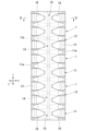
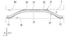
本実施形態のばね部材1は、図1および図2に示されるように、第1方向Zで互いに対向する第1被押圧体W1と第2被押圧体W2との間に、第1被押圧体W1および第2被押圧体W2を、互いが第1方向Zに離反する向きに押圧した状態で設けられる。
ばね部材1は、伝導板11および支持板12を備えている。伝導板11および支持板12は、全域にわたって互いに非接合状態とされて設けられている。
An embodiment of a spring member according to the present invention will be described below with reference to the drawings.
As shown in FIGS. 1 and 2, the
The
伝導板11および支持板12はそれぞれ、第1方向Zに直交する第2方向Xの中間部が、第2被押圧体W2側に向けて突出するように湾曲若しくは屈曲している。
以下、第1方向Zに沿う第1被押圧体W1側を一方側といい、第1方向Zに沿う第2被押圧体W2側を他方側という。
第2方向Xに沿って、中央部から離れて端部に向かう側を外側といい、端部から離れて中央部に向かう側を内側という。
第1方向Zおよび第2方向Xに直交する方向を第3方向Yという。
Each of the
Hereinafter, the side of the first pressed body W1 along the first direction Z will be referred to as one side, and the side of the second pressed body W2 along the first direction Z will be referred to as the other side.
Along the second direction X, the side away from the center toward the end is called the outside, and the side away from the end toward the center is called the inside.
A direction orthogonal to the first direction Z and the second direction X is called a third direction Y. As shown in FIG.
図示の例では、伝導板11および支持板12はそれぞれ、第2方向Xに沿って中央部から外側に向かうに従い前記一方側に向けて延びている。伝導板11および支持板12はそれぞれ、前記他方側に向けて突の曲面状となるように湾曲している。言い換えれば、伝導板11および支持板12はそれぞれ、第3方向Yに延びる軸回りに湾曲して、前記他方側に向けて突の曲面状となっている。
なお、伝導板11および支持板12はそれぞれ、例えば、前記他方側に向けて尖るように屈曲してもよい。
In the illustrated example, the
Incidentally, each of the
伝導板11は、支持板12を形成する材質より電気伝導率および熱伝導率のうちの少なくとも1つが高い材質で形成されている。伝導板11は、例えば銅、若しくはアルミニウム等で形成されている。伝導板11の板厚は、例えば50μm~100μm程度となっている。
支持板12は、伝導板11を形成する材質よりヤング率が高い材質で形成されている。支持板12は、例えば炭素鋼、若しくはステンレス鋼等で形成されている。
The
The
伝導板11において、第2方向Xの両端部に、第1被押圧体W1に当接する第1当接部13が形成されるとともに、第2方向Xの中間部に、第2被押圧体W2に当接する第2当接部14が形成されている。
第2当接部14の第3方向Yの大きさは、第1当接部13の第3方向Yの大きさより大きくなっている。第2当接部14の面積は、第1当接部13の面積より広くなっている。なお、第2当接部14の面積は、第1当接部13の面積以下であってもよい。
In the
The size of the
第1当接部13は、伝導板11における第2方向Xの開放端縁11cが、第2方向Xの外側を向くように第2方向Xに延びている。第1当接部13は、前記一方側に向けて突の曲面状となるように湾曲している。言い換えれば、第1当接部13は、第3方向Yに延びる軸回りに湾曲して、前記一方側に向けて突の曲面状となっている。図1および図3に示されるように、第1当接部13の第3方向Yの大きさは、第2方向Xの全域にわたって同等になっている。
第2当接部14は、表裏面が第1方向Zを向く平板状に形成されている。
The
The
伝導板11において、第1当接部13と第2当接部14との間に位置する接続部11a、並びに第2当接部14は、第2方向Xの外側に向かうに従い、第3方向Yの大きさが小さくなっている。
伝導板11は、第1方向Zから見て、伝導板11における第2方向Xの中央部を通る直線(第3方向Yに延びる直線)に対して対称形状を呈する。伝導板11は、第1方向Zから見て、伝導板11における第3方向Yの中央部を通る直線(第2方向Xに延びる直線)に対して対称形状を呈する。
In the
The
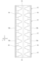
図2に示されるように、支持板12において、第2方向Xの両端部に、伝導板11における第2方向Xの両端部が各別に係止されるとともに、第2方向Xの中間部に、第2当接部14に当接して第2被押圧体W2との間で第2当接部14を第1方向Zに挟み込む第3当接部15が形成されている。
As shown in FIG. 2 , both ends of the
第3当接部15は、支持板12における第2方向Xの中央部に位置し、表裏面が第1方向Zを向く平板状に形成されている。第3当接部15の前記他方側を向く面が、伝導板11の第2当接部14に覆われている。第3当接部15および第2当接部14は、互いに非接合状態で当接している。
なお、第3当接部15および第2当接部14は、互いに接合してもよく、また、ばね部材1を、第1被押圧体W1と第2被押圧体W2との間に設ける前の状態では、第3当接部15および第2当接部14を、第1方向Zに互いに離間させてもよい。
The
In addition, the
支持板12における第2方向Xの両端部に、伝導板11における第2方向Xの両端部が各別に移動可能に係止されている。図示の例では、伝導板11および支持板12のうちのいずれか一方における少なくとも第2方向Xの両端部に、貫通孔16が形成されるとともに、いずれか他方における第2方向Xの両端部が、貫通孔16に移動可能に挿通されている。
言い換えれば、伝導板11および支持板12のうちのいずれか一方の、第2方向Xの中央部における第2方向Xの両側に、貫通孔16がそれぞれ形成されている。
Both ends of the
In other words, through
図示の例では、貫通孔16は、支持板12に形成されている。貫通孔16に、伝導板11における第1当接部13および接続部11aが、第2方向Xの内側から外側に向かうに従い、前記他方側から前記一方側に挿通されている。図1および図4に示されるように、貫通孔16の、第3方向Yの大きさは、第2方向Xの内側に向かうに従い小さくなっている。貫通孔16は、第1方向Zから見て台形状を呈する。
In the illustrated example, the through
貫通孔16は、図2および図4に示されるように、支持板12において、第2方向Xの開放端縁12bに連なる外端縁部12aと、第2方向Xの中央部と、の間に位置する部分の全域にわたって一体に形成されている。なお、貫通孔16は、支持板12のうち、第2方向Xの両端部に限って形成された、例えば第3方向Yに延びるスリット等であってもよい。
As shown in FIGS. 2 and 4, the through
支持板12において、貫通孔16よりも第2方向Xの外側に位置し、第2方向Xの開放端縁12bに連なる外端縁部12aは、支持板12における第2方向Xの開放端縁12bが、第2方向Xの外側を向くように第2方向Xに延びている。支持板12の外端縁部12aは、前記一方側に向けて突の曲面状となるように湾曲している。言い換えれば、外端縁部12aは、第3方向Yに延びる軸回りに湾曲して、前記一方側に向けて突の曲面状となっている。支持板12の外端縁部12aの前記一方側を向く面が、伝導板11の第1当接部13に覆われている。支持板12の外端縁部12a、および第1当接部13は、互いに非接合状態で当接している。なお、支持板12の外端縁部12a、および第1当接部13は、互いに接合してもよい。
In the
支持板12は、第1方向Zから見て、支持板12における第2方向Xの中央部を通る直線(第3方向Yに延びる直線)に対して対称形状を呈する。支持板12は、第1方向Zから見て、支持板12における第3方向Yの中央部を通る直線(第2方向Xに延びる直線)に対して対称形状を呈する。
The
図示の例では、伝導板11は弾性変形し、第1当接部13および第2当接部14が、支持板12に第1方向Zに圧接している。伝導板11および支持板12を互いに組付ける前の状態で、支持板12の第1方向Zの大きさは、伝導板11の第1方向Zの大きさより大きくなっている。
伝導板11および支持板12それぞれにおいて、貫通孔16を除き第1方向Zで互いに対向する部分は、全域にわたって互いに当接してもよい。
In the illustrated example, the
In each of the
伝導板11および支持板12はそれぞれ、図3および図4に示されるように、第3方向Yに連ねられて複数設けられている。伝導板11および支持板12の各数量は、図示の例に限らず適宜変更してもよい。
A plurality of
図3に示されるように、第3方向Yで互いに隣り合う伝導板11同士は、第2方向Xの中央部に限って連結片11bを介して連結されている。連結片11bの第2方向Xの大きさは、第2当接部14の第2方向Xの大きさより小さくなっている。第2当接部14における第3方向Yの大きさは、連結片11bから第2方向Xに離れるに従い小さくなっている。
このように複数の伝導板11が一体に形成された構成に対して、互いに分割された複数の支持板12が各別に取付けられたばね部材を採用してもよい。また、連結片11bは、第2方向Xに間隔をあけて複数設けられてもよく、また、伝導板11における第2方向Xの中央部から第2方向Xに離れた位置に設けられてもよい。
As shown in FIG. 3, the
In contrast to the configuration in which a plurality of
図4に示されるように、第3方向Yで互いに隣り合う支持板12同士は、第2方向Xの全長にわたって互いに連結されている。
なお、第3方向Yで互いに隣り合う支持板12同士は、第2方向Xにおける一部、若しくは複数個所に限って連結されてもよい。
このように複数の支持板12が一体に形成された構成に対して、互いに分割された複数の伝導板11が各別に取付けられたばね部材を採用してもよい。
As shown in FIG. 4, the
Note that the
In contrast to the configuration in which a plurality of
以上説明したように、本実施形態によるばね部材1によれば、伝導板11および支持板12を備えているので、ばね部材1を、第1被押圧体W1と第2被押圧体W2との間に設け、伝導板11とともに支持板12を第1方向Zに弾性変形させることで、伝導板11における第1当接部13および第2当接部14を、第1被押圧体W1および第2被押圧体W2に各別に強く当接させることが可能になり、主に伝導板11が有する例えば導電性および伝熱性等の特性を、設計通りに安定して発揮させることができる。
As described above, the
支持板12に、伝導板11の第2当接部14に当接して第2被押圧体W2との間で第2当接部14を第1方向Zに挟み込む第3当接部15が形成されているので、第2当接部14を、第2被押圧体W2に確実に強く当接させることが可能になり、第1被押圧体W1および第2被押圧体W2に対する伝導板11の接触状態を確実に安定させることができる。
ばね部材1が伝導板11を備えていて、支持板12の表面に、伝導板11と同じ材質のメッキが施されているのではない(または、伝導板11と同じ材質のメッキが施されている必要はない)ことから、電気伝導率および熱伝導率のうちの少なくとも1つを容易に高く確保することができるとともに、メッキの剥がれが無く、設計通りの前述した特性を、長期にわたって発揮させることができる。
The
The
支持板12における第2方向Xの両端部に、伝導板11における第2方向Xの両端部が各別に移動可能に係止されているので、ばね部材1の弾性変形に追従して、支持板12における第2方向Xの両端部、および伝導板11における第2方向Xの両端部を互いに相対移動させることが可能になり、例えば、支持板12および伝導板11それぞれにおける第2方向Xの両端部同士が各別に固着されている場合と比べて、耐久性を高めることができる。
Since both ends of the
伝導板11および支持板12のうちのいずれか他方における第2方向Xの両端部が、いずれか一方における少なくとも第2方向Xの両端部に形成された貫通孔16に移動可能に挿通されているので、支持板12における第2方向Xの両端部に、伝導板11における第2方向Xの両端部を各別に容易に移動可能に係止することができる。
Both ends in the second direction X of the other of the
貫通孔16における第3方向Yの大きさが、第2方向Xの中間部側に向かうに従い小さくなっているので、伝導板11および支持板12のうちのいずれか一方において、第2被押圧体W2から第1方向Zの押圧力を受ける第2当接部14若しくは第3当接部15の面積を広く確保することが可能になり、耐久性を高めることができる。
Since the size of the through-
伝導板11が弾性変形し、第1当接部13および第2当接部14が、支持板12に第1方向Zに圧接しているので、伝導板11および支持板12が、全域にわたって互いに非接合状態とされて設けられていても、ばね部材1単体において、伝導板11および支持板12を互いに離反させにくくすることが可能になり、ばね部材1を、第1被押圧体W1と第2被押圧体W2との間に容易に設けることができるとともに、第1方向Zの押圧力を受ける第1当接部13および第2当接部14の各剛性を高めることができる。
Since the
なお、本発明の技術的範囲は前記実施の形態に限定されるものではなく、本発明の趣旨を逸脱しない範囲において種々の変更を加えることが可能である。 The technical scope of the present invention is not limited to the above embodiments, and various modifications can be made without departing from the gist of the present invention.
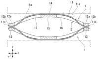
例えば、図5に示されるように、2つのばね部材1を、第1方向Zの向きを互いに逆向きにし、かつ2つのばね部材1の第1当接部13同士を第1方向Zに互いに当接させた状態で、第1被押圧体W1と第2被押圧体W2との間に設けてもよい。
この場合、一のばね部材1の第1当接部13が、他のばね部材1の伝導板11を介して第1被押圧体W1に当接する。また、2つのばね部材1が、第1方向Zに弾性変形するときに、2つのばね部材1において、第1方向Zで互いに当接した第1当接部13同士が擦れることなく一体に第2方向Xに変位し、かつ第1方向Zの弾性変形量を大きく確保することができる。
For example, as shown in FIG. 5, the two
In this case, the
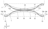
また、図6に示されるように、2つのばね部材1を、第1方向Zの向きを互いに逆向きにし、かつ2つのばね部材1の第2当接部14同士を第1方向Zに互いに当接させた状態で、第1被押圧体W1と第2被押圧体W2との間に設けてもよい。
この場合、一のばね部材1の第2当接部14が、他のばね部材1の伝導板11を介して第2被押圧体W2に当接し、また、第1方向Zの弾性変形量を大きく確保することができる。
Moreover, as shown in FIG. 6, the two
In this case, the
また、3つ以上のばね部材1を、第1被押圧体W1と第2被押圧体W2との間に設け、第1方向Zで隣り合うばね部材1の第1方向Zの向きを互いに逆向きにし、第1方向Zで互いに隣り合うばね部材1の第1当接部13同士、若しくは第2当接部14同士を第1方向Zで互いに当接させてもよい。
Further, three or
図3および図4で示した伝導板11および支持板12の各形状が、互いに入れ替わったばね部材2を採用してもよい。
すなわち、図3が、第1当接部13および第2当接部14に代えて第3当接部15を有する支持板22を示し、図4が、第3当接部15に代えて第1当接部13および第2当接部14を有する伝導板21を示している場合、図7に示されるように、伝導板21における第2方向Xの中間部を、支持板22における第2方向Xの中間部より前記他方側に位置させた状態で、伝導板21の貫通孔26に、支持板22の第2方向Xの両端部を、第2方向Xの内側から外側に向けて各別に挿通してもよい。
A
3 shows the
ばね部材1、2として、貫通孔16、26を有しない構成を採用してもよい。
例えば、図8に示されるように、伝導板31の第2方向Xの大きさを、支持板32の第2方向Xの大きさより大きくし、伝導板31により支持板32の前記他方側を向く面を第2方向Xの全長にわたって覆い、伝導板31における第2方向Xの両端部を、支持板32における第2方向Xの開放端縁12bを前記他方側から前記一方側に跨がせて、支持板32における第2方向Xの両端部に巻き付けたばね部材3を採用してもよい。
このばね部材3では、伝導板31における第2方向Xの両端部が、支持板32における第2方向Xの両端部を第1方向Zに締め付けており、支持板32および伝導板31それぞれにおける第2方向Xの両端部同士が各別に固着されている。また、このばね部材3では、第1当接部13において、伝導板31における第2方向Xの開放端縁31cが、第2方向Xの内側を向くように第2方向Xに延びている。
As the
For example, as shown in FIG. 8, the size of the
In this
さらに、このばね部材3において、1つの支持板32に対して、第3方向Yの大きさが支持板32より小さい複数の伝導板31が、第3方向Yに間隔をあけて複数設けられた構成を採用してもよく、また、1つの支持板32に対して、第3方向Yの大きさが支持板32より小さい複数の伝導板31が、第3方向Yに連結片11bを介して連結された部材が設けられた構成を採用してもよく、また、1つの支持板32に対して、第3方向Yの大きさが支持板32と比べて例えばわずかに小さい、若しくは同等の1つの伝導板31が設けられた構成を採用してもよい。
Further, in this
支持板12、22、32および伝導板11、21、31それぞれにおける第2方向Xの両端部同士は、例えばろう付け等により固着されてもよい。
ばね部材1、2、3として、伝導板11、21、31および支持板12、22、32がそれぞれ、第3方向Yに連ねられて複数設けられた構成を示したが、例えば図9に示されるばね部材1のように、伝導板11、21、31および支持板12、22、32を1つずつ備える構成を採用してもよいし、複数ずつ備える構成を採用してもよい。
Both ends of the
Although a plurality of
ばね部材1、2、3として、例えば、複数の支持板12、22、32が第3方向Yに連ねられて一体に形成された部材に対して、支持板12、22、32の数量より少ない数量の伝導板11、21、31が設けられた構成を採用してもよく、また、複数の支持板12、22、32が第3方向Yに連ねられて一体に形成された部材に対して、連結片11bを介して連結された複数の伝導板11、21、31と、1つの伝導板11、21、31と、の双方が設けられた構成を採用してもよい。
As the
また、複数の伝導板11、21、31が第3方向Yに連ねられて一体に形成された部材に対して、伝導板11、21、31の数量より少ない数量の支持板12、22、32が設けられた構成を採用してもよく、また、複数の伝導板11、21、31が第3方向Yに連ねられて一体に形成された部材に対して、第3方向Yに連ねられて一体に形成された複数の支持板12、22、32と、1つの支持板12、22、32と、の双方が設けられた構成を採用してもよい。
In addition, the number of
以下、前記実施形態のばね部材1、2、および3を、他の構造に適用した実施例を説明する。以下便宜的に「ばね部材1」と記載するが、以下の実施例に対してばね部材1、2、および3のいずれをも適用可能である。前記実施形態で説明した第2方向X、第3方向Y、および第1方向Zは、以下の実施例においても用いられ、第2方向X、第3方向Y、および第1方向Zと、ばね部材1と、の関係は前記実施形態と同一である。
Hereinafter, examples in which the
(実施例1)
図10~図14を参照して、前記実施形態のばね部材1を、接続端子構造40に適用した実施例1を説明する。
接続端子構造40は、後述する端子45と電気的に接続(導通)可能なメス端子として構成され、枠体41と、前記実施形態の2つのばね部材1とを備える。
(Example 1)
Example 1 in which the
The
枠体41は、第2方向Xに見た際にいずれもU字状に形成された第1枠部材42と第2枠部材43とを備える。第1枠部材42と第2枠部材43は互いに同等の構成を有している。第1枠部材42は、平板状の底壁部42aと、底壁部42aの第3方向Yの両端部に各別に接続され、かつ第1方向Zに突出した側壁部42bと、を備える。同様に第2枠部材43は、平板状の底壁部43aと、底壁部43aの第3方向Yの両端部に各別に接続され、かつ第1方向Zに突出した側壁部43bと、を備える。第1枠部材42と第2枠部材43は、それらの内部空間が互いに対向する姿勢で、互いに接続されている。すなわち、第1枠部材42の2つの側壁部42bが、第2枠部材43の2つの側壁部43bに各別に接しており、枠体41の内側には空間が設けられている。第1枠部材42及び第2枠部材43の第2方向Xの両端部の少なくとも一方は、第2方向Xに開放されており、当該一方の側において、枠体41の内部空間は外部に連通している。第1枠部材42及び第2枠部材43の第2方向Xの両端部の他方は、第2方向Xに開放されてもよいし、当該他方に、図示しない壁部が設けられてもよい。第1枠部材42と第2枠部材43はいずれも導電性材料で形成されている。第1枠部材42と第2枠部材43を形成する材料は、通電可能な材料ならば特に限定されず、例えば銅やアルミニウム等の金属が挙げられる。実施例1の第1枠部材42と第2枠部材43は、対向する各々の側壁部が接触することで、互いに電気的に接続されている。
The
枠体41の内部空間には、ばね部材1が2つ配置されている。実施例1の各ばね部材1において、第3方向Yに4つの伝導板11が並んで配置されているが、伝導板11の数は4以外であってもよい。また、第3方向Yに4つの支持板12が並んで配置されているが、支持板12の数は4以外であってもよい。2つのばね部材1は、第1方向Zにおいて互いに逆向きにして、かつそれぞれの第2当接部14が互いに対向し接するように、枠体41の内部空間に配置されている。第1方向Zに見た際には、2つのばね部材1は互いに重なって配置されている(図12参照)。2つのばね部材1のうち、一方のばね部材1が、第1枠部材42の内部空間(U字状の内側)に収容され、当該一方のばね部材1の第1当接部13が、底壁部42aの内面(内部空間に対向する面)に接して電気的に接続されており、他方のばね部材1が、第2枠部材43の内部空間(U字状の内側)に収容され、当該他方のばね部材1の第1当接部13が、底壁部43aの内面(内部空間に対向する面)に接して電気的に接続されている。図10および図11に示すように、後述する端子45の接続端子構造40に対する電気的接続が行われていない状態において、2つのばね部材1の第2当接部14が互いに接している構成でもよいし、2つのばね部材1の第2当接部14が互いに離間している構成でもよい。
Two
図13および図14に示すように、実施例1の接続端子構造40は、2つのばね部材1の間に板状の端子45を配置可能に構成されている。端子45は、2つのばね部材1の間に挿入可能なオス端子として構成され、例えば銅やアルミニウム等の導電性材料を用いて矩形板状に形成されている。なお、端子45の形状は矩形板状に限定されず、柱状や、第2方向Xに延びる棒状の部材が第3方向Yに複数配列された櫛歯状部材であってもよい。端子45は、絶縁性材料で形成された部材の外面に、例えばメッキ等によって導電性の層を設けた構造であってもよい。実施例1の端子45は、第1方向Zの一方側の面と他方側の面とが、電気的に導通した構成となっている。
As shown in FIGS. 13 and 14 , the
何ら荷重をかけていない2つのばね部材1の第1方向Zの厚みと、端子45の第1方向Zの厚みとの和が、枠体41の内部空間における第1方向Zの大きさ(すなわち、底壁部42aの内面と底壁部43aの内面との間の第1方向Zの距離)よりも大きい。このため、2つのばね部材1の間に端子45が配置されている状態では、2つのばね部材1は圧縮変形されており、この圧縮に基づく押圧力を端子45と枠体41(第1枠部材42および第2枠部材43)とに与えている。
The sum of the thickness in the first direction Z of the two
図10~図14を参照して、端子45を接続端子構造40に対して電気的に接続する手順について説明する。
図10~図12に示す端子45が挿入されていない接続端子構造40に対して、端子45を2つのばね部材1の第2当接部14に向けて第2方向Xに移動させる。2つのばね部材1は互いに向けて突となるように湾曲または屈曲しているので、移動する端子45は、2つのばね部材1の曲面または斜面に当接し、さらに端子45を第2方向Xに移動させると、2つのばね部材1は互いに離れる方向の力を端子45から受け、接していた2つの第2当接部14は離間する。2つの第2当接部14の第1方向Zの間隔が、端子45の第1方向Zの厚み以上になると、端子45は2つのばね部材1の間に挿入され、2つの第2当接部14が、端子45の第2方向Xの中間部分(端子45の第2方向Xの両端部以外の部分)の表裏面にそれぞれ当接する。
A procedure for electrically connecting the terminal 45 to the
The
上述したように、2つのばね部材1のうち、一方のばね部材1の第1当接部13が、底壁部42aの内面に接して電気的に接続され、他方のばね部材1の第1当接部13が、底壁部43aの内面に接して電気的に接続されているので、第1枠部材42、一方のばね部材1の伝導板11、および端子45の一方側の面が電気的に接続され、第2枠部材43、他方のばね部材1の伝導板11、および端子45の他方側の面が電気的に接続される。また、実施例1の第1枠部材42と第2枠部材43は互いに電気的に接続され、端子45は、第1方向Zの一方側の面と他方側の面とが電気的に導通した構成となっているので、端子45が接続端子構造40に挿入されると、第1枠部材42、第2枠部材43、2つのばね部材1、および端子45は電気的に接続される。このようにして、接続端子構造40と端子45の電気的な接続が完了する。
As described above, of the two
前記実施形態で説明したように、本発明の1では、伝導板11と支持板12とを別体で構成することから、必要な電気導通性(または必要な電気導通性と伝熱性)を伝導板11によって確保しつつ、適切な弾性力や押圧力を支持板12によって実現することができる。このため、端子45の機械的強度に合わせた適切な弾性力や押圧力を支持板12によって得ることができ、例えば接続端子構造40と端子45が接続されている状態で振動が加えられ、端子45の接続端子構造40に対する相対位置や姿勢が僅かに変更されるような場合であっても、端子45に対して過度の力が加えられることを防止でき、端子45の破損を抑制することができる。また、接続端子構造40と端子45との電気的接続が維持されたまま、例えば両者の第2方向Xの相対位置が変更されることを前提とする構造であっても(例えばロボットの関節部分に用いられる場合等)、同様に、端子45に対して過度の力が加えられることを防止でき、端子45の破損を抑制することができる。
As described in the above embodiment, according to the first aspect of the present invention, since the
接続端子構造40と端子45の電気的な接続を解消するには、端子45を接続端子構造40から離間するように第2方向Xに移動させ、端子45を2つのばね部材1の間から離脱させる。これにより、第2当接部14と端子45とが互いに離間し、接続端子構造40と端子45の電気的な接続が解消される。
To break the electrical connection between the
なお、前記実施例1に対して以下の構成を適用してもよい。
前記実施例1では、枠体41における第1枠部材42と第2枠部材43は別体で構成されているが、第1枠部材42と第2枠部材43とが一体で構成されてもよい。
前記実施例1において、第1枠部材42と第2枠部材43の一方が、側壁部を備えず、当該一方の底壁部が、第1枠部材42と第2枠部材43の他方の側壁部に接続される構成でもよい。
前記実施例1において、接続端子構造40と端子45とを備える接続端子機構を構成してもよい。
前記実施例1において、ばね部材1を枠体41に固定する何らかの固定構造が用いられてもよい。固定構造としては、ろう付け、溶接、接着、ネジ等の締結構造などが挙げられる。
Note that the following configuration may be applied to the first embodiment.
In Example 1, the
In Example 1, one of the
In Example 1, a connection terminal mechanism including the
In Example 1, any fixing structure for fixing the
前記実施例1では、枠体41の内部空間に2つのばね部材1が設けられているが、1つのばね部材1のみが枠体41内に設けられてもよい。例えば、第1枠部材42の内側に1つのばね部材1が、その第1当接部13が底壁部42aの内面に接するように収容され、第2枠部材43側にばね部材1は設けられておらず、端子45が接続端子構造40に挿入されると、第1枠部材42、当該1つのばね部材1の伝導板11、および端子45の一方側の面が電気的に接続され、さらに、第2枠部材43および端子45の他方側の面が電気的に接続される構成であってもよい。すなわち、底壁部43aの内面と端子45の他方側の面が電気的に接続される構成であってもよい。
ばね部材1が1つのみ枠体41内に設けられ、すなわち第1枠部材42の内側に配置される場合において、端子45と直接に接する第2枠部材43を、樹脂等の電気的絶縁材料(以下単に絶縁材料という)で形成してもよい。
Although the two
In the case where only one
前記実施例1では、接続端子構造40と端子45との電気的接続を目的としているが、この目的とともに、またはこの目的に代えて、接続端子構造40と端子45との間の伝熱性の確保、例えば接続端子構造40と端子45の一方が有する熱を他方を介して放熱させる構成であってもよい。例えば導電性と伝熱性を両立させる構成として、端子45の第1方向Zの一方側の面を導電性材料で形成し、他方側の面を絶縁材料で形成し、端子45を接続端子構造40に挿入した際に、第1枠部材42、一方のばね部材1の伝導板11、および端子45の一方側の面が電気的に接続されるが、第2枠部材43、他方のばね部材1の伝導板11、および端子45の他方側の面が必ずしも電気的には接続されず、伝熱性を確保するように接続され、端子45の熱を他方のばね部材1を介して第2枠部材43側に放熱させる構成でもよい。第1枠部材42、一方のばね部材1の伝導板11、および端子45の一方側の面における導電によって熱が生じる場合があるが、この熱を、第2枠部材43側に放熱するよう構成してもよい。なお、この場合、第2枠部材43や他方のばね部材1の伝導板11が絶縁材料で形成されてもよいし、第1枠部材42と第2枠部材43との間が電気的に絶縁されてもよい。第1枠部材42と第2枠部材43との間を電気的に絶縁するために、両者の間に絶縁材料を挟んだり、両者を互いに離間させたりしてもよい。第2枠部材43を放熱側とする場合は、例えば、第2枠部材43に冷却構造が設けられてもよい。冷却構造として、ヒートシンクや、冷却流体を流通させる冷却管を用いた構造が挙げられる。
In the first embodiment, the purpose is to electrically connect the
前記実施例1では、端子45の第1方向Zの一方側の面と他方側の面とが、電気的に導通した構成となっている。しかし、端子45の第1方向Zの一方側の面と他方側の面とがそれぞれ導電性材料で形成されているものの、これら面の間が絶縁され、かつ、第1枠部材42と第2枠部材43とが絶縁されている構成であってもよい。端子45の第1方向Zの一方側の面と他方側の面とを絶縁するために、絶縁材料を2つの導電性材料で挟み込んだ構造が挙げられ、例えばメッキ等によってこの構造を形成してもよい。この場合、端子45を接続端子構造40に挿入すると、第1の系統である、第1枠部材42、一方のばね部材1の伝導板11、および端子45の一方側の面が電気的に接続され、第2の系統である、第2枠部材43、他方のばね部材1の伝導板11、および端子45の他方側の面が電気的に接続されるが、前記第1および第2の系統は互いに絶縁されており、2系統の電気的接続を確保することが可能となる。
In Example 1, the surface on one side and the surface on the other side of the terminal 45 in the first direction Z are electrically connected. However, although one side surface and the other side surface of the terminal 45 in the first direction Z are each formed of a conductive material, these surfaces are insulated, and the
前記実施例1では、端子45を第2方向Xに移動させて、接続端子構造40の2つのばね部材1の間に挿入しているが、端子45を第3方向Yに移動させて、2つのばね部材1の間に挿入する構成でもよい。この場合、端子45が挿入可能なように、側壁部42bおよび43bの位置は適宜変更すればよい。また、端子45を挿入する前の2つのばね部材1の第2当接部14は互いに接しているが、端子45を第3方向Yに挿入可能とするための構造を適宜採用してもよい。例えば、端子45の端面に図示しない突出部が設けられ、当該突出部は、図11に示す第2当接部14の第2方向Xに隣り合う空間Sに挿入可能であり、端子45を接続端子構造40に向けて第3方向Yに移動させると、まず前記突出部が空間Sに挿入され、さらに端子45を移動させることで当該突出部によって2つのばね部材1が互いに押し拡げられ、端子45が2つのばね部材1の間に挿入可能となる構成であってもよい。また、端子45の第1方向Zの厚みと同等の厚みを有する絶縁材料の板状部材(以下絶縁板という)を予め2つのばね部材1の間に配置しておき、端子45を接続端子構造40に向けて第3方向Yに移動させて前記絶縁板を押して移動させ、前記絶縁板が配置されていた位置に端子45を代わりに配置させて、接続端子構造40と端子45とを電気的に接続させる構成でもよい。前記絶縁板を用いる場合は、端子45を接続端子構造40から離脱させる際に、前記絶縁板を2つのばね部材1の間に戻す機構を設けてもよい。
In the first embodiment, the
(実施例1の変形例)
前記実施例1の変形例を以下に説明する。
前記実施例1では、接続端子構造40と端子45との間の電気的接続(または電気的接続と伝熱)を確保することを目的としているが、図10~図14と類似の構成を用いた上で、接続端子構造40を例えばスイッチのように使用することも考えられる。
この場合、第1枠部材42と第2枠部材43との間は電気的に絶縁されている。例えば、第1枠部材42と第2枠部材43との間に絶縁材料が設けられてもよいし、第1枠部材42と第2枠部材43とが互いに離間していてもよい。何ら荷重をかけていない2つのばね部材1の第1方向Zの厚みの和が、枠体41の内部空間における第1方向Zの大きさよりも大きい。このため、2つのばね部材1の間に端子45が配置されていなくても、2つのばね部材1は圧縮変形されており、この圧縮に基づく押圧力を第1枠部材42と第2枠部材43とに与えている。また、2つのばね部材1の第2当接部14は互いに接している。第1枠部材42、第2枠部材43、および2つのばね部材1の伝導板11は導電性材料で形成されているので、端子45が2つのばね部材1の間に配置されていない状態では、第1枠部材42、一方のばね部材1の伝導板11、他方のばね部材1の伝導板11、および第2枠部材43は、電気的に接続されている。
(Modification of Example 1)
A modification of the first embodiment will be described below.
In the first embodiment, the purpose is to secure electrical connection (or electrical connection and heat transfer) between the
In this case, the
本変形例の端子45は、少なくとも、第1方向Zの一方側の面と他方側の面とが電気的に絶縁された構成となっている。この構成を得るために、端子45の全体を絶縁材料で形成してもよいし、絶縁材料を介在させることで端子45の第1方向Zの一方側の面と他方側の面とを電気的に絶縁させてもよい。後者の場合、端子45の第1方向Zの少なくとも一方の面が、導電性材料で形成されてもよい。
The terminal 45 of this modified example has a configuration in which at least one side surface in the first direction Z and the other side surface are electrically insulated. In order to obtain this configuration, the
このような構成では、端子45を接続端子構造40に挿入させていない状態では、上述したように、第1枠部材42、一方のばね部材1の伝導板11、他方のばね部材1の伝導板11、および第2枠部材43が、電気的に接続されている。すなわち、スイッチとしては「入」の状態となっている。
他方、端子45を接続端子構造40の2つのばね部材1の間に挿入させると、端子45の第1方向Zの一方側の面と他方側の面とが電気的に絶縁されているので、2つのばね部材1の第2当接部14の間が電気的に切断され、第1枠部材42から2つのばね部材1を介した第2枠部材43までの電気的接続が解消される。すなわち、スイッチとしては「切」の状態となる。このようにして、端子45を用いて接続端子構造40をスイッチのように機能させることが可能となる。
In such a configuration, when the terminal 45 is not inserted into the
On the other hand, when the terminal 45 is inserted between the two
(実施例2)
図15を参照して、前記実施形態のばね部材1を、放熱構造50に適用した実施例2を説明する。
放熱構造50は、半導体デバイスDを放熱させるための構造であって、前記実施形態のばね部材1と、当該ばね部材1に接続されたヒートシンク51とを備える。
半導体デバイスDは、半導体素子を樹脂等の絶縁材料で被覆した構造であり、例えば、パワー半導体を備え、その動作とともに熱を生じるパワーモジュール等が挙げられる。
ヒートシンク51は、半導体デバイスDの熱を効率よく放出するための部材であり、例えば櫛歯形状を有している。ヒートシンク51を構成する材料は、効率よく放熱できるのであれば特に限定されず、例えばアルミニウムや銅などの金属が挙げられる。
(Example 2)
Example 2 in which the
The
The semiconductor device D has a structure in which a semiconductor element is covered with an insulating material such as resin, and includes, for example, a power module that includes a power semiconductor and generates heat as it operates.
The
ばね部材1は、半導体デバイスDとヒートシンク51との間に配置されている。図15に示すように、ばね部材1がヒートシンク51に向けて突となるように配置され、第1当接部13が半導体デバイスDに接し、第2当接部14がヒートシンク51に接している。なお、ばね部材1が半導体デバイスDに向けて突となるように配置されてもよい。実施例2のばね部材1の伝導板11は、少なくとも放熱に適した熱伝導率を有していればよい。半導体デバイスDとヒートシンク51との間に複数のばね部材1が配置されてもよい。
半導体デバイスDとヒートシンク51をばね部材1を介して接続する構造は特に限定されず、半導体デバイスD(またはヒートシンク51)の自重によってばね部材1を圧縮し、その反発力を半導体デバイスDとヒートシンク51とに与えつつ、半導体デバイスDと第1当接部13との接続、および第2当接部14とヒートシンク51との接続を確保する構成でもよい。また、ばね部材1を圧縮した状態で半導体デバイスDとヒートシンク51との間に保持するために、ネジ部材等の締結部材によって半導体デバイスDとヒートシンク51とを互いに締結してもよい。ネジ部材を用いる場合は、当該ネジ部材をヒートシンク51に螺入させるとともに、半導体デバイスDに設けられた貫通孔に相対移動可能に挿通させ、ネジ部材の頭部をヒートシンク51の半導体デバイスDを挟んだ反対側に位置させてもよい。第1方向Zに貫通する貫通孔をばね部材1に設け、ネジ部材を当該貫通孔に挿通させてもよい。さらに、ネジ部材を1つのみ用いてもよいし、複数用いてもよい。また、ネジ部材を直接半導体デバイスDに連結するのではなく、半導体デバイスDを例えば板状の保持部材に設け、この保持部材とヒートシンク51との間をネジ部材で締結してもよい。ネジ部材以外に、ばね部材1を圧縮した状態で半導体デバイスDとヒートシンク51との間に保持するために、半導体デバイスDとヒートシンク51をまとめて把持するU字状の部材やクリップ部材等を用いてもよい。
The structure for connecting the semiconductor device D and the
ヒートシンク51のばね部材1側の面は平面状に形成されており、当該面の、第2方向Xと第3方向Yのいずれの位置においても、ヒートシンク51は第2当接部14(または第1当接部13)との間で伝熱できるように接続可能である。ヒートシンク51の前記櫛歯形状は、ばね部材1とは逆側に設けられている。一方、半導体デバイスDは、発熱量の大きな半導体素子(例えばパワー半導体)からの熱を効率よく放出させるために、ばね部材1の第1当接部13(または第2当接部14)は、半導体デバイスDのうち、当該半導体素子の近傍に接するように配置してもよい。
上述したように、前記実施形態のばね部材1では、伝導板11と支持板12とを別体で構成することから、適切な弾性力や押圧力を支持板12によって確保した上で、必要な熱伝導性を伝導板11によって容易かつ適切に確保することができる。よって、本変形例2によれば、従来よりも効率よく適切に半導体デバイスDの放熱を行うことが可能となる。
The surface of the
As described above, in the
その他、本発明の趣旨を逸脱しない範囲で、前記実施形態における構成要素を周知の構成要素に置き換えることは適宜可能であり、また、前記した実施形態、実施例および変形例を適宜組み合わせてもよい。 In addition, it is possible to appropriately replace the components in the above-described embodiments with known components without departing from the scope of the present invention, and the above-described embodiments, examples, and modifications may be combined as appropriate. .
本発明は、例えば、次の態様を採ることができる。 The present invention can adopt, for example, the following aspects.
前記課題を解決して、このような目的を達成するために、本発明の一態様のばね部材は、第1方向で互いに対向する第1被押圧体と第2被押圧体との間に、前記第1被押圧体および前記第2被押圧体を、互いが前記第1方向に離反する向きに押圧した状態で設けられるばね部材であって、伝導板および支持板を備え、前記伝導板は、前記支持板を形成する材質より電気伝導率および熱伝導率のうちの少なくとも1つが高い材質で形成され、前記支持板は、前記伝導板を形成する材質よりヤング率が高い材質で形成され、前記伝導板および前記支持板はそれぞれ、前記第1方向に直交する第2方向の中間部が、前記第2被押圧体側に向けて突出するように湾曲若しくは屈曲し、前記伝導板において、前記第2方向の両端部に、前記第1被押圧体に当接する第1当接部が形成されるとともに、前記第2方向の中間部に、前記第2被押圧体に当接する第2当接部が形成され、前記支持板において、前記第2方向の両端部に、前記伝導板における前記第2方向の両端部が各別に係止されるとともに、前記第2方向の中間部に、前記第2当接部に当接して前記第2被押圧体との間で前記第2当接部を前記第1方向に挟み込む第3当接部が形成されている。 In order to solve the above problems and achieve such an object, a spring member according to one aspect of the present invention includes a first pressed body and a second pressed body facing each other in a first direction, A spring member provided in a state in which the first pressed body and the second pressed body are pressed against each other in the first direction, the spring member comprising a conductive plate and a support plate, wherein the conductive plate is , at least one of electrical conductivity and thermal conductivity is higher than that of the material forming the support plate, and the support plate is formed of a material having a Young's modulus higher than that of the material forming the conduction plate; Each of the conductive plate and the support plate is curved or bent such that an intermediate portion in a second direction perpendicular to the first direction protrudes toward the second pressed body. A first contact portion that contacts the first pressed body is formed at both ends in two directions, and a second contact portion that contacts the second pressed body is formed at an intermediate portion in the second direction. is formed, and both end portions of the conductive plate in the second direction are respectively engaged with both end portions of the support plate in the second direction, and an intermediate portion in the second direction is provided with the second A third contact portion is formed that contacts the contact portion and sandwiches the second contact portion in the first direction with the second pressed body.
この発明によれば、ばね部材が、伝導板および支持板を備えているので、ばね部材を、第1被押圧体と第2被押圧体との間に設け、伝導板とともに支持板を第1方向に弾性変形させることで、伝導板における第1当接部および第2当接部を、第1被押圧体および第2被押圧体に各別に強く当接させることが可能になり、主に伝導板が有する例えば導電性および伝熱性等の特性を、設計通りに安定して発揮させることができる。
支持板に、伝導板の第2当接部に当接して第2被押圧体との間で第2当接部を第1方向に挟み込む第3当接部が形成されているので、第2当接部を、第2被押圧体に確実に強く当接させることが可能になり、第1被押圧体および第2被押圧体に対する伝導板の接触状態を確実に安定させることができる。
ばね部材が伝導板を備えていて、支持板の表面に、伝導板と同じ材質のメッキが施されているのではないことから、電気伝導率および熱伝導率のうちの少なくとも1つを容易に高く確保することができるとともに、メッキの剥がれが無く、設計通りの前述した特性を、長期にわたって発揮させることができる。
According to this aspect of the invention, the spring member includes the conduction plate and the support plate. By elastically deforming in the direction, the first contact portion and the second contact portion of the conductive plate can be brought into strong contact with the first pressed body and the second pressed body, respectively. The properties of the conductive plate, such as electrical conductivity and heat transfer, can be stably exhibited as designed.
The support plate is formed with the third contact portion that contacts the second contact portion of the conductive plate and sandwiches the second contact portion in the first direction with the second pressed body. It is possible to bring the abutting portion into strong contact with the second pressed body, and to reliably stabilize the contact state of the conductive plate with the first pressed body and the second pressed body.
Since the spring member has a conductive plate and the surface of the support plate is not plated with the same material as the conductive plate, at least one of electrical conductivity and thermal conductivity can be easily improved. It is possible to secure a high value, prevent peeling of the plating, and exhibit the above-described characteristics as designed for a long period of time.
前記一態様において、前記支持板における前記第2方向の両端部に、前記伝導板における前記第2方向の両端部が各別に移動可能に係止されてもよい。 In the above aspect, both ends of the conductive plate in the second direction may be movably locked to both ends of the support plate in the second direction.
この場合、支持板における第2方向の両端部に、伝導板における第2方向の両端部が各別に移動可能に係止されているので、ばね部材の弾性変形に追従して、支持板における第2方向の両端部、および伝導板における第2方向の両端部を互いに相対移動させることが可能になり、例えば、支持板および伝導板それぞれにおける第2方向の両端部同士が各別に固着されている場合と比べて、耐久性を高めることができる。 In this case, both ends of the conductive plate in the second direction are movably locked to both ends of the support plate in the second direction. Both ends in two directions and both ends of the conductive plate in the second direction can be moved relative to each other. For example, both ends in the second direction of the support plate and the conductive plate are fixed to each other. Durability can be improved compared to the case.
前記一態様において、前記伝導板および前記支持板のうちのいずれか一方における少なくとも前記第2方向の両端部に、貫通孔が形成されるとともに、いずれか他方における前記第2方向の両端部が、前記貫通孔に移動可能に挿通されてもよい。 In the above aspect, through holes are formed in at least both ends in the second direction of one of the conductive plate and the support plate, and both ends of the other in the second direction are It may be movably inserted through the through hole.
この場合、伝導板および支持板のうちのいずれか他方における第2方向の両端部が、いずれか一方における少なくとも第2方向の両端部に形成された貫通孔に移動可能に挿通されているので、支持板における第2方向の両端部に、伝導板における第2方向の両端部を各別に容易に移動可能に係止することができる。 In this case, both ends in the second direction of the other of the conductive plate and the support plate are movably inserted through the through-holes formed in at least both ends in the second direction of one of them. Both ends of the conductive plate in the second direction can be easily and movably locked to both ends of the support plate in the second direction.
前記一態様において、前記貫通孔の、前記第1方向および前記第2方向に直交する第3方向の大きさが、前記第2方向の中間部側に向かうに従い小さくなってもよい。 In the one aspect described above, the size of the through-hole in a third direction perpendicular to the first direction and the second direction may decrease toward an intermediate portion in the second direction.
この場合、貫通孔における第3方向の大きさが、第2方向の中間部側に向かうに従い小さくなっているので、伝導板および支持板のうちのいずれか一方において、第2被押圧体から第1方向の押圧力を受ける第2当接部若しくは第3当接部の面積を広く確保することが可能になり、耐久性を高めることができる。 In this case, since the size of the through-hole in the third direction decreases toward the intermediate portion in the second direction, either one of the conductive plate and the support plate can be moved from the second pressed body to the second pressed body. It becomes possible to secure a large area of the second contact portion or the third contact portion that receives the pressing force in one direction, and the durability can be improved.
前記一態様において、前記伝導板は弾性変形し、前記第1当接部および前記第2当接部が、前記支持板に前記第1方向に圧接してもよい。 In the one aspect, the conductive plate may be elastically deformed, and the first contact portion and the second contact portion may be pressed against the support plate in the first direction.
この場合、伝導板が弾性変形し、第1当接部および第2当接部が、支持板に第1方向に圧接しているので、例えば、伝導板および支持板が、全域にわたって互いに非接合状態とされて設けられていても、ばね部材単体において、伝導板および支持板を互いに離反させにくくすることが可能になり、ばね部材を、第1被押圧体と第2被押圧体との間に容易に設けることができるとともに、第1方向の押圧力を受ける第1当接部および第2当接部の各剛性を高めることができる。 In this case, the conductive plate is elastically deformed, and the first contact portion and the second contact portion are pressed against the support plate in the first direction. Even if the spring member is provided as a state, it is possible to make it difficult for the conductive plate and the support plate to separate from each other, and the spring member can be placed between the first pressed body and the second pressed body. In addition, the rigidity of each of the first contact portion and the second contact portion that receives the pressing force in the first direction can be increased.
1、2、3 ばね部材
11、21、31 伝導板
12、22、32 支持板
13 第1当接部
14 第2当接部
15 第3当接部
16、26 貫通孔
40 接続端子構造
W1 第1被押圧体
W2 第2被押圧体
X 第2方向
Y 第3方向
Z 第1方向
1, 2, 3
Claims (6)
第1部材および第2部材を備え、
前記第1部材は、前記第2部材を形成する材質より電気伝導率および熱伝導率のうちの少なくとも1つが高い材質で形成され、
前記第2部材は、前記第1部材を形成する材質よりヤング率が高い材質で形成され、
前記第1部材において、前記第1方向に直交する第2方向の両端部が、前記第1被押圧体に当接するとともに、前記第2方向の中間部が、前記第2被押圧体に当接し、
前記第2部材において、前記第2方向の両端部が、前記第1部材における前記第2方向の両端部を介して前記第1被押圧体を押圧するとともに、前記第2方向の中間部が、前記第1部材における前記第2方向の中間部を介して前記第2被押圧体を押圧する、ばね部材。 A spring member that presses a first pressed body and a second pressed body that are opposed to each other in a first direction so that they are separated from each other in the first direction,
comprising a first member and a second member;
The first member is made of a material having at least one of electrical conductivity and thermal conductivity higher than that of the material forming the second member,
The second member is formed of a material having a higher Young's modulus than the material forming the first member,
In the first member, both end portions in a second direction orthogonal to the first direction abut against the first pressed body, and an intermediate portion in the second direction abuts against the second pressed body. ,
In the second member, both ends in the second direction press the first pressed body via both ends in the second direction of the first member, and an intermediate portion in the second direction A spring member that presses the second pressed body via an intermediate portion of the first member in the second direction.
前記ばね部材が配置された内部空間を有し、かつ導電性材料で形成された枠体と、を備える接続端子構造であって、
前記ばね部材は、前記枠体の内部空間に2つ配置され、
2つの前記ばね部材は、前記第1方向において互いに逆向きにして、かつそれぞれの前記第1部材における前記第2方向の中間部が互いに対向し接するとともに、前記第1部材における前記第2方向の両端部が、前記枠体の内部空間を画成する内面のうち、前記第1方向で互いに対向する内面に当接するように、前記枠体の内部空間に配置され、
前記内部空間は、前記第2方向の両端部のうちの少なくとも一方が開放されており、この開放部分を通して、2つの前記ばね部材それぞれの前記第1部材における前記第2方向の中間部同士の間に、端子を配置可能に構成されている、接続端子構造。 A spring member according to any one of claims 1 to 5;
A connection terminal structure comprising a frame body having an internal space in which the spring member is arranged and formed of a conductive material,
Two of the spring members are arranged in the internal space of the frame,
The two spring members are oriented in opposite directions to each other in the first direction, and the intermediate portions of the first members in the second direction face each other and are in contact with each other. both end portions are arranged in the internal space of the frame so as to abut against inner surfaces facing each other in the first direction among inner surfaces defining the internal space of the frame;
At least one of the two ends in the second direction of the internal space is open. A connection terminal structure configured so that a terminal can be arranged in the connection terminal structure.
Applications Claiming Priority (4)
| Application Number | Priority Date | Filing Date | Title |
|---|---|---|---|
| JP2020180435 | 2020-10-28 | ||
| JP2020180435 | 2020-10-28 | ||
| PCT/JP2021/038324 WO2022091824A1 (en) | 2020-10-28 | 2021-10-15 | Spring member |
| JP2022554298A JP7177306B2 (en) | 2020-10-28 | 2021-10-15 | spring material |
Related Parent Applications (1)
| Application Number | Title | Priority Date | Filing Date |
|---|---|---|---|
| JP2022554298A Division JP7177306B2 (en) | 2020-10-28 | 2021-10-15 | spring material |
Publications (1)
| Publication Number | Publication Date |
|---|---|
| JP2023016830A true JP2023016830A (en) | 2023-02-02 |
Family
ID=81382517
Family Applications (2)
| Application Number | Title | Priority Date | Filing Date |
|---|---|---|---|
| JP2022554298A Active JP7177306B2 (en) | 2020-10-28 | 2021-10-15 | spring material |
| JP2022180567A Pending JP2023016830A (en) | 2020-10-28 | 2022-11-10 | Spring member and connection terminal structure |
Family Applications Before (1)
| Application Number | Title | Priority Date | Filing Date |
|---|---|---|---|
| JP2022554298A Active JP7177306B2 (en) | 2020-10-28 | 2021-10-15 | spring material |
Country Status (5)
| Country | Link |
|---|---|
| US (1) | US20230400078A1 (en) |
| EP (1) | EP4239211A1 (en) |
| JP (2) | JP7177306B2 (en) |
| CN (1) | CN116507825A (en) |
| WO (1) | WO2022091824A1 (en) |
Families Citing this family (2)
| Publication number | Priority date | Publication date | Assignee | Title |
|---|---|---|---|---|
| JP7419613B1 (en) | 2022-04-26 | 2024-01-22 | 日本発條株式会社 | spring member |
| WO2023210591A1 (en) * | 2022-04-26 | 2023-11-02 | 日本発條株式会社 | Spring member |
Family Cites Families (6)
| Publication number | Priority date | Publication date | Assignee | Title |
|---|---|---|---|---|
| JP4525582B2 (en) | 2005-12-15 | 2010-08-18 | 株式会社デンソー | Power converter |
| JP2014011936A (en) | 2012-07-03 | 2014-01-20 | Denso Corp | Power converter |
| JP6412877B2 (en) * | 2013-10-28 | 2018-10-24 | 日本発條株式会社 | Pressing structure and pressing unit |
| JP6221979B2 (en) * | 2014-07-25 | 2017-11-01 | 株式会社デンソー | Stacked cooler |
| WO2017033802A1 (en) * | 2015-08-21 | 2017-03-02 | 日本発條株式会社 | Pressing structure and pressing unit |
| JP2020180435A (en) | 2019-04-23 | 2020-11-05 | ロンシール工業株式会社 | Sheet waterproof structure and construction method |
-
2021
- 2021-10-15 WO PCT/JP2021/038324 patent/WO2022091824A1/en active Application Filing
- 2021-10-15 JP JP2022554298A patent/JP7177306B2/en active Active
- 2021-10-15 EP EP21885943.7A patent/EP4239211A1/en active Pending
- 2021-10-15 CN CN202180073225.8A patent/CN116507825A/en active Pending
- 2021-10-15 US US18/033,923 patent/US20230400078A1/en active Pending
-
2022
- 2022-11-10 JP JP2022180567A patent/JP2023016830A/en active Pending
Also Published As
| Publication number | Publication date |
|---|---|
| US20230400078A1 (en) | 2023-12-14 |
| WO2022091824A1 (en) | 2022-05-05 |
| JPWO2022091824A1 (en) | 2022-05-05 |
| EP4239211A1 (en) | 2023-09-06 |
| JP7177306B2 (en) | 2022-11-22 |
| CN116507825A (en) | 2023-07-28 |
Similar Documents
| Publication | Publication Date | Title |
|---|---|---|
| JP2023016830A (en) | Spring member and connection terminal structure | |
| US11380948B2 (en) | Battery module | |
| AU2008344797B2 (en) | Thermoelectric device | |
| US7663883B2 (en) | Heat transfer mechanism, heat dissipation system, and communication apparatus | |
| JP4432892B2 (en) | Semiconductor cooling structure | |
| WO2015186501A1 (en) | Battery module and battery pack | |
| TW200846881A (en) | Mounting device for chips and heat dissipating fins | |
| JP2017004689A (en) | Battery pack | |
| KR101376263B1 (en) | Semiconductor module and heat radiating plate | |
| US6917482B2 (en) | Optical module mounted body and securing method of optical module | |
| JP3969360B2 (en) | Cooling device and power conversion device provided with the same | |
| CN211959879U (en) | Thermal interface for multiple discrete electronic devices | |
| US20230422451A1 (en) | Heat dissipating device and controller assembly | |
| JP6501925B2 (en) | Radiator and method of assembling the same | |
| JP5888882B2 (en) | heatsink | |
| JP5971051B2 (en) | Semiconductor unit | |
| US20070247820A1 (en) | Memory module assembly including heat dissipating members | |
| JPH0992890A (en) | Thermoelectric converter | |
| JP2017142941A (en) | Battery pack | |
| JP7419613B1 (en) | spring member | |
| JP2001267481A (en) | Semiconductor device | |
| JP5528415B2 (en) | Semiconductor device | |
| JP7419612B1 (en) | spring member | |
| JP5737143B2 (en) | Method for manufacturing power conversion device | |
| TWI321983B (en) | Heat sink |