JP2022548351A - Methods for building a merge candidate list - Google Patents
Methods for building a merge candidate list Download PDFInfo
- Publication number
- JP2022548351A JP2022548351A JP2022514661A JP2022514661A JP2022548351A JP 2022548351 A JP2022548351 A JP 2022548351A JP 2022514661 A JP2022514661 A JP 2022514661A JP 2022514661 A JP2022514661 A JP 2022514661A JP 2022548351 A JP2022548351 A JP 2022548351A
- Authority
- JP
- Japan
- Prior art keywords
- candidate list
- merge candidate
- candidates
- merge
- coded
- Prior art date
- Legal status (The legal status is an assumption and is not a legal conclusion. Google has not performed a legal analysis and makes no representation as to the accuracy of the status listed.)
- Pending
Links
Images


Classifications
-
- H—ELECTRICITY
- H04—ELECTRIC COMMUNICATION TECHNIQUE
- H04N—PICTORIAL COMMUNICATION, e.g. TELEVISION
- H04N19/00—Methods or arrangements for coding, decoding, compressing or decompressing digital video signals
- H04N19/50—Methods or arrangements for coding, decoding, compressing or decompressing digital video signals using predictive coding
- H04N19/503—Methods or arrangements for coding, decoding, compressing or decompressing digital video signals using predictive coding involving temporal prediction
- H04N19/51—Motion estimation or motion compensation
- H04N19/513—Processing of motion vectors
-
- H—ELECTRICITY
- H04—ELECTRIC COMMUNICATION TECHNIQUE
- H04N—PICTORIAL COMMUNICATION, e.g. TELEVISION
- H04N19/00—Methods or arrangements for coding, decoding, compressing or decompressing digital video signals
- H04N19/10—Methods or arrangements for coding, decoding, compressing or decompressing digital video signals using adaptive coding
- H04N19/102—Methods or arrangements for coding, decoding, compressing or decompressing digital video signals using adaptive coding characterised by the element, parameter or selection affected or controlled by the adaptive coding
- H04N19/103—Selection of coding mode or of prediction mode
- H04N19/105—Selection of the reference unit for prediction within a chosen coding or prediction mode, e.g. adaptive choice of position and number of pixels used for prediction
-
- H—ELECTRICITY
- H04—ELECTRIC COMMUNICATION TECHNIQUE
- H04N—PICTORIAL COMMUNICATION, e.g. TELEVISION
- H04N19/00—Methods or arrangements for coding, decoding, compressing or decompressing digital video signals
- H04N19/10—Methods or arrangements for coding, decoding, compressing or decompressing digital video signals using adaptive coding
- H04N19/134—Methods or arrangements for coding, decoding, compressing or decompressing digital video signals using adaptive coding characterised by the element, parameter or criterion affecting or controlling the adaptive coding
- H04N19/136—Incoming video signal characteristics or properties
- H04N19/137—Motion inside a coding unit, e.g. average field, frame or block difference
- H04N19/139—Analysis of motion vectors, e.g. their magnitude, direction, variance or reliability
-
- H—ELECTRICITY
- H04—ELECTRIC COMMUNICATION TECHNIQUE
- H04N—PICTORIAL COMMUNICATION, e.g. TELEVISION
- H04N19/00—Methods or arrangements for coding, decoding, compressing or decompressing digital video signals
- H04N19/10—Methods or arrangements for coding, decoding, compressing or decompressing digital video signals using adaptive coding
- H04N19/134—Methods or arrangements for coding, decoding, compressing or decompressing digital video signals using adaptive coding characterised by the element, parameter or criterion affecting or controlling the adaptive coding
- H04N19/157—Assigned coding mode, i.e. the coding mode being predefined or preselected to be further used for selection of another element or parameter
- H04N19/159—Prediction type, e.g. intra-frame, inter-frame or bidirectional frame prediction
-
- H—ELECTRICITY
- H04—ELECTRIC COMMUNICATION TECHNIQUE
- H04N—PICTORIAL COMMUNICATION, e.g. TELEVISION
- H04N19/00—Methods or arrangements for coding, decoding, compressing or decompressing digital video signals
- H04N19/10—Methods or arrangements for coding, decoding, compressing or decompressing digital video signals using adaptive coding
- H04N19/169—Methods or arrangements for coding, decoding, compressing or decompressing digital video signals using adaptive coding characterised by the coding unit, i.e. the structural portion or semantic portion of the video signal being the object or the subject of the adaptive coding
- H04N19/17—Methods or arrangements for coding, decoding, compressing or decompressing digital video signals using adaptive coding characterised by the coding unit, i.e. the structural portion or semantic portion of the video signal being the object or the subject of the adaptive coding the unit being an image region, e.g. an object
- H04N19/176—Methods or arrangements for coding, decoding, compressing or decompressing digital video signals using adaptive coding characterised by the coding unit, i.e. the structural portion or semantic portion of the video signal being the object or the subject of the adaptive coding the unit being an image region, e.g. an object the region being a block, e.g. a macroblock
-
- H—ELECTRICITY
- H04—ELECTRIC COMMUNICATION TECHNIQUE
- H04N—PICTORIAL COMMUNICATION, e.g. TELEVISION
- H04N19/00—Methods or arrangements for coding, decoding, compressing or decompressing digital video signals
- H04N19/42—Methods or arrangements for coding, decoding, compressing or decompressing digital video signals characterised by implementation details or hardware specially adapted for video compression or decompression, e.g. dedicated software implementation
- H04N19/423—Methods or arrangements for coding, decoding, compressing or decompressing digital video signals characterised by implementation details or hardware specially adapted for video compression or decompression, e.g. dedicated software implementation characterised by memory arrangements
-
- H—ELECTRICITY
- H04—ELECTRIC COMMUNICATION TECHNIQUE
- H04N—PICTORIAL COMMUNICATION, e.g. TELEVISION
- H04N19/00—Methods or arrangements for coding, decoding, compressing or decompressing digital video signals
- H04N19/50—Methods or arrangements for coding, decoding, compressing or decompressing digital video signals using predictive coding
- H04N19/503—Methods or arrangements for coding, decoding, compressing or decompressing digital video signals using predictive coding involving temporal prediction
- H04N19/51—Motion estimation or motion compensation
- H04N19/577—Motion compensation with bidirectional frame interpolation, i.e. using B-pictures
Abstract

本開示は、映像処理に使用されるマージ候補リストを構築するためのシステム及び方法を提供する。1つの例示的方法は、コード化ブロックのマージ候補リストに空間的マージ候補の組を挿入することを含み、空間的マージ候補の組は、上の隣接ブロック、左の隣接ブロック、上の隣接ブロック、左の隣接ブロック及び左上の隣接ブロックの順に従って挿入される。この方法は、コロケーテッドコード化単位からの時間的マージ候補、先入れ先出し(FIFO)テーブルからの履歴ベースの動きベクトル予測子(HMVP)、ペアワイズ平均候補又はゼロ動きベクトルのうちの少なくとも1つをマージ候補リストに追加することを更に含み得る。
The present disclosure provides systems and methods for building merge candidate lists used in video processing. One exemplary method includes inserting a set of spatial merge candidates into the coded block's merge candidate list, where the set of spatial merge candidates is the upper neighbor block, the left neighbor block, the upper neighbor block , the left adjacent block and the upper left adjacent block. The method merges at least one of temporal merge candidates from collocated coded units, history-based motion vector predictors (HMVP) from first-in-first-out (FIFO) tables, pairwise average candidates, or zero motion vectors. It may further include adding to the candidate list.
Description
関連出願の相互参照
[001] 本開示は、参照によりその全体が本明細書に援用される、2019年9月19日に出願された米国仮特許出願第62/902,790号に対する優先権を主張する。
Cross-reference to related applications
[001] This disclosure claims priority to US Provisional Patent Application No. 62/902,790, filed September 19, 2019, which is hereby incorporated by reference in its entirety.
背景
[002] 映像は、視覚情報を捕捉する静的ピクチャ(又は「フレーム」)の組である。記憶メモリ及び伝送帯域幅を減らすために、映像は、記憶又は伝送前に圧縮し、表示前に解凍することができる。圧縮プロセスは、通常、符号化と呼ばれ、解凍プロセスは、通常、復号と呼ばれる。最も一般的には、予測、変換、量子化、エントロピーコード化及びインループフィルタリングに基づく規格化された映像コード化技術を使用する様々な映像コード化形式がある。特定の映像コード化形式を指定するHigh Efficiency Video Coding(HEVC/H.265)規格、Versatile Video Coding(VVC/H.266)規格、AVS規格等の映像コード化規格が規格化組織によって策定されている。一層進化した映像コード化技術が映像規格に採用されるにつれて、新たな映像コード化規格のコード化効率が一層高くなる。
background
[002] A video is a set of static pictures (or "frames") that capture visual information. To reduce storage memory and transmission bandwidth, video can be compressed before storage or transmission and decompressed before display. The compression process is usually called encoding and the decompression process is usually called decoding. There are various video coding formats that use standardized video coding techniques, most commonly based on prediction, transform, quantization, entropy coding and in-loop filtering. Standardization organizations have established video coding standards such as the High Efficiency Video Coding (HEVC/H.265) standard, the Versatile Video Coding (VVC/H.266) standard, and the AVS standard that specify specific video coding formats. there is As more advanced video coding techniques are adopted in video standards, the coding efficiency of new video coding standards will be higher.
開示の概要
[003] 本開示の実施形態は、マージ候補リストを構築するための方法を提供する。一部の実施形態によれば、1つの例示的方法は、コード化ブロックのマージ候補リストに空間的マージ候補の組を挿入することを含み、空間的マージ候補の組は、上の隣接ブロック、左の隣接ブロック、上の隣接ブロック、左の隣接ブロック及び左上の隣接ブロックの順に従って挿入される。
Summary of Disclosure
[003] Embodiments of the present disclosure provide a method for building a merge candidate list. According to some embodiments, one exemplary method includes inserting a set of spatial merging candidates into a coded block's merging candidate list, the set of spatial merging candidates being: The blocks are inserted in the following order: left neighbor, top neighbor, left neighbor and top left neighbor.
[004] 一部の実施形態によれば、1つの例示的方法は、予め設定された数値限界に基づいてコード化ブロックのマージ候補リストに空間的マージ候補の組を挿入することを含む。数値限界が2である場合、上の隣接ブロック、左の隣接ブロックの順序に基づいてマージ候補リスト内に空間的マージ候補の組が挿入される。数値限界が3である場合、上の隣接ブロック、左の隣接ブロック、上の隣接ブロックの順序に基づいてマージ候補リスト内に空間的マージ候補の組が挿入される。 [004] According to some embodiments, one exemplary method includes inserting a set of spatial merge candidates into a merge candidate list of a coded block based on preset numerical limits. If the numerical limit is 2, then the set of spatial merge candidates is inserted into the merge candidate list based on the top neighbor, left neighbor order. If the numerical limit is 3, then the set of spatial merge candidates is inserted into the merge candidate list based on the order top neighbor, left neighbor, top neighbor.
[005] 一部の実施形態によれば、1つの例示的方法は、コード化ブロックのマージ候補リストに空間的マージ候補の組を挿入することを含み、第1のコード化モードがコード化ブロックに適用される場合、空間的マージ候補の組は、第1の構築順序に従って挿入され、及び第2のコード化モードがコード化ブロックに適用される場合、空間的マージ候補の組は、第2の構築順序に従って挿入され、第1の構築順序は、第2の構築順序と異なる。 [005] According to some embodiments, one exemplary method includes inserting a set of spatial merge candidates into a merge candidate list of a coded block, wherein the first coding mode is the coded block , the set of spatial merging candidates is inserted according to the first construction order, and if the second coding mode is applied to the coded block, the set of spatial merging candidates is inserted in the second , where the first building order differs from the second building order.
[006] 一部の実施形態によれば、1つの例示的方法は、コード化ブロックのマージ候補リストに空間的マージ候補の組を挿入することを含み、コード化ブロックが低遅延ピクチャの一部である場合、空間的マージ候補の組は、第1の構築順序に従って挿入され、及びコード化ブロックが非低遅延ピクチャの一部である場合、空間的マージ候補の組は、第2の構築順序に従って挿入され、第1の構築順序は、第2の構築順序と異なる。 [006] According to some embodiments, one exemplary method includes inserting a set of spatial merge candidates into a merge candidate list of a coded block, wherein the coded block is part of a low-delay picture. , the set of spatial merging candidates is inserted according to the first construction order, and if the coded block is part of a non-low-delay picture, the set of spatial merging candidates is inserted according to the second construction order and the first building order differs from the second building order.
図面の簡単な説明
[007] 本開示の実施形態及び様々な態様を以下の詳細な説明及び添付図面に示す。図中に示す様々な特徴は、縮尺通りに描かれていない。
Brief description of the drawing
[007] Embodiments and various aspects of the present disclosure are illustrated in the following detailed description and accompanying drawings. Various features shown in the figures are not drawn to scale.
詳細な説明
[031] ここで、その例が添付図面に示される例示的実施形態を詳細に参照する。以下の説明は、添付図面を参照し、添付図面では、他に指示がない限り、異なる図中の同じ数字が同じ又は同様の要素を表す。例示的実施形態についての以下の説明に記載される実装形態は、本開示と合致する全ての実装形態を表すわけではない。代わりに、それらは、単に添付の特許請求の範囲に列挙される、本開示に関係する態様と合致する機器及び方法の例である。本開示の具体的な態様を以下でより詳細に説明する。参照により援用される用語及び/又は定義と矛盾する場合、本明細書で与えられる用語及び定義が優先する。
detailed description
[031] Reference will now be made in detail to exemplary embodiments, examples of which are illustrated in the accompanying drawings. The following description refers to the accompanying drawings, in which like numerals in different figures represent the same or similar elements, unless indicated otherwise. The implementations set forth in the following description of example embodiments do not represent all implementations consistent with this disclosure. Instead, they are merely examples of apparatus and methods consistent with aspects related to this disclosure recited in the claims that follow. Specific aspects of the disclosure are described in more detail below. In the event of conflict with terms and/or definitions incorporated by reference, the terms and definitions provided herein control.
[032] 上記の通り、映像とは、視覚的情報を記憶するために時系列順に配置されるフレームである。それらのピクチャを時系列順に捕捉し、記憶するために、映像捕捉装置(例えば、カメラ)を使用することができ、かかるピクチャを時系列順に表示するために、映像再生装置(例えば、テレビ、コンピュータ、スマートフォン、タブレットコンピュータ、ビデオプレーヤ又は表示機能を有する任意のエンドユーザ端末)を使用することができる。更に、一部の応用では、監視、会議又は生放送等のために、映像捕捉装置が捕捉映像を映像再生装置(例えば、モニタを有するコンピュータ)にリアルタイムで伝送することができる。 [032] As described above, a video is frames that are arranged in chronological order to store visual information. A video capture device (e.g., camera) can be used to capture and store those pictures in chronological order, and a video playback device (e.g., television, computer) can be used to display such pictures in chronological order. , smart phone, tablet computer, video player or any end-user terminal with display capabilities). Additionally, in some applications, a video capture device may transmit captured video in real time to a video playback device (eg, a computer with a monitor) for monitoring, conferencing, live broadcasting, or the like.
[033] かかる応用が必要とする記憶空間及び伝送帯域幅を減らすために、映像を記憶及び伝送前に圧縮し、表示前に解凍することができる。この圧縮及び解凍は、プロセッサ(例えば、汎用コンピュータのプロセッサ)又は専用ハードウェアによって実行されるソフトウェアによって実装され得る。圧縮のためのモジュールを一般に「符号器」と呼び、解凍のためのモジュールを一般に「復号器」と呼ぶ。符号器及び復号器は、まとめて「コーデック」と呼ぶことができる。符号器及び復号器は、様々な適切なハードウェア、ソフトウェア又はその組み合わせとして実装することができる。例えば、符号器及び復号器のハードウェア実装は、1つ又は複数のマイクロプロセッサ、デジタル信号プロセッサ(DSP)、特定用途向け集積回路(ASIC)、書換可能ゲートアレイ(FPGA)、ディスクリートロジック又はその任意の組み合わせ等の回路を含み得る。符号器及び復号器のソフトウェア実装は、プログラムコード、コンピュータ実行可能命令、ファームウェア又はコンピュータ可読媒体内に固定される任意の適切なコンピュータによって実装されるアルゴリズム若しくはプロセスを含み得る。一部の応用では、コーデックが第1のコード化規格から映像を解凍し、第2のコード化規格を使用して、解凍された映像を再圧縮することができ、その場合、コーデックを「トランスコーダ」と呼ぶことができる。 [033] To reduce the storage space and transmission bandwidth required by such applications, video may be compressed prior to storage and transmission, and decompressed prior to display. This compression and decompression can be implemented by software executed by a processor (eg, a processor of a general purpose computer) or dedicated hardware. The modules for compression are generally called "encoders" and the modules for decompression are generally called "decoders". Encoders and decoders may collectively be referred to as "codecs." Encoders and decoders can be implemented as various suitable hardware, software, or a combination thereof. For example, a hardware implementation of the encoder and decoder may be one or more microprocessors, digital signal processors (DSPs), application specific integrated circuits (ASICs), programmable gate arrays (FPGAs), discrete logic, or any may include circuits such as combinations of A software implementation of the encoder and decoder may include program code, computer-executable instructions, firmware, or any suitable computer-implemented algorithm or process fixed in a computer-readable medium. In some applications, a codec may decompress video from a first coding standard and recompress the decompressed video using a second coding standard, in which case the codec may be referred to as a "transformer". can be called a ``coda''.
[034] 映像符号化プロセスは、ピクチャを再構築するために使用可能な有用な情報を識別し、保つことができ、再構築に重要でない情報を無視することができる。無視された重要でない情報を完全に再構築できない場合、かかる符号化プロセスは、「非可逆」と呼ぶことができる。さもなければ、かかる符号化プロセスは、「可逆」と呼ぶことができる。殆どの符号化プロセスは、非可逆であり、これは、必要な記憶空間及び伝送帯域幅を減らすためのトレードオフである。 [034] The video encoding process can identify and retain useful information that can be used to reconstruct a picture, and ignore information that is not important for reconstruction. Such encoding processes can be called "lossy" if the ignored unimportant information cannot be fully reconstructed. Otherwise, such an encoding process can be called "lossless". Most encoding processes are lossy, which is a trade-off to reduce required storage space and transmission bandwidth.
[035] 符号化されているピクチャ(「現ピクチャ」と呼ぶ)の有用な情報は、参照ピクチャ(例えば、過去に符号化され、再構築されたピクチャ)に対する変化を含む。かかる変化は、ピクセルの位置変化、光度変化又は色変化を含むことができ、そのうちの位置変化が最も重要である。オブジェクトを表すピクセル群の位置変化は、参照ピクチャと現ピクチャとの間のオブジェクトの動きを反映し得る。 [035] Useful information in the picture being encoded (referred to as the "current picture") includes changes relative to a reference picture (eg, a previously encoded and reconstructed picture). Such changes may include pixel positional changes, intensity changes or color changes, of which positional changes are most important. A change in position of pixels representing an object may reflect movement of the object between the reference picture and the current picture.
[036] 別のピクチャを参照することなくコード化されるピクチャ(即ちそのようなピクチャが自らの参照ピクチャである)を「Iピクチャ」と呼ぶ。参照ピクチャとして過去のピクチャを使用してコード化されるピクチャを「Pピクチャ」と呼ぶ。参照ピクチャとして過去のピクチャ及び将来のピクチャの両方を使用してコード化される(即ち参照が「双方向」である)ピクチャを「Bピクチャ」と呼ぶ。 [036] A picture that is coded without reference to another picture (ie such picture is its own reference picture) is called an "I picture". A picture that is coded using a past picture as a reference picture is called a "P picture". A picture that is coded using both past and future pictures as reference pictures (ie, the reference is "bi-directional") is called a "B-picture".
[037] 半分の帯域幅を使用してHEVC/H.265と同じ主観的品質を実現するために、JVETは、共同探索モデル(JEM)参照ソフトウェアを使用して、HEVCを上回る技術を開発している。JEMにコード化の技術が組み込まれたため、JEMは、HEVCよりも大幅に高いコード化性能を実現した。 [037] HEVC/H. To achieve the same subjective quality as H.265, JVET is using the Joint Exploration Model (JEM) reference software to develop technology that surpasses HEVC. Due to the embedded coding technology in JEM, JEM achieved significantly higher coding performance than HEVC.
[038] VVC規格は、より優れた圧縮性能を与える更に多くのコード化技術を引き続き含んでいる。VVCは、HEVC、H.264/AVC、MPEG2、H.263等の現代の映像圧縮規格に使用されている同じハイブリッド映像コード化システムに基づく。VVCでは、新たなマージ候補を含むマージ候補リストを構築することができる。異なるインターモードに対して異なるマージリストのサイズが適用される。本開示の実施形態は、VVC内の新たなマージ候補(例えば、HMVP、ペアワイズ平均)及び新たなインターモード(例えば、MMVD、TPM)を考慮に入れる。例えば、空間的マージ候補の順序は、改善することができ、空間的マージ候補の数は、調節することができる。更に、空間的マージ候補の構築は、通常モード、MMVDモード及びTPMモードに関して固定され、空間的マージ候補の構築は、通常モード、MMVDモード及びTPMモードに関して固定される。 [038] The VVC standard continues to include more coding techniques that provide better compression performance. VVC is HEVC, H.I. 264/AVC, MPEG2, H.264/AVC. It is based on the same hybrid video coding system used in modern video compression standards such as H.263. VVC allows building a merge candidate list containing new merge candidates. Different merge list sizes apply for different intermodes. Embodiments of the present disclosure allow for new merge candidates within VVC (eg, HMVP, pairwise average) and new inter modes (eg, MMVD, TPM). For example, the order of spatial merge candidates can be improved and the number of spatial merge candidates can be adjusted. Furthermore, the construction of spatial merging candidates is fixed for normal mode, MMVD mode and TPM mode, and the construction of spatial merging candidates is fixed for normal mode, MMVD mode and TPM mode.
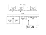
[039] 図1は、本開示の幾つかの実施形態による映像シーケンス100の一例の構造を示す。映像シーケンス100は、生中継映像又は捕捉され、アーカイブされている映像であり得る。映像100は、現実の映像、コンピュータによって生成される映像(例えば、コンピュータゲーム映像)又はその組み合わせ(例えば、拡張現実効果を有する現実の映像)であり得る。映像シーケンス100は、映像捕捉装置(例えば、カメラ)、過去に捕捉された映像を含む映像アーカイブ(例えば、記憶装置内に記憶される映像ファイル)又は映像コンテンツプロバイダから映像を受信するための映像フィードインタフェース(例えば、映像ブロードキャストトランシーバ)から入力され得る。
[039] Figure 1 illustrates the structure of an
[040] 図1に示すように、映像シーケンス100は、ピクチャ102、104、106及び108を含むタイムラインに沿って時間的に配置される一連のピクチャを含み得る。ピクチャ102~106は、連続的であり、ピクチャ106とピクチャ108との間に更に多くのピクチャがある。図1では、ピクチャ102は、Iピクチャであり、その参照ピクチャは、ピクチャ102自体である。ピクチャ104は、Pピクチャであり、矢印によって示すように、その参照ピクチャは、ピクチャ102である。ピクチャ106は、Bピクチャであり、矢印によって示すように、その参照ピクチャは、ピクチャ104及び108である。一部の実施形態では、ピクチャ(例えば、ピクチャ104)の参照ピクチャは、そのピクチャの直前又は直後になくてもよい。例えば、ピクチャ104の参照ピクチャは、ピクチャ102に先行するピクチャであり得る。ピクチャ102~106の参照ピクチャは、例に過ぎず、本開示は、参照ピクチャの実施形態を、図1に示す例に限定しないことに留意すべきである。
[040] As shown in FIG. 1, a
[041] 典型的には、映像コーデックは、全ピクチャを一度に符号化又は復号せず、それは、かかるタスクが計算的に複雑であるためである。むしろ、映像コーデックは、ピクチャを基本セグメントに分割し、ピクチャをセグメントごとに符号化又は復号することができる。本開示では、そのような基本セグメントを基本処理単位(「BPU」)と呼ぶ。例えば、図1の構造110は、映像シーケンス100のピクチャ(例えば、ピクチャ102~108の何れか)の構造の一例を示す。構造110では、ピクチャが4×4の基本処理単位に分けられており、その境界が破線で示されている。一部の実施形態では、基本処理単位は、一部の映像コード化規格(例えば、MPEGファミリ、H.261、H.263又はH.264/AVC)内の「マクロブロック」と呼ぶことができ、他の一部の映像コード化規格(例えば、H.265/HEVC又はH.266/VVC)内の「コード化ツリー単位」(「CTU」)と呼ぶことができる。128×128、64×64、32×32、16×16、4×8、16×32又はピクセルのあらゆる任意の形状及びサイズ等、基本処理単位は、ピクチャ内で可変サイズを有することができる。基本処理単位のサイズ及び形状は、コード化の効率と基本処理単位内で保とうとする詳細度とのバランスに基づいてピクチャについて選択することができる。
[041] Typically, video codecs do not encode or decode all pictures at once because such a task is computationally complex. Rather, the video codec can divide the picture into basic segments and encode or decode the picture segment by segment. In this disclosure, such basic segments are referred to as basic processing units (“BPUs”). For example,
[042] 基本処理単位は、コンピュータメモリ内(例えば、映像フレームバッファ内)に記憶される様々な種類の映像データ群を含み得る論理単位であり得る。例えば、カラーピクチャの基本処理単位は、無彩色の輝度情報を表すルマ成分(Y)、色情報を表す1つ又は複数のクロマ成分(例えば、Cb及びCr)並びにルマ成分及びクロマ成分が同じサイズを有し得る基本処理単位の関連構文要素を含むことができる。一部の映像コード化規格(例えば、H.265/HEVC又はH.266/VVC)では、ルマ成分及びクロマ成分が「コード化ツリーブロック」(「CTB」)と呼ばれ得る。基本処理単位に対して行われるいかなる操作も、そのルマ成分及びクロマ成分のそれぞれに対して繰り返し行うことができる。 [042] A basic processing unit may be a logical unit that may contain various types of video data groups stored in computer memory (eg, in a video frame buffer). For example, the basic processing unit of a color picture is a luma component (Y) representing achromatic luminance information, one or more chroma components (e.g., Cb and Cr) representing color information, and luma and chroma components of the same size. can contain related syntax elements of basic processing units that can have In some video coding standards (eg, H.265/HEVC or H.266/VVC), luma and chroma components may be referred to as "coding treeblocks" ("CTB"). Any operation performed on an elementary processing unit can be performed repeatedly on each of its luma and chroma components.
[043] 映像のコード化は、複数の操作段階を有し、その例を図2A~図2B及び図3A~図3Bで詳述する。それぞれの段階について、基本処理単位のサイズは、依然として処理するのに大き過ぎる場合があり、従って本開示で「基本処理副単位」と呼ぶセグメントに更に分けることができる。一部の実施形態では、基本処理副単位は、一部の映像コード化規格(例えば、MPEGファミリ、H.261、H.263又はH.264/AVC)内の「ブロック」と呼ぶことができるか、又は他の一部の映像コード化規格(例えば、H.265/HEVC又はH.266/VVC)内の「コード化単位」(「CU」)と呼ぶことができる。基本処理副単位は、基本処理単位と同じ又はそれよりも小さいサイズを有し得る。基本処理単位と同様に、基本処理副単位もコンピュータメモリ内(例えば、映像フレームバッファ内)に記憶される様々な種類の映像データ群(例えば、Y、Cb、Cr及び関連構文要素)を含み得る論理単位である。基本処理副単位に対して行われるいかなる操作も、そのルマ成分及びクロマ成分のそれぞれに対して繰り返し行うことができる。処理の必要性に応じて、かかる分割は、更なるレベルに対して行われ得ることに留意すべきである。様々な段階が様々な方式を使用して基本処理単位を分割できることにも留意すべきである。 [043] Video encoding has multiple operational stages, examples of which are detailed in Figures 2A-2B and Figures 3A-3B. For each stage, the size of the basic processing unit may still be too large to process, and thus can be further divided into segments called "basic processing subunits" in this disclosure. In some embodiments, a basic processing subunit can be referred to as a "block" within some video coding standard (eg, MPEG family, H.261, H.263 or H.264/AVC). or a "coding unit" ("CU") within some other video coding standards (eg, H.265/HEVC or H.266/VVC). A basic processing subunit may have the same or a smaller size than the basic processing unit. Similar to basic processing units, basic processing subunits may also include various types of video data groups (e.g., Y, Cb, Cr and related syntax elements) stored in computer memory (e.g., in a video frame buffer). Logical unit. Any operation performed on a basic processing subunit can be iteratively performed on each of its luma and chroma components. It should be noted that such division may be made to additional levels, depending on the processing needs. It should also be noted that different stages can divide the basic processing unit using different schemes.
[044] 例えば、(その一例を図2Bで詳述する)モード決定段階において、基本処理単位に対して何れの予測モード(例えば、イントラピクチャ予測又はインターピクチャ予測)を使用するかを符号器が決定することができ、基本処理単位は、かかる決定を下すには大き過ぎる場合がある。符号器は、基本処理単位を複数の基本処理副単位(例えば、H.265/HEVC又はH.266/VVCにあるCU)に分け、個々の基本処理副単位ごとに予測の種類を決定することができる。 [044] For example, in the mode decision stage (an example of which is detailed in FIG. 2B), the encoder determines which prediction mode (eg, intra-picture prediction or inter-picture prediction) to use for the basic processing unit. can be determined, and the elementary processing unit may be too large to make such a determination. The encoder divides a basic processing unit into a plurality of basic processing subunits (e.g., CUs in H.265/HEVC or H.266/VVC) and determines the type of prediction for each individual basic processing subunit. can be done.
[045] 別の例では、(その一例を図2A~2Bに詳述する)予測段階において、符号器は、基本処理副単位(例えば、CU)のレベルにおいて予測操作を行うことができる。しかし、一部の事例では、処理するのに基本処理副単位が依然として大き過ぎる場合がある。符号器は、基本処理副単位をより小さいセグメント(例えば、H.265/HEVC又はH.266/VVC内で「予測ブロック」又は「PB」と呼ばれる)に更に分けることができ、そのレベルにおいて予測操作を行うことができる。 [045] In another example, during the prediction stage (an example of which is detailed in Figures 2A-2B), the encoder may perform prediction operations at the level of basic processing subunits (eg, CUs). However, in some cases the basic processing subunit may still be too large to process. The encoder can subdivide the basic processing subunit into smaller segments (e.g., called "prediction blocks" or "PBs" in H.265/HEVC or H.266/VVC), at which level prediction operation can be performed.
[046] 別の例では、(その一例を図2A~2Bに詳述する)変換段階において、符号器は、残差基本処理副単位(例えば、CU)に対する変換操作を行うことができる。しかし、一部の事例では、処理するのに基本処理副単位が依然として大き過ぎる場合がある。符号器は、基本処理副単位をより小さいセグメント(例えば、H.265/HEVC又はH.266/VVC内で「変換ブロック」又は「TB」と呼ばれる)に更に分けることができ、そのレベルにおいて変換操作を行うことができる。同じ基本処理副単位の分割方式は、予測段階と変換段階とで異なり得ることに留意すべきである。例えば、H.265/HEVC又はH.266/VVCでは、同じCUについての予測ブロック及び変換ブロックは、異なるサイズ及び数を有し得る。 [046] In another example, during the transform stage (an example of which is detailed in Figures 2A-2B), the encoder may perform transform operations on residual elementary processing subunits (eg, CUs). However, in some cases the basic processing subunit may still be too large to process. The encoder can subdivide the basic processing subunit into smaller segments (e.g., called "transform blocks" or "TBs" in H.265/HEVC or H.266/VVC), at which level the transform operation can be performed. It should be noted that the partitioning scheme for the same basic processing subunit can be different for the prediction stage and the transform stage. For example, H. 265/HEVC or H.265/HEVC. In H.266/VVC, prediction blocks and transform blocks for the same CU may have different sizes and numbers.
[047] 図1の構造110では、基本処理単位112が3×3の基本処理副単位に更に分けられており、その境界が点線で示されている。同じピクチャの異なる基本処理単位を異なる方式で基本処理副単位に分けることができる。
[047] In the
[048] 一部の実装形態では、映像の符号化及び復号に並列処理及び誤り耐性の機能を与えるために、ピクチャを処理のための領域に分けることができ、それにより、ピクチャの領域について、符号化又は復号プロセスがピクチャの他の任意の領域の情報に依存しないようにすることができる。換言すれば、ピクチャの各領域を独立に処理することができる。そうすることで、コーデックは、ピクチャの異なる領域を並列に処理し、従ってコード化の効率を高めることができる。更に、領域のデータが処理内で破損するか又はネットワーク伝送内で失われる場合、コーデックは、破損するか又は失われたデータに依存することなく、同じピクチャの他の領域を正しく符号化又は復号することができ、従って誤り耐性の機能を提供する。一部の映像コード化規格では、ピクチャを異なる種類の領域に分割することができる。例えば、H.265/HEVC及びH.266/VVCは、「スライス」及び「タイル」という2種類の領域を提供する。映像シーケンス100の様々なピクチャは、ピクチャを領域に分けるための様々な分割方式を有し得ることにも留意すべきである。
[048] In some implementations, to provide parallel processing and error resilience capabilities for video encoding and decoding, a picture may be divided into regions for processing, such that for regions of a picture: The encoding or decoding process can be made independent of information in any other region of the picture. In other words, each region of the picture can be processed independently. By doing so, the codec can process different regions of the picture in parallel, thus increasing coding efficiency. Furthermore, if data in a region is corrupted in processing or lost in network transmission, the codec will correctly encode or decode other regions of the same picture without relying on the corrupted or lost data. , thus providing an error resilience feature. Some video coding standards allow pictures to be divided into different types of regions. For example, H. 265/HEVC and H.265/HEVC. H.266/VVC provides two types of regions: "slices" and "tiles." It should also be noted that different pictures of
[049] 例えば、図1では、構造110が3つの領域114、116及び118に分けられており、その境界が構造110内の実線として示されている。領域114は、4個の基本処理単位を含む。領域116及び118のそれぞれは、6個の基本処理単位を含む。図1の構造110の基本処理単位、基本処理副単位及び領域は、例に過ぎず、本開示は、その実施形態を限定しないことに留意すべきである。
[049] For example, in FIG.
[050] 図2Aは、本開示の実施形態と合致する、符号化プロセス200Aの一例の概略図を示す。例えば、符号化プロセス200Aは、符号器によって実行され得る。図2Aに示すように、符号器は、プロセス200Aに従って映像シーケンス202を映像ビットストリーム228に符号化することができる。図1の映像シーケンス100と同様に、映像シーケンス202は、時系列順に配置されるピクチャ(「元のピクチャ」と呼ぶ)の組を含み得る。図1の構造110と同様に、映像シーケンス202のそれぞれの元のピクチャは、符号器によって基本処理単位、基本処理副単位又は処理のための領域に分けられ得る。一部の実施形態では、符号器は、映像シーケンス202のそれぞれの元のピクチャに関する基本処理単位のレベルにおいてプロセス200Aを実行することができる。例えば、符号器は、プロセス200Aを反復的な方法で実行することができ、符号器は、プロセス200Aの1回の反復において基本処理単位を符号化することができる。一部の実施形態では、符号器は、映像シーケンス202のそれぞれの元のピクチャの領域(例えば、領域114~118)についてプロセス200Aを並列に実行することができる。
[050] Figure 2A shows a schematic diagram of an
[051] 図2Aでは、符号器は、映像シーケンス202の元のピクチャの基本処理単位(「元のBPU」と呼ぶ)を予測段階204にフィードして、予測データ206及び予測されたBPU208を生成することができる。符号器は、元のBPUから、予測されたBPU208を減算して、残差BPU210を生成することができる。符号器は、残差BPU210を変換段階212及び量子化段階214にフィードして、量子化された変換係数216を生成することができる。符号器は、予測データ206及び量子化された変換係数216をバイナリコード化段階226にフィードして、映像ビットストリーム228を生成することができる。構成要素202、204、206、208、210、212、214、216、226及び228は、「順方向経路」と呼ぶことができる。プロセス200A中、符号器は、量子化段階214後、量子化された変換係数216を逆量子化段階218及び逆変換段階220にフィードして、再構築された残差BPU222を生成することができる。符号器は、再構築された残差BPU222を、予測されたBPU208に加えて、プロセス200Aの次の反復の予測段階204に使用される予測基準224を生成することができる。プロセス200Aの構成要素218、220、222及び224は、「再構築経路」と呼ぶことができる。再構築経路は、符号器及び復号器の両方が予測に同じ参照データを使用することを確実にするために使用され得る。
[051] In FIG. 2A, the encoder feeds the elementary processing units of the original pictures of the video sequence 202 (referred to as "original BPUs") to the
[052] 符号器は、プロセス200Aを反復的に実行して、(順方向経路内で)元のピクチャのそれぞれの元のBPUを符号化し、(再構築経路内で)元のピクチャの次の元のBPUを符号化するための予測された基準224を生成することができる。元のピクチャの全ての元のBPUを符号化した後、符号器は、映像シーケンス202内の次のピクチャの符号化に進むことができる。
[052] The encoder iteratively performs the
[053] プロセス200Aを参照すると、符号器は、映像捕捉装置(例えば、カメラ)によって生成される映像シーケンス202を受信することができる。本明細書で使用する「受信(する)」という用語は、データを入力するために受信すること、入力すること、取得すること、取り出すこと、得ること、読み出すこと、アクセスすること又は任意の方法の任意のアクションを指すことができる。
[053] Referring to process 200A, an encoder may receive a
[054] 予測段階204では、現在の反復において、符号器が元のBPU及び予測基準224を受信し、予測操作を行って予測データ206及び予測されたBPU208を生成することができる。予測基準224は、プロセス200A前の反復の再構築経路から生成され得る。予測段階204の目的は、予測データ206を抽出することにより、情報の冗長性を減らすことでああり、予測データ206は、予測データ206及び予測基準224から予測されたBPU208として元のBPUを再構築するために使用され得る。
[054] In the
[055] 理想的には、予測されたBPU208は、元のBPUと同一であり得る。しかし、理想的でない予測及び再構築操作により、予測されたBPU208は、概して、元のBPUと僅かに異なる。そのような差を記録するために、符号器は、予測されたBPU208を生成した後、それを元のBPUから減算して残差BPU210を生成することができる。例えば、符号器は、予測されたBPU208のピクセルの値(例えば、グレースケール値又はRGB値)を元のBPUの対応するピクセルの値から減算することができる。元のBPUの対応するピクセルと、予測されたBPU208との間のかかる減算の結果、残差BPU210の各ピクセルは、残差値を有し得る。元のBPUと比較して、予測データ206及び残差BPU210は、より少ないビットを有し得るが、品質を著しく損なうことなく元のBPUを再構築するためにそれらを使用することができる。
[055] Ideally, the predicted
[056] 残差BPU210を更に圧縮するために、変換段階212において、符号器は、残差BPU210を2次元「基底パターン」の組に分解することにより、残差BPU210の空間的冗長性を低減することができ、各基底パターンは、「変換係数」に関連する。基底パターンは、同じサイズ(例えば、残差BPU210のサイズ)を有することができる。それぞれの基底パターンは、残差BPU210の変動周波数(例えば、輝度変動周波数)成分を表すことができる。基底パターンの何れも、他の任意の基底パターンの任意の組み合わせ(例えば、線形結合)から再現することができない。換言すれば、分解は、残差BPU210の変動を周波数領域内に分解することができる。かかる分解は、関数の離散フーリエ変換に類似し、基底パターンは、離散フーリエ変換の基底関数(例えば、三角関数)に類似し、変換係数は、基底関数に関連する係数に類似する。
[056] To further compress
[057] 様々な変換アルゴリズムが様々な基底パターンを使用することができる。例えば、離散コサイン変換、離散サイン変換等、変換段階212では、様々な変換アルゴリズムを使用することができる。変換段階212における変換は、可逆的である。即ち、符号器は、変換の逆操作(「逆変換」と呼ぶ)によって残差BPU210を復元することができる。例えば、残差BPU210のピクセルを復元するために、逆変換は、基底パターンの対応するピクセルの値を、関連するそれぞれの係数で乗算し、積を加算して加重和をもたらすことであり得る。映像コード化規格では、符号器及び復号器の両方が同じ変換アルゴリズム(従って同じ基底パターン)を使用することができる。従って、符号器は、変換係数のみを記録することができ、復号器は、符号器から基底パターンを受信することなく、変換係数から残差BPU210を再構築することができる。残差BPU210と比較して、変換係数の方が少ないビットを有し得るが、それらの変換係数は、品質を著しく損なうことなく残差BPU210を再構築するために使用され得る。従って、残差BPU210が更に圧縮される。
[057] Different transformation algorithms may use different underlying patterns. Various transform algorithms can be used in
[058] 符号器は、量子化段階214において変換係数を更に圧縮することができる。変換プロセスでは、様々な基底パターンが様々な変動周波数(例えば、輝度変動周波数)を表すことができる。人間の目は、概して、低周波変動を認識することが得意であるため、符号器は、復号の際の著しい品質劣化を引き起こすことなく高周波変動の情報を無視することができる。例えば、量子化段階214において、符号器は、各変換係数を整数値(「量子化パラメータ」と呼ぶ)で除算し、商をその最近隣数に丸めることにより、量子化された変換係数216を生成することができる。かかる操作後、高周波基底パターンの一部の変換係数をゼロに変換することができ、低周波基底パターンの変換係数をより小さい整数に変換することができる。符号器は、ゼロ値の量子化された変換係数216を無視することができ、それにより変換係数が更に圧縮される。量子化プロセスも可逆的であり、量子化された変換係数216は、量子化の逆操作(「逆量子化」と呼ぶ)内で変換係数に再構築することができる。
[058] The encoder may further compress the transform coefficients in the quantization stage 214. FIG. In the conversion process, different underlying patterns can represent different varying frequencies (eg, luminance varying frequencies). Since the human eye is generally good at recognizing low frequency variations, an encoder can ignore information in high frequency variations without causing significant quality degradation in decoding. For example, in the quantization stage 214, the encoder divides each transform coefficient by an integer value (referred to as the "quantization parameter") and rounds the quotient to its nearest neighbor, thereby dividing the quantized
[059] 符号器は、丸め操作内でかかる除算の剰余を無視するため、量子化段階214は、非可逆であり得る。典型的には、量子化段階214は、プロセス200A内で最大の情報損失に寄与し得る。情報損失が大きいほど、量子化された変換係数216が必要とし得るビットが少なくなる。情報損失の様々なレベルを得るために、符号器は、量子化パラメータの様々な値又は量子化プロセスの他の任意のパラメータを使用することができる。
[059] The quantization stage 214 may be lossy because the encoder ignores such division remainders in rounding operations. Typically, quantization stage 214 may contribute the most information loss within
[060] バイナリコード化段階226において、符号器は、例えば、エントロピーコード化、可変長コード化、算術コード化、ハフマンコード化、コンテキスト適応バイナリ算術コード化、又は他の任意の可逆若しくは非可逆圧縮アルゴリズム等のバイナリコード化技法を使用し、予測データ206及び量子化された変換係数216を符号化することができる。一部の実施形態では、予測データ206及び量子化された変換係数216に加えて、符号器は、例えば、予測段階204で使用される予測モード、予測操作のパラメータ、変換段階212の変換の種類、量子化プロセスのパラメータ(例えば、量子化パラメータ)、符号器制御パラメータ(例えば、ビットレート制御パラメータ)等の他の情報をバイナリコード化段階226において符号化することができる。符号器は、バイナリコード化段階226の出力データを使用して映像ビットストリーム228を生成することができる。一部の実施形態では、映像ビットストリーム228をネットワーク伝送のために更にパケット化することができる。
[060] In the binary encoding stage 226, the encoder performs, for example, entropy encoding, variable length encoding, arithmetic encoding, Huffman encoding, context adaptive binary arithmetic encoding, or any other lossless or lossy compression. Binary coding techniques such as algorithms can be used to encode the
[061] プロセス200Aの再構築経路を参照すると、逆量子化段階218では、符号器は、量子化された変換係数216に対して逆量子化を行って、再構築された変換係数を生成することができる。逆変換段階220では、符号器は、再構築された変換係数に基づいて、再構築された残差BPU222を生成することができる。符号器は、再構築された残差BPU222を、予測されたBPU208に加えて、プロセス200Aの次の反復内で使用される予測基準224を生成することができる。
[061] Referring to the reconstruction path of
[062] 映像シーケンス202を符号化するためにプロセス200Aの他のバリエーションを使用できることに留意すべきである。一部の実施形態では、符号器がプロセス200Aの段階を異なる順序で実行することができる。一部の実施形態では、プロセス200Aの1つ又は複数の段階を単一の段階に組み合わせることができる。一部の実施形態では、プロセス200Aの単一の段階を複数の段階に分けることができる。例えば、変換段階212と量子化段階214とを単一の段階に組み合わせることができる。一部の実施形態では、プロセス200Aは、追加の段階を含み得る。一部の実施形態では、プロセス200Aは、図2A内の1つ又は複数の段階を省くことができる。
[062] It should be noted that other variations of the
[063] 図2Bは、本開示の実施形態に合致する、符号化プロセスの別の例200Bの概略図を示す。プロセス200Bは、プロセス200Aから修正され得る。例えば、プロセス200Bは、ハイブリッド映像コード化規格(例えば、H.26xシリーズ)に準拠する符号器によって使用され得る。プロセス200Aと比較して、プロセス200Bの順方向経路は、モード決定段階230を更に含み、予測段階204を空間的予測段階2042及び時間的予測段階2044に分ける。プロセス200Bの再構築経路は、ループフィルタ段階232及びバッファ234を追加で含む。
[063] FIG. 2B shows a schematic diagram of another
[064] 概して、予測技法は、空間的予測及び時間的予測の2つの種類に分類することができる。空間的予測(例えば、イントラピクチャ予測又は「イントラ予測」)は、現BPUを予測するために、同じピクチャ内の既にコード化された1つ又は複数の隣接BPUのピクセルを使用することができる。即ち、空間的予測における予測基準224は、隣接BPUを含み得る。空間的予測は、ピクチャの固有の空間的冗長性を減らすことができる。時間的予測(例えば、インターピクチャ予測又は「インター予測」)は、現BPUを予測するために、既にコード化された1つ又は複数のピクチャの領域を使用することができる。即ち、時間的予測における予測基準224は、コード化されたピクチャを含み得る。時間的予測は、ピクチャの固有の時間的冗長性を減らすことができる。
[064] In general, prediction techniques can be categorized into two types: spatial prediction and temporal prediction. Spatial prediction (eg, intra-picture prediction or “intra-prediction”) can use pixels of one or more already coded neighboring BPUs in the same picture to predict the current BPU. That is,
[065] プロセス200Bを参照すると、順方向経路において、符号器は、空間的予測段階2042及び時間的予測段階2044で予測操作を行う。例えば、空間的予測段階2042では、符号器は、イントラ予測を行うことができる。符号化されているピクチャの元のBPUに関して、予測基準224は、同じピクチャ内の(順方向経路内で)符号化され、(再構築経路内で)再構築されている1つ又は複数の隣接BPUを含み得る。符号器は、隣接BPUを外挿することにより、予測されたBPU208を生成することができる。外挿技法は、例えば、線形外挿又は線形補間、多項式外挿又は多項式補間等を含み得る。一部の実施形態では、予測されたBPU208のピクセルごとに、対応するピクセルの値を外挿することによって等、符号器がピクセルレベルで外挿を行うことができる。外挿に使用される隣接BPUは、垂直方向(例えば、元のBPUの上)、水平方向(例えば、元のBPUの左)、対角線方向(例えば、元のBPUの左下、右下、左上又は右上)又は使用される映像コード化規格内で規定される任意の方向等、様々な方向から元のBPUに対して位置し得る。イントラ予測では、予測データ206は、例えば、使用される隣接BPUの位置(例えば、座標)、使用される隣接BPUのサイズ、外挿のパラメータ、元のBPUに対する使用される隣接BPUの方向等を含み得る。
[065] Referring to process 200B, in the forward pass, the encoder performs prediction operations in a
[066] 別の例では、時間的予測段階2044では、符号器は、インター予測を行うことができる。現ピクチャの元のBPUに関して、予測基準224は、(順方向経路内で)符号化され、(再構築経路内で)再構築されている1つ又は複数のピクチャ(「参照ピクチャ」と呼ぶ)を含み得る。一部の実施形態では、参照ピクチャがBPUごとに符号化され再構築され得る。例えば、符号器は、再構築された残差BPU222を、予測されたBPU208に加えて、再構築されたBPUを生成することができる。同じピクチャの全ての再構築されたBPUが生成されると、符号器は、参照ピクチャとして再構築されたピクチャを生成することができる。符号器は、参照ピクチャの範囲(「探索窓」と呼ぶ)内の一致領域を探すために「動き推定」の操作を行うことができる。参照ピクチャ内の探索窓の位置は、現ピクチャ内の元のBPUの位置に基づいて決定することができる。例えば、探索窓は、参照ピクチャ内において、現ピクチャ内の元のBPUと同じ座標を有する位置に中心を置くことができ、所定の距離にわたって広げることができる。符号器が探索窓内で元のBPUと同様の領域を(例えば、pel再帰アルゴリズム、ブロックマッチングアルゴリズム等を使用することによって)識別すると、符号器は、その領域を一致領域として決定することができる。一致領域は、元のBPUと異なる(例えば、それよりも小さい、等しい、大きい又は異なる形状の)寸法を有し得る。参照ピクチャ及び現ピクチャは、(例えば、図1に示すように)タイムライン内で時間的に隔てられているため、時間が経つにつれて一致領域が元のBPUの位置に「移動する」と見なすことができる。符号器は、かかる動きの方向及び距離を「動きベクトル」として記録することができる。(例えば、図1のピクチャ106のような)複数の参照ピクチャが使用される場合、符号器は、参照ピクチャごとに一致領域を探し、その関連する動きベクトルを求めることができる。一部の実施形態では、符号器は、個々の一致する参照ピクチャの一致領域のピクセル値に重みを割り当てることができる。
[066] In another example, in the
[067] 動き推定は、例えば、平行移動、回転、拡大縮小等の様々な種類の動きを識別するために使用することができる。インター予測では、予測データ206は、例えば、一致領域の位置(例えば、座標)、一致領域に関連する動きベクトル、参照ピクチャの数、参照ピクチャに関連する重み等を含み得る。
[067] Motion estimation can be used to identify different types of motion, eg, translation, rotation, scaling, and the like. For inter-prediction,
[068] 予測されたBPU208を生成するために、符号器は、「動き補償」の操作を行うことができる。動き補償は、予測データ206(例えば、動きベクトル)及び予測基準224に基づいて、予測されたBPU208を再構築するために使用することができる。例えば、符号器は、動きベクトルに従って参照ピクチャの一致領域を動かすことができ、その中では、符号器は、現ピクチャの元のBPUを予測することができる。(例えば、図1のピクチャ106のような)複数の参照ピクチャが使用される場合、符号器は、個々の動きベクトルに従って参照ピクチャの一致領域を動かし、一致領域のピクセル値を平均することができる。一部の実施形態では、符号器が、個々の一致する参照ピクチャの一致領域のピクセル値に重みを割り当てた場合、符号器は、動かした一致領域のピクセル値の加重和を加えることができる。
[068] To generate the predicted
[069] 一部の実施形態では、インター予測は、単方向又は双方向であり得る。単方向のインター予測は、現ピクチャに対して同じ時間的方向にある1つ又は複数の参照ピクチャを使用することができる。例えば、図1のピクチャ104は、参照ピクチャ(即ちピクチャ102)がピクチャ104に先行する単方向のインター予測ピクチャである。双方向のインター予測は、現ピクチャに対して両方の時間的方向にある1つ又は複数の参照ピクチャを使用することができる。例えば、図1のピクチャ106は、参照ピクチャ(即ちピクチャ104及び108)がピクチャ104に対して両方の時間的方向にある双方向のインター予測ピクチャである。
[069] In some embodiments, inter-prediction may be uni-directional or bi-directional. Unidirectional inter prediction can use one or more reference pictures that are in the same temporal direction for the current picture. For example,
[070] プロセス200Bの順方向経路を引き続き参照すると、空間的予測段階2042及び時間的予測段階2044後、モード決定段階230において、符号器は、プロセス200Bの現在の反復のための予測モード(例えば、イントラ予測又はインター予測の1つ)を選択することができる。例えば、符号器は、レート歪み最適化技法を実行することができ、かかる技法では、符号器は、候補予測モードのビットレート及び候補予測モード下の再構築された参照ピクチャの歪みに応じて、コスト関数の値を最小化するための予測モードを選択することができる。選択される予測モードに応じて、符号器は、対応する予測されたBPU208及び予測されたデータ206を生成することができる。
[070] Continuing with the forward path of
[071] プロセス200Bの再構築経路において、順方向経路内でイントラ予測モードが選択されている場合、予測基準224(例えば、現ピクチャ内で符号化され再構築されている現BPU)を生成した後、符号器は、後に使用するために(例えば、現ピクチャの次のBPUを外挿するために)空間的予測段階2042に予測基準224を直接フィードすることができる。順方向経路内でインター予測モードが選択されている場合、予測基準224(例えば、全てのBPUが符号化され再構築されている現ピクチャ)を生成した後、符号器は、ループフィルタ段階232に予測基準224をフィードすることができ、ループフィルタ段階232では、符号器は、予測基準224にループフィルタを適用して、インター予測によって引き起こされる歪み(例えば、ブロッキングアーティファクト)を減らすか又はなくすことができる。例えば、デブロッキング、サンプル適応オフセット、適応ループフィルタ等、符号器は、ループフィルタ段階232で様々なループフィルタ技法を適用することができる。ループフィルタされた参照ピクチャは、後に使用するために(例えば、映像シーケンス202の将来のピクチャのためのインター予測参照ピクチャとして使用するために)バッファ234(又は「復号されたピクチャバッファ」)内に記憶することができる。符号器は、時間的予測段階2044で使用するために1つ又は複数の参照ピクチャをバッファ234内に記憶することができる。一部の実施形態では、符号器は、量子化された変換係数216、予測データ206及び他の情報と共にループフィルタのパラメータ(例えば、ループフィルタの強度)をバイナリコード化段階226で符号化することができる。
[071] In the reconstruction pass of
[072] 図3Aは、本開示の実施形態に合致する、復号プロセス300Aの一例の概略図を示す。プロセス300Aは、図2Aの圧縮プロセス200Aに対応する解凍プロセスであり得る。一部の実施形態では、プロセス300Aは、プロセス200Aの再構築経路と同様であり得る。復号器は、プロセス300Aに従って映像ビットストリーム228を映像ストリーム304に復号することができる。映像ストリーム304は、映像シーケンス202と非常に類似し得る。しかし、圧縮及び解凍プロセス(例えば、図2A~図2Bの量子化段階214)における情報損失により、概して、映像ストリーム304は、映像シーケンス202と同一ではない。図2A~図2Bのプロセス200A及び200Bと同様に、復号器は、映像ビットストリーム228内に符号化される各ピクチャについて、基本処理単位(BPU)のレベルにおいてプロセス300Aを実行することができる。例えば、復号器は、プロセス300Aを反復的な方法で実行することができ、復号器は、プロセス300Aの1回の反復において基本処理単位を復号することができる。一部の実施形態では、復号器は、映像ビットストリーム228内に符号化される各ピクチャの領域(例えば、領域114~118)についてプロセス300Aを並列に実行することができる。
[072] Figure 3A shows a schematic diagram of an
[073] 図3Aでは、復号器は、符号化されたピクチャの基本処理単位(「符号化されたBPU」と呼ぶ)に関連する映像ビットストリーム228の一部をバイナリ復号段階302にフィードすることができる。バイナリ復号段階302では、復号器は、当該一部を予測データ206及び量子化された変換係数216に復号することができる。復号器は、量子化された変換係数216を逆量子化段階218及び逆変換段階220にフィードして、再構築された残差BPU222を生成することができる。復号器は、予測データ206を予測段階204にフィードして、予測されたBPU208を生成することができる。復号器は、再構築された残差BPU222を、予測されたBPU208に加えて、予測された基準224を生成することができる。一部の実施形態では、予測された基準224がバッファ(例えば、コンピュータメモリ内の復号されたピクチャバッファ)内に記憶され得る。復号器は、プロセス300Aの次の反復内で予測操作を行うための予測された基準224を予測段階204にフィードすることができる。
[073] In FIG. 3A, the decoder feeds a portion of the
[074] 復号器は、プロセス300Aを反復的に実行して、符号化されたピクチャの各符号化されたBPUを復号し、符号化されたピクチャの次の符号化されたBPUを符号化するための予測された基準224を生成することができる。符号化されたピクチャの全ての符号化されたBPUを復号した後、復号器は、表示するためにピクチャを映像ストリーム304に出力し、映像ビットストリーム228内の次の符号化されたピクチャの復号に進むことができる。
[074] The decoder iteratively performs the
[075] バイナリ復号段階302では、復号器は、符号器が使用したバイナリコード化技法(例えば、エントロピーコード化、可変長コード化、算術コード化、ハフマンコード化、コンテキスト適応バイナリ算術コード化又は他の任意の可逆圧縮アルゴリズム)の逆操作を行うことができる。一部の実施形態では、予測データ206及び量子化された変換係数216に加えて、復号器は、例えば、予測モード、予測操作のパラメータ、変換の種類、量子化プロセスのパラメータ(例えば、量子化パラメータ)、符号器制御パラメータ(例えば、ビットレート制御パラメータ)等の他の情報をバイナリ復号段階302において復号することができる。一部の実施形態では、映像ビットストリーム228がネットワーク上においてパケット単位で伝送される場合、復号器は、映像ビットストリーム228をパケット化解除してからそれをバイナリ復号段階302にフィードすることができる。
[075] In the
[076] 図3Bは、本開示の実施形態に合致する、復号プロセスの別の例300Bの概略図を示す。プロセス300Bは、プロセス300Aから修正され得る。例えば、プロセス300Bは、ハイブリッド映像コード化規格(例えば、H.26xシリーズ)に準拠する復号器によって使用され得る。プロセス300Aと比較して、プロセス300Bは、予測段階204を空間的予測段階2042及び時間的予測段階2044に更に分け、ループフィルタ段階232及びバッファ234を追加で含む。
[076] FIG. 3B shows a schematic diagram of another
[077] プロセス300Bでは、復号されている符号化されたピクチャ(「現ピクチャ」と呼ぶ)の符号化された基本処理単位(「現BPU」と呼ぶ)に関して、復号器によってバイナリ復号段階302から復号される予測データ206は、現BPUを符号化するために何れの予測モードが符号器によって使用されたかに応じて様々な種類のデータを含み得る。例えば、現BPUを符号化するためにイントラ予測が符号器によって使用された場合、予測データ206は、イントラ予測、イントラ予測操作のパラメータ等を示す予測モードインジケータ(例えば、フラグ値)を含み得る。イントラ予測操作のパラメータは、例えば、基準として使用される1つ又は複数の隣接BPUの位置(例えば、座標)、隣接BPUのサイズ、外挿のパラメータ、元のBPUに対する隣接BPUの方向等を含み得る。別の例では、現BPUを符号化するためにインター予測が符号器によって使用された場合、予測データ206は、インター予測、インター予測操作のパラメータ等を示す予測モードインジケータ(例えば、フラグ値)を含み得る。インター予測操作のパラメータは、例えば、現BPUに関連する参照ピクチャの数、参照ピクチャにそれぞれ関連する重み、それぞれの参照ピクチャ内の1つ又は複数の一致領域の位置(例えば、座標)、一致領域にそれぞれ関連する1つ又は複数の動きベクトル等を含み得る。
[077] In
[078] 予測モードインジケータに基づき、復号器は、空間的予測段階2042で空間的予測(例えば、イントラ予測)を行うか、又は時間的予測段階2044で時間的予測(例えば、インター予測)を行うかを決めることができる。かかる空間的予測又は時間的予測の実行の詳細は、図2Bに示されており、以下で繰り返さない。かかる空間的予測又は時間的予測を行った後、復号器は、予測されたBPU208を生成することができる。図3Aに記載したように、復号器は、予測されたBPU208と、再構築された残差BPU222とを加えて、予測基準224を生成することができる。
[078] Based on the prediction mode indicator, the decoder performs either spatial prediction (eg, intra prediction) at a
[079] プロセス300Bでは、復号器は、プロセス300Bの次の反復内で予測操作を行うための予測された基準224を空間的予測段階2042又は時間的予測段階2044にフィードすることができる。例えば、現BPUが空間的予測段階2042においてイントラ予測を使用して復号される場合、予測基準224(例えば、復号された現BPU)を生成した後、復号器は、後に使用するために(例えば、現ピクチャの次のBPUを外挿するために)空間的予測段階2042に予測基準224を直接フィードすることができる。現BPUが時間的予測段階2044においてインター予測を使用して復号される場合、予測基準224(例えば、全てのBPUが復号されている参照ピクチャ)を生成した後、符号器は、ループフィルタ段階232に予測基準224をフィードして歪み(例えば、ブロッキングアーティファクト)を減らすか又はなくすことができる。復号器は、図2Bに記載した方法で予測基準224にループフィルタを適用することができる。ループフィルタされた参照ピクチャは、後に使用するために(例えば、映像ビットストリーム228の将来の符号化ピクチャのためのインター予測参照ピクチャとして使用するために)バッファ234(例えば、コンピュータメモリ内の復号されたピクチャバッファ)内に記憶することができる。復号器は、時間的予測段階2044で使用するために1つ又は複数の参照ピクチャをバッファ234内に記憶することができる。一部の実施形態では、現BPUを符号化するためにインター予測が使用されたことを予測データ206の予測モードインジケータが示す場合、予測データは、ループフィルタのパラメータ(例えば、ループフィルタの強度)を更に含むことができる。
[079] In
[080] 図4Aは、本開示の実施形態に合致する、映像を符号化又は復号するための機器400の一例のブロック図である。図4Aに示すように、機器400は、プロセッサ402を含み得る。プロセッサ402が本明細書に記載の命令を実行するとき、機器400は、映像を符号化又は復号するための専用マシンになり得る。プロセッサ402は、情報を操作又は処理することができる任意の種類の回路であり得る。例えば、プロセッサ402は、任意の数の中央処理装置(「CPU」)、グラフィックス処理装置(「GPU」)、ニューラル処理ユニット(「NPU」)、マイクロコントローラユニット(「MCU」)、光プロセッサ、プログラム可能論理コントローラ、マイクロコントローラ、マイクロプロセッサ、デジタル信号プロセッサ、知的財産(IP)コア、プログラム可能論理アレイ(PLA)、プログラム可能アレイ論理(PAL)、汎用アレイ論理(GAL)、複合プログラム可能論理装置(CPLD)、書換可能ゲートアレイ(FPGA)、システムオンチップ(SoC)、特定用途向け集積回路(ASIC)等の任意の組み合わせを含み得る。一部の実施形態では、プロセッサ402は、単一の論理構成要素としてグループ化されるプロセッサの組であり得る。例えば、図4Aに示すように、プロセッサ402は、プロセッサ402a、プロセッサ402b及びプロセッサ402nを含む複数のプロセッサを含み得る。
[080] FIG. 4A is a block diagram of an
[081] 機器400は、データ(例えば、命令、コンピュータコード、中間データ等の組)を記憶するように構成されるメモリ404も含み得る。例えば、図4Aに示すように、記憶データは、プログラム命令(例えば、プロセス200A、200B、300A又は300B内の段階を実装するためのプログラム命令)及び処理用データ(例えば、映像シーケンス202、映像ビットストリーム228又は映像ストリーム304)を含み得る。プロセッサ402は、プログラム命令及び処理用データに(例えば、バス410を介して)アクセスし、プログラム命令を実行して処理用データに対する操作又は処理を行うことができる。メモリ404は、高速ランダムアクセス記憶装置又は不揮発性記憶装置を含み得る。一部の実施形態では、メモリ404は、任意の数のランダムアクセスメモリ(RAM)、読取専用メモリ(ROM)、光学ディスク、磁気ディスク、ハードドライブ、ソリッドステートドライブ、フラッシュドライブ、セキュリティデジタル(SD)カード、メモリスティック、コンパクトフラッシュ(登録商標)(CF)カード等の任意の組み合わせを含み得る。メモリ404は、単一の論理構成要素としてグループ化される(図4Aには不図示の)メモリ群でもあり得る。
[081]
[082] 内蔵バス(例えば、CPUメモリバス)、外部バス(例えば、ユニバーサルシリアルバスポート、周辺機器コンポーネント相互接続エクスプレスポート)等のバス410は、機器400内の構成要素間でデータを転送する通信装置であり得る。
[082] A bus 410, such as an internal bus (e.g., CPU memory bus), an external bus (e.g., Universal Serial Bus Port, Peripheral Component Interconnection Express Port), provides communication to transfer data between components within
[083] 曖昧さを招くことなく説明を簡単にするために、本開示では、プロセッサ402及び他のデータ処理回路をまとめて「データ処理回路」と呼ぶ。データ処理回路は、完全にハードウェアとして、又はソフトウェア、ハードウェア若しくはファームウェアの組み合わせとして実装することができる。加えて、データ処理回路は、単一の独立したモジュールであり得るか、又は機器400の他の任意の構成要素内に完全に若しくは部分的に組み合わされ得る。
[083] For simplicity of description without introducing ambiguity, processor 402 and other data processing circuitry will be collectively referred to as "data processing circuitry" in this disclosure. The data processing circuitry can be implemented entirely in hardware or as a combination of software, hardware or firmware. Additionally, the data processing circuitry may be a single independent module, or may be fully or partially combined within any other component of
[084] 機器400は、ネットワーク(例えば、インターネット、イントラネット、ローカルエリアネットワーク、モバイル通信ネットワーク等)との有線通信又は無線通信を提供するためのネットワークインタフェース406を更に含み得る。一部の実施形態では、ネットワークインタフェース406は、任意の数のネットワークインタフェースコントローラ(NIC)、無線周波数(RF)モジュール、トランスポンダ、トランシーバ、モデム、ルータ、ゲートウェイ、有線ネットワークアダプタ、無線ネットワークアダプタ、Bluetooth(登録商標)アダプタ、赤外線アダプタ、近距離無線通信(「NFC」)アダプタ、セルラネットワークチップ等の任意の組み合わせを含み得る。
[084]
[085] 一部の実施形態では、1つ又は複数の周辺装置への接続を提供するための周辺装置インタフェース408を任意選択的に機器400が更に含み得る。図4Aに示すように、周辺装置は、これのみに限定されないが、カーソル制御装置(例えば、マウス、タッチパッド又はタッチスクリーン)、キーボード、ディスプレイ(例えば、ブラウン管ディスプレイ、液晶ディスプレイ又は発光ダイオードディスプレイ)、映像入力装置(例えば、映像アーカイブに結合されるカメラ又は入力インタフェース)等を含み得る。
[085] In some embodiments, the
[086] 映像コーデック(例えば、プロセス200A、200B、300A又は300Bを実行するコーデック)は、機器400内の任意のソフトウェア又はハードウェアモジュールの任意の組み合わせとして実装できることに留意すべきである。例えば、プロセス200A、200B、300A又は300Bの一部の又は全ての段階は、メモリ404内にロード可能なプログラム命令等の、機器400の1つ又は複数のソフトウェアモジュールとして実装され得る。別の例では、プロセス200A、200B、300A又は300Bの一部の又は全ての段階は、専用データ処理回路(例えば、FPGA、ASIC、NPU等)等の、機器400の1つ又は複数のハードウェアモジュールとして実装され得る。
[086] It should be noted that a video codec (eg, a codec that performs
[087] インター予測を使用してコード化されるCUでは、前に復号されたピクチャ(即ち参照ピクチャ)内の参照ブロックが予測子として識別される。参照ピクチャ内の参照ブロックと現ピクチャ内のコード化ブロックとの間の相対位置が動きベクトル(MV)として定められる。現CUの動き情報は、予測子、参照ピクチャインデックス及び対応するMVの数によって指定される。動き情報に基づく動き補償によって予測を得た後、予測信号と元の信号との間の残差を変換、量子化及びエントロピーコード化に更にかけてから、出力ビットストリーム内にパックすることができる。 [087] In a CU that is coded using inter-prediction, reference blocks in previously decoded pictures (ie, reference pictures) are identified as predictors. A relative position between a reference block in a reference picture and a coded block in the current picture is defined as a motion vector (MV). The motion information of the current CU is specified by the predictor, reference picture index and number of corresponding MVs. After obtaining the prediction by motion compensation based on motion information, the residual between the prediction signal and the original signal can be further subjected to transform, quantization and entropy coding before being packed into the output bitstream.
[088] 一部の状況では、現CUの空間的及び時間的に隣接するCUの動き情報を使用して、現CUの動き情報を予測することができる。動き情報のコード化ビットを減らすために、マージモードを採用することができる。マージモードでは、空間的又は時間的に隣接するブロックから動き情報が導出され、何れの隣接ブロックから動き情報を導出したかを示すためにマージインデックスをシグナリングすることができる。 [088] In some situations, the motion information of the spatially and temporally neighboring CUs of the current CU may be used to predict the motion information of the current CU. A merge mode can be employed to reduce the coded bits of motion information. In merge mode, motion information is derived from spatially or temporally neighboring blocks, and a merge index can be signaled to indicate from which neighboring block the motion information was derived.
[089] HEVCでは、以下の候補に基づいてマージ候補リストを構築することができる。 [089] In HEVC, a merge candidate list can be constructed based on the following candidates.
[090] (1)5つの空間的隣接ブロックから導出される最大4つの空間的マージ候補。 [090] (1) Up to four spatial merge candidates derived from five spatially neighboring blocks.
[091] (2)時間的コロケーテッドブロックから導出される1つの時間的マージ候補。 [091] (2) One temporal merge candidate derived from temporal collocated blocks.
[092] (3)結合双予測候補及びゼロ動きベクトル候補を含む追加のマージ候補。 [092] (3) Additional merging candidates, including joint bi-prediction candidates and zero motion vector candidates.
[093] マージ候補リスト内の第1の候補は、空間的近傍である。図4Bは、5つの空間的候補の位置を示す。{A1,B1,B0,A0,B2}の順序に従って各候補の位置の可用性が検査される。空間的隣接ブロックがイントラ予測されるか、又は位置が現スライス若しくはタイルの外側にある場合、その空間的隣接ブロックは、マージ候補として利用できないと考えることができる。加えて、隣接ブロックからの動きデータが可能な限りユニークであることを確実にするために、幾らかの冗長性検査を行うことができる。冗長性検査に起因する複雑さを減らすために、限られた冗長性検査のみを行うことができ、ユニーク性は、必ずしも保証されない。例えば、{A1,B1,B0,A0,B2}の順序を所与とし、B0は、B1のみを検査し、A0は、A1のみを検査し、B2は、A1及びB1のみを検査する。 [093] The first candidates in the merge candidate list are the spatial neighbors. FIG. 4B shows the locations of five spatial candidates. The availability of each candidate location is checked according to the order {A1, B1, B0, A0, B2}. A spatially neighboring block may be considered unavailable as a merging candidate if the spatially neighboring block is intra-predicted or is located outside the current slice or tile. Additionally, some redundancy checking can be done to ensure that motion data from neighboring blocks is as unique as possible. To reduce complexity due to redundancy checks, only limited redundancy checks can be performed and uniqueness is not necessarily guaranteed. For example, given an order of {A1, B1, B0, A0, B2}, B0 tests only B1, A0 tests only A1, and B2 tests only A1 and B1.
[094] 時間的マージ候補では、利用可能である場合、図4Cに示すように、参照ピクチャのコロケーテッドブロックの直接外側の右下位置C0を使用する。さもなければ、代わりに中心位置C1を使用することができる。コロケーテッド参照ピクチャに何れの参照ピクチャリストが使用されるかは、スライスヘッダ内でシグナリングされるインデックスによって示され得る。図5に示すように、コロケーテッドブロックのMVは、ピクチャ順序カウント(POC)差に基づいてスケーリングしてからマージリスト内に挿入することができる。 [094] For temporal merge candidates, if available, use the bottom right position C0 immediately outside the collocated block of the reference picture, as shown in Figure 4C. Otherwise, the center position C1 can be used instead. Which reference picture list is used for collocated reference pictures may be indicated by an index signaled in the slice header. As shown in FIG. 5, the MVs of collocated blocks can be scaled based on picture order count (POC) differences before insertion into the merge list.
[095] マージ候補の最大数Cは、スライスヘッダ内で指定され得る。見つかった利用可能なマージ候補の数(時間的候補を含む)がCを上回る場合、最初のC-1の空間的候補及び時間的候補のみが保持される。そうではなく、利用可能なマージ候補の数がC未満である場合、数がCに等しくなるまで追加の候補が生成される。コード化データを構文解析する能力が、利用可能なマージ候補の数に依存しないため、この形態は、構文解析を単純化することができ、構文解析をよりロバストにする。共通実験条件(CTC)では、マージ候補の最大数Cが5に設定される。 [095] A maximum number of merge candidates C may be specified in the slice header. If the number of available merge candidates found (including temporal candidates) exceeds C, then only the first C−1 spatial and temporal candidates are retained. Otherwise, if the number of available merge candidates is less than C, additional candidates are generated until the number equals C. This form can simplify parsing and make parsing more robust because the ability to parse the coded data does not depend on the number of available merge candidates. Common experimental conditions (CTC) set the maximum number of merge candidates C to five.
[096] Bスライスでは、参照ピクチャリスト0及びリスト1に関する既定の順序に従って利用可能な2つの候補を組み合わせることで、追加のマージ候補が生成される。例えば、生成される第1の候補は、リスト0に関する第1のマージ候補及びリスト1に関する第2のマージ候補を使用する。HEVCは、(0,1)、(1,0)、(0,2)、(2,0)、(1,2)、(2,1)、(0,3)、(3,0)、(1,3)、(3,1)、(2,3)及び(3,2)として、既に構築されたマージ候補リスト内で2つの動きベクトルの合計12個の既定の対を上記の順序で規定し、ここで、(i,j)は、利用可能なマージ候補のインデックスを表す。それらのうち、冗長エントリを除去した後に最大5つの候補を含めることができる。
[096] For B slices, an additional merge candidate is generated by combining the two available candidates according to a predefined order for
[097] スライスがPスライスであるか、又はマージ候補の数が依然としてC未満である場合、マージ候補リスト内の残りの任意のエントリを埋めるために、ゼロから参照ピクチャ数マイナス1までの参照インデックスに関連するゼロ動きベクトルが使用される。 [097] If the slice is a P slice, or the number of merge candidates is still less than C, reference indices from zero to the number of reference pictures minus 1 to fill any remaining entries in the merge candidate list. A zero motion vector associated with is used.
[098] VVCでは、以下の5種類の候補を順に含めることによってマージ候補リストが構築される:
空間的隣接CUからの空間的マージ候補、
コロケーテッドCUからの時間的マージ候補、
FIFOテーブルからの履歴ベースの動きベクトル予測子(HMVP)、
ペアワイズ平均候補、及び
ゼロMV。
[098] In VVC, a merge candidate list is constructed by including the following five kinds of candidates in order:
Spatial merge candidates from spatially neighboring CUs,
Temporal merge candidates from collocated CUs,
history-based motion vector predictor (HMVP) from FIFO table,
Pairwise Mean Candidates, and Zero MVs.
[099] 空間的マージ候補及び時間的マージ候補の定義は、HEVCにあるのと同じである。空間的マージ候補及び時間的マージ候補後、HMVPマージ候補がマージリストに追加される。HMVPでは、過去にコード化されたブロックの動き情報がテーブル内に記憶され、及び現CUのための動きベクトル予測子として使用される。符号化/復号プロセス中、複数のHMVP候補を有するテーブルが維持される。新たなCTU行に遭遇するとき、テーブルは、リセットされる(空にされる)。非サブブロックのインターコード化されたCUがある場合、関連する動き情報は、新たなHMVP候補としてテーブルの最後のエントリに追加される。 [099] The definitions of spatial merge candidates and temporal merge candidates are the same as in HEVC. After spatial merge candidates and temporal merge candidates, HMVP merge candidates are added to the merge list. In HMVP, motion information for previously coded blocks is stored in a table and used as a motion vector predictor for the current CU. A table with multiple HMVP candidates is maintained during the encoding/decoding process. The table is reset (emptied) when a new CTU row is encountered. If there is a non-sub-block inter-coded CU, the associated motion information is added to the last entry of the table as a new HMVP candidate.
[0100] VVCでは、HMVPテーブルのサイズを6に設定することができ、即ち最大6つのHMVP候補をテーブルに追加することができる。テーブルに新たな動き候補を挿入するとき、制約付きの先入れ先出し(FIFO)規則を利用することができ、テーブル内に同一のHMVPがあるかどうかを見出すために冗長性検査が最初に適用される。見つかる場合、同一のHMVPをテーブルから除去し、その後の全てのHMVP候補を前に移動することができる。 [0100] In VVC, the size of the HMVP table can be set to 6, ie up to 6 HMVP candidates can be added to the table. When inserting new motion candidates into the table, a constrained first-in-first-out (FIFO) rule can be utilized and a redundancy check is first applied to find out if there are identical HMVPs in the table. If found, the same HMVP can be removed from the table and all subsequent HMVP candidates can be moved forward.
[0101] マージ候補リストの構築プロセス中、テーブル内の最後の幾つかのHMVP候補が順に検査され、時間的動きベクトル予測子(TMVP)候補後にマージ候補リストに挿入される。空間的マージ候補又は時間的マージ候補に対してHMVP候補を検査するために、冗長性検査を適用することができる。 [0101] During the merge candidate list construction process, the last few HMVP candidates in the table are examined in order and inserted into the merge candidate list after the temporal motion vector predictor (TMVP) candidates. Redundancy checking can be applied to check HMVP candidates against spatial or temporal merging candidates.
[0102] HMVP候補を挿入した後、マージ候補リストが依然として一杯でない場合、ペアワイズ平均候補を追加する。ペアワイズ平均候補は、既存のマージ候補リスト内の候補の既定の対を平均することによって生成される。既定の対は、{(0,1),(0,2),(1,2),(0,3),(1,3),(2,3)}として定められ、ここで、数字は、マージ候補リスト内のマージインデックスを表す。平均された動きベクトルが参照ピクチャリストごとに別々に計算される。両方の動きベクトルが1つのリスト内で入手可能である場合、それらの2つの動きベクトルは、異なる参照ピクチャを指す場合でも平均される。1つの動きベクトルのみが入手可能である場合、その利用可能なものを直接使用する。動きベクトルが入手できない場合、そのリストは、無効と見なされる。 [0102] After inserting the HMVP candidates, if the merge candidate list is still not full, add the pairwise average candidates. Pairwise average candidates are generated by averaging predefined pairs of candidates in the existing merge candidate list. The default pair is defined as {(0,1), (0,2), (1,2), (0,3), (1,3), (2,3)}, where the digits represents the merge index in the merge candidate list. An averaged motion vector is calculated separately for each reference picture list. If both motion vectors are available in one list, the two motion vectors are averaged even if they point to different reference pictures. If only one motion vector is available, use the available one directly. If motion vectors are not available, the list is considered invalid.
[0103] ペアワイズ平均マージ候補を追加した後もマージリストが依然として一杯でない場合、最大マージ候補数に達するまでゼロ動きベクトルが末尾に挿入される。 [0103] If the merge list is still not full after adding pairwise average merge candidates, zero motion vectors are inserted at the end until the maximum number of merge candidates is reached.
[0104] VVCでは、通常マージモードに加えて、マージ候補リストの構築は、merge mode with motion vector difference(MMVD)及び三角形分割モード(TPM)にも使用することができる。 [0104] In VVC, in addition to the normal merge mode, merge candidate list construction can also be used for merge mode with motion vector difference (MMVD) and triangulation mode (TPM).
[0105] MMVDでは、マージ候補がマージ候補リストからまず選択され、シグナリングされる動きベクトル差(MVD)情報によって更にリファインされる。MMVDマージ候補リストのサイズは、2に設定される。2つのMMVD候補の何れがベース動きベクトル(MV)として使用されるかを指定するために、マージ候補フラグがシグナリングされ得る。MVD情報は、距離インデックス及び方向インデックスによってシグナリングされ得る。距離インデックスは、動きの大きさの情報を指定し、ベースMVからの既定のオフセットを示す。距離インデックスと既定のオフセットとの関係を図6の例に示す。方向インデックスは、ベースMVに加えられるオフセットの符号を指定し、例えば、0は、正符号を示し、1は、負符号を示す。 [0105] In MMVD, merge candidates are first selected from a merge candidate list and further refined by signaled motion vector difference (MVD) information. The size of the MMVD merge candidate list is set to two. A merge candidate flag may be signaled to specify which of the two MMVD candidates is used as the base motion vector (MV). MVD information may be signaled by a distance index and a direction index. The distance index specifies motion magnitude information and indicates a default offset from the base MV. The relationship between the distance index and the default offset is shown in the example of FIG. The direction index specifies the sign of the offset added to the base MV, eg 0 indicates a positive sign and 1 indicates a negative sign.
[0106] TPMでは、CUは、対角線分割又は逆対角線分割を使用して2つの三角形区画に均等に分けられる。CU内のそれぞれの三角形区画は、自らの動きを使用してインター予測され得る。それぞれの区画について単予測のみが認められる。即ち、各区画は、1つの動きベクトル及び1つの参照インデックスを有する。双予測と同様に、2つの動き補償予測のみが各CUに必要であることを確実にするために、単予測動き制約が適用される。三角形分割モードが現CUに使用される場合、三角形分割の方向(対角線又は逆対角線)を示すフラグ及び2つのマージインデックス(区画ごとに1つ)が更にシグナリングされ得る。三角形区画のそれぞれを予測した後、適応重みを伴う混合処理を使用して、対角線エッジ又は逆対角線エッジに沿ったサンプル値を調節する。これは、全CUのための予測信号に対応し、通常のインターモードにあるように変換及び量子化プロセスを全CUに適用することができる。マージ候補リストを構築することができる。最大TPMマージ候補の数がスライスヘッダ内で明確にシグナリングされ、CTC内で5に設定され得る。 [0106] In TPM, a CU is divided evenly into two triangular partitions using diagonal or anti-diagonal partitioning. Each triangular partition within the CU can be inter-predicted using its own motion. Only unipredictions are allowed for each partition. That is, each partition has one motion vector and one reference index. Similar to bi-prediction, a uni-prediction motion constraint is applied to ensure that only two motion-compensated predictions are required for each CU. If the triangulation mode is used for the current CU, a flag indicating the triangulation direction (diagonal or anti-diagonal) and two merge indices (one per partition) may also be signaled. After predicting each of the triangle partitions, a blending process with adaptive weights is used to adjust the sample values along the diagonal or anti-diagonal edges. This corresponds to the prediction signal for the whole CU, and the transform and quantization process can be applied to the whole CU as in normal inter mode. A merge candidate list can be built. The number of maximum TPM merge candidates may be explicitly signaled in the slice header and set to 5 in the CTC.
[0107] VVCでは、空間的候補、時間的候補、HMVP及びペアワイズ平均候補を含むマージ候補リストが構築される。異なるインターモードに対して異なるマージリストのサイズが適用される。例えば、{A1,B1,B0,A0,B2}の順序に従って空間的マージ候補をマージリスト内に挿入することができる。しかし、空間的マージ候補の構築プロセスは、HEVCからVVCまで変更されておらず、それは、VVC内の新たなマージ候補(例えば、HMVP、ペアワイズ平均)及び新たなインターモード(例えば、MMVD、TPM)を考慮に入れていない。これは、現在の空間的マージ候補の様々な欠点につながる。 [0107] In VVC, a merge candidate list is constructed that includes spatial candidates, temporal candidates, HMVP and pairwise average candidates. Different merge list sizes apply for different intermodes. For example, spatial merge candidates can be inserted into the merge list according to the order {A1, B1, B0, A0, B2}. However, the process of constructing spatial merge candidates has not changed from HEVC to VVC, and it includes new merge candidates within VVC (e.g., HMVP, pairwise average) and new inter-modes (e.g., MMVD, TPM). not taken into account. This leads to various drawbacks of current spatial merge candidates.
[0108] 例えば、空間的マージ候補の順序を改善することができる。空間的マージ候補の数を調節することができる。更に、空間的マージ候補の構築は、通常モード、MMVDモード及びTPMモードに関して固定され、それは、マージ方法の潜在性を限定する。加えて、空間的マージ候補の構築は、低遅延ピクチャ及び非低遅延ピクチャに関して固定され、それは、柔軟性を下げる。上記の及び他の問題に対処するために、本開示では、様々な解決策を提供する。 [0108] For example, the order of spatial merge candidates can be improved. The number of spatial merge candidates can be adjusted. Moreover, the construction of spatial merging candidates is fixed for normal, MMVD and TPM modes, which limits the potential of merging methods. In addition, the construction of spatial merge candidates is fixed for low-delay pictures and non-low-delay pictures, which reduces flexibility. To address the above and other issues, the present disclosure provides various solutions.
[0109] 例えば、一部の実施形態では、空間的マージ候補の順序を変更することができる。空間的マージ候補の新たな順序{B1,A1,B0,A0,B2}を適用することができる。空間的隣接ブロックB1、A1、B0、A0及びB2の位置を図7に示す。一部の実施形態では、この順序を{B1,A1,B0,A0,B2}に変更することができる。 [0109] For example, in some embodiments, the order of spatial merge candidates may be changed. A new order of spatial merge candidates {B1, A1, B0, A0, B2} can be applied. The locations of spatially adjacent blocks B1, A1, B0, A0 and B2 are shown in FIG. In some embodiments, this order can be changed to {B1, A1, B0, A0, B2}.
[0110] 新たな順序は、上の隣接ブロック、左の隣接ブロック、上の隣接ブロック、左の隣接ブロック、及び左上の隣接ブロックに連続して対応し、この順序は、上の近傍と左の近傍とで交互になる。更に、空間的マージ候補の新たな順序は、より高いコード化性能を実現することができる。図8及び図9に示すように、一部の実施形態によれば、提案する方法は、ランダムアクセス(RA)及び低遅延(LD)構成下のVTM-6と比較して平均0.05%及び0.21%のコード化利得をそれぞれ得ることができる。 [0110] The new order corresponds sequentially to top neighbor, left neighbor, top neighbor, left neighbor, and top left neighbor, and the order is top neighbor and left neighbor. Alternate with neighbors. Moreover, the new order of spatial merge candidates can achieve higher coding performance. As shown in FIGS. 8 and 9, according to some embodiments, the proposed method yields an average of 0.05% compared to VTM-6 under random access (RA) and low delay (LD) configurations. and a coding gain of 0.21%, respectively.
[0111] 一部の実施形態では、空間的マージ候補の数を変更することができる。計算の複雑さとコード化性能との間のより優れたトレードオフを実現するために、本開示の様々な実施形態において、空間的マージ候補の数の減少が提案され適用される。空間的マージ候補の数を2に制限する場合、構築順序{B1,A1}を適用することができる。例えば、入手可能である場合、隣接ブロックB1を検査し、マージリスト内に挿入することができる。次いで、入手可能であり、B1と同じでない場合、隣接ブロックA1を検査し、マージリスト内に挿入することができる。空間的マージ候補{B1,A1}を挿入した後、その後のTMVP、HMVP及びペアワイズ平均候補をマージリスト内に追加することができる。 [0111] In some embodiments, the number of spatial merge candidates may vary. To achieve a better trade-off between computational complexity and coding performance, a reduction in the number of spatial merge candidates is proposed and applied in various embodiments of the present disclosure. If we limit the number of spatial merge candidates to two, we can apply the construction order {B1, A1}. For example, if available, neighboring block B1 can be examined and inserted into the merge list. Adjacent block A1 can then be checked and inserted into the merge list if it is available and not the same as B1. After inserting the spatial merge candidate {B1, A1}, subsequent TMVP, HMVP and pairwise average candidates can be added in the merge list.
[0112] 空間的マージ候補の数を3に制限する場合、構築順序{B1,A1,B0}を適用することができる。隣接ブロックの検査順序は、B1->A1->B0であり、入手可能であり、冗長でない場合、対応するMVをマージリスト内に挿入することができる。 [0112] If we limit the number of spatial merge candidates to three, we can apply the building order {B1, A1, B0}. The check order of adjacent blocks is B1->A1->B0, and if available and non-redundant, the corresponding MV can be inserted in the merge list.
[0113] 空間的マージ候補{B1,A1,B0}を使用する場合、VTM-6と比較した実験結果を図10及び図11に示す。図10及び図11に示すように、一部の実施形態によれば、提案する技法は、RA及びLD構成下で0.00%及び0.10%のコード化利得を実現することができる。 [0113] Experimental results compared to VTM-6 when using the spatial merge candidate {B1, A1, B0} are shown in Figures 10 and 11 . As shown in FIGS. 10 and 11, according to some embodiments, the proposed technique can achieve coding gains of 0.00% and 0.10% under RA and LD configurations.
[0114] 更に、一部のVVC技法では、マージ候補の総数をシグナリングすることができる。本開示の一部の実施形態では、マージ候補リストを構築する際に更なる柔軟性を得るために、空間的マージ候補の数を更にシグナリングすることを提案する。現ピクチャの予測構造を考慮し、空間的マージ候補の数は、様々な値に設定することができる。現ピクチャが非低遅延ピクチャである場合、空間的マージ候補の数を第1の値に設定することができる。非低遅延ピクチャは、表示順序に従って過去及び未来の両方からの参照ピクチャを使用してコード化されるピクチャを指し得る。そうではなく、現ピクチャが低遅延ピクチャである場合、空間的マージ候補の数を第2の値に設定することができる。低遅延ピクチャは、表示順序に従って過去からの参照ピクチャのみを使用してコード化されるピクチャを指し得る。第1の値は、第2の値よりも大きい値とすることができる。第1の値及び第2の値は、ビットストリーム内、例えばスライスヘッダ内で明確にシグナリングされ得る。図12に一例を示す。 [0114] Additionally, in some VVC techniques, the total number of merge candidates may be signaled. Some embodiments of the present disclosure propose to additionally signal the number of spatial merge candidates in order to gain more flexibility in building the merge candidate list. Considering the prediction structure of the current picture, the number of spatial merging candidates can be set to various values. If the current picture is a non-low delay picture, the number of spatial merge candidates can be set to a first value. Non-low-delay pictures may refer to pictures that are coded using reference pictures from both past and future according to display order. Otherwise, if the current picture is a low-delay picture, the number of spatial merge candidates can be set to a second value. Low-delay pictures may refer to pictures that are coded using only reference pictures from the past according to display order. The first value can be greater than the second value. The first value and the second value may be explicitly signaled within the bitstream, eg within the slice header. An example is shown in FIG.
[0115] 構文要素num_spatial_merge_cand_minus2(例えば、図12の要素1201)は、現スライスに使用される空間的マージ候補の数を示すことができる。num_spatial_merge_cand_minus2の値は、0~3(両端値を含む)の範囲内であり得る。num_spatial_merge_cand_minus2の要素がない場合、num_spatial_merge_cand_minus2は、0に等しいと推論することができる。
[0115] Syntax element num_spatial_merge_cand_minus2 (eg,
[0116] 現スライスをコード化するために使用される参照ピクチャに応じて、スライスは、低遅延又は非低遅延として分類することができ、様々な数のマージ候補を使用することができる。num_spatial_merge_cand_minus2の値は、符号器によって適宜設定され、ビットストリーム内で送信され得る。 [0116] Depending on the reference picture used to code the current slice, a slice can be classified as low-delay or non-low-delay, and different numbers of merge candidates can be used. The value of num_spatial_merge_cand_minus2 may be set appropriately by the encoder and sent in the bitstream.
[0117] 代替的に、スライスヘッダ内で1つの構文要素をシグナリングする代わりに、図13(例えば、要素1301)及び図14(例えば、要素1401)内で示すように、num_spatial_merge_cand_minus2_non_lowdelay及びnum_spatial_merge_cand_minus2_lowdelayの2つの構文要素をピクチャパラメータセット(PPS)又はシーケンスパラメータセット(SPS)内でシグナリングすることができる。更に、スライスレベルにおいて、スライスの種類に応じて対応する数の空間的マージ候補を使用することができる。 [0117] Alternatively, instead of signaling one syntax element in the slice header, two syntax elements, num_spatial_merge_cand_minus2_non_lowdelay and num_spatial_merge_cand_minus2_lowdelay, as shown in FIG. 13 (eg, element 1301) and FIG. 14 (eg, element 1401). Syntax elements can be signaled within a picture parameter set (PPS) or a sequence parameter set (SPS). Furthermore, at the slice level, a corresponding number of spatial merging candidates can be used depending on the type of slice.
[0118] num_spatial_merge_cand_minus2_non_lowdelay及びnum_spatial_merge_cand_minus2_lowdelayの値は、非低遅延スライス及び低遅延スライスに使用される空間的マージ候補の数をそれぞれ示し得る。num_spatial_merge_cand_minus2_non_lowdelay及びnum_spatial_merge_cand_minus2_lowdelayの値は、0~3(両端値を含む)の範囲内であり得る。num_spatial_merge_cand_minus2_non_lowdelay又はnum_spatial_merge_cand_minus2_lowdelayがない場合、それらは、0に等しいと推論することができる。 [0118] The values of num_spatial_merge_cand_minus2_non_lowdelay and num_spatial_merge_cand_minus2_lowdelay may indicate the number of spatial merge candidates used for non-low-delay slices and low-delay slices, respectively. The values of num_spatial_merge_cand_minus2_non_lowdelay and num_spatial_merge_cand_minus2_lowdelay can range from 0 to 3, inclusive. If there is no num_spatial_merge_cand_minus2_non_lowdelay or num_spatial_merge_cand_minus2_lowdelay, they can be inferred to be equal to zero.
[0119] 一部の実施形態では、異なるインターモードに対して空間的マージ候補の別々の構築順序が適用され得る。例えば、{B1,A1,B0,A0,B2}及び{A1,B1,B0,A0,B2}を含む、空間的マージ候補の2つの構築順序を検討することができる。通常マージモード、MMVDモード、及びTPMモードに対して異なる構築順序を採用することができる。一部の実施形態では、{B1,A1,B0,A0,B2}を通常マージモード及びTPMモードに使用し、{A1,B1,B0,A0,B2}をMMVDモードに使用することを提案する。例示的実施形態の実験結果を図15及び図16に示す。提案する方法は、RA及びLD構成下で平均0.07%及び0.16%のコード化利得をそれぞれ実現できることが認められている。 [0119] In some embodiments, different construction orders of spatial merge candidates may be applied for different inter modes. For example, two construction orders of spatial merge candidates can be considered, including {B1, A1, B0, A0, B2} and {A1, B1, B0, A0, B2}. Different build orders can be adopted for normal merge mode, MMVD mode, and TPM mode. Some embodiments propose to use {B1, A1, B0, A0, B2} for normal merge mode and TPM mode, and {A1, B1, B0, A0, B2} for MMVD mode. . Experimental results of an exemplary embodiment are shown in FIGS. 15 and 16. FIG. It is observed that the proposed method can achieve average coding gains of 0.07% and 0.16% under RA and LD configurations, respectively.
[0120] 本開示に基づき、空間的マージ候補の順序及びマージモードの他の組み合わせを使用できることを当業者であれば理解することができる。例えば、{B1,A1,B0,A0,B2}を通常マージモードのみに使用することができ、{A1,B1,B0,A0,B2}をMMVDモード及びTMPモードに使用することができる。 [0120] Based on this disclosure, one skilled in the art can appreciate that other combinations of spatial merge candidate orders and merge modes can be used. For example, {B1, A1, B0, A0, B2} can be used for normal merge mode only, and {A1, B1, B0, A0, B2} can be used for MMVD mode and TMP mode.
[0121] 一部の実施形態では、フレームの種類に基づいて空間的マージ候補の適応構築順序を適用することができる。例えば、低遅延ピクチャ及び非低遅延ピクチャ等の異なる種類のインターコード化ピクチャに対して異なる空間的マージ候補構築方法を適用することができる。一部の実施形態では、低遅延ピクチャに関して、空間的マージ候補の構築順序{B1,A1,B0,A0,B2}を、通常マージモード、TPMモード、及びMMVDモードに使用することができる。非低遅延ピクチャに関して、空間的マージ候補の構築順序{B1,A1,B0,A0,B2}を、通常マージモード及びTPMモードに使用することができ、空間的マージ候補の構築順序{A1,B1,B0,A0,B2}をMMVDモードに使用することができる。例示的実施形態の実験結果を図17及び図18に示す。提案する方法は、RA及びLD構成下で平均0.08%及び0.21%のコード化利得をそれぞれ実現できることが認められている。 [0121] In some embodiments, an adaptive building order of spatial merge candidates may be applied based on frame type. For example, different spatial merge candidate construction methods can be applied to different types of inter-coded pictures, such as low-delay pictures and non-low-delay pictures. In some embodiments, for low-delay pictures, the construction order of spatial merge candidates {B1, A1, B0, A0, B2} can be used for normal merge mode, TPM mode, and MMVD mode. For non-low delay pictures, the construction order of spatial merge candidates {B1, A1, B0, A0, B2} can be used for normal merge mode and TPM mode, and the construction order of spatial merge candidates {A1, B1 , B0, A0, B2} can be used for the MMVD mode. Experimental results of an exemplary embodiment are shown in FIGS. 17 and 18. FIG. It is observed that the proposed method can achieve average coding gains of 0.08% and 0.21% under RA and LD configurations, respectively.
[0122] 図19は、本開示の実施形態と合致する例示的な映像処理方法1900のフローチャートを示す。一部の実施形態では、方法1900は、符号器、復号器、機器(例えば、図4Aの機器400)の1つ又は複数のソフトウェア又はハードウェアコンポーネントによって実行され得る。例えば、プロセッサ(例えば、図4Aのプロセッサ402)は、方法1900を実行することができる。一部の実施形態では、方法1900は、コンピュータ(例えば、図4Aの機器400)によって実行されるプログラムコード等のコンピュータ実行可能命令を含むコンピュータ可読媒体において具体化されるコンピュータプログラム製品によって実装され得る。
[0122] FIG. 19 depicts a flowchart of an exemplary
[0123] ステップ802では、例えば符号器、復号器、又は機器(例えば、図4Aの機器400)の1つ若しくは複数のソフトウェア若しくはハードウェアコンポーネントにより、コード化ブロックのマージ候補リストに空間的マージ候補の組を挿入することができる。VVCでは、空間的マージ候補の順序を改善することができる。空間的マージ候補の組は、上の隣接ブロック、左の隣接ブロック、上の隣接ブロック、左の隣接ブロック、及び左上の隣接ブロックの順に従って挿入することができる。例えば、空間的マージ候補の新たな順序{B1,A1,B0,A0,B2}を図7に示す。
[0123] At
[0124] 空間的マージ候補の数は、調節することができる。ステップ804では、空間的マージ候補の予め設定された数値限界を決定する。
[0124] The number of spatial merge candidates can be adjusted. At
[0125] ステップ806では、数値限界が2である場合、上の隣接ブロック、左の隣接ブロックの順序に基づいてマージ候補リスト内に空間的マージ候補の組を挿入する。空間的マージ候補の数を2に制限する場合、構築順序{B1,A1}を適用することができる。例えば、入手可能である場合、隣接ブロックB1を検査し、マージリスト内に挿入することができる。次いで、入手可能であり、B1と同じでない場合、隣接ブロックA1を検査し、マージリスト内に挿入することができる。空間的マージ候補{B1,A1}を挿入した後、その後のTMVP、HMVP及びペアワイズ平均候補をマージリスト内に追加することができる。
[0125] At
[0126] ステップ808では、数値限界が3である場合、上の隣接ブロック、左の隣接ブロック、上の隣接ブロックの順序に基づいてマージ候補リスト内に空間的マージ候補の組を挿入する。空間的マージ候補の数を3に制限する場合、構築順序{B1,A1,B0}を適用することができる。隣接ブロックの検査順序は、B1->A1->B0であり、入手可能であり、冗長でない場合、対応するMVをマージリスト内に挿入することができる。
[0126] At
[0127] 一部の実施形態では、コロケーテッドコード化単位からの時間的マージ候補、先入れ先出し(FIFO)テーブルからの履歴ベースの動きベクトル予測子(HMVP)、ペアワイズ平均候補、又はゼロ動きベクトルの少なくとも1つをマージ候補リストに追加することができる。 [0127] In some embodiments, temporal merge candidates from collocated coded units, history-based motion vector predictors (HMVP) from first-in-first-out (FIFO) tables, pairwise average candidates, or zero motion vector candidates. At least one can be added to the merge candidate list.
[0128] HMVPでは、過去にコード化されたブロックの動き情報がFIFOテーブル内に記憶され、及び現コード化単位のための動きベクトル予測子として使用される。符号化/復号プロセス中、複数のHMVP候補を有するテーブルが維持される。新たなCTU行に遭遇するとき、テーブルは、リセットされる(空にされる)。非サブブロックのインターコード化されたコード化単位がある場合、非サブブロックのインターコード化されたコード化単位に関連する動き情報は、新たなHMVP候補としてFIFOテーブルの最後のエントリに追加される。 [0128] In HMVP, motion information for previously coded blocks is stored in a FIFO table and used as a motion vector predictor for the current coded unit. A table with multiple HMVP candidates is maintained during the encoding/decoding process. The table is reset (emptied) when a new CTU row is encountered. If there are non-sub-block inter-coded coded units, the motion information associated with the non-sub-block inter-coded coded units is added to the last entry of the FIFO table as a new HMVP candidate. .
[0129] ペアワイズ平均候補は、マージ候補リストが一杯でないことに応じて、マージ候補リスト内の候補の対を平均することによって生成され、及び1つ又は複数のHMVPがマージ候補リストに追加された後、マージ候補リストに追加される。 [0129] A pairwise average candidate is generated by averaging pairs of candidates in the merge candidate list in response to the merge candidate list not being full, and one or more HMVPs added to the merge candidate list. It will then be added to the merge candidates list.
[0130] ペアワイズ平均マージ候補を追加した後もマージリストが依然として一杯でない場合、最大マージ候補数に達するまでゼロ動きベクトルをマージ候補リストの末尾に挿入する。 [0130] If the merge list is still not full after adding the pairwise average merge candidates, insert zero motion vectors at the end of the merge candidate list until the maximum number of merge candidates is reached.
[0131] ステップ810では、例えば符号器又は復号器により、コード化ブロックに対して第1のコード化モードを適用するか又は第2のコード化モードを適用するかを決定する。第1のコード化モードは、第2のコード化モードと異なる。一部の実施形態では、第1のコード化モード及び第2のコード化モードのそれぞれが、通常マージモード、merge mode with motion vector difference(MMVD)、及び三角形分割モード(TPM)のうちの1つであり得る。
[0131] At
[0132] ステップ812では、第1のコード化モードがコード化ブロックに適用される場合、空間的マージ候補の組を第1の構築順序に従って挿入する。例えば、MMVDでは、マージ候補がマージ候補リストからまず選択され、シグナリングされる動きベクトル差(MVD)情報によってリファインされ、2つのMMVD候補の何れがベース動きベクトルとして使用されるかを指定するためにマージ候補フラグがシグナリングされる。MVD情報は、距離インデックス及び方向インデックスによってシグナリングされ得る。距離インデックスは、動きの大きさの情報を指定し、ベースMVからの既定のオフセットを示す。距離インデックスと既定のオフセットとの関係を図6の例に示す。方向インデックスは、ベースMVに加えられるオフセットの符号を指定し、例えば、0は、正符号を示し、1は、負符号を示す。
[0132] At
[0133] ステップ814では、第2のコード化モードがコード化ブロックに適用される場合、空間的マージ候補の組を第2の構築順序に従って挿入する。例えば、TPMでは、コード化単位は、対角線分割又は逆対角線分割の少なくとも1つを使用して2つの三角形区画に均等に分けられる。CU内のそれぞれの三角形区画は、自らの動きを使用してインター予測され得る。それぞれの区画について単予測のみが認められる。即ち、各区画は、1つの動きベクトル及び1つの参照インデックスを有する。 [0133] At step 814, if the second coding mode is applied to the coded block, the set of spatial merge candidates is inserted according to the second construction order. For example, in TPM, a coding unit is evenly divided into two triangular partitions using at least one of diagonal division or anti-diagonal division. Each triangular partition within the CU can be inter-predicted using its own motion. Only unipredictions are allowed for each partition. That is, each partition has one motion vector and one reference index.
[0134] ステップ816では、コード化ブロックが低遅延ピクチャの一部であるか、又は非低遅延ピクチャの一部であるかを決定する。
[0134] At
[0135] ステップ818では、コード化ブロックが低遅延ピクチャの一部である場合、空間的マージ候補の組を第3の構築順序に従って挿入する。一部の実施形態では、低遅延ピクチャに関して、空間的マージ候補の構築順序{B1,A1,B0,A0,B2}を、通常マージモード、TPMモード、及びMMVDモードに使用することができる。
[0135] At
[0136] ステップ820では、コード化ブロックが非低遅延ピクチャの一部である場合、空間的マージ候補の組を第4の構築順序に従って挿入する。第3の構築順序は、第4の構築順序と異なる。第3の構築順序及び第4の構築順序は、MMVDに使用される。一部の実施形態では、非低遅延ピクチャに関して、空間的マージ候補の構築順序{B1,A1,B0,A0,B2}を通常マージモード及びTPMモードに使用することができ、空間的マージ候補の構築順序{A1,B1,B0,A0,B2}をMMVDモードに使用することができる。
[0136] At
[0137] 本開示と合致して、上記の方法の1つ又は複数を組み合わせて使用するか又は別々に使用することができることを当業者であれば理解するであろう。例えば、空間的マージ候補の減少を採用する技法は、異なるインターモードに対して空間的マージ候補の別々の構築順序を使用する提案した方法と組み合わせて使用することができる。 [0137] Consistent with the present disclosure, one skilled in the art will appreciate that one or more of the above methods can be used in combination or separately. For example, techniques employing spatial merging candidate reduction can be used in combination with the proposed method of using separate construction orders of spatial merging candidates for different inter modes.
[0138] 一部の実施形態では、命令を含む非一時的コンピュータ可読記憶媒体も提供され、命令は、上記の方法を実行するための装置(開示した符号器及び復号器等)によって実行され得る。一般的な非一時的媒体は、例えば、フロッピ(登録商標)ディスク、フレキシブルディスク、ハードディスク、ソリッドステートドライブ、磁気テープ若しくは他の任意の磁気データ記憶媒体、CD-ROM、他の任意の光学データ記憶媒体、孔のパターンを有する任意の物理媒体、RAM、PROM及びEPROM、フラッシュEPROM若しくは他の任意のフラッシュメモリ、NVRAM、キャッシュ、レジスタ、他の任意のメモリチップ若しくはカートリッジ及びそれらのもののネットワーク化されたバージョンを含む。装置は、1つ又は複数のプロセッサ(CPU)、入力/出力インタフェース、ネットワークインタフェース及び/又はメモリを含み得る。 [0138] In some embodiments, there is also provided a non-transitory computer-readable storage medium comprising instructions, which may be executed by apparatus (such as the disclosed encoders and decoders) for performing the above methods. . Common non-transitory media include, for example, floppy disks, floppy disks, hard disks, solid state drives, magnetic tapes or any other magnetic data storage media, CD-ROMs, any other optical data storage media, any physical media with a pattern of holes, RAM, PROM and EPROM, flash EPROM or any other flash memory, NVRAM, cache, registers, any other memory chip or cartridge and networked of them Contains version. A device may include one or more processors (CPUs), input/output interfaces, network interfaces and/or memory.
[0139] 本明細書の「第1の」及び「第2の」等の関係語は、あるエンティティ又は操作を別のエンティティ又は操作と区別するために使用されるに過ぎず、それらのエンティティ又は操作間のいかなる実際の関係又は順序も必要としないか又は含意しないことに留意すべきである。更に、「含む」、「有する」、「含有する」及び「包含する」並びに他の同様の形式の用語は、意味の点で均等であることを意図し、これらの用語の何れか1つの後に続くアイテムがかかるアイテムの網羅的列挙であることを意図していないか、又は列挙するアイテムのみに限定されることを意図していない点で非限定的であることを意図する。 [0139] Relative terms such as "first" and "second" herein are only used to distinguish one entity or operation from another entity or operation, and the entities or operations It should be noted that no actual relationship or order between the operations is required or implied. Further, terms such as “include,” “have,” “contain,” and “include” and other similar forms are intended to be equivalent in meaning, and any one of these terms followed by The items that follow are intended to be non-limiting in that they are not intended to be an exhaustive listing of such items or to be limited only to the items listed.
[0140] 本明細書で使用するとき、別段の定めがない限り、「又は」という語は、実行不可能な場合を除いて、あり得る全ての組み合わせを包含する。例えば、あるデータベースがA又はBを含み得ると述べた場合、別段の定めがない限り又は実行不可能でない限り、そのデータベースは、A若しくはB又はA及びBを含むことができる。第2の例として、あるデータベースがA、B又はCを含み得ると述べた場合、別段の定めがない限り又は実行不可能でない限り、そのデータベースは、A、若しくはB、若しくはC、又はA及びB、又はA及びC、又はB及びC、又はA、及びB、及びCを含むことができる。 [0140] As used herein, unless stated otherwise, the term "or" includes all possible combinations except where impracticable. For example, if a database states that it can contain A or B, it can contain A or B or A and B, unless otherwise specified or impracticable. As a second example, if we state that a database may contain A, B, or C, then unless otherwise specified or impracticable, the database may include A, or B, or C, or A and B, or A and C, or B and C, or A, and B, and C can be included.
[0141] 上記で説明した実施形態は、ハードウェア若しくはソフトウェア(プログラムコード)又はハードウェアとソフトウェアとの組み合わせによって実装できることが理解されるであろう。ソフトウェアによって実装される場合、ソフトウェアは、上記のコンピュータ可読媒体に記憶することができる。ソフトウェアは、プロセッサによって実行されるとき、開示した方法を実行することができる。本開示で説明した計算ユニット及び他の機能ユニットは、ハードウェア若しくはソフトウェア又はハードウェアとソフトウェアとの組み合わせによって実装することができる。上記のモジュール/ユニットの複数を1つのモジュール/ユニットとして組み合わせることができ、上記のモジュール/ユニットのそれぞれを複数のサブモジュール/サブユニットに更に分割できることも当業者であれば理解するであろう。 [0141] It will be appreciated that the embodiments described above can be implemented in hardware or software (program code) or a combination of hardware and software. If implemented by software, the software can be stored in the computer-readable medium described above. The software can perform the disclosed methods when executed by a processor. The computational units and other functional units described in this disclosure may be implemented in hardware or software or a combination of hardware and software. It will also be appreciated by those skilled in the art that multiple of the modules/units described above can be combined as one module/unit, and each of the modules/units described above can be further divided into multiple sub-modules/sub-units.
[0142] 実施形態は、以下の条項を使用して更に記載することができる:
1.映像処理方法であって、
コード化ブロックのマージ候補リストに空間的マージ候補の組を挿入することを含み、
空間的マージ候補の組は、上の隣接ブロック、左の隣接ブロック、上の隣接ブロック、左の隣接ブロック、及び左上の隣接ブロックの順に従って挿入される、映像処理方法。
2.コロケーテッドコード化単位からの時間的マージ候補、先入れ先出し(FIFO)テーブルからの履歴ベースの動きベクトル予測子(HMVP)、ペアワイズ平均候補、又はゼロ動きベクトルのうちの少なくとも1つをマージ候補リストに追加することを更に含む、条項1に記載の方法。
3.過去にコード化されたブロックの動き情報は、FIFOテーブル内に記憶され、及び現コード化単位のための動きベクトル予測子として使用される、条項2に記載の方法。
4.非サブブロックのインターコード化されたコード化単位に関連する動き情報は、新たなHMVP候補としてFIFOテーブルの最後のエントリに追加される、条項2及び3の何れか一項に記載の方法。
5.ペアワイズ平均候補は、マージ候補リスト内の候補の対を平均することによって生成され、及びマージ候補リストが一杯でないことに応じて、1つ又は複数のHMVPがマージ候補リストに追加された後、マージ候補リストに追加される、条項2に記載の方法。
6.ゼロ動きベクトルは、最大マージ候補数に達するまでマージ候補リストの末尾に挿入される、条項2に記載の方法。
7.映像処理方法であって、
空間的マージ候補の予め設定された数値限界に基づいてコード化ブロックのマージ候補リストに空間的マージ候補の組を挿入することを含み、
数値限界が2である場合、上の隣接ブロック、左の隣接ブロックの順序に基づいてマージ候補リスト内に空間的マージ候補の組が挿入され、及び
数値限界が3である場合、上の隣接ブロック、左の隣接ブロック、上の隣接ブロックの順序に基づいてマージ候補リスト内に空間的マージ候補の組が挿入される、映像処理方法。
8.表示順序に従って過去の参照ピクチャ及び未来の参照ピクチャを使用して現ピクチャがコード化されていることに応じて、空間的マージ候補の数は、第1の値に設定され、及び
表示順序に従って過去の参照ピクチャを使用して現ピクチャがコード化されていることに応じて、空間的マージ候補の数は、第1の値未満の第2の値に設定される、条項7に記載の方法。
9.マージ候補リスト内に挿入される空間的マージ候補の数をシグナリングすることを更に含む、条項7に記載の方法。
10.コロケーテッドコード化単位からの時間的マージ候補、FIFOテーブルからの履歴ベースの動きベクトル予測子(HMVP)、ペアワイズ平均候補、又はゼロ動きベクトルのうちの少なくとも1つをマージ候補リストに追加することを更に含む、条項7~9の何れか一項に記載の方法。
11.過去にコード化されたブロックの動き情報は、FIFOテーブル内に記憶され、及び現コード化単位のための動きベクトル予測子として使用される、条項10に記載の方法。
12.非サブブロックのインターコード化されたコード化単位に関連する動き情報は、新たなHMVP候補としてFIFOテーブルの最後のエントリに追加される、条項10及び11の何れか一項に記載の方法。
13.ペアワイズ平均候補は、マージ候補リスト内の候補の対を平均することによって生成され、及びマージ候補リストが一杯でないことに応じて、1つ又は複数のHMVPがマージ候補リストに追加された後、マージ候補リストに追加される、条項10に記載の方法。
14.ゼロ動きベクトルは、最大マージ候補数に達するまでマージ候補リストの末尾に挿入される、条項10に記載の方法。
15.映像処理方法であって、
コード化ブロックのマージ候補リストに空間的マージ候補の組を挿入することを含み、
第1のコード化モードがコード化ブロックに適用される場合、空間的マージ候補の組が第1の構築順序に従って挿入され、及び
第2のコード化モードがコード化ブロックに適用される場合、空間的マージ候補の組が第2の構築順序に従って挿入され、
第1の構築順序は、第2の構築順序と異なる、映像処理方法。
16.第1のコード化モード及び第2のコード化モードは、通常マージモード、merge mode with motion vector difference(MMVD)、及び三角形分割モード(TPM)から選択される2つの異なるモードである、条項15に記載の方法。
17.MMVDでは、マージ候補は、マージ候補リストからまず選択され、シグナリングされる動きベクトル差(MVD)情報によってリファインされ、マージ候補フラグは、2つのMMVD候補の何れがベース動きベクトルとして使用されるかを指定するためにシグナリングされる、条項16に記載の方法。
18.TPMでは、コード化単位は、対角線分割又は逆対角線分割の少なくとも1つを使用して2つの三角形区画に均等に分けられる、条項16に記載の方法。
19.コロケーテッドコード化単位からの時間的マージ候補、FIFOテーブルからの履歴ベースの動きベクトル予測子、ペアワイズ平均候補、又はゼロ動きベクトルのうちの少なくとも1つをマージ候補リストに追加することを更に含む、条項15及び16の何れか一項に記載の方法。
20.過去にコード化されたブロックの動き情報は、FIFOテーブル内に記憶され、及び現コード化単位のための動きベクトル予測子として使用される、条項19に記載の方法。
21.非サブブロックのインターコード化されたコード化単位に関連する動き情報は、新たなHMVP候補としてFIFOテーブルの最後のエントリに追加される、条項19及び20の何れか一項に記載の方法。
22.ペアワイズ平均候補は、マージ候補リスト内の候補の対を平均することによって生成され、及びマージ候補リストが一杯でないことに応じて、1つ又は複数のHMVPがマージ候補リストに追加された後、マージ候補リストに追加される、条項19に記載の方法。
23.ゼロ動きベクトルは、最大マージ候補数に達するまでマージ候補リストの末尾に挿入される、条項19に記載の方法。
24.映像処理方法であって、
コード化ブロックのマージ候補リストに空間的マージ候補の組を挿入することを含み、
コード化ブロックが低遅延ピクチャの一部である場合、空間的マージ候補の組が第1の構築順序に従って挿入され、及び
コード化ブロックが非低遅延ピクチャの一部である場合、空間的マージ候補の組が第2の構築順序に従って挿入され、
第1の構築順序は、第2の構築順序と異なる、映像処理方法。
25.第1の構築順序及び第2の構築順序は、merge mode with motion vector difference(MMVD)に使用される、条項24に記載の方法。
26.コロケーテッドコード化単位からの時間的マージ候補、FIFOテーブルからの履歴ベースの動きベクトル予測子(HMVP)、ペアワイズ平均候補、又はゼロ動きベクトルのうちの少なくとも1つをマージ候補リストに追加することを更に含む、条項24に記載の方法。
27.過去にコード化されたブロックの動き情報は、FIFOテーブル内に記憶され、及び現コード化単位のための動きベクトル予測子として使用される、条項26に記載の方法。
28.非サブブロックのインターコード化されたコード化単位に関連する動き情報は、新たなHMVP候補としてFIFOテーブルの最後のエントリに追加される、条項26及び27の何れか一項に記載の方法。
29.ペアワイズ平均候補は、マージ候補リスト内の候補の対を平均することによって生成され、及びマージ候補リストが一杯でないことに応じて、1つ又は複数のHMVPがマージ候補リストに追加された後、マージ候補リストに追加される、条項26に記載の方法。
30.ゼロ動きベクトルは、最大マージ候補数に達するまでマージ候補リストの末尾に挿入される、条項26に記載の方法。
31.映像処理機器であって、
命令の組を記憶するメモリと、
1つ又は複数のプロセッサとを含み、1つ又は複数のプロセッサは、
コード化ブロックのマージ候補リストに空間的マージ候補の組を挿入することを機器に行わせるように、命令の組を実行するように構成され、
空間的マージ候補の組は、上の隣接ブロック、左の隣接ブロック、上の隣接ブロック、左の隣接ブロック、及び左上の隣接ブロックの順に従って挿入される、映像処理機器。
32.1つ又は複数のプロセッサは、コロケーテッドコード化単位からの時間的マージ候補、先入れ先出し(FIFO)テーブルからの履歴ベースの動きベクトル予測子(HMVP)、ペアワイズ平均候補、又はゼロ動きベクトルのうちの少なくとも1つをマージ候補リストに追加することを機器に更に行わせるように、命令の組を実行するように構成される、条項31に記載の機器。
33.過去にコード化されたブロックの動き情報は、FIFOテーブル内に記憶され、及び現コード化単位のための動きベクトル予測子として使用される、条項32に記載の機器。
34.非サブブロックのインターコード化されたコード化単位に関連する動き情報は、新たなHMVP候補としてFIFOテーブルの最後のエントリに追加される、条項32及び33の何れか一項に記載の機器。
35.ペアワイズ平均候補は、マージ候補リスト内の候補の対を平均することによって生成され、及びマージ候補リストが一杯でないことに応じて、1つ又は複数のHMVPがマージ候補リストに追加された後、マージ候補リストに追加される、条項32に記載の機器。
36.ゼロ動きベクトルは、最大マージ候補数に達するまでマージ候補リストの末尾に挿入される、条項32に記載の機器。
37.映像処理機器であって、
命令の組を記憶するメモリと、
1つ又は複数のプロセッサとを含み、1つ又は複数のプロセッサは、
空間的マージ候補の予め設定された数値限界に基づいてコード化ブロックのマージ候補リストに空間的マージ候補の組を挿入することを機器に行わせるように、命令の組を実行するように構成され、
数値限界が2である場合、上の隣接ブロック、左の隣接ブロックの順序に基づいてマージ候補リスト内に空間的マージ候補の組が挿入され、及び
数値限界が3である場合、上の隣接ブロック、左の隣接ブロック、上の隣接ブロックの順序に基づいてマージ候補リスト内に空間的マージ候補の組が挿入される、映像処理機器。
38.表示順序に従って過去の参照ピクチャ及び未来の参照ピクチャを使用して現ピクチャがコード化されていることに応じて、空間的マージ候補の数は、第1の値に設定され、及び
表示順序に従って過去の参照ピクチャを使用して現ピクチャがコード化されていることに応じて、空間的マージ候補の数は、第1の値未満の第2の値に設定される、条項37に記載の機器。
39.1つ又は複数のプロセッサは、
マージ候補リスト内に挿入される空間的マージ候補の数をシグナリングすることを機器に更に行わせるように、命令の組を実行するように構成される、条項37に記載の機器。
40.1つ又は複数のプロセッサは、コロケーテッドコード化単位からの時間的マージ候補、FIFOテーブルからの履歴ベースの動きベクトル予測子(HMVP)、ペアワイズ平均候補、又はゼロ動きベクトルのうちの少なくとも1つをマージ候補リストに追加することを機器に更に行わせるように、命令の組を実行するように構成される、条項37~39の何れか一項に記載の機器。
41.過去にコード化されたブロックの動き情報は、FIFOテーブル内に記憶され、及び現コード化単位のための動きベクトル予測子として使用される、条項40に記載の機器。
42.非サブブロックのインターコード化されたコード化単位に関連する動き情報は、新たなHMVP候補としてFIFOテーブルの最後のエントリに追加される、条項40及び41の何れか一項に記載の機器。
43.ペアワイズ平均候補は、マージ候補リスト内の候補の対を平均することによって生成され、及びマージ候補リストが一杯でないことに応じて、1つ又は複数のHMVPがマージ候補リストに追加された後、マージ候補リストに追加される、条項40に記載の機器。
44.ゼロ動きベクトルは、最大マージ候補数に達するまでマージ候補リストの末尾に挿入される、条項40に記載の機器。
45.映像処理機器であって、
命令の組を記憶するメモリと、
1つ又は複数のプロセッサとを含み、1つ又は複数のプロセッサは、
コード化ブロックのマージ候補リストに空間的マージ候補の組を挿入することを機器に行わせるように、命令の組を実行するように構成され、
第1のコード化モードがコード化ブロックに適用される場合、空間的マージ候補の組が第1の構築順序に従って挿入され、及び
第2のコード化モードがコード化ブロックに適用される場合、空間的マージ候補の組が第2の構築順序に従って挿入され、
第1の構築順序は、第2の構築順序と異なる、映像処理機器。
46.第1のコード化モード及び第2のコード化モードは、通常マージモード、merge mode with motion vector difference(MMVD)及び三角形分割モード(TPM)から選択される2つの異なるモードである、条項45に記載の機器。
47.MMVDでは、マージ候補は、マージ候補リストからまず選択され、シグナリングされる動きベクトル差(MVD)情報によってリファインされ、マージ候補フラグは、2つのMMVD候補の何れがベース動きベクトルとして使用されるかを指定するためにシグナリングされる、条項46に記載の機器。
48.TPMでは、コード化単位は、対角線分割又は逆対角線分割の少なくとも1つを使用して2つの三角形区画に均等に分けられる、条項45及び46の何れか一項に記載の機器。
49.コロケーテッドコード化単位からの時間的マージ候補、FIFOテーブルからの履歴ベースの動きベクトル予測子、ペアワイズ平均候補、又はゼロ動きベクトルのうちの少なくとも1つをマージ候補リストに追加する、条項46に記載の機器。
50.過去にコード化されたブロックの動き情報は、FIFOテーブル内に記憶され、及び現コード化単位のための動きベクトル予測子として使用される、条項49に記載の機器。
51.非サブブロックのインターコード化されたコード化単位に関連する動き情報は、新たなHMVP候補としてFIFOテーブルの最後のエントリに追加される、条項49及び50の何れか一項に記載の機器。
52.ペアワイズ平均候補は、マージ候補リスト内の候補の対を平均することによって生成され、及びマージ候補リストが一杯でないことに応じて、1つ又は複数のHMVPがマージ候補リストに追加された後、マージ候補リストに追加される、条項49に記載の機器。
53.ゼロ動きベクトルは、最大マージ候補数に達するまでマージ候補リストの末尾に挿入される、条項49に記載の機器。
54.映像処理機器であって、
命令の組を記憶するメモリと、
1つ又は複数のプロセッサとを含み、1つ又は複数のプロセッサは、
コード化ブロックのマージ候補リストに空間的マージ候補の組を挿入することを機器に行わせるように、命令の組を実行するように構成され、
コード化ブロックが低遅延ピクチャの一部である場合、空間的マージ候補の組が第1の構築順序に従って挿入され、及び
コード化ブロックが非低遅延ピクチャの一部である場合、空間的マージ候補の組が第2の構築順序に従って挿入され、
第1の構築順序は、第2の構築順序と異なる、映像処理機器。
55.第1の構築順序及び第2の構築順序は、merge mode with motion vector difference(MMVD)に使用される、条項54に記載の機器。
56.1つ又は複数のプロセッサは、コロケーテッドコード化単位からの時間的マージ候補、FIFOテーブルからの履歴ベースの動きベクトル予測子(HMVP)、ペアワイズ平均候補、及びゼロ動きベクトルのうちの少なくとも1つをマージ候補リストに追加することを機器に更に行わせるように、命令の組を実行するように構成される、条項54に記載の機器。
57.過去にコード化されたブロックの動き情報は、FIFOテーブル内に記憶され、及び現コード化単位のための動きベクトル予測子として使用される、条項56に記載の機器。
58.非サブブロックのインターコード化されたコード化単位に関連する動き情報は、新たなHMVP候補としてFIFOテーブルの最後のエントリに追加される、条項56及び57の何れか一項に記載の機器。
59.ペアワイズ平均候補は、マージ候補リスト内の候補の対を平均することによって生成され、及びマージ候補リストが一杯でないことに応じて、1つ又は複数のHMVPがマージ候補リストに追加された後、マージ候補リストに追加される、条項56に記載の機器。
60.ゼロ動きベクトルは、最大マージ候補数に達するまでマージ候補リストの末尾に挿入される、条項56に記載の機器。
61.命令の組を記憶する非一時的コンピュータ可読媒体であって、命令の組は、映像処理方法をコンピュータに行わせるように、コンピュータの少なくとも1つのプロセッサによって実行可能であり、方法は、
コード化ブロックのマージ候補リストに空間的マージ候補の組を挿入することを含み、
空間的マージ候補の組は、上の隣接ブロック、左の隣接ブロック、上の隣接ブロック、左の隣接ブロック、及び左上の隣接ブロックの順に従って挿入される、非一時的コンピュータ可読媒体。
62.命令の組は、コロケーテッドコード化単位からの時間的マージ候補、先入れ先出し(FIFO)テーブルからの履歴ベースの動きベクトル予測子(HMVP)、ペアワイズ平均候補、又はゼロ動きベクトルのうちの少なくとも1つをマージ候補リストに追加することをコンピュータに更に行わせるように、コンピュータによって実行可能である、条項61に記載の非一時的コンピュータ可読媒体。
63.過去にコード化されたブロックの動き情報は、FIFOテーブル内に記憶され、及び現コード化単位のための動きベクトル予測子として使用される、条項62に記載の非一時的コンピュータ可読媒体。
64.非サブブロックのインターコード化されたコード化単位に関連する動き情報は、新たなHMVP候補としてFIFOテーブルの最後のエントリに追加される、条項62及び63の何れか一項に記載の非一時的コンピュータ可読媒体。
65.ペアワイズ平均候補は、マージ候補リスト内の候補の対を平均することによって生成され、及びマージ候補リストが一杯でないことに応じて、1つ又は複数のHMVPがマージ候補リストに追加された後、マージ候補リストに追加される、条項62に記載の非一時的コンピュータ可読媒体。
66.ゼロ動きベクトルは、最大マージ候補数に達するまでマージ候補リストの末尾に挿入される、条項62に記載の非一時的コンピュータ可読媒体。
67.命令の組を記憶する非一時的コンピュータ可読媒体であって、命令の組は、映像処理方法をコンピュータに行わせるように、コンピュータの少なくとも1つのプロセッサによって実行可能であり、方法は、
空間的マージ候補の予め設定された数値限界に基づいてコード化ブロックのマージ候補リストに空間的マージ候補の組を挿入することを含み、
数値限界が2である場合、上の隣接ブロック、左の隣接ブロックの順序に基づいてマージ候補リスト内に空間的マージ候補の組が挿入され、及び
数値限界が3である場合、上の隣接ブロック、左の隣接ブロック、上の隣接ブロックの順序に基づいてマージ候補リスト内に空間的マージ候補の組が挿入される、非一時的コンピュータ可読媒体。
68.表示順序に従って過去の参照ピクチャ及び未来の参照ピクチャを使用して現ピクチャがコード化されていることに応じて、空間的マージ候補の数は、第1の値に設定され、及び
表示順序に従って過去の参照ピクチャを使用して現ピクチャがコード化されていることに応じて、空間的マージ候補の数は、第1の値未満の第2の値に設定される、条項67に記載の非一時的コンピュータ可読媒体。
69.命令の組は、マージ候補リスト内に挿入される空間的マージ候補の数をシグナリングすることをコンピュータに更に行わせるように、コンピュータによって実行可能である、条項67に記載の非一時的コンピュータ可読媒体。
70.少なくとも1つのプロセッサは、コロケーテッドコード化単位からの時間的マージ候補、FIFOテーブルからの履歴ベースの動きベクトル予測子(HMVP)、ペアワイズ平均候補、及びゼロ動きベクトルのうちの少なくとも1つをマージ候補リストに追加することをコンピュータに更に行わせるように、命令の組を実行するように構成される、条項67~69の何れか一項に記載の非一時的コンピュータ可読媒体。
71.過去にコード化されたブロックの動き情報は、FIFOテーブル内に記憶され、及び現コード化単位のための動きベクトル予測子として使用される、条項70に記載の非一時的コンピュータ可読媒体。
72.非サブブロックのインターコード化されたコード化単位に関連する動き情報は、新たなHMVP候補としてFIFOテーブルの最後のエントリに追加される、条項70及び71の何れか一項に記載の非一時的コンピュータ可読媒体。
73.ペアワイズ平均候補は、マージ候補リスト内の候補の対を平均することによって生成され、及びマージ候補リストが一杯でないことに応じて、1つ又は複数のHMVPがマージ候補リストに追加された後、マージ候補リストに追加される、条項70に記載の非一時的コンピュータ可読媒体。
74.ゼロ動きベクトルは、最大マージ候補数に達するまでマージ候補リストの末尾に挿入される、条項70に記載の非一時的コンピュータ可読媒体。
75.命令の組を記憶する非一時的コンピュータ可読媒体であって、命令の組は、映像処理方法をコンピュータに行わせるように、コンピュータの少なくとも1つのプロセッサによって実行可能であり、方法は、
コード化ブロックのマージ候補リストに空間的マージ候補の組を挿入することを含み、
第1のコード化モードがコード化ブロックに適用される場合、空間的マージ候補の組が第1の構築順序に従って挿入され、及び
第2のコード化モードがコード化ブロックに適用される場合、空間的マージ候補の組が第2の構築順序に従って挿入され、
第1の構築順序は、第2の構築順序と異なる、非一時的コンピュータ可読媒体。
76.第1のコード化モード及び第2のコード化モードは、通常マージモード、merge mode with motion vector difference(MMVD)及び三角形分割モード(TPM)から選択される2つの異なるモードである、条項75に記載の非一時的コンピュータ可読媒体。
77.MMVDでは、マージ候補は、マージ候補リストからまず選択され、シグナリングされる動きベクトル差(MVD)情報によってリファインされ、マージ候補フラグは、2つのMMVD候補の何れがベース動きベクトルとして使用されるかを指定するためにシグナリングされる、条項76に記載の非一時的コンピュータ可読媒体。
78.TPMでは、コード化単位は、対角線分割又は逆対角線分割の少なくとも1つを使用して2つの三角形区画に均等に分けられる、条項76に記載の非一時的コンピュータ可読媒体。
79.コロケーテッドコード化単位からの時間的マージ候補、FIFOテーブルからの履歴ベースの動きベクトル予測子、ペアワイズ平均候補、及びゼロ動きベクトルのうちの少なくとも1つをマージ候補リストに追加する、条項75及び76の何れか一項に記載の非一時的コンピュータ可読媒体。
80.過去にコード化されたブロックの動き情報は、FIFOテーブル内に記憶され、及び現コード化単位のための動きベクトル予測子として使用される、条項79に記載の非一時的コンピュータ可読媒体。
81.非サブブロックのインターコード化されたコード化単位に関連する動き情報は、新たなHMVP候補としてFIFOテーブルの最後のエントリに追加される、条項79及び80の何れか一項に記載の非一時的コンピュータ可読媒体。
82.ペアワイズ平均候補は、マージ候補リスト内の候補の対を平均することによって生成され、及びマージ候補リストが一杯でないことに応じて、1つ又は複数のHMVPがマージ候補リストに追加された後、マージ候補リストに追加される、条項79に記載の非一時的コンピュータ可読媒体。
83.ゼロ動きベクトルは、最大マージ候補数に達するまでマージ候補リストの末尾に挿入される、条項79に記載の非一時的コンピュータ可読媒体。
84.命令の組を記憶する非一時的コンピュータ可読媒体であって、命令の組は、映像処理方法をコンピュータに行わせるように、コンピュータの少なくとも1つのプロセッサによって実行可能であり、方法は、
コード化ブロックのマージ候補リストに空間的マージ候補の組を挿入することを含み、
コード化ブロックが低遅延ピクチャの一部である場合、空間的マージ候補の組が第1の構築順序に従って挿入され、及び
コード化ブロックが非低遅延ピクチャの一部である場合、空間的マージ候補の組が第2の構築順序に従って挿入され、
第1の構築順序は、第2の構築順序と異なる、非一時的コンピュータ可読媒体。
85.第1の構築順序及び第2の構築順序は、merge mode with motion vector difference(MMVD)に使用される、条項84に記載の非一時的コンピュータ可読媒体。
86.命令の組は、コロケーテッドコード化単位からの時間的マージ候補、FIFOテーブルからの履歴ベースの動きベクトル予測子(HMVP)、ペアワイズ平均候補、及びゼロ動きベクトルのうちの少なくとも1つをマージ候補リストに追加することをコンピュータに更に行わせるために、コンピュータによって実行可能である、条項84に記載の非一時的コンピュータ可読媒体。
87.過去にコード化されたブロックの動き情報は、FIFOテーブル内に記憶され、及び現コード化単位のための動きベクトル予測子として使用される、条項86に記載の非一時的コンピュータ可読媒体。
88.非サブブロックのインターコード化されたコード化単位に関連する動き情報は、新たなHMVP候補としてFIFOテーブルの最後のエントリに追加される、条項86及び87の何れか一項に記載の非一時的コンピュータ可読媒体。
89.ペアワイズ平均候補は、マージ候補リスト内の候補の対を平均することによって生成され、及びマージ候補リストが一杯でないことに応じて、1つ又は複数のHMVPがマージ候補リストに追加された後、マージ候補リストに追加される、条項86に記載の非一時的コンピュータ可読媒体。
90.ゼロ動きベクトルは、最大マージ候補数に達するまでマージ候補リストの末尾に挿入される、条項86に記載の非一時的コンピュータ可読媒体。
[0142] Embodiments can be further described using the following clauses:
1. A video processing method,
including inserting the set of spatial merge candidates into a merge candidate list of a coded block;
The video processing method, wherein the set of spatial merge candidates is inserted according to the following order: top neighbor, left neighbor, top neighbor, left neighbor, and top left neighbor.
2. At least one of a temporal merge candidate from a collocated coded unit, a history-based motion vector predictor (HMVP) from a first-in-first-out (FIFO) table, a pairwise average candidate, or a zero motion vector in the merge candidate list. The method of
3. 3. The method of
4. 4. The method of any one of
5. A pairwise average candidate is generated by averaging pairs of candidates in the merge candidate list, and depending on the merge candidate list not being full, one or more HMVPs are added to the merge candidate list before merging 3. The method of
6. 3. The method of
7. A video processing method,
inserting the set of spatial merge candidates into a coded block's merge candidate list based on a preset numerical limit of spatial merge candidates;
If the numerical limit is 2, then the upper neighbor block, the set of spatial merge candidates is inserted into the merge candidate list based on the order of the left neighbor block, and if the numerical limit is 3, then the upper neighbor block. A video processing method in which a set of spatial merge candidates is inserted into a merge candidate list based on the order of , left neighbor, top neighbor.
8. responsive to the current picture being coded using past reference pictures and future reference pictures according to display order, the number of spatial merge candidates is set to a first value; 8. The method of clause 7, wherein the number of spatial merge candidates is set to a second value less than the first value responsive to the current picture being coded using reference pictures of .
9. 8. The method of clause 7, further comprising signaling the number of spatial merge candidates to be inserted in the merge candidate list.
10. Adding at least one of a temporal merge candidate from a collocated coded unit, a history-based motion vector predictor (HMVP) from a FIFO table, a pairwise average candidate, or a zero motion vector to the merge candidate list. The method of any one of clauses 7-9, further comprising
11. 11. The method of
12. 12. The method of any one of
13. A pairwise average candidate is generated by averaging pairs of candidates in the merge candidate list, and depending on the merge candidate list not being full, one or more HMVPs are added to the merge candidate list before merging 11. The method of
14. 11. The method of
15. A video processing method,
including inserting the set of spatial merge candidates into a merge candidate list of a coded block;
If the first coding mode is applied to the coded block, the set of spatial merge candidates is inserted according to the first construction order, and if the second coding mode is applied to the coded block, the spatial a set of logical merge candidates are inserted according to a second construction order;
A video processing method, wherein the first building order is different than the second building order.
16. Clause 15, wherein the first coding mode and the second coding mode are two different modes selected from normal merge mode, merge mode with motion vector difference (MMVD), and triangulation mode (TPM). described method.
17. In MMVD, merge candidates are first selected from a merge candidate list and refined by signaled motion vector difference (MVD) information, and a merge candidate flag indicates which of the two MMVD candidates is used as the base motion vector. 17. The method of
18. 17. The method of
19. Adding at least one of temporal merge candidates from collocated coded units, history-based motion vector predictors from FIFO tables, pairwise average candidates, or zero motion vectors to the merge candidate list. ,
20. 20. The method of clause 19, wherein motion information for previously coded blocks is stored in a FIFO table and used as a motion vector predictor for the current coded unit.
21. 21. The method of any one of clauses 19 and 20, wherein motion information associated with inter-coded coded units of non-sub-blocks is added to the last entry of the FIFO table as a new HMVP candidate.
22. A pairwise average candidate is generated by averaging pairs of candidates in the merge candidate list, and depending on the merge candidate list not being full, one or more HMVPs are added to the merge candidate list before merging 20. The method of clause 19, added to a candidate list.
23. 20. The method of clause 19, wherein zero motion vectors are inserted at the end of the merge candidate list until the maximum number of merge candidates is reached.
24. A video processing method,
including inserting the set of spatial merge candidates into a merge candidate list of a coded block;
If the coded block is part of a low-delay picture, a set of spatial merge candidates is inserted according to the first construction order, and if the coded block is part of a non-low-delay picture, spatial merge candidates are inserted according to the second construction order, and
A video processing method, wherein the first building order is different than the second building order.
25. 25. The method of clause 24, wherein the first build order and the second build order are used for merge mode with motion vector difference (MMVD).
26. Adding at least one of a temporal merge candidate from a collocated coded unit, a history-based motion vector predictor (HMVP) from a FIFO table, a pairwise average candidate, or a zero motion vector to the merge candidate list. 25. The method of clause 24, further comprising:
27. 27. The method of clause 26, wherein motion information for previously coded blocks is stored in a FIFO table and used as a motion vector predictor for the current coded unit.
28. 28. The method of any one of clauses 26 and 27, wherein motion information associated with inter-coded coded units of non-sub-blocks is added to the last entry of the FIFO table as a new HMVP candidate.
29. A pairwise average candidate is generated by averaging pairs of candidates in the merge candidate list, and depending on the merge candidate list not being full, one or more HMVPs are added to the merge candidate list before merging 27. The method of clause 26, added to a candidate list.
30. 27. The method of clause 26, wherein zero motion vectors are inserted at the end of the merge candidate list until the maximum number of merge candidates is reached.
31. A video processing device,
a memory that stores a set of instructions;
and one or more processors, wherein the one or more processors are
configured to execute a set of instructions to cause a device to insert a set of spatial merge candidates into a merge candidate list of a coded block;
The video processing device, wherein the set of spatial merge candidates are inserted according to the following order: top neighbor, left neighbor, top neighbor, left neighbor, and top left neighbor.
32. The one or more processors generate temporal merge candidates from collocated coded units, history-based motion vector predictors (HMVP) from first-in-first-out (FIFO) tables, pairwise average candidates, or zero motion vector candidates. 32. The device of clause 31, configured to execute the set of instructions to further cause the device to add at least one of them to a merge candidate list.
33. 33. The apparatus of
34. 34. Apparatus according to any one of
35. A pairwise average candidate is generated by averaging pairs of candidates in the merge candidate list, and depending on the merge candidate list not being full, one or more HMVPs are added to the merge candidate list before merging A device according to
36. 33. The apparatus of
37. A video processing device,
a memory that stores a set of instructions;
and one or more processors, wherein the one or more processors are
configured to execute a set of instructions to cause a device to insert a set of spatial merge candidates into a merge candidate list of a coded block based on a preset numerical limit of spatial merge candidates. ,
If the numerical limit is 2, then the upper neighbor block, the set of spatial merge candidates is inserted into the merge candidate list based on the order of the left neighbor block, and if the numerical limit is 3, then the upper neighbor block. , left neighbor block, top neighbor block, wherein the set of spatial merge candidates is inserted into the merge candidate list based on the order of the left neighbor block, the top neighbor block.
38. responsive to the current picture being coded using past reference pictures and future reference pictures according to display order, the number of spatial merge candidates is set to a first value; 38. The apparatus of clause 37, wherein the number of spatial merge candidates is set to a second value less than the first value in response to the current picture being coded using the reference pictures of .
39. The one or more processors:
38. The device of clause 37, configured to execute the set of instructions to further cause the device to signal the number of spatial merge candidates to be inserted in the merge candidate list.
40. The one or more processors select at least one of temporal merge candidates from collocated coded units, history-based motion vector predictors (HMVP) from FIFO tables, pairwise average candidates, or zero motion vectors. 40. A device according to any one of clauses 37-39, configured to execute a set of instructions to further cause the device to add one to a merge candidate list.
41. 41. The apparatus of clause 40, wherein motion information for previously coded blocks is stored in a FIFO table and used as a motion vector predictor for the current coded unit.
42. 42. Apparatus according to any one of clauses 40 and 41, wherein motion information associated with inter-coded coded units of non-sub-blocks is added to the last entry of the FIFO table as a new HMVP candidate.
43. A pairwise average candidate is generated by averaging pairs of candidates in the merge candidate list, and depending on the merge candidate list not being full, one or more HMVPs are added to the merge candidate list before merging A device according to Clause 40 added to the Candidate List.
44. 41. The apparatus of clause 40, wherein zero motion vectors are inserted at the end of the merge candidate list until the maximum number of merge candidates is reached.
45. A video processing device,
a memory that stores a set of instructions;
and one or more processors, wherein the one or more processors are
configured to execute a set of instructions to cause a device to insert a set of spatial merge candidates into a merge candidate list of a coded block;
If the first coding mode is applied to the coded block, the set of spatial merge candidates is inserted according to the first construction order, and if the second coding mode is applied to the coded block, the spatial a set of logical merge candidates are inserted according to a second construction order;
A video processing device, wherein the first build order is different than the second build order.
46. 46. Clause 45, wherein the first coding mode and the second coding mode are two different modes selected from normal merge mode, merge mode with motion vector difference (MMVD) and triangulation mode (TPM) equipment.
47. In MMVD, merge candidates are first selected from a merge candidate list and refined by signaled motion vector difference (MVD) information, and a merge candidate flag indicates which of the two MMVD candidates is used as the base motion vector. 47. Equipment according to Clause 46, which is signaled to designate.
48. 47. Apparatus according to any one of clauses 45 and 46, wherein in TPM the coding units are evenly divided into two triangular partitions using at least one of diagonal division or anti-diagonal division.
49. adding at least one of a temporal merge candidate from a collocated coded unit, a history-based motion vector predictor from a FIFO table, a pairwise average candidate, or a zero motion vector to the merge candidate list, in Clause 46 equipment as described.
50. 50. The apparatus of clause 49, wherein motion information for previously coded blocks is stored in a FIFO table and used as a motion vector predictor for the current coded unit.
51. 51. Apparatus according to any one of clauses 49 and 50, wherein motion information associated with inter-coded coded units of non-sub-blocks is added to the last entry of the FIFO table as a new HMVP candidate.
52. A pairwise average candidate is generated by averaging pairs of candidates in the merge candidate list, and depending on the merge candidate list not being full, one or more HMVPs are added to the merge candidate list before merging A device according to clause 49 added to the candidate list.
53. 50. The apparatus of clause 49, wherein zero motion vectors are inserted at the end of the merge candidate list until the maximum number of merge candidates is reached.
54. A video processing device,
a memory that stores a set of instructions;
and one or more processors, wherein the one or more processors are
configured to execute a set of instructions to cause a device to insert a set of spatial merge candidates into a merge candidate list of a coded block;
If the coded block is part of a low-delay picture, a set of spatial merge candidates is inserted according to the first construction order, and if the coded block is part of a non-low-delay picture, spatial merge candidates are inserted according to the second construction order, and
A video processing device, wherein the first build order is different than the second build order.
55. 55. The apparatus of clause 54, wherein the first build order and the second build order are used for merge mode with motion vector difference (MMVD).
56. The one or more processors select at least one of temporal merge candidates from collocated coded units, history-based motion vector predictors (HMVP) from FIFO tables, pairwise average candidates, and zero motion vectors. 55. The device of clause 54, configured to execute the set of instructions to further cause the device to add one to the merge candidate list.
57. 57. Apparatus according to clause 56, wherein motion information of previously coded blocks is stored in a FIFO table and used as a motion vector predictor for the current coded unit.
58. 58. Apparatus according to any one of clauses 56 and 57, wherein motion information associated with inter-coded coded units of non-sub-blocks is added to the last entry of the FIFO table as a new HMVP candidate.
59. A pairwise average candidate is generated by averaging pairs of candidates in the merge candidate list, and depending on the merge candidate list not being full, one or more HMVPs are added to the merge candidate list before merging 57. A device according to Clause 56, added to the Candidate List.
60. 57. The apparatus of clause 56, wherein zero motion vectors are inserted at the end of the merge candidate list until the maximum number of merge candidates is reached.
61. A non-transitory computer-readable medium storing a set of instructions, the set of instructions being executable by at least one processor of a computer to cause the computer to perform a video processing method, the method comprising:
including inserting the set of spatial merge candidates into a merge candidate list of a coded block;
The non-transitory computer-readable medium, wherein the set of spatial merge candidates is inserted according to the following order: top neighbor, left neighbor, top neighbor, left neighbor, and top left neighbor.
62. The set of instructions is at least one of a temporal merge candidate from a colocated coded unit, a history-based motion vector predictor (HMVP) from a first-in-first-out (FIFO) table, a pairwise average candidate, or a zero motion vector. 62. The non-transitory computer-readable medium of clause 61, executable by the computer to further cause the computer to add to the merge candidate list.
63. 63. The non-transitory computer-readable medium of clause 62, wherein motion information for previously coded blocks is stored in a FIFO table and used as a motion vector predictor for the current coded unit.
64. 64. Non-temporary according to any one of clauses 62 and 63, wherein motion information associated with non-sub-block inter-coded coded units is added to the last entry of the FIFO table as a new HMVP candidate. computer readable medium.
65. A pairwise average candidate is generated by averaging pairs of candidates in the merge candidate list, and depending on the merge candidate list not being full, one or more HMVPs are added to the merge candidate list before merging 63. The non-transitory computer-readable medium of clause 62 added to the candidate list.
66. 63. The non-transitory computer-readable medium of clause 62, wherein zero motion vectors are inserted at the end of the merge candidate list until the maximum number of merge candidates is reached.
67. A non-transitory computer-readable medium storing a set of instructions, the set of instructions being executable by at least one processor of a computer to cause the computer to perform a video processing method, the method comprising:
inserting the set of spatial merge candidates into a coded block's merge candidate list based on a preset numerical limit of spatial merge candidates;
If the numerical limit is 2, then the upper neighbor block, the set of spatial merge candidates is inserted into the merge candidate list based on the order of the left neighbor block, and if the numerical limit is 3, then the upper neighbor block. A non-transitory computer-readable medium in which a set of spatial merge candidates is inserted into a merge candidate list based on the order of: , left neighbor block, top neighbor block.
68. responsive to the current picture being coded using past reference pictures and future reference pictures according to display order, the number of spatial merge candidates is set to a first value; 68. The number of spatial merge candidates is set to a second value less than the first value responsive to the current picture being coded using a reference picture of computer-readable medium.
69. 68. The non-transitory computer-readable medium of clause 67, wherein the set of instructions is executable by the computer to further cause the computer to signal the number of spatial merge candidates to be inserted into the merge candidate list. .
70. The at least one processor merges at least one of temporal merge candidates from collocated coded units, history-based motion vector predictors (HMVP) from FIFO tables, pairwise average candidates, and zero motion vectors. 70. A non-transitory computer-readable medium according to any one of clauses 67-69, configured to execute a set of instructions to further cause the computer to add to the candidate list.
71. 71. The non-transitory computer-readable medium of clause 70, wherein motion information for previously coded blocks is stored in a FIFO table and used as a motion vector predictor for the current coded unit.
72. 72. Non-transient according to any one of clauses 70 and 71, wherein motion information associated with non-sub-block inter-coded coded units is added to the last entry of the FIFO table as a new HMVP candidate. computer readable medium.
73. A pairwise average candidate is generated by averaging pairs of candidates in the merge candidate list, and depending on the merge candidate list not being full, one or more HMVPs are added to the merge candidate list before merging 71. The non-transitory computer-readable medium of clause 70 added to the candidate list.
74. 71. The non-transitory computer-readable medium of clause 70, wherein zero motion vectors are inserted at the end of the merge candidate list until the maximum number of merge candidates is reached.
75. A non-transitory computer-readable medium storing a set of instructions, the set of instructions being executable by at least one processor of a computer to cause the computer to perform a video processing method, the method comprising:
including inserting the set of spatial merge candidates into a merge candidate list of a coded block;
If the first coding mode is applied to the coded block, the set of spatial merge candidates is inserted according to the first construction order, and if the second coding mode is applied to the coded block, the spatial a set of logical merge candidates are inserted according to a second construction order;
A non-transitory computer-readable medium, wherein the first build order is different than the second build order.
76. 76. Clause 75, wherein the first coding mode and the second coding mode are two different modes selected from normal merge mode, merge mode with motion vector difference (MMVD) and triangulation mode (TPM) non-transitory computer-readable medium.
77. In MMVD, merge candidates are first selected from a merge candidate list and refined by signaled motion vector difference (MVD) information, and a merge candidate flag indicates which of the two MMVD candidates is used as the base motion vector. 77. The non-transitory computer-readable medium of clause 76, signaled to designate.
78. 77. The non-transitory computer-readable medium of clause 76, wherein in TPM, the coding unit is evenly divided into two triangular partitions using at least one of diagonal division or anti-diagonal division.
79. adding at least one of temporal merge candidates from collocated coded units, history-based motion vector predictors from FIFO tables, pairwise average candidates, and zero motion vectors to the merge candidate list, Clause 75 and 77. The non-transitory computer readable medium of any one of Clause 76.
80. 79. The non-transitory computer-readable medium of clause 79, wherein motion information for previously coded blocks is stored in a FIFO table and used as a motion vector predictor for the current coded unit.
81. 81. Non-transient according to any one of clauses 79 and 80, wherein motion information associated with non-sub-block inter-coded coded units is added to the last entry of the FIFO table as a new HMVP candidate. computer readable medium.
82. A pairwise average candidate is generated by averaging pairs of candidates in the merge candidate list, and depending on the merge candidate list not being full, one or more HMVPs are added to the merge candidate list before merging 79. The non-transitory computer-readable medium of clause 79 added to the candidate list.
83. 80. The non-transitory computer-readable medium of clause 79, wherein zero motion vectors are inserted at the end of the merge candidate list until the maximum number of merge candidates is reached.
84. A non-transitory computer-readable medium storing a set of instructions, the set of instructions being executable by at least one processor of a computer to cause the computer to perform a video processing method, the method comprising:
including inserting the set of spatial merge candidates into a merge candidate list of a coded block;
If the coded block is part of a low-delay picture, a set of spatial merge candidates is inserted according to the first construction order, and if the coded block is part of a non-low-delay picture, spatial merge candidates are inserted according to the second construction order, and
A non-transitory computer-readable medium, wherein the first build order is different than the second build order.
85. 85. The non-transitory computer-readable medium of clause 84, wherein the first build order and the second build order are used for merge mode with motion vector difference (MMVD).
86. The set of instructions selects at least one of temporal merge candidates from collocated coded units, history-based motion vector predictors (HMVP) from FIFO tables, pairwise average candidates, and zero motion vectors as merge candidates. 85. The non-transitory computer-readable medium of clause 84 executable by a computer to further cause the computer to add to the list.
87. 87. The non-transitory computer-readable medium of clause 86, wherein motion information for previously coded blocks is stored in a FIFO table and used as a motion vector predictor for the current coded unit.
88. 88. Non-temporary according to any one of clauses 86 and 87, wherein motion information associated with inter-coded coded units of non-sub-blocks is added to the last entry of the FIFO table as a new HMVP candidate. computer readable medium.
89. A pairwise average candidate is generated by averaging pairs of candidates in the merge candidate list, and depending on the merge candidate list not being full, one or more HMVPs are added to the merge candidate list before merging 87. The non-transitory computer-readable medium of clause 86 added to the candidate list.
90. 87. The non-transitory computer-readable medium of clause 86, wherein zero motion vectors are inserted at the end of the merge candidate list until the maximum number of merge candidates is reached.
[0143] 上記の本明細書では、実装形態ごとに変わり得る多数の具体的な詳細に関して実施形態を説明してきた。記載した実施形態に対する一定の適応形態及び修正形態がなされ得る。本明細書を検討し、本明細書で開示した本発明を実践することで他の実施形態が当業者に明らかになり得る。本明細書及び例は、専ら例示として検討され、本開示の真の範囲及び趣旨は、添付の特許請求の範囲によって示されることを意図する。図中に示すステップの順序は、例示目的に過ぎず、特定のステップの順序に限定されることを意図しない。そのため、それらのステップは、同じ方法を実装しながら異なる順序で実行できることを当業者であれば理解することができる。 [0143] In the foregoing specification, embodiments have been described in terms of numerous specific details that may vary from implementation to implementation. Certain adaptations and modifications to the described embodiments may be made. Other embodiments may be apparent to those skilled in the art from consideration of the specification and practice of the invention disclosed herein. It is intended that the specification and examples be considered as exemplary only, with a true scope and spirit of the disclosure being indicated by the following claims. The order of steps shown in the figures is for illustrative purposes only and is not intended to be limited to any particular order of steps. As such, those skilled in the art can appreciate that these steps can be performed in a different order while implementing the same method.
[0144] 図面及び本明細書で例示的実施形態を開示してきた。しかし、それらの実施形態に対する多くの改変形態及び修正形態がなされ得る。従って、特定の用語を使用したが、それらの用語は、限定目的ではなく、全般的及び説明的な意味で使用されたものに過ぎない。 [0144] Exemplary embodiments have been disclosed in the drawings and herein. However, many variations and modifications to those embodiments may be made. Accordingly, although specific terms have been employed, they have been used in a general and descriptive sense only and not for purposes of limitation.
Claims (18)
コード化ブロックのマージ候補リストに空間的マージ候補の組を挿入することを含み、
前記空間的マージ候補の組は、上の隣接ブロック、左の隣接ブロック、上の隣接ブロック、左の隣接ブロック及び左上の隣接ブロックの順に従って挿入される、映像処理方法。 A video processing method,
including inserting the set of spatial merge candidates into a merge candidate list of a coded block;
The video processing method, wherein the set of spatial merging candidates is inserted according to the order of top neighbor block, left neighbor block, top neighbor block, left neighbor block and top left neighbor block.
命令の組を記憶するメモリと、
1つ又は複数のプロセッサとを含み、前記1つ又は複数のプロセッサは、
コード化ブロックのマージ候補リストに空間的マージ候補の組を挿入することを前記機器に行わせるように、前記命令の組を実行するように構成され、
前記空間的マージ候補の組は、上の隣接ブロック、左の隣接ブロック、上の隣接ブロック、左の隣接ブロック及び左上の隣接ブロックの順に従って挿入される、映像処理機器。 A video processing device,
a memory that stores a set of instructions;
and one or more processors, the one or more processors comprising:
configured to execute the set of instructions to cause the device to insert a set of spatial merge candidates into a merge candidate list of coded blocks;
The video processing apparatus, wherein the set of spatial merge candidates are inserted according to the following order: top neighbor block, left neighbor block, top neighbor block, left neighbor block and top left neighbor block.
コロケーテッドコード化単位からの時間的マージ候補、先入れ先出し(FIFO)テーブルからの履歴ベースの動きベクトル予測子(HMVP)、ペアワイズ平均候補又はゼロ動きベクトルのうちの少なくとも1つを前記マージ候補リストに追加すること
を前記機器に更に行わせるように、前記命令の組を実行するように構成される、請求項7に記載の機器。 The one or more processors are
at least one of a temporal merge candidate from a collocated coded unit, a history-based motion vector predictor (HMVP) from a first-in-first-out (FIFO) table, a pairwise average candidate, or a zero motion vector in the merge candidate list. 8. The device of claim 7, configured to execute the set of instructions to further cause the device to add.
コード化ブロックのマージ候補リストに空間的マージ候補の組を挿入することを含み、
前記空間的マージ候補の組は、上の隣接ブロック、左の隣接ブロック、上の隣接ブロック、左の隣接ブロック及び左上の隣接ブロックの順に従って挿入される、非一時的コンピュータ可読媒体。 A non-transitory computer-readable medium storing a set of instructions, the set of instructions executable by at least one processor of the computer to cause the computer to perform a video processing method, the method comprising:
including inserting the set of spatial merge candidates into a merge candidate list of a coded block;
The non-transitory computer-readable medium, wherein the set of spatial merge candidates are inserted according to the following order: top neighbor block, left neighbor block, top neighbor block, left neighbor block and top left neighbor block.
コロケーテッドコード化単位からの時間的マージ候補、先入れ先出し(FIFO)テーブルからの履歴ベースの動きベクトル予測子(HMVP)、ペアワイズ平均候補又はゼロ動きベクトルの少なくとも1つを前記マージ候補リストに追加すること
を前記コンピュータに更に行わせるように、前記コンピュータによって実行可能である、請求項13に記載の非一時的コンピュータ可読媒体。 The set of instructions includes:
adding at least one of a temporal merge candidate from a collocated coded unit, a history-based motion vector predictor (HMVP) from a first-in-first-out (FIFO) table, a pairwise average candidate, or a zero motion vector to the merge candidate list. 14. The non-transitory computer-readable medium of claim 13, executable by the computer to cause the computer to do further things.
Applications Claiming Priority (3)
| Application Number | Priority Date | Filing Date | Title |
|---|---|---|---|
| US201962902790P | 2019-09-19 | 2019-09-19 | |
| US62/902,790 | 2019-09-19 | ||
| PCT/US2020/046799 WO2021055126A1 (en) | 2019-09-19 | 2020-08-18 | Methods for constructing a merge candidate list |
Publications (2)
| Publication Number | Publication Date |
|---|---|
| JP2022548351A true JP2022548351A (en) | 2022-11-18 |
| JPWO2021055126A5 JPWO2021055126A5 (en) | 2023-04-27 |
Family
ID=74882289
Family Applications (1)
| Application Number | Title | Priority Date | Filing Date |
|---|---|---|---|
| JP2022514661A Pending JP2022548351A (en) | 2019-09-19 | 2020-08-18 | Methods for building a merge candidate list |
Country Status (6)
| Country | Link |
|---|---|
| US (2) | US11523104B2 (en) |
| EP (1) | EP4032297A4 (en) |
| JP (1) | JP2022548351A (en) |
| KR (1) | KR20220063248A (en) |
| CN (1) | CN114762332A (en) |
| WO (1) | WO2021055126A1 (en) |
Families Citing this family (2)
| Publication number | Priority date | Publication date | Assignee | Title |
|---|---|---|---|---|
| US20230079743A1 (en) * | 2021-09-16 | 2023-03-16 | Qualcomm Incorporated | Multiple inter predictors with decoder side motion vector derivation for video coding |
| GB2611323A (en) * | 2021-09-29 | 2023-04-05 | Canon Kk | Video coding and decoding |
Family Cites Families (27)
| Publication number | Priority date | Publication date | Assignee | Title |
|---|---|---|---|---|
| JP2013545342A (en) * | 2010-10-08 | 2013-12-19 | フラウンホッファー−ゲゼルシャフト ツァ フェルダールング デァ アンゲヴァンテン フォアシュンク エー.ファオ | Image coding to support block partitioning and block integration |
| WO2013032074A1 (en) * | 2011-08-29 | 2013-03-07 | 주식회사 아이벡스피티홀딩스 | Apparatus for decoding merge mode motion information |
| KR20130050406A (en) * | 2011-11-07 | 2013-05-16 | 오수미 | Method for generating prediction block in inter prediction mode |
| KR101347062B1 (en) * | 2012-06-27 | 2014-01-10 | 숭실대학교산학협력단 | Apparatus and method of setting search area for motion vector prediction |
| KR102378459B1 (en) * | 2014-06-30 | 2022-03-24 | 한국전자통신연구원 | Apparatus And Method For Eliminating Redundancy Of View Synthesis Prediction Candidate In Merge Mode |
| SG11201703551VA (en) * | 2014-12-09 | 2017-05-30 | Mediatek Inc | Method of motion vector predictor or merge candidate derivation in video coding |
| EP3876541A1 (en) * | 2015-09-02 | 2021-09-08 | Mediatek Inc. | Fast sum of absolute differences calculation for motion vector derivation in video coding |
| US10944963B2 (en) * | 2016-05-25 | 2021-03-09 | Arris Enterprises Llc | Coding weighted angular prediction for intra coding |
| US20180242024A1 (en) * | 2017-02-21 | 2018-08-23 | Mediatek Inc. | Methods and Apparatuses of Candidate Set Determination for Quad-tree Plus Binary-tree Splitting Blocks |
| CN116866587A (en) * | 2017-05-17 | 2023-10-10 | 株式会社Kt | Method for decoding and encoding video and apparatus for storing compressed video data |
| US10602180B2 (en) * | 2017-06-13 | 2020-03-24 | Qualcomm Incorporated | Motion vector prediction |
| US11064217B2 (en) * | 2017-09-18 | 2021-07-13 | Intellectual Discovery Co., Ltd. | Method and apparatus for coding video using merging candidate list according to block division |
| KR102306562B1 (en) * | 2017-11-27 | 2021-09-30 | 엘지전자 주식회사 | Video decoding method and apparatus according to inter prediction in video coding system |
| US10812810B2 (en) * | 2018-02-06 | 2020-10-20 | Tencent America LLC | Method and apparatus for video coding in merge mode |
| EP3777164A4 (en) * | 2018-03-29 | 2021-03-17 | Huawei Technologies Co., Ltd. | Picture encoding and decoding, picture encoder, and picture decoder |
| US10587885B2 (en) * | 2018-06-04 | 2020-03-10 | Tencent America LLC | Method and apparatus for merge mode with additional middle candidates in video coding |
| US10491902B1 (en) * | 2018-07-16 | 2019-11-26 | Tencent America LLC | Method and apparatus for history-based motion vector prediction |
| US11122288B2 (en) * | 2018-12-06 | 2021-09-14 | Qualcomm Incorporated | Spatio-temporal motion vector prediction patterns for video coding |
| WO2020139061A1 (en) * | 2018-12-28 | 2020-07-02 | 인텔렉추얼디스커버리 주식회사 | Inter prediction encoding and decoding method and device |
| WO2020141913A1 (en) * | 2019-01-01 | 2020-07-09 | 엘지전자 주식회사 | Method and apparatus for processing video signal on basis of inter prediction |
| US11122260B2 (en) * | 2019-02-22 | 2021-09-14 | Mediatek Inc. | Method and apparatus of Merge list generation for Intra Block Copy mode |
| WO2020175915A1 (en) * | 2019-02-26 | 2020-09-03 | 주식회사 엑스리스 | Method for encoding/decoding video signal, and apparatus therefor |
| WO2020180155A1 (en) * | 2019-03-07 | 2020-09-10 | 엘지전자 주식회사 | Method and apparatus for processing video signal |
| CN113574878A (en) * | 2019-03-11 | 2021-10-29 | 株式会社 Xris | Method for encoding/decoding video signal and apparatus therefor |
| WO2020262902A1 (en) * | 2019-06-24 | 2020-12-30 | 엘지전자 주식회사 | Video decoding method using bi-prediction and device therefor |
| US11601666B2 (en) * | 2019-06-25 | 2023-03-07 | Qualcomm Incorporated | Derivation of temporal motion vector prediction candidates in video coding |
| US20210392337A1 (en) * | 2020-06-10 | 2021-12-16 | Kt Corporation | Method and apparatus for encoding/decoding a video signal based on weighted prediction, and a recording medium storing a bitstream |
-
2020
- 2020-08-18 EP EP20866064.7A patent/EP4032297A4/en active Pending
- 2020-08-18 KR KR1020227012760A patent/KR20220063248A/en unknown
- 2020-08-18 US US16/996,242 patent/US11523104B2/en active Active
- 2020-08-18 CN CN202080065957.8A patent/CN114762332A/en active Pending
- 2020-08-18 WO PCT/US2020/046799 patent/WO2021055126A1/en unknown
- 2020-08-18 JP JP2022514661A patent/JP2022548351A/en active Pending
-
2022
- 2022-11-02 US US18/052,011 patent/US20230300321A1/en active Pending
Also Published As
| Publication number | Publication date |
|---|---|
| EP4032297A1 (en) | 2022-07-27 |
| WO2021055126A1 (en) | 2021-03-25 |
| KR20220063248A (en) | 2022-05-17 |
| US20230300321A1 (en) | 2023-09-21 |
| EP4032297A4 (en) | 2022-11-23 |
| US20210092357A1 (en) | 2021-03-25 |
| US11523104B2 (en) | 2022-12-06 |
| CN114762332A (en) | 2022-07-15 |
Similar Documents
| Publication | Publication Date | Title |
|---|---|---|
| US11838541B2 (en) | Matrix weighted intra prediction of video signals | |
| JP2022548825A (en) | Signaling of quantization parameters in video processing | |
| US20230300321A1 (en) | Methods for constructing a merge candidate list | |
| US20230362384A1 (en) | Methods and systems for cross-component sample adaptive offset | |
| JP2023514136A (en) | Methods for processing chroma signals | |
| US11638019B2 (en) | Methods and systems for prediction from multiple cross-components | |
| CN114788284B (en) | Method and apparatus for encoding video data in palette mode | |
| US20210092388A1 (en) | Lossless coding of video data | |
| JP2023509838A (en) | Method and apparatus for signaling subpicture segmentation information | |
| US11876973B2 (en) | Method, apparatus, and non-transitory computer-readable storage medium for motion vector refinement for geometric partition mode | |
| CN115699744B (en) | Bi-directional predictive correction system and method | |
| US20210329254A1 (en) | Bitrate control method for video coding | |
| US20210266548A1 (en) | Signaling of maximum transform size and residual coding method | |
| KR20220057620A (en) | Method and apparatus for coding video data in transform-skip mode | |
| US20210385485A1 (en) | Angular weighted prediction for inter prediction | |
| US11711528B2 (en) | Systems and methods for liner model derivation | |
| US11412250B2 (en) | Method and apparatus for deriving temporal motion | |
| US11606577B2 (en) | Method for processing adaptive color transform and low-frequency non-separable transform in video coding | |
| US11451801B2 (en) | Methods for coding video data in palette mode | |
| US20230217026A1 (en) | Fusion of video prediction modes |
Legal Events
| Date | Code | Title | Description |
|---|---|---|---|
| A521 | Request for written amendment filed |
Free format text: JAPANESE INTERMEDIATE CODE: A523 Effective date: 20220509 |
|
| A521 | Request for written amendment filed |
Free format text: JAPANESE INTERMEDIATE CODE: A523 Effective date: 20230418 |
|
| A621 | Written request for application examination |
Free format text: JAPANESE INTERMEDIATE CODE: A621 Effective date: 20230418 |