JP2022547096A - Ablation device for treating target areas of tissue within an organ - Google Patents
Ablation device for treating target areas of tissue within an organ Download PDFInfo
- Publication number
- JP2022547096A JP2022547096A JP2022514786A JP2022514786A JP2022547096A JP 2022547096 A JP2022547096 A JP 2022547096A JP 2022514786 A JP2022514786 A JP 2022514786A JP 2022514786 A JP2022514786 A JP 2022514786A JP 2022547096 A JP2022547096 A JP 2022547096A
- Authority
- JP
- Japan
- Prior art keywords
- ablation
- tissue
- shape
- electrode
- thermal energy
- Prior art date
- Legal status (The legal status is an assumption and is not a legal conclusion. Google has not performed a legal analysis and makes no representation as to the accuracy of the status listed.)
- Pending
Links
- 238000002679 ablation Methods 0.000 title claims abstract description 388
- 210000000056 organ Anatomy 0.000 title claims abstract description 18
- 238000000034 method Methods 0.000 claims description 90
- 210000002216 heart Anatomy 0.000 claims description 35
- 238000011282 treatment Methods 0.000 claims description 33
- 206010003658 Atrial Fibrillation Diseases 0.000 claims description 30
- 238000004520 electroporation Methods 0.000 claims description 22
- 230000001746 atrial effect Effects 0.000 claims description 17
- 230000005684 electric field Effects 0.000 claims description 16
- 230000002427 irreversible effect Effects 0.000 claims description 16
- 210000005245 right atrium Anatomy 0.000 claims description 14
- 230000003902 lesion Effects 0.000 claims description 13
- 210000002837 heart atrium Anatomy 0.000 claims description 10
- 210000005246 left atrium Anatomy 0.000 claims description 10
- 238000007493 shaping process Methods 0.000 claims description 10
- 210000001013 sinoatrial node Anatomy 0.000 claims description 10
- 210000003748 coronary sinus Anatomy 0.000 claims description 9
- 238000003780 insertion Methods 0.000 claims description 7
- 230000037431 insertion Effects 0.000 claims description 7
- 210000003492 pulmonary vein Anatomy 0.000 claims description 7
- 206010047302 ventricular tachycardia Diseases 0.000 claims description 7
- 210000003157 atrial septum Anatomy 0.000 claims description 6
- 210000001631 vena cava inferior Anatomy 0.000 claims description 6
- 210000002620 vena cava superior Anatomy 0.000 claims description 6
- 230000006870 function Effects 0.000 claims description 5
- 230000001939 inductive effect Effects 0.000 claims description 5
- 206010003662 Atrial flutter Diseases 0.000 claims description 4
- 210000003195 fascia Anatomy 0.000 claims description 4
- 210000005240 left ventricle Anatomy 0.000 claims description 4
- 210000004115 mitral valve Anatomy 0.000 claims description 4
- 230000008569 process Effects 0.000 claims description 4
- 208000001871 Tachycardia Diseases 0.000 claims description 3
- 238000001914 filtration Methods 0.000 claims description 3
- 238000002955 isolation Methods 0.000 claims description 3
- 230000005923 long-lasting effect Effects 0.000 claims description 3
- 230000002085 persistent effect Effects 0.000 claims description 3
- 210000005241 right ventricle Anatomy 0.000 claims description 3
- 230000006794 tachycardia Effects 0.000 claims description 3
- 210000003462 vein Anatomy 0.000 claims description 2
- 210000001519 tissue Anatomy 0.000 description 204
- 239000000523 sample Substances 0.000 description 61
- 238000010438 heat treatment Methods 0.000 description 27
- 230000000694 effects Effects 0.000 description 23
- 210000004027 cell Anatomy 0.000 description 14
- 230000007246 mechanism Effects 0.000 description 14
- 210000005003 heart tissue Anatomy 0.000 description 12
- 230000008878 coupling Effects 0.000 description 10
- 238000010168 coupling process Methods 0.000 description 10
- 238000005859 coupling reaction Methods 0.000 description 10
- 206010003119 arrhythmia Diseases 0.000 description 9
- 230000008901 benefit Effects 0.000 description 9
- 230000008859 change Effects 0.000 description 9
- 238000013507 mapping Methods 0.000 description 9
- 230000030833 cell death Effects 0.000 description 8
- 206010028980 Neoplasm Diseases 0.000 description 7
- 230000000740 bleeding effect Effects 0.000 description 7
- 210000005242 cardiac chamber Anatomy 0.000 description 7
- 238000000315 cryotherapy Methods 0.000 description 7
- 230000006378 damage Effects 0.000 description 7
- 210000000170 cell membrane Anatomy 0.000 description 6
- 239000012530 fluid Substances 0.000 description 6
- 238000002560 therapeutic procedure Methods 0.000 description 6
- 230000007704 transition Effects 0.000 description 6
- 230000002159 abnormal effect Effects 0.000 description 5
- 238000013153 catheter ablation Methods 0.000 description 5
- 230000015572 biosynthetic process Effects 0.000 description 4
- 210000004369 blood Anatomy 0.000 description 4
- 239000008280 blood Substances 0.000 description 4
- 230000001788 irregular Effects 0.000 description 4
- BASFCYQUMIYNBI-UHFFFAOYSA-N platinum Chemical compound [Pt] BASFCYQUMIYNBI-UHFFFAOYSA-N 0.000 description 4
- 125000006850 spacer group Chemical group 0.000 description 4
- 238000002604 ultrasonography Methods 0.000 description 4
- FAPWRFPIFSIZLT-UHFFFAOYSA-M Sodium chloride Chemical compound [Na+].[Cl-] FAPWRFPIFSIZLT-UHFFFAOYSA-M 0.000 description 3
- 238000003491 array Methods 0.000 description 3
- 230000006793 arrhythmia Effects 0.000 description 3
- 230000005540 biological transmission Effects 0.000 description 3
- 210000004204 blood vessel Anatomy 0.000 description 3
- 230000000747 cardiac effect Effects 0.000 description 3
- 230000015271 coagulation Effects 0.000 description 3
- 238000005345 coagulation Methods 0.000 description 3
- 230000001404 mediated effect Effects 0.000 description 3
- 230000037361 pathway Effects 0.000 description 3
- 230000035699 permeability Effects 0.000 description 3
- 239000011148 porous material Substances 0.000 description 3
- 108090000623 proteins and genes Proteins 0.000 description 3
- 230000002441 reversible effect Effects 0.000 description 3
- 239000011780 sodium chloride Substances 0.000 description 3
- 210000004872 soft tissue Anatomy 0.000 description 3
- 208000003663 ventricular fibrillation Diseases 0.000 description 3
- OYPRJOBELJOOCE-UHFFFAOYSA-N Calcium Chemical compound [Ca] OYPRJOBELJOOCE-UHFFFAOYSA-N 0.000 description 2
- 206010053567 Coagulopathies Diseases 0.000 description 2
- 229920002614 Polyether block amide Polymers 0.000 description 2
- 230000036982 action potential Effects 0.000 description 2
- 230000001154 acute effect Effects 0.000 description 2
- 230000000259 anti-tumor effect Effects 0.000 description 2
- 210000001992 atrioventricular node Anatomy 0.000 description 2
- 230000002457 bidirectional effect Effects 0.000 description 2
- 230000017531 blood circulation Effects 0.000 description 2
- 210000004556 brain Anatomy 0.000 description 2
- 229910052791 calcium Inorganic materials 0.000 description 2
- 239000011575 calcium Substances 0.000 description 2
- 201000011510 cancer Diseases 0.000 description 2
- 238000013194 cardioversion Methods 0.000 description 2
- 230000005779 cell damage Effects 0.000 description 2
- 230000035602 clotting Effects 0.000 description 2
- 239000004020 conductor Substances 0.000 description 2
- 210000002808 connective tissue Anatomy 0.000 description 2
- 230000008602 contraction Effects 0.000 description 2
- 230000007547 defect Effects 0.000 description 2
- 230000001419 dependent effect Effects 0.000 description 2
- 238000010586 diagram Methods 0.000 description 2
- 201000010099 disease Diseases 0.000 description 2
- 208000037265 diseases, disorders, signs and symptoms Diseases 0.000 description 2
- 210000003238 esophagus Anatomy 0.000 description 2
- 210000002064 heart cell Anatomy 0.000 description 2
- 230000036540 impulse transmission Effects 0.000 description 2
- 238000012830 laparoscopic surgical procedure Methods 0.000 description 2
- 230000000670 limiting effect Effects 0.000 description 2
- 239000000463 material Substances 0.000 description 2
- 238000010197 meta-analysis Methods 0.000 description 2
- 230000004048 modification Effects 0.000 description 2
- 238000012986 modification Methods 0.000 description 2
- 230000002107 myocardial effect Effects 0.000 description 2
- 230000017074 necrotic cell death Effects 0.000 description 2
- 229920001778 nylon Polymers 0.000 description 2
- 238000002355 open surgical procedure Methods 0.000 description 2
- 229910052697 platinum Inorganic materials 0.000 description 2
- 238000005086 pumping Methods 0.000 description 2
- 238000012552 review Methods 0.000 description 2
- 230000009897 systematic effect Effects 0.000 description 2
- 230000003685 thermal hair damage Effects 0.000 description 2
- 230000002792 vascular Effects 0.000 description 2
- 235000008733 Citrus aurantifolia Nutrition 0.000 description 1
- RYGMFSIKBFXOCR-UHFFFAOYSA-N Copper Chemical compound [Cu] RYGMFSIKBFXOCR-UHFFFAOYSA-N 0.000 description 1
- 206010061818 Disease progression Diseases 0.000 description 1
- 108090000790 Enzymes Proteins 0.000 description 1
- 102000004190 Enzymes Human genes 0.000 description 1
- 108010033040 Histones Proteins 0.000 description 1
- 206010020772 Hypertension Diseases 0.000 description 1
- 206010020843 Hyperthermia Diseases 0.000 description 1
- 206010020850 Hyperthyroidism Diseases 0.000 description 1
- 108090000862 Ion Channels Proteins 0.000 description 1
- 102000004310 Ion Channels Human genes 0.000 description 1
- 239000000232 Lipid Bilayer Substances 0.000 description 1
- 239000004677 Nylon Substances 0.000 description 1
- 102000004257 Potassium Channel Human genes 0.000 description 1
- 206010060862 Prostate cancer Diseases 0.000 description 1
- 208000000236 Prostatic Neoplasms Diseases 0.000 description 1
- 208000003734 Supraventricular Tachycardia Diseases 0.000 description 1
- 208000007536 Thrombosis Diseases 0.000 description 1
- 235000011941 Tilia x europaea Nutrition 0.000 description 1
- 208000027418 Wounds and injury Diseases 0.000 description 1
- 230000003213 activating effect Effects 0.000 description 1
- 230000004913 activation Effects 0.000 description 1
- 210000000709 aorta Anatomy 0.000 description 1
- 238000003782 apoptosis assay Methods 0.000 description 1
- 238000013459 approach Methods 0.000 description 1
- 230000002763 arrhythmic effect Effects 0.000 description 1
- 230000000712 assembly Effects 0.000 description 1
- 238000000429 assembly Methods 0.000 description 1
- 206010003668 atrial tachycardia Diseases 0.000 description 1
- 230000009286 beneficial effect Effects 0.000 description 1
- 230000000903 blocking effect Effects 0.000 description 1
- 210000000601 blood cell Anatomy 0.000 description 1
- 238000009954 braiding Methods 0.000 description 1
- 210000000481 breast Anatomy 0.000 description 1
- 230000009460 calcium influx Effects 0.000 description 1
- 210000004413 cardiac myocyte Anatomy 0.000 description 1
- 150000001768 cations Chemical class 0.000 description 1
- 208000037887 cell injury Diseases 0.000 description 1
- 230000010001 cellular homeostasis Effects 0.000 description 1
- 230000000739 chaotic effect Effects 0.000 description 1
- 230000001112 coagulating effect Effects 0.000 description 1
- 238000002648 combination therapy Methods 0.000 description 1
- 238000001816 cooling Methods 0.000 description 1
- 208000029078 coronary artery disease Diseases 0.000 description 1
- 230000001086 cytosolic effect Effects 0.000 description 1
- 230000034994 death Effects 0.000 description 1
- 230000003247 decreasing effect Effects 0.000 description 1
- 230000007850 degeneration Effects 0.000 description 1
- 230000002999 depolarising effect Effects 0.000 description 1
- 238000013461 design Methods 0.000 description 1
- 206010012601 diabetes mellitus Diseases 0.000 description 1
- 230000005750 disease progression Effects 0.000 description 1
- 238000002651 drug therapy Methods 0.000 description 1
- 229920001971 elastomer Polymers 0.000 description 1
- -1 electrodes Substances 0.000 description 1
- 230000002124 endocrine Effects 0.000 description 1
- 210000003191 femoral vein Anatomy 0.000 description 1
- 230000004907 flux Effects 0.000 description 1
- 230000002496 gastric effect Effects 0.000 description 1
- 230000036541 health Effects 0.000 description 1
- 208000019622 heart disease Diseases 0.000 description 1
- 208000024348 heart neoplasm Diseases 0.000 description 1
- 230000017525 heat dissipation Effects 0.000 description 1
- 230000013632 homeostatic process Effects 0.000 description 1
- 230000036031 hyperthermia Effects 0.000 description 1
- 230000001976 improved effect Effects 0.000 description 1
- 230000004941 influx Effects 0.000 description 1
- 208000014674 injury Diseases 0.000 description 1
- 150000002500 ions Chemical class 0.000 description 1
- 229910052741 iridium Inorganic materials 0.000 description 1
- GKOZUEZYRPOHIO-UHFFFAOYSA-N iridium atom Chemical compound [Ir] GKOZUEZYRPOHIO-UHFFFAOYSA-N 0.000 description 1
- 210000000281 joint capsule Anatomy 0.000 description 1
- 210000003734 kidney Anatomy 0.000 description 1
- 231100000518 lethal Toxicity 0.000 description 1
- 230000001665 lethal effect Effects 0.000 description 1
- 210000003041 ligament Anatomy 0.000 description 1
- 239000004571 lime Substances 0.000 description 1
- 230000007774 longterm Effects 0.000 description 1
- 210000004072 lung Anatomy 0.000 description 1
- 230000001926 lymphatic effect Effects 0.000 description 1
- 239000012528 membrane Substances 0.000 description 1
- 230000028161 membrane depolarization Effects 0.000 description 1
- 229910052751 metal Inorganic materials 0.000 description 1
- 239000002184 metal Substances 0.000 description 1
- 229910001092 metal group alloy Inorganic materials 0.000 description 1
- 210000003205 muscle Anatomy 0.000 description 1
- 230000004118 muscle contraction Effects 0.000 description 1
- 230000003387 muscular Effects 0.000 description 1
- 210000004165 myocardium Anatomy 0.000 description 1
- 210000005036 nerve Anatomy 0.000 description 1
- 230000000926 neurological effect Effects 0.000 description 1
- 238000010899 nucleation Methods 0.000 description 1
- 230000004768 organ dysfunction Effects 0.000 description 1
- 210000004789 organ system Anatomy 0.000 description 1
- 230000008520 organization Effects 0.000 description 1
- 210000000496 pancreas Anatomy 0.000 description 1
- 230000036961 partial effect Effects 0.000 description 1
- 210000003105 phrenic nerve Anatomy 0.000 description 1
- 229920000642 polymer Polymers 0.000 description 1
- 108020001213 potassium channel Proteins 0.000 description 1
- 230000005522 programmed cell death Effects 0.000 description 1
- 210000002307 prostate Anatomy 0.000 description 1
- 230000002685 pulmonary effect Effects 0.000 description 1
- 238000007674 radiofrequency ablation Methods 0.000 description 1
- 210000002254 renal artery Anatomy 0.000 description 1
- 230000002336 repolarization Effects 0.000 description 1
- 230000001850 reproductive effect Effects 0.000 description 1
- 230000004044 response Effects 0.000 description 1
- 230000000284 resting effect Effects 0.000 description 1
- 208000004124 rheumatic heart disease Diseases 0.000 description 1
- 230000033764 rhythmic process Effects 0.000 description 1
- 210000001908 sarcoplasmic reticulum Anatomy 0.000 description 1
- 229910001285 shape-memory alloy Inorganic materials 0.000 description 1
- 238000004904 shortening Methods 0.000 description 1
- 210000002027 skeletal muscle Anatomy 0.000 description 1
- 239000010935 stainless steel Substances 0.000 description 1
- 229910001220 stainless steel Inorganic materials 0.000 description 1
- 230000004936 stimulating effect Effects 0.000 description 1
- 230000000638 stimulation Effects 0.000 description 1
- 208000024891 symptom Diseases 0.000 description 1
- 230000008685 targeting Effects 0.000 description 1
- 210000002435 tendon Anatomy 0.000 description 1
- 230000001225 therapeutic effect Effects 0.000 description 1
- 208000005057 thyrotoxicosis Diseases 0.000 description 1
- 230000019432 tissue death Effects 0.000 description 1
- 238000012546 transfer Methods 0.000 description 1
- 230000010415 tropism Effects 0.000 description 1
- 210000004881 tumor cell Anatomy 0.000 description 1
- 230000002485 urinary effect Effects 0.000 description 1
- 210000004291 uterus Anatomy 0.000 description 1
- 238000009834 vaporization Methods 0.000 description 1
- 230000008016 vaporization Effects 0.000 description 1
- 102000038650 voltage-gated calcium channel activity Human genes 0.000 description 1
- 108091023044 voltage-gated calcium channel activity Proteins 0.000 description 1
Images


Classifications
-
- A—HUMAN NECESSITIES
- A61—MEDICAL OR VETERINARY SCIENCE; HYGIENE
- A61B—DIAGNOSIS; SURGERY; IDENTIFICATION
- A61B18/00—Surgical instruments, devices or methods for transferring non-mechanical forms of energy to or from the body
- A61B18/04—Surgical instruments, devices or methods for transferring non-mechanical forms of energy to or from the body by heating
- A61B18/12—Surgical instruments, devices or methods for transferring non-mechanical forms of energy to or from the body by heating by passing a current through the tissue to be heated, e.g. high-frequency current
- A61B18/1206—Generators therefor
-
- A—HUMAN NECESSITIES
- A61—MEDICAL OR VETERINARY SCIENCE; HYGIENE
- A61B—DIAGNOSIS; SURGERY; IDENTIFICATION
- A61B18/00—Surgical instruments, devices or methods for transferring non-mechanical forms of energy to or from the body
- A61B18/04—Surgical instruments, devices or methods for transferring non-mechanical forms of energy to or from the body by heating
- A61B18/12—Surgical instruments, devices or methods for transferring non-mechanical forms of energy to or from the body by heating by passing a current through the tissue to be heated, e.g. high-frequency current
- A61B18/14—Probes or electrodes therefor
- A61B18/1492—Probes or electrodes therefor having a flexible, catheter-like structure, e.g. for heart ablation
-
- A—HUMAN NECESSITIES
- A61—MEDICAL OR VETERINARY SCIENCE; HYGIENE
- A61B—DIAGNOSIS; SURGERY; IDENTIFICATION
- A61B5/00—Measuring for diagnostic purposes; Identification of persons
- A61B5/24—Detecting, measuring or recording bioelectric or biomagnetic signals of the body or parts thereof
- A61B5/25—Bioelectric electrodes therefor
- A61B5/279—Bioelectric electrodes therefor specially adapted for particular uses
- A61B5/28—Bioelectric electrodes therefor specially adapted for particular uses for electrocardiography [ECG]
- A61B5/283—Invasive
-
- A—HUMAN NECESSITIES
- A61—MEDICAL OR VETERINARY SCIENCE; HYGIENE
- A61B—DIAGNOSIS; SURGERY; IDENTIFICATION
- A61B5/00—Measuring for diagnostic purposes; Identification of persons
- A61B5/48—Other medical applications
- A61B5/4836—Diagnosis combined with treatment in closed-loop systems or methods
-
- A—HUMAN NECESSITIES
- A61—MEDICAL OR VETERINARY SCIENCE; HYGIENE
- A61B—DIAGNOSIS; SURGERY; IDENTIFICATION
- A61B5/00—Measuring for diagnostic purposes; Identification of persons
- A61B5/68—Arrangements of detecting, measuring or recording means, e.g. sensors, in relation to patient
- A61B5/6846—Arrangements of detecting, measuring or recording means, e.g. sensors, in relation to patient specially adapted to be brought in contact with an internal body part, i.e. invasive
- A61B5/6847—Arrangements of detecting, measuring or recording means, e.g. sensors, in relation to patient specially adapted to be brought in contact with an internal body part, i.e. invasive mounted on an invasive device
- A61B5/6852—Catheters
- A61B5/6855—Catheters with a distal curved tip
-
- A—HUMAN NECESSITIES
- A61—MEDICAL OR VETERINARY SCIENCE; HYGIENE
- A61B—DIAGNOSIS; SURGERY; IDENTIFICATION
- A61B5/00—Measuring for diagnostic purposes; Identification of persons
- A61B5/68—Arrangements of detecting, measuring or recording means, e.g. sensors, in relation to patient
- A61B5/6846—Arrangements of detecting, measuring or recording means, e.g. sensors, in relation to patient specially adapted to be brought in contact with an internal body part, i.e. invasive
- A61B5/6847—Arrangements of detecting, measuring or recording means, e.g. sensors, in relation to patient specially adapted to be brought in contact with an internal body part, i.e. invasive mounted on an invasive device
- A61B5/6852—Catheters
- A61B5/6856—Catheters with a distal loop
-
- A—HUMAN NECESSITIES
- A61—MEDICAL OR VETERINARY SCIENCE; HYGIENE
- A61B—DIAGNOSIS; SURGERY; IDENTIFICATION
- A61B5/00—Measuring for diagnostic purposes; Identification of persons
- A61B5/68—Arrangements of detecting, measuring or recording means, e.g. sensors, in relation to patient
- A61B5/6846—Arrangements of detecting, measuring or recording means, e.g. sensors, in relation to patient specially adapted to be brought in contact with an internal body part, i.e. invasive
- A61B5/6847—Arrangements of detecting, measuring or recording means, e.g. sensors, in relation to patient specially adapted to be brought in contact with an internal body part, i.e. invasive mounted on an invasive device
- A61B5/6852—Catheters
- A61B5/6857—Catheters with a distal pigtail shape
-
- A—HUMAN NECESSITIES
- A61—MEDICAL OR VETERINARY SCIENCE; HYGIENE
- A61N—ELECTROTHERAPY; MAGNETOTHERAPY; RADIATION THERAPY; ULTRASOUND THERAPY
- A61N7/00—Ultrasound therapy
- A61N7/02—Localised ultrasound hyperthermia
- A61N7/022—Localised ultrasound hyperthermia intracavitary
-
- A—HUMAN NECESSITIES
- A61—MEDICAL OR VETERINARY SCIENCE; HYGIENE
- A61B—DIAGNOSIS; SURGERY; IDENTIFICATION
- A61B18/00—Surgical instruments, devices or methods for transferring non-mechanical forms of energy to or from the body
- A61B2018/00053—Mechanical features of the instrument of device
- A61B2018/0016—Energy applicators arranged in a two- or three dimensional array
-
- A—HUMAN NECESSITIES
- A61—MEDICAL OR VETERINARY SCIENCE; HYGIENE
- A61B—DIAGNOSIS; SURGERY; IDENTIFICATION
- A61B18/00—Surgical instruments, devices or methods for transferring non-mechanical forms of energy to or from the body
- A61B2018/00053—Mechanical features of the instrument of device
- A61B2018/00184—Moving parts
- A61B2018/00196—Moving parts reciprocating lengthwise
-
- A—HUMAN NECESSITIES
- A61—MEDICAL OR VETERINARY SCIENCE; HYGIENE
- A61B—DIAGNOSIS; SURGERY; IDENTIFICATION
- A61B18/00—Surgical instruments, devices or methods for transferring non-mechanical forms of energy to or from the body
- A61B2018/00315—Surgical instruments, devices or methods for transferring non-mechanical forms of energy to or from the body for treatment of particular body parts
- A61B2018/00345—Vascular system
- A61B2018/00351—Heart
-
- A—HUMAN NECESSITIES
- A61—MEDICAL OR VETERINARY SCIENCE; HYGIENE
- A61B—DIAGNOSIS; SURGERY; IDENTIFICATION
- A61B18/00—Surgical instruments, devices or methods for transferring non-mechanical forms of energy to or from the body
- A61B2018/00571—Surgical instruments, devices or methods for transferring non-mechanical forms of energy to or from the body for achieving a particular surgical effect
- A61B2018/00577—Ablation
-
- A—HUMAN NECESSITIES
- A61—MEDICAL OR VETERINARY SCIENCE; HYGIENE
- A61B—DIAGNOSIS; SURGERY; IDENTIFICATION
- A61B18/00—Surgical instruments, devices or methods for transferring non-mechanical forms of energy to or from the body
- A61B2018/00571—Surgical instruments, devices or methods for transferring non-mechanical forms of energy to or from the body for achieving a particular surgical effect
- A61B2018/00613—Irreversible electroporation
-
- A—HUMAN NECESSITIES
- A61—MEDICAL OR VETERINARY SCIENCE; HYGIENE
- A61B—DIAGNOSIS; SURGERY; IDENTIFICATION
- A61B18/00—Surgical instruments, devices or methods for transferring non-mechanical forms of energy to or from the body
- A61B2018/00636—Sensing and controlling the application of energy
- A61B2018/00696—Controlled or regulated parameters
- A61B2018/00702—Power or energy
-
- A—HUMAN NECESSITIES
- A61—MEDICAL OR VETERINARY SCIENCE; HYGIENE
- A61B—DIAGNOSIS; SURGERY; IDENTIFICATION
- A61B18/00—Surgical instruments, devices or methods for transferring non-mechanical forms of energy to or from the body
- A61B2018/00636—Sensing and controlling the application of energy
- A61B2018/00696—Controlled or regulated parameters
- A61B2018/00726—Duty cycle
-
- A—HUMAN NECESSITIES
- A61—MEDICAL OR VETERINARY SCIENCE; HYGIENE
- A61B—DIAGNOSIS; SURGERY; IDENTIFICATION
- A61B18/00—Surgical instruments, devices or methods for transferring non-mechanical forms of energy to or from the body
- A61B2018/00636—Sensing and controlling the application of energy
- A61B2018/00696—Controlled or regulated parameters
- A61B2018/00761—Duration
-
- A—HUMAN NECESSITIES
- A61—MEDICAL OR VETERINARY SCIENCE; HYGIENE
- A61B—DIAGNOSIS; SURGERY; IDENTIFICATION
- A61B18/00—Surgical instruments, devices or methods for transferring non-mechanical forms of energy to or from the body
- A61B2018/00636—Sensing and controlling the application of energy
- A61B2018/00696—Controlled or regulated parameters
- A61B2018/00767—Voltage
-
- A—HUMAN NECESSITIES
- A61—MEDICAL OR VETERINARY SCIENCE; HYGIENE
- A61B—DIAGNOSIS; SURGERY; IDENTIFICATION
- A61B18/00—Surgical instruments, devices or methods for transferring non-mechanical forms of energy to or from the body
- A61B2018/00636—Sensing and controlling the application of energy
- A61B2018/00773—Sensed parameters
- A61B2018/00839—Bioelectrical parameters, e.g. ECG, EEG
-
- A—HUMAN NECESSITIES
- A61—MEDICAL OR VETERINARY SCIENCE; HYGIENE
- A61B—DIAGNOSIS; SURGERY; IDENTIFICATION
- A61B18/00—Surgical instruments, devices or methods for transferring non-mechanical forms of energy to or from the body
- A61B2018/00636—Sensing and controlling the application of energy
- A61B2018/00773—Sensed parameters
- A61B2018/00886—Duration
-
- A—HUMAN NECESSITIES
- A61—MEDICAL OR VETERINARY SCIENCE; HYGIENE
- A61B—DIAGNOSIS; SURGERY; IDENTIFICATION
- A61B18/00—Surgical instruments, devices or methods for transferring non-mechanical forms of energy to or from the body
- A61B2018/0091—Handpieces of the surgical instrument or device
-
- A—HUMAN NECESSITIES
- A61—MEDICAL OR VETERINARY SCIENCE; HYGIENE
- A61B—DIAGNOSIS; SURGERY; IDENTIFICATION
- A61B18/00—Surgical instruments, devices or methods for transferring non-mechanical forms of energy to or from the body
- A61B18/02—Surgical instruments, devices or methods for transferring non-mechanical forms of energy to or from the body by cooling, e.g. cryogenic techniques
- A61B2018/0212—Surgical instruments, devices or methods for transferring non-mechanical forms of energy to or from the body by cooling, e.g. cryogenic techniques using an instrument inserted into a body lumen, e.g. catheter
-
- A—HUMAN NECESSITIES
- A61—MEDICAL OR VETERINARY SCIENCE; HYGIENE
- A61B—DIAGNOSIS; SURGERY; IDENTIFICATION
- A61B18/00—Surgical instruments, devices or methods for transferring non-mechanical forms of energy to or from the body
- A61B18/04—Surgical instruments, devices or methods for transferring non-mechanical forms of energy to or from the body by heating
- A61B18/12—Surgical instruments, devices or methods for transferring non-mechanical forms of energy to or from the body by heating by passing a current through the tissue to be heated, e.g. high-frequency current
- A61B18/1206—Generators therefor
- A61B2018/1226—Generators therefor powered by a battery
-
- A—HUMAN NECESSITIES
- A61—MEDICAL OR VETERINARY SCIENCE; HYGIENE
- A61B—DIAGNOSIS; SURGERY; IDENTIFICATION
- A61B18/00—Surgical instruments, devices or methods for transferring non-mechanical forms of energy to or from the body
- A61B18/04—Surgical instruments, devices or methods for transferring non-mechanical forms of energy to or from the body by heating
- A61B18/12—Surgical instruments, devices or methods for transferring non-mechanical forms of energy to or from the body by heating by passing a current through the tissue to be heated, e.g. high-frequency current
- A61B18/1206—Generators therefor
- A61B2018/124—Generators therefor switching the output to different electrodes, e.g. sequentially
-
- A—HUMAN NECESSITIES
- A61—MEDICAL OR VETERINARY SCIENCE; HYGIENE
- A61B—DIAGNOSIS; SURGERY; IDENTIFICATION
- A61B18/00—Surgical instruments, devices or methods for transferring non-mechanical forms of energy to or from the body
- A61B18/04—Surgical instruments, devices or methods for transferring non-mechanical forms of energy to or from the body by heating
- A61B18/12—Surgical instruments, devices or methods for transferring non-mechanical forms of energy to or from the body by heating by passing a current through the tissue to be heated, e.g. high-frequency current
- A61B18/1206—Generators therefor
- A61B2018/1246—Generators therefor characterised by the output polarity
- A61B2018/1253—Generators therefor characterised by the output polarity monopolar
-
- A—HUMAN NECESSITIES
- A61—MEDICAL OR VETERINARY SCIENCE; HYGIENE
- A61B—DIAGNOSIS; SURGERY; IDENTIFICATION
- A61B18/00—Surgical instruments, devices or methods for transferring non-mechanical forms of energy to or from the body
- A61B18/04—Surgical instruments, devices or methods for transferring non-mechanical forms of energy to or from the body by heating
- A61B18/12—Surgical instruments, devices or methods for transferring non-mechanical forms of energy to or from the body by heating by passing a current through the tissue to be heated, e.g. high-frequency current
- A61B18/1206—Generators therefor
- A61B2018/1246—Generators therefor characterised by the output polarity
- A61B2018/126—Generators therefor characterised by the output polarity bipolar
-
- A—HUMAN NECESSITIES
- A61—MEDICAL OR VETERINARY SCIENCE; HYGIENE
- A61B—DIAGNOSIS; SURGERY; IDENTIFICATION
- A61B18/00—Surgical instruments, devices or methods for transferring non-mechanical forms of energy to or from the body
- A61B18/04—Surgical instruments, devices or methods for transferring non-mechanical forms of energy to or from the body by heating
- A61B18/12—Surgical instruments, devices or methods for transferring non-mechanical forms of energy to or from the body by heating by passing a current through the tissue to be heated, e.g. high-frequency current
- A61B18/1206—Generators therefor
- A61B2018/1266—Generators therefor with DC current output
-
- A—HUMAN NECESSITIES
- A61—MEDICAL OR VETERINARY SCIENCE; HYGIENE
- A61B—DIAGNOSIS; SURGERY; IDENTIFICATION
- A61B18/00—Surgical instruments, devices or methods for transferring non-mechanical forms of energy to or from the body
- A61B18/04—Surgical instruments, devices or methods for transferring non-mechanical forms of energy to or from the body by heating
- A61B18/12—Surgical instruments, devices or methods for transferring non-mechanical forms of energy to or from the body by heating by passing a current through the tissue to be heated, e.g. high-frequency current
- A61B18/1206—Generators therefor
- A61B2018/1273—Generators therefor including multiple generators in one device
-
- A—HUMAN NECESSITIES
- A61—MEDICAL OR VETERINARY SCIENCE; HYGIENE
- A61B—DIAGNOSIS; SURGERY; IDENTIFICATION
- A61B18/00—Surgical instruments, devices or methods for transferring non-mechanical forms of energy to or from the body
- A61B18/04—Surgical instruments, devices or methods for transferring non-mechanical forms of energy to or from the body by heating
- A61B18/12—Surgical instruments, devices or methods for transferring non-mechanical forms of energy to or from the body by heating by passing a current through the tissue to be heated, e.g. high-frequency current
- A61B18/14—Probes or electrodes therefor
- A61B2018/1405—Electrodes having a specific shape
- A61B2018/1407—Loop
-
- A—HUMAN NECESSITIES
- A61—MEDICAL OR VETERINARY SCIENCE; HYGIENE
- A61B—DIAGNOSIS; SURGERY; IDENTIFICATION
- A61B18/00—Surgical instruments, devices or methods for transferring non-mechanical forms of energy to or from the body
- A61B18/04—Surgical instruments, devices or methods for transferring non-mechanical forms of energy to or from the body by heating
- A61B18/12—Surgical instruments, devices or methods for transferring non-mechanical forms of energy to or from the body by heating by passing a current through the tissue to be heated, e.g. high-frequency current
- A61B18/14—Probes or electrodes therefor
- A61B2018/1405—Electrodes having a specific shape
- A61B2018/1417—Ball
-
- A—HUMAN NECESSITIES
- A61—MEDICAL OR VETERINARY SCIENCE; HYGIENE
- A61B—DIAGNOSIS; SURGERY; IDENTIFICATION
- A61B18/00—Surgical instruments, devices or methods for transferring non-mechanical forms of energy to or from the body
- A61B18/04—Surgical instruments, devices or methods for transferring non-mechanical forms of energy to or from the body by heating
- A61B18/12—Surgical instruments, devices or methods for transferring non-mechanical forms of energy to or from the body by heating by passing a current through the tissue to be heated, e.g. high-frequency current
- A61B18/14—Probes or electrodes therefor
- A61B2018/1405—Electrodes having a specific shape
- A61B2018/1435—Spiral
-
- A—HUMAN NECESSITIES
- A61—MEDICAL OR VETERINARY SCIENCE; HYGIENE
- A61N—ELECTROTHERAPY; MAGNETOTHERAPY; RADIATION THERAPY; ULTRASOUND THERAPY
- A61N1/00—Electrotherapy; Circuits therefor
- A61N1/18—Applying electric currents by contact electrodes
- A61N1/32—Applying electric currents by contact electrodes alternating or intermittent currents
- A61N1/36—Applying electric currents by contact electrodes alternating or intermittent currents for stimulation
- A61N1/362—Heart stimulators
Abstract
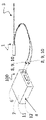
器官(44)内の組織(41)を治療するためのアブレーション装置(100)であって、アブレーションカテーテル(1)が、-も細長シャフト遠位部分(17)を備えるカテーテル細長シャフト(13)を備え、カテーテル細長シャフト(13)が、身体の血管(208)を通って進む可撓性の本体(207)を備え、-アブレーションカテーテル(1)が、細長シャフト遠位部分(17)に配設されたシャフトアブレーションアセンブリ(20)をさらに備え、-シャフトアブレーションアセンブリ(2)が、細長シャフト遠位部分(17)に固定された複数の電極(127、113、又は114)を備え、複数の電極(127、113、又は114)のすべてが、電気信号(S)を介して単一の電源(4)によって電力を供給され、組織(41)を治療するための非熱エネルギー及び組織(41)をアブレーションするための熱エネルギーの両方を送達するもの。【選択図】図63An ablation device (100) for treating tissue (41) within an organ (44), wherein the ablation catheter (1) comprises a catheter elongated shaft (13) comprising an elongated shaft distal portion (17). the catheter elongated shaft (13) comprises a flexible body (207) that passes through a body vessel (208); - the ablation catheter (1) is disposed on the elongated shaft distal portion (17); - the shaft ablation assembly (2) comprises a plurality of electrodes (127, 113 or 114) secured to the elongated shaft distal portion (17), the plurality of electrodes (127, 113 or 114) are all powered by a single power source (4) via an electrical signal (S) to provide non-thermal energy and tissue (41) to treat tissue (41). that deliver both thermal energy to ablate the [Selection drawing] Fig. 63
Description
本発明は、器官系内の組織の標的領域を治療するためのアブレーション装置またはアブレーションアセンブリ、および器官内の組織の標的領域を治療するための方法に関する。 The present invention relates to an ablation device or assembly for treating a target area of tissue within an organ system and a method for treating a target area of tissue within an organ.
より具体的には、本発明は、標的組織を非熱的に治療し、組織を熱的にアブレーションするための組み合わせシステムおよび方法に関する。該組織は、心臓細胞の活動電位が正常ではない、典型的なフェーズはフェーズ0~3である、心房細動(すなわちAF)患者などの、いずれかの病変であり得る。該組織はまた、患者の不規則な不整脈を阻止または防ぐために、難治性の波面を遮断する必要があると考えられる組織である可能性がある。 More specifically, the present invention relates to a combination system and method for non-thermally treating target tissue and thermally ablating tissue. The tissue may be any lesion, such as an atrial fibrillation (or AF) patient, in which cardiac cell action potentials are abnormal, typically phases 0-3. The tissue may also be tissue where it may be necessary to block refractory wavefronts in order to interrupt or prevent the patient's irregular arrhythmias.
本発明は概して、患者に標的組織アブレーションを実行するためのアブレーションシステムおよび方法に関する。特に、本発明は、強力なパルス電界(PEF)が細胞膜の透過性をもたらし、細胞の恒常性の破壊および細胞死を引き起こすときに発生する、高周波(RF)および/または不可逆エレクトロポレーション(IRE)を送達するカテーテルを提供する。不可逆エレクトロポレーション(IRE)エネルギーは、心臓の不整脈を引き起こすような標的組織に、安全で精密な焼灼巣を作成する。 The present invention relates generally to ablation systems and methods for performing targeted tissue ablation in a patient. In particular, the present invention relates to radiofrequency (RF) and/or irreversible electroporation (IRE), which occurs when intense pulsed electric fields (PEF) permeabilize cell membranes, causing disruption of cell homeostasis and cell death. ) is provided. Irreversible electroporation (IRE) energy creates a safe and precise lesion in target tissue that induces cardiac arrhythmias.
心臓病学におけるPEFの用途は広大であり、心房細動、心室細動、中隔アブレーション、および血管構造の標的化が含まれる。PEFには、組織特異的かつ非熱的である能力を含む、魅力的な特性がある。本発明は、心臓組織にIRE/PEFを送達するための新規のカテーテル設計を提供する。 The applications of PEF in cardiology are vast and include atrial fibrillation, ventricular fibrillation, septal ablation, and targeting of vascular structures. PEF has attractive properties, including the ability to be tissue-specific and non-thermal. The present invention provides a novel catheter design for delivering IRE/PEF to cardiac tissue.
パルス電界(PEF)とは、断続的で高強度の電界を短時間(マイクロ秒またはナノ秒)印加することを指し、これにより、細胞および組織のエレクトロポレーションがもたらされる。エレクトロポレーションは、印加された電界(すなわちPEF)が細胞膜の細孔の形成をもたらすプロセスである。細孔の形成は、印加されたPEFのパラメータに応じて、可逆的または不可逆的であり得る透過性をもたらす。可逆エレクトロポレーションでは、細胞は生存し続け、電気化学療法および遺伝子エレクトロトランスファーの基礎となる。文献を参照されたい。1)Mali B,Jarm T,Snoj M,Sersa G,Miklavcic D.Antitumor effectiveness of electrochemotherapy:A systematic review and meta-analysis.Eur J Surg Oncol.2013;39:4-16、2)Heller R,Heller LC.Gene Electrotransfer Clinical Trials.Adv Genet.2015;89:235-62、3)Neumann E,Schaefer-Ridder M,Wang Y,Hofschneider P.Gene transfer into mouse lyoma cells by electroporation in high electric fields.EMBO J.1982;1:841-5. Pulsed electric field (PEF) refers to the application of intermittent, high-intensity electric fields for short periods of time (microseconds or nanoseconds), resulting in electroporation of cells and tissues. Electroporation is a process in which an applied electric field (ie, PEF) results in the formation of pores in cell membranes. Pore formation results in permeability that can be reversible or irreversible, depending on the parameters of the applied PEF. With reversible electroporation, cells remain viable and are the basis for electrochemotherapy and gene electrotransfer. See literature. 1) Mali B, Jarm T, Snoj M, Sersa G, Miklavcic D.; Antitumor effectivity of electrochemotherapy: A systematic review and meta-analysis. Eur J Surg Oncol. 2013;39:4-16, 2) Heller R, Heller LC. Gene Electrotransfer Clinical Trials. Adv Genet. 2015;89:235-62, 3) Neumann E, Schaefer-Ridder M, Wang Y, Hofschneider P.; Gene transfer into mouse lyoma cells by electroporation in high electric fields. EMBOJ. 1982; 1:841-5.
エレクトロポレーションは、PEF(高電圧電流によって生成される)が細胞に印加され、その結果、細胞膜に細孔が形成され、続いて細胞の透過性が増加する現象である。電界は、最も一般的には、2つ以上の電極間に送達される高電圧直流によって生成される。電界が印加されると、脂質二重層全体に電荷が確立され、臨界閾値に達すると(膜貫通電圧に依存)、エレクトロポレーションが発生する。対照的に、不可逆エレクトロポレーション(IRE)では、プログラム細胞死カスケード活性化のために、細胞および組織は生存できない。IREは、固形腫瘍の定着した治療である。ただし、PEFは、現在の熱ベースのアプローチの制限を考えると、心臓病学、特に心臓アブレーションにも役立つ可能性がある。PEFは、組織を加熱せずに焼灼巣を作成でき、細胞/組織を選択できることにより、重要な周囲の構造を保存できる。 Electroporation is a phenomenon in which a PEF (produced by a high voltage electric current) is applied to cells, resulting in the formation of pores in the cell membrane and subsequent increase in cell permeability. The electric field is most commonly produced by a high voltage direct current delivered between two or more electrodes. When an electric field is applied, a charge is established across the lipid bilayer, and electroporation occurs when a critical threshold is reached (depending on the transmembrane voltage). In contrast, in irreversible electroporation (IRE) cells and tissues cannot survive due to activation of the programmed cell death cascade. IRE is an established treatment for solid tumors. However, PEF may also be useful in cardiology, especially cardiac ablation, given the limitations of current heat-based approaches. PEF can create lesions without heating the tissue, and the ability to select cells/tissues preserves important surrounding structures.
組織アブレーションは、患者を治療するための多くの医療処置で使用される。アブレーションは、病変心臓細胞などの望ましくない組織を除去または変性させるために実行できる。アブレーション処置はまた、不整脈状態の患者の心臓組織を通る電気的伝播の連鎖において、特定のエリアの電気的機能を停止するなど、除去せずに組織を改変することを含み得る。アブレーションは、電気エネルギーなどのエネルギーを1つ以上の電極に通し、電極が接触している場所で組織死を引き起こすことによって実行できる。アブレーション処置は、心房細動(AF)などの何かの心不整脈のある患者に対して、心臓内の組織をアブレーションすることによって実行できる。 Tissue ablation is used in many medical procedures to treat patients. Ablation can be performed to remove or degrade unwanted tissue, such as diseased heart cells. Ablation procedures may also include altering tissue without removing it, such as stopping electrical function in specific areas in the chain of electrical propagation through cardiac tissue of an arrhythmic patient. Ablation can be performed by passing energy, such as electrical energy, through one or more electrodes to cause tissue death where the electrodes are in contact. Ablation procedures can be performed on patients with any cardiac arrhythmia, such as atrial fibrillation (AF), by ablating tissue within the heart.
哺乳類の器官機能は、典型的には、心臓ペースメーカである洞房結節によって、電気的活動が自発的に発生したときに発生する。この電気インパルスは、右房全体に伝播し、バッハマン束を介して左房に伝播して、心房の心筋を刺激して収縮させる。伝導系は、特殊な心筋細胞からなる。心筋細胞は、安静時に膜電位が負になる。閾値を超える刺激は、電位依存性イオンチャネルの開放および細胞内への陽イオンの流入を誘発する。細胞に入る正に帯電したイオンは、活動電位の脱分極特性を引き起こす。骨格筋と同様に、脱分極は電位依存性カルシウムチャネルの開放および横行小管からのCa2+の放出を引き起こす。このカルシウムの流入は、筋小胞体からのカルシウム誘発性カルシウム放出を引き起こし、遊離Ca2+は筋収縮を引き起こす。遅れて、カリウムチャネルが再び開き、結果として生じる細胞からのK+の流れにより、休止状態への再分極が引き起こされる。この電気インパルスの伝達は、心腔を介して伝播する。このような電気的伝達の妨害は、器官の機能不全につながる可能性がある。電気インパルス伝達が適切な器官機能にとって重要である、1つの特定のエリアは心臓にあり、心房収縮を引き起こし、脈拍と同期した方法で心室内に血液を送り込むことにつながる。 Mammalian organ function typically occurs when electrical activity is spontaneously generated by the cardiac pacemaker, the sinoatrial node. This electrical impulse propagates throughout the right atrium and through the Bachmann's bundle to the left atrium, stimulating the atrial myocardium to contract. The conducting system consists of specialized myocardial cells. Cardiomyocytes have a negative membrane potential at rest. Transthreshold stimulation induces the opening of voltage-gated ion channels and the influx of cations into the cell. Positively charged ions entering a cell cause the depolarizing properties of the action potential. Similar to skeletal muscle, depolarization causes the opening of voltage-gated calcium channels and the release of Ca2+ from transverse canaliculi. This calcium influx causes calcium-induced calcium release from the sarcoplasmic reticulum and free Ca2+ causes muscle contraction. After a delay, the potassium channels reopen and the resulting flux of K+ from the cell causes repolarization to the resting state. This electrical impulse transmission propagates through the heart chambers. Such disruption of electrical transmission can lead to organ dysfunction. One particular area where electrical impulse transmission is critical to proper organ function is in the heart, causing atrial contraction, leading to pumping blood into the ventricles in a pulse-synchronous manner.
心房細動(AF)は、心房に無秩序な電気伝導があり、急速な非協調的心房収縮を引き起こし、その結果、心室内への血液の送り込みが無効になり、同期がとれない種類の心不整脈を指す。AF中、房室結節は洞房結節だけでなく、心房全体の多数の場所から電気インパルスを受信する。これらの異常な信号は房室結節を圧倒し、不規則かつ急速な心拍を生成する。その結果、血液が心房に溜まり、血栓が形成される可能性が高くなり得る。AFの主な危険因子には、年齢、冠状動脈疾患、リウマチ性心疾患、高血圧、糖尿病、および甲状腺中毒症が含まれる。AFは65歳より上の人口の、7%に影響を及ぼす。 Atrial fibrillation (AF) is an asynchronous type of cardiac arrhythmia in which there is chaotic electrical conduction in the atria, causing rapid, uncoordinated atrial contractions, resulting in ineffective pumping of blood into the ventricles. point to During AF, the atrioventricular node receives electrical impulses from multiple locations throughout the atrium, not just the sinoatrial node. These abnormal signals overwhelm the atrioventricular node, producing an irregular and rapid heartbeat. As a result, blood pools in the atria and can increase the likelihood of thrombus formation. Major risk factors for AF include age, coronary artery disease, rheumatic heart disease, hypertension, diabetes, and thyrotoxicosis. AF affects 7% of the population over the age of 65.
心房細動治療の選択肢は限られている。ライフスタイルの変更は、ライフスタイルに関連するAFを持つ個人のみ助けとなる。薬物療法はAFの症状を管理し、AFよりも危険な副作用を示すことが多く、かつAFを治すことはできない。電気的除細動は正常な洞調律を回復しようとするが、疾患の進行によりAF再発率が高くなる。さらに、心房に血栓がある場合、電気的除細動により血栓が心臓を離れ、脳(脳卒中を引き起こす)または身体の他の部分に移動する可能性がある。必要なのは、無秩序な電気伝導を伴うAFおよびその他の病状を治療するための新しい方法である。 Atrial fibrillation treatment options are limited. Lifestyle changes only help individuals with lifestyle-related AF. Drug therapy manages the symptoms of AF, often has more dangerous side effects than AF, and cannot cure AF. Cardioversion attempts to restore normal sinus rhythm, but disease progression results in a high recurrence rate of AF. Additionally, if there is a clot in the atrium, cardioversion can cause the clot to leave the heart and travel to the brain (causing a stroke) or other parts of the body. What is needed are new methods for treating AF and other conditions involving unregulated electrical conduction.
AFを治療するために、コックス迷路アブレーション処置、心房の様々な領域の線形アブレーション、および肺静脈口の円周アブレーションを含む、様々なアブレーション技術が提案されてきた。コックス迷路アブレーション処置および線形アブレーション処置は、長たらしく時間がかかり、完遂するのに数時間かかる。現在の肺静脈口アブレーションは、長期的には効果がないことが証明されている。すべてのアブレーション処置には、心臓の左房の組織をアブレーションしている間、食道などの非標的組織に不注意に損傷を与えるリスクが伴う。したがって、安全な方法で効果的な焼灼巣を作成する、改善された心房アブレーション製品および技術が必要である。 Various ablation techniques have been proposed to treat AF, including Cox's maze ablation procedure, linear ablation of various regions of the atria, and circumferential ablation of the pulmonary vein ostia. Cox's maze and linear ablation procedures are tedious and take hours to complete. Current pulmonary venous ostial ablation has proven ineffective in the long term. All ablation procedures carry the risk of inadvertently damaging non-target tissue such as the esophagus while ablating tissue in the left atrium of the heart. Accordingly, there is a need for improved atrial ablation products and techniques that create effective lesions in a safe manner.
心臓病学における非熱的および熱的アブレーションの用途は広大であり、心房細動、心室細動、中隔アブレーション、および血管構造疾患の患者の治療が含まれる。アブレーションには、組織特異的である能力を含む魅力的な特徴がある。 The applications of non-thermal and thermal ablation in cardiology are vast and include treatment of patients with atrial fibrillation, ventricular fibrillation, septal ablation, and vascular structural disease. Ablation has attractive features, including the ability to be tissue specific.
医療用心臓アブレーション技術は当技術分野で知られており、高周波(RF)、高強度超音波ビームなどの集束超音波、マイクロ波、レーザ、熱電加熱、直流(DC)または交流(AC)を使用する電極を用いた従来の加熱方法、ならびに加熱された流体および低温療法(凍結療法などであり、寒冷療法または冷凍アブレーションとしても知られている)の適用などの、治療法が含まれる。 Medical cardiac ablation techniques are known in the art and use radio frequency (RF), focused ultrasound such as high intensity ultrasound beams, microwaves, lasers, thermoelectric heating, direct current (DC) or alternating current (AC). Treatment methods such as conventional heating methods using electrodes that heat and apply heated fluids and cryotherapy (such as cryotherapy, also known as cryotherapy or cryoablation) are included.
解決策は、以下の文献において知られている。US8641704B2、US8475449B2、US2010152725A1、US2010152725A1、US8948865B2、US2008281314A1、US8540710B2、US2019038171A1、US8221411B2、US2016051324A1、US2015327994A1、WO2017192804A1、US2020229866A1、WO2019023280A1。 Solutions are known in the following documents. US8641704B2、US8475449B2、US2010152725A1、US2010152725A1、US8948865B2、US2008281314A1、US8540710B2、US2019038171A1、US8221411B2、US2016051324A1、US2015327994A1、WO2017192804A1、US2020229866A1、WO2019023280A1。
これらの処置の多くでは、針の有無にかかわらず、プローブなどのエネルギー送達デバイスが標的組織に挿入され、熱エネルギー、非熱エネルギー、および冷凍アブレーション処置に関連付けられたエネルギーなどのエネルギーの印加を通じて、心臓組織の標的領域の破壊を引き起こす。心腔または他の器官内へのエネルギー送達デバイスの挿入は、典型的には、心臓より下位のポイントから作成される細長トラックによって達成される。細長トラックまたはアクセスチューブは、皮膚の穿刺点から標的組織まで延伸するデバイスの挿入によって作成された空間として定義される。エネルギー送達デバイスが除去されるとき、それは、エネルギー送達デバイスの挿入を可能にするために先に作成された細長トラックまたはアクセスチューブに沿って引き戻される。 In many of these procedures, an energy delivery device such as a probe, with or without a needle, is inserted into the target tissue and through the application of energy, such as that associated with thermal, non-thermal, and cryoablation procedures. Causes destruction of target areas of heart tissue. Insertion of an energy delivery device into a heart chamber or other organ is typically accomplished by an elongated track created from points inferior to the heart. An elongated track or access tube is defined as the space created by insertion of the device extending from the skin puncture point to the target tissue. When the energy delivery device is removed, it is pulled back along a previously created elongated track or access tube to allow insertion of the energy delivery device.
送達デバイスが引き抜かれる前に、エネルギー送達デバイスに直接隣接する組織がアブレーションされる。これにより、アブレーション要素の周囲に局部化ゾーンを作成し、所望の組織の場所の死の確率を最大化できる。エネルギー送達デバイスが組織表面に設置される場合、RFなどの電気的に誘発された熱的アブレーションを使用して、組織部位を効果的かつ連続的に、局所的にアブレーションできることが当技術分野で知られている。RFは、正常組織を取り囲むマージンの凝固壊死を引き起こすことができ、温熱状態は、細胞質酵素の凝固やヒストン複合体の損傷などの細胞傷害を引き起こし、最終的な細胞死を引き起こす。これらの組織治療法およびシステムは、大量の標的組織を効果的にアブレーションすることができるが、各技術には制限がある。心臓アブレーション中にこれらの処置を使用する、よく引用される課題の1つに、ヒートシンクが含まれ、アブレーション要素で生成された熱が要素上のより冷たい血流によって除去/放散されるのに対して、プロセスによって一態様に血流を含めることができる。この熱放散効果は、アブレーションされる組織の形状および最大体積の両方を変化させることができる。エネルギー送達デバイスを用いて標的組織領域を治療した後、標的組織領域からエネルギー送達デバイスを除去するとき、エネルギー送達デバイスは、治療を必要とする、新しい、アブレーションされていない部位に設置することができる。 Tissue immediately adjacent to the energy delivery device is ablated before the delivery device is withdrawn. This creates a localized zone around the ablation element to maximize the probability of death at the desired tissue location. It is known in the art that electrically induced thermal ablation, such as RF, can be used to effectively and continuously locally ablate a tissue site when the energy delivery device is placed on the tissue surface. It is RF can cause coagulative necrosis of the margins surrounding normal tissue, and hyperthermia causes cellular injury, such as clotting of cytosolic enzymes and damage to histone complexes, leading to eventual cell death. Although these tissue treatment methods and systems can effectively ablate large amounts of target tissue, each technique has limitations. One of the often cited challenges of using these procedures during cardiac ablation involves heat sinking, where the heat generated in the ablation element is removed/dissipated by cooler blood flow over the element. Thus, the process can include blood flow in one aspect. This heat dissipation effect can change both the shape and maximum volume of the ablated tissue. After treating a target tissue area with an energy delivery device, upon removal of the energy delivery device from the target tissue area, the energy delivery device can be placed at a new, non-ablated site requiring treatment. .
より最近では、不可逆エレクトロポレーション(IRE)が、心臓または器官組織をアブレーションするための上述の処置の代替として使用されている。ただし、IREは細胞死を引き起こす非熱的方法であり得るが、凝固には理想的ではなく、特に電気的に誘発される熱凝固を引き起こさず、組織部位の加熱にRFまたは長いDCパルスなどの代替源を使用することの重要性を明示している。代わりに、IREは、マイクロ秒~ミリ秒の範囲で標的組織に電気パルスを印加することを含み、これは、ナノスケールのサイズの細胞膜に非熱的に生成された欠陥をもたらし得る。これらの欠陥は、細胞膜の恒常性の破壊につながることができ、それによって、組織アブレーションゾーンの温度を上げることなく、細胞壊死を誘発する不可逆的な細胞膜透過性を引き起こすIREアブレーション中、結合組織および足場構造は余地が残されるため、周囲の器官、構造、血管、および結合組織は無傷のままになる。非熱的IRE(nonthermal IRE)(以下、非熱的IRE(non-thermal IRE)とも呼ばれる)では、細胞死は非熱的機構によって取りなされるため、多くのアブレーション技術に関連するヒートシンクの問題は無効になる。したがって、組織温存を伴う熱的効果のない集中治療を可能にするIREの利点は、アブレーション部位の出血を防ぐのに効果的であることが証明されている、RFなどの熱治療と組み合わせて効果的に使用でき、これはまた、(この例示的な実施形態では)ユーザが決定されたRFレベルを利用することを可能にすることとなり、場合によってはアブレーション、および場合によっては凝固をもたらし、これは大きな組織領域を扱う場合、IREは効果的に凝固しないこととなるため、重要である。このようにして、新たに発見されたIREの利点は、RFを使用するか、RFを併用しないかを選択するという追加の利点とともに、非熱的損傷の既知の技術を用いて効果的に利用できる。 More recently, irreversible electroporation (IRE) has been used as an alternative to the above procedures for ablating heart or organ tissue. However, although IRE can be a non-thermal method of inducing cell death, it is not ideal for coagulation, especially it does not cause electrically induced thermal coagulation and heating of tissue sites such as RF or long DC pulses. Demonstrates the importance of using alternative sources. Instead, IRE involves applying electrical pulses to the target tissue in the microsecond to millisecond range, which can lead to non-thermally generated defects in cell membranes of nanoscale size. These defects can lead to disruption of cell membrane homeostasis, thereby causing irreversible cell membrane permeability that induces cell necrosis, without increasing the temperature of the tissue ablation zone, during IRE ablation, connective tissue and The scaffold structure is left room so that the surrounding organs, structures, blood vessels and connective tissue remain intact. In a nonthermal IRE (hereinafter also referred to as a non-thermal IRE) cell death is mediated by a non-thermal mechanism, so the heat sink problem associated with many ablation techniques is become invalid. Therefore, the advantage of IRE, which allows for intensive therapy without thermal effects with tissue sparing, can be effectively combined with thermal therapies such as RF, which have proven effective in preventing bleeding at the ablation site. This would also (in this exemplary embodiment) allow the user to utilize determined RF levels, possibly resulting in ablation and possibly coagulation, which is important when dealing with large tissue areas because the IRE will not coagulate effectively. In this way, the newly discovered advantages of IRE, along with the added advantage of choosing to use RF or not with RF, can be effectively exploited using known techniques of non-thermal damage. can.
IREには明確な利点があるが、治療処置中に熱的アブレーションを利用することにも利点がある。本発明の開示の前に、周囲の組織の完全性を維持しながら、心臓または器官組織の標的領域を非熱的にアブレーションする問題を解決し得、かつアブレーショントラックに沿って組織を効果的かつ熱的にアブレーションするためのデバイスに効果的に切り替える発明は提案されていなかった。特定の提案された実施形態では、様々な形態のエネルギーを印加することができる単一のエネルギー源によって電力が供給される、エネルギー送達デバイスを利用することができ、その後、処置の結果を最大化するために、同じエネルギー源からの異なる形態のエネルギーによって電力を供給できる同じエネルギー送達デバイスを使用して、不整脈の治療のための医療処置中に組織トラックをアブレーションする。示すように、IREは非熱的細胞死に対して利点を提供し、熱的機構は播種を防ぐだけでなく、効果的に凝固をもたらすためにも利点を提供する。この非熱/熱腫瘍アブレーションの組み合わせを提供でき、非熱的IREエネルギー送達と熱エネルギー送達とを切り替えて、腫瘍アブレーションの効率および有効性を高め、組織トラックを防止できる、システムおよび方法が必要である。 Although IRE has distinct advantages, there are also advantages to utilizing thermal ablation during therapeutic procedures. Prior to the present disclosure, the problem of non-thermally ablating a target region of heart or organ tissue while maintaining the integrity of the surrounding tissue, and effectively and effectively ablating the tissue along the ablation track, was demonstrated. No invention has been proposed to effectively switch to a device for thermal ablation. Certain proposed embodiments can utilize an energy delivery device powered by a single energy source that can apply various forms of energy and subsequently maximize treatment results. To do so, the same energy delivery device, which can be powered by different forms of energy from the same energy source, is used to ablate tissue tracks during medical procedures for the treatment of arrhythmias. As shown, the IRE offers advantages over non-thermal cell death and the thermal mechanism not only to prevent seeding but also to effectively effect clotting. Systems and methods are needed that can provide this combination of non-thermal/thermal tumor ablation and can switch between non-thermal IRE energy delivery and thermal energy delivery to increase the efficiency and effectiveness of tumor ablation and prevent tissue tracking. be.
したがって、特に心臓組織である、組織の治療およびアブレーションを簡素化し、治療をスピードアップし、介入時間を短縮する必要性が依然として強く存在する。 Therefore, there remains a strong need to simplify the treatment and ablation of tissue, especially cardiac tissue, to speed up treatment and reduce intervention time.
本発明は、心臓組織に非熱および熱エネルギーを送達するための新規のアセンブリまたは装置および方法を提供する。 The present invention provides novel assemblies or devices and methods for delivering non-thermal and thermal energy to cardiac tissue.
本発明の目的は、特定の実施形態において、少なくとも1つのエネルギー送達デバイスすなわちアブレーションカテーテル1、および、エネルギー送達デバイスにIREエネルギーおよび熱エネルギーを提供することができる、少なくとも1つの電力またはエネルギーまたは電源、すなわち単一の電源4を有する、組み合わせ治療システムを提供することである。少なくとも1つのエネルギー送達デバイスは、モノポーラまたはバイポーラデバイスのいずれかであり得る。このシステムは、エネルギーまたは電源を、非熱的形態で利用されるエネルギーから熱的形態のエネルギーに連続的に修正して、組織の標的領域およびトラックに沿った組織をアブレーションすることができる。
The object of the present invention is, in certain embodiments, at least one energy delivery device, namely the
本発明のさらなる目的は、非熱的IREエネルギーおよび熱エネルギーを使用して組織の標的領域を効果的にアブレーションすることを含む方法を提供することである。この方法は、組織の標的領域内の単一の電源に結合された少なくとも1つのエネルギー送達デバイスを位置決めすることと、周囲の構造への損傷を防ぎながら、電源からのIREエネルギーを、組織の標的領域をアブレーションするために使用されるエネルギー送達デバイスに印加することと、それから同じ電源を使用してIREエネルギーから熱エネルギーに切り替えることと、RFエネルギーなどの熱エネルギーを用いて該組織をアブレーションしながらエネルギー送達デバイスを位置決めして、とりわけ、組織を凝固させ、出血を防ぐ治療処置中に使用される、焦点組織のアブレーションおよび安全なエネルギー送達を可能にすることと、を含む。 It is a further object of the present invention to provide a method that includes effectively ablating a target area of tissue using non-thermal IRE energy and thermal energy. The method includes positioning at least one energy delivery device coupled to a single power source within a target region of tissue and delivering IRE energy from the power source to the target tissue while preventing damage to surrounding structures. applying to an energy delivery device used to ablate an area, then switching from IRE energy to thermal energy using the same power source, and ablating the tissue using thermal energy, such as RF energy; positioning the energy delivery device to allow focal tissue ablation and safe energy delivery used during therapeutic procedures to coagulate tissue and prevent bleeding, among other things.
本明細書で説明されるのは、組織を選択的にアブレーションするためのシステムおよび方法3であり、システム3は、アブレーションカテーテル1および単一の電源4を備える。
Described herein is a system and
代替の実施形態によれば、この方法は、組織をアブレーションおよび/または治療するためのIREの印加とともに、同じアブレーションデバイスおよび同じエネルギー源から組織を効果的にアブレーションするための代替エネルギー形態(熱エネルギーなど)を提供することを含む。この方法は、少なくとも非熱エネルギー源6および熱エネルギー源7を有する、少なくとも1つのエネルギー源、すなわち単一の電源4を提供することと、少なくとも1つのエネルギー源の所望のエネルギー源に選択的に操作可能に結合されるように構成されている、少なくとも1つのプローブ、すなわちアブレーションカテーテル1を提供することと、心臓または器官の所望の領域内の少なくとも1つのプローブの少なくとも一部を、プローブを介して位置決めすることと、少なくとも1つのプローブを非熱エネルギー源に選択的に結合することと、非熱エネルギー源に選択的にエネルギーを与え、非熱エネルギー源からの非熱エネルギーを所望の領域の少なくとも一部に印加して、所望の領域の少なくとも一部をアブレーションすることと、少なくとも1つのプローブを熱エネルギー源に選択的に結合することと、少なくともプローブを所望の領域から引き抜くことと、熱エネルギー源に選択的にエネルギーを与え、少なくとも1つのプローブの引き抜きの少なくとも一部の間に熱エネルギーを印加して、プローブトラックに実質的に隣接する組織をアブレーションすることと、を含む。
According to an alternative embodiment, the method includes an alternative form of energy (thermal energy) for effectively ablating tissue from the same ablation device and same energy source, along with the application of an IRE to ablate and/or treat tissue. etc.). The method comprises providing at least one energy source, i.e. a
代替の実施形態によれば、組織を選択的にアブレーションするためのシステム3が本明細書で提供され、システム3は、非熱エネルギー源6および熱エネルギー源7を有する、少なくとも1つのエネルギー源すなわち単一の電源4と、少なくとも1つのプローブすなわちアブレーションカテーテル1と、プローブを少なくとも1つのエネルギー源の1つの所望のエネルギー源に選択的に結合するための手段8と、少なくとも1つのエネルギー源の非熱エネルギー源に選択的にエネルギーを与え、所望の領域の少なくとも一部に非熱エネルギーを印加して、所望の領域の少なくとも一部をアブレーションする手段11と、少なくとも1つのプローブの引き抜き中に、少なくとも1つのエネルギー源の熱エネルギー源に選択的にエネルギーを与え、プローブトラックに実質的に隣接している組織を熱アブレーションする手段12と、を有する。
According to an alternative embodiment, provided herein is a
代替の実施形態によれば、独特の多電極および多機能アブレーションカテーテルおよびアブレーションカテーテルシステム、すなわちアブレーションアセンブリまたは装置100、ならびに患者の心腔内の心筋組織をマッピングおよびアブレーションする方法が提供される。この設置で発見された心電図信号部位(例えば、異常な信号を伴う部位)または複数の部位の組み合わせが、アブレーションされ得る。代替の実施形態では、アブレーションカテーテルおよびシステムを使用して、例えば、腫瘍組織、腎動脈神経などの非心臓患者の組織を治療することができる。
According to alternative embodiments, a unique multi-electrode and multi-function ablation catheter and ablation catheter system, ie, ablation assembly or
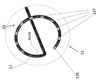
代替の実施形態によれば、患者に対して医療処置を実行するためのプローブ、例えばアブレーションカテーテル1が提供される。アブレーションカテーテル1は、近位端15および遠位端16を含む近位部分14を備えた細長シャフト13と、近位端18および遠位端19を備えた遠位部分17と、を備える。細長シャフト13は、RFおよび/または不可逆エレクトロポレーションエネルギーなどのエネルギーを組織41に送達するように構成されている、シャフトアブレーションアセンブリ20および遠位アブレーションアセンブリ21をさらに備える。シャフトアブレーションアセンブリ20は、遠位部分19の遠位端に近位であり、シャフト13に固定的または除去可能に取り付けられており、組織にアブレーションエネルギーを送達するように構成されている、少なくとも1つのシャフトアブレーション要素22またはシャフト電極127を含む。遠位アブレーションアセンブリ21は、遠位部分19の遠位端にあり、組織41にアブレーションエネルギーを送達するように構成されている、少なくとも1つの先端アブレーション要素23、または電極先端128を含む。
According to an alternative embodiment there is provided a probe, eg an
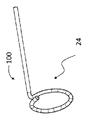
代替の実施形態によれば、遠位部分17は、円形構成であるように構成されており、1つ以上の偏向形状およびジオメトリ24で、1つ以上の方向に偏向することができる。偏向ジオメトリ24は、類似または対称的な偏向ジオメトリであり得るか、もしくは偏向ジオメトリは、似ていないまたは非対称の偏向ジオメトリであり得る。シャフトすなわちアブレーションカテーテル1は、遠位部分17を1つ以上の偏向方向に偏向させるように構成されている、1つ以上のステアリングワイヤ25を含み得る。カテーテルの偏向は、形状設定マンドレル26を設置または除去することによっても発生し得る。細長シャフト13は、その長さに沿って、シャフトの剛性の差を含み得る。細長シャフト13は、シャフト内、すなわちアブレーションカテーテル1内に形状設定マンドレル26を含み得、形状設定マンドレル26は、例えば、単一の平面に偏向を維持するように、遠位部分17の偏向(ステアリングおよび形状)を実行または増強するように構成されている。シャフトすなわちアブレーションカテーテルは、2つの部分の間の非対称継ぎ手27、壁内またはシャフトに固定的に取り付けられた一体型部材28、可変編組29、または非対称偏向ジオメトリの偏向など、複数の偏向を作成するために使用される他の変形などの、可変材料特性を有し得る。
According to an alternative embodiment,
代替の実施形態によれば、遠位アブレーションアセンブリ21は、遠位部分19の遠位端に固定的に取り付けられ得るか、または制御ポート30を介するなどして遠位シャフト17から前進可能であり得る。遠位アブレーションアセンブリ21は、電極などの単一のアブレーション要素31、または先端アブレーション要素23もしくは電極先端128、または複数のアブレーション要素32、またはマンドレル電極132を備え得る。遠位アブレーションアセンブリ21は、アブレーション要素の形状設定マンドレルキャリアアセンブリ33、または単に形状設定マンドレル26を含み得、形状設定マンドレルキャリアアセンブリ33は、コンパクトなジオメトリから拡張されたジオメトリに、例えば制御シャフトの前進および/または後退によって引き起こされるそのような遷移など変更可能であり得る。
According to alternative embodiments,
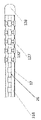
代替の実施形態によれば、シャフトアブレーションアセンブリ20は、単一のアブレーション要素31もしくは複数のアブレーション要素32、またはシャフト電極127、好ましくはシャフトまたは形状設定マンドレルに固定的に取り付けられた5~10個のアブレーション要素を含み得る。アブレーション要素は、シャフトの表面と同一平面上にあるプロファイルを有し得るか、またはより好ましくは、電極要素間のシャフトの外径35、すなわちシャフト外径35は、カテーテルの遠位端がより柔軟になるように、アブレーション電極36、すなわちシャフト電極外径36の直径よりもわずかに小さい。
According to alternative embodiments, the
代替の実施形態によれば、本発明のアブレーション要素31、32、127、128、132は、1つ以上の形態のエネルギー、好ましくはRFおよび/または不可逆エレクトロポレーションエネルギーを送達することができる。アブレーション要素は、類似または非類似の構成を有し得、かつ様々なサイズおよびジオメトリで構成され得る。アブレーション要素は、アブレーション要素の内側に互いに90°離れて装着された2つの熱電対などの、1つ以上の熱電対37を含み得る。アブレーション要素は、表面積の増加など、熱を放散する手段38を含み得る。代替の実施形態によれば、1つ以上のアブレーション要素は、管状のジオメトリで構成されており、壁の厚さ対外径が、1:15の比率に近い。代替の実施形態によれば、1つ以上のアブレーション要素は、心電図のマッピングなど、組織の電気的活動を記録すなわちマッピングするように構成されている。代替の実施形態によれば、1つ以上のアブレーション要素は、患者の心臓をペーシングするために送達されるエネルギーなどの、ペーシングエネルギーを送達するように構成されている。
According to alternative embodiments, the
代替の実施形態によれば、本発明のアブレーションカテーテルは、アブレーションエネルギーを組織に送達することによって1つ以上の病状を治療するために使用され得る。病状には、心臓の不整脈、がん、および組織の除去または変性が患者の健康を改善する、その他の病状が含まれる。 According to alternative embodiments, the ablation catheters of the present invention can be used to treat one or more medical conditions by delivering ablation energy to tissue. Medical conditions include cardiac arrhythmias, cancer, and other medical conditions in which removal or degeneration of tissue improves the health of the patient.
代替の実施形態によれば、アブレーションカテーテルのキット、すなわちアブレーションカテーテルキット300が提供される。第1のアブレーションカテーテル1は、少なくとも2つの対称的なジオメトリに偏向させることができる遠位部分を有する。第2のアブレーションカテーテル1’は、少なくとも2つの非対称なジオメトリに偏向させることができる遠位部分を有する。
According to an alternative embodiment, an ablation catheter kit, namely
代替の実施形態によれば、近位、持続性、または長期持続性心房細動の治療のための方法が提供される。本発明のアブレーションカテーテル1は、例えば、電位図のマッピングおよび/または組織をアブレーションするなどのために、患者の冠状静脈洞に設置され得、続いて、電位図のマッピングおよび/または組織をアブレーションするために、左房または右房に設置され得る。アブレーションカテーテルは、肺静脈の周りの筋膜、左房天蓋部、および僧帽弁峡部を含むがこれらに限定されない、1つ以上の組織の場所をアブレーションするために設置することができる。
According to alternative embodiments, methods are provided for the treatment of proximal, persistent, or long-lasting atrial fibrillation. The
代替の実施形態によれば、心房粗動を治療する方法が提供される。本発明のアブレーションカテーテルは、心臓43の右房の1つ以上の場所に設置することなどによって、双方向性ブロックを達成するために使用することができる。
According to an alternative embodiment, a method of treating atrial flutter is provided. Ablation catheters of the present invention can be used to achieve bidirectional block, such as by placement in one or more locations in the right atrium of
代替の実施形態によれば、心臓の右房の組織をアブレーションする方法が提供される。本発明のアブレーションカテーテルは、上大静脈と下大静脈との間、冠状静脈洞と下大静脈との間、上大静脈と冠状静脈洞との間、およびこれらの組み合わせに、焼灼巣を作成するために使用することができる。カテーテルは、電位図のマッピング、かつ/または洞房結節頻拍を治療するためなど、洞房結節をマッピングかつ/またはアブレーションするために使用することができる。 According to an alternative embodiment, a method of ablating tissue in the right atrium of the heart is provided. The ablation catheters of the present invention create lesions between the superior and inferior vena cava, between the coronary sinus and inferior vena cava, between the superior vena cava and coronary sinus, and combinations thereof. can be used to The catheter can be used for mapping and/or ablating the sinoatrial node, such as for electrogram mapping and/or treating sinoatrial node tachycardia.
代替の実施形態によれば、心室頻拍を治療する方法が提供される。本発明のアブレーションカテーテルは、心臓の左室または右室に設置されて、ペーシングエネルギーを送達することによって心室頻拍を誘発することができ、組織をアブレーションして患者を治療する。 According to an alternative embodiment, a method of treating ventricular tachycardia is provided. The ablation catheter of the present invention can be placed in the left or right ventricle of the heart to induce ventricular tachycardia by delivering pacing energy to ablate tissue to treat the patient.
代替の実施形態によれば、第2の偏向ジオメトリよりも大きい第1のジオメトリを有するアブレーションカテーテルが、形状設定マンドレルを介して提供される。アブレーションカテーテルは、以下の組織の場所の1つ以上:左心房中隔;左心房中隔に隣接する組織;および左房後壁に隣接する組織をアブレーションするために、より小さい第2の形状ジオメトリに設置される。アブレーションカテーテルは、少なくとも肺静脈の周囲をアブレーションするために、より大きな第1のジオメトリに設置される。 According to an alternative embodiment, an ablation catheter having a first geometry greater than a second deflection geometry is provided via a shape setting mandrel. The ablation catheter has a smaller second shape geometry for ablating one or more of the following tissue locations: left atrial septum; tissue adjacent to the left atrial septum; and tissue adjacent to the left atrial posterior wall. is installed in The ablation catheter is placed in a larger first geometry to ablate at least around the pulmonary veins.
代替の実施形態によれば、本発明のアブレーションカテーテルは、心臓の左房および右房の両方を治療するために使用される。カテーテルは、第1の形状設定マンドレルおよび/または偏向ジオメトリ、ならびに第2の形状設定マンドレルおよび/または偏向ジオメトリを有するジオメトリに遷移するように構成されており、第1のジオメトリは第2のジオメトリとは異なる。カテーテルは、少なくとも第1のジオメトリを使用して右房の組織をアブレーションするために使用され、また、少なくとも第2のジオメトリを使用して左房の組織をアブレーションするために使用される。 According to an alternative embodiment, the ablation catheter of the present invention is used to treat both the left and right atria of the heart. The catheter is configured to transition to a geometry having a first shape-setting mandrel and/or deflection geometry and a second shape-setting mandrel and/or deflection geometry, wherein the first geometry is combined with the second geometry. is different. The catheter is used to ablate right atrial tissue using at least a first geometry and is used to ablate left atrial tissue using at least a second geometry.
代替の実施形態によれば、患者に医療処置を実行するためのカテーテルが提供される。カテーテル、すなわちカテーテルアセンブリまたは装置100は、近位端および遠位端を含む近位部分を備えた細長シャフトと、近位端および遠位端を備えた遠位部分と、を備える。カテーテルは、第1のジオメトリで第1の方向に、かつ第2のジオメトリで第2の方向に遠位部分を成形するように構成されている形状設定マンドレルおよび/または偏向アセンブリをさらに備え、第1および第2のジオメトリは異なる。カテーテルは、遠位部分に固定的に装着された機能要素をさらに含む。
According to an alternative embodiment, a catheter is provided for performing a medical procedure on a patient. A catheter, catheter assembly or
したがって、本発明の目的は、例えば前述の必要性を満たし、先行技術のデバイスに関して上述の欠点を克服するような構造的かつ機能的特徴を有するアブレーション装置またはアセンブリを提供することである。 SUMMARY OF THE INVENTION Accordingly, it is an object of the present invention to provide an ablation device or assembly having structural and functional features that satisfy, for example, the aforementioned needs and overcome the aforementioned shortcomings with respect to prior art devices.
これらのおよび他の目的は、請求項1に記載のデバイスによって達成される。
These and other objects are achieved by a device according to
いくつかの有利な実施形態は、従属請求項の主題である。 Some advantageous embodiments are the subject matter of dependent claims.
本発明のさらなる特徴および利点は、添付の図面を参照して、非限定的な例として与えられた、その例示的な実施形態の以下に提供される説明から明らかになるであろう。 Further features and advantages of the invention will become apparent from the description provided below of exemplary embodiments thereof, given by way of non-limiting example, with reference to the accompanying drawings.
本発明は、以下の詳細な説明、実施例、図面、およびそれらの前後の説明を参照することにより、より容易に理解することができる。しかしながら、本デバイス、システム、および/または方法が開示および説明される前に、本発明は、他に特定されない限り、開示された特定のデバイス、システム、および/または方法に限定されず、よって、当然変更し得ることを理解すべきである。本明細書で使用される用語は、特定の態様を説明することのみを目的としており、限定することを意図するものではないことも理解すべきである。 The present invention can be understood more readily by reference to the following detailed description, examples, drawings, and the discussions that follow. However, before the present devices, systems and/or methods are disclosed and described, the present invention is not limited to the particular devices, systems and/or methods disclosed unless otherwise specified; Of course, it should be understood that this may change. It is also to be understood that the terminology used herein is for the purpose of describing particular aspects only and is not intended to be limiting.
本発明の以下の説明は、その最良の、現在知られている実施形態における、本発明の教示を可能にするものとして提供される。この目的を達成するために、当業者は、本発明の有益な結果を依然として得ながら、本明細書に記載の本発明の様々な態様に多くの変更を加えることができることを認識し、理解するであろう。また、本発明の所望の利益のうちのいくつかは、本発明の特徴のうちのいくつかを、他の特徴を利用することなく選択することによって、得ることができることも明らかであろう。よって、当技術分野で働く人々は、本発明に対する多くの修正および改変が可能であり、特定の状況においても望ましい可能性があり、本発明の一部であることを認識するであろう。したがって、以下の説明は、本発明の原理の例示として提供され、それを限定するものではない。全体を通して使用されているように、単数形の「a」、「an」、および「the」には、文脈で他に明確に指示されていない限り、複数の指示対象が含まれる。したがって、例えば、「チューブセグメント」への言及は、文脈が他に示さない限り、2つ以上のそのようなチューブセグメントを含むことができる。本明細書で使用される「複数」という用語は、2つ以上を指す。 The following description of the invention is provided as an enabling teaching of the invention in its best, currently known embodiment. To this end, those skilled in the art will recognize and understand that many modifications can be made to the various aspects of the invention described herein while still obtaining the beneficial results of the invention. Will. It will also be apparent that some of the desired benefits of the present invention can be obtained by selecting some of the features of the present invention without utilizing others. Thus, those working in the art will recognize that many modifications and variations to the present invention are possible, and may even be desirable in certain circumstances, and are part of the present invention. Accordingly, the following description is offered as an illustration of, and not a limitation of, the principles of the invention. As used throughout, the singular forms "a," "an," and "the" include plural referents unless the context clearly dictates otherwise. Thus, for example, reference to "a tube segment" can include two or more such tube segments unless the context indicates otherwise. As used herein, the term "plurality" refers to two or more.
範囲は、本明細書では、「約」ある特定の値から、および/または「約」別の特定の値までとして表すことができる。そのような範囲が表現されるとき、別の態様は、ある特定の値からおよび/または他の特定の値までを含む。同様に、値が近似値として表される場合、先行詞「約」を使用することにより、特定の値が別の態様を形成することが理解されよう。範囲の各々のエンドポイントは、他のエンドポイントとの関係で、および他のエンドポイントとは無関係に、重要であることが、さらに理解されよう。 Ranges can be expressed herein as from "about" one particular value, and/or to "about" another particular value. When such a range is expressed, another aspect includes from the one particular value and/or to the other particular value. Similarly, when values are expressed as approximations, by use of the antecedent "about," it will be understood that the particular value forms another aspect. It will be further understood that each endpoint of the range is important relative to and independent of the other endpoints.
本明細書で使用する場合、「任意選択の」または「任意選択で」という用語は、その後に説明される事象または状況が発生する可能性があるまたは発生しない可能性があることを意味し、この説明は事象または状況が発生する場合およびそれが発生しない場合を含む。 As used herein, the terms "optional" or "optionally" mean that the event or circumstances subsequently described may or may not occur; This description includes cases where the event or situation occurs and cases where it does not occur.
「遠位」という用語は、医者から離れて、処置が実行される身体部位に向かっていることを意味し、「近位」は、医者に向かって、身体部位から離れていることを意味すると理解される。 The term "distal" means away from the physician and toward the body part where the procedure is performed, and "proximal" means toward the physician and away from the body part. understood.
一般的な実施形態によれば、器官44内の組織41の標的領域を治療するためのアブレーション装置100は、アブレーションカテーテル1および単一の電源4を備える。
According to a general embodiment, an
該アブレーションカテーテル1は、少なくとも細長シャフト遠位部分17を備える、カテーテル細長シャフト13を備える。
The
該カテーテル細長シャフト13は、身体の血管208を通って進む可撓性の本体207を備える。
The catheter elongated
該アブレーションカテーテル1は、該細長シャフト遠位部分17に配設されたシャフトアブレーションアセンブリ20をさらに備える。
The
該シャフトアブレーションアセンブリ20は、該細長シャフト遠位部分17に固定的に配設された、少なくとも複数の電極127、113、または114を備える。
The
該少なくとも複数の127、113、または114のすべての電極は、該単一の電源4によって電気信号Sを介して電力を供給され、組織41を治療するための非熱エネルギーおよび組織41をアブレーションするための熱エネルギーの両方を送達する。
All of the at least plurality of 127, 113, or 114 electrodes are powered via electrical signal S by the
該単一の電源4は、要求されたとき、該少なくとも複数の電極127、113、または114に電力を供給して非熱エネルギーから熱エネルギーに、もしくはその逆を送達するために、または熱エネルギーおよび非熱エネルギーの組み合わせを同時に送達するために、該電気信号Sを連続的に変化させる。
The
代替の実施形態によれば、該単一の電源4は、単一の制御ユニット400、および該電気信号Sを生成するための電力ユニット401を備える。
According to an alternative embodiment, the
該電力ユニット401は、該少なくとも複数の電極127、113、または114のすべての電極に電気的に接続されている。
The
代替の実施形態によれば、該電力ユニット401は、単一の制御ユニット400によって駆動されて、非熱エネルギーから熱エネルギーに、およびその逆を送達するように、または熱エネルギーおよび非熱エネルギーの組み合わせを同時に送達するように、電極127、113、または114に供給される信号Sに関連付けられた電気エネルギーレベルを連続的に変化させる。
According to alternative embodiments, the
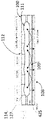
代替の実施形態によれば、該電力ユニット401は、電力モジュール402を備える。該電力モジュール402は、以下を備える。
According to an alternative embodiment, said
単一の制御ユニット400によって提供される供給電圧信号Vccから開始して、該電気信号Sを生成するために、単一の制御ユニット400によって制御される、駆動回路ブロック403、
a
該駆動回路ブロック403によって選択的に制御されて、該信号Sに関連付けられた電気エネルギーレベルを連続的に変化させる、選択ブロック404、
a
フィルタリングおよび電気絶縁ブロック405、406。 filtering and electrical isolation blocks 405, 406;
代替の実施形態によれば、該単一の制御ユニット400は、可変高電圧電源ブロック408およびプログラマブルロジックコントローラブロック409を制御するように構成されている、マイクロプロセッサ407を備える。
According to an alternative embodiment, the
該可変高電圧電源ブロック408は、該電気信号Sを生成するために、該供給電圧信号Vccを電力モジュール402に提供するように構成されている。
The variable high voltage
該プログラマブルロジックコントローラブロック409は、電力モジュール402の駆動回路ブロック403を制御するための駆動信号を生成するように構成されている。
The programmable
代替の実施形態によれば、該単一の制御ユニット400は、さらに以下を備える。
According to an alternative embodiment, the
マイクロプロセッサ407によって制御されて、装置100のパラメータを設定し、選択されたパラメータを表示する、ビデオインターフェースおよび押しボタンブロック410、410’、
video interface and push button blocks 410, 410' controlled by the
マイクロプロセッサ407の適切な機能を制御するための、ウォッチドッグブロック411、
a
アブレーションプロセスの正確さおよび/または発生したエラーを表す音声情報を提供するための、音声インターフェースブロック412。
代替の実施形態によれば、該電力ユニット401は、互いに等しい1つ以上の電力モジュール402を備える。
According to an alternative embodiment, said
代替の実施形態によれば、該電極127、113のうちの少なくとも1つはモノポーラ電極113であり、該少なくとも複数の電極のうちの該モノポーラ電極113は、該電力ユニット401の1つの電力モジュール402のみに電気的に接続されている。
According to an alternative embodiment, at least one of said
代替の実施形態によれば、該電極127、114のうちの少なくとも2つは、電気的に接続されてバイポーラ電極114を形成しており、該少なくとも複数の電極のうちの該バイポーラ電極114は、該電力ユニット401の電力モジュールの中から選択可能なそれぞれの電力モジュール402に、別々に電気的に接続されている。
According to an alternative embodiment, at least two of said
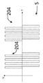
代替の実施形態によれば、該複数の127、113、または114の電極に供給される該電気信号Sは、パルス列204を含む。
According to an alternative embodiment, the electrical signal S supplied to the plurality of 127 , 113 or 114 electrodes comprises a
代替の実施形態によれば、該単一の制御ユニット400は、電力ユニット401を駆動して、パルス列204の各パルス201のパルス持続時間203を修正し、信号Sに関連付けられた電気エネルギーレベルを変化させるように構成されている。
According to an alternative embodiment, the
代替の実施形態によれば、該単一の制御ユニット400は、電力ユニット401を駆動して、パルス列204のパルス数209を修正し、信号Sに関連付けられた電気エネルギーレベルを変化させるように構成されている。
According to an alternative embodiment, the
代替の実施形態によれば、該単一の制御ユニット400は、電力ユニット401を駆動して、隣接するパルス列204間の時間間隔205を修正し、信号Sに関連付けられた電気エネルギーレベルを変化させるように構成されている。
According to an alternative embodiment, the
代替の実施形態によれば、該少なくとも複数の電極の各モノポーラ電極113は、モノポーラ電極113に溶接された単一のワイヤ210によって、該電力ユニット401の対応する電力モジュール402に電気的に接続されている。
According to an alternative embodiment, each
代替の実施形態によれば、該少なくとも複数の電極の各バイポーラ電極114は、バイポーラ電極114に溶接された2本のワイヤ210によって、該電力ユニット401の2つの選択された電力モジュール402に電気的に接続されている。
According to an alternative embodiment, each
代替の実施形態によれば、該少なくとも複数の電極127のうちの少なくとも1つの電極は、互いに電気的に絶縁された2つの導電性部分Nを備える。
According to an alternative embodiment, at least one electrode of said at least plurality of
代替の実施形態によれば、該少なくとも複数の電極127のうちの少なくとも1つの電極は、互いに電気的に絶縁された4つの導電性部分Nを備える。
According to an alternative embodiment, at least one electrode of said at least plurality of
代替の実施形態によれば、非熱エネルギーは不可逆エレクトロポレーションエネルギーすなわちIREであり、熱エネルギーは高周波エネルギーすなわちRFである。 According to an alternative embodiment, the non-thermal energy is irreversible electroporation energy or IRE and the thermal energy is radio frequency energy or RF.
代替の実施形態によれば、該複数の127、113、または114の電極に供給される該電気信号Sは、少なくとも矩形波信号を含む。 According to an alternative embodiment, the electrical signal S supplied to the plurality of 127, 113 or 114 electrodes comprises at least a square wave signal.
代替の実施形態によれば、該複数の127、113、または114の電極に供給される該電気信号Sは、2つ以上の矩形波信号を互いに組み合わせるか、または合計するか、または重ね合わせることによって得られる信号を含む。 According to an alternative embodiment, the electrical signal S supplied to the plurality of 127, 113 or 114 electrodes is a combination or sum or superposition of two or more square wave signals. including the signal obtained by
代替の実施形態によれば、該複数の127、113、または114の電極に供給される該電気信号Sは、DC信号もしくはAC信号、またはDC信号とAC信号との組み合わせを含む。 According to alternative embodiments, the electrical signal S supplied to the plurality of 127, 113 or 114 electrodes comprises a DC signal or an AC signal or a combination of DC and AC signals.
代替の実施形態によれば、該単一の電源4は、電池によって電力が供給されるか、または110ボルトもしくは240ボルトをもたらすことができるAC電力グリッドの標準的な壁コンセントに接続されている。
According to an alternative embodiment, the
代替の実施形態によれば、電気的に接続されてバイポーラ電極114を形成している、該少なくとも2つの電極127、114は、以下を備える。
According to an alternative embodiment, the at least two
第1のワイヤ210aによって該電力ユニット401の第1の電力モジュール402に接続された第1の電極114aであって、該第1の電極114aが、第1の電極114aの外側からアクセス可能な第1の電極114aの内部区画を区切る電極本体424を有する、第1の電極114a、
A
第2のワイヤ210bによって該電力ユニット401の第2の電力モジュール402に接続された第2の点状電極114bであって、該第2の点状電極114bが、第1の電極114aの該内部区画に収容されている、第2の点状電極114b。
a second point-
代替の実施形態によれば、単一の制御ユニット400が、該電力ユニット401を駆動して、各電力モジュール402において、電極127、113、または114に供給される複数の電気信号Sのそれぞれの電気信号Sを生成するように構成されており、
According to an alternative embodiment, a
該マイクロプロセッサ407が、該プログラマブルロジックコントローラブロック409を介して、各電力モジュール402を制御し、電極127、113、または114に供給される2以上の電気信号Sを選択することによって、接地電極425を用いて各電極からのモノポーラ電界、および2つの連接する電極の間のバイポーラ電界の両方が生成されるように、該複数の電気信号の各電気信号Sのオン状態、オフ状態、および位相角を修正する。
The
代替の実施形態によれば、該アブレーションカテーテル1は、長手方向の主方向X-Xを有する細長シャフト13を備える。該細長シャフト13は、少なくともシャフト遠位部分17を含む。該シャフト遠位部分17は、シャフト遠位部分遠位端19を含む。
According to an alternative embodiment, the
該アブレーションカテーテル1は、細長シャフト13内に配置された内側ルーメン118を備える。
The
該アブレーションカテーテル1は、該シャフト遠位部分17に固定的に配設された、シャフトアブレーションアセンブリ20を含み、シャフトアブレーションアセンブリ20は、該組織41をアブレーションするための熱エネルギー、および該組織41を治療するための非熱エネルギーの両方を送達するように構成されている。
The
該装置100は、少なくとも、アブレーションカテーテル1内に配設された形状設定マンドレル26を備える。形状設定マンドレル26は、内側ルーメン118内に挿入可能であり、内側ルーメン118から除去可能であり、
The
形状設定マンドレル26は、形状設定マンドレルの挿入中に該シャフト遠位部分17とのいかなる拘束も回避して、内側ルーメン118に対して自由に動くことができる。
The shape-setting
形状設定マンドレル26は、少なくとも予め成形された構成を含み、形状設定マンドレル26は、少なくとも直線装填された構成と該予め成形された構成との間で可逆的に変形可能である。
Shape-setting
形状設定マンドレル26がシャフト遠位部分17に完全に挿入されたとき、形状設定マンドレル26は、該シャフト遠位部分17を該予め成形された構成で形状設定するように構成されている。
When the shape-setting
代替の実施形態によれば、該シャフト遠位部分17は、弾性的に変形可能である。
According to an alternative embodiment, said shaft
代替の実施形態によれば、形状設定マンドレル26がシャフト遠位部分17に完全に挿入されたとき、該シャフト遠位部分17は、該成形された構成に適合するように構成されている。
According to an alternative embodiment, shaft
代替の実施形態によれば、形状設定マンドレル26がシャフト遠位部分17に完全に挿入されたとき、それは、マンドレル完全挿入位置と定義される。
According to an alternative embodiment, when the shape-setting
形状設定マンドレル26は、内側ルーメン118内で該マンドレル完全挿入位置に向かって摺動するが、形状設定マンドレル26は、該装填された直線構成から該予め成形された構成まで通過するシャフト遠位部分17を可変に形状設定するように構成されている。
As the shape-setting
代替の実施形態によれば、形状設定マンドレル26がシャフト遠位部分17に完全に挿入されたとき、該形状設定マンドレル26は、少なくともシャフト遠位部分平面Pにおいて該シャフト遠位部分17を変形させる。
According to an alternative embodiment, when the shaping
代替の実施形態によれば、該アブレーションカテーテル1は、シャフトアブレーションアセンブリ20の近位にあるカテーテル屈曲部分120を備え、該カテーテル屈曲部分120は、該長手方向の主方向X-Xに対して該シャフト遠位部分平面Pをステアリングするエルボを実現するように構成されている。
According to an alternative embodiment, the
代替の実施形態によれば、少なくとも形状設定マンドレル26がシャフト遠位部分17に完全に挿入されたとき、該シャフト遠位部分17は、シャフト長手方向の主方向X-Xに対して鋭角ALFAを形成する。
According to an alternative embodiment, at least when the shape-setting
代替の実施形態によれば、ここで形状設定マンドレル26がシャフト遠位部分17に完全に挿入されたとき、形状設定マンドレル26は、該カテーテル屈曲部分120で屈曲するように構成されている。
According to an alternative embodiment, shape-setting
代替の実施形態によれば、該予め成形された構成の該形状設定マンドレル26は、マンドレル屈曲部分146を備え、該形状設定マンドレル26が該シャフト遠位部分17に完全に挿入されたとき、該マンドレル屈曲部分146は、該カテーテル屈曲部分120を実行する該カテーテル屈曲部分120の対応箇所に配設される。
According to an alternative embodiment, the preformed configuration of the shape-setting
代替の実施形態によれば、形状設定マンドレル26がシャフト遠位部分17に完全に挿入されたとき、シャフト遠位部分17は、円形構成をとる。
According to an alternative embodiment, shaft
代替の実施形態によれば、形状設定マンドレル26は、少なくとも該直線装填された構成に変形して、該予め成形された構成に戻ることができる、マンドレル弾性体119を備える。
According to an alternative embodiment, the shape-setting
代替の実施形態によれば、形状設定マンドレル26は、少なくとも形状記憶合金から作製されている。
According to an alternative embodiment, shape-setting
代替の実施形態によれば、該アセンブリ100は、該形状設定マンドレル26に結合されたマンドレル加熱要素121を備え、該加熱要素121は、形状設定マンドレル26が形状構成を該装填された直線構成から該予め成形された構成に変化させるように、該形状設定マンドレル26に熱を加えるように構成されている。
According to an alternative embodiment, the
代替の実施形態によれば、該アブレーションアセンブリ100は、該形状設定マンドレル26が該マンドレル完全挿入位置にあるときに、該形状設定マンドレル26を該シャフト遠位部分17にロックするように構成されている、ロック機構122を備える。
According to an alternative embodiment, the
代替の実施形態によれば、該ロック機構122は、該形状設定マンドレル26を該マンドレル完全挿入位置に可逆的にロックする、保持要素123を備える。
According to an alternative embodiment, the
代替の実施形態によれば、該保持要素123は、引張力が該形状設定マンドレル26に加えられたときに、該形状設定マンドレル26を該マンドレル完全挿入位置から解放するように構成されている。
According to an alternative embodiment, the retaining
代替の実施形態によれば、該保持要素123は、金属、金属合金、ゴム、またはポリマーから作製されている。
According to alternative embodiments, the retaining
代替の実施形態によれば、該形状設定マンドレル26は、該形状設定マンドレル26が該完全挿入位置にあるときに、該保持要素123と係合するように構成されている、ボール型先端125を備える。
According to an alternative embodiment, the shape-setting
代替の実施形態によれば、該形状設定マンドレル26は、マンドレル遠位部分139を備える。
According to an alternative embodiment, the shape-setting
代替の実施形態によれば、該マンドレル遠位部分139は、マンドレル座部140を備え、該保持要素123は、該形状設定マンドレル26に固定され、該マンドレル座部140に部分的に収容される。
According to an alternative embodiment, the mandrel
代替の実施形態によれば、該シャフト遠位部分遠位端19に近位の該内側ルーメン118は、ネック部分141を提示し、該保持要素123は、該ネック部分141に干渉して、該形状設定マンドレル26を該マンドレル完全挿入位置にロックする。
According to an alternative embodiment, the
代替の実施形態によれば、該保持要素123は、Oリングであり、該マンドレル座部140は、トロイダルである。
According to an alternative embodiment, the retaining
代替の実施形態によれば、シャフト遠位部分17は、1つ以上の偏向形状およびジオメトリにおいて、1つ以上の方向に偏向可能である。
According to alternative embodiments, shaft
代替の実施形態によれば、予め成形された構成の形状設定マンドレル26は、シャフト遠位部分17の偏向を単一の平面に維持するように構成されている。
According to an alternative embodiment, the preformed configuration of shape-setting
代替の実施形態によれば、偏向方向は、対称な偏向ジオメトリまたは非対称な偏向ジオメトリである。 According to alternative embodiments, the deflection direction is a symmetric deflection geometry or an asymmetric deflection geometry.
代替の実施形態によれば、細長シャフト13は、その長さに沿って、シャフトの剛性に差を有する。
According to an alternative embodiment, the
代替の実施形態によれば、細長シャフト13は、シャフト近位部分14を備える。
According to an alternative embodiment,
代替の実施形態によれば、該シャフト近位部分14は、該シャフト遠位部分17よりも硬性である。
According to an alternative embodiment, the shaft
代替の実施形態によれば、細長シャフト13は、該シャフト近位部分14と該シャフト遠位部分17との間に配設されたシャフト遷移部分126を備える。
According to an alternative embodiment,
代替の実施形態によれば、該シャフト遷移部分126は、該シャフト遠位部分17よりも硬性であり、該シャフト近位部分14よりも硬性が少ない。
According to an alternative embodiment, the
代替の実施形態によれば、該細長シャフト13は、異なる剛性を有するシャフト部分を備え、該細長シャフト13は、異なる剛性を有する2つの該シャフト部分の間に、少なくとも1つの円周方向に不均整な剛性部分を備える。
According to an alternative embodiment, said
代替の実施形態によれば、該細長シャフト13はPebax(登録商標)で作製されているか、もしくは該細長シャフト13は編組され、ステンレス鋼フラットワイヤブレーキおよび/またはNylon(登録商標)ストランド編組で作製されている。
According to alternative embodiments, the
代替の実施形態によれば、該アブレーションカテーテル1は、1つ以上の偏向方向にシャフト遠位部分17を偏向させるように構成されている、少なくとも1つのステアリングワイヤ25を備え、該少なくとも1つのステアリングワイヤ25は、該シャフト遠位部分17に固定的に接続されている。
According to an alternative embodiment, the
代替の実施形態によれば、該少なくとも1つのステアリングワイヤ25は、シャフト近位部分14に対して外側に配置された、ワイヤ近位延在部142を備える。
According to an alternative embodiment, the at least one
代替の実施形態によれば、該ワイヤ近位延在部142は、シャフト遠位部分17内に完全に挿入された形状設定マンドレル26を有するシャフト遠位部分17をステアリングするための、少なくとも1つのステアリングワイヤ25を引っ張るように構成されている、ワイヤ把持部分143を備える。
According to an alternative embodiment, the wire
代替の実施形態によれば、該シャフト遠位部分17は、シャフト遠位部分近位端18を備える。
According to an alternative embodiment, the shaft
代替の実施形態によれば、該アブレーションカテーテル1は、少なくとも2本のステアリングワイヤ25を備える。
According to an alternative embodiment, the
代替の実施形態によれば、該少なくとも2つのステアリングワイヤ25のうちの第1のステアリングワイヤは、シャフト遠位部分遠位端19またはシャフト遠位部分近位端18の近位に固定的に接続されている。
According to an alternative embodiment, the first of said at least two
代替の実施形態によれば、該少なくとも2つのステアリングワイヤ25のうちの第2のステアリングワイヤは、シャフト遠位部分近位端18またはシャフト遠位部分遠位端19の近位に固定的に接続されている。
According to an alternative embodiment, the second of said at least two
代替の実施形態によれば、該少なくとも2つのステアリングワイヤ25のうちの第3のステアリングワイヤは、シャフト遠位部分遠位端19またはシャフト遠位部分近位端18の近位に固定的に接続されている。
According to an alternative embodiment, a third of said at least two
代替の実施形態によれば、該少なくとも2つのステアリングワイヤ25のうちの第4のステアリングワイヤは、シャフト遠位部分遠位端19またはシャフト遠位部分近位端18の近位に固定的に接続されている。
According to an alternative embodiment, a fourth of said at least two
代替の実施形態によれば、該形状設定マンドレル26は、マンドレル近位部分138を備え、該マンドレル近位部分138は、該形状設定マンドレル26がユーザによって駆動可能であるように、該内側ルーメン118の外側に配設されている。
According to an alternative embodiment, the shape-setting
代替の実施形態によれば、該細長シャフト13は、シャフト近位端15を備える。
According to an alternative embodiment, said
代替の実施形態によれば、該アブレーションカテーテル1は、該シャフト近位端15に取り付けられたステアリングデバイス144を備える。
According to an alternative embodiment, the
代替の実施形態によれば、該アブレーションカテーテル1は、ハンドル103を備え、該ステアリングデバイス144は、該ハンドル103に接続されている。
According to an alternative embodiment, the
代替の実施形態によれば、該ステアリングデバイス144は、該ハンドル103に対して回転して駆動可能であり、その結果、該ハンドルに対する該ステアリングデバイス144の回転は、該細長シャフト13の回転を引き起こす。
According to an alternative embodiment, the
代替の実施形態によれば、該ステアリングデバイス144は、該内側ルーメン118と連通する貫通孔145を備える。
According to an alternative embodiment, the
代替の実施形態によれば、形状設定マンドレル26の該アブレーションカテーテル1内への挿入またはそこからの除去中に、該形状設定マンドレル26は該貫通孔145を通過し、形状設定マンドレル26がシャフト遠位部分17に完全に挿入されたとき、該マンドレル近位部分138は、該ステアリングデバイス144の外側にある。
According to an alternative embodiment, during insertion or removal of the shape-setting
代替の実施形態によれば、形状設定マンドレル26がシャフト遠位部分17に完全に挿入されたとき、該形状設定マンドレル26は、少なくともシャフト遠位部分平面Pにおいて該シャフト遠位部分17を変形させる。
According to an alternative embodiment, when the shaping
代替の実施形態によれば、該ステアリングデバイス140は、少なくとも2つの突起147を備え、該少なくとも2つの突起および該シャフト遠位部分平面Pは同一平面上にあり、ユーザがカテーテルアセンブリ1を取り扱うのを助ける。
According to an alternative embodiment, the
代替の実施形態によれば、該アブレーションアセンブリ100は、少なくとも該シャフト遠位部分遠位端19において、使い捨て可能な遠位アブレーションアセンブリ21を備える。
According to an alternative embodiment, the
代替の実施形態によれば、該遠位アブレーションアセンブリ21は、該組織41をアブレーションするための熱エネルギー、および該組織41を治療するための非熱エネルギーの両方を送達するように構成されている。
According to an alternative embodiment, the
代替の実施形態によれば、該遠位アブレーションアセンブリ21は、少なくとも該シャフト遠位部分遠位端19において、使い捨て可能な少なくとも電極先端128を備える。
According to an alternative embodiment, the
代替の実施形態によれば、該シャフト電極127は、シャフト遠位部分17に沿って、互いに間隔を置いて配置されている。
According to an alternative embodiment, the
代替の実施形態によれば、該シャフトアブレーションアセンブリ20はまた、組織41をマッピングするように構成されている。
According to an alternative embodiment,
代替の実施形態によれば、該電極先端128は、非侵襲性であり、丸みを帯びた構成において弾力的に付勢されるように成形された、外面を有する。
According to an alternative embodiment, the
代替の実施形態によれば、該シャフト電極127および該電極先端128は、少なくともモノポーラ電極113および/または少なくともバイポーラ電極114を備える。
According to alternative embodiments, the
代替の実施形態によれば、該遠位アブレーションアセンブリ21は、少なくとも1つの熱電対37を含む。
According to an alternative embodiment, the
代替の実施形態によれば、該シャフトアブレーションアセンブリ20は、少なくとも1つの熱電対37を含む。
According to an alternative embodiment, the
代替の実施形態によれば、シャフト電極127は、シャフト遠位部分17に固定的に取り付けられた、5~10個の電極である。
According to an alternative embodiment,
代替の実施形態によれば、該電極先端128は、少なくとも該シャフト遠位部分遠位端19に固定的に配設されている。
According to an alternative embodiment, the
代替の実施形態によれば、該電極先端128は、該シャフト遠位部分遠位端19から除去可能であり、先端電極のセット39と交換可能であり、先端電極のセット39の先端電極は、異なる形状および寸法を有する。
According to an alternative embodiment, the
代替の実施形態によれば、シャフト電極127は、以下の構成のうちの1つにおいて、シャフト遠位部分17の長さに沿って間隔を置いて配置されている。
1~5cmの間隔、および/もしくは
2~3cm間隔、もしくは
4000ボルトの電圧が印加される場合、約2~5mmの間隔、好ましくは4mmの間隔、または
5000ボルトの電圧が印加される場合、約6mmの間隔、
および/または
ここで、該複数のシャフト電極127の各シャフト電極が、最大20~25mmまたは2~4mmの露出長を備える。
According to alternative embodiments,
A spacing of 1-5 cm, and/or a spacing of 2-3 cm, or when a voltage of 4000 volts is applied, a spacing of about 2-5 mm, preferably a spacing of 4 mm, or a voltage of 5000 volts, about 6mm spacing,
and/or wherein each shaft electrode of said plurality of
代替の実施形態によれば、該複数のシャフト電極127の各シャフト電極は、約0.05cm2~約5cm2または約1cm2~約2cm2の電極表面積を備える。
According to alternative embodiments, each shaft electrode of the plurality of
代替の実施形態によれば、該複数のシャフト電極127の各シャフト電極は、以下の電界強度範囲のうちの少なくとも1つで標的組織に電界を送達するように構成されている:約100V/cm~約7,000V/cm;および/または約200V/cm~約2000V/cm;および/または約300V/cmから約1000V/cm;および/または約2,000V/cmから約20,000V/cm。
According to alternative embodiments, each shaft electrode of the plurality of
代替の実施形態によれば、該複数のシャフト電極127は、遠位シャフト電極106を含み、該遠位シャフト電極106は、シャフト遠位部分遠位端19から2~4mmの距離でシャフト遠位部分17に装着されている。
According to an alternative embodiment, the plurality of
代替の実施形態によれば、シャフト電極127は円筒形である。
According to an alternative embodiment,
代替の実施形態によれば、シャフト電極127は、シャフトの表面と同一平面にあるプロファイルを有する。
According to an alternative embodiment,
代替の実施形態によれば、シャフト電極127は、シャフト電極外径36を提示し、シャフト電極127間のシャフト部分は、シャフト遠位端がより柔軟となるように、シャフト電極外径36よりもわずかに小さい外側シャフト径35を提示する。
According to an alternative embodiment, the
代替の実施形態によれば、シャフト電極127は、円形構成において弾力的に付勢される。
According to an alternative embodiment,
代替の実施形態によれば、シャフト電極127は、壁の厚さ対外径が1:15の比率に近い管状のジオメトリを提示する。
According to an alternative embodiment,
代替の実施形態によれば、該複数のシャフト電極127は、少なくともバイポーラ電極114を含み、該バイポーラ電極114は、小電極130および大電極131を備え、小電極130は、大電極131から隔絶されている。
According to an alternative embodiment, the plurality of
代替の実施形態によれば、シャフト遠位部分遠位端19は開いており、形状設定マンドレル26は、該マンドレル完全挿入位置からマンドレル最大露出位置まで、該シャフト遠位部分遠位端19の外側に摺動可能である。
According to an alternative embodiment, the shaft distal portion
代替の実施形態によれば、該遠位アブレーションアセンブリ21は、該マンドレル遠位部分139に固定的に配設されている。
According to an alternative embodiment, the
代替の実施形態によれば、該遠位アブレーションアセンブリ21は、複数のマンドレル電極132を備え、該マンドレル電極132は、該マンドレル遠位部分139に沿って軸方向に間隔が置かれている。
According to an alternative embodiment, the
代替の実施形態によれば、該マンドレル電極132は、少なくともモノポーラ電極113および/または少なくともバイポーラ電極114を含む。
According to alternative embodiments, the
代替の実施形態によれば、該形状設定マンドレル26が該マンドレル完全挿入位置にあるとき、シャフト電極127は、複数のマンドレル電極119の少なくとも一部と電気的に接続されている。
According to an alternative embodiment,
代替の実施形態によれば、該形状設定マンドレル26が該マンドレル最大露出位置にあるとき、シャフト電極127は、任意の電源から電気的に切断される。
According to an alternative embodiment,
代替の実施形態によれば、形状設定マンドレル26は、マンドレル完全挿入位置からマンドレル最大露出位置まで、シャフト遠位部分遠位端19の外側に摺動可能である。該マンドレル完全挿入位置では、マンドレル26は、該装填された直線構成にあり、該マンドレル最大露出位置では、マンドレルは、該予め成形された構成にある。
According to an alternative embodiment, shape-setting
本発明はまた、アブレーションキット200について言及する。
The present invention also refers to an
該アブレーションキット200は、以下を備える。
The
-先行実施形態のいずれか1つによる、少なくともアブレーション装置100、
- at least the
-形状設定マンドレルのセット134。
- a
該セット134の形状設定マンドレルは、異なる予め成形された構成を有する。
The shape setting mandrels of the
該セット134の形状設定マンドレルは、該アブレーションカテーテル1において、代替的に使い捨て可能および除去可能である。
The shape-setting mandrels of the
代替の実施形態によれば、該形状設定マンドレルのセット134は、少なくとも第1の形状設定マンドレル135および第2の形状設定マンドレル136を含む。
According to an alternative embodiment, the set of shape-setting
第1の形状設定マンドレル135は、第1の予め成形された構成を有し、第2の形状設定マンドレル136は、第2の予め成形された構成を有する。
The first shape-setting
該第1の予め成形された構成は、該第2の予め成形された構成とは異なり、その結果、該設定マンドレルのセット134のうちのどの形状設定マンドレル135、136が、アブレーションカテーテル1に配設されるかに応じて、シャフト遠位部分17の異なる形状が実行される。
The first pre-shaped configuration differs from the second pre-shaped configuration such that any shape-setting
代替の実施形態によれば、該形状設定マンドレルのセット134のうちの少なくとも1つの形状設定マンドレルは、円形の予め形成された構成を有する。
According to an alternative embodiment, at least one shape-setting mandrel of the set of shape-setting
代替の実施形態によれば、該形状設定マンドレルのセット134のうちの少なくとも1つの形状設定マンドレルは、螺旋状に予め形成された構成を有する。
According to an alternative embodiment, at least one shape-setting mandrel of the set of shape-setting
代替の実施形態によれば、該形状設定マンドレルのセット134のうちの少なくとも1つの形状設定マンドレルは、直線状に予め形成された構成を有する。
According to an alternative embodiment, at least one shape-setting mandrel of the set of shape-setting
代替の実施形態によれば、該形状設定マンドレルのセット134のうちの少なくとも1つの形状設定マンドレルは、エルボを備えた円形の予め形成された構成を有する。
According to an alternative embodiment, at least one shape-setting mandrel of the set of shape-setting
本発明はさらに、アブレーションカテーテルキット300について言及する。
The present invention further refers to
アブレーションカテーテルキット300は、先行記載の実施形態のいずれかによる、少なくとも第1のアブレーションアセンブリ100および第2のアブレーションアセンブリ100’を備える。
第1のアブレーションアセンブリ100のアブレーションカテーテル1のシャフト遠位部分17は、少なくとも2つの対称的なジオメトリに偏向可能である。
The shaft
第2のアブレーションアセンブリ100’のアブレーションカテーテル1’のシャフト遠位部分17’は、少なくとも2つの非対称なジオメトリに偏向可能である。 The shaft distal portion 17' of the ablation catheter 1' of the second ablation assembly 100' is deflectable into at least two asymmetric geometries.
本発明はさらに、アブレーション装置100において少なくとも複数の電極127、113、または114を制御するための方法に言及する。該アブレーション装置は、前述の実施形態のいずれかによる、アブレーションカテーテル1および単一の電源4を備える。
The present invention further refers to methods for controlling at least a plurality of
この方法は、以下のステップを含む。 This method includes the following steps.
該単一の電源4によって、該少なくとも複数の127、113、または114のすべての電極に電力を供給するための、パルス列204を含む電気信号Sを生成するステップ、
generating an electrical signal S comprising a
パルス列204の各パルス201のパルス持続時間203を修正、または
modifying the
パルス列204のパルス数209を修正、または
modify the number of
隣接するパルス列204間の時間間隔205を修正し、
modifying the
該少なくとも複数の電極127、113、または114を誘導して、非熱エネルギーから熱エネルギーに、もしくはその逆を送達するように、または熱エネルギーと非熱エネルギーとの組み合わせを同時に送達するようにするステップ。
Inducing the at least plurality of
提案された解決策のおかげで、アブレーションカテーテルを設定成形するための方法を提供することが可能であり、この方法は以下のステップを含む。 Thanks to the proposed solution, it is possible to provide a method for setting and shaping an ablation catheter, which method comprises the following steps.
-上記の実施形態のいずれかによるアブレーション装置100を提供するステップと、
- providing an
-該アブレーションカテーテル1の該内側ルーメン118内に、該装填された直線構成に該形状設定マンドレル26を挿入するステップと、
- inserting the shape-setting
-形状設定マンドレル26が該シャフト遠位部分17内に完全に挿入されるまで、該形状設定マンドレル26を該内側ルーメン118内でシャフト遠位部分遠位端19に向かって移動させるステップと、
- moving the shape-setting
-形状設定マンドレル26が該シャフト遠位部分17内に完全に挿入されたときに、シャフト遠位部分17の形状を該形状設定マンドレル26の予め成形された構成に適合させるステップ。
- Adapting the shape of the shaft
本発明はさらに、アブレーションカテーテルを複数回設定成形するための、以下のステップを含む方法に言及する。
-前述のように、アブレーションキット200を提供するステップと、
-アブレーションカテーテル1内に第1の形状設定マンドレル135を挿入するステップと、
-アブレーションカテーテル1の細長シャフト13のシャフト遠位部分17を、第1の形状設定マンドレル135の第1の予め形成された構成の形状に適合させるステップと、
-アブレーションカテーテル1の細長シャフト13から第1の形状設定マンドレル135を除去するステップと、
-アブレーションカテーテル1内に第2の形状設定マンドレル136を挿入するステップと、
The present invention further refers to a method for multiple set shaping of an ablation catheter, comprising the following steps.
- providing an
- inserting a first shape-setting
- adapting the shaft
- removing the first shape-setting
- inserting a second shape-setting
-シャフト遠位部分17を、第2の形状設定マンドレル136の第2の予め形成された構成の形状に適合させるステップ。
- conforming the shaft
提案された解決策のおかげで、以下のステップを含む、患者における近位、持続性、または長期持続性心房細動の治療のための方法を提供することが可能である。 Thanks to the proposed solution it is possible to provide a method for the treatment of proximal, persistent or long-lasting atrial fibrillation in a patient comprising the following steps.
-上記の実施形態のいずれかによるアブレーション装置100を提供するステップと、
- providing an
-例えば、電位図のマッピングをしたり、組織を治療するための非熱エネルギーおよび組織41をアブレーションするための熱エネルギーの両方を提供したりするために、アブレーションカテーテル1を患者の冠状静脈洞内に設置するステップと、その後、
the
-アブレーションカテーテル1を左房または右房に設置して、電位図のマッピングをし、かつ/または組織41を治療するための非熱エネルギーおよび組織41をアブレーションするための熱エネルギーの両方を送達するステップと、を含み、
- Place the
ここで、組織の場所には、肺静脈の周りの筋膜、および/または左房天蓋部、および/または僧帽弁峡部が含まれる。 Here, tissue locations include the fascia around the pulmonary veins, and/or the left atrial canopy, and/or the mitral valve isthmus.
提案された解決策のおかげで、以下のステップを含む、患者の心房粗動の治療のための方法を提供することが可能である。 Thanks to the proposed solution it is possible to provide a method for treatment of atrial flutter in a patient comprising the following steps.
-上記の実施形態のいずれかによるアブレーション装置100を提供するステップ、
- providing an
-アブレーションカテーテル1を心臓43の右房の1つ以上の場所に設置して、組織41を治療するための非熱エネルギーおよび組織41をアブレーションするための熱エネルギーの両方を送達することによって、双方向性ブロックを達成するステップ。
- by placing the
提案された解決策のおかげで、以下のステップを含む、心臓43の右房の組織をアブレーションする方法を提供することが可能である。
Thanks to the proposed solution, it is possible to provide a method of ablating tissue of the right atrium of the
-上記の実施形態のいずれかによるアブレーション装置100を提供するステップ、
- providing an
-アブレーションカテーテル1を心臓43の右房および/または左房の1つ以上の場所に設置するステップ、
-組織41を治療するための非熱エネルギーおよび組織41をアブレーションするため熱エネルギーの両方を送達することにより、上大静脈と下大静脈および/または冠状静脈洞と下大静脈および/または上大静脈と冠状静脈洞の間に、焼灼巣を作成するステップ。
- placing the
- the superior vena cava and inferior vena cava and/or coronary sinus and inferior vena cava and/or superior vena cava by delivering both non-thermal energy to treat
提案された解決策のおかげで、以下のステップを含む、患者の洞房結節頻拍の治療のための方法を提供することが可能である。 Thanks to the proposed solution it is possible to provide a method for the treatment of sinoatrial node tachycardia in a patient comprising the following steps.
-上記の実施形態のいずれかによるアブレーション装置100を提供するステップ、
- providing an
-アブレーションカテーテル1を心臓43の右房および/または左房の1つ以上の場所に設置するステップ、
- placing the
-組織を治療するための非熱エネルギーおよび組織をアブレーションするための熱エネルギーの両方を送達することによって、洞房結節の電位図のマッピングおよび/または洞房結節のマッピングおよび/または洞房結節のアブレーションを行うステップ。 - electrogram mapping of the sinoatrial node and/or mapping of the sinoatrial node and/or ablation of the sinoatrial node by delivering both non-thermal energy to treat tissue and thermal energy to ablate tissue step.
提案された解決策のおかげで、以下のステップを含む、患者の心室頻拍の治療のための方法を提供することが可能である。 Thanks to the proposed solution it is possible to provide a method for treatment of ventricular tachycardia in a patient comprising the following steps.
-上記の実施形態のいずれかによるアブレーション装置100を提供するステップと、
- providing an
-アブレーションカテーテル1を心臓43の左室または右室に設置するステップと、
- placing the
-ペーシングエネルギーを送達することによって心室頻拍を誘発するステップと、
-組織41を治療するための非熱エネルギーおよび組織41をアブレーションするための熱エネルギーの両方を送達することによって、組織をアブレーションして患者を治療するステップ。
- inducing a ventricular tachycardia by delivering pacing energy;
- ablating tissue to treat the patient by delivering both non-thermal energy to treat
提案された解決策のおかげで、以下のステップを含む心房組織をアブレーションする方法を提供することが可能である。 Thanks to the proposed solution it is possible to provide a method of ablating atrial tissue comprising the following steps.
-上記の実施形態のいずれかによるアブレーション装置100を提供するステップであって、
- providing an
シャフト遠位部分17が、形状設定マンドレル26が細長シャフト13に完全に挿入されたとき、第1の偏向ジオメトリを備え、シャフト遠位部分17が、形状設定マンドレル26がシャフト遠位部分17から除去されたときに第2の偏向ジオメトリを備え、第1の偏向ジオメトリは、第2の偏向ジオメトリよりも大きいステップ、
The shaft
-シャフト遠位部分17を第2の偏向ジオメトリにし、該形状設定マンドレル26を該遠位部分17の外側にした状態で、アブレーションカテーテル1を心房組織に触れさせるように設置するステップ、
- placing the
-組織を治療するための非熱エネルギーおよび組織をアブレーションするための熱エネルギーの両方を送達することにより、以下の組織の場所:左心房中隔;左心房中隔に隣接する組織;および左房後壁に隣接する組織のうちの1つ以上をアブレーションするステップ、 -By delivering both non-thermal energy to treat tissue and thermal energy to ablate tissue, the following tissue locations: the left atrial septum; tissue adjacent to the left atrial septum; and the left atrium. ablating one or more of the tissues adjacent to the posterior wall;
-細長シャフト13内に形状設定マンドレル26を完全に挿入することによって、第1の偏向ジオメトリのシャフト遠位部分17を備えたアブレーションカテーテル1を設置するステップ、
- installing the
-組織41を治療するための非熱エネルギーおよび組織41をアブレーションするための熱エネルギーの両方を送達することによって、少なくとも肺静脈の外周をアブレーションするステップ。
- ablating at least the perimeter of the pulmonary veins by delivering both non-thermal energy to treat the
本発明はさらに、上記の実施形態のいずれかにより、かつ心臓の左房および右房の両方を治療するためのキットの使用に言及し、アブレーション装置100のアブレーションカテーテル1が、少なくとも第1の形状設定マンドレル135を使用して、右房の組織をアブレーションするために使用され、同じアブレーションカテーテル1が、少なくとも第2の形状設定マンドレル136を使用して、左房の組織もアブレーションするために使用される。
The present invention further refers to the use of a kit according to any of the above embodiments and for treating both the left and right atria of the heart, wherein the
ここで、様々な実施形態において、同様の参照番号がいくつかの図全体にわたって同様の部品または要素を示す、図面を詳細に参照し、含まれる図を参照して、本明細書に提示されるのは、IREと熱的アブレーションとの組み合わせを使用して心臓組織を治療するための、例示的なシステムおよび方法である。 DETAILED DESCRIPTION OF THE INVENTION Reference will now be made in detail to the drawings, in which, in various embodiments, like reference numerals denote like parts or elements throughout the several figures, and with reference to the included figures, are presented herein. is an exemplary system and method for treating cardiac tissue using a combination of IRE and thermal ablation.
心臓の左房および左室内に経皮的に前進するように構成されている(経中隔シースを介して中隔を通る)。 It is configured for percutaneous advancement (through the septum via a transseptal sheath) into the left atrium and left ventricle of the heart.
前もってLAに設置されたシース(例えば、偏向可能または固定的な治療用シース)を介して前進させることができる。 It can be advanced through a sheath previously placed in the LA (eg, a deflectable or fixed therapeutic sheath).
細長カテーテル本体は、ステアリング可能であり得る(一方向または双方向) Elongated catheter body may be steerable (unidirectional or bidirectional)
例えば、1本の引張ワイヤ For example, a pull wire
例えば、2本の引張ワイヤ For example, two pull wires
例えば、遠位先端の近傍に_180°の間隔で取り付けられている For example, attached at _180° intervals near the distal tip
例えば、遠位先端の近傍に_90°の間隔で取り付けられている For example, attached at __90° intervals near the distal tip
例えば、4本の引張ワイヤ For example, four pull wires
例えば、遠位先端の近傍に_90°の間隔で取り付けられている For example, attached at __90° intervals near the distal tip
非対称のステアリング可能な曲線であり得る Can be an asymmetric steerable curve
例えば、スプリングは、1つの平面の曲線半径を制限し、反対側の平面を制限しない For example, a spring limits the curve radius in one plane and not in the opposite plane.
構成 Constitution
好ましくはPeBax preferably PeBax
編組(SSフラットワイヤ編組、Nylonストランド編組、組み合わせ) Braid (SS flat wire braid, Nylon strand braid, combination)
好ましくは、より硬性の近位端からより硬性の低い遠位端への遷移がある Preferably there is a transition from a stiffer proximal end to a less stiff distal end
第1の制御シャフト(外側) First control shaft (outer)
単一の非侵襲性電極先端の遠位端に取り付けられた遠位端 Distal tip attached to the distal end of a single atraumatic electrode tip
2つ割の非侵襲性電極先端の遠位端に取り付けられた遠位端 Distal tip attached to distal end of bifurcated atraumatic electrode tip
4つ割の非侵襲性電極先端の遠位端に取り付けられた遠位端 Distal tip attached to distal end of quadrant atraumatic electrode tip
非侵襲性先端電極に好適に取り付けられた遠位端 Distal tip suitably attached to an atraumatic tip electrode
シャフトは、生理食塩水フラッシュ用のルーメンを有することが好ましい The shaft preferably has a lumen for saline flush
シャフトは、信号線を隔絶するためのルーメンを有することが好ましい The shaft preferably has a lumen for isolating the signal line
シャフトは、好ましくは、遠位セクションの様々な場所で、直径の周りに90°の間隔で側孔ポートを有する。 The shaft preferably has sidehole ports at 90° intervals around the diameter at various locations in the distal section.
側孔ポートにより、信号線を内側から外側に通すことができる Side hole ports allow signal lines to pass from the inside to the outside
ハンドルに取り付けられた近位端 Proximal end attached to handle
代替的な設定-シャフトは、1本以上の電気(電源/信号)ワイヤ(単一のワイヤセグメントの電極/熱電対に接続されている)を有してもよい Alternative setup - shaft may have one or more electrical (power/signal) wires (connected to electrodes/thermocouples in a single wire segment)
その長さに沿って複数の電極を含んでいる contains multiple electrodes along its length
側孔ポートにより、生理食塩水フラッシュを制御シャフトルーメン内に存在させることができる A side hole port allows a saline flush to reside within the control shaft lumen
セグメントの孔-電極の下-ワイヤが孔を通り抜ける Hole in segment - under electrode - wire passes through hole
円筒形の電極を遠位先端から2~4mmの場所に、2~3mmの間隔を空けて装着する Place cylindrical electrodes 2-4 mm from the distal tip and spaced 2-3 mm apart
第2のルーメン-多目的(流体フラッシュおよび形状設定マンドレル) 2nd lumen - multipurpose (fluid flush and shape setting mandrel)
第1の内側ルーメンの内側に、近位から遠位に通っている running proximally to distally inside the first inner lumen
生理食塩水送達および/または形状設定のいずれかのためのポートを備えた、ハンドルの近位端に取り付けられている Attached to the proximal end of the handle with ports for either saline delivery and/or shape setting
マンドレル mandrel
遠位電極の近位にある制御シャフトに取り付けられている Attached to the control shaft proximal to the distal electrode
制御のためにハンドルに取り付けられた、シャフトの近位端 Proximal end of shaft attached to handle for control
柔らかく柔軟でありながら、高圧の流体の流れに耐えるように構成されているのが好ましい Preferably constructed to withstand high pressure fluid flow while being soft and flexible
非侵襲性電極先端 Non-invasive electrode tip
丸みを帯びた構成で弾力的に付勢される Resiliently biased in a rounded configuration
少なくとも1つの熱電対を含む Contains at least one thermocouple
例えば、電極に不可欠な熱電対 For example, the thermocouples that are integral to the electrodes
円筒形シャフト電極 cylindrical shaft electrode
円形構成で弾力的に付勢される resiliently biased in a circular configuration
セグメントの孔-電極の下-ワイヤが孔を通り抜ける Hole in segment - under electrode - wire passes through hole
少なくとも1つの熱電対を含む Contains at least one thermocouple
例えば、電極に不可欠な熱電対 For example, the thermocouples that are integral to the electrodes
電極 electrode
構成 Constitution
白金、白金/イリジウム Platinum, platinum/iridium
>2mmの長さ >2mm long
<4mmの長さ <4mm length
好ましくは熱電対を含む preferably contains a thermocouple
銅ワイヤおよびコンスタンティン(Constantine)ワイヤ Copper wire and Constantine wire
電極の内側部分に溶接されている Welded to the inner part of the electrode
代替的な設計-電極は、フィン、その他のヒートシンクを有してもよい Alternate Design—Electrodes May Have Fins, Other Heat Sinks
ハンドル handle
カテーテル本体の近位端上 on the proximal end of the catheter body
レバー(単一)-先端を偏向させるために2本の引張ワイヤに接続されている Lever (single) - connected to two pull wires to deflect the tip
非対称なステアリング係合のための第1の摺動ノブ First sliding knob for asymmetric steering engagement
第1の制御シャフトに取り付ける Attach to first control shaft
第2の制御シャフトに取り付ける Attach to second control shaft
好ましい-エネルギー活性化制御を含む Preferred - Including Energy Activated Control
代替例-単一の制御シャフト Alternative - single control shaft
非侵襲性電極先端の遠位端または近位端のいずれかに取り付けられている。 Attached to either the distal or proximal end of the atraumatic electrode tip.
代替の実施形態によれば、本発明は、対象者に様々な標的化された組織のアブレーションを実行するための、カテーテル1またはアブレーションアセンブリ100を提供する。代替の実施形態によれば、カテーテルは、近位端15および遠位端16、ならびに好ましくは、少なくとも部分的にそれらの間に延在するルーメンまたは内側ルーメン118を有する、細長シャフト13を備える。カテーテルは、心臓内処置を実行するためのものであり、典型的には、患者の脚の大腿静脈から、または患者の首の血管から導入されるように、使用される種類のものが好ましい。カテーテルは、好ましくは、経中隔シースなどの輸送チューブを介して導入可能であり、また好ましくは、カテーテルの遠位端が心腔内にあるときなどに、遠位部分17の位置決めを可能にするステアリング可能な先端を有する。カテーテルは、シャフトの遠位端に場所決めされたアブレーション要素23または先端アブレーション要素23(先端電極128)、および遠位端の近位の、シャフトの外面上または外面内に場所決めされたアブレーション要素22またはシャフトアブレーション要素22(チューブ電極またはシャフト電極127)を含む。先端電極128は、シャフトの遠位端に固定的に取り付けられてもよく、または前進可能および/または拡張可能なキャリアアセンブリに装着されてもよい。キャリアアセンブリは、同軸に配設されている制御シャフトに取り付けられ、シャフトのルーメン内に摺動式に受容されてもよい。キャリアアセンブリは、カテーテル1のハンドル103上の1つ以上の制御を起動させることによって、心臓組織、典型的には心房壁組織または他の心内膜組織に対して1つ以上のアブレーション要素を従事させるなどするように、展開可能である。シャフトは、カテーテルのハンドル上の制御部に、または異なる形状のマンドレル26を設置することができる中央ルーメンを介して、カテーテル遠位セクションの形状を変更するように、動作可能に接続されている手段などの、偏向手段を含んでもよい。偏向手段は、2つの対称ジオメトリ、2つの非対称ジオメトリ、またはこれらの組み合わせの状態の偏向など、シャフトの遠位部分を1つ以上の方向に偏向させることができる。非対称は、曲率半径の違い、湾曲の長さの違い、平面性の違い、他の異なる2D形状、および他の異なる3D形状などによって引き起こされ得る。
According to alternative embodiments, the present invention provides a
特に、代替の実施形態によれば、本発明は、強力なパルス電界(PEF)が細胞膜の透過性をもたらし、細胞の恒常性の破壊および細胞死を引き起こすときに発生する、高周波(RF)および/または不可逆エレクトロポレーション(IRE)などの電気エネルギーを提供する、複数の電極を備えたアブレーションカテーテルを提供する。モノポーラ(単極)、バイポーラ、または単極-バイポーラの組み合わせによる高周波(RF)エネルギー、およびこれらのデバイスによる発作性心房細動、慢性心房細動、心房粗動、上室頻拍、心房頻拍、心室頻拍、心室細動などの状態を治療する方法。 In particular, according to an alternative embodiment, the present invention provides radiofrequency (RF) and /or Provide an ablation catheter with multiple electrodes that provides electrical energy, such as irreversible electroporation (IRE). Monopolar (unipolar), bipolar, or combined unipolar-bipolar radio frequency (RF) energy, and paroxysmal atrial fibrillation, chronic atrial fibrillation, atrial flutter, supraventricular tachycardia, and atrial tachycardia from these devices , methods of treating conditions such as ventricular tachycardia and ventricular fibrillation.
心臓の正常な機能は、適切な電気インパルスの発生および伝達に依存している。特定の心臓病(例えば、心房細動)では、適切な電気の発生および伝達が、遮断されるか、またはさもなければ異常である。不適切なインパルスの発生および伝達が、望ましくない状態を引き起こすのを防ぐために、本発明のアブレーションカテーテルおよびRF発生器を採用することができる。 The normal functioning of the heart depends on the proper generation and transmission of electrical impulses. In certain heart diseases (eg, atrial fibrillation), proper electrical generation and transmission is blocked or otherwise abnormal. To prevent improper impulse generation and delivery from causing undesirable conditions, the ablation catheter and RF generator of the present invention can be employed.
心臓の不整脈を治療する現在の方法の1つは、カテーテルアブレーション療法によるものである。医師はカテーテルを使用して、体の内部領域にアクセスする。電極アレイまたは他のアブレーションデバイスが取り付けられたカテーテルは、心臓組織の電気経路を遮断する焼灼巣を作成するために使用される。心臓の不整脈の治療では、不規則な電気インパルスを放出または伝導する、心房の渦巻き型旋回興奮波(rotor)などの異常な伝導路を有する心臓組織の特定のエリアが、最初に局在化される。ユーザ(例えば、医師)は、カテーテルを大静脈または大動脈を通して、治療する心臓の内部領域に向かわせる。次に、アブレーション要素(または複数のアブレーション要素)が、アブレーションされる標的心臓組織の近傍に設置される。医師は、患者の外部の供給源によって提供されるエネルギーを、1つ以上のアブレーション要素から、隣接する組織をアブレーションして焼灼巣を形成するように向ける。一般に、カテーテルアブレーション療法の目標は、心臓組織の電気経路を遮断して放出を停止し、および/または不規則な電気インパルスの伝播を防ぎ、それによって疾患の病巣を治療することである。心房細動AFの治療では、現在利用可能な方法およびデバイスは限られた成功しか示しておらず、および/または使用が非常に困難であるか、そうでなければ実用的ではないデバイスを採用している。 One current method of treating cardiac arrhythmias is through catheter ablation therapy. Physicians use catheters to access internal areas of the body. Catheters fitted with electrode arrays or other ablation devices are used to create lesions that block the electrical pathways of heart tissue. In the treatment of cardiac arrhythmias, specific areas of cardiac tissue with abnormal conduction pathways, such as the atrial spiral rotors, that emit or conduct irregular electrical impulses are first localized. be. A user (eg, a physician) directs the catheter through the vena cava or aorta to the interior region of the heart to be treated. An ablation element (or a plurality of ablation elements) is then placed in proximity to the target heart tissue to be ablated. A physician directs energy provided by a source external to the patient from one or more ablation elements to ablate adjacent tissue to form a lesion. In general, the goal of catheter ablation therapy is to block the electrical pathways of heart tissue to stop ejection and/or prevent the propagation of irregular electrical impulses, thereby treating disease foci. In the treatment of atrial fibrillation AF, currently available methods and devices have shown limited success and/or employ devices that are very difficult to use or otherwise impractical. ing.
本発明のアブレーションシステムは、適切なサイズおよび形状の焼灼巣の生成を可能にし、無秩序な電気伝導(例えば、AF)を含む状態を治療する。本発明のアブレーションシステムはまた、使いやすさおよび患者へのリスクを制限すること(例えば、非標的組織への損傷を最小限に抑えながら有効な焼灼巣を作成すること)、ならびに処置時間を大幅に短縮するという観点において実用的である。本発明は、例えば、組織へのエネルギー送達または他の手段によって、心腔の心内膜表面などの組織に線状焼灼巣を作成するように構成されている、1つ以上の先端アブレーション要素および1つ以上のシャフトアブレーション要素の配置を用いて、この必要性に対処する。本発明の電極は、冷却特性を改善するために、突出するフィンまたは他の熱放散表面を含んでもよい。本発明のカテーテルシャフトの遠位部分は、2つ以上の対称または非対称のジオメトリ、例えば異なる曲率半径または他のジオメトリ形状の違いを有する非対称のジオメトリなどに偏向してもよい。本発明のアブレーションカテーテルおよびRF発生器は、臨床医が、現在のAFアブレーション処置よりもはるかに短い時間の長さの処置で、AFを有する患者を治療することを可能にする。本発明のアブレーションカテーテルおよびRF発生器によって作成された焼灼巣は、患者の食道または横隔神経などの非標的組織への損傷を最小限に抑えながら、リエントリー性不整脈の防止のために、心臓における不適切な電気インパルスの伝播を妨げるのに適している。 The ablation system of the present invention enables the creation of appropriately sized and shaped lesions to treat conditions involving unregulated electrical conduction (eg, AF). The ablation system of the present invention also offers ease of use and limited risk to the patient (e.g., creating effective lesions while minimizing damage to non-targeted tissue), as well as significantly reducing procedure time. It is practical from the viewpoint of shortening to The present invention provides one or more distal ablation elements and one or more distal ablation elements configured to create a linear lesion in tissue, such as the endocardial surface of a heart chamber, e.g., by energy delivery to the tissue or other means. One or more shaft ablation element arrangements are used to address this need. Electrodes of the present invention may include protruding fins or other heat dissipating surfaces to improve cooling properties. The distal portion of the catheter shaft of the present invention may deflect into two or more symmetrical or asymmetrical geometries, such as asymmetrical geometries having different radii of curvature or other geometric shape differences. The ablation catheter and RF generator of the present invention allow clinicians to treat patients with AF in a much shorter length of time than current AF ablation procedures. Ablation lesions created by the ablation catheters and RF generators of the present invention minimize damage to non-target tissues such as the patient's esophagus or phrenic nerves, while preventing reentrant arrhythmias in the heart. Suitable for blocking the propagation of irrelevant electrical impulses in
図を参照すると、組織を選択的にアブレーションするためのエネルギー送達システム、またはアブレーション装置もしくはアブレーションアセンブリ100の一実施形態が示されている。一態様では、システムは、モノポーラプローブ101などであるがこれらに限定されない、少なくとも1つのエネルギー送達デバイス、すなわちアブレーションカテーテル1、および少なくとも1つのエネルギー送達源、すなわち電源、すなわち単一の電源4を備えることができる。一態様では、プローブの少なくとも一部は、患者に挿入するように構成することができる。一態様では、少なくとも1つのエネルギー源、すなわち単一の電源4は、少なくとも非熱エネルギー源6および熱エネルギー源7をさらに備えることができる。一態様では、システムは、プローブを少なくとも1つのエネルギー源8の1つの所望のエネルギー源、すなわちプローブコネクタに結合するための機構を備えることができる。一態様では、モノポーラプローブが本明細書に記載されているが、当業者は、本明細書に記載のシステムで使用されるエネルギー送達デバイスが、バイポーラプローブ102などであるがこれらに限定されない、異なる種類のエネルギー送達デバイスであり得ることを認識するであろう。一態様では、プローブは、モノポーラ電極113、バイポーラ電極114、ならびにシャフト電極127、マンドレル電極132、および先端電極128などの電極アレイ111からなる群から選択することができる。
Referring to the figures, one embodiment of an energy delivery system or ablation device or
これにより、所与の医療処置に最適なエネルギー送達デバイスを利用できるようになる。一態様では、モノポーラプローブ101は、ハンドル103、近位端すなわち電極近位端104、および遠位端すなわち電極遠位端105を有する電極、ならびにプローブの少なくとも1つのコネクタを備えることができる。一態様では、1つ(または複数)の電極は、プローブの遠位端に位置決めされた少なくとも1つの遠位電極106と、心腔内に位置決めされた、プローブの本体上の丸型の電極107の位置とを備えることができる。一態様では、先端は、丸みを帯びた円錐型の形状であってもよく、心臓の壁に沿って摺動することができてもよく、該プローブは、摺動が心臓壁の動きに一致することを可能にするように設計されてもよい。
This allows the optimal energy delivery device to be utilized for a given medical procedure. In one aspect, the
一態様では、上記のように、少なくとも1つのモノポーラプローブをシステムで使用することができる。別の態様では、図示されていないが、上記のように、少なくとも2つのモノポーラ電極113をシステムで使用することができる。1つの例示的な実施形態では、システムで2つ以上の電極が使用される場合、プローブは、平行構成またはスパイラル構成などであるがこれらに限定されない、様々な構成および形状で使用できることが企図される。一態様では、2つの電極が使用される場合、遠位電極は1つとなり、身体電極の各々は、アブレーションの長さの要件に基づいて選択されるようになることが企図される。別の例示的な態様では、電極は、遠位先端が身体電極に対して長さをずらすことができるように位置決めすることができる。1つの例示的な実施形態では、システムで少なくとも2つの電極が使用される場合、少なくとも2つの電極は、心腔内に挿入されたカテーテル本体に装着されていると同時に、約2~5mm間隔で配置されていてもよく、最大4000ボルトの電圧を提供することができる。さらに別の例示的な実施形態では、少なくとも2つの電極は、カテーテル本体上の代替的な電極を選択するために約6mm以上の間隔で配置されていてもよく、最大約5000ボルトの電圧を有することができる。1つの例示的な実施形態では、少なくとも2つの電極は、標的組織に挿入されていると同時に、それらが約4mm間隔で配置されているように、互いに離間させてもよく、最大約4000ボルトの電圧を提供できる。
In one aspect, at least one monopolar probe can be used in the system, as described above. Alternatively, although not shown, at least two
一態様では、モノポーラプローブの少なくとも1つの電極は、エネルギー源に電気的に結合され、エネルギー源によってエネルギーを与えられるように構成することができる。さらに、示されていないが、当業者は、少なくとも1つの接地パッド108を少なくとも1つの電極と組み合わせて使用して、電気回路109を完成させることができることを認識するであろう。単一の電極構成が本明細書に記載されているが、他の様々な針110および/または電極アレイ編成が、本明細書に記載されている実施形態のうちのいずれかにおいて使用され得ることが企図される。本明細書のアレイは、複数のプローブ111の規則正しい配置を指す。一態様では、このアレイは、組織の標的領域の複数の形状およびサイズのアブレーションを可能にするために、様々な形状、構成、または組み合わせで配置された複数または一連のモノポーラおよび/またはバイポーラプローブであり得る。様々なアレイパターンは、複数の選択的に活性化可能な電極パターン112を可能にすることにより、治療中に電極アレイを再位置決めする必要性を減らすことができる。一態様では、電極は、正方形、楕円形、長方形、円形、または他の形状などであるがこれらに限定されない、異なるサイズおよび形状であってもよい。一態様では、本明細書に記載の電極は、当技術分野で知られている様々な材料から作製することができる。
In one aspect, at least one electrode of the monopolar probe can be electrically coupled to an energy source and configured to be energized by the energy source. Additionally, although not shown, those skilled in the art will recognize that at least one
一態様では、本明細書に記載の電極は、最大様々な長さまで露出することができる。一態様では、電極は、少なくとも2つの電極がカテーテル本体および遠位先端上に、最大約2~5mm mmの間隔で配置されている場合のように、組織に挿入されている間、最大約20~25mmの露出長さを有することができ、それは直線の長さまたは円形の長さのいずれかであってもよい。別の例示的な態様では、電極は、少なくとも2つの電極が約2~5mmの間隔で配置されている場合のように、最大約2~4mmの露出した電極の長さを有することができる。さらに別の態様では、電極は、互いに様々な距離で離間させることができる。一態様では、電極は、約0.5cm~約1cmの距離で離間させることができる。別の例示的な実施形態では、電極は、約1cm~約5cmの距離で離間させることができる。さらに別の実施形態では、電極は、約2cm~約3cmの間の距離で離間させることができる。1つの例示的な態様では、電極表面積は変更し得る。1つの例示的な実施形態では、電極表面積は、約0.05cm2~約5cm2まで変更し得る。さらに別の例示的な実施形態では、電極は、約1cm2~約2cm2の表面積を有することができる。 In one aspect, the electrodes described herein can be exposed up to varying lengths. In one aspect, the electrodes are used up to about 20 times while being inserted into the tissue, such as when the at least two electrodes are spaced on the catheter body and distal tip by up to about 2-5 mm mm. It can have an exposed length of ˜25 mm, which can be either a straight length or a circular length. In another exemplary aspect, the electrodes can have an exposed electrode length of up to about 2-4 mm, such as when the at least two electrodes are spaced apart by about 2-5 mm. In yet another aspect, the electrodes can be spaced apart from each other by varying distances. In one aspect, the electrodes can be separated by a distance of about 0.5 cm to about 1 cm. In another exemplary embodiment, the electrodes can be separated by a distance of about 1 cm to about 5 cm. In yet another embodiment, the electrodes can be separated by a distance between about 2 cm and about 3 cm. In one exemplary aspect, the electrode surface area can vary. In one exemplary embodiment, the electrode surface area can vary from about 0.05 cm2 to about 5 cm2. In yet another exemplary embodiment, the electrodes can have a surface area of about 1 cm2 to about 2 cm2.
一態様では、システムは、所望のエネルギー源に選択的にエネルギーを与えて、少なくとも1つのプローブに隣接する組織の少なくとも一部をアブレーションするための、手段11、12を備えることができる。一態様では、少なくとも1つのエネルギー源または単一の電源4の非熱エネルギー源6に選択的にエネルギーを与えて、非熱エネルギーを所望の組織領域の少なくとも一部に印加し、所望の組織領域45の少なくとも一部をアブレーションすることができる。したがって、一態様では、エネルギー源は、不可逆エレクトロポレーション(IRE)エネルギーなどだがそれらに限定されない、非熱エネルギーを標的組織に送達するように構成することができる。1つの例示的な実施形態では、熱エネルギー源は、RFエネルギー源であってもよい。一態様では、示されていないが、システムの使用中に、少なくとも1つの電極/プローブを非熱エネルギー源に選択的に結合することができ、非熱エネルギー源に選択的にエネルギーを与えて、非熱エネルギーを非熱エネルギー源から所望の組織領域の少なくとも一部に印加し、所望の組織領域の少なくとも一部をアブレーションすることができる。1つの例示的な態様では、少なくとも1つのエネルギー源は、少なくとも1つの電極/プローブへの選択的結合のために構成された、少なくとも1つのコネクタ8を有することができる。一態様では、エネルギー源は、正極コネクタ9および負極コネクタ10を有することができる。より具体的には、電極/プローブの少なくとも1つのコネクタは、正極コネクタおよび負極コネクタのうちの少なくとも1つを介してエネルギー源に接続することができる。
In one aspect, the system can comprise means 11, 12 for selectively energizing a desired energy source to ablate at least a portion of tissue adjacent to at least one probe. In one aspect, at least one energy source or
1つの例示的な実施形態では、電源すなわちエネルギー源は、最大1000ワットのRF電力を送達することができる、Argaモデル100の電気外科用発電機であってもよい。当業者は、様々な発電機モデルが本明細書に記載のシステムで使用され得ることを認識するであろう。一態様では、発電機は、電池5によって電力を供給することができる。一態様では、発電機は、約110ボルトまたは約240ボルトをもたらすることができる、標準的な壁コンセントに接続することができる。一態様では、電源は、電圧に応じて手動で調整することができてもよい。1つの例示的な実施形態では、発電機は、約100ボルト~約4000ボルトの最小電圧を生成することができてもよい。一態様では、本明細書に記載の電源コンセント、発電機、および電池源のうちの少なくとも1つを使用して、治療中に標的組織に電圧を供給することができる。さらに別の例示的な実施形態では、組織の標的領域のIREアブレーションを達成するために、電源または発電機を使用して、到達するのがいくらか困難な標的組織を含む、標的組織にIREエネルギーを送達することができる。一態様では、IRE発電機の例示的な実施形態は、2~10個の正極および負極コネクタを含むことができるが、当業者は、他の数の正極および負極コネクタ、ならびにコネクタの異なる実施形態が使用され得、最適なアブレーション構成となり、かつ最適なアブレーション構成のために必要な場合があることを理解するであろう。バイポーラプローブ102が使用されるシステム。一態様では、バイポーラプローブ102は、ハンドル103、近位端104および遠位端105を有する電極、ならびに少なくとも1つのプローブコネクタ9を備えることができる。一態様では、電極は、カテーテル内の遠位端に位置決めされ、かつアブレーション要素の最も遠位の部分に位置決めされる、少なくとも1つの電極を含むことができる。一態様では、電極は、カテーテルの最も遠位の部分に位置決めされている第1の電極115、遠位電極の近位に位置決めされている第2の電極116、および第1および第2の電極ならびに第3などの電極の各々の少なくとも一部の間および隣接して位置決めされ得る、少なくとも1つのスペーサ117をさらに備えることができる。一態様では、第2の電極の遠位部分の少なくとも一部は、スペーサの少なくとも近位部分に当接することができスペーサの少なくとも遠位部分は、第1の電極の近位部分の少なくとも一部に当接することができる。一態様では、モノポーラプローブと同様に、バイポーラプローブを熱エネルギー源8に結合することができる。システムの使用中、プローブをエネルギー源に結合することができる。より具体的には、1つの例示的な態様では、プローブ8の少なくとも1つのコネクタは、上記でも説明したように、正極コネクタ9および負極コネクタ10のうちの少なくとも1つを介してエネルギー源に接続することができる。
In one exemplary embodiment, the power supply or energy source may be an
電圧(DCもしくはAC、またはその両方の印加を含み、さらに1平方センチメートル当たりの電圧)、電流、パルス数209、パルス持続時間203、および組織に印加されたパルス間の滞留、または隣接するパルス205間のライムのギャップなどの、様々なパラメータに応じて、組織は、可逆エレクトロポレーション、不可逆エレクトロポレーション、または熱的損傷(一般的に抵抗加熱とみなされる)を受ける可能性がある。非熱的IREアブレーションは、死に至る細胞の破壊の、主要な方法が、エレクトロポレーションを介して取りなされるアブレーションを含む(加熱の影響または反応などの要因ではない)。特定の実施形態では、言及されたパラメータ(結果として生じる温度が生じる時間を含む)に応じて、細胞死は、最大約>46℃までの非熱的IREを介して取りなされ得る。特定の実施形態では、熱的加熱からの細胞損傷が、約>46℃超で発生する。様々な実施形態では、非熱的IREをもたらすパラメータは、熱的加熱を介して細胞の死をもたらすように変更されてもよい。パラメータは、非熱的IRE効果を持つものから、変更されたパラメータにも非熱的IRE効果がある代替設定に変更することもできる。
Voltage (including DC or AC or both applications and also voltage per square centimeter), current, number of
より具体的には、一態様では、様々な実施形態におけるパルス数209およびパルス列204の総数は、所望の治療結果および所与の組織に対する治療の有効性に基づいて変更することができる。非熱的IREエネルギーを標的組織に送達している間、組織を滞りなくアブレーションするように構成された電圧を生成することができる。一態様では、特定の実施形態は、約1マイクロ秒~約80,000ミリ秒のパルスを含むことができ、他の実施形態は、約75マイクロ秒~約20,000ミリ秒のパルスを含むことができる。さらに別の実施形態では、標的組織47に印加されるアブレーションパルスは、約20マイクロ秒~100マイクロ秒であり得る。一態様では、少なくとも1つのエネルギー源は、約100マイクロ秒~約100秒でエネルギーの少なくとも1つのパルスを放出するように構成することができ、10マイクロ秒間隔で調整可能とすることができる。特定の実施形態では、本明細書に記載の電極は、1センチメートル当たり約100ボルト(V/cm)~約7,000V/cmの電圧を標的組織に供給することができる。他の例示的な実施形態では、電圧は、約200V/cm~約2000V/cm、および約300V/cm~約1000V/cmであってもよい。他の例示的な実施形態は、約2000V/cm~約20,000V/cmの電圧を含むことができる。1つの例示的な態様では、バイポーラプローブ100は、最大約2700ボルトの電圧で使用することができる。
More specifically, in one aspect, the number of
一態様では、IREアブレーションで使用することができるパルス数209は変更することができる。特定の例示的な実施形態では、パルス数209は、約1パルス~約25パルスであってもよい。他の例示的な実施形態では、約1パルス~約25パルスの群は、各パルス群またはパルス列間の時間間隔に従って、連続して印加され得る。1つの例示的な実施形態では、パルスの群間の時間間隔は、約0.05秒~約2秒であってもよい。一態様では、パルスは、プローブ、電極、および他の導電性材料などであるがこれらに限定されない、エネルギー送達デバイスを使用して、標的組織に送達することができる。一態様では、そのようなエネルギー送達デバイスは、経皮的、腹腔鏡下、および開腹外科的処置などであるがこれらに限定されない処置での使用に適した、様々な長さのものであってもよい。一態様では、少なくとも1つのエネルギー源は、約5マイクロ秒~約10秒でエネルギーの少なくとも1つのパルスを放出するように構成することができる。1つの例示的な態様では、本明細書に記載の電圧は、組織の標的領域に5マイクロ秒の長さのパルスでバイポーラ電極114を使用して印加することができる。一態様では、電圧は、10のパルスの群またはパルス列において、約1マイクロ秒のパルスで印加することができ、パルス間の間隔は約50ミリ秒であり、パルス列間の時間は約0.5秒である。
In one aspect, the number of
1つの例示的な態様では、少なくとも2つのモノポーラ電極113を使用して、標的組織をアブレーションすることができ、その結果、約20~25mm×5~10mmのアブレーション組織のゾーンが生成される。1つの例示的な実施形態では、2つの単一電極は、約30mm×25mmのアブレーションエリアを含むがこれらに限定されない、他のアブレーションエリアを含むように構成することができる。当業者は、アブレーションのサイズおよび形状が、電極および様々な電極の種類の設置によって有利に変更し得ることが理解されるであろう。一態様では、治療中に、組織の標的領域の外縁を取り囲む追加のエリアもまたアブレーションされる(望ましくないまたは病変組織のアブレーション)。組織のこの周囲のエリアは、患者の安全、および組織の標的領域の完全かつ適切なアブレーションを確実にするために、アブレーションすることができる。一態様では、使用の方法の間、カテーテルのカテーテル電極先端128は、患者の組織を穿刺しないように設計されている。当業者は、組織の標的領域が、心臓組織、消化器、骨格、筋肉、神経、内分泌、循環、生殖、外皮、リンパ、泌尿器の組織もしくは器官、または選択的アブレーションが望まれる他の軟組織もしくは器官などであるがこれらに限定されない、望ましくないまたは病変組織をアブレーションするためにアブレーションを使用できる任意の器官の任意の組織であり得ることを認識するであろう。軟組織には、他の身体構造および/または器官を取り囲む、支持する、または接続する組織が含まれ得るが、これらに限定されない。例えば、軟組織には、筋肉、腱、靭帯、筋膜、関節包、およびその他の組織が含まれる。より具体的には、標的組織には、とりわけ、心臓のエリア、前立腺(前立腺がん組織を含む)、腎臓(腎細胞、がん組織を含む)、ならびに乳房、肺、膵臓、子宮、および脳組織が含まれる。
In one exemplary aspect, at least two
一態様では、エネルギー源は、熱エネルギー源であってもよい。一態様では、非熱エネルギー源は、所望の期間にわたって選択的にエネルギーを与えることができる。より具体的には、期間は、所定の期間であってもよい。さらに別の態様では、期間は、複数の所定の期間であってもよい。一態様では、熱エネルギー源は、高周波(RF)、集束超音波、マイクロ波、レーザ、熱電加熱、DCまたはAC電流を使用する電極を用いた従来の加熱方法、ならびに加熱された流体および低温療法(凍結療法など)の適用からなる群から選択される。RFエネルギーは、腫瘍アブレーションにおける効果的な使用であると当技術分野で知られているが、任意の形態の温度依存性連続アブレーションが当技術分野で知られている設定で使用され得ることは明らかである。一態様では、エネルギー送達デバイスが標的器官44に挿入された後、組織43がアブレーションされ、エネルギー送達デバイスが引き抜かれる。一態様では、熱エネルギー源7は、交流熱エネルギー源であってもよい。さらに別の態様では、熱エネルギー源7は、直流熱エネルギー源である。
In one aspect, the energy source may be a thermal energy source. In one aspect, the non-thermal energy source can selectively apply energy for a desired period of time. More specifically, the period may be a predetermined period of time. In yet another aspect, the time period may be multiple predetermined time periods. In one aspect, the thermal energy source includes radio frequency (RF), focused ultrasound, microwaves, lasers, thermoelectric heating, conventional heating methods with electrodes using DC or AC current, and heated fluids and cryotherapy. (cryotherapy, etc.). Although RF energy is known in the art to be of effective use in tumor ablation, it is clear that any form of temperature dependent continuous ablation can be used in settings known in the art. is. In one aspect, after the energy delivery device is inserted into
一態様では、1つ(または複数)の電極は、標的領域の非熱的アブレーションの点で開始することができる。一態様では、熱的アブレーションは、電極鎖の開始時に(カテーテル上で長さ方向に)開始することができ、これは、一実施形態では、abrehent組織の伝導を防ぐために適用される。エネルギー送達デバイスまたは電極が引き抜かれると、熱エネルギーが電極を介して標的組織に印加され得る。一態様では、電極は、熱エネルギーまたは非熱で選択的にエネルギーを与えられ、電極トラックに隣接しかつアブレーションされた組織の境界に近接する組織を、アブレーションする。 In one aspect, one (or more) electrodes can initiate at the point of non-thermal ablation of the target area. In one aspect, thermal ablation can begin at the beginning of the electrode chain (longitudinally on the catheter), which in one embodiment is applied to prevent conduction of abrehent tissue. When the energy delivery device or electrode is withdrawn, thermal energy can be applied to the target tissue through the electrode. In one aspect, the electrodes are selectively energized with thermal energy or non-thermal energy to ablate tissue adjacent to the electrode tracks and proximate the boundaries of the ablated tissue.
一態様では、標的組織のIRE治療、それに続く少なくとも1つの組織エリアの熱的アブレーションは、心臓、腹腔鏡下処置、および開腹外科的処置などの処置中に実行することができるが、これらに限定されない。一態様では、アブレーショントラックは、電極の再位置決めまたは引きずり中にアブレーションすることができる。一態様では、標的組織にIREエネルギーを送達した後、組織のアブレーションされた領域が残る。一態様では、組織のアブレーションされた領域は、標的組織領域および組織の周辺エリアを含む。1つの例示的な実施形態では、IREを使用して標的組織を治療した後、治療パラメータを再設定して、熱的トラックアブレーションをもたらすことができる。一態様では、標的組織のIRE治療後、エネルギー送達デバイスまたは電極が再位置決めされる。一態様では、エネルギー送達デバイスのエネルギー送達の終了(および場合によっては再位置決め)時に、異なるエリア/場所の組織をアブレーションすると、組織トラックが凝固し、出血を防ぐことができる。一態様では、RFエネルギーなどであるがこれに限定されない熱エネルギーを、アブレーションサイクル中にアブレーショントラックに印加することができる。別の態様では、出血を止めるためにトラックアブレーションゾーンが作成される。特に心臓の左側のアブレーションを伴う可能性のある処置中は、血餅が形成されないように出血を防ぐことが重要である。 In one aspect, IRE treatment of target tissue followed by thermal ablation of at least one tissue area can be performed during procedures such as, but not limited to, cardiac, laparoscopic, and open surgical procedures. not. In one aspect, the ablation track can be ablated during electrode repositioning or dragging. In one aspect, an ablated region of tissue remains after delivering IRE energy to the target tissue. In one aspect, the ablated region of tissue includes a target tissue region and surrounding areas of tissue. In one exemplary embodiment, after treating the target tissue using the IRE, the treatment parameters can be reset to effect thermal track ablation. In one aspect, the energy delivery device or electrode is repositioned after IRE treatment of the target tissue. In one aspect, at the end of energy delivery (and possibly repositioning) of the energy delivery device, ablating tissue in different areas/locations can coagulate the tissue track and prevent bleeding. In one aspect, thermal energy, such as but not limited to RF energy, can be applied to the ablation track during the ablation cycle. In another aspect, a track ablation zone is created to stop bleeding. Especially during procedures that may involve ablation of the left side of the heart, it is important to prevent bleeding so that clots do not form.
一態様では、熱的アブレーション処置中に使用される発電機または単一の電源4は、様々なアブレーション設定および機能を有するように構成することができる。1つの例示的な態様では、上記のArga1000発電機は、RFエネルギー源として使用することができる。一態様では、RFエネルギー源は、10~100ワットの電力を使用して組織をアブレーションするために使用することができる。他の例示的な態様では、当業者は、アブレーションを提供するために、必要に応じて、より少量またはより大量の電力を様々な実施形態で使用できることを認識するであろう。発電機を利用する1つの例示的な実施形態では、RF電源は、アブレーションに使用されることに加えてAC電力を供給することができ、一方、IRE電源は、DC電力を供給するために使用できる。
In one aspect, the generator or
一態様では、熱エネルギー源が使用される場合、それは、組織アブレーションをもたらすために様々な技術とともに使用され得る。1つの例示的な態様では、追加の実施形態は、高周波(RF)、集束超音波、マイクロ波、レーザ、熱電加熱、DCまたはAC電流を使用する電極を用いた従来の加熱方法、ならびに加熱された流体、およびこれに限定されないが、凍結療法で使用されるなどの低温療法の適用のうちの1つ以上を使用して実行されるアブレーションを含むことができる。一態様では、h熱エネルギーは、特定の実施形態では、約35マイクロ秒~約10秒の範囲であり得るパルスを介して送達することができる。他の例示的な実施形態では、少なくとも1つのエネルギー源は、約35マイクロ秒~約1秒の範囲で熱エネルギーの少なくとも1つのパルスを放出または送達するように構成することができる。さらに別の例示的な実施形態では、少なくとも1つのエネルギー源は、約35マイクロ秒~約1000マイクロ秒で、エネルギーの少なくとも1つのパルスを放出または送達することができる。さらに別の例示的な実施形態では、少なくとも1つのパルスは、約1マイクロ秒~約100マイクロ秒の範囲で送達することができる。 In one aspect, when a thermal energy source is used, it can be used with various techniques to effect tissue ablation. In one exemplary aspect, additional embodiments include conventional heating methods using electrodes using radio frequency (RF), focused ultrasound, microwaves, lasers, thermoelectric heating, DC or AC current, as well as heated and ablation performed using one or more cryotherapy applications, such as, but not limited to, those used in cryotherapy. In one aspect, the thermal energy can be delivered via pulses that can range from about 35 microseconds to about 10 seconds in certain embodiments. In other exemplary embodiments, the at least one energy source can be configured to emit or deliver at least one pulse of thermal energy in the range of about 35 microseconds to about 1 second. In yet another exemplary embodiment, the at least one energy source can emit or deliver at least one pulse of energy from about 35 microseconds to about 1000 microseconds. In yet another exemplary embodiment, at least one pulse can be delivered in a range of about 1 microsecond to about 100 microseconds.
1つの例示的な実施形態では、熱エネルギーは、温度の変動を引き起こして、治療を成し遂げるように印加することができる。一態様では、組織に提供される熱エネルギーは、標的組織を約46℃~約70℃に加熱して、細胞死をもたらすことができる。一態様では、温度は、外部から供給される流体および/または血液を介して生成される熱の、標的組織からの正確な除去速度に応じて、この温度範囲よりも低くまたは高くなるように調整することができる。一実施形態では、使用される温度は約50℃~約100℃であるが、当業者は、約100℃を超える温度が組織の蒸発を引き起こし得ることを認識するであろう。Ellis L,Curley S,Tanabe K.Radiofrequency Ablation for Cancer;Current Indications,Techniques,and Outcomes,NY:Springer,2004.1つの例示的な実施形態では、熱エネルギーを使用して、約2~3mmの組織をアブレーションすることができる。一態様では、この組織の厚さは、標的組織の状態、使用される様々なパラメータ、および治療オプションなどであるがこれらに限定されない、様々な要因に応じて変化し得る。 In one exemplary embodiment, thermal energy can be applied to cause variations in temperature to effect treatment. In one aspect, the thermal energy provided to the tissue can heat the target tissue to about 46° C. to about 70° C., resulting in cell death. In one aspect, the temperature is adjusted below or above this temperature range depending on the exact rate of removal from the target tissue of the heat generated via the externally supplied fluid and/or blood. can do. In one embodiment, the temperature used is from about 50° C. to about 100° C., although those skilled in the art will recognize that temperatures above about 100° C. can cause vaporization of tissue. Ellis L, Curley S, Tanabe K.; Radiofrequency Ablation for Cancer; Current Indications, Techniques, and Outcomes, NY: Springer, 2004. In one exemplary embodiment, thermal energy can be used to ablate approximately 2-3 mm of tissue. In one aspect, the tissue thickness can vary depending on a variety of factors, including, but not limited to, the condition of the target tissue, various parameters used, and treatment options.
一実施形態では、ユーザがIRE効果をもたらすためのパラメータを設定する機構は、抵抗加熱である熱的加熱によって熱的成果をもたらすように変更される。特定の実施形態では、DCエネルギーが熱的アブレーションをもたらすために印加されるように、機構が再設定される。1つの例示的な実施形態では、アブレーションは、DC電流を使用して実行することができる。一態様では、DC電流は、標的組織を加熱するために使用することができる。一態様では、DC電流の少なくとも1つのパルスを一方向に送達することができる。さらに別の態様では、DC電流の少なくとも1つのパルスを、電気回路の反対方向から送達することができる。一態様では、DC電流は、組織の温度が約42℃~約75℃になり得るように印加することができる。一態様では、DC電流は、約42℃の低温で熱的損傷が誘発されるように印加することができる。さらに別の態様では、プローブ除去率が増加するにつれて、温度が約42℃から約75℃になり得るように、DC電流を標的組織に印加することができる。Davalos R,Mir L,Rubinsky B.Tissue Ablation with Irreversible Electroporation.Annals of Biomedical Engineering,Vol.33(2):223-231(2005). In one embodiment, the mechanism by which the user sets the parameters for producing the IRE effect is modified to produce the thermal result by thermal heating, which is resistive heating. In certain embodiments, the mechanism is reconfigured such that DC energy is applied to effect thermal ablation. In one exemplary embodiment, ablation can be performed using a DC current. In one aspect, a DC current can be used to heat the target tissue. In one aspect, at least one pulse of DC current can be delivered unidirectionally. In yet another aspect, at least one pulse of DC current can be delivered from opposite directions in the electrical circuit. In one aspect, the DC current can be applied such that the temperature of the tissue can be from about 42°C to about 75°C. In one aspect, the DC current can be applied to induce thermal damage at temperatures as low as about 42°C. In yet another aspect, a DC current can be applied to the target tissue such that the temperature can go from about 42° C. to about 75° C. as the rate of probe removal increases. Davalos R, Mir L, Rubinsky B.; Tissue Ablation with Irreversible Electroporation. Annals of Biomedical Engineering, Vol. 33(2):223-231 (2005).
当業者は、効果的なトラックアブレーションをもたらすために様々な長さのDCパルスを印加できることを認識するであろう。さらに他の実施形態では、エネルギー送達デバイスが段階的に標的組織から除去されるときに、ACパルスを印加することができる。要約すると、組織を選択的にアブレーションするための方法は、上記の発電機などの少なくとも1つのエネルギー源を提供することを含む。一態様では、少なくとも1つのエネルギー源すなわち単一の電源4は、少なくとも1つのエネルギー源の所望のエネルギー源に選択的に手動で操作可能に結合されており、電極を介して、標的組織の所望の領域内に少なくとも1つの電極の少なくとも一部を位置決めするように構成されている少なくとも1つのプローブまたは少なくとも1つのアブレーションカテーテル1を提供する、少なくとも非熱エネルギー源6および熱エネルギー源7を備えることができる。一態様では、電極の熱エネルギー源への選択的結合は、スイッチ40を作動させて、非熱エネルギー源7と熱エネルギー源8との間で操作可能に選択することを含む。それから、少なくとも1つのプローブが非熱エネルギー源に選択的に結合され、非熱エネルギー源が選択的にエネルギーを与えられて、非熱エネルギー源からの非熱エネルギーを所望の領域の少なくとも一部に印加して所望の領域の少なくとも一部をアブレーションし、少なくとも1つのプローブを熱エネルギー源に選択的に結合し、所望の領域から少なくともプローブを引き抜き、熱エネルギー源に選択的にエネルギーを与えて、少なくとも1つのプローブの引き抜きの少なくとも一部の間に熱エネルギーを印加して、プローブトラックに実質的に隣接する組織をアブレーションする。一態様では、少なくとも1つのプローブを熱エネルギー源に選択的に結合する前に、少なくとも1つのプローブは、非熱エネルギー源から操作可能に分離される。
Those skilled in the art will recognize that DC pulses of varying lengths can be applied to produce effective track ablation. In still other embodiments, AC pulses can be applied as the energy delivery device is gradually removed from the target tissue. In summary, a method for selectively ablating tissue includes providing at least one energy source, such as the generator described above. In one aspect, the at least one energy source or
一態様では、1つのパルスが、抵抗加熱を介して熱的加熱を取りなすパルスだが、いずれかよりも持続時間が長くなっていてもよい。また、熱的加熱は、パルスがより数が多いかまたはより短く、パルスの長さが異なり、パルス間の滞留も変更されるようにエネルギーモードを変更することによって、アブレーションされる組織に適用し、BIOフィードバックがシステムから取得されるようにもたらすことができる。電圧およびパルスの一方または両方を改変し、いずれかまたは両方を増減して(パルス間の時間を変更するオプションがあることを含む)、トラックアブレーションの熱的効果をもたらすことも考えられる。特定の実施形態では、IRE効果につながるパルスからの変化、熱的効果につながる1つのパルスまたは複数のパルスを使用して、両方の効果が標的領域内にある組織に、IREおよび熱的効果をもたらす。また、特定の実施形態では、患者を最も効果的に治療するために、標的領域または組織、あるいはその両方でパルスおよびパルスまたはパルス切り替えを適用する順序。また、パルスおよびパルスまたはパルス鎖は、非熱的IRE効果、DC電流変化による抵抗加熱の効果、およびAC電流(RFなど)による熱的加熱効果が、患者の利益のために、標的組織または組織トラックに任意の順序でもたらされ得るように、高周波などの熱的加熱方法と組み合わせて使用できる。例えば、僧帽弁峡部組織は、IREもしくはRF(または抵抗加熱につながる他のACおよび他のDCパルス)、またはこれらのうちの1つ以上を任意の順序で用いて、標的組織をアブレーションし、または出血を制御し、または血管もしくは細胞を凝固させるもしくはアブレーションするように治療することができ、その後、プローブを除去するとき、IREまたはRF(または抵抗加熱につながる他のACおよび他のDCパルス)パルスを必要に応じて一緒にまたは独立して任意の順序で使用して、出血を制御し、組織、血管、腫瘍細胞を凝固もしくはアブレーションするか、またはその組織の周囲の組織をアブレーションもしくは治療することができる。特定の実施形態では、治療間または治療方法間の変更は、エネルギー源を介して本明細書に記載の1つ以上のパラメータを改変または変更するための機構またはデバイスまたはシステムを使用してもたらすことができ、源は、1つ以上の発電機に結合し得、パラメータは、システムまたは発電機またはエネルギー源の機構を使用して決定され得、機構には、プローブから直接、またはエネルギー源から直接ユーザが変更できる制御コンポーネントを含まれ得る。 In one aspect, one pulse mediates thermal heating via resistive heating, but may be longer in duration than either. Thermal heating is also applied to the tissue being ablated by changing the energy mode such that the pulses are more or shorter, the pulse length is different, and the dwell between pulses is also changed. , BIO feedback is obtained from the system. One or both of the voltage and pulses could be modified, increasing or decreasing either or both (including the option to change the time between pulses) to produce the thermal effect of track ablation. In certain embodiments, changes from the pulse leading to the IRE effect, one pulse or multiple pulses leading to the thermal effect are used to apply the IRE and the thermal effect to tissue where both effects are within the target area. Bring. Also, in certain embodiments, the order in which the pulses and pulses or pulse switches are applied in the target area and/or tissue to most effectively treat the patient. Pulses and pulses or pulse chains may also be used to reduce the effects of non-thermal IRE effects, resistive heating effects due to DC current changes, and thermal heating effects due to AC currents (such as RF) to the target tissue or tissue for the benefit of the patient. It can be used in combination with thermal heating methods such as radio frequency so that the tracks can be brought in any order. For example, mitral valve isthmus tissue is ablated with IRE or RF (or other AC and other DC pulses leading to resistive heating), or one or more of these in any order, to ablate the target tissue; or can be treated to control bleeding or coagulate or ablate blood vessels or cells, and then IRE or RF (or other AC and other DC pulses leading to resistive heating) when the probe is removed The pulses are used together or independently in any order as needed to control bleeding, coagulate or ablate tissue, blood vessels, tumor cells, or ablate or treat tissue surrounding the tissue. be able to. In certain embodiments, changes between treatments or treatment methods are effected using a mechanism or device or system for altering or altering one or more parameters described herein via an energy source. , the source may be coupled to one or more generators, and the parameters may be determined using a mechanism of the system or generator or energy source, the mechanism including direct from the probe or directly from the energy source User-modifiable control components may be included.
参考文献
Mali B,Jarm T,Snoj M,Sersa G,Miklavcic D.Antitumor effectiveness of electrochemotherapy:A systematic review and meta-analysis.Eur J Surg Oncol.2013;39:4-16.
References Mali B, Jarm T, Snoj M, Sersa G, Miklavcic D.; Antitumor effectivity of electrochemotherapy: A systematic review and meta-analysis. Eur J Surg Oncol. 2013;39:4-16.
Heller R,Heller LC.Gene Electrotransfer Clinical Trials.Adv Genet.2015;89:235-62. Heller R, Heller LC. Gene Electrotransfer Clinical Trials. Adv Genet. 2015;89:235-62.
Neumann E,Schaefer-Ridder M,Wang Y,Hofschneider P.Gene transfer into mouse lyoma cells by electroporation in high electric fields.EMBO J.1982;1:841-5. Neumann E, Schaefer-Ridder M, Wang Y, Hofschneider P.; Gene transfer into mouse lyoma cells by electroporation in high electric fields. EMBOJ. 1982; 1:841-5.
1 アブレーションカテーテルまたはエネルギー送達システムまたはエネルギー送達デバイスまたはプローブまたは多電極および多機能アブレーションカテーテル
3 組織を選択的にアブレーションするためのシステム
4 単一の電源またはエネルギー源またはエネルギー送達源または発電機
5 電池式発電機
6 非熱エネルギー源
7 熱エネルギー源または交流熱エネルギー源または直流熱エネルギー源
8 プローブを少なくとも1つのエネルギー源の1つの所望のエネルギー源に選択的に結合するための手段、またはプローブを1つの所望のエネルギー源に結合するための機構、またはプローブコネクタ
9 正極コネクタ
10 負極コネクタ
11 非熱エネルギー源に選択的にエネルギーを与えるための手段
12 熱エネルギー源に選択的にエネルギーを与えるための手段
13 細長シャフト
14 細長シャフト近位部分
15 細長シャフト近位端
16 細長シャフト遠位端
17 細長シャフト遠位部分
18 細長シャフト遠位部分近位端
19 細長シャフト遠位部分遠位端
20 シャフトアブレーションアセンブリまたは遠位部分に固定的に装着された機能要素
21 遠位アブレーションアセンブリまたは先端アブレーション要素または先端または電極を備えたマンドレル
22 シャフトアブレーション要素または電極または単一の/複数のアブレーション要素
23 先端アブレーション要素
24 遠位部分の偏向形状およびジオメトリまたは偏向ジオメトリ
25 ステアリングワイヤ(1つ以上の偏向方向に遠位部分を偏向するように構成されている)
26 形状設定マンドレルまたは偏向アセンブリ(単一の平面に偏向を維持するため)
27 非対称継ぎ手(2つの細長シャフト部分の間)
28 一体型部材
29 可変編組またはステアリングワイヤ
30 細長シャフトの先端の制御ポートまたは開口
31 単一のアブレーション要素またはアブレーション要素(RFおよび不可逆エレクトロポレーションに適している)または電極
32 複数のアブレーション要素または電極
33 形状設定マンドレルキャリアアセンブリまたは形状設定マンドレルまたは偏向アセンブリまたはマンドレル
34 制御シャフトまたはマンドレルの近位部分
35 シャフト外径
36 アブレーション電極/アブレーション要素外径
37 熱電対
38 熱を放散する手段(表面積の増加など)
39 電極先端のセット
40 非熱エネルギー源および熱エネルギー源のどちらかを操作可能に選択するためのスイッチ
41 組織
42 アブレーションされた組織
43 心臓
44 器官
45 アブレーション領域または所望の領域
100 アブレーション装置またはアセンブリ
101 モノポーラプローブまたはモノポーラ方策を有するアブレーションカテーテルまたは少なくとも1つの電極のモノポーラ配置を有するアブレーションカテーテル
102 電極のバイポーラ配置を有するバイポーラプローブまたはアブレーションカテーテル
103 ハンドル
104 電極近位端
105 電極遠位端
106 遠位電極
107 丸型の電極
108 接地パッド
109 電気回路
110 針
111 電極アレイまたは複数のプローブの規則正しい配置
112 複数の選択的に活性化可能な電極パターン。
113 モノポーラ電極
114 バイポーラ電極
115 第1の電極または最も遠位部分の電極
116 第2の電極または近位の電極
117 スペーサ
118 内側ルーメン(第2のルーメン-多目的(流体フラッシュおよび形状設定マンドレル))
119 マンドレル弾性体
120 カテーテル屈曲部分
121 マンドレル加熱要素
122 マンドレルロック機構
123 保持要素
124 ロック座部
125 ボール型先端
126 シャフト遷移部分
127 シャフト電極
128 電極先端/非侵襲性先端
130 小電極
131 大電極
132 マンドレル電極
134 形状フィッティングマンドレルのセット
135 第1の形状設定マンドレル
136 第2の形状設定マンドレル
138 マンドレル近位部分
139 マンドレル遠位部分
140 マンドレル座部
141 内側ルーメンネック部分
142 ワイヤ近位延在部
143 ワイヤ把持部分
144 ステアリングデバイス
145 ステアリングデバイス貫通孔
200 アブレーションカテーテルのキットおよびマンドレルのセット
201 パルス
202 パルス振幅
203 パルス持続時間
204 パルス列
205 隣接するパルス列間の時間間隔
206 エネルギーを与える期間
207 カテーテル細長シャフトの可撓性の本体=可撓性の本体
208 身体の血管
209 パルス数
210 ワイヤ
300 アブレーションカテーテルのキット
400 単一の制御ユニット
401 電力ユニット
402 電力モジュール
403 駆動回路ブロック
404 選択ブロック
405 フィルタリングブロック
406 電気絶縁ブロック
407 マイクロプロセッサ
408 可変高電圧電源ブロック
409 プログラマブルロジックコントローラブロック
410 ビデオインターフェースブロック
411 ウォッチドッグブロック
412 音声インターフェースブロック
S 電気信号
Vcc 供給電圧信号
N 電極の絶縁された導電性部分
IRE 不可逆エレクトロポレーション
RF 高周波
X-X 細長シャフトの長手方向の主方向
P シャフト遠位部分の平面
ALFA 鋭角
410’ 押しボタンブロック
114a 第1の電極
424 電極本体
114b 第2の点状電極
210a 第1のワイヤ
210b 第2のワイヤ
425 接地電極
1 ablation catheter or energy delivery system or energy delivery device or probe or multi-electrode and
26 shape setting mandrel or deflection assembly (to maintain deflection in a single plane)
27 asymmetric joint (between two elongated shaft sections)
28 integral member 29 variable braid or
39 set of electrode tips 40
113
119 Mandrel elastic 120 Catheter bend 121 Mandrel heating element 122 Mandrel locking mechanism 123 Retaining element 124 Locking seat 125 Ball tip 126 Shaft transition 127 Shaft electrode 128 Electrode tip/Atraumatic tip 130 Small electrode 131 Large electrode 132 Mandrel electrode 134 set of shape fitting mandrels 135 first shape setting mandrel 136 second shape setting mandrel 138 mandrel proximal portion 139 mandrel distal portion 140 mandrel seat 141 inner lumen neck portion 142 wire proximal extension 143 wire gripper Section 144 Steering Device 145 Steering Device Through Hole 200 Ablation Catheter Kit and Mandrel Set 201 Pulse 202 Pulse Amplitude 203 Pulse Duration 204 Pulse Train 205 Time Interval Between Adjacent Pulse Trains 206 Period of Energization 207 Flexibility of Catheter Elongated Shaft body = flexible body 208 body vessel 209 pulse number 210 wire 300 ablation catheter kit 400 single control unit 401 power unit 402 power module 403 drive circuit block 404 selection block 405 filtering block 406 electrical isolation block 407 micro processor 408 variable high voltage power supply block 409 programmable logic controller block 410 video interface block 411 watchdog block 412 audio interface block S electrical signal Vcc supply voltage signal N isolated conductive portion of electrode IRE irreversible electroporation RF radio frequency XX Main longitudinal direction P of the elongated shaft Plane ALFA of the shaft distal portion Acute angle 410' Push button block 114a First electrode 424 Electrode body 114b Second point electrode 210a First wire 210b Second wire 425 Ground electrode
Claims (32)
前記アブレーションカテーテル(1)が、
少なくとも細長シャフト遠位部分(17)を備えるカテーテル細長シャフト(13)を備え、
前記カテーテル細長シャフト(13)が、身体の血管(208)を通って進む可撓性の本体(207)を備え、
前記アブレーションカテーテル(1)が、前記細長シャフト遠位部分(17)に配設されたシャフトアブレーションアセンブリ(20)をさらに備え、
前記シャフトアブレーションアセンブリ(2)が、前記細長シャフト遠位部分(17)に固定的に配設された少なくとも複数の電極(127、113、または114)を備え、
前記少なくとも複数(127、113、または114)のすべての電極が、電気信号(S)を介して前記単一の電源(4)によって電力を供給されて、前記組織(41)を治療するための非熱エネルギーおよび前記組織(41)をアブレーションするための熱エネルギーの両方を送達し、
前記単一の電源(4)が、要求されたとき、前記少なくとも複数の電極(127、113、または114)に電力を供給して非熱エネルギーから熱エネルギーに、もしくはその逆を送達するために、または熱エネルギーおよび非熱エネルギーの組み合わせを同時に送達するために、前記電気信号(S)を連続的に変化させる、アブレーション装置(100)。 An ablation device (100) for treating a target area of tissue (41) within an organ (44) comprising an ablation catheter (1) and a single power source (4), comprising:
The ablation catheter (1) is
a catheter elongated shaft (13) comprising at least an elongated shaft distal portion (17);
said catheter elongated shaft (13) comprises a flexible body (207) that passes through a body vessel (208);
said ablation catheter (1) further comprising a shaft ablation assembly (20) disposed on said elongated shaft distal portion (17);
said shaft ablation assembly (2) comprising at least a plurality of electrodes (127, 113 or 114) fixedly disposed on said elongated shaft distal portion (17);
all electrodes of said at least plurality (127, 113 or 114) are powered by said single power source (4) via an electrical signal (S) for treating said tissue (41); delivering both non-thermal energy and thermal energy to ablate said tissue (41);
said single power source (4) for powering said at least a plurality of electrodes (127, 113 or 114) to deliver non-thermal energy to thermal energy or vice versa when required , or an ablation device (100) wherein said electrical signal (S) is varied continuously to simultaneously deliver a combination of thermal and non-thermal energy.
前記電力ユニット(401)が、前記少なくとも複数の電極(127、113、または114)のすべての電極に電気的に接続されている、請求項1に記載のアブレーション装置(100)。 said single power source (4) comprising a single control unit (400) and power unit (401) for generating said electrical signal (S);
2. The ablation device (100) of claim 1, wherein the power unit (401) is electrically connected to all of the at least plurality of electrodes (127, 113, or 114).
-前記単一の制御ユニット(400)によって提供される供給電圧信号(Vcc)から開始して、前記電気信号(S)を生成するために、前記単一の制御ユニット(400)によって制御される、駆動回路ブロック(403)、
-前記駆動回路ブロック(403)によって選択的に制御されて、前記信号(S)に関連付けられた前記電気エネルギーレベルを連続的に変化させる、選択ブロック(404)、
-フィルタリングおよび電気絶縁ブロック(405、406)を備える、請求項2に記載のアブレーション装置(100)。 The power unit (401) comprises a power module (402), the power module (402) comprising:
- controlled by said single control unit (400) to generate said electrical signal (S), starting from a supply voltage signal (Vcc) provided by said single control unit (400); , a drive circuit block (403),
- a selection block (404) selectively controlled by said drive circuit block (403) to continuously vary said electrical energy level associated with said signal (S);
- the ablation device (100) of claim 2, comprising filtering and electrical isolation blocks (405, 406);
可変高電圧電源ブロック(408)およびプログラマブルロジックコントローラブロック(409)を制御するように構成されている、マイクロプロセッサ(407)を備え、
前記可変高電圧電源ブロック408が、前記電気信号(S)を生成するために、前記供給電圧信号(Vcc)を前記電力モジュール(402)に提供するように構成されており、
前記プログラマブルロジックコントローラブロック(409)が、前記電力モジュール(402)の前記駆動回路ブロック(403)を制御するための駆動信号を生成するように構成されており、
前記単一の制御ユニット(400)が、
-前記マイクロプロセッサ(407)によって制御されて、前記装置(100)のパラメータを設定し、選択されたパラメータを表示する、ビデオインターフェースおよび押しボタンブロック(410、410’)、
-前記マイクロプロセッサ(407)の適切な機能を制御するための、ウォッチドッグブロック(411)、
-アブレーションプロセスの正確さおよび/または発生したエラーを表す音声情報を提供するための、音声インターフェースブロック(412)をさらに備える、請求項4に記載のアブレーション装置(100)。 said single control unit (400) comprising:
a microprocessor (407) configured to control a variable high voltage power supply block (408) and a programmable logic controller block (409);
said variable high voltage power supply block 408 is configured to provide said supply voltage signal (Vcc) to said power module (402) to generate said electrical signal (S);
said programmable logic controller block (409) is configured to generate a drive signal for controlling said drive circuit block (403) of said power module (402);
said single control unit (400) comprising:
- a video interface and push button block (410, 410') controlled by said microprocessor (407) to set the parameters of said device (100) and display selected parameters;
- a watchdog block (411) for controlling the proper functions of said microprocessor (407);
5. The ablation device (100) of claim 4, further comprising: - an audio interface block (412) for providing audio information representing the accuracy of the ablation process and/or any errors that have occurred.
前記電極(127、113)のうちの少なくとも1つが、モノポーラ電極(113)であり、前記少なくとも複数の電極のうちの前記モノポーラ電極(113)が、前記電力ユニット(401)の1つの電力モジュール(402)のみに電気的に接続されており、
前記電極(127、114)のうちの少なくとも2つが、電気的に接続されてバイポーラ電極(114)を形成しており、前記少なくとも複数の電極のうちの前記バイポーラ電極(114)が、前記電力ユニット(401)の前記電力モジュールの中から選択可能なそれぞれの電力モジュール(402)に、別々に電気的に接続されている、請求項2に記載のアブレーション装置(100)。 said power unit (401) comprising one or more power modules (402) equal to each other;
At least one of said electrodes (127, 113) is a monopolar electrode (113), said monopolar electrode (113) of said at least plurality of electrodes being associated with one power module ( 402) is electrically connected only to
At least two of said electrodes (127, 114) are electrically connected to form a bipolar electrode (114), said bipolar electrode (114) of said at least plurality of electrodes being connected to said power unit. 3. The ablation device (100) of claim 2, wherein the ablation device (100) is separately electrically connected to each power module (402) selectable from among the power modules of (401).
かつ/または、
前記少なくとも複数の電極の各バイポーラ電極(114)が、前記バイポーラ電極(114)に溶接された2本のワイヤ(210)によって、前記電力ユニット(401)の2つの選択された電力モジュール(402)に電気的に接続されている、請求項6に記載のアブレーション装置(100)。 Each monopolar electrode (113) of said at least plurality of electrodes is electrically connected to a corresponding power module (402) of said power unit (401) by a single wire (210) welded to said monopolar electrode (113). is connected to
and/or
Each bipolar electrode (114) of said at least plurality of electrodes is connected to two selected power modules (402) of said power unit (401) by two wires (210) welded to said bipolar electrodes (114). 7. The ablation device (100) of claim 6, wherein the ablation device (100) is electrically connected to a.
かつ/または、
前記少なくとも複数の電極(127)のうちの少なくとも1つの電極が、互いに電気的に絶縁された4つの導電性部分(N)を備える、請求項1に記載のアブレーション装置(100)。 at least one electrode of the at least plurality of electrodes (127) comprises two conductive portions (N) electrically isolated from each other;
and/or
The ablation device (100) of claim 1, wherein at least one electrode of the at least plurality of electrodes (127) comprises four conductive portions (N) electrically isolated from each other.
前記方法が、
前記単一の電源(4)によって、前記少なくとも複数の(127、113、または114)のすべての電極に電力を供給するための、パルス列(204)を含む電気信号(S)を生成することと、
前記パルス列(204)の各パルス(201)のパルス持続時間(203)を修正、または
前記パルス列(204)のパルス数(209)を修正、または
隣接するパルス列(204)間の時間間隔(205)を修正し、
前記少なくとも複数の電極(127、113、または114)を誘導して、非熱エネルギーから熱エネルギーに、およびその逆を送達するように、または熱エネルギーと非熱エネルギーとの組み合わせを同時に送達するようにすることと、を含む、方法。 Controlling at least a plurality of electrodes (127, 113 or 114) of an ablation device (100) comprising an ablation catheter (1) according to any one of claims 1 to 17 and a single power source (4) a method for
said method comprising:
generating an electrical signal (S) comprising a pulse train (204) for powering all electrodes of the at least plurality (127, 113, or 114) by the single power source (4); ,
modifying the pulse duration (203) of each pulse (201) of said pulse train (204), or modifying the number of pulses (209) of said pulse train (204), or modifying the time interval (205) between adjacent pulse trains (204). to fix the
Inducing said at least plurality of electrodes (127, 113, or 114) to deliver from non-thermal energy to thermal energy and vice versa, or to simultaneously deliver a combination of thermal and non-thermal energy a method comprising: making.
第1のワイヤ(210a)によって前記電力ユニット(401)の第1の電力モジュール(402)に接続された第1の電極(114a)であって、前記第1の電極(114a)が、前記第1の電極(114a)の外側からアクセス可能な前記第1の電極(114a)の内部区画を区切る電極本体(424)を有する、第1の電極(114a)、および
第2のワイヤ(210b)によって前記電力ユニット(401)の第2の電力モジュール(402)に接続された第2の点状電極(114b)であって、前記第2の点状電極(114b)が、前記第1の電極(114a)の前記内部区画に収容されている、第2の点状電極(114b)を備える、請求項6および11に記載のアブレーション装置(100)。 said at least two electrodes (127, 114), electrically connected to form a bipolar electrode (114),
a first electrode (114a) connected by a first wire (210a) to a first power module (402) of said power unit (401), said first electrode (114a) by a first electrode (114a) having an electrode body (424) delimiting an internal compartment of said first electrode (114a) accessible from the outside of said first electrode (114a), and a second wire (210b) A second point-like electrode (114b) connected to a second power module (402) of said power unit (401), wherein said second point-like electrode (114b) is connected to said first electrode ( 12. The ablation device (100) of claims 6 and 11, comprising a second point electrode (114b) housed in the inner compartment of 114a).
前記マイクロプロセッサ(407)が、前記プログラマブルロジックコントローラブロック(409)を介して、各電力モジュール(402)を制御し、前記電極(127、113、または114)に供給される2以上の電気信号(S)を選択することによって、接地電極(425)を用いて各電極からのモノポーラ電界、および2つの連接する電極の間のバイポーラ電界の両方が生成されるように、前記複数の電気信号の各電気信号(S)のオン状態、オフ状態、および位相角を修正するように構成されている、請求項5および6に記載のアブレーション装置(100)。 The single control unit (400) drives the power unit (401) to provide a plurality of electrical signals (S ) is configured to generate an electrical signal (S) for each of
Said microprocessor (407), through said programmable logic controller block (409), controls each power module (402) to provide two or more electrical signals ( S) by selecting each of the plurality of electrical signals such that a ground electrode (425) is used to generate both a monopolar electric field from each electrode and a bipolar electric field between two adjacent electrodes. 7. The ablation device (100) of claims 5 and 6, configured to modify the on-state, off-state and phase angle of the electrical signal (S).
前記アブレーションカテーテル(1)が、前記細長シャフト(13)内に配置された内側ルーメン(118)を備え、
前記アブレーションカテーテル(1)が、前記シャフト遠位部分(17)に固定的に配設された、シャフトアブレーションアセンブリ(20)を備え、前記シャフトアブレーションアセンブリ(20)が、前記組織(41)をアブレーションするための熱エネルギー、および前記組織(41)を治療するための非熱エネルギーの両方を送達するように構成されており、
-少なくとも、前記アブレーションカテーテル(1)内に配設された形状設定マンドレル(26)であり、前記形状設定マンドレル(26)が、前記内側ルーメン(118)内に挿入可能であり、前記内側ルーメン(118)から除去可能であり、
前記形状設定マンドレル(26)が、前記形状設定マンドレルの挿入中に前記シャフト遠位部分(17)とのいかなる拘束も回避して、前記内側ルーメン(118)に対して自由に動くことができ、
前記形状設定マンドレル(26)が、少なくとも予め成形された構成を含み、前記形状設定マンドレル(26)が、少なくとも直線装填された構成と前記予め成形された構成との間で可逆的に変形可能であり、
前記形状設定マンドレル(26)が前記シャフト遠位部分(17)に完全に挿入されたとき、前記形状設定マンドレル(26)は、前記シャフト遠位部分(17)を前記予め成形された構成で形状設定するように構成されている、請求項1~17のいずれか一項または19もしくは20に記載のアブレーション装置(100)。 An ablation catheter (1) comprises an elongate shaft (13) having a main longitudinal direction (XX), said elongate shaft (13) comprising at least a shaft distal portion (17), said shaft distal the portion (17) comprises a shaft distal portion distal end (19);
said ablation catheter (1) comprising an inner lumen (118) disposed within said elongated shaft (13);
The ablation catheter (1) comprises a shaft ablation assembly (20) fixedly disposed on the shaft distal portion (17), the shaft ablation assembly (20) ablating the tissue (41). configured to deliver both thermal energy for treating said tissue (41) and non-thermal energy for treating said tissue (41);
- at least a shape-setting mandrel (26) disposed within said ablation catheter (1), said shape-setting mandrel (26) being insertable into said inner lumen (118), said inner lumen ( 118) can be removed from
said shape-setting mandrel (26) is free to move relative to said inner lumen (118) avoiding any binding with said shaft distal portion (17) during insertion of said shape-setting mandrel;
wherein said shape-setting mandrel (26) comprises at least a pre-shaped configuration, wherein said shape-setting mandrel (26) is reversibly deformable between at least a linear loaded configuration and said pre-shaped configuration. can be,
When the shape-setting mandrel (26) is fully inserted into the shaft distal portion (17), the shape-setting mandrel (26) shapes the shaft distal portion (17) in the pre-shaped configuration. 21. The ablation device (100) of any one of claims 1-17 or 19 or 20, configured to set.
かつ/または、前記形状設定マンドレル(26)が前記シャフト遠位部分(17)に完全に挿入されたとき、前記シャフト遠位部分(17)は、前記成形された構成に適合するように構成されている、請求項1~17のいずれか一項または19もしくは21に記載のアブレーション装置(100)。 said shaft distal portion (17) being elastically deformable,
and/or the shaft distal portion (17) is configured to conform to the molded configuration when the shape-setting mandrel (26) is fully inserted into the shaft distal portion (17). The ablation device (100) of any one of claims 1-17 or 19 or 21, wherein the ablation device (100) comprises.
前記形状設定マンドレル(26)は、前記内側ルーメン(118)内で前記マンドレル完全挿入位置に向かって摺動するが、前記形状設定マンドレル(26)は、前記装填された直線構成から前記予め成形された構成まで通過する前記シャフト遠位部分(17)を可変に形状設定するように構成されている、請求項1~17および19~22のいずれか一項に記載のアブレーション装置(100)。 when the shape-setting mandrel (26) is fully inserted into the shaft distal portion (17), it is defined as the mandrel fully inserted position;
As the shape-setting mandrel (26) slides within the inner lumen (118) toward the mandrel fully inserted position, the shape-setting mandrel (26) is preformed from the loaded straight configuration. The ablation device (100) of any one of claims 1-17 and 19-22, configured to variably shape the shaft distal portion (17) passing through to the configuration.
-先行請求項21~23のいずれかに一項に記載の少なくともアブレーション装置(100)、
-形状設定マンドレルのセット(134)を備え、
前記セット(134)の前記形状設定マンドレルが、異なる予め成形された構成を有し、
前記セット(134)の前記形状設定マンドレルが、前記アブレーションカテーテル(1)において、代替的に使い捨て可能および除去可能である、アブレーションキット(200)。 An ablation kit (200) comprising:
- at least an ablation device (100) according to any one of the preceding claims 21-23,
- comprising a set of shape-setting mandrels (134);
said shape-setting mandrels of said set (134) having different preformed configurations;
An ablation kit (200), wherein said shape-setting mandrels of said set (134) are alternatively disposable and removable in said ablation catheter (1).
-請求項21~23のいずれか一項に記載のアブレーション装置(100)を提供するステップと、
-前記アブレーションカテーテル(1)の前記内側ルーメン(118)内に、前記装填された直線構成に前記形状設定マンドレル(26)を挿入するステップと、
-前記形状設定マンドレル(26)が前記シャフト遠位部分(17)内に完全に挿入されるまで、前記形状設定マンドレル(26)を前記内側ルーメン(118)内で前記シャフト遠位部分遠位端(19)に向かって移動させるステップと、
-前記形状設定マンドレル(26)が前記シャフト遠位部分(17)内に完全に挿入されたときに、前記シャフト遠位部分(17)の形状を前記形状設定マンドレル(26)の予め成形された構成に適合させるステップと、を含む、方法。 A method for setting and shaping an ablation catheter, comprising:
- providing an ablation device (100) according to any one of claims 21-23;
- inserting the shape setting mandrel (26) in the loaded straight configuration into the inner lumen (118) of the ablation catheter (1);
- inserting said shaping mandrel (26) into said inner lumen (118) until said shaping mandrel (26) is fully inserted into said shaft distal part (17) at the distal end of said shaft distal part; moving towards (19);
- when said shape-setting mandrel (26) is fully inserted into said shaft distal portion (17), the shape of said shaft distal portion (17) is the pre-formed shape of said shape-setting mandrel (26); adapting to a configuration.
-請求項1~17および19~23のいずれか一項に記載のアブレーション装置(100)を提供するステップと、
-例えば、組織を治療するための非熱エネルギーおよび組織をアブレーションするための熱エネルギーの両方を送達するように、アブレーションカテーテル(1)を前記患者の冠状静脈洞内に設置するステップと、その後、
-前記アブレーションカテーテル(1)を左房または右房に設置して、組織を治療するための非熱エネルギーおよび組織をアブレーションするための熱エネルギーの両方を送達するステップと、を含み、
前記組織の場所には、肺静脈の周りの筋膜、および/または左房天蓋部、および/または僧帽弁峡部が含まれる、方法。 A method for the treatment of proximal, persistent, or long-lasting atrial fibrillation in a patient, comprising:
- providing an ablation device (100) according to any one of claims 1-17 and 19-23;
- placing an ablation catheter (1) in the patient's coronary sinus, e.g. to deliver both non-thermal energy to treat tissue and thermal energy to ablate tissue;
- placing said ablation catheter (1) in the left or right atrium to deliver both non-thermal energy for treating tissue and thermal energy for ablating tissue;
The method, wherein the tissue location includes the fascia surrounding the pulmonary veins, and/or the left atrial canopy, and/or the isthmus of the mitral valve.
-請求項1~17および19~23のいずれか一項に記載のアブレーション装置(100)を提供するステップと、
-前記アブレーションカテーテル(1)を心臓の右房の1つ以上の場所に設置して、組織を治療するための非熱エネルギーおよび組織をアブレーションするための熱エネルギーの両方を送達することによって、双方向性ブロックを達成するステップと、を含む、方法。 A method for treatment of atrial flutter in a patient, comprising:
- providing an ablation device (100) according to any one of claims 1-17 and 19-23;
- by placing said ablation catheter (1) at one or more locations in the right atrium of the heart to deliver both non-thermal energy to treat tissue and thermal energy to ablate tissue; achieving tropic block.
-請求項1~17および19~23のいずれか一項に記載のアブレーション装置(100)を提供するステップと、
-前記アブレーションカテーテル(1)を前記心臓(43)の前記右房(および/または左房)の1つ以上の場所に設置するステップと、
-組織を治療するための非熱エネルギーおよび組織をアブレーションするため熱エネルギーの両方を送達することにより、上大静脈と下大静脈および/または冠状静脈洞と前記下大静脈および/または前記上大静脈と前記冠状静脈洞との間に、焼灼巣を作成するステップと、を含む、方法。 A method of ablating tissue in the right atrium of the heart, comprising:
- providing an ablation device (100) according to any one of claims 1-17 and 19-23;
- placing said ablation catheter (1) at one or more locations in said right (and/or left) atrium of said heart (43);
- the superior vena cava and inferior vena cava and/or coronary sinus and said inferior vena cava and/or said superior vena cava by delivering both non-thermal energy to treat tissue and thermal energy to ablate tissue creating a lesion between a vein and the coronary sinus.
-請求項1~17および19~23のいずれか一項に記載のアブレーション装置(100)を提供するステップと、
-前記アブレーションカテーテル(1)を前記心臓(43)の前記右房(および/または左房)の1つ以上の場所に設置するステップと、
-組織を治療するための非熱エネルギーおよび組織をアブレーションするための熱エネルギーの両方を送達することによって、前記洞房結節のアブレーションを行うステップと、を含む、方法。 A method for treatment of sinoatrial node tachycardia in a patient, comprising:
- providing an ablation device (100) according to any one of claims 1-17 and 19-23;
- placing said ablation catheter (1) at one or more locations in said right (and/or left) atrium of said heart (43);
- performing ablation of said sinoatrial node by delivering both non-thermal energy to treat tissue and thermal energy to ablate tissue.
-請求項1~17および19~23のいずれか一項に記載のアブレーション装置(100)を提供するステップと、
-前記アブレーションカテーテル(1)を前記心臓(43)の左室または右室に設置するステップと、
-ペーシングエネルギーを送達することによって心室頻拍を誘発するステップと、
-組織を治療するための非熱エネルギーおよび組織をアブレーションするための熱エネルギーの両方を送達することによって、組織をアブレーションして前記患者を治療するステップと、を含む、方法。 A method for treating ventricular tachycardia in a patient, comprising:
- providing an ablation device (100) according to any one of claims 1-17 and 19-23;
- placing the ablation catheter (1) in the left or right ventricle of the heart (43);
- inducing a ventricular tachycardia by delivering pacing energy;
- ablating tissue to treat said patient by delivering both non-thermal energy to treat tissue and thermal energy to ablate tissue.
-請求項1~17および19~23のいずれか一項に記載のアブレーション装置(100)を提供するステップであって、
前記シャフト遠位部分(17)が、前記形状設定マンドレル(26)が前記細長シャフト(13)に完全に挿入されたとき、第1の偏向ジオメトリを備え、前記シャフト遠位部分(17)が、前記形状設定マンドレル(26)が前記シャフト遠位部分(17)から除去されたときに第2の偏向ジオメトリを備え、前記第1の偏向ジオメトリは、前記第2の偏向ジオメトリよりも大きい、ステップと、
-前記シャフト遠位部分(17)を前記第2の偏向ジオメトリにし、前記形状設定マンドレル(26)を前記遠位部分(17)の外側にした状態で、前記アブレーションカテーテル(1)を心房組織に触れさせるように設置するステップと、
-組織を治療するための非熱エネルギーおよび組織をアブレーションするための熱エネルギーの両方を送達することにより、以下の組織の場所:左心房中隔;前記左心房中隔に隣接する組織;および左房後壁に隣接する組織のうちの1つ以上をアブレーションするステップと、
-前記細長シャフト(13)内に前記形状設定マンドレル(26)を完全に挿入することによって、前記第1の偏向ジオメトリの前記シャフト遠位部分(17)を備えた前記アブレーションカテーテル(1)を設置するステップと、
-組織を治療するための非熱エネルギーおよび組織をアブレーションするための熱エネルギーの両方を送達することによって、少なくとも肺静脈の外周をアブレーションするステップと、を含む、方法。 A method of ablating atrial tissue comprising:
- providing an ablation device (100) according to any one of claims 1-17 and 19-23,
said shaft distal portion (17) having a first deflection geometry when said shape-setting mandrel (26) is fully inserted into said elongated shaft (13), said shaft distal portion (17) comprising: wherein said shape-setting mandrel (26) comprises a second deflection geometry when removed from said shaft distal portion (17), said first deflection geometry being greater than said second deflection geometry; ,
- with said shaft distal portion (17) in said second deflection geometry and said shape-setting mandrel (26) outside said distal portion (17), said ablation catheter (1) into atrial tissue; a step of tangentially placing the
-By delivering both non-thermal energy to treat tissue and thermal energy to ablate tissue, the following tissue locations: left atrial septum; tissue adjacent to said left atrial septum; ablating one or more of the tissues adjacent to the posterior chamber wall;
- installing said ablation catheter (1) with said shaft distal portion (17) of said first deflection geometry by fully inserting said shape-setting mandrel (26) within said elongated shaft (13); and
- ablating at least the circumference of the pulmonary veins by delivering both non-thermal energy to treat tissue and thermal energy to ablate tissue.
Applications Claiming Priority (5)
| Application Number | Priority Date | Filing Date | Title |
|---|---|---|---|
| US201962895658P | 2019-09-04 | 2019-09-04 | |
| US62/895,658 | 2019-09-04 | ||
| US201962897200P | 2019-09-06 | 2019-09-06 | |
| US62/897,200 | 2019-09-06 | ||
| PCT/IB2020/058170 WO2021044310A1 (en) | 2019-09-04 | 2020-09-02 | Ablation equipment to treat target regions of tissue in organs |
Publications (1)
| Publication Number | Publication Date |
|---|---|
| JP2022547096A true JP2022547096A (en) | 2022-11-10 |
Family
ID=74853188
Family Applications (2)
| Application Number | Title | Priority Date | Filing Date |
|---|---|---|---|
| JP2022514790A Pending JP2022546736A (en) | 2019-09-04 | 2020-09-02 | Ablation assembly for treating targeted areas of tissue within organs |
| JP2022514786A Pending JP2022547096A (en) | 2019-09-04 | 2020-09-02 | Ablation device for treating target areas of tissue within an organ |
Family Applications Before (1)
| Application Number | Title | Priority Date | Filing Date |
|---|---|---|---|
| JP2022514790A Pending JP2022546736A (en) | 2019-09-04 | 2020-09-02 | Ablation assembly for treating targeted areas of tissue within organs |
Country Status (6)
| Country | Link |
|---|---|
| US (2) | US20220211427A1 (en) |
| EP (2) | EP4025130A1 (en) |
| JP (2) | JP2022546736A (en) |
| CN (2) | CN114554988A (en) |
| CA (2) | CA3150072A1 (en) |
| WO (2) | WO2021044310A1 (en) |
Families Citing this family (8)
| Publication number | Priority date | Publication date | Assignee | Title |
|---|---|---|---|---|
| US11065047B2 (en) | 2019-11-20 | 2021-07-20 | Farapulse, Inc. | Systems, apparatuses, and methods for protecting electronic components from high power noise induced by high voltage pulses |
| US11497541B2 (en) | 2019-11-20 | 2022-11-15 | Boston Scientific Scimed, Inc. | Systems, apparatuses, and methods for protecting electronic components from high power noise induced by high voltage pulses |
| WO2021181231A2 (en) * | 2020-03-07 | 2021-09-16 | Arga' Medtech Sa | Ablation equipment for delivering non-thermal energy to treat target regions of tissue in organs and control method thereof |
| US20230050489A1 (en) * | 2021-08-10 | 2023-02-16 | Biosense Webster(israel) Ltd. | Method for Renal Denervation |
| CN114343827A (en) * | 2021-12-07 | 2022-04-15 | 杭州德诺电生理医疗科技有限公司 | Ablation catheter |
| CN114469308B (en) * | 2021-12-23 | 2023-03-21 | 心航路医学科技(广州)有限公司 | Pulsed electric field ablation system |
| WO2023249987A1 (en) * | 2022-06-22 | 2023-12-28 | Mayo Foundation For Medical Education And Research | Methods and tools for myocardial tissue |
| CN114848135B (en) * | 2022-07-05 | 2022-09-09 | 中国医学科学院阜外医院 | Novel radio frequency ablation forceps for surgical operation |
Family Cites Families (19)
| Publication number | Priority date | Publication date | Assignee | Title |
|---|---|---|---|---|
| US5882346A (en) * | 1996-07-15 | 1999-03-16 | Cardiac Pathways Corporation | Shapable catheter using exchangeable core and method of use |
| JP2004520865A (en) | 2000-07-25 | 2004-07-15 | リタ メディカル システムズ インコーポレイテッド | Apparatus for tumor detection and treatment using localized impedance measurements |
| US20070129761A1 (en) | 2002-04-08 | 2007-06-07 | Ardian, Inc. | Methods for treating heart arrhythmia |
| US7101362B2 (en) * | 2003-07-02 | 2006-09-05 | St. Jude Medical, Atrial Fibrillation Division, Inc. | Steerable and shapable catheter employing fluid force |
| US8641704B2 (en) | 2007-05-11 | 2014-02-04 | Medtronic Ablation Frontiers Llc | Ablation therapy system and method for treating continuous atrial fibrillation |
| US8475449B2 (en) | 2007-12-10 | 2013-07-02 | Medtronic Ablation Frontiers Llc | RF energy delivery system and method |
| US8221411B2 (en) | 2008-07-28 | 2012-07-17 | Medtronic, Inc. | Systems and methods for cardiac tissue electroporation ablation |
| US20100152725A1 (en) * | 2008-12-12 | 2010-06-17 | Angiodynamics, Inc. | Method and system for tissue treatment utilizing irreversible electroporation and thermal track coagulation |
| US9314620B2 (en) * | 2011-02-28 | 2016-04-19 | Ethicon Endo-Surgery, Inc. | Electrical ablation devices and methods |
| AU2012272855C1 (en) | 2011-06-21 | 2018-04-05 | Twelve, Inc. | Prosthetic heart valve devices and associated systems and methods |
| US20130030430A1 (en) | 2011-07-29 | 2013-01-31 | Stewart Mark T | Intracardiac tools and methods for delivery of electroporation therapies |
| US9113911B2 (en) * | 2012-09-06 | 2015-08-25 | Medtronic Ablation Frontiers Llc | Ablation device and method for electroporating tissue cells |
| US10172673B2 (en) * | 2016-01-05 | 2019-01-08 | Farapulse, Inc. | Systems devices, and methods for delivery of pulsed electric field ablative energy to endocardial tissue |
| CA3027520A1 (en) | 2016-05-04 | 2017-11-09 | The Regents Of The University Of Colorado, A Body Corporate | Constructs, agents, and methods for facilitated ablation of cardiac tissue |
| US11364072B2 (en) * | 2017-01-27 | 2022-06-21 | Medtronic, Inc. | Catheter electrodes for energy management |
| WO2019023280A1 (en) | 2017-07-25 | 2019-01-31 | Affera, Inc. | Ablation catheters and related systems and methods |
| WO2019023259A2 (en) | 2017-07-25 | 2019-01-31 | Affera, Inc. | Ablation catheters and related systems and methods |
| US11633121B2 (en) | 2017-08-04 | 2023-04-25 | Medtronic, Inc. | Ablation check pulse routine and integration for electroporation |
| CN111615371B (en) * | 2018-01-23 | 2024-02-27 | 波士顿科学国际有限公司 | Enhanced needle array and treatment for tumor ablation |
-
2020
- 2020-09-02 JP JP2022514790A patent/JP2022546736A/en active Pending
- 2020-09-02 CN CN202080071833.0A patent/CN114554988A/en active Pending
- 2020-09-02 EP EP20768706.2A patent/EP4025130A1/en active Pending
- 2020-09-02 CA CA3150072A patent/CA3150072A1/en active Pending
- 2020-09-02 JP JP2022514786A patent/JP2022547096A/en active Pending
- 2020-09-02 WO PCT/IB2020/058170 patent/WO2021044310A1/en active Search and Examination
- 2020-09-02 WO PCT/IB2020/058173 patent/WO2021044312A1/en unknown
- 2020-09-02 CA CA3150063A patent/CA3150063A1/en active Pending
- 2020-09-02 EP EP20768705.4A patent/EP4025145A1/en active Pending
- 2020-09-02 CN CN202080074201.XA patent/CN114641245A/en active Pending
-
2022
- 2022-03-03 US US17/686,027 patent/US20220211427A1/en active Pending
- 2022-03-03 US US17/686,001 patent/US20220183752A1/en active Pending
Also Published As
| Publication number | Publication date |
|---|---|
| CA3150063A1 (en) | 2021-03-11 |
| WO2021044310A8 (en) | 2021-04-29 |
| WO2021044310A1 (en) | 2021-03-11 |
| CA3150072A1 (en) | 2021-03-11 |
| EP4025130A1 (en) | 2022-07-13 |
| US20220211427A1 (en) | 2022-07-07 |
| EP4025145A1 (en) | 2022-07-13 |
| CN114554988A (en) | 2022-05-27 |
| CN114641245A (en) | 2022-06-17 |
| WO2021044312A8 (en) | 2021-04-29 |
| US20220183752A1 (en) | 2022-06-16 |
| WO2021044312A1 (en) | 2021-03-11 |
| JP2022546736A (en) | 2022-11-07 |
Similar Documents
| Publication | Publication Date | Title |
|---|---|---|
| US20220313355A1 (en) | Catheter electrodes for energy management | |
| JP2022547096A (en) | Ablation device for treating target areas of tissue within an organ | |
| US11633230B2 (en) | Intracardiac tools and methods for delivery of electroporation therapies | |
| US9757194B2 (en) | RF energy delivery system and method | |
| WO2022007490A1 (en) | System for treating arrhythmias using pulsed electric field ablation technology | |
| JP2008502427A (en) | Ablation catheter and method of use | |
| US20230218340A1 (en) | Ablation equipment to treat target regions of tissue in organs | |
| WO2021181231A2 (en) | Ablation equipment for delivering non-thermal energy to treat target regions of tissue in organs and control method thereof | |
| US20230052114A1 (en) | Systems and methods for electroporation using asymmetric waveforms and waveforms with reduced burst duration | |
| JP2023010543A (en) | Irreversible electroporation and thermal ablation by focal catheter | |
| JP2023106345A (en) | Systems and methods for single spiral electrode assembly forming spherical basket for improved tissue contact and current delivery |
Legal Events
| Date | Code | Title | Description |
|---|---|---|---|
| A621 | Written request for application examination |
Free format text: JAPANESE INTERMEDIATE CODE: A621 Effective date: 20230901 |
|
| A977 | Report on retrieval |
Free format text: JAPANESE INTERMEDIATE CODE: A971007 Effective date: 20240327 |
|
| A131 | Notification of reasons for refusal |
Free format text: JAPANESE INTERMEDIATE CODE: A131 Effective date: 20240402 |