JP2022543550A - Hydraulic press piston-cylinder assembly - Google Patents
Hydraulic press piston-cylinder assembly Download PDFInfo
- Publication number
- JP2022543550A JP2022543550A JP2022505381A JP2022505381A JP2022543550A JP 2022543550 A JP2022543550 A JP 2022543550A JP 2022505381 A JP2022505381 A JP 2022505381A JP 2022505381 A JP2022505381 A JP 2022505381A JP 2022543550 A JP2022543550 A JP 2022543550A
- Authority
- JP
- Japan
- Prior art keywords
- piston
- cylinder
- hydraulic fluid
- hydraulic
- cylinder assembly
- Prior art date
- Legal status (The legal status is an assumption and is not a legal conclusion. Google has not performed a legal analysis and makes no representation as to the accuracy of the status listed.)
- Pending
Links
- 239000012530 fluid Substances 0.000 claims abstract description 110
- 230000000694 effects Effects 0.000 claims abstract description 11
- 125000006850 spacer group Chemical group 0.000 claims description 20
- 238000007789 sealing Methods 0.000 claims description 17
- 230000002093 peripheral effect Effects 0.000 claims description 13
- 238000010276 construction Methods 0.000 claims description 2
- 230000000712 assembly Effects 0.000 description 4
- 238000000429 assembly Methods 0.000 description 4
- 239000002184 metal Substances 0.000 description 3
- 238000010586 diagram Methods 0.000 description 2
- 238000009434 installation Methods 0.000 description 2
- 238000012986 modification Methods 0.000 description 2
- 230000004048 modification Effects 0.000 description 2
- 238000005192 partition Methods 0.000 description 2
- 230000001419 dependent effect Effects 0.000 description 1
- 238000005553 drilling Methods 0.000 description 1
- 238000007373 indentation Methods 0.000 description 1
- 238000002372 labelling Methods 0.000 description 1
- 239000000463 material Substances 0.000 description 1
- 230000003252 repetitive effect Effects 0.000 description 1
- 230000003068 static effect Effects 0.000 description 1
Images


Classifications
-
- B—PERFORMING OPERATIONS; TRANSPORTING
- B30—PRESSES
- B30B—PRESSES IN GENERAL
- B30B1/00—Presses, using a press ram, characterised by the features of the drive therefor, pressure being transmitted directly, or through simple thrust or tension members only, to the press ram or platen
- B30B1/32—Presses, using a press ram, characterised by the features of the drive therefor, pressure being transmitted directly, or through simple thrust or tension members only, to the press ram or platen by plungers under fluid pressure
- B30B1/34—Presses, using a press ram, characterised by the features of the drive therefor, pressure being transmitted directly, or through simple thrust or tension members only, to the press ram or platen by plungers under fluid pressure involving a plurality of plungers acting on the platen
-
- F—MECHANICAL ENGINEERING; LIGHTING; HEATING; WEAPONS; BLASTING
- F15—FLUID-PRESSURE ACTUATORS; HYDRAULICS OR PNEUMATICS IN GENERAL
- F15B—SYSTEMS ACTING BY MEANS OF FLUIDS IN GENERAL; FLUID-PRESSURE ACTUATORS, e.g. SERVOMOTORS; DETAILS OF FLUID-PRESSURE SYSTEMS, NOT OTHERWISE PROVIDED FOR
- F15B11/00—Servomotor systems without provision for follow-up action; Circuits therefor
- F15B11/02—Systems essentially incorporating special features for controlling the speed or actuating force of an output member
- F15B11/028—Systems essentially incorporating special features for controlling the speed or actuating force of an output member for controlling the actuating force
- F15B11/036—Systems essentially incorporating special features for controlling the speed or actuating force of an output member for controlling the actuating force by means of servomotors having a plurality of working chambers
- F15B11/0365—Tandem constructions
-
- B—PERFORMING OPERATIONS; TRANSPORTING
- B21—MECHANICAL METAL-WORKING WITHOUT ESSENTIALLY REMOVING MATERIAL; PUNCHING METAL
- B21D—WORKING OR PROCESSING OF SHEET METAL OR METAL TUBES, RODS OR PROFILES WITHOUT ESSENTIALLY REMOVING MATERIAL; PUNCHING METAL
- B21D24/00—Special deep-drawing arrangements in, or in connection with, presses
- B21D24/005—Multi-stage presses
-
- B—PERFORMING OPERATIONS; TRANSPORTING
- B30—PRESSES
- B30B—PRESSES IN GENERAL
- B30B1/00—Presses, using a press ram, characterised by the features of the drive therefor, pressure being transmitted directly, or through simple thrust or tension members only, to the press ram or platen
- B30B1/32—Presses, using a press ram, characterised by the features of the drive therefor, pressure being transmitted directly, or through simple thrust or tension members only, to the press ram or platen by plungers under fluid pressure
- B30B1/323—Presses, using a press ram, characterised by the features of the drive therefor, pressure being transmitted directly, or through simple thrust or tension members only, to the press ram or platen by plungers under fluid pressure using low pressure long stroke opening and closing means, and high pressure short stroke cylinder means
-
- B—PERFORMING OPERATIONS; TRANSPORTING
- B30—PRESSES
- B30B—PRESSES IN GENERAL
- B30B15/00—Details of, or accessories for, presses; Auxiliary measures in connection with pressing
- B30B15/0052—Details of, or accessories for, presses; Auxiliary measures in connection with pressing for fluid driven presses
-
- B—PERFORMING OPERATIONS; TRANSPORTING
- B30—PRESSES
- B30B—PRESSES IN GENERAL
- B30B15/00—Details of, or accessories for, presses; Auxiliary measures in connection with pressing
- B30B15/06—Platens or press rams
- B30B15/065—Press rams
-
- F—MECHANICAL ENGINEERING; LIGHTING; HEATING; WEAPONS; BLASTING
- F15—FLUID-PRESSURE ACTUATORS; HYDRAULICS OR PNEUMATICS IN GENERAL
- F15B—SYSTEMS ACTING BY MEANS OF FLUIDS IN GENERAL; FLUID-PRESSURE ACTUATORS, e.g. SERVOMOTORS; DETAILS OF FLUID-PRESSURE SYSTEMS, NOT OTHERWISE PROVIDED FOR
- F15B11/00—Servomotor systems without provision for follow-up action; Circuits therefor
- F15B11/02—Systems essentially incorporating special features for controlling the speed or actuating force of an output member
- F15B11/028—Systems essentially incorporating special features for controlling the speed or actuating force of an output member for controlling the actuating force
- F15B11/036—Systems essentially incorporating special features for controlling the speed or actuating force of an output member for controlling the actuating force by means of servomotors having a plurality of working chambers
-
- F—MECHANICAL ENGINEERING; LIGHTING; HEATING; WEAPONS; BLASTING
- F15—FLUID-PRESSURE ACTUATORS; HYDRAULICS OR PNEUMATICS IN GENERAL
- F15B—SYSTEMS ACTING BY MEANS OF FLUIDS IN GENERAL; FLUID-PRESSURE ACTUATORS, e.g. SERVOMOTORS; DETAILS OF FLUID-PRESSURE SYSTEMS, NOT OTHERWISE PROVIDED FOR
- F15B15/00—Fluid-actuated devices for displacing a member from one position to another; Gearing associated therewith
- F15B15/08—Characterised by the construction of the motor unit
- F15B15/14—Characterised by the construction of the motor unit of the straight-cylinder type
- F15B15/1409—Characterised by the construction of the motor unit of the straight-cylinder type with two or more independently movable working pistons
-
- F—MECHANICAL ENGINEERING; LIGHTING; HEATING; WEAPONS; BLASTING
- F15—FLUID-PRESSURE ACTUATORS; HYDRAULICS OR PNEUMATICS IN GENERAL
- F15B—SYSTEMS ACTING BY MEANS OF FLUIDS IN GENERAL; FLUID-PRESSURE ACTUATORS, e.g. SERVOMOTORS; DETAILS OF FLUID-PRESSURE SYSTEMS, NOT OTHERWISE PROVIDED FOR
- F15B15/00—Fluid-actuated devices for displacing a member from one position to another; Gearing associated therewith
- F15B15/08—Characterised by the construction of the motor unit
- F15B15/14—Characterised by the construction of the motor unit of the straight-cylinder type
- F15B15/1423—Component parts; Constructional details
- F15B15/1428—Cylinders
-
- F—MECHANICAL ENGINEERING; LIGHTING; HEATING; WEAPONS; BLASTING
- F15—FLUID-PRESSURE ACTUATORS; HYDRAULICS OR PNEUMATICS IN GENERAL
- F15B—SYSTEMS ACTING BY MEANS OF FLUIDS IN GENERAL; FLUID-PRESSURE ACTUATORS, e.g. SERVOMOTORS; DETAILS OF FLUID-PRESSURE SYSTEMS, NOT OTHERWISE PROVIDED FOR
- F15B15/00—Fluid-actuated devices for displacing a member from one position to another; Gearing associated therewith
- F15B15/08—Characterised by the construction of the motor unit
- F15B15/14—Characterised by the construction of the motor unit of the straight-cylinder type
- F15B15/149—Fluid interconnections, e.g. fluid connectors, passages
-
- F—MECHANICAL ENGINEERING; LIGHTING; HEATING; WEAPONS; BLASTING
- F15—FLUID-PRESSURE ACTUATORS; HYDRAULICS OR PNEUMATICS IN GENERAL
- F15B—SYSTEMS ACTING BY MEANS OF FLUIDS IN GENERAL; FLUID-PRESSURE ACTUATORS, e.g. SERVOMOTORS; DETAILS OF FLUID-PRESSURE SYSTEMS, NOT OTHERWISE PROVIDED FOR
- F15B3/00—Intensifiers or fluid-pressure converters, e.g. pressure exchangers; Conveying pressure from one fluid system to another, without contact between the fluids
Landscapes
- Engineering & Computer Science (AREA)
- Mechanical Engineering (AREA)
- Physics & Mathematics (AREA)
- Fluid Mechanics (AREA)
- General Engineering & Computer Science (AREA)
- Actuator (AREA)
- Pistons, Piston Rings, And Cylinders (AREA)
- Press Drives And Press Lines (AREA)
Abstract
本発明は、基本シリンダ(11)と第1のピストン及び第2のピストン(12、13)とを備える、油圧プレスのピストン-シリンダアセンブリ(10)に関する。基本シリンダの上方には、シリンダ構造の連続としてリングシリンダ(14)が形成される。第1のピストン(12)は、基本シリンダ(11)の下部で基本シリンダ(11)の内側に配置され、第2のピストン(13)は、シリンダ構造の上部で第1のピストン(12)の上方に配置される。ピストン-シリンダアッセンブリ(10)は、第1のピストン(12)の下方に第1の油圧流体空間(20)を有し、第2のピストン(13)の下方に第2の油圧流体空間(25)を有しており、ピストン-シリンダアセンブリは、第1のピストン(12)に圧力効果を与えるために、第1の油圧流体空間(20)に流体連通され、第2のピストン(13)に圧力効果を与えるために、第2の油圧流体空間(25)に流体連通される、一体化された油圧流体チャネル(21、22、24)を備えている。The present invention relates to a piston-cylinder assembly (10) of a hydraulic press, comprising a basic cylinder (11) and first and second pistons (12, 13). Above the basic cylinder a ring cylinder (14) is formed as a continuation of the cylinder structure. The first piston (12) is located inside the basic cylinder (11) at the bottom of the basic cylinder (11) and the second piston (13) is located above the first piston (12) at the top of the cylinder structure. placed above. The piston-cylinder assembly (10) has a first hydraulic fluid space (20) below the first piston (12) and a second hydraulic fluid space (25) below the second piston (13). ), the piston-cylinder assembly is fluidly connected to the first hydraulic fluid space (20) to exert a pressure effect on the first piston (12) and to the second piston (13). It has integrated hydraulic fluid channels (21, 22, 24) fluidly connected to the second hydraulic fluid space (25) to provide a pressure effect.
Description
本発明は、油圧プレスのピストン-シリンダアセンブリに関する。より詳細には、本発明は、独立請求項の前文による油圧プレスのピストン-シリンダアセンブリに関する。 The present invention relates to a hydraulic press piston-cylinder assembly. More particularly, the invention relates to a hydraulic press piston-cylinder assembly according to the preamble of the independent claim.
油圧成形は、油圧プレス内の静的な流体圧力によって達成される力を介して板材又は他の部品を成形するために使用される。油圧プレスでは、ピストン-シリンダアセンブリを介して達成される力は、所望の形成効果を達成するために、形成されるべき部品に向けられる。油圧プレスの動作はパスカルの法則に基づいており、この法則に従って、外部圧力は流体全体に均等に広がり、したがって、油圧プレスで達成される力は、油圧流体(hydraulic fluid)の圧力ピストンの表面積を乗じたものである。 Hydraulic forming is used to form sheet material or other parts through forces achieved by static fluid pressure in a hydraulic press. In a hydraulic press, forces achieved through a piston-cylinder assembly are directed at the part to be formed to achieve the desired forming effect. The operation of a hydraulic press is based on Pascal's law, according to which the external pressure is spread evenly over the fluid and therefore the force achieved in the hydraulic press is the surface area of the pressure piston of the hydraulic fluid. It is multiplied by
仏国特許出願公開第2290970号明細書には、2つの油圧ピストンが使用されるスタンピングツールのためのアセンブリが示されており、このアセンブリでは、油圧流体は、端部及び側部から、すなわち、2つの異なる油圧流体チャネルを通して、ピストン-シリンダアセンブリ内に取り込まれる。 FR-A-2290970 shows an assembly for a stamping tool in which two hydraulic pistons are used, in which the hydraulic fluid is directed from the end and side, i.e. It is drawn into the piston-cylinder assembly through two different hydraulic fluid channels.
中国実用新案第2845947号明細書には、2つの油圧ピストンが使用される、金属を形成するためのアセンブリが示されており、このアセンブリでは、油圧流体は、2つの異なる油圧流体チャネルを通して取り込まれる。 Chinese Utility Model No. 2845947 shows an assembly for forming metal in which two hydraulic pistons are used, in which hydraulic fluid is taken in through two different hydraulic fluid channels .
従来技術から知られている油圧プレスのピストン-シリンダアセンブリに関する1つの問題は、十分な作業力を達成するために、アセンブリのサイズが大きくなり、プレスを配置するのに大きな空間が必要になることである。 One problem with the piston-cylinder assemblies of hydraulic presses known from the prior art is that the size of the assembly increases and a large space is required to place the press in order to achieve sufficient working power. is.
従来技術から知られている油圧プレスのピストン-シリンダアセンブリの1つの欠点は、力を増加させるために2つのピストンを使用する場合、油圧流体のためのチャネル構造が複雑になり、ひいてはアセンブリ自体の構造も複雑になり、制御が困難になることである。 One drawback of the piston-cylinder assemblies of hydraulic presses known from the prior art is that when two pistons are used to increase the force, the channel structure for the hydraulic fluid becomes complicated and thus the assembly itself. The structure is also complicated and the control becomes difficult.
本発明の目的は、従来技術から知られている解決策の問題及び欠点が除去されるか、又は少なくとも最小化されている、油圧プレスの改良されたピストン-シリンダアセンブリを実現することである。 SUMMARY OF THE INVENTION It is an object of the present invention to realize an improved piston-cylinder assembly of a hydraulic press in which the problems and drawbacks of the solutions known from the prior art are eliminated or at least minimized.
本発明の1つの特定の目的は、特にプレス内のアセンブリの大型サイズ及び必要な配置スペースに関連する、従来技術から知られている解決策の問題及び欠点が除去されるか、又は少なくとも最小化されている、油圧プレスの改良されたピストン-シリンダアセンブリを作製することである。 One particular object of the present invention is to obviate or at least minimize the problems and drawbacks of the solutions known from the prior art, particularly related to the large size of the assembly and the required layout space in the press. The object is to make an improved piston-cylinder assembly for a hydraulic press, which has been developed.
本発明の別の特定の目的は、特に2つのピストンを使用する用途における油圧流体のための複雑なチャネル構造に関連する、従来技術から知られている解決策の問題及び欠点が除去されるか、又は少なくとも最小化されている、油圧プレスの改良されたピストン-シリンダアセンブリを作製することである。 Another particular object of the invention is to obviate the problems and drawbacks of the solutions known from the prior art, which are related to complex channel structures for hydraulic fluid, especially in applications using two pistons. Or at least to create an improved piston-cylinder assembly for a hydraulic press that is minimized.
上述した目的及び後述する目的を達成するために、本発明に係る油圧プレスのピストン-シリンダアセンブリは、主に、独立請求項の特徴部に示されている内容で特徴付けられる。有利な追加の特徴は、従属請求項に規定されている。 In order to achieve the objects mentioned above and those mentioned below, the piston-cylinder assembly of a hydraulic press according to the invention is mainly characterized by what is indicated in the characterizing part of the independent claim. Advantageous additional features are defined in the dependent claims.
本発明による油圧プレスのピストン-シリンダアセンブリは、基本シリンダと、第1のピストン及び第2のピストンとを備え、リングシリンダがシリンダ構造の連続体として基本シリンダの上方に取り付けられており、第1のピストンは基本シリンダの下部で基本シリンダの内側に配置され、第2のピストンはシリンダ構造の上部で第1のピストンの上方に配置される。ここで、ピストン-シリンダアセンブリは、第1のピストンの下方に第1の油圧流体空間を有し、第2のピストンの下方に第2の油圧流体空間を有し、ピストン-シリンダアセンブリは、第1のピストンに圧力効果を与えるために、第1の油圧流体空間に流体連通され、第2のピストンに圧力効果を与えるために、第2の油圧流体空間に流体連通される、一体化された油圧流体チャネルを備えている。 A hydraulic press piston-cylinder assembly according to the present invention comprises a basic cylinder, a first piston and a second piston, a ring cylinder being mounted above the basic cylinder as a continuum of cylinder construction, and a first The second piston is located at the bottom of the basic cylinder and inside the basic cylinder, and the second piston is located above the first piston at the top of the cylinder structure. Here, the piston-cylinder assembly has a first hydraulic fluid space below the first piston and a second hydraulic fluid space below the second piston, and the piston-cylinder assembly has a second hydraulic fluid space below the second piston. An integrated hydraulic fluid space in fluid communication with a first hydraulic fluid space for exerting a pressure effect on one piston and a second hydraulic fluid space in fluid communication with a second hydraulic fluid space for exerting a pressure effect on a second piston. Equipped with hydraulic fluid channels.
本発明の有利な付加的な特徴によれば、油圧流体チャネルは、基本シリンダの底部を貫通するように配置された第1の油圧流体チャネル部と、第1のピストンを貫通するように配置された第2の油圧流体チャネル部と、第2の油圧流体チャネル部から半径方向に続く横方向の第3の油圧流体チャネル部と、を備える。 According to an advantageous additional feature of the invention, the hydraulic fluid channel comprises a first hydraulic fluid channel portion arranged through the bottom of the basic cylinder and a first hydraulic fluid channel portion arranged through the first piston. and a lateral third hydraulic fluid channel portion radially continuing from the second hydraulic fluid channel portion.
本発明の有利な付加的な特徴によれば、第1の油圧流体チャネル部は第1の油圧流体空間と流体連通されており、第3の油圧流体チャネル部は第2の油圧流体空間と流体連通されている。 According to an advantageous additional feature of the invention, the first hydraulic fluid channel portion is in fluid communication with the first hydraulic fluid space and the third hydraulic fluid channel portion is in fluid communication with the second hydraulic fluid space. are communicated.
本発明の有利な付加的な特徴によれば、ピストン-シリンダアセンブリのシリンダ構造は、リングシリンダの下方でかつ基本シリンダの内側に配置されたスペーサリングを備えている。 According to an advantageous additional feature of the invention, the cylinder structure of the piston-cylinder assembly comprises a spacer ring arranged below the ring cylinder and inside the basic cylinder.
本発明の有利な付加的な特徴によれば、第1のピストンと第2のピストンとは、取り付け構造によって互いに取り付けられている。 According to an advantageous additional feature of the invention, the first piston and the second piston are attached to each other by an attachment structure.
本発明の有利な付加的な特徴によれば、ピストン-シリンダアセンブリのシリンダ構造内の基本シリンダとリングシリンダとは、取り付け構造で互いに取り付けられている。 According to an advantageous additional feature of the invention, the base cylinder and the ring cylinder in the cylinder structure of the piston-cylinder assembly are attached to each other with a mounting structure.
本発明の有利な付加的な特徴によれば、ピストン-シリンダアセンブリの第1の油圧流体空間は第1の封止リングで基本シリンダの内周面に対して封止され、第2の油圧流体空間は第2の封止リングでリングシリンダの内周面に対して封止されている。 According to an advantageous additional feature of the invention, the first hydraulic fluid space of the piston-cylinder assembly is sealed against the inner peripheral surface of the basic cylinder with a first sealing ring and the second hydraulic fluid The space is sealed against the inner peripheral surface of the ring cylinder with a second sealing ring.
本発明の有利な付加的な特徴によれば、スペーサリングは、突出部を介して第1のピストンの外周面に対して封止されている。 According to an advantageous additional feature of the invention, the spacer ring is sealed against the outer peripheral surface of the first piston via projections.
本発明の有利な付加的な特徴によれば、基本シリンダの内部の第1のピストンとスペーサリングとの間の空間が減圧されている。 According to an advantageous additional feature of the invention, the space between the first piston and the spacer ring inside the basic cylinder is decompressed.
本発明の有利な付加的な特徴によれば、ピストン-シリンダアセンブリのピストン、下側ピストン及びリングピストンの表面積は、所望の力が達成されるように寸法決めされている。 According to an advantageous additional feature of the invention, the surface areas of the piston, lower piston and ring piston of the piston-cylinder assembly are dimensioned to achieve the desired force.
本発明は、金属板の成形及び穿孔のための多くの異なるタイプの油圧プレスに関連して使用することができる。 The present invention can be used in conjunction with many different types of hydraulic presses for forming and drilling metal sheets.
本発明及びその有利な付加的な特徴は、油圧プレスのコンパクトでかつ同時に力を発揮するピストン-シリンダアセンブリを実現するのに役立つ。なぜなら、アセンブリが1つのシリンダ内に2つのピストンを有し、それによって、力が達成され、達成される力は、油圧流体の圧力に2つのピストンの表面積を乗じたものである。 The invention and its advantageous additional features help to realize a compact and simultaneously powerful piston-cylinder assembly for a hydraulic press. Because the assembly has two pistons in one cylinder by which the force is achieved, the force achieved is the pressure of the hydraulic fluid multiplied by the surface area of the two pistons.
本明細書及び特許請求の範囲において、下方(below)、上方(above)、下部(lower part)、上部(upper part)などの用語はピストン-シリンダアセンブリの使用及び/又は動作位置などを限定することを意味するものではなく、当該表現は部品及び部品アセンブリの相互位置を表すことのみを意味する。例えば、ピストン-シリンダアセンブリに鑑みて、「下方」という用語は、油圧流体がピストン-シリンダアセンブリにもたらされる側面を意味する。 In the present specification and claims, terms such as below, above, lower part, upper part, etc. define the use and/or operating position of the piston-cylinder assembly. is meant only to represent the relative position of parts and assemblies of parts. For example, in the context of a piston-cylinder assembly, the term "lower" means the side from which hydraulic fluid is brought into the piston-cylinder assembly.
以下では、添付の図面を参照して本発明をより詳細に説明するが、図面の詳細に本発明が狭く限定されることを決して意図するものではない。 In the following, the invention will be described in more detail with reference to the accompanying drawings, but it is not intended that the invention be narrowly limited to the details of the drawings in any way.
以下の説明において、対応する要素、部品、及び部品アセンブリは、特に言及しない限り、図1A~図6において対応する参照番号及び標識で示されており、実施例は異なる用途及び異なる状況のために変更可能であることを理解されたい。一部の図から、図面を明確にするために、いくつかの繰り返し使用される参照符号が省略されている。以下の説明では、特定の特徴が特定の文脈及び用途で説明されているが、このことが言及されているかどうかにかかわらず、これらの特徴は別の文脈及び用途にも適用することができ、したがって、多くの変更及び変形が可能である。 In the following description, corresponding elements, parts, and part assemblies are indicated by corresponding reference numerals and labeling in FIGS. It should be understood that this is subject to change. From some figures, some repetitive reference numerals have been omitted for the sake of drawing clarity. Although certain features are described in the following description in particular contexts and applications, these features may also be applied in other contexts and applications, whether or not this is mentioned; Therefore, many modifications and variations are possible.
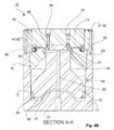
図1A~図3は、油圧プレスのピストン-シリンダアセンブリ10の一例を概略図として示しており、このピストン-シリンダアセンブリ10は、基本シリンダ11と、基本シリンダ11の上面に取り付けられたリングシリンダ14とを備えている。ピストン-シリンダアセンブリ10は、2つのピストン12、13、すなわち、基本シリンダ11の下部で基本シリンダ11の内部に配置された第1のピストン12と、第1のピストン12及び基本シリンダ11の上方に配置された第2のピストン13と、をさらに備える。
1A-3 schematically illustrate an example of a hydraulic press piston-
第1のピストン12と第2のピストン13とは、第2のピストン13に設けられた貫通孔37を貫通して第1のピストン12の取り付け孔38に取り付けられるネジ36を含む取り付け構造(attaching arrangement)36、37、38で互いに取り付けられている。
The
ピストン-シリンダアセンブリ10のシリンダ構造では、基本シリンダ11とリングシリンダ14とは、リングシリンダ14に設けられた貫通孔32を貫通して基本シリンダ11の取り付け孔33に取り付けられるネジ31を備える取り付け構造31、32、33で互いに取り付けられている。これにより、リングシリンダ14は、基本シリンダ11に連続する部分を形成している。
In the cylinder structure of the piston-
また、ピストン-シリンダアセンブリ10のシリンダ構造11、14は、リングシリンダ14の下方でかつ基本シリンダ11の内側に位置するスペーサリング15を備えている。スペーサリング15は、基本シリンダ11の内周面に設けられた肩部18上に下側から支持されると共に、リングシリンダ14内の突起部28に上側から支持されている。スペーサリング15は、突起部19を介して第1のピストン12の外周面に対して封止されており、第2の油圧流体空間25から、基本シリンダ11内部のスペーサリング15と第1のピストン12との間の空間に油圧流体が導かれないようにされている。
The
第1のピストン12の下方の第1の油圧流体空間20は、第1のピストン12の下面と基本シリンダ11の内側下面との間に形成され、第1の封止リング17で基本シリンダ11の内周面に対して封止されている。リングシリンダ14の内部には、スペーサリング15の上面と第2のピストン13の下面との間に、第2の油圧流体空間25が形成されており、第2の油圧流体空間25は、第2の封止リング16でリングシリンダ14の内周面に対して封止されている。第2のシールリング16は、取り付け構造41、42で第2のピストン13に取り付けられており、この取り付け構造41、42は、封止リング16を貫通し、第2のピストン13の下面に設けられた取り付け孔42に取り付けられる取り付けネジ41を備えている。
A first
加圧された油圧流体は、第1のピストン12に向けられた油圧を実現するために、第1の油圧流体チャネル部21を介して第1の油圧流体空間20に導かれる。第1の油圧流体チャネル部21は、その中間軸によって、基本シリンダ11の底部を貫通するように配置されている。油圧流体は、第2のピストン13に向けられた油圧を実現するために、その中間軸によって第1のピストン12を貫通し、半径方向において横方向の第3の油圧流体チャンネル部24に至る第2の油圧流体チャンネル部22を経由し、次に第3の油圧流体チャンネル24を経由して、第3の油圧流体空間25に導かれる。このように、チャネル部21、22、24は、第1のピストン12における圧力効果を得るために第1の油圧流体空間20に流体連通され、第2のピストン13における圧力効果を得るために第2の油圧流体空間25に流体連通されて、一体化された油圧流体チャネル21、22、24を形成する。
Pressurized hydraulic fluid is directed through the first hydraulic
したがって、ピストン-シリンダアセンブリ10で達成可能な力は、油圧流体の圧力に第1及び第2のピストンの表面積の合計を乗じたものであり、それによって、ピストン-シリンダアセンブリ10の直径を大きくすることなく、大きな力が達成される。したがって、ピストン-シリンダアセンブリ10はコンパクトであり、その必要な配置スペースは小さい。加えて、ピストン-シリンダアセンブリ10のチャネル及び他の構造は単純である。
Therefore, the force achievable in the piston-
第1のピストン12とスペーサリング15との間の空間は、基本シリンダ11の内部で減圧され、従って、油圧流体用の空間ではなく、油圧流体が基本シリンダ11の壁に作られたチャネル45内のいわゆる漏れ警報孔から噴出すると、封止リング16、17及び/又は封止用の突起部19、したがってピストン-シリンダアセンブリ10が、所望の方法で機能しないことが知られている。
The space between the
基本シリンダ11の内側下面は、好ましくは油圧流体チャネル21の出口の周りに内側に突出するボールセグメント形状の突起部を備えており、これに対応して、第1のピストン12は、有利には、ピストン-シリンダアセンブリ10及びその第1の油圧流体空間20の構造を強化するために、基本シリンダ11の下面に対応するボールセグメント形状の凹部を備えている。
The inner lower surface of the
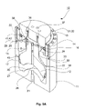
図4A~図6は、油圧プレスのピストン-シリンダアセンブリ10の第2の実施例を概略図として示している。このピストン-シリンダアセンブリ10は、基本シリンダ11と、基本シリンダ11の上面に取り付けられたリングシリンダ14と、を備えている。リングシリンダは、リングシリンダと一体であるカラーリング29を介して、スペーサリング15と一体に連結され、それによって、一体化されたリングシリンダアセンブリ30が形成されている。ピストン-シリンダアセンブリ10は、2つのピストン12、13、すなわち、基本シリンダ11の下部で基本シリンダ11の内部に配置された第1のピストン12と、第1のピストン12及び基本シリンダ11の上方に配置された第2のピストン13と、をさらに備えている。
Figures 4A-6 show in schematic form a second embodiment of a piston-
第1のピストン12と第2のピストン13とは、第2のピストン13に設けられた貫通孔37を貫通して第1のピストン12の取り付け孔38に取り付けられるネジ36を含む取り付け構造36、37、38で互いに取り付けられている。
The
ピストン-シリンダアセンブリ10のシリンダ構造では、基本シリンダ11とリングシリンダ14とは、リングシリンダ14に設けられた貫通孔32を貫通して基本シリンダ11の取り付け孔33に取り付けられるネジ31を備える取り付け構造31、32、33で互いに取り付けられている。これにより、リングシリンダ14は、基本シリンダ11に連続する部分を形成している。
In the cylinder structure of the piston-
ピストン-シリンダアセンブリ10のリングシリンダアセンブリ30は、リングシリンダ14と、リングシリンダ14の下方にあるスペーサリング15とを備え、リングシリンダ14とスペーサリング15とは、カラーリング29を介して一体に連結されている。リングシリンダアセンブリ30のリングシリンダ14の外径は、基本シリンダ11の外径と実質的に同じである。カラーリング29を介して実現可能な凹み(indentation)を介して、リングシリンダアセンブリ30のスペーサリング15が基本シリンダ11の内部に配置されるように設定されている。スペーサリング15は、基本シリンダ11の内周面に設けられた肩部に下側から支持されている。スペーサリング15は、封止部19を介して第1のピストン12の外周面に対して封止されており、第2の油圧流体空間25から、基本シリンダ11内部のスペーサリング15と第1のピストン12との間の空間に油圧流体が導かれないようにされている。
The
第1のピストン12の下方の第1の油圧流体空間20は、第1のピストン12の下面と基本シリンダ11の内側下面との間に形成され、第1の封止リング17で基本シリンダ11の内周面に対して封止されている。リングシリンダ14の内部には、スペーサリング15の上面と第2のピストン13の下面との間に、第2の油圧流体空間25が形成されており、第2の油圧流体空間25は、第2の封止リング16でリングシリンダ14の内周面に対して封止されている。第2のシールリング16は、取り付け構造41、42で第2のピストン13に取り付けられており、この取り付け構造41、42は、封止リング16を貫通し、第2のピストン13の下面に設けられた取り付け孔42に取り付けられる取り付けネジ41を備えている。
A first
加圧された油圧流体は、第1のピストン12に向けられた油圧を実現するために、第1の油圧流体チャネル部21を介して第1の油圧流体空間20に導かれる。第1の油圧流体チャネル部21は、その中間軸によって、基本シリンダ11の底部を貫通するように配置されている。油圧流体は、第2のピストン13に向けられた油圧を実現するために、その中間軸によって第1のピストン12を貫通し、半径方向において横方向の第3の油圧流体チャンネル部24に至る第2の油圧流体チャンネル部22を経由し、次に第3の油圧流体チャンネル24を経由して、第3の油圧流体空間25に導かれる。このように、チャネル部21、22、24は、第1のピストン12における圧力効果を得るために第1の油圧流体空間20に流体連通され、第2のピストン13における圧力効果を得るために第2の油圧流体空間25に流体連通されて、一体化された油圧流体チャネル21、22、24を形成する。
Pressurized hydraulic fluid is directed through the first hydraulic
したがって、ピストン-シリンダアセンブリ10で達成可能な力は、油圧流体の圧力に第1及び第2のピストンの表面積の合計を乗じたものであり、それによって、ピストン-シリンダアセンブリ10の直径を大きくすることなく、大きな力が達成される。したがって、ピストン-シリンダアセンブリ10はコンパクトであり、その必要な配置スペースは小さい。加えて、ピストン-シリンダアセンブリ10のチャネル及び他の構造は単純である。
Therefore, the force achievable in the piston-
第1のピストン12とスペーサリング15との間の空間は、基本シリンダ11の内部で減圧され、従って、油圧流体用の空間ではなく、油圧流体が基本シリンダ11の壁に作られたチャネル45内のいわゆる漏れ警報孔から噴出すると、封止リング16、17及び/又は封止用の突起部19、したがってピストン-シリンダアセンブリ10が、所望の方法で機能しないことが知られている。
The space between the
基本シリンダ11の内側下面は、好ましくは油圧流体チャネル21の出口の周りに内側に突出するボールセグメント形状の突起部を備えており、これに対応して、第1のピストン12は、有利には、ピストン-シリンダアセンブリ10及びその第1の油圧流体空間20の構造を強化するために、基本シリンダ11の下面に対応するボールセグメント形状の凹部を備えている。
The inner lower surface of the
本発明は、その有利な一実施例を参照してのみ上述されてきたが、その詳細は本発明を狭く限定することを意味するものではなく、以下の特許請求の範囲によって定義される本発明の思想の範囲内で多くの変更及び変形が可能である。
Although the invention has been described above only with reference to one preferred embodiment thereof, the details thereof are not meant to narrowly limit the invention, which is defined by the following claims. Many modifications and variations are possible within the concept of
中国実用新案第2845947号明細書には、2つの油圧ピストンが使用される、金属を形成するためのアセンブリが示されており、このアセンブリでは、油圧流体は、2つの異なる油圧流体チャネルを通して取り込まれる。
欧州特許出願公開第0561074号明細書には、油圧流体で作動可能なシリンダが示されている。このシリンダは、複数のシリンダ本体と、第1のシリンダ本体と第2のシリンダ本体との間に設けられ、軸方向に直列に配置された複数のシリンダ室を画定する仕切部材とを含むシリンダユニットを備えている。前記複数のシリンダ本体の各々は、作用側面と反対側面を有する1つのピストンを含み、前記仕切部材と第1のシリンダ本体及び第2のシリンダ本体との間は封止されている。
米国特許出願公開第2956549号明細書には、二重ピストンシリンダが示されている。この二重ピストンシリンダは、閉鎖端部を有するシリンダ部材と、前記シリンダの開放端部内に配置され、その一端に設けられ、前記シリンダを離間して配置されたチャンバに分割する横断環状壁を有するスリーブ部材と、前記シリンダ内に配置され、前記壁を通って延在するピストンシャフトと、前記チャンバの各々において前記シャフトに固定されたピストンヘッドと、前記ピストンシャフトを通って中央に形成され、前記ピストンヘッドの同様の側で前記チャンバの各々と開放連通する流体通路手段と、前記シリンダの閉鎖端部に配置され、前記ピストンヘッドの1つの近接面と直接連通し、前記流体通路を通って前記ピストンヘッドの対応する第2の面と連通する第1の流体入口手段と、を備えている。
Chinese Utility Model No. 2845947 shows an assembly for forming metal in which two hydraulic pistons are used, in which hydraulic fluid is taken in through two different hydraulic fluid channels .
EP-A-0561074 shows a cylinder operable with hydraulic fluid. This cylinder includes a plurality of cylinder bodies, and a partition member provided between the first cylinder body and the second cylinder body and defining a plurality of cylinder chambers arranged in series in the axial direction. It has Each of the plurality of cylinder bodies includes one piston having a working side and an opposite side, and sealing is provided between the partition member and the first and second cylinder bodies.
US Patent Application Publication No. 2,956,549 shows a double piston cylinder. The double-piston cylinder has a cylinder member having a closed end and a transverse annular wall disposed within and at one end of the open end of the cylinder and dividing the cylinder into spaced apart chambers. a sleeve member, a piston shaft disposed within said cylinder and extending through said wall, and a piston head fixed to said shaft in each of said chambers; fluid passage means in open communication with each of said chambers on a similar side of the piston head; and a first fluid inlet means in communication with the corresponding second face of the piston head.
Claims (7)
基本シリンダ(11)と第1のピストン及び第2のピストン(12、13)とを備え、
リングシリンダ(14)が、前記基本シリンダ(11)の上方にシリンダ構造の連続体として形成され、前記第1のピストン(12)が、前記基本シリンダ(11)の下部で前記基本シリンダ(11)の内側に配置され、前記第2のピストン(13)が、前記シリンダ構造の上部で前記第1のピストン(12)の上方に配置され、
第1のピストン(12)の下方に第1の油圧流体空間(20)を有し、第2のピストン(13)の下方に第2の油圧流体空間(25)を有し、第1のピストン(12)に圧力効果を与えるために、前記第1の油圧流体空間(20)に流体連通され、第2のピストン(13)に圧力効果を与えるために、前記第2の油圧流体空間(25)に流体連通される、一体化された油圧流体チャネル(21、22、24)を備えることを特徴とする、油圧プレスのピストン-シリンダアセンブリ(10)。 A hydraulic press piston-cylinder assembly (10) comprising:
comprising a basic cylinder (11) and first and second pistons (12, 13),
A ring cylinder (14) is formed as a continuum of cylinder construction above said basic cylinder (11) and said first piston (12) is located below said basic cylinder (11). and said second piston (13) is located above said first piston (12) at the top of said cylinder structure,
with a first hydraulic fluid space (20) below the first piston (12) and a second hydraulic fluid space (25) below the second piston (13); (12) is in fluid communication with said first hydraulic fluid space (20) for exerting a pressure effect on the second piston (13) and said second hydraulic fluid space (25) is fluidly connected for exerting a pressure effect on the second piston (13). A piston-cylinder assembly (10) for a hydraulic press, characterized in that it comprises integrated hydraulic fluid channels (21, 22, 24) in fluid communication with a hydraulic press.
7. Any one of claims 1 to 6, characterized in that the space between the first piston (12) and the spacer ring (15) inside the basic cylinder (11) is evacuated. A piston-cylinder assembly (10) for a hydraulic press according to any preceding claim.
Applications Claiming Priority (3)
| Application Number | Priority Date | Filing Date | Title |
|---|---|---|---|
| FI20195653A FI129623B (en) | 2019-07-29 | 2019-07-29 | Piston-cylinder assembly of a hydraulic press |
| FI20195653 | 2019-07-29 | ||
| PCT/FI2020/050504 WO2021019129A1 (en) | 2019-07-29 | 2020-07-24 | Piston-cylinder assembly of a hydraulic press |
Publications (2)
| Publication Number | Publication Date |
|---|---|
| JP2022543550A true JP2022543550A (en) | 2022-10-13 |
| JPWO2021019129A5 JPWO2021019129A5 (en) | 2023-07-11 |
Family
ID=72266309
Family Applications (1)
| Application Number | Title | Priority Date | Filing Date |
|---|---|---|---|
| JP2022505381A Pending JP2022543550A (en) | 2019-07-29 | 2020-07-24 | Hydraulic press piston-cylinder assembly |
Country Status (8)
| Country | Link |
|---|---|
| US (1) | US20220258444A1 (en) |
| EP (1) | EP4004382A1 (en) |
| JP (1) | JP2022543550A (en) |
| KR (1) | KR20220039654A (en) |
| CN (1) | CN114144588A (en) |
| CA (1) | CA3144196A1 (en) |
| FI (1) | FI129623B (en) |
| WO (1) | WO2021019129A1 (en) |
Family Cites Families (4)
| Publication number | Priority date | Publication date | Assignee | Title |
|---|---|---|---|---|
| US845144A (en) * | 1905-12-05 | 1907-02-26 | James A Taylor | Lifting-jack. |
| JPH0762481B2 (en) * | 1992-03-19 | 1995-07-05 | 浩然 高 | Fluid cylinder |
| US6633015B2 (en) * | 2000-12-08 | 2003-10-14 | Doben Limited | Soft-touch pneumatic drive unit |
| KR100887621B1 (en) * | 2007-07-31 | 2009-03-12 | 윤택수 | Oil-hydraulic press |
-
2019
- 2019-07-29 FI FI20195653A patent/FI129623B/en active IP Right Grant
-
2020
- 2020-07-24 WO PCT/FI2020/050504 patent/WO2021019129A1/en active Search and Examination
- 2020-07-24 CN CN202080054818.5A patent/CN114144588A/en active Pending
- 2020-07-24 JP JP2022505381A patent/JP2022543550A/en active Pending
- 2020-07-24 KR KR1020217041263A patent/KR20220039654A/en unknown
- 2020-07-24 US US17/630,753 patent/US20220258444A1/en active Pending
- 2020-07-24 CA CA3144196A patent/CA3144196A1/en active Pending
- 2020-07-24 EP EP20764133.3A patent/EP4004382A1/en not_active Withdrawn
Also Published As
| Publication number | Publication date |
|---|---|
| WO2021019129A1 (en) | 2021-02-04 |
| FI129623B (en) | 2022-05-31 |
| EP4004382A1 (en) | 2022-06-01 |
| CN114144588A (en) | 2022-03-04 |
| CA3144196A1 (en) | 2021-02-04 |
| US20220258444A1 (en) | 2022-08-18 |
| FI20195653A1 (en) | 2021-01-30 |
| KR20220039654A (en) | 2022-03-29 |
Similar Documents
| Publication | Publication Date | Title |
|---|---|---|
| CN103423358B (en) | Hydraulic damper | |
| CN100400873C (en) | Valve arrangement for reciprocating machinery such as a pump and a compressor | |
| US4821850A (en) | Double-tube vibration damper | |
| CN101203689B (en) | Clutch slave cylinder | |
| US2877026A (en) | Sealing device for a swivel joint having plural fluid passages | |
| WO2011099402A1 (en) | Fluid pressure cylinder | |
| RU2004122644A (en) | GUILLOTINE TYPE | |
| JP2004520551A5 (en) | ||
| JPS60231069A (en) | Pressure operation type seal ring | |
| JP2022543550A (en) | Hydraulic press piston-cylinder assembly | |
| ITMI970639U1 (en) | WORK CYLINDER | |
| EP2378136B1 (en) | Fluid pressure cylinder | |
| US6796216B2 (en) | Guide for the piston rod of a piston-cylinder assembly | |
| JP5308961B2 (en) | Fluid pressure cylinder | |
| GB1592080A (en) | Piston-cylinder assembly | |
| JPH01318769A (en) | Multiple cylinder device | |
| JPH03172605A (en) | Friction type clamping device | |
| WO2013099642A1 (en) | Fluid pressure cylinder | |
| JPH062009Y2 (en) | Segment type friction clamp device | |
| JPH0640326Y2 (en) | Cushion device for hydraulic cylinder | |
| JP2560303Y2 (en) | Cylinder device | |
| KR100602574B1 (en) | An oil pressure cylinder | |
| RU2258840C1 (en) | Pneumohydraulic booster | |
| JPH0124439Y2 (en) | ||
| RU2005128577A (en) | DEVICE FOR FORMING RADIALLY-CORRUGATED PIPES OF A BELLOW TYPE |
Legal Events
| Date | Code | Title | Description |
|---|---|---|---|
| A529 | Written submission of copy of amendment under article 34 pct |
Free format text: JAPANESE INTERMEDIATE CODE: A529 Effective date: 20220125 |
|
| A521 | Request for written amendment filed |
Free format text: JAPANESE INTERMEDIATE CODE: A523 Effective date: 20230703 |
|
| A621 | Written request for application examination |
Free format text: JAPANESE INTERMEDIATE CODE: A621 Effective date: 20230703 |
|
| A977 | Report on retrieval |
Free format text: JAPANESE INTERMEDIATE CODE: A971007 Effective date: 20240214 |
|
| A131 | Notification of reasons for refusal |
Free format text: JAPANESE INTERMEDIATE CODE: A131 Effective date: 20240220 |