JP2022536498A - screw insertion instrument - Google Patents
screw insertion instrument Download PDFInfo
- Publication number
- JP2022536498A JP2022536498A JP2021573473A JP2021573473A JP2022536498A JP 2022536498 A JP2022536498 A JP 2022536498A JP 2021573473 A JP2021573473 A JP 2021573473A JP 2021573473 A JP2021573473 A JP 2021573473A JP 2022536498 A JP2022536498 A JP 2022536498A
- Authority
- JP
- Japan
- Prior art keywords
- sleeve
- screw
- driver shaft
- bone
- locking
- Prior art date
- Legal status (The legal status is an assumption and is not a legal conclusion. Google has not performed a legal analysis and makes no representation as to the accuracy of the status listed.)
- Granted
Links
Images


Classifications
-
- A—HUMAN NECESSITIES
- A61—MEDICAL OR VETERINARY SCIENCE; HYGIENE
- A61B—DIAGNOSIS; SURGERY; IDENTIFICATION
- A61B17/00—Surgical instruments, devices or methods
- A61B17/56—Surgical instruments or methods for treatment of bones or joints; Devices specially adapted therefor
- A61B17/58—Surgical instruments or methods for treatment of bones or joints; Devices specially adapted therefor for osteosynthesis, e.g. bone plates, screws or setting implements
- A61B17/68—Internal fixation devices, including fasteners and spinal fixators, even if a part thereof projects from the skin
- A61B17/70—Spinal positioners or stabilisers, e.g. stabilisers comprising fluid filler in an implant
- A61B17/7001—Screws or hooks combined with longitudinal elements which do not contact vertebrae
-
- A—HUMAN NECESSITIES
- A61—MEDICAL OR VETERINARY SCIENCE; HYGIENE
- A61B—DIAGNOSIS; SURGERY; IDENTIFICATION
- A61B17/00—Surgical instruments, devices or methods
- A61B17/56—Surgical instruments or methods for treatment of bones or joints; Devices specially adapted therefor
- A61B17/58—Surgical instruments or methods for treatment of bones or joints; Devices specially adapted therefor for osteosynthesis, e.g. bone plates, screws or setting implements
- A61B17/88—Osteosynthesis instruments; Methods or means for implanting or extracting internal or external fixation devices
- A61B17/8875—Screwdrivers, spanners or wrenches
-
- A—HUMAN NECESSITIES
- A61—MEDICAL OR VETERINARY SCIENCE; HYGIENE
- A61B—DIAGNOSIS; SURGERY; IDENTIFICATION
- A61B17/00—Surgical instruments, devices or methods
- A61B17/56—Surgical instruments or methods for treatment of bones or joints; Devices specially adapted therefor
- A61B17/58—Surgical instruments or methods for treatment of bones or joints; Devices specially adapted therefor for osteosynthesis, e.g. bone plates, screws or setting implements
- A61B17/68—Internal fixation devices, including fasteners and spinal fixators, even if a part thereof projects from the skin
- A61B17/70—Spinal positioners or stabilisers, e.g. stabilisers comprising fluid filler in an implant
- A61B17/7074—Tools specially adapted for spinal fixation operations other than for bone removal or filler handling
- A61B17/7076—Tools specially adapted for spinal fixation operations other than for bone removal or filler handling for driving, positioning or assembling spinal clamps or bone anchors specially adapted for spinal fixation
- A61B17/7082—Tools specially adapted for spinal fixation operations other than for bone removal or filler handling for driving, positioning or assembling spinal clamps or bone anchors specially adapted for spinal fixation for driving, i.e. rotating, screws or screw parts specially adapted for spinal fixation, e.g. for driving polyaxial or tulip-headed screws
-
- A—HUMAN NECESSITIES
- A61—MEDICAL OR VETERINARY SCIENCE; HYGIENE
- A61B—DIAGNOSIS; SURGERY; IDENTIFICATION
- A61B17/00—Surgical instruments, devices or methods
- A61B17/56—Surgical instruments or methods for treatment of bones or joints; Devices specially adapted therefor
- A61B17/58—Surgical instruments or methods for treatment of bones or joints; Devices specially adapted therefor for osteosynthesis, e.g. bone plates, screws or setting implements
- A61B17/68—Internal fixation devices, including fasteners and spinal fixators, even if a part thereof projects from the skin
- A61B17/70—Spinal positioners or stabilisers, e.g. stabilisers comprising fluid filler in an implant
- A61B17/7074—Tools specially adapted for spinal fixation operations other than for bone removal or filler handling
-
- A—HUMAN NECESSITIES
- A61—MEDICAL OR VETERINARY SCIENCE; HYGIENE
- A61B—DIAGNOSIS; SURGERY; IDENTIFICATION
- A61B17/00—Surgical instruments, devices or methods
- A61B17/56—Surgical instruments or methods for treatment of bones or joints; Devices specially adapted therefor
- A61B17/58—Surgical instruments or methods for treatment of bones or joints; Devices specially adapted therefor for osteosynthesis, e.g. bone plates, screws or setting implements
- A61B17/68—Internal fixation devices, including fasteners and spinal fixators, even if a part thereof projects from the skin
- A61B17/84—Fasteners therefor or fasteners being internal fixation devices
- A61B17/86—Pins or screws or threaded wires; nuts therefor
- A61B17/8605—Heads, i.e. proximal ends projecting from bone
- A61B17/861—Heads, i.e. proximal ends projecting from bone specially shaped for gripping driver
- A61B17/8615—Heads, i.e. proximal ends projecting from bone specially shaped for gripping driver at the central region of the screw head
-
- A—HUMAN NECESSITIES
- A61—MEDICAL OR VETERINARY SCIENCE; HYGIENE
- A61B—DIAGNOSIS; SURGERY; IDENTIFICATION
- A61B17/00—Surgical instruments, devices or methods
- A61B17/56—Surgical instruments or methods for treatment of bones or joints; Devices specially adapted therefor
- A61B17/58—Surgical instruments or methods for treatment of bones or joints; Devices specially adapted therefor for osteosynthesis, e.g. bone plates, screws or setting implements
- A61B17/88—Osteosynthesis instruments; Methods or means for implanting or extracting internal or external fixation devices
- A61B17/8875—Screwdrivers, spanners or wrenches
- A61B17/8886—Screwdrivers, spanners or wrenches holding the screw head
- A61B17/8888—Screwdrivers, spanners or wrenches holding the screw head at its central region
-
- A—HUMAN NECESSITIES
- A61—MEDICAL OR VETERINARY SCIENCE; HYGIENE
- A61B—DIAGNOSIS; SURGERY; IDENTIFICATION
- A61B17/00—Surgical instruments, devices or methods
- A61B17/56—Surgical instruments or methods for treatment of bones or joints; Devices specially adapted therefor
- A61B17/58—Surgical instruments or methods for treatment of bones or joints; Devices specially adapted therefor for osteosynthesis, e.g. bone plates, screws or setting implements
- A61B17/88—Osteosynthesis instruments; Methods or means for implanting or extracting internal or external fixation devices
- A61B17/8875—Screwdrivers, spanners or wrenches
- A61B17/8886—Screwdrivers, spanners or wrenches holding the screw head
- A61B17/8891—Screwdrivers, spanners or wrenches holding the screw head at its periphery
-
- A—HUMAN NECESSITIES
- A61—MEDICAL OR VETERINARY SCIENCE; HYGIENE
- A61B—DIAGNOSIS; SURGERY; IDENTIFICATION
- A61B17/00—Surgical instruments, devices or methods
- A61B17/56—Surgical instruments or methods for treatment of bones or joints; Devices specially adapted therefor
- A61B17/58—Surgical instruments or methods for treatment of bones or joints; Devices specially adapted therefor for osteosynthesis, e.g. bone plates, screws or setting implements
- A61B17/88—Osteosynthesis instruments; Methods or means for implanting or extracting internal or external fixation devices
- A61B17/92—Impactors or extractors, e.g. for removing intramedullary devices
-
- A—HUMAN NECESSITIES
- A61—MEDICAL OR VETERINARY SCIENCE; HYGIENE
- A61B—DIAGNOSIS; SURGERY; IDENTIFICATION
- A61B17/00—Surgical instruments, devices or methods
- A61B17/56—Surgical instruments or methods for treatment of bones or joints; Devices specially adapted therefor
- A61B17/58—Surgical instruments or methods for treatment of bones or joints; Devices specially adapted therefor for osteosynthesis, e.g. bone plates, screws or setting implements
- A61B17/68—Internal fixation devices, including fasteners and spinal fixators, even if a part thereof projects from the skin
- A61B17/84—Fasteners therefor or fasteners being internal fixation devices
- A61B17/86—Pins or screws or threaded wires; nuts therefor
- A61B17/8625—Shanks, i.e. parts contacting bone tissue
- A61B17/863—Shanks, i.e. parts contacting bone tissue with thread interrupted or changing its form along shank, other than constant taper
-
- A—HUMAN NECESSITIES
- A61—MEDICAL OR VETERINARY SCIENCE; HYGIENE
- A61B—DIAGNOSIS; SURGERY; IDENTIFICATION
- A61B17/00—Surgical instruments, devices or methods
- A61B2017/0046—Surgical instruments, devices or methods with a releasable handle; with handle and operating part separable
-
- A—HUMAN NECESSITIES
- A61—MEDICAL OR VETERINARY SCIENCE; HYGIENE
- A61B—DIAGNOSIS; SURGERY; IDENTIFICATION
- A61B17/00—Surgical instruments, devices or methods
- A61B2017/0046—Surgical instruments, devices or methods with a releasable handle; with handle and operating part separable
- A61B2017/00469—Surgical instruments, devices or methods with a releasable handle; with handle and operating part separable for insertion of instruments, e.g. guide wire, optical fibre
-
- A—HUMAN NECESSITIES
- A61—MEDICAL OR VETERINARY SCIENCE; HYGIENE
- A61B—DIAGNOSIS; SURGERY; IDENTIFICATION
- A61B17/00—Surgical instruments, devices or methods
- A61B17/56—Surgical instruments or methods for treatment of bones or joints; Devices specially adapted therefor
- A61B2017/564—Methods for bone or joint treatment
-
- A—HUMAN NECESSITIES
- A61—MEDICAL OR VETERINARY SCIENCE; HYGIENE
- A61B—DIAGNOSIS; SURGERY; IDENTIFICATION
- A61B90/00—Instruments, implements or accessories specially adapted for surgery or diagnosis and not covered by any of the groups A61B1/00 - A61B50/00, e.g. for luxation treatment or for protecting wound edges
- A61B90/03—Automatic limiting or abutting means, e.g. for safety
- A61B2090/033—Abutting means, stops, e.g. abutting on tissue or skin
- A61B2090/036—Abutting means, stops, e.g. abutting on tissue or skin abutting on tissue or skin
Landscapes
- Health & Medical Sciences (AREA)
- Orthopedic Medicine & Surgery (AREA)
- Surgery (AREA)
- Life Sciences & Earth Sciences (AREA)
- Neurology (AREA)
- Medical Informatics (AREA)
- Biomedical Technology (AREA)
- Heart & Thoracic Surgery (AREA)
- Engineering & Computer Science (AREA)
- Molecular Biology (AREA)
- Animal Behavior & Ethology (AREA)
- General Health & Medical Sciences (AREA)
- Public Health (AREA)
- Veterinary Medicine (AREA)
- Nuclear Medicine, Radiotherapy & Molecular Imaging (AREA)
- Surgical Instruments (AREA)
Abstract
骨スクリューを埋め込むためのスクリュー挿入器具及び方法が、本明細書に開示される。例示的な一実施形態では、スクリュー挿入器具は、ドライバシャフトと、ドライバシャフトの周囲に配設された保持スリーブと、保持スリーブの周囲に配設されたロックスリーブと、を含み得る。ロックスリーブは、ロックスリーブが固定されている状態で、ドライバシャフトの回転が保持スリーブの対応する回転を引き起こす第1の位置と、ドライバシャフトが固定されている状態で、ロックスリーブの回転が保持スリーブの対応する回転を引き起こす第2の位置と、を有し得る。Disclosed herein are screw insertion instruments and methods for implanting bone screws. In one exemplary embodiment, a screw insertion instrument can include a driver shaft, a retaining sleeve disposed about the driver shaft, and a locking sleeve disposed about the retaining sleeve. The locking sleeve has a first position in which rotation of the driver shaft causes corresponding rotation of the retaining sleeve, with the locking sleeve fixed, and a first position in which rotation of the locking sleeve, with the driver shaft fixed, causes corresponding rotation of the retaining sleeve. and a second position that causes a corresponding rotation of .
Description
スクリュー挿入器具及び方法が本明細書に開示される。 Disclosed herein are screw insertion instruments and methods.
椎弓根スクリューなどの骨スクリューは、治癒、癒合、又は他のプロセス中に骨を固定するために整形外科手術で用いることができる。脊椎手術において、例えば、骨スクリューは、脊椎を硬直的に又は動的に固定させるために、1つ又は2つ以上の椎骨に脊椎固定要素を取り付けるために用いることができる。 Bone screws, such as pedicle screws, can be used in orthopedic surgery to secure bone during healing, fusion, or other processes. In spinal surgery, for example, bone screws can be used to attach spinal fixation elements to one or more vertebrae for rigid or dynamic fixation of the spine.
従来の後方椎弓根スクリューの固定は、椎弓根スクリューが挿入前に突き錐、プロービング、及びタッピングによって調製されることを必要とする。予め組み立てられた椎弓根スクリューの挿入を可能にする進歩がなされてきたが、これらのシステムは、経椎間孔的腰椎椎体間固定術(TLIF)の前に、構造体内に全てのスクリューを配置するのに理想的ではない。これは、椎弓根スクリューの予め組み立てられたヘッドによる視野の妨害によるものである。 Conventional posterior pedicle screw fixation requires that the pedicle screw be prepared by awl, probing, and tapping prior to insertion. Although advances have been made to allow for the insertion of pre-assembled pedicle screws, these systems rely on the insertion of all screws into the construct prior to transforaminal lumbar interbody fusion (TLIF). Not ideal for placing This is due to the obstruction of vision by the pre-assembled head of the pedicle screw.
ほとんどの椎弓根スクリューを挿入する際、スクリューは、スクリュー挿入器具に何らかの様式で保持されなければならない。これは、典型的には、スクリューの多軸ヘッド、又はモジュール式スクリューの場合には、それに連結されたコレットのいずれかにスリーブを螺入させることによって達成される。使用中、ユーザはスリーブを固定しており、その結果、スクリューを骨に打ち込む行為は、スクリューが骨に完全に挿入される前にスリーブをスクリューから螺出させることにもなる。臨床的には、これは、外科医がその後、埋め込みを終了するためにスクリューに再係合しなければならないために遅延を引き起こし得る。この再係合は、特にスクリューの直接可視化が損なわれる場合の課題となり得る。 When inserting most pedicle screws, the screw must be retained in some fashion in the screw insertion instrument. This is typically accomplished by threading a sleeve into either the polyaxial head of the screw or, in the case of a modular screw, a collet connected thereto. During use, the user is immobilizing the sleeve so that the act of driving the screw into the bone also causes the sleeve to unscrew from the screw before it is fully inserted into the bone. Clinically, this can cause delays as the surgeon must then re-engage the screw to finish the implantation. This re-engagement can be a challenge, especially when direct visualization of the screw is compromised.
低侵襲的処置の間、外科医がスクリューを骨に打ち込む際にスクリューを直接可視化することは困難であり得る。結果として、スクリューの挿入深さを決定することは視覚的な課題であり得、スクリューの不完全な埋め込み、あるいはスクリューの過剰な挿入につながり得る。例えば、モジュール式スクリューを使用する場合、スクリューは骨に深く打ち込まれすぎる可能性があり、その結果、骨から外向きに延在するスクリューの長さは、多軸ヘッドをスクリューに適切に取り付けるのに不十分になる。 During minimally invasive procedures, it can be difficult for the surgeon to directly visualize the screw as it is driven into the bone. As a result, determining the insertion depth of the screw can be a visual challenge and can lead to incomplete screw implantation or over-insertion of the screw. For example, when using a modular screw, the screw may be driven too deep into the bone, and as a result, the length of the screw extending outward from the bone is insufficient to properly attach the polyaxial head to the screw. become insufficient.
スクリュー挿入器具として、そこから突出するスタイレットを有するものを利用することができる。スタイレットは、器具を骨に向かって遠位に叩くか又は付勢することによって、骨にドッキングさせることができる。スタイレットが所望の深さまで前進すると、スタイレットがそこから後退する間に、連結された骨スクリューがスタイレットによって作られた経路に沿って駆動される。スタイレットの前進及び後退中に結合された骨スクリューが骨に挿入されるか又は骨から取り外されるのを防止するために、ユーザは、器具のスクリュードライバハンドルを固定位置に維持しなければならない。しかしながら、これは困難な場合があり、スタイレットの前進及び後退に干渉し得る。 A screw insertion instrument is available that has a stylet protruding therefrom. The stylet can be docked to the bone by tapping or urging the instrument distally toward the bone. Once the stylet is advanced to the desired depth, the coupled bone screw is driven along the path created by the stylet while the stylet is retracted therefrom. To prevent the coupled bone screw from being inserted or removed from the bone during advancement and retraction of the stylet, the user must maintain the screwdriver handle of the instrument in a fixed position. However, this can be difficult and can interfere with stylet advancement and retraction.
したがって、既存の技術にもかかわらず、骨スクリューを骨に打ち込むことに関連付けられた、改善された器具及び方法が依然として必要とされている。 Therefore, despite existing technology, there remains a need for improved instruments and methods associated with driving bone screws into bone.
骨スクリュー又は骨スクリューアセンブリを骨に埋め込むための様々なスクリュー挿入器具及び方法が開示される。 Various screw insertion instruments and methods are disclosed for implanting bone screws or bone screw assemblies in bone.
一実施形態では、スクリュー挿入器具が提供され、スクリュー挿入器具は、ドライバシャフトと、ドライバシャフトの周囲に配設された保持スリーブ、及び保持スリーブの周囲に配設されたロックスリーブを含む。ドライバシャフトは、骨スクリューを骨に打ち込むために骨スクリューに係合するように構成された遠位先端を有し得る。保持スリーブは、骨スクリューとネジ止めにより連結するように構成された遠位端を有し得る。ロックスリーブは、ロックスリーブが固定されている状態で、ドライバシャフトの回転が保持スリーブの対応する回転を引き起こす第1の位置と、ドライバシャフトが固定されている状態で、ロックスリーブの回転が保持スリーブの対応する回転を引き起こす第2の位置と、を有し得る。 In one embodiment, a screw insertion instrument is provided, the screw insertion instrument including a driver shaft, a retaining sleeve disposed about the driver shaft, and a locking sleeve disposed about the retaining sleeve. The driver shaft can have a distal tip configured to engage the bone screw to drive the bone screw into the bone. The retaining sleeve may have a distal end configured for threaded connection with a bone screw. The locking sleeve has a first position in which rotation of the driver shaft causes corresponding rotation of the retaining sleeve, with the locking sleeve fixed, and a first position in which rotation of the locking sleeve, with the driver shaft fixed, causes corresponding rotation of the retaining sleeve. and a second position that causes a corresponding rotation of .
いくつかの実施形態では、ロックスリーブが第1の位置にあるときに、保持スリーブ及びドライバシャフトがロックスリーブに対して第1の方向に一緒に回転して、骨スクリューが骨に打ち込まれ得る。他の実施形態では、ロックスリーブが第2の位置にあるときに、保持スリーブ及びロックスリーブがドライバシャフトに対して第2の方向に一緒に回転して、保持スリーブが骨スクリューから螺出され得る。 In some embodiments, when the locking sleeve is in the first position, the retaining sleeve and driver shaft can be rotated together in a first direction relative to the locking sleeve to drive the bone screw into the bone. In other embodiments, when the locking sleeve is in the second position, the retaining sleeve and locking sleeve can be rotated together relative to the driver shaft in the second direction to unscrew the retaining sleeve from the bone screw. .
ロックスリーブは、様々な構成を有し得る。例えば、いくつかの実施形態では、ロックスリーブは、保持スリーブに対して軸方向に並進及び回転して、第1の位置から第2の位置へ移動するように構成され得る。例示的な実施形態では、保持スリーブに対するロックスリーブの回転により、ロックスリーブに連結された少なくとも1つのロックピンが保持スリーブにネジ止めにより係合し得る。 The locking sleeve can have various configurations. For example, in some embodiments, the locking sleeve can be configured to axially translate and rotate relative to the retaining sleeve to move from the first position to the second position. In exemplary embodiments, rotation of the locking sleeve relative to the retaining sleeve may cause at least one locking pin coupled to the locking sleeve to threadably engage the retaining sleeve.
いくつかの実施形態では、スクリュー挿入器具は、停止スリーブを含み得る。停止スリーブは、保持スリーブの周囲に部分的に配設され得、保持スリーブの遠位端から遠位に延在し得る。停止スリーブは、骨スクリューの一部分の骨への挿入深さを制限するように構成され得る。一実施形態では、停止スリーブは、絶縁材料及び放射線不透過性材料のうちの少なくとも1つを含む。 In some embodiments, the screw insertion instrument can include a stop sleeve. A stop sleeve may be partially disposed about the retention sleeve and may extend distally from the distal end of the retention sleeve. The stop sleeve may be configured to limit the depth of insertion of a portion of the bone screw into the bone. In one embodiment, the stop sleeve includes at least one of an insulating material and a radiopaque material.
他の実施形態では、器具は、保持スリーブをドライバシャフトに選択的に連結し得る解放ボタンを含み得る。解放ボタンは、ドライバシャフトを遠位方向に付勢する接合面でドライバシャフトに係合し得る。 In other embodiments, the instrument can include a release button that can selectively couple the retaining sleeve to the driver shaft. A release button may engage the driver shaft at a mating surface that biases the driver shaft distally.
別の例示的な実施形態では、スクリュー駆動アセンブリと、スクリュー駆動アセンブリの周囲に少なくとも部分的に配設されたスリーブアセンブリとを有するスクリュー挿入器具が提供される。スクリュー駆動アセンブリは、ドライバシャフトが連結されたハンドルを含み得、ドライバシャフトは、骨スクリューを骨に打ち込むために骨スクリューに連結するように構成された遠位先端を有し得る。スリーブアセンブリは、骨スクリューにネジ止めにより連結するように構成され得る遠位端を有する保持スリーブと、保持スリーブに解放可能に連結されたロックスリーブとを含み得る。スリーブアセンブリは、ロックスリーブが固定されている状態で、スクリュー駆動アセンブリの回転が、保持スリーブの対応する回転を引き起こす第1の構成と、スクリュー駆動アセンブリが固定されている状態で、ロックスリーブの回転が、保持スリーブの対応する回転を引き起こす第2の構成とを有し得る。 In another exemplary embodiment, a screw insertion instrument is provided having a screw drive assembly and a sleeve assembly at least partially disposed around the screw drive assembly. The screw driving assembly may include a handle with a driver shaft coupled thereto, the driver shaft having a distal tip configured to couple to the bone screw for driving the bone screw into bone. The sleeve assembly may include a retaining sleeve having a distal end that may be configured to threadably couple to the bone screw, and a locking sleeve releasably coupled to the retaining sleeve. The sleeve assembly comprises a first configuration in which rotation of the screw drive assembly causes corresponding rotation of the retaining sleeve with the locking sleeve fixed, and a rotation of the locking sleeve with the screw drive assembly fixed. and a second configuration that causes corresponding rotation of the retaining sleeve.
スリーブアセンブリは、様々な構成を有し得る。例えば、いくつかの実施形態では、スリーブアセンブリは、保持スリーブとロックスリーブとの間に配設された連結要素を含み得る。連結要素は、保持スリーブの周囲に配設されたカラーの第2の組の歯に係合する第1の組の歯を有し得、それにより、保持スリーブは、骨スクリューを骨に打ち込む際に、骨スクリューにネジ止めにより連結されたままとなる。他の実施形態では、スリーブアセンブリは、ロックスリーブから保持スリーブに向かって半径方向内側に延在する少なくとも1つのロックピンを含み得る。少なくとも1つのロックピンは、軸方向に並進し、保持スリーブのネジ付き部分を通って回転するように構成され得る。 The sleeve assembly can have various configurations. For example, in some embodiments the sleeve assembly may include a connecting element disposed between the retaining sleeve and the locking sleeve. The coupling element may have a first set of teeth that engage a second set of teeth of a collar disposed about the retaining sleeve, such that the retaining sleeve is aligned during driving of the bone screw into bone. It remains threadedly connected to the bone screw. In other embodiments, the sleeve assembly may include at least one locking pin extending radially inward from the locking sleeve toward the retaining sleeve. The at least one locking pin may be configured to axially translate and rotate through the threaded portion of the retaining sleeve.
ロックスリーブはまた、様々な構成を有し得る。例えば、いくつかの実施形態では、ロックスリーブは、ロックスリーブが固定されている状態でスクリュー駆動アセンブリの回転を可能にするため、及び、スクリュー駆動アセンブリが固定されている状態で、ロックスリーブの回転を更に可能にするように、ハンドルに対して遠位に位置付けられ得る。他の実施形態では、ロックスリーブは、保持スリーブの周囲に配設され得る。このような実施形態では、ロックスリーブは、スリーブアセンブリが第1の構成から第2の構成に移動されるときに、近位に移動し、保持スリーブに対して回転するように構成され得る。 The locking sleeve can also have various configurations. For example, in some embodiments, the locking sleeve is configured to permit rotation of the screw drive assembly with the locking sleeve fixed and rotation of the locking sleeve with the screw drive assembly fixed. can be positioned distal to the handle to further allow for In other embodiments, the locking sleeve may be disposed around the retaining sleeve. In such embodiments, the locking sleeve may be configured to move proximally and rotate relative to the retaining sleeve when the sleeve assembly is moved from the first configuration to the second configuration.
いくつかの実施形態では、スクリュー挿入器具は、スリーブアセンブリをスクリュー駆動アセンブリに選択的に連結する連結機構を含み得る。連結機構は、ドライバシャフトを遠位方向に付勢する角度付き接合面でドライバシャフトに係合する解放ボタンを含み得る。 In some embodiments, the screw insertion instrument may include a coupling mechanism that selectively couples the sleeve assembly to the screw drive assembly. The coupling mechanism may include a release button that engages the driver shaft at an angled interface that biases the driver shaft distally.
骨スクリューを埋め込むための方法も提供される。本方法には、本文書に開示されるスクリュー挿入器具のいずれかを用いることができる。例示的な一実施形態では、本方法は、保持スリーブを器具上のドライバシャフトに対して挿入器具上で回転させて、保持スリーブをドライバシャフトの遠位先端に連結された骨スクリューにネジ止めにより係合させることを含み得る。この方法はまた、挿入器具上のロックスリーブを固定している状態で、ドライバシャフト上のハンドルを第1の方向に回転させて、骨スクリューを骨に打ち込むことを含み得る。保持スリーブは、ドライバシャフトと共に回転する。この方法はまた、ロックスリーブを保持スリーブに対して第1の位置から第2の位置へと移動させることと、第2の位置において、ドライバシャフトを固定している状態でロックスリーブを回転させて、保持スリーブを骨スクリューとのネジ止めによる係合から解除させることと、を含み得る。 A method for implanting a bone screw is also provided. Any of the screw insertion instruments disclosed in this document can be used in the method. In one exemplary embodiment, the method includes rotating the retaining sleeve on the insertion instrument relative to the driver shaft on the instrument to thread the retaining sleeve onto the bone screw coupled to the distal tip of the driver shaft. engaging. The method may also include rotating a handle on the driver shaft in a first direction to drive the bone screw into the bone while securing the locking sleeve on the insertion instrument. The retaining sleeve rotates with the driver shaft. The method also includes moving the locking sleeve from the first position to the second position relative to the retaining sleeve, and rotating the locking sleeve in the second position with the driver shaft fixed. and releasing the retaining sleeve from threaded engagement with the bone screw.
いくつかの実施形態では、ロックスリーブを移動させることは、ロックスリーブを近位方向に並進させることと、ロックスリーブを保持スリーブに対して回転させて、ロックスリーブを保持スリーブに選択的にロックすることとを含み得る。他の実施形態では、保持スリーブを骨スクリューにネジ止めにより係合するように回転させることは、ドライバシャフトを固定し、ロックスリーブを第1の方向に回転させて、保持スリーブの対応する回転を引き起こし、保持スリーブを骨スクリューにネジ止めにより係合させることを含み得る。 In some embodiments, moving the locking sleeve includes proximally translating the locking sleeve and rotating the locking sleeve relative to the retaining sleeve to selectively lock the locking sleeve to the retaining sleeve. and In other embodiments, rotating the retaining sleeve into threaded engagement with the bone screw locks the driver shaft and rotates the locking sleeve in a first direction to effect corresponding rotation of the retaining sleeve. triggering to threadably engage the retaining sleeve to the bone screw.
別の例示的な実施形態では、スクリュー挿入器具が提供され、スクリュー挿入器具は、第1のハンドル及び第1のハンドルに連結されたドライバシャフトを有するスクリュー駆動アセンブリと、第2のハンドル及びドライバシャフトを通って延在するスタイレットを有するスタイレットアセンブリとを含む。ドライバシャフトは、骨スクリューを骨に打ち込むために骨スクリューに連結するように構成された遠位先端を有し得る。第1のハンドルは、第2のハンドルが第1のハンドルに対して回転している間、第1のハンドルがドライバシャフトを固定位置に維持し得るように、第1のハンドル及びドライバシャフトが連結されるロック構成と、第1のハンドル及びドライバシャフトが第1の方向に同時に回転することができ、第1のハンドルは、ドライバシャフトとは独立して第2の反対方向に回転することができるロック解除構成と、を有し得る。一実施形態では、第1のハンドルは、ロック構成に付勢され得る。 In another exemplary embodiment, a screw insertion instrument is provided, the screw insertion instrument comprising a screw drive assembly having a first handle and a driver shaft coupled to the first handle; and a stylet assembly having a stylet extending therethrough. The driver shaft can have a distal tip configured to couple to the bone screw for driving the bone screw into the bone. The first handle and the driver shaft are coupled such that the first handle maintains the driver shaft in a fixed position while the second handle is rotated relative to the first handle. and the first handle and the driver shaft can rotate simultaneously in a first direction, and the first handle can rotate in a second opposite direction independently of the driver shaft. and an unlocked configuration. In one embodiment, the first handle may be biased into the locking configuration.
いくつかの実施形態では、スクリュー挿入器具は、第1のハンドル内に配設され、ドライバシャフトと連通する制御機構を含み得る。制御機構は、様々な構成を有し得る。例えば、いくつかの実施形態では、制御機構は、ロックリングに固定的に連結され得る少なくとも1つのトリガ要素を含むことができ、それにより、少なくとも1つのトリガ要素の移動によってロックリングが移動して、第1のハンドルをロック構成とロック解除構成との間で移動させることが可能になる。一実施形態では、第1のハンドルがロック構成にあるとき、ロックリングは、ドライバシャフトに動作可能に連結され得、それにより、第1のハンドル及びドライバシャフトは共にロックされる。別の実施形態では、第1のハンドルがロック解除構成にあるとき、ロックリングは、ドライバシャフトから動作可能に分離され得、それにより、第1のハンドル及びドライバシャフトは互いに独立して回転する。 In some embodiments, the screw insertion instrument may include a control mechanism disposed within the first handle and in communication with the driver shaft. The control mechanism may have various configurations. For example, in some embodiments, the control mechanism can include at least one trigger element that can be fixedly coupled to the lock ring such that movement of the at least one trigger element moves the lock ring. , allowing the first handle to be moved between a locked configuration and an unlocked configuration. In one embodiment, a lock ring may be operably coupled to the driver shaft when the first handle is in the locked configuration, thereby locking the first handle and the driver shaft together. In another embodiment, the lock ring may be operably separated from the driver shaft when the first handle is in the unlocked configuration, such that the first handle and driver shaft rotate independently of each other.
他の実施形態では、スクリュー挿入器具は、第1のハンドル内に配設されたラチェット機構を含み得る。ラチェット機構は、様々な構成を有し得る。一実施形態では、ラチェット機構は、第1のハンドルがロック解除構成にあるときに、ドライバシャフトを一方向に駆動して骨スクリューを骨に打ち込むように、第1のハンドルの両方向回転を可能にし得る。 In other embodiments, the screw insertion instrument may include a ratchet mechanism disposed within the first handle. The ratchet mechanism can have various configurations. In one embodiment, the ratchet mechanism allows bi-directional rotation of the first handle to drive the driver shaft in one direction to drive the bone screw into the bone when the first handle is in the unlocked configuration. obtain.
いくつかの実施形態では、スクリュー挿入器具は、ドライバシャフトの周囲に配設された保持スリーブを含み得る。保持スリーブは、骨スクリューにネジ止めにより係合するように構成された遠位端を有し得る。一実施形態では、第1のハンドルがロック構成にあるとき、第1のハンドルは、ドライバシャフトを固定位置に維持し得る一方、保持スリーブを回転させて、骨スクリューとのネジ止めによる係合を解除させることができ、第1のハンドルがロック解除構成にあるとき、第2のハンドルを固定し得る一方、第1のハンドルを第1の方向に回転させて、骨スクリューを骨に打ち込むように、ドライバシャフト及び保持スリーブを一緒に回転させ得る。 In some embodiments, the screw insertion instrument may include a retaining sleeve disposed around the driver shaft. The retaining sleeve may have a distal end configured to threadably engage the bone screw. In one embodiment, when the first handle is in the locked configuration, the first handle may maintain the driver shaft in a fixed position while rotating the retaining sleeve into threaded engagement with the bone screw. The first handle can be unlocked and when the first handle is in the unlocked configuration, the second handle can be locked while the first handle is rotated in the first direction to drive the bone screw into the bone. , the driver shaft and the retaining sleeve can rotate together.
別の例示的な実施形態では、ハンドルと、ハンドルに動作可能に連結されたドライバシャフトと、ハンドル内の、ドライバシャフトと連通しているロックアセンブリと、ハンドル及びドライバシャフトと連通しているクラッチアセンブリと、を含む、スクリュー駆動アセンブリを有するスクリュー挿入器具が提供される。ドライバシャフトは、骨スクリューを骨に打ち込むために骨スクリューに連結するように構成された遠位先端を有し得る。ロックアセンブリは、ハンドル及びドライバシャフトがユニットとして回転するように互いにロックされるロック構成と、ハンドル及びドライバシャフトが互いに独立して回転するロック解除構成とを有し得る。クラッチアセンブリは、ロックアセンブリがロック解除構成にあるとき、ハンドルが第1の方向及び第2の反対方向に回転して、ドライバシャフトを第1の方向にのみ駆動させることを可能にするように構成され得る。一実施形態では、ロックアセンブリは、ロック構成に付勢され得る。 In another exemplary embodiment, a handle, a driver shaft operably connected to the handle, a lock assembly within the handle in communication with the driver shaft, and a clutch assembly in communication with the handle and the driver shaft A screw insertion instrument having a screw drive assembly is provided, comprising: The driver shaft can have a distal tip configured to couple to the bone screw for driving the bone screw into the bone. The locking assembly may have a locking configuration in which the handle and driver shaft are locked together to rotate as a unit, and an unlocking configuration in which the handle and driver shaft rotate independently of each other. The clutch assembly is configured to allow the handle to rotate in a first direction and a second opposite direction to drive the driver shaft only in the first direction when the lock assembly is in the unlocked configuration. can be In one embodiment, the locking assembly may be biased into the locking configuration.
ロックアセンブリは、様々な構成を有し得る。例えば、いくつかの実施形態では、ロックアセンブリは、ロックリングに固定的に連結され得る少なくとも1つのトリガ要素を含み得、それにより、少なくとも1つのトリガ要素の移動によってロックリングが移動して、ロックアセンブリをロック構成とロック解除構成との間で移動させ得る。一実施形態では、ロックアセンブリがロック構成にあるとき、ロックリングは、ハンドル及びドライバシャフトが一緒にロックされるように、ドライバシャフトに動作可能に連結され得る。別の実施形態では、ロックアセンブリがロック解除構成にあるとき、ロックリングは、ハンドル及びドライバシャフトが互いに独立して回転するように、ドライバシャフトから動作可能に分離され得る。 The lock assembly can have various configurations. For example, in some embodiments, the lock assembly can include at least one trigger element that can be fixedly coupled to the lock ring such that movement of the at least one trigger element moves the lock ring to lock the lock. The assembly may be moved between locked and unlocked configurations. In one embodiment, the lock ring may be operably coupled to the driver shaft such that the handle and driver shaft are locked together when the lock assembly is in the locked configuration. In another embodiment, the lock ring may be operably separated from the driver shaft such that the handle and driver shaft rotate independently of each other when the lock assembly is in the unlocked configuration.
クラッチアセンブリは、様々な構成を有し得る。例えば、いくつかの実施形態では、クラッチアセンブリは、内側リング及び外側リングを含み得、内側リング及び外側リングは、互いに選択的に係合され、それにより、第1及び第2の内側リング及び外側リングが係合されたときにのみ、第1の方向へのハンドルの回転がドライバシャフトの回転を引き起こすのに有効になる。 The clutch assembly can have various configurations. For example, in some embodiments, the clutch assembly may include an inner ring and an outer ring, the inner ring and the outer ring being selectively engaged with each other, thereby providing first and second inner and outer rings. Rotation of the handle in the first direction is effective to cause rotation of the driver shaft only when the ring is engaged.
いくつかの実施形態では、スクリュー挿入器具は、ドライバシャフトの周囲に配設された保持スリーブを含み得る。保持スリーブは、骨スクリューにネジ止めにより係合するように構成された遠位端を有し得る。一実施形態では、ロックアセンブリがロック構成にあるとき、ドライバシャフトは固定されたままであり得る一方、保持スリーブは、骨スクリューとのネジ止めによる係合を解除するように回転可能であり、ロックアセンブリがロック解除構成にあるとき、ロックスリーブは固定されたままであり得る一方、ハンドルは第1の方向に回転されて、骨スクリューを骨に打ち込むように、ドライバシャフト及び保持スリーブを一緒に回転させることが可能である。 In some embodiments, the screw insertion instrument may include a retaining sleeve disposed around the driver shaft. The retaining sleeve may have a distal end configured to threadably engage the bone screw. In one embodiment, when the locking assembly is in the locked configuration, the driver shaft may remain fixed while the retaining sleeve is rotatable out of threaded engagement with the bone screw and the locking assembly is in the locked configuration. When the is in the unlocked configuration, the locking sleeve may remain fixed while the handle is rotated in a first direction to rotate the driver shaft and retaining sleeve together to drive the bone screw into the bone. is possible.
骨スクリューを埋め込む方法も提供される。例示的な一実施形態では、この方法は、スクリュー挿入器具上の第1のハンドル上のアクチュエータを移動させて、第1のハンドルをロック構成からロック解除構成に切り替え、それによって、第1のハンドルをスクリュー挿入器具上のドライバシャフトから分離することを含み得る。ドライバシャフトは、骨スクリューに連結された遠位先端を有し得る。この方法はまた、スクリュー挿入器具上の第2のハンドルを固定した状態で、第1のハンドルを第1の方向及び第2の方向に回転させて、第1のハンドルがドライバシャフトを第1の方向にのみ駆動するようにさせ、それによって骨スクリューを骨に打ち込むことを含み得る。 A method of implanting a bone screw is also provided. In one exemplary embodiment, the method includes moving an actuator on a first handle on the screw insertion instrument to switch the first handle from a locked configuration to an unlocked configuration, thereby moving the first handle from the driver shaft on the screw insertion instrument. A driver shaft may have a distal tip coupled to a bone screw. The method also includes rotating the first handle in a first direction and a second direction with a second handle on the screw insertion instrument fixed such that the first handle moves the driver shaft to the first position. It may involve only allowing the drive in one direction, thereby driving the bone screw into the bone.
いくつかの実施形態では、第1のハンドルを第1の方向に回転させることによって、クラッチアセンブリが第1のハンドルをドライバシャフトに連結するようにさせ得る。クラッチアセンブリは、第1のハンドルが第2の方向に回転されたときの、ドライバシャフトの第2の方向への回転を防止し得る。他の実施形態では、アクチュエータを移動させて、第1のハンドルをロック構成からロック解除構成に切り替えることにより、第1のハンドル内のロックリングを、ロックリングが第1のハンドル及びドライバシャフトに動作可能に連結される第1の位置から、ロックリングがドライバシャフトから動作可能に分離される第2の位置へと移動させ得る。 In some embodiments, rotating the first handle in the first direction may cause the clutch assembly to couple the first handle to the driver shaft. The clutch assembly may prevent rotation of the driver shaft in the second direction when the first handle is rotated in the second direction. In other embodiments, moving the actuator to switch the first handle from the locked configuration to the unlocked configuration actuates a locking ring within the first handle and the locking ring actuates the first handle and the driver shaft. From a first position in which the locking ring is operatively coupled, it can be moved to a second position in which it is operably separated from the driver shaft.
他の実施形態では、この方法は、第1のハンドル上のアクチュエータを移動させる前に、第1のハンドルを固定した状態で、第2のハンドルを回転させて、第2のハンドルに連結され、骨スクリューを通って延在するスタイレットを軸方向に並進させ、それによって骨スクリューに対するスタイレットの軸方向位置を調節することを含み得る。 In another embodiment, the method includes rotating the second handle to connect to the second handle while the first handle is fixed before moving the actuator on the first handle; Axially translating a stylet extending through the bone screw, thereby adjusting the axial position of the stylet relative to the bone screw.
本発明は、以下の発明を実施するための形態を添付図面と併せて読むことで、より完全に理解されるであろう。
以下に、本明細書で開示する装置及び方法の構造、機能、製造、及び使用の原理の全体的な理解が得られるように、特定の例示的な実施形態を説明する。これらの実施形態のうちの1つ又は2つ以上の実施例が、添付の図面に図示される。当業者であれば、本明細書で詳細に説明し、添付の図面に示される装置、システム、及び方法は、非限定的な例示的実施形態であり、本発明の範囲は、特許請求の範囲のみによって定義されることが理解されるであろう。例示的な一実施形態に関連して図示又は記載される特徴は、他の実施形態の特徴と組み合わせることができる。このような改変及び変形は、本発明の範囲内に含まれるものとする。 Certain illustrative embodiments are described below to provide a general understanding of the principles of construction, function, manufacture, and use of the apparatus and methods disclosed herein. One or more examples of these embodiments are illustrated in the accompanying drawings. Those skilled in the art will appreciate that the apparatus, systems, and methods described in detail herein and illustrated in the accompanying drawings are non-limiting exemplary embodiments, and the scope of the invention is defined by the claims. will be understood to be defined only by The features shown or described in connection with one exemplary embodiment may be combined with the features of other embodiments. Such modifications and variations are intended to be included within the scope of the present invention.
骨スクリュー又は骨スクリューアセンブリを骨に打ち込むための様々な外科用器具及び方法が提供される。いくつかの実施形態では、器具及び方法は、骨スクリューが骨に打ち込まれている間、骨スクリューと器具との間の接続を維持することを可能にする。この接続は、挿入時に骨スクリューの位置合わせを制御するのに役立ち、したがって、トグルを減少させ得る。その結果、骨スクリューは、骨内の意図される経路に沿ってより正確に挿入され得る。代替的に、又は加えて、器具及び方法は、スクリューが骨内での所望の挿入深さ(例えば、多軸ヘッドアセンブリに必要な十分な長さのスクリューに関連付けられた挿入深さ)に達すると、触覚フィードバックを提供するように設計され得る。この触覚フィードバックは、例えば、ユーザが、スクリューを骨に深く打ち込みすぎることを回避し得るように、制御されたスクリューの挿入を可能にし得る。更に、他の実施形態では、器具及び方法は、外科医がラチェット機構を使用してスクリューを骨に打ち込むことを可能にし、したがって外科医が、自分の手を器具に合わせたままにすることができるように設計され得る。その結果、外科医は、スクリュー挿入時に更なる有限制御を有する。 Various surgical instruments and methods are provided for driving bone screws or bone screw assemblies into bone. In some embodiments, the instruments and methods allow for maintaining a connection between the bone screw and the instrument while the bone screw is driven into the bone. This connection can help control the alignment of the bone screw during insertion, thus reducing toggle. As a result, the bone screw can be inserted more accurately along the intended path within the bone. Alternatively, or in addition, instruments and methods are provided to allow the screw to reach a desired insertion depth within the bone (e.g., insertion depth associated with a screw of sufficient length required for a polyaxial head assembly). It can then be designed to provide haptic feedback. This haptic feedback may allow controlled screw insertion, for example, so that the user may avoid driving the screw too deep into the bone. Furthermore, in other embodiments, the instruments and methods allow the surgeon to drive the screw into bone using a ratchet mechanism, thus allowing the surgeon to keep his or her hand on the instrument. can be designed to As a result, the surgeon has more limited control when inserting the screw.
例示的なスクリュー挿入器具は、本明細書で説明され、図面に示されるように、骨スクリューの埋め込みを容易にするための様々な特徴部を有し得る。しかしながら、スクリュー挿入器具は、これらの特徴部の一部のみを有し得、かつ/又は当該技術分野では既知の様々な他の特徴部を有し得るということは、当業者には認識されるであろう。本明細書に述べられるスクリュー挿入器具は、特定の例示的な実施形態を代表することを意図したものに過ぎない。 Exemplary screw insertion instruments can have various features to facilitate bone screw implantation, as described herein and shown in the drawings. However, those skilled in the art will recognize that the screw insertion instrument may have only some of these features and/or may have various other features known in the art. Will. The screw insertion instruments described herein are intended to be representative of certain exemplary embodiments only.
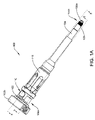
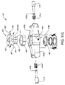
図1A~図7Bは、骨スクリューを骨に打ち込むときに骨スクリューからの保持スリーブの分離を防止するように構成されたスクリュー挿入器具100の例示的な実施形態を示す。図示されたスクリュー挿入器具100は、概して、ドライバシャフト102と、ドライバシャフト102の周囲に配設された保持スリーブ104と、ロックスリーブ118と、を含む。保持スリーブ104及びロックスリーブ118は、本明細書では、スリーブアセンブリと総称される。簡潔にするために、スクリュー挿入器具100の特定の構成要素は、図1A~図7Bには示されていない。
1A-7B illustrate an exemplary embodiment of a
ドライバシャフト102は様々な構成を有し得るが、ドライバシャフト102は、図1A~図3、図6A、及び図7Aに示されるように、図4の骨スクリュー103などの骨スクリューに結合するように構成された遠位先端102aを有する概ね細長い構成を有する。更に、ドライバシャフト102の近位端102bは、本明細書では近位ハンドルとも称される第1のハンドル(図示せず)に連結され得、それにより、第1のハンドルの第1の方向(例えば、時計回り)の回転が、連結された骨スクリューを骨に打ち込むのに有効なドライバシャフト102の同時回転を引き起こし得る。第1のハンドル及びドライバシャフト102は、本明細書ではスクリュー駆動アセンブリと総称される。
Although
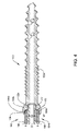
骨スクリューは、その中に画定された近位キャビティ及び遠位キャビティを有する近位ヘッド部分を含み得る。近位キャビティは、後述するように、保持スリーブ104の対応するネジ付き部分に係合するための雌ネジが内部に形成された、実質的な円筒形であり得る。遠位キャビティは、ドライバシャフト102の遠位先端102aと骨スクリューとを回転不能に係合するように成形され得る。したがって、ドライバシャフト102の遠位先端102aは、骨スクリューの遠位キャビティの形状及び寸法に少なくとも部分的に依存する、様々な形状及び寸法を有し得る。図1A~図3に示されるように、この図示した実施形態では、ドライバシャフト102の遠位先端102aは六角形の構成を有する。他の実施形態では、遠位先端102aは、任意の他の好適な形状を有し得る。当業者には理解されるように、骨に係合するように構成された任意の骨スクリューは、本明細書に記載されるスクリュー挿入器具のいずれかを含むスクリュー挿入器具と共に使用され得る。骨スクリューの例示的な実施形態は、米国特許公開第2018/0014858号及び同第2018/0014862号により詳細に記載されており、それぞれは、その全体が参照により本明細書に組み込まれる。
The bone screw may include a proximal head portion having proximal and distal cavities defined therein. The proximal cavity may be substantially cylindrical with internal threads formed therein for engaging corresponding threaded portions of the retaining
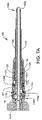
図1A~図3、図6A、及び図7Aに示すように、保持スリーブ104は近位端104aから遠位端104bまで延在する。保持スリーブ104の遠位端104bは、図4の骨スクリュー103のような骨スクリューに連結するように構成されている。保持スリーブ104の遠位端104bは様々な構成を有し得るが、図示のとおり、遠位端104bは、骨スクリュー(図示せず)の近位キャビティの対応する雌ネジにネジ止めにより係合するように構成されたネジ山106を含む。この図示した実施形態では、保持スリーブ104は、保持スリーブ104がドライバシャフト102の近位端102bと遠位先端102aとの間に延在するように、ドライバシャフト102の一部分の周囲に配設される。このようにして、ドライバシャフト102の遠位先端102aは、後述するように、図4の骨スクリュー103のような骨スクリューと最終的に係合し得るように露出される。したがって、骨スクリューは、例えば、遠位先端102aを骨スクリューの遠位キャビティに挿入し、保持スリーブ104の遠位端104bを骨スクリューの近位キャビティにネジ止めにより係合させることによって、スクリュー挿入器具100に連結され得る。
As shown in FIGS. 1A-3, 6A, and 7A,
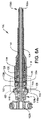
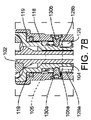
図4は、スクリュー挿入器具100に連結された例示的な骨スクリュー103を示す。骨スクリュー103は、カニューレが取り付けられており、ヘッド部分103aと、そこから遠位に延在するネジ付きシャフト103bとを含む。ヘッド部分103aは、それぞれその中に画定されたネジ付きの近位キャビティ109と、ネジなしの遠位キャビティ111とを含む。図示のとおり、ドライバシャフト102の遠位先端102aは、遠位キャビティ111内に位置付けられ、遠位キャビティ111と回転不能に係合され、保持スリーブ104のネジ山106の一部分は、近位キャビティ109の対応する雌ネジ109aにネジ止めにより係合される。この図示した実施形態では、近位キャビティ109は、遠位キャビティ111の直径(D2)よりも大きい直径(D1)を有し、それによって骨スクリュー103のヘッド部分103a内に肩部113を作る。結果として、保持スリーブ104の遠位端104bは、保持スリーブ104の最遠位端104dが肩部113と接触するまで、近位キャビティ109内に螺入される。
FIG. 4 shows an
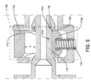
保持スリーブ104の近位端104aは、連結機構108を介してドライバシャフト102に選択的に連結され得る。連結機構108は、様々な構成を有し得る。例えば、図3に示され、図5により詳細に示される連結機構108は、ドライバシャフト102の近位端102bに隣接するドライバシャフト102の溝112に係合する解放ボタン110を含む。具体的には、解放ボタン110は、溝112に係合するように構成された第1の部分110aと、溝112から距離(D)で離間されるように構成された第2の部分110bとを含む。この距離は、以下により詳細に記載されるように、第1の部分110aを溝112から離れる方向に移動させ、それによって保持スリーブ104とドライバシャフト102とを分離することができるように、第2の部分110bを溝112に向かって選択的に押下することを可能にし得る。図3及び図5に示されるように、解放ボタン110は、拡張構成で付勢要素114を介してドライバシャフト102に係合される。付勢要素114は様々な構成を有し得るが、付勢要素114は、図3及び図5に示されるように、解放ボタン110の第1の部分110aを溝112に向かって付勢し、解放ボタン110の第2の部分110bを溝112から距離(D)だけ離れる方向に付勢する、螺旋バネの形態である。
A
使用中、ドライバシャフト102は、解放ボタン110の第1の部分110aが摺動してドライバシャフト102の溝112と接触して係合するまで、保持スリーブ104に挿入される。保持スリーブ104からドライバシャフト102を取り外すために、解放ボタン110を作動させて、解放ボタン110の第1の部分110aを溝112から離れる方向に移動させ、それにより溝112を係合解除することができる。例えば、ユーザは、解放ボタン110を、その第2の部分110bに十分な力を加えることによって作動させることで、第2の部分110bを溝112に向かって移動させることができる。これにより、解放ボタン110の第1の部分110aは、溝112及び付勢要素114から離れる方向にシフトして、圧縮構成へと移動する。その結果、解放ボタン110の第1の部分110aは、ドライバシャフト102の溝112を係合解除し、それによってドライバシャフト102を摺動可能に取り外すことを可能にする。他の実施形態では、他の連結機構が使用され得る。
In use,
更に、ドライバシャフト102の溝112は、保持スリーブ104に係合するように構成された追加の特徴部を含み得る。例えば、図5に示すように、溝112の遠位部分112dは、ドライバシャフト102を遠位方向に付勢するために使用され得る角度付き接合面116を含む。角度付き接合面116は、溝112の中間部分112aに対して様々な角度で延在し得る。図示した実施形態では、角度付き接合面は、溝112の中間部分112aに対して0度超かつ90度未満である横方向角度
Additionally, groove 112 of
![]()
![]()
使用時には、保持スリーブ104が骨スクリューに結合されると、解放ボタン110の遠位端110dが角度付き接合面116に係合し、解放ボタン110の遠位端110dと溝112とを直接接触させる。この直接接触は、ドライバシャフト102を遠位方向に付勢する。更に、この係合は、解放ボタン110の遠位端110dと溝112の角度付き接合面116との間の任意のクリアランスを除去する。結果として、この係合は、上述したように、保持スリーブ104の最遠位端が骨スクリュー内の肩部に底付きしている状態で、スクリュー挿入中のドライバシャフト102に対する骨スクリューのトグルを阻止し得る。更に、解放ボタン110の一部分のみを角度付き接合面116に直接係合させることにより、保持スリーブ104が骨スクリューの肩部に係合し、解放ボタン110の他の部分と溝112との間にクリアランスが残るため、保持スリーブ104を骨スクリューから係合解除する(例えば、螺出させる)ことを必要とせず、解放ボタン110を簡単に作動させることができる。したがって、保持スリーブ104は、ドライバシャフト102が解放ボタン110を介して係合解除され、それによりそこから取り外されている間、骨スクリューにネジ止めにより係合したままであり得る。ドライバシャフト102が骨スクリューから取り外されると、他の構成要素は、保持スリーブ104を通って、連結された骨スクリューに挿入され、追加の手順、例えば、それぞれ、その全体が参照により本明細書に組み込まれる米国特許第9,265,548号及び2019年6月13日に出願された「Instruments and Methods for Delivering Bone Cement to a Bone Screw」と題する米国特許出願第16/439,977号に記載された手順が実施され得る。
In use, when
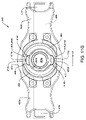
図1A、図3、及び図6A~図7Bに更に示されるように、保持スリーブ104の一部分の周囲にロックスリーブ118が配設される。ロックスリーブ118は、第1の位置又は係合解除位置(例えば、図1A及び図6A~図6B)と、第2の位置又は係合位置(図7A及び図7B)との間を(ユーザの起動によって)並進するように構成されている。以下でより詳細に説明するように、ロックスリーブ118がその第1の位置又は係合解除位置にあるとき、ロックスリーブ118は固定したままで、ドライバシャフト102及び保持スリーブ104を回転させることができる。結果として、ドライバシャフト102及び保持スリーブ104は、保持スリーブ104が骨スクリューに係合したままであるように保持スリーブ104を同時に回転させながら、骨スクリューを骨に打ち込むために、第1の方向(例えば、時計回り)にユニットとして一緒に回転させることができる。ロックスリーブ118が第2の位置又は係合位置にあるとき、ドライバシャフト102は固定したままで、保持スリーブ104及びロックスリーブ118を回転させることができる。その結果、保持スリーブ104及びロックスリーブ118は、保持スリーブ104が、埋め込まれた骨スクリューから係合解除することを可能にするために、第1の方向とは反対の第2の方向(例えば、反時計回り)にユニットとして一緒に回転し得る一方、ドライバシャフト102は固定したままであるため、骨に対して埋め込まれた骨スクリューの並進は生じない。このようにして、ロックスリーブ118は、埋め込み中に保持スリーブ104が骨スクリューに連結されたままであることを可能にし、埋め込み後に保持スリーブ104が骨スクリューから係合解除されることを可能にする。
As further shown in FIGS. 1A, 3, and 6A-7B, a locking
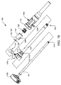
ロックスリーブ118は、図2~図3及び図6A~図7Bに示されるように、連結要素120によって保持スリーブ104に連結される。図1B及び図2により詳細に示される連結要素120は、保持スリーブ104とロックスリーブ118との間に配設される。連結要素120は、図2~図3及び図6A~図7Bに示されるように、様々な構成を有し得るが、連結要素120は、第1の端部120aに第1の組の歯122を有する第1の円筒形カラーの形態である。図示のとおり、第1の組の歯122は、保持スリーブ104の周囲に配設された第2の円筒形カラー124の第1の端部124aにおいて、第2の組の歯123に係合する。
Locking
第1の組及び第2の組の歯122、123は、図1B及び図2に示されるように、様々な構成を有し得るが、第1の組の歯122は、第1の角度配向で延在し、第2の組の歯123は、相補的な第2の角度配向で延在する。ドライバシャフト102及び保持スリーブ104が骨スクリューに連結され、したがって、互いに回転可能に連結されると、第1の組及び第2の組の歯122、123の係合によって、ロックスリーブ118は固定されたままで、ドライバシャフト102及び保持スリーブ104が第1の方向(例えば、時計回り)に一緒に回転して、骨スクリューを骨に打ち込むことが可能になる。このようにして、スクリューの挿入中、保持スリーブ104は骨スクリューに対して固定されたままにはならず、保持スリーブ104が骨スクリューから螺出されることにはならない。代わりに、保持スリーブ104は、骨スクリューが骨に打ち込まれる際に骨スクリューと共に回転し、したがって、骨スクリューに連結されたままとなる。
The first and second sets of
図3、図6A、及び図7Aに更に示されるように、付勢要素126は、ロックスリーブ118内に存在する。付勢要素126は、様々な構成を有し得るが、付勢要素126は、この図示した実施形態では螺旋バネである。付勢要素126は、第1の組の歯122を第2の組の歯123に向かって連続的に付勢し得る。結果として、第1の組及び第2の組の歯122、123は、ロックスリーブ118の位置とは無関係に係合されたままである。更に、後述するように、付勢要素126は、ロックスリーブ118を遠位に付勢することができ、それによってロックスリーブ118をその第1の位置又は係合解除位置に付勢することができる。
As further shown in FIGS. 3, 6A, and 7A, biasing
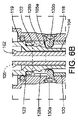
更に、図1B、図2、図6B、及び図7Bに示されるように、連結要素120は、その中に画定され、その第1の端部120aに近接して位置付けられた第1及び第2の切り欠き部分128a、128bを含む。第1及び第2の切り欠き部分128a、128bは、様々な形状及び寸法を有し得るが、図1B及び図2に示されるように、それぞれの切り欠き部分128a、128bは、実質的に矩形の形状である。第1及び第2の切り欠き部分128a、128bは、以下でより詳細に説明するように、ロックスリーブ118から半径方向内側に延在する第1及び第2のロックピン130a、130bが、保持スリーブ104のネジ付き部分105と選択的に係合するためにそこを通って延在することを可能にするような寸法及び形状である。更に、第1及び第2の切り欠き部分128a、128bの寸法は、ロックスリーブ118と保持スリーブ104との間の相対的な移動を可能にし、ロックスリーブ118が第1の位置に戻ることを可能にするように設計され得る。このようにして、第1及び第2の切り欠き部分128a、128bは、ロックスリーブ118と保持スリーブ104との間の一定量の滑りを可能にし得る。
Further, as shown in FIGS. 1B, 2, 6B, and 7B, connecting
骨スクリューが埋め込まれると、保持スリーブ104は、埋め込まれた骨スクリューから係合解除され得る。この係合解除は、ロックスリーブ118の第1の位置又は係合解除位置からその第2の位置又は係合位置への移動によって達成され得る。以下でより詳細に説明するように、ロックスリーブ118は、ドライバシャフト102が固定されている状態で、近位に移動し、第2の方向(例えば、反時計回り)に回転し、それによって、保持スリーブ104が埋め込まれた骨スクリューから係合解除されることを可能にするように構成され得る。このようにして、ドライバシャフト102が固定されているときに、ロックスリーブ118がその第2の位置又は係合位置まで移動されると、ロックスリーブ118は第2の方向に更に回転して、保持スリーブ104の同時回転を引き起こすことになる。結果として、これにより、埋め込まれた骨スクリューから保持スリーブ104が螺出される。
Once the bone screw is implanted, the retaining
例えば、使用中、ロックスリーブ118を近位方向に(例えば、ドライバシャフト102の近位端102bに連結された第1のハンドルに向かって)移動させる(引く)ことにより、ロックスリーブ118は、第1/係合解除位置(図1A、図3、及び図6A~図6B)から第2/係合位置(図7A及び図7B)に向かって並進し得る。このようにして、ユーザによって加えられる引っ張り力は、付勢要素126の付勢力に打ち勝つことができ、その結果、付勢要素126をその拡張構成から圧縮構成に移動させることができる。これにより、ロックスリーブ118は、保持スリーブ104に対して近位方向に移動することが可能になる。ロックスリーブ118が近位方向に軸方向並進すると、ロックスリーブ118から半径方向内側に延在するロックピン130a、130bが軸方向に並進する。この軸方向並進により、ロックピン130a、130bは、保持スリーブ104のネジ付き部分105の端部105aに当接する。ロックスリーブ118を近位に引くと、ロックスリーブ118は、保持スリーブ104に対して第2の方向(例えば、反時計回り)に回転して、ロックピン130a、130bを保持スリーブ104のネジ付き部分105にネジ止めにより係合させ、ネジ付き部分105の一部分を通って(例えば、第1のハンドルに向かって)近位に、かつ回転可能に並進させることができる。図7A~図7Bに示されるように、ロックスリーブ118は反時計回りに35度回転されている。他の実施形態では、ロックスリーブ118は、保持スリーブ104に対して約0°~180°の第2の方向に回転し得る。当業者であれば、ロックスリーブの回転量は、ロックスリーブと器具100の他の部品との間のネジ山ピッチ及び空間クリアランスに少なくとも依存することを理解するであろう。
For example, in use, moving (pulling) locking
ロックスリーブ118が回転すると、ロックピン130a、130bは、図7A及び図7Bに示されるように、ロックスリーブ118の内側表面118aから延在するフランジ119が保持スリーブ104の近位端104aと接触する切り欠き部分128a、128b内の近位位置に最終的に到達する。これにより、ロックスリーブ118は、その第2/係合位置へと移動する。具体的に言えば、近位端104aは、ロックスリーブ118が保持スリーブ104に対して更に近位に並進することを防止する。これにより、ロックスリーブ118が底に付き、ロックピン130a、130bは、保持スリーブ104のネジ付き部分105内に保持されて、ネジ付き部分105を通って遠位に移動することを防止される。その結果、ロックスリーブ118が第2/係合位置にあるとき、ロックスリーブ118が第2の方向(反時計回り)に更に回転すると、保持スリーブ104は、ドライバシャフト102に対して同じ方向に同時に回転し、ドライバシャフト102は固定されたままで埋め込まれた骨スクリューを固定位置に維持する。ロックスリーブ118及び保持スリーブ104の第2の方向のこの回転により、保持スリーブ104の遠位端104bは、埋め込まれた骨スクリューとのネジ止めによる係合を解除される。
As locking
保持スリーブ104及びドライバシャフト102が埋め込まれた骨スクリューから取り外されると、ロックスリーブ118はその第1の位置に戻り得る。例えば、使用中、ロックスリーブ118がその第2の位置にあるときに、ユーザは、ロックスリーブ118を解放することができる。これにより、付勢要素126は、その圧縮構成からその拡張構成に向かって拡張し、それによってロックスリーブ118は、その第1/係合位置に向かって移動する。このようにして、付勢要素126がロックスリーブ118を遠位方向に押すと、ロックピン130a、130bは、保持スリーブ104のネジ付き部分105の端部105aを越えて遠位に並進する。
Once the retaining
前述したように、スクリュー挿入器具を使用して、骨スクリューアセンブリを骨に埋め込むことができる。本明細書に記載されるようなスリーブアセンブリを有するスクリュー挿入器具のいずれかを操作するために、任意の好適な方法を使用することができる。例えば、スクリュー挿入器具100(図1A~図7B)を操作する場合、ドライバシャフト102を固定させた状態で、保持スリーブ104をドライバシャフト102に対して回転させて、保持スリーブ104を、ドライバシャフト102の遠位先端102aに連結された骨スクリューにネジ止めにより係合させることができる。骨スクリューに連結すると、ロックスリーブ118は固定されたままで、ドライバシャフト102上のハンドルを第1の方向に回転させて、骨スクリューを骨に打ち込むことができる。この回転はまた、上で説明したように、保持スリーブ104をドライバシャフト102と共に回転させ得る。骨スクリューが骨に埋め込まれると、ロックスリーブ118は、保持スリーブ104に対して第1の位置から第2の位置へと移動され得る。これは、ロックスリーブ118を近位に引くことによって、かつ、ロックスリーブ118を保持スリーブ104に対して反時計回りに回転させることによって達成され得る。ドライバシャフト102は、ロックスリーブ118がロック位置に回転されている間、固定されたままであり得る。上で説明したように、第2の位置にあるとき、ドライバシャフト102を固定した状態で、ロックスリーブ118を反時計回りに回転させることにより、保持スリーブ104を回転させることができ、それによって保持スリーブは、骨スクリューとのネジ止めによる係合を解除され得る。
As previously mentioned, a screw insertion instrument may be used to implant the bone screw assembly into the bone. Any suitable method can be used to operate any of the screw insertion instruments with sleeve assemblies as described herein. For example, when operating the screw insertion instrument 100 (FIGS. 1A-7B), the retaining
したがって、本明細書に記載されるロックスリーブは、ドライバを回転させて、そこに連結された骨スクリューを骨に打ち込むことができるように、ユーザがスクリュー挿入器具を把持するための場所を提供する。この把持の場所はまた、保持スリーブをドライバシャフトと共に同じ方向に回転させることを可能にし、その結果、骨スクリューの挿入中に連結された骨スクリューから保持スリーブが分離することを防止する。更に、ロックスリーブは、ユーザがスクリュー挿入器具を把持し、ドライバシャフトを保持しながらロックスリーブを回転させて、保持スリーブが埋め込まれた骨スクリューから分離されるようにするための場所を提供する。 Accordingly, the locking sleeves described herein provide a location for the user to grasp the screw insertion instrument so that the driver can be rotated to drive the bone screw coupled thereto into bone. . This gripping location also allows the retaining sleeve to rotate in the same direction with the driver shaft, thereby preventing separation of the retaining sleeve from the coupled bone screw during insertion of the bone screw. Additionally, the locking sleeve provides a location for the user to grasp the screw insertion instrument and rotate the locking sleeve while holding the driver shaft so that the retaining sleeve is separated from the implanted bone screw.
いくつかの実施形態では、スクリュー挿入器具はまた、骨に打ち込まれる骨スクリューの挿入深さを制限するように構成された停止スリーブを含み得る。停止スリーブは、停止スリーブの一部分が、保持スリーブに連結された骨スクリューの少なくとも一部分を取り囲むことができるように、保持スリーブの周囲に部分的に配設され得る。オーバーラップの長さは、多軸ヘッドアセンブリに必要な骨スクリューの長さに関連付けることができる。したがって、停止スリーブは、骨スクリューの一部分の骨への挿入を制限するように構成され得る。例えば、停止スリーブは、骨スクリューが所望の挿入深さに到達したときに、ユーザに触覚フィードバック及び視覚フィードバックを提供し得る。更に、特定の実施形態では、停止スリーブは、保持スリーブに連結されて、保持スリーブ及び停止スリーブが一緒に回転することを可能にし得るが、他の実施形態では、停止スリーブは、保持スリーブに対して自由に回転し得る。 In some embodiments, the screw insertion instrument can also include a stop sleeve configured to limit the insertion depth of the bone screw driven into the bone. The stop sleeve may be partially disposed around the retention sleeve such that a portion of the stop sleeve can surround at least a portion of the bone screw coupled to the retention sleeve. The length of the overlap can be related to the bone screw length required for the polyaxial head assembly. Accordingly, the stop sleeve can be configured to limit insertion of a portion of the bone screw into the bone. For example, the stop sleeve may provide tactile and visual feedback to the user when the bone screw reaches the desired insertion depth. Additionally, in certain embodiments, the stop sleeve may be coupled to the retention sleeve to allow the retention sleeve and stop sleeve to rotate together, while in other embodiments the stop sleeve is coupled to the retention sleeve. can rotate freely.
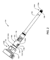
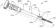
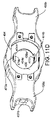
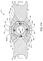
図8A~図8Bは、停止スリーブ232を有するスクリュー挿入器具200の実施形態を示す。以下に詳細に記載される違いを除いて、スクリュー挿入器具200は、スクリュー挿入器具100(図1A~図7B)に類似し得、したがって、本明細書では詳細に説明しない。更に、簡潔にするために、スクリュー挿入器具200の特定の構成要素は、図8A~図8Bには示されていない。更に、説明のためだけに、骨スクリュー234はスクリュー挿入器具200に連結されている。
8A-8B show an embodiment of
停止スリーブ232は、様々な構成を有し得る。例えば、図8A~図8Bに示される停止スリーブ232は、保持スリーブ204の一部分の周囲に配設され、そこから長さ(LH)で遠位に延在するヘッド238を有する細長い円筒形本体236を含む。細長い円筒形本体236及びヘッド238は、その両側に、内部に画定された窓239a、239bを含む。窓239a、239bは、例えば、ユーザが保持スリーブ204に連結されているときに骨スクリュー234を見ることを可能にし得る。更に、停止スリーブ232の近位端232pは、ロックスリーブ218の遠位端218dに固定的に連結され得る。結果として、ロックスリーブ218の移動は、停止スリーブ232の同時移動をもたらす。当業者であれば、他の実施形態では、停止スリーブ232の近位端232pは、停止スリーブ232がロックスリーブ218に対して自由に回転し、結果として保持スリーブ204及びドライバシャフト202に対して自由に回転することを可能にするような方法で、ロックスリーブ218の遠位端218dに連結され得ることを理解するであろう。
The
更に示されるように、骨スクリュー234が保持スリーブ204と完全に係合されたとき、ヘッド238の一部分238aが骨スクリュー234の一部分と重なり合う。その結果、使用中、骨スクリュー234が骨に打ち込まれると、ヘッド238の遠位端238dは、最終的に骨の表面と接触することになる。この接触は、骨スクリュー234が所定の挿入深さに達したことを(例えば、触覚フィードバック及び視覚フィードバックによって)ユーザに示すことになる。上述したように、重なりの長さは、多軸ヘッドアセンブリ(図示せず)を骨スクリュー234に取り付けることを可能にするのに有効な量のクリアランスを提供するように既定され得る。
As further shown, a
ヘッド238は様々な構成を有し得るが、図8A~図8Bのヘッド238は、実質的に円錐形の構成を有する。この図示した実施形態では、ヘッド238は、第1の部分240aに沿って遠位に増加する第1の外径と、第2の部分240bに沿って実質的に一定である第2の外径と、第3の部分240cに沿って遠位に減少する第3の外径とを有する。当業者であれば、他の実施形態では、ヘッド238は、遠位に増減するか、又はヘッド238の全長LHに沿って一定のままである外径を有し得ることを理解するであろう。更に、他の実施形態では、ヘッド238は、他の好適な形状及び寸法を有し得る。
図9A~図9Bは、スクリュー挿入器具300に連結された停止スリーブ332の別の実施形態を示す。以下に詳細に記載される違いを除いて、スクリュー挿入器具300は、スクリュー挿入器具100(図1A~図7B)に類似し得、したがって、本明細書では詳細に説明しない。更に、簡潔にするために、スクリュー挿入器具300の特定の構成要素は、図9A~図9Bには示されていない。更に、説明のためだけに、骨スクリュー334はスクリュー挿入器具300に連結されている。
9A-9B show another embodiment of a
図9A~図9Bに示される停止スリーブ332は、保持スリーブ304の一部分の周囲に配設され、そこから長さ(LH)で遠位に延在するヘッド338を有する細長い本体336を含む。図示のように、ヘッド338の一部分338aは、骨スクリュー234の一部分と重なり合う。この図示した実施形態では、ヘッド338は、基部343aと、基部343aから延在する2つの対向する脚部343b、343cとを有する実質的にU字形の構成を有する。更に、ヘッドは、その周囲に位置付けられた窓340a、340b、及び340cを含む。
The
図9A~図9Bに更に示されるように、停止スリーブ332の近位端332pは、連結要素339を介してロックスリーブ318の遠位端318dに連結される。連結要素339は、様々な構成を有し得るが、この図示した実施形態では、連結要素339は、第1の端部339aから第2の端部339bまで延在する略円筒形の本体の形態である。連結要素339は、そこから半径方向外側に延在する環状リング337を含む。図示のように、環状リング337は、連結要素339の第1の端部339aがロックスリーブ318内に存在するように、ロックスリーブ318内に画定された内部溝319に係合する。図示のように、連結要素339の第2の端部339bは、停止スリーブ332の近位端332p内に画定されたキャビティ341内に位置付けられる。更に、連結要素339の第2の端部339bにおける第1の組のネジ山342aは、停止スリーブ332内のキャビティ341の第2の組のネジ山342bに係合される。その結果、停止スリーブ332は、停止スリーブ332がロックスリーブ318に対して自由に回転し、結果として保持スリーブ304及びドライバシャフト302に対して自由に回転することを可能にするような方法で、ロックスリーブ318に嵌合され得る。
9A-9B,
特定の実施形態では、停止スリーブは、神経モニタリング中に保持スリーブ及び/又はドライバシャフトを電気的に絶縁するように構成された絶縁材料で形成又はコーティングされ得る。例えば、停止スリーブは、保持スリーブ及び/又はドライバシャフトに印加される電流が手術部位で周囲の組織から隔離されるように、障壁として機能する1つ又は2つ以上のプラスチックから形成され得る。追加的に又は代替的に、放射線不透過性材料を停止スリーブの遠位端に挿入して、ユーザが、電流を印加する前に、停止スリーブと骨スクリューとの間の接合面を可視化することを可能にし得る。 In certain embodiments, the stop sleeve may be formed or coated with an insulating material configured to electrically insulate the retention sleeve and/or driver shaft during neuromonitoring. For example, the stop sleeve may be formed from one or more plastics that act as a barrier so that current applied to the retention sleeve and/or driver shaft is isolated from surrounding tissue at the surgical site. Additionally or alternatively, inserting a radiopaque material into the distal end of the stopping sleeve to allow the user to visualize the interface between the stopping sleeve and the bone screw prior to applying the current. can enable
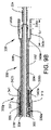
いくつかの実施形態では、スクリュー挿入器具は、図1A~図7Bの器具100のような器具の遠位端に連結される骨スクリューに対して、スタイレットの位置決めを制御するために、図10A~図10Bのスタイレットアセンブリ450のようなスタイレットアセンブリを含み得る。一般に、スタイレットアセンブリは、本明細書では遠位ハンドルとも称される、図10A~図10Bの第2のハンドル450aのような第2のハンドルと、器具の、図10A~図10Bのドライバシャフト402のようなドライバシャフトを通って延在する、図10A~図10Bのスタイレット450bのようなスタイレットと、を含み得る。スタイレットの軸方向位置は、第2のハンドルの回転によって調節され得る。連結された骨スクリューがスタイレットの前進及び後退中に挿入されるか又は骨から除去されるのを防止するために、ユーザは、第2のハンドルの回転中に、器具の第1のハンドルに逆トルクを加えることができる。このようにして、以下でより詳細に説明するように、ユーザは、第1のハンドルを固定した状態で、第2のハンドルを回転させることができ、スタイレットの軸方向の並進を引き起こすことができる。逆に、使用中、スタイレットが骨に対して位置付けられると、第1のハンドルが回転されて骨スクリューを骨に打ち込む間、第2のハンドルは固定されたままとなる。スクリューの前進中、ユーザが、第1のハンドルから手を放す必要はなく、器具のドライバシャフトを連続的に回転させることが望ましい場合がある。したがって、ラチェット特徴部を有するクラッチ機構、並びにスイッチ機構が提供され得る。スイッチは、ユーザが第1のハンドルを、第1のモード、例えば、第1のハンドルを固定したままにして、第2のハンドルの回転中に逆トルクを加えることができるロック構成と、第2のモード、例えば、ラチェット特徴部が作動されるロック解除構成との間で切り替えることを可能にする。ラチェット特徴部は、第1のハンドルが、反対方向の動きを防止しながら、一方向にのみドライバシャフトを連続的に駆動し、それによって骨スクリューを骨に打ち込むことを可能にする。この構成により、ユーザは、第1のハンドルとの接触を維持し、スクリューを骨内へとより迅速に前進させることを可能にする。
In some embodiments, the screw-insertion instrument has a
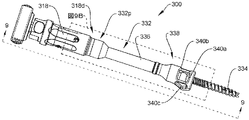
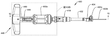
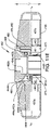
図10A~図10Bは、例示的なスクリュー挿入器具400を示す。以下に詳細に記載される違いを除いて、スクリュー挿入器具400は、スクリュー挿入器具100(図1A~図7B)に類似し得、したがって、本明細書では詳細に説明しない。簡潔にするために、スクリュー挿入器具400の特定の構成要素は、図10A~図10Bには示されていない。スクリュー挿入器具400は、一般に、第1のハンドル446、ドライバシャフト402、駆動管448、及びスタイレットアセンブリ450を含む。第1のハンドル446及びドライバシャフト402は、本明細書ではスクリュー駆動アセンブリと総称される。スクリュー挿入器具400はまた、上述したものと同様の保持スリーブ404、ロックスリーブ418、及び停止スリーブ432を含むが、当業者は、特定の実施形態では、保持スリーブ404、及び/又はロックスリーブ418、及び/又は停止スリーブ432が省略され得ることを理解するであろう。
10A-10B show an exemplary
図10Bに示すように、ドライバシャフト402の近位端402pは、駆動管448の遠位端448dに連結され、駆動管448の近位端448pは、第1又は近位ハンドル446に嵌合される。駆動管448は、近位部分448a及び遠位部分448bを有する概ね細長い中空管の形態であり得る。第1のハンドル446は、様々な機構を使用して駆動管448に選択的に嵌合され得るが、駆動管448の近位端448pは、第1のハンドル446内に配設された連結部材452の遠位部分463の内側表面463bと嵌合するために、そこに形成された嵌合特徴部449を含む。この図示した実施形態では、駆動管448上の嵌合特徴部449は、雄型六角特徴部であり、図11E~図11Gに示されるように、遠位部分463の内側表面463bは雌型六角特徴部の形態である。他の実施形態では、嵌合特徴部は、第1のハンドル446を駆動管448に選択的に嵌合するのに好適な任意の他の構成を有し得る。
As shown in FIG. 10B, the
スタイレットアセンブリ450は、図10A~図10Bに示されるように、第2のハンドル450a及びスタイレット450bを含む。第2のハンドル450aは、駆動管448の遠位部分448bの上に回転可能に位置付けられ、スタイレット450bはドライバシャフト402を通って延在する。使用中、第1のハンドル446を固定した状態で、第2のハンドル450aを回転させて、ドライバシャフト402に対してスタイレット450bを遠位に前進させるか又は近位に後退させる。更に、スクリュー駆動アセンブリに連結された骨スクリューを骨に打ち込むため、第2のハンドル450aを固定した状態で、第1のハンドル446及びドライバシャフト402を回転させる。スタイレットアセンブリ450は、スタイレット450bに連結され、駆動チューブ448内に移動可能に配設されたキャリア450cを含み得る。スタイレットアセンブリ450及び他の例示的なスタイレットアセンブリの更なる詳細は、米国特許公開第2018/0368893号、及び2017年11月2日に出願された「Bone Anchor Insertion Instruments and Methods」と題する米国特許出願第15/801,917号に見出すことができ、これらのそれぞれは、参照によりその全体が本明細書に組み込まれる。
The
スタイレットの前進及び後退中にドライバシャフト402が回転することを防止するために、ドライバシャフト402は、第1のハンドル446内に存在する、本明細書では制御機構とも称されるロックアセンブリ466によって、第1のハンドル446にロックされ得る。ロックアセンブリ466は、第1のハンドル446及びドライバシャフト402を、それらがユニットとして回転するように互いに選択的にロックするように構成され得る。したがって、ロックアセンブリ466は、ロック構成及びロック解除構成を有する。ロックアセンブリ466がロック構成にあるとき、ユーザは、第1のハンドル446を把持して固定することができ、それにより、ドライバシャフト402は固定された状態で、第2のハンドル450aが回転して、スタイレット450bを所望の長さに前進又は後退させる。すなわち、ロックアセンブリ466は、ドライバシャフト402の回転を防止しながら、第2のハンドル450aが時計回り又は反時計回りのいずれかの方向で回転する間に、ユーザが第1のハンドル446を介して逆トルクをかけることを可能にする。結果として、スタイレットの前進及び後退の間、ドライバシャフト402の遠位先端402aに連結された骨スクリュー(図示せず)の軸方向並進が防止され得る。ロックアセンブリ466がそのロック解除構成にあるとき、第1のハンドル446は、図11Hのクラッチアセンブリ480のようなクラッチアセンブリを介してドライバシャフト402に連結され、ドライバシャフト402と共に回転することが可能であり、これについては以下でより詳細に説明する。クラッチアセンブリは、ユーザが、第1のハンドル446から手を放すことなく、ドライバシャフト402を一方向のみに連続的に駆動することができるように、ラチェットとして機能する。
To prevent the
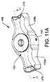
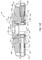
第1のハンドル446は、ユーザが第1のハンドル446を効果的に把持し、スクリュー挿入器具400を操作することを可能にする様々な構成を有し得る。例えば、図10Aに示されるように、第1のハンドル446はTハンドルの形態であり得る。第1のハンドル446は、図11A~図11Hにより詳細に示されており、基部部材454と、そこから反対方向外側に延在する第1及び第2のアーム部材456a、456bとを含む。第1及び第2のアーム部材456a、456bは、ユーザが、第1のハンドル446をその回転のために容易に把持することを可能にする。更に、図11D及び図11Eに示されるように、第1及び第2のアーム部材456a、456bはそれぞれ、第1のハンドル446の長手方向軸(LH)に沿って、内部を通って延在するチャネル457a、457bを含む。
First handle 446 may have various configurations that allow a user to effectively grasp
基部部材454は、図11A~図11Gに示すように、様々な構成を有し得るが、基部部材454は、内部を通って延在するチャネル454aを含む。図示のように、チャネル454aは、第1のハンドル446の長手方向軸(LH)に対して横方向である軸に沿って延在する。更に、図11D及び図11Eに示されるように、チャネル454aの一部分は、基部部材454の内側表面454bから半径方向内側に延在する第1のフランジ459の内側表面459aによって画定される。その結果、第1のキャビティ460、及びチャネル454aを介して第1のキャビティ460と連通する第2のキャビティ461が、基部部材454内に形成される。
図11E及び図11Fに更に示されるように、連結部材452は、基部部材454の第1のキャビティ460内に位置付けられ、第1のキャビティ460から第2のキャビティ461内に延在する。連結部材452は、様々な構成を有し得る。この図示した実施形態では、連結部材452は、近位部分462、遠位部分463、及びそれらの間に延在する中間部分464を有する、概ね細長い中空管の形態である。これらの部分462、463、464はそれぞれ、外側表面462a、463a、464a及び内側表面462b、463b、464bを有し、外側表面462a、463a、464aはそれぞれ実質的に円形の形状である。示されるように、連結部材452の外径は、概して、その長さ(LC)に沿って遠位に減少する。他の実施形態では、連結部材452は、他の好適な形状及び寸法を有し得る。更に、遠位部分463の内側表面463bは、実質的に六角形の形状である。その結果、この内側表面463bは、駆動管448上の雄型六角特徴部を受容して第1のハンドル446を駆動管448に嵌合するように構成されている雌型六角特徴部として機能する。連結部材452は、第1のハンドル446内に存在するロックアセンブリ466又はクラッチアセンブリ480のいずれかの一部を形成する追加の特徴部を含み、これについては以下でより詳細に説明する。
As further shown in FIGS. 11E and 11F , connecting
ロックアセンブリ466は、様々な構成を有し得る。例えば、図11C、図11F、及び図11Gに示されるように、ロックアセンブリ466は、基部部材454の第2のキャビティ461内に位置付けられたロックリング468に連結された第1及び第2のトリガ要素476、478を含む。この図示した実施形態では、ロックアセンブリ466がロック構成にあるとき、ロックリング468はドライバシャフト402に連結され、それにより、第1のハンドル446及びドライバシャフト402は共にロックされ、ユニットとして回転するようになる。ロックアセンブリ466がロック解除構成にあるとき、ロックリング468はドライバシャフト402から分離され、それにより、ドライバシャフト402が第1のハンドル446に対して自由に回転することが可能になる。以下でより詳細に説明するように、ロックアセンブリ466は、そのロック構成に付勢され、したがって、ロックアセンブリ466がそのロック解除構成に移動するまで、第1のハンドル446及びドライバシャフト402が一緒にロックされる。
第1及び第2のトリガ要素476、478は、様々な構成を有し得るが、図11F及び図11Gに示されるように、それぞれのトリガ要素476、478は、一般に、第1の端部476a、478a及び第2の端部476b、478bを有する細長い円筒状部材の形態である。図示のとおり、第1のトリガ要素476の一部分は、第1のアーム部材456aのチャネル457aを通って延在し、第2のトリガ要素478の一部分は、第2のアーム部材456bのチャネル457bを通って延在する。したがって、それぞれのトリガ要素476、478の第1の端部476a、478aは、第1のハンドル446の外側に位置付けられ、それぞれのトリガ要素476、478の第2の端部476b、478bは、図11F及び図11Gに示されるように、ロックリング468に固定的に連結される。他の実施形態では、第1のハンドル446は、他の好適な構成を有するトリガ要素(複数可)を含み得る。例えば、一実施形態では、少なくとも1つのトリガ要素は、スイッチの形態をとり得る。
The first and
図11Fに示すように、第1の付勢要素479aは、第1のアーム部材456aのチャネル457a内に配設され、第2の付勢要素479bは、第2のアーム部材456bのチャネル457b内に配設される。第1及び第2の付勢要素479a、479bは、様々な構成を有し得るが、それぞれの付勢要素479a、479bは、この図示した実施形態では螺旋バネである。第1及び第2の付勢要素479a、479bは、図11F及び図11Gに示されるように、拡張構成にあるときに、第1及び第2のトリガ要素476、478をそれぞれ第1の位置で付勢し得る。結果として、第1及び第2のトリガ要素476、478は、それらの第1の位置に付勢され、その結果、ロックアセンブリ466はそのロック構成に付勢される。
As shown in FIG. 11F, a
ロックリング468は、様々な形態を有し得る。図11Gに示されるように、ロックリング468は、間に第1の係合接合面471aを画定する第1の組の2つの隣接する凹部469と、間に第2の係合接合面471bを画定する第2の組の2つの隣接する凹部470とを含む。ロックアセンブリ466がそのロック構成にあるとき、第1及び第2の係合接合面471a、471bは、図11Gに示されるように、それぞれ第1及び第2の係合特徴部472a、472bに摩擦係合する。係合特徴部472a、472bは様々な構成を有し得るが、係合特徴部472a、472bはそれぞれ、ボール形状の構成を有する。他の実施形態では、係合特徴部472a、472bは、他の好適な形状及び寸法を有し得る。
The
図11Gに更に示すように、第1の係合特徴部472aの一部分は、第1の停止部材474a内に画定された穴473aを通って延在し、第2の係合特徴部472bの一部分は、第2の停止部材474b内に画定された穴473bを通って延在する。第1及び第2の停止部材474a、474bは、様々な構成を有し得るが、この図示した実施形態では、第1及び第2の停止部材474a、474bは、それぞれ第2及び第3のフランジの形態である。第2のフランジ及び第3のフランジはそれぞれ、第1のフランジ459から、第1のハンドル446の長手方向軸(LH)を横断する方向に、したがって第2のキャビティ461へと外向きに延在する。その結果、それぞれの停止部材474a、474bは、ロックリング468と連結部材452の遠位部分463との間に位置付けられる。他の実施形態では、それぞれの停止部材474a、474bは、係合特徴部がロックリング468と連結部材452の遠位部分463との間で摩擦係合されることを可能にする他の好適な構成を有し得る。
As further shown in FIG. 11G, a portion of
図示されていないが、第1の係合特徴部472aは、1組のチャネル475のうちの第1のチャネル内に部分的に着座され、第2の係合特徴部472bは、1組のチャネル475のうちの第2のチャネル内に部分的に着座される。1組のチャネル475のうちのそれぞれのチャネルは、図11E及び図11Fに示されるように、連結部材452の遠位部分463の外側表面463aから陥凹している。結果として、第1及び第2の係合接合面471a、471bが対応の第1及び第2の係合特徴部472a、472bと接触しているとき、ロックリング468と連結部材452との間に摩擦係合が形成される。この摩擦係合は、第1のハンドル446及びドライバシャフト402を互いにロックする。これは、上述のように、連結部材452の遠位部分463の内側表面463bが駆動管448の近位端448pに嵌合し、駆動管448の遠位端448dがドライバシャフト402に連結されるためである。このようにして、第1のハンドル446に対する連結部材452の回転運動を阻止することにより、第1のハンドル446をドライバシャフト402にロックして、それらがユニットとして一緒に回転できるようにする。
Although not shown, the
使用中、ロックアセンブリ466は、例えば、ユーザが第1及び第2のトリガ要素476、478のうちの1つを作動させて、ロックリング468を第1及び第2の係合特徴部472a、472bとの摩擦係合からシフトさせたとき、ロック構成からロック解除構成へと移動させることができる。簡潔にするために、以下の説明は、第1のトリガ要素476に関するものである。しかしながら、当業者は、以下の説明が、図11F及び図11Gに示されるように、第1のトリガ要素476と構造的に類似している第2のトリガ要素478にも適用可能であることを理解するであろう。
In use, the locking
いくつかの実施形態では、例えば、ユーザは、その第1の端部476aに十分な力を加えて、第1のトリガ要素476を第1の方向(D1)へ軸方向に並進させることによって、第1のトリガ要素476を作動させることができる。したがって、第1のトリガ要素476は、その第1の位置から第2の位置に移動される。これにより、第2の端部476bが基部部材454の第2のキャビティ461内に更に移動し、それによってロックリング468を第1の方向(D1)にシフトさせる。ロックリングのこのシフトは、ロックリング468と第1及び第2の係合特徴部472a、472bとの間の摩擦力に打ち勝つ。具体的には、第1及び第2の係合特徴部472a、472bはまた、第1の方向(D1)に移動され、第1の組の隣接する凹部469のうちの第1の凹部469a及び第2の組の隣接する凹部470のうちの第1の凹部470a内に部分的に受容される。その結果、それぞれの係合特徴部472a、472bは、ロックリング468に摩擦係合されなくなり、したがって、第1のハンドル446は、ドライバシャフト402に対して自由に回転することができ、逆もまた同様である。
In some embodiments, for example, the user applies sufficient force to its
ロックアセンブリ466をロック構成に戻すために、第1のトリガ要素476はその第1の位置に戻される。例えば、使用中、第1のトリガ要素476が第2の位置にあるとき、ユーザは、第1のトリガ要素476を解放して、第1の付勢要素479aをその第1の位置に向かって再び拡張させることができる。これは、第1のトリガ要素476をその第1の位置に向かって押し進め、その結果、ロックリング468は、第1及び第2の係合特徴部472a、472bとの摩擦係合状態に戻る。
To return
上述のように、ロックアセンブリ466がそのロック構成にあるとき、第1のハンドル446及びドライバシャフト402は、ユニットとして一緒に回転し得る。したがって、ユーザは、第1のハンドル446を回転させてドライバシャフト402の回転をもたらし、骨スクリューを骨に打ち込むことができるが、ユーザは、第1のハンドル446から手を放さずに、ドライバシャフト402を連続的に回転させることができなくなる。したがって、ロックアセンブリ466がそのロック解除構成にあるとき、第1のハンドル446は、ドライバシャフト402から分離され、ドライバシャフト402から独立して回転することができ、第1のハンドル446は、ラチェット機構とも称されるクラッチアセンブリ480を含み、ユーザが、第1のハンドル446から自分の手を放さずに、ドライバシャフト402を一方向のみに連続的に駆動することを可能にし得る。
As described above, when locking
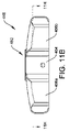
クラッチアセンブリ480は、第1のハンドル446をドライバシャフト402に連結して回転させるように選択的に係合されるように構成され得る。したがって、クラッチアセンブリ480は、係合構成及び係合解除構成を有する。クラッチアセンブリ480は様々な構成を有し得るが、いくつかの実施形態では、クラッチアセンブリ480は、一方向軸受の形態であり得る。例えば、一実施形態では、クラッチアセンブリ480は、図11Hに示されるように、外側リング481及び内側リング482を含み得る。この図示した実施形態では、内側リング482は、連結部材452の中間部分464でもある。
図11E及び図11Fに示されるように、外側リング481は、基部部材454の第1のキャビティ460の遠位部分460a内に存在し、図11Hに示されるように、内側リング482と基部部材454の内側表面454cとの間に位置付けられる。より具体的には、外側リング481の内側表面481bは、内側リング482の外側表面482aに当接し、外側リング481の外側表面481aは、第1のキャビティ460の遠位部分460aを画定する基部部材454の内側表面454cに当接する。更に、外側リング481の外側表面481a及び基部部材454の内側表面454cは、外側リング481が基部部材454に回転不能に連結されるように、対応する六角形形状を有する。他の実施形態では、外側表面481a及び内側表面454cは、他の好適な対応する形状を有し得る。
11E and 11F,
図11E、図11F、及び図11Hに更に示されるように、内側リング482は、外側表面482aからその内側表面482bに向かって延在する切り欠き部分483を含む。切り欠き部分483は、任意の好適な形状及び寸法を有し得る。この図示した実施形態では、それぞれの切り欠き部分483は管状の形状であり、所定の角度で内側に延在して、傾斜接合面483aを形成する。更に、それぞれの切り欠き部分483は、その中に配設された係合特徴部484を含む。この図示した実施形態では、それぞれの係合特徴部484は、対応する切り欠き部分483内に存在する付勢要素486を介して外側リング481との接触を維持するボール形状要素である。それぞれの付勢要素486は様々な構成を有し得るが、それぞれの付勢要素486は、図11Hに示されるように、その対応の係合特徴部484を外向きに、外側リング481の内側表面481bと接触するように付勢する螺旋バネである。
11E, 11F, and 11H, inner ring 482 includes a
使用中、第1のハンドル446は、最終的にクラッチアセンブリ480を介してドライバシャフト402と摩擦係合するように時計方向に回転させることができ、その結果、時計方向にのみユニットとして回転して、骨スクリューを骨に打ち込むことができる。より具体的には、第1のハンドル446の時計回りの回転により、クラッチアセンブリ480のそれぞれの係合特徴部484は、摩擦によって外側リング481の方に引かれる。すなわち、第1のハンドル446の時計回りの回転によって生じる摩擦力は、それぞれの係合特徴部484をその対応の切り欠き部分483の傾斜接合面483aに沿って半径方向外側に移動させる。結果として、摩擦は、それぞれの係合特徴部484と外側リング481との間で増加し、外側リング481を駆動管448に摩擦でロックさせ、結果として第1のハンドル446をドライバシャフト402にロックさせる。このようにして、第1のハンドル446は、ユーザがそれから手を放すことなく、時計回り及び反時計回りに回転されて、ドライバシャフトを時計回りにのみ駆動し、それによって骨スクリューを骨に打ち込むことができる。更に、これは、器具400の任意の他の可聴合図と混同され得る可聴合図を出すことなく達成され得る。
In use, the
更に、クラッチアセンブリ480は、埋め込まれた骨スクリューの骨からの後退を阻止し得る。すなわち、クラッチアセンブリ480は、第1のハンドルが反時計回りに回転するときに係合解除され得る。これにより、第1のハンドル446はドライバシャフト402から分離されるため、第1のハンドルの反時計回りの回転が、ドライバシャフト402の対応する反時計回りの回転を引き起こすことはない。使用中、第1のハンドル446、延いては外側リング481が反時計回りに回転すると、外側リング481は、係合特徴部484に摩擦反力を加える。これにより、それぞれの係合特徴部484は、その対応の切り欠き部分483の傾斜接合面483aに沿って半径方向内側に移動し、それによって付勢要素486が接触して圧縮される。したがって、それぞれの係合特徴部484のこの半径方向の移動が、外側リング481とのその摩擦を低減する。それにより、結果として外側リング481、延いては第1のハンドル446は、ドライバシャフト402に対して反時計方向に自由に回転することができる。
Additionally, the
したがって、本明細書に記載されるクラッチアセンブリは、第1のハンドルが、ドライバシャフトを駆動し、それに連結された骨スクリューを骨に打ち込むために第1の方向(例えば、時計回り)に回転され、かつ第1のハンドルがドライバシャフトに対して自由に回転する第2の方向(例えば、反時計回り)に回転されることを可能にする。結果として、ユーザは、第1のハンドルとの接触を維持し、時計回り及び反時計回りに繰り返し回転して、スクリューを時計方向にのみ駆動して骨に打ち込むことができる。このようにして、クラッチアセンブリは、ユーザが、第1のハンドルから手を放さずに骨スクリューを骨に打ち込むことを可能にする。 Accordingly, the clutch assemblies described herein are such that a first handle is rotated in a first direction (eg, clockwise) to drive a driver shaft and drive a bone screw coupled thereto into bone. , and allows the first handle to be rotated in a second direction (eg, counterclockwise) that rotates freely relative to the driver shaft. As a result, the user can maintain contact with the first handle and repeatedly rotate clockwise and counterclockwise to drive the screw clockwise only to drive it into the bone. In this manner, the clutch assembly allows the user to drive the bone screw into bone without releasing the first handle.
前述したように、スクリュー挿入器具を使用して、骨スクリューアセンブリを骨に埋め込むことができる。本明細書に記載される第1のハンドルを有するスクリュー挿入器具のいずれかを操作するために、任意の好適な方法を使用することができる。例えば、スクリュー挿入器具400を操作するとき(図10A~図10B)、保持スリーブ404は、上述のように、ドライバシャフト402の遠位先端に連結された骨スクリューにネジ止めにより係合され得る。骨スクリューに連結されると、スタイレットアセンブリ450の第2のハンドル450aは、ロックアセンブリ466がロック構成にあり、第1のハンドル446が固定されている状態で回転して、スタイレット450bをドライバシャフト402に対して軸方向に並進させることができる。スタイレット450bが所望の位置にあると、スタイレット450bは骨内にドッキングされ得る。ロックアセンブリ466は、第1のハンドル446をドライバシャフト402から分離するために、そのロック構成からそのロック解除構成へと移動され得る。これは、ロックアセンブリ466の第1又は第2のトリガ要素476、478を作動させて、ロックリング468を第1の位置から第2の位置へと移動させ、それにより、ドライバシャフト402から動作可能に分離することによって達成され得る。ロックアセンブリ466がロック解除構成にあるとき、第1のハンドル446は、第2のハンドル450aが固定された状態で、第1の方向に回転して、骨スクリューを骨に打ち込むように、第1のハンドル446をドライバシャフト402に連結し、ドライバシャフト402と共に回転させ得る。この回転により、クラッチアセンブリ480の外側リング及び内側リング481、482を互いにロックさせることができる。ロックアセンブリ466がロック解除構成であるとき、第1のハンドル446は、ドライバシャフト402に対して第2の方向に回転し得る。骨スクリューが骨に所望の挿入深さまで打ち込まれると、保持スリーブ404は、上述のように骨スクリューから螺出され得る。
As previously mentioned, a screw insertion instrument may be used to implant the bone screw assembly into the bone. Any suitable method can be used to operate any of the first handle screw insertion instruments described herein. For example, when manipulating the screw insertion instrument 400 (FIGS. 10A-10B), the retaining
本明細書に開示される器具は、1回の使用の後に廃棄されるように設計することができ、又はこれらは複数回使用されるように設計することができる。しかしながらいずれの場合でも、器具を少なくとも1回使用した後で再調整して、再使用することができる。再調整は、器具を分解する工程、続いて特定の部分を洗浄又は交換する工程、及びその後の再組み立ての工程の任意の組み合わせを含むことができる。特に、器具は分解することができ、器具の任意の数の特定の部分又は部品を、任意の組み合わせで選択的に交換又は取り除くことができる。特定の部品を洗浄及び/又は交換すると、器具は、再調整設備において、又は外科的処置の直前に手術チームによって、後で使用するために再組立てすることができる。器具の再調整が、分解、洗浄/交換、及び再組み立てのための様々な技術を利用してもよいことを、当業者は理解されよう。そのような技術の使用と、それにより再調整された器具は、全て本出願の範囲内にある。 The devices disclosed herein can be designed to be discarded after a single use, or they can be designed to be used multiple times. In either case, however, the device can be reconditioned and reused after at least one use. Reconditioning can include any combination of the steps of disassembly of the instrument, followed by cleaning or replacement of particular parts, and subsequent reassembly. In particular, the device can be disassembled and any number of specific parts or parts of the device can be selectively replaced or removed in any combination. Upon cleaning and/or replacement of particular parts, the instrument can be reassembled for later use either at a reconditioning facility or by a surgical team immediately prior to a surgical procedure. Those skilled in the art will appreciate that reconditioning of the instrument may utilize a variety of techniques for disassembly, cleaning/replacement, and reassembly. Use of such techniques, and instruments reconditioned thereby, are all within the scope of the present application.
更に、本開示においては、実施形態の同様の名称の構成要素は概して同様の特徴を有するものであり、したがって、特定の実施形態において、同様の名称の各構成要素の各特徴については必ずしも完全に詳しく述べることはしない。追加的に、開示されるシステム、装置、及び方法の説明で直線寸法又は円寸法が使用される範囲において、かかる寸法は、かかるシステム、装置、及び方法と組み合わせて使用することができる形状の種類を限定しようとするものではない。当業者には、任意の幾何学的形状についてかかる直線寸法及び円寸法に相当する寸法を容易に決定することができる点が認識されるであろう。システム及び装置、並びにその構成要素のサイズ及び形状は、少なくとも、システム及び装置が内部で使用される対象の解剖学的構造、システム及び装置が使用される構成要素のサイズ及び形状、並びにシステム及び装置が使用される方法及び処置に依存し得る。 Moreover, in the present disclosure, like-named components of the embodiments generally have like features, and thus in a particular embodiment, each feature of each like-named component is not necessarily fully described. I won't go into detail. Additionally, to the extent that linear or circular dimensions are used in describing disclosed systems, devices, and methods, such dimensions refer to the types of shapes that can be used in conjunction with such systems, devices, and methods. is not intended to limit Those skilled in the art will recognize that dimensions that correspond to such linear and circular dimensions can be readily determined for any geometric shape. The size and shape of the system and device, and components thereof, are at least the anatomical structure within which the system and device are used, the size and shape of the component in which the system and device are used, and the size and shape of the system and device. may depend on the method and procedure used.
「近位」及び「遠位」という用語は、本明細書では、器具のハンドルを握っている臨床医などのユーザを基準として使用されることが認識されるであろう。「前方」及び「後方」といった他の空間的用語は、同様に、遠位及び近位にそれぞれ対応する。便宜上、また説明を明確にするため、本明細書では「垂直」及び「水平」などの空間的用語が、図面に対して使用されている点も更に理解されるであろう。しかしながら、外科用器具は、多くの向き及び位置で使用されるものであり、これらの空間的用語は、限定的かつ絶対的なものであることを意図するものではない。 It will be appreciated that the terms "proximal" and "distal" are used herein with reference to the user, such as the clinician, holding the handle of the instrument. Other spatial terms such as "anterior" and "posterior" similarly correspond to distal and proximal respectively. It will also be appreciated that for convenience and clarity of description, spatial terms such as "vertical" and "horizontal" are used herein with respect to the drawings. However, surgical instruments are used in many orientations and positions, and these spatial terms are not intended to be limiting or absolute.
値又は範囲は、本明細書では、「約」及び/又は「約」1つの特定の値から別の特定の値までとして表すことができる。そのように値又は範囲が表される場合、開示される他の実施形態は、列挙された特定の値、及び/又は1つの特定の値から別の特定の値までを含む。同様に、先行する「約」の使用によって値が近似の形式で表現された場合、開示される多くの値が列挙され、その特定値により別の実施形態が形成されることが理解されるであろう。開示される多くの値が存在し、各値は、本明細書においては、その特定の値自体に加えて「約」が付く値として開示されることも更に理解されるであろう。一部の実施形態では、「約」は、例えば、列挙された値の10%以内、列挙された値の5%以内、又は列挙された値の2%以内を意味するために使用され得る。 Values or ranges can be expressed herein as "about" and/or "about" one particular value to another particular value. When such a value or range is expressed, another disclosed embodiment includes the specific value recited and/or from the one particular value to the other particular value. Similarly, when a value is expressed in approximation by the use of the antecedent "about," it is understood that many of the values disclosed are recited and that the particular value forms another embodiment. be. It will also be understood that there are a number of values disclosed and each value is disclosed herein as being "about" in addition to the specific value itself. In some embodiments, "about" can be used to mean, for example, within 10% of the recited value, within 5% of the recited value, or within 2% of the recited value.
本教示を説明及び定義する目的で、別途記載のない限り、用語「実質的に」は、本明細書では、任意の定量的な比較、値、測定、又は他の表現に起因し得る固有の不確実性の程度を表すために利用されることに留意されたい。用語「実質的に」はまた、本明細書では、定量的表現が、問題の対象物の基本的機能の変化をもたらすことなく、記述された基準から変化し得る程度を表すためにも利用される。 For the purposes of describing and defining the present teachings, unless stated otherwise, the term "substantially" herein is used herein to attribute any quantitative comparison, value, measurement, or other expression to an inherent Note that it is used to express the degree of uncertainty. The term "substantially" is also utilized herein to denote the degree to which a quantitative expression can vary from a stated baseline without resulting in a change in the underlying function of the subject matter in question. be.
当業者には、上で説明される実施形態に基づいて本発明の更なる特徴及び利点が認識されよう。したがって、本発明は、添付の特許請求の範囲によって示される場合を除き、具体的に示され説明された内容により限定されるものではない。本明細書に引用される全ての刊行物及び文献は、それらの全容を本明細書に明示的に援用する。参照によって全体又は一部が本明細書に組み込まれるとされる任意の特許、公開又は情報は、組み込まれる資料は、この文書に記載されている既存の定義、記述、又は他の開示資料と矛盾しない程度にのみ、本明細書に組み込まれる。したがって、本明細書に明確に示した開示内容は、本明細書に援用されるいかなる矛盾する文献にも優先するものとする。 Those skilled in the art will appreciate further features and advantages of the present invention based on the embodiments described above. Accordingly, the invention is not to be limited by what has been particularly shown and described, except as indicated by the appended claims. All publications and documents cited herein are expressly incorporated herein in their entirety. Any patents, publications or information herein incorporated by reference in whole or in part shall be deemed that the incorporated material contradicts any existing definitions, statements or other disclosure material contained in this document. incorporated herein only to the extent that it does not. Accordingly, the disclosure as expressly set forth herein shall supersede any conflicting documents incorporated herein.
〔実施の態様〕
(1) スクリュー挿入器具であって、
骨スクリューを骨に打ち込むために、前記骨スクリューに係合するように構成された遠位先端を有するドライバシャフトと、
前記ドライバシャフトの周りに配設され、前記骨スクリューにネジ止めにより連結するように構成された遠位端を有する保持スリーブと、
前記保持スリーブの周囲に配設されたロックスリーブであって、前記ロックスリーブは、前記ロックスリーブが固定されている状態で、前記ドライバシャフトの回転が前記保持スリーブの対応する回転を引き起こす、第1の位置と、前記ドライバシャフトが固定されている状態で、前記ロックスリーブの回転が前記保持スリーブの対応する回転を引き起こす、第2の位置と、を有する、ロックスリーブと、を備える、スクリュー挿入器具。
(2) 前記保持スリーブ及び前記ドライバシャフトは、前記骨スクリューを前記骨に打ち込むために、前記ロックスリーブが前記第1の位置にあるときに、前記ロックスリーブに対して第1の方向に一緒に回転する、実施態様1に記載のスクリュー挿入器具。
(3) 前記保持スリーブ及び前記ロックスリーブは、前記保持スリーブを前記骨スクリューから螺出させるために、前記ロックスリーブが前記第2の位置にあるときに、前記ドライバシャフトに対して第2の方向に一緒に回転する、実施態様2に記載のスクリュー挿入器具。
(4) 前記ロックスリーブは、前記保持スリーブに対して軸方向に並進及び回転して、前記第1の位置から前記第2の位置へと移動するように構成されている、実施態様1~3のいずれかに記載のスクリュー挿入器具。
(5) 前記保持スリーブに対する前記ロックスリーブの回転により、前記ロックスリーブに連結された少なくとも1つのロックピンが、前記保持スリーブにネジ止めにより係合される、実施態様2に従属する場合の、実施態様2、3、又は4に記載のスクリュー挿入器具。
[Mode of implementation]
(1) A screw insertion instrument comprising:
a driver shaft having a distal tip configured to engage the bone screw to drive the bone screw into bone;
a retaining sleeve disposed about the driver shaft and having a distal end configured for threaded connection to the bone screw;
A locking sleeve disposed about the retaining sleeve, the locking sleeve being configured such that, with the locking sleeve fixed, rotation of the driver shaft causes corresponding rotation of the retaining sleeve. and a second position in which, with the driver shaft fixed, rotation of the locking sleeve causes corresponding rotation of the retaining sleeve. .
(2) the retaining sleeve and the driver shaft together in a first direction relative to the locking sleeve when the locking sleeve is in the first position for driving the bone screw into the bone; 2. The screw insertion instrument of claim 1, which rotates.
(3) the retaining sleeve and the locking sleeve are oriented in a second orientation relative to the driver shaft when the locking sleeve is in the second position to unscrew the retaining sleeve from the bone screw; 3. The screw insertion instrument of embodiment 2, wherein the screw insertion instrument rotates together.
Embodiments 1-3, wherein the locking sleeve is configured to axially translate and rotate relative to the retaining sleeve to move from the first position to the second position. The screw insertion instrument according to any one of .
(5) An implementation when dependent on Clause 2, wherein rotation of the locking sleeve relative to the retaining sleeve causes at least one locking pin coupled to the locking sleeve to be screwed into engagement with the retaining sleeve. The screw insertion instrument of
(6) 前記保持スリーブの周囲に部分的に配設され、前記保持スリーブの前記遠位端から遠位に延在する停止スリーブを更に備え、前記停止スリーブは、前記骨スクリューの一部分の骨への挿入深さを制限するように構成されている、実施態様1~5のいずれかに記載のスクリュー挿入器具。
(7) 前記停止スリーブは、絶縁材料及び放射線不透過性材料のうちの少なくとも1つを含む、実施態様6に記載のスクリュー挿入器具。
(8) 前記保持スリーブを前記ドライバシャフトに選択的に連結する解放ボタンを更に備え、前記解放ボタンは、前記ドライバシャフトを遠位方向に付勢する接合面で前記ドライバシャフトに係合する、実施態様1~7のいずれかに記載のスクリュー挿入器具。
(9) スクリュー挿入器具であって、
ドライバシャフトが連結されたハンドルを含むスクリュー駆動アセンブリであって、前記ドライバシャフトは、骨スクリューを骨に打ち込むために前記骨スクリューに連結するように構成された遠位先端を有する、スクリュー駆動アセンブリと、
前記スクリュー駆動アセンブリの周囲に少なくとも部分的に配設され、前記骨スクリューにネジ止めにより連結するように構成された遠位端を有する保持スリーブと、前記保持スリーブに解放可能に連結されたロックスリーブと、を含む、スリーブアセンブリであって、前記スリーブアセンブリは、前記ロックスリーブが固定されている状態で、前記スクリュー駆動アセンブリの回転が前記保持スリーブの対応する回転を引き起こす第1の構成と、前記スクリュー駆動アセンブリが固定されている状態で、前記ロックスリーブの回転が前記保持スリーブの対応する回転を引き起こす第2の構成と、を有する、スリーブアセンブリと、を備える、スクリュー挿入器具。
(10) 前記ロックスリーブは、前記ロックスリーブが固定されている状態での前記スクリュー駆動アセンブリの回転を可能にするため、及び、前記スクリュー駆動アセンブリが固定されている状態での前記ロックスリーブの回転を更に可能にするため、前記ハンドルの遠位に位置付けられている、実施態様9に記載のスクリュー挿入器具。
(6) further comprising a stop sleeve partially disposed about the retention sleeve and extending distally from the distal end of the retention sleeve, the stop sleeve extending into a portion of the bone of the bone screw; 6. A screw insertion instrument according to any preceding embodiment, configured to limit the insertion depth of the.
7. The screw insertion instrument of
(8) further comprising a release button selectively coupling the retaining sleeve to the driver shaft, the release button engaging the driver shaft at a mating surface that biases the driver shaft distally; The screw insertion instrument according to any one of aspects 1-7.
(9) A screw insertion instrument comprising:
A screw driving assembly including a handle coupled to a driver shaft, the driver shaft having a distal tip configured to couple to the bone screw for driving the bone screw into bone. ,
a retention sleeve disposed at least partially around the screw drive assembly and having a distal end configured for threaded coupling to the bone screw; and a locking sleeve releasably coupled to the retention sleeve. and wherein, with the locking sleeve fixed, rotation of the screw drive assembly causes corresponding rotation of the retaining sleeve; and a second configuration in which rotation of the locking sleeve causes corresponding rotation of the retaining sleeve while the screw drive assembly is stationary.
(10) the locking sleeve is configured to allow rotation of the screw drive assembly with the locking sleeve fixed and rotation of the locking sleeve with the screw drive assembly fixed; 10. The screw insertion instrument of embodiment 9, positioned distally of the handle to further allow for .
(11) 前記スリーブアセンブリは、前記保持スリーブと前記ロックスリーブとの間に配設された連結要素を含み、前記連結要素は、前記保持スリーブの周囲に配設されたカラーの第2の組の歯に係合する第1の組の歯を有し、それにより、前記骨スクリューを前記骨に打ち込む際に、前記保持スリーブは前記骨スクリューにネジ止めにより連結されたままとなる、実施態様9又は10のいずれかに記載のスクリュー挿入器具。
(12) 前記ロックスリーブは、前記保持スリーブの周囲に配設されている、実施態様9~11のいずれかに記載のスクリュー挿入器具。
(13) 前記ロックスリーブは、前記スリーブアセンブリが前記第1の構成から前記第2の構成に移動されるとき、近位に移動し、前記保持スリーブに対して回転するように構成されている、実施態様12に記載のスクリュー挿入器具。
(14) 前記スリーブアセンブリは、前記ロックスリーブから前記保持スリーブに向かって半径方向内側に延在する少なくとも1つのロックピンを含み、前記少なくとも1つのロックピンは、軸方向に並進し、前記保持スリーブのネジ付き部分を通って回転するように構成されている、実施態様9~13のいずれかに記載のスクリュー挿入器具。
(15) 前記スリーブアセンブリを前記スクリュー駆動アセンブリに選択的に連結する連結機構を更に備え、前記連結機構は、前記ドライバシャフトを遠位方向に付勢する角度付き接合面で前記ドライバシャフトに係合する解放ボタンを含む、実施態様9~14のいずれかに記載のスクリュー挿入器具。
(11) The sleeve assembly includes a connecting element disposed between the retaining sleeve and the locking sleeve, the connecting element connecting a second set of collars disposed about the retaining sleeve. Embodiment 9, having a first set of teeth engaging teeth whereby said retaining sleeve remains threadably connected to said bone screw as said bone screw is driven into said bone. 11. The screw insertion instrument according to any one of 10.
(12) The screw insertion instrument according to any one of aspects 9 to 11, wherein the locking sleeve is arranged around the retaining sleeve.
(13) the locking sleeve is configured to move proximally and rotate relative to the retaining sleeve when the sleeve assembly is moved from the first configuration to the second configuration; 13. The screw insertion instrument according to embodiment 12.
(14) said sleeve assembly includes at least one locking pin extending radially inwardly from said locking sleeve toward said retaining sleeve, said at least one locking pin axially translating to said retaining sleeve; 14. A screw insertion instrument according to any of embodiments 9-13, configured to rotate through a threaded portion of the screw insertion instrument.
(15) further comprising a coupling mechanism selectively coupling the sleeve assembly to the screw drive assembly, the coupling mechanism engaging the driver shaft at an angled interface that biases the driver shaft distally; 15. A screw insertion instrument according to any of embodiments 9-14, comprising a release button for
(16) 骨スクリューを埋め込むための方法であって、
挿入器具上の保持スリーブを前記器具上のドライバシャフトに対して回転させて、前記保持スリーブを前記ドライバシャフトの遠位先端に連結された骨スクリューにネジ止めにより係合させることと、
前記挿入器具上のロックスリーブを固定した状態で、前記ドライバシャフト上のハンドルを第1の方向に回転させて、前記骨スクリューを骨に打ち込むことであって、前記保持スリーブは前記ドライバシャフトと一緒に回転する、ことと、
前記ロックスリーブを前記保持スリーブに対して第1の位置から第2の位置へと移動させ、前記第2の位置において、前記ドライバシャフトを固定した状態で前記ロックスリーブを回転させて、前記保持スリーブを回転させて前記骨スクリューとのネジ止めによる係合を解除させることと、を含む、方法。
(17) 前記ロックスリーブを移動させることは、前記ロックスリーブを近位方向に並進させることと、前記ロックスリーブを前記保持スリーブに対して回転させて、前記ロックスリーブを前記保持スリーブに選択的にロックすることと、を含む、実施態様16に記載の方法。
(18) 前記保持スリーブを回転させて、前記骨スクリューにネジ止めにより係合させることは、前記ドライバシャフトを固定したまま、前記ロックスリーブを前記第1の方向に回転させて、前記保持スリーブの対応する回転を引き起こし、前記保持スリーブを前記骨スクリューにネジ止めにより係合させることを含む、実施態様16又は17のいずれかに記載の方法。
(16) A method for implanting a bone screw, comprising:
rotating a retention sleeve on an insertion instrument relative to a driver shaft on the instrument to threadably engage the retention sleeve with a bone screw coupled to the distal tip of the driver shaft;
Rotating a handle on the driver shaft in a first direction while locking a locking sleeve on the insertion tool to drive the bone screw into bone, the retaining sleeve cooperating with the driver shaft. and
moving the locking sleeve relative to the retaining sleeve from a first position to a second position, in the second position rotating the locking sleeve with the driver shaft fixed to move the retaining sleeve; out of threaded engagement with the bone screw.
(17) moving the locking sleeve includes proximally translating the locking sleeve and rotating the locking sleeve relative to the retention sleeve to selectively move the locking sleeve to the retention sleeve; 17. The method of embodiment 16, comprising locking.
(18) Rotating the retaining sleeve into threaded engagement with the bone screw rotates the locking sleeve in the first direction while the driver shaft is fixed to rotate the retaining sleeve. 18. A method according to any of embodiments 16 or 17, comprising causing corresponding rotation to threadably engage the retaining sleeve to the bone screw.
Claims (15)
骨スクリューを骨に打ち込むために、前記骨スクリューに係合するように構成された遠位先端を有するドライバシャフトと、
前記ドライバシャフトの周りに配設され、前記骨スクリューにネジ止めにより連結するように構成された遠位端を有する保持スリーブと、
前記保持スリーブの周囲に配設されたロックスリーブであって、前記ロックスリーブは、前記ロックスリーブが固定されている状態で、前記ドライバシャフトの回転が前記保持スリーブの対応する回転を引き起こす、第1の位置と、前記ドライバシャフトが固定されている状態で、前記ロックスリーブの回転が前記保持スリーブの対応する回転を引き起こす、第2の位置と、を有する、ロックスリーブと、を備える、スクリュー挿入器具。 A screw insertion instrument,
a driver shaft having a distal tip configured to engage the bone screw to drive the bone screw into bone;
a retaining sleeve disposed about the driver shaft and having a distal end configured for threaded connection to the bone screw;
A locking sleeve disposed about the retaining sleeve, the locking sleeve being configured such that, with the locking sleeve fixed, rotation of the driver shaft causes corresponding rotation of the retaining sleeve. and a second position in which, with the driver shaft fixed, rotation of the locking sleeve causes corresponding rotation of the retaining sleeve. .
ドライバシャフトが連結されたハンドルを含むスクリュー駆動アセンブリであって、前記ドライバシャフトは、骨スクリューを骨に打ち込むために前記骨スクリューに連結するように構成された遠位先端を有する、スクリュー駆動アセンブリと、
前記スクリュー駆動アセンブリの周囲に少なくとも部分的に配設され、前記骨スクリューにネジ止めにより連結するように構成された遠位端を有する保持スリーブと、前記保持スリーブに解放可能に連結されたロックスリーブと、を含む、スリーブアセンブリであって、前記スリーブアセンブリは、前記ロックスリーブが固定されている状態で、前記スクリュー駆動アセンブリの回転が前記保持スリーブの対応する回転を引き起こす第1の構成と、前記スクリュー駆動アセンブリが固定されている状態で、前記ロックスリーブの回転が前記保持スリーブの対応する回転を引き起こす第2の構成と、を有する、スリーブアセンブリと、を備える、スクリュー挿入器具。 A screw insertion instrument,
A screw driving assembly including a handle coupled to a driver shaft, the driver shaft having a distal tip configured to couple to the bone screw for driving the bone screw into bone. ,
a retention sleeve disposed at least partially around the screw drive assembly and having a distal end configured for threaded coupling to the bone screw; and a locking sleeve releasably coupled to the retention sleeve. and wherein, with the locking sleeve fixed, rotation of the screw drive assembly causes corresponding rotation of the retaining sleeve; and a second configuration in which rotation of the locking sleeve causes corresponding rotation of the retaining sleeve while the screw drive assembly is stationary.
Applications Claiming Priority (3)
| Application Number | Priority Date | Filing Date | Title |
|---|---|---|---|
| US16/440,602 | 2019-06-13 | ||
| US16/440,602 US11123113B2 (en) | 2019-06-13 | 2019-06-13 | Screw inserter instruments and methods |
| PCT/EP2020/066027 WO2020249588A1 (en) | 2019-06-13 | 2020-06-10 | Screw inserter instruments |
Publications (2)
| Publication Number | Publication Date |
|---|---|
| JP2022536498A true JP2022536498A (en) | 2022-08-17 |
| JP7483759B2 JP7483759B2 (en) | 2024-05-15 |
Family
ID=71130948
Family Applications (1)
| Application Number | Title | Priority Date | Filing Date |
|---|---|---|---|
| JP2021573473A Active JP7483759B2 (en) | 2019-06-13 | 2020-06-10 | Screw insertion tool |
Country Status (6)
| Country | Link |
|---|---|
| US (1) | US11123113B2 (en) |
| EP (1) | EP3982854B1 (en) |
| JP (1) | JP7483759B2 (en) |
| CN (1) | CN113939240B (en) |
| AU (1) | AU2020292972A1 (en) |
| WO (1) | WO2020249588A1 (en) |
Families Citing this family (15)
| Publication number | Priority date | Publication date | Assignee | Title |
|---|---|---|---|---|
| US11224472B2 (en) | 2019-06-13 | 2022-01-18 | Medos International Sarl | Screw inserter instruments and methods |
| US11730529B2 (en) | 2020-03-26 | 2023-08-22 | Warsaw Orthopedic, Inc. | Powered modular head locker |
| US12004782B2 (en) | 2020-03-26 | 2024-06-11 | Warsaw Orthopedic, Inc. | Instrument for locking orthopedic screws |
| US11786278B2 (en) * | 2021-03-05 | 2023-10-17 | Seaspine, Inc. | Bone anchor insertion device and methods of use |
| US11291477B1 (en) | 2021-05-04 | 2022-04-05 | Warsaw Orthopedic, Inc. | Dorsal adjusting implant and methods of use |
| US11432848B1 (en) | 2021-05-12 | 2022-09-06 | Warsaw Orthopedic, Inc. | Top loading quick lock construct |
| US11712270B2 (en) | 2021-05-17 | 2023-08-01 | Warsaw Orthopedic, Inc. | Quick lock clamp constructs and associated methods |
| US12121268B2 (en) | 2021-07-07 | 2024-10-22 | Globus Medical, Inc. | Modular orthopedic implants, instruments, and navigation methods |
| US11957391B2 (en) | 2021-11-01 | 2024-04-16 | Warsaw Orthopedic, Inc. | Bone screw having an overmold of a shank |
| US11559338B1 (en) * | 2021-11-16 | 2023-01-24 | Warsaw Orthopedic, Inc. | Spinal implant system and method |
| US11547454B1 (en) * | 2021-11-16 | 2023-01-10 | Warsaw Orthopedic, Inc. | Spinal implant system and method |
| US11751920B2 (en) * | 2021-11-16 | 2023-09-12 | Warsaw Orthopedic, Inc. | Surgical instrument and method |
| US20240252215A1 (en) * | 2023-01-31 | 2024-08-01 | Orthofix Us Llc | Targeting and insertion instrument for orthopedic implants |
| DE102023118429A1 (en) | 2023-07-12 | 2025-01-16 | Aesculap Ag | preparation instrument for preparing a bone |
| US20250275799A1 (en) * | 2024-03-01 | 2025-09-04 | Larry McClintock | Screw Inserter |
Citations (3)
| Publication number | Priority date | Publication date | Assignee | Title |
|---|---|---|---|---|
| JP2015173984A (en) * | 2014-03-14 | 2015-10-05 | ビーダーマン・テクノロジーズ・ゲゼルシャフト・ミット・ベシュレンクテル・ハフツング・ウント・コンパニー・コマンディートゲゼルシャフトBiedermann Technologies Gmbh & Co. Kg | Instrument for holding and inserting bone anchor into bone, and system of instrument and bone anchor |
| JP2016511064A (en) * | 2013-03-14 | 2016-04-14 | デピュイ・シンセス・プロダクツ・インコーポレイテッド | Bone anchor and surgical instrument with integrated guide tip |
| WO2018013607A1 (en) * | 2016-07-13 | 2018-01-18 | Medos International Sàrl | Bone anchor assemblies and related instrumentation |
Family Cites Families (43)
| Publication number | Priority date | Publication date | Assignee | Title |
|---|---|---|---|---|
| US2512232A (en) | 1947-01-17 | 1950-06-20 | Ivan T Hart | Reversible ratchet screw driver |
| US4770071A (en) | 1986-06-24 | 1988-09-13 | Sam Steier | Tool drive mechanism |
| US5613585A (en) | 1995-05-02 | 1997-03-25 | Beere Precision Medical Instruments, Inc. | Ratcheting screwdriver |
| US6019776A (en) | 1997-10-14 | 2000-02-01 | Parallax Medical, Inc. | Precision depth guided instruments for use in vertebroplasty |
| US6981974B2 (en) | 1998-08-07 | 2006-01-03 | Berger J Lee | Cannulated internally threaded bone screw with aperatured insert |
| US6402757B1 (en) | 1999-03-12 | 2002-06-11 | Biomet, Inc. | Cannulated fastener system for repair of bone fracture |
| US7938836B2 (en) | 2003-10-23 | 2011-05-10 | Trans1, Inc. | Driver assembly for simultaneous axial delivery of spinal implants |
| US8216243B2 (en) | 2001-12-04 | 2012-07-10 | Synthes Usa, Llc | Headless compression screw with integrated reduction-compression instrument |
| US6827722B1 (en) | 2001-12-11 | 2004-12-07 | Biomet, Inc. | Method and apparatus for use of a guide wire capturing surgical instrument |
| US7338494B2 (en) | 2003-08-19 | 2008-03-04 | Synthes (U.S.A.) | Spring-loaded awl |
| US7766920B2 (en) | 2003-11-26 | 2010-08-03 | Synthes Usa, Llc | Cannulated fastener system |
| US7207995B1 (en) | 2004-01-29 | 2007-04-24 | Biomer Manufacturing Corp. | Method and apparatus for retaining a guide wire |
| US20050216027A1 (en) | 2004-03-24 | 2005-09-29 | Suh Sean S | Extraction screwdriver |
| US7604643B2 (en) | 2004-04-06 | 2009-10-20 | Synthes Usa, Llc | Adjustable tool for cannulated fasteners |
| US7488323B2 (en) | 2004-11-23 | 2009-02-10 | Biomet Sports Medicine, Llc | Method and apparatus for manipulating bone during a surgical procedure |
| US20070016219A1 (en) | 2005-07-14 | 2007-01-18 | Levine Marc J | Vertebral Marker Devices and Installation Methods |
| US7905884B2 (en) | 2006-04-27 | 2011-03-15 | Warsaw Orthopedic, Inc. | Method for use of dilating stylet and cannula |
| US7892207B2 (en) | 2006-04-27 | 2011-02-22 | Warsaw Orthopedic, Inc. | Dilating stylet and cannula |
| US8303601B2 (en) | 2006-06-07 | 2012-11-06 | Stryker Spine | Collet-activated distraction wedge inserter |
| JP5237282B2 (en) * | 2006-08-17 | 2013-07-17 | ジンテス ゲゼルシャフト ミット ベシュレンクテル ハフツング | Push-off driver and method for inserting bone screws |
| US20080147128A1 (en) | 2006-12-15 | 2008-06-19 | Zimmer Technology, Inc. | Cannulated bone screw and cannulated driver for the implantation thereof |
| ES2359477T3 (en) * | 2007-07-20 | 2011-05-24 | Synthes Gmbh | POLIAXIAL ELEMENT FOR BONE FIXATION. |
| US8236006B2 (en) | 2008-01-17 | 2012-08-07 | Life Spine, Inc. | One step entry pedicular preparation device and disc access system |
| US20090275954A1 (en) | 2008-04-30 | 2009-11-05 | Phan Christopher U | Apparatus and methods for inserting facet screws |
| US8192466B2 (en) | 2008-08-27 | 2012-06-05 | Alphatec Spine, Inc. | Conical interspinous apparatus and a method of performing interspinous distraction |
| WO2010051386A1 (en) | 2008-10-30 | 2010-05-06 | Depuy Spine, Inc. | Systems and methods for delivering bone cement to a bone anchor |
| US20100211115A1 (en) | 2008-12-24 | 2010-08-19 | Jeff Tyber | Compression screw assembly, an orthopedic fixation system including a compression screw assembly and method of use |
| US9060748B2 (en) | 2009-03-18 | 2015-06-23 | Smith & Nephew, Inc. | Soft tissue manipulator assembly |
| US8814914B2 (en) | 2009-08-28 | 2014-08-26 | Zimmer Spine, Inc. | Fusion method and pedicle access tool |
| US8394108B2 (en) * | 2010-06-18 | 2013-03-12 | Spine Wave, Inc. | Screw driver for a multiaxial bone screw |
| DE102011050996B4 (en) | 2011-06-09 | 2025-12-24 | Zbigniew Combrowski | Surgical instrument |
| EP2626019B1 (en) * | 2012-02-07 | 2016-03-23 | Advanced Orthopaedic Solutions Inc. | Telescoping bone screw |
| DE102012107056A1 (en) * | 2012-08-01 | 2014-05-15 | Aesculap Ag | Surgical instruments |
| DE202013004369U1 (en) | 2013-04-29 | 2014-07-30 | Silony Medical International AG | Screwdrivers for bone screws |
| US20150201987A1 (en) * | 2014-01-20 | 2015-07-23 | Zimmer Spine, Inc. | Quick-lock driver for a bone screw |
| US9855087B2 (en) | 2014-08-04 | 2018-01-02 | DePuy Synthes Products, LLC | Methods and devices for spinal screw insertion |
| US10285740B2 (en) | 2015-03-11 | 2019-05-14 | Warsaw Orthpedic, Inc. | Surgical instrument and method |
| US10085786B2 (en) * | 2015-04-13 | 2018-10-02 | Medos International Sàrl | Driver instruments and related methods |
| US10463402B2 (en) | 2016-07-13 | 2019-11-05 | Medos International Sàrl | Bone anchor assemblies and related instrumentation |
| US10973558B2 (en) | 2017-06-12 | 2021-04-13 | K2M, Inc. | Screw insertion instrument and methods of use |
| US10433883B2 (en) | 2017-06-27 | 2019-10-08 | Medos International Sarl | Spinal screw insertion devices and methods |
| US10779872B2 (en) | 2017-11-02 | 2020-09-22 | Medos International Sarl | Bone anchor insertion instruments and methods |
| US11224472B2 (en) | 2019-06-13 | 2022-01-18 | Medos International Sarl | Screw inserter instruments and methods |
-
2019
- 2019-06-13 US US16/440,602 patent/US11123113B2/en active Active
-
2020
- 2020-06-10 WO PCT/EP2020/066027 patent/WO2020249588A1/en not_active Ceased
- 2020-06-10 CN CN202080043221.0A patent/CN113939240B/en active Active
- 2020-06-10 AU AU2020292972A patent/AU2020292972A1/en active Pending
- 2020-06-10 JP JP2021573473A patent/JP7483759B2/en active Active
- 2020-06-10 EP EP20734326.0A patent/EP3982854B1/en active Active
Patent Citations (3)
| Publication number | Priority date | Publication date | Assignee | Title |
|---|---|---|---|---|
| JP2016511064A (en) * | 2013-03-14 | 2016-04-14 | デピュイ・シンセス・プロダクツ・インコーポレイテッド | Bone anchor and surgical instrument with integrated guide tip |
| JP2015173984A (en) * | 2014-03-14 | 2015-10-05 | ビーダーマン・テクノロジーズ・ゲゼルシャフト・ミット・ベシュレンクテル・ハフツング・ウント・コンパニー・コマンディートゲゼルシャフトBiedermann Technologies Gmbh & Co. Kg | Instrument for holding and inserting bone anchor into bone, and system of instrument and bone anchor |
| WO2018013607A1 (en) * | 2016-07-13 | 2018-01-18 | Medos International Sàrl | Bone anchor assemblies and related instrumentation |
Also Published As
| Publication number | Publication date |
|---|---|
| CN113939240A (en) | 2022-01-14 |
| EP3982854B1 (en) | 2025-10-15 |
| CN113939240B (en) | 2025-09-23 |
| US20200390478A1 (en) | 2020-12-17 |
| WO2020249588A1 (en) | 2020-12-17 |
| EP3982854A1 (en) | 2022-04-20 |
| US11123113B2 (en) | 2021-09-21 |
| AU2020292972A1 (en) | 2022-02-10 |
| JP7483759B2 (en) | 2024-05-15 |
Similar Documents
| Publication | Publication Date | Title |
|---|---|---|
| JP7483759B2 (en) | Screw insertion tool | |
| JP7497376B2 (en) | Screw insertion device and method | |
| AU2018358323B2 (en) | Bone anchor insertion instruments and methods | |
| US11937857B2 (en) | Bone anchors and surgical instruments with integrated guide tips | |
| US11337736B2 (en) | Driver instruments and related methods | |
| US7621916B2 (en) | Cervical bone preparation tool and implant guide systems | |
| US8123785B2 (en) | Minimally invasive spinal stabilization system | |
| US20070043378A1 (en) | Instrument for inserting, adjusting and removing a surgical implant | |
| US20250221743A1 (en) | Pedicle screw stabilization systems and instruments |
Legal Events
| Date | Code | Title | Description |
|---|---|---|---|
| A621 | Written request for application examination |
Free format text: JAPANESE INTERMEDIATE CODE: A621 Effective date: 20230420 |
|
| A977 | Report on retrieval |
Free format text: JAPANESE INTERMEDIATE CODE: A971007 Effective date: 20231221 |
|
| A131 | Notification of reasons for refusal |
Free format text: JAPANESE INTERMEDIATE CODE: A131 Effective date: 20231226 |
|
| A521 | Request for written amendment filed |
Free format text: JAPANESE INTERMEDIATE CODE: A523 Effective date: 20240313 |
|
| TRDD | Decision of grant or rejection written | ||
| A01 | Written decision to grant a patent or to grant a registration (utility model) |
Free format text: JAPANESE INTERMEDIATE CODE: A01 Effective date: 20240402 |
|
| A61 | First payment of annual fees (during grant procedure) |
Free format text: JAPANESE INTERMEDIATE CODE: A61 Effective date: 20240501 |
|
| R150 | Certificate of patent or registration of utility model |
Ref document number: 7483759 Country of ref document: JP Free format text: JAPANESE INTERMEDIATE CODE: R150 |