JP2022527042A - Health monitoring system and method - Google Patents
Health monitoring system and method Download PDFInfo
- Publication number
- JP2022527042A JP2022527042A JP2021543312A JP2021543312A JP2022527042A JP 2022527042 A JP2022527042 A JP 2022527042A JP 2021543312 A JP2021543312 A JP 2021543312A JP 2021543312 A JP2021543312 A JP 2021543312A JP 2022527042 A JP2022527042 A JP 2022527042A
- Authority
- JP
- Japan
- Prior art keywords
- signal
- red
- adhesive
- sensor
- sensors
- Prior art date
- Legal status (The legal status is an assumption and is not a legal conclusion. Google has not performed a legal analysis and makes no representation as to the accuracy of the status listed.)
- Pending
Links
- 238000000034 method Methods 0.000 title claims abstract description 167
- 238000012544 monitoring process Methods 0.000 title claims abstract description 49
- 230000036541 health Effects 0.000 title claims abstract description 43
- 230000001070 adhesive effect Effects 0.000 claims description 132
- 239000000853 adhesive Substances 0.000 claims description 130
- 239000010410 layer Substances 0.000 claims description 97
- 238000002106 pulse oximetry Methods 0.000 claims description 62
- 230000033001 locomotion Effects 0.000 claims description 57
- QVGXLLKOCUKJST-UHFFFAOYSA-N atomic oxygen Chemical compound [O] QVGXLLKOCUKJST-UHFFFAOYSA-N 0.000 claims description 52
- 229910052760 oxygen Inorganic materials 0.000 claims description 52
- 239000001301 oxygen Substances 0.000 claims description 52
- 239000000463 material Substances 0.000 claims description 51
- 239000000758 substrate Substances 0.000 claims description 50
- 230000005540 biological transmission Effects 0.000 claims description 44
- 230000007774 longterm Effects 0.000 claims description 32
- 238000004891 communication Methods 0.000 claims description 29
- 229920001296 polysiloxane Polymers 0.000 claims description 27
- 238000005259 measurement Methods 0.000 claims description 24
- 230000003287 optical effect Effects 0.000 claims description 24
- 230000004888 barrier function Effects 0.000 claims description 23
- 230000000694 effects Effects 0.000 claims description 19
- 239000002131 composite material Substances 0.000 claims description 17
- 238000012417 linear regression Methods 0.000 claims description 17
- 239000008280 blood Substances 0.000 claims description 16
- 210000004369 blood Anatomy 0.000 claims description 16
- 230000000241 respiratory effect Effects 0.000 claims description 16
- 230000029058 respiratory gaseous exchange Effects 0.000 claims description 16
- 230000000875 corresponding effect Effects 0.000 claims description 13
- 238000001914 filtration Methods 0.000 claims description 13
- 238000012806 monitoring device Methods 0.000 claims description 13
- 238000012935 Averaging Methods 0.000 claims description 11
- 230000006870 function Effects 0.000 claims description 11
- 238000012545 processing Methods 0.000 claims description 11
- 210000001061 forehead Anatomy 0.000 claims description 9
- 230000036387 respiratory rate Effects 0.000 claims description 9
- 239000012790 adhesive layer Substances 0.000 claims description 8
- 238000005070 sampling Methods 0.000 claims description 8
- 230000001133 acceleration Effects 0.000 claims description 7
- 230000002596 correlated effect Effects 0.000 claims description 7
- 229920002529 medical grade silicone Polymers 0.000 claims description 7
- 230000000737 periodic effect Effects 0.000 claims description 7
- CURLTUGMZLYLDI-UHFFFAOYSA-N Carbon dioxide Chemical compound O=C=O CURLTUGMZLYLDI-UHFFFAOYSA-N 0.000 claims description 6
- 230000008569 process Effects 0.000 claims description 6
- 238000005452 bending Methods 0.000 claims description 5
- 239000004593 Epoxy Substances 0.000 claims description 4
- 108010054147 Hemoglobins Proteins 0.000 claims description 4
- 102000001554 Hemoglobins Human genes 0.000 claims description 4
- 239000004033 plastic Substances 0.000 claims description 4
- 239000003566 sealing material Substances 0.000 claims description 4
- 230000005236 sound signal Effects 0.000 claims description 4
- 229910002092 carbon dioxide Inorganic materials 0.000 claims description 3
- 239000001569 carbon dioxide Substances 0.000 claims description 3
- 230000003993 interaction Effects 0.000 claims description 3
- 238000002310 reflectometry Methods 0.000 claims description 3
- 230000003321 amplification Effects 0.000 claims description 2
- 230000003139 buffering effect Effects 0.000 claims description 2
- 238000003199 nucleic acid amplification method Methods 0.000 claims description 2
- 238000002496 oximetry Methods 0.000 claims description 2
- 238000006213 oxygenation reaction Methods 0.000 claims description 2
- 230000002093 peripheral effect Effects 0.000 claims description 2
- 239000003990 capacitor Substances 0.000 claims 8
- 230000002452 interceptive effect Effects 0.000 claims 2
- 239000003292 glue Substances 0.000 claims 1
- 239000004615 ingredient Substances 0.000 claims 1
- 239000002184 metal Substances 0.000 claims 1
- 238000004804 winding Methods 0.000 claims 1
- 238000010586 diagram Methods 0.000 abstract description 2
- 238000004458 analytical method Methods 0.000 description 25
- 210000000038 chest Anatomy 0.000 description 23
- 238000003860 storage Methods 0.000 description 20
- 230000015654 memory Effects 0.000 description 19
- 208000009729 Ventricular Premature Complexes Diseases 0.000 description 10
- 206010003119 arrhythmia Diseases 0.000 description 10
- 239000003086 colorant Substances 0.000 description 10
- 239000000017 hydrogel Substances 0.000 description 10
- 230000006793 arrhythmia Effects 0.000 description 9
- 238000002565 electrocardiography Methods 0.000 description 9
- 239000004606 Fillers/Extenders Substances 0.000 description 8
- 230000008901 benefit Effects 0.000 description 8
- 230000036760 body temperature Effects 0.000 description 8
- 238000012546 transfer Methods 0.000 description 8
- XLYOFNOQVPJJNP-UHFFFAOYSA-N water Substances O XLYOFNOQVPJJNP-UHFFFAOYSA-N 0.000 description 8
- 238000004422 calculation algorithm Methods 0.000 description 6
- 230000005855 radiation Effects 0.000 description 6
- 239000013464 silicone adhesive Substances 0.000 description 6
- 238000012360 testing method Methods 0.000 description 6
- 206010003671 Atrioventricular Block Diseases 0.000 description 5
- BQCADISMDOOEFD-UHFFFAOYSA-N Silver Chemical compound [Ag] BQCADISMDOOEFD-UHFFFAOYSA-N 0.000 description 5
- 238000001514 detection method Methods 0.000 description 5
- 238000005538 encapsulation Methods 0.000 description 5
- 239000000499 gel Substances 0.000 description 5
- 230000006872 improvement Effects 0.000 description 5
- 230000037081 physical activity Effects 0.000 description 5
- 230000004044 response Effects 0.000 description 5
- 230000033764 rhythmic process Effects 0.000 description 5
- 229910052709 silver Inorganic materials 0.000 description 5
- 239000004332 silver Substances 0.000 description 5
- 210000001519 tissue Anatomy 0.000 description 5
- XAGFODPZIPBFFR-UHFFFAOYSA-N aluminium Chemical compound [Al] XAGFODPZIPBFFR-UHFFFAOYSA-N 0.000 description 4
- 229910052782 aluminium Inorganic materials 0.000 description 4
- 230000000747 cardiac effect Effects 0.000 description 4
- 239000000084 colloidal system Substances 0.000 description 4
- 239000004020 conductor Substances 0.000 description 4
- 238000007405 data analysis Methods 0.000 description 4
- 238000013500 data storage Methods 0.000 description 4
- 230000007423 decrease Effects 0.000 description 4
- 238000005516 engineering process Methods 0.000 description 4
- 230000000541 pulsatile effect Effects 0.000 description 4
- 230000009467 reduction Effects 0.000 description 4
- 206010003658 Atrial Fibrillation Diseases 0.000 description 3
- 206010003662 Atrial flutter Diseases 0.000 description 3
- 229910021607 Silver chloride Inorganic materials 0.000 description 3
- 230000009471 action Effects 0.000 description 3
- 230000036772 blood pressure Effects 0.000 description 3
- 230000008859 change Effects 0.000 description 3
- 238000006243 chemical reaction Methods 0.000 description 3
- 230000008878 coupling Effects 0.000 description 3
- 238000010168 coupling process Methods 0.000 description 3
- 238000005859 coupling reaction Methods 0.000 description 3
- 239000008393 encapsulating agent Substances 0.000 description 3
- 238000009413 insulation Methods 0.000 description 3
- 238000004519 manufacturing process Methods 0.000 description 3
- 238000012986 modification Methods 0.000 description 3
- 230000004048 modification Effects 0.000 description 3
- 229920001451 polypropylene glycol Polymers 0.000 description 3
- 230000001681 protective effect Effects 0.000 description 3
- 238000000926 separation method Methods 0.000 description 3
- HKZLPVFGJNLROG-UHFFFAOYSA-M silver monochloride Chemical compound [Cl-].[Ag+] HKZLPVFGJNLROG-UHFFFAOYSA-M 0.000 description 3
- 210000004243 sweat Anatomy 0.000 description 3
- 230000001960 triggered effect Effects 0.000 description 3
- 230000002861 ventricular Effects 0.000 description 3
- 239000011800 void material Substances 0.000 description 3
- RYGMFSIKBFXOCR-UHFFFAOYSA-N Copper Chemical compound [Cu] RYGMFSIKBFXOCR-UHFFFAOYSA-N 0.000 description 2
- LFQSCWFLJHTTHZ-UHFFFAOYSA-N Ethanol Chemical compound CCO LFQSCWFLJHTTHZ-UHFFFAOYSA-N 0.000 description 2
- 208000007888 Sinus Tachycardia Diseases 0.000 description 2
- 206010040741 Sinus bradycardia Diseases 0.000 description 2
- 206010047289 Ventricular extrasystoles Diseases 0.000 description 2
- 230000005856 abnormality Effects 0.000 description 2
- 230000002547 anomalous effect Effects 0.000 description 2
- 210000000988 bone and bone Anatomy 0.000 description 2
- 238000004364 calculation method Methods 0.000 description 2
- 239000003795 chemical substances by application Substances 0.000 description 2
- 229910052802 copper Inorganic materials 0.000 description 2
- 239000010949 copper Substances 0.000 description 2
- 238000013461 design Methods 0.000 description 2
- 238000011161 development Methods 0.000 description 2
- 230000018109 developmental process Effects 0.000 description 2
- 238000003745 diagnosis Methods 0.000 description 2
- 239000006185 dispersion Substances 0.000 description 2
- 230000005611 electricity Effects 0.000 description 2
- 230000002708 enhancing effect Effects 0.000 description 2
- 238000002847 impedance measurement Methods 0.000 description 2
- 230000013011 mating Effects 0.000 description 2
- 238000001615 p wave Methods 0.000 description 2
- 238000004382 potting Methods 0.000 description 2
- 229920006395 saturated elastomer Polymers 0.000 description 2
- 238000001228 spectrum Methods 0.000 description 2
- 230000003068 static effect Effects 0.000 description 2
- 210000001562 sternum Anatomy 0.000 description 2
- 206010047302 ventricular tachycardia Diseases 0.000 description 2
- 230000002747 voluntary effect Effects 0.000 description 2
- 238000004078 waterproofing Methods 0.000 description 2
- INGWEZCOABYORO-UHFFFAOYSA-N 2-(furan-2-yl)-7-methyl-1h-1,8-naphthyridin-4-one Chemical compound N=1C2=NC(C)=CC=C2C(O)=CC=1C1=CC=CO1 INGWEZCOABYORO-UHFFFAOYSA-N 0.000 description 1
- 208000001193 Accelerated Idioventricular Rhythm Diseases 0.000 description 1
- 208000000884 Airway Obstruction Diseases 0.000 description 1
- 241000473391 Archosargus rhomboidalis Species 0.000 description 1
- 208000002102 Atrial Premature Complexes Diseases 0.000 description 1
- 206010008589 Choking Diseases 0.000 description 1
- 208000002330 Congenital Heart Defects Diseases 0.000 description 1
- 241000218691 Cupressaceae Species 0.000 description 1
- 208000019693 Lung disease Diseases 0.000 description 1
- 241000289581 Macropus sp. Species 0.000 description 1
- 208000008589 Obesity Diseases 0.000 description 1
- 108010064719 Oxyhemoglobins Proteins 0.000 description 1
- 206010036590 Premature baby Diseases 0.000 description 1
- 208000037656 Respiratory Sounds Diseases 0.000 description 1
- 208000003734 Supraventricular Tachycardia Diseases 0.000 description 1
- 206010042602 Supraventricular extrasystoles Diseases 0.000 description 1
- 206010047281 Ventricular arrhythmia Diseases 0.000 description 1
- 206010047924 Wheezing Diseases 0.000 description 1
- 238000010521 absorption reaction Methods 0.000 description 1
- 230000005534 acoustic noise Effects 0.000 description 1
- 230000004913 activation Effects 0.000 description 1
- 238000001994 activation Methods 0.000 description 1
- 239000003570 air Substances 0.000 description 1
- 239000012080 ambient air Substances 0.000 description 1
- 238000000149 argon plasma sintering Methods 0.000 description 1
- 238000003491 array Methods 0.000 description 1
- 230000002763 arrhythmic effect Effects 0.000 description 1
- 238000007630 basic procedure Methods 0.000 description 1
- 239000011324 bead Substances 0.000 description 1
- 230000017531 blood circulation Effects 0.000 description 1
- 230000037237 body shape Effects 0.000 description 1
- 238000000576 coating method Methods 0.000 description 1
- 230000000052 comparative effect Effects 0.000 description 1
- 150000001875 compounds Chemical class 0.000 description 1
- 208000012696 congenital leptin deficiency Diseases 0.000 description 1
- 238000010276 construction Methods 0.000 description 1
- 230000001276 controlling effect Effects 0.000 description 1
- 238000007796 conventional method Methods 0.000 description 1
- 238000012937 correction Methods 0.000 description 1
- 238000013480 data collection Methods 0.000 description 1
- 230000006837 decompression Effects 0.000 description 1
- 230000003111 delayed effect Effects 0.000 description 1
- 230000001419 dependent effect Effects 0.000 description 1
- 230000035617 depilation Effects 0.000 description 1
- 238000009795 derivation Methods 0.000 description 1
- 230000006866 deterioration Effects 0.000 description 1
- 230000009977 dual effect Effects 0.000 description 1
- 229920001971 elastomer Polymers 0.000 description 1
- 230000008030 elimination Effects 0.000 description 1
- 238000003379 elimination reaction Methods 0.000 description 1
- 238000011156 evaluation Methods 0.000 description 1
- 238000000605 extraction Methods 0.000 description 1
- 239000000835 fiber Substances 0.000 description 1
- 238000010304 firing Methods 0.000 description 1
- 238000007667 floating Methods 0.000 description 1
- 239000012530 fluid Substances 0.000 description 1
- 210000004907 gland Anatomy 0.000 description 1
- 238000009499 grossing Methods 0.000 description 1
- 230000005831 heart abnormality Effects 0.000 description 1
- 208000019622 heart disease Diseases 0.000 description 1
- 238000009532 heart rate measurement Methods 0.000 description 1
- 230000006698 induction Effects 0.000 description 1
- 230000000977 initiatory effect Effects 0.000 description 1
- 230000031700 light absorption Effects 0.000 description 1
- 230000004298 light response Effects 0.000 description 1
- 238000011068 loading method Methods 0.000 description 1
- 238000012423 maintenance Methods 0.000 description 1
- 238000007726 management method Methods 0.000 description 1
- 239000012528 membrane Substances 0.000 description 1
- 239000002991 molded plastic Substances 0.000 description 1
- 208000001022 morbid obesity Diseases 0.000 description 1
- 210000003205 muscle Anatomy 0.000 description 1
- 230000003387 muscular Effects 0.000 description 1
- 239000012811 non-conductive material Substances 0.000 description 1
- 238000001441 oximetry spectrum Methods 0.000 description 1
- 239000003973 paint Substances 0.000 description 1
- 206010033675 panniculitis Diseases 0.000 description 1
- 230000035515 penetration Effects 0.000 description 1
- 230000001443 photoexcitation Effects 0.000 description 1
- 230000035479 physiological effects, processes and functions Effects 0.000 description 1
- 239000011241 protective layer Substances 0.000 description 1
- 230000011514 reflex Effects 0.000 description 1
- 238000005096 rolling process Methods 0.000 description 1
- 150000003839 salts Chemical class 0.000 description 1
- 239000004065 semiconductor Substances 0.000 description 1
- 201000002859 sleep apnea Diseases 0.000 description 1
- 229910000679 solder Inorganic materials 0.000 description 1
- 239000007787 solid Substances 0.000 description 1
- 125000006850 spacer group Chemical group 0.000 description 1
- 238000007920 subcutaneous administration Methods 0.000 description 1
- 210000004304 subcutaneous tissue Anatomy 0.000 description 1
- 230000002459 sustained effect Effects 0.000 description 1
- 230000002123 temporal effect Effects 0.000 description 1
- 239000010409 thin film Substances 0.000 description 1
- 230000007704 transition Effects 0.000 description 1
- 210000003462 vein Anatomy 0.000 description 1
- 230000037303 wrinkles Effects 0.000 description 1
Images


Classifications
-
- A—HUMAN NECESSITIES
- A61—MEDICAL OR VETERINARY SCIENCE; HYGIENE
- A61B—DIAGNOSIS; SURGERY; IDENTIFICATION
- A61B5/00—Measuring for diagnostic purposes; Identification of persons
- A61B5/68—Arrangements of detecting, measuring or recording means, e.g. sensors, in relation to patient
- A61B5/6801—Arrangements of detecting, measuring or recording means, e.g. sensors, in relation to patient specially adapted to be attached to or worn on the body surface
- A61B5/683—Means for maintaining contact with the body
- A61B5/6832—Means for maintaining contact with the body using adhesives
- A61B5/6833—Adhesive patches
-
- A—HUMAN NECESSITIES
- A61—MEDICAL OR VETERINARY SCIENCE; HYGIENE
- A61B—DIAGNOSIS; SURGERY; IDENTIFICATION
- A61B5/00—Measuring for diagnostic purposes; Identification of persons
- A61B5/0002—Remote monitoring of patients using telemetry, e.g. transmission of vital signals via a communication network
-
- A—HUMAN NECESSITIES
- A61—MEDICAL OR VETERINARY SCIENCE; HYGIENE
- A61B—DIAGNOSIS; SURGERY; IDENTIFICATION
- A61B5/00—Measuring for diagnostic purposes; Identification of persons
- A61B5/02—Detecting, measuring or recording pulse, heart rate, blood pressure or blood flow; Combined pulse/heart-rate/blood pressure determination; Evaluating a cardiovascular condition not otherwise provided for, e.g. using combinations of techniques provided for in this group with electrocardiography or electroauscultation; Heart catheters for measuring blood pressure
- A61B5/0205—Simultaneously evaluating both cardiovascular conditions and different types of body conditions, e.g. heart and respiratory condition
-
- A—HUMAN NECESSITIES
- A61—MEDICAL OR VETERINARY SCIENCE; HYGIENE
- A61B—DIAGNOSIS; SURGERY; IDENTIFICATION
- A61B5/00—Measuring for diagnostic purposes; Identification of persons
- A61B5/72—Signal processing specially adapted for physiological signals or for diagnostic purposes
- A61B5/7271—Specific aspects of physiological measurement analysis
- A61B5/7278—Artificial waveform generation or derivation, e.g. synthesising signals from measured signals
-
- A—HUMAN NECESSITIES
- A61—MEDICAL OR VETERINARY SCIENCE; HYGIENE
- A61B—DIAGNOSIS; SURGERY; IDENTIFICATION
- A61B7/00—Instruments for auscultation
- A61B7/02—Stethoscopes
- A61B7/04—Electric stethoscopes
-
- A—HUMAN NECESSITIES
- A61—MEDICAL OR VETERINARY SCIENCE; HYGIENE
- A61B—DIAGNOSIS; SURGERY; IDENTIFICATION
- A61B2560/00—Constructional details of operational features of apparatus; Accessories for medical measuring apparatus
- A61B2560/04—Constructional details of apparatus
- A61B2560/0406—Constructional details of apparatus specially shaped apparatus housings
- A61B2560/0412—Low-profile patch shaped housings
-
- A—HUMAN NECESSITIES
- A61—MEDICAL OR VETERINARY SCIENCE; HYGIENE
- A61B—DIAGNOSIS; SURGERY; IDENTIFICATION
- A61B2562/00—Details of sensors; Constructional details of sensor housings or probes; Accessories for sensors
- A61B2562/02—Details of sensors specially adapted for in-vivo measurements
- A61B2562/0204—Acoustic sensors
-
- A—HUMAN NECESSITIES
- A61—MEDICAL OR VETERINARY SCIENCE; HYGIENE
- A61B—DIAGNOSIS; SURGERY; IDENTIFICATION
- A61B2562/00—Details of sensors; Constructional details of sensor housings or probes; Accessories for sensors
- A61B2562/16—Details of sensor housings or probes; Details of structural supports for sensors
- A61B2562/164—Details of sensor housings or probes; Details of structural supports for sensors the sensor is mounted in or on a conformable substrate or carrier
-
- A—HUMAN NECESSITIES
- A61—MEDICAL OR VETERINARY SCIENCE; HYGIENE
- A61B—DIAGNOSIS; SURGERY; IDENTIFICATION
- A61B2562/00—Details of sensors; Constructional details of sensor housings or probes; Accessories for sensors
- A61B2562/22—Arrangements of medical sensors with cables or leads; Connectors or couplings specifically adapted for medical sensors
- A61B2562/225—Connectors or couplings
-
- A—HUMAN NECESSITIES
- A61—MEDICAL OR VETERINARY SCIENCE; HYGIENE
- A61B—DIAGNOSIS; SURGERY; IDENTIFICATION
- A61B5/00—Measuring for diagnostic purposes; Identification of persons
- A61B5/0002—Remote monitoring of patients using telemetry, e.g. transmission of vital signals via a communication network
- A61B5/0004—Remote monitoring of patients using telemetry, e.g. transmission of vital signals via a communication network characterised by the type of physiological signal transmitted
- A61B5/0006—ECG or EEG signals
-
- A—HUMAN NECESSITIES
- A61—MEDICAL OR VETERINARY SCIENCE; HYGIENE
- A61B—DIAGNOSIS; SURGERY; IDENTIFICATION
- A61B5/00—Measuring for diagnostic purposes; Identification of persons
- A61B5/08—Detecting, measuring or recording devices for evaluating the respiratory organs
- A61B5/0816—Measuring devices for examining respiratory frequency
-
- A—HUMAN NECESSITIES
- A61—MEDICAL OR VETERINARY SCIENCE; HYGIENE
- A61B—DIAGNOSIS; SURGERY; IDENTIFICATION
- A61B5/00—Measuring for diagnostic purposes; Identification of persons
- A61B5/08—Detecting, measuring or recording devices for evaluating the respiratory organs
- A61B5/083—Measuring rate of metabolism by using breath test, e.g. measuring rate of oxygen consumption
- A61B5/0833—Measuring rate of oxygen consumption
-
- A—HUMAN NECESSITIES
- A61—MEDICAL OR VETERINARY SCIENCE; HYGIENE
- A61B—DIAGNOSIS; SURGERY; IDENTIFICATION
- A61B7/00—Instruments for auscultation
- A61B7/003—Detecting lung or respiration noise
-
- A—HUMAN NECESSITIES
- A61—MEDICAL OR VETERINARY SCIENCE; HYGIENE
- A61B—DIAGNOSIS; SURGERY; IDENTIFICATION
- A61B7/00—Instruments for auscultation
- A61B7/02—Stethoscopes
- A61B7/026—Stethoscopes comprising more than one sound collector
Abstract
健康信号を受信する及び/又は健康モニタリングのための少なくとも1つの電極及び/又はセンサを有するモニタリングシステム、方法、及び/又はデバイスを含む、健康モニタリングにおけるノイズを低減するためのシステム、方法、及びデバイス。【選択図】図1DSystems, methods, and devices for reducing noise in health monitoring, including monitoring systems, methods, and / or devices that receive health signals and / or have at least one electrode and / or sensor for health monitoring. .. [Selection diagram] FIG. 1D
Description
ソフトウェア、電子機器、センサ技術、及び材料科学の進歩は、患者モニタリング技術に革命をもたらした。特に、多くのデバイス及びシステムが様々な健康モニタリング用途で利用できるようになっている。しかしながら、パラメータ決定のための効果的なデータ収集及び/又は操作のうちの1つ又は複数を提供する健康モニタリングデバイス及びシステムにはまだ改善が望まれる場合がある。 Advances in software, electronics, sensor technology, and materials science have revolutionized patient monitoring technology. In particular, many devices and systems have become available for a variety of health monitoring applications. However, improvements may still be desired in health monitoring devices and systems that provide one or more of effective data acquisition and / or manipulation for parameter determination.
そこで、場合によっては短期又は長期のデータを収集及び転送する及び/又はイベントをリアルタイムでモニタリングすることができる、場合によっては多変数パラメータの決定を含み得る、堅牢で便利なモニタリングを含むように、患者及びその医師のためのさらなる代替が開発され得る。 So, to include robust and convenient monitoring, where short-term or long-term data can be collected and transferred and / or events can be monitored in real time, and in some cases can include determination of multivariable parameters. Further alternatives for patients and their physicians may be developed.
本明細書で説明されるのは、場合によっては新生児、乳児、母親/親、アスリート、又は患者などの1人以上の個人の心臓及び/又は呼吸及び/又は温度及び/又は音声データの長期の感知及び/又は記録のためのパラメータ決定のためのいくつかの代替的な医療モニタリングデバイス、システム、及び/又は方法である。いくつかの代替的な実装及び用途が、本明細書の下で及び本明細書の全体を通して要約及び/又は例示される。 Described herein are long-term cardiac and / or respiratory and / or temperature and / or audio data of one or more individuals such as newborns, infants, mothers / parents, athletes, or patients. Several alternative medical monitoring devices, systems, and / or methods for parameter determination for sensing and / or recording. Several alternative implementations and uses are summarized and / or exemplified below and throughout the specification.
1つの代替的な態様では、本発明は、健康デバイスが、限定はされないが、心電図(ECG)のイオンポテンシャルの変化を測定するための電極、及び/又は光学ベースの酸素飽和度測定のための場合によってはLEDとフォトダイオードのペアを含む1つ以上の光源と1つ以上の光検出器、及び/又は1つ以上の温度センサ、及び/又は移動及び労作測定のための1つ以上のxyz加速度計、及び/又は1つ以上の音声又は音響ピックアップ又はセンサ又はマイクロフォンなどのうちの様々な1つ又は複数を含む1つ以上のセンサによって収集された時間的に一致する(time-concordant)測定値からの1人以上の個人の1つ以上の生理学的パラメータをモニタリングするように構成される実装を含み得る。一部の実装では、本発明の方法及びデバイスは、呼吸波形を生成するのに用いられ得る。他の実装は、個人に便利に接着する又は接着機能をもつ小さなフットプリントのデバイスにおけるコモンモードノイズの低減を可能にし得るDRL(driven right-leg)回路(本明細書では「代理DRL回路」と呼ばれることもある)を模擬する回路を含み得る。 In one alternative embodiment, the invention is for a health device, but not limited to, an electrode for measuring changes in the ionic potential of an electrocardiogram (ECG), and / or for an optical-based oxygen saturation measurement. One or more light sources and one or more light detectors, optionally including a pair of LEDs and photodiodes, and / or one or more temperature sensors, and / or one or more xyz for movement and exertion measurements. Time-concordant measurements collected by an accelerometer and / or one or more sensors including one or more various voice or acoustic pickups or sensors or microphones and the like. It may include an implementation configured to monitor one or more physiological parameters of one or more individuals from the values. In some implementations, the methods and devices of the invention can be used to generate respiratory waveforms. Other implementations are DRL (driven right-leg) circuits (referred to herein as "surrogate DRL circuits") that may allow reduction of common mode noise in devices with small footprints that are conveniently bonded or have a bonding function to the individual. It may include a circuit that mimics (sometimes called).
本発明の別の代替的な態様では、血圧の決定は、場合によっては脈波伝達時間の決定からなされ得る。脈波伝達時間は、心臓の圧力波が心臓から体内の他の場所に伝わるまでの時間である。次いで、脈波伝達時間の測定値を使用して血圧を推定することができる。脈波伝達時間を生成するために、ECGなどからの心拍タイミングとフォトプレチスモグラム(別名、PPG)信号を用いることができる。このような信号は、従来の又は他の開発予定のプロセス及び/又はデバイス又はシステムから生成され得る、又は、このような信号は、以下にも説明するような1つ以上のウェアラブル健康モニタリングデバイスから取得され得ることに留意されたい。 In another alternative aspect of the invention, the determination of blood pressure can optionally be made from the determination of pulse wave transmission time. The pulse wave transmission time is the time it takes for the pressure wave of the heart to travel from the heart to other parts of the body. Blood pressure can then be estimated using measurements of pulse wave transmission time. Heart rate timings and photoplethysmogram (also known as PPG) signals from ECG and the like can be used to generate pulse wave transmission times. Such signals may be generated from conventional or other processes and / or devices or systems to be developed, or such signals may be from one or more wearable health monitoring devices as described below. Note that it can be obtained.
別の代替的な態様では、本発明は、場合によっては、時間的に一致するパルスオキシメトリ信号及びECG信号から酸素飽和度パラメータを測定及び/又は決定するための1つ以上の方法及び/又はデバイスを含み得る。一部の実装では、ECG信号を使用して、そこから酸素飽和度の値が決定され得るパルスオキシメトリ信号の定数成分及び主要な周期的成分(例えば、DC及びAC成分)を決定するために収集及び平均される、パルスオキシメトリデータの間隔又は「フレーム」を定義することができる。パルスオキシメトリセンサ及びECGセンサを備えたこのような実装の患者ウェアラブルデバイスは、このような信号取得のために患者の胸に配置されたときに特に有用であり得る。 In another alternative embodiment, the invention is, in some cases, one or more methods and / or one or more methods for measuring and / or determining oxygen saturation parameters from time-matched pulse oximetry and ECG signals. May include devices. In some implementations, the ECG signal is used to determine the constant and major periodic components (eg, DC and AC components) of the pulsed oximetry signal from which the oxygen saturation value can be determined. It is possible to define the intervals or "frames" of pulsed oximetry data to be collected and averaged. Patient wearable devices with such implementations equipped with pulse oximetry sensors and ECG sensors can be particularly useful when placed on the patient's chest for such signal acquisition.
これらの並びに他の代替的な及び/又はさらなる態様は、いくつかの図示された代替的な及び/又はさらなる実装及び用途で例示され、それらのいくつかは、図面に示され、以下の特許請求の範囲で特徴付けられる。しかしながら、当業者によって理解されるように、上記の概要及び以下の詳細な説明は、本発明の全範囲を説明するものではなく、実際、本発明の各例示された実施形態又はすべての可能な実装を説明することを意図するものではなく、本明細書の以下に記載の特許請求の範囲又は保護の範囲を限定するものでもない。 These as well as other alternative and / or additional embodiments are exemplified in some of the illustrated alternative and / or additional implementations and uses, some of which are shown in the drawings and claimed below. Characterized by the range of. However, as will be appreciated by those skilled in the art, the above outline and the following detailed description do not illustrate the entire scope of the invention and, in fact, each exemplified embodiment of the invention or all possible embodiments. It is not intended to illustrate the implementation and is not intended to limit the claims or scope of protection described below herein.
本発明は様々な修正及び代替的な形態が可能であるが、本発明の詳細は、図面及び以下の説明において限定ではない例として本明細書に示されている。しかしながら、その意図は、本発明を説明された特定の実施形態に限定することではないことを理解されたい。その意図は、本明細書に記載されているか又は本明細書の文字通りの言葉又は図面を超えている場合であっても本明細書に含まれているかのように十分に理解できる本発明の精神及び範囲内にあるすべての修正、均等物、及び代替を包含することである。 Although various modifications and alternative forms of the invention are possible, details of the invention are set forth herein as, but not limited to, examples in the drawings and the following description. However, it should be understood that the intent is not limited to the particular embodiment described of the present invention. That intent is the spirit of the invention that is fully understandable as if it were contained herein, even if it is described herein or beyond the literal words or drawings of the specification. And to include all modifications, equivalents, and alternatives within scope.
一般に、本発明に含まれるのは、オンボディの多機能のバイオメトリックセンサである。これらのデバイスは、他の可能なオプションの中でも、ECG、PPG、体温、呼吸、及び活動のうちの1つ又は複数又はすべてなどの身体機能をモニタリングする。このようなデバイスは、多くの場合、接着剤、しばしば使い捨ての接着剤で、被検者の胸骨に又はその上に又はそれに隣接して又はその近くに或いは被検者の胸に動作可能に取り付けるように構成され得る。このようなデバイスは、通常、多くの場合、これに限定されないが、ユーザに対して小型で薄く(例えば、およそ±1.5インチ×3インチ×1/4インチ又はおよそ30mm×100mm×6.3mmのオーダーであり、実際のサイズはこれに限定されないが、とりわけ、他の特徴の中でも、体のサイズ及び実際のコンポーネントの利用可能性に依存し得る)、通常、乳児から病的肥満までの幅広い被検者によって装着可能であるように構成され得る。 Generally included in the present invention are on-body multifunctional biometric sensors. These devices monitor physical function such as one or more of ECG, PPG, body temperature, respiration, and activity, among other possible options. Such devices are often adhesives, often disposable adhesives, that are operably attached to or on or adjacent to or near the subject's sternum or to the subject's chest. Can be configured as Such devices are usually, but are not limited to, small and thin to the user (eg, approximately ± 1.5 inches x 3 inches x 1/4 inch or approximately 30 mm x 100 mm x 6. It is on the order of 3 mm and the actual size is not limited to this, but among other features, it may depend on the size of the body and the availability of actual components), usually from infants to morbid obesity. It can be configured to be wearable by a wide range of subjects.
一態様では、本発明のシステムは、心電図(別名、ECG又はEKG)、フォトプレチスモグラム(別名、PPG)、パルスオキシメトリ、体温、及び/又は患者の加速又は移動信号、及び/又は例えば心拍音などの音声又は音信号のうちの1つ又は複数又はすべてなどの生理学的パラメータをモニタリングするためのデバイスを含み得る。 In one aspect, the systems of the invention are electrocardiograms (also known as ECG or EKG), photoplethysmograms (also known as PPG), pulse oximetry, body temperature, and / or patient acceleration or movement signals, and / or eg. It may include a device for monitoring physiological parameters such as one or more or all of voices or sound signals such as heartbeats.
さらに、本発明のシステムは、以下の要素のうちのいずれか1つ又は複数を用いる又は含む患者のこのような信号を測定及び/又は処理するために確立され得る:(a)上面及び底面を有する平坦な弾性基板又は基板内に又は上に組み込まれたフレキシブル又はフレックス回路基板内又は上にある又はそれを形成するフレキシブルであり得る回路、この回路は、(i)平坦な弾性基板の底面内又は上に又はこれに隣接してマウントされた少なくとも1つのセンサのうちの1つ又は複数を有し、この少なくとも1つのセンサは、患者との電気又は光通信が可能である。一部の実装では、回路は、(ii)少なくとも1つのセンサからの信号を受信する及び/又は受け取るための、一部の実装ではこのような信号を患者データとして記憶するべく変換するための少なくとも1つの信号処理モジュール、及び/又は(iii)患者データを受信及び/又は受け取り、記憶するための少なくとも1つのメモリモジュール、及び/又は(iv)外部デバイスに記憶された又は他の方法での患者データを転送するための少なくとも1つのデータ通信モジュール、及び/又は(v)少なくとも1つのデータ通信モジュールによる患者データの転送を実施する及び少なくとも1つのメモリモジュールから患者データを消去する及び/又はワイプするコマンドを受信することができる、少なくとも1つのセンサと、少なくとも1つの信号処理モジュール、少なくとも1つのメモリモジュール、少なくとも1つのデータ通信モジュール、及び/又は制御モジュールのうちの1つ又は複数のタイミング及び動作を制御するための制御モジュールを含み得る。一部の実装では、本発明のシステムは、(b)平坦な弾性基板の底面に取り外し可能に取り付けられる導電性接着剤を含むことができ、導電性接着剤は、患者又は他のユーザの皮膚に接着することができ、一部の限定ではない例では、本発明のシステムは、実質的に平坦な弾性基板の底面に垂直な方向にのみ電気信号を伝導することができ、及び/又は一部の実装では、1つ以上のセンサに隣接する導電性部分と非導電性部分を含み得る。一部の実装では、導電性接着剤は、実質的に皮膚に垂直な方向にのみ電流を伝導する(すなわち「z軸」伝導)材料の領域を備えるという点で、異方性の導電性接着剤である。 In addition, the system of the invention may be established to measure and / or process such signals of the patient using or containing any one or more of the following elements: (a) top and bottom. A flexible or flex circuit board built into or on a flat elastic substrate or a circuit that may be flexible on or on or to form a flexible circuit substrate, the circuit having (i) in the bottom surface of the flat elastic substrate. Or having one or more of at least one sensor mounted on or adjacent to it, the at least one sensor being capable of electrical or optical communication with the patient. In some implementations, the circuit (ii) at least to receive and / or receive signals from at least one sensor, and in some implementations to convert such signals to be stored as patient data. One signal processing module and / or at least one memory module for receiving and / or receiving and storing patient data, and / or (iv) the patient stored in an external device or otherwise. Perform transfer of patient data by at least one data communication module for transferring data and / or (v) at least one data communication module and erase and / or wipe patient data from at least one memory module. Timing and operation of at least one sensor and at least one signal processing module, at least one memory module, at least one data communication module, and / or control module capable of receiving commands. May include a control module for controlling. In some implementations, the system of the invention may include (b) a conductive adhesive that is removable and attached to the bottom surface of a flat elastic substrate, where the conductive adhesive is the skin of the patient or other user. In some, but not limited to, systems of the invention can conduct electrical signals only in a direction perpendicular to the bottom surface of a substantially flat elastic substrate and / or one. The mounting of the portion may include conductive and non-conductive portions adjacent to one or more sensors. In some implementations, the conductive adhesive is anisotropic in that it comprises a region of material that conducts current only in a direction substantially perpendicular to the skin (ie, "z-axis" conduction). It is an agent.
一部の実装では、本発明のデバイスは、とりわけ、包括的な長期の心臓モニタリング用である。そのような特徴は、必ずしもそうとは限らないが、リード1 ECG、PPG、パルスオキシメータ、加速度計、温度センサ、及び/又は手動の患者イベントマーキングのためのボタン又は他のインジケータのうちのいずれか1つ又は複数を含み得る。このようなデバイスは、例えば、最大約2週間の連続データを記憶するように適合させることができ(しかし、代替的な実装ではより多く又は少なく実行可能である)、このデータは、一部の実装において、無線又は一例ではUSB又は他の許容できるデータ接続による有線であるかどうかにかかわらずコンピュータ接続を介して短時間で、一例としてわずか約90秒で(しかし、代替的な実装ではより多くの又は少ない時間で実行可能である)クリニック又は他のコンピュータにダウンロードされ得る。コンパニオンソフトウェアデータ分析パッケージは、自動化されたイベントの取り込みを提供する及び/又は即時の又は遅延したローカルデータ解釈を可能にするように適合され得る。 In some implementations, the devices of the invention are, among other things, for comprehensive long-term cardiac monitoring. Such features, but not necessarily, are either lead 1 ECG, PPG, pulse oximeters, accelerometers, temperature sensors, and / or buttons or other indicators for manual patient event marking. May include one or more. Such devices can be adapted, for example, to store continuous data for up to about 2 weeks (although more or less can be performed in alternative implementations), and this data is part of the data. In an implementation, in a short time over a computer connection, whether wired or wired via USB or other acceptable data connection in one example, in just about 90 seconds as an example (but more in alternative implementations). Can be downloaded to a clinic or other computer (which can be done in less time). Companion software data analysis packages may be adapted to provide automated event capture and / or to allow immediate or delayed local data interpretation.
断続的な心臓の異常は、通常、患者の身体検査中に発生しなければ、医師が検出及び/又は診断するのは難しい場合が多い。本発明のデバイスは、一部の実装では1つ又はいくつかのバイタルサインの連続的又は実質的に連続的なモニタリングであり得るものでこの問題に対処することができる。 Intermittent heart abnormalities are usually difficult for physicians to detect and / or diagnose unless they occur during a patient's physical examination. The device of the present invention can address this issue by being able to continuously or substantially continuously monitor one or several vital signs in some implementations.
いくつかの代替的な特徴は、(i)電極が胸部にのみ配置された「DRL」回路、及び/又は(ii)電極と電極の真下の患者の皮膚との間の電気通信のみを可能にし得る「z軸」又は異方性の導電性接着剤電極インターフェース、及び/又は(iii)CCU/ICU人員がアクセスできるローカルコンピュータへのデータ送信及びローカルコンピュータによるデータ解釈、及び/又は(iv)診断を支援するために時間的に一致する複数のデータソースの相関を可能にし得るハードウェアの独自の組み合わせ、のうちの1つ又は複数を含むがこれらに限定されない。 Some alternative features allow only (i) "DRL" circuits where the electrodes are located only on the chest and / or (ii) telecommunications between the electrodes and the patient's skin beneath the electrodes. Obtaining "z-axis" or anisotropic conductive adhesive electrode interfaces and / or (iii) data transmission to and / or (iv) diagnostics to and / or (iii) CCU / ICU personnel accessible local computers. A unique combination of hardware that may allow correlation of multiple data sources that are time-matched to assist in, but is not limited to.
いくつかの代替的な限定ではない実装では、本発明のデバイス及びシステムは、1)約10~15人の患者のテストでデバイスのコストを回収することを可能にし得る再利用性(場合によっては約1000人の患者に近いか又はそれ以上)、及び/又は2)ECG波形データ、慣性運動感知、手動のイベントマーキング、体温感知、及び/又はパルスオキシメトリのうちの1つ又は複数、これらのいずれか1つ又はすべては不整脈イベントをより良好に検出及び分析するために時間的に一致する、及び/又は3)効率的な水密性又は防水性(患者/装着者がデバイスを装着しながら泳ぐことができるようにするための)、及び/又は4)通常は即時のローカルデータ解釈のための包括的な分析パッケージを提供し得る。代替的なデバイスは、フレックス回路技術を利用して、患者/装着者の移動中に患者の皮膚に適合し、それと共に移動するために、軽量の、薄い、耐久性のある、フレキシブルなデバイスを提供するように適合され得る。 In some alternative, non-limiting implementations, the devices and systems of the invention are 1) reusability (possibly) that can allow the cost of the device to be reclaimed in tests of approximately 10-15 patients. Close to or more than about 1000 patients) and / or 2) ECG waveform data, inertial motion sensing, manual event marking, body temperature sensing, and / or one or more of these. Any one or all are time-matched to better detect and analyze arrhythmic events, and / or 3) Efficient watertightness or waterproofness (patient / wearer swims while wearing the device) (To be able to) and / or 4) can provide a comprehensive analytical package, usually for immediate local data interpretation. Alternative devices utilize flex circuit technology to provide lightweight, thin, durable, flexible devices to fit and move with the patient's skin during patient / wearer movement. Can be adapted to provide.
図1及び図2(それぞれのサブパートの図面によって定義される)は、そのように適合され得るデバイスの代替的な実装の例を示している。 1 and 2 (defined by the drawings of the respective subparts) show examples of alternative implementations of devices that may be so adapted.
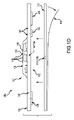
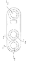
サブパートの図1A~図1Wによって定義され、それらのすべてを含む図1は、コンポーネント側又は上側101と、患者側又は回路側102と、参照符号103で概して識別される1つ以上の内側電気層と、細長いストリップ層105とを有するデバイス100を示す。ストリップ層105は、その上及び/又はその中に電子機器を有し得る。図1Aは、いくつかの限定ではない実装において、本発明で用いられ得るいくつかの他の要素と共に実質的に透明なデバイスと考えられ得るものでこれらを等尺で示す。より具体的には、図1Bは上側101の平面図、図1Cは下側の患者側102の平面図、及び図1Dは第1の立面側面図である。
FIG. 1, which is defined by FIGS. 1A-1W of the subparts and includes all of them, is one or more inner electrical layers generally identified by component side or
本発明の随意的な電子機器の多くは、1つ以上の電子機器層103に配置することができ、ここで概して示すように、電子機器は、それらを細長いストリップ層105上の又は内の動作位置に固定する又は細長いストリップ層105に対して他の方法で機能的に配置するために、材料104、医療グレードのシリコーン、プラスチックなど、又はポッティング材料内にカプセル化され得る(いくつかの例については図1A、図1B、図1D、及び図1S参照、及び、例えばさらに後述する図1T2、図1U、図1U1、及び図1U2参照)。ポッティング材料又は他の材料はまた又は代替的に、多くの実装において、水又は汗の中の使用環境でも電子機器を動作させ続けるためにそれらの防水性又は水密性又は耐水性の被覆を提供し得る。1つ以上のアクセスポイント、接合部、又は他の機能ユニット106が、その中又は下に配置された電子機器への外部アクセス及び/又は通信のために、カプセル化材料104のいずれかの側部上に及び/又はそれを通して設けられ得る。図1A、図1B、及び図1Dは、上側に4つのこのようなアクセス部106を示している。これらは、とりわけ、高Zデータ通信ポート及び/又は充電接点を含み得る。このデバイス100の上側又はコンポーネント側101は、いくつかの例では、例えば1つ以上のポート106を介したデータ通信又は転送のために及び/又は充電のために、HS USBコネクタのみが露出された状態で、保護及び/又は防水のためにシリコーン化合物でコーティングされ得る。
Many of the optional electronic devices of the present invention can be placed on one or more electronic device layers 103, and as generally shown here, the electronic devices operate them on or within the
細長いストリップ層105は、電子機器103とさらに後述する導電性パッド又は接点108、109、及び110(108及び109は、いくつかの例では、心電計、ECG、及び110のための高インピーダンス/高Z銀又は銅/銀電極は、時には参照電極である)との通信のための電気リード線又は他の内側層導体、例えば、図1Dに示されたリード107などの回路又は回路部分であり得る又はこれを含み得る。多くの実装において、ストリップ層105は、許容できる変形、ねじれ、屈曲などを提供し、それでもその中の堅牢な電気回路接続を保持すると理解される、フレックス回路であり得る又はこれを含み得る。電子機器103及び電極108、109、110は、層105に、電子機器103の場合は上部に、電極108、109、110の場合は下部又は患者側に取り付けられて示されているが、このような要素は、実際には、層105内に形成され得る又は他の方法で配置され得る、又は少なくとも、層105と共に、層105上に、又は層105に隣接する1つ以上の層の相対的な動作位置に比較的区別なく配置され得ることに留意されたい。同様に、リード又はトレース107は(図1Dの破線表現によって)埋め込まれて示されているが、これらは上側又は下側にあってもよく、しかしより好ましくは、上側は他の皮膚側の電気通信から絶縁される。最初に上側(又は下側)の場合、トレースはその後、絶縁性封止材料又は同様の保護カバー(個別に示されていない)、及び/又は多くの実装では、層105の全体又は大部分のフレキシブルな代替を維持するためにフレキシブルな材料で覆われ得る。
The
本明細書で説明される機能の多くには、高度な電子機器が好ましい場合があり、実際、多くの実装は、それぞれのデバイス上の多数の機能及び/又はその組み合わせを含む場合があり、多くの場合、同じことを達成するために高度な電子機器が必要とされる場合もある。フレキシブル回路基板(別名、FCB)及び/又はフレキシブルプリント回路(別名、FPC)は、電子部品を装着すると非常に剛性が高くなることがあり、複数のコンポーネントを追加するだけでフレキシブル回路基板でさえも比較的剛性が高くなる。より大きな集積回路(IC)のはんだ付けされた接続は、多くの場合、信頼性が低いか、又はフレキシブル基板の一定の或いは顕著な撓みの下で信頼性が低いはんだ付けとなることがある。多機能のウェアラブルなバイオメトリックモニタを製造する際のこれらの可撓性及び信頼性の問題に対処するために図1E~図1Nの代替的な実装、設計、及び方法が用いられ得る。 For many of the features described herein, advanced electronic devices may be preferred, and in fact, many implementations may include multiple features and / or combinations thereof on each device, and many. In some cases, sophisticated electronic devices may be required to achieve the same. Flexible circuit boards (also known as FCBs) and / or flexible printed circuits (also known as FPCs) can become very rigid when equipped with electronic components, even flexible circuit boards with the addition of multiple components. The rigidity is relatively high. Soldered connections of larger integrated circuits (ICs) can often be unreliable or unreliable under constant or significant deflection of the flexible substrate. Alternative implementations, designs, and methods of FIGS. 1E-1N may be used to address these flexibility and reliability issues in the manufacture of multifunctional wearable biometric monitors.
図1A~図1Dの実装(とりわけ、以下にも示され説明される)では、すべての回路がフレキシブル回路基板105に比較的直接に取り付けられて示されており、現在のフレキシブル基板ではおそらくあまり好ましくないが依然として実行可能な選択肢である。しかしながら、いくつかの代替では、被検者に面するFPCを図1A~図1Dの基板105よりも比較的可撓性にするために、大きなIC及び他のコンポーネントのすべてではないにしても多くを、それにもかかわらずフレキシブル回路基板に動作可能に接続することができる別の比較的剛性の高いプリント回路基板(別名、PCB)に再配置することができる。これらは、図1E~図1Nのデバイス500及び500aで示されている。
In the implementations of FIGS. 1A-1D (particularly also shown and described below), all circuits are shown mounted relatively directly on the
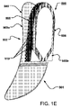
より具体的には、サブパートの図1E~図1Nは、コンポーネント側又は上側501と、患者側又は回路側502と、参照符号503で概して識別される1つ以上の電気層とをそれぞれ有するデバイス500又は代替的なデバイス500aを示す。また、その中に細長いストリップ層又は回路層505も配置される。回路層505は、その上及び/又はその中に電子機器を有することができ、例えばさらに後述するコンポーネント519を参照されたい。図1E及び図1Fは、いくつかの限定ではない実装において、本発明で用いられ得るいくつかの他の要素と共に実質的に透明又は半透明のデバイスとして示され得るものでこれらを等尺で示す。図1E及び図1Fは、著しく撓んで示されている、ここでは被検者ユーザ(ユーザ又は装着者1000は図1Fで概して識別される)で使用されているのでアーチ状に示されているフレキシブル又はフレックス回路層である第1の層503aの上に概して存在する2つ以上の層を示す。第2の又は中間回路層505は、ここでは、その上に、それに、及び/又はその中に接続された電気接続及び/又は回路コンポーネントをより容易に維持するためにアーク状又はアーチ状又は他の様態に撓むことを意図されていない比較的剛性の材料基板である。ここでは同じくフレキシブル層である随意的な第3の層503bも、ここでは回路層505の上に示されており、第3の層503bは、ここでは1つ以上のデータ通信デバイス506を介して、ここではアンテナ506を介して、データ通信機能を有する。
More specifically, FIGS. 1E-1N of the subparts are
デバイス500及び500aのそれぞれのバージョンの断面図がそれぞれの図1G及び図1H及び図1Iに示されている。これらはまた、上側又は外側501と、患者側502と、その中に細長いストリップ層又は回路層505を概して含む参照符号503で概して識別される1つ以上の電気層をそれぞれ有する。これらの実装では、これらの2つ以上のスタックが示されており、ここでは図のように、3つの層が積み重ねられている。接着層513が図1H及び図1Iに同様に示されているが、後述する他の動作部品を単に簡単に示す/表示するために図1Gの実装では省略されている。これらのスタックされた回路層に対して側方にあるのは、バッテリ520及びバッテリコンパートメント又はケージ520aである。他の随意的な及び/又は好ましいコンポーネントは以下でさらに探求/説明する。
Sectional views of the respective versions of the
下側の被検者に面する層、ここでは層503aから多くの電気コンポーネントが除去された状態では、この層503aは極めてフレキシブルなままであり、多様な体型、サイズ及び形状、及び体の動きに適合する能力を有する。この下側層503aにはわずかなコンポーネント、通常、この実装では、実際のセンサ自体が残る。これらは、ECG電極508及び509、PPG(フォトプレチスモグラフ)デバイス/センサ511、温度センサ515、及びマイクロフォン516、例えば、ピエゾマイクロフォンである。次いで、これらのセンサによって及び/又はこれらのセンサを通じて受信された信号は、それらの間の電気通信を伴う機械的ヒンジポイントとなるように配置されたマイクロコネクタ517を通じて、「浮いている」比較的剛性のPCBである、そのすぐ上の層505に渡すことができる。一部の実装では、処理電子機器519をこの剛性のPCB505上に存在するように配置することができ、これにより、はんだの信頼性が高まり、これにより、電気通信の信頼性及び頑健性が高まり、電子及び/又は処理コンポーネント519の、PCB505に対する移動の原因がほとんどなくなる。また、ICなどの電子機器519をフレキシブル層503aから取り出すことにより、より剛性の高い層505の下に配置された被検者に面する層503a内又はそこから剛性を除去又は低減することができる。
With many electrical components removed from the lower subject-facing layer, here
一部の実装では、ここに示すように、剛性の層505の上に別のフレキシブル層503bが配置され得る。いくつかの状況では、これは、前述のヒンジポイント517に隣接して配置されたマイクロ同軸コネクタ518によって層505に接続されるアンテナ506、例えば、Bluetoothアンテナであり得る。この第3の層503bは、3つの回路基板のスタック全体をフレキシブルに保つためにフレキシブルであるように構成され得る。
In some implementations, as shown here, another
他の部品の上に配置され得る及び他の部品を収容し得る外部ハウジング530が図1H及び図1Iに示されている。これは、通常、医療グレードのしなやかな又はフレキシブルなシリコーンでできていてもよく、実質的に図のような形状を提供する成形品であり得る。このようなハウジング530のプリーツ531又は折り目又はタック又はしわも示されており、このようなプリーツは、ここではデバイスの中央の近く及び/又はフレキシブル基板503aへの剛性の基板505の接続部の近くで、屈曲運動をさらに許容する。この接続領域は、以下参照の図1Iにより詳細に示され説明されており、図1Iは、図1Hの円C1Iの周りで取られた概して図1Hの拡大近似部分である。
図1Iには、主要な基板503aが接着剤513と共に示されている。基板503aに接続されているのは、電気/データコネクタ517を介して接続された剛性の基板505である。一般的な電気コンポーネント519が基板505の両側に示されており、両側は、基板505の全体サイズ、幅、及び長さを比較的最小に保ちながら基板505の専有面積を最大限に活用するために随意的に使用可能である。これは随意的であり、一部の実装では片側のみが用いられ得る。一般的な参考のために同じく図1Iに示されているのは、とりわけ、基板503a上のセンサコンポーネント511及び515、バッテリ520、及びバッテリケージ520aである(これは図示されていない他の形態をとり得る)。第3の高さにある層503bは、アンテナ506を収容し、コネクタ518を介してPCB505に接続されるように示されている。しかしながら、図1Hで紹介したように、カバー530のプリーツ531のより詳しい図が図1Iに示されており、プリーツ531は、基板503aのより大きな撓みを可能にする。ここではまた、それぞれ基板503a及び接着剤513に形成された2つのギャップ又はヒンジ503h及び513hをよりよく見ることができ、ヒンジの各ギャップは、フレキシブルにするために配置される。単純なモデル又はビューでは、これらは、これらのポイントでの材料の欠如によって形成され得る。(本明細書で説明される実装では、接着剤は、戦略的に配置された6つの層によって形成されてもよく、相対的なギャップ/ヒンジ513hについては、6つの層のうちの1つだけ又は別の少数の層だけこのポイント513hに存在する/残ることができ、材料の削減は概念を表すことに留意されたい。)ギャップ及び接着剤は、図1Gに示された代替的な実装には図示していないことに留意されたい。
In FIG. 1I, the
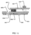
いくつかのオプションを示す、より概略的な図である図1Jは、基板503aのギャップ/ヒンジ503hと、接着剤513のギャップ/ヒンジ513hの随意的な表現(破線)を示している。代表的なセンサ要素、ここでは温度センサ515が、基板503aに概略的に取り付けられ得るように示されている。比較的剛性の基板505が、コネクタ517を介してフレキシブル基板503aに取り付けられ得るように示されている。電気コンポーネント519が、基板505の上側/外側に示され、第2のコンポーネント519が基板505の下側に破線/随意的な表現で示されており、これは、ここではそのように示されていないが上側にあるのは下側にあるのと同様に随意的であるので、これらの接続/配置の随意性を概略的に示すためである。
FIG. 1J, which is a more schematic diagram showing some options, shows an optional representation (dashed line) of the gap /
図1Kは、図1Jと異ならないが、接着剤を削除し、随意性/破線表現を削除することで、さらに概略的な表現となっている。主な観点では、図1Kの実装は、比較的撓んでいないフレキシブル回路基板503aを示している。比較すると、図1K1の実装は、基板503aが撓んだ構成で同じコンポーネントを示している。撓みの矢印は、概して動きを示している。図1K1は、コネクタ517のタイプによっては理想的ではない可能性があるものを示している。好ましくは、或る程度の回転運動を可能にし得るコネクタ517が選択されるが、好ましい実装は、517での堅牢なしっかりとした電気接続を提供する。図1K1では、一部のスペースはおそらく接続解除を実証しているように見えるかもしれないが、その意図は、可能な場合は或る程度の相対回転運動を可能にし得るがそれでもなお堅牢な電気及び/又はデータ通信接続を提供し続ける接続デバイスを示すことである。
FIG. 1K is not different from FIG. 1J, but is a more schematic representation by removing the adhesive and the voluntary / dashed line representation. From the main point of view, the implementation of FIG. 1K shows a
図1L及び図1L1に示すさらなる代替では、フレキシブル回路基板503aは、コネクタ517の下の/隣接する領域において相対的に剛性となるように配置され、この相対的剛性は、基板503aの特徴であり得るか、又はコネクタ517によってそれにもたらされ得る。いずれの場合も、この「フレキシブルなスタック-剛性のコネクタ」の実装は、図1K1の実装に対する相対的補正を提供し、これは、代わりに、コネクタの合わせ面が、撓み中に歪まないことを示す。図1L1に示すデバイスは、概して503a1及び503a3として識別される領域ではより相対的にフレキシブルであり、領域503a2ではより相対的に剛性であり得る。コネクタ自体は、この実装では、ほとんど又はまったく動きをもたない。図1K1では、コネクタ部品は僅かに歪んでいるように見えており、これは図1L1でも起こり得るがより僅かであり、多くの実装において、コネクタ517は、コネクタ内のいかなる動きも防ぐためにロックイヤーを有し、60個のピンすべてを互いに接触した状態に保つ。特定の好みを満たすことがわかっている特定のコネクタとしては、Samtech製のオスとメスの60ピンコネクタ517が挙げられる。Hiroseは、アンテナ506上/アンテナ506からコネクタ518(図1H及び図1Iの場合)への同軸コネクタの製造業者であり、基板505の両面の嵌合する同軸コネクタ518は、Amphenolから入手可能である(同じく図1H及び図1Iに示される)。
In the further alternatives shown in FIGS. 1L and 1L1, the
図1I~図1Lの実装に関する注記として、温度センサ515は、多くの実装において「断熱皮膚温度センサ」である場合があり、センサの位置は、スタックの剛性の部分の近くに及び/又は同様にデバイスの中央領域に、より望ましい配置を有することが見出され得る。剛性の部分の近くの位置は、最適ではないにしてもより良好な皮膚接触を提供することができ、一方、中央領域の位置は、縁からx及びy方向の最大距離を可能にし得る。接着剤スタック(本出願では断熱材として作用し得る)と組み合わせると、温度センサが迅速に皮膚と熱平衡になり、したがって、精度が向上する。
As a note regarding the implementations of FIGS. 1I-1L, the
図1M及び図1M1は、本明細書で実装され得る「フレキシブルマイクロフォン」を示す。本明細書で用いられるマイクロフォン技術は、それが受ける撓みの量に比例する振幅を有する電圧を放出する、フレキシブルピエゾストリップ516であり得る。電気接続516aによって基板503aに接続された薄膜ピエゾ516を使用することで、デバイスは2つのバンドパス(0~10Hz及び1100Hzのバンドパスを中心とする)で敏感になり得る。図1Mに示すようなピエゾ516の位置は興味深いものである。ピエゾ516は、ヒンジポイントと交差するように、基板503aの患者側に配置され得る。ピエゾの一部をフレキシブルヒンジ503hの上の領域516bに配置し、一部をあまりフレキシブルではない領域516cの上に配置することにより、マイクロフォン516は、呼吸中に発生する比較的大きな胸部運動(10Hzの範囲内)に敏感であり、超低周波数音から呼吸数を得ることができる。あまりフレキシブルでない部分の上の部分は、1100Hzの中音域の音に敏感であり、喘鳴、空気の閉塞量などの呼吸音データを生成する。ヒンジポイントは最大撓みが発生する場所であるため、患者の呼吸中に可能な最大電圧を生成する。次いで、この変調された電圧は、DSP技術を用いて処理され、患者の呼吸数及び呼吸深度の正確な測定値を提供する。
1M and 1M1 show "flexible microphones" that can be implemented herein. The microphone technique used herein can be a
アンテナ506の説明は、好ましくは、それがデバイス500/500aのエンベロープ内に嵌る、例えば、カスタムフィットし得るように設計され得るということである。これは最小定在波比と最大順方向電力で2.4GHzで共振し得る。これを達成するために、回路基板、シリコーンカバー530、及び接着剤513が定位置にある状態で、人体上で、その場で、活性要素の長さ、幅、及び誘電体の厚さが最適化され得る。新規な特徴は、普通は、共振周波数で等しい長さの2つの要素(1つは受動、もう1つは能動)で構築されるダイポールアンテナであり得る。このダイポールの実装は、共振周波数で活性要素を用いるが、受動要素として人体を用いる。
The description of the
図1N及び図1N1~図1N6は、デバイス500又は500aなどの様々な外観を示す。図1Nは三次元の上面図であり、より具体的には、図1N1は、上側501の平面図、図1N2は下側の患者側502の平面図、図1N3は第1の立面側面図、及び図1N4は第2の立面側面図である。図1N5は正面立面図であり、図1N6は、背面立面図である。
1N and FIGS. 1N1 to 1N6 show various appearances of the
図1Nは、随意的な第3の電極510、電極エクステンダ504、シリコーンカバー530、プリーツ531、バッテリケージ520、及び取り外し可能なバッテリケージカバー533を含む、デバイス500又は500aなどの三次元の上面図を提供する。取り外し可能なバッテリケージカバー533は、バッテリケージ520に対して定位置に固定することができる回転可能な摩擦嵌合型の(又は代替的にバヨネット式の)キャップであり得る。一部の実装では、取り外し可能なバッテリケージカバー533は、取り外し可能なバッテリケージカバー533がバッテリケージ及びより一般的にはデバイスに対して定位置に固定されているかどうかをユーザが判断するのを助けるために基準点マーキング536と位置合わせされるロック解除インジケータ534及びロックインジケータ535を有し得る。さらに、一部の実装において、バッテリケージカバー533は、バッテリケージカバーの表面から突出するハンドル537をさらに有することができ、これは、ユーザがバッテリケージカバーを回す(ねじ込む又は緩める)及び固定するのを支援することができる。代替的に、バッテリケージカバー533はまた、ユーザがバッテリケージカバーを回す(ねじ込む又は緩める)のを支援するために、1つ以上のくぼみ538を有し得る。場合によっては、バッテリケージカバーは、外部条件からのバッテリコンパートメントの防水性を提供するために、キャップの下側の円周の周りにシリコーン、ゴム、又は他の適切な材料(図には示されていない)のシール材料を有し得る。
FIG. 1N is a three-dimensional top view of a
図1N1は、随意的な第3の電極510、フレキシブル電極エクステンダ504、シリコーンカバー530、プリーツ531、バッテリケージ520、取り外し可能なバッテリケージカバー533、ロック解除インジケータ534、ロックインジケータ535、基準マーキング536、ハンドル537、及びくぼみ538を含む、デバイス500又は500aなどの上側501の平面図である。
FIG. 1N1 shows an optional
図1N2は、随意的な第3の電極510、フレキシブル電極エクステンダ504、及びシリコーンカバー530を含む、デバイス500又は500aなどの下側の、患者側502の平面図を提供する。
FIG. 1N2 provides a plan view of the
図1N3は、随意的な第3の電極510、フレキシブル電極エクステンダ504、シリコーンカバー530、プリーツ531、バッテリケージ520、取り外し可能なバッテリケージカバー533、及びハンドル537を含む、デバイス500又は500aなどの第1の立面側面図を提供する。
FIG. 1N3 includes a
図1N4は、随意的な第3の電極510、フレキシブル電極エクステンダ504、シリコーンカバー530、プリーツ531、バッテリケージ520、取り外し可能なバッテリケージカバー533、及びハンドル537を含む、デバイス500又は500aなどの第2の立面側面図を提供する。
FIG. 1N4 includes a
図1N5は、随意的な第3の電極510、フレキシブル電極エクステンダ504、シリコーンカバー530、プリーツ531、バッテリケージ520、取り外し可能なバッテリケージカバー533、及びハンドル537を含む、デバイス500又は500aなどの正面立面図である。
FIG. 1N5 shows the front of a
図1N6は、随意的な第3の電極510、フレキシブル電極エクステンダ504、シリコーンカバー530、プリーツ531、バッテリケージ520、取り外し可能なバッテリケージカバー533及びバッテリケージカバーハンドル537を含む、デバイス500又は500aなどの背面立面図である。
FIG. 1N6 includes a optional
図1N7は、随意的な第3の電極510、フレキシブル電極エクステンダ504、シリコーンカバー530、プリーツ531、バッテリケージ520、取り外し可能なバッテリケージカバー533、ロック解除インジケータ534、ロックインジケータ535、基準マーキング536、バッテリケージカバーハンドル537、及びくぼみ538を含む、デバイス500又は500aなどの上側501の平面図を提供する。
FIG. 1N7 shows an optional
別の代替的な実装が図1Wに示されている。そこに示されているのは、特に、通常、これに限定されないが、装着されたデバイス(図1W)のいずれかにおける可聴ノイズを低減するための、音声、可聴、又は音響ノイズを低減するための音声ピックアップ及び接着剤構造及び/又は方法である。患者への音声ピックアップデバイス又はセンサ又はマイクロフォンなどの適用、ピックアップセンサ又は同様のデバイスと皮膚との相互作用の変化、特に皮膚に対するセンサの移動は、存在する場合には重要な又は望ましい生理的音をマスキングする可能性がある望ましくないノイズを、センサ又はセンサの敏感な機械的膜に与える。これは、ノイズを導入するように配置され得る、電子的に増幅される或いは非常に感度の高い音声センサ上/内/でさらにより顕著になる。 Another alternative implementation is shown in Figure 1W. Shown herein are specifically, but not limited to, to reduce audio, audible, or acoustic noise to reduce audible noise in any of the mounted devices (FIG. 1W). Audio pickup and adhesive structure and / or method. Applications of voice pickup devices or sensors or microphones to patients, changes in the interaction of pickup sensors or similar devices with the skin, especially movement of the sensor to the skin, are important or desirable physiological sounds if present. It gives unwanted noise that may mask to the sensor or the sensitive mechanical membrane of the sensor. This becomes even more pronounced on / inside / on electronically amplified or very sensitive speech sensors that can be arranged to introduce noise.
本発明の実装は、一部の実装では片面又は両面が最初に剥離ライナによって保護される、取り外し可能な両面シリコーン接着剤を含み得る。このような実装では、一方の接着面を音声センサに適用し、次いで、もう一方の面を患者(モニタリングされる人)に適用し、次いで、皮膚に対するセンサの移動によって与えられるであろうモーションノイズの少なくとも幾らか、おそらく他の実装ではほぼすべてをなくす又は大幅に低減することができる。 The implementation of the present invention may include a removable double-sided silicone adhesive in which one or both sides are initially protected by a release liner in some implementations. In such an implementation, one adhesive surface is applied to the voice sensor, then the other surface is applied to the patient (the person being monitored), and then the motion noise that would be inflicted by the movement of the sensor with respect to the skin. At least some, perhaps in other implementations, can eliminate or significantly reduce almost everything.
1つ又は複数の主要な実装において、他の接着剤は通常含まれない(例えば、通常は導電性領域又は層なしであっても、複合接着剤なし又はスタックされた複合接着剤なし)、しかしながら、他の場合は、音声センサと共に用いられとき、又は例えば他のセンサ及び/又は電極が含まれるウェアラブル健康モニタリングデバイスと一緒に/上で用いられるときに、他の可能な実装ではこのような他の接着剤又は接着剤部分を有する又は含む。図1Wの主要な実装では、とりわけ、接着剤は、通常、単一の薄い両面シリコーン接着剤又はテープであり得る。通常、これは、皮膚との接触が認可されている或いは許容できるシリコーン接着剤であり、したがって、機械的ノイズをなくすことができる。これは、マイクロフォンと皮膚の間に比較的動かない又はかなり制限された状態で移動可能な結合部を提供することによってウェアラブルデバイスにも及び/又は代替的に適用することができ、したがって、機械的ノイズを低減する。一部の実装では、シリコーン接着剤は、特定の患者に1回又は数回適用されるように構成され得る。さらに、一部の実装では、接着剤を適切に選択すれば、除毛の必要はない場合がある。 In one or more major implementations, other adhesives are usually not included (eg, usually without conductive regions or layers, but without composite adhesives or stacked composite adhesives), however. Other possible implementations, such as when used with voice sensors, or, for example, with / on wearable health monitoring devices that include other sensors and / or electrodes. Has or contains an adhesive or adhesive portion of. In the main implementation of FIG. 1W, among other things, the adhesive can usually be a single thin double-sided silicone adhesive or tape. Usually this is a silicone adhesive that is licensed or acceptable for contact with the skin and thus can eliminate mechanical noise. It can also be applied to wearable devices and / or alternatives by providing a relatively immobile or fairly restricted mobile joint between the microphone and the skin, and thus mechanically. Reduce noise. In some implementations, the silicone adhesive may be configured to be applied once or several times to a particular patient. In addition, some implementations may not require depilation if the adhesive is properly selected.
図1Wでは、特定の第1の限定ではない例について、ウェアラブル健康モニタリングデバイス100bにおいて、例えば、マイクロフォン又は他の可聴、音響、又は音声センサ150が、患者又は他の装着者(図1Wには図示せず)への又はこれに関連する最終的な動作上の適用のために、デバイス100bの基板105上に又はその中に又は他の方法で動作可能に関連付けられて配置され得る。適切な取り扱いのためにセンサ又はマイクロフォン150を介して患者からの音データを健康モニタリングデバイス100bの中央データ収集及び/又は通信デバイス(基板105上に配置し、そのために用いることができる随意的な代替的な動作データ収集及び/又は操作デバイスの他の説明を参照されたい)に通信するための電気/音声信号接続151の破線表現も示されている。接着剤113は、音響センサ又はマイクロフォン150の上に及びこれに対して所定の位置に動作可能に配置されるように示されている(上記の説明と異ならない)(この例では、接着剤は、他のデバイス108、109、110、及び基板105の上に同様に配置されるように構成される)。接着剤113は、剥離ライナ114の除去によって露出され(本明細書の他の場所での説明と異ならない)、最終的な動作及び例えば心拍などの生理学的信号又は音の収集のために患者にも接続される。接着剤は、皮膚及び/又は患者に対するデバイス150の動作配置を隔離及び/又は維持するように動作し、デバイス150の移動及びその結果として生じるノイズ(そうでなければ、関心ある音又は信号データに割り込む又は潜在的に検出不能にするであろうノイズ)をなくす及び/又は低減する。
In FIG. 1W, for a particular non-first example, in a wearable
特定の使用は、1つ以上の他のセンサ、電極、及び/又は光学機器(エミッタ及び/又はレシーバ)と共に示されるようにデバイス100b上であり得る、又は代替的に、特定の使用は、音声センサ又はマイクロフォンのみを含み得る。成人又は子供での使用は両方とも、子供の心拍の感知及び/又は取り込みのための可能な強化された利点があることで想定される。
Certain uses may be on
他のコンポーネントの説明に戻ると、患者側102では、ECG電極108、109、及び110は、実質的に直接の患者の皮膚接触のために露出されたままにされ得る(しかし、少なくともその間に導電性ゲルが適用される可能性が高い)、及び/又は、多くの実装において、患者側電極108、109、及び/又は110は、後述するように導電性接着剤材料によって覆われ得る。電極は、例えば、生体適合性及び高い信号品質のために銀/塩化銀などの堅牢な高導電性材料でめっきされるか又はそのような材料で作製され、一部の実装において、非常に堅牢であり、1つの限定ではない例では、患者間の約1000回以上のアルコール洗浄サイクルに耐えるように適合され得る。場合によっては、これらの銀/塩化銀電極は、フレキシブル回路基板又はフレキシブルプリント回路に直接プリントすることができ、さらに他の例では、銀/塩化銀電極は、製作プロセスにおける個別の別個のステップでフレキシブル回路基板又はフレキシブルプリント回路に取り付ける又は固定することができる。窓又は他の通信チャネル又は開口部111、112(図1C)が、パルスオキシメータのために、例えば、LED及びセンサのために設けられ得る。このような開口部111、112(例えば、図1C)は、通常、患者の皮膚との間の最適な光通信のために配置されるであろう。電子機器103により近く配置及び/又は接続される1つ以上の光導管111a/112a(及び111b/112b)の代替的な配置が、図1Dの限定ではない例に示されている。様々な代替的な配置が本発明で使用可能であり、それらのいくつかをさらに後述する。
Returning to the description of the other components, on the
一部の実装では、太陽光又は他の周辺光源によって引き起こされるノイズを打ち消すために、周辺光のサンプリング(LEDをオフにした状態)を行い、次いで、これを各パルスオキシメトリ信号から差し引くことができる。 In some implementations, ambient light sampling (with the LED turned off) may then be subtracted from each pulse oximetry signal to counteract noise caused by sunlight or other ambient light sources. can.
LED及び1つ以上のフォトダイオードセンサはまた、及び/又は代替的に、センサ/LEDと患者の皮膚との間の空隙をなくすためにシリコーンの層で覆われ得る。そのいくつかの例が、それぞれの図1Q及び/又は図1S及び/又は図1T及び/又は図1T1及び/又は図1T2、図1U、図1U1、及び図1U2に記載されており、ここで、シリコーン層又はカバー121及び/又は121a及び/又は121b及び/又は121c及び/又は121dは、光導管及び/又はセンサ/LED111c/111d/112cを覆う/取り囲むように示されている。LED111c(図1Q及び/又は図1S、及び/又は図1T、図1T1、図1T2、図1U、図1U1、及び/又は図1U2のうちの1つ又は複数)は、赤色LEDであり、LED111d(図1Q及び/又は図1S、及び/又は図1T~図1U2のうちの1つ又は複数)は、IR(赤外)LEDであり、デバイス112c(図1Q及び図1S、及び/又は図1T~図1U2のうちの1つ又は複数))はセンサであり得る。代替的な及び/又はさらなるLEDが設けられる場合があり、第1の例について、例えばさらに後述するさらなる及び/又は代替的な機能のための緑色LED(図示せず)として、図1Q及び/又は図1S、及び/又は図1T~図1U2のうちの1つ又は複数に示されたものと異ならない1つ以上のさらなる又は代替的な色のLED(図示せず)が設けられる場合がある。
The LED and one or more photodiode sensors may also and / or alternatively be covered with a layer of silicone to eliminate the void between the sensor / LED and the patient's skin. Some examples thereof are described in FIGS. 1Q and / or FIGS. 1S and / or FIGS. 1T and / or FIGS. 1T1 and / or FIG. 1T2, FIG. 1U, FIG. 1U1, and FIG. 1U2, respectively. The silicone layer or cover 121 and / or 121a and / or 121b and / or 121c and / or 121d are shown to cover / surround the optical conduit and / or the sensor / LED111c / 111d / 112c. LED111c (one or more of FIGS. 1Q and / or FIG. 1S and / or FIG. 1T, FIG. 1T1, FIG. 1T2, FIG. 1U, FIG. 1U1, and / or FIG. 1U2) is a red LED and LED111d ( 1Q and / or FIG. 1S and / or one or more of FIGS. 1T-1U2) are IR (infrared) LEDs and
他の代替的なLED及びセンサアレイ又は構成が図1T及び図1T1に示されており、そこでは、1つ以上のLEDが、基板105a上のエポキシ/ライトパイプ121c内のより中央に配置され、1つ以上のセンサ又はフォトダイオードが、より周辺に配置されている。図1Tには2つのLED111c及び111d(図1Q及び/又は図1SのLED111c及び111dと異ならないが、位置決め/幾何学的形状のための)が、1つ以上のセンサ、ここでは2つのセンサ又はフォトダイオード112c及び112dに対して比較的中央に配置されて示されている。図1Q及び/又は図1Sに関して前述したように、LED111cは赤色LEDであり、LED111dはIR(赤外)LEDであり、デバイス112c及び/又は112dは、1つ以上のセンサ、ここでは2つのセンサ又はフォトダイオード112c及び112dであり得る。図1T1では、4つのLED111c、111d、111e、及び111f(図1Q及び/又は図1S及び/又は図1TのLED111c及び111dと異ならないが、数、位置決め、及び/又は幾何学的形状のための)が、1つ以上のセンサ、ここでは4つのセンサ又はフォトダイオード112c、112d、112e、及び112fに対して比較的中央に配置されて示されている。図1Q及び/又は図1S及び/又は図1Tに関して前述したように、LED111cは赤色LEDであり、LED111dはIR(赤外)LEDであり、及び/又は111eも赤色LEDであり、LED111fはIR(赤外)LEDであり、デバイス112c、112d、112e、及び/又は112fは、1つ以上のセンサ、ここでは4つのセンサ又はフォトダイオード112c、112d、112e、及び112fであり得る。
Other alternative LEDs and sensor arrays or configurations are shown in FIGS. 1T and 1T1, where one or more LEDs are located more centrally within the epoxy /
中央センサ又はフォトダイオードがLEDに取り囲まれるより又は比較的従来の方法とは対照的に、図1T及び図1T1のLEDをより中央の位置に配置し、これらのより中央に配置されたLEDをセンサ又はフォトダイオードで取り囲むことは、場合によってはLEDから放出された放出光のより多くの割合を取り込むように配置され得る幾何学的形状を提供する。より又は比較的従来の幾何学的形状では、フォトダイオードの反対側を向いている放出光の実質的にすべてが無駄になる。図1T及び図1T1の及び/又はそれについて説明された幾何学的形状では、より多くの光、おそらく事実上すべての放出光がセンサ又はフォトダイオードによって取り込まれ得るか、又は場合によっては、以前に想定されていたよりも顕著により高効率の取り込みが行われる。より高効率の光の取り込みに起因して、従来のマルチLED一体化センサよりも必要なLEDがより少なくてよい可能性がある。これは、電力消費を顕著に低減しながら、同様の又はより良好な測定結果を達成することに寄与し得る。要約すると、被検者(例えば、患者/乳児/新生児/母親/アスリート)の皮下領域へのより高濃度の光を可能にし得る、フォトダイオード(又はセンサ)のアレイと組み合わせた、上記の赤色とIRの組み合わせなどのLEDの幾何学的形状が示され説明されている。LEDとフォトダイオード/センサの組み合わせはまた、一部の実装では、高効率一体化センサと呼ばれる場合もある。この構成は、SpO2(末梢毛細血管酸素飽和度)の判定に実装され得る。一部の実際の実装では、図1T及び図1T1に示されたセンサは、例えば、約5mm2であり、センサ及びLEDを取り囲む外円の直径は、対応する約8mmであり得ることに留意されたい。一部の実装では、赤色LED光源の中央から対応する1つ以上のセンサの中央までの好ましい距離に対して約3.2mmの赤色を設定することができ、IR LED光源の中央から対応する1つ以上のセンサまでの約3.7mmの好ましい距離を設定することができる。 The LEDs of FIGS. 1T and 1T1 are located in a more central position and these more centrally located LEDs are sensors, as opposed to a central sensor or photodiode surrounded by LEDs or in relatively conventional fashion. Alternatively, enclosing with a photodiode provides a geometric shape that may be arranged to capture a higher proportion of the emitted light emitted from the LED. More or relatively conventional geometry wastes substantially all of the emitted light pointing to the opposite side of the photodiode. In FIGS. 1T and 1T1 and / or the geometry described thereof, more light, perhaps virtually all emitted light, can be captured by the sensor or photodiode, or in some cases previously. Significantly more efficient uptake than expected. Due to the higher efficiency of light capture, it may require fewer LEDs than conventional multi-LED integrated sensors. This can contribute to achieving similar or better measurement results while significantly reducing power consumption. In summary, with the red color above, combined with an array of photodiodes (or sensors) that may allow higher concentrations of light to the subcutaneous area of the subject (eg, patient / infant / newborn / mother / athlete). The geometry of the LEDs, such as the combination of IRs, is shown and described. The combination of LED and photodiode / sensor is also sometimes referred to as a high efficiency integrated sensor in some implementations. This configuration can be implemented in the determination of SpO2 (peripheral capillary oxygen saturation). Note that in some practical implementations, the sensors shown in FIGS. 1T and 1T1 are, for example, about 5 mm 2 , and the diameter of the outer circle surrounding the sensor and LED can be the corresponding about 8 mm. sea bream. In some implementations, a red color of about 3.2 mm can be set for a preferred distance from the center of the red LED light source to the center of one or more corresponding sensors, and the corresponding 1 from the center of the IR LED light source. A preferred distance of about 3.7 mm to one or more sensors can be set.
このシリコーン層又はカバー121/121a/121b/121c/121d/121eは、皮膚での反射によって失われる光を減らし、これにより、信号を大幅に増加させ、センサに対する皮膚の移動によって引き起こされるノイズを低減することができる。一部の実装では、このシリコーンは、ライトパイプと呼ばれる場合があり、いくつかの状況では、透明な、無色の、及び/又は医療グレードのシリコーンであり得る。以下でさらに説明するように、シリコーン層又はカバー121及び/又は121a及び/又は121b及び/又は121c及び/又は121d及び/又はレンズ表面121e(本明細書では121/121a/121b/121c/121d/121eと略して呼ばれることもあるが、本発明の同じ意味を有する)はまた/代替的に、発光時又は反射による受光時又はその両方のいずれであろうとも、光の透過にどのように関係するか又はそれを通じて透過されるかという点で、本明細書ではライトパイプ又はレンズ121/121a/121b/121c/121d/121eと呼ばれる場合もある。
This silicone layer or cover 121 / 121a / 121b / 121c / 121d / 121e reduces the light lost by reflections on the skin, thereby significantly increasing the signal and reducing the noise caused by skin movement to the sensor. can do. In some implementations, this silicone may be referred to as a light pipe, and in some situations it can be a clear, colorless, and / or medical grade silicone. As will be further described below, the silicone layer or cover 121 and / or 121a and / or 121b and / or 121c and / or 121d and / or the
1つ以上の実装において、本発明の封止材料及び/又はレンズ121/121a/121b/121c/121d/121eは、透明な、無色の、軟質の、低デュロメータのうちの1つ又は複数である医療グレードのシリコーンから作製され得る。本発明に用いられ得るこのような特別なシリコーンの例は、「粘着性のゲル」(いくつかの供給業者)として知られており、通常、好ましくは両面に組み込まれた、非常に粘着性の高い接着剤を有する。粘着性のゲルに両面接着剤が組み合わされた低デュロメータのシリコーンは、電子センサと皮膚の両方に適合し、一部の実装では皮膚とレンズとセンサの境界面での移動を制限することによりモーションアーチファクト低減特性を呈する、レンズ121/121a/121b/121c/121d/121eの構築を可能にする。本発明に係るレンズはまた/代替的に、複合接着剤ストリップ層間に閉じ込められるように特別に形状設定され(例えば、図1D、図1P及び図1R及び図1R1の代替を参照)、一部の実装では、レンズが接着剤ストリップの患者側に僅かに突き出ることを可能にする接着剤ストリップの開口部、多くの場合、長方形の開口部のサイズの隆起部分を有する(以下に説明する図1Sに関するさらなる詳細を参照)。
In one or more implementations, the encapsulant and / or
図1Sでは、LED及びセンサ111c/111d/112cのためのさらに代替的なシリコーンカバー又は封止材料121aの実装は、カバー外面121bに又はこれに隣接して凸レンズを含み得る。多くの実装において、外面とレンズは同一であり、及び/又はレンズは、封止材料121aの表面121bによって画定され得る。これにより、胸部又は額(例えば、乳児又は新生児)或いは患者又はユーザの体に取り付けられているかどうかにかかわらず、パルスオキシメトリLEDエミッタ111c/111d及び1つ以上のフォトダイオードセンサ112cを皮膚表面に接続するための構造及び方法が提供される。
In FIG. 1S, mounting of an alternative silicone cover or
より具体的には、本明細書で別途説明されるように、本発明のシステム及び/又はデバイス100は、選択された波長の1つ以上のLEDエミッタ111c/111d(及び/又は111e及び/又は111f)及び1つ以上のフォトダイオードセンサを使用することができる。しかしながら、装着者1000の皮膚1001へのLED/センサの組み合わせの結合を最大にするために、光学的に透明な医療グレードのシリコーンからなる封止材料及び/又はレンズ121/121a/121b/121c/121d/121eを、LED/センサの組み合わせ111c/111d/112cをカバーする状態でその上に成形する、又は後で取り付けることができるように成形することができる。多くの実装において、例えば図1Sのように、レンズ121bは、本質的に部分的に球形又はほぼ半球形であり得るが、必ずしもそうである必要はなく、例えば、以下で説明する図1T2~図1U2を参照されたい。他の形状の湾曲も同様に有用であり得る。湾曲は、装着者の移動などによるかどうかにかかわらず、デバイス100が移動し得るときの皮膚接触の喪失を低減することができる。すなわち、図1Sの装着者1000の又は装着者1000に対するデバイス100の移動は、結果的に皮膚1001上の及び皮膚1001に対するレンズの準転がり接触を生じることがある。皮膚接触が良好に維持されることは、中断なしの及び/又はノイズが低減された良好なデータ収集を意味する。上記及び以下を含む(しかし、本明細書に直接に示されていない、すなわち、本明細書に代替的に含まれる又は含まれない)、又は以下の図1U2を特に参照して説明される一部の実装では、薄いシリコーン接着剤113eを、シリコーン層121/121a/121b/121c/121d/121e上に及びその間に使用して、シリコーン封止材料121/121a/121b/121c/121d/121eに対する皮膚接触の維持を支援することができる。例えば以下の図1U2の説明を参照されたい。
More specifically, as described separately herein, the system and / or
さらに、接触を維持する機能に関連するのは、LED及びセンサが、異なる高さであっても封止材料121a/121c/121d/121eのライトパイプを通して空隙の間断が実質的にほとんどなしに又は実質的になしに皮膚へ放出して皮膚からセンサへ戻る光を通信しているときに達成され得るライトパイピング効果である。エミッタからライトパイプ121a/121c/121d/121eへの及びこれを通る空隙がない、及び/又は皮膚との実質的に一定の接触を有する湾曲面121bを含む場合があるため、同じライトパイプ材料121a/121c/121d/121eを介する、皮膚への透過及びセンサに戻る反射において空隙はないか又はほとんどないか又は空隙の間断がほとんどないか又は実質的にない(透過と反射は両方とも光の移動を指す)。これにより、空隙インターフェースでの光波散乱によって引き起こされる能率の悪さ(皮膚又は他の表面で空隙が光を跳ね返す)が低減する。すなわち、LED及びセンサのカプセル化は、空隙をもたらさず、ライトパイプ効果及び湾曲面は、皮膚への高品質の低散乱透過と皮膚及び骨からの反射の受光を提供する。ライトパイプ及び湾曲したレンズ表面は、間断のない皮膚接触を維持し、レンズは皮膚での反射による信号の損失を低減する。信号対ノイズ比が低下し、データ収集品質が向上する。
Further related to the ability to maintain contact is that the LEDs and sensors, even at different heights, have virtually no gaps in the voids through the light pipes of the encapsulating
したがって、このような封止材料121/121a/121c/121d及び/又はレンズ121b/121eは、場合によっては、とりわけ、(1)異なる高さのLED及びセンサの同等又はその他の高品質の結合、並びにモーションアーチファクトを低減するための皮膚への実質的に一定の結合を保証するために、「ライトパイプ」効果をもたらすこと、(2)皮膚を通って骨への放出光の合焦、及び(3)皮膚を通ってフォトダイオードセンサへの反射光の合焦、を含む1つ又は複数の目的に役立つ可能性がある。
Thus,
さらなる注記として、図1Sのような湾曲したレンズ121bオプションについて、レンズの半径は、(1)~(3)を最大にするように設計され得る。レンズの高さは、デバイス100の複合接着剤113の上及び皮膚の中に突き出ることを可能にするように設計され得るが、結果的に悪いデータを生じる可能性があるので毛細血管床を乱すほど深くはない。さらに、皮膚へ放射するのに用いられるLED、例えば、赤色及び赤外及び/又は緑色LEDは、非常に広い放射角度のアレイをもたらし、したがって、反射された多数の光波のアレイが多様な湾曲面によってセンサに合焦されるので、LED光波放射の曲率半径及び角度は必ずしも高度に制御される必要はない。すなわち、湾曲面は、移動(偶発的な又は意図的な)のなかで接触を維持するのに役立ち、皮膚を過る透過及びセンサに戻る反射の角度はそれほど重要ではない。言い換えれば、多くの異なる曲率半径が有効であり、データ/波の透過及び反射にほとんど差はなく、LEDの広角放射は、様々な半径に対応する。むしろ、湾曲は、デバイス100の移動に起因する接触の維持においてより多くの制限を有し得る。例えば、より平坦な湾曲は容易に曲がらない場合があり、曲率半径が非常に小さいと、それほど多くのデータが送受信されない。
As a further note, for the
一部の実装では、約12.6mm×6.6mmの区画内にLED及びセンサを有するデバイスについて、有用であることがわかった曲率半径は、約20~40であった(20.34mmと39.94mmの両方の曲率半径が有用であることがわかった)。LEDは、一方の側又は他方の側に又は2つの対向する側に、又はおそらくセンサの周りの4つ以上の実質的に等距離の点にあり、望ましい結果をもたらし得ることに留意されたい。 In some implementations, the radius of curvature found to be useful for devices with LEDs and sensors in a compartment of about 12.6 mm x 6.6 mm was about 20-40 (20.34 mm and 39). Both radii of curvature of .94 mm have been found to be useful). It should be noted that the LEDs are on one side or the other side or on two opposite sides, or perhaps at four or more substantially equidistant points around the sensor and can give the desired results.
さらに、本発明のパルスオキシメトリは、図1Q及び図1S、及び/又は図1T~図1U2のうちのいずれか1つ又は複数の配置の1つの解釈であるように、複数の光源及び/又はセンサを有し得ることに留意されたく、例えば、典型的なパルスオキシメトリ回路は、波長ごとに1つの光源(LED)(通常、赤色、赤外、及び場合によっては後述するさらなる例に関する緑色又は赤色/IRの長時間平均を含むその他の光源)を用いる。しかしながら、本発明のデバイス及び/又は方法は、各波長の複数の光源を利用することができる。これは、局所的なモーションアーチファクトの影響を減らすために、患者/装着者内/上の毛細血管床のより広い領域のインテロゲーションを可能にし得る。同様に、同じ又は類似の目的又は利点のために複数のセンサを用いることができる。 Further, the pulse oximetry of the present invention is one interpretation of any one or more of the arrangements of FIGS. 1Q and 1S and / or FIGS. 1T-1U2. It should be noted that it may have a sensor, for example, a typical pulse oximetry circuit may have one light source (LED) per wavelength (usually red, infrared, and in some cases green or with respect to further examples described below. Other light sources including red / IR long-term averages) are used. However, the device and / or method of the present invention can utilize multiple light sources of each wavelength. This may allow interrogation of a wider area of the capillary bed within / above the patient / wearer to reduce the effects of local motion artifacts. Similarly, multiple sensors can be used for the same or similar purposes or advantages.
さらに、DRL及び/又は代理DRLとパルスオキシメトリとの組み合わせは、さらなる利点をもたらすことができる。右脚回路、代理右脚、及び/又はDRLは、胸部又は額又は他の電極配置のいずれの場合でも、パルスオキシメトリセンサに容量結合される可能性のあるコモンモード及び電力線ノイズを除去し、その効果を低下させることができる。DRL及び/又は代理DRLと、図1Sで説明されるレンズ及び/又は図1Q及び/又は図1T~図1U2のうちのいずれか1つ又は複数のライトパイプを有する改善されたパルスオキシメトリとの組み合わせは、このようなノイズを顕著に低減し、これにより、データ収集を強化することができる。駆動電極については、以下のさらなる詳細を参照されたい。 In addition, the combination of DRL and / or surrogate DRL with pulse oximetry can provide additional benefits. The right leg circuit, surrogate right leg, and / or DRL eliminate common mode and power line noise that may be capacitively coupled to the pulse oximetry sensor, whether in the chest or forehead or other electrode arrangements. The effect can be reduced. With DRL and / or surrogate DRL and improved pulse oximetry having the lens and / or FIG. 1Q and / or one or more of FIGS. 1T-1U2 illustrated in FIG. 1S. The combination can significantly reduce such noise, thereby enhancing data acquisition. See further details below for drive electrodes.
したがって、動脈血酸素含有量の測定は、オキシヘモグロビンの有無に応じて異なる光吸収を呈する、通常は赤色及び赤外パルス光源からの光信号(心拍光信号と呼ばれることもある)を用いて行うことができる。要約すると、透過システムは光源と光検出器で用いられる。以下に説明する多くの実装において、1つ以上の光源と1つ以上のセンサのいずれか又は両方をカプセル化するライトパイプを使用することができ、特に、皮膚への光放射効率の向上及び/又はそうでなければ収集時に失われる光子の取り込みのいずれか又は両方をもたらすために、実質的に空隙がないことを意味するライトパイプのカプセル化を用いることができる。 Therefore, measurement of arterial oxygen content should be performed using light signals (sometimes referred to as heartbeat light signals), usually from red and infrared pulsed light sources, which exhibit different light absorption depending on the presence or absence of oxyhemoglobin. Can be done. In summary, transmission systems are used in light sources and photodetectors. In many implementations described below, light pipes that encapsulate one or more light sources and one or both of the sensors can be used, in particular to improve the efficiency of light emission to the skin and /. Or light pipe encapsulation, which means virtually no voids, can be used to result in either or both of the uptake of photons that would otherwise be lost during collection.
ここでは、反射システムが典型的であり、これらは多くの場合、邪魔にならず、おそらくよりポータブルであるといういくつかの利点を有する。本明細書で説明したように、このような反射システムは、通常、赤色及び赤外光源と、フォトダイオードセンサ又は検出器、又はこれらのコンポーネントの複数の構成を使用する。また、説明したように、1つの実装/方法は、1つ以上の中央大面積フォトダイオード/センサ/検出器と、フォトダイオードに隣接する又はその周りのアレイ状の1つ以上のLED光源、多くの場合、赤色及び赤外LED光源のそれぞれのうちの1つ又は複数を使用する。また、説明したように、代替的な構成は、各波長タイプ(赤色、赤外、緑色など)のうちの1つ又は複数の、1つ以上の中央LED光源セットと、中央LEDを取り囲む複数の大面積フォトダイオード又は光センサを使用する。このような構成は、LEDの周りに2又は3又は4つのこのような検出器を使用して、LEDから皮膚及び他の組織を通ったより多くの光散乱を収集し得る。例えば、図1T及び/又は図1T1参照。 Reflection systems are typical here, and they often have some advantages of being unobtrusive and perhaps more portable. As described herein, such reflection systems typically use a red and infrared light source and a photodiode sensor or detector, or multiple configurations of these components. Also, as described, one implementation / method is one or more central large area photodiodes / sensors / detectors and one or more LED light sources in an array adjacent to or around the photodiode, many. In the case of, one or more of each of the red and infrared LED light sources is used. Also, as described, alternative configurations include one or more central LED light source sets of each wavelength type (red, infrared, green, etc.) and multiple central LED light sources surrounding the central LED. Use large area photodiodes or optical sensors. Such a configuration may use two or three or four such detectors around the LED to collect more light scattering from the LED through the skin and other tissues. See, for example, FIG. 1T and / or FIG. 1T1.
さらに代替的な実装は、光源及び/又は1つ以上のフォトダイオードに対する及び/又はその周囲の構造的強化を採用することができる。最初に説明されるのは、前述の中央LED構成に関連して配置された1つ又は複数のこのような強化であるが、以下を、前述の中央センサ構成と共に又はそれに関連して同様に用いることができる。光強化構造は、収集領域への侵入を最小にし、フォトダイオード領域を縮小し、又はフォトダイオードの数を減らすことができる。したがって、費用対効果及び/又は効率の向上がもたらされる可能性がある。 Further alternative implementations can employ structural enhancements to and / or around the light source and / or one or more photodiodes. First described is one or more such enhancements arranged in connection with the aforementioned central LED configuration, but the following are used in conjunction with or in connection with the aforementioned central sensor configuration. be able to. The light-enhanced structure can minimize penetration into the collection area, reduce the photodiode area, or reduce the number of photodiodes. Therefore, cost-effectiveness and / or efficiency improvement may be brought about.
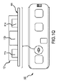
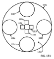
図1T2、図1U、図1U1、及び図1U2では、ライトパイプ121dにおいて、中央LED光源111c及び111dは、周囲の障壁122(ここでは代替的な参照符号B1でも識別される)によって基板105a上の周辺光検出器112c、112d、112e、及び112fから分離される。センサ領域を取り囲むさらに随意的な外部障壁123も示されている。障壁122(又はB1)及び/又は壁123(又はB2)は/又は好ましくは、LEDとセンサとの間のクロストークを防ぐために、赤色とIRの両方(又は使用されている光の他の色又は波長に関係なく、例えば緑色など)に対して不透明である及び/又はこれを反射する。すなわち、光線の一部がセンサに直接入る経路を見つけるのではなく、すべての光がLED領域を出て皮膚に入るようにすることが好ましい及び/又は望ましいであろう。障壁の好ましい表面は、拡散反射性である(一般に相対吸収及び/又は鏡面光沢とは対照的である)。例としては、透明な陽極酸化アルミニウムが挙げられる。もう1つは、別のテクスチャ加工された白色ペンキである。動作が、以下参照の図1U1及び/又は図1U2に関連して示され説明される。
In FIGS. 1T2, 1U, 1U1, and 1U2, in the
壁122の形状及びサイズは、LED光源、ここでは光源111c及び111dの形状及びサイズに合わせて選択することができる。例えば、壁122は、図のように、円形であるか、或いは四角形又は長方形の形状であるか、又はLED111c、111dの周りのその他の形状(図示せず)であり得る(ここでは、より多くの又は少ない光源が壁122内に含まれる又は囲まれ得ることにも留意されたい)。障壁122の幅又は厚さ、及び障壁122に用いられる材料は、必要又は要望に応じて同様に変更可能又は変更され、実際、特定の材料の相対的な不透明度は、特定のレベルの不透明度又は相対的な拡散反射率を提供するのに必要な幅の増減を意味し得るという点で、幅は材料に依存する及び/又はその逆であり得る。光の特定の波長、すなわち、用いられる光のタイプ、及び/又はセンサのタイプ、及び/又は相対的及び/又は全体的な幾何学的関係性(センサと光源、センサとセンサ、及び/又は光源と光源)も、及び/又は特定の波長に関連する相対的な不透明度に起因して、用いられる相対的な寸法及び/又は材料に関与し得る。相対的な厚さが、壁の材料のタイプ、又はその不透明度又は相対的な拡散反射率により関与し得る状況があり得る。一部の実装では、障壁/壁は、機械加工された、陽極酸化アルミニウム、又は他の同様の材料であり得るが、他の実装は、プラスチック、例えば、成形プラスチックであり得る。赤色及び赤外の使用の場合、駆動上の考慮事項は、材料が660ナノメートルと940ナノメートルの両方に対しておそらく好ましくは不透明であるか又は反射性又は拡散反射性であるということであり得る。したがって、多くの状況において、非常に薄いアルミニウムはこの基準を満たし、より厚いプラスチックも同様に満たす。
The shape and size of the
壁122のオプションは、主として、LEDからの放射(例えば、これまでのところ、LED111c/111dからの、例えば、赤色又は赤外光)のいずれかの横方向の伝搬に対する光学的障壁を提供することであり、壁122は、好ましくは、LEDの光出口ウィンドウと同じ高さであるか又は僅かにより高い。障壁122はまた、皮膚又は散乱材料に入らない光線の光学的クロストークを防ぐのに十分な幅を有するが、皮膚又は他の筋肉組織から散乱されたLEDからの光が障壁の外部のフォトダイオード検出器に到達するのを防ぐほど広くはないことが好ましい。
The option of
随意的な外部障壁123も採用することができる。これは、患者又はユーザから反射された光の収集を支援する。サイズ、厚さ、及び材料に関する同様の考慮事項が壁123に使用され、違いは、主として、光の生成ではなく収集にある。
An optional
これらの開発により、ここで、図1T2/図1U、及び/又は図1U1/図1U2で説明するように、検出器ダイオードが存在しない他の領域からの光を収集し、検出器のうちの1つ又は複数に到達するようにその放射の一部を伝導又は反射することができる光収集構造が追加されるという、外部検出器の改善が提供される。そうでなければ別々に分離された光源(図示せず)を伴う中央検出器も、同様の改善を有し得ることに留意されたい。 With these developments, light from other regions where the detector diode is not present is collected and one of the detectors, as described here in FIGS. 1T2 / 1U and / or FIG. 1U1 / FIG. 1U2. An improvement in the external detector is provided, with the addition of a light collection structure capable of conducting or reflecting some of its radiation to reach one or more. Note that a central detector with otherwise separated light sources (not shown) may have similar improvements.
このタイプの好ましい構造は、透明な光学媒体、ここではライトパイプ材料121dを含み得る。このライトパイプ材料は、比較的不透明な障壁122内の及び/又は周囲の形状に成形することができ(例えば、さらに後述する図1U2参照)、壁122の内側に光源111c及び111d(及び/又は存在する場合は他のもの)を収容し、及び/又は壁122の外側に(壁122と壁123の間)に、ライトパイプ材料との間に空隙がほとんどない又は実質的にない状態でその構造121dに組み込まれたダイオード検出器112c、112d、112e、及び/又は112f(及び/又は存在する場合は他のもの)を収容する。検出器デバイス112c、112d、112e、及び/又は112fは、光学媒体に、すなわち、ライトパイプ材料自体に成形されてもよく、又は該光学媒体内の予め成形されたキャビティ内にあってもよい。このタイプの光学構造を、概して「ライトパイプ」と呼ぶ場合がある。
Preferred structures of this type may include a transparent optical medium, in this case the
ライトパイプ構造体121d及び/又は表面121eの形状は、検出器ダイオードの数及びサイズ又は形状に応じて様々に選択することができ、検出器ダイオードと直接接触せずに又はその上で皮膚又は筋肉組織から受けた散乱光を取り込み、内部全反射によってそれを取り入れ、散乱反射面を用いて光線をフォトダイオードのうちの1つ又は複数に向かう方向に向け直すように設計することができる。このようにして、以前の設計では失われていたであろう光を、これらの本発明の実装のデバイスによって取り込むことができる。図1T2及び図1Uでは、エポキシ(ライトパイプ)121dは、凹面又は凸面ではなく比較的平坦である、すなわち、比較的平坦な表面121eを呈するが、その湾曲は、その障壁又は壁と共に作用し得る。図1U2にも、比較的又は実質的に平坦な表面121eも示されている。
The shape of the
同じく図1U2に示されているのは、皮膚に対するデバイスの移動を低減し、光の透過及び受け入れを強化するために、デバイスを皮膚(ここには図示せず)に接着するために使用され得る、表面121e上の随意的な薄いシリコーン接着剤113eである。使用される場合、このような接着剤は、好ましくは、それを通過する光波に干渉しない又は屈折をもたらさないように、動作上可能な限り薄いものであり得る。0.2mmの厚さがそのように動作可能であり得る。また、エポキシ/封止材料/ライトパイプ121/121a/121b/121c/121d/121eと同様の接着剤の屈折率が好ましい場合がある。この同様の屈折率の選択は、助けになり得る、又は使用される接着剤の厚さ及び材料に関係し得る。例えば、適切な屈折率の類似性は、動作可能な0.2mmの厚さからの結果である又はその厚さにつながり得る。
Also shown in FIG. 1U2 can be used to adhere the device to the skin (not shown here) in order to reduce the movement of the device to the skin and enhance the transmission and acceptance of light. An optional thin silicone adhesive 113e on the
図1U1及び1U2は、いくつかの動作例及び/又は代替を示す。図1U1には、簡単にするためにライトパイプが示されていないが、動作可能な代替的な例であり、例示的なLED111cから放射された光波放射A、B、及びCが示されている。波Aは、デバイスから皮膚(図示せず)への途中で障害物に遭遇しない比較的直接の放出であり、一方、波Bは、壁122で反射されたものとして示されている(波が説明されることがあるが、光エネルギーは、形態に関係なく、本明細書では、例えば、より具体的には放出及び/又は収集された光子としてよりよく理解され得ることに留意されたい)。あまり好ましくないのは、壁122で反射されていないことが示されている波Cであり、ここに示されているのは、LEDから出るすべてではないにしてもほとんどの波が、反射されてLED領域を出てユーザの皮膚(ここには図示せず)に入る道を見つけることへの優先性を単に強調するためである。光の収集が、例示的なセンサ112c及び112dに関連して図1U1及び図1U2に示されており、比較的直接的な波Dが、センサ領域に入り、センサ112c及び/又は112dによって取り込まれ得るものとして示されている。反射される波Eが、壁122及び/又は123で反射され得るものとして示されている。基板105aの床面又は上面も、波を拡散反射し、最終的にセンサでの収集のためにこれらの反射を支援し得ることに留意されたい。
1U1 and 1U2 show some examples of operation and / or alternatives. FIG. 1U1 does not show a light pipe for brevity, but is a viable alternative, showing light wave radiations A, B, and C emitted from an exemplary LED111c. .. Wave A is a relatively direct emission that does not encounter an obstacle on the way from the device to the skin (not shown), while wave B is shown as reflected by wall 122 (waves are shown). As may be explained, it should be noted that light energy, regardless of morphology, can be better understood herein, for example, more specifically as emitted and / or collected photons). Less preferred is wave C, which has been shown not to be reflected by the
図1U2には、ライトパイプ121dが随意的な薄い接着剤113eと共に示されている。これらの材料の相対的な屈折率は、これらを通過する光に影響する、影響しない、又は大いに影響する場合がある。屈折を最小にするために屈折率の類似性が優先される。そうであっても、例えば図1U2の光波Bの放出によって示されるようにいくらかの屈折が起こる場合があり、収集される波E及びFにおいて、Fは、光波Eのように壁122及び/又は123に反射されないという点でEとは異なる。光波Bは、反射と屈折の両方で示されている。相対的な構造の材料及びサイズ及び形状の選択は、光の放出及び/又は取り込み効率の向上のために相対的な反射及び/又は屈折の管理を支援することができる。
FIG. 1U2 shows the
代替的な接着剤に戻ると、図1Dは、本発明で用いられ得る接着剤113の第1の例を提供する。接着層113は、ここでは、デバイス100の底面102に適用するための両面接着剤であり、第2の面は、おそらく人間の患者の皮膚(図示せず)に接着するための異なるタイプの接着剤を備える。接着層を取り付けるために選択される材料が異なるという点で、通常、デバイス100に接続するための回路又は回路基板材料、及び患者側で患者の皮膚(別個に図示せず)に接着するために、異なるタイプの材料を用いることができる。患者への適用が望まれるまで患者側で保護バッキング114が使用され得る。多くの用途において、接着剤113は、好ましくは一方向又は実質的に一方向に、例えば、接着剤の接触面に垂直な軸方向にのみ導電性であり得るという点で異方性であることに留意されたい。したがって、信号通信のための良好な導電接触は、このような接着剤を通じて/接着剤を通じて電気接点又は電極108、109、及び110に通じることができる。パルスオキシメトリに通常関係する光データの通信のために層105内の/層105を通る光導管111a/112aと協働してそれを通じて光を通信するための対応する1つ以上の光開口111b/112bが図1Dの例の接着剤113に示されていることに留意されたい。
Returning to alternative adhesives, FIG. 1D provides a first example of an adhesive 113 that can be used in the present invention. The
したがって、接着剤は、一部の実装では実質的に恒久的に、又はある程度の交換可能性を伴って、デバイス100上に置かれる又は配置され得る。一部の実装では、図1A~図1D及び/又は図1Pに示すような接着剤なし(又は一部の実装ではあり)のデバイスは、再使用可能であり得る。多くのそのような場合、接着層113は、その後の各使用の前に除去及び交換され得るが、層113の及び層113と共にその後の再使用は排除されない。交換可能な接着層113を伴う最初の又はその後の使用において、デバイスを患者に適用するユーザ、例えば、医師又は技術者或いは患者自身が、導電性転写接着剤113をデバイス100の患者側102に適用することができる。次いで、保護バッキング114を除去し、デバイスを患者に接着して作動させることができる。
Thus, the adhesive may be placed or placed on the
患者/装着者への適用後のデバイスの作動は、いくつかの方法で行われ得る。場合によっては、例えば、十分な最小限の入力(慣性系の場合には移動、又はパルスオキシメトリでは血流の光反射)を受信すると実質的に自動的に作動し得る慣性及び/又はパルスオキシメータ作動のいずれかに起因して、医師又は患者などからの肯定的作動行為は必要ないことが予め設定され得るが、患者がデバイスを開始又は停止すること、或いは必要に応じてイベントをマークすることを可能にするために、アクセス部106に又は電子機器に隣接する他の場所にボタンを設けてもよい。1つの例示的な実装では、デバイスは、実質的に継続的にデータを収集するために2週間などの期間にわたって、又は本発明のシステムで好ましい及び確立され得る間隔で装着され得る。
Operation of the device after application to the patient / wearer can be performed in several ways. In some cases, for example, inertia and / or pulse oxy that can act substantially automatically upon receiving a sufficiently minimal input (movement in the case of an inertial system, or light reflection of blood flow in a pulse oximetry). It may be preset that no positive actuation from the doctor, patient, etc. is required due to any of the meter activations, but the patient starts or stops the device, or marks an event as needed. Buttons may be provided on the
モニタリング期間が終了した後に、医師、技術者、患者、又は他の人が、デバイスを患者の体から取り外し、場合によってはアルコールで接着剤を除去することができ、例えば、無線通信によって、又はUSB又はデータをダウンロードするための同様のデータコネクタの挿入/接続によって、データ転送のためのデータ通信接続を確立することができる。次いで、データが処理及び/又は解釈され、多くの場合、必要に応じて即座に解釈され得る。搭載される電源はバッテリを含むことができ、これは使用の合間に充電することもでき、一部の実装では、約24時間以内に迅速に完全に充電され、その後、デバイスは次の患者又は次の使用の準備ができているとみなされる。 After the monitoring period is over, a doctor, technician, patient, or other person can remove the device from the patient's body and possibly remove the adhesive with alcohol, eg, by wireless communication or by USB. Alternatively, a data communication connection for data transfer can be established by inserting / connecting a similar data connector for downloading data. The data is then processed and / or interpreted and can often be interpreted immediately as needed. The onboard power supply can include a battery, which can also be charged between uses, and in some implementations it will be fully charged quickly within about 24 hours, after which the device will be charged to the next patient or It is considered ready for the next use.
いくつかの代替的な導電性接着剤が本発明に用いられ得る。図1O、図1O1、及び図1Pは、1つのこのような代替的な導電性接着剤113aを示しており、図1Oはその底面図であり、図1O1及び図1Pはその立面側面図である(図1Pではデバイス100に接続されるものとして示されている)。一部の実装では、導電率は、前述のように異方性であり、一部の導電性は、完全ではないにしても主にZ軸の方向にあり、図1Oではページに(ページの内側に及び/又は外側に)垂直、及び/又は図1O1の実装図ではデバイス100の長い水平に示された軸線に対して垂直又は横方向にある。
Several alternative conductive adhesives can be used in the present invention. 1O, 1O1, and 1P show one such alternative conductive adhesive 113a, FIG. 1O is a bottom view thereof, and FIGS. 1O1 and 1P are elevation side views thereof. (Shown in FIG. 1P as being connected to device 100). In some implementations, the conductivity is anisotropic as described above, and some conductivity is primarily, if not perfect, in the Z-axis direction, in FIG. 1O on the page (page). Vertical (inward and / or outward) and / or in the implementation view of FIG. 1O1 perpendicular or lateral to the long horizontally indicated axis of
この例の実装は複合接着剤113aを含み、複合接着剤自体は、幾らかの非導電性部分113bと幾らかの1つ以上の導電性部分113cを含み得る。複合接着剤113aは、上記の接着剤113について説明したように、一方の面が患者に接着し、他方の面がデバイス100の下側102(図1P参照)に接着して、1つ以上の導電性部分113cが電子モニタリングデバイス100上の一体化された電極と電気的に通信及び/又は導電接触する状態に配置され得る又は置かれ得るように両面型であり得る。電極は、互いに電気的に分離又は絶縁されていても患者の皮膚と電気的に接触又は通信する場合により良好に動作するため、接着剤が、以下のような一部の実装においてさらにより特異的に配置され得る。
The implementation of this example comprises a
図1O及び図1O1に示すように、3つの分離された導電性部分113cが、非導電性であり得る本体部分113bによって互いに分離して配置され得る。その場合、これらは、上記の例からの、より具体的には図1Pに概略的に示される電極108、109、110に対応することができる(接着剤113aに関する尺度は誇張されており、したがって、デバイス100の電極との正確な一致は必ずしも示されていないことに留意されたい)。いくつかの例では、電極領域113cは、接着性である又は接着性ではない場合がある導電性ハイドロゲルであってよく、いくつかの例では、3M Corporationの9880ハイドロゲル接着剤(3M Company、ミネソタ州セントポール)などの導電性接着剤である導電性材料でできていてもよい。その場合、これらの領域113cは、3M Corporationの9836テープ又は3M両面転写接着剤9917(3M、ミネソタ州セントポール)又は同等物などの非導電性材料113bによって互いに分離され得る。さらなる層113dは、使用される場合、9836材料の113bと併せて用いられる3M 9917接着剤であり得る。これらの構造は、電極領域113cに関してZ軸方向(図1Oではページに垂直、図1O1及び図1Pでは垂直/横方向)に低電気インピーダンス経路、及び、X/Y方向(図1O、図1O1、及び図1P参照;図1Oではページと同一平面上、図1O1及び1Pではページに水平及び垂直)に電極間の高電気インピーダンス経路を生み出す効果をもたらし得る。したがって、複合接着剤ストリップは、デバイスが患者に接着することを保証するだけでなく、2つであるか又は図のように3つである電極が接着剤ストリップの導電性部分によって導電接続されることと、導電性部分と非導電性部分の組み合わせにより、信号ノイズを低減し及び/又はノイズのない特性を向上させることができる。皮膚に対して移動する電極はノイズを導入することがあり、すなわち、ゲルを介して皮膚に電気的に通信/接続される電極が皮膚に対して移動してノイズを導入する場合がある。しかしながら、それぞれの電極に接続され、次に皮膚に実質的にしっかりと接続された複合接着剤の1つ以上の導電性接着剤部分により、それぞれの電極が皮膚に対して実質的に固定された状態に保たれ、これにより、皮膚に対する電極の移動が低減又はさらには排除される。このような移動の除去によりノイズが除去され、これにより、心臓のP波のモニタリングを可能にし得るクリーンな信号が提供され、他の方法では検出できなかった不整脈を検出できる可能性が高まる。詳細については以下で説明する。
As shown in FIGS. 1O and 1O1, the three separated
一部の実装では、その下側102(図1P参照)でデバイス100に接続される電極間のさらなる構造的及び絶縁性の分離をもたらすために、さらに随意的な結合及び/又は絶縁構造113dが図1O1及び/又は図1Pに示すように実装され得る。図1O1及び図1Pでは別々に示されているが、これらの図の絶縁性接着剤113bと隣接している場合がある。
In some implementations, an additional optional coupling and / or insulating
接着剤に関連するさらなる代替が用いられ得る。一部の実装では、1つ又は複数のモーションアーチファクトを低減する特性を有する複合接着剤ストリップが用いられ得る。典型的なECG取付システムは、電極上に配置される導電性ゲルを用いる。しかしながら、ここでは、デバイスの選択された領域又はフットプリント全体をカバーする積層された接着剤の連続シートに組み込まれるハイドロゲル接着剤が用いられ得る。接着剤でデバイスを完全に覆うことと結びついた、ハイドロゲル自体が強い接着特性を有するという事実は、デバイスと患者の皮膚との強い結合を保証し得る。モーションアーチファクトの低減に寄与するのは、胸骨上のデバイスの代替的な垂直配置であり、これは、ECG信号、フォトプレチスモグラフィ波形、及び酸素飽和信号のうちの1つ又は複数に関するモーションアーチファクトの低減をもたらす。 Further alternatives related to adhesives may be used. In some implementations, composite adhesive strips may be used that have the property of reducing one or more motion artifacts. A typical ECG mounting system uses a conductive gel placed on the electrodes. However, here a hydrogel adhesive can be used that is incorporated into a continuous sheet of laminated adhesive that covers a selected area of the device or the entire footprint. The fact that the hydrogel itself has strong adhesive properties, coupled with the complete coverage of the device with adhesive, can guarantee a strong bond between the device and the patient's skin. Contribution to the reduction of motion artifacts is an alternative vertical placement of the device on the sternum, which reduces motion artifacts with respect to one or more of the ECG signal, photopretismography waveform, and oxygen saturation signal. Bring.
一部の実装では、複合接着剤の改善は、信号振幅の減少をもたらすオームインピーダンスの減少を防ぐためのハイドロゲル接着剤の防水カプセル化を含み得る。これは、親水コロイド接着剤の劣化を防ぐのにも役立ち得る。特に、図1R及び図1R1に非限定的な例示的な代替を示すように、いくつかの層が用いられ得る。本明細書において、層1(113h)は、汗及び細胞を吸収することにより長期の皮膚接触のために設計された接着剤である親水コロイドであり得る。層2(113i)は、同じく長期の皮膚接触のために設計された層であり得るが、この層2(113i)は、層3(113j)を皮膚との接触から分離する。層2(113i)の寸法がより小さいことで層1(113h)と層3(113j)の間に隙間が生じる。層1(113h)と層3(113j)が結合されると、層2(113i)の周りに水密シールが形成される。この層、すなわち層2(113i)は、親水コロイドをハイドロゲル接着剤から分離し、親水コロイドの接着特性を保護する。層3(113j)及び層5(113l)は、概して、両面接着剤を電気的に分離する防水層になる。これらの2つの層は、ハイドロゲル接着剤をカプセル化し、層4(113k)に関連して後述する「短絡」を防ぐ。層4(113k)は、本発明の導電性要素であるハイドロゲル接着剤である。層4(113k)のハイドロゲル接着剤の3つの島は、互いに電気的に分離されている必要がある。しかしながら、層1(113h)の親水コロイドが汗を吸収すると、これも導電性となり、層4(113k)のハイドロゲル接着剤の3つの島の間に潜在的な「短絡」が生じ、信号振幅が減少する。それにもかかわらず、この「短絡」は、上記の層3(113j)及び層5(113l)によって防止され得る。 In some implementations, improvements in the composite adhesive may include waterproof encapsulation of the hydrogel adhesive to prevent a decrease in ohmic impedance resulting in a decrease in signal amplitude. This can also help prevent deterioration of the hydrophilic colloidal adhesive. In particular, several layers may be used to show non-limiting exemplary alternatives in FIGS. 1R and 1R1. As used herein, layer 1 (113h) can be a hydrophilic colloid, an adhesive designed for long-term skin contact by absorbing sweat and cells. Layer 2 (113i) may be a layer also designed for long-term skin contact, which separates layer 3 (113j) from skin contact. Since the size of the layer 2 (113i) is smaller, a gap is created between the layer 1 (113h) and the layer 3 (113j). When the layer 1 (113h) and the layer 3 (113j) are combined, a watertight seal is formed around the layer 2 (113i). This layer, ie layer 2 (113i), separates the hydrophilic colloid from the hydrogel adhesive and protects the adhesive properties of the hydrophilic colloid. The layer 3 (113j) and the layer 5 (113l) are generally waterproof layers that electrically separate the double-sided adhesive. These two layers encapsulate the hydrogel adhesive and prevent the "short circuit" described below in connection with layer 4 (113k). Layer 4 (113k) is a hydrogel adhesive which is a conductive element of the present invention. The three islands of the hydrogel adhesive in layer 4 (113k) need to be electrically separated from each other. However, when the hydrophilic colloid of layer 1 (113h) absorbs sweat, it also becomes conductive, creating a potential "short circuit" between the three islands of the hydrogel adhesive of layer 4 (113k), resulting in signal amplitude. Decreases. Nevertheless, this "short circuit" can be prevented by the layers 3 (113j) and 5 (113l) described above.
一部の1つ又は複数のさらなる代替的な実装では、温度は、これによって決定されるパラメータであり得る。これは、本明細書で説明するように、単一のセンサ又は複数のセンサによるものであり得る。一部の温度の実装では、乳児又は新生児の体温が、ここで取り込まれるデータであると考えられ、又は他のユーザ、成人、又はその他のユーザの体温が用いられ得る。 In some additional alternative implementations, temperature can be a parameter determined by this. This may be due to a single sensor or multiple sensors, as described herein. In some temperature implementations, the body temperature of the infant or newborn is considered to be the data captured here, or the body temperature of another user, adult, or other user may be used.
乳児及び/又は新生児の体温の感知は、健康モニタリングモニタリングに非常に役立ち得る。額又は他での使用が、このような用途の1つであり得る。可能な用途の別の組は、いわゆる「カンガルーケア」に関係する乳児と母親との両方の体温を感知するための方法及びデバイスを含み得る。未熟児は、保育器に入れられるよりも親又は母親の皮膚と常に接触することでより多くの恩恵を受け得るという証拠がある。死亡率が低くなるという証拠もある。 Sensing body temperature in infants and / or newborns can be very useful for health monitoring monitoring. Use on the forehead or elsewhere can be one such use. Another set of possible uses may include methods and devices for sensing body temperature of both infants and mothers involved in so-called "kangaroo care". There is evidence that premature babies can benefit more from constant contact with the skin of their parents or mothers than they can be placed in an incubator. There is also evidence of lower mortality.
デュアル体温感知のためのデバイス100a、乳児装着者1000、及び母親1010又は周囲空気1011が添付の図1Vに示されている。基板1105は、好ましくは、小さいフレキシブル回路基板であり、いくつかの例では、およそ20mm×30mmである。基板1105は、例えば、相対的なXYZ位置及び/又は加速度、及び/又はBluetooth又は他の無線データ/信号接続を感知するための回路1103、並びに多くの例では、例えば7日間の連続モニタリングのように長期間使用するための交換可能及び/又は充電式バッテリを含むように配置され得る(代替的な回路素子がすべて個別に図1Vに示されているわけではない)。デバイス100aは、図1Vに示された複合接着剤1113などの接着剤で乳児に取り付けることができ、これはさらに、例えば、使い捨ての医療グレードの両面接着剤であり得る。
A
2つの温度センサ1111a及び1111bのそれぞれを、デバイス100aの代替的な対向する側部1101、1102に配置することができ、互いに熱的に分離することができ、多くの場合、防水性、水密性、又は耐水性である。断熱層又は分離層1103aは、電子機器1103及び/又はセンサ1111a及び1111bの熱的分離をもたらすことができる。断熱/分離層1103aを通してさらなるスペーサ1103bを配置することで、電子機器層1103へのセンサ1111bの電子通信のための通路を提供することができる。「乳児側」1102を分離し、防水又は耐水シールを与えるのを支援するために、シリコーンビード1104を設けることができ、シリコーンカバー1121は、「母親側」1101に防水性又は防水障壁を提供することができる。「母親側」又は上面又は外側1101のセンサ1111bは、カバー1121に対して僅かに突出している場合があり、多くの実装では、その上にカバー材料及び/又はシリコーンの薄い/より薄い層を有する。子供側又は患者側又は回路側1102のセンサ1111aは、接着剤を通って又は通して突出し、及び/又は露出して配置され、又は/代替的に、耐水性、水密性、又は抵抗性のために薄い保護層で覆われる。
Each of the two
断熱層は、1つ又は2つ以上の機能を提供し得る。これは、「乳児側」センサ1111aが平衡に達することを可能にし、したがって、乳児の正確な「中核温」を提供することであり得る。これはまた又は代替的に、乳児の体温測定値を母親又は周囲から分離することであり得る。「母親側」センサ1111bは、母親の正確な中核温を提供する必要はない。通常、センサ1111bの機能は、乳児が母親の皮膚に適正に直接接触しているかどうかを判別すること、すなわち、乳児が母親と相対的に接触しているかどうかを判定するための相対的な測定値を提供することである。乳児が間違った方向を向いていても依然として「ポーチ」に入っている場合、センサはその環境の周囲温度を読み取ることになる。乳児がポーチから出ている場合、周囲の室温を読み取ることになる。相対的な違いは、乳児がどの位置にいるか、例えば、接触しているか、又は制御された「ポーチ」環境内で密接に関連している(しかし接触していない)か、又はさらに離れた環境でポーチの外側にいるかどうかの指標を提供するために解釈することができる。
The insulation layer may provide one or more functions. This may allow the "infant side"
Bluetooth又は他の方法で無線で接続されたデバイスからの警報を使用して、乳児がもはや適正な所望の位置にいない又はもはや「ポーチ」にいないことを母親(又は医療専門家)に警告することができる。 Using alarms from Bluetooth or other wirelessly connected devices to warn the mother (or medical professional) that the baby is no longer in the proper desired position or is no longer in the "pouch". Can be done.
本発明のいくつかの代替的な実装は、1つ以上の胸部のみの電極(「駆動型胸部電極」)を備えたDRL ECG回路を含み得る。単一の又は複数のリード心電図信号を測定するのに用いられる電極に加えて、デバイス100は、コモンモードノイズを低減するために、さらなる電極を例えば参照電極110(例えば、図1A、図1C、図1D、及び図1P参照)として使用することができる。このような電極は、よく用いられるDRL電極と同様に機能し得るが、ここでは患者の右脚ではなく患者の胸部に配置することができ、それにもかかわらず、この第3の/参照電極は、脚電極の役割を果たすことができる。したがって、この胸部電極は、右脚電極を模擬する及び/又は代理DRL電極とみなすことができる。このように動作するように適合された回路又は回路全体の一部は、利得をもたらすためのいくつかの増幅器段のうちの1つ、2つ、3つ、又はそれ以上、並びに回路の安定性を確保し、全体の周波数応答を整形するためのフィルタリングを含み得る。このような回路は、心電図信号のコモンモードバイアスを制御するためにバイアスをかけることができる。この駆動型胸部電極の実装は、コモンモードノイズを低減するために差動又は計装増幅器と組み合わせて用いることができる。この場合、心電図電極のうちの1つとして感知電極を用いることができる。代替的に、差動心電図信号がグランド又はいくつかの他の既知の電圧を基準としている場合に、シングルエンド心電図増幅器が用いられ得る。
Some alternative implementations of the invention may include a DRL ECG circuit with one or more chest-only electrodes (“driven chest electrodes”). In addition to the electrodes used to measure a single or multiple lead electrocardiographic signals, the
図2A~図2Dに示されるようなトランジスタ201を使用する回路又はサブ回路200は、そのような回路(別名、モジュール)であり、したがって、さらに図2Aに示されるように、感知電極202、駆動電極203、及び増幅器204を含み得る。感知電極202と駆動電極203の両方は、患者への電気接続をもたらすように患者の胸部に配置される。増幅器204は、利得及びフィルタリングを含み得る。増幅器出力は、駆動電極に接続され、反転入力は感知電極に接続され、非反転入力はバイアス電圧205に接続される。増幅器は、感知電極の電圧をバイアス電圧に近いレベルに維持する。次いで、さらなる電極を使用して心電図信号を測定することができる。実際、上記の異方性の接着剤部分の使用を通じた導電率の向上の場合のように、ここでも又は代替的に、この第3の電極を右脚電極の代理(すなわち、代理DRL電極)として使用することにより、そうでなければ利用できない信号受信をもたらすことができる。したがって、クリーンな信号により、心臓のP波を受信できるようになり、他の方法では検出できなかった不整脈を検出できる可能性が高まる。
A circuit or
回路のさらに代替的な説明は、図2B及び図2Cに示されているものを含み、そこには、ECG信号をピックアップするために3つの隣接する電極E1、E2、及びE3が用いられ得る限定ではない代替が示されており、その電極のうちの1つは、従来のECGモニタの遠位肢電極の役割を果たす。電極と患者のインターフェースには関連するインピーダンス(Re1及びRe2)があるため、このインターフェースを流れる電流により、患者と電極との間に電圧差が生じる。回路は、患者電圧を検出するために感知電極(E1)を使用することができる。この例示的な回路ノードには回路グランド(GND)に対して高いインピーダンスがあるため、電極インターフェースを流れる電流はごくわずかであり、ゆえに、患者とこのノードの間の電圧降下は最小限である。これらの代替的な限定ではない回路のうちの第1の回路(図2B)はまた、その低いインピーダンス出力が別個の駆動電極(E2)に接続される、増幅器(U1)を含む。増幅器は、負帰還を使用して、患者電圧(感知電極E1によって測定される)がバイアス電圧(V1)と等しくなるように駆動電極を制御する。これは、駆動電極(E2)と患者との間に電圧差があるにもかかわらず、患者電圧をバイアス電圧に等しく効果的に維持することができる。これは、駆動電極と患者との間を(Re2を通じて)流れる電力線誘導電流によって生じる電圧差を含むことができる。この配置は、以下の少なくとも2つの点で従来の「DRL」回路とは異なる。駆動電極は、(右脚ではなく)患者の胸部に配置され、ECG信号は、第3の電極(E3)から取得されたシングルエンド(差動ではない)測定値である。胸部に取り付けられる例ではすべての電極が患者の胸部に存在するので、そこに配置される小さなデバイスは、ECG測定に必要なすべての電極を含む。シングルエンド測定の考えられる利点の1つは、記録(ECG出力)前にECG信号を調整するのに必要な利得及びフィルタリング回路(U2及び関連するコンポーネント(図2C))に必要なコンポーネントが少なく、コンポーネントの許容誤差のマッチングにあまり敏感ではないことである。図2A、図2B、及び図2Cの例は、限定ではない例であり、当業者は本明細書を考慮して他の回路素子を備えた他の回路を形成することができ、それでも本明細書の特許請求の精神及び範囲内であるので、本明細書の特許請求の範囲を限定すること意図していない。 A further alternative description of the circuit includes those shown in FIGS. 2B and 2C, wherein three adjacent electrodes E1, E2, and E3 can be used to pick up the ECG signal. Not an alternative has been shown, one of which serves as the distal limb electrode of a conventional ECG monitor. Since the interface between the electrode and the patient has associated impedances (Re1 and Re2), the current flowing through this interface creates a voltage difference between the patient and the electrode. The circuit can use the sensing electrode (E1) to detect the patient voltage. Due to the high impedance of this exemplary circuit node to circuit ground (GND), the current flowing through the electrode interface is negligible and therefore the voltage drop between the patient and this node is minimal. The first of these alternative, non-limiting circuits (FIG. 2B) also includes an amplifier (U1) whose low impedance output is connected to a separate drive electrode (E2). The amplifier uses negative feedback to control the drive electrode so that the patient voltage (measured by the sensing electrode E1) is equal to the bias voltage (V1). This allows the patient voltage to be maintained equally effectively to the bias voltage, despite the voltage difference between the drive electrode (E2) and the patient. This can include the voltage difference caused by the power line induced current flowing between the drive electrode and the patient (through Re2). This arrangement differs from conventional "DRL" circuits in at least two respects: The drive electrode is located on the patient's chest (not the right leg) and the ECG signal is a single-ended (non-differential) measurement taken from the third electrode (E3). In the chest-mounted example, all electrodes are present on the patient's chest, so the small device placed there contains all the electrodes needed for ECG measurements. One of the possible advantages of single-ended measurements is that the gain and filtering circuits (U2 and related components (FIG. 2C)) required to tune the ECG signal prior to recording (ECG output) require fewer components. It is not very sensitive to component tolerance matching. The examples of FIGS. 2A, 2B, and 2C are examples without limitation, and one of ordinary skill in the art can take into account the present specification to form other circuits with other circuit elements, and still this specification. It is not intended to limit the scope of the claims herein, as it is within the spirit and scope of the claims.
多くの実装において、本発明のシステムは、ECG電極と共に動作する他の回路を含むことができ、したがって、他のセンサを伴って、以下の時間的に一致するトレースを提供することができる:i)ECGのp波、qrs波、及びT波、ii)パルスオキシメトリで測定したO2飽和度、及び/又はiii)身体活動の指標を提供するためのxyz加速度。このような回路は、以下の電気的仕様のうちの1つ又は複数に実装することができる。一部の実装では、システム全体では2週間(以上)ほどの連続実行時間が含まれる場合があり、このような時間の間にデータを収集する。一部の実装は、1000回以上の使用を提供するように適合され得る。代替案は、流体又は湿気への暴露後又は暴露中であっても動作可能性を有することができ、一部のそのような例では、耐水性又は防水性又は水密性であり、場合によっては、(低塩水に)十分に浸漬されたときに十分に動作可能であり続ける。他の実装は、約90秒未満でのフルデータ転送のためにHS USBを使用する例などの高速データ転送を含み得る。通常、充電式バッテリを用いることができる。 In many implementations, the system of the invention can include other circuits that operate with the ECG electrode, and thus can be accompanied by other sensors to provide the following time-matched traces: i. ) ECG p-wave, qrs-wave, and T-wave, ii) O2 saturation measured by pulse oximetry, and / or iii) xyz acceleration to provide an indicator of physical activity. Such circuits can be implemented in one or more of the following electrical specifications: In some implementations, the entire system may include continuous execution times of up to two weeks (or more), during which data is collected. Some implementations may be adapted to provide 1000 or more uses. Alternatives can have operability after or during exposure to fluid or moisture, in some such cases being water resistant or waterproof or watertight, and in some cases watertight. , Will remain fully operational when fully immersed (in low salt water). Other implementations may include high speed data transfer, such as the example of using HS USB for full data transfer in less than about 90 seconds. Usually, a rechargeable battery can be used.
さらに代替的な実装は、電子「グランド」を含み得る。これは、もっぱらフレキシブル回路基板上に取り付けられる本発明のデバイスでは、グランドプレーン機能は、信号リード線に隣接する同軸グランドリード線によって提供され得る。このタイプのグランドシステムの主な寄与は、デバイスが皮膚に順応して接着するのに必要な可撓性をもたらし得ることである。この代替的な実装は、本発明の図面には示されていないことに留意されたい。 Further alternative implementations may include electronic "grounds". It is a device of the invention mounted exclusively on a flexible circuit board, the ground plane function may be provided by a coaxial ground lead adjacent to the signal lead. The main contribution of this type of gland system is that it can provide the flexibility required for the device to adapt and adhere to the skin. Note that this alternative implementation is not shown in the drawings of the present invention.
心電計、EKG又はECGについて、一部の実装は、約10メガオームを超える入力インピーダンスを含み、一部の実装は、0.1~48Hzの帯域幅で動作することができ、一部はおよそ256Hzのサンプリングレートで動作し、12ビット分解能を実装することができる。PPG及びパルスオキシメータについて、660及び940nmの波長、約80~100のSpO2範囲、0.05~4.8Hzの帯域幅、16Hzのサンプリングレート、及び12ビット分解能で動作することができる。加速度計について、3軸測定を採用することができ、一部の実装では、±2Gの範囲、16Hzのサンプリングレート、及び12ビット分解能を使用する。 For electrocardiographs, EKGs or ECGs, some implementations contain input impedances in excess of about 10 megaohms, some implementations can operate in a bandwidth of 0.1-48 Hz, and some are approximately. It operates at a sampling rate of 256 Hz and can implement 12-bit resolution. For PPGs and pulse oximeters, it can operate at wavelengths of 660 and 940 nm, a SpO2 range of about 80-100, a bandwidth of 0.05-4.8 Hz, a sampling rate of 16 Hz, and 12-bit resolution. For accelerometers, 3-axis measurements can be adopted, and some implementations use a range of ± 2G, a sampling rate of 16Hz, and 12-bit resolution.
パルスオキシメトリについて、PPG周辺光減算のオプションが含まれ得る。周辺光によって生じるパルスオキシメトリの誤差を低減するための方法及び回路が図2Dで説明され、回路のオプションが示される。ここでは、周辺光、光検出器の暗電流、及びフリッカーノイズの影響を除去するために用いられる相関二重サンプリング技術が示されている。 For pulse oximetry, options for PPG ambient light subtraction may be included. Methods and circuits for reducing pulse oximetry errors caused by ambient light are illustrated in FIG. 2D and circuit options are shown. Here, a correlated double sampling technique used to eliminate the effects of ambient light, photodetector dark current, and flicker noise is shown.
図2Dに示された概略は、最初にノイズ信号が測定される場合に用いられ得る。光源がオフにされ、スイッチS1が閉じられ、スイッチS2が開かれる。これにより、ノイズ信号に比例した電荷がC1に蓄積される。次いで、スイッチS1が開かれる。この時点で、C1の電圧はノイズ信号電圧に等しい。次に、光信号が測定される。光源がオンにされ、スイッチS2が閉じられ、電荷がC1からC2に直列に流れる。次いで、S2が開かれ、プロセス全体が繰り返されるときの次の測定サイクルまで電圧がC2に保持される。 The schematic shown in FIG. 2D can be used when the noise signal is first measured. The light source is turned off, the switch S1 is closed, and the switch S2 is opened. As a result, a charge proportional to the noise signal is accumulated in C1. Then the switch S1 is opened. At this point, the voltage of C1 is equal to the noise signal voltage. Next, the optical signal is measured. The light source is turned on, the switch S2 is closed, and the charge flows from C1 to C2 in series. The voltage is then held in C2 until the next measurement cycle when S2 is opened and the entire process is repeated.
C1がC2よりもかなり大きい場合、ほぼすべての電圧がC2に現れ、C2の電圧はノイズのない信号に等しくなる。それ以外の場合、C2の電圧は、前のC2電圧(p)とノイズのない信号の線形結合:(C2*s+C1*p)/(C1+C2)になる。これは、信号に一次ローパスIIR離散時間フィルタを適用する効果を有する。このフィルタリング効果が望まれない場合、各サイクルで信号が測定される前にC2の電圧がゼロに放電され、ゆえに、C2に保持される信号は単純に:(C2*s)/(C1+C2)である。 If C1 is significantly larger than C2, almost all voltages will appear in C2 and the voltage in C2 will be equal to a noise-free signal. Otherwise, the voltage of C2 is a linear combination of the previous C2 voltage (p) and the noise-free signal: (C2 * s + C1 * p) / (C1 + C2). This has the effect of applying a first-order lowpass IIR discrete-time filter to the signal. If this filtering effect is not desired, the voltage of C2 is discharged to zero before the signal is measured in each cycle, so the signal held in C2 is simply: (C2 * s) / (C1 + C2). be.
この回路は、抵抗Rの代わりにトランスインピーダンス増幅器、フォトダイオードの代わりにフォトトランジスタ、及びスイッチの代わりにFETと共に用いられ得る。出力の後に、追加のバッファリング段、増幅段、フィルタリング段、及び処理段が後続し得る。 This circuit can be used with a transimpedance amplifier instead of a resistor R, a phototransistor instead of a photodiode, and a FET instead of a switch. The output may be followed by additional buffering, amplification, filtering, and processing stages.
ここで、いくつかの要約の方法論が、図3に関連して理解され得るが、他のものは、本発明の開示の残りの部分を通じて及びその一部として理解され得る。図3のフローチャート300は、代替のうちのいくつかを実証し、最初の操作301は、患者へのデバイス100の適用であり得る。実際、これは、図1Dの113、又は図1O、図1O1、及び/又は図1Pのような接着剤の使用により/使用を通じて、本明細書で前述した接着剤の適用に関する代替のうちの特定の1つ又は複数を含み得る。次いで、図のように、流れ線311による移行において、データ収集動作302が実施され得る。これは、連続的又は実質的に連続的な収集、或いは特定の間隔での又は定期的な収集、或いはおそらくワンタイムイベント収集も含み得ることに留意されたい。これは、収集するデータのタイプに依存するか、及び/又は他の特徴又は代替、例えばECGの場合に、例えば長期的なデータ量が望まれるかどうか、又は例えばパルスオキシメトリの場合のように相対的な単一のデータポイントが有用であり得るかどうかに依存する場合がある(例えば明らかに低すぎる場合に、単一の飽和点が重要になる場合があるが、しかし、時間の経過に伴う傾向を示す比較データが実際により一般的であり得る)。
Here, some abstract methodologies can be understood in connection with FIG. 3, while others can be understood through and as part of the rest of the disclosure of the present invention. The
図3のフローチャート300にいくつかの代替が存在し、第1の代替は、データ送信動作303への流れ線312に従い、デバイス100からデータ分析及び/又は記憶装置及び/又はシステム(図3には別個に示されていないが、例えば、以下に説明する図4参照のコンピューティングデバイスなどを含むこともできる)への無線又は有線(例えば、USB又は他の)データ通信のいずれかを含む。このポイントからのオプションも示されている。しかしながら、第1の代替は、患者の相対的な健康状態の判定及び/又は状態診断のためにデータを分析するデータ分析動作304への流れ線313に従うことを含み得る。コンピューティングシステム、例えば、コンピュータ(ハンドヘルド、パーソナル、又はメインフレームなどの多くのタイプのものであり得る;図4及び以下の説明参照)をこの分析のために用いることもできる。しかしながら、いくつかの分析を行うことができるように十分なインテリジェンスをデバイス100の電子機器103に又はデバイス100自体に組み込むこともできる。限定ではない例は、例えば、低い(又はいくつかの例では、おそらく高い)閾値レベルに達したときにインジケータ又は警報がすべてデバイス100の電子機器103上で/によってアクティブ化される、パルスオキシメトリに関連した閾値比較であり得る。
There are several alternatives in the
同様のこのような例は、それ自体が部分312b及び312cに分岐する随意的な代替的な流れ線312aによって考慮され得る。次いで、流れ線312に従う第1の例示的なパス312bで、データ送信動作303のスキップが理解され、それにより、分析304は、実質的なデータ転送なしに達成され得る。これは、例えば上記の閾値の例によるかどうかにかかわらず、オンボード分析を説明することができ、又は場合によっては、電子機器103上に/内にどれだけのインテリジェンスが組み込まれるかに応じて、より詳細な分析を含むことができる。別の見方は、送信動作303が用いられたとしても、どれだけの送信が関係し得るかに関するものであり、これは、患者の皮膚から、導体108、109、及び/又は110を通してトレース107を通して、そこで分析するための電子機器103へのあるレベルでのデータの送信を含み得る。他の例では、もちろん、送信は、他のコンピューティングリソース(例えば、図4)へのオフボードダウンロードを含み得る。場合によっては、このようなデータのオフロードにより、より高度なコンピューティングパワーリソースを使用したより高度な分析が可能となり得る又は提供され得る。
A similar such example can be considered by the optional
さらなる代替は、主として、使用される場合、いつでも、どこにでも、データストレージを含み得る。インテリジェンスと同様に、デバイス100に搭載された電子機器103内で/によってストレージ又はメモリの一部が利用可能となる又はまったく利用可能ではない場合がある。多かれ少なかれいくらかのストレージがデバイス100で利用可能となる場合、データ305のいくらかの記憶を達成するためにパス312cへの流れ線312aが用いられ得る。これは多くの場合、必ずしも送信又は分析の前である必要はない(一部のタイプのデータについては、別の動作を開始する又は他の方法で実施する前に特定の動作を完了する必要なしに、記憶と送信又は記憶と分析が行われるように、複数のパスが同時に、並行して、しかしおそらく同時にではなく、又はシリアルに採用され得ることに留意されたい(例えば、パス312b及び312cは完全に他のパスを排除して採用される必要はない))。したがって、記憶305後(又は中に)、記憶されたデータについて、流れ線315aをたどってパス315bを経由して動作303で送信することができ、及び/又はパス315cを経由して動作304で分析することができる。多くの場合、オンボードストレージの例でもあるこのようなストレージの例では、データを収集してローカルメモリに記憶し、後で分析のために1つ以上の堅牢なコンピューティングリソース(例えば図4)にオフロード/送信することができる。往々にして、これは、例えば、数日又は数週間或いはそれ以上の長期のデータ収集を含むことがあり、したがって、患者が診療所又は他の医療施設から離れているときの遠隔収集を含み得る。したがって、患者の実際の状況で患者からデータを収集することができる。次いで、収集後に、データをデバイス100上のそのストレージから所望のコンピューティングリソース(例えば図4)に送り返すことができ、このような送信は、無線又は有線、或いは、例えば最終的な分析のためにインターネットを介して指定されたコンピュータにデータを通信し得るパーソナルコンピュータ(一例として図4)へのbluetooth又はWi-Fi接続との両方の組み合わせであり得る。別の例は、コンピュータへの、PC又はメインフレーム(図4)のいずれかへのUSB接続を含み、分析のための患者コンピュータ又は医師コンピュータへの接続であり得る。
Further alternatives may primarily include data storage, whenever and wherever it is used. Similar to intelligence, some of the storage or memory may or may not be available within / by the
ストレージ又はメモリがデバイス100にほとんど又はまったくない場合(又はいくつかの例では、使用可能な大量の常駐メモリが存在する場合でも)、収集後比較的すぐに、データが必要となるか、或いは、望ましくは送信及び記憶(動作303後のパス313a参照)及び/又は送信及び分析(パス312及び313)のいずれか又は両方が行われ得る。パス313aが用いられる場合、より一般的には、データストレージは、オフボードのコンピューティングリソース(図3には示されていないが以下に説明する図4参照)内/上にあり(しかし、オンボードメモリも同様に用いることができる)、次いで、パス315a、315b、及び315cのいずれかが用いられ得る。
If the
本発明の特徴は、オンボードデバイス100であるか、又は別個の、例えばパーソナル又はモバイル又はハンドヘルドコンピューティングデバイス(一般に図4による)であるかにかかわらず、1つ以上のデバイス100及びコンピューティングリソース(例えば図4参照)を含むシステム全体を含み、システム全体は、医師又は医者が収集された試験データの即時の院内分析及び提示を行う能力を提供する。これにより、一部の実装では、データの抽出と分析に第三者を利用せずに、デバイスからのオンサイトデータ分析が可能となる。
A feature of the invention is one or
したがって、本発明の代替的な実装は、複数の代替的なデータソース解釈のための1つ以上のハードウェアとソフトウェアの組み合わせを含み得る。上で述べたように、本発明のデバイス100は、様々な生理学的パラメータのうちの1つ又は複数をモニタリングし、次いで、モニタリングされたパラメータを表す関連データを生成及び記憶するハードウェアを含む。その場合、システムは、デバイス100及び/又はその部品などのハードウェアと、その処理のためのソフトウェア及びコンピューティングリソース(一般に図4)を含む。その場合、システムは、データの収集だけでなく、データの解釈及び相関も含む。
Accordingly, alternative implementations of the invention may include one or more hardware and software combinations for multiple alternative data source interpretations. As mentioned above, the
例えば、激しい運動中の心室性不整脈を明らかにする心電図トレースが、休息期間中の同じ不整脈とは異なるように解釈され得る。動きに応じて大きく変化する血中酸素飽和度レベルは、とりわけ、安静時よりも深刻な状態を示していることがある。4つの生理学的パラメータのさらに多くの組み合わせが可能であり、考えられる問題を表示及び強調表示する本発明のソフトウェアの能力は、医師の診断に大いに役立つであろう。したがって、本明細書に記載のシステムは、有益なデータ解釈を提供することができる。 For example, an electrocardiographic trace that reveals a ventricular arrhythmia during strenuous exercise can be interpreted differently than the same arrhythmia during the rest period. Blood oxygen saturation levels, which change significantly with movement, can be more severe than at rest, among other things. More combinations of the four physiological parameters are possible, and the ability of the software of the invention to display and highlight possible problems will be of great help to the diagnosis of a physician. Accordingly, the systems described herein can provide useful data interpretation.
この目的に向けて支援することができる特徴のうちのいくつかは、図3の動作303及び304のうちの1つ又は複数に包含され、デバイス100上で収集されたデータは、むしろ単純にコンピューティングリソース(ここでも、オンボードデバイス100、又は例えば図4のようにそれとは別個のもののいずれであろうとも)に通信/送信され得る。一例として、デバイスが適用された患者(動作301)が、データを収集(動作302)した試験期間後に診療所に戻ることができるとき、デバイスが、例えばUSBなどの1つ又は複数の代替的なデータ伝送を介して、診療所のコンピュータ(Windows又はMac)(一般に図4及びその説明を参照)に接続され、患者が待っている間、医師による即時の分析が可能となる(デバイス100は、最初に患者から取り外すことができ、又はさらなるデータが必要かどうかを判断するための送信及び分析が行われるまで取り付けたままにすることができることに留意されたい)。一部の実装では、データ分析時間は比較的速く、およそ15分未満、10分未満、及び5分未満である場合があり、分析ソフトウェアを通じて医師をガイドするべくユーザフレンドリーなGUI(グラフィックユーザインターフェース)を使用して実現され得る。
Some of the features that can be assisted for this purpose are contained in one or more of the
分析/ソフトウェアパッケージが、結果を医師に様々なフォーマットで提示するために配置され得る。一部の実装では、試験結果の概要が、より詳細な結果と共に又はその代わりに提示され得る。いずれの場合も、検出された異常及び/又は患者によってトリガされたイベントの要約が、概要の一部として及び/又はより詳細な提示の一部として提供され得る。個々の異常又は患者によりトリガされたイベントを選択することで、医師がECG及び/又は他のセンサからの生データを含むさらなる詳細を見ることができるようにするための望ましい融通性がもたらされる。パッケージは、データを印刷し、業界標準のEHR(電子健康記録)フォーマットで注釈を付けて保存することもできる。 Analysis / software packages may be arranged to present the results to the physician in various formats. In some implementations, a summary of test results may be presented with or in place of more detailed results. In either case, a summary of detected abnormalities and / or patient-triggered events may be provided as part of the summary and / or as part of a more detailed presentation. Selecting individual anomalies or patient-triggered events provides the desired flexibility to allow physicians to view further details, including raw data from ECG and / or other sensors. The package can also print the data and annotate and store it in the industry standard EHR (Electronic Health Record) format.
一実装では、患者データは、以下の仕様のうちの1つ又は複数を有するソフトウェアで分析され得る。いくつかの代替的な機能は、1.データ収集、すなわち、デバイスからデータファイルをロードすること、2.データフォーマット、すなわち、生データを業界標準のファイルフォーマットにフォーマットすること(例えば、aECG(xml)、DICOM、又はSCP-ECG)(このようなデータフォーマットは、取得、記憶、又は分析の一部であり得る、又は、別のフォーマットへの変換であり得ることに留意されたい(例えば、データは、分析するために変換又は他の解凍を必要とし得るコンパクトなフォーマットでより良好に記憶され得る))、3.データストレージ(ローカル、クリニック/医療施設レベル、又は例えば、クラウド(随意的であり、オフラインのポータブルブラウザベースの提示/分析が可能)、4.とりわけ、例えば、ノイズフィルタリング(ハイパス/ローパスデジタルフィルタリング)及び/又はQRS(心拍)検出(場合によっては、速度及び精度のために持続波変換(CWT)を含み得る)を含み得る、分析、及び/又は5.1つ又は複数のグラフィカルユーザインターフェース(GUI)を含むかどうかにかかわらず、おそらくより具体的には、患者によりトリガされたイベントの全体の概要及び/又は一般的な統計及び/又は異常の概要を含むデータ/結果の提示;インシデント(前、次)の血中酸素飽和度、ストレス相関などによる異常データのストリップビューを含むさらなる詳細レベルの提示、及び/又はインシデント及び/又はプリント機能によるケア提供者のブックマーク/注釈付け/メモを可能にすること、を含み得る。 In one implementation, patient data can be analyzed in software with one or more of the following specifications. Some alternative features are: Data acquisition, ie loading data files from the device, 2. Data format, ie, formatting raw data into an industry standard file format (eg, aECG (xml), DICOM, or CSP-ECG) (such data formats are part of acquisition, storage, or analysis). Note that it can be, or can be a conversion to another format (eg, the data can be better stored in a compact format that may require conversion or other decompression for analysis). 3. Data storage (local, clinic / medical facility level, or, for example, cloud (optional, offline portable browser-based presentation / analysis possible), 4. Above all, for example, noise filtering (high-pass / low-pass digital filtering) and / Or analysis, which may include QRS (heartbeat) detection (which may include sustained wave conversion (CWT) for speed and accuracy), and / or 5.1 or more graphical user interfaces (GUI). Perhaps more specifically, whether or not it contains data / results presentations that include an overall overview of patient-triggered events and / or general statistics and / or anomalies; incidents (previously, Allows the presentation of further levels of detail, including strip views of anomalous data due to blood oxygen saturation, stress correlation, etc., and / or incident and / or care provider bookmarking / annotation / memo by print function. That can include.
さらに、ハードウェアと独自仕様のソフトウェアパッケージの代替的な組み合わせは、:(i)EKG/ECG(右脚、及び/又はp波、qrs波、及び/又はT波)、又はO2飽和度、又はxyz加速度のうちの1つ又は複数から取得したデータ信号からの測定値を時間的に一致した様態で記憶するように1つのオンデバイスソフトウェアパッケージを適合させることができ、これにより、医師は測定値の時間的履歴にアクセスすることができ(例えば、一部の例では1~2週間の間隔で)、心臓イベントの発生前、発生中、及び発生後の患者の活動レベルに関する有用な情報が提供される、(ii)近くのステーション又はリレーへのリアルタイム測定パラメータのリアルタイム送信を交互に管理するための代替、及び/又は(iii)不整脈の認識を目的としたオフデバイスECG分析ソフトウェア、である。 In addition, alternative combinations of hardware and proprietary software packages include: (i) EKG / ECG (right leg and / or p-wave, qrs-wave, and / or T-wave), or O2 saturation, or. One on-device software package can be adapted to store measurements from data signals obtained from one or more of the xyz accelerations in a time-matched manner, which allows the doctor to adapt the measurements. Access to the temporal history of the heart (eg, at intervals of 1-2 weeks in some cases), providing useful information about the patient's activity levels before, during, and after the occurrence of a cardiac event. An alternative for alternately managing real-time transmission of real-time measurement parameters to nearby stations or relays, and / or off-device ECG analysis software aimed at recognizing arrhythmias.
上記のソフトウェアは、サードパーティによって提供される、業界で理解されているソフトウェア、又は本発明によって開発され、本発明のウェアラブルデバイス100によって送信及び/又は受信されるデータに特別に適合されたソフトウェアであり得る。標準(MIT-BIH/AHA/NST)(Massachusetts Institute of Technology - Beth Israel Hospital / American Heart Association - Noise Stress Test)不整脈データベース、FDA510(k)承認を使用した徹底的なテストが好ましい。このようなソフトウェアは、ECG信号処理、QRS検出及び測定、QRS特徴抽出、正常拍動と心室異所性拍動の分類、心拍数測定、PR及びQT間隔の測定、及び調律の解釈のための呼び出し可能な関数を提供することによって、自動ECG分析及び解釈のうちの1つ又は複数を可能にするように適合され得る。
The software described above may be industry-understood software provided by a third party, or software specifically adapted to the data developed by the invention and transmitted and / or received by the
多くの実装において、ソフトウェアは、以下の測定値のうちの1つ又は複数を提供するように適合され得る及び/又は供給できるようにされ得る:
表1:
1.心拍数の最小、最大、及び平均
2.QRS持続時間平均
3.PR間隔平均
4.QT間隔平均
5.ST偏差平均
また、ここに記載されているような広範囲の不整脈を認識するように適合され得る:
表2A:
1.洞調律
2.洞調律+IVCD
3.洞徐脈
4.洞徐脈+IVCD
5.洞頻脈
6.ポーズ
7.未分類の調律
8.アーチファクト
In many implementations, the software may be adapted and / or made available to provide one or more of the following measurements:
Table 1:
1. 1. Minimum, maximum, and
Table 2A:
1. 1.
3. 3. Sinus bradycardia 4. Sinus bradycardia + IVCD
5.
この上記の8つの第1のグループは、識別可能なP波がなくても認識可能であり得る不整脈タイプである。それらは、本発明のデバイス、システム、及び方法が対処することを提案している、外来患者モニタリング市場での既存の製品によって通常認識されているものである。 The eight first groups described above are arrhythmia types that can be recognizable in the absence of identifiable P waves. They are usually recognized by existing products in the outpatient monitoring market that the devices, systems, and methods of the invention propose to address.
下記の不整脈の第2の組又はグループは、識別可能且つ測定可能なP波を必要とし得る。デバイス100は、もちろん、例えば、デバイス100の位置又は患者の生理機能の影響を受ける可能性があるP波の強度に応じて、前述のようにP波を検出することが可能であり得るので、本発明のいくつかの実装は、それらを検出及び認識できるように適合され得る。
表2B:
9.心房細動/粗動SVR(遅い)
10.心房細動/粗動CVR(正常速度)
11.心房細動/粗動RVR(速い)
12.1度房室ブロック+洞調律
13.1度房室ブロック+洞頻脈
14.1度房室ブロック+洞徐脈
15.2度房室ブロック
16.3度房室ブロック
17.心房性期外収縮
18.上室性頻脈
19.心室性期外収縮
20.心室性二連発
21.心室性二段脈
22.心室性三段脈
23.心室固有調律
24.心室頻拍
25.遅い心室頻拍
A second set or group of arrhythmias below may require discernible and measurable P-waves. Since the
Table 2B:
9. Atrial fibrillation / flutter SVR (slow)
10. Atrial fibrillation / flutter CVR (normal speed)
11. Atrial fibrillation / flutter RVR (fast)
12.1 degree atrioventricular block + sinus rhythm 13.1 degree atrioventricular block + sinus tachycardia 14.1 degree atrioventricular block + sinus rhythm 15.2 degree atrioventricular block 16.3 degree
さらに、代替的なソフトウェアの実装において、いくつかのサンプルスクリーンショットが図5に示されている。第1のこのような代替が図5Aに示されており、図5Aは、本発明のデバイス100などのパッチデバイスを使用して取得されたECG及び酸素飽和度データを示す例示的なスクリーンショットである。非常にクリーンな信号が示されている(このデータにフィルタリング又は平滑化は実行されていない)。明確なP波も示されている(そのうち3つが矢印で例として示されている)。P波検出は、ECG異常の検出に極めて重要であり得る。パルスオキシメトリで測定された酸素飽和度が、下のプロットに示されている。これは胸部のデバイスによって取得されたデータであり、ECGデータと時間的に一致して取得される。
In addition, some sample screenshots are shown in FIG. 5 for the implementation of alternative software. A first such alternative is shown in FIG. 5A, which is an exemplary screenshot showing ECG and oxygen saturation data obtained using a patch device such as the
別の代替が、分析ソフトウェアの例示的なスクリーンショットである図5Bに示されている。これは、MIT-BIH不整脈データベースのRecord 205から取得したECGデータのサンプルである。本発明の分析システムで分析すると、「イベント発生の概要」リスト(左上)に5つの異常タイプ(及び正常洞調律)が表示される。このリストは、各異常の発生数、全ECGでの異常の総持続時間、及びこの異常が全ECGで発生する時間のパーセントも示す。各異常の特定のインスタンスを表示するには、ユーザは、図5Cに示す「イベント発生の概要」リストの特定の行をダブルクリックする。
Another alternative is shown in FIG. 5B, which is an exemplary screenshot of the analytical software. This is a sample of ECG data obtained from
紹介したように、図5Cは、心室頻拍の特定のインスタンスを示す例示的なスクリーンショットである。ECGプロットは、ECG波形の特定の時間に自動的にナビゲートし、イベントの開始と終了をマークする。この特定のイベントに関するより詳細なデータは、ここでは「発生の詳細」:このイベントの持続時間中のHR平均、HR最大などに示される。このECTの別の異常のインスタンスを表示するために、ユーザは、図5Dに示すように「イベント発生の概要」の「心室性期外収縮(PVC)」の行をクリックすることができる。 As introduced, FIG. 5C is an exemplary screenshot showing a particular instance of ventricular tachycardia. The ECG plot automatically navigates at specific times of the ECG waveform to mark the start and end of the event. More detailed data for this particular event is shown here in "Details of Occurrence": HR average, HR max, etc. during the duration of this event. To view another instance of this ECT anomaly, the user can click on the "Premature Ventricular Contraction (PVC)" line in the "Event Occurrence Summary" as shown in FIG. 5D.
紹介したように、図5Dは、心室性期外収縮の特定のインスタンスを示す例示的なスクリーンショットである。これは、PVCの発生を示す。「開始時間」リスト(中央上部)に、このECGでのPVC発生のすべてのインスタンスが表示され、各発生の開始時間が一覧表示される。この場合、ユーザは00:15:27に開始するPVC(11回目の発生)をクリックすることができる。ECGプロットは、波形におけるPVCインスタンスを表示する及び示すためにこの時点まで自動的に取得される。このタイムスロットにはPVCの3つのインスタンスがあるため、3つの発生すべてにマークが付けられる。 As introduced, FIG. 5D is an exemplary screenshot showing a particular instance of premature ventricular contraction. This indicates the occurrence of PVC. In the "Start Time" list (upper center), all instances of PVC occurrences in this ECG are displayed, and the start time of each occurrence is listed. In this case, the user can click on PVC (11th occurrence) starting at 00:15:27. ECG plots are automatically acquired up to this point to display and show PVC instances in the waveform. Since there are three instances of PVC in this time slot, all three occurrences are marked.
前述のように、本発明の一態様では、特に、パルスオキシメトリセンサが患者の胸などのノイズが発生しやすい場所に配置されている状況で、パルスオキシメトリ信号のノイズを低減し、酸素飽和度の値の計算を可能にするために、パルスオキシメトリ信号と時間的に一致して収集されたECG信号が用いられ得る。いくつかの実施形態では、この態様は、(a)複数の心拍にわたる心電図信号を測定するステップと、(b)心電図信号と1つ以上のパルスオキシメトリ信号が1つ以上の心拍にわたって時間的に一致するように、複数の心拍にわたって1つ以上のパルスオキシメトリ信号を測定するステップと、(c)心電図信号の一部と1つ以上のパルスオキシメトリ信号を1つ以上の心拍にわたって時間的に一致する様態で比較して、1つ以上のパルスオキシメトリ信号のそれぞれの定数成分及び主要な周期的成分を決定するステップと、(d)1つ以上のパルスオキシメトリ信号の定数成分及び主要な周期的成分から酸素飽和度を求めるステップによって実施され得る。ECG信号及びパルスオキシメトリ信号の測定は、本発明のデバイスの実施形態によって実施され得る。特に、パルスオキシメトリ信号は、本発明のデバイスの光検出器によって収集された反射赤外信号及び反射赤色光信号であり得る。代替としては、赤色及び赤外の一方又は両に加えて又はその代わりに、例えば緑色などの他の色が挙げられる。このような代替を以下でさらに説明する。 As described above, in one aspect of the invention, the pulse oximetry signal noise is reduced and oxygen saturated, especially in situations where the pulse oximetry sensor is located in a noisy location such as the patient's chest. An ECG signal collected in chronological order with the pulse oximetry signal can be used to allow the calculation of the degree value. In some embodiments, the embodiment comprises (a) measuring an electrocardiogram signal over a plurality of heartbeats and (b) an electrocardiogram signal and one or more pulse oximetry signals temporally across one or more heartbeats. The steps of measuring one or more pulse oximetry signals across multiple heartbeats to match, and (c) a portion of the electrocardiogram signal and one or more pulse oximetry signals temporally across one or more heartbeats. Steps to determine the respective constant and major periodic components of one or more pulse oximetry signals by comparing them in a consistent manner, and (d) the constant and major components of one or more pulse oximetry signals. It can be carried out by the step of determining the oxygen saturation from the periodic component. Measurement of ECG signals and pulse oximetry signals can be performed by embodiments of the device of the invention. In particular, the pulse oximetry signal can be a reflected infrared signal and a reflected red light signal collected by the photodetector of the device of the present invention. Alternatives include in addition to or in addition to one or both of red and infrared, and other colors such as, for example, green. Such alternatives are described further below.
心拍に対応するパルスオキシメトリ信号の間隔は、このような信号を時間的に一致するECG信号と比較することによって決定され得る。例えば(限定することを意図しない)、このような間隔を識別するために、時間的に一致するECG信号の連続するR波ピークが用いられ得るが、ECG信号の他の特徴も同様に用いられ得る。このような間隔が識別されると、パルスオキシメトリ信号の信号ノイズを低減し、定数成分(「DC成分」と呼ばれることもある)と主要な周期的成分(「AC成分」と呼ばれることもある)のより信頼できる値を得るために、間隔内の対応する時間での値を平均され得る(例えば、Warner et al, Anesthesiology, 108: 950-958(2008))。或る間隔内に記録される信号値の数は、使用する検出器及び処理電子機器の信号サンプリングレートに依存する。また、間隔は持続時間が異なる場合があるため、間隔内の値のサブセットに平均化が適用される場合がある。後述するように、酸素飽和度値は、従来のアルゴリズムを使用してこのようなDC及びAC成分から計算され得る。このような平均が計算され得る心拍又は間隔の数は、以下に示すように大きく異なり得る。いくつかの実施形態では、1つ以上の心拍又は間隔からの信号を分析することができ、他の実施形態では、複数の心拍又は間隔からの信号を分析することができ、いくつかの実施形態では、このような数は、2~25の範囲内、又は5~20の範囲内、又は10~20の範囲内であり得る。 The spacing of the pulse oximetry signals corresponding to the heartbeat can be determined by comparing such signals with time-matched ECG signals. For example (not intended to be limiting), a continuous R-wave peak of a time-matched ECG signal can be used to identify such intervals, but other features of the ECG signal are used as well. obtain. When such an interval is identified, it reduces the signal noise of the pulse oximetry signal and is sometimes referred to as a constant component (sometimes referred to as the "DC component") and a major periodic component (sometimes referred to as the "AC component"). ) Can be averaged at the corresponding time within the interval to obtain a more reliable value (eg, Warner et al, Anesthesiology, 108: 950-958 (2008)). The number of signal values recorded within a given interval depends on the signal sampling rate of the detector and processing electronics used. Also, intervals may vary in duration, so averaging may be applied to a subset of the values within the interval. As will be described later, the oxygen saturation value can be calculated from such DC and AC components using conventional algorithms. The number of heartbeats or intervals from which such an average can be calculated can vary widely as shown below. In some embodiments, signals from one or more heartbeats or intervals can be analyzed, in other embodiments, signals from multiple heartbeats or intervals can be analyzed, in some embodiments. Then, such a number can be in the range of 2 to 25, or in the range of 5 to 20, or in the range of 10 to 20.
説明したように、パルスオキシメトリ法では、赤色及び赤外波長でフォトプレチスモグラム(PPG)信号が測定される。DC又は平均値が推定され、差し引かれ、AC又は拍動性信号の比が推定及び/又は平均される。後述するように、2つの信号間の線形回帰を用いることができる。しかしながら、赤色信号と赤外信号との両方に同様のノイズが存在するため、パフォーマンスは制限される。光は、水又は他の組織よりも血液にはるかに多く吸収されるため、緑色光(約550nm)を使用して取得されたフォトプレチスモグラフィは、モーションノイズに対してより耐性がある。しかしながら、スペクトルの緑色領域での酸素化された血液と脱酸素化された血液との違いは、赤色の場合よりもはるかに小さい。代替的に、拍動性信号の形状を決定するために、緑色PPG信号(又は赤色/IRの長時間平均(以下を参照))が用いられ得る。拍動性波形の形状を推定するために、任意の数の異なる波長(緑色、赤色、及び赤外など)の加重平均が用いられ得る。 As described, the pulse oximetry method measures photoplethysmogram (PPG) signals at red and infrared wavelengths. The DC or mean value is estimated and subtracted, and the ratio of the AC or pulsatile signal is estimated and / or averaged. As will be described later, linear regression between the two signals can be used. However, performance is limited due to the presence of similar noise in both the red and infrared signals. Photopretismography obtained using green light (about 550 nm) is more resistant to motion noise because light is absorbed much more by blood than water or other tissues. However, the difference between oxygenated blood and deoxygenated blood in the green region of the spectrum is much smaller than in the red case. Alternatively, a green PPG signal (or a long-term average of red / IR (see below)) can be used to determine the shape of the pulsatile signal. Weighted averages of any number of different wavelengths (green, red, and infrared, etc.) can be used to estimate the shape of the pulsatile waveform.
さらに代替的な実装では、酸素飽和度の線形回帰アルゴリズムが用いられ得る。したがって、患者のECG信号及び/又は緑色(又は他の色)のLED PPG信号のいずれか又は両方が用いられ得る。第1の例として、心拍がいつ発生したかを判定するためにECG信号が用いられ得る。拍動の位置により、2つのフォトプレチスモグラム信号のそれぞれの相関時間平均が可能となる。次いで、2つの信号間の線形利得係数を求めるためにアンサンブル平均の線形回帰を用いることができる。この利得係数は、患者の酸素飽和度を求めるために用いることができる。 In a further alternative implementation, a linear regression algorithm for oxygen saturation can be used. Therefore, either or both of the patient's ECG signal and / or the green (or other color) LED PPG signal can be used. As a first example, an ECG signal can be used to determine when a heartbeat has occurred. The position of the beat allows the correlation time average of each of the two photoplethysmogram signals. An ensemble average linear regression can then be used to determine the linear gain coefficient between the two signals. This gain factor can be used to determine the patient's oxygen saturation.
代替的に及び/又は加えて、緑色光(約550nm)を用いるフォトプレチスモグラフィ(PPG)が実施される場合/とき、拍動性信号の形状を判定するためにPPG信号が用いられ得る。次いで、このより低ノイズ信号は、赤色信号と赤外信号との両方での線形回帰の独立変数として用いられ得る。これらの2つの回帰結果の比は、赤色信号と赤外信号との相関の推定値である。本明細書で開示されるように(例えば、以下のフレームの説明を参照)、複数の心拍のアンサンブル平均によってノイズを低減することができる。心拍タイミングを判定するためにECG信号を用いることに加えて又はその代わりに、緑色波長のPPG信号を用いることができる。代替的に、任意の数の異なる波長(緑色、赤色、及び赤外、又は赤色/IRの長時間平均(以下を参照)など)の加重平均を用いることができる。外れ値の心拍を検出し削除することによって、おそらく他の心拍よりも推定アンサンブル平均の相関が低い心拍を切り捨てることによって、又はノイズを推定し、ノイズの少ない領域からの心拍に重み付けすることによって、アンサンブル平均を改善することができる。平均する期間を長くすることによって、ノイズも改善することができる。 Alternatively and / or in addition, the PPG signal can be used to determine the shape of the pulsatile signal when / when photopretismography (PPG) using green light (about 550 nm) is performed. This lower noise signal can then be used as the independent variable for linear regression in both the red and infrared signals. The ratio of these two regression results is an estimate of the correlation between the red signal and the infrared signal. As disclosed herein (eg, see frame description below), noise can be reduced by ensemble averages of multiple heartbeats. In addition to or instead of using the ECG signal to determine heart rate timing, a green wavelength PPG signal can be used. Alternatively, a weighted average of any number of different wavelengths (such as green, red, and infrared, or red / IR long-term averages (see below)) can be used. By detecting and removing outlier heartbeats, perhaps by truncating heartbeats that have a lower correlation with the estimated ensemble average than other heartbeats, or by estimating noise and weighting heartbeats from areas of low noise. The ensemble average can be improved. Noise can also be improved by lengthening the averaging period.
したがって、本発明に含まれるのは、健康モニタリングのための方法であって、(a)ユーザのECG及び/又は第1のフォトプレチスモグラムPPG信号及び/又は波長の重み付けされた組み合わせのいずれか又は両方から心拍がいつ発生したかを判定することと、(b)第1の脈波形状テンプレート又はデータセットを生成するべく、第1のフォトプレチスモグラムPPG信号を時間平均することと、(c)拍動の位置と相関する、一方は赤色であり、他方はIRである、2つのさらなるフォトプレチスモグラム信号のそれぞれを時間平均することと、(d)赤色信号及びIR信号のそれぞれのアンサンブル平均を生成することと、(e)赤色及びIRのアンサンブル平均のそれぞれを第1の脈波形状テンプレート又はデータセットと比較することと、(f)第1の脈波テンプレート又はデータセットとの赤色及びIRのアンサンブル平均比較のそれぞれの線形回帰を使用して、2つの信号間の線形利得係数を求めることと、(g)利得係数から患者の酸素飽和度を求めることと、を含む方法であり得る。 Accordingly, included in the present invention is a method for health monitoring, which may be (a) a weighted combination of the user's ECG and / or the first photoplethysmogram PPG signal and / or wavelength. Determining when a heartbeat occurred from or both, and (b) time averaging the first photoplethysmogram PPG signal to generate the first pulse wave shape template or dataset. , (C) time averaging each of the two additional photopretismogram signals, one red and the other IR, which correlates with the position of the beat, and (d) the red and IR signals. To generate the respective ensemble averages of, (e) compare each of the red and IR ensemble averages with the first pulse wave shape template or data set, and (f) the first pulse wave template or data. Using the respective linear regressions of the red and IR ensemble mean comparisons with the set, finding the linear gain coefficient between the two signals and (g) finding the patient's oxygen saturation from the gain coefficient. It can be a method that includes.
同様の観点で、本発明に含まれるのは、パルス酸素濃度を求めるための方法であって、(a)ECGを使用して、緑色を使用して、又は波長の重み付された組み合わせを使用して、心拍を検出することと、(b)拍動の形状を得ることができる、緑色波長、赤色又はIRのいずれかの場合とほぼ同じ時間にわたる緑色のアンサンブル平均、赤色又はIRのいずれかの場合とほぼ同じ時間にわたる複数の波長のアンサンブル平均、又は赤色又はIRのいずれかの場合よりも大幅に長い時間にわたる複数の波長のアンサンブル平均、又は任意の色の単一波長の長時間平均の使用を含む、第1の脈波形状を表す第1の脈波形状テンプレート又はデータセットのうちの1つ又は複数を生成することと、(c)同じものを表す赤色脈波形状テンプレート又はデータセット及び同じものを表すIR脈波形状テンプレート又はデータセットを取得し、これらのそれぞれを上記の第1の脈波形状と比較することと、(d)線形回帰により、第1の脈波形状テンプレート又はデータセットを使用した赤色のアンサンブル平均を、第1の脈波形状又はデータセットを使用したIRのアンサンブル平均と相関することと、を含み、これらの相関の比は酸素飽和度のAC比として用いられる、方法であり得る。 From a similar point of view, included in the present invention is a method for determining the pulsed oxygen concentration, (a) using ECG, using green, or using wavelength weighted combinations. The green ensemble average, red or IR over a period of approximately the same time as either the green wavelength, red or IR, which can detect the heartbeat and (b) obtain the shape of the beat. An ensemble average of multiple wavelengths over approximately the same time as in the case of, or an ensemble average of multiple wavelengths over a significantly longer time than either red or IR, or a long-term average of a single wavelength of any color. Generating one or more of the first pulse wave shape templates or datasets representing the first pulse wave shape, including use, and (c) the red pulse wave shape template or dataset representing the same. And an IR pulse wave shape template or dataset representing the same, and comparing each of these with the first pulse wave shape described above, and (d) linear regression, the first pulse wave shape template or Containing that the red ensemble average using the dataset is correlated with the first pulse wave shape or the IR ensemble average using the dataset, the ratio of these correlations is used as the AC ratio of oxygen saturation. Can be a method.
脈波形状テンプレート又はデータセットは、一部の実装において、脈波形状テンプレートがPPG信号の長期のアンサンブル平均を表すという点で、本明細書で説明される参照フレームテンプレートと同様であり得る。しかしながら、違いは、本明細書の他の場所で説明されている参照フレームテンプレートが脈波伝達時間に関するものであるのに対し、第1の脈波形状又はデータセットなどに関連する本明細書での説明は酸素飽和度に関するものであることである。 The pulse wave shape template or dataset may be similar to the reference frame template described herein in that, in some implementations, the pulse wave shape template represents a long-term ensemble average of PPG signals. However, the difference is in the present specification relating to the first pulse wave shape or dataset, etc., whereas the reference frame template described elsewhere herein relates to pulse wave propagation time. The explanation is about oxygen saturation.
第1の方法は、心拍の検出のために緑色光を用いる方法であり得るが、心拍の検出のためにECGを用いる他の方法も同様に実行可能である。さらに、代替としては、第1の脈波形状のために用いられる緑色又は赤色及びIRの長時間平均が挙げられ、第1の脈波形状との酸素飽和度の比較のためにより短時間の赤色及びIRが用いられる。第1の脈波形状(又はデータセット)のために用いられる赤色及びIRの長時間平均は、酸素飽和度の測定のために用いられる比較的より短時間の赤色/IR信号に関連していることを理解することが有用であり得る。形状は酸素飽和度よりもゆっくりと変化すると予想されるため、酸素飽和度の部分についてより短時間の平均を使用しながら(したがって応答時間がより速くなる)、形状について長時間の平均を用いることができる。 The first method may be a method using green light for heartbeat detection, but other methods using ECG for heartbeat detection are similarly feasible. Further alternatives include long-term averages of green or red and IR used for the first pulse wave shape, and a shorter red color for comparison of oxygen saturation with the first pulse wave shape. And IR are used. The long-term average of red and IR used for the first pulse wave shape (or dataset) is associated with a relatively shorter red / IR signal used for measuring oxygen saturation. It can be useful to understand that. Since the shape is expected to change more slowly than the oxygen saturation, use the longer average for the shape while using the shorter average for the oxygen saturation portion (and therefore the faster response time). Can be done.
緑色は、高い信号対ノイズ比を有するため望ましいことがわかっており、パルス信号は、他の考えられるモーションノイズに比べて強いことに留意されたい。しかしながら、緑色の代わりに他の波長を用いることもでき、すなわち、一部の色で動作が良くなる又は他の色で信号対ノイズの関係性が悪くなることを念頭に置いて、緑色を光のスペクトルにおける他の色に置き換えることもできる。望ましい信号対ノイズ比ではなくても他の色を本発明で用いることができることに留意されたい。同様に、赤色及び/又はIR波長の優位性として、赤色及び/又はIRは、被検者の血液中の特定の酸素化ヘモグロビンに対して良好な相対反射率をもたらすことがわかっている。酸素化された血液は、比較的有効量の赤色光を反射し、脱酸素化された血液は、比較的有効量の赤外IR光を反射する。全体を通して、赤色及びIRの代わりに他の色を用いることができるが、他の色は、特定の用途においてより低い(又はより高い)効果を有し得る。当該技術分野で理解されるように、光の特定の色が説明されるときにはいつでも、いくつかの個別の波長がこのような定義内にあると理解され、その有用性は定義内又は定義外にあり得るが、優位性は一般的な色で識別され得ることにも留意されたい。したがって、緑色又は赤色又はIR以外の色が用いられることが理解され、及び/又はこのような色の選択は、信号対ノイズ比及び/又は酸素化に関連する反射性又は他の有用性のいずれかにおける最小限の効果によってのみ制限され得る。 It should be noted that green is desirable because it has a high signal-to-noise ratio, and the pulse signal is stronger than other possible motion noises. However, it is possible to use other wavelengths instead of green, i.e., light green, keeping in mind that some colors will work better or others will have a poor signal-to-noise relationship. It can also be replaced with other colors in the spectrum of. Note that other colors can be used in the present invention even if they are not the desired signal-to-noise ratio. Similarly, as an advantage of red and / or IR wavelengths, red and / or IR have been found to provide good relative reflectance for certain oxygenated hemoglobins in the subject's blood. Oxygenated blood reflects a relatively effective amount of red light, and deoxygenated blood reflects a relatively effective amount of infrared IR light. Throughout, other colors can be used in place of red and IR, but other colors may have a lower (or higher) effect in a particular application. As is understood in the art, whenever a particular color of light is described, it is understood that some individual wavelengths are within such a definition and their usefulness is within or outside the definition. It should also be noted that although it is possible, the advantages can be identified by common colors. Therefore, it is understood that colors other than green or red or IR are used, and / or the choice of such color is either signal-to-noise ratio and / or reflectivity or other usefulness associated with oxygenation. Can only be limited by the minimal effect on.
ECG又は緑色PPG(など)又は赤色/IRの長時間平均(以下を参照)データは、異なる光波長の2つ以上のフォトプレチスモグラフと時間的に一致する状態で記録され得る。心拍は、ECG又は緑色PPG信号で検出される。これらの心拍により、2つの隣接する心拍間の時間にわたるフォトプレチスモグラムデータの「フレーム」を定義することができる。次いで、これらのフレームのうちの2つ以上を各時点で平均して、時間間隔の平均フレームを作成することができる。フォトプレチスモグラムは心拍と相関しているため、フォトプレチスモグラフ信号はこの平均化により強化される。しかしながら、心拍と時間的に相関していないモーションアーチファクト又は他のノイズ源は減少する。したがって、平均フレームの信号対ノイズ比は、通常、個々のフレームの信号対ノイズ比よりも高い。 ECG or green PPG (etc.) or red / IR long-term average (see below) data can be recorded in a time-matched manner with two or more photopretismographs of different light wavelengths. Heartbeat is detected by ECG or green PPG signal. These heartbeats can define a "frame" of photoplethysmogram data over the time between two adjacent heartbeats. Two or more of these frames can then be averaged at each time point to create an average frame at the time interval. Since the photoplethysmogram correlates with the heartbeat, the photoplethysmogram signal is enhanced by this averaging. However, motion artifacts or other noise sources that are not temporally correlated with heart rate are reduced. Therefore, the signal-to-noise ratio of the average frame is usually higher than the signal-to-noise ratio of the individual frames.
異なる光波長の少なくとも2つのフォトプレチスモグラフの平均フレームが作成されると、線形回帰を使用して2つの平均フレーム信号間の利得を推定することができる。この利得値を使用して、血中酸素飽和度情報又はヘモグロビン、二酸化炭素などの血液中に存在する他の成分を推定することができる。このプロセスは、そうするためにさらなる及び/又は代替的な光波長について繰り返され得る。 Once the average frames of at least two photoplethysmographs with different light wavelengths have been created, linear regression can be used to estimate the gain between the two average frame signals. This gain value can be used to estimate blood oxygen saturation information or other components present in the blood such as hemoglobin and carbon dioxide. This process may be repeated for additional and / or alternative wavelengths of light to do so.
本発明の例示的/代替的な方法は、特定の及び/又は個別の信号間の、それが用いられ得る場合/ときには赤色及びIR及び/又は緑色フレーム信号間の、利得を求めることを含み得る。これらは、最初に2つのフレームを平均することによって見つけることができる。これにより、ノイズが低減された信号を得ることができる。利得は、赤色対組み合わせ及びIR対組み合わせの線形回帰を行い、これらの2つの結果の比を求めること、又は赤色対緑色との組み合わせ及びIR対緑色との組み合わせの線形回帰を行い、これらの2つの結果の比を求めること、又は赤色対緑色及びIR対緑色の線形回帰を行い、これらの2つの結果の比を求めること、又は緑色を赤色及びIRのそれぞれと組み合わせてこれらの結果の比を使用する線形回帰によって求められる。 An exemplary / alternative method of the invention may include finding gain between specific and / or individual signals, when it can be used / sometimes between red and IR and / or green frame signals. .. These can be found by first averaging the two frames. This makes it possible to obtain a signal with reduced noise. For gain, perform linear regression of red vs. combination and IR vs. combination to determine the ratio of these two results, or perform linear regression of combination with red vs. green and IR vs. green, and these 2 Find the ratio of one result, or do a linear regression of red vs. green and IR vs. green to find the ratio of these two results, or combine green with red and IR respectively to get the ratio of these results. Obtained by the linear regression used.
別の方法は、可能な利得値を選択することと、前記利得値を平均フレーム信号に乗算することと、異なる波長の平均フレームに関する残差を求めることとを含む。このプロセスは、いくつかの考えられる利得値に対して繰り返され得る。線形単回帰は大域的最小値の利得値を見つけるが、この方法では局所的最小値を見つけることができる。したがって、大域的最小値が、モーションアーチファクト、静脈血の動き、又は別のノイズ源によって生じる相関を表す可能性が高い場合、それは無視され、代わりに局所的最小値が選択され得る。 Another method involves selecting a possible gain value, multiplying the gain value by the average frame signal, and finding the residuals for the average frame of different wavelengths. This process can be repeated for several possible gain values. Linear simple regression finds the gain value of the global minimum, but this method can find the local minimum. Therefore, if the global minimum is likely to represent a correlation caused by a motion artifact, venous blood movement, or another noise source, it can be ignored and a local minimum can be selected instead.
また別の方法では、はるかに長時間にわたる赤色信号及び/又はIR信号のアンサンブル平均を使用して脈波形状を判定し、次いで、より短時間平均の信号をその波形形状に適合させる。基本的に、上記の緑色光信号又はECG信号は、赤色/IRの長時間平均に置き換えることができる。 In yet another method, the ensemble average of the red and / or IR signals over a much longer period of time is used to determine the pulse wave shape, and then the shorter time average signal is adapted to that waveform shape. Basically, the green light signal or ECG signal described above can be replaced with a long-term average of red / IR.
前述のように、上記態様を実装するための本発明の患者ウェアラブルデバイスは、このような測定のノイズの多い領域、例えば、胸部位置などの顕著な局所的な皮膚の動きがある場所で酸素飽和度をモニタリングするのに特に有用であり得る。 As mentioned above, the patient wearable device of the invention for implementing the above embodiments is oxygen saturated in noisy areas of such measurements, eg, where there is significant local skin movement such as chest position. It can be particularly useful for monitoring degrees.
本発明の上記態様の一実施形態が図6A~図6Cに示されている。図6Aでは、曲線A(600)は、赤外(IR)反射についての本発明のデバイスのフォトダイオードの時間で変化する出力を示し、曲線B(602)は、赤色光反射についてのデバイスのフォトダイオードの時間で変化する出力を示す。いくつかの実施形態では、皮膚は、赤色及びIR LEDで交互に照射され、生成された信号は同じフォトダイオードで収集される。図6Bでは、曲線C(604)で示される、時間的に同期した(すなわち時間的に一致する)ECGデータ(又は代替的に/さらに前述の緑色PPGデータ又は赤色/IRの長時間平均)が、図6Bのプロットに追加されている。ECGデータのピーク値(例えば、ピーク606及び608)(又は緑色PPG又は赤色/IRの長時間平均データ、上記を参照)を使用して、パルスオキシメトリデータのフレーム又は間隔を定義することができる。さらなる連続するフレーム又は間隔が612及び614で示されており、さらなるフレームは同様に決定され得る。この態様によれば、複数のフレームからパルスオキシメトリデータが収集される。フレームの数は、特定の用途に応じて大きく異なり得る。いくつかの実施形態では、収集されるフレームの数は5~25であり、一実施形態では、フレームの数は8から10の間である。通常、パルスオキシメトリデータのフレーム又は間隔には、異なる数の信号サンプルが含まれている。すなわち、センサからの出力は、32サンプル/秒などの所定の速度でサンプリングされ得る。ECG(又は緑色PPG又は赤色/IRの長時間平均)のピーク間の時間が変化する場合、フレームあたりのサンプルの数も変化する。一実施形態では、フレームの開始点として作用するECG(又は緑色PPG又は赤色/IRの長時間平均)データの特徴は、パルスオキシメトリデータの関連するピークがフレームのほぼ中間点又は中央になるように選択され、その後、フレームごとに所定の数の信号サンプルが記録される。好ましくは、この実施形態では、所定の数は、パルスオキシメトリ信号のピークがほぼフレームの中央にあることを保証するのに十分な大きさとなるように選択される。所定の値を超える時間点に対応するサンプル値は使用されない。データの複数のフレームが収集された後で、フレームの対応する時間点での値の平均が計算される。パルスオキシメトリデータのこのようなAC及びDC成分からの平均値が求められ、次いで、ratio-of-ratiosアルゴリズム、例えばCypress SemiconductorのドキュメントNo.001-26779 Rev A(2010年1月18日)などの従来の方法によって相対酸素飽和度を計算するのに用いられる。この基本的な手順は、図6Cのフローチャートに要約されている。最初に、フレームサイズ(サンプルの数の観点での)が決定される(620)。次に、各フレーム内の対応する時間点でのサンプルの値が合計され(622)、その後、各フレームの各時間点での平均値が計算される(624)、次に、ノイズが低減されたIR及び赤色及び/又は緑色光反射のAC及びDC成分が得られる。いくつかの実施形態では、これらの成分の値は、従来のアルゴリズムを使用して酸素飽和度を計算するために用いることができる(626)。酸素飽和度の相対値は、特定の実施形態の測定値を較正することによって絶対値に変換することができる。較正は、個人が様々な大気中の酸素濃度にさらされ、測定される酸素飽和度値が対応する酸素レベルに関連している制御された環境で実行することができる。 An embodiment of the above aspect of the present invention is shown in FIGS. 6A-6C. In FIG. 6A, curve A (600) shows the time-varying output of the photodiode of the device of the invention for infrared (IR) reflection, and curve B (602) shows the photo of the device for red light reflection. The output that changes with time of the diode is shown. In some embodiments, the skin is illuminated alternately with red and IR LEDs, and the generated signal is collected by the same photodiode. In FIG. 6B, the time-synchronized (ie, time-matched) ECG data (or alternative / even the aforementioned green PPG data or red / long-term average of IR), as shown by curve C (604). , Added to the plot in FIG. 6B. The peak values of the ECG data (eg, peaks 606 and 608) (or long-term average data of green PPG or red / IR, see above) can be used to define the frames or intervals of the pulse oximetry data. .. Further consecutive frames or intervals are indicated by 612 and 614, and additional frames can be determined as well. According to this aspect, pulse oximetry data is collected from multiple frames. The number of frames can vary widely depending on the particular application. In some embodiments, the number of frames collected is 5-25, and in one embodiment, the number of frames is between 8 and 10. Usually, the frames or intervals of pulse oximetry data contain different numbers of signal samples. That is, the output from the sensor can be sampled at a predetermined rate, such as 32 samples / sec. If the time between peaks of ECG (or green PPG or long-term average of red / IR) changes, so does the number of samples per frame. In one embodiment, the ECG (or green PPG or long-term average of red / IR) data that acts as the starting point of the frame is characterized so that the relevant peaks of the pulse oximetry data are approximately midpoint or center of the frame. Is selected, and then a predetermined number of signal samples are recorded for each frame. Preferably, in this embodiment, the predetermined number is selected to be large enough to ensure that the peak of the pulse oximetry signal is approximately in the center of the frame. Sample values corresponding to time points above a given value are not used. After multiple frames of data have been collected, the average of the values at the corresponding time points of the frames is calculated. Means of such AC and DC components of pulse oximetry data are determined, followed by document No. of the ratio-of-ratios algorithm, eg Cypress Semiconductor. Used to calculate relative oxygen saturation by conventional methods such as 001-26779 Rev A (January 18, 2010). This basic procedure is summarized in the flowchart of FIG. 6C. First, the frame size (in terms of the number of samples) is determined (620). The sample values at the corresponding time points in each frame are then summed (622), then the mean value at each time point in each frame is calculated (624), and then the noise is reduced. The AC and DC components of IR and red and / or green light reflection are obtained. In some embodiments, the values of these components can be used to calculate oxygen saturation using conventional algorithms (626). Relative values of oxygen saturation can be converted to absolute values by calibrating the measurements of a particular embodiment. Calibration can be performed in a controlled environment where an individual is exposed to various atmospheric oxygen concentrations and the measured oxygen saturation value is associated with the corresponding oxygen level.
ECG及び/又は緑色PPG又は赤色/IRの長時間平均信号をパルスオキシメトリ信号と比較する上記の実施形態に加えて、このような比較の他の実施形態の範囲は当業者の理解の範囲内にある。例えば、ノイズの存在下でパルスオキシメトリ信号のAC成分のピークを見つけるために、パルスオキシメトリの最大値及び/又は最小値の前後の特徴的な時間に位置する時間的に一致するECG信号の特徴を使用して、複数の心拍にわたって平均されたときの(心拍にわたるパルスオキシメトリ信号のすべての値を平均する必要はない)パルスオキシメトリのピーク値及び最小値を確実に決定することができる。例えば、或る間隔内で、ECG信号のR波ピークが、特徴的に、パルスオキシメトリ信号の最大値のxミリ秒前にあり、且つ、パルスオキシメトリ信号の最小値よりもyミリ秒ひきずっている場合、パルスオキシメトリ信号のAC成分に関する重要な情報は、パルスオキシメトリ信号の2つの値だけを繰り返し測定することによって得られる。 In addition to the above embodiments comparing long-term average signals of ECG and / or green PPG or red / IR with pulse oximetry signals, the scope of other embodiments of such comparison is within the understanding of those skilled in the art. It is in. For example, in order to find the peak of the AC component of the pulse oximetry signal in the presence of noise, a time-matched ECG signal located at a characteristic time before and after the maximum and / or minimum value of the pulse oximetry. The feature can be used to reliably determine the peak and minimum values of pulse oximetry when averaged over multiple heartbeats (not all values of the pulse oximetry signal across heartbeats need to be averaged). .. For example, within a certain interval, the R wave peak of the ECG signal is characteristically x milliseconds before the maximum value of the pulse oximetry signal and is dragged y millisecond above the minimum value of the pulse oximetry signal. If so, important information about the AC component of the pulse oximetry signal can be obtained by repeatedly measuring only two values of the pulse oximetry signal.
いくつかの実施形態では、フォトダイオードで測定されたIR又は赤色反射の値を使用して、呼吸深度及び/又は呼吸数を推定することができる。図6Dには、経時的な赤色又はIR又は緑色値の曲線(630)が示されている。図6Eには、曲線(630)の最大値及び最小値が、それぞれ破線の曲線(632)及び(634)で示されている。或る時間点での最大値と最小値の差は、モニタリングされる個人の呼吸深度に単調に関連する。したがって、図示されているように、時間(636)での呼吸は、時間(638)での呼吸よりも浅い。いくつかの実施形態では、個人の呼吸深度対時間が計算され、モニタリングされ得る。経時的に、最大値と最小値の経時的な曲線から呼吸数を評価することができる。 In some embodiments, IR or red reflex values measured by photodiodes can be used to estimate respiratory depth and / or respiratory rate. FIG. 6D shows a curve (630) of red or IR or green values over time. In FIG. 6E, the maximum value and the minimum value of the curve (630) are shown by the broken line curves (632) and (634), respectively. The difference between the maximum and minimum values at a given time point is monotonically associated with the monitored individual's breathing depth. Therefore, as shown, breathing at time (636) is shallower than breathing at time (638). In some embodiments, the individual's breathing depth vs. time can be calculated and monitored. Over time, the respiratory rate can be evaluated from the curves over time of the maximum and minimum values.
さらに、ECGのR-S振幅及び/又はR-R間隔からの呼吸波形の導出の評価から移行して、本明細書で説明されるPPG及び/又はパルスオキシメータを使用して、呼吸波形を比較的直接推定できることが見出されている。呼吸中に胸部が膨張及び収縮する際に、その動きは、PPG信号の曲がりくねったベースラインアーチファクトとして現れる。呼吸信号は、呼吸/呼吸信号に焦点をあてるためにPPGデータをフィルタリングすることにより分離することができる。これは胸部に取り付けられたPPGに特にあてはまる。 In addition, moving from the evaluation of the derivation of respiratory waveforms from the ECG's RS amplitude and / or RR interval, the respiratory waveforms are obtained using the PPG and / or pulse oximeter described herein. It has been found that it can be estimated relatively directly. As the chest expands and contracts during breathing, the movement manifests itself as a tortuous baseline artifact of the PPG signal. Respiratory signals can be separated by filtering PPG data to focus on respiratory / respiratory signals. This is especially true for PPGs attached to the chest.
加えて、胸部に取り付けられた加速度計も又は代替的に、特にユーザが仰向けになっているときに、呼吸波形を測定するために用いることができる。胸部が膨張及び収縮する際に、胸部は上下に(又は横方向に、或いは向きに応じて)加速し、これは加速度計で測定することができる。 In addition, a chest-mounted accelerometer or alternative can be used to measure respiratory waveforms, especially when the user is lying on his back. As the chest expands and contracts, the chest accelerates up and down (or laterally or depending on the orientation), which can be measured with an accelerometer.
これらのPPG及び/又は加速度計、デバイス及び/又は方法のいずれかは、個別に又は互いに組み合わせて及び/又は上記のECGベースの呼吸推定技術と組み合わせて用いることができる。複数の方法を使用すると、単一の方法に基づく推定と比較して精度が向上する場合がある。次いで、時間ドメイン及び/又は周波数ドメイン法を使用して、呼吸信号から呼吸数及び呼吸深度を推定することができる。 Any of these PPGs and / or accelerometers, devices and / or methods can be used individually or in combination with each other and / or in combination with the ECG-based respiratory estimation techniques described above. Using multiple methods may improve accuracy compared to estimation based on a single method. The time domain and / or frequency domain method can then be used to estimate the respiratory rate and depth from the respiratory signal.
一部の実装では、心拍タイミング(例えば、ECGからの)及びPPG信号は、脈波伝達時間、すなわち、圧力波が心臓から体内の他の場所に伝わるまでの時間を決定するのに用いることができる。次いで、脈波伝達時間の測定値を使用して血圧を決定又は推定することができる。心拍タイミング、ECG、及び/又はPPG信号は、従来の又は他の開発予定の方法、システム、又はデバイスによって生成され得る、又は、本明細書に別段の記載があるようなウェアラブルデバイスによって開発され得ることに留意されたい。すなわち、本発明のアルゴリズムは、ウェアラブル心臓デバイスで使用できるだけでなく、別個に使用することもできる。 In some implementations, heart rate timing (eg, from ECG) and PPG signals can be used to determine pulse wave transmission time, i.e., the time it takes for a pressure wave to travel from the heart to elsewhere in the body. can. Blood pressure can then be determined or estimated using measurements of pulse wave transmission time. Heart rate timings, ECGs, and / or PPG signals may be generated by conventional or other planned methods, systems, or devices, or may be developed by wearable devices as described elsewhere herein. Please note that. That is, the algorithms of the invention can be used not only in wearable heart devices, but also separately.
本明細書の他の場所に開示されているように、いくつかの心拍のPPG信号は、それぞれ心拍と相関させることで平均することができる。その結果、心拍数に相関するPPG信号が強化され、相関していないノイズが減少したPPGフレームが得られる。さらに、PPGフレームは心拍のタイミングと既に相関しているので、フレーム自体の開始又は終了のいずれかに関してピーク又は最小のいずれかの位置を判定することにより、脈波伝達時間を推定することができる。これは、最小及び/又は最大のサンプルを見つけること、又は信号を補間して、測定されたサンプル間のポイントを見つけることのいずれかによって行われ得る。例えば、補間は、2次フィット、3次スプライン、デジタルフィルタリング、又は多くの他の方法で行われ得る。 As disclosed elsewhere herein, the PPG signals of several heartbeats can each be averaged by correlating with the heartbeat. The result is a PPG frame in which the PPG signal that correlates with heart rate is enhanced and uncorrelated noise is reduced. Furthermore, since the PPG frame is already correlated with the timing of the heartbeat, the pulse wave transmission time can be estimated by determining either the peak or minimum position with respect to either the start or the end of the frame itself. .. This can be done either by finding the minimum and / or maximum sample, or by interpolating the signal to find points between the measured samples. For example, interpolation can be done by a second-order fit, a third-order spline, digital filtering, or many other methods.
脈波伝達時間も、PPGフレームをサンプル信号と相関させることによって推定することができる。2つの信号を互いに対してシフトさせることにより、最大の相関をもたらす時間シフトが決定され得る。サンプル信号が予想されるPPGフレームの近似値である場合、最大の相関をもつ時間シフトを使用して脈波伝達時間を求めることができる。 The pulse wave transmission time can also be estimated by correlating the PPG frame with the sample signal. By shifting the two signals relative to each other, the time shift that results in the greatest correlation can be determined. If the sample signal is an approximation of the expected PPG frame, the time shift with maximum correlation can be used to determine the pulse wave transmission time.
本発明の例示的な方法論又はアルゴリズムがここで説明され、図7A、図7B、及び図7Cに示される。最初に、このような方法710(パート710a、710b、及び/又は710cを含む及び/又はそれらにより定義される)は、例えば図7Aに示すように、入力として少なくとも1つの心拍(典型的なECG)信号712及び少なくとも1つのPPG信号711を取得する。各心拍からR波又は他のECG特徴を検出することによって心拍タイミング情報を生成するために心拍タイミング情報/信号712が使用され、心拍タイミング情報のより良好な推定値を得るために複数のECG信号(すなわち、体上の位置からの異なるリード)が使用され得る。PPG信号711は、単一の光波長又は複数の光波長からの信号を使用することができる。各PPG信号711に関連する対応する心拍タイミング情報を使用して、各PPG信号711が「フレーム」(図7AのPPGフレーム1、PPGフレーム2、及びPPGフレームN参照)にセグメント化され、各フレームには、対応する1つの心拍の持続時間にわたる単一波長のPPG信号が含まれる。
An exemplary methodology or algorithm of the invention is described herein and is shown in FIGS. 7A, 7B, and 7C. First, such method 710 (including and / or defined by
随意的に、しかし典型的には、PPG信号品質の推定も行われ得る。この例は、図7Bの方法パート710bとして示される。この推定は、PPG信号の分散、PPG信号の推定信号対ノイズ比、PPG信号飽和、加速度計又はジャイロスコープからの患者の動き情報、ECG又はインピーダンス測定のノイズ推定、又はPPG信号品質に関する他の情報を考慮し得る。図7Bに示されているのは、加速度計信号713をPPG信号711と併せて使用してPPG信号品質値/推定714を生成する例である。この信号品質の推定714を心拍タイミング情報712と併せて使用して、各フレームの利得(図7BのPPGフレーム1利得、PPGフレーム2利得、及びPPGフレームN利得参照)を生成することができ、信号品質が低いと利得が低くなる。計算時間を減らすために、信号品質の推定714を省略することができ、利得情報に定数を使用することができる。
Optional, but typically, PPG signal quality estimates can also be made. An example of this is shown as
図7Cに示すように、利得情報(図7BからのPPGフレーム1利得、PPGフレーム2利得、及びPPGフレームN利得)をフレーム情報(図7AからのPPGフレーム1、PPGフレーム2、及びPPGフレームN)と共に使用して(ここでは組み合わされた/操作されたものとして示される)、重み付されたnサンプル移動平均フレーム715を作成することができ、心拍タイミングと相関しているPPG信号が強化され、相関していないノイズが低減される。フレーム(n)715に含まれるサンプルの数は、ノイズを低減する又は応答時間を減少させるように適合され得る。フレームは、さらに遠くにあって潜在的に関連性が低いフレームに関して、最近の又は近い将来のフレームの寄与を増大させるべく時間によってさらに重み付けされ得る。この時間によるさらなる重み付けは、IIR(無限インパルス応答)又はFIR(有限インパルス応答)フィルタを使用して実施することができる。
As shown in FIG. 7C, the gain information (
平均フレーム715が所与の瞬間に生成されると、心拍に対するフレーム信号のシフトを見つけることによって脈波伝達時間716を求めることができる。これは、信号が最小又は最大であるサンプルインデックス717を見つけて、これをフレーム境界(心拍タイミング)と比較して脈波伝達時間を求めることで簡単に行われ得る。より正確な結果を得るために、最小又は最大値の周りにスプライン又は多項式のあてはめを使用して信号を補間することができ718、サンプルレートよりも高精度で最小又は最大を判定することができる。最後に、平均フレームがテンプレートに対してシフトされている参照フレームテンプレートとフレームを比較することができる719。平均フレームとテンプレートとの相関が最も高いシフトは、伝達時間716を示す。この参照テンプレートは、所定の信号であり得る、又は、既知の伝達時間での長期のフレーム平均を使用することによって適応され得る。
Once the
このような方法論は、従来の及び/又は開発予定の技術を含むがこれらに限定されない様々なソースから得られた、又は、どちらか一方又は他方を単独で又は一緒に、及び/又は以下でさらに説明するようにウェアラブルデバイス及び/又はシステムから得られた高品質信号(PPG分散、推定PPG信号対ノイズ比、PPG信号飽和、患者の動きの加速度計又はジャイロスコープデータ、ECG又はインピーダンス測定のノイズ推定、又はPPG信号品質に関する他の情報)と一緒に得ることができる、PPG及び心拍タイミング情報と共に用いることができることに留意されたい。 Such methodologies have been obtained from a variety of sources, including but not limited to conventional and / or techniques to be developed, or one or the other alone or together, and / or further below. High quality signals (PPG dispersion, estimated PPG signal to noise ratio, PPG signal saturation, patient motion accelerator or gyroscope data, ECG or impedance measurement noise estimation obtained from wearable devices and / or systems as described. , Or other information regarding PPG signal quality), it should be noted that it can be used with PPG and heart rate timing information.
一部のさらなる代替は、医師又は診療所又は例えばICU/CCU(集中治療室/冠状動脈疾患集中治療室)のいずれであるかにかかわらず、地域の医療施設によるデータ伝送及び/又は解釈を含み得る。したがって、心電図信号、フォトプレチスモグラム信号、パルスオキシメトリ信号、及び/又は患者加速度信号を含み得る様々な生理学的信号のうちの1つ又は複数を測定する本発明のデバイス100が、患者の胸部に配置され、本明細書で説明するように接着剤で保持される。デバイスは、生理学的信号を解釈と必要に応じてさらなる送信のために無線又は有線(例えばUSB)で近くの基地局に送信する。無線伝送は、Bluetooth、Wi-Fi、赤外線、RFID(Radio Frequency IDentification)、又は別の無線プロトコルを使用することができる。デバイスには、ワイヤレスインダクション、バッテリ、又はその2つの組み合わせによって電力を供給することができる。デバイス100は、生理学的信号をモニタリングする及び/又はそれを表すデータを収集する。次いで、収集したデータを、無線又は有線接続によってリアルタイムで近くの基地局に送信することができる。デバイスには、基地局又はバッテリによってワイヤレスで電力を供給することができ、患者とステーションとの間の配線の必要性が排除される。
Some further alternatives include data transmission and / or interpretation by local healthcare facilities, whether doctors or clinics or, for example, ICU / CCU (intensive care unit / coronary care unit). obtain. Thus, the
関連して及び/又は代替的に、患者又は装着者は、ICU(集中治療室)又は他の設備を含む病院で、無線でモニタリングすることができる。したがって、本発明の小型の無線パッチデバイスを使用して患者上でECG信号を測定することができる。次いで、信号がデジタル化され、無線でレシーバに送信される。レシーバは、元のECG信号の振幅を近似するように信号をアナログに変換する。次いで、この出力が、標準的な電極リードを通じて既存の病院ECGモニタに表示される。これにより、患者をモニタに接続するリード線の必要なしに、既存の病院インフラストラクチャを使用して患者をモニタリングすることができる。患者の胸部インピーダンスも測定することができ、再構成信号を、振幅だけでなく出力インピーダンスでもECG信号に近似することができる。これは、接続解除されたパッチを検出するために用いることができる。出力インピーダンスは、連続可変であり得る、又は、選択可能な離散値(例えば、接続されたデバイスに関する1つの低値と、パッチが緩んだことを示す1つの高値)を有し得る。インピーダンスはまた、無線伝送の問題を示すために用いることができる。 Relatedly and / or alternatives, the patient or wearer can be monitored wirelessly in a hospital that includes an ICU (Intensive Care Unit) or other equipment. Therefore, the small wireless patch device of the present invention can be used to measure ECG signals on the patient. The signal is then digitized and wirelessly transmitted to the receiver. The receiver converts the signal to analog so that it approximates the amplitude of the original ECG signal. This output is then displayed on an existing hospital ECG monitor through standard electrode leads. This allows the patient to be monitored using the existing hospital infrastructure without the need for leads connecting the patient to the monitor. The patient's chest impedance can also be measured and the reconstruction signal can be approximated to the ECG signal not only in amplitude but also in output impedance. It can be used to detect disconnected patches. The output impedance can be continuously variable or can have selectable discrete values (eg, one low value for the connected device and one high value indicating that the patch has loosened). Impedance can also be used to indicate problems with wireless transmission.
他の代替的な実装は、乳児の額に取り付けられた1つ以上のセンサを結合することを含み得る。最初に、乳児の額にデバイスを取り付けることによって酸素飽和度データを取得する方法が、紹介として用いられ得る。しかしながら、拡張又は代替は、同じ額に取り付けられたデバイス上で酸素飽和度センサと相対位置及び温度センサを結合することを含み得る。組み合わされたデータを使用して、乳児がうつ伏せの姿勢で窒息する危険があるかどうかを確認することができる。 Other alternative implementations may include coupling one or more sensors attached to the baby's forehead. First, a method of acquiring oxygen saturation data by attaching a device to the baby's forehead can be used as a referral. However, expansion or alternatives may include combining an oxygen saturation sensor with a relative position and temperature sensor on a device mounted on the same forehead. The combined data can be used to determine if the baby is at risk of choking in a prone position.
したがって、本発明の代替的な組み合わせのいくつかは、(1)数日間(例えば、一部の例では10日又は2週間まで)皮膚を損傷することなく皮膚との密接な接触を維持する能力及び異なるタイプのセンサでの操作性のために選択された医療グレードの接着剤(多くの可能な供給元からの)、(2)光励起に対する皮膚からの又は皮膚組織又は皮下組織の光応答からの電気信号を供給することができる導電性電極又は感光性検出器、(3)これらの信号を処理する及び記憶することができる増幅器、マイクロプロセッサ、及びメモリ、(4)格納された又はワイヤレスでアクセス可能な再充電機能を備えた、本発明の電子機器のための電源、(5)関心ある皮膚領域に適合できるフレキシブルストリップ内で上記の要素を一緒に結びつけることができるフレックス回路、のうちの1つ又は複数を含み得る。 Thus, some of the alternative combinations of the invention are: (1) the ability to maintain close contact with the skin for several days (eg, up to 10 days or 2 weeks in some cases) without damaging the skin. And medical grade adhesives selected for maneuverability with different types of sensors (from many possible sources), (2) from the skin or from the photoresponse of skin or subcutaneous tissue to photoexcitation. Conductive electrodes or photosensitive detectors capable of supplying electrical signals, (3) amplifiers, microprocessors, and memories capable of processing and storing these signals, (4) stored or wireless access. One of the power supplies for the electronic devices of the invention, with possible recharging capabilities, (5) a flex circuit that can combine the above elements together in a flexible strip that can be adapted to the skin area of interest. May include one or more.
モニタリング、記録/収集、及び/又は分析の対象となり得る生理学的パラメータの例は、心電図、例えば血液の酸素飽和度に関する光により励起された組織の光応答、脈拍数及び関連する変動、身体活動/加速度の指標、のうちの1つ又は複数を含み得る。これらのうちの1つ又は複数は、日中及び夜間の数日にわたり心臓疾患のある外来患者をモニタリングする際に使用することができ、これにより、O2飽和度及び身体活動の指標の同時の記録とともに、テスト後の分析のために数日分の連続ECG信号の記録が提供される。同様に、これらのうちの1つ又は複数は、O2飽和度及び身体活動の指標の同時の記録と共にテスト後の分析のために記録するために、日中及び夜間の数日にわたり肺疾患のある外来患者をモニタリングする際に使用することができる。代替的に及び/又は加えて、これらのうちの1つ又は複数は、クリニック、緊急処置室、又はICUのいずれかで、入院患者又は関心ある他の患者、例えば新生児を無線で(又は場合によっては有線で)モニタリングするために、場合によってはEKG、O2、及び/又は身体運動のパラメータを検出するために用いることもできるが、それらのパラメータは、保存する代わりにベッドサイドモニタ又は中央ステーションモニタのいずれかにワイヤレスで送信することができ、したがって、患者を物理的ワイヤに接続しなくてもよい。より具体的には、本発明のデバイスは、呼吸及び酸素飽和度をモニタリングするために新生児の額に接着することができる。さらなる代替では、本発明のデバイスは、睡眠時無呼吸に苦しむ患者の呼吸及びECGをモニタリングするために用いることができる。またさらなる代替では、本発明のデバイスは、生理学的パラメータの観察及びモニタリングを正当化し得る物理的条件にさらされ得るアスリート、ファーストレスポンダー(例えば消防士)、兵士、又は他の個人の生理学的パラメータを遠隔的にモニタリングするために用いることができる。 Examples of physiological parameters that can be monitored, recorded / collected, and / or analyzed are electrocardiograms, eg, light-excited tissue light response, pulse rate and associated fluctuations, physical activity / with respect to blood oxygen saturation. It may include one or more of the indicators of acceleration. One or more of these can be used to monitor outpatients with heart disease over several days during the day and at night, thereby simultaneously recording O2 saturation and indicators of physical activity. Along with this, several days of continuous ECG signal recording is provided for post-test analysis. Similarly, one or more of these have lung disease over several days during the day and at night to record for post-test analysis along with simultaneous recording of O2 saturation and indicators of physical activity. It can be used when monitoring outpatients. Alternatively and / or in addition, one or more of these may wirelessly (or optionally) inpatients or other patients of interest, such as newborns, in either the clinic, emergency room, or ICU. Can be used to monitor (wired) and, in some cases, to detect EKG, O2, and / or physical activity parameters, but those parameters can be used instead of storage on the bedside monitor or central station monitor. It can be transmitted wirelessly to any of the, and therefore the patient does not have to be connected to a physical wire. More specifically, the device of the invention can be adhered to the neonatal forehead to monitor respiration and oxygen saturation. As a further alternative, the devices of the invention can be used to monitor the respiration and ECG of patients suffering from sleep apnea. Further alternatives are the physiological parameters of athletes, first responders (eg, firefighters), soldiers, or other individuals who may be exposed to physical conditions that may justify the observation and monitoring of physiological parameters. Can be used for remote monitoring.
ここで、本発明で用いられ得る例示的なコンピュータシステム又はコンピューティングリソースを説明するが、本発明の合理的に予見可能な範囲内でコンピューティングシステム及びリソースの多くの代替が利用可能及び動作可能であり、以下は、本発明の精神及び範囲内で適切に意図される無数の可能な計算上の代替を制限することを決して意図していないことに留意されたい。 Although exemplary computer systems or computing resources that may be used in the present invention are described herein, many alternatives to computing systems and resources are available and operational to the extent reasonably foreseeable of the invention. It should be noted that the following is by no means intended to limit the myriad possible computational alternatives appropriately intended within the spirit and scope of the invention.
本発明の実装のいくつかは様々なステップを含む。これらの様々なステップは、ハードウェアコンポーネントによって実行される場合があり、又は、マシンで実行可能な命令で具体化される場合があり、これらの命令を使用して、その命令でプログラムされた汎用又は専用プロセッサにステップを実行させることができる。代替的に、ステップは、ハードウェア、ソフトウェア、及び/又はファームウェアの組み合わせによって実行される場合がある。したがって、図4は、本発明の実装を利用することができるコンピューティングリソース又はコンピュータシステム400の例である。本実施例によれば、このようなコンピュータシステム400のサンプルは、バス401、少なくとも1つのプロセッサ402、少なくとも1つの通信ポート403、メインメモリ404、取り外し可能な記憶媒体405、読出し専用メモリ406、及び大容量記憶装置407を含み得る。より多くの又はより少ないこれらの要素が本発明の特定の実装において用いられる場合がある。
Some of the implementations of the present invention include various steps. These various steps may be performed by hardware components or may be embodied in machine-executable instructions that are used to program general-purpose instructions. Alternatively, a dedicated processor can be made to execute the step. Alternatively, the steps may be performed by a combination of hardware, software, and / or firmware. Therefore, FIG. 4 is an example of a computing resource or
プロセッサ402は、限定はされないが、Intel(登録商標)Itanium(登録商標)又はItanium 2(登録商標)プロセッサ、又はAMD(登録商標)Opteron(登録商標)又はAthlon MP(登録商標)プロセッサ、又はMotorola(登録商標)プロセッサラインなどの任意の公知のプロセッサとすることができる。通信ポート403は、モデムベースのダイヤルアップ接続で使用するためのRS-232ポート、10/100イーサネットポート、ユニバーサルシリアルバス(USB)ポート、或いは銅線又はファイバーを使用するギガビットポートのいずれかとすることができる。通信ポート403は、ローカルエリアネットワーク(LAN)、ワイドエリアネットワーク(WAN)などのネットワーク、又はコンピュータシステム400が接続する又は接続するように適合され得る任意のネットワークに応じて選択され得る。
メインメモリ404は、ランダムアクセスメモリ(RAM)、又は当該技術分野では一般に公知の任意の他の動的記憶装置とすることができる。読出し専用メモリ406は、プロセッサ402の命令などの静的情報を記憶するためのプログラム可能な読出し専用メモリ(PROM)チップなどの任意の静的記憶装置とすることができる。
The
大容量記憶装置407は、情報及び命令を記憶するのに用いることができる。例えば、SCSIドライブのAdaptec(登録商標)ファミリーなどのハードディスク、光ディスク、RAIDドライブのAdaptecファミリーなどのRAIDなどのディスクアレイ、又は任意の他の大容量記憶装置が用いられ得る。
The
バス401は、プロセッサ402を、他のメモリ、ストレージ、及び通信ブロックに通信可能に結合する。バス401は、使用する記憶装置に応じて、PCI/PCI-X又はSCSIベースのシステムバスとすることができる。
取り外し可能な記憶媒体405は、任意の種類の外付けハードドライブ、フロッピードライブ、IOMEGA(登録商標)Zipドライブ、CD-ROM(Compact Disc-Read Only Memory)、CD-RW(Compact Disc-Re-Writable)、DVD-ROM(Digital Video Dis-Read Only Memory)、及び/又はmicroSDカードとすることができる。 The removable storage medium 405 includes any type of external hard drive, floppy drive, IOMEGA® Zip drive, CD-ROM (Compact Disc-Read Only Memory), and CD-RW (Compact Disc-Re-Writable). ), DVD-ROM (Digital Video Dis-Read Only Memory), and / or a microSD card.
前述のコンポーネントは、いくつかのタイプの可能性を例示することを意図している。上述の例は、単なる例示的な実施形態であるため、本発明の範囲を制限するものであってはならない。 The aforementioned components are intended to illustrate several types of possibilities. The above examples are merely exemplary embodiments and should not limit the scope of the invention.
本発明の実施形態は、とりわけ、心臓パラメータ及びデータをモニタリング及び処理するためのデバイス、システム、方法、媒体、及び構成に関する。本発明の1つ又は複数の実施形態の詳細な説明が上記で与えられているが、本発明の精神から変化することなく様々な代替、修正、及び均等物が当業者には明らかであろう。したがって、上記の説明は、付属の特許請求の範囲により定義される本発明の範囲を限定するものと解釈されるべきではない。 Embodiments of the invention relate, among other things, to devices, systems, methods, media, and configurations for monitoring and processing cardiac parameters and data. Although detailed description of one or more embodiments of the invention is given above, various alternatives, modifications, and equivalents will be apparent to those of skill in the art without change from the spirit of the invention. .. Therefore, the above description should not be construed as limiting the scope of the invention as defined by the appended claims.
Claims (121)
健康モニタリングのためにその上に交換可能に配置されるように構成された接着剤、
のうちの一方又は両方を有する、請求項1~請求項3のいずれかに記載の健康モニタリングのための音声センサ又はマイクロフォンのうちの1つ又は複数。 Adhesives configured to be placed on it, and adhesives configured to be replaceably placed on it for health monitoring,
One or more of the voice sensors or microphones for health monitoring according to any one of claims 1 to 3, having one or both of them.
2つの取り外し可能な剥離ライナを含む、健康モニタリングのためにその上に交換可能に配置されるように構成された接着剤を有するように構成された音声センサ又はマイクロフォンのうちの1つ又は複数、
のうちの一方又は両方をさらに含む、請求項1~請求項4のいずれかに記載の方法、デバイス、又はシステム。 One or more of voice sensors or microphones configured to have an adhesive configured to be interchangeably placed on it for health monitoring, including a removable peel liner, and 2 One or more of voice sensors or microphones configured to have an adhesive configured to be interchangeably placed on it for health monitoring, including one removable peel liner.
The method, device, or system according to any one of claims 1 to 4, further comprising one or both of the above.
ユーザの皮膚に前記接着剤を適用するために第2の剥離ライナを除去すること、
のうちの一方又は両方をさらに含む、請求項6に記載の方法、デバイス、又はシステム。 Removing the peeling liner to apply the adhesive to one or more of the voice sensors or microphones, and removing the second peeling liner to apply the adhesive to the user's skin. ,
The method, device, or system of claim 6, further comprising one or both of the above.
前記接着剤を音声センサ又はマイクロフォンのうちの1つ又は複数に適用すること、及び
前記接着剤を患者に適用すること、
をさらに含む、請求項10に記載の方法、デバイス、又はシステム。 Removing the first liner,
Applying the adhesive to one or more of voice sensors or microphones, and applying the adhesive to a patient,
10. The method, device, or system of claim 10.
ノイズを排除すること、
音声センサ又はマイクロフォンのうちの1つ又は複数と被検者の皮膚の移動又は他の相互作用の影響を低減すること、及び
ノイズ障害の少ない関心ある音信号を受信すること、
のうちの1つ又は複数をさらに含む、請求項11に記載の方法、デバイス、又はシステム。 To reduce noise,
Eliminating noise,
To reduce the effects of skin movement or other interactions of the subject with one or more of the voice sensors or microphones, and to receive interesting sound signals with less noise disturbance.
11. The method, device, or system of claim 11, further comprising one or more of the above.
健康モニタリングのためにその上に交換可能に配置されるように構成された接着剤、
のうちの一方又は両方を有する、請求項1~請求項15のいずれかに記載の健康モニタリングのための回路基板のスタック、回路基板のフレキシブルなスタック、少なくとも1つのフレキシブル回路基板と少なくとも1つの比較的剛性の回路基板とを含む回路基板のフレキシブルなスタックのうちの1つ又は複数。 Adhesives configured to be placed on it, and adhesives configured to be replaceably placed on it for health monitoring,
The stack of circuit boards for health monitoring according to any one of claims 1 to 15, which has one or both of them, a flexible stack of circuit boards, and at least one comparison with at least one flexible circuit board. One or more of flexible stacks of circuit boards, including circuit boards of rigorous rigidity.
2つの取り外し可能な剥離ライナを含む、健康モニタリングのためにその上に交換可能に配置されるように構成された接着剤を有するように構成された、回路基板のスタック、回路基板のフレキシブルなスタック、少なくとも1つのフレキシブル回路基板と少なくとも1つの比較的剛性の回路基板とを含む回路基板のフレキシブルなスタックのうちの1つ又は複数、
のうちの一方又は両方をさらに含む、請求項1~請求項16のいずれかに記載の方法、デバイス、又はシステム。 A stack of circuit boards, a flexible stack of circuit boards, at least configured to have an adhesive configured to be interchangeably placed on it for health monitoring, including a removable peel liner. On top of it for health monitoring, including one or more of the flexible stacks of circuit boards, including one flexible circuit board and at least one relatively rigid circuit board, and two removable peel liners. A stack of circuit boards, a flexible stack of circuit boards, at least one flexible circuit board and at least one relatively rigid circuit board, configured to have an adhesive configured to be interchangeably placed on the circuit board. One or more of the flexible stacks of circuit boards, including
The method, device, or system according to any one of claims 1 to 16, further comprising one or both of the above.
ノイズを排除すること、
音声センサ又はマイクロフォンのうちの1つ又は複数と被検者の皮膚の移動又は他の相互作用の影響を低減すること、及び
ノイズ障害の少ない関心ある音信号を受信すること、
のうちの1つ又は複数をさらに含む、請求項21に記載の方法、デバイス、又はシステム。 To reduce noise,
Eliminating noise,
To reduce the effects of skin movement or other interactions of the subject with one or more of the voice sensors or microphones, and to receive interesting sound signals with less noise disturbance.
21. The method, device, or system of claim 21, further comprising one or more of the above.
前記回路基板のスタックが、ユーザに取り付けられる少なくとも第1の基板と、コネクタを介して前記第1の基板に接続される第2の基板を含む、
方法、デバイス、又はシステム。 For one or more of a circuit board flexible stack for health monitoring, a circuit board flexible stack, a circuit board flexible stack including at least one flexible circuit board and at least one relatively rigid circuit board. A method, device, or system
A stack of circuit boards comprises at least a first board attached to the user and a second board connected to the first board via a connector.
Method, device, or system.
前記第2の基板の上に少なくとも1つの回路コンポーネントが配置され、この第2の基板コンポーネントはセンサコンポーネントである、
のうちの少なくとも1つである、請求項23~請求項28のいずれかに記載の方法、デバイス、又はシステム。 At least one circuit component is placed on the first board, the first board component is a non-sensor component, and at least one circuit component is placed on the second board. The board component of 2 is a sensor component,
The method, device, or system according to any one of claims 23 to 28, which is at least one of the above.
前記第2の回路基板は、比較的剛性の回路基板である、
のうちの少なくとも1つである、請求項23~請求項29のいずれかに記載の方法、デバイス、又はシステム。 The first circuit board is a flexible circuit board, and the second circuit board is a relatively rigid circuit board.
The method, device, or system according to any one of claims 23 to 29, which is at least one of the above.
前記第2の回路基板は、その底面に少なくとも1つの回路コンポーネントを有する、及び
前記第2の回路基板は、その上面に少なくとも1つの回路コンポーネントを有し、且つその底面に少なくとも1つの回路コンポーネントを有する、
のうちの少なくとも1つである、請求項30に記載の方法、デバイス、又はシステム。 The second circuit board has at least one circuit component on its upper surface.
The second circuit board has at least one circuit component on its bottom surface, and the second circuit board has at least one circuit component on its top surface and at least one circuit component on its bottom surface. Have,
The method, device, or system of claim 30, which is at least one of.
通信デバイス、及び
アンテナ、
のうちの1つ又は複数を含む、請求項37に記載の方法、デバイス、又はシステム。 The third layer is
Communication devices and antennas,
37. The method, device, or system of claim 37, comprising one or more of the above.
前記第2のコネクタは、可動コネクタである、
のうちの一方又は両方である、請求項38に記載の方法、デバイス、又はシステム。 The third layer is a flexible circuit board, and the second connector is a movable connector.
38. The method, device, or system of claim 38, which is one or both of the following.
前記フレキシブルカバーは、屈曲のためにプリーツ又は屈曲部を有する、
前記フレキシブルカバーは、前記第1の層のギャップ又はヒンジ及び/又は前記接着層のギャップ又はヒンジに隣接してプリーツ又は屈曲部を有する、
のうちの1つ又は複数である、請求項40に記載の方法、デバイス、又はシステム。 The flexible cover is made of medical grade silicone,
The flexible cover has pleats or bends for bending.
The flexible cover has pleats or bends adjacent to the gap or hinge of the first layer and / or the gap or hinge of the adhesive layer.
The method, device, or system of claim 40, which is one or more of the above.
直接収集又は反射の一方又は両方により光を収集すること、
のうちの1つ又は複数をさらに含み、
前記反射は障壁又は外部障壁で反射する、
前記請求項のいずれかに記載の方法、デバイス、又はシステム。 To emit light to the user's skin by one or both of direct emission or reflection, and to collect light by one or both of direct collection or reflection.
Including one or more of
The reflection is reflected by a barrier or an external barrier,
The method, device, or system according to any of the above claims.
前記障壁は、金属又はプラスチックの一方又は他方である、
前記障壁は、使用される1つ又は複数の光の波長に対して不透明又は拡散反射のいずれか又は両方である、
前記透過性材料は、実質的に平坦な表面を有する、
薄い接着剤が、皮膚に接着するために前記透過性材料の表面に適用される、
前記薄い接着剤は、前記透過性材料と同様の屈折率を有する、及び/又は
前記透過性材料と皮膚、光源、及びセンサのうちの1つ又は複数との間に空隙がほとんど又はまったくない、
のうちの1つ又は複数である、前記請求項のいずれかに記載の方法、デバイス、又はシステム。 The permeable material is epoxy.
The barrier is one or the other of metal or plastic.
The barrier is either opaque or diffuse reflection for one or more wavelengths of light used.
The permeable material has a substantially flat surface.
A thin adhesive is applied to the surface of the permeable material to adhere to the skin.
The thin adhesive has a refractive index similar to that of the permeable material and / or has little or no voids between the permeable material and one or more of the skin, light sources, and sensors.
The method, device, or system according to any one of the above claims, which is one or more of the above.
4つの光源又はLEDが、2つ以上のセンサに対して中央に配置される、及び
4つの光源又はLEDが、4つ以上のセンサに対して中央に配置される、
のうちの1つ又は複数であり、
前記障壁が、前記センサと前記光源又はLEDとの間に配置される、
前記請求項のいずれかに記載の方法。 Two light sources or LEDs are centrally located with respect to two or more sensors.
Four light sources or LEDs are centrally located with respect to two or more sensors, and four light sources or LEDs are centrally located with respect to four or more sensors.
One or more of
The barrier is placed between the sensor and the light source or LED.
The method according to any one of the above claims.
基板と、
前記基板に接続される導電性センサ、及び
前記基板に接続される1つ以上のパルスオキシメトリセンサ、1つ以上の波長の1つ以上の光源又はLED、及びそれらの間に配置される障壁の組み合わせ、
のうちの一方又は両方と、
を備える、前記請求項のいずれかに記載の生理学的パラメータをモニタリングするためのデバイス。 Adapted to adhere to the subject's skin for monitoring physiological parameters,
With the board
Conductive sensors connected to the substrate, and one or more pulse oximetry sensors connected to the substrate, one or more light sources or LEDs of one or more wavelengths, and barriers placed between them. combination,
With one or both of
A device for monitoring physiological parameters according to any one of the above claims.
4つの光源又はLEDが、2つ以上のセンサに対して中央に配置される、及び
4つの光源又はLEDが、4つ以上のセンサに対して中央に配置される、
のうちの1つ又は複数である、請求項54~請求項57に記載の方法。 Two light sources or LEDs are centrally located with respect to two or more sensors.
Four light sources or LEDs are centrally located with respect to two or more sensors, and four light sources or LEDs are centrally located with respect to four or more sensors.
The method according to claim 54 to 57, which is one or more of the above.
基板と、
前記基板に接続される導電性センサ、及び
前記基板に接続される1つ以上のパルスオキシメトリセンサ及び前記センサに対して中央に配置される1つ以上の波長の1つ以上の光源又はLEDの組み合わせ、
のうちの一方又は両方と、
を備える、前記請求項のいずれかに記載の生理学的パラメータをモニタリングするためのデバイス。 Adapted to adhere to the subject's skin for monitoring physiological parameters,
With the board
A conductive sensor connected to the substrate and one or more pulse oximetry sensors connected to the substrate and one or more light sources or LEDs of one or more wavelengths centrally located relative to the sensor. combination,
With one or both of
A device for monitoring physiological parameters according to any one of the above claims.
基板と、
前記基板に接続される導電性センサ、及び
相関二重サンプリング技術を使用して、周辺光によって引き起こされる異常を低減するための回路、
のうちの一方又は両方と、
を備え、前記回路が、
1つ以上の光センサと、
前記センサに対して中央に配置される、1つ以上の波長の1つ以上の光源又はLEDと、
第1及び第2のスイッチと、
第1及び第2のコンデンサと、
を備え、前記第1のコンデンサは前記光センサと直列であり、前記第2のコンデンサは前記出力と並列であり、前記第1及び第2のスイッチは、グランドへの出力又はシャントを交互に提供するべく前記出力とグランドとの間に配置される、
請求項54~請求項60のいずれかに記載の生理学的パラメータをモニタリングするためのデバイス。 Adapted to adhere to the subject's skin for monitoring physiological parameters,
With the board
A conductive sensor connected to the substrate, and a circuit for reducing anomalies caused by ambient light using correlated double sampling techniques.
With one or both of
The circuit is equipped with
With one or more optical sensors
One or more light sources or LEDs of one or more wavelengths centrally located with respect to the sensor.
The first and second switches,
With the first and second capacitors,
The first capacitor is in series with the optical sensor, the second capacitor is in parallel with the output, and the first and second switches provide alternating outputs or shunts to ground. Placed between the output and the ground as much as possible,
A device for monitoring physiological parameters according to any one of claims 54 to 60.
基板と、
前記基板に接続される導電性センサ、及び
相関二重サンプリング技術を使用して、周辺光によって引き起こされる異常を低減するための回路、
のうちの一方又は両方と、
を備え、前記回路が、
1つ以上の光センサと、
1つ以上の波長の1つ以上の光源又はLEDと、
前記1つ以上の光センサと前記1つ以上の光源又はLEDとの間に配置された障壁と、
第1及び第2のスイッチと、
第1及び第2のコンデンサと、
を備え、前記第1のコンデンサは前記光センサと直列であり、前記第2のコンデンサは前記出力と並列であり、前記第1及び第2のスイッチは、グランドへの出力又はシャントを交互に提供するべく前記出力とグランドとの間に配置される、
請求項1~請求項61のいずれかに記載の生理学的パラメータをモニタリングするためのデバイス、システム、又は方法。 The device, system, or method is adapted to adhere to the subject's skin to monitor physiological parameters, and the device is:
With the board
A conductive sensor connected to the substrate, and a circuit for reducing anomalies caused by ambient light using correlated double sampling techniques.
With one or both of
The circuit is equipped with
With one or more optical sensors
With one or more light sources or LEDs of one or more wavelengths,
A barrier disposed between the one or more light sensors and the one or more light sources or LEDs.
The first and second switches,
With the first and second capacitors,
The first capacitor is in series with the optical sensor, the second capacitor is in parallel with the output, and the first and second switches provide alternating outputs or shunts to ground. Placed between the output and the ground as much as possible,
A device, system, or method for monitoring a physiological parameter according to any one of claims 1 to 61.
光源がオフにされ、スイッチS1が閉じられ、スイッチS2が開かれ、ノイズ信号に比例した電荷がC1に蓄積され、次いで、スイッチS1が開かれるとき、C1の電圧はノイズ信号電圧に等しく、
次に、前記光信号を測定することができ、スイッチS2が閉じられ、電荷がC1からC2に直列に流れ、次いで、S2が開かれ、プロセス全体が繰り返されるときの次の測定サイクルまで電圧がC2に保持され、
C1がC2よりもかなり大きい場合、ほぼすべての電圧がC2に現れ、C2の電圧はノイズのない信号に等しくなり、又はそれ以外の場合、C2の電圧は、前のC2電圧(p)とノイズのない信号の線形結合:(C2*s+C1*p)/(C1+C2)になる、
請求項61、請求項62、請求項63、又は請求項64に記載のデバイス、システム、又は方法。 The first capacitor is C1, the second capacitor is C2, the first switch is S1, and the second switch is S2.
When the light source is turned off, the switch S1 is closed, the switch S2 is opened, a charge proportional to the noise signal is stored in C1, and then the switch S1 is opened, the voltage of C1 is equal to the noise signal voltage.
The optical signal can then be measured, the switch S2 is closed, the charge flows from C1 to C2 in series, then S2 is opened and the voltage is applied until the next measurement cycle when the entire process is repeated. Held in C2
If C1 is significantly larger than C2, almost all voltage will appear on C2 and the voltage on C2 will be equal to a noise-free signal, or otherwise the voltage on C2 will be noisy with the previous C2 voltage (p). Linear combination of signals without noise: (C2 * s + C1 * p) / (C1 + C2),
61, 62, 63, or 64. The device, system, or method of claim 64.
このフィルタリング効果が望まれない場合、各サイクルで信号が測定される前にC2の電圧がゼロに放電され、C2に保持される信号は(C2*s)/(C1+C2)である、
のうちのいずれか1つである、請求項65に記載のデバイス、システム、又は方法。 The effect is to apply a first-order lowpass IIR discrete-time filter to the signal, or if this filtering effect is not desired, the voltage of C2 is discharged to zero and C2 is discharged before the signal is measured in each cycle. The signal held in is (C2 * s) / (C1 + C2).
The device, system, or method of claim 65, which is any one of the following.
複数の心拍にわたる心電図信号を測定するステップと、
心電図信号と1つ以上のパルスオキシメトリ信号が1つ以上の心拍にわたって時間的に一致するように、複数の心拍にわたって1つ以上のパルスオキシメトリ信号を測定するステップと、
心電図信号の一部と1つ以上のパルスオキシメトリ信号を1つ以上の心拍にわたって時間的に一致する様態で比較して、1つ以上のパルスオキシメトリ信号のそれぞれの定数成分及び主要な周期的成分を決定するステップと、
1つ以上のパルスオキシメトリ信号の定数成分及び主要な周期的成分から酸素飽和度を求めるステップと、
を含む、個人の酸素飽和度を測定する請求項1~請求項67のいずれかに記載の方法、デバイス、又はシステム。 The above method
Steps to measure ECG signals across multiple heartbeats,
A step of measuring one or more pulse oximetry signals across multiple heartbeats so that the electrocardiogram signal and one or more pulse oximetry signals coincide in time over one or more heartbeats.
A portion of the electrocardiogram signal and one or more pulse oximetry signals are compared in a time-matched manner over one or more heartbeats, with each constant component and major periodic of the one or more pulse oximetry signals. Steps to determine the ingredients and
Steps to determine oxygen saturation from the constant and major periodic components of one or more pulsed oximetry signals,
The method, device, or system according to any one of claims 1 to 67, which measures an individual's oxygen saturation, including.
電子センサ及び皮膚の一方又は両方へのレンズの適合性、又は
皮膚とレンズとセンサの境界面での移動を制限することによるモーションアーチファクト低減効果、
のうちの一方又は両方を提供する、請求項90に記載のデバイス。 The silicone having the double-sided adhesive
The compatibility of the lens with one or both of the electronic sensor and the skin, or the effect of reducing motion artifacts by limiting movement at the interface between the skin and the lens and the sensor.
90. The device of claim 90, which provides one or both of the above.
緑色波長、赤色又はIRのいずれかの場合とほぼ同じ時間にわたる緑色のアンサンブル平均、赤色又はIRのいずれかの場合とほぼ同じ時間にわたる複数の波長のアンサンブル平均、又は赤色又はIRのいずれかの場合よりも大幅に長い時間にわたる複数の波長のアンサンブル平均の使用、
を含む方法。 A method of generating one or more of a pulse wave shape template or data set representing a pulse wave shape using the method, system, or device according to any one of claims 1 to 93. ,
Green ensemble average over a period of approximately the same time as either green wavelength, red or IR, ensemble average of multiple wavelengths over approximately the same time as either red or IR, or either red or IR Using an ensemble average of multiple wavelengths over a significantly longer period of time,
How to include.
緑色波長、赤色又はIRのいずれかの場合とほぼ同じ時間にわたる緑色のアンサンブル平均、赤色又はIRのいずれかの場合とほぼ同じ時間にわたる複数の波長のアンサンブル平均、又は赤色又はIRのいずれかの場合よりも大幅に長い時間にわたる複数の波長のアンサンブル平均、又は任意の色の単一波長の長時間平均の使用を含む、第1の脈波形状を表す第1の脈波形状テンプレート又はデータセットのうちの1つ又は複数を生成すること、
を含む、方法。 A method for determining a pulsed oxygen concentration using the method, system, or device according to any one of claims 1 to 94.
Green ensemble average over a period of approximately the same time as either green wavelength, red or IR, ensemble average of multiple wavelengths over approximately the same time as either red or IR, or either red or IR Of a first pulse wave shape template or dataset that represents a first pulse wave shape, including the use of an ensemble average of multiple wavelengths over a significantly longer period of time, or a long-term average of a single wavelength of any color. To generate one or more of them,
Including, how.
a)ECGを使用して、緑色又は別の波長を使用して、又は波長の重み付された組み合わせを使用して、心拍を検出することと、
b)緑色波長、赤色又はIRのいずれかの場合とほぼ同じ時間にわたる緑色のアンサンブル平均、赤色又はIRのいずれかの場合とほぼ同じ時間にわたる複数の波長のアンサンブル平均、又は赤色又はIRのいずれかの場合よりも大幅に長い時間にわたる複数の波長のアンサンブル平均、又は任意の色の単一波長の長時間平均の使用を含む、第1の脈波形状を表す第1の脈波形状テンプレート又はデータセットのうちの1つ又は複数を生成することと、
c)同じものを表す赤色脈波形状テンプレート又はデータセット及び同じものを表すIR脈波形状テンプレート又はデータセットを取得し、これらのそれぞれを上記の第1の脈波形状と比較することと、
d)線形回帰により、第1の脈波形状テンプレート又はデータセットを使用した赤色のアンサンブル平均を、第1の脈波形状又はデータセットを使用したIRのアンサンブル平均と相関することと、
を含み、これらの相関の比は酸素飽和度のAC比として用いられる、方法。 A method for determining a pulsed oxygen concentration using the method, system, or device according to any one of claims 1 to 95.
a) Using ECG to detect heartbeats using green or another wavelength, or using a weighted combination of wavelengths,
b) Green ensemble average over a period of approximately the same time as either green wavelength, red or IR, ensemble average of multiple wavelengths over approximately the same time as either red or IR, or either red or IR A first pulse wave shape template or data representing a first pulse wave shape, including the use of an ensemble average of multiple wavelengths over a significantly longer time than in the case of, or a long-term average of a single wavelength of any color. To generate one or more of the sets,
c) Obtaining a red pulse wave shape template or data set representing the same thing and an IR pulse wave shape template or data set representing the same thing, and comparing each of these with the first pulse wave shape described above.
d) By linear regression, correlate the red ensemble average using the first pulse wave shape template or dataset with the IR ensemble average using the first pulse wave shape or dataset.
The ratio of these correlations is used as the AC ratio of oxygen saturation, the method.
ユーザのECG及び/又は第1のフォトプレチスモグラムPPG信号及び/又は波長の重み付けされた組み合わせのいずれか又は両方から心拍がいつ発生したかを判定することと、
第1の脈波形状テンプレート又はデータセットを生成するべく、前記第1のフォトプレチスモグラムPPG信号を時間平均することと、
拍動の位置と相関する、一方は赤色であり、他方はIRである、2つのさらなるフォトプレチスモグラム信号のそれぞれを時間平均することと、
赤色信号及びIR信号のそれぞれのアンサンブル平均を生成することと、
赤色及びIRのアンサンブル平均のそれぞれを第1の脈波形状テンプレート又はデータセットと比較することと、
第1の脈波テンプレート又はデータセットとの赤色及びIRのアンサンブル平均比較のそれぞれの線形回帰を使用して、2つの信号間の線形利得係数を求めることと、
利得係数から患者の酸素飽和度を求めることと、
を含む、方法。 The method according to any one of claims 1 to 98 or a method for health monitoring using a device.
Determining when a heartbeat occurs from one or both of the user's ECG and / or the first photoplethysmogram PPG signal and / or a weighted combination of wavelengths.
Time averaging of the first photoplethysmogram PPG signal to generate a first pulse wave shape template or data set.
Time averaging each of the two additional photoplethysmogram signals, one that correlates with the position of the beat, one that is red and the other that is IR,
To generate the ensemble average of each of the red signal and IR signal,
Comparing each of the red and IR ensemble averages with the first pulse wave shape template or dataset,
Using the respective linear regressions of the red and IR ensemble average comparisons with the first pulse wave template or dataset to determine the linear gain coefficient between the two signals.
Determining the patient's oxygen saturation from the gain coefficient,
Including, how.
前記第1のPPG又はECG信号で心拍を検出することと、
これらの心拍により、2つの隣接する心拍間の時間にわたるフォトプレチスモグラムデータのフレームを定義することができ、
これらのフレームのうちの2つ以上を各時点で平均して前記時間間隔の平均フレームを作成することと、
前記フォトプレチスモグラムは心拍と相関しているため、フォトプレチスモグラフ信号はこの平均化により強化され、心拍と時間的に相関していないモーションアーチファクト又は他のノイズ源は減少し、
前記平均フレームの信号対ノイズ比を、通常、個々のフレームの信号対ノイズ比よりも高いものとして解釈することと、
線形回帰を使用して2つの平均フレーム信号間の利得を推定することと、
この利得値から、血中酸素飽和度又はヘモグロビン、二酸化炭素などの血液中に存在する他の成分のうちの1つ又は複数を推定することと、
をさらに含む、請求項1~請求項101のいずれかに記載の方法。 Recording the first PPG or ECG data in chronological order with one or more additional photoplethysmographs of different wavelengths.
Detecting the heartbeat with the first PPG or ECG signal,
These heartbeats can define a frame of photoplethysmogram data over the time between two adjacent heartbeats.
By averaging two or more of these frames at each time point to create an average frame for the time interval,
Since the photoplethysmogram correlates with the heartbeat, the photoplethysmogram signal is enhanced by this averaging, reducing motion artifacts or other noise sources that are not temporally correlated with the heartbeat.
Interpreting the signal-to-noise ratio of the average frame as higher than the signal-to-noise ratio of individual frames.
Using linear regression to estimate the gain between two average frame signals,
From this gain value, one or more of blood oxygen saturation or other components present in the blood such as hemoglobin and carbon dioxide can be estimated.
The method according to any one of claims 1 to 101, further comprising.
前記利得値を平均フレーム信号に乗算することと、
異なる波長の平均フレームに関する残差を求めることと、
を含み、前記赤色及び赤外(IR)フレーム信号間の利得は、
緑色又は他の色のPPG信号又は赤色/IRの長時間平均のうちの1つ又は複数を生成し、
前記緑色又は他の色のPPG信号又は赤色/IRの長時間平均のうちの1つ又は複数と赤色及びIRフレーム信号を含めて2つのフレームを作成し、
最初に前記2つのフレームを平均してノイズが低減された信号を提供し、
赤色対緑色との組み合わせ又は赤色/IRの長時間平均及びIR対緑色との組み合わせ又は赤色/IRの長時間平均の線形回帰、或いは赤色対緑色又は赤色/IRの長時間平均及びIR対緑色又は赤色/IRの長時間平均の線形回帰、或いは緑色又は赤色/IRの長時間平均を赤色及びIRのそれぞれと組み合わせ、これらの結果の比を用いることによる線形回帰を行い、
次いで、前記2つの対応する結果の比を見つけること、
によって見つけられる、請求項1~請求項103のいずれかに記載の方法又はデバイスを使用する方法。 Choosing a possible gain value and
Multiplying the gain value by the average frame signal
Finding the residuals for average frames of different wavelengths,
The gain between the red and infrared (IR) frame signals includes
Generate one or more of the green or other color PPG signals or the long-term average of red / IR,
Two frames are created, including one or more of the green or other color PPG signals or long-term averages of red / IR and the red and IR frame signals.
First, the two frames are averaged to provide a noise-reduced signal.
Linear regression of red vs. green or red / IR long-term mean and IR vs. green or red / IR long-term mean, or red vs. green or red / IR long-term mean and IR vs. green or A linear regression of the long-term average of red / IR, or a linear regression by combining the long-term average of green or red / IR with each of red and IR and using the ratio of these results is performed.
Then finding the ratio of the two corresponding results,
The method according to any one of claims 1 to 103 or a method of using a device, which is found by.
を含む、請求項106に記載の方法。 Using one or more of the ECG data, PPG data, pulse oximeter data, and / or accelerometer data to generate a respiratory waveform.
106. The method of claim 106.
基板と、
前記基板に接続される導電性センサと、
両面複合接着剤と、
を有するウェアラブル健康モニタリングデバイス、
のうちの1つ又は複数から得られ、前記両面複合接着剤は、
少なくとも1つの導電性接着剤部分と、
少なくとも1つの非導電性接着剤部分と、
を有し、
前記両面複合接着剤は、前記基板及び前記導電性センサに取り付けられ、
前記少なくとも1つの導電性接着剤部分は、前記導電性センサと導電通信接触する状態で配置され、被検者から前記導電性センサへの導電信号通信のために被検者の皮膚に導電的に接着するように構成される、
請求項1~請求項114のいずれかに記載の方法を用いるデバイス。 One or more of the signals
With the board
The conductive sensor connected to the substrate and
Double-sided composite adhesive and
Wearable health monitoring device,
The double-sided composite adhesive, obtained from one or more of the above,
With at least one conductive adhesive portion,
With at least one non-conductive adhesive portion,
Have,
The double-sided composite adhesive is attached to the substrate and the conductive sensor.
The at least one conductive adhesive portion is arranged in contact with the conductive sensor in conductive communication, and is conductively applied to the skin of the subject for conductive signal communication from the subject to the conductive sensor. Constructed to glue,
A device using the method according to any one of claims 1 to 114.
Applications Claiming Priority (3)
| Application Number | Priority Date | Filing Date | Title |
|---|---|---|---|
| US201962797197P | 2019-01-25 | 2019-01-25 | |
| US62/797,197 | 2019-01-25 | ||
| PCT/US2020/015099 WO2020154697A1 (en) | 2019-01-25 | 2020-01-24 | Health monitoring systems and methods |
Publications (2)
| Publication Number | Publication Date |
|---|---|
| JP2022527042A true JP2022527042A (en) | 2022-05-30 |
| JPWO2020154697A5 JPWO2020154697A5 (en) | 2022-06-06 |
Family
ID=71733113
Family Applications (1)
| Application Number | Title | Priority Date | Filing Date |
|---|---|---|---|
| JP2021543312A Pending JP2022527042A (en) | 2019-01-25 | 2020-01-24 | Health monitoring system and method |
Country Status (5)
| Country | Link |
|---|---|
| US (1) | US20200237309A1 (en) |
| EP (1) | EP3914159A4 (en) |
| JP (1) | JP2022527042A (en) |
| CN (1) | CN113631097A (en) |
| WO (1) | WO2020154697A1 (en) |
Cited By (2)
| Publication number | Priority date | Publication date | Assignee | Title |
|---|---|---|---|---|
| KR102446628B1 (en) | 2022-07-25 | 2022-09-26 | (주)아이트로닉스 | High Pass System For Having Drowsy Driving Alarm |
| KR20240001351A (en) | 2022-06-24 | 2024-01-03 | (주)아이트로닉스 | A Multifunctional Anti-drowsiness Aerminal For Vehicle |
Families Citing this family (7)
| Publication number | Priority date | Publication date | Assignee | Title |
|---|---|---|---|---|
| US10413251B2 (en) | 2012-10-07 | 2019-09-17 | Rhythm Diagnostic Systems, Inc. | Wearable cardiac monitor |
| US10610159B2 (en) | 2012-10-07 | 2020-04-07 | Rhythm Diagnostic Systems, Inc. | Health monitoring systems and methods |
| US11903700B2 (en) | 2019-08-28 | 2024-02-20 | Rds | Vital signs monitoring systems and methods |
| US11240579B2 (en) | 2020-05-08 | 2022-02-01 | Level 42 Ai | Sensor systems and methods for characterizing health conditions |
| IL278099B (en) * | 2020-10-16 | 2021-05-31 | Megatherapy Ltd | Method for health detection supportive devices and system |
| CN113616162B (en) * | 2021-09-18 | 2024-04-05 | 中国人民解放军空军军医大学 | Wearable equipment for improving sleep monitoring accuracy |
| WO2023195393A1 (en) * | 2022-04-05 | 2023-10-12 | 株式会社ジャパンディスプレイ | Detection device |
Family Cites Families (12)
| Publication number | Priority date | Publication date | Assignee | Title |
|---|---|---|---|---|
| JP2658935B2 (en) * | 1994-12-30 | 1997-09-30 | 日本電気株式会社 | Electronic device having hinge structure |
| US7257438B2 (en) | 2002-07-23 | 2007-08-14 | Datascope Investment Corp. | Patient-worn medical monitoring device |
| US6661161B1 (en) * | 2002-06-27 | 2003-12-09 | Andromed Inc. | Piezoelectric biological sound monitor with printed circuit board |
| US7946994B2 (en) | 2004-10-07 | 2011-05-24 | Tensys Medical, Inc. | Compact apparatus and methods for non-invasively measuring hemodynamic parameters |
| US8684900B2 (en) * | 2006-05-16 | 2014-04-01 | Bao Tran | Health monitoring appliance |
| US20080013747A1 (en) * | 2006-06-30 | 2008-01-17 | Bao Tran | Digital stethoscope and monitoring instrument |
| US20080058907A1 (en) * | 2006-08-30 | 2008-03-06 | Reuben David I | Self Sanitizing Bandage with Built-In Ultraviolet LED |
| US20080091090A1 (en) * | 2006-10-12 | 2008-04-17 | Kenneth Shane Guillory | Self-contained surface physiological monitor with adhesive attachment |
| WO2009036313A1 (en) * | 2007-09-14 | 2009-03-19 | Corventis, Inc. | Adherent device with multiple physiological sensors |
| US8823490B2 (en) * | 2008-12-15 | 2014-09-02 | Corventis, Inc. | Patient monitoring systems and methods |
| WO2016070128A1 (en) | 2014-10-31 | 2016-05-06 | Irhythm Technologies, Inc. | Wireless physiological monitoring device and systems |
| US10228725B2 (en) * | 2016-09-30 | 2019-03-12 | Intel IP Corporation | Flexible band wearable electronic device |
-
2020
- 2020-01-24 WO PCT/US2020/015099 patent/WO2020154697A1/en unknown
- 2020-01-24 EP EP20745511.4A patent/EP3914159A4/en active Pending
- 2020-01-24 JP JP2021543312A patent/JP2022527042A/en active Pending
- 2020-01-24 US US16/752,554 patent/US20200237309A1/en active Pending
- 2020-01-24 CN CN202080012437.0A patent/CN113631097A/en active Pending
Cited By (2)
| Publication number | Priority date | Publication date | Assignee | Title |
|---|---|---|---|---|
| KR20240001351A (en) | 2022-06-24 | 2024-01-03 | (주)아이트로닉스 | A Multifunctional Anti-drowsiness Aerminal For Vehicle |
| KR102446628B1 (en) | 2022-07-25 | 2022-09-26 | (주)아이트로닉스 | High Pass System For Having Drowsy Driving Alarm |
Also Published As
| Publication number | Publication date |
|---|---|
| EP3914159A1 (en) | 2021-12-01 |
| EP3914159A4 (en) | 2022-09-14 |
| WO2020154697A1 (en) | 2020-07-30 |
| CN113631097A (en) | 2021-11-09 |
| US20200237309A1 (en) | 2020-07-30 |
Similar Documents
| Publication | Publication Date | Title |
|---|---|---|
| JP7117027B2 (en) | Devices that monitor physiological parameters | |
| US11786182B2 (en) | Health monitoring systems and methods | |
| US10842391B2 (en) | Health monitoring systems and methods | |
| US11185291B2 (en) | Health monitoring systems and methods | |
| JP2022153480A (en) | Health state monitoring systems and methods | |
| US11903700B2 (en) | Vital signs monitoring systems and methods | |
| JP2022527042A (en) | Health monitoring system and method | |
| EP3313287A1 (en) | Health monitoring systems and methods |
Legal Events
| Date | Code | Title | Description |
|---|---|---|---|
| A521 | Request for written amendment filed |
Free format text: JAPANESE INTERMEDIATE CODE: A523 Effective date: 20220506 |
|
| A521 | Request for written amendment filed |
Free format text: JAPANESE INTERMEDIATE CODE: A523 Effective date: 20220525 |
|
| A621 | Written request for application examination |
Free format text: JAPANESE INTERMEDIATE CODE: A621 Effective date: 20230124 |
|
| A977 | Report on retrieval |
Free format text: JAPANESE INTERMEDIATE CODE: A971007 Effective date: 20231027 |
|
| A131 | Notification of reasons for refusal |
Free format text: JAPANESE INTERMEDIATE CODE: A131 Effective date: 20231205 |
|
| A521 | Request for written amendment filed |
Free format text: JAPANESE INTERMEDIATE CODE: A523 Effective date: 20240229 |