JP2022166325A - Combustion apparatus and ignition of combustion apparatus - Google Patents
Combustion apparatus and ignition of combustion apparatus Download PDFInfo
- Publication number
- JP2022166325A JP2022166325A JP2022135703A JP2022135703A JP2022166325A JP 2022166325 A JP2022166325 A JP 2022166325A JP 2022135703 A JP2022135703 A JP 2022135703A JP 2022135703 A JP2022135703 A JP 2022135703A JP 2022166325 A JP2022166325 A JP 2022166325A
- Authority
- JP
- Japan
- Prior art keywords
- fuel
- temperature
- combustion
- chimney
- combustion chamber
- Prior art date
- Legal status (The legal status is an assumption and is not a legal conclusion. Google has not performed a legal analysis and makes no representation as to the accuracy of the status listed.)
- Granted
Links
Images
Classifications
-
- Y—GENERAL TAGGING OF NEW TECHNOLOGICAL DEVELOPMENTS; GENERAL TAGGING OF CROSS-SECTIONAL TECHNOLOGIES SPANNING OVER SEVERAL SECTIONS OF THE IPC; TECHNICAL SUBJECTS COVERED BY FORMER USPC CROSS-REFERENCE ART COLLECTIONS [XRACs] AND DIGESTS
- Y02—TECHNOLOGIES OR APPLICATIONS FOR MITIGATION OR ADAPTATION AGAINST CLIMATE CHANGE
- Y02E—REDUCTION OF GREENHOUSE GAS [GHG] EMISSIONS, RELATED TO ENERGY GENERATION, TRANSMISSION OR DISTRIBUTION
- Y02E20/00—Combustion technologies with mitigation potential
- Y02E20/34—Indirect CO2mitigation, i.e. by acting on non CO2directly related matters of the process, e.g. pre-heating or heat recovery
Landscapes
- Regulation And Control Of Combustion (AREA)
- Solid-Fuel Combustion (AREA)
- Feeding And Controlling Fuel (AREA)
Abstract

【課題】燃焼装置の起動時における燃料への着火性の向上および連続燃焼における経済性の両立と、熱交換部の効率を上昇させる燃焼装置を提供すること。
【解決手段】燃焼装置1は、第1燃料F1を貯留する第1貯留部2aと、第2燃料F2を貯留する第2貯留部2bと、第1貯留部2a及び第2貯留部2bから送られた第1燃料F1及び第2燃料F2を燃焼室4内に搬送する搬送装置3を備える。燃焼室4内に設置された燃料排出口343近傍には、第1燃料F1及び第2燃料F2を着火する着火装置47と、搬送装置3の燃料排出口343の下方に位置し、第1燃料F1及び第2燃料F2を載置させると共に燃焼させる火格子41と、火格子41の下方位置し、火格子41から移動した灰を受けると共に下方へ落下可能に設けられた灰受け部43と、を備える。
【選択図】 図1
An object of the present invention is to provide a combustion device that improves the ignitability of fuel when the combustion device is started, achieves both economic efficiency in continuous combustion, and increases the efficiency of a heat exchange section.
A combustion device (1) includes a first storage section (2a) that stores a first fuel (F1), a second storage section (2b) that stores a second fuel (F2), and fuel from the first storage section (2a) and the second storage section (2b). A conveying device 3 is provided for conveying the first fuel F<b>1 and the second fuel F<b>2 into the combustion chamber 4 . In the vicinity of the fuel outlet 343 installed in the combustion chamber 4, an ignition device 47 for igniting the first fuel F1 and the second fuel F2, and below the fuel outlet 343 of the carrier device 3, the first fuel A fire grate 41 on which F1 and the second fuel F2 are placed and burned, an ash receiving part 43 located below the fire grate 41, receiving the ash moved from the fire grate 41 and capable of falling downward, Prepare.
[Selection diagram] Fig. 1
Description
本発明は、木質の固形物を燃料とした燃焼装置に関する。 TECHNICAL FIELD The present invention relates to a combustion device using woody solids as fuel.
木質の固形物を燃料とした燃焼装置は、この燃料の燃焼に際し、燃料内に含まれる水分量が低いことが、点火装置にて着火を容易にすると共に燃焼効率を向上させる。燃料内に含まれる水分量を一定条件にして燃焼室内に供給される燃料を安定燃焼させる燃焼装置が特許文献1にて開示されている。 In a combustion device using woody solids as a fuel, the low water content in the fuel facilitates ignition and improves combustion efficiency in the ignition device when the fuel is burned. Japanese Patent Application Laid-Open No. 2002-301001 discloses a combustion apparatus that stably burns fuel supplied into a combustion chamber under a constant condition of the amount of water contained in the fuel.
この燃焼装置は、「燃焼室と、燃焼室に固形燃料を供給するとともに、固形燃料を貯留する燃料タンクと、燃料を搬送して燃焼室に供給する燃料供給部と、燃焼室下方部に設けられ、固形燃料を載置して燃焼させる燃焼部と、燃焼部に空気を吹き込む燃焼空気供給部と、燃焼室から発生した燃焼ガスで液体を加熱する熱交換部と、を有し、燃料タンク内には、熱交換部で発生させた温水から熱交換された温風を送風して噴出される温風噴出し口が設けられる」とされる。 This combustion device consists of a combustion chamber, a fuel tank that supplies solid fuel to the combustion chamber and stores the solid fuel, a fuel supply unit that conveys the fuel and supplies it to the combustion chamber, and a fuel tank installed in the lower part of the combustion chamber. a combustion section for placing and burning solid fuel, a combustion air supply section for blowing air into the combustion section, and a heat exchange section for heating liquid with combustion gas generated from the combustion chamber, and a fuel tank Inside, a hot air blowing port is provided for blowing hot air that has been heat-exchanged from hot water generated in the heat exchanging part."
しかしながら、特許文献1に記載の燃焼装置は、起動時において燃料タンク内への温風は送風することはできずに、固形燃料に含まれる水分量が高いままで点火動作をすることになる。これは固形燃料への着火をさせ難くする原因になっている。また、熱交換部で交換される熱エネルギーの一部は燃料タンク内に送風されることになるため、熱交換部から取り出せる熱エネルギーが減少する問題がある。さらに、固形燃料に含まれる水分量が、燃料タンク内に送風される温風のみでは十分に低下させきれずに燃焼室内に搬送された場合は、燃焼効率が低下する問題がある。
However, the combustion device described in
燃焼装置に使用する燃料として、特に木質材を原料とした燃料の場合、丸太木材、製材品から生じた端材、枝、灌木、樹皮等を切削または破砕して製作したチップと、製材等で生じたおが屑やかんな屑等を粉砕して高温で圧縮成型したペレットがある。ペレットはその性質上、チップより乾燥していて着火後の連続燃焼に適しているが、圧縮成型していることから初期着火が悪いという課題がある。また、ペレットはチップより重量単価当りで高額になることが多く、連続燃焼において経済性が劣る問題がある。 Fuels used in combustion equipment, especially in the case of fuels made from wood, are chips made by cutting or crushing logs, offcuts, branches, shrubs, bark, etc. produced from lumber products, lumber, etc. Pellets are produced by pulverizing sawdust, planer dust, etc. and compressing them at high temperature. Pellets are inherently drier than chips and are suitable for continuous combustion after ignition. In addition, pellets are often more expensive per unit weight than chips, and there is a problem that the economy is inferior in continuous combustion.
したがって、本発明は上記問題点に着眼してなされたものであり、燃焼装置の起動時における燃料への着火性の向上および連続燃焼における経済性の両立と、熱交換部の効率を上昇させる燃焼装置を提供することを目的とする。また、燃料への着火後、正常な燃焼を安定的にさせることを目的とする。 Therefore, the present invention has been made with a focus on the above problems, and improves the ignitability of the fuel at the time of starting the combustion device and the economy of continuous combustion, and increases the efficiency of the heat exchange unit. The purpose is to provide an apparatus. Another object is to stabilize normal combustion after ignition of the fuel.
上記目的を達成するために、本発明の態様は、第1燃料を搬送する第1搬送装置、第2燃料を搬送する第2搬送装置、第1搬送装置から搬送された第1燃料及び第2搬送装置から搬送された第2燃料を燃焼室内に搬送する主搬送装置を含む搬送装置と、第1燃料及び第2燃料を着火する着火装置と、第1燃料及び第2燃料が燃焼した燃焼ガスを排気可能であって排気温度を計測可能な温度センサを有した煙突と、を備えた燃焼装置において、燃焼装置は、運転開始後に煙突内の排気温度を計測する工程と、第2燃料が燃焼開始後に煙突内の排気温度を計測する工程と、主搬送装置内の第2燃料を全て燃焼室内に搬送後に煙突内の排気温度を計測する工程と、第1燃料が燃焼中の第2燃料に載置後に煙突内の排気温度を計測する工程と、を含む燃焼装置の着火方法であることを要旨とする。
また、上記目的を達成するために、本発明の他の態様は、第1燃料を搬送する第1搬送装置、第2燃料を搬送する第2搬送装置、第1搬送装置から搬送された第1燃料及び第2搬送装置から搬送された第2燃料を燃焼室内に搬送する主搬送装置を含む搬送装置と、第1燃料及び第2燃料を着火する着火装置と、第1燃料及び第2燃料が燃焼した燃焼ガスを排気可能であって排気温度を計測可能な温度センサを有した煙突と、搬送装置および着火装置を動作可能に制御し、排気温度を記憶可能な制御部と、を備えた燃焼装置において、制御部は、運転開始後に煙突内の排気温度を記憶する工程と、第2燃料が燃焼開始後に煙突内の排気温度を記憶する工程と、主搬送装置内の第2燃料を全て燃焼室内に搬送後に煙突内の排気温度を記憶する工程と、第1燃料が燃焼中の第2燃料に載置後に煙突内の排気温度を記憶する工程と、を含む燃焼装置の着火方法であることを要旨とする。
In order to achieve the above object, an aspect of the present invention provides a first transporting device that transports a first fuel, a second transporting device that transports a second fuel, the first fuel transported from the first transporting device, and the second transporting device. A conveying device including a main conveying device that conveys the second fuel conveyed from the conveying device into a combustion chamber, an ignition device that ignites the first fuel and the second fuel, and a combustion gas produced by burning the first fuel and the second fuel. and a chimney having a temperature sensor capable of measuring the temperature of the exhaust gas, wherein the combustion apparatus includes a step of measuring the temperature of the exhaust gas in the chimney after the start of operation; A step of measuring the exhaust temperature in the chimney after the start, a step of measuring the exhaust temperature in the chimney after all the second fuel in the main transfer device is transferred into the combustion chamber, and a step of measuring the exhaust temperature in the chimney after the first fuel is burned. and measuring the exhaust temperature in the chimney after mounting.
In order to achieve the above object, another aspect of the present invention provides a first transport device that transports a first fuel, a second transport device that transports a second fuel, and a first fuel transport device transported from the first transport device. A conveying device including a main conveying device for conveying the fuel and the second fuel conveyed from the second conveying device into the combustion chamber, an ignition device for igniting the first fuel and the second fuel, and the first fuel and the second fuel Combustion comprising a chimney capable of exhausting combusted combustion gas and having a temperature sensor capable of measuring the temperature of the exhaust gas; In the device, the control unit stores the temperature of the exhaust gas in the chimney after the start of operation, the step of storing the temperature of the exhaust gas in the chimney after the second fuel starts burning, and the step of burning all the second fuel in the main carrier device. A method for igniting a combustion device, comprising the steps of: storing the temperature of the exhaust gas in the chimney after being transported into the chamber; and storing the temperature of the exhaust gas in the chimney after the first fuel is placed on the second fuel that is being burned. is the gist.
また、上記目的を達成するために、本発明の他の態様は、第1燃料を搬送する第1搬送装置、第2燃料を搬送する第2搬送装置、第1搬送装置から搬送された第1燃料及び第2搬送装置から搬送された第2燃料を燃焼室内に搬送する主搬送装置を含む搬送装置と、第1燃料及び第2燃料を着火する着火装置と、第1燃料及び第2燃料が燃焼した燃焼ガスを排気可能であって排気温度を計測可能な温度センサを有した煙突と、搬送装置および着火装置を動作可能に制御し、排気温度を記憶可能であるとともに排気温度が設定温度であるかを比較可能な制御部と、を備えた燃焼装置において、制御部は、運転開始後に煙突内の排気温度を初期温度として記憶する工程と、第2燃料が燃焼開始後の煙突内の排気温度が初期温度より第1設定温度以上であるかを判断する工程と、主搬送装置内の第2燃料を全て燃焼室内に搬送後の煙突内の排気温度が初期温度より第2設定温度以上であるかを判断する工程と、第1燃料を燃焼中の第2燃料に載置後の煙突内の排気温度が初期温度より第3設定温度以上であるかを判断する工程と、を含む燃焼装置の着火方法であることを要旨とする。
また、上記目的を達成するために、本発明の他の態様は、第1燃料を搬送する第1搬送装置、第2燃料を搬送する第2搬送装置、第1搬送装置から搬送された第1燃料及び第2搬送装置から搬送された第2燃料を燃焼室内に搬送する主搬送装置を含む搬送装置と、第1燃料及び第2燃料を着火する着火装置と、を備えた燃焼装置において、第2搬送装置及び主搬送装置を複数回に分けて駆動させる工程と、着火装置を作動させる工程と、第1燃料及び第2燃料を燃焼させた燃焼ガスの排気温度を複数回に分けて判定する工程と、排気温度を複数回に分けて判定する工程の内、初回の排気温度の判定後に主搬送装置のみを駆動させる工程と、主搬送装置のみが停止後に、第1搬送装置及び主搬送装置を複数回に分けて駆動させる工程と、を含む燃焼装置の着火方法であることを要旨とする。
In order to achieve the above object, another aspect of the present invention provides a first transport device that transports a first fuel, a second transport device that transports a second fuel, and a first fuel transport device transported from the first transport device. A conveying device including a main conveying device for conveying the fuel and the second fuel conveyed from the second conveying device into the combustion chamber, an ignition device for igniting the first fuel and the second fuel, and the first fuel and the second fuel A chimney capable of exhausting combusted combustion gas and having a temperature sensor capable of measuring the temperature of the exhaust gas, a conveying device and an ignition device are operably controlled, the exhaust temperature can be stored, and the exhaust temperature can be kept at a set temperature. and a control unit capable of comparing whether the second fuel is in a combustion apparatus, wherein the control unit stores the temperature of the exhaust gas in the chimney as an initial temperature after the start of operation; a step of determining whether the temperature is higher than the initial temperature by a first set temperature or higher; and determining whether the temperature of the exhaust gas in the chimney after the first fuel is placed on the burning second fuel is higher than the initial temperature and is equal to or higher than the third set temperature. The gist is that it is an ignition method of
In order to achieve the above object, another aspect of the present invention provides a first transport device that transports a first fuel, a second transport device that transports a second fuel, and a first fuel transport device transported from the first transport device. A combustion apparatus comprising: a conveying device including a main conveying device that conveys fuel and a second fuel conveyed from the second conveying device into a combustion chamber; and an ignition device that ignites the first fuel and the second fuel, 2. A step of driving the conveying device and the main conveying device in a plurality of times, a step of operating the ignition device, and determining the exhaust temperature of the combustion gas obtained by burning the first fuel and the second fuel in a plurality of times. a step of determining the exhaust gas temperature by dividing it into a plurality of times, a step of driving only the main transport device after the first determination of the exhaust temperature, and a step of driving only the main transport device after only the main transport device stops, the first transport device and the main transport device and a step of driving in a plurality of times.
本発明によれば、燃焼装置の起動時における燃料への着火性の向上および連続燃焼における経済性の両立と、熱交換部の効率を上昇させる燃焼装置を提供できる。 ADVANTAGE OF THE INVENTION According to this invention, the combustion apparatus which improves the ignitability to the fuel at the time of starting of a combustion apparatus, improves the economic efficiency in continuous combustion, and raises the efficiency of a heat exchange part can be provided.
次に、図面を参照して、本発明の一実施形態を説明する。以下の図面の記載において、同一又は類似の部分には同一又は類似の符号を付すことがある。説明に用いる図面は模式的なものであり、各部の寸法との関係等は現実のものとは異なることがある。
又、本発明の技術的思想は、特許請求の範囲に記載された請求項が規定する技術的範囲内において、種々の変更を加えることができる。
An embodiment of the present invention will now be described with reference to the drawings. In the following description of the drawings, the same or similar parts may be given the same or similar reference numerals. The drawings used for explanation are schematic, and the relationship with the dimensions of each part may differ from the actual one.
Also, the technical idea of the present invention can be modified in various ways within the technical scope defined by the claims.
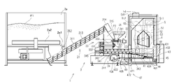
図1乃至4に示す本発明の燃焼装置1は、第1燃料F1を貯留する第1燃料貯留部2aと、第2燃料F2を貯留する第2燃料貯留部2bと、第1燃料F1及び第2燃料F2を搬送する搬送装置3と、を備える。燃焼装置1は、さらに、搬送装置3によって搬送された第1燃料F1及び第2燃料F2を火格子41上に配置し燃焼させるための燃焼室4と、燃焼室4で第1燃料F1及び第2燃料F2燃焼させて発生した高温の燃焼ガスを熱交換する熱交換部6と、を備えている。このような構成をした燃焼装置1は、第1燃料F1及び第2燃料F2を燃焼させて発生した熱によって熱交換部6で熱エネルギーを回収し、この熱エネルギーを活用するものである。
The
燃焼装置1の構成を詳細に説明する。
図1に示す第1燃料貯留部2aは直方体状に設けられた箱状の容器で、下方の面に孔部2a1を有している。第1燃料貯留部2aの内部には第1燃料F1が貯留可能で、孔部2a1から第1燃料F1が排出できる構造である。説明する実施形態において、第1燃料貯留部2aは1辺が1~2mと大きく設けられていて、第1燃料貯留部2aを多量に貯留することができる。第1燃料貯留部2aの内部で孔部2a1の近傍には鉛直方向を軸に回転する回転軸に対し放射状に腕部を設けた撹拌部2a2を備える。撹拌部2a2は第1燃料貯留部2aの内部の第1燃料F1を撹拌すると共に孔部2a1に誘導し、孔部2a1から排出させる。
The configuration of the
The
第1燃料貯留部2aとは離れた場所で、且つ、別体に設け第2燃料F2を貯留可能な第2燃料貯留部2bが配置されている。第2燃料貯留部2bは、下方に窄んだ四角錘状に設けた漏斗部材であり、窄んだ下方には孔部2b1が開けられている。第2燃料貯留部2bは、第2燃料F2を投入後、貯留することができると共に、孔部2b1から排出することができる。第2燃料貯留部2bの容積は第1燃料貯留部2aの容積より小さく設けられている。
A
ここで、第1燃料F1及び第2燃料F2を説明する。
第1燃料F1は燃焼装置1で燃焼させる主燃料で、主に木質を原料としたチップが用いられる。木質チップはその出所及び由来が多様で、例えば、丸太の様な幹、枝等の間伐材、灌木、剪定枝、樹皮等があり、これらをさらに切削又は破砕したものである。このことから木質チップそのものは一定の形状とはならず、その寸法は多様であるが、燃焼装置1に適した寸法は、横80mm以下、縦30mm以下、厚さ4mm以下であることが好まれる。
第1燃料F1となる木質チップは出所及び由来から、含有する水分量が多様である。燃料が含有する水分量は含水率として表され、第1燃料F1の含水率は水を含めた全体重量に対する水分重量の比として算出される。第1燃料F1の含水率は10~55重量%と幅広く、それぞればらつきが多いものの、安価で入手性が高く、連続的に使用する燃料としては好適である。
Here, the first fuel F1 and the second fuel F2 will be explained.
The first fuel F1 is the main fuel to be burned in the
The amount of moisture contained in the wood chips used as the first fuel F1 varies depending on the sources and origins. The amount of water contained in the fuel is expressed as a water content, and the water content of the first fuel F1 is calculated as the ratio of the water weight to the total weight including water. The water content of the first fuel F1 ranges widely from 10 to 55% by weight, and although there are many variations, it is inexpensive and highly available, and is suitable as a fuel for continuous use.
他方、第2燃料F2は、燃焼装置1で着火の際に用いる副燃料として使用する。第2燃料F2は、木材を細かく粉砕して小さな円筒状に固めた木質ペレットである。木質ペレットは、直径6~8mmで高さ10~12mmの円筒状に成型加工されている。また、木質ペレットは高温で圧縮成型するため、形状が安定していて、含水率は10重量%以下に抑制されたものが一般的に流通している。このことから、木質チップである第1燃料F1の含水率として表される重量%は、木質ペレットである第2燃料F2の重量%と同じか、高いものとなっている。形状安定性が良く且つ低含水率である第2燃料F2は、着火性及び燃焼性が良好であると言えるものの、第1燃料F1に対し高価で、連続的に使用するにはコストパフォーマンスが悪いという側面を持っている。
On the other hand, the second fuel F2 is used as an auxiliary fuel for ignition in the
さて、上述した第1燃料F1及び第2燃料F2は、第1燃料貯留部2aの孔部2a1と第2燃料貯留部2bの孔部2b1のそれぞれから下方に排出され、搬送装置3に送られる。搬送装置3は、第1燃料F1を搬送する第1搬送部31、第2燃料F2を搬送する第2搬送部32、第1搬送部31と第2搬送部32の合流部分でさらに下流側に搬送するパドル部33、パドル部33から送られた燃料をさらに下流の燃焼室4に送るための主搬送部34を有する。
Now, the first fuel F1 and the second fuel F2 described above are discharged downward from the hole 2a1 of the
第1搬送部31には、第1燃料貯留部2aの下部に一端側を位置させ、他端側を上方に持ち上げたように配置させ長い筒状部材311を備えている。筒状部材311の一端側の上部には、第1燃料貯留部2aの孔部2a1から排出された第1燃料F1を、筒状部材311の内部に誘導するための投入管路312が取付けられる。投入路312から筒状部材311内部に入れられた第1燃料F1は、筒状部材311の内部で筒と同軸に設けた螺旋羽根を有する第1スクリュ313によって筒状部材311の他端側に送られる。第1スクリュ313は、筒状部材311の他端側に設けた第1搬送モータ314によって回転駆動して、第1燃料F1を搬送する。筒状部材311の他端側に送られた第1燃料F1は、筒状部材311の他端側下部に設けられた中継管路315を通過してパドル部33の上方から送られる。
The first conveying
他方、第2燃料貯留部2bの孔部2b1から排出された第2燃料F2は第2搬送部32によって搬送される。第2搬送部32は、水平方向に長い筒状部材321を有する。筒状部材321の一端側には第2燃料貯留部2bの孔部2b1が接続され、第2燃料F2が筒状部材321の内部に直接入れられる。筒状部材321の内部には、螺旋羽根を有した第2スクリュ322が、筒の軸と同軸に取り付けられる。筒状部材321の一端には第2搬送モータ323が位置していて、第2スクリュ322を回転駆動させることにより、第2燃料F2を筒状部材321の一端側から他端側に搬送する。筒状部材321の他端はパドル部33の上部側方に接続されていて、第2燃料F2はパドル部33の上部側方に送られる。
On the other hand, the second fuel F2 discharged from the hole portion 2b1 of the second
パドル部33は、鉛直方向に向けて配置した矩形状断面を有したパドル管路331と、パドル管路331の対向する壁面間を架け渡すように配置したパドル332を有している。パドル332はパドル管路331の鉛直方向の中央部に配置され回転可能な部材で、回転軸を水平方向に向けている。パドル332には複数の羽根板333を回転軸に対し放射状に設けていて、回転時のパドル332の羽根板333の回転外周端はパドル管路331の壁面に近接するように設定されている。パドル332は回転駆動することによって、パドル管路331を羽根板で断続的に塞ぐことができる。パドル332の回転によって第1燃料F1及び第2燃料F2は間欠的にパドル部33下方に位置する主搬送部34に定量供給すると共に、後述する燃焼室4からの煙や熱気を、パドル部33より上流側に位置する第1搬送部31、第2搬送部32、第1燃料貯留部2a、第2燃料貯留部2bに流れることを防止する。
The
主搬送部34は、水平方向に長い筒状部材341を有する。筒状部材341の一端側の上部には、パドル部33と接続するために開口された搬入口342が位置していて、パドル部33より送られた第1燃料F1及び第2燃料F2を円筒状部材341内に導く。円筒状部材341の他端は後述する燃焼室4に接続され、第1燃料F1及び第2燃料F2を供給する部分となる燃料排出口343が設けられる。燃料排出口343は円筒状部材341の他端を筒の軸方向と直交する方向から切断した形状である。円筒状部材341の長手方向の内部には、主スクリュ344が設けられる。主スクリュ344は螺旋状部材を有した回転軸で、回転駆動することにより第1燃料F1及び第2燃料F2を搬入口342から燃料排出口343に搬送すると共に後述する燃焼室4に供給する。
The
前記パドル332、主スクリュ344は、ともに主搬送モータ345によって駆動される。主搬送モータ345は、筒状部材341の一端側に位置していて主スクリュ345を回転駆動する。主スクリュ344及び主スクリュ344の上方に位置するパドル332には、それぞれスプロケットが取付けられ、これらスプロケットにはチェーンが巻き付けることによってモータの回転をパドル332も伝動している。回転駆動するパドル332、主スクリュ344によって第1燃料F1及び第2燃料F2を燃焼室4内に供給する。
Both the
燃焼室4は、その内部に、第1燃料F1及び第2燃料F2が載置されると共に燃焼することができる火格子41と、火格子41上で発生した一時的に灰を受ける灰受け部43と、を備える。さらに燃焼室4は、灰受け部43の灰を回収すると共に燃焼室4外に移送する灰移送部45と、第1燃料F1及び第2燃料F2を着火させる着火装置47と、を備えている。
The
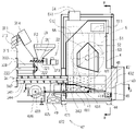
燃焼室4は、内部に燃焼用の空間を有した鉛直方向に長い箱状の多面体で、主搬送部34は燃焼室4の下部に接続されている。主搬送部34の燃料排出口343は、燃焼室4の内側に突出させて設けていて、第1燃料F1及び第2燃料F2を燃焼室4内に供給することができる。
The
燃焼室4内に位置する燃料排出口343の下方には、火格子41が位置していて、第1燃料F1及び第2燃料F2はこの火格子41上に供給される。火格子41は、主スクリュ34の回転軸と平行で、燃焼室4の内部に進むにつれて下るような階段状に形成している。実施形態において、火格子41は5段に設定されている。火格子41は、水平に設置した板状部材の端部を主スクリュ34の回転軸と直交する方向を稜線にして、図2に示すようにへの字状に下方に折り曲げた部材を複数重ねたように形成している。つまり、火格子41の階段状部分を下るにつれて、燃料排出口343から離れる構造になっている。
A
主スクリュ34によって押し出されるように燃料排出口343から供給されその後火格子41上に載置された第1燃料F1及び第2燃料F2は、主スクリュ34を回転させ続けると、後に供給された第1燃料F1及び第2燃料F2によって、階段状となった火格子41上を下るように押し出すことができる。
As the
火格子41上で燃焼を開始するには、先ず第2燃料F2を着火させる。着火に至る詳細な制御フローは後述するが、初めに第2燃料F2を火格子41上に少量ずつ供給する。その後、載置された火格子41上の第2燃料F2は、着火装置47によって高温となった空気を吹き付けられることによって発火する。着火装置47は、火格子41の上方で燃料排出口343の近傍に位置している。着火装置47は、伝熱部471によって加熱された空気を火格子41上にある少量の第2燃料F2に吹き付けることによって着火させる。その後、徐々に第2燃料F2を火格子41上に段階的に供給することによって、第2燃料F2の燃焼を安定化させる。
To start combustion on the
伝熱部471は、空気をパイプ状の給気管472で燃焼室4内に導くための給気管472内に設けられている。給気管472は、燃焼室4外に設けた給気ファン49に接続されることで、吸入した空気を伝熱部471に送る。給気管472の出口は燃焼室4内に突出させていて、伝熱部471は、この出口近傍に位置させている。これにより熱せられた空気が効率よく第2燃料F2に当たり、発火を促す。また、伝熱部471は電気エネルギーによって発熱が可能で、化石燃料等を使用する火炎バーナに対して、第1燃料F1及び第2燃料F2の他にさらに追加して燃料を搭載する必要が無い。このため、燃焼装置1を運用する上で必要な燃料を、第1燃料F1及び第2燃料F2に抑えることができる。
The
着火装置47によって点火し、安定的に燃焼している第2燃料F2には、搬送装置3によって第1燃料F1が供給されることで第1燃料F1が燃焼を開始する。燃焼中の第1燃料F1は、搬送装置3によって、段階的に火格子41上に送られ続ける。火格子41上で燃焼中の火炎は、燃料排出口343から供給される第1燃料F1に押されるため、燃料排出口343から離れた場所に位置する。図2に示す実施形態において、火炎は火格子41の1段目の角部から3段目の角部に渡って位置している。
The first fuel F1 is supplied by the conveying device 3 to the second fuel F2 that has been ignited by the
燃料排出口343から離れた場所で燃焼することで、燃料排出口343内及び火格子41上の燃料排出口343近傍に位置する第1燃料F1は、燃焼の火炎によって熱せられ、含有する水分が蒸発する。結果、燃焼室4内に供給された第1燃料F1は、含水率が低下することになり、第1燃料貯留部2aに貯留していた時よりも乾燥が進んだ状態になる。第1燃料F1は、搬送装置3によって燃料排出口343から新たに第1燃料F1が供給されることで、火炎側に押し出される。すると、乾燥状態になった第1燃料F1は火炎によって着火されて燃焼を開始する。このときの第1燃料F1は、乾燥が進んだ状態であるので燃焼効率が良く、安定的に燃焼を継続できる。
By combusting at a location away from the
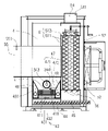
火格子41上の第1燃料F1及び第2燃料F2が押し出される方向に対して左右両端側は、複数の孔481があけられた給気箱48が設置されている。給気箱48は、給気ファン49から送られた空気を孔481から火格子41上の第1燃料F1及び第2燃料F2の側方側に送り、燃焼を助ける。さらに給気箱48の孔481は、火格子41の下方にも設けられている。火格子41の第1燃料F1及び第2燃料F2が押し出される方向に対して左右両部で、下方側に窪んだ段差部には切欠き部411が設けられていて、火格子41の下方の孔481から送られた空気は、この切欠き部411を通り第1燃料F1及び第2燃料F2に送られる。このように第1燃料F1及び第2燃料F2が載置されて燃焼する部分には下面に穴が無いため、第1燃料F1及び第2燃料F2及び燃焼後の灰は下方に落下することが無い。さらに、燃焼中の第1燃料F1及び第2燃料F2が押し出される方向の左右両側の近傍に位置する切欠き部411から空気が供給できるので、効率よく燃焼させることができる。
An
燃料排出口343より供給され続ける第1燃料F1によって、燃焼中の第1燃料F1及び第2燃料F2は火格子41上を階段を下るように移動しながら燃焼し、火格子41上を下るにつれて徐々に鎮火すると共に灰になっていく。灰は徐々に火格子41上から下方に押し出され、灰受け部43に到達する。
Due to the first fuel F1 continuously supplied from the
灰受け部43は、移動可能に設けられた揺動板431と、この揺動板431の下面に当接させると共に燃焼室4に対し固定して設けられた固定板432と、揺動板431を揺動駆動させる揺動モータ433を有している。さらに、灰受け部43は、溝部材44と、排出スクリュ45を備えていて、火格子41から移動してきた灰を燃焼室4外に移送させることができる。
The
揺動板431は、矩形状の厚板で、火格子41の階段状部分の最下段下部に位置させている。揺動板431の下方には、揺動板431と同様の矩形状板の厚板で燃焼室4に固定させた固定板432が位置していて、揺動板431は、火格子41の下方と固定板432
の上方の間で往復移動が可能に設けられている。揺動板431の端部には軸方向に摺動可能に設けたスライドロッド434の一端が連結され、スライドロッド434の他端側は燃焼室4外に突出させている。スライドロッド434の他端には、クランクロッド435の一端が回動自在に連結されている。さらにクランクロッド435の他端は、回転可能に設けられた円盤状のディスク436の外周近傍の面に回動自在に連結されている。
The rocking
is provided for reciprocating movement between above. One end of a
ディスク436の中心面は、燃焼室4外に設けた揺動モータ433に固着されていて、ディスク436は回転駆動することができる。ディスク436の回転は、クランクロッド435を介することでスライドロッド434が往復運動可能となり、スライドロッド434に接続する揺動板431も往復運動可能になっている。実施形態において揺動板431は、主スクリュ34の回転軸と平行に往復運動をする。また、揺動モータ433は、10~15回転毎分で回転駆動し、第1燃料F1の連続燃焼中30分に1回ずつ2分間駆動する。
The center surface of the
火格子41上を下るように移動してきた灰は、燃料排出口343から第1燃料F1によって押し出されるように、揺動板431又は固定板432上に移動する。
揺動板431が燃料排出口343から離れる位置にあり、且つ、揺動板431上に灰が移動してきた場合、揺動板431上の灰は、燃料排出口343側に近づくにつれて、火格子41の下部の板によって擦り落とされる。灰は相対的に揺動板431上を移動し、その後、固定板432上に落下する。その後、揺動板431は往復運動によって燃料排出口343から離れる方向に移動すると共に、固定板432上の灰を揺動板431の端面で押し出して、灰を溝部材44に落下させる。揺動板431が燃料排出口343に近い位置にあり、且つ、固定版432上に灰が直接移動してきた場合、揺動板431の移動と共に、固定板432上の灰を揺動板431の端面で押し出して、灰を溝部材44に落下させる。
The ash that has moved downward on the
When the rocking
溝部材44は、矩形状の板をコの字状に折り曲げ、開口側を上方に向けて溝を形成した部材である。溝部材44の溝の方向は、主スクリュ34の回転軸と直交する方向に向けられていて、片側の端部は燃焼室4外に延設されている。固定板432上の灰は、溝部材44の溝内に落下する。溝部材44の溝内には、溝と平行に設けた排出スクリュ45が配置されていて、溝部材44の溝内に落下した灰は、排出スクリュ45によって燃焼室4外に運ばれる。このため、燃焼室4内には、第1燃料F1及び第2燃料F2の燃焼後に発生する灰が溜まることがない。
The
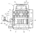
燃焼室4内で第1燃料F1及び第2燃料F2が燃焼して高温となった燃焼ガスは、燃焼室4に隣接する熱交換部5に移動する。熱交換部5は、燃焼室4の側方に設けられる円筒状の煙管51と、煙管51の周囲を囲うように配置した気体室52と、燃焼ガスを排気する煙突53を備えている。さらに、熱交換部5は、気体室52に固定して煙管51に空気を送風する送風ファン53と、送風ファン53によって煙管51から熱を受領した空気を送る配管を備えている。
The combustion gas heated to a high temperature by burning the first fuel F<b>1 and the second fuel F<b>2 in the
煙管51はパイプからなり、鉛直方向に長い気体室52中を貫通して鉛直方向に複数設置され、煙管51内を燃焼ガスが通過する。煙管51は、燃焼室4上部から下方に燃焼ガスが通過する入力側煙管511と、入力側煙管511を通過した燃焼ガスが排出側の上方に向かって通過する排出側煙管512からなる。
The
入力側煙管511と排出側煙管512はそれぞれ複数設けられ、それぞれ集められてグループを形成させる。これらそれぞれのグループに燃焼ガスが通気するので、燃焼ガスは乱れることなく、気体室52上部に設けた煙突54から排気される。煙突54の排出口内には温度センサ541が設置されていて、燃焼ガスの温度を計測することができる。
A plurality of input-
高温となった燃焼ガスは、気体室52内に配置された煙管51を通過することで、熱交換をすることができる。気体室52の側面には送風ファン53が取付けられていて、送風ファン53で気体室52内に送られる。送風された空気は気体室52内に滞留及び循環すると共に入力側煙管511と排出側煙管512に当たる。こうすることで、気体室52内に送られた空気は、煙管51から熱交換をして高温状態になる。
The hot combustion gas can exchange heat by passing through the
熱交換をより効率化するために、煙管51内には螺旋材56が挿入される。螺旋材75は、金属製の帯状板又は棒状材を螺旋状に成形してなる。燃焼ガスは、螺旋材75に沿って旋回しながら煙管51内を移動することで、燃焼ガスの移動距離が延びる。螺旋材75によって、燃焼ガスが、煙管71内を長い時間を掛けて移動するため、燃焼ガスの熱を煙管71から有効に気体室52内の送風ファン53によって送られた空気に伝達できる。熱交換後の燃焼ガスは熱を奪われて冷やされ、煙突54から排気される。
A
送風ファン53によって送られた空気は、熱交換後、気体室52に接続された配管55を経て、気体室52外に送られる。気体室52に一端を接続した配管55は、他端側を燃焼室4の中間部を貫通するように設置していて、熱交換後の空気は燃焼室4を横断する形態となっている。実施形態において、配管55の空気の流れる方向に対して直交する方向で断面した形状は五角形状となっていて、その下面は火格子41の階段部の角をそれぞれ結んだ直線で形成された傾斜線と平行になっている。
The air sent by the
こうすることにより、配管55は、燃焼室4内で発生した高温の燃焼ガス内に晒されると共に、火格子41上で発生する火炎にも晒される。配管55内に通気する熱交換後の空気は、燃焼室4内を横断する配管55からも、熱を受領することになる。結果、送風ファン53から気体室52、配管55を経て、配管55の他端から排出された空気は、より一層熱を受領した状態になり、より高温の空気を獲得できる。この高温の空気は、一例を挙げると、室内や農業用ハウス内の暖房及び乾燥等に使用される。また、配管55の他端部、内部には温度センサ551が取付けられていて、熱交換後の空気温度を計測する。
By doing so, the
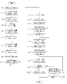
以上のように構成した燃焼装置1を使用し、停止状態から着火までの工程を、図5に示すフローチャートに基いて説明する。図中の符号Si(i=1,2,・・)は各ステップを示している。燃焼装置1は、停止状態から燃焼を点火させる着火モードと、着火後安定して燃焼させる通常燃焼モードがあるが、ここでは、停止状態から着火に至る工程の着火モードを説明する。
Using the
停止状態の燃焼装置1の運転スイッチ(図示せず)を操作すると、制御部(図示せず)に格納させた制御プログラムによって着火モードが開始される。すると、S1に移行して煙突の初期温度を計測する。温度の計測は、煙突54に設置された温度センサ541によって煙突54内を移動または滞留する排気温度を計測する。計測した値は、制御部に記憶される。
When the operation switch (not shown) of the
S1が終了すると、S2に移行し、第2搬送モータ323と主搬送モータ345を駆動させる。すると、第2燃料貯留部2bに貯留された第2燃料F2は、第2搬送部32及び主搬送部34を通過し、燃焼室4内の火格子41上に載置される。この実施の形態において、S2で駆動されるモータの駆動設定時間は50秒に設定されている。設定時間経過後、制御はS3に移行して第2搬送モータ323と主搬送モータ345を停止させ、火格子41への第2燃料F2の供給を停止させる。
When S1 ends, the process proceeds to S2, in which the
次いで、S4に移行して着火装置47の伝熱部471に通電すると共に給気ファン49を駆動させる。すると、給気ファン49によって送られた空気は、給気管472内に設置された発熱した伝熱部471を通過することによって加熱される。加熱した空気は熱風となり、火格子41上の第2燃料F2に吹き付けられる。すると、第2燃料F2は、熱風によって加熱し、その後着火に至る。また給気ファン49によって、空気は燃焼室4内の給気箱48に送り、火格子41の下部及び側部へ空気を吹き付ける。すると、火格子41上の第2燃料F2に、給気箱48の孔481及び火格子41の切欠き部411から空気が送られ、燃焼を助長させる。
Next, in S4, the
その後、S5に移行し、第2搬送モータ323と主搬送モータ345を再度駆動させ、第2燃料F2の供給を再開させる。着火を開始した火格子41上の第2燃料F2に、さらに、第2燃料F2を供給することになり、鎮火させることなく燃焼を継続させる。この実施の形態において、S5で駆動されるモータの駆動設定時間は30秒に設定されている。
設定時間経過後、制御はS6に移行して第2搬送モータ323と主搬送モータ345を停止させ、火格子41への第2燃料F2の供給を停止させる。また、S5からS6の間も熱風は火格子41上の第2燃料F2へ吹き続けていて、S4によって発生した初期燃焼を補助している。
After that, the process proceeds to S5, the
After the set time has elapsed, the control shifts to S6 to stop the second conveying
その後、S7に移行し、第2搬送モータ323と主搬送モータ345を再度駆動させ、格子41上に第2燃料F2を供給する。この実施の形態において、S7で駆動されるモータの駆動設定時間は20秒に設定されている。設定時間経過後、制御はS8に移行して第2搬送モータ323と主搬送モータ345を停止させる。
After that, the process proceeds to S7, the
S8に次いで、制御はS9に移行する。S9において、制御部は煙突54内の排気温度を計測し、記憶した後、S10に移行する。
S10において、制御部はS1で計測した温度より、S9で計測した温度が第1設定温度以上上昇しているかどうかを判断する。実施形態においては、第1設定温度を20度Cに設定している。S10でNoと判断した場合は、燃焼が不十分と判定してS7まで戻り、制御部はS7~S9の制御を実行させる。S10において、Yesと判断した場合は、燃焼室4内にて燃焼が行われていると判断してS11に移行する。
After S8, control passes to S9. In S9, the control unit measures the temperature of the exhaust gas in the
In S10, the controller determines whether the temperature measured in S9 is higher than the temperature measured in S1 by a first set temperature or more. In the embodiment, the first set temperature is set at 20 degrees Celsius. If it is determined No in S10, it is determined that the combustion is insufficient, and the process returns to S7, whereupon the control section executes the control of S7 to S9. If it is determined Yes in S10, it is determined that combustion is occurring in the
S11において、制御部は、主搬送モータ345を再度駆動させる。この実施形態において、主搬送モータ345は60秒駆動させる。これにより、主搬送部34内に残留する第2燃料F2を全て燃焼室4内に送り、筒状部材341内には何も無い状態にさせる。するとこの後に供給される第1燃料F1と混ざることがないので、着火特性及び燃焼特性の違いから生じる失火等の燃焼不具合を回避できる。その後、S12に移行し、主搬送モータ345を停止させる。
In S11, the control section drives the
次いで、S13に移行して煙突54内の排気温度を計測し、記憶する。その後、S14に移行する。S14において、制御部はS1で計測した温度より、S13で計測した温度が第2設定温度以上上昇しているかどうかを判断する。実施形態においては、第2設定温度を60度Cに設定している。S14でNoと判断した場合は、燃焼が不十分と判定してS11まで戻り、制御部はS11~S13の制御を実行させる。S14において、Yesと判断した場合は、制御部が燃焼室4内にて燃焼が正常に継続されていると判断し、S15に移行する。
Next, in S13, the exhaust temperature in the
S15に移行すると、伝熱部471への通電を停止させる。すると、給気管472から火格子41上の第2燃料F2への熱風の吹付けが停止され、S16に移行する。
S16では、第1搬送モータ314と主搬送モータ345を駆動させる。すると、第1燃料貯留部2aに貯留された第1燃料F1は、第1搬送部31及び主搬送部34を通過し、燃焼室4内の火格子41上及び火格子41上で燃焼する第2燃料F2上に載置される。S16で駆動される第1搬送モータ314の設定回転数は第1の回転数に設定されていて、連続的に燃料排出口343から火格子上41上に少量ずつ送られる。この実施形態においては、第1搬送モータ314の第1の回転数は1.2回転/毎分に設定されている。これは、徐々に第1燃料F1を送ることで、火格子41上での第2燃料F2の燃焼を妨げない効果がある。
After shifting to S15, the energization to the
In S16, the
S16に次いで、S17に移行する。S17では、煙突54内の排気温度を計測し、この排気温度を記憶する。その後、S18に移行する。
S18では、制御部はS1で計測した温度より、S17で計測した温度が第3設定温度以上上昇しているかどうかを判断する。実施形態においては、第3設定温度を100度Cに設定している。S18でNoと判断した場合は、燃焼が不十分と判定してS16まで戻り、制御部はS16~S17の制御を実行させる。S18において、Yesと判断した場合は、制御部が燃焼室4内にて燃焼が正常に継続されていると判断し、S19に移行する。
After S16, the process proceeds to S17. At S17, the temperature of the exhaust gas in the
In S18, the controller determines whether the temperature measured in S17 is higher than the temperature measured in S1 by a third set temperature or more. In the embodiment, the third preset temperature is set to 100 degrees Celsius. If it is determined No in S18, it is determined that the combustion is insufficient and the process returns to S16, and the control unit executes the control of S16 to S17. When it is determined Yes in S18, the control unit determines that the combustion is normally continued in the
S19では、第1搬送モータ314を第2の回転数で回転駆動させる。第2の回転数は、第1の回転数より速い回転数に設定されている。説明する実施形態において、第1搬送モータ314の第2の回転数は1.8回転/毎分に設定されている。このため、第1燃料貯留部2aに貯留された第1燃料F1は、S16より多く主搬送部34に送られ、結果として、単位時間あたりに燃焼室4内に送られる第1燃料F1は、S16よりS19が多くなる。これは、S18のステップによって、燃焼室4内で第1燃料F1の燃焼が進んで、安定して燃焼ができていると判断できることから、燃焼室4内に供給される第1燃料F1の量を増やして燃焼をさらに促進させる。
In S19, the
制御ステップはS19に次いでS20に移行する。S20では、配管55の排出口に設置された温度センサ551によって送風温度が設定温度以上であるかどうかを判断する。S19までのステップで燃焼室4にて燃焼が正常に行われると、燃焼ガスが正常に発生する。高温の燃焼ガスは熱交換部5経由し、排気される。着火モードとは別に制御される送風ファン53によって熱交換部5の配管51を通過した空気は、熱交換して熱を受領する。熱交換後の空気は加温された状態となっていて、温度センサ551は配管55を通過後の送風温度を計測している。S20のステップで、Noと判断すると、送風温度が設定温度以上となっていないと判断し、S21-1のステップに移行する。
After S19, the control step proceeds to S20. In S20, the
S21-1に移行すると、制御部は煙突51の排気温度が初期温度から第4設定温度以上上昇しているかどうかを判断する。実施形態においては、第4設定温度を100度Cに設定している。S21-1でNoと判断すると、制御はS22に移行する。すると、制御部は燃焼室4での燃焼が正常ではないと判断して、制御部は燃焼装置1を異常停止させて、着火モードは終了する。S21-1において、Yesと判断すると、制御部は燃焼室4内で燃焼は行われているものの、燃焼ガスの温度が上昇していないと判断し、S19まで戻り制御を繰り返す。
After shifting to S21-1, the control unit determines whether or not the exhaust temperature of the
S20において、Yesと判断すると、制御部は燃焼部4内での燃焼と熱交換部5における熱交換が正常に行われていると判断し、S21-2に移行する。S21-2において制御部は、燃焼モードを通常燃焼モードに移行させて、その後、着火モードを終了させる。
If it is determined Yes in S20, the control section determines that the combustion in the
以上のように着火工程を制御することで、第2燃料F2及び第1燃料F1はより確実に着火させることができ、燃焼装置1は着火完了後、正常に燃料を燃焼させることができる。
By controlling the ignition process as described above, the second fuel F2 and the first fuel F1 can be ignited more reliably, and the
また、図5に示すS5~S8のように、第2搬送モータ323と主搬送モータ345は、駆動と停止を複数回繰り返すことで、徐々に火格子41上に送られた第2燃料の燃焼を確実に行える。この実施形態では、制御ステップS4を経過後、第2搬送モータ323と主搬送モータ345は2回の駆動と停止を繰り返しているが、2回以上であっても良く、この場合、より緻密に燃焼を制御できる。
5, the second conveying
上述した実施形態で示した第1搬送モータ314及び第2搬送モータ323及び主搬送モータ345の駆動時間は、上述した時間以外でも良く、燃焼装置1を使用する環境や使用燃料の特性に合わせた時間に任意で変更することができる。
The driving times of the first conveying
また、上述した実施形態で示したS16~S19での主搬送モータ345の回転数は、第1及び第2の回転数として2種類で示したが、第3及びそれ以上の回転数を設定し、制御ステップが進むごとに徐々に回転数が大きくなるように設定しても良い。また、S21-2以降のステップに第3の回転数を設定してもよい。この場合、燃焼室4内に供給する第1燃料F1の量をより緻密にできるため、より細かな燃焼制御が可能である。
In addition, although the number of rotations of the
また、主搬送モータ345の回転数は、第1及び第2の回転数として具体的な回転数の数値を示したが、燃焼装置1を使用する環境や使用燃料の特性に合わせた回転数に任意で変更することができる。
Further, although the number of revolutions of the
また、揺動モータ433の回転数及び起動する時間の間隔は、具体的な回転数の数値を例示したが、燃焼度合や使用燃料の燃焼特性に合わせてそれぞれ任意で変更することができる。
Further, although the number of revolutions of the
以上のように構成した燃焼装置1によって、燃焼装置1の起動時における燃料への着火性の向上および連続燃焼における経済性の両立と、熱交換部の効率を上昇させる燃焼装置を提供できる。また。以上のように燃焼装置1な着火方法とすることで、第2燃料F2及び第1燃料F1はより確実に着火可能で、その後正常な燃焼を安定的にさせることができる。
With the
本発明は、上記の実施形態によって記載したが、この開示の一部をなす論述及び図面は、本発明を限定するものであると理解すべきではない。この開示に基づく実施形態、実施例及び運用技術の改変は、特許請求の範囲に記載された範囲内で可能であることは言うまでもない。 Although the present invention has been described by the above embodiments, the statements and drawings forming part of this disclosure should not be understood to limit the present invention. It goes without saying that modifications to the embodiments, examples, and operational techniques based on this disclosure are possible within the scope of the claims.
1 燃焼装置
2a 第1燃料貯留部
2b 第2燃料貯留部
3 搬送装置
31 第1搬送部
32 第2搬送部
34 主搬送部
4 燃焼室
41 火格子
411 切欠き部
43 灰受け部
431 揺動板
432 固定版
47 着火装置
5 熱交換部
F1 第1燃料
F2 第2燃料
1
Claims (5)
前記燃焼装置は、運転開始後に前記煙突内の排気温度を計測する工程と、
前記第2燃料が燃焼開始後に前記煙突内の排気温度を計測する工程と、
前記主搬送装置内の前記第2燃料を全て前記燃焼室内に搬送後に前記煙突内の排気温度を計測する工程と、
前記第1燃料が燃焼中の前記第2燃料に載置後に前記煙突内の排気温度を計測する工程と、
を含むことを特徴とする燃焼装置の着火方法。 a first transporting device that transports a first fuel, a second transporting device that transports a second fuel, the first fuel transported from the first transporting device, and the second fuel transported from the second transporting device a conveying device including a main conveying device for conveying into a combustion chamber; an ignition device for igniting the first fuel and the second fuel; A combustion apparatus comprising a chimney having a temperature sensor capable of measuring temperature,
a step of measuring the exhaust temperature in the chimney after the combustion apparatus starts operating;
measuring the exhaust temperature in the chimney after the second fuel starts burning;
a step of measuring the exhaust temperature in the chimney after all the second fuel in the main transfer device has been transferred into the combustion chamber;
measuring the exhaust temperature in the chimney after the first fuel is placed on the burning second fuel;
A method for igniting a combustion device, comprising:
前記制御部は、運転開始後に前記煙突内の排気温度を記憶する工程と、
前記第2燃料が燃焼開始後に前記煙突内の排気温度を記憶する工程と、
前記主搬送装置内の前記第2燃料を全て前記燃焼室内に搬送後に前記煙突内の排気温度を記憶する工程と、
前記第1燃料が燃焼中の前記第2燃料に載置後に前記煙突内の排気温度を記憶する工程と、
を含むことを特徴とする燃焼装置の着火方法。 a first transporting device that transports a first fuel, a second transporting device that transports a second fuel, the first fuel transported from the first transporting device, and the second fuel transported from the second transporting device a conveying device including a main conveying device for conveying into a combustion chamber; an ignition device for igniting the first fuel and the second fuel; A combustion apparatus comprising: a chimney having a temperature sensor capable of measuring temperature;
a step in which the control unit stores the temperature of the exhaust gas in the chimney after operation is started;
storing the exhaust temperature in the chimney after the second fuel starts burning;
a step of storing the temperature of the exhaust gas in the chimney after all the second fuel in the main conveying device has been conveyed into the combustion chamber;
storing the exhaust temperature in the chimney after the first fuel is placed on the burning second fuel;
A method for igniting a combustion device, comprising:
前記制御部は、運転開始後に前記煙突内の排気温度を初期温度として記憶する工程と、
前記第2燃料が燃焼開始後の前記煙突内の排気温度が前記初期温度より第1設定温度以上であるかを判断する工程と、
前記主搬送装置内の前記第2燃料を全て前記燃焼室内に搬送後の前記煙突内の排気温度が前記初期温度より第2設定温度以上であるかを判断する工程と、
前記第1燃料を燃焼中の前記第2燃料に載置後の前記煙突内の排気温度が前記初期温度より第3設定温度以上であるかを判断する工程と、
を含むことを特徴とする燃焼装置の着火方法。 a first transporting device that transports a first fuel, a second transporting device that transports a second fuel, the first fuel transported from the first transporting device, and the second fuel transported from the second transporting device a conveying device including a main conveying device for conveying into a combustion chamber; an ignition device for igniting the first fuel and the second fuel; A control capable of operably controlling a chimney having a temperature sensor capable of measuring temperature, the conveying device, and the ignition device, capable of storing the exhaust temperature, and capable of comparing whether the exhaust temperature is a set temperature. A combustion device comprising:
a step of storing the temperature of the exhaust gas in the chimney as an initial temperature after the operation is started;
a step of determining whether the temperature of the exhaust gas in the chimney after the second fuel starts burning is higher than the initial temperature and is equal to or higher than a first set temperature;
a step of determining whether the temperature of the exhaust gas in the chimney after all the second fuel in the main transfer device has been transferred into the combustion chamber is higher than the initial temperature and is equal to or higher than a second set temperature;
a step of determining whether the temperature of the exhaust gas in the chimney after the first fuel is placed on the burning second fuel is higher than the initial temperature to a third set temperature;
A method for igniting a combustion device, comprising:
前記制御部は、前記煙突内の排気温度が前記初期温度より第3設定温度以上であって、前記送風温度を計測する温度センサによる熱交換後の送風温度が設定温度以上になっていない場合に、前記煙突内の排気温度が初期温度から第4設定温度以上に上昇しているかどうかを判断する工程、
を含むことを特徴とする請求項3に記載の燃焼装置の着火方法。 The combustion device includes a pipe capable of exchanging heat with the combustion gas, and a temperature sensor inside the pipe for measuring the temperature of the blown air after heat exchange,
When the temperature of the exhaust gas in the chimney is higher than the initial temperature and is equal to or higher than a third set temperature, and the air temperature after heat exchange by the temperature sensor for measuring the air temperature is not equal to or higher than the set temperature , a step of determining whether the exhaust temperature in the chimney has increased from the initial temperature to a fourth set temperature or higher;
4. The method of igniting a combustion device according to claim 3, comprising:
前記第2搬送装置及び前記主搬送装置を複数回に分けて駆動させる工程と、
着火装置を作動させる工程と、
前記第1燃料及び前記第2燃料を燃焼させた燃焼ガスの排気温度を複数回に分けて判定する工程と、
前記排気温度を複数回に分けて判定する工程の内、初回の排気温度の判定後に前記主搬送装置のみを駆動させる工程と、
前記主搬送装置のみが停止後に、前記第1搬送装置及び前記主搬送装置を複数回に分けて駆動させる工程と、
を含むことを特徴とする燃焼装置の着火方法。
a first transporting device that transports a first fuel, a second transporting device that transports a second fuel, the first fuel transported from the first transporting device, and the second fuel transported from the second transporting device A combustion apparatus comprising a conveying device including a main conveying device for conveying into a combustion chamber, and an ignition device for igniting the first fuel and the second fuel,
a step of driving the second conveying device and the main conveying device in a plurality of times;
activating the ignition device;
a step of determining the exhaust temperature of the combustion gas obtained by burning the first fuel and the second fuel in a plurality of steps;
a step of driving only the main transport device after determining the exhaust gas temperature for the first time in the step of determining the exhaust gas temperature in a plurality of times;
a step of driving the first conveying device and the main conveying device in a plurality of times after only the main conveying device is stopped;
A method for igniting a combustion device, comprising:
Priority Applications (1)
| Application Number | Priority Date | Filing Date | Title |
|---|---|---|---|
| JP2022135703A JP7343933B2 (en) | 2018-10-31 | 2022-08-29 | Combustion device and ignition method for combustion device |
Applications Claiming Priority (2)
| Application Number | Priority Date | Filing Date | Title |
|---|---|---|---|
| JP2018206178A JP7137838B2 (en) | 2018-10-31 | 2018-10-31 | Combustion device and ignition method for combustion device |
| JP2022135703A JP7343933B2 (en) | 2018-10-31 | 2022-08-29 | Combustion device and ignition method for combustion device |
Related Parent Applications (1)
| Application Number | Title | Priority Date | Filing Date |
|---|---|---|---|
| JP2018206178A Division JP7137838B2 (en) | 2018-10-31 | 2018-10-31 | Combustion device and ignition method for combustion device |
Publications (2)
| Publication Number | Publication Date |
|---|---|
| JP2022166325A true JP2022166325A (en) | 2022-11-01 |
| JP7343933B2 JP7343933B2 (en) | 2023-09-13 |
Family
ID=70547769
Family Applications (2)
| Application Number | Title | Priority Date | Filing Date |
|---|---|---|---|
| JP2018206178A Active JP7137838B2 (en) | 2018-10-31 | 2018-10-31 | Combustion device and ignition method for combustion device |
| JP2022135703A Active JP7343933B2 (en) | 2018-10-31 | 2022-08-29 | Combustion device and ignition method for combustion device |
Family Applications Before (1)
| Application Number | Title | Priority Date | Filing Date |
|---|---|---|---|
| JP2018206178A Active JP7137838B2 (en) | 2018-10-31 | 2018-10-31 | Combustion device and ignition method for combustion device |
Country Status (1)
| Country | Link |
|---|---|
| JP (2) | JP7137838B2 (en) |
Families Citing this family (1)
| Publication number | Priority date | Publication date | Assignee | Title |
|---|---|---|---|---|
| CN115523507B (en) * | 2022-09-06 | 2025-04-18 | 华电浙江龙游热电有限公司 | A low-emission combustion control device for heavy-duty gas turbines |
Citations (2)
| Publication number | Priority date | Publication date | Assignee | Title |
|---|---|---|---|---|
| JP2006266546A (en) * | 2005-03-23 | 2006-10-05 | Kaneko Agricult Mach Co Ltd | Wood pellet fuel combustion equipment |
| JP2009030859A (en) * | 2007-07-26 | 2009-02-12 | Yamamoto Co Ltd | Wood pellet combustion equipment |
Family Cites Families (4)
| Publication number | Priority date | Publication date | Assignee | Title |
|---|---|---|---|---|
| JP2008215739A (en) | 2007-03-06 | 2008-09-18 | Schenkel Ernst | Water cooling type fire grate element |
| JP5096942B2 (en) | 2008-01-28 | 2012-12-12 | 三州産業株式会社 | Hot air heater for horticulture |
| KR101325750B1 (en) * | 2012-03-22 | 2013-11-08 | 주식회사 대경에스코 | The bio boiler with the facility which removes the dust to the automatic |
| JP6682231B2 (en) | 2015-10-13 | 2020-04-15 | 株式会社ササキコーポレーション | Combustion device |
-
2018
- 2018-10-31 JP JP2018206178A patent/JP7137838B2/en active Active
-
2022
- 2022-08-29 JP JP2022135703A patent/JP7343933B2/en active Active
Patent Citations (2)
| Publication number | Priority date | Publication date | Assignee | Title |
|---|---|---|---|---|
| JP2006266546A (en) * | 2005-03-23 | 2006-10-05 | Kaneko Agricult Mach Co Ltd | Wood pellet fuel combustion equipment |
| JP2009030859A (en) * | 2007-07-26 | 2009-02-12 | Yamamoto Co Ltd | Wood pellet combustion equipment |
Also Published As
| Publication number | Publication date |
|---|---|
| JP7137838B2 (en) | 2022-09-15 |
| JP2020070990A (en) | 2020-05-07 |
| JP7343933B2 (en) | 2023-09-13 |
Similar Documents
| Publication | Publication Date | Title |
|---|---|---|
| US4312278A (en) | Chip wood furnace and furnace retrofitting system | |
| JP4725712B2 (en) | Solid fuel combustion equipment | |
| JP5009265B2 (en) | Biomass fuel burner | |
| WO2009106992A2 (en) | Continuous drying apparatus and method | |
| US20130269677A1 (en) | Anti-Scorification Oven | |
| KR101062979B1 (en) | Combustion apparatus and heater and heater with same | |
| US20130269678A1 (en) | Anti-Scorification Oven | |
| JP5358794B2 (en) | Boiler system | |
| KR101772907B1 (en) | Solid fuel burner and solid fuel fan heater with the same | |
| JP2022166325A (en) | Combustion apparatus and ignition of combustion apparatus | |
| JP2005090802A (en) | Wood pellet fuel combustion system | |
| WO1995029366A1 (en) | A device for combustion of moist fuel | |
| EP2824049A1 (en) | Solid fuel heating apparatus | |
| JP6653901B2 (en) | Combustion equipment | |
| JP5030111B2 (en) | Ash removal means for solid fuel combustion equipment | |
| JP5393734B2 (en) | Automatic feeder for granular fuel and combustion apparatus for granular fuel incorporating the same | |
| JP2004293828A (en) | Combustion device | |
| JP5100232B2 (en) | Wood pellet combustion equipment | |
| KR101789463B1 (en) | Heating system with Solid fuel feeding device | |
| CN111051777B (en) | Rice husk burning device, grain drying system | |
| KR100877945B1 (en) | Auto combustion hot air fan | |
| JP2004316997A (en) | Pellet stove | |
| JP2011080614A (en) | Warm air heater | |
| JP4443825B2 (en) | Pellet fuel combustion equipment | |
| JP2007285570A (en) | Pellet stove and air supply method |
Legal Events
| Date | Code | Title | Description |
|---|---|---|---|
| A621 | Written request for application examination |
Free format text: JAPANESE INTERMEDIATE CODE: A621 Effective date: 20220926 |
|
| A977 | Report on retrieval |
Free format text: JAPANESE INTERMEDIATE CODE: A971007 Effective date: 20230419 |
|
| A131 | Notification of reasons for refusal |
Free format text: JAPANESE INTERMEDIATE CODE: A131 Effective date: 20230509 |
|
| A521 | Request for written amendment filed |
Free format text: JAPANESE INTERMEDIATE CODE: A523 Effective date: 20230601 |
|
| TRDD | Decision of grant or rejection written | ||
| A01 | Written decision to grant a patent or to grant a registration (utility model) |
Free format text: JAPANESE INTERMEDIATE CODE: A01 Effective date: 20230802 |
|
| A61 | First payment of annual fees (during grant procedure) |
Free format text: JAPANESE INTERMEDIATE CODE: A61 Effective date: 20230825 |
|
| R150 | Certificate of patent or registration of utility model |
Ref document number: 7343933 Country of ref document: JP Free format text: JAPANESE INTERMEDIATE CODE: R150 |