JP2022166323A - Article packaging box - Google Patents
Article packaging box Download PDFInfo
- Publication number
- JP2022166323A JP2022166323A JP2022135591A JP2022135591A JP2022166323A JP 2022166323 A JP2022166323 A JP 2022166323A JP 2022135591 A JP2022135591 A JP 2022135591A JP 2022135591 A JP2022135591 A JP 2022135591A JP 2022166323 A JP2022166323 A JP 2022166323A
- Authority
- JP
- Japan
- Prior art keywords
- small container
- container
- packaging box
- article packaging
- small
- Prior art date
- Legal status (The legal status is an assumption and is not a legal conclusion. Google has not performed a legal analysis and makes no representation as to the accuracy of the status listed.)
- Pending
Links
- 238000004806 packaging method and process Methods 0.000 title claims abstract description 307
- 238000000605 extraction Methods 0.000 claims description 53
- NJPPVKZQTLUDBO-UHFFFAOYSA-N novaluron Chemical compound C1=C(Cl)C(OC(F)(F)C(OC(F)(F)F)F)=CC=C1NC(=O)NC(=O)C1=C(F)C=CC=C1F NJPPVKZQTLUDBO-UHFFFAOYSA-N 0.000 claims description 25
- 230000004308 accommodation Effects 0.000 claims description 21
- 239000004743 Polypropylene Substances 0.000 claims description 15
- -1 polypropylene Polymers 0.000 claims description 15
- 229920001155 polypropylene Polymers 0.000 claims description 15
- 239000011347 resin Substances 0.000 claims description 15
- 229920005989 resin Polymers 0.000 claims description 15
- 239000007788 liquid Substances 0.000 claims description 11
- 239000002537 cosmetic Substances 0.000 claims description 8
- 238000003780 insertion Methods 0.000 description 32
- 230000037431 insertion Effects 0.000 description 32
- 239000000853 adhesive Substances 0.000 description 16
- 230000001070 adhesive effect Effects 0.000 description 16
- 238000010586 diagram Methods 0.000 description 11
- 230000000694 effects Effects 0.000 description 10
- 239000003292 glue Substances 0.000 description 10
- 238000005452 bending Methods 0.000 description 8
- 239000000463 material Substances 0.000 description 8
- 238000000034 method Methods 0.000 description 8
- 238000002834 transmittance Methods 0.000 description 4
- 230000015572 biosynthetic process Effects 0.000 description 3
- 239000006071 cream Substances 0.000 description 2
- 239000000499 gel Substances 0.000 description 2
- 230000002093 peripheral effect Effects 0.000 description 2
- 239000007787 solid Substances 0.000 description 2
Images

Classifications
-
- Y—GENERAL TAGGING OF NEW TECHNOLOGICAL DEVELOPMENTS; GENERAL TAGGING OF CROSS-SECTIONAL TECHNOLOGIES SPANNING OVER SEVERAL SECTIONS OF THE IPC; TECHNICAL SUBJECTS COVERED BY FORMER USPC CROSS-REFERENCE ART COLLECTIONS [XRACs] AND DIGESTS
- Y02—TECHNOLOGIES OR APPLICATIONS FOR MITIGATION OR ADAPTATION AGAINST CLIMATE CHANGE
- Y02W—CLIMATE CHANGE MITIGATION TECHNOLOGIES RELATED TO WASTEWATER TREATMENT OR WASTE MANAGEMENT
- Y02W30/00—Technologies for solid waste management
- Y02W30/50—Reuse, recycling or recovery technologies
- Y02W30/80—Packaging reuse or recycling, e.g. of multilayer packaging
Landscapes
- Cartons (AREA)
- Packages (AREA)
Abstract
Description
本発明は、2以上の容器を収容する物品包装箱に関するものであって、特に、高さの異なる2以上の容器を収容する柱状の物品包装箱に関する。 TECHNICAL FIELD The present invention relates to an article packaging box for accommodating two or more containers, and more particularly to a columnar article packaging box for accommodating two or more containers of different heights.
昨今、同じブランドを冠した種類の異なる化粧品等の製品を1つの物品包装箱に複数収容してパッケージ商品にして販売されることがある。
この物品包装箱に収容されている複数の製品は、それぞれの種類や目的・用途の違いにより、内容物の状態(液状・クリーム状・ジェル状・固形状等)や量が異なっている。
そのため、内容物を収める容器の形状は、製品によって異なっていることが多い。
In recent years, there are cases where a plurality of different types of products such as cosmetics bearing the same brand are housed in one article packaging box and sold as a packaged product.
A plurality of products housed in this product packaging box differ in content state (liquid, cream, gel, solid, etc.) and quantity due to differences in their types, purposes, and uses.
Therefore, the shape of the container containing the contents is often different depending on the product.
このような異なる容器形状の製品を1つの物品包装箱に複数収容して販売する場合、それぞれの製品が物品包装箱内でガタつかないように、物品包装箱の1つの周壁には収容された製品を上部より押さえるための押さえ片が物品包装箱内へ折り込み自在に延設されるとともに、押さえ片は物品包装箱内へ互いに異なる高さに突出して製品の上部に接する少なくとも2つの突出面を折り曲げ形成されたものが知られている(例えば、特許文献1)。 When a plurality of such products with different container shapes are housed in one article packaging box and sold, each product is housed in one peripheral wall of the article packaging box so as not to rattle in the article packaging box. A pressing piece for pressing the product from the upper part is provided so as to be freely foldable into the article packaging box, and the pressing piece protrudes into the article packaging box at different heights to form at least two protruding surfaces in contact with the upper part of the product. One that is formed by bending is known (for example, Patent Document 1).
通常、製品には企業ロゴや商品ロゴ等が記載される表示面が設けられており、複数の製品を物品包装箱に収容する際には、各々の製品の表示面の向きを揃えて物品包装箱に収容する。
しかしながら、前述の物品包装箱は、製品がガタついた際に製品が突出面に当たることで製品のガタつきを抑制するものにすぎないため、製品の容器形状が円柱形であった場合には輸送時の衝撃で製品が回ってしまい、出荷時に揃えておいた各々の製品の表示面の向きが揃わなくなってしまう恐れがある。
Products usually have a display surface on which a company logo, product logo, etc. are printed. house in a box.
However, the above-mentioned product packaging box only suppresses rattling of the product by hitting the projecting surface when the product rattles. There is a risk that the product will rotate due to the impact of time, and the orientation of the display surface of each product, which was aligned at the time of shipment, will not be aligned.
そこで、本発明は、前述したような従来技術の問題を解決するものであって、すなわち、本発明の目的は、輸送時等における容器の回動を抑えて収容姿勢を安定させる物品包装箱を提供することである。 SUMMARY OF THE INVENTION Accordingly, it is an object of the present invention to solve the above-described problems of the prior art, that is, an object of the present invention is to provide an article packaging box that suppresses rotation of the container during transportation and stabilizes the housing posture. to provide.
本請求項1に係る発明は、高さの異なる2以上の容器を取出開口から受け入れて前記高さの異なる2以上の容器を収矩形状の正面板と、該正面板の右側縁に連接した矩形状の右側面板と、前記正面板の左側縁に連接した矩形状の左側面板と、前記正面板の対向する矩形状の背面板とから形成され、高さの異なる2以上の容器を取出開口から受け入れて前記高さの異なる2以上の容器を収容する柱状の物品包装箱であって、前記2以上の容器のうち最も高い大容器を収容する柱状の大容器収容空間と、該大容器収容空間に併設されて前記2以上の容器のうち前記大容器以外の小容器を収容する柱状の小容器収容空間とを備え、前記大容器収容空間と前記小容器収容空間とが、単一のシートを折り込んで形成され、前記小容器収容空間が、前記正面板および前記小容器の表示面と対向する正面パネルと、前記正面パネルの右側縁と連接する矩形状の右側面パネルと、前記正面パネルの左側縁と連接する矩形状の左側面パネルと、前記背面板および前記小容器の裏面と対向する背面パネルとにより形成されて、前記取出開口と対向し前記小容器を前記小容器収容空間へと導く小容器受入開口を有し、前記背面パネルと連接される小容器保持片が、前記背面パネルと連接される連接端と、前記背面パネルに向かって上り傾斜となり前記小容器の表示面と当接する当接面とを有し、前記小容器が前記小容器収容空間に収容されている際に、前記小容器保持片が前記小容器受入開口を覆い、且つ、前記小容器保持片の当接面が前記小容器の表示面を前記小容器収容空間の背面パネル方向に向けて押圧して前記小容器を傾斜させた状態で位置決めしていることにより、前述した課題を解決するものである。 In the invention according to claim 1, two or more containers having different heights are received from a take-out opening and the two or more containers having different heights are accommodated in a rectangular front plate, which is connected to the right edge of the front plate. A rectangular right side plate, a rectangular left side plate contiguous with the left side edge of the front plate, and a rectangular rear plate opposite to the front plate. a columnar article packaging box for receiving two or more containers having different heights from a columnar article packaging box, the columnar large container accommodating space for accommodating the tallest large container among the two or more containers; A columnar small container storage space is provided side by side in the space and stores a small container other than the large container among the two or more containers, and the large container storage space and the small container storage space are formed into a single sheet. a front panel facing the front plate and the display surface of the small container, a rectangular right side panel connected to the right edge of the front panel, and the front panel and a rear panel facing the rear plate and the rear surface of the small container. The small container holding piece connected to the back panel has a small container receiving opening leading to the rear panel, and has a connecting end connected to the back panel and a display surface of the small container that slopes upward toward the back panel. and an abutting surface, wherein the small container holding piece covers the small container receiving opening when the small container is accommodated in the small container accommodating space, and the small container holding piece is brought into contact with the small container holding piece. The above-described problems are solved by positioning the small container in an inclined state by pressing the display surface of the small container toward the back panel of the small container housing space. .
本請求項2に係る発明は、請求項1に記載された物品包装箱の構成に加えて、前記取出開口を覆う天面蓋と、前記天面蓋が前記取出開口を覆っている際に前記取出開口と前記天面蓋との間を閉塞する天面サイドフラップと、前記小容器保持片と一端で連接されている帯状の連結片とを更に備え、前記天面蓋が前記取出開口を覆っている際に、前記連結片の他端が前記天面蓋または前記天面サイドフラップの少なくともいずれか一方と当接していることにより、前述した課題をさらに解決するものである。 The invention according to claim 2, in addition to the configuration of the article packaging box described in claim 1, further comprises a top cover covering the take-out opening, and a top cover covering the take-out opening. It further comprises a top side flap closing a space between the take-out opening and the top cover, and a strip-shaped connecting piece connected at one end to the small container holding piece, wherein the top cover covers the take-out opening. The above-described problem is further solved by the other end of the connecting piece abutting on at least one of the top cover and the top side flap when the cover is closed.
本請求項3に係る発明は、請求項2に記載された物品包装箱の構成に加えて、前記取出開口が開放されている際に、前記連結片が前記取出開口から突出していることにより、前述した課題をさらに解決するものである。 In the invention according to claim 3, in addition to the configuration of the article packaging box described in claim 2, when the extraction opening is opened, the connecting piece protrudes from the extraction opening, This is to further solve the above-mentioned problems.
本請求項4に係る発明は、請求項1乃至請求項3のいずれか1項に記載された物品包装箱の構成に加えて、前記正面パネルが、前記背面パネルと対向し、前記小容器保持片の可動領域と前記小容器収容空間の正面パネルとの間に間隙が形成されていることにより、前述した課題をさらに解決するものである。
The invention according to
本請求項5に係る発明は、請求項1乃至請求項4のいずれか1項に記載された物品包装箱の構成に加えて、前記小容器収容空間が、前記小容器の底部と当接する台座片を有し、前記大容器が前記大容器収容空間に収容されていると共に前記小容器が前記小容器収容空間に収容されている際に、前記台座片により前記小容器の底部が前記大容器の底部より上方に位置していることにより、前述した課題をさらに解決するものである。 The invention according to claim 5 is, in addition to the configuration of the article packaging box according to any one of claims 1 to 4, a pedestal in which the small container accommodating space abuts the bottom of the small container. When the large container is housed in the large container housing space and the small container is housed in the small container housing space, the pedestal piece prevents the bottom of the small container from being held against the large container. It further solves the above-mentioned problems by being located above the bottom of the .
本請求項6に係る発明は、請求項1乃至請求項5のいずれか1項に記載された物品包装箱の構成に加えて、前記小容器は、一端に出口が形成されており液体状の化粧品を収容するチューブ容器本体と、該チューブ容器本体の出口を閉塞する円筒状のチューブ容器蓋とを有し、前記小容器収容空間に前記小容器を収容した状態において、前記チューブ容器本体の出口が、鉛直下方を向いていることにより、前述した課題をさらに解決するものである。 The invention according to claim 6, in addition to the structure of the article packaging box according to any one of claims 1 to 5, is characterized in that the small container has an outlet formed at one end and is liquid-like. It has a tube container body that stores cosmetics and a cylindrical tube container lid that closes an outlet of the tube container body, and in a state in which the small container is stored in the small container storage space, the outlet of the tube container body. However, by facing vertically downward, the above-mentioned problems can be further solved.
本請求項7に係る発明は、請求項1乃至請求項6のいずれか1項に記載された物品包装箱の構成に加えて、光を透過するポリプロピレン樹脂で形成されていることにより、前述した課題をさらに解決するものである。 In addition to the configuration of the article packaging box according to any one of claims 1 to 6, the invention according to claim 7 is formed of a polypropylene resin that transmits light. This will further solve the problem.
本発明の物品包装箱によれば、2以上の容器を収容できるとともに、以下のような本発明に特有の効果を奏することができる。 According to the article packaging box of the present invention, two or more containers can be accommodated, and the following effects peculiar to the present invention can be exhibited.
本請求項1に係る発明の物品包装箱によれば、小容器が小容器収容空間に収容されている際に、小容器保持片が小容器受入開口を覆い、且つ、小容器保持片の当接面が小容器の表示面を小容器収容空間の背面パネル方向に向けて押圧して小容器を傾斜させた状態で位置決めしていることにより、物品包装箱に小容器を収容した状態で物品包装箱に振動が加わり、小容器に小容器の長手方向を中心とする回転力が付与されたとしても、小容器の表示面と小容器保持片の当接面とが接触しているため、小容器の長手方向を中心とする小容器の回動を抑制し、小容器の収容姿勢を安定させることができる。 According to the article packaging box of the invention according to claim 1, when the small container is accommodated in the small container accommodating space, the small container holding piece covers the small container receiving opening, and the small container holding piece touches the small container holding piece. The contact surface presses the display surface of the small container toward the back panel of the small container storage space and positions the small container in an inclined state, so that the goods can be handled while the small container is stored in the product packaging box. Even if the packaging box is vibrated and a rotational force is applied to the small container about the longitudinal direction of the small container, the display surface of the small container and the contact surface of the small container holding piece are in contact with each other. It is possible to suppress rotation of the small container about the longitudinal direction of the small container and stabilize the accommodation posture of the small container.
本請求項2に係る発明の物品包装箱によれば、請求項1に係る発明が奏する効果に加えて、小容器保持片と一端で連接されている帯状の連結片を備え、天面蓋が取出開口を覆っている際に、連結片の他端が天面蓋または天面サイドフラップの少なくともいずれか一方と当接していることにより、天面蓋が取出開口を覆っている際に、小容器保持片が当接面で小容器と当接すると共に天面蓋または天面サイドフラップのいずれか一方と当接する連結片と連接されていることで、小容器保持片の可動が抑制されるため、輸送時の振動等によって小容器に小容器収容空間の背面パネルから離反する方向の力が加わったとしても、小容器保持片と小容器との当接が保たれ、小容器の長手方向を中心とする小容器の回動を確実に抑制することができる。 According to the article packaging box of the invention according to claim 2, in addition to the effects of the invention according to claim 1, it is equipped with a strip-shaped connecting piece connected at one end to the small container holding piece, and the top lid is Since the other end of the connecting piece is in contact with at least one of the top cover and the top side flap when covering the extraction opening, when the top cover covers the extraction opening, the small Since the container holding piece abuts the small container on the abutment surface and is connected to the connecting piece that abuts either the top cover or the top side flap, movement of the small container holding piece is suppressed. Even if force is applied to the small container in the direction of separating it from the back panel of the small container storage space due to vibration during transportation, etc., the contact between the small container holding piece and the small container is maintained, and the small container is oriented in the longitudinal direction. Rotation of the center small container can be reliably suppressed.
本請求項3に係る発明の物品包装箱によれば、請求項2に係る発明が奏する効果に加えて、取出開口が開放されている際に、連結片が取出開口から突出していることにより、取出開口から小容器を取り出す際に連結片を把持可能となるため、取出開口から小容器を取り出す際に連結片を把持して小容器保持片を小容器から離反させると共に小容器受入開口を開放状態にして小容器を容易に取り出すことができる。 According to the article packaging box of the invention according to claim 3, in addition to the effects of the invention according to claim 2, when the extraction opening is open, the connecting piece protrudes from the extraction opening, Since the connecting piece can be gripped when taking out the small container from the take-out opening, the connecting piece is gripped to move the small container holding piece away from the small container and open the small container receiving opening when taking out the small container from the take-out opening. The small container can be easily taken out.
本請求項4に係る発明の物品包装箱によれば、請求項1乃至請求項3のいずれか1項に係る発明が奏する効果に加えて、小容器保持片の可動領域と小容器収容空間との間に間隙が形成されていることにより、小容器を出し入れする際に小容器保持片を可動させたとしても、小容器保持片の端部と小容器収容空間の正面パネルとが当接しないため、小容器を円滑に小容器収容空間内に保持できることに加え、小容器収容空間の正面パネルに擦り跡が形成されてしまうことを抑制することができる。
According to the article packaging box of the invention according to
本請求項5に係る発明の物品包装箱によれば、請求項1乃至請求項4のいずれか1項に係る発明が奏する効果に加えて、大容器が大容器収容空間に収容されていると共に小容器が小容器収容空間に収容されている際に、台座片により小容器の底部が大容器の底部より上方に位置していることにより、小容器の底部と大容器の底部とが鉛直方向において同じ高さに位置している場合に比べて、小容器が底上げされていることで小容器が取出開口に近づくため、小容器を取出開口から取り出しやすくなることに加え、小容器の表示面と大容器の表示面との位置を揃えることが可能になる。
しかも、台座片が小容器保持片と協働して小容器の上下動を抑え込むため、小容器の上下方向の収容位置を確実に決めることができる。
According to the article packaging box of the invention according to claim 5, in addition to the effects of the invention according to any one of claims 1 to 4, the large container is accommodated in the large container accommodation space. When the small container is accommodated in the small container accommodating space, the base piece positions the bottom of the small container above the bottom of the large container, so that the bottom of the small container and the bottom of the large container are aligned vertically. Compared to the case where the small container is positioned at the same height in , since the small container is raised, the small container is closer to the take-out opening, making it easier to take out the small container from the take-out opening. and the display surface of the large container can be aligned.
Moreover, since the pedestal piece cooperates with the small container holding piece to restrain the vertical movement of the small container, the vertical accommodation position of the small container can be determined reliably.
本請求項6に係る発明の物品包装箱によれば、請求項1乃至請求項5のいずれか1項に係る発明が奏する効果に加えて、小容器収容空間に小容器を収容した状態において、チューブ容器本体の出口が、鉛直下方を向いていることにより、小容器収容空間に小容器を収容した状態において、チューブ容器本体内に収容された化粧品が出口付近に貯まっている状態になるため、小容器を物品包装箱から取り出して使う際に、化粧品を小容器からすぐに出すことができる。
また、小容器の蓋部であるチューブ容器蓋が円筒状であることにより、より小容器が長手方向を中心として回動しやすくなっているが、小容器保持片によって小容器の回動を確実に抑制することができる。
According to the article packaging box of the invention according to claim 6, in addition to the effects of the invention according to any one of claims 1 to 5, in a state where the small container is accommodated in the small container accommodation space, Since the outlet of the tube container body faces vertically downward, cosmetics stored in the tube container body are accumulated near the outlet when the small container is stored in the small container storage space. To take out cosmetics from a small container immediately when the small container is taken out from an article packaging box and used.
In addition, since the tube container lid, which is the lid portion of the small container, is cylindrical, the small container can be more easily rotated about the longitudinal direction. can be suppressed to
本請求項7に係る発明の物品包装箱によれば、請求項1乃至請求項6のいずれか1項に係る発明が奏する効果に加えて、光を透過するポリプロピレン樹脂で形成されていることにより、物品包装箱の内部を外部から視認可能になるため、物品包装箱の収容物を外部から容易に把握することができる。 According to the article packaging box of the invention according to claim 7, in addition to the effects of the invention according to any one of claims 1 to 6, it is made of polypropylene resin that transmits light. Since the inside of the article packaging box can be visually recognized from the outside, the contents of the article packaging box can be easily grasped from the outside.
本発明は、矩形状の正面板と、この正面板の右側縁に連接した矩形状の右側面板と、正面板の左側縁に連接した矩形状の左側面板と、正面板の対向する矩形状の背面板とから形成され、高さの異なる2以上の容器を取出開口から受け入れて高さの異なる2以上の容器を収容する柱状の物品包装箱であって、2以上の容器のうち最も高い大容器を収容する柱状の大容器収容空間と、この大容器収容空間に併設されて2以上の容器のうち大容器以外の小容器を収容する柱状の小容器収容空間とを備え、大容器収容空間と小容器収容空間とが、単一のシートを折り込んで形成され、小容器収容空間が、正面板および小容器の表示面と対向する正面パネルと、正面パネルの右側縁と連接する矩形状の右側面パネルと、正面パネルの左側縁と連接する矩形状の左側面パネルと、背面板および小容器の裏面と対向する背面パネルとにより形成されて、取出開口と対向し小容器を小容器収容空間へと導く小容器受入開口を有し、背面パネルと連接される小容器保持片が、背面パネルと連接される連接端と、背面パネルに向かって上り傾斜となり小容器の表示面と当接する当接面とを有し、小容器が小容器収容空間に収容されている際に、小容器保持片が小容器受入開口を覆い、且つ、小容器保持片の当接面が前記小容器の表示面を小容器収容空間の背面パネル方向に向けて押圧して小容器を傾斜させた状態で位置決めし、小容器の長手方向を中心とする小容器の回動を抑制し、小容器の位置を定めることができるものであれば、その具体的な実施態様は、如何なるものであっても構わない。 The present invention comprises a rectangular front plate, a rectangular right side plate connected to the right side edge of the front plate, a rectangular left side plate connected to the left side edge of the front plate, and a rectangular shape facing the front plate. and a back plate, and receive two or more containers with different heights from take-out openings to store two or more containers with different heights, the container being the tallest among the two or more containers. The large container storage space is provided with a columnar large container storage space for storing containers and a small columnar container storage space for storing small containers other than the large containers among the two or more containers, which are provided side by side in the large container storage space. and a small container storage space are formed by folding a single sheet, and the small container storage space has a rectangular shape connected to the front panel facing the display surface of the front panel and the small container, and the right edge of the front panel. A right side panel, a rectangular left side panel connected to the left edge of the front panel, and a rear panel facing the rear panel and the rear surface of the small container, facing the take-out opening and accommodating the small container. A small container holding piece, which has a small container receiving opening leading to a space and is connected to the rear panel, is inclined upward toward the rear panel and contacts the display surface of the small container with the connecting end connected to the rear panel. and a contact surface, wherein the small container holding piece covers the small container receiving opening when the small container is accommodated in the small container accommodation space, and the contact surface of the small container holding piece contacts the small container. The display surface is pressed toward the back panel of the small container housing space to position the small container in an inclined state, suppress the rotation of the small container about the longitudinal direction of the small container, and position the small container. Any specific embodiment may be used as long as it is possible to define
例えば、物品包装箱は、箱体を形成できるものであれば、紙等の材料であっても良い。
なお、光を透過する材料で物品包装箱を形成する場合は、透明または半透明なポリプロピレン樹脂に限らず如何なる材料であっても良い。
For example, the article packaging box may be made of a material such as paper as long as it can form a box.
When the article packaging box is made of a light-transmitting material, the material is not limited to transparent or translucent polypropylene resin, and any material may be used.
また、本発明の物品包装箱に収容する容器については、高さの異なる2以上の容器であれば良いが、異なる高さの大小2つの容器を対象とした場合が最適である。 As for the containers to be housed in the article packaging box of the present invention, two or more containers having different heights may be used, but two large and small containers having different heights are optimal.
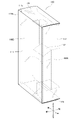
図1乃至図10に基づいて、本発明の第1実施例である物品包装箱100を説明する。
An
<1.1.物品包装箱100の基本構造>
まず、図1乃至図3を用いて、本発明の第1実施例である物品包装箱100の構造を説明する。
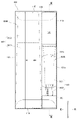
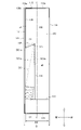
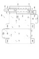
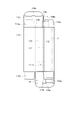
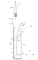
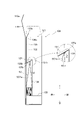
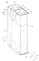
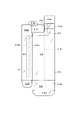
図1は本発明の第1実施例である物品包装箱の斜視概略図であり、図2は本発明の第1実施例である物品包装箱が陳列された状態の正面図であり、図3は図2のIII-III線に沿って見た物品包装箱の右端面の説明図である。
<1.1. Basic Structure of
First, the structure of an
FIG. 1 is a schematic perspective view of an article packaging box according to the first embodiment of the present invention, FIG. 2 is a front view of the article packaging box according to the first embodiment of the present invention in a displayed state, and FIG. 3 is an explanatory view of the right end face of the article packaging box as seen along line III-III of FIG. 2; FIG.
図1に示すように、物品包装箱100は、光を透過できる程度の透過率を有する透明または半透明なポリプロピレン樹脂で形成された柱状(直方体状)の箱体である。
そして、図1に示すように、物品包装箱100は、背の高い大容器BCを収容する柱状の大容器収容空間100Bと、背の低い小容器SCを収容する柱状の小容器収容空間100Sとを内部に有している。
本実施例では、正面視において、大容器収容空間100Bは左側に、小容器収容空間100Sは右側に併設されているが、大容器収容空間100Bを右側に、小容器収容空間100Sを左側に併設してもよい。
As shown in FIG. 1, the
As shown in FIG. 1, the
In this embodiment, when viewed from the front, the large
図2および図3は、大容器BCおよび小容器SCを収容した状態で陳列された物品包装箱100を示している。
ここで、図2および図3では、物品包装箱100の形状を明確にするために、大容器BCを物品包装箱100の底面板116から離間させているが、実際に物品包装箱100が陳列されている状態では、大容器BCは物品包装箱100内に載置されている。
また、物品包装箱100に大容器BCおよび小容器SCを収容した状態において、図3に示すように、大容器BCの表示面BC1aと小容器SCの表示面SC1aとは、いずれも前方を向いており、物品包装箱100を陳列した際に外部から視認されやすくなっている。
特に、小容器SCの表示面SC1aは、正面パネル131に形成された開口131cにより、外部から視認しやくなっている。
2 and 3 show an
Here, in FIGS. 2 and 3, the large container BC is separated from the
In addition, when the large container BC and the small container SC are accommodated in the
In particular, the display surface SC1a of the small container SC is easily visible from the outside due to the
なお、本実施例において、物品包装箱100は、2つの容器を収容しているが、3以上の容器を収容してもよい。
この場合、3以上の容器のうち、もっとも背の高い容器が大容器収容空間100Bに収容され、残りの容器のうち少なくとも1つが小容器収容空間100Sに収容されれば、その他の容器は物品包装箱100の如何なる場所に収容されていてもよい。
Although the
In this case, if the tallest container among the three or more containers is accommodated in the large
<1.2.容器の構造>
ここで、図2および図3を用いて、物品包装箱100に収容される大容器BCおよび小容器SCの構造を説明する。
<1.2. Container structure>
Here, the structures of the large container BC and the small container SC housed in the
大容器BCは、角錐台状であり、液体を収容している。
そして、この大容器BCは、大容器本体BC1と、大容器本体BC1の上方を覆う角筒状の大容器蓋BC2とを有している。
本実施例において、大容器BCは、大容器蓋BC2が上方に位置するように物品包装箱100に収容されているが、大容器BCの天地は逆であってもよい。
The large container BC is shaped like a truncated pyramid and contains a liquid.
The large container BC has a large container main body BC1 and a large container cover BC2 in the shape of a rectangular tube covering the upper part of the large container main body BC1.
In this embodiment, the large container BC is accommodated in the
小容器SCは、チューブ状の容器であり、大容器BCが収容している液体よりも粘度の高いクリーム状の液体を収容している。
そして、小容器SCは、一端に出口が形成されており液体状の化粧品を収容するチューブ容器本体SC1と、このチューブ容器本体SC1の出口を閉塞する円筒状のチューブ容器蓋SC2とを有している。
なお、ここでいう「円筒状」とは、楕円や多角形等の回動しやすい形状を意味する。
本実施例において、小容器SCは、チューブ容器蓋SC2が下方に位置するように、すなわち、チューブ容器本体SC1の出口が鉛直下方を向くように、物品包装箱100に収容されている。
The small container SC is a tube-shaped container and contains a cream-like liquid having a higher viscosity than the liquid contained in the large container BC.
The small container SC has an outlet formed at one end thereof and has a tube container main body SC1 for containing liquid cosmetics, and a cylindrical tube container lid SC2 for closing the outlet of the tube container main body SC1. there is
The term "cylindrical" as used herein means a shape such as an ellipse or a polygon that can be easily rotated.
In this embodiment, the small container SC is accommodated in the
<1.3.物品包装箱100の外観構造>
次に、図1乃至図4を用いて、物品包装箱100の外観構造を詳説する。
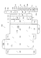
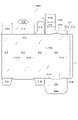
物品包装箱100は、単一のシート100Aを折り込んで形成される箱であり、図4に本発明の第1実施例である物品包装箱の展開図を示す。
<1.3. Appearance Structure of
Next, the external structure of the
The
大容器収容空間100Bの高さHは、図2に示すように、大容器BCの高さBHとほぼ等しくなっている。
大容器収容空間100Bの奥行きDは、図3に示すように、大容器BCの奥行きBDとほぼ等しくなっている。
これにより、大容器BCは、上下方向および前後方向に対して物品包装箱100内部でガタつきにくくなっている。
なお、ここでいう「大容器BCの奥行きBD」とは、大容器BCの奥行き(前後方向の長さ)のうち最も大きい部分であり、本実施例の場合は大容器本体BC1の底部の奥行きが「大容器BCの奥行きBD」に相当する。
The height H of the large
The depth D of the large
As a result, the large container BC is less likely to rattle inside the
Here, the "depth BD of the large container BC" is the largest part of the depth (the length in the front-rear direction) of the large container BC. corresponds to "the depth BD of the large container BC".
物品包装箱100の外観は、矩形状の正面板111と、この正面板111の右側縁111aに連接した矩形状の右側面板112と、正面板111の左側縁111bに連接すると共に右側面板112と対向する矩形状の左側面板113と、左側面板113の側縁(左側縁114b)に連接すると共に正面板111と対向する矩形状の背面板114と、正面板111の上側縁111cと連接した矩形状の天面板115と、背面板114の下側縁114aに連接すると共に天面板115と対向する矩形状の底面板116との6枚の矩形状板で形成されている。
このうち、正面板111と、右側面板112と、左側面板113と、背面板114とは、いずれも上下方向が長辺となっている。
また、天面板115および底面板116は、いずれも左右方向が長辺となっている。
The
Of these, the
Both the
そして、正面板111と、右側面板112と、左側面板113と、背面板114とにより物品包装箱100の前後左右が形成されている。
すなわち、正面板111と、右側面板112と、左側面板113と、背面板114とにより、物品包装箱100の上端には矩形状の取出開口121(図7B、図9参照)が形成されていると共に物品包装箱100の下端には矩形状の底部開口122(図7B参照)が形成されている。
この取出開口121の開口面積は、底部開口122の開口面積と等しい。
The
That is, the
The opening area of this
そして、取出開口121は、天面板115により覆われている。
取出開口121と天面板115との間には、右側面板112の上側縁に連接する右天面サイドフラップ112aと、左側面板113の上側縁に連接する左天面サイドフラップ113aとが設けられており、右天面サイドフラップ112aおよび左天面サイドフラップ113aの弾性により取出開口121と天面板115との間を閉塞している。
The
A right
底部開口122は、底面板116により覆われている。
底部開口122と底面板116との間には、右側面板112の下側縁に連接する右底面サイドフラップ112bと、左側面板113の下側縁に連接する左底面サイドフラップ113bとが設けられており、右底面サイドフラップ112bおよび左底面サイドフラップ113bの弾性により底部開口122と底面板116との間を閉塞している。
Between the
<1.4.物品包装箱100の内部構造>
次に、図1乃至図4に用いて、物品包装箱100の内部構造を詳説する。
<1.4. Internal Structure of
Next, the internal structure of the
小容器収容空間100Sは、小容器SCの表示面SC1aと対向する正面パネル131と、この正面パネル131の右側縁131aおよび背面板114の右側縁114cに連接した矩形状の右側面パネル132と、正面パネル131の左側縁131bに連接すると共に右側面パネル132と対向する左側面パネル133と、左側面パネル133の側縁133aに連接すると共に正面パネル131および小容器SCの裏面SC1bと対向する矩形状の背面パネル134とにより、前後左右が形成されている。
すなわち、正面パネル131と、右側面パネル132と、左側面パネル133と、背面パネル134とにより、小容器収容空間100Sの上端には取出開口121と対向する矩形状の小容器受入開口141が形成されている。
また、正面パネル131と、右側面パネル132と、左側面パネル133と、背面パネル134とは、いずれも上下方向が長辺となっている。
The small
That is, the
The
図3に示すように、正面パネル131は、正面板111と距離d1だけ離間対向すると共に正面板111と平行に配置されており、鉛直方向中央から下方にかけて開口131cが形成されている。
左側面パネル133は、小容器収容空間100Sの左側面を形成すると共に、大容器収容空間100Bと小容器収容空間100Sとを仕切っている。
背面パネル134は、背面板114と距離d2だけ離間対向すると共に背面板114と平行に配置されている。
As shown in FIG. 3, the
The
The
この背面パネル134と背面板114との距離d2は、正面パネル131と正面板111との距離d1より大きい。
また、小容器SCの前後方向の中心線C1は、物品包装箱100の前後方向の中心線Cよりも前方に位置している。
すなわち、小容器収容空間100Sは物品包装箱100の前方側に形成されており、小容器SCは物品包装箱100の前方側に配置されている。
The distance d2 between the
Further, the center line C1 in the front-rear direction of the small container SC is positioned forward of the center line C in the
That is, the small
また、小容器収容空間100Sは、底部に小容器SCと当接する台座片135を有している。
この台座片135は、貼り合わせ片139と連接している。
そして、台座片135は、右側面パネル132の下側縁に連接した矩形状の右底面サイドインナーフラップ132aと接着される接着片136aと、上下方向に延びていると共に接着片136aと台座片135とを連結する起立片136bとにより、水平に保たれている。
この台座片135により、大容器BCが大容器収容空間100Bに収容されていると共に小容器SCが小容器収容空間100Sに収容されている際に、小容器SCの底部が大容器BCの底部より鉛直方向上方に位置している。
In addition, the small
The
The
With this
さらに、小容器収容空間100Sは、背面パネル134の上側縁に連接されていると共に小容器SCを小容器収容空間100Sに収容している際に小容器受入開口141を覆う小容器保持片137を有している。
小容器保持片137は、背面パネル134と連接する連接端137aと、小容器SCを小容器収容空間100Sに収容している際に小容器SCと当接する矩形状の当接面137bとを有している。
Further, the small
The small
また、小容器保持片137は、前側端で帯状の連結片138とも連接されている。
この連結片138の他端には、連結片138より幅細の取っ手138aが形成されている。
The small
A
また、背面パネル134の側縁134aには、矩形状の貼り合わせ片139が連接されている。
そして、右側面パネル132、接着片136a、貼り合わせ片139に糊Pが塗布されている。
接着片136a、貼り合わせ片139については、表側に糊Pが帯状に塗布され、右側面パネル132については、裏側(紙面裏側)に糊Pが帯状に塗布されている。
A
Paste P is applied to the
The
<1.5.物品包装箱100の組み立て>
次に、図4乃至図7を用いて、物品包装箱100の組み立てを説明する。
図5、図6および図7(図7A、図7B)は、物品包装箱100の組み立て途中の状態を示す図である。
なお、組み立て工程を示す図5乃至図7では、物品包装箱100の構成を明確にするために、物品包装箱100が光を透過しないシートで形成されているとして図示する。
<1.5. Assembly of
Next, assembly of the
5, 6 and 7 (FIGS. 7A and 7B) are diagrams showing a state in which the
5 to 7 showing the assembly process, the
物品包装箱100は、図4に示す1枚のシート100Aを折り込んで形成される。
本実施例においてシート100Aはポリプロピレン樹脂製であることから、弾性変形しやすいため、シート100Aを折り込んでいく際に図4の状態(展開された状態)に復元しようとする力が働いてしまう。
そこで、シート100Aには、切り込みである罫線Vが複数かつ部分的に設けられており、この罫線Vによりシート100Aが図4の状態に戻りにくくなっている。
The
In this embodiment, since the
Therefore, the
シート100Aから物品包装箱100を組み立てるために、まず、正面パネル131の左側縁131bを折り込んで、貼り合わせ片139に塗布されている糊Pにより貼り合わせ片139と右側面パネル132とを貼り合わせる。
このとき、接着片136aに塗布されている糊Pにより接着片136aと右底面サイドインナーフラップ132aとが貼り合わされる。
これにより、図5のような状態になり、小容器収容空間100Sが形成される。
In order to assemble the
At this time, the
As a result, the state shown in FIG. 5 is obtained, and the small
続いて、背面板114の右側縁114cを折り込み、正面板111の左側縁111bを折り込む。
このとき、右側面パネル132に塗布されている糊Pにより右側面パネル132と右側面板112とが貼り合わされ、図6のような状態になる。
Next, the
At this time, the
続いて、右側面パネル132と右側面板112とが貼り合わされた状態のまま、右側縁111aおよび左側縁114bを折り曲げることにより、物品包装箱100の前後左右の面、取出開口121および底部開口122が形成される。
なお、この状態では、連結片138および取っ手138aが、取出開口121から突出している。
Subsequently, while the
In this state, the connecting
続いて、左底面サイドフラップ113bおよび右底面サイドフラップ112bを底部開口122に向かって折り込む(図7A参照)。
この際、右底面サイドフラップ112bを折り込むことで右底面サイドインナーフラップ132a(および右底面サイドインナーフラップ132aと一体になっている接着片136aも底部開口122に向かって折り込まれる。
そして、底面板116の底面差し込みフラップ116aを底部開口122に向かって折り込むことで、底部開口122が底面板116に覆われる(図7B参照)。
Subsequently, the left
At this time, by folding the right
Then, by folding the
続いて、取出開口121から大容器BCおよび小容器SCを物品包装箱100に入れる(物品包装箱100に対する小容器SCの出し入れについては後述する)。
Subsequently, the large container BC and the small container SC are put into the
続いて、左天面サイドフラップ113aおよび右天面サイドフラップ112aを取出開口121に向かって折り込む(図7A参照)。
そして、天面板115の天面差し込みフラップ115aを取出開口121に向かって折り込むことで、取出開口121が天面板115に覆われる(図7B参照)。
以上の手順により、物品包装箱100が形成される。
Subsequently, the left
By folding the
The
<1.6.物品包装箱100に対する小容器の出し入れ>
次に、物品包装箱100に対する小容器の出し入れについて詳述する。
<1.6. Putting in and taking out a small container from/to the
Next, the loading and unloading of the small container with respect to the
<1.6.1.物品包装箱100に対する小容器の挿入>
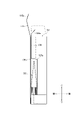
まず、物品包装箱100に対する小容器の挿入について、図2のIII-III線に沿って見た物品包装箱への小容器の挿入を説明する図である図8および図9を用いて詳述する。
<1.6.1. Insertion of Small Container into
First, the insertion of the small container into the
図8は、図7の状態から底部開口122を底面板116で覆った後の物品包装箱100である。
小容器SCの表示面SC1aを前方に向けた状態で、小容器SCを物品包装箱100の上方から小容器受入開口141に向けて挿入する。
この際、小容器SCを小容器受入開口141に挿入しやすくするために、天面板115および天面差し込みフラップ115aを前方側、連結片138および取っ手138aを後方側に倒しても良い。
FIG. 8 shows the
With the display surface SC1a of the small container SC facing forward, the small container SC is inserted from above the
At this time, in order to facilitate insertion of the small container SC into the small
小容器SCを小容器受入開口141に挿入して、台座片135に載置させた後、小容器保持片137の連接端137a、小容器保持片137と連結片138との境界の連結端138bを折り曲げて、図9に示すように、小容器保持片137が小容器受入開口141を覆う共に小容器保持片137の当接面137bを小容器SCの表示面SC1aと当接させる。
小容器保持片137の連接端137a、小容器保持片137と連結片138との境界の連結端138bを折り曲げる際、図8に示すように、小容器保持片137の可動領域Aと正面パネル131との間には間隙Gが形成されているので、小容器保持片137は、正面パネル131と当接しない。
After inserting the small container SC into the small
When bending the connecting
続いて、小容器保持片137の当接面137bと小容器SCの表示面SC1aとを当接させた状態で、左天面サイドフラップ113aおよび右天面サイドフラップ112aを取出開口121に向かって折り込む。
そして、連結片138と取っ手138aとの境界の上側端138cを折り曲げた状態で、天面板115の天面差し込みフラップ115aを取出開口121に向かって差し込む。
これにより、取出開口121が天面板115に覆われると共に、連結片138の上側端138cおよび取っ手138aが天面板115と当接する(図3等参照)。
Next, while the
Then, the
As a result, the
このとき、小容器保持片137の当接面137bが小容器SCの表示面SC1aを背面パネル134に向けて押しつけ力Fで押圧され、小容器SCが位置決めされる。
さらに、小容器保持片137が、当接面137bで小容器SCと当接すると共に天面板115と当接する連結片138と連結端138bで連接されているので、小容器保持片137の可動が抑制される。
加えて、連結片138の取っ手138aが天面板115および右天面サイドフラップで挟持されているため、連結片138(およびこれに連結する小容器保持片137)が動きにくくなり、小容器SCの回動をより抑制させている。
At this time, the
Furthermore, since the small
In addition, since the
なお、上記の説明では、左天面サイドフラップ113aおよび右天面サイドフラップ112aを取出開口121に向かって折り込んだ後に、連結片138と取っ手138aとの境界の上側端138cを折り曲げ、天面板115の天面差し込みフラップ115aを取出開口121に向かって差し込んだが、連結片138と取っ手138aとの境界の上側端138cを折り曲げた後に左天面サイドフラップ113aおよび右天面サイドフラップ112aを取出開口121に向かって折り込み、天面板115の天面差し込みフラップ115aを取出開口121に向かって差し込んでもよい。
In the above description, after folding the left
<1.6.2.物品包装箱100に対する小容器の取り出し>
次に、図10を用いて、物品包装箱100に対する小容器取り出しを詳述する。
図10は、図2のIII-III線に沿って見た物品包装箱に対する小容器の取り出しを説明する図である。
<1.6.2. Taking out a small container from the
Next, referring to FIG. 10, taking out the small container from the
FIG. 10 is a diagram illustrating removal of a small container from an article packaging box as viewed along line III-III in FIG.
図2および図3の状態から物品包装箱100から小容器SCを取り出す際、まずは天面板115および天面差し込みフラップ115aを上方に動かして取出開口121を開放する。
このとき、小容器保持片137、連結片138、取っ手138aに復元力が働き、図10のように、それぞれ上方に移動する。
When removing the small container SC from the
At this time, a restoring force acts on the small
この状態で、取っ手138aを摘まんで、上方に引き上げることで、小容器受入開口141が開放され、小容器SCが物品包装箱100から取り出せるようになる。
In this state, by grasping the
<1.7.第1実施例である物品包装箱100の効果>
このようにして得られた本発明の第1実施例である物品包装箱100は、小容器SCが小容器収容空間100Sに収容されている際に、小容器保持片137が小容器受入開口141を覆い、且つ、小容器保持片137の当接面137bが小容器SCの表示面SC1aを小容器収容空間100Sの背面パネル134方向に向けて押圧して小容器SCを位置決めしていることにより、小容器SCの長手方向を中心とする小容器SCの回動を抑制し、小容器SCの位置を定めることができる。
<1.7. Effects of the
In the
また、小容器保持片137と一端で連接されている帯状の連結片138を備え、天面蓋である天面板115が取出開口121を覆っている際に、連結片138の他端(取っ手138aまたは上側端138cの少なくとも一方)が天面板115または天面サイドフラップである右天面サイドフラップ112aの少なくともいずれか一方と当接していることにより、輸送時の振動等によって小容器SCに小容器収容空間100Sの背面パネル134から離反する方向の力が加わったとしても、小容器保持片137と小容器SCとの当接が保たれ、小容器SCの長手方向を中心とする小容器SCの回動を確実に抑制することができる。
Further, a belt-like connecting
また、小容器保持片137の可動領域Aと小容器収容空間100Sとの間に間隙Gが形成されていることにより、小容器SCを円滑に小容器収容空間100S内に保持できることに加え、小容器収容空間100Sの正面パネル131に擦り跡が形成されてしまうことを抑制することができる。
In addition, since the gap G is formed between the movable area A of the small
また、大容器BCが大容器収容空間100Bに収容されていると共に小容器SCが小容器収容空間100Sに収容されている際に、台座片135により小容器SCの底部が大容器BCの底部より上方に位置していることにより、小容器SCを取出開口121から取り出しやすくなることに加え、小容器SCの表示面SC1aと大容器BCの表示面BC1aとの位置を揃えることを可能にすることができる。
しかも、台座片135が小容器保持片137と協働して小容器SCの上下動を抑え込むため、小容器SCの上下方向の収容位置を確実に決めることができる。
Further, when the large container BC is housed in the large
Moreover, since the
また、物品包装箱100が光を透過するポリプロピレン樹脂で形成されていることにより、物品包装箱100の収容物を外部から容易に把握することができるなど、その効果は甚大である。
In addition, since the
次に、本発明の第2実施例である物品包装箱200について説明する。
第2実施例の物品包装箱200は、第1実施例の物品包装箱100における台座片13
5の形状を変更したものであり、多くの要素について第1実施例の物品包装箱100と共
通するので、共通する事項については詳しい説明を省略し、下2桁が共通する200番台
の符号を付すのみとする。
Next, an
The
5, and many elements are common to the
<2.1.物品包装箱200の基本構造>
まず、図11Aおよび図11Bを用いて、本発明の第2実施例である物品包装箱200の構造を説明する。
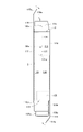
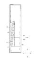
図11Aは本発明の第2実施例である物品包装箱が陳列された状態の正面図であり、図11Bは図11AのXI-XI線で切断した際における物品包装箱の右端面の説明図である。
<2.1. Basic Structure of
First, the structure of an
11A is a front view of the article packaging box according to the second embodiment of the present invention in a displayed state, and FIG. 11B is an explanatory view of the right end face of the article packaging box cut along line XI-XI in FIG. 11A. is.
第2実施例である物品包装箱200も第1実施例である物品包装箱100と同様に大容器BCと小容器SCとを収容しているが、大容器BCおよび小容器SCの形状が異なっている。
具体的には、大容器本体BC1が上方に、大容器蓋BC2が下方に設けられているが、第1実施例のように大容器本体BC1が上方に、大容器蓋BC2が下方に設けられている大容器BCであってもよい。
Like the
Specifically, the large container main body BC1 is provided upward and the large container lid BC2 is provided downward, but as in the first embodiment, the large container main body BC1 is provided upward and the large container lid BC2 is provided downward. It may be a large container BC with a
また、小容器SCは、チューブ状の容器ではなく、四方が密閉された帯状の容器である。
そして、図11Bに示すように、この小容器SCが複数個束になった状態で台座片235に載置されているが、正面パネル231と台座片235との前後方向の距離d3は、小容器SCの奥行きSDよりも狭くなっている。
これにより、小容器SCが正面パネル231と台座片235との間から落ちてしまうことが抑制されてている。
なお、ここでいう「小容器SCの奥行きSD」とは、小容器SCを束にした状態で奥行き(前後方向の長さ)のうち最も大きい部分である。
また、図11Bでは、3つの小容器SCが束になっているが、小容器SCの数はこれに限定されるものではない。
Also, the small container SC is not a tube-shaped container but a band-shaped container with four sides sealed.
As shown in FIG. 11B, a plurality of small containers SC are bundled and placed on the
This prevents the small container SC from falling from between the
The "depth SD of the small containers SC" referred to here is the largest part of the depth (the length in the front-rear direction) of the bundled small containers SC.
Also, although three small containers SC are bundled in FIG. 11B, the number of small containers SC is not limited to this.
次に、図12乃至図14を用いて本発明の参考例である物品包装箱300について説明する。
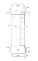
図12は本発明の参考例である物品包装箱を一部切り欠いた斜視概略図であり、図13は本発明の参考例である物品包装箱の展開図であり、図14は本発明の参考例である物品包装箱の組み立て途中の状態を示す背面図である。
なお、組み立て工程を示す図14では、物品包装箱300の構成を明確にするために、物品包装箱300が光を透過しないシートで形成されているとして図示する
Next, an
FIG. 12 is a schematic perspective view of a partially cut-out article packaging box that is a reference example of the present invention, FIG. 13 is a developed view of the article packaging box that is a reference example of the present invention, and FIG. It is a rear view which shows the state in the middle of assembly of the goods packaging box which is a reference example.
In addition, in FIG. 14 showing the assembly process, in order to clarify the configuration of the
<3.1.物品包装箱300の基本構造>
まず、図12を用いて本発明の参考例である物品包装箱300の構造を説明する。
図12に示すように、物品包装箱300は、光を透過できる程度の透過率を有する透明または半透明なポリプロピレン樹脂で形成された柱状(直方体状)の箱体である。
<3.1. Basic Structure of
First, the structure of an
As shown in FIG. 12, the
物品包装箱300は容器収容空間Sに複数の容器を収容しており、これら複数の容器のうち、少なくとも第1容器Cの表示面C1aは前方を向いており、物品包装箱300を陳列した際に外部から視認されやすくなっている。
なお、本実施例において、物品包装箱300は、2つの容器を収容しているが、3以上の容器を収容してもよい。
この場合、3以上の容器のうち、少なくとも1つの容器が容器保持片317と当接すれば、その他の容器は物品包装箱300の如何なる場所に収容されていてもよい。
The
Although the
In this case, as long as at least one of the three or more containers abuts against the
第1容器Cは、前述した小容器SCと同じチューブ状の容器であり、多くの要素について小容器SCと共通するので、共通する事項については詳しい説明を省略する。 The first container C is the same tube-shaped container as the small container SC described above, and has many elements in common with the small container SC, so detailed description of the common items will be omitted.
そして、第1容器Cが物品収容空間300Sに収容されている際に、容器保持片317の当接面317bが第1容器Cの表示面C1aを背面板314(図13参照)に向けて押しつけ力Fで押圧し、第1容器Cを位置決めしている。
さらに、容器保持片317が、当接面317bで第1容器Cと当接すると共に天面板315と当接する連結片318と連結端318bで連接されているので、容器保持片317の可動が抑制されている。
When the first container C is accommodated in the
Furthermore, since the
<3.2.物品包装箱300の外観構造>
次に、図12および図13を用いて、物品包装箱300の外観構造を詳説する。
物品包装箱300は、単一のシート300Aを折り込んで形成される箱であり、図13に本発明の参考例である物品包装箱の展開図を示す。
<3.2. Appearance Structure of
Next, the external structure of the
The
物品包装箱300の外観は、矩形状の正面板311と、この正面板311の右側縁311aに連接した矩形状の右側面板312と、正面板311の左側縁311bに連接すると共に右側面板312と対向する矩形状の左側面板313と、左側面板313の側縁(左側縁314b)に連接すると共に正面板311と対向する矩形状の背面板314と、正面板311の上側縁311cと連接した矩形状の天面板315と、背面板314の下側縁314aに連接すると共に天面板315と対向する矩形状の底面板316との6枚の矩形状板で形成されている。
このうち、正面板311と、右側面板312と、左側面板313と、背面板314とは、いずれも上下方向が長辺となっている。
また、天面板315および底面板316は、いずれも左右方向が長辺となっている。
そして、正面板311と、右側面板312と、左側面板313と、背面板314とにより物品包装箱300の前後左右が形成されている。
The
Of these, the
Both the
<3.3.物品包装箱300の内部構造>
次に、図12および図13を用いて、物品包装箱300の内部構造を詳説する。
右側面板312は、右側面板312の上側縁に連接する右天面サイドフラップ312aと、右側面板312の下側縁に連接する右底面サイドフラップ312bとを備えている。
また、左側面板313は、左側面板313の上側縁に連接する左天面サイドフラップ313aと、左側面板313の下側縁に連接する左底面サイドフラップ313bとを備えている。
この右天面サイドフラップ312aおよび左天面サイドフラップ313aの弾性により、取出開口と天面板315との間を閉塞している。
また、右底面サイドフラップ312bおよび左底面サイドフラップ313bの弾性により、底部開口と底面板316との間を閉塞している。
<3.3. Internal Structure of
Next, the internal structure of the
The
The
The resilience of the right
Also, the elasticity of the right
天面板315は、天面板315の上側縁に連接する天面差し込みフラップ315aを備えている。
底面板316は、底面板316の下側縁に連接する底面差し込みフラップ316aを備えている。
背面板314は、背面板314の右側縁314cに連接する貼り合わせ片314dを備えている。
この貼り合わせ片314dには、糊Pが塗布されている。
The
The
The
A glue P is applied to the
容器保持片317は、連接端317a(背面板314の上側縁)で背面板314と連接し、第1容器Cを容器収容空間300Sに収容している際に第1容器Cと当接する当接面317bとを有している。
そして、容器保持片317は、前側端(連結端318b)で帯状の連結片318とも連接されている。
この連結片318は、連結端318bとは反対側の端部である上側端318cで連接する取っ手318aを有している。
The
The
The connecting
<3.4.物品包装箱300の組み立て>
次に、図12乃至図14を用いて、物品包装箱300の組み立てを簡単に説明する。
<3.4. Assembly of
Next, assembly of the
物品包装箱300は、図13に示す1枚のシート300Aを折り込んで形成される。
本実施例においてシート300Aはポリプロピレン樹脂製であることから、弾性変形しやすいため、シート300Aを折り込んでいく際に図13の状態(展開された状態)に復元しようとする力が働いてしまう。
そこで、シート300Aには、切り込みである罫線Vが複数かつ部分的に設けられており、この罫線Vによりシート300Aが図13の状態に戻りにくくなっている。
The
In this embodiment, since the
Therefore, the
シート300Aから物品包装箱300を組み立てるために、まず、背面板314の左側縁314bを折り込んで、次に右側縁311aを折り曲げる。
このとき、貼り合わせ片314dに塗布されている糊Pにより貼り合わせ片314dと右側面板312とを貼り合わされ、図14のような状態になる。
In order to assemble the
At this time, the
続いて、貼り合わせ片314dと右側面板312とが貼り合わされた状態のまま、右側縁314cおよび左側縁311bを折り曲げることで、物品包装箱300の前後左右の面、取出開口および底部開口が形成される。
なお、この状態では、連結片318および取っ手318aが、取出開口から突出している。
Subsequently, while the
In this state, the connecting
続いて、左底面サイドフラップ313bおよび右底面サイドフラップ312bを底部開口に向かって折り込む。
そして、底面板316の底面差し込みフラップ316aを底部開口に向かって折り込むことで、底部開口が底面板に覆われる。
Subsequently, the left
By folding the
続いて、取出開口から第1容器Cやその他の容器を物品包装箱300に入れる。
Subsequently, the first container C and other containers are put into the
続いて、第1容器Cの表示面C1aを前方に向けた状態で、連結縁318bを折り曲げた状態で連接端317aを折り曲げる。
そして、左天面サイドフラップ313aおよび右天面サイドフラップ312aを取出開口に向かって折り込む。
そして、上側端318cを折り曲げた後、天面板315の天面差し込みフラップ315aを取出開口に向かって折り込むことで、取出開口が天面板315に覆われると共に取っ手318aが天面板315と当接する。
以上の手順により、物品包装箱300が形成される。
Subsequently, with the display surface C1a of the first container C facing forward, the connecting
Then, the left
After bending the
The
このように構成された物品包装箱300は、第1容器Cが容器収容空間300Sに収容されている際に、容器保持片317の当接面317bが第1容器Cの表示面C1aを背面板314方向に向けて押圧して第1容器Cを位置決めしていることにより、物品包装箱300に第1容器Cを収容した状態で物品包装箱300に振動が加わり、第1容器Cに第1容器Cの長手方向を中心とする回転力が付与されたとしても、第1容器Cの表示面C1aと容器保持片317の当接面317bとが接触しているため、第1容器Cの長手方向を中心とする第1容器Cの回動を抑制し、第1容器Cの収容姿勢を安定させることができる。
In the
100、200、300 ・・・ 物品包装箱
100A、 300A ・・・ シート
100B ・・・ 大容器収容空間
100S ・・・ 小容器収容空間
300S ・・・ 容器収容空間
111、 311 ・・・ 正面板
111a、 311a ・・・ 右側縁
111b、 311b ・・・ 左側縁
111c、 311c ・・・ 上側縁
112、 312 ・・・ 右側面板
112a、 312a ・・・ 右天面サイドフラップ(天面サイドフラップ)
112b、 312b ・・・ 右底面サイドフラップ
112c、 312c ・・・ 後側縁
113、 313 ・・・ 左側面板
113a、 313a ・・・ 左天面サイドフラップ
113b、 313b ・・・ 左底面サイドフラップ
114、 314 ・・・ 背面板
114a、 314a ・・・ 下側縁
114b、 314b ・・・ 左側縁
114c、 314c ・・・ 右側縁(右側面パネルの後側縁)
314d ・・・ 貼り合わせ片
115、 315 ・・・ 天面板(天面蓋)
115a、 315a ・・・ 天面差し込みフラップ
116、 316 ・・・ 底面板
116a、 316a ・・・ 底面差し込みフラップ
317 ・・・ 容器保持片
317a ・・・ 連接端
317b ・・・ 当接面
318 ・・・ 連結片
318a ・・・ 取っ手
318b ・・・ 連結端
318c ・・・ 上側端
121 ・・・ 取出開口
122 ・・・ 底部開口
131、231 ・・・ 正面パネル
131a ・・・ 右側縁
131b ・・・ 左側縁
131c ・・・ 開口
132 ・・・ 右側面パネル
132a ・・・ 右底面サイドインナーフラップ
132b ・・・ 後側縁
133 ・・・ 左側面パネル
133a ・・・ 側縁
134 ・・・ 背面パネル
134a ・・・ 側縁
135、235 ・・・ 台座片
136a ・・・ 接着片
136b ・・・ 起立片
137 ・・・ 小容器保持片
137a ・・・ 連接端
137b ・・・ 当接面
138 ・・・ 連結片
138a、 ・・・ 取っ手
138b、 ・・・ 連結端
138c、 ・・・ 上側端
139 ・・・ 貼り合わせ片
139b ・・・ 後側縁
141 ・・・ 小容器受入開口
C ・・・ 物品包装箱の前後方向の中心線
C1 ・・・ 小容器の前後方向の中心線
H ・・・ 大容器収容空間の高さ
D ・・・ 大容器収容空間の奥行き
d1 ・・・ 正面パネルと正面板との距離
d2 ・・・ 背面パネルと背面板との距離
d3 ・・・ 正面パネルと台座片との前後方向の距離
A ・・・ 小容器保持片の可動領域
G ・・・ 間隙
F ・・・ 押しつけ力
P ・・・ 糊
V ・・・ 罫線
BC ・・・ 大容器
BC1 ・・・ 大容器本体
BC1a ・・・ 表示面
BC2 ・・・ 大容器蓋
BH ・・・ 大容器の高さ
BD ・・・ 大容器の奥行き
SC ・・・ 小容器
SC1 ・・・ チューブ容器本体
SC1a ・・・ 表示面
SC1b ・・・ 裏面
SC2 ・・・ チューブ容器蓋
SD ・・・ 小容器の奥行き
C ・・・ 第1容器
C1 ・・・ 容器本体
C1a ・・・ 表示面
C2 ・・・ 容器蓋
100, 200, 300 ...
300S...
112b, 312b... right bottom side flaps 112c, 312c... rear side edges 113, 313...
314d...
115a, 315a ... Top surface insertion flaps 116, 316 ...
317 Container holding piece
317a ... connecting end
317b: contact surface
318 ... connecting piece
318a Handle
318b ... connection end
318c...
C... Front-back center line of article packaging box C1... Front-back center line of small container H... Height of large container storage space D... Depth of large container storage space d1... Distance between the front panel and the front board d2 --- Distance between the back panel and the back board d3 --- Distance between the front panel and the base piece in the front-rear direction
A: Movable area of small container holding piece G: Gap F: Pushing force P: Glue V: Ruled line
BC... Large container BC1... Large container main body BC1a... Display surface BC2... Large container cover BH... Height of large container BD... Depth of large container
SC... Small container SC1... Tube container body SC1a... Display surface SC1b... Back surface SC2... Tube container cover SD... Depth of small container
C... First container C1... Container main body C1a... Display surface C2... Container lid
本発明は、2以上の容器を収容する物品包装箱に関するものであって、特に、高さの異なる2以上の容器を収容する柱状の物品包装箱に関する。 TECHNICAL FIELD The present invention relates to an article packaging box for accommodating two or more containers, and more particularly to a columnar article packaging box for accommodating two or more containers of different heights.
昨今、同じブランドを冠した種類の異なる化粧品等の製品を1つの物品包装箱に複数収容してパッケージ商品にして販売されることがある。
この物品包装箱に収容されている複数の製品は、それぞれの種類や目的・用途の違いにより、内容物の状態(液状・クリーム状・ジェル状・固形状等)や量が異なっている。
そのため、内容物を収める容器の形状は、製品によって異なっていることが多い。
In recent years, there are cases where a plurality of different types of products such as cosmetics bearing the same brand are housed in one article packaging box and sold as a packaged product.
A plurality of products housed in this product packaging box differ in content state (liquid, cream, gel, solid, etc.) and quantity due to differences in their types, purposes, and uses.
Therefore, the shape of the container containing the contents is often different depending on the product.
このような異なる容器形状の製品を1つの物品包装箱に複数収容して販売する場合、それぞれの製品が物品包装箱内でガタつかないように、物品包装箱の1つの周壁には収容された製品を上部より押さえるための押さえ片が物品包装箱内へ折り込み自在に延設されるとともに、押さえ片は物品包装箱内へ互いに異なる高さに突出して製品の上部に接する少なくとも2つの突出面を折り曲げ形成されたものが知られている(例えば、特許文献1)。 When a plurality of such products with different container shapes are housed in one article packaging box and sold, each product is housed in one peripheral wall of the article packaging box so as not to rattle in the article packaging box. A pressing piece for pressing the product from the upper part is provided so as to be freely foldable into the article packaging box, and the pressing piece protrudes into the article packaging box at different heights to form at least two protruding surfaces in contact with the upper part of the product. One that is formed by bending is known (for example, Patent Document 1).
通常、製品には企業ロゴや商品ロゴ等が記載される表示面が設けられており、複数の製品を物品包装箱に収容する際には、各々の製品の表示面の向きを揃えて物品包装箱に収容する。
しかしながら、前述の物品包装箱は、製品がガタついた際に製品が突出面に当たることで製品のガタつきを抑制するものにすぎないため、製品の容器形状が円柱形であった場合には輸送時の衝撃で製品が回ってしまい、出荷時に揃えておいた各々の製品の表示面の向きが揃わなくなってしまう恐れがある。
Products usually have a display surface on which a company logo, product logo, etc. are printed. house in a box.
However, the above-mentioned product packaging box only suppresses rattling of the product by hitting the projecting surface when the product rattles. There is a risk that the product will rotate due to the impact of time, and the orientation of the display surface of each product, which was aligned at the time of shipment, will not be aligned.
そこで、本発明は、前述したような従来技術の問題を解決するものであって、すなわち、本発明の目的は、輸送時等における容器の回動を抑えて収容姿勢を安定させる物品包装箱を提供することである。 SUMMARY OF THE INVENTION Accordingly, it is an object of the present invention to solve the above-described problems of the prior art, that is, an object of the present invention is to provide an article packaging box that suppresses rotation of the container during transportation and stabilizes the housing posture. to provide.
本請求項1に係る発明は、高さの異なる2以上の容器を取出開口から受け入れて前記高さの異なる2以上の容器を収容する柱状の物品包装箱であって、前記2以上の容器のうち最も高い大容器を収容する柱状の大容器収容空間と、該大容器収容空間に併設されて前記2以上の容器のうち前記大容器以外の小容器を収容する柱状の小容器収容空間とを備え、前記大容器収容空間と前記小容器収容空間とが、単一のシートを折り込んで形成され、前記小容器収容空間が、前記小容器の裏面と対向する背面パネルと、前記取出開口と対向し前記小容器を前記小容器収容空間へと導く小容器受入開口と、前記背面パネルと連接される小容器保持片とにより少なくとも形成され、前記背面パネルと連接される小容器保持片が、前記背面パネルと連接される連接端と、前記背面パネルに向かって上り傾斜となり前記小容器の表示面と当接する当接面とを有し、前記小容器が前記小容器収容空間に収容されている際に、前記小容器保持片が前記小容器受入開口を覆い、且つ、前記小容器保持片の当接面が前記小容器の表示面を前記小容器収容空間の背面パネル方向に向けて押圧して前記小容器を傾斜させた状態で位置決めしていることにより、前述した課題を解決するものである。 The invention according to claim 1 is a columnar article packaging box for receiving two or more containers having different heights from take-out openings and housing the two or more containers having different heights, wherein the two or more containers A pillar-shaped large container storage space for accommodating the tallest large container among them, and a pillar-shaped small container storage space for accommodating the small containers other than the large container among the two or more containers, which are arranged side by side with the large container storage space. The large container storage space and the small container storage space are formed by folding a single sheet, and the small container storage space is provided with a rear panel facing the rear surface of the small container and the take-out opening. and a small container receiving opening for guiding the small container to the small container accommodating space, and a small container holding piece connected to the rear panel. It has a connecting end connected to a back panel and a contact surface that slopes upward toward the back panel and contacts the display surface of the small container, and the small container is accommodated in the small container accommodating space. At this time, the small container holding piece covers the small container receiving opening, and the contact surface of the small container holding piece presses the display surface of the small container toward the rear panel of the small container accommodating space. The above problem is solved by positioning the small container in an inclined state.
本請求項2に係る発明は、正面板と該正面板の左側縁に連接した左側面板と該左側面板に連接して前記正面板に離間対面する背面板と前記正面板の右側縁に連接した右側面板とで少なくとも囲繞された容器収容空間内に第1容器とその他の容器からなる2以上の容器を収容すると共に単一のシートを折り込んで形成された柱状の物品包装箱であって、前記背面板と連接される容器保持片を備え、前記容器保持片が、前記背面板と連接される連接端と、前記正面板側から前記背面板側に向かって上り傾斜となり前記第1容器の表示面と当接する当接面とを有し、前記第1容器が前記容器収容空間に収容されている際に、前記容器保持片の当接面が前記第1容器の表示面を前記背面板方向に向けて押圧して前記第1容器を位置決めしていることにより、前述した課題を解決するものである。 According to a second aspect of the present invention, there is provided a front plate, a left side plate connected to the left edge of the front plate, a rear plate connected to the left side plate and facing the front plate at a distance, and a right side edge of the front plate. A pillar-shaped article packaging box formed by folding a single sheet into which two or more containers consisting of a first container and other containers are accommodated in a container accommodating space at least surrounded by a right side plate, said A container holding piece connected to the back plate is provided, and the container holding piece slopes upward from the front plate side toward the back plate side with a connection end connected to the back plate to indicate the first container. and an abutment surface that abuts against the surface, and the abutment surface of the container holding piece faces the display surface of the first container in the direction of the back plate when the first container is housed in the container housing space. The above problem is solved by positioning the first container by pressing it toward.
本発明の物品包装箱によれば、2以上の容器を収容できるとともに、以下のような本発明に特有の効果を奏することができる。 According to the article packaging box of the present invention, two or more containers can be accommodated, and the following effects peculiar to the present invention can be exhibited.
本請求項1に係る発明の物品包装箱によれば、小容器が小容器収容空間に収容されている際に、小容器保持片が小容器受入開口を覆い、且つ、小容器保持片の当接面が小容器の表示面を小容器収容空間の背面パネル方向に向けて押圧して小容器を傾斜させた状態で位置決めしていることにより、物品包装箱に小容器を収容した状態で物品包装箱に振動が加わり、小容器に小容器の長手方向を中心とする回転力が付与されたとしても、小容器の表示面と小容器保持片の当接面とが接触しているため、小容器の長手方向を中心とする小容器の回動を抑制し、小容器の収容姿勢を安定させることができる。 According to the article packaging box of the invention according to claim 1, when the small container is accommodated in the small container accommodating space, the small container holding piece covers the small container receiving opening, and the small container holding piece touches the small container holding piece. The contact surface presses the display surface of the small container toward the back panel of the small container storage space and positions the small container in an inclined state, so that the goods can be handled while the small container is stored in the product packaging box. Even if the packaging box is vibrated and a rotational force is applied to the small container about the longitudinal direction of the small container, the display surface of the small container and the contact surface of the small container holding piece are in contact with each other. It is possible to suppress rotation of the small container about the longitudinal direction of the small container and stabilize the accommodation posture of the small container.
本請求項2に係る発明の物品包装箱によれば、第1容器が容器収容空間に収容されている際に、容器保持片の当接面が第1容器の表示面を背面板方向に向けて押圧して第1容器を位置決めしていることにより、物品包装箱に第1容器を収容した状態で物品包装箱に振動が加わり、第1容器に第1容器の長手方向を中心とする回転力が付与されたとしても、第1容器の表示面と容器保持片の当接面とが接触しているため、第1容器の長手方向を中心とする第1容器の回動を抑制し、第1容器の収容姿勢を安定させることができる。 According to the article packaging box of the invention of claim 2, when the first container is housed in the container housing space, the contact surface of the container holding piece faces the display surface of the first container toward the back plate. Vibration is applied to the article packaging box while the first container is accommodated in the article packaging box, and the first container rotates about the longitudinal direction of the first container. Even if force is applied, since the display surface of the first container and the contact surface of the container holding piece are in contact with each other, the rotation of the first container about the longitudinal direction of the first container is suppressed, The accommodation posture of the first container can be stabilized.
本発明は、高さの異なる2以上の容器を取出開口から受け入れて前記高さの異なる2以上の容器を収容する柱状の物品包装箱であって、前記2以上の容器のうち最も高い大容器を収容する柱状の大容器収容空間と、該大容器収容空間に併設されて前記2以上の容器のうち前記大容器以外の小容器を収容する柱状の小容器収容空間とを備え、前記大容器収容空間と前記小容器収容空間とが、単一のシートを折り込んで形成され、前記小容器収容空間が、前記小容器の裏面と対向する背面パネルと、前記取出開口と対向し前記小容器を前記小容器収容空間へと導く小容器受入開口と、前記背面パネルと連接される小容器保持片とにより少なくとも形成され、前記背面パネルと連接される小容器保持片が、前記背面パネルと連接される連接端と、前記背面パネルに向かって上り傾斜となり前記小容器の表示面と当接する当接面とを有し、前記小容器が前記小容器収容空間に収容されている際に、前記小容器保持片が前記小容器受入開口を覆い、且つ、前記小容器保持片の当接面が前記小容器の表示面を前記小容器収容空間の背面パネル方向に向けて押圧して前記小容器を傾斜させた状態で位置決めし、小容器の長手方向を中心とする小容器の回動を抑制し、小容器の位置を定めることができるものであれば、その具体的な実施態様は、如何なるものであっても構わない。 The present invention is a columnar article packaging box for receiving two or more containers with different heights from take-out openings to accommodate the two or more containers with different heights, wherein the large container is the tallest among the two or more containers. and a columnar small container space for accommodating a small container other than the large container among the two or more containers, the large container comprising a columnar large container space for accommodating the large container A storage space and the small container storage space are formed by folding a single sheet, and the small container storage space includes a rear panel facing the rear surface of the small container and a small container storage space facing the take-out opening. A small container holding piece connected to the rear panel is formed at least by a small container receiving opening leading to the small container accommodating space and a small container holding piece connected to the rear panel, and the small container holding piece connected to the rear panel is connected to the rear panel. and a contact surface that slopes upward toward the rear panel and contacts the display surface of the small container. The container holding piece covers the small container receiving opening, and the abutment surface of the small container holding piece presses the display surface of the small container toward the rear panel of the small container accommodating space to hold the small container. As long as it can position the small container in an inclined state, suppress the rotation of the small container about the longitudinal direction of the small container, and determine the position of the small container, any specific embodiment can be used. It doesn't matter if it is.
例えば、物品包装箱は、箱体を形成できるものであれば、紙等の材料であっても良い。
なお、光を透過する材料で物品包装箱を形成する場合は、透明または半透明なポリプロピレン樹脂に限らず如何なる材料であっても良い。
For example, the article packaging box may be made of a material such as paper as long as it can form a box.
When the article packaging box is made of a light-transmitting material, the material is not limited to transparent or translucent polypropylene resin, and any material may be used.
また、本発明の物品包装箱に収容する容器については、高さの異なる2以上の容器であれば良いが、異なる高さの大小2つの容器を対象とした場合が最適である。 As for the containers to be housed in the article packaging box of the present invention, two or more containers having different heights may be used, but two large and small containers having different heights are optimal.
図1乃至図10に基づいて、本発明の第1実施例である物品包装箱100を説明する。
An
<1.1.物品包装箱100の基本構造>
まず、図1乃至図3を用いて、本発明の第1実施例である物品包装箱100の構造を説明する。
図1は本発明の第1実施例である物品包装箱の斜視概略図であり、図2は本発明の第1実施例である物品包装箱が陳列された状態の正面図であり、図3は図2のIII-III線に沿って見た物品包装箱の右端面の説明図である。
<1.1. Basic Structure of
First, the structure of an
FIG. 1 is a schematic perspective view of an article packaging box according to the first embodiment of the present invention, FIG. 2 is a front view of the article packaging box according to the first embodiment of the present invention in a displayed state, and FIG. 3 is an explanatory view of the right end face of the article packaging box as seen along line III-III of FIG. 2; FIG.
図1に示すように、物品包装箱100は、光を透過できる程度の透過率を有する透明または半透明なポリプロピレン樹脂で形成された柱状(直方体状)の箱体である。
そして、図1に示すように、物品包装箱100は、背の高い大容器BCを収容する柱状の大容器収容空間100Bと、背の低い小容器SCを収容する柱状の小容器収容空間100Sとを内部に有している。
本実施例では、正面視において、大容器収容空間100Bは左側に、小容器収容空間100Sは右側に併設されているが、大容器収容空間100Bを右側に、小容器収容空間100Sを左側に併設してもよい。
As shown in FIG. 1, the
As shown in FIG. 1, the
In this embodiment, when viewed from the front, the large
図2および図3は、大容器BCおよび小容器SCを収容した状態で陳列された物品包装箱100を示している。
ここで、図2および図3では、物品包装箱100の形状を明確にするために、大容器BCを物品包装箱100の底面板116から離間させているが、実際に物品包装箱100が陳列されている状態では、大容器BCは物品包装箱100内に載置されている。
また、物品包装箱100に大容器BCおよび小容器SCを収容した状態において、図3に示すように、大容器BCの表示面BC1aと小容器SCの表示面SC1aとは、いずれも前方を向いており、物品包装箱100を陳列した際に外部から視認されやすくなっている。
特に、小容器SCの表示面SC1aは、正面パネル131に形成された開口131cにより、外部から視認しやくなっている。
2 and 3 show an
Here, in FIGS. 2 and 3, the large container BC is separated from the
In addition, when the large container BC and the small container SC are accommodated in the
In particular, the display surface SC1a of the small container SC is easily visible from the outside due to the
なお、本実施例において、物品包装箱100は、2つの容器を収容しているが、3以上の容器を収容してもよい。
この場合、3以上の容器のうち、もっとも背の高い容器が大容器収容空間100Bに収容され、残りの容器のうち少なくとも1つが小容器収容空間100Sに収容されれば、その他の容器は物品包装箱100の如何なる場所に収容されていてもよい。
Although the
In this case, if the tallest container among the three or more containers is accommodated in the large
<1.2.容器の構造>
ここで、図2および図3を用いて、物品包装箱100に収容される大容器BCおよび小容器SCの構造を説明する。
<1.2. Container structure>
Here, the structures of the large container BC and the small container SC housed in the
大容器BCは、角錐台状であり、液体を収容している。
そして、この大容器BCは、大容器本体BC1と、大容器本体BC1の上方を覆う角筒状の大容器蓋BC2とを有している。
本実施例において、大容器BCは、大容器蓋BC2が上方に位置するように物品包装箱100に収容されているが、大容器BCの天地は逆であってもよい。
The large container BC is shaped like a truncated pyramid and contains a liquid.
The large container BC has a large container main body BC1 and a large container cover BC2 in the shape of a rectangular tube covering the upper part of the large container main body BC1.
In this embodiment, the large container BC is accommodated in the
小容器SCは、チューブ状の容器であり、大容器BCが収容している液体よりも粘度の高いクリーム状の液体を収容している。
そして、小容器SCは、一端に出口が形成されており液体状の化粧品を収容するチューブ容器本体SC1と、このチューブ容器本体SC1の出口を閉塞する円筒状のチューブ容器蓋SC2とを有している。
なお、ここでいう「円筒状」とは、楕円や多角形等の回動しやすい形状を意味する。
本実施例において、小容器SCは、チューブ容器蓋SC2が下方に位置するように、すなわち、チューブ容器本体SC1の出口が鉛直下方を向くように、物品包装箱100に収容されている。
The small container SC is a tube-shaped container and contains a cream-like liquid having a higher viscosity than the liquid contained in the large container BC.
The small container SC has an outlet formed at one end thereof and has a tube container main body SC1 for containing liquid cosmetics, and a cylindrical tube container lid SC2 for closing the outlet of the tube container main body SC1. there is
The term "cylindrical" as used herein means a shape such as an ellipse or a polygon that can be easily rotated.
In this embodiment, the small container SC is accommodated in the
<1.3.物品包装箱100の外観構造>
次に、図1乃至図4を用いて、物品包装箱100の外観構造を詳説する。
物品包装箱100は、単一のシート100Aを折り込んで形成される箱であり、図4に本発明の第1実施例である物品包装箱の展開図を示す。
<1.3. Appearance Structure of
Next, the external structure of the
The
大容器収容空間100Bの高さHは、図2に示すように、大容器BCの高さBHとほぼ等しくなっている。
大容器収容空間100Bの奥行きDは、図3に示すように、大容器BCの奥行きBDとほぼ等しくなっている。
これにより、大容器BCは、上下方向および前後方向に対して物品包装箱100内部でガタつきにくくなっている。
なお、ここでいう「大容器BCの奥行きBD」とは、大容器BCの奥行き(前後方向の長さ)のうち最も大きい部分であり、本実施例の場合は大容器本体BC1の底部の奥行きが「大容器BCの奥行きBD」に相当する。
The height H of the large
The depth D of the large
As a result, the large container BC is less likely to rattle inside the
Here, the "depth BD of the large container BC" is the largest part of the depth (the length in the front-rear direction) of the large container BC. corresponds to "the depth BD of the large container BC".
物品包装箱100の外観は、矩形状の正面板111と、この正面板111の右側縁111aに連接した矩形状の右側面板112と、正面板111の左側縁111bに連接すると共に右側面板112と対向する矩形状の左側面板113と、左側面板113の側縁(左側縁114b)に連接すると共に正面板111と対向する矩形状の背面板114と、正面板111の上側縁111cと連接した矩形状の天面板115と、背面板114の下側縁114aに連接すると共に天面板115と対向する矩形状の底面板116との6枚の矩形状板で形成されている。
このうち、正面板111と、右側面板112と、左側面板113と、背面板114とは、いずれも上下方向が長辺となっている。
また、天面板115および底面板116は、いずれも左右方向が長辺となっている。
The
Of these, the
Both the
そして、正面板111と、右側面板112と、左側面板113と、背面板114とにより物品包装箱100の前後左右が形成されている。
すなわち、正面板111と、右側面板112と、左側面板113と、背面板114とにより、物品包装箱100の上端には矩形状の取出開口121(図7B、図9参照)が形成されていると共に物品包装箱100の下端には矩形状の底部開口122(図7B参照)が形成されている。
この取出開口121の開口面積は、底部開口122の開口面積と等しい。
The
That is, the
The opening area of this
そして、取出開口121は、天面板115により覆われている。
取出開口121と天面板115との間には、右側面板112の上側縁に連接する右天面サイドフラップ112aと、左側面板113の上側縁に連接する左天面サイドフラップ113aとが設けられており、右天面サイドフラップ112aおよび左天面サイドフラップ113aの弾性により取出開口121と天面板115との間を閉塞している。
The
A right
底部開口122は、底面板116により覆われている。
底部開口122と底面板116との間には、右側面板112の下側縁に連接する右底面サイドフラップ112bと、左側面板113の下側縁に連接する左底面サイドフラップ113bとが設けられており、右底面サイドフラップ112bおよび左底面サイドフラップ113bの弾性により底部開口122と底面板116との間を閉塞している。
Between the
<1.4.物品包装箱100の内部構造>
次に、図1乃至図4に用いて、物品包装箱100の内部構造を詳説する。
<1.4. Internal Structure of
Next, the internal structure of the
小容器収容空間100Sは、小容器SCの表示面SC1aと対向する正面パネル131と、この正面パネル131の右側縁131aおよび背面板114の右側縁114cに連接した矩形状の右側面パネル132と、正面パネル131の左側縁131bに連接すると共に右側面パネル132と対向する左側面パネル133と、左側面パネル133の側縁133aに連接すると共に正面パネル131および小容器SCの裏面SC1bと対向する矩形状の背面パネル134とにより、前後左右が形成されている。
すなわち、正面パネル131と、右側面パネル132と、左側面パネル133と、背面パネル134とにより、小容器収容空間100Sの上端には取出開口121と対向する矩形状の小容器受入開口141が形成されている。
また、正面パネル131と、右側面パネル132と、左側面パネル133と、背面パネル134とは、いずれも上下方向が長辺となっている。
The small
That is, the
The
図3に示すように、正面パネル131は、正面板111と距離d1だけ離間対向すると共に正面板111と平行に配置されており、鉛直方向中央から下方にかけて開口131cが形成されている。
左側面パネル133は、小容器収容空間100Sの左側面を形成すると共に、大容器収容空間100Bと小容器収容空間100Sとを仕切っている。
背面パネル134は、背面板114と距離d2だけ離間対向すると共に背面板114と平行に配置されている。
As shown in FIG. 3, the
The
The
この背面パネル134と背面板114との距離d2は、正面パネル131と正面板111との距離d1より大きい。
また、小容器SCの前後方向の中心線C1は、物品包装箱100の前後方向の中心線Cよりも前方に位置している。
すなわち、小容器収容空間100Sは物品包装箱100の前方側に形成されており、小容器SCは物品包装箱100の前方側に配置されている。
The distance d2 between the
Further, the center line C1 in the front-rear direction of the small container SC is positioned forward of the center line C in the
That is, the small
また、小容器収容空間100Sは、底部に小容器SCと当接する台座片135を有している。
この台座片135は、貼り合わせ片139と連接している。
そして、台座片135は、右側面パネル132の下側縁に連接した矩形状の右底面サイドインナーフラップ132aと接着される接着片136aと、上下方向に延びていると共に接着片136aと台座片135とを連結する起立片136bとにより、水平に保たれている。
この台座片135により、大容器BCが大容器収容空間100Bに収容されていると共に小容器SCが小容器収容空間100Sに収容されている際に、小容器SCの底部が大容器BCの底部より鉛直方向上方に位置している。
In addition, the small
The
The
With this
さらに、小容器収容空間100Sは、背面パネル134の上側縁に連接されていると共に小容器SCを小容器収容空間100Sに収容している際に小容器受入開口141を覆う小容器保持片137を有している。
小容器保持片137は、背面パネル134と連接する連接端137aと、小容器SCを小容器収容空間100Sに収容している際に小容器SCと当接する矩形状の当接面137bとを有している。
Further, the small
The small
また、小容器保持片137は、前側端で帯状の連結片138とも連接されている。
この連結片138の他端には、連結片138より幅細の取っ手138aが形成されている。
The small
A
また、背面パネル134の側縁134aには、矩形状の貼り合わせ片139が連接されている。
そして、右側面パネル132、接着片136a、貼り合わせ片139に糊Pが塗布されている。
接着片136a、貼り合わせ片139については、表側に糊Pが帯状に塗布され、右側面パネル132については、裏側(紙面裏側)に糊Pが帯状に塗布されている。
A
Paste P is applied to the
The
<1.5.物品包装箱100の組み立て>
次に、図4乃至図7を用いて、物品包装箱100の組み立てを説明する。
図5、図6および図7(図7A、図7B)は、物品包装箱100の組み立て途中の状態を示す図である。
なお、組み立て工程を示す図5乃至図7では、物品包装箱100の構成を明確にするために、物品包装箱100が光を透過しないシートで形成されているとして図示する。
<1.5. Assembly of
Next, assembly of the
5, 6 and 7 (FIGS. 7A and 7B) are diagrams showing a state in which the
5 to 7 showing the assembly process, the
物品包装箱100は、図4に示す1枚のシート100Aを折り込んで形成される。
本実施例においてシート100Aはポリプロピレン樹脂製であることから、弾性変形しやすいため、シート100Aを折り込んでいく際に図4の状態(展開された状態)に復元しようとする力が働いてしまう。
そこで、シート100Aには、切り込みである罫線Vが複数かつ部分的に設けられており、この罫線Vによりシート100Aが図4の状態に戻りにくくなっている。
The
In this embodiment, since the
Therefore, the
シート100Aから物品包装箱100を組み立てるために、まず、正面パネル131の左側縁131bを折り込んで、貼り合わせ片139に塗布されている糊Pにより貼り合わせ片139と右側面パネル132とを貼り合わせる。
このとき、接着片136aに塗布されている糊Pにより接着片136aと右底面サイドインナーフラップ132aとが貼り合わされる。
これにより、図5のような状態になり、小容器収容空間100Sが形成される。
In order to assemble the
At this time, the
As a result, the state shown in FIG. 5 is obtained, and the small
続いて、背面板114の右側縁114cを折り込み、正面板111の左側縁111bを折り込む。
このとき、右側面パネル132に塗布されている糊Pにより右側面パネル132と右側面板112とが貼り合わされ、図6のような状態になる。
Next, the
At this time, the
続いて、右側面パネル132と右側面板112とが貼り合わされた状態のまま、右側縁111aおよび左側縁114bを折り曲げることにより、物品包装箱100の前後左右の面、取出開口121および底部開口122が形成される。
なお、この状態では、連結片138および取っ手138aが、取出開口121から突出している。
Subsequently, while the
In this state, the connecting
続いて、左底面サイドフラップ113bおよび右底面サイドフラップ112bを底部開口122に向かって折り込む(図7A参照)。
この際、右底面サイドフラップ112bを折り込むことで右底面サイドインナーフラップ132a(および右底面サイドインナーフラップ132aと一体になっている接着片136aも底部開口122に向かって折り込まれる。
そして、底面板116の底面差し込みフラップ116aを底部開口122に向かって折り込むことで、底部開口122が底面板116に覆われる(図7B参照)。
Subsequently, the left
At this time, by folding the right
Then, by folding the
続いて、取出開口121から大容器BCおよび小容器SCを物品包装箱100に入れる(物品包装箱100に対する小容器SCの出し入れについては後述する)。
Subsequently, the large container BC and the small container SC are put into the
続いて、左天面サイドフラップ113aおよび右天面サイドフラップ112aを取出開口121に向かって折り込む(図7A参照)。
そして、天面板115の天面差し込みフラップ115aを取出開口121に向かって折り込むことで、取出開口121が天面板115に覆われる(図7B参照)。
以上の手順により、物品包装箱100が形成される。
Subsequently, the left
By folding the
The
<1.6.物品包装箱100に対する小容器の出し入れ>
次に、物品包装箱100に対する小容器の出し入れについて詳述する。
<1.6. Putting in and taking out a small container from/to the
Next, the loading and unloading of the small container with respect to the
<1.6.1.物品包装箱100に対する小容器の挿入>
まず、物品包装箱100に対する小容器の挿入について、図2のIII-III線に沿って見た物品包装箱への小容器の挿入を説明する図である図8および図9を用いて詳述する。
<1.6.1. Insertion of Small Container into
First, the insertion of the small container into the
図8は、図7の状態から底部開口122を底面板116で覆った後の物品包装箱100である。
小容器SCの表示面SC1aを前方に向けた状態で、小容器SCを物品包装箱100の上方から小容器受入開口141に向けて挿入する。
この際、小容器SCを小容器受入開口141に挿入しやすくするために、天面板115および天面差し込みフラップ115aを前方側、連結片138および取っ手138aを後方側に倒しても良い。
FIG. 8 shows the
With the display surface SC1a of the small container SC facing forward, the small container SC is inserted from above the
At this time, in order to facilitate insertion of the small container SC into the small
小容器SCを小容器受入開口141に挿入して、台座片135に載置させた後、小容器保持片137の連接端137a、小容器保持片137と連結片138との境界の連結端138bを折り曲げて、図9に示すように、小容器保持片137が小容器受入開口141を覆う共に小容器保持片137の当接面137bを小容器SCの表示面SC1aと当接させる。
小容器保持片137の連接端137a、小容器保持片137と連結片138との境界の連結端138bを折り曲げる際、図8に示すように、小容器保持片137の可動領域Aと正面パネル131との間には間隙Gが形成されているので、小容器保持片137は、正面パネル131と当接しない。
After inserting the small container SC into the small
When bending the connecting
続いて、小容器保持片137の当接面137bと小容器SCの表示面SC1aとを当接させた状態で、左天面サイドフラップ113aおよび右天面サイドフラップ112aを取出開口121に向かって折り込む。
そして、連結片138と取っ手138aとの境界の上側端138cを折り曲げた状態で、天面板115の天面差し込みフラップ115aを取出開口121に向かって差し込む。
これにより、取出開口121が天面板115に覆われると共に、連結片138の上側端138cおよび取っ手138aが天面板115と当接する(図3等参照)。
Next, while the
Then, the
As a result, the
このとき、小容器保持片137の当接面137bが小容器SCの表示面SC1aを背面パネル134に向けて押しつけ力Fで押圧され、小容器SCが位置決めされる。
さらに、小容器保持片137が、当接面137bで小容器SCと当接すると共に天面板115と当接する連結片138と連結端138bで連接されているので、小容器保持片137の可動が抑制される。
加えて、連結片138の取っ手138aが天面板115および右天面サイドフラップで挟持されているため、連結片138(およびこれに連結する小容器保持片137)が動きにくくなり、小容器SCの回動をより抑制させている。
At this time, the
Furthermore, since the small
In addition, since the
なお、上記の説明では、左天面サイドフラップ113aおよび右天面サイドフラップ112aを取出開口121に向かって折り込んだ後に、連結片138と取っ手138aとの境界の上側端138cを折り曲げ、天面板115の天面差し込みフラップ115aを取出開口121に向かって差し込んだが、連結片138と取っ手138aとの境界の上側端138cを折り曲げた後に左天面サイドフラップ113aおよび右天面サイドフラップ112aを取出開口121に向かって折り込み、天面板115の天面差し込みフラップ115aを取出開口121に向かって差し込んでもよい。
In the above description, after folding the left
<1.6.2.物品包装箱100に対する小容器の取り出し>
次に、図10を用いて、物品包装箱100に対する小容器取り出しを詳述する。
図10は、図2のIII-III線に沿って見た物品包装箱に対する小容器の取り出しを説明する図である。
<1.6.2. Taking out a small container from the
Next, referring to FIG. 10, taking out the small container from the
FIG. 10 is a diagram illustrating removal of a small container from an article packaging box as viewed along line III-III in FIG.
図2および図3の状態から物品包装箱100から小容器SCを取り出す際、まずは天面板115および天面差し込みフラップ115aを上方に動かして取出開口121を開放する。
このとき、小容器保持片137、連結片138、取っ手138aに復元力が働き、図10のように、それぞれ上方に移動する。
When removing the small container SC from the
At this time, a restoring force acts on the small
この状態で、取っ手138aを摘まんで、上方に引き上げることで、小容器受入開口141が開放され、小容器SCが物品包装箱100から取り出せるようになる。
In this state, by grasping the
<1.7.第1実施例である物品包装箱100の効果>
このようにして得られた本発明の第1実施例である物品包装箱100は、小容器SCが小容器収容空間100Sに収容されている際に、小容器保持片137が小容器受入開口141を覆い、且つ、小容器保持片137の当接面137bが小容器SCの表示面SC1aを小容器収容空間100Sの背面パネル134方向に向けて押圧して小容器SCを位置決めしていることにより、小容器SCの長手方向を中心とする小容器SCの回動を抑制し、小容器SCの位置を定めることができる。
<1.7. Effects of the
In the
また、小容器保持片137と一端で連接されている帯状の連結片138を備え、天面蓋である天面板115が取出開口121を覆っている際に、連結片138の他端(取っ手138aまたは上側端138cの少なくとも一方)が天面板115または天面サイドフラップである右天面サイドフラップ112aの少なくともいずれか一方と当接していることにより、輸送時の振動等によって小容器SCに小容器収容空間100Sの背面パネル134から離反する方向の力が加わったとしても、小容器保持片137と小容器SCとの当接が保たれ、小容器SCの長手方向を中心とする小容器SCの回動を確実に抑制することができる。
Further, a belt-like connecting
また、小容器保持片137の可動領域Aと小容器収容空間100Sとの間に間隙Gが形成されていることにより、小容器SCを円滑に小容器収容空間100S内に保持できることに加え、小容器収容空間100Sの正面パネル131に擦り跡が形成されてしまうことを抑制することができる。
In addition, since the gap G is formed between the movable area A of the small
また、大容器BCが大容器収容空間100Bに収容されていると共に小容器SCが小容器収容空間100Sに収容されている際に、台座片135により小容器SCの底部が大容器BCの底部より上方に位置していることにより、小容器SCを取出開口121から取り出しやすくなることに加え、小容器SCの表示面SC1aと大容器BCの表示面BC1aとの位置を揃えることを可能にすることができる。
しかも、台座片135が小容器保持片137と協働して小容器SCの上下動を抑え込むため、小容器SCの上下方向の収容位置を確実に決めることができる。
Further, when the large container BC is housed in the large
Moreover, since the
また、物品包装箱100が光を透過するポリプロピレン樹脂で形成されていることにより、物品包装箱100の収容物を外部から容易に把握することができるなど、その効果は甚大である。
In addition, since the
次に、本発明の第2実施例である物品包装箱200について説明する。
第2実施例の物品包装箱200は、第1実施例の物品包装箱100における台座片13
5の形状を変更したものであり、多くの要素について第1実施例の物品包装箱100と共
通するので、共通する事項については詳しい説明を省略し、下2桁が共通する200番台
の符号を付すのみとする。
Next, an
The
5, and many elements are common to the
<2.1.物品包装箱200の基本構造>
まず、図11Aおよび図11Bを用いて、本発明の第2実施例である物品包装箱200の構造を説明する。
図11Aは本発明の第2実施例である物品包装箱が陳列された状態の正面図であり、図11Bは図11AのXI-XI線で切断した際における物品包装箱の右端面の説明図である。
<2.1. Basic Structure of
First, the structure of an
11A is a front view of the article packaging box according to the second embodiment of the present invention in a displayed state, and FIG. 11B is an explanatory view of the right end face of the article packaging box cut along line XI-XI in FIG. 11A. is.
第2実施例である物品包装箱200も第1実施例である物品包装箱100と同様に大容器BCと小容器SCとを収容しているが、大容器BCおよび小容器SCの形状が異なっている。
具体的には、大容器本体BC1が上方に、大容器蓋BC2が下方に設けられているが、第1実施例のように大容器本体BC1が上方に、大容器蓋BC2が下方に設けられている大容器BCであってもよい。
Like the
Specifically, the large container main body BC1 is provided upward and the large container lid BC2 is provided downward, but as in the first embodiment, the large container main body BC1 is provided upward and the large container lid BC2 is provided downward. It may be a large container BC with a
また、小容器SCは、チューブ状の容器ではなく、四方が密閉された帯状の容器である。
そして、図11Bに示すように、この小容器SCが複数個束になった状態で台座片235に載置されているが、正面パネル231と台座片235との前後方向の距離d3は、小容器SCの奥行きSDよりも狭くなっている。
これにより、小容器SCが正面パネル231と台座片235との間から落ちてしまうことが抑制されている。
なお、ここでいう「小容器SCの奥行きSD」とは、小容器SCを束にした状態で奥行き(前後方向の長さ)のうち最も大きい部分である。
また、図11Bでは、3つの小容器SCが束になっているが、小容器SCの数はこれに限定されるものではない。
Also, the small container SC is not a tube-shaped container but a band-shaped container with four sides sealed.
As shown in FIG. 11B, a plurality of small containers SC are bundled and placed on the
This prevents the small container SC from falling from between the
The "depth SD of the small containers SC" referred to here is the largest part of the depth (the length in the front-rear direction) of the bundled small containers SC.
Also, although three small containers SC are bundled in FIG. 11B, the number of small containers SC is not limited to this.
次に、図12乃至図14を用いて本発明の第3実施例である物品包装箱300について説明する。
図12は本発明の第3実施例である物品包装箱を一部切り欠いた斜視概略図であり、図13は本発明の第3実施例である物品包装箱の展開図であり、図14は本発明の第3実施例である物品包装箱の組み立て途中の状態を示す背面図である。
なお、組み立て工程を示す図14では、物品包装箱300の構成を明確にするために、物品包装箱300が光を透過しないシートで形成されているとして図示する
Next, an
FIG. 12 is a schematic perspective view of the article packaging box according to the third embodiment of the present invention with a part cut away, FIG. 13 is an exploded view of the article packaging box according to the third embodiment of the present invention, and FIG. [FIG. 12] is a rear view showing a state in the middle of assembling the article packaging box according to the third embodiment of the present invention;
In addition, in FIG. 14 showing the assembly process, in order to clarify the configuration of the
<3.1.物品包装箱300の基本構造>
まず、図12を用いて本発明の第3実施例である物品包装箱300の構造を説明する。
図12に示すように、物品包装箱300は、光を透過できる程度の透過率を有する透明または半透明なポリプロピレン樹脂で形成された柱状(直方体状)の箱体である。
<3.1. Basic Structure of
First, the structure of an
As shown in FIG. 12, the
物品包装箱300は容器収容空間300Sに複数の容器を収容しており、これら複数の容器のうち、少なくとも第1容器Cの表示面C1aは前方を向いており、物品包装箱300を陳列した際に外部から視認されやすくなっている。
なお、本実施例において、物品包装箱300は、2つの容器を収容しているが、3以上の容器を収容してもよい。
この場合、3以上の容器のうち、少なくとも1つの容器が容器保持片317と当接すれば、その他の容器は物品包装箱300の如何なる場所に収容されていてもよい。
The
Although the
In this case, as long as at least one of the three or more containers abuts against the
第1容器Cは、前述した小容器SCと同じチューブ状の容器であり、多くの要素について小容器SCと共通するので、共通する事項については詳しい説明を省略する。 The first container C is the same tube-shaped container as the small container SC described above, and has many elements in common with the small container SC, so detailed description of the common items will be omitted.
そして、第1容器Cが容器収容空間300Sに収容されている際に、容器保持片317の当接面317bが第1容器Cの表示面C1aを背面板314(図13参照)に向けて押しつけ力Fで押圧し、第1容器Cを位置決めしている。
さらに、容器保持片317が、当接面317bで第1容器Cと当接すると共に天面板315と当接する連結片318と連結端318bで連接されているので、容器保持片317の可動が抑制されている。
When the first container C is housed in the
Furthermore, since the
<3.2.物品包装箱300の外観構造>
次に、図12および図13を用いて、物品包装箱300の外観構造を詳説する。
物品包装箱300は、単一のシート300Aを折り込んで形成される箱であり、図13に本発明の第3実施例である物品包装箱の展開図を示す。
<3.2. Appearance Structure of
Next, the external structure of the
The
物品包装箱300の外観は、矩形状の正面板311と、この正面板311の右側縁311aに連接した矩形状の右側面板312と、正面板311の左側縁311bに連接すると共に右側面板312と対向する矩形状の左側面板313と、左側面板313の側縁(左側縁314b)に連接すると共に正面板311と対向する矩形状の背面板314と、正面板311の上側縁311cと連接した矩形状の天面板315と、背面板314の下側縁314aに連接すると共に天面板315と対向する矩形状の底面板316との6枚の矩形状板で形成されている。
このうち、正面板311と、右側面板312と、左側面板313と、背面板314とは、いずれも上下方向が長辺となっている。
また、天面板315および底面板316は、いずれも左右方向が長辺となっている。
そして、正面板311と、右側面板312と、左側面板313と、背面板314とにより物品包装箱300の前後左右が形成されている。
The
Of these, the
Both the
<3.3.物品包装箱300の内部構造>
次に、図12および図13を用いて、物品包装箱300の内部構造を詳説する。
右側面板312は、右側面板312の上側縁に連接する右天面サイドフラップ312aと、右側面板312の下側縁に連接する右底面サイドフラップ312bとを備えている。
また、左側面板313は、左側面板313の上側縁に連接する左天面サイドフラップ313aと、左側面板313の下側縁に連接する左底面サイドフラップ313bとを備えている。
この右天面サイドフラップ312aおよび左天面サイドフラップ313aの弾性により、取出開口と天面板315との間を閉塞している。
また、右底面サイドフラップ312bおよび左底面サイドフラップ313bの弾性により、底部開口と底面板316との間を閉塞している。
<3.3. Internal Structure of
Next, the internal structure of the
The
The
The resilience of the right
Also, the elasticity of the right
天面板315は、天面板315の上側縁に連接する天面差し込みフラップ315aを備えている。
底面板316は、底面板316の下側縁に連接する底面差し込みフラップ316aを備えている。
背面板314は、背面板314の右側縁314cに連接する貼り合わせ片314dを備えている。
この貼り合わせ片314dには、糊Pが塗布されている。
The
The
The
A glue P is applied to the
容器保持片317は、連接端317a(背面板314の上側縁)で背面板314と連接し、第1容器Cを容器収容空間300Sに収容している際に第1容器Cと当接する当接面317bとを有している。
そして、容器保持片317は、前側端(連結端318b)で帯状の連結片318とも連接されている。
この連結片318は、連結端318bとは反対側の端部である上側端318cで連接する取っ手318aを有している。
The
The
The connecting
<3.4.物品包装箱300の組み立て>
次に、図12乃至図14を用いて、物品包装箱300の組み立てを簡単に説明する。
<3.4. Assembly of
Next, assembly of the
物品包装箱300は、図13に示す1枚のシート300Aを折り込んで形成される。
本実施例においてシート300Aはポリプロピレン樹脂製であることから、弾性変形しやすいため、シート300Aを折り込んでいく際に図13の状態(展開された状態)に復元しようとする力が働いてしまう。
そこで、シート300Aには、切り込みである罫線Vが複数かつ部分的に設けられており、この罫線Vによりシート300Aが図13の状態に戻りにくくなっている。
The
In this embodiment, since the
Therefore, the
シート300Aから物品包装箱300を組み立てるために、まず、背面板314の左側縁314bを折り込んで、次に右側縁311aを折り曲げる。
このとき、貼り合わせ片314dに塗布されている糊Pにより貼り合わせ片314dと右側面板312とを貼り合わされ、図14のような状態になる。
In order to assemble the
At this time, the
続いて、貼り合わせ片314dと右側面板312とが貼り合わされた状態のまま、右側縁314cおよび左側縁311bを折り曲げることで、物品包装箱300の前後左右の面、取出開口および底部開口が形成される。
なお、この状態では、連結片318および取っ手318aが、取出開口から突出している。
Subsequently, while the
In this state, the connecting
続いて、左底面サイドフラップ313bおよび右底面サイドフラップ312bを底部開口に向かって折り込む。
そして、底面板316の底面差し込みフラップ316aを底部開口に向かって折り込むことで、底部開口が底面板に覆われる。
Subsequently, the left
By folding the
続いて、取出開口から第1容器Cやその他の容器を物品包装箱300に入れる。
Subsequently, the first container C and other containers are put into the
続いて、第1容器Cの表示面C1aを前方に向けた状態で、連結縁318bを折り曲げた状態で連接端317aを折り曲げる。
そして、左天面サイドフラップ313aおよび右天面サイドフラップ312aを取出開口に向かって折り込む。
そして、上側端318cを折り曲げた後、天面板315の天面差し込みフラップ315aを取出開口に向かって折り込むことで、取出開口が天面板315に覆われると共に取っ手318aが天面板315と当接する。
以上の手順により、物品包装箱300が形成される。
Subsequently, with the display surface C1a of the first container C facing forward, the connecting
Then, the left
After bending the
The
このように構成された物品包装箱300は、第1容器Cが容器収容空間300Sに収容されている際に、容器保持片317の当接面317bが第1容器Cの表示面C1aを背面板314方向に向けて押圧して第1容器Cを位置決めしていることにより、物品包装箱300に第1容器Cを収容した状態で物品包装箱300に振動が加わり、第1容器Cに第1容器Cの長手方向を中心とする回転力が付与されたとしても、第1容器Cの表示面C1aと容器保持片317の当接面317bとが接触しているため、第1容器Cの長手方向を中心とする第1容器Cの回動を抑制し、第1容器Cの収容姿勢を安定させることができる。
In the
100、200、300 ・・・ 物品包装箱
100A、 300A ・・・ シート
100B ・・・ 大容器収容空間
100S ・・・ 小容器収容空間
300S ・・・ 容器収容空間
111、 311 ・・・ 正面板
111a、 311a ・・・ 右側縁
111b、 311b ・・・ 左側縁
111c、 311c ・・・ 上側縁
112、 312 ・・・ 右側面板
112a、 312a ・・・ 右天面サイドフラップ(天面サイドフラップ)
112b、 312b ・・・ 右底面サイドフラップ
112c、 312c ・・・ 後側縁
113、 313 ・・・ 左側面板
113a、 313a ・・・ 左天面サイドフラップ
113b、 313b ・・・ 左底面サイドフラップ
114、 314 ・・・ 背面板
114a、 314a ・・・ 下側縁
114b、 314b ・・・ 左側縁
114c、 314c ・・・ 右側縁(右側面パネルの後側縁)
314d ・・・ 貼り合わせ片
115、 315 ・・・ 天面板(天面蓋)
115a、 315a ・・・ 天面差し込みフラップ
116、 316 ・・・ 底面板
116a、 316a ・・・ 底面差し込みフラップ
317 ・・・ 容器保持片
317a ・・・ 連接端
317b ・・・ 当接面
318 ・・・ 連結片
318a ・・・ 取っ手
318b ・・・ 連結端
318c ・・・ 上側端
121 ・・・ 取出開口
122 ・・・ 底部開口
131、231 ・・・ 正面パネル
131a ・・・ 右側縁
131b ・・・ 左側縁
131c ・・・ 開口
132 ・・・ 右側面パネル
132a ・・・ 右底面サイドインナーフラップ
132b ・・・ 後側縁
133 ・・・ 左側面パネル
133a ・・・ 側縁
134 ・・・ 背面パネル
134a ・・・ 側縁
135、235 ・・・ 台座片
136a ・・・ 接着片
136b ・・・ 起立片
137 ・・・ 小容器保持片
137a ・・・ 連接端
137b ・・・ 当接面
138 ・・・ 連結片
138a ・・・ 取っ手
138b ・・・ 連結端
138c ・・・ 上側端
139 ・・・ 貼り合わせ片
139b ・・・ 後側縁
141 ・・・ 小容器受入開口
C ・・・ 物品包装箱の前後方向の中心線
C1 ・・・ 小容器の前後方向の中心線
H ・・・ 大容器収容空間の高さ
D ・・・ 大容器収容空間の奥行き
d1 ・・・ 正面パネルと正面板との距離
d2 ・・・ 背面パネルと背面板との距離
d3 ・・・ 正面パネルと台座片との前後方向の距離
A ・・・ 小容器保持片の可動領域
G ・・・ 間隙
F ・・・ 押しつけ力
P ・・・ 糊
V ・・・ 罫線
BC ・・・ 大容器
BC1 ・・・ 大容器本体
BC1a ・・・ 表示面
BC2 ・・・ 大容器蓋
BH ・・・ 大容器の高さ
BD ・・・ 大容器の奥行き
SC ・・・ 小容器
SC1 ・・・ チューブ容器本体
SC1a ・・・ 表示面
SC1b ・・・ 裏面
SC2 ・・・ チューブ容器蓋
SD ・・・ 小容器の奥行き
C ・・・ 第1容器
C1 ・・・ 容器本体
C1a ・・・ 表示面
C2 ・・・ 容器蓋
100, 200, 300 ...
300S...
112b, 312b... right bottom side flaps 112c, 312c... rear side edges 113, 313...
314d...
115a, 315a ... Top surface insertion flaps 116, 316 ...
317 Container holding piece
317a ... connecting end
317b: contact surface
318 ... connecting piece
318a Handle
318b ... connection end
318c...
C... Front-back center line of article packaging box C1... Front-back center line of small container H... Height of large container storage space D... Depth of large container storage space d1... Distance between the front panel and the front board d2 --- Distance between the back panel and the back board d3 --- Distance between the front panel and the base piece in the front-rear direction
A: Movable area of small container holding piece G: Gap F: Pushing force P: Glue V: Ruled line
BC... Large container BC1... Large container main body BC1a... Display surface BC2... Large container cover BH... Height of large container BD... Depth of large container
SC... Small container SC1... Tube container body SC1a... Display surface SC1b... Back surface SC2... Tube container cover SD... Depth of small container
C... First container C1... Container main body C1a... Display surface C2... Container lid
Claims (7)
前記2以上の容器のうち最も高い大容器を収容する柱状の大容器収容空間と、
該大容器収容空間に併設されて前記2以上の容器のうち前記大容器以外の小容器を収容する柱状の小容器収容空間とを備え、
前記大容器収容空間と前記小容器収容空間とが、単一のシートを折り込んで形成され、
前記小容器収容空間が、前記正面板および前記小容器の表示面と対向する正面パネルと、前記正面パネルの右側縁と連接する矩形状の右側面パネルと、前記正面パネルの左側縁と連接する矩形状の左側面パネルと、前記背面板および前記小容器の裏面と対向する背面パネルとにより形成されて、前記取出開口と対向し前記小容器を前記小容器収容空間へと導く小容器受入開口を有し、
前記背面パネルと連接される小容器保持片が、前記背面パネルと連接される連接端と、前記背面パネルに向かって上り傾斜となり前記小容器の表示面と当接する当接面とを有し、
前記小容器が前記小容器収容空間に収容されている際に、前記小容器保持片が前記小容器受入開口を覆い、且つ、前記小容器保持片の当接面が前記小容器の表示面を前記小容器収容空間の背面パネル方向に向けて押圧して前記小容器を傾斜させた状態で位置決めしていることを特徴とする物品包装箱。 A rectangular front plate, a rectangular right side plate connected to the right edge of the front plate, a rectangular left side plate connected to the left edge of the front plate, and a rectangular rear plate facing the front plate. and receiving two or more containers having different heights from an extraction opening to accommodate the two or more containers having different heights,
a pillar-shaped large container accommodating space for accommodating the tallest large container among the two or more containers;
a pillar-shaped small container storage space that is attached to the large container storage space and stores a small container other than the large container among the two or more containers;
The large container storage space and the small container storage space are formed by folding a single sheet,
The small container housing space is connected to a front panel facing the display surface of the front plate and the small containers, a rectangular right side panel connected to the right side edge of the front panel, and a left side edge of the front panel. A small container receiving opening formed by a rectangular left side panel and a rear panel facing the rear plate and the rear surface of the small container, facing the take-out opening and guiding the small container to the small container accommodating space. has
a small container holding piece connected to the back panel has a connecting end connected to the back panel and a contact surface that slopes upward toward the back panel and contacts the display surface of the small container;
When the small container is accommodated in the small container accommodation space, the small container holding piece covers the small container receiving opening, and the contact surface of the small container holding piece covers the display surface of the small container. An article packaging box characterized in that the small container is positioned in an inclined state by being pressed toward the back panel of the small container accommodating space.
前記天面蓋が前記取出開口を覆っている際に前記取出開口と前記天面蓋との間を閉塞する天面サイドフラップと、
前記小容器保持片と一端で連接されている帯状の連結片とを更に備え、
前記天面蓋が前記取出開口を覆っている際に、前記連結片の他端が前記天面蓋または前記天面サイドフラップの少なくともいずれか一方と当接していることを特徴とする請求項1に記載の物品包装箱。 a top cover covering the extraction opening;
a top surface side flap that closes a gap between the extraction opening and the top surface lid when the top surface lid covers the extraction opening;
Further comprising a strip-shaped connecting piece connected at one end to the small container holding piece,
2. The other end of the connecting piece is in contact with at least one of the top cover and the top side flap when the top cover covers the extraction opening. Item packaging box described in .
前記小容器保持片の可動領域と前記小容器収容空間の正面パネルとの間に間隙が形成されていることを特徴とする請求項1乃至請求項3のいずれか1項に記載の物品包装箱。 The front panel faces the rear panel,
4. The article packaging box according to any one of claims 1 to 3, wherein a gap is formed between the movable area of the small container holding piece and the front panel of the small container accommodating space. .
前記大容器が前記大容器収容空間に収容されていると共に前記小容器が前記小容器収容空間に収容されている際に、前記台座片により前記小容器の底部が前記大容器の底部より上方に位置していることを特徴とする請求項1乃至請求項4のいずれか1項に記載の物品包装箱。 The small container housing space has a pedestal piece that contacts the bottom of the small container,
When the large container is housed in the large container housing space and the small container is housed in the small container housing space, the base piece causes the bottom of the small container to be positioned above the bottom of the large container. 5. The article packaging box according to any one of claims 1 to 4, wherein the box is positioned.
前記小容器収容空間に前記小容器を収容した状態において、前記チューブ容器本体の出口が、鉛直下方を向いていることを特徴とする請求項1乃至請求項5のいずれか1項に記載の物品包装箱。 The small container has a tube container main body having an outlet formed at one end and containing liquid cosmetics, and a cylindrical tube container lid closing the outlet of the tube container main body,
6. The article according to any one of claims 1 to 5, wherein the outlet of the tube container main body faces vertically downward when the small container is accommodated in the small container accommodating space. packaging box.
Priority Applications (1)
| Application Number | Priority Date | Filing Date | Title |
|---|---|---|---|
| JP2022135591A JP2022166323A (en) | 2018-02-08 | 2022-08-29 | Article packaging box |
Applications Claiming Priority (2)
| Application Number | Priority Date | Filing Date | Title |
|---|---|---|---|
| JP2018021423A JP7134634B2 (en) | 2018-02-08 | 2018-02-08 | Goods packaging box |
| JP2022135591A JP2022166323A (en) | 2018-02-08 | 2022-08-29 | Article packaging box |
Related Parent Applications (1)
| Application Number | Title | Priority Date | Filing Date |
|---|---|---|---|
| JP2018021423A Division JP7134634B2 (en) | 2018-02-08 | 2018-02-08 | Goods packaging box |
Publications (1)
| Publication Number | Publication Date |
|---|---|
| JP2022166323A true JP2022166323A (en) | 2022-11-01 |
Family
ID=67693096
Family Applications (2)
| Application Number | Title | Priority Date | Filing Date |
|---|---|---|---|
| JP2018021423A Active JP7134634B2 (en) | 2018-02-08 | 2018-02-08 | Goods packaging box |
| JP2022135591A Pending JP2022166323A (en) | 2018-02-08 | 2022-08-29 | Article packaging box |
Family Applications Before (1)
| Application Number | Title | Priority Date | Filing Date |
|---|---|---|---|
| JP2018021423A Active JP7134634B2 (en) | 2018-02-08 | 2018-02-08 | Goods packaging box |
Country Status (1)
| Country | Link |
|---|---|
| JP (2) | JP7134634B2 (en) |
Families Citing this family (2)
| Publication number | Priority date | Publication date | Assignee | Title |
|---|---|---|---|---|
| JP2021079989A (en) * | 2019-11-21 | 2021-05-27 | 小林製薬株式会社 | Packaged commodity and packaging box included in the same |
| JP7503837B2 (en) | 2020-09-25 | 2024-06-21 | 新光化成株式会社 | Transparent fishing tackle case |
Citations (3)
| Publication number | Priority date | Publication date | Assignee | Title |
|---|---|---|---|---|
| JP2009062079A (en) * | 2007-09-07 | 2009-03-26 | Kose Corp | Packaging box for container |
| JP2014005045A (en) * | 2012-06-26 | 2014-01-16 | Sogo Insatsu Shiki Kk | Packing box |
| JP2014101122A (en) * | 2012-11-19 | 2014-06-05 | Rengo Co Ltd | Packing box with fixing pad |
-
2018
- 2018-02-08 JP JP2018021423A patent/JP7134634B2/en active Active
-
2022
- 2022-08-29 JP JP2022135591A patent/JP2022166323A/en active Pending
Patent Citations (3)
| Publication number | Priority date | Publication date | Assignee | Title |
|---|---|---|---|---|
| JP2009062079A (en) * | 2007-09-07 | 2009-03-26 | Kose Corp | Packaging box for container |
| JP2014005045A (en) * | 2012-06-26 | 2014-01-16 | Sogo Insatsu Shiki Kk | Packing box |
| JP2014101122A (en) * | 2012-11-19 | 2014-06-05 | Rengo Co Ltd | Packing box with fixing pad |
Also Published As
| Publication number | Publication date |
|---|---|
| JP7134634B2 (en) | 2022-09-12 |
| JP2019137424A (en) | 2019-08-22 |
Similar Documents
| Publication | Publication Date | Title |
|---|---|---|
| JP3708125B2 (en) | Carton with window with two cells | |
| US8813965B2 (en) | Carton, blank and method of packaging | |
| KR20050089851A (en) | Commercial-article package | |
| JP2022166323A (en) | Article packaging box | |
| US8973811B2 (en) | Shipping and display container | |
| EP0940345A1 (en) | Carton with product dividers | |
| JP4230853B2 (en) | Packaging box material and packaging box using the same | |
| US9334080B2 (en) | Display-cum-packaging box | |
| JP3119149U (en) | Packaging box | |
| JP5593155B2 (en) | Packaging box | |
| JP4979466B2 (en) | Individual packaging box for attaching containers to the bottle | |
| JP2001219927A (en) | Packaging box for circular prismatic bottle | |
| JP4640808B2 (en) | Storage box | |
| JPH09323722A (en) | Assembling type packaging case with shock-absorbing material | |
| JP7372771B2 (en) | packaging partition plate | |
| JP3179593U (en) | Package | |
| JP2020093824A (en) | Packaging container | |
| JP2014005045A (en) | Packing box | |
| JP3789114B2 (en) | Shipping box | |
| JP2001225875A (en) | Packaging case | |
| JP2006219145A (en) | Sleeve case | |
| KR20080004312U (en) | Product Container Box | |
| JP4215498B2 (en) | Packaging box | |
| EP1746034A1 (en) | Transport and display container | |
| JPH11334730A (en) | Interior box structure of goods |
Legal Events
| Date | Code | Title | Description |
|---|---|---|---|
| A521 | Request for written amendment filed |
Free format text: JAPANESE INTERMEDIATE CODE: A523 Effective date: 20220830 |
|
| A621 | Written request for application examination |
Free format text: JAPANESE INTERMEDIATE CODE: A621 Effective date: 20220922 |
|
| A131 | Notification of reasons for refusal |
Free format text: JAPANESE INTERMEDIATE CODE: A131 Effective date: 20230404 |
|
| A02 | Decision of refusal |
Free format text: JAPANESE INTERMEDIATE CODE: A02 Effective date: 20231003 |