JP2022166314A - Fitting - Google Patents
Fitting Download PDFInfo
- Publication number
- JP2022166314A JP2022166314A JP2022134602A JP2022134602A JP2022166314A JP 2022166314 A JP2022166314 A JP 2022166314A JP 2022134602 A JP2022134602 A JP 2022134602A JP 2022134602 A JP2022134602 A JP 2022134602A JP 2022166314 A JP2022166314 A JP 2022166314A
- Authority
- JP
- Japan
- Prior art keywords
- frame
- glass
- shoji
- fire
- upper frame
- Prior art date
- Legal status (The legal status is an assumption and is not a legal conclusion. Google has not performed a legal analysis and makes no representation as to the accuracy of the status listed.)
- Granted
Links
Images
Landscapes
- Special Wing (AREA)
- Hinge Accessories (AREA)
- Securing Of Glass Panes Or The Like (AREA)
- Wing Frames And Configurations (AREA)
Abstract
Description
本発明は、防火性能を有する建具に関する。 The present invention relates to fittings having fireproof performance.
従来の引違い窓では、防犯上、障子の窓枠からの取り外しを防ぐために、上枠に合成樹脂製の外れ止めを取付けて障子の上昇を規制している(例えば、特許文献1参照。)。
かかる従来の窓は、火災時には合成樹脂製の外れ止めは溶融してしまい、すると障子の縦框が熱伸びするのに伴って上框のガラスとのかかり代がなくなり、ガラスの上端と上框との間に貫通孔が形成される問題があった。
In the conventional double sliding window, in order to prevent the shoji from being removed from the window frame for crime prevention, a stopper made of synthetic resin is attached to the upper frame to restrict the upward movement of the shoji (see, for example, Patent Document 1). .
In such a conventional window, the synthetic resin stopper is melted in the event of a fire. There was a problem that a through hole was formed between
本発明は以上に述べた実情に鑑み、火災時にガラスと上框の間に貫通孔が形成されるのを防止できる建具の提供を目的とする。 SUMMARY OF THE INVENTION An object of the present invention is to provide fittings that can prevent a through hole from being formed between glass and an upper frame in the event of a fire.
上記の課題を達成するために請求項1記載の発明による建具は、枠と、障子とを備え、枠は、上枠の下面に金属製の上がり止め部品を有し、障子は、アルミ合金の押出形材よりなる上框と下框と縦框とを四周框組みしてあり、下框のガラス保持溝内に金属製のガラス敷板を有し、火災時に金属製のガラス敷板によりガラスの下がりを防止するとともに、金属製の上がり止め部品により上框の上昇を規制することで、ガラスの上端と上框のガラス保持溝とのかかりが維持されることを特徴とする。
In order to achieve the above object, the fitting according to the invention of
請求項1記載の発明による建具は、枠と、障子とを備え、枠は、上枠の下面に金属製の上がり止め部品を有し、障子は、アルミ合金の押出形材よりなる上框と下框と縦框とを四周框組みしてあり、下框のガラス保持溝内に金属製のガラス敷板を有し、火災時に金属製のガラス敷板によりガラスの下がりを防止するとともに、金属製の上がり止め部品により上框の上昇を規制することで、ガラスの上端と上框のガラス保持溝とのかかりが維持されるため、ガラスと上框の間に貫通孔が形成されるのを防止できるので、防火性能が向上する。
The fitting according to the invention of
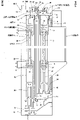
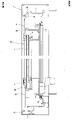
以下、本発明の実施の形態を図面に基づいて説明する。図1,2は、本発明の建具の一実施形態を示している。この建具は、ビル用の引違い窓に適用したものであって、躯体(図示省略)の開口部に取付けられる枠1と、枠1内に引違い状に開閉自在に設けた外障子2及び内障子3を備える。
BEST MODE FOR CARRYING OUT THE INVENTION Hereinafter, embodiments of the present invention will be described with reference to the drawings. 1 and 2 show an embodiment of fittings of the present invention. This fitting is applied to a double sliding window for a building. Equipped with
枠1は、アルミ合金の押出形材よりなる上枠4と下枠10と左右の縦枠11,11を四周枠組みして構成してある。
上枠4は、図1に示すように、室外側端部に室外側壁12を垂下して設けてあり、室外側壁12の室内側に外障子2の上部を案内するレール13が垂下して設けてある。さらに上枠4は、室内外方向の中間に中間垂下片14を有し、室内側端部に室内側壁15が垂下して設けてあり、中間垂下片14と室内側壁15との間の溝16に内障子3の上部を案内している。中間垂下片14と室内側壁15の下部にはタイト材ホルダー17が設けられ、タイト材ホルダー17にタイト材18が室外側に向けて取付けてあり、各タイト材18が外障子2の室内側面と内障子3の室内側面にそれぞれ当接している。
The
As shown in FIG. 1, the
下枠10は、図1に示すように、室内側が高くなるように略階段状に形成され、外障子2の下部を案内する外レール19と、内障子3の下部を案内する内レール20と、室内側壁21と、内レール20の付け根部より室外側に突出する突出片22を有している。突出片22の先端部と室内側壁21の上部にはタイト材ホルダー17が設けられ、タイト材ホルダー17にタイト材18が室外側に向けて取付けてあり、各タイト材18が外障子2の室内側面と内障子3の室内側面にそれぞれ当接している。
As shown in FIG. 1, the
外障子2と内障子3は、図1,2に示すように、アルミ合金の押出形材よりなる上框8と下框23と戸先框24と召合せ框25とを四周框組みし、各框の内周側に開口して設けたガラス保持溝9にグレイジングガスケット26を介してガラス7の外周縁部を嵌め込んで構成してある。下框23には、左右2箇所に樹脂製の戸車35が取付けてあり、各戸車35は下枠10のレール19,20の上端部と係合している。下框23のガラス保持溝9内には、金属製のガラス敷板27が設けてある。また、各框8,23,24,25のガラス保持溝27内には、火災時に火災の熱で発泡・膨張する加熱発泡材28が長手方向に沿って設けてある。
ガラス7の上端と上框8のガラス保持溝9底面間の隙間(エッジクリアランス)aは5.5mm、上框8のガラス7とのかかり代bは7.5mmとしてある。ガラス7の下端と下框23のガラス保持溝9底面間の隙間(エッジクリアランス)cは6.5mm、下框23のガラス7とのかかり代dは7.5mmとしてある。なお、エッジクリアランスは、排水等の理由から所定の寸法以上とすることが、平成28年度版公共建築工事標準仕様書(建築工事偏)(国土交通省大臣官房官庁営繕部監修)の第16章 建具工事、表16.14.1に規定されており、ガラスの框とのかかり代も合わせて規定されており、上記の寸法はこの基準に適合したものである。ちなみに同基準では、ガラスが単板ガラスでガラス留め材がグレイジングガスケットの場合、エッジクリアランスは4mm以上、かかり代は6.5mm以上と定められている。
As shown in FIGS. 1 and 2, the
The gap (edge clearance) a between the upper end of the
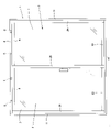
図1に示すように、レール13と中間垂下片14の間の上枠4下面には外障子2用の上がり止め部品5が取付けてあり、中間垂下片14と室内側壁15の間の上枠4下面には内障子3用の上がり止め部品6が取付けてある。各上がり止め部品5,6は、図2に示すように、各障子2,3の上方位置に間隔をおいて2つずつ設けてある。
外障子2用の上がり止め部品5は、アルミ形材を所定の長さに切断して形成したものであり、上部に二股状になった係合部29,29を有し、各係合部29,29を上枠4のレール13と中間垂下片14の根元部分に対向して形成された突条30,30に係合して取付けてある。
内障子3用の上がり止め部品6も、アルミ形材を所定の長さに切断して形成したものであり、略階段状に形成され、室外側端部に設けた突起31を上枠4の中間垂下片14の根元部分に形成された段部32に係合するとともに、室内側端部を上枠4の室内側壁15のタイト材ホルダー17上に係合している。なお、上枠4の突条30及び段部32は、上枠4下面に図示しない風止め板を取付けるためにもともと形成してあるもので、上がり止め部品5,6はそれらを利用して取付けできるようにしてある。
外障子2用及び内障子3用の上がり止め部品5,6には、押しねじ33,34がそれぞれ設けてあり、押しねじ33,34を緩めると当該上がり止め部品5,6は上枠4の長手方向にスライドでき、押しねじ33,34を締め付けると押しねじ33,34の先端が上枠4下面に押し付けられ、上がり止め部品5,6を上枠4の長手方向の任意の位置で固定できる。したがって、上下枠4,10間に障子2,3をけんどんで建て込む際には、押しねじ33,34を緩めて上がり止め部品5,6を側端部等の邪魔にならない位置にスライドさせ、障子2,3を建て込んだ後に各上がり止め部品5,6を図2に示すような位置にスライドし、押しねじ33,34を締め付けて上がり止め部品5,6を固定する。
平常時において、障子2,3の上端と上がり止め部品5,6の下面との間には、3mm程度の隙間が設けてある。
As shown in FIG. 1, on the lower surface of the
The up-stopping
The up-
Under normal conditions, a gap of about 3 mm is provided between the upper ends of the
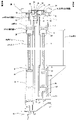
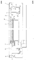
図3は、本建具の火災時の状態を示している。火災時には、戸車35やグレイジングガスケット26等の樹脂製の部品は火災の熱で溶融し、消失する。障子2,3は、縦框(戸先框24及び召合せ框25)が火災の熱で上下方向に伸び、外障子2の下框23の下端が下枠10上面に当接し、内障子3の縦框24,25下部の切欠き36が下枠10の内レール20の上端部に当接する。下框23のガラス保持溝9内のガラス敷板27は金属製のため、火災時でも残ってガラス7の下がりを防ぐ。一方、障子2,3の上框8は、上枠4下面に取付けた上がり止め部品5,6に当接することで上昇が規制される。
ガラス7も火災の熱で伸びるが、伸びる量は框24,25よりも少ないため、上がり止め部品5,6が無いと、図4に示すように、ガラス7の上端と上框8の間に貫通孔37ができるが、本建具は上枠4下面に設けた上がり止め部品5,6により上框8の上昇が規制されることで、図3に示すように、ガラス7の上端と上框8のガラス保持溝9とのかかりが維持されるため、ガラス7と上框8の間に貫通孔が形成されるのを防止できる。さらに、ガラス保持溝9内の隙間は発泡した加熱発泡材28で塞がれる。したがって、上框8とガラス7の間から火炎や煙が連通するのを阻止でき、高い防火性能を発揮する。
FIG. 3 shows the state of this fitting at the time of fire. In the event of a fire, resin parts such as the
The
従来、火災時にガラス7と上框8の間に貫通孔ができるのを防ぐ対策として、框のガラス保持溝9を深くしてガラス7のかかり代を大きくしていたが、そうすると框の見付寸法が大きくなって意匠性が悪く、ガラスの面積も小さくなるので採光量が減少する。本建具は、ガラスの7かかり代を大きくすることなく火災時にガラス7と上框8の間に貫通孔ができるのを防ぐことができ、意匠性、採光性にも優れる。
Conventionally, as a countermeasure for preventing a through hole from being formed between the
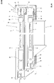
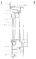
図5は、本発明の建具の他の実施形態であって、たてすべり出し窓に適用したものを示している。本建具は、躯体開口部に取付けられる枠1と、枠1内に設けた障子38とを備え、障子38は図示しないフリクションステーにより上枠4と下枠10に開閉自在に支持されている。
上枠4下面の室外側位置には、アルミ合金製のブロック状の上がり止め部品39が取付けてある。上がり止め部品39は、上枠4の長手方向の中央部1箇所、又は左右2箇所に設けてある。上がり止め部品39は、上枠4下面にねじ40で固定してある。
FIG. 5 shows another embodiment of fittings of the present invention applied to a vertical sliding window. This fitting comprises a
A block-shaped up-
図6は、本建具の火災時の状態を示している。火災時には、障子38の縦框が火災の熱で上下方向に伸びることで、上框8が上方に、下框23が下方に移動しようとするが、上枠4下面に上がり止め部品39が設けてあることで、上框8の上端が上がり止め部品39に当たり、上框8の上昇が規制される。上がり止め部品39が無いとすると、框の熱伸び量に対してガラス7の熱伸び量が小さいため、図7に示すように、ガラス7の上端と上框8の間に貫通孔37ができるが、本建具は上がり止め部品39により上框8の上昇が規制されることで、図6に示すように、ガラス7の上端と上框8のガラス保持溝9とのかかりが維持されるため、ガラス7と上框8の間に貫通孔が形成されるのを防止できる。
FIG. 6 shows the state of this fitting at the time of fire. In the event of a fire, the vertical frames of the
以上に述べたように本建具は、上枠4の下面に金属製の上がり止め部品5,6,39を有し、火災時に縦框24,25が熱伸びしたときでもガラス7の上端と上框8のガラス保持溝9とのかかりが維持されるため、ガラス7と上框8の間に貫通孔が形成されるのを防止できるので、防火性能が向上する。
障子2,3,38は、框8,23,24,25のガラス保持溝9内に加熱発泡材28が設けてあるので、火災時にガラス保持溝9内の隙間を発砲した加熱発泡材28が塞ぐので、火炎が連通するのをより確実に防止できる。
また、障子2,3は樹脂製の戸車35を有する引戸であり、下框23のガラス保持溝9内に金属製のガラス敷板27を有するので、火災時に樹脂製の戸車35が消失して下框23が下降するが、金属製のガラス敷板27によりガラス7の下がりを防止でき、上がり止め部品5,6により上框8の上昇を規制したことと相まって、ガラス7と框8間に貫通孔が形成されるのを確実に防止できる。
As described above, this fitting has the metal up-stopping
Since the
In addition, the
本発明は以上に述べた実施形態に限定されない。上がり止め部品の材質、形状は、適宜変更することができる。ガラスの種類、框への固定手段は、任意である。障子は、枠に固定した固定障子であってもよい。本発明の建具は、引違い窓やたてすべり出し窓に限らず、あらゆる窓種に対応することができる。 The invention is not limited to the embodiments described above. The material and shape of the up-stop part can be changed as appropriate. The type of glass and the fixing means to the stile are arbitrary. The shoji may be a fixed shoji fixed to a frame. The fittings of the present invention are not limited to double sliding windows and vertical sliding windows, and can be applied to all types of windows.
1 枠
2 外障子(障子)
3 内障子(障子)
4 上枠
5,6 上がり止め部品
7 ガラス
8 ガラス保持溝
38 障子
39 上がり止め部品
1
3 Inner shoji (shoji)
4
Claims (1)
Priority Applications (1)
| Application Number | Priority Date | Filing Date | Title |
|---|---|---|---|
| JP2022134602A JP7361173B2 (en) | 2018-10-24 | 2022-08-26 | fittings |
Applications Claiming Priority (2)
| Application Number | Priority Date | Filing Date | Title |
|---|---|---|---|
| JP2018199614A JP7161372B2 (en) | 2018-10-24 | 2018-10-24 | Fittings |
| JP2022134602A JP7361173B2 (en) | 2018-10-24 | 2022-08-26 | fittings |
Related Parent Applications (1)
| Application Number | Title | Priority Date | Filing Date |
|---|---|---|---|
| JP2018199614A Division JP7161372B2 (en) | 2018-10-24 | 2018-10-24 | Fittings |
Publications (2)
| Publication Number | Publication Date |
|---|---|
| JP2022166314A true JP2022166314A (en) | 2022-11-01 |
| JP7361173B2 JP7361173B2 (en) | 2023-10-13 |
Family
ID=70389792
Family Applications (2)
| Application Number | Title | Priority Date | Filing Date |
|---|---|---|---|
| JP2018199614A Active JP7161372B2 (en) | 2018-10-24 | 2018-10-24 | Fittings |
| JP2022134602A Active JP7361173B2 (en) | 2018-10-24 | 2022-08-26 | fittings |
Family Applications Before (1)
| Application Number | Title | Priority Date | Filing Date |
|---|---|---|---|
| JP2018199614A Active JP7161372B2 (en) | 2018-10-24 | 2018-10-24 | Fittings |
Country Status (1)
| Country | Link |
|---|---|
| JP (2) | JP7161372B2 (en) |
Citations (6)
| Publication number | Priority date | Publication date | Assignee | Title |
|---|---|---|---|---|
| JPH11107613A (en) * | 1997-10-06 | 1999-04-20 | Bunka Shutter Co Ltd | Outer stop of sliding door |
| JP2012136927A (en) * | 2010-12-10 | 2012-07-19 | Sankyotateyama Inc | Sash |
| JP2014066067A (en) * | 2012-09-26 | 2014-04-17 | Lixil Corp | Opening device |
| JP2015068004A (en) * | 2013-09-27 | 2015-04-13 | 三協立山株式会社 | sash |
| JP2016030998A (en) * | 2014-07-30 | 2016-03-07 | Ykk Ap株式会社 | Joinery |
| JP2016098536A (en) * | 2014-11-20 | 2016-05-30 | Ykk Ap株式会社 | window |
Family Cites Families (3)
| Publication number | Priority date | Publication date | Assignee | Title |
|---|---|---|---|---|
| JP2013113063A (en) * | 2011-11-30 | 2013-06-10 | Lixil Corp | Window sash |
| JP6410475B2 (en) * | 2014-05-28 | 2018-10-24 | Ykk Ap株式会社 | Joinery |
| JP6700076B2 (en) * | 2016-03-17 | 2020-05-27 | 不二サッシ株式会社 | Window device with windbreak plate |
-
2018
- 2018-10-24 JP JP2018199614A patent/JP7161372B2/en active Active
-
2022
- 2022-08-26 JP JP2022134602A patent/JP7361173B2/en active Active
Patent Citations (6)
| Publication number | Priority date | Publication date | Assignee | Title |
|---|---|---|---|---|
| JPH11107613A (en) * | 1997-10-06 | 1999-04-20 | Bunka Shutter Co Ltd | Outer stop of sliding door |
| JP2012136927A (en) * | 2010-12-10 | 2012-07-19 | Sankyotateyama Inc | Sash |
| JP2014066067A (en) * | 2012-09-26 | 2014-04-17 | Lixil Corp | Opening device |
| JP2015068004A (en) * | 2013-09-27 | 2015-04-13 | 三協立山株式会社 | sash |
| JP2016030998A (en) * | 2014-07-30 | 2016-03-07 | Ykk Ap株式会社 | Joinery |
| JP2016098536A (en) * | 2014-11-20 | 2016-05-30 | Ykk Ap株式会社 | window |
Also Published As
| Publication number | Publication date |
|---|---|
| JP7361173B2 (en) | 2023-10-13 |
| JP7161372B2 (en) | 2022-10-26 |
| JP2020066902A (en) | 2020-04-30 |
Similar Documents
| Publication | Publication Date | Title |
|---|---|---|
| JP6624810B2 (en) | Sliding door device | |
| JP6128889B2 (en) | Fire protection structure of window shutter bottom frame | |
| JP6785123B2 (en) | Joinery | |
| JP6502051B2 (en) | Heat insulation sash | |
| KR102493007B1 (en) | Sliding window | |
| JP6158545B2 (en) | Fireproof structure of window shutter vertical frame | |
| JP2022166314A (en) | Fitting | |
| JP2017008583A (en) | Fixture | |
| JP6647927B2 (en) | Joinery | |
| JP2025031913A (en) | Fittings | |
| JP6701318B2 (en) | Joinery | |
| JP6333767B2 (en) | Joinery | |
| JP6741528B2 (en) | Joinery | |
| JP6883947B2 (en) | Sash window | |
| JP6271133B2 (en) | Window shutter device | |
| JP7061057B2 (en) | Joinery | |
| JP2016204872A (en) | Fitting | |
| JP6379316B2 (en) | Joinery | |
| JP6506594B2 (en) | Joiner | |
| JP7678853B2 (en) | Composite window frames and/or composite stiles | |
| JP7750766B2 (en) | Building materials | |
| JP7009557B2 (en) | Joinery | |
| JP2024067965A (en) | Airtight material and fitting | |
| JP4919066B2 (en) | Screen door fall prevention device | |
| JP6542310B2 (en) | sash |
Legal Events
| Date | Code | Title | Description |
|---|---|---|---|
| A621 | Written request for application examination |
Free format text: JAPANESE INTERMEDIATE CODE: A621 Effective date: 20220914 |
|
| A131 | Notification of reasons for refusal |
Free format text: JAPANESE INTERMEDIATE CODE: A131 Effective date: 20230620 |
|
| TRDD | Decision of grant or rejection written | ||
| A01 | Written decision to grant a patent or to grant a registration (utility model) |
Free format text: JAPANESE INTERMEDIATE CODE: A01 Effective date: 20230919 |
|
| A61 | First payment of annual fees (during grant procedure) |
Free format text: JAPANESE INTERMEDIATE CODE: A61 Effective date: 20231002 |
|
| R150 | Certificate of patent or registration of utility model |
Ref document number: 7361173 Country of ref document: JP Free format text: JAPANESE INTERMEDIATE CODE: R150 |