JP2022145604A - optical laminate - Google Patents
optical laminate Download PDFInfo
- Publication number
- JP2022145604A JP2022145604A JP2022038107A JP2022038107A JP2022145604A JP 2022145604 A JP2022145604 A JP 2022145604A JP 2022038107 A JP2022038107 A JP 2022038107A JP 2022038107 A JP2022038107 A JP 2022038107A JP 2022145604 A JP2022145604 A JP 2022145604A
- Authority
- JP
- Japan
- Prior art keywords
- layer
- dye
- liquid crystal
- group
- containing layer
- Prior art date
- Legal status (The legal status is an assumption and is not a legal conclusion. Google has not performed a legal analysis and makes no representation as to the accuracy of the status listed.)
- Pending
Links
Images


Abstract
Description
本発明は、光学積層体に関し、さらにはそれを備えた表示装置にも関する。 TECHNICAL FIELD The present invention relates to an optical layered body and further to a display device provided with the same.
有機エレクトロルミネッセンス(以下、「有機EL」ということがある。)表示装置において、画像を表示するパネルは、内部に組み込まれた電極等に起因して、外部から入射した光を反射する。この反射光は、パネルに表示された画像を視認しづらくする原因となる。このため、パネルの視認側に円偏光板を配置することが広く行われている。円偏光板は、直線偏光板とλ/4位相差板とを積層した光学素子であり、直線偏光板の吸収軸とλ/4位相差板の遅相軸とは略45°の角度をなしている。この円偏光板は通常、直線偏光板が視認側となり、λ/4位相差板がパネル側となるように配置される。このような円偏光板を備えた有機EL表示装置を正面方向から視認すると、反射光の影響が低減され、特に黒画像を高画質で表示することが可能になる。 2. Description of the Related Art In an organic electroluminescence (hereinafter sometimes referred to as “organic EL”) display device, a panel that displays an image reflects externally incident light due to electrodes and the like incorporated therein. This reflected light makes the image displayed on the panel difficult to see. Therefore, it is widely practiced to arrange a circularly polarizing plate on the viewing side of the panel. A circularly polarizing plate is an optical element in which a linear polarizing plate and a λ/4 retardation plate are laminated, and the absorption axis of the linear polarizing plate and the slow axis of the λ/4 retardation plate form an angle of approximately 45°. ing. The circularly polarizing plate is usually arranged so that the linear polarizing plate is on the viewing side and the λ/4 retardation plate is on the panel side. When an organic EL display device having such a circularly polarizing plate is viewed from the front, the influence of reflected light is reduced, making it possible to display black images with high image quality.
一方、円偏光板を備えた有機EL表示装置を斜め方向から視認すると、黒画像が着色して見える場合がある。これは、有機EL表示装置を斜め方向から視認した場合には、λ/4位相差板が理想的な位相差値から外れて機能するためである。また、有機EL表示装置のパネルの内部には金属電極が組み込まれているため、有機EL表示装置を斜め方向から視認した場合には、金属電極表面で斜め方向に反射した反射光の位相差の影響を受ける。そのため、有機EL表示装置を斜め方向から視認した際の黒画像は、対象とするパネルごとに異なる色に着色する。 On the other hand, when an organic EL display device having a circularly polarizing plate is viewed from an oblique direction, a black image may appear colored. This is because when the organic EL display device is viewed from an oblique direction, the λ/4 retardation plate functions outside the ideal retardation value. In addition, since metal electrodes are incorporated inside the panel of the organic EL display device, when the organic EL display device is viewed from an oblique direction, the phase difference of the reflected light obliquely reflected on the surface of the metal electrode is to be influenced. Therefore, when the organic EL display device is viewed from an oblique direction, a black image is colored in a different color for each target panel.
このような問題を解決し得るものとしては、特許文献1に開示される垂直配向液晶硬化膜が挙げられる。この垂直配向液晶硬化膜は、二色性色素及び重合性液晶化合物を含む組成物を、重合性液晶化合物が垂直方向に配向した状態で硬化させた硬化膜である。この硬化膜は厚み方向に位相差を示すため、いわゆるポジティブC位相差板として機能する。このポジティブC位相差板とλ/4位相差板とを組み合わせて有機EL表示装置に適用することにより、斜め方向から視認したときのλ/4位相差板の位相差値が補償され、λ/4位相差板の理想的な位相差値を実現することができる。 A vertically aligned liquid crystal cured film disclosed in Japanese Patent Laid-Open No. 2002-200300 can be cited as a solution that can solve such problems. This vertically aligned liquid crystal cured film is a cured film obtained by curing a composition containing a dichroic dye and a polymerizable liquid crystal compound while the polymerizable liquid crystal compound is vertically aligned. Since this cured film exhibits retardation in the thickness direction, it functions as a so-called positive C retardation plate. By combining this positive C retardation plate and the λ / 4 retardation plate and applying it to an organic EL display device, the retardation value of the λ / 4 retardation plate when viewed from an oblique direction is compensated, and λ / An ideal retardation value of four retarders can be realized.
垂直配向液晶硬化膜を用いた有機EL表示装置では、黒画像にさらに僅かな着色が残ることもある。特許文献1に記載の垂直配向液晶硬化膜は、膜内で垂直配向した二色性色素により着色層としての機能も有する。そのため、垂直配向液晶膜に含まれる二色性色素として、有機EL表示装置を斜め方向から視認したときの黒画像の着色と補色関係にある色の二色性色素を選択することにより、黒画像に僅かに残った着色を打ち消すことも可能となる。
In an organic EL display device using a vertically aligned liquid crystal cured film, a slight coloration may remain in the black image. The vertically aligned liquid crystal cured film described in
しかしながら、直線偏光板、λ/4位相差板、及び垂直配向液晶硬化膜を積層した円偏光板では、垂直配向液晶硬化膜の厚み方向の位相差値と着色の程度とを同時に制御する必要がある。この制御には、垂直配向液晶硬化膜を作製するための重合性液晶化合物、及びこれに組み合わせる二色性色素の選択、並びに、これらの配合比等の調整が必要であるが、これらの調整は煩雑であり、多くの試行錯誤を要する。 However, in a circularly polarizing plate in which a linear polarizing plate, a λ/4 retardation plate, and a vertically aligned liquid crystal cured film are laminated, it is necessary to simultaneously control the retardation value in the thickness direction of the vertically aligned liquid crystal cured film and the degree of coloring. be. For this control, it is necessary to select a polymerizable liquid crystal compound for producing a vertically aligned liquid crystal cured film, a dichroic dye to be combined with it, and adjust the compounding ratio of these compounds. It is complicated and requires much trial and error.
本発明者は、多くの試行錯誤を要することなく、目的とするパネルに適した円偏光板を容易に製造するべく鋭意検討した。その結果、垂直配向液晶硬化膜が有する2つの機能、すなわちポジティブC位相差板としての機能、及び、垂直配向した二色性色素を備える着色層としての機能をそれぞれ独立した層が担い、着色層としての機能を担う層を直線偏光板よりもさらに視認側に配置することにより、厚み方向の位相差値と黒画像の着色の程度とを互いに独立して制御できることを見出し、本発明に至った。 The present inventor has made extensive studies to easily produce a circularly polarizing plate suitable for the intended panel without much trial and error. As a result, the two functions of the vertically aligned liquid crystal cured film, that is, the function as a positive C retardation plate and the function as a colored layer having a vertically aligned dichroic dye, are performed by independent layers, and the colored layer By arranging a layer that functions as a layer further on the viewing side than the linear polarizing plate, the inventors found that the retardation value in the thickness direction and the degree of coloring of the black image can be controlled independently of each other, resulting in the present invention. .
本発明は、表示装置を斜め方向から視認した際の黒画像の着色の低減を簡便に行うことができる光学積層体及びそれを備えた表示装置の提供を目的とする。 An object of the present invention is to provide an optical layered body and a display device having the same, which can easily reduce the coloring of a black image when the display device is viewed from an oblique direction.
本発明は、以下の光学積層体及び表示装置を提供する。
〔1〕 色素含有層、偏光層、及び、面内位相差を有する位相差層をこの順に含む光学積層体であって、
前記色素含有層は、
波長400nm以上750nm以下の範囲に極大吸収を有する二色性色素を含み、
下記式(1)及び下記式(2)の関係を満たす、光学積層体。
0.001≦AxC≦0.3 (1)
AxC(z=60)/AxC>2 (2)
[式(1)及び式(2)中、
AxCは、前記色素含有層の波長400nm以上750nm以下の範囲における吸収極大波長の吸光度であって、x軸方向に振動する直線偏光の吸光度を表し、
AxC(z=60)は、前記色素含有層の波長400nm以上750nm以下の範囲における吸収極大波長の吸光度であって、y軸を回転軸として前記色素含有層を60°回転させたときの前記x軸方向に振動する直線偏光の吸光度を表し、
前記x軸は、前記色素含有層の面内における任意の方向を表し、前記y軸は、前記色素含有層の面内において前記x軸に垂直な方向を表す。]
〔2〕 前記色素含有層、前記偏光層、前記位相差層、及び、前記光学積層体の積層方向に重合性液晶化合物が配向した状態で硬化した垂直配向液晶層をこの順に含む積層体の製造中間体である、〔1〕に記載の光学積層体。
〔3〕 色素含有層、偏光層、面内位相差を有する位相差層、及び、垂直配向液晶層をこの順に含む光学積層体であって、
前記垂直配向液晶層は、前記光学積層体の積層方向に重合性液晶化合物が配向した状態で硬化した硬化物層であり、
前記色素含有層は、
波長400nm以上750nm以下の間に極大吸収を有する二色性色素を含み、
下記式(1)及び下記式(2)の関係を満たす、光学積層体。
0.001≦AxC≦0.3 (1)
AxC(z=60)/AxC>2 (2)
[式(1)及び式(2)中、
AxCは、前記色素含有層の波長400nm以上750nm以下の範囲における吸収極大波長の吸光度であって、x軸方向に振動する直線偏光の吸光度を表し、
AxC(z=60)は、前記色素含有層の波長400nm以上750nm以下の範囲における吸収極大波長の吸光度であって、y軸を回転軸として前記色素含有層を60°回転させたときの前記x軸方向に振動する直線偏光の吸光度を表し、
前記x軸は、前記色素含有層の面内における任意の方向を表し、前記y軸は、前記色素含有層の面内において前記x軸に垂直な方向を表す。]
〔4〕 前記色素含有層は、さらに、前記光学積層体の積層方向に重合性液晶化合物が配向した状態で硬化した硬化物を含む、〔1〕~〔3〕のいずれかに記載の光学積層体。
〔5〕 前記位相差層は、前記光学積層体の積層方向に直交する方向に重合性液晶化合物が配向した状態で硬化した水平配向液晶層である、〔1〕~〔4〕のいずれかに記載の光学積層体。
〔6〕 前記位相差層は、下記式(3)の関係を満たす、〔1〕~〔5〕のいずれかに記載の光学積層体。
ReA(450)/ReA(550)<1.00 (3)
[式(3)中、ReA(450)及びReA(550)は、それぞれ波長450nm及び波長550nmにおける前記位相差層の面内位相差値を表す。]
〔7〕 前記位相差層は、下記式(4)の関係を満たす、〔1〕~〔6〕のいずれかに記載の光学積層体。
120nm≦ReA(550)≦170nm (4)
[式(4)中、ReA(550)は、波長550nmにおける前記位相差層の面内位相差値を表す。]
〔8〕 前記偏光層の吸収軸と前記位相差層の遅相軸とのなす角度は、45°±5°の範囲内である、〔1〕~〔7〕のいずれかに記載の光学積層体。
〔9〕 前記二色性色素は、アゾ色素である、〔1〕~〔8〕のいずれかに記載の光学積層体。
〔10〕 前記色素含有層は、下記[a1]~[a3]のうちのいずれかを満たす、〔1〕~〔9〕のいずれかに記載の光学積層体。
[a1]波長400nm以上550nm未満の範囲、及び、波長550nm以上700nm未満の範囲の両方に極大吸収を有する、
[a2]波長400nm以上550nm未満の範囲に極大吸収を有し、波長550nm以上700nm以下の範囲に極大吸収を有さない、
[a3]波長400nm以上550nm未満の範囲に極大吸収を有さず、波長550nm以上700nm以下の範囲に極大吸収を有する。
〔11〕 さらに、前記色素含有層の前記偏光層側とは反対側にハードコート層を含む、〔1〕~〔10〕のいずれかに記載の光学積層体。
〔12〕 さらに、前記色素含有層の前記偏光層側とは反対側に保護フィルムを含む、〔1〕~〔11〕のいずれかに記載の光学積層体。
〔13〕 さらに、前記位相差層と前記垂直配向液晶層との間に、接着剤層を有し、
前記接着剤層は、前記位相差層及び前記垂直配向液晶層に直接接している、〔1〕~〔12〕のいずれかに記載の光学積層体。
〔14〕 前記接着剤層は、紫外線硬化型接着剤組成物の硬化物層である、〔13〕に記載の光学積層体。
〔15〕 〔1〕~〔14〕のいずれかに記載の光学積層体を備え、
前記光学積層体は、前記色素含有層が前記偏光層よりも視認側となるように配置される、表示装置。
〔16〕 有機EL表示装置である、〔15〕に記載の表示装置。
The present invention provides the following optical laminate and display device.
[1] An optical laminate comprising a dye-containing layer, a polarizing layer, and a retardation layer having an in-plane retardation in this order,
The dye-containing layer is
Containing a dichroic dye having a maximum absorption in the wavelength range of 400 nm or more and 750 nm or less,
An optical laminate that satisfies the relationships of the following formulas (1) and (2).
0.001≤AxC≤0.3 (1)
AxC(z=60)/AxC>2 (2)
[In formulas (1) and (2),
AxC is the absorbance of the absorption maximum wavelength in the wavelength range of 400 nm or more and 750 nm or less of the dye-containing layer, and represents the absorbance of linearly polarized light vibrating in the x-axis direction,
AxC (z = 60) is the absorbance at the absorption maximum wavelength in the wavelength range of 400 nm or more and 750 nm or less of the dye-containing layer, and the x when the dye-containing layer is rotated by 60° with the y axis as the rotation axis. represents the absorbance of linearly polarized light oscillating in the axial direction,
The x-axis represents an arbitrary direction in the plane of the dye-containing layer, and the y-axis represents a direction perpendicular to the x-axis in the plane of the dye-containing layer. ]
[2] Production of a laminate comprising, in this order, the dye-containing layer, the polarizing layer, the retardation layer, and a vertically aligned liquid crystal layer cured in a state in which the polymerizable liquid crystal compound is aligned in the lamination direction of the optical laminate. The optical laminate according to [1], which is an intermediate.
[3] An optical laminate comprising, in this order, a dye-containing layer, a polarizing layer, a retardation layer having an in-plane retardation, and a vertically aligned liquid crystal layer,
The vertically aligned liquid crystal layer is a cured product layer cured in a state in which the polymerizable liquid crystal compound is oriented in the lamination direction of the optical laminate,
The dye-containing layer is
Containing a dichroic dye having a maximum absorption between wavelengths of 400 nm and 750 nm,
An optical laminate that satisfies the relationships of the following formulas (1) and (2).
0.001≤AxC≤0.3 (1)
AxC(z=60)/AxC>2 (2)
[In formulas (1) and (2),
AxC is the absorbance of the absorption maximum wavelength in the wavelength range of 400 nm or more and 750 nm or less of the dye-containing layer, and represents the absorbance of linearly polarized light vibrating in the x-axis direction,
AxC (z = 60) is the absorbance at the absorption maximum wavelength in the wavelength range of 400 nm or more and 750 nm or less of the dye-containing layer, and the x when the dye-containing layer is rotated by 60° with the y axis as the rotation axis. represents the absorbance of linearly polarized light oscillating in the axial direction,
The x-axis represents an arbitrary direction in the plane of the dye-containing layer, and the y-axis represents a direction perpendicular to the x-axis in the plane of the dye-containing layer. ]
[4] The optical laminate according to any one of [1] to [3], wherein the dye-containing layer further includes a cured product obtained by curing the polymerizable liquid crystal compound in a lamination direction of the optical laminate. body.
[5] Any one of [1] to [4], wherein the retardation layer is a horizontally aligned liquid crystal layer cured in a state in which the polymerizable liquid crystal compound is aligned in a direction orthogonal to the lamination direction of the optical layered body. An optical laminate as described.
[6] The optical layered body according to any one of [1] to [5], wherein the retardation layer satisfies the relationship of formula (3) below.
ReA(450)/ReA(550)<1.00 (3)
[In formula (3), ReA(450) and ReA(550) represent in-plane retardation values of the retardation layer at wavelengths of 450 nm and 550 nm, respectively. ]
[7] The optical layered body according to any one of [1] to [6], wherein the retardation layer satisfies the relationship of formula (4) below.
120 nm≦ReA(550)≦170 nm (4)
[In formula (4), ReA(550) represents an in-plane retardation value of the retardation layer at a wavelength of 550 nm. ]
[8] The optical laminate according to any one of [1] to [7], wherein the angle formed by the absorption axis of the polarizing layer and the slow axis of the retardation layer is within the range of 45°±5°. body.
[9] The optical laminate according to any one of [1] to [8], wherein the dichroic dye is an azo dye.
[10] The optical laminate according to any one of [1] to [9], wherein the dye-containing layer satisfies any one of [a1] to [a3] below.
[a1] having maximum absorption in both the wavelength range of 400 nm or more and less than 550 nm and the wavelength range of 550 nm or more and less than 700 nm;
[a2] has a maximum absorption in a wavelength range of 400 nm or more and less than 550 nm, and does not have a maximum absorption in a wavelength range of 550 nm or more and 700 nm or less;
[a3] It has no maximum absorption in the wavelength range of 400 nm or more and less than 550 nm, but has maximum absorption in the wavelength range of 550 nm or more and 700 nm or less.
[11] The optical layered body according to any one of [1] to [10], further comprising a hard coat layer on the side of the dye-containing layer opposite to the polarizing layer.
[12] The optical layered body according to any one of [1] to [11], further comprising a protective film on the side of the dye-containing layer opposite to the polarizing layer.
[13] further comprising an adhesive layer between the retardation layer and the vertically aligned liquid crystal layer;
The optical laminate according to any one of [1] to [12], wherein the adhesive layer is in direct contact with the retardation layer and the vertically aligned liquid crystal layer.
[14] The optical laminate according to [13], wherein the adhesive layer is a cured product layer of an ultraviolet curable adhesive composition.
[15] Provided with the optical layered body according to any one of [1] to [14],
In the display device, the optical layered body is arranged such that the dye-containing layer is located on the viewing side of the polarizing layer.
[16] The display device according to [15], which is an organic EL display device.
本発明の光学積層体によれば、表示装置を斜め方向から視認した際の黒画像の着色の低減を簡便に行うことができる。 According to the optical laminate of the present invention, it is possible to easily reduce the coloring of a black image when viewing the display device from an oblique direction.
以下、図面を参照して光学積層体及び表示装置の好ましい実施形態について説明する。各図面において、先に説明した部材と同じ部材については同じ符号を付してその説明を省略する。 Preferred embodiments of the optical layered body and the display device will be described below with reference to the drawings. In each drawing, the same reference numerals are assigned to the same members as those previously described, and the description thereof will be omitted.
[実施形態1]
(光学積層体)
図1は、本発明の一実施形態に係る光学積層体を模式的に示す断面図である。図1に示すように、光学積層体1は、色素含有層11、偏光層12、及び、面内位相差を有する位相差層13をこの順に備える。光学積層体1は、偏光層12及び位相差層13によって楕円偏光板(円偏光板である場合を含む。)を構成することが好ましい。光学積層体1はさらに、色素含有層11の偏光層12側とは反対側に、ハードコート層16又は保護フィルム15を有していてもよい。図1に示す光学積層体1は、ハードコート層16及び保護フィルム15を同時に有している。光学積層体1がハードコート層16及び保護フィルム15を同時に有する場合、色素含有層11側から、保護フィルム15及びハードコート層16をこの順に備えることが好ましい。
[Embodiment 1]
(Optical laminate)
FIG. 1 is a cross-sectional view schematically showing an optical layered body according to one embodiment of the present invention. As shown in FIG. 1, the optical
光学積層体1を構成する各層は、粘着剤層又は接着剤層である貼合層を介して積層されることが好ましい。光学積層体1がハードコート層16及び保護フィルム15を同時に有する場合、保護フィルム15とハードコート層16とは、貼合層を介さずに直接接するように設けられていることが好ましい。
Each layer constituting the optical
色素含有層11、偏光層12、及び位相差層13が重合性液晶化合物等の液晶化合物を用いて形成された層である場合、光学積層体1は、上記液晶化合物を用いて形成された層に直接接するように液晶化合物の配向を規制するための配向膜を有していてもよく、上記液晶化合物を用いて形成された層又は配向膜を形成するための基材を有していてもよい。上記液晶化合物を用いて形成された層又は配向膜と基材とは、直接接するように設けることができる。
When the dye-containing
光学積層体1において、偏光層12の吸収軸と位相差層13の遅相軸とのなす角度は、45°±5°の範囲内であることが好ましい。上記角度は、45°±3°の範囲内であってもよく、45°であってもよい。
In the
光学積層体1は、後述する図3に示す光学積層体5のように、色素含有層11、偏光層12、面内位相差を有する位相差層13、及び、光学積層体1の積層方向に重合性液晶化合物が配向した状態で硬化した垂直配向液晶層17(図3)をこの順に含む積層体の製造中間体として用いることもできる。この場合、光学積層体1の位相差層13側に、垂直配向液晶層17を設けることにより、上記積層体を製造することができる。
The optical
光学積層体1は表示装置に用いることができ、特に有機EL表示装置に好適に用いることができる。表示装置において光学積層体1は、色素含有層11が偏光層12よりも視認側になるように配置される。光学積層体1は後述する式(1)及び式(2)の関係を満たす色素含有層11を含む。そのため、上記した配置で光学積層体1が組み入れられた表示装置では、パネルに表示された黒画像を斜め方向から視認したときの黒画像の着色を、色素含有層11によって打ち消すことができる。これにより、表示装置を斜め方向から視認した際の黒画像の着色を低減することができる。
The optical
(色素含有層)
色素含有層11は、波長400nm以上750nm以下の範囲に極大吸収を有する二色性色素を含み、下記式(1)及び下記式(2)の関係を満たす。
0.001≦AxC≦0.3 (1)
AxC(z=60)/AxC>2 (2)[式(1)及び式(2)中、
AxCは、色素含有層11の波長400nm以上750nm以下の範囲における吸収極大波長の吸光度であって、x軸方向に振動する直線偏光の吸光度を表し、
AxC(z=60)は、色素含有層11の波長400nm以上750nm以下の範囲における吸収極大波長の吸光度であって、y軸を回転軸として色素含有層11を60°回転させたときのx軸方向に振動する直線偏光の吸光度を表し、
x軸は、色素含有層11の面内における任意の方向を表し、y軸は、色素含有層11の面内においてx軸に垂直な方向を表す。]
(Dye-containing layer)
The dye-containing
0.001≤AxC≤0.3 (1)
AxC (z = 60) / AxC>2 (2) [in formulas (1) and (2),
AxC is the absorbance of the absorption maximum wavelength in the wavelength range of 400 nm or more and 750 nm or less of the dye-containing
AxC (z=60) is the absorbance of the dye-containing
The x-axis represents an arbitrary direction within the plane of the dye-containing
本明細書における吸光度はいずれも、測定時の界面反射の影響を除いた状態で測定した際の吸光度を表す。界面反射の影響を取り除く方法としては、例えば、分光光度計を用いて波長800nm等の長波長領域で化合物の吸収が無視できる波長における吸光度を0とし、その状態で化合物の吸収が存在する領域の波長の吸光度を測定する、等の方法が挙げられる。 All absorbances in this specification represent absorbances measured in a state where the influence of interfacial reflection is excluded during measurement. As a method of removing the influence of interface reflection, for example, using a spectrophotometer, the absorbance at a wavelength at which the absorption of the compound is negligible in a long wavelength region such as a wavelength of 800 nm is set to 0, and in that state, the absorption of the compound exists. A method such as measuring the absorbance of a wavelength can be used.
色素含有層11は、波長400nm以上750nm以下の範囲に極大吸収を有する二色性色素(以下、「本二色性色素」ということがある。)を少なくとも1種含む。二色性色素とは、分子の長軸方向における吸光度と、短軸方向における吸光度とが異なる性質を有する色素である。本二色性色素は、色素含有層11が上記式(1)及び式(2)の関係を満たしていることから、色素含有層11において光学積層体1の積層方向に配向していると考えられる。色素含有層11は、本二色性色素以外の二色性色素を含んでいてもよい。
The dye-containing
円偏光板を備える有機EL表示装置のパネルを斜め方向から視認すると、黒画像が着色して見える場合があった。これは、円偏光板に含まれる位相差層が理想的な位相差値から外れて機能するためである。また、有機EL表示装置のパネルの内部には金属電極が組み込まれているため、有機EL表示装置を斜め方向から視認した場合には、金属電極表面で斜め方向に反射した反射光の位相差の影響を受ける。そのため、有機EL表示装置を斜め方向から視認した際の黒画像は、対象とするパネルごとに異なる色に着色する。 When the panel of the organic EL display device provided with the circularly polarizing plate is viewed from an oblique direction, the black image may appear colored. This is because the retardation layer included in the circularly polarizing plate functions outside the ideal retardation value. In addition, since metal electrodes are incorporated inside the panel of the organic EL display device, when the organic EL display device is viewed from an oblique direction, the phase difference of the reflected light obliquely reflected on the surface of the metal electrode is to be influenced. Therefore, when the organic EL display device is viewed from an oblique direction, a black image is colored in a different color for each target panel.
本実施形態の光学積層体1は、本二色性色素として表示装置を斜め方向から視認した際のパネルの黒表示時の着色を打ち消し得る光吸収能を有する二色性色素を含む色素含有層11を備える。そのため、光学積層体1が組み入れられた表示装置では、黒表示時における正面反射色相と斜方反射色相との色相差を低減することができる。例えば、パネルの黒表示時に斜め45°方向からパネルを視認したときの色相に対して、色素含有層11の同方向から見たときの反射色相が補色の関係になるように、色素含有層11の400~750nmにおける極大吸収波長を調整する。これにより、光学積層体1を備えた表示装置を斜め45°方向から視認した際の着色を打ち消すことができる。そのため、表示装置の黒表示時の正面反射色相に影響を与えることなく斜方反射色相を改善することができ、正面反射色相と斜方反射色相との色相差を抑制することができることから、表示装置を斜め方向から視認した際の黒画像の着色を低減することができる。
The optical
上記式(1)及び式(2)中のAxCは、色素含有層11の厚み方向(以下、「z軸方向」ということがある。)から、色素含有層11の表面に向かってx軸方向に振動する直線偏光を入射して測定することができる。上記式(1)は、色素含有層11の正面方向(色素含有層11の表面に対して直交する方向であり、光学積層体1の積層方向)の吸光度が0.001以上0.3以下であることを意味し、AxCの値が小さいほど色素含有層11の表面に対して本二色性色素が光学積層体1の積層方向に精度よく配向しているといえる。AxCが0.3を超える場合には色素含有層11の正面方向における着色が強くなるため、位相差層13との組み合わせにより表示装置の正面の発光を阻害することから、AxCは、好ましくは0.1以下であり、より好ましくは0.05以下である。また、AxCの下限値は通常0.001以上であり、好ましくは0.003以上であり、さらに好ましくは0.005以上である。
AxC in the above formulas (1) and (2) is the x-axis direction toward the surface of the dye-containing
上記式(2)中のAxC(z=60)は、y軸を回転軸として色素含有層11を60°回転させた状態で、AxCを測定した直線偏光と同一の直線偏光を入射して測定することができる。ここで、色素含有層11の回転は、AxCを測定した状態の色素含有層11を、y軸を回転軸として直線偏光の入射方向に60°回転させて行う。AxC(z=60)/AxCが2以下であると良好な光吸収異方性を得難くなり、特に表示装置の正面の発光を阻害することがある。AxC(z=60)/AxCは、好ましくは2.5以上であり、より好ましくは3以上である。一方で、AxC(z=60)/AxCが大きすぎると特に表示装置を斜め方向から視認した際の発光を阻害することがあるため、AxC(z=60)/AxCは、好ましくは50以下、より好ましくは30以下、さらに好ましくは20以下である。また、AxC(z=60)は、好ましくは0.01以上であり、より好ましくは0.05以上であり、さらに好ましくは0.10以上であり、また、好ましくは1.0以下であり、より好ましくは0.5以下であり、さらに好ましくは0.3以下である。
AxC (z = 60) in the above formula (2) is measured by inputting the same linearly polarized light as that for measuring AxC with the dye-containing
なお、本明細書における色素含有層11において、y軸方向に振動する直線偏光の吸光度AyCは通常AxCとほぼ等しい値となる。AxCとAyCとが異なる場合、面内で二色性を有することとなり、この場合、特に表示装置の正面の発光を阻害することがある。
In addition, in the dye-containing
色素含有層11が上記式(1)及び式(2)を満たす場合、色素含有層11が優れた偏光性能(吸収異方性)を有するといえ、これにより正面方向からの光を効果的に透過し、かつ、斜め方向からの光を効果的に吸収することができる。したがって、色素含有層11を含む光学積層体1が組み込まれた表示装置では、表示装置の正面発光を阻害することなく、黒表示において正面反射色相と斜方反射色相との色相差を抑制することができる。
When the dye-containing
色素含有層11のAxC及びAxC(z=60)は、例えば、色素含有層11の厚み、製造工程の条件、色素含有層11に含まれる本二色性色素の種類及び/又は配合量等を調整することによって制御することができる。後述するように、色素含有層11が光学積層体1の積層方向に重合性液晶化合物が配向した状態で硬化した硬化物を含む場合、AxC及びAxC(z=60)は、重合性液晶化合物の種類及び/又は配合量を調整することによって制御することもでき、上記硬化物(液晶)と本二色性色素とのホストゲスト相互作用により制御することができる。AxC(z=60)/AxCの値は、重合性液晶化合物がネマチック液晶の場合には2~10程度、スメクチック液晶の場合には5~30程度となり、目的の光学特性に合わせて適宜選択することが可能である。
AxC and AxC (z = 60) of the dye-containing
上記したように、色素含有層11が偏光層12よりも視認側になるように光学積層体1が組み入れられた表示装置では、色素含有層11は、黒表示における正面反射色相と斜方反射色相との色相差を抑制するために用いることができる。表示装置において色素含有層11が偏光層12よりも視認側に配置されることにより、色素含有層11が厚み方向に位相差を有していても人の目には認識されない。したがって、色素含有層11は厚み方向に位相差を有していてもよく、その値の大きさも特に限定されない。そのため、色素含有層11の厚み方向の位相差値に囚われることなく、式(1)及び式(2)を満たすように色素含有層11の厚みや本二色性色素の濃度を調整することができる。このように、光学積層体1を用いることにより、黒表示における正面反射色相と斜方反射色相との色相差の抑制を簡便に行うことができる。
As described above, in the display device in which the optical
位相差層13が理想的な位相差値から外れて機能した際に着色する色は様々であるが、例えば赤色又は青色への変化が多い。このことから、パネルと光学積層体1とを組み合わせた表示装置において、斜め方向から観察したときの斜方反射色相を望ましい色相に調整しやすくするために、色素含有層11は下記[a1]~[a3]のいずれかを満たすことが好ましい。
[a1]波長400nm以上550nm未満の範囲、及び、波長550nm以上700nm未満の範囲の両方に極大吸収を有する、
[a2]波長400nm以上550nm未満の範囲に極大吸収を有し、波長550nm以上700nm以下の範囲に極大吸収を有さない、
[a3]波長400nm以上550nm未満の範囲に極大吸収を有さず、波長550nm以上700nm以下の範囲に極大吸収を有する。
Various colors are produced when the
[a1] having maximum absorption in both the wavelength range of 400 nm or more and less than 550 nm and the wavelength range of 550 nm or more and less than 700 nm;
[a2] has a maximum absorption in a wavelength range of 400 nm or more and less than 550 nm, and does not have a maximum absorption in a wavelength range of 550 nm or more and 700 nm or less;
[a3] It has no maximum absorption in the wavelength range of 400 nm or more and less than 550 nm, but has maximum absorption in the wavelength range of 550 nm or more and 700 nm or less.
色素含有層11が上記[a3]を満たす場合、斜め方向から漏れ出る反射光を吸収することができるが、表示装置を発光させた場合の視認性の観点からは、上記[a1]又は上記[a2]を満たす色素含有層11を用いることが好ましい。色素含有層11が上記[a2]を満たす場合、色素含有層11を、斜め45°における黒表示時に波長400nm以上550nm未満の範囲の光の反射が顕著な楕円偏光板と組み合わせて用いることにより、表示装置の黒表示時の斜方反射色相を向上させることができる。また、色素含有層11が上記[a3]を満たす場合、色素含有層11を、斜め45°における黒表示時に波長550nm以上700nm以下の範囲の光の反射が顕著な楕円偏光板と組み合わせて用いることにより、表示装置の黒表示時の斜方反射色相を向上させることができる。
When the dye-containing
色素含有層11は、光学積層体1の積層方向に重合性液晶化合物が配向した状態で硬化した硬化物を含むことが好ましい。該硬化物を含むことにより、当該硬化物によって形成された硬化膜中に、本二色性色素を光学積層体1の積層方向に配向させやすくなるため、色素含有層11を作製しやすくなる。本二色性色素及び重合性液晶化合物の詳細については、後述する。
The dye-containing
色素含有層11の厚みは、特に限定されず、表示装置の構造等に応じて適宜選択できる。色素含有層11の厚みは、好ましくは0.1μm以上であり、より好ましくは0.2μm以上であり、また、好ましくは10μm以下であり、より好ましくは3μm以下であり、さらに好ましくは2μm以下である。
The thickness of the dye-containing
(偏光層)
偏光層12は、無偏光の光を入射させたとき、吸収軸に直交する振動面をもつ直線偏光を透過させる性質を有する直線偏光層である。偏光層12は、吸収異方性を有する色素を吸着させた延伸フィルム、吸収異方性を有する色素を含む組成物を基材フィルムに塗布して形成した偏光層を含むフィルム等が挙げられる。偏光層12の詳細については、後述する。
(polarizing layer)
The
(位相差層)
位相差層13は、面内位相差を有する。位相差層13が有する面内位相差の値は特に限定されないが、波長550nmにおける位相差層13の面内位相差値ReA(550)が50nm以上であることが好ましく、90nm以上であることがより好ましい。位相差層13のReA(550)は、さらに好ましくは100nm以上250nm以下の範囲であり、特に好ましくは下記式(4)の範囲である。
120nm≦ReA(550)≦170nm (4)
[式(4)中、ReA(550)は、波長550nmにおける位相差層13の面内位相差値を表す。]
(retardation layer)
The
120 nm≦ReA(550)≦170 nm (4)
[In formula (4), ReA(550) represents an in-plane retardation value of the
位相差層13の面内位相差ReA(550)が上記式(4)の範囲内であることにより、光学積層体1が組み入れられた表示装置の黒表示時の正面反射色相を向上させる効果(着色を抑制させる効果)が顕著になる。面内位相差値ReA(550)は、より好ましくは130nm以上であり、また、より好ましくは150nm以下である。
By setting the in-plane retardation ReA (550) of the
位相差層13は、例えば、面内位相差を有する延伸フィルムであってもよく、光学積層体1の積層方向に直交する方向(以下、「水平方向」ということがある。)に重合性液晶化合物が配向した状態で硬化した硬化物層(以下、「水平配向液晶層」ということがある。)であってもよい。位相差層13を所望する面内位相差値に容易に制御可能であること、薄膜化が可能であることから、位相差層13は、水平配向液晶層であることが好ましい。
The
位相差層13は、下記式(3)の関係を満たすことが好ましい。
ReA(450)/ReA(550)<1.00 (3)
[式(3)中、ReA(450)及びReA(550)は、それぞれ波長450nm及び波長550nmにおける位相差層13の面内位相差値を表す。]
The
ReA(450)/ReA(550)<1.00 (3)
[In formula (3), ReA(450) and ReA(550) represent in-plane retardation values of the
ここで、波長λにおける位相差層13の面内位相差値ReA(λ)は、下記式(6)で表される。
ReA(λ)=(nxA(λ)-nyA(λ))×dA (6)
[式(6)中、
nxA(λ)は、位相差層13の面内における波長λnmでの主屈折率を表し、
nyA(λ)は、nxA(λ)と同一面内で、nxA(λ)の方向に対して直交する方向の波長λnmでの屈折率を表し、
dAは、位相差層13の厚みを示す。]
Here, the in-plane retardation value ReA(λ) of the
ReA(λ)=(nxA(λ)−nyA(λ))×dA (6)
[In formula (6),
nxA(λ) represents the principal refractive index at a wavelength λnm in the plane of the
nyA (λ) represents the refractive index at a wavelength λ nm in a direction orthogonal to the direction of nxA (λ) in the same plane as nxA (λ),
dA indicates the thickness of the
位相差層13が上記式(3)の関係を満たす場合、位相差層13は、短波長での面内位相差値が長波長での面内位相差値よりも小さくなる、いわゆる逆波長分散性を示す。逆波長分散性を向上させる観点から、ReA(450)/ReA(550)は、好ましくは0.70以上、より好ましくは0.78以上であり、また、好ましくは0.95以下、より好ましくは0.92以下である。
When the
面内位相差値ReA(λ)は、位相差層13の厚みdAによって調整することができる。面内位相差値ReA(λ)は上記式(6)によって決定されることから、所望の面内位相差値を得るには、3次元屈折率と膜厚dAとを調整すればよい。
The in-plane retardation value ReA(λ) can be adjusted by the thickness dA of the
位相差層13が延伸フィルムである場合、位相差層13の厚みは、通常5μm以上200μm以下であり、好ましくは10μm以上80μm以下、さらに好ましくは40μm以下である。位相差層13が水平配向液晶層である場合、位相差層13の厚みは、好ましくは0.1μm以上であり、より好ましくは0.2μm以上であり、また、好ましくは3μm以下であり、より好ましくは2μm以下である。
When the
位相差層13は、λ/4の位相差特性を有する層とλ/2の位相差特性を有する層との組み合わせ等、各層の遅相軸どうしのなす角度が任意の角度となるように複数の層を積層することにより、全体として面内位相差値ReA(550)が上記式(4)の関係を満たし、ReA(450)/ReA(550)が上記式(3)の関係を満たすものであってもよい。位相差層13がλ/4の位相差特性を有する層とλ/2の位相差特性を有する層とを積層した積層体である場合は、例えば、各層の遅相軸どうしのなす角度が50°以上70°以下とするように積層したものを好適に用いることができる。
The
位相差層13を構成する材料、位相差層13の形成方法等の詳細については、後述する。
Details of the material forming the
(光学積層体の製造方法)
図2は、図1に示す光学積層体1の製造方法の一例を模式的に示す概略図である。図1に示す光学積層体1は、上記した各層を、必要に応じて貼合層を介して積層することによって製造することができる。図2に示すように、長尺のフィルムを連続的に搬送しながら積層する、いわゆるロールトゥロールによって光学積層体1を製造する場合、例えば、色素含有層11と偏光層12とを含む第1積層体20と、位相差層13とを、図2中の矢印方向に連続的に搬送しながら貼合層を介して貼合すればよい。位相差層13が水平配向液晶層である場合、基材上に水平配向液晶層を設けた積層体と、第1積層体20とを貼合してもよい。
(Method for manufacturing optical laminate)
FIG. 2 is a schematic diagram schematically showing an example of a method for manufacturing the optical
ロールトゥロールによって光学積層体1を製造することにより、光学積層体1の製造工程を短縮することができ、また、層間に異物が混入することを防止して視認性に優れた光学積層体1を製造することができる。
By manufacturing the optical
(表示装置)
光学積層体1は、表示装置に用いることができる。表示装置としては、有機EL表示装置が好ましい。光学積層体1は表示装置のパネルの視認側に設けられ、表示装置においては、色素含有層11が偏光層12よりも視認側になるように配置することが好ましい。これにより、黒表示における正面反射色相と斜方反射色相との色相差を抑制した表示装置を提供することができる。
(Display device)
The optical
[実施形態2]
(光学積層体)
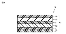
図3は、本発明の他の一実施形態に係る光学積層体を模式的に示す断面図である。図3に示すように、光学積層体5は、色素含有層11、偏光層12、面内位相差を有する位相差層13、及び、垂直配向液晶層17をこの順に備える。光学積層体5は、偏光層12及び位相差層13によって楕円偏光板(円偏光板である場合を含む。)を構成することが好ましい。光学積層体5はさらに、色素含有層11の偏光層12側とは反対側に、ハードコート層16又は保護フィルム15を有していてもよい。図3に示す光学積層体5は、ハードコート層16及び保護フィルム15を同時に有している。光学積層体5がハードコート層16及び保護フィルム15を同時に有する場合、色素含有層11側から、保護フィルム15及びハードコート層16をこの順に備えることが好ましい。
[Embodiment 2]
(Optical laminate)
FIG. 3 is a cross-sectional view schematically showing an optical laminate according to another embodiment of the invention. As shown in FIG. 3, the
光学積層体5を構成する各層は、粘着剤層又は接着剤層である貼合層を介して積層されることが好ましい。光学積層体5がハードコート層16及び保護フィルム15を同時に有する場合、保護フィルム15とハードコート層16とは、貼合層を介さずに直接接するように設けられていることが好ましい。光学積層体5において、位相差層13と垂直配向液晶層17との間に接着剤層を有し、当該接着剤層は、位相差層13及び垂直配向液晶層17に直接接していることが好ましい。当該接着剤層は、後述する紫外線硬化型接着剤組成物の硬化物層であることが好ましい。
Each layer constituting the optical
色素含有層11、偏光層12、位相差層13、及び垂直配向液晶層17が重合性液晶化合物等の液晶化合物を用いて形成された層である場合、光学積層体5は、上記液晶化合物を用いて形成された層に直接接するように液晶化合物の配向を規制するための配向膜を有していてもよく、上記液晶化合物を用いて形成された層又は配向膜を形成するための基材を有していてもよい。上記液晶化合物を用いて形成された層又は配向膜と基材とは、直接接するように設けることができる。
When the dye-containing
光学積層体5において、偏光層12の吸収軸と位相差層13の遅相軸とのなす角度は、45°±5°の範囲内であることが好ましい。上記角度は、45°±3°の範囲内であってもよく、45°であってもよい。
In the
光学積層体5は、表示装置に用いることができ、特に有機EL表示装置において好適に用いることができる。表示装置において光学積層体5は、色素含有層11が偏光層12よりも視認側になるように配置される。このような配置で光学積層体5が組み入れられた表示装置では、黒表示時において、表示装置の斜め方向からの反射光の色づき度合い(斜方反射色相)を改善することができる。
The optical
色素含有層11、偏光層12、及び位相差層13は、先の実施形態で説明したものを用いることができ、その配置も先の実施形態で説明したようにすることができる。
The dye-containing
(垂直配向液晶層)
垂直配向液晶層17は、光学積層体5の積層方向に重合性液晶化合物が配向した状態で硬化した硬化物層である。垂直配向液晶層17は、二色性色素を含んでいてもよいが、少なくとも本二色性色素を含んでいないことが好ましく、二色性色素全般を含んでいないことがより好ましい。
(Vertical alignment liquid crystal layer)
The vertically aligned
ここで、波長λにおける垂直配向液晶層17の厚み方向の位相差値RthC(λ)は、下記式(7)で表される。
RthC(λ)
=((nxC(λ)+nyC(λ))/2-nzC(λ))×dC (7)
[式(7)中、
nxC(λ)は、垂直配向液晶層17の面内における波長λnmでの主屈折率を表し、
nyC(λ)は、nxC(λ)と同一面内で、nxC(λ)に対して直交する方向の波長λnmでの屈折率を表し、
nzC(λ)は、垂直配向液晶層17の厚み方向における波長λnmでの屈折率を表し、nxC(λ)=nyC(λ)である場合、nxC(λ)は、垂直配向液晶層17の面内での任意の方向の屈折率とすることができ、
dCは、垂直配向液晶層17の膜厚を示す。]
Here, the retardation value RthC(λ) in the thickness direction of the vertically aligned
RthC(λ)
= ((nxC(λ)+nyC(λ))/2−nzC(λ))×dC (7)
[In formula (7),
nxC(λ) represents the principal refractive index at a wavelength λnm in the plane of the vertically aligned
nyC(λ) represents the refractive index at a wavelength λ nm in the same plane as nxC(λ) and in a direction perpendicular to nxC(λ),
nzC(λ) represents the refractive index at wavelength λnm in the thickness direction of the vertically aligned
dC indicates the film thickness of the vertically aligned
RthC(450)/RthC(550)は、特に限定されず、好ましくは0.70以上であり、より好ましくは0.75以上であり、さらに好ましくは0.80以上であり、1.00以上であってもよく、1.10以上であってもよく、1.20以上であってもよい。また、好ましくは0.95以下であり、さらに好ましくは0.92以下であり、特に好ましくは0.90以下である。 RthC(450)/RthC(550) is not particularly limited, preferably 0.70 or more, more preferably 0.75 or more, still more preferably 0.80 or more, and 1.00 or more. 1.10 or more, or 1.20 or more. Also, it is preferably 0.95 or less, more preferably 0.92 or less, and particularly preferably 0.90 or less.
垂直配向液晶層17は、重合性液晶化合物が積層方向に高い秩序で配向していることが好ましい。これにより、光学積層体5が組み入れられた表示装置の黒表示時の斜方反射色相を改善する効果を高めることができる。当該効果を得やすくするために、垂直配向液晶層17のRthC(550)は、-120nm以上-30nm以下の範囲であることが好ましい。上記効果をさらに向上させる観点から、垂直配向液晶層17のRthC(550)は、より好ましくは-100nm以上であり、さらに好ましくは-90nm以上であり、特に好ましくは-80nm以上であり、また、より好ましくは-40nm以下、さらに好ましくは-50nm以下である。
In the vertically aligned
厚み方向の位相差値RthC(λ)は、垂直配向液晶層17の厚みdCによって調整することができる。厚み方向の位相差値RthC(λ)は上記式(7)によって決定されることから、所望の厚み方向の位相差値RthC(λ)を得るためには、3次元屈折率と膜厚dCとを調整すればよい。
The retardation value RthC(λ) in the thickness direction can be adjusted by the thickness dC of the vertically aligned
上記したように、色素含有層11が偏光層12よりも視認側になるように光学積層体5が組み入れられた表示装置では、垂直配向液晶層17は、表示装置の黒表示時の斜方反射色相を改善するために用いることができる。よって、光学積層体5を組み込んだ表示装置では、表示装置の黒表示時の斜方反射色相を改善することができる。
As described above, in the display device in which the optical
一方、色素含有層11を設けず、上記垂直配向液晶層17に本二色性色素を含ませた層(以下、「色素含有液晶層」ということがある。)を用いたこと以外は、光学積層体5と同様の層構造とした積層体を用いても、表示装置の黒表示時の斜方反射色相を改善することができる。しかしながら、色素含有液晶層の吸光度及び吸収波長と、色素含有液晶層の厚み方向の位相差値Rthとは、相互に関係するパラメータである。そのため、例えば、色素含有液晶層の厚み方向の位相差値Rthを調整するために、色素含有液晶層の厚みのみを増減させると、吸光度にも大きな増減が発生し、例えば表示装置の白表示時に斜方から視認すると色づきが確認されることがある。また、例えば、二色性色素の吸光度を調整するために、色素含有液晶層に含まれる二色性色素の濃度を変化させると、色素含有液晶層の厚み方向の位相差値Rthが変動し、表示装置の黒表示時に斜め方向から見た際のコントラストの低下を引き起こすことがある。さらに、表示装置のパネルの種類により金属電極表面で斜め方向に反射した反射光の位相差の大きさが異なることにより、最適な厚み方向の位相差値Rthが変動するため、表示装置の構造に応じて調整する必要がある。したがって、色素含有液晶層のみを用いて、斜方反射色相を改善するためには、表示装置の構造に応じて色素含有液晶層の厚み及び二色性色素の濃度を調整する必要があり、色素含有液晶層の作製が煩雑になるという問題がある。
On the other hand, except that the dye-containing
これに対し、本実施形態の光学積層体5では、色素含有層11が斜め方向からの着色光を吸収し、垂直配向液晶層17が厚み方向の位相差値Rthによって位相差層13の斜め方向の位相差値を調整することにより、反射色相を改善している。このように、光学積層体5では、独立した二つの層が上記した二つの機能を分担して担っている。そのため、吸光度及び吸収波長を調整する場合には色素含有層11を調整すればよく、厚み方向の位相差値Rthを調整する場合には垂直配向液晶層17を調整すればよい。このように、光学積層体5では、独立した二つの層において上記二つの機能をそれぞれ独立して調整することができるため、上記した色素含有液晶層のように一つの層において上記二つの機能を調整する場合に比較すると、上記二つの機能の調整を簡便に行うことができる。
On the other hand, in the
(光学積層体の製造方法)
図3に示す光学積層体5は、図1に示す光学積層体1と、垂直配向液晶層17とを、貼合層を介して積層することによって製造することができる。当該貼合層は、接着剤層であることが好ましく、紫外線硬化型接着剤組成物の硬化物層であることがより好ましい。光学積層体5は、光学積層体1と、基材上に垂直配向液晶層17を設けた積層体とを貼合してもよい。光学積層体5の製造は、先の実施形態で説明した光学積層体1の製造(図2)のように、ロールトゥロールによって製造することが好ましい。
(Method for manufacturing optical laminate)
The optical
(表示装置)
光学積層体5は、表示装置に用いることができる。表示装置としては、有機EL表示装置が好ましい。光学積層体5は表示装置のパネルの視認側に設けられ、表示装置において色素含有層11が偏光層12よりも視認側になるように配置することが好ましい。これにより、表示装置の黒表示における正面反射色相と斜方反射色相との色相差を抑制した表示装置を提供することができる。
(Display device)
The
[実施形態3]
(光学積層体)
図4及び図5は、本発明のさらに他の一実施形態に係る光学積層体を模式的に示す断面図である。
[Embodiment 3]
(Optical laminate)
4 and 5 are cross-sectional views schematically showing an optical layered body according to still another embodiment of the present invention.
図4に示すように、光学積層体6は、色素含有層11、偏光層12、及び、面内位相差を有する位相差層13をこの順に備える。光学積層体6は、偏光層12及び位相差層13によって楕円偏光板(円偏光板である場合を含む。)を構成することが好ましい。光学積層体6はさらに、色素含有層11の偏光層12側とは反対側に第1ハードコート層16及び/又は第1保護フィルム15を有していてもよい。第1ハードコート層16及び第1保護フィルム15はそれぞれ、先の実施形態で説明したハードコート層16及び保護フィルム15に対応する。図4に示す光学積層体6は、第1ハードコート層16及び第1保護フィルム15を同時に有している。光学積層体6は第1ハードコート層16及び第1保護フィルム15を同時に有する場合、図4に示すように、色素含有層11側から第1保護フィルム15及び第1ハードコート層16をこの順に備えることが好ましい。
As shown in FIG. 4, the optical
光学積層体6を構成する各層は、粘着剤層又は接着剤層である貼合層を介して積層されることが好ましい。光学積層体6が第1ハードコート層16及び第1保護フィルム15を同時に有する場合、第1保護フィルム15と第1ハードコート層16とは貼合層を介することなく直接接するように設けられていることが好ましい。
Each layer constituting the optical
図4に示す光学積層体6は、さらに色素含有層11と偏光層12との間に、色素含有層11側から順に第2ハードコート層162及び第2保護フィルム152を有している。第2ハードコート層162と第2保護フィルム152とは貼合層を介することなく、直接接するように設けられていることが好ましい。第2ハードコート層162は、色素含有層11に通常、貼合層を介して積層される。第2保護フィルム152は偏光層12に通常、貼合層を介して積層される。貼合層は粘着剤層又は接着剤層である。第2ハードコート層162、第2保護フィルム152、及び偏光層12は、偏光板を構成することができる。
The
光学積層体6は、色素含有層11の偏光層12側とは反対側に、第1保護フィルム15を介して第1ハードコート層16を備え、色素含有層11の偏光層12側に、第2ハードコート層162及び第2保護フィルム152をこの順に備える。このような光学積層体6において、第1ハードコート層16側からの衝撃に対する色素含有層11の耐クラック性を向上する観点から、第1ハードコート層16は第1保護フィルム15に積層された状態で鉛筆硬度がHB~6Bであり、第2ハードコート層162は第2保護フィルム152に積層された状態で鉛筆硬度がHB~6Bであることが好ましい。第1ハードコート層16の鉛筆硬度と第2ハードコート層162の鉛筆硬度とは同じであってもよい。あるいは、第1ハードコート層16の鉛筆硬度が第2ハードコート層162の鉛筆硬度よりも柔らかくてもよいし、硬くてもよい。第1ハードコート層16の鉛筆硬度と第2ハードコート層162の鉛筆硬度とが異なる場合、その差は通常6段階以下となるが、耐クラック性をより向上し得る観点から2段階以上であることが好ましい。
The
光学積層体6は、さらに、色素含有層11と偏光層12との間に、第3ハードコート層を有していてもよい。光学積層体6が第2ハードコート層162及び第2保護フィルム152を備える場合、色素含有層11と第2ハードコート層162との間に第3ハードコート層を備えることができる。第3ハードコート層は、色素含有層11又は色素含有層11に直接接している配向膜に、直接接して設けることができ、第3ハードコート層と偏光層12又は第2ハードコート層162とは貼合層を介して積層されることが好ましい。上記貼合層は、偏光層12又は第2ハードコート層162と、第3ハードコート層とに直接接していることが好ましい。第3ハードコート層の鉛筆硬度は、第1ハードコート層16又は第2ハードコート層162と同じであってもよく、異なっていてもよい。
The optical
図4に示す光学積層体6は、表示装置に用いることができる。光学積層体6は、光学積層体6の位相差層13側に、光学積層体6の積層方向に重合性液晶化合物が配向した状態で硬化した垂直配向液晶層17をこの順に含む光学積層体7(図5)の製造中間体として用いることもできる。
The optical
図5に示す光学積層体7は、光学積層体6と垂直配向液晶層17とを積層した構造を有する。光学積層体7において、垂直配向液晶層17は、光学積層体6の位相差層13側に、粘着剤層又は接着剤層である貼合層を介して積層されることが好ましい。
The optical
光学積層体6,7は表示装置に用いることができ、特に有機EL表示装置に好適に用いることができる。表示装置において光学積層体6,7は、色素含有層11が偏光層12よりも視認側になるように配置される。上記した配置で光学積層体6が組み入れられた表示装置では、パネルに表示された黒画像を斜め方向から視認したときの黒画像の着色を、色素含有層11によって打ち消すことができる。これにより、表示装置を斜め方向から視認した際の黒画像の着色を低減することができる。また、上記した配置で光学積層体7が組み入れられた表示装置では、黒表示時において、表示装置の斜め方向からの反射光の色づき度合い(斜方反射色相)を改善することができる。
The optical
色素含有層11、偏光層12、位相差層13、及び垂直配向液晶層17は、先の実施形態で説明したものを用いることができ、その配置も先の実施形態で説明したようにすることができる。
The dye-containing
(光学積層体の製造方法)
図4に示す光学積層体6及び図5に示す光学積層体7は、上記した各層を、必要に応じて貼合層を介して積層することによって製造することができる。光学積層体6は、例えば、まず、第1ハードコート層16、第1保護フィルム15、色素含有層、及び必要に応じて第3ハードコート層を含む第2積層体と、第2ハードコート層162、第2保護フィルム152、及び偏光層12を含む偏光板とを貼合層を介して積層して、第3積層体を得る。次に、この第3積層体と位相差層13とを貼合層を介して積層して、光学積層体6を得ることができる。光学積層体7は、光学積層体6と、垂直配向液晶層17とを、貼合層を介して積層することによって製造することができる。光学積層体7は、光学積層体6と、基材上に垂直配向液晶層17を設けた積層体とを貼合してもよい。光学積層体6,7の製造は、先の実施形態で説明した光学積層体1の製造(図2)のように、ロールトゥロールによって製造することが好ましい。
(Method for manufacturing optical laminate)
The optical
(表示装置)
光学積層体6,7は、表示装置に用いることができる。表示装置としては、有機EL表示装置が好ましい。光学積層体6,7は表示装置のパネルの視認側に設けられ、表示装置において色素含有層11が偏光層12よりも視認側になるように配置することが好ましい。これにより、表示装置の黒表示における正面反射色相と斜方反射色相との色相差を抑制した表示装置を提供することができる。
(Display device)
The
以下、本実施形態の光学積層体で用いた各部材の詳細及びその製造方法等について説明する。
(本二色性色素)
色素含有層に含まれる本二色性色素は、波長400nm以上750nm以下の範囲に極大吸収を有する二色性色素であれば特に限定されない。本二色性色素は染料であってもよいし、顔料であってもよい。色素含有層に含まれる本二色性色素は、二種以上の染料の組み合わせであってもよく、二種以上の顔料の組み合わせであってもよく、染料と顔料との組み合わせであってもよい。
Details of each member used in the optical layered body of the present embodiment, a method for manufacturing the same, and the like will be described below.
(Present dichroic dye)
The dichroic dye contained in the dye-containing layer is not particularly limited as long as it is a dichroic dye having a maximum absorption in the wavelength range of 400 nm or more and 750 nm or less. The dichroic dye may be a dye or a pigment. The dichroic dye contained in the dye-containing layer may be a combination of two or more dyes, a combination of two or more pigments, or a combination of a dye and a pigment. .
色素含有層は上記した[a1]又は[a2]を満たすことが好ましいことから、本二色性色素としては、アクリジン色素、オキサジン色素、シアニン色素、ナフタレン色素、アゾ色素及びアントラキノン色素から選ばれる色素を用いることが好ましい。中でも、配向性の観点からアゾ色素を用いることがより好ましい。また、本二色性色素は液晶性を示してもよい。 Since the dye-containing layer preferably satisfies [a1] or [a2] described above, the present dichroic dye is a dye selected from acridine dyes, oxazine dyes, cyanine dyes, naphthalene dyes, azo dyes and anthraquinone dyes. is preferably used. Among them, it is more preferable to use an azo dye from the viewpoint of orientation. Further, the present dichroic dye may exhibit liquid crystallinity.
アゾ色素としては、モノアゾ色素、ビスアゾ色素、トリスアゾ色素、テトラキスアゾ色素及びスチルベンアゾ色素等が挙げられ、ビスアゾ色素及びトリスアゾ色素が好ましく、例えば、式(i)で表される化合物(以下、「化合物(i)」ということがある。)が挙げられる。
K1(-N=N-K2)p-N=N-K3 (i)
[式(i)中、
K1及びK3は、互いに独立に、置換基を有していてもよいフェニル基、置換基を有していてもよいナフチル基又は置換基を有していてもよい1価の複素環基を表す。
K2は、置換基を有していてもよいp-フェニレン基、置換基を有していてもよいナフタレン-1,4-ジイル基又は置換基を有していてもよい2価の複素環基を表す。
pは1~4の整数を表す。pが2以上の整数である場合、複数のK2は互いに同一でも異なっていてもよい。
可視域に吸収を示す範囲で-N=N-結合が-C=C-、-COO-、-NHCO-、-N=CH-結合に置き換わっていてもよい。]
Examples of azo dyes include monoazo dyes, bisazo dyes, trisazo dyes, tetrakis azo dyes and stilbene azo dyes, and preferred are bisazo dyes and trisazo dyes. (i)” may be mentioned).
K 1 (-N=N-K 2 ) p -N=N-K 3 (i)
[In the formula (i),
K 1 and K 3 are each independently a phenyl group optionally having substituent(s), a naphthyl group optionally having substituent(s) or a monovalent heterocyclic group optionally having substituent(s) represents
K 2 is a p-phenylene group optionally having substituents, a naphthalene-1,4-diyl group optionally having substituents or a divalent heterocyclic ring optionally having substituents represents a group.
p represents an integer of 1 to 4; When p is an integer of 2 or more, multiple K2 may be the same or different.
-N=N-bonds may be replaced with -C=C-, -COO-, -NHCO- and -N=CH-bonds within the range of absorption in the visible region. ]
1価の複素環基としては、例えば、キノリン、チアゾール、ベンゾチアゾール、チエノチアゾール、イミダゾール、ベンゾイミダゾール、オキサゾール、ベンゾオキサゾール等の複素環化合物から1個の水素原子を除いた基が挙げられる。2価の複素環基としては、上記複素環化合物から2個の水素原子を除いた基が挙げられる。 Examples of monovalent heterocyclic groups include groups obtained by removing one hydrogen atom from heterocyclic compounds such as quinoline, thiazole, benzothiazole, thienothiazole, imidazole, benzimidazole, oxazole, and benzoxazole. The divalent heterocyclic group includes a group obtained by removing two hydrogen atoms from the above heterocyclic compound.
K1及びK3におけるフェニル基、ナフチル基及び1価の複素環基、並びにK2におけるp-フェニレン基、ナフタレン-1,4-ジイル基及び2価の複素環基が任意に有する置換基としては、炭素数1~20のアルキル基、重合性基を有する炭素数1~20のアルキル基、炭素数1~4のアルケニル基;メトキシ基、エトキシ基、ブトキシ基等の炭素数1~20のアルコキシ基;重合性基を有する炭素数1~20のアルコキシ基;トリフルオロメチル基等の炭素数1~4のフッ化アルキル基;シアノ基;ニトロ基;ハロゲン原子;アミノ基、ジエチルアミノ基、ピロリジノ基等の置換又は無置換アミノ基(置換アミノ基とは、炭素数1~6のアルキル基を1つ又は2つ有するアミノ基、重合性基を有する炭素数1~6のアルキル基を1つ又は2つ有するアミノ基、あるいは2つの置換アルキル基が互いに結合して炭素数2~8のアルカンジイル基を形成しているアミノ基を意味する。無置換アミノ基は-NH2である。)等が挙げられる。なお、ここで、上記重合性基としては、アクリロイル基、メタアクリロイル基、アクリロイルオキシ基、メタアクリロイルオキシ基等が挙げられる。 Optional substituents of the phenyl group, naphthyl group and monovalent heterocyclic group for K 1 and K 3 and the p-phenylene group, naphthalene-1,4-diyl group and divalent heterocyclic group for K 2 is an alkyl group having 1 to 20 carbon atoms, an alkyl group having 1 to 20 carbon atoms having a polymerizable group, an alkenyl group having 1 to 4 carbon atoms; alkoxy group; alkoxy group having 1 to 20 carbon atoms having a polymerizable group; fluorinated alkyl group having 1 to 4 carbon atoms such as trifluoromethyl group; cyano group; nitro group; halogen atom; amino group, diethylamino group, pyrrolidino A substituted or unsubstituted amino group such as a group (a substituted amino group is an amino group having one or two alkyl groups having 1 to 6 carbon atoms, an alkyl group having 1 to 6 carbon atoms having a polymerizable group) or an amino group having two, or an amino group in which two substituted alkyl groups are bonded together to form an alkanediyl group having 2 to 8 carbon atoms.An unsubstituted amino group is —NH 2. ) etc. Here, examples of the polymerizable group include an acryloyl group, a methacryloyl group, an acryloyloxy group, and a methacryloyloxy group.
化合物(i)の中でも、以下の式(i-1)~式(i-8)のいずれかで表される化合物が好ましい。

[式(i-1)~(i-8)中、
B1~B30は、互いに独立して、水素原子、炭素数1~6のアルキル基、炭素数1~6のアルケニル基、炭素数1~4のアルコキシ基、シアノ基、ニトロ基、置換又は無置換のアミノ基(置換アミノ基及び無置換アミノ基の定義は上記のとおり)、塩素原子又はトリフルオロメチル基を表す。
n1~n4は、互いに独立に0~3の整数を表す。
n1が2以上である場合、複数のB2は互いに同一でも異なっていてもよく、
n2が2以上である場合、複数のB6は互いに同一でも異なっていてもよく、
n3が2以上である場合、複数のB9は互いに同一でも異なっていてもよく、
n4が2以上である場合、複数のB14は互いに同一でも異なっていてもよい。]
Among compounds (i), compounds represented by any one of the following formulas (i-1) to (i-8) are preferred.
[In the formulas (i-1) to (i-8),
B 1 to B 30 each independently represents a hydrogen atom, an alkyl group having 1 to 6 carbon atoms, an alkenyl group having 1 to 6 carbon atoms, an alkoxy group having 1 to 4 carbon atoms, a cyano group, a nitro group, substituted or represents an unsubstituted amino group (the definitions of a substituted amino group and an unsubstituted amino group are as described above), a chlorine atom or a trifluoromethyl group;
n1 to n4 each independently represents an integer of 0 to 3;
When n1 is 2 or more, the plurality of B2 may be the same or different,
When n2 is 2 or more, the plurality of B6 may be the same or different,
When n3 is 2 or more, multiple B9 may be the same or different,
When n4 is 2 or more, the plurality of B14 may be the same or different. ]
アントラキノン色素としては、式(i-9)で表される化合物が好ましい。

[式(i-9)中、
R1~R8は、互いに独立して、水素原子、-Rx、-NH2、-NHRx、-NRx
2、-SRx又はハロゲン原子を表す。
Rxは、炭素数1~4のアルキル基又は炭素数6~12のアリール基を表す。]
As the anthraquinone dye, a compound represented by formula (i-9) is preferred.
[In the formula (i-9),
R 1 to R 8 independently represent a hydrogen atom, —R x , —NH 2 , —NHR x , —NR x 2 , —SR x or a halogen atom.
R x represents an alkyl group having 1 to 4 carbon atoms or an aryl group having 6 to 12 carbon atoms. ]
オキサゾン色素としては、式(i-10)で表される化合物が好ましい。

[式(i-10)中、
R9~R15は、互いに独立して、水素原子、-Rx、-NH2、-NHRx、-NRx
2、-SRx又はハロゲン原子を表す。
Rxは、炭素数1~4のアルキル基又は炭素数6~12のアリール基を表す。]
As the oxazone dye, a compound represented by formula (i-10) is preferable.
[In formula (i-10),
R 9 to R 15 each independently represent a hydrogen atom, —R x , —NH 2 , —NHR x , —NR x 2 , —SR x or a halogen atom.
R x represents an alkyl group having 1 to 4 carbon atoms or an aryl group having 6 to 12 carbon atoms. ]
アクリジン色素としては、式(i-11)で表される化合物が好ましい。

[式(i-11)中、
R16~R23は、互いに独立して、水素原子、-Rx、-NH2、-NHRx、-NRx
2、-SRx又はハロゲン原子を表す。
Rxは、炭素数1~4のアルキル基又は炭素数6~12のアリール基を表す。]
As the acridine dye, a compound represented by formula (i-11) is preferable.
[In the formula (i-11),
R 16 to R 23 each independently represent a hydrogen atom, —R x , —NH 2 , —NHR x , —NR x 2 , —SR x or a halogen atom.
R x represents an alkyl group having 1 to 4 carbon atoms or an aryl group having 6 to 12 carbon atoms. ]
式(i-9)、式(i-10)及び式(i-11)において、Rxの炭素数1~6のアルキル基としては、メチル基、エチル基、プロピル基、ブチル基、ペンチル基及びヘキシル基等が挙げられ、炭素数6~12のアリール基としては、フェニル基、トルイル基、キシリル基及びナフチル基等が挙げられる。 In formula (i-9), formula (i-10) and formula (i-11), the alkyl group having 1 to 6 carbon atoms for R x includes a methyl group, an ethyl group, a propyl group, a butyl group and a pentyl group. and a hexyl group, and examples of the aryl group having 6 to 12 carbon atoms include a phenyl group, a toluyl group, a xylyl group, a naphthyl group, and the like.
シアニン色素としては、式(i-12)で表される化合物及び式(i-13)で表される化合物が好ましい。

[式(i-12)中、
D1及びD2は、互いに独立に、式(i-12a)~式(i-12d)のいずれかで表される基を表す。

n5は、1~3の整数を表す。]
As the cyanine dye, a compound represented by formula (i-12) and a compound represented by formula (i-13) are preferable.
[In the formula (i-12),
D 1 and D 2 each independently represent a group represented by any one of formulas (i-12a) to (i-12d).
n5 represents an integer of 1-3. ]

[式(i-13)中、
D3及びD4は、互いに独立に、式(i-13a)~式(i-13h)のいずれかで表される基を表す。

n6は、1~3の整数を表す。]
[In formula (i-13),
D 3 and D 4 each independently represent a group represented by any one of formulas (i-13a) to (i-13h).
n6 represents an integer of 1-3. ]
配向性の観点から、色素含有層は、本二色性色素として少なくとも1種のアゾ色素を含むことが好ましい。本二色性色素の重量平均分子量は、通常、300~2000であり、好ましくは400~1000である。 From the viewpoint of orientation, the dye-containing layer preferably contains at least one kind of azo dye as the present dichroic dye. The weight average molecular weight of the present dichroic dye is usually 300-2000, preferably 400-1000.
色素含有層を形成する組成物中の本二色性色素の含有量は、本二色性色素の種類等に応じて適宜決定し得る。色素含有層が重合性液晶化合物の硬化物を含む場合、上記組成物中の本二色性色素の含有量は、重合性液晶化合物100質量部に対して、好ましくは0.1~20質量部であり、より好ましくは0.1~10質量部であり、さらに好ましくは0.1~5質量部である。本二色性色素の含有量が、上記範囲内であると、表示装置の白表示を阻害せず、かつ斜め方向からの反射色相を補償するように吸光度を制御することが可能となる。また、重合性液晶化合物の配向を乱し難く、高い配向秩序度を有する重合性液晶化合物の硬化物を得ることができる。 The content of the present dichroic dye in the composition forming the dye-containing layer can be appropriately determined according to the type of the present dichroic dye. When the dye-containing layer contains a cured product of a polymerizable liquid crystal compound, the content of the present dichroic dye in the composition is preferably 0.1 to 20 parts by mass with respect to 100 parts by mass of the polymerizable liquid crystal compound. , more preferably 0.1 to 10 parts by mass, still more preferably 0.1 to 5 parts by mass. When the content of the present dichroic dye is within the above range, it is possible to control the absorbance so as to compensate for the reflected hue from oblique directions without impairing the white display of the display device. In addition, it is possible to obtain a cured product of a polymerizable liquid crystal compound having a high degree of alignment order without disturbing the alignment of the polymerizable liquid crystal compound.
(色素含有層を形成するための重合性液晶化合物及び重合性液晶組成物)
色素含有層は、光学積層体の積層方向に重合性液晶化合物が配向した状態で硬化した硬化物を含んでいてもよい。当該重合性液晶化合物は、重合性基を有する液晶化合物であり、重合性基は光重合性基であることが好ましい。重合性液晶化合物としては、上記式(1)及び(2)を満たす色素含有層を形成し得るものであれば特に限定されず、例えば位相差フィルムの分野において従来公知の重合性液晶化合物を用いることができる。
(Polymerizable liquid crystal compound and polymerizable liquid crystal composition for forming dye-containing layer)
The dye-containing layer may contain a cured product in which the polymerizable liquid crystal compound is oriented in the lamination direction of the optical laminate. The polymerizable liquid crystal compound is a liquid crystal compound having a polymerizable group, and the polymerizable group is preferably a photopolymerizable group. The polymerizable liquid crystal compound is not particularly limited as long as it can form a dye-containing layer that satisfies the above formulas (1) and (2). For example, conventionally known polymerizable liquid crystal compounds in the field of retardation films are used. be able to.
重合性基とは、重合反応に関与しうる基をいう。光重合性基とは、重合性基であって、光重合開始剤から発生した反応活性種、例えば活性ラジカルや酸等によって重合反応に関与し得る基をいう。光重合性基としては、例えばビニル基、ビニルオキシ基、1-クロロビニル基、イソプロペニル基、4-ビニルフェニル基、アクリロイルオキシ基、メタクリロイルオキシ基、オキシラニル基、オキセタニル基等が挙げられる。中でも、アクリロイルオキシ基、メタクリロイルオキシ基、ビニルオキシ基、オキシラニル基、及びオキセタニル基が好ましく、アクリロイルオキシ基がより好ましい。重合性液晶化合物が示す液晶性はサーモトロピック性液晶であってもよいし、リオトロピック性液晶であってもよいが、緻密な膜厚制御が可能な点でサーモトロピック性液晶が好ましい。また、サーモトロピック性液晶における相秩序構造としてはネマチック液晶でもスメクチック液晶でもよい。上記した式(1)及び式(2)における、AxCの値を小さくし、AxC(z=60)/AxCの値を大きくする観点から、スメクチック液晶が好ましい。AxCの値が小さく、AxC(z=60)/AxCの値が大きい場合には、上記表示装置の白表示を良好に保ちつつ、斜方反射色相を効果的に改善できる。重合性液晶化合物は単独又は二種以上組み合わせて使用できる。 A polymerizable group refers to a group that can participate in a polymerization reaction. A photopolymerizable group is a polymerizable group, and refers to a group that can participate in a polymerization reaction by a reactive species generated from a photopolymerization initiator, such as an active radical or an acid. Examples of photopolymerizable groups include vinyl group, vinyloxy group, 1-chlorovinyl group, isopropenyl group, 4-vinylphenyl group, acryloyloxy group, methacryloyloxy group, oxiranyl group and oxetanyl group. Among them, an acryloyloxy group, a methacryloyloxy group, a vinyloxy group, an oxiranyl group, and an oxetanyl group are preferred, and an acryloyloxy group is more preferred. The liquid crystallinity exhibited by the polymerizable liquid crystal compound may be a thermotropic liquid crystal or a lyotropic liquid crystal, but the thermotropic liquid crystal is preferable because it enables precise film thickness control. The phase-ordered structure of the thermotropic liquid crystal may be nematic liquid crystal or smectic liquid crystal. From the viewpoint of reducing the value of AxC and increasing the value of AxC (z=60)/AxC in the above formulas (1) and (2), smectic liquid crystals are preferable. When the value of AxC is small and the value of AxC (z=60)/AxC is large, the oblique reflection hue can be effectively improved while maintaining good white display of the display device. A polymerizable liquid crystal compound can be used individually or in combination of 2 or more types.
重合性液晶化合物としては、一般に正波長分散性を示す重合性液晶化合物と逆波長分散性を示す重合性液晶化合物が挙げられ、どちらか一方の重合性液晶化合物のみを使用することもできるし、両方の重合性液晶化合物を混合して用いることもできる。 Examples of the polymerizable liquid crystal compound generally include a polymerizable liquid crystal compound exhibiting forward wavelength dispersion and a polymerizable liquid crystal compound exhibiting reverse wavelength dispersion. Only one of the polymerizable liquid crystal compounds may be used, Both polymerizable liquid crystal compounds can be mixed and used.
逆波長分散性を示す重合性液晶化合物としては、下記(A)~(D)の特徴を有する化合物であることが好ましい。
(A)ネマチック相又はスメクチック相を形成し得る化合物である。
(B)該重合性液晶化合物の長軸方向(a)上にπ電子を有する。
(C)長軸方向(a)に対して交差する方向〔交差方向(b)〕上にπ電子を有する。
(D)長軸方向(a)に存在するπ電子の合計をN(πa)、長軸方向に存在する分子量の合計をN(Aa)として下記式(ia)で定義される重合性液晶化合物の長軸方向(a)のπ電子密度:
D(πa)=N(πa)/N(Aa) (ia)
と、交差方向(b)に存在するπ電子の合計をN(πb)、交差方向(b)に存在する分子量の合計をN(Ab)として下記式(iib)で定義される重合性液晶化合物の交差方向(b)のπ電子密度:
D(πb)=N(πb)/N(Ab) (iib)
とが、式(iii)
0≦〔D(πa)/D(πb)〕<1 (iiic)
の関係にある〔すなわち、交差方向(b)のπ電子密度が、長軸方向(a)のπ電子密度よりも大きい〕。また、上記記載のように長軸及びそれに対して交差方向上にπ電子を有する重合性液晶化合物は、例えばT字構造となる。
The polymerizable liquid crystal compound exhibiting reverse wavelength dispersion is preferably a compound having the following characteristics (A) to (D).
(A) A compound capable of forming a nematic phase or a smectic phase.
(B) The polymerizable liquid crystal compound has π electrons along the longitudinal direction (a).
(C) It has π electrons in a direction crossing the major axis direction (a) [intersecting direction (b)].
(D) A polymerizable liquid crystal compound defined by the following formula (ia), where N (πa) is the total number of π electrons present in the longitudinal direction (a), and N (Aa) is the total molecular weight present in the longitudinal direction. π electron density in the long axis direction (a) of
D(πa)=N(πa)/N(Aa) (ia)
and a polymerizable liquid crystal compound defined by the following formula (iib), where N(πb) is the sum of π electrons present in the cross direction (b), and N(Ab) is the sum of the molecular weights present in the cross direction (b). π electron density in the cross direction (b) of
D(πb)=N(πb)/N(Ab) (iib)
is the formula (iii)
0≦[D(πa)/D(πb)]<1 (iiiic)
[that is, the π electron density in the cross direction (b) is higher than the π electron density in the long axis direction (a)]. In addition, as described above, a polymerizable liquid crystal compound having π electrons on the major axis and the direction crossing it has, for example, a T-shaped structure.
上記(A)~(D)の特徴において、長軸方向(a)及びπ電子数Nは以下のように定義される。
・長軸方向(a)は、例えば棒状構造を有する化合物であれば、その棒状の長軸方向である。
・長軸方向(a)上に存在するπ電子数N(πa)には、重合反応により消失するπ電子は含まない。
・長軸方向(a)上に存在するπ電子数N(πa)には、長軸上のπ電子及びこれと共役するπ電子の合計数であり、例えば長軸方向(a)上に存在する環であって、ヒュッケル則を満たす環に存在するπ電子の数が含まれる。
・交差方向(b)に存在するπ電子数N(πb)には、重合反応により消失するπ電子は含まない。
上記を満たす重合性液晶化合物は、長軸方向にメソゲン構造を有している。このメソゲン構造によって、液晶相(ネマチック相、スメクチック相)を発現する。
In the features (A) to (D) above, the major axis direction (a) and the number of π electrons N are defined as follows.
- The long axis direction (a) is, for example, the long axis direction of a rod-like structure in the case of a compound having a rod-like structure.
- The number of π electrons N (πa) present in the major axis direction (a) does not include π electrons that disappear due to the polymerization reaction.
The number of π electrons N (πa) present along the major axis direction (a) is the total number of π electrons on the major axis and π electrons conjugated therewith, for example, present along the major axis direction (a) It includes the number of π electrons present in a ring that satisfies Hückel's rule.
- The number of π electrons N (πb) existing in the cross direction (b) does not include π electrons that disappear due to the polymerization reaction.
A polymerizable liquid crystal compound satisfying the above has a mesogenic structure in the major axis direction. A liquid crystal phase (nematic phase, smectic phase) is expressed by this mesogenic structure.
上記(A)~(D)を満たす重合性液晶化合物は、基材又は配向膜上に塗布し、相転移温度以上に加熱することにより、ネマチック相やスメクチック相を形成することが可能である。この重合性液晶化合物が配向して形成されたネマチック相又はスメクチック相では通常、重合性液晶化合物の長軸方向が互いに平行になるように配向しており、この長軸方向がネマチック相の配向方向となる。このような重合性液晶化合物を膜状とし、ネマチック相又はスメクチック相の状態で重合させると、長軸方向(a)に配向した状態で重合した重合体からなる重合体膜を形成することができる。この重合体膜は、長軸方向(a)上のπ電子と交差方向(b)上のπ電子により紫外線を吸収する。ここで、交差方向(b)上のπ電子により吸収される紫外線の吸収極大波長をλbmaxとする。λbmaxは通常300nm~400nmである。π電子の密度は、上記式(iiic)を満足していて、交差方向(b)のπ電子密度が長軸方向(a)のπ電子密度よりも大きいので、交差方向(b)に振動面を有する直線偏光紫外線(波長はλbmax)の吸収が、長軸方向(a)に振動面を有する直線偏光紫外線(波長はλbmax)の吸収よりも大きな重合体膜となる。その比(直線偏光紫外線の交差方向(b)の吸光度/長軸方向(a)の吸光度の比)は、例えば1.0超であり、好ましくは1.2以上であり、通常30以下であり、例えば10以下である。 A polymerizable liquid crystal compound satisfying the above (A) to (D) can form a nematic phase or a smectic phase by coating it on a substrate or an alignment film and heating it to a phase transition temperature or higher. In the nematic phase or smectic phase formed by aligning the polymerizable liquid crystal compound, the long axis directions of the polymerizable liquid crystal compound are usually oriented parallel to each other, and the long axis direction is the alignment direction of the nematic phase. becomes. When such a polymerizable liquid crystal compound is made into a film and polymerized in a nematic phase or smectic phase, a polymer film composed of a polymer oriented in the major axis direction (a) can be formed. . This polymer film absorbs ultraviolet rays by π electrons in the long axis direction (a) and π electrons in the cross direction (b). Let λbmax be the absorption maximum wavelength of ultraviolet rays absorbed by π electrons in the cross direction (b). λbmax is typically between 300 nm and 400 nm. The π-electron density satisfies the above formula (iiic), and the π-electron density in the cross direction (b) is higher than the π-electron density in the major axis direction (a). is greater than the absorption of linearly polarized UV light (wavelength: λbmax) having a plane of vibration in the major axis direction (a). The ratio (absorbance in cross direction (b) of linearly polarized ultraviolet rays/absorbance in major axis direction (a)) is, for example, more than 1.0, preferably 1.2 or more, and usually 30 or less. , for example 10 or less.
上記特性を有する重合性液晶化合物は、一般に逆波長分散性を示すものであることが多い。具体的には、例えば、下記式(X)で表される化合物が挙げられる。

式(X)中、Arは置換基を有していてもよい芳香族基を有する二価の基を表す。ここでいう芳香族基とは、該環構造が有するπ電子数がヒュッケル則に従い[4n+2]個であるものを指し、例えば後述する(Ar-1)~(Ar-23)で例示されるようなAr基を、二価の連結基を介して2個以上有していてもよい。ここでnは整数を表す。-N=や-S-等のヘテロ原子を含んで環構造を形成している場合、これらヘテロ原子上の非共有結合電子対を含めてヒュッケル則を満たし、芳香族性を有する場合も含む。該芳香族基中には窒素原子、酸素原子、硫黄原子のうち少なくとも1つ以上が含まれることが好ましい。二価の基Arに含まれる芳香族基は1つであってもよいし、2つ以上であってもよい。芳香族基が1つである場合、二価の基Arは置換基を有していてもよい二価の芳香族基であってもよい。二価の基Arに含まれる芳香族基が2つ以上である場合、2つ以上の芳香族基は互いに単結合、-CO-O-、-O-等の二価の結合基で結合していてもよい。
G1及びG2はそれぞれ独立に、二価の芳香族基又は二価の脂環式炭化水素基を表す。ここで、該二価の芳香族基又は二価の脂環式炭化水素基に含まれる水素原子は、ハロゲン原子、炭素数1~4のアルキル基、炭素数1~4のフルオロアルキル基、炭素数1~4のアルコキシ基、シアノ基又はニトロ基に置換されていてもよく、該二価の芳香族基又は二価の脂環式炭化水素基を構成する炭素原子が、酸素原子、硫黄原子又は窒素原子に置換されていてもよい。
L1、L2、B1及びB2はそれぞれ独立に、単結合又は二価の連結基である。
k、lは、それぞれ独立に0~3の整数を表し、1≦k+lの関係を満たす。ここで、2≦k+lである場合、B1及びB2、G1及びG2は、それぞれ互いに同一であってもよく、異なっていてもよい。
E1及びE2はそれぞれ独立に、炭素数1~17のアルカンジイル基を表し、炭素数4~12のアルカンジイル基がより好ましい。また、アルカンジイル基に含まれる水素原子は、ハロゲン原子で置換されていてもよく、該アルカンジイル基に含まれる-CH2-は、-O-、-S-、-SiH2-、-C(=O)-で置換されていてもよい。
P1及びP2は互いに独立に、重合性基又は水素原子を表し、少なくとも1つは重合性基である。
In formula (X), Ar represents a divalent group having an optionally substituted aromatic group. The aromatic group as used herein refers to a ring structure having [4n+2] number of π electrons according to Hückel's rule, for example, as exemplified in (Ar-1) to (Ar-23) described later. may have two or more Ar groups via a divalent linking group. Here n represents an integer. When heteroatoms such as -N= and -S- are included to form a ring structure, the non-covalent electron pairs on these heteroatoms satisfy Hückel's rule and have aromaticity. At least one or more of a nitrogen atom, an oxygen atom and a sulfur atom are preferably contained in the aromatic group. The number of aromatic groups contained in the divalent group Ar may be one, or two or more. When there is one aromatic group, the divalent group Ar may be an optionally substituted divalent aromatic group. When the number of aromatic groups contained in the divalent group Ar is two or more, the two or more aromatic groups are bonded to each other via a single bond, -CO-O-, -O- or other divalent linking group. may be
G 1 and G 2 each independently represent a divalent aromatic group or a divalent alicyclic hydrocarbon group. Here, the hydrogen atom contained in the divalent aromatic group or divalent alicyclic hydrocarbon group is a halogen atom, an alkyl group having 1 to 4 carbon atoms, a fluoroalkyl group having 1 to 4 carbon atoms, a carbon may be substituted with an alkoxy group, cyano group or nitro group having a number of 1 to 4, and the carbon atoms constituting the divalent aromatic group or divalent alicyclic hydrocarbon group are oxygen atoms, sulfur atoms Alternatively, it may be substituted with a nitrogen atom.
L 1 , L 2 , B 1 and B 2 are each independently a single bond or a divalent linking group.
k and l each independently represents an integer of 0 to 3 and satisfies the
E 1 and E 2 each independently represent an alkanediyl group having 1 to 17 carbon atoms, more preferably an alkanediyl group having 4 to 12 carbon atoms. A hydrogen atom contained in the alkanediyl group may be substituted with a halogen atom, and —CH 2 — contained in the alkanediyl group is —O—, —S—, —SiH 2 —, —C It may be substituted with (=O)-.
P 1 and P 2 each independently represent a polymerizable group or a hydrogen atom, at least one of which is a polymerizable group.
G1及びG2は、それぞれ独立に、好ましくは、ハロゲン原子及び炭素数1~4のアルキル基からなる群から選ばれる少なくとも1つの置換基で置換されていてもよい1,4-フェニレンジイル基、ハロゲン原子及び炭素数1~4のアルキル基からなる群から選ばれる少なくとも1つの置換基で置換されていてもよい1,4-シクロヘキサンジイル基であり、より好ましくはメチル基で置換された1,4-フェニレンジイル基、無置換の1,4-フェニレンジイル基、又は無置換の1,4-trans-シクロヘキサンジイル基であり、特に好ましくは無置換の1,4-フェニレンジイル基、又は無置換の1,4-trans-シクロへキサンジイル基である。
また、複数存在するG1及びG2のうち少なくとも1つは二価の脂環式炭化水素基であることが好ましく、また、L1又はL2に結合するG1及びG2のうち少なくとも1つは二価の脂環式炭化水素基であることがより好ましい。
G 1 and G 2 are each independently preferably a 1,4-phenylenediyl group optionally substituted with at least one substituent selected from the group consisting of a halogen atom and an alkyl group having 1 to 4 carbon atoms. , a 1,4-cyclohexanediyl group optionally substituted with at least one substituent selected from the group consisting of a halogen atom and an alkyl group having 1 to 4 carbon atoms, more preferably 1 substituted with a methyl group ,4-phenylenediyl group, unsubstituted 1,4-phenylenediyl group, or unsubstituted 1,4-trans-cyclohexanediyl group, particularly preferably unsubstituted 1,4-phenylenediyl group, or unsubstituted It is a substituted 1,4-trans-cyclohexanediyl group.
At least one of G 1 and G 2 present in plurality is preferably a divalent alicyclic hydrocarbon group, and at least one of G 1 and G 2 bonded to L 1 or L 2 is more preferably a divalent alicyclic hydrocarbon group.
L1及びL2はそれぞれ独立に、好ましくは、単結合、炭素数1~4のアルキレン基、-O-、-S-、-Ra1ORa2-、-Ra3COORa4-、-Ra5OCORa6-、-Ra7OC=OORa8-、-N=N-、-CRc=CRd-、又は-C≡C-である。ここで、Ra1~Ra8はそれぞれ独立に単結合、又は炭素数1~4のアルキレン基を表し、Rc及びRdは炭素数1~4のアルキル基又は水素原子を表す。L1及びL2はそれぞれ独立に、より好ましくは単結合、-ORa2-1-、-CH2-、-CH2CH2-、-COORa4-1-、又は-OCORa6-1-である。ここで、Ra2-1、Ra4-1、Ra6-1はそれぞれ独立に単結合、-CH2-、-CH2CH2-のいずれかを表す。L1及びL2はそれぞれ独立に、さらに好ましくは単結合、-O-、-CH2CH2-、-COO-、-COOCH2CH2-、又は-OCO-である。 L 1 and L 2 are each independently preferably a single bond, an alkylene group having 1 to 4 carbon atoms, —O—, —S—, —R a1 OR a2 —, —R a3 COOR a4 —, —R a5 OCOR a6 -, -R a7 OC=OOR a8 -, -N=N-, -CR c =CR d -, or -C≡C-. Here, R a1 to R a8 each independently represent a single bond or an alkylene group having 1 to 4 carbon atoms, and R c and R d represent an alkyl group having 1 to 4 carbon atoms or a hydrogen atom. L 1 and L 2 are each independently more preferably a single bond, -OR a2-1 -, -CH 2 -, -CH 2 CH 2 -, -COOR a4-1 -, or -OCOR a6-1 - be. Here, R a2-1 , R a4-1 and R a6-1 each independently represent a single bond, —CH 2 — or —CH 2 CH 2 —. L 1 and L 2 are each independently more preferably a single bond, -O-, -CH 2 CH 2 -, -COO-, -COOCH 2 CH 2 -, or -OCO-.
B1及びB2はそれぞれ独立に、好ましくは、単結合、炭素数1~4のアルキレン基、-O-、-S-、-Ra9ORa10-、-Ra11COORa12-、-Ra13OCORa14-、又は-Ra15OC=OORa16-である。ここで、Ra9~Ra16はそれぞれ独立に単結合、又は炭素数1~4のアルキレン基を表す。B1及びB2はそれぞれ独立に、より好ましくは単結合、-ORa10-1-、-CH2-、-CH2CH2-、-COORa12-1-、又は-OCORa14-1-である。ここで、Ra10-1、Ra12-1、Ra14-1はそれぞれ独立に単結合、-CH2-、-CH2CH2-のいずれかを表す。B1及びB2はそれぞれ独立に、さらに好ましくは単結合、-O-、-CH2CH2-、-COO-、-COOCH2CH2-、-OCO-、又はOCOCH2CH2-である。 B 1 and B 2 are each independently preferably a single bond, an alkylene group having 1 to 4 carbon atoms, —O—, —S—, —R a9 OR a10 —, —R a11 COOR a12 —, —R a13 OCOR a14 -, or -R a15 OC= OOR a16 -. Here, R a9 to R a16 each independently represent a single bond or an alkylene group having 1 to 4 carbon atoms. B 1 and B 2 are each independently more preferably a single bond, —OR a10-1 —, —CH 2 —, —CH 2 CH 2 —, —COOR a12-1 —, or —OCOR a14-1 — be. Here, R a10-1 , R a12-1 and R a14-1 each independently represent a single bond, —CH 2 — or —CH 2 CH 2 —. B 1 and B 2 are each independently more preferably a single bond, -O-, -CH 2 CH 2 -, -COO-, -COOCH 2 CH 2 -, -OCO-, or OCOCH 2 CH 2 - .
k及びlは、逆波長分散性の発現の観点から2≦k+l≦6の範囲が好ましく、k+l=4であることが好ましく、k=2かつl=2であることがより好ましい。k=2かつl=2であると対称構造となるため好ましい。 k and l are preferably in the range of 2≦k+l≦6, preferably k+l=4, and more preferably k=2 and l=2 from the viewpoint of manifestation of reverse wavelength dispersion. It is preferable that k=2 and l=2 because of the symmetrical structure.
P1又はP2で表される重合性基としては、エポキシ基、ビニル基、ビニルオキシ基、1-クロロビニル基、イソプロペニル基、4-ビニルフェニル基、アクリロイルオキシ基、メタクリロイルオキシ基、オキシラニル基、及びオキセタニル基等が挙げられる。中でも、アクリロイルオキシ基、メタクリロイルオキシ基、ビニルオキシ基、オキシラニル基及びオキセタニル基が好ましく、アクリロイルオキシ基がより好ましい。 Polymerizable groups represented by P 1 or P 2 include epoxy group, vinyl group, vinyloxy group, 1-chlorovinyl group, isopropenyl group, 4-vinylphenyl group, acryloyloxy group, methacryloyloxy group and oxiranyl group. , and oxetanyl groups. Among them, an acryloyloxy group, a methacryloyloxy group, a vinyloxy group, an oxiranyl group and an oxetanyl group are preferred, and an acryloyloxy group is more preferred.
Arは置換基を有していてもよい芳香族炭化水素環、置換基を有していてもよい芳香族複素環、及び電子吸引性基から選ばれる少なくとも一つを有することが好ましい。当該芳香族炭化水素環としては、例えば、ベンゼン環、ナフタレン環、アントラセン環等が挙げられ、ベンゼン環、ナフタレン環が好ましい。当該芳香族複素環としては、フラン環、ベンゾフラン環、ピロール環、インドール環、チオフェン環、ベンゾチオフェン環、ピリジン環、ピラジン環、ピリミジン環、トリアゾール環、トリアジン環、ピロリン環、イミダゾール環、ピラゾール環、チアゾール環、ベンゾチアゾール環、チエノチアゾール環、オキサゾール環、ベンゾオキサゾール環、及びフェナンスロリン環等が挙げられる。中でも、チアゾール環、ベンゾチアゾール環、又はベンゾフラン環を有することが好ましく、ベンゾチアゾール基を有することがさらに好ましい。また、Arに窒素原子が含まれる場合、当該窒素原子はπ電子を有することが好ましい。 Ar preferably has at least one selected from an optionally substituted aromatic hydrocarbon ring, an optionally substituted aromatic heterocycle, and an electron-withdrawing group. Examples of the aromatic hydrocarbon ring include benzene ring, naphthalene ring, anthracene ring and the like, with benzene ring and naphthalene ring being preferred. Examples of the aromatic heterocyclic ring include furan ring, benzofuran ring, pyrrole ring, indole ring, thiophene ring, benzothiophene ring, pyridine ring, pyrazine ring, pyrimidine ring, triazole ring, triazine ring, pyrroline ring, imidazole ring, and pyrazole ring. , thiazole ring, benzothiazole ring, thienothiazole ring, oxazole ring, benzoxazole ring, and phenanthroline ring. Among them, it preferably has a thiazole ring, a benzothiazole ring, or a benzofuran ring, and more preferably has a benzothiazole group. Moreover, when a nitrogen atom is contained in Ar, the nitrogen atom preferably has a π electron.
式(X)中、Arで表される2価の芳香族基に含まれるπ電子の合計数Nπは8以上が好ましく、より好ましくは10以上であり、さらに好ましくは14以上であり、特に好ましくは16以上である。また、好ましくは30以下であり、より好ましくは26以下であり、さらに好ましくは24以下である。 In formula (X), the total number Nπ of π electrons contained in the divalent aromatic group represented by Ar is preferably 8 or more, more preferably 10 or more, still more preferably 14 or more, and particularly preferably is 16 or greater. Also, it is preferably 30 or less, more preferably 26 or less, and still more preferably 24 or less.
Arで表される芳香族基としては、例えば以下の基が挙げられる。

式(Ar-1)~式(Ar-23)中、*印は連結部を表し、Z0、Z1及びZ2は、それぞれ独立に、水素原子、ハロゲン原子、炭素数1~12のアルキル基、シアノ基、ニトロ基、炭素数1~12のアルキルスルフィニル基、炭素数1~12のアルキルスルホニル基、カルボキシル基、炭素数1~12のフルオロアルキル基、炭素数1~12のアルコキシ基、炭素数1~12のアルキルチオ基、炭素数1~12のN-アルキルアミノ基、炭素数2~12のN,N-ジアルキルアミノ基、炭素数1~12のN-アルキルスルファモイル基又は炭素数2~12のN,N-ジアルキルスルファモイル基を表す。また、Z0、Z1及びZ2は、重合性基を含んでいてもよい。 In formulas (Ar-1) to (Ar-23), the * mark represents a connecting portion, and Z 0 , Z 1 and Z 2 each independently represent a hydrogen atom, a halogen atom, or an alkyl having 1 to 12 carbon atoms. a cyano group, a nitro group, an alkylsulfinyl group having 1 to 12 carbon atoms, an alkylsulfonyl group having 1 to 12 carbon atoms, a carboxyl group, a fluoroalkyl group having 1 to 12 carbon atoms, an alkoxy group having 1 to 12 carbon atoms, an alkylthio group having 1 to 12 carbon atoms, an N-alkylamino group having 1 to 12 carbon atoms, an N,N-dialkylamino group having 2 to 12 carbon atoms, an N-alkylsulfamoyl group having 1 to 12 carbon atoms, or carbon represents an N,N-dialkylsulfamoyl group of numbers 2 to 12; Moreover, Z 0 , Z 1 and Z 2 may contain a polymerizable group.
Q1及びQ2は、それぞれ独立に、-CR2’R3’-、-S-、-NH-、-NR2’-、-CO-又は-O-を表し、R2’及びR3’は、それぞれ独立に、水素原子又は炭素数1~4のアルキル基を表す。 Q 1 and Q 2 each independently represent -CR 2' R 3' -, -S-, -NH-, -NR 2' -, -CO- or -O-, and R 2' and R 3 ' each independently represents a hydrogen atom or an alkyl group having 1 to 4 carbon atoms.
J1、及びJ2は、それぞれ独立に、炭素原子、又は窒素原子を表す。 J 1 and J 2 each independently represent a carbon atom or a nitrogen atom.
Y1、Y2及びY3は、それぞれ独立に、置換されていてもよい芳香族炭化水素基又は芳香族複素環基を表す。 Y 1 , Y 2 and Y 3 each independently represent an optionally substituted aromatic hydrocarbon group or aromatic heterocyclic group.
W1及びW2は、それぞれ独立に、水素原子、シアノ基、メチル基又はハロゲン原子を表し、mは0~6の整数を表す。 W 1 and W 2 each independently represent a hydrogen atom, a cyano group, a methyl group or a halogen atom, and m represents an integer of 0-6.
Y1、Y2及びY3における芳香族炭化水素基としては、フェニル基、ナフチル基、アンスリル基、フェナンスリル基、ビフェニル基等の炭素数6~20の芳香族炭化水素基が挙げられ、フェニル基、ナフチル基が好ましく、フェニル基がより好ましい。芳香族複素環基としては、フリル基、ピロリル基、チエニル基、ピリジニル基、チアゾリル基、ベンゾチアゾリル基等の窒素原子、酸素原子、硫黄原子等のヘテロ原子を少なくとも1つ含む炭素数4~20の芳香族複素環基が挙げられ、フリル基、チエニル基、ピリジニル基、チアゾリル基、ベンゾチアゾリル基が好ましい。 Examples of the aromatic hydrocarbon group for Y 1 , Y 2 and Y 3 include aromatic hydrocarbon groups having 6 to 20 carbon atoms such as phenyl group, naphthyl group, anthryl group, phenanthryl group and biphenyl group. , is preferably a naphthyl group, more preferably a phenyl group. The aromatic heterocyclic group includes a C4-20 group containing at least one heteroatom such as a nitrogen atom, an oxygen atom, a sulfur atom such as a furyl group, a pyrrolyl group, a thienyl group, a pyridinyl group, a thiazolyl group and a benzothiazolyl group. An aromatic heterocyclic group can be mentioned, and a furyl group, a thienyl group, a pyridinyl group, a thiazolyl group, and a benzothiazolyl group are preferable.
Y1、Y2及びY3は、それぞれ独立に、置換されていてもよい多環系芳香族炭化水素基又は多環系芳香族複素環基であってもよい。多環系芳香族炭化水素基は、縮合多環系芳香族炭化水素基、又は芳香環集合に由来する基をいう。多環系芳香族複素環基は、縮合多環系芳香族複素環基、又は芳香環集合に由来する基をいう。 Y 1 , Y 2 and Y 3 may each independently be an optionally substituted polycyclic aromatic hydrocarbon group or polycyclic aromatic heterocyclic group. A polycyclic aromatic hydrocarbon group refers to a condensed polycyclic aromatic hydrocarbon group or a group derived from an aromatic ring assembly. A polycyclic aromatic heterocyclic group refers to a condensed polycyclic aromatic heterocyclic group or a group derived from an aromatic ring assembly.
Z0、Z1及びZ2は、それぞれ独立に、水素原子、ハロゲン原子、炭素数1~12のアルキル基、シアノ基、ニトロ基、炭素数1~12のアルコキシ基であることが好ましく、Z0は、水素原子、炭素数1~12のアルキル基、シアノ基がさらに好ましく、Z1及びZ2は、水素原子、フッ素原子、塩素原子、メチル基、シアノ基がさらに好ましい。また、Z0、Z1及びZ2は重合性基を含んでいてもよい。 Z 0 , Z 1 and Z 2 are each independently preferably a hydrogen atom, a halogen atom, an alkyl group having 1 to 12 carbon atoms, a cyano group, a nitro group, an alkoxy group having 1 to 12 carbon atoms, and Z 0 is more preferably a hydrogen atom, an alkyl group having 1 to 12 carbon atoms, or a cyano group, and Z 1 and Z 2 are more preferably a hydrogen atom, a fluorine atom, a chlorine atom, a methyl group, or a cyano group. Moreover, Z 0 , Z 1 and Z 2 may contain a polymerizable group.
Q1及びQ2は、-NH-、-S-、-NR2’-、-O-が好ましく、R2’は水素原子が好ましい。中でも-S-、-O-、-NH-が特に好ましい。 Q 1 and Q 2 are preferably -NH-, -S-, -NR 2' - and -O-, and R 2' is preferably a hydrogen atom. Among them, -S-, -O- and -NH- are particularly preferred.
式(Ar-1)~(Ar-23)の中でも、式(Ar-6)及び式(Ar-7)が分子の安定性の観点から好ましい。 Among formulas (Ar-1) to (Ar-23), formulas (Ar-6) and (Ar-7) are preferable from the viewpoint of molecular stability.
式(Ar-16)~(Ar-23)において、Y1は、これが結合する窒素原子及びZ0と共に、芳香族複素環基を形成していてもよい。芳香族複素環基としては、Arが有していてもよい芳香族複素環として前記したものが挙げられるが、例えば、ピロール環、イミダゾール環、ピロリン環、ピリジン環、ピラジン環、ピリミジン環、インドール環、キノリン環、イソキノリン環、プリン環、ピロリジン環等が挙げられる。この芳香族複素環基は、置換基を有していてもよい。また、Y1は、これが結合する窒素原子及びZ0と共に、上記した置換されていてもよい多環系芳香族炭化水素基又は多環系芳香族複素環基であってもよい。例えば、ベンゾフラン環、ベンゾチアゾール環、ベンゾオキサゾール環等が挙げられる。 In formulas (Ar-16) to (Ar-23), Y 1 may form an aromatic heterocyclic group together with the nitrogen atom to which it is attached and Z 0 . Examples of the aromatic heterocyclic group include those described above as the aromatic heterocyclic ring that Ar may have, and examples thereof include pyrrole ring, imidazole ring, pyrroline ring, pyridine ring, pyrazine ring, pyrimidine ring, and indole. ring, quinoline ring, isoquinoline ring, purine ring, pyrrolidine ring and the like. This aromatic heterocyclic group may have a substituent. In addition, Y 1 may be the optionally substituted polycyclic aromatic hydrocarbon group or polycyclic aromatic heterocyclic group described above together with the nitrogen atom and Z 0 to which it is attached. Examples include benzofuran ring, benzothiazole ring, benzoxazole ring and the like.
また、色素含有層を形成する重合性液晶化合物として、例えば、下記式(Y)で表される基を含む化合物(以下、「重合性液晶化合物(Y)」ということがある。)を用いてもよい。重合性液晶化合物(Y)は一般に正波長分散性を示す傾向にある。重合性液晶化合物は単独又は2種以上を組み合わせて用いることができる。 Further, as the polymerizable liquid crystal compound forming the dye-containing layer, for example, a compound containing a group represented by the following formula (Y) (hereinafter sometimes referred to as "polymerizable liquid crystal compound (Y)") is used. good too. The polymerizable liquid crystal compound (Y) generally tends to exhibit positive wavelength dispersion. A polymerizable liquid crystal compound can be used individually or in combination of 2 or more types.
P11-B11-E11-B12-A11-B13- (Y)
[式(Y)中、
P11は、重合性基を表す。
A11は、2価の脂環式炭化水素基又は2価の芳香族炭化水素基を表す。該2価の脂環式炭化水素基及び2価の芳香族炭化水素基に含まれる水素原子は、ハロゲン原子、炭素数1~6のアルキル基、炭素数1~6アルコキシ基、シアノ基又はニトロ基で置換されていてもよく、該炭素数1~6のアルキル基及び該炭素数1~6アルコキシ基に含まれる水素原子は、フッ素原子で置換されていてもよい。
B11は、-O-、-S-、-CO-O-、-O-CO-、-O-CO-O-、-CO-NR16-、-NR16-CO-、-CO-、-CS-又は単結合を表す。R16は、水素原子又は炭素数1~6のアルキル基を表す。
B12及びB13は、それぞれ独立に、-C≡C-、-CH=CH-、-CH2-CH2-、-O-、-S-、-C(=O)-、-C(=O)-O-、-O-C(=O)-、-O-C(=O)-O-、-CH=N-、-N=CH-、-N=N-、-C(=O)-NR16-、-NR16-C(=O)-、-OCH2-、-OCF2-、-CH2O-、-CF2O-、-CH=CH-C(=O)-O-、-O-C(=O)-CH=CH-又は単結合を表す。
E11は、炭素数1~12のアルカンジイル基を表し、該アルカンジイル基に含まれる水素原子は、炭素数1~5のアルコキシ基で置換されていてもよく、該アルコキシ基に含まれる水素原子は、ハロゲン原子で置換されていてもよい。また、該アルカンジイル基を構成する-CH2-は、-O-又は-CO-に置き換わっていてもよい。]
P11-B11-E11-B12-A11-B13- (Y)
[In formula (Y),
P11 represents a polymerizable group.
A11 represents a divalent alicyclic hydrocarbon group or a divalent aromatic hydrocarbon group. The hydrogen atom contained in the divalent alicyclic hydrocarbon group and the divalent aromatic hydrocarbon group is a halogen atom, an alkyl group having 1 to 6 carbon atoms, an alkoxy group having 1 to 6 carbon atoms, a cyano group or a nitro group. A hydrogen atom contained in the alkyl group having 1 to 6 carbon atoms and the alkoxy group having 1 to 6 carbon atoms may be substituted with a fluorine atom.
B11 is -O-, -S-, -CO-O-, -O-CO-, -O-CO-O-, -CO-NR 16 -, -NR 16 -CO-, -CO-, - represents CS- or a single bond; R 16 represents a hydrogen atom or an alkyl group having 1 to 6 carbon atoms.
B12 and B13 each independently represent -C≡C-, -CH=CH-, -CH 2 -CH 2 -, -O-, -S-, -C(=O)-, -C(=O ) -O-, -O-C(=O)-, -O-C(=O)-O-, -CH=N-, -N=CH-, -N=N-, -C(=O ) -NR 16 -, -NR 16 -C(=O)-, -OCH 2 -, -OCF 2 -, -CH 2 O-, -CF 2 O-, -CH=CH-C(=O)- represents O-, -OC(=O)-CH=CH- or a single bond;
E11 represents an alkanediyl group having 1 to 12 carbon atoms, the hydrogen atom contained in the alkanediyl group may be substituted with an alkoxy group having 1 to 5 carbon atoms, and the hydrogen atom contained in the alkoxy group may be substituted with a halogen atom. -CH 2 - constituting the alkanediyl group may be replaced with -O- or -CO-. ]
A11の芳香族炭化水素基及び脂環式炭化水素基の炭素数は、3~18の範囲であることが好ましく、5~12の範囲であることがより好ましく、5又は6であることが特に好ましい。A11としては、シクロヘキサン-1,4-ジイル基、1,4-フェニレン基が好ましい。 The number of carbon atoms in the aromatic hydrocarbon group and alicyclic hydrocarbon group of A11 is preferably in the range of 3 to 18, more preferably in the range of 5 to 12, particularly 5 or 6. preferable. A11 is preferably a cyclohexane-1,4-diyl group or a 1,4-phenylene group.
E11としては、直鎖状の炭素数1~12のアルカンジイル基が好ましい。該アルカンジイル基を構成する-CH2-は、-O-に置き換っていてもよい。
具体的には、メチレン基、エチレン基、プロパン-1,3-ジイル基、ブタン-1,4-ジイル基、ペンタン-1,5-ジイル基、へキサン-1,6-ジイル基、へプタン-1,7-ジイル基、オクタン-1,8-ジイル基、ノナン-1,9-ジイル基、デカン-1,10-ジイル基、ウンデカン-1,11-ジイル基及びドデカン-1,12-ジイル基等の炭素数1~12の直鎖状アルカンジイル基;-CH2-CH2-O-CH2-CH2-、-CH2-CH2-O-CH2-CH2-O-CH2-CH2-及び-CH2-CH2-O-CH2-CH2-O-CH2-CH2-O-CH2-CH2-等が挙げられる。
B11としては、-O-、-S-、-CO-O-、-O-CO-が好ましく、中でも、-CO-O-がより好ましい。
B12及びB13としては、それぞれ独立に、-O-、-S-、-C(=O)-、-C(=O)-O-、-O-C(=O)-、-O-C(=O)-O-が好ましく、中でも、-O-又は-O-C(=O)-O-がより好ましい。
E11 is preferably a linear alkanediyl group having 1 to 12 carbon atoms. —CH 2 — constituting the alkanediyl group may be replaced with —O—.
Specifically, methylene group, ethylene group, propane-1,3-diyl group, butane-1,4-diyl group, pentane-1,5-diyl group, hexane-1,6-diyl group, heptane -1,7-diyl group, octane-1,8-diyl group, nonane-1,9-diyl group, decane-1,10-diyl group, undecane-1,11-diyl group and dodecane-1,12- Linear alkanediyl groups having 1 to 12 carbon atoms such as diyl groups; -CH 2 -CH 2 -O-CH 2 -CH 2 -, -CH 2 -CH 2 -O-CH 2 -CH 2 -O- CH 2 -CH 2 - and -CH 2 -CH 2 -O-CH 2 -CH 2 -O-CH 2 -CH 2 -O-CH 2 -CH 2 - and the like.
B11 is preferably -O-, -S-, -CO-O- or -O-CO-, and more preferably -CO-O-.
B12 and B13 each independently represent -O-, -S-, -C(=O)-, -C(=O)-O-, -OC(=O)-, -OC (=O)-O- is preferred, and -O- or -OC(=O)-O- is more preferred.
P11で示される重合性基としては、重合反応性、特に光重合反応性が高いという点で、ラジカル重合性基又はカチオン重合性基が好ましく、取り扱いが容易な上、液晶化合物の製造自体も容易であることから、重合性基は、下記の式(P-11)~式(P-15)で表される基であることが好ましい。

[式(P-11)~(P-15)中、
R17~R21はそれぞれ独立に、炭素数1~6のアルキル基又は水素原子を表す。]
As the polymerizable group represented by P11, a radically polymerizable group or a cationically polymerizable group is preferable in terms of high polymerization reactivity, particularly photopolymerization reactivity, and handling is easy, and the production of the liquid crystal compound itself is also easy. Therefore, the polymerizable group is preferably a group represented by the following formulas (P-11) to (P-15).
[In the formulas (P-11) to (P-15),
R 17 to R 21 each independently represent an alkyl group having 1 to 6 carbon atoms or a hydrogen atom. ]
式(P-11)~式(P-15)で表される基の具体例としては、下記式(P-16)~式(P-20)で表される基が挙げられる。

P11は、式(P-14)~式(P-20)で表される基であることが好ましく、ビニル基、p-スチルベン基、エポキシ基又はオキセタニル基がより好ましい。
P11-B11-で表される基が、アクリロイルオキシ基又はメタアクリロイルオキシ基であることがさらに好ましい。
P11 is preferably a group represented by formulas (P-14) to (P-20), more preferably a vinyl group, a p-stilbene group, an epoxy group or an oxetanyl group.
More preferably, the group represented by P11-B11- is an acryloyloxy group or a methacryloyloxy group.
重合性液晶化合物(Y)としては、式(I)、式(II)、式(III)、式(IV)、式(V)又は式(VI)で表される化合物が挙げられる。
P11-B11-E11-B12-A11-B13-A12-B14-A13-B15-A14-B16-E12-B17-P12 (I)
P11-B11-E11-B12-A11-B13-A12-B14-A13-B15-A14-F11 (II)
P11-B11-E11-B12-A11-B13-A12-B14-A13-B15-E12-B17-P12 (III)
P11-B11-E11-B12-A11-B13-A12-B14-A13-F11 (IV)
P11-B11-E11-B12-A11-B13-A12-B14-E12-B17-P12 (V)
P11-B11-E11-B12-A11-B13-A12-F11 (VI)
[式(I)~(VI)中、
A12~A14はそれぞれ独立に、A11と同義であり、B14~B16はそれぞれ独立に、B12と同義であり、B17は、B11と同義であり、E12は、E11と同義である。
F11は、水素原子、炭素数1~13のアルキル基、炭素数1~13のアルコキシ基、シアノ基、ニトロ基、トリフルオロメチル基、ジメチルアミノ基、ヒドロキシ基、メチロール基、ホルミル基、スルホ基(-SO3H)、カルボキシ基、炭素数1~10のアルコキシカルボニル基又はハロゲン原子を表し、該アルキル基及びアルコキシ基を構成する-CH2-は、-O-に置き換っていてもよい。]
Examples of the polymerizable liquid crystal compound (Y) include compounds represented by formula (I), formula (II), formula (III), formula (IV), formula (V), or formula (VI).
P11-B11-E11-B12-A11-B13-A12-B14-A13-B15-A14-B16-E12-B17-P12 (I)
P11-B11-E11-B12-A11-B13-A12-B14-A13-B15-A14-F11 (II)
P11-B11-E11-B12-A11-B13-A12-B14-A13-B15-E12-B17-P12 (III)
P11-B11-E11-B12-A11-B13-A12-B14-A13-F11 (IV)
P11-B11-E11-B12-A11-B13-A12-B14-E12-B17-P12 (V)
P11-B11-E11-B12-A11-B13-A12-F11 (VI)
[In the formulas (I) to (VI),
A12 to A14 are each independently synonymous with A11, B14 to B16 are each independently synonymous with B12, B17 is synonymous with B11, and E12 is synonymous with E11.
F11 is a hydrogen atom, an alkyl group having 1 to 13 carbon atoms, an alkoxy group having 1 to 13 carbon atoms, a cyano group, a nitro group, a trifluoromethyl group, a dimethylamino group, a hydroxy group, a methylol group, a formyl group, a sulfo group; (—SO 3 H), a carboxy group, an alkoxycarbonyl group having 1 to 10 carbon atoms or a halogen atom, and —CH 2 — constituting the alkyl group and alkoxy group may be replaced with —O— good. ]
重合性液晶化合物(Y)の具体例としては、液晶便覧(液晶便覧編集委員会編、丸善(株)平成12年10月30日発行)の「3.8.6 ネットワーク(完全架橋型)」、「6.5.1 液晶材料 b.重合性ネマチック液晶材料」に記載された化合物の中で重合性基を有する化合物、特開2010-31223号公報、特開2010-270108号公報、特開2011-6360号公報及び特開2011-207765号公報に記載の重合性液晶が挙げられる。 Specific examples of the polymerizable liquid crystal compound (Y) are described in "3.8.6 Network (completely crosslinked type)" in Liquid Crystal Handbook (Liquid Crystal Handbook Editing Committee, published by Maruzen Co., Ltd. on October 30, 2000). , Compounds having a polymerizable group among the compounds described in "6.5.1 Liquid crystal material b. Polymerizable nematic liquid crystal material", JP 2010-31223, JP 2010-270108, JP Polymerizable liquid crystals described in JP-A-2011-6360 and JP-A-2011-207765 can be mentioned.
重合性液晶化合物(Y)の具体例としては、下記式(I-1)~式(I-4)、式(II-1)~式(II-4)、式(III-1)~式(III-26)、式(IV-1)~式(IV-26)、式(V-1)~式(V-2)及び式(VI-1)~式(VI-6)で表わされる化合物が挙げられる。なお、下記式中、k1及びk2は、それぞれ独立して、2~12の整数を表わす。これらの重合性液晶化合物(Y)は、その合成の容易さ、又は、入手の容易さの点で、好ましい。 Specific examples of the polymerizable liquid crystal compound (Y) include the following formulas (I-1) to (I-4), formulas (II-1) to (II-4), formulas (III-1) to formula (III-26), formulas (IV-1) to (IV-26), formulas (V-1) to (V-2) and formulas (VI-1) to (VI-6) compound. In the following formula, k1 and k2 each independently represent an integer of 2-12. These polymerizable liquid crystal compounds (Y) are preferable in terms of ease of synthesis or availability.


スメクチック液晶性を示す重合性液晶化合物を用いることにより、配向秩序度の高い色素含有層を形成することができ、配向秩序度が高いと、上記した式(1)及び式(2)における、AxCの値が小さく、AxC(z=60)/AxCの値が大きくなる。色素含有層を形成する重合性液晶化合物として、スメクチック液晶性を示す重合性液晶化合物を用いる場合、より高い配向秩序度を実現し得る観点から、該重合性液晶化合物は高次スメクチック相(高次スメクチック液晶状態)であることがより好ましい。ここで、高次スメクチック相とは、スメクチックB相、スメクチックD相、スメクチックE相、スメクチックF相、スメクチックG相、スメクチックH相、スメクチックI相、スメクチックJ相、スメクチックK相及びスメクチックL相を意味し、これらの中でも、スメクチックB相、スメクチックF相及びスメクチックI相がより好ましい。液晶性はサーモトロピック性液晶でもリオトロピック性液晶でもよいが、緻密な膜厚制御が可能な点でサーモトロピック性液晶が好ましい。また、スメクチック液晶性を示す重合性液晶化合物はモノマーであってもよいが、重合性基が重合したオリゴマーであってもポリマーであってもよい。 By using a polymerizable liquid crystal compound exhibiting smectic liquid crystallinity, a dye-containing layer having a high degree of orientational order can be formed. is small and the value of AxC (z=60)/AxC is large. When a polymerizable liquid crystal compound exhibiting smectic liquid crystallinity is used as the polymerizable liquid crystal compound forming the dye-containing layer, the polymerizable liquid crystal compound has a high-order smectic phase (high-order smectic liquid crystal state). Here, the higher order smectic phase includes smectic B phase, smectic D phase, smectic E phase, smectic F phase, smectic G phase, smectic H phase, smectic I phase, smectic J phase, smectic K phase and smectic L phase. Among these, smectic B phase, smectic F phase and smectic I phase are more preferable. Thermotropic liquid crystals or lyotropic liquid crystals may be used as liquid crystals, but thermotropic liquid crystals are preferred because they allow precise film thickness control. Further, the polymerizable liquid crystal compound exhibiting smectic liquid crystallinity may be a monomer, but may be an oligomer or polymer in which a polymerizable group is polymerized.
スメクチック液晶性を示す重合性液晶化合物は、少なくとも1つの重合性基を有する液晶化合物であり、色素含有層の耐熱性向上の観点から、2つ以上の重合性基を有する液晶化合物であることが好ましい。重合性基としては、例えば、(メタ)アクリロイルオキシ基、ビニル基、ビニルオキシ基、1-クロロビニル基、イソプロペニル基、4-ビニルフェニル基、オキシラニル基、オキセタニル基等が挙げられるが、中でも製造が容易であること、色素含有層の耐熱性が向上しやすいこと、色素含有層と基材との密着性を調整しやすいことから、(メタ)アクリロイルオキシ基を含むことが好ましい。本明細書において(メタ)アクリロイルとは、アクリロイル又はメタクリロイルをいう。 The polymerizable liquid crystal compound exhibiting smectic liquid crystallinity is a liquid crystal compound having at least one polymerizable group, and from the viewpoint of improving the heat resistance of the dye-containing layer, it is preferred to be a liquid crystal compound having two or more polymerizable groups. preferable. Examples of the polymerizable group include (meth)acryloyloxy, vinyl, vinyloxy, 1-chlorovinyl, isopropenyl, 4-vinylphenyl, oxiranyl, and oxetanyl groups. (Meth)acryloyloxy groups are preferred because they facilitate the process, improve the heat resistance of the dye-containing layer, and facilitate adjustment of the adhesion between the dye-containing layer and the substrate. As used herein, (meth)acryloyl refers to acryloyl or methacryloyl.
スメクチック液晶性を示す重合性液晶化合物としては、例えば、下記式(Z)で表される化合物(以下、「重合性液晶化合物(Z)」ということがある。)が挙げられる。
U1z-V1z-W1z-(X1z-Y1z-)nz-X2z-W2z-V2z-U2z (Z)
[式(Z)中、
X1z及びX2zは、互いに独立して、2価の芳香族基又は2価の脂環式炭化水素基を表し、ここで、該2価の芳香族基又は2価の脂環式炭化水素基に含まれる水素原子は、ハロゲン原子、炭素数1~4のアルキル基、炭素数1~4のフルオロアルキル基、炭素数1~4のアルコキシ基、シアノ基又はニトロ基に置換されていてもよく、該2価の芳香族基又は2価の脂環式炭化水素基を構成する炭素原子が、酸素原子又は硫黄原子又は窒素原子に置換されていてもよい。ただし、X1z及びX2zのうち少なくとも1つは、置換基を有していてもよい1,4-フェニレン基又は置換基を有していてもよいシクロヘキサン-1,4-ジイル基である。
Y1zは、単結合又は二価の連結基である。
nzは1~3であり、nzが2以上の場合、複数のX1zは互いに同じであってもよいし、異なっていてもよい。X2zは、複数のX1zのうちのいずれか又は全てと同じであってもよいし、異なっていてもよい。また、nzが2以上の場合、複数のY1zは互いに同じであってもよいし、異なっていてもよい。液晶性の観点からnzは2以上が好ましい。
U1zは、水素原子又は(メタ)アクリロイルオキシ基を表す。
U2zは、重合性基を表す。
W1z及びW2zは、互いに独立して、単結合又は二価の連結基である。
V1z及びV2zは、互いに独立して、置換基を有していてもよい炭素数1~20のアルカンジイル基を表し、該アルカンジイル基を構成する-CH2-は、-O-、-CO-、-S-又は-NH-に置き換わっていてもよい。]
Polymerizable liquid crystal compounds exhibiting smectic liquid crystallinity include, for example, compounds represented by the following formula (Z) (hereinafter sometimes referred to as “polymerizable liquid crystal compound (Z)”).
U 1z -V 1z -W 1z -(X 1z -Y 1z -) nz -X 2z -W 2z -V 2z -U 2z (Z)
[In formula (Z),
X 1z and X 2z each independently represent a divalent aromatic group or a divalent alicyclic hydrocarbon group, wherein the divalent aromatic group or divalent alicyclic hydrocarbon A hydrogen atom contained in the group may be substituted with a halogen atom, an alkyl group having 1 to 4 carbon atoms, a fluoroalkyl group having 1 to 4 carbon atoms, an alkoxy group having 1 to 4 carbon atoms, a cyano group or a nitro group. A carbon atom constituting the divalent aromatic group or divalent alicyclic hydrocarbon group may be substituted with an oxygen atom, a sulfur atom, or a nitrogen atom. However, at least one of X 1z and X 2z is an optionally substituted 1,4-phenylene group or an optionally substituted cyclohexane-1,4-diyl group.
Y 1z is a single bond or a divalent linking group.
nz is 1 to 3, and when nz is 2 or more, a plurality of X 1z may be the same or different. X 2z may be the same as or different from any or all of a plurality of X 1z . Also, when nz is 2 or more, the plurality of Y 1z may be the same or different. From the viewpoint of liquid crystallinity, nz is preferably 2 or more.
U 1z represents a hydrogen atom or a (meth)acryloyloxy group.
U 2z represents a polymerizable group.
W 1z and W 2z are each independently a single bond or a divalent linking group.
V 1z and V 2z each independently represent an optionally substituted alkanediyl group having 1 to 20 carbon atoms, and —CH 2 — constituting the alkanediyl group is —O—, -CO-, -S- or -NH- may be substituted. ]
重合性液晶化合物(Z)において、X1z及びX2zは、互いに独立して、好ましくは、置換基を有していてもよい1,4-フェニレン基、又は、置換基を有していてもよいシクロヘキサン-1,4-ジイル基であり、X1z及びX2zのうちの少なくとも1つは、置換基を有していてもよい1,4-フェニレン基、又は、置換基を有していてもよいシクロヘキサン-1,4-ジイル基であり、トランス-シクロへキサン-1,4-ジイル基であることが好ましい。置換基を有していてもよい1,4-フェニレン基、又は、置換基を有していてもよいシクロへキサン-1,4-ジイル基が任意に有する置換基としては、メチル基、エチル基及びブチル基等の炭素数1~4のアルキル基、シアノ基及び塩素原子、フッ素原子等のハロゲン原子が挙げられる。好ましくは無置換である。 In the polymerizable liquid crystal compound (Z), X 1z and X 2z are each independently preferably a 1,4-phenylene group optionally having a substituent, or a 1,4-phenylene group optionally having a substituent, or a cyclohexane-1,4-diyl group, wherein at least one of X 1z and X 2z is an optionally substituted 1,4-phenylene group, or a substituted cyclohexane-1,4-diyl group, preferably trans-cyclohexane-1,4-diyl group. Optionally substituted 1,4-phenylene group or optionally substituted cyclohexane-1,4-diyl group may have a methyl group, ethyl and alkyl groups having 1 to 4 carbon atoms such as butyl group, cyano group and halogen atoms such as chlorine atom and fluorine atom. It is preferably unsubstituted.
また、重合性液晶化合物(Z)は、式(Z)中、式(Z1):
-(X1z-Y1z-)n-X2z- (Z1)
[式(Z1)中、X1z、Y1z、X2z及びnzはそれぞれ上記と同じ意味を表す。]で示される部分(以下、「部分構造(Z1)」ということがある。)が非対称構造であることが、スメクチック液晶性を発現し易い点で、好ましい。
部分構造(Z1)が非対称構造である重合性液晶化合物(Z)としては、例えば、nzが1であり、1つのX1zとX2zとが互いに異なる構造である重合性液晶化合物(Z)が挙げられる。また、nzが2であり、2つのY1zが互いに同じ構造である化合物であって、2つのX1zが互いに同じ構造であり、1つのX2zはこれら2つのX1zとは異なる構造である重合性液晶化合物(Z)、2つのX1zのうちのW1zに結合するX1zが、他方のX1z及びX2zとは異なる構造であり、他方のX1zとX2zとは互いに同じ構造である重合性液晶化合物(Z)も挙げられる。さらに、nzが3であり、3つのY1zが互いに同じ構造である化合物であって、3つのX1z及び1つのX2zのうちのいずれか1つが他の3つの全てと異なる構造である重合性液晶化合物(Z)が挙げられる。
Further, the polymerizable liquid crystal compound (Z) has the formula (Z1) in the formula (Z):
-(X 1z -Y 1z -) n -X 2z - (Z1)
[In Formula (Z1), X 1z , Y 1z , X 2z and nz each have the same meaning as above. ] (hereinafter may be referred to as “partial structure (Z1)”) has an asymmetric structure, because it facilitates smectic liquid crystallinity.
As the polymerizable liquid crystal compound (Z) in which the partial structure (Z1) is an asymmetric structure, for example, there is a polymerizable liquid crystal compound (Z) in which nz is 1 and one X1z and one X2z are different structures. mentioned. Also, a compound in which nz is 2, two Y 1z have the same structure, two X 1z have the same structure, and one X 2z has a different structure from these two X 1z Polymerizable liquid crystal compound (Z), X 1z bonded to W 1z of two X 1z has a different structure from the other X 1z and X 2z , and the other X 1z and X 2z have the same structure A polymerizable liquid crystal compound (Z) is also included. Furthermore, a compound in which nz is 3, three Y 1z have the same structure, and any one of the three X 1z and one X 2z has a different structure from all the other three. liquid crystal compound (Z).
Y1zは、-CH2CH2-、-CH2O-、-CH2CH2O-、-COO-、-OCOO-、単結合、-N=N-、-CRaz=CRbz-、-C≡C-、-CRaz=N-又は-CO-NRaz-が好ましい。Raz及びRbzは、互いに独立して、水素原子又は炭素数1~4のアルキル基を表わす。Y1zは、-CH2CH2-、-COO-又は単結合であることがより好ましく、複数のY1zが存在する場合、X2zと結合するY1zは、-CH2CH2-又は-CH2O-であることがより好ましい。X1z及びX2zが全て同一構造である場合、互いに異なる結合方式である2以上のY1zが存在することが好ましい。互いに異なる結合方式である複数のY1zが存在する場合には、非対称構造となるため、スメクチック液晶性が発現しやすい傾向にある。 Y 1z is -CH 2 CH 2 -, -CH 2 O-, -CH 2 CH 2 O-, -COO-, -OCOO-, a single bond, -N=N-, -CR az =CR bz -, -C≡C-, -CR az =N- or -CO-NR az - are preferred. R az and R bz each independently represent a hydrogen atom or an alkyl group having 1 to 4 carbon atoms. Y 1z is more preferably -CH 2 CH 2 -, -COO- or a single bond, and when a plurality of Y 1z are present, Y 1z bonded to X 2z is -CH 2 CH 2 - or - CH 2 O— is more preferred. When both X 1z and X 2z have the same structure, it is preferable that there are two or more Y 1z having different bonding schemes. When there are a plurality of Y 1z having different bonding schemes, an asymmetric structure is formed, and smectic liquid crystallinity tends to occur.
U2zは、上記の重合性基である。U1zは、水素原子又は重合性基である。製造が容易であること、色素含有層の耐熱性が向上しやすいこと、色素含有層と基材との密着性を調整しやすいことから、重合性基は(メタ)アクリロイルオキシ基であることが好ましい。重合性基は重合している状態であってもよいし、未重合の状態であってもよいが、好ましくは未重合の状態である。 U 2z is a polymerizable group as described above. U 1z is a hydrogen atom or a polymerizable group. The polymerizable group is preferably a (meth)acryloyloxy group because it is easy to manufacture, the heat resistance of the dye-containing layer can be easily improved, and the adhesion between the dye-containing layer and the substrate can be easily adjusted. preferable. The polymerizable group may be in a polymerized state or in an unpolymerized state, preferably in an unpolymerized state.
V1z及びV2zで表されるアルカンジイル基としては、メチレン基、エチレン基、プロパン-1,3-ジイル基、ブタン-1,3-ジイル基、ブタン-1,4-ジイル基、ペンタン-1,5-ジイル基、ヘキサン-1,6-ジイル基、ヘプタン-1,7-ジイル基、オクタン-1,8-ジイル基、デカン-1,10-ジイル基、テトラデカン-1,14-ジイル基及びイコサン-1,20-ジイル基等が挙げられる。V1z及びV2zは、好ましくは炭素数2~12のアルカンジイル基であり、より好ましくは炭素数6~12のアルカンジイル基である。 The alkanediyl groups represented by V 1z and V 2z include methylene, ethylene, propane-1,3-diyl, butane-1,3-diyl, butane-1,4-diyl, pentane- 1,5-diyl group, hexane-1,6-diyl group, heptane-1,7-diyl group, octane-1,8-diyl group, decane-1,10-diyl group, tetradecane-1,14-diyl group and icosane-1,20-diyl group. V 1z and V 2z are preferably alkanediyl groups having 2 to 12 carbon atoms, more preferably alkanediyl groups having 6 to 12 carbon atoms.
該アルカンジイル基が任意に有する置換基としては、シアノ基及びハロゲン原子等が挙げられるが、該アルカンジイル基は、無置換であることが好ましく、無置換の直鎖状アルカンジイル基であることがより好ましい。 Examples of substituents optionally possessed by the alkanediyl group include a cyano group and a halogen atom. The alkanediyl group is preferably unsubstituted, and is an unsubstituted linear alkanediyl group is more preferred.
W1z及びW2zは、互いに独立に、単結合、-O-、-S-、-COO-又は-OCOO-が好ましく、単結合又は-O-がより好ましい。 W 1z and W 2z are each independently preferably a single bond, -O-, -S-, -COO- or -OCOO-, more preferably a single bond or -O-.
重合性液晶化合物(Z)は、分子構造中に非対称性の分子構造を有することが好ましく、具体的には下記式(A-a)~式(A-i)で表される部分構造を有する重合性液晶化合物であることがより好ましい。高次スメクチック液晶性を示しやすいという観点から式(A-a)、式(A-b)又は式(A-c)で表される部分構造を有することがより好ましい。なお、式(A-a)~式(A-i)において、*は結合手(単結合)を表す。 The polymerizable liquid crystal compound (Z) preferably has an asymmetric molecular structure in its molecular structure, and specifically has a partial structure represented by the following formulas (Aa) to (Ai). A polymerizable liquid crystal compound is more preferable. It is more preferable to have a partial structure represented by formula (Aa), formula (Ab), or formula (Ac) from the viewpoint of easily exhibiting high-order smectic liquid crystallinity. In formulas (Aa) to (Ai), * represents a bond (single bond).

重合性液晶化合物(Z)としては、具体的には例えば、式(A-1)~式(A-25)で表される化合物が挙げられる。重合性液晶化合物(Z)がシクロヘキサン-1,4-ジイル基を有する場合、そのシクロヘキサン-1,4-ジイル基は、トランス体であることが好ましい。 Specific examples of the polymerizable liquid crystal compound (Z) include compounds represented by formulas (A-1) to (A-25). When the polymerizable liquid crystal compound (Z) has a cyclohexane-1,4-diyl group, the cyclohexane-1,4-diyl group is preferably a trans form.


これらの中でも、式(A-2)、式(A-3)、式(A-4)、式(A-5)、式(A-6)、式(A-7)、式(A-8)、式(A-13)、式(A-14)、式(A-15)、式(A-16)及び式(A-17)で表される化合物からなる群より選ばれる少なくとも1種が好ましい。重合性液晶化合物(Z)として、1種を単独で用いてもよく、2種以上を組合せて用いてもよい。 Among these, formula (A-2), formula (A-3), formula (A-4), formula (A-5), formula (A-6), formula (A-7), formula (A- 8), at least one selected from the group consisting of compounds represented by formula (A-13), formula (A-14), formula (A-15), formula (A-16) and formula (A-17) Seeds are preferred. As the polymerizable liquid crystal compound (Z), one type may be used alone, or two or more types may be used in combination.
重合性液晶化合物(Z)は、例えば、Lub等、Recl.Trav.Chim.Pays-Bas、115、321-328(1996)、又は特許第4719156号等に記載の公知の方法で製造できる。 The polymerizable liquid crystal compound (Z) is described, for example, in Lub et al., Recl. Trav. Chim. Pays-Bas, 115, 321-328 (1996), or a known method described in Japanese Patent No. 4,719,156.
色素含有層を形成する重合性液晶化合物は、波長300~400nmの間に極大吸収波長を有する重合性液晶化合物であることが好ましい。色素含有層を形成する重合性液晶組成物に光重合開始剤が含まれる場合、長期保管時に重合性液晶化合物の重合反応及びゲル化が進行するおそれがある。しかし、重合性液晶化合物の極大吸収波長が300~400nmであれば保管中に紫外光が曝露されても、光重合開始剤からの反応活性種の発生及び該反応活性種による重合性液晶化合物の重合反応及びゲル化の進行を有効に抑制できる。したがって、重合性液晶組成物の長期安定性の点で有利となり、得られる色素含有層の配向性及び膜厚の均一性を向上できる。なお、重合性液晶化合物の極大吸収波長は、溶媒中で紫外可視分光光度計を用いて測定できる。該溶媒は重合性液晶化合物を溶解し得る溶媒であり、例えばクロロホルム等が挙げられる。 The polymerizable liquid crystal compound forming the dye-containing layer is preferably a polymerizable liquid crystal compound having a maximum absorption wavelength in the range of 300 to 400 nm. When the polymerizable liquid crystal composition forming the dye-containing layer contains a photopolymerization initiator, the polymerization reaction and gelation of the polymerizable liquid crystal compound may proceed during long-term storage. However, if the maximum absorption wavelength of the polymerizable liquid crystal compound is 300 to 400 nm, even if it is exposed to ultraviolet light during storage, the generation of reactive species from the photopolymerization initiator and the production of the polymerizable liquid crystal compound by the reactive species. It can effectively suppress the progress of the polymerization reaction and gelation. Therefore, it is advantageous in terms of the long-term stability of the polymerizable liquid crystal composition, and the orientation and thickness uniformity of the obtained dye-containing layer can be improved. The maximum absorption wavelength of the polymerizable liquid crystal compound can be measured in a solvent using an ultraviolet-visible spectrophotometer. The solvent is a solvent capable of dissolving the polymerizable liquid crystal compound, and examples thereof include chloroform.
色素含有層を形成する重合性液晶組成物中の重合性液晶化合物の含有量は、重合性液晶組成物の固形分100質量部に対して、例えば70~99.5質量部であり、好ましくは80~99質量部であり、より好ましくは85~98質量部であり、さらに好ましくは90~95質量部である。重合性液晶化合物の含有量が上記範囲内であると、得られる色素含有層の配向性の観点から有利である。なお、本明細書において、重合性液晶組成物の固形分とは、重合性液晶組成物から有機溶媒等の揮発性成分を除いた全ての成分を意味する。 The content of the polymerizable liquid crystal compound in the polymerizable liquid crystal composition forming the dye-containing layer is, for example, 70 to 99.5 parts by mass with respect to 100 parts by mass of the solid content of the polymerizable liquid crystal composition, preferably It is 80 to 99 parts by mass, more preferably 85 to 98 parts by mass, still more preferably 90 to 95 parts by mass. When the content of the polymerizable liquid crystal compound is within the above range, it is advantageous from the viewpoint of the orientation of the resulting dye-containing layer. In the present specification, the solid content of the polymerizable liquid crystal composition means all components excluding volatile components such as organic solvents from the polymerizable liquid crystal composition.
色素含有層の形成に用いる重合性液晶組成物は、重合性液晶化合物及び本二色性色素に加えて、溶媒、光重合開始剤、レベリング剤、酸化防止剤、光増感剤等の添加剤をさらに含んでいてもよい。これらの成分は、それぞれ、1種のみを用いてもよく、2種以上を組み合わせて用いてもよい。 The polymerizable liquid crystal composition used for forming the dye-containing layer contains, in addition to the polymerizable liquid crystal compound and the present dichroic dye, additives such as a solvent, a photopolymerization initiator, a leveling agent, an antioxidant, and a photosensitizer. may further include Each of these components may be used alone or in combination of two or more.
色素含有層の形成用の重合性液晶組成物は、通常、溶媒に溶解した状態で基材等に塗布されるため、溶媒を含むことが好ましい。溶媒としては、重合性液晶化合物を溶解し得る溶媒が好ましく、また、重合性液晶化合物の重合反応に不活性な溶媒であることが好ましい。溶媒としては、例えば、水、メタノール、エタノール、エチレングリコール、イソプロピルアルコール、プロピレングリコール、エチレングリコールメチルエーテル、エチレングリコールブチルエーテル、1-メトキシ-2-プロパノール、2-ブトキシエタノール、及びプロピレングリコールモノメチルエーテル等のアルコール溶媒;酢酸エチル、酢酸ブチル、エチレングリコールメチルエーテルアセテート、γ-ブチロラクトン、プロピレングリコールメチルエーテルアセテート、及び乳酸エチル等のエステル溶媒;アセトン、メチルエチルケトン、シクロペンタノン、シクロヘキサノン、2-ヘプタノン、及びメチルイソブチルケトン等のケトン溶媒;ペンタン、ヘキサン、及びヘプタン等の脂肪族炭化水素溶媒;エチルシクロヘキサン等の脂環式炭化水素溶媒;トルエン及びキシレン等の芳香族炭化水素溶媒;アセトニトリル等のニトリル溶媒;テトラヒドロフラン及びジメトキシエタン等のエーテル溶媒;クロロホルム及びクロロベンゼン等の塩素含有溶媒;ジメチルアセトアミド、ジメチルホルミアミド、N-メチル-2-ピロリドン(NMP)、1,3-ジメチル-2-イミダゾリジノン等のアミド系溶媒等が挙げられる。これらの溶媒は、単独又は二種以上組み合わせて使用できる。これらの中でも、アルコール溶媒、エステル溶媒、ケトン溶媒、塩素含有溶媒、アミド系溶媒、及び芳香族炭化水素溶媒が好ましい。 Since the polymerizable liquid crystal composition for forming the dye-containing layer is usually applied to a substrate or the like in a state of being dissolved in a solvent, it preferably contains a solvent. As the solvent, a solvent capable of dissolving the polymerizable liquid crystal compound is preferable, and a solvent inert to the polymerization reaction of the polymerizable liquid crystal compound is preferable. Examples of solvents include water, methanol, ethanol, ethylene glycol, isopropyl alcohol, propylene glycol, ethylene glycol methyl ether, ethylene glycol butyl ether, 1-methoxy-2-propanol, 2-butoxyethanol, and propylene glycol monomethyl ether. Alcohol solvents; ester solvents such as ethyl acetate, butyl acetate, ethylene glycol methyl ether acetate, γ-butyrolactone, propylene glycol methyl ether acetate, and ethyl lactate; acetone, methyl ethyl ketone, cyclopentanone, cyclohexanone, 2-heptanone, and methyl isobutyl ketone solvents such as ketones; aliphatic hydrocarbon solvents such as pentane, hexane, and heptane; alicyclic hydrocarbon solvents such as ethylcyclohexane; aromatic hydrocarbon solvents such as toluene and xylene; nitrile solvents such as acetonitrile; Ether solvents such as dimethoxyethane; Chlorine-containing solvents such as chloroform and chlorobenzene; Amide solvents such as dimethylacetamide, dimethylformamide, N-methyl-2-pyrrolidone (NMP), 1,3-dimethyl-2-imidazolidinone A solvent etc. are mentioned. These solvents can be used alone or in combination of two or more. Among these, alcohol solvents, ester solvents, ketone solvents, chlorine-containing solvents, amide solvents, and aromatic hydrocarbon solvents are preferred.
重合性液晶組成物中の溶媒の含有量は、重合性液晶組成物100質量部に対して、好ましくは50~98質量部、より好ましくは70~95重量部である。したがって、重合性液晶組成物100質量部に占める固形分は、2~50質量部が好ましい。固形分が50質量部以下であると、重合性液晶組成物の粘度が低くなることから、層の厚みが略均一になり、ムラが生じ難くなる傾向がある。上記固形分は、製造しようとする色素含有層の厚みを考慮して適宜定めることができる。 The content of the solvent in the polymerizable liquid crystal composition is preferably 50 to 98 parts by weight, more preferably 70 to 95 parts by weight, per 100 parts by weight of the polymerizable liquid crystal composition. Therefore, the solid content in 100 parts by mass of the polymerizable liquid crystal composition is preferably 2 to 50 parts by mass. When the solid content is 50 parts by mass or less, the viscosity of the polymerizable liquid crystal composition is low, so that the thickness of the layer becomes substantially uniform, and unevenness tends to be less likely to occur. The above solid content can be appropriately determined in consideration of the thickness of the dye-containing layer to be produced.
重合開始剤は、熱又は光の寄与によって反応活性種を生成し、重合性液晶化合物等の重合反応を開始し得る化合物である。反応活性種としては、ラジカル、若しくは、カチオン又はアニオン等の活性種が挙げられる。中でも反応制御が容易であるという観点から、光照射によってラジカルを発生する光重合開始剤が好ましい。 The polymerization initiator is a compound capable of initiating a polymerization reaction such as a polymerizable liquid crystal compound by generating reactive species with the contribution of heat or light. Examples of reactive species include radicals or active species such as cations and anions. Among them, a photopolymerization initiator that generates radicals by light irradiation is preferable from the viewpoint that reaction control is easy.
光重合開始剤としては、例えば、ベンゾイン化合物、ベンゾフェノン化合物、ベンジルケタール化合物、α-ヒドロキシケトン化合物、α-アミノケトン化合物、オキシム化合物、トリアジン化合物、ヨードニウム塩及びスルホニウム塩が挙げられる。具体的には、イルガキュア(Irgacure、登録商標)907、イルガキュア184、イルガキュア651、イルガキュア819、イルガキュア250、イルガキュア369、イルガキュア379、イルガキュア127、イルガキュア2959、イルガキュア754、イルガキュア379EG(以上、BASFジャパン株式会社製)、セイクオールBZ、セイクオールZ、セイクオールBEE(以上、精工化学株式会社製)、カヤキュアー(kayacure)BP100(日本化薬株式会社製)、カヤキュアーUVI-6992(ダウ社製)、アデカオプトマーSP-152、アデカオプトマーSP-170、アデカオプトマーN-1717、アデカオプトマーN-1919、アデカアークルズNCI-831、アデカアークルズNCI-930(以上、株式会社ADEKA製)、TAZ-A、TAZ-PP(以上、日本シイベルヘグナー社製)、及びTAZ-104(三和ケミカル社製)が挙げられる。 Examples of photopolymerization initiators include benzoin compounds, benzophenone compounds, benzyl ketal compounds, α-hydroxyketone compounds, α-aminoketone compounds, oxime compounds, triazine compounds, iodonium salts and sulfonium salts. Specifically, Irgacure (registered trademark) 907, Irgacure 184, Irgacure 651, Irgacure 819, Irgacure 250, Irgacure 369, Irgacure 379, Irgacure 127, Irgacure 2959, Irgacure 754, Irgacure 379EG (above, BASF Japan Corporation ), Seikuol BZ, Seikuol Z, Seikuol BEE (manufactured by Seiko Chemical Co., Ltd.), Kayacure BP100 (manufactured by Nippon Kayaku Co., Ltd.), Kayacure UVI-6992 (manufactured by Dow), Adeka Optomer SP- 152, Adeka Optomer SP-170, Adeka Optomer N-1717, Adeka Optomer N-1919, Adeka Arkles NCI-831, Adeka Arkles NCI-930 (manufactured by ADEKA Co., Ltd.), TAZ-A, TAZ -PP (manufactured by Nihon SiberHegner Co., Ltd.) and TAZ-104 (manufactured by Sanwa Chemical Co., Ltd.).
光重合開始剤は、光源から発せられるエネルギーを十分に活用でき、生産性に優れるため、極大吸収波長が300nm~400nmであると好ましく、300nm~380nmであるとより好ましく、中でも、α-アセトフェノン系重合開始剤、オキシム系光重合開始剤が好ましい。 Since the photopolymerization initiator can fully utilize the energy emitted from the light source and is excellent in productivity, it is preferable that the maximum absorption wavelength is 300 nm to 400 nm, more preferably 300 nm to 380 nm. Polymerization initiators and oxime photopolymerization initiators are preferred.
α-アセトフェノン化合物としては、2-メチル-2-モルホリノ-1-(4-メチルスルファニルフェニル)プロパン-1-オン、2-ジメチルアミノ-1-(4-モルホリノフェニル)-2-ベンジルブタン-1-オン及び2-ジメチルアミノ-1-(4-モルホリノフェニル)-2-(4-メチルフェニルメチル)ブタン-1-オン等が挙げられ、より好ましくは2-メチル-2-モルホリノ-1-(4-メチルスルファニルフェニル)プロパン-1-オン及び2-ジメチルアミノ-1-(4-モルホリノフェニル)-2-ベンジルブタン-1-オンが挙げられる。α-アセトフェノン化合物の市販品としては、イルガキュア369、379EG、907(以上、BASFジャパン(株)製)及びセイクオールBEE(精工化学社製)等が挙げられる。 α-Acetophenone compounds include 2-methyl-2-morpholino-1-(4-methylsulfanylphenyl)propan-1-one, 2-dimethylamino-1-(4-morpholinophenyl)-2-benzylbutane-1 -one and 2-dimethylamino-1-(4-morpholinophenyl)-2-(4-methylphenylmethyl)butan-1-one and the like, more preferably 2-methyl-2-morpholino-1-( 4-methylsulfanylphenyl)propan-1-one and 2-dimethylamino-1-(4-morpholinophenyl)-2-benzylbutan-1-one. Commercially available α-acetophenone compounds include Irgacure 369, 379EG, and 907 (manufactured by BASF Japan Ltd.) and Seikuol BEE (manufactured by Seiko Kagaku Co., Ltd.).
オキシム系光重合開始剤は、光が照射されることによってフェニルラジカルやメチルラジカル等のラジカルを生成させる。このラジカルにより重合性液晶化合物の重合が好適に進行するが、中でもメチルラジカルを発生させるオキシム系光重合開始剤は重合反応の開始効率が高い点で好ましい。また、重合反応をより効率的に進行させるという観点から、波長350nm以上の紫外線を効率的に利用可能な光重合開始剤を使用することが好ましい。波長350nm以上の紫外線を効率的に利用可能な光重合開始剤としては、オキシム構造を含むトリアジン化合物やカルバゾール化合物が好ましく、感度の観点からはオキシムエステル構造を含むカルバゾール化合物がより好ましい。オキシム構造を含むカルバゾール化合物としては、1,2-オクタンジオン、1-[4-(フェニルチオ)-2-(O-ベンゾイルオキシム)]、エタノン,1-[9-エチル-6-(2-メチルベンゾイル)-9H-カルバゾール-3-イル]-1-(O-アセチルオキシム)等が挙げられる。オキシムエステル系光重合開始剤の市販品としては、イルガキュアOXE-01、イルガキュアOXE-02、イルガキュアOXE-03(以上、BASFジャパン株式会社製)、アデカオプトマーN-1919、アデカアークルズNCI-831(以上、株式会社ADEKA製)等が挙げられる。 Oxime-based photopolymerization initiators generate radicals such as phenyl radicals and methyl radicals when irradiated with light. Polymerization of the polymerizable liquid crystal compound favorably proceeds by these radicals, and among them, an oxime-based photopolymerization initiator that generates methyl radicals is preferable because of its high initiation efficiency of the polymerization reaction. Moreover, from the viewpoint of allowing the polymerization reaction to proceed more efficiently, it is preferable to use a photopolymerization initiator capable of efficiently utilizing ultraviolet rays having a wavelength of 350 nm or more. As a photopolymerization initiator capable of efficiently utilizing ultraviolet light having a wavelength of 350 nm or more, a triazine compound or a carbazole compound containing an oxime structure is preferable, and a carbazole compound containing an oxime ester structure is more preferable from the viewpoint of sensitivity. Carbazole compounds containing an oxime structure include 1,2-octanedione, 1-[4-(phenylthio)-2-(O-benzoyloxime)], ethanone, 1-[9-ethyl-6-(2-methyl benzoyl)-9H-carbazol-3-yl]-1-(O-acetyloxime) and the like. Commercially available oxime ester photopolymerization initiators include Irgacure OXE-01, Irgacure OXE-02, Irgacure OXE-03 (manufactured by BASF Japan Ltd.), Adeka Optomer N-1919, and Adeka Arcles NCI-831. (above, manufactured by ADEKA Corporation) and the like.
光重合開始剤の含有量は、重合性液晶化合物100質量部に対して、通常、0.1~30質量部であり、好ましくは1~20質量部であり、より好ましくは1~15質量部である。上記範囲内であれば、重合性基の反応が十分に進行し、かつ、重合性液晶化合物の配向を乱し難い。 The content of the photopolymerization initiator is usually 0.1 to 30 parts by mass, preferably 1 to 20 parts by mass, and more preferably 1 to 15 parts by mass with respect to 100 parts by mass of the polymerizable liquid crystal compound. is. Within the above range, the reaction of the polymerizable group proceeds sufficiently and the alignment of the polymerizable liquid crystal compound is less likely to be disturbed.
レベリング剤とは、重合性液晶組成物の流動性を調整し、組成物を塗布して得られる塗膜をより平坦にする機能を有する添加剤であり、例えば、シリコーン系、ポリアクリレート系及びパーフルオロアルキル系のレベリング剤が挙げられる。レベリング剤として市販品を用いてもよく、具体的には、DC3PA、SH7PA、DC11PA、SH28PA、SH29PA、SH30PA、ST80PA、ST86PA、SH8400、SH8700、FZ2123(以上、全て東レ・ダウコーニング(株)製)、KP321、KP323、KP324、KP326、KP340、KP341、X22-161A、KF6001(以上、全て信越化学工業(株)製)、TSF400、TSF401、TSF410、TSF4300、TSF4440、TSF4445、TSF-4446、TSF4452、TSF4460(以上、全てモメンティブ パフォーマンス マテリアルズ ジャパン合同会社製)、フロリナート(fluorinert)(登録商標)FC-72、同FC-40、同FC-43、同FC-3283(以上、全て住友スリーエム(株)製)、メガファック(登録商標)R-08、同R-30、同R-90、同F-410、同F-411、同F-443、同F-445、同F-470、同F-477、同F-479、同F-482、同F-483、同F-556(以上、いずれもDIC(株)製)、エフトップ(商品名)EF301、同EF303、同EF351、同EF352(以上、全て三菱マテリアル電子化成(株)製)、サーフロン(登録商標)S-381、同S-382、同S-383、同S-393、同SC-101、同SC-105、KH-40、SA-100(以上、全てAGCセイミケミカル(株)製)、商品名E1830、同E5844((株)ダイキンファインケミカル研究所製)、BM-1000、BM-1100、BYK-352、BYK-353及びBYK-361N(いずれも商品名:BM Chemie社製)等が挙げられる。レベリング剤は単独又は2種以上を組み合わせて使用できる。 A leveling agent is an additive that has the function of adjusting the fluidity of the polymerizable liquid crystal composition and making the coating film obtained by coating the composition more flat. A fluoroalkyl-based leveling agent can be used. Commercially available products may be used as the leveling agent. Specifically, DC3PA, SH7PA, DC11PA, SH28PA, SH29PA, SH30PA, ST80PA, ST86PA, SH8400, SH8700, FZ2123 (all manufactured by Dow Corning Toray Co., Ltd.). , KP321, KP323, KP324, KP326, KP340, KP341, X22-161A, KF6001 (all manufactured by Shin-Etsu Chemical Co., Ltd.), TSF400, TSF401, TSF410, TSF4300, TSF4440, TSF4445, TSF-4446, TSF446, TSF444 (all manufactured by Momentive Performance Materials Japan LLC), fluorinert (registered trademark) FC-72, FC-40, FC-43, FC-3283 (all manufactured by Sumitomo 3M Co., Ltd.) ), Megafac (registered trademark) R-08, R-30, R-90, F-410, F-411, F-443, F-445, F-470, F- 477, F-479, F-482, F-483, F-556 (all manufactured by DIC Corporation), F-top (trade name) EF301, EF303, EF351, EF352 ( All of the above are manufactured by Mitsubishi Materials Electronics Chemical Co., Ltd.), Surflon (registered trademark) S-381, S-382, S-383, S-393, SC-101, SC-105, KH-40 , SA-100 (all manufactured by AGC Seimi Chemical Co., Ltd.), trade names E1830, E5844 (manufactured by Daikin Fine Chemicals Laboratory Co., Ltd.), BM-1000, BM-1100, BYK-352, BYK-353 and BYK-361N (both trade names: manufactured by BM Chemie) and the like. A leveling agent can be used individually or in combination of 2 or more types.
レベリング剤の含有量は、重合性液晶化合物100質量部に対して、0.01~5質量部が好ましく、0.05~3質量部がさらに好ましい。レベリング剤の含有量が、上記範囲内であると、重合性液晶化合物を配向させることが容易であり、かつ得られる色素含有層がより平滑となる傾向にあるため好ましい。 The content of the leveling agent is preferably 0.01 to 5 parts by mass, more preferably 0.05 to 3 parts by mass, based on 100 parts by mass of the polymerizable liquid crystal compound. When the content of the leveling agent is within the above range, it is preferable because the polymerizable liquid crystal compound can be easily oriented and the resulting dye-containing layer tends to be smoother.
酸化防止剤を配合することにより、重合性液晶化合物の重合反応をコントロールすることができる。酸化防止剤としては、フェノール系酸化防止剤、アミン系酸化防止剤、キノン系酸化防止剤、ニトロソ系酸化防止剤から選ばれる一次酸化防止剤であってもよいし、リン系酸化防止剤及び硫黄系酸化防止剤から選ばれる二次酸化防止剤であってもよい。重合性液晶化合物の配向を乱すことなく、重合性液晶化合物を重合するためには、酸化防止剤の含有量は、重合性液晶化合物100質量部に対して、通常0.01~10質量部であり、好ましくは0.1~5質量部であり、さらに好ましくは0.1~3質量部である。酸化防止剤は単独又は2種以上を組み合わせて使用できる。 By adding an antioxidant, the polymerization reaction of the polymerizable liquid crystal compound can be controlled. The antioxidant may be a primary antioxidant selected from phenol antioxidants, amine antioxidants, quinone antioxidants, nitroso antioxidants, phosphorus antioxidants and sulfur It may be a secondary antioxidant selected from system antioxidants. In order to polymerize the polymerizable liquid crystal compound without disturbing the alignment of the polymerizable liquid crystal compound, the content of the antioxidant is usually 0.01 to 10 parts by mass with respect to 100 parts by mass of the polymerizable liquid crystal compound. Yes, preferably 0.1 to 5 parts by mass, more preferably 0.1 to 3 parts by mass. An antioxidant can be used individually or in combination of 2 or more types.
光増感剤を用いることにより、光重合開始剤を高感度化することができる。光増感剤としては、例えば、キサントン、チオキサントン等のキサントン類;アントラセン及びアルキルエーテル等の置換基を有するアントラセン類;フェノチアジン;ルブレンが挙げられる。光増感剤は単独又は2種以上を組み合わせて使用できる。光増感剤の含有量は、重合性液晶化合物100質量部に対して、通常0.01~10質量部であり、好ましくは0.05~5質量部であり、さらに好ましくは0.1~3質量部である。 A photopolymerization initiator can be highly sensitive by using a photosensitizer. Examples of photosensitizers include xanthones such as xanthone and thioxanthone; anthracenes having substituents such as anthracene and alkyl ether; phenothiazine; and rubrene. A photosensitizer can be used individually or in combination of 2 or more types. The content of the photosensitizer is usually 0.01 to 10 parts by mass, preferably 0.05 to 5 parts by mass, and more preferably 0.1 to 10 parts by mass with respect to 100 parts by mass of the polymerizable liquid crystal compound. 3 parts by mass.
重合性液晶組成物は、重合性液晶化合物及び本二色性色素と、溶媒や光重合開始剤等の重合性液証化合物及び本二色性色素以外の成分とを所定温度で撹拌等することにより得ることができる。 The polymerizable liquid crystal composition is prepared by stirring a polymerizable liquid crystal compound and the present dichroic dye, and components other than the polymerizable liquid proof compound and the present dichroic dye, such as a solvent and a photopolymerization initiator, at a predetermined temperature. can be obtained by
(色素含有層の製造方法)
色素含有層が重合性液晶化合物を含む場合、色素含有層は、例えば、
色素含有層の形成用の重合性液晶組成物の塗膜を形成する工程、
前記塗膜を乾燥させて乾燥塗膜を形成する工程、及び、
乾燥塗膜に活性エネルギー線を照射し、色素含有層を形成する工程
を含む方法により製造することができる。
(Method for producing dye-containing layer)
When the dye-containing layer contains a polymerizable liquid crystal compound, the dye-containing layer contains, for example,
forming a coating film of a polymerizable liquid crystal composition for forming a dye-containing layer;
A step of drying the coating film to form a dry coating film, and
It can be produced by a method including a step of irradiating a dry coating film with an active energy ray to form a dye-containing layer.
重合性液晶組成物の塗膜の形成は、例えば、基材、配向膜、又は偏光層等に色素含有層の形成用の重合性液晶組成物を塗布することにより行うことができる。 The coating film of the polymerizable liquid crystal composition can be formed, for example, by applying the polymerizable liquid crystal composition for forming the dye-containing layer onto a substrate, an alignment film, a polarizing layer, or the like.
基材としては、例えば、ガラス基材やフィルム基材等が挙げられるが、加工性の観点から樹脂フィルム基材が好ましい。フィルム基材を構成する樹脂としては、例えば、ポリエチレン、ポリプロピレン、及びノルボルネン系ポリマーのようなポリオレフィン;環状オレフィン系樹脂;ポリビニルアルコール;ポリエチレンテレフタレート;ポリメタクリル酸エステル;ポリアクリル酸エステル;トリアセチルセルロース、ジアセチルセルロース、及びセルロースアセテートプロピオネートのようなセルロースエステル;ポリエチレンナフタレート;ポリカーボネート;ポリスルホン;ポリエーテルスルホン;ポリエーテルケトン;ポリフェニレンスルフィド、及びポリフェニレンオキシドのようなプラスチックが挙げられる。このような樹脂を、溶媒キャスト法、溶融押出法等の公知の手段により製膜してフィルム基材とすることができる。フィルム基材表面には、アクリル樹脂、メタクリル樹脂、エポキシ樹脂、オキセタン樹脂、ウレタン樹脂、メラミン樹脂等から形成される保護層が形成されていてもよく、フィルム基材と保護層との積層体を基材として用いてもよい。フィルム基材表面には、シリコーン処理のような離型処理、コロナ処理、プラズマ処理等の表面処理が施されていてもよく、フィルム基材と表面処理によって形成された層とを基材として用いてもよい。保護層としては、例えばハードコート層(上記した第3ハードコート層)等が挙げられる。当該ハードコート層としては、後述する色素含有層の表面を保護するハードコート層(第1ハードコート層)で説明したものが挙げられる。基材フィルムに保護層が設けられたり、表面処理が施されていたりする場合、保護層側又は表面処理側に、配向膜及び/又は色素含有層が積層されることが好ましい。 Examples of the substrate include glass substrates and film substrates, and resin film substrates are preferable from the viewpoint of workability. Examples of resins constituting the film substrate include polyolefins such as polyethylene, polypropylene, and norbornene-based polymers; cyclic olefin-based resins; polyvinyl alcohol; polyethylene terephthalate; Cellulose esters such as diacetyl cellulose and cellulose acetate propionate; plastics such as polyethylene naphthalate; polycarbonates; polysulfones; polyethersulfones; polyetherketones; Such a resin can be formed into a film substrate by known means such as a solvent casting method and a melt extrusion method. A protective layer made of an acrylic resin, a methacrylic resin, an epoxy resin, an oxetane resin, a urethane resin, a melamine resin, or the like may be formed on the surface of the film substrate. You may use it as a base material. The surface of the film substrate may be subjected to a release treatment such as silicone treatment, a corona treatment, a surface treatment such as plasma treatment, etc., and the film substrate and the layer formed by the surface treatment are used as the substrate. may Examples of the protective layer include a hard coat layer (the above-described third hard coat layer) and the like. Examples of the hard coat layer include those described in the hard coat layer (first hard coat layer) for protecting the surface of the dye-containing layer described later. When the substrate film is provided with a protective layer or surface-treated, it is preferable that an alignment film and/or a dye-containing layer is laminated on the protective layer side or the surface-treated side.
基材として市販の製品を用いてもよい。市販のセルロースエステル基材としては、例えば、フジタックフィルムのような富士写真フィルム株式会社製のセルロースエステル基材;「KC8UX2M」、「KC8UY」、及び「KC4UY」のようなコニカミノルタオプト株式会社製のセルロースエステル基材等が挙げられる。市販の環状オレフィン系樹脂としては、例えば「Topas(登録商標)」のようなTicona社(独)製の環状オレフィン系樹脂;「アートン(登録商標)」のようなJSR株式会社製の環状オレフィン系樹脂;「ゼオノア(ZEONOR)(登録商標)」、及び「ゼオネックス(ZEONEX)(登録商標)」のような日本ゼオン株式会社製の環状オレフィン系樹脂;「アペル」(登録商標)のような三井化学株式会社製の環状オレフィン系樹脂が挙げられる。市販されている環状オレフィン系樹脂基材を用いることもできる。市販の環状オレフィン系樹脂基材としては、「エスシーナ(登録商標)」及び「SCA40(登録商標)」のような積水化学工業株式会社製の環状オレフィン系樹脂基材;「ゼオノアフィルム(登録商標)」のようなオプテス株式会社製の環状オレフィン系樹脂基材;「アートンフィルム(登録商標)」のようなJSR株式会社製の環状オレフィン系樹脂基材が挙げられる。 A commercially available product may be used as the substrate. Commercially available cellulose ester substrates include, for example, cellulose ester substrates manufactured by Fuji Photo Film Co., Ltd. such as Fujitac Film; and cellulose ester base materials. Examples of commercially available cyclic olefin resins include cyclic olefin resins manufactured by Ticona (Germany) such as "Topas (registered trademark)"; cyclic olefin resins manufactured by JSR Corporation such as "Arton (registered trademark)"; Resin; Cyclic olefin resin manufactured by Nippon Zeon Co., Ltd. such as "ZEONOR (registered trademark)" and "ZEONEX (registered trademark)"; Mitsui Chemicals such as "APEL" (registered trademark) Cyclic olefin-based resins manufactured by K.K. A commercially available cyclic olefin resin base material can also be used. Examples of commercially available cyclic olefin resin substrates include cyclic olefin resin substrates manufactured by Sekisui Chemical Co., Ltd. such as "Escina (registered trademark)" and "SCA40 (registered trademark)"; Optes Co., Ltd. cyclic olefin resin base material such as "; JSR Co., Ltd. cyclic olefin resin base material such as "Arton Film (registered trademark)".
光学積層体の薄型化、基材の剥離容易性、基材のハンドリング性等の観点から、基材の厚みは、通常、5~300μmであり、好ましくは10~150μmである。 The thickness of the substrate is usually 5 to 300 μm, preferably 10 to 150 μm, from the viewpoints of thinning of the optical layered body, ease of peeling of the substrate, handleability of the substrate, and the like.
重合性液晶組成物を基材等に塗布する方法としては、スピンコーティング法、エクストルージョン法、グラビアコーティング法、ダイコーティング法、バーコーティング法、アプリケータ法等の塗布法、フレキソ法等の印刷法等の公知の方法が挙げられる。 Examples of methods for applying the polymerizable liquid crystal composition to a substrate or the like include coating methods such as spin coating, extrusion, gravure coating, die coating, bar coating, and applicator methods, and printing methods such as flexography. and other known methods.
次いで、溶媒を乾燥等により除去することにより、乾燥塗膜が形成される。乾燥方法としては、自然乾燥法、通風乾燥法、加熱乾燥、及び減圧乾燥法等が挙げられる。この際、重合性液晶組成物から得られた塗膜を加熱することにより、塗膜から溶媒を乾燥除去させるとともに、重合性液晶化合物を塗膜平面に対して垂直方向に配向させることができる。塗膜の加熱温度は、用いる重合性液晶化合物及び塗膜を形成する基材等の材質等を考慮して、適宜決定し得るが、重合性液晶化合物を液晶層状態へ相転移させるために液晶相転移温度以上の温度であることが必要である。重合性液晶組成物に含まれる溶媒を除去しながら、重合性液晶化合物を垂直配向状態とするため、例えば、重合性液晶組成物に含まれる重合性液晶化合物の液晶相転移温度(スメクチック相転移温度又はネマチック相転移温度)程度以上の温度まで加熱することができる。 Then, the solvent is removed by drying or the like to form a dry coating film. Examples of the drying method include natural drying, ventilation drying, heat drying, and reduced pressure drying. At this time, by heating the coating film obtained from the polymerizable liquid crystal composition, the solvent can be removed from the coating film by drying, and the polymerizable liquid crystal compound can be oriented in the direction perpendicular to the plane of the coating film. The heating temperature of the coating film can be appropriately determined in consideration of the polymerizable liquid crystal compound to be used and the material of the base material forming the coating film. The temperature must be equal to or higher than the phase transition temperature. In order to bring the polymerizable liquid crystal compound into a vertically aligned state while removing the solvent contained in the polymerizable liquid crystal composition, for example, the liquid crystal phase transition temperature (smectic phase transition temperature) of the polymerizable liquid crystal compound contained in the polymerizable liquid crystal composition or nematic phase transition temperature).
液晶相転移温度は、例えば、温度調節ステージを備えた偏光顕微鏡や、示差走査熱量計(DSC)、熱重量示差熱分析装置(TG-DTA)等を用いて測定することができる。また、重合性液晶化合物として2種以上を組み合わせて用いる場合、上記相転移温度は、重合性液晶組成物を構成する全重合性液晶化合物を重合性液晶組成物における組成と同じ比率で混合した重合性液晶化合物の混合物を用いて、1種の重合性液晶化合物を用いる場合と同様にして測定される温度を意味する。なお、一般に前記重合性液晶組成物中における重合性液晶化合物の液晶相転移温度は、重合性液晶化合物単体としての液晶相転移温度よりも下がる場合もあることが知られている。 The liquid crystal phase transition temperature can be measured using, for example, a polarizing microscope equipped with a temperature control stage, a differential scanning calorimeter (DSC), a thermogravimetric differential thermal analyzer (TG-DTA), or the like. Further, when two or more kinds of polymerizable liquid crystal compounds are used in combination, the phase transition temperature is obtained by polymerization in which all the polymerizable liquid crystal compounds constituting the polymerizable liquid crystal composition are mixed in the same ratio as the composition in the polymerizable liquid crystal composition. It means a temperature measured using a mixture of polymerizable liquid crystal compounds in the same manner as in the case of using one type of polymerizable liquid crystal compound. It is generally known that the liquid crystal phase transition temperature of the polymerizable liquid crystal compound in the polymerizable liquid crystal composition may be lower than the liquid crystal phase transition temperature of the polymerizable liquid crystal compound itself.
加熱時間は、加熱温度、用いる重合性液晶化合物の種類、溶媒の種類やその沸点及びその量等に応じて適宜決定し得るが、通常、15秒~10分であり、好ましくは0.5~5分である。 The heating time can be appropriately determined according to the heating temperature, the type of polymerizable liquid crystal compound used, the type of solvent, its boiling point and its amount, etc., but it is usually 15 seconds to 10 minutes, preferably 0.5 to 10 minutes. Five minutes.
塗膜からの溶媒の除去は、重合性液晶化合物の液晶相転移温度以上への加熱と同時に行ってもよいし、別途で行ってもよいが、生産性向上の観点から同時に行うことが好ましい。重合性液晶化合物の液晶相転移温度以上への加熱を行う前に、重合性液晶組成物から得られた塗膜中に含まれる重合性液晶化合物が重合しない条件で塗膜中の溶媒を適度に除去させるための予備乾燥工程を設けてもよい。かかる予備乾燥工程における乾燥方法としては、自然乾燥法、通風乾燥法、加熱乾燥及び減圧乾燥法等が挙げられ、該乾燥工程における乾燥温度(加熱温度)は、用いる重合性液晶化合物の種類、溶媒の種類やその沸点及びその量等に応じて適宜決定し得る。 The removal of the solvent from the coating film may be carried out simultaneously with the heating of the polymerizable liquid crystal compound to the liquid crystal phase transition temperature or higher, or may be carried out separately. Before heating to the liquid crystal phase transition temperature or higher of the polymerizable liquid crystal compound, the solvent in the coating film is moderately added under conditions in which the polymerizable liquid crystal compound contained in the coating film obtained from the polymerizable liquid crystal composition is not polymerized. A pre-drying step may be provided for removal. Examples of the drying method in the preliminary drying step include a natural drying method, a ventilation drying method, a heat drying method, a reduced pressure drying method, and the like. can be determined as appropriate according to the type, boiling point and amount thereof.
次いで、得られた乾燥塗膜において、重合性液晶化合物の垂直配向状態を保持したまま、重合性液晶化合物を重合させることにより、色素含有層が形成される。重合方法としては、熱重合法や光重合法が挙げられるが、重合反応を制御しやすい観点から光重合法が好ましい。光重合において、乾燥塗膜に照射する光としては、当該乾燥塗膜に含まれる光重合開始剤の種類、重合性液晶化合物の種類(特に、該重合性液晶化合物が有する重合性基の種類)及びその量に応じて適宜選択される。その具体例としては、可視光、紫外光、赤外光、X線、α線、β線、及びγ線からなる群より選択される1種以上の光や活性電子線が挙げられる。中でも、重合反応の進行を制御し易い点や、光重合装置として当分野で広範に用いられているものが使用できるという点で、紫外光が好ましく、紫外光によって、光重合可能なように、重合性液晶組成物に含有される重合性液晶化合物や光重合開始剤の種類を選択しておくことが好ましい。また、重合時に、適切な冷却手段により乾燥塗膜を冷却しながら光照射することで、重合温度を制御することもできる。このような冷却手段の採用により、より低温で重合性液晶化合物の重合を実施すれば、基材が比較的耐熱性が低いものを用いたとしても、適切に色素含有層を形成できる。また、光照射時の熱による不具合(基材の熱による変形等)が発生しない範囲で重合温度を高くすることにより重合反応を促進することも可能である。光重合の際、マスキングや現像を行う等によって、パターニングされた色素含有層を得ることもできる。 Next, in the obtained dried coating film, the dye-containing layer is formed by polymerizing the polymerizable liquid crystal compound while maintaining the vertically aligned state of the polymerizable liquid crystal compound. Examples of the polymerization method include a thermal polymerization method and a photopolymerization method, and the photopolymerization method is preferable from the viewpoint of easy control of the polymerization reaction. In photopolymerization, the light irradiated to the dry coating film includes the type of photopolymerization initiator contained in the dry coating film, the type of polymerizable liquid crystal compound (especially the type of polymerizable group possessed by the polymerizable liquid crystal compound). and is appropriately selected according to its amount. Specific examples thereof include one or more types of light selected from the group consisting of visible light, ultraviolet light, infrared light, X-rays, α-rays, β-rays, and γ-rays, and active electron beams. Among them, ultraviolet light is preferable in that it is easy to control the progress of the polymerization reaction and that a widely used photopolymerization apparatus in the field can be used. It is preferable to select the types of the polymerizable liquid crystal compound and the photopolymerization initiator contained in the polymerizable liquid crystal composition. The polymerization temperature can also be controlled by light irradiation while cooling the dry coating film with an appropriate cooling means at the time of polymerization. By adopting such a cooling means and polymerizing the polymerizable liquid crystal compound at a lower temperature, the dye-containing layer can be properly formed even if the base material has relatively low heat resistance. It is also possible to accelerate the polymerization reaction by raising the polymerization temperature within a range in which problems caused by heat during light irradiation (such as deformation of the base material due to heat) do not occur. A patterned dye-containing layer can also be obtained by performing masking, development, or the like during photopolymerization.
活性エネルギー線の光源としては、例えば、低圧水銀ランプ、中圧水銀ランプ、高圧水銀ランプ、超高圧水銀ランプ、キセノンランプ、ハロゲンランプ、カーボンアーク灯、タングステンランプ、ガリウムランプ、エキシマレーザー、波長範囲380~440nmを発光するLED光源、ケミカルランプ、ブラックライトランプ、マイクロウェーブ励起水銀灯、メタルハライドランプ等が挙げられる。 Examples of light sources for active energy rays include low-pressure mercury lamps, medium-pressure mercury lamps, high-pressure mercury lamps, ultra-high-pressure mercury lamps, xenon lamps, halogen lamps, carbon arc lamps, tungsten lamps, gallium lamps, excimer lasers, and a wavelength range of 380. LED light sources, chemical lamps, black light lamps, microwave-excited mercury lamps, metal halide lamps, etc., that emit light of up to 440 nm can be used.
紫外線照射強度は、通常、10~3,000mW/cm2である。紫外線照射強度は、好ましくは光重合開始剤の活性化に有効な波長領域における強度である。光を照射する時間は、通常0.1秒~10分であり、好ましくは0.1秒~5分、より好ましくは0.1秒~3分、さらに好ましくは0.1秒~1分である。このような紫外線照射強度で1回又は複数回照射すると、その積算光量は、10~3,000mJ/cm2、好ましくは50~2,000mJ/cm2、より好ましくは100~1,000mJ/cm2である。 The UV irradiation intensity is usually 10 to 3,000 mW/cm 2 . The ultraviolet irradiation intensity is preferably in the wavelength range effective for activation of the photopolymerization initiator. The light irradiation time is usually 0.1 seconds to 10 minutes, preferably 0.1 seconds to 5 minutes, more preferably 0.1 seconds to 3 minutes, still more preferably 0.1 seconds to 1 minute. be. When irradiated once or multiple times with such an ultraviolet irradiation intensity, the integrated light quantity is 10 to 3,000 mJ/cm 2 , preferably 50 to 2,000 mJ/cm 2 , more preferably 100 to 1,000 mJ/cm. 2 .
重合性液晶組成物の塗膜は配向膜上に形成されてもよい。配向膜は、重合性液晶化合物を所望の方向に液晶配向させる、配向規制力を有するものである。配向膜には、重合性液晶化合物を水平方向に配向させる配向規制力を有する配向膜を水平配向膜、垂直方向に配向させる配向規制力を有する配向膜を垂直配向膜等があるが、色素含有層を形成する際に用いる配向膜は垂直配向膜である。配向規制力は、配向膜の種類、表面状態やラビング条件等によって任意に調整することが可能であり、配向膜が光配向性ポリマーから形成されている場合は、偏光照射条件等によって任意に調整することが可能である。 A coating film of the polymerizable liquid crystal composition may be formed on the alignment film. The alignment film has an alignment regulating force that aligns the polymerizable liquid crystal compound in a desired direction. The alignment film includes a horizontal alignment film that has an alignment control force to align the polymerizable liquid crystal compound in the horizontal direction, and a vertical alignment film that has an alignment control force to align the polymerizable liquid crystal compound in the vertical direction. The alignment film used for forming the layers is a vertical alignment film. The alignment regulation force can be arbitrarily adjusted by the type of alignment film, surface condition, rubbing conditions, etc., and when the alignment film is formed from a photo-orientable polymer, it can be arbitrarily adjusted by polarized irradiation conditions, etc. It is possible to
配向膜としては、重合性液晶組成物の塗布等により溶解しない溶媒耐性を有し、また、溶媒の除去や後述する重合性液晶化合物の配向のための加熱処理における耐熱性を有するものが好ましい。配向膜としては、配向性ポリマーを含む配向膜、光配向膜及び表面に凹凸パターンや複数の溝を有するグルブ配向膜、配向方向に延伸してある延伸フィルム等が挙げられ、配向角の精度及び品質の観点から光配向膜が好ましい。 The alignment film preferably has solvent resistance so that it does not dissolve when the polymerizable liquid crystal composition is applied or the like, and also has heat resistance during heat treatment for removing the solvent and for aligning the polymerizable liquid crystal compound, which will be described later. Examples of the alignment film include an alignment film containing an alignment polymer, a photo-alignment film, a groove alignment film having an uneven pattern or a plurality of grooves on the surface, and a stretched film stretched in the alignment direction. A photo-alignment film is preferable from the viewpoint of quality.
配向性ポリマーとしては、例えば、分子内にアミド結合を有するポリアミドやゼラチン類、分子内にイミド結合を有するポリイミド及びその加水分解物であるポリアミック酸、ポリビニルアルコール、アルキル変性ポリビニルアルコール、ポリアクリルアミド、ポリオキサゾール、ポリエチレンイミン、ポリスチレン、ポリビニルピロリドン、ポリアクリル酸及びポリアクリル酸エステル類が挙げられる。中でも、ポリビニルアルコールが好ましい。配向性ポリマーは単独又は2種以上を組み合わせて使用できる。 Examples of the oriented polymer include polyamides and gelatins having an amide bond in the molecule, polyimide having an imide bond in the molecule and its hydrolysates such as polyamic acid, polyvinyl alcohol, alkyl-modified polyvinyl alcohol, polyacrylamide, poly Oxazole, polyethyleneimine, polystyrene, polyvinylpyrrolidone, polyacrylic acid and polyacrylic acid esters. Among them, polyvinyl alcohol is preferred. Orientation polymer can be used individually or in combination of 2 or more types.
配向性ポリマーを含む配向膜は、通常、配向性ポリマーが溶媒に溶解した組成物(以下、「配向性ポリマー組成物」ということがある。)を基材に塗布し、溶媒を除去する、又は、配向性ポリマー組成物を基材に塗布し、溶媒を除去し、ラビングする(ラビング法)ことで得られる。溶媒としては、重合性液晶組成物に用い得る溶媒として先に例示した溶媒が挙げられる。 An oriented film containing an oriented polymer is usually prepared by applying a composition in which an oriented polymer is dissolved in a solvent (hereinafter sometimes referred to as an "oriented polymer composition") to a substrate and removing the solvent, or , is obtained by applying an oriented polymer composition to a substrate, removing the solvent, and rubbing (rubbing method). Examples of the solvent include the solvents exemplified above as solvents that can be used in the polymerizable liquid crystal composition.
配向性ポリマー組成物中の配向性ポリマーの濃度は、配向性ポリマー材料が、溶媒に完溶できる範囲であればよいが、溶液に対して固形分換算で0.1~20%が好ましく、0.1~10%程度がさらに好ましい。 The concentration of the oriented polymer in the oriented polymer composition may be within a range in which the oriented polymer material can be completely dissolved in the solvent. 0.1 to 10% is more preferable.
配向性ポリマー組成物として、市販の配向膜材料をそのまま使用してもよい。市販の配向膜材料としては、サンエバー(登録商標、日産化学工業(株)製)、オプトマー(登録商標、JSR(株)製)等が挙げられる。 A commercially available alignment film material may be used as it is as the alignment polymer composition. Commercially available alignment film materials include Sanever (registered trademark, manufactured by Nissan Chemical Industries, Ltd.) and Optomer (registered trademark, manufactured by JSR Corporation).
配向性ポリマー組成物を基材に塗布する方法としては、重合性液晶組成物を基材へ塗布する方法として例示したものと同様のものが挙げられる。 Examples of the method for applying the oriented polymer composition to the substrate include the same methods as those exemplified as the method for applying the polymerizable liquid crystal composition to the substrate.
配向性ポリマー組成物に含まれる溶媒を除去する方法としては、自然乾燥法、通風乾燥法、加熱乾燥、及び減圧乾燥法等が挙げられる。 Methods for removing the solvent contained in the oriented polymer composition include natural drying, ventilation drying, heat drying, and vacuum drying.
ラビング法により配向規制力を付与する方法としては、ラビング布が巻きつけられ、回転しているラビングロールに、配向性ポリマー組成物を基材に塗布しアニールすることで基材表面に形成された配向性ポリマーの膜を接触させる方法が挙げられる。ラビング処理を行う時に、マスキングを行えば、配向の方向が異なる複数の領域(パターン)を配向膜に形成することもできる。 As a method for imparting an alignment regulating force by a rubbing method, a rubbing cloth is wound around a rotating rubbing roll, and an orienting polymer composition is applied to the substrate and then annealed to form an orientation polymer composition on the substrate surface. A method of contacting a film of an oriented polymer can be mentioned. A plurality of regions (patterns) with different alignment directions can be formed in the alignment film by masking during the rubbing process.
光配向膜は、通常、光反応性基を有するポリマー又はモノマーと溶媒とを含む組成物(以下、「光配向膜形成用組成物」ということがある。)を基材に塗布し、溶媒を除去後に偏光(好ましくは、偏光UV)を照射することで得られる。光配向膜は、照射する偏光の偏光方向を選択することにより、配向規制力の方向を任意に制御することができる点でも有利である。 A photo-alignment film is usually formed by coating a substrate with a composition containing a polymer or monomer having a photoreactive group and a solvent (hereinafter sometimes referred to as a "composition for forming a photo-alignment film"), and removing the solvent. It can be obtained by irradiating polarized light (preferably polarized UV) after removal. The photo-alignment film is also advantageous in that the direction of the alignment regulating force can be arbitrarily controlled by selecting the polarization direction of the irradiated polarized light.
光反応性基とは、光照射することにより液晶配向能を生じる基をいう。具体的には、光照射により生じる分子の配向誘起又は異性化反応、二量化反応、光架橋反応又は光分解反応等の液晶配向能の起源となる光反応に関与する基が挙げられる。中でも、二量化反応又は光架橋反応に関与する基が、配向性に優れる点で好ましい。光反応性基として、不飽和結合、特に二重結合を有する基が好ましく、炭素-炭素二重結合(C=C結合)、炭素-窒素二重結合(C=N結合)、窒素-窒素二重結合(N=N結合)、及び炭素-酸素二重結合(C=O結合)からなる群より選ばれる少なくとも1つを有する基が特に好ましい。 A photoreactive group refers to a group that exhibits liquid crystal alignment ability upon irradiation with light. Specific examples include groups involved in photoreactions that cause liquid crystal alignment ability such as orientation induction of molecules caused by light irradiation or isomerization reactions, dimerization reactions, photocrosslinking reactions, photodecomposition reactions, and the like. Among them, a group involved in a dimerization reaction or a photocrosslinking reaction is preferable from the viewpoint of excellent orientation. As the photoreactive group, a group having an unsaturated bond, particularly a double bond is preferable, and a carbon-carbon double bond (C=C bond), a carbon-nitrogen double bond (C=N bond), a nitrogen-nitrogen double bond Groups having at least one selected from the group consisting of a heavy bond (N=N bond) and a carbon-oxygen double bond (C=O bond) are particularly preferred.
C=C結合を有する光反応性基としては、ビニル基、ポリエン基、スチルベン基、スチルバゾ-ル基、スチルバゾリウム基、カルコン基及びシンナモイル基等が挙げられる。C=N結合を有する光反応性基としては、芳香族シッフ塩基、芳香族ヒドラゾン等の構造を有する基が挙げられる。N=N結合を有する光反応性基としては、アゾベンゼン基、アゾナフタレン基、芳香族複素環アゾ基、ビスアゾ基、ホルマザン基、及びアゾキシベンゼン構造を有する基等が挙げられる。C=O結合を有する光反応性基としては、ベンゾフェノン基、クマリン基、アントラキノン基、及びマレイミド基等が挙げられる。これらの基は、アルキル基、アルコキシ基、アリ-ル基、アリルオキシ基、シアノ基、アルコキシカルボニル基、ヒドロキシル基、スルホン酸基、ハロゲン化アルキル基等の置換基を有していてもよい。 Photoreactive groups having a C=C bond include vinyl groups, polyene groups, stilbene groups, stilbazole groups, stilbazolium groups, chalcone groups and cinnamoyl groups. Photoreactive groups having a C═N bond include groups having structures such as aromatic Schiff bases and aromatic hydrazones. The photoreactive group having an N=N bond includes an azobenzene group, an azonaphthalene group, an aromatic heterocyclic azo group, a bisazo group, a formazan group, and a group having an azoxybenzene structure. A benzophenone group, a coumarin group, an anthraquinone group, a maleimide group, and the like can be mentioned as the photoreactive group having a C═O bond. These groups may have substituents such as alkyl groups, alkoxy groups, aryl groups, allyloxy groups, cyano groups, alkoxycarbonyl groups, hydroxyl groups, sulfonic acid groups, and halogenated alkyl groups.
中でも、光二量化反応に関与する光反応性基が好ましく、光配向に必要な偏光照射量が比較的少なく、かつ、熱安定性や経時安定性に優れる光配向膜が得られやすいという点で、シンナモイル基及びカルコン基が好ましい。光反応性基を有するポリマーとしては、当該ポリマー側鎖の末端部が桂皮酸構造となるようなシンナモイル基を有するものが特に好ましい。 Among them, a photoreactive group that participates in a photodimerization reaction is preferable, the amount of polarized light irradiation required for photoalignment is relatively small, and a photoalignment film having excellent thermal stability and stability over time can be easily obtained. Cinnamoyl and chalcone groups are preferred. As the polymer having a photoreactive group, a polymer having a cinnamoyl group having a cinnamic acid structure at the end of the polymer side chain is particularly preferred.
光配向膜形成用組成物を基材上に塗布することにより、基材上に光配向誘起層を形成することができる。該組成物に含まれる溶媒としては、重合性液晶組成物に用い得る溶媒として先に例示した溶媒が挙げられ、光反応性基を有するポリマーあるいはモノマーの溶解性に応じて適宜選択することができる。 A photo-alignment inducing layer can be formed on a substrate by applying the composition for forming a photo-alignment film onto the substrate. Examples of the solvent contained in the composition include the solvents exemplified above as solvents that can be used in the polymerizable liquid crystal composition, and can be appropriately selected according to the solubility of the polymer or monomer having a photoreactive group. .
光配向膜形成用組成物中の光反応性基を有するポリマー又はモノマーの含有量は、ポリマー又はモノマーの種類や目的とする光配向膜の厚みによって適宜調節できるが、光配向膜形成用組成物の質量に対して、少なくとも0.2質量%とすることが好ましく、0.3~10質量%の範囲がより好ましい。光配向膜の特性が著しく損なわれない範囲で、光配向膜形成用組成物は、ポリビニルアルコ-ルやポリイミド等の高分子材料や光増感剤を含んでいてもよい。 The content of the polymer or monomer having a photoreactive group in the composition for forming a photo-alignment film can be appropriately adjusted depending on the type of polymer or monomer and the thickness of the desired photo-alignment film. It is preferably at least 0.2% by mass, more preferably in the range of 0.3 to 10% by mass. The composition for forming a photo-alignment film may contain a polymeric material such as polyvinyl alcohol or polyimide, or a photosensitizer, as long as the properties of the photo-alignment film are not significantly impaired.
光配向膜形成用組成物を基材に塗布する方法としては、配向性ポリマー組成物を基材に塗布する方法と同様の方法が挙げられる。塗布された光配向膜形成用組成物から、溶媒を除去する方法としては例えば、自然乾燥法、通風乾燥法、加熱乾燥及び減圧乾燥法等が挙げられる。 The method for applying the photo-alignment film-forming composition to the substrate includes the same method as the method for applying the orienting polymer composition to the substrate. Examples of the method for removing the solvent from the coated composition for forming a photo-alignment film include natural drying, ventilation drying, heat drying, and reduced pressure drying.
偏光を照射するには、基材上に塗布された光配向膜形成用組成物から、溶媒を除去したものに直接、偏光UVを照射する形式でも、基材側から偏光を照射し、偏光を透過させて照射する形式でもよい。また、当該偏光は、実質的に平行光であると特に好ましい。照射する偏光の波長は、光反応性基を有するポリマー又はモノマーの光反応性基が、光エネルギーを吸収し得る波長領域のものがよい。具体的には、波長250~400nmの範囲のUV(紫外線)が特に好ましい。当該偏光照射に用いる光源としては、キセノンランプ、高圧水銀ランプ、超高圧水銀ランプ、メタルハライドランプ、KrF、ArF等の紫外光レーザー等が挙げられ、高圧水銀ランプ、超高圧水銀ランプ及びメタルハライドランプがより好ましい。これらの中でも、高圧水銀ランプ、超高圧水銀ランプ及びメタルハライドランプが、波長313nmの紫外線の発光強度が大きいため好ましい。光源からの光を、適当な偏光子を通過して照射することにより、偏光UVを照射することができる。かかる偏光子としては、偏光フィルターやグラントムソン、グランテーラー等の偏光プリズムやワイヤーグリッドタイプの偏光子を用いることができる。 In order to irradiate polarized light, the composition for forming a photo-alignment film coated on the substrate may be directly irradiated with polarized UV light after the solvent has been removed. A format in which light is transmitted and irradiated may be used. Moreover, it is particularly preferable that the polarized light is substantially parallel light. The wavelength of the polarized light to be irradiated is preferably in a wavelength range in which the photoreactive group of the polymer or monomer having a photoreactive group can absorb the light energy. Specifically, UV (ultraviolet rays) with a wavelength in the range of 250 to 400 nm is particularly preferred. Light sources used for the polarized irradiation include xenon lamps, high-pressure mercury lamps, ultra-high-pressure mercury lamps, metal halide lamps, and ultraviolet light lasers such as KrF and ArF. High-pressure mercury lamps, ultra-high-pressure mercury lamps and metal halide lamps are more preferred. preferable. Among these, high-pressure mercury lamps, ultra-high-pressure mercury lamps, and metal halide lamps are preferable because of their high emission intensity of ultraviolet rays having a wavelength of 313 nm. Polarized UV can be emitted by passing light from a light source through a suitable polarizer. As such a polarizer, a polarizing filter, a polarizing prism such as Glan-Thompson or Glan-Taylor, or a wire grid type polarizer can be used.
ラビング又は偏光照射を行う時に、マスキングを行えば、液晶化合物の配向の方向が異なる複数の領域(パターン)を形成することもできる。 A plurality of regions (patterns) having different alignment directions of the liquid crystal compound can be formed by masking during rubbing or polarized light irradiation.
グルブ(groove)配向膜は、膜表面に凹凸パターン又は複数のグルブ(溝)を有する膜である。等間隔に並んだ複数の直線状のグルブを有する膜に重合性液晶化合物を塗布した場合、その溝に沿った方向に液晶分子が配向する。 A groove alignment film is a film having an uneven pattern or a plurality of grooves on its surface. When a polymerizable liquid crystal compound is applied to a film having a plurality of linear grooves arranged at regular intervals, liquid crystal molecules are aligned along the grooves.
グルブ配向膜を得る方法としては、感光性ポリイミド膜表面にパターン形状のスリットを有する露光用マスクを介して露光後、現像及びリンス処理を行って凹凸パターンを形成する方法、表面に溝を有する板状の原盤に、硬化前のUV硬化樹脂の層を形成し、形成された樹脂層を基材へ移してから硬化する方法、及び、基材に形成した硬化前のUV硬化樹脂の膜に、複数の溝を有するロール状の原盤を押し当てて凹凸を形成し、その後硬化する方法等が挙げられる。 As a method for obtaining a grooved alignment film, after exposure through an exposure mask having pattern-shaped slits on the surface of a photosensitive polyimide film, development and rinsing are performed to form an uneven pattern, and a plate having grooves on the surface. A method of forming a UV curable resin layer before curing on a shaped master, transferring the formed resin layer to a substrate and then curing, and a UV curable resin film before curing formed on the substrate, A method of pressing a roll-shaped master plate having a plurality of grooves to form unevenness and then curing the same may be used.
重合性液晶化合物を塗膜平面に対して垂直方向に配向させる配向規制力を示す材料としては、上述した配向性ポリマー等の他にパーフルオロアルキル等のフッ素系ポリマー及びシラン化合物並びにそれらの縮合反応により得られるポリシロキサン化合物等を用いてもよい。 As a material exhibiting an alignment control force for aligning the polymerizable liquid crystal compound in the direction perpendicular to the plane of the coating film, in addition to the above-mentioned aligning polymers, fluorine-based polymers such as perfluoroalkyl, silane compounds, and their condensation reactions. You may use the polysiloxane compound etc. which are obtained by.
配向膜を形成する材料としてシラン化合物を使用する場合には、表面張力を低下させやすく、配向膜に隣接する層との密着性を高めやすい観点から、構成元素にSi元素とC元素とを含む化合物が好ましく、シラン化合物を好適に使用することができる。シラン化合物としては、後述する非イオン性シラン化合物や、後述するイオン性化合物として例示されるようなシラン含有イオン性化合物等が使用可能であり、これらのシラン化合物を使用することにより垂直配向規制力を高めることができる。これらのシラン化合物は、1種を単独で用いてもよく、2種以上を組み合わせて用いてもよく、その他材料と混合して使用してもよい。シラン化合物が非イオン性シラン化合物である場合には、垂直配向規制力を高めやすい観点から分子末端にアルキル基を有するシラン化合物が好ましく、炭素数3~30のアルキル基を有するシラン化合物がより好ましい。 When a silane compound is used as the material for forming the alignment film, the constituent elements include Si element and C element from the viewpoint of easily reducing the surface tension and increasing the adhesion to the layer adjacent to the alignment film. Compounds are preferred, and silane compounds can be suitably used. As the silane compound, it is possible to use a nonionic silane compound, which will be described later, or a silane-containing ionic compound, which is exemplified as an ionic compound, which will be described later. can increase These silane compounds may be used singly, in combination of two or more, or in combination with other materials. When the silane compound is a nonionic silane compound, a silane compound having an alkyl group at the molecular end is preferable, and a silane compound having an alkyl group having 3 to 30 carbon atoms is more preferable, from the viewpoint of easily increasing the vertical alignment control force. .
配向膜(配向性ポリマーを含む配向膜又は光配向膜)の厚みは、通常10~10000nmの範囲であり、好ましくは10~1000nmの範囲であり、より好ましくは10~500nm以下であり、さらに好ましくは10~300nm、特に好ましい50~250nmの範囲である。 The thickness of the alignment film (orientation film containing an alignment polymer or photo-alignment film) is usually in the range of 10 to 10000 nm, preferably in the range of 10 to 1000 nm, more preferably in the range of 10 to 500 nm, still more preferably. is in the range from 10 to 300 nm, particularly preferably from 50 to 250 nm.
重合性液晶組成物の塗膜は、配向膜を用いずに基材上に直接形成してもよい。基材上に直接、重合性液晶組成物の塗膜が形成される場合、配向膜を形成する工程を必要としないため、生産効率や生産コストの面において有利である。この場合、色素含有層の形成用の重合性液晶組成物は、通常、配向促進剤を含む。配向促進剤とは、所望の方向への重合性液晶化合物の液晶配向を促進させる材料を意味する。 The coating film of the polymerizable liquid crystal composition may be formed directly on the substrate without using an alignment film. Forming a coating film of a polymerizable liquid crystal composition directly on a substrate does not require a step of forming an alignment film, which is advantageous in terms of production efficiency and production cost. In this case, the polymerizable liquid crystal composition for forming the dye-containing layer usually contains an alignment promoter. An alignment promoter means a material that promotes liquid crystal alignment of a polymerizable liquid crystal compound in a desired direction.
重合性液晶化合物の垂直方向への配向を促進させる配向促進剤としては、非金属原子からなるイオン性化合物及び非イオン性シラン化合物等が挙げられる。色素含有層を形成する重合性液晶組成物が、非金属原子からなるイオン性化合物及び非イオン性シラン化合物のうちの少なくとも1種を含むことが好ましく、非金属原子からなるイオン性化合物及び非イオン性シラン化合物をともに含むことがより好ましい。 Examples of the alignment promoter for promoting alignment of the polymerizable liquid crystal compound in the vertical direction include ionic compounds and nonionic silane compounds composed of non-metal atoms. The polymerizable liquid crystal composition forming the dye-containing layer preferably contains at least one of an ionic compound consisting of nonmetallic atoms and a nonionic silane compound, and the ionic compound consisting of nonmetallic atoms and the nonionic It is more preferable to include both a silane compound.
色素含有層を形成する重合性液晶組成物が、非金属原子からなるイオン性化合物を含む場合、色素含有層の形成用の重合性液晶組成物を用いて基材上に形成された乾燥塗膜には、静電相互作用によって重合性液晶化合物に対する垂直配向規制力が発現し、乾燥塗膜内において重合性液晶化合物が基材表面に対して垂直方向に配向する傾向にある。これにより、重合性液晶化合物が垂直配向した状態を保持して色素含有層を形成することができる。 A dry coating film formed on a substrate using a polymerizable liquid crystal composition for forming a dye-containing layer when the polymerizable liquid crystal composition for forming the dye-containing layer contains an ionic compound composed of nonmetallic atoms. In this case, the electrostatic interaction exerts a force for controlling the vertical alignment of the polymerizable liquid crystal compound, and the polymerizable liquid crystal compound tends to be aligned in the vertical direction with respect to the substrate surface in the dried coating film. As a result, the dye-containing layer can be formed while maintaining the vertically aligned state of the polymerizable liquid crystal compound.
非金属原子からなるイオン性化合物としては、例えば、オニウム塩(より具体的には、窒素原子がプラスの電荷を有する第四級アンモニウム塩、第三級スルホニウム塩、及びリン原子がプラスの電荷を有する第四級ホスホニウム塩等)が挙げられる。これらのオニウム塩のうち、重合性液晶化合物の垂直配向性をより向上させ得る観点から第四級オニウム塩が好ましく、入手性及び量産性を向上させる観点から、第四級ホスホニウム塩又は第四級アンモニウム塩がより好ましい。オニウム塩は分子内に2つ以上の第四級オニウム塩部位を有していてもよく、オリゴマーやポリマーであってもよい。 Examples of ionic compounds composed of non-metal atoms include onium salts (more specifically, quaternary ammonium salts, tertiary sulfonium salts in which the nitrogen atom has a positive charge, and phosphorus atoms in which the phosphorus atom has a positive charge). quaternary phosphonium salts, etc.). Among these onium salts, quaternary onium salts are preferred from the viewpoint of further improving the vertical alignment properties of the polymerizable liquid crystal compound, and from the viewpoint of improving availability and mass productivity, quaternary phosphonium salts or quaternary onium salts are preferred. Ammonium salts are more preferred. The onium salt may have two or more quaternary onium salt sites in the molecule, and may be an oligomer or polymer.
イオン性化合物の分子量は、100以上10,000以下であることが好ましい。分子量が上記範囲内であると、重合性液晶組成物の塗布性を確保したまま重合性液晶化合物の垂直配向性を向上させやすい。イオン性化合物の分子量は、より好ましくは5000以下、さらに好ましくは3000以下である。 The molecular weight of the ionic compound is preferably 100 or more and 10,000 or less. When the molecular weight is within the above range, it is easy to improve the vertical alignment property of the polymerizable liquid crystal compound while ensuring the applicability of the polymerizable liquid crystal composition. The molecular weight of the ionic compound is more preferably 5000 or less, still more preferably 3000 or less.
イオン性化合物のカチオン成分としては、例えば、無機のカチオン及び有機のカチオンが挙げられる。中でも、重合性液晶化合物の配向欠陥を生じ難いことから、有機のカチオンが好ましい。有機のカチオンとしては、例えば、イミダゾリウムカチオン、ピリジニウムカチオン、アンモニウムカチオン、スルホニウムカチオン及びホスホニウムカチオン等が挙げられる。 Cationic components of ionic compounds include, for example, inorganic cations and organic cations. Among them, organic cations are preferable because they hardly cause alignment defects in the polymerizable liquid crystal compound. Examples of organic cations include imidazolium cations, pyridinium cations, ammonium cations, sulfonium cations and phosphonium cations.
イオン性化合物は一般的に対アニオンを有する。上記カチオン成分の対イオンとなるアニオン成分としては、例えば、無機のアニオン及び有機のアニオンが挙げられる。中でも、重合性液晶化合物の配向欠陥を生じ難いことから、有機のアニオンが好ましい。なお、カチオンとアニオンとは、必ずしも一対一の対応となっている必要があるわけではない。 Ionic compounds generally have a counter anion. Examples of the anion component that serves as a counterion for the cation component include inorganic anions and organic anions. Among them, an organic anion is preferable because it hardly causes an alignment defect of the polymerizable liquid crystal compound. Note that cations and anions do not necessarily have to correspond one-to-one.
アニオン成分としては、具体的に例えば、以下のものが挙げられる。
クロライドアニオン〔Cl-〕、
ブロマイドアニオン〔Br-〕、
ヨーダイドアニオン〔I-〕、
テトラクロロアルミネートアニオン〔AlCl4
-〕、
ヘプタクロロジアルミネートアニオン〔Al2Cl7
-〕、
テトラフルオロボレートアニオン〔BF4
-〕、
ヘキサフルオロホスフェートアニオン〔PF6
-〕、
パークロレートアニオン〔ClO4
-〕、
ナイトレートアニオン〔NO3
-〕、
アセテートアニオン〔CH3COO-〕、
トリフルオロアセテートアニオン〔CF3COO-〕、
フルオロスルホネートアニオン〔FSO3
-〕、
メタンスルホネートアニオン〔CH3SO3
-〕、
トリフルオロメタンスルホネートアニオン〔CF3SO3
-〕、
p-トルエンスルホネートアニオン〔p-CH3C6H4SO3
-〕、
ビス(フルオロスルホニル)イミドアニオン〔(FSO2)2N-〕、
ビス(トリフルオロメタンスルホニル)イミドアニオン〔(CF3SO2)2N-〕、
トリス(トリフルオロメタンスルホニル)メタニドアニオン〔(CF3SO2)3C-〕、
ヘキサフルオロアーセネートアニオン〔AsF6
-〕、
ヘキサフルオロアンチモネートアニオン〔SbF6
-〕、
ヘキサフルオロニオベートアニオン〔NbF6
-〕、
ヘキサフルオロタンタレートアニオン〔TaF6
-〕、
ジメチルホスフィネートアニオン〔(CH3)2POO-〕、
(ポリ)ハイドロフルオロフルオライドアニオン〔F(HF)n
-〕(例えば、nは1~3の整数を表す。)、
ジシアナミドアニオン〔(CN)2N-〕、
チオシアンアニオン〔SCN-〕、
パーフルオロブタンスルホネートアニオン〔C4F9SO3
-〕、
ビス(ペンタフルオロエタンスルホニル)イミドアニオン〔(C2F5SO2)2N-〕、
パーフルオロブタノエートアニオン〔C3F7COO-〕、及び、
(トリフルオロメタンスルホニル)(トリフルオロメタンカルボニル)イミドアニオン〔(CF3SO2)(CF3CO)N-〕。
Specific examples of the anion component include the following.
chloride anion [Cl − ],
bromide anion [Br − ],
iodide anion [I − ],
tetrachloroaluminate anion [AlCl 4 − ],
heptachlorodialuminate anion [Al 2 Cl 7 − ],
tetrafluoroborate anion [BF 4 − ],
hexafluorophosphate anion [PF 6 − ],
perchlorate anion [ClO 4 − ],
nitrate anion [NO 3 − ],
Acetate anion [CH 3 COO − ],
trifluoroacetate anion [CF 3 COO − ],
fluorosulfonate anion [FSO 3 − ],
methanesulfonate anion [CH 3 SO 3 − ],
trifluoromethanesulfonate anion [CF 3 SO 3 − ],
p-toluenesulfonate anion [p-CH 3 C 6 H 4 SO 3 − ],
bis(fluorosulfonyl)imide anion [(FSO 2 ) 2 N − ],
bis(trifluoromethanesulfonyl)imide anion [(CF 3 SO 2 ) 2 N − ],
tris(trifluoromethanesulfonyl)methanide anion [(CF 3 SO 2 ) 3 C − ],
hexafluoroarsenate anion [AsF 6 − ],
hexafluoroantimonate anion [SbF 6 − ],
hexafluoroniobate anion [NbF 6 − ],
hexafluorotantalate anion [TaF 6 − ],
dimethylphosphinate anion [(CH 3 ) 2 POO − ],
(poly)hydrofluorofluoride anion [F(HF) n − ] (for example, n represents an integer of 1 to 3),
dicyanamide anion [(CN) 2 N − ],
thiocyan anion [SCN - ],
perfluorobutanesulfonate anion [C 4 F 9 SO 3 − ],
bis(pentafluoroethanesulfonyl)imide anion [(C 2 F 5 SO 2 ) 2 N − ],
perfluorobutanoate anion [C 3 F 7 COO − ], and
(trifluoromethanesulfonyl)(trifluoromethanecarbonyl)imide anion [(CF 3 SO 2 )(CF 3 CO)N − ].
イオン性化合物の具体例は、上記カチオン成分とアニオン成分との組合せから適宜選択することができる。具体的なカチオン成分とアニオン成分の組合せである化合物としては、以下のものが挙げられる。 Specific examples of the ionic compound can be appropriately selected from combinations of the above cationic components and anionic components. Specific examples of compounds that are combinations of cationic components and anionic components include the following.
(ピリジニウム塩)
N-ヘキシルピリジニウム ヘキサフルオロホスフェート、
N-オクチルピリジニウム ヘキサフルオロホスフェート、
N-メチル-4-ヘキシルピリジニウム ヘキサフルオロホスフェート、
N-ブチル-4-メチルピリジニウム ヘキサフルオロホスフェート、
N-オクチル-4-メチルピリジニウム ヘキサフルオロホスフェート、
N-ヘキシルピリジニウム ビス(フルオロスルホニル)イミド、
N-オクチルピリジニウム ビス(フルオロスルホニル)イミド、
N-メチル-4-ヘキシルピリジニウム ビス(フルオロスルホニル)イミド、
N-ブチル-4-メチルピリジニウム ビス(フルオロスルホニル)イミド、
N-オクチル-4-メチルピリジニウム ビス(フルオロスルホニル)イミド、
N-ヘキシルピリジニウム ビス(トリフルオロメタンスルホニル)イミド、
N-オクチルピリジニウム ビス(トリフルオロメタンスルホニル)イミド、
N-メチル-4-ヘキシルピリジニウム ビス(トリフルオロメタンスルホニル)イミド、
N-ブチル-4-メチルピリジニウム ビス(トリフルオロメタンスルホニル)イミド、
N-オクチル-4-メチルピリジニウム ビス(トリフルオロメタンスルホニル)イミド、
N-ヘキシルピリジニウム p-トルエンスルホネート、
N-オクチルピリジニウム p-トルエンスルホネート、
N-メチル-4-ヘキシルピリジニウム p-トルエンスルホネート、
N-ブチル-4-メチルピリジニウム p-トルエンスルホネート、及び、
N-オクチル-4-メチルピリジニウム p-トルエンスルホネート。
(pyridinium salt)
N-hexylpyridinium hexafluorophosphate,
N-octylpyridinium hexafluorophosphate,
N-methyl-4-hexylpyridinium hexafluorophosphate,
N-butyl-4-methylpyridinium hexafluorophosphate,
N-octyl-4-methylpyridinium hexafluorophosphate,
N-hexylpyridinium bis(fluorosulfonyl)imide,
N-octylpyridinium bis(fluorosulfonyl)imide,
N-methyl-4-hexylpyridinium bis(fluorosulfonyl)imide,
N-butyl-4-methylpyridinium bis(fluorosulfonyl)imide,
N-octyl-4-methylpyridinium bis(fluorosulfonyl)imide,
N-hexylpyridinium bis(trifluoromethanesulfonyl)imide,
N-octylpyridinium bis(trifluoromethanesulfonyl)imide,
N-methyl-4-hexylpyridinium bis(trifluoromethanesulfonyl)imide,
N-butyl-4-methylpyridinium bis(trifluoromethanesulfonyl)imide,
N-octyl-4-methylpyridinium bis(trifluoromethanesulfonyl)imide,
N-hexylpyridinium p-toluenesulfonate,
N-octylpyridinium p-toluenesulfonate,
N-methyl-4-hexylpyridinium p-toluenesulfonate,
N-butyl-4-methylpyridinium p-toluenesulfonate, and
N-octyl-4-methylpyridinium p-toluenesulfonate.
(イミダゾリウム塩)
1-エチル-3-メチルイミダゾリウム ヘキサフルオロホスフェート、
1-エチル-3-メチルイミダゾリウム ビス(フルオロスルホニル)イミド、
1-エチル-3-メチルイミダゾリウム ビス(トリフルオロメタンスルホニル)イミド、
1-エチル-3-メチルイミダゾリウム p-トルエンスルホネート、
1-ブチル-3-メチルイミダゾリウム メタンスルホネート、等。
(imidazolium salt)
1-ethyl-3-methylimidazolium hexafluorophosphate,
1-ethyl-3-methylimidazolium bis(fluorosulfonyl)imide,
1-ethyl-3-methylimidazolium bis(trifluoromethanesulfonyl)imide,
1-ethyl-3-methylimidazolium p-toluenesulfonate,
1-butyl-3-methylimidazolium methanesulfonate, and the like.
(ピロリジニウム塩)
N-ブチル-N-メチルピロリジニウム ヘキサフルオロホスフェート、
N-ブチル-N-メチルピロリジニウム ビス(フルオロスルホニル)イミド、
N-ブチル-N-メチルピロリジニウム ビス(トリフルオロメタンスルホニル)イミド、
N-ブチル-N-メチルピロリジニウム p-トルエンスルホネート、等。
(Pyrrolidinium salt)
N-butyl-N-methylpyrrolidinium hexafluorophosphate,
N-butyl-N-methylpyrrolidinium bis(fluorosulfonyl)imide,
N-butyl-N-methylpyrrolidinium bis(trifluoromethanesulfonyl)imide,
N-butyl-N-methylpyrrolidinium p-toluenesulfonate, and the like.
(アンモニウム塩)
テトラブチルアンモニウム ヘキサフルオロホスフェート、
テトラブチルアンモニウム ビス(フルオロスルホニル)イミド、
テトラヘキシルアンモニウム ビス(フルオロスルホニル)イミド、
トリオクチルメチルアンモニウム ビス(フルオロスルホニル)イミド、
(2-ヒドロキシエチル)トリメチルアンモニウム ビス(フルオロスルホニル)イミド、
テトラブチルアンモニウム ビス(トリフルオロメタンスルホニル)イミド、
テトラヘキシルアンモニウム ビス(トリフルオロメタンスルホニル)イミド、
トリオクチルメチルアンモニウム ビス(トリフルオロメタンスルホニル)イミド、
(2-ヒドロキシエチル)トリメチルアンモニウム ビス(トリフルオロメタンスルホニル)イミド、
テトラブチルアンモニウム p-トルエンスルホネート、
テトラヘキシルアンモニウム p-トルエンスルホネート、
トリオクチルメチルアンモニウム p-トルエンスルホネート、
(2-ヒドロキシエチル)トリメチルアンモニウム p-トルエンスルホネート、
(2-ヒドロキシエチル)トリメチルアンモニウム ジメチルホスフィネート、
1-(3-トリメトキシシリルプロピル)-1,1,1-トリブチルアンモニウム ビス(トリフルオロメタンスルホニル)イミド、
1-(3-トリメトキシシリルプロピル)-1,1,1-トリメチルアンモニウム ビス(トリフルオロメタンスルホニル)イミド、
1-(3-トリメトキシシリルブチル)-1,1,1-トリブチルアンモニウム ビス(トリフルオロメタンスルホニル)イミド、
1-(3-トリメトキシシリルブチル)-1,1,1-トリメチルアンモニウム ビス(トリフルオロメタンスルホニル)イミド、
N-{(3-トリエトキシシリルプロピル)カルバモイルオキシエチル)}-N,N,N-トリメチルアンモニウム ビス(トリフルオロメタンスルホニル)イミド、及び、
N-[2-{3-(3-トリメトキシシリルプロピルアミノ)-1-オキソプロポキシ}エチル]-N,N,N-トリメチルアンモニウム ビス(トリフルオロメタンスルホニル)イミド。
(ammonium salt)
tetrabutylammonium hexafluorophosphate,
tetrabutylammonium bis(fluorosulfonyl)imide,
tetrahexylammonium bis(fluorosulfonyl)imide,
trioctylmethylammonium bis(fluorosulfonyl)imide,
(2-hydroxyethyl)trimethylammonium bis(fluorosulfonyl)imide,
tetrabutylammonium bis(trifluoromethanesulfonyl)imide,
tetrahexylammonium bis(trifluoromethanesulfonyl)imide,
trioctylmethylammonium bis(trifluoromethanesulfonyl)imide,
(2-hydroxyethyl)trimethylammonium bis(trifluoromethanesulfonyl)imide,
tetrabutylammonium p-toluenesulfonate,
tetrahexylammonium p-toluenesulfonate,
trioctylmethylammonium p-toluenesulfonate,
(2-hydroxyethyl)trimethylammonium p-toluenesulfonate,
(2-hydroxyethyl)trimethylammonium dimethylphosphinate,
1-(3-trimethoxysilylpropyl)-1,1,1-tributylammonium bis(trifluoromethanesulfonyl)imide,
1-(3-trimethoxysilylpropyl)-1,1,1-trimethylammonium bis(trifluoromethanesulfonyl)imide,
1-(3-trimethoxysilylbutyl)-1,1,1-tributylammonium bis(trifluoromethanesulfonyl)imide,
1-(3-trimethoxysilylbutyl)-1,1,1-trimethylammonium bis(trifluoromethanesulfonyl)imide,
N-{(3-triethoxysilylpropyl)carbamoyloxyethyl)}-N,N,N-trimethylammonium bis(trifluoromethanesulfonyl)imide, and
N-[2-{3-(3-trimethoxysilylpropylamino)-1-oxopropoxy}ethyl]-N,N,N-trimethylammonium bis(trifluoromethanesulfonyl)imide.
(ホスホニウム塩)
トリブチル(2-メトキシエチル)ホスホニウム ビス (トリフルオロメタンスルホニル)イミド、
トリブチルメチルホスホニウム ビス (トリフルオロメタンスルホニル)イミド、
1,1,1-トリメチル-1-[(トリメトキシシリル)メチル]ホスホニウム ビス (トリフルオロメタンスルホニル)イミド、
1,1,1-トリメチル-1-[2-(トリメトキシシリル)エチル]ホスホニウム ビス(トリフルオロメタンスルホニル)イミド、
1,1,1-トリメチル-1-[3-(トリメトキシシリル)プロピル]ホスホニウム ビス(トリフルオロメタンスルホニル)イミド、
1,1,1-トリメチル-1-[4-(トリメトキシシリル)ブチル]ホスホニウム ビス(トリフルオロメタンスルホニル)イミド、
1,1,1-トリブチル-1-[(トリメトキシシリル)メチル]ホスホニウム ビス(トリフルオロメタンスルホニル)イミド、
1,1,1-トリブチル-1-[2-(トリメトキシシリル)エチル]ホスホニウム ビス(トリフルオロメタンスルホニル)イミド、及び、
1,1,1-トリブチル-1-[3-(トリメトキシシリル)プロピル]ホスホニウ ビス(トリフルオロメタンスルホニル)イミド。
(Phosphonium salt)
tributyl(2-methoxyethyl)phosphonium bis(trifluoromethanesulfonyl)imide,
tributylmethylphosphonium bis(trifluoromethanesulfonyl)imide,
1,1,1-trimethyl-1-[(trimethoxysilyl)methyl]phosphonium bis (trifluoromethanesulfonyl)imide,
1,1,1-trimethyl-1-[2-(trimethoxysilyl)ethyl]phosphonium bis(trifluoromethanesulfonyl)imide,
1,1,1-trimethyl-1-[3-(trimethoxysilyl)propyl]phosphonium bis(trifluoromethanesulfonyl)imide,
1,1,1-trimethyl-1-[4-(trimethoxysilyl)butyl]phosphonium bis(trifluoromethanesulfonyl)imide,
1,1,1-tributyl-1-[(trimethoxysilyl)methyl]phosphonium bis(trifluoromethanesulfonyl)imide,
1,1,1-tributyl-1-[2-(trimethoxysilyl)ethyl]phosphonium bis(trifluoromethanesulfonyl)imide, and
1,1,1-tributyl-1-[3-(trimethoxysilyl)propyl]phosphoniu bis(trifluoromethanesulfonyl)imide.
これらのイオン性化合物はそれぞれ単独で用いてもよく、2種以上を組み合わせて用いてもよい。 These ionic compounds may be used alone or in combination of two or more.
重合性液晶化合物の垂直配向性をより向上させ得る観点から、イオン性化合物はカチオン部位の分子構造中にSi元素及び/又はF元素を有していることが好ましい。イオン性化合物がカチオン部位の分子構造中にSi元素及び/又はF元素を有していると、イオン性化合物を色素含有層の表面に偏析させやすくなる。中でも、構成する元素が全て非金属元素であるイオン性化合物として、下記イオン性化合物(I-i)~(I-iii)等が好ましい。 From the viewpoint of further improving the vertical alignment property of the polymerizable liquid crystal compound, the ionic compound preferably has Si element and/or F element in the molecular structure of the cation site. When the ionic compound has Si element and/or F element in the molecular structure of the cation site, the ionic compound tends to segregate on the surface of the dye-containing layer. Among them, the following ionic compounds (Ii) to (I-iii) and the like are preferable as ionic compounds whose constituent elements are all non-metallic elements.
(イオン性化合物(I-i))

(イオン性化合物(I-ii))

(イオン性化合物(I-iii))

重合性液晶化合物の垂直配向性を向上させる方法として、例えば、ある程度鎖長の長いアルキル基を有する界面活性剤を用いて基材表面を処理する方法が知られている(例えば、「液晶便覧」の第2章 液晶の配向と物性(丸善株式会社発行)等を参照)。このような界面活性剤により液晶化合物の垂直配向性を向上させる方法はイオン性化合物にも適用することができる。すなわち、ある程度鎖長の長いアルキル基を有するイオン性化合物を用いて基材表面を処理することにより、重合性液晶化合物の垂直配向性を効果的に向上させることができる。 As a method for improving the vertical alignment property of a polymerizable liquid crystal compound, for example, a method of treating the substrate surface with a surfactant having an alkyl group having a long chain length to some extent is known (see, for example, "Liquid Crystal Handbook"). Chapter 2 Orientation and physical properties of liquid crystals (published by Maruzen Co., Ltd.), etc.). The method of improving the vertical alignment property of liquid crystal compounds using such surfactants can also be applied to ionic compounds. That is, by treating the base material surface with an ionic compound having an alkyl group with a relatively long chain length, the vertical orientation of the polymerizable liquid crystal compound can be effectively improved.
具体的には、イオン性化合物が下記式(8)の関係を満たすことが好ましい。
5<M<16 (8)
[式(8)中、Mは下記式(9)で表される。
M=(プラスの電荷を有する原子上に直接結合される置換基の内、分子鎖末端までの共有結合数が最も多い置換基の、プラスの電荷を有する原子から分子鎖末端までの共有結合数)÷(プラスの電荷を有する原子の数) (9)]
Specifically, the ionic compound preferably satisfies the relationship of the following formula (8).
5<M<16 (8)
[In formula (8), M is represented by the following formula (9).
M = (Number of covalent bonds from the positively charged atom to the molecular chain end of the substituent with the largest number of covalent bonds to the molecular chain end among the substituents directly bonded to the positively charged atom ) ÷ (number of atoms with positive charge) (9)]
イオン性化合物が上記式(8)の関係を満たすことにより、重合性液晶化合物の垂直配向性を効果的に向上させることができる。 When the ionic compound satisfies the relationship of the formula (8), the vertical alignment property of the polymerizable liquid crystal compound can be effectively improved.
イオン性化合物の分子中にプラスの電荷を有する原子が2つ以上存在する場合、プラスの電荷を有する原子を2つ以上有する置換基については、基点として考えるプラスの電荷を有する原子から数えて最も近い別のプラスの電荷を有する原子までの共有結合数を、上記Mの定義に記載の「プラスの電荷を有する原子から分子鎖末端までの共有結合数」とする。また、イオン性化合物が繰返し単位を2つ以上有するオリゴマーやポリマーである場合には、構成単位を一分子として考え、上記Mを算出する。プラスの電荷を有する原子が環構造に組み込まれている場合、環構造を経由して同プラスの電荷を有する原子に至るまでの共有結合数、又は環構造に結合している置換基の末端までの共有結合数のうち、共有結合数が多い方を上記Mの定義に記載の「プラスの電荷を有する原子から分子鎖末端までの共有結合数」とする。 When there are two or more positively charged atoms in the molecule of an ionic compound, for substituents having two or more positively charged atoms, The number of covalent bonds to another nearby positively charged atom is defined as "the number of covalent bonds from the positively charged atom to the end of the molecular chain" described in the definition of M above. Further, when the ionic compound is an oligomer or polymer having two or more repeating units, the above M is calculated considering the constituent unit as one molecule. When a positively charged atom is incorporated into a ring structure, the number of covalent bonds through the ring structure to the positively charged atom, or to the end of a substituent attached to the ring structure. Among the number of covalent bonds, the one with the larger number of covalent bonds is defined as "the number of covalent bonds from the positively charged atom to the end of the molecular chain" described in the definition of M above.
色素含有層を形成する重合性液晶組成物がイオン性化合物を含む場合、その含有量は、通常、重合性液晶組成物の固形分に対して0.01~5質量%であることが好ましく、0.05~4質量%であることがより好ましく、0.1~3質量%であることがさらに好ましい。イオン性化合物の含有量が上記範囲内であると、重合性液晶組成物の良好な塗布性を維持しながら、重合性液晶化合物の垂直配向性を効果的に促進させることができる。 When the polymerizable liquid crystal composition forming the dye-containing layer contains an ionic compound, the content thereof is usually preferably 0.01 to 5% by mass based on the solid content of the polymerizable liquid crystal composition. It is more preferably 0.05 to 4% by mass, even more preferably 0.1 to 3% by mass. When the content of the ionic compound is within the above range, it is possible to effectively promote vertical alignment of the polymerizable liquid crystal compound while maintaining good applicability of the polymerizable liquid crystal composition.
色素含有層を形成する重合性液晶組成物が非イオン性シラン化合物を含む場合、非イオン性シラン化合物が重合性液晶組成物の表面張力を低下させ、基材上に色素含有層の形成用の重合性液晶組成物から形成された乾燥塗膜においては、乾燥塗膜の基材とは反対側の面に非イオン性シラン化合物が存在し、重合性液晶化合物に対する垂直配向規制力を高め、乾燥塗膜内において重合性液晶化合物が基材表面に対して垂直方向に配向する傾向にある。これにより、重合性液晶化合物が垂直配向した状態を保持して色素含有層を形成することができる。 When the polymerizable liquid crystal composition forming the dye-containing layer contains a nonionic silane compound, the nonionic silane compound reduces the surface tension of the polymerizable liquid crystal composition, and the dye-containing layer is formed on the substrate. In the dry coating film formed from the polymerizable liquid crystal composition, the nonionic silane compound is present on the surface of the dry coating film opposite to the base material, and the vertical alignment regulating force for the polymerizable liquid crystal compound is increased. In the coating film, the polymerizable liquid crystal compound tends to be oriented in the direction perpendicular to the substrate surface. As a result, the dye-containing layer can be formed while maintaining the vertically aligned state of the polymerizable liquid crystal compound.
非イオン性シラン化合物は、非イオン性であってSi元素を含む化合物である。非イオン性シラン化合物としては、例えば、ポリシランのようなケイ素ポリマー、シリコーンオイル及びシリコーンレジンのようなシリコーン樹脂、並びにシリコーンオリゴマー、シルセスシロキサン及びアルコキシシランのような有機無機シラン化合物(より具体的には、シランカップリング剤等)、レベリング剤として例示したシラン含有化合物等が挙げられる。 A nonionic silane compound is a compound that is nonionic and contains Si element. Nonionic silane compounds include, for example, silicon polymers such as polysilanes, silicone resins such as silicone oils and silicone resins, and organic and inorganic silane compounds such as silicone oligomers, silsessiloxanes and alkoxysilanes (more specifically, includes silane coupling agents, etc.), silane-containing compounds exemplified as leveling agents, and the like.
非イオン性シラン化合物は、シリコーンモノマータイプのものであってもよく、シリコーンオリゴマー(ポリマー)タイプのものであってもよい。シリコーンオリゴマーを(単量体)-(単量体)コポリマーの形式で示すと、3-メルカプトプロピルトリメトキシシラン-テトラメトキシシランコポリマー、3-メルカプトプロピルトリメトキシシラン-テトラエトキシシランコポリマー、3-メルカプトプロピルトリエトキシシラン-テトラメトキシシランコポリマー及び3-メルカプトプロピルトリエトキシシラン-テトラエトキシシランコポリマーのようなメルカプトプロピル基含有のコポリマー;メルカプトメチルトリメトキシシラン-テトラメトキシシランコポリマー、メルカプトメチルトリメトキシシラン-テトラエトキシシランコポリマー、メルカプトメチルトリエトキシシラン-テトラメトキシシランコポリマー及びメルカプトメチルトリエトキシシラン-テトラエトキシシランコポリマーのようなメルカプトメチル基含有のコポリマー;3-メタクリロイルオキシプロピルトリメトキシシラン-テトラメトキシシランコポリマー、3-メタクリロイルオキシプロピルトリメトキシシラン-テトラエトキシシランコポリマー、3-メタクリロイルオキシプロピルトリエトキシシラン-テトラメトキシシランコポリマー、3-メタクリロイルオキシプロピルトリエトキシシラン-テトラエトキシシランコポリマー、3-メタクリロイルオキシプロピルメチルジメトキシシラン-テトラメトキシシランコポリマー、3-メタクリロイルオキシプロピルメチルジメトキシシラン-テトラエトキシシランコポリマー、3-メタクリロイルオキシプロピルメチルジエトキシシラン-テトラメトキシシランコポリマー及び3-メタクリロキシイルオプロピルメチルジエトキシシラン-テトラエトキシシランコポリマーのようなメタクリロイルオキシプロピル基含有のコポリマー;3-アクリロイルオキシプロピルトリメトキシシラン-テトラメトキシシランコポリマー、3-アクリロイルオキシプロピルトリメトキシシラン-テトラエトキシシランコポリマー、3-アクリロイルオキシプロピルトリエトキシシラン-テトラメトキシシランコポリマー、3-アクリロイルオキシプロピルトリエトキシシラン-テトラエトキシシランコポリマー、3-アクリロイルオキシプロピルメチルジメトキシシラン-テトラメトキシシランコポリマー、3-アクリロイルオキシプロピルメチルジメトキシシラン-テトラエトキシシランコポリマー、3-アクリロイルオキシプロピルメチルジエトキシシラン-テトラメトキシシランコポリマー及び3-アクリロイルオキシプロピルメチルジエトキシシラン-テトラエトキシシランコポリマーのようなアクリロイルオキシプロピル基含有のコポリマー;ビニルトリメトキシシラン-テトラメトキシシランコポリマー、ビニルトリメトキシシラン-テトラエトキシシランコポリマー、ビニルトリエトキシシラン-テトラメトキシシランコポリマー、ビニルトリエトキシシラン-テトラエトキシシランコポリマー、ビニルメチルジメトキシシラン-テトラメトキシシランコポリマー、ビニルメチルジメトキシシラン-テトラエトキシシランコポリマー、ビニルメチルジエトキシシラン-テトラメトキシシランコポリマー及びビニルメチルジエトキシシラン-テトラエトキシシランコポリマーのようなビニル基含有のコポリマー;3-アミノプロピルトリメトキシシラン-テトラメトキシシランコポリマー、3-アミノプロピルトリメトキシシラン-テトラエトキシシランコポリマー、3-アミノプロピルトリエトキシシラン-テトラメトキシシランコポリマー、3-アミノプロピルトリエトキシシラン-テトラエトキシシランコポリマー、3-アミノプロピルメチルジメトキシシラン-テトラメトキシシランコポリマー、3-アミノプロピルメチルジメトキシシラン-テトラエトキシシランコポリマー、3-アミノプロピルメチルジエトキシシラン-テトラメトキシシランコポリマー及び3-アミノプロピルメチルジエトキシシラン-テトラエトキシシランコポリマーのようなアミノ基含有のコポリマー等が挙げられる。これらの非イオン性シラン化合物は、1種を単独で用いてもよく、又は2種以上組み合わせて用いてもよい。中でも、隣接する層との密着性をより向上させる観点から、シランカップリング剤が好ましい。 The nonionic silane compound may be of the silicone monomer type or of the silicone oligomer (polymer) type. In the form of (monomer)-(monomer) copolymer, the silicone oligomers are 3-mercaptopropyltrimethoxysilane-tetramethoxysilane copolymer, 3-mercaptopropyltrimethoxysilane-tetraethoxysilane copolymer, 3-mercapto Mercaptopropyl group-containing copolymers such as propyltriethoxysilane-tetramethoxysilane copolymer and 3-mercaptopropyltriethoxysilane-tetraethoxysilane copolymer; Mercaptomethyl group-containing copolymers such as ethoxysilane copolymers, mercaptomethyltriethoxysilane-tetramethoxysilane copolymers and mercaptomethyltriethoxysilane-tetraethoxysilane copolymers; 3-methacryloyloxypropyltrimethoxysilane-tetramethoxysilane copolymers, 3 -Methacryloyloxypropyltrimethoxysilane-tetraethoxysilane copolymer, 3-methacryloyloxypropyltriethoxysilane-tetramethoxysilane copolymer, 3-methacryloyloxypropyltriethoxysilane-tetraethoxysilane copolymer, 3-methacryloyloxypropylmethyldimethoxysilane- Tetramethoxysilane Copolymer, 3-Methacryloyloxypropylmethyldimethoxysilane-Tetraethoxysilane Copolymer, 3-Methacryloyloxypropylmethyldiethoxysilane-Tetramethoxysilane Copolymer and 3-Methacryloyloxypropylmethyldiethoxysilane-Tetraethoxysilane Copolymer 3-acryloyloxypropyltrimethoxysilane-tetramethoxysilane copolymer, 3-acryloyloxypropyltrimethoxysilane-tetraethoxysilane copolymer, 3-acryloyloxypropyltriethoxysilane-tetramethoxy Silane Copolymer, 3-Acryloyloxypropyltriethoxysilane-Tetraethoxysilane Copolymer, 3-Acryloyloxypropylmethyldimethoxysilane-Tetramethoxysilane Copolymer, 3-Acryloyloxypropylmethyldimethoxysilane-Tetraethoxysilane Copolymer, 3-Acryloyloxypropyl acryloyloxypropyl group-containing copolymers such as methyldiethoxysilane-tetramethoxysilane copolymer and 3-acryloyloxypropylmethyldiethoxysilane-tetraethoxysilane copolymer; vinyltrimethoxysilane-tetramethoxysilane copolymer, vinyltrimethoxysilane -tetraethoxysilane copolymer, vinyltriethoxysilane-tetramethoxysilane copolymer, vinyltriethoxysilane-tetraethoxysilane copolymer, vinylmethyldimethoxysilane-tetramethoxysilane copolymer, vinylmethyldimethoxysilane-tetraethoxysilane copolymer, vinylmethyldiethoxy Vinyl group-containing copolymers such as silane-tetramethoxysilane copolymer and vinylmethyldiethoxysilane-tetraethoxysilane copolymer; 3-aminopropyltrimethoxysilane-tetramethoxysilane copolymer, 3-aminopropyltrimethoxysilane-tetraethoxysilane copolymer, 3-aminopropyltriethoxysilane-tetramethoxysilane copolymer, 3-aminopropyltriethoxysilane-tetraethoxysilane copolymer, 3-aminopropylmethyldimethoxysilane-tetramethoxysilane copolymer, 3-aminopropylmethyldimethoxysilane-tetra Amino group-containing copolymers such as ethoxysilane copolymers, 3-aminopropylmethyldiethoxysilane-tetramethoxysilane copolymers and 3-aminopropylmethyldiethoxysilane-tetraethoxysilane copolymers, and the like. These nonionic silane compounds may be used singly or in combination of two or more. Among them, the silane coupling agent is preferable from the viewpoint of further improving the adhesion with the adjacent layer.
シランカップリング剤は、末端にビニル基、エポキシ基、スチリル基、メタクリル基、アクリル基、アミノ基、イソシアヌレート基、ウレイド基、メルカプト基、イソシアネート基、カルボキシ基、及びヒドロキシ基からなる群から選択される少なくとも1種のような官能基と、少なくとも1つのアルコキシシリル基又はシラノール基とを有するSi元素を含む化合物である。これらの官能基を適宜選定することにより、色素含有層の機械的強度の向上、色素含有層の表面改質、色素含有層と隣接する層(例えば、基材)との密着性向上等の特異な効果を付与することが可能となる。密着性の観点からは、シランカップリング剤がアルコキシシリル基ともう1つの異なる反応基(例えば、上記官能基)とを有するシランカップリング剤であることが好ましい。さらに、シランカップリング剤が、アルコキシシリル基と極性基とを有するシランカップリング剤であることが好ましい。シランカップリング剤がその分子内に少なくとも1つのアルコキシシリル基と、少なくとも1つの極性基とを有すると、重合性液晶化合物の垂直配向性がより向上しやすく、垂直配向促進効果が顕著に得られる傾向にある。極性基としては、例えば、エポキシ基、アミノ基、イソシアヌレート基、メルカプト基、カルボキシ基及びヒドロキシ基が挙げられる。なお、極性基はシランカップリング剤の反応性を制御するために適宜置換基又は保護基を有していてもよい。 The silane coupling agent is selected from the group consisting of vinyl group, epoxy group, styryl group, methacrylic group, acrylic group, amino group, isocyanurate group, ureido group, mercapto group, isocyanate group, carboxyl group, and hydroxy group at the terminal. and at least one alkoxysilyl group or silanol group. By appropriately selecting these functional groups, it is possible to improve the mechanical strength of the dye-containing layer, modify the surface of the dye-containing layer, and improve the adhesion between the dye-containing layer and an adjacent layer (for example, a substrate). effect can be given. From the viewpoint of adhesion, the silane coupling agent is preferably a silane coupling agent having an alkoxysilyl group and another different reactive group (for example, the functional group described above). Furthermore, the silane coupling agent is preferably a silane coupling agent having an alkoxysilyl group and a polar group. When the silane coupling agent has at least one alkoxysilyl group and at least one polar group in its molecule, the vertical alignment property of the polymerizable liquid crystal compound can be more easily improved, and the effect of promoting vertical alignment can be significantly obtained. There is a tendency. Polar groups include, for example, epoxy groups, amino groups, isocyanurate groups, mercapto groups, carboxy groups and hydroxy groups. In addition, the polar group may have an appropriate substituent or protective group in order to control the reactivity of the silane coupling agent.
シランカップリング剤としては、具体的に例えば、ビニルトリメトキシシラン、ビニルトリエトキシシラン、ビニルトリス(2-メトキシエトキシ)シラン、N-(2-アミノエチル)-3-アミノプロピルメチルジメトキシシラン、N-(2-アミノエチル)-3-アミノプロピルトリメトキシシラン、3-アミノプロピルトリエトキシシラン、3-トリエトキシシリル-N-(1,3-ジメチル-ブチリデン)プロピルアミン、3-グリシドキシプロピルトリメトキシシラン、3-グリシドキシプロピルメチルジメトキシシラン、2-(3,4-エポキシシクロヘキシル)エチルトリメトキシシラン、3-クロロプロピルメチルジメトキシシラン、3-クロロプロピルトリメトキシシラン、3-メタクリロイルオキシプロピルトリメトキシシラン、3-メルカプトプロピルトリメトキシシラン、3-グリシドキシプロピルトリメトキシシラン、3-グリシドキシプロピルトリエトキシシラン、3-グリシドキシプロピルジメトキシメチルシラン、及び3-グリシドキシプロピルエトキシジメチルシランが挙げられる。 Specific examples of the silane coupling agent include vinyltrimethoxysilane, vinyltriethoxysilane, vinyltris(2-methoxyethoxy)silane, N-(2-aminoethyl)-3-aminopropylmethyldimethoxysilane, N- (2-aminoethyl)-3-aminopropyltrimethoxysilane, 3-aminopropyltriethoxysilane, 3-triethoxysilyl-N-(1,3-dimethyl-butylidene)propylamine, 3-glycidoxypropyltri Methoxysilane, 3-glycidoxypropylmethyldimethoxysilane, 2-(3,4-epoxycyclohexyl)ethyltrimethoxysilane, 3-chloropropylmethyldimethoxysilane, 3-chloropropyltrimethoxysilane, 3-methacryloyloxypropyltri Methoxysilane, 3-mercaptopropyltrimethoxysilane, 3-glycidoxypropyltrimethoxysilane, 3-glycidoxypropyltriethoxysilane, 3-glycidoxypropyldimethoxymethylsilane, and 3-glycidoxypropylethoxydimethylsilane Silanes are mentioned.
市販のシランカップリング剤としては、例えば、KP321、KP323、KP324、KP326、KP340、KP341、X22-161A、KF6001、KBM-1003、KBE-1003、KBM-303、KBM-402、KBM-403、KBE-402、KBE-403、KBM-1403、KBM-502、KBM-503、KBE-502、KBE-503、KBM-5103、KBM-602、KBM-603、KBM-903、KBE-903、KBE-9103、KBM-573、KBM-575、KBM-9659、KBE-585、KBM-802、KBM-803、KBE-846、及びKBE-9007のような信越化学工業(株)製のシランカップリング剤が挙げられる。 Commercially available silane coupling agents include, for example, KP321, KP323, KP324, KP326, KP340, KP341, X22-161A, KF6001, KBM-1003, KBE-1003, KBM-303, KBM-402, KBM-403, KBE -402, KBE-403, KBM-1403, KBM-502, KBM-503, KBE-502, KBE-503, KBM-5103, KBM-602, KBM-603, KBM-903, KBE-903, KBE-9103 , KBM-573, KBM-575, KBM-9659, KBE-585, KBM-802, KBM-803, KBE-846, and KBE-9007. be done.
色素含有層を形成する重合性液晶組成物が非イオン性シラン化合物を含む場合、その含有量は、通常、重合性液晶組成物の固形分に対して0.01質量%~5質量%であることが好ましく、0.05質量%~4質量%であることがより好ましく、0.1質量%~3質量%であることがさらに好ましい。非イオン性シラン化合物の含有量が上記範囲内であると、重合性液晶組成物の良好な塗布性を維持しながら、重合性液晶化合物の垂直配向性を効果的に促進させることができる。 When the polymerizable liquid crystal composition forming the dye-containing layer contains a nonionic silane compound, the content thereof is usually 0.01% by mass to 5% by mass with respect to the solid content of the polymerizable liquid crystal composition. preferably 0.05% by mass to 4% by mass, and even more preferably 0.1% by mass to 3% by mass. When the content of the nonionic silane compound is within the above range, it is possible to effectively promote vertical alignment of the polymerizable liquid crystal compound while maintaining good applicability of the polymerizable liquid crystal composition.
色素含有層を形成する重合性液晶組成物が、イオン性化合物及び非イオン性シラン化合物の両方を含むことにより、基材上に上記重合性液晶組成物から形成された乾燥塗膜においては、イオン性化合物に由来する静電相互作用と、非イオン性シラン化合物に由来する表面張力の低下効果により、重合性液晶化合物の垂直配向がより促進されやすくなる。これにより、重合性液晶化合物がより精度よく垂直配向した状態を保持して色素含有層を形成することができる。 Since the polymerizable liquid crystal composition forming the dye-containing layer contains both an ionic compound and a nonionic silane compound, in a dry coating film formed from the polymerizable liquid crystal composition on a substrate, ions Due to the electrostatic interaction derived from the ionic compound and the effect of lowering the surface tension derived from the nonionic silane compound, the vertical alignment of the polymerizable liquid crystal compound is more likely to be promoted. As a result, the dye-containing layer can be formed while the polymerizable liquid crystal compound is maintained in a vertically aligned state with higher accuracy.
(位相差層を構成する延伸フィルム)
位相差層を構成する延伸フィルムとしては、従来公知のものを用いることができ、樹脂フィルムを一軸延伸又は二軸延伸することによって面内位相差を付与したものを用いることができる。樹脂フィルムとしては、トリアセチルセルロース及びジアセチルセルロース等のセルロース系フィルム、ポリエチレンテレフタレート、ポリエチレンイソフタレート及びポリブチレンテレフタレート等のポリエステル系フィルム、ポリメチル(メタ)アクリレート及びポリエチル(メタ)アクリレート等のアクリル樹脂系フィルム、ポリカーボネート系フィルム、ポリエーテルスルホン系フィルム、ポリスルホン系フィルム、ポリイミド系フィルム、ポリオレフィン系フィルム、ポリノルボルネン系フィルム等を用いることができるが、これらに限定されるものではない。
(Stretched film constituting retardation layer)
As the stretched film constituting the retardation layer, a conventionally known one can be used, and a resin film to which an in-plane retardation is imparted by uniaxially or biaxially stretching can be used. Examples of resin films include cellulose films such as triacetylcellulose and diacetylcellulose, polyester films such as polyethylene terephthalate, polyethylene isophthalate and polybutylene terephthalate, and acrylic resin films such as polymethyl (meth)acrylate and polyethyl (meth)acrylate. , polycarbonate-based films, polyethersulfone-based films, polysulfone-based films, polyimide-based films, polyolefin-based films, polynorbornene-based films, and the like can be used, but are not limited to these.
(水平配向液晶層)
位相差層を構成する水平配向液晶層を形成するために用いる重合性液晶化合物としては、従来公知の重合性液晶化合物を用いることができる。中でも、いわゆる逆波長分散性を示す重合性液晶化合物が好ましく、そのような重合性液晶化合物としては、例えば、上記式(X)で示される化合物を好適に用いることができる。重合性液晶化合物は単独又は2種以上を組み合わせて用いることができる。
(Horizontal alignment liquid crystal layer)
Conventionally known polymerizable liquid crystal compounds can be used as the polymerizable liquid crystal compound used for forming the horizontally aligned liquid crystal layer constituting the retardation layer. Among them, a polymerizable liquid crystal compound exhibiting so-called reverse wavelength dispersion is preferable, and as such a polymerizable liquid crystal compound, for example, a compound represented by the above formula (X) can be preferably used. A polymerizable liquid crystal compound can be used individually or in combination of 2 or more types.
水平配向液晶層の形成に用いる重合性液晶組成物中の重合性液晶化合物の含有量は、重合性液晶組成物の固形分100質量部に対して、例えば70~99.5質量部であり、好ましくは80~99質量部であり、より好ましくは85~98質量部であり、さらに好ましくは90~95質量部である。重合性液晶化合物の含有量が上記範囲内であれば、得られる水平配向液晶層の配向性の観点から有利である。 The content of the polymerizable liquid crystal compound in the polymerizable liquid crystal composition used for forming the horizontal alignment liquid crystal layer is, for example, 70 to 99.5 parts by mass with respect to 100 parts by mass of the solid content of the polymerizable liquid crystal composition, It is preferably 80 to 99 parts by mass, more preferably 85 to 98 parts by mass, still more preferably 90 to 95 parts by mass. If the content of the polymerizable liquid crystal compound is within the above range, it is advantageous from the viewpoint of the orientation of the horizontal alignment liquid crystal layer to be obtained.
水平配向液晶層の形成に用いる重合性液晶組成物は、重合性液晶化合物に加えて、溶媒、光重合開始剤、レベリング剤、酸化防止剤、光増感剤等の添加剤をさらに含んでいてもよい。これらの成分としては、色素含有層で用い得る成分として先に例示したものが挙げられ、それぞれ、1種のみを用いてもよく、2種以上を組み合わせて用いてもよい。 In addition to the polymerizable liquid crystal compound, the polymerizable liquid crystal composition used for forming the horizontal alignment liquid crystal layer further contains additives such as a solvent, a photopolymerization initiator, a leveling agent, an antioxidant, and a photosensitizer. good too. Examples of these components include those previously exemplified as components that can be used in the dye-containing layer, and each of them may be used alone or in combination of two or more.
水平配向液晶層の形成に用いる重合性液晶組成物は、重合性液晶化合物と、溶媒や光重合開始剤等の重合性液晶化合物以外の成分とを所定温度で撹拌等することにより得ることができる。 The polymerizable liquid crystal composition used for forming the horizontal alignment liquid crystal layer can be obtained by stirring a polymerizable liquid crystal compound and components other than the polymerizable liquid crystal compound such as a solvent and a photopolymerization initiator at a predetermined temperature. .
水平配向液晶層は、例えば、
水平配向液晶層の形成用の重合性液晶化合物を基材又は配向膜上に塗布して塗膜を得る工程、
上記塗膜を乾燥させて乾燥塗膜を形成する工程、及び、
乾燥塗膜に活性エネルギー線を照射し、水平配向液晶層を形成する工程
を含む方法により製造することができる。
For example, the horizontally aligned liquid crystal layer is
obtaining a coating film by applying a polymerizable liquid crystal compound for forming a horizontally aligned liquid crystal layer onto a substrate or an alignment film;
A step of drying the coating film to form a dry coating film, and
It can be produced by a method including a step of irradiating a dry coating film with an active energy ray to form a horizontally aligned liquid crystal layer.
重合性液晶組成物の塗膜の形成は、例えば、基材上や配向膜上等に水平配向液晶層の形成用の重合性液晶組成物を塗布することにより行うことができる。ここで用い得る基材としては、色素含有層の製造に用い得る基材として先に例示したものを用いることができる。 The coating film of the polymerizable liquid crystal composition can be formed, for example, by applying the polymerizable liquid crystal composition for forming the horizontally aligned liquid crystal layer on the base material, the alignment film, or the like. As the base material that can be used here, those exemplified above as the base material that can be used in the production of the dye-containing layer can be used.
配向膜は、重合性液晶化合物を塗膜平面に対して水平方向に配向させる水平配向規制力を有する水平配向膜を用いることができる。配向規制力は、配向膜の種類、表面状態やラビング条件等によって任意に調整することが可能であり、光配向性ポリマーから形成されている場合は、偏光照射条件等によって任意に調整することが可能である。このような材料としては、例えば、色素含有層の製造に用い得る配向膜として説明した配向性ポリマー等が挙げられる。水平配向膜は、水平配向規制力を有する材料と溶媒(例えば、色素含有層において例示した溶媒)とを含む組成物を基材に塗布し、溶媒除去後、塗膜に乾燥処理を施すことで得ることができる。水平配向膜としては、品質の観点から光配向膜を用いることが好ましい。 As the alignment film, a horizontal alignment film having a horizontal alignment regulating force for aligning the polymerizable liquid crystal compound in the horizontal direction with respect to the plane of the coating film can be used. The alignment regulation force can be arbitrarily adjusted by the type of alignment film, surface condition, rubbing conditions, etc., and in the case of being formed from a photo-orientable polymer, it can be arbitrarily adjusted by polarized irradiation conditions, etc. It is possible. Such materials include, for example, the oriented polymer described as the oriented film that can be used in the production of the dye-containing layer. A horizontal alignment film is formed by coating a substrate with a composition containing a material having a horizontal alignment regulating force and a solvent (for example, the solvent exemplified in the dye-containing layer), removing the solvent, and subjecting the coating film to a drying treatment. Obtainable. From the viewpoint of quality, it is preferable to use a photo-alignment film as the horizontal alignment film.
乾燥方法としては、自然乾燥法、通風乾燥法、加熱乾燥、及び減圧乾燥法等が挙げられる。生産性の面からは加熱乾燥が好ましく、その場合の加熱温度は、溶媒を除去でき、かつ、重合性液晶化合物の相転移温度以上であることが好ましい。かかる工程における手順や条件は、色素含有層の製造で採用し得る手順及び条件が挙げられる。 Examples of the drying method include natural drying, ventilation drying, heat drying, and reduced pressure drying. From the viewpoint of productivity, drying by heating is preferable, and the heating temperature in that case is preferably equal to or higher than the phase transition temperature of the polymerizable liquid crystal compound and the solvent can be removed. Procedures and conditions in such steps include procedures and conditions that can be employed in the production of the dye-containing layer.
得られた乾燥塗膜に活性エネルギー線(より具体的には、紫外線等)を照射し、重合性液晶化合物が塗膜平面に対して水平方向に配向した状態を保持したまま、重合性液晶化合物を重合させることにより、水平配向液晶層が形成される。重合方法としては、色素含有層の製造で採用し得る方法が挙げられる。 The obtained dried coating film is irradiated with an active energy ray (more specifically, ultraviolet rays, etc.), and the polymerizable liquid crystal compound is irradiated while maintaining the state in which the polymerizable liquid crystal compound is aligned in the horizontal direction with respect to the plane of the coating film. is polymerized to form a horizontally aligned liquid crystal layer. Polymerization methods include methods that can be employed in the production of the dye-containing layer.
(偏光層を構成する延伸フィルム)
偏光層は、吸収異方性を有する色素を吸着させた延伸フィルムであってもよい。このような延伸フィルムで構成された偏光層は、通常、ポリビニルアルコール系樹脂フィルムを一軸延伸する工程、ポリビニルアルコール系樹脂フィルムを吸収異方性を有する色素で染色することにより、その吸収異方性を有する色素を吸着させる工程、吸収異方性を有する色素が吸着されたポリビニルアルコール系樹脂フィルムをホウ酸水溶液で処理する工程、及びホウ酸水溶液による処理後に水洗する工程を経て製造することができる。偏光層は、片面又は両面に接着剤を介して透明保護フィルムを積層した偏光板として、光学積層体に組み込まれてもよい。
(Stretched film constituting polarizing layer)
The polarizing layer may be a stretched film to which a dye having absorption anisotropy is adsorbed. A polarizing layer composed of such a stretched film is usually obtained by uniaxially stretching a polyvinyl alcohol resin film and dyeing the polyvinyl alcohol resin film with a dye having anisotropic absorption. a step of adsorbing a dye having anisotropic absorption, a step of treating a polyvinyl alcohol-based resin film adsorbed with a dye having anisotropic absorption with an aqueous boric acid solution, and a step of washing with water after treatment with an aqueous boric acid solution. . The polarizing layer may be incorporated into the optical laminate as a polarizing plate having a transparent protective film laminated on one side or both sides via an adhesive.
ポリビニルアルコール系樹脂は、ポリ酢酸ビニル系樹脂をケン化することによって得られる。ポリ酢酸ビニル系樹脂としては、酢酸ビニルの単独重合体であるポリ酢酸ビニルの他、酢酸ビニルとそれに共重合可能な他の単量体との共重合体が用いられる。酢酸ビニルに共重合可能な他の単量体としては、例えば、不飽和カルボン酸類、オレフィン類、ビニルエーテル類、不飽和スルホン酸類、アンモニウム基を有するアクリルアミド類等が挙げられる。 A polyvinyl alcohol-based resin is obtained by saponifying a polyvinyl acetate-based resin. Polyvinyl acetate-based resins include polyvinyl acetate, which is a homopolymer of vinyl acetate, and copolymers of vinyl acetate with other monomers copolymerizable therewith. Other monomers copolymerizable with vinyl acetate include, for example, unsaturated carboxylic acids, olefins, vinyl ethers, unsaturated sulfonic acids, and acrylamides having an ammonium group.
ポリビニルアルコール系樹脂のケン化度は、通常85~100モル%程度であり、好ましくは98モル%以上である。ポリビニルアルコール系樹脂は変性されていてもよく、例えば、アルデヒド類で変性されたポリビニルホルマールやポリビニルアセタールも使用することができる。ポリビニルアルコール系樹脂の重合度は、通常1,000~10,000程度であり、好ましくは1,500~5,000の範囲である。 The degree of saponification of the polyvinyl alcohol resin is usually about 85 to 100 mol %, preferably 98 mol % or more. The polyvinyl alcohol-based resin may be modified, and for example, polyvinyl formal or polyvinyl acetal modified with aldehydes may be used. The degree of polymerization of the polyvinyl alcohol resin is generally about 1,000 to 10,000, preferably 1,500 to 5,000.
このようなポリビニルアルコール系樹脂を製膜したものが、偏光層の原反フィルムとして用いられる。ポリビニルアルコール系樹脂を製膜する方法は、特に限定されるものでなく、公知の方法で製膜することができる。ポリビニルアルコール系原反フィルムの膜厚は、例えば、10~150μm程度とすることができる。 A film obtained by forming such a polyvinyl alcohol-based resin is used as a raw film for the polarizing layer. The method of forming the polyvinyl alcohol-based resin into a film is not particularly limited, and the film can be formed by a known method. The film thickness of the polyvinyl alcohol-based raw film can be, for example, about 10 to 150 μm.
ポリビニルアルコール系樹脂フィルムの一軸延伸は、吸収異方性を有する色素による染色の前、染色と同時、又は染色の後で行うことができる。一軸延伸を染色の後で行う場合、この一軸延伸は、ホウ酸処理の前に行ってもよいし、ホウ酸処理中に行ってもよい。また、これらの複数の段階で一軸延伸を行うことも可能である。一軸延伸にあたっては、周速の異なるロール間で一軸に延伸してもよいし、熱ロールを用いて一軸に延伸してもよい。また一軸延伸は、大気中で延伸を行う乾式延伸であってもよいし、溶媒を用い、ポリビニルアルコール系樹脂フィルムを膨潤させた状態で延伸を行う湿式延伸であってもよい。延伸倍率は、通常3~8倍程度である。 The uniaxial stretching of the polyvinyl alcohol-based resin film can be performed before, at the same time as, or after dyeing with a dye having anisotropic absorption. When uniaxial stretching is performed after dyeing, this uniaxial stretching may be performed before boric acid treatment or during boric acid treatment. It is also possible to carry out uniaxial stretching in these multiple stages. In the uniaxial stretching, the film may be uniaxially stretched between rolls having different circumferential speeds, or may be uniaxially stretched using hot rolls. The uniaxial stretching may be dry stretching in which the film is stretched in the atmosphere, or wet stretching in which the polyvinyl alcohol resin film is stretched in a swollen state using a solvent. The draw ratio is usually about 3 to 8 times.
ポリビニルアルコール系樹脂フィルムの吸収異方性を有する色素による染色は、例えば、吸収異方性を有する色素を含有する水溶液に、ポリビニルアルコール系樹脂フィルムを浸漬する方法によって行われる。 Dyeing a polyvinyl alcohol resin film with a dye having anisotropic absorption is performed, for example, by immersing the polyvinyl alcohol resin film in an aqueous solution containing a dye having anisotropic absorption.
吸収異方性を有する色素として、具体的には、ヨウ素や二色性の有機染料が用いられる。二色性の有機染料としては、C.I.DIRECT RED 39等のジスアゾ化合物からなる二色性直接染料、及び、トリスアゾ、テトラキスアゾ等の化合物からなる二色性直接染料等が挙げられる。ポリビニルアルコール系樹脂フィルムは、染色処理前に、水への浸漬処理を施しておくことが好ましい。 Specifically, iodine and dichroic organic dyes are used as dyes having absorption anisotropy. Dichroic organic dyes include C.I. I. Dichroic direct dyes composed of disazo compounds such as DIRECT RED 39, and dichroic direct dyes composed of compounds such as trisazo and tetrakisazo are included. The polyvinyl alcohol-based resin film is preferably immersed in water before dyeing.
吸収異方性を有する色素としてヨウ素を用いる場合は通常、ヨウ素及びヨウ化カリウムを含有する水溶液に、ポリビニルアルコール系樹脂フィルムを浸漬して染色する方法が採用される。この水溶液におけるヨウ素の含有量は、水100質量部あたり、通常、0.01~1質量部程度である。また、ヨウ化カリウムの含有量は、水100質量部あたり、通常、0.5~20質量部程度である。染色に用いる水溶液の温度は、通常20~40℃程度である。また、この水溶液への浸漬時間(染色時間)は、通常20~1,800秒程度である。 When iodine is used as a dye having anisotropic absorption, a method of dyeing a polyvinyl alcohol-based resin film by immersing it in an aqueous solution containing iodine and potassium iodide is usually employed. The content of iodine in this aqueous solution is usually about 0.01 to 1 part by mass per 100 parts by mass of water. Also, the content of potassium iodide is usually about 0.5 to 20 parts by mass per 100 parts by mass of water. The temperature of the aqueous solution used for dyeing is usually about 20 to 40°C. The immersion time (dyeing time) in this aqueous solution is usually about 20 to 1,800 seconds.
一方、吸収異方性を有する色素として二色性の有機染料を用いる場合は通常、水溶性二色性染料を含む水溶液にポリビニルアルコール系樹脂フィルムを浸漬して染色する方法が採用される。この水溶液における二色性の有機染料の含有量は、水100質量部あたり、通常、1×10⁻⁴~10質量部程度であり、好ましくは1×10⁻³~1質量部であり、さらに好ましくは1×10⁻³~1×10⁻²質量部である。この水溶液は、硫酸ナトリウム等の無機塩を染色助剤として含んでいてもよい。染色に用いる二色性染料を含む水溶液の温度は、通常、20~80℃程度である。また、この水溶液への浸漬時間(染色時間)は、通常、10~1,800秒程度である。 On the other hand, when a dichroic organic dye is used as a dye having anisotropic absorption, a method of dyeing by immersing a polyvinyl alcohol-based resin film in an aqueous solution containing a water-soluble dichroic dye is usually employed. The content of the dichroic organic dye in the aqueous solution is usually about 1×10 −4 to 10 parts by weight, preferably 1×10 −3 to 1 part by weight, per 100 parts by weight of water. It is preferably 1×10 −3 to 1×10 −2 parts by mass. This aqueous solution may contain an inorganic salt such as sodium sulfate as a dyeing aid. The temperature of the aqueous solution containing the dichroic dye used for dyeing is usually about 20 to 80°C. The immersion time (dyeing time) in this aqueous solution is usually about 10 to 1,800 seconds.
吸収異方性を有する色素による染色後のホウ酸処理は通常、染色されたポリビニルアルコール系樹脂フィルムをホウ酸水溶液に浸漬する方法により行うことができる。このホウ酸水溶液におけるホウ酸の含有量は、水100質量部あたり、通常2~15質量部程度であり、好ましくは5~12質量部である。吸収異方性を有する色素としてヨウ素を用いた場合には、このホウ酸水溶液はヨウ化カリウムを含有することが好ましく、その場合のヨウ化カリウムの含有量は、水100質量部あたり、通常0.1~15質量部程度であり、好ましくは5~12質量部である。ホウ酸水溶液への浸漬時間は、通常60~1,200秒程度であり、好ましくは150~600秒、さらに好ましくは200~400秒である。ホウ酸処理の温度は、通常50℃以上であり、好ましくは50~85℃、さらに好ましくは60~80℃である。 The boric acid treatment after dyeing with a dye having anisotropic absorption can usually be carried out by immersing the dyed polyvinyl alcohol-based resin film in an aqueous boric acid solution. The content of boric acid in the boric acid aqueous solution is usually about 2 to 15 parts by mass, preferably 5 to 12 parts by mass, per 100 parts by mass of water. When iodine is used as a dye having absorption anisotropy, the boric acid aqueous solution preferably contains potassium iodide. .1 to 15 parts by mass, preferably 5 to 12 parts by mass. The immersion time in the boric acid aqueous solution is usually about 60 to 1,200 seconds, preferably 150 to 600 seconds, more preferably 200 to 400 seconds. The temperature of boric acid treatment is usually 50°C or higher, preferably 50 to 85°C, more preferably 60 to 80°C.
ホウ酸処理後のポリビニルアルコール系樹脂フィルムは通常、水洗処理される。水洗処理は、例えば、ホウ酸処理されたポリビニルアルコール系樹脂フィルムを水に浸漬する方法により行うことができる。水洗処理における水の温度は、通常5~40℃程度である。また浸漬時間は、通常1~120秒程度である。 The polyvinyl alcohol-based resin film after boric acid treatment is usually washed with water. The water washing treatment can be performed, for example, by immersing the boric acid-treated polyvinyl alcohol-based resin film in water. The temperature of water in the water washing process is usually about 5 to 40°C. The immersion time is usually about 1 to 120 seconds.
水洗後に乾燥処理が施されて、偏光層が得られる。乾燥処理は例えば、熱風乾燥機や遠赤外線ヒーターを用いて行うことができる。乾燥処理の温度は、通常30~100℃程度であり、好ましくは50~80℃である。乾燥処理の時間は、通常60~600秒程度であり、好ましくは120~600秒である。乾燥処理により、偏光層の水分率は実用程度にまで低減される。その水分率は、通常5~20重量%程度であり、好ましくは8~15重量%である。水分率が5重量%を下回ると、偏光層の可撓性が失われ、偏光層がその乾燥後に損傷したり、破断したりすることがある。また、水分率が20重量%を上回ると、偏光層の熱安定性が悪くなる可能性がある。 After washing with water, a drying treatment is performed to obtain a polarizing layer. The drying treatment can be performed using, for example, a hot air dryer or a far-infrared heater. The drying temperature is usually about 30 to 100°C, preferably 50 to 80°C. The drying time is usually about 60 to 600 seconds, preferably 120 to 600 seconds. The drying process reduces the moisture content of the polarizing layer to a practical level. Its moisture content is usually about 5 to 20% by weight, preferably 8 to 15% by weight. If the moisture content is less than 5% by weight, the flexibility of the polarizing layer may be lost and the polarizing layer may be damaged or broken after drying. Moreover, when the moisture content exceeds 20% by weight, the thermal stability of the polarizing layer may deteriorate.
こうしてポリビニルアルコール系樹脂フィルムに、一軸延伸、吸収異方性を有する色素による染色、ホウ酸処理、水洗及び乾燥をして得られる偏光層の厚みは、好ましくは5~40μmである。 The thickness of the polarizing layer obtained by subjecting the polyvinyl alcohol resin film to uniaxial stretching, dyeing with a dye having absorption anisotropy, boric acid treatment, washing with water and drying is preferably 5 to 40 μm.
(吸収異方性を有する色素を基材フィルムに塗布して形成した偏光層)
吸収異方性を有する色素を基材フィルムに塗布して形成した偏光層としては、液晶性及び吸収異方性を有する色素を含む組成物、又は、吸収異方性を有する色素と重合性液晶とを含む組成物を基材フィルムに塗布して得られる偏光層が挙げられる。基材フィルムとしては、色素含有層の製造に用い得る基材として先に例示したものが挙げられる。
(Polarizing layer formed by coating a base film with a dye having absorption anisotropy)
A polarizing layer formed by coating a base film with a dye having anisotropic absorption may be a composition containing a dye having liquid crystallinity and anisotropic absorption, or a dye having anisotropic absorption and a polymerizable liquid crystal. and a polarizing layer obtained by coating a base film with a composition containing Examples of the substrate film include those exemplified above as substrates that can be used in the production of the dye-containing layer.
上記のようにして形成した基材フィルムと偏光層との合計厚みは小さい方が好ましいが、小さすぎると強度が低下し、加工性に劣る傾向があるため、通常20μm以下であり、好ましくは5μm以下であり、より好ましくは0.5~3μmである。 The total thickness of the substrate film and the polarizing layer formed as described above is preferably as small as possible. or less, more preferably 0.5 to 3 μm.
上記偏光層としては、具体的には、特開2013-33249号公報等に記載の偏光層が挙げられる。 Specific examples of the polarizing layer include those described in JP-A-2013-33249.
上記ようにして得られた偏光層(延伸フィルム、吸収異方性を有する色素を基材フィルムに塗布して形成した偏光層)は、その片面又は両面に、接着剤を介して透明保護フィルムを積層した偏光板とした状態で光学積層体に組み込まれてもよい。透明保護フィルムを構成する上記第2保護フィルム152及び第2ハードコート層162としては、色素含有層の製造に用い得る基材として先に例示したもの、及び、後述する保護フィルム及びハードコート層として例示したものを好適に用いることができる。吸収異方性を有する色素を基材フィルムに塗布して形成した偏光層では、上記した基材フィルムを透明保護フィルムとしてもよい。
The polarizing layer obtained as described above (a stretched film, a polarizing layer formed by coating a base film with a dye having anisotropic absorption) is coated with a transparent protective film on one or both sides thereof via an adhesive. The laminated polarizing plate may be incorporated into the optical laminate. As the second
(ハードコート層(第1ハードコート層))
ハードコート層(第1ハードコート層)は、色素含有層の表面を保護するために、色素含有層の偏光層側とは反対側に設けることができる。ハードコート層は、好ましくは、任意の適切な紫外線硬化型樹脂の硬化物層である。紫外線硬化型樹脂としては、例えば、アクリル系樹脂、シリコーン系樹脂、ポリエステル系樹脂、ウレタン系樹脂、アミド系樹脂、エポキシ系樹脂等が挙げられる。ハードコート層は、必要に応じて、任意の適切な添加剤を含み得る。当該添加剤の代表例としては、無機系微粒子及び/又は有機系微粒子が挙げられる。微粒子を含むことにより、例えば、適切な屈折率を備え得る。
(Hard coat layer (first hard coat layer))
A hard coat layer (first hard coat layer) can be provided on the opposite side of the dye-containing layer to the polarizing layer in order to protect the surface of the dye-containing layer. The hard coat layer is preferably a cured product layer of any suitable UV-curable resin. Examples of UV curable resins include acrylic resins, silicone resins, polyester resins, urethane resins, amide resins, and epoxy resins. The hard coat layer may contain any appropriate additive as necessary. Typical examples of the additive include inorganic fine particles and/or organic fine particles. By including fine particles, for example, a suitable refractive index can be provided.
ハードコート層の厚みは、任意の適切な値に設定し得る。好ましくは50μm以下であり、より好ましくは1~50μmであり、さらに好ましくは1~40μmであり、特に好ましくは1~30μmである。ハードコート層の鉛筆硬度は、好ましくは4H以上であり、さらに好ましくは5H~8Hである。 The thickness of the hard coat layer can be set to any appropriate value. It is preferably 50 μm or less, more preferably 1 to 50 μm, still more preferably 1 to 40 μm, particularly preferably 1 to 30 μm. The hard coat layer preferably has a pencil hardness of 4H or more, more preferably 5H to 8H.
ハードコート層は、代表的には、保護フィルム(第1保護フィルム)等の基材上にハードコート処理を施して積層体とした状態で光学積層体に設けられる。基材は、後述する保護フィルムで説明する樹脂フィルムの他、上記した色素含有層の製造方法で用いた基材を採用し得る。 The hard coat layer is typically provided in the optical layered body in the state of forming a layered body by subjecting a base material such as a protective film (first protective film) to hard coating treatment. As the base material, the base material used in the method for producing the dye-containing layer described above can be used in addition to the resin film described in the later-described protective film.
ハードコート層は、色素含有層の表面、又は、保護フィルムの表面に上記した紫外線硬化型樹脂を塗布して形成してもよい。 The hard coat layer may be formed by coating the surface of the dye-containing layer or the surface of the protective film with the above-described UV-curable resin.
(保護フィルム(第1保護フィルム))
保護フィルム(第1保護フィルム)は、色素含有層の表面を保護するために、色素含有層の偏光層側とは反対側に設けることができる。保護フィルムとしては、任意の適切なフィルムを採用し得る。当該フィルムの主成分となる材料の具体例としては、トリアセチルセルロース(TAC)等のセルロース系樹脂、ポリエステル系、ポリビニルアルコール系、ポリカーボネート系、ポリアミド系、ポリイミド系、ポリエーテルスルホン系、ポリスルホン系、ポリスチレン系、ポリノルボルネン系、ポリオレフィン系、(メタ)アクリル系、アセテート系等の透明樹脂等が挙げられる。また、(メタ)アクリル系、ウレタン系、(メタ)アクリルウレタン系、エポキシ系、シリコーン系等の熱硬化型樹脂又は紫外線硬化型樹脂等も挙げられる。この他にも、例えば、シロキサン系ポリマー等のガラス質系ポリマーも挙げられる。また、特開2001-343529号公報(国際公開2001/37007号)に記載のポリマーフィルムも使用できる。このフィルムの材料としては、例えば、側鎖に置換又は非置換のイミド基を有する熱可塑性樹脂と、側鎖に置換又は非置換のフェニル基並びにニトリル基を有する熱可塑性樹脂を含有する樹脂組成物が使用でき、例えば、イソブテンとN-メチルマレイミドからなる交互共重合体と、アクリロニトリル・スチレン共重合体とを有する樹脂組成物が挙げられる。当該ポリマーフィルムは、例えば、上記樹脂組成物の押出成形物であり得る。本明細書において(メタ)アクリル系とは、アクリル系及び/又はメタクリル系をいう。
(Protective film (first protective film))
A protective film (first protective film) can be provided on the opposite side of the dye-containing layer from the polarizing layer side in order to protect the surface of the dye-containing layer. Any appropriate film can be adopted as the protective film. Specific examples of the material that is the main component of the film include cellulose resins such as triacetyl cellulose (TAC), polyesters, polyvinyl alcohols, polycarbonates, polyamides, polyimides, polyethersulfones, polysulfones, Examples include transparent resins such as polystyrene, polynorbornene, polyolefin, (meth)acrylic, and acetate. Thermosetting resins such as (meth)acrylic, urethane, (meth)acrylic urethane, epoxy, and silicone, or ultraviolet curable resins may also be used. In addition, for example, a glassy polymer such as a siloxane-based polymer can also be used. Further, polymer films described in JP-A-2001-343529 (International Publication No. 2001/37007) can also be used. Materials for this film include, for example, a thermoplastic resin having a substituted or unsubstituted imide group in the side chain and a thermoplastic resin having a substituted or unsubstituted phenyl group and nitrile group in the side chain. can be used, for example, a resin composition comprising an alternating copolymer of isobutene and N-methylmaleimide and an acrylonitrile/styrene copolymer. The polymer film can be, for example, an extrudate of the resin composition. As used herein, (meth)acrylic refers to acrylic and/or methacrylic.
上記(メタ)アクリル系樹脂としては、Tg(ガラス転移温度)が、好ましくは115℃以上、より好ましくは120℃以上、さらに好ましくは125℃以上、特に好ましくは130℃以上である。耐久性に優れ得るからである。上記(メタ)アクリル系樹脂のTgの上限値は特に限定されないが、成形性等の観点から、好ましくは170℃以下である。 The (meth)acrylic resin has a Tg (glass transition temperature) of preferably 115° C. or higher, more preferably 120° C. or higher, still more preferably 125° C. or higher, and particularly preferably 130° C. or higher. It is because durability can be excellent. Although the upper limit of Tg of the (meth)acrylic resin is not particularly limited, it is preferably 170° C. or less from the viewpoint of moldability and the like.
上記(メタ)アクリル系樹脂としては、本発明の効果を損わない範囲内で、任意の適切な(メタ)アクリル系樹脂を採用し得る。例えば、ポリメタクリル酸メチル等のポリ(メタ)アクリル酸エステル、メタクリル酸メチル-(メタ)アクリル酸共重合体、メタクリル酸メチル-(メタ)アクリル酸エステル共重合体、メタクリル酸メチル-アクリル酸エステル-(メタ)アクリル酸共重合体、(メタ)アクリル酸メチル-スチレン共重合体(MS樹脂等)、脂環族炭化水素基を有する重合体(例えば、メタクリル酸メチル-メタクリル酸シクロヘキシル共重合体、メタクリル酸メチル-(メタ)アクリル酸ノルボルニル共重合体等)が挙げられる。好ましくは、ポリ(メタ)アクリル酸メチル等のポリ(メタ)アクリル酸C1-6アルキルが挙げられる。より好ましくは、メタクリル酸メチルを主成分(50~100重量%、好ましくは70~100重量%)とするメタクリル酸メチル系樹脂が挙げられる。 As the (meth)acrylic resin, any suitable (meth)acrylic resin can be adopted as long as the effects of the present invention are not impaired. For example, poly(meth)acrylic acid ester such as polymethyl methacrylate, methyl methacrylate-(meth)acrylic acid copolymer, methyl methacrylate-(meth)acrylic acid ester copolymer, methyl methacrylate-acrylic acid ester - (meth)acrylic acid copolymer, methyl (meth)acrylate-styrene copolymer (MS resin, etc.), polymer having an alicyclic hydrocarbon group (e.g., methyl methacrylate-cyclohexyl methacrylate copolymer , methyl methacrylate-norbornyl (meth)acrylate copolymer, etc.). Preferable examples include poly(meth)acrylic acid C1-6 alkyl such as polymethyl(meth)acrylate. Methyl methacrylate-based resins containing methyl methacrylate as a main component (50 to 100% by weight, preferably 70 to 100% by weight) are more preferred.
上記(メタ)アクリル系樹脂の具体例としては、例えば、三菱レイヨン社製のアクリペットVHやアクリペットVRL20A、特開2004-70296号公報に記載の分子内に環構造を有する(メタ)アクリル系樹脂、分子内架橋や分子内環化反応により得られる高Tg(メタ)アクリル系樹脂が挙げられる。 Specific examples of the (meth)acrylic resin include, for example, ACRYPET VH and ACRYPET VRL20A manufactured by Mitsubishi Rayon Co., Ltd., and (meth)acrylic resins having a ring structure in the molecule described in JP-A-2004-70296. Resins, and high Tg (meth)acrylic resins obtained by intramolecular cross-linking or intramolecular cyclization reaction can be mentioned.
上記(メタ)アクリル系樹脂として、高い耐熱性、高い透明性、高い機械的強度を有する点で、ラクトン環構造を有する(メタ)アクリル系樹脂が特に好ましい。 As the (meth)acrylic resin, a (meth)acrylic resin having a lactone ring structure is particularly preferable because it has high heat resistance, high transparency, and high mechanical strength.
上記ラクトン環構造を有する(メタ)アクリル系樹脂としては、特開2000-230016号公報、特開2001-151814号公報、特開2002-120326号公報、特開2002-254544号公報、特開2005-146084号公報等に記載の、ラクトン環構造を有する(メタ)アクリル系樹脂が挙げられる。 As the (meth)acrylic resin having the lactone ring structure, JP-A-2000-230016, JP-A-2001-151814, JP-A-2002-120326, JP-A-2002-254544, JP-A-2005 Examples include (meth)acrylic resins having a lactone ring structure, such as those described in JP-A-146084.
上記ラクトン環構造を有する(メタ)アクリル系樹脂は、質量平均分子量(重量平均分子量と称することもある)が、好ましくは1000~2000000、より好ましくは5000~1000000、さらに好ましくは10000~500000、特に好ましくは50000~500000である。 The (meth)acrylic resin having the lactone ring structure has a mass average molecular weight (also referred to as weight average molecular weight) of preferably 1,000 to 2,000,000, more preferably 5,000 to 1,000,000, still more preferably 10,000 to 500,000, especially It is preferably 50,000 to 500,000.
上記ラクトン環構造を有する(メタ)アクリル系樹脂は、耐久性の観点から、Tg(ガラス転移温度)が、好ましくは115℃以上、より好ましくは125℃以上、さらに好ましくは130℃以上、特に好ましくは135℃、最も好ましくは140℃以上である。上記ラクトン環構造を有する(メタ)アクリル系樹脂のTgの上限値は特に限定されないが、成形性等の観点から、好ましくは170℃以下である。 From the viewpoint of durability, the (meth)acrylic resin having a lactone ring structure has a Tg (glass transition temperature) of preferably 115° C. or higher, more preferably 125° C. or higher, even more preferably 130° C. or higher, and particularly preferably 130° C. or higher. is 135°C, most preferably 140°C or higher. Although the upper limit of the Tg of the (meth)acrylic resin having the lactone ring structure is not particularly limited, it is preferably 170° C. or less from the viewpoint of moldability and the like.
保護フィルムは、透明で、色付きが無いことが好ましい。保護フィルムの波長590nmにおける厚み方向の位相差値Rth(590)は、好ましくは-90nm~+90nm、より好ましくは-80nm~+80nm、さらに好ましくは-70nm~+70nmである。 The protective film is preferably transparent and non-colored. The thickness direction retardation value Rth(590) of the protective film at a wavelength of 590 nm is preferably −90 nm to +90 nm, more preferably −80 nm to +80 nm, and still more preferably −70 nm to +70 nm.
保護フィルムの偏光層側とは反対側の表面には、ハードコート処理、反射防止処理、スティッキング防止処理、アンチグレア処理等を行ってもよい。 The surface of the protective film opposite to the polarizing layer may be subjected to hard coat treatment, anti-reflection treatment, anti-sticking treatment, anti-glare treatment, or the like.
保護フィルムの厚みは、任意の適切な厚みを採用することができるが、好ましくは200μm以下であり、より好ましくは1~200μmであり、さらに好ましくは3~150μmであり、特に好ましくは5~100μmである。 The thickness of the protective film can be any appropriate thickness, preferably 200 μm or less, more preferably 1 to 200 μm, still more preferably 3 to 150 μm, particularly preferably 5 to 100 μm. is.
(貼合層)
光学積層体に設けられる貼合層は、公知の粘着剤層又は接着剤層を用いることができる。
(Lamination layer)
A known pressure-sensitive adhesive layer or adhesive layer can be used for the bonding layer provided in the optical laminate.
粘着剤層は、粘着剤を用いて形成された層である。本明細書において粘着剤とは、それ自体をパネル等の被着体に張り付けることで接着性を発現するものであり、いわゆる感圧型接着剤と称されるものである。粘着剤としては、従来公知の光学的な透明性に優れる粘着剤を特に制限なく用いることができ、例えば、アクリル系、ウレタン系、シリコーン系、ポリビニルエーテル系等のベースポリマーを有する粘着剤を用いることができる。粘着剤層の厚みは3μm以上であってもよく、5μm以上であってもよく、また、35μm以下であってもよく、30μm以下であってもよい。 The adhesive layer is a layer formed using an adhesive. As used herein, the pressure-sensitive adhesive is a so-called pressure-sensitive adhesive that exhibits adhesiveness when it is attached to an adherend such as a panel. As the adhesive, a conventionally known adhesive having excellent optical transparency can be used without particular limitation. For example, an adhesive having a base polymer such as acrylic, urethane, silicone, or polyvinyl ether is used. be able to. The thickness of the adhesive layer may be 3 µm or more, 5 µm or more, or 35 µm or less, or 30 µm or less.
粘着剤層は、紫外線吸収剤、イオン性化合物等を用いた帯電防止剤、溶媒、架橋触媒、粘着付与樹脂(タッキファイヤー)、可塑剤、軟化剤、染料、顔料、無機フィラー等の添加剤を含んでいてもよい。 The adhesive layer contains additives such as ultraviolet absorbers, antistatic agents using ionic compounds, solvents, cross-linking catalysts, tackifying resins (tackifiers), plasticizers, softeners, dyes, pigments, and inorganic fillers. may contain.
接着剤層は、接着剤中の硬化性成分を硬化させることによって形成することができる。接着剤層を形成するための接着剤としては、感圧型接着剤(粘着剤)以外の接着剤であって、例えば、水系接着剤、紫外線硬化型接着剤等の活性エネルギー線硬化型接着剤が挙げられる。 The adhesive layer can be formed by curing a curable component in the adhesive. Adhesives for forming the adhesive layer include adhesives other than pressure-sensitive adhesives (adhesives), for example, water-based adhesives, active energy ray-curable adhesives such as UV-curable adhesives. mentioned.
以下、実施例を示して本発明をさらに具体的に説明するが、本発明はこれらの例によって限定されるものではない。実施例及び比較例中の「%」及び「部」は、特記しない限り、質量%及び質量部である。 EXAMPLES Hereinafter, the present invention will be described in more detail with reference to examples, but the present invention is not limited to these examples. Unless otherwise specified, "%" and "parts" in Examples and Comparative Examples are % by mass and parts by mass.
<水平配向液晶層(位相差層)の作製>
(1)水平配向膜形成用組成物の調製
下記構造の光配向性材料5部(重量平均分子量:30000)とシクロペンタノン(溶媒)95部とを成分として混合し、得られた混合物を80℃で1時間撹拌することにより、水平配向膜形成用組成物を得た。

(1) Preparation of Composition for Forming
(2)重合性液晶化合物の調製
下記分子構造を有する重合性液晶化合物(X1)及び重合性液晶化合物(X2)を、それぞれ調製した。重合性液晶化合物(X1)は、特開2010-31223号公報に記載の方法に準じて製造した。また、重合性液晶化合物(X2)は、特開2009-173893号公報に記載の方法に準じて製造した。
(2) Preparation of Polymerizable Liquid Crystal Compounds A polymerizable liquid crystal compound (X1) and a polymerizable liquid crystal compound (X2) having the following molecular structures were prepared. Polymerizable liquid crystal compound (X1) was produced according to the method described in JP-A-2010-31223. Further, the polymerizable liquid crystal compound (X2) was produced according to the method described in JP-A-2009-173893.
重合性液晶化合物(X1):

重合性液晶化合物(X2):

テトラヒドロフラン50mLに重合性液晶化合物(X1)1mgを溶解させて溶液を得た。得られた溶液を光路長1cmの測定用セルに入れて測定用試料とした。測定用試料を紫外可視分光光度計(株式会社島津製作所製「UV-2450」)にセットして吸収スペクトルを測定し、得られた吸収スペクトルから極大吸収となる波長を読み取ったところ、波長300~400nmの範囲における吸収極大波長λmaxは350nmであった。 A solution was obtained by dissolving 1 mg of the polymerizable liquid crystal compound (X1) in 50 mL of tetrahydrofuran. The resulting solution was placed in a measurement cell with an optical path length of 1 cm to prepare a measurement sample. The absorption spectrum was measured by setting the measurement sample in an ultraviolet-visible spectrophotometer (manufactured by Shimadzu Corporation "UV-2450"), and the wavelength at which the maximum absorption was obtained was read from the obtained absorption spectrum. The absorption maximum wavelength λmax in the range of 400 nm was 350 nm.
(3)水平配向液晶層の形成用の重合性液晶組成物(A1)の調製
重合性液晶化合物(X1)及び重合性液晶化合物(X2)を質量比90:10で混合し、混合物を得た。得られた混合物100部に対して、レベリング剤「BYK-361N」(BM Chemie社製)0.1部と、光重合開始剤として2-ジメチルアミノ-2-ベンジル-1-(4-モルホリノフェニル)ブタン-1-オン(BASFジャパン株式会社製「イルガキュア(登録商標)369(Irg369)」)6部を添加した。さらに、固形分濃度が13%となるようにN-メチル-2-ピロリドン(NMP)を添加した。この混合物を80℃で1時間撹拌することにより、水平配向液晶層の形成用の重合性液晶組成物(A1)を得た。
(3) Preparation of polymerizable liquid crystal composition (A1) for forming horizontal alignment liquid crystal layer The polymerizable liquid crystal compound (X1) and the polymerizable liquid crystal compound (X2) were mixed at a mass ratio of 90:10 to obtain a mixture. . With respect to 100 parts of the resulting mixture, 0.1 part of the leveling agent "BYK-361N" (manufactured by BM Chemie) and 2-dimethylamino-2-benzyl-1-(4-morpholinophenyl as a photopolymerization initiator ) 6 parts of butan-1-one (“Irgacure (registered trademark) 369 (Irg369)” manufactured by BASF Japan Ltd.) was added. Furthermore, N-methyl-2-pyrrolidone (NMP) was added so that the solid content concentration was 13%. The mixture was stirred at 80° C. for 1 hour to obtain a polymerizable liquid crystal composition (A1) for forming a horizontally aligned liquid crystal layer.
(4)水平配向液晶層の作製
日本ゼオン株式会社製のCOPフィルム(ZF-14-50)上に、コロナ処理を実施した後、上記で得た水平配向膜形成用組成物をバーコーター塗布し、80℃で1分間乾燥し、偏光UV照射装置(SPOT CURE SP-9;ウシオ電機株式会社製)を用いて、波長313nmにおける積算光量:100mJ/cm2で偏光UV露光を実施し、水平配向膜を得た。得られた水平配向膜の膜厚をエリプソメータで測定したところ、200nmであった。
(4) Preparation of horizontal alignment liquid crystal layer COP film (ZF-14-50) manufactured by Nippon Zeon Co., Ltd. was subjected to corona treatment, and then the composition for forming a horizontal alignment film obtained above was coated with a bar coater. , dried at 80 ° C. for 1 minute, and subjected to polarized UV exposure using a polarized UV irradiation device (SPOT CURE SP-9; manufactured by Ushio Inc.) at a wavelength of 313 nm with an integrated light amount of 100 mJ / cm 2 and horizontally aligned. A membrane was obtained. The film thickness of the resulting horizontal alignment film was measured with an ellipsometer and found to be 200 nm.
続いて、水平配向膜上にバーコーターを用いて上記で得た重合性液晶組成物(A1)を塗布し、120℃で60秒間加熱した後、高圧水銀ランプ(ユニキュアVB-15201BY-A、ウシオ電機株式会社製)を用いて、重合性液晶組成物(A1)を塗布した面から紫外線を照射(窒素雰囲気下、波長365nmにおける積算光量:500mJ/cm2)することにより、水平配向液晶層を形成し、COPフィルム/水平配向膜/水平配向液晶層の層構造を有する積層構造体(A1)を得た。COPフィルムに位相差がないことを確認した後、王子計測機器株式会社製のKOBRA-WPRを用いて、積層構造体(A1)の波長450nm及び波長550nmにおける面内位相差値ReA(450)及びReA(550)を測定したところ、ReA(550)は139nmであり、ReA(450)/ReA(550)を算出したところ、0.87であった。 Subsequently, the polymerizable liquid crystal composition (A1) obtained above was applied using a bar coater on the horizontal alignment film, heated at 120° C. for 60 seconds, and then heated with a high-pressure mercury lamp (Unicure VB-15201BY-A, Ushio (manufactured by Denki Co., Ltd.), the surface coated with the polymerizable liquid crystal composition (A1) is irradiated with ultraviolet rays (in a nitrogen atmosphere, the integrated amount of light at a wavelength of 365 nm: 500 mJ/cm 2 ), thereby forming a horizontally aligned liquid crystal layer. to obtain a laminate structure (A1) having a layer structure of COP film/horizontally aligned film/horizontally aligned liquid crystal layer. After confirming that there is no retardation in the COP film, using KOBRA-WPR manufactured by Oji Scientific Instruments Co., Ltd., the in-plane retardation value ReA (450) and When ReA(550) was measured, ReA(550) was 139 nm, and when ReA(450)/ReA(550) was calculated, it was 0.87.
<色素含有層の作製>
(5)色素含有層の形成用の重合性液晶組成物(C1)の調製
以下に示すとおり、下記重合性液晶化合物(X3)及び重合性液晶化合物(X4)を質量比90:10で混合した重合性液晶化合物の混合体100部に対して、レベリング剤「F-556」(DIC社製)を0.25部、下記二色性色素Aを0.9部、光重合開始剤として2-ジメチルアミノ-2-ベンジル-1-(4-モルホリノフェニル)ブタン-1-オン(BASFジャパン株式会社製「イルガキュア(登録商標)369(Irg369)」)を6部添加した。さらに、固形分濃度が25%となるようにo-キシレンを添加した。この混合物を80℃で30分間撹拌することにより、色素含有層の形成用の重合性液晶組成物(C1)を得た。
<Preparation of dye-containing layer>
(5) Preparation of polymerizable liquid crystal composition (C1) for forming dye-containing layer As shown below, the following polymerizable liquid crystal compound (X3) and polymerizable liquid crystal compound (X4) were mixed at a mass ratio of 90:10. With respect to 100 parts of the mixture of polymerizable liquid crystal compounds, 0.25 parts of leveling agent "F-556" (manufactured by DIC), 0.9 parts of the following dichroic dye A, 2- as a
重合性液晶化合物(X3)及び(X4)は、lub等、Recl.Trav.Chim.Pays-Bas、115、321-328(1996)記載の方法にしたがって合成した。 Polymerizable liquid crystal compounds (X3) and (X4) are described in lub et al., Recl. Trav. Chim. It was synthesized according to the method described in Pays-Bas, 115, 321-328 (1996).
重合性液晶化合物(X3):

重合性液晶化合物(X4):

二色性色素A(極大吸収波長592nm(クロロホルム溶液中で測定)):

(6)色素含有層1の作製
シランカップリング剤「KBE-9103」(信越化学工業株式会社製)を、エタノールと水を9:1(重量比)の割合で混合した混合溶媒に溶解させ、固形分濃度が1%の垂直配向膜形成用組成物を得た。日本ゼオン株式会社製のCOPフィルム(ZF-14-50)上にハードコート層(HC層)が形成されたHC-COPフィルム1を準備した。このHC-COPフィルム1のハードコート層側にコロナ処理を実施した後、垂直配向膜形成用組成物をバーコーター塗布し、120℃で1分間乾燥し、垂直配向膜を得た。得られた垂直配向膜の膜厚をエリプソメータで測定したところ、100nmであった。
(6) Preparation of dye-containing layer 1 A silane coupling agent “KBE-9103” (manufactured by Shin-Etsu Chemical Co., Ltd.) is dissolved in a mixed solvent in which ethanol and water are mixed at a ratio of 9:1 (weight ratio), A composition for forming a vertical alignment film having a solid concentration of 1% was obtained. HC-
続いて、得られた垂直配向膜上に重合性液晶組成物(C1)を、バーコーターを用いて塗布し、120℃で1分間乾燥した後、高圧水銀ランプ(ユニキュアVB-15201BY-A、ウシオ電機株式会社製)を用いて、重合性液晶組成物(C1)を塗布した面側から紫外線を照射(窒素雰囲気下、波長365nmにおける積算光量:500mJ/cm2)することにより、色素含有層1を形成し、COPフィルム/ハードコート層/垂直配向膜/色素含有層1の層構造を有する積層構造体(D1)を得た。色素含有層1の厚みをエリプソメータ(日本分光株式会社製M-220)で測定したところ、0.6μmであった。
Subsequently, the polymerizable liquid crystal composition (C1) was applied onto the obtained vertical alignment film using a bar coater and dried at 120° C. for 1 minute. (manufactured by Denki Co., Ltd.), the dye-containing
(7)色素含有層1の吸光度測定
厚み25μmの感圧式の粘着剤層(リンテック社製)を介して、上記(6)で得た積層構造体(D1)と、縦4cm×横4cm×厚み0.7mmのガラスとを貼合して測定用サンプルを得た。測定用サンプルは、積層構造体(D1)の色素含有層1側がガラス側となるように作製した。測定用サンプルを紫外可視分光光度計(株式会社島津製作所製「UV-2450」)にセットし、波長400~750nmの吸収極大波長(λmax)、上記した式(1)及び式(2)中の吸光度AxC及びAxC(z=60)を決定した。吸光度AxCは、測定用サンプルの波長800nmにおける吸光度がゼロとなるように補正した後に測定した。AxC(z=60)についても、測定用サンプルをセットして傾斜させ、波長800nmの吸光度がゼロとなるように補正した後に測定した。波長400~750nmの吸収極大波長(λmax)は598nmであり、AxCは0.005であり、AxC(z=60)は0.073であり、AxC(z=60)/AxCは14.6であった。
(7) Absorbance measurement of dye-containing
(8)色素含有層2の作製
バーコーターを変更し、重合性液晶組成物(C1)の塗布厚みを変更したこと以外は、色素含有層1と同様にして色素含有層2を作製し、COPフィルム/ハードコート層/垂直配向膜/色素含有層2の層構造を有する積層構造体(D2)を得た。色素含有層2の厚みをエリプソメータ(日本分光株式会社製M-220)で測定したところ、1.2μmであった。
(8) Preparation of dye-containing layer 2 A dye-containing layer 2 was prepared in the same manner as the dye-containing
(9)色素含有層2の吸光度測定
色素含有層1の吸光度測定と同様にして色素含有層2の吸光度を測定した。波長400~750nmの吸収極大波長(λmax)は598nmであり、AxCは0.010であり、AxC(z=60)は0.15であり、AxC(z=60)/AxCは15.0であった。
(9) Absorbance Measurement of Dye-Containing Layer 2 The absorbance of the dye-containing layer 2 was measured in the same manner as the absorbance measurement of the dye-containing
(10)色素含有層の形成用の重合性液晶組成物(C2)の調製
二色性色素Aの部数を重合性液晶化合物の混合体100部に対して1.8部に変更したこと以外は重合性液晶組成物(C1)の調製と同様にして、色素含有層の形成用の重合性液晶組成物(C2)を得た。
(10) Preparation of polymerizable liquid crystal composition (C2) for forming dye-containing layer Except for changing the number of parts of dichroic dye A to 1.8 parts with respect to 100 parts of the mixture of polymerizable liquid crystal compounds A polymerizable liquid crystal composition (C2) for forming a dye-containing layer was obtained in the same manner as in the preparation of the polymerizable liquid crystal composition (C1).
(11)色素含有層3の作製
重合性液晶組成物(C1)を重合性液晶組成物(C2)に変更したこと以外は色素含有層1の作製と同様にして、色素含有層3を形成し、COPフィルム/ハードコート層/垂直配向膜/色素含有層3の層構造を有する積層構造体(D3)を得た。色素含有層3の厚みをエリプソメータ(日本分光株式会社製M-220)で測定したところ、0.6μmであった。
(11) Preparation of dye-containing layer 3 A dye-containing layer 3 was formed in the same manner as the dye-containing
(12)色素含有層3の吸光度測定
色素含有層1の吸光度測定と同様にして色素含有層3の吸光度を測定した。波長400~750nmの吸収極大波長(λmax)は598nmであり、AxCは0.010であり、AxC(z=60)は0.15であり、AxC(z=60)/AxCは15.0であった。
(12) Absorbance Measurement of Dye-Containing Layer 3 The absorbance of the dye-containing layer 3 was measured in the same manner as the absorbance measurement of the dye-containing
(13)色素含有層4の作製
バーコーターを変更し、重合性液晶組成物(C2)の塗布厚みを変更したこと以外は、色素含有層3と同様にして色素含有層4を作製し、COPフィルム/ハードコート層/垂直配向膜/色素含有層4の層構造を有する積層構造体(D4)を得た。色素含有層4の厚みをエリプソメータ(日本分光株式会社製M-220)で測定したところ、1.2μmであった。
(13) Preparation of dye-containing layer 4 A dye-containing layer 4 was prepared in the same manner as the dye-containing layer 3 except that the bar coater was changed and the coating thickness of the polymerizable liquid crystal composition (C2) was changed. A laminate structure (D4) having a layer structure of film/hard coat layer/vertical alignment film/dye-containing layer 4 was obtained. When the thickness of the dye-containing layer 4 was measured with an ellipsometer (M-220 manufactured by JASCO Corporation), it was 1.2 μm.
(14)色素含有層4の吸光度測定
色素含有層1の吸光度測定と同様にして色素含有層4の吸光度を測定した。波長400~750nmの吸収極大波長(λmax)は598nmであり、AxCは0.010であり、AxC(z=60)は0.28であり、AxC(z=60)/AxCは28.0であった。
(14) Absorbance Measurement of Dye-Containing Layer 4 The absorbance of the dye-containing layer 4 was measured in the same manner as the absorbance measurement of the dye-containing
(15)水系接着剤の調製
水100部に対し、カルボキシル基変性ポリビニルアルコール〔株式会社クラレから入手した商品名「KL-318」〕を3部溶解し、その水溶液に水溶性エポキシ樹脂であるポリアミドエポキシ系添加剤〔田岡化学工業株式会社から入手した商品名「スミレーズレジン(登録商標) 650(30)」、固形分濃度30%の水溶液〕を1.5部添加して、水系接着剤を調製した。
(15) Preparation of water-based adhesive Dissolve 3 parts of carboxyl group-modified polyvinyl alcohol [trade name "KL-318" obtained from Kuraray Co., Ltd.] in 100 parts of water, and polyamide, which is a water-soluble epoxy resin, is dissolved in the aqueous solution. 1.5 parts of an epoxy additive [product name "Sumireze Resin (registered trademark) 650 (30)" obtained from Taoka Chemical Co., Ltd., aqueous solution with a solid concentration of 30%] was added to prepare a water-based adhesive. prepared.
(16)紫外線硬化型接着剤組成物の調製
下記に示すカチオン硬化性成分a1~a3及びカチオン重合開始剤を混合した後、下記に示すカチオン重合開始剤及び増感剤をさらに混合し、得られた混合物を脱泡して、紫外線硬化型接着剤組成物を調製した。なお、下記の配合量は固形分量に基づく。
・カチオン硬化性成分a1(70部):
3',4'-エポキシシクロヘキシルメチル 3',4'-エポキシシクロヘキサンカルボキシレート(商品名:CEL2021P、株式会社ダイセル製)
・カチオン硬化性成分a2(20部):
ネオペンチルグリコールジグリシジルエーテル(商品名:EX-211、ナガセケムテックス株式会社製)
・カチオン硬化性成分a3(10部):
2-エチルヘキシルグリシジルエーテル(商品名:EX-121、ナガセケムテックス株式会社製)
・カチオン重合開始剤(2.25部(固形分量)):
商品名:CPI-100(サンアプロ株式会社製)の50%プロピレンカーボネート溶液
・増感剤(2部):
1,4-ジエトキシナフタレン
(16) Preparation of UV-curable adhesive composition After mixing the cationic curable components a1 to a3 and the cationic polymerization initiator shown below, the cationic polymerization initiator and sensitizer shown below are further mixed to obtain The resulting mixture was defoamed to prepare an ultraviolet curable adhesive composition. In addition, the following compounding quantity is based on solid content.
- Cationic curable component a1 (70 parts):
3′,4′-epoxycyclohexylmethyl 3′,4′-epoxycyclohexane carboxylate (trade name: CEL2021P, manufactured by Daicel Corporation)
- Cationic curable component a2 (20 parts):
Neopentyl glycol diglycidyl ether (trade name: EX-211, manufactured by Nagase ChemteX Corporation)
- Cationic curable component a3 (10 parts):
2-ethylhexyl glycidyl ether (trade name: EX-121, manufactured by Nagase ChemteX Corporation)
- Cationic polymerization initiator (2.25 parts (solid content)):
Product name: 50% propylene carbonate solution of CPI-100 (manufactured by San-Apro Co., Ltd.) Sensitizer (2 parts):
1,4-diethoxynaphthalene
<偏光板の作製>
(17)偏光層の作製
厚み20μmのポリビニルアルコール系樹脂フィルムを延伸し、ヨウ素で染色することにより、ポリビニルアルコール系樹脂フィルムにヨウ素が吸着配向した偏光層(厚み8μm)を得た。かかる延伸におけるトータル延伸倍率は5.2倍であった。
<Preparation of polarizing plate>
(17) Preparation of Polarizing Layer A 20 μm thick polyvinyl alcohol resin film was stretched and dyed with iodine to obtain a polarizing layer (8 μm thick) in which iodine was adsorbed and oriented on the polyvinyl alcohol resin film. The total draw ratio in this drawing was 5.2 times.
(18)偏光板の作製
環状ポリオレフィン系樹脂フィルム(COPフィルム)(厚み13μm)の片面にハードコート層(HC層)(厚み3μm)が形成されたハードコート環状オレフィン系樹脂フィルム(HC-COPフィルム2)を準備した。このHC-COPフィルム2はHC層側表面の鉛筆硬度が5Bであった。上記(17)で得た偏光層の一方の面に、上記(15)で調製した水系接着剤を介して、このHC-COPフィルム2のCOPフィルム側(HC層側とは反対側)を貼合した。このHC-COPフィルム2の波長550nmにおける面内位相差値Re(550)は0(ゼロ)nmであり、積分球式光線透過率測定装置(スガ試験機株式会社製「Haze Meter Hz-V3」)を用いて、JIS K7105に準拠して、全光線透過率Ht(%)を測定すると、0.1%であった。
(18) Preparation of polarizing plate A hard coat cyclic olefin resin film (HC-COP film) in which a hard coat layer (HC layer) (thickness 3 µm) is formed on one side of a cyclic polyolefin resin film (COP film) (
偏光板の偏光層側を入射面として分光光度計(V7100、日本分光製)を用いて光学特性を確認したところ、視感度補正単体透過率は42.1%、視感度補正偏光度は99.996%、単体色相aは-1.1、単体色相bは3.7であった。 When the optical characteristics were confirmed using a spectrophotometer (V7100, manufactured by JASCO Corp.) with the polarizing layer side of the polarizing plate as the incident surface, the luminosity correction single transmittance was 42.1%, and the luminosity correction polarization degree was 99.1%. 996%, -1.1 for single hue a, and 3.7 for single hue b.
<光学積層体(製造中間体)の作製>
〔実施例1〕
(光学積層体(E1)の作製)
ハードコート層が設けられた保護フィルムとして、環状ポリオレフィン系樹脂フィルム(COPフィルム)(厚み13μm)の片面にハードコート層(HC層)(厚み3μm)が形成されたハードコート環状オレフィン系樹脂フィルム(厚み16μm)(以下、「16HC-COPフィルム」ということがある。)を用意した。この16HC-COPフィルムはHC層側表面の鉛筆硬度が3Bであった。この16HC-COPフィルムのハードコート層側にはプロテクトフィルムを貼合した。16HC-COPフィルムのCOPフィルム側(ハードコート層側とは反対側)に、上記(16)で調製した紫外線硬化型接着剤組成物(厚み2μm)を介して、上記で得た積層構造体(D1)を、色素含有層側が16HC-COPフィルム側となるように貼合した。その後、積層構造体(D1)側(COPフィルム側)から、ベルトコンベア付き紫外線照射装置(ランプは、フュージョンUVシステムズ社製の“Hバルブ”使用)により、UVA域では照射強度が390W/cm2、積算光量が420mJ/cm2となるように、UVB域では400mW/cm2、積算光量が400mJ/cm2となるように、紫外線を照射して紫外線硬化型接着剤組成物を硬化させて接着剤層を形成して積層体を得た。この積層体は、プロテクトフィルム/ハードコート層(鉛筆硬度3B)/COPフィルム/接着剤層(紫外線硬化型接着剤組成物の硬化物層)/色素含有層1/垂直配向膜/ハードコート層/COPフィルムの層構造を有する。続いて、得られた積層体のCOPフィルム(ZF-14-50)を剥離し、露出した面に、粘着剤層(リンテック社製、感圧式粘着剤、5μm)を介して、上記(18)で得た偏光板のHC-COPフィルム2側を貼合した。
<Preparation of optical laminate (manufacturing intermediate)>
[Example 1]
(Preparation of optical laminate (E1))
As a protective film provided with a hard coat layer, a hard coat cyclic olefin resin film (a hard coat layer (HC layer) (thickness: 3 μm) formed on one side of a cyclic polyolefin resin film (COP film) (thickness: 13 μm) (thickness: 3 μm). 16 μm thick) (hereinafter sometimes referred to as “16HC-COP film”) was prepared. This 16HC-COP film had a pencil hardness of 3B on the HC layer side surface. A protective film was attached to the hard coat layer side of the 16HC-COP film. The laminated structure ( D1) was laminated so that the dye-containing layer side was on the 16HC-COP film side. After that, from the laminated structure (D1) side (COP film side), an ultraviolet irradiation device with a belt conveyor (the lamp used is "H bulb" manufactured by Fusion UV Systems Co., Ltd.), and the irradiation intensity is 390 W / cm 2 in the UVA region. UV rays are irradiated so that the integrated light amount is 420 mJ/cm 2 , the UVB region is 400 mW/cm 2 , and the integrated light amount is 400 mJ/cm 2 to cure and bond the ultraviolet curable adhesive composition. An agent layer was formed to obtain a laminate. This laminate comprises a protective film/hard coat layer (pencil hardness of 3B)/COP film/adhesive layer (cured layer of UV-curable adhesive composition)/dye-containing
次に、上記の積層体に貼合した偏光板の偏光層側に、粘着剤層(リンテック社製、感圧式粘着剤、5μm)を介して、上記(4)で得た積層構造体(A1)を、水平配向液晶層側が偏光板側となるように貼合し、COPフィルム(ZF-14-50)を剥離して光学積層体(E1)を得た。この際、偏光層の吸収軸と水平配向液晶層の遅相軸とのなす角が45°となるように貼合した。光学積層体(E1)の層構造は、プロテクトフィルム/ハードコート層(鉛筆硬度3B)/COPフィルム/接着剤層(紫外線硬化型接着剤組成物の硬化物層)/色素含有層1/垂直配向膜/ハードコート層/粘着剤層/ハードコート層(鉛筆硬度5B)/COPフィルム/接着剤層(水系接着剤の硬化物層)/偏光層/粘着剤層/水平配向液晶層(位相差層)/水平配向膜である。この光学積層体(E1)に用いた粘着剤層は、積分球式光線透過率測定装置(スガ試験機株式会社製「Haze Meter Hz-V3」)を用いて、JIS K7105に準拠して、全光線透過率Ht(%)を測定すると、0.1%であった。
Next, the laminate structure obtained in (4) above (A1 ) were laminated so that the horizontally aligned liquid crystal layer side was on the polarizing plate side, and the COP film (ZF-14-50) was peeled off to obtain an optical laminate (E1). At this time, they were laminated so that the angle between the absorption axis of the polarizing layer and the slow axis of the horizontally aligned liquid crystal layer was 45°. The layer structure of the optical laminate (E1) is: protective film/hard coat layer (pencil hardness 3B)/COP film/adhesive layer (cured product layer of UV-curable adhesive composition)/pigment-containing
〔実施例2〕
(光学積層体(E2)の作製)
積層構造体(D1)を積層構造体(D2)に変更したこと、紫外線硬化型接着剤組成物を、粘着剤層(リンテック社製、感圧式粘着剤、5μm)に変更し、積層構造体(D2)との貼合後の紫外線照射を行わなかったこと以外は、光学積層体(E1)の作製と同様にして、光学積層体(E2)を作製した。光学積層体(E2)の層構造は、プロテクトフィルム/ハードコート層(鉛筆硬度3B)/COPフィルム/粘着剤層/色素含有層2/垂直配向膜/ハードコート層/粘着剤層/ハードコート層(鉛筆硬度5B)/COPフィルム/接着剤層(水系接着剤の硬化物層)/偏光層/粘着剤層/水平配向液晶層(位相差層)/水平配向膜である。この光学積層体(E2)に用いた粘着剤層はいずれも、積分球式光線透過率測定装置(スガ試験機株式会社製「Haze Meter Hz-V3」)を用いて、JIS K7105に準拠して、全光線透過率Ht(%)を測定すると、0.1%であった。
[Example 2]
(Preparation of optical laminate (E2))
The laminated structure (D1) was changed to the laminated structure (D2), the UV-curable adhesive composition was changed to an adhesive layer (manufactured by Lintec, pressure-sensitive adhesive, 5 μm), and the laminated structure ( An optical layered body (E2) was produced in the same manner as the optical layered body (E1), except that the ultraviolet irradiation after bonding with D2) was not performed. The layer structure of the optical laminate (E2) is protective film/hard coat layer (pencil hardness 3B)/COP film/adhesive layer/dye-containing layer 2/vertical alignment film/hard coat layer/adhesive layer/hard coat layer. (Pencil hardness 5B)/COP film/adhesive layer (hardened water-based adhesive layer)/polarizing layer/adhesive layer/horizontally aligned liquid crystal layer (retardation layer)/horizontally aligned film. All of the pressure-sensitive adhesive layers used in this optical laminate (E2) were measured in accordance with JIS K7105 using an integrating sphere light transmittance measuring device (“Haze Meter Hz-V3” manufactured by Suga Test Instruments Co., Ltd.). , the total light transmittance Ht (%) was 0.1%.
〔実施例3~5〕
積層構造体(D1)を積層構造体(D2)~(D4)に変更したこと以外は、光学積層体(E1)の作製と同様にして、光学積層体(E3)~(E5)を作製した。
[Examples 3 to 5]
Optical laminates (E3) to (E5) were produced in the same manner as the optical laminate (E1) except that the laminate structure (D1) was changed to the laminate structures (D2) to (D4). .
<垂直配向液晶層の作製>
(19)垂直配向液晶層1の作製
重合性液晶化合物であるPaliocolor LC242(BASF社登録商標)100部に対して、レベリング剤としてF-556を0.1部、及び重合開始剤としてイルガキュア369を3部添加した。固形分濃度が13%となるようにシクロペンタノンを添加して、重合性液晶組成物(C3)を得た。次に、重合性液晶組成物(C3)を用いたこと以外は、上記(6)で説明した色素含有層1の作製と同様にして、ハードコート層上に形成した垂直配向膜上に垂直配向液晶層1を形成して、積層構造体(D5)を得た。
<Preparation of Vertically Aligned Liquid Crystal Layer>
(19) Preparation of vertically aligned
(20)垂直配向液晶層1の厚み方向の位相差の測定
垂直配向液晶層1における重合性液晶化合物の配向状態を確認するため、COPフィルムに位相差がないことを確認した上で、王子計測機器株式会社製KOBRA-WPRを使用して、積層構造体(D5)の厚み方向の位相差値を、垂直配向液晶層1の厚み方向の位相差値RthCとして測定した。なお、上記計測機器では可視光に異方的な吸収を有するフィルムの位相差を測定することができないため、参考として、二色性色素を除いた垂直配向液晶硬化膜のRthC(λ)を測定した。測定においては、積層構造体(D5)への光の入射角を変化させて、垂直配向液晶層1の正面位相差値、及び進相軸を中心に40°傾斜させたときの位相差値を測定した。各波長における平均屈折率は、日本分光株式会社製のエリプソメータM-220を用いて測定した。また、垂直配向液晶層1の厚みは浜松ホトニクス株式会社製のOptical NanoGauge膜厚計C12562-01を使用して測定した。上記で測定した正面位相差値、進相軸を中心に40°傾斜させたときの位相差値、平均屈折率、垂直配向液晶層1の厚みの値から、王子計測機器技術資料(http://www.oji-keisoku.co.jp/products/kobra/reference.html)を参考に3次元屈折率を算出した。得られた3次元屈折率から、上記した式(7)にしたがって、垂直配向液晶層1の厚み方向の位相差値RthC(λ)を算出した。その結果、RthC(550)は-70nmであり、RthC(450)/RthC(550)は1.10であった。
(20) Measurement of Retardation in Thickness Direction of Vertically Aligned
(21)垂直配向液晶層2の作製
バーコーターを変更し、重合性液晶組成物(C3)の塗布厚みを変更したこと以外は、垂直配向液晶層1の作製と同様にして垂直配向液晶層2を形成し、積層構造体(D6)を得た。
(21) Fabrication of vertically aligned liquid crystal layer 2 A vertically aligned liquid crystal layer 2 was prepared in the same manner as the vertically aligned
(22)垂直配向液晶層2の厚み方向の位相差の測定
垂直配向液晶層1の厚み方向の位相差の測定と同様にして垂直配向液晶層2の厚み方向の位相差値RthC(λ)を算出した。その結果、RthC(550)は-140nmであり、RthC(450)/RthC(550)は1.10であった。
(22) Measurement of Retardation in the Thickness Direction of the Vertically Aligned Liquid Crystal Layer 2 In the same manner as the measurement of the retardation in the thickness direction of the vertically aligned
<光学積層体の作製>
〔実施例6〕
(光学積層体(F1)の作製)
実施例1で作製した光学積層体(E1)の積層構造体(A1)の水平配向膜側に、上記(16)で調製した紫外線硬化型接着剤を用いて形成された接着剤層(厚み2μm)を介して、上記(19)で作製した積層構造体(D5)を、垂直配向液晶層1側が光学積層体(E1)側となるように貼合した。その後、積層構造体(D5)側(COPフィルム側)から、ベルトコンベア付き紫外線照射装置(ランプは、フュージョンUVシステムズ社製の“Hバルブ”使用)により、UVA域では照射強度が390W/cm2、積算光量が420mJ/cm2となるように、UVB域では400mW/cm2、積算光量が400mJ/cm2となるように、紫外線を照射して紫外線硬化型接着剤組成物を硬化させて接着剤層を形成し、COPフィルム(ZF-14-50)を剥離して光学積層体(F1)を得た。光学積層体(F1)の層構造は、プロテクトフィルム/ハードコート層(鉛筆硬度3B)/COPフィルム/接着剤層(紫外線硬化型接着剤組成物の硬化物層)/色素含有層1/垂直配向膜/ハードコート層/粘着剤層/ハードコート層(鉛筆硬度5B)/COPフィルム/接着剤層(水系接着剤の硬化物層)/偏光層/粘着剤層/水平配向液晶層(位相差層)/水平配向膜/接着剤層(紫外線硬化型接着剤組成物の硬化物層)/垂直配向液晶層1/垂直配向膜/ハードコート層である。
<Preparation of optical laminate>
[Example 6]
(Production of optical laminate (F1))
An adhesive layer (thickness: 2 μm ), the laminated structure (D5) prepared in (19) above was laminated so that the vertically aligned
(粘着剤層付き光学積層体(G1)の作製)
光学積層体(F1)の積層構造体(D5)の垂直配向液晶層側に、粘着剤層(リンテック社製、感圧式粘着剤、25μm)を貼合して、粘着剤層付き光学積層体(G1)を得た。粘着剤層付き光学積層体(G1)の層構造は、プロテクトフィルム/ハードコート層(鉛筆硬度3B)/COPフィルム/接着剤層(紫外線硬化型接着剤組成物の硬化物層)/色素含有層1/垂直配向膜/ハードコート層/粘着剤層/ハードコート層(鉛筆硬度5B)/COPフィルム/接着剤層(水系接着剤の硬化物層)/偏光層/粘着剤層/水平配向液晶層(位相差層)/水平配向膜/接着剤層(紫外線硬化型接着剤組成物の硬化物層)/垂直配向液晶層1/垂直配向膜/ハードコート層/粘着剤層である。
(Preparation of optical laminate (G1) with adhesive layer)
An adhesive layer (manufactured by Lintec Corporation, pressure-sensitive adhesive, 25 μm) is attached to the vertically aligned liquid crystal layer side of the laminated structure (D5) of the optical laminate (F1) to form an optical laminate with an adhesive layer ( G1) was obtained. The layer structure of the adhesive layer-attached optical laminate (G1) is: protective film/hard coat layer (pencil hardness 3B)/COP film/adhesive layer (cured product layer of UV-curable adhesive composition)/pigment-containing layer. 1/vertical alignment film/hard coat layer/adhesive layer/hard coat layer (pencil hardness 5B)/COP film/adhesive layer (cured water-based adhesive layer)/polarizing layer/adhesive layer/horizontally aligned liquid crystal layer (retardation layer)/horizontal alignment film/adhesive layer (cured product layer of UV-curable adhesive composition)/vertical alignment
〔実施例7~9〕
光学積層体(E1)を表1に示す光学積層体(実施例3~5で得た光学積層体)に変更したこと以外は、光学積層体(F1)及び粘着剤層付き光学積層体(G1)の作製と同様にして、光学積層体(F2)~(F4)及び粘着剤層付き光学積層体(G2)~(G4)を作製した。
[Examples 7 to 9]
Optical layered body (F1) and adhesive layer-attached optical layered body (G1 ), optical laminates (F2) to (F4) and adhesive layer-attached optical laminates (G2) to (G4) were produced.
〔実施例10〕
垂直配向液晶層を積層するために用いた積層構造体(D5)を上記(21)で作製した積層構造体(D6)に変更したこと以外は、光学積層体(F2)及び粘着剤層付き光学積層体(G2)の作製と同様にして、光学積層体(F5)及び粘着剤層付き光学積層体(G5)を作製した。
[Example 10]
Optical laminate (F2) and optical with adhesive layer except that the laminate structure (D5) used for laminating the vertically aligned liquid crystal layer was changed to the laminate structure (D6) prepared in (21) above. An optical laminate (F5) and an optical laminate with an adhesive layer (G5) were produced in the same manner as the laminate (G2).
〔実施例11〕
光学積層体(E1)を実施例2で得た光学積層体(E2)に変更したこと以外は、光学積層体(F2)及び粘着剤層付き光学積層体(G2)の作製と同様にして、光学積層体(F6)及び粘着剤層付き光学積層体(G6)を作製した。
[Example 11]
Except that the optical layered body (E1) was changed to the optical layered body (E2) obtained in Example 2, in the same manner as the optical layered body (F2) and the adhesive layer-attached optical layered body (G2), An optical laminate (F6) and an optical laminate with an adhesive layer (G6) were produced.
〔比較例1〕
(光学積層体(F7)の作製)
上記(18)で作製した偏光板の16HC-COPフィルムのハードコート層側にプロテクトフィルムを貼合し、偏光層側に、粘着剤層(リンテック社製、感圧式粘着剤、5μm)を介して、上記(4)で得た積層構造体(A1)を、水平配向液晶層側が偏光板側となるように貼合し、COPフィルム(ZF-14-50)を剥離して光学積層体(E6)を得た。光学積層体(E6)の層構造は、プロテクトフィルム/ハードコート層(鉛筆硬度5B)/COPフィルム/接着剤層(水系接着剤の硬化物層)/偏光層/粘着剤層/水平配向液晶層(位相差層)/水平配向膜である。この光学積層体(E6)に用いた粘着剤層は、積分球式光線透過率測定装置(スガ試験機株式会社製「Haze Meter Hz-V3」)を用いて、JIS K7105に準拠して、全光線透過率Ht(%)を測定すると、0.1%であった。
[Comparative Example 1]
(Production of optical laminate (F7))
A protective film is attached to the hard coat layer side of the 16HC-COP film of the polarizing plate prepared in (18) above, and an adhesive layer (manufactured by Lintec, pressure-sensitive adhesive, 5 μm) is placed on the polarizing layer side. , The laminated structure (A1) obtained in (4) above is laminated so that the horizontally aligned liquid crystal layer side faces the polarizing plate side, and the COP film (ZF-14-50) is peeled off to obtain an optical laminated body (E6 ). The layer structure of the optical laminate (E6) is a protective film/hard coat layer (pencil hardness of 5B)/COP film/adhesive layer (cured water-based adhesive layer)/polarizing layer/adhesive layer/horizontally aligned liquid crystal layer. (retardation layer)/horizontal alignment film. The pressure-sensitive adhesive layer used in this optical laminate (E6) was measured in accordance with JIS K7105 using an integrating sphere light transmittance measuring device (“Haze Meter Hz-V3” manufactured by Suga Test Instruments Co., Ltd.). When the light transmittance Ht (%) was measured, it was 0.1%.
上記で得た光学積層体(E6)の積層構造体(A1)の水平配向膜側に、粘着剤層(リンテック社製、感圧式粘着剤、5μm)を介して、上記(6)で作製した積層構造体(D1)を、色素含有層1側が光学積層体(E1)側となるように貼合し、COPフィルムを剥離して光学積層体(F7)を得た。光学積層体(F7)の層構造は、プロテクトフィルム/ハードコート層(鉛筆硬度5B)/COPフィルム/接着剤層(水系接着剤の硬化物層)/偏光層/粘着剤層/水平配向液晶層(位相差層)/水平配向膜/粘着剤層/色素含有層1/垂直配向膜/ハードコート層である。
On the horizontal alignment film side of the laminated structure (A1) of the optical laminate (E6) obtained above, an adhesive layer (manufactured by Lintec Corporation, pressure-sensitive adhesive, 5 μm) was interposed, and prepared in the above (6). The laminate structure (D1) was laminated so that the dye-containing
垂直配向液晶層1の厚み方向の位相差の測定と同様にして色素含有層1の厚み方向の位相差値RthC(λ)を算出した。その結果、RthC(550)は-70nmであり、RthC(450)/RthC(550)は1.10であった。
The thickness direction retardation value RthC(λ) of the dye-containing
(粘着剤層付き光学積層体(G7)の作製)
光学積層体(F7)の積層構造体(D1)の垂直配向液晶層側に、粘着剤層(リンテック社製、感圧式粘着剤、25μm)を貼合して、粘着剤層付き光学積層体(G7)を得た。粘着剤層付き光学積層体(G7)の層構造は、プロテクトフィルム/ハードコート層(鉛筆硬度5B)/COPフィルム/接着剤層(水系接着剤の硬化物層)/偏光層/粘着剤層/水平配向液晶層(位相差層)/水平配向膜/粘着剤層/色素含有層1/垂直配向膜/ハードコート層/粘着剤層である。
(Preparation of optical layered body (G7) with adhesive layer)
An adhesive layer (manufactured by Lintec Corporation, pressure-sensitive adhesive, 25 μm) is attached to the vertically aligned liquid crystal layer side of the laminated structure (D1) of the optical laminate (F7) to form an optical laminate with an adhesive layer ( G7) was obtained. The layer structure of the adhesive layer-attached optical laminate (G7) is: protective film/hard coat layer (pencil hardness 5B)/COP film/adhesive layer (cured water-based adhesive layer)/polarizing layer/adhesive layer/ Horizontal alignment liquid crystal layer (retardation layer)/horizontal alignment film/adhesive layer/dye-containing
〔比較例2〕
積層構造体(D1)を上記(8)で作製した積層構造体(D2)に変更したこと以外は、光学積層体(F7)及び粘着剤層付き光学積層体(G7)の作製と同様にして、光学積層体(F8)及び粘着剤層付き光学積層体(G8)を作製した。
[Comparative Example 2]
Optical layered body (F7) and adhesive layer-attached optical layered body (G7) were prepared in the same manner as the optical layered body (F7) except that the layered structure (D1) was changed to the layered structure (D2) prepared in (8) above. , an optical laminate (F8) and an optical laminate with an adhesive layer (G8) were produced.
垂直配向液晶層1の厚み方向の位相差の測定と同様にして色素含有層2の厚み方向の位相差値RthC(λ)を算出した。その結果、RthC(550)は-140nmであり、RthC(450)/RthC(550)は1.10であった。
The thickness direction retardation value RthC(λ) of the dye-containing layer 2 was calculated in the same manner as the measurement of the thickness direction retardation of the vertically aligned
〔比較例3〕
積層構造体(D1)を上記(19)で作製した積層構造体(D5)に変更したこと以外は、光学積層体(F7)及び粘着剤層付き光学積層体(G7)の作製と同様にして、光学積層体(F9)及び粘着剤層付き光学積層体(G9)を作製した。
[Comparative Example 3]
Optical layered body (F7) and adhesive layer-attached optical layered body (G7) were prepared in the same manner as the optical layered body (F7) except that the layered structure (D1) was changed to the layered structure (D5) prepared in (19) above. , an optical laminate (F9) and an optical laminate with an adhesive layer (G9) were produced.
<評価>
(初期の粘着剤層付き光学積層体の評価)
SAMSUNG社製「GalaxyS5」より前面ガラス及び偏光板を除去して、表示装置を取り出した。上記の方法で作製した粘着剤層付き光学積層体の粘着剤層側を貼合し、プロテクトフィルムを剥がした。その後、表示装置の電源をOFFにした状態(黒表示時)で、正面方向及び斜め方向から視認した際の反射色相を確認し、下記に示す評価基準で評価した。結果を表1及び表2に示す。
[評価基準]
A:色味を感じない
B:わずかに色味を感じる
C:色味を感じる
D:より色味を感じる
<Evaluation>
(Evaluation of initial optical laminate with adhesive layer)
The front glass and the polarizing plate were removed from "Galaxy S5" manufactured by SAMSUNG, and the display device was taken out. The pressure-sensitive adhesive layer side of the pressure-sensitive adhesive layer-attached optical layered body produced by the above method was bonded, and the protective film was peeled off. After that, with the power source of the display device turned off (during black display), the reflected hue was observed when viewed from the front direction and oblique direction, and evaluated according to the evaluation criteria shown below. The results are shown in Tables 1 and 2.
[Evaluation criteria]
A: No color is felt B: Color is slightly felt C: Color is felt D: More color is felt
続いて、同じサンプルを用いて表示装置の電源をON輝度を最大とした上でブルーライトカット機能やカラーバランス変更等の画面表示色を変更する設定をすべてOFFにし、白画面を表示した状態(白表示時)で(HTMLのカラーコード#FFFFFFを表示した状態)、正面方向及び斜め方向から視認した際の色相を確認し、上記した評価基準で評価した。 Next, using the same sample, turn on the power of the display device to maximize the brightness, turn off all the settings that change the screen display color such as the blue light cut function and color balance change, and display the white screen ( When white is displayed) (when the HTML color code #FFFFFF is displayed), the hue when viewed from the front direction and oblique direction was confirmed and evaluated according to the evaluation criteria described above.
(耐熱試験後の粘着剤層付き光学積層体の評価)
上記の方法で作成した粘着剤層付き光学積層体を、温度80℃に設定したオーブンに投入し、240時間保持する耐熱試験を行った。耐熱試験後の粘着剤層付き光学積層体について、初期の粘着剤層付き光学積層体の評価と同様の手順で評価した。結果を表1及び表2に示す。
(Evaluation of optical laminate with pressure-sensitive adhesive layer after heat resistance test)
The pressure-sensitive adhesive layer-attached optical layered body prepared by the above method was put into an oven set at a temperature of 80° C., and a heat resistance test was performed by holding the oven for 240 hours. The pressure-sensitive adhesive layer-attached optical layered body after the heat resistance test was evaluated in the same procedure as the initial evaluation of the pressure-sensitive adhesive layer-attached optical layered body. The results are shown in Tables 1 and 2.


1 光学積層体、5~7 光学積層体、11 色素含有層、12 偏光層、13 位相差層、15 保護フィルム(第1保護フィルム)、16 ハードコート層(第1ハードコート層)、17 垂直配向液晶層、20 第1積層体、152 第1保護フィルム、162 第2ハードコート層。
1 optical laminate, 5 to 7 optical laminate, 11 dye-containing layer, 12 polarizing layer, 13 retardation layer, 15 protective film (first protective film), 16 hard coat layer (first hard coat layer), 17 vertical Oriented
Claims (16)
前記色素含有層は、
波長400nm以上750nm以下の範囲に極大吸収を有する二色性色素を含み、
下記式(1)及び下記式(2)の関係を満たす、光学積層体。
0.001≦AxC≦0.3 (1)
AxC(z=60)/AxC>2 (2)
[式(1)及び式(2)中、
AxCは、前記色素含有層の波長400nm以上750nm以下の範囲における吸収極大波長の吸光度であって、x軸方向に振動する直線偏光の吸光度を表し、
AxC(z=60)は、前記色素含有層の波長400nm以上750nm以下の範囲における吸収極大波長の吸光度であって、y軸を回転軸として前記色素含有層を60°回転させたときの前記x軸方向に振動する直線偏光の吸光度を表し、
前記x軸は、前記色素含有層の面内における任意の方向を表し、前記y軸は、前記色素含有層の面内において前記x軸に垂直な方向を表す。] An optical laminate comprising a dye-containing layer, a polarizing layer, and a retardation layer having an in-plane retardation in this order,
The dye-containing layer is
Containing a dichroic dye having a maximum absorption in the wavelength range of 400 nm or more and 750 nm or less,
An optical laminate that satisfies the relationships of the following formulas (1) and (2).
0.001≤AxC≤0.3 (1)
AxC(z=60)/AxC>2 (2)
[In formulas (1) and (2),
AxC is the absorbance of the absorption maximum wavelength in the wavelength range of 400 nm or more and 750 nm or less of the dye-containing layer, and represents the absorbance of linearly polarized light vibrating in the x-axis direction,
AxC (z = 60) is the absorbance at the absorption maximum wavelength in the wavelength range of 400 nm or more and 750 nm or less of the dye-containing layer, and the x when the dye-containing layer is rotated by 60° with the y axis as the rotation axis. represents the absorbance of linearly polarized light oscillating in the axial direction,
The x-axis represents an arbitrary direction in the plane of the dye-containing layer, and the y-axis represents a direction perpendicular to the x-axis in the plane of the dye-containing layer. ]
前記垂直配向液晶層は、前記光学積層体の積層方向に重合性液晶化合物が配向した状態で硬化した硬化物層であり、
前記色素含有層は、
波長400nm以上750nm以下の間に極大吸収を有する二色性色素を含み、
下記式(1)及び下記式(2)の関係を満たす、光学積層体。
0.001≦AxC≦0.3 (1)
AxC(z=60)/AxC>2 (2)
[式(1)及び式(2)中、
AxCは、前記色素含有層の波長400nm以上750nm以下の範囲における吸収極大波長の吸光度であって、x軸方向に振動する直線偏光の吸光度を表し、
AxC(z=60)は、前記色素含有層の波長400nm以上750nm以下の範囲における吸収極大波長の吸光度であって、y軸を回転軸として前記色素含有層を60°回転させたときの前記x軸方向に振動する直線偏光の吸光度を表し、
前記x軸は、前記色素含有層の面内における任意の方向を表し、前記y軸は、前記色素含有層の面内において前記x軸に垂直な方向を表す。] An optical laminate comprising, in this order, a dye-containing layer, a polarizing layer, a retardation layer having an in-plane retardation, and a vertically aligned liquid crystal layer,
The vertically aligned liquid crystal layer is a cured product layer cured in a state in which the polymerizable liquid crystal compound is oriented in the lamination direction of the optical laminate,
The dye-containing layer is
Containing a dichroic dye having a maximum absorption between wavelengths of 400 nm and 750 nm,
An optical laminate that satisfies the relationships of the following formulas (1) and (2).
0.001≤AxC≤0.3 (1)
AxC(z=60)/AxC>2 (2)
[In formulas (1) and (2),
AxC is the absorbance of the absorption maximum wavelength in the wavelength range of 400 nm or more and 750 nm or less of the dye-containing layer, and represents the absorbance of linearly polarized light vibrating in the x-axis direction,
AxC (z = 60) is the absorbance at the absorption maximum wavelength in the wavelength range of 400 nm or more and 750 nm or less of the dye-containing layer, and the x when the dye-containing layer is rotated by 60° with the y axis as the rotation axis. represents the absorbance of linearly polarized light oscillating in the axial direction,
The x-axis represents an arbitrary direction in the plane of the dye-containing layer, and the y-axis represents a direction perpendicular to the x-axis in the plane of the dye-containing layer. ]
ReA(450)/ReA(550)<1.00 (3)
[式(3)中、ReA(450)及びReA(550)は、それぞれ波長450nm及び波長550nmにおける前記位相差層の面内位相差値を表す。] The optical laminate according to any one of claims 1 to 5, wherein the retardation layer satisfies the relationship of formula (3) below.
ReA(450)/ReA(550)<1.00 (3)
[In formula (3), ReA(450) and ReA(550) represent in-plane retardation values of the retardation layer at wavelengths of 450 nm and 550 nm, respectively. ]
120nm≦ReA(550)≦170nm (4)
[式(4)中、ReA(550)は、波長550nmにおける前記位相差層の面内位相差値を表す。] The optical laminate according to any one of claims 1 to 6, wherein the retardation layer satisfies the relationship of formula (4) below.
120 nm≦ReA(550)≦170 nm (4)
[In formula (4), ReA(550) represents an in-plane retardation value of the retardation layer at a wavelength of 550 nm. ]
[a1]波長400nm以上550nm未満の範囲、及び、波長550nm以上7000nm未満の範囲の両方に極大吸収を有する、
[a2]波長400nm以上550nm未満の範囲に極大吸収を有し、波長550nm以上700nm以下の範囲に極大吸収を有さない、
[a3]波長400nm以上550nm未満の範囲に極大吸収を有さず、波長550nm以上700nm以下の範囲に極大吸収を有する。 The optical laminate according to any one of claims 1 to 9, wherein the dye-containing layer satisfies any one of the following [a1] to [a3].
[a1] having maximum absorption in both the wavelength range of 400 nm or more and less than 550 nm and the wavelength range of 550 nm or more and less than 7000 nm;
[a2] has a maximum absorption in a wavelength range of 400 nm or more and less than 550 nm, and does not have a maximum absorption in a wavelength range of 550 nm or more and 700 nm or less;
[a3] It has no maximum absorption in the wavelength range of 400 nm or more and less than 550 nm, but has maximum absorption in the wavelength range of 550 nm or more and 700 nm or less.
前記接着剤層は、前記位相差層及び前記垂直配向液晶層に直接接している、請求項1~12のいずれか1項に記載の光学積層体。 Further, an adhesive layer is provided between the retardation layer and the vertically aligned liquid crystal layer,
The optical laminate according to any one of claims 1 to 12, wherein the adhesive layer is in direct contact with the retardation layer and the vertically aligned liquid crystal layer.
前記光学積層体は、前記色素含有層が前記偏光層よりも視認側となるように配置される、表示装置。 An optical laminate according to any one of claims 1 to 14,
In the display device, the optical layered body is arranged such that the dye-containing layer is located on the viewing side of the polarizing layer.
Priority Applications (4)
| Application Number | Priority Date | Filing Date | Title |
|---|---|---|---|
| KR1020237027745A KR20230154809A (en) | 2021-03-17 | 2022-03-14 | optical laminate |
| PCT/JP2022/011305 WO2022196632A1 (en) | 2021-03-17 | 2022-03-14 | Optical laminated body |
| CN202280010550.4A CN116724255A (en) | 2021-03-17 | 2022-03-14 | Optical laminate |
| TW111109430A TW202248002A (en) | 2021-03-17 | 2022-03-15 | Optical laminate |
Applications Claiming Priority (4)
| Application Number | Priority Date | Filing Date | Title |
|---|---|---|---|
| JP2021043357 | 2021-03-17 | ||
| JP2021043357 | 2021-03-17 | ||
| JP2022000483 | 2022-01-05 | ||
| JP2022000483 | 2022-01-05 |
Publications (1)
| Publication Number | Publication Date |
|---|---|
| JP2022145604A true JP2022145604A (en) | 2022-10-04 |
Family
ID=83460344
Family Applications (1)
| Application Number | Title | Priority Date | Filing Date |
|---|---|---|---|
| JP2022038107A Pending JP2022145604A (en) | 2021-03-17 | 2022-03-11 | optical laminate |
Country Status (1)
| Country | Link |
|---|---|
| JP (1) | JP2022145604A (en) |
-
2022
- 2022-03-11 JP JP2022038107A patent/JP2022145604A/en active Pending
Similar Documents
| Publication | Publication Date | Title |
|---|---|---|
| JP7311958B2 (en) | Vertically aligned liquid crystal cured film and laminate including the same | |
| JP7443413B2 (en) | Vertical alignment liquid crystal cured film | |
| JP2024009942A (en) | Laminate and composition for forming vertically aligned liquid crystal cured film | |
| JP2023157939A (en) | Liquid crystal cured film-forming composition and use thereof | |
| JP7329926B2 (en) | Laminate and its manufacturing method | |
| WO2019159888A1 (en) | Layered body and method for manufacturing same | |
| WO2020149357A1 (en) | Layered body, elliptical polarization plate and polymerizable liquid crystal composition | |
| WO2022196632A1 (en) | Optical laminated body | |
| WO2019159889A1 (en) | Layered body and method for manufacturing same | |
| JP2022145604A (en) | optical laminate | |
| TWI838520B (en) | Laminated body and composition for forming vertically aligned liquid crystal cured film | |
| WO2019159886A1 (en) | Composition | |
| CN116724255A (en) | Optical laminate | |
| US20230018608A1 (en) | Horizontally oriented liquid crystal cured film and laminate including the same |