JP2022106982A - Method and device for encoding/decoding image - Google Patents
Method and device for encoding/decoding image Download PDFInfo
- Publication number
- JP2022106982A JP2022106982A JP2022078472A JP2022078472A JP2022106982A JP 2022106982 A JP2022106982 A JP 2022106982A JP 2022078472 A JP2022078472 A JP 2022078472A JP 2022078472 A JP2022078472 A JP 2022078472A JP 2022106982 A JP2022106982 A JP 2022106982A
- Authority
- JP
- Japan
- Prior art keywords
- coefficient
- information
- region
- probability
- flag
- Prior art date
- Legal status (The legal status is an assumption and is not a legal conclusion. Google has not performed a legal analysis and makes no representation as to the accuracy of the status listed.)
- Pending
Links
- 238000000034 method Methods 0.000 title claims abstract description 169
- 238000006243 chemical reaction Methods 0.000 claims description 176
- 230000008569 process Effects 0.000 description 24
- 230000002093 peripheral effect Effects 0.000 description 19
- 238000013139 quantization Methods 0.000 description 17
- 238000001914 filtration Methods 0.000 description 14
- 208000037170 Delayed Emergence from Anesthesia Diseases 0.000 description 11
- 238000010586 diagram Methods 0.000 description 10
- 230000003044 adaptive effect Effects 0.000 description 8
- 238000012937 correction Methods 0.000 description 7
- 238000012545 processing Methods 0.000 description 4
- 230000006870 function Effects 0.000 description 3
- 230000006835 compression Effects 0.000 description 2
- 238000007906 compression Methods 0.000 description 2
- 230000014509 gene expression Effects 0.000 description 2
- 238000009499 grossing Methods 0.000 description 2
- 230000006698 induction Effects 0.000 description 2
- 238000012546 transfer Methods 0.000 description 2
- 238000013459 approach Methods 0.000 description 1
- 230000005540 biological transmission Effects 0.000 description 1
- 230000008859 change Effects 0.000 description 1
- 230000000694 effects Effects 0.000 description 1
- 238000003709 image segmentation Methods 0.000 description 1
- 238000012986 modification Methods 0.000 description 1
- 230000004048 modification Effects 0.000 description 1
- 230000008520 organization Effects 0.000 description 1
- 230000001151 other effect Effects 0.000 description 1
- 238000010845 search algorithm Methods 0.000 description 1
Images


Classifications
-
- H—ELECTRICITY
- H04—ELECTRIC COMMUNICATION TECHNIQUE
- H04N—PICTORIAL COMMUNICATION, e.g. TELEVISION
- H04N19/00—Methods or arrangements for coding, decoding, compressing or decompressing digital video signals
- H04N19/90—Methods or arrangements for coding, decoding, compressing or decompressing digital video signals using coding techniques not provided for in groups H04N19/10-H04N19/85, e.g. fractals
- H04N19/91—Entropy coding, e.g. variable length coding [VLC] or arithmetic coding
-
- H—ELECTRICITY
- H04—ELECTRIC COMMUNICATION TECHNIQUE
- H04N—PICTORIAL COMMUNICATION, e.g. TELEVISION
- H04N19/00—Methods or arrangements for coding, decoding, compressing or decompressing digital video signals
- H04N19/10—Methods or arrangements for coding, decoding, compressing or decompressing digital video signals using adaptive coding
- H04N19/102—Methods or arrangements for coding, decoding, compressing or decompressing digital video signals using adaptive coding characterised by the element, parameter or selection affected or controlled by the adaptive coding
- H04N19/103—Selection of coding mode or of prediction mode
-
- H—ELECTRICITY
- H04—ELECTRIC COMMUNICATION TECHNIQUE
- H04N—PICTORIAL COMMUNICATION, e.g. TELEVISION
- H04N19/00—Methods or arrangements for coding, decoding, compressing or decompressing digital video signals
- H04N19/10—Methods or arrangements for coding, decoding, compressing or decompressing digital video signals using adaptive coding
- H04N19/102—Methods or arrangements for coding, decoding, compressing or decompressing digital video signals using adaptive coding characterised by the element, parameter or selection affected or controlled by the adaptive coding
- H04N19/117—Filters, e.g. for pre-processing or post-processing
-
- H—ELECTRICITY
- H04—ELECTRIC COMMUNICATION TECHNIQUE
- H04N—PICTORIAL COMMUNICATION, e.g. TELEVISION
- H04N19/00—Methods or arrangements for coding, decoding, compressing or decompressing digital video signals
- H04N19/10—Methods or arrangements for coding, decoding, compressing or decompressing digital video signals using adaptive coding
- H04N19/102—Methods or arrangements for coding, decoding, compressing or decompressing digital video signals using adaptive coding characterised by the element, parameter or selection affected or controlled by the adaptive coding
- H04N19/124—Quantisation
-
- H—ELECTRICITY
- H04—ELECTRIC COMMUNICATION TECHNIQUE
- H04N—PICTORIAL COMMUNICATION, e.g. TELEVISION
- H04N19/00—Methods or arrangements for coding, decoding, compressing or decompressing digital video signals
- H04N19/10—Methods or arrangements for coding, decoding, compressing or decompressing digital video signals using adaptive coding
- H04N19/102—Methods or arrangements for coding, decoding, compressing or decompressing digital video signals using adaptive coding characterised by the element, parameter or selection affected or controlled by the adaptive coding
- H04N19/129—Scanning of coding units, e.g. zig-zag scan of transform coefficients or flexible macroblock ordering [FMO]
-
- H—ELECTRICITY
- H04—ELECTRIC COMMUNICATION TECHNIQUE
- H04N—PICTORIAL COMMUNICATION, e.g. TELEVISION
- H04N19/00—Methods or arrangements for coding, decoding, compressing or decompressing digital video signals
- H04N19/10—Methods or arrangements for coding, decoding, compressing or decompressing digital video signals using adaptive coding
- H04N19/102—Methods or arrangements for coding, decoding, compressing or decompressing digital video signals using adaptive coding characterised by the element, parameter or selection affected or controlled by the adaptive coding
- H04N19/13—Adaptive entropy coding, e.g. adaptive variable length coding [AVLC] or context adaptive binary arithmetic coding [CABAC]
-
- H—ELECTRICITY
- H04—ELECTRIC COMMUNICATION TECHNIQUE
- H04N—PICTORIAL COMMUNICATION, e.g. TELEVISION
- H04N19/00—Methods or arrangements for coding, decoding, compressing or decompressing digital video signals
- H04N19/10—Methods or arrangements for coding, decoding, compressing or decompressing digital video signals using adaptive coding
- H04N19/102—Methods or arrangements for coding, decoding, compressing or decompressing digital video signals using adaptive coding characterised by the element, parameter or selection affected or controlled by the adaptive coding
- H04N19/132—Sampling, masking or truncation of coding units, e.g. adaptive resampling, frame skipping, frame interpolation or high-frequency transform coefficient masking
-
- H—ELECTRICITY
- H04—ELECTRIC COMMUNICATION TECHNIQUE
- H04N—PICTORIAL COMMUNICATION, e.g. TELEVISION
- H04N19/00—Methods or arrangements for coding, decoding, compressing or decompressing digital video signals
- H04N19/10—Methods or arrangements for coding, decoding, compressing or decompressing digital video signals using adaptive coding
- H04N19/134—Methods or arrangements for coding, decoding, compressing or decompressing digital video signals using adaptive coding characterised by the element, parameter or criterion affecting or controlling the adaptive coding
- H04N19/167—Position within a video image, e.g. region of interest [ROI]
-
- H—ELECTRICITY
- H04—ELECTRIC COMMUNICATION TECHNIQUE
- H04N—PICTORIAL COMMUNICATION, e.g. TELEVISION
- H04N19/00—Methods or arrangements for coding, decoding, compressing or decompressing digital video signals
- H04N19/10—Methods or arrangements for coding, decoding, compressing or decompressing digital video signals using adaptive coding
- H04N19/169—Methods or arrangements for coding, decoding, compressing or decompressing digital video signals using adaptive coding characterised by the coding unit, i.e. the structural portion or semantic portion of the video signal being the object or the subject of the adaptive coding
- H04N19/17—Methods or arrangements for coding, decoding, compressing or decompressing digital video signals using adaptive coding characterised by the coding unit, i.e. the structural portion or semantic portion of the video signal being the object or the subject of the adaptive coding the unit being an image region, e.g. an object
- H04N19/176—Methods or arrangements for coding, decoding, compressing or decompressing digital video signals using adaptive coding characterised by the coding unit, i.e. the structural portion or semantic portion of the video signal being the object or the subject of the adaptive coding the unit being an image region, e.g. an object the region being a block, e.g. a macroblock
-
- H—ELECTRICITY
- H04—ELECTRIC COMMUNICATION TECHNIQUE
- H04N—PICTORIAL COMMUNICATION, e.g. TELEVISION
- H04N19/00—Methods or arrangements for coding, decoding, compressing or decompressing digital video signals
- H04N19/10—Methods or arrangements for coding, decoding, compressing or decompressing digital video signals using adaptive coding
- H04N19/169—Methods or arrangements for coding, decoding, compressing or decompressing digital video signals using adaptive coding characterised by the coding unit, i.e. the structural portion or semantic portion of the video signal being the object or the subject of the adaptive coding
- H04N19/18—Methods or arrangements for coding, decoding, compressing or decompressing digital video signals using adaptive coding characterised by the coding unit, i.e. the structural portion or semantic portion of the video signal being the object or the subject of the adaptive coding the unit being a set of transform coefficients
-
- H—ELECTRICITY
- H04—ELECTRIC COMMUNICATION TECHNIQUE
- H04N—PICTORIAL COMMUNICATION, e.g. TELEVISION
- H04N19/00—Methods or arrangements for coding, decoding, compressing or decompressing digital video signals
- H04N19/10—Methods or arrangements for coding, decoding, compressing or decompressing digital video signals using adaptive coding
- H04N19/169—Methods or arrangements for coding, decoding, compressing or decompressing digital video signals using adaptive coding characterised by the coding unit, i.e. the structural portion or semantic portion of the video signal being the object or the subject of the adaptive coding
- H04N19/184—Methods or arrangements for coding, decoding, compressing or decompressing digital video signals using adaptive coding characterised by the coding unit, i.e. the structural portion or semantic portion of the video signal being the object or the subject of the adaptive coding the unit being bits, e.g. of the compressed video stream
-
- H—ELECTRICITY
- H04—ELECTRIC COMMUNICATION TECHNIQUE
- H04N—PICTORIAL COMMUNICATION, e.g. TELEVISION
- H04N19/00—Methods or arrangements for coding, decoding, compressing or decompressing digital video signals
- H04N19/60—Methods or arrangements for coding, decoding, compressing or decompressing digital video signals using transform coding
- H04N19/61—Methods or arrangements for coding, decoding, compressing or decompressing digital video signals using transform coding in combination with predictive coding
-
- H—ELECTRICITY
- H04—ELECTRIC COMMUNICATION TECHNIQUE
- H04N—PICTORIAL COMMUNICATION, e.g. TELEVISION
- H04N19/00—Methods or arrangements for coding, decoding, compressing or decompressing digital video signals
- H04N19/70—Methods or arrangements for coding, decoding, compressing or decompressing digital video signals characterised by syntax aspects related to video coding, e.g. related to compression standards
-
- H—ELECTRICITY
- H04—ELECTRIC COMMUNICATION TECHNIQUE
- H04N—PICTORIAL COMMUNICATION, e.g. TELEVISION
- H04N19/00—Methods or arrangements for coding, decoding, compressing or decompressing digital video signals
- H04N19/80—Details of filtering operations specially adapted for video compression, e.g. for pixel interpolation
- H04N19/82—Details of filtering operations specially adapted for video compression, e.g. for pixel interpolation involving filtering within a prediction loop
Abstract
Description
本発明は、画像信号符号化/復号化方法及び装置に係り、より具体的には、エントロピー符号化/復号化に関する。 The present invention relates to an image signal coding / decoding method and apparatus, and more specifically to entropy coding / decoding.
最近、インターネットでは、動画像などのマルチメディアデータの需要が急増している。しかし、チャネル(Channel)の帯域幅(Bandwidth)が発展する速度は、急増しているマルチメディアデータの量に追いつかない状況である。かかる状況を考慮して、国際標準化機構であるITU-TのVCEG(Video Coding Expert Group)とISO/IECのMPEG(Moving Picture Expert Group)は、2014年2月、動画像圧縮標準であるHEV(High Efficiency Videdo Coding)バージョン1を制定した。
Recently, the demand for multimedia data such as moving images has increased rapidly on the Internet. However, the rate at which the bandwidth of the channel develops cannot keep up with the rapidly increasing amount of multimedia data. In consideration of this situation, VCEG (Video Coding Expert Group) of ITU-T, which is an international standardization organization, and MPEG (Moving Picture Expert Group) of ISO / IEC were introduced in February 2014 as HEV (Video Compression Standard), which is a moving image compression standard. High Efficiency Video Coding)
HEVCでは、画面内(Intra)予測、画面間(Inter)予測、変換、量子化、エントロピー符号化及びインループフィルタ(In-loop filter)などの様々な技術を持っている。エントロピー符号化の入力となる情報は、様々な方法を用いて生成される。符号化または復号化する入力画像または単位ブロックの大きさが大きくなるにつれて、エントロピー符号化するデータが急激に増加する可能性がある。 HEVC has various techniques such as in-screen (Intra) prediction, inter-screen (Inter) prediction, conversion, quantization, entropy coding, and in-loop filter. The input information for entropy coding is generated using various methods. As the size of the input image or unit block to be encoded or decoded increases, the amount of entropy-encoded data can increase exponentially.
前述した問題点を解決するために、本発明は、より効率の良いエントロピー符号化及び復号化技術を提供することに主な目的がある。 In order to solve the above-mentioned problems, the main object of the present invention is to provide a more efficient entropy coding and decoding technique.
また、本発明は、スキップ領域を用いてエントロピー符号化または復号化することにより、符号化するデータの量を減少させることに主な目的がある。 Another object of the present invention is to reduce the amount of data to be encoded by entropy coding or decoding using the skip region.
また、本発明は、コンテキスト適応算術符号化及び復号化の際に、各シンボルの符号化または復号化に適用される確率情報を効果的に選択することにより、算術符号化及び算術復号化の性能を向上させることに主な目的がある。 In addition, the present invention provides the performance of arithmetic coding and decoding by effectively selecting the probabilistic information applied to the coding or decoding of each symbol during context-adaptive arithmetic coding and decoding. The main purpose is to improve.
本発明の一実施形態に係る画像の符号化方法または符号化装置は、符号化する現在変換ブロック内の基準係数の位置を符号化し、前記基準係数の位置に基づいて選択されたスキップ領域に対するスキップ領域情報を符号化することができる。 The image coding method or coding apparatus according to the embodiment of the present invention encodes the position of the reference coefficient in the current conversion block to be encoded, and skips to the skip region selected based on the position of the reference coefficient. Area information can be encoded.
前記スキップ領域情報は、前記スキップ領域内の係数が同じ係数値を持つか否かを示すことができる。 The skip area information can indicate whether or not the coefficients in the skip area have the same coefficient value.
本発明の他の実施形態に係る画像の符号化方法または符号化装置は、変換係数の値を2値化し、2値化された情報を取得し、変換ブロック内での前記変換係数の位置に基づいて、前記2値化された情報の符号化に適用される確率情報を決定することができる。 The image coding method or coding apparatus according to another embodiment of the present invention binarizes the value of the conversion coefficient, acquires the binarized information, and positions the conversion coefficient in the conversion block. Based on this, the coefficient information applied to the coding of the binarized information can be determined.
前記2値化された情報の符号化に適用される確率情報は、複数の領域に区分される変換ブロック内で前記変換係数がどの領域に位置するかによって決定できる。 The probability information applied to the encoding of the binarized information can be determined by which region the conversion coefficient is located in the conversion block divided into a plurality of regions.
本発明の別の実施形態に係る画像の符号化方法または符号化装置は、符号化する現在変換ブロック内の基準係数の位置を符号化し、前記基準係数の位置に基づいて選択されたスキップ領域に対するスキップ領域情報を符号化し、前記スキップ領域に含まれていない変換係数の値を2値化し、2値化された情報を取得し、複数の確率情報テーブルの中から、前記2値化された情報の符号化に適用する確率情報テーブルを選択することができる。 An image coding method or device according to another embodiment of the present invention encodes the position of a reference coefficient within the current conversion block to be encoded and with respect to a skip region selected based on the position of the reference coefficient. The skip area information is encoded, the value of the conversion coefficient not included in the skip area is binarized, the binarized information is acquired, and the binarized information is obtained from a plurality of probability information tables. You can select the probability information table to apply to the coding of.
前記2値化された情報の符号化に適用する確率情報テーブルは、前記現在変換ブロックの符号化に前記スキップ領域が使用されるか否かによって選択できる。 The probability information table applied to the encoding of the binarized information can be selected depending on whether or not the skip area is used for encoding the current conversion block.
本発明の一実施形態に係る画像の復号化方法または復号化装置は、復号化する現在変換ブロック内の基準係数の位置を復号化し、前記基準係数の位置に基づいて選択されたスキップ領域に対するスキップ領域情報を復号化することができる。 The image decoding method or decoding apparatus according to the embodiment of the present invention decodes the position of the reference coefficient in the current conversion block to be decoded, and skips the skip region selected based on the position of the reference coefficient. The area information can be decoded.
前記スキップ領域情報は、前記スキップ領域内の係数が同じ係数値を持つか否かを示すことができる。 The skip area information can indicate whether or not the coefficients in the skip area have the same coefficient value.
本発明の他の実施形態に係る画像の復号化方法または復号化装置は、ビットストリームから算術符号化された変換係数の値を取得し、変換ブロック内での前記変換係数の位置に基づいて、前記算術符号化された変換係数の復号化に適用する確率情報を決定することができる。 The image decoding method or decoding apparatus according to another embodiment of the present invention obtains the value of the arithmetically encoded conversion coefficient from the bitstream and is based on the position of the conversion coefficient in the conversion block. It is possible to determine the probability information to be applied to the decoding of the arithmetically encoded conversion coefficient.
前記算術符号化された変換係数の復号化に適用する確率情報は、複数の領域に区分される変換ブロック内で前記変換係数がどの領域に位置するかによって決定できる。 The probability information applied to the decoding of the arithmetically encoded conversion coefficient can be determined depending on which region the conversion coefficient is located in the conversion block divided into a plurality of regions.
本発明の別の実施形態に係る画像の復号化方法または復号化装置は、復号化する現在変換ブロック内の基準係数の位置を復号化し、前記基準係数の位置に基づいて選択されたスキップ領域に対するスキップ領域情報を復号化し、前記スキップ領域に含まれていない変換係数の算術符号化された値を取得し、複数の確率情報テーブルの中から、前記変換係数の算術符号化された値の復号化に適用する確率情報テーブルを選択することができる。 The image decoding method or decoding apparatus according to another embodiment of the present invention decodes the position of the reference coefficient in the current conversion block to be decoded, and with respect to the skip region selected based on the position of the reference coefficient. The skip area information is decoded, the arithmetically encoded value of the conversion coefficient not included in the skip area is acquired, and the arithmetically encoded value of the conversion coefficient is decoded from a plurality of probability information tables. You can select the probability information table to apply to.
前記変換係数の算術符号化された値の復号化に適用する確率情報テーブルは、前記現在変換ブロックの復号化に前記スキップ領域が使用されるか否かに応じて、前記複数の確率情報テーブルのうちのいずれかが選択できる。 The probability information table applied to the decoding of the arithmetically encoded value of the conversion coefficient is of the plurality of probability information tables depending on whether or not the skip area is used for decoding the current conversion block. You can choose one of them.
本発明の一様相による画像の復号化方法は、現在変換ブロック内の基準係数の位置を復号化するステップと、前記基準係数の位置に基づいて符号化パラメータの確率情報を誘導するステップと、前記誘導された確率情報を用いて前記符号化パラメータを復号化するステップとを含むことができる。 The method for decoding an image using a uniform phase of the present invention includes a step of decoding the position of a reference coefficient in a conversion block at present, a step of deriving probability information of a coding parameter based on the position of the reference coefficient, and the above-mentioned step. It can include a step of decoding the encoding parameter using the derived probability information.
前記画像の復号化方法において、前記基準係数は、前記現在変換ブロック内の係数の逆スキャン順における最初の0ではない係数であってもよい。 In the image decoding method, the reference coefficient may be the first non-zero coefficient in the inverse scan order of the coefficients in the current conversion block.
前記画像の復号化方法において、前記現在変換ブロックは、第1領域及び第2領域に分割され、前記符号化パラメータの確率情報は、前記基準係数がどの領域に存在するかに基づいて決定できる。 In the image decoding method, the current conversion block is divided into a first region and a second region, and the probability information of the coding parameter can be determined based on which region the reference coefficient exists in.
本発明の一様相による画像の復号化方法は、現在変換ブロックのDC係数の部分情報を復号化するステップと、前記DC係数の部分情報に基づいて符号化パラメータの確率情報を誘導するステップと、前記誘導された確率情報を用いて前記符号化パラメータを復号化するステップとを含むことができる。 The method for decoding an image using a uniform phase of the present invention includes a step of decoding partial information of the DC coefficient of the current conversion block, a step of deriving the probability information of the encoding parameter based on the partial information of the DC coefficient, and a step of deriving the probability information of the coding parameter. It can include a step of decoding the encoding parameter using the derived probability information.
前記画像の復号化方法において、前記DC係数は、前記現在変換ブロックの左上側に位置した係数であってもよい。 In the image decoding method, the DC coefficient may be a coefficient located on the upper left side of the current conversion block.
前記画像の復号化方法において、前記DC係数の部分情報は、前記DC係数を復号化するための情報のうちの少なくとも一つの情報であってもよい。 In the image decoding method, the partial information of the DC coefficient may be at least one piece of information for decoding the DC coefficient.
前記画像の復号化方法において、前記現在変換ブロック内の基準係数の位置を復号化するステップをさらに含み、前記符号化パラメータの確率情報は、前記DC係数と前記基準係数との距離情報及び前記DC係数の部分情報に基づいて誘導できる。 In the method of decoding the image, the step of decoding the position of the reference coefficient in the current conversion block is further included, and the probability information of the coding parameter includes the distance information between the DC coefficient and the reference coefficient and the DC. It can be derived based on the partial information of the coefficient.
本発明の一様相による画像の符号化方法は、現在変換ブロック内の基準係数の位置を符号化するステップと、前記基準係数の位置に基づいて符号化パラメータの確率情報を誘導するステップと、前記誘導された確率情報を用いて前記符号化パラメータを符号化するステップとを含むことができる。 The method of coding an image using a uniform phase of the present invention includes a step of encoding the position of a reference coefficient in a conversion block at present, a step of deriving probability information of a coding parameter based on the position of the reference coefficient, and the above-mentioned step. It can include a step of encoding the coding parameter using the derived probability information.
前記画像の符号化方法において、前記基準係数は、前記現在変換ブロック内の係数の逆スキャン順における最初の0ではない係数であってもよい。 In the image coding method, the reference coefficient may be the first non-zero coefficient in the inverse scan order of the coefficients in the current conversion block.
前記画像の符号化方法において、前記現在変換ブロックは、第1領域及び第2領域に分割され、前記符号化パラメータの確率情報は、前記基準係数がどの領域に存在するかに基づいて決定できる。 In the image coding method, the current conversion block is divided into a first region and a second region, and the probability information of the coding parameter can be determined based on which region the reference coefficient exists in.
前記画像の符号化方法において、現在変換ブロックのDC係数の部分情報を符号化するステップと、前記DC係数の部分情報に基づいて符号化パラメータの確率情報を誘導するステップと、前記誘導された確率情報を用いて前記符号化パラメータを符号化するステップとを含むことができる。 In the image coding method, a step of encoding partial information of the DC coefficient of the current conversion block, a step of deriving the probability information of the coding parameter based on the partial information of the DC coefficient, and the derived probability. It can include a step of encoding the coding parameter with information.
前記画像の符号化方法において、前記DC係数は、前記現在変換ブロックの左上側に位置した係数であってもよい。 In the image coding method, the DC coefficient may be a coefficient located on the upper left side of the current conversion block.
前記画像の符号化方法において、前記DC係数の部分情報は、前記DC係数を符号化するための情報のうちの少なくとも一つの情報であってもよい。 In the image coding method, the partial information of the DC coefficient may be at least one piece of information for encoding the DC coefficient.
前記画像の符号化方法において、前記現在変換ブロック内の基準係数の位置を符号化するステップをさらに含み、前記符号化パラメータの確率情報は、前記DC係数と前記基準係数との距離情報及び前記DC係数の部分情報に基づいて誘導できる。 In the image coding method, the step of coding the position of the reference coefficient in the current conversion block is further included, and the probability information of the coding parameter includes the distance information between the DC coefficient and the reference coefficient and the DC. It can be derived based on the partial information of the coefficient.
本発明によれば、動画像を符号化した結果、生成される符号化情報の量を減らすことができるため、符号化効率を向上させることができる。 According to the present invention, the amount of coding information generated as a result of coding the moving image can be reduced, so that the coding efficiency can be improved.
また、コンテキスト適応算術符号化及び復号化の際に、各シンボルの符号化または復号化に適用される確率情報を効果的に選択することにより、算術符号化及び算術復号化の性能を向上させることができる。 In addition, in context-adaptive arithmetic coding and decoding, the performance of arithmetic coding and arithmetic decoding should be improved by effectively selecting the probabilistic information applied to the coding or decoding of each symbol. Can be done.
本開示で得られる効果は上述した効果に限定されず、上述していない別の効果は以降の記載から本開示の属する技術分野における通常の知識を有する者に明確に理解できるであろう。 The effects obtained in the present disclosure are not limited to those described above, and other effects not described above will be clearly understood by those who have ordinary knowledge in the technical field to which the present disclosure belongs from the following description.
本発明は、様々な変更を加えることができ、様々な実施形態を有することができるので、特定の実施形態を図面に例示し、詳細な説明に詳細に説明する。ところが、これは本発明を特定の実施形態について限定するものではなく、本発明の思想及び技術範囲に含まれるすべての変更、均等物乃至代替物を含むものと理解されるべきである。各図面を説明しながら、類似の参照符号を類似の構成要素に対して使用した。 Since the present invention can be modified in various ways and can have various embodiments, specific embodiments will be illustrated in the drawings and described in detail in the detailed description. However, this does not limit the invention to any particular embodiment and should be understood to include all modifications, equivalents or alternatives contained within the ideas and technical scope of the invention. Similar reference codes were used for similar components, explaining each drawing.
用語「第1」、「第2」などは多様な構成要素の説明に使用できるが、これらの構成要素は上記の用語により限定されてはならない。これらの用語は、一つの構成要素を他の構成要素から区別する目的にのみ使われる。例えば、本発明の権利範囲から外れない限り、第1構成要素は第2構成要素と命名することができ、これと同様に、第2構成要素も第1構成要素と命名することができる。用語「及び/又は」は、複数の関連した記載項目の組み合わせ又は複数の関連した記載項目のいずれかを含む。 The terms "first", "second", etc. can be used to describe various components, but these components should not be limited by the above terms. These terms are used only to distinguish one component from the other. For example, the first component can be named the second component as long as it does not deviate from the scope of rights of the present invention, and similarly, the second component can be named the first component. The term "and / or" includes either a combination of a plurality of related entries or a plurality of related entries.
ある構成要素が他の構成要素に「連結されて」いる或いは「接続されて」いるとした場合には、その他の構成要素に直接連結されている或いは接続されていることもあるが、それらの間に別の構成要素が介在することもあると理解されるべきである。これに対し、ある構成要素が他の構成要素に「直接連結されて」いる或いは「直接接続されて」いるとした場合には、それらの間に別の構成要素が介在しないと理解されるべきである。 If one component is "connected" or "connected" to another component, it may be directly connected or connected to the other component, but of those It should be understood that other components may intervene between them. On the other hand, if one component is "directly connected" or "directly connected" to another component, it should be understood that no other component intervenes between them. Is.
本発明で使用した用語は、単に特定の実施形態を説明するためのものであり、本発明を限定するものではない。単数の表現は、文脈上明白に異なる意味ではない限り、複数の表現を含む。本発明において、「含む」又は「有する」などの用語は、明細書上に記載された特徴、数字、ステップ、動作、構成要素、部品又はこれらの組み合わせが存在することを指定するものであり、一つ又はそれ以上の他の特徴や数字、ステップ、動作、構成要素、部品又はこれらの組み合わせの存在又は付加可能性を予め排除しないものと理解されるべきである。 The terms used in the present invention are merely for the purpose of describing a specific embodiment and are not intended to limit the present invention. A singular expression includes multiple expressions unless they have distinctly different meanings in the context. In the present invention, terms such as "including" or "having" specify the existence of features, numbers, steps, actions, components, parts or combinations thereof described herein. It should be understood that it does not preclude the existence or addability of one or more other features or numbers, steps, actions, components, components or combinations thereof.
以下、添付図面を参照して、本発明の実施形態を詳細に説明する。図面上の同一の構成要素については同一の参照符号を使用し、同一の構成要素についての重複説明は省略する。 Hereinafter, embodiments of the present invention will be described in detail with reference to the accompanying drawings. The same reference numerals are used for the same components on the drawings, and duplicate description of the same components is omitted.
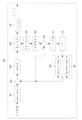
図1は本発明の一実施形態に係る画像符号化装置を示すブロック図である。 FIG. 1 is a block diagram showing an image coding apparatus according to an embodiment of the present invention.
図1を参照すると、画像符号化装置100は、画像分割部101、画面内予測部102、画面間予測部103、減算部104、変換部105、量子化部106、エントロピー符号化部107、逆量子化部108、逆変換部109、増算部110、フィルタ部111及びメモリ112を含むことができる。
Referring to FIG. 1, the
図1に示された各構成部は、画像符号化装置で互いに異なる特徴的な機能を示すために独立して図示したものであって、各構成部が分離されたハードウェア又は一つのソフトウェア構成単位からなることを意味しない。すなわち、各構成部は、説明の便宜上、それぞれの構成部として羅列して含むものであり、各構成部のうちの少なくとも二つの構成部が組み合わせられて1つの構成部をなすか、或いは1つの構成部が複数の構成部に分けられて機能を行うことができ、このような各構成部の統合された実施形態及び分離された実施形態も、本発明の本質から外れない限り、本発明の権利範囲に含まれる。 Each component shown in FIG. 1 is shown independently in order to show distinctive functions different from each other in the image coding device, and each component is a separate hardware or one software configuration. It does not mean that it consists of units. That is, each component is included in a list as each component for convenience of explanation, and at least two components of each component are combined to form one component, or one component. The components can be divided into a plurality of components to perform functions, and such integrated and separated embodiments of the components of the present invention are also described as long as they do not deviate from the essence of the present invention. Included in the scope of rights.
また、一部の構成要素は、本発明において本質的な機能を行う不可欠の構成要素ではなく、単に性能を向上させるための選択的構成要素であり得る。本発明は、単に性能向上のために使用される構成要素を除いた、本発明の本質の実現に必要不可欠な構成部のみを含んで実現でき、単に性能向上のために使用される選択的構成要素を除いた必須構成要素のみを含む構造も本発明の権利範囲に含まれる。 In addition, some components may not be essential components that perform essential functions in the present invention, but may simply be selective components for improving performance. The present invention can be realized by including only the components essential for the realization of the essence of the present invention, excluding the components used for improving the performance, and is merely a selective configuration used for improving the performance. A structure containing only essential components excluding elements is also included in the scope of rights of the present invention.
画像分割部101は、入力された画像を少なくとも一つのブロックに分割することができる。このとき、入力された画像は、ピクチャ、スライス、タイル、セグメントなど、さまざまな形状及びサイズを持つことができる。ブロックは、符号化単位(CU)、予測単位(PU)又は変換単位(TU)を意味することができる。前記分割は、4分木(quad tree)及び2分木(binary tree)のうちの少なくとも一つに基づいて行われ得る。4分木は、上位ブロックを、幅と高さが上位ブロックの半分である下位ブロックに四分割する方式である。2分木は、上位ブロックを、幅または高さのうちのいずれかが上位ブロックの半分である下位ブロックに二分割する方式である。前述した2分木ベースの分割によって、ブロックは正方形だけでなく、非正方形の形状を有することができる。
The
予測部102、103は、インター予測を行う画面間予測部103と、イントラ予測を行う画面内予測部102を含むことができる。予測単位に対してインター予測を行うかイントラ予測を行うかを決定し、各予測方法による具体的な情報(例えば、イントラ予測モード、動きベクトル、参照ピクチャなど)を決定することができる。このとき、予測が行われる処理単位と、予測方法及び具体的な内容が定められる処理単位とは互いに異なり得る。例えば、予測方法と予測モードなどは予測単位で決定され、予測の実行は変換単位で行われてもよい。
The
生成された予測ブロックと原本ブロック間の残差値(残差ブロック)は、変換部105に入力できる。また、予測のために使用した予測モード情報や動きベクトル情報などは、残差値と一緒にエントロピー符号化部107で符号化されて復号化器へ伝達できる。特定の符号化モードを使用する場合、予測部102、103を介して予測ブロックを生成せずに、原本ブロックをそのまま符号化して復号化部へ伝送することも可能である。
The residual value (residual block) between the generated predicted block and the original block can be input to the
画面内予測部102は、現在ピクチャ内の画素情報である現在ブロック周辺の参照ピクセル情報に基づいて予測ブロックを生成することができる。イントラ予測が行われる現在ブロックの周辺ブロックの予測モードがインター予測である場合には、インター予測が適用された周辺ブロックに含まれる参照画素を、イントラ予測が適用された周辺の他のブロック内の参照画素で代替することができる。すなわち、参照画素が利用可能ではない場合、利用可能でない参照画素情報を、利用可能な参照画素のうちの少なくとも一つの参照画素で代替して使用することができる。
The in-
イントラ予測における予測モードは、参照画素情報を予測方向に応じて使用する方向性予測モードと、予測の実行時に方向性情報を使用しない非方向性モードとを持つことができる。輝度情報を予測するためのモードと色差情報を予測するためのモードとが互いに異なってもよく、色差情報を予測するために、輝度情報を予測するために使用されたイントラ予測モード情報又は予測された輝度信号情報を活用することができる。 The prediction mode in the intra prediction can have a directional prediction mode in which the reference pixel information is used according to the prediction direction and a non-directional mode in which the directional information is not used when the prediction is executed. The mode for predicting the luminance information and the mode for predicting the color difference information may be different from each other, and the intra-prediction mode information or predicted used to predict the luminance information to predict the luminance information. It is possible to utilize the luminance signal information.
画面内予測部102は、AIS(Adaptive Intra Smoothing)フィルタ、参照画素補間部、及びDCフィルタを含むことができる。AISフィルタは、現在ブロックの参照画素に対してフィルタリングを行うフィルタであって、現在予測単位の予測モードに応じて、フィルタを適用するか否かを適応的に決定することができる。現在ブロックの予測モードがAISフィルタリングを行わないモードである場合、AISフィルタは適用されなくてもよい。
The in-
画面内予測部102の参照画素補間部は、予測単位のイントラ予測モードが参照画素を補間した画素値に基づいてイントラ予測を行う予測単位である場合、参照画素を補間して分数単位位置の参照画素を生成することができる。現在予測単位の予測モードが参照画素を補間せずに予測ブロックを生成する予測モードである場合、参照画素は補間されなくてもよい。DCフィルタは、現在ブロックの予測モードがDCモードである場合、フィルタリングを介して予測ブロックを生成することができる。
When the intra-prediction mode of the prediction unit is a prediction unit that performs intra-prediction based on the pixel value obtained by interpolating the reference pixel, the reference pixel interpolation unit of the in-
画面間予測部103は、メモリ112に保存された、既に復元された参照画像と動き情報を用いて予測ブロックを生成する。動き情報は、例えば動きベクトル、参照ピクチャインデックス、リスト1予測フラグ、リスト0予測フラグなどを含むことができる。
The
予測部102、103で生成された予測単位と予測単位の原本ブロックとの差異値である残差値(Residual)情報を含む残差ブロックが生成できる。生成された残差ブロックは、変換部105に入力されて変換できる。
A residual block including residual value (Error) information which is a difference value between the prediction unit generated by the
画面間予測部103は、現在ピクチャの以前ピクチャ又は以後ピクチャのうちの少なくとも一つのピクチャの情報に基づいて予測ブロックを誘導することができる。また、現在ピクチャ内の符号化が完了した一部領域の情報に基づいて、現在ブロックの予測ブロックを誘導することができる。本発明の一実施形態に係る画面間予測部103は、参照ピクチャ補間部、動き予測部及び動き補償部を含むことができる。
The
参照ピクチャ補間部では、メモリ112から参照ピクチャ情報の提供を受け、参照ピクチャにおいて整数画素以下の画素情報を生成することができる。輝度画素の場合、1/4画素単位で整数画素以下の画素情報を生成するためにフィルタ係数を異にするDCTベースの8タップ補間フィルタ(DCT-based Interpolation Filter)が使用できる。色差信号の場合、1/8画素単位で整数画素以下の画素情報を生成するためにフィルタ係数を異にするDCTベースの4タップ補間フィルタ(DCT-based Interpolation Filter)が使用できる。
The reference picture interpolation unit receives the reference picture information from the
動き予測部は、参照ピクチャ補間部によって補間された参照ピクチャに基づいて動き予測を行うことができる。動きベクトルを算出するための方法として、FBMA(Full search-based Block Matching Algorithm)、TSS(Three Step Search)、NTS(New Three-Step Search Algorithm)などの様々な方法が使用できる。動きベクトルは、補間された画素に基づいて1/2又は1/4画素単位の動きベクトル値を持つことができる。動き予測部では、動き予測方法を異にして現在ブロックの予測ブロックを予測することができる。動き予測方法として、スキップ(Skip)方法、マージ(Merge)方法、AMVP(Advanced Motion Vector Prediction)方法などの様々な方法が使用できる。 The motion prediction unit can perform motion prediction based on the reference picture interpolated by the reference picture interpolation unit. As a method for calculating the motion vector, various methods such as FBMA (Full search-based Block Matching Algorithm), TSS (Three Step Search), and NTS (New Three-Step Search Algorithm) can be used. The motion vector can have a motion vector value in units of 1/2 or 1/4 pixels based on the interpolated pixels. The motion prediction unit can predict the prediction block of the current block by using a different motion prediction method. As a motion prediction method, various methods such as a skip method, a merge method, and an AMVP (Advanced Motion Vector Prediction) method can be used.
減算部104は、現在符号化しようとするブロックと、画面内予測部102或いは画面間予測部103で生成された予測ブロックとを減算して現在ブロックの残差ブロックを生成する。
The
変換部105では、残差データを含む残差ブロックをDCT、DST、KLT(Karhunen Loeve Transform)などの変換方法を用いて変換させることができる。この時、変換方法は、残差ブロックを生成するために使用された予測単位のイントラ予測モードに基づいて決定できる。例えば、イントラ予測モードに応じて、横方向にはDCTを使用し、縦方向にはDSTを使用してもよい。
In the
量子化部106は、変換部105で周波数領域に変換された値を量子化することができる。ブロックに応じて又は画像の重要度に応じて、量子化係数は変わり得る。量子化部106で算出された値は、逆量子化部108とエントロピー符号化部107に提供できる。
The
前記変換部105及び/又は量子化部106は、画像符号化装置100に選択的に含まれ得る。すなわち、画像符号化装置100は、残差ブロックの残差データに対して、変換又は量子化のうちの少なくとも一つを行うか、或いは変換及び量子化の両方をスキップして残差ブロックを符号化することができる。画像符号化装置100で変換又は量子化のいずれかが行われないか、或いは変換及び量子化の両方が行われなくても、エントロピー符号化部107の入力に入るブロックを、通常、変換ブロックと呼ぶ。エントロピー符号化部107は、入力データをエントロピー符号化する。エントロピー符号化は、例えば、指数ゴロム(Exponential Golomb)、CAVLC(Context-Adaptive Variable Length Coding)、CABAC(Context-Adaptive Binary Arithmetic Coding)などのさまざまな符号化方法を使用することができる。
The
エントロピー符号化部107は、変換ブロックの係数情報、ブロックタイプ情報、予測モード情報、分割単位情報、予測単位情報、伝送単位情報、動きベクトル情報、参照フレーム情報、ブロックの補間情報、フィルタリング情報などの様々な情報を符号化することができる。変換ブロックの係数は、変換ブロック内のサブブロック単位で符号化できる。
The
変換ブロックの係数の符号化のために、逆スキャン順における最初の0ではない係数の位置を知らせるシンタックス要素(syntax element)であるLast_sig、サブブロック内に0ではない係数が少なくとも一つあるかを知らせるフラグであるCoded_sub_blk_flag、0ではない係数であるかを知らせるフラグであるSig_coeff_flag、係数の絶対値が1よりも大きいかを知らせるフラグであるAbs_greater1_flag、係数の絶対値が2よりも大きいかを知らせるフラグであるAbs_greater2_flag、係数の符号を示すフラグであるSign_flagなどの様々なシンタックス要素が符号化できる。前記シンタックス要素のみで符号化されない係数の残余値は、シンタックス要素remaining_coeffを介して符号化できる。 Last_sig, which is a syntax element that indicates the position of the first non-zero coefficient in the reverse scan order, for encoding the coefficients of the conversion block, is there at least one non-zero coefficient in the subblock? Coded_sub_blk_flag which is a flag indicating Various syntax elements such as Abs_greeter2_flag, which is a flag, and Sign_flag, which is a flag indicating the code of a coefficient, can be encoded. The residual value of the coefficient, which is not encoded only by the syntax element, can be encoded via the syntax element remaining_coeff.
逆量子化部108及び逆変換部109では、量子化部106で量子化された値を逆量子化し、変換部105で変換された値を逆変換する。逆量子化部108及び逆変換部109で生成された残差値(Residual)は、予測部102、103に含まれている動き推定部、動き補償部及び画面内予測部102を介して予測された予測単位と合わせられて復元ブロック(Reconstructed Block)を生成することができる。増算器110は、予測部102、103で生成された予測ブロックと、逆変換部109を介して生成された残差ブロックとを増算して復元ブロックを生成する。
In the
フィルタ部111は、デブロッキングフィルタ、オフセット補正部及びALF(Adaptive Loop Filter)のうちの少なくとも一つを含むことができる。 The filter unit 111 can include at least one of a deblocking filter, an offset correction unit, and an ALF (Adaptive Loop Filter).
デブロッキングフィルタは、復元されたピクチャからブロック間の境界により生じたブロック歪みを除去することができる。デブロッキングを行うか否かを判断するために、ブロックに含まれた幾つかの列又は行に含まれているピクセルに基づいて、現在ブロックにデブロッキングフィルタを適用するか否かを判断することができる。ブロックにデブロッキングフィルタを適用する場合、必要なデブロッキングフィルタリング強度に応じて強いフィルタ(Strong Filter)又は弱いフィルタ(Weak Filter)を適用することができる。また、デブロッキングフィルタを適用するにあたり、垂直フィルタリング及び水平フィルタリングを行う際に、水平方向のフィルタリング及び垂直方向のフィルタリングが併行処理されるようにすることができる。 The deblocking filter can remove the block distortion caused by the boundary between blocks from the restored picture. To determine whether to deblock, determine whether to apply a deblocking filter to the current block based on the pixels contained in some columns or rows contained in the block. Can be done. When applying a deblocking filter to a block, a strong filter (Strong Filter) or a weak filter (Wake Filter) can be applied depending on the required deblocking filtering intensity. Further, when applying the deblocking filter, when performing vertical filtering and horizontal filtering, horizontal filtering and vertical filtering can be performed in parallel.
オフセット補正部は、デブロッキングを行った画像に対してピクセル単位で原本画像とのオフセットを補正することができる。特定のピクチャに対するオフセット補正を行うために、画像に含まれているピクセルを一定数の領域に区分した後、オフセットを行う領域を決定し、該当領域にオフセットを適用する方法、又は各ピクセルのエッジ情報を考慮してオフセットを適用する方法を使用することができる。 The offset correction unit can correct the offset from the original image on a pixel-by-pixel basis with respect to the deblocked image. In order to perform offset correction for a specific picture, the pixels contained in the image are divided into a certain number of areas, then the area to be offset is determined, and the offset is applied to the area, or the edge of each pixel. You can use the method of applying the offset in consideration of the information.
ALF(Adaptive Loop Filtering)は、フィルタリングした復元画像と元来の画像とを比較した値に基づいて行われ得る。画像に含まれているピクセルを所定のグループに分けた後、該当グループに適用される1つのフィルタを決定し、グループごとに差別的にフィルタリングを行うことができる。ALFを適用するか否かに関連した情報は、輝度信号は符号化単位(Coding Unit、CU)別に伝送でき、それぞれのブロックに応じて適用されるALFフィルタの形状及びフィルタ係数は変わり得る。また、適用対象ブロックの特性を問わずに、同じ形態(固定された形態)のALFフィルタが適用されてもよい。 ALF (Adaptive Loop Filtering) can be performed based on a value comparing the filtered restored image with the original image. After dividing the pixels contained in the image into predetermined groups, one filter applied to the group can be determined, and filtering can be performed discriminatively for each group. As for the information related to whether or not ALF is applied, the luminance signal can be transmitted for each coding unit (Cuding Unit, CU), and the shape and filter coefficient of the applied ALF filter can change according to each block. Further, the ALF filter of the same form (fixed form) may be applied regardless of the characteristics of the block to be applied.
メモリ112は、フィルタ部111を介して算出された復元ブロック又はピクチャを保存することができ、保存された復元ブロック又はピクチャは、画面間予測を行うときに予測部102、103に提供できる。
The
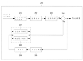
次に、本発明の一実施形態に係る画像復号化装置を図面に基づいて説明する。図2は本発明の一実施形態に係る画像復号化装置200を示すブロック図である。
Next, the image decoding apparatus according to the embodiment of the present invention will be described with reference to the drawings. FIG. 2 is a block diagram showing an
図2を参照すると、画像復号化装置200は、エントロピー復号化部201、逆量子化部202、逆変換部203、増算部204、フィルタ部205、メモリ206及び予測部207、208を含むことができる。
Referring to FIG. 2, the
画像符号化装置100によって生成された画像ビットストリームが画像復号化装置200に入力される場合、入力されたビットストリームは、画像符号化装置100で行われた過程と反対の過程によって復号化できる。
When the image bitstream generated by the
エントロピー復号化部201は、画像符号化装置100のエントロピー符号化部107でエントロピー符号化を行ったのと反対の手順でエントロピー復号化を行うことができる。例えば、画像符号化器で行われた方法に対応して指数ゴロム(Exponential Golomb)、CAVLC(Context-Adaptive Variable Length Coding)、CABAC(Context-Adaptive Binary Arithmetic Coding)などのさまざまな方法が適用できる。エントロピー復号化部201は、前述したようなシンタックス要素、すなわちLast_sig、Coded_sub_blk_flag、Sig_coeff_flag、Abs_greater1_flag、Abs_greater2_flag、Sign_flag及びremaining_coeffを復号化することができる。また、エントロピー復号化部201は、画像符号化装置100で行われたイントラ予測及びインター予測に関する情報を復号化することができる。
The
逆量子化部202は、量子化された変換ブロックに対して逆量子化を行って変換ブロックを生成する。図1の逆量子化部108と実質的に同様に動作する。
The
逆変換部203は、変換ブロックに対して逆変換を行って残差ブロックを生成する。このとき、変換方法は、予測方法(インター又はイントラ予測)、ブロックのサイズ及び/又は形状、イントラ予測モードなどに関する情報に基づいて決定できる。図1の逆変換部109と実質的に同様に動作する。
The
増算部204は、画面内予測部207或いは画面間予測部208で生成された予測ブロックと、逆変換部203を介して生成された残差ブロックとを増算して復元ブロックを生成する。図1の増算部110と実質的に同様に動作する。
The
フィルタ部205は、復元されたブロックに発生するさまざまな種類のノイズを減少させる。
The
フィルタ部205は、デブロッキングフィルタ、オフセット補正部及びALFを含むことができる。
The
画像符号化装置100から、該当ブロック又はピクチャにデブロッキングフィルタを適用するか否かについての情報、及び、デブロッキングフィルタを適用した場合、強いフィルタを適用したか弱いフィルタを適用したかについての情報の提供を受けることができる。画像復号化装置200のデブロッキングフィルタでは、画像符号化装置100から提供されたデブロッキングフィルタ関連情報の提供を受け、画像復号化装置200で該当ブロックに対するデブロッキングフィルタリングを行うことができる。
Information on whether or not a deblocking filter is applied to the corresponding block or picture from the
オフセット補正部は、符号化の際に、画像に適用されたオフセット補正の種類及びオフセット値の情報などに基づいて、復元された画像に対してオフセット補正を行うことができる。 At the time of coding, the offset correction unit can perform offset correction on the restored image based on the type of offset correction applied to the image, information on the offset value, and the like.
ALFは、画像符号化装置100から提供されたALF適用有無情報、ALF係数情報などに基づいて符号化単位に適用できる。このようなALF情報は、特定のパラメータセットに含まれて提供されてもよい。フィルタ部205は、図1のフィルタ部111と実質的に同様に動作する。
The ALF can be applied to the coding unit based on the ALF application presence / absence information, the ALF coefficient information, and the like provided by the
メモリ206は、増算部204によって生成された復元ブロックを保存する。図1のメモリ112と実質的に同様に動作する。
The
予測部207、208は、エントロピー復号化部201から提供された予測ブロック生成関連情報、及びメモリ206から提供された以前に復号化されたブロック又はピクチャ情報に基づいて予測ブロックを生成することができる。
The
予測部207、208は、画面内予測部207及び画面間予測部208を含むことができる。別途図示されてはいないが、予測部207、208は、予測単位判別部をさらに含んでもよい。予測単位判別部は、エントロピー復号化部201から入力される予測単位情報、イントラ予測方法の予測モード情報、インター予測方法の動き予測関連情報などの様々な情報の入力を受け、現在符号化単位で予測単位を区分し、予測単位がインター予測を行うか、それともイントラ予測を行うかを判別することができる。画面間予測部208は、画像符号化装置100から提供された現在予測単位のインター予測に必要な情報を用いて、現在予測単位が含まれている現在ピクチャの以前ピクチャ又は以後ピクチャのうちの少なくとも一つのピクチャに含まれている情報に基づいて、現在予測単位に対する画面間予測を行うことができる。又は、現在予測単位が含まれている現在ピクチャ内で、既に復元された一部領域の情報に基づいて画面間予測を行うこともできる。
The
画面間予測を行うために、符号化単位を基準に、該当符号化単位に含まれている予測単位の動き予測方法がスキップモード(Skip Mode)、マージモード(Merge Mode)及びAMVPモード(AMVP Mode)のうちのどの方法であるかを判断することができる。 In order to perform inter-screen prediction, the motion prediction method of the prediction unit included in the corresponding coding unit is skip mode (Skip Mode), merge mode (Merge Mode), and AMVP mode (AMVP Mode) based on the coding unit. ) Can be determined.
画面内予測部207は、現在符号化しようとするブロックの周辺に位置した、既に復元された画素を用いて、予測ブロックを生成する。
The in-
画面内予測部207は、AIS(Adaptive Intra Smoothing)フィルタ、参照画素補間部及びDCフィルタを含むことができる。AISフィルタは、現在ブロックの参照画素にフィルタリングを行うフィルタであって、現在予測単位の予測モードに応じてフィルタの適用有無を適応的に決定することができる。画像符号化装置100から提供された予測単位の予測モード及びAISフィルタ情報を用いて、現在ブロックの参照画素にAISフィルタリングを行うことができる。現在ブロックの予測モードがAISフィルタリングを行わないモードである場合、AISフィルタは適用されなくてもよい。
The in-
画面内予測部207の参照画素補間部は、予測単位の予測モードが参照画素を補間した画素値に基づいてイントラ予測を行う予測単位である場合、参照画素を補間して分数単位位置の参照画素を生成することができる。生成された分数単位位置の参照画素が現在ブロック内の画素の予測画素として使用できる。現在予測単位の予測モードが、参照画素を補間せずに予測ブロックを生成する予測モードである場合、参照画素は補間されなくてもよい。DCフィルタは、現在ブロックの予測モードがDCモードである場合、フィルタリングを介して予測ブロックを生成することができる。
When the prediction mode of the prediction unit is a prediction unit that performs intra-prediction based on the pixel value obtained by interpolating the reference pixel, the reference pixel interpolation unit of the in-
画面内予測部207は、図1の画面内予測部102と実質的に同様に動作する。
The in-
画面間予測部208は、メモリ206に保存された参照ピクチャ、動き情報を用いて画面間予測ブロックを生成する。画面間予測部208は、図1の画面間予測部103と実質的に同様に動作する。
The
以下、本発明の様々な実施形態を図面に基づいてより詳細に説明する。 Hereinafter, various embodiments of the present invention will be described in more detail with reference to the drawings.
(第1実施形態) (First Embodiment)
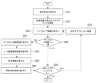
図3は本発明の一実施形態に係る変換ブロックの符号化方法を示す流れ図である。図3の変換ブロックの符号化方法は、画像符号化装置100のエントロピー符号化部107によって行われ得る。
FIG. 3 is a flow chart showing a method for encoding a conversion block according to an embodiment of the present invention. The coding method of the conversion block of FIG. 3 can be performed by the
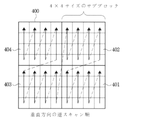
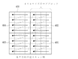
図4aに示すように、一つの変換ブロックはサブブロック単位で符号化できる。図4aを参照すると、符号化または復号化する現在変換ブロック400が8×8ブロックである場合には、4×4サイズの4つのサブブロック1(401)乃至サブブロック4(404)に分割できる。変換ブロック内の変換係数の符号化順序を決定するためのスキャン方法には、現在ブロックまたは現在変換ブロックの予測モードに応じて垂直、水平または対角線方向の逆スキャン方法などが利用できる。ここで、予測モードは画面間予測または画面内予測であり得る。
As shown in FIG. 4a, one conversion block can be encoded in sub-block units. Referring to FIG. 4a, when the
図4b、図4c及び図4dはそれぞれ対角線方向の逆スキャン、垂直方向の逆スキャン及び水平方向の逆スキャンを示す。ここで、説明の便宜のために、対角線方向の逆スキャンを例として説明するが、垂直方向の逆スキャンまたは水平方向の逆スキャンもすべて適用可能である。 4b, 4c and 4d show diagonal reverse scan, vertical reverse scan and horizontal reverse scan, respectively. Here, for convenience of explanation, the reverse scan in the diagonal direction will be described as an example, but the reverse scan in the vertical direction or the reverse scan in the horizontal direction are all applicable.
図3を参照すると、まず、逆スキャン順に従って変換係数をスキャンするとき、最初の0ではない係数を基準係数として定め、その位置情報Last_sigを符号化する(S301)。 Referring to FIG. 3, first, when scanning the conversion coefficient according to the reverse scan order, the first non-zero coefficient is set as the reference coefficient, and the position information Last_sig is encoded (S301).
基準係数が含まれているサブブロックを選択し(S302)、当該サブブロック情報を符号化する(S303)。サブブロック情報であるCoded_sub_blk_flagは、現在サブブロック内に0ではない係数が少なくとも一つあるかを知らせるフラグである。その後、0ではない係数情報を符号化する(S304)。ここで、0ではない係数情報であるSig_coeff_flagは、サブブロック内に存在する各係数の値が0であるか否かを示す。 A subblock containing a reference coefficient is selected (S302), and the subblock information is encoded (S303). The sub-block information Coded_sub_blk_flag is a flag indicating whether there is at least one non-zero coefficient in the sub-block at present. Then, the non-zero coefficient information is encoded (S304). Here, Sig_coeff_flag, which is coefficient information that is not 0, indicates whether or not the value of each coefficient existing in the subblock is 0.
そして、N超過係数情報を符号化する(S305)。ここで、N超過係数情報は、サブブロック内に存在するすべての係数に対して、各係数の絶対値が1からNまでの値をそれぞれ超えるかを示す。Nは符号化及び復号化の際に任意の所定の値を使用するが、Nの値を符号化して符号化及び復号化の際に同じ値を使用するようにすることができる。N超過係数情報の個数は、任意の所定の値を使用してもよく、基準係数の位置に応じて異なるように使用してもよい。例えば、Nが3に設定された場合、サブブロック内のすべての0ではないと判断された係数に対して、各係数の絶対値が1よりも大きい値であるか否かを符号化する。このため、係数の絶対値が1よりも大きいかを知らせるフラグであるAbs_greater1_flagが使用される。その後、1よりも大きい値と判断された係数に対してのみ、2よりも大きい値であるか否かを符号化する。このため、係数の絶対値が2よりも大きいかを知らせるフラグであるAbs_greater2_flagが使用される。最後に、2よりも大きい値と判断された係数に対してのみ、3よりも大きい値であるか否かを符号化する。このためには、係数の絶対値が3よりも大きいかを知らせるフラグであるAbs_greater3_flagが使用できる。 Then, the N excess coefficient information is encoded (S305). Here, the N excess coefficient information indicates whether the absolute value of each coefficient exceeds the value from 1 to N for all the coefficients existing in the subblock. N uses an arbitrary predetermined value during encoding and decoding, but the value of N can be encoded so that the same value is used during encoding and decoding. Any predetermined value may be used for the number of N excess coefficient information, or may be used differently depending on the position of the reference coefficient. For example, when N is set to 3, it encodes whether or not the absolute value of each coefficient is greater than 1 for all the non-zero coefficients in the subblock. Therefore, Abs_greeter1_flag, which is a flag indicating whether the absolute value of the coefficient is larger than 1, is used. Then, only for the coefficient determined to be a value larger than 1, whether or not the value is larger than 2 is encoded. Therefore, Abs_greeter2_flag, which is a flag indicating whether the absolute value of the coefficient is larger than 2, is used. Finally, only for the coefficient determined to be a value greater than 2, whether or not the value is greater than 3 is encoded. For this purpose, Abs_greeter3_flag, which is a flag indicating whether the absolute value of the coefficient is larger than 3, can be used.
その後、0ではないと判断された各係数に対して負数であるか正数であるかを示す符号情報が符号化される(S306)。符号情報は、Sign_flagが使用できる。そして、Nよりも大きいと判断された係数に対してのみ、Nを引いた残りの値を残差係数情報として定義し、この係数の残余値情報remaining_coeffが符号化される(S307)。 After that, code information indicating whether the coefficient is a negative number or a positive number is encoded for each coefficient determined to be non-zero (S306). Sign_flag can be used as the code information. Then, only for the coefficient determined to be larger than N, the remaining value obtained by subtracting N is defined as the residual coefficient information, and the residual value information remaining_coeff of this coefficient is encoded (S307).
その後、次のサブブロックが存在するか否かを確認した後(S309)。次のサブブロックが存在する場合には、次のサブブロックへ移動し(S310)、サブブロック情報を符号化する(S303)。当該サブブロック情報Coded_sub_blk_flagを確認し(S308)、Coded_sub_blk_flagの値が真であると確認されると、0ではない係数情報であるSig_coeff_flagを符号化する。もし当該サブブロック情報Coded_sub_blk_flagの値が偽である場合には、当該サブブロックに符号化する係数が存在しないという意味なので、次のサブブロックの存否を確認する。或いは、次のサブブロックへ移動した後、当該サブブロックが最も低周波側に位置したサブブロックである場合、0ではない係数が存在するという仮定の下に、サブブロック情報の符号化及び復号化なしに真であると符号化及び復号化の際に同一に設定することも可能である。 Then, after confirming whether or not the next subblock exists (S309). If the next subblock exists, it moves to the next subblock (S310) and encodes the subblock information (S303). When the sub-block information Coded_sub_blk_flag is confirmed (S308) and the value of Coded_sub_blk_flag is confirmed to be true, the non-zero coefficient information Sig_coeff_flag is encoded. If the value of the subblock information Code_sub_blk_flag is false, it means that there is no coefficient to be encoded in the subblock, so the existence of the next subblock is confirmed. Alternatively, after moving to the next subblock, if the subblock is the subblock located on the lowest frequency side, the subblock information is encoded and decoded under the assumption that there is a non-zero coefficient. It is also possible to set the same when encoding and decoding if it is true without.
図5は本発明の一実施形態に係る変換ブロックの復号化方法を示す流れ図である。図5の変換ブロックの復号化方法は、図3の変換ブロックの符号化方法に対応する。図5の変換ブロックの復号化方法は、画像復号化装置200のエントロピー復号化部201によって行われ得る。
FIG. 5 is a flow chart showing a method for decoding a conversion block according to an embodiment of the present invention. The method of decoding the conversion block of FIG. 5 corresponds to the method of encoding the conversion block of FIG. The method of decoding the conversion block of FIG. 5 can be performed by the
逆スキャン順に従って最初に出てくる0ではない変換係数である基準係数の位置情報Last_sigを復号化する(S501)。 The position information Last_sig of the reference coefficient, which is a non-zero conversion coefficient that first appears in the reverse scan order, is decoded (S501).
基準係数が含まれているサブブロックを選択し(S502)、サブブロック情報Coded_sub_blk_flagを復号化する(S503)。その後、0ではない係数情報Sig_coeff_flagを復号化する(S504)。そして、N超過係数情報が復号化される(S505)。ここで、N超過係数情報には、前述したようなAbs_greater1_flag、Abs_greater2_flag及びAbs_greater3_flagなどが含まれ得る。 The subblock containing the reference coefficient is selected (S502), and the subblock information Coded_sub_blk_flag is decoded (S503). Then, the non-zero coefficient information Sig_coeff_flag is decoded (S504). Then, the N excess coefficient information is decoded (S505). Here, the N excess coefficient information may include Abs_greeter1_flag, Abs_greeter2_flag, Abs_greeter3_flag, and the like as described above.
その後、0ではないと判断された各係数に対して係数の符号情報Sign_flagが復号化される(S506)。そして、Nよりも大きいと判断された係数に対してのみ、Nを引いた残りの値に該当する残差係数情報remaing_coeffが復号化される(S507)。その後、次のサブブロックが存在するか否かを確認した後(S509)、存在する場合には、次のサブブロックへ移動し(S510)、サブブロック情報Coded_sub_blk_flagを復号化する(S503)。当該サブブロック情報Coded_sub_blk_flagを確認し(S508)、もし当該サブブロック情報が真である場合には、0ではない係数情報Sig_coeff_flagを復号化し、もし当該サブブロック情報が偽である場合には、当該サブブロックに復号化する係数が存在しないという意味なので、次のサブブロックの存否を確認する。 Then, the coefficient code information Sign_flag is decoded for each coefficient determined to be non-zero (S506). Then, the residual coefficient information remaing_coeff corresponding to the remaining value obtained by subtracting N is decoded only for the coefficient determined to be larger than N (S507). Then, after confirming whether or not the next subblock exists (S509), if it exists, the process moves to the next subblock (S510), and the subblock information Coded_sub_blk_flag is decoded (S503). The sub-block information Coded_sub_blk_flag is confirmed (S508), and if the sub-block information is true, the non-zero coefficient information Sig_coeff_flag is decoded, and if the sub-block information is false, the sub-block information is decoded. Since it means that there is no coefficient to decode in the block, check the existence of the next subblock.
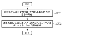
図6は本発明の一実施形態によって、スキップ領域を用いた画像符号化方法を示す流れ図である。図6の画像符号化方法は、画像符号化装置100のエントロピー符号化部107によって行われ得る。
FIG. 6 is a flow chart showing an image coding method using a skip region according to an embodiment of the present invention. The image coding method of FIG. 6 can be performed by the
図6を参照すると、まず、エントロピー符号化部107は、符号化する現在変換ブロック内の基準係数の位置を符号化する(S601)。前述したように、基準係数は、逆スキャン順に係数をスキャンするときに最初の0ではない係数をいう。その後、基準係数の位置に基づいて選択されたスキップ領域に対するスキップ領域情報を符号化する(S602)。
Referring to FIG. 6, first, the
ここで、スキップ領域とは、基準係数の位置に基づいて定められる、現在変換ブロック内の領域である。スキップ領域情報は、スキップ領域内の係数がすべて同じ値を持つか否かを示す。ここで、スキップ領域内の係数が持つ同じ値は0であり得る。もし、スキップ領域内の係数が持つ同じ値が0ではない場合には、0ではないどの値であるかを示す情報がさらに符号化できる。スキップ領域内の係数が持つ同じ値として、0ではない任意の所定の値を使用することも可能である。この場合、所定の値の情報を変換ブロック単位ではない上位ヘッダを介して符号化することが可能である。 Here, the skip area is an area in the current conversion block determined based on the position of the reference coefficient. The skip area information indicates whether or not all the coefficients in the skip area have the same value. Here, the same value of the coefficients in the skip region can be zero. If the same value of the coefficients in the skip region is not 0, the information indicating which value is not 0 can be further encoded. It is also possible to use any predetermined non-zero value as the same value of the coefficients in the skip area. In this case, it is possible to encode the information of a predetermined value via a higher-level header that is not a conversion block unit.
一方、スキップ領域は、所定の規則によって符号化/復号化過程で同様に決定してもよく、変換ブロック内のスキップ領域の範囲を知らせる座標をさらに符号化して符号化装置100または復号化装置200で同じ位置を利用してもよい。
On the other hand, the skip area may be similarly determined in the coding / decoding process according to a predetermined rule, and the coordinates indicating the range of the skip area in the conversion block are further encoded to be further encoded by the
図7は本発明の一実施形態に係るスキップ領域を示す図である。対角線方向の逆スキャンが現在変換ブロック700の係数符号化に使用される場合を仮定する。
FIG. 7 is a diagram showing a skip region according to an embodiment of the present invention. Suppose a diagonal reverse scan is currently used for coefficient coding in
図7を参照すると、基準係数701の位置を基準に左下45度方向に基準線702を生成した後、基準線702上に位置する係数と、基準線702の下側に存在する係数とを含む領域がスキップ領域として指定されている。図7において、スキップ領域は陰影で表示されており、スキップ領域内のすべての係数は0の同一値を持つ。また、スキップ領域内のすべての係数は、基準係数よりも符号化順序における後ろに位置する。
Referring to FIG. 7, after the
スキップ領域を設定する他の実施形態として、基準係数が変換ブロック内のいずれかの任意の領域に位置することにより、スキップ領域内に存在する係数の数が少なければ、基準係数を基準にスキップ領域を定めるのではなく、逆スキャン順上、基準係数以後に出てくる0ではない係数のうちのいずれかまたは基準係数に隣接する係数を用いて、スキップ領域を設定することができる。ここで、基準係数が位置する、変換ブロック内の任意の領域は、逆スキャン順に計算したサブブロックの個数を所定のしきい値と比較して設定することが可能である。または、基準係数が変換ブロックのいずれかの任意の位置からどれほど離れているかを把握し、所定のしきい値と比較して設定することもできる。例えば、この任意の位置は、変換ブロックの横と縦の中間地点である中心点であってもよい。または、変換ブロックの横と縦をそれぞれm及びn等分した後、この分けられた領域のうちの一つを任意の領域として決定することも可能である。ここで、mとnの値は、ブロック単位或いは上位ヘッダを介して符号化することも可能であり、符号化及び復号化の際に同様に所定の値を使用することも可能である。 As another embodiment for setting the skip area, if the reference coefficient is located in any area in the conversion block and the number of coefficients existing in the skip area is small, the skip area is based on the reference coefficient. The skip area can be set by using any of the non-zero coefficients appearing after the reference coefficient or the coefficient adjacent to the reference coefficient in the reverse scan order. Here, any region in the conversion block where the reference coefficient is located can be set by comparing the number of subblocks calculated in the reverse scan order with a predetermined threshold value. Alternatively, it is possible to grasp how far the reference coefficient is from any position of the conversion block and set it in comparison with a predetermined threshold value. For example, this arbitrary position may be a center point that is an intermediate point between the horizontal and vertical directions of the conversion block. Alternatively, after dividing the horizontal and vertical directions of the conversion block into m and n equal parts, one of the divided regions can be determined as an arbitrary region. Here, the values of m and n can be encoded in block units or via a higher-level header, and predetermined values can also be used during encoding and decoding.
図8は本発明の他の実施形態に係るスキップ領域を示す図である。変換ブロック800内の基準係数801の位置から変換ブロック800内の左下側コーナーに存在する係数802の位置に基準線803を生成した後、基準線803上に位置する係数と基準線803の下側に存在する係数とを含む領域をスキップ領域として指定する。ここで、スキップ領域に属する係数は基準係数よりも符号化順序における後ろに位置する。図8において、スキップ領域は陰影で表示されている。
FIG. 8 is a diagram showing a skip region according to another embodiment of the present invention. After the
一方、図6に示されてはいないが、ステップS601及びS603によって設定されたスキップ領域以外に、さらにスキップ領域を設定してもよい。さらに設定されるスキップ領域は、追加スキップ領域情報を用いて符号化できる。 On the other hand, although not shown in FIG. 6, a skip area may be further set in addition to the skip area set in steps S601 and S603. Further, the skip area to be set can be encoded by using the additional skip area information.
図9は本発明の一実施形態に係る追加スキップ領域を示す図である。図7に示されたスキップ領域に加えて、さらに追加スキップ領域が図9に設定されている。図7のスキップ領域上側の領域が追加スキップ領域として設定され、追加スキップ領域内の係数がすべて同じ値であるか否かを示す追加スキップ領域情報が符号化できる。ここで、スキップ領域内の係数が持つ同じ値は0であり得る。もし、スキップ領域内の係数が持つ同じ値が0ではない場合、0ではないどの値であるかを示す情報がさらに符号化できる。スキップ領域内の係数が持つ同じ値として、0ではない任意の所定の値を使用することも可能である。この場合、所定の値の情報を、変換ブロック単位ではない上位ヘッダを介して符号化することが可能である。 FIG. 9 is a diagram showing an additional skip region according to an embodiment of the present invention. In addition to the skip area shown in FIG. 7, an additional skip area is set in FIG. The area above the skip area in FIG. 7 is set as the additional skip area, and the additional skip area information indicating whether or not all the coefficients in the additional skip area have the same value can be encoded. Here, the same value of the coefficients in the skip region can be zero. If the same value of the coefficients in the skip region is not 0, the information indicating which value is not 0 can be further encoded. It is also possible to use any predetermined non-zero value as the same value of the coefficients in the skip area. In this case, it is possible to encode the information of a predetermined value via a higher-level header that is not a conversion block unit.
一方、追加スキップ領域の位置は、所定の規則によって符号化及び復号化過程で同様に決定されてもよく、変換ブロック内の座標をさらに符号化して符号化装置100及び復号化装置200で同じ位置を用いてもよい。ここで、新たに生成された追加スキップ領域は、以前スキップ領域から距離pだけ離れていてもよい。
On the other hand, the position of the additional skip region may be similarly determined in the coding and decoding process according to a predetermined rule, and the coordinates in the conversion block are further encoded to be the same position in the
図9を参照すると、基準係数701を基準に基準線702を生成することにより、スキップ領域が設定され、さらに基準線702の上側を追加スキップ領域として設定した例示を示す。追加スキップ領域とスキップ領域との距離pが0である場合には、基準線703上の係数を含む領域が追加スキップ領域になり得る。もし距離pが1である場合には、追加スキップ領域は、基準線703上の係数を含む領域、及び基準線704上の係数を含む領域を含む。
With reference to FIG. 9, a skip area is set by generating the
本実施形態において、追加スキップ領域とスキップ領域との距離pは0または1である場合を例として挙げたが、その他の値が使用されてもよい。ここで、pは符号化/復号化過程で所定の同じ値が使用できる。或いはpの値をブロック単位で符号化するか、或いは上位ヘッダを介して符号化することも可能である。 In the present embodiment, the case where the distance p between the additional skip area and the skip area is 0 or 1 is given as an example, but other values may be used. Here, p can use the same predetermined value in the encoding / decoding process. Alternatively, the value of p can be encoded in block units, or can be encoded via an upper header.
また、追加スキップ領域は、所定の方式によって追加されることが可能である。例えば、追加スキップ領域情報が偽であると判断されるまで、追加スキップ領域を追加し続けるか、或いは所定の回数qだけ符号化し続けることも可能である。ここで、追加される各追加スキップ領域ごとに互いに異なるpを設定することが可能である。 Further, the additional skip area can be added by a predetermined method. For example, the additional skip area can be continuously added or encoded a predetermined number of times q until the additional skip area information is determined to be false. Here, it is possible to set different ps for each additional skip area to be added.
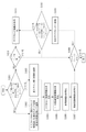
図10は本発明の一実施形態によって、スキップ領域または追加スキップ領域を含む変換ブロックを符号化する方法を示す流れ図である。図10に示された方法は、図6に示された方法以後に行われ得る。図10の符号化方法は、画像符号化装置100のエントロピー符号化部107によって行われ得る。
FIG. 10 is a flow chart showing a method of encoding a conversion block including a skip region or an additional skip region according to an embodiment of the present invention. The method shown in FIG. 10 can be performed after the method shown in FIG. The coding method of FIG. 10 can be performed by the
現在符号化しようとする変換ブロック内のサブブロックに基準係数が含まれた場合には、符号化する係数が含まれたという意味なので、サブブロック情報であるCoded_sub_blk_flagが符号化されない。スキップ領域情報または追加スキップ領域情報が真であり、且つ現在符号化しようとするサブブロックがスキップ領域または追加スキップ領域を含むか否かを確認する(S1001)。もし上記の二つの条件が真であれば、現在サブブロック内に位置しながら、符号化順序上、スキップ領域の外に位置した係数を選択する(S1002)。もしそうでなければ、スキップ領域とは関係なく、符号化されるべき係数をすべて選択する(S1003)。その後、係数の0ではない係数情報符号化(S1004)、N超過係数情報符号化(S1005)、符号情報符号化(S1006)、残差係数情報符号化(S1007)の順に符号化される。 When the reference coefficient is included in the subblock in the conversion block to be encoded at present, it means that the coefficient to be encoded is included, so that the coded_sub_blk_flag which is the subblock information is not encoded. It is confirmed whether the skip area information or the additional skip area information is true and whether or not the subblock currently to be encoded includes the skip area or the additional skip area (S1001). If the above two conditions are true, a coefficient located outside the skip area in the coding order while currently located in the subblock is selected (S1002). If not, all coefficients to be encoded are selected regardless of the skip area (S1003). After that, the coefficient is encoded in the order of non-zero coefficient information coding (S1004), N excess coefficient information coding (S1005), code information coding (S1006), and residual coefficient information coding (S1007).
その後、次のサブブロックが存在する場合(S1008)には、次のサブブロックへ移動する(S1009)。スキップ領域情報または追加スキップ領域情報が真であり、且つ現在符号化しようとするサブブロックがスキップ領域または追加スキップ領域を含むか否かを確認する(S1010)、既にスキップ領域情報で当該サブブロックの情報を符号化したので、次のサブブロックへ移動する。ただし、この場合は、スキップ領域内の係数の値が0である場合にのみ使用可能である。もしスキップ領域内の係数の値が0ではない場合には、当該サブブロック情報を符号化しなければならない。 After that, if the next subblock exists (S1008), the next subblock is moved to (S1009). It is confirmed whether the skip area information or the additional skip area information is true and the subblock to be currently encoded includes the skip area or the additional skip area (S1010). Now that we have encoded the information, we move on to the next subblock. However, in this case, it can be used only when the value of the coefficient in the skip area is 0. If the value of the coefficient in the skip area is non-zero, the subblock information must be encoded.
サブブロックがスキップ領域または追加スキップ領域を含まないか、或いはスキップ領域情報が偽であれば、サブブロック情報を符号化し(S1011)、サブブロック情報が真である場合には(S1012)、ステップS1001へ移動し、サブブロック情報が偽である場合には、ステップS1008へ移動する。ステップS1008に移動した後、次のサブブロックが存在しないと決定されると、図10のアルゴリズムが終了する。 If the subblock does not include the skip area or the additional skip area, or if the skip area information is false, the subblock information is encoded (S1011), and if the subblock information is true (S1012), step S1001 If the subblock information is false, the process proceeds to step S1008. After moving to step S1008, if it is determined that the next subblock does not exist, the algorithm of FIG. 10 ends.
以下、図6及び図10に示されたアルゴリズムを図7の例示を用いてさらに説明する。現在変換ブロックにおいて、スキャン方法は、対角線方向の逆スキャン順と仮定し、初めて出てきた0ではない係数を基準係数として設定する。基準係数を基準に左下方向の係数と、その下の係数をスキップ領域として設定した後、スキップ領域の値をすべて確認する。スキップ領域の係数がすべて0と同じ値を持つので、スキップ領域情報は真に符号化する。サブブロック単位で分けた後、基準係数が含まれているサブブロックから符号化する。 Hereinafter, the algorithms shown in FIGS. 6 and 10 will be further described with reference to the examples of FIG. In the current conversion block, the scanning method is assumed to be the reverse scanning order in the diagonal direction, and the non-zero coefficient that appears for the first time is set as the reference coefficient. After setting the coefficient in the lower left direction and the coefficient below it as the skip area based on the reference coefficient, check all the values in the skip area. Since all the coefficients of the skip area have the same value as 0, the skip area information is truly encoded. After dividing by sub-block unit, it is encoded from the sub-block containing the reference coefficient.
現在変換ブロックは8×8、サブブロックは4×4サイズを例として挙げて説明する。一番目に符号化するサブブロックのスキップ領域情報が真であり、当該サブブロック内に符号化する係数が存在する。スキップ領域外の係数のみ符号化するため、図7に示された例の場合、基準係数とその上に存在する1、0、0、-2のみ符号化すればよい。この場合、0ではない係数情報は、それぞれ真、偽、偽、真となる。 Nが2であると仮定すると、0ではないと判断された係数でのみ1超過情報を符号化する。係数値1と-2の1超過情報は、それぞれ偽と真が設定される。2超過情報は1超過情報が真である場合にのみ符号化され、係数値-2の2超過情報は偽に符号化される。その後、係数値1と-2の符号である+と-がそれぞれ符号化される。その後、次のサブブロックが存在するので、次のサブブロックへ移動する。 Currently, the conversion block is 8 × 8 and the subblock is 4 × 4 size as an example. The skip area information of the subblock to be encoded first is true, and there is a coefficient to be encoded in the subblock. Since only the coefficients outside the skip region are encoded, in the case of the example shown in FIG. 7, only the reference coefficient and 1, 0, 0, -2 existing on the reference coefficient need to be encoded. In this case, the non-zero coefficient information is true, false, false, and true, respectively. Assuming that N is 2, 1 excess information is encoded only with a coefficient determined to be non-zero. False and true are set for the 1 excess information of the coefficient values 1 and -2, respectively. The 2 excess information is encoded only when the 1 excess information is true, and the 2 excess information with a coefficient value of -2 is falsely encoded. After that, + and-, which are the codes of the coefficient values 1 and -2, are encoded, respectively. After that, since the next subblock exists, it moves to the next subblock.
二番目に符号化するサブブロックの場合、スキップ領域情報が真であり、当該サブブロックの中に符号化する係数が存在するため、サブブロック情報は真となる。したがって、スキップ領域外の係数0、0及び1のみ符号化する。係数0、0及び1の0ではない係数情報は、それぞれ偽、偽、真が符号化された後、係数1の1超過情報のみが偽に符号化される。係数1の符号情報は、+に符号化され、次のサブブロックへ移動する。
In the case of the second encoded subblock, the skip area information is true, and the subblock information is true because there is a coefficient to be encoded in the subblock. Therefore, only the
三番目に符号化するサブブロックの場合、スキップ領域情報が真であり、当該サブブロック内に符号化する係数が存在するため、サブブロック情報は真になる。スキップ領域外の係数を逆スキャンで整列すると、0、0、0、0、0、1、1、1、1、-2、-2、1、-3、3、10となる。これらの係数は、ステップS1004乃至S1007を用いて符号化される。 In the case of the third encoded subblock, the skip area information is true, and the subblock information is true because there is a coefficient to be encoded in the subblock. When the coefficients outside the skip area are aligned by reverse scanning, they are 0, 0, 0, 0, 0, 1, 1, 1, 1, -2, -2, 1, -3, 3, 10. These coefficients are encoded using steps S1004 through S1007.
図11は本発明の一実施形態によって、スキップ領域を用いた画像復号化方法を示す流れ図である。図11の復号化方法は、画像復号化装置200のエントロピー 復号化部 201によって行われ得る。
FIG. 11 is a flow chart showing an image decoding method using a skip region according to an embodiment of the present invention. The decoding method of FIG. 11 can be performed by the
図11を参照すると、まず、エントロピー復号化部201は、復号化する現在変換ブロック内の基準係数の位置を復号化する(S1101)。その後、基準係数の位置に基づいて選択されたスキップ領域に対するスキップ領域情報を復号化する(S1103)。前述したように、基準係数の位置は、Last_sigを復号化することにより誘導できる。スキップ領域及びスキップ領域情報は、前述と同様なので、詳細な説明は省略する。また、図11に別途示されてはいないが、スキップ領域以外にさらに設定された追加スキップ領域があれば、追加スキップ領域は、追加スキップ領域情報を用いて復号化できる。
Referring to FIG. 11, first, the
図12は本発明の一実施形態によって、スキップ領域または追加スキップ領域を含む変換ブロックを復号化する方法を示す流れ図である。図12に示された方法は、図11に示された方法以後に実行できる。図12の復号化方法は、画像復号化装置200のエントロピー復号化部201によって実行できる。
FIG. 12 is a flow chart showing a method of decoding a conversion block including a skip region or an additional skip region according to an embodiment of the present invention. The method shown in FIG. 12 can be performed after the method shown in FIG. The decoding method of FIG. 12 can be executed by the
図12に示された方法は、図10に示された方法と実質的に同様なので、詳細な説明は省略する。ただし、図10ではスキップ領域情報、追加スキップ領域情報、サブブロック情報Coded_sub_blk_flag、0ではない係数情報、N超過係数情報、符号情報及び残差係数情報などが符号化されたが、図12ではこれらの情報が復号化されるという点において、違いがある。 Since the method shown in FIG. 12 is substantially the same as the method shown in FIG. 10, detailed description thereof will be omitted. However, in FIG. 10, skip area information, additional skip area information, subblock information Code_sub_blk_flag, non-zero coefficient information, N excess coefficient information, code information, residual coefficient information, etc. are encoded, but in FIG. 12, these are encoded. There is a difference in that the information is decrypted.
図11及び図12に示されたアルゴリズムを図7の例示を用いてさらに説明する。現在変換ブロックにおける基準係数の位置情報Last_sigを復号化した後、基準係数を設定する。基準係数の位置に基づいてスキップ領域が設定され、スキップ領域情報が復号化される。この例では、スキップ領域情報は真である。変換ブロックをサブブロック単位に分けた後、基準係数が含まれているサブブロックから復号化する。 The algorithms shown in FIGS. 11 and 12 will be further described with reference to the illustrations of FIG. After decoding the position information Last_sig of the reference coefficient in the current conversion block, the reference coefficient is set. The skip area is set based on the position of the reference coefficient, and the skip area information is decoded. In this example, the skip area information is true. After dividing the conversion block into sub-block units, decoding is performed from the sub-block containing the reference coefficient.
現在変換ブロックは8×8、サブブロックは4×4サイズであることを例として説明する。一番目に復号化するサブブロックの場合、スキップ領域情報が真であり、当該サブブロックの中に復号化する係数が存在する。スキップ領域外の係数のみ復号化するため、図7に示された例の場合、基準係数とその上に存在する1、0、0、-2のみ復号化すればよい。この場合、0ではない係数情報の復号化された値は、それぞれ真、偽、偽、真となる。Nが2であると仮定すると、0ではないと判断された係数でのみ1超過情報を復号化する。係数値1と-2の1超過情報は、それぞれ偽と真に復号化される。2超過情報は1超過情報が真である場合にのみ復号化され、係数値-2の2超過情報は偽に復号化される。その後、係数値1と-2の符号である+と-がそれぞれ復号化される。その後、次のサブブロックが存在するので、次のサブブロックへ移動する。 It will be described as an example that the conversion block is currently 8 × 8 and the subblock is 4 × 4. In the case of the first subblock to be decoded, the skip area information is true, and there is a coefficient to be decoded in the subblock. Since only the coefficients outside the skip area are decoded, in the case of the example shown in FIG. 7, only the reference coefficient and 1, 0, 0, -2 existing on the reference coefficient need to be decoded. In this case, the decoded values of the non-zero coefficient information are true, false, false, and true, respectively. Assuming that N is 2, the 1 excess information is decoded only by the coefficient determined to be non-zero. The 1 excess information of the coefficient values 1 and -2 is decoded as false and true, respectively. The 2 excess information is decoded only when the 1 excess information is true, and the 2 excess information having a coefficient value of -2 is falsely decoded. After that, + and-, which are the codes of the coefficient values 1 and -2, are decoded, respectively. After that, since the next subblock exists, it moves to the next subblock.
二番目に復号化するサブブロックの場合、スキップ領域情報が真であり、当該サブブロックの中に復号化する係数が存在するため、サブブロック情報は真となる。したがって、スキップ領域外の係数である0、0及び1のみ復号化する。係数0、0及び1の0ではない係数情報は、それぞれ偽、偽、真が復号化された後、係数1の1超過情報のみが偽に復号化される。係数1の符号情報は+に復号化され、次のサブブロックへ移動する。
In the case of the second subblock to be decoded, the skip area information is true, and the subblock information is true because there is a coefficient to be decoded in the subblock. Therefore, only the
三番目に復号化するサブブロックの場合、スキップ領域情報が真であり、当該サブブロックの中に復号化する係数が存在するため、サブブロック情報は真となる。スキップ領域外の係数を逆スキャンで整列すると、0、0、0、0、0、1、1、1、1、-2、-2、1、-3、3、10となる。この係数は、ステップS1204乃至S1207を用いて復号化される。 In the case of the third subblock to be decoded, the skip area information is true, and the subblock information is true because there is a coefficient to be decoded in the subblock. When the coefficients outside the skip area are aligned by reverse scanning, they are 0, 0, 0, 0, 0, 1, 1, 1, 1, -2, -2, 1, -3, 3, 10. This coefficient is decoded using steps S1204 to S1207.
(第2実施形態) (Second Embodiment)
以下、図面を参照して本発明の第2実施形態を説明する。 Hereinafter, a second embodiment of the present invention will be described with reference to the drawings.
符号化された情報は、2値化過程によって、コンテキスト適応バイナリ算術過程が行われる。コンテキスト適応バイナリ算術過程とは、ブロック内の符号化された情報をシンボル化し、状況に応じて確率情報を用いてシンボルの発生確率を異ならせて適用し、符号化する過程をいう。本実施形態では、説明の便宜のために、シンボルを0と1のみ使用したが、シンボルの個数はN個(Nは2以上の自然数)であり得る。 The encoded information undergoes a context-adaptive binary arithmetic process by the binarization process. The context-adaptive binary arithmetic process is a process of symbolizing the coded information in a block, applying the probability of occurrence of the symbol differently by using the probability information according to the situation, and encoding the code. In this embodiment, for convenience of explanation, only 0 and 1 symbols are used, but the number of symbols can be N (N is a natural number of 2 or more).
確率情報とは、2値化された情報における0と1の発生確率をいう。両情報の発生確率を、以前復元された情報に応じて同一にしてもよく、異ならせてもよい。情報に応じてN個の確率情報を有することもできる。 Probability information refers to the probability of occurrence of 0 and 1 in binarized information. The probability of occurrence of both pieces of information may be the same or different depending on the previously restored information. It is also possible to have N probability information depending on the information.
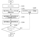
図13は本発明の一実施形態に係るコンテキスト適応バイナリ算術符号化方法を示す流れ図である。まず、確率初期化が行われる(S1301)。確率初期化とは、2値化された情報を、確率情報に設定されている確率で確率区間を分ける過程である。ただし、どの確率情報を使用するかは、符号化装置または復号化装置で任意に所定の規則によって同じ条件を使用してもよく、別途に確率情報が符号化されてもよい。初期確率区間は所定の規則によって符号化/復号化過程で同一に決定されてもよい。または、初期確率区間を新たに符号化して使用してもよい。 FIG. 13 is a flow chart showing a context-adaptive binary arithmetic coding method according to an embodiment of the present invention. First, probability initialization is performed (S1301). The probability initialization is a process of dividing the binarized information into probability intervals with the probability set in the probability information. However, as to which probability information is used, the encoding device or the decoding device may arbitrarily use the same conditions according to a predetermined rule, or the probability information may be encoded separately. The initial probability interval may be determined uniformly in the encoding / decoding process according to a predetermined rule. Alternatively, the initial probability interval may be newly encoded and used.
符号化する現在符号化パラメータの2値情報が決定されると(S1302)、現在符号化パラメータの2値化された情報は、ステップS1302の以前ステップまでの確率区間状態と、同じ符号化パラメータの以前確率情報を用いて符号化される(S1303)。その後、符号化される2値情報のために確率情報と確率区間が更新(S1304)された後、次の符号化される符号化パラメータ情報が存在する場合(S1305)には、次の符号化パラメータ情報へ移動し(S1306)、前述した過程を繰り返し行う。もし次の符号化される符号化パラメータ情報が存在しない場合には、本流れ図は終了する。 When the binary information of the current coding parameter to be encoded is determined (S1302), the binarized information of the current coding parameter has the same coding parameter as the probability interval state up to the previous step in step S1302. Previously encoded using probability information (S1303). Then, after the probability information and the probability interval are updated (S1304) for the coded binary information, if the next coded coding parameter information exists (S1305), the next coding is performed. Move to the parameter information (S1306), and repeat the above-mentioned process. If the next encoded parameter information to be encoded does not exist, the flow chart ends.
図14は本発明の一実施形態に係るコンテキスト適応バイナリ算術復号化方法を示す流れ図である。符号化装置とは異なり、復号化装置では、確率情報及び確率区間を用いて符号化パラメータの2値情報を復号化(S1402)した後、現在符号化パラメータの2値情報を決定(S1403)する。その他の図14の復号化方法は、図13の符号化方法に対応するので、詳細な説明は省略する。 FIG. 14 is a flow chart showing a context-adaptive binary arithmetic decoding method according to an embodiment of the present invention. Unlike the coding device, the decoding device decodes the binary information of the coding parameter using the probability information and the probability interval (S1402), and then determines the binary information of the current coding parameter (S1403). .. Since the other decoding method of FIG. 14 corresponds to the encoding method of FIG. 13, detailed description thereof will be omitted.
前述した図13及び図14のステップS1303とS1402において、各符号化パラメータ別に周辺に既に復元された情報を用いて、所定のN個の確率情報のうち、最適な確率情報を選択的に用いて符号化または復号化が行われ得る。例えば、量子化された変換ブロックに属する情報の確率情報は、変換ブロックの大きさに応じて情報が発生する確率の高い確率情報を使用してもよい。 In steps S1303 and S1402 of FIGS. 13 and 14 described above, the optimum probability information is selectively used from the predetermined N probability information by using the information already restored to the periphery for each coding parameter. Coding or decoding can be done. For example, as the probability information of the information belonging to the quantized conversion block, the probability information having a high probability that the information is generated according to the size of the conversion block may be used.
または、現在符号化または復号化する係数の周辺係数の情報に応じて確率情報を異ならせて適用することができ、以前の符号化または復号化された情報の確率情報を用いて、現在符号化または復号化する情報の確率情報を選択することもできる。 Alternatively, the probabilistic information can be applied differently depending on the peripheral coefficient information of the currently encoded or decoded coefficient, and is currently encoded using the probabilistic information of the previously encoded or decoded information. Alternatively, the probability information of the information to be decoded can be selected.
図15a乃至図15cは周辺係数の情報に応じて確率情報を異ならせて適用した一例を示す図である。図15bは現在係数のSig_coeff_flag情報値を符号化または復号化に使用する確率情報テーブルの例示である。図15bを参照すると、現在符号化または復号化する係数1501に隣接する係数のうち、現在係数1501のSig_coeff_flag情報値1と同じ情報値を有する係数の数が1つである場合には、現在係数1501にはインデックス8が割り当てられる。このとき、現在係数1501のSig_coeff_flag2値情報であるシンボル1の確率は61%であり、シンボル0の確率は39%である。もし現在係数1501のSig_coeff_flag情報値と同じ情報値を有する周辺係数の数が2つである場合、現在係数1501にはインデックス5が割り当てられ、このときの現在係数1501のSig_coeff_flag2値情報であるシンボル1の確率は71%であり、シンボル0の確率は29%である。もし、現在係数1501のSig_coeff_flag情報値と同じ情報値を有する周辺係数の数が3つである場合、現在係数1501にはインデックス2が割り当てられ、現在係数1501のSig_coeff_flag2値情報であるシンボル1の確率は87%であり、シンボル0の確率は13%である。図15bに示された確率情報テーブルを用いて、現在係数1501が符号化または復号化された後、図15cのように確率情報は更新できる。
15a to 15c are diagrams showing an example in which the probability information is applied differently according to the information of the peripheral coefficient. FIG. 15b is an example of a probability information table in which the Sigma_coeff_flag information value of the current coefficient is used for encoding or decoding. Referring to FIG. 15b, if one of the coefficients adjacent to the
一方、0ではない係数情報Sig_coeff_flagの場合には、低周波領域に近いほど、0ではない係数情報の発生確率が高い確率情報が使用できる。N超過係数情報の確率情報は、直前に符号化/復号化したN超過係数情報の確率情報を用いて現在のN超過係数情報の確率情報を設定するか、或いはサブブロック単位で初めて符号化/復号化するN超過係数情報の確率情報をそのまま使用することもできる。サブブロック情報は、周辺の符号化/復号化されたM個のサブブロックの確率情報を用いるか、或いは直前に符号化/復号化されたサブブロックの確率情報を用いることもできる。 On the other hand, in the case of the non-zero coefficient information Sig_coeff_flag, the probability information that the probability of occurrence of the non-zero coefficient information is higher as it is closer to the low frequency region can be used. For the probability information of the N excess coefficient information, the probability information of the current N excess coefficient information is set using the probability information of the N excess coefficient information encoded / decoded immediately before, or the probability information of the current N excess coefficient information is encoded / for the first time in subblock units. The probability information of the N excess coefficient information to be decoded can also be used as it is. As the sub-block information, the probability information of the surrounding encoded / decoded M sub-blocks can be used, or the probability information of the sub-block encoded / decoded immediately before can be used.
図16a乃至図16cは周波数領域の変換ブロックを複数の領域に分割する様々な実施形態を示す図である。図16a乃至図16cを参照すると、変換ブロックは、周波数A領域1601、1604、1607、周波数B領域1602、1605、1608、及び周波数C領域1603、1606、1609の3つの領域に区分できる。各領域は、変換ブロックのスキャン方向に沿って適応的に決定できるが、図16aは変換ブロックのスキャン方向が対角線方向であるとき、図16bはスキャン方向が横方向であるとき、図16cはスキャン方向が縦方向であるときの周波数領域区分方法についての例示である。周波数A領域1601、1604、1607は、0ではない係数情報が発生する確率が最も高い低周波領域であり、周波数B領域1602、1605、1608は、A領域1601、1604、1607よりは0ではない係数情報が少なく発生し、周波数C領域1603、1606、1609は、高周波領域であって、A領域1601、1604、1607、B領域1602、1605、1608よりは0ではない係数情報が最も少なく発生する領域であることを利用して、確率情報を各領域別に異ならせて設定することができる。周波数A領域1601、1604、1607、周波数B領域1602、1605、1608、及び周波数C領域1603、1606、1609は、変換ブロックの左上側コーナーに位置したDC係数からの距離によって区分されたと見ることもできる。
16a to 16c are diagrams showing various embodiments in which the conversion block of the frequency domain is divided into a plurality of regions. With reference to FIGS. 16a to 16c, the conversion block can be divided into three regions:
図15bの確率情報テーブルを再び参照すると、現在符号化または復号化する係数がA領域1601、1604、1607に属する場合には、現在係数にはインデックス8が割り当てられ、シンボル1の確率は61%であり、シンボル0の確率は39%である。もし、現在係数がB領域1602、1605、1608に属する場合、現在係数にはインデックス5が割り当てられ、シンボル1の確率は71%であり、シンボル0の確率は29%である。もし現在係数がC領域1603、1606、1609に属する場合、現在係数にはインデックス2が割り当てられ、シンボル1の確率は87%であり、シンボル0の確率は13%でる。図15bに示された確率情報テーブルを用いて現在係数が符号化または復号化された後、図15cのように確率情報は更新できる。
Looking back at the probability information table of FIG. 15b, if the currently encoded or decoded coefficient belongs to regions A 1601, 1604, 1607, the current coefficient is assigned an
0ではない係数情報、N超過係数情報、サブブロック情報の確率情報は、A領域1601、1604、1607に近づくほど発生確率が高い確率情報を用いることができ、N超過係数情報の確率情報は、0ではない係数情報を参照して確率情報を選択することができる。周波数領域分割は、符号化/復号化装置で同じ条件で行ってもよく、別途の分割情報を符号化して復号化装置へ伝送して行ってもよい。
As the probability information of the non-zero coefficient information, the N excess coefficient information, and the subblock information, the probability information that the probability of occurrence increases as it approaches the
図17は本発明の一実施形態に係る算術符号化方法を示す流れ図である。図17を参照すると、符号化する変換係数の値を2値化し、2値化された情報が誘導される(S1701)。変換ブロック内での前記変換係数の位置に基づいて、前記2値化された情報の符号化に適用する確率情報が決定される(S1703)。図16aに示された例を参照すると、符号化する現在係数が周波数A領域1601、周波数B領域1602または周波数C領域1603のうちのどの領域に属するかによって、適用される確率情報が決定される。ここで、周波数A領域1601、周波数B領域1602及び周波数C領域1603は、変換ブロックの左上側コーナーに位置したDC係数からの距離によって区分されたと見ることができる。
FIG. 17 is a flow chart showing an arithmetic coding method according to an embodiment of the present invention. With reference to FIG. 17, the value of the conversion coefficient to be encoded is binarized, and the binarized information is derived (S1701). Based on the position of the conversion factor in the conversion block, the probability information to be applied to the encoding of the binarized information is determined (S1703). With reference to the example shown in FIG. 16a, the probability information to be applied is determined by which region of the
図18は本発明の一実施形態に係る算術復号化方法を示す流れ図である。図18を参照すると、ビットストリームから算術符号化された変換係数の値が抽出される(S1801)。変換ブロック内での前記変換係数の位置に基づいて、前記算術符号化された変換係数の復号化に適用する確率情報が決定される(S1803)。前述したように、図16aに示された例を参照すると、復号化する現在係数が周波数A領域1601、周波数B領域1602または周波数C領域1603のうちのどの領域に属するかによって、適用される確率情報が決定される。ここで、周波数A領域1601、周波数B領域1602及び周波数C領域1603は、変換ブロックの左上側コーナーに位置したDC係数からの距離によって区分されたと見ることができる。
FIG. 18 is a flow chart showing an arithmetic decoding method according to an embodiment of the present invention. With reference to FIG. 18, the value of the arithmetically coded conversion factor is extracted from the bitstream (S1801). Based on the position of the conversion factor in the conversion block, the probability information to be applied to the decoding of the arithmetically coded conversion factor is determined (S1803). As described above, with reference to the example shown in FIG. 16a, the probability that the current coefficient to be decoded is applied depends on which region of
次に、図19a乃至図19cと図20を参照して、本発明の他の実施形態に係る算術符号化及び算術復号化について説明する。 Next, arithmetic coding and arithmetic decoding according to other embodiments of the present invention will be described with reference to FIGS. 19a to 19c and FIG. 20.
本実施形態では、図7乃至図9に示されたスキップ領域を用いた、量子化された変換係数の符号化方法が使用された場合には、スキップ領域が使用されている場合とスキップ領域が使用されていない場合に応じて、現在情報を符号化または復号化するときに互いに異なる確率情報が用いられる。 In the present embodiment, when the method of encoding the quantized conversion coefficient using the skip region shown in FIGS. 7 to 9 is used, the skip region is used and the skip region is Different stochastic information is used when encoding or decoding the current information, depending on where it is not used.
図19aに示された現在係数1901の符号化または復号化のために、図19bまたは図19cに示された確率情報テーブルが使用されると仮定する。図19bに示された確率情報テーブルは、スキップ領域が使用されない場合に適用される確率情報テーブルであり、図19cに示された確率情報テーブルは、スキップ領域が使用される場合に適用される確率情報テーブルである。
It is assumed that the probability information table shown in FIG. 19b or 19c is used for encoding or decoding the
図19aを参照すると、現在係数1901の属する変換ブロックまたはサブブロックにスキップ領域が存在するので、現在係数1901の符号化または復号化のために、図19cに示された確率情報テーブルが適用される。よって、例えば、現在係数1901にはインデックス5が割り当てられる。この場合、シンボル1の確率は71%であり、シンボル0の確率は29%である。
Referring to FIG. 19a, since there is a skip area in the conversion block or subblock to which the
または、周辺係数においてN超過係数の個数に応じて確率情報を異ならせて適用することができる。0ではない係数情報とN超過係数情報は、周辺に符号化/復号化された情報の個数と周波数領域の位置に基づいて発生確率が高い確率情報を用いることができ、周波数C領域でありながらスキップ領域の周辺に位置した係数である場合、0ではない係数情報、N超過係数情報、サブブロック情報の発生確率が低い確率情報を適用することもできる。 Alternatively, the probability information can be applied differently depending on the number of N excess coefficients in the peripheral coefficient. For the non-zero coefficient information and the N excess coefficient information, it is possible to use probability information having a high probability of occurrence based on the number of encoded / decoded information in the periphery and the position of the frequency region, even though it is in the frequency C region. When the coefficient is located around the skip area, it is possible to apply non-zero coefficient information, N excess coefficient information, and probability information having a low probability of occurrence of subblock information.
図20は本発明の他の実施形態に係る算術符号化または復号化方法を示す流れ図である。図19a乃至図19cを参照して先立って説明したように、スキップ領域が使用されている場合とスキップ領域が使用されていない場合に応じて、現在情報を符号化または復号化するときに互いに異なる確率情報を使用する。 FIG. 20 is a flow chart showing an arithmetic coding or decoding method according to another embodiment of the present invention. As previously described with reference to FIGS. 19a-19c, the current information is currently encoded or decoded differently depending on whether the skip area is used or not. Use probability information.
図20を参照すると、まず、符号化または復号化する現在変換ブロック内の基準係数の位置が符号化または復号化される(S2001)。その後、前記基準係数の位置に基づいて選択されたスキップ領域に対するスキップ領域情報が符号化または復号化される(S2003)。前記スキップ領域に含まれていない変換係数の値を2値化し、2値化された情報が得られると、複数の確率情報テーブルの中から、前記2値化された情報の符号化に適用する確率情報テーブルが選択される(S2005)。ここで、前記複数の確率情報テーブルは、スキップ領域が使用される場合のためのテーブルと、スキップ領域が使用されない場合のためのテーブルの少なくとも2つを含む。 Referring to FIG. 20, first, the position of the reference coefficient in the current conversion block to be encoded or decoded is encoded or decoded (S2001). Then, the skip area information for the skip area selected based on the position of the reference coefficient is encoded or decoded (S2003). When the value of the conversion coefficient not included in the skip area is binarized and the binarized information is obtained, it is applied to the encoding of the binarized information from the plurality of probability information tables. The probability information table is selected (S2005). Here, the plurality of probability information tables include at least two tables, one for when the skip area is used and the other for when the skip area is not used.
符号化された情報は、2値化過程を介してコンテキスト適応バイナリ算術過程が行われる。コンテキスト適応バイナリ算術過程とは、ブロック内の符号化された情報をシンボル化し、状況に応じて確率情報を用いてシンボルの発生確率を異ならせて適用し、符号化する過程をいう。本例示では、説明の便宜のために、シンボルを0と1のみ使用したが、シンボルの個数はN個(Nは2以上の自然数)であり得る。 The encoded information undergoes a context-adaptive binary arithmetic process via a binarization process. The context-adaptive binary arithmetic process is a process of symbolizing the coded information in a block, applying the probability of occurrence of the symbol differently by using the probability information according to the situation, and encoding the code. In this example, for convenience of explanation, only 0 and 1 symbols are used, but the number of symbols can be N (N is a natural number of 2 or more).
確率情報とは、2値化された情報において0と1の発生確率をいう。両情報の発生確率を、以前復元された情報に応じて同一にしてもよく、異ならせてもよい。情報に応じてN個の確率情報を有することもできる。 The probability information refers to the probability of occurrence of 0 and 1 in the binarized information. The probability of occurrence of both pieces of information may be the same or different depending on the previously restored information. It is also possible to have N probability information depending on the information.
図21はコンテキスト適応バイナリ算術符号化方法を示す流れ図である。まず、確率初期化が行われる(S2101)。確率初期化とは、2値化された情報を、確率情報に設定されている確率で確率区間を分ける過程である。ただし、どの確率情報を用いるかは、符号化装置または復号化装置で任意に所定の規則によって同じ条件を使用してもよく、別途に確率情報が符号化されてもよい。初期確率区間は、所定の規則によって符号化/復号化過程で同一に決定されてもよい。または、初期確率区間を新たに符号化して使用してもよい。 FIG. 21 is a flow chart showing a context-adaptive binary arithmetic coding method. First, probability initialization is performed (S2101). The probability initialization is a process of dividing the binarized information into probability intervals with the probability set in the probability information. However, as to which probability information is used, the encoding device or the decoding device may arbitrarily use the same conditions according to a predetermined rule, or the probability information may be encoded separately. The initial probability interval may be determined uniformly in the encoding / decoding process according to a predetermined rule. Alternatively, the initial probability interval may be newly encoded and used.
符号化する現在符号化パラメータの2値情報が決定されると(S2102)、現在符号化パラメータの2値化された情報は、図21のステップS2102の以前ステップまでの確率区間状態と、同じ符号化パラメータの以前確率情報を用いて符号化される(S2103)。そして、以後に符号化される2値情報のために確率情報と確率区間が更新(S2104)できる。次に符号化される符号化パラメータ情報が存在する場合(S2105)には、次の符号化パラメータ情報へ移動し(S2106)、前述した過程を繰り返し行う。もし次に符号化される符号化パラメータ情報が存在しない場合には、本流れ図は終了する。 When the binary information of the current coding parameter to be encoded is determined (S2102), the binarized information of the current coding parameter has the same code as the probability interval state up to the previous step of step S2102 in FIG. It is encoded using the previous probability information of the conversion parameter (S2103). Then, the probability information and the probability interval can be updated (S2104) for the binary information encoded thereafter. If the coded parameter information to be encoded next exists (S2105), the process moves to the next coded parameter information (S2106), and the above-described process is repeated. If there is no coding parameter information to be encoded next, the flow chart ends.
図22はコンテキスト適応バイナリ算術復号化方法を示す流れ図である。符号化装置とは異なり、復号化装置では、確率情報及び確率区間を用いて符号化パラメータの2値情報を復号化(S2202)した後、現在符号化パラメータの2値情報を決定(S2203)する。その他の図22の復号化方法は、図21の符号化方法に対応するので、詳細な説明は省略する。 FIG. 22 is a flow chart showing a context-adaptive binary arithmetic decoding method. Unlike the coding device, the decoding device decodes the binary information of the coding parameter using the probability information and the probability interval (S2202), and then determines the binary information of the current coding parameter (S2203). .. Since the other decoding method of FIG. 22 corresponds to the encoding method of FIG. 21, detailed description thereof will be omitted.
前記説明した図21及び図22のステップS2103とS2202で、各符号化パラメータ別に周辺に既に復元された情報(または符号化パラメータ)を用いて所定のN個の確率情報のうち、最適な確率情報を選択的に用いて符号化または復号化が行われ得る。 In steps S2103 and S2202 of FIGS. 21 and 22 described above, the optimum probability information out of the predetermined N probability information using the information (or coding parameter) already restored to the periphery for each coding parameter is used. Can be selectively used to encode or decode.
例えば、量子化された変換ブロックに属する情報(または符号化パラメータ)の確率情報は、変換ブロックのサイズに応じて情報が発生する確率の高い確率情報を使用することもできる。 For example, as the probability information of the information (or coding parameter) belonging to the quantized conversion block, the probability information having a high probability that the information is generated according to the size of the conversion block can be used.
または、現在符号化または復号化する係数の周辺係数の情報に応じて確率情報を異ならせて適用することができ、以前の符号化または復号化された情報の確率情報を用いて、現在符号化または復号化する情報の確率情報を選択することもできる。 Alternatively, the probabilistic information can be applied differently depending on the peripheral coefficient information of the currently encoded or decoded coefficient, and is currently encoded using the probabilistic information of the previously encoded or decoded information. Alternatively, the probability information of the information to be decoded can be selected.
図23a及び図23bは、周辺係数の情報に応じて確率情報を異ならせて適用した一例を示す図である。 23a and 23b are diagrams showing an example in which the probability information is applied differently according to the information of the peripheral coefficient.
図23aは現在係数のSig_coeff_flag情報値を符号化または復号化に使用する確率情報テーブルの例示である。現在符号化または復号化する係数に隣接する係数のうち、現在係数のSig_coeff_flag情報値と同じ情報値を有する係数の数が1つである場合には、現在係数にはインデックス8が割り当てられる。このとき、現在係数のSig_coeff_flag2値情報であるシンボル1の確率は61%であり、シンボル0の確率は39%である。もし、現在係数のSig_coeff_flag情報値と同じ情報値を有する周辺係数の数が2つである場合、現在係数にはインデックス5が割り当てられ、このときの現在係数のSig_coeff_flag2値情報であるシンボル1の確率は71%であり、シンボル0の確率は29%である。もし現在係数のSig_coeff_flag情報値と同じ情報値を有する周辺係数の数が3つである場合、現在係数にはインデックス2が割り当てられ、現在係数のSig_coeff_flag2値情報であるシンボル1の確率は87%であり、シンボル0の確率は13%である。
FIG. 23a is an example of a probability information table in which the Sigma_coeff_flag information value of the current coefficient is used for encoding or decoding. If one of the coefficients adjacent to the coefficient to be currently encoded or decoded has the same information value as the Sigma_coeff_flag information value of the current coefficient, the
図23aに示された確率情報テーブルを用いて現在係数が符号化または復号化された後、図23bのように確率情報は更新できる。 After the current coefficients are encoded or decoded using the probability information table shown in FIG. 23a, the probability information can be updated as in FIG. 23b.
一方、0ではない係数情報Sig_coeff_flagの場合には、低周波領域に近いほど、0ではない係数情報Sig_coeff_flagの発生確率が高い確率情報が使用できる。 On the other hand, in the case of the non-zero coefficient information Sig_coeff_flag, the probability information that the probability of occurrence of the non-zero coefficient information Sig_coeff_flag is higher as it is closer to the low frequency region can be used.
そして、N超過係数情報の確率情報は、直前に符号化/復号化したN超過係数情報の確率情報を用いて現在のN超過係数情報の確率情報を設定するか、或いはサブブロック単位で初めて符号化/復号化するN超過係数情報の確率情報をそのまま使用することもできる。上述したように、N超過係数情報は、Abs_greater 1_flag、Abs_greater2_flag及びAbs_greater3_flagなどが含まれ得る。 Then, the probability information of the N excess coefficient information is set by setting the probability information of the current N excess coefficient information using the probability information of the N excess coefficient information encoded / decoded immediately before, or is coded for the first time in subblock units. The probability information of the N excess coefficient information to be converted / decoded can also be used as it is. As described above, the N excess coefficient information may include Abs_greeter 1_flag, Abs_greeter2_flag, Abs_greeter3_flag, and the like.
そして、サブブロック情報Coded_sub_blk_flagは、周辺の符号化/復号化されたM個のサブブロックの確率情報を用いてもよく、直前に符号化/復号化されたサブブロックの確率情報を用いてもよい。 Then, the sub-block information Coded_sub_blk_flag may use the probability information of the surrounding encoded / decoded M sub-blocks, or may use the probability information of the sub-block encoded / decoded immediately before. ..
(第3実施形態) (Third Embodiment)
図24は本発明の一実施形態によって、基準係数の位置に基づいた各符号化パラメータの確率情報を決定し、これを用いて各符号化パラメータの情報を符号化する方法を示す流れ図である。図24の流れ図は、画像符号化装置100のエントロピー符号化部107によって実行できる。
FIG. 24 is a flow chart showing a method of determining the probability information of each coding parameter based on the position of the reference coefficient according to the embodiment of the present invention and using this to encode the information of each coding parameter. The flow chart of FIG. 24 can be executed by the
図24を参照すると、まず、エントロピー符号化部107は、符号化する現在変換ブロック内の基準係数の位置を符号化する(S2401)。ここで、基準係数の位置は、基準係数位置情報Last_sigに符号化できる。
Referring to FIG. 24, first, the
前述したように、基準係数は逆スキャン順に係数をスキャンするとき、最初の0ではない係数を意味することもあるが、画像符号化装置100と画像復号化装置200で同一に設定された他の条件によっても決定可能である。
As described above, the reference coefficient may mean the first non-zero coefficient when scanning the coefficients in the reverse scan order, but other coefficients set to be the same in the
その後、基準係数の位置に基づいて各符号化パラメータの確率情報を誘導し、当該符号化パラメータを符号化する(S2402)。 Then, the probability information of each coding parameter is derived based on the position of the reference coefficient, and the coding parameter is encoded (S2402).
ここで、基準係数の位置に基づいて確率テーブルを設定する方法は、図25の図面例示を参照する。 Here, for a method of setting the probability table based on the position of the reference coefficient, refer to the drawing example of FIG.
図25を参照すると、A領域2500は、変換ブロック内のDC係数と近い任意の領域を意味し、B領域2501は、変換ブロック内のA領域2500ではない領域を意味する。また、変換ブロックをN個以上の領域に分割することも可能である。ここで、A領域を示す任意の領域情報は、上位ヘッダから伝送されてもよく、画像符号化装置100と画像復号化装置200で変換ブロックの形態に応じて同じ条件で決定されてもよい。
With reference to FIG. 25, the
図25において基準係数の位置がA領域2500或いはB領域2501のうちのどの領域に存在するかによって、単一確率テーブル内で符号化パラメータの確率情報を異ならせて誘導し、符号化パラメータの確率情報を更新することができる。
In FIG. 25, the probability information of the coding parameter is derived differently in the single probability table depending on which region of the
または、基準係数の位置がA領域或いはB領域のうちのどの領域に存在するかによって、2つ以上の互いに異なる初期確率テーブル、或いは互いに同じ初期確率テーブルを独立して用いて符号化パラメータの確率情報を更新することができる。 Alternatively, depending on which region of the A region or the B region the position of the reference coefficient exists in, two or more different initial probability tables or the same initial probability tables are used independently to determine the probability of the coding parameter. Information can be updated.
次に、前述した方法の詳細な例示を説明する。 Next, a detailed example of the above-mentioned method will be described.
変換ブロック内の各係数が0であるか否かを示すSig_coeff_flag情報の確率情報を誘導するために、2つの互いに同じ初期確率テーブルを独立して用いて符号化する場合、変換ブロックの基準係数がA領域2500に存在するときには、図26aの2600テーブルを用いて、B領域2501に存在するときには、図26aの2601テーブルを用いて、独立してSig_coeff_flag情報の確率情報を更新することができる。
When two mutually same initial probability tables are used independently to derive the probability information of the Sig_coeff_flag information indicating whether or not each coefficient in the conversion block is 0, the reference coefficient of the conversion block is When present in the
図26bの2602確率テーブルは、図26aの2600初期確率テーブルにおいて基準係数の位置による確率テーブルのインデックス情報が5と決定されて確率情報が更新された結果であり、図26bの2603確率テーブルは、図26aの2601初期確率テーブルにおいて基準係数の位置による確率テーブルのインデックス情報が8と決定されて確率情報が更新された結果である。 The 2602 probability table of FIG. 26b is the result of the index information of the probability table based on the position of the reference coefficient being determined to be 5 in the 2600 initial probability table of FIG. 26a and the probability information is updated. This is the result of updating the probability information by determining that the index information of the probability table based on the position of the reference coefficient is 8 in the 2601 initial probability table of FIG. 26a.
前述した例示と同様の原理で、変換ブロック内の係数の絶対値が1よりも大きいかを知らせるAbs_greater1_flag情報の確率情報は、基準係数がA領域にあるときには、Abs_greater1_flag情報が1である確率が高い確率情報を選択し、基準係数がB領域にあるときには、Abs_greater1_flag情報が0である確率の高い確率情報を選択して符号化することができる。 By the same principle as the above-mentioned example, the probability information of the Abs_greeter1_flag information indicating whether the absolute value of the coefficient in the conversion block is larger than 1 has a high probability that the Abs_greeter1_flag information is 1 when the reference coefficient is in the A region. When the probability information is selected and the reference coefficient is in the B region, the probability information having a high probability that the Abs_greeter1_flag information is 0 can be selected and encoded.
一方、確率テーブル内でどの確率を用いるかを示すインデックス情報を決定する方法は、基準係数の詳細座標に応じてインデックス情報が決定できる。 On the other hand, in the method of determining the index information indicating which probability is used in the probability table, the index information can be determined according to the detailed coordinates of the reference coefficient.
例えば、変換ブロック内の基準係数の詳細座標がA領域の最左上側(図25の2502)に位置する場合、図26aの2600初期確率テーブルにおいて基準係数の位置による確率テーブルのインデックス情報が5と決定できる。図26bの2602確率テーブルのようにインデックス情報5の確率情報が更新できる。
For example, when the detailed coordinates of the reference coefficient in the conversion block are located on the upper left side of the A region (2502 in FIG. 25), the index information of the probability table based on the position of the reference coefficient in the 2600 initial probability table in FIG. 26a is 5. Can be decided. The probability information of the
変換ブロック内の基準係数の詳細座標がB領域の中間に位置(図25の2503)する場合、図26aの2601初期確率テーブルにおいて基準係数の位置による確率テーブルのインデックス情報が8と決定できる。そして、図26bの2603確率テーブルのように、インデックス情報8の確率情報が更新できる。図27は本発明の一実施形態によって、基準係数の位置による各符号化パラメータの確率情報を決定し、これを用いて各符号化パラメータの情報を復号化する方法を示す流れ図である。図27の復号化方法は、画像復号化装置200のエントロピー復号化部201によって実行できる。
When the detailed coordinates of the reference coefficient in the conversion block are located in the middle of the B region (2503 in FIG. 25), the index information of the probability table based on the position of the reference coefficient in the 2601 initial probability table in FIG. 26a can be determined to be 8. Then, the probability information of the
図27を参照すると、まず、エントロピー復号化部201は、復号化する現在変換ブロック内の基準係数の位置を復号化する(S2701)。前述したように、基準係数は、逆スキャン順に係数をスキャンするときに最初の0ではない係数をいう。その後、基準係数の位置に基づいて、各符号化パラメータの確率情報を誘導し、当該パラメータ情報を復号化する(S2702)。
Referring to FIG. 27, first, the
(第4実施形態) (Fourth Embodiment)
図28は本発明の一実施形態に係る、DC係数の部分情報に基づいて各符号化パラメータの確率情報誘導及び符号化方法を示す流れ図である。図28の符号化方法は、画像符号化装置100のエントロピー符号化部107によって実行できる。
FIG. 28 is a flow chart showing a probability information induction and coding method of each coding parameter based on partial information of the DC coefficient according to the embodiment of the present invention. The coding method of FIG. 28 can be executed by the
図28を参照すると、DC係数の部分情報を符号化し(S2801)、DCの部分情報に基づいて各符号化パラメータの確率情報を誘導し、当該パラメータ情報を符号化することができる(S2802)。 With reference to FIG. 28, the partial information of the DC coefficient can be encoded (S2801), the probability information of each coding parameter can be derived based on the partial information of DC, and the parameter information can be encoded (S2802).
ここで、DC係数は、変換ブロックの最左上側に位置した係数であるか、或いは逆スキャン順における最後に出てくるノンゼロ係数(0ではない係数)であり得る。 Here, the DC coefficient may be a coefficient located on the upper left side of the conversion block, or may be a non-zero coefficient (non-zero coefficient) that appears last in the reverse scan order.
また、ここで、DC係数の部分情報とは、DC係数を符号化及び復号化するために必要な一部の部分情報を意味する。たとえば、DC係数の部分情報は、DC係数のSig_coeff_flag情報及びAbs_greater1_flag情報のうちの少なくとも一つを意味することができる。 Further, here, the partial information of the DC coefficient means a part of the partial information necessary for encoding and decoding the DC coefficient. For example, the partial information of the DC coefficient can mean at least one of the Sigma_coeff_flag information and the Abs_greeter1_flag information of the DC coefficient.
DC係数の部分情報に基づいて、単一確率テーブル内でDC係数の部分情報を除いた符号化パラメータの確率情報を異ならせて誘導し、符号化パラメータの確率情報を更新することができる。 Based on the partial information of the DC coefficient, the probability information of the coding parameter excluding the partial information of the DC coefficient can be derived differently in the single probability table, and the probability information of the coding parameter can be updated.
または、DC係数の部分情報に基づいて、2つ以上の互いに異なる初期確率テーブル或いは互いに同じ初期確率テーブルを独立して用いて、符号化パラメータの確率情報を更新することができる。 Alternatively, the probability information of the coding parameter can be updated by independently using two or more different initial probability tables or the same initial probability tables based on the partial information of the DC coefficient.
次に、前述した方法の詳細な例示を説明する。 Next, a detailed example of the above-mentioned method will be described.
変換ブロック内の各係数が0であるか否かを示すSig_coeff_flag情報の確率情報を誘導するために、2つの互いに同じ初期確率テーブルを独立して用いて符号化し、DC係数の部分情報は、Sig_coeff_flag情報のみを用いることができる。DC係数の部分情報が0である場合には、図26aの2600テーブルを用いて、DCの部分情報が1である場合には、図26aの2601テーブルを用いて、独立してSig_coeff_flag情報の確率情報を更新することができる。 In order to derive the probability information of the Sig_coeff_flag information indicating whether or not each coefficient in the conversion block is 0, the two identical initial probability tables are independently encoded and the partial information of the DC coefficient is the Sig_coeff_flag. Only information can be used. When the partial information of the DC coefficient is 0, the 2600 table of FIG. 26a is used, and when the partial information of the DC is 1, the 2601 table of FIG. 26a is used to independently determine the probability of the Sig_coeff_flag information. Information can be updated.
前述した例示と同様の原理で、変換ブロック内の係数の絶対値が1よりも大きいかを知らせるAbs_greater1_flag情報の確率情報は、DC係数の部分情報であるSig_coeff_flagが1である場合には、Abs_greater1_flag情報が1である確率が高い確率情報を選択し、DC係数の部分情報であるSig_coeff_flagが0である場合には、Abs_greater1_flag情報が0である確率が高い確率情報を選択して符号化することができる。 By the same principle as the above-mentioned example, the probability information of Abs_greeter1_flag information indicating whether the absolute value of the coefficient in the conversion block is larger than 1 is the Abs_greeter1_flag information when Sig_coeff_flag, which is the partial information of the DC coefficient, is 1. When the probability information having a high probability that is 1 is selected and the Sigma_coeff_flag information which is the partial information of the DC coefficient is 0, the probability information having a high probability that the Abs_greeter1_flag information is 0 can be selected and encoded. ..
確率テーブル内でどの確率を用いるかを示すインデックス情報を決定する方法は、DC係数の部分情報に基づいてインデックス情報が決定できる。 As a method of determining the index information indicating which probability is used in the probability table, the index information can be determined based on the partial information of the DC coefficient.
たとえば、現在符号化する係数のSig_coeff_flag情報が1である場合、図26aの2600初期確率テーブルのインデックス情報が5と決定できる。そして、図26bの2602確率テーブルのようにインデックス情報5の確率情報が更新できる。
For example, when the Sig_coeff_flag information of the coefficient to be currently encoded is 1, the index information of the 2600 initial probability table in FIG. 26a can be determined to be 5. Then, the probability information of the
現在符号化する係数のSig_coeff_flag情報が0である場合、図26aの2601初期確率テーブルのインデックス情報が8と決定できる。そして、図26bの2603確率テーブルのようにインデックス情報8の確率情報が更新できる。
When the Sig_coeff_flag information of the coefficient to be currently encoded is 0, the index information of the 2601 initial probability table in FIG. 26a can be determined to be 8. Then, the probability information of the
図29はDC係数の部分情報を用いて変換ブロック係数を符号化する方法を示す流れ図である。 FIG. 29 is a flow chart showing a method of encoding the conversion block coefficient using the partial information of the DC coefficient.
基準係数情報を符号化した後(S2901)、DC係数の部分情報を符号化する(S2902)。このとき、DC係数の位置が符号化/復号化装置で既に設定された場合、DC係数の位置符号化プロセスは省略することができる。そうでない場合には、DC係数の位置を符号化する(S2903)。変換ブロック内のサブブロックに基準係数が含まれた場合は、符号化する係数が含まれたという意味なので、サブブロック情報であるCoded_sub_blk_flagが符号化されない。以後、係数の0ではない係数情報符号化(S2906)、N超過係数情報符号化(S2907)、符号情報符号化(S2908)、残差係数情報符号化(S2909)の順に符号化される。ただし、DC係数の部分情報は、既に符号化したので、(S2906)から(S2909)までのステップでDC係数の符号化の際にDC係数の部分情報に使用されたステップは省略することができる。 After encoding the reference coefficient information (S2901), the partial information of the DC coefficient is encoded (S2902). At this time, if the position of the DC coefficient has already been set in the coding / decoding apparatus, the position coding process of the DC coefficient can be omitted. If not, the position of the DC coefficient is encoded (S2903). When the reference coefficient is included in the subblock in the conversion block, it means that the coefficient to be encoded is included, so that the coded_sub_blk_flag which is the subblock information is not encoded. After that, the coefficient is encoded in the order of non-zero coefficient information coding (S2906), N excess coefficient information coding (S2907), code information coding (S2908), and residual coefficient information coding (S2909). However, since the partial information of the DC coefficient has already been encoded, the step used for the partial information of the DC coefficient in the coding of the DC coefficient in the steps (S2906) to (S2909) can be omitted. ..
その後、次のサブブロックが存在する場合(S2911)には、次のサブブロックへ移動(S2912)して(S2906)から(S2909)までの順に情報を符号化し、次のサブブロックが存在しない場合には、アルゴリズムを終了する。 After that, when the next subblock exists (S2911), the information is encoded in the order of (S2906) to (S2909) by moving to the next subblock (S2912), and when the next subblock does not exist. Terminates the algorithm.
図30は本発明の一実施形態に係るもので、DC係数の部分情報に基づいて各符号化パラメータの確率情報誘導及び復号化方法を示す流れ図である。図30の復号化方法は、画像復号化装置200のエントロピー復号化部201によって実行できる。
FIG. 30 relates to an embodiment of the present invention, and is a flow chart showing a method of deriving and decoding probability information of each coding parameter based on partial information of DC coefficients. The decoding method of FIG. 30 can be executed by the
図30を参照すると、まず、エントロピー復号化部201は、DC係数の部分情報を復号化した後(S3001)、DC係数の部分情報に基づいて各符号化パラメータの確率情報を誘導し、当該パラメータ情報を復号化する(S3002)。
Referring to FIG. 30, first, the
図31はDC係数の部分情報を用いて変換ブロック係数を復号化する方法を示す流れ図である。 FIG. 31 is a flow chart showing a method of decoding the conversion block coefficient using the partial information of the DC coefficient.
基準係数情報を復号化した後(S3101)、DC係数の部分情報を復号化する(S3102)。このとき、DC係数の位置が符号化/復号化装置で既に設定された場合、DC係数の位置復号化過程は省略することができる。そうでない場合には、DC係数の位置を復号化する(S3103)。変換ブロック内のサブブロックに基準係数が含まれた場合は、復号化する係数が含まれたという意味なので、サブブロック情報であるCoded_sub_blk_flagが復号化されない。以後、係数の0ではない係数情報復号化(S3106)、N超過係数情報復号化(S3107)、符号情報復号化(S3108)、残差係数情報復号化(S3109)の順に復号化される。ただし、DC係数の部分情報は、既に復号化したので、(S3106)から(S3109)までのステップでDC係数の復号化の際にDC係数部分情報に使用されたステップは省略することができる。 After decoding the reference coefficient information (S3101), the partial information of the DC coefficient is decoded (S3102). At this time, if the position of the DC coefficient has already been set by the encoding / decoding device, the process of decoding the position of the DC coefficient can be omitted. If not, the position of the DC coefficient is decoded (S3103). When the reference coefficient is included in the subblock in the conversion block, it means that the coefficient to be decoded is included, so that the coded_sub_blk_flag which is the subblock information is not decoded. After that, the non-zero coefficient information decoding (S3106), the N excess coefficient information decoding (S3107), the code information decoding (S3108), and the residual coefficient information decoding (S3109) are performed in this order. However, since the partial information of the DC coefficient has already been decoded, the step used for the partial information of the DC coefficient at the time of decoding the DC coefficient in the steps (S3106) to (S3109) can be omitted.
その後、次のサブブロックが存在する場合(S3111)には、次のサブブロックへ移動(S3112)して(S3106)から(S3109)までの順に情報を復号化し、次のサブブロックが存在しない場合には、アルゴリズムを終了する。 After that, when the next subblock exists (S3111), the information is decoded in the order of (S3106) to (S3109) by moving to the next subblock (S3112), and when the next subblock does not exist. Terminates the algorithm.
(第5実施形態) (Fifth Embodiment)
図32は本発明の一実施形態に係るもので、DC係数と基準係数との距離及びDC係数の部分情報に基づいて各符号化パラメータの確率情報誘導及び符号化方法を示す流れ図である。図32の符号化方法は、画像符号化装置100のエントロピー符号化部107によって実行できる。
FIG. 32 relates to an embodiment of the present invention, and is a flow chart showing a probability information induction and coding method of each coding parameter based on the distance between the DC coefficient and the reference coefficient and partial information of the DC coefficient. The coding method of FIG. 32 can be executed by the
図32を参照すると、エントロピー符号化部107は、現在変換ブロックの基準係数の位置を符号化する(S3201)。前述したように、基準係数は、逆スキャン順に係数をスキャンするときに最初の0ではない係数を意味することもできるが、画像符号化装置100と画像復号化装置200で同一に設定された他の条件によっても決定可能である。DC係数の部分情報を符号化した後、DC係数と基準係数との距離及びDC係数の部分情報に基づいて符号化パラメータの確率情報を誘導し、当該パラメータ情報を符号化する(S3202)。
Referring to FIG. 32, the
ここで、DC係数は、変換ブロックの最左上側に位置した係数であるか、或いは逆スキャン順における最後に出てくるノンゼロ係数(0ではない係数)であり得る。 Here, the DC coefficient may be a coefficient located on the upper left side of the conversion block, or may be a non-zero coefficient (non-zero coefficient) that appears last in the reverse scan order.
また、ここで、DC係数の部分情報とは、DC係数を符号化及び復号化するために必要な一部の部分情報を意味する。たとえば、DC係数の部分情報は、DC係数のSig_coeff_flag情報及びAbs_greater1_flag情報のうちの少なくとも一つを意味することができる。 Further, here, the partial information of the DC coefficient means a part of the partial information necessary for encoding and decoding the DC coefficient. For example, the partial information of the DC coefficient can mean at least one of the Sigma_coeff_flag information and the Abs_greeter1_flag information of the DC coefficient.
DC係数と基準係数との距離及びDC係数の部分情報に基づいて、単一確率テーブル内でDC係数の部分情報を除いた符号化パラメータの確率情報を異ならせて誘導し、符号化パラメータの確率情報を更新することができる。 Based on the distance between the DC coefficient and the reference coefficient and the partial information of the DC coefficient, the probability information of the coding parameter excluding the partial information of the DC coefficient is derived differently in the single probability table, and the probability of the coding parameter is derived. Information can be updated.
または、DC係数と基準係数との距離及びDC係数の部分情報に基づいて、2つ以上の互いに異なる初期確率テーブル、或いは互いに同じ初期確率テーブルを独立して用いて符号化パラメータの確率情報を更新することができる。 Alternatively, the probability information of the coding parameter is updated by independently using two or more different initial probability tables or the same initial probability tables based on the distance between the DC coefficient and the reference coefficient and the partial information of the DC coefficient. can do.
ここで、DC係数と基準係数との距離情報を決定する方法は、符号化/復号化装置で所定の規則によって同一の方法で距離情報を決定することもでき、距離情報を符号化することもできる。 Here, as a method of determining the distance information between the DC coefficient and the reference coefficient, the distance information can be determined by the same method in the coding / decoding device according to a predetermined rule, or the distance information can be encoded. can.
次に、前述した方法の詳細な例示を説明する。 Next, a detailed example of the above-mentioned method will be described.
変換ブロック内の各係数が0であるか否かを示すSig_coeff_flag情報の確率情報を誘導するために、3つの互いに同じ初期確率テーブルを独立して用いて符号化し、DC係数の部分情報は、Sig_coeff_flag情報のみを用いることができる。DC係数と基準係数との距離情報が所定の任意のしきい値よりも大きい場合、図33の3300テーブルを用い、DC係数と基準係数との距離情報が所定の任意のしきい値よりも小さい場合、図33の3301或いは3302テーブルを用いる。ここで、所定の任意のしきい値は、符号化/復号化装置に既に設定された値であるか、或いは符号化装置で決定されて復号化装置へ伝送される情報に基づいた値であり得る。このとき、3301或いは3302テーブルのうちのどの確率テーブルを使用するかは、DC係数の部分情報に基づいて決定できる。たとえば、DC係数の部分情報であるSig_coeff_flag情報が1であれば、図33の3301テーブルを用い、0であれば、図33の3302テーブルを用いて確率情報を決定することができる。 In order to derive the probability information of the Sigma_coeff_flag information indicating whether or not each coefficient in the conversion block is 0, three mutually same initial probability tables are independently encoded and the partial information of the DC coefficient is Sigma_coeff_flag. Only information can be used. When the distance information between the DC coefficient and the reference coefficient is larger than a predetermined arbitrary threshold value, the distance information between the DC coefficient and the reference coefficient is smaller than a predetermined arbitrary threshold value using the 3300 table of FIG. In this case, the 3301 or 3302 table of FIG. 33 is used. Here, the predetermined arbitrary threshold value is a value already set in the encoding / decoding device, or a value based on the information determined by the encoding device and transmitted to the decoding device. obtain. At this time, which probability table of the 3301 or 3302 table is used can be determined based on the partial information of the DC coefficient. For example, if the sig_coeff_flag information, which is the partial information of the DC coefficient, is 1, the 3301 table of FIG. 33 can be used, and if it is 0, the probability information can be determined using the 3302 table of FIG. 33.
一方、確率テーブル内でどの確率を用いるかを示すインデックス情報を決定する方法は、DC係数と基準係数との距離情報に基づいてインデックス情報を決定した後、DC係数の部分情報に基づいて決定されたインデックス情報を補正することができる。 On the other hand, the method of determining the index information indicating which probability is used in the probability table is determined based on the partial information of the DC coefficient after determining the index information based on the distance information between the DC coefficient and the reference coefficient. The index information can be corrected.
図34は本発明の一実施形態に係るもので、DC係数と基準係数との距離及びDC係数の部分情報に基づいて各符号化パラメータの確率情報誘導及び復号化方法を示す流れ図である。図34の復号化方法は、画像復号化装置200のエントロピー復号化部201によって実行できる。
FIG. 34 relates to an embodiment of the present invention, and is a flow chart showing a method of deriving and decoding probability information of each coding parameter based on the distance between the DC coefficient and the reference coefficient and partial information of the DC coefficient. The decoding method of FIG. 34 can be executed by the
図34を参照すると、エントロピー復号化部201は、現在変換ブロックの基準係数の位置及びDC係数の部分情報を復号化する(S3401)。前述したように、基準係数は、逆スキャン順に係数をスキャンするときに最初の0ではない係数を意味することもできるが、画像符号化装置100と画像復号化装置200で同一に設定された他の条件によっても決定可能である。また、DC係数と基準係数との距離及びDC係数の部分情報に基づいて符号化パラメータの確率情報を誘導し、当該パラメータ情報を復号化する(S3402)。
Referring to FIG. 34, the
画像符号化装置100と画像復号化装置200での符号化/復号化アルゴリズムは、前述した図29及び図31の内容と同一であり得る。
The encoding / decoding algorithms in the
本開示の例示的な方法は、説明の明確性のために動作のシリーズで表現されているが、これは、ステップが実行される順序を制限するためのものではなく、必要に応じてはそれぞれのステップが同時にまたは異なる順に実行されてもよい。本開示による方法を実現するために、例示するステップにさらに他のステップを含むか、一部のステップを除いて残りのステップを含むか、或いは一部のステップを除いて更なる他のステップを含んでもよい。 The exemplary methods of the present disclosure are expressed in a series of actions for clarity of description, but this is not to limit the order in which the steps are performed, and each as needed. Steps may be performed simultaneously or in a different order. In order to realize the method according to the present disclosure, the illustrated steps include further steps, some steps are excluded and the remaining steps are included, or some steps are excluded and further other steps are included. It may be included.
本開示の様々な実施形態は、すべての可能な組み合わせを羅列したものではなく、本開示の代表的な様相を説明するためのものであり、様々な実施形態で説明する事項は、独立して適用されてもよく、二つ以上の組み合わせで適用されてもよい。 The various embodiments of the present disclosure are not a list of all possible combinations, but are intended to illustrate typical aspects of the present disclosure, and the matters described in the various embodiments are independent. It may be applied, or it may be applied in combination of two or more.
また、本開示の様々な実施形態は、ハードウェア、ファームウェア(firmware)、ソフトウェア、又はそれらの組み合わせなどによって実現できる。ハードウェアによる実現の場合、1つ又はそれ以上のASICs(Application Specific Integrated Circuits)、DSPs(Digital Signal Processors)、DSPDs(Digital Signal Processing Devices)、PLDs(Programmable Logic Devices)、FPGAs(Field Programmable Gate Arrays)、汎用プロセッサ(general processor)、コントローラ、マイクロコントローラ、マイクロプロセッサなどによって実現できる。 In addition, various embodiments of the present disclosure can be realized by hardware, firmware, software, or a combination thereof. In the case of hardware implementation, one or more ASICs (Application Special Integrated Circuits), DSPs (Digital Signal Processors), DSPDs (Digital Signal Processing Devices), PLCs (Digital Signal Processing Devices), PLCs , General processor, controller, microprocessor, microprocessor and the like.
本開示の範囲は、様々な実施形態の方法による動作が装置又はコンピュータ上で実行されるようにするソフトウェア又はマシン-実行可能な命令(たとえば、オペレーティングシステム、アプリケーション、ファームウェア(firmware)、プログラムなど)、及びこのようなソフトウェア又は命令などが保存されて装置又はコンピュータ上で実行可能な非一時的コンピュータ-可読媒体(non-transitory computer-readable medium)を含む。 The scope of this disclosure is software or machines that allow operations by the methods of various embodiments to be performed on a device or computer-executable instructions (eg, operating systems, applications, firmware, programs, etc.). , And non-transitory computer-readable media in which such software or instructions are stored and run on the device or computer.
本発明は、画像を符号化/復号化する装置に利用可能である。 The present invention can be used in devices that encode / decode images.
Claims (5)
現在変換ブロックの係数情報を含むビットストリームを受信するステップと、前記係数情報は、現在変換係数の重要度係数フラグを含み、前記重要度係数フラグは、前記現在変換係数がノンゼロであるか否かを示し、
前記ビットストリームからの前記現在変換係数の前記重要度フラグをエントロピー復号化するステップと、
前記重要度フラグをエントロピー復号化するステップは、
前記現在変換ブロック内の複数の領域のなかで、前記現在変換係数が属する領域を決定するステップと、
前記決定された領域に基づいて、前記重要度係数フラグに対する確率情報を決定するステップと、
前記確率情報に従って、前記重要度係数フラグを復号化するステップと、
を備え、
前記現在変換ブロックは、第1の領域、第2の領域及び第3の領域を含む3つの領域に分割され、
前記第1の領域は、左上側コーナー係数と、前記左上側コーナー係数に隣接する右側隣接係数と、前記左上側コーナー係数に隣接する下側隣接係数とを含み、
前記第3の領域は、右下側コーナー係数と、前記右下側コーナー係数に隣接する隣接係数とを含み、
前記第2の領域は、前記第1の領域と前記第3の領域との間に位置していることを特徴とする画像の復号化方法。 A method for decoding an image, wherein the method is
The step of receiving the bitstream containing the coefficient information of the current conversion block, the coefficient information includes the importance coefficient flag of the current conversion coefficient, and the importance coefficient flag indicates whether or not the current conversion coefficient is non-zero. Indicates,
A step of entropy decoding the importance flag of the current conversion factor from the bitstream,
The step of entropy decoding the importance flag is
A step of determining the region to which the current conversion coefficient belongs among the plurality of regions in the current conversion block, and
Based on the determined region, the step of determining the probability information for the importance coefficient flag, and
The step of decoding the importance coefficient flag according to the probability information, and
With
The present conversion block is divided into three regions including a first region, a second region and a third region.
The first region includes an upper left corner coefficient, a right adjacency coefficient adjacent to the upper left corner coefficient, and a lower adjacency coefficient adjacent to the upper left corner coefficient.
The third region includes a lower right corner coefficient and an adjacency coefficient adjacent to the lower right corner coefficient.
A method for decoding an image, wherein the second region is located between the first region and the third region.
5つの係数を含み、
xとyは、前記現在変換係数の座標を表すことを特徴とする請求項2に記載の画像の復号化方法。 The adjacency coefficient adjacent to the current conversion coefficient includes five coefficients having coordinates of (x + 1, y), (x + 2, y), (x + 1, y + 1), (x, y + 1) and (x, y + 2). ,
The image decoding method according to claim 2, wherein x and y represent the coordinates of the current conversion coefficient.
現在変換ブロックの係数情報を取得するステップと、前記係数情報は、現在変換係数の重要度係数フラグを含み、前記重要度係数フラグは、前記現在変換係数がノンゼロであるか否かを示し、
前記現在変換ブロックの前記係数情報を符号化することによって、ビットストリームを生成するステップと、
を備え、
前記係数情報を符号化するステップは、前記現在変換係数の前記重要度係数フラグをエントロピー符号化するステップを備え、
前記重要度係数フラグをエントロピー符号化するステップは、
前記現在変換ブロック内の複数の領域のなかで、前記現在変換係数が属する領域を決定するステップと、
前記決定された領域に基づいて、前記重要度係数フラグに対する確率情報を決定するステップと、
前記確率情報に従って、前記重要度係数フラグを符号化するステップと、
を備え、
前記現在変換ブロックは、第1の領域、第2の領域及び第3の領域を含む3つの領域に分割され、
前記第1の領域は、左上側コーナー係数と、前記左上側コーナー係数に隣接する右側隣接係数と、前記左上側コーナー係数に隣接する下側隣接係数とを含み、
前記第3の領域は、右下側コーナー係数と、前記右下側コーナー係数に隣接する隣接係数とを含み、
前記第2の領域は、前記第1の領域と前記第3の領域との間に位置していることを特徴とする画像の符号化方法。 An image coding method, wherein the method is
The step of acquiring the coefficient information of the current conversion block, the coefficient information includes the importance coefficient flag of the current conversion coefficient, and the importance coefficient flag indicates whether or not the current conversion coefficient is non-zero.
A step of generating a bitstream by encoding the coefficient information of the current conversion block,
With
The step of encoding the coefficient information includes a step of entropy-coding the importance coefficient flag of the current conversion coefficient.
The step of entropy-coding the importance coefficient flag is
A step of determining the region to which the current conversion coefficient belongs among the plurality of regions in the current conversion block, and
Based on the determined region, the step of determining the probability information for the importance coefficient flag, and
The step of encoding the importance coefficient flag according to the probability information, and
With
The present conversion block is divided into three regions including a first region, a second region and a third region.
The first region includes an upper left corner coefficient, a right adjacency coefficient adjacent to the upper left corner coefficient, and a lower adjacency coefficient adjacent to the upper left corner coefficient.
The third region includes a lower right corner coefficient and an adjacency coefficient adjacent to the lower right corner coefficient.
A method for encoding an image, wherein the second region is located between the first region and the third region.
前記ビットストリームは、現在変換ブロックの係数情報を含み、
前記係数情報は、現在変換係数の重要度係数フラグを含み、前記重要度係数フラグは、前記現在変換係数がノンゼロであるか否かを示し、
前記重要度係数フラグに対する確率情報に基づいて、前記重要度係数フラグがエントロピー復号化され、
前記現在変換ブロック内の複数の領域のなかで、前記現在変換係数が属する領域に基づいて、前記確率情報が決定され、
前記現在変換ブロックは、第1の領域、第2の領域及び第3の領域を含む3つの領域に分割され、
前記第1の領域は、左上側コーナー係数と、前記左上側コーナー係数に隣接する右側隣接係数と、前記左上側コーナー係数に隣接する下側隣接係数とを含み、
前記第3の領域は、右下側コーナー係数と、前記右下側コーナー係数に隣接する隣接係数とを含み、
前記第2の領域は、前記第1の領域と前記第3の領域との間に位置していることを特徴とする非一時的なコンピュータ可読媒体。 A non-transitory computer-readable medium that stores the bitstream associated with an image signal.
The bitstream currently contains the coefficient information of the conversion block.
The coefficient information includes an importance coefficient flag of the current conversion coefficient, and the importance coefficient flag indicates whether or not the current conversion coefficient is non-zero.
The importance coefficient flag is entropy-decoded based on the probability information for the importance coefficient flag.
Among the plurality of regions in the current conversion block, the probability information is determined based on the region to which the current conversion coefficient belongs.
The present conversion block is divided into three regions including a first region, a second region and a third region.
The first region includes an upper left corner coefficient, a right adjacency coefficient adjacent to the upper left corner coefficient, and a lower adjacency coefficient adjacent to the upper left corner coefficient.
The third region includes a lower right corner coefficient and an adjacency coefficient adjacent to the lower right corner coefficient.
The second region is a non-transitory computer-readable medium characterized in that it is located between the first region and the third region.
Applications Claiming Priority (6)
| Application Number | Priority Date | Filing Date | Title |
|---|---|---|---|
| KR10-2017-0013637 | 2017-01-31 | ||
| KR20170013637 | 2017-01-31 | ||
| KR1020180007285A KR20180089290A (en) | 2017-01-31 | 2018-01-19 | Method and apparatus for encoding/decoding an image |
| KR10-2018-0007285 | 2018-01-19 | ||
| JP2019541229A JP2020505870A (en) | 2017-01-31 | 2018-01-31 | Image encoding / decoding method and apparatus |
| PCT/KR2018/001341 WO2018143670A1 (en) | 2017-01-31 | 2018-01-31 | Method and device for encoding/decoding image |
Related Parent Applications (1)
| Application Number | Title | Priority Date | Filing Date |
|---|---|---|---|
| JP2019541229A Division JP2020505870A (en) | 2017-01-31 | 2018-01-31 | Image encoding / decoding method and apparatus |
Publications (1)
| Publication Number | Publication Date |
|---|---|
| JP2022106982A true JP2022106982A (en) | 2022-07-20 |
Family
ID=63230260
Family Applications (2)
| Application Number | Title | Priority Date | Filing Date |
|---|---|---|---|
| JP2019541229A Pending JP2020505870A (en) | 2017-01-31 | 2018-01-31 | Image encoding / decoding method and apparatus |
| JP2022078472A Pending JP2022106982A (en) | 2017-01-31 | 2022-05-11 | Method and device for encoding/decoding image |
Family Applications Before (1)
| Application Number | Title | Priority Date | Filing Date |
|---|---|---|---|
| JP2019541229A Pending JP2020505870A (en) | 2017-01-31 | 2018-01-31 | Image encoding / decoding method and apparatus |
Country Status (5)
| Country | Link |
|---|---|
| US (2) | US11425426B2 (en) |
| EP (2) | EP3579557A4 (en) |
| JP (2) | JP2020505870A (en) |
| KR (2) | KR20180089290A (en) |
| CN (6) | CN110235445B (en) |
Families Citing this family (2)
| Publication number | Priority date | Publication date | Assignee | Title |
|---|---|---|---|---|
| CN117119195A (en) | 2018-03-29 | 2023-11-24 | 弗劳恩霍夫应用研究促进协会 | Transform coefficient block coding |
| WO2020060328A1 (en) * | 2018-09-21 | 2020-03-26 | 주식회사 엑스리스 | Image signal encoding/decoding method and apparatus therefor |
Family Cites Families (24)
| Publication number | Priority date | Publication date | Assignee | Title |
|---|---|---|---|---|
| US5351085A (en) | 1993-06-16 | 1994-09-27 | Intel Corporation | Method and system for generating compressed image signals |
| US7379608B2 (en) * | 2003-12-04 | 2008-05-27 | Fraunhofer-Gesellschaft Zur Foerderung Der Angewandten Forschung, E.V. | Arithmetic coding for transforming video and picture data units |
| KR101356733B1 (en) | 2007-03-07 | 2014-02-05 | 삼성전자주식회사 | Method and apparatus for Context Adaptive Binary Arithmetic Coding and decoding |
| US8144784B2 (en) | 2007-07-09 | 2012-03-27 | Cisco Technology, Inc. | Position coding for context-based adaptive variable length coding |
| KR101375668B1 (en) * | 2008-03-17 | 2014-03-18 | 삼성전자주식회사 | Method and apparatus for encoding transformed coefficients and method and apparatus for decoding transformed coefficients |
| EP2182732A1 (en) * | 2008-10-28 | 2010-05-05 | Panasonic Corporation | Switching between scans in image coding |
| CN104661033B (en) | 2009-12-10 | 2018-02-06 | Sk电信有限公司 | Use the decoding apparatus of tree structure |
| NO2559244T3 (en) | 2010-04-13 | 2017-12-30 | ||
| PL3621306T3 (en) | 2010-04-13 | 2022-04-04 | Ge Video Compression, Llc | Video coding using multi-tree sub-divisions of images |
| KR101955142B1 (en) | 2011-01-14 | 2019-03-06 | 지이 비디오 컴프레션, 엘엘씨 | Entropy encoding and decoding scheme |
| US20120207400A1 (en) * | 2011-02-10 | 2012-08-16 | Hisao Sasai | Image coding method, image coding apparatus, image decoding method, image decoding apparatus, and image coding and decoding apparatus |
| US9106913B2 (en) | 2011-03-08 | 2015-08-11 | Qualcomm Incorporated | Coding of transform coefficients for video coding |
| CN102186087B (en) | 2011-06-24 | 2013-06-12 | 哈尔滨工业大学 | Parallel non-zero coefficient context modeling method for binary arithmetic coding |
| US20130003858A1 (en) * | 2011-06-30 | 2013-01-03 | Vivienne Sze | Simplified Context Selection For Entropy Coding of Transform Coefficient Syntax Elements |
| KR101656965B1 (en) | 2011-10-07 | 2016-09-12 | 후지쯔 콤포넌트 가부시끼가이샤 | Printer device |
| MY167316A (en) | 2011-11-04 | 2018-08-16 | Sharp Kk | Arithmetic decoding device, image decoding device, arithmetic coding device, image coding device, and arithmetic decoding method |
| US10390046B2 (en) | 2011-11-07 | 2019-08-20 | Qualcomm Incorporated | Coding significant coefficient information in transform skip mode |
| JP2015080004A (en) | 2012-01-30 | 2015-04-23 | 三菱電機株式会社 | Color moving picture encoder, color moving picture decoder, color moving image encoding method, and color moving picture decoding method |
| ES2729781T3 (en) * | 2012-06-01 | 2019-11-06 | Velos Media Int Ltd | Arithmetic decoding device, image decoding device, arithmetic coding device and image coding device |
| JPWO2013190990A1 (en) | 2012-06-22 | 2016-05-26 | シャープ株式会社 | Arithmetic decoding apparatus, arithmetic encoding apparatus, image decoding apparatus, and image encoding apparatus |
| US20140003488A1 (en) * | 2012-06-30 | 2014-01-02 | Research In Motion Limited | Position-based context selection for greater-than-one flag decoding and encoding |
| US9538175B2 (en) | 2012-09-26 | 2017-01-03 | Qualcomm Incorporated | Context derivation for context-adaptive, multi-level significance coding |
| GB2518823A (en) * | 2013-09-25 | 2015-04-08 | Sony Corp | Data encoding and decoding |
| US9179151B2 (en) * | 2013-10-18 | 2015-11-03 | Google Inc. | Spatial proximity context entropy coding |
-
2018
- 2018-01-19 KR KR1020180007285A patent/KR20180089290A/en not_active IP Right Cessation
- 2018-01-31 EP EP18747331.9A patent/EP3579557A4/en not_active Ceased
- 2018-01-31 CN CN201880009395.8A patent/CN110235445B/en active Active
- 2018-01-31 CN CN202210973907.0A patent/CN115379224A/en active Pending
- 2018-01-31 CN CN202210973319.7A patent/CN115379223A/en active Pending
- 2018-01-31 CN CN202210973259.9A patent/CN115379222A/en active Pending
- 2018-01-31 CN CN202210975650.2A patent/CN115379225A/en active Pending
- 2018-01-31 US US16/482,457 patent/US11425426B2/en active Active
- 2018-01-31 JP JP2019541229A patent/JP2020505870A/en active Pending
- 2018-01-31 CN CN202210975749.2A patent/CN115379226A/en active Pending
- 2018-01-31 EP EP23195330.8A patent/EP4270956A3/en active Pending
-
2022
- 2022-05-11 JP JP2022078472A patent/JP2022106982A/en active Pending
- 2022-07-05 US US17/857,470 patent/US11882315B2/en active Active
-
2023
- 2023-07-31 KR KR1020230099846A patent/KR20230118538A/en not_active Application Discontinuation
Also Published As
| Publication number | Publication date |
|---|---|
| CN110235445B (en) | 2022-09-02 |
| CN110235445A (en) | 2019-09-13 |
| EP4270956A2 (en) | 2023-11-01 |
| US20200045345A1 (en) | 2020-02-06 |
| CN115379223A (en) | 2022-11-22 |
| EP3579557A4 (en) | 2020-08-05 |
| EP3579557A1 (en) | 2019-12-11 |
| CN115379224A (en) | 2022-11-22 |
| CN115379225A (en) | 2022-11-22 |
| CN115379226A (en) | 2022-11-22 |
| CN115379222A (en) | 2022-11-22 |
| US20220400294A1 (en) | 2022-12-15 |
| US11882315B2 (en) | 2024-01-23 |
| JP2020505870A (en) | 2020-02-20 |
| EP4270956A3 (en) | 2023-11-29 |
| US11425426B2 (en) | 2022-08-23 |
| KR20180089290A (en) | 2018-08-08 |
| KR20230118538A (en) | 2023-08-11 |
Similar Documents
| Publication | Publication Date | Title |
|---|---|---|
| US10721469B2 (en) | Line buffer reduction for adaptive loop filtering in video coding | |
| US11044473B2 (en) | Adaptive loop filtering classification in video coding | |
| US20190238845A1 (en) | Adaptive loop filtering on deblocking filter results in video coding | |
| US11882282B2 (en) | Method for encoding/decoding image signal, and apparatus therefor | |
| CN111213379A (en) | Method and apparatus for encoding/decoding image, and recording medium storing bitstream | |
| CN113905238A (en) | Method and computer readable medium for decoding or encoding video | |
| CN113395517B (en) | Video signal encoding/decoding method and apparatus thereof | |
| KR102502216B1 (en) | Method and apparatus for encoding/decoding an image | |
| JP2022106982A (en) | Method and device for encoding/decoding image | |
| US11792426B2 (en) | Method and apparatus for encoding/decoding image using a prediction value based on reference pixels | |
| CN113225560A (en) | Video encoding/decoding method, video encoding/decoding apparatus, and storage medium | |
| CN113170117A (en) | Video coding/decoding method and device | |
| CN112335248B (en) | Video coding method and apparatus using decoder-side motion compensation | |
| CN115516863A (en) | Entropy coding for segmentation syntax | |
| CN113170107B (en) | Inter-image component prediction method, and image encoding and decoding methods and apparatuses using the same | |
| KR20190092930A (en) | Method and apparatus for encoding/decoding an image | |
| KR20190142751A (en) | Image encoding/decoding method and apparatus | |
| KR20230137232A (en) | Method And Apparatus for Video Coding Using Context Model Initialization | |
| KR20190023294A (en) | Method and apparatus for encoding/decoding a video signal |
Legal Events
| Date | Code | Title | Description |
|---|---|---|---|
| A621 | Written request for application examination |
Free format text: JAPANESE INTERMEDIATE CODE: A621 Effective date: 20220530 |
|
| A131 | Notification of reasons for refusal |
Free format text: JAPANESE INTERMEDIATE CODE: A131 Effective date: 20230718 |
|
| A601 | Written request for extension of time |
Free format text: JAPANESE INTERMEDIATE CODE: A601 Effective date: 20231006 |
|
| A521 | Request for written amendment filed |
Free format text: JAPANESE INTERMEDIATE CODE: A523 Effective date: 20231214 |
|
| A02 | Decision of refusal |
Free format text: JAPANESE INTERMEDIATE CODE: A02 Effective date: 20240305 |