JP2022104876A - Armature segment, armature, and assembling methods thereof - Google Patents
Armature segment, armature, and assembling methods thereof Download PDFInfo
- Publication number
- JP2022104876A JP2022104876A JP2021192647A JP2021192647A JP2022104876A JP 2022104876 A JP2022104876 A JP 2022104876A JP 2021192647 A JP2021192647 A JP 2021192647A JP 2021192647 A JP2021192647 A JP 2021192647A JP 2022104876 A JP2022104876 A JP 2022104876A
- Authority
- JP
- Japan
- Prior art keywords
- armature
- coils
- support structure
- segment
- segments
- Prior art date
- Legal status (The legal status is an assumption and is not a legal conclusion. Google has not performed a legal analysis and makes no representation as to the accuracy of the status listed.)
- Pending
Links
- 238000000034 method Methods 0.000 title claims abstract description 30
- 238000001816 cooling Methods 0.000 claims description 74
- 230000005291 magnetic effect Effects 0.000 claims description 30
- 229920005989 resin Polymers 0.000 claims description 27
- 239000011347 resin Substances 0.000 claims description 27
- 239000000835 fiber Substances 0.000 claims description 19
- 238000010292 electrical insulation Methods 0.000 claims description 15
- 238000004804 winding Methods 0.000 claims description 14
- 239000002131 composite material Substances 0.000 claims description 13
- 125000006850 spacer group Chemical group 0.000 description 9
- 230000004323 axial length Effects 0.000 description 6
- 230000003068 static effect Effects 0.000 description 6
- 239000000853 adhesive Substances 0.000 description 5
- 230000001070 adhesive effect Effects 0.000 description 5
- 239000003302 ferromagnetic material Substances 0.000 description 5
- 239000010419 fine particle Substances 0.000 description 5
- 239000012530 fluid Substances 0.000 description 5
- 239000004020 conductor Substances 0.000 description 4
- 239000000463 material Substances 0.000 description 4
- 238000012986 modification Methods 0.000 description 4
- 230000004048 modification Effects 0.000 description 4
- 229910045601 alloy Inorganic materials 0.000 description 3
- 239000000956 alloy Substances 0.000 description 3
- 229910052782 aluminium Inorganic materials 0.000 description 3
- XAGFODPZIPBFFR-UHFFFAOYSA-N aluminium Chemical compound [Al] XAGFODPZIPBFFR-UHFFFAOYSA-N 0.000 description 3
- 230000005611 electricity Effects 0.000 description 3
- 229920001343 polytetrafluoroethylene Polymers 0.000 description 3
- 239000004810 polytetrafluoroethylene Substances 0.000 description 3
- RYGMFSIKBFXOCR-UHFFFAOYSA-N Copper Chemical compound [Cu] RYGMFSIKBFXOCR-UHFFFAOYSA-N 0.000 description 2
- 239000004593 Epoxy Substances 0.000 description 2
- 230000000295 complement effect Effects 0.000 description 2
- 239000012809 cooling fluid Substances 0.000 description 2
- 229910052802 copper Inorganic materials 0.000 description 2
- 239000010949 copper Substances 0.000 description 2
- 230000005294 ferromagnetic effect Effects 0.000 description 2
- 239000003365 glass fiber Substances 0.000 description 2
- PCHJSUWPFVWCPO-UHFFFAOYSA-N gold Chemical compound [Au] PCHJSUWPFVWCPO-UHFFFAOYSA-N 0.000 description 2
- 229910052737 gold Inorganic materials 0.000 description 2
- 239000010931 gold Substances 0.000 description 2
- 238000005470 impregnation Methods 0.000 description 2
- 238000002347 injection Methods 0.000 description 2
- 239000007924 injection Substances 0.000 description 2
- 239000000523 sample Substances 0.000 description 2
- 229910052709 silver Inorganic materials 0.000 description 2
- 239000004332 silver Substances 0.000 description 2
- 230000007704 transition Effects 0.000 description 2
- RNFJDJUURJAICM-UHFFFAOYSA-N 2,2,4,4,6,6-hexaphenoxy-1,3,5-triaza-2$l^{5},4$l^{5},6$l^{5}-triphosphacyclohexa-1,3,5-triene Chemical group N=1P(OC=2C=CC=CC=2)(OC=2C=CC=CC=2)=NP(OC=2C=CC=CC=2)(OC=2C=CC=CC=2)=NP=1(OC=1C=CC=CC=1)OC1=CC=CC=C1 RNFJDJUURJAICM-UHFFFAOYSA-N 0.000 description 1
- 241000473391 Archosargus rhomboidalis Species 0.000 description 1
- 229910000976 Electrical steel Inorganic materials 0.000 description 1
- 229920002430 Fibre-reinforced plastic Polymers 0.000 description 1
- 229920001410 Microfiber Polymers 0.000 description 1
- 229910001275 Niobium-titanium Inorganic materials 0.000 description 1
- BQCADISMDOOEFD-UHFFFAOYSA-N Silver Chemical compound [Ag] BQCADISMDOOEFD-UHFFFAOYSA-N 0.000 description 1
- PZKRHHZKOQZHIO-UHFFFAOYSA-N [B].[B].[Mg] Chemical compound [B].[B].[Mg] PZKRHHZKOQZHIO-UHFFFAOYSA-N 0.000 description 1
- 239000011230 binding agent Substances 0.000 description 1
- 230000000903 blocking effect Effects 0.000 description 1
- 229910010293 ceramic material Inorganic materials 0.000 description 1
- 239000002482 conductive additive Substances 0.000 description 1
- 230000008878 coupling Effects 0.000 description 1
- 238000010168 coupling process Methods 0.000 description 1
- 238000005859 coupling reaction Methods 0.000 description 1
- 238000001514 detection method Methods 0.000 description 1
- 230000005684 electric field Effects 0.000 description 1
- 239000012777 electrically insulating material Substances 0.000 description 1
- 238000005516 engineering process Methods 0.000 description 1
- 239000003822 epoxy resin Substances 0.000 description 1
- 230000001747 exhibiting effect Effects 0.000 description 1
- 239000003733 fiber-reinforced composite Substances 0.000 description 1
- 239000011151 fibre-reinforced plastic Substances 0.000 description 1
- 239000000945 filler Substances 0.000 description 1
- 239000012467 final product Substances 0.000 description 1
- 239000003063 flame retardant Substances 0.000 description 1
- 230000004907 flux Effects 0.000 description 1
- 239000011888 foil Substances 0.000 description 1
- 238000009413 insulation Methods 0.000 description 1
- 239000012212 insulator Substances 0.000 description 1
- 239000002648 laminated material Substances 0.000 description 1
- 239000011159 matrix material Substances 0.000 description 1
- 229910052751 metal Inorganic materials 0.000 description 1
- 239000002184 metal Substances 0.000 description 1
- 239000003658 microfiber Substances 0.000 description 1
- KJSMVPYGGLPWOE-UHFFFAOYSA-N niobium tin Chemical compound [Nb].[Sn] KJSMVPYGGLPWOE-UHFFFAOYSA-N 0.000 description 1
- RJSRQTFBFAJJIL-UHFFFAOYSA-N niobium titanium Chemical compound [Ti].[Nb] RJSRQTFBFAJJIL-UHFFFAOYSA-N 0.000 description 1
- 229910000657 niobium-tin Inorganic materials 0.000 description 1
- 239000004033 plastic Substances 0.000 description 1
- 229920003023 plastic Polymers 0.000 description 1
- 229920002647 polyamide Polymers 0.000 description 1
- 229920000647 polyepoxide Polymers 0.000 description 1
- 229920000728 polyester Polymers 0.000 description 1
- -1 polytetrafluoroethylene Polymers 0.000 description 1
- 239000007787 solid Substances 0.000 description 1
- 229910001281 superconducting alloy Inorganic materials 0.000 description 1
- 229920001567 vinyl ester resin Polymers 0.000 description 1
- 239000002759 woven fabric Substances 0.000 description 1
Images


Classifications
-
- H—ELECTRICITY
- H02—GENERATION; CONVERSION OR DISTRIBUTION OF ELECTRIC POWER
- H02K—DYNAMO-ELECTRIC MACHINES
- H02K3/00—Details of windings
- H02K3/02—Windings characterised by the conductor material
-
- H—ELECTRICITY
- H02—GENERATION; CONVERSION OR DISTRIBUTION OF ELECTRIC POWER
- H02K—DYNAMO-ELECTRIC MACHINES
- H02K55/00—Dynamo-electric machines having windings operating at cryogenic temperatures
- H02K55/02—Dynamo-electric machines having windings operating at cryogenic temperatures of the synchronous type
- H02K55/04—Dynamo-electric machines having windings operating at cryogenic temperatures of the synchronous type with rotating field windings
-
- H—ELECTRICITY
- H02—GENERATION; CONVERSION OR DISTRIBUTION OF ELECTRIC POWER
- H02K—DYNAMO-ELECTRIC MACHINES
- H02K3/00—Details of windings
- H02K3/04—Windings characterised by the conductor shape, form or construction, e.g. with bar conductors
-
- H—ELECTRICITY
- H02—GENERATION; CONVERSION OR DISTRIBUTION OF ELECTRIC POWER
- H02K—DYNAMO-ELECTRIC MACHINES
- H02K3/00—Details of windings
- H02K3/04—Windings characterised by the conductor shape, form or construction, e.g. with bar conductors
- H02K3/28—Layout of windings or of connections between windings
-
- F—MECHANICAL ENGINEERING; LIGHTING; HEATING; WEAPONS; BLASTING
- F03—MACHINES OR ENGINES FOR LIQUIDS; WIND, SPRING, OR WEIGHT MOTORS; PRODUCING MECHANICAL POWER OR A REACTIVE PROPULSIVE THRUST, NOT OTHERWISE PROVIDED FOR
- F03D—WIND MOTORS
- F03D9/00—Adaptations of wind motors for special use; Combinations of wind motors with apparatus driven thereby; Wind motors specially adapted for installation in particular locations
- F03D9/20—Wind motors characterised by the driven apparatus
- F03D9/25—Wind motors characterised by the driven apparatus the apparatus being an electrical generator
- F03D9/255—Wind motors characterised by the driven apparatus the apparatus being an electrical generator connected to electrical distribution networks; Arrangements therefor
-
- H—ELECTRICITY
- H02—GENERATION; CONVERSION OR DISTRIBUTION OF ELECTRIC POWER
- H02K—DYNAMO-ELECTRIC MACHINES
- H02K1/00—Details of the magnetic circuit
- H02K1/06—Details of the magnetic circuit characterised by the shape, form or construction
- H02K1/12—Stationary parts of the magnetic circuit
- H02K1/14—Stator cores with salient poles
- H02K1/146—Stator cores with salient poles consisting of a generally annular yoke with salient poles
- H02K1/148—Sectional cores
-
- H—ELECTRICITY
- H02—GENERATION; CONVERSION OR DISTRIBUTION OF ELECTRIC POWER
- H02K—DYNAMO-ELECTRIC MACHINES
- H02K1/00—Details of the magnetic circuit
- H02K1/06—Details of the magnetic circuit characterised by the shape, form or construction
- H02K1/12—Stationary parts of the magnetic circuit
- H02K1/16—Stator cores with slots for windings
-
- H—ELECTRICITY
- H02—GENERATION; CONVERSION OR DISTRIBUTION OF ELECTRIC POWER
- H02K—DYNAMO-ELECTRIC MACHINES
- H02K1/00—Details of the magnetic circuit
- H02K1/06—Details of the magnetic circuit characterised by the shape, form or construction
- H02K1/12—Stationary parts of the magnetic circuit
- H02K1/20—Stationary parts of the magnetic circuit with channels or ducts for flow of cooling medium
-
- H—ELECTRICITY
- H02—GENERATION; CONVERSION OR DISTRIBUTION OF ELECTRIC POWER
- H02K—DYNAMO-ELECTRIC MACHINES
- H02K15/00—Methods or apparatus specially adapted for manufacturing, assembling, maintaining or repairing of dynamo-electric machines
- H02K15/02—Methods or apparatus specially adapted for manufacturing, assembling, maintaining or repairing of dynamo-electric machines of stator or rotor bodies
-
- H—ELECTRICITY
- H02—GENERATION; CONVERSION OR DISTRIBUTION OF ELECTRIC POWER
- H02K—DYNAMO-ELECTRIC MACHINES
- H02K15/00—Methods or apparatus specially adapted for manufacturing, assembling, maintaining or repairing of dynamo-electric machines
- H02K15/06—Embedding prefabricated windings in machines
-
- H—ELECTRICITY
- H02—GENERATION; CONVERSION OR DISTRIBUTION OF ELECTRIC POWER
- H02K—DYNAMO-ELECTRIC MACHINES
- H02K15/00—Methods or apparatus specially adapted for manufacturing, assembling, maintaining or repairing of dynamo-electric machines
- H02K15/10—Applying solid insulation to windings, stators or rotors
- H02K15/105—Applying solid insulation to windings, stators or rotors to the windings
-
- H—ELECTRICITY
- H02—GENERATION; CONVERSION OR DISTRIBUTION OF ELECTRIC POWER
- H02K—DYNAMO-ELECTRIC MACHINES
- H02K3/00—Details of windings
- H02K3/32—Windings characterised by the shape, form or construction of the insulation
-
- H—ELECTRICITY
- H02—GENERATION; CONVERSION OR DISTRIBUTION OF ELECTRIC POWER
- H02K—DYNAMO-ELECTRIC MACHINES
- H02K3/00—Details of windings
- H02K3/32—Windings characterised by the shape, form or construction of the insulation
- H02K3/34—Windings characterised by the shape, form or construction of the insulation between conductors or between conductor and core, e.g. slot insulation
-
- H—ELECTRICITY
- H02—GENERATION; CONVERSION OR DISTRIBUTION OF ELECTRIC POWER
- H02K—DYNAMO-ELECTRIC MACHINES
- H02K55/00—Dynamo-electric machines having windings operating at cryogenic temperatures
-
- H—ELECTRICITY
- H02—GENERATION; CONVERSION OR DISTRIBUTION OF ELECTRIC POWER
- H02K—DYNAMO-ELECTRIC MACHINES
- H02K55/00—Dynamo-electric machines having windings operating at cryogenic temperatures
- H02K55/02—Dynamo-electric machines having windings operating at cryogenic temperatures of the synchronous type
-
- H—ELECTRICITY
- H02—GENERATION; CONVERSION OR DISTRIBUTION OF ELECTRIC POWER
- H02K—DYNAMO-ELECTRIC MACHINES
- H02K7/00—Arrangements for handling mechanical energy structurally associated with dynamo-electric machines, e.g. structural association with mechanical driving motors or auxiliary dynamo-electric machines
- H02K7/18—Structural association of electric generators with mechanical driving motors, e.g. with turbines
- H02K7/1807—Rotary generators
- H02K7/1823—Rotary generators structurally associated with turbines or similar engines
- H02K7/183—Rotary generators structurally associated with turbines or similar engines wherein the turbine is a wind turbine
-
- F—MECHANICAL ENGINEERING; LIGHTING; HEATING; WEAPONS; BLASTING
- F05—INDEXING SCHEMES RELATING TO ENGINES OR PUMPS IN VARIOUS SUBCLASSES OF CLASSES F01-F04
- F05B—INDEXING SCHEME RELATING TO WIND, SPRING, WEIGHT, INERTIA OR LIKE MOTORS, TO MACHINES OR ENGINES FOR LIQUIDS COVERED BY SUBCLASSES F03B, F03D AND F03G
- F05B2220/00—Application
- F05B2220/70—Application in combination with
- F05B2220/706—Application in combination with an electrical generator
-
- F—MECHANICAL ENGINEERING; LIGHTING; HEATING; WEAPONS; BLASTING
- F05—INDEXING SCHEMES RELATING TO ENGINES OR PUMPS IN VARIOUS SUBCLASSES OF CLASSES F01-F04
- F05D—INDEXING SCHEME FOR ASPECTS RELATING TO NON-POSITIVE-DISPLACEMENT MACHINES OR ENGINES, GAS-TURBINES OR JET-PROPULSION PLANTS
- F05D2220/00—Application
- F05D2220/70—Application in combination with
- F05D2220/76—Application in combination with an electrical generator
-
- H—ELECTRICITY
- H02—GENERATION; CONVERSION OR DISTRIBUTION OF ELECTRIC POWER
- H02K—DYNAMO-ELECTRIC MACHINES
- H02K2201/00—Specific aspects not provided for in the other groups of this subclass relating to the magnetic circuits
- H02K2201/15—Sectional machines
-
- H—ELECTRICITY
- H02—GENERATION; CONVERSION OR DISTRIBUTION OF ELECTRIC POWER
- H02K—DYNAMO-ELECTRIC MACHINES
- H02K3/00—Details of windings
- H02K3/30—Windings characterised by the insulating material
-
- H—ELECTRICITY
- H02—GENERATION; CONVERSION OR DISTRIBUTION OF ELECTRIC POWER
- H02K—DYNAMO-ELECTRIC MACHINES
- H02K7/00—Arrangements for handling mechanical energy structurally associated with dynamo-electric machines, e.g. structural association with mechanical driving motors or auxiliary dynamo-electric machines
- H02K7/18—Structural association of electric generators with mechanical driving motors, e.g. with turbines
- H02K7/1807—Rotary generators
- H02K7/1823—Rotary generators structurally associated with turbines or similar engines
- H02K7/183—Rotary generators structurally associated with turbines or similar engines wherein the turbine is a wind turbine
- H02K7/1838—Generators mounted in a nacelle or similar structure of a horizontal axis wind turbine
-
- Y—GENERAL TAGGING OF NEW TECHNOLOGICAL DEVELOPMENTS; GENERAL TAGGING OF CROSS-SECTIONAL TECHNOLOGIES SPANNING OVER SEVERAL SECTIONS OF THE IPC; TECHNICAL SUBJECTS COVERED BY FORMER USPC CROSS-REFERENCE ART COLLECTIONS [XRACs] AND DIGESTS
- Y02—TECHNOLOGIES OR APPLICATIONS FOR MITIGATION OR ADAPTATION AGAINST CLIMATE CHANGE
- Y02E—REDUCTION OF GREENHOUSE GAS [GHG] EMISSIONS, RELATED TO ENERGY GENERATION, TRANSMISSION OR DISTRIBUTION
- Y02E10/00—Energy generation through renewable energy sources
- Y02E10/70—Wind energy
- Y02E10/72—Wind turbines with rotation axis in wind direction
-
- Y—GENERAL TAGGING OF NEW TECHNOLOGICAL DEVELOPMENTS; GENERAL TAGGING OF CROSS-SECTIONAL TECHNOLOGIES SPANNING OVER SEVERAL SECTIONS OF THE IPC; TECHNICAL SUBJECTS COVERED BY FORMER USPC CROSS-REFERENCE ART COLLECTIONS [XRACs] AND DIGESTS
- Y02—TECHNOLOGIES OR APPLICATIONS FOR MITIGATION OR ADAPTATION AGAINST CLIMATE CHANGE
- Y02E—REDUCTION OF GREENHOUSE GAS [GHG] EMISSIONS, RELATED TO ENERGY GENERATION, TRANSMISSION OR DISTRIBUTION
- Y02E40/00—Technologies for an efficient electrical power generation, transmission or distribution
- Y02E40/60—Superconducting electric elements or equipment; Power systems integrating superconducting elements or equipment
Landscapes
- Engineering & Computer Science (AREA)
- Power Engineering (AREA)
- Life Sciences & Earth Sciences (AREA)
- Sustainable Development (AREA)
- Sustainable Energy (AREA)
- Manufacturing & Machinery (AREA)
- Chemical & Material Sciences (AREA)
- Combustion & Propulsion (AREA)
- Mechanical Engineering (AREA)
- General Engineering & Computer Science (AREA)
- Superconductive Dynamoelectric Machines (AREA)
- Insulation, Fastening Of Motor, Generator Windings (AREA)
- Connection Of Motors, Electrical Generators, Mechanical Devices, And The Like (AREA)
- Wind Motors (AREA)
Abstract
Description
本開示は、超電導電気機械用の電機子に関する。より詳細には、本開示は、風力タービンの超電導発電機用の電機子のための電機子モジュールまたはセグメント、ならびにそのような電機子セグメントおよび電機子を組み立てるための方法に関する。 The present disclosure relates to an armature for a superconducting air machine. More specifically, the present disclosure relates to armature modules or segments for armatures for wind turbine superconducting generators, as well as such armature segments and methods for assembling armatures.
一般に、現代の風力タービンは、電気を送電網に供給するために使用されている。この種の風力タービンは、一般に、タワーと、タワー上に配置されたロータとを備える。典型的にはハブおよび複数のブレードを備えるロータは、ブレードへの風の影響下で回転するようになっている。前記回転は、通常、ロータシャフトを通して発電機に直接またはギアボックスを通して伝達されるトルクを生成する。このようにして、発電機は、送電網に供給することができる電気を発生する。 Modern wind turbines are commonly used to supply electricity to the grid. This type of wind turbine generally comprises a tower and a rotor located on the tower. A rotor, typically with a hub and multiple blades, is designed to rotate under the influence of wind on the blades. The rotation typically produces torque transmitted directly to the generator through the rotor shaft or through the gearbox. In this way, the generator produces electricity that can be supplied to the grid.
風力タービンハブは、ナセルの前部に回転可能に結合されてもよい。風力タービンハブは、ロータシャフトに接続することができ、次いでロータシャフトは、ナセルの内側のフレームに配置された1つまたは複数のロータシャフト軸受を使用してナセル内に回転可能に装着することができる。ナセルは、例えば、ギアボックス(存在する場合)および発電機、ならびに風力タービンに応じて、電力変換器、および補助システムなどのさらなる構成要素を収容および保護する風力タービンタワーの上部に配置されたハウジングである。 The wind turbine hub may be rotatably coupled to the front of the nacelle. The wind turbine hub can be connected to the rotor shaft, which can then be rotatably mounted within the nacelle using one or more rotor shaft bearings located in the inner frame of the nacelle. can. The nacelle is a housing located on top of the wind turbine tower that houses and protects additional components such as gearboxes (if any) and generators, as well as power converters, and auxiliary systems, depending on the wind turbine. Is.
ナセル内の発電機は、超電導発電機であってもよい。超電導発電機は、磁場発生器および電機子を有することができ、磁場発生器は、磁場を生成するように構成され、電機子は、電機子および磁場発生器の相対運動によって生成される時変磁場に起因してその巻線に誘導される電圧を支持するように構成される。この目的のために、一例では、磁場発生器は静止していてもよく、電機子は、例えば、シャフトによって回転可能であってもよい。特に、シャフトは、風力タービンロータのロータシャフトであってもよい。 The generator in the nacelle may be a superconducting generator. A superconducting generator can have a magnetic field generator and an armor, the magnetic field generator is configured to generate a magnetic field, and the armature is time-varying generated by the relative motion of the armor and the magnetic field generator. It is configured to support the voltage induced in its windings due to the magnetic field. For this purpose, in one example, the magnetic field generator may be stationary and the armature may be rotatable, for example, by a shaft. In particular, the shaft may be the rotor shaft of a wind turbine rotor.
磁場発生器は、十分に低い温度において超電導状態に遷移する導電性材料を含む超電導巻線を備えることができる。そのため、超電導巻線は、いかなる散逸も受けることなく非常に高い電流密度を支持し、したがって、例えば、約7T(テスラ)以上の非常に高い磁場を生成することができる。したがって、従来の非超電導発電機と比較して、従来の発電機よりも小型化、軽量化された超電導発電機で同等以上の電力を得ることができる。 The magnetic field generator can include a superconducting winding containing a conductive material that transitions to a superconducting state at a sufficiently low temperature. As such, superconducting windings can support very high current densities without any dissipation and thus can generate very high magnetic fields of, for example, about 7T (tesla) or higher. Therefore, as compared with the conventional non-superconducting generator, the superconducting generator, which is smaller and lighter than the conventional generator, can obtain the same or more electric power.
超電導発電機は、従来の非超電導発電機よりも小さくて軽量であり得るが、その構成要素は依然として大きくて重量があり、したがって、それらを操作して装着するために大きな空間および大きな機器、例えば、クレーンおよびホイストが必要である。例えば、超電導発電機の電機子は、直径が8~10mであり得、かつ数十トンの重量であり得る。したがって、組み立ては、例えば、必要とされる時間、労働力、機械装置、および工場のフロアスペースの点で、複雑で資源を消費する可能性がある。 Superconducting generators can be smaller and lighter than traditional non-superconducting generators, but their components are still large and heavy, so large spaces and large equipment for manipulating and mounting them, such as , Cranes and hoists are required. For example, the armature of a superconducting generator can be 8-10 m in diameter and weigh several tens of tons. Thus, assembly can be complex and resource consuming, for example, in terms of time required, labor, machinery, and factory floor space.
加えて、電機子が、電機子の巻線を支持および/または電気的に絶縁するための1つまたは複数の管、例えば、1つまたは複数の円筒管を含む場合、組み立ての難易度が増大する可能性がある。そのような電機子の一例は、国際公開第2020/005221号パンフレットに見ることができる。そのような1つまたは複数の管は、例えば、円周方向に沿って長さが20~30mであり、軸方向に沿って高さが約2mであり、約1または2cmの厚さを有し得る。したがって、大きな空間および機械装置に加えて、組み立て中に電機子の構成要素、例えば、上述の1つまたは複数の管を取り扱う際にも、多大な注意が必要な場合がある。 In addition, if the armature includes one or more tubes for supporting and / or electrically insulating the armature windings, eg, one or more cylindrical tubes, the difficulty of assembly increases. there's a possibility that. An example of such an armature can be found in Pamphlet International Publication No. 2020/005221. Such one or more tubes are, for example, 20-30 m in length along the circumferential direction, about 2 m in height along the axial direction, and have a thickness of about 1 or 2 cm. Can be. Therefore, in addition to large spaces and mechanical devices, great care may be required when handling armature components, such as one or more of the tubes described above, during assembly.
本開示の第1の態様では、超電導電気機械用の電機子のための電機子セグメントが提供される。電機子セグメントは、複数のコイルであって、円周方向に沿って間隔を置いて配置される複数のコイルと、構造的支持を複数のコイルに提供する電気絶縁支持構造とを備える。 In the first aspect of the present disclosure, an armature segment for an armature for a superconducting air machine is provided. The armature segment comprises a plurality of coils, a plurality of coils spaced apart along the circumferential direction, and an electrically insulated support structure that provides structural support to the plurality of coils.
この態様によれば、電機子は、電機子セグメントのサイズおよび重量が、単一体の構成要素を含む電機子、例えば、上述のような1つまたは複数の円筒形の一体型管を含む電機子と比較してより管理しやすいので、より容易かつ安全な方法で組み立てることができる。加えて、電機子の装着に必要な複数の電機子セグメントを並列に製造することができるため、電機子の組み立て時間を短縮することができる。したがって、組み立てに必要な空間をより効率的に使用することもできる。さらに、電機子全体をまとめる前に1つまたは複数の電機子セグメントを試験することができ、初期段階での障害の検出および修正を容易にすることができる。これは、電機子が完全に組み立てられた後のリスクを低減するのに役立ち得る。 According to this aspect, the armature comprises an armature in which the size and weight of the armature segment comprises a single component, eg, one or more cylindrical integrated tubes as described above. It is easier to manage compared to, so it can be assembled in an easier and safer way. In addition, since a plurality of armature segments required for mounting the armature can be manufactured in parallel, the armature assembly time can be shortened. Therefore, the space required for assembly can be used more efficiently. In addition, one or more armature segments can be tested prior to grouping the entire armature, facilitating early detection and correction of failures. This can help reduce the risk after the armature is fully assembled.
本明細書では、電機子セグメントは、電気機械、例えば、超電導発電機用の電機子の一部を指すことが理解されよう。複数の電機子セグメントおよび電機子支持構造は、例えば、電機子支持構造の周りにまとめられると、電機子を形成することができる。 It will be appreciated herein that the armature segment refers to a portion of an electric machine, eg, an armature for a superconducting generator. A plurality of armature segments and armature support structures can form an armature, for example, when grouped around the armature support structure.
別の態様では、電気機械用の電機子のための電機子セグメントを組み立てるための方法が提供される。方法は、治具内に複数のコイルを配置することと、治具内に配置された複数のコイルを繊維および樹脂で囲むこととを含む。方法は、樹脂を硬化させることをさらに含む。 In another aspect, a method for assembling an armature segment for an armature for an electromechanical machine is provided. The method comprises arranging a plurality of coils in the jig and surrounding the plurality of coils arranged in the jig with fibers and resin. The method further comprises curing the resin.
さらに別の態様では、電気機械用の電機子を組み立てるための方法が提供される。方法は、複数の電機子セグメントを設けることを含み、各電機子セグメントは、円周方向に沿って間隔を置いて配置された複数のコイル、および構造的支持を複数のコイルに提供する電気絶縁支持構造を含む。方法は、複数の電機子セグメントを電機子支持構造に取り付けることをさらに含む。 In yet another aspect, a method for assembling an armature for an electromechanical machine is provided. The method comprises providing multiple armature segments, each armature segment providing multiple coils spaced apart along the circumferential direction, and electrical insulation providing structural support to the multiple coils. Includes support structure. The method further comprises attaching multiple armature segments to the armature support structure.
ここで、本発明の実施形態を詳細に参照するが、その1つまたは複数の例が図面に示されている。各例は、本発明を説明するものとして提示されており、本発明を限定するものではない。実際、本発明の範囲または趣旨から逸脱することなく、本発明において様々な修正および変更が行われ得ることは、当業者には明らかであろう。例えば、ある実施形態の一部として図示または記載された特徴は、またさらなる実施形態をもたらすために、別の実施形態において使用することができる。したがって、本発明は、添付の特許請求の範囲およびそれらの均等物の範囲に含まれるそのような修正および変更を包含することを意図している。 Here, embodiments of the present invention are referred to in detail, with one or more examples thereof shown in the drawings. Each example is presented as an explanation for the present invention and is not intended to limit the present invention. In fact, it will be apparent to those skilled in the art that various modifications and modifications may be made in the invention without departing from the scope or intent of the invention. For example, the features illustrated or described as part of one embodiment can also be used in another embodiment to provide further embodiments. Accordingly, the invention is intended to include such modifications and modifications contained within the appended claims and their equivalents.
風力タービンの超電導発電機用の電機子セグメントおよび電機子の例が詳細に示されているが、同じ電機子セグメントおよび電機子は、他の電気機械および/または他の用途にも使用することができる。 Examples of armature segments and armatures for superconducting generators in wind turbines are shown in detail, but the same armature segments and armatures may be used for other electromechanical machines and / or other applications. can.
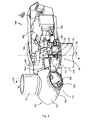
図1は、風力タービン160の一例の斜視図を示している。図示するように、風力タービン160は、支持面150から延びるタワー170と、タワー170に装着されたナセル161と、ナセル161に結合されたロータ115とを含む。ロータ115は、回転可能なハブ110と、ハブ110に結合され、ハブ110から外側に延びる少なくとも1つのロータブレード120とを含む。例えば、図示の実施形態では、ロータ115は、3つのロータブレード120を含む。しかし、代替の実施形態では、ロータ115は、3つよりも多いまたは少ない数のロータブレード120を含んでもよい。各ロータブレード120は、ロータ115の回転を容易にし、風から運動エネルギーが使用可能な機械的エネルギー、続いて電気エネルギーに変換され得るように、ハブ110の周りに間隔を置いて配置され得る。例えば、ハブ110は、ナセル161内に位置決めされた発電機162(図2)に回転可能に結合され、電気エネルギーの発生を可能にし得る。
FIG. 1 shows a perspective view of an example of a
図2は、図1の風力タービン160のナセル161の一例の簡略化された内部図を示している。図示するように、発電機162は、ナセル161内に配置されてもよい。一般に、発電機162は、ロータ115によって生成された回転エネルギーから電力を生成するために、風力タービン160のロータ115に結合され得る。例えば、ロータ115は、ハブ110と共に回転するためにハブ110に結合された主ロータシャフト163を含むことができる。次に、発電機162は、ロータシャフト163の回転が発電機162を駆動するように、ロータシャフト163に結合され得る。例えば、図示の実施形態では、発電機162は、ギアボックス164を通してロータシャフト163に回転可能に結合された発電機シャフト166を含む。
FIG. 2 shows a simplified internal view of an example of the
ロータシャフト163、ギアボックス164、および発電機162は、一般に、風力タービンタワー170の頂部に位置決めされた支持フレームまたはベッドプレート165によってナセル161内に支持され得ることを理解されたい。
It should be appreciated that the
ナセル161は、ナセル161がヨー軸YAを中心に回転することができるように、またはロータを風に対して所望の角度に位置決めするための他の方法が存在し得るように、ヨーシステム20を通してタワー170に回転可能に結合されてもよい。ヨーシステムが存在する場合、そのようなシステムは、通常、他方に対して回転するように構成された2つの軸受構成要素を有するヨー軸受を備える。タワー170が軸受構成要素の一方に結合され、ナセル161のベッドプレートまたは支持フレーム165が他方の軸受構成要素に結合される。ヨーシステム20は、環状ギア21と、モータ23を有する複数のヨー駆動装置22と、ギアボックス24と、軸受構成要素の一方を他方に対して回転させるように環状ギア21と噛み合うためのピニオン25とを備える。
The
ブレード120は、ブレード120とハブ110との間にピッチ軸受100を介してハブ110に結合される。ピッチ軸受100は、内側リングと、外側リングとを備える。風力タービンブレードは、内側軸受リングまたは外側軸受リングのいずれかに取り付けることができ、ハブは他方に接続される。ブレード120は、ピッチシステム107が作動されると、ハブ110に対して相対回転運動を行うことができる。したがって、内側軸受リングは、外側軸受リングに対して回転運動を行うことができる。図2のピッチシステム107は、風力タービンブレードをピッチ軸PAの周りで回転させるために内側軸受リングに設けられた環状ギア109と噛み合うピニオン108を備える。
The
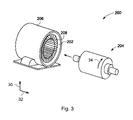
発電機162は、超電導発電機200であってもよい。一例による超電導発電機200の概略分解図を、図3に見ることができる。上述のように、超電導発電機200は、磁場発生器202、例えば、静止磁場発生器202と、電機子204、例えば、回転可能な電機子204とを含むことができる。磁場発生器202および電機子は、ハウジング206内に載置され得る。
The
静止磁場発生器202は、超電導界磁巻線208を含むことができる。超電導界磁巻線208は、十分に低い温度において超電導状態に遷移する導電性材料を使用して作製された1つまたは複数のコイルを含むことができる。そのような材料は、ニオブスズ合金、ニオブチタン合金、二ホウ化マグネシウム合金、超電導特性を示したいくつかのセラミック材料のいずれか、またはそれらの組み合わせを含むことができる。多くの場合、限定はしないが、銅、アルミニウム、陽極酸化アルミニウム、銀、金、またはそれらの組み合わせなどの導電性材料は、機械的特性を改善するために超電導合金と組み合わせて使用することができる。
The quiescent
電機子204は、シャフト163を介して、またはシャフト163とギアボックス164の両方を介して、風力タービン160のロータ115に結合することができる。電機子204の回転により、超電導発電機200は、電機子巻線が超電導界磁巻線208によって確立された磁場を通過する際に電機子巻線に誘導される電圧によって電力を生成することができる。
The
図3に図示される超電導発電機200は半径方向磁場電気機械であるが、本発明は、軸方向磁場または横方向磁場電気機械にも適用可能である。
Although the
いくつかの例では、電機子204は、例えば、図3に示されるように、静止磁場発生器202によって(半径方向に)囲まれてもよい。いくつかの他の例では、静止磁場発生器202は、電機子204によって(半径方向に)囲まれてもよい(図示せず)。さらにいくつかの他の例では、静止磁場発生器202および電機子204は、並んで配置されてもよい(図示せず)。
In some examples, the
参照番号30および32はそれぞれ、超電導発電機200の半径方向および軸方向を表し、したがって電機子204の半径方向および軸方向も表す。参照番号34は、超電導発電機200の円周方向を表し、したがって電機子204の円周方向も表す。
本発明の一態様では、超電導発電機用の電機子、例えば、電機子204は、2つ以上の電機子セグメント300を含む。電機子セグメント300の概略例は、図4に図示される。
In one aspect of the invention, an armature for a superconducting generator, eg,
図4の電機子セグメント300は、複数のコイル305を備える。コイル305は、円周方向34に沿って間隔を置いて配置される。電機子300は、構造的支持を複数のコイル305に提供する電気絶縁支持構造310をさらに備える。
The
図4の例では、電気絶縁支持構造310は、第1の電気絶縁壁315と、第2の電気絶縁壁320とを備える。第2の電気絶縁壁320は、第1の電気絶縁壁315から半径方向に距離を置いて載置され、複数のコイル305は、第1の電気絶縁壁315と第2の電気絶縁壁320との間に載置される。第1の電気絶縁壁315は、第2の電気絶縁壁320よりも半径方向において回転シャフト163、166に近い。
In the example of FIG. 4, the electrically insulating
コイルは、第1の側部部分306と、第2の側部部分307と、2つの端部部分308、309とを含むことができる。端部部分309は、例えば、コイル305から電流を運ぶための電気接続部330を有するものであり得る。第1の側部部分306は、第2の電気絶縁壁320よりも第1の電気絶縁壁315に近い軸方向に実質的に平行なコイルの部分を含んでもよい。第2の側部部分307は、第1の電気絶縁壁315よりも第2の電気絶縁壁320に近い軸方向に実質的に平行なコイルの部分を含んでもよい。言い換えると、第1の側部部分306は、第2の側部部分307よりも半径方向において回転シャフト163、166に近い。そのようなコイルは、図5にも見ることができる。
The coil can include a
いくつかの例では、電気絶縁支持構造310は、複数のコイル305のうちのコイルの第1の側部部分306と第2の側部部分307との間にあり、円周方向34に沿って延びる電気絶縁コイル側セパレータ325をさらに備えてもよい。
In some examples, the electrically insulating
いくつかの例では、電気絶縁コイル側セパレータ325は、例えば、図5に示すように、湾曲プレートであってもよい。複数の湾曲プレート325が、一緒になって管状または環状構造を形成することができる。この例の湾曲プレート325の各々は、管状構造のセグメントを形成することができる。
In some examples, the electrically insulated coil-
図5の例は、コイル500、およびコイル500に通された電気絶縁コイル側セパレータ325を示す。コイル500は、第1の側部部分306と、第2の側部部分307と、2つの端部部分308、309とを備える。図5では、電気絶縁コイル側セパレータ325の軸方向長さ326は、軸方向32に平行なコイル500の部分に沿って部分的に延びる。しかし、図4の例のような他の例では、電気絶縁コイル側セパレータ325の軸方向長さは、コイル500の端部308、309に向かって、軸方向32に平行であり、さらにそれを超えているコイル500の部分に沿って全体的に延びる。電気絶縁コイル側セパレータ325の円周方向長さ327は、円周方向34に沿って延びる。
The example of FIG. 5 shows the
同様に、第1の電気絶縁壁315および第2の電気絶縁壁320は各々、軸方向長さおよび円周方向長さを有し得る。第1の電気絶縁壁315および第2の電気絶縁壁320の軸方向長さは、一般に、軸方向32に実質的に平行に延びてもよいが、例えば、コイル305の端部308、309において、この方向からずれてもよい。
Similarly, the first electrical insulating
図4および図5の例からも分かるように、複数のコイル500のコイル305の第1の側部部分306および第2の側部部分307は、円周方向34にオフセットされている。特に、これらの例では、これらの部分306、307は、互いに半径方向および円周方向に変位している。これらの部分306、307は、2つの端部部分308および309を介してそれらの間を接続する。
As can be seen from the examples of FIGS. 4 and 5, the
本開示を通して、複数のコイル305内のコイルは、銅、アルミニウム、銀、および金の1つまたは複数を含む導電性材料で作製されてもよい。
Throughout the present disclosure, the coils in the plurality of
本開示を通して、第1の電気絶縁壁315および第2の電気絶縁壁320ならびに電気絶縁コイル側セパレータ325のいずれも、繊維強化複合材料、例えば、G-10、G-11、F-24、およびFR-4の1つまたは複数を含む繊維強化ポリマーを使用して形成されてもよい。
Throughout the present disclosure, both the first electrical insulating
FR-4は、ガラス強化エポキシ積層材料FR-4のNEMA(「National Electrical Manufacturers Association」)グレードの名称であり、耐燃性のエポキシ樹脂バインダを有する織布または不織布ガラス繊維で構成された複合材料である。ここで、FRは、難燃剤を表す。G-10およびG-11は、高圧ガラス繊維エポキシ積層体である。G-10はG-11よりもわずかに強いが、G11はより良好な絶縁体であり、より高い温度により良好に耐えることができる。 FR-4 is the name of the NEMA ("National Electrical Manufacturers Association") grade of the glass-reinforced epoxy laminated material FR-4, which is a composite material composed of a woven fabric or a non-woven glass fiber having a flame-resistant epoxy resin binder. be. Here, FR represents a flame retardant. G-10 and G-11 are high-pressure glass fiber epoxy laminates. G-10 is slightly stronger than G-11, but G11 is a better insulator and can better withstand higher temperatures.
あるいは、温度、機械的負荷、および電気的負荷に耐えて電機子を機能させることができる任意の他の複合材料を使用することができる。これには、限定はしないが、ポリエステル、ビニルエステル、またはポリアミドをベースとするマトリックス材料が含まれる。 Alternatively, any other composite material capable of withstanding temperature, mechanical load, and electrical load to allow the armature to function can be used. This includes, but is not limited to, polyester, vinyl ester, or polyamide-based matrix materials.
本開示を通して、電機子セグメント300は、1つまたは複数のコイル500を含むことができる。いくつかの例では、電機子セグメント300は、10~30個のコイルを含むことができる。いくつかの例では、複数のコイル305は、1つまたは2つまたは任意のより多い数の極を備えることができる。
Throughout the present disclosure, the
複数のコイル305のコイル間、すなわち、円周方向34における空間は、コイル305および/または電機子セグメント300を冷却するために使用することができる。すなわち、いくつかの例では、電機子セグメント300は、コイルを分離する空間内に冷却チャネルをさらに備えてもよい。一例では、空気などの冷却流体は、コイル間のそのような間隔を単に通過することができる。いくつかの他の例では、電気絶縁スペーサ(図示せず)が、コイルの第1の側部部分306と隣接するコイルの第1の側部部分306との間に含まれてもよい。追加的または代替的に、電気絶縁スペーサが、コイルの第2の側部部分307と隣接するコイルの第2の側部部分307との間に含まれてもよい。
The space between the coils of the plurality of
そのような電気絶縁スペーサの1つまたは複数は、電機子セグメントコイル305の冷却を助けるために、通過する冷却流体の流れを促進するように構成された1つまたは複数の冷却チャネルを含むことができる。電気絶縁スペーサおよび1つまたは複数の冷却チャネルは、軸方向32に少なくとも部分的に延びる軸方向長さを有することができる。すなわち、これらの要素は、一般に、軸方向32に実質的に平行に延在してもよいが、例えば、コイル305の端部308、309において、この方向からずれてもよい。
One or more of such electrically insulating spacers may include one or more cooling channels configured to facilitate the flow of cooling fluid through to aid in cooling the
これらの例のいずれかにおいて、電機子セグメント300を冷却するために、電機子セグメントの内外に流体、例えば、空気を導くための冷却ポート312を設けることができる。いくつかの例では、電気絶縁支持構造310は、例えば、図4に示すように軸方向32に沿った各端部に1つずつ、2つの冷却ポート312を含むことができる。いくつかの他の例では、電気絶縁支持構造310は、軸方向32に沿ったその端部の各々に2つ以上の冷却ポート312を含んでもよい。冷却ポート312は、図4の例のように、管状形状を有することができる。
In any of these examples, in order to cool the
いくつかの例では、電機子セグメント300は、複数の冷却チャネル700を含むことができる。複数の冷却チャネル700は、いくつかの例では、図8に示される705のものなどの冷却チャネル、すなわち、コイル500の形状に適合するように構成され得る冷却チャネル705を含むことができる。そのような冷却チャネル700に関するさらなる情報は、以下の図8に関連して提供される。
In some examples, the
一例では、互いに接合されると、複数のコイル305および電気絶縁支持構造310は、繊維および樹脂で囲むことができ、樹脂はその後硬化させることができる。いくつかの他の例では、電気絶縁支持構造310、例えば、第1の電気絶縁壁315および第2の電気絶縁壁320、ならびに任意選択で電気絶縁コイル側セパレータ325は、繊維および樹脂で囲まれて最初に硬化され、次いで複数のコイル305に接合され得る。これらの例のいずれかによる電機子セグメントは、金型内に配置することができ、繊維、マイクロファイバ、または繊維マットが金型内に配置され得、その後、樹脂を金型内に導入してもよい。
In one example, when joined to each other, the plurality of
いくつかの他の例では、1つまたは複数の電機子セグメント構成要素に微粒子を注入することができる。一例では、少なくとも複数のコイルを金型内に配置し、微粒子を注入し、次いで樹脂で覆うことができる。 In some other examples, fine particles can be injected into one or more armature segment components. In one example, at least a plurality of coils can be placed in the mold, injected with fine particles, and then covered with resin.
いくつかの例では、例えば、以下にさらに示されるように、能動的注入圧力および/または真空支援樹脂含浸が使用されてもよい。 In some examples, for example, active injection pressure and / or vacuum assisted resin impregnation may be used, as further shown below.
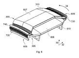
電機子セグメント300の別の概略例が、図6に示される。図6の例の電機子セグメント300はまた、複数のコイル305を備え、コイルは、円周方向34に沿って間隔を置いて配置される。電機子セグメント300は、構造的支持を複数のコイル305に提供する電気絶縁支持構造310をさらに備える。
Another schematic example of the
この例では、電気絶縁支持構造310は、複数のコイル305を囲む繊維および樹脂を含む複合材を含む。したがって、電気絶縁壁315、320、および任意選択で電気絶縁コイル側セパレータ325は、この例では構造的支持を複数のコイル305に提供するためにもはや必要とされない。複合材は、必要な支持を提供することができる。
In this example, the electrically insulated
第1の側部部分306、第2の側部部分307、および2つの端部部分308、309を含むコイル500と同様に、複数のコイル305は、第1の中央部分606と、第2の中央部分607と、2つの複数のコイル端部部分608、609とを含むことができる。第1の中央部分606は、第2の中央部分607よりも半径方向において回転シャフト163、166に近い。したがって、本明細書では、囲むということは、図6に図示されるように、複数のコイル305の少なくとも第1の中央部分606および複数のコイル305の少なくとも第2の中央部分607を完全に覆う、例えば、包むことを指すことができる。いくつかの例では、樹脂を添加し硬化させる前に、繊維マットまたは繊維束を使用して複数のコイル305を囲み、任意選択でアセンブリ、例えば、治具610内の任意の他の構成要素を囲んでもよい。
Similar to the
いくつかの例では、電機子セグメント300は、複数のコイル305が配置されている治具610を備えてもよい。これらの例のいくつかでは、治具610は、例えば、繊維マットによって囲まれ、樹脂で覆われて硬化されている可能性があるという事実のために、複合材の一部であり得る。例えば、図6の例では、電機子300の複合材は、複数のコイルが配置されている治具610をさらに囲む。これは、電機子セグメント300の堅牢性およびその中の個々の構成要素の位置決めの精度を高めることができる。
In some examples, the
いくつかの例では、治具610は、電機子モジュール300を電機子支持構造1000(例えば、図11および図12参照)に取り付けることができる穴を有することができる。
In some examples, the
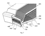
図6の電機子セグメント300の概略例の代替例を示す図7では、複数のコイル305の端部608は、繊維および樹脂を含む複合材でさらに囲まれている、すなわち、完全に覆われているかまたは包まれている。例えば、コイル305から電流を運ぶための電気接続部330を有さない端部608は、繊維および樹脂を含む複合材でさらに覆われているものであってもよい。
In FIG. 7, which shows an alternative example of the schematic example of the
図7の例では、電機子セグメント300の電気絶縁支持構造310の一部のみが、下にある複数のコイル305を示すために含まれている。複数のコイル305の他に、複数の冷却チャネル700も見ることができる。この例では、冷却チャネル705が、2つの隣接するコイル500を分離する。言い換えると、複数のチャネル700は、円周方向34に位置してもよい。この例では、複数の冷却チャネル700は、複数のコイル305の周りに嵌合する、すなわち、形状が適合するように構成することができる。単一の冷却チャネル705の一例を、図8に見ることができる。図8の冷却チャネル705、図5のコイル500、および図7にまとめられたこれらの要素を比較すると理解することができるように、冷却チャネル705は、コイル500の形状に適合するように構成することができる。
In the example of FIG. 7, only a portion of the electrically insulating
そのような冷却チャネル700は、図4の例の電機子セグメント300にも使用することができる。
Such a
冷却チャネル705は、第1の冷却部分710と、第2の冷却部分715とを含むことができる。チャネル705の第1の冷却部分710は、2つの第1の冷却通路711、712を有してもよく、各通路711、712は、コイル500の第1の側部部分306の側部の各々、および部分的に、コイル500の2つの端部部分308、309の側部に沿う、例えば、それらに実質的に平行に延びるように構成される。第1の冷却通路711および712は、流体が第1の冷却通路から他方の第1の冷却通路に通過することができるように、冷却チャネル705の第1の部分710の第1の別個の端部713で合流することができる。同様に、チャネル705の第2の冷却部分715は、2つの第2の冷却通路716、717を有してもよく、各通路716、717は、コイル500の第2の側部部分307の側部の各々、および部分的に、コイル500の2つの端部部分308、309の側部に沿う、例えば、それらに実質的に平行に延びるように構成される。第2の冷却通路716および717は、流体が第2の冷却通路から他方の第2の冷却通路に通過することができるように、冷却チャネル705の第2の部分715の第2の別個の端部718で合流することができる。
The cooling
コイル500の第1の側部部分306および第2の側部部分307の側部は、複数のコイル305のコイルが、例えば、冷却チャネルによって円周方向に沿って間隔を置いて配置されていない場合に他のコイル500と接触するコイル500の部分を指すことができる。一例では、これらの側部は、半径方向30および軸方向32によって形成される平面に実質的に平行な平面内に位置してもよい。
The sides of the
第1の冷却通路711、712および第2の冷却通路716、717がそれぞれ合流する第1の別個の端部713および第2の別個の端部718は、例えば、コイル500上に誘導電流を出力するための電気接続部330を有するコイル500の端部部分309の近くに、例えば、その上に載置されるように構成することができる。第1の冷却部分710および第2の冷却部分715はまた、冷却チャネル705の接合端部720で合流することができる。接合端部720は、第1の別個の端部713および第2の別個の端部718の反対側にあり得る。
The first
接合端部720は、コイル500を冷却するために冷却チャネル705を通過することができる流体のための入口730および出口725を含むことができる。入口725および出口730は、冷却マニホールドの分配器に接続されるように構成されてもよい。そのような分配器は、流体を複数のコイル305の入口730に送達し、複数のコイル305の出口725から収集することができる第1の分配導管735および第2の分配導管740を備えることができる。図7および図8では、入口および出口がそれぞれ730および725としてラベル付けされているが、他の例では、ラベル725は入口を指すことができ、ラベル730は出口を指すことができることに留意されたい。
The
冷却チャネル700は、金属および/またはプラスチックであってもよい。一例では、冷却チャネル700は、ポリテトラフルオロエチレン(PTFE)を含むことができ、より詳細には、熱伝導性添加剤を含浸させたPTFE材料によって形成することができる。これにより、冷却チャネル705の熱伝導率を高めることができる。
The cooling
一例では、これらの種類の冷却チャネル700は、例えば、コイル間に冷却チャネルを含むスペーサを導入する代わりに、図4および図5の例の電機子セグメント300に使用することができる。図8に関連して説明した冷却チャネル700は、例えば、複数のコイル305の端部308(608)、309(609)を冷却することによって、電機子セグメント300のより効率的な冷却を可能にすることができる。
In one example, these types of cooling
強磁性歯を欠く電機子セグメント300、すなわち、図4、図6、および図7のもののように電機子コイル305に近い強磁性材料がないことにより、電機子コイル305の絶縁要件が緩和され得る。また、電気絶縁支持構造310に非強磁性および電気絶縁材料を使用することにより、電機子コイル305は、超電導界磁巻線208によって発生される増加した磁場で動作することができる。
The absence of an
上記の例で説明したような複数の電機子セグメント300を使用して、電気機械、例えば、超電導発電機200用の電機子204を組み立てることができる。この目的のために、電機子セグメント300は、相補的な形状を有してもよい。いくつかの例では、電機子204を組み立てるために、図4および図5を参照して説明したような複数の電機子セグメントを互いに取り付けることができる。いくつかの他の例では、図6および図7に関連して説明したような複数の電機子セグメントを使用して、電機子204を形成することができる。したがって、円周方向に沿って電機子支持構造1000に取り付けられた、本開示を通して説明する複数のセグメントを備える電気機械用の電機子を提供することができる。複数の電機子セグメント300を電機子204に組み立てるいくつかの可能性が、後に示される。
A plurality of
電機子204を装着するために、2つ以上の電機子セグメント300が取り付けられてもよい。いくつかの例では、電機子204は、20~50個の電機子セグメント300を備えることができる。
Two or
いくつかの例では、電機子204は、シールド1210(図13参照)を含むことができる。シールド1210は、電機子支持構造1000と複数のセグメント300との間に位置されてもよい。シールド1210は、強磁性材料を含むことができる。例えば、シールド1210は、電磁鋼を含むことができる。いくつかの例では、シールド1210は、積層されてもよい。これは、シールド1210および支持構造1000内の誘導電流に関連する損失を低減するのに役立ち得る。シールド1210はまた、超電導界磁巻線208からの磁束が半径方向30に留まるように促すことができる。これは、磁場発生器202によって生成された磁場と電機子コイル305との間の磁気結合を改善することができる。
In some examples, the
本明細書に開示されるような磁場発生器202、例えば、静止磁場発生器と、磁場発生器202と同心に載置された超電導界磁巻線208と、複数の電機子セグメント300を備える電機子204とを備える超電導発電機200を提供することができる。
An electric field comprising a
さらに、上述のように風力タービンタワー170と、タワー170の上部のナセル161と、ナセル161に装着された1つまたは複数の風力タービンブレード120を含むロータ115と、ナセル161内の超電導発電機200とを備える風力タービン160を提供することができる。
Further, as described above, the
図9は、電気機械用の電機子を組み立てるための方法900の一例を示す。例えば、図3の電機子204は、そのような方法で組み立てることができる。
FIG. 9 shows an example of a
方法は、ブロック910において、図4~図8のいずれかに関する電機子セグメント300などの複数の電機子セグメントを設けることを含む。
The method comprises providing the
これに関して、各電機子セグメント300は、複数のコイル305、および構造的支持を複数のコイル305に提供する電気絶縁支持構造310を含む。
In this regard, each
方法は、ブロック920において、複数の電機子セグメント300を電機子支持構造1000に取り付けることをさらに含む。電機子セグメント300は、相補的な形状を有してもよい。電機子支持構造1000に取り付けられる電機子セグメント300の数は、例えば、電機子204のサイズ(例えば、直径)および電機子セグメント300に含まれるコイル500の数に応じて選択することができる。一例では、20~50個の電機子セグメント300を電機子支持構造1000に取り付けることができる。
The method further comprises attaching a plurality of
電機子支持構造1000の一例を、図10Bに見ることができる。この図では、電機子支持構造1000は、複数の電機子セグメント300が取り付けられ得るようにリング形状を有する。いくつかの他の例では、電機子支持構造1000は、断面(半径方向30および円周方向34を含む平面)が多角形形状であってもよい。すなわち、電機子支持構造1000は複数の面を含むことができ、面の数は、例えば、取り付けられる電機子セグメント300の数に等しくてもよい。これらの例のいくつかでは、断面における電機子支持構造1000は、20~50個の面または側部において多角形であってもよい。
An example of the
いくつかの例では、電機子支持構造1000は、1つまたは複数の強磁性材料の固体片(すなわち、単一の非積層片)を含むことができる。いくつかの他の例では、電機子支持構造1000は、1つまたは複数の強磁性材料の積層、例えば、単一の積層片を含むことができる。これは、渦電流を低減するのに役立ち得る。
In some examples, the
いくつかの例では、複数の電機子セグメント300を電機子支持構造1000に取り付けることは、複数の電機子セグメント300を電機子支持構造1000に取り付ける前に、複数の電機子セグメント300を外側電機子セグメント支持体1100に取り付けることを含んでもよい。これは、図10Aおよび図10Bに示すことができる。
In some examples, attaching the plurality of
図10Aは、これらの例のいくつかにおいて、電気絶縁支持構造310、例えば、コイル305の電気接続部300に近い電気絶縁支持構造310の端部311における2つの穴、および外側電機子セグメント支持体1100における別の2つの穴を通過するために、締結具1105、例えば、2つのバー、ねじ、またはピン1105をどのように使用することができるかを示す。バー、ねじ、またはピン1105は、例えば、ナットによって固定されてもよい。いくつかの他の例では、単一のそのような締結具または3つ以上の締結具が使用されてもよい。
FIG. 10A shows, in some of these examples, two holes in the electrical
外側電機子セグメント支持体1100は、いくつかの例では、図10Bに示されるように半リング形状を有してもよい。複数の電機子セグメント300が外側セグメント支持体1100に取り付けられているとき、外側セグメント支持体1100は、電機子支持構造1000の近くに(またはその逆に)移動されてもよく、電機子セグメント300は、電機子支持構造1000に取り付けられてもよい。電機子支持構造1000と電機子セグメント300を接合するために、接着剤および/または例えば、ボルトナット、ならびにリベットを含むことができる締結具を使用することができる。クレーン1110を使用して、電機子セグメント300および/または電機子支持構造1000と共に外側セグメント支持体1100を移動させることができる。
The outer
電機子204の組み立てを完了するために、別の外側セグメント支持体1100を設けることができ、複数の電機子セグメント300をそれに取り付けることができ、次いで複数の電機子セグメント300を電機子支持構造1000に取り付けることができる。2つの外側セグメント支持体1100および/またはそれらの端部に取り付けられた電機子セグメント300は、例えば、接着剤および/または締結具1105を用いて互いに接合することができる。これにより、電機子204の堅牢性を高めることができる。
To complete the assembly of the
いくつかの例では、図11に示すように、結果として得られる構造(すなわち、取り付けられた複数の電機子セグメント)は、カバー1120、例えば、複合スリーブ、ラッパ、またはストリップに包まれてもよい。これにより、電機子204のさらなる支持および堅牢性を提供することができる。
In some examples, as shown in FIG. 11, the resulting structure (ie, multiple attached armature segments) may be wrapped in a
外側電機子セグメント支持体1100は、他の形状を有してもよく、半リングの円周方向長さとは異なる円周方向長さ、例えば、より短い円周方向長さを有してもよい。例えば、外側電機子セグメント支持体1100は、複数の表面、例えば、平坦または湾曲表面を含むことができ、表面の数は、取り付けられる電機子セグメント300の数に対応する。
The outer
いくつかの例では、複数の電機子セグメントを電機子支持構造に取り付けることは、複数の電機子セグメントアセンブリカート1200を使用して、電機子支持構造1000に取り付けられる複数の電機子セグメント300を移動させることを含む。
In some examples, attaching multiple armature segments to an armature support structure uses a plurality of armature
複数の電機子セグメント300を移動させる複数のカート1200の一例が、図12に示される。この例では、複数の電機子セグメント300は、複数の電機子セグメントアセンブリカート1200上に載置されてもよく、図の右部分に示すように、カート1200上の複数の電機子セグメント300を電機子支持構造1000に取り付けるために事前に互いに取り付けられてもよい。セグメントアセンブリカート1200は、例えば、電動ドリーを用いて、電機子支持構造1000に向かって移動させることができる。
An example of a plurality of
電機子支持構造1000に近づく前に、任意の数の電機子セグメント300をまとめることができる。例えば、図12に示すように、電機子204を形成する電機子セグメント300の半分をまとめることができるが、より多くのまたは少ない数の電機子セグメント300を接合することが可能である。
Any number of
また、電機子支持構造1000に取り付ける前に複数の電機子セグメント300をまとめることは、複数の段階で実施することができ、すなわち、電機子セグメント300を様々な組にグループ化することができ、次いでこれらの組をより大きな組にグループ化することができる。組は、1つまたは複数の電機子セグメント300を備えることができる。
Also, grouping a plurality of
加えて、電機子セグメント300は、電機子支持構造1000に取り付ける前に別の電機子セグメント300に取り付けられなくてもよいが、電機子支持構造1000に取り付けられ、次いで別の電機子セグメント300に取り付けられてもよい。一例では、複数の電機子セグメントの各電機子セグメント300は、電機子支持構造1000に取り付けられてもよい。次いで、電機子セグメント300を互いに取り付けることができる。ここでも、電機子セグメント300を電機子支持構造1000に取り付けるために、接着剤および締結具1105、例えば、ボルトナットの1つまたは複数を使用することができる。電機子セグメント300を互いに取り付けるために、接着剤および締結具1105、例えば、ボルトナットの1つまたは複数を使用することができる。
In addition, the
これらの例のいくつかでは、図11に関して示されるように、結果として得られる構造は、スリーブ1120、例えば、複合スリーブに包まれ得る。
In some of these examples, as shown with respect to FIG. 11, the resulting structure may be wrapped in a
いくつかの例では、複数の電機子セグメントを電機子支持構造に取り付けることは、複数の電機子セグメント300を電機子支持構造1000に取り付ける前に、シールド1210を電機子支持構造1000に取り付けることを含む。シールド1210の一例を、図13に見ることができる。一例では、シールド1210の積層は、電機子支持構造1000の周りに積み重ねられてもよい。
In some examples, attaching the plurality of armature segments to the armature support structure means attaching the
いくつかの例では、(ブロック910において)複数の電機子セグメントを設けることは、複数のコイル305を有する複数の冷却チャネル700を配置することをさらに含むことができる。図4の例では、これは、複数のコイル305および冷却チャネル700のアセンブリを第1の電気絶縁壁315に取り付ける前に行うことができる。図6および図7の例では、これは、複数のコイル305および冷却チャネル700のアセンブリを繊維および樹脂で囲む前に行うことができる。
In some examples, providing multiple armature segments (in block 910) can further include arranging
いくつかの例では、複数の冷却チャネル700は、複数のコイル305の形状に適合する、すなわち、その周りに嵌合するように構成された冷却チャネル700を含むことができる。複数のコイル305の形状に適合するように構成された複数の冷却チャネル700は、複数の冷却チャネル700が個々に複数のコイル305の形状に適合することができると理解することができる。すなわち、図8に示されるようなチャネルを含む複数の冷却チャネル700を設けることができ、各適合する冷却チャネル705は、対応するコイル500の形状に適合し、したがってそれに嵌合することができる。
In some examples, the plurality of cooling
いくつかの例では、(ブロック910において)複数の電機子セグメントを設けることは、複数のコイル305を第1の電気絶縁壁315に取り付けることと、第2の電気絶縁壁320を第1の絶縁壁315に既に取り付けられている複数のコイル305に取り付けることとを含む。このようにして、電機子セグメント300を組み立てることができる。より多くの電機子セグメント300を同様に組み立て、設けることも可能である。
In some examples, providing multiple armature segments (in block 910) allows
これらの例のいくつかでは、複数の電機子セグメントを設けることは、円周方向34において複数のコイル305のコイルの第1の側部部分306と第2の側部部分307との間に電気絶縁コイル側セパレータ325を導入することをさらに含む。
In some of these examples, the provision of multiple armature segments provides electricity between the
いくつかの例では、(ブロック910において)複数の電機子セグメントを設けることは、治具610内に複数のコイル305を配置することと、治具610内に配置された複数のコイル305を繊維および樹脂で囲むことと、樹脂を硬化させることとを含む。いくつかの例では、複数のコイル305を繊維で囲むことは、それらを繊維マットまたは繊維束で囲むことを含むことができる。いくつかの例では、治具610はまた、繊維および樹脂で囲まれてもよい。
In some examples, providing multiple armature segments (in block 910) may result in the placement of
いくつかの他の例では、(ブロック910において)複数の電機子セグメントを設けることは、治具610内に複数のコイル305を配置することと、治具610内に配置された複数のコイル305を微粒子および樹脂で囲むことと、樹脂を硬化させることとを含む。複数のコイルを微粒子で囲むことは、コイルに微粒子を注入することを含み得る。
In some other examples, providing multiple armature segments (in block 910) may result in the placement of
治具610内に配置された複数のコイル305の一例を、図14に見ることができる。この例では、治具610は、2つの治具支持体1305、1310を含む。各支持体1305、1310は、脚部1315と、グリッパ1320とを含む。複数のコイル305は、脚部1315によって支持され、グリッパ1320によって一緒に保持され得る。いくつかの例では、1つの治具支持体1305が使用されてもよい。いくつかの他の例では、3つ以上の治具支持体1305が使用されてもよい。2つ以上の治具支持体1305が使用される場合、2つ以上の支持体1305が接合されていてもよい。すなわち、2つ以上の部品ではなく、単一の部品として設けることができる。また、いくつかの例では、脚部1315およびグリッパ1320は単一の部品として設けられてもよいが、いくつかの他の例では、それらは2つの別個の部品として設けられてもよい。いくつかの例では、脚部1315は、図13に示されるように、電機子支持構造1000に取り付けることができる。図13の例では、ボルトなどの締結具1105を使用して、電機子セグメント300を電機子支持構造1000に取り付ける。
An example of a plurality of
いくつかの例では、複数の電機子セグメントを提供するために、能動的注入圧力および/または真空支援樹脂含浸を使用することができる。真空を維持するため、および/または樹脂の加圧された流れを案内するために、電機子セグメントは、電機子セグメントの形状に沿う十分に真空もしくは気密なテーブルもしくは金型上に載置されてもよく、一方、真空を十分に維持するために箔で、かつ/または一緒になって真空を十分に維持すること、および/もしくはアセンブリを通る樹脂の加圧された流れを案内することを可能にする金型の別のセクションもしくは複数の金型セクションで他方の側部が覆われる。そのような金型は、正しい圧力/真空条件を維持するため、潜在的に過剰な樹脂の流れのための出口を提供するため、および/またはプローブもしくはセンサへのアクセスを提供するための入口および出口チャネルが備えられ得る。いくつかの例では、電機子セグメント構成要素をその中に位置決めする前に、金型を部分的に組み立てることができる。いくつかの他の例では、金型は、電機子セグメント構成要素の位置決めに沿って、または部分的にその後に構築されてもよい。 In some examples, active injection pressure and / or vacuum assisted resin impregnation can be used to provide multiple armature segments. To maintain vacuum and / or to guide the pressurized flow of resin, the armature segment is placed on a sufficiently vacuum or airtight table or mold that follows the shape of the armature segment. It is also possible, on the other hand, to maintain sufficient vacuum with foil to maintain sufficient vacuum and / or together and / or to guide the pressurized flow of resin through the assembly. The other side is covered with another section of the mold or multiple mold sections. Such molds have an inlet and / or an inlet to provide access to a probe or sensor to maintain correct pressure / vacuum conditions, to provide an outlet for potentially excess resin flow, and / or to provide access to a probe or sensor. An exit channel may be provided. In some examples, the mold can be partially assembled before the armature segment component is positioned therein. In some other examples, the mold may be constructed along or partially after the positioning of the armature segment components.
いくつかの例では、1つまたは複数のスペーサ、例えば、電気絶縁スペーサが、2つのコイル、例えば、隣接するコイル間に導入されてもよい。1つまたは複数のスペーサが、追加的または代替的に、同じコイルの2つの部分の間に導入されてもよい。スペーサはまた、電機子セグメント300の他の構成要素を分離することができる。
In some examples, one or more spacers, eg, electrically insulating spacers, may be introduced between the two coils, eg, adjacent coils. One or more spacers may be additionally or optionally introduced between two parts of the same coil. The spacer can also separate other components of the
組み立てられると、電機子204は、1つまたは複数の発電機162の構成要素に取り付けられてもよい。図2に概略的に示されるように、いくつかの例では、電機子204は、シャフト163を介して、またはシャフト163とギアボックス164の両方を介して、風力タービン160のロータ115に結合することができる。電機子セグメント300および/または電機子204は、1つまたは複数の発電機構成要素に取り付けるための適切な嵌合具、取り付け具、または接続要素を備えることができる。さらに別の態様では、電気機械、例えば、超電導発電機200用の電機子204のための電機子セグメント300を組み立てるための方法1400が提供される。この方法を示すフローチャートが、図15に示される。方法1400は、ブロック1410において、治具610内に複数のコイル305を配置することと、ブロック1420において、治具610内に配置された複数のコイル305を繊維および樹脂で囲むことと、ブロック1430において、樹脂を硬化させることとを含む。
Once assembled, the
いくつかの例では、方法1400は、複数のコイル305と共に、複数の冷却チャネル700、任意選択で、複数のコイル305の周りに嵌合する、すなわち、形状が適合するように構成された複数の冷却チャネル700を配置することをさらに含むことができる。
In some examples, the
この態様に関する説明、および電機子セグメント300、治具610、および冷却チャネル700の組み立ての詳細に関連して上述した説明は、この態様にも適用することができる。
The description of this aspect and the description described above in relation to the details of the assembly of the
本明細書に開示される例のいずれにおいても、電機子のセグメントは、フィラー要素、例えば、特定の機械的特性を提供するために硬化もしくは配置される必要があるか、または材料および重量を節約するために最終製品に穴を生成するように配置される必要がある複合材の体積に大きな差があることを回避するように配置された予備硬化構成要素を備えることができる。 In any of the examples disclosed herein, the armature segment needs to be cured or placed to provide a filler element, eg, a particular mechanical property, or saves material and weight. Pre-curing components can be provided that are arranged to avoid large differences in volume of the composite that need to be arranged to create holes in the final product.
本明細書は、実施例を用いて、好ましい実施形態を含む本発明を開示し、また、当業者が、任意の装置またはシステムを作製し使用し、任意の組み込まれた方法を実施することを含めて、本発明を実践することを可能にする。本発明の特許可能な範囲は、特許請求の範囲によって定義され、当業者が想到する他の実施例を含むことができる。このような他の実施例は、特許請求の範囲の文言との差がない構造要素を有する場合、または特許請求の範囲の文言との実質的な差がない等価の構造要素を含む場合、特許請求の範囲内にあることを意図している。当業者であれば、上述の種々の実施形態からの態様ならびに各々のそのような態様についての他の公知の均等物を混ぜ合わせて適合させることで、本出願の原理に従ったさらなる実施形態および技術を構築することができる。図面に関連する参照符号が特許請求の範囲の括弧内に配置されている場合、それらの参照符号は単に特許請求の範囲の明瞭性を高めるためのものであり、特許請求の範囲を限定するものと解釈されるべきではない。 The present specification discloses the present invention, including preferred embodiments, using examples, and one of ordinary skill in the art is capable of making and using any device or system to implement any incorporated method. Including, it makes it possible to practice the present invention. The patentable scope of the invention is defined by the claims and may include other embodiments conceived by those skilled in the art. Such other embodiments are patented if they have structural elements that are not significantly different from the wording of the claims, or if they contain equivalent structural elements that are not substantially different from the wording of the claims. Intended to be within the claims. Further embodiments and embodiments according to the principles of the present application can be made by those skilled in the art by mixing and adapting embodiments from the various embodiments described above as well as other known equivalents for each such embodiment. Technology can be built. If the reference codes associated with the drawings are placed within the brackets of the claims, those reference codes are merely to enhance the clarity of the claims and limit the scope of the claims. Should not be interpreted as.
20 ヨーシステム
21 環状ギア
22 ヨー駆動装置
23 モータ
24 ギアボックス
25 ピニオン
30 半径方向
32 軸方向
34 円周方向
100 ピッチ軸受
107 ピッチシステム
108 ピニオン
109 環状ギア
110 ハブ
115 ロータ
120 ロータブレード、風力タービンブレード
150 支持面
160 風力タービン
161 ナセル
162 発電機
163 主ロータシャフト、回転シャフト
164 ギアボックス
165 支持フレーム、ベッドプレート
166 発電機シャフト、回転シャフト
170 風力タービンタワー
200 超電導発電機
202 静止磁場発生器
204 電機子
206 ハウジング
208 超電導界磁巻線
300 電機子セグメント、電機子モジュール、電気接続部、電機子
305 電機子コイル、電機子セグメントコイル
306 第1の側部部分
307 第2の側部部分
308 端部部分
309 端部部分
310 電気絶縁支持構造
311 端部
312 冷却ポート
315 第1の電気絶縁壁
320 第2の電気絶縁壁
325 電気絶縁コイル側セパレータ、湾曲プレート
326 軸方向長さ
327 円周方向長さ
330 電気接続部
500 コイル
606 第1の中央部分
607 第2の中央部分
608 コイル端部部分
609 コイル端部部分
610 治具
700 冷却チャネル
705 冷却チャネル
710 第1の冷却部分
711 第1の冷却通路
712 第1の冷却通路
713 第1の別個の端部
715 第2の冷却部分
716 第2の冷却通路
717 第2の冷却通路
718 第2の別個の端部
720 接合端部
725 入口、出口
730 入口、出口
735 第1の分配導管
740 第2の分配導管
900 方法
1000 電機子支持構造
1100 外側電機子セグメント支持体、外側セグメント支持体
1105 接着剤および/または締結具、バー、ねじ、またはピン
1110 クレーン
1120 カバー、スリーブ
1200 電機子セグメントアセンブリカート
1210 シールド
1305 治具支持体
1310 治具支持体
1315 脚部
1320 グリッパ
1400 方法
PA ピッチ軸
YA ヨー軸
20 Yaw System 21 Circular Gear 22 Yaw Drive 23 Motor 24 Gearbox 25 Pinion 30 Radial 32 Axial 34 Circumferential 100 Pitch Bearing 107 Pitch System 108 Pinion 109 Ring Gear 110 Hub 115 Rotor 120 Rotor Blade, Wind Turbine Blade 150 Support surface 160 Wind turbine 161 Nacelle 162 Generator 163 Main rotor shaft, rotary shaft 164 Gearbox 165 Support frame, bed plate 166 Generator shaft, rotary shaft 170 Wind turbine tower 200 Superconducting generator 202 Static magnetic field generator 204 Armature 206 Housing 208 Superconducting field winding 300 Armature segment, armature module, electrical connection, armature 305 Armature coil, armature segment coil 306 First side part 307 Second side part 308 End part 309 End part 310 Electrical insulation support structure 311 End part 312 Cooling port 315 First electrical insulation wall 320 Second electrical insulation wall 325 Electrical insulation coil side separator, curved plate 326 Axial length 327 Circumferential length 330 Electric Connection part 500 Coil 606 1st central part 607 2nd central part 608 Coil end part 609 Coil end part 610 Jig 700 Cooling channel 705 Cooling channel 710 1st cooling part 711 1st cooling passage 712 1st Cooling Passage 713 First Separate End 715 Second Cooling Part 716 Second Cooling Passage 717 Second Cooling Passage 718 Second Separate End 720 Joint End 725 Inlet, Outlet 730 Inlet, Outlet 735 First distribution conduit 740 Second distribution conduit 900 Method 1000 Armature support structure 1100 Outer armature segment support, outer segment support 1105 Adhesive and / or fasteners, bars, screws, or pins 1110 Crane 1120 cover, Sleeve 1200 Armature Segment Assembly Cart 1210 Shield 1305 Jig Support 1310 Jig Support 1315 Leg 1320 Gripper 1400 Method PA Pitch Axis YA Yaw Axis
Claims (15)
複数のコイル(305)であって、円周方向(34)に沿って間隔を置いて配置される複数のコイル(305)と、
構造的支持を前記複数のコイル(305)に提供する電気絶縁支持構造(310)と
を備え、
前記コイル(305)は、第1の側部部分(306)および第2の側部部分(307)を備え、前記第1および第2の側部部分(306、307)は、端部部分(308、309)を介して接続され、前記第1および第2の側部部分(306、307)は、互いに半径方向(30)および円周方向(34)に変位している、
電機子セグメント(300)。 An armature segment (300) for an armature (204) for a superconducting air machine.
A plurality of coils (305), and a plurality of coils (305) arranged at intervals along the circumferential direction (34).
With an electrically insulated support structure (310) that provides structural support to the plurality of coils (305).
The coil (305) comprises a first side portion (306) and a second side portion (307), and the first and second side portions (306, 307) are end portions (306, 307). Connected via 308, 309), the first and second side portions (306, 307) are displaced from each other in the radial (30) and circumferential (34) directions.
Armature segment (300).
第1の電気絶縁壁(315)と、第2の電気絶縁壁(320)とを備え、前記第2の電気絶縁壁(320)は、前記第1の電気絶縁壁(315)から半径方向に距離を置いて載置され、前記複数のコイル(305)は、前記第1の電気絶縁壁(315)と前記第2の電気絶縁壁(320)との間に載置される、
請求項1に記載の電機子セグメント(300)。 The electrical insulation support structure (310) is
A first electrical insulating wall (315) and a second electrical insulating wall (320) are provided, and the second electrical insulating wall (320) is radially from the first electrical insulating wall (315). The plurality of coils (305) are mounted at a distance, and the plurality of coils (305) are mounted between the first electrically insulating wall (315) and the second electrically insulating wall (320).
The armature segment (300) according to claim 1.
前記複数のコイル(305)のうちの前記コイル(305)の第1の側部部分(306)と第2の側部部分(307)との間にあり、円周方向(34)に沿って延びる電気絶縁コイル側セパレータ(325)
をさらに備える、請求項2に記載の電機子セグメント(300)。 The electrical insulation support structure (310) is
It is located between the first side portion (306) and the second side portion (307) of the coil (305) among the plurality of coils (305), and is located along the circumferential direction (34). Extending electrically insulated coil side separator (325)
2. The armature segment (300) according to claim 2.
前記複数のコイル(305)を囲む繊維および樹脂を含む複合材料
を含む、請求項1に記載の電機子セグメント(300)。 The electrical insulation support structure (310) is
The armature segment (300) of claim 1, comprising a composite material comprising a fiber and a resin surrounding the plurality of coils (305).
前記磁場発生器(202)と同心に載置された超電導界磁巻線(208)と、
請求項7に記載の電機子(204)と
を備える、超電導発電機(200)。 With the magnetic field generator (202),
A superconducting field winding (208) placed concentrically with the magnetic field generator (202),
A superconducting generator (200) comprising the armature (204) according to claim 7.
複数の電機子セグメント(300)を設けること(910)であって、前記電機子セグメント(300)は、複数のコイル(305)、および構造的支持を複数のコイル(305)に提供する電気絶縁支持構造(310)を含むことと、
前記複数の電機子セグメント(300)を電機子支持構造(1000)に取り付けること(920)と
を含む、方法(900、1400)。 A method (900, 1400) for assembling an armature (204) for a superconducting air machine.
A plurality of armature segments (300) are provided (910), wherein the armature segment (300) provides a plurality of coils (305) and electrical insulation providing structural support to the plurality of coils (305). Including the support structure (310) and
A method (900, 1400) comprising attaching the plurality of armature segments (300) to an armature support structure (1000) (920).
複数のコイル(305)を第1の電気絶縁壁(315)に取り付けることと、
第2の電気絶縁壁(320)を前記第1の絶縁壁(315)に既に取り付けられている前記複数のコイル(305)に取り付けることと
を含む、請求項10乃至13のいずれか1項に記載の方法(900、1400)。 Providing a plurality of armature segments (300) (910)
Attaching multiple coils (305) to the first electrically insulating wall (315)
10. One of claims 10 to 13, comprising attaching a second electrical insulating wall (320) to the plurality of coils (305) already attached to the first insulating wall (315). The method of description (900, 1400).
治具(610)内に複数のコイル(305)を配置すること(1410)と、
前記治具(610)内に配置された前記複数のコイル(305)を繊維および樹脂で囲むこと(1420)と、
前記樹脂を硬化させること(1430)と
を含む、請求項10乃至13のいずれか1項に記載の方法(900、1400)。 Providing a plurality of armature segments (300) (910)
By arranging a plurality of coils (305) in the jig (610) (1410),
Surrounding the plurality of coils (305) arranged in the jig (610) with fibers and resin (1420),
The method (900, 1400) according to any one of claims 10 to 13, comprising curing the resin (1430).
Applications Claiming Priority (2)
| Application Number | Priority Date | Filing Date | Title |
|---|---|---|---|
| EP20383176.3 | 2020-12-30 | ||
| EP20383176.3A EP4024672A1 (en) | 2020-12-30 | 2020-12-30 | Armature segment, armature and methods for assembling them |
Publications (1)
| Publication Number | Publication Date |
|---|---|
| JP2022104876A true JP2022104876A (en) | 2022-07-12 |
Family
ID=74205597
Family Applications (1)
| Application Number | Title | Priority Date | Filing Date |
|---|---|---|---|
| JP2021192647A Pending JP2022104876A (en) | 2020-12-30 | 2021-11-29 | Armature segment, armature, and assembling methods thereof |
Country Status (5)
| Country | Link |
|---|---|
| US (1) | US11552518B2 (en) |
| EP (1) | EP4024672A1 (en) |
| JP (1) | JP2022104876A (en) |
| KR (1) | KR20220097261A (en) |
| CN (1) | CN114765407A (en) |
Family Cites Families (15)
| Publication number | Priority date | Publication date | Assignee | Title |
|---|---|---|---|---|
| JPS497604Y1 (en) | 1970-07-09 | 1974-02-22 | ||
| US3743867A (en) | 1971-12-20 | 1973-07-03 | Massachusetts Inst Technology | High voltage oil insulated and cooled armature windings |
| JPH0744801B2 (en) | 1992-02-03 | 1995-05-15 | 超電導発電関連機器・材料技術研究組合 | Rotating electric machine stator |
| AU2001230723A1 (en) * | 2000-01-11 | 2001-07-24 | American Superconductor Corporation | Hts superconducting rotating machine |
| US6628020B1 (en) | 2002-05-21 | 2003-09-30 | General Electric Company | Heat transfer enhancement of ventilation grooves of rotor end windings in dynamoelectric machines |
| JP3906124B2 (en) | 2002-07-25 | 2007-04-18 | 本田技研工業株式会社 | Armature coil of rotating machine |
| US7786645B2 (en) | 2006-09-07 | 2010-08-31 | American Superconductor Corporation | Superconducting machine stator |
| WO2012031621A1 (en) | 2010-09-07 | 2012-03-15 | Abb Research Ltd | Fault-tolerant electrical machine |
| EP2493056B1 (en) * | 2011-02-28 | 2020-06-24 | Siemens Aktiengesellschaft | Electrical machine, in particular an electrical generator |
| US8436499B2 (en) * | 2011-04-27 | 2013-05-07 | General Electric Company | Electrical machine with superconducting armature coils and other components |
| US8338979B2 (en) * | 2011-06-30 | 2012-12-25 | General Electric Company | Method and apparatus for a superconducting direct current generator driven by a wind turbine |
| EP3078104B1 (en) * | 2013-12-04 | 2018-10-17 | Hyper Tech Research, Inc. | Superconducting generators and motors |
| CN104600886B (en) | 2015-01-27 | 2017-01-25 | 新疆金风科技股份有限公司 | Direct drive permanent magnet wind generator, direct drive permanent magnet wind generator system and stator of direct drive permanent magnet wind generator |
| US11606017B2 (en) | 2018-06-27 | 2023-03-14 | General Electric Company | Wind turbine having superconducting generator and armature for use in the superconducting generator |
| JP7302399B2 (en) * | 2019-09-10 | 2023-07-04 | 株式会社デンソー | Rotating electric machine manufacturing apparatus and rotating electric machine manufacturing method |
-
2020
- 2020-12-30 EP EP20383176.3A patent/EP4024672A1/en active Pending
-
2021
- 2021-06-09 US US17/343,214 patent/US11552518B2/en active Active
- 2021-11-29 JP JP2021192647A patent/JP2022104876A/en active Pending
- 2021-12-22 KR KR1020210185216A patent/KR20220097261A/en unknown
- 2021-12-30 CN CN202111647060.9A patent/CN114765407A/en active Pending
Also Published As
| Publication number | Publication date |
|---|---|
| US11552518B2 (en) | 2023-01-10 |
| EP4024672A1 (en) | 2022-07-06 |
| US20220209604A1 (en) | 2022-06-30 |
| CN114765407A (en) | 2022-07-19 |
| KR20220097261A (en) | 2022-07-07 |
Similar Documents
| Publication | Publication Date | Title |
|---|---|---|
| US10700561B2 (en) | Double-rotor flux-switching machine | |
| US8981609B2 (en) | Generator for a wind energy installation and method for its production | |
| US7042109B2 (en) | Wind turbine | |
| US7839049B2 (en) | Stator and stator tooth modules for electrical machines | |
| CA2660731C (en) | Superconducting machine stator | |
| US8492951B2 (en) | Segmented stator assembly | |
| US20100090549A1 (en) | Thermal management in a fault tolerant permanent magnet machine | |
| Liu et al. | Design and analysis of oil-immersed cooling stator with nonoverlapping concentrated winding for high-power ironless stator axial-flux permanent magnet machines | |
| CN102405584A (en) | Electrical machine and method for the manufacturing of stator sections therefor | |
| EP2424076B1 (en) | Segmented stator assembly | |
| CN112585845B (en) | Rotary armature for wind turbine generator with superconducting stator | |
| EP3186505B1 (en) | Synchronous superconductive rotary machine having a slidable pole assembly and methods thereof | |
| JP2022104876A (en) | Armature segment, armature, and assembling methods thereof | |
| US8319389B2 (en) | Segmented stator assembly | |
| US20140062238A1 (en) | Modular electrical machine | |
| US20150171718A1 (en) | Manufacturing a generator rotor | |
| EP2802062A1 (en) | An electric generator for a wind power generator | |
| JP2013183535A (en) | Rotor of rotary electric machine, method of manufacturing the same, and rotary electric machine | |
| WO2024019737A1 (en) | Fiber reinforced composite armature winding support structure for a superconducting machine | |
| CN117154975A (en) | Stator assembly | |
| CA2788794A1 (en) | Modular electrical machine |