JP2022104348A - Control device for human-powered vehicle - Google Patents

Control device for human-powered vehicle Download PDF

Info

Publication number
JP2022104348A
JP2022104348A JP2020219511A JP2020219511A JP2022104348A JP 2022104348 A JP2022104348 A JP 2022104348A JP 2020219511 A JP2020219511 A JP 2020219511A JP 2020219511 A JP2020219511 A JP 2020219511A JP 2022104348 A JP2022104348 A JP 2022104348A
Authority
JP
Japan
Prior art keywords
human
powered vehicle
control unit
motor
powered
Prior art date
Legal status (The legal status is an assumption and is not a legal conclusion. Google has not performed a legal analysis and makes no representation as to the accuracy of the status listed.)
Pending
Application number
JP2020219511A
Other languages
Japanese (ja)
Inventor
聡 謝花
Satoshi Shaka
暁 井上
Akira Inoue
信吾 櫻井
Shingo Sakurai
Current Assignee (The listed assignees may be inaccurate. Google has not performed a legal analysis and makes no representation or warranty as to the accuracy of the list.)
Shimano Inc
Original Assignee
Shimano Inc
Priority date (The priority date is an assumption and is not a legal conclusion. Google has not performed a legal analysis and makes no representation as to the accuracy of the date listed.)
Filing date
Publication date
Application filed by Shimano Inc filed Critical Shimano Inc
Priority to JP2020219511A priority Critical patent/JP2022104348A/en
Priority to CN202111384718.1A priority patent/CN114684314A/en
Priority to DE102021132921.3A priority patent/DE102021132921A1/en
Priority to US17/557,694 priority patent/US20220204130A1/en
Publication of JP2022104348A publication Critical patent/JP2022104348A/en
Pending legal-status Critical Current

Links

Images

Classifications

    • BPERFORMING OPERATIONS; TRANSPORTING
    • B62LAND VEHICLES FOR TRAVELLING OTHERWISE THAN ON RAILS
    • B62MRIDER PROPULSION OF WHEELED VEHICLES OR SLEDGES; POWERED PROPULSION OF SLEDGES OR SINGLE-TRACK CYCLES; TRANSMISSIONS SPECIALLY ADAPTED FOR SUCH VEHICLES
    • B62M6/00Rider propulsion of wheeled vehicles with additional source of power, e.g. combustion engine or electric motor
    • B62M6/40Rider propelled cycles with auxiliary electric motor
    • B62M6/45Control or actuating devices therefor
    • B62M6/50Control or actuating devices therefor characterised by detectors or sensors, or arrangement thereof
    • BPERFORMING OPERATIONS; TRANSPORTING
    • B62LAND VEHICLES FOR TRAVELLING OTHERWISE THAN ON RAILS
    • B62MRIDER PROPULSION OF WHEELED VEHICLES OR SLEDGES; POWERED PROPULSION OF SLEDGES OR SINGLE-TRACK CYCLES; TRANSMISSIONS SPECIALLY ADAPTED FOR SUCH VEHICLES
    • B62M6/00Rider propulsion of wheeled vehicles with additional source of power, e.g. combustion engine or electric motor
    • B62M6/40Rider propelled cycles with auxiliary electric motor
    • B62M6/45Control or actuating devices therefor
    • BPERFORMING OPERATIONS; TRANSPORTING
    • B62LAND VEHICLES FOR TRAVELLING OTHERWISE THAN ON RAILS
    • B62JCYCLE SADDLES OR SEATS; AUXILIARY DEVICES OR ACCESSORIES SPECIALLY ADAPTED TO CYCLES AND NOT OTHERWISE PROVIDED FOR, e.g. ARTICLE CARRIERS OR CYCLE PROTECTORS
    • B62J1/00Saddles or other seats for cycles; Arrangement thereof; Component parts
    • B62J1/08Frames for saddles; Connections between saddle frames and seat pillars; Seat pillars
    • BPERFORMING OPERATIONS; TRANSPORTING
    • B62LAND VEHICLES FOR TRAVELLING OTHERWISE THAN ON RAILS
    • B62KCYCLES; CYCLE FRAMES; CYCLE STEERING DEVICES; RIDER-OPERATED TERMINAL CONTROLS SPECIALLY ADAPTED FOR CYCLES; CYCLE AXLE SUSPENSIONS; CYCLE SIDE-CARS, FORECARS, OR THE LIKE
    • B62K25/00Axle suspensions
    • B62K25/04Axle suspensions for mounting axles resiliently on cycle frame or fork
    • B62K25/06Axle suspensions for mounting axles resiliently on cycle frame or fork with telescopic fork, e.g. including auxiliary rocking arms
    • B62K25/08Axle suspensions for mounting axles resiliently on cycle frame or fork with telescopic fork, e.g. including auxiliary rocking arms for front wheel
    • BPERFORMING OPERATIONS; TRANSPORTING
    • B62LAND VEHICLES FOR TRAVELLING OTHERWISE THAN ON RAILS
    • B62LBRAKES SPECIALLY ADAPTED FOR CYCLES
    • B62L3/00Brake-actuating mechanisms; Arrangements thereof
    • BPERFORMING OPERATIONS; TRANSPORTING
    • B62LAND VEHICLES FOR TRAVELLING OTHERWISE THAN ON RAILS
    • B62MRIDER PROPULSION OF WHEELED VEHICLES OR SLEDGES; POWERED PROPULSION OF SLEDGES OR SINGLE-TRACK CYCLES; TRANSMISSIONS SPECIALLY ADAPTED FOR SUCH VEHICLES
    • B62M25/00Actuators for gearing speed-change mechanisms specially adapted for cycles
    • B62M25/08Actuators for gearing speed-change mechanisms specially adapted for cycles with electrical or fluid transmitting systems
    • BPERFORMING OPERATIONS; TRANSPORTING
    • B62LAND VEHICLES FOR TRAVELLING OTHERWISE THAN ON RAILS
    • B62JCYCLE SADDLES OR SEATS; AUXILIARY DEVICES OR ACCESSORIES SPECIALLY ADAPTED TO CYCLES AND NOT OTHERWISE PROVIDED FOR, e.g. ARTICLE CARRIERS OR CYCLE PROTECTORS
    • B62J1/00Saddles or other seats for cycles; Arrangement thereof; Component parts
    • B62J1/08Frames for saddles; Connections between saddle frames and seat pillars; Seat pillars
    • B62J2001/085Seat pillars having mechanisms to vary seat height, independently of the cycle frame
    • BPERFORMING OPERATIONS; TRANSPORTING
    • B62LAND VEHICLES FOR TRAVELLING OTHERWISE THAN ON RAILS
    • B62KCYCLES; CYCLE FRAMES; CYCLE STEERING DEVICES; RIDER-OPERATED TERMINAL CONTROLS SPECIALLY ADAPTED FOR CYCLES; CYCLE AXLE SUSPENSIONS; CYCLE SIDE-CARS, FORECARS, OR THE LIKE
    • B62K25/00Axle suspensions
    • B62K25/04Axle suspensions for mounting axles resiliently on cycle frame or fork
    • B62K2025/044Suspensions with automatic adjustment
    • BPERFORMING OPERATIONS; TRANSPORTING
    • B62LAND VEHICLES FOR TRAVELLING OTHERWISE THAN ON RAILS
    • B62MRIDER PROPULSION OF WHEELED VEHICLES OR SLEDGES; POWERED PROPULSION OF SLEDGES OR SINGLE-TRACK CYCLES; TRANSMISSIONS SPECIALLY ADAPTED FOR SUCH VEHICLES
    • B62M6/00Rider propulsion of wheeled vehicles with additional source of power, e.g. combustion engine or electric motor
    • B62M6/40Rider propelled cycles with auxiliary electric motor
    • B62M6/55Rider propelled cycles with auxiliary electric motor power-driven at crank shafts parts

Abstract

To provide a control device for a human-powered vehicle which preferably controls a motor for providing propulsion power to a human-powered vehicle according to a travel state of the human-powered vehicle.SOLUTION: A control device for a human-powered vehicle includes a control unit configured to control a motor for providing propulsion power to a human-powered vehicle. The control unit increases at least one of an assist level by the motor, a maximum value of the output of the motor, and the output of the motor when predetermined conditions are met. The predetermined conditions include a first condition that a deceleration of the human-powered vehicle in a travel direction of the human-powered vehicle is a first threshold value or higher.SELECTED DRAWING: Figure 2

Description

本発明は、人力駆動車用の制御装置に関する。 The present invention relates to a control device for a human-powered vehicle.

例えば、特許文献1に開示されている人力駆動車の制御装置は、人力駆動力に対するモータによるアシスト力の比率が予め定める比率になるようにモータを制御する。 For example, the control device for a human-powered vehicle disclosed in Patent Document 1 controls a motor so that the ratio of the assist force by the motor to the human-powered drive force becomes a predetermined ratio.

特開平10-59260号公報Japanese Unexamined Patent Publication No. 10-59260

本開示の目的の1つは、人力駆動車に推進力を付与するモータを、人力駆動車の走行状態に応じて好適に制御する人力駆動車用の制御装置を提供することである。 One of the objects of the present disclosure is to provide a control device for a human-powered vehicle that appropriately controls a motor that applies propulsive force to the human-powered vehicle according to the traveling state of the human-powered vehicle.

本開示の第1側面に従う制御装置は、人力駆動車用の制御装置であって、前記人力駆動車に推進力を付与するモータを制御するように構成される制御部を備え、前記制御部は、予め定める条件が満たされる場合、前記モータによるアシストレベル、前記モータの出力の最大値、および、前記モータの出力の少なくとも1つを増加させ、前記予め定める条件は、前記人力駆動車の進行方向における前記人力駆動車の減速度が第1閾値以上であるという第1条件を含む。
第1側面の制御装置によれば、人力駆動車の進行方向における人力駆動車の減速度が第1閾値以上である場合には、モータによるアシストレベル、モータの出力の最大値、および、モータの出力の少なくとも1つが増加するため、人力駆動車の走行状態に応じてモータを好適に制御できる。第1側面の制御装置によれば、例えば、人力駆動車が急減速する場合、ライダの負荷を低減できる。
The control device according to the first aspect of the present disclosure is a control device for a human-powered vehicle, the control unit includes a control unit configured to control a motor for applying a propulsive force to the human-powered vehicle. When a predetermined condition is satisfied, at least one of the assist level by the motor, the maximum value of the output of the motor, and the output of the motor is increased, and the predetermined condition is the traveling direction of the human-powered vehicle. The first condition that the deceleration of the human-powered vehicle in the above is equal to or higher than the first threshold value is included.
According to the control device on the first side, when the deceleration of the human-powered vehicle in the traveling direction of the human-powered vehicle is equal to or higher than the first threshold value, the assist level by the motor, the maximum value of the motor output, and the motor Since at least one of the outputs is increased, the motor can be suitably controlled according to the traveling state of the human-powered vehicle. According to the control device on the first side surface, for example, when the human-powered vehicle suddenly decelerates, the load on the rider can be reduced.

本開示の第1側面に従う第2側面の制御装置において、前記予め定める条件は、人力駆動力が入力される入力軸が回転しているという第2条件をさらに含む。
第2側面の制御装置によれば、ライダが意図的に人力駆動車を駆動する場合に、ライダの負荷を低減できる。
In the control device of the second aspect according to the first aspect of the present disclosure, the predetermined condition further includes the second condition that the input shaft into which the human-powered driving force is input is rotating.
According to the control device on the second side, when the rider intentionally drives the human-powered vehicle, the load on the rider can be reduced.

本開示の第1または第2側面に従う第3側面の制御装置において、前記予め定める条件は、前記人力駆動車に人力駆動力が入力されているという第3条件をさらに含む。
第3側面の制御装置によれば、ライダが意図的に人力駆動車を駆動する場合に、ライダの負荷を低減できる。
In the control device of the third aspect according to the first or second aspect of the present disclosure, the predetermined condition further includes the third condition that the human-powered driving force is input to the human-powered vehicle.
According to the control device on the third side, when the rider intentionally drives the human-powered vehicle, the load on the rider can be reduced.

本開示の第1から第3側面のいずれか1つに従う第4側面の制御装置において、前記予め定める条件は、前記人力駆動車のブレーキ装置の操作装置が操作されていないという第4条件をさらに含む。
第4側面の制御装置によれば、ライダが人力駆動車を意図的に減速させない場合に、ライダの負荷を低減できる。
In the control device of the fourth side according to any one of the first to third sides of the present disclosure, the predetermined condition further includes the fourth condition that the operation device of the brake device of the human-powered vehicle is not operated. include.
According to the control device on the fourth side, the load on the rider can be reduced when the rider does not intentionally decelerate the human-powered vehicle.

本開示の第1から第4側面のいずれか1つに従う第5側面の制御装置において、前記予め定める条件は、前記第1条件が満たされる直前に、前記人力駆動車の車速が増加するという第5条件を含む。
第5側面の制御装置によれば、人力駆動車の走行方向における速度の変化が大きい場合に、ライダの負荷を低減できる。
In the control device of the fifth side according to any one of the first to the fourth sides of the present disclosure, the predetermined condition is that the vehicle speed of the human-powered vehicle increases immediately before the first condition is satisfied. Includes 5 conditions.
According to the control device on the fifth side surface, the load on the rider can be reduced when the change in speed in the traveling direction of the human-powered vehicle is large.

本開示の第1から第5側面のいずれか1つに従う第6側面の制御装置において、前記人力駆動車は、変速機を含み、前記変速機は、前記人力駆動車の人力駆動力の伝達経路に設けられ、かつ、変速比を変更するように構成され、前記制御部は、前記変速機の現在の前記変速比に関する第1情報と、前記人力駆動車の第1走行状態および前記人力駆動車の第1走行環境の少なくとも1つに対応する前記変速比に関する第2情報と、に応じて、前記モータを制御する。
第6側面の制御装置によれば、現在の変速比と、第1走行状態および第1走行環境の少なくとも1つに対応する変速比と、に応じてモータを好適に制御できる。
In the control device of the sixth side according to any one of the first to fifth sides of the present disclosure, the human-powered vehicle includes a transmission, and the transmission is a transmission path of the human-powered driving force of the human-powered vehicle. The control unit is provided in the above and is configured to change the gear ratio, and the control unit includes first information regarding the current gear ratio of the transmission, a first traveling state of the human-powered vehicle, and the human-powered vehicle. The motor is controlled according to the second information regarding the gear ratio corresponding to at least one of the first traveling environments of the above.
According to the control device on the sixth side, the motor can be suitably controlled according to the current gear ratio and the gear ratio corresponding to at least one of the first traveling state and the first traveling environment.

本開示の第6側面に従う第7側面の制御装置において、前記予め定める条件は、前記第1情報が前記第2情報とは異なるという第6条件を含む。
第7側面の制御装置によれば、現在の変速比が、第1走行状態および第1走行環境の少なくとも1つに対応する変速比とは異なる場合において、変速比を変更することなく、ライダの負荷を低減できる。
In the control device of the seventh aspect according to the sixth aspect of the present disclosure, the predetermined condition includes the sixth condition that the first information is different from the second information.
According to the control device on the seventh side, when the current gear ratio is different from the gear ratio corresponding to at least one of the first driving state and the first driving environment, the rider's gear ratio is not changed. The load can be reduced.

本開示の第1から第5側面のいずれか1つに従う第8側面の制御装置において、前記制御部は、前記人力駆動車の車速に関する情報に応じて、前記人力駆動車用のコンポーネントを制御するように構成され、前記コンポーネントは、前記人力駆動車において人力駆動力の伝達経路に設けられ、かつ、変速比を変更するように構成される少なくとも1つの変速機、少なくとも1つのサスペンション装置、および、アジャスタブルシートポストの少なくとも1つを含む。
第8側面の制御装置によれば、人力駆動車の速度に関する情報に応じて、変速機、少なくとも1つのサスペンション装置、および、アジャスタブルシートポストの少なくとも1つを好適に制御できる。
In the control device of the eighth side according to any one of the first to fifth sides of the present disclosure, the control unit controls the component for the human-powered vehicle according to the information regarding the vehicle speed of the human-powered vehicle. At least one transmission, at least one suspension device, and the component are provided in the transmission path of the human-powered driving force in the human-powered vehicle and configured to change the gear ratio. Includes at least one of the adjustable seatposts.
According to the control device on the eighth side, the transmission, at least one suspension device, and at least one of the adjustable seatposts can be suitably controlled according to the information regarding the speed of the human-powered vehicle.

本開示の第8側面に従う第9側面の制御装置において、前記コンポーネントは、前記少なくとも1つのサスペンション装置を含み、前記少なくとも1つのサスペンション装置は、フロントサスペンション装置を含み、前記制御部は、前記人力駆動車の進行方向における前記人力駆動車の減速度が第2閾値以上の場合、前記フロントサスペンション装置の硬さを増加させるように前記フロントサスペンション装置を制御する。
第9側面の制御装置によれば、人力駆動車の進行方向における人力駆動車の減速度が第2閾値以上の場合、フロントサスペンション装置の硬さが増加するので、人力駆動車の姿勢が安定しやすい。
In the control device of the ninth aspect according to the eighth aspect of the present disclosure, the component includes the at least one suspension device, the at least one suspension device includes a front suspension device, and the control unit is manually driven. When the deceleration of the human-powered vehicle in the traveling direction of the vehicle is equal to or greater than the second threshold value, the front suspension device is controlled so as to increase the hardness of the front suspension device.
According to the control device on the ninth side, when the deceleration of the human-powered vehicle in the traveling direction of the human-powered vehicle is equal to or higher than the second threshold value, the hardness of the front suspension device increases, so that the posture of the human-powered vehicle becomes stable. Cheap.

本開示の第8または第9側面に従う第10側面の制御装置において、前記コンポーネントは、前記アジャスタブルシートポストを含み、前記制御部は、前記人力駆動車の進行方向における前記人力駆動車の減速度が第3閾値以上になると、前記アジャスタブルシートポストの長さを減少させるように前記アジャスタブルシートポストを制御する。
第10側面の制御装置によれば、人力駆動車の進行方向における人力駆動車の減速度が第3閾値以上の場合、アジャスタブルシートポストの長さが減少するので、ライダが足を地面につけやすくなる。
In the control device of the tenth aspect according to the eighth or ninth aspect of the present disclosure, the component includes the adjustable seatpost, and the control unit is capable of decelerating the human-powered vehicle in the traveling direction of the human-powered vehicle. When the third threshold value or more is reached, the adjustable seatpost is controlled so as to reduce the length of the adjustable seatpost.
According to the control device on the tenth side, when the deceleration of the human-powered vehicle in the traveling direction of the human-powered vehicle is equal to or higher than the third threshold value, the length of the adjustable seatpost is reduced, so that the rider can easily put his / her foot on the ground. ..

本開示の第8から第10側面に従う第11側面の制御装置において、前記コンポーネントは、前記変速機を含み、前記制御部は、前記人力駆動車の進行方向における前記人力駆動車の減速度が第4閾値以上になると、前記変速比を減少させるように前記変速機を制御する。
第11側面の制御装置によれば、人力駆動車の進行方向における人力駆動車の減速度が第4閾値以上の場合、変速比を減少するので、ライダの負荷を低減できる。
In the control device of the eleventh aspect according to the eighth to tenth aspects of the present disclosure, the component includes the transmission, and the control unit has a deceleration of the human-powered vehicle in the traveling direction of the human-powered vehicle. When it becomes 4 threshold values or more, the transmission is controlled so as to reduce the gear ratio.
According to the control device on the eleventh side surface, when the deceleration of the human-powered vehicle in the traveling direction of the human-powered vehicle is equal to or higher than the fourth threshold value, the gear ratio is reduced, so that the load on the rider can be reduced.

本開示の人力駆動車用の制御装置は、人力駆動車に推進力を付与するモータを、人力駆動車の走行状態に応じて好適に制御できる。 The control device for a human-powered vehicle of the present disclosure can suitably control a motor that applies propulsive force to the human-powered vehicle according to the traveling state of the human-powered vehicle.

第1実施形態の人力駆動車用の制御装置を含む人力駆動車の側面図。A side view of a human-powered vehicle including a control device for the human-powered vehicle according to the first embodiment. 第1実施形態の人力駆動車用の制御装置、を含む人力駆動車の電気的な構成を示すブロック図。FIG. 6 is a block diagram showing an electrical configuration of a human-powered vehicle including a control device for a human-powered vehicle according to a first embodiment. 図2の制御部によって実行され、モータの制御状態を変更する処理のフローチャート。The flowchart of the process which is executed by the control part of FIG. 2 and changes the control state of a motor. 第2実施形態の人力駆動車用の制御装置を含む人力駆動車の電気的な構成を示すブロック図。FIG. 3 is a block diagram showing an electrical configuration of a human-powered vehicle including a control device for the human-powered vehicle of the second embodiment. 図4の制御部によって実行され、モータおよび変速機を制御する処理のフローチャート。The flowchart of the process which is executed by the control part of FIG. 4 and controls a motor and a transmission. 第3実施形態の人力駆動車用の制御装置を含む人力駆動車の電気的な構成を示すブロック図。FIG. 3 is a block diagram showing an electrical configuration of a human-powered vehicle including a control device for the human-powered vehicle according to the third embodiment. 図6の制御部によって実行され、サスペンション装置を制御する処理のフローチャート。FIG. 6 is a flowchart of a process executed by the control unit of FIG. 6 to control the suspension device. 図6の制御部によって実行され、アジャスタブルシートポストを制御する処理のフローチャート。The flowchart of the process which is executed by the control part of FIG. 6 and controls an adjustable seatpost. 図6の制御部によって実行され、変速機を制御する処理のフローチャート。The flowchart of the process executed by the control unit of FIG. 6 and controls a transmission. 変形例の制御部によって実行され、モータを制御する処理のフローチャート。Flow chart of the process executed by the control unit of the modified example and controlling the motor.

<第1実施形態>
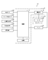
図1から図3を参照して、第1実施形態の人力駆動車用の制御装置70が説明される。人力駆動車10は、少なくとも1つの車輪を有し、少なくとも人力駆動力Hによって駆動できる乗り物である。人力駆動車10は、例えばマウンテンバイク、ロードバイク、シティバイク、カーゴバイク、および、ハンドバイク、リカンベントなど種々の種類の自転車を含む。人力駆動車10が有する車輪の数は限定されない。人力駆動車10は、例えば1輪車および3輪以上の車輪を有する乗り物も含む。人力駆動車10は、人力駆動力Hのみによって駆動できる乗り物に限定されない。人力駆動車10は、人力駆動力Hだけではなく、電気モータの駆動力を推進に利用するイーバイク(E-bike)を含む。イーバイクは、電気モータによって推進が補助される電動アシスト自転車を含む。以下、実施形態において、人力駆動車10を、電動アシスト自転車、かつ、マウンテンバイクとして説明する。
<First Embodiment>
The control device 70 for a human-powered vehicle according to the first embodiment will be described with reference to FIGS. 1 to 3. The human-powered vehicle 10 is a vehicle having at least one wheel and can be driven by at least a human-powered driving force H. The human-powered vehicle 10 includes various types of bicycles such as mountain bikes, road bikes, city bikes, cargo bikes, and hand bikes and recumbent bikes. The number of wheels of the human-powered vehicle 10 is not limited. The human-powered vehicle 10 also includes, for example, a one-wheeled vehicle and a vehicle having three or more wheels. The human-powered vehicle 10 is not limited to a vehicle that can be driven only by the human-powered driving force H. The human-powered vehicle 10 includes not only the human-powered driving force H but also an e-bike that utilizes the driving force of the electric motor for propulsion. E-bikes include electrically power assisted bicycles that are assisted by electric motors. Hereinafter, in the embodiment, the human-powered vehicle 10 will be described as an electrically assisted bicycle and a mountain bike.

人力駆動車10は、人力駆動力Hが入力されるクランク12を備える。人力駆動車10は、少なくとも1つの車輪14と、車体16と、を、さらに備える。少なくとも1つの車輪14は、後輪14Aと、前輪14Bと、を含む。車体16は、フレーム18を含む。クランク12は、フレーム18に対して回転可能な入力軸12Aと、入力軸12Aの軸方向の第1端部に設けられる第1クランクアーム12Bと、入力軸12Aの軸方向の第2端部に設けられる第2クランクアーム12Cと、を含む。本実施形態において、入力軸12Aは、クランク軸である。第1クランクアーム12Bには、第1ペダル20Aが連結される。第2クランクアーム12Cには、第2ペダル20Bが連結される。 The human-powered vehicle 10 includes a crank 12 to which a human-powered driving force H is input. The human-powered vehicle 10 further includes at least one wheel 14 and a vehicle body 16. At least one wheel 14 includes a rear wheel 14A and a front wheel 14B. The vehicle body 16 includes a frame 18. The crank 12 has an input shaft 12A rotatable with respect to the frame 18, a first crank arm 12B provided at the first axial end of the input shaft 12A, and an axial second end of the input shaft 12A. Includes a second crank arm 12C provided. In this embodiment, the input shaft 12A is a crank shaft. The first pedal 20A is connected to the first crank arm 12B. A second pedal 20B is connected to the second crank arm 12C.

駆動機構22は、入力軸12Aに連結される第1回転体24を含む。入力軸12Aと第1回転体24とは、相対回転不能に連結されてもよく、第1ワンウェイクラッチを介して連結されていてもよい。第1ワンウェイクラッチは、クランク12が前転した場合に、第1回転体24を前転させ、クランク12が後転した場合に、クランク12と第1回転体24との相対回転を許容するように構成される。第1回転体24は、スプロケット、プーリ、または、ベベルギアを含む。駆動機構22は、第2回転体26と、連結部材28とをさらに含む。連結部材28は、第1回転体24の回転力を第2回転体26に伝達する。連結部材28は、例えば、チェーン、ベルト、または、シャフトを含む。 The drive mechanism 22 includes a first rotating body 24 connected to the input shaft 12A. The input shaft 12A and the first rotating body 24 may be connected so as not to be relatively rotatable, or may be connected via a first one-way clutch. The first one-way clutch causes the first rotating body 24 to rotate forward when the crank 12 rotates forward, and allows the relative rotation between the crank 12 and the first rotating body 24 when the crank 12 rotates backward. It is composed of. The first rotating body 24 includes a sprocket, a pulley, or a bevel gear. The drive mechanism 22 further includes a second rotating body 26 and a connecting member 28. The connecting member 28 transmits the rotational force of the first rotating body 24 to the second rotating body 26. The connecting member 28 includes, for example, a chain, a belt, or a shaft.

第2回転体26は、後輪14Aに連結される。第2回転体26は、スプロケット、プーリ、または、ベベルギアを含む。第2回転体26と後輪14Aとの間には、好ましくは、第2ワンウェイクラッチが設けられている。第2ワンウェイクラッチは、第2回転体26が前転する場合に、後輪14Aを前転させ、第2回転体26が後転する場合に、第2回転体26と後輪14Aとの相対回転を許容するように構成される。人力駆動車10は、変速機を含んでいてもよい。変速機は、外装変速機および内装変速機の少なくとも1つを含む。外装変速機は、例えば、ディレイラ、第1回転体24、および、第2回転体26を含む。ディレイラは、フロントディレイラおよびリアディレイラの少なくとも1つを含む。第1回転体24は、複数のスプロケットを含んでいてもよい。第2回転体は、複数のスプロケットを含んでいてもよい。内装変速機は、例えば、後輪14Aのハブに設けられてもよく、入力軸12Aから第1回転体24までの動力伝達経路に設けられてもよい。 The second rotating body 26 is connected to the rear wheel 14A. The second rotating body 26 includes a sprocket, a pulley, or a bevel gear. A second one-way clutch is preferably provided between the second rotating body 26 and the rear wheel 14A. The second one-way clutch causes the rear wheel 14A to rotate forward when the second rotating body 26 rotates forward, and the relative between the second rotating body 26 and the rear wheel 14A when the second rotating body 26 rotates backward. It is configured to allow rotation. The human-powered vehicle 10 may include a transmission. The transmission includes at least one of an external transmission and an internal transmission. The external transmission includes, for example, a derailleur, a first rotating body 24, and a second rotating body 26. The derailleur includes at least one of a front derailleur and a rear derailleur. The first rotating body 24 may include a plurality of sprockets. The second rotating body may include a plurality of sprockets. The internal transmission may be provided, for example, in the hub of the rear wheel 14A, or may be provided in the power transmission path from the input shaft 12A to the first rotating body 24.

フレーム18には、フロントフォーク30を介して前輪14Bが取り付けられる。フロントフォーク30には、ハンドルバー34がステム32を介して連結される。本実施形態では、後輪14Aが駆動機構22によってクランク12に連結されるが、後輪14Aおよび前輪14Bの少なくとも1つが、駆動機構22によってクランク12に連結されてもよい。 The front wheel 14B is attached to the frame 18 via the front fork 30. A handlebar 34 is connected to the front fork 30 via a stem 32. In the present embodiment, the rear wheel 14A is connected to the crank 12 by the drive mechanism 22, but at least one of the rear wheel 14A and the front wheel 14B may be connected to the crank 12 by the drive mechanism 22.

人力駆動車10は、バッテリ36をさらに含む。バッテリ36は、1または複数のバッテリ素子を含む。バッテリ素子は、充電池を含む。バッテリ36は、制御装置70に電力を供給するように構成される。バッテリ36は、好ましくは、制御装置70の制御部72と電気ケーブルまたは無線通信装置を介して通信可能に接続される。バッテリ36は、例えば電力線通信(PLC;power line communication)、CAN(Controller Area Network)、または、UART(Universal Asynchronous Receiver/Transmitter)によって制御部72と通信可能である。 The human-powered vehicle 10 further includes a battery 36. The battery 36 includes one or more battery elements. The battery element includes a rechargeable battery. The battery 36 is configured to power the control device 70. The battery 36 is preferably connected to the control unit 72 of the control device 70 so as to be communicable via an electric cable or a wireless communication device. The battery 36 can communicate with the control unit 72 by, for example, power line communication (PLC), CAN (Controller Area Network), or UART (Universal Asynchronous Receiver / Transmitter).

人力駆動車10は、人力駆動車10に推進力を付与するように構成されるモータ38を含む。モータ38は、少なくとも1つの電気モータを含む。電気モータは、例えば、ブラシレスモータである。モータ38は、ペダル20A,20Bから後輪14Aまでの人力駆動力Hの動力伝達経路、および、前輪14Bの少なくとも1つに回転力を伝達するように構成される。ペダル20A,20Bから後輪14Aまでの人力駆動力Hの動力伝達経路には、後輪14Aも含まれる。本実施形態では、モータ38は、人力駆動車10のフレーム18に設けられ、第1回転体24に回転力を伝達するように構成される。 The human-powered vehicle 10 includes a motor 38 configured to impart propulsive force to the human-powered vehicle 10. The motor 38 includes at least one electric motor. The electric motor is, for example, a brushless motor. The motor 38 is configured to transmit a rotational force to at least one of the power transmission path of the human-powered driving force H from the pedals 20A and 20B to the rear wheels 14A and the front wheels 14B. The rear wheel 14A is also included in the power transmission path of the human-powered driving force H from the pedals 20A and 20B to the rear wheel 14A. In the present embodiment, the motor 38 is provided on the frame 18 of the human-powered vehicle 10 and is configured to transmit the rotational force to the first rotating body 24.

モータ38は、ハウジング40Aに設けられる。ハウジング40Aは、フレーム18に設けられる。ハウジング40Aは、例えばフレーム18に着脱可能に取り付けられる。モータ38およびモータ38が設けられるハウジング40Aを含んで、ドライブユニット40が構成される。ドライブユニット40には、モータ38の出力軸に接続される減速機が設けられてもよい。本実施形態では、ハウジング40Aは、入力軸12Aを回転可能に支持する。本実施形態では、モータ38と入力軸12Aとの間の動力伝達経路には、好ましくは、入力軸12Aを人力駆動車10が前進する方向に回転させた場合にクランク12の回転力のモータ38への伝達を抑制する第3ワンウェイクラッチが設けられる。後輪14Aおよび前輪14Bの少なくとも1つにモータ38を設ける場合、モータ38は、ハブに設けられて、ハブと共にハブモータを構成してもよい。 The motor 38 is provided in the housing 40A. The housing 40A is provided on the frame 18. The housing 40A is detachably attached to, for example, the frame 18. The drive unit 40 includes a motor 38 and a housing 40A in which the motor 38 is provided. The drive unit 40 may be provided with a speed reducer connected to the output shaft of the motor 38. In this embodiment, the housing 40A rotatably supports the input shaft 12A. In the present embodiment, the power transmission path between the motor 38 and the input shaft 12A preferably includes the motor 38 of the rotational force of the crank 12 when the input shaft 12A is rotated in the direction in which the human-powered vehicle 10 advances. A third one-way clutch that suppresses transmission to the vehicle is provided. When the motor 38 is provided on at least one of the rear wheels 14A and the front wheels 14B, the motor 38 may be provided on the hub to form a hub motor together with the hub.

制御装置70は、制御部72を含む。制御部72は、予め定める制御プログラムを実行する演算処理装置を含む。制御部72に含まれる演算処理装置は、例えばCPU(Central Processing Unit)またはMPU(Micro Processing Unit)を含む。制御部72に含まれる演算処理装置は、相互に離れた複数の場所に設けられてもよい。例えば、演算処理装置の一部は、人力駆動車10に設けられ、演算処理装置の他の一部は、インターネットに接続されるサーバに設けられてもよい。演算処理装置が、相互に離れた複数の場所に設けられる場合、演算処理装置の各部分は、無線通信装置を介して相互に通信可能に接続される。制御部72は、1または複数のマイクロコンピュータを含んでいてもよい。 The control device 70 includes a control unit 72. The control unit 72 includes an arithmetic processing unit that executes a predetermined control program. The arithmetic processing unit included in the control unit 72 includes, for example, a CPU (Central Processing Unit) or an MPU (Micro Processing Unit). The arithmetic processing units included in the control unit 72 may be provided at a plurality of locations separated from each other. For example, a part of the arithmetic processing unit may be provided in the human-powered vehicle 10, and the other part of the arithmetic processing unit may be provided in a server connected to the Internet. When the arithmetic processing units are provided at a plurality of locations separated from each other, the respective parts of the arithmetic processing units are connected to each other so as to be communicable with each other via a wireless communication device. The control unit 72 may include one or more microcomputers.

好ましくは、制御装置70は、記憶部74をさらに含む。記憶部74には、制御プログラムおよび制御処理に用いられる情報が記憶される。記憶部74は、例えば不揮発性メモリおよび揮発性メモリを含む。不揮発性メモリは、例えば、ROM(Read-Only Memory)、EPROM(Erasable Programmable Read Only Memory)、EEPROM(Electrically Erasable Programmable Read-Only Memory)、および、フラッシュメモリの少なくとも1つを含む。揮発性メモリは、例えば、RAM(Random access memory)を含む。 Preferably, the control device 70 further includes a storage unit 74. The storage unit 74 stores information used for the control program and control processing. The storage unit 74 includes, for example, a non-volatile memory and a volatile memory. The non-volatile memory includes, for example, at least one of a ROM (Read-Only Memory), an EPROM (Erasable Programmable Read Only Memory), an EEPROM (Electrically Erasable Programmable Read-Only Memory), and a flash memory. Volatile memory includes, for example, RAM (Random access memory).

制御装置70は、好ましくは、モータ38の駆動回路76をさらに備える。駆動回路76と、制御部72とは、好ましくは、ドライブユニット40のハウジング40Aに設けられる。駆動回路76と、制御部72とは、例えば同一の回路基板に設けられてもよい。駆動回路76は、インバータ回路を含む。駆動回路76は、バッテリ36からモータ38に供給される電力を制御する。駆動回路76は、制御部72と、導電線、電気ケーブルまたは無線通信装置などを介して接続される。駆動回路76は、制御部72からの制御信号に応じてモータ38を駆動させる。 The control device 70 preferably further includes a drive circuit 76 for the motor 38. The drive circuit 76 and the control unit 72 are preferably provided in the housing 40A of the drive unit 40. The drive circuit 76 and the control unit 72 may be provided on the same circuit board, for example. The drive circuit 76 includes an inverter circuit. The drive circuit 76 controls the electric power supplied from the battery 36 to the motor 38. The drive circuit 76 is connected to the control unit 72 via a conductive wire, an electric cable, a wireless communication device, or the like. The drive circuit 76 drives the motor 38 in response to a control signal from the control unit 72.

好ましくは、人力駆動車10は、車速センサ42をさらに含む。好ましくは、人力駆動車10は、クランク回転センサ44、および、人力駆動力検出部46の少なくとも1つをさらに含む。 Preferably, the human-powered vehicle 10 further includes a vehicle speed sensor 42. Preferably, the human-powered vehicle 10 further includes a crank rotation sensor 44 and at least one of a human-powered driving force detection unit 46.

車速センサ42は、人力駆動車10の車速Vに関する情報を検出するように構成される。本実施形態では、車速センサ42は、人力駆動車10の少なくとも1つの車輪14の回転速度CWに関する情報を検出するように構成される。車速センサ42は、例えば、人力駆動車10の少なくとも1つの車輪14に設けられる磁石を検出するように構成される。車速センサ42は、例えば、少なくとも1つの車輪14のうちの1つの車輪14が1回転する間に、予め定める回数の検出信号を出力するように構成される。予め定める回数は、例えば、1である。車速センサ42は、車輪14の回転速度CWに応じた信号を出力する。制御部72は、車輪14の回転速度CWに応じた信号と、車輪14の周長に関する情報とに基づいて人力駆動車10の車速Vを算出できる。記憶部74には車輪14の周長に関する情報が記憶される。 The vehicle speed sensor 42 is configured to detect information regarding the vehicle speed V of the human-powered vehicle 10. In this embodiment, the vehicle speed sensor 42 is configured to detect information about the rotational speed CW of at least one wheel 14 of the human-powered vehicle 10. The vehicle speed sensor 42 is configured to detect, for example, a magnet provided on at least one wheel 14 of the human-powered vehicle 10. The vehicle speed sensor 42 is configured to output a predetermined number of detection signals, for example, while one wheel 14 of at least one wheel 14 makes one rotation. The predetermined number of times is, for example, 1. The vehicle speed sensor 42 outputs a signal corresponding to the rotation speed CW of the wheel 14. The control unit 72 can calculate the vehicle speed V of the human-powered vehicle 10 based on the signal corresponding to the rotation speed CW of the wheel 14 and the information regarding the peripheral length of the wheel 14. Information about the circumference of the wheel 14 is stored in the storage unit 74.

車速センサ42は、例えばリードスイッチを構成する磁性リード、または、ホール素子などの磁気センサを含む。車速センサ42は、人力駆動車10のフレーム18のチェーンステイに取り付けられ、後輪14Aに取り付けられる磁石を検出する構成としてもよく、フロントフォーク30に設けられ、前輪14Bに取り付けられる磁石を検出する構成としてもよい。本実施形態において、車速センサ42は、車輪14が一回転した場合に、リードスイッチが磁石を1回検出するように構成される。車速センサ42は、人力駆動車10の車速Vに関する情報を取得できればどのような構成であってもよく、車輪14に設けられる磁石を検出する構成に限らず、例えば、ディスクブレーキに設けられるスリットを検出するように構成されてもよく、光学センサなどを含んで構成されてもよく、GPS(Global Positioning System)受信機を含んで構成されてもよい。車速センサ42がGPS受信器を含む場合、制御部72は、時間と移動距離とに応じて車速Vを算出できる。車速センサ42は、無線通信装置または電気ケーブルを介して、制御部72に接続される。 The vehicle speed sensor 42 includes, for example, a magnetic lead constituting a reed switch or a magnetic sensor such as a Hall element. The vehicle speed sensor 42 may be configured to be attached to the chain stay of the frame 18 of the human-powered vehicle 10 to detect a magnet attached to the rear wheel 14A, or may be provided on the front fork 30 to detect a magnet attached to the front wheel 14B. It may be configured. In the present embodiment, the vehicle speed sensor 42 is configured such that the reed switch detects the magnet once when the wheel 14 makes one rotation. The vehicle speed sensor 42 may have any configuration as long as it can acquire information on the vehicle speed V of the human-powered vehicle 10, and is not limited to the configuration for detecting the magnet provided on the wheel 14, for example, a slit provided on the disc brake. It may be configured to detect, may be configured to include an optical sensor or the like, or may be configured to include a GPS (Global Positioning System) receiver. When the vehicle speed sensor 42 includes the GPS receiver, the control unit 72 can calculate the vehicle speed V according to the time and the moving distance. The vehicle speed sensor 42 is connected to the control unit 72 via a wireless communication device or an electric cable.

クランク回転センサ44は、入力軸12Aの回転速度NCに関する情報を検出するように構成される。クランク回転センサ44は、例えば、人力駆動車10のフレーム18またはドライブユニット40に設けられる。クランク回転センサ44は、ドライブユニット40のハウジング40Aに設けられてもよい。クランク回転センサ44は、磁界の強度に応じた信号を出力する磁気センサを含んで構成される。周方向に磁界の強度が変化する環状の磁石が、入力軸12A、入力軸12Aに連動して回転する部材、または、入力軸12Aから第1回転体24までの間の動力伝達経路に設けられる。入力軸12Aに連動して回転する部材は、モータ38の出力軸を含んでもよい。 The crank rotation sensor 44 is configured to detect information regarding the rotation speed NC of the input shaft 12A. The crank rotation sensor 44 is provided, for example, in the frame 18 or the drive unit 40 of the human-powered vehicle 10. The crank rotation sensor 44 may be provided in the housing 40A of the drive unit 40. The crank rotation sensor 44 includes a magnetic sensor that outputs a signal according to the strength of the magnetic field. An annular magnet whose magnetic field strength changes in the circumferential direction is provided in the input shaft 12A, a member that rotates in conjunction with the input shaft 12A, or in the power transmission path between the input shaft 12A and the first rotating body 24. .. The member that rotates in conjunction with the input shaft 12A may include the output shaft of the motor 38.

クランク回転センサ44は、入力軸12Aの回転速度NCに応じた信号を出力する。例えば、入力軸12Aと第1回転体24との間に第1ワンウェイクラッチが設けられない場合、磁石は、第1回転体24に設けられてもよい。クランク回転センサ44は、入力軸12Aの回転速度NCに関する情報を取得できればどのような構成であってもよく、磁気センサに代えて光学センサ、加速度センサ、ジャイロセンサ、またはトルクセンサなどを含んでいてもよい。クランク回転センサ44は、無線通信装置または電気ケーブルを介して、制御部72に接続される。 The crank rotation sensor 44 outputs a signal corresponding to the rotation speed NC of the input shaft 12A. For example, if the first one-way clutch is not provided between the input shaft 12A and the first rotating body 24, the magnet may be provided on the first rotating body 24. The crank rotation sensor 44 may have any configuration as long as it can acquire information on the rotation speed NC of the input shaft 12A, and includes an optical sensor, an acceleration sensor, a gyro sensor, a torque sensor, and the like in place of the magnetic sensor. It is also good. The crank rotation sensor 44 is connected to the control unit 72 via a wireless communication device or an electric cable.

人力駆動力検出部46は、人力駆動力Hに関する情報を検出するように構成される。人力駆動力検出部46は、例えば、人力駆動車10のフレーム18、ドライブユニット40、クランク12、または、ペダル20A,20Bに設けられる。人力駆動力検出部46は、ドライブユニット40のハウジング40Aに設けられてもよい。人力駆動力検出部46は、例えば、トルクセンサを含む。トルクセンサは、人力駆動力Hによってクランク12に与えられるトルクに応じた信号を出力するように構成される。トルクセンサは、例えば、動力伝達経路に第1ワンウェイクラッチが設けられる場合、好ましくは、第1ワンウェイクラッチよりも動力伝達経路の上流側に設けられる。トルクセンサは、歪センサ、磁歪センサ、または、圧力センサなどを含む。歪センサは、歪ゲージを含む。 The human-powered driving force detection unit 46 is configured to detect information regarding the human-powered driving force H. The human-powered driving force detecting unit 46 is provided, for example, on the frame 18, the drive unit 40, the crank 12, or the pedals 20A and 20B of the human-powered vehicle 10. The human-powered driving force detecting unit 46 may be provided in the housing 40A of the drive unit 40. The human-powered driving force detection unit 46 includes, for example, a torque sensor. The torque sensor is configured to output a signal corresponding to the torque applied to the crank 12 by the human-powered driving force H. For example, when the first one-way clutch is provided in the power transmission path, the torque sensor is preferably provided on the upstream side of the power transmission path with respect to the first one-way clutch. The torque sensor includes a strain sensor, a magnetostriction sensor, a pressure sensor, and the like. The strain sensor includes a strain gauge.

トルクセンサは、動力伝達経路に含まれる部材、または、動力伝達経路に含まれる部材の近傍に設けられる。動力伝達経路に含まれる部材は、例えば、入力軸12A、入力軸12Aと第1回転体24との間において人力駆動力Hを伝達する部材、クランクアーム12B,12C、または、ペダル20A,20Bである。人力駆動力検出部46は、無線通信装置または電気ケーブルを介して、制御部72に接続される。人力駆動力検出部46は、人力駆動力Hに関する情報を取得できればどのような構成であってもよく、例えば、ペダル20A,20Bに与えられる圧力を検出するセンサ、または、チェーンの張力を検出するセンサなどを含んでいてもよい。 The torque sensor is provided in the vicinity of a member included in the power transmission path or a member included in the power transmission path. The member included in the power transmission path is, for example, an input shaft 12A, a member that transmits a human-powered driving force H between the input shaft 12A and the first rotating body 24, crank arms 12B, 12C, or pedals 20A, 20B. be. The human-powered driving force detection unit 46 is connected to the control unit 72 via a wireless communication device or an electric cable. The human-powered driving force detecting unit 46 may have any configuration as long as it can acquire information on the human-powered driving force H. For example, the sensor for detecting the pressure applied to the pedals 20A and 20B or the tension of the chain is detected. It may include a sensor or the like.

人力駆動車10は、ブレーキ装置52、および、ブレーキ装置52の操作装置54をさらに含む。ブレーキ装置52は、好ましくは、人力駆動車10は、クランク回転センサ44、および、人力駆動力検出部46の少なくとも1つをさらに含む。ブレーキ装置52は、フレーム18およびフロントフォーク30に設けられ、車輪14に制動力を付与するように構成される。ブレーキ装置52は、ディスクブレーキであってもよく、リムブレーキであってもよく、ローラブレーキであってもよい。操作装置54は、例えば、ハンドルバー34に設けられる。
操作装置54は、ブレーキレバーと、ブレーキレバーの操作状態に応じた情報を出力するブレーキセンサとを有する。ブレーキセンサは、例えば、磁気センサ、光学センサ、または、ポテンショメータを含む。ブレーキセンサは、無線通信装置または電気ケーブルを介して、制御部72に接続される。ブレーキセンサは、操作装置54ではなく、ボーデンケーブル、または、ブレーキ装置52に設けられてもよい。ブレーキセンサは、ブレーキ装置52の操作状態を検出できれば、どのようなセンサによって構成されてもよい。本実施形態では、ブレーキレバーが操作されると、ブレーキセンサから制御部72に予め定める信号が出力される。
The human-powered vehicle 10 further includes a brake device 52 and an operation device 54 of the brake device 52. The brake device 52 preferably further includes at least one of the crank rotation sensor 44 and the human-powered driving force detection unit 46 in the human-powered vehicle 10. The braking device 52 is provided on the frame 18 and the front fork 30 and is configured to apply braking force to the wheels 14. The brake device 52 may be a disc brake, a rim brake, or a roller brake. The operating device 54 is provided on the handlebar 34, for example.
The operating device 54 has a brake lever and a brake sensor that outputs information according to the operating state of the brake lever. Brake sensors include, for example, magnetic sensors, optical sensors, or potentiometers. The brake sensor is connected to the control unit 72 via a wireless communication device or an electric cable. The brake sensor may be provided on the Bowden cable or the brake device 52 instead of the operating device 54. The brake sensor may be configured by any sensor as long as it can detect the operating state of the brake device 52. In the present embodiment, when the brake lever is operated, a predetermined signal is output from the brake sensor to the control unit 72.

制御部72は、人力駆動車10に推進力を付与するモータ38を制御するように構成される。好ましくは、制御部72は、人力駆動車10に入力される人力駆動力Hに応じてモータ38を制御するように構成される。人力駆動力Hは、トルクによって表されてもよく、仕事率によって表されてもよい。 The control unit 72 is configured to control the motor 38 that applies propulsive force to the human-powered vehicle 10. Preferably, the control unit 72 is configured to control the motor 38 according to the human-powered driving force H input to the human-powered vehicle 10. The human-powered driving force H may be expressed by torque or by power.

制御部72は、例えば、モータ38によるアシストレベルAが、予め定めるアシストレベルAになるようにモータ38を制御するように構成される。アシストレベルAは、人力駆動力Hに対するモータ38によるアシスト力の比率、または、クランク12の回転速度に対するモータ38によるアシスト力の比率を含む。人力駆動力Hに対するモータ38によるアシスト力の比率を、アシスト比率と記載する場合がある。制御部72は、例えば、人力駆動力Hに対して、モータ38によるアシスト力が予め定める比率になるように、モータ38を制御するように構成される。人力駆動力Hは、ユーザがクランク12を回転させることによって発生する人力駆動車10の推進力に対応する。アシスト力は、モータ38によって発生する人力駆動車10の推進力に対応する。予め定める比率は、一定ではなく、例えば、人力駆動力Hに応じて変化してもよく、入力軸12Aの回転速度NCに応じて変化してもよく、車速Vに応じて変化してもよく、人力駆動力H、入力軸12Aの回転速度NC、および、車速Vのうちのいずれか2つ、または、全てに応じて変化してもよい。 The control unit 72 is configured to control the motor 38 so that the assist level A by the motor 38 becomes, for example, a predetermined assist level A. The assist level A includes the ratio of the assist force by the motor 38 to the human-powered driving force H or the ratio of the assist force by the motor 38 to the rotation speed of the crank 12. The ratio of the assist force by the motor 38 to the human-powered driving force H may be referred to as an assist ratio. The control unit 72 is configured to control the motor 38 so that, for example, the assist force of the motor 38 has a predetermined ratio to the human-powered driving force H. The human-powered driving force H corresponds to the propulsive force of the human-powered vehicle 10 generated by the user rotating the crank 12. The assist force corresponds to the propulsive force of the human-powered vehicle 10 generated by the motor 38. The predetermined ratio is not constant and may change, for example, according to the human-powered driving force H, may change according to the rotation speed NC of the input shaft 12A, or may change according to the vehicle speed V. , Human-powered driving force H, rotational speed NC of the input shaft 12A, and vehicle speed V may be changed according to any two or all of them.

人力駆動力Hおよびアシスト力をトルクによって表わす場合、人力駆動力Hを人力トルクHTと記載し、アシスト力をアシストトルクMTと記載する。人力駆動力Hおよびアシスト力を仕事率によって表わす場合、人力駆動力Hを人力仕事率HWと記載し、アシスト力をアシスト仕事率MWと記載する。比率は、人力駆動車10の人力トルクHTに対するアシストトルクMTのトルク比率であってもよく、人力仕事率HWに対するモータ38によるアシスト仕事率MWの比率であってもよい。 When the human-powered driving force H and the assisting force are expressed by torque, the human-powered driving force H is described as the human-powered torque HT, and the assisting force is described as the assist torque MT. When the human power driving force H and the assisting force are expressed by the work rate, the human power driving force H is described as the human power work rate HW and the assist force is described as the assist power MW. The ratio may be the torque ratio of the assist torque MT to the human power torque HT of the human power drive vehicle 10, or may be the ratio of the assist power MW by the motor 38 to the human power work rate HW.

本実施形態のドライブユニット40では、クランク12が変速機を介さずに第1回転体24に接続され、かつ、モータ38の出力Mが第1回転体24に入力される。クランク12が変速機を介さずに第1回転体24に接続され、かつ、モータ38の出力Mが第1回転体24に入力される場合、人力駆動力Hは、ユーザがクランク12を回転させることによって第1回転体24に入力される駆動力に対応する。クランク12が変速機を介さずに第1回転体24に接続され、かつ、モータ38の出力Mが第1回転体24に入力される場合、アシスト力は、モータ38が回転することによって第1回転体24に入力される駆動力に対応する。モータ38の出力Mが減速機を介して第1回転体24に入力される場合は、アシスト力は、減速機の出力に対応する。 In the drive unit 40 of the present embodiment, the crank 12 is connected to the first rotating body 24 without going through a transmission, and the output M of the motor 38 is input to the first rotating body 24. When the crank 12 is connected to the first rotating body 24 without going through the transmission and the output M of the motor 38 is input to the first rotating body 24, the human-powered driving force H causes the user to rotate the crank 12. This corresponds to the driving force input to the first rotating body 24. When the crank 12 is connected to the first rotating body 24 without going through the transmission and the output M of the motor 38 is input to the first rotating body 24, the assist force is first due to the rotation of the motor 38. Corresponds to the driving force input to the rotating body 24. When the output M of the motor 38 is input to the first rotating body 24 via the reducer, the assist force corresponds to the output of the reducer.

後輪14Aにモータ38が設けられる場合、人力駆動力Hは、ユーザのみによって駆動される後輪14Aの出力に対応する。後輪14Aにモータ38が設けられる場合、アシスト力は、モータ38のみによって駆動される後輪14Aの出力に対応する。前輪14Bにモータ38が設けられる場合、人力駆動力Hは、ユーザのみによって駆動される後輪14Aの出力に対応する。前輪14Bにモータ38が設けられる場合、アシスト力は、モータ38のみによって駆動される前輪14Bの出力に対応する。 When the motor 38 is provided on the rear wheel 14A, the human-powered driving force H corresponds to the output of the rear wheel 14A driven only by the user. When the motor 38 is provided on the rear wheel 14A, the assist force corresponds to the output of the rear wheel 14A driven only by the motor 38. When the motor 38 is provided on the front wheel 14B, the human-powered driving force H corresponds to the output of the rear wheel 14A driven only by the user. When the motor 38 is provided on the front wheel 14B, the assist force corresponds to the output of the front wheel 14B driven only by the motor 38.

制御部72は、アシスト力が最大値Mmax以下になるようにモータ38を制御するように構成される。モータ38の出力Mが第1回転体24に入力され、かつ、アシスト力がトルクによって表される場合、制御部72は、アシストトルクMTが最大値MTX以下になるようにモータ38を制御するように構成される。好ましくは、最大値MTXは、20Nm以上200Nm以下の範囲の値である。モータ38の出力Mが第1回転体24に入力され、かつ、アシスト力が仕事率によって表される場合、制御部72は、アシスト仕事率MWが最大値MWX以下になるようにモータ38を制御するように構成される。 The control unit 72 is configured to control the motor 38 so that the assist force becomes equal to or less than the maximum value Mmax. When the output M of the motor 38 is input to the first rotating body 24 and the assist force is represented by the torque, the control unit 72 controls the motor 38 so that the assist torque MT is equal to or less than the maximum value MTX. It is composed of. Preferably, the maximum value MTX is a value in the range of 20 Nm or more and 200 Nm or less. When the output M of the motor 38 is input to the first rotating body 24 and the assist force is represented by the work rate, the control unit 72 controls the motor 38 so that the assist work rate MW is equal to or less than the maximum value MWX. It is configured to do.

好ましくは、人力駆動車10は、加速度検出部48を備える。加速度検出部48は、人力駆動車10が前進する方向における加速度に応じた信号を出力するように構成される。加速度検出部48は、加速度センサを含んでいてもよく、車速センサ42を含んでいてもよい。加速度検出部48は、無線通信装置または電気ケーブルを介して、制御部72に接続される。加速度検出部48が車速センサ42を含む場合、制御部72は、車速Vを微分することによって人力駆動車10が前進する方向における加速度に関する情報を取得する。 Preferably, the human-powered vehicle 10 includes an acceleration detection unit 48. The acceleration detection unit 48 is configured to output a signal corresponding to the acceleration in the direction in which the human-powered vehicle 10 moves forward. The acceleration detection unit 48 may include an acceleration sensor or may include a vehicle speed sensor 42. The acceleration detection unit 48 is connected to the control unit 72 via a wireless communication device or an electric cable. When the acceleration detection unit 48 includes the vehicle speed sensor 42, the control unit 72 acquires information on the acceleration in the direction in which the human-powered vehicle 10 advances by differentiating the vehicle speed V.

制御部72は、加速度検出部48の出力に応じて、人力駆動車10の進行方向における人力駆動車10の減速度Dを算出するように構成されていてもよい。減速度Dは、減速するほど大きくなる値として表される。減速度Dが大きいほど、人力駆動車10の車速Vは大きく減少する。
The control unit 72 may be configured to calculate the deceleration D of the human-powered vehicle 10 in the traveling direction of the human-powered vehicle 10 according to the output of the acceleration detection unit 48. The deceleration D is expressed as a value that increases as the vehicle decelerates. The larger the deceleration D, the greater the decrease in the vehicle speed V of the human-powered vehicle 10.

制御部72は、人力駆動車10に推進力を付与するモータ38を制御するように構成される。制御部72は、予め定める条件が満たされる場合、モータ38によるアシストレベルA、モータ38の出力Mの最大値Mmax、および、モータ38の出力Mの少なくとも1つを増加させる。 The control unit 72 is configured to control the motor 38 that applies propulsive force to the human-powered vehicle 10. When the predetermined conditions are satisfied, the control unit 72 increases the assist level A by the motor 38, the maximum value Mmax of the output M of the motor 38, and at least one of the output M of the motor 38.

好ましくは、予め定める条件は、人力駆動車10の進行方向における人力駆動車10の減速度Dが第1閾値DX以上であるという第1条件を含む。第1閾値DXは、例えば、3km/h/秒以上、かつ、8.5km/h/秒以下である。予め定める条件は、第1条件に代えて、人力駆動車10の進行方向における人力駆動車10の減速度Dが、第1閾値DX以上であり、かつ、第5閾値DV以下、という第7条件を含んでいてもよい。第5閾値DVは、第1閾値DXよりも大きい。第5閾値DVは、例えば、3km/h/秒以上、かつ、8.5km/h/秒以下である。例えば、人力駆動車10が走行している道路が、下り坂から上り坂に急激に変化する場合に、第1条件、または、第7条件が満たされる。 Preferably, the predetermined condition includes the first condition that the deceleration D of the human-powered vehicle 10 in the traveling direction of the human-powered vehicle 10 is equal to or greater than the first threshold DX. The first threshold DX is, for example, 3 km / h / sec or more and 8.5 km / h / sec or less. The predetermined condition is a seventh condition that, instead of the first condition, the deceleration D of the human-powered vehicle 10 in the traveling direction of the human-powered vehicle 10 is equal to or greater than the first threshold DX and is equal to or less than the fifth threshold DV. May include. The fifth threshold DV is larger than the first threshold DX. The fifth threshold DV is, for example, 3 km / h / sec or more and 8.5 km / h / sec or less. For example, when the road on which the human-powered vehicle 10 is traveling suddenly changes from a downhill to an uphill, the first condition or the seventh condition is satisfied.

好ましくは、第7条件は、人力駆動車10の進行方向における人力駆動車10の減速度Dが、3km/h/秒以上、かつ、8.5km/h/秒以下の場合に満たされる。さらに好ましくは、第7条件は、人力駆動車10の進行方向における人力駆動車10の減速度Dが、4km/h/秒以上、かつ、7km/h/秒以下の場合に満たされる。人力駆動車10の進行方向における人力駆動車10の減速度Dが第5閾値DVを超える場合は、ライダが意図的にブレーキ装置52によって人力駆動車10を制動している可能性が高い。制御部72は、予め定める条件が第7条件を含むことによって、ライダが意図的にブレーキ装置52によって人力駆動車10を制動している場合に、モータ38によるアシストレベルA、モータ38の出力Mの最大値Mmax、および、モータ38の出力Mの少なくとも1つが増加することを抑制できる。 Preferably, the seventh condition is satisfied when the deceleration D of the human-powered vehicle 10 in the traveling direction of the human-powered vehicle 10 is 3 km / h / sec or more and 8.5 km / h / sec or less. More preferably, the seventh condition is satisfied when the deceleration D of the human-powered vehicle 10 in the traveling direction of the human-powered vehicle 10 is 4 km / h / sec or more and 7 km / h / sec or less. When the deceleration D of the human-powered vehicle 10 in the traveling direction of the human-powered vehicle 10 exceeds the fifth threshold DV, it is highly possible that the rider intentionally brakes the human-powered vehicle 10 by the braking device 52. The control unit 72 has an assist level A by the motor 38 and an output M of the motor 38 when the rider intentionally brakes the human-powered vehicle 10 by the brake device 52 because the predetermined condition includes the seventh condition. It is possible to suppress an increase in the maximum value Mmax of Mmax and at least one of the output M of the motor 38.

好ましくは、予め定める条件は、人力駆動力Hが入力される入力軸12Aが回転しているという第2条件をさらに含む。制御部72は、例えば、入力軸12Aの回転速度NCが予め定める回転速度CXよりも大きい場合、入力軸12Aが回転していると判定する。予め定める回転速度CXは、好ましくは、0rpm以上かつ5rpm以下の範囲の値である。予め定める回転速度CXは、例えば、0rpmである。 Preferably, the predetermined condition further includes a second condition that the input shaft 12A into which the human-powered driving force H is input is rotating. For example, when the rotation speed NC of the input shaft 12A is larger than the predetermined rotation speed CX, the control unit 72 determines that the input shaft 12A is rotating. The predetermined rotation speed CX is preferably a value in the range of 0 rpm or more and 5 rpm or less. The predetermined rotation speed CX is, for example, 0 rpm.

好ましくは、予め定める条件は、人力駆動車10に人力駆動力Hが入力されているという第3条件をさらに含む。制御部72は、例えば、人力駆動力Hが予め定める駆動力HXよりも大きい場合、人力駆動力Hが入力されていると判定する。予め定める予め定める駆動力HXは、例えば、0Nm以上かつ5Nm以下の範囲の値である。予め定める予め定める駆動力HXは、例えば、0Nmである。 Preferably, the predetermined condition further includes a third condition that the human-powered driving force H is input to the human-powered vehicle 10. For example, when the human-powered driving force H is larger than the predetermined driving force HX, the control unit 72 determines that the human-powered driving force H is input. The predetermined driving force HX is, for example, a value in the range of 0 Nm or more and 5 Nm or less. The predetermined driving force HX is, for example, 0 Nm.

好ましくは、予め定める条件は、人力駆動車10のブレーキ装置52の操作装置54が操作されていないという第4条件をさらに含む。
好ましくは、予め定める条件は、第1条件が満たされる直前に、人力駆動車10の車速Vが増加するという第5条件を含む。制御部72は、例えば、車速Vが増加してから予め定める期間以内に減速度Dが第1閾値DX以上になった場合、第5条件を満たされると判定する。予め定める期間は、例えば、0.1秒以上かつ5秒以下の範囲である。
Preferably, the predetermined condition further includes a fourth condition that the operation device 54 of the brake device 52 of the human-powered vehicle 10 is not operated.
Preferably, the predetermined condition includes the fifth condition that the vehicle speed V of the human-powered vehicle 10 increases immediately before the first condition is satisfied. The control unit 72 determines that the fifth condition is satisfied, for example, when the deceleration D becomes equal to or higher than the first threshold value DX within a predetermined period after the vehicle speed V increases. The predetermined period is, for example, in the range of 0.1 seconds or more and 5 seconds or less.

予め定める条件は、第1条件のみを含んでいてもよい。予め定める条件は、第7条件のみを含んでいてもよい。予め定める条件は、第1条件または第7条件に加えて、第2条件、第3条件、第4条件、および、第5条件の少なくとも1つを含んでいてもよい。好ましくは、制御部72は、予め定める条件に含まれる全ての条件が満たされる場合、予め定める条件が満たされると判定する。 The predetermined condition may include only the first condition. The predetermined condition may include only the seventh condition. The predetermined condition may include at least one of the second condition, the third condition, the fourth condition, and the fifth condition in addition to the first condition or the seventh condition. Preferably, the control unit 72 determines that the predetermined conditions are satisfied when all the conditions included in the predetermined conditions are satisfied.

図3を参照して、制御部72がモータ38を制御する制御状態を切り替える処理が説明される。制御部72は、例えば、制御部72に電力が供給されると、処理を開始して図3に示すフローチャートのステップS11に移行する。制御部72は、図3のフローチャートが終了すると、例えば、電力の供給が停止されるまでは、予め定める周期後にステップS11からの処理を繰り返す。 A process of switching the control state in which the control unit 72 controls the motor 38 will be described with reference to FIG. For example, when power is supplied to the control unit 72, the control unit 72 starts processing and proceeds to step S11 of the flowchart shown in FIG. When the flowchart of FIG. 3 is completed, the control unit 72 repeats the process from step S11 after a predetermined cycle, for example, until the power supply is stopped.

制御部72は、ステップS11において、第1条件が満たされるか否かを判定する。制御部72は、第1条件が満たされない場合、処理を終了する。制御部72は、第1条件が満たされる場合、ステップS12に移行する。制御部72は、減速度Dを複数回取得し、減速度Dが複数回連続して、第1閾値DX以上である場合、ステップS11において、第1条件が満たされると判定してもよい。制御部72が減速度Dを取得する周期は、例えば、予め定める時間が経過する毎であってもよく、車輪14が1回転する毎であってもよい。 The control unit 72 determines in step S11 whether or not the first condition is satisfied. If the first condition is not satisfied, the control unit 72 ends the process. When the first condition is satisfied, the control unit 72 proceeds to step S12. The control unit 72 may acquire the deceleration D a plurality of times, and if the deceleration D is continuously performed a plurality of times and is equal to or greater than the first threshold value DX, it may be determined in step S11 that the first condition is satisfied. The cycle in which the control unit 72 acquires the deceleration D may be, for example, every time a predetermined time elapses, or every time the wheel 14 makes one rotation.

制御部72は、ステップS11において、第1条件に代えて、第7条件が満たされるか否かを判定してもよい。制御部72は、第7条件が満たされない場合、処理を終了する。制御部72は、第7条件が満たされる場合、ステップS12に移行する。制御部72は、減速度Dを複数回取得し、減速度Dが複数回連続して、第1閾値DX以上であり、かつ、第5閾値以下である場合、ステップS11において、第7条件が満たされるか否かを判定してもよい。 In step S11, the control unit 72 may determine whether or not the seventh condition is satisfied instead of the first condition. If the seventh condition is not satisfied, the control unit 72 ends the process. When the seventh condition is satisfied, the control unit 72 proceeds to step S12. When the control unit 72 acquires the deceleration D a plurality of times and the deceleration D is continuously equal to or greater than the first threshold value DX and is equal to or less than the fifth threshold value, the seventh condition is set in step S11. It may be determined whether or not it is satisfied.

制御部72は、ステップS12において、第2条件が満たされるか否かを判定する。制御部72は、第2条件が満たされない場合、処理を終了する。制御部72は、第2条件が満たされる場合、ステップS13に移行する。制御部72は、入力軸12Aの回転速度NCを複数回取得し、入力軸12Aの回転速度NCが複数回連続して、予め定める回転速度CXよりも大きい場合、ステップS12において、第2条件が満たされると判定してもよい。制御部72が予め定める回転速度CXを取得する周期は、例えば、予め定める時間が経過する毎であってもよい。 The control unit 72 determines in step S12 whether or not the second condition is satisfied. If the second condition is not satisfied, the control unit 72 ends the process. When the second condition is satisfied, the control unit 72 proceeds to step S13. When the control unit 72 acquires the rotation speed NC of the input shaft 12A a plurality of times and the rotation speed NC of the input shaft 12A is continuously larger than the predetermined rotation speed CX, the second condition is set in step S12. It may be determined that it is satisfied. The cycle for acquiring the rotation speed CX predetermined by the control unit 72 may be, for example, every time a predetermined time elapses.

制御部72は、ステップS13において、第3条件が満たされるか否かを判定する。制御部72は、第3条件が満たされない場合、処理を終了する。制御部72は、第3条件が満たされる場合、ステップS14に移行する。制御部72は、人力駆動力Hを複数回取得し、人力駆動力Hが複数回連続して、予め定める駆動力HXよりも大きい場合、ステップS13において、第3条件が満たされると判定してもよい。制御部72が予め定める駆動力HXを取得する周期は、例えば、予め定める時間が経過する毎であってもよい。 The control unit 72 determines in step S13 whether or not the third condition is satisfied. If the third condition is not satisfied, the control unit 72 ends the process. When the third condition is satisfied, the control unit 72 proceeds to step S14. The control unit 72 acquires the human-powered driving force H a plurality of times, and if the human-powered driving force H is continuously larger than the predetermined driving force HX a plurality of times, it is determined in step S13 that the third condition is satisfied. May be good. The cycle for acquiring the driving force HX predetermined by the control unit 72 may be, for example, every time a predetermined time elapses.

制御部72は、ステップS14において、第4条件が満たされるか否かを判定する。制御部72は、第4条件が満たされない場合、処理を終了する。制御部72は、第4条件が満たされる場合、ステップS15に移行する。制御部72は、ブレーキセンサによって検出される情報を複数回取得し、ブレーキセンサによって検出される情報が複数回連続して、ブレーキ装置52が操作されていないことを示す場合、ステップS14において、第3条件が満たされると判定してもよい。制御部72がブレーキセンサによって検出される情報を取得する周期は、例えば、予め定める時間が経過する毎であってもよい。 The control unit 72 determines in step S14 whether or not the fourth condition is satisfied. If the fourth condition is not satisfied, the control unit 72 ends the process. When the fourth condition is satisfied, the control unit 72 proceeds to step S15. When the control unit 72 acquires the information detected by the brake sensor a plurality of times and the information detected by the brake sensor is continuously performed a plurality of times to indicate that the brake device 52 is not operated, the first step is in step S14. It may be determined that the three conditions are satisfied. The cycle in which the control unit 72 acquires the information detected by the brake sensor may be, for example, every time a predetermined time elapses.

制御部72は、ステップS15において、第5条件が満たされるか否かを判定する。制御部72は、第5条件が満たされない場合、処理を終了する。制御部72は、第5条件が満たされる場合、ステップS16に移行する。制御部72は、ステップS16において、アシストレベルA、モータ38の出力Mの最大値Mmax、および、モータ38の出力Mの少なくとも1つを増加させ、処理を終了する。 The control unit 72 determines in step S15 whether or not the fifth condition is satisfied. If the fifth condition is not satisfied, the control unit 72 ends the process. When the fifth condition is satisfied, the control unit 72 proceeds to step S16. In step S16, the control unit 72 increases the assist level A, the maximum value Mmax of the output M of the motor 38, and at least one of the output M of the motor 38, and ends the process.

ステップS11、ステップS12、ステップS13、ステップS14、および、ステップS15の処理の順序は、入れ替えてもよい。ステップS11、ステップS12、ステップS13、ステップS14、および、ステップS15のうちの少なくとも1つにおける判定がNOであれば、ステップS16の処理は実行されない。本実施形態では、ステップS11、ステップS12、ステップS13、ステップS14、および、ステップS15のうちの全てがYESであれば、ステップS16の処理が実行される。ステップS12、ステップS13、ステップS14、および、ステップS15の少なくとも1つは、省略されてもよい。 The processing order of step S11, step S12, step S13, step S14, and step S15 may be changed. If the determination in at least one of step S11, step S12, step S13, step S14, and step S15 is NO, the process of step S16 is not executed. In the present embodiment, if all of step S11, step S12, step S13, step S14, and step S15 are YES, the process of step S16 is executed. At least one of step S12, step S13, step S14, and step S15 may be omitted.

人力駆動車10の車速Vが予め定める速度VX以上の場合、制御部72は、減速度Dに応じてモータ38を制御する制御状態を切り替える処理を禁止してもよい。予め定める速度VXは、例えば、時速30kmから45kmの範囲の値である。 When the vehicle speed V of the human-powered vehicle 10 is equal to or higher than the predetermined speed VX, the control unit 72 may prohibit the process of switching the control state for controlling the motor 38 according to the deceleration D. The predetermined speed VX is, for example, a value in the range of 30 km / h to 45 km / h.

本実施形態において、減速度Dを、減速エネルギに置き換えてもよい。減速エネルギは、1/2×M×Vによって表される。Mは、人力駆動車10の重量であってもよく、人力駆動車10の重量とライダの体重との合計値であってもよい。人力駆動車10の重量に関する情報、または、人力駆動車10の重量とライダの体重との合計値に関する情報は、記憶部74に記憶される。第1閾値DX、第5閾値DVは、減速エネルギに対応する値に変更される。例えば、時速10kmから減速する場合と、時速35kmから減速する場合とにおいて、減速度Dは等しくても、減速エネルギが異なるので、制御部72は、減速エネルギを用いてモータ38を制御する制御状態を切り替えると、より好ましいモータ38の制御を実現できる。 In the present embodiment, the deceleration D may be replaced with deceleration energy. The deceleration energy is represented by 1/2 x M x V 2 . M may be the weight of the human-powered vehicle 10 or may be the total value of the weight of the human-powered vehicle 10 and the weight of the rider. Information on the weight of the human-powered vehicle 10 or information on the total value of the weight of the human-powered vehicle 10 and the weight of the rider is stored in the storage unit 74. The first threshold value DX and the fifth threshold value DV are changed to values corresponding to the deceleration energy. For example, in the case of decelerating from 10 km / h and the case of decelerating from 35 km / h, even if the deceleration D is the same, the deceleration energy is different, so that the control unit 72 controls the motor 38 using the deceleration energy. By switching between, more preferable control of the motor 38 can be realized.

<第2実施形態>
図4および図5を参照して、第2実施形態の制御装置70について説明する。第2実施形態の制御装置70は、制御部72が変速機56を制御可能に構成される点と、図3のフローチャートの処理に代えて図5のフローチャートの処理を実行する点以外は第1実施形態の制御装置70と同様の構成を含む。このため、第2実施形態の制御装置70のうちの第1実施形態と共通する構成については、第1実施形態と同一の符号を付し、重複する説明を省略する。
<Second Embodiment>
The control device 70 of the second embodiment will be described with reference to FIGS. 4 and 5. The control device 70 of the second embodiment is the first except that the control unit 72 is configured to be able to control the transmission 56 and that the processing of the flowchart of FIG. 5 is executed instead of the processing of the flowchart of FIG. It includes the same configuration as the control device 70 of the embodiment. Therefore, the configuration common to the first embodiment of the control device 70 of the second embodiment is designated by the same reference numerals as those of the first embodiment, and duplicate description will be omitted.

本実施形態では、人力駆動車10は、変速機56を含む。変速機56は、人力駆動車10の人力駆動力Hの伝達経路に設けられ、かつ、変速比Rを変更するように構成される。 In the present embodiment, the human-powered vehicle 10 includes a transmission 56. The transmission 56 is provided in the transmission path of the human-powered driving force H of the human-powered vehicle 10, and is configured to change the gear ratio R.

変速機56は、人力駆動力Hの伝達経路に設けられ、変速比Rを変更するように構成される。変速機56は、複数の変速ステージを有する。各変速ステージに対応する変速比Rは、相互に異なる。変速ステージの数は、例えば3から30の範囲である。変速比Rは、入力軸12Aの回転速度NCに対する駆動輪の回転速度の比率である。本実施形態では、駆動輪は後輪14Aである。変速機56は、例えばフロントディレイラ、リアディレイラ、および、内装変速機の少なくとも1つを含む。変速機56が内装変速機を含む場合、内装変速機は、例えば、後輪14Aのハブに設けられる。内装変速機は、CVTを含んでいてもよい。 The transmission 56 is provided in the transmission path of the human-powered driving force H, and is configured to change the gear ratio R. The transmission 56 has a plurality of shift stages. The gear ratios R corresponding to each shift stage are different from each other. The number of shift stages is, for example, in the range of 3 to 30. The gear ratio R is the ratio of the rotation speed of the drive wheels to the rotation speed NC of the input shaft 12A. In this embodiment, the drive wheels are the rear wheels 14A. The transmission 56 includes, for example, a front derailleur, a rear derailleur, and at least one of the internal derailleurs. When the transmission 56 includes an internal transmission, the internal transmission is provided, for example, on the hub of the rear wheel 14A. The internal transmission may include a CVT.

変速機56は、アクチュエータによって動作するように構成される電動変速機を含む。変速機56がフロントディレイラを含む場合、変速機56は、第1回転体24を含み、第1回転体24は、複数のフロントスプロケットを含む。変速機56がリアディレイラを含む場合、変速機56は、第2回転体26を含み、第2回転体26は、複数のリアスプロケットを含む。変速機56は、アクチュエータによって動作するように構成される電動変速機を含む。アクチュエータは、電気アクチュエータを含む。アクチュエータは、例えば、電気モータを含む。変速比Rと、駆動輪の回転速度NWと、入力軸12Aの回転速度NCとの関係は、式(1)によって表される。
式(1):変速比R=回転速度NW/回転速度NC
The transmission 56 includes an electric transmission configured to be operated by an actuator. When the transmission 56 includes a front derailleur, the transmission 56 includes a first rotating body 24 and the first rotating body 24 includes a plurality of front sprockets. When the transmission 56 includes a rear derailleur, the transmission 56 includes a second rotating body 26, and the second rotating body 26 includes a plurality of rear sprockets. The transmission 56 includes an electric transmission configured to be operated by an actuator. Actuators include electric actuators. Actuators include, for example, electric motors. The relationship between the gear ratio R, the rotation speed NW of the drive wheels, and the rotation speed NC of the input shaft 12A is expressed by the equation (1).
Equation (1): Gear ratio R = rotation speed NW / rotation speed NC

駆動輪の回転速度NWと、入力軸12Aの回転速度NCとは、それぞれ単位時間あたりの回転数であってもよい。駆動輪の回転速度NWを、フロントスプロケットの歯数に置き換え、入力軸12Aの回転速度NCを、リアスプロケットの歯数に置き換えてもよい。 The rotation speed NW of the drive wheel and the rotation speed NC of the input shaft 12A may be the rotation speeds per unit time, respectively. The rotation speed NW of the drive wheel may be replaced with the number of teeth of the front sprocket, and the rotation speed NC of the input shaft 12A may be replaced with the number of teeth of the rear sprocket.

制御部72は、変速機56の現在の変速比Rに関する第1情報と、人力駆動車10の第1走行状態および人力駆動車10の第1走行環境の少なくとも1つに対応する変速比Rに関する第2情報と、に応じて、モータ38を制御する。第1走行状態は、例えば、人力駆動車10の車速V、人力駆動車10の進行方向における人力駆動車10の加速度、および、クランク12の回転速度の少なくとも1つを含む。第1走行環境は、人力駆動車10の走行路の斜度、天気、湿度、および、明るさの少なくとも1つを含む。記憶部74には、第1走行状態および第1走行環境の少なくとも1つと、変速比Rとが対応付けられる第3情報が記憶される。第3情報は、例えばテーブルを含む。制御部72は、記憶部74に記憶される第3情報に応じて、第2情報を決定する。 The control unit 72 relates to the first information regarding the current gear ratio R of the transmission 56 and the gear ratio R corresponding to at least one of the first traveling state of the human-powered vehicle 10 and the first traveling environment of the human-powered vehicle 10. The motor 38 is controlled according to the second information. The first traveling state includes, for example, at least one of the vehicle speed V of the human-powered vehicle 10, the acceleration of the human-powered vehicle 10 in the traveling direction of the human-powered vehicle 10, and the rotational speed of the crank 12. The first driving environment includes at least one of the slope, weather, humidity, and brightness of the driving path of the human-powered vehicle 10. The storage unit 74 stores third information in which at least one of the first traveling state and the first traveling environment is associated with the gear ratio R. The third information includes, for example, a table. The control unit 72 determines the second information according to the third information stored in the storage unit 74.

表1は、第3情報の一例を示す。表1では、変速比が7段階に変更可能な変速機について示している。表1において、V1<V2<V3<V4<V5<V6<V7である。表1において、R1<R2<R3<R4<R5<R6<R7である。 Table 1 shows an example of the third information. Table 1 shows a transmission whose gear ratio can be changed in 7 steps. In Table 1, V1 <V2 <V3 <V4 <V5 <V6 <V7. In Table 1, R1 <R2 <R3 <R4 <R5 <R6 <R7.

Figure 2022104348000002

好ましくは、人力駆動車10は、変速状態検出部58を備える。変速状態検出部58は、第1情報を検出可能に構成される。変速状態検出部58は、変速機56がディレイラである場合、ディレイラの位置に応じた信号を出力する。変速状態検出部58は、変速操作装置の操作位置に応じた信号を出力するようにしてもよい。変速状態検出部58は、変速操作装置と、変速機56とが、ボーデンケーブルによって接続される場合、ボーデンケーブルの位置と、ボーデンケーブルの動作と、の少なくとも1つに応じた信号を出力するようにしてもよい。変速状態検出部58は、例えば、磁気センサ、光学センサ、または、ポテンショメータを含む。変速状態検出部58は、無線通信装置または電気ケーブルを介して、制御部72に接続される。 Preferably, the human-powered vehicle 10 includes a shift state detection unit 58. The shift state detection unit 58 is configured to be able to detect the first information. When the transmission 56 is a derailleur, the shift state detection unit 58 outputs a signal corresponding to the position of the derailleur. The shift state detection unit 58 may output a signal according to the operation position of the shift operation device. When the speed change operation device and the transmission 56 are connected by a Bowden cable, the shift state detection unit 58 outputs a signal corresponding to at least one of the position of the Bowden cable and the operation of the Bowden cable. You may do it. The shift state detection unit 58 includes, for example, a magnetic sensor, an optical sensor, or a potentiometer. The shift state detection unit 58 is connected to the control unit 72 via a wireless communication device or an electric cable.

本実施形態では、予め定める条件は、第1情報が第2情報とは異なるという第6条件を含む。予め定める条件は、第1条件および第6条件のみを含んでもよく、第1条件および第6条件に加えて、第2条件、第3条件、第4条件、および、第5条件の少なくとも1つを含んでいてもよい。第1条件は、第7条件に代えてもよい。好ましくは、制御部72は、予め定める条件に含まれる全ての条件が満たされる場合、予め定める条件が満たされると判定する。 In the present embodiment, the predetermined condition includes the sixth condition that the first information is different from the second information. The predetermined conditions may include only the first condition and the sixth condition, and in addition to the first condition and the sixth condition, at least one of the second condition, the third condition, the fourth condition, and the fifth condition. May include. The first condition may be replaced with the seventh condition. Preferably, the control unit 72 determines that the predetermined conditions are satisfied when all the conditions included in the predetermined conditions are satisfied.

好ましくは、制御部72は、予め定める条件が満たされる場合、第1情報が、第2情報に一致するように変速機56を制御する。好ましくは、制御部72は、予め定める条件が満たされる場合、第1情報が、第2情報に一致するように変速機56を制御する第3処理を実行する。 Preferably, the control unit 72 controls the transmission 56 so that the first information matches the second information when the predetermined condition is satisfied. Preferably, the control unit 72 executes a third process of controlling the transmission 56 so that the first information matches the second information when the predetermined condition is satisfied.

好ましくは、制御部72は、第1処理を実行する場合、第1処理を実行した後に第3処理を実行し、第1情報が、第2情報に一致すると、第2処理を実行する。好ましくは、制御部72は、第2処理を実行する場合、第2処理を実行した後に第3処理を実行し、第1情報が、第2情報に一致すると、第1処理を実行する。 Preferably, when the control unit 72 executes the first process, the third process is executed after the first process is executed, and when the first information matches the second information, the second process is executed. Preferably, when the second process is executed, the control unit 72 executes the third process after executing the second process, and when the first information matches the second information, the control unit 72 executes the first process.

好ましくは、制御部72は、第1処理において、モータ38によるアシストレベル、モータ38の出力Mの最大値Mmax、および、モータ38の出力Mの少なくとも1つを増加させる。制御部72は、第2処理において、モータ38によるアシストレベル、モータ38の出力Mの最大値Mmax、および、モータ38の出力Mの少なくとも1つを減少させる。 Preferably, the control unit 72 increases at least one of the assist level by the motor 38, the maximum value Mmax of the output M of the motor 38, and the output M of the motor 38 in the first process. In the second process, the control unit 72 reduces at least one of the assist level by the motor 38, the maximum value Mmax of the output M of the motor 38, and the output M of the motor 38.

図5を参照して、制御部72がモータ38を制御する制御状態を切り替える処理が説明される。制御部72は、例えば、制御部72に電力が供給されると、処理を開始して図5に示すフローチャートのステップS21に移行する。制御部72は、図5のフローチャートが終了すると、例えば、電力の供給が停止されるまでは、予め定める周期後にステップS21からの処理を繰り返す。 A process of switching the control state in which the control unit 72 controls the motor 38 will be described with reference to FIG. For example, when power is supplied to the control unit 72, the control unit 72 starts processing and proceeds to step S21 of the flowchart shown in FIG. When the flowchart of FIG. 5 is completed, the control unit 72 repeats the process from step S21 after a predetermined cycle, for example, until the power supply is stopped.

制御部72は、ステップS21において、予め定める条件が満たされるか否かを判定する。制御部72は、予め定める条件が満たされない場合、処理を終了する。制御部72は、予め定める条件が満たされる場合、ステップS23に移行する。 In step S21, the control unit 72 determines whether or not the predetermined condition is satisfied. If the predetermined condition is not satisfied, the control unit 72 ends the process. When the predetermined condition is satisfied, the control unit 72 proceeds to step S23.

制御部72は、ステップS23において、第1処理を実行し、ステップS24に移行する。本実施形態では、制御部72は、例えば、第1情報に対応する変速比が、第2情報に対応する変速比R未満の場合、第1処理を実行することによって、人力駆動車10が急減速した場合に、モータ38によるアシスト力が不足することが抑制される。制御部72は、例えば、第1情報に対応する変速比Rが、第2情報に対応する変速比Rを超える場合、第1処理を実行してもよい。この場合、理想的な変速比Rよりも実際の変速比Rの方が大きくても、ライダの負荷の増加を抑制できる。 The control unit 72 executes the first process in step S23, and proceeds to step S24. In the present embodiment, for example, when the gear ratio corresponding to the first information is less than the gear ratio R corresponding to the second information, the control unit 72 suddenly causes the human-powered vehicle 10 by executing the first process. When decelerating, the lack of assist force by the motor 38 is suppressed. The control unit 72 may execute the first process, for example, when the gear ratio R corresponding to the first information exceeds the gear ratio R corresponding to the second information. In this case, even if the actual gear ratio R is larger than the ideal gear ratio R, the increase in the load of the rider can be suppressed.

制御部72は、ステップS24において、第3処理を実行し、ステップS25に移行する。制御部72は、ステップS25において、第1情報が第2情報に一致するか否かを判定する。制御部72は、第1情報が第2情報に一致しない場合、再びステップS25の処理を実行する。制御部72は、第1情報が第2情報に一致すると、ステップS26に移行する。 The control unit 72 executes the third process in step S24, and proceeds to step S25. In step S25, the control unit 72 determines whether or not the first information matches the second information. If the first information does not match the second information, the control unit 72 executes the process of step S25 again. When the first information matches the second information, the control unit 72 proceeds to step S26.

制御部72は、ステップS26において、第2処理を実行し、処理を終了する。好ましくは、制御部72は、ステップS26において、ステップS23の第2処理を実行する前のモータ38によるアシストレベルA、モータ38の出力Mの最大値Mmax、および、モータ38の出力Mの少なくとも1つになるように、モータ38によるアシストレベルA、モータ38の出力Mの最大値Mmax、および、モータ38の出力Mの少なくとも1つを減少させる。好ましくは、制御部72は、ステップS26において、ステップS23の第2処理を実行する直前のモータ38によるアシストレベルA、モータ38の出力Mの最大値Mmax、および、モータ38の出力Mの少なくとも1つになるように、モータ38によるアシストレベルA、モータ38の出力Mの最大値Mmax、および、モータ38の出力Mの少なくとも1つを減少させる。 In step S26, the control unit 72 executes the second process and ends the process. Preferably, in step S26, the control unit 72 has an assist level A by the motor 38 before executing the second process of step S23, a maximum value Mmax of the output M of the motor 38, and at least one of the output M of the motor 38. At least one of the assist level A by the motor 38, the maximum value Mmax of the output M of the motor 38, and the output M of the motor 38 is reduced so as to be one. Preferably, in step S26, the control unit 72 has an assist level A by the motor 38 immediately before executing the second process of step S23, a maximum value Mmax of the output M of the motor 38, and at least one of the output M of the motor 38. At least one of the assist level A by the motor 38, the maximum value Mmax of the output M of the motor 38, and the output M of the motor 38 is reduced so as to be one.

<第3実施形態>
図6から図9を参照して、第3実施形態の制御装置70について説明する。第3実施形態の制御装置70は、図3および図5のいずれかのフローチャートの処理に加えて図7から図9の少なくとも1つのフローチャートの処理を実行する点以外は、第1実施形態および第2実施形態のいずれかの制御装置70と同様の構成を含む。このため、第3実施形態の制御装置70のうちの第1実施形態および第2実施形態と共通する構成については、第1実施形態および第2実施形態と同一の符号を付し、重複する説明を省略する。
<Third Embodiment>
The control device 70 of the third embodiment will be described with reference to FIGS. 6 to 9. The first embodiment and the first embodiment, except that the control device 70 of the third embodiment executes the processing of at least one flowchart of FIGS. 7 to 9 in addition to the processing of the flowchart of FIG. 3 and FIG. 2 Includes the same configuration as the control device 70 of any of the embodiments. Therefore, the configurations common to the first embodiment and the second embodiment of the control device 70 of the third embodiment are designated by the same reference numerals as those of the first embodiment and the second embodiment, and the description overlaps. Is omitted.

本実施形態では、制御部72は、人力駆動車10の車速Vに関する情報に応じて、人力駆動車用のコンポーネント60を制御するように構成される。コンポーネント60は、人力駆動車10において人力駆動力Hの伝達経路に設けられ、かつ、変速比Rを変更するように構成される少なくとも1つの変速機56、少なくとも1つのサスペンション装置62、および、アジャスタブルシートポスト64の少なくとも1つを含む。 In the present embodiment, the control unit 72 is configured to control the component 60 for the human-powered vehicle according to the information regarding the vehicle speed V of the human-powered vehicle 10. The component 60 is provided in the transmission path of the human-powered driving force H in the human-powered vehicle 10, and has at least one transmission 56 configured to change the gear ratio R, at least one suspension device 62, and an adjustable component 60. Includes at least one of the seatposts 64.

サスペンション装置62は、サスペンション装置62を動作させるための電動アクチュエータを含む。サスペンション装置62は、電動アクチュエータに与える電力を制御する駆動回路をさらに含む。電動アクチュエータは、電気モータを含む。電動アクチュエータに含まれる電気モータは、ソレノイドに置き換えてもよい。駆動回路は、制御部72からの制御信号に応じて電動アクチュエータを駆動させる。 The suspension device 62 includes an electric actuator for operating the suspension device 62. The suspension device 62 further includes a drive circuit that controls the electric power applied to the electric actuator. Electric actuators include electric motors. The electric motor included in the electric actuator may be replaced with a solenoid. The drive circuit drives the electric actuator in response to a control signal from the control unit 72.

サスペンション装置62は、リアサスペンション装置およびフロントサスペンション装置62Aの少なくとも1つを含む。サスペンション装置62は、車輪14に加えられる衝撃を吸収する。サスペンション装置62は、油圧サスペンションであってもよく、エアサスペンションであってもよい。サスペンション装置62は、第1部分と、第1部分に嵌め込まれて第1部分と相対移動可能な第2部分とを含む。サスペンション装置62の動作状態は、例えば、第1部分と第2部分との相対移動が規制されるロック状態と、第1部分と第2部分との相対移動が許容されるロック解除状態とを含む。電動アクチュエータは、サスペンション装置62の動作状態を切り替える。サスペンション装置62のロック状態は、車輪14に強い力が加えられた場合に、第1部分と第2部分とがわずかに相対移動する状態を含み得る。サスペンション装置62の動作状態は、ロック状態およびロック解除状態に代えて、または、加えて、減衰力が異なる複数の動作状態、および、ストローク量が異なる複数の動作状態の少なくとも1つを含んでいてもよい。 The suspension device 62 includes at least one of the rear suspension device and the front suspension device 62A. The suspension device 62 absorbs the impact applied to the wheel 14. The suspension device 62 may be a hydraulic suspension or an air suspension. The suspension device 62 includes a first portion and a second portion that is fitted into the first portion and is movable relative to the first portion. The operating state of the suspension device 62 includes, for example, a locked state in which the relative movement between the first portion and the second portion is restricted, and an unlocked state in which the relative movement between the first portion and the second portion is permitted. .. The electric actuator switches the operating state of the suspension device 62. The locked state of the suspension device 62 may include a state in which the first portion and the second portion move slightly relative to each other when a strong force is applied to the wheel 14. The operating state of the suspension device 62 includes at least one of a plurality of operating states having different damping forces and a plurality of operating states having different stroke amounts in place of or in addition to the locked and unlocked states. May be good.

リアサスペンション装置は、人力駆動車10のフレーム18に設けられるように構成される。リアサスペンションは、フレーム18のフレーム本体と後輪14Aを支持するスイングアームとの間に設けられる。リアサスペンション装置は、後輪14Aに加えられる衝撃を吸収する。フロントサスペンション装置62Aは、人力駆動車10のフレーム18と前輪14Bとの間に設けられるように構成される。フロントサスペンションは、フロントフォーク30に設けられる。フロントサスペンション装置62Aは、前輪14Bに加えられる衝撃を吸収する。 The rear suspension device is configured to be provided on the frame 18 of the human-powered vehicle 10. The rear suspension is provided between the frame body of the frame 18 and the swing arm that supports the rear wheels 14A. The rear suspension device absorbs the impact applied to the rear wheel 14A. The front suspension device 62A is configured to be provided between the frame 18 of the human-powered vehicle 10 and the front wheels 14B. The front suspension is provided on the front fork 30. The front suspension device 62A absorbs the impact applied to the front wheels 14B.

アジャスタブルシートポスト64は、電動アクチュエータを含む。アジャスタブルシートポスト64は、電動アクチュエータに与える電力を制御する駆動回路をさらに含む。電動アクチュエータは、電気モータを含む。電動アクチュエータに含まれる電気モータは、ソレノイドに置き換えてもよい。駆動回路は、制御部72からの制御信号に応じて電動アクチュエータを駆動させる。アジャスタブルシートポスト64は、シートチューブに設けられ、サドルの高さを変更するように構成される。アジャスタブルシートポスト64は、電動アクチュエータの力でシートポストが伸縮する電気式シートポスト、または、電動アクチュエータの力でバルブを制御することによって、シートポストがばねおよび空気の少なくとも一方の力によって伸び、人力を加えることによって縮む機械式シートポストを含む。機械式シートポストは、油圧式シートポスト、または、油圧および空気圧式シートポストを含む。 The adjustable seatpost 64 includes an electric actuator. The adjustable seatpost 64 further includes a drive circuit that controls the power applied to the electric actuator. Electric actuators include electric motors. The electric motor included in the electric actuator may be replaced with a solenoid. The drive circuit drives the electric actuator in response to a control signal from the control unit 72. The adjustable seatpost 64 is provided on the seat tube and is configured to change the height of the saddle. The adjustable seatpost 64 is an electric seatpost whose seatpost expands and contracts by the force of an electric actuator, or by controlling a valve by the force of an electric actuator, the seatpost is extended by the force of at least one of a spring and air, and is manually operated. Includes a mechanical seatpost that shrinks by adding. Mechanical seatposts include hydraulic seatposts or hydraulic and pneumatic seatposts.

コンポーネント60が、少なくとも1つのサスペンション装置62を含む場合、例えば、少なくとも1つのサスペンション装置62は、フロントサスペンション装置62Aを含み、制御部72は、人力駆動車10の進行方向における人力駆動車10の減速度Dが第2閾値DY以上の場合、フロントサスペンション装置62Aの硬さを増加させるようにフロントサスペンション装置62Aを制御する。第2閾値DYは、例えば、第1閾値DXと等しい。第2閾値DYは、第1閾値DXよりも大きな値であってもよい。 When the component 60 includes at least one suspension device 62, for example, at least one suspension device 62 includes a front suspension device 62A, and the control unit 72 reduces the number of the human-powered vehicle 10 in the traveling direction of the human-powered vehicle 10. When the speed D is equal to or higher than the second threshold value DY, the front suspension device 62A is controlled so as to increase the hardness of the front suspension device 62A. The second threshold DY is, for example, equal to the first threshold DX. The second threshold DY may have a larger value than the first threshold DX.

図7を参照して、制御部72がフロントサスペンション装置を制御する制御状態を切り替える処理が説明される。制御部72は、例えば、制御部72に電力が供給されると、処理を開始して図7に示すフローチャートのステップS81に移行する。制御部72は、図7のフローチャートが終了すると、例えば、電力の供給が停止されるまでは、予め定める周期後にステップS81からの処理を繰り返す。 A process of switching the control state in which the control unit 72 controls the front suspension device will be described with reference to FIG. 7. For example, when power is supplied to the control unit 72, the control unit 72 starts processing and proceeds to step S81 of the flowchart shown in FIG. 7. When the flowchart of FIG. 7 is completed, the control unit 72 repeats the process from step S81 after a predetermined cycle, for example, until the power supply is stopped.

制御部72は、ステップS81において、減速度Dが第2閾値DY以上か否かを判定する。制御部72は、減速度Dが第2閾値DY以上ではない場合、処理を終了する。制御部72は、減速度Dが第2閾値DY以上の場合、ステップS82に移行する。制御部72は、ステップS82において、フロントサスペンション装置62Aの硬さを増加させるようにフロントサスペンション装置62Aを制御し、処理を終了する。制御部72は、フロントサスペンション装置62Aがロック解除状態である場合、ステップS82において、フロントサスペンション装置62Aがロック状態に変更する。 In step S81, the control unit 72 determines whether or not the deceleration D is equal to or greater than the second threshold value DY. The control unit 72 ends the process when the deceleration D is not equal to or higher than the second threshold value DY. When the deceleration D is equal to or higher than the second threshold value DY, the control unit 72 proceeds to step S82. In step S82, the control unit 72 controls the front suspension device 62A so as to increase the hardness of the front suspension device 62A, and ends the process. When the front suspension device 62A is in the unlocked state, the control unit 72 changes the front suspension device 62A to the locked state in step S82.

制御部72は、人力駆動車10の進行方向における人力駆動車10の減速度Dが第2閾値DY以上、かつ、第6閾値DR以下の場合、フロントサスペンション装置62Aの硬さを増加させるようにフロントサスペンション装置62Aを制御するように構成されてもよい。第2閾値DYは、第1閾値DXと等しく、第6閾値DRは、第5閾値DVと等しい。 The control unit 72 increases the hardness of the front suspension device 62A when the deceleration D of the human-powered vehicle 10 in the traveling direction of the human-powered vehicle 10 is equal to or greater than the second threshold value DY and is equal to or less than the sixth threshold value DR. It may be configured to control the front suspension device 62A. The second threshold DY is equal to the first threshold DX, and the sixth threshold DR is equal to the fifth threshold DV.

コンポーネント60がアジャスタブルシートポスト64を含む場合、例えば、制御部72は、人力駆動車10の進行方向における人力駆動車10の減速度Dが第3閾値DZ以上になると、アジャスタブルシートポスト64の長さを減少させるようにアジャスタブルシートポスト64を制御する。第3閾値DZは、例えば、第1閾値DXと等しい。第3閾値DZは、第1閾値DXよりも大きな値であってもよい。 When the component 60 includes the adjustable seatpost 64, for example, the control unit 72 determines the length of the adjustable seatpost 64 when the deceleration D of the human-powered vehicle 10 in the traveling direction of the human-powered vehicle 10 becomes the third threshold value DZ or more. The adjustable seatpost 64 is controlled so as to reduce. The third threshold DZ is, for example, equal to the first threshold DX. The third threshold value DZ may be a value larger than the first threshold value DX.

図8を参照して、制御部72がアジャスタブルシートポスト64を制御する処理が説明される。制御部72は、例えば、制御部72に電力が供給されると、処理を開始して図8に示すフローチャートのステップS83に移行する。制御部72は、図8のフローチャートが終了すると、例えば、電力の供給が停止されるまでは、予め定める周期後にステップS83からの処理を繰り返す。 A process in which the control unit 72 controls the adjustable seatpost 64 will be described with reference to FIG. For example, when power is supplied to the control unit 72, the control unit 72 starts processing and proceeds to step S83 of the flowchart shown in FIG. When the flowchart of FIG. 8 is completed, the control unit 72 repeats the process from step S83 after a predetermined cycle, for example, until the power supply is stopped.

制御部72は、ステップS83において、減速度Dが第3閾値DZ以上か否かを判定する。制御部72は、減速度Dが第3閾値DZ以上ではない場合、処理を終了する。制御部72は、減速度Dが第3閾値DZ以上の場合、ステップS84に移行する。制御部72は、ステップS84において、アジャスタブルシートポスト64の長さを減少させるようにアジャスタブルシートポスト64を制御し、処理を終了する。 In step S83, the control unit 72 determines whether or not the deceleration D is equal to or greater than the third threshold value DZ. The control unit 72 ends the process when the deceleration D is not equal to or higher than the third threshold value DZ. When the deceleration D is equal to or higher than the third threshold value DZ, the control unit 72 proceeds to step S84. In step S84, the control unit 72 controls the adjustable seatpost 64 so as to reduce the length of the adjustable seatpost 64, and ends the process.

制御部72は、人力駆動車10の進行方向における人力駆動車10の減速度Dが第3閾値DZ以上、かつ、第7閾値DS以下の場合、アジャスタブルシートポスト64の長さを減少させるようにアジャスタブルシートポスト64を制御するように構成されてもよい。第3閾値DZは、第1閾値DXと等しく、第7閾値DSは、第5閾値DVと等しい。 The control unit 72 reduces the length of the adjustable seatpost 64 when the deceleration D of the human-powered vehicle 10 in the traveling direction of the human-powered vehicle 10 is equal to or greater than the third threshold value DZ and equal to or less than the seventh threshold value DS. It may be configured to control the adjustable seatpost 64. The third threshold DZ is equal to the first threshold DX, and the seventh threshold DS is equal to the fifth threshold DV.

コンポーネント60が少なくとも1つの変速機56を含む場合、例えば、制御部72は、人力駆動車10の進行方向における人力駆動車10の減速度Dが第4閾値DW以上になると、変速比Rを減少させるように変速機56を制御する。第4閾値DWは、例えば、第1閾値DXと等しい。 When the component 60 includes at least one transmission 56, for example, the control unit 72 reduces the gear ratio R when the deceleration D of the human-powered vehicle 10 in the traveling direction of the human-powered vehicle 10 becomes the fourth threshold value DW or more. The transmission 56 is controlled so as to cause the transmission. The fourth threshold DW is, for example, equal to the first threshold DX.

図9を参照して、制御部72が変速機56を制御する処理が説明される。制御部72は、例えば、制御部72に電力が供給されると、処理を開始して図9に示すフローチャートのステップS85に移行する。制御部72は、図9のフローチャートが終了すると、例えば、電力の供給が停止されるまでは、予め定める周期後にステップS85からの処理を繰り返す。 A process in which the control unit 72 controls the transmission 56 will be described with reference to FIG. For example, when power is supplied to the control unit 72, the control unit 72 starts processing and proceeds to step S85 of the flowchart shown in FIG. When the flowchart of FIG. 9 is completed, the control unit 72 repeats the process from step S85 after a predetermined cycle, for example, until the power supply is stopped.

制御部72は、ステップS85において、減速度Dが第4閾値DW以上か否かを判定する。制御部72は、減速度Dが第4閾値DW以上ではない場合、処理を終了する。制御部72は、減速度Dが第4閾値DW以上の場合、ステップS86に移行する。制御部72は、ステップS86において、変速比Rを減少させるように変速機56を制御し、処理を終了する。 In step S85, the control unit 72 determines whether or not the deceleration D is equal to or greater than the fourth threshold value DW. The control unit 72 ends the process when the deceleration D is not equal to or higher than the fourth threshold value DW. When the deceleration D is equal to or higher than the fourth threshold value DW, the control unit 72 proceeds to step S86. In step S86, the control unit 72 controls the transmission 56 so as to reduce the gear ratio R, and ends the process.

制御部72は、人力駆動車10の進行方向における人力駆動車10の減速度Dが第4閾値DW以上、かつ、第8閾値DT以下の場合、になると、変速比Rを減少させるように変速機56を制御するように構成されてもよい。第4閾値DWは、第1閾値DXと等しく、第8閾値DTは、第5閾値DVと等しい。 When the deceleration D of the human-powered vehicle 10 in the traveling direction of the human-powered vehicle 10 is equal to or greater than the fourth threshold value DW and equal to or less than the eighth threshold value DT, the control unit 72 shifts the gear so as to reduce the gear ratio R. It may be configured to control the machine 56. The fourth threshold DW is equal to the first threshold DX and the eighth threshold DT is equal to the fifth threshold DV.

<変形例>
実施形態に関する説明は、本開示に従う人力駆動車用の制御装置が取り得る形態の例示であり、その形態を制限することを意図していない。本開示に従う人力駆動車用の制御装置は、例えば以下に示される実施形態の変形例、および、相互に矛盾しない少なくとも2つの変形例が組み合わせられた形態を取り得る。以下の変形例において、実施形態の形態と共通する部分については、実施形態と同一の符号を付してその説明を省略する。
<Modification example>
The description of the embodiments is an example of possible embodiments of the control device for a manpower driven vehicle according to the present disclosure, and is not intended to limit the embodiments. The control device for a human-powered vehicle according to the present disclosure may take, for example, a modification of the embodiment shown below and a combination of at least two modifications that do not contradict each other. In the following modification, the parts common to the embodiment are designated by the same reference numerals as those in the embodiment, and the description thereof will be omitted.

・第1実施形態および第1実施形態を含む変形例において、制御部72は、予め定める条件が満たされる場合、モータ38によるアシストレベルA、モータ38の出力Mの最大値Mmax、および、モータ38の出力Mの少なくとも1つを増加させるようにすれば、いずれの構成を省略してもよい。予め定める条件は、第1条件のみを含むようにしてもよい。
図10を参照して、制御部72がモータ38を制御する制御状態を切り替える処理が説明される。制御部72は、例えば、制御部72に電力が供給されると、処理を開始して図10に示すフローチャートのステップS91に移行する。制御部72は、図10のフローチャートが終了すると、例えば、電力の供給が停止されるまでは、予め定める周期後にステップS91からの処理を繰り返す。
制御部72は、ステップS91において、予め定める条件が満たされるか否かを判定する。制御部72は、予め定める条件が満たされない場合、処理を終了する。制御部72は、予め定める条件が満たされる場合、ステップS92に移行する。
制御部72は、ステップS92において、モータ38によるアシストレベルA、モータ38の出力Mの最大値Mmax、および、モータ38の出力Mの少なくとも1つを増加させ、処理を終了する。
In the first embodiment and the modified examples including the first embodiment, when the predetermined conditions are satisfied, the control unit 72 has the assist level A by the motor 38, the maximum value Mmax of the output M of the motor 38, and the motor 38. Any configuration may be omitted by increasing at least one of the outputs M of. The predetermined condition may include only the first condition.
A process of switching the control state in which the control unit 72 controls the motor 38 will be described with reference to FIG. For example, when power is supplied to the control unit 72, the control unit 72 starts processing and proceeds to step S91 of the flowchart shown in FIG. When the flowchart of FIG. 10 is completed, the control unit 72 repeats the process from step S91 after a predetermined cycle, for example, until the power supply is stopped.
In step S91, the control unit 72 determines whether or not a predetermined condition is satisfied. If the predetermined condition is not satisfied, the control unit 72 ends the process. When the predetermined condition is satisfied, the control unit 72 proceeds to step S92.
In step S92, the control unit 72 increases the assist level A by the motor 38, the maximum value Mmax of the output M of the motor 38, and at least one of the output M of the motor 38, and ends the process.

・制御部72は、図5のステップS25に代えてまたは加えて、第1処理または第3処理を開始してから予め定める第1期間が経過すると、YESと判定するようにしてもよい。
・制御部72は、図5のステップS25に代えてまたは加えて、第2処理または第3処理を開始してから予め定める第2期間が経過すると、YESと判定するようにしてもよい。
・第3実施形態の図7、図8、および、図9のフローチャートの処理は、第1または第2実施形態とは独立して行うようにしてもよい。
-The control unit 72 may determine YES in place of or in addition to step S25 in FIG. 5 when a predetermined first period elapses from the start of the first process or the third process.
-The control unit 72 may determine YES in place of or in addition to step S25 in FIG. 5 when a predetermined second period has elapsed from the start of the second process or the third process.
-The processing of the flowcharts of FIGS. 7, 8 and 9 of the third embodiment may be performed independently of the first or second embodiment.

本明細書において使用される「少なくとも1つ」という表現は、所望の選択肢の「1つ以上」を意味する。一例として、本明細書において使用される「少なくとも1つ」という表現は、選択肢の数が2つであれば「1つの選択肢のみ」または「2つの選択肢の双方」を意味する。他の例として、本明細書において使用される「少なくとも1つ」という表現は、選択肢の数が3つ以上であれば「1つの選択肢のみ」または「2つ以上の任意の選択肢の組み合わせ」を意味する。 As used herein, the expression "at least one" means "one or more" of the desired choice. As an example, the expression "at least one" as used herein means "only one option" or "both two options" if the number of options is two. As another example, the expression "at least one" as used herein means "only one option" or "combination of two or more arbitrary options" if the number of options is three or more. means.

10…人力駆動車、12A…入力軸、38…モータ、52…ブレーキ装置、54…操作装置、56…変速機、60…コンポーネント、62…サスペンション装置、62A…フロントサスペンション装置、64…アジャスタブルシートポスト、70…制御装置、72…制御部。 10 ... Human-powered vehicle, 12A ... Input shaft, 38 ... Motor, 52 ... Brake device, 54 ... Operating device, 56 ... Transmission, 60 ... Component, 62 ... Suspension device, 62A ... Front suspension device, 64 ... Adjustable seatpost , 70 ... Control device, 72 ... Control unit.

Claims (11)

人力駆動車用の制御装置であって、
前記人力駆動車に推進力を付与するモータを制御するように構成される制御部を備え、
前記制御部は、
予め定める条件が満たされる場合、前記モータによるアシストレベル、前記モータの出力の最大値、および、前記モータの出力の少なくとも1つを増加させ、
前記予め定める条件は、前記人力駆動車の進行方向における前記人力駆動車の減速度が第1閾値以上であるという第1条件を含む、制御装置。
It is a control device for human-powered vehicles.
A control unit configured to control a motor that applies propulsive force to the human-powered vehicle is provided.
The control unit
When the predetermined conditions are met, the assist level by the motor, the maximum value of the output of the motor, and at least one of the output of the motor are increased.
The predetermined condition is a control device including the first condition that the deceleration of the human-powered vehicle in the traveling direction of the human-powered vehicle is equal to or higher than the first threshold value.
前記予め定める条件は、人力駆動力が入力される入力軸が回転しているという第2条件をさらに含む、請求項1に記載の制御装置。 The control device according to claim 1, wherein the predetermined condition further includes a second condition that the input shaft into which the human-powered driving force is input is rotating. 前記予め定める条件は、前記人力駆動車に人力駆動力が入力されているという第3条件をさらに含む、請求項1または2に記載の制御装置。 The control device according to claim 1 or 2, wherein the predetermined condition further includes a third condition that a human-powered driving force is input to the human-powered vehicle. 前記予め定める条件は、前記人力駆動車のブレーキ装置の操作装置が操作されていないという第4条件をさらに含む、請求項1から3のいずれか一項に記載の制御装置。 The control device according to any one of claims 1 to 3, wherein the predetermined condition further includes a fourth condition that the operating device of the brake device of the human-powered vehicle is not operated. 前記予め定める条件は、前記第1条件が満たされる直前に、前記人力駆動車の車速が増加するという第5条件を含む、請求項1から4のいずれか一項に記載の制御装置。 The control device according to any one of claims 1 to 4, wherein the predetermined condition includes a fifth condition that the vehicle speed of the human-powered vehicle increases immediately before the first condition is satisfied. 前記人力駆動車は、変速機を含み、
前記変速機は、前記人力駆動車の人力駆動力の伝達経路に設けられ、かつ、変速比を変更するように構成され、
前記制御部は、前記変速機の現在の前記変速比に関する第1情報と、前記人力駆動車の第1走行状態および前記人力駆動車の第1走行環境の少なくとも1つに対応する前記変速比に関する第2情報と、に応じて、前記モータを制御する、請求項1から5のいずれか一項に記載の制御装置。
The human-powered vehicle includes a transmission and includes a transmission.
The transmission is provided in the transmission path of the human-powered driving force of the human-powered vehicle, and is configured to change the gear ratio.
The control unit relates to the first information regarding the current gear ratio of the transmission and the gear ratio corresponding to at least one of the first traveling state of the human-powered vehicle and the first traveling environment of the human-powered vehicle. The control device according to any one of claims 1 to 5, which controls the motor according to the second information.
前記予め定める条件は、前記第1情報が前記第2情報とは異なるという第6条件を含む、請求項6に記載の制御装置。 The control device according to claim 6, wherein the predetermined condition includes a sixth condition that the first information is different from the second information. 前記制御部は、前記人力駆動車の車速に関する情報に応じて、前記人力駆動車用のコンポーネントを制御するように構成され、
前記コンポーネントは、
前記人力駆動車において人力駆動力の伝達経路に設けられ、かつ、変速比を変更するように構成される変速機、
少なくとも1つのサスペンション装置、および、
アジャスタブルシートポストの少なくとも1つを含む、請求項1から5のいずれか一項に記載の制御装置。
The control unit is configured to control components for the human-powered vehicle in response to information about the vehicle speed of the human-powered vehicle.
The component is
A transmission provided in the transmission path of the human-powered driving force in the human-powered vehicle and configured to change the gear ratio,
At least one suspension device and
The control device according to any one of claims 1 to 5, which comprises at least one of the adjustable seatposts.
前記コンポーネントは、前記少なくとも1つのサスペンション装置を含み、
前記少なくとも1つのサスペンション装置は、フロントサスペンション装置を含み、
前記制御部は、前記人力駆動車の進行方向における前記人力駆動車の減速度が第2閾値以上の場合、前記フロントサスペンション装置の硬さを増加させるように前記フロントサスペンション装置を制御する、請求項8に記載の制御装置。
The component comprises the at least one suspension device.
The at least one suspension device includes a front suspension device.
The control unit controls the front suspension device so as to increase the hardness of the front suspension device when the deceleration of the human-powered vehicle in the traveling direction of the human-powered vehicle is equal to or greater than a second threshold value. 8. The control device according to 8.
前記コンポーネントは、前記アジャスタブルシートポストを含み、
前記制御部は、前記人力駆動車の進行方向における前記人力駆動車の減速度が第3閾値以上になると、前記アジャスタブルシートポストの長さを減少させるように前記アジャスタブルシートポストを制御する、請求項8または9に記載の制御装置。
The component includes the adjustable seatpost.
The control unit controls the adjustable seatpost so as to reduce the length of the adjustable seatpost when the deceleration of the human-powered vehicle in the traveling direction of the human-powered vehicle becomes the third threshold value or more. The control device according to 8 or 9.
前記コンポーネントは、前記変速機を含み、
前記制御部は、前記人力駆動車の進行方向における前記人力駆動車の減速度が第4閾値以上になると、前記変速比を減少させるように前記変速機を制御する、請求項8から10のいずれか一項に記載の制御装置。
The component includes the transmission.
13. The control device according to item 1.
JP2020219511A 2020-12-28 2020-12-28 Control device for human-powered vehicle Pending JP2022104348A (en)

Priority Applications (4)

Application Number Priority Date Filing Date Title
JP2020219511A JP2022104348A (en) 2020-12-28 2020-12-28 Control device for human-powered vehicle
CN202111384718.1A CN114684314A (en) 2020-12-28 2021-11-19 Control device for human-powered vehicle
DE102021132921.3A DE102021132921A1 (en) 2020-12-28 2021-12-14 CONTROL DEVICE FOR A MUSCLE-POWERED VEHICLE
US17/557,694 US20220204130A1 (en) 2020-12-28 2021-12-21 Control device for human-powered vehicle

Applications Claiming Priority (1)

Application Number Priority Date Filing Date Title
JP2020219511A JP2022104348A (en) 2020-12-28 2020-12-28 Control device for human-powered vehicle

Publications (1)

Publication Number Publication Date
JP2022104348A true JP2022104348A (en) 2022-07-08

Family

ID=81972523

Family Applications (1)

Application Number Title Priority Date Filing Date
JP2020219511A Pending JP2022104348A (en) 2020-12-28 2020-12-28 Control device for human-powered vehicle

Country Status (4)

Country Link
US (1) US20220204130A1 (en)
JP (1) JP2022104348A (en)
CN (1) CN114684314A (en)
DE (1) DE102021132921A1 (en)

Family Cites Families (6)

* Cited by examiner, † Cited by third party
Publication number Priority date Publication date Assignee Title
JP2623419B2 (en) * 1992-09-30 1997-06-25 ヤマハ発動機株式会社 Bicycle with electric motor
JP4613225B2 (en) * 2008-05-30 2011-01-12 ジヤトコ株式会社 Control device for continuously variable transmission
JP5936703B2 (en) * 2012-11-01 2016-06-22 日産自動車株式会社 Hybrid vehicle mode switching control device
TW201827292A (en) * 2017-01-25 2018-08-01 立群企業有限公司 Control system of power-assisted vehicle overcoming driving resistance caused by difficult road condition and reducing riding time and fatigue
JP6964013B2 (en) * 2018-02-20 2021-11-10 株式会社シマノ Human-powered vehicle controls, shock absorbers, and human-powered vehicles
JP7193332B2 (en) * 2018-12-18 2022-12-20 株式会社シマノ Electronics and systems for human powered vehicles

Also Published As

Publication number Publication date
CN114684314A (en) 2022-07-01
DE102021132921A1 (en) 2022-06-30
US20220204130A1 (en) 2022-06-30

Similar Documents

Publication Publication Date Title
JP7078500B2 (en) Control device for human-powered vehicles
JP2021095119A (en) Control device for human-powered vehicle and power transmission system
US20220135176A1 (en) Human-powered vehicle control device
JP2021059295A (en) Control device for human-power driven vehicle
JP2024009328A (en) Control device for human-powered vehicle
JP2023082212A (en) Controller for human-powered vehicle
JP2023087060A (en) Control device for human-powered vehicle
JP2022104358A (en) Control device for human-powered vehicle and control system for human-powered vehicle
JP2019001335A (en) Device for controlling bicycle and system for controlling bicycle including the device
JP2023097869A (en) Control device for man-power drive vehicle
JP2022104348A (en) Control device for human-powered vehicle
US11840310B2 (en) Control device for human-powered vehicle
US20220135177A1 (en) Human-powered vehicle control device
JP2022104359A (en) Control device for human-powered vehicle
JP7244240B2 (en) Manpowered vehicle controller
JP7386127B2 (en) Control device for human-powered vehicles
JP2020069985A (en) Device for controlling human-powered drive vehicle
US11807336B2 (en) Human-powered vehicle control device
US20220204127A1 (en) Human-powered vehicle control device and human-powered vehicle control system
US20240034430A1 (en) Control device for human-powered vehicle
JP7424754B2 (en) Control device for human-powered vehicles
JP2021187304A (en) Control device for human-powered vehicle
JP2022083310A (en) Control device for human power-driven vehicle
JP2021187302A (en) Control device for human-powered vehicle
JP2024017490A (en) Control device for human-powered vehicles

Legal Events

Date Code Title Description
A621 Written request for application examination

Free format text: JAPANESE INTERMEDIATE CODE: A621

Effective date: 20231214