JP2022077458A - Fixtures for hanging wood materials, ceilings with hangings, ceiling structures - Google Patents
Fixtures for hanging wood materials, ceilings with hangings, ceiling structures Download PDFInfo
- Publication number
- JP2022077458A JP2022077458A JP2020188342A JP2020188342A JP2022077458A JP 2022077458 A JP2022077458 A JP 2022077458A JP 2020188342 A JP2020188342 A JP 2020188342A JP 2020188342 A JP2020188342 A JP 2020188342A JP 2022077458 A JP2022077458 A JP 2022077458A
- Authority
- JP
- Japan
- Prior art keywords
- ceiling
- wood
- hanging
- fixture
- hanger
- Prior art date
- Legal status (The legal status is an assumption and is not a legal conclusion. Google has not performed a legal analysis and makes no representation as to the accuracy of the status listed.)
- Pending
Links
Images


Landscapes
- Joining Of Building Structures In Genera (AREA)
Abstract
Description
本発明は、木質系の床材などの材料に対して、他の部材を取り付けるための技術に関する。 The present invention relates to a technique for attaching other members to a material such as a wood-based flooring material.
木材は、人類にとってなじみがある素材であって、古来より住宅などの建築に利用されてきており、近年では戦後造林された森林資源も充実してきている。一方、木材は、可燃性材料であって、単木では品質のばらつきがあることなど建築材料としては使いにくい点がある。
集成材などにして、均一性の高い木質系素材も開発され、大型建築にも利用可能となっている。 可燃性対策も各種検討されている。集成材の他、CLT(Cross Laminated Timber)、LVL(Laminated Veneer Lumber)など耐荷重性に優れた材料が用いられるようになり、柱、梁、床、壁などの構造材などに使われるようになっている。さらに、平成22年に「公共建築物等における木材の利用の促進に関する法律」が施行されたことに伴い、中大規模建築物への木材利用の機運が高まっている。
Wood is a material familiar to humankind and has been used for construction of houses and the like since ancient times. In recent years, forest resources that have been planted after the war have been enriched. On the other hand, wood is a flammable material, and it is difficult to use it as a building material because the quality of single wood varies.
Highly uniform wood-based materials have also been developed, such as laminated lumber, and can be used for large-scale buildings. Various measures against flammability are also being considered. In addition to laminated lumber, materials with excellent load resistance such as CLT (Cross Laminated Timber) and LVL (Laminated Veneer Lumber) have come to be used, so that they can be used for structural materials such as columns, beams, floors, and walls. It has become. Furthermore, with the enforcement of the "Act on Promotion of Wood Use in Public Buildings" in 2010, the momentum for wood use in medium- and large-scale buildings is increasing.
天井構造は、鉄筋コンクリート製の建物では床材(上階の床スラブなど)の下面がむき出しとなっている天井は少なく、化粧用天井を吊り下げたシステム天井となっている例が多い。システム天井には空調ダクト、電気配線、通信線、電気機器、空調機器など機器類が取り付けられる。これらのシステム天井を構築する基本部材が吊り部材であって、コンクリート床などでは、埋め込みアンカーに吊り部材が取り付けられている。
特許文献1(特開平6-93676号公報)には、天井スラブから垂下される吊りボルトにて吊持される天井下地材間に取付下地部材を架設固定し、取付下地部材の下面と天井パネルの裏面との間に間仕切レール取付部材を固定したシステム天井(図11参照)が提案されている。
特許文献2(特開平6-307000号公報)には、二階床パネル等の横架材(コ字状フレーム材など)のフランジに挿入して挟持する挟持部とこの挟持部の下部に連設し、一階側天井パネルを支持する吊垂片とより成る取付金物を用いて天井パネルを支持する構成が開示されている。
特許文献3(特開2000-170311号公報)には、木造建物の上下階間の梁に固着する取付け板と取付け板から垂下させた帯金を有する天井の高さ調節が行える天井吊金具(図10(b)参照)が提案されている。
As for the ceiling structure, in buildings made of reinforced concrete, there are few ceilings where the lower surface of the floor material (floor slab on the upper floor, etc.) is exposed, and there are many cases where the ceiling is a system ceiling in which a cosmetic ceiling is hung. Equipment such as air conditioning ducts, electrical wiring, communication lines, electrical equipment, and air conditioning equipment are installed on the system ceiling. The basic members that construct these system ceilings are suspension members, and in concrete floors and the like, suspension members are attached to embedded anchors.
In Patent Document 1 (Japanese Unexamined Patent Publication No. 6-93676), a mounting base member is erected and fixed between ceiling base materials suspended by hanging bolts hanging from a ceiling slab, and the lower surface of the mounting base member and the ceiling panel. A system ceiling (see FIG. 11) in which a partition rail mounting member is fixed to the back surface of the ceiling has been proposed.
In Patent Document 2 (Japanese Unexamined Patent Publication No. 6-307000), a pinching portion to be inserted and sandwiched by a flange of a horizontal material (U-shaped frame material, etc.) such as a floor panel on the second floor and a pinching portion connected to the lower portion of the sandwiching portion are continuously provided. However, a configuration is disclosed in which the ceiling panel is supported by using a mounting hardware composed of a hanging piece that supports the ceiling panel on the first floor side.
In Patent Document 3 (Japanese Unexamined Patent Publication No. 2000-170311), a ceiling hanging bracket (ceiling hanging bracket) having a mounting plate fixed to a beam between the upper and lower floors of a wooden building and a band hanging from the mounting plate can be adjusted in height. (See FIG. 10 (b)) has been proposed.
本発明は、木質系床材などに適する吊り用の固定具を開発し、木製の天井構造を提供することを目的とする An object of the present invention is to develop a hanging fixture suitable for a wooden floor material or the like and to provide a wooden ceiling structure.
本発明者は、乾燥収縮などによって、ネジなどが緩みやすい木質系の材に対しても、安定性の高い固定具を開発した。本発明の主な構成は次のとおりである。
1.埋設プレート部とハンガー部を備えた木質系材料用の吊り用固定具であって、埋設プレート部とハンガー部は直線ないしは屈曲していることを特徴とする木質系材料用の吊り用固定具。
2.床が木質系材料で形成された建物において、上階の床である木質系天井材に1.記載の木質系材料用の吊り用固定具が取り付けられた吊り具付き天井であって、
木質系天井材にスリットを設け、該スリットに埋設プレート部を挿入し、埋設プレート部の穴に天井材の表面から線状定着具を通して取付けられて、天井表面にハンガー部が露出している吊り具付き天井。
3.2.に記載された吊り具付き天井であって、木質系材料用の吊り用固定具のハンガー部に天井構造材や天井部に設置される設備機材用の連結材を設けたことを特徴とする天井構造。
4.木質系材料で形成された梁に1.記載の木質系材料用の吊り用固定具が取り付けられた吊り具付き梁。
The present inventor has developed a fixture having high stability even for a wood-based material in which screws and the like are easily loosened due to drying shrinkage or the like. The main configurations of the present invention are as follows.
1. 1. A hanging fixture for wood-based materials provided with a buried plate portion and a hanger portion, wherein the buried plate portion and the hanger portion are straight or bent.
2. 2. In a building whose floor is made of wood-based material, the wood-based ceiling material, which is the floor of the upper floor, should be used. A ceiling with a hanger attached to the hanger fixtures for the wood-based materials described.
A slit is provided in the wood-based ceiling material, the buried plate portion is inserted into the slit, and the hanger portion is exposed on the ceiling surface and attached to the hole of the buried plate portion through a linear fixing tool from the surface of the ceiling material. Ceiling with tools.
3.2. The ceiling with a hanging tool described in the above, characterized in that a ceiling structural material and a connecting material for equipment to be installed on the ceiling part are provided on the hanger part of the hanging fixture for wood-based materials. Construction.
4. For beams made of wood-based
1.本発明は、木質系床材や木質系梁材などに適する吊り用固定具を開発することができた。この吊り用固定具を木製の天井などに取り付けることにより、長期の引張応力に対して脆性破壊などの危険が少なく安全に抵抗できる。本発明の吊り用固定具を用いることにより、木質系床材においても、システム天井などを構築することができる。
2.本発明の吊り用固定具には、木質系材料に挿入される埋設プレートと木質材料の表面に露出するハンガー部が設けられている。埋設プレートは、V字状、コ字状、U字状、I字状などの形状をしている。埋設プレートを貫通する釘やボルトなどの線状の定着具で固定しているので、吊り荷重によってハンガー部に印加された鉛直荷重がかかってもせん断抵抗もしくは曲げ抵抗によって負担させることができる。スクリューボルト(ビス)を木質材料に打ち込んだアンカーの場合は、長期間の間にネジに接した木材の接合部の脆性破壊が進み、抜け落ちる危険が生ずるようなリスクを防止できる。定着具は、埋設プレートを突き刺して貫通するか、埋設プレートに設けられた穴を通過している。
3.本発明の吊り用固定具は、荷重試験では、十分な吊り荷重に耐えること、十分な変形性能を有することが確認できた。
1. 1. INDUSTRIAL APPLICABILITY The present invention has been able to develop a hanging fixture suitable for a wood-based flooring material, a wood-based beam material, or the like. By attaching this suspension fixture to a wooden ceiling or the like, it is possible to safely resist long-term tensile stress with less risk of brittle fracture. By using the hanging fixture of the present invention, it is possible to construct a system ceiling or the like even with a wooden floor material.
2. 2. The suspending fixture of the present invention is provided with a buried plate inserted into the wood-based material and a hanger portion exposed on the surface of the wood-based material. The embedded plate has a V-shaped, U-shaped, U-shaped, I-shaped, or other shape. Since it is fixed by a linear fixing tool such as a nail or a bolt penetrating the buried plate, even if a vertical load applied to the hanger portion due to a hanging load is applied, it can be borne by shear resistance or bending resistance. In the case of an anchor in which a screw bolt (screw) is driven into a wood material, the risk of brittle fracture of the wood joint in contact with the screw progresses over a long period of time and a risk of falling off can be prevented. The fuser either pierces and penetrates the buried plate or passes through a hole provided in the buried plate.
3. 3. In the load test, it was confirmed that the suspension fixture of the present invention can withstand a sufficient suspension load and has sufficient deformation performance.
本発明は、木質系用の吊り用固定具に関する発明である。さらに、この吊り用固定具を用いて構成した天井及び天井構造を実現した発明である。埋設プレート部とハンガー部を備えた木質系材料用の吊り用固定具であって、埋設プレートとハンガーは直線ないしは屈曲している。
本発明の吊り用固定具は、例えば、埋設プレート部は、ノ字状、V字状、コ字状、U字状、I字状である。埋設プレート部は木質材中に挿入される部分であり、ハンガー部は木質材から露出している部分である。
木質系材料の下面に設けたスリットに埋設プレートを挿入し、埋設プレートを貫通するように線状の定着具を打ち込んで吊り用固定具を取り付ける。ハンガー部が木質系材料の下面に露出している。このハンガー部に吊りボルトなどの吊り材が取り付けられる。
本発明は、スリットに挿入された面状の埋設プレートと埋設するプレートを貫通する線状の定着具によって、長期の引張応力を負担することになる。これは、せん断抵抗もしくは曲げ抵抗によって、長期引張応力に抵抗することになり、接合部の脆性破壊を避け、安全に設備等を吊ることができるものである。また、斜めに埋設された埋設プレート部が木質系部材の断面内で曲げ変形で抵抗して、吊り用固定具が抜け出すことがなく、高い定着性を発揮する。
The present invention is an invention relating to a suspension fixture for wood-based materials. Further, it is an invention that realizes a ceiling and a ceiling structure configured by using this hanging fixture. It is a hanging fixture for wood-based materials provided with a buried plate portion and a hanger portion, and the buried plate and the hanger are straight or bent.
In the suspension fixture of the present invention, for example, the embedded plate portion has a V-shape, a V-shape, a U-shape, a U-shape, and an I-shape. The buried plate part is a part inserted into the wood material, and the hanger part is a part exposed from the wood material.
The buried plate is inserted into the slit provided on the lower surface of the wood-based material, and a linear fixing tool is driven so as to penetrate the buried plate to attach the hanging fixture. The hanger part is exposed on the lower surface of the wood-based material. A hanging material such as a hanging bolt is attached to this hanger portion.
In the present invention, a long-term tensile stress is borne by a planar embedded plate inserted into the slit and a linear fixing tool penetrating the embedded plate. This resists long-term tensile stress due to shear resistance or bending resistance, avoids brittle fracture of the joint, and can safely hang equipment and the like. In addition, the buried plate portion buried diagonally resists bending deformation within the cross section of the wood-based member, and the suspending fixative does not come off, exhibiting high fixing property.
なお、図10に示す打ち込んだスクリューボルトの頭に直接に引っ張りをかけると、数年~数十年の長期間の間にスクリューボルトのネジ部と木材の間で脆性破壊が進むので、建築物の寿命や改修時期に耐えることができない場合がある。
鉄筋コンクリート製などの建築物では、上階のコンクリート床スラブの下面にアンカーを固定して天井材や照明などを取り付ける吊りボルトなどを設けて構成したシステム天井が一般化している。
本発明は、近年、高層建築物の構造材として利用可能なCLT材など木質系材の下面に照明や空調機器などを取り付けるためのアンカーとなる吊り用固定具を開発したものである。
従来の固定具には図10(a)に示すスクリューボルトを木質材の下面に打ち込む方法がある。この方法では、スクリューボルトなどに長期の引張応力が付加され、木材とビスとの界面でのせん断破壊により、脆性的に破壊し、重量物が落下する危険がある。図10(b)に示すように上階の梁に取付け板を固定して、吊りボルトなどを取り付ける方法では、取り付け箇所が梁の側面に制限される問題がある。
If the head of the screw bolt driven in is pulled directly as shown in FIG. 10, brittle fracture progresses between the screw part of the screw bolt and the wood within a long period of several years to several decades. It may not be able to withstand the life of the product and the time of repair.
In buildings made of reinforced concrete, system ceilings are generally constructed by fixing anchors to the underside of concrete floor slabs on the upper floors and providing hanging bolts to attach ceiling materials and lighting.
In recent years, the present invention has developed a hanging fixture that serves as an anchor for attaching lighting, air conditioning equipment, etc. to the lower surface of a wood-based material such as a CLT material that can be used as a structural material for high-rise buildings.
As a conventional fixture, there is a method of driving a screw bolt shown in FIG. 10A into the lower surface of a wood material. In this method, long-term tensile stress is applied to screw bolts and the like, and there is a risk that heavy objects will fall due to brittle fracture due to shear fracture at the interface between wood and screws. As shown in FIG. 10B, in the method of fixing the mounting plate to the beam on the upper floor and mounting the hanging bolt or the like, there is a problem that the mounting location is limited to the side surface of the beam.
埋設プレート部とハンガー部は連続体又は別部材を接続して一体化して形成される。埋設プレート部とハンガー部は、直線状あるいは屈曲して形成することができる。別部材の接合には、溶接あるいはヒンジ結合などを採用することができる。
埋設プレート部が両側に開いた形状のV字状、コ字状、埋設プレートが片側に傾斜しハンガー部が垂下している形状のノ字状、埋設プレート部とハンガー部が一直線である形状のI字状などの形態がある。
図1に主な埋設プレート部の例を示す。埋設プレート部2がV字状の吊り用固定具11(a)、埋設プレート部2がI字状の吊り用固定具12(b)、埋設プレート部2がU字状の吊り用固定具13(c)、埋設プレート部2がコ字状の吊り用固定具14(d)である。なお、埋設プレート部2の下にはそれぞれハンガー部3がある。
埋設プレート部とハンガー部の素材は、金属材であって、鉄系、ステンレス、SUS、真鍮、銅などを用いることができる。
The buried plate portion and the hanger portion are integrally formed by connecting a continuous body or another member. The buried plate portion and the hanger portion can be formed linearly or bent. Welding, hinge coupling, or the like can be adopted for joining the separate members.
V-shaped or U-shaped with the buried plate part open on both sides, no-shaped with the buried plate tilted to one side and the hanger part hanging down, and the shape where the buried plate part and the hanger part are in a straight line There are forms such as I-shape.
FIG. 1 shows an example of a main buried plate portion. The buried
The material of the buried plate portion and the hanger portion is a metal material, and iron-based, stainless steel, SUS, brass, copper and the like can be used.
埋設プレート部は、1枚あるいは2枚以上設けることができる。埋設プレート部の厚みは、穴を設けない場合、0.4~2.0mm程度が適している。埋設プレート部の大きさは、長さ20~80mm×高さ30~100mm程度である。ただし、このサイズは吊り用固定具が負担する荷重に応じて設計される。また、木質材の性質、厚みによっても変化する。埋設プレート部には、線状の定着具が貫通する穴を設けるが、薄い場合は定着具が打ち抜くことができるので貫通用の穴を設けなくても良い。例えば、CN釘を手打ちする場合や、インパクトドライバーによるビス打ちを行う場合は、埋設プレート部の厚みは、1.5mm以下が適している。釘の場合、埋設プレート部の厚みは、1.0mm以下が適している。
埋設プレート部の表面は平滑の他、粗面、毛羽立ち(とげ状突起)面に形成することができる。エンボスなどの粗面やとげ状の突起を設けることにより、摩擦が大きくなり抜けにくくなる。
埋設プレート部に穴を設けていない場合は、天井などに固定する場合に現場で定着具の打ち込み位置を決めることができる。穴を設ける場合に比べて加工数が減るので、コストも減る。
One or two or more embedded plate portions may be provided. The thickness of the embedded plate portion is preferably about 0.4 to 2.0 mm when no hole is provided. The size of the buried plate portion is about 20 to 80 mm in length × 30 to 100 mm in height. However, this size is designed according to the load borne by the suspending fixative. It also changes depending on the properties and thickness of the wood material. The buried plate portion is provided with a hole through which the linear fixing tool penetrates, but if it is thin, the fixing tool can be punched out, so that it is not necessary to provide a hole for penetration. For example, when the CN nail is manually driven or when the impact driver is used for screwing, the thickness of the embedded plate portion is preferably 1.5 mm or less. In the case of nails, the thickness of the embedded plate portion is preferably 1.0 mm or less.
The surface of the embedded plate portion can be formed into a rough surface or a fluffy (thorn-like protrusion) surface as well as a smooth surface. By providing a rough surface such as embossing or a thorn-shaped protrusion, friction becomes large and it becomes difficult to pull out.
When the buried plate portion is not provided with a hole, the position where the fixing tool is driven can be determined on-site when fixing to the ceiling or the like. Since the number of processes is reduced as compared with the case of providing holes, the cost is also reduced.
ハンガー部は木質材の外部に露出している部分であって、吊りボルトなどを繋なぐ機能を果たす。ハンガー部には、吊りボルトなどを係止するための穴などを設ける。穴以外に、J型の折り返しなどの機構でも良い。ハンガー部は埋設プレート部に対して、角度が固定されている場合と、揺動できるように設けることができる。揺動できるようにした場合は、連結する吊りボルトなどの吊り材を斜めにすることもできる。
ハンガー部は、吊りボルトなどを取り付けることができる大きさと強度を有する。また、ハンガー部は、吊りボルトなどを兼用する長さにすることもできる。
The hanger part is a part exposed to the outside of the wood material and functions to connect hanging bolts and the like. The hanger portion is provided with a hole or the like for locking a hanging bolt or the like. In addition to the hole, a mechanism such as a J-shaped folding back may be used. The hanger portion can be provided so that the hanger portion can swing with respect to the buried plate portion when the angle is fixed and when the angle is fixed. If it is possible to swing, the hanging material such as the hanging bolt to be connected can be slanted.
The hanger portion has a size and strength to which a hanging bolt or the like can be attached. Further, the hanger portion may have a length that also serves as a hanging bolt or the like.
木質系材料は、集成材、CLT、LVLなどの厚さと大きさを適宜調整できる材が適している。例えば、出願人はCLT床材を提案している。コンクリート床だと180ミリの厚さが必要なところ、厚さ150ミリのCLTを用いることで遮音性に優れた床・天井構造を実現できている。吊り用固定具が取り付けられる木質系材料としては、木質系床材の他、木質系梁などの木質系横架材があげられる。 As the wood-based material, laminated lumber, CLT, LVL and other materials whose thickness and size can be appropriately adjusted are suitable. For example, the applicant proposes a CLT flooring material. Where a concrete floor requires a thickness of 180 mm, a floor / ceiling structure with excellent sound insulation can be realized by using a CLT with a thickness of 150 mm. Examples of the wood-based material to which the suspension fixture is attached include wood-based flooring materials and wood-based horizontal materials such as wood-based beams.
線状の定着部材は、埋設プレートを貫通するように木質材に打ち込まれる部材である。CN釘、ビス(スクリューボルト、ラグスクリューボルトも含む)、ドリフトピン、ボルトなどがあげられる。 The linear fixing member is a member that is driven into the wood material so as to penetrate the buried plate. CN nails, screws (including screw bolts and lug screw bolts), drift pins, bolts, etc. can be mentioned.
さらに本発明は、CLTなどで構成された上階の木質系床の下面にスリットを形成して、プレート部を挿入して線状の定着部材を打ち込んで、ハンガー部が天井面に露出した吊り用固定具が所定箇所に取り付けられた吊り具付き天井である。
吊り用固定具の取り付け作業は、床施工後に行うこともできるが、床用のCLT材などにあらかじめ吊り用固定具を取り付けたのちに床を施工することもできる。CLT材などに、あらかじめスリットを形成して吊り用固定具を取り付ける作業を行うことは、作業が容易であり、効率的である。
CLTなどを使用した木質系天井は、化粧用天井材を設けずに露出させることもあり、また、不燃ボードなどの化粧材を取り付けた天井とすることもできる。
Further, in the present invention, a slit is formed on the lower surface of a wooden floor on the upper floor made of CLT or the like, a plate portion is inserted, and a linear fixing member is driven in, so that the hanger portion is exposed on the ceiling surface. A ceiling with a hanger with a fixture attached in place.
The work of attaching the hanging fixture can be performed after the floor is constructed, but the floor can also be constructed after the hanging fixture is attached to the CLT material for the floor in advance. It is easy and efficient to perform the work of forming a slit in advance on the CLT material or the like and attaching the suspension fixture.
A wood-based ceiling using CLT or the like may be exposed without providing a decorative ceiling material, or may be a ceiling to which a decorative material such as a non-combustible board is attached.
また、本発明は、吊り具付き天井面に露出している吊り用固定具のハンガー部に天井面材や照明、空調設備などの非構造部材を取り付けるための連結材を設けた天井構造である。連結材は吊りボルト等従来使用されている部材を利用することができる。システム天井として普及している天井構造に適用される。システム天井の例を図7に示す。
連結材に取り付けられる機器や部材は、野縁受材、野縁材、照明機材、空調機器、ダクト、通信ケーブル、消防用機器、ラックなど天井裏に装備される機器類があげられる。また、収納棚、内装壁材、外装壁材もあげられる。
Further, the present invention is a ceiling structure in which a connecting material for attaching a non-structural member such as a ceiling surface material, lighting, or air conditioning equipment is provided on a hanger portion of a hanging fixture exposed on a ceiling surface with a hanging tool. .. Conventionally used members such as hanging bolts can be used as the connecting material. It is applied to the ceiling structure that is widely used as a system ceiling. An example of the system ceiling is shown in FIG.
Equipment and members attached to the connecting material include field edge receiving materials, field edge materials, lighting equipment, air conditioning equipment, ducts, communication cables, firefighting equipment, racks, and other equipment installed behind the ceiling. In addition, storage shelves, interior wall materials, and exterior wall materials can also be mentioned.
図2に吊り用固定具1の例としてV字状吊り用固定具11を示す((a)参照)。
2枚の埋設プレート21をV字状設けて埋設プレート部2を形成する。埋設プレート部2の屈曲部から下方にハンガー部3が取り付けられている。吊り用固定具は金属板製である。
埋設プレート21には、線状材が貫通する穴23が設けられている。穴23の数は、一つあるいは複数設ける。また、埋設プレートを線状材が打ち抜くことができれば、穴を設けなくてもよい。インパクトドライバーを用いる場合は、1.0mm以下の厚みさ金属板であれば、穴がなくても打ち抜くことができる。なお、実施例2に示すようなとげ状突起などを埋設プレートに形成することもできる。
ハンガー部3には、連結材を接続するための係止孔31が設けられている。接続用の機構としては、J形の折り返しやフックなども例示できる。
FIG. 2 shows a V-shaped
Two buried
The buried
The
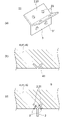
CLT製などの木質系天井材(上階の床材41)42にスリット43をV字状に形成する((b))。スリットの幅は、埋設プレート21の厚さと略同じとする。
A
このスリット43に埋設プレート21を挿入し、木質系天井材42の表面から線状材からなる定着具6を埋設プレート21の孔23を貫通するように打ち込む。これによって、木質系天井材42にハンガー部3を露出させた状態に吊り用固定具1を取り付けた吊り具付き天井5((c))を形成する。
The buried
図3にI字状の吊り用固定具12を示す。(a)は斜視図、(b)は断面図である。
I字状の吊り用固定具12は、平板状に形成されており、上部が埋設プレート部22、下部がハンガー部3を形成している。埋設プレート部22には穴23、ハンガー部3には係止孔31が形成されている。この穴23と係止孔31は、実施例1と同様に設けない場合もある。
本例では、とげ状突起24を埋設プレート部22に設けてある。とげ状突起24はスリットからの抜け出し防止機能であって、エンボス加工によって形成された粗面やパンチングによるバリなどでも形成することができる。
このI字状の吊り用固定具12は、長い平板を折り返して形成することもできる。長い平板にあらかじめ穴23、係止孔31、とげ状突起24を形成したのちに、折り返すことも可能である。
FIG. 3 shows an I-shaped
The I-shaped
In this example, the thorn-shaped
The I-shaped
図3(c)にスリット43を形成した木質系天井材42を示す。I型吊り用固定具12の埋設プレート部22が挿入されるように垂直にスリット43を形成する。スリットの幅は埋設プレート部22と同程度であって、とげ状突起が引き起こされて抜け止め効果を発揮するように形成される。
FIG. 3C shows a wood-based
図3(d)にI字状吊り用固定具12を取り付けた吊り具付き天井5を示す。このスリット43に埋設プレート部22を挿入し、木質系天井材42の表面から線状材からなる定着具6を埋設プレート21の穴23を貫通するようにクロスに打ち込む。これによって、木質系天井材42にハンガー部3を露出させた状態に吊り用固定具1を取り付けた吊り具付き天井5が形成される。
FIG. 3D shows a
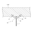
図4にU字状の吊り用固定具13を示す。
U字状の吊り用固定具13は、ハンガー部3を横に設け、このハンガー部の左右端から傾斜した埋設プレート21を設けている。ハンガー部3には、係止孔31を設けてある。
U字状の吊り用固定具13のハンガー部3は、木質系天井材42の表面と隙間があるように取り付けられる。取り付けは、木質系天井材にスリットを設け、埋設プレート21の下端が出るように挿入し、定着具6を打ち込んで固定される。
吊ボルトなどの連結材7の上端をハンガー部3の係止孔31に挿入し、ナット72で止める。このナット72はあらかじめ係止孔31の上部に溶接などにより固定することもできる。ナットを使用せずに連結材7の上端部にフックを形成し、ひっかけることもできる。
FIG. 4 shows a
The
The
The upper end of the connecting
図5にコ字状の吊り用固定具14を示す。
埋設プレート21がコ字状に形成されており、連結材を接続するための係止孔31が形成されたハンガー部3が中央下部に取り付けられている。(a)は埋設プレート部がメクラ板で示されたコ字状の吊り用固定具14ある。(b)は埋設プレート21bに線状材が貫通する穴23が設けられたコ字状の吊り用固定具14bを示す。穴23の数は、一つあるいは複数設ける。穴23の有無は、実施例1と同様に、埋設プレートを線状材が打ち抜くことができれば、穴を設けなくてもよい。なお、実施例2に示すようなとげ状突起などを埋設プレートに形成することもできる。
CLT製などの木質系天井材(上階の床材41)42にスリット43を平行に形成する((c))。スリットの幅は、埋設プレート21(21b)の厚さと略同じとする。
このスリット43に埋設プレート21(21b)を挿入し、木質系天井材42の表面から線状材からなる定着具6が埋設プレート21(21b)を貫通するように打ち込む。これによって、木質系天井材42にハンガー部3を露出させた状態に吊り用固定具1を取り付けた吊り具付き天井5((d))を形成する。
FIG. 5 shows a
The buried
A
The buried plate 21 (21b) is inserted into the
<吊り具付き天井及び天井構造>
吊り用固定具1を木質系天井材42に取り付けた状態の吊り具付き天井5の例を図6に示す。(a)は平面図、(b)はA―A断面図である。木質系天井材42は、単位大きさのCLT材などの木質材を組み合わせて構成されている。この例では、単位となる木質材を42-1・・・・・と表している。吊り用固定具1はV字状吊り用固定具である。
単位となる木質材にあらかじめスリット形成して、V字状吊り用固定具を取り付けて準備し、床(天井)を施工する。鉄筋コンクリート製の床スラブでは、コンクリート打設時あるいは打設後に吊りボルト用のアンカーを設ける必要があるが、木質系床材では、予め仕組むことができる。
<Ceiling and ceiling structure with hanging tools>
FIG. 6 shows an example of a
A slit is formed in advance in the wood material as a unit, a V-shaped hanging fixture is attached and prepared, and the floor (ceiling) is constructed. For reinforced concrete floor slabs, it is necessary to provide anchors for hanging bolts during or after concrete placement, but for wood floor materials, it can be pre-assembled.
この吊り具付き天井5に取り付けられている吊り用固定具1のハンガー部3に吊りボルトなどの連結材7を取り付けて天井構造を構成する。連結材7は、取り付ける機材の種類や地震対応などに応じた種類を使用する。図7に示すシステム天井を採用することもできる。
A connecting
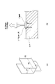
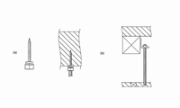
コ字状の吊り用固定具を用いて引張試験を行った。試験の概略を図8に示す。(a)は試験に用いたコ字状固定具、(b)は引張試験の概略である。
1.試験仕様
木質材:5層CLT材
固定具:形状、サイズ、素材
コ字状の連結プレートのサイズ 長さ40mm、巾21mm、高さ65mm、
材質 鋼板、厚み0.6mm、1.2mm
定着材:ビス1(パネリュードII)、ビス2(CPQ75)、
釘1(CN65)、釘2(CN90)
A tensile test was performed using a U-shaped suspension fixture. The outline of the test is shown in FIG. (A) is a U-shaped fixture used in the test, and (b) is an outline of a tensile test.
1. 1. Test specifications Wood material: 5-layer CLT material Fixture: Shape, size, material
U-shaped connecting
Material Steel plate, thickness 0.6mm, 1.2mm
Fixing material: Screw 1 (Panelude II), Screw 2 (CPQ75),
Nail 1 (CN65), Nail 2 (CN90)
2.試験方法
(a)CLT材にコ字状の連結プレートが挿入できる溝を平行に形成し、連結プレートを挿入する。
(b)CLTの表面から斜めに連結プレートを打ち抜くように定着材を打ち込み、連結プレートを定着材が貫通するか確認する。
(c)定着材が貫通した試験体のハンガー部に引っ張り荷重を負荷して、破壊するまでの変化を計測した。変化は、荷重と抜け出し変位である。従来の吊り金物の強度を参考にして、引抜き強度の設計値を1.2kNに設定した。
2. 2. Test method (a) A groove into which a U-shaped connecting plate can be inserted is formed in parallel in the CLT material, and the connecting plate is inserted.
(B) The fixing material is driven so as to punch out the connecting plate diagonally from the surface of the CLT, and it is confirmed whether the fixing material penetrates the connecting plate.
(C) A tensile load was applied to the hanger portion of the test piece through which the fixing material penetrated, and the change until the test piece was broken was measured. The changes are loads and breakout displacements. The design value of the pull-out strength was set to 1.2 kN with reference to the strength of the conventional hanging hardware.
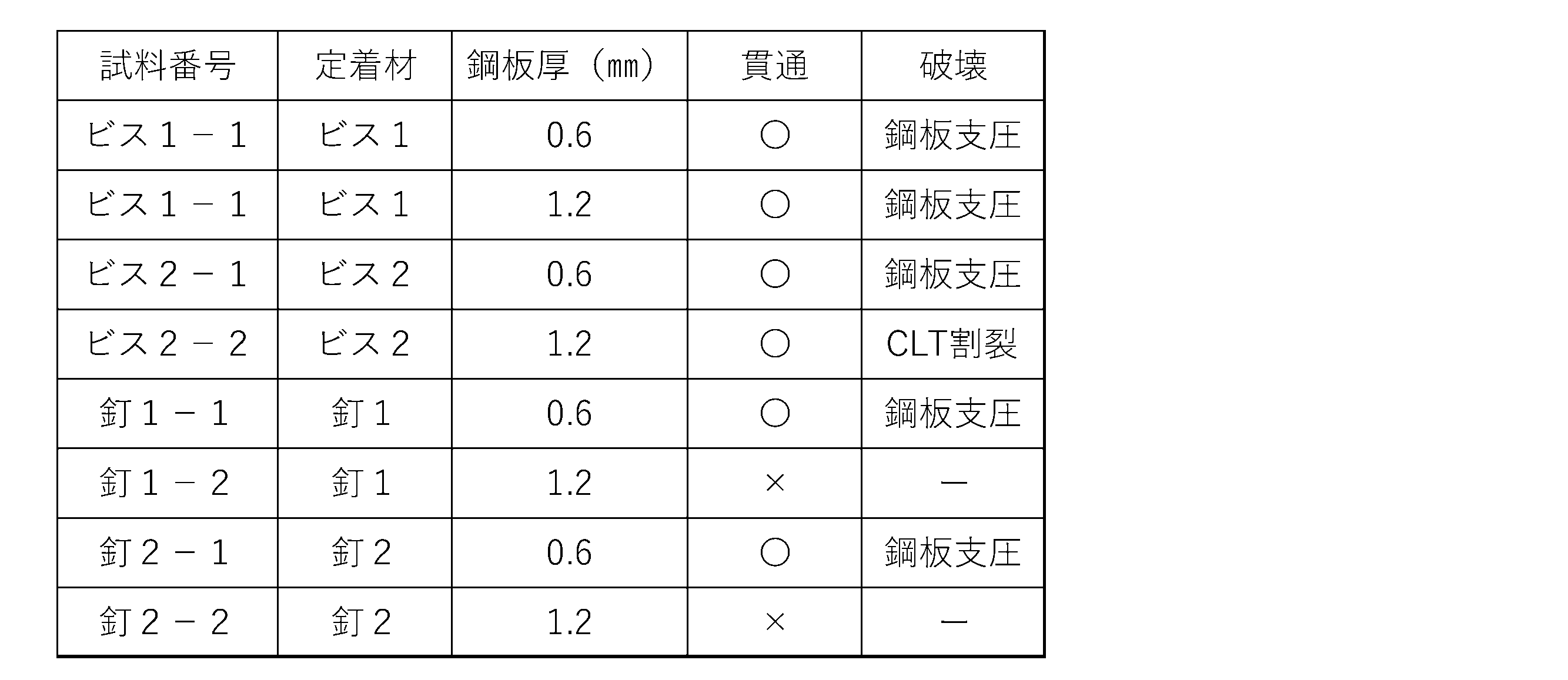
3.試験結果
試験結果の概要を表1に示す。
(1)定着材の貫通結果
(a)ビス1、ビス2とも、厚み0.6mm、1.2mmの鋼板を打ち抜いて、連結プレートをCLT材に固定することができた。
(b)釘1(CN65)、釘2(CN90)は、厚み0.6mmの鋼板を打ち抜くことはできたが、1.2mmの鋼板を打ち抜くことができなかった。
(2)引張試験の結果
(a)定着材が連結プレートを貫通した6種類について、引張試験をした。ビス2を用いたコ字状の吊り用固定具では、CLTが割裂破壊した。他の5種類のコ字状の吊り用固定具では、連結プレートを構成する鋼板が断裂する鋼板支圧破壊が生じた。
これらの破壊はいずれも、設計値1.2kNを超えていた。
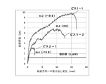
(b)鋼板支圧破壊を示した3種類について引張試験の結果を図9に示す。
ビス1-1(鋼板厚0.6mm)、ビス1-2(鋼板厚1.2mm)、ビス2-1(鋼板厚0.6mm)の3種類である。
ビス1-1、ビス1-2、ビス2-1の破壊強度を示す荷重は、約10kN、約6.5.0kN、約7kN、約3kNであり、十分に設計強度を満足する。
3. 3. Test results Table 1 summarizes the test results.
(1) Penetration result of fixing material (a) Both
(B) Nail 1 (CN65) and Nail 2 (CN90) were able to punch out a steel plate having a thickness of 0.6 mm, but could not punch out a steel plate having a thickness of 1.2 mm.
(2) Tensile test results (a) Tensile tests were conducted on 6 types of fixing materials that penetrated the connecting plate. In the U-shaped suspension fixture using the
All of these fractures exceeded the design value of 1.2 kN.
(B) FIG. 9 shows the results of the tensile test for the three types showing the steel plate bearing fracture.
There are three types: screw 1-1 (steel plate thickness 0.6 mm), screw 1-2 (steel plate thickness 1.2 mm), and screw 2-1 (steel plate thickness 0.6 mm).
The loads indicating the breaking strength of the screws 1-1, the screws 1-2, and the screws 2-1 are about 10 kN, about 6.5.0 kN, about 7 kN, and about 3 kN, which sufficiently satisfy the design strength.
4.考察
この試験から、本発明の木質系材料を対象とする吊り用固定具は、十分な耐久性を示すことが確認された。埋設プレートに0.6mm厚程度の鋼板を用いた場合は、釘でも十分に貫通することができ、1.2mm厚の鋼板ではビスでは貫通することができることが確認された。したがって、穴を設けない埋設プレートの鋼板として、2.0mm以下を使用できると見込まれる。
4. Discussion From this test, it was confirmed that the suspension fixture for the wood-based material of the present invention exhibits sufficient durability. It was confirmed that when a steel plate having a thickness of about 0.6 mm was used for the buried plate, it could be sufficiently penetrated by a nail, and that a steel plate having a thickness of 1.2 mm could be penetrated by a screw. Therefore, it is expected that 2.0 mm or less can be used as the steel plate of the buried plate without holes.
1 吊り用固定具
11・・V字状吊り用固定具
12・・I字状の吊り用固定具
13・・U字状の吊り用固定具
14・・コ字状の吊り用固定具
2、22 埋設プレート部
21・・埋設プレート
23・・穴
24・・とげ状突起
3 ハンガー部
31・・係止孔
4 吊り具付き天井
41・・上階の床材
42・・木質系天井材
43・・スリット
5 吊り具付き天井
6 定着具
7 連結材
72・・ナット
1
Claims (4)
埋設プレート部とハンガー部は直線ないしは屈曲していることを特徴とする木質系材料用の吊り用固定具。 A hanging fixture for wood-based materials with a buried plate and a hanger.
A hanging fixture for wood-based materials, characterized in that the buried plate and hanger are straight or bent.
木質系天井材にスリットを設け、該スリットに埋設プレート部を挿入し、埋設プレート部の穴に天井材の表面から線状定着具を通して取付けられて、天井表面にハンガー部が露出している吊り具付き天井。 In a building whose floor is made of a wood-based material, the ceiling is a ceiling with a hanging tool in which the hanging fixture for the wood-based material according to claim 1 is attached to the wood-based ceiling material which is the floor of the upper floor.
A slit is provided in the wood-based ceiling material, the buried plate portion is inserted into the slit, and the hanger portion is exposed on the ceiling surface and attached to the hole of the buried plate portion through a linear fixing tool from the surface of the ceiling material. Ceiling with tools.
Priority Applications (1)
| Application Number | Priority Date | Filing Date | Title |
|---|---|---|---|
| JP2020188342A JP2022077458A (en) | 2020-11-11 | 2020-11-11 | Fixtures for hanging wood materials, ceilings with hangings, ceiling structures |
Applications Claiming Priority (1)
| Application Number | Priority Date | Filing Date | Title |
|---|---|---|---|
| JP2020188342A JP2022077458A (en) | 2020-11-11 | 2020-11-11 | Fixtures for hanging wood materials, ceilings with hangings, ceiling structures |
Publications (1)
| Publication Number | Publication Date |
|---|---|
| JP2022077458A true JP2022077458A (en) | 2022-05-23 |
Family
ID=81654055
Family Applications (1)
| Application Number | Title | Priority Date | Filing Date |
|---|---|---|---|
| JP2020188342A Pending JP2022077458A (en) | 2020-11-11 | 2020-11-11 | Fixtures for hanging wood materials, ceilings with hangings, ceiling structures |
Country Status (1)
| Country | Link |
|---|---|
| JP (1) | JP2022077458A (en) |
Cited By (1)
| Publication number | Priority date | Publication date | Assignee | Title |
|---|---|---|---|---|
| JP2024080518A (en) * | 2022-12-02 | 2024-06-13 | 大成建設株式会社 | Fixture and method for supporting member |
-
2020
- 2020-11-11 JP JP2020188342A patent/JP2022077458A/en active Pending
Cited By (1)
| Publication number | Priority date | Publication date | Assignee | Title |
|---|---|---|---|---|
| JP2024080518A (en) * | 2022-12-02 | 2024-06-13 | 大成建設株式会社 | Fixture and method for supporting member |
Similar Documents
| Publication | Publication Date | Title |
|---|---|---|
| AU2019201196B2 (en) | Drywall joist hanger connection | |
| US11649626B2 (en) | Hanger for fire separation wall | |
| US10179992B2 (en) | Heavy duty hanger for fire separation wall | |
| JP2022077458A (en) | Fixtures for hanging wood materials, ceilings with hangings, ceiling structures | |
| JP7266244B2 (en) | Ceiling panel and ceiling structure using the same | |
| CN113498446B (en) | Ceiling panel | |
| US20240376704A1 (en) | Drywall Spacing Joist Hanger | |
| JP6633320B2 (en) | Supports and ceiling structures | |
| Masuzawa et al. | Study on aseismic performance of integrated ceiling system and anti-fall measures of ceiling | |
| CN212453440U (en) | Panel connecting device and panel installing system | |
| JP5159333B2 (en) | Staircase | |
| CN120331388A (en) | Fireproof partition and installation method thereof | |
| US20050050834A1 (en) | Metal fireblock | |
| JP2020012322A (en) | Auxiliary pipe installing tool and standard erecting structure | |
| NZ720992B2 (en) | Drywall joist hanger connection | |
| NZ760085B2 (en) | Drywall joist hanger | |
| JPH0581415U (en) | Ceiling support structure | |
| JP2017031619A (en) | Wall structure and ceiling structure of architectural structure, wall and ceiling construction method for architectural structure, pedestal member used in construction method | |
| JPH09125590A (en) | Ceiling support structure |