JP2022071402A - Laser processing device and laser processing method - Google Patents
Laser processing device and laser processing method Download PDFInfo
- Publication number
- JP2022071402A JP2022071402A JP2020180345A JP2020180345A JP2022071402A JP 2022071402 A JP2022071402 A JP 2022071402A JP 2020180345 A JP2020180345 A JP 2020180345A JP 2020180345 A JP2020180345 A JP 2020180345A JP 2022071402 A JP2022071402 A JP 2022071402A
- Authority
- JP
- Japan
- Prior art keywords
- laser
- processing
- street
- light
- spot
- Prior art date
- Legal status (The legal status is an assumption and is not a legal conclusion. Google has not performed a legal analysis and makes no representation as to the accuracy of the status listed.)
- Pending
Links
- 238000003672 processing method Methods 0.000 title claims abstract description 8
- 230000033001 locomotion Effects 0.000 claims abstract description 41
- 230000006866 deterioration Effects 0.000 claims abstract description 13
- 230000003287 optical effect Effects 0.000 claims description 145
- 238000005520 cutting process Methods 0.000 claims description 70
- 238000003754 machining Methods 0.000 claims description 53
- 238000000034 method Methods 0.000 claims description 52
- 230000005494 condensation Effects 0.000 abstract 2
- 238000009833 condensation Methods 0.000 abstract 2
- 230000002265 prevention Effects 0.000 abstract 1
- 235000012431 wafers Nutrition 0.000 description 70
- 230000000052 comparative effect Effects 0.000 description 16
- 238000010586 diagram Methods 0.000 description 12
- 238000005338 heat storage Methods 0.000 description 8
- 230000015572 biosynthetic process Effects 0.000 description 7
- 230000006870 function Effects 0.000 description 5
- 238000002679 ablation Methods 0.000 description 4
- 239000000758 substrate Substances 0.000 description 4
- 230000000903 blocking effect Effects 0.000 description 3
- 230000002542 deteriorative effect Effects 0.000 description 3
- 239000000463 material Substances 0.000 description 3
- 230000005540 biological transmission Effects 0.000 description 2
- 230000007423 decrease Effects 0.000 description 2
- 239000004065 semiconductor Substances 0.000 description 2
- 229910052710 silicon Inorganic materials 0.000 description 2
- 239000010703 silicon Substances 0.000 description 2
- 240000006829 Ficus sundaica Species 0.000 description 1
- 238000003491 array Methods 0.000 description 1
- 239000012141 concentrate Substances 0.000 description 1
- 238000001514 detection method Methods 0.000 description 1
- 230000000694 effects Effects 0.000 description 1
- 239000012212 insulator Substances 0.000 description 1
- 238000010030 laminating Methods 0.000 description 1
- 239000002932 luster Substances 0.000 description 1
- 238000004519 manufacturing process Methods 0.000 description 1
- 238000002844 melting Methods 0.000 description 1
- 230000008018 melting Effects 0.000 description 1
- 230000010287 polarization Effects 0.000 description 1
- 238000004088 simulation Methods 0.000 description 1
Images


Classifications
-
- H—ELECTRICITY
- H01—ELECTRIC ELEMENTS
- H01L—SEMICONDUCTOR DEVICES NOT COVERED BY CLASS H10
- H01L21/00—Processes or apparatus adapted for the manufacture or treatment of semiconductor or solid state devices or of parts thereof
- H01L21/70—Manufacture or treatment of devices consisting of a plurality of solid state components formed in or on a common substrate or of parts thereof; Manufacture of integrated circuit devices or of parts thereof
- H01L21/77—Manufacture or treatment of devices consisting of a plurality of solid state components or integrated circuits formed in, or on, a common substrate
- H01L21/78—Manufacture or treatment of devices consisting of a plurality of solid state components or integrated circuits formed in, or on, a common substrate with subsequent division of the substrate into plural individual devices
-
- B—PERFORMING OPERATIONS; TRANSPORTING
- B23—MACHINE TOOLS; METAL-WORKING NOT OTHERWISE PROVIDED FOR
- B23K—SOLDERING OR UNSOLDERING; WELDING; CLADDING OR PLATING BY SOLDERING OR WELDING; CUTTING BY APPLYING HEAT LOCALLY, e.g. FLAME CUTTING; WORKING BY LASER BEAM
- B23K26/00—Working by laser beam, e.g. welding, cutting or boring
- B23K26/36—Removing material
- B23K26/362—Laser etching
- B23K26/364—Laser etching for making a groove or trench, e.g. for scribing a break initiation groove
-
- B—PERFORMING OPERATIONS; TRANSPORTING
- B23—MACHINE TOOLS; METAL-WORKING NOT OTHERWISE PROVIDED FOR
- B23K—SOLDERING OR UNSOLDERING; WELDING; CLADDING OR PLATING BY SOLDERING OR WELDING; CUTTING BY APPLYING HEAT LOCALLY, e.g. FLAME CUTTING; WORKING BY LASER BEAM
- B23K26/00—Working by laser beam, e.g. welding, cutting or boring
- B23K26/02—Positioning or observing the workpiece, e.g. with respect to the point of impact; Aligning, aiming or focusing the laser beam
- B23K26/06—Shaping the laser beam, e.g. by masks or multi-focusing
- B23K26/0604—Shaping the laser beam, e.g. by masks or multi-focusing by a combination of beams
-
- B—PERFORMING OPERATIONS; TRANSPORTING
- B23—MACHINE TOOLS; METAL-WORKING NOT OTHERWISE PROVIDED FOR
- B23K—SOLDERING OR UNSOLDERING; WELDING; CLADDING OR PLATING BY SOLDERING OR WELDING; CUTTING BY APPLYING HEAT LOCALLY, e.g. FLAME CUTTING; WORKING BY LASER BEAM
- B23K26/00—Working by laser beam, e.g. welding, cutting or boring
- B23K26/02—Positioning or observing the workpiece, e.g. with respect to the point of impact; Aligning, aiming or focusing the laser beam
- B23K26/06—Shaping the laser beam, e.g. by masks or multi-focusing
- B23K26/062—Shaping the laser beam, e.g. by masks or multi-focusing by direct control of the laser beam
- B23K26/0622—Shaping the laser beam, e.g. by masks or multi-focusing by direct control of the laser beam by shaping pulses
-
- B—PERFORMING OPERATIONS; TRANSPORTING
- B23—MACHINE TOOLS; METAL-WORKING NOT OTHERWISE PROVIDED FOR
- B23K—SOLDERING OR UNSOLDERING; WELDING; CLADDING OR PLATING BY SOLDERING OR WELDING; CUTTING BY APPLYING HEAT LOCALLY, e.g. FLAME CUTTING; WORKING BY LASER BEAM
- B23K26/00—Working by laser beam, e.g. welding, cutting or boring
- B23K26/02—Positioning or observing the workpiece, e.g. with respect to the point of impact; Aligning, aiming or focusing the laser beam
- B23K26/06—Shaping the laser beam, e.g. by masks or multi-focusing
- B23K26/064—Shaping the laser beam, e.g. by masks or multi-focusing by means of optical elements, e.g. lenses, mirrors or prisms
- B23K26/0648—Shaping the laser beam, e.g. by masks or multi-focusing by means of optical elements, e.g. lenses, mirrors or prisms comprising lenses
-
- B—PERFORMING OPERATIONS; TRANSPORTING
- B23—MACHINE TOOLS; METAL-WORKING NOT OTHERWISE PROVIDED FOR
- B23K—SOLDERING OR UNSOLDERING; WELDING; CLADDING OR PLATING BY SOLDERING OR WELDING; CUTTING BY APPLYING HEAT LOCALLY, e.g. FLAME CUTTING; WORKING BY LASER BEAM
- B23K26/00—Working by laser beam, e.g. welding, cutting or boring
- B23K26/02—Positioning or observing the workpiece, e.g. with respect to the point of impact; Aligning, aiming or focusing the laser beam
- B23K26/06—Shaping the laser beam, e.g. by masks or multi-focusing
- B23K26/0665—Shaping the laser beam, e.g. by masks or multi-focusing by beam condensation on the workpiece, e.g. for focusing
-
- B—PERFORMING OPERATIONS; TRANSPORTING
- B23—MACHINE TOOLS; METAL-WORKING NOT OTHERWISE PROVIDED FOR
- B23K—SOLDERING OR UNSOLDERING; WELDING; CLADDING OR PLATING BY SOLDERING OR WELDING; CUTTING BY APPLYING HEAT LOCALLY, e.g. FLAME CUTTING; WORKING BY LASER BEAM
- B23K26/00—Working by laser beam, e.g. welding, cutting or boring
- B23K26/02—Positioning or observing the workpiece, e.g. with respect to the point of impact; Aligning, aiming or focusing the laser beam
- B23K26/06—Shaping the laser beam, e.g. by masks or multi-focusing
- B23K26/067—Dividing the beam into multiple beams, e.g. multifocusing
- B23K26/0676—Dividing the beam into multiple beams, e.g. multifocusing into dependently operating sub-beams, e.g. an array of spots with fixed spatial relationship or for performing simultaneously identical operations
-
- B—PERFORMING OPERATIONS; TRANSPORTING
- B23—MACHINE TOOLS; METAL-WORKING NOT OTHERWISE PROVIDED FOR
- B23K—SOLDERING OR UNSOLDERING; WELDING; CLADDING OR PLATING BY SOLDERING OR WELDING; CUTTING BY APPLYING HEAT LOCALLY, e.g. FLAME CUTTING; WORKING BY LASER BEAM
- B23K26/00—Working by laser beam, e.g. welding, cutting or boring
- B23K26/02—Positioning or observing the workpiece, e.g. with respect to the point of impact; Aligning, aiming or focusing the laser beam
- B23K26/06—Shaping the laser beam, e.g. by masks or multi-focusing
- B23K26/073—Shaping the laser spot
-
- B—PERFORMING OPERATIONS; TRANSPORTING
- B23—MACHINE TOOLS; METAL-WORKING NOT OTHERWISE PROVIDED FOR
- B23K—SOLDERING OR UNSOLDERING; WELDING; CLADDING OR PLATING BY SOLDERING OR WELDING; CUTTING BY APPLYING HEAT LOCALLY, e.g. FLAME CUTTING; WORKING BY LASER BEAM
- B23K26/00—Working by laser beam, e.g. welding, cutting or boring
- B23K26/36—Removing material
- B23K26/38—Removing material by boring or cutting
-
- H—ELECTRICITY
- H01—ELECTRIC ELEMENTS
- H01L—SEMICONDUCTOR DEVICES NOT COVERED BY CLASS H10
- H01L21/00—Processes or apparatus adapted for the manufacture or treatment of semiconductor or solid state devices or of parts thereof
- H01L21/67—Apparatus specially adapted for handling semiconductor or electric solid state devices during manufacture or treatment thereof; Apparatus specially adapted for handling wafers during manufacture or treatment of semiconductor or electric solid state devices or components ; Apparatus not specifically provided for elsewhere
- H01L21/67005—Apparatus not specifically provided for elsewhere
- H01L21/67011—Apparatus for manufacture or treatment
- H01L21/67092—Apparatus for mechanical treatment
-
- B—PERFORMING OPERATIONS; TRANSPORTING
- B23—MACHINE TOOLS; METAL-WORKING NOT OTHERWISE PROVIDED FOR
- B23K—SOLDERING OR UNSOLDERING; WELDING; CLADDING OR PLATING BY SOLDERING OR WELDING; CUTTING BY APPLYING HEAT LOCALLY, e.g. FLAME CUTTING; WORKING BY LASER BEAM
- B23K2101/00—Articles made by soldering, welding or cutting
- B23K2101/36—Electric or electronic devices
- B23K2101/40—Semiconductor devices
-
- B—PERFORMING OPERATIONS; TRANSPORTING
- B23—MACHINE TOOLS; METAL-WORKING NOT OTHERWISE PROVIDED FOR
- B23K—SOLDERING OR UNSOLDERING; WELDING; CLADDING OR PLATING BY SOLDERING OR WELDING; CUTTING BY APPLYING HEAT LOCALLY, e.g. FLAME CUTTING; WORKING BY LASER BEAM
- B23K2103/00—Materials to be soldered, welded or cut
- B23K2103/50—Inorganic material, e.g. metals, not provided for in B23K2103/02 – B23K2103/26
- B23K2103/56—Inorganic material, e.g. metals, not provided for in B23K2103/02 – B23K2103/26 semiconducting
Abstract
Description
本発明は、ウェーハのレーザ加工を行うレーザ加工装置及びレーザ加工方法に関する。 The present invention relates to a laser processing apparatus and a laser processing method for laser processing a wafer.
近年の半導体デバイスの製造分野では、シリコン等の基板の表面にガラス質材料からなる低誘電率絶縁体被膜(Low-k膜)と回路を形成する機能膜とを積層した積層体により複数のデバイスを形成しているウェーハ(半導体ウェーハ)が知られている。このようなウェーハは、複数のデバイスが格子状のストリートによって格子状に区画されており、ウェーハをストリートに沿って分割することにより個々のデバイスが製造される。 In the field of semiconductor device manufacturing in recent years, a plurality of devices are formed by laminating a low-dielectric-constant insulator film (Low-k film) made of a vitreous material and a functional film forming a circuit on the surface of a substrate such as silicon. Wafers (semiconductor wafers) forming the above are known. In such a wafer, a plurality of devices are partitioned in a grid pattern by grid-like streets, and individual devices are manufactured by dividing the wafer along the streets.
ウェーハを複数のデバイス(チップ)に分割する方法として、高速回転するブレードを用いる方法、ウェーハの内部にストリートに沿ってレーザ加工領域を形成してこのレーザ加工領域が形成されることにより強度が低下したストリートに沿って外力を加える方法が知られている。しかしながら、Low-k膜が適用されたウェーハの場合、Low-k膜の素材とウェーハの素材とが異なるため、前者の方法ではブレードにより絶縁膜と基板とを同時に切削することが困難である。また、後者の方法ではストリート上にLow-k膜が存在する場合に良好な品質で個々のデバイスに分割することが困難である。 As a method of dividing a wafer into a plurality of devices (chips), a method using a blade that rotates at high speed, a laser processing region is formed inside the wafer along a street, and the strength is lowered by forming this laser processing region. It is known how to apply an external force along the street. However, in the case of a wafer to which a Low-k film is applied, since the material of the Low-k film and the material of the wafer are different, it is difficult to cut the insulating film and the substrate at the same time by the blade by the former method. Also, with the latter method, it is difficult to divide into individual devices with good quality when a Low-k film is present on the street.
そこで、特許文献1には、ウェーハのストリートに沿って2条の縁切り溝(遮断溝)を形成する縁切り加工と、2条の縁切り溝の間に中抜き溝(分割溝)を形成する中抜き加工と、を行うレーザ加工装置が開示されている。このレーザ加工装置は、ウェーハに対してレーザ光学系を加工送り方向の一方向側(例えば往路方向側)に相対移動させながら、レーザ光学系により同一のストリートに沿って2条の縁切り溝と中抜き溝とを同時形成(並行形成)することでLow-k膜等を除去する。
Therefore, in
特許文献2には、ウェーハを保持するチャックとレーザ光学系とを相対移動させながら、レーザ光学系によりダイシングストリートに沿って互いに平行な一対のトレンチ(2条の第1溝)と、一対のトレンチの間に形成される凹部であるファロウ(第2溝)と、を形成するレーザ加工装置が開示されている。特許文献2のレーザ光学系は、ウェーハに対するレーザ光学系の加工送り方向(往路方向、復路方向)に関係なく、トレンチの加工に対応するレーザビームをファロウの加工に対応するレーザビームよりも先行させる。
In
また、特許文献2に記載のレーザ加工装置は、ファロウの加工に対応するレーザビームを加工送り方向に4分岐させ、4分岐させたレーザビームを共通の集光レンズでストリート上に個別に集光させることによりファロウの加工を行っている。
Further, in the laser processing apparatus described in
ところで、特許文献1に記載のレーザ加工装置においてストリート上に形成される加工溝(2条の縁切り溝、中抜き溝)、特に中抜き溝の加工深さを深くしたい場合には、中抜き加工に対応するレーザ光(パルスレーザ光)のパワーを上げる、或いはこのレーザ光の繰り返し周波数を上げる必要がある。しかしながら、この場合にはウェーハの溶融による加工溝の埋め戻りが支配的になり、所望の加工深さが得られず且つ加工品質も悪化する。
By the way, in the laser processing apparatus described in
加工溝(中抜き溝)の加工品質の悪化等を防止するためには、例えば、ウェーハごとに定められた加工品質が保たれるレーザ光のパワーの閾値に基づき、この閾値以下のパワーのレーザ光で中抜き加工を行う方法がある。しかしながら、この場合にはストリートごとに複数回(複数パス)の中抜き加工を行う必要があり、タクトタイムが増加してしまう。 In order to prevent deterioration of the processing quality of the processing groove (hollow groove), for example, based on the threshold value of the power of the laser beam that maintains the processing quality determined for each wafer, a laser with a power equal to or less than this threshold value. There is a method of hollowing out with light. However, in this case, it is necessary to perform the hollowing process a plurality of times (multiple passes) for each street, which increases the tact time.
このため、上述の閾値未満のパワーのレーザ光で中抜き加工を行う場合には、例えば、中抜き加工を行う集光レンズを増やすことで、ストリートごとに1回の中抜き加工を行うだけで所望深さの中抜き溝を形成する方法が考えられる(後述の図8参照)。しかしながら、この場合には集光レンズの数の増加分だけウェーハに対するレーザ光学系の相対移動量(加工距離)が増加するため、タクトタイムが増加してしまう。また、各集光レンズを同一直線上に配置する必要があり、その配置調整の煩雑さ及び難易度が増えてしまう。 For this reason, when performing the hollowing process with a laser beam having a power lower than the above threshold value, for example, by increasing the number of condenser lenses for performing the hollowing process, it is only necessary to perform the hollowing process once for each street. A method of forming a hollow groove having a desired depth can be considered (see FIG. 8 described later). However, in this case, the relative movement amount (machining distance) of the laser optical system with respect to the wafer increases by the increase in the number of condenser lenses, so that the tact time increases. Further, it is necessary to arrange each condenser lens on the same straight line, which increases the complexity and difficulty of the arrangement adjustment.
そこで、上記特許文献2に記載されているように、中抜き加工に対応するレーザ光を複数の分岐光に分岐させ、各分岐光を共通の集光レンズでストリートに集光させる方法が考えられる。しかしながら、各分岐光の分岐距離(間隔)が狭いと、レーザ光の繰り返し周波数を増加させたのと同様の状態になる。この場合には、ウェーハが十分に冷却されない状態でストリートに次々とレーザ光(パルスレーザ光)が照射されるため、ウェーハに対する入熱量の増加による加工溝の加工品質の悪化が懸念される。
Therefore, as described in
本発明はこのような事情に鑑みてなされたものであり、加工溝の加工品質の維持とタクトタイムの増加防止とを両立可能なレーザ加工装置及びレーザ加工方法を提供することを目的とする。 The present invention has been made in view of such circumstances, and an object of the present invention is to provide a laser processing apparatus and a laser processing method capable of both maintaining the processing quality of a machined groove and preventing an increase in tact time.
本発明の目的を達成するためのレーザ加工装置は、ウェーハを保持するテーブルに対しレーザ光学系をウェーハのストリートに沿った加工送り方向に相対移動させながら、レーザ光学系によりストリートに沿って互いに平行な2条の第1溝を形成する縁切り加工と、2条の第1溝の間に第2溝を形成する中抜き加工と、を行うレーザ加工装置において、レーザ光学系が、縁切り加工に対応する2本の第1レーザ光と、中抜き加工に対応する第2レーザ光と、を出射するレーザ光出射系と、レーザ光出射系から出射された2本の第1レーザ光を加工対象のストリートに集光させる第1集光レンズと、レーザ光出射系から出射された第2レーザ光を加工送り方向に沿って複数の分岐光に分岐させる分岐素子と、分岐素子により分岐された複数の分岐光を、加工対象のストリートに集光させる第2集光レンズと、を備え、第2集光レンズによりストリートに集光される分岐光ごとのスポットの中で互いに隣り合う先行スポットと後行スポットとの間隔である分岐距離をLとし、相対移動の速度である加工速度をVとし、先行スポットの加工位置に対して後行スポットが重なるまでの時間をτとした場合に、時間がτ=L/Vで表され、第2溝の加工品質の悪化が発生する時間の閾値をτ1とした場合にτ>τ1を満たす。 The laser processing apparatus for achieving the object of the present invention moves the laser optical system relative to the table holding the wafer in the processing feed direction along the street of the wafer, and is parallel to each other along the street by the laser optical system. The laser optical system supports edge cutting in a laser processing device that performs edge cutting to form the first groove of two rows and hollowing to form a second groove between the first grooves of two rows. The laser beam emitting system that emits the two first laser beams and the second laser beam corresponding to the hollowing process, and the two first laser beams emitted from the laser beam emitting system are processed. A first condensing lens that condenses light on the street, a branching element that branches the second laser beam emitted from the laser light emitting system into a plurality of branched lights along the processing feed direction, and a plurality of branched elements branched by the branching element. A second condensing lens that condenses the branched light on the street to be processed is provided, and among the spots for each branch light condensed on the street by the second condensing lens, the preceding spot and the trailing spot that are adjacent to each other are provided. When the branch distance, which is the distance from the spot, is L, the machining speed, which is the relative movement speed, is V, and the time until the trailing spot overlaps the machining position of the preceding spot is τ, the time is τ. = L / V, and τ> τ1 is satisfied when the threshold time at which the deterioration of the processing quality of the second groove occurs is τ1.
このレーザ加工装置によれば、タクトタイムの増加を防止し、且つ加工溝(第2溝)の加工品質を悪化させることなく所望の加工深さが得られる。 According to this laser processing apparatus, a desired processing depth can be obtained without increasing the tact time and without deteriorating the processing quality of the processing groove (second groove).
本発明の他の態様に係るレーザ加工装置において、レーザ光出射系が、縁切り加工に対応する条件のレーザ光を出射する第1レーザ光源と、中抜き加工に対応する条件のレーザ光を出射する第2レーザ光源と、第1レーザ光源から出射されたレーザ光から2本の第1レーザ光を形成する第1光形成素子と、第2レーザ光源から出射されたレーザ光から第2レーザ光を形成する第2光形成素子と、を備え、分岐素子が、第2光形成素子と第2集光レンズとの間の光路上に設けられている。これにより、レーザ加工を高速化してタクトタイムを低減させることができる。 In the laser processing apparatus according to another aspect of the present invention, the laser light emitting system emits a first laser light source that emits laser light under conditions corresponding to edge cutting and emits laser light under conditions corresponding to hollowing. The second laser light source, the first light forming element forming two first laser light from the laser light emitted from the first laser light source, and the second laser light from the laser light emitted from the second laser light source. A second light forming element to be formed is provided, and a branching element is provided on the optical path between the second light forming element and the second condensing lens. As a result, the laser processing can be speeded up and the tact time can be reduced.
本発明の他の態様に係るレーザ加工装置において、レーザ光出射系が、レーザ光を出射するレーザ光源と、レーザ光源から出射されたレーザ光を2分岐させる2分岐素子と、2分岐素子により2分岐されたレーザ光の一方から2本の第1レーザ光を形成する第1光形成素子と、2分岐素子により2分岐されたレーザ光の他方から第2レーザ光を形成する第2光形成素子と、を備え、分岐素子が、第2光形成素子と第2集光レンズとの間の光路上に設けられている。 In the laser processing apparatus according to another aspect of the present invention, the laser light emitting system comprises a laser light source that emits laser light, a bifurcated element that bifurcates the laser light emitted from the laser light source, and a bifurcated element. A first light forming element that forms two first laser beams from one of the branched laser lights, and a second light forming element that forms a second laser light from the other of the two branched laser lights by the two-branched element. And, a branching element is provided on the optical path between the second light forming element and the second condensing lens.
本発明の他の態様に係るレーザ加工装置において、第2光形成素子が、ストリートに非円形状のスポットを形成する第2レーザ光を形成し、第2光形成素子を、第2光形成素子の光軸を中心とする軸周り方向に回転させる第2光形成素子回転機構と、を備える。これにより、第2溝の幅を調整することができる。 In the laser processing apparatus according to another aspect of the present invention, the second light forming element forms the second laser light forming a non-circular spot on the street, and the second light forming element is referred to as the second light forming element. It is provided with a second light forming element rotation mechanism that rotates in a direction around the axis about the optical axis of the above. Thereby, the width of the second groove can be adjusted.
本発明の他の態様に係るレーザ加工装置において、第1光形成素子を、第1光形成素子の光軸を中心とする軸周り方向に回転させる第1光形成素子回転機構を備える。これにより、2条の第1溝の間隔を調整することができる。
In the laser processing apparatus according to another aspect of the present invention, the laser processing apparatus includes a first light forming element rotation mechanism that rotates the first light forming element in an axial direction about the optical axis of the first light forming element. Thereby, the interval of the first groove of
本発明の他の態様に係るレーザ加工装置において、第2集光レンズが、第1集光レンズを間に挟んで2個設けられ且つ第1集光レンズと共に加工送り方向に沿って一列に配置され、レーザ光出射系から出射された2本の第1レーザ光を第1集光レンズに導き且つ分岐素子により分岐された複数の分岐光を2個の第2集光レンズに選択的に導く接続光学系を備え、接続光学系が、テーブルに対してレーザ光学系が加工送り方向の往路方向側に相対移動される場合には、複数の分岐光を第1集光レンズに対して往路方向側とは反対の復路方向側に位置する第2集光レンズに導き、且つテーブルに対してレーザ光学系が復路方向側に相対移動される場合には、複数の分岐光を第1集光レンズに対して往路方向側に位置する第2集光レンズに導く。これにより、レーザ加工のタクトタイムを低減させることができる。 In the laser processing apparatus according to another aspect of the present invention, two second condensing lenses are provided with the first condensing lens sandwiched between them, and the second condensing lens is arranged in a row together with the first condensing lens along the processing feed direction. Then, the two first laser beams emitted from the laser beam emitting system are guided to the first condenser lens, and the plurality of branched lights branched by the branching element are selectively guided to the two second condenser lenses. When the connecting optical system is provided and the laser optical system is relatively moved toward the table in the outward path direction in the processing feed direction, a plurality of branched lights are directed in the outward path direction with respect to the first condenser lens. When leading to the second condenser lens located on the return path side opposite to the side and the laser optical system is moved relative to the return path side with respect to the table, a plurality of branched lights are directed to the first condenser lens. It leads to the second condenser lens located on the outward direction side. This makes it possible to reduce the tact time of laser processing.
本発明の他の態様に係るレーザ加工装置において、第2レーザ光がパルスレーザ光であり、加工速度及び第2レーザ光の繰り返し周波数の少なくともいずれか一方を調整して、スポットごとに、スポットに対して次回に照射されるスポットの加工送り方向のオーバーラップ率を50%以下にする。これにより、加工溝(第2溝)の加工品質をより向上させることができる。 In the laser processing apparatus according to another aspect of the present invention, the second laser beam is a pulsed laser beam, and at least one of the processing speed and the repetition frequency of the second laser beam is adjusted to make a spot for each spot. On the other hand, the overlap rate in the processing feed direction of the spot to be irradiated next time is set to 50% or less. Thereby, the processing quality of the processing groove (second groove) can be further improved.
本発明の目的を達成するためのレーザ加工方法は、ウェーハを保持するテーブルに対しレーザ光学系をウェーハのストリートに沿った加工送り方向に相対移動させながら、レーザ光学系によりストリートに沿って互いに平行な2条の第1溝を形成する縁切り加工と、2条の第1溝の間に第2溝を形成する中抜き加工と、を行うレーザ加工方法において、レーザ光学系が、縁切り加工に対応する2本の第1レーザ光と中抜き加工に対応する第2レーザ光とを出射し、2本の第1レーザ光を第1集光レンズにより加工対象のストリートに集光し、第2レーザ光を加工送り方向に沿って複数の分岐光に分岐し、複数の分岐光を第2集光レンズにより加工対象のストリートに集光し、第2集光レンズによりストリートに集光される分岐光ごとのスポットの中で互いに隣り合う先行スポットと後行スポットとの間隔である分岐距離をLとし、相対移動の速度である加工速度をVとし、先行スポットの加工位置に対して後行スポットが重なるまでの時間をτとした場合に、時間がτ=L/Vで表され、第2溝の加工品質の悪化が発生する時間の閾値をτ1とした場合にτ>τ1を満たす。 In the laser processing method for achieving the object of the present invention, the laser optical system is moved relative to the table holding the wafer in the processing feed direction along the street of the wafer, and is parallel to each other along the street by the laser optical system. The laser optical system supports edge cutting in a laser processing method that performs edge cutting to form the first groove of two rows and hollowing to form a second groove between the first grooves of two rows. The two first laser beams and the second laser beam corresponding to the hollowing process are emitted, and the two first laser beams are focused on the street to be processed by the first condenser lens, and the second laser is used. The light is branched into a plurality of branched lights along the processing feed direction, the plurality of branched lights are focused on the street to be processed by the second condenser lens, and the branched light is condensed on the street by the second condenser lens. The branch distance, which is the distance between the preceding spot and the following spot that are adjacent to each other in each spot, is L, the processing speed, which is the relative movement speed, is V, and the following spot is the processing position of the preceding spot. When the time until the overlap is τ, the time is represented by τ = L / V, and when the threshold time at which the deterioration of the processing quality of the second groove occurs is τ1, τ> τ1 is satisfied.
本発明は、加工溝の加工品質の維持とタクトタイムの増加防止とを両立可能である。 INDUSTRIAL APPLICABILITY According to the present invention, it is possible to maintain the processing quality of the processing groove and prevent the tact time from increasing.
[第1実施形態のレーザ加工装置の全体構成]
図1は、第1実施形態のレーザ加工装置10の概略図である。図1に示すように、レーザ加工装置10は、ウェーハ12を複数のチップ14(図2参照)に分割する前の前工程として、ウェーハ12に対してレーザ加工(アブレーション溝加工)を施す。なお、図中のXYZ方向は互いに直交し、このうちX方向及びY方向は水平方向であり、Z方向は上下方向である。ここで、X方向は本発明の加工送り方向に相当する。
[Overall configuration of the laser processing apparatus of the first embodiment]
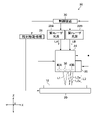
FIG. 1 is a schematic view of the
図2は、レーザ加工装置10による加工対象のウェーハ12の平面図である。図2に示すように、ウェーハ12は、シリコン等の基板の表面にLow-k膜と回路を形成する機能膜とを積層した積層体である。ウェーハ12は格子状に配列された複数のストリートC(分割予定ライン)によって複数の領域に区画されている。この区画された各領域にはチップ14を構成するデバイス16が設けられている。
FIG. 2 is a plan view of the
レーザ加工装置10は、図中の括弧付き数字(1)~(4)、・・・に示すように、ストリートCごとにストリートCに沿ってウェーハ12に対してレーザ加工を行うことで、基板上のLow-k膜等を除去する。
As shown by the numbers (1) to (4) in parentheses in the figure, the
この際にレーザ加工装置10は、ウェーハ12のレーザ加工に要するタクトタイムを低減するために、ウェーハ12に対して後述のレーザ光学系24をX方向に相対移動させる際の相対移動方向をストリートCごとに交互に切り替える。
At this time, the
例えば、図中の括弧付き数字(1),(3)等に示す奇数番目のストリートCに沿ってレーザ加工を行う場合には、ウェーハ12に対して後述のレーザ光学系24をX方向の一方向側である往路方向側X1(図5参照)に相対移動させる。また、図中の括弧付き数字(2),(4)等に示す偶数番目のストリートCに沿ってレーザ加工を行う場合には、ウェーハ12に対してレーザ光学系24をX方向の他方向側、すなわち往路方向側X1とは反対の復路方向側X2(図6参照)に相対移動させる。
For example, when laser processing is performed along the odd-numbered streets C shown by the numbers (1) and (3) in parentheses in the figure, the laser
図3は、奇数番目のストリートCに沿ったレーザ加工を説明するための説明図である。図4は、偶数番目のストリートCに沿ったレーザ加工を説明するための説明図である。 FIG. 3 is an explanatory diagram for explaining laser machining along the odd-numbered street C. FIG. 4 is an explanatory diagram for explaining laser processing along the even-numbered street C.
図3及び図4に示すように、本実施形態ではレーザ加工として縁切り加工及び中抜き加工が同時に(並行して)実行される。縁切り加工は、2本の第1レーザ光L1を用いて行うレーザ加工であって、且つストリートCに沿って互いに平行な2条の縁切り溝18(本発明の2条の第1溝に相当するアブレーション溝)を形成するレーザ加工である。
As shown in FIGS. 3 and 4, in this embodiment, edge cutting and hollowing are simultaneously (parallel) executed as laser machining. The edge cutting process is a laser process performed by using two first laser beams L1 and has two
中抜き加工は、縁切り加工で形成された2条の縁切り溝18の間に中抜き溝19(本発明の第2溝に相当するアブレーション溝)を形成するレーザ加工である。本実施形態では、この中抜き加工を、2本の第1レーザ光L1よりも太径の第2レーザ光L2を加工送り方向(X方向)に複数分岐した分岐光L2aを用いて行う。なお、アブレーション溝である2条の縁切り溝18及び中抜き溝19については公知技術であるので、その詳細についての説明は省略する(特許文献1参照)。
The hollowing process is a laser machining in which a hollowing groove 19 (ablation groove corresponding to the second groove of the present invention) is formed between the two
レーザ加工装置10では、ウェーハ12に対して後述のレーザ光学系24を往路方向側X1(図5参照)に相対移動させたり或いは復路方向側X2(図6参照)に相対移動させたりする場合のいずれにおいても、縁切り加工を中抜き加工よりも先行して行う。
In the
図1に戻って、レーザ加工装置10は、テーブル20と、第1レーザ光源22Aと、第2レーザ光源22Bと、レーザ光学系24と、顕微鏡26と、相対移動機構28と、制御装置30と、を備える。
Returning to FIG. 1, the
テーブル20は、ウェーハ12を保持する。また、テーブル20は、制御装置30の制御の下、相対移動機構28により加工対象のストリートCに平行な加工送り方向であるX方向とストリートCの幅方向に平行なY方向とに移動されると共に、Z方向に平行なテーブル20の中心軸(回転軸)を中心として回転される。
The table 20 holds the
第1レーザ光源22A及び第2レーザ光源22Bは、後述のレーザ光学系24と共に本発明のレーザ光学系を構成する。第1レーザ光源22Aは、縁切り加工に適した条件(波長、パルス幅、及び繰り返し周波数等)のパルスレーザ光であるレーザ光LAをレーザ光学系24へ常時出射する。第2レーザ光源22Bは、中抜き加工に適した条件(波長、パルス幅、及び繰り返し周波数等)のパルスレーザ光であるレーザ光LBをレーザ光学系24へ常時出射する。
The first
ここで、後述の第4実施形態のように1つのレーザ光源22(図23参照)で、縁切り溝加工と中抜き溝加工とを行うことも考えられるが、レーザ光条件によっては縁切り溝加工の速度は向上できても中抜き溝加工の速度が向上できず、その結果、速度向上できない中抜き溝加工の速度で加工する必要がある。また、レーザ光条件によってはその逆となる場合がある。従って、それぞれにおいて低速度となる側の速度がレーザ加工における上限速度となってしまう。 Here, it is conceivable to perform edge cutting groove processing and hollow groove processing with one laser light source 22 (see FIG. 23) as in the fourth embodiment described later, but edge cutting groove processing may be performed depending on the laser light conditions. Even if the speed can be improved, the speed of the hollow groove processing cannot be improved, and as a result, it is necessary to process at the speed of the hollow groove processing where the speed cannot be improved. The opposite may be true depending on the laser light conditions. Therefore, the speed on the low speed side in each case becomes the upper limit speed in laser machining.
このように縁切り加工及び中抜き加工では、加工速度と加工仕上がりにそれぞれ適したレーザ光条件が有る。このため、縁切り加工と中抜き加工とで異なる光源(第1レーザ光源22A及び第2レーザ光源22B)を用いることが好ましい。これにより、レーザ加工がより高速化されるので、タクトタイムを低減させることができる。
As described above, in the edge cutting process and the hollowing process, there are laser light conditions suitable for the processing speed and the processing finish. Therefore, it is preferable to use different light sources (first
レーザ光学系24(レーザユニット又はレーザヘッドともいう)は、詳しくは後述するが、第1レーザ光源22Aからのレーザ光LAに基づき縁切り加工用の2本の第1レーザ光L1を形成する。また、レーザ光学系24は、第2レーザ光源22Bからのレーザ光LBに基づき中抜き加工用の1本の第2レーザ光L2を形成した後、この第2レーザ光L2を複数の分岐光L2aに分岐させる。そして、レーザ光学系24は、2本の第1レーザ光L1を第1集光レンズ38からストリートCに向けて出射(照射)する。また、レーザ光学系24は、制御装置30の制御の下、各分岐光L2aを2個の第2集光レンズ40A,40Bから選択的にストリートCに向けて出射(照射)する。
The laser optical system 24 (also referred to as a laser unit or a laser head), which will be described in detail later, forms two first laser beams L1 for edge cutting based on the laser beam LA from the first
さらに、レーザ光学系24は、制御装置30の制御の下、相対移動機構28によりY方向及びZ方向に移動される。
Further, the laser
顕微鏡26は、レーザ光学系24に固定されており、レーザ光学系24と一体に移動する。顕微鏡26は、縁切り加工及び中抜き加工の前に、ウェーハ12に形成されているアライメント基準(図示は省略)を撮影する。また、顕微鏡26は、縁切り加工及び中抜き加工によりストリートCに沿って形成された2条の縁切り溝18及び中抜き溝19の撮影を行う。顕微鏡26により撮影された撮影画像(画像データ)は、制御装置30へ出力され、この制御装置30により不図示のモニタに表示される。
The
相対移動機構28は、不図示のXYZアクチュエータ及びモータ等から構成されており、制御装置30の制御の下、テーブル20のXY方向の移動及び回転軸を中心とする回転と、レーザ光学系24のZ方向の移動と、を行う。これにより、相対移動機構28は、テーブル20及びウェーハ12に対してレーザ光学系24を相対移動させることができる。なお、テーブル20(ウェーハ12)に対してレーザ光学系24を各方向(回転を含む)に相対移動可能であればその相対移動方法は特に限定はされない。
The
相対移動機構28を駆動することで、加工対象のストリートCの一端である加工開始位置に対するレーザ光学系24の位置合わせ(アライメント)と、ストリートCに沿ったX方向[往路方向側X1(図5参照)又は復路方向側X2(図6参照)]のレーザ光学系24の相対移動と、を実行することができる。また、相対移動機構28を駆動して、テーブル20を90°回転させることで、ウェーハ12のY方向に沿った各ストリートCを加工送り方向であるX方向に平行にすることができる。
By driving the
制御装置30は、例えばパーソナルコンピュータのような演算装置により構成され、各種のプロセッサ(Processor)及びメモリ等から構成された演算回路を備える。各種のプロセッサには、CPU(Central Processing Unit)、GPU(Graphics Processing Unit)、ASIC(Application Specific Integrated Circuit)、及びプログラマブル論理デバイス[例えばSPLD(Simple Programmable Logic Devices)、CPLD(Complex Programmable Logic Device)、及びFPGA(Field Programmable Gate Arrays)]等が含まれる。なお、制御装置30の各種機能は、1つのプロセッサにより実現されてもよいし、同種または異種の複数のプロセッサで実現されてもよい。
The
制御装置30は、第1レーザ光源22A、第2レーザ光源22B、レーザ光学系24、顕微鏡26、及び相対移動機構28等の動作を統括的に制御する。
The
[レーザ光学系]
図5は、ウェーハ12に対して往路方向側X1に相対移動されるレーザ光学系24による縁切り加工及び中抜き加工を説明するための説明図である。図6は、ウェーハ12に対して復路方向側X2に相対移動されるレーザ光学系24による縁切り加工及び中抜き加工を説明するための説明図である。以下、ウェーハ12に対して往路方向側X1に相対移動されるレーザ光学系24の加工対象である奇数番目のストリートCを適宜「往路」といい、復路方向側X2に相対移動されるレーザ光学系24の加工対象である偶数番目のストリートCを適宜「復路」という。
[Laser optical system]
FIG. 5 is an explanatory diagram for explaining edge cutting and hollowing by the laser
図5及び図6に示すように、レーザ光学系24は、第1安全シャッタ100A及び第2安全シャッタ100Bと、安全シャッタ駆動機構102と、第1光形成素子32と、第2光形成素子34と、分岐素子35と、接続切替素子36と、第1集光レンズ38と、2個の第2集光レンズ40A,40Bと、第1高速シャッタ47A及び第2高速シャッタ47Bと、高速シャッタ駆動機構47Cと、を備える。
As shown in FIGS. 5 and 6, the laser
第1安全シャッタ100Aは、第1レーザ光源22Aと第1光形成素子32との間のレーザ光LAの光路上に挿脱自在に設けられている。また、第2安全シャッタ100Bは、第2レーザ光源22Bと第2光形成素子34との間のレーザ光LBの光路上に挿脱自在に設けられている。
The
安全シャッタ駆動機構102は、制御装置30の制御の下、レーザ光LAの光路に対して第1安全シャッタ100Aを挿脱させると共に、レーザ光LBの光路に対して第2安全シャッタ100Bを挿脱させるアクチュエータである。安全シャッタ駆動機構102は、レーザ加工時以外では、レーザ光LAの光路に対して第1安全シャッタ100Aを挿入させると共に、レーザ光LBの光路に対して第2安全シャッタ100Bを挿入させることで、レーザ光LA,LBの光路を開放する。
Under the control of the
また、安全シャッタ駆動機構102は、レーザ加工時にはレーザ光LAの光路から第1安全シャッタ100Aを退避させると共に、レーザ光LBの光路から第2安全シャッタ100Bを退避させることで、レーザ光LA,LBの光路を開放する。
Further, the safety
第1光形成素子32及び第2光形成素子34は、既述の第1レーザ光源22A及び第2レーザ光源22Bと共に本発明のレーザ光出射系を構成する。第1光形成素子32は、例えば回折光学素子(Diffractive Optical Element:DOE)が用いられる。この第1光形成素子32は、第1レーザ光源22Aより入射したレーザ光LAから縁切り加工に対応する2本の第1レーザ光L1を形成し、2本の第1レーザ光L1を第1集光レンズ38に向けて出射する。これにより、ストリートC(往路及び復路)上に第1集光レンズ38により2本の第1レーザ光L1が集光され、ストリートC上においてY方向に離間した2個のスポットSP1(集光点又は加工点ともいう)が形成される。なお、図示は省略するが、第1光形成素子32から第1集光レンズ38に至る2本の第1レーザ光L1の光路(光路上に設けられた各種光学素子を含む)は、本発明の接続光学系の一部を構成する。
The first
第2光形成素子34は、例えば回折光学素子及びマスク等が用いられる。第2光形成素子34は、第2レーザ光源22Bより入射したレーザ光LBから中抜き加工に対応する第2レーザ光L2を形成する。第2レーザ光L2は、後述の分岐素子35を経て、2条の縁切り溝18の間において矩形状(円形状等の他の形状でも可)で且つX方向に沿った複数個のスポットSP2を形成する。このスポットSP2のY方向の幅は、2条の縁切り溝18の間隔に合わせて調整されている。そして、第2光形成素子34は、第2レーザ光L2を分岐素子35へ出射する。
As the second
分岐素子35は、第2光形成素子34から入射した第2レーザ光L2をX方向(加工送り方向)に沿って複数の分岐光L2aに分岐させる。この分岐素子35としては、例えば、回折光学素子、屈折光学素子、プリズム、及びこれらの組み合わせ等が用いられる。なお、図中では、分岐素子35により第2レーザ光L2を2分岐させているが、3以上に分岐させてもよい。そして、分岐素子35は、各分岐光L2aを接続切替素子36へ出射する。なお、各分岐光L2aの具体的な分岐条件については後述する。
The branching
接続切替素子36は、本発明の接続光学系を構成する。この接続切替素子36としては、例えば、公知の光スイッチ或いは各種光学素子(λ/2板、偏光ビームスプリッタ、ハーフミラー、及びミラー等、或いはこれらの組み合わせ)が用いられる。接続切替素子36は、制御装置30の制御の下、分岐素子35から出射された各分岐光L2aを第2集光レンズ40A,40Bに選択的に導く。
The
第1集光レンズ38及び第2集光レンズ40A,40Bは、X方向(加工送り方向)に沿って一列に配置されている。第1集光レンズ38は、第2集光レンズ40Aと第2集光レンズ40Bとの間に配置されている。換言すると、第2集光レンズ40A,40Bは、第1集光レンズ38を間に挟むように配置されている。第2集光レンズ40Aは、第1集光レンズ38に対して復路方向側X2に配置されている。第2集光レンズ40Bは、第1集光レンズ38に対して往路方向側X1に配置されている。
The
第1集光レンズ38は、第1光形成素子32から入射した2本の第1レーザ光L1をストリートC(往路及び復路)上に集光させる。第2集光レンズ40Aは、接続切替素子36から入射した各分岐光L2aをストリートC(往路)上に集光させる。第2集光レンズ40Bは、接続切替素子36から入射した各分岐光L2aをストリートC(復路)上に集光させる。
The
接続切替素子36は、相対移動機構28によりレーザ光学系24がウェーハ12に対して往路方向側X1及び復路方向側X2のいずれか一方向側に相対移動される場合に、各分岐光L2aを、第2集光レンズ40A,40Bの中で第1集光レンズ38に対して往路方向側X1及び復路方向側X2の他方向側に位置するレンズに導く。
The
具体的には図5に示すように、接続切替素子36は、相対移動機構28によりレーザ光学系24がウェーハ12に対して往路方向側X1に相対移動される場合には、分岐素子35から出射された各分岐光L2aを第2集光レンズ40Aに導く。これにより、ストリートC(往路)上に第2集光レンズ40Aにより各分岐光L2aが個別に集光されることで分岐光L2aごとのスポットSP2が形成される。その結果、レーザ光学系24の往路方向側X1への相対移動によりストリートC(往路)に沿って縁切り加工が先行して実行されることで2条の縁切り溝18が形成され、続いて中抜き加工が実行されることで2条の縁切り溝18の間に中抜き溝19が形成される。
Specifically, as shown in FIG. 5, when the laser
図6に示すように、接続切替素子36は、相対移動機構28によりレーザ光学系24がウェーハ12に対して復路方向側X2に相対移動される場合には、分岐素子35から出射された各分岐光L2aを第2集光レンズ40Bに導く。これにより、ストリートC(復路)上に第2集光レンズ40Bにより各分岐光L2aが個別に集光されることで分岐光L2aごとのスポットSP2が形成される。その結果、レーザ光学系24の復路方向側X2への相対移動によりストリートC(復路)に沿って縁切り加工が先行して実行されることで2条の縁切り溝18が形成され、続いて中抜き加工が実行されることで2条の縁切り溝18の間に中抜き溝19が形成される。
As shown in FIG. 6, when the laser
このように本実施形態では、第2レーザ光L2を複数の分岐光L2aに分岐させて、第2集光レンズ40A,40Bにより各分岐光L2aを個別にストリートC上に集光させることで、分岐光L2aごとにストリートCの中抜き加工を行うことができる。その結果、ウェーハ12に対するレーザ光学系24の1回の往路方向側X1又は復路方向側X2の相対移動によって、分岐光L2aの数に応じた複数回分の中抜き加工をストリートCに対して同時に行うことができる。このため、第2レーザ光L2のパワーを上げることなく中抜き溝19(加工溝)の加工深さを深くすることができる。これにより、タクトタイムを増加させることなく、中抜き溝19の加工品質が維持されるようなパワーの第2レーザ光L2で中抜き加工を行うことができる。
As described above, in the present embodiment, the second laser beam L2 is branched into a plurality of branched lights L2a, and each branched light L2a is individually focused on the street C by the
第1高速シャッタ47Aは、第1レーザ光源22Aと第1光形成素子32との間のレーザ光LAの光路(第1光形成素子32と第1集光レンズ38との間の光路でも可)に対して挿脱自在に設けられている。第1高速シャッタ47Aは、第1レーザ光源22Aと第1光形成素子32との間の光路に挿入された場合に、第1レーザ光源22Aから第1光形成素子32に入射するレーザ光LAを遮断することで第1集光レンズ38からの2本の第1レーザ光L1の出射を停止させる。
The first high-
第2高速シャッタ47Bは、第2レーザ光源22Bと第2光形成素子34との間のレーザ光LBの光路(第2光形成素子34と接続切替素子36との間の光路でも可)に対して挿脱自在に設けられている。第2高速シャッタ47Bは、第2レーザ光源22Bと第2光形成素子34との間の光路に挿入された場合に、第2レーザ光源22Bから第2光形成素子34に入射するレーザ光LBを遮断することで、第2集光レンズ40A,40Bからの各分岐光L2aの出射を停止させる。
The second high-
高速シャッタ駆動機構47Cは、制御装置30の制御の下、第1高速シャッタ47A及び第2高速シャッタ47Bを既述の各光路に対して挿脱させるアクチュエータである。高速シャッタ駆動機構47Cは、縁切り加工時には第1高速シャッタ47Aをレーザ光LAの光路から退避させ且つ縁切り加工時以外では第1高速シャッタ47Aをレーザ光LAの光路に挿入する。また、高速シャッタ駆動機構47Cは、中抜き加工時には第2高速シャッタ47Bをレーザ光LBの光路から退避させ且つ中抜き加工時以外では第2高速シャッタ47Bをレーザ光LBの光路に挿入する。
The high-speed
[レーザ加工(各シャッタの動作)]
図7は、上記構成の第1実施形態のレーザ加工装置10によるウェーハ12のストリートCごとのレーザ加工の流れ、特に第1高速シャッタ47A、第2高速シャッタ47B、第1安全シャッタ100A、及び第2安全シャッタ100Bの動作を示したフローチャートである。
[Laser machining (operation of each shutter)]
FIG. 7 shows the flow of laser processing for each street C of the
図7に示すように、レーザ加工対象のウェーハ12がテーブル20に保持されると、制御装置30が、最初に安全シャッタ駆動機構102を駆動して各安全シャッタ100A,100Bをレーザ光LA,LBの光路上から退避させる(ステップS0)。
As shown in FIG. 7, when the
次いで、制御装置30が相対移動機構28を駆動して、ウェーハ12に対して顕微鏡26をウェーハ12のアライメント基準(図示は省略)を撮影可能な位置まで相対移動させた後、顕微鏡26によるアライメント基準の撮影を実行させる。そして、制御装置30は、顕微鏡26により撮影されたアライメント基準の撮影画像に基づき、ウェーハ12内の各ストリートCの位置を検出するアライメント検出を行う。次いで、制御装置30は、相対移動機構28を駆動して、レーザ光学系24の第1集光レンズ38の光軸と、第1番目のストリートC(往路)の加工開始位置との位置合わせを行う(ステップS1)。
Next, the
また、制御装置30は、接続切替素子36を駆動して各分岐光L2aを出射するレンズを第2集光レンズ40Aに切り替えた後(ステップS2)、高速シャッタ駆動機構47Cを駆動して第1高速シャッタ47Aをレーザ光LAの光路上から退避させる(ステップS3)。これにより、第1集光レンズ38から2本の第1レーザ光L1が出射され、2本の第1レーザ光L1がストリートC(往路)上の加工開始位置に集光される。
Further, the
次いで、制御装置30は、相対移動機構28を駆動して、ウェーハ12に対してレーザ光学系24を往路方向側X1に相対移動させる(ステップS4)。そして、第2集光レンズ40Aの光軸がストリートC(往路)の加工開始位置に到達すると、制御装置30は、高速シャッタ駆動機構47Cを駆動して第2高速シャッタ47Bをレーザ光LBの光路上から退避させる(ステップS5)。これにより、第2集光レンズ40Aから各分岐光L2aが出射され、各分岐光L2aが上述の加工開始位置に集光される。
Next, the
レーザ光学系24の往路方向側X1への相対移動が継続すると、図3及び図5に示したように、2本の第1レーザ光L1のスポットSP1と分岐光L2aごとのスポットSP2とがストリートC(往路)に沿って往路方向側X1に移動する。その結果、ストリートC(往路)に沿って、縁切り加工による2条の縁切り溝18の形成と中抜き加工による中抜き溝19の形成とが間隔を空けて同時に実行される。
When the relative movement of the laser
制御装置30は、スポットSP1がストリートC(往路)の加工終了位置に到達するタイミングに合わせて、高速シャッタ駆動機構47Cを駆動して第1高速シャッタ47Aをレーザ光LAの光路上に挿入させる(ステップS6,S7)。また、制御装置30は、各スポットSP2が上述の加工終了位置に到達するタイミングに合わせて、高速シャッタ駆動機構47Cを駆動して第2高速シャッタ47Bをレーザ光LBの光路上に挿入させる(ステップS8)。これにより、第1番目のストリートC(往路)のレーザ加工が完了する。
The
制御装置30は、第1番目のストリートC(往路)のレーザ加工が完了すると、相対移動機構28を駆動して、第1集光レンズ38の光軸と、第2番目のストリートC(復路)の加工開始位置との位置合わせを行う(ステップS9でYES、ステップS10)。
When the laser processing of the first street C (outward route) is completed, the
また、制御装置30は、接続切替素子36を駆動して各分岐光L2aを出射するレンズを第2集光レンズ40Bに切り替えた後(ステップS11)、高速シャッタ駆動機構47Cを駆動して第1高速シャッタ47Aをレーザ光LAの光路上から退避させる(ステップS12)。これにより、第1集光レンズ38により2本の第1レーザ光L1がストリートC(復路)上の加工開始位置に集光される。
Further, the
次いで、制御装置30は、相対移動機構28を駆動して、ウェーハ12に対してレーザ光学系24を復路方向側X2に相対移動させる(ステップS13)。そして、第2集光レンズ40Bの光軸が通常ストリートC(復路)の加工開始位置に到達すると、制御装置30は、高速シャッタ駆動機構47Cを駆動して第2高速シャッタ47Bをレーザ光LBの光路上から退避させる(ステップS14)。これにより、第2集光レンズ40Bにより各分岐光L2aが加工開始位置に集光される。
Next, the
レーザ光学系24の復路方向側X2への相対移動が継続すると、図4及び図6に示したように、2本の第1レーザ光L1のスポットSP1と分岐光L2aごとのスポットSP2とがストリートC(復路)に沿って復路方向側X2に移動する。その結果、ストリートC(復路)に沿って、縁切り加工による2条の縁切り溝18の形成と中抜き加工による中抜き溝19の形成とが間隔を空けて同時に実行される。
When the relative movement of the laser
制御装置30は、スポットSP1がストリートC(復路)の加工終了位置に到達するタイミングに合わせて、高速シャッタ駆動機構47Cを駆動して第1高速シャッタ47Aをレーザ光LAの光路上に挿入させる(ステップS15,S16)。また、制御装置30は、分岐光L2aごとのスポットSP2が加工終了位置に到達するタイミングに合わせて、高速シャッタ駆動機構47Cを駆動して第2高速シャッタ47Bをレーザ光LBの光路上に挿入させる(ステップS17)。これにより、第2番目のストリートC(復路)のレーザ加工が完了する。
The
以下同様に、X方向に平行な全てのストリートCに沿ってレーザ加工(縁切り加工及び中抜き加工)が繰り返し実行される(ステップS9でYES、ステップS18でYES)。次いで、制御装置30は、相対移動機構28を駆動してテーブル20を90°回転させた後、上述の一連の処理を繰り返し実行する。これにより、格子状の各ストリートCに沿ってレーザ加工が実行される。
Similarly, laser machining (edge cutting and hollowing) is repeatedly executed along all streets C parallel to the X direction (YES in step S9, YES in step S18). Next, the
図8は、比較例(符号8A参照)と本実施形態(符号8B参照)とにおいて、ストリートCごとのレーザ加工に要する加工距離(ウェーハ12に対するレーザ光学系24の相対移動量)を比較するための説明図である。なお、図8では、第2レーザ光L2を4分岐させた場合を例に挙げて説明を行っている。
FIG. 8 is for comparing the processing distance (relative movement amount of the laser
本実施形態では、1個(共通)の第2集光レンズ40A(第2集光レンズ40B)内で第2レーザ光L2を各分岐光L2aに分岐させているが、例えば、図8の符号8Aに示す比較例のように、中抜き加工を行う第2集光レンズ40A,40Bを増やす方法も考えられる。
In the present embodiment, the second laser beam L2 is branched into each branched light L2a in one (common)
しかしながら、比較例では、複数の第2集光レンズ40A,40Bのうちの最後のレンズが加工終了位置に到達するまでウェーハ12に対するレーザ光学系24の相対移動を継続する必要あり、レーザ加工の加工距離が増加することでタクトタイムが増加してしまう。特に本実施形態のようにストリートC(往路、復路)のレーザ加工を往復で行う場合には、加工距離がさらに増えてしまう。また、複数の第2集光レンズ40A,40Bを同一直線上に配置する必要があり、配置調整の煩雑さ及び難易度が増えるという問題ある。
However, in the comparative example, it is necessary to continue the relative movement of the laser
これに対して図8の符号8Bに示すように、本実施形態では、1個(共通)の第2集光レンズ40A,40B内で第2レーザ光L2(スポットSP2)を分岐させているので、比較例とは異なり加工距離は増加せず、タクトタイムの増加が防止される。また、比較例のように複数の第2集光レンズ40A,40Bの配置調整を行う必要がなくなる。
On the other hand, as shown by
[中抜き加工]
図9は、第2レーザ光L2の繰り返し周波数が10kHzで且つ加工速度が300mm/sである場合の中抜き加工を説明するための説明図である。図10は、第2レーザ光L2の繰り返し周波数が10kHzで且つ加工速度が30mm/sである場合の中抜き加工を説明するための説明図である。
[Cut-out processing]
FIG. 9 is an explanatory diagram for explaining the hollowing process when the repetition frequency of the second laser beam L2 is 10 kHz and the processing speed is 300 mm / s. FIG. 10 is an explanatory diagram for explaining the hollowing process when the repetition frequency of the second laser beam L2 is 10 kHz and the processing speed is 30 mm / s.
図9及び図10に示すように、中抜き加工では、レーザ光学系24によりストリートC上に複数のスポットSP2を形成する。この際に、第2レーザ光L2はパルスレーザ光であるので、レーザ光学系24からストリートCに対する各分岐光L2aの照射は第2レーザ光L2の繰り返し周波数に応じて断続的(一定間隔ごと)に行われる。また同時に、相対移動機構28がウェーハ12に対してレーザ光学系24をX方向に相対移動、具体的にはウェーハ12を所定の加工速度でX方向に移動させる。これにより、ストリートCに対して各分岐光L2aのパルスが照射されるごとに、各スポットSP2の位置がストリートCに沿って移動する。
As shown in FIGS. 9 and 10, in the hollowing process, a plurality of spots SP2 are formed on the street C by the laser
各スポットSP2の位置の移動量であるスポット移動量dは、第2レーザ光L2の繰り返し周波数及び加工速度に応じて変化する。 The spot movement amount d, which is the movement amount of the position of each spot SP2, changes according to the repetition frequency and the processing speed of the second laser beam L2.
例えば、図9に示したように繰り返し周波数が10kHzで且つ加工速度が300mm/sである場合のスポット移動量dは30μmである。また、図10に示したように繰り返し周波数が10kHzで且つ加工速度が30mm/sである場合のスポット移動量dは3μmである。なお、スポット移動量dは、繰り返し周波数が増加するほど減少し、逆に繰り返し周波数が減少するほど増加する。 For example, as shown in FIG. 9, when the repetition frequency is 10 kHz and the processing speed is 300 mm / s, the spot movement amount d is 30 μm. Further, as shown in FIG. 10, when the repetition frequency is 10 kHz and the processing speed is 30 mm / s, the spot movement amount d is 3 μm. The spot movement amount d decreases as the repetition frequency increases, and conversely increases as the repetition frequency decreases.
図11は、本発明のレーザ加工方法を説明するための説明図であり、より具体的には第2集光レンズ40A,40BによりストリートC(復路、復路)上に集光される各分岐光L2aのスポットSP2を示した上面図である。
FIG. 11 is an explanatory diagram for explaining the laser processing method of the present invention, and more specifically, each branched light focused on the street C (return path, return path) by the
図11に示すように、本実施形態では、ストリートC上に集光される分岐光L2aごとのスポットSP2の間隔、すなわち分岐光L2aごとのスポットSP2の中で互いに隣り合う先行スポットSP2aと後行スポットSP2bとの間隔である分岐距離を「L」とする。なお、互いに隣り合うスポットSP2の中でストリートCに沿って先行して移動する方が先行スポットSP2aであり、ストリートCに沿って後行して移動する方が後行スポットSP2bである。 As shown in FIG. 11, in the present embodiment, the distance between the spots SP2 for each branch light L2a focused on the street C, that is, the preceding spots SP2a and the trailing spots SP2 adjacent to each other in the spot SP2 for each branch light L2a. The branch distance, which is the distance from the spot SP2b, is defined as "L". Among the spots SP2 adjacent to each other, the one that moves ahead along the street C is the leading spot SP2a, and the one that moves backward along the street C is the trailing spot SP2b.
そして、レーザ加工(縁切り加工及び中抜き加工)の加工速度を「V」とした場合に、ストリートC上での先行スポットSP2aの加工位置に対して後行スポットSP2bが重なるまでの時間τは、τ=L/Vで表される。 When the processing speed of laser processing (edge cutting and hollowing) is set to "V", the time τ until the trailing spot SP2b overlaps the machining position of the leading spot SP2a on the street C is It is represented by τ = L / V.
この際に時間τが短い場合、すなわち分岐距離Lが短かったり加工速度Vが速かったりすると、第2レーザ光L2の繰り返し周波数を増加させたのと同様の状態となり、ウェーハ12に対する入熱量が大きくなり過ぎることで中抜き溝19の加工品質が悪化する。また逆に、時間τが長い場合、すなわち分岐距離Lが長かったり加工速度Vが遅かったりする場合には、ストリートC上での先行スポットSP2aの加工位置に対して後行スポットSP2bが重なるまでの間にこの加工位置が冷却されるので、ウェーハ12に対する入熱量が一定範囲内に抑えられる。その結果、中抜き溝19の加工品質が保たれる。
At this time, if the time τ is short, that is, if the branching distance L is short or the processing speed V is high, the state is the same as when the repetition frequency of the second laser beam L2 is increased, and the amount of heat input to the
そこで本実施形態では、中抜き溝19の加工品質の悪化が発生する時間τの閾値(上限値)である時間閾値をτ1とした場合に、τ>τ1を満たす状態で中抜き加工(レーザ加工)を行う。ここで時間閾値τ1については、予め実験或いはシミュレーションを行うことで、ウェーハ12の種類、第2レーザ光L2の種類及びパワー等に応じて決定することができる。また、「τ>τ1を満たした状態」とは、τ>τ1を満たすように分岐距離L及び加工速度Vの少なくとも一方が調整されている状態である。さらに、分岐光L2aが3以上である場合も同様に、互いに隣り合う分岐光L2a(先行スポットSP2a、後行スポットSP2b)の間でτ>τ1を満たすようにする。
Therefore, in the present embodiment, when the time threshold value (upper limit value) of the time τ at which the processing quality of the
図12から図15は、ストリートCの任意の一点での入熱量と経過時間との関係を示したグラフである。図12は、第2レーザ光L2を分岐させない場合の任意の一点での入熱量と経過時間との関係を示す。図13は、第2レーザ光L2を2分岐させているがτが「τ<τ1」となる場合の任意の一点での入熱量と経過時間との関係を示す。図14は、第2レーザ光L2を2分岐させ且つτが「τ>>τ1」を満たす場合の任意の一点での入熱量と経過時間との関係を示す。図15は、第2レーザ光L2を2分岐させ且つτが「τ>τ1」を満たす場合の任意の一点での入熱量と経過時間との関係を示す。 12 to 15 are graphs showing the relationship between the amount of heat input and the elapsed time at any one point on the street C. FIG. 12 shows the relationship between the amount of heat input and the elapsed time at any one point when the second laser beam L2 is not branched. FIG. 13 shows the relationship between the amount of heat input and the elapsed time at any one point when the second laser beam L2 is branched into two but τ is “τ <τ1”. FIG. 14 shows the relationship between the amount of heat input and the elapsed time at any one point when the second laser beam L2 is branched into two and τ satisfies “τ >> τ1”. FIG. 15 shows the relationship between the amount of heat input and the elapsed time at any one point when the second laser beam L2 is branched into two and τ satisfies “τ> τ1”.
なお、図12から図15では、説明の煩雑化を防止するために、第2レーザ光L2及び各分岐光L2aの1パルスごとのエネルギーを矩形で表しているが、他の形状、例えばガウシンアン或いは三角波などであってもよい。また、図12から図15中の「加工発生」は中抜き溝19を形成可能な入熱量の閾値を示し、「品質悪化」は中抜き溝19の加工品質が悪化する入熱量の閾値を示す。
In addition, in FIGS. 12 to 15, in order to prevent the explanation from being complicated, the energy of each pulse of the second laser beam L2 and each branch light L2a is represented by a rectangle, but other shapes such as Gaussin Ann or It may be a triangular wave or the like. Further, "processing occurrence" in FIGS. 12 to 15 indicates a threshold value of the amount of heat input that can form the
図12に示すように、第2レーザ光L2を分岐させない場合は、中抜き溝19の加工深さを深くするためには第2レーザ光L2のパワーを上げる必要がある。その結果、任意の一点に対する第2レーザ光L2の1回のパルスの照射で、任意の一点の蓄熱HS(入熱量)が「品質悪化」の閾値を超えてしまう。
As shown in FIG. 12, when the second laser beam L2 is not branched, it is necessary to increase the power of the second laser beam L2 in order to deepen the processing depth of the
図13に示すように、第2レーザ光L2を2分岐させているがτが「τ<τ1」となる場合、すなわち分岐距離Lが短かったり、或いは加工速度Vが速かったり(繰り返し周波数が高すぎたり)する場合には、任意の一点において各分岐光L2a(先行スポットSP2a及び後行スポットSP2b)による入熱量が蓄積される。その結果、この任意の一点の蓄熱HS(入熱量)が「品質悪化」の閾値を超えてしまう。 As shown in FIG. 13, when the second laser beam L2 is branched into two but τ is “τ <τ1”, that is, the branch distance L is short or the processing speed V is high (repetition frequency is high). In the case of too much), the amount of heat input by each branch light L2a (leading spot SP2a and trailing spot SP2b) is accumulated at an arbitrary point. As a result, the heat storage HS (heat input amount) at any one point exceeds the threshold value of "quality deterioration".
図14に示すように、第2レーザ光L2を2分岐させ且つτが「τ>>τ1」を満たす場合には、任意の一点に対する先行スポットSP2aによる蓄熱HS(入熱量)が「加工発生」の閾値を超えた後、後行スポットSP2bによる入熱が開始されるまでの間に十分に冷却される。このため、この任意の一点に対して後行スポットSP2bによる入熱が開始された後も蓄熱HS(入熱量)が「品質悪化」の閾値を超えることなく、中抜き溝19の加工品質が維持される。その結果、中抜き溝19の加工品質を悪化させることなく所望の加工深さが得られる。
As shown in FIG. 14, when the second laser beam L2 is branched into two and τ satisfies "τ >> τ1", the heat storage HS (heat input amount) by the preceding spot SP2a for any one point is "processing generation". After exceeding the threshold value of, it is sufficiently cooled until the heat input by the trailing spot SP2b is started. Therefore, the processing quality of the
図15に示すように、第2レーザ光L2を2分岐させ且つτが「τ>τ1」を満たす場合、図13よりもτが大きい(例えば分岐距離Lが広い)ので、任意の一点に対する先行スポットSP2a及び後行スポットSP2bの入熱が連続したとしても、蓄熱HS(入熱量)が「品質悪化」の閾値を超えることなく、中抜き溝19の加工品質が維持される。その結果、中抜き溝19の加工品質を悪化させることなく所望の加工深さが得られる。
As shown in FIG. 15, when the second laser beam L2 is branched into two and τ satisfies "τ> τ1", τ is larger than that in FIG. 13 (for example, the branch distance L is wide), so that it precedes any one point. Even if the heat input of the spot SP2a and the subsequent spot SP2b is continuous, the processing quality of the
[第1実施形態の効果]
以上のように第1実施形態では、第2集光レンズ40A,40B内で第2レーザ光L2(スポットSP2)を複数に分岐させることで、タクトタイムの増加を防止することができる。そして、第1実施形態では、τ>τ1を満たすように分岐距離L及び加工速度V(繰り返し周波数)の少なくとも一方を調整した状態で中抜き加工を行うことにより、中抜き溝19の加工品質を悪化させることなく所望の加工深さが得られる。その結果、第1実施形態では、タクトタイムの増加防止と、所望の加工深さの中抜き溝19の加工品質の維持と、を両立することができる。
[Effect of the first embodiment]
As described above, in the first embodiment, the increase in tact time can be prevented by branching the second laser beam L2 (spot SP2) into a plurality of
[第2実施形態]
次に、第2実施形態のレーザ加工装置10について説明を行う。上記第1実施形態で説明したように、τ>τ1を満たすためには、分岐距離Lを広くする又は加工速度Vを遅くする又はその双方が考えられる。この際に加工速度Vを遅くするほど、スポットSP2ごとに、ストリートCに照射されたスポットSP2に対して次回に照射されるスポットSP2のX方向(加工送り方向)のオーバーラップ率が上昇する。そして、後述の図16に示すように、オーバーラップ率と中抜き溝19の加工品質との間には相関関係がある。そこで第2実施形態では、τ>τ1を満たした上でさらにオーバーラップ率が後述の所定条件(50%以下)を満たすように、加工速度V及び第2レーザ光L2の繰り返し周波数の少なくともいずれか一方の調整を行う。
[Second Embodiment]
Next, the
なお、第2実施形態のレーザ加工装置10は、上記第1実施形態のレーザ加工装置10と基本的に同じ構成であるので、上記第1実施形態と機能又は構成上同一のものについては、同一符号を付してその説明は省略する。
Since the
図16は、第2レーザ光L2を分岐させない「1スポット」の比較例と第2レーザ光L2を2分岐させる「2スポット」の本実施例とにおいて、中抜き加工の加工条件(加工速度V及びオーバーラップ率)と中抜き溝19の底面の加工状態との関係を示した説明図である。図17は、図16に示した加工条件(A~D、A1~D1)ごとの入熱量と中抜き溝19の加工深さとの関係を示したグラフである。図18は、図16に示した加工条件ごとの加工速度Vと中抜き溝19の加工深さとの関係を示したグラフである。
FIG. 16 shows the machining conditions (machining speed V) of the hollowing process in the comparative example of “1 spot” in which the second laser beam L2 is not branched and the present embodiment of “2 spots” in which the second laser beam L2 is branched into two. And the overlap rate) and the machined state of the bottom surface of the
なお、加工速度V及びオーバーラップ率以外の加工条件は、繰り返し周波数が50kHzであり、X方向(加工送り方向)の第2レーザ光L2及び分岐光L2aの幅が10μmであり、本実施例の分岐距離Lは100μmである。また、比較例の第2レーザ光L2、本実施例の個々の分岐光L2aのエネルギーは同一である。このため、本実施例と比較例とがストリートCに加えるエネルギーの大きさを比較すると、同一の加工条件(加工速度V及びオーバーラップ率)で本実施例が比較例に対して2倍の大きさになる。 The machining conditions other than the machining speed V and the overlap rate are that the repetition frequency is 50 kHz and the width of the second laser beam L2 and the branch light L2a in the X direction (machining feed direction) is 10 μm. The branching distance L is 100 μm. Further, the energies of the second laser beam L2 of the comparative example and the individual branched light L2a of the present embodiment are the same. Therefore, when the magnitude of the energy applied to the street C by this example and the comparative example is compared, the present embodiment is twice as large as the comparative example under the same processing conditions (machining speed V and overlap rate). It will be.
図16に示すように、本実施例と比較例とにおいて加工条件ごとの中抜き溝19の加工品質を比較すると、本実施例の加工条件C1,D1では中抜き溝19の底面に金属光沢が見られるので中抜き溝19の加工品質は良好である。また、本実施例の加工条件A1,B1では、中抜き溝19の底面に若干の焦げが発生しているので、中抜き溝19の加工品質は上述の加工条件C1,D1よりも劣る。
As shown in FIG. 16, when the processing qualities of the
一方、比較例の加工条件Aでは、中抜き溝19の底面が完全に焦げているので、中抜き溝19の加工品質がNGになる。また、比較例の加工条件B~Dでは、中抜き溝19の加工不足が発生するので、中抜き溝19の加工品質がNGになる。
On the other hand, under the processing condition A of the comparative example, the bottom surface of the
図17及び図18に示すように、本実施例の加工条件D1と比較例の加工条件Bは、ストリートCに対する単位面積当たりの熱投入量は同じになるが、加工条件D1の方が中抜き溝19の加工深さを深くすることができる。さらに加工条件D1は、既述の図16で説明したように中抜き溝19の加工品質が加工条件Bよりも良好である。また、本実施例の加工条件B1と比較例の加工条件Aについても同様である。
As shown in FIGS. 17 and 18, the processing condition D1 of this embodiment and the processing condition B of the comparative example have the same heat input amount per unit area with respect to the street C, but the processing condition D1 is hollowed out. The processing depth of the
図16から図18に示したように、本実施例の加工条件A1~D1を比較すると、オーバーラップ率が50%よりも高くなると、中抜き溝19の加工品質の低下が発生する。
As shown in FIGS. 16 to 18, when the machining conditions A1 to D1 of this embodiment are compared, when the overlap rate is higher than 50%, the machining quality of the
図19は、中抜き加工(レーザ加工)の好ましいオーバーラップ率を説明するための説明図である。図19の符号XIXA,XIXBに示すように、スポットSP2のオーバーラップ率が50%よりも大きくなると、ストリートC上に3スポット分の分岐光L2aが照射される領域OAが発生する。その結果、既述の図13に示したように蓄熱HS(入熱量)が増加することで中抜き溝19の加工品質が低下したり或いは蓄熱HSが「品質悪化」の閾値を超えたりするおそれがある。
FIG. 19 is an explanatory diagram for explaining a preferable overlap rate of the hollowing process (laser processing). As shown by the reference numerals XIXA and XIXB in FIG. 19, when the overlap rate of the spots SP2 becomes larger than 50%, a region OA in which the branch light L2a for three spots is irradiated is generated on the street C. As a result, as shown in FIG. 13 described above, there is a possibility that the processing quality of the
従って、上記第1実施形態で説明したようにτ>τ1を満たすように分岐距離L及び加工速度Vを調整する場合には、さらにオーバーラップ率が50%以下になるように加工速度V及び第2レーザ光L2の繰り返し周波数の少なくともいずれか一方を調整することが好ましい。例えば、第2レーザ光L2の繰り返し周波数が50kHzでオーバーラップ率が50%であるとすると、時間閾値τ1はτ1=20μsであるので、τ>20μsを満たすように分岐距離L等の調整を行う。これにより、第1実施形態よりも中抜き溝19の加工品質をより向上させることができる。
Therefore, when the branch distance L and the machining speed V are adjusted so as to satisfy τ> τ1 as described in the first embodiment, the machining speed V and the machining speed V are further adjusted so that the overlap rate is 50% or less. 2 It is preferable to adjust at least one of the repetition frequencies of the laser beam L2. For example, assuming that the repetition frequency of the second laser beam L2 is 50 kHz and the overlap rate is 50%, the time threshold value τ1 is τ1 = 20 μs, so the branch distance L or the like is adjusted so as to satisfy τ> 20 μs. .. Thereby, the processing quality of the
[第3実施形態]
次に、第3実施形態のレーザ加工装置10の説明を行う。第3実施形態のレーザ加工装置10は、2条の縁切り溝18のY方向の間隔と、中抜き溝19のY方向の幅と、を調整可能である。なお、第3実施形態のレーザ加工装置10は、後述の第1回転機構44(図20参照)と第2回転機構46(図21参照)とを備える点を除けば、上記各実施形態のレーザ加工装置10と基本的に同じ構成である。このため、上記各実施形態と機能又は構成上同一のものについては、同一符号を付してその説明は省略する。
[Third Embodiment]
Next, the
図20は、第1回転機構44による2条の縁切り溝18のY方向の間隔調整を説明するための説明図である。図20に示すように、第1回転機構44(本発明の第1光形成素子回転機構に相当)は、例えばモータ及び駆動伝達機構により構成されており、制御装置30の制御の下、第1光形成素子32をその光軸を中心とする軸周り方向に回転させる。これにより、ウェーハ12をZ方向上方側から見た場合において、第1集光レンズ38によりストリートC上に集光される2本の第1レーザ光L1のスポットSP1を、第1集光レンズ38の光軸を中心として回転させることができる。その結果、ストリートC上の2個のスポットSP1のY方向の間隔を広げたり或いは狭めたりすることで、2条の縁切り溝18のY方向の間隔を調整可能である。
FIG. 20 is an explanatory diagram for explaining the adjustment of the distance between the two
図21は、第2回転機構46による中抜き溝19のY方向の幅調整を説明するための説明図である。図22は、第3実施形態の分岐光L2aごとのスポットSP2の上面図である。
FIG. 21 is an explanatory diagram for explaining the width adjustment of the
図21に示すように、第2回転機構46(本発明の第2光形成素子回転機構に相当)は、第1回転機構44と同様に例えばモータ及び駆動伝達機構により構成されており、制御装置30の制御の下、第2光形成素子34をその光軸を中心とする軸周り方向に回転させる。これにより、図22の符号XXIIA,XXIIBに示すように、ウェーハ12をZ方向上方側から見た場合において、第2集光レンズ40A,40BによりストリートC上に集光される分岐光L2aごとのスポットSP2を、第2集光レンズ40A,40Bの光軸を中心として回転させることができる。
As shown in FIG. 21, the second rotation mechanism 46 (corresponding to the second light forming element rotation mechanism of the present invention) is composed of, for example, a motor and a drive transmission mechanism like the
ここで分岐光L2aごとのスポットSP2は矩形状、すなわち非円形状である。このため、各スポットSP2を回転させることで、ストリートC上に形成される中抜き溝19のY方向の幅を広げたり或いは狭めたり等の調整が可能となる。なお、各スポットSP2の形状は、非円形状であれば矩形状に限定されるものではない。
Here, the spot SP2 for each branch light L2a has a rectangular shape, that is, a non-circular shape. Therefore, by rotating each spot SP2, it is possible to make adjustments such as widening or narrowing the width of the
制御装置30は、オペレータにより不図示の操作部に入力された調整指示に基づき、第1回転機構44及び第2回転機構46をそれぞれ駆動して、第1光形成素子32及び第2光形成素子34をそれぞれ回転させることで、2条の縁切り溝18の間隔及び中抜き溝19の幅を調整する。
The
[第4実施形態]
図23は、第4実施形態のレーザ加工装置10のレーザ光学系24の概略図である。上記各実施形態のレーザ加工装置10は、第1レーザ光源22Aから出射されるレーザ光LAに基づき縁切り加工用の2本の第1レーザ光L1を生成し且つ第2レーザ光源22Bから出射されるレーザ光LBに基づき中抜き加工用の第2レーザ光L2を生成している。これに対して第4実施形態のレーザ加工装置10は、共通のレーザ光源22から出射されるレーザ光L0から2本の第1レーザ光L1と第2レーザ光L2とを生成する。
[Fourth Embodiment]
FIG. 23 is a schematic view of the laser
図23に示すように、第4実施形態のレーザ加工装置10は、第1レーザ光源22A及び第2レーザ光源22Bの代わりにレーザ光源22を備え、且つ第1安全シャッタ100A及び第2安全シャッタ100Bの代わりに安全シャッタ100及び分岐素子31を備える点を除けば、上記各実施形態のレーザ加工装置10と基本的に同じ構成である。このため、上記各実施形態と機能又は構成上同一のものについては同一符号を付してその説明は省略する。
As shown in FIG. 23, the
レーザ光源22は、分岐素子31、第1光形成素子32、及び第2光形成素子34と共に本発明のレーザ光出射系を構成する。レーザ光源22は、縁切り加工及び中抜き加工の双方に適した条件(波長、パルス幅、及び繰り返し周波数等)のレーザ光L0(パルスレーザ光等)を常時出射する。レーザ光源22から出射されたレーザ光L0はレーザ光学系24の分岐素子31に入射する。
The
安全シャッタ100は、レーザ光源22と分岐素子31との間のレーザ光L0の光路上に挿脱自在に設けられている。第4実施形態の安全シャッタ駆動機構102は、制御装置30の制御の下、レーザ光L0の光路に対して安全シャッタ100を挿脱させる。安全シャッタ駆動機構102は、レーザ加工時以外では、上述の光路に対して安全シャッタ100を挿入させる。また、安全シャッタ駆動機構102は、レーザ加工時には、上述の光路から安全シャッタ100を退避させる。
The
分岐素子31(本発明の2分岐素子に相当)は、例えばハーフミラー等が用いられたり、或いは分岐素子35と同様に回折光学素子、屈折光学素子、プリズム、及びこれらの組み合わせ等が用いられたりする。分岐素子31は、レーザ光源22から出射されたレーザ光L0を2分岐させて、2分岐したレーザ光L0の一方を第1光形成素子32へ出射し、且つレーザ光L0の他方を第2光形成素子34へ出射する。
For the branching element 31 (corresponding to the two-branching element of the present invention), for example, a half mirror or the like may be used, or a diffractive optical element, a refracting optical element, a prism, or a combination thereof may be used as in the branching
以下、上記各実施形態と同様に、第1光形成素子32による2本の第1レーザ光L1の形成と、第1集光レンズ38によるストリートC上への2本の第1レーザ光L1の集光と、が行われる。また、第2光形成素子34による第2レーザ光L2の形成と、分岐素子35による各分岐光L2aの生成と、接続切替素子36による第2集光レンズ40A,40Bの切替と、第2集光レンズ40A,40BによるストリートC上への各分岐光L2aの集光と、が行われる。
Hereinafter, as in each of the above embodiments, the formation of the two first laser beams L1 by the first
[その他]
上記各実施形態のレーザ加工装置10では、第1集光レンズ38によりストリートC上に集光されるスポットSP1と、第2集光レンズ40AによりストリートC上に集光される各スポットSP2と、第2集光レンズ40BによりストリートC上に集光される各スポットSP2と、が互いに独立している。このため、上記各実施形態のように第1集光レンズ38及び第2集光レンズ40A,40Bの位置が固定されていると、レーザ加工時の加工送り軸(X軸)の運動精度に応じて、2条の縁切り溝18及び中抜き溝19の間に水平方向(Y方向)及び垂直方向(Z方向)にずれが生じるという問題がある。
[others]
In the
そこで、上記各実施形態のレーザ加工装置10に、第1集光レンズ38によりストリートC上に集光されるスポットSP1と、第2集光レンズ40AによりストリートC上に集光される各スポットSP2と、第2集光レンズ40BによりストリートC上に集光される各スポットSP2と、のY方向及びZ方向の位置を個別調整する機能を設けてもよい。これにより、例えばレーザ加工装置10の製造メーカにおいて各スポットSP1,SP2のY方向位置及びZ方向位置を調整(平行度を調整)することができる。
Therefore, in the
また、ウェーハ12のレーザ加工中において顕微鏡26により撮影された撮影画像に基づき、縁切り加工のスポットSP1をストリートCに対してトレースさせ且つ中抜き加工の各スポットSP2を2条の縁切り溝18の中央に対してトレースさせることができる。さらに、上述の撮影画像に基づき、ウェーハ12(ストリートC)の表面に対するスポットSP1及び各スポットSP2のZ方向のずれ量(集光位置のずれ量)を調整することができる。
Further, based on the captured image taken by the
上記各実施形態では、各安全シャッタ100,100A,100Bを光路上に挿脱させることで縁切り加工及び中抜き加工のオフオンを切り替えているが、第1レーザ光源22A及び第2レーザ光源22B(レーザ光源22)をオンオフさせることで縁切り加工及び中抜き加工のオンオフを切り替えてもよい。また、第1安全シャッタ100Aと第1高速シャッタ47Aとが一体化され、且つ第2安全シャッタ100Bと第2高速シャッタ47Bとが一体化されていてもよい。
In each of the above embodiments, the
上記各実施形態では、ストリートCに対して第1集光レンズ38により縁切り加工を行い且つ第2集光レンズ40A,40Bの一方により中抜き加工を行っているが、ストリートCに対して第2集光レンズ40A,40Bの一方により縁切り加工を行い且つ第1集光レンズ38により中抜き加工を行ってもよい。この場合においても、加工送り方向に関係なく常に縁切り加工が中抜き加工よりも先行するように接続切替素子36を制御する。
In each of the above embodiments, the street C is trimmed by the
上記各実施形態では、第2集光レンズ40A,40B内で第2レーザ光L2を複数に分岐させると共にτ>τ1を満たすように分岐距離L及び加工速度V(繰り返し周波数)の少なくとも一方を調整した状態で中抜き加工を行っているが、縁切り加工についても同様に行ってもよい。すなわち,第1集光レンズ38内で2本の第1レーザ光L1を複数に分岐させると共にτ>τ1を満たすように分岐距離L及び加工速度Vの少なくとも一方を調整した状態で縁切り加工を行ってもよい。
In each of the above embodiments, at least one of the branch distance L and the processing speed V (repetition frequency) is adjusted so as to branch the second laser beam L2 into a plurality of pieces in the
上記各実施形態では、第1集光レンズ38及び第2集光レンズ40A,40Bを用いてレーザ加工を行っているが、2種類の集光レンズ(本発明の第1集光レンズ及び第2集光レンズに相当)を用いてレーザ加工を行ってもよい。この場合には、ウェーハ12に対するレーザ光学系24の相対移動方向に応じて、2種類の集光レンズの一方による縁切り加工及び他方による中抜き加工と、2種類の集光レンズの他方による縁切り加工及び一方による中抜き加工と、を切り替える。
In each of the above embodiments, laser processing is performed using the
上記各実施形態では、ウェーハ12に対してレーザ光学系24をX方向に相対的に1往復させることで2本分のストリートC(往路および復路)のレーザ加工を行っているが、レーザ加工の方向が一方向に固定されているレーザ加工装置10にも本発明を適用可能である。
In each of the above embodiments, the laser
10 レーザ加工装置
12 ウェーハ
14 チップ
16 デバイス
18 縁切り溝
19 中抜き溝
20 テーブル
22 レーザ光源
22A 第1レーザ光源
22B 第2レーザ光源
24 レーザ光学系
26 顕微鏡
28 相対移動機構
30 制御装置
31,35 分岐素子
32 第1光形成素子
34 第2光形成素子
36 接続切替素子
38 第1集光レンズ
40A,40B 第2集光レンズ
44 第1回転機構
46 第2回転機構
47A 第1高速シャッタ
47B 第2高速シャッタ
47C 高速シャッタ駆動機構
100 安全シャッタ
100A 第1安全シャッタ
100B 第2安全シャッタ
102 安全シャッタ駆動機構
HS 蓄熱
L 分岐距離
L0 レーザ光
L1 第1レーザ光
L2 第2レーザ光
L2a 分岐光
LA,LB レーザ光
OA 領域
SP1,SP2 スポット
SP2a 先行スポット
SP2b 後行スポット
V 加工速度
X1 往路方向側
X2 復路方向側
d スポット移動量
τ1 時間閾値
10
Claims (8)
前記レーザ光学系が、
前記縁切り加工に対応する2本の第1レーザ光と、前記中抜き加工に対応する第2レーザ光と、を出射するレーザ光出射系と、
前記レーザ光出射系から出射された前記2本の第1レーザ光を加工対象の前記ストリートに集光させる第1集光レンズと、
前記レーザ光出射系から出射された前記第2レーザ光を前記加工送り方向に沿って複数の分岐光に分岐させる分岐素子と、
前記分岐素子により分岐された複数の前記分岐光を、加工対象の前記ストリートに集光させる第2集光レンズと、
を備え、
前記第2集光レンズにより前記ストリートに集光される前記分岐光ごとのスポットの中で互いに隣り合う先行スポットと後行スポットとの間隔である分岐距離をLとし、前記相対移動の速度である加工速度をVとし、前記先行スポットの加工位置に対して前記後行スポットが重なるまでの時間をτとした場合に、前記時間がτ=L/Vで表され、
前記第2溝の加工品質の悪化が発生する前記時間の閾値をτ1とした場合にτ>τ1を満たすレーザ加工装置。 Edge cutting that forms two parallel first grooves along the street by the laser optical system while moving the laser optical system relative to the table holding the wafer in the machining feed direction along the street of the wafer. In a laser processing apparatus that performs processing and hollow processing that forms a second groove between the first grooves of Article 2.
The laser optical system
A laser light emitting system that emits two first laser beams corresponding to the edge cutting process and a second laser beam corresponding to the hollowing process.
A first condensing lens that condenses the two first laser beams emitted from the laser beam emitting system onto the street to be processed, and a first condensing lens.
A branching element that branches the second laser beam emitted from the laser beam emitting system into a plurality of branched lights along the processing feed direction.
A second condensing lens that condenses a plurality of the branched lights branched by the branch element onto the street to be processed, and a second condensing lens.
Equipped with
Let L be the branch distance, which is the distance between the preceding spot and the trailing spot adjacent to each other in the spots for each branch light focused on the street by the second focusing lens, and this is the relative movement speed. When the processing speed is V and the time until the trailing spot overlaps with the processing position of the preceding spot is τ, the time is expressed as τ = L / V.
A laser machining apparatus that satisfies τ> τ1 when the threshold value of the time at which the deterioration of the machining quality of the second groove occurs is τ1.
前記縁切り加工に対応する条件のレーザ光を出射する第1レーザ光源と、
前記中抜き加工に対応する条件のレーザ光を出射する第2レーザ光源と、
前記第1レーザ光源から出射された前記レーザ光から前記2本の第1レーザ光を形成する第1光形成素子と、
前記第2レーザ光源から出射された前記レーザ光から前記第2レーザ光を形成する第2光形成素子と、
を備え、
前記分岐素子が、前記第2光形成素子と前記第2集光レンズとの間の光路上に設けられている請求項1に記載のレーザ加工装置。 The laser light emitting system
A first laser light source that emits a laser beam under the conditions corresponding to the edge cutting process,
A second laser light source that emits a laser beam under the conditions corresponding to the hollowing process, and
A first light forming element that forms the two first laser beams from the laser light emitted from the first laser light source.
A second light forming element that forms the second laser beam from the laser beam emitted from the second laser light source, and
Equipped with
The laser processing apparatus according to claim 1, wherein the branching element is provided on an optical path between the second light forming element and the second condensing lens.
レーザ光を出射するレーザ光源と、
前記レーザ光源から出射された前記レーザ光を2分岐させる2分岐素子と、
前記2分岐素子により2分岐された前記レーザ光の一方から前記2本の第1レーザ光を形成する第1光形成素子と、
前記2分岐素子により2分岐された前記レーザ光の他方から前記第2レーザ光を形成する第2光形成素子と、
を備え、
前記分岐素子が、前記第2光形成素子と前記第2集光レンズとの間の光路上に設けられている請求項1に記載のレーザ加工装置。 The laser light emitting system
A laser light source that emits laser light and
A bifurcated element that bifurcates the laser beam emitted from the laser light source, and
A first light forming element that forms the two first laser beams from one of the laser beams bifurcated by the bifurcated element.
A second light forming element that forms the second laser beam from the other side of the laser beam bifurcated by the bifurcated element.
Equipped with
The laser processing apparatus according to claim 1, wherein the branching element is provided on an optical path between the second light forming element and the second condensing lens.
前記第2光形成素子を、前記第2光形成素子の光軸を中心とする軸周り方向に回転させる第2光形成素子回転機構と、
を備える請求項2又は3に記載のレーザ加工装置。 The second light forming element forms the second laser beam that forms the non-circular spot on the street.
A second light forming element rotation mechanism that rotates the second light forming element in a direction around the axis about the optical axis of the second light forming element, and a mechanism for rotating the second light forming element.
The laser processing apparatus according to claim 2 or 3.
前記レーザ光出射系から出射された前記2本の第1レーザ光を前記第1集光レンズに導き且つ前記分岐素子により分岐された複数の前記分岐光を2個の前記第2集光レンズに選択的に導く接続光学系を備え、
前記接続光学系が、前記テーブルに対して前記レーザ光学系が前記加工送り方向の往路方向側に相対移動される場合には、複数の前記分岐光を前記第1集光レンズに対して前記往路方向側とは反対の復路方向側に位置する前記第2集光レンズに導き、且つ前記テーブルに対して前記レーザ光学系が前記復路方向側に相対移動される場合には、複数の前記分岐光を前記第1集光レンズに対して前記往路方向側に位置する前記第2集光レンズに導く請求項1から5のいずれか1項に記載のレーザ加工装置。 Two second condensing lenses are provided with the first condensing lens in between, and the second condensing lens is arranged in a row along with the first condensing lens along the processing feed direction.
The two first laser beams emitted from the laser light emitting system are guided to the first condenser lens, and the plurality of the branched lights branched by the branch element are transferred to the two second condenser lenses. Equipped with a connection optical system that selectively guides
When the connecting optical system moves relative to the table in the outward path direction of the processing feed direction, a plurality of the branched lights are directed to the first condenser lens in the outward path. When the laser optical system is guided to the second condenser lens located on the return path side opposite to the direction side and the laser optical system is relatively moved toward the return path side with respect to the table, the plurality of the branched lights are present. The laser processing apparatus according to any one of claims 1 to 5, wherein the light is guided to the second condenser lens located on the outward direction side with respect to the first condenser lens.
前記加工速度及び前記第2レーザ光の繰り返し周波数の少なくともいずれか一方を調整して、前記スポットごとに、前記スポットに対して次回に照射される前記スポットの前記加工送り方向のオーバーラップ率を50%以下にする請求項1から6のいずれか1項に記載のレーザ加工装置。 The second laser beam is a pulsed laser beam.
By adjusting at least one of the processing speed and the repetition frequency of the second laser beam, the overlap rate in the processing feed direction of the spot to be irradiated to the spot next time is 50 for each spot. % Or the laser processing apparatus according to any one of claims 1 to 6.
前記レーザ光学系が、前記縁切り加工に対応する2本の第1レーザ光と前記中抜き加工に対応する第2レーザ光とを出射し、前記2本の第1レーザ光を第1集光レンズにより加工対象の前記ストリートに集光し、前記第2レーザ光を前記加工送り方向に沿って複数の分岐光に分岐し、複数の前記分岐光を第2集光レンズにより加工対象の前記ストリートに集光し、
前記第2集光レンズにより前記ストリートに集光される前記分岐光ごとのスポットの中で互いに隣り合う先行スポットと後行スポットとの間隔である分岐距離をLとし、前記相対移動の速度である加工速度をVとし、前記先行スポットの加工位置に対して前記後行スポットが重なるまでの時間をτとした場合に、前記時間がτ=L/Vで表され、
前記第2溝の加工品質の悪化が発生する前記時間の閾値をτ1とした場合にτ>τ1を満たすレーザ加工方法。 Edge cutting that forms two parallel first grooves along the street by the laser optical system while moving the laser optical system relative to the table holding the wafer in the machining feed direction along the street of the wafer. In a laser processing method in which processing and hollow processing for forming a second groove between the first grooves of the above two articles are performed.
The laser optical system emits two first laser beams corresponding to the edge cutting process and a second laser beam corresponding to the hollowing process, and the two first laser beams are emitted from the first condenser lens. The second laser beam is branched into a plurality of branched lights along the processing feed direction, and the plurality of branched lights are focused on the street to be processed by the second condenser lens. Condensing and
Let L be the branch distance, which is the distance between the preceding spot and the trailing spot adjacent to each other in the spots for each branch light focused on the street by the second focusing lens, and this is the relative movement speed. When the processing speed is V and the time until the trailing spot overlaps with the processing position of the preceding spot is τ, the time is expressed as τ = L / V.
A laser machining method that satisfies τ> τ1 when the threshold value of the time at which deterioration of the machining quality of the second groove occurs is τ1.
Priority Applications (7)
| Application Number | Priority Date | Filing Date | Title |
|---|---|---|---|
| JP2020180345A JP2022071402A (en) | 2020-10-28 | 2020-10-28 | Laser processing device and laser processing method |
| CN202180073415.XA CN116507443A (en) | 2020-10-28 | 2021-10-06 | Laser processing apparatus and laser processing method |
| EP21885840.5A EP4238686A4 (en) | 2020-10-28 | 2021-10-06 | Laser processing device and laser processing method |
| KR1020237014523A KR20230069240A (en) | 2020-10-28 | 2021-10-06 | Laser processing device and laser processing method |
| PCT/JP2021/036929 WO2022091721A1 (en) | 2020-10-28 | 2021-10-06 | Laser processing device and laser processing method |
| TW110139613A TW202224827A (en) | 2020-10-28 | 2021-10-26 | Laser processing device and laser processing method |
| US18/140,452 US20230264292A1 (en) | 2020-10-28 | 2023-04-27 | Laser machining apparatus and laser machining method |
Applications Claiming Priority (1)
| Application Number | Priority Date | Filing Date | Title |
|---|---|---|---|
| JP2020180345A JP2022071402A (en) | 2020-10-28 | 2020-10-28 | Laser processing device and laser processing method |
Publications (1)
| Publication Number | Publication Date |
|---|---|
| JP2022071402A true JP2022071402A (en) | 2022-05-16 |
Family
ID=81382369
Family Applications (1)
| Application Number | Title | Priority Date | Filing Date |
|---|---|---|---|
| JP2020180345A Pending JP2022071402A (en) | 2020-10-28 | 2020-10-28 | Laser processing device and laser processing method |
Country Status (7)
| Country | Link |
|---|---|
| US (1) | US20230264292A1 (en) |
| EP (1) | EP4238686A4 (en) |
| JP (1) | JP2022071402A (en) |
| KR (1) | KR20230069240A (en) |
| CN (1) | CN116507443A (en) |
| TW (1) | TW202224827A (en) |
| WO (1) | WO2022091721A1 (en) |
Family Cites Families (7)
| Publication number | Priority date | Publication date | Assignee | Title |
|---|---|---|---|---|
| JP5284651B2 (en) | 2008-01-29 | 2013-09-11 | 株式会社ディスコ | Wafer processing method |
| JP2013180295A (en) * | 2012-02-29 | 2013-09-12 | Mitsubishi Heavy Ind Ltd | Machining apparatus and machining method |
| JP6210902B2 (en) * | 2014-02-18 | 2017-10-11 | 株式会社ディスコ | Laser processing groove detection method |
| JP2015167969A (en) * | 2014-03-06 | 2015-09-28 | 株式会社ディスコ | Laser processing device and laser processing method |
| WO2015137179A1 (en) * | 2014-03-12 | 2015-09-17 | 三菱電機株式会社 | Laser machining head device with monitoring camera |
| US9786562B2 (en) | 2015-04-21 | 2017-10-10 | Asm Technology Singapore Pte Ltd | Method and device for cutting wafers |
| JP2017177194A (en) * | 2016-03-31 | 2017-10-05 | 株式会社東京精密 | Laser processing device and laser processing method |
-
2020
- 2020-10-28 JP JP2020180345A patent/JP2022071402A/en active Pending
-
2021
- 2021-10-06 EP EP21885840.5A patent/EP4238686A4/en active Pending
- 2021-10-06 CN CN202180073415.XA patent/CN116507443A/en active Pending
- 2021-10-06 WO PCT/JP2021/036929 patent/WO2022091721A1/en active Application Filing
- 2021-10-06 KR KR1020237014523A patent/KR20230069240A/en unknown
- 2021-10-26 TW TW110139613A patent/TW202224827A/en unknown
-
2023
- 2023-04-27 US US18/140,452 patent/US20230264292A1/en active Pending
Also Published As
| Publication number | Publication date |
|---|---|
| EP4238686A1 (en) | 2023-09-06 |
| KR20230069240A (en) | 2023-05-18 |
| US20230264292A1 (en) | 2023-08-24 |
| WO2022091721A1 (en) | 2022-05-05 |
| TW202224827A (en) | 2022-07-01 |
| EP4238686A4 (en) | 2024-05-01 |
| CN116507443A (en) | 2023-07-28 |
Similar Documents
| Publication | Publication Date | Title |
|---|---|---|
| JP6309341B2 (en) | Method for grooving semiconductor substrate by irradiation | |
| JP4551086B2 (en) | Partial machining with laser | |
| KR102442329B1 (en) | Laser machining device and laser machining method | |
| JP2004528991A5 (en) | ||
| US20110132885A1 (en) | Laser machining and scribing systems and methods | |
| US7482553B2 (en) | Laser beam processing machine | |
| JP5379384B2 (en) | Laser processing method and apparatus for transparent substrate | |
| TW201343296A (en) | Laser scribing system and method with extended depth affectation into a workpiece | |
| EP2974822B1 (en) | Method of dicing thin semiconductor substrates | |
| KR20030064808A (en) | Laser machining of semiconductor materials | |
| JP2005138143A (en) | Machining apparatus using laser beam | |
| KR20140004017A (en) | Laser dicing method | |
| WO2022091721A1 (en) | Laser processing device and laser processing method | |
| JP6752232B2 (en) | How to cut the object to be processed | |
| JP6998536B2 (en) | Laser processing equipment | |
| JP2021093460A (en) | Laser processing device and control method of the laser processing device | |
| JP7198999B2 (en) | Laser processing equipment | |
| JP6957187B2 (en) | Chip manufacturing method and silicon chip | |
| WO2023189715A1 (en) | Laser optical system and adjustment method therefor, and laser machining device and method | |
| KR20150127844A (en) | Substrate cutting apparatus and method | |
| JP2020138204A (en) | Laser processing method and laser processing device |
Legal Events
| Date | Code | Title | Description |
|---|---|---|---|
| A621 | Written request for application examination |
Free format text: JAPANESE INTERMEDIATE CODE: A621 Effective date: 20230908 |