JP2022068832A - Processing device, measurement device, lithography device, article manufacturing method, model, processing method, measurement method, generation method and computer - Google Patents
Processing device, measurement device, lithography device, article manufacturing method, model, processing method, measurement method, generation method and computer Download PDFInfo
- Publication number
- JP2022068832A JP2022068832A JP2021142700A JP2021142700A JP2022068832A JP 2022068832 A JP2022068832 A JP 2022068832A JP 2021142700 A JP2021142700 A JP 2021142700A JP 2021142700 A JP2021142700 A JP 2021142700A JP 2022068832 A JP2022068832 A JP 2022068832A
- Authority
- JP
- Japan
- Prior art keywords
- mark
- image data
- position information
- measurement
- feature amount
- Prior art date
- Legal status (The legal status is an assumption and is not a legal conclusion. Google has not performed a legal analysis and makes no representation as to the accuracy of the status listed.)
- Pending
Links
Images


Abstract
Description
本発明は、処理装置、計測装置、リソグラフィ装置、物品製造方法、モデル、処理方法、計測方法、生成方法、およびコンピュータに関する。 The present invention relates to a processing device, a measuring device, a lithography device, an article manufacturing method, a model, a processing method, a measurement method, a generation method, and a computer.
半導体デバイス等の物品を製造するためのリソグラフィ工程において、インプリント装置および露光装置等のリソグラフィ装置が使用されうる。リソグラフィ装置は、基板のショット領域に原版のパターンを転写しうる。インプリント装置では、基板のショット領域の上に配置されたインプリント材に型を接触させ、該インプリント材を硬化させることによって該ショット領域の上に該インプリント材の硬化物からなるパターンが形成される。また、露光装置では、感光材が塗布された基板のショット領域に原版のパターンを投影することによって該感光材に該原版のパターンの潜像が形成される。該潜像は、現像工程によって物理的なパターンに変換される。このようなリソグラフィ装置では、基板(ショット領域)に原版のパターンを精度よく転写するため、基板と原版とのアライメントを高精度に行うことが求められている(特許文献1参照)。 In a lithography process for manufacturing an article such as a semiconductor device, a lithography device such as an imprint device and an exposure device can be used. The lithography apparatus can transfer the pattern of the original plate to the shot area of the substrate. In the imprint device, a pattern consisting of a cured product of the imprint material is formed on the shot region by bringing the mold into contact with the imprint material arranged on the shot region of the substrate and curing the imprint material. It is formed. Further, in the exposure apparatus, a latent image of the pattern of the original plate is formed on the photosensitive material by projecting the pattern of the original plate on the shot region of the substrate coated with the photosensitive material. The latent image is converted into a physical pattern by the developing process. In such a lithography apparatus, in order to transfer the pattern of the original plate to the substrate (shot region) with high accuracy, it is required to perform the alignment between the substrate and the original plate with high accuracy (see Patent Document 1).
基板と原版とのアライメントは、例えば、計測対象物として、基板および/または原版に設けられたマークを撮像し、それにより得られた画像データから該マークの位置情報を求めることによって行われうる。しかしながら、基板および/または原版には、本来形成されるべき形状や位置で形成されていないマーク(異常マーク)が存在することがあり、このような異常マークの位置情報をそのまま使用してしまうと、該アライメントを高精度に行うことが困難になりうる。 Alignment between the substrate and the original plate can be performed, for example, by imaging a mark provided on the substrate and / or the original plate as a measurement object and obtaining position information of the mark from the image data obtained thereby. However, there may be marks (abnormal marks) that are not formed in the shape and position that should be originally formed on the substrate and / or the original plate, and if the position information of such abnormal marks is used as it is. , It may be difficult to perform the alignment with high accuracy.
そこで、本発明は、計測対象物の位置情報を適切に使用するための有利な技術を提供することを目的とする。 Therefore, an object of the present invention is to provide an advantageous technique for appropriately using the position information of the object to be measured.
上記目的を達成するために、本発明の一側面としての処理装置は、計測対象物の画像データに基づいて、第1方向における前記計測対象物の位置情報を生成する生成部と、前記第1方向と異なる第2方向に関する前記画像データの特徴量に基づいて、前記生成部で生成された前記計測対象物の位置情報の確信度を決定する決定部と、を備えることを特徴とする。 In order to achieve the above object, the processing apparatus as one aspect of the present invention includes a generation unit that generates position information of the measurement object in the first direction based on image data of the measurement object, and the first. It is characterized by including a determination unit for determining the certainty of the position information of the measurement object generated by the generation unit based on the feature amount of the image data with respect to the second direction different from the direction.
本発明の更なる目的又はその他の側面は、以下、添付図面を参照して説明される好ましい実施形態によって明らかにされるであろう。 Further objects or other aspects of the invention will be manifested in the preferred embodiments described below with reference to the accompanying drawings.
本発明によれば、例えば、計測対象物の位置情報を適切に使用するための有利な技術を提供することができる。 According to the present invention, for example, it is possible to provide an advantageous technique for appropriately using the position information of a measurement object.
以下、添付図面を参照して実施形態を詳しく説明する。なお、以下の実施形態は特許請求の範囲に係る発明を限定するものではない。実施形態には複数の特徴が記載されているが、これらの複数の特徴の全てが発明に必須のものとは限らず、また、複数の特徴は任意に組み合わせられてもよい。さらに、添付図面においては、同一若しくは同様の構成に同一の参照番号を付し、重複した説明は省略する。 Hereinafter, embodiments will be described in detail with reference to the accompanying drawings. The following embodiments do not limit the invention according to the claims. Although a plurality of features are described in the embodiment, not all of the plurality of features are essential for the invention, and the plurality of features may be arbitrarily combined. Further, in the attached drawings, the same or similar configurations are given the same reference numbers, and duplicate explanations are omitted.
<第1実施形態>
本発明に係る第1実施形態について説明する。第1実施形態では、リソグラフィ装置の例としてインプリント装置を説明するが、インプリント装置と露光装置とは、基板のショット領域と原版とのアライメント技術に関しては、共通する部分が多い。よって、以下で説明されるアライメント技術は、露光装置にも適用可能である。
<First Embodiment>
The first embodiment according to the present invention will be described. In the first embodiment, the imprint device will be described as an example of the lithography device, but the imprint device and the exposure device have many parts in common with respect to the alignment technique between the shot area of the substrate and the original plate. Therefore, the alignment technique described below can also be applied to an exposure apparatus.
図2(a)には、一実施形態のインプリント装置IMPの構成が模式的に記載されている。インプリント装置IMPは、基板Sのショット領域の上のインプリト材IMと型Mのパターン領域MPとを接触させた状態でインプリント材IMを硬化させ、その後にインプリント材IMの硬化物と型Mとを分離するインプリント処理を行う。このインプリント処理によって、基板Sのショット領域の上に、インプリント材IMの硬化物からなるパターンが形成される。 FIG. 2A schematically describes the configuration of the imprint device IMP of one embodiment. The imprint device IMP cures the imprint material IM in a state where the imprint material IM on the shot region of the substrate S and the pattern region MP of the mold M are in contact with each other, and then cures the imprint material IM and the mold. An imprint process for separating from M is performed. By this imprint process, a pattern made of a cured product of the imprint material IM is formed on the shot region of the substrate S.
インプリント材としては、硬化用のエネルギーが与えられることにより硬化する硬化性組成物(未硬化状態の樹脂と呼ぶこともある)が用いられうる。硬化用のエネルギーとしては、電磁波、熱等が用いられうる。電磁波は、例えば、その波長が10nm以上1mm以下の範囲から選択される光、例えば、赤外線、可視光線、紫外線などでありうる。硬化性組成物は、光の照射により、あるいは、加熱により硬化する組成物でありうる。これらのうち、光の照射により硬化する光硬化性組成物は、少なくとも重合性化合物と光重合開始剤とを含有し、必要に応じて非重合性化合物または溶剤を更に含有してもよい。非重合性化合物は、増感剤、水素供与体、内添型離型剤、界面活性剤、酸化防止剤、ポリマー成分などの群から選択される少なくとも一種である。インプリント材は、液滴状、或いは複数の液滴が繋がってできた島状又は膜状となって基板上に配置されうる。インプリント材の粘度(25℃における粘度)は、例えば、1mPa・s以上100mPa・s以下でありうる。基板の材料としては、例えば、ガラス、セラミックス、金属、半導体、樹脂等が用いられうる。必要に応じて、基板の表面に、基板とは別の材料からなる部材が設けられてもよい。基板は、例えば、シリコンウェハ、化合物半導体ウェハ、石英ガラスである。 As the imprint material, a curable composition (sometimes referred to as an uncured resin) that cures when energy for curing is applied can be used. As the energy for curing, electromagnetic waves, heat and the like can be used. The electromagnetic wave may be, for example, light selected from a wavelength range of 10 nm or more and 1 mm or less, for example, infrared rays, visible rays, ultraviolet rays, and the like. The curable composition can be a composition that is cured by irradiation with light or by heating. Of these, the photocurable composition that is cured by irradiation with light contains at least a polymerizable compound and a photopolymerization initiator, and may further contain a non-polymerizable compound or a solvent, if necessary. The non-polymerizable compound is at least one selected from the group of sensitizers, hydrogen donors, internal release mold release agents, surfactants, antioxidants, polymer components and the like. The imprint material can be arranged on the substrate in the form of droplets or islands or films formed by connecting a plurality of droplets. The viscosity of the imprint material (viscosity at 25 ° C.) can be, for example, 1 mPa · s or more and 100 mPa · s or less. As the material of the substrate, for example, glass, ceramics, metal, semiconductor, resin and the like can be used. If necessary, a member made of a material different from the substrate may be provided on the surface of the substrate. The substrate is, for example, a silicon wafer, a compound semiconductor wafer, or quartz glass.
本明細書および添付図面では、基板Sの表面に平行な方向をXY平面とするXYZ座標系において方向を示す。XYZ座標系におけるX軸、Y軸、Z軸にそれぞれ平行な方向をX方向、Y方向、Z方向とし、X軸周りの回転、Y軸周りの回転、Z軸周りの回転をそれぞれθX、θY、θZとする。X軸、Y軸、Z軸に関する制御または駆動は、それぞれX軸に平行な方向、Y軸に平行な方向、Z軸に平行な方向に関する制御または駆動を意味する。また、θX軸、θY軸、θZ軸に関する制御または駆動は、それぞれX軸に平行な軸の周りの回転、Y軸に平行な軸の周りの回転、Z軸に平行な軸の周りの回転に関する制御または駆動を意味する。また、位置は、X軸、Y軸、Z軸の座標に基づいて特定されうる情報であり、姿勢は、θX軸、θY軸、θZ軸の値で特定されうる情報である。位置決めは、位置および/または姿勢を制御することを意味する。アライメント(位置合わせ)は、基板および型の少なくとも一方の位置および/または姿勢の制御を含みうる。 In the present specification and the accompanying drawings, the direction is shown in the XYZ coordinate system in which the direction parallel to the surface of the substrate S is the XY plane. The directions parallel to the X-axis, Y-axis, and Z-axis in the XYZ coordinate system are the X-direction, Y-direction, and Z-direction, and the rotation around the X-axis, the rotation around the Y-axis, and the rotation around the Z-axis are θX and θY, respectively. , ΘZ. Control or drive with respect to the X-axis, Y-axis, and Z-axis means control or drive with respect to a direction parallel to the X-axis, a direction parallel to the Y-axis, and a direction parallel to the Z-axis, respectively. Further, the control or drive regarding the θX axis, the θY axis, and the θZ axis is related to the rotation around the axis parallel to the X axis, the rotation around the axis parallel to the Y axis, and the rotation around the axis parallel to the Z axis, respectively. Means control or drive. Further, the position is information that can be specified based on the coordinates of the X-axis, the Y-axis, and the Z-axis, and the posture is the information that can be specified by the values of the θX-axis, the θY-axis, and the θZ-axis. Positioning means controlling position and / or posture. Alignment may include control of the position and / or orientation of at least one of the substrate and the mold.
インプリント装置IMPは、基板Sを保持する基板保持部102、基板保持部102を駆動することによって基板Sを駆動する基板駆動機構105、基板保持部102を支持するベース104、基板保持部102の位置を計測する位置計測部103を備えうる。基板駆動機構105は、例えば、リニアモータ等のモータを含みうる。インプリント装置IMPは、アライメント時に基板駆動機構105が基板S(基板保持部102)を駆動するために要する基板駆動力(アライメント負荷)を計測するセンサ151を備えうる。基板Sの上のインプリント材IMと型Mのパターン領域MPとが接触した状態でなされるアライメントにおける基板駆動力は、例えば、基板Sと型Mとの間に作用するせん断力に相当する。せん断力は、主に、基板Sおよび型Mの平面方向に働く力である。アライメント時における基板駆動力は、例えば、アライメント時における基板駆動機構105のモータに供給される電流の大きさに相関を有し、センサ151は、該電流の大きさに基づいて基板駆動力を計測することができる。センサ151は、パターンの形成において型Mが受ける影響(せん断力)を計測するセンサの一例である。また、後述する制御部110が基板駆動機構105に対して出す駆動要求(指令値)をステージ制御値と呼ぶ。
The imprint device IMP includes a
インプリント装置IMPは、原版としての型(モールド)Mを保持する型保持部121、型保持部121を駆動することによって型Mを駆動する型駆動機構122、型駆動機構122を支持する支持構造体130を含みうる。型駆動機構122は、例えば、ボイスコイルモータ等のモータを含みうる。インプリント装置IMPは、離型力(分離負荷)および/または押圧力を計測するセンサ152を備えうる。離型力は、基板Sの上のインプント材IMの硬化物と型Mとを分離するために要する力である。押圧力は、基板Sの上のインプリント材IMに原版Mを接触させるために原版Mが押圧される力である。離型力および押圧力は、主に、基板Sおよび型Mの平面方向と垂直な方向に働く力である。離型力および押圧力は、例えば、型駆動機構122のモータに供給される電流の大きさに相関を有し、センサ152は、該電流の大きさに基づいて分離力および押圧力を計測することができる。センサ152は、パターンの形成において型Mが受ける影響(離型力および/または押圧力)を計測するセンサの一例である。また、後述する制御部110が型駆動機構122に対して出す駆動要求(指令値)もステージ制御値と呼ぶ。
The imprint device IMP has a
基板駆動機構105および型駆動機構122は、基板Sと型Mとの相対位置および相対姿勢を調整する駆動機構を構成する。該駆動機構による基板Sと型Mとの相対位置の調整は、基板Sの上のインプリント材に対する型の接触、および、硬化したインプリント材(硬化物のパターン)からの型の分離のための駆動を含む。基板駆動機構105は、基板Sを複数の軸(例えば、X軸、Y軸、θZ軸の3軸、好ましくは、X軸、Y軸、Z軸、θX軸、θY軸、θZ軸の6軸)について駆動するように構成されうる。型駆動機構122は、型Mを複数の軸(例えば、Z軸、θX軸、θY軸の3軸、好ましくは、X軸、Y軸、Z軸、θX軸、θY軸、θZ軸の6軸)について駆動するように構成されうる。
The
インプリント装置IMPは、型Mを搬送する型搬送機構140および型クリーナ150を備えうる。型搬送機構140は、例えば、型Mを型保持部121に搬送したり、型Mを型保持部121から原版ストッカ(不図示)または型クリーナ150等に搬送したりするように構成されうる。型クリーナ150は、型Mを紫外線や薬液等によってクリーニングする。
The imprint device IMP may include a
型保持部121は、型Mの裏面(基板Sに転写すべきパターンが形成されたパターン領域MPとは反対側の面)の側に圧力制御空間CSを形成する窓部材125を含みうる。インプリント装置IMPは、圧力制御空間CSの圧力(以下、キャビティ圧と呼ぶ)を制御することによって、図2(b)に模式的に示されるように、型Mのパターン領域MPを基板Sに向かって凸形状に変形させる変形機構123を備えうる。また、インプリント装置IMPは、アライメント計測器(アライメントスコープ、撮像部)106、硬化部107、観察部112、光学部材111を備えうる。
The
アライメント計測部106は、基板S(第1部材)の第1マークと型M(第2部材)の第2マークを照明し、第1マークおよび第2マークとによって形成される光学像であるモアレ縞(計測対象物)を撮像することによって画像データを生成しうる。なお、アライメントのために用いられるマークは、アライメントマークと呼ばれうる。アライメント計測部106あるいは制御部110は、撮像によって生成された画像データを処理することによって第1マークと第2マークとの相対位置情報を検出しうる。アライメント計測部106は、観察すべきアライメントマークの位置に応じて、不図示の駆動機構によって位置決めされてもよい。
The
ここで、アライメント計測部106は、第1マークと第2マークとによって形成されたモアレ縞によらずに、第1マークと第2マークとの相対位置情報を計測してもよい。例えば、第1マークと第2マークとでボックスインボックスマークが形成される場合、アライメント計測部106は、当該ボックスインボックスマークの撮像により生成された画像データを処理することで第1マークと第2マークとの相対位置情報を計測しうる。また、アライメント計測部106は、第1マークの位置情報および/または第2マークの位置情報を個別に計測してもよい。以下では、アライメント計測部106による撮像で生成された画像データを、アライメント画像と呼ぶことがある。また、アライメント計測部106を使って計測された結果を、アライメント計測値と呼ぶことがある。
Here, the
硬化部107は、インプリント材IMを硬化させるためのエネルギー(例えば、紫外光等の光)を、光学部材111を介してインプリント材IMに照射し、これによりインプリント材IMを硬化させる。観察部112は、光学部材111および窓部材125を介して基板S、型Mおよびインプリント材IMを撮像することにより、インプリント材IMの状態を観察する。以下では、観察部112による撮像で得られた画像データを、スプレッド画像と呼ぶことがある。
The
インプリント装置IMPは、基板Sのショット領域の上にインプリント材IMを配置(供給)するディスペンサ108を備えうる。ディスペンサ108は、例えば、インプリント材IMの配置を示すドロップレシピに従ってインプリント材IMが基板Sのショット領域の上に配置されるようにインプリント材IMを吐出する。また、インプリント装置IMPは、基板駆動機構105、型駆動機構122、変形機構123、型搬送機構140、型クリーナ150、アライメントスコープ106、硬化部107、観察部112、ディスペンサ108等を制御する制御部110を備えうる。制御部110は、例えば、FPGA(Field Programmable Gate Arrayの略。)などのPLD(Programmable Logic Deviceの略。)、又は、ASIC(Application Specific Integrated Circuitの略。)、又は、プログラム113が組み込まれた汎用コンピュータ、又は、これらの全部または一部の組み合わせによって構成されうる。
The imprint device IMP may include a
図3には、半導体デバイス等の物品を製造するための物品製造システム1001の構成が例示されている。物品製造システム1001は、例えば、1又は複数のリソグラフィ装置(インプリント装置IMPおよび/または露光装置)を備えうる。図3では、リソグラフィ装置としてインプリント装置IMPが例示されている。また、物品製造システム1001は、1又は複数の検査装置1005(例えば、重ね合わせ検査装置、異物検査装置)と、1又は複数の後処理装置1006(エッチング装置、成膜装置)とを備えうる。更に、物品製造システム1001は、位置合わせエラー量を算出するための機械学習モデル、および確信度を決定するための機械学習モデルを生成する1又は複数のモデル生成装置(機械学習部)1007を備えうる。これらの装置は、ネットワーク1002を介して外部システムの1つである制御装置1003と接続され、制御装置1003によって制御されうる。制御装置1003の一例としては、MES、EEC等がある。モデル生成装置1007は、例えば、FPGA(Field Programmable Gate Arrayの略。)などのPLD(Programmable Logic Deviceの略。)、又は、ASIC(Application Specific Integrated Circuitの略。)、又は、プログラムが組み込まれた汎用コンピュータ、又は、これらの全部または一部の組み合わせによって構成されうる。モデル生成装置1007は、例えば、EdgeServerと呼ばれるサーバ等でありうる。モデル生成装置1007は、各リソグラフィ装置の制御部110、又は、制御装置1003等に組み込まれてもよい。インプリント装置IMPまたは露光装置等のリソグラフィ装置とモデル生成装置1007を含むシステムは、リソグラフィシステムとして理解されてもよい。
FIG. 3 illustrates the configuration of an
インプリント装置IMPのアライメント計測部106および制御部(プロセッサ)110は、計測対象物の位置情報を計測あるいは検出する計測装置を構成しうる。他の観点において、インプリント装置IMPは、計測対象物の位置情報を計測あるいは検出する計測装置を含む。該計測装置は、アライメントマークを構成する回折格子の回折方向、即ち計測方向である第1方向における計測対象物の位置情報を計測あるいは検出する計測装置として動作しうる。該計測装置は、更に、計測方向である第1方向と異なる方向、すなわち非計測方向である第2方向(例えば、第1方向と直交する方向)における計測対象物の位置情報も計測するように構成されうる。制御部110は、画像データから得られる第1方向における計測対象物の仮位置情報と、第1方向と異なる第2方向に関する画像データの特徴量に基づく補正値とに基づいて、第1方向における計測対象物の位置情報を決定しうる。第2方向は、第1方向に直交する方向でありうる。該計測装置は、特徴量に基づいて補正値を得るためのモデルを用いて、該補正値を決定しうる。また、該計測装置は、該モデルを機械学習によって生成する機械学習部(モデル生成装置1007)を備えていてもよい。
The
以下、本実施形態のリソグラフィ方法について説明する。このリソグラフィ方法は、計測対象物の位置情報を計測(生成)する計測方法、基板のショット領域と原版(型)とのアライメント誤差を計測する計測方法、および、基板のショット領域と原版(型)とのアライメントを行うアライメント方法を含みうる。 Hereinafter, the lithography method of this embodiment will be described. This lithography method measures (generates) the position information of the object to be measured, measures the alignment error between the shot area of the substrate and the original plate (mold), and the shot area of the substrate and the original plate (mold). It may include an alignment method for aligning with.
このリソグラフィ方法では、計測対象物の画像データから補正値あるいは補正量としての位置合わせエラー量が推定される。ここで、計測対象物は、マーク(の光学像)、または、第1マークと第2マークとによって形成される光学像(例えば、モアレ縞)でありうる。位置合わせエラー量は、計測対象物の画像データに基づいて算出(生成)されるマークの位置情報、または、第1マークと第2マークとの相対位置情報に含まれると推定されるエラー量(推定誤差量)でありうる。なお、エラー量は、計測対象物の位置情報に含まれると推定される誤差の大きさに関する情報に加えて、当該誤差の方向に関する情報を含んでもよい。 In this lithography method, a correction value or an alignment error amount as a correction amount is estimated from the image data of the measurement object. Here, the object to be measured may be a mark (optical image) or an optical image formed by the first mark and the second mark (for example, moire fringes). The alignment error amount is an error amount estimated to be included in the position information of the mark calculated (generated) based on the image data of the measurement object or the relative position information between the first mark and the second mark (the amount of error). Estimated error amount). The error amount may include information on the direction of the error in addition to the information on the magnitude of the error estimated to be included in the position information of the measurement target.
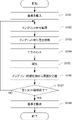
図1には、リソグラフィ方法の一実施形態として、インプリント装置IMPを含むリソグラフィシステムにおいて実行されるリソグラフィ方法が示されている。図1に示される動作は、制御部110によって制御されうる 工程S101では、不図示の基板搬送機構によって基板Sが搬送元(例えば、前処理装置とインプリント装置IMPとの中継部)から基板保持部102の上に搬送される。
FIG. 1 shows, as an embodiment of a lithography method, a lithography method performed in a lithography system including an imprinting apparatus IMP. The operation shown in FIG. 1 can be controlled by the
工程S102~S106では、基板Sの複数のショット領域のうち選択されたショット領域に対するインプリント処理(パターンの形成)が実行される。以下では、基板Sの複数のショット領域のうち選択されたショット領域を、対象ショット領域と呼ぶことがある。 In steps S102 to S106, imprint processing (pattern formation) is executed for a shot area selected from the plurality of shot areas of the substrate S. Hereinafter, the shot area selected from the plurality of shot areas of the substrate S may be referred to as a target shot area.
まず、工程S102では、基板Sの対象ショット領域の上にディスペンサ108によってインプリント材IMが配置される。この処理は、例えば、基板駆動機構105によって基板Sを駆動しながらディスペンサ108からインプリント材IMを吐出することによってなされうる。次に、工程S103では、対象ショット領域の上のインプリント材IMに型Mのパターン領域MPが接触するように型駆動機構122および基板駆動機構105の少なくとも一方によって基板Sと型Mとが相対的に駆動される。一例においては、対象ショット領域の上のインプリント材IMに型Mのパターン領域MPが接触するように型駆動機構122によって型Mが駆動される。インプリント材IMに型Mのパターン領域MPを接触させる処理において、変形機構123によって型Mのパターン領域MPが基板Sに向かって凸形状に変形されうる。この際、キャビティ圧が制御され、その値が蓄積されうる。また、インプリント材IMに型Mのパターン領域MPを接触させる処理において観察部112による撮像が実行され、撮像された画像(スプレッド画像)が蓄積されうる。
First, in step S102, the imprint material IM is arranged by the
工程S104では、基板Sの対象ショット領域と型Mのパターン領域MPとのアライメントがなされうる。アライメントは、例えば、アライメント計測部106を使って得られたショット領域の第1マークと型Mの第2マークとの相対位置情報に基づいて、第1マークと第2マークとの相対位置が目標相対位置の許容範囲に収まるようになされうる。アライメントでは、型駆動機構122および基板駆動機構105の少なくとも一方によって基板Sと型Mとが相対的に駆動されうる。ここで、基板Sと型Mとの相対位置情報は、仮位置情報(仮相対位置情報)を位置合わせエラー量(補正値)に基づいて補正することによって得られ、基板Sと型Mとの相対駆動量の目標値を決定するために用いられうる。仮位置情報(仮相対位置情報)は、アライメントスコープ106を使って得られた画像データに基づいて決定される情報であり、基板Sのショット領域と型Mとの仮の相対位置を示しうる。位置合わせエラー量は、アライメントスコープ106を使って得られた画像データに基づいて算出されうる。位置合わせエラー量は、モデル生成装置1007によって生成されインプリント装置IMPの制御部110に提供されるモデルを使って算出されうる。位置合わせエラー量(補正値)による仮位置情報(仮相対位置情報)の補正は、アライメントの実行期間の全てにおいて実行されてもよいし、ショット領域と型Mとの相対位置が基準値以下に収まった時点以降において実行されてもよい。制御部110は、アライメントスコープ106を使って得られる画像データを蓄積し、蓄積された画像データをモデル生成装置1007(機械学習部)に提供しうる。モデル生成装置1007は、インプリント装置IMPの制御部110から提供される画像データに基づいて、位置合わせエラー量を決定するためのモデルを生成しうる。
In step S104, the target shot region of the substrate S and the pattern region MP of the mold M can be aligned. For alignment, for example, the relative position between the first mark and the second mark is targeted based on the relative position information between the first mark of the shot region and the second mark of the type M obtained by using the
ここで、マークの位置を計測する方法を例示的に説明する。図6(a)には、X方向の位置を計測するマークを撮像して得られたマーク画像(画像データ)401が例示され、図6(b)には、マーク画像401から得られるアライメント波形406が例示されている。基板Sは、図6(a)のマーク画像に対応するマークと、該マークを90度回転させたマークとを有しうる。図6(a)のマーク画像に対応するマークは、計測方向がX方向であり、X方向における位置を計測するために使用されるマーク(以下では、X方向計測用のマークと呼ぶことがある)である。図6(a)のマーク画像に対応するマークを90度回転させたマークは、計測方向がY方向であり、Y方向における位置を計測するために使用されるマーク(以下では、Y方向計測用のマークと呼ぶことがある)である。
Here, a method of measuring the position of the mark will be exemplified. FIG. 6A exemplifies a mark image (image data) 401 obtained by imaging a mark for measuring a position in the X direction, and FIG. 6B shows an alignment waveform obtained from the
例えば、制御部110は、基板Sのショット領域に設けられたX方向計測用の第1マークと基板Sのショット領域に設けられたY方向計測用の第1マークとを使って、該ショット領域のX方向の位置およびY方向の位置を仮位置情報として求める。同様に、型Mに設けられたX方向の位置を計測するための第2マークと型Mに設けられたY方向の位置を計測するための第2マークとを使って、型MのX方向の位置およびY方向の位置を仮位置情報として求める。そして、制御部110は、これらの仮位置情報を位置合わせエラー量(補正値)に基づいて補正することにより、基板Sのショット領域と型Mとの相対位置情報(アライメント誤差)を生成することができる。
For example, the
また、制御部110は、基板Sのショット領域に設けられたX方向用の第1マークと型Mに設けられたX方向用の第2マークとによって形成されるモアレ縞からショット領域と型MとのX方向における相対位置を仮相対位置情報として求める。同様に、基板Sのショット領域に設けられたY方向用の第1マークと型Mに設けられたY方向用の第2マークとによって形成されるモアレ縞からショット領域と型MとのY方向における相対位置を仮相対位置情報として求める。そして、制御部110は、これらの仮相対位置情報を位置合わせエラー量(補正値)に基づいて補正することにより、基板Sのショット領域と型Mとの相対位置情報(アライメント誤差)を生成することができる。
Further, the
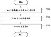
図7には、アライメント計測部106を使ってマークの位置を仮位置情報として求める方法が示されている。以下、図6(a)のマーク画像を例として、マーク位置402を仮位置情報として求める方法を説明する。マーク位置402は、一例として、計測方向(図6(a)ではX方向)におけるマーク画像の中心位置であり、これはマーク画像に対応するマークの中心位置でもある。この例では、計測方向404はX方向であり、非計測方向405はY方向である。
FIG. 7 shows a method of obtaining the position of the mark as temporary position information by using the
工程S501では、制御部110は、アライメント計測部106を使ってマークを撮像することによりマーク画像401(画像データ)を取得する。工程S502では、制御部110は、マーク画像401に基づいてアライメント波形406を生成(算出)する。アライメント波形406は、マーク画像401から得られる計測方向(X方向)の信号波形である。アライメント波形406は、例えば、マーク画像401を含む計測領域403を構成する複数の画素のうち、計測方向404(X方向)における位置が等しい画素のそれぞれについての積算値を算出することによって生成されうる。
In step S501, the
工程S503では、制御部110は、アライメント波形406に基づいてマーク位置402を仮位置情報として算出する。算出方法の一例としては、アライメント波形406の重心位置をマーク位置402とする方法がある。別例として、フーリエ変換等によりアライメント波形の位相を算出する事によりマーク位置を算出する方法、あるいは、パターンマッチング法を用いてマーク位置を算出する方法などがある。
In step S503, the
図1に戻って、工程S105では、硬化部107によってインプリント材IMを硬化させるためのエネルギーが、基板Sと型Mのパターン領域MPとの間のインプリント材IMに照射される。これによってインプリント材IMが硬化し、インプリント材IMの硬化物が形成される。工程S106では、インプリント材IMの硬化物と型Mのパターン領域MPとが分離されるように、型駆動機構122および基板駆動機構105の少なくとも一方によって基板Sと型Mとが相対的に駆動される。一例においては、インプリント材IMの硬化物と型Mのパターン領域MPとが分離されるように、型駆動機構122によって型Mが駆動される。インプリント材IMの硬化物と型Mのパターン領域MPとが分離される際も、型Mのパターン領域MPが基板Sに向かって凸形状に変形されるとよい。また、観察部112による撮像が実行され、撮像された画像に基づいてインプリント材IMと型Mとの分離の状態が観察されうる。
Returning to FIG. 1, in step S105, the energy for curing the imprint material IM by the
工程S107では、制御部110は、基板Sの全てのショット領域に対して工程S102~S106のインプリント処理を実行したかどうかを判断する。そして、制御部110は、基板Sの全てのショット領域に対して工程S102~S106のインプリト処理を実行した場合には工程S108に進み、未処理のショット領域が存在する場合には工程S102に戻る。この場合、未処理のショット領域のうち選択されたショット領域が対象ショット領域とされ、当該対象ショット領域に対して工程S102~S106のインプリント処理が実行される。
In step S107, the
工程S108では、不図示の基板搬送機構によって基板Sが基板保持部102から搬送先(例えば、後処理装置との中継部)に搬送される。図1に示される動作は、複数の基板で構成されるロットが処理される場合には、該複数の基板のそれぞれに対して実行される。
In step S108, the substrate S is transported from the
ここで、インプリント装置IMP(リソグラフィ装置)において、基板Sおよび/または型Mに設けられたマークには、本来形成されるべき形状や位置で形成されていないマーク(異常マーク)が存在することがある。このような異常マークの位置情報をそのまま使用してしまうと、基板Sと型Mとのアライメントを高精度に行うことが困難になりうる。そのため、本実施形態のインプリント装置IMP(制御部110)は、画像データ(マーク画像)から得られる計測対象物(例えばマーク)の位置情報を適切に使用するための判断材料の1つとして、当該位置情報の確信度を決定しうる。 Here, in the imprint device IMP (lithography device), the marks provided on the substrate S and / or the mold M have marks (abnormal marks) that are not formed in the shape and position that should be originally formed. There is. If the position information of such an abnormality mark is used as it is, it may be difficult to perform high-precision alignment between the substrate S and the mold M. Therefore, the imprint device IMP (control unit 110) of the present embodiment can be used as one of the judgment materials for appropriately using the position information of the measurement object (for example, the mark) obtained from the image data (mark image). The certainty of the location information can be determined.
具体的には、インプリント装置IMPの制御部110は、計測対象物の位置情報を生成する生成部と、当該位置情報の確信度を決定する決定部と、を備える処理装置として機能するように構成されうる。生成部は、アライメント計測部106による撮像で生成された計測対象物の画像データに基づいて、第1方向(計測方向)における計測対象物の位置情報を生成しうる。生成部は、上述したように、計測対象物の仮位置情報と補正値とに基づいて、第1方向における計測対象物の位置情報を生成(決定)してもよい。決定部は、第1方向と異なる第2方向(非計測方向)に関する画像データの特徴量に基づいて、生成部で生成された計測対象物の位置情報の確信度を決定しうる。確信度は、生成部で生成された計測対象物の位置情報が正常であると確信することができる度合いを表した指標(情報)であり、確からしさおよび/または信頼度として理解されてもよい。
Specifically, the
上記の処理装置として機能する制御部110(決定部)は、画像データにおける第2方向の特徴量に基づいて第1方向の位置情報の確信度を得るためのモデルを用いて、該特徴量から確信度を決定しうる。制御部110は、該モデルを機械学習によって生成する機械学習部(モデル生成部1007)を備えていてもよい。また、上記の処理装置としての機能は、インプリント装置IMPの制御部110の代わりに又は加えて、制御装置1003に組み込まれてもよい。
The control unit 110 (determination unit) that functions as the above-mentioned processing device uses a model for obtaining the certainty of the position information in the first direction based on the feature amount in the second direction in the image data, and uses the feature amount to obtain the certainty. Can determine confidence. The
次に、図4を参照しながら、モデル生成装置1007におけるモデルの生成方法を説明する。なお、上述したように、モデル生成装置1007は、インプリント装置IMP(例えば、制御部110)に組み込まれてもよく、この場合、モデルの生成は、インプリント装置IMPにおいてなされる。
Next, a model generation method in the
工程S201では、モデル生成装置1007は、位置合わせエラー量を取得する。具体的には、モデル生成装置1007は、重ね合わせ検査装置(検査装置1005)で測定した基板Sの1つのショット領域の計測値を取得する。取得する計測値は、基板Sの各ショット領域に属する少なくとも1点の重ね合わせ精度を計測した結果でありうる。例えば、計測値は、基板Sの下地レイヤー(の重ね合わせ検査マーク)とその上にインプリント装置IMPによって形成されたレイヤー(の重ね合わせ検査マーク)との重ね合わせずれ量でありうる。そして、モデル生成装置1007は、重ね合わせ検査装置による計測値とインプリント装置IMPでの最終計測値(例えば、工程S104で最終的に得られた位置情報(アライメント誤差))との差分を位置合わせエラー量として算出する。
In step S201, the
工程S202では、モデル生成装置1007は、少なくとも非計測方向におけるマーク画像の特徴量を取得する。具体的には、モデル生成装置1007は、まず、直前の工程S201で計測値を取得したショット領域のマークのマーク画像(画像データ)を取得する。このマーク画像は、工程S104でアライメント計測部106を使って取得したものであり、工程S104の終了後の任意のタイミングでインプリント装置IMPからモデル生成装置1007に提供されうる。そして、モデル生成装置1007は、取得したマーク画像の特徴量を求める。この特徴量は、少なくとも非計測方向に関する特徴量を含み、付加的に計測方向に関する特徴量を含んでもよい。計測方向は、図6の例では、X方向である。非計測方向は、図6の例では、X方向と交差する方向であり、例えば、Y方向である。
In step S202, the
工程S203では、モデル生成装置1007は、基板Sの考慮対象の複数のショット領域の全てについて工程S201~S202を実行したかどうかを判断する。未実行のショット領域がある場合には工程S201に戻り、該未実行のショット領域について工程S201~S202を実行する。そして、考慮対象の複数のショット領域の全てについて工程S201~S202の実行が終了したら工程S204に進む。工程S204では、モデル生成装置1007は、特徴量に基づいて位置合わせエラー量を推定するためのモデル、および、特徴量に基づいて確信度を決定するためのモデルを生成する。
In step S203, the
重ね合わせ検査装置による計測値とインプリント装置IMPでの計測値とで生じる位置ずれの要因によっては、非計測方向に関する特徴量と、計測方向に関する特徴量とを用いてモデルを生成したほうが位置合わせエラー量を低減できる場合がある。そのような場合には、非計測方向に関する特徴量と、計測方向に関する特徴量の両方を用いて学習したモデルを生成することが好ましい。 Depending on the cause of the positional deviation between the measured value by the superposition inspection device and the measured value by the imprint device IMP, it is better to generate a model using the feature amount related to the non-measurement direction and the feature amount related to the measurement direction. It may be possible to reduce the amount of error. In such a case, it is preferable to generate a model learned by using both the feature amount related to the non-measurement direction and the feature amount related to the measurement direction.
ここで、特徴量に基づいて位置合わせエラー量を推定するためのモデル(エラー量推定モデル)は、特徴量を入力とし、位置合わせエラー量を示す情報を出力とするように構成されうる。エラー量推定モデルは、位置合わせエラー量を示す情報として、位置合わせエラー量自体を出力するように構成されてもよいし、位置合わせエラー量を示す指標が含まれる分布および/または値を出力するように構成されてもよい。また、特徴量に基づいて確信度を決定するためのモデル(確信度決定モデル)は、特徴量を入力とし、確信度を示す情報を出力とするように構成されうる。確信度決定モデルは、確信度を示す情報として、確信度自体を出力するように構成されてもよいし、確信度を示す指標が含まれる分布および/または値を出力するように構成されてもよい。本実施形態では、特徴量を入力とし、位置合わせエラー量を示す指標と確信度を示す指標とが含まれる分布を出力とするモデルを生成する例について説明する。 Here, the model for estimating the alignment error amount based on the feature amount (error amount estimation model) can be configured to input the feature amount and output information indicating the alignment error amount. The error amount estimation model may be configured to output the alignment error amount itself as information indicating the alignment error amount, or output a distribution and / or a value including an index indicating the alignment error amount. It may be configured as follows. Further, the model for determining the certainty based on the feature amount (certainty degree determination model) may be configured to input the feature amount and output the information indicating the certainty degree. The certainty determination model may be configured to output the certainty itself as information indicating the certainty, or may be configured to output a distribution and / or a value containing an index indicating the certainty. good. In this embodiment, an example of generating a model in which a feature amount is input and a distribution including an index indicating an alignment error amount and an index indicating a certainty degree is included as an output will be described.
モデルの生成は、例えば、機械学習によって行うことができる。具体例を挙げると次のとおりである。まず、インプリント装置IMPによって基板の複数のショット領域に同じ条件で新たなレイヤー(パターン)を形成する。そして、外部の重ね合わせ検査装置によって、各ショット領域の下地レイヤー(の重ね合わせ検査マーク)と新たに形成されたレイヤー(の重ね合わせ検査マーク)との重ね合わせずれ量を計測する。次いで、モデル生成装置1007は、計測された各ショット領域の重ね合わせずれ量を取得し、重ね合わせずれ量と当該ショット領域に新たにレイヤーを形成した際の最終計測値との差分を位置合わせエラー量として算出する。そして、モデル生成装置1007は、新たにレイヤーを形成する際に使用した各ショット領域のマーク画像の特徴量をモデルの入力データとし、算出された位置合わせエラー量を教師データとして用いて機械学習をする。
The model can be generated, for example, by machine learning. Specific examples are as follows. First, a new layer (pattern) is formed in a plurality of shot areas of the substrate by the imprint device IMP under the same conditions. Then, an external superposition inspection device measures the amount of superposition deviation between the base layer (superposition inspection mark) of each shot area and the newly formed layer (superposition inspection mark). Next, the
機械学習に際しては、位置合わせエラー量に対して前処理を実施してもよい。前処理の例としては、例えば、位置合わせエラー量にオフセット値を加算する方法、位置合わせエラー量に値を乗算し、エラー量のスケールを変更する方法を挙げることができる。 In machine learning, preprocessing may be performed for the amount of alignment error. Examples of the preprocessing include a method of adding an offset value to the alignment error amount, and a method of multiplying the alignment error amount by a value to change the scale of the error amount.
機械学習の方法としては、例えば、変数を確率として扱うことで不確かさを考慮した推論を行うガウス過程回帰およびベイズ推定を挙げることができる。ガウス過程回帰およびベイズ推定を使用する場合、モデルは、特徴量を入力して位置合わせエラー量の確率分布を出力する関数であり、機械学習によって内部変数の最適化が行われうる。得られたエラー量の確率分布の期待値をエラー量の推論値として用いることができ、当該確率分布の分散を確信度として用いることができる。 Examples of machine learning methods include Gaussian process regression and Bayesian inference, which make inferences considering uncertainty by treating variables as probabilities. When using Gaussian process regression and Bayesian inference, the model is a function that inputs features and outputs a probability distribution of alignment errors, and machine learning can be used to optimize internal variables. The expected value of the obtained probability distribution of the error amount can be used as the inferred value of the error amount, and the variance of the probability distribution can be used as the certainty.
推論の計算量を削減する必要がある場合、重回帰分析等のように計算量が少ない統計モデルを使用することが適している。マーク画像の画素値を特徴量とする等の高次元の特徴量を用いて位置合わせエラー量を算出する場合、多層パーセプトロンで構成されたニューラルネットワークを用いて内部の変数を最適化する手法が適している。位置合わせエラー量またはマーク画像に異常値が多く含まれている場合、異常値に頑健な決定木分析に基づいた手法を適用してもよい。重回帰分析またはニューラルネットワークを使用する場合は、モデルは、特徴量を入力して位置合わせエラー量を出力するように定義され、機械学習によって内部変数の最適化が行われうる。決定木分析を使用する場合は、モデルは、特徴量を入力して位置合わせエラー量を出力するように定義され、機械学習によって決定木の構築が行われうる。 When it is necessary to reduce the amount of inference calculation, it is suitable to use a statistical model with a small amount of calculation such as multiple regression analysis. When calculating the alignment error amount using a high-dimensional feature amount such as the pixel value of the mark image, the method of optimizing the internal variables using a neural network composed of a multi-layer perceptron is suitable. ing. If the amount of misalignment error or the mark image contains a large number of outliers, a method based on robust decision tree analysis may be applied to the outliers. When using multiple regression analysis or neural networks, the model is defined to input features and output alignment errors, and machine learning can be used to optimize internal variables. When using decision tree analysis, the model is defined to input features and output alignment error amounts, and machine learning can be used to build the decision tree.
工程S205では、モデル生成装置1007は、工程S204で生成されたモデルを保存する。また、モデル生成装置1007は、工程S204で生成されたモデルをインプリント装置IMPの制御部110に提供しうる。
In step S205, the
ここで、位置合わせエラー量の推定および確信度の決定において、非計測方向におけるマーク画像の特徴量を用いる理由(原理)を説明する。図14(d)には、基板Sのショット領域に設けられた第1マークと型Mに設けられた第2マークとによって形成される光学像であるモアレ縞に基づいて基板Sのショット領域と型Mとの相対位置情報を計測する原理が示されている。図14(d)には、基板Sのショット領域に設けられた第1マーク3aと型Mに設けられた第2マーク2aとが示されている。アライメントスコープ106は、マークを照明する照明光学系を有し、該照明光学系は、瞳面Pを有する。IL1、IL2、IL3、IL4は、瞳面Pに形成される極からの照明光を示している。
Here, the reason (principle) for using the feature amount of the mark image in the non-measurement direction in the estimation of the alignment error amount and the determination of the certainty degree will be described. FIG. 14D shows the shot region of the substrate S based on the moire fringes which are optical images formed by the first mark provided in the shot region of the substrate S and the second mark provided in the mold M. The principle of measuring the relative position information with the type M is shown. FIG. 14D shows a first mark 3a provided in the shot region of the substrate S and a
基板Sのショット領域と型MとのX方向における相対位置の計測には、照明光IL1、IL2が使用される。図14(a)に例示されるように、X方向における相対位置の計測においては、X方向における相対位置の計測には使用されない照明光IL3、IL4が第1マーク3a、第2マーク2aのエッジで散乱光を発生させうる。この散乱光は、フレアとなってモアレ縞信号(モアレ縞画像データ)に混入しうる。図14(c)には、図14(a)におけるモアレ縞信号のX方向における信号強度分布(アライメントスコープ106の撮像素子の受光面上の光強度分布)が例示されている。第1マーク3a、第2マーク2aのエッジからの散乱光によって信号強度分布における左端側および右端側のピークが大きいことが分かる。4周期あるモアレ縞信号のうち左端側および右端側の2周期は散乱光の影響を受けてしまい、これにより相対位置の計測精度が影響を受ける。図14(b)に示すように、Y方向における相対位置の計測についても同様であり、Y方向における相対位置の計測に使用されない照明光IL1、IL2が第1マーク3b、第2マーク2bのエッジで散乱光を発生させうる。そして、この散乱光がフレア光となってモアレ縞信号に混入しうる。以上は、計測方向における光強度分布がフレアの影響を受けうることを説明するものであるが、同様の原理によって、非計測方向における光強度分布も、フレアの影響を受けて変化しうる。そして、非計測方向における光強度分布の変化は、計測方向についての相対位置または位置の計測精度を低下させうる。
Illumination lights IL1 and IL2 are used to measure the relative positions of the shot region of the substrate S and the mold M in the X direction. As illustrated in FIG. 14A, in the measurement of the relative position in the X direction, the illumination lights IL3 and IL4, which are not used for the measurement of the relative position in the X direction, are the edges of the first mark 3a and the
図15、図16には、計測方向(X方向)の信号波形406と、非計測方向(Y方向)の信号波形407とがそれぞれ例示されている。計測方向の信号波形406は、アライメント波形とも呼ばれ、アライメント計測部106を使って得られた画像データ401を構成する複数の画素のうち、計測方向における位置が等しい画素のそれぞれの信号値の積算値を算出することによって得られうる。また、非計測方向の信号波形は、アライメント計測部106を使って得られた画像データ401を構成する複数の画素のうち、非計測方向における位置が等しい画素のそれぞれの信号値の積算値を算出することにより得られうる。
15 and 16 illustrate the
図16の例は、図15の例に比べて、フレア光の影響が大きい。図16に例示された計測方向の信号波形406は、図15に例示された計測方向の信号波形406よりも歪が大きく、そのために計測方向における計測結果に誤差901が生じうる。また、図16に例示された非計測方向の信号波形407は、図15に例示された非計測方向の信号波形407よりも歪が大きく、信号値のばらつき902が大きいことを示している。つまり、非計測方向の信号波形407は、計測方向の信号波形406、即ち計測方向における計測結果に対して相関を有することが分かる。したがって、非計測方向に関する画像データの特徴量を求め、該特徴量に基づいて、該画像データから得られる計測方向における計測対象物の仮位置情報を補正することにより計測対象物の位置情報を高精度に決定することができる。また、上記の説明から、非計測方向に関する画像データの特徴量は、計測方向における信号波形の歪みおよび/信号値のばらつきを反映しているといえる。そのため、該特徴量に基づいて、画像データから決定された計測対象物の位置情報についての確信度(確からしさ、信頼度)を決定することができる。
The example of FIG. 16 is more affected by flare light than the example of FIG. The
ここで、非計測方向(第2方向)に関して画像データから得られる特徴量について、図8を参照しながら説明する。図8には、図6と同様に、X方向の位置を計測するマークを撮像して得られたマーク画像(画像データ)401と、該マーク画像401から得られるアライメント波形406(計測方向(X方向)の信号波形)とが例示されている。また、図8には、マーク画像401から得られる非計測方向(Y方向)の信号波形407も例示されている。非計測方向の信号波形407は、例えば、マーク画像401を含む計測領域403を構成する複数の画像のうち、非計測方向(Y方向)における位置が等しい画素のそれぞれについての積算値を算出することによって生成されうる。
Here, the feature amount obtained from the image data in the non-measurement direction (second direction) will be described with reference to FIG. Similar to FIG. 6, FIG. 8 shows a mark image (image data) 401 obtained by imaging a mark for measuring a position in the X direction, and an alignment waveform 406 (measurement direction (X)) obtained from the
非計測方向(第2方向)に関して画像データから得られる特徴量は、図8に例示されるように、非計測方向における複数の位置にそれぞれに対応する複数の値603を含みうる。該複数の値603は、複数の積算値を含み、該複数の積算値の各々は、画像データを構成する複数の画素のうち非計測方向における位置が等しい画素のそれぞれの信号値の積算値でありうる。あるいは、該複数の値603は、画像データを構成する複数の画素のうち非計測方向に平行な線上の複数の画素の信号値を含みうる。あるいは、該複数の値603は、画像データを構成する複数の画素のうち非計測方向に平行な線上の複数の画素の信号値を処理して得られる複数の値でありうる。あるいは、該複数の値603は、複数の積算値に対して基底変換を行うことによって得られ、該複数の積算値の各々は、画像データを構成する複数の画素のうち非計測方向における位置が等しい画素のそれぞれの信号値の積算値でありうる。あるいは、該複数の値603は、画像データを構成する複数の画素のうち非計測方向に平行な線上の複数の画素の信号値に対して基底変換を行うことによって得られる値でありうる。あるいは、該複数の値603は、画像データを構成する複数の画素のうち非計測方向に平行な線上の複数の画素の信号値を処理して得られた複数の値に対して基底変換を行うことによって得られる値でありうる。
The feature quantity obtained from the image data in the non-measurement direction (second direction) may include a plurality of
あるいは、図9において、部分領域701において計測方向の位置が等しい画素のそれぞれの信号値を積算した結果と、部分領域702において計測方向の位置が等しい画素のそれぞれの信号値を積算した結果との差分を非計測方向における特徴量としてもよい。具体的には、部分領域701から得られる計測方向(X方向)のアライメント波形406aと、部分領域702から得られる計測方向(X方向)のアライメント波形406bとの差分を、非計測方向における特徴量としてもよい。部分領域701および部分領域702は、マーク画像401を含む計測領域403のうち非計測方向(Y方向)の位置が互いに異なる領域である。
Alternatively, in FIG. 9, the result of integrating the signal values of the pixels having the same position in the measurement direction in the
以下、図10を参照しながら非計測方向に関する画像データの特徴量を算出あるいは決定する例を説明する。図10において、x1、x2・・・は、アライメント計測部106による撮像によって得られた画像データ(マーク画像401)のX座標(X方向における画素位置)を表す。また、y1、y2・・・は、該画像データのY座標(Y方向における画素位置)を表している。以下では、X座標がx1、Y座標がy1の画素の画素値をx1y1と表す。ここで、サンプリングあるいは抽出する画素の座標x1、x2・・・、y1、y2・・・の間隔および個数については、任意に決定(設定)することができる。
Hereinafter, an example of calculating or determining the feature amount of the image data regarding the non-measurement direction will be described with reference to FIG. In FIG. 10, x1, x2 ... Represent the X coordinate (pixel position in the X direction) of the image data (mark image 401) obtained by imaging by the
一例として、(x1y1 + x2y1+ x3y1 +・・・)、(x1y2 + x2y2 + x3y2・・・)、・・・のように、y座標が等しい画素の画素値を積算することで、非計測方向の信号波形が有する特徴を特徴量として得ることができる。このような方法は、非計測方向に沿って回折光および/または散乱光が生じている場合に有効である。 As an example, by integrating the pixel values of pixels having the same y coordinate, such as (x1y1 + x2y1 + x3y1 + ...), (x1y2 + x2y2 + x3y2 ...), ... The features of the signal waveform can be obtained as the feature amount. Such a method is effective when diffracted light and / or scattered light is generated along the non-measurement direction.
回折光、散乱光が局所的に生じている場合、(x1y1)、(x1y2)、(x1y3)、(x1y4)、(x1y5)、(x1y6)、(x2y1)、(x2y2)、・・・のように各座標の画素の画素値をそのまま非計測方向の特徴量として用いてもよい。ここで、(x1y1+ x1y2)、(x1y3 + x1y4)、(x1y5 + x1y6)、(x2y1 + x2y2)、(x2y3 + x2y4)、・・・のように特徴量を決定してもよい。このように、y方向の複数の画素の画素値を加算することで特徴量を示すデータの数を削減することができ、これにより、特徴量に基づく補正値の計算における計算量を削減することができる。また、(x1y1+ x1y3)、(x1y2 + x1y4)・・・のように、複数の画素からなるグループの平均座標が昇順になるように、各グループにおける画素値の合計値を特徴量として抽出してもよい。あるいは、(x1y1+ x1y2 + x1y3)、(x1y3 + x1y4 + x1y5)・・・のように、複数の画素からなるグループの座標が部分的にオーバーラップするように、各グループにおける画素値の合計値を特徴量として抽出してもよい。あるいは、(x1y1+ x1y2 + x2y1 + x2y2)、(x1y2 + x1y3 + x2y2 + x2y3)、(x1y3 + x1y4 + x2y3 + x2y4)、・・・のようにxy方向に加算を行って特徴量を抽出してもよい。回折光および/または散乱光が斜め方向に沿って生じている場合、(x1y1+ x2y2)、(x2y2 + x3y3)、(x1y2 + x2y3)、(x2y3 + x3y4)、・・・のように斜め方向に加算を行って特徴量を抽出してもよい。 When diffracted light and scattered light are locally generated, (x1y1), (x1y2), (x1y3), (x1y4), (x1y5), (x1y6), (x2y1), (x2y2), ... As described above, the pixel values of the pixels of each coordinate may be used as they are as the feature amount in the non-measurement direction. Here, the feature amount may be determined as (x1y1 + x1y2), (x1y3 + x1y4), (x1y5 + x1y6), (x2y1 + x2y2), (x2y3 + x2y4), and so on. In this way, the number of data indicating the feature amount can be reduced by adding the pixel values of a plurality of pixels in the y direction, thereby reducing the calculation amount in the calculation of the correction value based on the feature amount. Can be done. Further, the total value of the pixel values in each group is extracted as a feature amount so that the average coordinates of the group consisting of a plurality of pixels are in ascending order, such as (x1y1 + x1y3), (x1y2 + x1y4), and so on. May be good. Alternatively, the total value of the pixel values in each group is set so that the coordinates of the groups consisting of a plurality of pixels partially overlap, such as (x1y1 + x1y2 + x1y3), (x1y3 + x1y4 + x1y5), and so on. It may be extracted as a feature amount. Alternatively, (x1y1 + x1y2 + x2y1 + x2y2), (x1y2 + x1y3 + x2y2 + x2y3), (x1y3 + x1y4 + x2y3 + x2y4), ... May be good. When diffracted light and / or scattered light is generated along an oblique direction, (x1y1 + x2y2), (x2y2 + x3y3), (x1y2 + x2y3), (x2y3 + x3y4), ... The feature amount may be extracted by performing addition.
また、(α×x1y1)、(β×x1y2)、(γ×x1y3)、・・・のように、定数α、β、γ、・・・を各画素の画素値に乗算してもよい。これによって、補正の効果が薄い特徴量の重みを任意に下げることができる。また、(α×x1y1+ β×x1y2 + γ×x1y3)、(a×x1y2 + b×x1y3 + c×x1y4)、(p×x1y3 + q×x1y4 + r×x1y5)、・・・のように特徴量を決定してもよい。ここで、α、β、γ、a、b、c、p、q、rは、画素値に乗じる定数である。α=a=p=-1、β=b=p=2、γ=c=r=-1とすると、非計測方向の勾配を特徴量として得ることができる。 Further, constants α, β, γ, ... may be multiplied by the pixel value of each pixel, such as (α × x1y1), (β × x1y2), (γ × x1y3), .... As a result, the weight of the feature amount for which the correction effect is small can be arbitrarily reduced. Further, features such as (α × x1y1 + β × x1y2 + γ × x1y3), (a × x1y2 + b × x1y3 + c × x1y4), (p × x1y3 + q × x1y4 + r × x1y5), and so on. The amount may be determined. Here, α, β, γ, a, b, c, p, q, and r are constants to be multiplied by the pixel value. When α = a = p = -1, β = b = p = 2, and γ = c = r = -1, a gradient in the non-measurement direction can be obtained as a feature quantity.
得られた非計測方向の特徴量に対して基底変換を行うことによって新たな特徴量を得てもよい。基底変換の例としては、フーリエ変換を行って位相および振幅を得る方法、主成分分析によって基底を求め、基底変換を行うことで情報量を縮約する方法がある。また、特徴量に対してオフセット値を加算または乗算して新たな特徴量をすることもできる。非計測方向の特徴量に加えて、計測方向の特徴量を使用して、これらに基づいて補正値を決定してもよい。計測方向の波形(画像データ)の任意の点をサンプリングして特徴量として用いてもよく、非計測方向の特徴量と同じように基底変換やオフセット加算、乗算が行える。なお、画像データから特徴量を求める処理は、インプリント装置IMPの制御部110等で実行されてもよい。
A new feature amount may be obtained by performing a basis conversion on the obtained feature amount in the non-measurement direction. Examples of the basis transform include a method of obtaining a phase and an amplitude by performing a Fourier transform, and a method of obtaining a basis by principal component analysis and reducing the amount of information by performing a basis transform. Further, a new feature amount can be created by adding or multiplying the offset value with respect to the feature amount. In addition to the features in the non-measurement direction, the features in the measurement direction may be used to determine the correction value based on these. Arbitrary points of the waveform (image data) in the measurement direction may be sampled and used as the feature amount, and the basis conversion, offset addition, and multiplication can be performed in the same way as the feature amount in the non-measurement direction. The process of obtaining the feature amount from the image data may be executed by the
次に、図5を参照しながら、前述した工程S104(アライメント)において実行される処理を説明する。この処理では、前述のモデルを用いて位置合わせエラー量が算出され、その位置合わせエラー量(補正量)に基づいて、画像データに基づいて求められる計測方向に関する仮位置情報を補正することにより、計測対象物の位置情報を生成する。また、前述のモデルを用いて確信度が決定され、その確信度に基づいて、工程S104(アライメント)における計測対象物の位置情報の使用に関する設定を行う。 Next, the process executed in the above-mentioned step S104 (alignment) will be described with reference to FIG. In this process, the alignment error amount is calculated using the above-mentioned model, and the temporary position information regarding the measurement direction obtained based on the image data is corrected based on the alignment error amount (correction amount). Generate position information of the object to be measured. Further, the certainty is determined using the above-mentioned model, and the use of the position information of the measurement object in the step S104 (alignment) is set based on the certainty.
工程S301では、インプリント装置IMPの制御部110は、モデル生成装置1007によって生成されたモデルを取得する。なお、モデルの取得は、次工程である工程S302の直前である必要は無く、例えば、前述した工程S102の前などの任意のタイミングでなされてもよい。
In step S301, the
工程S302では、制御部110は、工程S104においてアライメント計測部106による撮像で得られた画像データを取得し、該画像データから少なくとも非計測方向に関する特徴量を取得(抽出、算出)する。工程S302における特徴量の抽出あるいは算出方法は、モデル生成装置1007が工程S202で実行する特徴量の抽出あるいは算出方法と同じである。
In step S302, the
工程S303では、制御部110は、工程S301で取得されたモデルと、工程S302で抽出あるいは算出された特徴量とを用いて、位置合わせエラー量を算出する。例えば、学習手段としてガウス過程回帰を用いる場合、工程S301で取得したモデルに対して特徴量を入力し、該モデルから出力された確率分布の期待値を位置合わせエラー量として得ることができる。この位置合わせエラー量は、補正値として使用されうる。
In the process S303, the
工程S304では、制御部110は、工程S104においてアライメント計測部106による撮像で得られた画像データの計測方向に関する光強度分布に基づいて、計測方向に関する計測対象物の仮位置情報を決定する(求める)。この仮位置情報は、画像データの非計測方向に関する特徴量を考慮することなく得られる暫定的な計測対象物の位置情報である。
In step S304, the
工程S305では、制御部110は、工程S304で得られた仮位置情報と、工程S303で得られた非計測方向に関する画像データの特徴量に基づく補正値とに基づいて、計測方向における計測対象物の位置情報を生成する。具体的には、制御部110は、工程S304で得られた仮位置情報から工程S303で得られた非計測方向に関する画像データの特徴量に基づく補正値を減じることによって、計測方向における計測対象物の位置情報を生成することができる。
In step S305, the
モデル作成時に非計測方向に関する特徴量に加え、計測方向に関する特徴量を用いている場合には、制御部110は、工程S302で非計測方向に関する特徴量と、計測方向に関する特徴量とを抽出あるいは算出してもよい。そして、制御部110は、工程S303でモデルに対して非計測方向に関する特徴量と計測方向に関する特徴量とを入力し、モデルから出力された位置合わせエラー量を補正値とし、工程S305で計測対象物の位置情報を求めてもよい。
When the feature amount related to the measurement direction is used in addition to the feature amount related to the non-measurement direction at the time of model creation, the
工程S306では、制御部110は、工程S301で取得されたモデルと、工程S302で抽出あるいは算出された特徴量とを用いて、工程S305で求めた計測対象物の位置情報の確信度を決定(算出)する。例えば、学習手段としてガウス過程回帰を用いる場合、工程S301で取得したモデルに対して特徴量を入力し、該モデルから出力された確率分布の分散を確信度として決定することができる。このように計測対象物(例えばマーク)の確信度を決定することにより、該確信度に基づいて、該計測対象物としてのマークが異常マークか否かを判断することができる。換言すると、工程S104のアライメントにおいて該計測対象物の位置情報を使用可能か否かを判断することができる。
In the process S306, the
工程S307では、制御部110は、工程S306で決定された特徴量に基づいて、工程S305で生成された計測対象物の位置情報の使用(工程S104のアライメントでの使用)に関する設定を行う。該設定は、例えば、工程S305で生成された計測対象物の位置情報を工程S104のアライメントで使用するか否かの設定であってもよい。また、工程S305で生成された計測対象物の位置情報を工程S104のアライメントで使用する際に該位置情報に付与される重みの設定であってもよい。これらの設定は、処理装置の一部として制御部110および/または制御装置1003に備えられた設定部により実行されうる。
In the step S307, the
ここで、上記の処理に基づいたアライメントの例について説明する。基板Sの対象ショット領域に配置された1以上のマーク(アライメントマーク)を計測対象物として上記の処理により生成された位置情報(アライメント計測値)を用いて、基板S(ショット領域)と型Mとの相対位置を目標相対位置に制御する場合を想定する。この場合において、以下の式(1)で表される評価値Vが最小になるような目標相対位置sx、sy、θx、θy、βx、βyを求める。式(1)において、xiおよびyiは、対象ショット領域におけるマークの設計上のX方向の位置およびY方向の位置をそれぞれ示しており、dxiおよびdyiは、X方向のアライメント計測値およびY方向のアライメント計測値をそれぞれ示している。iはマークの番号を示しており、nはマークの数を示している。また、sxおよびsyは、目標相対位置のX方向のシフト成分およびY方向のシフト成分をそれぞれ示しており、θxおよびθyは、目標相対位置のX軸周りの回転成分およびY軸周りの回転成分をそれぞれ示している。βxおよびβyは、目標相対位置のX方向の伸び成分およびY方向の伸び成分をそれぞれ示している。このような目標相対位置の各成分に基づいて、基板S(対象ショット領域)と型Mとのアライメントが制御されうる。 Here, an example of alignment based on the above processing will be described. Using the position information (alignment measurement value) generated by the above processing with one or more marks (alignment marks) arranged in the target shot area of the board S as the measurement target, the board S (shot area) and the mold M It is assumed that the relative position with and is controlled to the target relative position. In this case, the target relative positions s x , sy , θ x , θ y , β x , and β y are obtained so that the evaluation value V represented by the following equation (1) is minimized. In equation (1), x i and y i indicate the design position of the mark in the target shot area in the X direction and the position in the Y direction, respectively, and dx i and dy i are alignment measurement values in the X direction. And the alignment measurement values in the Y direction are shown respectively. i indicates the number of the mark, and n indicates the number of marks. Further, s x and sy indicate the shift component in the X direction and the shift component in the Y direction of the target relative position, respectively, and θ x and θ y are the rotation component around the X axis and the Y axis of the target relative position. The surrounding rotation components are shown respectively. β x and β y indicate the elongation component in the X direction and the elongation component in the Y direction of the target relative position, respectively. The alignment between the substrate S (target shot region) and the mold M can be controlled based on each component of such a target relative position.

このとき、各マークのアライメント計測値dxi、dyiに異常値(例えば、他のマークのアライメント計測値に比べて極端に異なる値)が含まれる場合、基板S(対象ショット領域)と型Mとのアライメントを高精度に制御することが困難になりうる。そこで、本実施形態の制御部110は、各マークを計測対象物として位置情報(アライメント計測値)の確信度を求め、該確信度が閾値未満であるマークがある場合、そのマークを使用せずに、残りのマークを用いて基板Sと型Mとのアライメントを制御しうる。または、以下の式(2)で表されるように、確信度に応じて、各マークのアライメント計測値(位置情報)に重みwを乗算して目標相対位置の各成分を求め、求めた目標相対位置の各成分に基づいて、基板Sと型Mとのアライメントを制御しうる。これにより、異常マークの影響を低減し、基板Sと型Mとのアライメントを高精度に制御することができる。
At this time, if the alignment measurement values dx i and dy i of each mark include abnormal values (for example, values extremely different from the alignment measurement values of other marks), the substrate S (target shot area) and the type M It can be difficult to control the alignment with and with high accuracy. Therefore, the

また、制御部110は、確信度に応じて、基板Sと型Mとのアライメントの終了時刻を調整してもよい。このような調整は、計測対象物としてのマークを構成する凹部にインプリント材IMが十分に充填されていないことに起因して、マーク画像(画像データ)の特徴量が正常に抽出または算出されずに、確信度が閾値より低く求められる場合に有効である。このような場合では、時間の経過に伴ってインプリント材IMが計測対象物(マーク)の凹部に十分に充填され、特徴量が正常に抽出または算出されるようになるため、確信度も上昇しうる。つまり、確信度に応じてアライメントの終了時刻を調整することにより、基板Sと型Mとのアライメント精度を向上させることができる。
Further, the
例えば、制御部110は、基板Sと型Mとのアライメントの初期段階で得られた確信度に応じて、該アライメントの終了時刻を調整してもよい。具体的には、確信度と、アライメント精度が所定値以上となるアライメントの実行時間との対応関係を示す情報に基づいて、アライメントの初期段階で得られた確信度に応じて該アライメントの実行時間(即ち終了時刻)を調整することができる。該対応関係を示す情報は、例えば実験やシミュレーション等により事前に取得されうる。また、制御部110は、基板Sと型Mとのアライメント中において、計測対象物としてのマークの位置情報(アライメント計測値)および確信度を逐次的に(連続的に)求め、確信度が閾値以上になったことに応じて、該アライメントの終了時刻を調整してもよい。この場合、制御部110は、確信度が閾値以上になった時刻から所定時間において基板Sと型Mとのアライメントが行われるように、該アライメントの終了時刻を調整してもよい。
For example, the
以下、本実施形態の検証結果を示す。この検証は、図11のようなショット領域内のX方向のアライメントマーク801、803、805、807およびY方向のアライメントマーク802、804、806、808の8個のマークを用いて行われた。809は、重ね合わせ検査装置で用いるマーク(検査マーク)である。この検証では、各アライメントマーク801~808についてアライメント計測部106を用いて得られた位置情報と、各アライメントマークの近傍の検査マーク809についての重ね合わせ計測結果とに基づいて、位置合わせエラー量が算出される。該位置合わせエラー量を算出するために用いられる位置情報としては、非計測方向に関する画像データの特徴量に基づく補正値により補正する前の位置情報(即ち、仮位置情報)と、補正した後の位置情報とが用いられる。また、モデルを生成するための学習には、20枚のウェハ×69個のショット領域のデータを使用し、学習に使用したデータとは異なる6枚のウェハ×69個のショット領域に対して補正を適用した。アライメントマークの位置および方向について、それぞれ独立に学習と補正を行った。
The verification results of this embodiment are shown below. This verification was performed using eight marks of the alignment marks 801, 803, 805, 807 in the X direction and the alignment marks 802, 804, 806, 808 in the Y direction in the shot region as shown in FIG.
図12は、補正前および補正後において、全データの位置合わせエラー量の標準偏差を表しており、位置合わせエラー量がどれだけばらついているかを示している。このばらつきを小さくすることが本実施形態の目的であり、グラフから位置合わせエラー量のばらつきが最大で16%程度小さくなっていることが確認できる。 FIG. 12 shows the standard deviation of the alignment error amount of all the data before and after the correction, and shows how much the alignment error amount varies. It is an object of the present embodiment to reduce this variation, and it can be confirmed from the graph that the variation in the alignment error amount is reduced by about 16% at the maximum.
図13(a)~(b)は、補正前および補正後について、各データの位置合わせエラー量を横に並べて表示したグラフである。図13(a)は、補正前における各データの位置合わせエラー量を示しており、図13(b)は、補正後における各データの位置合わせエラー量を示している。また、図13(c)は、各データについて、非計測方向に関する画像データの特徴量に基づいて得られた確信度を示している。 13 (a) to 13 (b) are graphs showing the amount of misalignment error of each data side by side before and after the correction. FIG. 13A shows the amount of alignment error of each data before correction, and FIG. 13B shows the amount of alignment error of each data after correction. Further, FIG. 13C shows the certainty obtained for each data based on the feature amount of the image data regarding the non-measurement direction.
図13(a)~(b)を参照すると、例えば、丸Aで囲んだ右側部分のデータにおいて、補正により位置合わせエラー量(および/または、位置合わせエラー量のばらつき)が低減されていることを確認することができる。また、丸Bで囲んだデータにおいては、他のデータと比べて位置合わせエラー量が極端に大きく、補正によっても位置合わせエラー量が改善されていないことを確認することができる。このデータについての確信度を図13(c)により確認すると、他のデータに比べて極端に小さくなっている。これは、丸Bで囲んだデータが得られたアライメントマークにおいて、例えば本来形成されるべき形状や位置で形成されていない等の異常が発生し、アライメント計測部106による正常な計測結果(位置情報)が得られなかったことを示している。
Referring to FIGS. 13 (a) to 13 (b), for example, in the data on the right side surrounded by the circle A, the alignment error amount (and / or the variation in the alignment error amount) is reduced by the correction. Can be confirmed. Further, in the data surrounded by the circle B, the alignment error amount is extremely large as compared with other data, and it can be confirmed that the alignment error amount is not improved by the correction. When the certainty of this data is confirmed by FIG. 13 (c), it is extremely small as compared with other data. This is because an abnormality such as not being formed in the shape or position that should be originally formed occurs in the alignment mark from which the data surrounded by the circle B is obtained, and the normal measurement result (position information) by the
以上、一実施形態として、インプリント処理の際のインプリント装置IMPの状態を示すデータから算出した補正値をそのショット領域の重ね合わせに適用する例について述べたが、これに限るものではない。例えば、インプリント装置IMPから制御装置1003に補正値を提供し、その後の処理において該補正値が用いられてもよい。例えば、インプリント処理時のインプリント装置IMPの状態を示す情報から求めた補正値を次のショット領域等の別のショット領域のアライメント時に適用しても構わない。または、補正値を次の基板の同一位置のショット領域のアライメント時に適用しても構わない。
As described above, as one embodiment, an example in which a correction value calculated from data indicating the state of the imprint device IMP at the time of imprint processing is applied to the superposition of the shot areas has been described, but the present invention is not limited to this. For example, the imprint device IMP may provide a correction value to the
また、一実施形態として、インプリント処理の際中に補正値および/または確信度を逐次的に算出する例について述べたが、これに限るものではない。例えば、インプリント処理が終了した基板S(ウェハ)における各ショット領域に対して位置合わせ計測の確信度を算出し、該確信度からアライメントマークの異常検知を行っても構わない。 Further, as an embodiment, an example of sequentially calculating a correction value and / or a certainty degree during an imprint process has been described, but the present invention is not limited to this. For example, the certainty of the alignment measurement may be calculated for each shot region in the substrate S (wafer) at which the imprint processing is completed, and the abnormality of the alignment mark may be detected from the certainty.
さらに、一実施形態として上述した補正値および/または確信度の算出・学習等は、インプリント装置のみならず、他のリソグラフィ装置(例えば、露光装置)に適用されてもよい。露光装置においても、基板のショット領域と原版とのアライメントがなされる。このアライメントにおいて、基板のショット領域に設けられたマークの位置が計測され、その計測の結果が、マークの画像データの非計測方向における特徴量に応じた補正値を使って補正されうる。また、マークの画像データの非計測方向における特徴量に応じた確信度に基づいて、該マークの使用に関する設定が行われうる。 Further, as one embodiment, the above-mentioned correction value and / or certainty calculation / learning may be applied not only to the imprint device but also to another lithography device (for example, an exposure device). Also in the exposure apparatus, the shot area of the substrate and the original plate are aligned. In this alignment, the position of the mark provided in the shot area of the substrate is measured, and the measurement result can be corrected by using the correction value according to the feature amount in the non-measurement direction of the image data of the mark. Further, the setting regarding the use of the mark can be made based on the certainty according to the feature amount in the non-measurement direction of the image data of the mark.
<第2実施形態>
本発明に係る第2実施形態について説明する。第1実施形態では、補正値および確信度の両方を決定(算出、推定)することができるモデルを使用して、アライメント計測結果の補正とマーク異常検知とを行う例について述べた。第2実施形態では、補正値を決定せずに確信度のみを決定するモデルを使用し、マーク異常検知のみを行う例について述べる。なお、第2実施形態は、第1実施形態を基本的に引き継ぐものであり、例えば装置構成や処理のシーケンスなどは第1実施形態と同様である。第2実施形態では、モデルの生成方法(機械学習の方法)、確信度の決定方法が第1実施形態と異なる。
<Second Embodiment>
A second embodiment according to the present invention will be described. In the first embodiment, an example of correcting an alignment measurement result and detecting a mark abnormality using a model capable of determining (calculating and estimating) both a correction value and a certainty degree has been described. In the second embodiment, an example in which only the mark abnormality detection is performed by using a model in which only the certainty degree is determined without determining the correction value will be described. The second embodiment basically inherits the first embodiment, and for example, the apparatus configuration and the processing sequence are the same as those of the first embodiment. In the second embodiment, the model generation method (machine learning method) and the certainty determination method are different from those in the first embodiment.
本実施形態におけるモデルの生成方法について説明する。該生成方法では、まず、インプリント装置IMPによって基板Sの複数のショット領域に対して同じ条件でインプリント処理を行い、アライメントに使用したマーク画像(画像データ)の特徴量を得る。本実施形態では、第1実施形態と異なり、重ね合わせ検査装置(検査装置1005)による重ね合わせずれ量の計測を行わない。つまり、少なくとも非計測方向に関するマーク画像の特徴量を入力とし、確信度を示す情報を出力とするモデルが、教師データを使用せずに機械学習を行うことで生成される(教師なし学習)。 The model generation method in this embodiment will be described. In the generation method, first, the imprint device IMP performs imprint processing on a plurality of shot regions of the substrate S under the same conditions, and obtains a feature amount of a mark image (image data) used for alignment. In this embodiment, unlike the first embodiment, the superposition inspection device (inspection device 1005) does not measure the amount of superposition deviation. In other words, a model that inputs at least the features of the mark image related to the non-measurement direction and outputs the information indicating the certainty is generated by performing machine learning without using the teacher data (unsupervised learning).
この場合における機械学習の例としては、主成分分析やオートエンコーダ等の手法が挙げられる。このような主成分分析やオートエンコーダ等の手法は、異常なマークのマーク画像から得られた非計測方向に関する特徴量がランダム成分を多く含むときに特に有効である。これらの手法では、機械学習に使用した特徴量から共通の特徴が抽出され、抽出された特徴によって、確信度を決定する対象の特徴量をどれだけ説明することができるかが算出される。そして、該対象の特徴量において、この説明することができる成分の度合(例えば、抽出された特徴を含む度合)を確信度として決定することができる。つまり、機械学習に使用した特徴量から抽出された特徴により説明することができる度合が大きいほど(例えば、説明することができる成分が多いほど)高い確信度が得られることとなる。よって、異常マークから得られたランダム成分の多い特徴量では、該抽出された特徴により説明することができる成分が少なく、確信度が低く算出される。 Examples of machine learning in this case include methods such as principal component analysis and autoencoder. Such methods such as principal component analysis and autoencoder are particularly effective when the feature amount in the non-measurement direction obtained from the mark image of an abnormal mark contains a large amount of random components. In these methods, common features are extracted from the features used for machine learning, and the extracted features are used to calculate how much the feature amount of the object that determines the certainty can be explained. Then, in the feature amount of the object, the degree of the component that can be explained (for example, the degree of including the extracted feature) can be determined as the degree of certainty. That is, the greater the degree that can be explained by the features extracted from the features used for machine learning (for example, the more components that can be explained), the higher the certainty can be obtained. Therefore, in the feature amount having a large amount of random components obtained from the abnormality mark, there are few components that can be explained by the extracted features, and the certainty is calculated to be low.
また、機械学習に使用するマーク(計測対象物)に異常マークがほぼ含まれない場合には、One Class SVMによる異常検知も有効である。One Class SVMでは、機械学習に使用した特徴量について、正常マークから得られた特徴量と異常マークから得られた特徴量との境界が機械学習によって算出され、確信度を決定する対象の特徴量と該境界との距離に応じて確信度が求められる。 In addition, when the mark (measurement target) used for machine learning contains almost no abnormality mark, abnormality detection by One Class SVM is also effective. In One Class SVM, for the features used for machine learning, the boundary between the features obtained from the normal mark and the features obtained from the abnormal mark is calculated by machine learning, and the feature amount to be determined for certainty. The degree of certainty is required according to the distance between the machine and the boundary.
また、他の手法として、機械学習に使用するマーク画像の特徴量の平均と分散共分散行列とを機械学習し、確信度を決定する対象のマーク画像の特徴量と該平均とのマハラノビス距離から確信度を求める手法がある。 As another method, the average of the features of the mark image used for machine learning and the variance-covariance matrix are machine-learned, and the Mahalanobis distance between the feature of the target mark image for which the certainty is determined and the average is used. There is a method to find the degree of certainty.
このように本実施形態では、上記の手法を用いてモデルを生成し、該モデルを用いて計測対象物の確信度を決定(推定)することができる。例えば、図5の工程S301において、上記の手法によって生成されたモデルを取得し、工程S306において、該モデルを用いて確信度を決定することができる。そして、決定された確信度に基づいて、計測対象物としてのマークの異常検知を行い、工程S307において、該マークの位置情報の使用に関する設定を行うことができる。なお、本実施形態で生成されたモデルでは、位置合わせエラー量(補正値)が算出されないため、アライメント計測値(仮位置情報)の補正を行う際には、補正値を算出するための別のモデルが用いられうる。 As described above, in the present embodiment, a model can be generated by using the above method, and the certainty of the measurement target can be determined (estimated) by using the model. For example, in step S301 of FIG. 5, a model generated by the above method can be acquired, and in step S306, the certainty can be determined using the model. Then, based on the determined certainty, the abnormality of the mark as the measurement target can be detected, and in step S307, the setting regarding the use of the position information of the mark can be made. Since the alignment error amount (correction value) is not calculated in the model generated in this embodiment, another method for calculating the correction value when correcting the alignment measurement value (temporary position information) is performed. A model can be used.
<第3実施形態>
本発明に係る第3実施形態について説明する。本実施形態は、第1実施形態を基本的に引き継ぐものであり、以下で言及すること以外については第1実施形態で説明したとおりであるため説明を省略する。また、本実施形態は、第2実施形態の内容を含むものであってもよい。
<Third Embodiment>
A third embodiment according to the present invention will be described. This embodiment basically inherits the first embodiment, and the description is omitted because it is as described in the first embodiment except for those mentioned below. Further, the present embodiment may include the contents of the second embodiment.
第1実施形態では、工程S201において、モデル生成装置1007は、重ね合わせ検査装置による計測値とインプリント装置IMPでの計測値(工程S104における最終的なアライメント誤差)との差分を位置合わせエラー量として算出する例を説明した。また、第1実施形態では、工程S202においてモデル生成装置1007が取得するマーク画像は、工程S104すなわちインプリント材の硬化前にインプリント装置IMPにおいてアライメントスコープ106を使って取得されるものである。
In the first embodiment, in step S201, the
これに対し、本実施形態では、インプリント装置IMPでの計測値およびマーク画像として、工程S105と工程S106の間、即ちインプリント材の硬化後にインプリント装置IMPにおいてアライメントスコープ106において取得されるものが用いられる。
On the other hand, in the present embodiment, the measured values and mark images in the imprint device IMP are acquired in the
また、本実施形態では、工程S202において、このインプリント材の硬化後に撮像されたマーク画像から特徴量が求められる。この特徴量は、少なくとも非計測方向に関する特徴量を含み、計測方向に関する特徴量も含んでもよい。 Further, in the present embodiment, in step S202, the feature amount is obtained from the mark image captured after the imprint material is cured. This feature amount includes at least a feature amount related to the non-measurement direction, and may also include a feature amount related to the measurement direction.
外部の重ね合わせ検査装置で計測される基板Sはインプリント材が硬化された後の状態である。したがって、本実施形態のように、インプリント装置IMPにおける計測値およびマーク画像として、インプリント材の硬化後の補正値およびマーク画像を用いることで、インプリント材が硬化する際に生じる変動を排除することができる。 The substrate S measured by an external superposition inspection device is a state after the imprint material has been cured. Therefore, as in the present embodiment, by using the corrected value and the mark image after the imprint material is cured as the measured value and the mark image in the imprint device IMP, the fluctuation generated when the imprint material is cured is eliminated. can do.
<第4実施形態>
本発明に係る第4実施形態について説明する。本実施形態では、リソグラフィ装置の例として露光装置を説明する。なお、本実施形態は、以下で特に言及されない限り、第1実施形態を基本的に引き継ぐものである。例えば、モデルの生成方法や確信度の決定方法などは、以下で特に言及されない限り、第1実施形態を引き継いでいる。また、本実施形態は、第2実施形態および/または第3実施形態の内容を含むものであってもよい。
<Fourth Embodiment>
A fourth embodiment according to the present invention will be described. In this embodiment, an exposure apparatus will be described as an example of a lithography apparatus. It should be noted that this embodiment basically inherits the first embodiment unless otherwise specified below. For example, the method of generating the model and the method of determining the certainty are inherited from the first embodiment unless otherwise specified below. Further, the present embodiment may include the contents of the second embodiment and / or the third embodiment.
図17には、一実施形態の露光装置EXPの構成が模式的に記載されている。露光装置EXPは、照明部200と、原版としてのレチクルRを保持するレチクルステージ201と、投影光学系202と、基板としてのウェハWを保持するウェハステージ203と、マーク位置計測部204と、制御部205とを含みうる。ウェハステージWSの上には、基準プレート206が配置される。制御部205は、CPUやメモリを有し、照明部200、レチクルステージ201、ウェハステージ203およびマーク位置計測部204と電気的に接続され、それらを制御して露光装置EXPの動作を統括的に制御する。
FIG. 17 schematically shows the configuration of the exposure apparatus EXP of one embodiment. The exposure apparatus EXP controls the
制御部205は、例えば、FPGA(Field Programmable Gate Arrayの略。)などのPLD(Programmable Logic Deviceの略。)、又は、ASIC(Application Specific Integrated Circuitの略。)、又は、プログラム113が組み込まれた汎用コンピュータ、又は、これらの全部または一部の組み合わせによって構成されうる。また、本実施形態の制御部205は、マーク位置計測部204を用いて得られた計測対象物(例えばウェハWのマーク)の位置情報(仮位置情報)を補正するための補正値の算出、および/または、マークの位置情報の確信度の決定を行うように構成されうる。制御部205は、第1~第2実施形態で上述したモデル生成装置1007(機械学習部)を備えていてもよい。
The
照明部200は、光源部200aと照明光学系200bとを有し、レチクルステージ201により保持されたレチクルRを照明する。光源部200aは、例えばレーザーを使用する。レーザーとしては、波長約193nmのArFエキシマレーザー、波長約248nmのKrFエキシマレーザーなどを使用することができるが、光源の種類はエキシマレーザーに限定されない。具体的には、波長約157nmのF2レーザーや波長20nm以下のEUV(Extreme UltraViolet)光を使用してもよい。また、照明光学系200bは、レチクルRを均一に照明するための機能や、偏光照明機能などを有しうる。照明光学系200bは、光源部200aから射出した光束を用いて被照明面を照明する光学系であり、本実施形態では、光束を露光に最適な所定の形状の露光スリットに成形し、レチクルRを照明する。照明光学系200bは、レンズ、ミラー、オプティカルインテグレーター、絞り等を含みうる。例えば、照明光学系200bには、コンデンサーレンズ、ハエの目レンズ、開口絞り、コンデンサーレンズ、スリット、および結像光学系が、その順で配置されている。
The
レチクルRは、例えば、石英製であり、その上にはウェハW上に転写されるべき回路パターンが形成されている。レチクルRは、レチクルステージ201によって保持および駆動され、照明部200によって照明されうる。レチクルRを透過した回折光は、投影光学系202を通り、ウェハW上に投影される。また、レチクルステージ201は、レチクルRを保持するレチクルチャックと、該レチクルチャックを駆動することによってレチクルRを駆動するレチクル駆動機構とを有する。レチクル駆動機構は、リニアモータなどで構成され、X軸方向、Y軸方向、Z軸方向および各軸の回転方向にレチクルRを駆動することができる。なお、露光装置EXPには、不図示の光斜入射系のレチクル検出部が設けられており、該レチクル検出手段によってレチクルRの位置が検出され、その検出結果に基づいてレチクルRの位置が制御されうる。
The reticle R is made of, for example, quartz, on which a circuit pattern to be transferred is formed on the wafer W. The reticle R is held and driven by the
投影光学系202は、物体面からの光束を像面に結像する機能を有し、本実施形態では、レチクルRに形成されたパターンを経た回折光をウェハW上に結像(投影)する。投影光学系202としては、複数のレンズ素子からなる光学系が使用されうるが、他の種類の光学系が使用されてもよい。例えば、投影光学系202として、複数のレンズ素子と少なくとも1つの凹面鏡とを有する光学系(カタディオプトリック光学系)、複数のレンズ素子と少なくとも1つのキノフォームなどの回折光学素子とを有する光学系等を使用することもできる。
The projection
ウェハWは、例えば半導体ウェハや液晶基板などの被処理体であり、その上面にはフォトレジストが塗布されている。本実施形態では、マーク位置計測部204によってウェアWのマークが検出(撮像)されるため、ウェハWおよび/またはウェハWのマークは、マーク位置計測部204による計測対象物として理解されてもよい。また、ウェハステージ203は、ウェハWを保持するウェハチャックと、該ウェアチャックを駆動することによりウェハWを駆動するウェハ駆動機構とを有する。ウェハ駆動機構は、リニアモータなどで構成され、X軸方向、Y軸方向、Z軸方向および各軸の回転方向にウェハWを駆動することができる。なお、露光装置EXPには、不図示の面位置検出部が設けられており、該面位置検出部によってウェハWの面位置が検出され、その検出結果に基づいてウェハWの面位置(例えばウェハWの高さ)が制御されうる。
The wafer W is an object to be processed such as a semiconductor wafer or a liquid crystal substrate, and a photoresist is coated on the upper surface thereof. In the present embodiment, since the mark of the wear W is detected (imaged) by the mark
レチクルステージ201とウェハステージ203との相対位置は、例えば、6軸のレーザー干渉計207などにより計測(監視)され、その計測結果に基づいて、ウェハWの露光時におけるレチクルRとウェハWとの相対位置が制御部205により制御されうる。例えば、レチクルRとウェハWとは光学的に共役の関係に配置され、レチクルRとウェハWとを投影光学系202の投影倍率に応じた速度比で相対的に走査することにより、レチクルRのパターンをウェハW上に転写することができる。
The relative positions of the
図18Aには、一実施形態のマーク位置計測部204の構成が模式的に記載されている。マーク位置計測部204は、光ファイバ261から射出された光でウェハWに照明する照明系と、ウェハWに設けられたマーク272の像を結像する結像系とで構成され、ウェハWのマーク272を撮像して画像データ(マーク画像)を生成しうる。マーク位置計測部204は、第1実施形態で説明したアライメント計測部(撮像部)106と同様のユニットとして理解されてもよい。照明系は、例えば、照明光学系(レンズ262、263、266)、照明開口絞り264、ミラーM2、リレーレンズ267、偏光ビームスプリッタ268、λ/4板270、および対物光学系271を含みうる。また、結像系は、対物光学系271、λ/4板270、検出開口絞り269、偏光ビームスプリッタ268、および結像光学系274を含み、マーク272からの反射光をセンサ275(受光面)に結像するように構成されている。このように構成されたマーク位置計測部204を用いて得られたマーク画像(画像データ、信号波形)と、レーザー干渉計207で測定されたウェハステージWSの位置とに基づいて、制御部205は、マーク272の座標位置(位置情報)を求めることができる。
FIG. 18A schematically shows the configuration of the mark
マーク位置計測部204において、光ファイバ261から射出された光は、照明光学系のレンズ262、263を通り、ウェハWと共役な位置に配置された照明開口絞り264に到達する。このとき、照明開口絞り264での光束径は、光ファイバ261での光束径よりも十分に小さいものとなる。照明開口絞り264を通過した光は、照明光学系のレンズ266、ミラーM2、リレーレンズ267を介して偏光ビームスプリッタ268に導かれる。ここで、偏光ビームスプリッタ268は、例えば、X方向およびY方向のうち一方に平行なP偏光の光を透過し、他方に平行なS偏光の光を反射するように構成されうる。このため、偏光ビームスプリッタ268を透過したP偏光の光は、検出開口絞り269を通過した後、λ/4板270を透過して円偏光に変換され、対物光学系271を通過してウェハWのマーク272をケーラー照明する。
In the mark
マーク272で反射・回折・散乱された光は、再度、対物光学系271を通過した後、λ/4板270を透過して円偏光からS偏光に変換され、検出開口絞り269に到達する。ここで、マーク272で反射された光の偏光状態は、マーク272に照射された円偏光の光とは逆回りの円偏光となる。即ち、マーク272に照射された光の偏光状態が右回りの円偏光の場合、マーク272で反射された光の偏光状態は左回りの円偏光となる。また、検出開口絞り269は、制御部205からの命令で絞り量を変えることにより、マーク272からの反射光の開口数を変更することができる。検出開口絞り269を通過した光は、偏光ビームスプリッタ268で反射された後、結像光学系274を通過してセンサ275に導かれる。このように、本実施形態のマーク位置計測部204では、ウェハWへの照明光の光路とウェハWからの反射光の光路とを偏光ビームスプリッタ268によって分離し、ウェハWのマーク272の像をセンサ275の受光面に形成(結像)することができる。
The light reflected / diffracted / scattered by the
光ファイバ261は、例えば、ハロゲンランプ、メタルハライドランプ、プラズマ光源、LED等の光源250から射出された光を照明光学系のレンズ262に導光する。この光源250と光ファイバ261との間には、透過させる波長を可変とする波長フィルタ251が配置されている。波長フィルタ251は、マーク位置計測部204で得られるマーク画像の品質(例えば、コントラストや計測騙され)に基づいて、最適な照明光の波長を透過することができるように構成されうる。但し、波長フィルタ251のフィルタリング方法および構成については限定されない。
The
照明開口絞り264は、光を透過する開口部の形状を切り替えるための切替機構(本例では回転機構)を有しており、透過する光源分布の形状を変更可能に構成されている。この構成は、開口部の大きさ(所謂、照明σ値)の選択を可能にしたり、変形照明等を可能にしたりしうる。この開口部の形状の切り替えによっても、マーク位置計測部204で得られるマーク画像の品質を変更する事が可能となる。本実施形態の照明開口絞り264には、一例として、図18Bに示すように、形状が互いに異なる4種類の開口部255a~255dが回転機構に設けられている。そして、これら4種類の開口部255a~255dのいずれかが光路上に配置されるように回転機構を駆動することで、ウェハWのマーク272への照明状態を変更することができる。なお、開口部の形状は、図18Bで示した形状に限定されるものではなく、任意に設定・変更することができる。
The
上記のように、波長フィルタ251、照明開口絞り264、および/または検出開口絞り269等の光学パラメータ(光学条件)を変更することで、マーク位置計測部204で得られるマーク画像の品質を変更することができる。以下では、その例について図19、図20を参照しながら説明する。
As described above, the quality of the mark image obtained by the mark
図19には、マーク272の一例がXY平面内で示されている。図19に示されるマーク272は、X方向の位置を計測するためのマーク要素(272X1、272X2)と、Y方向の位置を計測するためのマーク要素(272Y1、272Y2)とで構成されうる。マーク位置計測部204は、マーク272を撮像してマーク画像(画像データ)を生成する。そして、マーク位置計測部204あるいは制御部205は、該マーク画像を処理することによってマーク272(各マーク要素)の位置を計測する。このようなマーク272では、例えば、半導体プロセスのCMP(化学機械研磨)やエッチング、レジストの塗布ムラ等のプロセス影響によって、計測誤差(計測騙され)が生じる可能性がある。特に、このような2方向の計測を行うためのマーク272等では、計測方向に限らず、計測方向ではない方向(非計測方向)においても、後述するマーク形状の非対称性が生じる可能性がある。
FIG. 19 shows an example of the
図20(A)は、図19に示したマーク272を構成する4つのマーク要素ののうち1つのマーク要素272X1に着目し、そのマーク要素272X1の断面(ZX断面)を示している。該マーク要素272X1は、段差構造で構成されており、その上にはレジスト253が塗布されている。レジスト253は、一般的には、ウェハWの全面に対し、液体の状態でスピンコート法により塗布されうる。このように段差構造を有するマーク要素272X1では、スピンコート法により液体のレジスト253が塗布されると、例えばマーク要素272X1のウェハW上の位置に応じて、計測方向(X方向)においてレジスト厚が非対称になりうる。この場合、マーク位置計測部204で得られるマーク要素272X1のマーク画像においても非対称成分が生じ、マーク位置の計測結果に計測誤差(計測騙され)が発生してしまう。
FIG. 20A focuses on one mark element 272X1 among the four mark elements constituting the
図21(A)は、図19に示したマーク272を構成する4つのマーク要素のうち1つのマーク要素272X1に着目し、そのマーク要素272X1の平面図(XY平面)を示している。該マーク要素272X1は、段差構造で構成されており、その上にはレジスト253が塗布されている。上述したように、レジスト253は、一般的には、ウェハWの全面に対して、液体の状態でスピンコート法により塗布されうる。この場合、図20を参照して説明した計測方向と同様に、えばマーク要素272X1のウェハW上の位置に応じて、非計測方向(例えばY方向)においてもレジスト厚が非対称になる。つまり、マーク位置計測部204で得られるマーク画像における非計測方向のエッジ形状が非対称になりうる。このような非計測方向における非対称性は、計測方向における非対称性に対して相関を有しうる(例えば、同じ傾向が得られうる)。
FIG. 21A focuses on one mark element 272X1 among the four mark elements constituting the
図20(B)~(E)には、上述した光学パラメータを変更した場合に得られるマーク画像における計測方向の信号波形が、横軸にX方向(計測方向)の位置、縦軸に信号強度で示されている。また、図21(B)~(E)には、上述した光学パラメータを変更した場合に得られるマーク画像における非計測方向の信号波形が、横軸に振動強度、縦軸にY方向(非計測方向)の位置で示されている。図21(B)~(E)は、図20(B)~(E)とそれぞれ同条件(即ち、同じ光学パラメータ)で得られた信号波形である。 20 (B) to 20 (E) show the signal waveform in the measurement direction in the mark image obtained when the above-mentioned optical parameters are changed, the position in the X direction (measurement direction) on the horizontal axis, and the signal intensity on the vertical axis. Indicated by. Further, in FIGS. 21 (B) to 21 (E), the signal waveform in the non-measurement direction in the mark image obtained when the above-mentioned optical parameters are changed has the vibration intensity on the horizontal axis and the Y direction (non-measurement) on the vertical axis. Direction) position. 21 (B) to (E) are signal waveforms obtained under the same conditions (that is, the same optical parameters) as those of FIGS. 20 (B) to 20 (E).
図20(B)、図21(B)には、ある光学パラメータ(波長、照明σ値)で得られたマーク画像の信号波形の例が示されている。図20(B)、図21(B)に示される信号波形では、信号強度(コントラスト)が比較的低い状態である。このように信号強度が低い場合、計測精度が低下するため、信号強度を増加させるように光学パラメータを変更することが好ましい。一方、図20(C)、図21(C)には、図20(B)、図21(B)の光学パラメータに対して波長を変更した場合に得られる信号波形の例が示されており、図20(B)、図21(B)に示される信号波形より信号強度が増幅している。この場合では、レジスト厚の非対称性に起因する信号強度の非対称性も顕著になり、計測誤差が発生する可能性が上昇しうる。 20 (B) and 21 (B) show an example of a signal waveform of a mark image obtained with a certain optical parameter (wavelength, illumination σ value). In the signal waveforms shown in FIGS. 20 (B) and 21 (B), the signal strength (contrast) is relatively low. When the signal strength is low as described above, the measurement accuracy is lowered. Therefore, it is preferable to change the optical parameters so as to increase the signal strength. On the other hand, FIGS. 20 (C) and 21 (C) show examples of signal waveforms obtained when the wavelength is changed with respect to the optical parameters of FIGS. 20 (B) and 21 (B). , The signal strength is amplified from the signal waveforms shown in FIGS. 20 (B) and 21 (B). In this case, the asymmetry of the signal strength due to the asymmetry of the resist thickness becomes remarkable, and the possibility of a measurement error may increase.
図20(D)、図21(D)には、上記の図20(C)、図21(C)の光学パラメータに対して照明σ値を小さくした場合に得られる信号波形の例が示されている。照明σ値を小さくすることで、マーク要素272X1の周辺部(周縁部)に対応する位置に信号協調を発生させ、コントラストを増加させることができる。また、マーク位置計測部204のフォーカス位置を変化させることで、信号協調の発生量や信号協調を発生させるX方向の位置等を変更することができる。したがって、マーク画像を得るための条件(コントラスト、計測騙され等)に応じて、照明σ値および/またはフォーカス位置を調整するとよい。
20 (D) and 21 (D) show examples of signal waveforms obtained when the illumination σ value is reduced with respect to the optical parameters of FIGS. 20 (C) and 21 (C) above. ing. By reducing the illumination σ value, signal coordination can be generated at a position corresponding to the peripheral portion (peripheral portion) of the mark element 272X1 and the contrast can be increased. Further, by changing the focus position of the mark
図20(E)、図21(E)には、図20(B)、図21(B)の光学パラメータに対して、照明光の波長を大きくした場合に得られる信号波形の例が示されている。マーク要素272X1には、レジスト253が塗布されているため、マーク要素272X1の段差構造における凹部の干渉と凸部の干渉と条件が異なる。例えば、凹部と凸部とで位相差が発生する場合、凹部の強度と凸部の強度の関係が変化する。このように照明光の波長を変更することで発生するコントラストの変化は、本実施形態のような段差構造のマーク以外にも、実際の半導体プロセスで用いられうるマークにおいてより顕著になることがある。いずれにしても、マーク要素272X1の構造に応じて照明光の波長を変更することで、マーク位置計測部204で得られるマーク画像の様子(状態)が異なってくる。
20 (E) and 21 (E) show examples of signal waveforms obtained when the wavelength of the illumination light is increased with respect to the optical parameters of FIGS. 20 (B) and 21 (B). ing. Since the resist 253 is applied to the mark element 272X1, the conditions are different from the interference of the concave portion and the interference of the convex portion in the step structure of the mark element 272X1. For example, when a phase difference occurs between the concave portion and the convex portion, the relationship between the strength of the concave portion and the strength of the convex portion changes. The change in contrast generated by changing the wavelength of the illumination light in this way may become more remarkable in the marks that can be used in an actual semiconductor process, in addition to the marks having a stepped structure as in the present embodiment. .. In any case, by changing the wavelength of the illumination light according to the structure of the mark element 272X1, the state (state) of the mark image obtained by the mark
このように、段差構造を有するマーク272(マーク要素272X1)では、その上に塗布されたレジスト253の非対称性に起因して計測誤差(計測騙され)が発生しうる。したがって、本実施形態においても、第1実施形態と同様に、非計測方向に関するマーク画像(画像データ、信号波形)の特徴量を求め、該特徴量に基づいて、該画像データから得られる計測方向におけるマーク(計測対象物)の仮位置情報を補正するとよい。これにより、マークの位置情報を高精度に決定することができる。非計測方向に関するマーク画像の特徴量は、第1実施形態で説明されているが、一例として、非計測方向における複数の位置にそれぞれに対応する複数の値を含みうる。該複数の値は、複数の積算値を含んでもよく、該複数の積算値の各々は、画像データを構成する複数の画素のうち非計測方向における位置が等しい画素のそれぞれの信号値の積算値でありうる。特徴量を求める他の方法については、第1実施形態を参照されたい。 As described above, in the mark 272 (mark element 272X1) having a stepped structure, a measurement error (measurement deception) may occur due to the asymmetry of the resist 253 applied on the mark 272 (mark element 272X1). Therefore, also in the present embodiment, as in the first embodiment, the feature amount of the mark image (image data, signal waveform) relating to the non-measurement direction is obtained, and the measurement direction obtained from the image data based on the feature amount. It is advisable to correct the temporary position information of the mark (measurement target) in. As a result, the position information of the mark can be determined with high accuracy. The feature amount of the mark image regarding the non-measurement direction is described in the first embodiment, but as an example, a plurality of values corresponding to each of a plurality of positions in the non-measurement direction may be included. The plurality of values may include a plurality of integrated values, and each of the plurality of integrated values is an integrated value of the signal values of the pixels having the same position in the non-measurement direction among the plurality of pixels constituting the image data. Can be. For other methods for determining the feature amount, refer to the first embodiment.
また、上記の説明から、非計測方向に関するマーク画像の特徴量は、計測方向における非対称性(例えばレジスト厚のムラ)を反映しているといえる。そのため、該特徴量に基づいて、マーク画像から決定されたマークの位置情報についての確信度を求めることができ、該確信度に基づいて、マークの位置情報の使用に関する設定を行うことができる。確信度を求める方法、およびマークの位置情報の使用に関する設定方法については、第1実施形態を参照されたい。 Further, from the above description, it can be said that the feature amount of the mark image in the non-measurement direction reflects the asymmetry in the measurement direction (for example, unevenness of the resist thickness). Therefore, the certainty of the mark position information determined from the mark image can be obtained based on the feature amount, and the setting regarding the use of the mark position information can be made based on the certainty. Please refer to the first embodiment for the method of obtaining the certainty and the setting method regarding the use of the position information of the mark.
<物品の製造方法の実施形態> 本発明の実施形態にかかる物品の製造方法は、例えば、半導体デバイス等のマイクロデバイスや微細構造を有する素子等の物品を製造するのに好適である。本実施形態の物品の製造方法は、上記のリソグラフィ装置によって基板上にパターンを形成する形成工程と、該形成工程でパターンが形成された該基板を加工する加工工程と、を含み、該加工工程で加工された該基板から物品を製造する。更に、かかる製造方法は、他の周知の工程(酸化、成膜、蒸着、ドーピング、平坦化、エッチング、レジスト剥離、ダイシング、ボンディング、パッケージング等)を含んでもよい。本実施形態の物品の製造方法は、従来の方法に比べて、物品の性能・品質・生産性・生産コストの少なくとも1つにおいて有利である。 <Embodiment of Method for Manufacturing Articles> The method for manufacturing articles according to the embodiment of the present invention is suitable for manufacturing articles such as microdevices such as semiconductor devices and elements having a fine structure, for example. The method for manufacturing an article of the present embodiment includes a forming step of forming a pattern on a substrate by the above-mentioned lithography apparatus and a processing step of processing the substrate on which the pattern is formed in the forming step. The article is manufactured from the substrate processed in. Further, such a manufacturing method may include other well-known steps (oxidation, film formation, vapor deposition, doping, flattening, etching, resist peeling, dicing, bonding, packaging, etc.). The method for manufacturing an article of the present embodiment is advantageous in at least one of the performance, quality, productivity, and production cost of the article as compared with the conventional method.
以下、図22を参照しながら、一例として、リソグラフィ装置としてインプリント装置を使って物品を製造する物品製造方法について説明する。インプリント装置を用いて成形した硬化物のパターンは、各種物品の少なくとも一部に恒久的に、或いは各種物品を製造する際に一時的に、用いられる。物品とは、電気回路素子、光学素子、MEMS、記録素子、センサ、或いは、型等である。電気回路素子としては、DRAM、SRAM、フラッシュメモリ、MRAMのような、揮発性或いは不揮発性の半導体メモリや、LSI、CCD、イメージセンサ、FPGAのような半導体素子等が挙げられる。型としては、インプリント用のモールド等が挙げられる。 Hereinafter, with reference to FIG. 22, an article manufacturing method for manufacturing an article using an imprint device as a lithography apparatus will be described as an example. The pattern of the cured product formed by using the imprint device is used permanently for at least a part of various articles or temporarily when manufacturing various articles. The article is an electric circuit element, an optical element, a MEMS, a recording element, a sensor, a mold, or the like. Examples of the electric circuit element include volatile or non-volatile semiconductor memories such as DRAM, SRAM, flash memory, and MRAM, and semiconductor elements such as LSI, CCD, image sensor, and FPGA. Examples of the mold include a mold for imprinting.
硬化物のパターンは、上記物品の少なくとも一部の構成部材として、そのまま用いられるか、或いは、レジストマスクとして一時的に用いられる。基板の加工工程においてエッチング又はイオン注入等が行われた後、レジストマスクは除去される。 The pattern of the cured product is used as it is as a constituent member of at least a part of the above-mentioned article, or is temporarily used as a resist mask. After etching or ion implantation in the substrate processing step, the resist mask is removed.
次に、物品の具体的な製造方法について説明する。図22(a)に示すように、絶縁体等の被加工材2zが表面に形成されたシリコンウェハ等の基板1zを用意し、続いて、インクジェット法等により、被加工材2zの表面にインプリント材3zを付与する。ここでは、複数の液滴状になったインプリント材3zが基板上に付与された様子を示している。
Next, a specific manufacturing method of the article will be described. As shown in FIG. 22 (a), a
図22(b)に示すように、インプリント用の型4zを、その凹凸パターンが形成された側を基板上のインプリント材3zに向け、対向させる。図22(c)に示すように、インプリント材3zが付与された基板1zと型4zとを接触させ、圧力を加える。インプリント材3zは型4zと被加工材2zとの隙間に充填される。この状態で硬化用のエネルギーとして光を型4zを通して照射すると、インプリント材3zは硬化する。
As shown in FIG. 22B, the
図22(d)に示すように、インプリント材3zを硬化させた後、型4zと基板1zを引き離すと、基板1z上にインプリント材3zの硬化物のパターンが形成される。この硬化物のパターンは、型の凹部が硬化物の凸部に、型の凸部が硬化物の凹部に対応した形状になっており、即ち、インプリント材3zに型4zの凹凸パターンが転写されたことになる。
As shown in FIG. 22D, when the
図22(e)に示すように、硬化物のパターンを耐エッチングマスクとしてエッチングを行うと、被加工材2zの表面のうち、硬化物が無いか或いは薄く残存した部分が除去され、溝5zとなる。図22(f)に示すように、硬化物のパターンを除去すると、被加工材2zの表面に溝5zが形成された物品を得ることができる。ここでは硬化物のパターンを除去したが、加工後も除去せずに、例えば、半導体素子等に含まれる層間絶縁用の膜、つまり、物品の構成部材として利用してもよい。
As shown in FIG. 22 (e), when etching is performed using the pattern of the cured product as an etching resistant mask, the portion of the surface of the
発明は上記実施形態に制限されるものではなく、発明の精神及び範囲から離脱することなく、様々な変更及び変形が可能である。従って、発明の範囲を公にするために請求項を添付する。 The invention is not limited to the above embodiment, and various modifications and modifications can be made without departing from the spirit and scope of the invention. Therefore, a claim is attached to publicize the scope of the invention.
IMP:インプリント装置、S:基板、M:型、110:制御部、102:基板保持部、105:基板駆動機構、121:型保持部、122:型駆動機構、1007:モデル生成装置 IMP: imprint device, S: substrate, M: mold, 110: control unit, 102: substrate holder, 105: substrate drive mechanism, 121: mold holder, 122: mold drive mechanism, 1007: model generator
Claims (25)
前記第1方向と異なる第2方向に関する前記画像データの特徴量に基づいて、前記生成部で生成された前記計測対象物の位置情報の確信度を決定する決定部と、
を備えることを特徴とする処理装置。 A generation unit that generates position information of the measurement object in the first direction based on the image data of the measurement object, and a generation unit.
A determination unit that determines the certainty of the position information of the measurement object generated by the generation unit based on the feature amount of the image data regarding the second direction different from the first direction.
A processing device characterized by comprising.
前記決定部は、前記モデルから出力された前記確率分布の分散を前記確信度として決定する、ことを特徴とする請求項2に記載の処理装置。 The model is configured to input the feature amount and output the probability distribution of the error estimated to be included in the position information generated by the generation unit.
The processing apparatus according to claim 2, wherein the determination unit determines the variance of the probability distribution output from the model as the certainty.
前記計測対象物を撮像して画像データを生成する撮像部と、
前記撮像部で得られた前記画像データを処理する請求項1乃至16のいずれか1項に記載の処理装置と、
を備え、
前記処理装置は、前記撮像部で得られた前記画像データに基づいて、前記計測対象物の位置情報を生成するとともに、当該位置情報の確信度を決定する、ことを特徴とする計測装置。 A measuring device that measures the position of an object to be measured.
An image pickup unit that captures an image of the measurement object and generates image data,
The processing apparatus according to any one of claims 1 to 16, which processes the image data obtained by the image pickup unit.
Equipped with
The processing device is a measuring device characterized in that it generates position information of the measurement object and determines the certainty of the position information based on the image data obtained by the image pickup unit.
請求項17に記載の計測装置と、
前記計測装置の出力に基づいて、前記基板と前記原版とのアライメントを制御する制御部と、
を備えることを特徴とするリソグラフィ装置。 A lithography device that transfers the pattern of the original plate onto a substrate.
The measuring device according to claim 17 and
A control unit that controls the alignment between the substrate and the original plate based on the output of the measuring device.
A lithography apparatus characterized by being provided with.
前記形成工程を経た前記基板を処理する処理工程と、を含み、
前記処理工程を経た前記基板から物品を得ることを特徴とする物品製造方法。 A forming step of forming a pattern on a substrate by using the lithography apparatus according to claim 18 or 19.
Including a processing step of processing the substrate that has undergone the forming step.
A method for manufacturing an article, which comprises obtaining an article from the substrate that has undergone the processing step.
前記第1方向と異なる第2方向に関する前記画像データの特徴量に基づいて前記情報を発生するように構成されている、ことを特徴とするモデル。 It is a model that generates information indicating the degree of certainty about the position information of the measurement object in the first direction generated based on the image data of the measurement object.
A model characterized in that the information is generated based on a feature amount of the image data regarding a second direction different from the first direction.
前記画像データに基づいて、第1方向における前記計測対象物の位置情報を生成する生成工程と、
前記第1方向と異なる第2方向に関する前記画像データの特徴量に基づいて、前記生成工程で生成された前記計測対象物の位置情報の確信度を決定する決定工程と、
を含むことを特徴とする処理方法。 It is a processing method of image data of a measurement object that measures the position.
A generation step of generating position information of the measurement object in the first direction based on the image data, and
A determination step of determining the certainty of the position information of the measurement object generated in the generation step based on the feature amount of the image data regarding the second direction different from the first direction.
A processing method characterized by including.
前記計測対象物を撮像して画像データを生成する撮像工程と、
前記画像データに基づいて、第1方向における前記計測対象物の位置情報を生成する生成工程と、
前記第1方向と異なる第2方向に関する前記画像データの特徴量に基づいて、前記生成工程で生成された前記計測対象物の位置情報の確信度を決定する決定工程と、
を含むことを特徴とする計測方法。 It is a measurement method that measures the position of the object to be measured.
An imaging process that images an object to be measured and generates image data,
A generation step of generating position information of the measurement object in the first direction based on the image data, and
A determination step of determining the certainty of the position information of the measurement object generated in the generation step based on the feature amount of the image data regarding the second direction different from the first direction.
A measurement method characterized by including.
前記第1方向と異なる第2方向に関する前記画像データの特徴量を取得する工程と、
前記計測対象物の位置情報に含まれる誤差の計測値を取得する工程と、
前記特徴量を前記モデルの入力データとし、前記誤差の計測値を教師データとして機械学習を行うことにより前記モデルを生成する工程と、
を含むことを特徴とする生成方法。 It is a generation method for generating a model by a computer for determining the certainty of the position information of the measurement object in the first direction generated based on the image data of the measurement object.
The step of acquiring the feature amount of the image data regarding the second direction different from the first direction, and
The process of acquiring the measured value of the error included in the position information of the measurement target, and
A process of generating the model by performing machine learning using the feature amount as input data of the model and the measured value of the error as teacher data.
A generation method characterized by including.
前記第1方向と異なる第2方向に関する前記画像データの特徴量、および、前記計測対象物の位置情報に含まれる誤差の計測値を取得し、
前記特徴量を前記モデルの入力データとし、前記誤差の計測値を教師データとして機械学習を行うことにより前記モデルを生成する、
ことを特徴とするコンピュータ。 A computer that generates a model for determining the certainty of the position information of the measurement object in the first direction generated based on the image data of the measurement object.
The feature amount of the image data regarding the second direction different from the first direction and the measured value of the error included in the position information of the measurement object are acquired.
The model is generated by performing machine learning using the feature amount as input data of the model and the measured value of the error as teacher data.
A computer that features that.
Priority Applications (4)
| Application Number | Priority Date | Filing Date | Title |
|---|---|---|---|
| TW110137269A TW202217475A (en) | 2020-10-22 | 2021-10-07 | Processing apparatus, measurement apparatus, lithography apparatus, method of manufacturing article, model, processing method, measurement method, generation method, and generation apparatus |
| US17/502,514 US20220130028A1 (en) | 2020-10-22 | 2021-10-15 | Processing apparatus, measurement apparatus, lithography apparatus, method of manufacturing article, model, processing method, measurement method, generation method, and generation apparatus |
| CN202111214067.1A CN114384772A (en) | 2020-10-22 | 2021-10-19 | Processing apparatus and method, measuring apparatus and method, lithographic apparatus, method of manufacturing an article, model, generation method and apparatus |
| KR1020210140701A KR20220053492A (en) | 2020-10-22 | 2021-10-21 | Processing apparatus, measurement apparatus, lithography apparatus, method of manufacturing article, model, processing method, measurement method, generation method, and generation apparatus |
Applications Claiming Priority (2)
| Application Number | Priority Date | Filing Date | Title |
|---|---|---|---|
| JP2020177445 | 2020-10-22 | ||
| JP2020177445 | 2020-10-22 |
Publications (1)
| Publication Number | Publication Date |
|---|---|
| JP2022068832A true JP2022068832A (en) | 2022-05-10 |
Family
ID=81460048
Family Applications (1)
| Application Number | Title | Priority Date | Filing Date |
|---|---|---|---|
| JP2021142700A Pending JP2022068832A (en) | 2020-10-22 | 2021-09-01 | Processing device, measurement device, lithography device, article manufacturing method, model, processing method, measurement method, generation method and computer |
Country Status (1)
| Country | Link |
|---|---|
| JP (1) | JP2022068832A (en) |
Cited By (1)
| Publication number | Priority date | Publication date | Assignee | Title |
|---|---|---|---|---|
| EP4343710A1 (en) | 2022-09-26 | 2024-03-27 | SCREEN Holdings Co., Ltd. | Mark detection method and computer program |
-
2021
- 2021-09-01 JP JP2021142700A patent/JP2022068832A/en active Pending
Cited By (2)
| Publication number | Priority date | Publication date | Assignee | Title |
|---|---|---|---|---|
| EP4343710A1 (en) | 2022-09-26 | 2024-03-27 | SCREEN Holdings Co., Ltd. | Mark detection method and computer program |
| KR20240043069A (en) | 2022-09-26 | 2024-04-02 | 가부시키가이샤 스크린 홀딩스 | Mark detection method and computer program |
Similar Documents
| Publication | Publication Date | Title |
|---|---|---|
| JP5412528B2 (en) | Inspection method, inspection system, substrate, and mask | |
| JP6140662B2 (en) | Stress and overlay feedforward and / or feedback lithographic process control | |
| US7528966B2 (en) | Position detection apparatus and exposure apparatus | |
| TWI403856B (en) | Lithographic apparatus and device manufacturing method | |
| JP5284481B2 (en) | Scatterometer and lithographic apparatus | |
| TW201633190A (en) | Process window identifier | |
| KR20200030605A (en) | Patterning process control method, device manufacturing method | |
| EP3583467B1 (en) | Methods and apparatus for monitoring a lithographic manufacturing process | |
| JP2013500597A (en) | Inspection method for lithography | |
| KR20190027872A (en) | Apparatus and method for determining a fingerprint of a performance parameter | |
| US10481507B2 (en) | Measurement method comprising in-situ printing of apparatus mark and corresponding apparatus | |
| JP2022068832A (en) | Processing device, measurement device, lithography device, article manufacturing method, model, processing method, measurement method, generation method and computer | |
| TWI646404B (en) | Method for adjusting actuation of a lithographic apparatus | |
| JP2008166483A (en) | Grid matching method and exposure system | |
| US20220130028A1 (en) | Processing apparatus, measurement apparatus, lithography apparatus, method of manufacturing article, model, processing method, measurement method, generation method, and generation apparatus | |
| US20230185208A1 (en) | Measurement apparatus, lithography apparatus, and article manufacturing method | |
| JP2022149848A (en) | Measurement device, lithographic apparatus, and article manufacturing method | |
| JP2022039990A (en) | Measurement device, measurement method, lithography device, article manufacturing method, and model | |
| CN109782548B (en) | Lithographic apparatus, lithographic method, determination method, storage medium, and article manufacturing method | |
| EP3848757A1 (en) | Method for controlling a lithographic apparatus | |
| JP2023170174A (en) | Detector, lithography apparatus, article manufacturing method and detection system | |
| KR20220029448A (en) | Measurement apparatus that measures position information of measurement target in predetermined direction | |
| JP2023072533A (en) | Exposure device, exposure method, and article manufacturing method | |
| TW202132906A (en) | Metrology method and associated metrology and lithographic apparatuses | |
| TW202318098A (en) | A method of monitoring a lithographic process and associated apparatuses |