JP2022051149A - Blood vessel image capturing device and personal authentication system - Google Patents
Blood vessel image capturing device and personal authentication system Download PDFInfo
- Publication number
- JP2022051149A JP2022051149A JP2020157468A JP2020157468A JP2022051149A JP 2022051149 A JP2022051149 A JP 2022051149A JP 2020157468 A JP2020157468 A JP 2020157468A JP 2020157468 A JP2020157468 A JP 2020157468A JP 2022051149 A JP2022051149 A JP 2022051149A
- Authority
- JP
- Japan
- Prior art keywords
- finger
- blood vessel
- light
- image
- vessel image
- Prior art date
- Legal status (The legal status is an assumption and is not a legal conclusion. Google has not performed a legal analysis and makes no representation as to the accuracy of the status listed.)
- Pending
Links
- 210000004204 blood vessel Anatomy 0.000 title claims abstract description 111
- 238000003384 imaging method Methods 0.000 claims abstract description 92
- 210000003462 vein Anatomy 0.000 claims abstract description 14
- 230000003287 optical effect Effects 0.000 claims description 33
- 239000011248 coating agent Substances 0.000 claims description 5
- 238000000576 coating method Methods 0.000 claims description 5
- 239000000428 dust Substances 0.000 claims description 5
- 238000000034 method Methods 0.000 description 21
- 230000001681 protective effect Effects 0.000 description 14
- 238000012545 processing Methods 0.000 description 13
- 230000002093 peripheral effect Effects 0.000 description 5
- 230000000694 effects Effects 0.000 description 4
- 238000010586 diagram Methods 0.000 description 3
- 238000013459 approach Methods 0.000 description 2
- 210000002615 epidermis Anatomy 0.000 description 2
- 230000006870 function Effects 0.000 description 2
- 230000014509 gene expression Effects 0.000 description 2
- 230000002411 adverse Effects 0.000 description 1
- 238000002583 angiography Methods 0.000 description 1
- 238000005452 bending Methods 0.000 description 1
- 238000005352 clarification Methods 0.000 description 1
- 238000004891 communication Methods 0.000 description 1
- 230000006866 deterioration Effects 0.000 description 1
- 230000003760 hair shine Effects 0.000 description 1
- 230000001678 irradiating effect Effects 0.000 description 1
- 238000010606 normalization Methods 0.000 description 1
- 238000012805 post-processing Methods 0.000 description 1
- 238000004381 surface treatment Methods 0.000 description 1
- 230000002792 vascular Effects 0.000 description 1
- 238000012800 visualization Methods 0.000 description 1
Images


Abstract
Description
本発明は、人間の生体情報、特に指に近赤外線を照射して静脈血管の画像を撮像する撮影装置、および静脈血管画像の血管パターンが個人ごとに異なることを利用して個人を識別する血管画像撮像装置および本人認証システムに関する。 The present invention utilizes human biological information, particularly an imaging device that irradiates a finger with near infrared rays to capture an image of a venous blood vessel, and a blood vessel that identifies an individual by utilizing the fact that the blood vessel pattern of the venous blood vessel image differs from person to person. Regarding the image imaging device and the personal authentication system.
高精度な本人認証が可能な生体認証装置の一つに血管のパターンを利用したものがある。これは血管パターンが個人ごとに異なることを利用し、例えば指に光を当てることで浮かび上がる血管パターンを、予め登録しておいた指血管パターンの情報と比べることで本人認証を行う装置である。特許文献1には、指血管のパターンを用いて本人認証を行う個人認証装置について、指を当てる部分の上に覆いのない開放型で、指の左右から光を照射して個人認証を行う方式の装置の例が記載されている。 One of the biometric authentication devices capable of highly accurate personal authentication is one that uses a blood vessel pattern. This is a device that utilizes the fact that the blood vessel pattern is different for each individual, for example, the blood vessel pattern that emerges by shining light on the finger is compared with the information of the finger blood vessel pattern registered in advance to authenticate the person. .. Patent Document 1 describes a personal authentication device that authenticates a person using a finger blood vessel pattern by irradiating light from the left and right sides of the finger with an open type without a cover on the part to which the finger touches. An example of the device is described.
特許文献1に記載されているような、手をかざす部分の上に構成物の無い開放型の指血管パターンを用いて本人認証を行う個人認証装置を、小型化して組み込み型にすることで、限られたスペースに内蔵することができる。また開放型であることから指を提示する部分の装置筐体の突出を抑えられ、大きな建物だけでなく小さなビルのエントランスや一般住宅の玄関ドア、ホテルの客室ドアなどに組み込むことが可能になり、利用範囲を拡大することができる。 By reducing the size of the personal authentication device that authenticates the person using an open finger blood vessel pattern without a structure on the part where the hand is held, as described in Patent Document 1, and making it an embedded type. It can be built in a limited space. In addition, because it is an open type, the protrusion of the device housing at the part where the finger is presented can be suppressed, and it can be incorporated not only in large buildings but also in the entrances of small buildings, entrance doors of general houses, guest room doors of hotels, etc. , The range of use can be expanded.
しかしながら、認証装置を小型化した場合、装置全体のサイズが小さくなることで、構成要素を望ましい位置に配置できない場合がある。例えば、認証対象である指を撮影する画像に光源が輝点として写り込まないよう、光源を適切な位置に配置することが望ましいが、装置サイズの制約によりそのような位置に配置できない場合がある。このような場合は画像に輝点が写り込み、指が光っているのか輝点が光っているのかの区別がつかないことで、正確な指輪郭取得の妨げとなる場合がある。正確な指輪郭の情報は、指幅を求めて指幅が一定になるように画像を拡大縮小する正規化を行うことで、指と撮像装置の間の距離の違いによる撮像画像の指の大きさのバラつきを揃え、本人認証の精度を高めることができる。光源の輝点は、特許文献1に記載がある遮光板を配置することで光源が画像に写り込まないように隠すことができる。しかし、装置が小型であるため指が遮光板に触れやすく、指が触れた場合に、指に照射された光が内部散乱により指内を伝わり、遮光板の光源とは反対側の面まで回り込んで再び指の外に出てきた光によって遮光板自体が反射により指の輪郭付近と同程度の明るさで光ってしまい、指輪郭位置が正確に取得できない場合がある。 However, when the authentication device is miniaturized, the size of the entire device may be reduced, so that the components may not be placed in a desired position. For example, it is desirable to place the light source in an appropriate position so that the light source does not appear as a bright spot in the image of the finger to be authenticated, but it may not be possible to place it in such a position due to device size restrictions. .. In such a case, a bright spot is reflected in the image, and it is not possible to distinguish whether the finger is shining or the bright spot is shining, which may hinder accurate finger contour acquisition. Accurate finger contour information is obtained by finding the finger width and performing normalization to enlarge or reduce the image so that the finger width is constant. It is possible to improve the accuracy of personal authentication by aligning the variations. The bright spot of the light source can be hidden so that the light source is not reflected in the image by arranging the light-shielding plate described in Patent Document 1. However, since the device is small, it is easy for the finger to touch the light-shielding plate, and when the finger touches it, the light radiated to the finger is transmitted inside the finger due to internal scattering and turns to the surface opposite to the light source of the light-shielding plate. The light that comes out of the finger again may cause the light-shielding plate itself to shine with the same brightness as the vicinity of the contour of the finger due to reflection, and the finger contour position may not be accurately obtained.
光源自体の他に、光源の周辺部位が光を反射して輝点として撮影画像に写り込み、指が光っているのか輝点が光っているのかの区別がつかないことで、正確な指輪郭取得の妨げとなる場合がある。 In addition to the light source itself, the peripheral part of the light source reflects light and is reflected in the captured image as a bright spot, and it is not possible to distinguish whether the finger is shining or the bright spot is shining, so the accurate finger contour It may interfere with the acquisition.
装置が小型であることから、指を装置に沿ってかざすように促す指先側と指付け根側にある指置台の間隔が短く、これにより指を斜めにかざし易くなり、撮像画像に指輪郭の一部が写らないことで、認証精度が低下する場合がある。 Due to the small size of the device, the distance between the fingertip side and the finger rest on the finger base side, which encourages the finger to be held along the device, is short, which makes it easier to hold the finger diagonally, which is one of the finger contours in the captured image. If the part is not shown, the authentication accuracy may decrease.
装置を小型にするために指と撮像装置が近接した装置構成で撮影するため、必然的に広角撮影となり、認証を行うのに十分な解像度を指の幅方向で確保しようとすると、撮影画像は指の長さ方向にも広い範囲で得られる。認証精度を高めるためには、取得した指のできるだけ広い範囲を情報として利用することが望ましいが、このような画像から血管パターンを抽出した場合、指の長さ方向に細長く幅方向の狭いパターンとなり、照合時において、指をかざす位置のずれ幅を調べるための探索範囲が広くなることで処理時間が長くなる場合がある。 In order to make the device smaller, the finger and the image pickup device are close to each other for shooting, which inevitably results in wide-angle shooting. It can be obtained in a wide range in the length direction of the finger. In order to improve the authentication accuracy, it is desirable to use the widest possible range of the acquired finger as information, but when the blood vessel pattern is extracted from such an image, the pattern becomes elongated in the length direction of the finger and narrow in the width direction. At the time of collation, the processing time may become longer because the search range for investigating the deviation width of the position where the finger is held is widened.
指の輪郭まで広範囲に撮影するためには一定程度の長さの光路長が必要である。小型化された装置構成では、必要な長さの光路長を確保するため、ミラーを使用して光路を折り曲げることで一方向だけに筐体が大きくならないように工夫することが行われる。さらに小型化を進めると、各装置構成要素間の距離が近づき、例えば、ミラーによる反射光が、撮像部と指の間に設置した光学フィルタに反射して撮像部に届き、撮像画像の指と重なる位置に輝点が写り込み、鮮明な血管画像撮影の妨げとなる場合がある。構成要素間の距離に余裕があれば、輝点の写り込みを抑制するような配置にすることもできるが、小型化を優先すると両立が難しい。特に、指輪郭が写る部分まで撮像範囲に含めることと光路長を小型の筐体に収めることを両立するためには、曲面ミラーを利用することが考えられるが、その場合、撮像範囲に対する構成要素間の近接の度合いがさらに強くなり、上記輝点の影響が顕著になる。 An optical path length of a certain length is required to capture a wide range of images up to the contour of the finger. In the miniaturized device configuration, in order to secure the required length of the optical path, it is devised so that the housing does not become large in only one direction by bending the optical path using a mirror. As the miniaturization progresses further, the distance between each device component becomes closer. Bright spots may appear at overlapping positions, which may interfere with clear angiography. If there is a margin between the components, it is possible to arrange the layout so as to suppress the reflection of bright spots, but it is difficult to achieve both if miniaturization is prioritized. In particular, in order to both include the part where the finger contour is reflected in the imaging range and to fit the optical path length in a small housing, it is conceivable to use a curved mirror, but in that case, it is a component for the imaging range. The degree of proximity between them becomes stronger, and the influence of the bright spots becomes remarkable.
ユーザーが認証装置を利用して本人認証を行うときに、装置に接触せず認証したい場合がある。指を装置の上にかざす血管画像撮像装置の場合、接触しないで認証する場合、指を静止して装置の上で保持する必要があるが、静止させようとすると指の震えなどにより左右に動いてしまい、ブレのある画像となってしまう。ブレを抑えて画像を撮影するには、指を静止させるより、むしろ、指をゆっくりと下ろすように動かし続けるほうが容易であるが、指を下ろし続けることでいずれ装置に触れてしまう。もちろん、指が装置に触れることのないように、指を下ろし続ける先には装置の構成部品を配置しないようにすることも考えられる。しかしながら、指の静脈を鮮明に撮影するためには、撮像部がこの場合の指の進行方向に配置されていることが望ましく、また、何もないと認証に最適な位置がわからず、精度面で悪影響が出る恐れがある。 When a user authenticates himself / herself using an authentication device, he / she may want to authenticate without touching the device. In the case of a blood vessel image imaging device in which a finger is held over the device, it is necessary to hold the finger stationary on the device when authenticating without touching it, but when trying to make it stationary, it moves left and right due to the shaking of the finger. The image will be blurred. It is easier to keep your finger moving slowly, rather than letting it rest, in order to reduce blurring and take an image, but if you keep your finger down, you will eventually touch the device. Of course, it is also conceivable not to place the components of the device at the point where the finger is kept down so that the finger does not touch the device. However, in order to clearly photograph the veins of the finger, it is desirable that the imaging unit is arranged in the direction of travel of the finger in this case, and if there is nothing, the optimum position for authentication cannot be known, and the accuracy is improved. There is a risk of adverse effects.
特許文献2には、生体情報を暗号化して生体情報を秘匿したまま本人認証を行い、情報漏洩に対して安全に生体情報を利用する記述が記載されている。しかし、ユーザーによっては生体情報が暗号化して登録されていることを認知できず、生体情報を登録することに心理的な抵抗感を持つ場合がある。 Patent Document 2 describes a description in which the biometric information is encrypted, the person is authenticated while the biometric information is kept secret, and the biometric information is safely used against information leakage. However, some users may not be able to recognize that the biometric information is encrypted and registered, and may have a psychological resistance to registering the biometric information.
本発明は、小型の個人の特定を行う認証装置において、認証精度を高める、または接触せず本人認証を行う、または生体情報の登録に対する心理的な抵抗を低くすることが可能な血管画像撮像装置および本人認証システムを提供することを目的とする。 INDUSTRIAL APPLICABILITY The present invention is a blood vessel image imaging device capable of increasing authentication accuracy, performing personal authentication without contact, or reducing psychological resistance to registration of biometric information in a small personal authentication device. And the purpose is to provide a personal authentication system.
本発明の一態様にかかる血管画像撮像装置は、対面する位置に配置され、指の左右から光を照射する光源と、下方から指の静脈パターンを撮影するための撮像部と、前記光源が撮像画像に写り込まないよう前記光源の下部に配置した遮光板であって、切り欠けを有した前記遮光板と、備え、前記撮像部は、前記指とともに前記切り欠けで背景と指輪郭を含む画像を撮影する、ことを特徴とする血管画像撮像装置として構成される。 The blood vessel image imaging device according to one aspect of the present invention is arranged at a position facing each other, and is imaged by a light source that irradiates light from the left and right sides of the finger, an imaging unit for photographing a vein pattern of the finger from below, and the light source. A light-shielding plate arranged below the light source so as not to be reflected in an image, the light-shielding plate having a notch is provided, and the image pickup unit includes the background and the outline of the notch together with the finger. It is configured as a blood vessel image imaging device characterized by taking a picture of a light source.
本発明の一態様によれば、小型の個人の特定を行う認証装置において、認証精度を高める、または接触せず本人認証を行う、または生体情報の登録に対する心理的な抵抗を低くする効果がある。 According to one aspect of the present invention, in an authentication device for identifying a small individual, there is an effect of increasing the authentication accuracy, performing personal authentication without contact, or reducing psychological resistance to registration of biometric information. ..
以下、図面を参照して本発明の実施形態を説明する。以下の記載および図面は、本発明を説明するための例示であって、説明の明確化のため、適宜、省略および簡略化がなされている。本発明は、他の種々の形態でも実施する事が可能である。特に限定しない限り、各構成要素は単数でも複数でも構わない。 Hereinafter, embodiments of the present invention will be described with reference to the drawings. The following description and drawings are examples for explaining the present invention, and are appropriately omitted and simplified for the sake of clarification of the description. The present invention can also be implemented in various other forms. Unless otherwise specified, each component may be singular or plural.
図面において示す各構成要素の位置、大きさ、形状、範囲などは、発明の理解を容易にするため、実際の位置、大きさ、形状、範囲などを表していない場合がある。このため、本発明は、必ずしも、図面に開示された位置、大きさ、形状、範囲などに限定されない。 The positions, sizes, shapes, ranges, etc. of each component shown in the drawings may not represent the actual positions, sizes, shapes, ranges, etc., in order to facilitate understanding of the invention. Therefore, the present invention is not necessarily limited to the position, size, shape, range and the like disclosed in the drawings.
以下の説明では、「テーブル」、「リスト」等の表現にて各種情報を説明することがあるが、各種情報は、これら以外のデータ構造で表現されていてもよい。データ構造に依存しないことを示すために「XXテーブル」、「XXリスト」等を「XX情報」と呼ぶことがある。識別情報について説明する際に、「識別情報」、「識別子」、「名」、「ID」、「番号」等の表現を用いた場合、これらについてはお互いに置換が可能である。 In the following description, various information may be described by expressions such as "table" and "list", but various information may be expressed by a data structure other than these. The "XX table", "XX list", etc. may be referred to as "XX information" to indicate that they do not depend on the data structure. When expressions such as "identification information", "identifier", "name", "ID", and "number" are used in explaining the identification information, these can be replaced with each other.
同一あるいは同様な機能を有する構成要素が複数ある場合には、同一の符号に異なる添字を付して説明する場合がある。ただし、これらの複数の構成要素を区別する必要がない場合には、添字を省略して説明する場合がある。 When there are a plurality of components having the same or similar functions, they may be described by adding different subscripts to the same reference numerals. However, if it is not necessary to distinguish between these multiple components, the subscripts may be omitted for explanation.
また、以下の説明では、プログラムを実行して行う処理を説明する場合があるが、プログラムは、プロセッサ(例えばCPU(Central Processing Unit)、GPU(Graphics Processing Unit))によって実行されることで、定められた処理を、適宜に記憶資源(例えばメモリ)および/またはインターフェースデバイス(例えば通信ポート)等を用いながら行うため、処理の主体がプロセッサとされてもよい。同様に、プログラムを実行して行う処理の主体が、プロセッサを有するコントローラ、装置、システム、計算機、ノードであってもよい。プログラムを実行して行う処理の主体は、演算部であれば良く、特定の処理を行う専用回路(例えばFPGA(Field-Programmable Gate Array)やASIC(Application Specific Integrated Circuit))を含んでいてもよい。 Further, in the following description, a process performed by executing a program may be described, but the program is determined by being executed by a processor (for example, a CPU (Central Processing Unit) or a GPU (Graphics Processing Unit)). In order to perform the processed processing while appropriately using storage resources (for example, memory) and / or interface devices (for example, communication port), the main body of the processing may be a processor. Similarly, the main body of the process of executing the program may be a controller, an apparatus, a system, a computer, or a node having a processor. The main body of the processing performed by executing the program may be any arithmetic unit, and may include a dedicated circuit (for example, FPGA (Field-Programmable Gate Array) or ASIC (Application Specific Integrated Circuit)) for performing specific processing. ..
プログラムは、プログラムソースから計算機のような装置にインストールされてもよい。プログラムソースは、例えば、プログラム配布サーバまたは計算機が読み取り可能な記憶メディアであってもよい。プログラムソースがプログラム配布サーバの場合、プログラム配布サーバはプロセッサと配布対象のプログラムを記憶する記憶資源を含み、プログラム配布サーバのプロセッサが配布対象のプログラムを他の計算機に配布してもよい。また、以下の説明において、2以上のプログラムが1つのプログラムとして実現されてもよいし、1つのプログラムが2以上のプログラムとして実現されてもよい。 The program may be installed from a program source into a device such as a calculator. The program source may be, for example, a program distribution server or a computer-readable storage medium. When the program source is a program distribution server, the program distribution server includes a processor and a storage resource for storing the program to be distributed, and the processor of the program distribution server may distribute the program to be distributed to other computers. Further, in the following description, two or more programs may be realized as one program, or one program may be realized as two or more programs.
また、以下では、血管画像撮像装置を用いて本人認証装置を構成する場合を例示しているが、CPUやメモリ、光学フィルタをはじめとする本人認証装置を構成する各部を血管画像撮像装置に保持し、1つのシステムとして構成してもよい。また、以下に示す実施例において、光源の制御、血管パターンの生成、装置の下部の開閉、生体情報の暗号化や可視化をはじめとする処理や各部の制御は、上記血管画像撮像装置や本人認証装置のCPUが実行することにより実現できる。 Further, in the following, a case where the personal authentication device is configured by using the blood vessel image imaging device is illustrated, but each part constituting the personal authentication device such as a CPU, a memory, and an optical filter is held in the blood vessel image imaging device. However, it may be configured as one system. Further, in the examples shown below, processing such as control of the light source, generation of blood vessel patterns, opening / closing of the lower part of the device, encryption and visualization of biological information, and control of each part are performed by the blood vessel image imaging device and personal authentication. This can be achieved by executing the CPU of the device.
本実施例は、光源が撮像画像に写り込まないための遮光板を備えた小型の血管画像撮像装置において、遮光板に指の輪郭位置を正確に取得するための切り欠けを設けた場合の構成例である。 In this embodiment, in a small blood vessel image imaging device provided with a light-shielding plate for preventing the light source from being reflected in the captured image, the light-shielding plate is provided with a notch for accurately acquiring the contour position of the finger. This is an example.
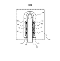
図1は斜め上方からの図である。血管画像撮像装置101は、指に近赤外線を照射する複数の光源104、105、106、107と、光源を保護するための透明な保護カバー102、103と、指先側の指置台108と、指付け根側の指置台109と、光源が撮像画像に写り込まないように隠すための遮光板110、111を備える。遮光板110、111は、正確な指輪郭位置を取得するための切り欠け112、113を備える。切り欠けは遮光板が撮像画像に写り込むことを防ぐ機能を損なわないような位置に設けることが望ましい。図1の場合、指先側の左右と、指付け根側の左右に光源があるため、いずれの光源からも離れた位置となる、遮光板の指先側と指付け根側の中央に設けるのが良い。また、切り欠けの縁の部分が指の輪郭線と誤認される可能性を低減するため、指の長さ方向に対して直角もしくは指の輪郭線と区別できる程度に直角に近い角度に設けるのが良い。
FIG. 1 is a view from diagonally above. The blood vessel
図2は図1の血管画像撮像装置を上方から見た図である。遮光板110、111に切り欠け112、113を設けることで、指が遮光板に触れることが無い部分ができるため、ここから正確な指輪郭情報を得ることができる。具体的には、切り欠けの部分は必ず指ではなく背景が写るため、画像中の切り欠け部分を起点として画像中央付近まで各画素の輝度走査を行ったとき、指が画像内に写っている場合は、指の輪郭線は、切り欠け部分より画像中央寄りに必ず存在し、また、輪郭線付近で背景との輝度差が生じるため、この差を検出することで正確に輪郭を求めることができる。切り欠けがない場合には、背景であると確定できる部分がないため、特に指が遮光板と密着している場合に、指の輪郭線と遮光板の境界線とが区別しにくくなり、指内の比較的輝度差の大きな部分を輪郭線と誤認する可能性がある。さらには、この切り欠け部分の輝度から背景の外光の強さを取得し、撮像装置の露光調整を行うこともできる。
FIG. 2 is a view of the blood vessel image capturing apparatus of FIG. 1 as viewed from above. By providing the
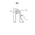
図3は、図1の血管画像撮像装置において、光源の保護カバー102、103の、遮光板の切り欠けの上の部分に反射防止板301、302を設けた例である。切り欠け112、113があることで、装置の光源以外からの光である外光がある環境下で血管画像撮像装置を使用する場合、外光が保護カバー102、103に反射して切り欠けから装置に進入して撮像画像に輝点として写り込む場合がある。反射防止板301、302によりこのような光の反射を防ぐことができる。なお、反射防止板を設けるのではなく、保護カバーを指先側と指付け根側に分割して、切り欠けの上の部分を不透明にすることで反射を抑える、または保護カバーの切り欠けの上の部分の表面にシボ加工などの反射を抑える表面処理を行ってもよい。
FIG. 3 is an example in which the
このように、実施例1では、対面する位置に配置され、指の左右から光を照射する光源(例えば、光源104~106)と、下方から指の静脈パターンを撮影するための撮像部(例えば、後述する撮像装置902や906、あるいは撮像手段1207や1505と同様の撮像部)と、上記光源が撮像画像に写り込まないよう上記光源の下部に配置した遮光板であって、切り欠けを有した遮光板(例えば、遮光板110、111)と、備え、上記撮像部は、上記指とともに上記切り欠けで背景と指輪郭を含む画像を撮影する。したがって、例えば、遮光板が光って正確な指輪郭が取得できない場合でも、遮光板に切り欠けを設けることで、遮光板に常に指に触れることなく指輪郭と背景が写る部分ができ、それを手がかりとして正確な指輪郭を取得することができる。
As described above, in the first embodiment, a light source (for example,
本実施例は、光源の周辺部分が光を反射して輝点として撮像画像に写り込むことを防ぐため、透明な保護カバー102、103を曲面化して光を反射する部位まで延長することで光を透過させ、反射による輝点を抑止した血管画像撮像装置の構成例である。
In this embodiment, in order to prevent the peripheral portion of the light source from reflecting light and being reflected in the captured image as a bright spot, the transparent
図4は、血管画像撮像装置の光源格納部を指付け根側から見た断面図である。光源107の光が、光の進行経路401のような光源格納部の天井部分による反射や、光の進行経路402のような光源の保護カバーの上部の界面による反射で血管画像撮像装置に進入し、輝点として撮像画像に写り込む場合がある。
FIG. 4 is a cross-sectional view of the light source storage portion of the blood vessel image imaging device as viewed from the finger base side. The light of the
図5は、図4で示した反射による輝点の撮像画像への映り込みを低減する血管画像撮像装置の例である。曲面化した保護カバー501は、透明な保護カバーを光源格納部の天井部分まで延長されている。これにより、光源格納部の天井近傍の保護カバーの界面の位置をずらし、天井方向への光を反射させずに透過させて反射光の血管画像撮像装置への侵入を低減することで輝点の発生を抑えている。
FIG. 5 is an example of a blood vessel image imaging device that reduces the reflection of bright spots on the captured image due to the reflection shown in FIG. The curved
このように、実施例2では、光源(例えば、光源107)を保護しつつ上記光源の光を透過させる透明カバーであって、上記光源の上部まで曲面で覆われた透明カバー(例えば、保護カバー501)を備える。したがって、例えば、光源の周辺部分が光を反射して輝点として撮像画像に写り込む場合であっても、光を反射する部位を透明にすることで光を透過させ、反射による輝点を抑止することができる。 As described above, in the second embodiment, the transparent cover for transmitting the light of the light source while protecting the light source (for example, the light source 107), and the transparent cover covered with a curved surface up to the upper part of the light source (for example, the protective cover). 501) is provided. Therefore, for example, even when the peripheral part of the light source reflects light and is reflected in the captured image as a bright spot, the light is transmitted by making the part that reflects the light transparent to suppress the bright spot due to the reflection. can do.
本実施例は、指を斜めにかざしたときに指輪郭の一部が撮像画像に写らないことで、認証精度が低下することを防ぐため、指付け根側に指を装置に沿ってかざすようガイドを設けて指を装置に沿ってかざすよう促す血管画像撮像装置の構成例である。 In this embodiment, in order to prevent the authentication accuracy from being deteriorated because a part of the finger contour is not reflected in the captured image when the finger is held diagonally, a guide is provided so that the finger is held along the device on the finger base side. This is a configuration example of a blood vessel image imaging device that prompts the user to hold a finger along the device.
図6は、指付け根側にガイド601、602を備えている。ガイドは、指の厚み方向の中央の高さ、つまり、指が指幅方向に一番張り出している高さで、指に沿った方向に長い形状とすることで、指を装置に沿ってかざすことを促す効果が高くなる。指付け根側の指置台全体を延長することもできるが、装置全体のサイズが大きくなってしまうため、突起物としてガイドを設けることで、装置全体のサイズへの影響をなるべく小さくしている。なお、図6ではガイドの形状が三角形になっているが、指の厚み方向の中央の高さが指付け根方向に長い形状であれば、三角形である必要はない。
FIG. 6 is provided with
図7の(a)はガイドの無い血管画像撮像装置に指701を斜めに提示した場合の例である。装置全体のサイズが小さいことで、指先側の指置台と指付け根側の指置台の間隔が短く、指を斜めに提示した場合に、指輪郭近傍の一部が画角から外れて撮像範囲外となってしまう場合がある。図7の(b)は、ガイドの無い血管画像撮像装置に指を斜めにかざしたことで指輪郭近傍の一部が画角から外れている撮像画像の例である。画像の右上の部分が画角から外れている。これにより指輪郭が正しく識別できず、指付け根側が細くなった指であると誤認される場合がある。
FIG. 7A is an example in which the
図8の(a)はガイド付きの血管画像撮像装置に指801を斜めに提示した場合の例である。ガイドを設けることで、指を斜めに提示できる範囲が制限され、装置に沿って指を提示するよう促すことができる。図8の(b)はガイド付きの指血管画像撮像装置に指をかざして撮影した画像の例である。ガイド602により指を装置に沿ってかざすよう促されることで、指の一部が画角から外れることなく撮影することができる。
FIG. 8A is an example in which the
このように、実施例3では、少なくとも指の付け根に配置した指置台(例えば、指付け根側の指置台109)を有し、上記指置台は、当該指置台の左右部分の、提示された上記指の厚みの中央の高さで、上記指の付け根方向に延長したガイド(例えば、ガイド601、602)を有する。したがって、例えば、指を斜めにかざすことで指輪郭の一部が撮像画像に写らないことによる認証精度が低下することを防ぐため、指付け根側に指を装置に沿ってかざすようガイドを設けることで指を装置に沿ってかざすよう促すことができる。
As described above, in the third embodiment, the finger rest (for example, the
本実施例は、指と撮像装置が近接する装置構成による撮影で、指の長さ方向に細長い血管パターンが生成され、指をかざす位置のずれ幅を調べるための探索範囲が広くなって処理時間が長くなることを防ぐための実施例である。具体的には、血管パターン生成の前に、予め撮像画像を指の長さ方向に縮小してから血管パターンを生成し、処理時間が長くなることを防ぐ場合の例である。なお、画像の指の長さ方向の縮小によって血管パターン情報が欠落するが、指の血管の多くは指の長さ方向に走っているため、長さ方向の縮小により網目パターンが欠落することが少なく、画像の撮影サイズにもよるが、指の長さ方向の画像サイズを2、3割短くする程度の縮小であれば、認証精度への影響はほとんどない。 In this embodiment, an image is taken with a device configuration in which the finger and the image pickup device are close to each other. This is an example for preventing the lengthening of. Specifically, this is an example in which the captured image is reduced in the length direction of the finger before the blood vessel pattern is generated, and then the blood vessel pattern is generated to prevent the processing time from becoming long. The blood vessel pattern information is lost due to the reduction in the length direction of the finger in the image, but since most of the blood vessels of the finger run in the length direction of the finger, the mesh pattern may be missing due to the reduction in the length direction. Although it depends on the shooting size of the image, if the image size in the finger length direction is reduced by 20 to 30%, there is almost no effect on the authentication accuracy.
図9の(a)は、装置を小型化することにより指901と撮像装置902を所定の基準値以上近接させて撮影する場合の例、図9の(b)は、指905と撮像手段906を所定の基準値からやや離して撮影する場合の例である。指は円柱状の形状をしており、撮像手段902を一定以上近接させると、指の撮像範囲を示す線903は撮像手段から指の左右への接線となる。撮像範囲904は、撮像範囲を示す線に囲まれた範囲となる。図9の(a)のように指901と撮像手段902が近い場合、撮像範囲を示す線903と指901の接点は、指の最も下の点に近い位置となる。一方で図9の(b)のように、指905と撮像手段906の距離が離れている場合、撮像範囲を示す線907と指905の接点は、図9の(a)と比べると指の最も下の点から離れた位置になるため、撮像範囲908は撮像範囲904に比べて広い範囲となる。
9 (a) is an example in which the
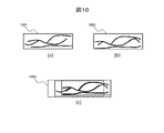
図10は、図9の(a)のように指と撮像装置を一定以上近接させて撮影した画像からそのまま生成した血管パターンの例である。図10の(a)は登録血管パターン1001、図10の(b)は入力血管パターン1002の例である。血管パターン同士の照合は、例えばある画像のパターンが別の画像の中に存在するかを調べるテンプレートマッチングを行って、調べる画像パターンの位置を前後左右に少しずつずらしながら一致する画素の数を調べ、一致する画素の一番多い場所において一致しない画素の数を数えることでスコアを算出して、一番小さいスコアを求めることで行う。図10の(c)は登録血管パターン1001と、入力血管パターン1002の位置を前後左右に少しずつずらしながら重ね合わせて、ミスマッチ率の一番小さい位置を探索する範囲の例である。探索範囲1003は点線で囲まれた範囲となる。
FIG. 10 is an example of a blood vessel pattern generated as it is from an image taken with a finger and an image pickup device brought close to each other by a certain distance or more as shown in FIG. 9A. FIG. 10 (a) is an example of the registered
図11は、図9の(a)のように指と撮像装置を一定以上近接させて撮影した画像を、予め指の長さ方向に縮小して生成した血管パターンの例である。図11の(a)は登録血管パターン1101、図11の(b)は入力血管パターン1102の例である。図11の(c)は登録血管パターン1101と、入力血管パターン1102の位置を前後左右に少しずつずらしながら重ね合わせて、ミスマッチ率の一番小さい位置を探索する範囲の例である。探索範囲1103は点線で囲まれた範囲となる。指の長さ方向に縮小して生成した血管パターンでは探索範囲1103が、図10の探索範囲1003に比べて小さくなるため、処理時間を短縮することができる。
FIG. 11 is an example of a blood vessel pattern generated by reducing an image taken by bringing a finger and an image pickup device closer to each other by a certain distance or more in advance in the length direction of the finger as shown in FIG. 9A. 11 (a) is an example of the registered
なお、曲面ミラーとの組み合わせにより、指の長さ方向に細長い画像が撮影できるが、一方でこれは拡大された高精細な画像が取得できるということでもあるため、可視光線の撮像手段を併用して、表皮模様などほかの生体情報と組み合わせる場合に、高精細な表皮用の画像が撮影により精度の高い照合に利用できるという利点もある。 In addition, by combining with a curved mirror, it is possible to take an elongated image in the length direction of the finger, but on the other hand, this also means that a magnified high-definition image can be obtained, so a visible light imaging means is also used. There is also an advantage that a high-definition image for the epidermis can be used for highly accurate collation by taking a picture when combined with other biological information such as an epidermis pattern.
このように、実施例4では、撮像部(例えば、撮像手段902)が一定以上近接して撮影した指の画像を、上記指の長さ方向に縮めることで、位置合わせのための探索範囲を小さくする制御部(例えば、CPU1810と同様のCPU)、を備える。具体的には、指と撮像装置が近接する装置構成による撮影により、指の長さ方向に細長い血管パターンが生成されるが、当該血管パターン生成の前に、予め撮像画像を指の長さ方向に縮小しておくことで、指をかざす位置のずれ幅を調べるための探索範囲が広くなって処理時間が長くなることを防ぐことができる。 As described above, in the fourth embodiment, the image of the finger taken by the image pickup unit (for example, the image pickup means 902) in close proximity to a certain degree or more is shrunk in the length direction of the finger to obtain a search range for alignment. A control unit (for example, a CPU similar to the CPU 1810) for making the size smaller is provided. Specifically, an elongated blood vessel pattern is generated in the length direction of the finger by taking a picture with a device configuration in which the finger and the image pickup device are close to each other. By reducing the size to, it is possible to prevent the search range for investigating the deviation width of the position where the finger is held from becoming wide and the processing time from becoming long.
本実施例は、装置を小型化するためにミラー、特に曲面ミラーを使用した場合に、曲面ミラーによる反射光が撮像部と指の間に設置した光学フィルタに反射して、輝点が撮像画像に写り込むことによる認証精度の低下を低減する血管画像撮像装置の構成例である。 In this embodiment, when a mirror, especially a curved mirror, is used to reduce the size of the device, the light reflected by the curved mirror is reflected by the optical filter installed between the image pickup unit and the finger, and the bright spot is the captured image. This is a configuration example of a blood vessel image imaging device that reduces a decrease in authentication accuracy due to reflection on the image.
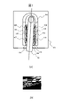
図12は、光学フィルタに反射防止コーティングを施すことで輝点の発生を低減する血管画像撮像装置の構成例である。光源105、107から照射された近赤外線は、指1206の内部で散乱した後、指の下方から抜けて、光の進行経路1203で示すように、光学フィルタ1205を抜けた後、曲面ミラー1202に反射して撮像手段1207に向かうが、一部は光学フィルタに戻る方向に反射して、さらに光学フィルタで反射する場合がある。ここで反射する位置が撮像範囲1201の範囲内のとき、輝点1204として撮像画像に写り込む場合がある。そこで光学フィルタに反射防止コーティングを施すことで輝点の発生を低減し、認証精度の低下を防ぐことができる。なお、光学フィルタ1205は生体を透過する周波数帯の近赤外線のみ透過させることで、ノイズの少ない鮮明な血管画像を撮影する目的と、装置の内部にほこりが入り込むことを防ぐ目的で設置されている。
FIG. 12 is a configuration example of a blood vessel image imaging device that reduces the generation of bright spots by applying an antireflection coating to an optical filter. The near-infrared rays emitted from the
図13は血管パターンから図12に示した輝点が撮像画像に写り込むことによる認証精度の低下を低減する血管画像撮像装置の構成例である。図13の(a)の血管パターン1301には、輝点の外縁部が血管以外の指の部分に比べて相対的に暗くなることで生成される偽血管の線1302がある。この偽血管の線1302は、すべての指について、置き方にかかわらず同じような位置に出現するため、本来異なる血管パターン同士であるにもかかわらず、似ている部分が現れ、認証精度の低下につながる。これを、図13(b)に示すように、血管パターン1303から偽血管の線1304を除いた部分を認証対象領域1305とすることで認証精度の低下を防ぐことができる。
FIG. 13 is a configuration example of a blood vessel image imaging device that reduces a decrease in authentication accuracy due to the bright spots shown in FIG. 12 being reflected in the captured image from the blood vessel pattern. In the
このように、実施例5では、撮像部(例えば、撮像手段1207)が指を広く撮影するための曲面ミラー(例えば、曲面ミラー1202)と、上記指と上記曲面ミラーとの間に配置され、光源(例えば、光源105、107)から照射された所定波長域の光を通すとともに装置内部へのほこりの侵入を防ぐための光学フィルタ(例えば、光学フィルタ1205)とを備え、上記光学フィルタには、上記光学フィルタを透過して上記曲面ミラーに反射した光がさらに上記光学フィルタにより上記曲面ミラーに反射した輝点を抑えるための反射防止コーティングが施されている。また、上記撮像部(例えば、撮像手段1207)が指を広く撮影するための曲面ミラー(例えば、曲面ミラー1202)と、上記指と上記曲面ミラーとの間に配置され、光源(例えば、光源105、107)から照射された所定波長域の光を通すとともに装置内部へのほこりの侵入を防ぐための光学フィルタ(例えば、光学フィルタ1205)とを備え、上記撮像部(例えば、撮像手段1207)が撮影した指の画像のうち、上記曲面ミラーに反射した光がさらに上記光学フィルタにより上記曲面ミラーに反射した輝点を除いた部分を除外した部分を認証対象領域とする制御部(例えば、CPU1810と同様のCPU)を備える。したがって、装置を小型化するためにミラー、特に曲面ミラーを使用した場合に、ミラーによる反射光が撮像部と指の間に設置した光学フィルタに反射して、輝点が撮像画像に写り込むことを防ぐため、光学フィルタに反射防止コーティングを行う、もしくは輝点の写り込む部分を血管パターン生成の対象外とすることで、認証精度の低下を防ぐことができる。
As described above, in the fifth embodiment, the imaging unit (for example, the imaging means 1207) is arranged between the curved mirror (for example, the curved mirror 1202) for widely photographing the finger and the finger and the curved mirror. The optical filter is provided with an optical filter (for example, an optical filter 1205) for passing light in a predetermined wavelength range emitted from a light source (for example,
本実施例は、ユーザーが装置に接触せず本人認証ができるように装置の下部を開閉式とし、本人認証完了時に装置の下部を開き、指を通過させて装置に触れることなく血管画像の撮影を行うことができる装置の構成例である。 In this embodiment, the lower part of the device is opened and closed so that the user can authenticate the person without touching the device, the lower part of the device is opened when the person authentication is completed, and the blood vessel image is taken without touching the device by passing a finger. This is a configuration example of a device capable of performing the above.
図14は、装置の下部を開閉式にした血管画像撮像装置の例である。認証開始前は図14の(a)のように平板状の部位である装置下部1401は閉じている。指を上からゆっくりとおろしながら提示すると、装置に接触する直前に近接センサーなどで指を感知して図14の(b)のように、装置下部1401が開く。よって提示した指は下方に抜けることができ、指が震えることで装置に触れることなく血管画像の撮影ができる。
FIG. 14 is an example of a blood vessel image imaging device in which the lower part of the device is openable and closable. Before the start of authentication, the
図15は、図14の血管画像撮像装置を指付け根側から見た断面図である。光源105、107、遮光板110、111、保護カバー501、502の配置は図12と同様である。装置下部1401は内部が空洞になっており、曲面ミラーを内蔵している。指と正対する上部には光学フィルタ1502、側面には撮影用窓1503がある。指1509の画像は、光学フィルタ1502を通して曲面ミラー1501で反射し、撮影用窓1503と撮像装置側撮影窓1504を通って撮像手段1505で撮影する。また、装置下部1401は、ステー1508を介してソレノイドアクチュエータ1506のプランジャー1507につながっている。近接センサー1510は指の接近を感知して、指が撮影に十分な所定の距離まで近づいたタイミングでソレノイドアクチュエータ1506により装置下部を開放する。
FIG. 15 is a cross-sectional view of the blood vessel image capturing apparatus of FIG. 14 as viewed from the finger base side. The arrangement of the
図16はソレノイドアクチュエータ1506に通電して、プランジャー1507が引き上げられ、つながっているステー1508が引かれることで、装置下部1401が開いた状態を示している。ソレノイドアクチュエータ1506への通電が止まると、プランジャー1507は再び元の位置に下がり、装置下部1401は図15の閉じた状態に戻る。
FIG. 16 shows a state in which the
このように、実施例6では、下方から指の静脈パターンを撮影するための撮像部(例えば、撮像手段1505)と、装置下部(例えば、装置下部1401)を開閉式として、上記撮像部により指の静脈パターンが撮影されたときに上記装置下部を開放する制御部(例えば、CPU1810と同様のCPU)と、を備える。具体的には、ユーザーが装置に接触せず本人認証ができるように装置の下部を開閉式とし、認証に好適な指提示位置を明示するとともに、指が装置に触れる直前まで血管画像の撮影を行って、指が振れる直前に装置の下部を開き、指を通過させることで指のブレを抑えつつ装置に触れずに血管画像の撮影を行うことができる。
As described above, in the sixth embodiment, the image pickup unit (for example, the image pickup means 1505) for photographing the vein pattern of the finger from below and the lower part of the device (for example, the
本実施例は、ユーザーによっては生体情報が暗号化して登録されていることを認知できず、生体情報を登録することへの心理的な抵抗感を低くするため、暗号化した生体情報を表示するための表示装置を備えた血管画像撮像装置の例である。図17は暗号化した生体情報を表示するための表示装置を備えた血管画像撮像装置の例である。表示装置1701に暗号化した生体情報1702を可視化して表示することで、ユーザーに生体情報をそのまま使うのではなく、暗号化して安全に生体情報を使用していることを示すことができる。暗号化した生体情報を可視化して表示する代わりに、生体情報を暗号化していることを示す記号やパターンを表示してもよい。
In this embodiment, some users cannot recognize that the biometric information is encrypted and registered, and the encrypted biometric information is displayed in order to reduce the psychological resistance to registering the biometric information. This is an example of a blood vessel image imaging device provided with a display device for the purpose. FIG. 17 is an example of a blood vessel image imaging device provided with a display device for displaying encrypted biological information. By visualizing and displaying the encrypted
このように、実施例7では、暗号化された登録血管パターン、または暗号化された照合血管パターンを表示するための表示部(例えば、表示装置1701)を備える。したがって、ユーザーによっては生体情報が暗号化して登録されていることを認知できず、生体情報を登録することへの心理的な抵抗感を低くすることができる。また、血管画像撮像装置に表示装置を設置して暗号化した生体情報を表示して、安全に生体情報を使用していることを示すことができる。 As described above, the seventh embodiment includes a display unit (for example, a display device 1701) for displaying an encrypted registered blood vessel pattern or an encrypted matching blood vessel pattern. Therefore, some users cannot recognize that the biometric information is encrypted and registered, and it is possible to reduce the psychological resistance to registering the biometric information. Further, it is possible to display the encrypted biological information by installing a display device on the blood vessel image imaging device to indicate that the biological information is safely used.
本実施例は、実施例1、2、3、4、5、6のいずれかの血管画像撮像装置を用いて、本人認証装置を構成する場合のシステムの一例である。 This embodiment is an example of a system in which a personal authentication device is configured by using any of the blood vessel image imaging devices of Examples 1, 2, 3, 4, 5, and 6.
図18は、本人認証装置のシステム構成図である。認証装置101に、指1801を提示すると、光源104、105、106、107から近赤外線を照射された画角1812の範囲内の指の画像を、光学フィルタ1105を通し、撮像手段1802にて電気信号に変換し、近赤外線画像入力部1803およびインターフェース1804を介して画像としてCPU1810に取り込み、メモリ1809に記録される。近赤外線光源制御部1805は光源104、105、106から照射された近赤外線の光量等を制御する。メモリ1809に記録された画像は、メモリ1809に記録されたプログラムにより、予め外部記憶装置1811に記録されている一つ以上の生体情報と照合され、本人認証を行う。認証の結果はスピーカ1806やキーボード1807からの指示により表示装置1808に表示して本人に通知することができる。なお、認証装置101を、撮影した血管の情報を認証部に伝達する血管画像撮像装置として使用し、図19に示す処理を外部のコンピュータにより実行しても良い。
FIG. 18 is a system configuration diagram of the personal authentication device. When the
図19は本人認証装置で本人認証をするためのプログラムのフローチャート例である。まずステップ1901にて使用者が指を提示する。次にステップ1902に進み、CPU1810は近赤外線光源制御部1805を制御して指の右側から近赤外線を照射する。次に手段1903に進み、CPU1810は近赤外線画像入力部1803や撮像手段1802等を制御して指の近赤外線画像の取得を行う。
FIG. 19 is an example of a flowchart of a program for authenticating a person with a person authentication device. First, in
次にステップ1904に進み、CPU1810は近赤外線光源制御部1805を制御して指の左側から近赤外線を照射する。次に手段1905に進み、CPU1810は近赤外線画像入力部1803や撮像手段1802等を制御して指の近赤外線画像の取得を行う。次にステップ1906に進み、CPU1810は近赤外線画像入力部1803や撮像手段1802等が取得した指の近赤外線画像から指の検出を行う。次にステップ1907に進み、CPU1810は先のステップ1906において指が検出されたか否かの判定を行う。
Next, the process proceeds to step 1904, and the
CPU1810は指が検出されていないと判定した場合は(ステップ1907;NO)、ステップ1902に戻る。一方、CPU1810は指が検出されたと判定した場合は(ステップ1907;YES)、ステップ1908に進み、指輪郭の検出を行って指の近赤外線画像の指の領域を明確にする。次にステップ1909に進み、CPU1810は先のステップ1908で得られた指輪郭から指幅の平均の長さを算出して、指の近赤外線画像の指幅があらかじめ設定した標準の長さになるように画像の拡大または縮小を行い、指の近赤外線画像の正規化を行う。次に、ステップ1910に進み、CPU1810は正規化した指の近赤外線画像から指の平均輝度の算出を行う。
If the
次にステップ1911に進み、CPU1810はステップ1910で算出した指の平均輝度が、目標輝度の上限と下限の間であるか否かを調べる。CPU1810は平均輝度が目標値の上限と下限の間にないと判定した場合は(ステップ1911;NO)、ステップ1912に進み、平均輝度が目標の下限を下回っている場合は光量値を増やし、平均輝度が目標の上限を上回っている場合は光量値を減らして、照射するよう光源制御を行った後、ステップ1902に戻る。一方、CPU1810はステップ1911で平均輝度が目標値の上限と下限の間にあると判定した場合は(ステップ1911;YES)、ステップ1913に進み、あらかじめ記録しておいた血管パターンと提示した指から抽出した血管パターンの照合を行って、血管パターン同士の不一致度のスコアを照合スコアとして算出する。スコアの算出は、CPU1810が、例えばある画像のパターンが別の画像の中に存在するかを調べるテンプレートマッチングを行って、調べる画像パターンの位置を少しずつずらしながら一致する画素の数を調べ、一致する画素の一番多い場所において一致しない画素の数を数えることで算出する。
Next, the process proceeds to step 1911, and the
次にステップ1914に進み、CPU1810は算出した照合スコアが閾値を下回っているかを調べる。CPU1810は照合スコアが閾値を下回っていたと判定した場合は(ステップ1914;NO)、ステップ1915に進み、表示装置1808に認証成功である旨を表示する等の認証成功後処理を行って、ステップ1917で認証処理を終了する。一方、CPU1810は算出した照合スコアが閾値を下回っていないと判定した場合は(ステップ1914;YES)、ステップ1914からステップ1916に進み、表示装置1808に認証失敗である旨を表示する等の認証失敗後処理を行って、ステップ1917で認証処理を終了する。
Next, the process proceeds to step 1914, and the
このように、本実施例では、実施例1~7のいずれかの血管画像撮像装置により撮影した指静脈画像を用いて本人認証を行う制御部(例えば、CPU1810)を備えることを特徴とする本人認証装置を用いることにより、指静脈認証装置と組み合わせて、小型で精度の良い本人認証を行うことができる。 As described above, the person in the present embodiment is provided with a control unit (for example, CPU1810) that authenticates the person using the finger vein image taken by the blood vessel image imaging device according to any one of Examples 1 to 7. By using the authentication device, it is possible to perform small and accurate personal authentication in combination with the finger vein authentication device.
101 認証装置
102、103 保護カバー
104~107 光源
108 指先側の指置台
109 指付け根側の指置台
110、111 遮光板
112、113 遮光板の切り欠け
301、302 反射防止板
501 保護カバー
601、602 指提示部のガイド
1202 曲面ミラー
1205 光学フィルタ
1207 撮像手段
1401 開閉式の血管画像撮像装置下部
1501 曲面ミラー
1502 光学フィルタ
1503 撮影用窓
1504 撮像装置側撮影窓
1505 撮像手段
1506 ソレノイドアクチュエータ
1507 プランジャー
1508 ステー
1510 近接センサー
1701 表示装置
1802 撮像手段
1803 近赤外線画像入力部
1804 インターフェース
1805 近赤外線光源制御部
1806 スピーカ
1807 キーボード
1808 表示装置
1809 メモリ
1810 CPU
1811 外部記憶装置
101
1811 external storage
Claims (9)
下方から指の静脈パターンを撮影するための撮像部と、
前記光源が撮像画像に写り込まないよう前記光源の下部に配置した遮光板であって、切り欠けを有した前記遮光板と、備え、
前記撮像部は、前記指とともに前記切り欠けで背景と指輪郭を含む画像を撮影する、
ことを特徴とする血管画像撮像装置。 A light source that is placed facing each other and irradiates light from the left and right of the finger,
An imaging unit for capturing finger vein patterns from below,
A light-shielding plate arranged below the light source so that the light source is not reflected in the captured image, and is provided with the light-shielding plate having a notch.
The image pickup unit captures an image including a background and a finger contour with the notch together with the finger.
A blood vessel image imaging device characterized by this.
前記光源を保護しつつ前記光源の光を透過させる透明カバーであって、前記光源の上部まで曲面で覆われた前記透明カバー、
を備えること特徴とする血管画像撮像装置。 The blood vessel image imaging apparatus according to claim 1.
A transparent cover that protects the light source and allows the light of the light source to pass through, and the transparent cover is covered with a curved surface up to the upper part of the light source.
A blood vessel image imaging device characterized by being provided with.
少なくとも前記指の付け根に配置した指置台を有し、
前記指置台は、当該指置台の左右部分の、提示された前記指の厚みの中央の高さで、前記指の付け根方向に延長したガイドを有する、
ことを特徴とする血管画像撮像装置。 The blood vessel image imaging apparatus according to claim 1.
It has at least a finger rest placed at the base of the finger,
The finger rest has a guide extending toward the base of the finger at a central height of the presented finger thickness on the left and right portions of the finger rest.
A blood vessel image imaging device characterized by this.
前記撮像部が一定以上近接して撮影した指の画像を、前記指の長さ方向に縮めることで、位置合わせのための探索範囲を小さくする制御部、
を備えることを特徴とする血管画像撮像装置。 The blood vessel image imaging apparatus according to claim 1.
A control unit that reduces the search range for alignment by shrinking an image of a finger taken by the imaging unit closer than a certain distance in the length direction of the finger.
A blood vessel image imaging device characterized by comprising.
前記撮像部が指を広く撮影するための曲面ミラーと、
前記指と前記曲面ミラーとの間に配置され、前記光源から照射された所定波長域の光を通すとともに装置内部へのほこりの侵入を防ぐための光学フィルタとを備え、
前記光学フィルタには、前記光学フィルタを透過して前記曲面ミラーに反射した前記光がさらに前記光学フィルタにより前記曲面ミラーに反射した輝点を抑えるための反射防止コーティングが施されている、
ことを特徴とする血管画像撮像装置。 The blood vessel image imaging apparatus according to claim 1.
A curved mirror for the image pickup unit to take a wide picture of the finger,
It is provided between the finger and the curved mirror, and is provided with an optical filter for passing light in a predetermined wavelength range emitted from the light source and preventing dust from entering the inside of the device.
The optical filter is provided with an antireflection coating for suppressing the bright spots that the light transmitted through the optical filter and reflected on the curved mirror is further reflected on the curved mirror by the optical filter.
A blood vessel image imaging device characterized by this.
前記撮像部が指を広く撮影するための曲面ミラーと、
前記指と前記曲面ミラーとの間に配置され、前記光源から照射された所定波長域の光を通すとともに装置内部へのほこりの侵入を防ぐための光学フィルタとを備え、
前記撮像部が撮影した指の画像のうち、前記曲面ミラーに反射した前記光がさらに前記光学フィルタにより前記曲面ミラーに反射した輝点を除いた部分を除外した部分を認証対象領域とする制御部、
を備えることを特徴とする血管画像撮像装置。 The blood vessel image imaging device according to claim 1.
A curved mirror for the image pickup unit to take a wide picture of the finger,
It is provided between the finger and the curved mirror, and is provided with an optical filter for passing light in a predetermined wavelength range emitted from the light source and preventing dust from entering the inside of the device.
A control unit whose authentication target area is a portion of the finger image captured by the imaging unit, excluding a portion excluding a portion where the light reflected by the curved mirror is further reflected by the optical filter on the curved mirror. ,
A blood vessel image imaging device characterized by comprising.
装置下部を開閉式として、前記撮像部により前記指の静脈パターンが撮影されたときに前記装置下部を開放する制御部と、
を備えることを特徴とする血管画像撮像装置。 An imaging unit for capturing finger vein patterns from below,
A control unit that opens and closes the lower part of the device and opens the lower part of the device when the vein pattern of the finger is photographed by the imaging unit.
A blood vessel image imaging device characterized by comprising.
を備えることを特徴とする血管画像撮像装置。 Display unit for displaying encrypted registered vessel pattern or encrypted matching vessel pattern,
A blood vessel image imaging device characterized by comprising.
を備えることを特徴とする本人認証システム。 A control unit that authenticates a person using a finger vein image taken by the blood vessel image imaging device according to claim 1.
A personal authentication system characterized by being equipped with.
Priority Applications (2)
| Application Number | Priority Date | Filing Date | Title |
|---|---|---|---|
| JP2020157468A JP2022051149A (en) | 2020-09-18 | 2020-09-18 | Blood vessel image capturing device and personal authentication system |
| CN202110966770.1A CN114283459A (en) | 2020-09-18 | 2021-08-23 | Blood vessel image capturing device and person authentication system |
Applications Claiming Priority (1)
| Application Number | Priority Date | Filing Date | Title |
|---|---|---|---|
| JP2020157468A JP2022051149A (en) | 2020-09-18 | 2020-09-18 | Blood vessel image capturing device and personal authentication system |
Publications (1)
| Publication Number | Publication Date |
|---|---|
| JP2022051149A true JP2022051149A (en) | 2022-03-31 |
Family
ID=80854838
Family Applications (1)
| Application Number | Title | Priority Date | Filing Date |
|---|---|---|---|
| JP2020157468A Pending JP2022051149A (en) | 2020-09-18 | 2020-09-18 | Blood vessel image capturing device and personal authentication system |
Country Status (2)
| Country | Link |
|---|---|
| JP (1) | JP2022051149A (en) |
| CN (1) | CN114283459A (en) |
-
2020
- 2020-09-18 JP JP2020157468A patent/JP2022051149A/en active Pending
-
2021
- 2021-08-23 CN CN202110966770.1A patent/CN114283459A/en active Pending
Also Published As
| Publication number | Publication date |
|---|---|
| CN114283459A (en) | 2022-04-05 |
Similar Documents
| Publication | Publication Date | Title |
|---|---|---|
| TWI381319B (en) | Refers to the intravenous authentication device | |
| JP3770241B2 (en) | Personal authentication device and personal authentication method | |
| JP4736502B2 (en) | Personal authentication device, personal authentication method | |
| KR100888527B1 (en) | Personal authentication device | |
| JP6134662B2 (en) | Biometric authentication device and biometric authentication method | |
| EP2172911A2 (en) | Authentication apparatus | |
| JPWO2016084214A1 (en) | Blood vessel imaging device and personal authentication system | |
| JP2009187520A (en) | Authentication device, authentication method, registration device and registration method | |
| KR102538405B1 (en) | Biometric authentication system, biometric authentication method and program | |
| JP4603915B2 (en) | Deposit deposit machine and processing method thereof | |
| JP6160148B2 (en) | Biological information input device, biometric information input program, and biometric information input method | |
| JP5846291B2 (en) | Biometric authentication device, biometric authentication method, and biometric authentication program | |
| JP5459263B2 (en) | Blood vessel imaging device | |
| KR101547659B1 (en) | A finger vein recognition apparatus and a terminal with the same | |
| JP6165659B2 (en) | Blood vessel imaging device | |
| JP2022051149A (en) | Blood vessel image capturing device and personal authentication system | |
| JP2020123068A (en) | Biometric authentication device, biometric authentication method, and computer program | |
| JP4788744B2 (en) | Personal authentication device and blood vessel image extraction device | |
| JP5182341B2 (en) | Personal authentication apparatus and method | |
| JP5522119B2 (en) | Blood vessel imaging device | |
| JP2018081469A (en) | Blood vessel image pickup apparatus and personal authentication system | |
| KR20220061844A (en) | Photographing apparatus, authentication apparatus and biometric photographing method | |
| JP6015787B2 (en) | Blood vessel imaging device | |
| JP5733324B2 (en) | Blood vessel imaging device | |
| JP2008000464A (en) | Authentication device and authentication method |
Legal Events
| Date | Code | Title | Description |
|---|---|---|---|
| A711 | Notification of change in applicant |
Free format text: JAPANESE INTERMEDIATE CODE: A711 Effective date: 20210708 |
|
| A521 | Request for written amendment filed |
Free format text: JAPANESE INTERMEDIATE CODE: A821 Effective date: 20210708 |
|
| A621 | Written request for application examination |
Free format text: JAPANESE INTERMEDIATE CODE: A621 Effective date: 20230119 |
|
| A977 | Report on retrieval |
Free format text: JAPANESE INTERMEDIATE CODE: A971007 Effective date: 20231020 |
|
| A131 | Notification of reasons for refusal |
Free format text: JAPANESE INTERMEDIATE CODE: A131 Effective date: 20231114 |
|
| A521 | Request for written amendment filed |
Free format text: JAPANESE INTERMEDIATE CODE: A523 Effective date: 20240115 |
|
| A02 | Decision of refusal |
Free format text: JAPANESE INTERMEDIATE CODE: A02 Effective date: 20240319 |