JP2022040134A - Estimation system and automobile - Google Patents

Estimation system and automobile Download PDF

Info

Publication number
JP2022040134A
JP2022040134A JP2021203250A JP2021203250A JP2022040134A JP 2022040134 A JP2022040134 A JP 2022040134A JP 2021203250 A JP2021203250 A JP 2021203250A JP 2021203250 A JP2021203250 A JP 2021203250A JP 2022040134 A JP2022040134 A JP 2022040134A
Authority
JP
Japan
Prior art keywords
image
unit
distance
estimation
information
Prior art date
Legal status (The legal status is an assumption and is not a legal conclusion. Google has not performed a legal analysis and makes no representation as to the accuracy of the status listed.)
Granted
Application number
JP2021203250A
Other languages
Japanese (ja)
Other versions
JP7242822B2 (en
Inventor
達馬 櫻井
Tatsuma Sakurai
琢麿 山本
Takuma Yamamoto
直 三島
Sunao Mishima
Current Assignee (The listed assignees may be inaccurate. Google has not performed a legal analysis and makes no representation or warranty as to the accuracy of the list.)
Toshiba Corp
Original Assignee
Toshiba Corp
Priority date (The priority date is an assumption and is not a legal conclusion. Google has not performed a legal analysis and makes no representation as to the accuracy of the date listed.)
Filing date
Publication date
Priority claimed from JP2017127389A external-priority patent/JP2019011971A/en
Application filed by Toshiba Corp filed Critical Toshiba Corp
Priority to JP2021203250A priority Critical patent/JP7242822B2/en
Publication of JP2022040134A publication Critical patent/JP2022040134A/en
Application granted granted Critical
Publication of JP7242822B2 publication Critical patent/JP7242822B2/en
Active legal-status Critical Current
Anticipated expiration legal-status Critical

Links

Images

Abstract

PROBLEM TO BE SOLVED: To provide an estimation system capable of easily estimating a self position based on an actual distance.
SOLUTION: An estimation system includes an imaging unit and an estimation unit. The imaging unit, which is a monocular imaging unit, can obtain an image and information on a distance to a subject included in the image, at one-time imaging. The estimation unit estimates the position of the imaging unit by using the image and the information on the distance.
SELECTED DRAWING: Figure 1
COPYRIGHT: (C)2022,JPO&INPIT

Description

本発明の実施形態は、推定システム、および当該推定システムが適用される自動車に関する。 Embodiments of the present invention relate to an estimation system and an automobile to which the estimation system is applied.

近年、ロボット等の自己位置・姿勢を推定する技術が利用されている。例えば、未知環境下においてロボットや自動車のような移動体が移動する際に、この自己位置・姿勢推定技術を用いることで、カメラやセンサから得られる情報から周囲環境の地図を作成し、その地図上での自己位置や自己姿勢を推定可能となる。また、この地図や自己位置、自己姿勢を考慮することで、例えば、効率の良い移動経路が生成可能になる。 In recent years, techniques for estimating the self-position and posture of robots and the like have been used. For example, when a moving object such as a robot or a car moves in an unknown environment, by using this self-position / posture estimation technology, a map of the surrounding environment is created from the information obtained from cameras and sensors, and the map is created. It is possible to estimate the self-position and self-posture above. Further, by considering this map, self-position, and self-posture, for example, an efficient movement route can be generated.

特開2008-304268号公報Japanese Unexamined Patent Publication No. 2008-304268

ラウル・マー-アータル(Raul Mur-Artal)、外1名、“ORB-SLAM2:単眼、ステレオおよびRGB-DカメラのためのオープンソースSLAMシステム(ORB-SLAM2: an Open-Source SLAM System for Monocular, Stereo and RGB-D Cameras)”、[online]、平成28年10月20日、コーネル大学ライブラリー(Cornell University Library)、[平成29年5月24日検索]、インターネット<URL:https://arxiv.org/pdf/1610.06475>Raul Mur-Artal, 1 outside, "ORB-SLAM2: an Open-Source SLAM System for Monocular, ORB-SLAM2: an Open-Source SLAM System for Monocular, Stereo and RGB-D Cameras) ”, [online], October 20, 2016, Cornell University Library, [Search May 24, 2017], Internet <URL: https: // arxiv.org/pdf/1610.06475 >

実際の空間で移動体が移動する経路を決定するためには、推定される自己位置が実距離に基づいている必要がある。 In order to determine the path the moving object travels in the actual space, the estimated self-position needs to be based on the actual distance.

本発明が解決しようとする課題は、実距離に基づく自己位置を容易に推定できる推定システムおよび自動車を提供することである。 An object to be solved by the present invention is to provide an estimation system and an automobile that can easily estimate a self-position based on an actual distance.

実施形態によれば、推定システムは、撮像部と推定部とを具備する。撮像部は、単眼の撮像部であって、画像と、前記画像に含まれる被写体までの実距離に関する情報と、を一度の撮影で取得可能である。推定部は、前記画像と前記実距離に関する情報とを用いて、前記撮像部の位置を推定する。前記推定部は、作業メモリ内の実スケールの第1キーフレームを探索する。前記推定部は、前記画像と前記実距離に関する情報とに基づく前記実スケールの第2キーフレームを決定する。前記推定部は、前記第1キーフレームと前記第2キーフレームとの間の近似度を算出することによって、前記第1キーフレーム内の複数の特徴点と前記第2キーフレーム内の複数の特徴点との間の複数の対応点を決定する。前記推定部は、前記複数の対応点の数が第1閾値以上である場合、前記複数の対応点間の変位を決定する。前記推定部は、前記変位が第2閾値以上である場合、前記実スケールの前記撮像部の位置を推定する。 According to the embodiment, the estimation system includes an imaging unit and an estimation unit. The image pickup unit is a monocular image pickup unit, and can acquire an image and information on an actual distance to a subject included in the image in a single shooting. The estimation unit estimates the position of the image pickup unit using the image and the information regarding the actual distance. The estimation unit searches for the first key frame of the actual scale in the working memory. The estimation unit determines a second key frame of the real scale based on the image and information about the real distance. By calculating the degree of approximation between the first key frame and the second key frame, the estimation unit has a plurality of feature points in the first key frame and a plurality of features in the second key frame. Determine multiple points of correspondence between points. When the number of the plurality of corresponding points is equal to or greater than the first threshold value, the estimation unit determines the displacement between the plurality of corresponding points. When the displacement is equal to or greater than the second threshold value, the estimation unit estimates the position of the image pickup unit on the actual scale.

実施形態に係る推定システムの構成を示すブロック図。The block diagram which shows the structure of the estimation system which concerns on embodiment. 同実施形態の推定システムに用いられる撮像装置のシステム構成の例を示すブロック図。The block diagram which shows the example of the system configuration of the image pickup apparatus used in the estimation system of the same embodiment. 図2の撮像装置に設けられるフィルタの構成の例を示す図。The figure which shows the example of the structure of the filter provided in the image pickup apparatus of FIG. 図2の撮像装置に設けられるフィルタの構成の別の例を示す図。The figure which shows another example of the structure of the filter provided in the image pickup apparatus of FIG. 図3のフィルタの透過率特性の例を示す図。The figure which shows the example of the transmittance characteristic of the filter of FIG. 図3のフィルタが配置されたカラー開口の光線変化と、ぼけの形状とを説明するための図。The figure for demonstrating the light ray change of the color aperture in which the filter of FIG. 3 is arranged, and the shape of a blur. 図2の撮像装置によって撮像された画像上のぼけを利用して、被写体までの距離を算出する方法の例を説明するための図。FIG. 3 is a diagram for explaining an example of a method of calculating a distance to a subject by using a blur on an image captured by the image pickup apparatus of FIG. 2. 同実施形態の推定システムに用いられる情報処理装置のシステム構成の例を示すブロック図。The block diagram which shows the example of the system configuration of the information processing apparatus used in the estimation system of the same embodiment. 図2の撮像装置の機能構成の例を示すブロック図。The block diagram which shows the example of the functional structure of the image pickup apparatus of FIG. 図8の情報処理装置の機能構成の例を示すブロック図。The block diagram which shows the example of the functional structure of the information processing apparatus of FIG. 同実施形態の推定システムによって実行される処理の手順の例を示すフローチャート。The flowchart which shows the example of the procedure of the process performed by the estimation system of the same embodiment. 同実施形態の推定システムによって実行されるSimultaneous Localization And Mapping(SLAM)処理の手順の例を示すフローチャート。The flowchart which shows the example of the procedure of the Simultaneous Localization And Mapping (SLAM) processing performed by the estimation system of the same embodiment. 撮像画像を取得してから同実施形態の推定システムによって実行される実スケールキーフレーム探索処理を行うまでの手順の例を示すフローチャート。The flowchart which shows the example of the procedure from the acquisition of the captured image to the real scale key frame search process executed by the estimation system of the same embodiment. 同実施形態の推定システムによって実行される処理の手順の別の例を示すフローチャート。A flowchart showing another example of the procedure of processing performed by the estimation system of the same embodiment. 同実施形態の推定システムを備える移動体の構成を示すブロック図。The block diagram which shows the structure of the moving body which comprises the estimation system of the same embodiment. 同実施形態の推定システムを備える自動車の外観の例を示す斜視図。The perspective view which shows the example of the appearance of the automobile which comprises the estimation system of the same embodiment. 同実施形態の推定システムを備えるドローンの外観の例を示す斜視図。The perspective view which shows the example of the appearance of the drone provided with the estimation system of the same embodiment. 同実施形態の推定システムを備えるロボットの外観の例を示す斜視図。The perspective view which shows the example of the appearance of the robot provided with the estimation system of the same embodiment. 同実施形態の推定システムを備えるロボットアームの外観の例を示す斜視図。The perspective view which shows the example of the appearance of the robot arm provided with the estimation system of the same embodiment.

以下、実施の形態について図面を参照して説明する。
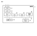
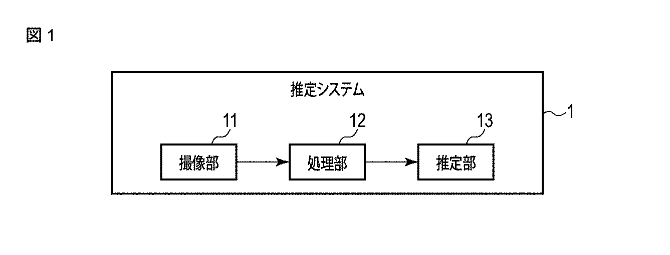
まず、図1を参照して、一実施形態に係る推定システムの構成を説明する。この推定システム1は、カメラ、カメラを備えるコンピュータ、データを相互に送受信可能なカメラとコンピュータ、または各種電子機器に内蔵される組み込みシステムとして実現され得る。推定システム1は、例えば、撮像部11と処理部12と推定部13とを備える。
Hereinafter, embodiments will be described with reference to the drawings.
First, the configuration of the estimation system according to the embodiment will be described with reference to FIG. The estimation system 1 can be realized as a camera, a computer including a camera, a camera and a computer capable of transmitting and receiving data to and from each other, or an embedded system built in various electronic devices. The estimation system 1 includes, for example, an image pickup unit 11, a processing unit 12, and an estimation unit 13.

撮像部11は、被写体を撮像するとき、被写体と撮像部11(カメラ)との間の実際の距離である実距離を符号化して撮像する。撮像部11は、少なくとも一つのカメラ(例えば、単眼カメラ)を備え、カメラの開口部に符号化開口を設けることにより、被写体から撮像部11までの距離を符号化して撮像する。つまり、撮像部11は、単眼で、画像と、画像に含まれる被写体までの距離に関する情報とを一度の撮影で取得可能である。撮像部11は、撮像により得られた撮像画像である符号化情報を生成し、処理部12に出力する。 When the subject is imaged, the image pickup unit 11 encodes and captures the actual distance, which is the actual distance between the subject and the image pickup unit 11 (camera). The image pickup unit 11 includes at least one camera (for example, a monocular camera), and by providing a coded aperture in the opening of the camera, the distance from the subject to the image pickup unit 11 is coded and imaged. That is, the image pickup unit 11 can acquire the image and the information regarding the distance to the subject included in the image with a single eye with a single eye. The image pickup unit 11 generates coded information, which is an image captured image obtained by imaging, and outputs the coded information to the processing unit 12.

距離の符号化は、撮像過程を変更することにより、例えば、カメラの開口部に入射する光の位相、波長、および強度の少なくともいずれか一つを変化させることにより、実現される。したがって、変化した光に基づく撮像画像に、当該変化の特性が考慮された特定の処理を施すことにより、撮像画像に符号化された距離を算出(推定)することができる。撮像部11は、画像と距離に関する情報とを同期して記録できるものであれば、符号化開口に限らず、他の形態のコンピュテーショナルフォトグラフィを用いるものであってもよい。 Distance coding is achieved by changing the imaging process, for example, by changing at least one of the phase, wavelength, and intensity of the light incident on the aperture of the camera. Therefore, the distance encoded in the captured image can be calculated (estimated) by subjecting the captured image based on the changed light to a specific process in which the characteristics of the change are taken into consideration. The image pickup unit 11 is not limited to the coded aperture as long as it can record the image and the information related to the distance in synchronization, and may use other forms of computational photography.

処理部12は、符号化情報を処理することにより、符号化情報を画像と距離に関する情報とに変換する。具体的な変換方法については図2から図7を参照して後述する。処理部12は、画像と距離に関する情報とを推定部13に出力する。 The processing unit 12 converts the coded information into information related to the image and the distance by processing the coded information. The specific conversion method will be described later with reference to FIGS. 2 to 7. The processing unit 12 outputs the image and the information regarding the distance to the estimation unit 13.

推定部13は、符号化情報を用いて、実距離に基づいて、自己位置と自己姿勢と地図の少なくともいずれか一つを推定する。より具体的には、推定部13は、例えば、画像と距離に関する情報とを用いて、実距離に基づいて、自己位置と自己姿勢と地図の少なくともいずれか一つを推定する。実距離に基づく位置や座標は、実寸大の三次元空間上の位置や座標として表現されている。推定部13は、例えば、少なくとも自己位置を推定する。 The estimation unit 13 estimates at least one of the self-position, the self-posture, and the map based on the actual distance by using the coded information. More specifically, the estimation unit 13 estimates at least one of the self-position, the self-posture, and the map based on the actual distance, for example, using the image and the information about the distance. The positions and coordinates based on the actual distance are expressed as the positions and coordinates in the actual size three-dimensional space. The estimation unit 13 estimates, for example, at least its own position.

自己位置は、例えば、撮像部11の位置を示す。また、自己姿勢は、例えば基準軸に対する姿勢であってもよい。なお、自己位置は、撮像部11の位置に限らず、任意の位置であってもよい。この任意の位置と撮像部11との位置関係は、予め取得されていてもよい。そのような自己位置として、例えば、撮像部11または撮像部11を含む推定システム1が設けられる移動体(例えば、自動車、ロボット等)の中心の位置が用いられ得る。自己姿勢は、例えば、撮像部11に設けられるレンズの光軸の姿勢を示す。地図は、例えば、画像上の複数の特徴点に対応する複数の三次元座標によって示される。地図は、例えば自己位置を含む領域の地図である。地図は、例えば三次元で表される。推定部13は、画像と距離に関する情報とを用いて、例えば、Simultaneous Localization And Mapping(SLAM)処理を行うことにより、実スケールに基づく自己位置、自己姿勢、および地図の少なくともいずれか一つを推定することができる。 The self-position indicates, for example, the position of the imaging unit 11. Further, the self-posture may be, for example, a posture with respect to the reference axis. The self-position is not limited to the position of the imaging unit 11, and may be any position. The positional relationship between this arbitrary position and the imaging unit 11 may be acquired in advance. As such a self-position, for example, the position of the center of the moving body (for example, a car, a robot, etc.) in which the estimation system 1 including the image pickup unit 11 or the image pickup unit 11 is provided can be used. The self-posture indicates, for example, the posture of the optical axis of the lens provided in the image pickup unit 11. The map is represented, for example, by a plurality of three-dimensional coordinates corresponding to the plurality of feature points on the image. The map is, for example, a map of an area including a self-position. The map is represented in three dimensions, for example. The estimation unit 13 estimates at least one of the self-position, the self-posture, and the map based on the actual scale by performing, for example, Simultaneous Localization And Mapping (SLAM) processing using the image and the information about the distance. can do.

実スケールに基づく位置や座標は、実寸大の三次元空間上の位置や座標として表現されている。したがって、例えば、自己位置と地図上の複数の点の三次元座標とが推定された場合、推定された自己位置から地図上のある点(三次元座標)までの距離は、撮像の対象となった実際の空間における、自己位置から、その地図上の点に対応する被写体上の点までの距離に相当し、高精度の推定が行われたならば略一致する。 The positions and coordinates based on the actual scale are expressed as the positions and coordinates in the actual size three-dimensional space. Therefore, for example, when the self-position and the three-dimensional coordinates of a plurality of points on the map are estimated, the distance from the estimated self-position to a certain point (three-dimensional coordinates) on the map is the target of imaging. It corresponds to the distance from the self-position to the point on the subject corresponding to the point on the map in the actual space, and if a highly accurate estimation is made, it is almost the same.

推定部13は、例えばRGB-D SLAMを適用して、実スケールに基づいて自己位置、自己姿勢、および地図の少なくともいずれかを推定することができる。RGB-D
SLAMは、RGB画像と奥行きマップ(depth map)とを用いた手法であるので、画像と距離に関する情報とが用いられる推定システム1に適用することが容易である。一般に、RGB画像と奥行きマップとは、データ取得時のタイムスタンプに基づいて、すなわち、RGB画像がカメラによって取得された時点を示すタイムスタンプと、奥行きマップが距離センサ等によって取得された時点を示すタイムスタンプとに基づいて、同期させる必要がある。これに対して、本実施形態の推定システム1で用いられる画像と距離に関する情報とは、例えば、符号化開口(例えば、カラー開口)を備える単眼カメラを用いて取得されるので、既に同期されている。そのため、推定システム1では、データの同期のための処理が必要とされず、その分の計算コストを低減したり、同期のための処理装置を省略したりすることができる。
The estimation unit 13 can apply, for example, RGB-D SLAM to estimate at least one of the self-position, the self-posture, and the map based on the actual scale. RGB-D
Since SLAM is a method using an RGB image and a depth map, it can be easily applied to an estimation system 1 in which information on an image and a distance is used. Generally, the RGB image and the depth map indicate a time stamp indicating the time when the RGB image is acquired by the camera and a time stamp indicating the time when the depth map is acquired by a distance sensor or the like, based on the time stamp at the time of data acquisition. Need to be synchronized based on the time stamp. On the other hand, the information about the image and the distance used in the estimation system 1 of the present embodiment is already synchronized because it is acquired by using, for example, a monocular camera having a coded aperture (for example, a color aperture). There is. Therefore, the estimation system 1 does not require processing for data synchronization, and can reduce the calculation cost by that amount or omit the processing device for synchronization.

あるいは、推定部13は、例えばMonocular SLAMを適用して、相対スケールに基づいて画像から自己位置や自己姿勢、地図を推定する。その後、推定部13は、距離に関する情報をさらに用いて、推定された自己位置や自己姿勢、地図を実スケールに基づいて拡大または縮小(すなわち、スケーリング)することにより、実スケール(実距離)に基づく自己位置や自己姿勢、地図を推定することができる。 Alternatively, the estimation unit 13 applies, for example, Monocular SLAM to estimate the self-position, self-posture, and map from the image based on the relative scale. After that, the estimation unit 13 further uses the information on the distance to enlarge or reduce (that is, scale) the estimated self-position, self-posture, and map based on the actual scale to achieve the actual scale (actual distance). It is possible to estimate the self-position, self-posture, and map based on it.

推定部13は、上述したRGB-D SLAMやMonocular SLAMに限らず、様々なSLAMの手法(例えば、非特許文献1参照)を適用してSLAM処理を行うことができる。 The estimation unit 13 can perform SLAM processing by applying various SLAM methods (see, for example, Non-Patent Document 1), not limited to the RGB-D SLAM and Monocular SLAM described above.

実スケールに基づく自己位置や自己姿勢、地図の推定には、例えば、ステレオカメラを用いる方法、単眼カメラと距離センサとを用いる方法、単眼カメラと被写体に関する辞書データとを用いる方法等がある。ステレオカメラを用いる方法や、単眼カメラと距離センサとを用いる方法では、移動体に複数のカメラやセンサを設置するためのスペースが必要になり、またカメラとセンサ間でデータを同期しなければならない。また、単眼カメラと物体に関する辞書データを用いる方法では、物体の三次元形状に関する辞書データを準備しておく必要があり、また辞書データに示される物体が撮影されなければ、実スケールに基づく推定ができない。本実施形態の推定システム1は、単眼カメラを用いて、一度の撮影で画像と距離情報とを取得できるので、画像と距離情報との同期の必要がなく、且つ物体の辞書データを準備しておく必要がなく、自己位置・姿勢や地図を容易に推定することができる。 For estimating the self-position, self-posture, and map based on the actual scale, for example, there are a method using a stereo camera, a method using a monocular camera and a distance sensor, a method using a monocular camera and dictionary data related to the subject, and the like. The method using a stereo camera or the method using a monocular camera and a distance sensor requires space for installing multiple cameras and sensors on a moving object, and data must be synchronized between the cameras and sensors. .. In addition, in the method using a monocular camera and dictionary data related to an object, it is necessary to prepare dictionary data related to the three-dimensional shape of the object, and if the object shown in the dictionary data is not photographed, estimation based on the actual scale can be performed. Can not. Since the estimation system 1 of the present embodiment can acquire the image and the distance information in one shooting by using the monocular camera, there is no need to synchronize the image and the distance information, and the dictionary data of the object is prepared. It is not necessary to keep it, and the self-position / posture and map can be easily estimated.

なお、推定システム1の撮像部11、処理部12、および推定部13は、一つの装置内に設けられていてもよいし、複数の装置に分かれて設けられていてもよい。以下では、推定システム1は、撮像部11と処理部12とを有する撮像装置と、この撮像装置との間でデータを相互に送受信可能な情報処理装置とを備える場合を例示する。なお、処理部12は、撮像装置ではなく、情報処理装置に組み込まれていてもよい。 The imaging unit 11, the processing unit 12, and the estimation unit 13 of the estimation system 1 may be provided in one device or may be divided into a plurality of devices. In the following, the estimation system 1 exemplifies a case in which an image pickup device having an image pickup unit 11 and a processing unit 12 and an information processing device capable of transmitting and receiving data to and from the image pickup device are provided. The processing unit 12 may be incorporated in an information processing device instead of an image pickup device.

図2は、撮像部11および処理部12を備える撮像装置2のシステム構成の例を示す。撮像部11は、例えば、フィルタ21、レンズ22およびイメージセンサ23を備える。処理部12は、例えばCPU24で構成される。撮像装置2は、さらに記憶部を備える。記憶部は、例えば、RAM25、不揮発性メモリ26、メモリカードスロット27で構成される。撮像装置2は、さらに通信デバイス28を備えていてもよい。CPU24は、例えば、不揮発性メモリ26からRAM25にロードされた特定のプログラムを実行することにより、処理部12として機能する。イメージセンサ23、CPU24、RAM25、不揮発性メモリ26、メモリカードスロット27、および通信デバイス28は、例えば、バス20を介して相互に接続され得る。 FIG. 2 shows an example of the system configuration of the image pickup apparatus 2 including the image pickup unit 11 and the processing unit 12. The image pickup unit 11 includes, for example, a filter 21, a lens 22, and an image sensor 23. The processing unit 12 is composed of, for example, a CPU 24. The image pickup device 2 further includes a storage unit. The storage unit is composed of, for example, a RAM 25, a non-volatile memory 26, and a memory card slot 27. The image pickup device 2 may further include a communication device 28. The CPU 24 functions as the processing unit 12, for example, by executing a specific program loaded from the non-volatile memory 26 into the RAM 25. The image sensor 23, the CPU 24, the RAM 25, the non-volatile memory 26, the memory card slot 27, and the communication device 28 may be connected to each other via, for example, the bus 20.

イメージセンサ23は、フィルタ21とレンズ22とを透過した光を受光し、受光した光を電気信号に変換(光電変換)する。イメージセンサ23には、例えばCCD(Charge Coupled Device)やCMOS(Complementary Metal Oxide Semiconductor)が用いられる。イメージセンサ23は、例えば、赤色(R)の光を受光する撮像素子と、緑色(G)の光を受光する撮像素子と、青色(B)の光を受光する撮像素子とを備える。各撮像素子は、対応する波長帯域の光を受光し、受光した光を電気信号に変換する。この電気信号をA/D変換することによりカラー画像を生成することができる。以下では、画像のR成分、G成分、B成分を、それぞれR画像、G画像、B画像とも称する。なお、赤色、緑色、青色の撮像素子毎の電気信号を用いて、R画像、G画像、B画像をそれぞれ生成することもできる。 The image sensor 23 receives the light transmitted through the filter 21 and the lens 22, and converts the received light into an electric signal (photoelectric conversion). As the image sensor 23, for example, a CCD (Charge Coupled Device) or a CMOS (Complementary Metal Oxide Sensor) is used. The image sensor 23 includes, for example, an image pickup element that receives red (R) light, an image pickup element that receives green (G) light, and an image pickup element that receives blue (B) light. Each image sensor receives light in the corresponding wavelength band and converts the received light into an electric signal. A color image can be generated by A / D conversion of this electric signal. Hereinafter, the R component, the G component, and the B component of the image are also referred to as an R image, a G image, and a B image, respectively. It is also possible to generate an R image, a G image, and a B image by using the electric signals of each of the red, green, and blue image pickup elements.

CPU24は、撮像装置2内の様々なコンポーネントの動作を制御するプロセッサである。CPU24は、ストレージデバイスである不揮発性メモリ26からRAM25にロードされる様々なプログラムを実行する。不揮発性メモリ26には、イメージセンサ23によって出力された電気信号に基づく撮像画像や、その画像の処理結果も格納され得る。 The CPU 24 is a processor that controls the operation of various components in the image pickup apparatus 2. The CPU 24 executes various programs loaded into the RAM 25 from the non-volatile memory 26 which is a storage device. The non-volatile memory 26 may also store an image captured based on an electric signal output by the image sensor 23 and a processing result of the image.

メモリカードスロット27には、SDメモリカードやSDHCメモリカードのような各種の可搬記憶媒体が挿入され得る。メモリカードスロット27に記憶媒体が挿入された場合、その記憶媒体に対するデータの書き込みおよび読み出しが実行され得る。データは、例えば画像データや距離に関するデータである。 Various portable storage media such as SD memory cards and SDHC memory cards can be inserted into the memory card slot 27. When a storage medium is inserted into the memory card slot 27, data can be written to and read from the storage medium. The data is, for example, image data or data related to distance.

通信デバイス28は、有線通信または無線通信を実行するように構成されたインターフェース機器である。通信デバイス28は、信号を有線または無線送信する送信部と、信号を有線または無線受信する受信部とを含む。 The communication device 28 is an interface device configured to perform wired or wireless communication. The communication device 28 includes a transmitting unit that transmits a signal by wire or wirelessly, and a receiving unit that receives the signal by wire or wirelessly.

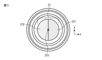
次いで、図3は、フィルタ21の構成の例を示す。フィルタ21は、互いに異なる光の波長帯域(色成分)を透過する複数のフィルタ領域を有し、2以上のフィルタ領域は、撮像装置2の光学中心213に対して非点対称な形状である。フィルタ21は、例えば、二色のカラーフィルタ領域である第1フィルタ領域211と第2フィルタ領域212とで構成される。フィルタ21の中心は、撮像装置2(レンズ22)の光学中心213と一致している。第1フィルタ領域211および第2フィルタ領域212はそれぞれ、光学中心213に対して非点対称である形状を有している。また、例えば、二つのフィルタ領域211,212は重複せず、且つ二つのフィルタ領域211,212によってフィルタ21の全領域を構成している。図3に示す例では、第1フィルタ領域211および第2フィルタ領域212はそれぞれ、円形のフィルタ21が光学中心213を通る線分で分割された半円の形状を有している。第1フィルタ領域211は、例えばイエロー(Y)のフィルタ領域であり、第2フィルタ領域212は、例えばシアン(C)のフィルタ領域である。なお、第1フィルタ領域211がマゼンタ(M)のフィルタ領域であって、第2フィルタ領域212がイエロー(Y)のフィルタ領域であってもよい。さらに、第1フィルタ領域211がシアン(C)のフィルタ領域であって、第2フィルタ領域212がマゼンタ(M)のフィルタ領域であってもよい。 Next, FIG. 3 shows an example of the configuration of the filter 21. The filter 21 has a plurality of filter regions that transmit different wavelength bands (color components) of light, and the two or more filter regions have a shape that is non-point symmetric with respect to the optical center 213 of the image pickup apparatus 2. The filter 21 is composed of, for example, a first filter region 211 and a second filter region 212, which are two-color filter regions. The center of the filter 21 coincides with the optical center 213 of the image pickup apparatus 2 (lens 22). The first filter region 211 and the second filter region 212 each have a shape that is non-point symmetric with respect to the optical center 213. Further, for example, the two filter regions 211 and 212 do not overlap, and the two filter regions 211 and 212 constitute the entire region of the filter 21. In the example shown in FIG. 3, the first filter region 211 and the second filter region 212 each have a semicircular shape in which the circular filter 21 is divided by a line segment passing through the optical center 213. The first filter region 211 is, for example, a yellow (Y) filter region, and the second filter region 212 is, for example, a cyan (C) filter region. The first filter area 211 may be a magenta (M) filter area, and the second filter area 212 may be a yellow (Y) filter area. Further, the first filter region 211 may be a cyan (C) filter region, and the second filter region 212 may be a magenta (M) filter region.

各カラーフィルタが透過する波長領域は異なる。一つのフィルタ領域が透過する光の波長帯域の一部と、別の一つのカラーフィルタ領域が透過する光の波長帯域の一部は、例えば重複する。一つのカラーフィルタ領域が透過する光の波長帯域は、例えば別の一つのカラーフィルタ領域が透過する光の波長帯域を含んでもよい。 The wavelength range transmitted by each color filter is different. A part of the wavelength band of light transmitted by one filter region and a part of the wavelength band of light transmitted by another color filter region overlap, for example. The wavelength band of light transmitted by one color filter region may include, for example, the wavelength band of light transmitted by another color filter region.

なお、第1フィルタ領域211と第2フィルタ領域212とは、任意の波長帯域の透過率を変更するフィルタ、任意方向の偏光光を通過させる偏光フィルタ、または任意の波長帯域の集光パワーを変更するマイクロレンズであってもよい。例えば、任意の波長帯域の透過率を変更するフィルタは、原色フィルタ(RGB)、補色フィルタ(CMY)、色補正フィルタ(CC-RGB/CMY)、赤外線・紫外線カットフィルタ、NDフィルタ、または遮蔽板であってもよい。第1フィルタ領域211や第2フィルタ領域212がマイクロレンズである場合は、レンズ22により光線の集光の分布に偏りが生じることでぼけの形状が変化する。 In the first filter region 211 and the second filter region 212, a filter that changes the transmittance in an arbitrary wavelength band, a polarizing filter that allows polarized light in an arbitrary direction to pass through, or a focusing power in an arbitrary wavelength band is changed. It may be a microlens. For example, the filter that changes the transmission rate in an arbitrary wavelength band is a primary color filter (RGB), a complementary color filter (CMY), a color correction filter (CC-RGB / CMY), an infrared / ultraviolet cut filter, an ND filter, or a shielding plate. May be. When the first filter region 211 and the second filter region 212 are microlenses, the shape of the blur changes due to the bias in the distribution of the light rays collected by the lens 22.

また、図4は、三つ以上のカラーフィルタ領域を有するフィルタ21A,21B,21Cの例を示す。各フィルタ21A,21B,21Cは、フィルタ21の代わりに用いられ得る。上述したように、各フィルタ領域は、撮像装置2の光学中心213に対して非点対称な形状を有している。 Further, FIG. 4 shows an example of filters 21A, 21B, and 21C having three or more color filter regions. Each of the filters 21A, 21B, 21C can be used in place of the filter 21. As described above, each filter region has a shape that is non-point symmetric with respect to the optical center 213 of the image pickup apparatus 2.

図4(A)に示すフィルタ21Aは、三つのフィルタ領域231,232,233を有する。第1フィルタ領域231は、光学中心213を通る線分に対して対称な瞳形状を有し、第2フィルタ領域232および第3フィルタ領域233は、瞳形状の第1フィルタ領域231の左右にそれぞれ隣接する三日月状の領域である。各フィルタ領域231,232,233は重複せず、且つ三つのフィルタ領域231,232,233によってフィルタ21Aの全領域を構成している。第1フィルタ領域231は、例えば透明のフィルタ領域であり、第2フィルタ領域232は、例えばイエロー(Y)のフィルタ領域であり、第3フィルタ領域233は、例えばシアン(C)のフィルタ領域である。なお、第2フィルタ領域232がマゼンタ(M)のフィルタ領域であり、第3フィルタ領域233がイエロー(Y)のフィルタ領域であってもよい。また、第2フィルタ領域232がシアン(C)のフィルタ領域であり、第3フィルタ領域233がマゼンタ(M)のフィルタ領域であってもよい。このフィルタ21Aでは、中心の領域を含む第1フィルタ領域231で全ての光線が透過されるので、高い透過率(例えば、90%)で透過された光線に基づく画像を得ることができる。 The filter 21A shown in FIG. 4A has three filter regions 231,232,233. The first filter region 231 has a pupil shape symmetrical with respect to the line segment passing through the optical center 213, and the second filter region 232 and the third filter region 233 are on the left and right of the first filter region 231 of the pupil shape, respectively. It is an adjacent crescent-shaped area. The filter regions 231, 232, 233 do not overlap, and the three filter regions 231, 232, 233 constitute the entire region of the filter 21A. The first filter region 231 is, for example, a transparent filter region, the second filter region 232 is, for example, a yellow (Y) filter region, and the third filter region 233 is, for example, a cyan (C) filter region. .. The second filter region 232 may be a magenta (M) filter region, and the third filter region 233 may be a yellow (Y) filter region. Further, the second filter region 232 may be a cyan (C) filter region, and the third filter region 233 may be a magenta (M) filter region. In this filter 21A, all the light rays are transmitted in the first filter region 231 including the central region, so that an image based on the light rays transmitted with a high transmittance (for example, 90%) can be obtained.

図4(B)に示すフィルタ21Bは、三つのフィルタ領域241,242,243を有する。第1フィルタ領域241および第2フィルタ領域242は、円形のフィルタ21Bの直径の半分の直径を有する円形を有し、各フィルタ領域241,242が、レンズ22の光学中心213を通る線分に対して対称に配置されている。これら第1フィルタ領域241および第2フィルタ領域242を除いた、フィルタ21B上の残りの領域が、第3フィルタ領域243である。第1フィルタ領域241は、例えばシアン(C)のフィルタ領域であり、第2フィルタ領域242は、例えばイエロー(Y)のフィルタ領域であり、第3フィルタ領域243は、例えば緑(G)のフィルタ領域である。このフィルタ21Bを用いて得られるR画像およびB画像では、ぼけ関数を均等に制御することができる。なお、第1フィルタ領域241がマゼンタ(M)のフィルタ領域であり、第2フィルタ領域242がイエロー(Y)のフィルタ領域であり、第3フィルタ領域243が赤(R)のフィルタ領域であってもよい。また、第1フィルタ領域241がシアン(C)のフィルタ領域であり、第2フィルタ領域242がマゼンタ(M)のフィルタ領域であり、第3フィルタ領域243が青(B)のフィルタ領域であってもよい。 The filter 21B shown in FIG. 4B has three filter regions 241,242,243. The first filter region 241 and the second filter region 242 have a circular shape having a diameter half the diameter of the circular filter 21B, and each filter region 241, 242 is for a line segment passing through the optical center 213 of the lens 22. Are arranged symmetrically. The remaining region on the filter 21B excluding the first filter region 241 and the second filter region 242 is the third filter region 243. The first filter region 241 is, for example, a cyan (C) filter region, the second filter region 242 is, for example, a yellow (Y) filter region, and the third filter region 243 is, for example, a green (G) filter. It is an area. The blur function can be controlled evenly in the R image and the B image obtained by using this filter 21B. The first filter region 241 is a magenta (M) filter region, the second filter region 242 is a yellow (Y) filter region, and the third filter region 243 is a red (R) filter region. May be good. Further, the first filter region 241 is a cyan (C) filter region, the second filter region 242 is a magenta (M) filter region, and the third filter region 243 is a blue (B) filter region. May be good.

図4(C)に示すフィルタ21Cは、四つのフィルタ領域251,252,253,254を有する。第1フィルタ領域251、第2フィルタ領域252、および第3フィルタ領域253は正方形の形状を有し、これらフィルタ領域251,252,253を除く残りの部分が第4フィルタ領域254である。第1フィルタ領域251は、例えば赤(R)のフィルタ領域である。第2フィルタ領域252は、例えば緑(G)のフィルタ領域である。第3フィルタ領域253は、例えば青(B)のフィルタ領域である。また、第4フィルタ領域254は、例えば黒(遮蔽)のフィルタ領域である。 The filter 21C shown in FIG. 4C has four filter regions 251,252, 253, 254. The first filter region 251, the second filter region 252, and the third filter region 253 have a square shape, and the remaining portion excluding these filter regions 251, 252, 253 is the fourth filter region 254. The first filter region 251 is, for example, a red (R) filter region. The second filter region 252 is, for example, a green (G) filter region. The third filter region 253 is, for example, a blue (B) filter region. Further, the fourth filter area 254 is, for example, a black (shielding) filter area.

以下では、説明を分かりやすくするために、図3に示すフィルタ21において、第1フィルタ領域211がイエロー(Y)のフィルタ領域であり、第2フィルタ領域212がシアン(C)のフィルタ領域である場合を主に例示する。 In the following, in order to make the explanation easy to understand, in the filter 21 shown in FIG. 3, the first filter region 211 is a yellow (Y) filter region, and the second filter region 212 is a cyan (C) filter region. The case is mainly illustrated.

このようなフィルタ21がカメラの開口部に配置されることによって、開口部が二色で二分割された構造開口であるカラー開口が構成される。このカラー開口を透過する光線に基づき、イメージセンサ23を用いて画像が生成される。イメージセンサ23に入射する光の光路上において、レンズ22とイメージセンサ23との間にフィルタ21が配置されてもよい。また、レンズ22が複数設けられる場合には、フィルタ21が2つのレンズ22の間に配置されてもよい。 By arranging such a filter 21 in the opening of the camera, a color opening, which is a structural opening in which the opening is divided into two colors, is formed. An image is generated using the image sensor 23 based on the light rays transmitted through the color aperture. A filter 21 may be arranged between the lens 22 and the image sensor 23 on the optical path of the light incident on the image sensor 23. Further, when a plurality of lenses 22 are provided, the filter 21 may be arranged between the two lenses 22.

イメージセンサ23の緑(G)の光を受光する撮像素子に対応する波長帯域の光は、イエローの第1フィルタ領域211とシアンの第2フィルタ領域212の両方を透過する。イメージセンサ23の赤(R)の光を受光する撮像素子に対応する波長帯域の光は、イエローの第1フィルタ領域211を透過し、シアンの第2フィルタ領域212を透過しない。イメージセンサ23の青(B)の光を受光する撮像素子に対応する波長帯域の光は、シアンの第2フィルタ領域212を透過し、イエローの第1フィルタ領域211を透過しない。 The light in the wavelength band corresponding to the image sensor that receives the green (G) light of the image sensor 23 passes through both the yellow first filter region 211 and the cyan second filter region 212. The light in the wavelength band corresponding to the image sensor that receives the red (R) light of the image sensor 23 passes through the first filter region 211 of yellow and does not pass through the second filter region 212 of cyan. The light in the wavelength band corresponding to the image sensor that receives the blue (B) light of the image sensor 23 passes through the cyan second filter region 212 and does not pass through the yellow first filter region 211.

なお、ある波長帯域の光がフィルタまたはフィルタ領域を透過するとは、フィルタまたはフィルタ領域が高い透過率でその波長帯域の光を透過し、そのフィルタまたはフィルタ領域による当該波長帯域の光の減衰(すなわち、光量の低下)が極めて小さいことを意味する。また、ある波長帯域の光がフィルタまたはフィルタ領域を透過しないとは、光がフィルタまたはフィルタ領域に遮蔽されることであり、例えば、フィルタまたはフィルタ領域が低い透過率でその波長帯域の光を透過し、そのフィルタまたはフィルタ領域による当該波長帯域の光の減衰が極めて大きいことを意味する。フィルタまたはフィルタ領域は、例えば、ある波長帯域の光を吸収することにより光を減衰させる。 When light in a certain wavelength band passes through a filter or a filter region, the filter or the filter region transmits light in the wavelength band with a high transmittance, and the filter or the filter region attenuates the light in the wavelength band (that is,). , The decrease in the amount of light) is extremely small. Also, the fact that light in a certain wavelength band does not pass through the filter or filter area means that the light is shielded by the filter or filter area, for example, the filter or filter area transmits light in that wavelength band with low transmittance. However, it means that the attenuation of light in the wavelength band by the filter or the filter region is extremely large. The filter or filter region attenuates light, for example, by absorbing light in a wavelength band.

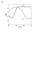
図5は、第1フィルタ領域211および第2フィルタ領域212の透過率特性の例を示す。なお、可視光の波長帯域のうち700nmより長い波長の光に対する透過率は図示を省略してあるが、その透過率は700nmの場合に近いものである。図5に示すイエローの第1フィルタ領域211の透過率特性215では、波長帯域が620nmから750nm程度のR画像に対応する光と、波長帯域が495nmから570nm程度のG画像に対応する光とが高い透過率で透過され、波長帯域が450nmから495nm程度のB画像に対応する光がほとんど透過されていない。また、シアンの第2フィルタ領域212の透過率特性216では、B画像およびG画像に対応する波長帯域の光が高い透過率で透過され、R画像に対応する波長帯域の光がほとんど透過されていない。 FIG. 5 shows an example of the transmittance characteristics of the first filter region 211 and the second filter region 212. Although the transmittance for light having a wavelength longer than 700 nm in the wavelength band of visible light is not shown, the transmittance is close to that of 700 nm. In the transmittance characteristic 215 of the first filter region 211 of yellow shown in FIG. 5, light corresponding to an R image having a wavelength band of about 620 nm to 750 nm and light corresponding to a G image having a wavelength band of about 495 nm to 570 nm are present. It is transmitted with a high transmittance, and almost no light corresponding to a B image having a wavelength band of about 450 nm to 495 nm is transmitted. Further, in the transmittance characteristic 216 of the second filter region 212 of cyan, the light in the wavelength band corresponding to the B image and the G image is transmitted with a high transmittance, and the light in the wavelength band corresponding to the R image is almost transmitted. do not have.

したがって、R画像に対応する波長帯域の光はイエローの第1フィルタ領域211のみを透過し、B画像に対応する波長帯域の光はシアンの第2フィルタ領域212のみを透過する。G画像に対応する波長帯域の光は、第1フィルタ領域211と第2フィルタ領域212を透過する。 Therefore, the light in the wavelength band corresponding to the R image passes only through the first filter region 211 of yellow, and the light in the wavelength band corresponding to the B image passes only through the second filter region 212 of cyan. Light in the wavelength band corresponding to the G image passes through the first filter region 211 and the second filter region 212.

このようなR画像、B画像および画像上のぼけの形状は被写体までの距離dに応じて変化する。また、各フィルタ領域211,212が光学中心213に対して非点対称な形状であるので、R画像およびB画像上のぼけの偏りの方向が、撮像点から見て、被写体が合焦位置よりも手前にあるか、それとも奥にあるかによってそれぞれ反転する。この合焦位置は、撮像点から合焦距離dfだけ離れた点であり、画像上にぼけが発生しないピントが合う位置である。 Such R image, B image, and the shape of the blur on the image change according to the distance d to the subject. Further, since each of the filter regions 211 and 212 has a shape that is non-point symmetric with respect to the optical center 213, the direction of the blur bias on the R image and the B image is from the in-focus position when the subject is viewed from the imaging point. Also flips depending on whether it is in the foreground or in the back. This focusing position is a point separated from the imaging point by the focusing distance df, and is a position where the image is in focus without blurring.

図6を参照して、フィルタ21が配置されたカラー開口による光線変化と、ぼけの形状とについて説明する。 With reference to FIG. 6, the light ray change due to the color aperture in which the filter 21 is arranged and the shape of the blur will be described.

まず、被写体5が合焦距離df(合焦位置)よりも奥にある場合(d>df)、イメージセンサ23によって撮像された画像にはぼけが発生する。この画像上のぼけの形状を示すぼけ関数は、R画像、G画像およびB画像でそれぞれ異なっている。すなわち、R画像のぼけ関数201Rは左側に偏ったぼけの形状を示し、G画像のぼけ関数201Gは偏りのないぼけの形状を示し、B画像のぼけ関数201Bは右側に偏ったぼけの形状を示している。 First, when the subject 5 is deeper than the focusing distance df (focusing position) (d> df), the image captured by the image sensor 23 is blurred. The blur function indicating the shape of the blur on this image is different between the R image, the G image, and the B image. That is, the blur function 201R of the R image shows the shape of the blur biased to the left side, the blur function 201G of the G image shows the shape of the blur without bias, and the blur function 201B of the B image shows the shape of the blur biased to the right. Shows.

次に、被写体5が合焦距離dfにある場合(d=df)、イメージセンサ23によって撮像された画像にはほとんどぼけが発生しない。この画像上のぼけの形状を示すぼけ関数は、R画像、G画像およびB画像でほぼ同じである。すなわち、R画像のぼけ関数202R、G画像のぼけ関数202G、およびB画像のぼけ関数202Bは、偏りのないぼけの形状を示している。 Next, when the subject 5 is at the focusing distance df (d = df), almost no blur occurs in the image captured by the image sensor 23. The blur function indicating the shape of the blur on this image is almost the same for the R image, the G image, and the B image. That is, the blur function 202R of the R image, the blur function 202G of the G image, and the blur function 202B of the B image show an unbiased shape of the blur.

さらに、被写体5が合焦距離dfよりも手前にある場合(d<df)、イメージセンサ23によって撮像された画像にはぼけが発生する。この画像上のぼけの形状を示すぼけ関数は、R画像、G画像およびB画像でそれぞれ異なっている。すなわち、R画像のぼけ関数203Rは右側に偏ったぼけの形状を示し、G画像のぼけ関数203Gは偏りのないぼけの形状を示し、B画像のぼけ関数203Bは左側に偏ったぼけの形状を示している。 Further, when the subject 5 is in front of the focusing distance df (d <df), the image captured by the image sensor 23 is blurred. The blur function indicating the shape of the blur on this image is different between the R image, the G image, and the B image. That is, the blur function 203R of the R image shows the shape of the blur biased to the right, the blur function 203G of the G image shows the shape of the blur without bias, and the blur function 203B of the B image shows the shape of the blur biased to the left. Shows.

このように、被写体5が合焦距離dfよりも手前または奥にある場合、イエローの第1フィルタ領域211を透過した光線に基づくR画像のぼけ関数201R,203Rは非対称であり、またシアンの第2フィルタ領域212を透過した光線に基づくB画像のぼけ関数201B,203Bも非対称である。そして、そのR画像のぼけ関数201R,203Rは、B画像のぼけ関数201B,203Bとは異なっている。 As described above, when the subject 5 is in front of or behind the focusing distance df, the blur functions 201R and 203R of the R image based on the light rays transmitted through the first filter region 211 of yellow are asymmetrical, and the cyanth th. 2 The blur functions 201B and 203B of the B image based on the light rays transmitted through the filter region 212 are also asymmetric. The blur functions 201R and 203R of the R image are different from the blur functions 201B and 203B of the B image.

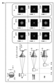
図7は、このような画像上のぼけを利用して被写体5までの距離を算出(推定)する方法を示す。図7に示す例では、フィルタ21は、イエローの第1フィルタ領域211とシアンの第2フィルタ領域212とによって構成されている。そのため、R画像に対応する波長帯域の光が、第1フィルタ領域211に対応する部分51Rを通過し、G画像に対応する波長帯域の光が、第1フィルタ領域211および第2フィルタ領域212に対応する部分51Gを通過し、B画像に対応する波長帯域の光が、第2フィルタ領域212に対応する部分51Bを通過する。 FIG. 7 shows a method of calculating (estimating) the distance to the subject 5 by using such a blur on the image. In the example shown in FIG. 7, the filter 21 is composed of a yellow first filter region 211 and a cyan second filter region 212. Therefore, the light in the wavelength band corresponding to the R image passes through the portion 51R corresponding to the first filter region 211, and the light in the wavelength band corresponding to the G image passes through the first filter region 211 and the second filter region 212. Light in the wavelength band corresponding to the B image passes through the corresponding portion 51G and passes through the portion 51B corresponding to the second filter region 212.

このようなフィルタ21を用いて撮像された画像上にぼけが生じた場合、R画像、G画像およびB画像上のぼけはそれぞれ異なる形状になる。図7に示すように、G画像のぼけ関数52Gは左右対称であるぼけの形状を表している。また、R画像のぼけ関数52RおよびB画像のぼけ関数52Bは非点対称であるぼけの形状を表し、ぼけの偏りはそれぞれ異なっている。 When blurring occurs on an image captured by using such a filter 21, the blurring on the R image, the G image, and the B image has different shapes. As shown in FIG. 7, the blur function 52G of the G image represents a symmetrical blur shape. Further, the blur function 52R of the R image and the blur function 52B of the B image represent the shape of the blur that is non-point symmetric, and the bias of the blur is different from each other.

R画像のぼけ関数52RおよびB画像のぼけ関数52Bには、R画像およびB画像上の非点対称なぼけを左右対称なぼけに補正するためのぼけ補正フィルタ53,54が適用され、ぼけ補正フィルタ53、54が適用された後のぼけ関数がG画像のぼけ関数52Gと一致するかどうかが判定される。ぼけ補正フィルタ53,54は複数用意されており、複数のぼけ補正フィルタ53、54は、被写体との複数の距離に対応する。あるぼけ補正フィルタ53,54が適用されたぼけ関数が、G画像のぼけ関数52Gと一致した場合には、そのぼけ補正フィルタ53,54に対応する距離が、撮影された被写体5までの距離に決定される。 Blurring function 52R of R image and blurring function 52B of B image are blurred correction filters 53 and 54 for correcting non-point symmetric blurring on R image and B image to left-right symmetric blurring. It is determined whether the blur function after the filters 53 and 54 are applied matches the blur function 52G of the G image. A plurality of blur correction filters 53 and 54 are prepared, and the plurality of blur correction filters 53 and 54 correspond to a plurality of distances to the subject. When the blur function to which a certain blur correction filter 53, 54 is applied matches the blur function 52G of the G image, the distance corresponding to the blur correction filter 53, 54 is the distance to the photographed subject 5. It is determined.

このぼけ関数が一致しているかどうかの判定には、例えば、ぼけ補正フィルタが適用されたR画像またはB画像と、G画像との相関が用いられる。したがって、例えば、複数のぼけ補正フィルタから、ぼけ補正フィルタが適用されたぼけ関数と、G画像のぼけ関数との相関がより高くなるぼけ補正フィルタを探索することで、画像上の各画素に写る被写体までの距離が推定される。 In determining whether or not the blur functions match, for example, the correlation between the R image or the B image to which the blur correction filter is applied and the G image is used. Therefore, for example, by searching for a blur correction filter that has a higher correlation between the blur function to which the blur correction filter is applied and the blur function of the G image from a plurality of blur correction filters, the image appears in each pixel on the image. The distance to the subject is estimated.

ぼけ補正フィルタが適用されたR画像またはB画像と、G画像との相関を示す相関値には、例えば、NCC(Normalized Cross-Correlation)、ZNCC(Zero-mean Normalized Cross-Correlation)、Color Alignment Measure、等が用いられ得る。 Correlation values indicating the correlation between the R image or B image to which the blur correction filter is applied and the G image include, for example, NCC (Normalized Cross-Correlation), ZNCC (Zero-mean Normalized Cross-Correlation), and Color Alignment Measurement. , Etc. can be used.

また、あるぼけ補正フィルタ53,54が適用されたぼけ関数55R,55Bが、G画像のぼけ関数52Gと一致しているかどうかの判定に、ぼけ補正フィルタが適用されたR画像またはB画像と、G画像との相違度が用いられてもよい。この相違度がより低くなる距離を求めることで、被写体までの距離を算出することができる。相違度には、例えば、SSD(Sum of Squared Difference)、SAD(Sum of Absolute Difference)、等が用いられ得る。 Further, the R image or the B image to which the blur correction filter is applied is used to determine whether the blur functions 55R and 55B to which the blur correction filters 53 and 54 are applied match the blur function 52G of the G image. The degree of difference from the G image may be used. The distance to the subject can be calculated by obtaining the distance at which the degree of difference becomes lower. For the degree of difference, for example, SSD (Sum of Squared Difference), SAD (Sum of Absolute Difference), and the like can be used.

なお、ここでは、距離自体が算出される例を示したが、距離に関する指標や画像(画素)のぼけに関する指標が算出されるようにしてもよい。算出される距離や指標には、上述した相関値や相違度に基づいて、その距離や指標の妥当性を示す信頼度が付加されていてもよい。例えば、相関値が高い場合または相違度が低い場合には、算出される距離や指標に高い信頼度が付加される。一方、例えば、相関値が低い場合または相違度が高い場合には、算出される距離や指標に低い信頼度が付加される。信頼度は、画素毎に付加されてもよいし、画像に対して付加されてもよい。また、信頼度はいくつかの画素にまたがったものを複数定義しても良い。信頼度が画像に対して付加される場合、例えば、ダウンサンプルした画像に対して1つの信頼度が設定されてもよい。また、画像内の複数の代表画素に与えられる信頼度を基に、画像に対する信頼度を設定してもよい。代表値は、例えば複数の代表画素の信頼度の平均値である。例えば、画像上の各画素について距離が算出(決定)されたときの相関値(または相違度)を全て用いて、それら相関値の最大値または最小値に基づいて信頼度が決定されてもよい。 Although the example in which the distance itself is calculated is shown here, an index related to the distance or an index related to the blurring of the image (pixel) may be calculated. A reliability indicating the validity of the distance or the index may be added to the calculated distance or the index based on the above-mentioned correlation value or the degree of difference. For example, when the correlation value is high or the degree of difference is low, high reliability is added to the calculated distance or index. On the other hand, for example, when the correlation value is low or the degree of difference is high, low reliability is added to the calculated distance or index. The reliability may be added for each pixel or may be added to the image. Further, the reliability may be defined as a plurality of reliabilitys that span several pixels. When reliability is added to an image, for example, one reliability may be set for the downsampled image. Further, the reliability for the image may be set based on the reliability given to a plurality of representative pixels in the image. The representative value is, for example, the average value of the reliability of a plurality of representative pixels. For example, the reliability may be determined based on the maximum or minimum of the correlation values (or the degree of difference) when the distance is calculated (determined) for each pixel on the image. ..

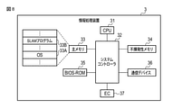
次いで、図8は、情報処理装置3のシステム構成を示す。情報処理装置3は、撮像装置2(処理部12)によって出力される画像と距離に関する情報とを用いて、撮像装置2(撮像部11)の位置、姿勢、および地図を推定する推定部13の機能を有する。 Next, FIG. 8 shows the system configuration of the information processing apparatus 3. The information processing device 3 is an estimation unit 13 that estimates the position, posture, and map of the image pickup device 2 (imaging unit 11) by using the image output by the image pickup device 2 (processing unit 12) and information on the distance. Has a function.

情報処理装置3は、例えば、CPU31、システムコントローラ32、主メモリ33、不揮発性メモリ34、BIOS-ROM35、通信デバイス36、エンベデッドコントローラ(EC)37等を備える。 The information processing device 3 includes, for example, a CPU 31, a system controller 32, a main memory 33, a non-volatile memory 34, a BIOS-ROM 35, a communication device 36, an embedded controller (EC) 37, and the like.

CPU31は、情報処理装置3内の様々なコンポーネントの動作を制御するプロセッサである。CPU31は、ストレージデバイスである不揮発性メモリ34から主メモリ33にロードされる様々なプログラムを実行する。これらプログラムには、オペレーティングシステム(OS)33A、および様々なアプリケーションプログラムが含まれている。アプリケーションプログラムには、SLAMプログラム33Bが含まれている。このSLAMプログラム33Bは、撮像部11の位置、姿勢、および地図を推定するための命令群を含んでいる。 The CPU 31 is a processor that controls the operation of various components in the information processing apparatus 3. The CPU 31 executes various programs loaded from the non-volatile memory 34, which is a storage device, into the main memory 33. These programs include an operating system (OS) 33A and various application programs. The application program includes SLAM program 33B. The SLAM program 33B includes instructions for estimating the position, orientation, and map of the imaging unit 11.

また、CPU31は、BIOS-ROM35に格納された基本入出力システム(BIOS)も実行する。BIOSは、ハードウェア制御のためのプログラムである。 The CPU 31 also executes the basic input / output system (BIOS) stored in the BIOS-ROM 35. The BIOS is a program for hardware control.

システムコントローラ32は、CPU31のローカルバスと各種コンポーネントとの間を接続するデバイスである。システムコントローラ32には、主メモリ33をアクセス制御するメモリコントローラも内蔵されている。 The system controller 32 is a device that connects between the local bus of the CPU 31 and various components. The system controller 32 also has a built-in memory controller that controls access to the main memory 33.

通信デバイス36は、有線または無線通信を実行するように構成されたデバイスである。通信デバイス36は、信号を送信する送信部と、信号を受信する受信部とを含む。EC37は、電力管理のためのエンベデッドコントローラを含むワンチップマイクロコンピュータである。EC37は、ユーザによるパワーボタンの操作に応じて本情報処理装置3を電源オンまたは電源オフする機能を有している。 The communication device 36 is a device configured to perform wired or wireless communication. The communication device 36 includes a transmission unit that transmits a signal and a reception unit that receives the signal. The EC37 is a one-chip microcomputer that includes an embedded controller for power management. The EC 37 has a function of turning on or off the power of the information processing apparatus 3 according to the operation of the power button by the user.

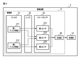
次いで、図9と図10とを参照して、撮像装置2と情報処理装置3の機能構成について説明する。以下に記載する構成は一例であって、撮像装置2に設けられる構成の一部が情報処理装置3に設けられていてもよいし、あるいは情報処理装置3に設けられる構成の一部が撮像装置2に設けられていてもよい。 Next, the functional configurations of the image pickup apparatus 2 and the information processing apparatus 3 will be described with reference to FIGS. 9 and 10. The configuration described below is an example, and a part of the configuration provided in the image pickup apparatus 2 may be provided in the information processing apparatus 3, or a part of the configuration provided in the information processing apparatus 3 may be provided in the information processing apparatus 3. It may be provided in 2.

まず、図9は、撮像装置2の機能構成の例を示す。上述したように、撮像装置2は、フィルタ21、レンズ22およびイメージセンサ23を備えている。フィルタ21からイメージセンサ23までの矢印は、光の経路を示す。フィルタ21は、第1フィルタ領域211と第2フィルタ領域212とを含んでいる。ここでは、第1フィルタ領域211がイエローのフィルタ領域であり、第2フィルタ領域212がシアンのフィルタ領域である場合を例示する。イメージセンサ23は、第1センサ231、第2センサ232および第3センサ233を含んでいる。第1センサ231は、例えば赤色(R)の光を受光する撮像素子を含む。第2センサ232は、例えば緑色(G)の光を受光する撮像素子を含む。第3センサ233は、例えば青色(B)の光を受光する撮像素子を含む。イメージセンサ23は、受光した光を光電変換することにより電気信号を生成する。 First, FIG. 9 shows an example of the functional configuration of the image pickup apparatus 2. As described above, the image pickup apparatus 2 includes a filter 21, a lens 22, and an image sensor 23. The arrow from the filter 21 to the image sensor 23 indicates the path of light. The filter 21 includes a first filter area 211 and a second filter area 212. Here, a case where the first filter region 211 is a yellow filter region and the second filter region 212 is a cyan filter region is illustrated. The image sensor 23 includes a first sensor 231 and a second sensor 232 and a third sensor 233. The first sensor 231 includes, for example, an image pickup element that receives red (R) light. The second sensor 232 includes, for example, an image pickup element that receives green (G) light. The third sensor 233 includes, for example, an image pickup element that receives blue (B) light. The image sensor 23 generates an electric signal by photoelectrically converting the received light.

撮像装置2は、さらに、生成部29および処理部12を備える。イメージセンサ23から生成部29までの矢印は、電気信号の経路を示す。生成部29から処理部12への矢印はデータの経路を示す。この生成部29および処理部12を含む撮像装置2内の各機能構成は、ハードウェア(回路)、CPU24によって実行されるソフトウェア(プログラム)、およびソフトウェアとハードウェアの組み合わせのいずれとして実現されてもよい。 The image pickup apparatus 2 further includes a generation unit 29 and a processing unit 12. The arrow from the image sensor 23 to the generation unit 29 indicates the path of the electric signal. The arrow from the generation unit 29 to the processing unit 12 indicates the data path. Each functional configuration in the image pickup apparatus 2 including the generation unit 29 and the processing unit 12 may be realized as any of hardware (circuit), software (program) executed by the CPU 24, and a combination of software and hardware. good.

生成部29は、イメージセンサ23によって生成された電気信号を用いて、撮像画像を生成(出力)する。生成される撮像画像は、R成分、G成分およびB成分を含む画像であってもよいし、R画像、G画像およびB画像の三つの画像であってもよい。撮像画像は、フィルタ21により距離情報が符号化された符号化情報である。より詳しくは、撮像画像では、距離情報が符号化されることにより、被写体までの距離が合焦距離である画素ではぼけが発生せず、被写体までの距離が合焦距離でない画素ではぼけが発生する。R成分、G成分およびB成分を含む画像が生成される場合、例えば、第1色成分の画像に生じるぼけは、非点対称なぼけ関数で表され、第2色成分の画像に生じるぼけは、点対称なぼけ関数で表される。この第1色成分は、例えばR成分またはB成分であり、第2色成分は、例えばG成分である。 The generation unit 29 generates (outputs) an captured image using the electric signal generated by the image sensor 23. The captured image to be generated may be an image containing an R component, a G component and a B component, or may be three images of an R image, a G image and a B image. The captured image is coded information in which the distance information is coded by the filter 21. More specifically, in the captured image, the distance information is encoded so that blurring does not occur in pixels whose distance to the subject is the in-focus distance, and blurring occurs in pixels whose distance to the subject is not the in-focus distance. do. When an image containing R component, G component and B component is generated, for example, the blur generated in the image of the first color component is represented by a non-point symmetric blur function, and the blur generated in the image of the second color component is represented by a non-point symmetric blur function. , Represented by a point-symmetrical blur function. The first color component is, for example, an R component or a B component, and the second color component is, for example, a G component.

処理部12は、撮像画像を処理することにより、距離に関する情報を生成する。処理部12は、図6および図7を参照して述べたような、撮像画像上のぼけに基づいて、画素毎に、その画素に撮像されている物体(被写体)までの距離に関する情報を算出する機能を有する。この距離に関する情報は、距離自体であってもよいし、距離に関する指標やぼけに関する指標であってもよい。距離に関する指標およびぼけに関する指標は、各々に関連付けられた特定のルックアップテーブル(LUT)を用いることにより、距離に換算することができる。 The processing unit 12 processes the captured image to generate information regarding the distance. The processing unit 12 calculates information about the distance to the object (subject) imaged in the pixel for each pixel based on the blur on the captured image as described with reference to FIGS. 6 and 7. Has the function of The information regarding this distance may be the distance itself, or may be an index regarding distance or an index regarding blurring. The distance index and the blur index can be converted into distance by using a specific look-up table (LUT) associated with each.

また、処理部12は、算出される距離や指標に、その距離や指標の妥当性を示す信頼度を付加してもよい。その場合、距離に関する情報には、算出される距離や指標と、その距離や指標の妥当性を示す信頼度とが含まれている。 Further, the processing unit 12 may add a reliability indicating the validity of the distance or the index to the calculated distance or the index. In that case, the information about the distance includes the calculated distance or index and the reliability indicating the validity of the distance or index.

処理部12は、通信デバイス28を介して、画像と距離に関する情報とを情報処理装置3に送信(出力)する。処理部12が情報処理装置3に含まれる場合には、撮像画像と距離に関する情報の代わりに、撮像画像が情報処理装置3に送信されるようにしてもよい。その場合、生成部29が、通信デバイス28を介して、撮像画像を情報処理装置3に送信する。 The processing unit 12 transmits (outputs) an image and information about a distance to the information processing device 3 via the communication device 28. When the processing unit 12 is included in the information processing device 3, the captured image may be transmitted to the information processing device 3 instead of the information regarding the captured image and the distance. In that case, the generation unit 29 transmits the captured image to the information processing device 3 via the communication device 28.

なお、生成部29は、連続した撮影により得られる複数の撮像画像を生成し得る。複数の画像は単一の光学系により取得されたものである。各画像は、非対称なぼけ関数を含む第1色成分画像(例えば、赤や青の成分画像)を含む。各画像はさらに、対象なぼけ関数を含む第2色成分画像(例えば緑の成分画像)を含んでもよい。撮像画像は、順次、処理部12に出力される。以下では、各撮像画像をフレームとも称する。 The generation unit 29 can generate a plurality of captured images obtained by continuous shooting. Multiple images are taken by a single optical system. Each image includes a first color component image (eg, a red or blue component image) that includes an asymmetric blur function. Each image may further include a second color component image (eg, a green component image) that includes a target blur function. The captured images are sequentially output to the processing unit 12. Hereinafter, each captured image is also referred to as a frame.

図10は、情報処理装置3によって実行されるSLAMプログラム33Bの機能構成を示す。SLAMプログラム33Bは、例えば、推定部13を備える。すなわち、CPU31は、SLAMプログラム33Bに含まれる命令群を実行することにより、推定部13の機能を実現する。SLAMプログラム33Bには、例えば、撮像装置2の撮像部11および処理部12を用いて得られた画像と距離に関する情報とが入力される。図10の推定部13は、例えば、自己位置と自己姿勢と地図とを推定する。 FIG. 10 shows a functional configuration of the SLAM program 33B executed by the information processing apparatus 3. The SLAM program 33B includes, for example, an estimation unit 13. That is, the CPU 31 realizes the function of the estimation unit 13 by executing the instruction group included in the SLAM program 33B. In the SLAM program 33B, for example, an image obtained by using the image pickup unit 11 and the processing unit 12 of the image pickup apparatus 2 and information on the distance are input. The estimation unit 13 in FIG. 10 estimates, for example, a self-position, a self-posture, and a map.

推定部13は、処理部12から、画像と距離に関する情報とを受信する。推定部13は、画像と距離に関する情報とを用いて、撮像装置2(撮像部11)の位置、姿勢、および撮像装置2周辺の地図を推定する。距離に関する情報には信頼度が含まれ得る。推定部13は、例えば、特徴点抽出部131、キーフレーム判定部132、距離取得部133、特徴点追跡部134、対応点判定部135、位置・姿勢推定部136、地図推定部137、及び作業メモリ65を含む。推定部13は、さらに最適化部138を含んでもよい。 The estimation unit 13 receives information about an image and a distance from the processing unit 12. The estimation unit 13 estimates the position and posture of the image pickup device 2 (imaging unit 11) and a map around the image pickup device 2 by using the image and the information regarding the distance. Information about distance can include confidence. The estimation unit 13 includes, for example, a feature point extraction unit 131, a key frame determination unit 132, a distance acquisition unit 133, a feature point tracking unit 134, a corresponding point determination unit 135, a position / posture estimation unit 136, a map estimation unit 137, and a working unit. Includes memory 65. The estimation unit 13 may further include an optimization unit 138.

特徴点抽出部131は、画像から特徴点群を抽出する。特徴点抽出部131は、画像上の局所的な特徴量を用いて、画像上のエッジや角(コーナー)のような特徴点を検出する。特徴点は、一枚の画像から複数検出され得る。また、特徴点の抽出のために用いられる特徴量には、例えば、ORB、BRIEF、FAST、AKAZE、SIFT等が用いられ得る。なお、特徴点抽出部131は、画像上の各画素に対応する距離(距離に関する情報)をさらに考慮して、例えば、隣接する画素間での距離の変化量が大きな画素を特徴点として抽出してもよい。 The feature point extraction unit 131 extracts a feature point cloud from the image. The feature point extraction unit 131 detects feature points such as edges and corners on the image by using the local feature amount on the image. Multiple feature points can be detected from one image. Further, as the feature amount used for extracting the feature points, for example, ORB, BRIEF, FAST, AKAZE, SIFT and the like can be used. The feature point extraction unit 131 further considers the distance (information about the distance) corresponding to each pixel on the image, and extracts, for example, a pixel having a large change in distance between adjacent pixels as a feature point. You may.

距離取得部133は、距離に関する情報から、抽出された各特徴点に対応する距離を取得することにより、特徴点と距離とを対応付ける。例えば、距離に関する情報が距離画像である場合、距離取得部133は、特徴点毎に、特徴点である画素に対応する距離を取得し、特徴点と取得された距離とを対応付ける。また、距離に関する情報がぼけに関する指標である場合、距離取得部133は、特徴点毎に、特徴点である画素に対応するぼけに関する指標を取得し、特徴点と取得されたぼけに関する指標とを対応付ける。 The distance acquisition unit 133 associates the feature points with the distance by acquiring the distance corresponding to each of the extracted feature points from the information regarding the distance. For example, when the information regarding the distance is a distance image, the distance acquisition unit 133 acquires the distance corresponding to the pixel which is the feature point for each feature point, and associates the feature point with the acquired distance. When the information related to the distance is an index related to blur, the distance acquisition unit 133 acquires an index related to blur corresponding to the pixel as the feature point for each feature point, and obtains the feature point and the acquired index related to blur. Correspond.

なお、距離取得部133は、距離に関する情報の信頼度を考慮して、特徴点群を抽出してもよい。距離取得部133は、例えば、信頼度が閾値未満である特徴点を、特徴点群から除外してもよいし、当該特徴点に距離に関する情報を対応付けないようにしてもよい。これは、特徴点に信頼度が低い距離に関する情報が対応付けられることが、自己位置、姿勢および地図の推定精度の悪化を招くためである。また、信頼度が高い距離(距離に関する情報)に対応付けられる特徴点を選択して利用することにより、自己位置、姿勢および地図の推定精度を向上させることができる。なお、閾値は動的に変化し得る。 The distance acquisition unit 133 may extract a feature point cloud in consideration of the reliability of the information regarding the distance. For example, the distance acquisition unit 133 may exclude feature points whose reliability is less than the threshold value from the feature point group, or may not associate the distance information with the feature points. This is because the association of information about a distance with low reliability with the feature points causes deterioration of the estimation accuracy of the self-position, the posture, and the map. Further, by selecting and using a feature point associated with a highly reliable distance (information about the distance), it is possible to improve the estimation accuracy of the self-position, the posture, and the map. The threshold value can change dynamically.

キーフレーム判定部132は、特定の条件に基づいて、フレームが、自己位置等の推定のためのキーフレームに適しているか否かを判定する。キーフレーム判定部132は、フレームがキーフレームに適していると判断した場合、フレームに関する情報を、例えば作業メモリ65等に保存する。作業メモリ65には、少なくとも2のキーフレーム(第1キーフレーム651、第2キーフレーム652)に関する情報が保存される。より具体的には、キーフレーム判定部132は、例えば、特徴点抽出部131によって補正画像から抽出された特徴点の数が第1閾値以上であり、且つそれら特徴点の内、距離取得部133によって距離に関する情報が対応付けられた特徴点の数が第2閾値以上である場合に、フレームに関する情報を作業メモリ65に保存する。フレームに関する情報は、キーフレーム(撮像画像)を含む。保存される情報には、さらに、例えば、対応付けられた特徴点と距離に関する情報とが含まれる。キーフレームに適していないフレームの情報は破棄され、後続するフレームの情報からキーフレームがさらに探索される。 The key frame determination unit 132 determines whether or not the frame is suitable for a key frame for estimating a self-position or the like based on a specific condition. When the key frame determination unit 132 determines that the frame is suitable for the key frame, the key frame determination unit 132 stores information about the frame in, for example, a working memory 65 or the like. Information about at least two key frames (first key frame 651, second key frame 652) is stored in the working memory 65. More specifically, in the key frame determination unit 132, for example, the number of feature points extracted from the corrected image by the feature point extraction unit 131 is equal to or greater than the first threshold value, and among those feature points, the distance acquisition unit 133. When the number of feature points to which the information regarding the distance is associated is equal to or greater than the second threshold value, the information regarding the frame is stored in the work memory 65. Information about the frame includes a key frame (captured image). The stored information further includes, for example, associated feature points and information about distances. The information of the frame that is not suitable for the key frame is discarded, and the key frame is further searched from the information of the subsequent frame.

なお、距離取得部133は、キーフレーム判定部132によって補正画像から抽出された特徴点の数が第1閾値以上であると判定された場合に、特徴点と距離に関する情報とを対応付ける処理を行ってもよい。その後、キーフレーム判定部132は、距離に関する情報が対応付けられた特徴点の数が第2閾値以上であるか否かを判定する。 The distance acquisition unit 133 performs a process of associating the feature points with the distance information when it is determined by the key frame determination unit 132 that the number of feature points extracted from the corrected image is equal to or greater than the first threshold value. You may. After that, the key frame determination unit 132 determines whether or not the number of feature points to which the information regarding the distance is associated is equal to or greater than the second threshold value.

特徴点追跡部134は、作業メモリ65に二つのキーフレーム651,652に関する情報が保存された場合、特徴点追跡部134は、第1キーフレーム651の特徴点と第2キーフレーム652の特徴点との対応付けを行う。特徴点追跡部134は、第1キーフレーム651のある特徴点に対応する、第2キーフレーム652の特徴点を検出する。より具体的には、推定部13は、第1キーフレーム651のある特徴点の特徴量と、第2キーフレーム652のある特徴点の特徴量との近似度(あるいは相違度)を算出し、例えば、近似度が閾値以上である場合に、それら特徴点が対応すると判断する。また、例えば、第1キーフレーム651のある特徴点との近似度が閾値以上である特徴点が第2キーフレーム652にない場合には、第1キーフレーム651のその特徴点に対応する特徴点がないと判断する。このような特徴点間の対応付けの際に、各特徴点に対応付けられた距離に関する情報が考慮されてもよい。以下では、対応付けされた二つの特徴点を、対応点とも称する。 When the feature point tracking unit 134 stores information about two key frames 651 and 652 in the working memory 65, the feature point tracking unit 134 uses the feature points of the first key frame 651 and the feature points of the second key frame 652. Corresponds to. The feature point tracking unit 134 detects a feature point of the second key frame 652 corresponding to a certain feature point of the first key frame 651. More specifically, the estimation unit 13 calculates the degree of approximation (or degree of difference) between the feature amount of a certain feature point of the first key frame 651 and the feature amount of a certain feature point of the second key frame 652. For example, when the degree of approximation is equal to or greater than the threshold value, it is determined that these feature points correspond to each other. Further, for example, when the second key frame 652 does not have a feature point whose degree of approximation to a certain feature point of the first key frame 651 is equal to or higher than the threshold value, the feature point corresponding to the feature point of the first key frame 651. Judge that there is no. In associating between such feature points, information regarding the distance associated with each feature point may be taken into consideration. In the following, the two associated feature points will also be referred to as corresponding points.

対応点判定部135は、特定の条件に基づいて、取得された対応点が、自己位置、姿勢および地図の推定に適しているか否かを判定する。対応点判定部135は、例えば、対応点の数が第3閾値以上であり、且つ対応点間の変位が第4閾値以上である場合に、取得された対応点が推定に適していると判定する。なお、対応点判定部135は、例えば、対応点の数が第3閾値未満である場合、または対応点間の変位が第4閾値未満である場合、取得された対応点が推定に適していないと判定し、特徴点抽出部131、距離取得部133およびキーフレーム判定部132に新たなキーフレームを探索させる。新たなキーフレームの探索により、作業メモリ65に保存されたキーフレーム651,652の内の一方のフレームが取り替えられてもよいし、それらキーフレーム651,652の両方が取り替えられてもよい。 The correspondence point determination unit 135 determines whether or not the acquired correspondence point is suitable for estimating the self-position, the posture, and the map based on a specific condition. The corresponding point determination unit 135 determines that the acquired corresponding points are suitable for estimation when, for example, the number of corresponding points is equal to or greater than the third threshold value and the displacement between the corresponding points is equal to or greater than the fourth threshold value. do. In the corresponding point determination unit 135, for example, when the number of corresponding points is less than the third threshold value or the displacement between the corresponding points is less than the fourth threshold value, the acquired corresponding points are not suitable for estimation. The feature point extraction unit 131, the distance acquisition unit 133, and the key frame determination unit 132 are made to search for a new key frame. By searching for a new key frame, one of the key frames 651 and 652 stored in the working memory 65 may be replaced, or both of the key frames 651 and 652 may be replaced.

位置・姿勢推定部136は、推定に適していると判定された対応点を用いて、自己位置および姿勢(例えば、撮像部11の位置および姿勢)を推定する。自己位置は、例えば、任意のローカル座標系における三次元座標によって示される。自己位置は、世界座標系の三次元座標や、緯度経度によってあらわされてもよい。自己姿勢は、例えば、ヨー、ロール、ピッチで示されても良いし、クオータニオンによって示されても良い。 The position / posture estimation unit 136 estimates its own position and posture (for example, the position and posture of the image pickup unit 11) using the corresponding points determined to be suitable for estimation. The self-position is indicated, for example, by three-dimensional coordinates in any local coordinate system. The self-position may be represented by the three-dimensional coordinates of the world coordinate system or the latitude and longitude. Self-posture may be indicated by, for example, yaw, roll, pitch, or by quaternion.

より具体的には、位置・姿勢推定部136は、例えば、第1キーフレーム651と第2キーフレーム652との間で、対応点を用いて、例えば、Two-view Structure from Motion(Two-view SfM)を行うことにより、撮像部11の移動を推定する。より具体的には、位置・姿勢推定部136は、第1キーフレーム651に対応する撮像画像が撮像された時点の第1位置および姿勢から、第2キーフレーム652に対応する撮像画像が撮像された時点の第2位置および姿勢への撮像部11の移動(カメラ運動)を推定し、推定された移動に基づいて、第1位置および姿勢と第2位置および各位置における姿勢とを相対的に推定する。第1位置および第1位置における姿勢と第2位置および第2位置における姿勢とは、例えば、実スケールで推定される。推定に当たっては、処理部12が第1キーフレーム651に関して算出した距離と、第2キーフレーム652に関して算出した距離と、が用いられる。具体的には、第1キーフレーム651から算出された被写体までの距離と、第2キーフレーム652から算出された被写体までの距離と、の片方もしくは両方が推定に用いられる。第1キーフレーム651が撮像された時の自己位置と被写体の相対関係と、第2キーフレーム651が撮像された時の自己位置と被写体の相対関係と、から撮像部11の移動または被写体の移動を推定することに依り、自己位置、自己姿勢および地図を推定する。 More specifically, the position / attitude estimation unit 136 uses, for example, a corresponding point between the first key frame 651 and the second key frame 652, for example, Two-view Structure from Motion (Two-view). By performing SfM), the movement of the imaging unit 11 is estimated. More specifically, the position / attitude estimation unit 136 captures the captured image corresponding to the second keyframe 652 from the first position and posture at the time when the captured image corresponding to the first keyframe 651 is captured. The movement of the imaging unit 11 to the second position and posture at the time (camera movement) is estimated, and based on the estimated movement, the first position and posture and the posture at the second position and each position are relatively relative to each other. presume. The postures at the first and first positions and the postures at the second and second positions are estimated, for example, on a real scale. In the estimation, the distance calculated by the processing unit 12 with respect to the first key frame 651 and the distance calculated with respect to the second key frame 652 are used. Specifically, one or both of the distance to the subject calculated from the first key frame 651 and the distance to the subject calculated from the second key frame 652 are used for estimation. The movement of the image pickup unit 11 or the movement of the subject from the relative relationship between the self-position when the first key frame 651 is imaged and the subject, and the relative relationship between the self-position when the second key frame 651 is imaged and the subject. Estimates self-position, self-posture and map by estimating.

位置・姿勢推定部136は、少なくとも、第1位置と第2位置に関する情報を出力する。位置・姿勢推定部136は、例えば、さらに第1位置における姿勢と第2位置における姿勢に関する情報を出力してもよい。位置・姿勢推定部136は、例えば、第1位置と第2位置および各位置における姿勢に関する情報を出力してもよい。 The position / attitude estimation unit 136 outputs at least information regarding the first position and the second position. The position / posture estimation unit 136 may further output information regarding the posture at the first position and the posture at the second position, for example. The position / posture estimation unit 136 may output, for example, information on the first position, the second position, and the posture at each position.

地図推定部137は、推定に適していると判定された対応点を用いて、地図を推定する。地図推定部137は、上記のローカル座標系における各対応点(特徴点)の三次元座標を推定する。地図推定部137は、撮像部11の位置を含む領域の第1地図を実距離に基づいて推定する。地図推定部137は、例えば、推定された撮像部11の第1位置および姿勢と第2位置および姿勢とから三角測量の原理に基づいて、各対応点の三次元座標を実スケールで算出する。地図推定部137は、推定された対応点群の三次元座標に基づいて、物体(被写体)上の特徴点群によって構成される立体的な地図を作成することができる。地図推定部137は、例えば推定した地図に関する情報を出力してもよい。 The map estimation unit 137 estimates the map using the corresponding points determined to be suitable for estimation. The map estimation unit 137 estimates the three-dimensional coordinates of each corresponding point (feature point) in the above local coordinate system. The map estimation unit 137 estimates the first map of the region including the position of the image pickup unit 11 based on the actual distance. The map estimation unit 137 calculates, for example, the three-dimensional coordinates of each corresponding point on an actual scale from the estimated first position and posture of the imaging unit 11 and the second position and posture based on the principle of triangulation. The map estimation unit 137 can create a three-dimensional map composed of a group of feature points on an object (subject) based on the three-dimensional coordinates of the estimated corresponding point cloud. The map estimation unit 137 may output information about the estimated map, for example.

また、最適化部138は、推定された対応点群の三次元座標と自己位置および姿勢とを最適化するための処理を行ってもよい。この処理には、例えば、Bundle adjustmentが用いられる。Bundle adjustmentでは、特徴点の画像上の座標と、特徴点の推定された三次元座標を画像上に再投影した投影座標との誤差(再投影誤差)を特徴点毎に算出し、この再投影誤差の総和を最小化することにより、各特徴点の三次元座標と自己位置および姿勢が最適化される。三次元画像を算出する度に最適化を行わなくともよい。例えば、3以上の画像(キーフレーム)をもとに1の特徴点につき得られた複数の三次元座標と、特徴点の画像上の座標と、の誤差を最小化することで最適化を行ってもよい。さらに、現在の三次元座標を算出する処理が行われているスレッドとは別に、マルチスレッドで過去に算出した三次元画像を使った最適化処理をしても良い。最適化部138は、例えば、最適化した自己位置を出力する。最適化部138は、さらに、姿勢、地図の少なくともいずれかを出力してもよい。 Further, the optimization unit 138 may perform a process for optimizing the three-dimensional coordinates of the estimated corresponding point cloud and the self-position and the posture. For this process, for example, Bundle adjustment is used. In Bundle adjustment, the error (reprojection error) between the coordinates on the image of the feature points and the projected coordinates obtained by reprojecting the estimated three-dimensional coordinates of the feature points on the image is calculated for each feature point, and this reprojection is performed. By minimizing the sum of the errors, the 3D coordinates, self-position and orientation of each feature point are optimized. It is not necessary to perform optimization every time a three-dimensional image is calculated. For example, optimization is performed by minimizing the error between a plurality of three-dimensional coordinates obtained for one feature point based on three or more images (key frames) and the coordinates of the feature points on the image. You may. Further, in addition to the thread in which the process of calculating the current three-dimensional coordinates is performed, the optimization process using the three-dimensional image calculated in the past by the multi-thread may be performed. The optimization unit 138 outputs, for example, the optimized self-position. The optimization unit 138 may further output at least one of a posture and a map.

なお、撮像部11の位置、姿勢および地図は相対スケールに基づいて推定されてもよく、対応点(特徴点)の三次元座標は相対スケールに基づいて推定されてもよい。この場合、位置・姿勢推定部136および地図推定部137は、相対スケールで推定された撮像部の位置や対応点の三次元座標を、距離に関する情報をさらに用いて実スケールに基づいて推定(変換)する。 The position, posture, and map of the imaging unit 11 may be estimated based on the relative scale, and the three-dimensional coordinates of the corresponding points (feature points) may be estimated based on the relative scale. In this case, the position / attitude estimation unit 136 and the map estimation unit 137 estimate (convert) the three-dimensional coordinates of the position and the corresponding point of the imaging unit estimated by the relative scale based on the actual scale by further using the information on the distance. )do.

以上のように、推定システム1では、撮像部11から物体までの距離情報が符号化された撮像画像を用いることにより、撮像部11の位置、姿勢および撮像画像に捉えられたシーンの地図を、実スケールに基づいて容易に推定することができる。なお、推定システム1において、情報処理装置3は撮像装置2の遠隔に設置され、ネットワークを介して互いにデータを通信するように構成されていてもよい。例えば、撮像装置2はロボットや自動車のような移動体に設けられ、情報処理装置3はネットワークを介して撮像装置2と通信可能なサーバコンピュータとして実現され得る。 As described above, in the estimation system 1, by using the captured image in which the distance information from the imaging unit 11 to the object is encoded, the position, posture of the imaging unit 11 and the map of the scene captured in the captured image are displayed. It can be easily estimated based on the actual scale. In the estimation system 1, the information processing device 3 may be installed remotely from the image pickup device 2 and configured to communicate data with each other via a network. For example, the image pickup device 2 can be provided on a moving body such as a robot or an automobile, and the information processing device 3 can be realized as a server computer capable of communicating with the image pickup device 2 via a network.

また、上述した例では、画像と距離に関する情報とを用いて推定部13における処理(SLAM)が行われる場合について記載したが、距離に関する情報だけを用いて、画像を用いずにSLAMが行われてもよい。例えば、距離に関する情報が距離画像である場合、特徴点抽出部131は、画素毎の距離情報に基づいて、距離画像からエッジ等に基づく特徴点群を抽出する。各特徴点は、距離画像から抽出されているので距離情報を有している。キーフレーム判定部132、特徴点追跡部134、対応点判定部135、位置・姿勢推定部136、地図推定部137、および最適化部138は、上述した方法と同様にして、抽出された特徴点群と各特徴点が有する距離情報とを用いて、自己位置、姿勢および地図を推定する。なお、この場合、特徴点の特徴量には、例えば、距離に基づく特徴量が用いられる。 Further, in the above-mentioned example, the case where the processing (SLAM) in the estimation unit 13 is performed using the image and the information related to the distance is described, but the SLAM is performed using only the information related to the distance and without using the image. You may. For example, when the information regarding the distance is a distance image, the feature point extraction unit 131 extracts a feature point group based on an edge or the like from the distance image based on the distance information for each pixel. Since each feature point is extracted from the distance image, it has distance information. The key frame determination unit 132, the feature point tracking unit 134, the corresponding point determination unit 135, the position / attitude estimation unit 136, the map estimation unit 137, and the optimization unit 138 are extracted feature points in the same manner as described above. The self-position, attitude, and map are estimated using the group and the distance information of each feature point. In this case, for example, a feature amount based on a distance is used as the feature amount of the feature point.

例えば、LiDAR(Light Detection And Ranging,Laser Imaging Detection And Ranging)等で得られた距離情報では、エッジ等に基づく特徴点抽出が困難である場合がある。特徴点が抽出できない場合にはSLAMにより自己位置や地図の推定を行うことができず、また抽出される特徴点が少ない場合にはSLAMにより推定される自己位置や地図の精度が極めて悪くなる。 For example, it may be difficult to extract feature points based on an edge or the like with distance information obtained by LiDAR (Light Detection And Ringing, Laser Imaging Detection And Ringing) or the like. If the feature points cannot be extracted, the self-position and the map cannot be estimated by SLAM, and if the number of feature points to be extracted is small, the accuracy of the self-position and the map estimated by SLAM becomes extremely poor.

これに対して、符号化開口を用いて得られた距離情報では、エッジ等に基づく特徴点を効率的に抽出することができ、そのため、SLAMによる自己位置や地図の推定に成功しやすく、またSLAMにより推定される自己位置や地図の精度を高めることができる。 On the other hand, with the distance information obtained by using the coded aperture, feature points based on edges and the like can be efficiently extracted, so that it is easy to succeed in estimating the self-position and the map by SLAM, and also. It is possible to improve the accuracy of the self-position and the map estimated by SLAM.

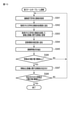
次いで、図11のフローチャートを参照して、推定システム1によって実行される処理の手順を説明する。この処理では、撮像部11と被写体との間の距離に関する情報を利用して、自己位置、自己姿勢および地図が実スケールに基づいて推定される。 Next, the procedure of the process executed by the estimation system 1 will be described with reference to the flowchart of FIG. In this process, the self-position, self-posture, and map are estimated based on the actual scale by using the information about the distance between the image pickup unit 11 and the subject.

まず、撮像部11は、撮像により、画像と距離とに関する撮像情報を取得する(ステップS101)。取得される撮像情報は、例えば、距離情報が符号化された撮像画像を含む。なお、この撮像情報には、画像と距離に関する情報とが含まれていてもよい。撮像部11は、取得された撮像情報を処理部12に送る(ステップS102)。撮像情報は、例えば撮像画像である。 First, the imaging unit 11 acquires imaging information regarding an image and a distance by imaging (step S101). The acquired image pickup information includes, for example, an image captured image in which the distance information is encoded. It should be noted that this imaging information may include information regarding an image and a distance. The imaging unit 11 sends the acquired imaging information to the processing unit 12 (step S102). The captured information is, for example, a captured image.

処理部12は、撮像情報から得られた変換情報を出力する(ステップS103)。変換情報は、距離に関する情報である。そして、処理部12は、出力された変換情報を推定部13に送る(ステップS104)。処理部12は、さらに撮像画像を推定部13に送信してもよい。距離に関する情報には、信頼度が付加されていてもよい。 The processing unit 12 outputs the conversion information obtained from the imaging information (step S103). The conversion information is information about the distance. Then, the processing unit 12 sends the output conversion information to the estimation unit 13 (step S104). The processing unit 12 may further transmit the captured image to the estimation unit 13. Reliability may be added to the information regarding the distance.

次いで、推定部13は、変換情報を基に、自己位置と自己姿勢と地図の少なくともいずれかを実スケールに基づいて推定する(ステップS105)。 Next, the estimation unit 13 estimates at least one of the self-position, the self-posture, and the map based on the actual scale based on the conversion information (step S105).

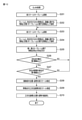
このような処理は、SLAM処理(例えば、RGB-D SLAM)として実現され得る。図12のフローチャートは、推定システム1によって実行されるSLAM処理の手順の例を示す。 Such processing can be realized as SLAM processing (for example, RGB-D SLAM). The flowchart of FIG. 12 shows an example of a procedure for SLAM processing performed by the estimation system 1.

まず、推定部13は、実スケールのキーフレームを探索するためのキーフレーム探索処理を行う(ステップS201)。撮像部11および処理部12はフレーム単位のデータを順次取得する。より具体的には、フレーム単位のデータとして、撮像部11は距離情報が符号化された撮像画像(符号化情報)を取得し、処理部12は、撮像画像から距離に関する情報を取得する。推定部13は、撮像画像との中からキーフレームを探索する。キーフレーム探索処理の詳細な手順については、図13のフローチャートを参照して後述する。 First, the estimation unit 13 performs a keyframe search process for searching for a real-scale keyframe (step S201). The imaging unit 11 and the processing unit 12 sequentially acquire data in frame units. More specifically, as frame-by-frame data, the image pickup unit 11 acquires a captured image (encoded information) in which the distance information is encoded, and the processing unit 12 acquires information regarding the distance from the captured image. The estimation unit 13 searches for a key frame from the captured image. The detailed procedure of the key frame search process will be described later with reference to the flowchart of FIG.

推定部13は、フレーム(撮像画像)と、画像特徴点と、各画像特徴点に対応付けられた距離に関する情報とを第1キーフレーム651に関する情報として、例えば、作業メモリ65に保持する(ステップS202)。つまり、第1キーフレーム651に関する情報には、特徴点と距離に関する情報との複数の組が含まれている。 The estimation unit 13 holds the frame (captured image), the image feature points, and the information about the distance associated with each image feature point as the information regarding the first key frame 651, for example, in the working memory 65 (step). S202). That is, the information regarding the first key frame 651 includes a plurality of sets of information regarding feature points and distances.

次いで、推定部13は、ステップS201と同様にして、例えば後続するフレームから、実スケールのキーフレームを探索するためのキーフレーム探索処理を行う(ステップS203)。推定部13は、探索されたフレームと、画像特徴点と、各画像特徴点に対応付けられた距離に関する情報とを第2キーフレーム652に関する情報として、例えば、作業メモリ65に保持する(ステップS204)。つまり、第2キーフレーム652に関する情報には、特徴点と距離に関する情報との複数の組が含まれている。 Next, the estimation unit 13 performs a key frame search process for searching for a real-scale key frame from, for example, a subsequent frame, in the same manner as in step S201 (step S203). The estimation unit 13 holds the searched frame, the image feature points, and the information regarding the distance associated with each image feature point as information regarding the second key frame 652, for example, in the working memory 65 (step S204). ). That is, the information regarding the second key frame 652 includes a plurality of sets of information regarding feature points and distances.

そして、推定部13は、第1キーフレーム651と第2キーフレーム652との間で、特徴点の対応付け(特徴点追跡)を行う(ステップS205)。推定部13は、第1キーフレーム651のある特徴点に対応する、第2キーフレーム652の特徴点を検出する。なお、対応付けされた二つの特徴点は、対応点とも称する。 Then, the estimation unit 13 associates the feature points (feature point tracking) between the first key frame 651 and the second key frame 652 (step S205). The estimation unit 13 detects a feature point of the second key frame 652 corresponding to a feature point of the first key frame 651. The two associated feature points are also referred to as corresponding points.

推定部13は、ステップS205で対応付けされた対応点の数が第3閾値以上であるか否かを判定する(ステップS206)。対応点の数が第3閾値未満である場合(ステップS206のNO)、ステップS203に戻り、新たな第2キーフレームが探索される。なお、ステップS201に戻り、新たな第1キーフレームと第2キーフレームとが探索されるようにしてもよい。 The estimation unit 13 determines whether or not the number of corresponding points associated in step S205 is equal to or greater than the third threshold value (step S206). If the number of corresponding points is less than the third threshold value (NO in step S206), the process returns to step S203 and a new second key frame is searched for. It should be noted that the process may return to step S201 so that a new first key frame and second key frame are searched for.

対応点の数が第3閾値以上である場合(ステップS206のYES)、推定部13は、対応点群間の変位が第4閾値以上であるか否かを判定する(ステップS207)。推定部13は、例えば、対応点である二つの特徴点間の変位を対応点毎に算出し、算出された変位の総和が第4閾値以上であるか否かを判定する。対応点群間の変位が第4閾値未満である場合(ステップS207のNO)、ステップS203に戻り、新たな第2キーフレームが探索される。なお、ステップS201に戻り、新たな第1キーフレームと第2キーフレームとが探索されるようにしてもよい。 When the number of corresponding points is equal to or greater than the third threshold value (YES in step S206), the estimation unit 13 determines whether or not the displacement between the corresponding point groups is equal to or greater than the fourth threshold value (step S207). For example, the estimation unit 13 calculates the displacement between the two feature points, which are the corresponding points, for each corresponding point, and determines whether or not the total of the calculated displacements is equal to or greater than the fourth threshold value. When the displacement between the corresponding point groups is less than the fourth threshold value (NO in step S207), the process returns to step S203 and a new second key frame is searched for. It should be noted that the process may return to step S201 so that a new first key frame and second key frame are searched for.

対応点群間の変位が第4閾値以上である場合(ステップS207のYES)、推定部13は、撮像部11の位置および姿勢を実スケールに基づいて推定する(ステップS208)。そして、推定部13は、各特徴点(各対応点)の三次元座標を実スケールに基づいて推定する(ステップS209)。 When the displacement between the corresponding point groups is equal to or greater than the fourth threshold value (YES in step S207), the estimation unit 13 estimates the position and orientation of the image pickup unit 11 based on the actual scale (step S208). Then, the estimation unit 13 estimates the three-dimensional coordinates of each feature point (each corresponding point) based on the actual scale (step S209).

また、推定部13は、推定された各特徴点の三次元座標と撮像部11の位置および姿勢とを最適化するための処理を行ってもよい(ステップS210)。 Further, the estimation unit 13 may perform a process for optimizing the three-dimensional coordinates of each estimated feature point and the position and orientation of the image pickup unit 11 (step S210).

ステップS208とステップS209のいずれかは、省略されてもよい。また、ステップS208が実行される場合には、少なくとも自己位置と自己姿勢のいずれかが推定されればよい。 Either step S208 or step S209 may be omitted. Further, when step S208 is executed, at least one of the self-position and the self-posture may be estimated.

次いで、図13のフローチャートは、撮像画像を取得してからキーフレーム探索処理を行うまでの手順の例を示す。このキーフレーム探索処理は、上述したSLAM処理の一部(例えば、ステップS201およびステップS203の手順)として行われるものである。 Next, the flowchart of FIG. 13 shows an example of the procedure from the acquisition of the captured image to the key frame search process. This key frame search process is performed as a part of the SLAM process described above (for example, the procedure of step S201 and step S203).

まず、撮像部11は、符号化情報(例えば、距離情報が符号化された撮像画像)を取得する(ステップS301)。そして、撮像部11は、取得された符号化情報を処理部12に送る(ステップS302)。 First, the image pickup unit 11 acquires the coded information (for example, the captured image in which the distance information is encoded) (step S301). Then, the imaging unit 11 sends the acquired coded information to the processing unit 12 (step S302).

処理部12は、符号化情報を距離に関する情報とに変換し(ステップS303)、撮像画像と距離に関する情報を推定部13に送る(ステップS304)。 The processing unit 12 converts the coded information into information related to the distance (step S303), and sends the captured image and the information related to the distance to the estimation unit 13 (step S304).

推定部13は、画像から画像特徴点群を抽出する(ステップS305)。そして、推定部13は、補正画像から抽出された特徴点群に含まれる特徴点の数が第1閾値以上であるか否かを判定する(ステップS306)。この第1閾値は動的に変更されてもよい。特徴点の数が第1閾値未満である場合(ステップS306のNO)、ステップS301で取得された符号化情報が自己位置、姿勢および地図の推定に適していないので、ステップS301に戻り、撮像部11によって新たな符号化情報が取得される。 The estimation unit 13 extracts an image feature point cloud from the image (step S305). Then, the estimation unit 13 determines whether or not the number of feature points included in the feature point group extracted from the corrected image is equal to or greater than the first threshold value (step S306). This first threshold may be changed dynamically. When the number of feature points is less than the first threshold value (NO in step S306), the coded information acquired in step S301 is not suitable for estimating the self-position, the posture, and the map. New coding information is acquired by 11.

特徴点の数が第1閾値以上である場合(ステップS306のYES)、推定部13は、抽出された各特徴点と、距離に関する情報とを対応付ける(ステップS307)。そして、推定部13は、画像から抽出された特徴点群の内、距離に関する情報に対応付けられた特徴点の数が第2閾値以上であるか否かを判定する(ステップS308)。この第2閾値は動的に変更されてもよい。対応付けられた特徴点の数が第2閾値未満である場合(ステップS308のNO)、ステップS301で取得された符号化情報が自己位置、姿勢および地図の推定に適していないので、ステップS301に戻り、新たな符号化情報が取得される。 When the number of feature points is equal to or greater than the first threshold value (YES in step S306), the estimation unit 13 associates each extracted feature point with information regarding the distance (step S307). Then, the estimation unit 13 determines whether or not the number of feature points associated with the information regarding the distance in the feature point group extracted from the image is equal to or greater than the second threshold value (step S308). This second threshold may be changed dynamically. When the number of associated feature points is less than the second threshold value (NO in step S308), the coded information acquired in step S301 is not suitable for estimating the self-position, posture, and map, so that step S301 is performed. Go back and get new encoding information.

対応付けられた特徴点の数が第2閾値以上である場合(ステップS308のYES)、その画像をキーフレームと決定して処理を終了する。キーフレームと特徴点と距離に関する情報は、作業メモリ65に保存される。 When the number of associated feature points is equal to or greater than the second threshold value (YES in step S308), the image is determined as a key frame and the process ends. Information about key frames, feature points, and distances is stored in the working memory 65.

以上の処理により、自己位置、姿勢および地図の推定に適したキーフレームを取得することができる。 By the above processing, it is possible to acquire a key frame suitable for estimating the self-position, the posture, and the map.

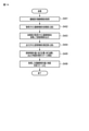
また、図14のフローチャートは、推定システム1によって実行される処理の手順の別の例を示す。図11のフローチャートを参照して上述した処理では、地図や撮像部11の位置が実スケールで推定されるのに対して、図14に示す処理では、地図や撮像部11の位置を相対スケールに基づいて推定した後に、推定された地図や撮像部11の位置が実スケール化される例を示す。 Further, the flowchart of FIG. 14 shows another example of the procedure of processing executed by the estimation system 1. In the process described above with reference to the flowchart of FIG. 11, the position of the map or the image pickup unit 11 is estimated on the actual scale, whereas in the process shown in FIG. 14, the position of the map or the image pickup unit 11 is set to the relative scale. An example is shown in which the estimated map and the position of the image pickup unit 11 are actually scaled after the estimation based on the estimation.

ステップS401からステップS404までの手順は、図11のフローチャートに示したステップS101からステップS104までの手順と同じである。 The procedure from step S401 to step S404 is the same as the procedure from step S101 to step S104 shown in the flowchart of FIG.

これらステップS401からステップS404までの手順が行われた後、推定部13は、変換情報(例えば、補正画像と距離に関する情報)を基に、自己位置、自己姿勢、および地図を相対スケールに基づいて推定する(ステップS405)。そして、推定部13は、推定された地図を、距離に関する情報を用いてスケーリング(拡大または縮小)することにより実スケール化する(ステップS406)。推定部13は、例えば、距離に関する情報により、撮像部11から地図上の地点(特徴点)までの実際の距離が示されるとき、相対スケールで示されている地図における自己位置と当該地点との距離がその実際の距離になるようにスケーリングすることにより、地図を実スケール化することができる。推定部13は、自己位置、自己姿勢、および地図に関する情報を出力する。 After performing these steps from step S401 to step S404, the estimation unit 13 sets the self-position, the self-posture, and the map based on the relative scale based on the conversion information (for example, the information regarding the corrected image and the distance). Estimate (step S405). Then, the estimation unit 13 scales (enlarges or reduces) the estimated map using the information regarding the distance (step S406). For example, when the estimation unit 13 indicates the actual distance from the image pickup unit 11 to a point (feature point) on the map by information on the distance, the estimation unit 13 sets the self-position on the map shown on the relative scale and the point. The map can be scaled to real by scaling the distance to its actual distance. The estimation unit 13 outputs information regarding the self-position, the self-posture, and the map.

以上説明したように、推定システム1は、実スケールに基づく自己位置、姿勢および地図を容易に推定することができる。推定システム1は、実スケールに基づく自己位置、自己姿勢、地図の少なくともいずれかを出力することができる。 As described above, the estimation system 1 can easily estimate the self-position, the posture, and the map based on the actual scale. The estimation system 1 can output at least one of the self-position, the self-posture, and the map based on the actual scale.

例えば、カメラで撮像された画像と、距離センサで計測された距離とを用いて自己位置、姿勢および地図を推定する方法では、画像と距離とを同期させるための処理が必要となる。本実施形態の推定システム1は、一度の撮影で取得される画像と距離に関する情報、あるいは符号化情報が推定に用いられるので、画像と距離とを同期させるための処理が必要ない。そのため、この処理に要する時間が省略されるので、撮像部11の位置を容易に推定することができる。 For example, a method of estimating a self-position, a posture, and a map using an image captured by a camera and a distance measured by a distance sensor requires a process for synchronizing the image and the distance. Since the estimation system 1 of the present embodiment uses the information regarding the image and the distance acquired in one shooting or the coded information for the estimation, no processing for synchronizing the image and the distance is required. Therefore, since the time required for this process is omitted, the position of the imaging unit 11 can be easily estimated.

また、例えば、単眼カメラで撮像された画像と、物体の形状等の辞書データとを用いて自己位置、姿勢および地図を推定する方法では、この辞書データを準備しておく必要があり、また辞書に登録された物体がカメラで撮影されない場合には、自己位置、姿勢および地図を推定することができない。本実施形態の推定システム1では、辞書データを準備しておく必要がなく、ユーザによる手間を軽減することができる。 Further, for example, in a method of estimating a self-position, an attitude, and a map using an image captured by a monocular camera and dictionary data such as the shape of an object, it is necessary to prepare this dictionary data, and a dictionary. If the object registered in is not photographed by the camera, the self-position, posture and map cannot be estimated. In the estimation system 1 of the present embodiment, it is not necessary to prepare dictionary data, and it is possible to reduce the time and effort by the user.

次いで、上記のような構成を有する推定システム1が適用される応用例についていくつか説明する。 Next, some application examples to which the estimation system 1 having the above configuration is applied will be described.

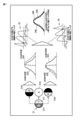
図15は、推定システム1を含む移動体6の機能構成例を示す。移動体6は、例えば、自動運転機能を有する自動車、無人航空機、自律型の移動ロボット等として実現され得る。無人航空機は、人が乗ることができない飛行機、回転翼航空機、滑空機、飛行船であって、遠隔操作または自動操縦により飛行させることができるものであり、例えば、ドローン(マルチコプター)、ラジコン機、農薬散布用ヘリコプター等を含む。自律型の移動ロボットは、無人搬送車(Automated Guided Vehicle:AGV)のような移動ロボット、床を掃除するための掃除ロボット、来場者に各種案内を行うコミュニケーションロボット等を含む。移動体6にはさらに、ロボット本体が移動するものだけでなく、ロボットアームのような、ロボットの一部分の移動・回転用の駆動機構を有する産業用ロボットも含まれ得る。 
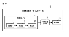
FIG. 15 shows an example of the functional configuration of the mobile body 6 including the estimation system 1. The mobile body 6 can be realized as, for example, an automobile having an automatic driving function, an unmanned aerial vehicle, an autonomous mobile robot, or the like. Unmanned aerial vehicles are aircraft, rotorcraft, gliders, and airships that cannot be boarded by humans and can be flown by remote control or automatic control, such as drones (multicopters), radio-controlled aircraft, and so on. Includes helicopters for spraying pesticides. Autonomous mobile robots include mobile robots such as automated guided vehicles (AGVs), cleaning robots for cleaning floors, communication robots that provide various guidance to visitors, and the like. The mobile body 6 may further include not only a robot body to which the robot body moves, but also an industrial robot having a drive mechanism for moving / rotating a part of the robot, such as a robot arm.

図15に示すように、移動体6は、例えば、推定システム1と制御信号生成部14と駆動機構15とを有する。推定システム1の内、少なくとも撮像部11は、例えば、移動体6またはその一部分の進行方向の被写体を撮像するように設置される。 As shown in FIG. 15, the mobile body 6 has, for example, an estimation system 1, a control signal generation unit 14, and a drive mechanism 15. In the estimation system 1, at least the image pickup unit 11 is installed so as to image a subject in the traveling direction of the moving body 6 or a part thereof, for example.

図16に示すように、移動体6が自動車6Aである場合、撮像部11は、前方を撮像するいわゆるフロントカメラとして設置され得るほか、バック時に後方を撮像するいわゆるリアカメラとしても設置され得る。もちろん、これら両方が設置されてもよい。また、撮像部11は、いわゆるドライブレコーダーとしての機能を兼ねて設置されるものであってもよい。すなわち、撮像部11は録画機器であってもよい。 As shown in FIG. 16, when the moving body 6 is an automobile 6A, the image pickup unit 11 can be installed as a so-called front camera that images the front and also as a so-called rear camera that images the rear when backing up. Of course, both of these may be installed. Further, the image pickup unit 11 may be installed so as to also function as a so-called drive recorder. That is, the image pickup unit 11 may be a recording device.

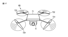
次いで、図17は、移動体6がドローン6Bである場合の例を示す。ドローン6Bは、駆動機構15に相当するドローン本体71と四つのプロペラ部721,722,723,724とを備える。各プロペラ部721,722,723,724はプロペラとモータとを有する。モータの駆動がプロペラに伝達されることによって、プロペラが回転し、その回転による揚力によってドローン6Bが浮上する。ドローン本体71の、例えば下部には、撮像部11(あるいは、撮像部11を含む推定システム1)が搭載されている。 Next, FIG. 17 shows an example when the moving body 6 is a drone 6B. The drone 6B includes a drone main body 71 corresponding to the drive mechanism 15 and four propeller portions 721, 722, 723, 724. Each propeller section 721, 722, 723, 724 has a propeller and a motor. When the drive of the motor is transmitted to the propeller, the propeller rotates, and the lift generated by the rotation causes the drone 6B to levitate. An image pickup unit 11 (or an estimation system 1 including the image pickup unit 11) is mounted on the lower portion of the drone body 71, for example.

また、図18は、移動体6が自律型の移動ロボット6Cである場合の例を示す。移動ロボット6Cの下部には、駆動機構15に相当する、モータや車輪等を含む動力部81が設けられている。動力部81は、モータの回転数や車輪の向きを制御する。移動ロボット6Cは、モータの駆動が伝達されることによって、路面又は床面に接地する車輪が回転し、当該車輪の向きが制御されることにより任意の方向に移動することができる。撮像部11は、例えば、人型の移動ロボット6Cの頭部に、前方を撮像するように設置され得る。なお、撮像部11は、後方や左右を撮像するように設置されてもよいし、複数の方位を撮像するように複数設置されてもよい。また、センサ等を搭載するためのスペースが少ない小型ロボットに少なくとも撮像部11を設けて、自己位置、姿勢および地図を推定することにより、デッドレコニングを行うこともできる。 Further, FIG. 18 shows an example in which the mobile body 6 is an autonomous mobile robot 6C. At the lower part of the mobile robot 6C, a power unit 81 including a motor, wheels, and the like, which corresponds to the drive mechanism 15, is provided. The power unit 81 controls the rotation speed of the motor and the direction of the wheels. The mobile robot 6C can move in any direction by rotating the wheels that come into contact with the road surface or the floor surface by transmitting the drive of the motor and controlling the direction of the wheels. The image pickup unit 11 may be installed, for example, on the head of the humanoid mobile robot 6C so as to image the front. The image pickup unit 11 may be installed so as to image the rear or left and right, or may be installed in plurality so as to image a plurality of directions. In addition, dead reckoning can be performed by providing at least an image pickup unit 11 on a small robot having a small space for mounting a sensor or the like and estimating a self-position, a posture, and a map.

なお、移動体6の一部分の移動および回転を制御する場合、図19に示すように、撮像部11は、例えば、ロボットアーム6Dで把持される物体を撮像するように、ロボットアームの先端等に設置されてもよい。推定部13は、把持しようとする物体の三次元形状やその物体が置かれている位置を推定する。これにより、物体の正確な把持動作を行うことができる。 When controlling the movement and rotation of a part of the moving body 6, as shown in FIG. 19, the image pickup unit 11 is attached to the tip of the robot arm or the like so as to image an object gripped by the robot arm 6D, for example. It may be installed. The estimation unit 13 estimates the three-dimensional shape of the object to be grasped and the position where the object is placed. As a result, it is possible to perform an accurate gripping operation of the object.

制御信号生成部14は、推定システム1から出力される自己位置、姿勢および地図に基づいて、駆動機構15を制御するための制御信号を出力する。駆動機構15は、制御信号により、移動体6または移動体の一部分を駆動する。駆動機構15は、例えば、移動体6またはその一部分の移動、回転、加速、減速、推力(揚力)の加減、進行方向の転換、通常運転モードと自動運転モード(衝突回避モード)の切り替え、およびエアバック等の安全装置の作動の内の少なくとも一つを行う。駆動機構15は、例えば、自己位置から被写体までの距離がしきい値未満である場合、移動、回転、加速、推力(揚力)の加減、物体に近寄る方向への方向転換、および自動運転モード(衝突回避モード)から通常運転モードへの切り替えの内の少なくとも一つを行ってもよい。 The control signal generation unit 14 outputs a control signal for controlling the drive mechanism 15 based on the self-position, the posture, and the map output from the estimation system 1. The drive mechanism 15 drives the moving body 6 or a part of the moving body by the control signal. The drive mechanism 15 may, for example, move the moving body 6 or a part thereof, rotate, accelerate, decelerate, adjust the thrust (lift), change the traveling direction, switch between the normal operation mode and the automatic operation mode (collision avoidance mode), and the drive mechanism 15. Perform at least one of the activations of safety devices such as airbags. For example, when the distance from the self-position to the subject is less than the threshold value, the drive mechanism 15 moves, rotates, accelerates, adjusts the thrust (lift), changes the direction toward the object, and automatically operates the mode (automatic driving mode). At least one of the switching from the collision avoidance mode) to the normal operation mode may be performed.

自動車6Aの駆動機構15は、例えばタイヤである。ドローン6Bの駆動機構は、例えばプロペラである。移動ロボット6Cの駆動機構は、例えば足部である。ロボットアーム6Dの駆動機構15は、例えば撮像部が設けられた先端を支持する支持部である。 The drive mechanism 15 of the automobile 6A is, for example, a tire. The drive mechanism of the drone 6B is, for example, a propeller. The drive mechanism of the mobile robot 6C is, for example, a foot. The drive mechanism 15 of the robot arm 6D is, for example, a support portion that supports the tip provided with an image pickup unit.

移動体6は、さらに推定部13からの自己位置、自己姿勢、および地図に関する情報が入力されるスピーカやディスプレイを備えていてもよい。スピーカやディスプレイは、自己位置、自己姿勢、および地図に関する音声または画像を出力する。スピーカやディスプレイは、自己推定システム1と有線または無線で接続されている。さらに、移動体6は、推定部13からの自己位置、自己姿勢、および地図に関する情報が入力される発光部を有していていもよい。発光部は、例えば、推定部13からの自己位置、自己姿勢、および地図に関する情報に応じて点灯したり消灯したりする。 The mobile body 6 may further include a speaker or display into which information about the self-position, self-posture, and map from the estimation unit 13 is input. Speakers and displays output audio or images of self-position, self-posture, and maps. The speaker and the display are connected to the self-estimation system 1 by wire or wirelessly. Further, the moving body 6 may have a light emitting unit into which information about the self-position, the self-posture, and the map from the estimation unit 13 is input. The light emitting unit is turned on or off depending on, for example, information about the self-position, the self-posture, and the map from the estimation unit 13.

なお、推定システム1の推定部13は、推定された撮像部11の位置と、推定システム1以外によって作成され推定システム1に入力される地図(例えばカーナビゲーションのための地図)とを用いて、この地図上での撮像部11の位置を推定してもよい。移動体6は、GPS信号を受信し、GPS座標系における位置を検出するためのGPSレシーバ(図示せず)を備えていてもよい。また、カーナビゲーションのための地図は、例えば、自動車に設けられるカーナビゲーションシステムで用いられる地図であって、GPS座標系に基づいた、道路や、橋、建物等のオブジェクトを示すデータが含まれている。GPSレシーバを用いて取得される位置には、GPS信号の取得状況等によって誤差(例えば、数メートルの誤差)が含まれている場合がある。そのため、GPSレシーバを用いて取得される位置だけでなく、推定システム1によって推定された撮像部11の位置も用いることにより、地図上でのより正確な自己位置を推定することができる。さらに、GPS信号が受信できずにGPSレシーバを用いて位置が取得できない場合にも、一旦、地図上での自己位置が取得できていれば、推定部13は、推定システム1によって連続して推定される撮像部11の位置を用いて、地図上での自己位置を推定し続けることができるので、移動体6を目的位置まで移動等させることができる。 The estimation unit 13 of the estimation system 1 uses the estimated position of the imaging unit 11 and a map created by other than the estimation system 1 and input to the estimation system 1 (for example, a map for car navigation). The position of the image pickup unit 11 on this map may be estimated. The mobile body 6 may include a GPS receiver (not shown) for receiving a GPS signal and detecting a position in the GPS coordinate system. Further, the map for car navigation is, for example, a map used in a car navigation system installed in an automobile, and includes data showing objects such as roads, bridges, and buildings based on a GPS coordinate system. There is. The position acquired by using the GPS receiver may include an error (for example, an error of several meters) depending on the acquisition status of the GPS signal or the like. Therefore, by using not only the position acquired by using the GPS receiver but also the position of the imaging unit 11 estimated by the estimation system 1, a more accurate self-position on the map can be estimated. Further, even when the GPS signal cannot be received and the position cannot be acquired by using the GPS receiver, once the self-position on the map can be acquired, the estimation unit 13 continuously estimates by the estimation system 1. Since the self-position on the map can be continuously estimated by using the position of the image pickup unit 11, the moving body 6 can be moved to a target position or the like.

また、推定部13は、推定された特徴点の三次元座標(すなわち、補正画像上の画素に撮像された被写体の三次元座標)を用いて、カーナビゲーションのための地図を補完してもよい。推定部13は、例えば、自動車の走行中に連続して得られる撮像画像から、特徴点の三次元座標を繰り返し推定することができる。これにより、カーナビゲーションのための地図に含まれていないオブジェクトの三次元座標を当該地図に追加することができ、より詳細な地図を得ることができる。制御信号生成部14および駆動機構15は、補完された地図上での撮像部11の位置に基づいて、例えば、衝突を回避するように移動体6(例えば、自動車)を移動させることができる。 Further, the estimation unit 13 may complement the map for car navigation by using the three-dimensional coordinates of the estimated feature points (that is, the three-dimensional coordinates of the subject captured by the pixels on the corrected image). .. The estimation unit 13 can repeatedly estimate the three-dimensional coordinates of the feature points from, for example, captured images continuously obtained while the automobile is traveling. As a result, three-dimensional coordinates of objects that are not included in the map for car navigation can be added to the map, and a more detailed map can be obtained. The control signal generation unit 14 and the drive mechanism 15 can move the moving body 6 (for example, an automobile) so as to avoid a collision, for example, based on the position of the imaging unit 11 on the complemented map.

別の例として、例えば、移動体6がドローンである場合、上空から、地図(物体の三次元形状)の作成、ビルや地形の構造調査、ひび割れや電線破断等の点検等が行われる際に、撮像部11は対象を撮影した画像を取得し、自己位置と地図上の物体との距離が閾値以上であるか否かを判定する。制御信号生成部14は、この判定結果に基づいて、点検対象との距離が一定になるようにドローンの推力を制御するための制御信号を生成する。ここで、推力には揚力も含まれる。駆動機構15が、この制御信号に基づいてドローンを動作させることにより、ドローンを点検対象に並行して飛行させることができる。移動体6が監視用のドローンである場合、監視対象の物体との距離を一定に保つようにドローンの推力を制御するための制御信号を生成してもよい。 As another example, for example, when the moving body 6 is a drone, when a map (three-dimensional shape of an object) is created, a structural survey of a building or terrain, an inspection such as a crack or a broken electric wire is performed from the sky. The imaging unit 11 acquires an image of the target and determines whether or not the distance between the self-position and the object on the map is equal to or greater than the threshold value. Based on this determination result, the control signal generation unit 14 generates a control signal for controlling the thrust of the drone so that the distance to the inspection target becomes constant. Here, thrust includes lift. By operating the drone based on this control signal, the drive mechanism 15 can make the drone fly in parallel with the inspection target. When the moving body 6 is a drone for monitoring, a control signal for controlling the thrust of the drone may be generated so as to keep the distance to the object to be monitored constant.

また、ドローンの飛行時に、撮像部11は地面方向を撮影した画像を取得し、自己位置と地面との距離が閾値以上であるか否かを判定する。制御信号生成部14は、この判定結果に基づいて、地面からの高さが指定された高さになるようにドローンの推力を制御するための制御信号を生成する。駆動機構15が、この制御信号に基づいてドローンを動作させることにより、ドローンを指定された高さで飛行させることができる。農薬散布用ドローンであれば、ドローンの地面からの高さを一定に保つことで、農薬を均等に散布しやすくなる。 Further, when the drone is flying, the image pickup unit 11 acquires an image taken in the direction of the ground and determines whether or not the distance between the self-position and the ground is equal to or greater than the threshold value. Based on this determination result, the control signal generation unit 14 generates a control signal for controlling the thrust of the drone so that the height from the ground becomes a designated height. The drive mechanism 15 operates the drone based on this control signal, so that the drone can be flown at a designated height. For a drone for spraying pesticides, keeping the height of the drone above the ground constant makes it easier to spray pesticides evenly.

また、移動体6がドローンまたは自動車である場合、ドローンの連携飛行や自動車の連隊走行時に、撮像部11は、周囲のドローンや前方の自動車を撮影した画像を取得し、自己位置からそのドローンや自動車までの距離が閾値以上であるか否かを判定する。制御信号生成部14は、この判定結果に基づいて、その周囲のドローンや前方の自動車との距離が一定になるように、ドローンの推力や自動車の速度を制御するための制御信号を生成する。駆動機構15が、この制御信号に基づいてドローンや自動車を動作させることにより、ドローンの連携飛行や自動車の連隊走行を容易に行うことができる。移動体6が自動車である場合、ドライバーが閾値を設定できるように、ユーザインタフェースを介してドライバーの指示を受理することで、閾値を変化させてもよい。これにより、ドライバーが好む車間距離で自動車を走行させられる。あるいは、前方の自動車との安全な車間距離を保つために、自動車の速度に応じて閾値を変化させてもよい。安全な車間距離は、自動車の速度によって異なる。そこで、自動車の速度が速いほど閾値を長く設定することができる。また、移動体6が自動車である場合に、進行方向の所定の距離を閾値に設定しておき、その閾値の手前に物体が現れた場合にブレーキが自動で作動したり、エアバック等の安全装置が自動で作動する制御信号生成部14を構成するとよい。この場合、自動ブレーキやエアバック等の安全装置が駆動機構15に設けられる。 Further, when the moving body 6 is a drone or a car, the imaging unit 11 acquires an image of the surrounding drone and the car in front of the drone during the cooperative flight of the drone or the regimental running of the car, and the drone or the car is taken from its own position. Determine if the distance to the vehicle is greater than or equal to the threshold. Based on this determination result, the control signal generation unit 14 generates a control signal for controlling the thrust of the drone and the speed of the vehicle so that the distance to the drone and the vehicle in front thereof is constant. By operating the drone or the automobile based on the control signal, the drive mechanism 15 can easily perform the cooperative flight of the drone or the regimental running of the automobile. When the moving body 6 is an automobile, the threshold value may be changed by accepting the driver's instruction via the user interface so that the driver can set the threshold value. As a result, the vehicle can be driven at the inter-vehicle distance preferred by the driver. Alternatively, the threshold value may be changed according to the speed of the vehicle in order to maintain a safe distance from the vehicle in front. Safe inter-vehicle distance depends on the speed of the vehicle. Therefore, the faster the vehicle speed, the longer the threshold value can be set. Further, when the moving body 6 is an automobile, a predetermined distance in the traveling direction is set as a threshold value, and when an object appears in front of the threshold value, the brake is automatically activated, and safety such as airbags is achieved. It is preferable to configure the control signal generation unit 14 in which the device automatically operates. In this case, a safety device such as an automatic brake or an airbag is provided in the drive mechanism 15.

以上説明したように、本実施形態によれば、実スケールに基づく自己位置や地図を容易に推定することができ、この実スケールに基づく自己位置や地図を用いることにより、例えば、自動車、ドローン、ロボット等の各種の移動体6の動作を容易に制御することができる。 As described above, according to the present embodiment, the self-position and the map based on the actual scale can be easily estimated, and by using the self-position and the map based on the actual scale, for example, a car, a drone, and the like. The operation of various moving bodies 6 such as robots can be easily controlled.

また、本実施形態に記載された様々な機能の各々は、回路(処理回路)によって実現されてもよい。処理回路の例には、中央処理装置(CPU)のような、プログラムされたプロセッサが含まれる。このプロセッサは、メモリに格納されたコンピュータプログラム(命令群)を実行することによって、記載された機能それぞれを実行する。このプロセッサは、電気回路を含むマイクロプロセッサであってもよい。処理回路の例には、デジタル信号プロセッサ(DSP)、特定用途向け集積回路(ASIC)、マイクロコントローラ、コントローラ、他の電気回路部品も含まれる。本実施形態に記載されたCPU以外の他のコンポーネントの各々もまた処理回路によって実現されてもよい。 Further, each of the various functions described in the present embodiment may be realized by a circuit (processing circuit). Examples of processing circuits include programmed processors such as central processing units (CPUs). This processor executes each of the described functions by executing a computer program (instruction group) stored in the memory. This processor may be a microprocessor including an electric circuit. Examples of processing circuits also include digital signal processors (DSPs), application specific integrated circuits (ASICs), microcontrollers, controllers, and other electrical circuit components. Each of the components other than the CPU described in this embodiment may also be realized by the processing circuit.

また、本実施形態の各種処理はコンピュータプログラムによって実現することができるので、このコンピュータプログラムを格納したコンピュータ読み取り可能な記憶媒体を通じてこのコンピュータプログラムをコンピュータにインストールして実行するだけで、本実施形態と同様の効果を容易に実現することができる。 Further, since various processes of the present embodiment can be realized by a computer program, the present embodiment and the present embodiment can be obtained by simply installing and executing the computer program on a computer through a computer-readable storage medium in which the computer program is stored. A similar effect can be easily achieved.

本発明のいくつかの実施形態を説明したが、これらの実施形態は、例として提示したものであり、発明の範囲を限定することは意図していない。これら新規な実施形態は、その他の様々な形態で実施されることが可能であり、発明の要旨を逸脱しない範囲で、種々の省略、置き換え、変更を行うことができる。これら実施形態やその変形は、発明の範囲や要旨に含まれるとともに、特許請求の範囲に記載された発明とその均等の範囲に含まれる。 Although some embodiments of the present invention have been described, these embodiments are presented as examples and are not intended to limit the scope of the invention. These novel embodiments can be implemented in various other embodiments, and various omissions, replacements, and changes can be made without departing from the gist of the invention. These embodiments and variations thereof are included in the scope and gist of the invention, and are also included in the scope of the invention described in the claims and the equivalent scope thereof.

1…推定システム、11…撮像部、12…処理部、13…推定部、2…撮像装置、21…フィルタ、22…レンズ、23…イメージセンサ、24…CPU、25…RAM、26…不揮発性メモリ、27…メモリカードスロット、28…通信デバイス、20…バス、3…情報処理装置、31…CPU、32…システムコントローラ、33…主メモリ、34…不揮発性メモリ、35…BIOS-ROM、36…通信デバイス、37…EC、33A…OS、33B…SLAMプログラム。 1 ... estimation system, 11 ... image pickup unit, 12 ... processing unit, 13 ... estimation unit, 2 ... image pickup device, 21 ... filter, 22 ... lens, 23 ... image sensor, 24 ... CPU, 25 ... RAM, 26 ... non-volatile Memory, 27 ... memory card slot, 28 ... communication device, 20 ... bus, 3 ... information processing device, 31 ... CPU, 32 ... system controller, 33 ... main memory, 34 ... non-volatile memory, 35 ... BIOS-ROM, 36 ... communication device, 37 ... EC, 33A ... OS, 33B ... SLAM program.

Claims (17)

単眼の撮像部であって、画像と、前記画像に含まれる被写体までの実距離に関する情報と、を一度の撮影で取得可能な撮像部と、
前記画像と前記実距離に関する情報とを用いて、前記撮像部の位置を推定する推定部と、を具備し、
前記推定部は、
作業メモリ内の実スケールの第1キーフレームを探索し、
前記画像と前記実距離に関する情報とに基づく前記実スケールの第2キーフレームを決定し、
前記第1キーフレームと前記第2キーフレームとの間の近似度を算出することによって、前記第1キーフレーム内の複数の特徴点と前記第2キーフレーム内の複数の特徴点との間の複数の対応点を決定し、
前記複数の対応点の数が第1閾値以上である場合、前記複数の対応点間の変位を決定し、
前記変位が第2閾値以上である場合、前記実スケールの前記撮像部の位置を推定する推定システム。
An image pickup unit that is a monocular image pickup unit and can acquire an image and information on the actual distance to the subject included in the image in a single shooting.
An estimation unit that estimates the position of the image pickup unit using the image and information about the actual distance is provided.
The estimation unit
Search for the first keyframe of the real scale in the working memory,
A second keyframe of the real scale is determined based on the image and information about the real distance.
By calculating the degree of approximation between the first key frame and the second key frame, between the plurality of feature points in the first key frame and the plurality of feature points in the second key frame. Determine multiple correspondence points and
When the number of the plurality of corresponding points is equal to or greater than the first threshold value, the displacement between the plurality of corresponding points is determined.
An estimation system that estimates the position of the image pickup unit on the actual scale when the displacement is equal to or greater than the second threshold value.
被写体から撮像部までの実距離を符号化して撮像して、符号化情報を出力する撮像部と、
前記符号化情報を用いて、実距離に基づく前記撮像部の位置を推定する推定部と、
を具備し、
前記推定部は、
作業メモリ内の実スケールの第1キーフレームを探索し、
前記符号化情報に基づく前記実スケールの第2キーフレームを決定し、
前記第1キーフレームと前記第2キーフレームとの間の近似度を算出することによって、前記第1キーフレーム内の複数の特徴点と前記第2キーフレーム内の複数の特徴点との間の複数の対応点を決定し、
前記複数の対応点の数が第1閾値以上である場合、前記複数の対応点間の変位を決定し、
前記変位が第2閾値以上である場合、前記実スケールの前記撮像部の位置を推定する推定システム。
An imaging unit that encodes the actual distance from the subject to the imaging unit, captures the image, and outputs the encoded information.
An estimation unit that estimates the position of the image pickup unit based on the actual distance using the coding information, and an estimation unit.
Equipped with
The estimation unit
Search for the first keyframe of the real scale in the working memory,
The second key frame of the real scale based on the coding information is determined.
By calculating the degree of approximation between the first key frame and the second key frame, between the plurality of feature points in the first key frame and the plurality of feature points in the second key frame. Determine multiple correspondence points and
When the number of the plurality of corresponding points is equal to or greater than the first threshold value, the displacement between the plurality of corresponding points is determined.
An estimation system that estimates the position of the image pickup unit on the actual scale when the displacement is equal to or greater than the second threshold value.
前記推定部は、前記符号化情報を画像と前記実距離に関する情報とに変換し、前記画像と前記実距離に関する情報とを用いて前記撮像部の位置を実距離に基づいて推定する請求項2記載の推定システム。 2. The estimation unit converts the coded information into an image and information about the actual distance, and estimates the position of the imaging unit based on the actual distance by using the image and the information about the actual distance. The estimation system described. 前記撮像部は前記被写体を含む画像から前記符号化情報を出力する請求項3に記載の推定システム。 The estimation system according to claim 3, wherein the imaging unit outputs the coded information from an image including the subject. 前記撮像部は少なくとも2の前記画像を取得し、
前記推定部は、
前記少なくとも2の画像から複数の特徴点を検出し、
検出された前記複数の特徴点を用いて、前記撮像部の位置を相対スケールに基づいて推定し、
前記実距離に関する情報を用いて、前記推定された撮像部の位置を実距離に基づいて推定する請求項1または請求項4記載の推定システム。
The imaging unit acquires at least two of the images and obtains them.
The estimation unit
A plurality of feature points are detected from the at least two images, and the feature points are detected.
Using the detected plurality of feature points, the position of the imaging unit is estimated based on the relative scale.
The estimation system according to claim 1 or 4, wherein the estimated position of the imaging unit is estimated based on the actual distance by using the information regarding the actual distance.
前記撮像部は少なくとも2の前記画像を取得し、
前記推定部は、
前記少なくとも2の画像から複数の特徴点を検出し、
検出された前記複数の特徴点と、前記複数の特徴点に対応する前記実距離に関する情報とを用いて、前記撮像部の位置を実スケールに基づいて推定し、前記複数の特徴点に対応する複数の三次元座標を実距離に基づいて推定する請求項1または請求項4記載の推定システム。
The imaging unit acquires at least two of the images and obtains them.
The estimation unit
A plurality of feature points are detected from the at least two images, and the feature points are detected.
Using the detected plurality of feature points and the information regarding the actual distance corresponding to the plurality of feature points, the position of the image pickup unit is estimated based on the actual scale, and the plurality of feature points correspond to the plurality of feature points. The estimation system according to claim 1 or 4, wherein a plurality of three-dimensional coordinates are estimated based on an actual distance.
前記実距離に関する情報は、前記撮像部から、前記画像上の各画素に撮像された被写体までの第1距離と、前記第1距離の妥当性を示す信頼度とを含む請求項1または請求項3記載の推定システム。 Claim 1 or claim that the information regarding the actual distance includes a first distance from the imaging unit to a subject imaged by each pixel on the image and a reliability indicating the validity of the first distance. 3 The estimation system described. 前記信頼度は、前記第1距離の推定のために用いられる指標に基づき決定される請求項7記載の推定システム。 The estimation system according to claim 7, wherein the reliability is determined based on an index used for estimating the first distance. 前記推定部は、前記信頼度をさらに用いて、前記撮像部の位置を推定する請求項7または請求項8記載の推定システム。 The estimation system according to claim 7 or 8, wherein the estimation unit further uses the reliability to estimate the position of the image pickup unit. 前記推定部は、さらに、前記撮像部の姿勢を実距離に基づいて推定する請求項1または2記載の推定システム。 The estimation system according to claim 1 or 2, wherein the estimation unit further estimates the posture of the image pickup unit based on an actual distance. 前記推定部は、さらに、前記撮像部の位置を含む領域の第1地図を実距離に基づいて推定する請求項1または2記載の推定システム。 The estimation system according to claim 1 or 2, wherein the estimation unit further estimates a first map of a region including the position of the imaging unit based on an actual distance. 前記撮像部は、開口部に、光学中心に対して非点対称な形状をそれぞれ有する複数の領域を備える請求項1または請求項2記載の推定システム。 The estimation system according to claim 1 or 2, wherein the imaging unit includes a plurality of regions having a shape that is non-point symmetric with respect to the optical center in the opening. 前記複数の領域は、互いに異なる波長領域を透過する請求項12記載の推定システム。 12. The estimation system according to claim 12, wherein the plurality of regions transmit different wavelength regions from each other. 前記複数の領域は、第1フィルタ領域と第2フィルタ領域とを含み、
前記第1フィルタ領域を透過した光線に基づく第1画像の第1ぼけ関数は、非点対称であり、
前記第2フィルタ領域を透過した光線に基づく第2画像の第2ぼけ関数は、非点対称であり、
前記第1ぼけ関数は、前記第2ぼけ関数とは異なる請求項12記載の推定システム。
The plurality of regions include a first filter region and a second filter region.
The first blur function of the first image based on the light rays transmitted through the first filter region is non-point symmetric.
The second blur function of the second image based on the light rays transmitted through the second filter region is non-point symmetric and is non-point symmetric.
The estimation system according to claim 12, wherein the first blur function is different from the second blur function.
前記撮像部は、互いに異なる波長帯域の光を受光する複数のセンサを有するイメージセンサを用いて、前記被写体と前記撮像部との実距離を符号化して撮像し、前記符号化情報を出力する請求項2記載の推定システム。 The imaging unit encodes and images the actual distance between the subject and the imaging unit by using an image sensor having a plurality of sensors that receive light in different wavelength bands, and outputs the encoded information. Item 2 The estimation system. 自動車であって、
請求項1乃至請求項15のいずれか一項に記載の推定システムと、
前記推定部によって推定される前記撮像部の位置に基づいて、前記自動車を移動させる駆動機構と、を備える自動車。
It ’s a car,
The estimation system according to any one of claims 1 to 15, and the estimation system.
A vehicle including a drive mechanism for moving the vehicle based on the position of the image pickup unit estimated by the estimation unit.
前記推定部は、さらに、前記推定された撮像部の位置と、入力された第2地図とを用いて、前記第2地図上での前記撮像部の位置を推定する請求項16記載の自動車。 The automobile according to claim 16, wherein the estimation unit further estimates the position of the image pickup unit on the second map using the estimated position of the image pickup unit and the input second map.
JP2021203250A 2017-06-29 2021-12-15 Estimation system and car Active JP7242822B2 (en)

Priority Applications (1)

Application Number Priority Date Filing Date Title
JP2021203250A JP7242822B2 (en) 2017-06-29 2021-12-15 Estimation system and car

Applications Claiming Priority (2)

Application Number Priority Date Filing Date Title
JP2017127389A JP2019011971A (en) 2017-06-29 2017-06-29 Estimation system and automobile
JP2021203250A JP7242822B2 (en) 2017-06-29 2021-12-15 Estimation system and car

Related Parent Applications (1)

Application Number Title Priority Date Filing Date
JP2017127389A Division JP2019011971A (en) 2017-06-29 2017-06-29 Estimation system and automobile

Publications (2)

Publication Number Publication Date
JP2022040134A true JP2022040134A (en) 2022-03-10
JP7242822B2 JP7242822B2 (en) 2023-03-20

Family

ID=87699617

Family Applications (1)

Application Number Title Priority Date Filing Date
JP2021203250A Active JP7242822B2 (en) 2017-06-29 2021-12-15 Estimation system and car

Country Status (1)

Country Link
JP (1) JP7242822B2 (en)

Citations (4)

* Cited by examiner, † Cited by third party
Publication number Priority date Publication date Assignee Title
JP2015196600A (en) * 2014-03-31 2015-11-09 パナソニック インテレクチュアル プロパティ コーポレーション オブアメリカPanasonic Intellectual Property Corporation of America Object management system and transport robot
JP2017021427A (en) * 2015-07-07 2017-01-26 トヨタ自動車株式会社 Self-position estimation apparatus, self-position estimation method and program
JP2017040642A (en) * 2015-08-20 2017-02-23 株式会社東芝 Image processing apparatus and imaging apparatus
JP2017092983A (en) * 2017-01-25 2017-05-25 キヤノン株式会社 Image processing device, image processing method, image processing program, and imaging device

Patent Citations (4)

* Cited by examiner, † Cited by third party
Publication number Priority date Publication date Assignee Title
JP2015196600A (en) * 2014-03-31 2015-11-09 パナソニック インテレクチュアル プロパティ コーポレーション オブアメリカPanasonic Intellectual Property Corporation of America Object management system and transport robot
JP2017021427A (en) * 2015-07-07 2017-01-26 トヨタ自動車株式会社 Self-position estimation apparatus, self-position estimation method and program
JP2017040642A (en) * 2015-08-20 2017-02-23 株式会社東芝 Image processing apparatus and imaging apparatus
JP2017092983A (en) * 2017-01-25 2017-05-25 キヤノン株式会社 Image processing device, image processing method, image processing program, and imaging device

Also Published As

Publication number Publication date
JP7242822B2 (en) 2023-03-20

Similar Documents

Publication Publication Date Title
CN109211103B (en) Estimation system
JP6878219B2 (en) Image processing device and ranging device
US11106203B2 (en) Systems and methods for augmented stereoscopic display
US11649052B2 (en) System and method for providing autonomous photography and videography
US10936894B2 (en) Systems and methods for processing image data based on region-of-interest (ROI) of a user
US20210116943A1 (en) Systems and methods for uav interactive instructions and control
CN111448476B (en) Technique for sharing mapping data between unmanned aerial vehicle and ground vehicle
US20200344421A1 (en) Image pickup apparatus, image pickup control method, and program
CN111683193B (en) Image processing apparatus
US11100662B2 (en) Image processing apparatus, ranging apparatus and processing apparatus
US20180275659A1 (en) Route generation apparatus, route control system and route generation method
JP2018160228A (en) Route generation device, route control system, and route generation method
CN111226154B (en) Autofocus camera and system
KR20200096518A (en) Information processing device, moving object, control system, information processing method and program
US11107245B2 (en) Image processing device, ranging device, and method
WO2021078003A1 (en) Obstacle avoidance method and device for unmanned vehicle, and unmanned vehicle
JP6971933B2 (en) Image processing equipment and imaging equipment
JP2017169170A (en) Imaging apparatus, moving apparatus, imaging system, imaging method, and program
JP7242822B2 (en) Estimation system and car
US20240096049A1 (en) Exposure control based on scene depth
KR20230078675A (en) Simultaneous localization and mapping using cameras capturing multiple light spectra

Legal Events

Date Code Title Description
A621 Written request for application examination

Free format text: JAPANESE INTERMEDIATE CODE: A621

Effective date: 20211215

A977 Report on retrieval

Free format text: JAPANESE INTERMEDIATE CODE: A971007

Effective date: 20221108

A131 Notification of reasons for refusal

Free format text: JAPANESE INTERMEDIATE CODE: A131

Effective date: 20221115

A521 Request for written amendment filed

Free format text: JAPANESE INTERMEDIATE CODE: A523

Effective date: 20230106

TRDD Decision of grant or rejection written
A01 Written decision to grant a patent or to grant a registration (utility model)

Free format text: JAPANESE INTERMEDIATE CODE: A01

Effective date: 20230207

A61 First payment of annual fees (during grant procedure)

Free format text: JAPANESE INTERMEDIATE CODE: A61

Effective date: 20230308

R151 Written notification of patent or utility model registration

Ref document number: 7242822

Country of ref document: JP

Free format text: JAPANESE INTERMEDIATE CODE: R151