JP2022029891A - Game machine - Google Patents
Game machine Download PDFInfo
- Publication number
- JP2022029891A JP2022029891A JP2020133481A JP2020133481A JP2022029891A JP 2022029891 A JP2022029891 A JP 2022029891A JP 2020133481 A JP2020133481 A JP 2020133481A JP 2020133481 A JP2020133481 A JP 2020133481A JP 2022029891 A JP2022029891 A JP 2022029891A
- Authority
- JP
- Japan
- Prior art keywords
- main control
- control cpu
- symbol
- game
- special symbol
- Prior art date
- Legal status (The legal status is an assumption and is not a legal conclusion. Google has not performed a legal analysis and makes no representation as to the accuracy of the status listed.)
- Pending
Links
- 238000000034 method Methods 0.000 claims abstract description 666
- 230000008569 process Effects 0.000 claims abstract description 565
- 230000000694 effects Effects 0.000 description 962
- 238000004519 manufacturing process Methods 0.000 description 183
- 230000008859 change Effects 0.000 description 145
- 238000012545 processing Methods 0.000 description 133
- 230000003936 working memory Effects 0.000 description 130
- 230000009467 reduction Effects 0.000 description 107
- 238000003860 storage Methods 0.000 description 99
- 230000006870 function Effects 0.000 description 77
- 230000015654 memory Effects 0.000 description 63
- 238000013461 design Methods 0.000 description 61
- 239000011521 glass Substances 0.000 description 45
- 238000001514 detection method Methods 0.000 description 43
- 239000004973 liquid crystal related substance Substances 0.000 description 40
- 230000007704 transition Effects 0.000 description 30
- 230000005540 biological transmission Effects 0.000 description 29
- 238000010586 diagram Methods 0.000 description 28
- 238000007781 pre-processing Methods 0.000 description 23
- 238000004904 shortening Methods 0.000 description 23
- 230000001419 dependent effect Effects 0.000 description 22
- 238000010304 firing Methods 0.000 description 22
- 230000002829 reductive effect Effects 0.000 description 22
- 238000012790 confirmation Methods 0.000 description 17
- 239000000463 material Substances 0.000 description 17
- 238000005096 rolling process Methods 0.000 description 13
- 235000000832 Ayote Nutrition 0.000 description 12
- 235000009854 Cucurbita moschata Nutrition 0.000 description 12
- 240000001980 Cucurbita pepo Species 0.000 description 12
- 235000009804 Cucurbita pepo subsp pepo Nutrition 0.000 description 12
- 230000007423 decrease Effects 0.000 description 12
- 235000015136 pumpkin Nutrition 0.000 description 12
- 230000007246 mechanism Effects 0.000 description 11
- 230000002093 peripheral effect Effects 0.000 description 11
- 238000004891 communication Methods 0.000 description 10
- 238000012546 transfer Methods 0.000 description 10
- 239000003550 marker Substances 0.000 description 9
- 230000004397 blinking Effects 0.000 description 8
- 238000009826 distribution Methods 0.000 description 8
- 230000004913 activation Effects 0.000 description 7
- 230000004044 response Effects 0.000 description 7
- 230000003213 activating effect Effects 0.000 description 6
- 238000004364 calculation method Methods 0.000 description 6
- 238000005034 decoration Methods 0.000 description 6
- 238000005286 illumination Methods 0.000 description 6
- WHXSMMKQMYFTQS-UHFFFAOYSA-N Lithium Chemical compound [Li] WHXSMMKQMYFTQS-UHFFFAOYSA-N 0.000 description 5
- 229910052744 lithium Inorganic materials 0.000 description 5
- 230000014759 maintenance of location Effects 0.000 description 5
- 238000003825 pressing Methods 0.000 description 5
- 238000012360 testing method Methods 0.000 description 5
- 210000003813 thumb Anatomy 0.000 description 5
- 230000001960 triggered effect Effects 0.000 description 5
- 238000011144 upstream manufacturing Methods 0.000 description 5
- 241001465754 Metazoa Species 0.000 description 4
- 230000009471 action Effects 0.000 description 4
- 238000005520 cutting process Methods 0.000 description 4
- 238000012544 monitoring process Methods 0.000 description 4
- 239000004033 plastic Substances 0.000 description 4
- 238000011084 recovery Methods 0.000 description 4
- 239000011347 resin Substances 0.000 description 4
- 229920005989 resin Polymers 0.000 description 4
- 239000002023 wood Substances 0.000 description 4
- KRQUFUKTQHISJB-YYADALCUSA-N 2-[(E)-N-[2-(4-chlorophenoxy)propoxy]-C-propylcarbonimidoyl]-3-hydroxy-5-(thian-3-yl)cyclohex-2-en-1-one Chemical compound CCC\C(=N/OCC(C)OC1=CC=C(Cl)C=C1)C1=C(O)CC(CC1=O)C1CCCSC1 KRQUFUKTQHISJB-YYADALCUSA-N 0.000 description 3
- BDEDPKFUFGCVCJ-UHFFFAOYSA-N 3,6-dihydroxy-8,8-dimethyl-1-oxo-3,4,7,9-tetrahydrocyclopenta[h]isochromene-5-carbaldehyde Chemical compound O=C1OC(O)CC(C(C=O)=C2O)=C1C1=C2CC(C)(C)C1 BDEDPKFUFGCVCJ-UHFFFAOYSA-N 0.000 description 3
- 241001463014 Chazara briseis Species 0.000 description 3
- 230000008901 benefit Effects 0.000 description 3
- 238000010924 continuous production Methods 0.000 description 3
- 238000011161 development Methods 0.000 description 3
- 238000012423 maintenance Methods 0.000 description 3
- 238000002360 preparation method Methods 0.000 description 3
- 239000004065 semiconductor Substances 0.000 description 3
- 230000002311 subsequent effect Effects 0.000 description 3
- 125000002066 L-histidyl group Chemical group [H]N1C([H])=NC(C([H])([H])[C@](C(=O)[*])([H])N([H])[H])=C1[H] 0.000 description 2
- 208000025174 PANDAS Diseases 0.000 description 2
- 208000021155 Paediatric autoimmune neuropsychiatric disorders associated with streptococcal infection Diseases 0.000 description 2
- 240000000220 Panda oleosa Species 0.000 description 2
- 235000016496 Panda oleosa Nutrition 0.000 description 2
- 230000002159 abnormal effect Effects 0.000 description 2
- 230000005856 abnormality Effects 0.000 description 2
- NIXOWILDQLNWCW-UHFFFAOYSA-N acrylic acid group Chemical group C(C=C)(=O)O NIXOWILDQLNWCW-UHFFFAOYSA-N 0.000 description 2
- 239000003086 colorant Substances 0.000 description 2
- 238000006073 displacement reaction Methods 0.000 description 2
- 230000010365 information processing Effects 0.000 description 2
- 238000011031 large-scale manufacturing process Methods 0.000 description 2
- 230000000670 limiting effect Effects 0.000 description 2
- 230000007257 malfunction Effects 0.000 description 2
- 230000003446 memory effect Effects 0.000 description 2
- 229910052751 metal Inorganic materials 0.000 description 2
- 239000002184 metal Substances 0.000 description 2
- 239000007769 metal material Substances 0.000 description 2
- 239000000203 mixture Substances 0.000 description 2
- 239000005022 packaging material Substances 0.000 description 2
- 239000011120 plywood Substances 0.000 description 2
- 238000012805 post-processing Methods 0.000 description 2
- 230000000717 retained effect Effects 0.000 description 2
- 238000010187 selection method Methods 0.000 description 2
- 230000000007 visual effect Effects 0.000 description 2
- 241000272201 Columbiformes Species 0.000 description 1
- 241001417534 Lutjanidae Species 0.000 description 1
- 241000270295 Serpentes Species 0.000 description 1
- 230000000740 bleeding effect Effects 0.000 description 1
- 230000015556 catabolic process Effects 0.000 description 1
- 239000002131 composite material Substances 0.000 description 1
- 230000006835 compression Effects 0.000 description 1
- 238000007906 compression Methods 0.000 description 1
- 239000013078 crystal Substances 0.000 description 1
- 230000003247 decreasing effect Effects 0.000 description 1
- 230000007547 defect Effects 0.000 description 1
- 238000012217 deletion Methods 0.000 description 1
- 230000037430 deletion Effects 0.000 description 1
- 230000037433 frameshift Effects 0.000 description 1
- PCHJSUWPFVWCPO-UHFFFAOYSA-N gold Chemical compound [Au] PCHJSUWPFVWCPO-UHFFFAOYSA-N 0.000 description 1
- 239000010931 gold Substances 0.000 description 1
- 229910052737 gold Inorganic materials 0.000 description 1
- 210000003128 head Anatomy 0.000 description 1
- 230000035876 healing Effects 0.000 description 1
- 238000007689 inspection Methods 0.000 description 1
- 238000011835 investigation Methods 0.000 description 1
- 230000001788 irregular Effects 0.000 description 1
- 230000009191 jumping Effects 0.000 description 1
- 230000036651 mood Effects 0.000 description 1
- 230000008450 motivation Effects 0.000 description 1
- NJPPVKZQTLUDBO-UHFFFAOYSA-N novaluron Chemical compound C1=C(Cl)C(OC(F)(F)C(OC(F)(F)F)F)=CC=C1NC(=O)NC(=O)C1=C(F)C=CC=C1F NJPPVKZQTLUDBO-UHFFFAOYSA-N 0.000 description 1
- 230000001151 other effect Effects 0.000 description 1
- 230000036961 partial effect Effects 0.000 description 1
- 230000002250 progressing effect Effects 0.000 description 1
- 230000008054 signal transmission Effects 0.000 description 1
- 230000002459 sustained effect Effects 0.000 description 1
- 230000001360 synchronised effect Effects 0.000 description 1
- 230000002194 synthesizing effect Effects 0.000 description 1
- 230000001550 time effect Effects 0.000 description 1
Images


Abstract
Description
本発明は、図柄を表示する遊技機に関する。 The present invention relates to a gaming machine that displays a symbol.
従来、この種の遊技機として、大役抽選に係る種々の乱数値を用いて、当り時及びはずれ時それぞれに別の処理で図柄の変動時間を決定するものが知られている(例えば、特許文献1を参照。)。 Conventionally, as this type of gaming machine, there is known a machine that uses various random value values related to a large winning combination lottery and determines the fluctuation time of a symbol by different processing for each of a hit time and a miss time (for example, Patent Document). See 1.).
また、このような遊技機において、遊技盤には外レールが設けられており、発射装置により発射された遊技球は、発射方向に延びる外レールに案内されて遊技領域に打ち込まれる(例えば、特許文献2を参照。)。 Further, in such a gaming machine, an outer rail is provided on the gaming board, and the gaming ball launched by the launching device is guided by the outer rail extending in the launching direction and driven into the gaming area (for example, a patent). See Document 2).
上記のように、種々の乱数値を用いて変動時間を決定することにより、図柄の変動パターンを多様化させた遊技性が発揮される。
しかし、近年では、多様な遊技性を発揮するために複雑な処理を行う遊技機が多く提案されており、演出上の違和感を軽減させつつ、外レールを正確かつ容易に取り付けることができる斬新な遊技機が望まれている。
As described above, by determining the fluctuation time using various random value values, the playability in which the fluctuation pattern of the symbol is diversified is exhibited.
However, in recent years, many gaming machines that perform complicated processing in order to demonstrate various playability have been proposed, and it is a novel that the outer rail can be attached accurately and easily while reducing the discomfort in the production. A gaming machine is desired.
そこで、本発明は、演出上の違和感を軽減させつつ、外レールを正確かつ容易に取り付けることができる斬新な遊技機を提供することを課題とする。 Therefore, it is an object of the present invention to provide a novel gaming machine capable of accurately and easily attaching an outer rail while reducing a sense of discomfort in production.
本発明は、上記の課題を解決するため以下の解決手段を採用する。なお、以下の解決手段及び括弧書中の文言はあくまで例示であり、本発明はこれに限定されるものではない。また、本発明は、以下の解決手段に示す各発明特定事項を少なくとも1つ含む発明とすることができる。さらに、以下の解決手段に示す各発明特定事項には、発明特定事項を限定する要素を追加して下位概念化することができ、発明特定事項を限定する要素を削除して上位概念化することもできる。 The present invention employs the following solutions to solve the above problems. The following solutions and the wording in parentheses are merely examples, and the present invention is not limited thereto. Further, the present invention can be an invention including at least one specific matter for each invention shown in the following solutions. Further, each invention specifying matter shown in the following solutions can be made into a subordinate concept by adding an element limiting the invention specifying matter, and can also be made into a higher conceptual by deleting the element limiting the invention specifying matter. ..
解決手段1:本解決手段の遊技機は、抽選の実行に応じて図柄の変動表示及び停止表示を行う図柄表示手段と、前記図柄表示手段が停止表示を行う図柄として非当選図柄か、もしくは複数種類の当選図柄のうちいずれか1つを選択する停止図柄選択手段と、前記非当選図柄又は前記当選図柄のいずれが選択された場合も図柄の変動表示に関する変動パターンを共通の処理を用いて選択する変動パターン選択手段とを備えた遊技機である。 SOLUTION: The gaming machine of the present solving means has a symbol display means for displaying a variation of a symbol and a stop display according to the execution of a lottery, and a non-winning symbol as a symbol for which the symbol display means displays a stop, or a plurality of symbols. The stop symbol selection means for selecting any one of the winning symbols of the type and the variation pattern related to the variation display of the symbol regardless of whether the non-winning symbol or the winning symbol is selected are selected by using a common process. It is a gaming machine provided with a means for selecting a variable pattern.
抽選の結果が当選である場合、変動パターンは当選時に適した変動時間(全体の中で比較的長い時間)となるものを選択すればよいが、抽選の結果が非当選(はずれ)である場合、ある変動では変動時間を比較的短くしたり、別の変動では比較的長くしたりして多様な遊技性を実現する必要がある。このため、抽選の実行に応じて図柄の変動表示を行う際、多種多様な変動パターンを決定するために乱数を用いることが一般的に行われている。さらに、変動パターン決定用の乱数に複数のものを用いれば、乱数ごとに段階を追って抽選を行うことにより、膨大な選択肢の中から最終的な変動パターンを決定することができる。 If the result of the lottery is winning, the fluctuation pattern may be selected to have a fluctuation time suitable for winning (a relatively long time in the whole), but if the result of the lottery is non-winning (missing). , It is necessary to realize various playability by making the fluctuation time relatively short for one fluctuation and relatively long for another fluctuation. For this reason, it is common practice to use random numbers to determine a wide variety of fluctuation patterns when displaying fluctuations in a symbol according to the execution of a lottery. Further, if a plurality of random numbers for determining the fluctuation pattern are used, the final fluctuation pattern can be determined from a huge number of options by performing a step-by-step lottery for each random number.
しかし、上記の手法では、非当選時と当選時で変動パターンを選択する処理を別々に用意しなければならないことになり、遊技機としては斬新性に欠けている。
そこで本解決手段の遊技機は、以下の構成を備えることとした。
However, in the above method, it is necessary to separately prepare a process for selecting a fluctuation pattern at the time of non-winning and at the time of winning, which lacks novelty as a gaming machine.
Therefore, the gaming machine of the present solution means has the following configuration.
(1)図柄表示手段は、抽選の実行に応じて図柄の変動表示及び停止表示を行う。
(2)停止図柄選択手段は、停止表示を行う図柄として、非当選図柄もしくは複数種類の当選図柄のいずれか1つを選択する。
(3)その上で、変動パターン選択手段は、非当選図柄又は当選図柄のいずれが選択された場合でも、図柄の変動パターンを共通の処理を用いて選択する。
(1) The symbol display means displays a change in the symbol and a stop display according to the execution of the lottery.
(2) The stop symbol selection means selects either a non-winning symbol or a plurality of types of winning symbols as the symbol for displaying the stop.
(3) Then, the variation pattern selection means selects the variation pattern of the symbol by using a common process regardless of whether the non-winning symbol or the winning symbol is selected.
本解決手段によれば、共通の処理において非当選図柄についての変動パターンの選択を多様化することにより、当選図柄についても同様に、変動パターンの選択を多様化することができる。したがって、当選時はいつも一律に比較的長い変動時間となる変動パターンばかりが選択されることとならず、ある当選時の変動では比較的短縮化された変動時間となる変動パターンが選択されるといったように、斬新な遊技性が発揮される。また、変動パターンを選択する処理が共通であるため、非当選時と当選時とで別々の処理を設ける必要がなく、別々の処理を用いる場合と比較して、処理プログラムの容量を削減した斬新な遊技機が得られる。 According to the present solution, by diversifying the selection of the variation pattern for the non-winning symbol in the common process, it is possible to diversify the selection of the variation pattern for the winning symbol as well. Therefore, it is not always the case that only the fluctuation pattern having a relatively long fluctuation time is selected at the time of winning, and the fluctuation pattern having a relatively shortened fluctuation time is selected for a certain fluctuation at the time of winning. As you can see, a novel playability is demonstrated. In addition, since the processing for selecting the fluctuation pattern is common, it is not necessary to provide separate processing for non-winning and winning, and the capacity of the processing program is reduced compared to the case where different processing is used. You can get a good gaming machine.
解決手段F1:また、本解決手段の遊技機は、遊技領域を形成する遊技盤と、前記遊技盤に設けられた外レールと、抽選の実行に応じて図柄の変動表示及び停止表示を行う図柄表示手段と、前記図柄表示手段が停止表示を行う図柄として非当選図柄か、もしくは複数種類の当選図柄のうちいずれか1つを選択する停止図柄選択手段と、前記非当選図柄又は前記当選図柄のいずれが選択された場合も図柄の変動表示に関する変動パターンを共通の処理を用いて選択する変動パターン選択手段とを備え、前記外レールには、前記遊技盤への取り付け位置を案内する所定の案内部が複数形成されており、前記外レールが前記遊技盤に遊技球の発射方向に沿って取り付けられた状態において、前記外レールの始端から左端までの範囲を第1の範囲とし、前記外レールの左端から上端までの範囲を第2の範囲とし、前記外レールの上端から終端までの範囲を第3の範囲とすると、前記所定の案内部の数は、前記第1の範囲では前記第2の範囲以上(例えば、第1の範囲では3個、第2の範囲では2個)であり、前記第1の範囲では前記第3の範囲以上である(例えば、第3の範囲では0個)ことを特徴とする遊技機である。 SOLUTION: The gaming machine of the present solving means has a gaming board forming a game area, an outer rail provided on the gaming board, and a symbol that displays a change in a symbol and a stop display according to the execution of a lottery. The display means, the stop symbol selection means for selecting any one of the non-winning symbol or the plurality of types of winning symbols as the symbol to be stopped by the symbol display means, and the non-winning symbol or the winning symbol. Regardless of which one is selected, the outer rail is provided with a variation pattern selection means for selecting a variation pattern related to the variation display of the symbol by using a common process, and the outer rail is provided with a predetermined guide for guiding the attachment position to the game board. In a state where a plurality of portions are formed and the outer rail is attached to the game board along the launch direction of the game ball, the range from the start end to the left end of the outer rail is set as the first range, and the outer rail is defined as the outer rail. Assuming that the range from the left end to the upper end of the outer rail is the second range and the range from the upper end to the end of the outer rail is the third range, the number of the predetermined guide portions is the second range in the first range. (For example, 3 in the first range, 2 in the second range), and equal to or more than the third range in the first range (for example, 0 in the third range). It is a gaming machine characterized by this.
本解決手段によれば、上記解決手段の斬新な特徴に加えて、発射された遊技球から外レールが受ける衝撃が最も大きく、かつ、外レールの配置について特に正確さが求められる発射装置側(発射装置により近い部分)に所定の案内部の数を多くし、発射装置側での外レールのずれや振動の発生を確実に防止することができる。また、外レールが遊技球から受ける衝撃が小さく、かつ、遊技に与える影響が少ない終端側では所定の案内部の数を少なくすることで、外レールの加工やレールベースへの取り付けを容易にすることができる。
さらに、本解決手段によれば、演出上の違和感を軽減させつつ、外レールを正確かつ容易に取り付けることができる。
なお、本解決手段には、上述した解決手段1による特徴を追加することができる。
そして、上述した各解決手段によれば、斬新な遊技機を提供することができる。
According to the present solution, in addition to the novel feature of the above-mentioned solution, the impact received by the outer rail from the launched game ball is the largest, and the launcher side (which requires particular accuracy in the arrangement of the outer rail). By increasing the number of predetermined guides (the portion closer to the launcher), it is possible to reliably prevent the outer rail from shifting and vibration on the launcher side. In addition, by reducing the number of predetermined guides on the terminal side where the impact on the outer rail from the game ball is small and the effect on the game is small, the outer rail can be easily machined and attached to the rail base. be able to.
Further, according to the present solution, the outer rail can be attached accurately and easily while reducing the discomfort in the production.
In addition, the feature of the above-mentioned
Then, according to each of the above-mentioned solutions, it is possible to provide a novel gaming machine.
解決手段2:本解決手段の遊技機は、上記解決手段において、遊技の進行に関わる複数種類の遊技状態のうちいずれかを設定する遊技状態設定手段をさらに備え、前記変動パターン選択手段は、複数種類の遊技状態別に規定された共通の処理を用いて前記変動パターンを選択することを特徴とする遊技機である。 SOLUTION: The gaming machine of the present solving means further includes, in the above-mentioned solving means, a gaming state setting means for setting any one of a plurality of types of gaming states related to the progress of the game, and the variable pattern selecting means is plural. It is a gaming machine characterized in that the variation pattern is selected by using a common process defined for each type of gaming state.
本解決手段によれば、変動パターンを選択する処理を非当選時と当選時とで共通にしつつも、いずれの遊技状態で抽選が行われたかによって、遊技状態別の処理を用いて変動パターンを選択することができる。したがって、上記解決手段の利点を活かしつつ、さらに斬新な遊技性を発揮することができる。 According to the present solution, while the process of selecting the variation pattern is common between the non-winning time and the winning time, the variation pattern is determined by using the processing according to the game state depending on which game state the lottery is performed. You can choose. Therefore, while taking advantage of the above-mentioned solution means, it is possible to exhibit more innovative playability.
本発明によれば、演出上の違和感を軽減させつつ、外レールを正確かつ容易に取り付けることができる斬新な遊技機を提供することができる。 According to the present invention, it is possible to provide a novel gaming machine capable of accurately and easily attaching an outer rail while reducing a sense of discomfort in the production.
以下、本発明の実施形態について、図面を参照しながら説明する。
図1は、パチンコ遊技機(以下、「パチンコ機」と略称する。)1の正面図である。また、図2は、パチンコ機1の背面図である。パチンコ機1は、遊技球を遊技媒体として用いるものであり、遊技者は、遊技場運営者から遊技球を借り受けてパチンコ機1による遊技を行う。なお、パチンコ機1における遊技において、遊技球はその1個1個が遊技価値を有した媒体であり、遊技の成果として遊技者が享受する特典(利益)は、例えば遊技者が獲得した遊技球の数に基づいて遊技価値に換算することができる。以下、図1及び図2を参照しつつパチンコ機1の全体構成について説明する。
Hereinafter, embodiments of the present invention will be described with reference to the drawings.
FIG. 1 is a front view of a pachinko gaming machine (hereinafter, abbreviated as “pachinko machine”) 1. Further, FIG. 2 is a rear view of the
〔全体構成〕
パチンコ機1は、その本体として主に外枠ユニット2、一体扉ユニット4及び内枠アセンブリ7(プラ枠、遊技機枠)を備えている。遊技者に相対する正面からみて、その最も前面側には一体扉ユニット4が位置している。一体扉ユニット4の背面側(奥側)には内枠アセンブリ7が位置しており、内枠アセンブリ7の外側を囲むようにして外枠ユニット2が配置されている。
〔overall structure〕
The
外枠ユニット2は、木材及び金属材を縦長の矩形状に組み合わせた構造体であり、この外枠ユニット2は、遊技場内の島設備(図示されていない)に対してねじ等の締結具を用いて固定されるものである。なお、縦長矩形状の外枠ユニット2において、上下の短辺に相当する部位には木材が用いられており、左右の長辺に相当する部位には金属材が用いられている。
The
一体扉ユニット4は、その下部位置に受皿ユニット6が一体化された構造である。一体扉ユニット4及び内枠アセンブリ7は、外枠ユニット2を介して島設備に取り付けられ、これらはそれぞれ図示しないヒンジ機構を介して開閉式に動作する。図示しないヒンジ機構の開閉軸線は、パチンコ機1の正面からみて左側端部に沿って垂直方向に延びている。
The
図1中の正面からみて内枠アセンブリ7の右側縁部(図2では左側縁部)には、その内側に統一錠ユニット9が設けられている。また、これに対応して一体扉ユニット4及び外枠ユニット2の右側縁部(裏側)にも、それぞれ図示しない施錠具が設けられている。図1に示されるように、外枠ユニット2に対して一体扉ユニット4及び内枠アセンブリ7が閉じた状態で、その裏側にある統一錠ユニット9は施錠具とともに一体扉ユニット4及び内枠アセンブリ7の開放を不能にしている。
A
また、受皿ユニット6の右側縁部には鍵穴付きのシリンダ錠6aが設けられている。例えば、遊技場の管理者が専用キーを鍵穴に差し込んでシリンダ錠6aを時計回りに捻ると、統一錠ユニット9が作動して内枠アセンブリ7とともに一体扉ユニット4の開放が可能な状態となる。これら全体を外枠ユニット2から前面側へ開放する(扉のように動かす)と、前面側にてパチンコ機1の裏側が露出することになる。
Further, a
一方、シリンダ錠6aを反時計回りに捻ると、内枠アセンブリ7は施錠されたままで一体扉ユニット4の施錠だけが解除され、一体扉ユニット4が開放可能となる。一体扉ユニット4を前面側へ開放すると遊技盤ユニット8が直に露出し、この状態で遊技場の管理者が盤面内での球詰まり等の障害を取り除くことができる。また、一体扉ユニット4を開放すると、受皿ユニット6も一緒に前面側へ開放される。
On the other hand, when the
また、パチンコ機1は、遊技用ユニットとして遊技盤ユニット8を備えている。遊技盤ユニット8は、一体扉ユニット4の背後(内側)で内枠アセンブリ7に支持されている。遊技盤ユニット8は、例えば一体扉ユニット4を前面側へ開放した状態で内枠アセンブリ7に対して着脱可能である。一体扉ユニット4には、その中央部に縦長円形状の窓4aが形成されており、この窓4a内にガラスユニット(参照符号なし)が取り付けられている。ガラスユニットは、例えば窓4aの形状に合わせてカットされた2枚の透明板(ガラス板)を組み合わせたものである。ガラスユニットは、一体扉ユニット4の裏側に図示しない取り付け具を介して取り付けられる。遊技盤ユニット8の前面には遊技領域8a(盤面、遊技盤)が形成されており、この遊技領域8aは窓4aを通じて前面側から遊技者に視認可能である。一体扉ユニット4が閉じられると、ガラスユニットの内面と盤面との間に遊技球が流下できる空間が形成される。
Further, the
〔球皿の構成〕
受皿ユニット6は、全体的に一体扉ユニット4から前面側へ突出した形状をなしており、その上面に上皿6bが形成されている。この上皿6bには、遊技者に貸し出された遊技球(貸球)や入賞により獲得した遊技球(賞球)を貯留することができる。また、受皿ユニット6には、上皿6bの下段位置に下皿6cが形成されている。この下皿6cには、上皿6bが満杯の状態でさらに払い出された遊技球が貯留される。なお、本実施形態のパチンコ機1はいわゆるCR機(CRユニットに接続する機種)であり、遊技者が借り受けた遊技球は、賞球とは別に裏側の払出装置ユニット172から受皿ユニット6(上皿6b又は下皿6c)に払い出される。
[Composition of ball plate]
The
受皿ユニット6の上面には貸出操作部14が設けられており、この貸出操作部14には、球貸ボタン10及び返却ボタン12が配置されている。図示しないCRユニットに有価媒体(例えば磁気記録媒体、記憶IC内蔵媒体等)を投入した状態で球貸ボタン10を遊技者が操作すると、予め決められた度数単位(例えば5度数)に対応する個数(例えば125個)分の遊技球が貸し出される。このため貸出操作部14の上面には度数表示部(図示されていない)が配置されており、この度数表示部には、CRユニットに投入されている有価媒体の残存度数が表示される。なお、遊技者は、返却ボタン12を操作することで、度数が残存している有価媒体の返却を受けることができる。本実施形態ではCR機を例に挙げているが、パチンコ機1はCR機とは別の現金機(CRユニットに接続されない機種)であってもよい。
A
また、受皿ユニット6の上面には、上段位置にある上皿6bの手前に上皿球抜きボタン6dが設置されており、そして下皿6cの手前でその中央部には下皿球抜きレバー6eが設置されている。遊技者は上皿球抜きボタン6dを例えば押し込み操作することで、上皿6bに貯留された遊技球を下皿6cへ流下させることができる。また、遊技者は、下皿球抜きレバー6eを例えば左方向へスライドさせることで、下皿6cに貯留された遊技球を下方へ落下させて排出することができる。排出された遊技球は、例えば図示しない球受け箱等に受け止められる。
Further, on the upper surface of the
受皿ユニット6の右下部には、ハンドルユニット16が設置されている。遊技者はこのハンドルユニット16を操作することで発射制御基板セット174を作動させ、遊技領域8aに向けて遊技球を発射する(打ち込む)ことができる(球発射装置)。発射された遊技球は、遊技盤ユニット8の下縁部から左側縁部に沿って上昇し、図示しない外レール(外バンド)に案内されて遊技領域8a内に放り込まれる。遊技領域8a内には多数の障害釘や風車(図中参照符号なし)等が配置されており、放り込まれた遊技球は障害釘や風車により誘導・案内されながら遊技領域8a内を流下する。なお、遊技領域8a内(盤面、遊技盤)の構成については、別の図面を参照しながらさらに後述する。
A
〔枠前面の構成〕
一体扉ユニット4には、演出用の構成要素として左トップレンズユニット47及び右上電飾ユニット49が設置されている。このうち左トップレンズユニット47にはガラス枠トップランプ46及び左側のガラス枠装飾ランプ48が組み込まれており、右上電飾ユニット49には右側のガラス枠装飾ランプ50が組み込まれている。その他にも一体扉ユニット4には、左トップレンズユニット47及び右上電飾ユニット49の下方にそれぞれ連なるようにして左右のガラス枠装飾ランプ52が設置されており、これらガラス枠装飾ランプ52は、一体扉ユニット4の左右縁部から受皿ユニット6の上側位置にまで回り込むようにして延びている。一体扉ユニット4においてガラス枠トップランプ46や左右のガラス枠装飾ランプ48,50,52等は、ガラスユニットを取り巻くようにして配置されている。
[Structure on the front of the frame]
The
上述した各種ランプ46,48,50,52は、例えば内蔵するLEDの発光(点灯や点滅、輝度階調の変化、色調の変化等)により演出を実行する(演出実行手段)。また、一体扉ユニット4の上部において、左トップレンズユニット47及び右上電飾ユニット49にはそれぞれガラス枠上スピーカ54が組み込まれており、左右のガラス枠装飾ランプ52にはそれぞれガラス枠内スピーカ55が組み込まれている。一方、内枠アセンブリ7の右下位置(パチンコ機1の正面からみてハンドルユニット16の左上位置)には内枠スピーカ56が組み込まれており、また外枠ユニット2の左下位置には外枠スピーカ58が組み込まれている。これらスピーカ54,55,56,58は、効果音やBGM、音声等(音響全般)を出力して演出を実行するものである(演出実行手段)。
The
〔操作部材〕
また、受皿ユニット6の中央には、上皿6bから前面側上方へ突出するようにして操作ユニット60が設置されている(操作手段)。操作ユニット60は、その中央部に大きなプッシュボタン64を有しており、プッシュボタン64の左側にはハンドルレバー62を有している。操作ユニット60は、演出上で示される様々な場面で操作を受け付けることが可能である。演出上のある場面ではハンドルレバー62が遊技者によって手前側に引き込み操作されたり、別の場面ではプッシュボタン64が押し込み操作されたりする。遊技者は、各種の態様で操作ユニット60を操作することにより、演出内容(例えば液晶表示器42に表示される背景画面)を切り替えたり、例えば図柄の変動中や大当りの確定表示中、あるいは大当り遊技中に何らかの演出(予告演出、確変昇格演出、大役中の昇格演出等)を発生させたりすることができる。
[Operating member]
Further, in the center of the
また、プッシュボタン64の周囲には、リング状部65がプッシュボタン64を取り囲むようにして設置されている。リング状部65は、ハンドルレバー62やプッシュボタン64とは異なり、装飾用として設けられた部材であり、ハンドルレバー62の引き込み操作に連動して反時計回りに回転動作する。また、リング状部65は、周方向に一定の間隔で区切られてなる複数のセルを有している。これらのセルは、遊技者による操作を受け付けることはできないが、遊技者に対し操作方法を知らせる場面で有効活用される。
Further, around the
遊技者に何らかの操作を要求する場合、操作ユニット60の操作方法を表す縮小版画像が液晶表示器42の画面に表示される。このとき、指定した操作を行うことが可能な時間(操作有効時間)を併せて遊技者に知らせるために、縮小版画像におけるリング状部65は各セルがあたかもランプであるかのように表現される。より具体的には、縮小版画像中のリング状部65は、操作可能な状態になると全てのセルが点灯しているように表され、残り時間の減少に伴いセルが1つずつ消灯していくように表され、残り時間がなくなると全てのセルが消灯したように表される。実際のリング状部65は光源を有しておらず、画面に表示された縮小版画像に表されたリング状部65のように点灯/消灯することはないが、縮小版画像中のリング状部65の点灯/消灯をこのようにして切り替えることにより、遊技者に対して操作の残り時間を感覚的に把握させることができる。
When requesting some operation from the player, a reduced version image showing the operation method of the
さらに、プッシュボタン64は、遊技の進行過程で所定の契機が発生すると、上方に大きく突出する構造に構成されている。プッシュボタン64の突出時には、通常時の約3倍の高さまで飛び出す。プッシュボタン64はその内部に光源を有している。プッシュボタン64は、通常時は1色(例えば青色)又は多色に発光するが、突出時にはさらにカラフルに発光して非常な存在感を発揮することができる。このようなプッシュボタン64の動作により、この場面で要求されているボタンの押し込み操作が特別に重要なものであることを遊技者に認識させることができる。
Further, the
なお、本実施形態では、ハンドルレバー62及びプッシュボタン64は同じ操作ユニット60に搭載されているが、ハンドルレバー62とプッシュボタン64とがそれぞれ独立した操作部材として設けられていてもよい。また、これらの操作部材は、近接した位置に配置されていてもよく、離れた位置に配置されていてもよい。
In the present embodiment, the
その他に、受け皿ユニット6の上面には、貸出操作部14に隣接して方向キー66が設置されている。方向キー66は上下左右の方向を示す4つのキースイッチを十字形状に配列したものであり、各方向別のキースイッチは独立して押し込み操作可能である。遊技者は演出上の様々な場面で方向キー66を押し込み操作することで、液晶表示器の画面上に表示されるカーソル等を任意に移動させることができる。
In addition, a direction key 66 is installed on the upper surface of the
〔裏側の構成〕
図2に示されているように、パチンコ機1の裏側には、電源制御ユニット162や主制御基板ユニット170、払出装置ユニット172、流路ユニット173、発射制御基板セット174、払出制御基板ユニット176、裏カバーユニット178等が設置されている。この他にパチンコ機1の裏側には、パチンコ機1の電源系統や制御系統を構成する各種の電子機器類(図示しない制御コンピュータを含む)や外部端子板160、電源コード(電源プラグ)164、アース線(アース端子)166、図示しない接続配線等が設置されている。なお、電子機器類については別のブロック図(図5及び図6)を参照しながらさらに後述する。
[Backside configuration]
As shown in FIG. 2, on the back side of the
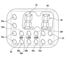
主制御基板ユニット170には、主制御装置が内蔵されており、主制御装置には、性能表示モニタ200が接続されている。性能表示モニタ200は、パチンコ機1を裏側から見て、主制御基板ユニット170の左上の領域に視認可能な態様で主制御装置に配置されており、4つの7セグメントLEDを備えている。4個の7セグメントLEDは左右方向に並べて配置されており、それぞれの7セグメントLEDは、10進数のアラビア数字を表示することができる7つのセグメントと、その右下に位置するドットセグメントとによって構成されている。性能表示モニタ200は、主制御基板ユニット170を覆っている透明ケースを通じて視認可能である。
The main
また、主制御装置には、RAMクリアスイッチ304及び設定キー用鍵穴306が設けられている。RAMクリアスイッチ304は、RAMクリア、すなわち主制御装置内に装備されているRAM(RWM)の初期化を行う際に用いられるスイッチであり、本実施形態においては、設定変更用のスイッチとしても兼用される。設定キー用鍵穴306は、パチンコ機1の遊技に関する設定を変更又は参照する上で必要とされる設定キーを差し込むための鍵穴である。
Further, the main control device is provided with a RAM
RAMクリアスイッチ304は、主制御基板ユニット170を覆っている透明ケースに形成された貫通孔を通じて押下可能に設けられている。なお、RAMクリアスイッチ304は、透明ケース外に配置されていてもよい。また、設定キー用鍵穴306は、キーシリンダが透明ケースを貫通した状態(透明ケースがキーシリンダの周囲を囲んだ状態)で設けられている。したがって、透明ケースが封止されたままの状態で設定キーを差し込み、回転させることが可能である。
The RAM
なお、図2に示した性能表示モニタ200やRAMクリアスイッチ304、設定キー用鍵穴306の配設位置は、あくまで一例であり、任意の位置に配置することができる。また、性能表示モニタ200やRAMクリアスイッチ304、設定キー用鍵穴306は、主制御装置の外側に設けられて主制御装置に接続される構成としてもよい。
The arrangement positions of the
払出装置ユニット172は、例えば賞球タンク172a及び賞球ケース(参照符号なし)を有しており、このうち賞球タンク172aは内枠アセンブリ7の上縁部(裏側)に設置された状態で、図示しない補給経路から補給された遊技球を蓄えることができる。賞球タンク172aに蓄えられた遊技球は、図示しない上側賞球樋を通じて賞球ケースに導かれる。流路ユニット173は、払出装置ユニット172から送り出された遊技球を前面側の受皿ユニット6に向けて案内する。
The
また、外部端子板160は、パチンコ機1を外部の電子機器(例えばデータ表示装置、ホールコンピュータ等)に接続するためのものであり、この外部端子板160からは、パチンコ機1の遊技進行状態やメンテナンス状態等を表す各種の外部情報信号(例えば賞球情報、扉開放情報、図柄確定回数情報、大当り情報、始動口情報等)が外部の電子機器に向けて出力されるものとなっている。
Further, the external
電源コード164は、例えば遊技場の島設備に設置された電源装置(例えばAC24V)に接続されることで、パチンコ機1の動作に必要な電源(電力)を確保するものである。また、アース線166は、同じく島設備に設置されたアース端子に接続されることで、パチンコ機1のアース(接地)を確保するものである。
The
図3は、遊技盤ユニット8を単独で示す正面図である。遊技盤ユニット8は、ベースとなる遊技板8bを備えており、この遊技板8bの前面側に遊技領域8aが形成されている。遊技板8bは、例えば透明樹脂板で構成されており、遊技盤ユニット8が内枠アセンブリ7に固定された状態で、遊技板8bの前面はガラスユニットに平行となる。遊技板8bの前面には、略円形状に設置された発射レール(参照符号なし)の内側に遊技領域8aが形成されている。なお、発射レールは遊技板8bの左下隅位置から遊技板8bの右上隅位置まで時計回り方向に延びている。
FIG. 3 is a front view showing the
遊技領域8a内には、その中央位置に比較的大型の演出ユニット40が配置されており、この演出ユニット40を中心として遊技領域8aが左側部分、右側部分及び下部分に大きく分かれている。遊技領域8aの左側部分は、通常遊技状態(低確率非時間短縮状態)で使用される第1遊技領域(左打ち領域)であり、遊技領域8aの右側部分は、特殊遊技状態(大当り遊技状態、低確率時間短縮状態、高確率時間短縮状態等)で使用される第2遊技領域(右打ち領域、特定の領域)である。なお、遊技領域8aの左側部分は、高確率非時間短縮状態(有利遊技状態)においても使用される。また、遊技領域8a内には、演出ユニット40の周辺に中始動入賞口26、始動ゲート20、普通入賞口22,24、可変始動入賞装置28、第1可変入賞装置30、第2可変入賞装置31等が分布して設置されている。
In the
このうち、中始動入賞口26は、遊技領域8aの下部分の中央に配置されている。始動ゲート20、可変始動入賞装置28、第2可変入賞装置31及び第1可変入賞装置30は、遊技領域8aの右側部分に上からこの順番で配置されている。ここで、第1可変入賞装置30は、中始動入賞口26の右側に配置されており、第2可変入賞装置31は、第1可変入賞装置30の右上に配置されている。さらに、左側の3つの普通入賞口22は遊技領域8aの左側部分に配置されており、右側の1つの普通入賞口24(所定の入賞口)は可変始動入賞装置28の下方に配置されている。
Of these, the middle
また、可変始動入賞装置28の上方には、4つの障害釘が配置されており、さらにその上方には入球口19a及び放出口19bが配置されている。入球口19aと放出口19bとは図示しない裏側の連絡通路によって連結されている。入球口19aに入球した遊技球は、この連絡通路を通って減速・整流され、放出口19bから放出される。
さらに、始動ゲート20の右側にはアウト口19c(所定の入球口)が配置されている。放出口19bから放出された遊技球は、基本的には真っ直ぐに落下して始動ゲート20を通過するが、障害釘によって右側に弾かれた場合にはアウト口19cに入球する。
Further, four obstacle nails are arranged above the variable
Further, an
遊技領域8a内に放り込まれた遊技球は、その流下の過程で中始動入賞口26、普通入賞口22,24に入球したり、始動ゲート20を通過したり、作動時の可変始動入賞装置28や開放動作時の第1可変入賞装置30、開放動作時の第2可変入賞装置31に入球したりする。ここで、遊技領域8aの左側領域を流下する遊技球は、主に中始動入賞口26に入球するか、普通入賞口22に入球する可能性がある。一方、遊技領域8aの右側領域を流下する遊技球は、入球口19aに入球して放出口19bから放出され、主に始動ゲート20を通過するか、作動時の可変始動入賞装置28に入球するか、開放動作時の第1可変入賞装置30に入球するか、開放動作時の第2可変入賞装置31に入球するか、普通入賞口24に入球する可能性がある。始動ゲート20を通過した遊技球は続けて遊技領域8a内を流下するが、中始動入賞口26、普通入賞口22,24、可変始動入賞装置28、第1可変入賞装置30、第2可変入賞装置31、アウト口19cに入球した遊技球は遊技板(遊技盤ユニット8を構成する合板材、透明板等)に形成された貫通孔を通じて遊技盤ユニット8の裏側へ回収される。
The game ball thrown into the
ここで、本実施形態では、遊技領域8a(盤面)の構成上、中始動入賞口26や普通入賞口22に遊技球を入球させる場合は、遊技領域8a内の左側部分の領域(左打ち領域)に遊技球を打ち込む(いわゆる「左打ち」を実行する)必要がある。
Here, in the present embodiment, due to the configuration of the
一方、可変始動入賞装置28や、第1可変入賞装置30、第2可変入賞装置31、普通入賞口24に遊技球を入球させる場合は、遊技領域8a内の右側部分の領域(右打ち領域)に遊技球を打ち込む(いわゆる「右打ち」を実行する)必要がある。
On the other hand, when a game ball is to be entered into the variable
本実施形態において、可変始動入賞装置28は、所定の作動条件が満たされた場合(普通図柄が当りの態様で所定の停止表示時間にわたり停止表示された場合)に作動し、それに伴って右始動入賞口28a(所定の入球口)への入球を可能にする(普通電動役物)。可変始動入賞装置28には、舌片型(ベロタイプ)の開閉部材28bが設けられている。図示の状態にて、開閉部材28bは、盤面より奥に引っ込んだ位置(待避位置)にあり、遊技球が右始動入賞口28aに入球することを不能又は困難にしている。一方、開閉部材28bが盤面より手前側へ突出した位置(駆動位置)に移動すると、開閉部材28bは上方から流下してくる遊技球を受け止め、右始動入賞口28aに遊技球を案内する(右始動入賞口28aへの入球が可能又は容易となる)。なお、可変始動入賞装置28は、開閉部材がその下端縁部分をヒンジとして前方へ倒れ込むように変位して、右始動入賞口を開放する装置であってもよい。
In the present embodiment, the variable
第1可変入賞装置30は、規定の条件が満たされた場合(特別図柄が大当りの態様で停止表示された場合)であって所定の第1条件(例えば大当り遊技の1ラウンド目から5ラウンド目、又は、7ラウンド目から15ラウンド目であるという条件)が満たされた場合に作動し、第1大入賞口30bへの入球を可能にする(特別電動役物、第1特別入球事象発生手段)。なお、特別図柄が小当りの態様で停止表示された場合に規定の条件が満たされることとしてもよい。
The first variable winning
第1可変入賞装置30は、中始動入賞口26の右側に配置された装置であり(いわゆる下アタッカ)、例えば1つの開閉部材30aを有している。第1可変入賞装置30は、開閉部材30aが盤面の内部にスライドするタイプの装置である(スライド式のアタッカ)。そして、この開閉部材30aは、例えば図示しないソレノイドを用いたリンク機構の働きにより、盤面に対して前後方向に往復動作する。開閉部材30aは、盤面から遊技者側に突出した状態で閉位置(閉鎖状態)にあり、このとき遊技球は開閉部材30aの上面を転動することになるため、第1大入賞口30bへの入球は不能又は困難(第1大入賞口30bは閉塞中)である。そして、第1可変入賞装置30が作動すると、開閉部材30aが盤面の内部に引き込まれ、第1大入賞口30bを開放する(開放状態)。この間に第1可変入賞装置30は遊技球の流入が不能ではない(可能又は容易な)状態となり、第1大入賞口30bへの入球という事象を発生させることができる。
The first variable winning
第2可変入賞装置31は、第1可変入賞装置30と同様に規定の条件が満たされた場合(特別図柄が大当りの態様で停止表示された場合)であって、所定の第2条件(例えば大当り遊技の6ラウンド目であるという条件)が満たされた場合に作動し、第2大入賞口31b(特定の入賞口)への入球を可能にする(特別電動役物、第2特別入球事象発生手段)。
The second variable winning
第2可変入賞装置31は、第1可変入賞装置30の右上に配置された装置であり(いわゆる上アタッカ)、例えば1つの開閉部材31aを有している。第2可変入賞装置31は、開閉部材31aが盤面の内部にスライドするタイプの装置である(スライド式のアタッカ)。そして、この開閉部材31aは、例えば図示しないソレノイドを用いたリンク機構の働きにより、盤面に対して前後方向に往復動作する。開閉部材31aは、盤面から遊技者側に突出した状態で閉位置(閉鎖状態)にあり、このとき遊技球は開閉部材31aの上面を転動することになるため、第2大入賞口31bへの入球は不能又は困難(第2大入賞口31bは閉塞中)である。そして、第2可変入賞装置31が作動すると、開閉部材31aが盤面の内部に引き込まれ、第2大入賞口31bを開放する(開放状態)。この間に第2可変入賞装置31は遊技球の流入が不能ではない(可能又は容易な)状態となり、第2大入賞口31bへの入球という事象を発生させることができる。
The second variable winning
また、第2可変入賞装置31の内部には、第2可変入賞装置31に入球した遊技球を誘導するための誘導通路31cが配置されている。誘導通路31cは、第2大入賞口31bから下方に延び、そこから左に曲がって左下方に延びた後、再び下方に延びている。
Further, inside the second variable winning
そして、誘導通路31cの上流には、第2カウントスイッチ85が配置されており、誘導通路31cの中流には、確変領域用羽根部材31d及び確変領域用孔31eが配置されており、誘導通路31cの下流には、排出口31fが配置されている。
A
第2可変入賞装置31に入球した遊技球は、最初に第2カウントスイッチ85にて入球したことが検出される。ここで、確変領域用羽根部材31dを作動させる確変領域ソレノイドがONとなっている場合には、確変領域用羽根部材31dが起き上がって遊技球を確変領域用孔31eに導く。一方、確変領域用羽根部材31dを作動させる確変領域ソレノイドがOFFとなっている場合には、確変領域用羽根部材31dが起き上がらないため、遊技球は確変領域用羽根部材31dの上部を通り抜けて、排出口31fに導かれる。
It is detected that the game ball that has entered the second variable winning
〔確変領域(特定領域)〕
また、確変領域用孔31eの内部には、確変領域(参照符号なし)が設けられている。確変領域は、第2可変入賞装置31が閉鎖状態である場合は遊技球が通過不能な領域であり、第2可変入賞装置31が開放状態である場合であって確変領域用羽根部材31dが作動している場合は遊技球が通過可能な領域である。
[Probability change area (specific area)]
Further, a probability variation region (without reference numeral) is provided inside the probability
確変領域用羽根部材31dは、大当り遊技中に第2可変入賞装置31が開放する際に作動する。確変領域用羽根部材31dの動作パターンは、ラウンドの開始と同時に短期間(例えば0.1秒)にわたり演出領域を開放し、その後に数秒(2~3秒程度)閉鎖した後に確変領域を長期間(例えば20秒程度)にわたってロング開放するパターンである。なお、ラウンドの開始と同時に実行される短期開放では遊技球は確変領域用羽根部材31dまで到達しないので、この作動によって遊技球が確変領域に導かれることはない。また、確変領域用羽根部材31dが動作しても、第2可変入賞装置31がショート開放する場合には、遊技球が確変領域を通過することはない。
The probabilistic
遊技盤ユニット8には、その中央位置から右側部分にかけて演出ユニット40が設置されている。演出ユニット40は、その上縁部40aが遊技球の流下方向を変化させる案内部材として機能する他、その内側に各種の装飾部品40b,40cを備えている。装飾部品40b,40cはその立体的な造形により遊技盤ユニット8の装飾性を高めるとともに、例えば内蔵された発光器(LED等)により透過光を発することで、演出的な動作をすることができる。また、演出ユニット40の内側には液晶表示器42(画像表示器)が設置されており、この液晶表示器42には特別図柄に対応させた演出図柄をはじめ、各種の演出画像が表示される(演出実行手段)。このように遊技盤ユニット8は、その盤面の構成や演出ユニット40の装飾性に基づいて、遊技者にパチンコ機1の特徴を印象付けている。また、本実施形態のように遊技板8bが透明樹脂板(例えばアクリル板)である場合、前面側だけでなく遊技板8bの背後に配置された各種の装飾体(可動体や発光体を含む)による装飾性を付加することができる。
The
その他に演出ユニット40の内部には、演出用の可動体40f(例えば女性キャラクターが搭乗している乗り物を模した装飾物)とともに駆動源(例えばモータ、ソレノイド等)が付属している。演出用の可動体40fは、液晶表示器42による画像を用いた演出や発光器による演出に加えて、有形物の動作を伴う演出を実行することができる。これら可動体40fを用いた演出により、二次元の画像を用いた演出とは別の訴求力を発揮することができる(演出実行手段)。
In addition, a drive source (for example, a motor, a solenoid, etc.) is attached to the inside of the
また、演出ユニット40の左側縁部には球案内通路40dが形成されており、その下縁部には転動ステージ40eが形成されている。球案内通路40dは遊技領域8a内にて左斜め上方に開口しており、遊技領域8a内を流下する遊技球が無作為に球案内通路40d内に流入すると、その内部を通過して転動ステージ40e上に放出される。転動ステージ40eの上面は滑らかな湾曲面を有しており、ここでは遊技球が左右方向に転動自在である。転動ステージ40e上で転動した遊技球は、やがて下方の遊技領域8a内に流下する。転動ステージ40eの中央位置には球放出路40kが形成されており、転動ステージ40eから球放出路40kに案内された遊技球は、その真下にある中始動入賞口26に流入しやすくなる。
Further, a
その他、遊技領域8a内にはアウト口32が形成されており、各種入賞口に入球(入賞)しなかった遊技球は最終的にアウト口32を通じて遊技盤ユニット8の裏側へ回収される。また、普通入賞口22,24や中始動入賞口26、右始動入賞口28a、第1可変入賞装置30、第2可変入賞装置31、アウト口19cに入球した遊技球も含めて、遊技領域8a内に打ち込まれた全ての遊技球は遊技盤ユニット8の裏側へ回収される。回収された遊技球は、図示しないアウト通路アセンブリを通じてパチンコ機1の裏側から枠外へ排出され、さらに図示しない島設備の補給経路に合流する。
In addition, an
図4は、遊技盤ユニット8の一部(窓4a内の左下位置)を拡大して示す正面図である。図示されるように、遊技盤ユニット8には、例えば窓4a内の左下位置に普通図柄表示装置33及び普通図柄作動記憶ランプ33aが設けられている他、第1特別図柄表示装置34、第2特別図柄表示装置35及び遊技状態表示装置38が設けられている。
FIG. 4 is an enlarged front view showing a part of the game board unit 8 (lower left position in the
このうち普通図柄表示装置33は、例えば2つのランプ(LED)を交互に点灯させて普通図柄を変動表示し、そしてランプの点灯又は消灯により普通図柄を停止表示する。普通図柄作動記憶ランプ33aは、例えば2つのランプ(LED)の消灯又は点灯、点滅の組み合わせによって0~4個の記憶数を表示する。例えば、2つのランプをともに消灯させた表示態様では記憶数0個を表示し、1つのランプを点灯させた表示態様では記憶数1個を表示し、同じ1つのランプを点滅させた表示態様では記憶数2個を表示し、1つのランプの点滅に加えてもう1つのランプを点灯させた表示態様では記憶数3個を表示し、そして2つのランプをともに点滅させた表示態様では記憶数4個を表示する、といった具合である。なお、ここでは2つのランプ(LED)を使用することとしているが、4つのランプ(LED)を使用して普通図柄作動記憶ランプ33aを構成してもよい。この場合、点灯するランプの個数で作動記憶数を表示することができる。
Of these, the ordinary
普通図柄作動記憶ランプ33aは、始動ゲート20を遊技球が通過すると、その都度、作動抽選の契機となる通過が発生したことを記憶する意味で1個ずつ増加後の表示態様へと変化していき(最大4個まで)、その通過を契機として普通図柄の変動が開始されるごとに1個ずつ減少後の表示態様へと変化していく。なお、本実施形態では、普通図柄作動記憶ランプ33aが未点灯(記憶数が0個)の場合、普通図柄が既に変動開始可能な状態(停止表示時)で始動ゲート20を遊技球が通過しても表示態様は変化しない。すなわち、普通図柄作動記憶ランプ33aの表示態様によって表される記憶数(最大4個)は、その時点で未だ普通図柄の変動が開始されていない通過の回数を表している。
The normal symbol
また、第1特別図柄表示装置34及び第2特別図柄表示装置35は、例えばそれぞれ7セグメントLED(ドット付き)により、対応する第1特別図柄又は第2特別図柄の変動状態と停止状態とを表示することができる(図柄表示手段)。なお、第1特別図柄表示装置34や第2特別図柄表示装置35は、複数のドットLEDを幾何学的(例えば円形状)に配列した形態であってもよい。
Further, the first special
また、第1特別図柄作動記憶ランプ34a及び第2特別図柄作動記憶ランプ35aは、例えばそれぞれ2つのランプ(LED)の消灯又は点灯、点滅の組み合わせで構成される表示態様により、それぞれ0~4個の記憶数を表示する(記憶数表示手段)。例えば、2つのランプをともに消灯させた表示態様では記憶数0個を表示し、1つのランプを点灯させた表示態様では記憶数1個を表示し、同じ1つのランプを点滅させた表示態様では記憶数2個を表示し、1つのランプの点滅に加えてもう1つのランプを点灯させた表示態様では記憶数3個を表示し、そして、2つのランプをともに点滅させた表示態様では記憶数4個を表示する、といった具合である。
Further, the first special symbol
第1特別図柄作動記憶ランプ34aは、中始動入賞口26に遊技球が入球するごとに、中始動入賞口26に遊技球が入球したことを記憶する意味で1個ずつ増加後の表示態様へと変化していき(最大4個まで)、その入球を契機として特別図柄の変動が開始されるごとに1個ずつ減少後の表示態様へと変化していく。また、第2特別図柄作動記憶ランプ35aは、可変始動入賞装置28に遊技球が入球するごとに、右始動入賞口28aに遊技球が入球したことを記憶する意味で1個ずつ増加後の表示態様へと変化し(最大4個まで)、その入球を契機として特別図柄の変動が開始されるごとに1個ずつ減少後の表示態様へと変化する。なお、本実施形態では、第1特別図柄作動記憶ランプ34aが未点灯(記憶数が0個)の場合、第1特別図柄が既に変動開始可能な状態(停止表示時)で中始動入賞口26に遊技球が入球しても表示態様は変化しない。また、第2特別図柄作動記憶ランプ35aが未点灯(記憶数が0個)の場合、第2特別図柄が既に変動開始可能な状態(停止表示時)で可変始動入賞装置28に遊技球が入球しても表示態様は変化しない。すなわち、各特別図柄作動記憶ランプ34a,35aの表示態様により表される記憶数(最大4個)は、その時点で未だ第1特別図柄又は第2特別図柄の変動が開始されていない入球の回数を表している。
The first special symbol
また、遊技状態表示装置38には、例えば大当り種別表示ランプ38a,38b,38c、確率変動状態表示ランプ38d、時短状態表示ランプ38e、発射位置指定ランプ38fにそれぞれ対応するLEDが含まれている。なお、本実施形態では、上述した普通図柄表示装置33や普通図柄作動記憶ランプ33a、第1特別図柄表示装置34、第2特別図柄表示装置35、第1特別図柄作動記憶ランプ34a、第2特別図柄作動記憶ランプ35a及び遊技状態表示装置38が1枚の統合表示基板89に実装された状態で遊技盤ユニット8に取り付けられている。
Further, the game
統合表示基板89に実装されたこれらのLEDランプは、その点灯又は消灯の切り替えを制御する目的で、異なる4つの制御領域(以下、「コモン」と称する)に区分けされている。見方を変えると、統合表示基板89には4つのコモンが存在し、個々のランプはいずれか1つのコモンに属している。本実施形態においてはダイナミック点灯方式が採用されており、ランプの駆動は割込周期(例えば4ms)の間隔をおいてコモン単位で順に行われる。したがって、統合表示基板89に実装された全てのランプが同時に駆動されることはない。
These LED lamps mounted on the
〔制御上の構成〕
次に、パチンコ機1の制御に関する構成について説明する。図5は、パチンコ機1に装備された各種の電子機器類を示すブロック図である。パチンコ機1は、制御動作の中枢となる主制御装置70(主制御用コンピュータ)を備えており、この主制御装置70は主に、パチンコ機1における遊技の進行を制御する機能を有している。なお、主制御装置70は、主制御基板ユニット170に内蔵されている。
[Control configuration]
Next, the configuration related to the control of the
また、主制御装置70には、中央演算処理装置である主制御CPU72を実装した回路基板(主制御基板)が装備されており、主制御CPU72は、図示しないCPUコアやレジスタとともにROM74、RAM(RWM)76等の半導体メモリを集積したLSIとして構成されている。また、主制御装置70には、乱数回路75や割込コントローラ(割込CTR)192、パラレルI/Oポート79、タイマ回路(PTC)194、シリアル通信回路(SCU)196が装備されている。このうち乱数回路75は、特別図柄抽選の大当り判定用や普通図柄抽選の当り判定用にハードウェア乱数(例えば10進数表記で0~65535)を発生させるものであり、ここで発生された乱数は主制御CPU72に入力される。また、割込コントローラ192は、パラレルI/Oポート79、タイマ回路194、シリアル通信回路196から各割込要求(XINT割込、PTC割込、SCU割込)を受け付け、これらの割込要求を優先順位に基づき制御する。その他にも主制御装置70には、図示しないクロック発生回路、様々な状態を監視し必要に応じてリセットを発生させるリセットコントローラ等の周辺ICが装備されており、これらは主制御CPU72とともに回路基板上に実装されている。なお、回路基板上(又は内層部分)には、信号伝送経路や電源供給経路、制御用バス等が配線パターンとして形成されている。なお、主制御装置70のI/Oポートはシリアル形式としてもよい。
Further, the
さらに、主制御装置70には、設定変更装置300、設定キースイッチ302、RAMクリアスイッチ304が設けられている。なお、設定変更装置300は、1つの設定値を設定(例えば予め定められた所定値に設定)する設定変更装置300であってもよい。主制御装置70(主制御CPU72)は、設定変更装置300を動作させることにより設定を変更する。設定変更装置300は、設定(少なくとも特別図柄抽選の当選確率に関する複数段階の設定値又は1つの設定値)を切り替え、又は1つの値とする装置であり(設定手段、設定変更手段)、RAMクリアスイッチ304等の操作により作動する。また、設定とは、作動確率の組み合わせをいい、設定が1つの値である場合は当該設定値によって定められる作動確率をいう。さらに、作動確率とは、条件装置が作動することとなる(大当り遊技が実行されることとなる)特別図柄の組み合わせが表示される確率をいう。設定キースイッチ302は、設定を切り替える上で必須となる設定キーの回転に伴い、その回転状態を示す信号(ON/OFF)を入力する入力装置である。設定の変更の手順は、様々な手法を採用することができるが、例えば、以下の手順で行うことができる。
Further, the
(1)まず、パチンコ機1の電源をOFFにする。
(2)次いで、専用キー(ドアキー)でパチンコ機1の扉を開ける。具体的には、専用キーをシリンダ錠6aの鍵穴に差し込んで右方向に回転し、内枠アセンブリ7とともに一体扉ユニット4を開放する。
(3)パチンコ機1の裏側には、設定キーを挿入するための設定キー用鍵穴306と、RAMクリアスイッチ304とが設けられているため、設定キー用鍵穴306に設定キーを挿入し、設定キーを右方向に回転する。
(4)そして、パチンコ機1の電源をONにする。
(1) First, the power of the
(2) Next, open the door of the
(3) Since the setting
(4) Then, the power of the
(5)これにより、設定キーが変更位置に回転されたことを示す信号(ON)が設定キースイッチ302により入力され、この入力信号に基づいて設定の変更が可能な状態となる。このとき、図示しないロック機構により安全ロックが掛けられる。したがって、設定キーは、元の位置に戻されない限りは抜き取ることが不可能となる。
(5) As a result, a signal (ON) indicating that the setting key has been rotated to the change position is input by the setting
ここで、設定キーを右方向に回転した状態で、RAMクリアスイッチ304をONにしながら、電源をONにすると、設定の変更が可能な状態となる。一方、設定キーを右方向に回転した状態で、RAMクリアスイッチ304をONにせずに、電源をONにすると、設定の参照が可能な状態となる。
Here, if the power is turned on while the RAM
(6)設定の変更が可能な状態において、RAMクリアスイッチ304を任意の回数だけ押下することにより、予め設けられた複数段階のうちいずれかの段階に設定を変更することができる。
設定値は、例えば、専用の7セグメントLED、遊技状態表示装置38(特別図柄表示装置等)、性能表示モニタ200に表示することができる。
(6) By pressing the RAM
The set value can be displayed on, for example, a dedicated 7-segment LED, a game status display device 38 (special symbol display device, etc.), and a
(7)スロット機の場合、目的の設定に達したら、レバーON処理が必要になるが、パチンコ機1にはレバーが存在しないため、レバーON処理の代わりの代替処理(例えば、設定キーを左方向に回転する処理、不図示の設定変更確定ボタンをONにする処理等)を実行したり、レバーON処理を省略したりしてもよい。本実施形態では、目的の設定に達したら、設定キーを反時計回りに回転させて元の位置に戻す。この操作により、設定キーが元の位置に戻されたことを示す信号(OFF)が設定キースイッチ302により入力され、この入力信号に基づいて設定の変更が確定する。
(7) In the case of a slot machine, when the target setting is reached, the lever ON process is required, but since the
(8)そして、設定の変更が確定すると、設定キー用鍵穴306から設定キーを抜き取ることができる状態となる。また、設定の変更が確定したことに伴い、専用の7セグメントLED、遊技状態表示装置38、性能表示モニタ200に設定値を表示している場合には、その表示が消える。
(9)最後に、パチンコ機1の扉を閉める。これにより、設定の変更が完了する。設定の変更が完了すると、通常の遊技が開始される。
(8) Then, when the change of the setting is confirmed, the setting key can be taken out from the setting
(9) Finally, close the door of the
設定が変更された場合、主制御CPU72は、変更後の設定値をRAM76の設定値バッファに記憶する。設定値バッファは、バックアップの対象となるメモリ領域とすることができる。
When the setting is changed, the main control CPU 72 stores the changed setting value in the setting value buffer of the
〔設定変更状態〕
「設定キーON」、「内枠開放状態」、かつ、「RAMクリアスイッチ押下状態」で電源が投入されると、RAMクリア後、設定変更中の状態(設定変更状態、設定変更モード)に移行する。
[Setting change status]
When the power is turned on with the "setting key ON", "inner frame open state", and "RAM clear switch pressed state", the state shifts to the setting changing state (setting change state, setting change mode) after the RAM is cleared. do.
設定変更中の状態では、メイン表示器(遊技状態表示装置38に含まれる各種ランプ)への表示はなされず、遊技球の発射や遊技球の賞球等は一切できない状態となる。また、性能表示モニタ200において、左側2つの7セグメントLED(識別セグ)に「rn.」が表示されるとともに、右側2つの7セグメントLED(比率セグ)に「-1」のように設定値が表示される。また、RAMクリアスイッチ304が押下されると、設定値が1~6の範囲で変化する。そして、「設定キーOFF」となると、設定が確定され、比率セグの表示は「空欄(非表示)1」のように「-」のセグが消灯する(非表示となる)。
In the state where the setting is being changed, the display is not made on the main display (various lamps included in the game status display device 38), and the game ball cannot be launched or the game ball prize ball or the like cannot be fired at all. Further, in the
この状態で、「内枠閉鎖状態」となった場合(実際には閉鎖状態が100ms継続した場合)には、設定変更中の状態が終了し、一旦、電源断前の状態に移行してから、遊技可能状態に移行する。 In this state, if the "inner frame closed state" is reached (actually, the closed state continues for 100 ms), the state in which the setting is being changed ends, and once the state is changed to the state before the power was turned off. , Move to the playable state.
なお、本実施形態では、RAMクリアスイッチ304が設定変更スイッチを兼ねる構成としているが、RAMクリアスイッチ304を兼用せずに設定変更スイッチを別途設ける構成としてもよい。
In the present embodiment, the RAM
〔設定確認状態〕
一方、「設定キーON」、「内枠開放状態」、かつ、「RAMクリアスイッチ押下でない状態」で電源が投入されると、設定確認中の状態(設定確認状態、設定確認モード)に移行する。
[Setting confirmation status]
On the other hand, when the power is turned on with the "setting key ON", "inner frame open state", and "RAM clear switch not pressed", the state shifts to the setting confirmation state (setting confirmation state, setting confirmation mode). ..
設定変更中の状態と同様に、設定確認中の状態では、メイン表示器への表示はなされず、遊技球の発射や遊技球の賞球等は一切できない状態となる。また、性能表示モニタにおいて、左側2つの7セグメントLED(識別セグ)に「rn.」が表示されるとともに、右側2つの7セグメントLED(比率セグ)に「空欄(非表示)1」のように設定値が表示される。なお、設定確認中の状態では、RAMクリアスイッチ304が押下されても設定値は変化しない。
Similar to the state in which the setting is being changed, in the state in which the setting is being confirmed, the display is not made on the main display, and the game ball cannot be launched or the game ball prize ball or the like cannot be fired at all. Further, in the performance display monitor, "rn." Is displayed on the two 7-segment LEDs (identification segment) on the left side, and "blank (hidden) 1" is displayed on the two 7-segment LEDs (ratio segment) on the right side. The set value is displayed. In the state where the setting is being confirmed, the set value does not change even if the RAM
この状態で、「設定キーOFF」、かつ、「内枠閉鎖状態」となった場合(実際には閉鎖状態が100ms継続した場合)には、設定確認中の状態が終了し、一旦、電源断前の状態に移行してから、遊技可能状態に移行する。 In this state, if the "setting key is OFF" and the "inner frame closed state" is reached (actually, the closed state continues for 100 ms), the state in which the setting is being confirmed ends, and the power is temporarily turned off. After shifting to the previous state, it shifts to the playable state.
なお、本実施形態では、遊技可能状態で設定確認を行うことはできないが、遊技可能状態で設定確認を実行可能にしてもよい。 In the present embodiment, the setting confirmation cannot be performed in the game-enabled state, but the setting confirmation may be executed in the game-enabled state.
上述した始動ゲート20には、遊技球の通過を検出するためのゲートスイッチ78が一体的に設けられている。また、遊技盤ユニット8には、中始動入賞口26、可変始動入賞装置28、第1可変入賞装置30及び第2可変入賞装置31にそれぞれ対応して中始動入賞口スイッチ80、右始動入賞口スイッチ82、第1カウントスイッチ84及び第2カウントスイッチ85が装備されている。各始動入賞口スイッチ80,82は、中始動入賞口26、可変始動入賞装置28(右始動入賞口28a)への遊技球の入球を検出するためのものである。また、第1カウントスイッチ84は、第1可変入賞装置30(第1大入賞口)への遊技球の入球を検出し、その数をカウントするためのものである。さらに、第2カウントスイッチ85は、第2可変入賞装置31(第2大入賞口31b)への遊技球の入球を検出し、その数をカウントするためのものである。さらに、確変領域スイッチ95は、第2可変入賞装置31の内部に配置された確変領域を遊技球が通過したことを検出するためのスイッチである(検出手段)。
The
同様に遊技盤ユニット8には、普通入賞口22への遊技球の入球を検出する第1入賞口スイッチ86と、普通入賞口24への遊技球の入球を検出する第2入賞口スイッチ81とが装備されている。なお、左側の3つの普通入賞口22については、共通の入賞口スイッチ86を用いる構成を例に挙げているが、例えば3つの入賞口スイッチを設置して、各普通入賞口22に対する遊技球の入球を個別に検出してもよい。
Similarly, the
いずれにしても、これらスイッチ類の入賞検出信号は、図示しない入出力ドライバを介して主制御CPU72に入力される。なお、遊技盤ユニット8の構成上、本実施形態ではゲートスイッチ78、第1カウントスイッチ84、第2カウントスイッチ85、第1入賞口スイッチ86、第2入賞口スイッチ81、確変領域スイッチ95からの入賞検出信号は、パネル中継端子板87を経由して送信され、パネル中継端子板87には、それぞれの入賞検出信号を中継するための配線パターンや接続端子等が設けられている。
In any case, the winning detection signals of these switches are input to the main control CPU 72 via an input / output driver (not shown). Due to the configuration of the
上述した普通図柄表示装置33や普通図柄作動記憶ランプ33a、第1特別図柄表示装置34、第2特別図柄表示装置35、第1特別図柄作動記憶ランプ34a、第2特別図柄作動記憶ランプ35a及び遊技状態表示装置38は、主制御CPU72からの制御信号に基づいて表示動作を制御されている。主制御CPU72は、遊技の進行状況に応じてこれら表示装置33,34,35,38及びランプ33a,34a,35aに対する制御信号を出力し、各LEDの点灯状態を制御している。また、これら表示装置33,34,35,38及びランプ33a,34a,35aは、上述したように1枚の統合表示基板89に実装された状態で遊技盤ユニット8に設置されており、この統合表示基板89にはパネル中継端子板87を中継して主制御CPU72から制御信号が送信される。
The above-mentioned ordinary
また、主制御装置70には、パネル中継端子板87を介して、性能表示モニタ200が接続されている。性能表示モニタ200は、遊技球が各入賞口(始動入賞口、普通入賞口)に入球することによって払い出される賞球数を、遊技領域に発射した遊技球の数を示すアウト数(アウトスイッチ99で検出された遊技球の数)で除算して算出されるベースを表示するためのモニタである。ベースは、遊技を進行させる制御に用いられる使用領域とは別の領域(使用外領域)を用いて予め設定された区間ごとに算出され、現在の区間のベースと、前回の区間のベースとが、予め設定された間隔ごとに切り替わって表示される。性能表示モニタ200は、主制御CPU72からの制御信号に基づいてその表示動作が制御される。主制御CPU72は、ベースの算出状況に応じて性能表示モニタ200に対する制御信号を出力し、各7セグメントの点灯状態を制御する。
Further, a performance display monitor 200 is connected to the
なお、性能表示モニタ200は、パネル中継端子板87を介して主制御装置70に接続する例で説明しているが、パネル中継端子板87を介さずに主制御装置70に接続してもよく、主制御装置70の内部の構成として性能表示モニタ200を配置してもよい。
Although the performance display monitor 200 is described with an example of connecting to the
また、遊技盤ユニット8には、可変始動入賞装置28、第1可変入賞装置30、第2可変入賞装置31及び確変領域の上流にそれぞれ対応して普通電動役物ソレノイド88、第1大入賞口ソレノイド90、第2大入賞口ソレノイド97及び確変領域用ソレノイド99が設けられている。これらソレノイド88,90,97,99は主制御CPU72からの制御信号に基づいて動作(励磁)し、それぞれ可変始動入賞装置28、第1可変入賞装置30及び第2可変入賞装置31を開閉動作(作動)させたり、確変領域用羽根部材31dを可動させたりする。なお、これらソレノイド88,90,97,99についてもパネル中継端子板87を中継して主制御CPU72から制御信号が送信される。
Further, in the
その他に一体扉ユニット4にはガラス枠開放スイッチ91が設置されており、また、内枠アセンブリ7にはプラ枠開放スイッチ93が設置されている。一体扉ユニット4が単独で開放されると、ガラス枠開放スイッチ91からの接点信号が主制御装置70(主制御CPU72)に入力され、また、外枠ユニット2から内枠アセンブリ7が開放されると、プラ枠開放スイッチ93からの接点信号が主制御装置70(主制御CPU72)に入力される。主制御CPU72は、これら接点信号から一体扉ユニット4や内枠アセンブリ7の開放状態を検出することができる。なお、主制御CPU72は、一体扉ユニット4や内枠アセンブリ7の開放状態を検出すると、外部情報信号として扉開放情報信号を生成する。
In addition, a glass frame opening switch 91 is installed in the
パチンコ機1の裏側には、払出制御装置92が装備されている。この払出制御装置92(払出制御コンピュータ)は、上述した払出装置ユニット172の動作を制御する。払出制御装置92には、払出制御CPU94を実装した回路基板(払出制御基板)が装備されており、この払出制御CPU94もまた、図示しないCPUコアとともにROM96、RAM98等の半導体メモリを集積したLSIとして構成されている。払出制御装置92(払出制御CPU94)は、主制御CPU72からの賞球指示コマンドに基づいて払出装置ユニット172の動作を制御し、要求された個数の遊技球の払出動作を実行させる。なお、主制御CPU72は賞球指示コマンドとともに、外部情報信号として賞球情報信号を生成する。
A
払出装置ユニット172の図示しない賞球ケース内には、払出モータ102(例えばステッピングモータ)とともに払出装置基板100が設置されており、この払出装置基板100には払出モータ102の駆動回路が設けられている。払出装置基板100は、払出制御装置92(払出制御CPU94)からの払出数指示信号に基づいて払出モータ102の回転角度を具体的に制御し、指示された数の遊技球を賞球ケースから払い出させる。払い出された遊技球は、流路ユニット173内の払出流路を通って受皿ユニット6に送られる。
A
また、例えば賞球ケースの上流位置には払出路球切れスイッチ104が設置されている他、払出モータ102の下流位置には払出計数スイッチ106が設置されている。払出モータ102の駆動により実際に賞球が払い出されると、その都度、払出計数スイッチ106からの計数信号が払出装置基板100に入力される。また、賞球ケースの上流位置で球切れが発生すると、払出路球切れスイッチ104からの接点信号が払出装置基板100に入力される。払出装置基板100は、入力された計数信号や接点信号を払出制御装置92(払出制御CPU94)に送信する。払出制御CPU94は、払出装置基板100から受信した信号に基づき、実際の払出数や球切れ状態を検知することができる。
Further, for example, a payout path ball out
また、パチンコ機1には、例えば下皿6cの内部(パチンコ機1の正面からみて奧の位置)に満タンスイッチ161が設置されている。実際に払い出された賞球(遊技球)は流路ユニット173を通じて上皿6bに放出されるが、上皿6bが遊技球で満杯になると、それ以上に払い出された遊技球は上述したように下皿6cへ流れ込む。さらに、下皿6cが遊技球で満杯になると、それによって満タンスイッチ161がONになり、満タン検出信号が払出制御装置92(払出制御CPU94)に入力される。これを受けて払出制御CPU94は、主制御CPU72から賞球指示コマンドを受信してもそれ以上の賞球動作を一旦保留とし、未払出の賞球残数をRAM98に記憶させておく。なお、RAM98の記憶は電源断時にもバックアップが可能であり、遊技中に停電(瞬間的な停電を含む)が発生しても、未払出の賞球残数情報が消失してしまうことはない。
Further, in the
また、パチンコ機1の裏側には、発射制御基板108とともに発射ソレノイド110が設置されている(球発射手段)。また、受皿ユニット6内には球送りソレノイド111が設けられている。これら発射制御基板108、発射ソレノイド110及び球送りソレノイド111は上述した発射制御基板セット174を構成しており、このうち発射制御基板108には発射ソレノイド110及び球送りソレノイド111の駆動回路が設けられている。このうち球送りソレノイド111は、受皿ユニット6内に蓄えられた遊技球を1個ずつ、発射機ケース内で所定の発射位置に送り出す動作を行う。また、発射ソレノイド110は、発射位置に送り出された遊技球を打撃し、上述したように遊技領域8aに向けて遊技球を1個ずつ連続的(間欠的)に打ち出す動作を行う。なお、遊技球の発射間隔は、例えば0.6秒程度の間隔(1分間で100個以内)である。
Further, on the back side of the
一方、パチンコ機1の表側に位置するハンドルユニット16には、発射レバーボリューム112、タッチセンサ114及び発射停止スイッチ116が設けられている。このうち発射レバーボリューム112は、遊技者による発射ハンドルの操作量(いわゆるストローク)に比例したアナログ信号を生成する。また、タッチセンサ114は、静電容量の変化から遊技者の身体がハンドルユニット16(発射ハンドル)に触れていることを検出し、その検出信号を出力する。そして、発射停止スイッチ116は、遊技者の操作に応じて発射停止信号(接点信号)を生成する。
On the other hand, the
受皿ユニット6には発射中継端子板118が設置されており、発射レバーボリューム112やタッチセンサ114、発射停止スイッチ116からの各信号は、発射中継端子板118を経由して発射制御基板108に送信される。また、発射制御基板108からの駆動信号は、発射中継端子板118を経由して球送りソレノイド111に印加される。遊技者が発射ハンドルを操作すると、その操作量に応じて発射レバーボリューム112でアナログ信号(エンコードされたデジタル信号でもよい)が生成され、このときの信号に基づいて発射ソレノイド110が駆動される。これにより、遊技者の操作量に応じて遊技球を打ち出す強さが調整されるものとなっている。なお、発射制御基板108の駆動回路は、タッチセンサ114からの検出信号がオフ(ローレベル)の場合か、もしくは発射停止スイッチ116から発射停止信号が入力された場合は発射ソレノイド110の駆動を停止する。この他に、発射中継端子板118には遊技球等貸出装置接続端子板120が接続されており、この遊技球等貸出装置接続端子板120にCRユニットが接続されていない場合、同じく発射制御基板108の駆動回路は発射ソレノイド110の駆動を停止する。
A firing
また、受皿ユニット6には度数表示基板122及び貸出及び返却スイッチ基板123が内蔵されている。このうち度数表示基板122には、度数表示部の表示器(3桁分の7セグメントLED)が設けられている。また、貸出及び返却スイッチ基板123には球貸ボタン10や返却ボタン12にそれぞれ接続されるスイッチモジュールが実装されており、球貸ボタン10又は返却ボタン12が操作されると、その操作信号が貸出及び返却スイッチ基板123から遊技球等貸出装置接続端子板120を経由してCRユニットに送信される。また、CRユニットからは、有価媒体の残り度数を表す度数信号が遊技球等貸出装置接続端子板120を経由して度数表示基板122に送信される。度数表示基板122上の図示しない表示回路は、度数信号に基づいて表示器を駆動し、有価媒体の残り度数を数値表示する。また、CRユニットに有価媒体が投入されていなかったり、あるいは投入された有価媒体の残り度数が0になったりした場合、度数表示基板122の表示回路は表示器を駆動してデモ表示(有価媒体の投入を促す表示)を行うこともできる。
Further, the
また、パチンコ機1は制御上の構成として、演出制御装置124(演出制御用コンピュータ)を備えている。この演出制御装置124は、パチンコ機1における遊技の進行に伴う演出の制御を行う。演出制御装置124にもまた、中央演算処理装置である演出制御CPU126が回路基板(複合サブ制御基板)上に装備されている。演出制御CPU126は、図示しないCPUコアとともにRAM(RWM)130やeDRAM131等の半導体メモリを内蔵したLSIとして構成されている。なお、演出制御装置124は、パチンコ機1の裏側で裏カバーユニット178に覆われる位置に設けられている。
Further, the
その他にも演出制御装置124には、VDP152やドライバIC132、音声IC134等の演出を実現する上で必要となる様々な機能部品が搭載されている。このうちVDP152は、液晶表示器42の画面上で再生される演出画面を描画するためのプロセッサである。ドライバIC132は、ランプ46~52や盤面ランプ53、可動体モータ57等のデバイスを制御するICを搭載している。また、音声IC134は、スピーカ54,55,56,58の駆動を制御する。このような演出制御装置124の内部の機能構成については、次の図を参照しながら詳しく後述する。
In addition, the
演出制御装置124と主制御装置70とは、例えば図示しない通信用ハーネスを介して相互に接続されている。ただし、これらの間の通信は、主制御装置70から演出制御装置124への一方向のみで行われ、逆方向への通信は行われない。なお、通信用ハーネスには、主制御装置70から演出制御装置124に対して送信される各種演出用のコマンド(以下、「演出コマンド」と称する。)のバス幅に応じてパラレル形式を採用してもよいし、それぞれのドライバ(I/O)のハード構成に合わせてシリアル形式を採用してもよい。
The
本実施形態では一体扉ユニット4の内面にサブ接続基板136が設置されており、ドライバIC132や音声IC134からの駆動信号はサブ接続基板136を経由して各種ランプ46~52やスピーカ54,55,56,58に印加されている。また、サブ接続基板136には、ハンドルレバー62、ボタンモータ63、プッシュボタン64、方向キー66の他に図示しない音量調整スイッチが接続されており、遊技者がこれらの操作部材を操作すると、それらの接点信号がサブ接続基板136を通じて演出制御装置124に入力される。なお、ここではサブ接続基板136に各操作部材62,64,66を接続した例を挙げているが、受け皿電飾基板を設置する場合、各操作部材62,64,66は受け皿電飾基板に接続されていてもよい。
In the present embodiment, the
ボタンモータ63は、プッシュボタン64に対応したステッピングモータであり、操作ユニット60を制御する不図示の操作ユニット制御装置によって駆動される(切替手段)。操作ユニット制御装置は、演出制御装置124から送信される駆動信号に基づいてボタンモータ63を駆動することにより、プッシュボタン64を通常の状態(初期位置)又は突出した状態(最大可動位置)のいずれかに切り替える(変位させる)。
The
その他、遊技盤ユニット8にはドライバ基板138が設置されており、このドライバ基板138には盤面ランプ53の他に可動体モータ57が接続されている。可動体モータ57は、例えば図示しないリンク機構を介して可動体40fを駆動する。ドライバIC132からの駆動信号は、ドライバ基板138を経由して盤面ランプ53及び可動体モータ57にそれぞれ印加される。
In addition, a
液晶表示器42は遊技盤ユニット8の裏側に設置されており、遊技盤ユニット8に形成された略矩形の開口を通じてその表示画面が視認可能となっている。また、遊技盤ユニット8の裏側にはインバータ基板158が設置されており、このインバータ基板158は液晶表示器42のバックライト(例えば冷陰極管)に印加される交流電源を生成している。
The
その他、内枠アセンブリ7の裏側には電源制御ユニット162(電源制御手段)が装備されている。この電源制御ユニット162はスイッチング電源回路を内蔵し、電源コード164を通じて島設備から外部電力(例えばAC24V等)を取り込むと、そこから必要な電力(例えばDC+34V、+12V等)を生成することができる。電源制御ユニット162で生成された電力は、主制御装置70や払出制御装置92、演出制御装置124、インバータ基板158に分配されている。さらに、払出制御装置92を経由して発射制御基板108に電力が供給されている他、遊技球等貸出装置接続端子板120を経由してCRユニットに電力が供給されている。なお、ロジック用の低電圧電力(例えばDC+5V)は、各装置に内蔵された電源用IC(3端子レギュレータ等)で生成される。また、上述したように電源制御ユニット162は、アース線166を通じて島設備にアース(接地)されている。
In addition, a power supply control unit 162 (power supply control means) is provided on the back side of the
外部端子板160は払出制御装置92に接続されており、主制御装置70(主制御CPU72)にて生成された各種の外部情報信号は、払出制御装置92を経由して外部端子板160から外部に出力されるものとなっている。主制御装置70(主制御CPU72)及び払出制御装置92(払出制御CPU94)は、外部端子板160を通じてパチンコ機1の外部に向けて外部情報信号を出力することができる。外部端子板160から出力される信号は、例えば遊技場のホールコンピュータ(図示していない)で集計される。なお、ここでは払出制御装置92を経由する構成を例に挙げているが、主制御装置70からそのまま外部情報信号が外部端子板160に出力される構成であってもよい。
The external
〔演出制御装置の内部構成〕
図6は、演出制御装置124の内部の機能構成を示すブロック図である。
上述したように、演出制御装置124は遊技の進行に伴い演出を制御する演出制御プロセッサとしての役割を有している。そのため演出制御装置124には、演出制御CPU126に加え、演出制御装置124が演出制御プロセッサとして機能する上で必要となる制御ROM180及びウォッチドッグタイマIC(WDTIC)188が装備されている。制御ROM180には、演出の制御に関する基本的なプログラムが格納されている。演出制御CPU126は、図示しないCPUバスを介して制御ROM180にアクセスし、制御ROM180に格納されたプログラムを実行することにより演出を制御する。ウォッチドッグタイマIC188は、演出制御装置124で実行される制御が正常になされているか(想定時間内に処理が完了しているか)を監視するタイマであり、演出制御CPU126のリセット端子に接続されている。ウォッチドッグタイマIC188の監視タイマをクリアするための信号(クリアパルス)が所定時間内に入力されなかった場合、ウォッチドッグタイマIC188は演出制御CPU126に対しリセット起動させるための信号(リセットパルス)を出力する。これにより、演出制御装置124が強制的にリセット起動されることとなる。
[Internal configuration of production control device]
FIG. 6 is a block diagram showing an internal functional configuration of the
As described above, the
演出制御装置124にはこれらの他にも、演出に関わる機能として、バックアップデータ用の記憶領域であるSRAM182、所定周波数のクロック信号を生成する水晶発振器181、時刻管理を行うリアルタイムクロック(RTC)184、SRAM182及びリアルタイムクロック184に対しバックアップ電源を供給するリチウム電池186、図示しない入出力ドライバやカウンタ/タイマ回路等の周辺IC等が装備されている。リチウム電池186は、電源制御ユニット162から演出制御装置124に対し駆動電力が供給されている間に、この電力を蓄えて自身を充電する。SRAM182及びリアルタイムクロック184は、リチウム電池186に接続されており、電源制御ユニット162からの演出制御装置124への駆動電力の供給が断たれた場合にはリチウム電池186により駆動可能となる。したがって、SRAM182及びリアルタイムクロック184は、電源制御ユニット162からの電力供給が断たれた場合でも、リチウム電池186の充電が切れるまでの期間(例えば、約1か月半)は動作を継続するため、SRAM182は、電源断の状況下においても暫くは格納されている情報を保持することができる。
In addition to these, the
なお、演出制御プログラムは、容易に消去されるべきではないセキュリティや監視、不具合等に関する情報をSRAM182に保存する構成となっている。これにより、例えば、演出制御装置124で何らかの不具合が発生した場合に、パチンコ機1を回収(又は設置状態で点検)し、SRAM182に保持されている情報を解析することにより不具合の要因調査を進めることが可能となる。
The effect control program is configured to store information on security, monitoring, defects, and the like that should not be easily erased in the
通常、演出制御CPU126が制御ROM180に格納されたプログラムに沿って実行する演出の制御には、上述したように液晶表示器42、各種ランプ46~53やスピーカ54,55,56,58等のデバイスを用いた演出の制御が含まれる。この演出制御の流れは、大きくみると「全体制御(再生指示)」と「個別制御(再生制御)」の2つの段階に分けられる。演出制御CPU126は、先ず主制御装置70から送信される演出コマンドを受信し、演出コマンドの内容に応じた演出の再生を各デバイスに対して間接的に指示する(全体制御)。次に、演出制御CPU126は指示内容を各デバイスに適したより具体的な表現に変換した指示データを生成し、演出制御CPU126と各デバイスとの間を中継する各制御デバイス134,152,198,199に送信する(個別制御)。その結果として、各制御デバイス134,152,198,199により指示データに基づく各デバイスの制御がなされ、パチンコ機1における各デバイスを用いた演出再生(画面表示、音声出力、ランプ発光、可動体変位等)が実現される。
Normally, for the control of the effect executed by the
このように、演出制御CPU126は、演出制御の段階に応じて異なる機能を有しており、これらの機能は演出制御CPU126のリソースを使い分けることにより実現されている。図5では、演出制御CPU126の内部リソースをいくつかの機能ブロックに分けたものが演出制御部210、表示制御部220、音声制御部222、ランプ制御部224、モータ制御部226、入力制御部228等として示されている。以下の説明では、個々の機能ブロックを制御処理の動作主体として扱うものとする。
As described above, the
先ず、全体制御の段階では、演出制御CPU126内の演出制御部210が動作主体となる。また、個別制御の段階では、制御対象とされるデバイスに応じて演出制御CPU126内の表示制御部220、音声制御部222、ランプ制御部224、モータ制御部226又は入力制御部228が各動作主体となる。なお、演出制御部210が各制御デバイス134,152,198,199等を直接的に制御する構成としてもよい。
First, at the stage of overall control, the
演出制御装置124は、全体制御の段階では演出制御プロセッサとして機能するのに対し、個別制御の段階では演出再生プロセッサとして機能する。そのため、演出制御装置124にはさらに、VDP152を実装した回路基板(演出表示制御基板)やCGROM(画像・音声ROM)190の他、演出の再生に用いられる各種デバイスを制御するための音声IC134、LEDドライバ198、SMC(シリアル制御コントローラ)199及びドライバIC132が装備されている。
The
CGROM190は、演出画面を構成する描画素材(動画像データ)や演出の進行とともに出力される音声素材(音声データ)を所定の圧縮アルゴリズムにより圧縮された状態で格納している。CGROM190は、図示しないCGバスを介してVDP152や音声IC134に接続されている。
The
VDP152は、演出画像の描画専用のプロセッサであり、演出制御CPU126とともにワンチップに統合されている。また、VDP152はVRAM156及び描画素材デコーダ157を内蔵する。このうちVRAM156は、主に描画素材を展開する際に用いられ、描画素材デコーダ157は、圧縮された状態の描画素材を解凍(復号)する際に用いられる。VDP152は、先ず表示制御部220から送信された指示内容を解析し、CGバスを介してCGROM190から必要な描画素材を読み出してVRAM156に転送する。そして、読み出した描画素材を描画素材デコーダ157で復号してVRAM156上で演出画像の描画を行い、演出画像を1フレーム(単位時間あたりの静止画像)ごとにフレームバッファに展開する。ここでバッファされた画像データに基づき液晶表示器42の各画素(フルカラー画素)を個別に駆動することにより、演出画面の再生が実現される。
The
音声IC134は、演出の実行中に再生される効果音やBGM等の音声を生成するサウンドジェネレータであり、VDP152と同様に演出制御CPU126とワンチップに統合されている。音声IC134は、図示しないアンプや外部DRAM、CGバスに接続されている。また、音声IC134には、圧縮された状態の音声素材を解凍(復号)する音声素材デコーダ135が内蔵されている。音声IC134は、先ず音声制御部222から送信された指示内容を解析し、CGバスを介してCGROM190から必要な音声素材を読み出す。そして、読み出した音声素材を外部DRAM上で音声素材デコーダ135を用いて復号する。アンプを経由してガラス枠上スピーカ54、ガラス枠内スピーカ55、内枠スピーカ56及び外枠スピーカ58に復号した音声を出力することにより、ステレオ2ch又はモノラル2chの音声再生(より大きなチャンネル数としてもよい)を実現する。また、音声IC134は、音量調整スイッチが操作された場合に入力される接点信号に基づいて、各スピーカ54,55,56,58の出力音量を調整する。
The
LEDドライバ198は、パチンコ機1の前面側に設けられた各種ランプ46~53の演出の実行にともなう点灯パターン及び輝度パターンを制御する。LEDドライバ198においては、アドレス指定同期シリアル方式が採用されている。LEDドライバ198は、先ずランプ制御部224から送信された指示内容に基づいて点灯パターン及び輝度パターンの制御を行い、これに応じた駆動データをドライバIC132に転送する。
The
SMC199は、演出ユニット40の内部に設けられた演出用の可動体40f等の駆動源となる可動体モータ57の駆動パターンを制御する。SMC199もまた、演出制御CPU126とワンチップに統合されている。SMC199においては、クロック同期式シリアル方式が採用されている。SMC199は、先ずモータ制御部226から送信された指示内容に基づいて駆動パターンを生成し、これをドライバIC132に転送する。なお、ここではSMC199をモータの駆動パターン生成にのみ用いているが、SMC199はモータだけでなくランプの点灯パターンや輝度パターンを生成することもできるため、上述したLEDドライバ198に代えてSMC199を適用し、SMC199がランプ及びモータの両方のデータパターンを生成する構成とすることも可能である。
The
ドライバIC132は、LEDドライバ198やSMC199から転送された駆動データに基づいてランプやモータに対し印加する駆動電圧の制御を行う。ドライバIC132は、例えば図示しないPWM(パルス幅変調)ICやMOSFET等のスイッチング素子を備えており、各種ランプ46~53や可動体モータ57に印加する駆動電圧をスイッチング(又はデューティ切替)して、その動作を管理することにより、ランプや可動体を用いた演出再生を実現する。なお、各種ランプには、ガラス枠トップランプ46やガラス枠装飾ランプ48,50,52の他に、操作ユニット60の各部位に内蔵された光源や遊技盤ユニット8に設置された装飾・演出用の盤面ランプ53が含まれる。盤面ランプ53は、演出ユニット40に内蔵されるLEDや、可変始動入賞装置28、第1可変入賞装置30、第2可変入賞装置31等に内蔵されるLEDに相当するものである。また、ここではガラス枠装飾ランプ52がサブ接続基板136に接続されている例を挙げているが、受皿ユニット6に受け皿電飾基板を設置し、ガラス枠装飾ランプ52については受け皿電飾基板を介してドライバIC132に接続される構成であってもよい。
The
この他にドライバIC132は、ハンドルレバー62やプッシュボタン64等の操作部材が遊技者により操作された場合に入力される接点信号を、入力制御部228を経由して演出制御部210に転送する。演出制御部210は、転送される接点信号の内容に基づいて、再生する演出内容を適宜変化させる。
以上がパチンコ機1の制御に関する構成例である。
In addition, the
The above is a configuration example relating to the control of the
〔設定値と特別図柄抽選の当選確率との関係〕
図7は、設定値と特別図柄抽選の当選確率との関係を示す図である。
[Relationship between set value and winning probability of special symbol lottery]
FIG. 7 is a diagram showing the relationship between the set value and the winning probability of the special symbol lottery.
〔低確率状態〕
以下は、低確率状態での特別図柄抽選の当選確率である。
設定値が「1」である場合、特別図柄抽選の当選確率は、「1/319」である。
設定値が「2」である場合、特別図柄抽選の当選確率は、「1/299」である。
設定値が「3」である場合、特別図柄抽選の当選確率は、「1/279」である。
設定値が「4」である場合、特別図柄抽選の当選確率は、「1/259」である。
設定値が「5」である場合、特別図柄抽選の当選確率は、「1/239」である。
設定値が「6」である場合、特別図柄抽選の当選確率は、「1/219」である。
[Low probability state]
The following is the winning probability of the special symbol lottery in the low probability state.
When the set value is "1", the winning probability of the special symbol lottery is "1/319".
When the set value is "2", the winning probability of the special symbol lottery is "1/299".
When the set value is "3", the winning probability of the special symbol lottery is "1/279".
When the set value is "4", the winning probability of the special symbol lottery is "1/259".
When the set value is "5", the winning probability of the special symbol lottery is "1/239".
When the set value is "6", the winning probability of the special symbol lottery is "1/219".
〔高確率状態〕
以下は、高確率状態での特別図柄抽選の当選確率である。
設定値が「1」である場合、特別図柄抽選の当選確率は、「1/159.5」である。
設定値が「2」である場合、特別図柄抽選の当選確率は、「1/149.5」である。
設定値が「3」である場合、特別図柄抽選の当選確率は、「1/139.5」である。
設定値が「4」である場合、特別図柄抽選の当選確率は、「1/129.5」である。
設定値が「5」である場合、特別図柄抽選の当選確率は、「1/119.5」である。
設定値が「6」である場合、特別図柄抽選の当選確率は、「1/109.5」である。
[High probability state]
The following is the winning probability of the special symbol lottery in the high probability state.
When the set value is "1", the winning probability of the special symbol lottery is "1 / 159.5".
When the set value is "2", the winning probability of the special symbol lottery is "1 / 149.5".
When the set value is "3", the winning probability of the special symbol lottery is "1 / 139.5".
When the set value is "4", the winning probability of the special symbol lottery is "1 / 129.5".
When the set value is "5", the winning probability of the special symbol lottery is "1 / 119.5".
When the set value is "6", the winning probability of the special symbol lottery is "1 / 109.5".
このように、設定値が大きい値であるほど、特別図柄抽選の当選確率(低確率状態及び高確率状態)は、大きな値となっているため、遊技者にとって有利な状況となる。 As described above, the larger the set value, the larger the winning probability (low probability state and high probability state) of the special symbol lottery, which is advantageous for the player.
なお、図示の例では、特別図柄抽選の当選確率は、低確率状態及び高確率状態の両方でそれぞれ設定差を設ける例で説明したが、低確率状態のみ又は高確率状態のいずれかのみに設定差を設ける(例えば、設定値が「1」~「6」である場合、特別図柄抽選の当選確率は共通の「1/100」である等)こととしてもよい。また、設定に関しては、大当り確率だけでなく、小当りを設けた場合は小当り確率に設定差を設けてもよい。さらに、その他の項目(例えば、高確率状態への移行率、時間短縮状態への移行率、確変回数、時短回数、特殊変動回数等)に設定差を設けてもよい。 In the illustrated example, the winning probability of the special symbol lottery has been described in the example of providing a setting difference in both the low-probability state and the high-probability state, but it is set only in the low-probability state or the high-probability state. A difference may be provided (for example, when the set value is "1" to "6", the winning probability of the special symbol lottery is the common "1/100"). Further, regarding the setting, not only the big hit probability but also the small hit probability may be set differently when the small hit is provided. Further, setting differences may be provided for other items (for example, the transition rate to the high probability state, the transition rate to the time shortening state, the number of probability changes, the number of time reductions, the number of special fluctuations, etc.).
続いて、主制御装置70の主制御CPU72により実行される制御上の処理について説明する。
Subsequently, the control processing executed by the main control CPU 72 of the
〔主制御装置におけるCPU初期化(メイン)処理〕
パチンコ機1に電源が投入されると、主制御CPU72はCPU初期化処理を開始する。CPU初期化処理は、前回の電源遮断時に保存されたバックアップ情報を元に遊技状態を復旧(いわゆる復電)したり、逆にバックアップ情報をクリアしたりすることで、パチンコ機1の初期状態を整えるための処理である。また、CPU初期化処理は、初期状態の調整後にパチンコ機1の安定した遊技動作を保証するためのメイン処理(メイン制御プログラム)として位置付けられる。
[CPU initialization (main) processing in the main controller]
When the power is turned on to the
図8及び図9は、CPU初期化処理の手順例を示すフローチャートである。以下、主制御CPU72が行う処理について、各手順を追って説明する。 8 and 9 are flowcharts showing a procedure example of the CPU initialization process. Hereinafter, the processing performed by the main control CPU 72 will be described step by step.
ステップS100:主制御CPU72は、先ずスタックポインタにスタック領域の先頭アドレスをセットする。 Step S100: The main control CPU 72 first sets the start address of the stack area in the stack pointer.
ステップS102:続いて主制御CPU72は、割込ベクタテーブルの設定を行う。この処理では、主制御CPU72は割込ベクタテーブルのアドレスを割込制御に使用するIレジスタ(割込ベクタレジスタ)にセットする。割込ベクタテーブルにはCPU初期化処理の実行中に発生した割込要求を制御する上で必要となる優先順位が定義されており、主制御CPU72は割込ベクタテーブルに定義された優先順位に基づき複数の割込要求を順番に実行することとなる。割込処理の制御については、詳しく後述する。 Step S102: Subsequently, the main control CPU 72 sets the interrupt vector table. In this process, the main control CPU 72 sets the address of the interrupt vector table in the I register (interrupt vector register) used for interrupt control. The interrupt vector table defines the priority order required to control the interrupt request generated during the execution of the CPU initialization process, and the main control CPU 72 sets the priority order defined in the interrupt vector table. Based on this, multiple interrupt requests will be executed in order. The control of the interrupt process will be described in detail later.
ステップS104:主制御CPU72は、RAMクリア信号(RAMクリアスイッチ304からの入力信号)を退避させる。より具体的には、RAMクリア信号が入力される入力ポートの値を2回連続して取得し、これらの値による論理和を入力ポート値として退避させておく。 Step S104: The main control CPU 72 saves the RAM clear signal (input signal from the RAM clear switch 304). More specifically, the values of the input port to which the RAM clear signal is input are acquired twice in succession, and the logical sum of these values is saved as the input port value.
ステップS106:主制御CPU72は、ここで待機処理を実行する。この処理は、電源投入後にある程度の待機時間(例えば数千ms程度)を確保しておき、その間に電源断予告信号(電源の遮断が発生しつつあることを示す信号)のチェックを行うためのものである。具体的には、主制御CPU72は待機時間分のループカウンタをセットすると、ループカウンタの値をデクリメントしながら電源断予告信号の入力ポートをビットチェックする。電源断予告信号は、駆動電圧の電圧レベルを監視するICにより入力される。そして、ループカウンタが0になる前に電源断予告信号の入力を確認すると、主制御CPU72は先頭から処理を再開する。これにより、例えば図示しない主電源スイッチの投入と切断の操作が短時間(1~2秒程度)内に繰り返し行われた場合のシステム保護を図ることができる。 Step S106: The main control CPU 72 executes the standby process here. This process is for securing a certain amount of standby time (for example, about several thousand ms) after turning on the power, and checking the power cutoff warning signal (signal indicating that the power is being cut off) during that time. It is a thing. Specifically, when the main control CPU 72 sets the loop counter for the standby time, it bit-checks the input port of the power cutoff warning signal while decrementing the value of the loop counter. The power cutoff warning signal is input by an IC that monitors the voltage level of the drive voltage. Then, if the input of the power cutoff warning signal is confirmed before the loop counter becomes 0, the main control CPU 72 restarts the processing from the beginning. This makes it possible to protect the system when, for example, the operation of turning on and off the main power switch (not shown) is repeatedly performed within a short time (about 1 to 2 seconds).
ステップS108:次に主制御CPU72は、RAM76のワーク領域に対するアクセスを許可する。具体的には、ワーク領域のRAMプロテクト設定値をリセット(00H)する。これにより、以後はRAM76のワーク領域に対するアクセスが許可された状態となる。
Step S108: Next, the main control CPU 72 permits access to the work area of the
ステップS110:主制御CPU72は、先のステップS104で退避させた入力ポート値の特定ビットをチェックすることによりRAMクリア信号を参照し、RAMクリアスイッチ304が操作(スイッチON)されたか否かを確認する。RAMクリアスイッチ304が操作されていなければ(No)、次にステップS112を実行する。
Step S110: The main control CPU 72 refers to the RAM clear signal by checking the specific bit of the input port value saved in the previous step S104, and confirms whether or not the RAM
ステップS112:次に主制御CPU72は、RAM76にバックアップ情報が保存されているか否か、つまり、バックアップ有効判定フラグがセットされているか否かを確認する。前回の電源遮断時に実行された処理でバックアップが正常に終了し、バックアップ有効判定フラグ(例えば「A5H」)がセットされていれば(Yes)、次に主制御CPU72はステップS114を実行する。なお、電源遮断時に実行される処理については、別のフローチャートを用いて後述する。
Step S112: Next, the main control CPU 72 confirms whether or not the backup information is stored in the
ステップS114:主制御CPU72は、RAM76のバックアップ情報についてサムチェックを実行する。具体的には、主制御CPU72はRAM76のワーク領域(使用禁止領域及びスタック領域を含むユーザワーク領域)のうち、バックアップ有効判定フラグ及びサムチェックバッファを除く全ての領域をサムチェックする。サムチェックの結果が正常であれば(Yes)、次に主制御CPU72はステップS116を実行する。
Step S114: The main control CPU 72 executes a thumb check for the backup information of the
ステップS116:主制御CPU72は、RAM76の一部領域の記憶内容をクリアする。RAM76の一部領域とは、電源復帰時にクリア対象とするバックアップ有効判定フラグのアドレスを基準とした連続する所定範囲内のワーク領域のことである。この領域の記憶内容をアドレス毎に(バイト単位で)クリアしつつ、保存されている有効なバックアップ情報はそのまま保持しておくことにより、主制御CPU72は電源遮断時の状態を復旧させることが可能となる(記憶復帰手段)。
Step S116: The main control CPU 72 clears the stored contents of a part of the
ステップS118:主制御CPU72は、電源遮断から復帰して起動したことを示す電源復帰指定の演出コマンド(演出制御装置124に対し送信するべきコマンド)及び払出コマンド(払出制御装置92に対し送信するべきコマンド)をセットする。 Step S118: The main control CPU 72 should transmit to the power return designated effect command (command to be transmitted to the effect control device 124) and the payout command (to the payout control device 92) indicating that the main control CPU 72 has recovered from the power cutoff and started. Command) is set.
一方、電源投入時にRAMクリアスイッチ304が操作されていた場合(ステップS110:Yes)や、バックアップ有効判定フラグがセットされていなかった場合(ステップS112:No)、あるいは、バックアップ情報が正常でなかった場合(ステップS114:No)、主制御CPU72はステップS120に移行する。
On the other hand, when the RAM
ステップS120:主制御CPU72は、RAM76の使用禁止領域以外の記憶内容をクリアする。これにより、RAM76のワーク領域及びスタック領域は全て初期化され、有効なバックアップ情報が保存されていても、その内容は消去される。
ステップS122:また、主制御CPU72は、RAM76の初期設定を行う。
Step S120: The main control CPU 72 clears the stored contents other than the prohibited area of the
Step S122: Further, the main control CPU 72 performs the initial setting of the
ステップS124:主制御CPUは、RAMクリア起動したことを示すRAMクリア指定の演出コマンド(演出制御装置124に対するコマンド)及び払出コマンド(払出制御装置92に対するコマンド)をセットする。 Step S124: The main control CPU sets a RAM clear designated effect command (command for the effect control device 124) and a payout command (command for the payout control device 92) indicating that the RAM clear has been started.
ステップS126:次に主制御CPU72は、払出制御出力処理を実行する。この処理では、主制御CPU72は、ステップS118でセットされた払出コマンド(電源復帰指定)又はステップS124でセットされた払出コマンド(RAMクリア指定)を、払出コマンドバッファに出力する。 Step S126: Next, the main control CPU 72 executes the payout control output process. In this process, the main control CPU 72 outputs the payout command (power recovery designation) set in step S118 or the payout command (RAM clear designation) set in step S124 to the payout command buffer.
ステップS128:主制御CPU72は、演出制御出力処理を実行する。この処理では、主制御CPU72は先ず、ステップS118でセットされた演出コマンド(電源復帰指定)又はステップS124でセットされた演出コマンド(RAMクリア指定)を演出コマンドバッファに出力する。主制御CPU72はさらに、演出制御に必要となるその他の各種演出コマンド(例えば、機種指定コマンド、特別図柄確率状態指定コマンド、特図先判定演出コマンド、作動記憶数増加時演出コマンド、作動記憶数減少時演出コマンド、回数切りカウンタ残数コマンド、特別遊技状態指定コマンド、発射位置指定コマンド等)をセットし、これらを演出コマンドバッファに出力する。このとき、主制御CPU72はこれらの演出コマンドに対し、電源復帰時とRAMクリア時とで異なる値をセットする。 Step S128: The main control CPU 72 executes the effect control output process. In this process, the main control CPU 72 first outputs the effect command (power recovery designation) set in step S118 or the effect command (RAM clear specification) set in step S124 to the effect command buffer. The main control CPU 72 further includes various other effect commands (for example, a model designation command, a special symbol probability state specification command, a special symbol destination determination effect command, an operation memory number increase effect command, and an operation memory number decrease) required for the effect control. Set the time effect command, count cut counter remaining number command, special game state specification command, launch position specification command, etc.) and output these to the effect command buffer. At this time, the main control CPU 72 sets different values for these effect commands when the power is restored and when the RAM is cleared.
例えば、電源復帰時には、バックアップ情報に基づいて各演出コマンドの値をセットする。これらの演出コマンドが後の演出コマンド送信処理(ステップS142)において演出制御装置124に対し送信されることにより、演出制御装置124は、前回の電源遮断時に実行中であった演出状態(例えば、内部確率状態、演出図柄の表示態様、作動記憶数の演出表示態様、音響出力内容、各種ランプの発光状態等)を復帰させることができる。
For example, when the power is restored, the value of each effect command is set based on the backup information. By transmitting these effect commands to the
ステップS130:主制御CPU72は、入力ポート処理を実行する。この処理では、主制御CPU72は各入力ポートの内容を取得し、その値に対して所定の演算を行った結果を各入力ポートの状態フラグに格納する。この処理を終えると、主制御CPU72は次にステップS131に進む(接続記号A→A)。 Step S130: The main control CPU 72 executes input port processing. In this process, the main control CPU 72 acquires the contents of each input port and stores the result of performing a predetermined operation on the value in the state flag of each input port. When this process is completed, the main control CPU 72 then proceeds to step S131 (connection symbol A → A).
ステップS131:主制御CPU72は、主コマンド許可信号を出力ポートの特定ビットにセットする。主コマンド許可信号とは、主制御装置70が自身へのコマンド送信を許可する旨を払出制御装置92に対し表明する信号である。主コマンド許可信号が払出制御装置92に入力されると、これを受けて払出制御装置92は、主制御装置70に対し払出コマンドの送信を許可する旨を表明する払出コマンド許可信号を入力することとなる。
Step S131: The main control CPU 72 sets the main command permission signal to the specific bit of the output port. The main command permission signal is a signal indicating to the
ステップS132:主制御CPU72は、出力ポートの特定ビットをリセット(OFF)して発射許可信号をクリアする(特定出力情報クリア手段)。発射許可信号は電源遮断時におけるバックアップの対象に含まれる。したがって、主制御装置70(パチンコ機1)が電源復帰した場合、主制御CPU72はCPU初期化処理において電源復帰時のフローを実行し、バックアップ情報に基づいて主制御装置70を電源遮断時の状態に復帰させるが(ステップS116)、その一環で、発射許可信号も電源遮断時の状態に戻される。
Step S132: The main control CPU 72 resets (OFF) the specific bit of the output port to clear the emission permission signal (specific output information clearing means). The launch permission signal is included in the backup target when the power is cut off. Therefore, when the power of the main control device 70 (pachinko machine 1) is restored, the main control CPU 72 executes the flow at the time of power restoration in the CPU initialization process, and the state when the power of the
発射許可信号は、RAM76に記憶されている特定の出力ポートバッファ(例えば、出力ポート3用のバッファ)のうち、特定のビット(例えば、ビット0)にセットされている。ただし、ここで対象とする出力ポートバッファのアドレスは、RAM76のアドレス空間のうち、ステップS116でクリア対象とした連続領域からは外れた場所に位置している。このため仮に、ステップS116の処理の一環で、クリア対象領域に加えて発射許可信号がセットされている特定アドレスの特定ビットの値をもクリアしようとすると、その具体的なアドレスを特定した上で、そのアドレスに記憶されている8ビットのデータのうちの特定ビットのデータのみをクリアしつつ残りの7ビット分のデータは維持するという例外的な処理を行わなければならず、RAM76の一部領域をクリアする処理の効率が非常に悪くなる。このような事情から、主制御CPU72は、先のステップS116では発射許可信号をクリアせずに他のバックアップ対象データと区別せず同様に取扱い、一旦は電源遮断時の状態に戻すこととしている。
The emission permission signal is set to a specific bit (for example, bit 0) of the specific output port buffer (for example, the buffer for the output port 3) stored in the
しかしながら、主制御装置70においてバックアップ情報が戻された段階(ステップS116)では、払出制御装置92との通信が未だ確立しておらず、払出制御装置92が正常に起動しているか(主制御装置70からのコマンドによる指示を受け付けられるか)否かを確認できていない。発射許可信号がONの状態で電源が遮断された場合には、発射許可信号がONに戻されるため、結果として払出制御装置92の正常性が不明であるにもかかわらず遊技球を発射できるという状態が発生することとなる。ここで仮に、電源の遮断中に払出制御装置92が本来の検査適合していない改造品(例えば、賞球数が改変されたもの等)と交換され、その後の電源復帰により主制御装置70が起動した場合、発射許可信号がONに戻されることより遊技球の発射が可能となってしまう。このような状態は、セキュリティの観点から好ましくない。
However, at the stage where the backup information is returned in the main control device 70 (step S116), communication with the
そこで、本実施形態においては、電源復帰による起動であるかRAMクリア指定の起動であるかに関わらず、主制御CPU72がメインループに遷移する前の段階で発射許可信号を一度明示的にクリア(OFFにリセット)している。その後、払出制御装置92から主制御装置70に対し払出コマンド許可信号が入力されたことを主制御CPU72が確認し、その上で払出制御装置92に対して払出コマンドを送信したことを契機として、発射許可信号をONにセットする制御を採用している。このような制御を行うことにより、メインループの処理により遊技が開始(再開)しても主制御装置70と払出制御装置92との間の通信が確立しない限りは遊技球の発射が許可されないため、上述したような不正がなされた場合に遊技球の不正な発射を回避することができる。
Therefore, in the present embodiment, the firing permission signal is explicitly cleared once before the main control CPU 72 transitions to the main loop, regardless of whether the startup is performed by power recovery or the RAM clear designation (starting). (Reset to OFF). After that, the main control CPU 72 confirms that the payout command permission signal has been input from the
ステップS133:主制御CPU72は、タイマ割込周期を設定する。より具体的には、主制御CPU72はタイマ割込周期(例えば、4ms)に相当する値をタイマ回路194のカウンタ設定レジスタに設定する。
ステップS134:主制御CPU72は、割込デイジーチェーンをリセットする。より具体的には、主制御CPU72は、割込処理の事前準備として、この後で説明するメインループの先頭アドレスをバックアップした上でRETI命令を実行する。この処理を行うことにより、これ以降に発生する割込処理を正常に開始させ、さらに割込処理の実行後にはメインループから処理を続行することが可能となる。
Step S133: The main control CPU 72 sets the timer interrupt cycle. More specifically, the main control CPU 72 sets a value corresponding to the timer interrupt cycle (for example, 4 ms) in the counter setting register of the
Step S134: The main control CPU 72 resets the interrupt daisy chain. More specifically, the main control CPU 72 executes the RETI instruction after backing up the start address of the main loop, which will be described later, as a preliminary preparation for the interrupt process. By performing this process, it is possible to normally start the interrupt process that occurs thereafter, and to continue the process from the main loop after the interrupt process is executed.
CPU初期化処理において以上の手順を実行すると、主制御CPU72はメインループ(以下に説明するステップS136~S146)に遷移する。電源制御ユニット162からの電力供給が保たれている限り、主制御CPU72はメインループを終始繰り返して実行する。
When the above procedure is executed in the CPU initialization process, the main control CPU 72 transitions to the main loop (steps S136 to S146 described below). As long as the power supply from the
ステップS136,ステップS138:主制御CPU72は割込を禁止した上で、初期値更新乱数更新処理を実行する。この処理では、主制御CPU72は、各種のソフトウェア乱数の初期値を更新(変更)するための乱数をインクリメントする。本実施形態では、大当り決定乱数(ハードウェア乱数)、及び普通図柄に対応する当り決定乱数(ハードウェア乱数)を除く各種の乱数(例えば、大当り図柄乱数、リーチ判定乱数、変動パターン決定乱数等)をプログラム上で発生させている。これらソフトウェア乱数は、別のタイマ割込処理(図12中のステップS212)で所定範囲内のループカウンタにより更新されているが、この処理において乱数値が一巡する毎にループカウンタの初期値(全ての乱数が対象でなくてもよい)を変更している。初期値更新用乱数は、この初期値をランダムに変更するために用いられており、ステップS138では、その初期値更新用乱数の更新を行っている。なお、ステップS136で割込を禁止した後にステップS138を実行しているのは、別のタイマ割込処理(図12中のステップS210)でも同様の処理を実行するため、これとの重複(競合)を防止するためである。なお、本実施形態において大当り決定乱数及び当り決定乱数は乱数回路75により発生されるハードウェア乱数であり、その更新周期はタイマ割込周期(例えば数ms)よりもさらに高速(例えば数μs)であるため、大当り決定乱数及び当り決定乱数の初期値を更新する必要はない。なお、タイマ割込処理については別の図面を用いて後述する。
Step S136, Step S138: The main control CPU 72 prohibits interruption and then executes the initial value update random number update process. In this process, the main control CPU 72 increments random numbers for updating (changing) the initial values of various software random numbers. In the present embodiment, various random numbers (for example, jackpot symbol random numbers, reach determination random numbers, fluctuation pattern determination random numbers, etc.) excluding jackpot determination random numbers (hardware random numbers) and hit determination random numbers (hardware random numbers) corresponding to ordinary symbols). Is generated on the program. These software random numbers are updated by the loop counter within a predetermined range in another timer interrupt process (step S212 in FIG. 12), but the initial values of the loop counter (all) each time the random number value makes a round in this process. Random numbers do not have to be the target). The initial value update random number is used to randomly change the initial value, and in step S138, the initial value update random number is updated. It should be noted that the reason why the step S138 is executed after the interrupt is prohibited in the step S136 is that the same process is executed in another timer interrupt process (step S210 in FIG. 12), so that it overlaps with this (conflict). ) To prevent. In the present embodiment, the big hit decision random number and the hit decision random number are hardware random numbers generated by the
ステップS140:主制御CPU72は、受信コマンド管理処理を実行する。この処理では、払出制御装置92から受信したデータを解析し、その結果に応じた処理を行う。主制御CPU72は、受信したコマンドが払出起動指定コマンドである場合には払出起動確認指定コマンドを払出コマンドバッファに出力する一方、そうでない場合は受信データが所定範囲内の値であるか(受信コマンドとして適切な値であるか)を確認した上で範囲外ならば払出エラー指定コマンドを演出コマンドバッファに出力し、さらに状況に応じて払出電波エラーフラグのセットを行う。
Step S140: The main control CPU 72 executes the received command management process. In this process, the data received from the
ステップS142:主制御CPU72は、演出コマンド送信処理を実行する。この処理では、主制御CPU72は演出制御装置124に対し、演出コマンドバッファに出力されている各演出コマンドの送信を行う。
Step S142: The main control CPU 72 executes the effect command transmission process. In this process, the main control CPU 72 transmits each effect command output to the effect command buffer to the
ステップS144,ステップS146:主制御CPU72は割込を許可し、その他乱数更新処理を実行する。この処理で更新される乱数は、ソフトウェア乱数のうち当選種類(当り種別)の判定に関わらない乱数(リーチ判定乱数、変動パターン決定乱数等)である。この処理は、メインループの実行中に割込要求が発生し、主制御CPU72が各種割込処理を実行した場合の残り時間で行われる。なお、割込処理の内容については、さらに別のフローチャートを用いて後述する。 Step S144, Step S146: The main control CPU 72 permits interruption and executes other random number update processing. The random numbers updated by this process are random numbers (reach determination random numbers, fluctuation pattern determination random numbers, etc.) that are not related to the determination of the winning type (winning type) among the software random numbers. This process is performed with the remaining time when an interrupt request is generated during the execution of the main loop and the main control CPU 72 executes various interrupt processes. The content of the interrupt process will be described later using yet another flowchart.
〔電源断時退避処理〕
次に、電源の遮断(以下、「電源断」と略称する)が発生した際に実行する処理について説明する。図10は、電源断時退避処理の手順例を示すフローチャートである。主制御装置70においては、電源断の発生とリセットの発生とが同一の監視IC(例えば、図示しないリセットコントローラに実装されたIC)によって監視されている。この監視ICは、電源制御ユニット162から供給される駆動電圧を監視し、その電圧レベルが基準電圧を下回った場合に、パラレルI/Oポート79のXINT端子へ電源断予告信号を出力する。主制御CPU72は、XINT端子への電源断予告信号の入力(XINT割込)を契機として、電源断時退避処理(XINT割込処理、バックアップ手段)を実行する。以下、電源断時退避処理の各手順を追って説明する。
[Evacuation processing when power is turned off]
Next, a process to be executed when a power cutoff (hereinafter, abbreviated as "power cutoff") occurs will be described. FIG. 10 is a flowchart showing a procedure example of the evacuation process when the power is turned off. In the
ステップS150,S152:主制御CPU72は、パラレルI/Oポート79の電源断検出スイッチ入力用ポートを読み込み、特定のビットをチェックして電源断予告信号を検出したか否かを確認する。電源断予告信号を検出したことを確認できない場合(No)、主制御CPU72は割込を許可し、電源断時退避処理を終了してCPU初期化処理(図8~図9)のメインループ(スタックポインタで指示されるプログラムアドレス)に復帰する。一方、電源断予告信号を検出したことを確認した場合(Yes)、主制御CPU72は次のステップS154に進む。 Steps S150 and S152: The main control CPU 72 reads the power cutoff detection switch input port of the parallel I / O port 79, checks a specific bit, and confirms whether or not the power cutoff warning signal has been detected. If it cannot be confirmed that the power cutoff warning signal has been detected (No), the main control CPU 72 permits interruption, ends the power cutoff save process, and ends the main loop of the CPU initialization process (FIGS. 8 to 9) (FIG. 8 to FIG. 9). Returns to the program address specified by the stack pointer). On the other hand, when it is confirmed that the power cutoff warning signal has been detected (Yes), the main control CPU 72 proceeds to the next step S154.
ステップS154:主制御CPU72は、普通電動役物ソレノイド88や第1大入賞口ソレノイド90、第2大入賞口ソレノイド97、確変領域用ソレノイド99に対応する出力ポートに加え、試験信号端子やコマンド制御信号に対応する出力ポートバッファをクリアする。
Step S154: The main control CPU 72 has an output port corresponding to the ordinary electric accessory solenoid 88, the first
ステップS156,ステップS158:次に主制御CPU72は、RAM76のワーク領域のうち、バックアップ有効判定フラグ及びサムチェックバッファを除く全体の内容を1バイト単位で加算し、全領域について加算を完了するまで繰り返す。
ステップS160:全領域についてサムの算出が完了すると(ステップS158:Yes)、主制御CPU72はサムチェックバッファにサム結果値を保存する。
Step S156, Step S158: Next, the main control CPU 72 adds the entire contents of the work area of the
Step S160: When the calculation of the sum for the entire area is completed (step S158: Yes), the main control CPU 72 saves the sum result value in the thumb check buffer.
ステップS162:次に主制御CPU72は、バックアップ有効判定フラグ領域に有効値を格納する。
ステップS164:また、主制御CPU72は、RAM76のプロテクト値にアクセス禁止を表す「00H」を格納し、RAM76のワーク領域(使用禁止領域及びスタック領域を含む)に対するアクセスを禁止する。
Step S162: Next, the main control CPU 72 stores a valid value in the backup valid determination flag area.
Step S164: Further, the main control CPU 72 stores “00H” indicating access prohibition in the protect value of the
ステップS166:主制御CPU72は、ループカウンタに電源断予告信号のチェック回数をカウントするための所定の値をセットする。
ステップS168:主制御CPU72は、電源断予告信号を検出したか否かを確認する。電源断予告信号の確認方法は、上述したステップS150における方法と同じである。電源断予告信号を検出したことを確認した場合(Yes)、主制御CPU72は再び前ステップS166に戻る。一方、電源断予告信号を検出したことを確認できない場合(No)、主制御CPU72は次のステップS170に進む。
Step S166: The main control CPU 72 sets a predetermined value for counting the number of checks of the power cutoff warning signal in the loop counter.
Step S168: The main control CPU 72 confirms whether or not the power supply cutoff warning signal has been detected. The method for confirming the power cutoff warning signal is the same as the method in step S150 described above. When it is confirmed that the power cutoff warning signal has been detected (Yes), the main control CPU 72 returns to the previous step S166 again. On the other hand, if it cannot be confirmed that the power cutoff warning signal has been detected (No), the main control CPU 72 proceeds to the next step S170.
ステップS170:主制御CPU72は、ループカウンタの値を1減算する。
ステップS172:主制御CPU72は、ループカウンタの値が「0」であるか否かを確認する。ループカウンタの値が「0」であることを確認できない場合(No)、主制御CPU72はステップS168に戻る。一方、ループカウンタの値が「0」であることを確認した場合(Yes)、主制御CPU72はステップS174に進む。
ステップS174:主制御CPU72は、電源断時退避処理からCPU初期化処理(図8)に移行する。このとき、CPU初期化処理への移行前にRETI命令は実行されないため、他の割込を禁止したままの状態でCPU初期化処理を開始することができる。
Step S170: The main control CPU 72
Step S172: The main control CPU 72 confirms whether or not the value of the loop counter is “0”. If it cannot be confirmed that the value of the loop counter is "0" (No), the main control CPU 72 returns to step S168. On the other hand, when it is confirmed that the value of the loop counter is "0" (Yes), the main control CPU 72 proceeds to step S174.
Step S174: The main control CPU 72 shifts from the power-off save process to the CPU initialization process (FIG. 8). At this time, since the RETI instruction is not executed before the transition to the CPU initialization process, the CPU initialization process can be started with other interruptions prohibited.
上述したステップS166~ステップS172の処理は、電源制御ユニット162からの電力供給の遮断に備えて実行されるいわば待機処理(経過観察処理)である。電源断予告信号が継続して検出される場合は、ステップS166~ステップS168が繰り返し実行されるため、ループカウンタが「0」になることはない。そのため、電力供給が持続する限り待機状態が継続されることとなる。一方、電源断予告信号の検出が一時的なもの(例えば、瞬間的な停電等による検出)であった場合は、ステップS168~ステップS172が繰り返し実行され、時間の経過とともにループカウンタが減算されていき、「0」になったことを契機としてCPU初期化処理に移行される。つまり、主制御CPU72は、電力供給が完全に断たれる前に先ずチェックサムの計算とその結果の保存を行って待機の態勢に入り、電力供給が遮断されつつある状況下では他の処理を実行させずに待機状態を維持して安全な状態で来るべき電力供給の遮断を迎えるのに対し、一時的な電源断が発生した後で安定的な電力供給が回復した状況下ではCPU初期化処理に移行してメイン処理を再開させる。このような待機処理の実行により、主制御装置70ひいてはパチンコ機1の安定した遊技動作を保証することが可能となる。
The processes of steps S166 to S172 described above are so-called standby processes (follow-up processes) executed in preparation for disconnecting the power supply from the power
なお、電源制御ユニット162からの電力供給が遮断されると、主制御装置70への電力供給源は自動的にバックアップ用電源に切り替わる。主制御装置70は、電源断の発生後は図示しないバックアップ用電源回路(例えば、主制御装置70に実装された容量素子を含む回路)からバックアップ用電力が供給されるため、RAM76の記憶内容は電源断後も消失することなく保持される。なお、バックアップ用電源回路は、例えば電源制御ユニット162に内蔵されていてもよい。
When the power supply from the power
以上の処理を通じて、バックアップ対象(サム加算対象)となるRAM76のワーク領域に記憶されていた情報は、電源断後も全てRAM76に記憶として保持されることになる。また、保持されていた記憶は、先のCPU初期化処理(図8)でチェックサムの正常を確認した上で、電源断発生時のバックアップ情報として復元される。
Through the above processing, all the information stored in the work area of the
〔コマンド受信割込処理〕
次に、払出制御装置92からコマンドを受信した際に実行する処理について説明する。図11は、コマンド受信割込処理の手順例を示すフローチャートである。払出制御装置92は、遊技球の払い出しを開始したことを示す払出起動指定のコマンドを主制御装置70に対して送信する他に、遊技の進行に伴い賞球の払い出しに関わる各種装置(例えば、払出装置基板100や満タンスイッチ161等)から主制御装置70に対し送信されるコマンドの中継送信を行う。払出制御装置92により送信されるこれらのコマンドは、主制御装置70のシリアル通信回路196の特定チャネルの受信データレジスタにより受信される。主制御CPU72は、このコマンド受信(SCU割込)を契機として、コマンド受信割込処理(SCU割込処理)を実行する。以下、コマンド受信割込処理の各手順を追って説明する。
[Command reception interrupt processing]
Next, a process to be executed when a command is received from the
ステップS180:先ず主制御CPU72は、メインループの実行中に使用していたAレジスタ(アキュムレータ)とFレジスタ(フラグレジスタ)の値をRAM76の退避領域に退避させる。値を退避させた後の各レジスタには、データ受信割込処理の過程で別の値を書き込むことができる。
Step S180: First, the main control CPU 72 saves the values of the A register (accumulator) and the F register (flag register) used during the execution of the main loop to the save area of the
ステップS182:次に主制御CPU72は、ステータスレジスタの特定ビットをチェックして受信データレジスタ(受信FIFO)にデータが有るか否かを確認する。受信データレジスタにデータがあることを確認した場合(Yes)、主制御CPU72は次のステップS184に進む。一方、受信データレジスタにデータがあることを確認できない場合(No)、主制御CPU72はステップS186を実行する。
ステップS184:主制御CPU72は、データレジスタの内容を受信コマンドバッファに格納する。
Step S182: Next, the main control CPU 72 checks the specific bit of the status register to confirm whether or not there is data in the received data register (received FIFO). When it is confirmed that there is data in the received data register (Yes), the main control CPU 72 proceeds to the next step S184. On the other hand, if it cannot be confirmed that there is data in the received data register (No), the main control CPU 72 executes step S186.
Step S184: The main control CPU 72 stores the contents of the data register in the receive command buffer.
ステップS186,S188:主制御CPU72は、ステップS180で退避させたA,Fレジスタの値を各レジスタに復帰させ、割込を許可した後、コマンド受信割込処理を終了してCPU初期化処理のメインループ(図9)に復帰する。 Steps S186 and S188: The main control CPU 72 restores the values of the A and F registers saved in step S180 to each register, permits interrupting, and then ends the command reception interrupt processing to perform CPU initialization processing. Return to the main loop (Fig. 9).
〔タイマ割込処理〕
次に、タイマ割込処理について説明する。図12は、タイマ割込処理の手順例を示すフローチャートである。主制御CPU72は、タイマ回路194により出力される割込要求(PTC割込)に基づき、所定時間(例えば、数ms)毎にタイマ割込処理(PTC割込処理)を実行する。以下、タイマ割込処理の各手順を追って説明する。
[Timer interrupt processing]
Next, the timer interrupt process will be described. FIG. 12 is a flowchart showing a procedure example of the timer interrupt process. The main control CPU 72 executes a timer interrupt process (PTC interrupt process) every predetermined time (for example, several ms) based on the interrupt request (PTC interrupt) output by the
ステップS200:先ず主制御CPU72は、メインループの実行中に使用していたAFレジスタ(アキュムレータとフラグレジスタのペア)、BC,DE,HLレジスタ(汎用レジスタのペア)の値をRAM76の退避領域に退避させる。値を退避させた後の各レジスタには、タイマ割込処理の過程で別の値を書き込むことができる。
Step S200: First, the main control CPU 72 sets the values of the AF register (accumulator / flag register pair) and BC, DE, HL register (general purpose register pair) used during the execution of the main loop into the save area of the
ステップS202:次に主制御CPU72は、割込を許可する。ここで割込が許可されることにより、タイマ割込処理の次ステップ以降を実行している間に他の割込が発生することが可能となる。このように、タイマ割込処理は多重割込が許可されている。なお、割込要求信号の受付や多重割込の優先制御等は、割込コントローラ192により実行される。割込コントローラ192による割込管理については、改めて後述する。
Step S202: Next, the main control CPU 72 permits interruption. If the interrupt is permitted here, another interrupt can be generated while the next step or later of the timer interrupt process is being executed. As described above, multiple interrupts are permitted for the timer interrupt process. The interrupt
ステップS204:主制御CPU72は、ダイナミックポート出力処理を実行する。この処理では、統合表示基板89に実装された各ランプの点灯をダイナミック点灯方式で制御するために、コモン単位でのポート出力を行う。より具体的には、主制御CPU72は、出力ポートをクリアした後に、選択されたコモンに対応するコモン出力要求バッファに出力された内容を出力ポートに格納する。
Step S204: The main control CPU 72 executes the dynamic port output process. In this process, in order to control the lighting of each lamp mounted on the
ステップS206:主制御CPU72は、ポート入力処理を実行する。この処理では、入力ポート情報に基づき最新のスイッチ状態を正確に取得するために、主制御CPU72はパラレルI/Oポート79から各種スイッチ信号の入力値と前回入力値の反転結果値との論理積を入力ポートオン検出フラグに格納する。この結果、入力ポートオン検出フラグの値(ON/OFF)により、各種スイッチ信号の前回からの変化を踏まえた正確な入力状態を把握することが可能となる。各種スイッチ信号には、具体的には、ゲートスイッチ78及び確変領域スイッチ95からの通過検出信号や、中始動入賞口スイッチ80、右始動入賞口スイッチ82、第1カウントスイッチ84、第2カウントスイッチ85、第1入賞口スイッチ86、第2入賞口スイッチ81からの入賞検出信号等が含まれる。
Step S206: The main control CPU 72 executes the port input process. In this process, in order to accurately acquire the latest switch state based on the input port information, the main control CPU 72 is ANDed with the input values of various switch signals from the parallel I / O port 79 and the inversion result values of the previous input values. Is stored in the input port on detection flag. As a result, it is possible to grasp the accurate input state based on the change from the previous time of various switch signals by the value (ON / OFF) of the input port on detection flag. Specific examples of the various switch signals include pass detection signals from the
ステップS208:主制御CPU72は、タイマ更新処理を実行する。この処理では、主制御CPU72は、遊技時間や普通電動役物の閉鎖時間を管理するタイマの他、外部情報用の各種タイマ、セキュリティ信号用タイマ等のカウンタを1減算して更新する。 Step S208: The main control CPU 72 executes the timer update process. In this process, the main control CPU 72 increments and updates counters such as various timers for external information and timers for security signals, in addition to the timer for managing the game time and the closing time of the ordinary electric accessory.
ステップS210:主制御CPU72は、ここでも初期値更新乱数更新処理を実行する。処理の内容は、CPU初期化処理の過程(図9のステップS138)で述べたものと同じである。 Step S210: The main control CPU 72 also executes the initial value update random number update process. The content of the process is the same as that described in the process of the CPU initialization process (step S138 in FIG. 9).
ステップS212:主制御CPU72は、当り図柄乱数更新処理を実行する。この処理では、主制御CPU72は特別図柄及び普通図柄の抽選用の各種乱数を発生させるためのカウンタの値を更新する。各カウンタの値は、RAM76のカウンタ領域にてインクリメントされ、それぞれ規定の範囲内でループする。各種乱数には、例えば大当り図柄乱数等が含まれる。
Step S212: The main control CPU 72 executes the hit symbol random number update process. In this process, the main control CPU 72 updates the value of the counter for generating various random numbers for lottery of special symbols and ordinary symbols. The value of each counter is incremented in the counter area of the
ステップS214:次に主制御CPU72は、スイッチ入力イベント処理を実行する。この処理では、先のポート入力処理(ステップS206)で入力したスイッチ信号のうち、ゲートスイッチ78、中始動入賞口スイッチ80、右始動入賞口スイッチ82、第1カウントスイッチ84、第2カウントスイッチ85、第1入賞口スイッチ86、第2入賞口スイッチ81からの入賞検出信号に基づいて遊技中に発生した事象の判定を行い、それぞれ発生した事象に応じて、さらに別の処理を実行する。なお、スイッチ入力イベント処理の具体的な内容については、さらに別のフローチャートを用いて後述する。
Step S214: Next, the main control CPU 72 executes switch input event processing. In this process, among the switch signals input in the previous port input process (step S206), the
本実施形態では、中始動入賞口スイッチ80又は右始動入賞口スイッチ82から入賞検出信号(ON)が入力されると、主制御CPU72はそれぞれ第1特別図柄又は第2特別図柄に対応した内部抽選の契機(抽選契機)となる事象が発生したと判定する。また、ゲートスイッチ78から通過検出信号(ON)が入力されると、主制御CPU72は普通図柄に対応した抽選契機となる事象が発生したと判定する。いずれかの事象が発生したと判定すると、主制御CPU72は、それぞれの発生事象に応じた処理を実行する。なお、中始動入賞口スイッチ80又は右始動入賞口スイッチ82から入賞検出信号が入力された場合に実行される処理については、さらに別のフローチャートを用いて後述する。
In the present embodiment, when a winning detection signal (ON) is input from the middle start winning
ステップS215:主制御CPU72は、設定変更処理(設定関連処理)を実行する。この処理では、設定値の変更や確認に伴う処理を実行する。なお、設定変更状態や設定確認状態でない場合、すなわち遊技可能状態である場合には、主制御CPU72は、本ステップをスキップして(設定変更処理を実行せずに)、代わりに、ベースを算出して性能表示モニタ200に表示する処理を実行することができる。主制御CPU72は、遊技球が各入賞口(始動入賞口、普通入賞口、大入賞口)に入球することによって払い出される賞球数を、遊技領域に発射した遊技球の数を示すアウト数(アウトスイッチで検出された遊技球の数)で除算することによりベースの算出が可能である。 Step S215: The main control CPU 72 executes a setting change process (setting-related process). In this process, the process associated with changing or confirming the set value is executed. If the setting is not changed or confirmed, that is, the game is possible, the main control CPU 72 skips this step (without executing the setting change process) and instead calculates the base. Then, the process of displaying on the performance display monitor 200 can be executed. The main control CPU 72 is an out number indicating the number of game balls fired into the game area by the number of prize balls paid out when the game ball enters each winning opening (starting winning opening, normal winning opening, large winning opening). The base can be calculated by dividing by (the number of game balls detected by the out switch).
また、本ステップにて設定変更処理(設定関連処理)を実行した場合には、主制御CPU72は、設定関連終了指定コマンドを生成する。ここで、「設定関連終了指定コマンド」とは、設定の変更又は確認に関連する処理が終了したことを伝える演出コマンドのことであり、設定関連終了指定コマンドには、この他に設定値の情報を含ませることができる。生成された設定関連終了指定コマンドは、メインループ内で実行される演出コマンド送信処理(図9中のステップS142)において演出制御装置124に送信される。
Further, when the setting change process (setting-related process) is executed in this step, the main control CPU 72 generates a setting-related end designation command. Here, the "setting-related end specification command" is an effect command that informs that the processing related to the change or confirmation of the setting is completed, and the setting-related end specification command includes information on the setting value in addition to this. Can be included. The generated setting-related end designation command is transmitted to the
ステップS216,ステップS218:主制御CPU72は、特別図柄遊技処理及び普通図柄遊技処理を実行する。これらの処理は、パチンコ機1における遊技を具体的に進行させるためのものである。このうち特別図柄遊技処理(ステップS216)では、主制御CPU72は先に述べた第1特別図柄又は第2特別図柄に対応する内部抽選の実行を制御したり、第1特別図柄表示装置34及び第2特別図柄表示装置35による変動表示や停止表示を決定したり、その表示結果に応じて第1可変入賞装置30及び第2可変入賞装置31の作動を制御したりする。なお、特別図柄遊技処理の詳細については、さらに別のフローチャートを用いて後述する。
Step S216, Step S218: The main control CPU 72 executes the special symbol game process and the normal symbol game process. These processes are for specifically advancing the game in the
また、普通図柄遊技処理(ステップS218)では、主制御CPU72は先に述べた普通図柄表示装置33による変動表示や停止表示を決定したり、その表示結果に応じて可変始動入賞装置28の作動を制御したりする。例えば、主制御CPU72は先のスイッチ入力イベント処理(ステップS204)の中で始動ゲート20の通過を契機として取得した乱数(普通図柄当り決定乱数)を記憶しておき、この普通図柄遊技処理の中で記憶から乱数値を読み出し、所定の当り範囲内に該当するか否かの判定を行う(作動抽選実行手段)。乱数値が当り範囲内に該当する場合、普通図柄表示装置33により普通図柄を変動表示させて所定の当り態様で普通図柄の停止表示を行った後、主制御CPU72は普通電動役物ソレノイド88を励磁して可変始動入賞装置28を作動させる(可動片作動手段)。一方、乱数値が当り範囲外であれば、主制御CPU72は、変動表示の後にはずれの態様で普通図柄の停止表示を行う。
Further, in the normal symbol game processing (step S218), the main control CPU 72 determines the variation display or the stop display by the normal
ステップS220:次に主制御CPU72は、状態管理処理を実行する。この処理では、主制御CPU72は、入賞頻度の異常(中始動入賞口26、普通入賞口22,24への入球数が異常に多い状態)やベース異常(遊技盤ユニット8の裏側へ回収された遊技球数、すなわち遊技領域8a内に打ち込まれた遊技球数よりも各入賞口22,24,26,28a,30b,31bへの入賞球数の合計の方が多い状態)等の危険度の高い状態が発生していないかのチェックを行う。異常状態を検知した場合、主制御CPU72は、遊技場のホールコンピュータに対してはセキュリティ信号の出力により、また、演出制御装置124に対しては所定の演出制御コマンドの送信により、異常が発生したことを報知する。
Step S220: Next, the main control CPU 72 executes the state management process. In this process, the main control CPU 72 is collected to an abnormal winning frequency (a state in which the number of balls entered into the middle
ステップS222:主制御CPU72は、入賞口スイッチ処理を実行する。この処理では、先のポート入力処理(ステップS206)において各種スイッチ80,81,82,84,85,86から入力された入賞検出信号に基づき格納した各入力ポートオン検出フラグがONの場合に、それぞれの対象となる賞球制御カウンタを1加算して更新する。
Step S222: The main control CPU 72 executes the winning opening switch process. In this process, when each input port on detection flag stored based on the winning detection signals input from the
ステップS224:主制御CPU72は、賞球払出処理を実行する。詳細なフローは図示していないが、この処理では、主制御CPU72はまず払出コマンドバッファが空でないか(送信すべき払出コマンドがセットされているか)否かを確認し、空でない(払出コマンドがセットされている)場合は、払出コマンドバッファに出力された各種払出コマンドを払出制御装置92に対して送信する。例えば、電源投入時の起動モードを示す払出コマンドは、CPU初期化処理の過程でセットされ(図8中のステップS118、ステップS124)、払出コマンドバッファに出力される(図8中のステップS126)が、この起動モードを示す払出コマンドがここで送信される。一方、払出コマンドバッファが空である場合は、賞球の払い出しを指示するための処理に進む。主制御CPU72は賞球制御カウンタが0でないか否かを確認し、賞球制御カウンタが0でない場合は、このカウンタに対応する賞球個数を指示する賞球指定の払出コマンドを払出制御装置92に対して送信する。より具体的には、前ステップS222において更新された各賞球制御カウンタに対応する賞球指定の払出コマンドがここで送信される。なお、払出コマンドの送信は、払出制御装置92から主制御装置70に対し払出コマンド許可信号が入力されており、かつ、送信データレジスタ(送信FIFO)にセットされている払出コマンドの数が所定数未満である場合(より具体的には、前回以前に実行されたステップS224において送信FIFOにセットされた払出コマンドが送信済みであるか、又は、現在送信中であって送信FIFOに空きがある場合)にのみ実行される。
Step S224: The main control CPU 72 executes the prize ball payout process. Although the detailed flow is not shown, in this process, the main control CPU 72 first checks whether the payout command buffer is empty (whether the payout command to be transmitted is set), and is not empty (the payout command is not empty). If it is set), various payout commands output to the payout command buffer are transmitted to the
また、特に電源投入時のステップS224においては、CPU初期化処理の過程でセットされた払出コマンドが正常に送信された場合、主制御CPU72はこれを契機として発射許可信号をオンにする。具体的には、主制御CPU72は電源投入時に出力した払出コマンドバッファをクリアするとともに、出力ポートの特定ビットをセットすることで発射許可信号をオンにする(特定出力情報セット手段)。これにより電源投入後の正常動作を確認した上で遊技球の発射が許可され、この発射許可信号が払出制御装置92を介して発射制御基板108に送られることにより、遊技球の発射が可能な状態となる。
Further, particularly in step S224 at the time of turning on the power, when the payout command set in the process of CPU initialization processing is normally transmitted, the main control CPU 72 turns on the launch permission signal as an opportunity. Specifically, the main control CPU 72 clears the payout command buffer output when the power is turned on, and turns on the emission permission signal by setting a specific bit of the output port (specific output information setting means). As a result, the launch of the game ball is permitted after confirming the normal operation after the power is turned on, and the launch permission signal is sent to the
また、主制御CPU72は、賞球払出処理において、演出制御装置124に対して賞球個数の内容を伝達する賞球内容コマンドを出力する。第1可変入賞装置30又は第2可変入賞装置31に対応する第1カウントスイッチ84又は第2カウントスイッチ85から入賞検出信号が入力された場合、第1利益(遊技球15個分)に対応する賞球内容コマンドを生成する。また、普通入賞口24に対応する第2入賞口スイッチ81から入賞検出信号が入力された場合、第2利益(遊技球10個分)に対応する賞球内容コマンドを生成する。賞球内容コマンドは、後述するポート出力処理(ステップS236)において演出制御装置124に送信される。
Further, the main control CPU 72 outputs a prize ball content command for transmitting the content of the number of prize balls to the
〔賞球数及び獲得遊技球数について〕
第1特別図柄の始動口の賞球数及び第2特別図柄の始動口の賞球数は、それぞれ1個以上の規定数に設定されている。また、第1特別図柄の始動口と第2特別図柄の始動口とでは、賞球数を異ならせてもよい。さらに、特別図柄の当選確率や、総獲得遊技球数の期待値(初当りから時間短縮状態が終了するまでの一連の期間に得られる平均出球数)に基づいて、最低賞球数を設定してもよい。さらにまた、特別図柄の当選確率、総獲得遊技球数の期待値、大入賞口の開放回数、大入賞口の開放時間、大入賞口の最大入賞数、大入賞口の賞球数が所定の条件を満たした場合、1回の大当りによる獲得遊技球数が最大の獲得遊技球数の1/4未満となる大当りを設定してもよい。
[About the number of prize balls and the number of game balls won]
The number of prize balls at the starting port of the first special symbol and the number of prize balls at the starting port of the second special symbol are set to a specified number of one or more, respectively. Further, the number of prize balls may be different between the starting port of the first special symbol and the starting port of the second special symbol. Furthermore, the minimum number of prize balls is set based on the winning probability of the special symbol and the expected value of the total number of game balls acquired (the average number of balls obtained in a series of periods from the first hit to the end of the time reduction state). You may. Furthermore, the winning probability of the special symbol, the expected value of the total number of game balls won, the number of opening of the big winning opening, the opening time of the big winning opening, the maximum number of winning of the big winning opening, the number of winning balls of the big winning opening are predetermined. If the conditions are satisfied, a jackpot may be set in which the number of game balls acquired by one jackpot is less than 1/4 of the maximum number of acquired game balls.
ステップS226:主制御CPU72は、発射位置指定処理を実行する。この処理では、主制御CPU72は、先ず発射位置指定フラグを前回発射位置指定フラグにセットしてから発射位置指定フラグをクリアする。その上で、主制御CPU72は、可変入賞装置が作動中であるか又は時間短縮機能が作動中であれば発射位置指定フラグをONにし、さらに発射位置指定フラグと前回発射位置指定フラグが一致しなければ発射位置指定コマンドを生成する。生成された発射位置指定コマンドは、メインループ内で実行される演出コマンド送信処理(図9中のステップS142)において演出制御装置124に送信される。
Step S226: The main control CPU 72 executes the firing position designation process. In this process, the main control CPU 72 first sets the launch position designation flag to the previous launch position designation flag, and then clears the launch position designation flag. Then, the main control CPU 72 turns on the launch position designation flag if the variable winning device is operating or the time reduction function is operating, and the launch position designation flag and the previous launch position designation flag match. If not, a launch position specification command is generated. The generated firing position designation command is transmitted to the
ステップS228:次に主制御CPU72は、外部情報処理を実行する。この処理では、主制御CPU72は外部端子板160を通じて遊技場のホールコンピュータに対して外部情報信号(例えば賞球情報、扉開放情報、図柄確定回数情報、大当り情報、始動口情報等)をポート出力要求バッファに格納する。
Step S228: Next, the main control CPU 72 executes external information processing. In this process, the main control CPU 72 outputs an external information signal (for example, prize ball information, door opening information, symbol confirmation count information, jackpot information, start port information, etc.) to the hall computer of the amusement park through the external
なお、本実施形態では、各種の外部情報信号のうち、例えば大当り情報として「大当り1」~「大当り5」を外部に出力することで、パチンコ機1に接続された外部の電子機器(データ表示器やホールコンピュータ)に対して多様な大当り情報を提供することができる(外部情報信号出力手段)。すなわち、大当り情報を複数の「大当り1」~「大当り5」に分けて出力することで、これらの組み合わせから大当りの種別(当選種類)を図示しないホールコンピュータで集計・管理したり、内部的な確率状態(低確率状態又は高確率状態)や図柄変動時間の短縮状態の変化を認識したりすることが可能になる。また、小当りを設けた場合は非当選以外であっても「大当り」に分類されない小当り(条件装置が作動しない当り)の発生を集計・管理したりすることが可能となる。また、大当り情報に基づき、例えば図示しないデータ表示装置によりパチンコ機1の台ごとに過去数営業日以内の大当り発生回数を計数及び表示したり、台ごとに現在大当り中であるか否かを認識したり、あるいは台ごとに現在図柄変動時間の短縮状態であるか否かを認識したりすることができる。この外部情報処理において、主制御CPU72は「大当り1」~「大当り5」のそれぞれの出力状態(ON又はOFFのセット)を詳細に制御する。
In this embodiment, among various external information signals, for example, by outputting "
ステップS230:また、主制御CPU72は、試験信号処理を実行する。この処理では、主制御CPU72が自己の内部状態(例えば、普通図柄遊技管理状態、特別図柄遊技管理状態、発射位置指定、大当り中、確率変動機能作動中、時間短縮機能作動中)を表す各種の試験信号を生成し、これらをポート出力要求バッファに格納する。この試験信号により、例えば主制御装置70の外部で主制御CPU72の内部状態を試験することができる。
Step S230: Further, the main control CPU 72 executes the test signal processing. In this process, the main control CPU 72 represents various internal states (for example, normal symbol game management state, special symbol game management state, launch position designation, big hit, probability fluctuation function operating, time shortening function operating). Generate test signals and store them in the port output request buffer. With this test signal, for example, the internal state of the main control CPU 72 can be tested outside the
ステップS232:次に主制御CPU72は、表示出力管理処理を実行する。この処理では、主制御CPU72は普通図柄表示装置33、普通図柄作動記憶ランプ33a、第1特別図柄表示装置34、第2特別図柄表示装置35、第1特別図柄作動記憶ランプ34a、第2特別図柄作動記憶ランプ35a、遊技状態表示装置38等の点灯状態を管理する上で必要となる処理を行う。具体的には、先の特別図柄遊技処理(ステップS216)や普通図柄遊技処理(ステップS218)において決定された図柄の変動表示や停止表示、作動記憶数表示、遊技状態表示等に対応する態様で各ランプを点灯させるための駆動信号を、バイトデータとして各コモン用のポート出力要求バッファに格納する。
Step S232: Next, the main control CPU 72 executes the display output management process. In this process, the main control CPU 72 has a normal
なお、ここで各コモン用のポート出力要求バッファに格納されたバイトデータは、タイマ割込処理が発生する毎にダイナミックポート出力処理(ステップS204)において1コモンずつ順繰りに出力ポートに格納されてポート出力される。例えば、次回に実行されるタイマ割込処理ではコモン1用として格納されたバイトデータがポート出力され、次々回に実行されるタイマ割込処理ではコモン2用として格納されたバイトデータがポート出力される、という具合に各コモン用のポート出力要求バッファに格納されたバイトデータが1つずつ順番に処理されていく。これにより、所定の表示態様(図柄の変動表示や停止表示、作動記憶数表示、遊技状態表示等を行う態様)を構成する各ランプがコモン単位で順繰りに駆動され、ダイナミック点灯方式により点灯制御されることになる。 Here, the byte data stored in the port output request buffer for each common is sequentially stored in the output port one common at a time in the dynamic port output process (step S204) each time the timer interrupt process occurs. It is output. For example, in the timer interrupt process executed next time, the byte data stored for common 1 is output to the port, and in the timer interrupt process executed one after another, the byte data stored for common 2 is output to the port. , And so on, the byte data stored in the port output request buffer for each common is processed one by one in order. As a result, each lamp constituting a predetermined display mode (a mode in which a symbol variation display, a stop display, an operation memory number display, a game state display, etc.) is sequentially driven in a common unit, and lighting control is performed by a dynamic lighting method. Will be.
ステップS234:また、主制御CPU72は、ソレノイド出力管理処理を実行する。この処理では、主制御CPU72は、ポート出力要求バッファに格納されている普通電動役物ソレノイド88、第1大入賞口ソレノイド90、第2大入賞口ソレノイド97及び確変領域用ソレノイド99の各駆動信号、試験信号等を合わせてポート出力要求バッファに格納する。
Step S234: Further, the main control CPU 72 executes the solenoid output management process. In this process, the main control CPU 72 drives each drive signal of the ordinary electric accessory solenoid 88, the first special winning
ステップS236:主制御CPU72は、ポート出力処理を実行する。この処理では、主制御CPU72は各出力バッファ(ポート出力要求バッファ)に値が格納されているかを確認し、値が格納されている場合はポート出力する。例えば、前ステップS234でポート出力要求バッファに格納された各ソレノイド88,90,97,99の各駆動信号をポート出力する。この場合、各駆動信号が対応する各ソレノイド88,90,97,99に送信され、各ソレノイドに駆動信号に応じた動作をさせることが可能となる。
Step S236: The main control CPU 72 executes the port output process. In this process, the main control CPU 72 confirms whether a value is stored in each output buffer (port output request buffer), and if the value is stored, outputs the port. For example, the drive signals of the
なお、本実施形態では、ステップS216~ステップS236の処理(遊技制御プログラムモジュール)をタイマ割込処理の一部として実行する例を挙げているが、これら処理をCPUのメインループ中に組み込んで実行している公知のプログラミング例もある。 In this embodiment, an example in which the processes (game control program module) of steps S216 to S236 are executed as a part of the timer interrupt process is given, but these processes are incorporated into the main loop of the CPU and executed. There are also known programming examples.
ステップS238:制御CPU72は、ステップS200で退避させたHL,DE,BC,AFレジスタの値を各レジスタに復帰させ、タイマ割込処理を終了してCPU初期化処理のメインループ(図9)に復帰する。 Step S238: The control CPU 72 returns the values of the HL, DE, BC, and AF registers saved in step S200 to each register, ends the timer interrupt processing, and enters the main loop of the CPU initialization processing (FIG. 9). Return.
〔割込コントローラによる割込管理〕
以上に説明したように、主制御装置70においては、メイン制御プログラムであるCPU初期化処理(図8)の実行中に、XINT割込(電源断時退避処理(図10)の元となるパラレルI/Oポート79により出力される割込要求)、SCU割込(コマンド受信割込処理(図11)の元となるシリアル通信回路196により出力される割込要求)、PTC割込(タイマ割込処理(図12)の元となるタイマ回路194により出力される割込要求)が発生しうる。これらの割込要求は、主制御装置70に実装された割込コントローラ192によって管理/制御される。割込コントローラ192は、主制御CPU72の割込許可命令(EI命令)により割込要求の受付を許可し、割込禁止命令(DI命令)により割込要求の受付を禁止する、いわゆるマスカブル割込の制御を行っている。
[Interruption management by interrupt controller]
As described above, in the
XINT割込、SCU割込、PTC割込は、いずれも相互依存性のない独立した発生要因に基づいて生じるため、複数の割込要求が同時期に発生する場合も当然に考えられる。そこで、割込コントローラ192は、割込処理の重要度や処理効率等を考慮して予め定められた割込要求の優先順位に従って各割込要求を制御する。
Since the XINT interrupt, the SCU interrupt, and the PTC interrupt are all generated based on independent factors that do not depend on each other, it is naturally conceivable that a plurality of interrupt requests occur at the same time. Therefore, the interrupt
より具体的には、割込要求(割込処理)の優先順位は割込ベクタテーブルに定義されており、XINT割込(電源断時退避処理)の優先度が最も低く、SCU割込(コマンド受信割込処理)の優先度が最も高く設定されている。割込ベクタテーブルの設定がCPU初期化処理の序盤(図8中のステップS102)になされることにより、割込コントローラ192はこれ以降のタイミングで発生する割込要求の優先制御を行うことができる。実際には、CPU初期化処理がメインループ(図9中のステップS136~S146)に遷移した後、割込が許可されてから(図9中のステップS144)割込が禁止されるまで(図9中のステップS136)の間にいずれかの割込要求が発生すると、割込コントローラ192は受け付けた割込要求を割込ベクタテーブルに設定された優先順位に基づいて制御する。例えば、XINT割込とPTC割込を同時に受け付けた場合、より優先度の高いPTC割込(タイマ割込処理)が先に処理される。タイマ割込処理が実行されている間、XINT割込は割込待ち状態となり、タイマ割込処理が終了した後で電源断時退避処理が実行される。
More specifically, the priority of the interrupt request (interrupt processing) is defined in the interrupt vector table, the priority of the XINT interrupt (save processing when the power is turned off) is the lowest, and the SCU interrupt (command). The priority of reception interrupt processing) is set to the highest. By setting the interrupt vector table at the beginning of the CPU initialization process (step S102 in FIG. 8), the interrupt
また、各割込み処理の手順例を改めて確認してみると、電源断時退避処理(図10)及びコマンド受信割込処理(図11)においては、それぞれの割込処理から復帰する直前(RETI命令を実行する直前)にはじめて割込が許可されるのに対し(図10中のステップS152、図11中のステップS188)、タイマ割込処理(図12)においては、割込処理の序盤に割込が許可され(図12中のステップS202)、その後で主要なステップが実行される。つまり、割込コントローラ192(主制御CPU72)は、電源断時退避処理及びコマンド受信割込処理の実行中には多重割込の実行を禁止する一方、タイマ割込処理の実行中には多重割込の実行を許可している。
Further, when the procedure example of each interrupt process is reconfirmed, in the power-off save process (FIG. 10) and the command reception interrupt process (FIG. 11), immediately before returning from each interrupt process (RETI command). The interrupt is permitted for the first time (immediately before the execution of FIG. 10) (step S152 in FIG. 10 and step S188 in FIG. 11), whereas in the timer interrupt process (FIG. 12), the interrupt is interrupted at the beginning of the interrupt process. Interrupts are allowed (step S202 in FIG. 12), after which the main steps are performed. That is, the interrupt controller 192 (main control CPU 72) prohibits the execution of multiple interrupts during the execution of the power off save process and the command reception interrupt process, while the interrupt
このようにして優先順位に基づく割込要求の制御を行うことにより、割込コントローラ192は主制御装置70における多重割込の実行を可能としている。
By controlling the interrupt request based on the priority in this way, the interrupt
〔スイッチ入力イベント処理〕
図13は、スイッチ入力イベント処理(図12中のステップS214)の手順例を示すフローチャートである。以下、各手順を追って説明する。
[Switch input event processing]
FIG. 13 is a flowchart showing a procedure example of the switch input event processing (step S214 in FIG. 12). Hereinafter, each procedure will be described step by step.
ステップS10:主制御CPU72は、第1特別図柄に対応する中始動入賞口スイッチ80から入賞検出信号が入力(抽選契機が発生)されたか否かを確認する。この入賞検出信号の入力が確認された場合(Yes)、主制御CPU72は次のステップS12に進んで第1特別図柄記憶更新処理を実行する。具体的な処理の内容については、別のフローチャートを用いてさらに後述する。一方、入賞検出信号の入力がなかった場合(No)、主制御CPU72はステップS14に進む。
Step S10: The main control CPU 72 confirms whether or not a winning detection signal has been input (a lottery trigger has occurred) from the middle start winning
ステップS14:次に主制御CPU72は、第2特別図柄に対応する右始動入賞口スイッチ82から入賞検出信号が入力(抽選契機が発生)されたか否かを確認する。この入賞検出信号の入力が確認された場合(Yes)、主制御CPU72は次のステップS16に進んで第2特別図柄記憶更新処理を実行する。ここでも同様に、具体的な処理の内容については別のフローチャートを用いてさらに後述する。一方、入賞検出信号の入力がなかった場合(No)、主制御CPU72はステップS18に進む。
Step S14: Next, the main control CPU 72 confirms whether or not a winning detection signal has been input (a lottery trigger has occurred) from the right-starting winning
ステップS18:主制御CPU72は、第1可変入賞装置30の第1大入賞口に対応する第1カウントスイッチ84から入賞検出信号が入力されたか否かを確認する。この入賞検出信号の入力が確認された場合(Yes)、主制御CPU72は次のステップS20に進んで第1大入賞口カウント処理を実行する。第1大入賞口カウント処理では、主制御CPU72は大当り遊技中に1ラウンドごとの第1可変入賞装置30への入賞球数をカウントする。一方、入賞検出信号の入力がなかった場合(No)、主制御CPU72はステップS21aに進む。
Step S18: The main control CPU 72 confirms whether or not the winning detection signal has been input from the
ステップS21a:主制御CPU72は、第2可変入賞装置31の第2大入賞口に対応する第2カウントスイッチ85から入賞検出信号が入力されたか否かを確認する。この入賞検出信号の入力が確認された場合(Yes)、主制御CPU72は次のステップS21bに進んで第2大入賞口カウント処理を実行する。第2大入賞口カウント処理では、主制御CPU72は大当り遊技中に第2可変入賞装置31への入賞球数をカウントする。一方、入賞検出信号の入力がなかった場合(No)、主制御CPU72はステップS22に進む。
Step S21a: The main control CPU 72 confirms whether or not the winning detection signal has been input from the
ステップS22:主制御CPU72は、普通図柄に対応するゲートスイッチ78から通過検出信号が入力されたか否かを確認する。この通過検出信号の入力が確認された場合(Yes)、主制御CPU72は次のステップS24に進んで普通図柄記憶更新処理を実行する。普通図柄記憶更新処理では、主制御CPU72は現在の普通図柄作動記憶数が上限数(例えば4個)未満であるか否かを確認し、上限数に達していなければ、普通図柄当り乱数を取得する。また、主制御CPU72は、普通図柄作動記憶数を1インクリメントする。そして、主制御CPU72は、取得した普通図柄当り乱数値をRAM76の乱数記憶領域に記憶させる。一方、入賞検出信号の入力がなかった場合(No)、主制御CPU72はステップS26に進む。
Step S22: The main control CPU 72 confirms whether or not the passage detection signal is input from the
ステップS26:主制御CPU72は、第2可変入賞装置31の内部に設けられた確変領域に対応する確変領域スイッチ95から検出信号が入力されたか否かを確認する。この検出信号の入力が確認された場合(Yes)、主制御CPU72は次のステップS28に進んで確変領域通過時処理を実行する。確変領域通過時処理として、主制御CPU72は、遊技状態フラグとして確率変動機能作動フラグの値(01H)をRAM76のフラグ領域にセットする処理を実行する(高確率状態移行手段、確率変動機能作動手段、有利遊技状態移行手段、特別状態移行手段)。この確率変動機能作動フラグは、大当り遊技の終了後、当選の結果が得られずに特別図柄が所定回数(170回)変動するとリセットされる。また、確変領域通過時処理として、主制御CPU72は、確変領域通過コマンドを生成する。確変領域通過コマンドは、メインループ内で実行される演出コマンド送信処理(図9中のステップS142)において演出制御装置124に送信される。なお、主制御CPU72は、特定の有効時間内(例えば、大当り遊技中に確変領域用ソレノイド99を作動させている時間内)に限って確変領域通過時処理を実行することにしてもよい。一方、検出信号の入力がなかった場合(No)、主制御CPU72はタイマ割込処理(図12)に復帰する。
Step S26: The main control CPU 72 confirms whether or not the detection signal is input from the probability change area switch 95 corresponding to the probability change area provided inside the second variable winning
〔第1特別図柄記憶更新処理〕
図14は、第1特別図柄記憶更新処理(図13中のステップS12)の手順例を示すフローチャートである。以下、第1特別図柄記憶更新処理の手順について順を追って説明する。
[1st special symbol memory update process]
FIG. 14 is a flowchart showing a procedure example of the first special symbol storage update process (step S12 in FIG. 13). Hereinafter, the procedure of the first special symbol memory update process will be described step by step.
ステップS30:ここでは先ず、主制御CPU72は第1特別図柄作動記憶数カウンタの値を参照し、作動記憶数が最大値(例えば4とする)未満であるか否かを確認する。作動記憶数カウンタは、RAM76の乱数記憶領域に記憶されている大当り決定乱数や大当り図柄乱数等の個数(組数)を表すものである。ここで、RAM76の乱数記憶領域は、第1特別図柄及び第2特別図柄で共通して使用する8つのセクション(例えば各2バイト)に分けられており、各セクションには大当り決定乱数及び大当り図柄乱数を1個ずつセット(組)で記憶可能である。このとき、第1特別図柄に対応する作動記憶数カウンタの値が最大値に達していれば(No)、主制御CPU72はスイッチ入力イベント処理(図13)に復帰する。一方、作動記憶数カウンタの値が最大値未満であれば(Yes)、主制御CPU72は次のステップS31に進む。
Step S30: Here, first, the main control CPU 72 refers to the value of the first special symbol operation memory number counter, and confirms whether or not the operation memory number is less than the maximum value (for example, 4). The working memory number counter represents the number (set number) of the big hit determination random number, the big hit symbol random number, etc. stored in the random number storage area of the
ステップS31:主制御CPU72は、第1特別図柄作動記憶数を1つ加算する。第1特別図柄作動記憶数カウンタは、例えばRAM76の作動記憶数領域に記憶されており、主制御CPU72はその値をインクリメント(+1)する。ここで加算されたカウンタの値に基づき、表示出力管理処理(図12中のステップS232)で第1特別図柄作動記憶ランプ34aの点灯状態が制御されることになる。
Step S31: The main control CPU 72 adds one first special symbol operation storage number. The first special symbol operation storage number counter is stored in, for example, the operation storage number area of the
ステップS32:そして、主制御CPU72は、乱数回路75から第1特別図柄に対応する大当り決定乱数値を取得する(第1抽選要素取得手段、抽選要素取得手段)。乱数値の取得は、乱数回路75のピンアドレスを指定して行う。主制御CPU72が8ビット処理の場合、アドレスの指定は上位及び下位で1バイトずつ2回に分けて行われる。主制御CPU72は、指定したアドレスから大当り決定乱数値をリードすると、これを第1特別図柄に対応する大当り決定乱数として転送先のアドレスにセーブする。
Step S32: Then, the main control CPU 72 acquires the jackpot determination random number value corresponding to the first special symbol from the random number circuit 75 (first lottery element acquisition means, lottery element acquisition means). The random number value is acquired by designating the pin address of the
ステップS33:次に主制御CPU72は、RAM76の大当り図柄乱数カウンタ領域から第1特別図柄に対応する大当り図柄乱数値を取得する。この乱数値の取得もまた、大当り図柄乱数カウンタ領域のアドレスを指定して行う。主制御CPU72は、指定したアドレスから大当り図柄乱数値をリードすると、これを第1特別図柄に対応する大当り図柄乱数として転送先のアドレスにセーブする。
Step S33: Next, the main control CPU 72 acquires the jackpot symbol random number value corresponding to the first special symbol from the jackpot symbol random number counter area of the
ステップS34:また、主制御CPU72は、RAM76の変動用乱数カウンタ領域から、第1特別図柄の変動条件に関する乱数値として、変動グループ決定乱数、変動モード決定乱数及び変動パターン決定乱数を順番に取得する(変動パターン決定要素取得手段、要素取得手段)。これら乱数値の取得も同様に、変動用乱数カウンタ領域のアドレスを指定して行われる。そして、主制御CPU72は、指定したアドレスから変動グループ決定乱数、変動モード決定乱数及び変動パターン決定乱数をそれぞれ取得すると、これらを転送先のアドレスにセーブする。なお、変動グループ決定乱数をリーチグループ決定乱数、変動モード決定乱数をリーチモード決定乱数としてもよい。
Step S34: Further, the main control CPU 72 sequentially acquires a variation group determination random number, a variation mode determination random number, and a variation pattern determination random number as random number values relating to the variation condition of the first special symbol from the variation random number counter area of the
ステップS35:主制御CPU72は、セーブした大当り決定乱数、大当り図柄乱数、変動グループ決定乱数、変動モード決定乱数及び変動パターン決定乱数をともに第1特別図柄に対応する乱数記憶領域に転送し、これら乱数を領域内の空きセクションにセットで記憶させる(記憶手段、抽選要素記憶手段)。複数のセクションには順番(例えば第1~第4)が設定されており、現段階で第1~第4の全てのセクションが空きであれば、第1セクションから順に各乱数が記憶される。あるいは、第1セクションが既に埋まっており、その他の第2~第4セクションが空きであれば、第2セクションから順に各乱数が記憶されていく。なお、乱数記憶領域の読み出しはFIFO(First In First Out)形式である。 Step S35: The main control CPU 72 transfers the saved jackpot determination random number, jackpot symbol random number, variation group determination random number, variation mode determination random number, and variation pattern determination random number to the random number storage area corresponding to the first special symbol, and these random numbers. Is stored as a set in an empty section in the area (storage means, lottery element storage means). An order (for example, first to fourth) is set for the plurality of sections, and if all the first to fourth sections are empty at this stage, each random number is stored in order from the first section. Alternatively, if the first section is already filled and the other second to fourth sections are empty, each random number is stored in order from the second section. The random number storage area is read out in a FIFO (First In First Out) format.
ステップS36:次に主制御CPU72は、現在の特別遊技管理ステータス(遊技状態)が大当り中であるか否かを確認する。大当り中以外であれば(No)、主制御CPU72は次以降のステップS37,S38を実行する。大当り中であれば(Yes)、主制御CPU72はステップS37,S38をスキップしてステップS38aに進む。本実施形態においてこの判断を行っているのは、大当り中に発生した入球については先読みによる演出を行わないためである。 Step S36: Next, the main control CPU 72 confirms whether or not the current special game management status (game state) is a big hit. If it is not during the big hit (No), the main control CPU 72 executes the following steps S37 and S38. If the jackpot is in progress (Yes), the main control CPU 72 skips steps S37 and S38 and proceeds to step S38a. This determination is made in the present embodiment because the pre-reading effect is not performed for the ball entering during the big hit.
ステップS37:大当り中以外の場合(ステップS36:No)、主制御CPU72は第1特別図柄に関して取得時演出判定処理を実行する。この処理は、先のステップS32,S33でそれぞれ取得した第1特別図柄の大当り決定乱数及び大当り図柄乱数に基づいて事前(変動開始前)に内部抽選の結果を判定し、また、ステップS34で取得した変動用乱数に基づいて事前に変動パターン情報を判定することで、演出内容を先判定(いわゆる「先読み」)するためのものである。また、この処理において、主制御CPU72は各種の先読み情報コマンドを生成する。なお、具体的な処理の内容については別のフローチャートを参照しながらさらに後述する。 Step S37: In the case other than during the big hit (step S36: No), the main control CPU 72 executes the acquisition-time effect determination process for the first special symbol. In this process, the result of the internal lottery is determined in advance (before the start of fluctuation) based on the big hit determination random number and the big hit symbol random number of the first special symbol acquired in the previous steps S32 and S33, respectively, and also acquired in step S34. By determining the variation pattern information in advance based on the random number for variation, the effect content is pre-determined (so-called "look-ahead"). Further, in this process, the main control CPU 72 generates various look-ahead information commands. The specific contents of the processing will be described later with reference to another flowchart.
ステップS38:取得時演出判定処理から復帰すると、次に主制御CPU72は、第1特別図柄に関して特図先判定演出コマンドの上位バイト分(例えば「B8H」)をセットする。この上位バイトデータは、コマンド種別が「第1特別図柄に関する特図先判定演出用」であることを記述したものである。なお、特図先判定演出コマンドの下位バイト分は、先の取得時演出判定処理(ステップS37)においてセットされているので、ここでは下位バイトに上位バイトを合成することで例えば1ワード長のコマンドが生成されることになる。 Step S38: After returning from the acquisition-time effect determination process, the main control CPU 72 then sets the upper byte (for example, “B8H”) of the special figure destination determination effect command for the first special symbol. This high-order byte data describes that the command type is "for special figure destination determination effect regarding the first special symbol". Since the lower byte of the special figure destination determination effect command is set in the previous acquisition effect determination process (step S37), here, by synthesizing the upper byte with the lower byte, for example, a command having a length of one word. Will be generated.
ステップS38a:次に主制御CPU72は、第1特別図柄に関して作動記憶数増加時演出コマンドをセットする。具体的には、コマンドの種別を表す上位バイトの先行値(例えば「BBH」)に対し、増加後の作動記憶数(例えば「01H」~「04H」)を下位バイトに付加した1ワード長の演出コマンドを生成する。このとき下位バイトについては、デフォルトで第2の位を「0」とすることにより、その値が「作動記憶数の増加による結果(変化情報)」であることを表している。つまり、下位バイトが「01H」であれば、それは前回までの作動記憶数「00H」から1つ増加した結果、今回の作動記憶数が「01H」となったことを表している。同様に、下位バイトが「02H」~「04H」であれば、それは前回までの作動記憶数「01H」~「03H」からそれぞれ1つ増加した結果、今回の作動記憶数が「02H」~「04H」となったことを表している。なお、先行値「BBH」は、今回の演出コマンドが第1特別図柄についての作動記憶数コマンドであることを表す値である。 Step S38a: Next, the main control CPU 72 sets an effect command for increasing the number of working memories with respect to the first special symbol. Specifically, the one-word length obtained by adding the increased working memory number (for example, "01H" to "04H") to the lower byte with respect to the preceding value (for example, "BBH") of the upper byte indicating the type of the command. Generate a production command. At this time, for the lower byte, by setting the second digit to "0" by default, the value indicates that the value is "the result (change information) due to the increase in the number of working memories". That is, if the lower byte is "01H", it means that the working memory number this time is "01H" as a result of increasing by one from the working memory number "00H" up to the previous time. Similarly, if the lower byte is "02H" to "04H", it increases by one from the previous working memory numbers "01H" to "03H", respectively, and as a result, the working memory number this time is "02H" to "04H". It means that it became "04H". The preceding value "BBH" is a value indicating that the effect command this time is a working memory number command for the first special symbol.
ステップS39:そして、主制御CPU72は、第1特別図柄に関して演出コマンド出力設定処理を実行する。この処理は、先のステップS38で生成した特図先判定演出コマンドや、ステップS38aで生成した作動記憶数増加時演出コマンド、始動口入賞音制御コマンドを演出制御装置124に対して送信するためのものである。
そして、以上の処理を終えると、主制御CPU72はスイッチ入力イベント処理(図13)に復帰する。
Step S39: Then, the main control CPU 72 executes the effect command output setting process with respect to the first special symbol. This process is for transmitting the special figure destination determination effect command generated in step S38, the operation memory number increase effect command generated in step S38a, and the start opening winning sound control command to the
Then, when the above processing is completed, the main control CPU 72 returns to the switch input event processing (FIG. 13).
〔第2特別図柄記憶更新処理〕
次に図15は、第2特別図柄記憶更新処理(図13中のステップS16)の手順例を示すフローチャートである。以下、第2特別図柄記憶更新処理の手順について順を追って説明する。
[Second special symbol memory update process]
Next, FIG. 15 is a flowchart showing a procedure example of the second special symbol storage update process (step S16 in FIG. 13). Hereinafter, the procedure of the second special symbol memory update process will be described step by step.
ステップS40:主制御CPU72は、第2特別図柄作動記憶数カウンタの値を参照し、作動記憶数が最大値未満であるか否かを確認する。第2特別図柄作動記憶数カウンタについても上記と同様に、RAM76の乱数記憶領域に記憶されている大当り決定乱数や大当り図柄乱数等の個数(組数)を表すものである。このとき第2特別図柄作動記憶数カウンタの値が最大値(例えば4とする)に達していれば(No)、主制御CPU72はスイッチ入力イベント処理(図13)に復帰する。一方、未だ第2特別図柄作動記憶数カウンタの値が最大値未満であれば(Yes)、主制御CPU72は次のステップS41以降に進む。
Step S40: The main control CPU 72 refers to the value of the second special symbol operation memory number counter, and confirms whether or not the operation memory number is less than the maximum value. Similarly to the above, the second special symbol operation storage number counter represents the number (number of sets) of the jackpot determination random number, the jackpot symbol random number, etc. stored in the random number storage area of the
ステップS41:主制御CPU72は、第2特別図柄作動記憶数を1つ加算(第2特別図柄作動記憶数カウンタの値をインクリメント)する。先のステップS31(図14)と同様に、ここで加算されたカウンタの値に基づき、表示出力管理処理(図12中のステップS232)で第2特別図柄作動記憶ランプ35aの点灯状態が制御されることになる。
Step S41: The main control CPU 72 adds one second special symbol operation storage number (increments the value of the second special symbol operation storage number counter). Similar to the previous step S31 (FIG. 14), the lighting state of the second special symbol
ステップS42:そして、主制御CPU72は、乱数回路75から第2特別図柄に対応する大当り決定乱数値を取得する(第2抽選要素取得手段、抽選要素取得手段)。乱数値を取得する手法は、先に説明したステップS32(図14)と同様である。 Step S42: Then, the main control CPU 72 acquires the jackpot determination random number value corresponding to the second special symbol from the random number circuit 75 (second lottery element acquisition means, lottery element acquisition means). The method of acquiring the random number value is the same as that of step S32 (FIG. 14) described above.
ステップS43:次に主制御CPU72は、RAM76の大当り図柄乱数カウンタ領域から第2特別図柄に対応する大当り図柄乱数値を取得する。乱数値を取得する方法は、先に説明したステップS33(図14)と同様である。
Step S43: Next, the main control CPU 72 acquires the jackpot symbol random number value corresponding to the second special symbol from the jackpot symbol random number counter area of the
ステップS44:また、主制御CPU72は、RAM76の変動用乱数カウンタ領域から、第2特別図柄の変動条件に関する変動グループ決定乱数、変動モード決定乱数及び変動パターン決定乱数を順番に取得する(変動パターン決定要素取得手段、要素取得手段)。これら乱数値の取得もまた、先に説明したステップS34(図14)と同様に行われる。 Step S44: Further, the main control CPU 72 sequentially acquires the variation group determination random number, the variation mode determination random number, and the variation pattern determination random number regarding the variation condition of the second special symbol from the variation random number counter area of the RAM 76 (variation pattern determination). Element acquisition means, element acquisition means). The acquisition of these random numbers is also performed in the same manner as in step S34 (FIG. 14) described above.
ステップS45:主制御CPU72は、セーブした大当り決定乱数、大当り図柄乱数、変動グループ決定乱数、変動モード決定乱数及び変動パターン決定乱数をともに第2特別図柄に対応する乱数記憶領域に転送し、これら乱数を領域内の空きセクションにセットで記憶させる(記憶手段)。記憶の手法は、先に説明したステップS35(図14)と同様である。 Step S45: The main control CPU 72 transfers the saved jackpot determination random number, jackpot symbol random number, variation group determination random number, variation mode determination random number, and variation pattern determination random number to the random number storage area corresponding to the second special symbol, and these random numbers. Is stored as a set in an empty section in the area (storage means). The storage method is the same as in step S35 (FIG. 14) described above.
ステップS45a:次に主制御CPU72は、現在の遊技管理ステータス(遊技状態)が大当り中であるか否かを確認する。そして、大当り中以外であれば(No)、主制御CPU72は次以降のステップS46,S47を実行する。逆に大当り中であれば(Yes)、主制御CPU72はステップS46,S47をスキップしてステップS48に進む。本実施形態においてこの判断を行っているのは、同じく大当り中に発生した入球については先読みによる演出を行わないためである。 Step S45a: Next, the main control CPU 72 confirms whether or not the current game management status (game state) is a big hit. Then, if it is not during the big hit (No), the main control CPU 72 executes the following steps S46 and S47. On the contrary, if it is a big hit (Yes), the main control CPU 72 skips steps S46 and S47 and proceeds to step S48. The reason why this judgment is made in the present embodiment is that the effect of pre-reading is not performed for the incoming ball that also occurs during the big hit.
ステップS46:大当り中以外である場合(ステップS45a:No)、次に主制御CPU72は、第2特別図柄に関して取得時演出判定処理を実行する。この処理もまた、先のステップS42,S43でそれぞれ取得した第2特別図柄の大当り決定乱数及び大当り図柄乱数に基づいて事前(変動開始前)に内部抽選の結果を判定し、また、ステップS44で取得した変動用乱数に基づいて事前に変動パターン情報を判定することで、演出内容を先判定するためのものである。ここでも同様に、主制御CPU72は各種の先読み情報コマンドを生成する。なお、具体的な処理の内容は後述する。 Step S46: When it is not during the big hit (step S45a: No), the main control CPU 72 then executes the acquisition-time effect determination process for the second special symbol. This process also determines the result of the internal lottery in advance (before the start of fluctuation) based on the big hit determination random number and the big hit symbol random number of the second special symbol acquired in the previous steps S42 and S43, respectively, and also in step S44. By determining the variation pattern information in advance based on the acquired random number for variation, the effect content is determined in advance. Here as well, the main control CPU 72 generates various look-ahead information commands. The details of the specific processing will be described later.
ステップS47:取得時演出判定処理から復帰すると、次に主制御CPU72は特図先判定演出コマンドの上位バイト分(例えば「B9H」)をセットする。この上位バイトデータは、コマンド種別が「第2特別図柄に関する特図先判定演出用」であることを記述したものである。ここでも同様に、特図先判定演出コマンドの下位バイト分は、先の取得時演出判定処理(ステップS46)においてセットされているので、ここでは下位バイトに上位バイトを合成することで例えば1ワード長のコマンドが生成されることになる。 Step S47: After returning from the acquisition effect determination process, the main control CPU 72 next sets the upper byte portion (for example, “B9H”) of the special figure destination determination effect command. This high-order byte data describes that the command type is "for special figure destination determination effect regarding the second special symbol". Similarly, since the lower byte of the special figure destination determination effect command is set in the previous acquisition effect determination process (step S46), here, for example, one word is combined with the lower byte. A long command will be generated.
ステップS48:次に主制御CPU72は、第2特別図柄に関して作動記憶数増加時演出コマンドをセットする。ここでは、コマンドの種別を表す上位バイトの先行値(例えば「BCH」)に対し、増加後の作動記憶数(例えば「01H」~「04H」)を下位バイトに付加した1ワード長の演出コマンドを生成する。第2特別図柄についても同様に、デフォルトで下位バイトの第2の位を「0」とすることにより、その値が「作動記憶数の増加による結果(変化情報)」であることを表すことができる。なお、先行値「BCH」は、今回の演出コマンドが第2特別図柄についての作動記憶数コマンドであることを表す値である。 Step S48: Next, the main control CPU 72 sets the operation memory number increase effect command with respect to the second special symbol. Here, a one-word length production command in which the increased operating memory number (for example, "01H" to "04H") is added to the lower byte with respect to the preceding value (for example, "BCH") of the upper byte indicating the type of the command. To generate. Similarly, for the second special symbol, by setting the second digit of the lower byte to "0" by default, it is possible to indicate that the value is "the result (change information) due to the increase in the number of working memories". can. The preceding value "BCH" is a value indicating that the effect command this time is a working memory number command for the second special symbol.
ステップS49:そして、主制御CPU72は、第2特別図柄に関して演出コマンド出力設定処理を実行する。これにより、第2特別図柄に関して特図先判定演出コマンドや作動記憶数増加時演出コマンド、始動口入賞音制御コマンド等を演出制御装置124に対して送信する準備が行われる。
そして、以上の手順を終えると、主制御CPU72はスイッチ入力イベント処理(図13)に復帰する。
Step S49: Then, the main control CPU 72 executes the effect command output setting process with respect to the second special symbol. As a result, preparations are made for transmitting the special symbol destination determination effect command, the operation memory number increase effect command, the start opening winning sound control command, and the like to the
Then, when the above procedure is completed, the main control CPU 72 returns to the switch input event processing (FIG. 13).
〔取得時演出判定処理〕
図16は、取得時演出判定処理の手順例を示すフローチャートである。主制御CPU72は、先の第1特別図柄記憶更新処理及び第2特別図柄記憶更新処理(図14中のステップS37,図15中のステップS46)においてこの取得時演出判定処理を実行する(事前判定手段)。上述したように、この処理は第1特別図柄(中始動入賞口26への入球時)、第2特別図柄(可変始動入賞装置28への入球時)のそれぞれについて実行される。したがって以下の説明は、第1特別図柄に関する処理に該当する場合と、第2特別図柄に関する処理に該当する場合とがある。以下、各手順に沿って処理の内容を説明する。
[Production judgment processing at the time of acquisition]
FIG. 16 is a flowchart showing a procedure example of the effect determination process at the time of acquisition. The main control CPU 72 executes this acquisition-time effect determination process in the first special symbol memory update process and the second special symbol memory update process (step S37 in FIG. 14 and step S46 in FIG. 15) (preliminary determination). means). As described above, this process is executed for each of the first special symbol (when the ball enters the middle start winning opening 26) and the second special symbol (when the ball enters the variable start winning device 28). Therefore, the following description may correspond to the process relating to the first special symbol or the process relating to the second special symbol. Hereinafter, the content of the process will be described according to each procedure.
ステップS50:主制御CPU72は、特図先判定演出コマンド(先判定情報)の下位バイト分(例えば「00H」)をセットする。なお、ここでセットしたバイトデータはコマンドの標準値(はずれ時)を表すものとなる。 Step S50: The main control CPU 72 sets the lower bytes (for example, “00H”) of the special figure destination determination effect command (first determination information). The byte data set here represents the standard value (at the time of deviation) of the command.
ステップS52:次に主制御CPU72は、先判定用乱数値として大当り決定乱数をロードする。ここでロードする乱数は、先の第1特別図柄記憶更新処理(図14中のステップS35)又は第2特別図柄記憶更新処理(図15中のステップS45)でRAM76に記憶されているものである。
Step S52: Next, the main control CPU 72 loads the jackpot determination random number as the random number value for the first determination. The random number to be loaded here is stored in the
ステップS54:そして、主制御CPU72は、ロードした乱数が当り値の範囲外(ここでは下限値以下)であるか否かを判定する(抽選結果先判定手段、事前判定手段)。具体的には、主制御CPU72は比較値(下限値)をAレジスタにセットし、この比較値からロードした乱数値を減算する。なお、比較値(下限値)は、パチンコ機1における内部抽選の当選確率に応じて予め規定されている。次に主制御CPU72は、例えばフラグレジスタの値から演算結果が0又は正の値であるか否かを判別する。その結果、ロードした乱数が当り値の範囲外であれば(Yes)、主制御CPU72はステップS79に進む。
Step S54: Then, the main control CPU 72 determines whether or not the loaded random number is outside the range of the hit value (here, the lower limit value or less) (lottery result destination determination means, prior determination means). Specifically, the main control CPU 72 sets the comparison value (lower limit value) in the A register, and subtracts the loaded random number value from this comparison value. The comparison value (lower limit value) is predetermined according to the winning probability of the internal lottery in the
ステップS79:次に主制御CPU72は、変動パターン情報事前判定処理を実行する(変動パターン先判定手段)。ステップS54から移行してきた場合、この処理では、主制御CPU72は、はずれ時の変動時間について変動パターン先判定コマンドを生成する。ここで生成される変動パターン先判定コマンドには、例えば当該変動で選択される変動パターン(変動時間)に関する情報が含まれる。また、ここで生成された変動パターン先判定コマンドは、演出コマンド出力設定処理(ステップS39,S49)で送信バッファにセットされる。 Step S79: Next, the main control CPU 72 executes the variation pattern information pre-determination process (variation pattern destination determination means). When shifting from step S54, in this process, the main control CPU 72 generates a fluctuation pattern destination determination command for the fluctuation time at the time of disconnection. The fluctuation pattern destination determination command generated here includes, for example, information regarding a fluctuation pattern (variation time) selected for the fluctuation. Further, the fluctuation pattern destination determination command generated here is set in the transmission buffer in the effect command output setting process (steps S39 and S49).
以上の手順を実行すると、主制御CPU72は取得時演出判定処理を終了し、呼び出し元の第1特別図柄記憶更新処理(図14)又は第2特別図柄記憶更新処理(図15)に復帰する。一方、先のステップS54の判断において、ロードした乱数が当り値の範囲外でなく、範囲内であれば(ステップS54:No)、主制御CPU72は次にステップS56に進む。 When the above procedure is executed, the main control CPU 72 ends the acquisition-time effect determination process and returns to the caller's first special symbol memory update process (FIG. 14) or second special symbol memory update process (FIG. 15). On the other hand, in the determination of step S54 above, if the loaded random number is not outside the range of the hit value but within the range (step S54: No), the main control CPU 72 then proceeds to step S56.
ステップS56:主制御CPU72は、先判定結果による確率状態予定フラグがセットされているか否かを確認する。先判定結果による確率状態予定フラグは、未だ変動は開始されていないが、これまで記憶されている大当り決定乱数の中に当選値がある場合にセットされるものである。具体的には、これまでに記憶されている大当り決定乱数に当選値があった場合、これと組になる大当り図柄乱数が「確変領域通過可能図柄(12ラウンド通常図柄以外のいずれかの確変図柄)」に該当するものであれば、確率状態予定フラグに例えば「A0H」がセットされる。この値は、この大当り決定乱数よりも後に取得された大当り決定乱数の事前判定(先読み判定)に際して、高確率状態になることを予定として設定するためのフラグ値を表すものである。一方、これまでに記憶されている大当り決定乱数に当選値があった場合であって、これと組になる大当り図柄乱数が「非確変(通常)図柄」に該当するものであれば、確率状態予定フラグに例えば「01H」がセットされる。この値は、この大当り決定乱数よりも後に取得された大当り決定乱数の事前判定(先読み判定)に際して、通常(低)確率状態になることを予定として設定するためのフラグ値を表すものである。なお、これまでに記憶されている大当り決定乱数に当選値が未だ存在しなければ、フラグ値はリセット(00H)されている。また、確率状態予定フラグの値は、例えばRAM76のフラグ領域に格納されている。なお、ここでは「確率状態予定フラグ」を用いて厳密に事前の当り判定を行う例を挙げているが、単純に現在の確率状態に基づいて事前の当り判定を行う場合、このステップS56と以降のステップS58,ステップS60,ステップS62,ステップS76等を省略してもよい。
Step S56: The main control CPU 72 confirms whether or not the probability state schedule flag based on the prior determination result is set. The probability state schedule flag based on the prior determination result is set when the winning value is among the jackpot determination random numbers stored so far, although the fluctuation has not started yet. Specifically, if there is a winning value in the jackpot determination random numbers stored so far, the jackpot symbol random number that is paired with this is "a symbol that can pass through the probabilistic region (12 rounds, any probabilistic symbol other than the normal symbol). ) ”, For example,“ A0H ”is set in the probability state schedule flag. This value represents a flag value for setting a high probability state as a schedule in the preliminary determination (look-ahead determination) of the jackpot determination random number acquired after the jackpot determination random number. On the other hand, if the jackpot determination random number stored so far has a winning value and the jackpot symbol random number paired with this corresponds to the "non-probability (normal) symbol", the probability state For example, "01H" is set in the schedule flag. This value represents a flag value for setting a normal (low) probability state as a schedule in the preliminary determination (look-ahead determination) of the jackpot determination random number acquired after the jackpot determination random number. If the winning value does not yet exist in the jackpot determination random numbers stored so far, the flag value is reset (00H). Further, the value of the probability state scheduled flag is stored in, for example, the flag area of the
主制御CPU72は、未だ確率状態予定フラグがセットされていなければ(ステップS56:No)、次にステップS66を実行する。 If the probability state schedule flag is not yet set (step S56: No), the main control CPU 72 executes step S66 next.
ステップS66:この場合、主制御CPU72は次に低確率時(通常時)用比較値をAレジスタにセットする。なお、低確率時用比較値もまた、パチンコ機1における低確率時の当選確率に応じて予め規定されている。
Step S66: In this case, the main control CPU 72 next sets the comparison value for low probability (normal time) in the A register. The low-probability comparison value is also predetermined according to the low-probability winning probability of the
ステップS68:次に主制御CPU72は、「現在の確率状態フラグ」をロードする。この確率状態フラグは、現在の内部状態が高確率(確変中)であるか否かを表すものであり、RAM76のフラグ領域内に記憶されているものである。現在の確率状態が高確率(確変中)であれば、状態フラグとして値「01H」がセットされており、低確率(通常中)であれば、状態フラグの値はリセットされている(「00H」)。
Step S68: Next, the main control CPU 72 loads the “current probability state flag”. This probability state flag indicates whether or not the current internal state has a high probability (during probability change), and is stored in the flag area of the
ステップS70:そして、主制御CPU72は、ロードした現在の特別図柄確率状態フラグが高確率を表すものでない(≠01H)か否かを確認し、その結果、高確率を表すものであれば(No)、次にステップS64を実行する。 Step S70: Then, the main control CPU 72 confirms whether or not the loaded current special symbol probability state flag does not represent a high probability (≠ 01H), and as a result, if it represents a high probability (No). ), Then step S64 is executed.
ステップS64:主制御CPU72は、高確率時用比較値をセットする。これにより、先のステップS66でセットされた低確率時用比較値が書き換えられることになる。なお、高確率時用比較値は、パチンコ機1における高確率時の当選確率に応じて予め規定されている。
Step S64: The main control CPU 72 sets a comparison value for high probability. As a result, the low-probability comparison value set in step S66 above is rewritten. The high-probability comparison value is predetermined according to the high-probability winning probability of the
このように、先判定結果による確率状態予定フラグが未だセットされていない場合であって、現在の内部状態が高確率の場合は、比較値を高確率時用に書き換えた上で次のステップS72を実行することになる。これに対し、先のステップS70で現在の確率状態フラグが高確率を表すものでないことを確認した場合(Yes)、主制御CPU72はステップS64をスキップして次のステップS72を実行する。 In this way, when the probability state schedule flag based on the previous determination result has not been set yet and the current internal state has a high probability, the comparison value is rewritten for the high probability time, and then the next step S72. Will be executed. On the other hand, when it is confirmed in the previous step S70 that the current probability state flag does not represent a high probability (Yes), the main control CPU 72 skips step S64 and executes the next step S72.
ステップS72:主制御CPU72は、先のステップS52でロードした乱数が当り値の範囲外であるか否かを判定する(抽選結果先判定手段)。すなわち、主制御CPU72は状態別でセットした比較値から大当り決定乱数値を減算する。そして、主制御CPU72は、同様にフラグレジスタの値から演算結果が負の値(<0)であるか否かを判別し、その結果、ロードした乱数が当り値の範囲外であれば(Yes)、主制御CPU72は、変動パターン情報事前判定処理(ステップS79)を実行する。これに対し、ロードした乱数が当り値の範囲外でなく、範囲内であれば(No)、主制御CPU72は次にステップS74に進む。 Step S72: The main control CPU 72 determines whether or not the random number loaded in the previous step S52 is out of the range of the winning value (lottery result destination determination means). That is, the main control CPU 72 subtracts the jackpot determination random value from the comparison value set for each state. Then, the main control CPU 72 similarly determines from the value of the flag register whether or not the operation result is a negative value (<0), and as a result, if the loaded random number is out of the range of the hit value (Yes). ), The main control CPU 72 executes the fluctuation pattern information pre-determination process (step S79). On the other hand, if the loaded random number is not outside the range of the hit value but within the range (No), the main control CPU 72 then proceeds to step S74.
ステップS74:主制御CPU72は、大当り図柄種別判定処理を実行する。この処理は、大当り決定乱数と組になっている大当り図柄乱数に基づいて、そのときの大当り種別(当選種類)を判定するためのものである。例えば、主制御CPU72は先の第1特別図柄記憶更新処理(図14中のステップS35)又は第2特別図柄記憶更新処理(図15中のステップS45)で記憶した図柄別の大当り図柄乱数をロードすると、ステップS54と同様に比較値を用いた演算を実行し、その結果から大当り種別として「確変領域通過困難図柄(12ラウンド通常図柄)」又は「確変領域通過可能図柄」のいずれに該当するかを判別する。主制御CPU72は、このときの判別結果を特別図柄先判定値として記憶し、次のステップS76に進む。 Step S74: The main control CPU 72 executes the jackpot symbol type determination process. This process is for determining the jackpot type (winning type) at that time based on the jackpot symbol random number paired with the jackpot determination random number. For example, the main control CPU 72 loads the jackpot symbol random numbers for each symbol stored in the first special symbol storage update process (step S35 in FIG. 14) or the second special symbol memory update process (step S45 in FIG. 15). Then, the calculation using the comparison value is executed in the same manner as in step S54, and from the result, whether the jackpot type corresponds to "probability change area passable symbol (12 round normal symbol)" or "probability change area passable symbol". To determine. The main control CPU 72 stores the determination result at this time as a special symbol destination determination value, and proceeds to the next step S76.
ステップS76:そして、主制御CPU72は、先判定結果による確率状態予定フラグの値をセットする。具体的には、先のステップS74で記憶した特別図柄先判定値が「確変領域通過困難図柄」を表す場合、主制御CPU72は確率状態予定フラグに値「01H」をセットする。一方、特別図柄先判定値が「確変領域通過可能図柄」を表す場合、主制御CPU72は確率状態予定フラグに値「A0H」をセットする。これにより、次回以降の処理ではステップS56において「フラグセット済み」と判定されることになる。 Step S76: Then, the main control CPU 72 sets the value of the probability state schedule flag based on the prior determination result. Specifically, when the special symbol destination determination value stored in the previous step S74 represents a “probability variation region passage difficulty symbol”, the main control CPU 72 sets the value “01H” in the probability state schedule flag. On the other hand, when the special symbol destination determination value represents "probability change region passable symbol", the main control CPU 72 sets the value "A0H" in the probability state schedule flag. As a result, in the next and subsequent processes, it is determined that "flag set has been completed" in step S56.
ステップS78:主制御CPU72は、特図先判定演出コマンドの下位バイトとして、先のステップS74で記憶した特別図柄先判定値をセットする。特別図柄先判定値は、例えば「確変領域通過困難図柄」に該当する場合は「01H」がセットされ、「確変領域通過可能図柄」に該当する場合は「A0H」がセットされる。いずれにしても、ここで下位バイト分のデータをセットすることにより、先のステップS50でセットした標準の下位バイトデータ「00H」が書き換えられることになる。 Step S78: The main control CPU 72 sets the special symbol destination determination value stored in the previous step S74 as a lower byte of the special symbol destination determination effect command. For the special symbol destination determination value, for example, "01H" is set when it corresponds to "a symbol which is difficult to pass through a probabilistic region", and "A0H" is set when it corresponds to a "symbol which can pass through a probabilistic region". In any case, by setting the data for the lower byte here, the standard lower byte data "00H" set in the previous step S50 is rewritten.
ステップS79:次に主制御CPU72は、変動パターン情報事前判定処理を実行する(変動パターン先判定手段)。ステップS78から移行してきた場合、この処理では、主制御CPU72は、大当り時の変動時間について変動パターン先判定コマンドを生成する。ここで生成される変動パターン先判定コマンドには、例えば当該変動で選択される変動パターン(変動時間)に関する情報が含まれる。また、ここで生成された変動パターン先判定コマンドは、演出コマンド出力設定処理(ステップS39,S49)で送信バッファにセットされる。 Step S79: Next, the main control CPU 72 executes the variation pattern information pre-determination process (variation pattern destination determination means). When shifting from step S78, in this process, the main control CPU 72 generates a fluctuation pattern destination determination command for the fluctuation time at the time of a big hit. The fluctuation pattern destination determination command generated here includes, for example, information regarding a fluctuation pattern (variation time) selected for the fluctuation. Further, the fluctuation pattern destination determination command generated here is set in the transmission buffer in the effect command output setting process (steps S39 and S49).
ここで本実施形態では、上記のようにステップS79ではずれ時の変動パターン先判定コマンドも生成している。すなわち、主制御CPU72は、はずれ時及び大当り時のいずれの変動時間についても、共通の処理で変動パターン先判定コマンドを生成する。そして、ここで生成される変動パターン先判定コマンドには、例えばはずれ時非リーチ変動時間、はずれ時リーチ変動時間又は大当り時リーチ変動時間(又は変動パターン番号)に関する事前の判定情報が反映される。 Here, in the present embodiment, as described above, in step S79, the fluctuation pattern destination determination command at the time of deviation is also generated. That is, the main control CPU 72 generates a fluctuation pattern destination determination command by a common process for both the fluctuation time at the time of disconnection and the fluctuation time at the time of big hit. Then, the fluctuation pattern destination determination command generated here reflects, for example, prior determination information regarding the non-reach fluctuation time at the time of loss, the reach fluctuation time at the time of loss, or the reach fluctuation time at the time of big hit (or the fluctuation pattern number).
以上は、先判定結果による確率状態予定フラグがセットされる前(内部初当り前)における手順である。これに対し、先のステップS76を経て確率状態予定フラグがセットされた場合、以下の手順が実行される。ただし、現在の確率状態だけで事前の当り判定を行う場合、以下のステップS56,ステップS58,ステップS60,ステップS62、及びステップS76を実行する必要はない。 The above is the procedure before the probability state schedule flag is set based on the prior determination result (before the internal first hit). On the other hand, when the probability state schedule flag is set through the previous step S76, the following procedure is executed. However, when the prior hit determination is performed only by the current probability state, it is not necessary to execute the following steps S56, S58, step S60, step S62, and step S76.
ステップS56:主制御CPU72は、既に確率状態予定フラグに値がセットされていることを確認すると(Yes)、次にステップS58を実行する。 Step S56: When the main control CPU 72 confirms that the value has already been set in the probability state schedule flag (Yes), the main control CPU 72 then executes step S58.
ステップS58:主制御CPU72は、先ず低確率時(通常時)用比較値をAレジスタにセットする。 Step S58: The main control CPU 72 first sets the comparison value for low probability (normal time) in the A register.
ステップS60:次に主制御CPU72は、「確率状態予定フラグ」をロードする。確率状態予定フラグは、直前の先判定結果に基づきそれ以降の先判定において確率状態を予定的に設定するためのものであり、RAM76のフラグ領域内に記憶されているものである。直前の先判定結果に基づく確率状態が高確率(確変)に移行する予定であれば、確率状態予定フラグの値として「A0H」がセットされており、逆に直前の先判定結果に基づく確率状態が低確率(通常)に戻る予定であれば、確率状態予定フラグの値として「01H」がセットされている。
Step S60: Next, the main control CPU 72 loads the “probability state schedule flag”. The probability state schedule flag is for setting the probability state in a planned manner in the subsequent prior determination based on the immediately preceding prior determination result, and is stored in the flag area of the
ステップS62:そして、主制御CPU72は、ロードした確率状態予定フラグが高確率の予定を表すものでない(≠01H)か否かを確認し、その結果、高確率の予定を表すものであれば(No)、次にステップS64を実行し、高確率時用比較値をセットする。 Step S62: Then, the main control CPU 72 confirms whether or not the loaded probability state schedule flag does not represent a high-probability schedule (≠ 01H), and as a result, if it represents a high-probability schedule (). No), then step S64 is executed, and the comparison value for high probability is set.
このように、先判定結果による確率状態予定フラグが既にセットされており、その値が高確率を予定するものである場合は、比較値を高確率時用に書き換えた上で次のステップS72以降を実行することになる。これに対し、先のステップS62で確率状態予定フラグが高確率の予定を表すものでなく、通常(低)確率の予定を表すものであることを確認した場合(Yes)、主制御CPU72はステップS64をスキップして次のステップS72以降を実行する。これにより本実施形態では、先判定結果に基づくその後の内部状態の変化(通常確率状態→高確率状態、高確率状態→通常確率状態)を考慮した上で、事前の大当り判定を行うことができる。 In this way, if the probability state schedule flag based on the previous determination result is already set and the value is for high probability, the comparison value is rewritten for high probability and the next step S72 or later. Will be executed. On the other hand, when it is confirmed in the previous step S62 that the probability state schedule flag does not represent a high-probability schedule but represents a normal (low) probability schedule (Yes), the main control CPU 72 steps. S64 is skipped and the next step S72 or later is executed. As a result, in the present embodiment, the jackpot determination in advance can be performed after considering the subsequent changes in the internal state (normal probability state → high probability state, high probability state → normal probability state) based on the prior determination result. ..
以上の手順を終えると、主制御CPU72は第1特別図柄記憶更新処理(図14)又は第2特別図柄記憶更新処理(図15)に復帰する。 When the above procedure is completed, the main control CPU 72 returns to the first special symbol storage update process (FIG. 14) or the second special symbol memory update process (FIG. 15).
〔特別図柄遊技処理〕
次に、タイマ割込処理(図12)の中で実行される特別図柄遊技処理の詳細について説明する。図17は、特別図柄遊技処理の構成例を示すフローチャートである。特別図柄遊技処理は、実行選択処理(ステップS1000)、特別図柄変動前処理(ステップS2000)、特別図柄変動中処理(ステップS3000)、特別図柄停止表示中処理(ステップS4000)、大当り時可変入賞装置管理処理(ステップS5000)のサブルーチン(プログラムモジュール)群を含む構成である。ここでは先ず、各処理に沿って特別図柄遊技処理の基本的な流れを説明する。
[Special symbol game processing]
Next, the details of the special symbol game process executed in the timer interrupt process (FIG. 12) will be described. FIG. 17 is a flowchart showing a configuration example of the special symbol game processing. The special symbol game processing includes execution selection processing (step S1000), special symbol change pre-processing (step S2000), special symbol change processing (step S3000), special symbol stop display processing (step S4000), and variable winning device at the time of big hit. It is a configuration including a subroutine (program module) group of the management process (step S5000). Here, first, the basic flow of the special symbol game processing will be described along with each processing.
ステップS1000:実行選択処理において、主制御CPU72は次に実行するべき処理(ステップS2000~ステップS5000のいずれか)のジャンプ先を「ジャンプテーブル」から選択する。例えば、主制御CPU72は次に実行するべき処理のプログラムアドレスをジャンプ先のアドレスとし、また、戻り先のアドレスとして特別図柄遊技処理の末尾をスタックポインタにセットする。 Step S1000: In the execution selection process, the main control CPU 72 selects the jump destination of the process to be executed next (any of steps S2000 to S5000) from the "jump table". For example, the main control CPU 72 sets the program address of the process to be executed next as the jump destination address, and sets the end of the special symbol game process in the stack pointer as the return destination address.
いずれの処理を次のジャンプ先として選択するかは、これまでに行われた処理の進行状況(特別図柄遊技管理ステータス)によって異なる。例えば、未だ特別図柄が変動表示を開始していない状況であれば(特別図柄遊技管理ステータス:00H)、主制御CPU72は次のジャンプ先として特別図柄変動前処理(ステップS2000)を選択する。一方、既に特別図柄変動前処理が完了していれば(特別図柄遊技管理ステータス:01H)、主制御CPU72は次のジャンプ先として特別図柄変動中処理(ステップS3000)を選択し、特別図柄変動中処理まで完了していれば(特別図柄遊技管理ステータス:02H)、次のジャンプ先として特別図柄停止表示中処理(ステップS4000)を選択するといった具合である。なお、本実施形態ではジャンプ先のアドレスを「ジャンプテーブル」で指定して処理を選択しているが、このような選択手法とは別に、「プロセスフラグ」や「処理選択フラグ」等を用いてCPUが次に実行するべき処理を選択している公知のプログラミング例もある。このようなプログラミング例では、CPUが一通り各処理をCALLし、その先頭ステップで一々フラグを参照して条件分岐(継続/リターン)することになるが、本実施形態の選択手法では、主制御CPU72が各処理を一々呼び出す手間は不要である。 Which process is selected as the next jump destination depends on the progress of the processes performed so far (special symbol game management status). For example, if the special symbol has not yet started the variation display (special symbol game management status: 00H), the main control CPU 72 selects the special symbol variation preprocessing (step S2000) as the next jump destination. On the other hand, if the special symbol change preprocessing has already been completed (special symbol game management status: 01H), the main control CPU 72 selects the special symbol changing process (step S3000) as the next jump destination, and the special symbol is changing. If the processing is completed (special symbol game management status: 02H), the processing during display of special symbol stop display (step S4000) is selected as the next jump destination. In the present embodiment, the jump destination address is specified in the "jump table" to select the process, but apart from such a selection method, a "process flag", a "process selection flag", or the like is used. There is also a known programming example in which the CPU selects the process to be executed next. In such a programming example, the CPU CALLs each process, and in the first step thereof, the flag is referred to one by one for conditional branching (continuation / return). However, in the selection method of the present embodiment, the main control is performed. There is no need for the CPU 72 to call each process one by one.
ステップS2000:特別図柄変動前処理では、主制御CPU72は特別図柄の変動表示を開始するための条件を整える作業を行う。なお、具体的な処理の内容は、別のフローチャートを用いて後述する。 Step S2000: In the special symbol change preprocessing, the main control CPU 72 performs an operation of adjusting the conditions for starting the change display of the special symbol. The specific contents of the processing will be described later using another flowchart.
ステップS3000:特別図柄変動中処理では、主制御CPU72は変動タイマをカウントしつつ、第1特別図柄表示装置34又は第2特別図柄表示装置35の駆動制御を行う。具体的には、7セグメントLEDの各セグメント及びドット(0番~7番)に対してON又はOFFの駆動信号(1バイトデータ)を出力する。駆動信号のパターンは時間の経過に伴って変化し、それによって特別図柄の変動表示が行われる。
Step S3000: In the special symbol changing process, the main control CPU 72 controls the drive of the first special
ステップS4000:特別図柄停止表示中処理では、主制御CPU72は第1特別図柄表示装置34又は第2特別図柄表示装置35の駆動制御を行う。ここでも同様に、7セグメントLEDの各セグメント及びドットに対してON又はOFFの駆動信号を出力するが、駆動信号のパターンは一定であり、これにより特別図柄の停止表示が行われる。
Step S4000: In the special symbol stop display processing, the main control CPU 72 controls the drive of the first special
ステップS5000:大当り時可変入賞装置管理処理は、先の特別図柄停止表示中処理において大当りの態様で特別図柄が停止表示された場合に選択される。特別図柄が大当りの態様で停止表示されると、それまでの通常状態から大当り遊技状態(遊技者にとって有利な特別遊技状態)に移行する契機が発生する。大当り遊技中は、先の実行選択処理(ステップS1000)においてジャンプ先が大当り時可変入賞装置管理処理にセットされ、特別図柄の変動表示は行われない。大当り時可変入賞装置管理処理においては、第1大入賞口ソレノイド90又は第2大入賞口ソレノイド97が一定時間(例えば29秒間若しくは0.1秒間又は10個の遊技球の入球をカウントするまで)、予め設定された連続作動回数(例えば16回等)にわたって励磁され、これにより第1可変入賞装置30及び第2可変入賞装置31が決まったパターンで開閉動作する。この間に第1可変入賞装置30や第2可変入賞装置31に対して遊技球を集中的に入賞させることで、遊技者には、まとまって多くの賞球を獲得する機会が与えられる(特別遊技実行手段)。なお、このように大当り時に第1可変入賞装置30や第2可変入賞装置31が開閉動作することを「ラウンド」と称し、連続作動回数が全部で16回あれば、これらを「15ラウンド」と総称することがある。
Step S5000: The variable winning device management process at the time of a big hit is selected when the special symbol is stopped and displayed in the mode of the big hit in the above-mentioned processing during the special symbol stop display. When the special symbol is stopped and displayed in the form of a big hit, an opportunity occurs to shift from the normal state up to that point to the big hit gaming state (a special gaming state advantageous to the player). During the big hit game, the jump destination is set in the big hit variable winning device management process in the previous execution selection process (step S1000), and the variable display of the special symbol is not performed. In the big hit variable winning device management process, until the first big winning
本実施形態では、1ラウンド目から5ラウンド目まで、及び、7ラウンド目から15ラウンド目までは第1可変入賞装置30を開閉動作させ、6ラウンド目では第2可変入賞装置31を開閉動作させている。
In the present embodiment, the first variable winning
また、主制御CPU72は大当り時可変入賞装置管理処理において大入賞口開放パターン(ラウンド数と1ラウンドごとの開閉動作の回数、開放時間等)を設定すると、1ラウンド分の第1可変入賞装置30又は第2可変入賞装置31の開閉動作を終了させるごとにラウンド数カウンタの値を1インクリメントする。ラウンド数カウンタの値は、例えば初期値を0としてRAM76のカウント領域に記憶されている。また、主制御CPU72は、ラウンド数カウンタの値を表すラウンド数コマンドを生成する。ラウンド数コマンドは、演出コマンド送信処理(図9中のステップS142)において演出制御装置124に送信される。ラウンド数カウンタの値が設定した連続作動回数に達すると、主制御CPU72はそのラウンド限りで大当り遊技(大役)を終了する。
Further, when the main control CPU 72 sets the big winning opening opening pattern (number of rounds, number of opening / closing operations per round, opening time, etc.) in the big hit variable winning device management process, the first variable winning
そして、大当り遊技を終了すると、主制御CPU72は遊技状態フラグ(確率変動機能作動フラグ、時間短縮機能作動フラグ)に基づいて大当り遊技終了後の状態(高確率状態、時間短縮状態)を変化させる(高確率時間短縮状態移行手段、有利遊技状態移行手段、特別状態移行手段)。「高確率状態」では確率変動機能が作動し、内部抽選での当選確率が通常よりも例えば10倍程度に高くなる(特定遊技状態移行手段、高確率状態移行手段、高確率状態設定手段)。また、「時間短縮状態」では時間短縮機能が作動し、普通図柄の作動抽選が高確率になり、また、普通図柄の変動時間が短縮されるとともに可変始動入賞装置28の開放時間が延長されて開放回数が増加する(いわゆる電チューサポートが行われる)。なお、「高確率状態」及び「時間短縮状態」については、制御上でいずれか一方だけに移行する場合もあれば、これら両方に合わせて移行する場合もある。
Then, when the big hit game is finished, the main control CPU 72 changes the state (high probability state, time shortening state) after the big hit game is finished based on the game state flag (probability fluctuation function operation flag, time reduction function operation flag) ( High probability time reduction state transition means, advantageous game state transition means, special state transition means). In the "high probability state", the probability fluctuation function is activated, and the winning probability in the internal lottery becomes, for example, about 10 times higher than usual (specific game state transition means, high probability state transition means, high probability state setting means). Further, in the "time reduction state", the time reduction function is activated, the operation lottery of the normal symbol becomes high probability, the fluctuation time of the normal symbol is shortened, and the opening time of the variable
〔複数の当選種類〕
本実施形態では、複数の当選種類として、以下の当選種類が設けられている。
(1)「6ラウンド確変大当り1」
(2)「6ラウンド確変大当り2」
(3)「12ラウンド確変大当り1(実質4ラウンド)」
(4)「12ラウンド確変大当り2(実質9ラウンド)」
(5)「12ラウンド通常大当り(実質9ラウンド)」
(6)「15ラウンド確変大当り」
なお、本実施形態において、6ラウンド、12ラウンド、15ラウンド以外の大当りが設けられていてもよい。
[Multiple winning types]
In this embodiment, the following winning types are provided as a plurality of winning types.
(1) "6 round
(2) "6 round
(3) "12 rounds probability variation jackpot 1 (actually 4 rounds)"
(4) "12 rounds probability variation jackpot 2 (actually 9 rounds)"
(5) "12 rounds normal jackpot (actually 9 rounds)"
(6) "15 round probability change jackpot"
In this embodiment, big hits other than 6 rounds, 12 rounds, and 15 rounds may be provided.
当選種類は、当選時に停止表示される第1特別図柄又は第2特別図柄の種類に対応している。例えば、「6ラウンド確変大当り1」は「6ラウンド確変図柄1」の大当りに対応し、「6ラウンド確変大当り2」は「6ラウンド確変図柄2」の大当りに対応する。また、「12ラウンド確変大当り1」は「12ラウンド確変図柄1」の大当りに対応し、「12ラウンド確変大当り2」は「12ラウンド確変図柄2」の大当りに対応する。さらに、「12ラウンド通常大当り」は「12ラウンド通常図柄」の大当りに対応し、「15ラウンド確変大当り」は「15ラウンド確変図柄」の大当りに対応する。このため以下では、「当選種類」のことを「当選図柄」として適宜呼称するものとする。
The winning type corresponds to the type of the first special symbol or the second special symbol that is stopped and displayed at the time of winning. For example, "6 round
〔可変入賞装置の開放動作パターン〕
図18は、可変入賞装置の開放動作パターンを示す図である。各当選図柄に対応する大入賞口及び確変領域の開放について内容を説明する。
[Opening operation pattern of variable winning device]
FIG. 18 is a diagram showing an opening operation pattern of the variable winning device. The contents of the opening of the large winning opening and the probability change area corresponding to each winning symbol will be explained.
〔6ラウンド確変図柄1〕
特別図柄停止表示中処理において、特別図柄が「6ラウンド確変図柄1」の態様で停止表示されると、それまでの通常状態から大当り遊技状態に移行する契機が発生する(特別遊技実行手段)。この場合、1ラウンド目から5ラウンド目では、第1可変入賞装置30の第1大入賞口がロング開放する(例えば29.0秒開放)。また、6ラウンド目では、第2可変入賞装置31の第2大入賞口がロング開放する(例えば29.0秒開放)。このため、「6ラウンド確変図柄1」の大当り遊技は、実質的に6ラウンド分の出玉(賞球)を遊技者に付与するものとなる。
[6 round probability variation symbol 1]
When the special symbol is stopped and displayed in the mode of "6 round
ここで、「6ラウンド確変図柄1」に該当した場合の6ラウンド目では、第2大入賞口がロング開放するため、遊技球は確変領域を通過する可能性がある。このため、「6ラウンド確変図柄1」に該当した場合であって、6ラウンド目に第2可変入賞装置31の内部に配置された確変領域を遊技球が通過した場合、大当り遊技の終了後には「確率変動機能」が作動されて、「高確率状態」に移行する特典が遊技者に付与される。
Here, in the sixth round in the case of falling under the "sixth round
さらに、「6ラウンド確変図柄1」に該当した場合は、確変領域の通過の有無に関わらず、それまでの遊技で「時間短縮機能」が非作動の状態であったとしても、大当り遊技の終了後に「時間短縮機能」を作動させることで、「時間短縮状態」に移行する特典が遊技者に付与される。
Furthermore, in the case of "6 round
〔6ラウンド確変図柄2〕
特別図柄停止表示中処理において、特別図柄が「6ラウンド確変図柄2」の態様で停止表示されると、それまでの通常状態から大当り遊技状態に移行する契機が発生する(特別遊技実行手段)。この場合、1ラウンド目から5ラウンド目では、第1可変入賞装置30の第1大入賞口がロング開放する(例えば29.0秒開放)。また、6ラウンド目では、第2可変入賞装置31の第2大入賞口がロング開放する(例えば29.0秒開放)。このため、「6ラウンド確変図柄2」の大当り遊技は、実質的に6ラウンド分の出玉(賞球)を遊技者に付与するものとなる。
[6 round probability variation symbol 2]
When the special symbol is stopped and displayed in the mode of "6 round
ここで、「6ラウンド確変図柄2」に該当した場合の6ラウンド目では、第2大入賞口がロング開放するため、遊技球は確変領域を通過する可能性がある。このため、「6ラウンド確変図柄2」に該当した場合であって、6ラウンド目に第2可変入賞装置31の内部に配置された確変領域を遊技球が通過した場合、大当り遊技の終了後には「確率変動機能」が作動されて、「高確率状態」に移行する特典が遊技者に付与される。
Here, in the sixth round when the "sixth round
さらに、「6ラウンド確変図柄2」に該当した場合は、確変領域の通過の有無に関わらず、それまでの遊技で「時間短縮機能」が非作動の状態であったとしても、大当り遊技の終了後に「時間短縮機能」を作動させることで、「時間短縮状態」に移行する特典が遊技者に付与される。なお、「6ラウンド確変図柄1」と「6ラウンド確変図柄2」との相違点は付与される時短回数の違いである(詳細は後述する)。
Furthermore, in the case of "6 round
〔12ラウンド確変図柄1〕
特別図柄停止表示中処理において、特別図柄が「12ラウンド確変図柄1」の態様で停止表示されると、それまでの通常状態から大当り遊技状態に移行する契機が発生する(特別遊技実行手段)。この場合、1ラウンド目及び2ラウンド目では、第1可変入賞装置30の第1大入賞口がショート開放する(例えば0.1秒開放)。このため、「12ラウンド確変図柄1」に該当した場合の1ラウンド目及び2ラウンド目では、実質的な出玉(賞球)を遊技者に付与することなく終了する。また、3ラウンド目から5ラウンド目では、第1可変入賞装置30の第1大入賞口がロング開放する(例えば29.0秒開放)。また、6ラウンド目では、第2可変入賞装置31の第2大入賞口がロング開放する(例えば29.0秒開放)。さらに、7ラウンド目から12ラウンド目では、第1可変入賞装置30の第1大入賞口がショート開放する(例えば0.1秒開放)。このため、「12ラウンド確変図柄1」に該当した場合の7ラウンド目から12ラウンド目では、実質的な出玉(賞球)を遊技者に付与することなく終了する。このため、「12ラウンド確変図柄1」の大当り遊技は、実質的に4ラウンド分の出玉(賞球)を遊技者に付与するものとなる。
[12 round probability variation symbol 1]
When the special symbol is stopped and displayed in the mode of "12 round
ここで、「12ラウンド確変図柄1」に該当した場合の6ラウンド目では、第2大入賞口がロング開放するため、遊技球は確変領域を通過する可能性がある。このため、「12ラウンド確変図柄1」に該当した場合であって、6ラウンド目に第2可変入賞装置31の内部に配置された確変領域を遊技球が通過した場合、大当り遊技の終了後には「確率変動機能」が作動されて、「高確率状態」に移行する特典が遊技者に付与される。
Here, in the sixth round when the "12th round
さらに、「12ラウンド確変図柄1」に該当した場合は、確変領域の通過の有無に関わらず、それまでの遊技で「時間短縮機能」が非作動の状態であったとしても、大当り遊技の終了後に「時間短縮機能」を作動させることで、「時間短縮状態」に移行する特典が遊技者に付与される。
Furthermore, in the case of "12 round
〔12ラウンド確変図柄2〕
特別図柄停止表示中処理において、特別図柄が「12ラウンド確変図柄2」の態様で停止表示されると、それまでの通常状態から大当り遊技状態に移行する契機が発生する(特別遊技実行手段)。この場合、1ラウンド目から5ラウンド目では、第1可変入賞装置30の第1大入賞口がロング開放する(例えば29.0秒開放)。また、6ラウンド目では、第2可変入賞装置31の第2大入賞口がロング開放する(例えば29.0秒開放)。さらに、7ラウンド目から9ラウンド目では、第1可変入賞装置30の第1大入賞口がロング開放する(例えば29.0秒開放)。さらに、10ラウンド目から12ラウンド目では、第1可変入賞装置30の第1大入賞口がショート開放する(例えば0.1秒開放)。このため、「12ラウンド確変図柄2」に該当した場合の10ラウンド目から12ラウンド目では、実質的な出玉(賞球)を遊技者に付与することなく終了する。このため、「12ラウンド確変図柄2」の大当り遊技は、実質的に9ラウンド分の出玉(賞球)を遊技者に付与するものとなる。
[12 round probability variation symbol 2]
When the special symbol is stopped and displayed in the mode of "12 round
ここで、「12ラウンド確変図柄2」に該当した場合の6ラウンド目では、第2大入賞口がロング開放するため、遊技球は確変領域を通過する可能性がある。このため、「12ラウンド確変図柄2」に該当した場合であって、6ラウンド目に第2可変入賞装置31の内部に配置された確変領域を遊技球が通過した場合、大当り遊技の終了後には「確率変動機能」が作動されて、「高確率状態」に移行する特典が遊技者に付与される。
Here, in the sixth round in the case of falling under "12 round
さらに、「12ラウンド確変図柄2」に該当した場合は、確変領域の通過の有無に関わらず、それまでの遊技で「時間短縮機能」が非作動の状態であったとしても、大当り遊技の終了後に「時間短縮機能」を作動させることで、「時間短縮状態」に移行する特典が遊技者に付与される。
Furthermore, in the case of "12 round
〔12ラウンド通常図柄〕
特別図柄停止表示中処理において、特別図柄が「12ラウンド通常図柄」の態様で停止表示されると、それまでの通常状態から大当り遊技状態に移行する契機が発生する(特別遊技実行手段)。この場合、1ラウンド目から5ラウンド目では、第1可変入賞装置30の第1大入賞口がロング開放する(例えば29.0秒開放)。また、6ラウンド目では、第2可変入賞装置31の第2大入賞口がショート開放する(例えば0.1秒開放)。さらに、7ラウンド目から10ラウンド目では、第1可変入賞装置30の第1大入賞口がロング開放する(例えば29.0秒開放)。さらに、10ラウンド目及び11ラウンド目では、第1可変入賞装置30の第1大入賞口がショート開放する(例えば0.1秒開放)。このため、「12ラウンド通常図柄」に該当した場合の10ラウンド目及び11ラウンド目では、実質的な出玉(賞球)を遊技者に付与することなく終了する。このため、「12ラウンド通常図柄」の大当り遊技は、実質的に9ラウンド分の出玉(賞球)を遊技者に付与するものとなる。
[12 round normal design]
When the special symbol is stopped and displayed in the mode of "12 round normal symbol" in the process during the special symbol stop display, an opportunity to shift from the normal state up to that point to the jackpot game state occurs (special game execution means). In this case, in the first to fifth rounds, the first large winning opening of the first variable winning
ここで、「12ラウンド通常図柄」に該当した場合の6ラウンド目では、第2大入賞口がショート開放するため、遊技球が確変領域を通過することは困難(不可能)である。このため、大当り遊技の終了後には「確率変動機能」が作動されることはなく、「高確率状態」に移行する特典が遊技者に付与されることもない。 Here, in the sixth round in the case of the "12th round normal symbol", it is difficult (impossible) for the game ball to pass through the probable change area because the second big winning opening is short-opened. Therefore, the "probability fluctuation function" is not activated after the end of the big hit game, and the privilege of shifting to the "high probability state" is not given to the player.
また、「12ラウンド通常図柄」に該当した場合は、それまでの遊技で「時間短縮機能」が非作動の状態であったとしても、大当り遊技の終了後に「時間短縮機能」を作動させることで、「時間短縮状態」に移行する特典が遊技者に付与される。 In addition, in the case of "12 round normal symbol", even if the "time reduction function" is not activated in the previous game, the "time reduction function" is activated after the big hit game is completed. , The player is given the privilege of shifting to the "time reduction state".
〔15ラウンド確変図柄〕
特別図柄停止表示中処理において、特別図柄が「15ラウンド確変図柄」の態様で停止表示されると、それまでの通常状態から大当り遊技状態に移行する契機が発生する(特別遊技実行手段)。この場合、1ラウンド目から5ラウンド目では、第1可変入賞装置30の第1大入賞口がロング開放する(例えば29.0秒開放)。また、6ラウンド目では、第2可変入賞装置31の第2大入賞口がロング開放する(例えば29.0秒開放)。さらに、7ラウンド目から15ラウンド目では、第1可変入賞装置30の第1大入賞口がロング開放する(例えば29.0秒開放)。このため、「15ラウンド確変図柄」の大当り遊技は、実質的に15ラウンド分の出玉(賞球)を遊技者に付与するものとなる。
[15 round probability variation pattern]
When the special symbol is stopped and displayed in the mode of "15 round probability variation symbol" in the processing during the special symbol stop display, an opportunity to shift from the normal state up to that point to the jackpot game state occurs (special game execution means). In this case, in the first to fifth rounds, the first large winning opening of the first variable winning
ここで、「15ラウンド確変図柄」に該当した場合の6ラウンド目では、第2大入賞口がロング開放するため、遊技球は確変領域を通過する可能性がある。このため、「15ラウンド確変図柄」に該当した場合であって、6ラウンド目に第2可変入賞装置31の内部に配置された確変領域を遊技球が通過した場合、大当り遊技の終了後には「確率変動機能」が作動されて、「高確率状態」に移行する特典が遊技者に付与される。
Here, in the sixth round when the "15th round probability variation symbol" is applied, the second big winning opening is opened for a long time, so that the game ball may pass through the probability variation area. Therefore, in the case of falling under the "15th round probability variation symbol", when the game ball passes through the probability variation area arranged inside the second variable winning
さらに、「15ラウンド確変図柄」に該当した場合は、確変領域の通過の有無に関わらず、それまでの遊技で「時間短縮機能」が非作動の状態であったとしても、大当り遊技の終了後に「時間短縮機能」を作動させることで、「時間短縮状態」に移行する特典が遊技者に付与される。 Furthermore, in the case of the "15 round probability variation symbol", regardless of whether or not the probability variation area has passed, even if the "time reduction function" is not activated in the previous game, after the jackpot game is completed. By activating the "time reduction function", the player is given the privilege of shifting to the "time reduction state".
ここで、第1可変入賞装置30の第1大入賞口は、1ラウンド内に規定回数(例えば10回=遊技球10個)の入賞が発生すると、最長の開放時間の経過を待たずに閉鎖される。また、第2可変入賞装置31の第2大入賞口も同様に、1ラウンド内に規定回数(例えば10回=遊技球10個)の入賞が発生すると、最長の開放時間の経過を待たずに閉鎖される。
Here, the first large winning opening of the first variable winning
いずれにしても、当選図柄が「12ラウンド通常図柄以外のいずれかの確変図柄」に該当し、かつ、大当り遊技中に遊技球が確変領域を通過すると、大当り遊技終了後に内部状態を「高確率時間短縮状態」に移行させる特典が遊技者に付与される。一方、当選図柄が「12ラウンド通常図柄」に該当すると、大当り遊技中に遊技球が確変領域を通過することは困難であるため、大当り遊技終了後に内部状態は「低確率時間短縮状態」に移行する。なお、当選図柄が「12ラウンド通常図柄以外のいずれかの確変図柄」に該当しても、大当り遊技中に遊技球が確変領域を通過しなければ、大当り遊技終了後に内部状態は「低確率時間短縮状態」に移行する。 In any case, if the winning symbol corresponds to "any of the probabilistic symbols other than the 12-round normal symbol" and the game ball passes through the probabilistic variation area during the jackpot game, the internal state is "high probability" after the jackpot game ends. The privilege of shifting to the "time reduction state" is given to the player. On the other hand, if the winning symbol corresponds to the "12 round normal symbol", it is difficult for the game ball to pass through the probability variation area during the jackpot game, so the internal state shifts to the "low probability time shortened state" after the jackpot game ends. do. Even if the winning symbol corresponds to "a probability variation symbol other than the 12-round normal symbol", if the game ball does not pass through the probability variation area during the jackpot game, the internal state is "low probability time" after the jackpot game ends. Move to "shortened state".
また、本テーブルに示す動作パターンにおいては、ラウンド間インターバル時間は共通の「1.5秒」となっている。なお、ラウンド間インターバル時間とは、ラウンドとラウンドとの間に設定される待機時間のことである。 Further, in the operation pattern shown in this table, the interval time between rounds is a common "1.5 seconds". The interval time between rounds is a waiting time set between rounds.
なお、本実施形態では、非当選以外の図柄の種類として小当りが設けられていないが、小当りが設けられていてもよい。小当りに当選すると、大当り遊技とは別に小当り遊技が行われて第1可変入賞装置30が開閉動作する(特例遊技実行手段)。すなわち、先の特別図柄停止表示中処理において、第1特別図柄が小当りの態様で停止表示されると、低確率状態又は高確率状態の中で小当り遊技(第1可変入賞装置30が作動する遊技)が実行されることになる。このような小当り遊技では第1可変入賞装置30が所定回数(例えば2回)だけ開閉動作するものの、第1大入賞口への入賞はほとんど発生しない。また、小当り遊技が終了しても、「確率変動機能」が作動することはなく、また、「時間短縮機能」が作動することもないので、「高確率状態」や「時間短縮状態」へ移行する特典は付与されない(そのための前提条件とはならない。)。また、「高確率状態」で小当りに当選しても、その小当り遊技終了後に「高確率状態」が終了することはないし、「時間短縮状態」で小当りに当選しても、その小当り遊技終了後に「時間短縮状態」が終了することもない(上限回数に達した場合を除く。)。
In this embodiment, a small hit is not provided as a type of symbol other than the non-winning symbol, but a small hit may be provided. When the small hit is won, the small hit game is performed separately from the big hit game, and the first variable winning
〔特別図柄変動前処理〕
図19は、特別図柄変動前処理の手順例を示すフローチャートである。以下、各手順に沿って説明する。
[Special symbol change pre-processing]
FIG. 19 is a flowchart showing a procedure example of special symbol change preprocessing. Hereinafter, each procedure will be described.
ステップS2100:先ず主制御CPU72は、第1特別図柄作動記憶数又は第2特別図柄作動記憶数が残存しているか(0より大であるか)否かを確認する。この確認は、RAM76に記憶されている作動記憶数カウンタの値を参照して行うことができる。第1特別図柄及び第2特別図柄の両方の作動記憶数が0であった場合(No)、主制御CPU72はステップS2500のデモ設定処理を実行する。
Step S2100: First, the main control CPU 72 confirms whether or not the first special symbol operation memory number or the second special symbol operation memory number remains (is greater than 0). This confirmation can be performed by referring to the value of the working memory counter stored in the
ステップS2500:この処理では、主制御CPU72はデモ演出用コマンドを生成する。デモ演出用コマンドは、演出コマンド送信処理(図9中のステップS142)において演出制御装置124に送信される。デモ設定処理を実行すると、主制御CPU72は特別図柄遊技処理に復帰する。なお、復帰時は、上述したように末尾アドレスに復帰する(以降も同様)。
Step S2500: In this process, the main control CPU 72 generates a command for demo effect. The demo effect command is transmitted to the
これに対し、第1特別図柄又は第2特別図柄のいずれかの作動記憶数カウンタの値が0より大きければ(Yes)、主制御CPU72は次にステップS2200を実行する。 On the other hand, if the value of the working memory counter of either the first special symbol or the second special symbol is larger than 0 (Yes), the main control CPU 72 then executes step S2200.
ステップS2200:主制御CPU72は、特別図柄記憶エリアシフト処理を実行する。この処理では、主制御CPU72はRAM76の乱数記憶領域に記憶されている抽選用乱数(大当り決定乱数、大当り図柄乱数)のうち、第2特別図柄に対応する方を優先的に読み出す。このとき2つ以上のセクションに乱数が記憶されていれば、主制御CPU72は先頭のセクションから順に乱数を読み出して消去(消費)した後、残った乱数を1つずつ前のセクションに移動(シフト)させる。読み出した乱数は、例えば別の一時記憶領域に保存される。第2特別図柄に対応する乱数が記憶されていない場合、主制御CPU72は第1特別図柄に対応する乱数を読み出して一時記憶領域に保存する。一時記憶領域に保存された各乱数は、次の大当り判定処理で内部抽選に使用される。その結果、本実施形態では第1特別図柄よりも第2特別図柄の変動表示が優先的に行われることになる。なお、このような特別図柄別の優先順位を設けることなく、単純に記憶された順番で乱数が読み出されるプログラムであってもよい。また、この処理において、主制御CPU72はRAM76に記憶されている作動記憶数カウンタ(第1特別図柄又は第2特別図柄のうち、乱数のシフトを行った方)の値を1つ減算し、減算後の値を「変動開始時作動記憶数」に設定する。これにより、表示出力管理処理(図12中のステップS232)の中で第1特別図柄作動記憶ランプ34a又は第2特別図柄作動記憶ランプ35aによる記憶数の表示態様が変化(1減少)する。ここまでの手順を終えると、主制御CPU72は次にステップS2300を実行する。
Step S2200: The main control CPU 72 executes the special symbol storage area shift process. In this process, the main control CPU 72 preferentially reads out the lottery random numbers (big hit determination random number, big hit symbol random number) stored in the random number storage area of the
ステップS2300:主制御CPU72は、大当り判定処理(内部抽選)を実行する。この処理では、主制御CPU72は、先ず大当り値の範囲を設定し、この範囲内に読み出した乱数値が含まれるか否かを判断する(図柄抽選実行手段)。このとき設定される大当り値の範囲は、低確率状態と高確率状態(確率変動機能作動時)とで異なり、高確率状態では低確率状態よりも大当り値の範囲が約2倍程度(2倍~10倍程度でもよい)に拡大される。また、大当り値の範囲は、現在の設定値によっても異なり、低設定の場合よりも高設定の場合の方が大当り値の範囲が広く設定される。このようにして、現在の設定値に対応した当選確率により特別図柄抽選(所定の抽選)が実行される。そして、このとき読み出した乱数値が大当り値の範囲内に含まれていれば、主制御CPU72は大当りフラグ(01H)をセットし、次にステップS2400に進む。 Step S2300: The main control CPU 72 executes a jackpot determination process (internal lottery). In this process, the main control CPU 72 first sets a range of jackpot values, and determines whether or not the read random value is included in this range (design lottery execution means). The range of the jackpot value set at this time differs between the low probability state and the high probability state (when the probability fluctuation function is activated), and in the high probability state, the range of the jackpot value is about twice (double) than in the low probability state. It may be up to 10 times). Further, the range of the jackpot value differs depending on the current set value, and the range of the jackpot value is set wider in the case of the high setting than in the case of the low setting. In this way, the special symbol lottery (predetermined lottery) is executed with the winning probability corresponding to the current set value. Then, if the random value read at this time is included in the range of the jackpot value, the main control CPU 72 sets the jackpot flag (01H), and then proceeds to step S2400.
ステップS2400:主制御CPU72は、先の大当り判定処理で大当りフラグに値(01H)がセットされたか否かを判断する。大当りフラグに値(01H)がセットされていなければ(No)、主制御CPU72は次にステップS2404を実行する。 Step S2400: The main control CPU 72 determines whether or not the value (01H) is set in the jackpot flag in the previous jackpot determination process. If the value (01H) is not set in the jackpot flag (No), the main control CPU 72 then executes step S2404.
ステップS2404:主制御CPU72は、はずれ時停止図柄決定処理を実行する(停止図柄選択手段)。この処理では、主制御CPU72は、第1特別図柄表示装置34又は第2特別図柄表示装置35によるはずれ時の停止図柄番号データをセットする。また、主制御CPU72は、演出制御装置124に送信するための停止図柄コマンド及び抽選結果コマンド(はずれ時)を生成する。これらコマンドは、演出コマンド送信処理(図9中のステップS142)において演出制御装置124に送信される。
Step S2404: The main control CPU 72 executes a stop symbol determination process at the time of disconnection (stop symbol selection means). In this process, the main control CPU 72 sets the stop symbol number data at the time of disconnection by the first special
なお、本実施形態では、はずれ時停止図柄を1種類としており、複数のはずれ図柄(はずれ時停止図柄)を用いていない。また、第1特別図柄表示装置34や第2特別図柄表示装置35に7セグメントLEDを用いているため、例えば、はずれ時の停止図柄の表示態様を常に1つのセグメント(中央のバー「-」)の点灯表示だけにしておき、停止図柄番号データを1つの値(例えば64H)に固定することができる。この場合、プログラム上で使用する記憶容量を削減し、主制御CPU72の処理負荷を軽減して処理速度を向上することができる。
In this embodiment, there is only one type of stop symbol at the time of loss, and a plurality of missed symbols (stop symbols at the time of loss) are not used. Further, since the 7-segment LED is used for the first special
以上のステップS2404は、大当り判定結果がはずれ時(非当選以外の場合)の制御手順であるが、判定結果が大当り(ステップS2400:Yes)の場合、主制御CPU72は以下の手順を実行する。 The above step S2404 is a control procedure when the jackpot determination result is missed (when other than non-winning), but when the determination result is a jackpot (step S2400: Yes), the main control CPU 72 executes the following procedure.
ステップS2410:主制御CPU72は、大当り時停止図柄決定処理を実行する(停止図柄選択手段、当選種類決定手段)。この処理では、主制御CPU72は大当り図柄乱数に基づき、特別図柄別(第1特別図柄又は第2特別図柄)に今回の当選図柄の種類(大当り時停止図柄番号)を決定する。大当り図柄乱数値と当選図柄の種類との関係は、予め特別図柄判定データテーブルで規定されている(当選種類規定手段)。このため主制御CPU72は、大当り時停止図柄決定処理において大当り時停止図柄選択テーブルを参照し、その記憶内容から大当り図柄乱数に基づいて当選図柄の種類を決定することができる。 Step S2410: The main control CPU 72 executes a stop symbol determination process at the time of a big hit (stop symbol selection means, winning type determination means). In this process, the main control CPU 72 determines the type of the winning symbol (stop symbol number at the time of jackpot) for each special symbol (first special symbol or second special symbol) based on the big hit symbol random number. The relationship between the jackpot symbol random value and the type of winning symbol is defined in advance in the special symbol determination data table (winning type defining means). Therefore, the main control CPU 72 can refer to the jackpot stop symbol selection table in the jackpot stop symbol determination process and determine the type of the winning symbol based on the jackpot symbol random number from the stored contents.
〔大当り時の当選図柄〕
本実施形態では大当り時に選択的に決定される当選図柄として、大きく分けて6種類の当選図柄が用意されている。6種類の内訳は、「6ラウンド確変図柄1」、「6ラウンド確変図柄2」、「12ラウンド確変図柄1」、「12ラウンド確変図柄2」、「12ラウンド通常図柄」、「15ラウンド確変図柄」である。なお、各当選図柄は、さらに複数の当選図柄を含んでいてもよい。例えば「6ラウンド確変図柄1」であれば、「6ラウンド確変図柄1a」、「6ラウンド確変図柄1b」、「6ラウンド確変図柄1c」、・・・といった具合である。
[Winning symbol at the time of big hit]
In this embodiment, six types of winning symbols are roughly prepared as winning symbols that are selectively determined at the time of a big hit. The breakdown of the 6 types is "6 round
また、本実施形態では、第1特別図柄と第2特別図柄とでは、それぞれに対応する内部抽選の大当り時に選択される当選図柄の選択比率が異なっている。このため主制御CPU72は、今回の大当りの結果が第1特別図柄に対応するものであるか、第2特別図柄に対応するものであるかによって選択する当選図柄を区別している。 Further, in the present embodiment, the selection ratio of the winning symbols selected at the time of the big hit of the internal lottery corresponding to each of the first special symbol and the second special symbol is different. Therefore, the main control CPU 72 distinguishes the winning symbol to be selected depending on whether the result of the jackpot this time corresponds to the first special symbol or the second special symbol.
〔第1特別図柄大当り時停止図柄選択テーブル〕
図20は、第1特別図柄大当り時停止図柄選択テーブルの構成例を示す図である。主制御CPU72は、今回の大当りの結果が第1特別図柄に対応する場合、この第1特別図柄大当り時停止図柄選択テーブル(当選種類規定手段)を参照して当選図柄の種類を決定する。
[First special symbol jackpot stop symbol selection table]
FIG. 20 is a diagram showing a configuration example of the first special symbol jackpot stop symbol selection table. When the result of the current jackpot corresponds to the first special symbol, the main control CPU 72 determines the type of the winning symbol with reference to the first special symbol jackpot stop symbol selection table (winning type defining means).
第1特別図柄大当り時停止図柄選択テーブル中、左カラムには当選図柄別の振分値が示されており、各振分値「38」,「10」,「50」,「2」は分母を100とした場合の割合に相当する。また、左から2番目のカラムには、各振分値に対応する「12ラウンド確変図柄1(実質4ラウンド)」、「12ラウンド確変図柄2(実質9ラウンド)」、「12ラウンド通常図柄(実質9ラウンド)」、「15ラウンド確変図柄」が示されている。すなわち、第1特別図柄に対応する大当り時には、「12ラウンド確変図柄1(実質4ラウンド)」が選択される割合は100分の38(=38%)であり、「12ラウンド確変図柄2(実質9ラウンド)」が選択される割合は100分の10(=10%)であり、「12ラウンド通常大当り(実質9ラウンド)」が選択される割合は100分の50(=50%)であり、「15ラウンド確変大当り(最大ラウンド)」が選択される割合は100分の2(=2%)である。各振分値の大きさは、大当り図柄乱数を用いた当選図柄別の選択比率に相当する。 In the first special symbol jackpot stop symbol selection table, the distribution values for each winning symbol are shown in the left column, and each distribution value "38", "10", "50", "2" is the denominator. Corresponds to the ratio when is set to 100. In the second column from the left, "12 round probability variation symbol 1 (substantially 4 rounds)", "12 round probability variation symbol 2 (substantially 9 rounds)", and "12 round normal symbol" corresponding to each distribution value (substantially 9 rounds). "Actually 9 rounds)" and "15 rounds probable variation pattern" are shown. That is, at the time of a big hit corresponding to the first special symbol, the ratio of selecting "12 round probability variation symbol 1 (substantially 4 rounds)" is 38/100 (= 38%), and "12 round probability variation symbol 2 (substantially 4 rounds)". The ratio of selecting "9 rounds" is 10/100 (= 10%), and the ratio of selecting "12 rounds normal jackpot (actually 9 rounds)" is 50/100 (= 50%). , "15 round probability variation jackpot (maximum round)" is selected at 2/100 (= 2%). The size of each distribution value corresponds to the selection ratio for each winning symbol using the big hit symbol random number.
いずれにしても、今回の大当りの結果が第1特別図柄に対応する場合、主制御CPU72は大当り図柄乱数に基づいて選択抽選を行い、第1特別図柄大当り時停止図柄選択テーブルに示される選択比率で当選図柄を選択的に決定する。また、第1特別図柄大当り時停止図柄選択テーブルには、左から3番目のカラムに示されるように当選時の停止図柄コマンドとして例えば2バイトのコマンドデータが規定されている。停止図柄コマンドは、例えばMODE値-EVENT値の組み合わせで記述されており、このうち上位バイトのMODE値「B1H」は、今回の当選図柄が第1特別図柄の大当り時に選択されたものであることを表している。また、下位バイトのEVENT値「01H」,「02H」,「03H」,「04H」は、それぞれ選択テーブル中で対応する当選図柄の種類を表している。このため例えば、今回の大当りの結果が第1特別図柄に対応するものであり、当選図柄として「12ラウンド確変図柄1」が選択された場合、当選時の停止図柄コマンドは「B1H01H」で記述されることになる。
In any case, when the result of the current jackpot corresponds to the first special symbol, the main control CPU 72 performs a selection lottery based on the jackpot symbol random number, and the selection ratio shown in the first special symbol jackpot stop symbol selection table. Select the winning symbol with. Further, in the first special symbol jackpot stop symbol selection table, for example, 2-byte command data is defined as a stop symbol command at the time of winning as shown in the third column from the left. The stop symbol command is described by, for example, a combination of MODE value and EVENT value, and among them, the MODE value "B1H" of the upper byte is the one selected when the winning symbol of this time is the big hit of the first special symbol. Represents. Further, the EVENT values "01H", "02H", "03H", and "04H" of the lower byte represent the types of the corresponding winning symbols in the selection table, respectively. Therefore, for example, when the result of this big hit corresponds to the first special symbol and "12 round
以上のように、主制御CPU72は第1特別図柄大当り時停止図柄選択テーブルから当選図柄を選択すると、そのときの停止図柄コマンドを生成する。生成した停止図柄コマンドは、例えば演出コマンド送信処理において演出制御装置124に送信される。また、主制御CPU72は、選択した当選図柄に基づいて第1特別図柄についての大当り時停止図柄番号を決定する。
As described above, when the main control CPU 72 selects the winning symbol from the first special symbol jackpot stop symbol selection table, the main control CPU 72 generates a stop symbol command at that time. The generated stop symbol command is transmitted to the
〔確変回数〕
第1特別図柄大当り時停止図柄選択テーブルの右から2番目のカラムには、大当り遊技の終了後に付与される確変回数(ST回数)の値が示されている。
本実施形態では、「12ラウンド確変図柄1」、「12ラウンド確変図柄2」又は「15ラウンド確変図柄」のいずれかに該当し、大当り遊技中に遊技球が確変領域を通過した場合、確変回数は170回付与される。
一方、「12ラウンド通常図柄」に該当した場合、大当り遊技中に遊技球が確変領域を通過することは困難となっているため、確変回数は付与されない。なお、「12ラウンド確変図柄1」、「12ラウンド確変図柄2」又は「15ラウンド確変図柄」のいずれかに該当したものの、大当り遊技中に遊技球が確変領域を通過しなかった場合、確変回数は付与されない。
[Probability change count]
The value of the probability variation number (ST number) given after the end of the big hit game is shown in the second column from the right of the first special symbol big hit stop symbol selection table.
In the present embodiment, it corresponds to any of "12 round
On the other hand, in the case of the "12 round normal symbol", since it is difficult for the game ball to pass through the probability variation region during the big hit game, the probability variation number is not given. If the game ball does not pass through the probability variation area during the big hit game, although it corresponds to any of "12 round
〔時短回数〕
第1特別図柄大当り時停止図柄選択テーブルの右カラムには、大当り遊技の終了後に付与される時短回数(限度回数)の値が示されている。
本実施形態では、「12ラウンド確変図柄1」、「12ラウンド確変図柄2」又は「15ラウンド確変図柄」のいずれかに該当し、大当り遊技中に遊技球が確変領域を通過した場合、時短回数は170回付与される。
一方、「12ラウンド通常図柄」に該当した場合、時短回数は100回付与される。
なお、「12ラウンド確変図柄1」、「12ラウンド確変図柄2」又は「15ラウンド確変図柄」のいずれかに該当したものの、大当り遊技中に遊技球が確変領域を通過しなかった場合、時短回数は100回付与される。あるいは、確変領域不通過の場合に確変回数は付与されないが、時短回数は170回付与されることとしてもよい。
[Number of time reductions]
In the right column of the first special symbol jackpot stop symbol selection table, the value of the time reduction number (limit number of times) given after the end of the jackpot game is shown.
In the present embodiment, it corresponds to any one of "12 round
On the other hand, if it corresponds to the "12 round normal symbol", the number of time reductions is 100 times.
If the game ball does not pass through the probability variation area during the big hit game, although it corresponds to any of "12 round
〔第2特別図柄大当り時停止図柄選択テーブル〕
図21は、第2特別図柄大当り時停止図柄選択テーブルの構成例を示す図である。主制御CPU72は、今回の大当りの結果が第2特別図柄に対応する場合、この第2特別図柄大当り時停止図柄選択テーブル(当選種類規定手段)を参照して当選図柄の種類を決定する。
[Second special symbol jackpot stop symbol selection table]
FIG. 21 is a diagram showing a configuration example of the second special symbol jackpot stop symbol selection table. When the result of the current jackpot corresponds to the second special symbol, the main control CPU 72 determines the type of the winning symbol with reference to the second special symbol jackpot stop symbol selection table (winning type defining means).
第2特別図柄大当り時停止図柄選択テーブルにおいても、その左カラムには当選図柄別の振分値が示されており、各振分値「60」,「20」,「20」は分母を100とした場合の割合に相当する。同様に左から2番目のカラムには、振分値に対応する「15ラウンド確変図柄」、「6ラウンド確変図柄1」、「6ラウンド確変図柄2」が示されている。すなわち、第2特別図柄に対応する大当り時においては、「15ラウンド確変図柄」が選択される割合は100分の60(=60%)であり、「6ラウンド確変図柄1」が選択される割合は100分の20(=20%)であり、「6ラウンド確変図柄2」が選択される割合は100分の20(=20%)である。
Also in the second special symbol jackpot stop symbol selection table, the distribution value for each winning symbol is shown in the left column, and each distribution value "60", "20", "20" has a denominator of 100. Corresponds to the ratio in the case of. Similarly, in the second column from the left, "15 round probability variation symbol", "6 round
今回の大当りの結果が第2特別図柄に対応する場合、主制御CPU72は大当り図柄乱数に基づいて選択抽選を行い、第2特別図柄大当り時停止図柄選択テーブルに示される選択比率で当選図柄を選択的に決定する。同様に第2特別図柄大当り時停止図柄選択テーブルにも、その左から3番目のカラムに示されるように当選時の停止図柄コマンドとして例えば2バイトのコマンドデータが規定されている。ここでも停止図柄コマンドは、MODE値-EVENT値の組み合わせで記述されており、このうち上位バイトのMODE値「B2H」は、今回の当選図柄が第2特別図柄の大当り時に選択されたものであることを表している。また、下位バイトのEVENT値「01H」,「02H」,「03H」は、それぞれ選択テーブル中で対応する当選図柄の種類を表している。このため例えば、今回の大当りの結果が第2特別図柄に対応するものであり、当選図柄として「15ラウンド確変図柄」が選択された場合、停止図柄コマンドは「B2H01H」で記述されることになる。 When the result of this big hit corresponds to the second special symbol, the main control CPU 72 performs a selection lottery based on the big hit symbol random number, and selects the winning symbol by the selection ratio shown in the second special symbol jackpot stop symbol selection table. To decide. Similarly, in the second special symbol jackpot stop symbol selection table, for example, 2-byte command data is specified as the stop symbol command at the time of winning as shown in the third column from the left. Here, too, the stop symbol command is described by a combination of MODE value and EVENT value, and among them, the MODE value "B2H" of the upper byte is the one selected when the winning symbol of this time is the big hit of the second special symbol. It represents that. Further, the EVENT values "01H", "02H", and "03H" of the lower byte represent the types of the corresponding winning symbols in the selection table, respectively. Therefore, for example, if the result of this big hit corresponds to the second special symbol and "15 round probability variation symbol" is selected as the winning symbol, the stop symbol command will be described by "B2H01H". ..
以上のように、主制御CPU72は第2特別図柄大当り時停止図柄選択テーブルから当選図柄を選択すると、そのときの停止図柄コマンドを生成する。生成した停止図柄コマンドは、例えば演出コマンド送信処理において演出制御装置124に送信される。また、主制御CPU72は、選択した当選図柄に基づいて第2特別図柄についての大当り時停止図柄番号を決定する。
As described above, when the main control CPU 72 selects the winning symbol from the second special symbol jackpot stop symbol selection table, the main control CPU 72 generates a stop symbol command at that time. The generated stop symbol command is transmitted to the
〔確変回数〕
第2特別図柄大当り時停止図柄選択テーブルの右から2番目のカラムには、大当り遊技の終了後に付与される確変回数(ST回数)の値が示されている。
本実施形態では、「15ラウンド確変図柄」、「6ラウンド確変図柄1」又は「6ラウンド確変図柄2」に該当し、大当り遊技中に遊技球が確変領域を通過した場合、確変回数は170回付与される。なお、「15ラウンド確変図柄」、「6ラウンド確変図柄1」又は「6ラウンド確変図柄2」に該当したものの、大当り遊技中に遊技球が確変領域を通過しなかった場合、確変回数は付与されない。
[Probability change count]
The value of the probability variation number (ST number) given after the end of the big hit game is shown in the second column from the right of the second special symbol big hit stop symbol selection table.
In this embodiment, it corresponds to "15 round probability variation symbol", "6 round
〔時短回数〕
第2特別図柄大当り時停止図柄選択テーブルの右カラムには、大当り遊技の終了後に付与される時短回数(限度回数)の値が示されている。
本実施形態では、「15ラウンド確変図柄」又は「6ラウンド確変図柄1」に該当し、大当り遊技中に遊技球が確変領域を通過した場合、時短回数は170回付与される。
一方、「6ラウンド確変図柄2」に該当し、大当り遊技中に遊技球が確変領域を通過した場合、時短回数は100回付与される。
なお、「15ラウンド確変図柄」、「6ラウンド確変図柄1」又は「6ラウンド確変図柄2」に該当したものの、大当り遊技中に遊技球が確変領域を通過しなかった場合、時短回数は100回付与される。あるいは、確変領域不通過の場合に確変回数は付与されないが、時短回数は170回付与されることとしてもよい。
[Number of time reductions]
In the right column of the second special symbol jackpot stop symbol selection table, the value of the time reduction number (limit number of times) given after the end of the jackpot game is shown.
In the present embodiment, it corresponds to "15 round probability variation symbol" or "6 round
On the other hand, when the game ball passes through the probability variation area during the big hit game, which corresponds to "6 round
In addition, although it corresponds to "15 round probability variation symbol", "6 round
〔図19:特別図柄変動前処理を参照〕
ステップS2414:次に主制御CPU72は、大当り時その他設定処理を実行する。この処理では、主制御CPU72は、先のステップS2410で決定した当選図柄の種類(大当り時停止図柄番号)がいずれの当選図柄であっても、遊技状態フラグとして時間短縮機能作動フラグの値(01H)をRAM76のフラグ領域にセットする(時間短縮状態移行手段、時間短縮機能作動手段、有利遊技状態移行手段、特別状態移行手段)。
[See Fig. 19: Special symbol change preprocessing]
Step S2414: Next, the main control CPU 72 executes other setting processing at the time of a big hit. In this process, the main control CPU 72 sets the value of the time reduction function operation flag (01H) as the game state flag regardless of the winning symbol type (big hit stop symbol number) determined in the previous step S2410. ) Is set in the flag area of the RAM 76 (time reduction state transition means, time reduction function operating means, advantageous gaming state transition means, special state transition means).
また、ステップS2414の処理において、主制御CPU72は大当り時停止図柄番号に基づいて第1特別図柄表示装置34又は第2特別図柄表示装置35による停止図柄(大当り図柄)の表示態様を決定する。合わせて主制御CPU72は、停止図柄コマンド(大当り時)とともに抽選結果コマンド(大当り時)を生成する。これら停止図柄コマンド及び抽選結果コマンドもまた、演出コマンド送信処理において演出制御装置124に送信される。
Further, in the process of step S2414, the main control CPU 72 determines the display mode of the stop symbol (big hit symbol) by the first special
ステップS2406:主制御CPU72は、変動パターン決定処理を実行する(変動パターン選択手段)。この処理は、ステップS2300の大当り判定処理の結果、非当選(はずれ)又は当選(大当り)のいずれとなった場合についても、共通に実行されるものである。すなわち、本実施形態では、抽選の結果に応じて停止図柄には、1つのはずれ図柄又は複数種類の当選図柄のいずれか1つを選択(決定)しているが、いずれの停止図柄が選択された場合についても、第1特別図柄又は第2特別図柄の変動パターンを共通の処理を用いて選択(決定)することとしている。なお、具体的な処理の内容については、別のフローチャートを用いてさらに後述する。 Step S2406: The main control CPU 72 executes the variation pattern determination process (variation pattern selection means). This process is commonly executed regardless of whether the result of the big hit determination process in step S2300 is non-winning (missing) or winning (big hit). That is, in the present embodiment, one of one missing symbol or a plurality of types of winning symbols is selected (determined) as the stop symbol according to the result of the lottery, but which stop symbol is selected. In this case as well, the fluctuation pattern of the first special symbol or the second special symbol is selected (determined) using a common process. The specific contents of the processing will be described later using another flowchart.
ステップS2415:次に主制御CPU72は、特別図柄変動開始処理を実行する。この処理では、主制御CPU72は変動パターン番号(はずれ時/当り時)に基づいて変動パターンデータを選択する。合わせて主制御CPU72は、RAM76のフラグ領域に特別図柄の変動開始フラグをセットする。そして、主制御CPU72は、演出制御装置124に送信する変動開始コマンドを生成する。この変動開始コマンドもまた、演出コマンド送信処理において演出制御装置124に送信される。以上の手順を終えると、主制御CPU72は特別図柄変動中処理(ステップS3000)を次のジャンプ先に設定し、特別図柄遊技処理に復帰する。
Step S2415: Next, the main control CPU 72 executes a special symbol variation start process. In this process, the main control CPU 72 selects fluctuation pattern data based on the fluctuation pattern number (at the time of loss / at the time of hit). At the same time, the main control CPU 72 sets the fluctuation start flag of the special symbol in the flag area of the
〔図17:特別図柄変動中処理,特別図柄停止表示中処理〕
特別図柄変動中処理では、主制御CPU72は変動タイマの値をレジスタからタイマカウンタにロードし、その後、時間の経過(クロックパルスのカウント数又は割込カウンタの値)に応じてタイマカウンタの値をデクリメントする。そして、主制御CPU72は、タイマカウンタの値を参照しつつ、その値が0になるまで特別図柄の変動表示を制御する。そして、タイマカウンタの値が0になると、主制御CPU72は特別図柄停止表示中処理(ステップS4000)を次のジャンプ先に設定するとともに、確定コマンドを生成する。ここで、「確定コマンド」とは、特別図柄が停止したことを示すコマンドである。確定コマンドは、メインループ内で実行される演出コマンド送信処理(図9中のステップS142)において演出制御装置124に送信される。
[Fig. 17: Processing during special symbol change, processing during special symbol stop display]
In the special symbol change processing, the main control CPU 72 loads the value of the fluctuation timer from the register to the timer counter, and then sets the value of the timer counter according to the passage of time (the count number of clock pulses or the value of the interrupt counter). Decrement. Then, the main control CPU 72 controls the variation display of the special symbol until the value becomes 0 while referring to the value of the timer counter. Then, when the value of the timer counter becomes 0, the main control CPU 72 sets the special symbol stop display process (step S4000) to the next jump destination, and generates a confirmation command. Here, the "confirmation command" is a command indicating that the special symbol has stopped. The confirmation command is transmitted to the
また、特別図柄停止表示中処理では、主制御CPU72は停止図柄決定処理(図19中のステップS2404,ステップS2410)で決定した停止図柄に基づいて特別図柄の停止表示を制御する。また、主制御CPU72は、停止表示時間終了コマンドを生成する。停止表示時間終了コマンドは、演出コマンド送信処理において演出制御装置124に送信される。特別図柄停止表示中処理の中で停止図柄を所定時間にわたり表示させると、主制御CPU72は図柄変動中フラグを消去する。
Further, in the special symbol stop display processing, the main control CPU 72 controls the stop display of the special symbol based on the stop symbol determined in the stop symbol determination process (step S2404 and step S2410 in FIG. 19). Further, the main control CPU 72 generates a stop display time end command. The stop display time end command is transmitted to the
〔変動パターン決定処理〕
図22は、変動パターン決定処理の手順例を示すフローチャートである。上記のように主制御CPU72は、はずれ時及び当り時の両方について、共通化した本処理を用いて変動パターンを決定する(変動パターン選択手段)。以下、手順例に沿って説明する。
[Variation pattern determination process]
FIG. 22 is a flowchart showing a procedure example of the fluctuation pattern determination process. As described above, the main control CPU 72 determines the fluctuation pattern using the common processing for both the time of loss and the time of hit (variation pattern selection means). Hereinafter, a procedure example will be described.
ステップS2450:主制御CPU72は、状態別及び停止図柄別テーブルアドレスをセットする。ここでセットされるテーブルアドレスは、以後の手順において最終的に変動パターンを決定(乱数抽選により選択)するためのベースとなるテーブルマスタの場所を指定するためのものである。本実施形態では上記のように、はずれ時又は大当り時のいずれについても処理が共通となっているが、変動パターンの決定に用いるテーブルの場所(テーブルアドレス)については、現在の遊技状態別及び停止図柄別のものがROM74に記憶したテーブルで規定されている。なお、状態別及び停止図柄別テーブルアドレスを規定したテーブルの構成例については、さらに別の図面を用いて後述する。
Step S2450: The main control CPU 72 sets the table addresses for each state and each stop symbol. The table address set here is for designating the location of the table master which is the base for finally determining the fluctuation pattern (selecting by random number lottery) in the subsequent procedure. In the present embodiment, as described above, the processing is common for both the time of loss and the time of big hit, but the location (table address) of the table used for determining the fluctuation pattern is determined by the current game state and stopped. Each symbol is specified in the table stored in the
ステップS2451:次に主制御CPU72は、作動記憶数別オフセット値を取得する。このオフセット値は、例えば今回の変動対象図柄が第1特別図柄であれば第1特別図柄作動記憶数カウンタ値、第2特別図柄であれば第2特別図柄作動記憶数カウンタ値に基づいて、作動記憶数別オフセット値テーブルから取得することができる。なお、作動記憶数別オフセット値テーブルの構成例については、別の図面を用いて後述する。また、作動記憶数別オフセット値は、第1特別図柄の作動記憶数及び第2特別図柄の作動記憶数を合計したカウンタ値に基づいて取得されるテーブル構成としてもよい。 Step S2451: Next, the main control CPU 72 acquires an offset value for each number of working memories. This offset value operates based on, for example, the first special symbol operating memory counter value if the variable target symbol this time is the first special symbol, and the second special symbol operating memory counter value if the second special symbol. It can be obtained from the offset value table for each storage number. A configuration example of the offset value table for each working memory will be described later with reference to another drawing. Further, the offset value for each working memory number may be a table configuration acquired based on the counter value obtained by totaling the working memory number of the first special symbol and the working memory number of the second special symbol.
ステップS2452:主制御CPU72は、取得した作動記憶数別オフセット値から、第1段階選択用テーブルをセットする。ここでいう「第1段階選択用テーブル」は、変動パターンの決定に関する3つの乱数(変動グループ決定乱数、変動モード決定乱数及び変動パターン決定乱数)のうち、特に変動グループ決定乱数を用いて変動パターンの第1カテゴリである「変動グループ」の抽選を行うテーブルである。なお、「第1段階選択用テーブル」の構成例については、別の図面を用いて後述する。 Step S2452: The main control CPU 72 sets the first stage selection table from the acquired offset value for each number of working memories. The "first stage selection table" referred to here is a variation pattern using a variation group determination random number among the three random numbers (variation group determination random number, variation mode determination random number, and variation pattern determination random number) related to the determination of the variation pattern. It is a table for drawing a lottery of "variable group" which is the first category of. A configuration example of the "first stage selection table" will be described later with reference to another drawing.
ステップS2454:したがって、主制御CPU72は、RAM76の乱数記憶領域から変動グループ決定乱数をロードする。
ステップS2456:そして、主制御CPU72は、第1段階変動グループ決定処理を実行する。この処理は、上記のように変動グループ決定乱数を用いて変動パターンの第1カテゴリ抽選(変動グループの抽選)を行い、取得した変動グループ指定オフセット値を戻り値としてセットするものである。なお、具体的な処理の内容については、「第1段階選択用テーブル」の構成例とともに後述する。
Step S2454: Therefore, the main control CPU 72 loads the variable group determination random number from the random number storage area of the
Step S2456: Then, the main control CPU 72 executes the first stage variation group determination process. In this process, as described above, the first category lottery (lottery of the variable group) of the variable pattern is performed using the random number determined by the variable group, and the acquired variable group designated offset value is set as the return value. The specific contents of the process will be described later together with a configuration example of the "first stage selection table".
ステップS2458:次に、主制御CPU72は、主制御CPU72は、先の戻り値である変動モード選択オフセットを用いて「第2段階選択用テーブル」をセットする。ここでいう「第2段階選択用テーブル」は、特に変動モード決定乱数を用いて変動パターンの第2カテゴリである「変動モード」の抽選を行うテーブルである。なお、「第2段階選択用テーブル」の構成例についても、別の図面を用いて後述する。 Step S2458: Next, the main control CPU 72 sets the "second stage selection table" by the main control CPU 72 using the variable mode selection offset which is the previous return value. The "second stage selection table" referred to here is a table in which a lottery for the "variable mode", which is the second category of the variable pattern, is performed using a random number for determining the variable mode. A configuration example of the "second stage selection table" will also be described later with reference to another drawing.
ステップS2460:次に主制御CPU72は、RAM76の乱数記憶領域から変動モード決定乱数をロードする。
ステップS2462:そして、主制御CPU72は、第2段階変動モード決定処理を実行する。この処理は、上記のように変動モード決定乱数を用いて変動パターンの第2カテゴリ抽選(変動モードの抽選)を行い、取得した変動モード指定オフセット値を戻り値としてセットするものである。ここで取得した変動モード指定オフセットは、最終第3段階の変動パターン決定処理で用いられる変動パターン選択テーブルのアドレスを指定するものとなる。なお、具体的な処理の内容については、「第2段階選択用テーブル」の構成例とともに後述する。
Step S2460: Next, the main control CPU 72 loads the variable mode determination random number from the random number storage area of the
Step S2462: Then, the main control CPU 72 executes the second stage variation mode determination process. In this process, as described above, the second category lottery (lottery of the variable mode) of the variable pattern is performed using the random number for determining the variable mode, and the acquired variable mode designated offset value is set as the return value. The variation mode designation offset acquired here specifies the address of the variation pattern selection table used in the variation pattern determination process of the final third stage. The specific contents of the process will be described later together with a configuration example of the "second stage selection table".
ステップS2464:次に主制御CPU72は、戻り値である変動モード指定オフセットを用いて第3段階選択用テーブル(変動パターン選択テーブル)をセットする。具体的には、上記のように変動モード指定オフセットの値で示されるテーブルアドレスをROM74上で指定する。
Step S2464: Next, the main control CPU 72 sets the third stage selection table (variation pattern selection table) using the variation mode designation offset which is the return value. Specifically, as described above, the table address indicated by the value of the variable mode designation offset is specified on the
ステップS2466:テーブルアドレスを指定すると、主制御CPU72は、変動パターン決定乱数をロードする。
ステップS2468:そして主制御CPU72は、第3段階変動パターン決定処理を実行する。この処理では、主制御CPU72は変動パターン決定乱数に基づき、上記の「第3段階選択用テーブル(変動モード別変動パターン選択テーブル)」から対応する変動パターン番号を選択する。また主制御CPU72は、選択した変動パターン番号を戻り値にセットする。ここで選択した変動パターン番号は、最終的に当該変動で行われる一意の変動パターン(変動開始から予告の発生、テンパイまでの時間、リーチ態様、リーチ変動時間、最終停止表示に至るまでの変動態様)を表すものであり、この変動パターン番号から当該変動におけるトータルの変動時間(変動秒数)が一意に定まることになる。
Step S2466: When the table address is specified, the main control CPU 72 loads the variation pattern determination random number.
Step S2468: Then, the main control CPU 72 executes the third stage variation pattern determination process. In this process, the main control CPU 72 selects the corresponding variation pattern number from the above-mentioned "third stage selection table (variation pattern selection table for each variation mode)" based on the variation pattern determination random number. Further, the main control CPU 72 sets the selected variation pattern number as the return value. The variation pattern number selected here is a unique variation pattern that is finally performed in the variation (variation mode from the start of the variation to the occurrence of the notice, the time from the tempai, the reach mode, the reach variation time, and the final stop display). ), And the total fluctuation time (number of fluctuation seconds) in the fluctuation is uniquely determined from this fluctuation pattern number.
ステップS2470:最後に主制御CPU72は、戻り値として選択した変動パターン番号から変動パターンコマンドを生成する。生成した変動パターンコマンドは、演出コマンド送信処理(図9中のステップS142)で演出制御装置124に送信される。そして、演出制御装置124は、受け取った変動パターンコマンドから当該変動の変動パターン情報を把握したり、変動演出パターンを選択したりすることができる。
Step S2470: Finally, the main control CPU 72 generates a variation pattern command from the variation pattern number selected as the return value. The generated variation pattern command is transmitted to the
〔状態別及び停止図柄別選択テーブルアドレス指定テーブル〕
図23は、状態別及び停止図柄別選択テーブルアドレス指定テーブルの構成例を示す図である。このテーブルは、現在の遊技状態及びその時の停止図柄に応じて、以後の処理で使用するべき選択テーブルのアドレスを指定したものである。また、テーブルはROM74のテーブルデータ領域に記憶されている(各種テーブルの記憶については以降も同様。)。
[Selection table by status and stop symbol Address specification table]
FIG. 23 is a diagram showing a configuration example of a selection table address designation table for each state and each stop symbol. This table specifies the address of the selection table to be used in the subsequent processing according to the current gaming state and the stop symbol at that time. Further, the table is stored in the table data area of the ROM 74 (the same applies to the storage of various tables thereafter).
例えば、図23のテーブル中、左端カラムには、現在の遊技状態として「低確率非時間短縮状態(特図低普図低)」、「低確率時間短縮状態(特図低普図高)」及び「高確率時間短縮状態(特図高普図高)」が規定されている。また、左から2番目(中央)のカラムには、停止図柄として「はずれ」、「12ラウンド通常図柄」、「6ラウンド確変図柄1」、「6ラウンド確変図柄2」、「12ラウンド確変図柄1」、「12ラウンド確変図柄2」及び「15ラウンド確変図柄」が規定されている。右端カラムは、状態別及び停止図柄別の選択テーブルアドレスが規定されており、本実施形態では、遊技状態が3種類あり、各状態で停止図柄が7種類あるため、全体として(3種類×7種類=)21種類の選択テーブルマスタが規定されている。なお、ゲームフロー上、低確率非時間短縮状態で第2特別図柄が変動することは基本的にないため、停止図柄に「6ラウンド確変図柄1」や「6ラウンド確変図柄2」を設ける必要はないが、本来のゲームフローから外れたイレギュラー事象として第2特別図柄が変動することは起こり得る。このため、図23では遊技状態数×停止図柄数の選択テーブルアドレスを規定している。
For example, in the table of FIG. 23, in the leftmost column, the current gaming states are "low probability non-time shortening state (special figure low normal figure low)" and "low probability time shortening state (special figure low normal figure high)". And "high probability time shortening state (special figure high normal figure high)" is stipulated. In the second (center) column from the left, "missing", "12 round normal symbol", "6 round
したがって、先の変動パターン決定処理のステップS2450において、主制御CPU72は、図23のテーブルから現在の遊技状態及び停止図柄別に選択テーブルのアドレスを取得(使用する選択テーブルアドレスをセット)することができる。例えば、現在の遊技状態が「低確率非時間短縮状態(特図低普図低)」であり、停止図柄が「はずれ」であれば、主制御CPU72は、選択テーブルアドレスとして「低確率非時間短縮状態はずれ時テーブルアドレス」を取得する。あるいは、現在の遊技状態が「低確率非時間短縮状態(特図低普図低)」であり、停止図柄が「12ラウンド確変図柄1」であれば、主制御CPU72は、選択テーブルアドレスとして「低確率非時間短縮状態12ラウンド確変当り1時テーブルアドレス」を取得する。
Therefore, in step S2450 of the previous variation pattern determination process, the main control CPU 72 can acquire the address of the selection table (set the selection table address to be used) for each of the current gaming state and the stop symbol from the table of FIG. 23. .. For example, if the current gaming state is "low probability non-time shortened state (special figure low normal figure low)" and the stop symbol is "missing", the main control CPU 72 has "low probability non-time" as the selection table address. Acquires "table address when the shortened state is out". Alternatively, if the current gaming state is "low probability non-time shortened state (special figure low normal figure low)" and the stop symbol is "12 round
〔作動記憶数別オフセット値テーブル〕
図24は、作動記憶数別オフセット値テーブルの構成例を示す図である。このテーブルは、左カラムに変動対象図柄の作動記憶数として「0」~「3」を規定するとともに、右カラムにオフセット値として「00」~「03」を規定したものである。先の変動パターン決定処理のステップS2451において、主制御CPU72は、変動対象図柄の作動記憶数カウンタ値が「0」であれば、これに対応するオフセット値として「00」を取得する。あるいは、作動記憶数カウンタ値が「1」であれば、これに対応するオフセット値として「01」を取得し、作動記憶数カウンタ値が「2」であれば、これに対応するオフセット値として「02」を取得し、作動記憶数カウンタ値が「3」であれば、これに対応するオフセット値として「03」を取得する。なお、ここでは作動記憶数として変動開始時の値を規定しているが、変動開始前の作動記憶数を規定したテーブル構成としてもよい。また、作動記憶数の条件としては、例えば第1特別図柄又は第2特別図柄ごとに0~1個、2個、3個等の区別、あるいは、両方の合計作動記憶数として0~4個、5個、6個、7個等の区別を設けてもよい。
[Offset value table by working memory]
FIG. 24 is a diagram showing a configuration example of an offset value table for each number of working memories. In this table, "0" to "3" are specified as the working memory number of the variable target symbol in the left column, and "00" to "03" are specified as offset values in the right column. In step S2451 of the previous variation pattern determination process, if the operation storage number counter value of the variation target symbol is "0", the main control CPU 72 acquires "00" as the offset value corresponding to this. Alternatively, if the operation memory counter value is "1", "01" is acquired as the corresponding offset value, and if the operation memory counter value is "2", the corresponding offset value is "01". 02 ”is acquired, and if the operation memory counter value is“ 3 ”,“ 03 ”is acquired as the corresponding offset value. Although the value at the start of fluctuation is specified here as the number of working memories, a table configuration may be used in which the number of working memories before the start of fluctuation is specified. As the condition of the number of working memories, for example, 0 to 1, 2, 3, etc. are distinguished for each of the first special symbol or the second special symbol, or 0 to 4 as the total number of working memories of both. A distinction such as 5, 6 or 7 may be provided.
〔はずれ時第1段階選択用テーブル(作動記憶数別)〕
図25は、変動パターン決定処理中の第1段階変動グループ決定処理で用いられるはずれ時第1段階選択用テーブルの構成例を示す図である。はずれ時第1段階選択用テーブルは、作動記憶数別にテーブルT01~T04の4種類が規定されており、主制御CPU72がいずれのテーブルT01~T04を参照するかは、作動記憶数別オフセット値「00」~「03」に応じて決まる。すなわち、オフセット値が「00」であれば、主制御CPU72はテーブルT01を参照し、オフセット値が「01」であれば、主制御CPU72はテーブルT02を参照し、オフセット値が「02」であれば、主制御CPU72はテーブルT03を参照し、オフセット値が「03」であれば、主制御CPU72はテーブルT04を参照するといった具合である。
[Table for selecting the first stage at the time of disconnection (by the number of working memories)]
FIG. 25 is a diagram showing a configuration example of a first-stage selection table at the time of loss, which is used in the first-stage variation group determination process during the variation pattern determination process. Four types of tables T01 to T04 are specified for the first stage selection table at the time of disconnection according to the number of working memories, and which table T01 to T04 the main control CPU 72 refers to is an offset value for each number of working memories. It is decided according to "00" to "03". That is, if the offset value is "00", the main control CPU 72 refers to the table T01, and if the offset value is "01", the main control CPU 72 refers to the table T02, and the offset value is "02". For example, the main control CPU 72 refers to the table T03, and if the offset value is “03”, the main control CPU 72 refers to the table T04, and so on.
各テーブルT01~T04は、左カラムに「変動グループ」として「不定値通常変動」、「不定値ノーマルリーチ」、「作動記憶数依存通常変動」、「作動記憶数依存ノーマルリーチ」、「作動記憶数依存スーパーリーチ1」、「作動記憶数依存スーパーリーチ2」、「固定値通常変動」、「固定値ノーマルリーチ」、「固定値スーパーリーチ1」、「固定値スーパーリーチ2」、「固定値特殊変動」、「固定値特殊ノーマルリーチ」及び「固定値特殊スーパーリーチ」が規定されており、中央カラムには、変動グループ決定乱数の「比較値」が規定されている。そして、右カラムには、「変動グループ指定オフセット値」として「変動グループ指定01」~「変動グループ指定13」が規定されている。なお、左カラムはインデックス情報として用いるものである。例えば、テーブルT01を用いた第1段階抽選において、「比較値」には、例えば8つの段階的に異なる値「124」,「174」,「374」,「546」,「616」,「761」,「999(0FFFH)」が設けられており、それぞれの「比較値」に対して「オフセット値」としての変動グループ選択オフセット指定「01」、「02」、「03」、「04」、「05」、「06」、「07」が割り当てられている。
Each table T01 to T04 has "variable group" in the left column, "indefinite value normal fluctuation", "indefinite value normal reach", "working memory number dependent normal fluctuation", "working memory number dependent normal reach", "working memory number dependent". "
主制御CPU72は、見出し欄を除く1段目から比較値(下限値)をAレジスタにセットし、この比較値からロードした変動グループ決定乱数値を減算する。次に主制御CPU72は、例えばフラグレジスタの値から演算結果が0又は正の値であるか否かを判別する。その結果、ロードした乱数値が比較値の範囲外であれば、主制御CPU72は次の比較値をAレジスタにセットし、改めて比較値からロードした変動グループ決定乱数値を減算する。ここでもロードした乱数値が比較値の範囲外であれば、主制御CPU72は次の段の比較値をセットして同じ演算を行い、乱数値が比較値の範囲内であるとの演算結果を得ると、その比較値の行に対応する右カラムのオフセット値を選択する。したがって、例えば今回ロードした変動グループ決定乱数が「521」であれば、比較値「546」の範囲内となり、主制御CPU72は、オフセット値として「変動グループ指定04」を選択する。この場合、今回の「変動グループ」には「作動記憶数依存ノーマルリーチ」が選択されることになる。「作動記憶数依存ノーマルリーチ」は、そのときの作動記憶数「0」~「3」に依存して決定されるノーマルリーチ変動パターンの1カテゴリである。あるいは、今回ロードした変動グループ決定乱数が「853」であれば、見出し欄を除く上から6段目の比較値「761」の範囲外であるが、7段目の比較値「999」の範囲内となるため、主制御CPU72は、オフセット値として「変動グループ指定07」を選択する。この場合、今回の「変動グループ」には「固定値通常変動」が選択されることになる。なお、比較値「999」は、実際のテーブル上では「0FFFH」が割り当てられている。これは、変動グループ決定乱数の範囲が0~999であるものの、ノイズ等の影響により上限を超える乱数値が記憶されていた場合の不具合を防止するためである。
The main control CPU 72 sets the comparison value (lower limit value) in the A register from the first stage excluding the heading column, and subtracts the loaded variable group determination random value value from this comparison value. Next, the main control CPU 72 determines whether or not the calculation result is 0 or a positive value from the value of the flag register, for example. As a result, if the loaded random value is out of the range of the comparison value, the main control CPU 72 sets the next comparison value in the A register and subtracts the loaded variable group determination random value from the comparison value again. If the loaded random value is out of the range of the comparison value, the main control CPU 72 sets the comparison value in the next stage and performs the same operation, and obtains the calculation result that the random value is within the range of the comparison value. Once obtained, select the offset value in the right column that corresponds to the row of comparison values. Therefore, for example, if the random number for determining the variable group loaded this time is "521", it is within the range of the comparison value "546", and the main control CPU 72 selects "
なお、図25にはテーブルT01のみが示されているが、その他のテーブルT02~T04にも、それぞれ「変動グループ」、「比較値」及び「オフセット値」が規定されており、テーブルT02~T04では、「比較値」の割り当てが個々に異なっている。例えば、テーブルT01では「固定値ノーマルリーチ」以降の段に「比較値」の割り当てが規定されていない。これは、作動記憶数「0」の場合にこれらの「変動グループ」が選択されないことを意味する。逆に、テーブルT02~T04のいずれかで「固定値ノーマルリーチ」以降の段に「比較値」の割り当てが規定されている場合、そのテーブルでは「固定値ノーマルリーチ」以降の「変動グループ」が選択されることになる。なお、「比較値」の割り当ては図25の例に限られず、その他の割り当てが規定されていてもよい。また、「変動グループ」のカテゴリは図25の例に限られない。 Although only the table T01 is shown in FIG. 25, the other tables T02 to T04 also specify the "variable group", the "comparison value", and the "offset value", respectively, and the tables T02 to T04. Then, the assignment of "comparison value" is different for each. For example, in the table T01, the assignment of the "comparison value" is not specified in the columns after the "fixed value normal reach". This means that these "variable groups" are not selected when the working memory number is "0". On the contrary, if the assignment of "comparison value" is specified in the column after "fixed value normal reach" in any of the tables T02 to T04, the "variable group" after "fixed value normal reach" is selected in that table. Will be. The assignment of the "comparison value" is not limited to the example of FIG. 25, and other assignments may be specified. Further, the category of "variable group" is not limited to the example of FIG. 25.
〔通常当り時第1段階選択用テーブル(作動記憶数別)〕
また、図26は、同じく第1段階変動グループ決定処理で用いられる通常当り時第1段階選択用テーブルの構成例を示す図である。通常当り時第1段階選択用テーブルもまた、作動記憶数別にテーブルT11~T14の4種類が規定されており、主制御CPU72がいずれのテーブルT11~T14を参照するかは、作動記憶数別オフセット値「00」~「03」に応じて決まる。すなわち、オフセット値が「00」であれば、主制御CPU72はテーブルT11を参照し、オフセット値が「01」であれば、主制御CPU72はテーブルT12を参照し、オフセット値が「02」であれば、主制御CPU72はテーブルT13を参照し、オフセット値が「03」であれば、主制御CPU72はテーブルT14を参照するといった具合である。このように、本実施形態では、大当り時の変動パターン決定においても、作動記憶数を加味した処理が行われる。
[Normal hit time 1st stage selection table (by number of working memories)]
Further, FIG. 26 is a diagram showing a configuration example of a normal hit time first stage selection table also used in the first stage fluctuation group determination process. The table for selecting the first stage at the time of normal hit is also defined as four types of tables T11 to T14 according to the number of working memories, and which table T11 to T14 the main control CPU 72 refers to is an offset according to the number of working memories. It is determined according to the values "00" to "03". That is, if the offset value is "00", the main control CPU 72 refers to the table T11, and if the offset value is "01", the main control CPU 72 refers to the table T12, and the offset value is "02". For example, the main control CPU 72 refers to the table T13, and if the offset value is “03”, the main control CPU 72 refers to the table T14, and so on. As described above, in the present embodiment, even in the determination of the fluctuation pattern at the time of a big hit, the processing in consideration of the number of working memories is performed.
各テーブルT11~T14は、左カラムに「変動グループ」として「作動記憶数依存リーチ1」、「作動記憶数依存リーチ2」、「作動記憶数依存リーチ3」、「ノーマルリーチ擬似1」、「ノーマルリーチ擬似2」、「スーパーリーチ擬似1」、「スーパーリーチ擬似2」及び「スーパーリーチ擬似3」が規定されており、中央カラムには、変動グループ決定乱数の「比較値」が規定されている。そして、右カラムには、「変動グループ指定オフセット値」として「変動グループ指定21」~「変動グループ指定28」が規定されている。
Each table T11 to T14 has "working memory number
本実施形態では、通常当り時第1段階選択用テーブル(例えばテーブルT11)を用いた場合、そのときの作動記憶数「0」~「3」に依存して「作動記憶数依存リーチ1」、「作動記憶数依存リーチ2」又は「作動記憶数依存リーチ3」のいずれかが「変動グループ」として選択されることになる。ここでは図示していないが、図26以外にも「確変当り時第1段階選択用テーブル」が当選図柄別に規定されており、それらのテーブルにおいても、作動記憶数に依存して決定される「変動グループ」が規定されている。このように本実施形態では、はずれ時だけでなく大当り時の変動パターン決定においても、はずれ時のように作動記憶数に依存して決定される「変動グループ」を選択することが可能となっている。
In the present embodiment, when a table for selecting the first stage at the time of normal hit (for example, table T11) is used, "working memory number
いずれにしても、主制御CPU72は、例えば図25や図26に示されるようなテーブルから「変動グループ」のオフセット値を取得すると、そこから次の抽選で用いる「第2段階選択用テーブル」をセットする。また、図25及び図26に示されるテーブルは、「第1段階選択用テーブル」の一例でしかなく、実際には、図23に示す選択テーブルアドレスごとに、作動記憶数オフセット別の「第1段階選択用テーブル」が規定されている。 In any case, when the main control CPU 72 acquires the offset value of the "variable group" from the table as shown in FIGS. 25 and 26, for example, the "second stage selection table" to be used in the next lottery is obtained from the offset value. set. Further, the tables shown in FIGS. 25 and 26 are only an example of the “first stage selection table”, and in reality, for each selection table address shown in FIG. 23, the “first” for each working memory offset. "Table for stage selection" is specified.
〔第2段階選択用テーブル(変動グループ別変動モード選択用テーブル)〕
図27は、第2段階選択用テーブルの構成例を示す図である。第2段階選択用テーブルは、先の第1段階変動グループ決定処理で選択される変動グループ別にテーブルT001,T002,T003,T004,T005,T006・・・の複数が規定されており、選択可能な変動グループの全カテゴリ数に対応している。例えば、テーブルT001であれば、「不定値通常変動」の変動グループ(変動グループ指定01のオフセット値)に対応しており、左カラムには、次のカテゴリとして変動モード「01」、「02」、「03」、「04」、「05」、「06」、「07」、「08」、「09」、「10」、「11」が規定されている。また、中央カラムには、上記と同様に「比較値」が割り当てられており、右カラムには、各行の比較値と対応するオフセット値として「変動モード指定01」、「変動モード指定02」、「変動モード指定03」、「変動モード指定04」、「変動モード指定05」、「変動モード指定06」、「変動モード指定07」、「変動モード指定08」、「変動モード指定09」、「変動モード指定10」、「変動モード指定11」が規定されている。なお、比較値及び変動モード指定オフセット値の割り当ては図27の例に限られない。
[Table for selecting the second stage (table for selecting the variable mode for each variable group)]
FIG. 27 is a diagram showing a configuration example of the second stage selection table. As the second stage selection table, a plurality of tables T001, T002, T003, T004, T005, T006 ... Are specified for each fluctuation group selected in the first stage fluctuation group determination process, and can be selected. It corresponds to the total number of categories in the variable group. For example, the table T001 corresponds to the fluctuation group (offset value of the fluctuation group designation 01) of "indefinite value normal fluctuation", and the left column shows the fluctuation modes "01" and "02" as the following categories. , "03", "04", "05", "06", "07", "08", "09", "10", "11" are specified. Further, a "comparison value" is assigned to the center column in the same manner as above, and in the right column, "
主制御CPU72は、第2段階選択用テーブルを用いた第2段階変動モード決定処理(図22のステップS2462)において、変動モード決定乱数と比較値との比較演算を行い、いずれかの対応する変動モード指定オフセット値を取得する。例えばテーブルT001を用いた抽選において、変動モード決定乱数が比較値「616」の範囲内であったとすると、主制御CPU72は「変動モード指定05」をオフセット値として取得する。この場合、変動パターンの第2カテゴリには「変動モード05」が選択されたことになる。
The main control CPU 72 performs a comparison operation between the variation mode determination random number and the comparison value in the second stage variation mode determination process (step S2462 in FIG. 22) using the second stage selection table, and one of the corresponding variations. Gets the mode-specified offset value. For example, in the lottery using the table T001, if the random number for determining the variable mode is within the range of the comparison value "616", the main control CPU 72 acquires "
なお、図27にはテーブルT001のみが示されているが、その他のテーブルT002以降にも、それぞれ「変動モード」、「比較値」及び「オフセット値」が規定されており、テーブルT002以降では、「比較値」の割り当てが個々に異なっている。例えば、テーブルT01では「変動モード07」以降の段に「比較値」の割り当てが規定されていない。これは、「不定値通常変動」の場合にこれらの「変動モード」が選択されないことを意味する。逆に、テーブルT002以降のいずれかで「変動モード07」以降の段に「比較値」の割り当てが規定されている場合、そのテーブルでは「変動モード07」以降が選択されることになる。なお、「比較値」の割り当ては図27の例に限られず、その他の割り当てが規定されていてもよい。また、「変動モード」のカテゴリは図27の例に限られない。
In addition, although only the table T001 is shown in FIG. 27, the "variable mode", the "comparison value" and the "offset value" are specified in the other tables T002 and later, respectively. The assignment of "comparison value" is different for each. For example, in the table T01, the assignment of the "comparison value" is not specified in the stages after the "
〔第3段階選択用テーブル(変動モード別変動パターン選択用テーブル)〕
図28は、第3段階選択用テーブルの構成例を示す図である。なお、図28中(A)~(K)は、変動モード指定オフセットの値「01」~「11」で指定されるテーブルをアドレス単位で区別して示したものである。また、各テーブルには、その左カラムに変動パターン決定乱数の範囲を示し、右カラムに対応する変動パターン番号を示している。
[Third stage selection table (variation pattern selection table for each variation mode)]
FIG. 28 is a diagram showing a configuration example of the third stage selection table. It should be noted that (A) to (K) in FIG. 28 show the tables designated by the variable mode designation offset values “01” to “11” in an address-based manner. Further, in each table, the range of the random number for determining the fluctuation pattern is shown in the left column, and the fluctuation pattern number corresponding to the right column is shown.
例えば、主制御CPU72が変動モード指定オフセット「01」を戻り値にセットしていた場合、第3段階変動パターン決定処理(図22のステップS2468)において、主制御CPU72は図28中(A)に示されるテーブルアドレスを指定する。この場合、変動パターン決定乱数が0~250のいずれの値であっても、主制御CPU72は変動パターン番号として「00」を選択することになる。 For example, when the main control CPU 72 sets the variation mode designation offset “01” as the return value, in the third stage variation pattern determination process (step S2468 of FIG. 22), the main control CPU 72 is in FIG. 28 (A). Specify the table address shown. In this case, the main control CPU 72 selects "00" as the variation pattern number regardless of the value of the variation pattern determination random number from 0 to 250.
また、主制御CPU72が変動モード指定オフセット「02」を戻り値にセットしていた場合、第3段階変動パターン決定処理において、主制御CPU72は図28中(B)に示されるテーブルアドレスを指定する。この場合、変動パターン決定乱数が0~250のいずれの値であっても、主制御CPU72は変動パターン番号として「01」を選択することになる。 Further, when the main control CPU 72 sets the variation mode designation offset “02” as the return value, the main control CPU 72 specifies the table address shown in FIG. 28 (B) in the third stage variation pattern determination process. .. In this case, the main control CPU 72 selects “01” as the variation pattern number regardless of the value of the variation pattern determination random number from 0 to 250.
次に、主制御CPU72が変動モードオフセット「03」を戻り値にセットしていた場合、主制御CPU72は図28中(C)に示されるテーブルアドレスを指定する。このとき、変動パターン決定乱数が0~200の範囲内であれば、主制御CPU72は変動パターン番号として「02」を選択するが、変動パターン決定乱数が201以上(250までの範囲内)であれば、主制御CPU72は変動パターン番号として「04」を選択することになる。 Next, when the main control CPU 72 sets the variable mode offset “03” as the return value, the main control CPU 72 specifies the table address shown in FIG. 28 (C). At this time, if the variation pattern determination random number is within the range of 0 to 200, the main control CPU 72 selects "02" as the variation pattern number, but the variation pattern determination random number is 201 or more (within the range up to 250). For example, the main control CPU 72 selects “04” as the variation pattern number.
以下同様にして、戻り値である変動モードオフセット「04」,「05」,「06」,「07」,「08」,「09」,「10」,「11」について、主制御CPU72はそれぞれ順に図28中(D),(E),(F),(G),(H),(I),(J),(K)に示されるテーブルアドレスを指定する。そして主制御CPU72は、各テーブルにおいて変動パターン決定乱数の値に対応する変動パターン番号を選択することができる。 Similarly, the main control CPU 72 has the return values of the variable mode offsets “04”, “05”, “06”, “07”, “08”, “09”, “10”, and “11”, respectively. The table addresses shown in (D), (E), (F), (G), (H), (I), (J), and (K) in FIG. 28 are specified in order. Then, the main control CPU 72 can select the variation pattern number corresponding to the value of the variation pattern determination random number in each table.
〔変動グループ種別〕
ここで、図25に示される「変動グループ」のうち、「不定値通常変動」、「作動記憶数依存通常変動」、「固定値通常変動」及び「固定値特殊変動」は、いずれも当該の変動表示においてリーチ変動を行わない変動パターンのカテゴリを表している。また、リーチ変動を行わないカテゴリであっても、「不定値通常変動」及び「作動記憶数依存通常変動」については、当該の変動開始時における作動記憶数に応じて変動時間が可変的に設定される通常変動パターンのカテゴリであり、逆に「固定値通常変動」及び「固定値特殊変動」は、当該の変動開始時における作動記憶数に関わらず変動時間が固定値に設定される通常変動パターンのカテゴリである。
[Variable group type]
Here, among the "variation groups" shown in FIG. 25, "indefinite value normal fluctuation", "working memory number dependent normal fluctuation", "fixed value normal fluctuation" and "fixed value special fluctuation" are all relevant. It represents the category of fluctuation patterns that do not perform reach fluctuation in the fluctuation display. In addition, even in the category that does not perform reach fluctuation, the fluctuation time is variably set according to the working memory number at the start of the fluctuation for "indefinite value normal fluctuation" and "working memory number dependent normal fluctuation". This is a category of normal fluctuation patterns, and conversely, "fixed value normal fluctuation" and "fixed value special fluctuation" are normal fluctuations in which the fluctuation time is set to a fixed value regardless of the number of working memories at the start of the fluctuation. It is a category of patterns.
一方、「不定値ノーマルリーチ」、「作動記憶数依存ノーマルリーチ」、「作動記憶数依存スーパーリーチ1」、「作動記憶数依存スーパーリーチ2」、「固定値通常変動」、「固定値ノーマルリーチ」、「固定値スーパーリーチ1」、「固定値スーパーリーチ2」、「固定値特殊ノーマルリーチ」及び「固定値特殊スーパーリーチ」は、当該の変動表示においてリーチ変動を行う変動パターンのカテゴリを表している。また、リーチ変動を行うカテゴリであっても、「不定値ノーマルリーチ」、「作動記憶数依存ノーマルリーチ」、「作動記憶数依存スーパーリーチ1」及び「作動記憶数依存スーパーリーチ2」については、当該の変動開始時における作動記憶数に応じて変動時間が可変的に設定されるリーチ変動パターンのカテゴリであり、逆に「固定値通常変動」、「固定値ノーマルリーチ」、「固定値スーパーリーチ1」、「固定値スーパーリーチ2」、「固定値特殊ノーマルリーチ」及び「固定値特殊スーパーリーチ」は、当該の変動開始時における作動記憶数に関わらず変動時間が固定値に設定されるリーチ変動パターンのカテゴリである。
On the other hand, "indefinite value normal reach", "working memory number dependent normal reach", "working memory number dependent
また、図26に示される「変動グループ」は、いずれも当該の変動表示においてリーチ変動を行う変動パターンのカテゴリを表している。ただし、「作動記憶数依存リーチ1」、「作動記憶数依存リーチ2」及び「作動記憶数依存リーチ3」については、当該の変動開始時における作動記憶数に応じて変動時間が可変的に設定される通常当り時リーチ変動パターンのカテゴリであり、逆に「ノーマルリーチ擬似1」、「ノーマルリーチ擬似2」、「スーパーリーチ擬似1」、「スーパーリーチ擬似2」及び「スーパーリーチ擬似3」は、当該の変動開始時における作動記憶数に関わらず変動時間が固定値に設定される通常当り時リーチ変動パターンのカテゴリであり、当該の変動中に例えば擬似変動演出や擬似連演出等が行われるものとなっている。
Further, each of the "variation groups" shown in FIG. 26 represents a category of fluctuation patterns in which reach variation is performed in the variation display. However, for "working memory number-
このように、本実施形態では、はずれ時及び大当り時の両方について変動グループを決定する処理を共通化していることから、はずれ時だけでなく、大当り時の変動についても作動記憶数を加味した変動パターンを決定することができる。したがって、例えば、一般的に大当り時の変動ではリーチ演出を実行するために比較的長い変動時間の変動パターンが選択されることが多いが、本実施形態では、ある大当り時の変動開始時に作動記憶数が比較的少ないとした(0個~1個)場合、変動開始から数秒~十数秒程度の変動時間で変動表示が停止し、大当り時の停止図柄が停止するといった変動パターンを設けることもでき、それだけ多様な遊技性を発揮することができる。 As described above, in the present embodiment, since the process of determining the fluctuation group is common for both the time of the miss and the time of the big hit, the fluctuation not only at the time of the miss but also at the time of the big hit is the fluctuation considering the number of working memories. The pattern can be determined. Therefore, for example, in general, in the fluctuation at the time of a big hit, a fluctuation pattern with a relatively long fluctuation time is often selected in order to execute the reach effect, but in the present embodiment, the operation memory at the start of the fluctuation at the time of a certain big hit. If the number is relatively small (0 to 1), it is possible to provide a fluctuation pattern in which the fluctuation display stops within a fluctuation time of several seconds to a dozen seconds from the start of the fluctuation, and the stop symbol at the time of a big hit stops. , It is possible to demonstrate a variety of playability.
〔変動モード種別〕
また、図27には「変動モード」が数値ラベルで規定されているが、例えば「変動モード01」~「変動モード03」は、例えば演出上で左・右・中の演出図柄が順番に停止する変動モードを指定するカテゴリである。また、「変動モード04」~「変動モード06」は、例えば演出上で左の演出図柄が停止した後、右の演出図柄が一旦停止してリーチ状態となったかのように見せるが、1コマずれてリーチ状態とならずに停止したり、左・右の演出図柄が順番に停止した後、中の演出図柄が一旦停止して擬似連演出に発展するかのように見せるが、1コマずれて擬似連演出には発展せず停止したり(いわゆるスベリ変動)する変動モードを指定するカテゴリである。「変動モード07」は、例えば演出上で左の演出図柄が停止した後、右の演出図柄がリーチ状態となるかのように停止しかけるが、最終的にリーチ状態とならずに停止(いわゆるテンパイ煽り)する変動モードを指定するカテゴリである。その他、「変動モード08」~「変動モード11」については、例えば演出上で一旦はノーマルリーチ状態となるが、その後に擬似連演出等を挟んでスーパーリーチ演出に発展する複数の変動モードを指定するカテゴリである。
[Variable mode type]
Further, in FIG. 27, the "variable mode" is defined by a numerical label. For example, in "
〔変動パターン種別〕
また、図28では変動パターン番号のみ示されているが、例えば「変動パターン00」、「変動パターン02」及び「変動パターン04」がそれぞれ変動時間の異なる非リーチ変動パターンであり、「変動パターン03」、「変動パターン05」~「変動パターン13」は、それぞれ変動時間の異なる非リーチ変動パターンであり、「変動パターン14」~「変動パターン20」は、それぞれ変動時間の異なるリーチ変動パターンである。
[Variation pattern type]
Further, although only the fluctuation pattern number is shown in FIG. 28, for example, "
以上のように本実施形態では、主制御CPU72による変動パターンの選択を、はずれ時及び大当り時の両方について共通の処理(変動パターン決定処理)を用いて行うことができる。これにより、以下の利点が得られる。
(1)はずれ時と大当り時とで別々の処理を行う必要がなく、共通化によって処理が簡略化されるため、CPU72の処理負担を軽減することができる。
(2)はずれ時と大当り時とで別々に変動パターン決定処理を設けた場合と比較して、プログラムコードの使用量を少なく抑えることができる。
(3)変動パターン決定処理のプログラム構成(ロジック)が共通であるため、停止図柄別に規定するテーブル構成の基本骨格を共通化することができる。このため、例えば変動グループや変動モード、変動パターン等の各選択比率の調整についても、特段にはずれ時と大当り時とで異なる手法を用いる必要がなく、共通の手法で比率調整を行うことができる。
(4)さらに、大当り時の変動でも、はずれ時のように作動記憶数を加味した変動パターンの選択が可能となり、遊技性の幅を大きく広げることができる。
As described above, in the present embodiment, the fluctuation pattern can be selected by the main control CPU 72 by using a common process (variation pattern determination process) for both the time of loss and the time of big hit. This has the following advantages.
(1) It is not necessary to perform separate processing at the time of loss and at the time of big hit, and the processing is simplified by standardization, so that the processing load of the CPU 72 can be reduced.
(2) The amount of the program code used can be kept small as compared with the case where the fluctuation pattern determination processing is separately provided for the time of the loss and the time of the big hit.
(3) Since the program configuration (logic) of the fluctuation pattern determination process is common, the basic skeleton of the table configuration defined for each stop symbol can be standardized. Therefore, for example, it is not necessary to use different methods for the adjustment of each selection ratio such as the fluctuation group, the fluctuation mode, and the fluctuation pattern, and the ratio can be adjusted by a common method. ..
(4) Further, even if the fluctuation occurs at the time of a big hit, it is possible to select a fluctuation pattern that takes into account the number of working memories as in the case of a missed hit, and the range of playability can be greatly expanded.
〔応用例〕
本実施形態の変動パターン決定処理については、例えば以下の応用例を用いることができる。
[Application example]
For the variation pattern determination process of the present embodiment, for example, the following application examples can be used.
〔応用例の遊技仕様〕
ここまでの実施形態では、停止図柄として1つの「はずれ図柄」又は複数種類のうちいずれかの「当選図柄」を決定し、遊技状態別及び停止図柄別にテーブルをセットしていたが、停止図柄として1つ又は複数の「時短図柄」を追加した遊技仕様としてもよい。この場合、例えば大当り判定処理(図19のステップS2300)において、主制御CPU72は、大当り決定乱数を用いた抽選で「大当り」、「はずれ」又は「時短」を決定することとする。また、「時短」については「時短A」、「時短B」のように複数種類の中から1つを決定することとしてもよい。また、1段階目に抽選で「大当り」、「はずれ」又は「時短」を決定し、「時短」の場合は2段階目に図柄乱数等を用いて「時短A」又は「時短B」を決定することとしてもよい。さらに、「時短C」、「時短D」、「時短E」・・・といったように、より多くの時短図柄から1つを決定してもよい。
[Game specifications of application examples]
In the embodiments up to this point, one "missing symbol" or one of a plurality of "winning symbols" is determined as the stop symbol, and the table is set according to the game state and the stop symbol, but as the stop symbol. It may be a game specification in which one or more "time saving symbols" are added. In this case, for example, in the jackpot determination process (step S2300 in FIG. 19), the main control CPU 72 determines "big hit", "missing", or "time saving" by lottery using the jackpot determination random number. Further, regarding "time reduction", one may be determined from a plurality of types such as "time reduction A" and "time reduction B". In addition, "big hit", "missing" or "time saving" is decided by lottery in the first stage, and in the case of "time saving", "time saving A" or "time saving B" is decided by using a symbol random number etc. in the second stage. You may do it. Further, one may be determined from more time-saving symbols such as "time-saving C", "time-saving D", "time-saving E", and the like.
「時短A」や「時短B」の抽選結果は、これらの停止図柄が第1特別図柄表示装置34又は第2特別図柄表示装置35で停止表示された場合、大当り遊技状態(条件装置の作動)となることなく、時間短縮機能を作動させることができるものとすることができる。また、「時短A」と「時短B」とで、時間短縮機能が付与される特別図柄の変動回数は同じ(例えばどちらも100回)としてもよいし、変動回数が異なることとしてもよい(「時短A」は100回、「時短B」は50回等)。
The lottery results of "time reduction A" and "time reduction B" are the jackpot game state (operation of the condition device) when these stop symbols are stopped and displayed on the first special
上記の遊技仕様において、本実施形態の処理を応用すると、図23のテーブルには、さらに「時短図柄A」及び「時短図柄B」の各停止図柄別の選択テーブルアドレスが追加される(さらに多くの「時短図柄」がある場合はそれらに応じて増加)。 In the above game specifications, when the processing of the present embodiment is applied, the selection table addresses for each stop symbol of "time saving symbol A" and "time saving symbol B" are further added to the table of FIG. 23 (more). If there are "time saving symbols", increase accordingly).
そして、「時短A」や「時短B」等の「時短図柄」についても、それぞれ作動記憶数別オフセット値を用いて時短図柄時第1段階選択用テーブルを選択し、以後の選択処理を行って最終的に変動パターンを決定することができる。 Then, for the "time saving symbols" such as "time saving A" and "time saving B", the first stage selection table for the time saving symbols is selected using the offset value for each working memory number, and the subsequent selection processing is performed. Finally, the fluctuation pattern can be determined.
〔特別図柄記憶エリアシフト処理〕
図29は、特別図柄記憶エリアシフト処理の手順例を示すフローチャートである。先の特別図柄変動前処理において、第1特別図柄又は第2特別図柄に対応する作動記憶数カウンタの値が「0」より大であった場合(図19中のステップS2100:Yes)、主制御CPU72はこの特別図柄記憶エリアシフト処理を実行する。以下、各手順に沿って説明する。
[Special symbol storage area shift processing]
FIG. 29 is a flowchart showing a procedure example of the special symbol storage area shift process. In the previous special symbol change preprocessing, when the value of the working memory counter corresponding to the first special symbol or the second special symbol is larger than "0" (step S2100: Yes in FIG. 19), the main control The CPU 72 executes this special symbol storage area shift process. Hereinafter, each procedure will be described.
ステップS2210:主制御CPU72は、現在ある作動記憶の中で最も古いものが第1特別図柄に対応するものであるか否かを確認する。すなわち、RAM76の記憶エリアにアクセスし、その中で最も古い作動記憶が第1特別図柄に対応するものでなく、第2特別図柄に対応するものであれば(No)、主制御CPU72は次にステップS2212に進む。
Step S2210: The main control CPU 72 confirms whether or not the oldest existing working memory corresponds to the first special symbol. That is, if the storage area of the
ステップS2212:主制御CPU72は、記憶エリアをシフトする対象の特別図柄として第2特別図柄を指定する。この指定は、例えば対象図柄指定値として「02H」をセットすることで行われる。 Step S2212: The main control CPU 72 designates a second special symbol as a special symbol to be shifted in the storage area. This designation is performed, for example, by setting "02H" as the target symbol designation value.
ステップS2214:一方、最も古い作動記憶が第1特別図柄に対応するものであった場合(ステップS2210:Yes)、主制御CPU72は記憶エリアをシフトする対象の特別図柄として第1特別図柄を指定する。この場合の指定は、例えば対象図柄指定値として「01H」をセットすることで行われる。 Step S2214: On the other hand, when the oldest working memory corresponds to the first special symbol (step S2210: Yes), the main control CPU 72 designates the first special symbol as the special symbol whose storage area is to be shifted. .. The designation in this case is performed, for example, by setting "01H" as the target symbol designation value.
ステップS2216:ステップS2212又はステップS2214のいずれかで指定した対象の特別図柄について、主制御CPU72はRAM76の乱数記憶領域をシフトする。なお、具体的な処理の内容については、先の特別図柄変動前処理において既に述べたとおりである。
Step S2216: The main control CPU 72 shifts the random number storage area of the
ステップS2218:次いで主制御CPU72は、対象の特別図柄について作動記憶数カウンタの値を減算する。例えば、今回の記憶エリアをシフトする対象が第2特別図柄であれば、主制御CPU72は第2特別図柄に対応する作動記憶数カウンタの値を減算(-1)する。 Step S2218: Next, the main control CPU 72 subtracts the value of the working memory counter for the target special symbol. For example, if the target for shifting the storage area this time is the second special symbol, the main control CPU 72 subtracts (-1) the value of the working memory counter corresponding to the second special symbol.
ステップS2220:そして、主制御CPU72は、減算後の作動記憶数カウンタの値から「変動開始時作動記憶数」を設定する。なお、ここでは第1特別図柄と第2特別図柄の両方について、作動記憶数カウンタの値を加算した上で「変動開始時作動記憶数」を設定してもよい。 Step S2220: Then, the main control CPU 72 sets the “working memory number at the start of fluctuation” from the value of the working memory number counter after subtraction. Here, for both the first special symbol and the second special symbol, the “working memory number at the start of fluctuation” may be set after adding the value of the working memory counter.
ステップS2222:また、主制御CPU72は、今回の記憶エリアをシフトする対象の特別図柄が第2特別図柄であるか否かを確認する。
ステップS2224:対象が第2特別図柄であった場合(ステップS2222:Yes)、主制御CPU72は第2特別図柄に関して作動記憶数減少時演出コマンドをセットする。ここでセットされる演出コマンドもまた、1ワード長のコマンドとして生成されるが、その構成は上述した「作動記憶数増加時演出コマンド」と対照的である。すなわち、作動記憶数減少時演出コマンドは、コマンド種別を表す上位バイトの先行値(例えば「BCH」)に対して、減少後の作動記憶数を表す下位バイトの値(例えば「00H」~「03H」)を付加するとともに、下位バイトの値については、「消費に伴う作動記憶数の減少」を意味する加算値(例えば「10H」)をさらに付加(論理和)したものである。したがって下位バイトについては、加算値「10H」を論理和することでその第2の位が「1」となり、この値によって「作動記憶数の減少による結果(変化情報)」であることを表したものとなる。つまり、コマンドの下位バイトが「13H」であれば、それは前回までの作動記憶数「4」(コマンド表記は「14H」)が1つ減少した結果、今回の作動記憶数が「3」(コマンド表記は「13H」)となったことを表している。同様に、下位バイトが「12H」~「10H」であれば、それは前回までの作動記憶数「3」~「1」(コマンド表記は「13H」~「11H」)がそれぞれ1つ減少した結果、今回の作動記憶数が「2」~「0」(コマンド表記は「12H」~「10H」)となったことを表している。なお、先行値「BCH」は、今回の演出コマンドが第2特別図柄についての作動記憶数コマンドであることを表す値である。
Step S2222: Further, the main control CPU 72 confirms whether or not the special symbol to be shifted the storage area this time is the second special symbol.
Step S2224: When the target is the second special symbol (step S2222: Yes), the main control CPU 72 sets the operation memory number reduction effect command for the second special symbol. The effect command set here is also generated as a command having a length of one word, but its configuration is in contrast to the above-mentioned "effect command when the number of working memories is increased". That is, the effect command when the number of working memories is reduced is the value of the lower byte (for example, "00H" to "03H") indicating the number of working memories after the decrease with respect to the preceding value (for example, "BCH") of the upper byte indicating the command type. ") Is added, and the value of the lower byte is further added (logical sum) with an added value (for example," 10H ") meaning" decrease in the number of working memories due to consumption ". Therefore, for the lower byte, the second digit becomes "1" by ORing the added value "10H", and this value indicates that it is the "result (change information) due to the decrease in the number of working memories". It becomes a thing. In other words, if the lower byte of the command is "13H", it means that the number of working memories "4" (command notation is "14H") up to the previous time is reduced by one, and as a result, the number of working memories this time is "3" (command). The notation indicates that it has become "13H"). Similarly, if the lower byte is "12H" to "10H", it is the result of one decrease in the number of working memories "3" to "1" (command notation is "13H" to "11H") up to the previous time. , It means that the number of working memories this time is "2" to "0" (command notation is "12H" to "10H"). The preceding value "BCH" is a value indicating that the effect command this time is a working memory number command for the second special symbol.
ステップS2226:なお、今回の対象が第1特別図柄であった場合(ステップS2222:No)、主制御CPU72は第1特別図柄に関して作動記憶数減少時演出コマンドをセットする。この場合のコマンドは、先行値が第1特別図柄についての作動記憶数コマンドであることを表す値(例えば「BBH」)となる以外は上記と同じである。 Step S2226: When the target of this time is the first special symbol (step S2222: No), the main control CPU 72 sets the operation memory number reduction effect command for the first special symbol. The command in this case is the same as the above except that the preceding value is a value (for example, "BBH") indicating that it is a working memory number command for the first special symbol.
ステップS2228:そして、主制御CPU72は、演出コマンド出力処理を実行する。この処理は、先のステップS2224又はステップS2226でセットした作動記憶数減少時演出コマンドを演出制御装置124に対して送信するためのものである(記憶数通知手段)。
以上の手順を終えると、主制御CPU72は特別図柄変動前処理(図19)に復帰する。
Step S2228: Then, the main control CPU 72 executes the effect command output process. This process is for transmitting the operation storage number reduction effect command set in the previous step S2224 or step S2226 to the effect control device 124 (storage number notification means).
After completing the above procedure, the main control CPU 72 returns to the special symbol change preprocessing (FIG. 19).
〔特別図柄停止表示中処理〕
次に図30は、特別図柄停止表示中処理の手順例を示すフローチャートである。以下、各手順に沿って説明する。
[Processing during special symbol stop display]
Next, FIG. 30 is a flowchart showing a procedure example of the process during special symbol stop display. Hereinafter, each procedure will be described.
ステップS4100:主制御CPU72は、停止図柄表示タイマの値を減算(割込周期分だけデクリメント)する。 Step S4100: The main control CPU 72 subtracts the value of the stop symbol display timer (decrements by the interrupt cycle).
ステップS4200:そして、主制御CPU72は、今回減算した停止図柄表示タイマの値に基づき、停止表示時間が終了したか否かを判断する。具体的には、停止図柄表示タイマの値が0以下でなければ、主制御CPU72は未だ停止表示時間が終了していないと判断する(No)。この場合、主制御CPU72は特別図柄遊技処理に復帰し、次の割込周期においても実行選択処理(図17中のステップS1000)からジャンプして特別図柄停止表示中処理を繰り返し実行する。 Step S4200: Then, the main control CPU 72 determines whether or not the stop display time has expired based on the value of the stop symbol display timer subtracted this time. Specifically, if the value of the stop symbol display timer is not 0 or less, the main control CPU 72 determines that the stop display time has not ended (No). In this case, the main control CPU 72 returns to the special symbol game process, jumps from the execution selection process (step S1000 in FIG. 17) in the next interrupt cycle, and repeatedly executes the special symbol stop display process.
これに対し、停止図柄表示タイマの値が0以下であれば、主制御CPU72は停止表示時間が終了したと判断する(Yes)。この場合、主制御CPU72は次にステップS4250を実行する。 On the other hand, if the value of the stop symbol display timer is 0 or less, the main control CPU 72 determines that the stop display time has ended (Yes). In this case, the main control CPU 72 then executes step S4250.
ステップS4250:主制御CPU72は、停止表示時間終了コマンドを生成する。停止表示時間終了コマンドは、演出コマンド送信処理において演出制御装置124に送信される。また、主制御CPU72は、ここで図柄変動中フラグを消去する。なお、「停止表示時間終了コマンド」とは、特別図柄の停止表示時間が終了(経過)したことを示すコマンドである。
Step S4250: The main control CPU 72 generates a stop display time end command. The stop display time end command is transmitted to the
ステップS4300:ここで主制御CPU72は、大当りフラグの値(01H)がセットされているか否かを確認する。大当りフラグの値(01H)がセットされている場合(Yes)、主制御CPU72は次にステップS4350を実行する。 Step S4300: Here, the main control CPU 72 confirms whether or not the value of the jackpot flag (01H) is set. When the value of the jackpot flag (01H) is set (Yes), the main control CPU 72 then executes step S4350.
〔当選時〕
ステップS4350:主制御CPU72は、ジャンプテーブルのジャンプ先を「大当り時可変入賞装置管理処理」に設定する。なお、主制御CPU72は、本処理にて各種機能を非作動に設定する処理を実行する。具体的には、確率変動機能を非作動とし、時間短縮機能を非作動とする。これにより、特別遊技(大役)が開始される前には、低確率非時間短縮状態に移行されることになる。
[At the time of winning]
Step S4350: The main control CPU 72 sets the jump destination of the jump table to the "big hit variable winning device management process". The main control CPU 72 executes a process of setting various functions to be inactive in this process. Specifically, the probability fluctuation function is deactivated and the time saving function is deactivated. As a result, before the special game (major role) is started, the state is shifted to the low probability non-time reduction state.
ステップS4400:そして、主制御CPU72は、制御上の内部状態フラグとして「大役開始(大当り遊技中)」をセットする。また、主制御CPU72は、大当り図柄の種類に応じて連続作動回数ステータスの値をセットする。例えば、大当り図柄の種類が「15ラウンド確変図柄」である場合、連続作動回数ステータスには「15ラウンド」に対応する値がセットされる。また、大当り図柄の種類が「12ラウンド確変図柄1,2」又は「12ラウンド通常図柄」である場合、連続作動回数ステータスには「12ラウンド」を表す値がセットされる。さらに、大当り図柄の種類が「6ラウンド確変図柄1,2」である場合、連続作動回数ステータスには「6ラウンド」を表す値がセットされる。そして、主制御CPU72は、大当り中を表す状態コマンドを生成する。大当り中を表す状態コマンドは、演出コマンド送信処理において演出制御装置124に送信される。
Step S4400: Then, the main control CPU 72 sets "start of big role (during big hit game)" as an internal state flag on control. Further, the main control CPU 72 sets the value of the continuous operation count status according to the type of the jackpot symbol. For example, when the type of the jackpot symbol is "15 round probability variation symbol", the value corresponding to "15 rounds" is set in the continuous operation count status. Further, when the type of the jackpot symbol is "12 round
ステップS4500:そして、主制御CPU72は、連続作動回数コマンドを生成する。連続作動回数コマンドは、先の大当り時停止図柄決定処理(図19中のステップS2410)で決定された大当り図柄の種類(停止図柄番号)に基づいて生成することができる。例えば、大当り図柄の種類が「15ラウンド確変図柄」である場合、連続作動回数コマンドは「15ラウンド」を表す値として生成される。また、大当り図柄の種類が「12ラウンド確変図柄1,2」又は「12ラウンド通常図柄」である場合、連続作動回数コマンドは「12ラウンド」を表す値として生成される。さらに、大当り図柄の種類が「6ラウンド確変図柄1,2」である場合、連続作動回数コマンドは「6ラウンド」を表す値として生成される。生成された連続作動回数コマンドは、演出コマンド送信処理において演出制御装置124に送信される。
Step S4500: Then, the main control CPU 72 generates a continuous operation count command. The continuous operation number command can be generated based on the type (stop symbol number) of the jackpot symbol determined in the previous jackpot stop symbol determination process (step S2410 in FIG. 19). For example, when the type of the jackpot symbol is "15 round probability variation symbol", the continuous operation count command is generated as a value representing "15 rounds". Further, when the type of the jackpot symbol is "12 round
大当り時に以上の手順を終えると、主制御CPU72は特別図柄遊技処理に復帰する。 When the above procedure is completed at the time of a big hit, the main control CPU 72 returns to the special symbol game processing.
〔非当選時〕
これに対し、大当り時以外の場合は以下の手順が実行される。
すなわち主制御CPU72は、ステップS4300において大当りフラグの値(01H)がセットされておらず、単純にはずれであると判断した場合(No)、主制御CPU72は次にステップS4602を実行する。
[When not winning]
On the other hand, the following procedure is executed except at the time of big hit.
That is, when the main control CPU 72 determines that the value of the jackpot flag (01H) is not set in step S4300 and is simply out of alignment (No), the main control CPU 72 then executes step S4602.
ステップS4602:主制御CPU72は、ジャンプテーブルのジャンプ先アドレスとして特別図柄変動前処理のアドレスをセットする。 Step S4602: The main control CPU 72 sets the address of the special symbol change preprocessing as the jump destination address of the jump table.
ステップS4610:次に主制御CPU72は、回数切りカウンタの値をロードする。「回数切りカウンタ」は、「高確率状態」や「時間短縮状態」においてそれぞれのカウンタ値がRAM76の確変カウント領域、時短カウント領域にセットされている。本実施形態では、いわゆる回数切り確変の機能を採用しているため、「高確率時間短縮状態」に移行させる場合、高確率状態に関する回数切りカウンタは所定の数値(例えば170回)に設定され、時間短縮状態に関する回数切りカウンタは所定の数値(例えば170回又は100回)に設定される。また、「低確率時間短縮状態」に移行させる場合、高確率状態に関する回数切りカウンタは設定されず、時間短縮状態に関する回数切りカウンタは所定の数値(例えば100回)に設定される。
Step S4610: Next, the main control CPU 72 loads the value of the number-cut counter. In the "count cut counter", the respective counter values are set in the probability variation count area and the time reduction count area of the
ステップS4620:主制御CPU72は、ロードしたカウンタ値が0であるか否かを確認する。このとき、既に回数切りカウンタ値が0であれば(Yes)、主制御CPU72は特別図柄遊技処理に復帰する。一方、回数切りカウンタ値が0でなかった場合(No)、回数切りカウンタ値コマンドを生成してから、主制御CPU72は次にステップS4630を実行する。 Step S4620: The main control CPU 72 confirms whether or not the loaded counter value is 0. At this time, if the number-of-count counter value is already 0 (Yes), the main control CPU 72 returns to the special symbol game processing. On the other hand, when the number-of-count counter value is not 0 (No), the main control CPU 72 then executes step S4630 after generating the number-cut counter value command.
ステップS4630:主制御CPU72は、回数切りカウンタ値をデクリメント(1減算)する。
ステップS4640:そして、主制御CPU72は、その減算結果が0でないか否かを判断する。減算の結果、回数切りカウンタの値が0でなかった場合(Yes)、主制御CPU72は特別図柄遊技処理に復帰する。これに対し、回数切りカウンタの値が0になった場合(No)、主制御CPU72はステップS4650に進む。
Step S4630: The main control CPU 72 decrements (1 subtracts) the number-of-count counter value.
Step S4640: Then, the main control CPU 72 determines whether or not the subtraction result is not 0. As a result of the subtraction, if the value of the number-of-times cut counter is not 0 (Yes), the main control CPU 72 returns to the special symbol game processing. On the other hand, when the value of the number-of-times cut counter becomes 0 (No), the main control CPU 72 proceeds to step S4650.
ステップS4650:ここで主制御CPU72は、回数切り機能作動時のフラグをリセットする。本実施形態では、「6ラウンド確変図柄2以外のいずれかの確変図柄」に該当して「高確率時間短縮状態」に移行させる場合、高確率状態及び時間短縮状態に関する回数切りカウンタは所定の数値(例えば170回)に設定されるため、リセットされるのは、確率変動機能作動フラグ及び時間短縮機能作動フラグである。
Step S4650: Here, the main control CPU 72 resets the flag when the number-cutting function is activated. In the present embodiment, when shifting to the "high probability time shortening state" corresponding to "any of the probability variation symbols other than the 6-round
また、6ラウンド確変図柄2に該当して「高確率時間短縮状態」に移行させる場合、高確率状態に関する回数切りカウンタは所定の数値(例えば170回)に設定され、時間短縮状態に関する回数切りカウンタは所定の数値(例えば100回)に設定される。このため、100変動目が終了した時点でリセットされるのは時間短縮機能作動フラグであり、170変動目が終了した時点でリセットされるのは確率変動機能作動フラグである(有利遊技状態移行手段、特別状態移行手段)。
Further, when shifting to the "high probability time shortening state" corresponding to the 6-round
さらに、「低確率時間短縮状態」に移行される場合、時間短縮状態に関する回数切りカウンタは所定の数値(例えば100回)に設定されるため、リセットされるのは、時間短縮機能作動フラグだけである。これにより、特別図柄の停止表示を経て時間短縮状態や高確率状態が終了する。以上の手順を終えると、特別図柄遊技処理に復帰する。 Furthermore, when shifting to the "low probability time reduction state", the number of times cut counter related to the time reduction state is set to a predetermined value (for example, 100 times), so that only the time reduction function activation flag is reset. be. As a result, the time reduction state and the high probability state end after the stop display of the special symbol. After completing the above procedure, the process returns to the special symbol game processing.
〔表示出力管理処理〕
次に図31は、タイマ割込処理の中で実行される表示出力管理処理(図12中のステップS232)の構成例を示すフローチャートである。表示出力管理処理は、特別図柄表示設定処理(ステップS1200)、普通図柄表示設定処理(ステップS1210)、状態表示設定処理(ステップS1220)、作動記憶表示設定処理(ステップS1230)、連続作動回数表示設定処理(ステップS1240)のサブルーチン群を含む構成である。
[Display output management process]
Next, FIG. 31 is a flowchart showing a configuration example of the display output management process (step S232 in FIG. 12) executed in the timer interrupt process. The display output management process includes special symbol display setting process (step S1200), normal symbol display setting process (step S1210), status display setting process (step S1220), working memory display setting process (step S1230), and continuous operation count display setting. The configuration includes a group of subroutines for processing (step S1240).
このうち特別図柄表示設定処理(ステップS1200)と普通図柄表示設定処理(ステップS1210)、作動記憶表示設定処理(ステップS1230)、については、既に述べたように第1特別図柄表示装置34、第2特別図柄表示装置35、普通図柄表示装置33、普通図柄作動記憶ランプ33a、第1特別図柄作動記憶ランプ34a及び第2特別図柄作動記憶ランプ35aの各LEDに対して印加する駆動信号を生成及び出力する処理である。
Of these, the special symbol display setting process (step S1200), the normal symbol display setting process (step S1210), and the working memory display setting process (step S1230) are the first special
状態表示設定処理(ステップS1220)及び連続作動回数表示設定処理(ステップS1240)については、遊技状態表示装置38の各LEDに対して印加する駆動信号を生成及び出力する処理である。先ず状態表示設定処理では、主制御CPU72は、確率変動機能作動フラグ又は時間短縮機能作動フラグの値に応じてそれぞれ確率変動状態表示ランプ38d、時短状態表示ランプ38eの点灯を制御する。例えば、パチンコ機1の電源投入時において確率変動機能作動フラグに値(01H)がセットされていれば、主制御CPU72は確率変動状態表示ランプ38dに対応するLEDに対して点灯信号を出力する。なお、確率変動状態表示ランプ38dは、特別図柄に関する大当り遊技が開始されるまで、もしくは、特別図柄の変動表示が規定回数行われた後に確率変動機能がOFFにされるまで点灯しつづけ、その後非表示に(消灯)切り替えられる。一方、時間短縮機能作動フラグに値(01H)がセットされていれば、特に電源投入時であるか否かに関わらず、主制御CPU72は時短状態表示ランプ38eに対応するLEDに対して点灯信号を出力する。さらに、主制御CPU72は、特別遊技管理ステータスに応じて発射位置指定ランプ38fの点灯を制御する。例えば、大当り遊技により第1可変入賞装置30又は第2可変入賞装置31が作動状態となる場合、主制御CPU72は発射位置指定ランプ38fに対応するLEDに対して点灯信号を出力する。また、時間短縮機能作動フラグに値(01H)がセットされていれば、主制御CPU72は時短状態表示ランプ38eに加えて、発射位置指定ランプ38fに対応するLEDに対しても点灯信号を出力する。なお、発射位置指定ランプ38fは、大当り遊技を経て「時間短縮状態」に移行する場合、大当り遊技開始から「時間短縮状態」が終了するまで点灯し、「時間短縮状態」の終了により非点灯(OFF)となる。
The state display setting process (step S1220) and the continuous operation number display setting process (step S1240) are processes for generating and outputting a drive signal applied to each LED of the game
また、主制御CPU72は、連続作動回数表示設定処理において大当り種別表示ランプ38a,38b,38cの点灯を制御する。具体的には、主制御CPU72は連続作動回数ステータスの値に基づき、大当り種別表示ランプ38a,38b,38cのいずれかに対する点灯信号を出力する。このとき点灯信号を出力する対象となるのは、連続作動回数ステータスの値で指定された大当り図柄に対応するいずれかの表示ランプ38a,38b,38cである。例えば、連続作動回数ステータスの値が「15ラウンド」を指定するものであれば、主制御CPU72は「15ラウンド(15R)」を表すランプ38cに対して点灯信号を出力する。また、連続作動回数ステータスの値が「12ラウンド」を指定するものであれば、主制御CPU72は「12ラウンド(12R)」を表すランプ38bに対して点灯信号を出力する。さらに、連続作動回数ステータスの値が「6ラウンド」を指定するものであれば、主制御CPU72は「6ラウンド(6R)」を表すランプ38aに対して点灯信号を出力する。
Further, the main control CPU 72 controls the lighting of the jackpot
〔大当り時可変入賞装置管理処理〕
次に、大当り時可変入賞装置管理処理の詳細について説明する。図32は、大当り時可変入賞装置管理処理の構成例を示すフローチャートである。大当り時可変入賞装置管理処理は、大当り時遊技プロセス選択処理(ステップS5100)、大当り時大入賞口開放パターン設定処理(ステップS5200)、大当り時大入賞口開閉動作処理(ステップS5300)、大当り時大入賞口閉鎖処理(ステップS5400)、大当り時終了処理(ステップS5500)のサブルーチン群を含む構成である。
[Variable winning device management process at the time of big hit]
Next, the details of the variable winning device management process at the time of big hit will be described. FIG. 32 is a flowchart showing a configuration example of the variable winning device management process at the time of a big hit. The jackpot variable winning device management process includes the jackpot game process selection process (step S5100), the jackpot opening pattern setting process (step S5200), the jackpot opening / closing operation process (step S5300), and the jackpot opening / closing operation process. The configuration includes a group of subroutines for the winning opening closing process (step S5400) and the jackpot end processing (step S5500).
ステップS5100:大当り時遊技プロセス選択処理において、主制御CPU72は次に実行するべき処理(ステップS5200~ステップS5500のいずれか)のジャンプ先を選択する。すなわち主制御CPU72は、ジャンプテーブルから次に実行するべき処理のプログラムアドレスをジャンプ先のアドレスとして選択し、また、戻り先のアドレスとして大当り時可変入賞装置管理処理の末尾をスタックポインタにセットする。いずれの処理を次のジャンプ先として選択するかは、これまでに行われた処理の進行状況によって異なる。例えば、未だ第1可変入賞装置30又は第2可変入賞装置31の作動(開閉動作)を開始していない状況であれば、主制御CPU72は次のジャンプ先として大当り時大入賞口開放パターン設定処理(ステップS5200)を選択する。一方、既に大当り時大入賞口開放パターン設定処理が完了していれば、主制御CPU72は次のジャンプ先として大当り時大入賞口開閉動作処理(ステップS5300)を選択し、大当り時大入賞口開閉動作処理まで完了していれば、次のジャンプ先として大当り時大入賞口閉鎖処理(ステップS5400)を選択する。また、設定された連続作動回数(ラウンド数)にわたって大当り時大入賞口開閉動作処理及び大当り時大入賞口閉鎖処理が繰り返し実行されると、主制御CPU72は次のジャンプ先として大当り時終了処理(ステップS5500)を選択する。以下、それぞれの処理についてさらに詳しく説明する。
Step S5100: In the jackpot game process selection process, the main control CPU 72 selects the jump destination of the process to be executed next (any of step S5200 to step S5500). That is, the main control CPU 72 selects the program address of the process to be executed next from the jump table as the jump destination address, and sets the end of the jackpot variable winning device management process as the return destination address in the stack pointer. Which process is selected as the next jump destination depends on the progress of the processes performed so far. For example, if the operation (opening / closing operation) of the first variable winning
〔大当り時大入賞口開放パターン設定処理〕
図33は、大当り時大入賞口開放パターン設定処理の手順例を示すフローチャートである。この処理は、大当り時に第1可変入賞装置30又は第2可変入賞装置31を開閉動作する回数や各開放の時間等の条件を設定するためのものである。以下、各手順に沿って説明する。
[Large winning opening pattern setting process at the time of big hit]
FIG. 33 is a flowchart showing a procedure example of the big winning opening opening pattern setting process at the time of a big hit. This process is for setting conditions such as the number of times the first variable winning
ステップS5204:主制御CPU72は、図柄別開放パターン選択処理を実行する。この処理では、主制御CPU72は今回の該当する当選図柄に応じて大入賞口の開放パターン(ラウンドごとの開放回数及び各開放の時間)やラウンド間のインターバル時間、1ラウンド中のカウント数(最大入賞回数)、確変領域用ソレノイド99の作動パターンを選択する。当選図柄別の大入賞口の開放パターンや確変領域用ソレノイド99の作動パターン、ラウンド間のインターバル時間については、図18に示す大当り中の可変入賞装置の動作パターンで説明した通りである。なお、1ラウンド中のカウント数(最大入賞回数)は基本的には10個程度であるが、極端な短時間(0.1秒程度)の開放中に入賞が発生することはほとんどない(不能ではないが極めて困難である)。 Step S5204: The main control CPU 72 executes a symbol-specific open pattern selection process. In this process, the main control CPU 72 determines the opening pattern of the large winning opening (opening number of each round and opening time), interval time between rounds, and count number in one round (maximum) according to the corresponding winning symbol of this time. The number of winnings) and the operation pattern of the solenoid 99 for the probability variation region are selected. The opening pattern of the big winning opening for each winning symbol, the operation pattern of the solenoid 99 for the probability change region, and the interval time between rounds are as described in the operation pattern of the variable winning device during the big hit shown in FIG. The number of counts (maximum number of winnings) in one round is basically about 10, but winnings rarely occur during opening for an extremely short time (about 0.1 seconds) (impossible). It's not, but it's extremely difficult).
ステップS5206:主制御CPU72は、先の大当り時停止図柄決定処理(図19中のステップS2410)で選択した大当り時の当選図柄に基づき、今回の大当り遊技における実行ラウンド数を設定する。具体的には、当選図柄として「15ラウンド確変図柄」を選択していれば、主制御CPU72は実行ラウンド数を16回に設定する。また、当選図柄として「12ラウンド確変図柄1,2」又は「12ラウンド通常図柄」を選択していれば、主制御CPU72は実行ラウンド数を12回に設定する。さらに、当選図柄として「6ラウンド確変図柄1,2」を選択していれば、主制御CPU72は実行ラウンド数を6回に設定する。ここで設定した実行ラウンド数は、プログラム上で対応する値を用いて例えばRAM76のバッファ領域に格納される。
Step S5206: The main control CPU 72 sets the number of execution rounds in the current jackpot game based on the winning symbol at the time of the jackpot selected in the previous jackpot stop symbol determination process (step S2410 in FIG. 19). Specifically, if "15 rounds probability variation symbol" is selected as the winning symbol, the main control CPU 72 sets the number of execution rounds to 16. If "12 round
ステップS5208:次に主制御CPU72は、先のステップS5204で設定した大入賞口開放パターン及び確変領域用ソレノイド99の作動パターンに基づき、大当り時開放タイマ及び確変領域タイマ(確変領域の開放時間をカウントするタイマ)を設定する。ここで設定したタイマの値は、第1可変入賞装置30又は第2可変入賞装置31の開放時間や確変領域の開放時間となる。なお、大当り時開放タイマ及び確変領域タイマの値として20.0~29.0秒程度の時間が設定されていれば、その開放時間は1回の開放中に大入賞口への入球や確変領域の通過が容易に発生する充分な時間(例えば発射制御基板セット174により遊技球が10個以上発射される時間、好ましくは6秒以上)となる。一方、大当り時開放タイマ及び確変領域タイマの値として0.1秒が設定されていれば、その開放時間は1回の開放中に大入賞口への入球や確変領域の通過が不能ではなくとも、ほとんど発生しない(困難となる)短時間(例えば1秒より短い時間、好ましくは発射制御基板セット174による遊技球の発射間隔よりも短い時間)となる。
Step S5208: Next, the main control CPU 72 counts the opening time of the jackpot opening timer and the probabilistic region timer (counting the opening time of the probabilistic region) based on the large winning opening opening pattern and the operation pattern of the solenoid 99 for the probabilistic change region set in the previous step S5204. Timer) is set. The value of the timer set here is the opening time of the first variable winning
ステップS5210:そして、主制御CPU72は、先のステップS5204で設定した大入賞口開放パターン及び確変領域用ソレノイド99の作動パターンに基づき、大当り時インターバルタイマ及び確変領域インターバルタイマ(確変領域を一時的に閉鎖させるための待ち時間をカウントするタイマ)を設定する。ここで設定したタイマの値は、大当り中のラウンド間での待機時間又は確変領域の一時的な閉鎖時間となる。 Step S5210: Then, the main control CPU 72 temporarily sets the probability change area interval timer and the probability change area interval timer based on the big winning opening opening pattern and the operation pattern of the probability change area solenoid 99 set in the previous step S5204. Set a timer to count the waiting time for closing). The value of the timer set here is the waiting time between rounds during the jackpot or the temporary closing time of the probabilistic region.
ステップS5212:以上の手順を終えると、主制御CPU72は次のジャンプ先を大当り時大入賞口開閉動作処理に設定し、大当り時可変入賞装置管理処理(図32)に復帰する。 Step S5212: When the above procedure is completed, the main control CPU 72 sets the next jump destination to the jackpot opening / closing operation process, and returns to the jackpot variable winning device management process (FIG. 32).
〔大当り時大入賞口開閉動作処理〕
図34は、大当り時大入賞口開閉動作処理の手順例を示すフローチャートである。この処理は、大当り時に第1可変入賞装置30又は第2可変入賞装置31の開閉動作を制御するためのものである。以下、手順に沿って説明する。
[Large winning opening opening / closing operation processing at the time of big hit]
FIG. 34 is a flowchart showing a procedure example of the opening / closing operation process of the big winning opening at the time of a big hit. This process is for controlling the opening / closing operation of the first variable winning
ステップS5301:主制御CPU72は、大入賞口インターバルタイマがカウントダウン中であるか否かを確認する。具体的には、以下のステップS5314で設定する大入賞口インターバルタイマが既に動作中であるか否かを確認することにより、大入賞口インターバルタイマがカウントダウン中であるか否かを確認することができる。 Step S5301: The main control CPU 72 confirms whether or not the grand prize opening interval timer is counting down. Specifically, it is possible to confirm whether or not the large winning opening interval timer is counting down by confirming whether or not the large winning opening interval timer set in the following step S5314 is already operating. can.
その結果、大入賞口インターバルタイマがカウントダウン中であることを確認した場合(Yes)、主制御CPU72はステップS5314を実行する。一方、大入賞口インターバルタイマがカウントダウン中であることを確認できない場合(No)、主制御CPU72はステップS5302を実行する。 As a result, when it is confirmed that the large winning opening interval timer is counting down (Yes), the main control CPU 72 executes step S5314. On the other hand, when it cannot be confirmed that the large winning opening interval timer is counting down (No), the main control CPU 72 executes step S5302.
ステップS5302:主制御CPU72は、第1大入賞口又は第2大入賞口を開放させる。具体的には、図18に示す大当り中の可変入賞装置の動作パターンに基づいて、第1大入賞口ソレノイド90又は第2大入賞口ソレノイド97に対して印加する駆動信号を出力する。これにより、第1可変入賞装置30又は第2可変入賞装置31が作動して閉鎖状態から開放状態に移行する。
Step S5302: The main control CPU 72 opens the first prize opening or the second prize opening. Specifically, a drive signal applied to the first special winning
ステップS5303:次に主制御CPU72は、開放タイマカウントダウン処理を実行する。この処理では、先の大当り時大入賞口開放パターン設定処理(図33中のステップS5208)で設定した開放タイマのカウントダウンを実行する。 Step S5303: Next, the main control CPU 72 executes the release timer countdown process. In this process, the countdown of the release timer set in the previous jackpot opening pattern setting process (step S5208 in FIG. 33) is executed.
ステップS5303a:主制御CPU72は、確変領域インターバルタイマがカウントダウン中であるか否かを確認する。具体的には、以下のステップS5314で設定する確変領域インターバルタイマが既に動作中であるか否かを確認することにより、確変領域インターバルタイマがカウントダウン中であるか否かを確認することができる。 Step S5303a: The main control CPU 72 confirms whether or not the probabilistic region interval timer is counting down. Specifically, by confirming whether or not the probabilistic region interval timer set in step S5314 below is already in operation, it is possible to confirm whether or not the probabilistic region interval timer is in the countdown.
その結果、確変領域インターバルタイマがカウントダウン中であることを確認した場合(Yes)、主制御CPU72はステップS5314を実行する。一方、確変領域インターバルタイマがカウントダウン中であることを確認できない場合(No)、主制御CPU72はステップS5304を実行する。 As a result, when it is confirmed that the probability variation area interval timer is counting down (Yes), the main control CPU 72 executes step S5314. On the other hand, when it cannot be confirmed that the probabilistic region interval timer is counting down (No), the main control CPU 72 executes step S5304.
ステップS5304:主制御CPU72は、確変領域開放処理を実行する。具体的には、図18に示す大当り中の可変入賞装置の動作パターンに基づいて、確変領域用ソレノイド99に対して印加する駆動信号を出力する。これにより、確変領域用羽根部材31dが開放して、第2可変入賞装置31の内部に配置された確変領域へ遊技球を案内することができる状態となる。
Step S5304: The main control CPU 72 executes the probabilistic region opening process. Specifically, a drive signal applied to the probabilistic region solenoid 99 is output based on the operation pattern of the variable winning device during the jackpot shown in FIG. As a result, the
ステップS5305:次に主制御CPU72は、確変領域タイマカウントダウン処理を実行する。この処理では、先の大当り時大入賞口開放パターン設定処理(図33中のステップS5208)で設定した確変領域タイマのカウントダウンを実行する。 Step S5305: Next, the main control CPU 72 executes the probability change area timer countdown process. In this process, the countdown of the probability variation area timer set in the previous jackpot opening pattern setting process (step S5208 in FIG. 33) is executed.
ステップS5306:続いて主制御CPU72は、大入賞口開放時間が終了したか否かを確認する。具体的には、カウントダウン処理後の開放タイマの値が0以下であるか否かを確認し、未だ開放タイマの値が0以下になっていなければ(No)、主制御CPU72は次にステップS5307aを実行する。 Step S5306: Subsequently, the main control CPU 72 confirms whether or not the large winning opening opening time has ended. Specifically, it is confirmed whether or not the value of the open timer after the countdown process is 0 or less, and if the value of the open timer is not yet 0 or less (No), the main control CPU 72 next steps S5307a. To execute.
ステップS5307a:続いて主制御CPU72は、確変領域開放時間が終了したか否かを確認する。具体的には、カウントダウン処理後の確変領域タイマの値が0以下であるか否かを確認し、未だ開放タイマの値が0以下になっていなければ(No)、主制御CPU72はステップS5308を実行する。 Step S5307a: Subsequently, the main control CPU 72 confirms whether or not the probability variation region opening time has ended. Specifically, it is confirmed whether or not the value of the probability variation area timer after the countdown process is 0 or less, and if the value of the open timer is not yet 0 or less (No), the main control CPU 72 performs step S5308. Execute.
一方、確変領域タイマの値が0以下になっている場合(Yes)、主制御CPU72はステップS5307bを実行する。 On the other hand, when the value of the probability variation area timer is 0 or less (Yes), the main control CPU 72 executes step S5307b.
ステップS5307b:確変領域閉鎖処理を実行する。具体的には、確変領域用ソレノイド99に対して印加している駆動信号の出力を停止する処理を実行する。これにより、確変領域用羽根部材31dが閉鎖して、第2可変入賞装置31の内部に配置された確変領域へ遊技球を案内することができない状態となる。
Step S5307b: The probabilistic region closing process is executed. Specifically, a process of stopping the output of the drive signal applied to the solenoid 99 for the probability variation region is executed. As a result, the
ステップS5308:主制御CPU72は、入賞球数カウント処理を実行する。この処理では、開放時間内に第1可変入賞装置30又は第2可変入賞装置31(開放中の第1大入賞口又は第2大入賞口)に入賞した遊技球の個数をカウントする。具体的には、主制御CPU72は開放時間内に第1カウントスイッチ84又は第2カウントスイッチ85から入力された入賞検出信号に基づいて、カウント数の値をインクリメントする。
Step S5308: The main control CPU 72 executes the winning ball number counting process. In this process, the number of game balls that have won a prize in the first variable winning
ステップS5310:次に主制御CPU72は、現在のカウント数が所定数(10個)未満であるか否かを確認する。この所定数は、開放1回(大当り中の1ラウンド)あたりに許容する入賞球数の上限(賞球数の上限)を定めたものである。未だカウント数が所定数に達していなければ(Yes)、主制御CPU72は大当り時可変入賞装置管理処理に復帰する。そして、次に大当り時可変入賞装置管理処理を実行すると、現段階ではジャンプ先が大当り時大入賞口開閉動作処理に設定されているので、主制御CPU72はステップS5301~ステップS5310の手順を繰り返し実行する。 Step S5310: Next, the main control CPU 72 confirms whether or not the current count number is less than a predetermined number (10). This predetermined number defines the upper limit of the number of winning balls (upper limit of the number of winning balls) allowed per opening (one round during a big hit). If the count number has not reached the predetermined number (Yes), the main control CPU 72 returns to the jackpot variable winning device management process. Then, when the jackpot variable winning device management process is executed next, the jump destination is set to the jackpot opening / closing operation process at the present stage, so that the main control CPU 72 repeatedly executes the steps from step S5301 to step S5310. do.
ステップS5306で大入賞口開放時間が終了したと判断するか(Yes)、もしくはステップS5310でカウント数が所定数に達したことを確認すると(No)、主制御CPU72は次にステップS5312を実行する。 If it is determined in step S5306 that the opening time for the large winning opening has ended (Yes), or if it is confirmed in step S5310 that the number of counts has reached a predetermined number (No), the main control CPU 72 then executes step S5312. ..
ステップS5312:主制御CPU72は、第1大入賞口又は第2大入賞口を閉鎖させる。具体的には、第1大入賞口ソレノイド90又は第2大入賞口ソレノイド97に印加していた駆動信号の出力を停止する。これにより、第1可変入賞装置30又は第2可変入賞装置31が開放状態から閉鎖状態に移行する。
Step S5312: The main control CPU 72 closes the first prize opening or the second prize opening. Specifically, the output of the drive signal applied to the first special winning
ステップS5313:主制御CPU72は、確変領域閉鎖処理を実行する。具体的には、確変領域用ソレノイド99に対して印加している駆動信号の出力を停止する処理を実行する。これにより、確変領域用羽根部材31dが閉鎖して、第2可変入賞装置31の内部に配置された確変領域へ遊技球を案内することができない状態となる。
Step S5313: The main control CPU 72 executes the probabilistic region closing process. Specifically, a process of stopping the output of the drive signal applied to the solenoid 99 for the probability variation region is executed. As a result, the
ステップS5314:次に主制御CPU72は、インターバルタイマカウントダウン処理を実行する。この処理では、主制御CPU72は大当り時大入賞口開放パターン設定処理(図33中のステップS5210)で設定した大入賞口インターバルタイマ及び確変領域インターバルタイマのカウントダウンを実行する。 Step S5314: Next, the main control CPU 72 executes the interval timer countdown process. In this process, the main control CPU 72 executes the countdown of the big prize opening interval timer and the probability variation area interval timer set in the big winning opening opening pattern setting process (step S5210 in FIG. 33).
ステップS5315:主制御CPU72は、大入賞口インターバル時間が終了したか否かを確認する。具体的には、カウントダウン処理後の大入賞口インターバルタイマの値が0以下であるか否かを確認し、未だ大入賞口インターバルタイマの値が0以下になっていなければ(No)、主制御CPU72は大当り時可変入賞装置管理処理(図32)の末尾アドレスに復帰する。そして、次回の呼び出しで大当り時大入賞口開閉動作処理が実行されると、先頭のステップS5301からジャンプして直にステップS5314を実行する。一方、カウントダウン処理後の大入賞口インターバルタイマの値が0以下になったことを確認した場合(Yes)、主制御CPU72はステップS5318を実行する。 Step S5315: The main control CPU 72 confirms whether or not the grand winning opening interval time has expired. Specifically, it is confirmed whether or not the value of the large winning opening interval timer after the countdown process is 0 or less, and if the value of the large winning opening interval timer is not yet 0 or less (No), the main control The CPU 72 returns to the end address of the variable winning device management process (FIG. 32) at the time of a big hit. Then, when the big hit big winning opening opening / closing operation process is executed in the next call, the step S5314 is directly executed by jumping from the first step S5301. On the other hand, when it is confirmed that the value of the large winning opening interval timer after the countdown process is 0 or less (Yes), the main control CPU 72 executes step S5318.
ステップS5318:主制御CPU72は、開放回数カウンタの値をインクリメントする。なお、開放回数カウンタの値は、例えば初期値を0としてRAM76のカウント領域に記憶されている。
Step S5318: The main control CPU 72 increments the value of the open count counter. The value of the open count counter is stored in the count area of the
ステップS5320:主制御CPU72は、インクリメント後の開放回数カウンタの値が現ラウンド内で設定した回数に達しているか否かを確認する。ここで、「現ラウンド内で設定した回数」を判断しているのは、例えば「大当り中の1ラウンド内で第1可変入賞装置30又は第2可変入賞装置31を複数回にわたり開放動作させる」という開放パターンに対応するためである。なお、本実施形態では、このような開放パターンを採用しておらず、「現ラウンド内で設定した回数」は、各ラウンドで1回ずつに設定されている。したがって、大当り遊技中の各ラウンドでは1回の開閉動作でカウンタ値が設定した回数に達するため(Yes)、主制御CPU72は次にステップS5322に進むことになる。
Step S5320: The main control CPU 72 confirms whether or not the value of the open count counter after the increment has reached the number of times set in the current round. Here, the "number of times set in the current round" is determined, for example, "the first variable winning
一方、1ラウンド内で複数回の開閉動作を繰り返すパターンを採用している場合には、1回の開放終了時に未だカウンタ値が設定した回数に達していないことになる(No)。この場合、主制御CPU72は大当り時可変入賞装置管理処理に復帰すると、現段階ではジャンプ先が大当り時大入賞口開閉動作処理に設定されているので、ステップS5301~ステップS5320までの手順を繰り返し実行する。その結果、ステップS5318で開放回数カウンタのインクリメントが進み、そして、カウンタ値が設定した回数に達すると(Yes)、主制御CPU72は次にステップS5322に進むことになる。 On the other hand, when the pattern of repeating the opening / closing operation a plurality of times in one round is adopted, the counter value has not reached the set number of times at the end of one opening (No). In this case, when the main control CPU 72 returns to the jackpot variable winning device management process, the jump destination is set to the jackpot opening / closing operation process at the present stage, so the steps from step S5301 to step S5320 are repeatedly executed. do. As a result, the increment of the open count counter proceeds in step S5318, and when the counter value reaches the set number of times (Yes), the main control CPU 72 next proceeds to step S5322.
ステップS5322:主制御CPU72は次のジャンプ先を大当り時大入賞口閉鎖処理に設定し、大当り時可変入賞装置管理処理に復帰する。そして、次に大当り時可変入賞装置管理処理を実行すると、主制御CPU72は次に大当り時大入賞口閉鎖処理を実行する。 Step S5322: The main control CPU 72 sets the next jump destination to the big hit big winning opening closing process, and returns to the big hit variable winning device management process. Then, when the jackpot variable winning device management process is executed next, the main control CPU 72 then executes the jackpot jackpot closing process.
〔大当り時大入賞口閉鎖処理〕
図35は、大当り時大入賞口閉鎖処理の手順例を示すフローチャートである。この大当り時大入賞口閉鎖処理は、第1可変入賞装置30又は第2可変入賞装置31の作動を継続したり、その作動を終了したりするためのものである。以下、手順に沿って説明する。
[Large winning opening closing process at the time of big hit]
FIG. 35 is a flowchart showing a procedure example of the big winning opening closing process at the time of a big hit. This big hit big winning opening closing process is for continuing the operation of the first variable winning
ステップS5402:主制御CPU72は、ラウンド数カウンタをインクリメントする。これにより、例えば1ラウンド目が終了し、2ラウンド目に向かう段階でラウンド数カウンタの値は「1」となっている。 Step S5402: The main control CPU 72 increments the round number counter. As a result, for example, the value of the round number counter is "1" at the stage where the first round is completed and the second round is approached.
ステップS5404:主制御CPU72は、インクリメント後のラウンド数カウンタの値が設定した実行ラウンド数に達しているか否かを確認する。具体的には、主制御CPU72はインクリメント後のラウンド数カウンタの値(1~15)を参照し、その値が設定した実行ラウンド数(1減算後の1~15)未満であれば(No)、次にステップS5405を実行する。 Step S5404: The main control CPU 72 confirms whether or not the value of the round number counter after the increment has reached the set number of execution rounds. Specifically, the main control CPU 72 refers to the value (1 to 15) of the round number counter after incrementing, and if the value is less than the set number of execution rounds (1 to 15 after 1 subtraction), (No). Then, step S5405 is executed.
ステップS5405:主制御CPU72は、現在のラウンド数カウンタの値からラウンド数コマンドを生成する。このコマンドは、演出コマンド送信処理において演出制御装置124に送信されるものである。演出制御装置124は、受信したラウンド数コマンドに基づいて現在のラウンド数を確認することができる。
Step S5405: The main control CPU 72 generates a round number command from the value of the current round number counter. This command is transmitted to the
ステップS5406:主制御CPU72は、次のジャンプ先を大当り時大入賞口開閉動作処理に設定する。 Step S5406: The main control CPU 72 sets the next jump destination to the jackpot opening / closing operation process at the time of a big hit.
ステップS5408:そして、主制御CPU72は、入賞球数カウンタをリセットし、大当り時可変入賞装置管理処理に復帰する。 Step S5408: Then, the main control CPU 72 resets the winning ball number counter and returns to the variable winning device management process at the time of big hit.
主制御CPU72が次に大当り時可変入賞装置管理処理を実行すると、大当り時遊技プロセス選択処理(図32中のステップS5100)で主制御CPU72は次のジャンプ先である大当り時大入賞口開閉動作処理を実行する。そして、大当り時大入賞口開閉動作処理の実行後は大当り時大入賞口閉鎖処理の実行を経て、主制御CPU72は再び大当り時大入賞口閉鎖処理を実行し、ステップS5402~ステップS5408を繰り返し実行する。これにより、実際のラウンド数が設定した実行ラウンド数(9回又は16回)に達するまでの間、第1可変入賞装置30又は第2可変入賞装置31の開閉動作が連続して実行される。
Next, when the main control CPU 72 executes the jackpot variable winning device management process, the main control CPU 72 performs the jackpot opening / closing operation process, which is the next jump destination, in the jackpot game process selection process (step S5100 in FIG. 32). To execute. Then, after the execution of the big hit big winning opening opening / closing operation process, the big hit big winning opening closing process is executed, the main control CPU 72 again executes the big hit big winning opening closing process, and steps S5402 to S5408 are repeatedly executed. do. As a result, the opening / closing operation of the first variable winning
実際のラウンド数が設定した実行ラウンド数に達した場合(ステップS5404:Yes)、主制御CPU72は次にステップS5410を実行する。 When the actual number of rounds reaches the set number of execution rounds (step S5404: Yes), the main control CPU 72 then executes step S5410.
ステップS5410,ステップS5412:この場合、主制御CPU72はラウンド数カウンタをリセット(=0)すると、次のジャンプ先を大当り時終了処理に設定する。 Step S5410, Step S5412: In this case, when the main control CPU 72 resets (= 0) the round number counter, the next jump destination is set to the jackpot end process.
ステップS5408:そして、主制御CPU72は、入賞球数カウンタをリセットし、大当り時可変入賞装置管理処理に復帰する。これにより、次に主制御CPU72が大当り時可変入賞装置管理処理を実行すると、今度は大当り時終了処理が選択されることになる。 Step S5408: Then, the main control CPU 72 resets the winning ball number counter and returns to the variable winning device management process at the time of big hit. As a result, when the main control CPU 72 next executes the jackpot variable winning device management process, the jackpot end process is selected this time.
〔大当り時終了処理〕
図36は、大当り時終了処理の手順例を示すフローチャートである。この大当り時終了処理は、大当り時の第1可変入賞装置30又は第2可変入賞装置31の作動を終了する際の条件を整えるためのものである。以下、手順例に沿って説明する。
[End processing at the time of big hit]
FIG. 36 is a flowchart showing a procedure example of the jackpot end processing. This big hit end process is for adjusting the conditions for ending the operation of the first variable winning
ステップS5501:主制御CPU72は、大当り時終了時間タイマカウントダウン処理を実行する。この処理では、主制御CPU72は大当り時終了時間タイマに初期値を設定し、その後、時間の経過に伴って(本モジュールの呼び出しごとに)タイマをカウントダウンする。 Step S5501: The main control CPU 72 executes the jackpot end time timer countdown process. In this process, the main control CPU 72 sets an initial value in the jackpot end time timer, and then counts down the timer (for each call of this module) with the passage of time.
ステップS5502:次に主制御CPU72は、大当り時終了時間が経過したか否かを確認する。具体的には、大当り時終了時間タイマの値が未だ0になっていなければ、主制御CPU72は大当り時終了時間が経過していないと判断する(No)。この場合、主制御CPU72は本モジュールを終了して大当り時可変入賞装置管理処理(図32)に復帰する。 Step S5502: Next, the main control CPU 72 confirms whether or not the end time at the time of a big hit has elapsed. Specifically, if the value of the jackpot end time timer is not yet 0, the main control CPU 72 determines that the jackpot end time has not elapsed (No). In this case, the main control CPU 72 ends this module and returns to the jackpot variable winning device management process (FIG. 32).
この後、時間の経過に伴って大当り時終了時間タイマの値が0になると、主制御CPU72は大当り時終了時間が経過したと判断し(Yes)、ステップS5503以降を実行する。 After that, when the value of the jackpot end time timer becomes 0 with the passage of time, the main control CPU 72 determines that the jackpot end time has elapsed (Yes), and executes step S5503 and subsequent steps.
ステップS5503,ステップS5504:主制御CPU72は大当りフラグをリセット(00H)する。これにより、主制御CPU72の制御処理上で大当り遊技状態は終了する。また、主制御CPU72は、ここで内部状態フラグから「大当り中」を消去し、制御処理上で内部状態としての大役終了を宣言する。なお、主制御CPU72は連続作動回数ステータスの値をリセットする。 Step S5503, Step S5504: The main control CPU 72 resets (00H) the jackpot flag. As a result, the jackpot game state ends on the control process of the main control CPU 72. Further, the main control CPU 72 erases "big hit" from the internal state flag here, and declares the end of the major role as the internal state in the control process. The main control CPU 72 resets the value of the continuous operation count status.
ステップS5506:次に主制御CPU72は、確率変動機能作動フラグの値(01H)がセットされているか否かを確認する。このフラグは、先のスイッチ入力イベント処理(図13中のステップS28)でセットされるものである。 Step S5506: Next, the main control CPU 72 confirms whether or not the value (01H) of the probability fluctuation function operation flag is set. This flag is set in the previous switch input event processing (step S28 in FIG. 13).
ステップS5508:確率変動機能作動フラグの値がセットされている場合(ステップS5506:Yes)、主制御CPU72は確率変動回数(例えば170回)を設定する。設定した確率変動回数の値は、例えばRAM76の確変カウンタ領域に格納されて回数切りカウンタ値となる。ここで設定した確率変動回数は、これ以降の遊技で特別図柄の変動(内部抽選)を高確率状態で行う上限回数となる。本実施形態では、高確率状態に実質的な上限を設けているため、高確率状態で当選の結果が得られずに低確率状態に復帰する場合もある(いわゆる回数切り確変)。なお、確率変動機能作動フラグの値がセットされていなければ(ステップS5506:No)、主制御CPU72はステップS5508を実行しない。
Step S5508: When the value of the probability fluctuation function operation flag is set (step S5506: Yes), the main control CPU 72 sets the number of probability fluctuations (for example, 170 times). The set value of the number of probability fluctuations is stored in, for example, the probability variation counter area of the
ステップS5510:次に主制御CPU72は、時間短縮機能作動フラグの値(01H)がセットされているか否かを確認する。このフラグは、先の特別図柄変動前処理中の大当り時その他設定処理(図19中のステップS2414)でセットされるものである。 Step S5510: Next, the main control CPU 72 confirms whether or not the value (01H) of the time reduction function operation flag is set. This flag is set in the big hit other setting process (step S2414 in FIG. 19) during the previous special symbol change preprocessing.
ステップS5512:そして、時間短縮機能作動フラグの値がセットされている場合(ステップS5510:Yes)、主制御CPU72は時短回数(例えば100回又は170回)を設定する。ここで、いずれの時短回数を設定するかについては、確率変動機能作動フラグの値に左右される。すなわち、主制御CPU72は確率変動機能作動フラグの値がセットされていれば時短回数として170回を設定し(高確率時間短縮状態移行手段、有利遊技状態移行手段)、確率変動機能作動フラグの値がセットされてなければ時短回数として100回を設定する(低確率時間短縮状態移行手段、有利遊技状態移行手段)。ただし、主制御CPU72は、確率変動機能作動フラグの値がセットされていたとしても、当選図柄が6ラウンド確変図柄2に該当している場合には、時短回数として100回を設定する(有利遊技状態移行手段、特別状態移行手段)。設定した時短回数の値は、RAM76の時短カウント領域に格納される。ここで設定した時短回数は、これ以降の遊技で特別図柄の変動時間を短縮化する上限回数となる。なお、時間短縮機能作動フラグの値がセットされていなければ(ステップS5510:No)、主制御CPU72はステップS5512を実行しない。
Step S5512: Then, when the value of the time reduction function operation flag is set (step S5510: Yes), the main control CPU 72 sets the number of time reductions (for example, 100 times or 170 times). Here, which time reduction number is set depends on the value of the probability fluctuation function operation flag. That is, if the value of the probability variation function activation flag is set, the main control CPU 72
ステップS5514:そして、主制御CPU72は、各種のフラグに基づいて状態指定コマンドを生成する。具体的には、大当りフラグのリセット又は大役終了に伴い、遊技状態として「通常中」を表す状態指定コマンドを生成する。また、確率変動機能作動フラグがセットされていれば、内部状態として「高確率中」を表す状態指定コマンドを生成し、時間短縮機能作動フラグがセットされていれば、内部状態として「時間短縮中」を表す状態指定コマンドを生成する。これら状態指定コマンドは、演出コマンド送信処理において演出制御装置124に送信される。
Step S5514: Then, the main control CPU 72 generates a state specification command based on various flags. Specifically, with the reset of the jackpot flag or the end of the major winning combination, a state specification command indicating "normal" is generated as the game state. If the probability fluctuation function operation flag is set, a state specification command indicating "high probability in progress" is generated as the internal state, and if the time reduction function operation flag is set, the internal state is "time reduction in progress". Generates a state specification command that represents. These state designation commands are transmitted to the
ステップS5516:以上の手順を経ると主制御CPU72は次のジャンプ先を大当り時大入賞口開放パターン設定処理に設定する。 Step S5516: After the above procedure, the main control CPU 72 sets the next jump destination to the jackpot opening pattern setting process at the time of a big hit.
ステップS5518:そして、主制御CPU72は、特別図柄遊技処理の中の実行選択処理(図17中のステップS1000)でのジャンプ先を特別図柄変動前処理に設定する。以上の手順を終えると、主制御CPU72は大当り時可変入賞装置管理処理に復帰する。 Step S5518: Then, the main control CPU 72 sets the jump destination in the execution selection process (step S1000 in FIG. 17) in the special symbol game process to the special symbol change pre-process. After completing the above procedure, the main control CPU 72 returns to the jackpot variable winning device management process.
〔ゲームフロー(その1)〕
図37は、通常モードにて「12ラウンド通常図柄」、「12ラウンド確変図柄1,2」又は「15ラウンド確変図柄」のいずれかに該当した場合に展開されるゲームフローについて説明する図である。
パチンコ機1で遊技を開始する場合、〔F1〕通常モードから遊技が開始される。「通常モード」は、特別図柄の当選確率は「低確率状態」であり、かつ、普通図柄の当選確率は「低確率状態」である。このように、〔F1〕通常モードは、「低確率非時間短縮状態」となるので、中始動入賞口26に遊技球を入球させることにより、第1特別図柄が変動を開始して遊技が進行していく。
[Game flow (1)]
FIG. 37 is a diagram illustrating a game flow developed when any one of "12 round normal symbols", "12 round
When starting the game with the
〔F1〕通常モードにて、〔F2〕「12ラウンド通常図柄」の大当りに当選すると、〔F3〕12ラウンド大当り遊技(バトルボーナス)が実行され、〔F4〕大役中演出のバトルで敗北して、〔F5〕海岸モードに移行する。 In [F1] normal mode, if you win the jackpot of [F2] "12 round normal symbol", [F3] 12 round jackpot game (battle bonus) will be executed, and you will be defeated in the battle of [F4] big role production. , [F5] Shift to coastal mode.
〔F5〕海岸モードは、低確率時間短縮状態である。〔F5〕海岸モードにて、当選の結果が得られずに〔F6〕特別図柄が100回変動すると、〔F1〕通常モードに移行する。 [F5] The coastal mode is a low probability time shortening state. In the [F5] coastal mode, if the winning result is not obtained and the [F6] special symbol fluctuates 100 times, the mode shifts to the [F1] normal mode.
〔F1〕通常モードにて、〔F7.1〕「12ラウンド確変図柄1,2」の大当りに当選すると、〔F3.1〕12ラウンド大当り遊技(バトルボーナス)が実行され、〔F8.1〕大役中演出のバトルで勝利する。
[F1] In the normal mode, if the jackpot of [F7.1] "12 round
そして、〔F9〕12ラウンド大当り遊技の6ラウンド目で遊技球が確変領域を通過した場合(V入賞した場合)、〔F10〕V入賞が発生したことを示す演出が実行され、〔F11〕花火ラッシュに移行する。 Then, when the game ball passes through the probability variation area in the 6th round of the [F9] 12-round jackpot game (when the V prize is won), the effect indicating that the [F10] V prize has occurred is executed, and [F11] fireworks are executed. Move to the rush.
〔F1〕通常モードにて、〔F7.2〕「15ラウンド確変図柄」の大当りに当選すると、〔F3.2〕15ラウンド大当り遊技(プレミアムボーナス)が実行され、〔F8.2〕大役中演出でV入賞(確変領域に遊技球を通過させること)を促す表示が行われる。 [F1] In the normal mode, if you win the big hit of [F7.2] "15 round probability variation symbol", [F3.2] 15 round big hit game (premium bonus) is executed, and [F8.2] big role production Is displayed to encourage V winning (passing the game ball through the probability variation area).
そして、〔F9〕15ラウンド大当り遊技の6ラウンド目で遊技球が確変領域を通過した場合(V入賞した場合)、〔F10〕V入賞が発生したことを示す演出が実行され、〔F11〕花火ラッシュに移行する。
なお、ここでは〔F10〕V入賞が発生したことを示す演出で画面内に数字の「5」を表す演出図柄が表示されている例にまとめているが、〔F7.2〕「15ラウンド確変図柄」の大当りに当選した場合の〔F3.2〕15ラウンド大当り遊技(プレミアムボーナス)からの流れでは、画面内に表示される演出図柄の態様は異なるもの(例えば、数字の「7」)となる。また、〔F10〕の演出の態様が別途15ラウンド大当り遊技(プレミアムボーナス)に専用のものであることとしてもよい(例えば図38の〔G4〕)。
Then, when the game ball passes through the probability variation area in the 6th round of the [F9] 15-round jackpot game (when the V prize is won), the effect indicating that the [F10] V prize has occurred is executed, and [F11] fireworks are executed. Move to the rush.
In addition, although [F10] V winning effect is summarized in the example where the effect symbol representing the number "5" is displayed on the screen in the effect, [F7.2] "15 round probability change". In the flow from the [F3.2] 15-round jackpot game (premium bonus) when the jackpot of "design" is won, the mode of the effect symbol displayed on the screen is different (for example, the number "7"). Become. Further, the mode of the production of [F10] may be separately dedicated to the 15-round jackpot game (premium bonus) (for example, [G4] in FIG. 38).
〔F11〕花火ラッシュは、高確率時間短縮状態である。〔F11〕花火ラッシュにて、当選の結果が得られずに〔F12〕特別図柄が170回変動すると、〔F1〕通常モードに移行する。 [F11] The fireworks rush is in a state of shortening the time with high probability. In the [F11] fireworks rush, if the winning result is not obtained and the [F12] special symbol fluctuates 170 times, the mode shifts to the [F1] normal mode.
一方、〔F13〕「12ラウンド確変図柄1,2」又は「15ラウンド確変図柄」に該当したものの、大当り遊技の6ラウンド目で遊技球が確変領域を通過しなかった場合(V入賞しなかった場合)、〔F14〕V入賞が発生しなかったことを示す演出が実行され、〔F5〕海岸モードに移行する。ここでも〔F14〕の演出の態様が別途15ラウンド大当り遊技(プレミアムボーナス)に専用のものであるとしてもよい(例えば図38の〔G6〕)。
On the other hand, when [F13] corresponds to "12 round
〔ゲームフロー(その2)〕
図38は、花火ラッシュ又は海岸モードにて「15ラウンド確変図柄」又は「6ラウンド確変図柄1,2」に該当した場合に展開されるゲームフローについて説明する図である。
〔F5〕海岸モード又は〔F11〕花火ラッシュにて〔G1〕「15ラウンド確変図柄」の大当りに当選すると、〔G2〕15ラウンド大当り遊技(スペシャルボーナス)が実行される。
[Game flow (2)]
FIG. 38 is a diagram illustrating a game flow developed when "15 round probability variation symbols" or "6 round
If you win the jackpot of [G1] "15 round probability variation symbol" in [F5] coast mode or [F11] fireworks rush, [G2] 15 round jackpot game (special bonus) is executed.
そして、〔G3〕15ラウンド大当り遊技の6ラウンド目で遊技球が確変領域を通過した場合(V入賞した場合)、〔G4〕V入賞が発生したことを示す演出が実行され、大当り遊技の終了後に〔F11〕花火ラッシュに移行する。 Then, when the game ball passes through the probability variation area in the 6th round of the [G3] 15-round jackpot game (when the V prize is won), the effect indicating that the [G4] V prize has occurred is executed, and the jackpot game ends. Later, it shifts to [F11] fireworks rush.
一方、〔G5〕15ラウンド確変図柄に該当したものの、大当り遊技の6ラウンド目で遊技球が確変領域を通過しなかった場合(V入賞しなかった場合)、〔G6〕V入賞が発生しなかったことを示す演出が実行され、大当り遊技の終了後に〔F5〕海岸モードに移行する。 On the other hand, if the game ball does not pass through the probability variation area in the 6th round of the jackpot game (when the V prize is not won), the [G6] V prize does not occur, although it corresponds to the [G5] 15 round probability variation symbol. An effect indicating that is executed is executed, and after the jackpot game is completed, the mode shifts to the [F5] coast mode.
〔F5〕海岸モード又は〔F11〕花火ラッシュにて〔G10〕「6ラウンド確変図柄1,2」の大当りに当選すると、〔G11〕6ラウンド大当り遊技(ノーマルボーナス演出)が実行される。
If the jackpot of [G10] "6 round
そして、〔G12〕6ラウンド大当り遊技の6ラウンド目で遊技球が確変領域を通過した場合(V入賞した場合)、〔G13〕V入賞が発生したことを示す演出が実行され、大当り遊技の終了後に〔F11〕花火ラッシュに移行する。 Then, when the game ball passes through the probability variation area in the 6th round of the [G12] 6-round jackpot game (when the V prize is won), the effect indicating that the [G13] V prize has occurred is executed, and the jackpot game ends. Later, it shifts to [F11] fireworks rush.
一方、〔G14〕「6ラウンド確変図柄1,2」に該当したものの、大当り遊技の6ラウンド目で遊技球が確変領域を通過しなかった場合(V入賞しなかった場合)、〔G15〕V入賞が発生しなかったことを示す演出が実行され、その後〔F5〕海岸モードに移行する。なお、特に図示していないが「6ラウンド確変図柄2」に該当し、花火ラッシュに移行して100変動が経過すると、通常モードに移行するが、内部的には高確率非時間短縮状態となっている。
On the other hand, when [G14] "6 rounds
なお、以上のゲームフローに関しては、代表的なゲームフローの一例を示したものであり遊技の流れをすべて網羅しているものではない。 It should be noted that the above game flow shows an example of a typical game flow and does not cover all the game flows.
〔演出画像の例〕
次に、パチンコ機1において実際に液晶表示器42に表示される演出画像について、いくつかの例を挙げて説明する。以上のように、パチンコ機1において大当りの内部抽選が行われると、主制御CPU72による制御の下で変動パターン(変動時間)を決定し、第1特別図柄や第2特別図柄による変動表示が行われる(図柄表示手段)。ただし、第1特別図柄や第2特別図柄そのものは7セグメントLEDによる点灯・点滅表示であるため、見た目上の訴求力に乏しい。そこでパチンコ機1では、演出図柄を用いた変動表示演出が行われている。
[Example of production image]
Next, the effect image actually displayed on the
演出図柄には、例えば左演出図柄、中演出図柄、右演出図柄の3つが含まれており、これらは液晶表示器42の画面上で左・中・右に並んで表示される(図1参照)。各演出図柄は、例えば数字の「1」~「9」とともにキャラクターが付された絵札をデザインしたものとなっている。ここで、左演出図柄、中演出図柄、及び右演出図柄は、いずれも数字が「9」~「1」の降順に並んだ図柄列を構成している。このような図柄列は、画面上の左領域・中領域・右領域でそれぞれ縦方向に流れる(スクロールする)ようにして変動表示される。また、通常は演出図柄として表示されることは殆どないが、特定の演出の実行時に表示される特定の演出図柄(例えば数字ではなく文字列とともにキャラクターが付された絵札)が含まれることとしてもよい。 The effect symbols include, for example, a left effect symbol, a middle effect symbol, and a right effect symbol, which are displayed side by side on the screen of the liquid crystal display 42 (see FIG. 1). ). Each production pattern is, for example, a design of a picture card with a character attached to the numbers "1" to "9". Here, the left effect symbol, the middle effect symbol, and the right effect symbol all form a symbol sequence in which the numbers are arranged in descending order of "9" to "1". Such a symbol sequence is displayed in a variable manner so as to flow (scroll) in the vertical direction in each of the left area, the middle area, and the right area on the screen. In addition, although it is rarely displayed as an effect symbol normally, it is assumed that a specific effect symbol displayed at the time of executing a specific effect (for example, a picture card with a character attached to a character string instead of a number) is included. May be good.
図39は、特別図柄の変動表示及び停止表示に対応させた演出画像の例を示す連続図である。なお、ここでは非当選(はずれ)時の特別図柄の変動について、演出図柄を用いて行われる変動表示演出と停止表示演出(結果表示演出)の一例を表している。この変動表示演出は、特別図柄(ここでは第1特別図柄とするが、第2特別図柄でもよい。)が変動表示を開始してから、停止表示するまでの間に行われる一連の演出に該当する。また、停止表示演出は、特別図柄が停止表示されたことと、そのときの内部抽選の結果を演出図柄の組み合わせとして表す演出である。ここでは先ず、制御処理の具体的な内容を説明する前に、本実施形態で採用されている変動1回ごとの変動表示演出と停止表示演出の基本的な流れについて説明する。 FIG. 39 is a continuous diagram showing an example of an effect image corresponding to a variable display and a stop display of a special symbol. It should be noted that here, regarding the fluctuation of the special symbol at the time of non-winning (missing), an example of the variation display effect and the stop display effect (result display effect) performed by using the effect symbol is shown. This variable display effect corresponds to a series of effects performed from the start of the variable display to the stop display of the special symbol (here, the first special symbol is used, but the second special symbol may be used). do. Further, the stop display effect is an effect of expressing the stop display of the special symbol and the result of the internal lottery at that time as a combination of the effect symbols. Here, first, before explaining the specific contents of the control process, the basic flow of the variation display effect and the stop display effect for each variation adopted in the present embodiment will be described.
〔変動表示前〕
図39中(A):例えば、第1特別図柄が変動を開始する前の状態(デモ演出中でない状態)で、液晶表示器42の画面内には3本の演出図柄の列が大きく表示されている。このとき第1特別図柄又は第2特別図柄の停止表示に合わせて、演出図柄も停止表示された状態にある。
[Before fluctuation display]
In FIG. 39 (A): For example, in a state before the first special symbol starts to fluctuate (a state in which the demonstration effect is not in progress), a large row of three effect symbols is displayed on the screen of the
〔記憶表示演出〕
また、液晶表示器42の画面下部の変動前表示領域X1には、第1特別図柄及び第2特別図柄それぞれの作動記憶数を表すマーカ(図中に参照符号M1,M2を付す)が表示されている。これらマーカM1,M2は、それぞれの表示個数が第1特別図柄、第2特別図柄の作動記憶数(第1特別図柄作動記憶ランプ34a、第2特別図柄作動記憶ランプ35aの表示数)を表しており、遊技中の作動記憶数の変化に連動して表示個数も増減する。
[Memory display effect]
Further, in the pre-variation display area X1 at the lower part of the screen of the
また、マーカM1,M2は、視覚的な判別を容易にするため第1特別図柄に対応するマーカM1が例えば円(○)の図形で表示され、第2特別図柄に対応するマーカM2が例えばハートの図形で表示されている。図示の例では、マーカM1が4つとも点灯表示されることで第1特別図柄の作動記憶数が4個であることを表し、マーカM2が全て非表示(破線で示す)となっていることで第2特別図柄の作動記憶数が0個であることを表している(記憶表示演出)。 Further, in the markers M1 and M2, the marker M1 corresponding to the first special symbol is displayed as, for example, a circle (○) in order to facilitate visual discrimination, and the marker M2 corresponding to the second special symbol is, for example, a heart. It is displayed as a figure of. In the illustrated example, all four markers M1 are lit and displayed to indicate that the number of working memories of the first special symbol is four, and all the markers M2 are hidden (indicated by a broken line). Indicates that the number of working memories of the second special symbol is 0 (memory display effect).
また、演出図柄の変動表示中、例えば液晶表示器42の画面右上には第4図柄(図中に参照符号Z1,Z2を付す)が表示されている。この第4図柄Z1,Z2は、左・中・右演出図柄に続く「第4の演出図柄」であり、演出図柄の変動表示中はこれに同期して変動表示されている。なお、第4図柄Z1,Z2は、単純なマーク(例えば「□」の図形)に色彩を付しただけのものであり、例えばその表示色を変化させることで変動表示を表現することができる。第4図柄Z1は、第1特別図柄に対応しており、第4図柄Z2は、第2特別図柄に対応している。
Further, during the variable display of the effect symbols, for example, the fourth symbol (reference numerals Z1 and Z2 are attached in the figure) is displayed on the upper right of the screen of the
また、第4図柄Z1,Z2については、はずれに対応する態様(例えば白表示色)で停止表示されている。これは、停止表示演出が正しく行われており、パチンコ機1が正常に動作しているということを客観的に明らかにするためのものである。したがって、「はずれ」ではなく、実際に内部抽選の結果が「6ラウンド大当り」や「12ラウンド大当り」、「15ラウンド大当り」であれば、それらに対応する態様(例えば青表示色や赤表示色等)で第4図柄Z1,Z2は停止表示される。
Further, the fourth symbols Z1 and Z2 are stopped and displayed in a mode corresponding to the detachment (for example, a white display color). This is for objectively clarifying that the stop display effect is correctly performed and that the
〔変動表示演出開始〕
図39中(B):例えば第1特別図柄の変動開始に同期して、液晶表示器42の表示画面上で3本の図柄列がスクロール変動することで変動表示演出が開始される(図柄演出実行手段)。すなわち、第1特別図柄の変動開始に同期して、液晶表示器42の表示画面内で左演出図柄、中演出図柄、右演出図柄の列が縦方向にスクロールする(流れる)ようにして変動表示演出が開始される。また、マーカM1,M2は、変動開始前は、液晶表示器42の下方部分における帯状部分の変動前表示領域X1に表示されているが、変動開始後は、液晶表示器42の左下部分に表示されている台座画像による変動中表示領域X2に移動して、特別図柄(演出図柄)の変動が停止表示されるまで表示され続ける(記憶画像表示維持演出)。なお、図中、演出図柄の変動表示は単に下向きの矢印で示されている。また、変動表示中、個々の演出図柄が透けた状態で表示(透過表示)されることにより、このとき表示画面内には演出図柄の背景となる画像(背景画像)が視認しやすい状態で表示されている。
[Start of variable display production]
In FIG. 39 (B): For example, in synchronization with the start of fluctuation of the first special symbol, the variation display effect is started by scrolling the three symbol rows on the display screen of the liquid crystal display 42 (symbol effect). Execution means). That is, in synchronization with the start of fluctuation of the first special symbol, the columns of the left effect symbol, the middle effect symbol, and the right effect symbol are scrolled (flowed) vertically in the display screen of the
この場合の背景画像は、例えば浴衣を着こなした女性キャラクターが長椅子に腰掛け、夕涼みでもするかのようにリラックスしている風景を表現したものである。このような背景画像は、演出上での滞在モードが例えば「通常モード」であることを表現している。本実施形態において「通常モード」は、時間短縮機能が非作動であり、また、確率変動機能も非作動である通常状態に対応するものとする。この他にも演出上で各種のモードが設けられており、モードごとに風景や情景の異なる背景画像が用意されている(状態表示演出実行手段)。これらモードの違いは、内部的な「時間短縮状態」に対応するものであったり、「高確率状態」に対応するものであったりする。ここでは特に図示していないが、この後、例えば表示画面内にキャラクターやアイテム等の画像を表示させることで、予告演出が行われる態様であってもよい。 The background image in this case represents, for example, a landscape in which a female character dressed in a yukata sits on a chaise longue and relaxes as if it were a cool evening. Such a background image expresses that the stay mode in the production is, for example, a "normal mode". In the present embodiment, the "normal mode" corresponds to a normal state in which the time saving function is not activated and the probability fluctuation function is also inactive. In addition to this, various modes are provided for the production, and background images with different landscapes and scenes are prepared for each mode (state display production execution means). The difference between these modes corresponds to an internal "time reduction state" or a "high probability state". Although not particularly shown here, the advance notice effect may be performed by displaying an image of a character, an item, or the like on the display screen, for example.
また、演出図柄の変動表示中、液晶表示器42の画面右上では第4図柄Z1が変動表示されており、第4図柄Z1は、その表示色を変化させることで変動表示を表現している。
Further, during the variable display of the effect symbol, the fourth symbol Z1 is variablely displayed at the upper right of the screen of the
〔左図柄停止〕
図39中(C):例えば、ある程度の時間(変動時間の半分程度)が経過すると、最初に左演出図柄が変動を停止する。この例では、画面の左側位置に数字の「8」を表す演出図柄が停止したことを表している。なお、ここでは背景画像の図示を省略している(これ以降も同様)。
[Stop the design on the left]
In FIG. 39 (C): For example, when a certain amount of time (about half of the fluctuation time) elapses, the left effect symbol first stops the fluctuation. In this example, it means that the effect symbol representing the number "8" has stopped at the position on the left side of the screen. The background image is not shown here (the same applies thereafter).
〔作動記憶数減少時の演出例〕
ここで、先の図39中(B)に示されているように、変動開始に伴って第1特別図柄の作動記憶数が1個分減少するため、それに連動してマーカM1の表示個数が1個分減少されている。例えば、それまでに作動記憶数が4個あったとすると、マーカM1において最も以前(古い)の記憶数表示が1個だけ変動中表示領域X2に移動され、内部抽選によって消費される演出が合わせて行われる。これにより、第1特別図柄に関して作動記憶数が消費されたということを演出上でも遊技者に教示することができる。
[Example of production when the number of working memories decreases]
Here, as shown in FIG. 39 (B) above, the number of working memories of the first special symbol decreases by one as the fluctuation starts, so that the number of displayed markers M1 is increased accordingly. It has been reduced by one. For example, if there are four working memory numbers by then, only one oldest (oldest) memory number display in the marker M1 is moved to the changing display area X2, and the effect consumed by the internal lottery is also combined. Will be done. As a result, it is possible to teach the player that the working memory number has been consumed for the first special symbol in terms of production.
そして、図39中(C)の例においては、記憶順で先頭にあったマーカM1が変動中表示領域X2に移動することにより、変動前表示領域X1での表示が残り3個になったため、画面上に残った3つのマーカM1がそれぞれ1個分ずつ一方向(ここでは左方向)へずれていく演出が行われている。これにより、作動記憶数の変化の前後関係を正確に演出上で表現するとともに、遊技者に対して「作動記憶が消費されて1つ減った」ということや「作動記憶が消費されて特別図柄が変動中である」ということを直感的に分かりやすく教示することができる。 Then, in the example of FIG. 39 (C), the marker M1 at the head in the storage order moves to the changing display area X2, so that the remaining three displays in the pre-changing display area X1 are displayed. The effect is that the three markers M1 remaining on the screen are shifted in one direction (here, to the left) by one each. As a result, the context of the change in the number of working memories is accurately expressed in the production, and the player is told that "the working memory is consumed and reduced by one" and "the working memory is consumed and the special symbol is displayed." Can be taught intuitively and in an easy-to-understand manner.
〔右演出図柄停止〕
図39中(D):左演出図柄に続いて、その後に右演出図柄が変動を停止する。この例では、画面の中側位置に数字の「3」を表す演出図柄が停止したことを表している。この時点で既にリーチ状態が発生しないことは確定しているので、今回の変動が非リーチ(通常)変動であるということが見た目上でほとんど明らかとなっている。なお、ここではすべりパターン等によるリーチ変動を除くものとする。「すべりパターン」とは、例えば一旦は数字の「7」を表す演出図柄が停止した後、図柄列が1図柄分すべって数字の「8」を表す演出図柄が停止し、それによってリーチに発展するというものである。あるいは、一旦は数字の「9」を表す演出図柄が停止した後、図柄列が逆向きに1図柄分すべって数字の「8」を表す演出図柄が停止し、それによってリーチに発展するパターンもある。また、その他にも例えば「5」等の全くかけ離れた数字を表す演出図柄が一旦停止した後、画面上にキャラクターが出現して右演出図柄列を再変動させると、数字の「8」を表す演出図柄が停止してリーチに発展するといったパターンもある。
[Stop right production design]
In FIG. 39 (D): Following the left effect symbol, the right effect symbol stops changing. In this example, it means that the effect symbol representing the number "3" has stopped at the middle position of the screen. Since it has already been confirmed that the reach state does not occur at this point, it is almost clear in appearance that this fluctuation is a non-reach (normal) fluctuation. Here, reach fluctuations due to slip patterns, etc. are excluded. The "sliding pattern" is, for example, once the production symbol representing the number "7" is stopped, then the symbol row slides by one symbol and the production symbol representing the number "8" is stopped, thereby developing into reach. It is to do. Alternatively, once the effect symbol representing the number "9" is stopped, the effect symbol representing the number "8" is stopped by sliding the symbol row in the opposite direction by one symbol, and as a result, a pattern that develops into reach is also possible. be. In addition, when a character appears on the screen and the right effect symbol sequence is changed again after the effect symbol representing a completely distant number such as "5" is temporarily stopped, the number "8" is expressed. There is also a pattern in which the production pattern stops and develops into reach.
〔停止表示演出〕
図39中(E):第1特別図柄の停止表示に同期して、最後の中演出図柄が停止する。今回の内部抽選の結果が非当選であって、第1特別図柄が非当選(はずれ)の態様で停止表示される場合、演出図柄も同様に非当選(はずれ)の態様で停止表示演出が行われる。すなわち、図示の例では、画面の中段位置に数字の「1」を表す演出図柄が停止したことを表しており、この場合、演出図柄の組み合わせは「8」-「1」-「3」のはずれ目であるため、今回の変動は通常の「はずれ」に該当したことが演出上で表現されている。このとき、第4図柄Z1は、はずれに対応する態様(例えば白表示色)で停止表示される。
[Stop display effect]
In FIG. 39 (E): The last middle effect symbol is stopped in synchronization with the stop display of the first special symbol. If the result of this internal lottery is non-winning and the first special symbol is stopped and displayed in the non-winning (missing) mode, the effect symbol is also stopped and displayed in the non-winning (missing) mode. Will be. That is, in the illustrated example, it is shown that the effect symbol representing the number "1" has stopped at the middle position of the screen, and in this case, the combination of the effect symbols is "8"-"1"-"3". Since it is an outlier, it is expressed in the production that this change corresponds to the normal "outlier". At this time, the fourth symbol Z1 is stopped and displayed in a mode corresponding to the detachment (for example, a white display color).
また、停止表示演出が行われると、変動中表示領域X2に移動して表示を継続していたマーカM1も非表示となる。したがって、遊技者に対して「特別図柄の変動が終了した」ということを直感的に分かりやすく教示することができる。 Further, when the stop display effect is performed, the marker M1 that has moved to the changing display area X2 and continued to display is also hidden. Therefore, it is possible to intuitively and easily teach the player that "the change of the special symbol has been completed".
以上は、1回の変動ごとに演出図柄を用いて行われる変動表示演出と停止表示演出(非当選時)の一例である。このような演出を通じて、遊技者に当選に対する期待感を抱かせるとともに、最終的に内部抽選の結果を演出上で明確に教示することができる。 The above is an example of a variable display effect and a stop display effect (at the time of non-winning) performed by using the effect symbol for each change. Through such an effect, it is possible to give the player a sense of expectation for winning, and finally to clearly teach the result of the internal lottery in the effect.
また、上述した例は非当選時についてのものであるが、大当り(当選)時には変動表示演出中にリーチ演出が実行された後、停止表示演出において演出図柄が大当りの態様で停止表示される。このとき演出図柄の停止表示態様は、基本的には主制御CPU72によって内部的に選択された当選図柄(第1特別図柄表示装置34又は第2特別図柄表示装置35の停止表示態様)に対応させて選択される。
Further, although the above-mentioned example is for a non-winning case, at the time of a big hit (winning), after the reach effect is executed during the variable display effect, the effect symbol is stopped and displayed in the mode of the big hit in the stop display effect. At this time, the stop display mode of the effect symbol basically corresponds to the winning symbol (stop display mode of the first special
〔大当り時の演出例〕
次に、大当り(当選)時の演出例を説明する。
図40は、特別図柄の変動表示中に実行されるスーパーリーチ演出の流れを示す連続図である。スーパーリーチ演出は、中程度の変動時間(例えば50~100秒)が選択された変動表示に伴い実行されるリーチ演出である。
[Example of production at the time of big hit]
Next, an example of the production at the time of a big hit (winning) will be described.
FIG. 40 is a continuous diagram showing the flow of the super reach effect executed during the variable display of the special symbol. The super reach effect is a reach effect performed with a variation display in which a medium variation time (for example, 50 to 100 seconds) is selected.
なお、ここでは大当り時に実行されるスーパーリーチ演出の流れを説明するが、スーパーリーチ演出は大当り時だけでなくはずれ時においても割合は比較的低いが実行される。また、ここではリーチ演出の他に、変動表示演出や停止表示演出及び予告演出が含まれるものとする。その他にも、変動表示演出中に実行される予告演出(リーチ発生前予告演出、リーチ発生後予告演出)の一例を説明する。 Here, the flow of the super reach effect executed at the time of a big hit will be described, but the super reach effect is executed although the ratio is relatively low not only at the time of a big hit but also at the time of a miss. Further, in addition to the reach effect, a variable display effect, a stop display effect, and a notice effect are included here. In addition, an example of the advance notice effect (pre-reach advance notice effect, post-reach advance notice effect) executed during the variable display effect will be described.
以下のリーチ演出は、例えば第1特別図柄表示装置34において大当り時の変動パターンによる変動表示が行われた後、第1特別図柄が大当りの態様(例えば7セグメントLEDの「己」,「ヨ」,「口」,「巳」,「F」,「E」,「L」,「Γ」等)で停止表示されるまでに実行される(リーチ演出実行手段)。なお、図40中、各演出図柄を数字のみに簡略化して示している。また、マーカM1,M2、第4図柄Z1,Z2、変動前表示領域X1及び変動中表示領域X2については図示を省略している(以下の図面でも同様)。以下、演出の流れに沿って説明する。
In the following reach effect, for example, in the first special
〔変動表示演出〕
図40中(A):例えば、第1特別図柄の変動開始に略同期して、液晶表示器42の画面上で左演出図柄、中演出図柄、右演出図柄の列が縦方向(例えば上から下)にスクロールするようにして変動表示演出が開始される。
[Variable display effect]
In FIG. 40 (A): For example, in substantially synchronization with the start of fluctuation of the first special symbol, the rows of the left effect symbol, the middle effect symbol, and the right effect symbol are arranged in the vertical direction (for example, from above) on the screen of the
〔リーチ発生前予告演出(1段階目)〕
図40中(B):次に、変動表示演出の比較的初期において、キャラクターの絵柄画像(絵札)を用いた1段階目のリーチ発生前予告演出が行われる。このリーチ発生前予告演出は、予め定められた順序にしたがって1段階目から複数段階目(例えば2~5段階目)まで、段階的に態様の変化が進行していく予告演出である。このリーチ発生前予告演出で用いられる絵柄画像は、画面上で変動表示されている演出図柄の手前に位置し、例えば画面の左端からひょっこりと出現するようにして表示される(その他の出現の態様でもよい。)。なお、ここでいう「リーチ発生前予告」とは、いずれかの演出図柄が停止表示される前にリーチの可能性や大当りの可能性を予告するという意味である。このような「リーチ発生前予告演出」を実行することで、遊技者に対して「リーチに発展するかも知れない=大当りの可能性が高まる」という期待感を抱かせる効果が得られる。
[Preliminary notice before reach occurs (1st stage)]
In FIG. 40 (B): Next, in the relatively early stage of the variable display effect, the first stage pre-reach advance notice effect using the character's picture image (picture card) is performed. This pre-reach advance notice effect is a advance notice effect in which the mode changes gradually from the first stage to a plurality of stages (for example, the second to fifth stages) according to a predetermined order. The pattern image used in this pre-reach advance notice effect is located in front of the effect pattern that is variablely displayed on the screen, and is displayed so as to appear from the left edge of the screen, for example (other modes of appearance). It may be.). In addition, the "pre-reach notice" here means to give a notice of the possibility of reach or the possibility of a big hit before any of the effect symbols is stopped and displayed. By executing such a "pre-reach advance notice effect", it is possible to obtain an effect that gives the player a sense of expectation that "it may develop into reach = the possibility of a big hit increases".
〔リーチ発生前予告演出(2段階目)〕
図40中(C):リーチ発生前予告演出の1段階目の態様が実行された後、続いてリーチ発生前予告演出の態様の変化が2段階目に進行する。ここでは2段階目のリーチ発生前予告演出として、先とは違うキャラクターの絵柄画像を用いた演出が行われている。具体的には、画面の右端から別の絵柄画像が追加で出現し、先に表示されていた絵柄画像の前面に重なって表示される。また、このとき表示される絵柄画像は、先に表示されていた絵柄画像よりもサイズが大きい。そして、絵柄画像で表現されたキャラクターが台詞(例えば「リーチになるよ」等)を発するという、音響出力による演出もあわせて行われる。
[Preliminary notice before reach occurs (second stage)]
In FIG. 40 (C): After the first stage mode of the pre-reach advance notice effect is executed, the change of the pre-reach advance notice effect mode is subsequently advanced to the second stage. Here, as the second stage pre-reach advance notice effect, an effect using a picture image of a character different from the previous one is performed. Specifically, another picture image appears additionally from the right edge of the screen, and is displayed so as to overlap the front of the previously displayed picture image. Further, the pattern image displayed at this time is larger in size than the previously displayed pattern image. Then, the character represented by the picture image emits a line (for example, "become a reach"), which is also produced by acoustic output.
このような2つ目の絵柄画像を用いたリーチ発生前予告演出(2段階目)は、先の図40中(B)で行われたリーチ発生前予告演出(1段階目)からさらに一歩進んだ発展型である。このように発展していく「リーチ発生前予告演出」の態様を称して、一般的に「ステップアップ予告」等と表現することがある。ここではリーチ発生前予告演出で2段階目の絵柄画像が出現する例を挙げているが、3段階目、4段階目、5段階目の絵柄画像が次々と出現して表示される演出態様であってもよい。また、例えば3段階目、4段階目、5段階目の絵柄画像が次々と出現して表示されるごとに、そのサイズが拡大されるものとしてもよい。なお、この段階でも演出図柄の変動表示は継続されている。いずれにしても、リーチ発生前予告演出の態様の変化をより多くの段階まで進行させることにより、今回の変動で大当りになる可能性(期待度)が高いことを遊技者に示唆することができる(例えば、5段階目まで進行すると最大の期待度を示唆する等。)。 The pre-reach advance notice effect (second stage) using such a second pattern image goes one step further from the pre-reach advance notice effect (first stage) performed in FIG. 40 (B) above. It's an advanced type. The mode of "pre-reach notice effect" that develops in this way is generally referred to as "step-up notice" or the like. Here, an example is given in which a second-stage picture image appears in the pre-reach advance notice effect, but in an effect mode in which the third-stage, fourth-stage, and fifth-stage picture images appear one after another and are displayed. There may be. Further, for example, each time the third-stage, fourth-stage, and fifth-stage picture images appear and are displayed one after another, the size may be expanded. Even at this stage, the variable display of the production design is continued. In any case, it is possible to suggest to the player that there is a high possibility (expectation) of a big hit due to this change by advancing the change of the mode of the pre-reach advance notice effect to more stages. (For example, progressing to the 5th stage suggests the maximum degree of expectation, etc.).
〔左演出図柄の停止〕
図40中(D):変動表示演出の中期にさしかかり、やがて左演出図柄の変動表示が停止される。なお、この時点で画面の左側位置に数字の「5」を表す演出図柄が停止している。
[Stop of left effect design]
In FIG. 40 (D): The variable display of the left effect symbol is stopped in the middle of the variable display effect. At this point, the effect symbol representing the number "5" is stopped at the position on the left side of the screen.
〔リーチ状態の発生〕
図40中(E):そして左演出図柄に続き、例えば右演出図柄の変動表示が停止される。この時点で、画面の右側位置に数字の「5」を表す演出図柄が停止していることから、「5」-「変動中」-「5」のリーチ状態が発生している。そして画面上には、リーチ状態となる1本のラインを強調する画像が合わせて表示される。また、合わせて「リーチ!」等の音声を出力する演出が行われる。
[Occurrence of reach state]
In FIG. 40 (E): Then, following the left effect symbol, for example, the variable display of the right effect symbol is stopped. At this point, since the effect symbol representing the number "5" is stopped at the position on the right side of the screen, the reach state of "5"-"changing"-"5" has occurred. Then, an image that emphasizes one line in the reach state is also displayed on the screen. In addition, a production such as "reach!" Is output at the same time.
リーチ状態の発生後、当選時のリーチ演出が実行される(ただし、この時点では未だ当選の結果は表出されていない。)。リーチ演出では、テンパイした数字(ここでは「5」)に対応する演出図柄だけが画面上に表示され、それ以外は表示されなくなる。なお、このとき演出図柄が画面の四隅にそれぞれ縮小された状態で表示される場合もある。 After the reach state occurs, the reach effect at the time of winning is executed (however, the result of winning has not been displayed yet at this point). In the reach effect, only the effect symbol corresponding to the tempered number (here, "5") is displayed on the screen, and the others are not displayed. At this time, the effect symbols may be displayed in a reduced state at each of the four corners of the screen.
〔リーチ発生後予告演出(1回目)〕
図40中(F):リーチ状態が発生して暫くすると、例えばハートの図形を表す画像が群をなして画面上を斜めに通り過ぎていくリーチ発生後予告演出(1回目)が行われる。この場合、突然、画面上にハート群の画像が流れていくように表示されるため、これによって遊技者に対する視覚的な訴求力を高めることができる。このような視覚的に賑やかなリーチ予告発生後予告演出を実行することで、遊技者に対してさらに大きな期待感を抱かせる効果が得られる。
[Notice production after reach occurs (1st time)]
In FIG. 40 (F): After a while after the reach state occurs, for example, a post-reach advance notice effect (first time) is performed in which images representing heart figures form a group and pass diagonally on the screen. In this case, since the image of the heart group is suddenly displayed on the screen as if flowing, it is possible to enhance the visual appeal to the player. By executing the advance notice effect after the occurrence of such a visually lively reach notice, the effect of giving the player a greater sense of expectation can be obtained.
〔リーチ演出の進行〕
図40中(G):1回目のリーチ発生後予告演出に続いて、例えば数字の「2」~「6」を表す画像が画面上で立体的な列を構成した状態で表示され、列の先頭(手前)から「2」、「3」、「4」・・・という順番に画面から数字の画像が消去されていく演出が行われる。このような演出もまた、数字の「5」が最後まで消去されずに残ると「大当り」であることを遊技者に示唆(暗示)したり、想起させたりする目的で行われる。また、数字の「4」まで消去されて「5」が画面手前に残ると「大当り」であり、そして数字の「5」も消去されてしまうと「はずれ」であることを意味する。なお、はずれの場合、数字の「5」が消去された後の画面上に例えば数字の「6」が表示される。したがって、この間、数字の「2」、「3」、「4」と順番に画像が消去されていくに連れて、遊技者の緊張感や期待感も高まっていくことになる。そして、実際に画面上で数字の「4」まで消去され、数字の「5」が画面上に残った状態で演出が進行すると、「大当り」の可能性が高まるため、そこで遊技者の緊張感も一気に高まる。
[Progress of reach production]
In FIG. 40 (G): Following the advance notice effect after the first reach occurs, for example, an image representing the numbers "2" to "6" is displayed on the screen in a state of forming a three-dimensional column, and the column is displayed. From the beginning (front), the images of numbers are erased from the screen in the order of "2", "3", "4", and so on. Such an effect is also performed for the purpose of suggesting (implying) or reminding the player that the number "5" is a "big hit" if it remains unerased until the end. Further, when the number "4" is erased and "5" remains in front of the screen, it means "big hit", and when the number "5" is also erased, it means "missing". In the case of off, for example, the number "6" is displayed on the screen after the number "5" is erased. Therefore, during this period, as the images are erased in the order of the numbers "2", "3", and "4", the player's sense of tension and expectation also increases. Then, if the number "4" is actually erased on the screen and the production progresses with the number "5" remaining on the screen, the possibility of a "big hit" increases, so the player feels nervous. Also rises at once.
〔リーチ発生後予告演出(2回目)〕
図40中(H):リーチ演出が終盤に近付いたところで、突然、画面上にキャラクターの画像が大写しに割って入るようにして表示され、そのキャラクターが何らかの台詞を発するという内容(又は、無言で微笑むという内容でもよい)のリーチ発生後予告演出(2回目)が行われる。この時点で例えばリーチ演出の内容は、「数字の「5」が消去されずに残れば、そのまま「5」-「5」-「5」の大当りの可能性が高まる」という展開である。したがって、このタイミングで大きくキャラクターの画像を出現させることにより、遊技者に対して「大当りになるかもしれない」という期待感を抱かせる効果が得られる。
[Notice production after reach occurs (second time)]
In FIG. 40 (H): When the reach production is approaching the final stage, the image of the character is suddenly displayed on the screen as if it were split into a large copy, and the character utters some dialogue (or silently). After the reach occurs, a notice production (second time) will be performed. At this point, for example, the content of the reach effect is that "if the number" 5 "remains unerased, the possibility of a big hit of" 5 "-" 5 "-" 5 "increases". Therefore, by making a large image of the character appear at this timing, it is possible to obtain the effect of giving the player a sense of expectation that "it may be a big hit".
上記とは別のリーチ演出として、例えば「数字の「2」~「4」までが消去されてしまい、最後に数字の「5」が消去されずに残れば大当りになる」という展開もある。このようなタイミングでキャラクターの画像を出現させると、遊技者に対して「いよいよ大当りが近いかもしれない」という期待感を抱かせる効果が得られる。 As a reach effect different from the above, for example, there is a development that "the numbers" 2 "to" 4 "are erased, and if the number" 5 "is left unerased at the end, it becomes a big hit". When the image of the character appears at such a timing, the effect of giving the player a sense of expectation that "the big hit may finally be near" can be obtained.
〔停止表示演出〕
図40中(I):そして、最後の中演出図柄が停止する。この例では、「5」を表す演出図柄を画面の中央に停止表示させることにより、遊技者に対して大当りであるということを伝達することができる。
[Stop display effect]
In FIG. 40 (I): Then, the final middle effect symbol is stopped. In this example, by displaying the effect symbol representing "5" in the center of the screen, it is possible to convey to the player that it is a big hit.
図40中(J):そして、例えば第1特別図柄の停止表示に略同期して、演出図柄としての停止表示演出が行われる。演出図柄の停止表示演出は、例えば左・中・右演出図柄をそれぞれ初期の大きさに復元した状態で行われる。このような停止表示演出を行うことで、最終的な当選種類が演出上で確定したことを遊技者に対して教示することができる。逆に言えば、演出上で不明確な停止表示演出を行うことにより、いずれの当選図柄で当選したのかということを遊技者に対して非開示としておくことができる。 In FIG. 40 (J): Then, for example, a stop display effect as an effect symbol is performed substantially in synchronization with the stop display of the first special symbol. The stop display effect of the effect symbol is performed, for example, in a state where the left, middle, and right effect symbols are restored to their initial sizes. By performing such a stop display effect, it is possible to teach the player that the final winning type has been confirmed in the effect. Conversely, by performing an unclear stop display effect on the effect, it is possible to keep the player from not disclosing to the player which winning symbol was won.
なお、内部抽選の結果が非当選であれば、今回の変動対象である第1特別図柄がはずれ図柄で停止表示されるため、演出図柄も同様にはずれの態様で停止表示演出が行われる。この場合、画面の中央には「5」以外の数字「4」や「6」を表示することで、残念ながら今回の変動では大当りにならなかったことを知らせる演出が行われる。なお、このような演出は「はずれリーチ演出」として実行されるものである。 If the result of the internal lottery is non-winning, the first special symbol, which is the subject of this change, is stopped and displayed as a missed symbol, so that the effect symbol is also stopped and displayed in the same manner. In this case, by displaying numbers "4" and "6" other than "5" in the center of the screen, unfortunately, an effect is performed to inform that the change did not result in a big hit. It should be noted that such an effect is executed as an "out-of-reach effect".
〔特定演出の例〕
続いて、図柄の変動表示中から変動終了以降にかけて実行される特定の演出(以下、「特定演出」と称する。)が実行される際の流れを説明する。また、本実施形態において特定演出は、パチンコ機1の設定(設定値)にも関連する演出である。
[Example of specific production]
Subsequently, a flow when a specific effect (hereinafter, referred to as "specific effect") executed from the variable display of the symbol to the end of the variation is executed will be described. Further, in the present embodiment, the specific effect is an effect related to the setting (set value) of the
図41~図48は、特別図柄の変動表示中に実行される特定演出の演出例を示す連続図である。なお、ここでは、変動時間の終盤に演出図柄が仮停止した後に当選種類の昇格が行われるかをジャッジする演出(図柄ジャッジ演出)を絡めて特定演出が実行される場合を例に挙げる。以下、演出の流れに沿って説明する。 41 to 48 are continuous views showing an example of a specific effect performed during variable display of a special symbol. Here, an example is given in which a specific effect is executed with an effect (design judge effect) that judges whether or not the winning type is promoted after the effect symbol is temporarily stopped at the end of the variable time. Hereinafter, the explanation will be given along with the flow of the production.
〔変動表示演出前〕
図41中(A):液晶表示器42の画面内には、3本の演出図柄の列が大きく停止表示されている(「8」-「6」-「7」)。また、画面の右上位置では、第4図柄Z1,Z2がはずれに対応する態様(例えば白表示色)で停止表示されている。背景画像は、女性キャラクターが長椅子に腰掛けている「通常モード」の背景画像となっている。
[Before variable display production]
In FIG. 41 (A): In the screen of the
〔変動表示演出〕
図41中(B):第1特別図柄の変動開始に略同期して、画面上で左演出図柄、中演出図柄、右演出図柄の列が縦方向にスクロールするようにして変動表示演出が開始される。また、演出図柄の変動表示中、画面右上では第4図柄Z1が変動表示されており、第4図柄Z1は、その表示色を変化させることで変動表示を表現している。
[Variable display effect]
In FIG. 41 (B): The variation display effect is started by scrolling the columns of the left effect symbol, the middle effect symbol, and the right effect symbol vertically on the screen in substantially synchronization with the start of the change of the first special symbol. Will be done. Further, during the variable display of the effect symbol, the fourth symbol Z1 is variablely displayed in the upper right of the screen, and the fourth symbol Z1 expresses the variable display by changing the display color.
〔左演出図柄の停止〕
図41中(C):変動表示演出の中期にさしかかり、左演出図柄が停止表示される。図示の例では、画面の左位置に数字の「2」を表す左演出図柄が停止表示されている。なお、ここでは図示していないが、変動表示演出の初期から中期にかけて何らかの予告演出(例えば、ステップアップ予告、当該保留変化予告、ミニキャラクター出現予告、擬似連予告等のリーチ発生前予告演出)が実行される態様であってもよい。
[Stop of left effect design]
In FIG. 41 (C): The left effect symbol is stopped and displayed in the middle of the variable display effect. In the illustrated example, the left effect symbol representing the number "2" is stopped and displayed at the left position of the screen. Although not shown here, some kind of advance notice (for example, step-up notice, pending change notice, mini character appearance notice, pseudo-ream notice, etc.) is provided from the early stage to the middle of the variable display effect. It may be a mode to be carried out.
〔右演出図柄の停止〕
図42中(D):左演出図柄に続いて、右演出図柄が停止表示される。図示の例では、画面の右位置に数字の「2」を表す右演出図柄が停止表示されている。右演出図柄が停止表示されることにより、画面上に横一線状(1本のライン上)に数字の「2」-「変動中」-「2」のリーチ状態が発生している。そして画面上には、リーチ状態となる1本のラインを強調する画像が合わせて表示される。なお、今回の変動開始時に第1特別図柄の作動記憶数が4個であったにも関わらず、ここまで変動時間が短縮されていないことから、この時点で何らかのリーチ変動が行われている可能性が高いと言える。また、図示していないが、この後は中演出図柄がある程度の低速でスクロールダウンする動作が入るとともに、演出図柄の「2」が停止するか、通り過ぎてしまうかといった煽り演出が行われてもよい。また適宜、中演出図柄のスクロールライン上に数字とは別の図柄(例えば「チャンス」、「SUPER」等の文字やキャラクター画像を表す図柄)が混在していてもよい。
[Stop of the right effect design]
In FIG. 42 (D): Following the left effect symbol, the right effect symbol is stopped and displayed. In the illustrated example, the right effect symbol representing the number "2" is stopped and displayed at the right position of the screen. When the right effect symbol is stopped and displayed, the reach state of the numbers "2"-"changing"-"2" is generated in a horizontal line (on one line) on the screen. Then, an image that emphasizes one line in the reach state is also displayed on the screen. Although the number of working memories of the first special symbol was 4 at the start of this fluctuation, the fluctuation time has not been shortened so far, so it is possible that some reach fluctuation has occurred at this point. It can be said that the sex is high. In addition, although not shown, after this, the middle effect symbol scrolls down at a certain low speed, and even if the effect symbol "2" stops or passes by, it is possible to perform a fanning effect. good. Further, as appropriate, a symbol other than the numbers (for example, a symbol representing characters such as "chance" and "SUPER" or a character image) may be mixed on the scroll line of the middle effect symbol.
〔リーチ発生後予告演出〕
図42中(E):リーチ状態が発生して暫くすると、動物のキャラクター(例えばハト)を表す画像が群をなして画面上を右から左に通過していくリーチ発生後予告演出(群予告演出)が実行される。このような群予告演出の実行により、遊技者に対して遊技に対する期待感を抱かせることができる。
[Preliminary production after reach occurs]
In FIG. 42 (E): After a while after the reach state occurs, images representing animal characters (for example, pigeons) form a group and pass on the screen from right to left. Direction) is executed. By executing such a group notice effect, it is possible to give the player a sense of expectation for the game.
図42中(F):群予告演出において群をなして現れた動物のキャラクターが、画面上を右から左に通過する途中で突然停止する。これにより、本来なら動物のキャラクター群が画面を横切っていくであろうことを予想していた遊技者に対し、「果たして何が起きたのだろうか」という印象を抱かせ、演出の成り行きにさらに注目させることができる。 In FIG. 42 (F): Animal characters appearing in a group in a group notice effect suddenly stop while passing from right to left on the screen. This gives the player, who originally expected the animal characters to cross the screen, the impression of "what happened?" It can be noticed.
このとき、停止した動物のキャラクター群をある程度の間表示し続けて、画面が固まったような演出(フリーズ演出)を実行することも可能である。この場合には、未だ変動表示中である中演出図柄のスクロールも固まって(スクロールがフリーズして)表示される。本来であれば画面が停止するはずのない場面にフリーズ演出を適用することにより、遊技者に驚きや違和感と共に、何が起こるのだろうといった期待感を与えることができる。 At this time, it is also possible to continuously display the characters of the stopped animals for a certain period of time to perform an effect (freeze effect) in which the screen is frozen. In this case, the scroll of the medium effect symbol, which is still being displayed in a variable manner, is also frozen (scroll freezes) and displayed. By applying the freeze effect to a scene where the screen should not stop, it is possible to give the player a sense of surprise and discomfort as well as an expectation of what will happen.
なお、フリーズ演出が実行されている間も、第4図柄Z1は変動表示され続ける。したがって、パチンコ機1に何らかの動作不良や誤作動が生じて画面が停止しているのではなく、遊技が正常に進行しており演出の一環であるということを遊技者に認識させると同時に、今後の展開に対する興味を強く惹き付けることができる。
Even while the freeze effect is being executed, the fourth symbol Z1 continues to be displayed in a variable manner. Therefore, the player is made aware that the game is proceeding normally and is part of the production, rather than the screen being stopped due to some malfunction or malfunction of the
〔リーチ演出の発展〕
図43中(G):リーチ発生後予告演出に続いて、画面の左側に敵キャラクターとしての「かぼちゃのお化け」が出現し、画面の右側に味方キャラクターとしての「男性キャラクター」が出現するストーリーリーチ演出が開始される。ストーリーリーチ演出の開始時(図示された場面)においては、画面の中央に「VS」の文字が表示される。この表示により、リーチ演出が発展したこと、そして、この後で画面の両側に表示された2つのキャラクターがバトルを繰り広げる演出が実行されることを、遊技者に認識させることができる。
[Development of reach production]
In FIG. 43 (G): Following the notice effect after the reach occurs, a story reach in which a "ghost of a pumpkin" appears on the left side of the screen and a "male character" appears on the right side of the screen as an ally character. The production starts. At the start of the story reach effect (the scene shown in the figure), the characters "VS" are displayed in the center of the screen. With this display, the player can be made aware that the reach effect has been developed and that the effect that the two characters displayed on both sides of the screen are subsequently engaged in a battle is executed.
このとき、これまで画面の中段に大きく表示されていた3本の演出図柄の列は、画面の左上隅位置に縮小した状態で表示され、変動表示演出が実行されている(「2」-「変動中」-「2」)。 At this time, the rows of the three effect symbols that have been displayed large in the middle of the screen are displayed in a reduced state at the upper left corner position of the screen, and the variable display effect is executed ("2"-". "Fluctuating"-"2").
図43中(H):ストーリーリーチ演出の序盤では、「男性キャラクター」がファイティングポーズをとる姿が表現され、「かぼちゃのお化け」と「男性キャラクター」の間でバトルが開始されることを示唆する演出が行われる。ここでは、「かぼちゃのお化け」が「男性キャラクター」の敵という設定であるが、登場させる敵キャラクターの種類(強さ)によって大当りとなる可能性(期待度)を示唆してもよい。例えば、「かぼちゃのお化け」が中程度に手強い敵キャラクターであるとすると、そのときの期待度も中程度であるが、別の弱い敵キャラクター(例えば「提灯お化け」)が登場した場合、そのときの期待度が高くなり、反対に最強に手強い敵キャラクター(例えば「パンダお化け」)が登場した場合、見かけ上の期待度は低くなるといった具合である。 In FIG. 43 (H): At the beginning of the story reach production, a figure of a "male character" taking a fighting pose is expressed, suggesting that a battle will start between the "pumpkin ghost" and the "male character". The production is done. Here, the "ghost of a pumpkin" is set as an enemy of a "male character", but it may be suggested that there is a possibility of a big hit (expectation) depending on the type (strength) of the enemy character to appear. For example, if "Pumpkin Ghost" is a moderately formidable enemy character, then the expectation is also moderate, but if another weak enemy character (for example, "Lantern Ghost") appears, then On the contrary, when the strongest and formidable enemy character (for example, "Pumpkin ghost") appears, the apparent expectation is low.
図43中(I):ファイティングポーズに続いて、今度は「男性キャラクター」の目が血走るとともに全身から湯気(又はオーラ)が立っている様子が表現され、「男性キャラクター」がバトルに向けて気合を溜め込んでいることを表す演出が行われる。また、ここでの湯気(オーラ)の表示色(青、黄、緑、赤等)によって大当りに期待できる度合を表してもよい。 In FIG. 43 (I): Following the fighting pose, the eyes of the "male character" are bleeding and steam (or aura) is standing from the whole body, and the "male character" is heading for the battle. A production is performed to show that the spirit is accumulated. Further, the degree of expectation of a big hit may be expressed by the display color (blue, yellow, green, red, etc.) of steam (aura) here.
図44中(J):ストーリーリーチ演出の中盤では、「かぼちゃのお化け」と「男性キャラクター」がついにバトルを開始し、双方が互角に戦う演出が行われる。 In FIG. 44 (J): In the middle of the story reach production, the "pumpkin ghost" and the "male character" finally start the battle, and the production is performed in which both fight evenly.
図44中(K):ストーリーリーチ演出が終盤になると、「かぼちゃのお化け」が無数のパンチを繰り出し、「男性キャラクター」がチョップで応戦する演出が行われる。この状態で「男性キャラクター」が勝利すれば大当りとなり、「男性キャラクター」が敗北すればはずれとなる。このように目が離せないバトル演出の展開により、遊技者を遊技に惹き付けることができる。また、各キャラクターの繰り出す技に「弱攻撃」、「中攻撃」、「強攻撃」さらには「必殺技」といった段階的な概念を設定し、「男性キャラクター」については、より強い攻撃を繰り出すほど勝利期待度(=大当りとなる可能性)が高く、反対に「かぼちゃのお化け」についてはより強い攻撃を繰り出してくるほど敗北危険度(=大当りとならない可能性)が高いことを示唆してもよい。 In FIG. 44 (K): At the end of the story reach production, the "Pumpkin Haunted" punches innumerably, and the "male character" responds with a chop. If the "male character" wins in this state, it will be a big hit, and if the "male character" is defeated, it will be a loss. By developing a battle effect that keeps an eye on, players can be attracted to the game. In addition, step-by-step concepts such as "weak attack", "medium attack", "strong attack", and "special move" are set for each character's technique, and the stronger the attack is for "male character". Even if it suggests that the degree of expectation of victory (= possibility of becoming a big hit) is high, and on the contrary, the risk of defeat (= possibility of not becoming a big hit) is high enough to launch a stronger attack for "pumpkin ghost". good.
〔カットイン予告〕
図44中(L):バトルが繰り広げられている間に突然、画面全体に割り込むようにして、大きな緑色の文字と金貨が詰まった巾着袋とで構成された画像が表示される(カットイン予告)。表示された個々の文字は、その大きさや向きがバラバラであり、一瞥しただけでは何と書かれているのかを識別するのが困難であるが、よく見れば「一攫千金も夢じゃない」と書かれていると識別することが可能である。フレーズの内容はさておき、文字が緑色で表されていることから、今回はさほど期待できないかも知れないと遊技者に思わせることができる。
[Cut-in notice]
In FIG. 44 (L): Suddenly, while the battle is unfolding, an image composed of large green letters and a drawstring bag filled with gold coins is displayed so as to interrupt the entire screen (cut-in notice). ). The size and orientation of the displayed individual characters are different, and it is difficult to identify what is written at a glance, but if you look closely, you can see that "a lot of money is not a dream." It is possible to identify it as written. Aside from the content of the phrase, the letters are shown in green, which makes the player think that this time it may not be so promising.
〔特定演出示唆演出〕
図45中(M):カットイン予告が実行されている間に、福の神である「恵比須天」を模したキャラクターがにこやかな表情で鯛と釣竿を抱えており、その上から大判小判がじゃらじゃらと降ってくる様子を表した画像が、瞬間的に(例えば、0.5~1.0秒程度の短時間にわたり)、モノトーンでチラつく(ちらりと見える)態様で表示される(特定演出示唆演出)。いかにもご利益のありそうな画像が上記のような態様で表示されることにより、「諦めかけていたが、もしかしたらイケるのでは?!」と思わせ、遊技者に大きな期待感を抱かせることができる。なお、本実施形態では、このような特定演出示唆演出については、この後に特定演出が実行される可能性を示す意味を持つものとすることができる。
[Specific production suggestion production]
In Fig. 45 (M): While the cut-in notice is being executed, a character imitating "Ebisu Ten", the god of good fortune, is holding a snapper and a fishing rod with a smiley expression, and a large oval is jerky from above. An image showing the falling state is displayed instantaneously (for a short period of about 0.5 to 1.0 second, for example) in a monotone flickering (glittering) manner (specific production suggestion production). .. By displaying an image that seems to be very profitable in the above manner, it makes the player think "I was about to give up, but maybe it's cool ?!" and give the player a great sense of expectation. Can be done. In addition, in this embodiment, such a specific effect suggestion effect may have a meaning indicating the possibility that the specific effect will be executed after that.
図45中(N):少し経過すると、モノトーンでチラつく態様による画像の表示(特定演出示唆演出)は行われなくなる。このとき、画面上では、依然としてカットイン予告が実行されている。 In FIG. 45 (N): After a short time, the display of the image (specific effect suggestion effect) in a monotone flickering manner is not performed. At this time, the cut-in notice is still executed on the screen.
〔ボタン演出〕
図45中(O):画面全体が切り替わり、中央部にはプッシュボタン64を模した画像が表示される(ボタン演出)。また、ボタン画像の上部には、遊技者にボタンの押し込み操作を促す「押せ!」との文字が表示される。この表示により、プッシュボタン64の押し込み操作が要求されていることを遊技者に認識させることができる。なお、プッシュボタン64の押し込み操作が操作有効時間内になされなかった場合でも、自動的に押し込み操作がなされたものとして、この後の演出を実行してもよい。
[Button effect]
In FIG. 45 (O): The entire screen is switched, and an image imitating a
〔強予告演出〕
図46中(P):画面の表示に従って遊技者がプッシュボタン64を押し込み操作すると、画面全体が再び切り替わり、ボタン演出の実行前にチラつく態様で表示されていた「恵比須天」のキャラクターと大判小判とで構成された画像が、ここではカラーでくっきりとした態様で表示される(強予告演出)。この表示により、味方キャラクターである「男性のキャラクター」がバトルに勝利すること(大当りになること)を遊技者に直感させ、遊技者の期待感を高めてバトルの結末に遊技者を一段と惹きつけることができる。
[Strong notice production]
In FIG. 46 (P): When the player pushes the
図46中(Q):特定演出の実行後にはバトル演出に戻り、敵キャラクターである「かぼちゃのお化け」が弱り切った表情を浮かべる様子を表した画像とともに、画面下部にはこのキャラクターの心の声と思われる「参りました・・・」との台詞が表示される。この表示により、味方のキャラクターである「男性のキャラクター」がバトルに勝利したこと(大当りになったこと)を遊技者に確信させることができる。また、このとき「かぼちゃのお化け」の画像の手前に数字の「2」の画像を揺れながら被せるようにして表示し、最終的に中演出図柄として数字の「2」が停止するということを視覚的に印象付けてもよい。 In FIG. 46 (Q): After executing the specific effect, the battle effect is returned, and the image showing the enemy character "Pumpkin Haunted" with a weakened expression is shown at the bottom of the screen, and the heart of this character is at the bottom of the screen. The line "I'm here ...", which seems to be a voice, is displayed. With this display, the player can be convinced that the ally character "male character" has won the battle (it became a big hit). Also, at this time, the image of the number "2" is displayed in front of the image of the "Pumpkin ghost" while shaking, and finally the number "2" is visually observed to stop as a medium production pattern. You may make an impression.
〔停止表示演出(当選時演出)〕
図46中(R):「勝利!!」の文字とともに、「男性キャラクター」が大きく表示され、「かぼちゃのお化け」が小さく表示されると、大当りであることを意味している。そして、特別図柄の停止表示に略同期して、中演出図柄が停止表示され、3本の演出図柄が三つ揃いした状態となる。図示の例では、数字の「2」を表す中演出図柄が停止表示され、3本の演出図柄が「2」-「2」-「2」で三つ揃いしている。このとき3本の演出図柄「2」-「2」-「2」は画面中央に大きく被せて表示し、勝利の気分を高める効果音を出力させる態様となっているが、画面左上に表示される態様であってもよい。ただし、第1特別図柄の変動表示は未だ終了していない(変動中である)ため、演出図柄「2」-「2」-「2」の表示は、例えば僅かに上下に揺れ動く表示態様となっており、完全には停止していない。また、第4図柄Z1は、変動中の態様で表示されている。
[Stop display production (production at the time of winning)]
In FIG. 46 (R): When the "male character" is displayed large and the "pumpkin ghost" is displayed small along with the characters "victory !!", it means that it is a big hit. Then, substantially in synchronization with the stop display of the special symbol, the middle effect symbol is stopped and displayed, and the three effect symbols are in a state of being aligned. In the illustrated example, the middle effect symbol representing the number "2" is stopped and displayed, and three effect symbols are arranged in "2"-"2"-"2". At this time, the three production symbols "2"-"2"-"2" are displayed by covering them largely in the center of the screen to output a sound effect that enhances the mood of victory, but they are displayed in the upper left of the screen. It may be in this mode. However, since the variable display of the first special symbol has not been completed (it is changing), the display of the effect symbols "2"-"2"-"2" is, for example, a display mode that slightly swings up and down. It has not stopped completely. Further, the fourth symbol Z1 is displayed in a variable mode.
なお、非当選時(はずれ時)には、「敗北・・」の文字とともに、上記の例とは反対に、「かぼちゃのお化け」が大きく表示され、「男性キャラクター」が小さく表示される。この場合には、中演出図柄は「2」以外の数字で停止表示され、第1特別図柄の停止表示とともに第4図柄Z1ははずれに対応する態様(例えば白表示色)で停止表示されることとなる。 At the time of non-winning (at the time of loss), "Pumpkin ghost" is displayed in large size and "Male character" is displayed in small size, contrary to the above example, along with the characters "Defeat ...". In this case, the middle effect symbol is stopped and displayed with a number other than "2", and the fourth symbol Z1 is stopped and displayed in a mode corresponding to the detachment (for example, white display color) together with the stop display of the first special symbol. It becomes.
〔図柄ジャッジ演出〕
図47中(S):演出図柄が「2」-「2」-「2」のように三つ揃いした場合、そこで大当りということは確定しているが、「2」-「2」-「2」のような偶数の演出図柄の組み合わせは、大当りの種類(当選図柄)がそれほど利益の大きいものではないことを演出上で示している。これは、偶数=非確変大当り、奇数=確変大当りという概念が一般的に共有されているためである。そこで本実施形態では、大当りとなる場合に、一旦は「2」-「2」-「2」のような偶数の演出図柄で三つ揃いする演出を実行するが、その後に改めて「今回の大当りの種類がいずれであるか」を最終的に知らせる図柄ジャッジ演出を実行することとしている。このような演出は、いわゆる「再抽選演出」とも呼ばれるものである。図示の例では、画面に上部に「図柄ジャッジ」の文字情報が表示されている。これにより、遊技者に対しては、これから大当りの種類に関して最終判定する演出が開始され、「2の演出図柄」から「7の演出図柄」に変化するかもしれないし、場合によっては「特定演出図柄」に変化するかも知れないといった期待感を与えることができる。
[Design judge production]
In FIG. 47 (S): When three production symbols are aligned like "2"-"2"-"2", it is confirmed that the big hit is there, but "2"-"2"-" The combination of even-numbered production symbols such as "2" indicates on the production that the type of jackpot (winning symbol) is not so profitable. This is because the concepts of even number = non-probability jackpot and odd number = probability variation jackpot are generally shared. Therefore, in the present embodiment, in the case of a big hit, once an even-numbered production pattern such as "2"-"2"-"2" is used to perform a three-piece production, but after that, "this big hit" is performed again. It is decided to carry out a design judge production that finally informs which type of. Such an effect is also called a so-called "re-lottery effect". In the illustrated example, the character information of "design judge" is displayed at the upper part of the screen. As a result, for the player, the final judgment regarding the type of jackpot will be started from now on, and the effect may change from "2 effect symbol" to "7 effect symbol", and in some cases, "specific effect symbol". It can give a feeling of expectation that it may change to.
図47中(T):三つ揃いした演出図柄が徐々に小さく表示されるとともに、三つ揃いした演出図柄が回転しながら画面上奥側に吸い込まれていく演出が実行される。 In FIG. 47 (T): The three-set effect symbols are gradually displayed smaller, and the three-set effect symbols are rotated and sucked into the back side of the screen.
図47中(U):そして、3つの演出図柄がほとんど視認できなくなるほど小さくなり、その時点で、表示画面の下部にプッシュボタン64の画像が表示され、遊技者に対してプッシュボタン64の押し込み操作を促す演出が行われる。
In FIG. 47 (U): Then, the three effect symbols become so small that they are almost invisible, and at that point, the image of the
〔図柄ジャッジ非昇格演出(再抽選失敗演出)〕
図47中(V):図柄ジャッジで特に数字「2」から昇格して変化しない(再抽選演出に失敗する)場合、すなわち、12ラウンド通常大当り(12ラウンド確変大当りでもよい)に該当している場合には、図柄ジャッジ非昇格演出(再抽選失敗演出)が実行される。この場合、プッシュボタン64の押下を契機として演出図柄が奥側から手前側に飛び出してくる演出が実行され、3つの演出図柄のすべてを表示しきれない程に演出図柄が拡大して表示されるが、この場合は演出図柄の数字は変更されない(「2」のまま)。
[Design judge non-promotion production (re-lottery failure production)]
In FIG. 47 (V): It corresponds to the case where the symbol judge is promoted from the number "2" and does not change (the re-lottery effect fails), that is, the 12-round normal jackpot (12-round probability variation jackpot may be used). In that case, the symbol judge non-promotion effect (re-lottery failure effect) is executed. In this case, when the
図47中(W):第1特別図柄の停止表示に略同期して、演出図柄についても停止表示演出が行われる。演出図柄の停止表示演出は、揺れを伴わないで演出図柄を完全に停止させた状態で行われる。また、第4図柄Z1については、12ラウンド通常大当りに対応する態様(例えば青表示色等)で停止表示される。そして、この後は12ラウンド大当りに対応したバトルボーナス演出が実行される。 In FIG. 47 (W): The stop display effect is also performed for the effect symbol in substantially synchronization with the stop display of the first special symbol. Stop display of the effect symbol The effect is performed in a state where the effect symbol is completely stopped without shaking. Further, the fourth symbol Z1 is stopped and displayed in a mode corresponding to a 12-round normal jackpot (for example, a blue display color or the like). After that, a battle bonus effect corresponding to the 12-round jackpot is executed.
〔図柄ジャッジ昇格演出(再抽選成功演出)〕
図47中(X):一方、図柄ジャッジで数字「2」から昇格して変化する(再抽選演出に成功する)場合、すなわち、15ラウンド確変大当り(又は12ラウンド確変大当り)に該当している場合には、図柄ジャッジ昇格演出(再抽選成功演出)が実行される。この場合、プッシュボタン64の押下を契機として可動体40fが落下する演出が実行される。また、合わせて効果音も出力される。
[Design judge promotion production (re-lottery success production)]
In FIG. 47 (X): On the other hand, it corresponds to the case where the symbol judge is promoted from the number "2" and changes (successful in the re-lottery effect), that is, the 15-round probability variation jackpot (or the 12-round probability variation jackpot). In that case, the symbol judge promotion effect (re-lottery success effect) is executed. In this case, the effect of dropping the
図49中(Y):そして、第1特別図柄の停止表示に略同期して、演出図柄についても停止表示演出が行われる(「7」-「7」-「7」)。演出図柄の停止表示演出は、揺れを伴わないで演出図柄を完全に停止させた状態で行われる。また、第4図柄Z1については、15ラウンド確変大当り(又は12ラウンド確変大当り)に対応する態様(例えば赤表示色等)で停止表示される。そして、この後は15ラウンド確変大当りに対応したスペシャルボーナス演出(又は12ラウンド確変大当りの場合のバトルボーテス演出)が実行される。 In FIG. 49 (Y): Then, the stop display effect is performed for the effect symbol in substantially synchronization with the stop display of the first special symbol ("7"-"7"-"7"). Stop display of the effect symbol The effect is performed in a state where the effect symbol is completely stopped without shaking. Further, the fourth symbol Z1 is stopped and displayed in a mode corresponding to a 15-round probability variation jackpot (or a 12-round probability variation jackpot) (for example, a red display color or the like). After that, a special bonus effect corresponding to the 15-round probability variation jackpot (or a battle vote effect in the case of a 12-round probability variation jackpot) is executed.
〔その他の図柄ジャッジ昇格演出〕
ここでは図示していないが、本実施形態では、図柄ジャッジ昇格演出(再抽選成功演出)の態様として以下のものがある。
例えば、内部的に12ラウンド確変大当りに該当している場合には、図47中(U)から(V)への流れにおいて、プッシュボタン64の押下を契機として演出図柄が奥側から手前側に飛び出してくる演出が実行され、3つの演出図柄のすべてを表示しきれない程に演出図柄が拡大して表示されるが、この場合は演出図柄の数字が「2」から「3」に変更されているものとする。そして、図47中(W)において、演出図柄は数字の「3」-「3」-「3」が三つ揃いして停止表示する態様に差し替えられる。これにより、図柄ジャッジにおいて停止図柄が偶数の「2」から奇数の「3」に昇格し、この後の大当り遊技の中でV入賞による確率変動状態への移行が可能になることを遊技者に知らせることができる。なお、図47中(U)から(X)の流れから数字の「3」が表示されることとしてもよい。
[Other design judge promotion production]
Although not shown here, in the present embodiment, there are the following modes of the symbol judge promotion effect (re-lottery success effect).
For example, in the case of internally corresponding to a 12-round probability variation jackpot, in the flow from (U) to (V) in FIG. 47, the effect symbol is moved from the back side to the front side when the
〔図柄ジャッジ演出の実行頻度〕
以上のような図柄ジャッジ演出(非昇格及び昇格)の内容は、内部的にいずれの当選種類(大当り図柄)に該当しているかに大きく依存して決定されており、実行比率(実行頻度)に関して、パチンコ機1の設定(設定値)の違いによる差があまり設けられていない。したがって、数字の「2」、「3」、「7」を停止表示する図柄ジャッジ演出については、設定に殆ど関係なく均等な頻度で実行されることになる。
[Execution frequency of design judge production]
The content of the symbol judge effect (non-promotion and promotion) as described above is determined largely depending on which winning type (big hit symbol) is internally determined, and the execution ratio (execution frequency) is determined. , There is not much difference due to the difference in the setting (set value) of the
〔設定差のある図柄ジャッジ演出〕
これに対し、図柄ジャッジ演出の中でも、パチンコ機1の設定(設定値)に依存して実行される頻度が異なるものが本実施形態には用意されている。例えば、実行される頻度が設定に応じて異なり、特に高設定(設定が特定の値)である場合、その他の設定(設定が特定の値以外)である場合に比較して高い頻度で実行される図柄ジャッジ演出がある。以下、このような設定差のある図柄ジャッジ演出の例を説明する。
[Design judge production with different settings]
On the other hand, among the symbol judge effects, those having different frequencies of execution depending on the setting (set value) of the
図48中(U):先の図47中(T)で三つ揃いした演出図柄が徐々に小さく表示されるとともに、三つ揃いした演出図柄が回転しながら画面上奥側に吸い込まれていく演出が実行されるのに続いて、3つの演出図柄がほとんど視認できなくなるほど小さくなる。この時点で、表示画面の下部にハンドルレバー62の画像が表示され、遊技者に対してハンドルレバー62を大きく引く操作を促す演出が行われる。
In FIG. 48 (U): The three aligned production symbols in the previous FIG. 47 (T) are gradually displayed smaller, and the three aligned production symbols are sucked into the back side of the screen while rotating. Following the execution of the effect, the three effect symbols become so small that they are almost invisible. At this point, the image of the
〔図柄ジャッジ昇格演出(特定の演出1)〕
図48中(V):例えば、図柄ジャッジで数字「2」から昇格して変化する(再抽選演出に成功する)場合であり、かつ、内部的に15ラウンド確変大当りに該当している場合、特定演出の一態様として特定の図柄ジャッジ昇格演出(特定の演出1)が実行される。この場合、ハンドルレバー62の引く操作を契機として演出図柄が奥側から手前側に飛び出してくる演出が実行され、3つの演出図柄のすべてを表示しきれない程に演出図柄が拡大して表示されるとともに、演出図柄のキャラクターが数字の「2」とは異なるもの(別キャラクター)に変化している(特定演出実行手段)。これにより、遊技者に対して「何か違う図柄に昇格したかもしれない」との期待感を抱かせ、今後の演出に対する興味を引きつけることができる。
[Design judge promotion production (specific production 1)]
In FIG. 48 (V): For example, when the symbol judge is promoted from the number "2" and changes (successfully re-lottery effect), and internally corresponds to a 15-round probability change jackpot. As one aspect of the specific effect, a specific symbol judge promotion effect (specific effect 1) is executed. In this case, the effect that the effect symbol pops out from the back side to the front side is executed triggered by the pulling operation of the
図48中(W):そして、演出図柄は数字のものではなく、特定の態様である文字「峰子」-「峰子」-「峰子」が三つ揃いして停止表示する態様に大きく変化している(特定演出実行手段)。これにより、図柄ジャッジにおいて停止図柄が単なる偶数の「2」から特定の文字図柄である「峰子」に大きく昇格し、この後の大当り遊技の中でV入賞による確率変動状態への移行が可能になるとともに、最大ラウンド数の大当り遊技が実行されることを遊技者に知らせることができる。なお、文字の「峰子」は、例えば遊技中に実行される演出上で重要なポジションを担うキャラクターの名前とすることができる。また、ここでは演出図柄にキャラクターを合わせて表示しているが、文字の「峰子」の部分を全体に拡大表示した演出図柄を用いてもよい。 In FIG. 48 (W): And, the effect design is not a number, but it is greatly changed to a mode in which three characters "Mineko"-"Mineko"-"Mineko", which are specific modes, are stopped and displayed. (Specific production execution means). As a result, the stop symbol is greatly promoted from a mere even number "2" to a specific character symbol "Mineko" in the symbol judge, and it is possible to shift to the probability fluctuation state by V prize in the subsequent big hit game. At the same time, it is possible to inform the player that the maximum number of rounds of the jackpot game will be executed. The character "Mineko" can be, for example, the name of a character who plays an important position in the production performed during the game. Further, although the character is displayed together with the effect symbol here, the effect symbol in which the "Mineko" part of the character is enlarged and displayed as a whole may be used.
〔図柄ジャッジ昇格演出(特定の演出2)〕
図48中(X):また、図柄ジャッジで数字「2」から昇格して変化する(再抽選演出に成功する)場合であり、かつ、内部的に15ラウンド確変大当りに該当している場合、特定演出の別の一態様として特定の図柄ジャッジ昇格演出(特定の演出2)が実行される。この場合、ハンドルレバー62の引く操作を契機として可動体40fが落下する演出が実行される。また、合わせて効果音も出力される。
[Design judge promotion production (specific production 2)]
In FIG. 48 (X): In addition, when the symbol judge is promoted from the number "2" and changes (successfully re-lottery effect), and internally corresponds to a 15-round probability variation jackpot. As another aspect of the specific effect, a specific symbol judge promotion effect (specific effect 2) is executed. In this case, the effect of dropping the
図48中(Y):そして、ここでも同様に演出図柄は数字のものではなく、特定の態様である文字「最強」-「最強」-「最強」が三つ揃いして停止表示する態様に大きく変化している(特定演出実行手段)。これにより、図柄ジャッジにおいて停止図柄が単なる偶数の「2」から特定の文字図柄である「最強」に大きく昇格し、この後の大当り遊技の中でV入賞による確率変動状態への移行が可能になるとともに、最大ラウンド数の大当り遊技が実行されることを遊技者に知らせることができる。なお、文字の「最強」は、この後の大当り遊技で実行されるラウンド数、及び大当り終了後に移行可能な遊技状態(いわゆるモード)が最高に有利な状態であることを表すものとすることができる。また、ここでも演出図柄にキャラクターを合わせて表示しているが、文字の「最強」の部分を全体に拡大表示した演出図柄を用いてもよい。 In FIG. 48 (Y): Similarly, the effect symbol is not a number, but a specific mode in which the characters "strongest"-"strongest"-"strongest" are aligned and displayed as a stop. It has changed significantly (means for executing specific effects). As a result, in the symbol judge, the stopped symbol is greatly promoted from a mere even number "2" to a specific character symbol "strongest", and it is possible to shift to a probability fluctuation state by V winning in the subsequent big hit game. At the same time, it is possible to inform the player that the maximum number of rounds of the jackpot game will be executed. In addition, the character "strongest" may indicate that the number of rounds executed in the subsequent big hit game and the game state (so-called mode) that can be transferred after the big hit is the most advantageous state. can. Further, although the character is displayed together with the effect symbol here as well, the effect symbol in which the "strongest" part of the character is enlarged and displayed as a whole may be used.
〔演出実行頻度の設定差〕
以上のような図柄ジャッジ昇格演出(特定の演出1,2)については、例えば以下のように実行される頻度に設定差を設けることができる。なお、以下でいう「高設定」は設定値が大きいことを意味し、「低設定」は設定値が小さいことを意味する。
(1)文字の「峰子」を用いた演出図柄を表示する特定の演出1は、高設定であるほど実行される頻度(出現頻度)が高く、低設定であるほど実行される頻度は低い。
(2)ただし、文字の「峰子」を用いた演出図柄を表示する特定の演出1は、低設定であっても極低い頻度で実行されることがある。
(3)文字の「最強」を用いた演出図柄を表示する特定の演出2は、最高設定(例えば設定6)である場合に比較的低い頻度で実行される。
(4)文字の「最強」を用いた演出図柄を表示する特定の演出2は、準最高設定(例えば設定5)である場合にも極低い頻度(上記(3)より低い頻度)で実行される。
(5)文字の「最強」を用いた演出図柄を表示する特定の演出2は、低設定(例えば設定1)である場合に殆ど実行されることがない。
[Difference in setting the production execution frequency]
For the symbol judge promotion effect (
(1) The higher the setting, the higher the frequency (appearance frequency) of the
(2) However, the
(3) The
(4) The
(5) The
以上のような設定差は一例であり、別の設定差が設けられていてもよい。したがって、以下でもよい。
(6)文字の「峰子」又は「最強」を用いた演出図柄を表示する特定の演出1,2は、設定が高い場合(設定4,5,6)に実行される頻度(出現頻度)が高く、設定が低い場合(設定1,2,3)に実行される頻度は低い。
(7)文字の「峰子」又は「最強」を用いた演出図柄を表示する特定の演出1,2は、偶数設定である場合(設定2,4,6)に実行される頻度(出現頻度)が高く、奇数設定である(設定1,3,5)場合に実行される頻度は低い。
(8)文字の「最強」を用いた演出図柄を表示する特定の演出2は、最高設定(例えば設定6)である場合にのみ実行され、それ以外の設定では実行されることがない。
(9)文字の「峰子」を用いた演出図柄を表示する特定の演出2は、準最高設定以下(例えば設定5以下)である場合に実行されるが、最高設定である場合は実行されない。
The above setting difference is an example, and another setting difference may be provided. Therefore, it may be as follows.
(6) The frequency (appearance frequency) of the
(7) Frequency (appearance frequency) that the
(8) The
(9) The
いずれにしても、文字「峰子」又は「最強」を用いた演出図柄を表示する図柄ジャッジ昇格演出には、実行される頻度(出現率)に設定差を設けることで、パチンコ機1の設定に対する推測の材料とすることができる。また、図柄ジャッジ非昇格演出及び図柄ジャッジ昇格演出で用いられた演出図柄は、特別図柄の変動表示が終了した以降も継続して表示される。以下、この点について、図柄ジャッジ非昇格演出後及び図柄ジャッジ昇格演出後に行われる大当り遊技中の演出例を含めて説明する。
In any case, in the symbol judge promotion effect that displays the effect symbol using the characters "Mineko" or "strongest", by providing a setting difference in the execution frequency (appearance rate), the setting of the
〔「12ラウンド通常図柄」等に該当した場合の大役中演出の演出例〕
先ず、図柄ジャッジ非昇格演出が実行された後の大役中演出例を挙げる。
図49~図52は、「12ラウンド通常図柄」又は「12ラウンド確変図柄2」に該当した場合の大役中演出の演出例を部分的に示す連続図である。
[Example of production during a major role when it corresponds to "12 round normal design" etc.]
First, an example of a large-scale production after the design judge non-promotion production is executed will be given.
49 to 52 are continuous diagrams partially showing an example of a large-scale production in the case of falling under the “12-round normal symbol” or the “12-round
本実施形態では、「12ラウンド通常図柄」に該当している場合、大役中演出にて味方キャラクターが敵キャラクターに敗北する演出が実行され、「12ラウンド確変図柄2」に該当している場合、味方キャラクターが敵キャラクターに勝利する演出が実行される。以下、演出の流れについて順を追って説明する。
In this embodiment, when the "12 round normal symbol" is applicable, the effect that the ally character is defeated by the enemy character is executed in the big role production, and when the "12 round
〔1ラウンド目〕
図49中(A):大当り遊技の1ラウンド目が開始されると、例えば画面内に「ROUND1」のラウンド数に対応する文字情報が表示されるとともに、大役中のバトル演出が開始される。図示の例では、画面の左側に敵キャラクターとなる傘のお化けの画像が表示され、画面の右側に味方キャラクターとなる女性キャラクターの画像が表示され、画面の中央に「VS」の文字の画像が表示される。これにより、遊技者に対してこれからバトル演出が開始されるということを教示することができる。
[1st round]
In FIG. 49 (A): When the first round of the big hit game is started, for example, the character information corresponding to the number of rounds of "ROUND1" is displayed on the screen, and the battle effect during the big role is started. In the illustrated example, the image of the ghost of the umbrella that is the enemy character is displayed on the left side of the screen, the image of the female character that is the ally character is displayed on the right side of the screen, and the image of the characters "VS" is displayed in the center of the screen. Is displayed. This makes it possible to teach the player that the battle effect is about to start.
また、画面の右下隅位置には、今回の当選図柄に対応した演出図柄(ここでは「2」の演出図柄)が表示されている。このように、大当り遊技中も引き続き図柄ジャッジ非昇格演出で用いられた当選時の演出図柄(いわゆる「残し目」)を表示しておくことで、遊技者に対して「「2」の演出図柄で当選した」という情報を引き続き教示することができる。 Further, in the lower right corner position of the screen, an effect symbol corresponding to the winning symbol (here, the effect symbol of "2") is displayed. In this way, by displaying the winning effect symbol (so-called "remaining eye") used in the symbol judge non-promotion effect even during the big hit game, the effect symbol of "2" is displayed to the player. You can continue to teach the information that "I won the prize."
〔2ラウンド目〕
図49中(B):大当り遊技の2ラウンド目が開始されると、大役中のバトル演出が具体的に進行する。図示の例では、傘のお化けが左側から右側に移動していく演出が行われている。そして、女性キャラクターが傘のお化けに驚いて逃げ出し、画面の右側へ消え去っていく演出が行われる。
[2nd round]
In FIG. 49 (B): When the second round of the big hit game is started, the battle production during the big role specifically progresses. In the illustrated example, the ghost of the umbrella moves from the left side to the right side. Then, the female character is surprised by the ghost of the umbrella and runs away, and disappears to the right side of the screen.
〔3ラウンド目〕
図49中(C):大当り遊技の3ラウンド目が開始されると、大役中のバトル演出が具体的に進行する。図示の例では、女性キャラクターがうちわ(武器)を取り出し、そのうちわから炎(オーラ)が出現する演出が行われている。
[3rd round]
In FIG. 49 (C): When the third round of the big hit game is started, the battle production during the big role specifically progresses. In the illustrated example, a female character takes out a fan (weapon), and a flame (aura) appears from the fan (weapon).
〔4ラウンド目〕
図49中(D):そして、大当り遊技の4ラウンド目では、傘のお化けが口から長い舌を飛び出させる必殺技を繰り出し、女性キャラクターがその必殺技をうちわで迎え撃つ演出が行われている。この状態で傘のお化けが勝利すれば「12ラウンド通常図柄」で大当りしていたことを意味しており、女性キャラクターが勝利すれば「12ラウンド確変図柄2」で大当りしていたことを意味している。
[4th round]
In FIG. 49 (D): Then, in the fourth round of the jackpot game, a ghost of an umbrella performs a special move that causes a long tongue to pop out from the mouth, and a female character greets the special move with a fan. If the ghost of the umbrella wins in this state, it means that it was a big hit with "12 round normal symbol", and if the female character wins, it means that it was a big hit with "12 round
〔5ラウンド目(12ラウンド通常図柄当選時)〕
図50中(E):「12ラウンド通常図柄」での当選の場合、5ラウンド目では敗北演出が実行される。具体的には、「敗北・・」の文字とともに、傘のお化けが大きく表示され、女性キャラクターが小さく表示される(味方キャラクター敗北演出)。
[5th round (when the 12th round normal symbol is won)]
In FIG. 50 (E): In the case of winning in the "12th round normal symbol", the defeat effect is executed in the 5th round. Specifically, along with the characters "Defeat ...", the ghost of the umbrella is displayed in a large size, and the female character is displayed in a small size (allied character defeat production).
〔6ラウンド目(12ラウンド通常図柄当選時)〕
図50中(F):「12ラウンド通常図柄」での当選の場合、6ラウンド目では再挑戦促進演出が実行される。具体的には、女性キャラクターが「次は負けない!」といった台詞を発する演出が実行される。これにより、遊技者に対して再度大当りを目指そうという意欲を与えることができる。なお、大当り遊技の7ラウンド目から12ラウンド目においても、6ラウンド目と同様の再挑戦促進演出が実行される。
[6th round (when the 12th round normal symbol is won)]
In FIG. 50 (F): In the case of winning in the "12th round normal symbol", the re-challenge promotion effect is executed in the 6th round. Specifically, a production is performed in which a female character utters a line such as "I will not lose next time!". This makes it possible to motivate the player to aim for a big hit again. In the 7th to 12th rounds of the big hit game, the same re-challenge promotion effect as in the 6th round is executed.
なお、「12ラウンド通常図柄」で当選した場合の6ラウンド目では、第2可変入賞装置31が開放するが、開放時間は極端に短く設定されているため、遊技球が確変領域を通過することはない。
In the sixth round when the player wins the "12th round normal symbol", the second variable winning
〔大役終了時〕
図50中(G):「12ラウンド通常図柄」での大当り遊技が終了するタイミング(終了処理中)において、この後に移行する内部状態を教示する内容の大役終了演出が実行される。図示の例では、画面内に「海岸モード突入!」という文字情報が表示されている。このような大役終了演出を実行することにより、大当り遊技終了後の特典として「低確率時間短縮状態」の海岸モードに移行することを遊技者に教示することができる。
[At the end of the big role]
In FIG. 50 (G): At the timing (during the end process) when the big hit game in the “12 round normal symbol” ends, the big role end effect of the content that teaches the internal state to be transferred after that is executed. In the illustrated example, the text information "Enter coastal mode!" Is displayed on the screen. By executing such a big role end effect, it is possible to teach the player to shift to the coastal mode of the "low probability time shortened state" as a privilege after the big hit game ends.
〔5ラウンド目(12ラウンド確変図柄2当選時)〕
図51中(H):一方、「12ラウンド確変図柄2」での当選の場合、5ラウンド目では勝利演出が実行される。具体的には、「勝利!!」の文字とともに、女性キャラクターが大きく表示され、傘のお化けが小さく表示される(味方キャラクター勝利演出)。
[5th round (when the 12th round
In FIG. 51 (H): On the other hand, in the case of winning in "12 round
〔6ラウンド目(12ラウンド確変図柄2当選時)〕
図51中(I):「12ラウンド確変図柄2」での当選の場合、6ラウンド目では花火ラッシュチャレンジ演出が実行される。このチャレンジ演出に成功すると、「高確率時間短縮状態」である花火ラッシュに突入する。具体的には、仙人のキャラクターが「Vアタッカを狙うのじゃ!」といった台詞を発する演出が実行される。これにより、遊技者に対して第2可変入賞装置31を狙うといった遊技性を伝達することができる。また、「12ラウンド確変図柄2」で当選した場合の6ラウンド目では、第2可変入賞装置31がロング開放するため、いままでのラウンドと同様に出球による利益が得られる。さらに、「12ラウンド確変図柄2」に当選した場合の6ラウンド目では、確変領域用ソレノイド99が確変領域をロング開放するように作動するため、第2可変入賞装置31に遊技球が入球すると、遊技球は確変領域用羽根部材31dに案内されて確変領域を通過する。
[6th round (when the 12th round
In FIG. 51 (I): In the case of winning in "12 round
図51中(J):そして、遊技者が右打ちを継続することにより、遊技球が第2可変入賞装置31に入球して確変領域を通過すると、パンダのキャラクターがVマークを掲げる祝福演出が実行される。なお、大当り遊技の7ラウンド目から12ラウンド目においても、6ラウンド目と同様の祝福演出が実行される。また、演出図柄は数字の「2」が継続して表示されているものの、大当り遊技終了後は高確率時間短縮状態へ移行することになる。
In FIG. 51 (J): Then, when the player continues to hit the right side and the game ball enters the second variable winning
〔大役終了時〕
図51中(K):大当り遊技が終了するタイミング(終了処理中)において、この後に移行する内部状態を教示する内容の大役終了演出が実行される。図示の例では、画面内に「花火ラッシュ突入!」という文字情報が表示されている。このような大役終了演出を実行することにより、大当り遊技終了後の特典として「高確率時間短縮状態」の花火ラッシュに移行することを遊技者に教示することができる。
[At the end of the big role]
In FIG. 51 (K): At the timing when the big hit game ends (during the end process), the big role end effect of the content that teaches the internal state to be transferred after this is executed. In the illustrated example, the text information "Fireworks rush rush!" Is displayed on the screen. By executing such a big role end effect, it is possible to teach the player to shift to the fireworks rush in the "high probability time shortened state" as a privilege after the big hit game ends.
以上は、「12ラウンド確変図柄2」に該当して、遊技球が無事に確変領域を通過した際の演出例であるが、「12ラウンド確変図柄2」に該当しても遊技球が確変領域を通過しなければ以下のような演出例となる。
The above is an example of the production when the game ball safely passes through the probabilistic area according to the "12-round
〔5ラウンド目(12ラウンド確変図柄2当選時)〕
図52中(L):「12ラウンド確変図柄2」での当選の場合、5ラウンド目では勝利演出が実行される。具体的には、「勝利!!」の文字とともに、女性キャラクターが大きく表示され、傘のお化けが小さく表示される(味方キャラクター勝利演出)。
[5th round (when the 12th round
In FIG. 52 (L): In the case of winning in "12 round
〔6ラウンド目(12ラウンド確変図柄2当選時)〕
図52中(M):「12ラウンド確変図柄2」での当選の場合、6ラウンド目では花火ラッシュチャレンジ演出が実行される。このチャレンジ演出に成功すると、「高確率時間短縮状態」である花火ラッシュに突入する。具体的には、仙人のキャラクターが「Vアタッカを狙うのじゃ!」といった台詞を発する演出が実行される。これにより、遊技者に対して第2可変入賞装置31を狙うといった遊技性を伝達することができる。また、「12ラウンド確変図柄2」で当選した場合の6ラウンド目では、第2可変入賞装置31がロング開放するため、いままでのラウンドと同様に出球による利益が得られる。さらに、「12ラウンド確変図柄2」に当選した場合の6ラウンド目では確変領域用ソレノイド99が確変領域をロング開放するように作動するため、第2可変入賞装置31に遊技球が入球すると、遊技球は確変領域用羽根部材31dに案内されて確変領域を通過する。
[6th round (when the 12th round
In FIG. 52 (M): In the case of winning in "12 round
ただし、ここでは何らかの理由(右打ちせず、球詰まり等)により、6ラウンド目が終了するまでに遊技球が第2可変入賞装置31に1つも入球しなかったものとする。この場合、遊技球は確変領域を通過することはない。
However, here, it is assumed that no game ball has entered the second variable winning
図52中(N):この場合は、パンダのキャラクターが「残念」という台詞を発する失敗演出が実行される。なお、大当り遊技の7ラウンド目から12ラウンド目においても、失敗演出が継続される。 In FIG. 52 (N): In this case, a failure effect in which the panda character utters the line "sorry" is executed. In addition, even in the 7th to 12th rounds of the big hit game, the failure effect is continued.
〔大役終了時〕
図52中(O):「12ラウンド確変図柄2」での大当り遊技が終了するタイミング(終了処理中)において、この後に移行する内部状態を教示する内容の大役終了演出が実行される。図示の例では、画面内に「海岸モード突入!」という文字情報が表示されている。このような大役終了演出を実行することにより、大当り遊技終了後の特典として「低確率時間短縮状態」の海岸モードに移行することを遊技者に教示することができる。
[At the end of the big role]
In FIG. 52 (O): At the timing (during the end process) when the big hit game in the “12 round
ここで、「12ラウンド確変図柄1」に該当した場合の演出例は特に図示していないが、「12ラウンド確変図柄2」に該当した場合と同様にバトル演出を実行して勝利演出を実行してもよく、バトル演出以外の演出を実行してもよい。「12ラウンド確変図柄2」に該当した場合も6ラウンド目で第2可変入賞装置31がロング開放するため、遊技球が確変領域を通過すると、花火ラッシュに突入する。なお、「12ラウンド確変図柄2」では実質的に4ラウンド分の出球を得ることができる。
Here, an example of the effect in the case of "12 round
〔花火ラッシュの演出例〕
図53は、花火ラッシュの演出例を示す連続図である。この花火ラッシュは、「12ラウンド通常図柄以外のいずれかの確変図柄」に当選し、かつ、大当り遊技中に遊技球が確変領域を通過した場合の大当り遊技後に移行されるモードである。花火ラッシュは、高確率時間短縮状態である。以下、演出の流れについて順を追って説明する。
[Example of fireworks rush production]
FIG. 53 is a continuous diagram showing an example of producing a fireworks rush. This fireworks rush is a mode in which the player wins the "12-round probability variation symbol other than the normal symbol" and is transferred after the jackpot game when the game ball passes through the probability variation area during the jackpot game. Fireworks rush is a high probability time reduction state. Hereinafter, the flow of the production will be explained step by step.
図53中(A):例えば、大当り遊技終了後から1回目の変動表示が行われることで、「花火ラッシュ」の状態で演出図柄の変動表示が行われている。花火ラッシュの背景画像は、遊技者に対して花火のモチーフを深く印象付けるために、「夜空に花火が打ち上げられる情景」とともに「女性キャラクターが花火を観賞している様子」が表現された背景画像となっている。また、液晶表示器42の画面右上部では第4図柄Z2が変動表示されている。
In FIG. 53 (A): For example, by performing the first variation display after the end of the big hit game, the variation display of the effect symbol is performed in the state of "fireworks rush". The background image of the fireworks rush is a background image that expresses "a scene where fireworks are launched in the night sky" and "a female character watching fireworks" in order to deeply impress the player with the motif of fireworks. It has become. Further, the fourth symbol Z2 is variablely displayed in the upper right portion of the screen of the
図53中(B):そして、大当り遊技終了後から1回目の変動(非当選時)が終了したことにより、すべての演出図柄が停止表示されている(「3」-「1」-「7」)。また、第4図柄Z2は、非当選の態様(例えば白色表示色)で停止表示されている。 In FIG. 53 (B): Then, due to the end of the first fluctuation (at the time of non-winning) after the end of the big hit game, all the production symbols are stopped and displayed ("3"-"1"-"7". "). Further, the fourth symbol Z2 is stopped and displayed in a non-winning mode (for example, a white display color).
図53中(C):次回の変動が開始されると、大当り遊技終了後から2回目の変動表示が行われる。なお、花火ラッシュ(高確率時間短縮状態)では、可変始動入賞装置28の作動が高頻度で行われるため、遊技者が右打ちを継続する限り、第2特別図柄の変動表示に伴う演出図柄の変動表示が行われることが多い。また、花火ラッシュにて当選の結果が得られた場合は、リーチ演出が実行されて大当りとなる。
In FIG. 53 (C): When the next fluctuation is started, the fluctuation display for the second time is performed after the end of the big hit game. In the fireworks rush (high probability time shortened state), the variable
花火ラッシュにおいては、通常モードと同様に、変動前表示領域X1や変動中表示領域X2を表示して、マーカM1やマーカM2を表示してもよい。この点は、以下の海岸モードにおいても同様である。 In the fireworks rush, the marker M1 and the marker M2 may be displayed by displaying the pre-change display area X1 and the changing display area X2 as in the normal mode. This point is the same in the following coastal modes.
〔大役中演出(ノーマルボーナス演出)〕
次に、変動表示中の演出(図示していない)で仮の停止表示時(図柄ジャッジ昇格演出前)に数字の「3」-「3」-「3」が表示され、図柄ジャッジ非昇格演出が実行された後の大役中演出例を挙げる。なお、仮の停止表示時に数字の「2」-「2」-「2」が表示され、図柄ジャッジ昇格演出で数字の「3」-「3」-「3」が表示された場合でもよい。
[Major role production (normal bonus production)]
Next, the numbers "3"-"3"-"3" are displayed at the time of temporary stop display (before the symbol judge promotion effect) in the effect during the variable display (not shown), and the symbol judge non-promotion effect. Here is an example of a production during a major role after is executed. It should be noted that the numbers "2"-"2"-"2" may be displayed at the time of temporary stop display, and the numbers "3"-"3"-"3" may be displayed in the symbol judge promotion effect.
図54は、「6ラウンド確変図柄1」又は「6ラウンド確変図柄2」に該当した場合の大当り遊技中に実行される大役中演出の例を部分的に示す連続図である。
FIG. 54 is a continuous diagram partially showing an example of a big winning effect performed during a big hit game in the case of corresponding to the “6 round
〔1ラウンド〕
図54中(A):大当り遊技の1ラウンド目が開始されると、「大当り中」という遊技の進行状況に対応した内容の大役中演出が実行される。大役中演出では、例えば画面内に「ROUND1」のラウンド数に対応する文字情報が表示される。また、画面の右下隅位置には、今回の当選図柄に対応した演出図柄(ここでは「3」の演出図柄)が表示されている。このように、大当り遊技中も引き続き図柄ジャッジ非昇格演出で用いられた当選時の演出図柄(いわゆる「残し目」)を表示しておくことで、遊技者に対して「「3」の演出図柄で当選した」という情報を引き続き教示することができる。また、表示画面の下側の領域には、「ノーマルボーナス」の文字が表示され、画面の周囲には団扇や太鼓等といった祭りに関する画像が表示される。
[1 round]
In FIG. 54 (A): When the first round of the big hit game is started, the big hit production of the content corresponding to the progress of the game called "big hit in progress" is executed. In the big role production, for example, character information corresponding to the number of rounds of "ROUND1" is displayed on the screen. Further, in the lower right corner position of the screen, an effect symbol corresponding to the winning symbol (here, the effect symbol of "3") is displayed. In this way, by displaying the winning effect symbol (so-called "remaining eye") used in the symbol judge non-promotion effect even during the big hit game, the effect symbol of "3" is displayed to the player. You can continue to teach the information that "I won the prize." In addition, the characters "normal bonus" are displayed in the lower area of the display screen, and images related to festivals such as fan fans and drums are displayed around the screen.
〔6ラウンド〕
図54中(B):「6ラウンド確変図柄1」又は「6ラウンド確変図柄2」での当選の場合、6ラウンド目において花火ラッシュチャレンジ演出が実行される。このチャレンジ演出に成功すると、高確率時間短縮状態である花火ラッシュに突入する。具体的には、女性のキャラクターが「Vアタッカを狙ってね」といった台詞を発する演出が実行される。これにより、遊技者に対して第2可変入賞装置31を狙うといった遊技性を伝達することができる。また、「6ラウンド確変図柄1」又は「6ラウンド確変図柄2」で当選した場合の6ラウンド目では、第2可変入賞装置31がロング開放するため、いままでのラウンドと同様に出球による利益が得られる。さらに、「6ラウンド確変図柄1」又は「6ラウンド確変図柄2」に当選した場合の6ラウンド目では確変領域用ソレノイド99が確変領域をロング開放するように作動するため、第2可変入賞装置31に遊技球が入球すると、遊技球は確変領域用羽根部材31dに案内されて確変領域を通過する。
[6 rounds]
In FIG. 54 (B): In the case of winning in "6 round
図54中(C):そして、遊技者が右打ちを継続することにより、遊技球が第2可変入賞装置31に入球して確変領域を通過すると、表示画面の右上にVマークが表示される祝福演出が実行される。
In FIG. 54 (C): Then, when the player continues to hit the right side and the game ball enters the second variable winning
〔大役終了時〕
図54中(D):大当り遊技が終了するタイミングにおいて、この後に移行する内部状態を教示する内容の大役終了演出が実行される。図示の例では、画面内に「花火ラッシュ突入!」という文字情報が表示されている。このような大役終了演出を実行することにより、大当り遊技終了後の特典として「高確率時間短縮状態」の花火ラッシュに移行することを遊技者に教示することができる。
[At the end of the big role]
In FIG. 54 (D): At the timing when the big hit game ends, the big role end effect of the content that teaches the internal state to be transferred after that is executed. In the illustrated example, the text information "Fireworks rush rush!" Is displayed on the screen. By executing such a big role end effect, it is possible to teach the player to shift to the fireworks rush in the "high probability time shortened state" as a privilege after the big hit game ends.
〔大役中演出(スペシャルボーナス演出)〕
次に、図柄ジャッジ昇格演出が実行された後の大役中演出例を挙げる。例えば、変動表示中の演出で仮の停止表示時(図柄ジャッジ昇格演出前)に数字の「2」-「2」-「2」が表示され、図柄ジャッジ昇格演出が実行されて数字の「7」-「7」-「7」が表示された場合、又は文字の「峰子」-「峰子」-「峰子」が表示された場合、もしくは文字の「最強」-「最強」-「最強」が表示された場合である。
[Major role production (special bonus production)]
Next, an example of a major role production after the design judge promotion production is executed will be given. For example, in the effect during variable display, the numbers "2"-"2"-"2" are displayed at the time of temporary stop display (before the symbol judge promotion effect), the symbol judge promotion effect is executed, and the number "7" is executed. When "7"-"7" is displayed, or when the characters "Mineko"-"Mineko"-"Mineko" are displayed, or when the characters "strongest"-"strongest"-"strongest" are displayed. If it is displayed.
図55は、「15ラウンド確変図柄」に該当した場合の大当り遊技中に実行される大役中演出の例を部分的に示す連続図である。 FIG. 55 is a continuous diagram partially showing an example of a big winning effect performed during a big hit game in the case of corresponding to the “15 round probability variation symbol”.
〔1ラウンド〕
図55中(A):大当り遊技の1ラウンド目が開始されると、「大当り中」という遊技の進行状況に対応した内容の大役中演出が実行される。大役中演出では、例えば画面内に「ROUND1」のラウンド数に対応する文字情報が表示される。また、表示画面の下側の領域には、「スペシャルボーナス」の文字が表示され、画面の周囲には馬にまたがりピースサインを行う女性キャラクターの画像が表示される。なお、大当り遊技の開始前に、例えば通常遊技状態(低確率非時間短縮状態)で第1特別図柄の変動表示が行われていた場合、ゲームフロー上は「プレミアムボーナス」となるため、表示画面の下側領域には「スペシャルボーナス」の文字が表示されることになる。したがって、ここでは花火ラッシュ突入後に第2特別図柄の変動表示が行われて図柄ジャッジ昇格演出が実行された後の大役中演出を例に挙げているものとする。
[1 round]
In FIG. 55 (A): When the first round of the big hit game is started, the big hit production of the content corresponding to the progress of the game called "big hit in progress" is executed. In the big role production, for example, character information corresponding to the number of rounds of "ROUND1" is displayed on the screen. In addition, the characters "special bonus" are displayed in the lower area of the display screen, and an image of a female character straddling a horse and performing a peace sign is displayed around the screen. Before the start of the big hit game, for example, if the fluctuation display of the first special symbol is performed in the normal game state (low probability non-time shortened state), it becomes a "premium bonus" on the game flow, so the display screen. The word "Special Bonus" will be displayed in the lower area. Therefore, here, it is assumed that after the fireworks rush has entered, the variation display of the second special symbol is performed and the symbol judge promotion effect is executed, and then the big role effect is taken as an example.
〔特定演出図柄の表示継続〕
また、画面の右下隅位置には、大当り遊技中も引き続き図柄ジャッジ昇格演出で用いられた当選時の演出図柄(いわゆる「残し目」)が表示されている。すなわち、今回の当選図柄に対応した演出図柄(ここでは「7」の演出図柄、「峰子」の演出図柄又は「最強」の演出図柄)が特別図柄の変動終了以降も継続的に表示されている(継続表示手段、表示継続手段)。このように、大当り遊技中も引き続き当選図柄を表示しておくことで、遊技者に対して「「7」の演出図柄、「峰子」の演出図柄又は「最強」の演出図柄で当選した」という情報を引き続き教示することができる。
[Continued display of specific production symbols]
Further, in the lower right corner position of the screen, the effect symbol (so-called “remaining eye”) at the time of winning, which was continuously used in the symbol judge promotion effect during the big hit game, is displayed. That is, the effect symbols corresponding to the winning symbols (here, the effect symbol of "7", the effect symbol of "Mineko" or the effect symbol of "strongest") are continuously displayed even after the change of the special symbol ends. (Continuous display means, display continuation means). In this way, by continuing to display the winning symbol during the big hit game, the player is said to have won the "7" production symbol, the "Mineko" production symbol, or the "strongest" production symbol. " Information can continue to be taught.
〔6ラウンド〕
図55中(B):「15ラウンド確変図柄」での当選の場合、6ラウンド目では花火ラッシュチャレンジ演出が実行される。このチャレンジ演出に成功すると、高確率時間短縮状態である花火ラッシュに突入する。具体的には、仙人のキャラクターが「Vアタッカを狙うのじゃ!」といった台詞を発する演出が実行される。これにより、遊技者に対して第2可変入賞装置31を狙うといった遊技性を伝達することができる。また、「15ラウンド確変図柄」で当選した場合の6ラウンド目では、第2可変入賞装置31がロング開放するため、いままでのラウンドと同様に出球による利益が得られる。さらに、15ラウンド確変図柄に当選した場合の6ラウンド目では確変領域用ソレノイド99が確変領域をロング開放するように作動するため、第2可変入賞装置31に遊技球が入球すると、遊技球は確変領域用羽根部材31dに案内されて確変領域を通過する。なお、ここでも画面の右下隅位置には、当選時の演出図柄が「残し目」として継続して表示されている(継続表示手段、表示継続手段)。
[6 rounds]
In FIG. 55 (B): In the case of winning in the "15th round probability variation symbol", the fireworks rush challenge production is executed in the 6th round. If you succeed in this challenge production, you will enter the fireworks rush, which is a state with a high probability of shortening the time. Specifically, a production is performed in which the hermit character utters a line such as "Aim for the V attacker!". As a result, it is possible to convey to the player the playability of aiming at the second variable winning
図55中(C):そして、遊技者が右打ちを継続することにより、遊技球が第2可変入賞装置31に入球して確変領域を通過すると、飛び上がった女性キャラクターの横にVマークが表示される祝福演出が実行される。同様に、画面の右下隅位置には当選時の演出図柄が「残し目」として継続して表示されている(継続表示手段、表示継続手段)。
In FIG. 55 (C): Then, when the player continues to hit the right side and the game ball enters the second variable winning
〔15ラウンド〕
図55中(D):この後、大当り遊技が順調に進行し、最終の15ラウンドに移行すると、画面内には「ROUND16」のラウンド数に対応する文字情報が表示されるとともに、大当り遊技中に固有の演出画像が表示されている。また、画面の右下隅位置には、当選時の演出図柄が「残し目」として継続して表示されている(継続表示手段、表示継続手段)。
[15 rounds]
In FIG. 55 (D): After that, when the big hit game progresses smoothly and the final 15 rounds are entered, the character information corresponding to the number of rounds of "
〔大役終了時〕
図55中(E):大当り遊技が終了するタイミングにおいて、この後に移行する内部状態を教示する内容の大役終了演出が実行される。図示の例では、画面内に「花火ラッシュ突入!」という文字情報が表示されている。このような大役終了演出を実行することにより、大当り遊技終了後の特典として「高確率時間短縮状態」の花火ラッシュに移行することを遊技者に教示することができる。なお、ここでも当選時の演出図柄を「残し目」として継続して表示してもよい(継続表示手段、表示継続手段)。
[At the end of the big role]
In FIG. 55 (E): At the timing when the big hit game ends, the big role end effect of the content that teaches the internal state to be transferred after that is executed. In the illustrated example, the text information "Fireworks rush rush!" Is displayed on the screen. By executing such a big role end effect, it is possible to teach the player to shift to the fireworks rush in the "high probability time shortened state" as a privilege after the big hit game ends. In addition, here as well, the effect symbol at the time of winning may be continuously displayed as a "remaining eye" (continuous display means, display continuous means).
〔その他の特定演出図柄の表示継続例〕
以上のように、大役演出中に当選時の演出図柄を「残し目」として継続して表示している一例を挙げたが、特定の演出図柄の表示を継続する手法は以下の構成でもよい(継続表示手段、表示継続手段)。
(1)例えば、高確率時間短縮状態で大当りが連続している(いわゆる連荘している)場合、大役中演出の中でこれまでの当選時の演出図柄の履歴(変遷、経緯)を継続して表示する。具体的には、図55中(A)~(E)の画面右側位置に、これまでの当選時の演出図柄を縦方向に並べて表示し続けてもよい。なお、具体的な態様例については別の図面を用いてさらに後述する。
(2)また、高確率時間短縮状態で大当りが連続している(いわゆる連荘している)場合、特別図柄が変動表示されている花火ラッシュ中も継続してこれまでの当選時の演出図柄の履歴(変遷、経緯)を継続して表示する。具体的には、図53中(A)~(C)の画面右側位置に、これまでの当選時の演出図柄を縦方向に並べて表示し続けてもよい。
[Example of continuous display of other specific production symbols]
As described above, an example is given in which the production symbol at the time of winning is continuously displayed as a "remaining eye" during the major role production, but the method of continuously displaying the specific production symbol may be configured as follows (). Continuous display means, display continuous means).
(1) For example, when big hits are continuous (so-called consecutive villas) in a high probability time shortening state, the history (transition, history) of the production symbols at the time of winning so far is continued in the production during the big role. And display. Specifically, the effect symbols at the time of winning may be continuously displayed side by side in the vertical direction at the positions on the right side of the screen in FIGS. 55 (A) to (E). A specific example of the embodiment will be described later with reference to another drawing.
(2) In addition, if the big hits are continuous (so-called consecutive villas) in a high probability time shortened state, the special symbols will continue to be displayed during the fireworks rush, and the production symbols at the time of winning so far will continue. The history (transition, history) of is continuously displayed. Specifically, the effect symbols at the time of winning may be continuously displayed side by side in the vertical direction at the positions on the right side of the screen in FIGS. 53 (A) to (C).
いずれにしても、特定の演出図柄(これまでの例では文字の「峰子」又は「最強」を用いた演出図柄)を特別図柄の変動中に表示するとともに、その表示を変動終了以降も継続させることで、出現率に設定差が設けられている特定の演出を遊技者に認識させる機会を確保することができる。これにより、設定が特定の値(例えば高設定)であることの推測(判断)に対する機会損失を抑え、遊技意欲の維持を図ることができる。 In any case, a specific effect symbol (in the previous example, an effect symbol using the characters "Mineko" or "strongest") is displayed during the change of the special symbol, and the display is continued even after the change ends. This makes it possible to secure an opportunity for the player to recognize a specific effect in which the appearance rate has a setting difference. As a result, it is possible to suppress the opportunity loss for the estimation (judgment) that the setting is a specific value (for example, a high setting), and to maintain the motivation to play.
〔海岸モードの演出例〕
図56は、海岸モードの演出例を示す連続図である。この海岸モードは、「12ラウンド通常図柄」に該当した場合の大当り遊技の終了後や、いずれかの確変図柄に該当したものの大当り遊技中に遊技球が確変領域を通過しなかった場合の大当り遊技の終了後に移行されるモードである。海岸モードは、「低確率時間短縮状態」である。以下、演出の流れについて順を追って説明する。
[Example of coastal mode production]
FIG. 56 is a continuous diagram showing an example of the production of the coastal mode. This coastal mode is a jackpot game when the game ball does not pass through the probability variation area after the end of the jackpot game when it corresponds to the "12 round normal symbol" or when the game ball does not pass through the probability variation area during the jackpot game which corresponds to any of the probability variation symbols. This is the mode to be transferred after the end of. The coastal mode is a "low probability time reduction state". Hereinafter, the flow of the production will be explained step by step.
図56中(A):例えば、「12ラウンド通常図柄」での大当り遊技の終了後、1回目の変動表示が行われることで、「海岸モード」の状態で演出図柄の変動表示が行われている。海岸モードの背景画像は、海岸モードのコンセプトである癒しの印象を表現するために、「砂浜」や「海」、「山」等の画像をモチーフとした背景画像となっている。また、液晶表示器42の画面右上では第4図柄Z2が変動表示されている。
In FIG. 56 (A): For example, after the jackpot game in the "12 round normal symbol" is completed, the first variation display is performed, so that the variation display of the effect symbol is performed in the "coast mode" state. There is. The background image of the coastal mode is a background image with images such as "sandy beach", "sea", and "mountain" as motifs in order to express the healing impression which is the concept of the coastal mode. Further, the fourth symbol Z2 is variablely displayed on the upper right of the screen of the
図56中(B):そして、今回の変動(非当選時)が終了したことにより、すべての演出図柄が停止表示されている(「1」-「1」-「5」)。また、第4図柄Z2は、非当選の態様(例えば白色表示色)で停止表示されている。 In FIG. 56 (B): Then, due to the end of this change (at the time of non-winning), all the effect symbols are stopped and displayed ("1"-"1"-"5"). Further, the fourth symbol Z2 is stopped and displayed in a non-winning mode (for example, a white display color).
図56中(C):そして、次回の変動が開始される。この海岸モードは、当選の結果が得られずに特別図柄が100回変動すると終了となる。海岸モードが終了すると低確率非時間短縮状態の通常モードに移行する。なお、海岸モードにて当選の結果が得られた場合は、リーチ演出が実行されて大当りとなる。 In FIG. 56 (C): Then, the next fluctuation is started. This coastal mode ends when the special symbol fluctuates 100 times without a winning result. When the coastal mode ends, it shifts to the normal mode with a low probability of non-time reduction. If the winning result is obtained in the coastal mode, the reach effect is executed and it becomes a big hit.
次に、以上の演出を具体的に実現するための制御手法の例について説明する。上述した変動表示演出やリーチ演出、予告演出、記憶表示演出、図柄ジャッジ演出(特定の演出)、大役中演出等は、いずれも演出制御装置124で実行される以下の制御処理を通じて制御されている。
Next, an example of a control method for concretely realizing the above effect will be described. The above-mentioned variable display effect, reach effect, notice effect, memory display effect, design judge effect (specific effect), major role effect, etc. are all controlled through the following control processes executed by the
〔演出制御処理〕
演出制御装置124は、上述したように演出制御プロセッサとしての機能と演出再生プロセッサとしての機能を有しており、各々に演出制御CPU126の異なるリソースを割り当てることによりこれら2つの機能を実現している。演出制御プロセッサとしての演出制御CPU126は、主制御装置70から送信される演出コマンドを受信し、この内容に応じて演出の再生を指示する各種の制御テーブルを設定する。また、演出再生プロセッサとしての演出制御CPU126は、演出制御プロセッサにより設定された制御テーブルを解析し、その内容に基づき各デバイスに向けてより具体的な指示を行うことにより各デバイスの動作(液晶表示器42による画面表示、スピーカ54,55,56,58による音声出力、各種ランプ46~52及び盤面ランプ53等による発光、可動体モータ57による各種可動体の変位等)を制御し、パチンコ機1での演出再生を実現させる。
[Production control processing]
As described above, the
そこで、説明の便宜のため、これ以降の説明においては、演出制御CPU126が演出制御プロセッサとして機能する場合の動作主体を「演出制御部210」と表現し、演出制御CPU126が演出表示プロセッサとして機能する場合の動作主体を内容に応じて適宜「表示制御部220」、「音声制御部222」、「ランプ制御部224」又は「モータ制御部226」と表現することとする。
Therefore, for convenience of explanation, in the following description, the operation subject when the
図57は、演出制御CPU126により実行される演出制御処理の手順例を示すフローチャートである。この演出制御処理は、例えば図示しないリセットスタート(メイン)処理とは別にタイマ割込処理(割込管理処理)の中で実行される。演出制御CPU126は、リセットスタート処理の実行中に所定の割込周期(例えば数十μs~数ms周期)でタイマ割込を発生させ、タイマ割込処理を実行する。
FIG. 57 is a flowchart showing a procedure example of the effect control process executed by the
演出制御処理は、コマンド受信処理(ステップS400)、作動記憶演出管理処理(ステップS401)、演出図柄管理処理(ステップS402)、表示出力処理(ステップS404)、入力制御処理(ステップS405)、ランプ駆動処理(ステップS406)、音響駆動処理(ステップS408)、演出乱数更新処理(ステップS410)及びその他の処理(ステップS412)のサブルーチン群を含む構成である。以下、各処理に沿って演出制御処理の基本的な流れを説明する。 The effect control process includes command reception process (step S400), working memory effect management process (step S401), effect symbol management process (step S402), display output process (step S404), input control process (step S405), and lamp drive. The configuration includes a group of subroutines for processing (step S406), acoustic driving processing (step S408), effect random number update processing (step S410), and other processing (step S412). Hereinafter, the basic flow of the effect control process will be described along with each process.
ステップS400:コマンド受信処理において、演出制御部210は主制御CPU72から送信される演出コマンドを受信する。また、演出制御部210は受信した演出コマンドを解析し、それらを種類別にRAM130のコマンドバッファ領域に保存する。なお、主制御CPU72から送信される演出コマンドには、例えば特図先判定演出コマンド、(特別図柄)作動記憶数増加時演出コマンド、(特別図柄)作動記憶数減少時演出コマンド、始動口入賞音制御コマンド、デモ演出用コマンド、抽選結果コマンド、変動パターンコマンド、変動開始コマンド、停止図柄コマンド、確定コマンド、状態指定コマンド、ラウンド数コマンド、エラー通知コマンド、大当り終了演出コマンド、回数切りカウンタ値コマンド、変動パターン先判定コマンド、停止表示時間終了コマンド、確変領域通過コマンド、賞球内容コマンド、設定関連終了指定コマンド等がある。
Step S400: In the command reception process, the
ステップS401:作動記憶演出管理処理では、演出制御部210は記憶表示演出や、マーカM1,M2を用いた先読み予告演出の実行を制御する。なお、作動記憶演出管理処理の内容については、別の図面を参照しながらさらに後述する。
Step S401: In the working memory effect management process, the
ステップS402:演出図柄管理処理では、演出制御部210は演出図柄を用いた変動表示演出や停止表示演出、図柄ジャッジ演出の内容を制御したり、第1可変入賞装置30又は第2可変入賞装置31の開閉動作時の演出内容を制御したりする(演出実行手段、特定演出実行手段、継続表示手段、表示継続手段)。また、この処理において、演出制御部210は各種予告演出(リーチ発生前予告演出、リーチ発生後予告演出等)の演出パターンを選択する。なお、演出図柄管理処理の内容については、別の図面を参照しながらさらに後述する。
Step S402: In the effect symbol management process, the
ステップS404:表示出力処理では、先ず演出制御部210が、表示制御部220に対して演出内容(例えば、第1特別図柄及び第2特別図柄それぞれの作動記憶数、作動記憶演出パターン番号、先読み予告演出パターン番号、変動演出パターン番号、変動時予告演出番号、背景パターン番号、当該保留消去等)を指示するメッセージや制御テーブルを設定する。これを受けて表示制御部220は、設定されたメッセージや制御テーブルの内容に基づいてVDP152に対し具体的な描画の指示を行い、液晶表示器42による表示動作を制御する。
Step S404: In the display output process, first, the
ステップS405:入力制御処理では、先ず演出制御部210が、演出の進行に伴い遊技者による操作を要求する場面に同期させて、入力制御部228に対し操作ユニット60等の操作部材が遊技者により指定した態様で操作されるか否かの検出を指示する。より具体的には、演出制御部210は、制御ROM180に予め定義されているいずれかの入力制御テーブルを設定する。これを受けて入力制御部228は、設定された入力制御テーブルの内容を解析し、これに基づいて、いずれかの操作部材に対する操作の受付を可能とする期間を設定する。また、演出制御部210が指定した態様に合致する操作(遊技者に要求する操作)がなされるか否かを検出し、検出結果を出力して演出制御部210に返す。
Step S405: In the input control process, first, the
ステップS406:ランプ駆動処理では、先ず演出制御部210が、ランプ制御部224に対して演出内容を指示する制御テーブルを設定する。これを受けてランプ制御部224は、設定された制御テーブルの内容に基づいてLEDドライバ198を中継しドライバIC132に対して具体的な駆動信号を出力し、各種ランプ46~52、盤面ランプ53や操作ユニット60の各部位に内蔵された光源等を駆動(点灯又は消灯、点滅、輝度階調変化等)させる。
Step S406: In the lamp drive process, first, the
ステップS408:音響駆動処理では、先ず演出制御部210が、音声制御部222に対して演出内容を指示する制御テーブルを設定する。これを受けて音声制御部222は、設定された制御テーブルの内容に基づいて音声IC134に対し具体的な出力内容の指示を行い、スピーカ54,55,56,58から演出内容に応じた音(効果音、BGM等)を出力させる。
Step S408: In the acoustic drive process, first, the
ステップS410:演出乱数更新処理では、演出制御部210はRAM130のカウンタ領域において各種の演出乱数を更新する。演出乱数には、例えば予告選択に用いられる乱数や通常の背景チェンジ抽選(演出抽選)に用いられる乱数等がある。
Step S410: In the effect random number update process, the
ステップS412:その他の処理では、例えば、先ず演出制御部210が、モータ制御部226に対して演出内容を指示する制御テーブルを設定する。これを受けてモータ制御部226は、設定された制御テーブルの内容に基づいてSMC199に対し具体的な制御内容の指示を行う。さらにSMC199は、モータ制御部226からの指示に基づいて可動体40fの作動パターンを作成し、これに応じた制御信号をドライバICに出力し、可動体40fを駆動させる。可動体40fは可動体モータ57を駆動源として動作し、液晶表示器42による画像の表示と同期して、又は単独で演出を行う。
Step S412: In other processes, for example, the
以上の演出制御処理を通じて、演出制御部210はパチンコ機1における演出内容を統括的に制御することができる。次に、演出制御処理の中で実行される作動記憶演出管理処理の内容について説明する。
Through the above-mentioned effect control process, the
〔作動記憶演出管理処理〕
図58は、作動記憶演出管理処理の手順例を示すフローチャートである。
作動記憶演出管理処理は、主制御装置70において記憶されている抽選要素の数(作動記憶数)の増減に連動させて液晶表示器42の画面上になされる第1特別図柄及び第2特別図柄に対応したマーカM1,M2の表示を更新する処理であり(記憶表示演出実行手段)、演出制御処理の過程(図57中のステップS401)で呼び出されて実行される。以下、手順例に沿って説明する。
[Working memory production management process]
FIG. 58 is a flowchart showing a procedure example of the working memory effect management process.
The operation memory effect management process is performed on the screen of the
ステップS700:先ず演出制御部210は、主制御CPU72から作動記憶数増加時演出コマンドを受信したか否かを確認する。具体的には、演出制御部210はRAM130のコマンドバッファ領域にアクセスし、作動記憶数増加時演出コマンドが保存されているか否かを確認する。作動記憶数増加時演出コマンドが保存されていることを確認した場合(ステップS700:Yes)、演出制御部210はステップS702を実行する。なお、作動記憶数増加時演出コマンドが保存されていることを確認できない場合(ステップS700:No)、演出制御部210はステップS702を実行しない。
Step S700: First, the
ステップS702:演出制御部210は、作動記憶数増加時演出選択処理を実行する。この処理では、演出制御部210は、第1特別図柄及び第2特別図柄に対応したマーカM1,M2を表示させる演出を選択する。
Step S702: The
ステップS704:演出制御部210は、主制御CPU72から作動記憶数減少時演出コマンドを受信したか否かを確認する。具体的には、演出制御部210はRAM130のコマンドバッファ領域にアクセスし、作動記憶数減少時演出コマンドが保存されているか否かを確認する。作動記憶数減少時演出コマンドが保存されていることを確認した場合(ステップS704:Yes)、演出制御部210はステップS706を実行する。なお、作動記憶数減少時演出コマンドが保存されていることを確認できない場合(ステップS704:No)、演出制御部210はステップS706を実行しない。
Step S704: The
ステップS706:演出制御部210は、作動記憶数減少時演出選択処理を実行する。この処理では、演出制御部210は、第1特別図柄及び第2特別図柄に対応したマーカM1,M2をスライドさせる演出、内部抽選により消費した抽選要素に対応するマーカを変動前表示領域X1から変動中表示領域X2に移動させる演出を選択する。なお、変動中表示領域X2に移動させた記憶マーカは変動終了時に消去する演出を選択する。
以上の手順を終えると、演出制御部210は、演出制御処理(図57)に復帰する。
Step S706: The
When the above procedure is completed, the
〔演出図柄管理処理〕
図59は、演出図柄管理処理の手順例を示すフローチャートである。演出図柄管理処理は、実行選択処理(ステップS500)、演出図柄変動前処理(ステップS502)、演出図柄変動中処理(ステップS504)、演出図柄停止表示中処理(ステップS506)及び可変入賞装置作動時処理(ステップS508)のサブルーチン群を含む構成である。以下、各処理に沿って演出図柄管理処理の基本的な流れを説明する。
[Production design management process]
FIG. 59 is a flowchart showing a procedure example of the effect symbol management process. The effect symbol management process includes execution selection process (step S500), effect symbol change pre-process (step S502), effect symbol change process (step S504), effect symbol stop display process (step S506), and variable winning device operation. The configuration includes a group of subroutines for processing (step S508). Hereinafter, the basic flow of the effect symbol management process will be described along with each process.
ステップS500:実行選択処理において、演出制御部210は次に実行するべき処理(ステップS502~ステップS508のいずれか)のジャンプ先を選択する。例えば、演出制御部210は次に実行するべき処理のプログラムアドレスをジャンプ先のアドレスとし、また、戻り先のアドレスとして演出図柄管理処理の末尾を「ジャンプテーブル」にセットする。いずれの処理を次のジャンプ先として選択するかは、これまでに行われた処理の進行状況によって異なる。例えば、未だ変動表示演出を開始していない状況であれば、演出制御部210は次のジャンプ先として演出図柄変動前処理(ステップS502)を選択する。一方、既に演出図柄変動前処理が完了していれば、演出制御部210は次のジャンプ先として演出図柄変動中処理(ステップS504)を選択し、演出図柄変動中処理まで完了していれば、次のジャンプ先として演出図柄停止表示中処理(ステップS506)を選択する。また、可変入賞装置作動時処理(ステップS508)は、主制御CPU72において大当り時可変入賞装置管理処理(図17中のステップS5000)が選択された場合にジャンプ先として選択される。この場合、ステップS502~ステップS506は実行されない。
Step S500: In the execution selection process, the
ステップS502:演出図柄変動前処理では、演出制御部210は演出図柄を用いた変動表示演出を開始するための条件を整える作業を行う。また、この処理において、演出制御部210は各種の条件(抽選結果、当選種類、変動パターン等)に応じてリーチ演出の内容を選択したり、予告演出についての演出パターン(先読み予告演出パターン以外のリーチ発生前予告パターン、リーチ発生後予告パターン等)を選択したりする。その他にも演出制御部210は、パチンコ機1がいわゆる客待ち状態である場合のデモ演出の制御も行う。なお、具体的な処理の内容は、別のフローチャートを用いて後述する。
Step S502: In the effect symbol change preprocessing, the
ステップS504:演出図柄変動中処理では、演出制御部210は必要に応じて表示制御部220に指示する制御情報を生成する。例えば、演出図柄を用いた変動表示演出を実行中に操作ユニット60を用いた演出を行う場合、遊技者による操作ユニット60の操作の有無を入力制御部228が監視するとともに、その結果に応じた演出内容(操作契機演出、連打演出、連係操作演出等)の制御情報を表示制御部220に対して指示する。
Step S504: In the effect symbol changing processing, the
ステップS506:演出図柄停止表示中処理では、演出制御部210は内部抽選の結果に応じた態様で演出図柄や動画像を用いた停止表示演出の内容を制御する。すなわち、演出制御部210は表示制御部220に対して変動表示演出の終了と停止表示演出の実行を指示する。これを受けて表示制御部220は、VDP152を介して実際に液晶表示器42の表示画面内でそれまで実行していた変動表示演出を終了させ、停止表示演出を実行する。これにより、特別図柄の停止表示に略同期して停止表示演出が実行され、遊技者に対して内部抽選の結果を演出的に教示(開示、告知、報知等)することができる(図柄演出実行手段)。
Step S506: In the process of displaying the stop display of the effect symbol, the
ステップS508:可変入賞装置作動時処理では、演出制御部210は大当り中の演出内容を制御する(特別遊技演出実行手段)。この処理において、演出制御部210は各種の条件(例えば当選種類)に応じて大役中演出の内容を選択する。例えば15ラウンド大当りの場合、演出制御部210は液晶表示器42に表示する演出内容として、15ラウンドの大役中演出パターンを選択し、これを表示制御部220に対して指示する。これにより、液晶表示器42の表示画面では大役中演出の画像が表示されるとともに、ラウンドの進行に伴って演出内容が変化していくことになる。
Step S508: In the process when the variable winning device is activated, the
〔演出図柄変動前処理〕
図60は、演出図柄変動前処理の手順例を示すフローチャートである。以下、手順例に沿って説明する。
[Pre-processing for effect pattern fluctuation]
FIG. 60 is a flowchart showing a procedure example of the effect symbol change preprocessing. Hereinafter, a procedure example will be described.
ステップS600:演出制御部210は、主制御CPU72からデモ演出用コマンドを受信したか否かを確認する。具体的には、演出制御部210はRAM130のコマンドバッファ領域にアクセスし、デモ演出用コマンドが保存されているか否かを確認する。その結果、デモ演出用コマンドが保存されていることを確認した場合(Yes)、演出制御部210はステップS602を実行する。
Step S600: The
ステップS602:演出制御部210は、デモ選択処理を実行する。この処理では、演出制御部210はデモ演出パターンを選択する。デモ演出パターンは、パチンコ機1がいわゆる客待ち状態であることを表す演出の内容を規定したものである。
Step S602: The
以上の手順を終えると、演出制御部210は演出図柄管理処理の末尾のアドレスに復帰する。そして演出制御部210はそのまま演出制御処理に復帰し、続く表示出力処理(図57中のステップS404)、ランプ駆動処理(図57中のステップS406)においてデモ演出パターンに基づいてデモ演出の内容を制御する。
When the above procedure is completed, the
一方、ステップS600においてデモ演出用コマンドが保存されていないことを確認すると(No)、演出制御部210は次にステップS604を実行する。
On the other hand, if it is confirmed in step S600 that the demo effect command is not saved (No), the
ステップS604:演出制御部210は、今回の変動が大当り(当選)であるか否かを確認する。具体的には、演出制御部210はRAM130のコマンドバッファ領域にアクセスし、大当り時の抽選結果コマンドが保存されているか否かを確認する。その結果、大当り時の抽選結果コマンドが保存されていることを確認した場合(Yes)、演出制御部210はステップS610を実行する。逆に、大当り時の抽選結果コマンドが保存されていないことを確認した場合(No)、非当選(はずれ)時の抽選結果コマンドであるので、この場合、演出制御部210はステップS612を実行する。なお、今回の変動が大当りであるか否かの確認は、変動パターンコマンドや停止図柄コマンドに基づいて行うことも可能である。すなわち、今回の変動パターンコマンドが大当り変動のカテゴリに該当していれば、今回の変動が大当りであると判定することができる。また、今回の停止図柄コマンドが大当り図柄に該当していれば、今回の変動が大当りであると判定することができる。
Step S604: The
ステップS610:演出制御部210は、大当り時変動演出パターン選択処理を実行する。この処理では、演出制御部210は主制御CPU72から受信した設定関連終了指定コマンド(設定値やその変更の有無を表すコマンド)及び変動パターンコマンド(例えば、「E0H00H」~「F0H7FH」)に基づいて、そのときの演出パターン番号を決定する。大当り時演出パターン選択処理の中では、さらに大当り時停止図柄別に処理を分岐させてもよい。なお、演出パターン番号は、変動パターンコマンドと対になって用意されていてもよく、1つの変動パターンコマンドに対して複数のものが用意されていてもよい。
Step S610: The
また、演出パターン番号を選択すると、演出制御部210は図示しない演出テーブルを参照し、そのときの変動演出パターン番号に対応する演出図柄の変動スケジュール(変動時間やリーチの種類とリーチ発生タイミング)、停止表示の態様等を決定する。なお、ここで決定される演出図柄の種類は、全て「大当り時の図柄の組み合わせ」に該当するものとなっている。
Further, when the effect pattern number is selected, the
また、非当選時の場合は以下の手順が実行される。すなわち、演出制御部210はステップS604ではずれであることを確認すると(No)、次にステップS612を実行する。
In the case of non-winning, the following procedure is executed. That is, when the
ステップS612:演出制御部210は、はずれ時変動演出パターン選択処理を実行する。この処理では、演出制御部210は主制御CPU72から受信した変動パターンコマンド(例えば、「A0H00H」~「A6H7FH」)に基づいて、はずれ時の演出パターン番号を決定する。はずれ時の演出パターン番号は、「はずれ通常変動」や「時短はずれ変動」、「はずれリーチ変動」等に分類されており、さらに「はずれリーチ変動」には細かいリーチ変動パターンが規定されている。なお、演出制御部210がいずれの演出パターン番号を選択するかは、主制御CPU72から送信された変動パターンコマンドによって決まる。
Step S612: The
はずれ時の演出パターン番号を選択すると、演出制御部210は図示しない演出テーブルを参照し、そのときの変動演出パターン番号に対応する演出図柄の変動スケジュール(変動時間やリーチ発生の有無、リーチ発生の場合はリーチ種類とリーチ発生タイミング)、停止表示の態様(例えば「7」-「2」-「4」等)を決定する。
When the effect pattern number at the time of off is selected, the
以上のステップS610,ステップS612のいずれかの処理を実行すると、演出制御部210は次にステップS614を実行する。
When any of the above steps S610 and S612 is executed, the
ステップS614:演出制御部210は、予告選択処理を実行する(予告演出実行手段)。この処理では、演出制御部210は今回の変動表示演出中に実行するべき予告演出の内容を抽選によって選択する。予告演出の内容は、例えば内部抽選の結果(当選又は非当選)や現在の内部状態(通常状態、高確率状態、時間短縮状態)に基づいて決定される。予告演出は、変動表示演出中にリーチ状態が発生する可能性を遊技者に予告したり、最終的に大当りになる可能性があることを予告したりするものである。したがって、非当選時には予告演出の選択比率は低く設定されているが、当選時には遊技者の期待感を高めるため、予告演出の選択比率は比較的高く設定されている。
Step S614: The
以上の手順を終えると、演出制御部210は演出図柄管理処理(末尾アドレス)に復帰する。これにより、その後の演出図柄変動中処理(図59中のステップS504)において、実際に選択された変動演出パターンに基づいて変動表示演出及び停止表示演出が実行されるとともに(演出実行手段)、各種予告演出パターンに基づいて予告演出が実行される。
When the above procedure is completed, the
〔可変入賞装置作動時処理〕
図61は、可変入賞装置作動時処理の構成例を示すフローチャートである。可変入賞装置作動時処理は、実行選択処理(ステップS902)、可変入賞装置作動前処理(ステップS904)、可変入賞装置作動中処理(ステップS906)、可変入賞装置作動後処理(ステップS908)のサブルーチン(プログラムモジュール)群を含む構成である。ここでは先ず、各処理に沿って可変入賞装置作動時処理の基本的な流れを説明する。
[Processing when the variable winning device is activated]
FIG. 61 is a flowchart showing a configuration example of processing when the variable winning device is operated. The variable winning device operation time processing is a subroutine of execution selection processing (step S902), variable winning device operation pre-processing (step S904), variable winning device operating processing (step S906), and variable winning device operation post-processing (step S908). It is a configuration including a (program module) group. Here, first, the basic flow of the processing at the time of operating the variable winning device will be described along with each processing.
ステップS902:実行選択処理において、演出制御部210は次に実行するべき処理(ステップS904~ステップS908のいずれか)のジャンプ先を「ジャンプテーブル」から選択する。例えば、演出制御部210は次に実行するべき処理のプログラムアドレスをジャンプ先のアドレスとし、また戻り先のアドレスとして可変入賞装置作動時処理の末尾をスタックポインタにセットする。
Step S902: In the execution selection process, the
いずれの処理を次のジャンプ先として選択するかは、これまでに行われた処理の進行状況によって異なる。例えば、未だ可変入賞装置作動前処理を開始していない状況であれば、演出制御部210は次のジャンプ先として可変入賞装置作動前処理(ステップS904)を選択する。また、既に可変入賞装置作動前処理が完了していれば、演出制御部210は次のジャンプ先として可変入賞装置作動中処理(ステップS906)を選択する。さらに、可変入賞装置作動中処理が完了していれば、演出制御部210は次のジャンプ先として可変入賞装置作動後処理(ステップS908)を選択する。
ステップS904:可変入賞装置作動前処理では、演出制御部210は大当り遊技中に実行する演出の内容を選択する処理を実行する。例えば、「12ラウンド通常図柄」での当選の場合は、味方キャラクターが敵キャラクターに敗北する演出を選択する処理を実行する。また、「12ラウンド確変図柄1,2」での当選の場合は、味方キャラクターが敵キャラクターに勝利する演出を選択する処理を実行する。さらに、「6ラウンド確変図柄1,2」での当選の場合は、ノーマルボーナス演出を選択する処理を実行する。さらにまた、「15ラウンド確変図柄」での当選の場合は、プレミアムボーナス演出又はスペシャルボーナス演出を選択する処理を実行する。加えて、大当り遊技前の図柄変動演出で最終的に表示された演出図柄(例えば数字の「2」や「7」、文字の「峰子」や「最強」等)の表示を継続する演出パターンを選択する処理を実行する(表示継続手段、継続表示手段)。
Which process is selected as the next jump destination depends on the progress of the processes performed so far. For example, if the variable winning device pre-operation processing has not been started yet, the
Step S904: In the variable winning device operation pre-processing, the
ステップS906:可変入賞装置作動中処理では、演出制御部210は必要に応じて表示制御部220に指示する制御情報を生成する。例えば、大当り演出の実行中に操作ユニット60を用いた演出を行う場合、遊技者による操作ユニット60の操作の有無を入力制御部228に検出させるとともに、その結果に応じた演出内容(操作契機演出、連打演出、連係操作演出等)の制御情報を表示制御部220に対して指示する。また、この可変入賞装置作動中処理において、大当り遊技中に確変領域通過コマンドを受信した場合には、V入賞が発生したことを示す演出(図51中(J)等に示す演出)を選択する処理を実行する一方、大当り遊技中に確変領域通過コマンドを受信しなかった場合には、V入賞が発生しなかったことを示す演出(図52中(N)等に示す演出)を選択する処理を実行する。
Step S906: In the process during operation of the variable winning device, the
ステップS908:可変入賞装置作動後処理では、演出制御部210は、可変入賞装置の終了時間の間に移行先のモードを遊技者に対して伝達する演出を実行する。例えば、演出制御部210は、当選図柄や確変領域の通過の有無に応じて海岸モード突入演出を実行したり、花火ラッシュ突入演出を実行したりする。具体的には、大当り遊技中に確変領域通過コマンドを受信した場合には、花火ラッシュに突入することを示す演出(図51中(K)等に示す演出)を選択する処理を実行し、大当り遊技中に確変領域通過コマンドを受信しなかった場合には、海岸モードに突入することを示す演出(図50中(G)等に示す演出)を選択する処理を実行する。
以上の処理を終えると、演出制御部210は、演出図柄管理処理(図59)に復帰する。
Step S908: In the post-operation processing of the variable winning device, the
When the above processing is completed, the
本発明は上述した一実施形態に制約されることなく、種々に変形して実施することができる。一実施形態で挙げた演出の態様や各種数値はあくまで例示であり、上述した内容に限定されるものではない。 The present invention can be variously modified and implemented without being limited to the above-described embodiment. The mode of production and various numerical values given in one embodiment are merely examples, and are not limited to the above-mentioned contents.
図23~図28で挙げたテーブル構成はあくまで例示であり、その他のテーブル構成としてもよい。また、図23のテーブル構成では「遊技状態別及び停止図柄別」を1つの括りとして選択テーブルアドレスを指定しているが、いずれの遊技状態であるかに関わらず、「停止図柄別」に選択テーブルアドレスを指定してもよい。 The table configurations shown in FIGS. 23 to 28 are merely examples, and other table configurations may be used. Further, in the table configuration of FIG. 23, the selection table address is specified with "by game state and by stop symbol" as one group, but it is selected as "by stop symbol" regardless of which game state it is in. You may specify the table address.
また、変動パターンのカテゴリとして挙げた「変動グループ」の例や「変動モード」は実施形態のものに限らず、その他のものとしてもよい。さらに、一実施形態では複数の段階に分けて変動パターンの決定抽選を行っているが、段階数を減じたり、逆に段階数をさらに増加したりしてもよい。また、変動パターンの決定抽選を1回だけで行うこととしてもよい。 Further, the example of the “variation group” and the “variation mode” mentioned as the category of the fluctuation pattern are not limited to those of the embodiment, and may be other ones. Further, in one embodiment, the lottery for determining the fluctuation pattern is performed by dividing into a plurality of stages, but the number of stages may be reduced or conversely, the number of stages may be further increased. Further, the lottery for determining the fluctuation pattern may be performed only once.
上述した実施形態では、確変領域を有する遊技機に本発明を適用する例で説明したが、確変領域を有しない遊技機に本発明を適用してもよい。また、いわゆる同時回し機に本発明を適用することも可能である。 In the above-described embodiment, the present invention has been described as an example of applying the present invention to a gaming machine having a probability variation region, but the present invention may be applied to a gaming machine having no probability variation region. It is also possible to apply the present invention to a so-called simultaneous turning machine.
その他の演出例であげた画像はあくまで一例であり、これらは適宜に変形することができる。また、パチンコ機1の構造や盤面構成、具体的な数値等は図示のものも含めて好ましい例示であり、これらを適宜に変形可能であることはいうまでもない。
The images given in the other production examples are just examples, and these can be appropriately deformed. Further, the structure, board surface configuration, specific numerical values, and the like of the
〔追加実施形態〕
次に、上述した各種実施形態のパチンコ機1に追加して実施することが可能な構成を備えた追加実施形態について説明する。
[Additional Embodiment]
Next, an additional embodiment having a configuration that can be additionally implemented in addition to the
図62は、追加実施形態のパチンコ機の正面図である。また、図63は、追加実施形態のパチンコ機の背面図である。なお、以下の説明では、基本的には、上述した各種実施形態と同様の説明は省略しているが、重複して説明している箇所もある。また、図中の符号については、上述した各種実施形態と同一の符号を付している部分もあれば、異なる符号を付している部分もある。上述した各種実施形態と追加実施形態との大きな相違点は、追加実施形態のパチンコ機の前方上部に、装飾ユニットが取り付けられている点である。また、説明中で「本実施形態」等と言うときは、追加実施形態について言及しているものとする。以下、追加実施形態のパチンコ機について説明する。 FIG. 62 is a front view of the pachinko machine of the additional embodiment. Further, FIG. 63 is a rear view of the pachinko machine of the additional embodiment. In the following description, basically, the same description as in the above-mentioned various embodiments is omitted, but there are some duplicate explanations. Further, with respect to the reference numerals in the drawings, there are parts having the same reference numerals as those of the various embodiments described above, and parts having different reference numerals. The major difference between the various embodiments described above and the additional embodiment is that a decorative unit is attached to the front upper portion of the pachinko machine of the additional embodiment. In addition, when referring to "the present embodiment" or the like in the explanation, it is assumed that the additional embodiment is referred to. Hereinafter, the pachinko machine of the additional embodiment will be described.
パチンコ機1は、遊技球を遊技媒体として用いるものであり、遊技者は、遊技場運営者から遊技球を借り受けてパチンコ機1による遊技を行う。なお、パチンコ機1における遊技において、遊技球はその1個1個が遊技価値を有した媒体であり、遊技の成果として遊技者が享受する特典(利益)は、例えば遊技者が獲得した遊技球の数に基づいて遊技価値に換算することができる。以下、パチンコ機1の全体構成について説明する。
The
ここで、本明細書では、パチンコ機1に相対するようにして着席した遊技者から見て左側を左とし、遊技者から見て右側を右とし、遊技者から見て上側を上とし、遊技者から見て下側を下とし、遊技者から見て手前側を前とし、遊技者から見て奥側を後として説明している。
Here, in the present specification, the left side is the left side when viewed from the player who is seated facing the
〔全体構成〕
パチンコ機1は、その本体として主に外枠ユニット2、一体扉ユニット4及び内枠アセンブリ7(プラ枠、遊技機枠)を備えている。遊技者に相対する正面からみて、その最も前面側には一体扉ユニット4が位置している。一体扉ユニット4の背面側(奥側)には内枠アセンブリ7が位置しており、内枠アセンブリ7の外側を囲むようにして外枠ユニット2が配置されている。
〔overall structure〕
The
外枠ユニット2は、木材及び金属材を縦長の矩形状に組み合わせた構造体であり、この外枠ユニット2は、遊技場内の島設備(図示されていない)に対してねじ等の締結具を用いて固定されるものである。なお、縦長矩形状の外枠ユニット2において、上下の短辺に相当する部位には木材が用いられており、左右の長辺に相当する部位には金属材が用いられている。
The
一体扉ユニット4は、その下部位置に受皿ユニット6が一体化された構造である。一体扉ユニット4及び内枠アセンブリ7は、外枠ユニット2を介して島設備に取り付けられ、これらはそれぞれ図示しないヒンジ機構を介して開閉式に動作する。図示しないヒンジ機構の開閉軸線は、パチンコ機1の正面からみて左側端部に沿って垂直方向に延びている。
The integrated
パチンコ機1の正面からみて内枠アセンブリ7の右側縁部には、その内側に統一錠ユニット9が設けられている。また、これに対応して一体扉ユニット4及び外枠ユニット2の右側縁部(裏側)にも、それぞれ図示しない施錠具が設けられている。外枠ユニット2に対して一体扉ユニット4及び内枠アセンブリ7が閉じた状態で、その裏側にある統一錠ユニット9は施錠具とともに一体扉ユニット4及び内枠アセンブリ7の開放を不能にしている。
A
また、受皿ユニット6の右側縁部には鍵穴付きのシリンダ錠6aが設けられている。例えば、遊技場の管理者が専用キーを鍵穴に差し込んでシリンダ錠6aを時計回りに捻ると、統一錠ユニット9が作動して内枠アセンブリ7とともに一体扉ユニット4の開放が可能な状態となる。これら全体を外枠ユニット2から前面側へ開放する(扉のように動かす)と、前面側にてパチンコ機1の裏側が露出することになる。
Further, a
一方、シリンダ錠6aを反時計回りに捻ると、内枠アセンブリ7は施錠されたままで一体扉ユニット4の施錠だけが解除され、一体扉ユニット4が開放可能となる。一体扉ユニット4を前面側へ開放すると遊技盤ユニット8が直に露出し、この状態で遊技場の管理者が盤面内での球詰まり等の障害を取り除くことができる。また、一体扉ユニット4を開放すると、受皿ユニット6も一緒に前面側へ開放される。
On the other hand, when the
また、パチンコ機1は、遊技用ユニットとして遊技盤ユニット8を備えている。遊技盤ユニット8は、一体扉ユニット4の背後(内側)で内枠アセンブリ7に支持されている。遊技盤ユニット8は、例えば一体扉ユニット4を前面側へ開放した状態で内枠アセンブリ7に対して着脱可能である。一体扉ユニット4には、その中央部に縦長円形状の窓4aが形成されており、この窓4a内にガラスユニット(参照符号なし)が取り付けられている。ガラスユニットは、例えば窓4aの形状に合わせてカットされた2枚の透明板(ガラス板)を組み合わせたものである。ガラスユニットは、一体扉ユニット4の裏側に図示しない取り付け具を介して取り付けられる。遊技盤ユニット8の前面には遊技領域8a(遊技球が流下する遊技領域、盤面)が形成されており、この遊技領域8aは窓4aを通じて前面側から遊技者に視認可能である。一体扉ユニット4が閉じられると、ガラスユニットの内面と盤面との間に遊技球が流下できる空間が形成される。
Further, the
〔球皿の構成〕
受皿ユニット6は、全体的に一体扉ユニット4から前面側へ突出した形状をなしており、その上面に上皿6bが形成されている。この上皿6bには、遊技者に貸し出された遊技球(貸球)や入賞により獲得した遊技球(賞球)を貯留することができる。また、受皿ユニット6には、上皿6bの下段位置に下皿6cが形成されている。この下皿6cには、上皿6bが満杯の状態でさらに払い出された遊技球が貯留される。なお、本実施形態のパチンコ機1はカードユニットに接続する機種であり、遊技者が借り受けた遊技球は、賞球とは別に裏側の払出装置ユニット172から受皿ユニット6(上皿6b又は下皿6c)に払い出される。
[Composition of ball plate]
The
受皿ユニット6の上面には貸出操作部14が設けられており、この貸出操作部14には、球貸ボタン10及び返却ボタン12が配置されている。図示しないカードユニットに有価媒体(例えば磁気記録媒体、記憶IC内蔵媒体等)を投入した状態で球貸ボタン10を遊技者が操作すると、予め決められた度数単位(例えば5度数)に対応する個数(例えば125個)分の遊技球が貸し出される。このため貸出操作部14の上面には度数表示部(図示されていない)が配置されており、この度数表示部には、カードユニットに投入されている有価媒体の残存度数が表示される。なお、遊技者は、返却ボタン12を操作することで、度数が残存している有価媒体の返却を受けることができる。本実施形態ではカードユニットに接続する機種の例で説明しているが、パチンコ機1は現金機(カードユニットに接続しない機種)であってもよい。
A
また、受皿ユニット6の上面には、上段位置にある上皿6bの手前に上皿球抜きボタン6dが設置されており、そして下皿6cの手前でその中央部には下皿球抜きレバー6eが設置されている。遊技者は上皿球抜きボタン6dを例えば押し込み操作することで、上皿6bに貯留された遊技球を下皿6cへ流下させることができる。また、遊技者は、下皿球抜きレバー6eを後方へ押し込むことで、下皿6cに貯留された遊技球を下方へ落下させて排出することができる。排出された遊技球は、例えば図示しない球受け箱等に受け止められる。
Further, on the upper surface of the
受皿ユニット6の右下部には、ハンドルユニット16が設置されている。遊技者はこのハンドルユニット16を操作することで発射制御基板セット174を作動させ、遊技領域8aに向けて遊技球を発射する(打ち込む)ことができる(球発射装置)。発射された遊技球は、遊技盤ユニット8の下縁部から左側縁部に沿って上昇し、図示しない外レールに案内されて遊技領域8a内に放り込まれる。遊技領域8a内には多数の障害釘や風車(図中参照符号なし)等が配置されており、放り込まれた遊技球は障害釘や風車により誘導・案内されながら遊技領域8a内を流下する。なお、遊技領域8a内の構成については、別の図面を参照しながらさらに後述する。
A
〔枠前面の構成〕
一体扉ユニット4には、演出用の構成要素として左トップレンズユニット47及び右上電飾ユニット49が設置されている。このうち左トップレンズユニット47にはガラス枠トップランプ46及び左側のガラス枠装飾ランプ48が組み込まれており、右上電飾ユニット49には右側のガラス枠装飾ランプ50が組み込まれている。その他にも一体扉ユニット4には、左トップレンズユニット47及び右上電飾ユニット49の下方にそれぞれ連なるようにして左右のガラス枠装飾ランプ52が設置されており、これらガラス枠装飾ランプ52は、一体扉ユニット4の左右縁部から受皿ユニット6の上側位置にまで回り込むようにして延びている。一体扉ユニット4においてガラス枠トップランプ46や左右のガラス枠装飾ランプ48,50,52等は、ガラスユニットを取り巻くようにして配置されている。
[Structure on the front of the frame]
The
上述した各種ランプ46,48,50,52は、例えば内蔵するLEDの発光(点灯や点滅、輝度階調の変化、色調の変化等)により演出を実行する。また、一体扉ユニット4の上部において、左トップレンズユニット47及び右上電飾ユニット49にはそれぞれガラス枠上スピーカ54が組み込まれており、左右のガラス枠装飾ランプ52にはそれぞれガラス枠内スピーカ55が組み込まれている。一方、内枠アセンブリ7の右下位置(パチンコ機1の正面からみてハンドルユニット16の左上位置)には内枠スピーカ56が組み込まれており、また外枠ユニット2の左下位置には外枠スピーカ58が組み込まれている。これらスピーカ54,55,56,58は、効果音やBGM、音声等(音響全般)を出力して演出を実行するものである。
The
〔操作部材〕
また、受皿ユニット6の中央には、上皿6bから前面側上方へ突出するようにして操作ユニット60が設置されている(操作手段)。操作ユニット60は、その中央部に大きなプッシュボタン64を有しており、プッシュボタン64の左側にはハンドルレバー62を有している。操作ユニット60は、演出上で示される様々な場面で操作を受け付けることが可能である。演出上のある場面ではハンドルレバー62が遊技者によって手前側に引き込み操作されたり、別の場面ではプッシュボタン64が押し込み操作されたりする。遊技者は、各種の態様で操作ユニット60を操作することにより、演出内容(例えば液晶表示器42に表示される背景画面)を切り替えたり、例えば図柄の変動中や大当りの確定表示中、あるいは大当り遊技中に何らかの演出(予告演出、確変昇格演出、大役中の昇格演出等)を発生させたりすることができる。
[Operating member]
Further, in the center of the
また、プッシュボタン64の周囲には、リング状部65がプッシュボタン64を取り囲むようにして設置されている。リング状部65は、ハンドルレバー62やプッシュボタン64とは異なり、装飾用として設けられた部材であり、ハンドルレバー62の引き込み操作に連動して反時計回りに回転動作する。また、リング状部65は、周方向に一定の間隔で区切られてなる複数のセルを有している。これらのセルは、遊技者による操作を受け付けることはできないが、遊技者に対し操作方法を知らせる場面で有効活用される。
Further, around the
遊技者に何らかの操作を要求する場合、操作ユニット60の操作方法を表す縮小版画像が液晶表示器42の画面に表示される。このとき、指定した操作を行うことが可能な時間(操作有効時間)を併せて遊技者に知らせるために、縮小版画像におけるリング状部65は各セルがあたかもランプであるかのように表現される。より具体的には、縮小版画像中のリング状部65は、操作可能な状態になると全てのセルが点灯しているように表され、残り時間の減少に伴いセルが1つずつ消灯していくように表され、残り時間がなくなると全てのセルが消灯したように表される。実際のリング状部65は光源を有しておらず、画面に表示された縮小版画像に表されたリング状部65のように点灯/消灯することはないが、縮小版画像中のリング状部65の点灯/消灯をこのようにして切り替えることにより、遊技者に対して操作の残り時間を感覚的に把握させることができる。
When requesting some operation from the player, a reduced version image showing the operation method of the
さらに、プッシュボタン64は、遊技の進行過程で所定の契機が発生すると、上方に大きく突出する構造に構成されている。プッシュボタン64の突出時には、通常時の約3倍の高さまで飛び出す。プッシュボタン64はその内部に光源を有している。プッシュボタン64は、通常時は1色(例えば青色)又は多色に発光するが、突出時にはさらにカラフルに発光して非常な存在感を発揮することができる。このようなプッシュボタン64の動作により、この場面で要求されているボタンの押し込み操作が特別に重要なものであることを遊技者に認識させることができる。
Further, the
なお、本実施形態では、ハンドルレバー62及びプッシュボタン64は同じ操作ユニット60に搭載されているが、ハンドルレバー62とプッシュボタン64とがそれぞれ独立した操作部材として設けられていてもよい。また、これらの操作部材は、近接した位置に配置されていてもよく、離れた位置に配置されていてもよい。
In the present embodiment, the
その他に、受皿ユニット6の上面には、貸出操作部14に隣接して方向キー66が設置されている。方向キー66は上下左右の方向を示す4つのキースイッチを十字形状に配列したものであり、各方向別のキースイッチは独立して押し込み操作可能である。遊技者は演出上の様々な場面で方向キー66を押し込み操作することで、液晶表示器の画面上に表示されるカーソル等を任意に移動させることができる。
In addition, a direction key 66 is installed on the upper surface of the
〔装飾ユニット〕
パチンコ機1の前方上部には、装飾ユニット800が取り付けられている。装飾ユニット800は、所定の取り付け部材(ネジやフック等の機械的な機構)によってパチンコ機1に着脱可能である。なお、装飾ユニット800は、パチンコ機1から取り外し不能なものであってもよい。
装飾ユニット800(装飾物)は、箱型の部材であり、光を透過する透明又は半透明の部材により構成されている。装飾ユニット800は、所定の文字情報が表示された立方体形状の部材であり、後方の一体扉ユニット4に配置されたLED(例えば左トップレンズユニット47やガラス枠トップランプ46)が発光することにより発光する。
[Decorative unit]
A
The decorative unit 800 (decorative object) is a box-shaped member, and is composed of a transparent or translucent member that transmits light. The
〔裏側の構成〕
図63に示すように、パチンコ機1の裏側には、電源制御ユニット162や主制御基板ユニット170、払出装置ユニット172、流路ユニット173、発射制御基板セット174、払出制御基板ユニット176、裏カバーユニット178等が設置されている。この他にパチンコ機1の裏側には、パチンコ機1の電源系統や制御系統を構成する各種の電子機器類(図示しない制御コンピュータを含む)や外部端子板160、電源コード(電源プラグ)164、アース線(アース端子)166、図示しない接続配線等が設置されている。
[Backside configuration]
As shown in FIG. 63, on the back side of the
主制御基板ユニット170には、主制御装置が内蔵されており、主制御装置には、性能表示モニタ200が接続されている。性能表示モニタ200は、パチンコ機1を裏側から見て、主制御基板ユニット170の左上の領域に視認可能な態様で主制御装置に配置されており、4つの7セグメントLEDを備えている。4個の7セグメントLEDは左右方向に並べて配置されており、それぞれの7セグメントLEDは、10進数のアラビア数字を表示することができる7つのセグメントと、その右下に位置するドットセグメントとによって構成されている。性能表示モニタ200は、主制御基板ユニット170を覆っている透明ケースを通じて視認可能である。
The main
また、主制御装置には、RAMクリアスイッチ304及び設定キー用鍵穴306が設けられている。RAMクリアスイッチ304は、RAMクリア、すなわち主制御装置内に装備されているRAM(RWM)の初期化を行う際に用いられるスイッチであり、本実施形態においては、設定変更用のスイッチとしても兼用される。設定キー用鍵穴306は、パチンコ機1の遊技に関する設定を変更又は参照する上で必要とされる設定キーを差し込むための鍵穴である。
Further, the main control device is provided with a RAM
RAMクリアスイッチ304は、主制御基板ユニット170を覆っている透明ケースに形成された貫通孔を通じて押下可能に設けられている。なお、RAMクリアスイッチ304は、透明ケース外に配置されていてもよい。また、設定キー用鍵穴306は、キーシリンダが透明ケースを貫通した状態(透明ケースがキーシリンダの周囲を囲んだ状態)で設けられている。したがって、透明ケースが封止されたままの状態で設定キーを差し込み、回転させることが可能である。
The RAM
なお、性能表示モニタ200やRAMクリアスイッチ304、設定キー用鍵穴306の配設位置は、あくまで一例であり、任意の位置に配置することができる。また、性能表示モニタ200やRAMクリアスイッチ304、設定キー用鍵穴306は、主制御装置の外側に設けられて主制御装置に接続される構成としてもよい。
The arrangement positions of the
払出装置ユニット172は、例えば賞球タンク172a及び賞球ケース(参照符号なし)を有しており、このうち賞球タンク172aは内枠アセンブリ7の上縁部(裏側)に設置された状態で、図示しない補給経路から補給された遊技球を蓄えることができる。賞球タンク172aに蓄えられた遊技球は、図示しない上側賞球樋を通じて賞球ケースに導かれる。流路ユニット173は、払出装置ユニット172から送り出された遊技球を前面側の受皿ユニット6に向けて案内する。
The
また、外部端子板160は、パチンコ機1を外部の電子機器(例えばデータ表示装置、ホールコンピュータ等)に接続するためのものであり、この外部端子板160からは、パチンコ機1の遊技進行状態やメンテナンス状態等を表す各種の外部情報信号(例えば賞球情報、扉開放情報、図柄確定回数情報、大当り情報、始動口情報等)が外部の電子機器に向けて出力されるものとなっている。
Further, the external
電源コード164は、例えば遊技場の島設備に設置された電源装置(例えばAC24V)に接続されることで、パチンコ機1の動作に必要な電源(電力)を確保するものである。また、アース線166は、同じく島設備に設置されたアース端子に接続されることで、パチンコ機1のアース(接地)を確保するものである。
The
図64は、追加実施形態の遊技盤ユニット8を単独で示す正面図である。遊技盤ユニット8は、ベースとなる遊技板8bを備えており、この遊技板8bの前面側に遊技領域8aが形成されている。遊技板8bは、例えば透明樹脂板で構成されており、遊技盤ユニット8が内枠アセンブリ7に固定された状態で、遊技板8bの前面はガラスユニットに平行となる。遊技板8bの前面には、略円形状に設置された発射レール(参照符号なし)の内側に遊技領域8aが形成されている。なお、発射レールは遊技板8bの左下隅位置から遊技板8bの右上隅位置まで時計回り方向に延びている。
FIG. 64 is a front view showing the
遊技領域8a内には、その中央位置に比較的大型の演出ユニット40が配置されており、この演出ユニット40を中心として遊技領域8aが左側部分、右側部分及び下部分に大きく分かれている。遊技領域8aの左側部分は、通常遊技状態(低確率非時間短縮状態)で使用される第1遊技領域(左打ち領域L)であり、遊技領域8aの右側部分は、特殊遊技状態(大当り遊技状態、小当り遊技状態、低確率時間短縮状態、高確率時間短縮状態等)で使用される第2遊技領域(右打ち領域R、特定の領域)である。なお、遊技領域8aの左側部分は、高確率非時間短縮状態(有利遊技状態)においても使用される。また、遊技領域8a内には、演出ユニット40の周辺に中始動入賞口26、始動ゲート20、普通入賞口22,24、可変始動入賞装置28、第1可変入賞装置30、第2可変入賞装置31等が分布して設置されている。
In the
このうち、中始動入賞口26は、遊技領域8aの下部分の中央に配置されている。始動ゲート20、可変始動入賞装置28、第2可変入賞装置31及び第1可変入賞装置30は、遊技領域8aの右側部分に上からこの順番で配置されている。ここで、第1可変入賞装置30は、中始動入賞口26の右側に配置されており、第2可変入賞装置31は、第1可変入賞装置30の右上に配置されている。さらに、左側の3つの普通入賞口22は遊技領域8aの左側部分に配置されており、右側の1つの普通入賞口24(所定の入賞口)は第1可変入賞装置30の左下に配置されている。
Of these, the middle
遊技領域8a内に放り込まれた遊技球は、その流下の過程で中始動入賞口26、普通入賞口22,24に入球したり、始動ゲート20を通過したり、作動時の可変始動入賞装置28や開放動作時の第1可変入賞装置30、開放動作時の第2可変入賞装置31に入球したりする。ここで、遊技領域8aの左側領域を流下する遊技球は、主に中始動入賞口26に入球するか、普通入賞口22に入球する可能性がある。一方、遊技領域8aの右側領域を流下する遊技球は、主に始動ゲート20を通過するか、作動時の可変始動入賞装置28に入球するか、開放動作時の第1可変入賞装置30に入球するか、開放動作時の第2可変入賞装置31に入球するか、普通入賞口24に入球する可能性がある。始動ゲート20を通過した遊技球は続けて遊技領域8a内を流下するが、中始動入賞口26、普通入賞口22,24、可変始動入賞装置28、第1可変入賞装置30、第2可変入賞装置31に入球した遊技球は遊技板(遊技盤ユニット8を構成する合板材、透明板等)に形成された貫通孔を通じて遊技盤ユニット8の裏側へ回収される。
The game ball thrown into the
ここで、本実施形態では、遊技領域8a(盤面)の構成上、中始動入賞口26や普通入賞口22に遊技球を入球させる場合は、遊技領域8a内の左側部分の領域(左打ち領域)に遊技球を打ち込む(いわゆる「左打ち」を実行する)必要がある。
Here, in the present embodiment, due to the configuration of the
一方、可変始動入賞装置28や、第1可変入賞装置30、第2可変入賞装置31、普通入賞口24に遊技球を入球させる場合は、遊技領域8a内の右側部分の領域(右打ち領域)に遊技球を打ち込む(いわゆる「右打ち」を実行する)必要がある。
On the other hand, when a game ball is to be entered into the variable
本実施形態において、可変始動入賞装置28は、所定の作動条件が満たされた場合(普通図柄が当りの態様で所定の停止表示時間にわたり停止表示された場合)に作動し、それに伴って右始動入賞口28a(所定の入球口)への入球を可能にする(普通電動役物)。可変始動入賞装置28には、舌片型(ベロタイプ)の開閉部材28bが設けられている。図示の状態にて、開閉部材28bは、盤面より奥に引っ込んだ位置(待避位置)にあり、遊技球が右始動入賞口28aに入球することを不能又は困難にしている。一方、開閉部材28bが盤面より手前側へ突出した位置(駆動位置)に移動すると、開閉部材28bは上方から流下してくる遊技球を受け止め、右始動入賞口28aに遊技球を案内する(右始動入賞口28aへの入球が可能又は容易となる)。なお、可変始動入賞装置28は、開閉部材がその下端縁部分をヒンジとして前方へ倒れ込むように変位して、右始動入賞口を開放する装置であってもよい。
In the present embodiment, the variable
第1可変入賞装置30は、規定の条件が満たされた場合(特別図柄が大当り又は小当りの態様で停止表示された場合)であって所定の第1条件(例えば大当り遊技の1ラウンド目から5ラウンド目、又は、7ラウンド目から10ラウンド目であるという条件、小当り遊技の開放状態であるという条件)が満たされた場合に作動し、第1大入賞口30bへの入球を可能にする(特別電動役物、第1特別入球事象発生手段)。
The first variable winning
第1可変入賞装置30は、可変始動入賞装置28の下方に配置された装置であり(上アタッカ)、例えば1つの開閉部材30aを有している。この開閉部材30aは、例えば図示しないソレノイドを用いたリンク機構の働きにより、閉位置から開放位置に向けて変位する。図示のように先端が上を向いた状態で開閉部材30aは閉位置(閉止状態)にあり、このとき第1大入賞口30bへの入賞は不能(第1大入賞口30bは閉塞中)である。第1可変入賞装置30が作動すると、開閉部材30aがその下端縁部分をヒンジとして右側へ倒れ込むようにして変位し、第1大入賞口30bを開放する(開放状態)。この間に第1可変入賞装置30は遊技球の流入が不能ではない状態となり、第1大入賞口30bへの入賞という事象を発生させることができる。なお、このとき開閉部材30aは第1大入賞口30bへの遊技球の流入を案内する部材としても機能する。第1大入賞口30bに入賞した遊技球は、第1カウントスイッチ84を通過して入賞を検出された後、回収通路(参照符号なし)を通じて遊技盤ユニット8の裏側へ回収される。
The first variable winning
第2可変入賞装置31は、規定の条件が満たされた場合(特別図柄が大当りの態様で停止表示された場合)であって、所定の第2条件(例えば大当り遊技の6ラウンド目であるという条件)が満たされた場合に作動し、第2大入賞口31b(特定の入賞口)への入球を可能にする(特別電動役物、第2特別入球事象発生手段)。
The second variable winning
第2可変入賞装置31は、第1可変入賞装置30の下方に配置された装置であり(下アタッカ)、例えば1つの開閉部材31aを有している。第2可変入賞装置31は、開閉部材31aが盤面の内部にスライドするタイプの装置である(スライド式のアタッカ)。そして、この開閉部材31aは、例えば図示しないソレノイドを用いたリンク機構の働きにより、盤面に対して前後方向に往復動作する。開閉部材31aは、盤面から遊技者側に突出した状態で閉位置(閉鎖状態)にあり、このとき遊技球は開閉部材31aの上面を転動することになるため、第2大入賞口31bへの入球は不能又は困難(第2大入賞口31bは閉塞中)である。そして、第2可変入賞装置31が作動すると、開閉部材31aが盤面の内部に引き込まれ、第2大入賞口31bを開放する(開放状態)。この間に第2可変入賞装置31は遊技球の流入が不能ではない(可能又は容易な)状態となり、第2大入賞口31bへの入球という事象を発生させることができる。
The second variable winning
また、第2可変入賞装置31の内部には、第2可変入賞装置31に入球した遊技球を誘導するための誘導通路31cが配置されている。誘導通路31cは、第2大入賞口31bから左下方に延び、その先で2又に分岐している。
Further, inside the second variable winning
そして、誘導通路31cの上流には、第2カウントスイッチ85が配置されており、誘導通路31cの下方右側には、確変領域用羽根部材31d及び確変領域用孔31eが配置されており、誘導通路31cの下方左側には、排出口31f(排出領域)が配置されている。
A
第2可変入賞装置31に入球した遊技球は、最初に第2カウントスイッチ85にて入球したことが検出される。ここで、確変領域用羽根部材31dを作動させる確変領域ソレノイドがONとなっている場合には、確変領域用羽根部材31dが、盤面より奥に引っ込んだ位置(開放位置)に移動し、遊技球を確変領域用孔31eに導く。一方、確変領域用羽根部材31dを作動させる確変領域ソレノイドがOFFとなっている場合には、確変領域用羽根部材31dが、盤面より手前側へ突出した位置(閉鎖位置)に移動するため、遊技球は確変領域用羽根部材31dの上部を通り抜けて、排出口31fに導かれる。
It is detected that the game ball that has entered the second variable winning
〔確変領域(特定領域)〕
また、確変領域用孔31eの内部には、確変領域(参照符号なし)が設けられている。確変領域は、第2可変入賞装置31が閉鎖状態である場合は遊技球が通過不能な領域であり、第2可変入賞装置31が開放状態である場合であって確変領域用羽根部材31dが作動している場合は遊技球が通過可能な領域である。
[Probability change area (specific area)]
Further, a probability variation region (without reference numeral) is provided inside the probability
確変領域用羽根部材31dは、大当り遊技中に作動する可能性がある。確変領域用羽根部材31dの動作パターンは、ラウンドの開始と同時に短期間(例えば0.1秒)にわたり確変領域を開放し、その後に数秒(2~3秒程度)閉鎖した後に確変領域を長期間(例えば20秒程度)にわたってロング開放するロング開放パターンと、ラウンドの開始と同時に短期間(例えば0.1秒)にわたり確変領域を開放するだけのショート開放するショート開放パターンとのいずれかを適用する。いずれの動作パターンにより確変領域用羽根部材31dを動作させるかについては、当選図柄によって選択することができる。具体的には、確変図柄での当選時には確変領域をロング開放するロング開放パターンが選択され、通常図柄での当選時には確変領域をショート開放するショート開放パターンが選択される。
The probabilistic
なお、確変領域用羽根部材31dの動作パターンは、確変領域用羽根部材31dがロング開放するパターンのみを適用し、第1可変入賞装置30がショート開放してラウンドが終了する際には、確変領域用羽根部材31dがロング開放する機会を消滅させるようにしてもよい。また、ラウンドの開始と同時に実行される短期開放では遊技球は確変領域用羽根部材31dまで到達しないので、この作動によって遊技球が確変領域に導かれることは困難である。
As the operation pattern of the probabilistic
そして、大当り遊技中に遊技球が確変領域を通過した場合、大当り遊技の終了後に低確率状態から高確率状態に移行される。なお、この際、非時間短縮状態から時間短縮状態に合わせて移行させてもよい(高確率時間短縮状態)。一方、大当り遊技中に遊技球が確変領域を通過しなかった場合、大当り遊技の終了後に低確率状態に移行する。なお、この際、非時間短縮状態から時間短縮状態に合わせて移行させてもよい(低確率時間短縮状態)。 Then, when the game ball passes through the probability variation region during the big hit game, the low probability state is changed to the high probability state after the big hit game is completed. At this time, the transition from the non-time reduction state to the time reduction state may be performed (high probability time reduction state). On the other hand, if the game ball does not pass through the probability variation region during the big hit game, the state shifts to the low probability state after the end of the big hit game. At this time, the transition from the non-time reduction state to the time reduction state may be performed (low probability time reduction state).
遊技盤ユニット8には、その中央位置から右側部分にかけて演出ユニット40が設置されている。演出ユニット40は、その上縁部40aが遊技球の流下方向を変化させる案内部材として機能する他、その内側に各種の装飾部品40b,40cを備えている。装飾部品40b,40cはその立体的な造形により遊技盤ユニット8の装飾性を高めるとともに、例えば内蔵された発光器(LED等)により透過光を発することで、演出的な動作をすることができる。また、演出ユニット40の内側には液晶表示器42(画像表示器)が設置されており、この液晶表示器42には特別図柄に対応させた演出図柄をはじめ、各種の演出画像が表示される。このように遊技盤ユニット8は、その盤面の構成や演出ユニット40の装飾性に基づいて、遊技者にパチンコ機1の特徴を印象付けている。また、本実施形態のように遊技板8bが透明樹脂板(例えばアクリル板)である場合、前面側だけでなく遊技板8bの背後に配置された各種の装飾体(可動体や発光体を含む)による装飾性を付加することができる。液晶表示器42の前方には、リング状のロゴLEDユニット900が配置されている。
The
その他に演出ユニット40の内部には、演出用の可動体40f(例えばスペードの形状を模した装飾物)とともに駆動源(例えばモータ、ソレノイド等)が付属している。演出用の可動体40fは、液晶表示器42による画像を用いた演出や発光器による演出に加えて、有形物の動作を伴う演出を実行することができる。これら可動体40fを用いた演出により、二次元の画像を用いた演出とは別の訴求力を発揮することができる。
In addition, a drive source (for example, a motor, a solenoid, etc.) is attached to the inside of the
また、演出ユニット40の左側縁部には球案内通路40dが形成されており、その下縁部には転動ステージ40eが形成されている。球案内通路40dは遊技領域8a内にて左斜め上方に開口しており、遊技領域8a内を流下する遊技球が無作為に球案内通路40d内に流入すると、その内部を通過して転動ステージ40e上に放出される。転動ステージ40eの上面は滑らかな湾曲面を有しており、ここでは遊技球が左右方向に転動自在である。転動ステージ40e上で転動した遊技球は、やがて下方の遊技領域8a内に流下する。転動ステージ40eの中央位置には球放出路40kが形成されており、転動ステージ40eから球放出路40kに案内された遊技球は、その真下にある中始動入賞口26に流入しやすくなる。なお、球案内通路40dの入口に、図示しないソレノイドで常時可動する羽根部材を配置し、球案内通路40dの出口に、図示しないソレノイドで常時可動する振分装置(中始動入賞口26に遊技球を誘導するか否かの振り分けを行う装置)を配置してもよい。
Further, a
その他、遊技領域8a内にはアウト口32が形成されており、各種入賞口に入球(入賞)しなかった遊技球は最終的にアウト口32を通じて遊技盤ユニット8の裏側へ回収される。また、普通入賞口22,24や中始動入賞口26、右始動入賞口28a、第1可変入賞装置30、第2可変入賞装置31に入球した遊技球も含めて、遊技領域8a内に打ち込まれた全ての遊技球は遊技盤ユニット8の裏側へ回収される。回収された遊技球は、図示しないアウト通路アセンブリを通じてパチンコ機1の裏側から枠外へ排出され、さらに図示しない島設備の補給経路に合流する。
In addition, an
〔外レールの上端部の視認性〕
図65は、図62のA-A断面図を示す概略図である。図65は、遊技領域8aの上端(頂部、外周面502(外レール)の上端)を通る上下方向及び前後方向に平行な面で切った断面を示すものである。図65に示す断面は、内周面504(内レール)の上端(頂部)及び装飾ユニット800(意匠部材)の下面852の後端の上端(頂部)も通っている。
[Visibility of the upper end of the outer rail]
FIG. 65 is a schematic view showing a sectional view taken along the line AA of FIG. 62. FIG. 65 shows a cross section cut along a plane parallel to the vertical direction and the front-rear direction passing through the upper end (top, upper end of the outer peripheral surface 502 (outer rail)) of the
装飾ユニット800の下面852の後端は、遊技領域8aの上端に対応する部分(遊技領域8a上端の前方部分)において、遊技領域8aの上端よりも下方に位置している。つまり、装飾ユニット800の下面852の後端は、誘導通路500の上面840aの上端よりも下方に位置している。また、装飾ユニット800の下面852の後端は、誘導通路500の下面840bの上端よりも上方に位置している。また、装飾ユニット800の下面852の後端は、遊技領域8aの上端に位置した状態の遊技球X(誘導通路500の上面840aの上端に接した状態の遊技球)の下端よりも上方に位置している。より具体的には、当該状態の遊技球Xの中心(図65に一点鎖線Yで図示している位置)よりも上方に位置している。
The rear end of the
また、突出部856は、遊技領域8aの上端に位置した状態の遊技球Xの中心よりも下方に突出している。つまり、突出部856の下端は、当該状態の遊技球Xの中心よりも下方に位置している。より具体的には、突出部856の下端は、当該状態の遊技球Xの下端よりも下方に位置している。また、突出部856は、誘導通路500の下面840bの上端よりも下方に突出している。
Further, the protruding
以上から明らかなように、装飾ユニット800は、前後方向(遊技盤ユニット8及びガラスユニットGに垂直な方向)において、遊技領域8aの上端に位置した状態の遊技球Xと重なり合うようになっており、当該状態の遊技球X全体を覆うようになっている。また、装飾ユニット800は、下面852の後端における遊技領域8aの上端に対応する部分(遊技領域8a上端の前方部分)が、前後方向(遊技盤ユニット8及びガラスユニットGに垂直な方向)において、遊技領域8aの上端に位置した状態の遊技球Xの少なくとも下半分と重ならないようになっており、当該状態の遊技球の少なくとも下半分を覆わないようになっている。また、下面852の後側部分は、傾斜面854となっている。このため、遊技球が遊技領域8aの上端に位置する場合であっても、遊技領域8aを転がる遊技球を遊技者が容易に視認できるようになっている。ここで、所定の位置、具体的には遊技者のアイポイントからは、遊技者が顔を上下左右に動かすことなく当該状態の遊技球の少なくとも下半分が見えるようになっていることが好ましい。遊技者のアイポイントとは、椅子に座って遊技をするときの遊技者の目の位置を意味する。具体的には、例えば、前後方向におけるガラスユニットGと遊技者の目との距離が50~90cm未満の場合に、遊技者が顔を上下左右に動かすことなく当該状態の遊技球の少なくとも一部(下半分)を視認することができるようになっているとよい。つまり、ガラスユニットGからの距離が50~90cm未満である所定点から遊技領域8aの上端に位置する遊技球X(遊技球Xの中心よりも下側の部分)までの直線上に装飾ユニット800がかからないようになっているとよい。
As is clear from the above, the
図65の構成からは、以下の特徴を導き出すことができる。括弧書きで示す以下の構成のうち、少なくとも1つの構成を備える遊技機とすることができる。
(1)上部に意匠部(トップレンズ部、装飾ユニット800)がある前枠(一体扉ユニット4)と、遊技盤(遊技盤ユニット8)がある内枠(内枠アセンブリ7)と、を備えている遊技機である。
(2)遊技盤には、遊技領域8aが形成されている。
(3)遊技領域8aの上部には、遊技球を右打ち領域に案内する誘導通路500がある。
(4)誘導通路500には、外周面(外周面502、誘導通路500の上面840a)と内周面(内周面504、誘導通路500の下面840b)がある。
(5)遊技盤面に対して垂直方向に延びる線のうち、外周面の頂上を通る線を第1基準線L1とする。
(6)第1基準線L1と交わる鉛直線のうち(第1基準線L1に対する鉛直線が交わり得る部分のうち、第1基準線L1と交わる鉛直線が意匠部と交わる部分のうち)、意匠部の下面における最も後側の部分を第1意匠部D1とする。
(7)第1基準線L1と交わる鉛直線のうち(第1基準線L1に対する鉛直線が交わり得る部分のうち、第1基準線L1と交わる鉛直線が意匠部と交わる部分のうち)、意匠部の下面における最も下側の部分を第2意匠部D2とする。
(8)第1意匠部D1は、第1基準線L1よりも下方に位置するとともに、第1基準線L1からの距離(寸法A)が遊技球の直径以下(4mm)となっている。なお、遊技球の直径は約11mmである。
(9)第2意匠部D2は、第1基準線L1よりも下方に位置するとともに、第1基準線L1からの距離(寸法B)が遊技球の直径以上(40mm)となっている。
第2意匠部D2は、第1基準線L1よりも下方に位置するとともに、第1基準線L1からの距離(寸法B)が遊技球の直径以上となるので、意匠部を大型化することができる。
また、このように意匠部を大型化しつつも、第1基準線L1と第1意匠部D1との間隔を遊技球の直径以下としたことにより、遊技球が強く打ち出された場合(遊技球通路の上面に沿って遊技球が転がる場合)において、遊技球の視認性を確保することができる。
The following features can be derived from the configuration of FIG. 65. It can be a gaming machine having at least one of the following configurations shown in parentheses.
(1) A front frame (integrated door unit 4) having a design part (top lens part, decorative unit 800) and an inner frame (inner frame assembly 7) having a game board (game board unit 8) are provided at the upper part. It is a gaming machine.
(2) A
(3) At the upper part of the
(4) The
(5) Of the lines extending in the direction perpendicular to the game board surface, the line passing through the top of the outer peripheral surface is defined as the first reference line L1.
(6) Of the vertical lines intersecting with the first reference line L1 (among the parts where the vertical lines intersecting with the first reference line L1 can intersect the vertical lines intersecting with the first reference line L1), the design The rearmost portion on the lower surface of the portion is referred to as the first design portion D1.
(7) Of the vertical lines intersecting with the first reference line L1 (among the parts where the vertical lines intersecting with the first reference line L1 can intersect the vertical lines intersecting with the first reference line L1), the design The lowermost portion on the lower surface of the portion is referred to as a second design portion D2.
(8) The first design portion D1 is located below the first reference line L1 and the distance (dimension A) from the first reference line L1 is equal to or less than the diameter of the game ball (4 mm). The diameter of the game ball is about 11 mm.
(9) The second design portion D2 is located below the first reference line L1 and the distance (dimension B) from the first reference line L1 is equal to or larger than the diameter of the game ball (40 mm).
Since the second design portion D2 is located below the first reference line L1 and the distance (dimension B) from the first reference line L1 is equal to or larger than the diameter of the game ball, the design portion can be enlarged. can.
Further, when the game ball is strongly launched (game ball passage) by making the distance between the first reference line L1 and the first design part D1 smaller than the diameter of the game ball while increasing the size of the design part in this way. When the game ball rolls along the upper surface of the above), the visibility of the game ball can be ensured.
(10)遊技盤面に対して垂直方向に延びる線のうち、内周面における外周面の頂上の直下に位置する部分(B地点より右側の部分、B地点より左側の部分、B地点となる部分)を通る線を第2基準線L2とする。
(11)第2基準線L2と交わる鉛直線のうち(第2基準線L2に対する鉛直線が交わり得る部分のうち、第2基準線L2と交わる鉛直線が意匠部と交わる部分のうち)、意匠部の下面における最も後側の部分を第1意匠部D1とする。
(12)第2基準線L2と交わる鉛直線のうち(第2基準線L2に対する鉛直線が交わり得る部分のうち、第2基準線L2と交わる鉛直線が意匠部と交わる部分のうち)、意匠部の下面における最も下側の部分を第2意匠部D2とする。
(13)第1意匠部D1は、第2基準線L2よりも上方に位置するとともに、第2基準線L2からの距離(寸法C)が遊技球の半径以上(14mm)となっている。
(14)第2意匠部D2は、第2基準線L2よりも下方に位置するとともに、第2基準線L2からの距離(寸法D)が遊技球の直径以上(22mm)となっている。
第2意匠部D2は、第2基準線L2よりも下方に位置するとともに、第2基準線L2からの距離(寸法D)が遊技球の直径以上となるので、意匠部を大型化することができる。また、このように意匠部を大型化しつつも、第2基準線L2と第1意匠部D1との間隔を遊技球の半径以上としたことにより、遊技球が弱く打ち出された場合(遊技球通路の下面に沿って遊技球が転がる場合)において、遊技球の視認性を確保することができる。
そして、このような構成を採用することにより、遊技盤面の視認性を構造により確保することができる。
(10) Of the lines extending in the direction perpendicular to the game board surface, the part located directly below the top of the outer peripheral surface on the inner peripheral surface (the part on the right side of the point B, the part on the left side of the point B, and the part that becomes the point B). ) Is the second reference line L2.
(11) Of the vertical lines intersecting with the second reference line L2 (among the portions where the vertical lines intersecting with the second reference line L2 can intersect with the second reference line L2), the design The rearmost portion on the lower surface of the portion is referred to as the first design portion D1.
(12) Of the vertical lines intersecting with the second reference line L2 (among the parts where the vertical lines intersecting with the second reference line L2 can intersect, the part where the vertical lines intersecting with the second reference line L2 intersect with the design portion), the design. The lowermost portion on the lower surface of the portion is referred to as a second design portion D2.
(13) The first design portion D1 is located above the second reference line L2, and the distance (dimension C) from the second reference line L2 is equal to or greater than the radius of the game ball (14 mm).
(14) The second design portion D2 is located below the second reference line L2, and the distance (dimension D) from the second reference line L2 is equal to or larger than the diameter of the game ball (22 mm).
Since the second design portion D2 is located below the second reference line L2 and the distance (dimension D) from the second reference line L2 is equal to or larger than the diameter of the game ball, the design portion can be enlarged. can. Further, when the game ball is launched weakly by making the distance between the second reference line L2 and the first design part D1 equal to or larger than the radius of the game ball while increasing the size of the design part in this way (game ball passage). When the game ball rolls along the lower surface of the game ball), the visibility of the game ball can be ensured.
By adopting such a configuration, the visibility of the game board surface can be ensured by the structure.
〔外レールの位置決め孔の配置〕
図66は、外レールを示す図である。図67は、遊技板、外レール及びレールベースを示す図である。図68は、外レールに遊技球が接触する様子を示す図である。図69は、外レール及び遊技板を示す図である。
図66に示すように、外レール600は、湾曲可能な薄板状の横長の部材である。外レール600には、遊技盤(レールベース700)への取り付け位置を案内する所定の案内部601(孔)が複数形成されている。また、外レール600には、外レール600の加工の際に使用される孔602が複数形成されている。孔602は、案内部601よりもサイズが小さい。
[Arrangement of positioning holes on the outer rail]
FIG. 66 is a diagram showing an outer rail. FIG. 67 is a diagram showing a game board, an outer rail, and a rail base. FIG. 68 is a diagram showing how the game ball comes into contact with the outer rail. FIG. 69 is a diagram showing an outer rail and a game board.
As shown in FIG. 66, the
所定の案内部601(孔)の中心から外レール600の端(図中下端)までの距離Wcは、2.7mmに設定されている。つまり、所定の案内部601は、外レール600の内側の案内面を転がる遊技球が当たることのない位置に配置されている。より具体的には、外レール600の内側の案内面を転がる遊技球が当たることのない位置に、全ての所定の案内部601が配置されている。
The distance Wc from the center of the predetermined guide portion 601 (hole) to the end (lower end in the figure) of the
図67に示すように、遊技板8bの前方には、レールベース700が配置され、レールベース700の内側の湾曲したガイド面702には、湾曲した外レール600が配置される。ガイド面702には、所定の案内部601に対応する位置に、複数の突出部701が形成されている。
As shown in FIG. 67, the
図68に示すように、レールベース700のガイド面702には、外レール600が配置される。外レール600の所定の案内部601には、レールベース700の突出部701が挿入され、これにより、外レール600がレールベース700に位置決めされる。ここで、突出部701は遊技球Xに接触しない位置に配置されている。
As shown in FIG. 68, the
図69に示すように、外レール600は、遊技板8bの前方に配置されており、左下の外レール600の始端(PS)から、左側の外レール600の左端(PL)を通り、上側の外レール600の上端(PU)を通り、右上の外レール600の終端(PE)に到達するように湾曲して配置される。
As shown in FIG. 69, the
これらの図に示す構成からは、以下の特徴を導き出すことができる。括弧書きで示す以下の構成のうち、少なくとも1つの構成を備える遊技機とすることができる。
(1)遊技領域を形成する遊技盤(遊技盤ユニット8、遊技板8b、レールベース700)と、遊技盤に設けられた外レール600とを備えた遊技機である。
(2)外レール600には、遊技盤への取り付け位置を案内する所定の案内部601(突出部701を挿入する孔(多数)、位置決めピンを取り付ける孔、突出部701を嵌め合わせる切り欠き)が複数形成されている。また、外レール600には、外レール600の加工の際に使用される孔602が形成されている。
(3)外レール600が遊技盤に設けられた状態において、外レール600の始端(PS)から左端(PL)までの範囲を第1の範囲(H1)とし、外レール600の左端(PL)から上端(PU)までの範囲を第2の範囲(H2)とし、外レール600の上端(PU)から終端(PE)までの範囲を第3の範囲(H3)とする。
(4)所定の案内部601の数は、第1の範囲(H1)(例えば3個)の方が第2の範囲(H2)(例えば2個)より多く、第2の範囲(H2)の方が第3の範囲(H3)(例えば0個)よりも多くなっている。
The following features can be derived from the configurations shown in these figures. It can be a gaming machine having at least one of the following configurations shown in parentheses.
(1) A gaming machine including a gaming board (
(2) The
(3) In a state where the
(4) The number of
これにより、遊技球から受ける衝撃が大きく、かつ、外レール600の配置について特に正確さが求められる球発射装置側に所定の案内部601を多く配置し、球発射装置側の外レール600のずれや振動を確実に防止することができる。
また、遊技球から受ける衝撃が小さく、かつ、遊技に与える影響が少ない外レール600の終端側は所定の案内部601を少なく配置し、外レール600の加工やレールベース700への取り付けを容易にすることができる。
As a result, a large number of
Further, the terminal side of the
(5)上記(4)に代えて、所定の案内部601の数は、第1の範囲(H1)には第2の範囲(H2)以上あり、第2の範囲(H2)には第3の範囲(H3)以上ある。
(6)上記(4)に代えて、所定の案内部601の数は、第1の範囲(H1)には第3の範囲(H3)以上あり、第2の範囲(H2)には第3の範囲(H3)以上ある。
(7)上記(4)に代えて、所定の案内部601の数は、第1の範囲(H1)には第2の範囲(H2)以上あり、第1の範囲(H1)には第3の範囲(H3)以上ある。
(8)所定の案内部601は、外レール600の上頂点(PU)及び左頂点(PL)には形成されていない。
(5) Instead of the above (4), the number of
(6) Instead of the above (4), the number of
(7) Instead of the above (4), the number of
(8) The
(9)所定の案内部601は、第3の範囲(H3)には形成されていない。
(10)所定の案内部601は、遊技球が接触しない位置(例えば遊技球が接する軌道を避けた位置)に形成されている。
(11)外レール600は、レールベース700のガイド面702に沿うように支持されており、レールベース700のガイド面702は、遊技球が前方向に流れにくくなるように傾斜している。
(12)所定の案内部601は、それぞれの配置間隔が均等ではない。
(9) The
(10) The
(11) The
(12) The
(13)上記(3)(4)に代えて、外レール600が遊技盤に設けられた状態において、外レール600の始端(PS)から左端(PL)までの範囲を第4の範囲(H4)とし、外レール600の左端(PL)から終端(PE)までの範囲を第5の範囲(H5)とすると、所定の案内部601の数は、第4の範囲(H4)(例えば、3個)の方が第5の範囲(H5)(例えば、2個)より多い。
(14)上記(3)(4)に代えて、外レール600が遊技盤に設けられた状態において、外レール600の始端(PS)から上端(PU)までの範囲を第6の範囲(H6)とし、外レール600の上端(PU)から終端(PE)までの範囲を第7の範囲(H7)とすると、所定の案内部601の数は、第6の範囲(H6)(例えば5個)の方が第7の範囲(H7)(例えば0個)より多い。
(15)上記(3)(4)に代えて、外レール600が遊技盤に設けられた状態において、外レール600の始端(PS)から中間(PM)までの範囲を第8の範囲(H8)とし、外レール600の中間(PM)から終端(PE)までの範囲を第9の範囲(H9)とすると、所定の案内部601の数は、第8の範囲(H8)(例えば、4個)の方が第9の範囲(H9)(例えば、1個)より多い。
そして、このような構成を採用することにより、遊技球の軌道を安定させ、設計値通りの遊技を行うことができる。
(13) Instead of the above (3) and (4), in a state where the
(14) Instead of the above (3) and (4), in a state where the
(15) Instead of the above (3) and (4), in a state where the
Then, by adopting such a configuration, the trajectory of the game ball can be stabilized and the game can be performed according to the design value.
1 パチンコ機
8 遊技盤ユニット
8a 遊技領域
16 ハンドルユニット
20 始動ゲート
28 可変始動入賞装置
33 普通図柄表示装置
33a 普通図柄作動記憶ランプ
34 第1特別図柄表示装置
35 第2特別図柄表示装置
34a 第1特別図柄作動記憶ランプ
35a 第2特別図柄作動記憶ランプ
38 遊技状態表示装置
42 液晶表示器
70 主制御装置
72 主制御CPU
76 RAM
124 演出制御装置
126 演出制御CPU
130 RAM
210 演出制御部
600 外レール
601 案内部
1
76 RAM
124
130 RAM
210
Claims (2)
前記遊技盤に設けられた外レールと、
抽選の実行に応じて図柄の変動表示及び停止表示を行う図柄表示手段と、
前記図柄表示手段が停止表示を行う図柄として非当選図柄か、もしくは複数種類の当選図柄のうちいずれか1つを選択する停止図柄選択手段と、
前記非当選図柄又は前記当選図柄のいずれが選択された場合も図柄の変動表示に関する変動パターンを共通の処理を用いて選択する変動パターン選択手段とを備え、
前記外レールには、前記遊技盤への取り付け位置を案内する所定の案内部が複数形成されており、
遊技球の発射方向に沿って前記外レールが前記遊技盤に取り付けられた状態において、前記外レールの始端から左端までの範囲を第1の範囲とし、前記外レールの左端から上端までの範囲を第2の範囲とし、前記外レールの上端から終端までの範囲を第3の範囲とすると、
前記所定の案内部は、前記第3の範囲には形成されていないことを特徴とする遊技機。 The game board that forms the game area,
The outer rail provided on the game board and
A symbol display means that displays fluctuations and stops of symbols according to the execution of the lottery,
A stop symbol selection means for selecting either a non-winning symbol or a plurality of types of winning symbols as the symbol to be stopped by the symbol display means.
It is provided with a variation pattern selection means for selecting a variation pattern related to a variation display of a symbol by using a common process regardless of whether the non-winning symbol or the winning symbol is selected.
The outer rail is formed with a plurality of predetermined guide portions for guiding the mounting position to the game board.
In a state where the outer rail is attached to the game board along the launch direction of the game ball, the range from the start end to the left end of the outer rail is set as the first range, and the range from the left end to the upper end of the outer rail is defined as the first range. The second range is defined as the range from the upper end to the end of the outer rail as the third range.
The gaming machine, characterized in that the predetermined guide portion is not formed in the third range.
遊技の進行に関わる複数種類の遊技状態のうちいずれかを設定する遊技状態設定手段をさらに備え、
前記変動パターン選択手段は、
複数種類の遊技状態別に規定された共通の処理を用いて前記変動パターンを選択することを特徴とする遊技機。 In the gaming machine according to claim 1,
Further equipped with a game state setting means for setting one of a plurality of types of game states related to the progress of the game.
The fluctuation pattern selection means is
A gaming machine characterized in that the variation pattern is selected by using a common process defined for each of a plurality of types of gaming states.
Priority Applications (1)
| Application Number | Priority Date | Filing Date | Title |
|---|---|---|---|
| JP2020133481A JP2022029891A (en) | 2020-08-06 | 2020-08-06 | Game machine |
Applications Claiming Priority (1)
| Application Number | Priority Date | Filing Date | Title |
|---|---|---|---|
| JP2020133481A JP2022029891A (en) | 2020-08-06 | 2020-08-06 | Game machine |
Publications (2)
| Publication Number | Publication Date |
|---|---|
| JP2022029891A true JP2022029891A (en) | 2022-02-18 |
| JP2022029891A5 JP2022029891A5 (en) | 2023-08-09 |
Family
ID=80323786
Family Applications (1)
| Application Number | Title | Priority Date | Filing Date |
|---|---|---|---|
| JP2020133481A Pending JP2022029891A (en) | 2020-08-06 | 2020-08-06 | Game machine |
Country Status (1)
| Country | Link |
|---|---|
| JP (1) | JP2022029891A (en) |
-
2020
- 2020-08-06 JP JP2020133481A patent/JP2022029891A/en active Pending
Similar Documents
| Publication | Publication Date | Title |
|---|---|---|
| JP6838909B2 (en) | Game machine | |
| JP7076419B2 (en) | Pachinko machine | |
| JP7082104B2 (en) | Pachinko machine | |
| JP6912176B2 (en) | Pachinko machine | |
| JP2020110345A (en) | Game machine | |
| JP7379282B2 (en) | gaming machine | |
| JP2022019222A (en) | Game machine | |
| JP6773519B2 (en) | Game machine | |
| JP2021145817A (en) | Game machine | |
| JP2021145810A (en) | Game machine | |
| JP2021058280A (en) | Game machine | |
| JP6912404B2 (en) | Pachinko machine | |
| JP2020137630A (en) | Game machine | |
| JP2022029891A (en) | Game machine | |
| JP2019150390A (en) | Game machine | |
| JP2021142261A (en) | Game machine | |
| JP7431677B2 (en) | gaming machine | |
| JP7382977B2 (en) | gaming machine | |
| JP7444629B2 (en) | gaming machine | |
| JP2022101046A (en) | Game machine | |
| JP6785108B2 (en) | Game machine | |
| JP2021094347A (en) | Game machine | |
| JP2021194383A (en) | Game machine | |
| JP2020198958A (en) | Game machine | |
| JP6747913B2 (en) | Amusement machine |
Legal Events
| Date | Code | Title | Description |
|---|---|---|---|
| A521 | Request for written amendment filed |
Free format text: JAPANESE INTERMEDIATE CODE: A523 Effective date: 20230801 |
|
| A621 | Written request for application examination |
Free format text: JAPANESE INTERMEDIATE CODE: A621 Effective date: 20230801 |
|
| A977 | Report on retrieval |
Free format text: JAPANESE INTERMEDIATE CODE: A971007 Effective date: 20240410 |
|
| A131 | Notification of reasons for refusal |
Free format text: JAPANESE INTERMEDIATE CODE: A131 Effective date: 20240416 |