JP2022019374A - Image processing method, program image processing device, method of producing trained model, and image processing system - Google Patents
Image processing method, program image processing device, method of producing trained model, and image processing system Download PDFInfo
- Publication number
- JP2022019374A JP2022019374A JP2020123171A JP2020123171A JP2022019374A JP 2022019374 A JP2022019374 A JP 2022019374A JP 2020123171 A JP2020123171 A JP 2020123171A JP 2020123171 A JP2020123171 A JP 2020123171A JP 2022019374 A JP2022019374 A JP 2022019374A
- Authority
- JP
- Japan
- Prior art keywords
- image
- optical system
- state
- information
- image processing
- Prior art date
- Legal status (The legal status is an assumption and is not a legal conclusion. Google has not performed a legal analysis and makes no representation as to the accuracy of the status listed.)
- Pending
Links
- 238000003672 processing method Methods 0.000 title claims abstract description 18
- 238000012545 processing Methods 0.000 title claims description 42
- 238000000034 method Methods 0.000 title claims description 26
- 230000003287 optical effect Effects 0.000 claims abstract description 96
- 238000010801 machine learning Methods 0.000 claims abstract description 42
- 238000012549 training Methods 0.000 claims description 65
- 230000008569 process Effects 0.000 claims description 7
- 238000004519 manufacturing process Methods 0.000 claims description 3
- 230000005540 biological transmission Effects 0.000 claims 1
- 230000000717 retained effect Effects 0.000 abstract description 11
- 238000003860 storage Methods 0.000 description 24
- 238000013527 convolutional neural network Methods 0.000 description 18
- 238000003384 imaging method Methods 0.000 description 18
- 238000010586 diagram Methods 0.000 description 14
- 230000006870 function Effects 0.000 description 9
- 238000004891 communication Methods 0.000 description 6
- 238000009826 distribution Methods 0.000 description 6
- 238000004364 calculation method Methods 0.000 description 4
- 230000004075 alteration Effects 0.000 description 3
- 230000008859 change Effects 0.000 description 3
- 230000007423 decrease Effects 0.000 description 3
- 238000010606 normalization Methods 0.000 description 3
- 238000013528 artificial neural network Methods 0.000 description 2
- 238000006243 chemical reaction Methods 0.000 description 2
- 230000006866 deterioration Effects 0.000 description 2
- 230000000694 effects Effects 0.000 description 2
- 238000012986 modification Methods 0.000 description 2
- 230000004048 modification Effects 0.000 description 2
- 238000004088 simulation Methods 0.000 description 2
- 230000009471 action Effects 0.000 description 1
- 230000000295 complement effect Effects 0.000 description 1
- 230000002708 enhancing effect Effects 0.000 description 1
- 230000002068 genetic effect Effects 0.000 description 1
- 229910044991 metal oxide Inorganic materials 0.000 description 1
- 150000004706 metal oxides Chemical class 0.000 description 1
- 230000004044 response Effects 0.000 description 1
- 238000012546 transfer Methods 0.000 description 1
Images


Classifications
-
- G—PHYSICS
- G06—COMPUTING; CALCULATING OR COUNTING
- G06T—IMAGE DATA PROCESSING OR GENERATION, IN GENERAL
- G06T7/00—Image analysis
- G06T7/50—Depth or shape recovery
-
- G—PHYSICS
- G01—MEASURING; TESTING
- G01B—MEASURING LENGTH, THICKNESS OR SIMILAR LINEAR DIMENSIONS; MEASURING ANGLES; MEASURING AREAS; MEASURING IRREGULARITIES OF SURFACES OR CONTOURS
- G01B11/00—Measuring arrangements characterised by the use of optical techniques
-
- G—PHYSICS
- G01—MEASURING; TESTING
- G01C—MEASURING DISTANCES, LEVELS OR BEARINGS; SURVEYING; NAVIGATION; GYROSCOPIC INSTRUMENTS; PHOTOGRAMMETRY OR VIDEOGRAMMETRY
- G01C3/00—Measuring distances in line of sight; Optical rangefinders
- G01C3/02—Details
- G01C3/06—Use of electric means to obtain final indication
-
- H—ELECTRICITY
- H04—ELECTRIC COMMUNICATION TECHNIQUE
- H04N—PICTORIAL COMMUNICATION, e.g. TELEVISION
- H04N23/00—Cameras or camera modules comprising electronic image sensors; Control thereof
- H04N23/60—Control of cameras or camera modules
-
- H—ELECTRICITY
- H04—ELECTRIC COMMUNICATION TECHNIQUE
- H04N—PICTORIAL COMMUNICATION, e.g. TELEVISION
- H04N23/00—Cameras or camera modules comprising electronic image sensors; Control thereof
- H04N23/60—Control of cameras or camera modules
- H04N23/61—Control of cameras or camera modules based on recognised objects
-
- G—PHYSICS
- G06—COMPUTING; CALCULATING OR COUNTING
- G06T—IMAGE DATA PROCESSING OR GENERATION, IN GENERAL
- G06T2207/00—Indexing scheme for image analysis or image enhancement
- G06T2207/20—Special algorithmic details
- G06T2207/20081—Training; Learning
-
- G—PHYSICS
- G06—COMPUTING; CALCULATING OR COUNTING
- G06T—IMAGE DATA PROCESSING OR GENERATION, IN GENERAL
- G06T2207/00—Indexing scheme for image analysis or image enhancement
- G06T2207/20—Special algorithmic details
- G06T2207/20084—Artificial neural networks [ANN]
Landscapes
- Engineering & Computer Science (AREA)
- Physics & Mathematics (AREA)
- General Physics & Mathematics (AREA)
- Theoretical Computer Science (AREA)
- Computer Vision & Pattern Recognition (AREA)
- Signal Processing (AREA)
- Multimedia (AREA)
- Electromagnetism (AREA)
- Radar, Positioning & Navigation (AREA)
- Remote Sensing (AREA)
- Image Analysis (AREA)
- Studio Devices (AREA)
- Length Measuring Devices By Optical Means (AREA)
- Measurement Of Optical Distance (AREA)
Abstract
Description
本発明は、光学系を用いて撮像された撮像画像から、距離情報を推定する画像処理方法に関する。 The present invention relates to an image processing method for estimating distance information from an image captured by using an optical system.
非特許文献1には、単一の光学系を用いて撮像された撮像画像のデフォーカスぼけから、機械学習モデルを用いて距離情報を推定する方法が開示されている。
Non-Patent
非特許文献1に開示された方法は、様々な収差が発生する光学系で撮像した撮像画像から距離情報を推定する場合、推定の精度低下、または学習負荷と保持データ量の増大を招く。光学系では、焦点距離、絞り値、およびフォーカス距離などにより、デフォーカスぼけが変化する。このため、デフォーカスぼけから距離情報を推定するには、以下の2つの方法が考えられる。
The method disclosed in
第1の方法は、光学系で発生し得るデフォーカスぼけ全てを含む学習データで、機械学習モデルを学習する方法である。しかし、学習データに似たような形状のデフォーカスぼけが複数含まれている場合、各々のデフォーカスぼけに対する距離情報の推定精度は低下する。第2の方法は、光学系で発生し得るデフォーカスぼけを各々、類似する複数のグループに分け、各グループの学習データで個別に機械学習モデルを学習する方法である。しかしこの場合、高倍率なズームレンズなどの様々な収差が発生する光学系では、グループ数が膨大になり、学習負荷と保持データ量(学習した機械学習モデルのウエイトを示すデータの容量)が増大する。このため、距離情報の推定精度と、学習負荷および保持データ量とを両立させることは困難である。 The first method is a method of learning a machine learning model with learning data including all defocus blurs that can occur in an optical system. However, when a plurality of defocus blurs having a shape similar to the training data are included, the estimation accuracy of the distance information for each defocus blur is lowered. The second method is a method in which the defocus blur that can occur in the optical system is divided into a plurality of similar groups, and the machine learning model is individually learned from the training data of each group. However, in this case, in an optical system such as a high-magnification zoom lens in which various aberrations occur, the number of groups becomes enormous, and the learning load and the amount of retained data (the amount of data indicating the weight of the learned machine learning model) increase. do. Therefore, it is difficult to achieve both the estimation accuracy of the distance information and the learning load and the amount of retained data.
そこで本発明の目的は、機械学習モデルの学習負荷と保持データ量を抑制して、撮像画像のデフォーカスぼけから高精度に距離情報を推定することが可能な画像処理方法などを提供することである。 Therefore, an object of the present invention is to provide an image processing method capable of estimating distance information with high accuracy from defocus blur of a captured image by suppressing the learning load and the amount of retained data of a machine learning model. be.
本発明の一側面としての画像処理方法は、撮像画像と、前記撮像画像の撮像に用いた光学系の状態に関する情報とを含む入力データを取得する工程と、前記入力データを機械学習モデルに入力し、前記撮像画像の距離情報を推定する工程とを有し、前記光学系の状態に関する情報は、焦点距離、絞り値、またはフォーカス距離の少なくとも一つを含む。 The image processing method as one aspect of the present invention includes a step of acquiring input data including a captured image and information on the state of the optical system used for capturing the captured image, and inputting the input data to a machine learning model. The step of estimating the distance information of the captured image is included, and the information regarding the state of the optical system includes at least one of a focal length, an aperture value, or a focal length.
本発明の他の目的及び特徴は、以下の実施例において説明される。 Other objects and features of the present invention will be described in the following examples.
本発明によれば、機械学習モデルの学習負荷と保持データ量を抑制して、撮像画像のデフォーカスぼけから高精度に距離情報を推定することが可能な画像処理方法などを提供することができる。 INDUSTRIAL APPLICABILITY According to the present invention, it is possible to provide an image processing method capable of estimating distance information with high accuracy from defocus blur of a captured image by suppressing the learning load and the amount of retained data of a machine learning model. ..
以下、本発明の実施例について、図面を参照しながら詳細に説明する。各図において、同一の部材については同一の参照符号を付し、重複する説明は省略する。 Hereinafter, examples of the present invention will be described in detail with reference to the drawings. In each figure, the same members are designated by the same reference numerals, and duplicate description will be omitted.
本実施例の具体的な説明を行う前に、本発明の要旨を説明する。本発明は、単一の光学系を用いて撮像された撮像画像のデフォーカスぼけから、機械学習モデルを用いて距離情報を推定する。デフォーカスぼけの形状は合焦位置からの距離に応じて変化するため、この性質を利用して距離情報を推定することができる。機械学習モデルは、例えば、ニューラルネットワーク、遺伝的プログラミング、またはベイジアンネットワークなどを含む。ニューラルネットワークは、CNN(Convolutional Neural Network)などを含む。機械学習モデルに入力される入力データは、撮像画像と、撮像画像を撮像した際の光学系の状態に関する情報とを含む。光学系の状態は、例えば、光学系の焦点距離、絞り値、またはフォーカス距離などであるが、これらに限定されるものではない。 A gist of the present invention will be described before giving a specific description of the present embodiment. The present invention estimates distance information using a machine learning model from the defocus blur of an image captured using a single optical system. Since the shape of the defocus blur changes according to the distance from the in-focus position, it is possible to estimate the distance information by using this property. Machine learning models include, for example, neural networks, genetic programming, or Bayesian networks. Neural networks include CNNs (Convolutional Neural Networks) and the like. The input data input to the machine learning model includes the captured image and information regarding the state of the optical system when the captured image is captured. The state of the optical system is, for example, the focal length, the aperture value, the focal length, and the like of the optical system, but is not limited thereto.
機械学習モデルの学習と学習後の推定において、光学系の状態に関する情報を入力することで、機械学習モデルは撮像画像に作用しているデフォーカスぼけが光学系のどの状態で発生したものか特定することができる。これにより、機械学習モデルは、学習に様々な形状のデフォーカスぼけが含まれていても、光学系の状態ごとに異なる距離情報の推定を行うウエイトを学習する。このため、各デフォーカスぼけに対して高精度な距離情報を推定することができる。したがって、距離情報の推定精度の低下を抑制し、様々な形状のデフォーカスぼけを含む学習データを一括で学習することが可能となる。その結果、学習負荷と保持データ量を抑制して、撮像画像のデフォーカスぼけから高精度に距離情報を推定することができる。 By inputting information about the state of the optical system in the training of the machine learning model and the estimation after learning, the machine learning model identifies in which state of the optical system the defocus blur acting on the captured image occurred. can do. As a result, the machine learning model learns weights that estimate different distance information for each state of the optical system even if the learning includes defocus blurs of various shapes. Therefore, it is possible to estimate highly accurate distance information for each defocus blur. Therefore, it is possible to suppress the deterioration of the estimation accuracy of the distance information and to learn the learning data including the defocus blur of various shapes at once. As a result, the learning load and the amount of retained data can be suppressed, and the distance information can be estimated with high accuracy from the defocus blur of the captured image.
なお以下では、機械学習モデルのウエイトを学習する段階のことを学習フェーズとし、学習済みのウエイトを用いた機械学習モデルで距離情報の推定を行う段階のことを推定フェーズとする。 In the following, the stage of learning the weights of the machine learning model will be referred to as the learning phase, and the stage of estimating the distance information with the machine learning model using the trained weights will be referred to as the estimation phase.
まず、図2および図3を参照して、本発明の実施例1における画像処理システムについて説明する。図2は、画像処理システム100のブロック図である。図3は、画像処理システム100の外観図である。
First, the image processing system according to the first embodiment of the present invention will be described with reference to FIGS. 2 and 3. FIG. 2 is a block diagram of the
画像処理システム100は、学習装置101、撮像装置(画像処理装置)102、およびネットワーク103を有する。学習装置101と撮像装置102は、有線または無線であるネットワーク103を介して接続される。学習装置101は、記憶部111、取得部112、演算部113、および更新部114を有し、機械学習モデルで距離情報の推定を行うためのウエイトを学習する(学習済みモデルを製造する)。撮像装置102は、被写体空間を撮像して撮像画像を取得し、撮像後または予め読み出したウエイトの情報を用いて、撮像画像から距離情報の推定をする。学習装置101で実行されるウエイトの学習、および、撮像装置102で実行される距離情報の推定に関する詳細については後述する。
The
撮像装置102は、結像光学系(光学系)121および撮像素子122を有する。結像光学系121は、被写体空間から入射した光を集光し、光学像(被写体像)を形成する。撮像素子122は、光学像を光電変換によって電気信号へ変換し、撮像画像を生成する。撮像素子122は、例えばCCD(Charge Coupled Device)センサや、CMOS(Complementary Metal-Oxide Semiconductor)センサなどである。
The
画像処理部123は、取得部(取得手段)123aおよび距離推定部(推定手段)123bを有し、撮像画像から距離情報を推定した推定画像(距離情報画像)を生成する。推定画像の生成には、学習装置101で学習された学習済みのウエイトの情報が用いられる。ウエイトの情報は、記憶部124に記憶されている。記録媒体125は、推定画像を保存する。または、記録媒体125に撮像画像を保存し、画像処理部123が該撮像画像を読み込んで推定画像を生成してもよい。表示部126は、ユーザの指示に従って、記録媒体125に保存された推定画像を表示する。システムコントローラ127は、上記の一連の動作を制御する。
The
次に、図4を参照して、デフォーカスぼけの形状と被写体距離に関して説明する。図4は、デフォーカスぼけの大きさと被写体距離との関係を示す図であり、軸上におけるデフォーカスぼけの大きさ(ピクセル)と被写体距離(mm)との関係を幾何光学的に計算した結果を示す。図4において、横軸は被写体距離(mm)、縦軸はデフォーカスぼけの大きさ(px)をそれぞれ示す。計算条件は、合焦位置2500mm、F値1.4、焦点距離50mm、画素ピッチ5.5μmとしている。 Next, with reference to FIG. 4, the shape of the defocus blur and the subject distance will be described. FIG. 4 is a diagram showing the relationship between the size of the defocus blur and the subject distance, and is the result of geometrically calculating the relationship between the size of the defocus blur (pixels) and the subject distance (mm) on the axis. Is shown. In FIG. 4, the horizontal axis indicates the subject distance (mm), and the vertical axis indicates the magnitude of defocus blur (px). The calculation conditions are a focusing position of 2500 mm, an F value of 1.4, a focal length of 50 mm, and a pixel pitch of 5.5 μm.
被写体が合焦位置から離れる程、デフォーカスぼけのサイズは大きくなる。例えば、被写体距離が5000mmの場合は約65ピクセルであり、被写体距離が6000mmの場合は約75ピクセルとなる。一方で、被写体距離が1700mmの場合も約65ピクセルであり、被写体距離が5000mmの場合とデフォーカスぼけの大きさが同じである。しかし、実際の光学系においては、収差の影響によりPSF(Point Spread Function)の大きさは同じでも強度分布が異なる。なお本実施例において、PSFの大きさとはPSFが強度を持つ範囲に相当し、PSFの形状とはPSFの強度分布に相当する。このため、5000mmと1700mmにおけるデフォーカスぼけを区別して距離情報の推定が可能である。具体的には、強度分布が異なることで、ガウスぼけ、玉ぼけ、二線ぼけ等の違いが生じる。 The farther the subject is from the in-focus position, the larger the size of the defocus blur. For example, when the subject distance is 5000 mm, it is about 65 pixels, and when the subject distance is 6000 mm, it is about 75 pixels. On the other hand, when the subject distance is 1700 mm, it is about 65 pixels, and the size of the defocus blur is the same as when the subject distance is 5000 mm. However, in an actual optical system, the intensity distribution is different even if the size of the PSF (Point Spread Function) is the same due to the influence of aberration. In this embodiment, the size of the PSF corresponds to the range in which the PSF has strength, and the shape of the PSF corresponds to the strength distribution of the PSF. Therefore, it is possible to estimate the distance information by distinguishing the defocus blur at 5000 mm and 1700 mm. Specifically, the difference in intensity distribution causes differences in Gauss blur, ball blur, double-line blur, and the like.
ここで、図5を参照して、二線ぼけ、玉ぼけ、ガウスぼけについて説明する。図5(A)は、二線ぼけの点像強度分布(PSF)を示す図である。図5(A)において、横軸は空間座標(位置)、縦軸は強度を示す。この点は、後述の図5(B)、(C)に関しても同様である。図5(A)に示されるように、二線ぼけは、ピークが分離したPSFを有する。デフォーカス距離におけるPSFが図5(A)のような形状を有する場合、本来は1本の線である被写体が、デフォーカスした際に2重にぼけているように見える。図5(B)は、玉ぼけのPSFを示す図である。玉ぼけは、強度がフラットなPSFを有する。図5(C)は、ガウスぼけのPSFを示す図である。ガウスぼけは、ガウス分布のPSFを有する。以上のように、デフォーカスぼけの形状と被写体距離との間には相関関係があり、デフォーカスぼけの形状から距離情報の推定が可能である。 Here, with reference to FIG. 5, two-line blur, ball blur, and Gauss blur will be described. FIG. 5A is a diagram showing a two-line blurred point image intensity distribution (PSF). In FIG. 5A, the horizontal axis represents spatial coordinates (position) and the vertical axis represents intensity. This point is the same for FIGS. 5 (B) and 5 (C) described later. As shown in FIG. 5 (A), the two-line blur has a PSF with separated peaks. When the PSF at the defocus distance has the shape as shown in FIG. 5A, the subject, which is originally a single line, appears to be doubly blurred when defocused. FIG. 5B is a diagram showing PSF of bokeh. The bokeh has a PSF with a flat strength. FIG. 5C is a diagram showing a PSF with Gaussian blur. Gaussian blur has a Gaussian PSF. As described above, there is a correlation between the shape of the defocus blur and the subject distance, and it is possible to estimate the distance information from the shape of the defocus blur.
次に、図6を参照して、デフォーカスぼけの形状とレンズステート(焦点距離、絞り値、フォーカス距離)に関して説明する。デフォーカスぼけの形状は、レンズステートに応じて変化する。図6は、レンズステートを変化させたときのデフォーカスぼけの大きさと被写体距離との関係を示す図である。図6は、図4のレンズステートから、焦点距離、絞り値、およびフォーカス距離を変化させたときの、軸上におけるデフォーカスぼけの大きさ(ピクセル)と被写体距離(mm)との関係を幾何光学的に計算した結果を示している。図6の結果は、図4のレンズステートから焦点距離を80mm(二点鎖線1001)、絞り値をF2.8(一点鎖線1002)、フォーカス距離を5000mm(点線1003)に変化させた場合である。 Next, with reference to FIG. 6, the shape of the defocus blur and the lens state (focal length, aperture value, focus distance) will be described. The shape of the defocus blur changes according to the lens state. FIG. 6 is a diagram showing the relationship between the magnitude of defocus blur and the subject distance when the lens state is changed. FIG. 6 geometrically shows the relationship between the size of defocus blur (pixels) and the subject distance (mm) on the axis when the focal length, aperture value, and focal length are changed from the lens state of FIG. The result calculated optically is shown. The result of FIG. 6 is a case where the focal length is changed to 80 mm (two-dot chain line 1001), the aperture value is changed to F2.8 (one-dot chain line 1002), and the focus distance is changed to 5000 mm (dotted line 1003) from the lens state of FIG. ..
図6に示されるように、レンズステートに応じてデフォーカスぼけの大きさと被写体距離の関係が変化している。すなわち、レンズステートが変化すると、特定のデフォーカスぼけの大きさに対応する被写体距離が多数存在することになる。上述したように、特定のレンズステートにおけるデフォーカスは数が少ないため、PSFの強度分布から距離情報の推定が可能である。しかし、学習するデフォーカスぼけの数が増えると、デフォーカスぼけの形状のみから距離情報を推定することは難しく、推定精度が低下する。そこで本実施例では、撮像画像と共に光学系の状態に関する情報を機械学習モデルに入力することで、光学系の状態ごとに異なる距離情報の推定を行うウエイトを学習する。これにより、各デフォーカスぼけに対して高精度な距離情報の推定が可能となる。 As shown in FIG. 6, the relationship between the size of the defocus blur and the subject distance changes according to the lens state. That is, when the lens state changes, there are many subject distances corresponding to a specific size of defocus blur. As described above, since the number of defocuses in a specific lens state is small, it is possible to estimate the distance information from the intensity distribution of the PSF. However, as the number of defocus blurs to be learned increases, it is difficult to estimate the distance information only from the shape of the defocus blurs, and the estimation accuracy decreases. Therefore, in this embodiment, by inputting information on the state of the optical system together with the captured image into the machine learning model, the weight for estimating the distance information different for each state of the optical system is learned. This makes it possible to estimate the distance information with high accuracy for each defocus blur.
次に、図7を参照して、学習装置101で実行されるウエイトの学習(学習フェーズ)について説明する。図7は、ウエイトの学習(学習済みモデルの製造方法)に関するフローチャートである。図7の各ステップは、主に、学習装置101の各部により実行される。なお本実施例では、機械学習モデルとしてCNNを使用するが、他のモデルについても同様に適用可能である。
Next, the weight learning (learning phase) executed by the
まずステップS101において、取得部112は、記憶部111から1組以上の正解画像と訓練入力データを取得する。訓練入力データは、CNNの学習フェーズにおける入力データである。訓練入力データは、訓練画像と、訓練画像に対応する光学系の状態に関する情報とを含む。訓練画像と正解画像は、デフォーカスぼけの作用した画像とデフォーカスぼけに対応した距離情報画像のペアである。訓練画像はデフォーカスぼけの作用した画像であり、正解画像はデフォーカスぼけに対応した距離情報画像である。距離情報画像は、訓練画像の1つのチャンネル成分と同じ要素数(画素数)である。一例として、距離情報画像が、被写体距離の取り得る範囲に基づいて正規化された数値を有する場合を示す。Lを被写体距離とし、被写体距離の最小値および最大値をそれぞれLmin、Lmaxとする。このとき、正規化されたlは、以下の式(1)で求められる。
First, in step S101, the

なお、数値の取り方に制限はなく、最至近を1とし、撮像装置から最も離れた距離を0としてもよい。また、被写体距離の取り得る範囲に基づいて正規化された数値ではなく、取り得るデフォーカスぼけの大きさに基づいて正規化された数値を距離情報画像としてもよい。この場合、フォーカス距離の前後で同じ大きさのデフォーカスぼけが存在する。そのため、前ぼけと後ぼけを区別できる情報を有していることが望ましい。例えば、距離情報画像の1チャンネル目をデフォーカスぼけの大きさに基づいて正規化された数値とし、2チャンネル目をフォーカス距離に対する前後の位置関係を示す数値とすればいい。1枚の訓練画像には、特定の焦点距離、絞り値、フォーカス距離におけるデフォーカスぼけが作用している。 There is no limitation on how to take the numerical value, and the nearest one may be 1 and the farthest distance from the image pickup apparatus may be 0. Further, instead of the numerical value normalized based on the possible range of the subject distance, the numerical value normalized based on the magnitude of the possible defocus blur may be used as the distance information image. In this case, there is a defocus blur of the same magnitude before and after the focus distance. Therefore, it is desirable to have information that can distinguish between front blur and back blur. For example, the first channel of the distance information image may be a numerical value normalized based on the magnitude of the defocus blur, and the second channel may be a numerical value indicating the positional relationship before and after the focus distance. Defocus blur at a specific focal length, aperture value, and focal length acts on one training image.
訓練画像に対応する光学系の状態に関する情報とは、特定の焦点距離、絞り値、またはフォーカス距離の少なくとも一つを示す情報である。換言すると、光学系の状態に関する情報とは、訓練画像に作用しているデフォーカスぼけを特定する情報である。本実施例において、光学系の状態に関する情報は、焦点距離、絞り値、およびフォーカス距離の全てを含む。ただし本実施例は、これに限定されるものではなく、光学系の状態に関する情報は、焦点距離、絞り値、およびフォーカス距離の一部のみを含むものでもよく、また、他の情報を含んでいてもよい。 The information regarding the state of the optical system corresponding to the training image is information indicating at least one of a specific focal length, aperture value, or focus distance. In other words, the information about the state of the optical system is the information that identifies the defocus blur acting on the training image. In this embodiment, the information regarding the state of the optical system includes all of the focal length, the aperture value, and the focal length. However, the present embodiment is not limited to this, and the information regarding the state of the optical system may include only a part of the focal length, the aperture value, and the focal length, and may include other information. You may.
以下、記憶部111に記憶されている、正解画像と訓練入力データの生成方法の例を示す。第一の例は、原画像を被写体として、撮像シミュレーションを行う方法である。原画像は、実写画像やCG(Computer Graphics)画像などである。様々な被写体に対して正しく距離情報の推定を行うことができるように、原画像は、様々な強度と方向を有するエッジや、テクスチャ、グラデーション、平坦部などを有する画像であることが望ましい。原画像は、1枚でも複数枚でもよい。訓練画像は、デフォーカスぼけを原画像に作用させて撮像シミュレーションを行った画像である。 Hereinafter, an example of a method of generating a correct image and training input data stored in the storage unit 111 will be shown. The first example is a method of performing an imaging simulation using an original image as a subject. The original image is a live-action image, a CG (Computer Graphics) image, or the like. The original image is preferably an image having edges, textures, gradations, flat parts, etc. having various intensities and directions so that distance information can be correctly estimated for various subjects. The original image may be one or a plurality of images. The training image is an image obtained by performing an imaging simulation by applying defocus blur to the original image.
本実施例では、結像光学系121の状態(Z,F,D)で発生するデフォーカスぼけを作用させる。ここで、Zは焦点距離、Fは絞り値、Dはフォーカス距離の状態を示す。撮像素子122が複数の色成分を取得する場合、各色成分のデフォーカスぼけを原画像に作用させる。デフォーカスぼけの作用は、原画像に対してPSF(Point Spread Function)を畳み込むか、または原画像の周波数特性とOTF(Optical Transfer Function)の積をとることで実行できる。(Z,F,D)で指定されるデフォーカスぼけを作用させた訓練画像に対応する光学系の状態に関する情報は、(Z,F,D)を特定する情報である。
In this embodiment, the defocus blur generated in the state (Z, F, D) of the imaging
正解画像は、デフォーカスぼけに対応した距離情報画像である。正解画像と訓練画像は、未現像のRAW画像でも現像後の画像でもよい。1枚以上の原画像に対し、複数の異なる(Z,F,D)のデフォーカスぼけを作用させ、複数組の正解画像と訓練画像を生成する。本実施例では、結像光学系121で発生するデフォーカスぼけ全てに対する距離情報の推定を、一括で学習する。故に、(Z,F,D)を結像光学系121が取り得る範囲で変化させ、複数組の正解画像と訓練画像を生成する。また、同一の(Z,F,D)においても、像高とアジムスに依存して複数のデフォーカスぼけが存在するため、異なる像高とアジムスごとにも正解画像と訓練画像の組を生成する。
The correct image is a distance information image corresponding to defocus blur. The correct image and the training image may be an undeveloped RAW image or a developed image. A plurality of different (Z, F, D) defocus blurs are applied to one or more original images to generate a plurality of sets of correct image and training image. In this embodiment, the estimation of the distance information for all the defocus blurs generated in the imaging
好ましくは、原画像は、撮像素子122の輝度飽和値よりも高い信号値を有する。これは、実際の被写体においても、特定の露出条件で撮像装置102により撮像を行った際、輝度飽和値に収まらない被写体が存在するためである。正解画像は、原画像を撮像素子122の輝度飽和値で信号をクリップすることにより生成される。訓練画像は、ぼけを作用させた後、輝度飽和値によってクリップすることで生成される。
Preferably, the original image has a signal value higher than the luminance saturation value of the
正解画像と訓練入力データの生成方法の第二の例は、結像光学系121と撮像素子122による実写画像を使用する方法である。結像光学系121が(Z,F,D)の状態で撮像し、訓練画像を得る。訓練画像に対応する光学系の状態に関する情報は、(Z,F,D)を特定する情報である。正解画像は、訓練画像を撮影する際に距離情報を取得することで得られる。距離情報は、ToF(Time Of Flight)センサ等を使用するか、撮像した被写体が全画角で同一距離の場合は、メジャー等の計測器具を使用することでも取得することができる。なお、前述の2つの方法で生成した訓練画像と正解画像とから、既定の画素数の部分領域を抽出して学習に用いてもよい。
The second example of the method of generating the correct image and the training input data is the method of using the live-action image by the image pickup
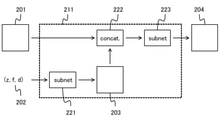
続いて、図7のステップS102において、演算部113は、訓練入力データをCNNへ入力し、出力画像を生成する。ここで、図1を参照して、本実施例における出力画像の生成に関して説明する。図1は、機械学習モデルの構成を示す図である。訓練入力データは、訓練画像201と光学系の状態に関する情報(z,f,d)202とを含む。訓練画像201は、グレースケールでも、複数のチャンネル成分を有していてもよい。正解画像も同様である。(z,f,d)200は、正規化された(Z,F,D)である。正規化は、焦点距離、絞り値、およびフォーカス距離のそれぞれに関して、結像光学系121の取り得る範囲に基づいて行われる。
Subsequently, in step S102 of FIG. 7, the
例えば、Zを焦点距離、Fを絞り値、Dを撮像装置102からフォーカス被写体までの距離の絶対値の逆数とする。結像光学系121の焦点距離Zの最小値と最大値をそれぞれZmin、Zmax、絞り値Fの最小値と最大値をそれぞれFmin、Fmax、フォーカス可能な距離の絶対値の逆数Dの最小値と最大値をそれぞれDmin、Dmaxとする。ここで、フォーカス可能な距離が無限遠の場合、Dmin=1/|∞|=0である。正規化された(z,f,d)は、以下の式(2)で求められる。
For example, Z is the focal length, F is the aperture value, and D is the reciprocal of the absolute value of the distance from the

xは(z,f,d)のいずれか、Xは(Z,F,D)のいずれかを示すダミー変数である。なお、Xmin=Xmaxの場合、xは定数とする。または、xには自由度がないため、光学系の状態に関する情報から除外する。ここで、一般にフォーカス距離が近くなるほど、結像光学系121の性能変化は大きくなるため、Dを距離の逆数としている。
x is any of (z, f, d), and X is a dummy variable indicating any of (Z, F, D). When X min = X max , x is a constant. Alternatively, since x has no degrees of freedom, it is excluded from the information regarding the state of the optical system. Here, in general, the closer the focus distance is, the larger the change in the performance of the imaging
本実施例において、CNN211は、第1のサブネットワーク221および第2のサブネットワーク223を有する。第1のサブネットワーク221は、1層以上の畳み込み層またはフルコネクション層を有する。第2のサブネットワーク223は、1層以上の畳み込み層を有する。畳み込み層(フィルタ)が影響する範囲は、フィルタの層数とサイズによって決まる。例えば、フィルタの層数を20層、サイズを3×3画素とした場合、注目画素から最大20画素離れた画素まで影響が及ぶことになる。フィルタの層数と大きさは、学習するデフォーカスぼけの大きさに応じて決定することが好ましい。すなわち、デフォーカスぼけの大きさが40画素の場合、フィルタの層数を20層、サイズを3×3画素とすることで、デフォーカスぼけ全体にフィルタが適用される。
In this embodiment, the
学習の初回において、CNN211のウエイト(フィルタの各要素とバイアスの値)は、乱数により生成される。第1のサブネットワーク221は、光学系の状態に関する情報(z,f,d)202を入力とし、特徴マップに変換したステートマップ203を生成する。ステートマップ203は、光学系の状態を示すマップであり、訓練画像201の1つのチャンネル成分と同じ要素数(画素数)である。本実施例において、ステートマップ203は、撮像画像の画素数と、光学系の状態に関する情報とに基づいて生成される。また本実施例において、ステートマップに203おける同一のチャンネルの要素は、互いに同一の数値を有する。
At the first time of learning, the weight of CNN211 (each element of the filter and the value of the bias) is generated by a random number. The
連結層(concatenation layer)222は、訓練画像201とステートマップ203とをチャンネル方向に規定の順番で連結する。なお、訓練画像201とステートマップ203の間に他のデータを連結しても構わない。第2のサブネットワーク223は、連結した訓練画像201とステートマップ203を入力とし、出力画像204を生成する。ステップS101にて複数組の訓練入力データを取得している場合、それぞれに対して出力画像204を生成する。また、訓練画像201を第3のサブネットワークによって特徴マップへ変換し、特徴マップとステートマップ203を連結層222で連結する構成としてもよい。
The
続いて、図7のステップS103において、更新部114は、出力画像と正解画像の誤差から、CNNのウエイトを更新する。本実施例では、出力画像と正解画像における信号値の差のユークリッドノルムをロス関数とする。ただし、ロス関数はこれに限定されるものではない。ステップS101にて複数組の訓練入力データと正解画像を取得している場合、各組に対してロス関数の値を算出する。更新部114は、算出されたロス関数の値から、誤差逆伝播法(Backpropagation)などによりウエイトを更新する。
Subsequently, in step S103 of FIG. 7, the updating
続いてステップS104において、更新部114は、ウエイトの学習が完了したかを判定する。完了は、学習(ウエイトの更新)の反復回数が規定の回数に達したかや、更新時のウエイトの変化量が規定値より小さいかなどによって、判定することができる。未完と判定された場合はステップS101へ戻り、1組以上の新たな訓練入力データと正解画像を取得する。一方、完了と判定された場合は学習を終了し、ウエイトの情報を記憶部111に保存する。
Subsequently, in step S104, the
次に、図8を参照して、画像処理部123で実行される撮像画像の距離情報の推定(推定フェーズ)に関して説明する。図8は、推定画像の生成に関するフローチャートである。図8の各ステップは、主に、画像処理部123の各部により実行される。
Next, with reference to FIG. 8, the estimation (estimation phase) of the distance information of the captured image executed by the
まずステップS201において、取得部123aは、入力データとウエイトの情報とを取得する。入力データは、撮像画像と、撮像画像を撮像した際の光学系の状態に関する情報とを含む。取得する撮像画像は、撮像画像の全体の一部でもよい。光学系の情報に関する情報は、結像光学系121の焦点距離、絞り値、およびフォーカス距離の状態を示す(z,f,d)である。ウエイトの情報は、記憶部124から読み出して取得することができる。
First, in step S201, the
続いてステップS202において、距離推定部123bは、入力データをCNNに入力し、推定画像を生成する。推定画像は、撮像画像に対して、結像光学系121に起因するデフォーカスぼけから距離情報が推定された画像である。学習時と同様に、図1に示されるCNNを用いて推定画像を生成する。CNNには、取得された学習済みのウエイトが使用される。なお、入力データの大きさ(画素数)に制限はなく、CNNが有する畳み込み層が影響する範囲より大きくてもよい。畳み込み層が影響する範囲に収まるように撮像画像を分割してCNNへ入力する場合、個々の分割画像ごとに距離情報を推定するため、処理時間が増加する。このため、機械学習モデルの構造は、畳み込み層が影響する範囲より入力データが大きくてもよい構造とすることが好ましい。すなわち、距離情報の一部の領域を得るため(推定するため)に機械学習モデルが用いる撮像画像の領域は、機械学習モデルに入力される撮像画像の全体よりも小さいような構造とすることが好ましい。本実施例では、結像光学系の取り得る全ての(z,f,d)に対して、一括で距離情報推定のウエイトを学習している。このため、全ての(z,f,d)の撮像画像に対して、同一のウエイトを用いたCNNで距離情報の推定が実行される。
Subsequently, in step S202, the
以上の構成により、本実施例によれば、機械学習モデルの学習負荷と保持データ量を抑制して、撮像画像のデフォーカスぼけから高精度に距離情報を推定することが可能な画像処理システムを実現することができる。 With the above configuration, according to this embodiment, an image processing system capable of suppressing the learning load and the amount of retained data of the machine learning model and estimating the distance information with high accuracy from the defocus blur of the captured image is provided. It can be realized.
次に、図10および図11を参照して、本発明の実施例2における画像処理システムに関して説明する。図10は、本実施例における画像処理システム300のブロック図である。図11は、画像処理システム300の外観図である。
Next, the image processing system according to the second embodiment of the present invention will be described with reference to FIGS. 10 and 11. FIG. 10 is a block diagram of the
画像処理システム300は、学習装置301、撮像装置302、画像推定装置(画像処理装置)303、および、ネットワーク304、305を有する。学習装置301と画像推定装置303は、ネットワーク304を介して互いに通信可能である。撮像装置302と画像推定装置303は、ネットワーク305を介して互いに通信可能である。学習装置301は、記憶部301a、取得部301b、生成部301c、および、更新部301dを有し、距離情報の推定に用いる機械学習モデルのウエイトを学習する。なお、ウエイトの学習、およびウエイトを用いた距離情報の推定に関する詳細については後述する。
The
撮像装置302は、光学系302a、撮像素子302b、取得部302c、記録媒体302d、および、システムコントローラ302eを有する。光学系302aは、被写体空間から入射した光を集光し、光学像(被写体像)を形成する。撮像素子302bは、光学像を光電変換によって電気信号へ変換し、撮像画像を生成する。
The
画像推定装置(画像処理装置)303は、記憶部303a、距離推定部(推定手段)303b、および、取得部(取得手段)303cを有する。画像推定装置303は、撮像装置302で撮像された撮像画像(またはその少なくとも一部)に対して、距離情報の推定をした推定画像を生成する。推定画像の生成には、学習装置301で学習された学習済みのウエイトの情報が用いられる。ウエイトの情報は、記憶部303aに記憶されている。取得部302cは推定画像を取得し、記録媒体302dは推定画像を保存する。システムコントローラ302eは、撮像装置302の一連の動作を制御する。
The image estimation device (image processing device) 303 has a
次に、図7を参照して、学習装置301で実行されるウエイトの学習(学習フェーズ)について説明する。図7の各ステップは、主に、学習装置301の各部により実行される。なお本実施例では、機械学習モデルとしてCNNを使用するが、他のモデルについても同様に適用可能である。また、実施例1と同様の説明については省略する。
Next, the weight learning (learning phase) executed by the
まずステップS101において、取得部301bは、1組以上の正解画像と訓練入力データとを記憶部301aから取得する。記憶部301aには、光学系302aと撮像素子302bの複数種類の組み合わせに対して、訓練画像が保存されている。本実施例2は、距離情報推定のウエイトの学習を、光学系302aの種類ごとに一括で行う。このため、まずウエイトを学習する光学系302aの種類を決定し、それに対応する訓練画像の集合から、訓練画像を取得する。ある種類の光学系302aに対応する訓練画像の集合はそれぞれ、焦点距離、絞り値、フォーカス距離、像高、アジムスなどが異なるデフォーカスぼけの作用した画像の集合である。
First, in step S101, the
本実施例では、図9に示されるCNNの構成で学習を行う。図9は、本実施例における機械学習モデルの構成を示す図である。訓練入力データ404は、訓練画像401、ステートマップ402、および、位置マップ403を含む。ステートマップ402と位置マップ403の生成は、本ステップで行われる。位置マップは、撮像画像の各画素の位置に関する情報である。ステートマップ402と位置マップ403はそれぞれ、取得した訓練画像に作用しているデフォーカスぼけに対応する(Z,F,D)と(X,Y)を示すマップである。(X,Y)は、図12で示される像面の座標(水平方向と垂直方向)であり、極座標表示で像高とアジムスに対応する。本実施例において座標(X,Y)は、光学系302aの光軸を原点とする。
In this embodiment, learning is performed with the configuration of CNN shown in FIG. FIG. 9 is a diagram showing the configuration of the machine learning model in this embodiment. The
図12は、光学系302aのイメージサークル501、撮像素子302bの第1の有効画素領域502および第2の有効画素領域503と、座標(X,Y)との関係を示す図である。撮像素子302bのサイズは、撮像装置302の種類に応じて異なる。このため撮像装置302は、第1の有効画素領域502を有する種類と、第2の有効画素領域503を有する種類が存在する。光学系302aに接続可能な撮像装置302のうち、最大サイズの撮像素子302bを有する撮像装置302は、第1の有効画素領域502を有する。
FIG. 12 is a diagram showing the relationship between the
図9の位置マップ403は、座標(X,Y)を正規化した(x,y)に基づいて生成される。正規化は、光学系302aのイメージサークル501に基づく長さ(イメージサークルの半径)511で、(X,Y)を除することによって行われる。または、Xを原点から第1の有効画素領域の水平方向の長さ512で、Yを原点から第1の有効画素領域の垂直方向の長さ513で、それぞれ除して正規化してもよい。仮に、撮像画像の端が常に1となるように(X,Y)を正規化すると、異なるサイズの撮像素子302bで撮像した画像によって、(x,y)が同じ値でも示す位置(X,Y)が異なり、(x,y)とぼけの対応が一意に決まらない。これにより、距離情報推定精度の低下を招く。位置マップ403は、(x,y)の値をそれぞれチャンネル成分に有する2チャンネルのマップである。なお、位置マップ403に極座標を用いてもよく、原点の取り方も図12に限定されるものではない。
The
ステートマップ402は、正規化された(z,f,d)の値をそれぞれチャンネル成分に有する3チャンネルのマップである。すなわち本実施例において、ステートマップ402は、光学系の焦点距離、絞り値、またはフォーカス距離の少なくとも二つを示す数値をそれぞれ異なるチャンネルの要素として有する。訓練画像401、ステートマップ402、および位置マップ403のそれぞれの1チャンネルあたりの要素数(画素数)は等しい。なお、位置マップ403とステートマップ402の構成はこれに限定されるものではない。第1の有効画素領域502を複数の部分領域に分割し、各部分領域に数値を割り当てることで、位置マップを1チャンネルで表現してもよい。また、(Z,F,D)も同様に、それぞれを軸とした3次元空間で複数の部分領域に分割して数値を割り当て、ステートマップを1チャンネルで表現してもよい。訓練画像401、ステートマップ402、および、位置マップ403は、図9の連結層411でチャンネル方向に規定の順番で連結され、訓練入力データ404が生成される。
The
続いて、図7のステップS102において、生成部301cは、訓練入力データ404をCNN412へ入力し、出力画像405を生成する。続いてステップS103において、更新部301dは、出力画像と正解画像の誤差から、CNNのウエイトを更新する。続いてステップS104において、更新部301dは、学習が完了したか否かを判定する。学習済みのウエイトの情報は、記憶部301aに記憶される。
Subsequently, in step S102 of FIG. 7, the
次に、図13を参照して、画像推定装置303で実行される撮像画像の距離情報の推定(推定フェーズ)に関して、図13は、推定画像の生成に関するフローチャートである。図13の各ステップは、主に、画像推定装置303の各部により実行される。
Next, with reference to FIG. 13, regarding the estimation (estimation phase) of the distance information of the captured image executed by the
まずステップS301において、取得部303cは、撮像画像(またはその少なくとも一部)を取得する。続いてステップS302において、取得部303cは、撮像画像に対応するウエイトの情報を取得する。本実施例では、光学系302aの種類ごとのウエイトの情報が、予め記憶部301aから読み出され、記憶部303aに記憶されている。このため、撮像画像の撮像に用いた光学系302aの種類に対応したウエイトの情報を記憶部303aから取得する。撮像に用いた光学系302aの種類は、例えば、撮像画像のファイル内のメタデータなどから特定する。
First, in step S301, the
続いてステップS303において、取得部303cは、撮像画像に対応するステートマップと位置マップを生成し、入力データを生成する。ステートマップは、撮像画像の画素数と、撮像画像を撮像した際の光学系302aの状態(Z,F,D)の情報と、に基づいて生成される。撮像画像とステートマップの1チャンネルあたりの要素数(画素数)は、等しい。(Z,F,D)は、例えば、撮像画像のメタデータなどから特定する。位置マップは、撮像画像の画素数と、撮像画像の各画素の位置の情報と、に基づいて生成される。撮像画像と位置マップの1チャンネルあたりの要素数(画素数)は、等しい。撮像画像のメタデータなどから、撮像画像の撮像に用いた撮像素子302bの有効画素領域の大きさを特定し、例えば同様に特定した光学系302aのイメージサークルの長さを用いて、正規化された位置マップを生成する。入力データは、図9と同様に、撮像画像、ステートマップ、および位置マップをチャンネル方向に規定の順序で連結して生成する。なお、ステップS302とステップS303の順序は問わない。また、撮像画像の撮像時にステートマップと位置マップを生成し、撮像画像と合わせて保存しておいても構わない。
Subsequently, in step S303, the
続いてステップS304において、距離推定部303bは、図9と同様に、入力データをCNNに入力し、推定画像を生成する。
Subsequently, in step S304, the
以上の構成により、本実施例によれば、機械学習モデルの学習負荷と保持データ量を抑制して、撮像画像のデフォーカスぼけから高精度に距離情報を推定することが可能な画像処理システムを実現することができる。 With the above configuration, according to this embodiment, an image processing system capable of suppressing the learning load and the amount of retained data of the machine learning model and estimating the distance information with high accuracy from the defocus blur of the captured image is provided. It can be realized.
次に、本実施例の効果を高める好ましい条件に関して説明する。入力データは、撮像画像の撮像に用いた撮像素子302bの画素ピッチに関する情報も含むことが好ましい。これにより、撮像素子302bの種類に依らず、高精度な距離情報の推定が可能となる。画素ピッチによって、画素開口劣化の強さや、画素に対するデフォーカスぼけの大きさが変化する。学習フェーズにおいて、訓練画像に対応する画素ピッチを特定する情報を、訓練入力データに含ませる。例えば、正規化された画素ピッチの数値を要素とするマップを含む。正規化には、複数種類の撮像装置302のうち最大の画素ピッチを除数とするとよい。推定フェーズでも同様のマップを入力データに含めることで、距離情報推定の精度を向上できる。このようなマップは、撮像画像の画素数に基づいて生成される。
Next, preferable conditions for enhancing the effect of this embodiment will be described. The input data preferably includes information on the pixel pitch of the
次に、図14および図15を参照して、本発明の実施例3における画像処理システムに関して説明する。図14は、本実施例における画像処理システム600のブロック図である。図15は、画像処理システム600の外観図である。
Next, the image processing system according to the third embodiment of the present invention will be described with reference to FIGS. 14 and 15. FIG. 14 is a block diagram of the
画像処理システム600は、学習装置601、レンズ装置602、撮像装置603、制御装置(第1の装置)604、画像推定装置(第2の装置)605、および、ネットワーク606、607を有する。学習装置601と画像推定装置605は、ネットワーク606を介して互いに通信可能である。制御装置604と画像推定装置605は、ネットワーク607を介して互いに通信可能である。学習装置601および画像推定装置605はそれぞれ、例えばサーバである。制御装置604は、パーソナルコンピュータやモバイル端末などのユーザが操作する機器である。学習装置601は、記憶部601a、取得部601b、演算部601c、および、更新部601dを有し、レンズ装置602と撮像装置603を用いて撮像された撮像画像から距離情報の推定をする機械学習モデルのウエイトを学習する。なお、本実施例の学習方法は実施例1と同様のため、その説明を省略する。
The
撮像装置603は撮像素子603aを有し、撮像素子603aがレンズ装置602の形成した光学像を光電変換して撮像画像を取得する。レンズ装置602と撮像装置603とは着脱可能であり、互いに複数種類と組み合わることが可能である。制御装置604は、通信部604a、記憶部604b、および、表示部604cを有し、有線または無線で接続された撮像装置603から取得した撮像画像に対して、実行する処理をユーザの操作に従って制御する。または、撮像装置603で撮像した撮像画像を予め記憶部604bに記憶しておき、撮像画像を読み出してもよい。
The
画像推定装置605は、通信部605a、記憶部605b、取得部605c、および、距離推定部605dを有する。画像推定装置605は、ネットワーク607を介して接続された制御装置604の要求に応じて、撮像画像の距離情報推定処理を実行する。画像推定装置605は、ネットワーク606を介して接続された学習装置601から、学習済みのウエイトの情報を距離情報の推定時または予め取得し、撮像画像の距離情報の推定に用いる。距離情報の推定後の推定画像は、再び制御装置604へ伝送されて、記憶部604bに記憶され、表示部604cに表示される。なお、学習装置601で行う学習データの生成とウエイトの学習(学習フェーズ)は、実施例1と同様のため、それらの説明を省略する。
The
次に、図16を参照して、制御装置604と画像推定装置605で実行される距離情報の推定(推定フェーズ)に関して説明する。図16は、本実施例における推定画像の生成に関するフローチャートである。
Next, with reference to FIG. 16, the estimation (estimation phase) of the distance information executed by the
まずステップS401において、通信部604aは、画像推定装置605へ撮像画像と距離情報の推定処理の実行に関する要求とを送信する。
First, in step S401, the
続いてステップS501において、通信部605aは、制御装置604から送信された撮像画像と処理の要求とを受信して取得する。続いてステップS502において、取得部605cは、撮像画像に対応する学習済みのウエイトの情報を記憶部605bから取得する。ウエイトの情報は、予め記憶部601aから読み出され、記憶部605bに記憶されている。
Subsequently, in step S501, the
続いてステップS503において、取得部605cは、撮像画像に対応する光学系の状態に関する情報を取得して、入力データを生成する。撮像画像のメタデータから、撮像画像を撮像した際の結像光学系602の種類、焦点距離、絞り値、およびフォーカス距離を特定する情報を取得し、図1と同様に、ステートマップ(レンズステートマップ)を生成する。入力データは、撮像画像とステートマップをチャンネル方向に既定の順序で連結して生成する。
Subsequently, in step S503, the
続いてステップS504において、距離推定部605dは、入力データを生成器に入力し、距離情報の推定をした推定画像を生成する。生成器には、ウエイトの情報が使用される。続いてステップS505において、通信部605aは、推定画像を制御装置604へ送信する。
Subsequently, in step S504, the
続いてステップS402において、通信部604aは、画像推定装置605から送信された推定画像を取得する。
Subsequently, in step S402, the
以上の構成により、本実施例によれば、機械学習モデルの学習負荷と保持データ量を抑制して、撮像画像のデフォーカスぼけから高精度に距離情報を推定することが可能な画像処理システムを実現することができる。 With the above configuration, according to this embodiment, an image processing system capable of suppressing the learning load and the amount of retained data of the machine learning model and estimating the distance information with high accuracy from the defocus blur of the captured image is provided. It can be realized.
(その他の実施例)
本発明は、上述の実施例の1以上の機能を実現するプログラムを、ネットワーク又は記憶媒体を介してシステム又は装置に供給し、そのシステム又は装置のコンピュータにおける1つ以上のプロセッサーがプログラムを読出し実行する処理でも実現可能である。また、1以上の機能を実現する回路(例えば、ASIC)によっても実現可能である。
(Other examples)
The present invention supplies a program that realizes one or more functions of the above-described embodiment to a system or device via a network or storage medium, and one or more processors in the computer of the system or device reads and executes the program. It can also be realized by the processing to be performed. It can also be realized by a circuit (for example, ASIC) that realizes one or more functions.
各実施例によれば、機械学習モデルの学習負荷と保持データ量を抑制し、撮像画像のデフォーカスぼけから高精度に距離情報を推定することが可能な画像処理方法、プログラム、画像処理装置、学習済みモデルの製造方法、画像処理システムを提供することができる。 According to each embodiment, an image processing method, a program, an image processing device, which can suppress the learning load and the amount of retained data of a machine learning model and can estimate distance information with high accuracy from defocus blur of the captured image. It is possible to provide a method for manufacturing a trained model and an image processing system.
以上、本発明の好ましい実施形態について説明したが、本発明はこれらの実施形態に限定されず、その要旨の範囲内で種々の変形及び変更が可能である。 Although the preferred embodiments of the present invention have been described above, the present invention is not limited to these embodiments, and various modifications and modifications can be made within the scope of the gist thereof.
102 撮像装置(画像処理装置)
123a 取得部(取得手段)
123b 距離推定部(生成手段)
102 Imaging device (image processing device)
123a Acquisition unit (acquisition means)
123b Distance estimation unit (generation means)
Claims (16)
前記入力データを機械学習モデルに入力し、前記撮像画像の距離情報を推定する工程と、を有し、
前記光学系の状態に関する情報は、焦点距離、絞り値、またはフォーカス距離の少なくとも一つを含むことを特徴とする画像処理方法。 A step of acquiring input data including an image taken and information on the state of the optical system used for taking the image.
It has a step of inputting the input data into a machine learning model and estimating the distance information of the captured image.
An image processing method comprising the information about the state of the optical system at least one of a focal length, an aperture value, or a focal length.
前記数値は、正規化されていることを特徴とする請求項1または2に記載の画像処理方法。 The information regarding the state of the optical system includes a numerical value indicating at least one of the focal length, the aperture value, or the focus distance of the optical system.
The image processing method according to claim 1 or 2, wherein the numerical value is normalized.
前記ステートマップは、前記撮像画像の画素数と、前記光学系の状態に関する情報と、に基づいて生成されることを特徴とする請求項1乃至3のいずれか一項に記載の画像処理方法。 The input data includes a state map showing the state of the optical system.
The image processing method according to any one of claims 1 to 3, wherein the state map is generated based on the number of pixels of the captured image and information on the state of the optical system.
前記入力データを機械学習モデルに入力し、前記撮像画像の距離情報を推定する推定手段と、を有し、
前記光学系の状態に関する情報は、焦点距離、絞り値、またはフォーカス距離の少なくとも一つを含むことを特徴とする画像処理装置。 An acquisition means for acquiring input data including an captured image and information on the state of an optical system used for capturing the captured image, and an acquisition means.
It has an estimation means for inputting the input data into a machine learning model and estimating the distance information of the captured image.
An image processing apparatus characterized in that the information regarding the state of the optical system includes at least one of a focal length, an aperture value, or a focal length.
前記訓練画像と、前記正解画像と、前記光学系の状態に関する情報とに基づいて、機械学習モデルを学習する工程と、を有し、
前記光学系の状態に関する情報は、焦点距離、絞り値、またはフォーカス距離の少なくとも一つを含むことを特徴とする学習方法。 A process of acquiring a training image, a correct image having distance information corresponding to the training image, and information on the state of an optical system, and a process of acquiring the training image.
It has a step of learning a machine learning model based on the training image, the correct image, and information about the state of the optical system.
A learning method characterized in that the information regarding the state of the optical system includes at least one of a focal length, an aperture value, or a focal length.
前記訓練画像と、前記正解画像と、前記光学系の状態に関する情報とに基づいて、機械学習モデルを学習する工程と、を有し、
前記光学系の状態に関する情報は、焦点距離、絞り値、またはフォーカス距離の少なくとも一つを含むことを特徴とする学習済みモデルの製造方法。 A process of acquiring a training image, a correct image having distance information corresponding to the training image, and information on the state of an optical system, and a process of acquiring the training image.
It has a step of learning a machine learning model based on the training image, the correct image, and information about the state of the optical system.
A method of manufacturing a trained model, wherein the information about the state of the optical system includes at least one of a focal length, an aperture value, or a focal length.
前記訓練画像と、前記正解画像と、前記光学系の状態に関する情報とに基づいて、機械学習モデルを学習する学習手段と、を有し、
前記光学系の状態に関する情報は、焦点距離、絞り値、またはフォーカス距離の少なくとも一つを含むことを特徴とする画像処理装置。 An acquisition means for acquiring a training image, a correct image having distance information corresponding to the training image, and information on the state of the optical system.
It has a training image, a correct image, and a learning means for learning a machine learning model based on information about the state of the optical system.
An image processing apparatus characterized in that the information regarding the state of the optical system includes at least one of a focal length, an aperture value, or a focal length.
前記第1の装置は、撮像画像に対する処理の実行に関する要求を前記第2の装置へ送信する送信手段を有し、
前記第2の装置は、
前記要求を受信する受信手段と、
前記撮像画像と、前記撮像画像の撮像に用いた光学系の状態に関する情報と、を含む入力データを取得する取得手段と、
前記要求に基づいて、前記入力データを機械学習モデルに入力し、前記撮像画像の距離情報を推定する推定手段と、を有し、
前記光学系の状態に関する情報は、焦点距離、絞り値、またはフォーカス距離の少なくとも一つを含むことを特徴とする画像処理システム。 An image processing system having a first device and a second device capable of communicating with each other.
The first device has a transmission means for transmitting a request for performing processing on a captured image to the second device.
The second device is
The receiving means for receiving the request and
An acquisition means for acquiring input data including the captured image and information on the state of the optical system used for capturing the captured image.
Based on the request, the input data is input to the machine learning model, and the estimation means for estimating the distance information of the captured image is provided.
An image processing system characterized in that the information regarding the state of the optical system includes at least one of a focal length, an aperture value, or a focal length.
Priority Applications (3)
| Application Number | Priority Date | Filing Date | Title |
|---|---|---|---|
| JP2020123171A JP2022019374A (en) | 2020-07-17 | 2020-07-17 | Image processing method, program image processing device, method of producing trained model, and image processing system |
| PCT/JP2021/018966 WO2022014148A1 (en) | 2020-07-17 | 2021-05-19 | Image processing method, program, image processing device, learned model production method, and image processing system |
| US18/069,514 US20230128856A1 (en) | 2020-07-17 | 2022-12-21 | Image processing method, storage medium, image processing apparatus, manufacturing method of trained model, and image processing system |
Applications Claiming Priority (1)
| Application Number | Priority Date | Filing Date | Title |
|---|---|---|---|
| JP2020123171A JP2022019374A (en) | 2020-07-17 | 2020-07-17 | Image processing method, program image processing device, method of producing trained model, and image processing system |
Publications (2)
| Publication Number | Publication Date |
|---|---|
| JP2022019374A true JP2022019374A (en) | 2022-01-27 |
| JP2022019374A5 JP2022019374A5 (en) | 2023-07-20 |
Family
ID=79554740
Family Applications (1)
| Application Number | Title | Priority Date | Filing Date |
|---|---|---|---|
| JP2020123171A Pending JP2022019374A (en) | 2020-07-17 | 2020-07-17 | Image processing method, program image processing device, method of producing trained model, and image processing system |
Country Status (3)
| Country | Link |
|---|---|
| US (1) | US20230128856A1 (en) |
| JP (1) | JP2022019374A (en) |
| WO (1) | WO2022014148A1 (en) |
Family Cites Families (5)
| Publication number | Priority date | Publication date | Assignee | Title |
|---|---|---|---|---|
| JP6755737B2 (en) * | 2016-07-27 | 2020-09-16 | キヤノン株式会社 | Distance measuring device, imaging device, and distance measuring method |
| JP7237450B2 (en) * | 2018-01-23 | 2023-03-13 | キヤノン株式会社 | Image processing device, image processing method, program, storage medium, and imaging device |
| JP7246900B2 (en) * | 2018-11-26 | 2023-03-28 | キヤノン株式会社 | Image processing device, image processing system, imaging device, image processing method, program, and storage medium |
| JP7051740B2 (en) * | 2019-03-11 | 2022-04-11 | 株式会社東芝 | Image processing equipment, ranging equipment, methods and programs |
| JP7309506B2 (en) * | 2019-07-29 | 2023-07-18 | 京セラ株式会社 | Image processing system, machine learning device, imaging device and learning method |
-
2020
- 2020-07-17 JP JP2020123171A patent/JP2022019374A/en active Pending
-
2021
- 2021-05-19 WO PCT/JP2021/018966 patent/WO2022014148A1/en active Application Filing
-
2022
- 2022-12-21 US US18/069,514 patent/US20230128856A1/en active Pending
Also Published As
| Publication number | Publication date |
|---|---|
| WO2022014148A1 (en) | 2022-01-20 |
| US20230128856A1 (en) | 2023-04-27 |
Similar Documents
| Publication | Publication Date | Title |
|---|---|---|
| JP7439145B2 (en) | Image processing method, image processing device, image processing system, learned weight generation method, and program | |
| JP7258604B2 (en) | Image processing method, image processing device, program, and method for manufacturing learned model | |
| JP7362284B2 (en) | Image processing method, image processing device, program, image processing system, and learned model manufacturing method | |
| JP7297470B2 (en) | Image processing method, image processing apparatus, program, image processing system, and method for manufacturing trained model | |
| US11508038B2 (en) | Image processing method, storage medium, image processing apparatus, learned model manufacturing method, and image processing system | |
| JP5468404B2 (en) | Imaging apparatus and imaging method, and image processing method for the imaging apparatus | |
| JP6362068B2 (en) | Distance measuring device, imaging device, distance measuring method, and program | |
| JP2021196951A (en) | Image processing apparatus, image processing method, program, method for manufacturing learned model, and image processing system | |
| JP2016061609A (en) | Distance measuring device, imaging apparatus, and distance measuring method | |
| JP2015036632A (en) | Distance measuring device, imaging apparatus, and distance measuring method | |
| US20220368877A1 (en) | Image processing method, image processing apparatus, storage medium, manufacturing method of learned model, and image processing system | |
| US11308592B2 (en) | Image processing method, image processing apparatus, imaging apparatus, and storage medium, that correct a captured image using a neutral network | |
| JP2020036310A (en) | Image processing method, image processing apparatus, imaging apparatus, lens device, program, storage medium, and image processing system | |
| WO2022014148A1 (en) | Image processing method, program, image processing device, learned model production method, and image processing system | |
| JP2020030569A (en) | Image processing method, image processing device, imaging device, lens device, program, and storage medium | |
| WO2022215375A1 (en) | Image processing method, method for producing machine learning model, image processing device, image processing system, and program | |
| JP7451465B2 (en) | Learning method, program and image processing device | |
| JP7009219B2 (en) | Image processing method, image processing device, image pickup device, image processing program, and storage medium | |
| JP2013141192A (en) | Depth-of-field expansion system, and depth-of-field expansion method | |
| JP6570706B2 (en) | Distance measuring device, imaging device, distance measuring method, and program | |
| JP2021174070A (en) | Image processing method, producing method of learned model, program, and image processing apparatus | |
| JP2023069527A (en) | Image processing device and image processing method | |
| JP2017034595A (en) | Image processing system, imaging apparatus and image processing program | |
| WO2019235258A1 (en) | Image processing method, image processing device, imaging apparatus, program, and storage medium | |
| JP2017050605A (en) | Image processing apparatus and method, imaging device, program |
Legal Events
| Date | Code | Title | Description |
|---|---|---|---|
| A521 | Request for written amendment filed |
Free format text: JAPANESE INTERMEDIATE CODE: A523 Effective date: 20230711 |
|
| A621 | Written request for application examination |
Free format text: JAPANESE INTERMEDIATE CODE: A621 Effective date: 20230711 |
|
| A131 | Notification of reasons for refusal |
Free format text: JAPANESE INTERMEDIATE CODE: A131 Effective date: 20240806 |