JP2022018869A - Liquid storage container - Google Patents
Liquid storage container Download PDFInfo
- Publication number
- JP2022018869A JP2022018869A JP2020122278A JP2020122278A JP2022018869A JP 2022018869 A JP2022018869 A JP 2022018869A JP 2020122278 A JP2020122278 A JP 2020122278A JP 2020122278 A JP2020122278 A JP 2020122278A JP 2022018869 A JP2022018869 A JP 2022018869A
- Authority
- JP
- Japan
- Prior art keywords
- liquid
- storage container
- liquid storage
- male screw
- nozzle
- Prior art date
- Legal status (The legal status is an assumption and is not a legal conclusion. Google has not performed a legal analysis and makes no representation as to the accuracy of the status listed.)
- Pending
Links
- 239000007788 liquid Substances 0.000 title claims abstract description 176
- 238000003860 storage Methods 0.000 title claims abstract description 66
- 230000008878 coupling Effects 0.000 abstract description 7
- 238000010168 coupling process Methods 0.000 abstract description 7
- 238000005859 coupling reaction Methods 0.000 abstract description 7
- 239000004743 Polypropylene Substances 0.000 description 11
- -1 polyethylene Polymers 0.000 description 11
- 239000000976 ink Substances 0.000 description 9
- 238000003466 welding Methods 0.000 description 9
- 239000004698 Polyethylene Substances 0.000 description 8
- 238000004891 communication Methods 0.000 description 8
- 238000000034 method Methods 0.000 description 7
- 229920001155 polypropylene Polymers 0.000 description 7
- 238000010586 diagram Methods 0.000 description 6
- 239000000463 material Substances 0.000 description 6
- 230000000052 comparative effect Effects 0.000 description 4
- 229920000573 polyethylene Polymers 0.000 description 4
- 238000011156 evaluation Methods 0.000 description 3
- 238000007789 sealing Methods 0.000 description 3
- 239000003086 colorant Substances 0.000 description 2
- 238000005336 cracking Methods 0.000 description 2
- 230000000694 effects Effects 0.000 description 2
- 229920001971 elastomer Polymers 0.000 description 2
- 238000002347 injection Methods 0.000 description 2
- 239000007924 injection Substances 0.000 description 2
- 230000002093 peripheral effect Effects 0.000 description 2
- 229910001220 stainless steel Inorganic materials 0.000 description 2
- 239000010935 stainless steel Substances 0.000 description 2
- 238000007599 discharging Methods 0.000 description 1
- 239000000806 elastomer Substances 0.000 description 1
- 230000008020 evaporation Effects 0.000 description 1
- 238000001704 evaporation Methods 0.000 description 1
- 239000004744 fabric Substances 0.000 description 1
- 238000004519 manufacturing process Methods 0.000 description 1
- 230000003287 optical effect Effects 0.000 description 1
- 239000002985 plastic film Substances 0.000 description 1
- 230000001902 propagating effect Effects 0.000 description 1
- 239000011347 resin Substances 0.000 description 1
- 229920005989 resin Polymers 0.000 description 1
- 238000009751 slip forming Methods 0.000 description 1
Images


Classifications
-
- B—PERFORMING OPERATIONS; TRANSPORTING
- B41—PRINTING; LINING MACHINES; TYPEWRITERS; STAMPS
- B41J—TYPEWRITERS; SELECTIVE PRINTING MECHANISMS, i.e. MECHANISMS PRINTING OTHERWISE THAN FROM A FORME; CORRECTION OF TYPOGRAPHICAL ERRORS
- B41J2/00—Typewriters or selective printing mechanisms characterised by the printing or marking process for which they are designed
- B41J2/005—Typewriters or selective printing mechanisms characterised by the printing or marking process for which they are designed characterised by bringing liquid or particles selectively into contact with a printing material
- B41J2/01—Ink jet
- B41J2/17—Ink jet characterised by ink handling
- B41J2/175—Ink supply systems ; Circuit parts therefor
- B41J2/17503—Ink cartridges
- B41J2/17506—Refilling of the cartridge
- B41J2/17509—Whilst mounted in the printer
-
- B—PERFORMING OPERATIONS; TRANSPORTING
- B41—PRINTING; LINING MACHINES; TYPEWRITERS; STAMPS
- B41J—TYPEWRITERS; SELECTIVE PRINTING MECHANISMS, i.e. MECHANISMS PRINTING OTHERWISE THAN FROM A FORME; CORRECTION OF TYPOGRAPHICAL ERRORS
- B41J2/00—Typewriters or selective printing mechanisms characterised by the printing or marking process for which they are designed
- B41J2/005—Typewriters or selective printing mechanisms characterised by the printing or marking process for which they are designed characterised by bringing liquid or particles selectively into contact with a printing material
- B41J2/01—Ink jet
- B41J2/17—Ink jet characterised by ink handling
- B41J2/175—Ink supply systems ; Circuit parts therefor
- B41J2/17503—Ink cartridges
- B41J2/17513—Inner structure
-
- B—PERFORMING OPERATIONS; TRANSPORTING
- B41—PRINTING; LINING MACHINES; TYPEWRITERS; STAMPS
- B41J—TYPEWRITERS; SELECTIVE PRINTING MECHANISMS, i.e. MECHANISMS PRINTING OTHERWISE THAN FROM A FORME; CORRECTION OF TYPOGRAPHICAL ERRORS
- B41J2/00—Typewriters or selective printing mechanisms characterised by the printing or marking process for which they are designed
- B41J2/005—Typewriters or selective printing mechanisms characterised by the printing or marking process for which they are designed characterised by bringing liquid or particles selectively into contact with a printing material
- B41J2/01—Ink jet
- B41J2/17—Ink jet characterised by ink handling
- B41J2/175—Ink supply systems ; Circuit parts therefor
- B41J2/17503—Ink cartridges
- B41J2/1752—Mounting within the printer
- B41J2/17523—Ink connection
-
- B—PERFORMING OPERATIONS; TRANSPORTING
- B41—PRINTING; LINING MACHINES; TYPEWRITERS; STAMPS
- B41J—TYPEWRITERS; SELECTIVE PRINTING MECHANISMS, i.e. MECHANISMS PRINTING OTHERWISE THAN FROM A FORME; CORRECTION OF TYPOGRAPHICAL ERRORS
- B41J2/00—Typewriters or selective printing mechanisms characterised by the printing or marking process for which they are designed
- B41J2/005—Typewriters or selective printing mechanisms characterised by the printing or marking process for which they are designed characterised by bringing liquid or particles selectively into contact with a printing material
- B41J2/01—Ink jet
- B41J2/17—Ink jet characterised by ink handling
- B41J2/175—Ink supply systems ; Circuit parts therefor
- B41J2/17503—Ink cartridges
- B41J2/17536—Protection of cartridges or parts thereof, e.g. tape
- B41J2/1754—Protection of cartridges or parts thereof, e.g. tape with means attached to the cartridge, e.g. protective cap
-
- B—PERFORMING OPERATIONS; TRANSPORTING
- B41—PRINTING; LINING MACHINES; TYPEWRITERS; STAMPS
- B41J—TYPEWRITERS; SELECTIVE PRINTING MECHANISMS, i.e. MECHANISMS PRINTING OTHERWISE THAN FROM A FORME; CORRECTION OF TYPOGRAPHICAL ERRORS
- B41J2/00—Typewriters or selective printing mechanisms characterised by the printing or marking process for which they are designed
- B41J2/005—Typewriters or selective printing mechanisms characterised by the printing or marking process for which they are designed characterised by bringing liquid or particles selectively into contact with a printing material
- B41J2/01—Ink jet
- B41J2/17—Ink jet characterised by ink handling
- B41J2/175—Ink supply systems ; Circuit parts therefor
- B41J2/17503—Ink cartridges
- B41J2/17553—Outer structure
-
- B—PERFORMING OPERATIONS; TRANSPORTING
- B41—PRINTING; LINING MACHINES; TYPEWRITERS; STAMPS
- B41J—TYPEWRITERS; SELECTIVE PRINTING MECHANISMS, i.e. MECHANISMS PRINTING OTHERWISE THAN FROM A FORME; CORRECTION OF TYPOGRAPHICAL ERRORS
- B41J2/00—Typewriters or selective printing mechanisms characterised by the printing or marking process for which they are designed
- B41J2/005—Typewriters or selective printing mechanisms characterised by the printing or marking process for which they are designed characterised by bringing liquid or particles selectively into contact with a printing material
- B41J2/01—Ink jet
- B41J2/17—Ink jet characterised by ink handling
- B41J2/175—Ink supply systems ; Circuit parts therefor
- B41J2/17596—Ink pumps, ink valves
-
- B—PERFORMING OPERATIONS; TRANSPORTING
- B65—CONVEYING; PACKING; STORING; HANDLING THIN OR FILAMENTARY MATERIAL
- B65D—CONTAINERS FOR STORAGE OR TRANSPORT OF ARTICLES OR MATERIALS, e.g. BAGS, BARRELS, BOTTLES, BOXES, CANS, CARTONS, CRATES, DRUMS, JARS, TANKS, HOPPERS, FORWARDING CONTAINERS; ACCESSORIES, CLOSURES, OR FITTINGS THEREFOR; PACKAGING ELEMENTS; PACKAGES
- B65D47/00—Closures with filling and discharging, or with discharging, devices
- B65D47/04—Closures with discharging devices other than pumps
- B65D47/06—Closures with discharging devices other than pumps with pouring spouts or tubes; with discharge nozzles or passages
- B65D47/12—Closures with discharging devices other than pumps with pouring spouts or tubes; with discharge nozzles or passages having removable closures
- B65D47/122—Threaded caps
- B65D47/123—Threaded caps with internal parts
-
- B—PERFORMING OPERATIONS; TRANSPORTING
- B65—CONVEYING; PACKING; STORING; HANDLING THIN OR FILAMENTARY MATERIAL
- B65D—CONTAINERS FOR STORAGE OR TRANSPORT OF ARTICLES OR MATERIALS, e.g. BAGS, BARRELS, BOTTLES, BOXES, CANS, CARTONS, CRATES, DRUMS, JARS, TANKS, HOPPERS, FORWARDING CONTAINERS; ACCESSORIES, CLOSURES, OR FITTINGS THEREFOR; PACKAGING ELEMENTS; PACKAGES
- B65D49/00—Arrangements or devices for preventing refilling of containers
- B65D49/02—One-way valves
- B65D49/08—Spring-loaded valves
Landscapes
- Closures For Containers (AREA)
- Containers And Packaging Bodies Having A Special Means To Remove Contents (AREA)
- Ink Jet (AREA)
Abstract
Description
本発明は、液体を収容する液体収容容器に関する。 The present invention relates to a liquid storage container for containing a liquid.
インクジェット記録装置のような液体吐出装置で使用される液体タンクには、液体を補充できるものがある。例えば、液体を注入するための注出口を備えた液体収容容器を用いて、その注出口から液体タンクに液体を補充することができる(特許文献1参照)。 Some liquid tanks used in liquid ejection devices, such as inkjet recording devices, can be refilled with liquid. For example, a liquid container provided with a spout for injecting a liquid can be used to refill the liquid tank from the spout (see Patent Document 1).
特許文献1においては、液体収容容器本体の全周に雄ネジが設けられ、この雄ネジに螺合可能な雌ネジが設けられた蓋部材を液体収容容器本体に装着して固定することで、液体収容容器本体から液体が流出することを封止する構成が記載されている。
In
しかしながら、特許文献1に記載の構成のように、液体収容容器本体の雄ネジ部が全周に設けられている場合、落下等で蓋部材に衝撃が加わった際に、蓋部材の割れ又は液体封止箇所の変形により、液体収容容器本体から液体が漏洩する虞がある。
However, as in the configuration described in
本発明は、蓋部材に衝撃が加わった際に、液体が漏洩することを抑制する液体収容容器を提供することを目的とする。 An object of the present invention is to provide a liquid storage container that suppresses leakage of liquid when an impact is applied to a lid member.
本発明の一態様にかかる液体収容容器は、収容部に収容されている液体を注出する注出口と、外側に雄ネジ部を配した結合部と、を有する注出口部材と、前記雄ネジ部と螺合する雌ネジ部を内部に有し、前記注出口部材に装着可能に構成された蓋部と、を備え、前記結合部において、前記雄ネジ部が分断されていることを特徴とする。 The liquid storage container according to one aspect of the present invention has a spout member having a spout for pouring out the liquid contained in the storage portion and a joint portion having a male screw portion arranged on the outside, and the male screw. It is characterized by having a female screw portion to be screwed with the portion inside, a lid portion configured to be mounted on the spout outlet member, and the male screw portion being divided at the joint portion. do.
本発明によれば、蓋部材に衝撃が加わった際に、液体が漏洩することを抑制する液体収容容器を提供することができる。 According to the present invention, it is possible to provide a liquid storage container that suppresses leakage of liquid when an impact is applied to the lid member.
以下、図面を参照して実施形態を説明する。尚、同一の構成については、同じ符号を付して説明する。また、実施形態に記載されている構成要素の相対配置、形状などは、あくまで例示である。 Hereinafter, embodiments will be described with reference to the drawings. The same configuration will be described with the same reference numerals. Further, the relative arrangement, shape, and the like of the components described in the embodiment are merely examples.
<<第1実施形態>>
図1は、本実施形態の液体吐出装置1の外観を示す斜視図である。図1に示す液体吐出装置1は、シリアル型のインクジェット記録装置である。図1に示す液体吐出装置1は、筐体11と、筐体11の内部に配置された液体タンク12とを備える。液体タンク12は、記録媒体(不図示)に吐出される液体であるインクを収容する。
<< First Embodiment >>
FIG. 1 is a perspective view showing the appearance of the
図2は、図1に示した液体吐出装置1の内部構成を示す斜視図である。図2において液体吐出装置1は、記録媒体(不図示)を搬送するための搬送ローラ13と、液体を吐出する記録ヘッド14が設けられたキャリッジ15と、キャリッジ15を駆動するためのキャリッジモータ16とを備える。記録媒体は、記録ヘッド14から吐出された液体によって画像が形成されるものであれば、特に限定されない。例えば、記録媒体としては、紙、布、光ディスクラベル面、プラスチックシート、またはOHPシートなどが挙げられる。
FIG. 2 is a perspective view showing the internal configuration of the
液体は、液体タンク12に収容されており、液体流通路17を介して記録ヘッド14に供給され、記録ヘッド14から吐出される。本実施形態では、液体として、4色(例えば、シアン、マゼンタ、イエロー、およびブラック)のインクが使用され、液体タンク12として、各色のインクを収容する4つの色別の液体タンク12a~12dが設けられている。以下、個々の液体タンクを識別して言及する場合、液体タンク12a~12dなどを末尾にアルファベットを付し、任意の液体タンクを言及する場合、液体タンク12と称するものとする。色別の液体タンク12a~12dのそれぞれは、筐体11の内部における液体吐出装置1の前面部に配置されている。
The liquid is contained in the
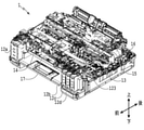
図3(a)は、図1に示した液体吐出装置1の液体タンク12b~12dが収納された部分の拡大斜視図の一例であり、図3(b)は、図3(a)で示した斜視図の平面図である。液体タンク12は、液体を収容するための液体タンク本体121と、液体タンク本体121内の液体収容室に連通する連通流路122とを有する。また、液体補充時以外に連通流路122を覆い、液体タンク本体121の収容室を密閉するために装着可能なタンクカバー123(図2参照)を有する。液体を液体タンク12に補充する場合には、液体収容容器2(図4参照)の注出口を連通流路122に挿入し、液体を注入する。液体補充時以外はタンクカバー123で液体収容室を密閉することで、液体タンク12内部の液体の蒸発を抑制することができる。連通流路122は、内部に鉛直方向に並列に延びる2つの流路を備えており、気液交換によって液体収容容器2内の液体が液体タンクに注入される仕組みとなっている。液体吐出装置1において、液体収容容器2の注出口を挿入する部分にはソケット18が設けられている場合がある。ソケット18が設けられている場合、ソケット18には内周壁から内側に突出する凸部19が設けられている。ソケット18は、液体タンク12ごとに設けられており、凸部19の形状は、液体容器の入れ間違い抑制の為にソケット18ごとに異なっている。凸部19は、連通流路122の中心軸に対して、180°の回転対称に存在している。
3 (a) is an example of an enlarged perspective view of a portion of the
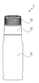
図4は、液体タンク12に液体を補充する液体容器である液体収容容器2の外観を示す立面図である。図4における液体収容容器2は、液体を収容する収容部(本体部)であるボトル21と、ボトル21と接続されたノズル22と、ノズル22に着脱可能なキャップ23とを有する。ノズル22は、ボトル21に収容された液体を注出する際の出口としての機能を有する注出口部材である。キャップ23は、ノズル22に装着されることで、液体収容容器2(具体的には、ボトル21)の内部を外気から遮蔽する蓋部である。ボトル21とノズル22とを接続する方法は、可撓性の部品を挟んでシールする方法、または、ボトル21とノズル22とを共に樹脂部品とし、二部品を溶着する方法などがある。ボトル21およびノズル22は、一体の部品であってもよい。
FIG. 4 is an elevational view showing the appearance of the liquid storage container 2, which is a liquid container for replenishing the
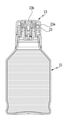
図5(a)は、図4に示す液体収容容器2の部品構成図の例を示す図である。図5(b)は、図5(a)に示す液体収容容器2の部品構成図を結合した状態の断面図である。液体収容容器2のボトル21は、上部に形成されたボトル溶着部21aと、下部に形成された液体収容部21bとを含む。ノズル22は、液体を注出する注出口22aと、外側に雄ネジ構造が形成された結合部22bと、内側または底面に溶着面が形成されたノズル溶着部22cとを含む。蓋部であるキャップ23は、注出口部材であるノズル22に着脱可能に構成されており、注出口22aを開閉可能としている。ボトル21を形成する材料としては、PE(ポリエチレン)またはPP(ポリプロピレン)等が挙げられる。ノズル22を形成する材料としては、PE(ポリエチレン)またはPP(ポリプロピレン)等が挙げられる。ノズル22は、ノズル溶着部22cがボトル溶着部21aと溶着することでボトル21と接合される。ボトル21とノズル22とを溶着により接合する場合は、ボトル21およびノズル22は同種の材料であることが好ましい。ノズル22内部には、開口を有するシール24と、シール24の開口を開閉するバルブ25と、バルブ25を付勢するバネ26と、バネ26を固定するホルダ27とが備えられている。
FIG. 5A is a diagram showing an example of a component configuration diagram of the liquid storage container 2 shown in FIG. FIG. 5 (b) is a cross-sectional view of the liquid storage container 2 shown in FIG. 5 (a) in a combined state. The
キャップ23をノズル22に装着する方法の例として、ノズル22とキャップ23とを螺合する方法が挙げられる。具体的には、図5(a)および図5(b)に示すように、ノズル22の外側に雄ネジ構造が形成された結合部22bと、キャップ23の下部の内側に雌ネジ構造が形成されたキャップネジ部23aとを用いて螺合する方法が挙げられる。このようにキャップ23は、キャップネジ部23aが結合部22bと螺合することでノズル22に装着される。この際、キャップ23のキャップシール部23bとノズル22の注出口22aの一部とが嵌合し、液体収容容器2の内部が密閉される。即ち、キャップシール部23bとノズル22の注出口22aの一部との当接箇所によって密閉部が形成される。
As an example of the method of attaching the
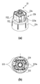
図6は、本実施形態の注出口部材であるノズル22を説明する図である。図6(a)は、ノズル22の部品形状の斜視図の一例である。図6(b)は、図6(a)の上面図である。本実施形態のノズル22の雄ネジ部221は、分断された構造となっている。即ち、雄ネジ部221は、ノズル22の全周にわたって連続して形成されておらず、一部が分断されている。分断された雄ネジ部221は、全体として一つの螺旋形状を形成しており、分断された雄ネジがそれぞれキャップの雌ネジと螺合する構成となっている。尚、キャップ23のキャップネジ部23aの一部にも分断部が形成されていてもよい。
FIG. 6 is a diagram illustrating a
雄ネジ部221の分断された部分の少なくとも一部には、凹部223が形成されている。本実施形態における凹部223とは、図6(b)に示すように、ノズル22の上面図において、雄ネジ部221を有する結合部22bの根本からなる円222(点線で示す)に対して内径側に形成される空間の一端となる部分のことである。円222の直径は、キャップ開封時の回転半径に相当する径であり、概ね15mm以上40mm以下である。円222の直径は、結合部22bにおいて、雄ネジ部221の隆起部分を除いた部分の直径に対応する。ノズル22の凹部223の幅224としては、落下耐性への効果の観点から、0.5mm以上であることが好ましく、1.0mm以上であることがより好ましい。ここで、凹部223の幅224とは、円222のうち凹部223に対応する円弧と、凹部223との距離に対応するものである。本例では、ノズル22の上面図において円222とノズル22との最大距離に対応する。円222に対する凹部223の割合としては、落下耐性への効果の観点から10%以上であることが好ましく、20%以上であることがより好ましい。一方、振動等に対するキャップの緩み防止の観点から、円222に対する凹部223の割合は、90%以下であることが好ましく、70%以下であることがより好ましい。ここで、円222に対する凹部223の割合とは、円222の全周の角度である360°に対する凹部223の角度の割合を示す。図6(a)および(b)に示す例では、凹部223は、回転対称に二箇所に設けられている。このため、円222に対する凹部223の割合は、図6(b)に示す角度θ×2/360で求められる。
A
以上のように、ノズル22の雄ネジ部221を分断させることで、落下等で蓋部材であるキャップ23に衝撃が加わった際にも、液体収容容器2本体から液体が漏洩することを抑制できる。尚、図6(a)および(b)の例では、凹部223は、180°回転対称に二箇所に設けられている例を説明したが、凹部223は、複数個所に設けられていなくてもよい。凹部223は、少なくとも一箇所に設けられていればよい。また、凹部223は、液体吐出装置1の液体タンク12に液体を補充する際に位置決めとして用いられる部位と共通したものでもよい。以下、図7を用いて、位置決めに用いられる凹部を説明する。
As described above, by dividing the
図7は、本実施形態におけるノズル22の他の例を示す図である。図7(a)は、ノズル22の部品形状の斜視図であり、図7(b)は、図7(a)の上面図である。図7のノズル22では、180°の回転対称に存在する凹部223aを有しており、凹部223aが、液体吐出装置1の液体タンク12に設けられたソケット18の内周壁から内側に突出する凸部19に係合する構成となっている。液体タンク12の色別に形状が異なる凸部19に係合する凹部223aを有する液体収容容器2を用いることによって、液体タンク12への異なる色の液体収容容器2の液体を注入する誤注入を防止できる。さらにこのような構成をとることで、ノズルネジ部として機能する結合部22bに、液体吐出装置1との位置決め部を設けることになるため、液体収容容器2の小型化にも寄与することができる。尚、図7では、図6に示す凹部223に加えて、液体タンク12の凸部19に係合する凹部223aを別途設けている例を示しているが、凹部223が設けられていなくてもよい。即ち、結合部22bには、液体タンク12の凸部19に係合する凹部223aのみが設けられていてもよい。
FIG. 7 is a diagram showing another example of the
以上がノズル22の雄ネジ部221の説明である。次に、図5を再度参照して、ノズル22の内部構造を説明する。ノズル22には、先端(上端)に連通流路122が挿入される開口を有するオリフィス部であるシール24が配されている。そして、液止弁の弁体であるバルブ25をバネ26で開口側に付勢することでシール24とバルブ25とのギャップが閉塞され、液体収容容器2が密閉される。本実施形態では、付勢機構としてバネ26を用い、ノズル22の内空間に固定したホルダ27にバネ26を保持させている。シール24は、ゴムまたはエラストマー等の可撓性部材で構成されている。バルブ25を形成する材料としては、PE(ポリエチレン)またはPP(ポリプロピレン)等が挙げられる。バネ26を形成する材料としては、SUS(ステンレス)等が挙げられる。ホルダ27を形成する材料としては、PE(ポリエチレン)またはPP(ポリプロピレン)等が挙げられる。ホルダ27をノズル22に固定する方法としては、溶着等が挙げられる。
The above is the description of the
液体収容容器2から液体タンク12へ液体を供給する際には、シール24の開口から連通流路122がノズル22内に挿入されることで、バルブ25が開放される。そして、前述したように、液体収容容器2のノズル22に、液体吐出装置1のソケット18の凸部19に係合する凹部223aが設けられている場合、ソケット18によって液体収容容器2の位置決めをすることができる。そして、液体収容容器2内の液体は水頭差によって連通流路122を介して液体タンク本体121の収容室に供給される。尚、図5(b)にあるように、キャップ23に突起23f等を設けることで、開栓および閉栓時にバルブ25を開放する場合もある。これにより、液体収容容器2内の圧力が外部の気圧より高い場合にも、液体タンク12へ液体を供給する際に液体タンク12に液体が勢いよく流入し液体タンクが溢れることを抑制できる。
When the liquid is supplied from the liquid storage container 2 to the
以上説明したように、本実施形態では、ノズル22の雄ネジ部221を分断させている。このため、落下等で蓋部材であるキャップ23に衝撃が加わった際にも、ノズル22の雄ネジ部221が全周に設けられていないので、衝撃がキャップとノズル間で伝播することを抑制できる。従って、キャップ23とノズル22との間のシール部から液体が漏れ出すことを抑制したり、キャップの割れを抑制したりすることができる。また、ノズル22に凹部223(または凹部223a)が形成されていることで、ノズル22の剛性が下がるので、キャップ23への衝撃をさらに抑制することができる。
As described above, in the present embodiment, the
<<実施例>>
以下に各種の実施例を説明する。尚、以下は、例示に過ぎず、これらの実施例に限定されるものではない。
<< Example >>
Various examples will be described below. It should be noted that the following is merely an example and is not limited to these examples.
<実施例1>
図8は、各実施例で用いた液体収容容器2の断面図を示す図である。図8に示した液体収容容器2においては、ボトル21として、外径Φ64mm、高さ100mmのポリプロピレン製ボトルを用いた。キャップ23として、外径Φ33mm、雌ネジ部の内径Φ27.2mmのポリプロピレン製キャップを用いた。
<Example 1>
FIG. 8 is a diagram showing a cross-sectional view of the liquid storage container 2 used in each embodiment. In the liquid storage container 2 shown in FIG. 8, a polypropylene bottle having an outer diameter of Φ64 mm and a height of 100 mm was used as the
図9は、各実施例で用いたノズル22の上面図を示している。図9(a)は、実施例1に用いたノズル22の上面図を示している。ノズル22として、雄ネジ部の根本からなる円222が、Φ27.0mm、凹部の幅224が0.5mm、円222に対する凹部の割合が17%であるポリプロピレン製ノズルを用いた。その他の構成は、図5と同様の構成にして、液体収容容器2を作製した。
FIG. 9 shows a top view of the
<実施例2>
図9(b)に示す実施例2のノズル22は、凹部の幅224が1.0mm、円222に対する凹部の割合が25%である。その他は、実施例1と同様にした液体収容容器2を作製した。
<Example 2>
In the
<実施例3>
図9(c)に示す実施例3のノズル22は、凹部の幅224が2.5mm、円222に対する凹部の割合が39%である。その他は、実施例1と同様にした液体収容容器2を作製した。
<Example 3>
In the
<実施例4>
図9(d)に示す実施例4のノズル22は、凹部の幅224が3.5mm、円222に対する凹部の割合が48%である。その他は、実施例1と同様にした液体収容容器2を作製した。
<Example 4>
In the
<実施例5>
図9(e)に示す実施例5のノズル22は、凹部の幅224が2.5mmである。さらに、液体吐出装置1のソケット18の凸部19に係合し、180°の回転対称に存在する二箇所の凹部223aを設けた。円222に対する凹部の割合は、73%である。その他は、実施例1と同様にした液体収容容器2を作製した。
<Example 5>
In the
<実施例6>
図9(f)に示す実施例6のノズル22は、凹部の幅224が2.5mmである。さらに、液体吐出装置1のソケット18の凸部19に係合し、180°の回転対称に存在する二箇所の凹部223aを設けた。円222に対する凹部の割合は、59%である。その他は、実施例1と同様にした液体収容容器2を作製した。
<Example 6>
In the
<実施例7>
図9(g)に示す実施例7のノズル22は、凹部の幅224が2.5mmである。さらに、液体吐出装置1のソケット18の凸部19に係合し、180°の回転対称に存在する六箇所の凹部223aを設けた。円222に対する凹部の割合は、59%である。その他は、実施例1と同様にした液体収容容器2を作製した。
<Example 7>
In the
<実施例8>
図9(h)に示す実施例8のノズル22は、凹部の幅224が2.5mmである。さらに、液体吐出装置1のソケット18の凸部19に係合し、180°の回転対称に存在する2箇所の凹部223aを設けた。円222に対する凹部の割合は、66%である。その他は、実施例1と同様にした液体収容容器2を作製した。
<Example 8>
In the
<比較例1>
図9(i)に示す比較例1のノズル22は、凹部がない構成である。このため、円222に対する凹部の割合は、0%である。その他は、実施例1と同様にした液体収容容器2を作製した。
<Comparative Example 1>
The
<落下耐性の評価>
実施例1~8および比較例1で作製した液体収容容器2に、200mlのインクを注入し、180cmの高さより落下耐性の評価を行い、以下の基準で評価した。評価結果を表1に「落下耐性」として示す。
<Evaluation of drop resistance>
200 ml of ink was injected into the liquid container 2 prepared in Examples 1 to 8 and Comparative Example 1, and the drop resistance was evaluated from a height of 180 cm, and the evaluation was made according to the following criteria. The evaluation results are shown in Table 1 as "drop resistance".

ここで、表1における形状a~iは、図9の(a)~(i)の各ノズルに対応する。また、表1における落下耐性は、以下を示している。
A:キャップのシール部からインクの染み出しが見られなかった。
B:キャップのシール部から僅かにインクの染み出しが見られた。
C:ボトル外部にインクが漏れた、またはキャップ割れが見られた。
Here, the shapes a to i in Table 1 correspond to the nozzles (a) to (i) in FIG. The drop resistance in Table 1 is shown below.
A: No ink ooze out from the seal part of the cap.
B: Slight ink oozing out from the seal part of the cap was observed.
C: Ink leaked to the outside of the bottle, or the cap was cracked.
実施例1~8では、ボトル外部へのインク漏れ、またはキャップ割れが見られなかった。実施例1~4の比較によれば、ノズルの凹部の幅が1mm以上あれば、落下耐性がさらに良化した。また、実施例5~8の比較によれば、雄ネジの根本からなる円に対する凹部の割合が70%以下であれば、落下耐性がさらに良化した。一方、比較例1では、雄ネジ部が分断されておらず凹部が設けられていない構成であり、落下耐性が良化しなかった。 In Examples 1 to 8, no ink leakage to the outside of the bottle or cracking of the cap was observed. According to the comparison of Examples 1 to 4, when the width of the concave portion of the nozzle is 1 mm or more, the drop resistance is further improved. Further, according to the comparison of Examples 5 to 8, when the ratio of the recess to the circle formed by the root of the male screw was 70% or less, the drop resistance was further improved. On the other hand, in Comparative Example 1, the male screw portion was not divided and no recess was provided, and the drop resistance was not improved.
<<その他の実施形態>>
上記の実施形態において、液体収容容器は、液体吐出装置の液体タンクに液体を補充するために用いられる例を説明したが、任意の装置の液体タンクに液体を補充するために用いるものであってもよい。また、液体収容容器に収容される液体としてインクを用いる例を説明したが、任意の液体を収容してよい。
<< Other Embodiments >>
In the above embodiment, the liquid storage container has been described as an example used for refilling the liquid tank of the liquid discharge device, but is used for refilling the liquid tank of any device. May be good. Further, although an example of using ink as the liquid to be stored in the liquid storage container has been described, any liquid may be stored.
2 液体収容容器
22 ノズル
22b 結合部
221 雄ネジ部
222 円
223 凹部
223a 凹部
23 キャップ
2 Liquid storage container
22 nozzle
Claims (12)
前記雄ネジ部と螺合する雌ネジ部を内部に有し、前記注出口部材に装着可能に構成された蓋部と、
を備え、
前記結合部において、前記雄ネジ部が分断されていることを特徴とする液体収容容器。 A spout member having a spout for pouring out the liquid contained in the accommodating portion and a joint portion having a male screw portion arranged on the outside.
A lid portion having an internal female screw portion to be screwed with the male screw portion and configured to be mounted on the spout port member, and a lid portion.
Equipped with
A liquid storage container characterized in that the male screw portion is divided at the joint portion.
前記結合部の前記凹部は、前記液体タンクの外側を取り囲むように設けられたソケットに形成された凸部に設けられた凸部と係合するように構成されている、請求項2または3に記載の液体収容容器。 The liquid storage container stores the liquid to be replenished in the liquid tank of the liquid discharge device that discharges the liquid in the storage unit.
2. The liquid storage container described.
前記結合部の前記凹部は、前記複数の液体タンクのうちの一つの液体タンクの前記ソケットに形成された前記凸部のみと係合することが可能であり、他の液体タンクの前記ソケットに形成された前記凸部と係合しない、請求項4または5に記載の液体収容容器。 The liquid discharge device is provided with a plurality of the liquid tanks, and the sockets of the liquid tanks have different shapes.
The recess of the joint can be engaged only with the protrusion formed in the socket of one of the plurality of liquid tanks, and is formed in the socket of the other liquid tank. The liquid storage container according to claim 4 or 5, which does not engage with the convex portion.
少なくとも一部の凹部が前記凸部と係合し、他の凹部は前記凸部と係合しない、請求項4乃至6のいずれか一項に記載の液体収容容器。 The joint has the plurality of recesses and has a plurality of recesses.
The liquid storage container according to any one of claims 4 to 6, wherein at least a part of the concave portions engages with the convex portion and the other concave portions do not engage with the convex portion.
前記結合部は、複数の前記凹部を有し、
前記複数の凹部が前記複数の凸部とそれぞれ係合する、請求項4乃至6のいずれか一項に記載の液体収容容器。 The liquid tank socket has the plurality of said protrusions and has a plurality of said protrusions.
The joint has the plurality of recesses and has a plurality of recesses.
The liquid storage container according to any one of claims 4 to 6, wherein the plurality of recesses engage with the plurality of protrusions, respectively.
Priority Applications (7)
| Application Number | Priority Date | Filing Date | Title |
|---|---|---|---|
| JP2020122278A JP2022018869A (en) | 2020-07-16 | 2020-07-16 | Liquid storage container |
| US17/370,955 US11760101B2 (en) | 2020-07-16 | 2021-07-08 | Liquid storage container |
| KR1020210090120A KR20220009880A (en) | 2020-07-16 | 2021-07-09 | Liquid storage container |
| EP21185101.9A EP3939793B1 (en) | 2020-07-16 | 2021-07-12 | Liquid storage container |
| CN202110787356.4A CN113942310B (en) | 2020-07-16 | 2021-07-13 | Liquid storage container |
| CN202310873294.8A CN116653439A (en) | 2020-07-16 | 2021-07-13 | liquid storage container |
| US18/364,919 US20240017550A1 (en) | 2020-07-16 | 2023-08-03 | Liquid storage container |
Applications Claiming Priority (1)
| Application Number | Priority Date | Filing Date | Title |
|---|---|---|---|
| JP2020122278A JP2022018869A (en) | 2020-07-16 | 2020-07-16 | Liquid storage container |
Publications (2)
| Publication Number | Publication Date |
|---|---|
| JP2022018869A true JP2022018869A (en) | 2022-01-27 |
| JP2022018869A5 JP2022018869A5 (en) | 2023-07-25 |
Family
ID=76890905
Family Applications (1)
| Application Number | Title | Priority Date | Filing Date |
|---|---|---|---|
| JP2020122278A Pending JP2022018869A (en) | 2020-07-16 | 2020-07-16 | Liquid storage container |
Country Status (5)
| Country | Link |
|---|---|
| US (2) | US11760101B2 (en) |
| EP (1) | EP3939793B1 (en) |
| JP (1) | JP2022018869A (en) |
| KR (1) | KR20220009880A (en) |
| CN (2) | CN116653439A (en) |
Family Cites Families (56)
| Publication number | Priority date | Publication date | Assignee | Title |
|---|---|---|---|---|
| DE69725264T2 (en) | 1996-11-15 | 2004-08-05 | Canon K.K. | Container for dispensing liquid |
| JP3295366B2 (en) | 1997-02-19 | 2002-06-24 | キヤノン株式会社 | Liquid holding container with cap, cap and liquid holding container |
| JP3286210B2 (en) | 1997-06-19 | 2002-05-27 | キヤノン株式会社 | Ink tank |
| DE60006883T2 (en) | 1999-04-05 | 2004-10-14 | Canon K.K. | Ink absorbers and ink containers |
| JP3745161B2 (en) | 1999-04-15 | 2006-02-15 | キヤノン株式会社 | Liquid storage container |
| JP3706782B2 (en) | 1999-04-15 | 2005-10-19 | キヤノン株式会社 | Method for producing fiber laminate, fiber laminate produced by the method, liquid storage container containing the fiber laminate, and liquid discharge head cartridge having the container |
| JP2001063079A (en) | 1999-08-24 | 2001-03-13 | Canon Inc | Liquid storage container, liquid ejecting mechanism and liquid ejecting device |
| JP3647326B2 (en) | 1999-08-24 | 2005-05-11 | キヤノン株式会社 | Liquid storage container, liquid discharge mechanism, and ink jet recording apparatus |
| US6123212A (en) | 1999-08-27 | 2000-09-26 | Alcoa Closure Systems International | Plastic closure with rotation-inhibiting projections |
| JP3809401B2 (en) | 2001-07-27 | 2006-08-16 | キヤノン株式会社 | Ink tank |
| US7452062B2 (en) | 2003-07-18 | 2008-11-18 | Seiko Epson Corporation | Liquid container with structure for controlling leaked liquid |
| JP4585797B2 (en) | 2004-06-07 | 2010-11-24 | キヤノン株式会社 | Liquid supply device |
| JP3977355B2 (en) | 2004-06-07 | 2007-09-19 | キヤノン株式会社 | Ink tank and recording head |
| JP4522245B2 (en) | 2004-12-09 | 2010-08-11 | キヤノン株式会社 | Liquid container and inkjet recording apparatus |
| JP4560401B2 (en) | 2004-12-22 | 2010-10-13 | キヤノン株式会社 | Ink tank and ink jet recording apparatus |
| JP4994648B2 (en) | 2005-11-30 | 2012-08-08 | キヤノン株式会社 | Ink tank and ink jet recording apparatus using the same |
| JP2007152733A (en) | 2005-12-05 | 2007-06-21 | Canon Inc | Inkjet recording apparatus and ink tank therefor |
| US8313185B2 (en) | 2006-03-31 | 2012-11-20 | Canon Kabushiki Kaisha | Liquid container and liquid container package |
| JP4926538B2 (en) | 2006-05-11 | 2012-05-09 | キヤノン株式会社 | Liquid storage container and recording apparatus |
| JP4164519B2 (en) | 2006-06-16 | 2008-10-15 | キヤノン株式会社 | Inkjet recording device |
| JP4942163B2 (en) | 2006-08-03 | 2012-05-30 | キヤノン株式会社 | Ink storage container |
| US7950790B2 (en) | 2006-09-11 | 2011-05-31 | Canon Kabushiki Kaisha | Ink container and ink jet recording apparatus |
| JP5224754B2 (en) | 2006-11-29 | 2013-07-03 | キヤノン株式会社 | Inkjet recording device |
| JP5031506B2 (en) | 2007-10-12 | 2012-09-19 | キヤノン株式会社 | Ink tank and recording device |
| DE602009000757D1 (en) | 2008-03-31 | 2011-04-07 | Canon Kk | Ink tank and ink jet recording system |
| JP5550220B2 (en) | 2008-08-29 | 2014-07-16 | キヤノン株式会社 | Ink tank |
| US8708470B1 (en) | 2012-11-29 | 2014-04-29 | Videojet Technologies Inc. | Ink system |
| BR112016005892B1 (en) | 2013-09-18 | 2023-02-14 | Canon Kabushiki Kaisha | CARTRIDGE |
| DE112014004288T5 (en) | 2013-09-18 | 2016-06-09 | Canon Kabushiki Kaisha | Ink cartridge and inkjet printer |
| US9738079B2 (en) * | 2013-11-29 | 2017-08-22 | Hitachi Industrial Equipment Systems Co., Ltd. | Replenishment container and inkjet recording device comprising same |
| JP6415114B2 (en) | 2014-05-30 | 2018-10-31 | キヤノン株式会社 | Liquid storage unit, liquid discharge apparatus using the same, and method for removing bubbles from liquid storage unit |
| US9375938B2 (en) | 2014-06-27 | 2016-06-28 | Canon Kabushiki Kaisha | Ink cartridge and ink jet printing apparatus |
| JP6395471B2 (en) | 2014-06-27 | 2018-09-26 | キヤノン株式会社 | Liquid storage container and liquid discharge device |
| JP6611564B2 (en) | 2015-10-30 | 2019-11-27 | キヤノン株式会社 | Liquid storage bottle and liquid storage bottle package |
| JP6498098B2 (en) | 2015-10-30 | 2019-04-10 | キヤノン株式会社 | Recording apparatus and liquid storage member |
| US10005287B2 (en) | 2016-01-08 | 2018-06-26 | Canon Kabushiki Kaisha | Liquid ejection apparatus, liquid ejection head, and method of supplying liquid |
| JP6611618B2 (en) | 2016-01-08 | 2019-11-27 | キヤノン株式会社 | Recording apparatus, recording apparatus control method, and program |
| US9914308B2 (en) | 2016-01-08 | 2018-03-13 | Canon Kabushiki Kaisha | Liquid ejection apparatus and liquid ejection head |
| JP6808324B2 (en) | 2016-01-08 | 2021-01-06 | キヤノン株式会社 | Liquid discharge recorder and liquid discharge head |
| JP6716258B2 (en) | 2016-01-08 | 2020-07-01 | キヤノン株式会社 | Recording device, recording device control method, and program |
| JP2017209864A (en) | 2016-05-25 | 2017-11-30 | キヤノン株式会社 | Liquid discharge device and liquid discharge head |
| US10350901B2 (en) | 2016-06-10 | 2019-07-16 | Seiko Epson Corporation | Ink bottle |
| US10308029B2 (en) | 2016-06-10 | 2019-06-04 | Seiko Epson Corporation | Liquid holding unit and liquid ejection device |
| CN107487084B (en) * | 2016-06-10 | 2020-08-14 | 精工爱普生株式会社 | Ink replenishing container |
| JP6915304B2 (en) | 2017-03-01 | 2021-08-04 | セイコーエプソン株式会社 | Ink replenishment container |
| JP6759876B2 (en) * | 2016-09-02 | 2020-09-23 | セイコーエプソン株式会社 | Bottle set, bottle |
| JP6903905B2 (en) | 2016-12-12 | 2021-07-14 | 凸版印刷株式会社 | Liquid dripping prevention cap and its manufacturing method |
| JP2018144239A (en) * | 2017-03-01 | 2018-09-20 | セイコーエプソン株式会社 | Printer and ink bottle |
| JP2018149785A (en) | 2017-03-15 | 2018-09-27 | セイコーエプソン株式会社 | Ink replenishing container |
| JP7267708B2 (en) | 2017-10-13 | 2023-05-02 | キヤノン株式会社 | MEMBER HAVING PAD ELECTRODE, INK CARTRIDGE, RECORDING DEVICE |
| JP2019093669A (en) | 2017-11-27 | 2019-06-20 | キヤノン株式会社 | Liquid supplement container and liquid supplement system |
| JP7110038B2 (en) | 2018-09-06 | 2022-08-01 | キヤノン株式会社 | Liquid storage container and liquid ejection device |
| JP7154919B2 (en) | 2018-09-28 | 2022-10-18 | キヤノン株式会社 | ink cartridge |
| JP7183777B2 (en) | 2018-12-25 | 2022-12-06 | ブラザー工業株式会社 | liquid supply system |
| JP7257856B2 (en) | 2019-04-05 | 2023-04-14 | キヤノン株式会社 | recording device |
| JP2023035250A (en) * | 2021-08-31 | 2023-03-13 | ブラザー工業株式会社 | liquid storage bottle |
-
2020
- 2020-07-16 JP JP2020122278A patent/JP2022018869A/en active Pending
-
2021
- 2021-07-08 US US17/370,955 patent/US11760101B2/en active Active
- 2021-07-09 KR KR1020210090120A patent/KR20220009880A/en not_active Application Discontinuation
- 2021-07-12 EP EP21185101.9A patent/EP3939793B1/en active Active
- 2021-07-13 CN CN202310873294.8A patent/CN116653439A/en active Pending
- 2021-07-13 CN CN202110787356.4A patent/CN113942310B/en active Active
-
2023
- 2023-08-03 US US18/364,919 patent/US20240017550A1/en active Pending
Also Published As
| Publication number | Publication date |
|---|---|
| KR20220009880A (en) | 2022-01-25 |
| EP3939793A1 (en) | 2022-01-19 |
| CN116653439A (en) | 2023-08-29 |
| US20220016894A1 (en) | 2022-01-20 |
| US11760101B2 (en) | 2023-09-19 |
| US20240017550A1 (en) | 2024-01-18 |
| CN113942310A (en) | 2022-01-18 |
| CN113942310B (en) | 2023-08-01 |
| EP3939793B1 (en) | 2024-07-10 |
Similar Documents
| Publication | Publication Date | Title |
|---|---|---|
| US11597207B2 (en) | Ink bottle and bottle set | |
| JP7434259B2 (en) | liquid refill system | |
| US20230302804A1 (en) | Liquid storage container | |
| JP2022018869A (en) | Liquid storage container | |
| JP7483457B2 (en) | Fluid Refill System | |
| US11584132B2 (en) | Liquid storage container | |
| US20230136126A1 (en) | Ink replenishment container | |
| CN111497452B (en) | Ink replenishing container and ink replenishing system | |
| CN211617053U (en) | Ink replenishing container | |
| CN111746903B (en) | Liquid storage bottle | |
| JP2024115109A (en) | Ink refill container | |
| JP2024013889A (en) | Ink replenishment container and printer |
Legal Events
| Date | Code | Title | Description |
|---|---|---|---|
| A521 | Request for written amendment filed |
Free format text: JAPANESE INTERMEDIATE CODE: A523 Effective date: 20230713 |
|
| A621 | Written request for application examination |
Free format text: JAPANESE INTERMEDIATE CODE: A621 Effective date: 20230713 |
|
| A977 | Report on retrieval |
Free format text: JAPANESE INTERMEDIATE CODE: A971007 Effective date: 20240125 |
|
| A131 | Notification of reasons for refusal |
Free format text: JAPANESE INTERMEDIATE CODE: A131 Effective date: 20240213 |
|
| A521 | Request for written amendment filed |
Free format text: JAPANESE INTERMEDIATE CODE: A523 Effective date: 20240415 |