JP2022017558A - Side light emission optical fiber - Google Patents
Side light emission optical fiber Download PDFInfo
- Publication number
- JP2022017558A JP2022017558A JP2021183519A JP2021183519A JP2022017558A JP 2022017558 A JP2022017558 A JP 2022017558A JP 2021183519 A JP2021183519 A JP 2021183519A JP 2021183519 A JP2021183519 A JP 2021183519A JP 2022017558 A JP2022017558 A JP 2022017558A
- Authority
- JP
- Japan
- Prior art keywords
- optical fiber
- stress
- emitting optical
- fiber
- clad
- Prior art date
- Legal status (The legal status is an assumption and is not a legal conclusion. Google has not performed a legal analysis and makes no representation as to the accuracy of the status listed.)
- Pending
Links
Images


Classifications
-
- G—PHYSICS
- G02—OPTICS
- G02B—OPTICAL ELEMENTS, SYSTEMS OR APPARATUS
- G02B6/00—Light guides; Structural details of arrangements comprising light guides and other optical elements, e.g. couplings
- G02B6/0001—Light guides; Structural details of arrangements comprising light guides and other optical elements, e.g. couplings specially adapted for lighting devices or systems
- G02B6/0005—Light guides; Structural details of arrangements comprising light guides and other optical elements, e.g. couplings specially adapted for lighting devices or systems the light guides being of the fibre type
- G02B6/001—Light guides; Structural details of arrangements comprising light guides and other optical elements, e.g. couplings specially adapted for lighting devices or systems the light guides being of the fibre type the light being emitted along at least a portion of the lateral surface of the fibre
Landscapes
- Physics & Mathematics (AREA)
- General Physics & Mathematics (AREA)
- Optics & Photonics (AREA)
- Light Guides In General And Applications Therefor (AREA)
- Optical Fibers, Optical Fiber Cores, And Optical Fiber Bundles (AREA)
Abstract

【課題】長尺の光源から離れた位置でも多くの発光量を得ることができる側面発光型光ファイバを提供する。
【解決手段】側面発光型光ファイバAは、コア11と、それを被覆するように設けられた光散乱体Sを含むクラッド12とを有するファイバ本体10を備える。クラッド12に対して部分的にファイバ長さ方向以外の方向に応力を付与する応力付与構造が構成されている。
【選択図】図1B
PROBLEM TO BE SOLVED: To provide a side-emitting optical fiber capable of obtaining a large amount of light emission even at a position away from a long light source.
SOLUTION: A side light emitting optical fiber A includes a fiber main body 10 having a core 11 and a clad 12 including a light scattering body S provided so as to cover the core 11. A stress applying structure is configured in which stress is partially applied to the clad 12 in a direction other than the fiber length direction.
[Selection diagram] FIG. 1B
Description
本発明は、側面発光型光ファイバに関する。 The present invention relates to a side light emitting optical fiber.
照明等に用いられる側面発光型光ファイバでは、コアやクラッドに光散乱体を含ませ、その濃度等を調整して発光量が制御されている。例えば、特許文献1には、コアに光散乱体としてシリコーン粒子を0.0008質量%以上0.08質量%以下含ませるとともに、クラッドに光散乱体として酸化亜鉛粒子を0.05質量%以上0.15質量%以下含ませた側面発光型光ファイバが開示されている。特許文献2には、クラッドに光散乱体としてガラス等を0.14質量%以上3質量%以下含ませた側面発光型光ファイバが開示されている。 In a side-emitting optical fiber used for lighting or the like, a light scattering body is included in a core or a cladding, and the amount of light emitted is controlled by adjusting the concentration or the like. For example, Patent Document 1 contains 0.0008 mass% or more and 0.08 mass% or less of silicone particles as a light scatterer in the core, and 0.05 mass% or more and 0 mass% or more of zinc oxide particles as a light scatterer in the clad. A side emitting optical fiber containing .15% by mass or less is disclosed. Patent Document 2 discloses a side-emitting optical fiber in which a clad contains 0.14% by mass or more and 3% by mass or less of glass or the like as a light scattering body.
側面発光型光ファイバにおいて、光散乱体の濃度を高くして発光量を多くしようとすると、光源に近い位置では、多くの発光量が得られるものの、光源からの距離が遠くなると、急激に発光量が低下し、そのため短尺でしか使用することができない。一方、光散乱体の濃度を低くして長尺で発光量を均一化しようとすると、全体的に発光量が少なく、そのため適用できる用途が限定される。 In a side-emitting optical fiber, if an attempt is made to increase the amount of light emitted by increasing the concentration of a light scatterer, a large amount of light can be obtained at a position close to the light source, but a large amount of light can be obtained when the distance from the light source increases. The amount is reduced, so it can only be used in short lengths. On the other hand, if an attempt is made to reduce the concentration of the light scatterer to make the amount of light emitted uniform over a long period of time, the amount of light emitted is small as a whole, and therefore the applicable applications are limited.
本発明の課題は、長尺の光源から離れた位置でも多くの発光量を得ることができる側面発光型光ファイバを提供することである。 An object of the present invention is to provide a side-emitting optical fiber capable of obtaining a large amount of light emission even at a position away from a long light source.
本発明は、コアと、前記コアを被覆するように設けられた光散乱体を含むクラッドと、を有するファイバ本体を備えた側面発光型光ファイバであって、前記クラッドに対して部分的にファイバ長さ方向以外の方向に応力を付与する応力付与構造が構成されている。 The present invention is a side-emitting optical fiber comprising a fiber body comprising a core and a clad containing a light scatterer provided to cover the core, the fiber partially relative to the clad. A stress applying structure that applies stress in a direction other than the length direction is configured.
本発明によれば、光散乱体を含むクラッドに対して部分的にファイバ長さ方向以外の方向に応力を付与する応力付与構造が構成されていることにより、その応力付与構造において発光量が高められ、そのため長尺の光源から離れた位置でも多くの発光量を得ることができる。 According to the present invention, a stress applying structure for partially applying stress to a clad containing a light scattering body in a direction other than the fiber length direction is configured, so that the amount of light emitted is increased in the stress applying structure. Therefore, a large amount of light can be obtained even at a position away from a long light source.
以下、実施形態について詳細に説明する。 Hereinafter, embodiments will be described in detail.
(実施形態1)
図1A~Cは、実施形態1に係る側面発光型光ファイバAを示す。
(Embodiment 1)
1A to 1C show the side light emitting optical fiber A according to the first embodiment.
実施形態1に係る側面発光型光ファイバAは、ファイバ本体10を備え、ファイバ本体10は、コア11とクラッド12と被覆層13とを有する。
The side-emitting optical fiber A according to the first embodiment includes a fiber
コア11は、ファイバ中心に1つ設けられている。なお、コア11は、偏心して設けられていてもよく、また、複数設けられていてもよい。コア11は、クラッド12に比べて相対的に屈折率が高い材料で形成されている。コア11の形成材料としては、例えば、石英などのガラス材料、アクリル系樹脂やフッ素系樹脂などの有機材料等が挙げられる。コア11には、ゲルマニウム等の屈折率を高めるドーパントがドープされていてもよい。コア径は、例えば20μm以上2000μm(2mm)以下である。
One
クラッド12は、コア11を被覆するように設けられている。クラッド12は、コア11に比べて相対的に屈折率が低い材料で形成されている。クラッド12の形成材料としては、例えば、シリコーン系樹脂やアクリル系樹脂やフッ素系樹脂などの有機材料、石英などのガラス材料等が挙げられる。クラッド12には、フッ素等の屈折率を低めるドーパントがドープされていてもよい。クラッド径は、例えば100μm以上10000μm(10mm)以下である。
The
クラッド12は、分散した光散乱体Sを含む。光散乱体Sとしては、例えば、粉状のセラミックスや金属や石英などの無機材料、粉状のポリメタクリル酸メチル樹脂(PMMA)などの有機材料等が挙げられる。クラッド12における光散乱体Sの含有量は、例えば0.01質量%以上10質量%以下である。なお、コア11は、このような光散乱体Sを実質的に含まないことが好ましい。なお、コア11が光散乱体Sを実質的に含まないとは、コア11における光散乱体Sの含有量が0.000001質量%以下であることをいう。
The
被覆層13は、クラッド12を更に被覆するように設けられている。被覆層13の形成材料としては、例えば、アクリル系樹脂やナイロン系樹脂やフッ素系樹脂などの有機材料等が挙げられる。また、被覆層13は、被覆層伝搬光を光散乱させて側面発光を促進することができることから、結晶性を有する材料で形成されていてもよい。被覆径は、例えば200μm以上20000μm(20mm)以下である。
The
被覆層13は、クラッド12と同様、分散した光散乱体Sを含んでいてもよい。被覆層13における光散乱体Sの含有量は、クラッド12における光散乱体Sの含有量と同一であってもよく、クラッド12における光散乱体Sの含有量よりも多くてもよく、クラッド12における光散乱体Sの含有量よりも少なくてもよい。被覆層13における光散乱体Sの含有量は、例えば0.01質量%以上30質量%以下である。
The
なお、コア11、クラッド12、及び被覆層13の断面外郭形状は、円形の他、楕円形、矩形などの多角形であってもよい。
The cross-sectional outer shape of the core 11, the clad 12, and the
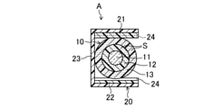
実施形態1に係る側面発光型光ファイバAは、応力付与部材20を更に備える。
The side light emitting optical fiber A according to the first embodiment further includes a
応力付与部材20は、ファイバ本体10のファイバ長さ方向の中間部分に取り付けられている。応力付与部材20が取り付けられている部分の長さは例えば5mm以上である。応力付与部材20は、一対の細長矩形状の第1及び第2板状部品21,22と、断面コの字状の保持部品23とを有する。第1及び第2板状部品21,22は、被覆層13の外側からファイバ本体10を挟持するように設けられている。第1及び第2板状部品21,22のそれぞれのファイバ本体10側には、各々、幅方向に延びる断面半円形状の突条で構成された複数の応力付与部24がファイバ長さ方向に間隔をおいて配設されている。第1板状部品21の応力付与部24と第2板状部品22の応力付与部24とは、ファイバ長さ方向にずれて設けられている。保持部品23は、ファイバ本体10を挟持した第1及び第2板状部品21,22を両側から弾性的に挟んで保持するように設けられている。したがって、応力付与部材20は、ファイバ本体10のファイバ長さ方向の任意の位置に取り付けることができる。第1及び第2板状部品21,22並びに保持部品23は、金属や樹脂や木材等の剛性を有する材料で形成されていることが好ましい。
The
応力付与部材20は、第1及び第2板状部品21,22の各応力付与部24が、ファイバ本体10の外周面に断面U字溝状の凹みを形成するように食い込み、ファイバ本体10の外周面をファイバ長さ方向に対して直交する横断面に沿う方向に線状に押圧し、且つこれらに保持部品23が外嵌めされ、これにより被覆層13を介してクラッド12に対して外部から部分的にファイバ長さ方向に直交する横断面に沿った方向に応力を付与する。すなわち、応力付与部材20は、クラッド12に対して部分的にファイバ長さ方向に対して角度をなす方向、すなわち、ファイバ長さ方向以外の方向に応力を付与する応力付与構造を構成する。
In the
以上の構成の実施形態1に係る側面発光型光ファイバAによれば、このように光散乱体Sを含むクラッド12に対して部分的にファイバ長さ方向以外の方向に応力を付与する応力付与構造が構成されていることにより、その応力付与構造において発光量が高められ、そのため長尺の光源から離れた位置でも多くの発光量を得ることができる。これは、クラッド12に対して部分的に応力が付与されることにより、その応力がコア11とクラッド12との界面、及びクラッド12と被覆層13との界面に影響し、コア11の伝搬光のクラッド12の伝搬光への変換、及びクラッド12の伝搬光の被覆層13の伝搬光への変換が促進され、そのクラッド12の伝搬光がクラッド12の光散乱体Sで散乱し、また、被覆層13が光散乱体Sを含む場合には、それが被覆層13の光散乱体Sで散乱するためであると推測される。なお、応力付与構造は、クラッド12に対してファイバ長さ方向以外の方向に加えて、ファイバ長さ方向にも応力を付与していてもよい。また、応力付与構造での光吸収を低減する観点からは、第1及び第2板状部品21,22並びに保持部品23は、伝搬光に対して透明な材料で形成されていることが好ましい。同様の観点から、応力付与部24の表面は光反射面に構成されていることが好ましい。なお、第1及び第2板状部品21,22並びに保持部品23は、透明な部材と光反射面を有する部材とを組み合わせたものであってもよい。
According to the side-emitting optical fiber A according to the first embodiment of the above configuration, stress is applied to the clad 12 including the light scattering body S in this way to partially apply stress in a direction other than the fiber length direction. Since the structure is configured, the amount of light emitted is increased in the stress-applied structure, and therefore a large amount of light can be obtained even at a position away from a long light source. This is because the partial stress is applied to the clad 12, and the stress affects the interface between the core 11 and the clad 12 and the interface between the clad 12 and the
第1及び第2板状部品21,22における応力付与部24の数は、応力付与構造による発光量を高める観点から、好ましくは1個以上1000個以下である。応力付与部24間の間隔は、応力付与構造による発光量を高める観点から、好ましくは200μm以上30mm以下である。応力付与部24の断面半円形状の直径は、応力付与構造による発光量を高める観点から、好ましくは100μm以上5mm以下である。応力付与部24がファイバ本体10に付与する応力は、そのファイバ本体10への食い込み深さで制御することができる。その食い込み深さは、ファイバ全長に渡る発光量の分布を考慮するとともに、クラッド12の厚さ及び被覆層13の厚さに応じて決定すればよく、例えば、150μm以上15mm以下である。応力付与部24のファイバ本体10への食い込み深さは、応力付与部24の断面半円形状の直径、保持部品23の大きさ、及びそれらの形成材料の硬さや弾性などにより調整することができる。
The number of stress-applied
以上の構成の実施形態1に係る側面発光型光ファイバAは、一端がレーザ等の光源に接続されて照明等の種々の用途で用いられる。例えば、応力付与部材20における第1及び第2板状部品21,22の応力付与部24が、形状記憶合金材料やバイメタル材料で形成され、温度に依存してクラッド12に付与する応力が変化する場合には、周辺温度に対応して応力付与構造による発光量を変化させることができることから、実施形態1に係る側面発光型光ファイバAを温度センサとして用いることができる。
The side-emitting optical fiber A according to the first embodiment of the above configuration is used for various purposes such as lighting by connecting one end to a light source such as a laser. For example, the
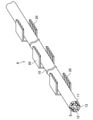
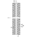
なお、応力付与部材20は、図2に示すように、ファイバ本体10のファイバ長さ方向に沿って間隔をおいて複数設けられていてもよい。応力付与部材20間の間隔は、例えば0.1m以上であり、数百mであってもよい。この場合、複数の応力付与部材20の取付位置の設定、ファイバ本体10に付与する応力、すなわち応力付与部24のファイバ本体10への食い込み深さにより、ファイバ長さ方向に沿った発光量の分布を制御することができる。また、応力付与部材20は、透明材料により形成されていれば、ファイバ本体10の全長に渡って設けられていてもよい。透明材料で形成された応力付与部材20には、内部に光散乱体を含有させることができる。
As shown in FIG. 2, a plurality of
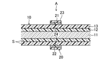
応力付与部材20は、図3に示すように、その取付位置においてファイバ本体10の被覆層13が剥がされ、第1及び第2板状部品21,22の応力付与部24がクラッド12に直接接触するように設けられていてもよい。また、ファイバ本体10は、全長に渡って被覆層13を有さず、コア11及びクラッド12のみで構成されていてもよい。
As shown in FIG. 3, in the
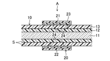
応力付与部材20は、図4に示すように、第1板状部品21の応力付与部24と第2板状部品22の応力付与部24とがファイバ長さ方向に対応して設けられた構成であってもよい。また、応力付与部材20は、図5に示すように、応力付与部24が設けられた第1板状部品21を有する一方、第2板状部品22を有さない構成であってもよい。
As shown in FIG. 4, the
応力付与部材20は、図6に示すように、第1及び第2板状部品21,22のそれぞれに単一の応力付与部24が設けられた構成であってもよい。第1及び第2板状部品21,22の単一の応力付与部24は、ファイバ長さ方向に対応して設けられていてもよく、ファイバ長さ方向にずれて設けられていてもよい。また、応力付与部材20は、第1板状部品21又は第2板状部品22のみに単一の応力付与部24が設けられた構成であってもよい。
As shown in FIG. 6, the
応力付与部材20は、図7に示すように、第1及び第2板状部品21,22の応力付与部24の断面形状が三角形に形成され、その応力付与部24がファイバ本体10の外周面に断面V字溝状の凹みを形成するように食い込み、ファイバ本体10の外周面をファイバ長さ方向に対して直交する横断面に沿う方向に線状に押圧し、且つこれらに保持部品23が外嵌めされ、これにより被覆層13を介してクラッド12に対して外部から部分的にファイバ長さ方向に直交する横断面に沿った方向に応力を付与する構成であってもよい。また、応力付与部24は、クラッド12に対して部分的にファイバ長さ方向に対して角度をなす方向に応力を付与するものであれば、断面矩形状等の突条で構成されていてもよい。
As shown in FIG. 7, in the
応力付与部材20は、図8に示すように、第1及び第2板状部品21,22がファイバ本体10に外嵌めされた円筒体を縦に二分割した形状に形成されているとともに、それぞれの内周面に周方向に延びる突条の応力付与部24が設けられ、その応力付与部24がファイバ本体10の外周面に周方向に延びる凹みを形成するように食い込み、ファイバ本体10の外周面の全周をファイバ長さ方向に対して直交するファイバ中心に向かう方向に線状に押圧し、且つそれらに保持部品23が外嵌めして設けられ、これにより被覆層13を介してクラッド12の全周に対して外部から部分的にファイバ長さ方向に直交する横断面に沿った方向に応力を付与する構成であってもよい。なお、応力付与部材20の応力付与部24は、ファイバ長さ方向に延びる構成であってもよい。また、応力付与部材20を構成する円筒体の分割数は、三分割以上であってもよく、任意である。
As shown in FIG. 8, the
(実施形態2)
図9A及びBは、実施形態2に係る側面発光型光ファイバAを示す。なお、実施形態1と同一名称の部分は、実施形態1と同一符号で示す。
(Embodiment 2)
9A and 9B show the side-emitting optical fiber A according to the second embodiment. The portion having the same name as that of the first embodiment is indicated by the same reference numeral as that of the first embodiment.
実施形態2に係る側面発光型光ファイバAでは、応力付与部材20は、断面円形状の線状材の応力付与部品25と、円筒状の保持部品23とを有する。応力付与部品25は、ファイバ本体10にファイバ長さ方向に沿って全長に渡って螺旋状に巻き付けられている。保持部品23は、応力付与部品25が巻き付けられたファイバ本体10に外嵌めして設けられている。応力付与部品25及び保持部品23は、透明な樹脂等で形成されていることが好ましい。
In the side light emitting optical fiber A according to the second embodiment, the
応力付与部材20は、応力付与部品25がファイバ本体10の外周面に螺旋状に延びる断面U字溝状の凹みを形成するように食い込み、ファイバ本体10の外周面をファイバ長さ方向に対して直交するファイバ中心に向かう方向に線状に押圧し、且つ保持部品23がそれに外嵌めして設けられ、これにより被覆層13を介してクラッド12に対して外部から部分的にファイバ長さ方向に直交する方向に応力を付与する構成であってもよい。すなわち、応力付与部材20は、クラッド12に対して部分的にファイバ長さ方向に対して角度をなす方向、すなわち、ファイバ長さ方向以外の方向に応力を付与する応力付与構造を構成する。
The
以上の構成の実施形態2に係る側面発光型光ファイバAによれば、このように光散乱体Sを含むクラッド12に対して部分的にファイバ長さ方向以外の方向に応力を付与する応力付与構造が構成されていることにより、その応力付与構造において発光量が高められ、そのため長尺の光源から離れた位置でも多くの発光量を得ることができる。 According to the side-emitting optical fiber A according to the second embodiment of the above configuration, stress is applied to the clad 12 including the light scattering body S in this way to partially apply stress in a direction other than the fiber length direction. Since the structure is configured, the amount of light emitted is increased in the stress-applied structure, and therefore a large amount of light can be obtained even at a position away from a long light source.
応力付与部品25の螺旋のピッチは、応力付与構造による発光量を高める観点から、好ましくは200μm以上30mm以下である。応力付与部品25の直径は、応力付与構造による発光量を高める観点から、好ましくは100μm以上5mm以下である。応力付与部品25がファイバ本体10に付与する応力は、そのファイバ本体10への食い込み深さで制御することができる。その食い込み深さは、ファイバ全長に渡る発光量の分布を考慮するとともに、クラッド12の厚さ及び被覆層13の厚さに応じて決定すればよく、例えば、150μm以上15mm以下である。応力付与部品25のファイバ本体10への食い込み深さは、応力付与部品25の直径、保持部品23の内径、及びそれらの形成材料の硬さや弾性などにより調整することができる。
The pitch of the spiral of the
なお、応力付与部品25の螺旋のピッチは、図10に示すように、ファイバ長さ方向に沿って変調していてもよい。例えば、光源側の螺旋のピッチを長くする一方、末端側の螺旋のピッチを短くすれば、コア11の伝搬光からクラッド12及び被覆層13の伝搬光への変換割合が調整され、それによりファイバ長さ方向における発光量の均一化を図ることができる。また、応力付与部品25の直径や保持部品23の内径がファイバ長さ方向に沿って変調していても、同様の効果を得ることができる。
As shown in FIG. 10, the pitch of the spiral of the
応力付与部材20は、図11に示すように、ファイバ本体10のファイバ長さ方向に沿って間隔をおいて複数設けられていてもよい。応力付与部材20間の間隔は、例えば0.1m以上であり、数百mであってもよい。この場合、複数の応力付与部材20の取付位置の設定やファイバ本体10に付与する応力を変えることにより、ファイバ長さ方向に沿った発光量の分布を制御することができる。
As shown in FIG. 11, a plurality of
(その他の実施形態)
上記実施形態1及び2では、応力付与部材20により応力付与構造を構成するが、特にこれに限定されるものではなく、ファイバ本体10に与えた変形によりクラッド12や被覆層13に対する応力付与構造が維持される構成では、必ずしも応力付与部材20が取り付けられていなくてもよい。
(Other embodiments)
In the above-described first and second embodiments, the stress applying structure is configured by the
上記実施形態1及び2では、応力付与部材20がファイバ本体10の外周面を線状に押圧する構成としたが、特にこれに限定されるものではなく、ファイバ本体10の外周面を点状に押圧する構成であってもよい。また、応力付与構造として、ファイバ本体10の外周で液状樹脂を硬化させ、その硬化時の収縮を利用して応力付与部を形成する構成であってもよい。この場合、ファイバ本体10の外周に液状樹脂を直接塗布して応力付与部を形成してもよく、また、ファイバ本体10及び液状樹脂を型に入れて応力付与部を形成してもよい。液状樹脂としては、例えば、光硬化性樹脂、熱硬化性樹脂、室温硬化性樹脂等が挙げられる。液状樹脂が透明であれば、内部に散乱体を含有させることができる。
In the first and second embodiments, the
(側面発光型光ファイバ)
<実施例>
純粋石英で形成されたコア(コア径125μm)と、シリコーン系材料で形成され光散乱体としてPMMAを0.2質量%含むクラッド(クラッド径200μm)と、フッ素系材料で形成された被覆層(被覆径700μm)とを有する長さ20mのファイバ本体に、その光源接続側の一端から10mの位置に上記実施形態1における図5に示すのと同様の構成の応力付与部材を取り付けた側面発光型光ファイバを実施例とした。応力付与部材は、第1板状部品における応力付与部の数が4個、応力付与部間の間隔3mm、及び応力付与部の断面半円形状の直径が1mmであった。
(Side emission type optical fiber)
<Example>
A core made of pure quartz (core diameter 125 μm), a clad made of a silicone-based material containing 0.2% by mass of PMMA as a light scatterer (clad diameter 200 μm), and a coating layer made of a fluorine-based material (clad diameter 200 μm). A side-emitting type in which a stress-applying member having the same configuration as that shown in FIG. An optical fiber was used as an example. In the stress applying member, the number of stress applying portions in the first plate-shaped part was 4, the distance between the stress applying portions was 3 mm, and the diameter of the semicircular cross section of the stress applying portions was 1 mm.
<比較例>
応力付与部材を取り付けていないことを除いて実施例と同一構成の側面発光型光ファイバを比較例とした。
<Comparison example>
A side-emitting optical fiber having the same configuration as that of the embodiment was used as a comparative example except that a stress applying member was not attached.
(試験方法及び結果)
実施例及び比較例のそれぞれについて、一端を光源(半導体レーザ、波長640nm)に接続して光を伝搬させ、ファイバ長さ方向に沿った複数の位置でレーザ照度計(日置電機製)を用いて発光量を測定した。
(Test method and results)
For each of the examples and comparative examples, one end is connected to a light source (semiconductor laser, wavelength 640 nm) to propagate light, and a laser luminometer (manufactured by Hioki Electric Co., Ltd.) is used at a plurality of positions along the fiber length direction. The amount of light emitted was measured.
図12は、実施例及び比較例の光源からの距離と発光量との関係を示す。 FIG. 12 shows the relationship between the distance from the light source of Examples and Comparative Examples and the amount of light emitted.
これらの図12によれば、実施例及び比較例のいずれも、基本的には、光源からの距離が遠くなるに従って発光量が少なくなる傾向が認められる。これは、クラッドや被覆層の伝搬光が光散乱体により散乱して消滅するためであると考えられる。しかしながら、実施例では、応力付与部材を取り付けた位置において発光量が著しく多くなっており、光源近傍における発光量よりも多いことが分かる。これは、応力付与部材を取り付けた位置において、クラッドに対して部分的に応力が付与されることにより、その応力がコアとクラッドとの界面、及びクラッドと被覆層との界面に影響し、コアの伝搬光のクラッドの伝搬光への変換、及びクラッドの伝搬光の被覆層の伝搬光への変換が促進され、それらの変換された光の散乱体による散乱光量が、クラッドや被覆層の伝搬光のファイバ長さ方向に消滅する光量を上回るためであると考えられる。 According to these FIGS. 12, basically, in both the examples and the comparative examples, the amount of light emitted tends to decrease as the distance from the light source increases. It is considered that this is because the propagating light of the clad or the coating layer is scattered by the light scatterer and disappears. However, in the embodiment, it can be seen that the amount of light emitted is remarkably large at the position where the stress applying member is attached, which is larger than the amount of light emitted in the vicinity of the light source. This is because the stress is partially applied to the clad at the position where the stress applying member is attached, and the stress affects the interface between the core and the clad and the interface between the clad and the coating layer, and the core. The conversion of the propagating light of the clad into the propagating light of the clad and the conversion of the propagating light of the clad into the propagating light of the covering layer are promoted, and the amount of scattered light by the scatterer of the converted light is the propagation of the clad or the covering layer. This is considered to be because the amount of light that disappears in the fiber length direction of light is exceeded.
本発明は、側面発光型光ファイバの技術分野について有用である。 The present invention is useful in the technical field of side-emitting optical fibers.
A 側面発光型光ファイバ
S 光散乱体
10 ファイバ本体
11 コア
12 クラッド
13 被覆層
20 応力付与部材
21 第1板状部品
22 第2板状部品
23 保持部品
24 応力付与部
25 応力付与部品
A Side light emitting optical fiber S
Claims (10)
前記クラッドに対して部分的にファイバ長さ方向以外の方向に応力を付与する応力付与構造が構成された側面発光型光ファイバ。 A side-emitting optical fiber comprising a fiber body comprising a core and a clad containing a light scatterer provided to cover the core.
A side-emitting optical fiber having a stress-applying structure that partially applies stress to the clad in a direction other than the fiber length direction.
前記応力付与構造が前記クラッドに対してファイバ長さ方向に直交する横断面の外周に沿って線状に押圧して応力を付与する側面発光型光ファイバ。 In the side-emitting optical fiber according to claim 1,
A side-emitting optical fiber in which the stress-applying structure is linearly pressed along the outer circumference of a cross section orthogonal to the clad in the fiber length direction to apply stress.
前記クラッドが有機材料で形成されている側面発光型光ファイバ。 In the side-emitting optical fiber according to claim 1 or 2.
A side-emitting optical fiber whose clad is made of an organic material.
前記応力付与構造を構成する応力付与部材を更に備えた側面発光型光ファイバ。 In the side-emitting optical fiber according to any one of claims 1 to 3.
A side-emitting optical fiber further provided with a stress applying member constituting the stress applying structure.
前記応力付与部材が前記ファイバ本体の外周面を線状又は点状に押圧する側面発光型光ファイバ。 In the side-emitting optical fiber according to claim 4,
A side-emitting optical fiber in which the stress-applying member presses the outer peripheral surface of the fiber body in a linear or dot shape.
前記応力付与部材が、前記ファイバ本体の外周面に断面U字溝状の凹みを形成するように食い込む応力付与部を含む側面発光型光ファイバ。 In the side-emitting optical fiber according to claim 5,
A side-emitting optical fiber including a stress-applying portion in which the stress-applying member bites into the outer peripheral surface of the fiber body so as to form a recess having a U-shaped cross section.
前記応力付与部材は、前記応力付与部が設けられた第1の部品と、前記第1の部品の前記応力付与部が前記ファイバ本体の外周面を押圧するように前記第1の部品を前記ファイバ本体に保持する第2の部品とを有し、前記ファイバ本体のファイバ長さ方向の任意の位置に取り付け可能に構成された側面発光型光ファイバ。 In the side-emitting optical fiber according to claim 6,
The stress-applying member is a fiber having a first component provided with the stress-applying portion and the first component so that the stress-applying portion of the first component presses the outer peripheral surface of the fiber body. A side-emitting optical fiber having a second component held in the main body and configured to be mountable at an arbitrary position in the fiber length direction of the fiber main body.
前記コアが光散乱体を実質的に含まない側面発光型光ファイバ。 In the side-emitting optical fiber according to any one of claims 1 to 7.
A side-emitting optical fiber whose core is substantially free of light scatterers.
前記ファイバ本体が、前記クラッドを被覆するように設けられた被覆層を更に有する側面発光型光ファイバ。 In the side-emitting optical fiber according to any one of claims 1 to 8.
A side-emitting optical fiber in which the fiber body further has a coating layer provided so as to cover the clad.
前記被覆層が光散乱体を含む側面発光型光ファイバ。 In the side-emitting optical fiber according to claim 9,
A side-emitting optical fiber in which the coating layer contains a light scatterer.
Priority Applications (1)
| Application Number | Priority Date | Filing Date | Title |
|---|---|---|---|
| JP2021183519A JP2022017558A (en) | 2018-12-26 | 2021-11-10 | Side light emission optical fiber |
Applications Claiming Priority (2)
| Application Number | Priority Date | Filing Date | Title |
|---|---|---|---|
| JP2018242718A JP7023831B2 (en) | 2018-12-26 | 2018-12-26 | Side emission type optical fiber |
| JP2021183519A JP2022017558A (en) | 2018-12-26 | 2021-11-10 | Side light emission optical fiber |
Related Parent Applications (1)
| Application Number | Title | Priority Date | Filing Date |
|---|---|---|---|
| JP2018242718A Division JP7023831B2 (en) | 2018-12-26 | 2018-12-26 | Side emission type optical fiber |
Publications (1)
| Publication Number | Publication Date |
|---|---|
| JP2022017558A true JP2022017558A (en) | 2022-01-25 |
Family
ID=71448953
Family Applications (2)
| Application Number | Title | Priority Date | Filing Date |
|---|---|---|---|
| JP2018242718A Active JP7023831B2 (en) | 2018-12-26 | 2018-12-26 | Side emission type optical fiber |
| JP2021183519A Pending JP2022017558A (en) | 2018-12-26 | 2021-11-10 | Side light emission optical fiber |
Family Applications Before (1)
| Application Number | Title | Priority Date | Filing Date |
|---|---|---|---|
| JP2018242718A Active JP7023831B2 (en) | 2018-12-26 | 2018-12-26 | Side emission type optical fiber |
Country Status (1)
| Country | Link |
|---|---|
| JP (2) | JP7023831B2 (en) |
Cited By (1)
| Publication number | Priority date | Publication date | Assignee | Title |
|---|---|---|---|---|
| JP2023183673A (en) * | 2022-06-16 | 2023-12-28 | 三菱電線工業株式会社 | light emitting device |
Families Citing this family (1)
| Publication number | Priority date | Publication date | Assignee | Title |
|---|---|---|---|---|
| JP7613683B2 (en) * | 2020-11-09 | 2025-01-15 | Mfオプテックス株式会社 | Photochemical reaction treatment method |
Citations (4)
| Publication number | Priority date | Publication date | Assignee | Title |
|---|---|---|---|---|
| US4422719A (en) * | 1981-05-07 | 1983-12-27 | Space-Lyte International, Inc. | Optical distribution system including light guide |
| JPH1184136A (en) * | 1997-07-14 | 1999-03-26 | Matsushita Electric Works Ltd | Side face light emitting optical fiber |
| JP2000137119A (en) * | 1998-10-29 | 2000-05-16 | Matsushita Electric Works Ltd | Side face light emission optical fiber |
| JP2001504598A (en) * | 1996-11-21 | 2001-04-03 | ミネソタ マイニング アンド マニュファクチャリング カンパニー | Forward light extraction film for light guide device and method of manufacturing the same |
Family Cites Families (2)
| Publication number | Priority date | Publication date | Assignee | Title |
|---|---|---|---|---|
| JPH11281819A (en) * | 1998-03-02 | 1999-10-15 | Minnesota Mining & Mfg Co <3M> | Optical fiber and light emitting device |
| JP4319090B2 (en) | 2004-05-31 | 2009-08-26 | 株式会社フジクラ | Surface light leakage optical waveguide and photocatalytic module |
-
2018
- 2018-12-26 JP JP2018242718A patent/JP7023831B2/en active Active
-
2021
- 2021-11-10 JP JP2021183519A patent/JP2022017558A/en active Pending
Patent Citations (4)
| Publication number | Priority date | Publication date | Assignee | Title |
|---|---|---|---|---|
| US4422719A (en) * | 1981-05-07 | 1983-12-27 | Space-Lyte International, Inc. | Optical distribution system including light guide |
| JP2001504598A (en) * | 1996-11-21 | 2001-04-03 | ミネソタ マイニング アンド マニュファクチャリング カンパニー | Forward light extraction film for light guide device and method of manufacturing the same |
| JPH1184136A (en) * | 1997-07-14 | 1999-03-26 | Matsushita Electric Works Ltd | Side face light emitting optical fiber |
| JP2000137119A (en) * | 1998-10-29 | 2000-05-16 | Matsushita Electric Works Ltd | Side face light emission optical fiber |
Cited By (2)
| Publication number | Priority date | Publication date | Assignee | Title |
|---|---|---|---|---|
| JP2023183673A (en) * | 2022-06-16 | 2023-12-28 | 三菱電線工業株式会社 | light emitting device |
| JP2025063890A (en) * | 2022-06-16 | 2025-04-16 | Mfオプテックス株式会社 | Light Emitting Device |
Also Published As
| Publication number | Publication date |
|---|---|
| JP2020106596A (en) | 2020-07-09 |
| JP7023831B2 (en) | 2022-02-22 |
Similar Documents
| Publication | Publication Date | Title |
|---|---|---|
| JP6450686B2 (en) | Light diffusing optical fiber bundle, illumination system including light diffusing optical fiber bundle, and method for attaching light diffusing optical fiber bundle to polymer optical fiber | |
| JP2022017558A (en) | Side light emission optical fiber | |
| US8540409B2 (en) | Light guide and semiconductor luminaire | |
| TWI245864B (en) | Linear light source having serration reflecting face | |
| US6137928A (en) | Optical fiber light distribution system and method of manufacture and illumination | |
| US20100195019A1 (en) | Surface light source apparatus | |
| US20100098377A1 (en) | Light confinement using diffusers | |
| KR880000807A (en) | Fiber optic device | |
| US20080198624A1 (en) | Light guide orientation connector | |
| CN101725910A (en) | Liner light source device | |
| JP5480015B2 (en) | Diffusing optical fiber and medical optical component using the same | |
| JP5869017B2 (en) | Elongated lighting device | |
| JP2011145520A (en) | Optical fiber | |
| JP2008016432A (en) | Light guide, backlight device, and light source device | |
| JPWO2017104195A1 (en) | Optical element and LED lighting device | |
| JP5656785B2 (en) | Lighting device and liquid crystal display | |
| US20050135741A1 (en) | System and method for extending viewing angle of light emitted from light pipe | |
| US20140218972A1 (en) | Light guiding apparatus and light source device including the same | |
| CN213633906U (en) | Dispersion optical fiber with hard dispersion head | |
| TWM508682U (en) | Light guide bar | |
| JP6636727B2 (en) | Lighting equipment | |
| JP2003121664A (en) | Plastic optical fiber with rectangular cross section | |
| JP6902523B2 (en) | Side emitting optical fiber | |
| JPS58208708A (en) | leaky optical fiber | |
| JP2009016246A (en) | Rod-shaped light guide body, and linear light source using it, as well as planar light source |
Legal Events
| Date | Code | Title | Description |
|---|---|---|---|
| A621 | Written request for application examination |
Free format text: JAPANESE INTERMEDIATE CODE: A621 Effective date: 20211224 |
|
| A131 | Notification of reasons for refusal |
Free format text: JAPANESE INTERMEDIATE CODE: A131 Effective date: 20220830 |
|
| A02 | Decision of refusal |
Free format text: JAPANESE INTERMEDIATE CODE: A02 Effective date: 20230228 |