JP2022017444A - Image guided focused ultrasound treatment device and aiming apparatus - Google Patents
Image guided focused ultrasound treatment device and aiming apparatus Download PDFInfo
- Publication number
- JP2022017444A JP2022017444A JP2021178654A JP2021178654A JP2022017444A JP 2022017444 A JP2022017444 A JP 2022017444A JP 2021178654 A JP2021178654 A JP 2021178654A JP 2021178654 A JP2021178654 A JP 2021178654A JP 2022017444 A JP2022017444 A JP 2022017444A
- Authority
- JP
- Japan
- Prior art keywords
- ray
- cradle
- marker
- image
- fus
- Prior art date
- Legal status (The legal status is an assumption and is not a legal conclusion. Google has not performed a legal analysis and makes no representation as to the accuracy of the status listed.)
- Granted
Links
Images


Classifications
-
- A—HUMAN NECESSITIES
- A61—MEDICAL OR VETERINARY SCIENCE; HYGIENE
- A61B—DIAGNOSIS; SURGERY; IDENTIFICATION
- A61B18/00—Surgical instruments, devices or methods for transferring non-mechanical forms of energy to or from the body
- A61B18/04—Surgical instruments, devices or methods for transferring non-mechanical forms of energy to or from the body by heating
-
- A—HUMAN NECESSITIES
- A61—MEDICAL OR VETERINARY SCIENCE; HYGIENE
- A61B—DIAGNOSIS; SURGERY; IDENTIFICATION
- A61B34/00—Computer-aided surgery; Manipulators or robots specially adapted for use in surgery
- A61B34/20—Surgical navigation systems; Devices for tracking or guiding surgical instruments, e.g. for frameless stereotaxis
-
- A—HUMAN NECESSITIES
- A61—MEDICAL OR VETERINARY SCIENCE; HYGIENE
- A61B—DIAGNOSIS; SURGERY; IDENTIFICATION
- A61B90/00—Instruments, implements or accessories specially adapted for surgery or diagnosis and not covered by any of the groups A61B1/00 - A61B50/00, e.g. for luxation treatment or for protecting wound edges
- A61B90/36—Image-producing devices or illumination devices not otherwise provided for
- A61B90/37—Surgical systems with images on a monitor during operation
-
- A—HUMAN NECESSITIES
- A61—MEDICAL OR VETERINARY SCIENCE; HYGIENE
- A61B—DIAGNOSIS; SURGERY; IDENTIFICATION
- A61B90/00—Instruments, implements or accessories specially adapted for surgery or diagnosis and not covered by any of the groups A61B1/00 - A61B50/00, e.g. for luxation treatment or for protecting wound edges
- A61B90/39—Markers, e.g. radio-opaque or breast lesions markers
-
- A—HUMAN NECESSITIES
- A61—MEDICAL OR VETERINARY SCIENCE; HYGIENE
- A61N—ELECTROTHERAPY; MAGNETOTHERAPY; RADIATION THERAPY; ULTRASOUND THERAPY
- A61N7/00—Ultrasound therapy
-
- A—HUMAN NECESSITIES
- A61—MEDICAL OR VETERINARY SCIENCE; HYGIENE
- A61N—ELECTROTHERAPY; MAGNETOTHERAPY; RADIATION THERAPY; ULTRASOUND THERAPY
- A61N7/00—Ultrasound therapy
- A61N7/02—Localised ultrasound hyperthermia
-
- A—HUMAN NECESSITIES
- A61—MEDICAL OR VETERINARY SCIENCE; HYGIENE
- A61B—DIAGNOSIS; SURGERY; IDENTIFICATION
- A61B18/00—Surgical instruments, devices or methods for transferring non-mechanical forms of energy to or from the body
- A61B2018/00571—Surgical instruments, devices or methods for transferring non-mechanical forms of energy to or from the body for achieving a particular surgical effect
- A61B2018/00577—Ablation
-
- A—HUMAN NECESSITIES
- A61—MEDICAL OR VETERINARY SCIENCE; HYGIENE
- A61B—DIAGNOSIS; SURGERY; IDENTIFICATION
- A61B34/00—Computer-aided surgery; Manipulators or robots specially adapted for use in surgery
- A61B34/20—Surgical navigation systems; Devices for tracking or guiding surgical instruments, e.g. for frameless stereotaxis
- A61B2034/2046—Tracking techniques
- A61B2034/2065—Tracking using image or pattern recognition
-
- A—HUMAN NECESSITIES
- A61—MEDICAL OR VETERINARY SCIENCE; HYGIENE
- A61B—DIAGNOSIS; SURGERY; IDENTIFICATION
- A61B34/00—Computer-aided surgery; Manipulators or robots specially adapted for use in surgery
- A61B34/20—Surgical navigation systems; Devices for tracking or guiding surgical instruments, e.g. for frameless stereotaxis
- A61B2034/2068—Surgical navigation systems; Devices for tracking or guiding surgical instruments, e.g. for frameless stereotaxis using pointers, e.g. pointers having reference marks for determining coordinates of body points
-
- A—HUMAN NECESSITIES
- A61—MEDICAL OR VETERINARY SCIENCE; HYGIENE
- A61B—DIAGNOSIS; SURGERY; IDENTIFICATION
- A61B90/00—Instruments, implements or accessories specially adapted for surgery or diagnosis and not covered by any of the groups A61B1/00 - A61B50/00, e.g. for luxation treatment or for protecting wound edges
- A61B90/36—Image-producing devices or illumination devices not otherwise provided for
- A61B90/37—Surgical systems with images on a monitor during operation
- A61B2090/371—Surgical systems with images on a monitor during operation with simultaneous use of two cameras
-
- A—HUMAN NECESSITIES
- A61—MEDICAL OR VETERINARY SCIENCE; HYGIENE
- A61B—DIAGNOSIS; SURGERY; IDENTIFICATION
- A61B90/00—Instruments, implements or accessories specially adapted for surgery or diagnosis and not covered by any of the groups A61B1/00 - A61B50/00, e.g. for luxation treatment or for protecting wound edges
- A61B90/36—Image-producing devices or illumination devices not otherwise provided for
- A61B90/37—Surgical systems with images on a monitor during operation
- A61B2090/376—Surgical systems with images on a monitor during operation using X-rays, e.g. fluoroscopy
- A61B2090/3762—Surgical systems with images on a monitor during operation using X-rays, e.g. fluoroscopy using computed tomography systems [CT]
- A61B2090/3764—Surgical systems with images on a monitor during operation using X-rays, e.g. fluoroscopy using computed tomography systems [CT] with a rotating C-arm having a cone beam emitting source
-
- A—HUMAN NECESSITIES
- A61—MEDICAL OR VETERINARY SCIENCE; HYGIENE
- A61B—DIAGNOSIS; SURGERY; IDENTIFICATION
- A61B90/00—Instruments, implements or accessories specially adapted for surgery or diagnosis and not covered by any of the groups A61B1/00 - A61B50/00, e.g. for luxation treatment or for protecting wound edges
- A61B90/39—Markers, e.g. radio-opaque or breast lesions markers
- A61B2090/3937—Visible markers
-
- A—HUMAN NECESSITIES
- A61—MEDICAL OR VETERINARY SCIENCE; HYGIENE
- A61B—DIAGNOSIS; SURGERY; IDENTIFICATION
- A61B90/00—Instruments, implements or accessories specially adapted for surgery or diagnosis and not covered by any of the groups A61B1/00 - A61B50/00, e.g. for luxation treatment or for protecting wound edges
- A61B90/39—Markers, e.g. radio-opaque or breast lesions markers
- A61B2090/3966—Radiopaque markers visible in an X-ray image
-
- A—HUMAN NECESSITIES
- A61—MEDICAL OR VETERINARY SCIENCE; HYGIENE
- A61B—DIAGNOSIS; SURGERY; IDENTIFICATION
- A61B90/00—Instruments, implements or accessories specially adapted for surgery or diagnosis and not covered by any of the groups A61B1/00 - A61B50/00, e.g. for luxation treatment or for protecting wound edges
- A61B90/39—Markers, e.g. radio-opaque or breast lesions markers
- A61B2090/3983—Reference marker arrangements for use with image guided surgery
-
- A—HUMAN NECESSITIES
- A61—MEDICAL OR VETERINARY SCIENCE; HYGIENE
- A61N—ELECTROTHERAPY; MAGNETOTHERAPY; RADIATION THERAPY; ULTRASOUND THERAPY
- A61N7/00—Ultrasound therapy
- A61N2007/0004—Applications of ultrasound therapy
- A61N2007/0021—Neural system treatment
- A61N2007/003—Destruction of nerve tissue
-
- A—HUMAN NECESSITIES
- A61—MEDICAL OR VETERINARY SCIENCE; HYGIENE
- A61N—ELECTROTHERAPY; MAGNETOTHERAPY; RADIATION THERAPY; ULTRASOUND THERAPY
- A61N7/00—Ultrasound therapy
- A61N2007/0086—Beam steering
-
- A—HUMAN NECESSITIES
- A61—MEDICAL OR VETERINARY SCIENCE; HYGIENE
- A61N—ELECTROTHERAPY; MAGNETOTHERAPY; RADIATION THERAPY; ULTRASOUND THERAPY
- A61N7/00—Ultrasound therapy
- A61N2007/0086—Beam steering
- A61N2007/0091—Beam steering with moving parts, e.g. transducers, lenses, reflectors
Abstract
Description
本発明は、集束超音波(FUS;focused ultrasound)の分野に関し、特に、X線誘導FUSデバイスの分野に関する。 The present invention relates to the field of focused ultrasound (FUS), and more particularly to the field of X-ray guided FUS devices.
図1は、先行技術の高周波(RF;radiofrequency)神経アブレーション手技の高レベル概略図である。RFアブレーション手技は、痛みのある炎症を起こした関節70に分布する内側枝神経の熱破壊を含む。RFアブレーション手技は、クリニックまたは病院でX線誘導を用いて行われ、処置医がX線誘導を用いて針92の先端を標的脊椎の椎間関節73の横関節突起71と上関節突起72との接合部に誘導し、針を内側枝神経91の経路に沿って置く。針92はその先端でRFエネルギーにより熱を生成し、組織をその先端のまわりで内側枝神経も含めて小円筒状に熱凝固させる。先行技術のアブレーション手技は、患者に感染および出血のリスクがある、侵襲性で不快であり痛みを伴う手技である。
FIG. 1 is a high-level schematic of a radio frequency (RF) radiofrequency (radiofrequency) nerve ablation procedure of the prior art. The RF ablation procedure involves thermal destruction of the medial branch nerves distributed in the painful and
以下は、本発明の最初の理解を提供する簡単な概要である。概要は、主要要素を必ずしも特定するものでも本発明の範囲を制限するものでもなく、以下の説明の序論として役立つにすぎない。 The following is a brief overview that provides a first understanding of the invention. The overview does not necessarily specify the main elements or limit the scope of the invention and is only useful as an introduction to the following explanation.
画像誘導集束超音波処置のためのX線誘導装置は、ベースで手技プラットフォームに取り付けられた関節アームと、アームの遠位端に固定されたクレードルと、クレードル内に固定された照準装置と、クレードル内に固定された中心軸を有し、超音波治療エネルギービームを患者内の処置位置に伝達するように構成された、集束超音波(FUS;focused ultrasound)トランスデューサであって、トランスデューサによる集束超音波の印加を制御するためのコントローラに接続された、FUSトランスデューサと、X線画像化システムから画像化データを導出するように構成された画像化ユニットに接続された画像化ワークステーションと、を含む。 X-ray guidance devices for image-guided focused ultrasound procedures include a joint arm attached to the procedure platform at the base, a cradle fixed to the distal end of the arm, an aiming device fixed inside the cradle, and a cradle. Focused Ultrasound (FUS) transducer, which has a fixed central axis within and is configured to transmit an ultrasonic therapy energy beam to a treatment position within the patient, and is focused ultrasound by the transducer. Includes a FUS transducer connected to a controller for controlling the application of the ultrasound and an imaging workstation connected to an imaging unit configured to derive imaging data from the X-ray imaging system.
本装置は、焦点スポットを処置位置に誘導するために、FUSトランスデューサの位置および向きの照準を補助するためのX線システム等の画像化デバイスに依存する。 The device relies on an imaging device, such as an X-ray system, to assist in aiming the position and orientation of the FUS transducer in order to guide the focal spot to the treatment position.
本発明のこれらの態様および/もしくは効果、追加の態様および/もしくは効果、ならびに/またはその他の態様および/もしくは効果は、以下の詳細な説明に記載されており、場合によっては詳細な説明から推測可能であり、および/または本発明の実施によって知ることができる。 These embodiments and / or effects, additional embodiments and / or effects, and / or other embodiments and / or effects of the present invention are described in the detailed description below and may be inferred from the detailed description. It is possible and / or can be known by practicing the present invention.
本発明の実施形態のより良い理解のため、および本発明の実施形態をいかに実行しうるかを示すために、ここで単なる例として添付の図面が参照されるが、図面においては類似の数字は全体を通して対応する要素またはセクションを示す。 In order to better understand the embodiments of the present invention and to show how the embodiments of the present invention can be carried out, the accompanying drawings are referred to herein as merely examples, but in the drawings similar numbers are in whole. Indicates the corresponding element or section through.
以下の説明では、本発明の様々な態様が記載される。説明の目的で、本発明の十分な理解を提供するために特定の構成および詳細が記載される。しかし、本発明は本明細書に提示された具体的詳細を伴わずに実施されうることも当業者には明らかであろう。さらに、周知の特徴は、本発明が不明瞭にならないように省略または簡略化されていることもある。特に図面に関しては、図示された細部は例であり、本発明の説明的議論を目的とするにすぎず、本発明の原理および概念的態様の最も有用で理解しやすい説明と考えられるものを提供するために提示されたものであることが強調される。この点で、発明の基本的理解のために必要である以上に詳細に本発明の構造的詳細を示すことは試みられず、図面と合わせた説明により、本発明の複数の形態が実際にどのように具体化されうるかが当業者に明らかになる。 The following description describes various aspects of the invention. For purposes of illustration, specific configurations and details are described to provide a full understanding of the invention. However, it will also be apparent to those skilled in the art that the invention may be practiced without the specific details presented herein. Moreover, well-known features may be omitted or simplified so as not to obscure the invention. Particularly with respect to the drawings, the details illustrated are examples and are provided for purposes of descriptive discussion of the invention and are considered to be the most useful and easy-to-understand explanations of the principles and conceptual aspects of the invention. It is emphasized that it was presented to do. In this regard, no attempt has been made to show structural details of the invention in more detail than necessary for a basic understanding of the invention, and by description in conjunction with the drawings, which of the plurality of embodiments of the invention is actually It will be clear to those skilled in the art whether it can be embodied in this way.
本発明の少なくとも1つの実施形態が詳細に説明される前に、本発明の応用が以下の説明に記載されるかまたは図面に示された部品の構造および配置の詳細に限定されないことが理解されよう。本発明は、開示された実施形態の組み合わせにも、様々な仕方で実践または実施されうる他の実施形態にも、応用可能である。また、本明細書において使用される専門語および用語は、説明を目的としたものであり、限定と考えられるものではないことが理解されよう。 Prior to the detailed description of at least one embodiment of the invention, it is understood that the application of the invention is not limited to the details of the structure and arrangement of parts described in the following description or shown in the drawings. Yeah. The present invention is applicable to a combination of disclosed embodiments and to other embodiments that may be practiced or practiced in various ways. It will also be appreciated that the technical terms and terms used herein are for illustration purposes only and are not considered to be limiting.
特段の定めがない限り、以下の説明から明らかなように、明細書の全体にわたり、「処理する」、「計算する」、「算出する」、「決定する」、「強化する」などの用語を用いた議論は、計算システムのレジスタおよび/またはメモリ内の電子量等の物理量として表されるデータを、計算システムのメモリ、レジスタまたは他のそのような情報格納、伝送または表示デバイス内の物理量として同様に表される他のデータに操作および/または変換するコンピュータもしくは計算システムまたは類似の電子計算デバイスの動作および/またはプロセスをさすものと理解される。 Unless otherwise specified, terms such as "process", "calculate", "calculate", "determine", and "strengthen" are used throughout the specification, as will be apparent from the following description. The discussion used is that data represented as physical quantities such as the amount of electrons in the compute system's registers and / or memory can be used as physical quantities in the compute system's memory, registers or other such information storage, transmission or display devices. It is understood to refer to the operation and / or process of a computer or computing system or similar electronic computing device that manipulates and / or converts to other data represented similarly.
画像誘導集束超音波(FUS)処置のためのX線誘導装置および方法が提供される。本装置は、ベースで手技プラットフォームに取り付けられた関節アームと、アームの遠位端に固定されたクレードルと、照準装置と、クレードル内に固定された中心軸を有し、超音波治療エネルギービームを標的患者内の処置位置に伝達するように構成された、FUSトランスデューサおよびX線照準器であって、FUSトランスデューサは、トランスデューサによる集束超音波の印加を制御するように構成されたコントローラに接続される、FUSトランスデューサおよびX線照準器と、X線画像化システムから画像化データを導出するように構成された画像化ユニットに接続された画像化ワークステーションと、を含む。本装置は、Cアーム、蛍光透視または任意の一般的なX線画像化システム等の適切な画像化デバイスを備えたクリニックまたは病院で使用されうる。本装置は術前画像化システムにより誘導されてもよく、その場合には異なる画像化システム(例えばCT、MRIまたは他の任意のシステム)により撮影された画像がFUS処置手技の間に生成された画像と融合され、位置合わせされ、重ね合わせられうる。本装置は、Cアーム、Oアーム、Gアーム、X線コンピュータ断層装置(CT;computed tomography)またはその他の任意のX線デバイスと組み合わせて用いられうる。本装置は、任意の超音波画像化システムに対応しうる。 X-ray guidance devices and methods for image-guided focused ultrasound (FUS) treatment are provided. The device has a joint arm mounted on the procedure platform at the base, a cradle fixed to the distal end of the arm, a sighting device, and a central axis fixed within the cradle to provide an ultrasonic therapy energy beam. A FUS transducer and X-ray sight configured to transmit to a treatment position within the target patient, the FUS transducer is connected to a controller configured to control the application of focused ultrasound by the transducer. , FUS transducers and sights, and an imaging workstation connected to an imaging unit configured to derive imaging data from an X-ray imaging system. The device can be used in clinics or hospitals equipped with suitable imaging devices such as C-arms, fluoroscopy or any common X-ray imaging system. The device may be guided by a preoperative imaging system, in which case images taken by a different imaging system (eg CT, MRI or any other system) were generated during the FUS procedure. It can be fused, aligned and overlaid with the image. The device can be used in combination with a C-arm, O-arm, G-arm, X-ray computed tomography (CT) or any other X-ray device. The device may be compatible with any ultrasonic imaging system.
図2は、本発明の一部の実施形態による、画像誘導FUS処置のためのX線誘導装置100の高レベル概略図である。装置100は、ベースで手技プラットフォーム90に取り付けられた関節アーム111を含む。ある実施形態では、手技プラットフォーム90は、手術室テーブル、画像化テーブルおよび専用カートのうちの少なくとも1つを含むことができ、カートは、電子機器およびその他のデバイスのアクセサリを運ぶように設計され、カート車輪は、カートの移動を防ぐためにロックされるように設計される。装置100は、アーム111の遠位端に取り付けられたクレードル110をさらに含みうる。装置100は、トランスデューサ表面120を組織80の表面83に音響的に結合するように構成された結合アクセサリ125をさらに含みうる。
FIG. 2 is a high-level schematic of the
装置100は、クレードル110内に固定されFUSエネルギービーム140を患者内の処置位置141に伝達するように構成された、中心軸112を有するFUSトランスデューサ120をさらに含みうる。装置100は、FUSエネルギー140の送達を終了するように構成されたトリガ119をさらに含みうる。装置100は、ユーザインタフェースにより制御されてもよい治療FUSトランスデューサ120によるFUSエネルギー送達を制御するように構成されたコントローラ160をさらに含みうる。装置100は、スクリーン165をさらに含みうる。スクリーン165は、選択されたパワーレベル、音波処理持続時間、有益なメンテナンスおよびサービスメッセージ等であるがこれらに限定されない技術情報を医師に提供する。スクリーン165は、基本的にワークステーション180が提供する臨床情報を含むことができ、逆にワークステーション180が技術情報を提供することもできる。装置100は、クレードル110内に固定されるように構成された照準装置130をさらに含みうる。ある実施形態では、クレードル110は、FUSトランスデューサ120と照準装置130とが同時に内部に固定されうるようにさらに構成されうる。ある実施形態では、X線誘導を可能にするためにX線照準器150がFUSトランスデューサ120に取り付けられうる。ある実施形態では、クレードル110は、前後(A‐P;anterior‐posterior)、上下(S‐I;superior‐inferior)、左右(L‐R;left‐right)等であるがこれらに限定されないいくつかの運動自由度を含みうる。ある実施形態では、クレードル110は、照準装置およびFUSトランスデューサの挿入、ロックおよび解除にスムーズに対応するように構成されうる。ある実施形態では、クレードル110、FUSトランスデューサ120、照準装置130およびX線照準器150は、単一のユニットとして構築される。
The
装置100は、X線インテンシファイア85とX線源86とを含むX線画像化システムをさらに含むことができ、X線インテンシファイア85とX線源86とはX線画像化システムとして接続される。ある実施形態では、X線画像化システムは、処置位置141を含む組織80の領域91を画像化するように構成されうる。ある実施形態では、X線画像化は、FUS処置の前およびFUS処置の間に行われうる。ある実施形態では、装置100は、以下のX線のタイプ:Cアーム、Oアーム、Gアームおよび他の任意の一般的なX線のタイプのうちの少なくとも1つに対応するように構成されうる。
The
装置100は、X線画像化システムのX線インテンシファイア85に接続されたワークステーション180をさらに含むことができ、ワークステーション180は、X線画像化システムから画像化データを導出するように構成される。ある実施形態では、コントローラ160とスクリーン165とはワークステーション180内に組み合わせられてもよい。
The
ある実施形態では、関節アーム111は、手技プラットフォーム90に取り付けられた機械的アームまたはロボットアームでもよい。ある実施形態では、関節アーム111は、患者内の所望の処置位置141に対するFUSエネルギービーム140のアライメントを可能にするために、前後(A‐P)、上下(S‐I)、左右(L‐R)等であるがこれらに限定されないいくつかの自由度ならびにヨー、ピッチおよびロール等の傾斜を含みうる。ある実施形態では、関節アーム111は、クレードル110を所定の向きおよび位置にアライニングするために、手動でおよび/または電子的におよび/または自動で調節されうる。
In certain embodiments, the
ある実施形態では、装置100は、関節アーム111の位置および向きを遠隔制御するように構成された手動のまたは制御された遠隔操縦モジュールをさらに含みうる。操縦モジュールは、非限定的な様式で関節アーム111に接続された少なくとも1つのロッドと、関節アーム111の運動を制御するように構成された制御ユニットとを含みうる。ロッドは、金属、プラスチック、木およびカーボンのうちの少なくとも1つで作られうる。関節アーム111の遠隔制御は、施術医のX線放射被曝を最小化することができる。ある実施形態では、操縦モジュールの制御ユニットは、コントローラ160および/またはワークステーション180内に実装されうる。
In certain embodiments, the
ある実施形態では、結合アクセサリ125は、音響結合品質を強化するためにFUSトランスデューサ120の内側形状を模倣し、患者の皮膚83との結合を強化するために所望の柔軟性を提供するように設計される。ある実施形態では、結合アクセサリ125は、流体またはゲルで満たされたバルーンまたは膜でもよい。バルーンまたは膜は、手技の間にクレードル110に取り付けられた結合アクセサリ125を止着するゴムおよび/またはリングを使用してクレードル110に固定されうる。
In one embodiment, the
ある実施形態では、結合アクセサリ125はゲルパッドを含みうる。ゲルパッド125は、角度の操縦柔軟性を可能にするためにマージンを含めてFUSトランスデューサ120の内側形状を模倣するように設計されうる。マージンによって、施術医は、FUSトランスデューサとゲルパッド125との間の結合に悪影響を与えることなくクレードル110とFUSトランスデューサ120とを異なる角度位置で操縦する可能性が与えられる。ある実施形態では、ゲルパッド125は、FUSトランスデューサ120の挿入の間にクレードル110にゲルパッド125を固定するために、クレードル110のまわりに巻きつく形状に設計されうる。ゲルパッド125は、患者の皮膚83に取り付けられる側が凸形状に設計されてもよい。凸形状によって、施術医は、ゲルパッド125と患者の皮膚83との間の結合に影響を与えることなくクレードル110を異なる角度位置で操縦する可能性が与えられる。ある実施形態では、結合アクセサリ125は、光透過性、音響透過性、および放射線透過性のうちの少なくとも1つでありうる。ある実施形態では、結合アクセサリ125は、音響ビーム140の組織80内への所定の浸透角度にトランスデューサ120を配置するのを誘導するように設計されうる。
In certain embodiments, the
ある実施形態では、FUSトランスデューサ120は、結合アクセサリ125の異なるサイズ、および/または電子ステアリングとしてのフェーズドアレイトランスデューサ素子のチューニングのうちの少なくとも1つを用いて、処置位置141の場所に応じてFUSエネルギー140を異なる深さに送達するように構成されうる。
In one embodiment, the FUS transducer 120 uses at least one of the different sizes of the
ある実施形態では、FUSトランスデューサ120は、隣接する骨構造を利用し、隣接する軟組織への損傷を防ぎながら、FUSビームエネルギー140を、集束した様式で焦点スポット位置としての処置位置141上に投射するようにさらに構成されうる。ある実施形態では、FUSトランスデューサ120は、単素子または素子のフェーズドアレイもしくは2つ以上の環状素子のうちの少なくとも1つを含みうる。ある実施形態では、FUSトランスデューサ120は、処置位置141の閉環境内の範囲141A内の深さに幾何学的に焦束された少なくとも2つの環状リング素子を含みうる(例えば図3Bを参照)。FUSトランスデューサ120の環状素子の設置は、少なくとも2つの環状素子のそれぞれを異なる位相で振動するように操作することによってFUSビーム140の音響焦点を幾何学的焦点深さの近位または遠位におくことを可能にする。これにより、単一のFUSトランスデューサ120で開口部サイズが同じであるが幾何学的焦点距離が異なる一連のトランスデューサを模倣することができる。これにより施術医は、手技の間にFUSビーム140の音響焦点の深さを処置位置141の深さにマッチするように調節し、これにより処置の効力を高めることができる。ある実施形態では、トランスデューサの異なる環状素子は、細長い音響焦点を作るために、素子間の相対的位相の連続的変化が生じるわずかに異なる周波数(インコヒーレントモード)で駆動されてもよい。ある実施形態では、FUSトランスデューサ120の環状リング素子のうちの少なくとも1つは、FUSエネルギービーム140が高強度音響エネルギーに曝露されるべきでないビーム経路内の脊椎骨突起またはその他の音響吸収構造体に当たるのを避けるためにオフにされるように構成されうる。ある実施形態では、エネルギービーム140が骨構造体に対してある角度で脊椎上の処置位置141上に伝達されるように、FUSトランスデューサ120の中心軸112が患者の背部に対して傾けられ、これによりFUSエネルギー140が(例えば脊椎突起および椎弓板により)ブロックされうる状況が避けられてもよい。FUSエネルギー140のほとんどが骨により吸収され、反射されないように、骨表面に対する入射角が屈折角より小さくなることができるようにある角度が選択されうる。ある実施形態では、装置100および投射されるFUSエネルギー140は、骨によるエネルギーの吸収を最大化するために骨に対する音響エネルギーの入射角を最適化するように用いられうる。ビーム角度が骨に対して垂直のときに、骨による音響エネルギーの吸収が最大である。
In one embodiment, the FUS transducer 120 utilizes adjacent bone structures to project
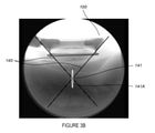
図3Aは、クレードル110の高レベル概略図である。ある実施形態では、クレードル110は、円錐の境界線の投影がFUSトランスデューサ120により生成されるFUSビーム140と一致するように、幾何学的円錐形状を有するように設計される。ある実施形態では、クレードル110の円錐形状は、円錐の側部を投影した頂点(例えば円錐の境界線の投影の交点)がFUSエネルギービーム140の焦点深さに対応するように設計される。したがって、図3Bに示すように、FUSエネルギービーム140の処置位置141上への集束を誘導するためにX線画像上で視認可能なマーカとして円錐形状のクレードル110を用いることができる。図3Bは、本発明の一部の実施形態による、クレードル110の側面X線画像の高レベル概略図である。ある実施形態では、ワークステーション180は、クレードル110の側面X線画像を受け取り、クレードル110の側面X線画像をスクリーン165に送り、公知技術の画像処理を用いて、少なくとも1つのコンピュータプロセッサによってクレードル110の円錐の境界線の投影を認識し、これらの投影をクレードル110の側面X線画像に表示するように構成されたソフトウェアモジュールをさら含みうる。好ましい実施形態では、円錐の境界線の投影の交点は円錐の側部を投影した頂点を表し、これはFUSエネルギービーム140の焦点深さに対応する。したがって、円錐の側部を投影した頂点を用いて、施術医がFUSエネルギービーム140を処置位置141に正確かつ安全にナビゲートするのを補助することができる。クレードル110の円錐形態は、側面視の広範な側面投影画像において不変である。したがって、頂点を含めた円錐形状が様々な視点から復元されうる。ある実施形態では、クレードル110は、放射線不透過性材料、放射線不透過性材料で被覆された放射線透過性材料、および半放射線不透過性材料のうちの少なくとも1つを含みうる。
FIG. 3A is a high level schematic of the
ある実施形態では、画像誘導侵襲手技、特にフレームレス定位手技は、FUSエネルギービーム140の標的位置141への位置合わせおよびナビゲーションを助けるために特別なマーカでタグ付けされたオブジェクトを追跡する立体光学イメージセンサを含む。このようなマーカは通常、視野内で容易に識別されうる大きな球体であるか、または同様に特定のオブジェクトを一意的に識別して視野内で追跡できる符号化された白黒のバーコード状ラベルでありうる。球体はその形状が視角の変化に対してほぼ不変であるため、特に一般的である。CTまたはMRのような3D画像化モダリティにおいては、マーカは一次元または二次元であり、視認可能にするために放射線不透過性材料または磁性材料で作られる。X線(蛍光透視)誘導には、放射線不透過性マーカによる2Dテンプレートが、術前3D画像化データとの位置合わせおよび追跡のために通常用いられる。
In certain embodiments, the image-guided invasion procedure, in particular the frameless localization procedure, is a stereoscopic image that tracks an object tagged with a special marker to aid in the alignment and navigation of the
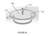
図4Aは、本発明の一部の実施形態による、クレードル110内に配置された照準装置130の高レベル概略図である。ある実施形態では、照準装置130は、クレードル110内に配置されるように構成されたモックアップ115を含みうる。ある実施形態では、モックアップ115は、施術医(physical)が患者の皮膚83を視野内に保てるようにする透明材料(例えばPerspex(登録商標))を含みうる。ある実施形態では、モックアップ115は、標的位置141の鮮明なX線画像を生成するために放射線透過性材料(例えばPerspex(登録商標)および炭素繊維)を含みうる。
FIG. 4A is a high-level schematic of the
ある実施形態では、照準装置130は、少なくとも1つの光学マーカホルダ113をさらに含みうる。ある実施形態では、光学マーカホルダ113は、少なくとも1つのレーザーポインタを含みうる。ある実施形態では、少なくとも1つの光学マーカホルダ113は、FUSトランスデューサ120およびクレードル110の中心軸112に沿って直線を作るようにアライニングされうる。ある実施形態では、少なくとも1つの光学マーカホルダ113は、X線画像化システム視野85の法線に対するクレードル110およびFUSトランスデューサ120の位置を確かめるために追加の線を作るように構成されうる。
In certain embodiments, the aiming
図4Bは、本発明の一部の実施形態による、照準装置130のモックアップ115と光学マーカホルダ113との高レベル概略図である。ある実施形態では、照準装置130は、少なくとも1つの光学マーカホルダ113の垂直軸上に配置された少なくとも2つのX線照準マーカ133、134をさらに含みうる。ある実施形態では、X線照準マーカ133、134はリングでもよい。少なくとも1つのX線照準マーカ133、134は、少なくとも1つの溝133Aを含みうる。ある実施形態では、モックアップ115およびX線照準マーカ133、134のうちの少なくとも1つは非対称で、この非対称が光学的にも放射線学的にも視認可能であり、施術医が両方のビューを相関させ、クレードル110を中心軸112に沿ってX線インテンシファイア85と相互にアライニングするために必要に応じて移動の方向および角度を決定できるものであってもよい。
FIG. 4B is a high-level schematic of the aiming
ある実施形態では、モックアップ115および光学マーカホルダ113のうちの少なくとも1つは、X線画像においてモックアップ115の向きを見つけることができるように、少なくとも1つのX線基準マーカを有しうる。ある実施形態では、光学マーカホルダ113は、モックアップ115に固定されるかまたは隣接して置かれた個別のオンおよびオフスイッチを有しうる。
In certain embodiments, at least one of the
図5A~図5Bは、本発明の一部の実施形態による、一方法を示した高レベルフローチャートである。ステップ510で、少なくとも1つの放射線不透過性マーカがX線インテンシファイア85の中心に置かれる(例えば図6Aの70Aを参照)。ステップ515で、患者が手技プラットフォーム90に腹臥位で配置される。患者がテーブル上に配置されたあと、患者の脊椎とクレードルとの両方がX線視野内に見えるように、テーブルとCアームとの相対的高さが調節される。高さは一旦設定されると、手技の間中ロックされたままである。この調節は、側面X線画像ならびにテーブル高さおよびCアーム高さの操作により行われる。
5A-5B are high-level flowcharts showing a method according to some embodiments of the present invention. At
ステップ520で、X線画像で見える放射線不透過性マーカ70Aを患者内の処置位置141に重なるように置くために、X線アーム87(図2参照)を水平に移動させる(例えば図6Aの70A‐2参照)。ある実施形態では、X線インテンシファイア85が処置位置141に対してある角度で配置されて、放射線不透過性マーカ70Aが処置位置141の上に重ねられうる。角度が設定される場合には、設定はステップ520の前に行われる点に注意することが重要である。この角度は所望の視角となるであろう。これは、患者の身体へのFUSエネルギー浸透の角度でもある。ステップ525で、X線画像中に放射線不透過性マーカ70A‐2を用いて処置位置141を確かめたあとに少なくとも1つの一時的マーカ84(例えば針の先端)を患者の皮膚83上に一時的に置くことにより施術医が患者の皮膚83上で選択する特定の位置に放射線不透過性マーカ70Bが置かれる(例えば図6Bを参照)。ある実施形態では、マーカ70Bだけが/マーカ70Bも可視マーカであってもよい。このマーカは、FUSエネルギーによる患者皮膚に対する近接場加熱および損傷を避けるために大きな音響吸収性を有しない。
In
ステップ530で、結合アクセサリ125が、ステップ525のように患者の皮膚83上のマーカ70Bの上に置かれる。ステップ535で、モックアップ115を備えたクレードル110が、結合アクセサリ125上に置かれる(例えば図6Bを参照)。
At
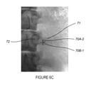
ステップ540で、モックアップ115上の少なくとも1つの光学マーカホルダ113がオンにされ、装置100の関節アーム111を用い、コリニアレーザを患者の皮膚83上の放射線不透過性マーカ70Bとインテンシファイア85上の放射線不透過性マーカ70Aとに向けて、クレードル110がアライニングされる。ステップ545で、軸112に沿ったX線画像化システム視野の中心の法線に対するクレードル110およびモックアップ115のアライメントを確かめるためにX線画像が撮影される。ステップ550で、アライメントが確かめられる。ステップ545のX線画像上で放射線不透過性マーカ70A‐2、70B‐1が重なっていれば、クレードル110およびモックアップ115が軸112に沿ってX線画像化システム視野の中心の法線とアライニングされているということである(例えば図6Cを参照)。ステップ545のX線画像上で放射線不透過性マーカ70A‐2、70B‐1が重なっていなければ、ステップ535を再び行わなければならない。ある実施形態では、クレードル110およびモックアップ115のX線画像化システム視野の中心の法線とのアライメントは、少なくとも1つの光学マーカホルダ113の垂直軸上に配置された少なくとも2つのX線照準マーカ133、134を用いて確かめられてもよい。クレードル110およびモックアップ115が軸112に沿ってX線画像化システム視野の中心の法線とアライニングされると、X線照準マーカ133、134はステップ545のX線画像で同中心に見えるようになる(例えば図7Aを参照)。ステップ545のX線画像でX線照準マーカ133、134が同中心に見えなければ(例えば図7Bを参照)、ステップ535が繰り返されなければならない。照準装置130のある範囲の位置および角度エラーは許容されうる。許容されるエラーの指示は、照準マーカの直径間の隙間など、X線照準マーカ133、134の形状および/またはサイズにより施術医に提示されることができ、エラー限度内でのアライメントを指示するために内側のX線照準マーカ133のまわりに視認可能なままでなければならない。ある実施形態では、このステップでのクレードルおよび照準装置のアライメントの品質についての判断は、X線画像化を必要とせずに光学マーカだけに基づいて行われることもできる。
At
ある実施形態では、クレードル110のアライメントは、インテンシファイア85に面するクレードル110またはFUSトランスデューサ120上に位置する深さカメラにより生み出される深さ画像に基づいて行われうる。クレードル110は、深さ画像分析によりインテンシファイア85の平面がクレードル110と平行になるように、またインテンシファイア85の形状がクレードル110またはFUSトランスデューサ120の中心と軸合わせされてクレードル110、インテンシファイア85および中心軸112が同一直線上になるように、アライニングされる。ある実施形態では、クレードル110のアライメントは、インテンシファイア85に面するクレードル110またはFUSトランスデューサ120上に位置する超音波センサ、RFセンサ、IRセンサまたはレーザセンサ等であるがこれらに限定されない少なくとも2つの距離センサに基づいて行われうる。これらのセンサは、インテンシファイア85からの距離を測定し、クレードル110をインテンシファイア85の面に対して平行にアライニングするために必要なアライメントを指示することができる。距離センサを補って(complimentary)、インテンシファイア85に面するクレードル110またはFUSトランスデューサ120上に位置するカメラがインテンシファイア85の丸い形状の画像を生み出して、インテンシファイア85に対するクレードル110の位置、および中心軸112とインテンシファイア85とクレードル110とを相互にアライニングするためにクレードル110を移動させるべき方向を指示する。ある実施形態では、クレードル110のアライメントは、クレードル110またはFUSトランスデューサ120上とインテンシファイア85上とに位置する少なくとも2つの二軸傾斜計または角形成センサに基づいて行われうる。これらのセンサは、クレードル110またはFUSトランスデューサ120の角度およびインテンシファイア85の角度を測定し、クレードル110をインテンシファイア85の面に対して平行にアライニングするために必要なアライメントを指示することができる。これは、絶対角度の測定に基づいて、または基線の平行の向きで行われる較正にしたがって行われうる。角度センサを補って、インテンシファイア85に面するクレードル110またはFUSトランスデューサ120上に位置するカメラがインテンシファイア85の丸い形状の画像を生み出して、インテンシファイア85に対するクレードル110の位置、およびインテンシファイア85の中心軸とクレードル110とを相互にアライニングするためにクレードル110を移動させるべき方向を指示する。傾斜計または角形成センサは、有線でも無線でもよく、必要な角度を測定するために任意の既存の技術を使用しうる。
In certain embodiments, the alignment of the
ステップ555で、ワークステーション180のソフトウェアモジュールにより認識されるFUSビーム経路140を用いて処置位置141の深さを確かめるために、X線画像化システムのCアーム87が横方向に、好ましくはクレードル軸112に対して直角の角度に傾けられる(例えば図3Bを参照)。Cアーム87の傾斜は、好ましくは単一軸上で実行されなければならない。CT、超音波およびその他等の他のタイプの画像化を誘導に使用する際には、トランスデューサの焦点の位置が画像から外挿されることもできる。適用可能な焦点範囲内に処置深さが確かめられたら、Cアーム87が以前の垂直位置に戻されなければならない。Cアーム87は、モックアップ115の角度にしたがって、光学マーカホルダ113を放射線不透過性マーカ70Aおよび70B上に向けて、再配置されなければならない。ある実施形態では、アライメントを確かめるためにX線画像が再び撮影されうる。
At
ステップ560で、モックアップ115がクレードル110から取り外され、トランスデューサ120がクレードル110に挿入される。ステップ565で、X線照準器150がFUSトランスデューサ120内に置かれる。ステップ570で、X線照準器150を用いてステップ550のようにクレードル110およびFUSトランスデューサ120が軸112に沿ったX線画像化システム視野の中心の法線とアライニングされていることを確かめるためにX線画像が撮影される。ステップ575で、FUS音響エネルギービーム140が投入され、標的ポジション141のアブレーションが行われる。ある実施形態では、FUS音響エネルギーは、アブレーションレベルのエネルギーパルスを投入する前に、患者ごとの標的フィードバックを確かめるためにまず低レベルで投入されることもできる。
At
図8A~図8Bは、本発明の一部の実施形態による、異なる位置に位置する光学マーカホルダの高レベル概略図である。本発明のこれらの実施形態では、光学マーカ113または鏡114から生じるレーザビームが、Cアームの中心軸線112とアライニングされ、インテンシファイアプレートの中心の放射線不透過性マーカがX線画像上で処置標的と一致するように調節されるため、モックアップ115の使用は必要ない。代わりに、FUSトランスデューサに直接取り付けられたX線/光学照準器が使用されうる。
8A-8B are high-level schematics of optical marker holders located at different positions according to some embodiments of the present invention. In these embodiments of the present invention, the laser beam generated from the
光学マーカホルダ113(図8A)または鏡114(図8B)は、Cアーム(X線)インテンシファイアプレート85の中心に取り付けられうる。光学マーカホルダ113または鏡114は、インテンシファイアプレートに対する手動および/または自動での角度アライメントを可能にし、レーザビームをCアーム源86(図2)の中心に投射することによりCアームの中心軸112(図2)とアライニングされるように設計されうる。光学マーカ113または鏡114は、X線画像上で視認可能な放射線不透過性マーカに取り付けられるかまたは放射線不透過性マーカからなってもよい。光学マーカ113または鏡114は、放射線不透過性マーカの中心に適宜置かれうる。図8Aでは、鏡114は角度アライメント能力を有し、光学マーカ113はこの鏡の中心を照準するように調節することができる。
The optical marker holder 113 (FIG. 8A) or mirror 114 (FIG. 8B) may be mounted in the center of the C-arm (X-ray)
図9A~図9Bは、本発明の一部の実施形態による、FUSトランスデューサ120内に固定される改造型X線照準器150の高レベル概略図である。改造型X線照準器150は、光学照準器としてもX線照準器としても使用されうる。
9A-9B are high-level schematics of a modified
改造型X線照準器150は、FUSトランスデューサの中心軸112に沿ってFUSトランスデューサ120のソケットまたは凹部内に置かれ、FUSトランスデューサの垂直軸に沿って置かれたリング133、134等の2つ以上のX線照準マーカを含みうる。FUSトランスデューサを標的に向くようにアライニングするためには、光学マーカが上リング133および下リング134の中心に見えることが必要である。FUSトランスデューサがCアーム中心軸112に正確にアライニングされていることを確かめるために、放射線不透過性リング133,134がX線画像上で同中心に見えることが必要である(図7A、図10)。リングが画像で同中心に見えないか(図7B)または医師が移動を確認した場合には、医師は配置手順を繰り返すものとする。
The modified
改造型x線照準器150のある範囲の位置および角度エラーは許容されうる。許容されるエラーの指示は、リングの直径間の隙間など、X線照準マーカ133、134の形状および/またはサイズにより医師に提示されることができ(図7A~図7B)、エラー限度内でのアライメントを指示するために内側のリング133のまわりを視認可能なままでなければならない。
A range of position and angle errors in the modified
ここで、この構成の一部の実施形態における患者に対する画像誘導集束超音波処置のための方法1100の概略フローダイヤグラムである図11A~図11Bを参照する。
Now refer to FIGS. 11A-11B, which are schematic flow diagrams of
ステップ1110で、放射線不透過性マーカがX線インテンシファイアプレートの中心に置かれうる。その後、ステップ1115のとおり光学マーカホルダがX線インテンシファイアの中心に置かれ、X線源に照準されうる。
At
ステップ1120で、患者が手技プラットフォーム90に腹臥位で配置される。患者がテーブル上に配置されたあと、患者の脊椎とクレードルとの両方がX線視野内に視認可能であるように、テーブルとCアームとの相対的高さが調節される。高さは一旦設定されると、手技の間中ロックされたままである。この調節は、側面X線画像ならびにテーブル高さおよびCアーム高さの操作により行われる。
At
ステップ1125では、X線画像で見える放射線不透過性マーカ70Aを患者内の処置位置141に重なるように置くために、X線アーム87を水平に移動させる(例えば図6Aの70A‐2を参照)。ある実施形態では、X線インテンシファイア85が処置位置141に対してある角度で配置されて、放射線不透過性マーカ70Aが処置位置141の上に重ねられうる。角度が設定される場合には、設定はステップ520の前に行われる点に注意することが重要である。この角度は所望の視角となるであろう。これは、患者の身体へのFUSエネルギー浸透の角度でもある。
In
ステップ1135で、結合アクセサリ125が皮膚83上に置かれる。ステップ1140で、FUSトランスデューサ120を備えたクレードル110が結合アクセサリ125の上に置かれる。ステップ1145で、改造型X線照準器150が、FUSトランスデューサ120の中心ホールの中に置かれる。
At
ステップ1150で、X線インテンシファイア85上の少なくとも1つの光学マーカホルダ(図8A~8B)がオンにされ、ステップ1155にしたがって、一方が改造型X線照準器150の上リング133上、他方が改造型X線照準器150の下リング134の(図9A)中心マーカに向けるようにレーザを用いて、クレードルのアライメントが行われる。照準マーカ133、134がX線画像で同中心に見える場合には、クレードルがアライニングされている(図6A)。X線画像で照準マーカ133、134が同中心に見えなければ、ステップ1155が繰り返されなければならない。改造型X線照準器のある範囲の位置および角度エラーは許容されうる。許容されるエラーの指示は、リングの直径間の隙間など、照準マーカ133、134の形状および/またはサイズにより医師に提示されることができ(図7A~7B)、エラー限度内でのアライメントを指示するために内側のリング133のまわりに視認可能なままでなければならない。ある実施形態では、クレードルおよび照準装置のアライメントの品質についての判断は、X線画像化を必要とせずに光学マーカだけに基づいて行われることもできる。
At
ステップ1170で、処置深さが確かめられなければならない。X線アームをクレードル軸112に対して横に好ましくは90度傾けて、画像化ワークステーションのビーム経路と焦点ポイントとの重ね合わせを用いて処置位置の深さが確かめられるものとする(図3B)。
At
適用可能な焦点範囲内に処置位置深さが確かめられたら、医師はステップ1175にしたがって音響エネルギーを投入し、標的組織をアブレーションする。ある実施形態では、音響エネルギーは、アブレーションレベルのエネルギーパルスを投入する前に、患者ごとの標的フィードバックを確かめるためにまず低レベルで投入されることもできる。
Once the treatment position depth is confirmed within the applicable focal range, the physician applies sound energy according to
ある実施形態によれば、X線照準器150および照準装置130の形状は、画像品質の干渉を低減する様式で設計されうる。図12A~図12Gは、本発明の一部の実施形態による、様々なX線照準器150を備えたFUSトランスデューサ120のX線画像の高レベル概略図であり(図12A~図12C)、うち図12D~図12Gは、異なる設計の照準装置130のX線画像の高レベル概略図である。画像12Hは、照準器が一切挿入されていないトランスデューサを参考として示す。
According to certain embodiments, the shapes of the
提示されたすべてのX線照準器において、画像をできるだけ鮮明にするために、照準器と無関係な放射線不透過度の異なる材料間の鋭い境界面を除去することによってアーチファクトを最小化するために設計が最適化される。類似の効果は、照準装置の設計に(より大きな程度で)見られ、図12F~図12Gで分かるように、図12Dはアーチファクトの多い設計を示し、図12Eは光透過性でもある鮮明な設計を示す。 In all presented X-ray sights, designed to minimize artifacts by removing sharp interface between materials with different radiation opacity unrelated to the sight, in order to make the image as sharp as possible. Is optimized. Similar effects are seen in the design of the sighting device (to a greater extent), as can be seen in FIGS. 12F-12G, FIG. 12D shows a design with a lot of artifacts, and FIG. 12E shows a clear design that is also light transmissive. Is shown.
加えて、X線照準器150の下部は、図12H~図12Gに見られるように、照準器の全体的な放射線不透過性を高め、FUSトランスデューサ120開口部を通した(ゲインおよび画像彩度に関して)よりバランスのよい人体組織の画像化を可能にする、厚いディスク形状のプラスチック部分を有する。
In addition, the lower part of the
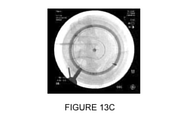
図13A~図13Cは、本発明の一部の実施形態による、クレードル内にFUSトランスデューサを備えた、または備えない、処置標的のX線画像のそれぞれの高レベル概略図である。図13Aは、手技の間にデバイスワークステーション上に示されるFUSトランスデューサのA‐P画像を示す。 13A-13C are high-level schematics of X-ray images of treatment targets with or without a FUS transducer in the cradle, according to some embodiments of the invention. FIG. 13A shows an AP image of the FUS transducer shown on the device workstation during the procedure.
配置プロセスが終わり、クレードルが中心軸112にアライニングされて固定されたあと、ワークステーションは、画像内のクレードルの円形形状を識別して保存し、画像処理を用いて、トランスデューサのX線不透過性により生じる暗領域(図13A)を、処置標的を含むクレードルの内側領域のクリア画像(図13B)を用いて置き換え、これにより患者の人体組織の遮蔽を避けることができる。これにより、音波処理の準備完了時には、トランスデューサがクレードル内にある状態で処置標的のクリア画像が生み出される(図13C)。その後、医師は画像を観察することができるが、この画像には現在、放射線「透過性トランスデューサ」が示されており、不透過性トランスデューサによりブロックされていた解剖学的情報を提供する。このような画像の重要性は、医師が処置位置と患者が動く可能性がある場合の警告とを確認し、確かめるのを補助することである。これらの特徴は、デバイスの安全プロフィールおよび有効性の結果の向上に決定的である。
After the placement process is complete and the cradle is aligned and secured to the
本装置の別の実施形態は、処置標的を視認しFUSトランスデューサを処置標的にアライニングするために、X線デバイスの画像化を使用する代わりに超音波(US;ultrasound)画像化プローブを使用することである。図14Aは、FUSトランスデューサの中心に装着されたUS画像化プローブの概略図である。アライメントアダプタを用いて、US画像化プローブをトランスデューサ中心軸と連接するようにアライニングする。 Another embodiment of the device uses an ultrasound (US) imaging probe instead of using imaging of an X-ray device to visually recognize the treatment target and align the FUS transducer with the treatment target. That is. FIG. 14A is a schematic view of a US imaging probe mounted in the center of the FUS transducer. An alignment adapter is used to align the US imaging probe with the transducer center axis.
画像化プローブおよびトランスデューサUS音波処理の同時作業は超音波画像の品質を大きく劣化させ、画像化能力を完全にブロックしさえするため、交互パルス化方法が図14Bに記載される。FUSエネルギーは、短時間の中止周期を伴ってパルス化されることになる。中止周期にあれば、超音波画像化ストリームからアーチファクトまたは劣化のない画像がとらえられて、次のエネルギー中止周期にとらえられる次の歪みのない画像により置き換えられるまで画像化ワークステーションに提示される。このようにして、画像化のリフレッシュレートはより低くなるであろうが、音波処理の間になお画像フィードバックを生み出すことができる。予測される画像劣化のレベルが大きいため、基本的画像処理技術を用いて歪みのない画像が確認されうる。あるいは、治療音波を生み出すパルスが、超音波画像のアーチファクトおよび劣化を最小化する様式で生み出されてもよい。上記の具体化の独自性は、臨床的適応に必要な画像化特性を備えた任意の一般的な超音波画像化システムを、改造またはゲート信号への接続を必要とせずに集束超音波システムのガイダンスとしてそのまま使用できることである点に注意することが重要である。 An alternating pulse method is described in FIG. 14B, as simultaneous work of imaging probe and transducer US acoustic processing significantly degrades the quality of the ultrasound image and even completely blocks the imaging capability. The FUS energy will be pulsed with a short stop cycle. If in the discontinuation cycle, an artifact or degradation-free image is captured from the ultrasound imaging stream and presented to the imaging workstation until it is replaced by the next distortion-free image captured in the next energy discontinuation cycle. In this way, the refresh rate of imaging will be lower, but image feedback can still be produced during sound wave processing. Due to the high level of predicted image degradation, distortion-free images can be confirmed using basic image processing techniques. Alternatively, the pulse that produces the therapeutic sound waves may be produced in a manner that minimizes artifacts and degradation of the ultrasound image. The uniqueness of the above embodiment is that any common ultrasound imaging system with the imaging properties required for clinical adaptation can be transformed into a focused ultrasound system without the need to modify or connect to a gate signal. It is important to note that it can be used as-is as guidance.
以上の説明において、実施形態は、本発明の例または具体化である。「一実施形態」、「実施形態」、「ある実施形態」または「一部の実施形態」の様々な出現は、必ずしも全てが同じ実施形態をさすとは限らない。本発明の様々な特徴は、単一の実施形態の文脈で記載されているかもしれないが、これらの特徴が別々に提供されても、または任意の適切な組み合わせで提供されてもよい。逆にいえば、本発明は、本明細書においては明確のために別々の実施形態の文脈で記載されているかもしれないが、本発明は単一の実施形態で実施されてもよい。本発明のある実施形態は、上に開示した異なる実施形態からの特徴を含んでもよく、ある実施形態は、上に開示した他の実施形態からの要素を組み込んでもよい。特定の実施形態の文脈での本発明の要素の開示は、それらの使用をその特定の実施形態だけに制限するものと解釈されるものではない。さらに、本発明が様々な仕方で実行または実践されうること、および本発明が以上の説明に概説されたもの以外のある実施形態で実施されうることが理解されるものである。 In the above description, embodiments are examples or embodiment of the present invention. The various appearances of "one embodiment", "embodiment", "certain embodiment" or "partial embodiment" do not necessarily refer to the same embodiment. The various features of the invention may be described in the context of a single embodiment, but these features may be provided separately or in any suitable combination. Conversely, the invention may be described herein in the context of separate embodiments for clarity, but the invention may be implemented in a single embodiment. Certain embodiments of the invention may include features from different embodiments disclosed above, and some embodiments may incorporate elements from other embodiments disclosed above. Disclosure of the elements of the invention in the context of a particular embodiment is not construed to limit their use to that particular embodiment alone. Further, it is understood that the invention may be practiced or practiced in various ways and that the invention may be practiced in certain embodiments other than those outlined in the above description.
本発明は、図または対応する説明に限定されない。例えば、フローが図示されたボックスまたは状態をそれぞれ通って進まなくても、または図示または説明と全く同じ順序で進まなくてもよい。別段の定めがない限り、本明細書において用いられる技術的および科学的用語の意味は、本発明が帰属する技術の当業者により一般に理解されるものとする。本発明は、限定数の実施形態に関して記載されるが、これらは本発明の範囲に対する制限としてではなく、好ましい実施形態のいくつかの例証として解釈されるものである。他の考えられるバリエーション、変更および応用も、本発明の範囲内である。したがって、本発明の範囲は、以上に記載されていることによってではなく、添付の請求の範囲およびそれらの法律的等価物により制限されるものとする。 The invention is not limited to the figures or the corresponding description. For example, the flow may not travel through each of the illustrated boxes or states, or may not proceed in exactly the same order as illustrated or described. Unless otherwise specified, the meanings of the technical and scientific terms used herein are generally understood by those skilled in the art to which the invention belongs. The invention is described with respect to a limited number of embodiments, but these are to be construed as some illustration of preferred embodiments, not as limitations to the scope of the invention. Other possible variations, modifications and applications are also within the scope of the invention. Accordingly, the scope of the invention shall be limited not by what is described above, but by the claims of attachment and their legal equivalents.
Claims (56)
関節アームのベースで手技プラットフォームに取り付けられた、関節アームと、
前記アームの遠位端に固定されたクレードルと、
前記クレードル内に固定された照準装置と、
前記クレードル内に固定された中心軸を有し、患者内の処置位置に超音波治療エネルギービームを伝達するように構成された、集束超音波(FUS)トランスデューサであって、前記トランスデューサによる集束超音波の印加を制御するためにコントローラに接続された、FUSトランスデューサと、
X線画像化システムから画像化データを導出するように構成された画像化ユニットに接続された、画像化ワークステーションと、
を含む、装置。 An X-ray guidance device for image-guided focused ultrasound (FUS) treatment.
With the joint arm attached to the procedure platform at the base of the joint arm,
With a cradle fixed to the distal end of the arm,
With the aiming device fixed in the cradle,
A focused ultrasound (FUS) transducer that has a central axis fixed within the cradle and is configured to transmit an ultrasonic therapy energy beam to a treatment position within the patient, the focused ultrasound by the transducer. FUS transducers connected to the controller to control the application of
An imaging workstation connected to an imaging unit configured to derive imaging data from an X-ray imaging system,
Including equipment.
放射線不透過性材料;
被覆材料を備えた放射線透過性材料;および
半放射線不透過性材料、
のうちのいずれかから作られる、請求項1に記載の装置。 The cradle has the following material types:
Radiation impermeable material;
Radiation permeable material with coating material; and semi-radiation opaque material,
The device according to claim 1, which is made from any of the above.
Cアーム;
Oアーム;
Gアーム;および
他の任意の一般的なx線のタイプ、
のうちのいずれかに対応する、請求項2に記載の装置。 The device has the following X-ray type:
C arm;
O arm;
G-arms; and any other common x-ray type,
The device according to claim 2, which corresponds to any of the above.
前記ワークステーションに電子的に接続されたディスプレイシステムと;
前記X線画像化システムから処置画像を受け取ること;
前記X線処置画像を前記ディスプレイシステムに送ること;および
操作者が集束超音波エネルギービームを前記処置位置に正確かつ安全にナビゲートするのを補助するために、画像処理を用いて前記超音波エネルギービームの円錐形状を前記ディスプレイ上の前記X線処置画像の上にマークすること、
をするように構成された、処理モジュールと、
をさらに含む、請求項15または16に記載の装置。 The workstation
With a display system electronically connected to the workstation;
Receiving treatment images from the X-ray imaging system;
Sending the X-ray treated image to the display system; and using image processing to assist the operator in accurately and safely navigating the focused ultrasound energy beam to the treatment position. Marking the cone shape of the beam on the X-ray treated image on the display,
A processing module configured to do, and
The device of claim 15 or 16, further comprising.
画像処理を用いて前記FUSトランスデューサの放射線不透過性により生じる暗領域を置き換えて前記処置位置のクリア画像を生み出すことにより、前記X線画像化を更新すること;および
前記更新されたX線画像化を前記ディスプレイシステムに送ること、
をするようにさらに構成される、請求項17に記載の装置。 The processing module is
Updating the X-ray imaging by using image processing to replace the dark areas caused by the radiodensity of the FUS transducer to produce a clear image of the treatment position; and the updated X-ray imaging. To the display system,
17. The apparatus of claim 17, further configured to do so.
X線画像化から前記FUSトランスデューサの前記円形形状を識別すること;および
選択されたピクセルだけで画像処理を実行すること、
をするようにさらに構成される、請求項17に記載の装置。 The processing module is
Identifying the circular shape of the FUS transducer from X-ray imaging; and performing image processing on selected pixels only.
17. The apparatus of claim 17, further configured to do so.
前記少なくとも1つの放射線不透過性マーカをX線インテンシファイアの中心に置くステップと;
前記患者を前記処置プラットフォームに腹臥位で配置するステップと;
前記X線アームが所望の角度にロックされている間に前記X線画像で見える前記放射線不透過性マーカを前記治療位置に重なるように置くために、前記X線アームを水平に移動させるステップと;
前記マーカを前記患者の皮膚上にマークするステップと;
前記結合アクセサリを、前記患者の前記皮膚上の、前記患者の皮膚上の前記マーカの上に置くステップと;
前記モックアップを備えた前記クレードルを前記結合アクセサリ上に置くステップと;
前記少なくとも1つの光学マーカホルダをオンにし、前記クレードルをアライニングするステップと;
前記治療深さを確かめるステップと;
前記モックアップを前記FUSトランスデューサで置き換えるステップと;
任意のX線照準器を前記FUSトランスデューサ内に置くステップと;
前記FUSトランスデューサがアライニングされていることを確かめるためにX線画像を撮影するステップと;
前記音響エネルギーを投入するステップと、
を含む、方法。 A method of image-guided focused ultrasound treatment for a patient using the kit of claim 48.
With the step of placing the at least one radiodensity marker in the center of the X-ray intensifier;
With the step of placing the patient in the prone position on the treatment platform;
With the step of moving the X-ray arm horizontally in order to place the radiation opaque marker visible in the X-ray image so as to overlap the treatment position while the X-ray arm is locked at a desired angle. ;
With the step of marking the marker on the patient's skin;
With the step of placing the binding accessory on the marker on the patient's skin, on the patient's skin;
With the step of placing the cradle with the mockup on the coupling accessory;
With the step of turning on the at least one optical marker holder and lining the cradle;
With the step to confirm the treatment depth;
With the step of replacing the mockup with the FUS transducer;
With the step of placing any X-ray sight in the FUS transducer;
With the step of taking an X-ray image to make sure the FUS transducer is aligned;
The step of inputting the sound energy and
Including, how.
放射線不透過性マーカをX線インテンシファイアの中心に置くステップと;
光学マーカホルダを前記X線インテンシファイアの中心に置くステップと;
前記患者を前記手技プラットフォームに腹臥位で配置するステップと;
前記X線アームが所望の角度の処置位置にロックされている間に前記X線画像で見える前記放射線不透過性マーカを前記処置位置に重なるように置くために、前記X線アームを水平に移動させるステップと;
前記結合アクセサリを、前記患者の前記皮膚上の、前記患者の皮膚上の前記マーカの上に置くステップと;
前記FUSトランスデューサを備えた前記クレードルを前記結合アクセサリ上に置くステップと;
前記X線照準器を前記FUSトランスデューサの中心ホールの中に置くステップと;
前記少なくとも1つの光学マーカホルダをオンにするステップと;
一方が前記X線照準器の上リング上にあり、他方が前記X線照準器の下リングにある前記中心マーカに向けるように前記レーザを用いて、前記クレードルをアライニングするステップと;
前記処置深さを確かめるステップと;
前記音響エネルギーを投入するステップと、
を含む、方法。 A method of image-guided focused ultrasound treatment for a patient using the kit of claim 49.
With the step of placing the radiodensity marker in the center of the X-ray intensifier;
With the step of placing the optical marker holder in the center of the X-ray intensifier;
With the step of placing the patient in the prone position on the procedure platform;
Move the X-ray arm horizontally to place the radiation opaque marker visible in the X-ray image so that it overlaps the treatment position while the X-ray arm is locked to the treatment position at the desired angle. Steps to make;
With the step of placing the binding accessory on the marker on the patient's skin, on the patient's skin;
With the step of placing the cradle with the FUS transducer on the coupling accessory;
With the step of placing the X-ray sight in the central hole of the FUS transducer;
With the step of turning on the at least one optical marker holder;
With the step of aligning the cradle with the laser so that one is on the upper ring of the X-ray sight and the other is directed at the central marker in the lower ring of the X-ray sight;
With the step to confirm the treatment depth;
The step of inputting the sound energy and
Including the method.
Priority Applications (1)
| Application Number | Priority Date | Filing Date | Title |
|---|---|---|---|
| JP2023026660A JP2023058733A (en) | 2015-08-10 | 2023-02-22 | Image guided focused ultrasound treatment device and aiming apparatus |
Applications Claiming Priority (8)
| Application Number | Priority Date | Filing Date | Title |
|---|---|---|---|
| US201562203114P | 2015-08-10 | 2015-08-10 | |
| US62/203,114 | 2015-08-10 | ||
| US201562238263P | 2015-10-07 | 2015-10-07 | |
| US62/238,263 | 2015-10-07 | ||
| US201662333896P | 2016-05-10 | 2016-05-10 | |
| US62/333,896 | 2016-05-10 | ||
| PCT/US2016/046328 WO2017027577A1 (en) | 2015-08-10 | 2016-08-10 | Image guided focused ultrasound treatment device and aiming apparatus |
| JP2018507005A JP6971967B2 (en) | 2015-08-10 | 2016-08-10 | Image-guided focusing ultrasound treatment device and aiming device |
Related Parent Applications (1)
| Application Number | Title | Priority Date | Filing Date |
|---|---|---|---|
| JP2018507005A Division JP6971967B2 (en) | 2015-08-10 | 2016-08-10 | Image-guided focusing ultrasound treatment device and aiming device |
Related Child Applications (1)
| Application Number | Title | Priority Date | Filing Date |
|---|---|---|---|
| JP2023026660A Division JP2023058733A (en) | 2015-08-10 | 2023-02-22 | Image guided focused ultrasound treatment device and aiming apparatus |
Publications (2)
| Publication Number | Publication Date |
|---|---|
| JP2022017444A true JP2022017444A (en) | 2022-01-25 |
| JP7235834B2 JP7235834B2 (en) | 2023-03-08 |
Family
ID=57983630
Family Applications (3)
| Application Number | Title | Priority Date | Filing Date |
|---|---|---|---|
| JP2018507005A Active JP6971967B2 (en) | 2015-08-10 | 2016-08-10 | Image-guided focusing ultrasound treatment device and aiming device |
| JP2021178654A Active JP7235834B2 (en) | 2015-08-10 | 2021-11-01 | Image-guided focused ultrasound treatment device and sighting device |
| JP2023026660A Pending JP2023058733A (en) | 2015-08-10 | 2023-02-22 | Image guided focused ultrasound treatment device and aiming apparatus |
Family Applications Before (1)
| Application Number | Title | Priority Date | Filing Date |
|---|---|---|---|
| JP2018507005A Active JP6971967B2 (en) | 2015-08-10 | 2016-08-10 | Image-guided focusing ultrasound treatment device and aiming device |
Family Applications After (1)
| Application Number | Title | Priority Date | Filing Date |
|---|---|---|---|
| JP2023026660A Pending JP2023058733A (en) | 2015-08-10 | 2023-02-22 | Image guided focused ultrasound treatment device and aiming apparatus |
Country Status (13)
| Country | Link |
|---|---|
| US (1) | US20180236270A1 (en) |
| EP (2) | EP3791929A1 (en) |
| JP (3) | JP6971967B2 (en) |
| KR (2) | KR20240032165A (en) |
| CN (2) | CN112370669B (en) |
| CA (1) | CA2995114A1 (en) |
| CY (1) | CY1123885T1 (en) |
| DK (1) | DK3334497T3 (en) |
| ES (1) | ES2842183T3 (en) |
| IL (1) | IL257464B (en) |
| PL (1) | PL3334497T3 (en) |
| PT (1) | PT3334497T (en) |
| WO (1) | WO2017027577A1 (en) |
Families Citing this family (9)
| Publication number | Priority date | Publication date | Assignee | Title |
|---|---|---|---|---|
| KR102148854B1 (en) * | 2018-10-31 | 2020-08-28 | (주)클래시스 | Ultrasound apparatus for treating brain disease |
| US20210259711A1 (en) * | 2019-10-30 | 2021-08-26 | Tsinghua University | 2d-image guided robotic distal locking system |
| CN111134776A (en) * | 2020-01-10 | 2020-05-12 | 深圳市奥昇医疗科技有限责任公司 | High-intensity focused ultrasound equipment and control method |
| KR102148853B1 (en) * | 2020-07-02 | 2020-08-28 | (주)클래시스 | Ultrasound apparatus for treating brain disease |
| CN113940747B (en) * | 2020-07-15 | 2024-04-16 | 首都医科大学附属北京友谊医院 | Positioning navigation device for bone channel of nail hole of orthopedic implant |
| EP4192404A4 (en) * | 2020-08-07 | 2024-04-03 | Alpheus Medical Inc | Ultrasound arrays for enhanced sonodynamic therapy for treating cancer |
| CN112107363B (en) * | 2020-08-31 | 2022-08-02 | 上海交通大学 | Ultrasonic fat dissolving robot system based on depth camera and auxiliary operation method |
| KR102588217B1 (en) * | 2021-05-13 | 2023-10-12 | 주식회사 제이시스메디칼 | Ultrasonic generator with adjustment of ultrasonic focusing depth |
| KR102431184B1 (en) * | 2022-01-28 | 2022-08-10 | 심영석 | Needle adjustment device to prevent radiation |
Citations (5)
| Publication number | Priority date | Publication date | Assignee | Title |
|---|---|---|---|---|
| JPH05237131A (en) * | 1991-10-24 | 1993-09-17 | Siemens Ag | Treatment device |
| JPH06233776A (en) * | 1993-01-14 | 1994-08-23 | Richard Wolf Gmbh | External medical treatment equipment |
| JP2007507275A (en) * | 2003-09-30 | 2007-03-29 | コーニンクレッカ フィリップス エレクトロニクス エヌ ヴィ | Target tracking method and apparatus for radiation therapy planning and implementation |
| JP2007525296A (en) * | 2004-03-01 | 2007-09-06 | シーメンス アクチエンゲゼルシヤフト | Apparatus for image-assisted shock wave therapy |
| JP2009533086A (en) * | 2006-04-07 | 2009-09-17 | ヴァリアン メディカル システムズ テクノロジーズ インコーポレイテッド | Patient positioning using tomosynthesis technology |
Family Cites Families (32)
| Publication number | Priority date | Publication date | Assignee | Title |
|---|---|---|---|---|
| NL8701074A (en) * | 1987-05-07 | 1988-12-01 | Optische Ind De Oude Delft Nv | MEASURING DEVICE. |
| US4938217A (en) * | 1988-06-21 | 1990-07-03 | Massachusetts Institute Of Technology | Electronically-controlled variable focus ultrasound hyperthermia system |
| JP3448778B2 (en) * | 1992-01-31 | 2003-09-22 | 株式会社ニコン | Mark detection apparatus, exposure apparatus having the detection apparatus, device manufactured by the exposure apparatus, mark detection method, exposure method including the detection method, and device manufacturing method including the exposure method |
| US5769790A (en) * | 1996-10-25 | 1998-06-23 | General Electric Company | Focused ultrasound surgery system guided by ultrasound imaging |
| US6516699B2 (en) * | 1997-12-08 | 2003-02-11 | Horus Vision, Llc | Apparatus and method for calculating aiming point information for rifle scopes |
| US6120454A (en) * | 1998-02-03 | 2000-09-19 | Boston Scientific Corporation | Annular array ultrasound catheter |
| US20030060736A1 (en) * | 1999-05-14 | 2003-03-27 | Martin Roy W. | Lens-focused ultrasonic applicator for medical applications |
| CN1121884C (en) * | 2000-10-26 | 2003-09-24 | 上海交通大学 | Multielement self-focusing supersonic transducer |
| JP3964655B2 (en) * | 2001-11-12 | 2007-08-22 | 東芝松下ディスプレイテクノロジー株式会社 | Positioning method |
| SE520858C2 (en) * | 2002-01-15 | 2003-09-02 | Ultrazonix Dnt Ab | Device with both therapeutic and diagnostic sensors for non-invasive ultrasound treatment of an object |
| ATE521276T1 (en) * | 2002-02-11 | 2011-09-15 | Amo Mfg Usa Llc | DETERMINATION OF RELATIVE POSITIONAL AND ROTATIONAL OFFSETS |
| US7311701B2 (en) * | 2003-06-10 | 2007-12-25 | Cierra, Inc. | Methods and apparatus for non-invasively treating atrial fibrillation using high intensity focused ultrasound |
| WO2005107622A1 (en) * | 2004-05-06 | 2005-11-17 | Nanyang Technological University | Mechanical manipulator for hifu transducers |
| US8676300B2 (en) * | 2006-09-18 | 2014-03-18 | Mediguide Ltd. | Method and system for navigating through an occluded tubular organ |
| DE112008002851B4 (en) * | 2007-10-24 | 2018-06-21 | Nuvasive, Inc. | Surgical pathway monitoring system and related procedures |
| WO2011020104A2 (en) * | 2009-08-14 | 2011-02-17 | University Of Southern California | Extended depth-of-focus high intensity ultrasonic transducer |
| US20110144544A1 (en) * | 2009-12-15 | 2011-06-16 | General Electric Company | Ultrasound transducer assembly and methods of using |
| JP5681727B2 (en) * | 2009-12-28 | 2015-03-11 | コーニンクレッカ フィリップス エヌ ヴェ | Optimization of high-density focused ultrasonic transducer |
| JP2012005602A (en) * | 2010-06-23 | 2012-01-12 | Olympus Corp | Ultrasonic irradiation device |
| US8831708B2 (en) * | 2011-03-15 | 2014-09-09 | Siemens Aktiengesellschaft | Multi-modal medical imaging |
| CN102430211B (en) * | 2011-08-19 | 2014-10-01 | 陈明 | X-ray location-based focusing therapy unit and system |
| EP2763591A4 (en) * | 2011-10-09 | 2015-05-06 | Clear Guide Medical Llc | Interventional in-situ image-guidance by fusing ultrasound video |
| JP6207024B2 (en) * | 2012-02-27 | 2017-10-04 | コーニンクレッカ フィリップス エヌ ヴェKoninklijke Philips N.V. | Computed Tomography (CT)-High Density Focused Ultrasound (HIFU) System and / or Method |
| CN103479403B (en) * | 2012-06-08 | 2016-06-22 | 长庚大学 | System and the method thereof that focusing ultrasound wave releases energy is guided with operation guiding system |
| WO2014032171A1 (en) * | 2012-08-27 | 2014-03-06 | Target Tape Inc. | Medical procedure localizing aid |
| US9510802B2 (en) * | 2012-09-21 | 2016-12-06 | Guided Therapy Systems, Llc | Reflective ultrasound technology for dermatological treatments |
| US9289188B2 (en) * | 2012-12-03 | 2016-03-22 | Liposonix, Inc. | Ultrasonic transducer |
| WO2015135057A1 (en) * | 2014-03-14 | 2015-09-17 | Synaptive Medical (Barbados) Inc. | Intelligent positioning system and methods therefore |
| WO2014193013A1 (en) * | 2013-05-31 | 2014-12-04 | 알피니언메디칼시스템 주식회사 | Ultrasonic transducer having cooling function |
| CN103584880B (en) * | 2013-11-04 | 2015-12-30 | 张松方 | A kind of for the conforming checkout gear of the wild launched field of light |
| CN104644200B (en) * | 2013-11-25 | 2019-02-19 | Ge医疗系统环球技术有限公司 | The method and apparatus for reducing pseudomorphism in computed tomography images reconstruct |
| US20150305823A1 (en) * | 2014-04-25 | 2015-10-29 | General Electric Company | System and method for processing navigational sensor data |
-
2016
- 2016-08-10 EP EP20190745.8A patent/EP3791929A1/en active Pending
- 2016-08-10 WO PCT/US2016/046328 patent/WO2017027577A1/en active Application Filing
- 2016-08-10 JP JP2018507005A patent/JP6971967B2/en active Active
- 2016-08-10 CN CN202011147419.1A patent/CN112370669B/en active Active
- 2016-08-10 US US15/752,116 patent/US20180236270A1/en active Pending
- 2016-08-10 CN CN201680054194.0A patent/CN108290053B/en active Active
- 2016-08-10 KR KR1020247006466A patent/KR20240032165A/en active Application Filing
- 2016-08-10 DK DK16835826.5T patent/DK3334497T3/en active
- 2016-08-10 ES ES16835826T patent/ES2842183T3/en active Active
- 2016-08-10 KR KR1020187006948A patent/KR102642526B1/en active IP Right Grant
- 2016-08-10 PT PT168358265T patent/PT3334497T/en unknown
- 2016-08-10 PL PL16835826T patent/PL3334497T3/en unknown
- 2016-08-10 CA CA2995114A patent/CA2995114A1/en active Pending
- 2016-08-10 EP EP16835826.5A patent/EP3334497B1/en active Active
-
2018
- 2018-02-11 IL IL257464A patent/IL257464B/en unknown
-
2020
- 2020-12-21 CY CY20201101207T patent/CY1123885T1/en unknown
-
2021
- 2021-11-01 JP JP2021178654A patent/JP7235834B2/en active Active
-
2023
- 2023-02-22 JP JP2023026660A patent/JP2023058733A/en active Pending
Patent Citations (5)
| Publication number | Priority date | Publication date | Assignee | Title |
|---|---|---|---|---|
| JPH05237131A (en) * | 1991-10-24 | 1993-09-17 | Siemens Ag | Treatment device |
| JPH06233776A (en) * | 1993-01-14 | 1994-08-23 | Richard Wolf Gmbh | External medical treatment equipment |
| JP2007507275A (en) * | 2003-09-30 | 2007-03-29 | コーニンクレッカ フィリップス エレクトロニクス エヌ ヴィ | Target tracking method and apparatus for radiation therapy planning and implementation |
| JP2007525296A (en) * | 2004-03-01 | 2007-09-06 | シーメンス アクチエンゲゼルシヤフト | Apparatus for image-assisted shock wave therapy |
| JP2009533086A (en) * | 2006-04-07 | 2009-09-17 | ヴァリアン メディカル システムズ テクノロジーズ インコーポレイテッド | Patient positioning using tomosynthesis technology |
Also Published As
| Publication number | Publication date |
|---|---|
| PL3334497T3 (en) | 2021-05-04 |
| JP7235834B2 (en) | 2023-03-08 |
| WO2017027577A1 (en) | 2017-02-16 |
| CN108290053A (en) | 2018-07-17 |
| KR102642526B1 (en) | 2024-02-28 |
| KR20240032165A (en) | 2024-03-08 |
| EP3334497A4 (en) | 2019-04-17 |
| PT3334497T (en) | 2020-12-30 |
| ES2842183T3 (en) | 2021-07-13 |
| CN108290053B (en) | 2020-11-13 |
| CN112370669A (en) | 2021-02-19 |
| CN112370669B (en) | 2023-11-17 |
| CY1123885T1 (en) | 2022-03-24 |
| DK3334497T3 (en) | 2020-12-21 |
| EP3791929A1 (en) | 2021-03-17 |
| US20180236270A1 (en) | 2018-08-23 |
| EP3334497B1 (en) | 2020-09-30 |
| EP3334497A1 (en) | 2018-06-20 |
| JP2018525104A (en) | 2018-09-06 |
| CA2995114A1 (en) | 2017-02-16 |
| JP2023058733A (en) | 2023-04-25 |
| IL257464B (en) | 2021-10-31 |
| KR20180038538A (en) | 2018-04-16 |
| IL257464A (en) | 2018-04-30 |
| JP6971967B2 (en) | 2021-11-24 |
Similar Documents
| Publication | Publication Date | Title |
|---|---|---|
| JP7235834B2 (en) | Image-guided focused ultrasound treatment device and sighting device | |
| JP6181459B2 (en) | Radiation therapy system | |
| CN101820949B (en) | Mri-guided HIFU marking to guide radiotherapy and other procedures | |
| US20120238873A1 (en) | Ultrasound Treatment Device | |
| US7725166B2 (en) | Image-assisted shockwave therapy installation | |
| JP7402207B2 (en) | Hand-held device and related method for projecting focused ultrasound waves | |
| US20150042643A1 (en) | Medical x-ray apparatus | |
| JP2006519048A (en) | Method and apparatus for improving motion tracking for HIFU ultrasound therapy | |
| JP2022058793A (en) | System and workflow for grid-less transperineal prostate syndrome | |
| JP2000237205A (en) | Ultrasonic therapeutic apparatus | |
| US8414472B2 (en) | Navigation for focused wave treatment | |
| CN109481018A (en) | A kind of navigation equipment and method applied in medical care precess | |
| KR20160068922A (en) | System for and method of performing sonasurgery | |
| US11234884B2 (en) | Medical apparatus and method for operating the medical apparatus | |
| KR200487320Y1 (en) | Operating medical navigation system with the tiltable head part | |
| JP2004073697A (en) | Ultrasonic irradiation apparatus | |
| JP2015217247A (en) | Ultrasonic treatment device and ultrasonic treatment system | |
| US20230190386A1 (en) | System and method for tissue intervention via image-guided boiling histotripsy | |
| KR20240021745A (en) | Robot equipped with ultrasound probe for real-time guidance of percutaneous interventions |
Legal Events
| Date | Code | Title | Description |
|---|---|---|---|
| A521 | Request for written amendment filed |
Free format text: JAPANESE INTERMEDIATE CODE: A523 Effective date: 20211130 |
|
| A621 | Written request for application examination |
Free format text: JAPANESE INTERMEDIATE CODE: A621 Effective date: 20211130 |
|
| A131 | Notification of reasons for refusal |
Free format text: JAPANESE INTERMEDIATE CODE: A131 Effective date: 20220920 |
|
| A521 | Request for written amendment filed |
Free format text: JAPANESE INTERMEDIATE CODE: A523 Effective date: 20221216 |
|
| TRDD | Decision of grant or rejection written | ||
| A01 | Written decision to grant a patent or to grant a registration (utility model) |
Free format text: JAPANESE INTERMEDIATE CODE: A01 Effective date: 20230124 |
|
| A61 | First payment of annual fees (during grant procedure) |
Free format text: JAPANESE INTERMEDIATE CODE: A61 Effective date: 20230224 |
|
| R150 | Certificate of patent or registration of utility model |
Ref document number: 7235834 Country of ref document: JP Free format text: JAPANESE INTERMEDIATE CODE: R150 |