JP2022016603A - Method for producing rare earth aluminate sintered body - Google Patents
Method for producing rare earth aluminate sintered body Download PDFInfo
- Publication number
- JP2022016603A JP2022016603A JP2021190689A JP2021190689A JP2022016603A JP 2022016603 A JP2022016603 A JP 2022016603A JP 2021190689 A JP2021190689 A JP 2021190689A JP 2021190689 A JP2021190689 A JP 2021190689A JP 2022016603 A JP2022016603 A JP 2022016603A
- Authority
- JP
- Japan
- Prior art keywords
- rare earth
- sintered body
- earth aluminate
- raw material
- aluminate sintered
- Prior art date
- Legal status (The legal status is an assumption and is not a legal conclusion. Google has not performed a legal analysis and makes no representation as to the accuracy of the status listed.)
- Granted
Links
Images


Classifications
-
- C—CHEMISTRY; METALLURGY
- C09—DYES; PAINTS; POLISHES; NATURAL RESINS; ADHESIVES; COMPOSITIONS NOT OTHERWISE PROVIDED FOR; APPLICATIONS OF MATERIALS NOT OTHERWISE PROVIDED FOR
- C09K—MATERIALS FOR MISCELLANEOUS APPLICATIONS, NOT PROVIDED FOR ELSEWHERE
- C09K11/00—Luminescent, e.g. electroluminescent, chemiluminescent materials
- C09K11/08—Luminescent, e.g. electroluminescent, chemiluminescent materials containing inorganic luminescent materials
- C09K11/77—Luminescent, e.g. electroluminescent, chemiluminescent materials containing inorganic luminescent materials containing rare earth metals
- C09K11/7766—Luminescent, e.g. electroluminescent, chemiluminescent materials containing inorganic luminescent materials containing rare earth metals containing two or more rare earth metals
- C09K11/7774—Aluminates
-
- B—PERFORMING OPERATIONS; TRANSPORTING
- B22—CASTING; POWDER METALLURGY
- B22F—WORKING METALLIC POWDER; MANUFACTURE OF ARTICLES FROM METALLIC POWDER; MAKING METALLIC POWDER; APPARATUS OR DEVICES SPECIALLY ADAPTED FOR METALLIC POWDER
- B22F1/00—Metallic powder; Treatment of metallic powder, e.g. to facilitate working or to improve properties
- B22F1/14—Treatment of metallic powder
- B22F1/142—Thermal or thermo-mechanical treatment
-
- B—PERFORMING OPERATIONS; TRANSPORTING
- B22—CASTING; POWDER METALLURGY
- B22F—WORKING METALLIC POWDER; MANUFACTURE OF ARTICLES FROM METALLIC POWDER; MAKING METALLIC POWDER; APPARATUS OR DEVICES SPECIALLY ADAPTED FOR METALLIC POWDER
- B22F7/00—Manufacture of composite layers, workpieces, or articles, comprising metallic powder, by sintering the powder, with or without compacting wherein at least one part is obtained by sintering or compression
- B22F7/008—Manufacture of composite layers, workpieces, or articles, comprising metallic powder, by sintering the powder, with or without compacting wherein at least one part is obtained by sintering or compression characterised by the composition
-
- C—CHEMISTRY; METALLURGY
- C01—INORGANIC CHEMISTRY
- C01F—COMPOUNDS OF THE METALS BERYLLIUM, MAGNESIUM, ALUMINIUM, CALCIUM, STRONTIUM, BARIUM, RADIUM, THORIUM, OR OF THE RARE-EARTH METALS
- C01F17/00—Compounds of rare earth metals
- C01F17/30—Compounds containing rare earth metals and at least one element other than a rare earth metal, oxygen or hydrogen, e.g. La4S3Br6
- C01F17/32—Compounds containing rare earth metals and at least one element other than a rare earth metal, oxygen or hydrogen, e.g. La4S3Br6 oxide or hydroxide being the only anion, e.g. NaCeO2 or MgxCayEuO
- C01F17/34—Aluminates, e.g. YAlO3 or Y3-xGdxAl5O12
-
- C—CHEMISTRY; METALLURGY
- C04—CEMENTS; CONCRETE; ARTIFICIAL STONE; CERAMICS; REFRACTORIES
- C04B—LIME, MAGNESIA; SLAG; CEMENTS; COMPOSITIONS THEREOF, e.g. MORTARS, CONCRETE OR LIKE BUILDING MATERIALS; ARTIFICIAL STONE; CERAMICS; REFRACTORIES; TREATMENT OF NATURAL STONE
- C04B35/00—Shaped ceramic products characterised by their composition; Ceramics compositions; Processing powders of inorganic compounds preparatory to the manufacturing of ceramic products
- C04B35/01—Shaped ceramic products characterised by their composition; Ceramics compositions; Processing powders of inorganic compounds preparatory to the manufacturing of ceramic products based on oxide ceramics
- C04B35/10—Shaped ceramic products characterised by their composition; Ceramics compositions; Processing powders of inorganic compounds preparatory to the manufacturing of ceramic products based on oxide ceramics based on aluminium oxide
- C04B35/111—Fine ceramics
- C04B35/117—Composites
-
- C—CHEMISTRY; METALLURGY
- C04—CEMENTS; CONCRETE; ARTIFICIAL STONE; CERAMICS; REFRACTORIES
- C04B—LIME, MAGNESIA; SLAG; CEMENTS; COMPOSITIONS THEREOF, e.g. MORTARS, CONCRETE OR LIKE BUILDING MATERIALS; ARTIFICIAL STONE; CERAMICS; REFRACTORIES; TREATMENT OF NATURAL STONE
- C04B35/00—Shaped ceramic products characterised by their composition; Ceramics compositions; Processing powders of inorganic compounds preparatory to the manufacturing of ceramic products
- C04B35/01—Shaped ceramic products characterised by their composition; Ceramics compositions; Processing powders of inorganic compounds preparatory to the manufacturing of ceramic products based on oxide ceramics
- C04B35/44—Shaped ceramic products characterised by their composition; Ceramics compositions; Processing powders of inorganic compounds preparatory to the manufacturing of ceramic products based on oxide ceramics based on aluminates
-
- C—CHEMISTRY; METALLURGY
- C04—CEMENTS; CONCRETE; ARTIFICIAL STONE; CERAMICS; REFRACTORIES
- C04B—LIME, MAGNESIA; SLAG; CEMENTS; COMPOSITIONS THEREOF, e.g. MORTARS, CONCRETE OR LIKE BUILDING MATERIALS; ARTIFICIAL STONE; CERAMICS; REFRACTORIES; TREATMENT OF NATURAL STONE
- C04B35/00—Shaped ceramic products characterised by their composition; Ceramics compositions; Processing powders of inorganic compounds preparatory to the manufacturing of ceramic products
- C04B35/622—Forming processes; Processing powders of inorganic compounds preparatory to the manufacturing of ceramic products
- C04B35/626—Preparing or treating the powders individually or as batches ; preparing or treating macroscopic reinforcing agents for ceramic products, e.g. fibres; mechanical aspects section B
- C04B35/62605—Treating the starting powders individually or as mixtures
- C04B35/62645—Thermal treatment of powders or mixtures thereof other than sintering
- C04B35/62675—Thermal treatment of powders or mixtures thereof other than sintering characterised by the treatment temperature
-
- C—CHEMISTRY; METALLURGY
- C04—CEMENTS; CONCRETE; ARTIFICIAL STONE; CERAMICS; REFRACTORIES
- C04B—LIME, MAGNESIA; SLAG; CEMENTS; COMPOSITIONS THEREOF, e.g. MORTARS, CONCRETE OR LIKE BUILDING MATERIALS; ARTIFICIAL STONE; CERAMICS; REFRACTORIES; TREATMENT OF NATURAL STONE
- C04B35/00—Shaped ceramic products characterised by their composition; Ceramics compositions; Processing powders of inorganic compounds preparatory to the manufacturing of ceramic products
- C04B35/622—Forming processes; Processing powders of inorganic compounds preparatory to the manufacturing of ceramic products
- C04B35/64—Burning or sintering processes
-
- C—CHEMISTRY; METALLURGY
- C09—DYES; PAINTS; POLISHES; NATURAL RESINS; ADHESIVES; COMPOSITIONS NOT OTHERWISE PROVIDED FOR; APPLICATIONS OF MATERIALS NOT OTHERWISE PROVIDED FOR
- C09K—MATERIALS FOR MISCELLANEOUS APPLICATIONS, NOT PROVIDED FOR ELSEWHERE
- C09K11/00—Luminescent, e.g. electroluminescent, chemiluminescent materials
- C09K11/02—Use of particular materials as binders, particle coatings or suspension media therefor
-
- G—PHYSICS
- G02—OPTICS
- G02B—OPTICAL ELEMENTS, SYSTEMS OR APPARATUS
- G02B1/00—Optical elements characterised by the material of which they are made; Optical coatings for optical elements
-
- G—PHYSICS
- G02—OPTICS
- G02B—OPTICAL ELEMENTS, SYSTEMS OR APPARATUS
- G02B26/00—Optical devices or arrangements for the control of light using movable or deformable optical elements
- G02B26/007—Optical devices or arrangements for the control of light using movable or deformable optical elements the movable or deformable optical element controlling the colour, i.e. a spectral characteristic, of the light
- G02B26/008—Optical devices or arrangements for the control of light using movable or deformable optical elements the movable or deformable optical element controlling the colour, i.e. a spectral characteristic, of the light in the form of devices for effecting sequential colour changes, e.g. colour wheels
-
- G—PHYSICS
- G03—PHOTOGRAPHY; CINEMATOGRAPHY; ANALOGOUS TECHNIQUES USING WAVES OTHER THAN OPTICAL WAVES; ELECTROGRAPHY; HOLOGRAPHY
- G03B—APPARATUS OR ARRANGEMENTS FOR TAKING PHOTOGRAPHS OR FOR PROJECTING OR VIEWING THEM; APPARATUS OR ARRANGEMENTS EMPLOYING ANALOGOUS TECHNIQUES USING WAVES OTHER THAN OPTICAL WAVES; ACCESSORIES THEREFOR
- G03B21/00—Projectors or projection-type viewers; Accessories therefor
- G03B21/14—Details
- G03B21/20—Lamp housings
- G03B21/2006—Lamp housings characterised by the light source
- G03B21/2033—LED or laser light sources
- G03B21/204—LED or laser light sources using secondary light emission, e.g. luminescence or fluorescence
-
- H—ELECTRICITY
- H01—ELECTRIC ELEMENTS
- H01L—SEMICONDUCTOR DEVICES NOT COVERED BY CLASS H10
- H01L33/00—Semiconductor devices with at least one potential-jump barrier or surface barrier specially adapted for light emission; Processes or apparatus specially adapted for the manufacture or treatment thereof or of parts thereof; Details thereof
- H01L33/48—Semiconductor devices with at least one potential-jump barrier or surface barrier specially adapted for light emission; Processes or apparatus specially adapted for the manufacture or treatment thereof or of parts thereof; Details thereof characterised by the semiconductor body packages
- H01L33/50—Wavelength conversion elements
- H01L33/501—Wavelength conversion elements characterised by the materials, e.g. binder
- H01L33/502—Wavelength conversion materials
-
- B—PERFORMING OPERATIONS; TRANSPORTING
- B22—CASTING; POWDER METALLURGY
- B22F—WORKING METALLIC POWDER; MANUFACTURE OF ARTICLES FROM METALLIC POWDER; MAKING METALLIC POWDER; APPARATUS OR DEVICES SPECIALLY ADAPTED FOR METALLIC POWDER
- B22F2201/00—Treatment under specific atmosphere
- B22F2201/03—Oxygen
-
- B—PERFORMING OPERATIONS; TRANSPORTING
- B22—CASTING; POWDER METALLURGY
- B22F—WORKING METALLIC POWDER; MANUFACTURE OF ARTICLES FROM METALLIC POWDER; MAKING METALLIC POWDER; APPARATUS OR DEVICES SPECIALLY ADAPTED FOR METALLIC POWDER
- B22F2301/00—Metallic composition of the powder or its coating
- B22F2301/45—Rare earth metals, i.e. Sc, Y, Lanthanides (57-71)
-
- B—PERFORMING OPERATIONS; TRANSPORTING
- B22—CASTING; POWDER METALLURGY
- B22F—WORKING METALLIC POWDER; MANUFACTURE OF ARTICLES FROM METALLIC POWDER; MAKING METALLIC POWDER; APPARATUS OR DEVICES SPECIALLY ADAPTED FOR METALLIC POWDER
- B22F2302/00—Metal Compound, non-Metallic compound or non-metal composition of the powder or its coating
- B22F2302/25—Oxide
-
- B—PERFORMING OPERATIONS; TRANSPORTING
- B22—CASTING; POWDER METALLURGY
- B22F—WORKING METALLIC POWDER; MANUFACTURE OF ARTICLES FROM METALLIC POWDER; MAKING METALLIC POWDER; APPARATUS OR DEVICES SPECIALLY ADAPTED FOR METALLIC POWDER
- B22F2303/00—Functional details of metal or compound in the powder or product
- B22F2303/01—Main component
-
- B—PERFORMING OPERATIONS; TRANSPORTING
- B22—CASTING; POWDER METALLURGY
- B22F—WORKING METALLIC POWDER; MANUFACTURE OF ARTICLES FROM METALLIC POWDER; MAKING METALLIC POWDER; APPARATUS OR DEVICES SPECIALLY ADAPTED FOR METALLIC POWDER
- B22F2304/00—Physical aspects of the powder
- B22F2304/10—Micron size particles, i.e. above 1 micrometer up to 500 micrometer
-
- C—CHEMISTRY; METALLURGY
- C01—INORGANIC CHEMISTRY
- C01P—INDEXING SCHEME RELATING TO STRUCTURAL AND PHYSICAL ASPECTS OF SOLID INORGANIC COMPOUNDS
- C01P2004/00—Particle morphology
- C01P2004/01—Particle morphology depicted by an image
- C01P2004/03—Particle morphology depicted by an image obtained by SEM
-
- C—CHEMISTRY; METALLURGY
- C01—INORGANIC CHEMISTRY
- C01P—INDEXING SCHEME RELATING TO STRUCTURAL AND PHYSICAL ASPECTS OF SOLID INORGANIC COMPOUNDS
- C01P2004/00—Particle morphology
- C01P2004/60—Particles characterised by their size
-
- C—CHEMISTRY; METALLURGY
- C01—INORGANIC CHEMISTRY
- C01P—INDEXING SCHEME RELATING TO STRUCTURAL AND PHYSICAL ASPECTS OF SOLID INORGANIC COMPOUNDS
- C01P2004/00—Particle morphology
- C01P2004/60—Particles characterised by their size
- C01P2004/62—Submicrometer sized, i.e. from 0.1-1 micrometer
-
- C—CHEMISTRY; METALLURGY
- C04—CEMENTS; CONCRETE; ARTIFICIAL STONE; CERAMICS; REFRACTORIES
- C04B—LIME, MAGNESIA; SLAG; CEMENTS; COMPOSITIONS THEREOF, e.g. MORTARS, CONCRETE OR LIKE BUILDING MATERIALS; ARTIFICIAL STONE; CERAMICS; REFRACTORIES; TREATMENT OF NATURAL STONE
- C04B2235/00—Aspects relating to ceramic starting mixtures or sintered ceramic products
- C04B2235/02—Composition of constituents of the starting material or of secondary phases of the final product
- C04B2235/30—Constituents and secondary phases not being of a fibrous nature
- C04B2235/32—Metal oxides, mixed metal oxides, or oxide-forming salts thereof, e.g. carbonates, nitrates, (oxy)hydroxides, chlorides
- C04B2235/3217—Aluminum oxide or oxide forming salts thereof, e.g. bauxite, alpha-alumina
- C04B2235/3222—Aluminates other than alumino-silicates, e.g. spinel (MgAl2O4)
-
- C—CHEMISTRY; METALLURGY
- C04—CEMENTS; CONCRETE; ARTIFICIAL STONE; CERAMICS; REFRACTORIES
- C04B—LIME, MAGNESIA; SLAG; CEMENTS; COMPOSITIONS THEREOF, e.g. MORTARS, CONCRETE OR LIKE BUILDING MATERIALS; ARTIFICIAL STONE; CERAMICS; REFRACTORIES; TREATMENT OF NATURAL STONE
- C04B2235/00—Aspects relating to ceramic starting mixtures or sintered ceramic products
- C04B2235/02—Composition of constituents of the starting material or of secondary phases of the final product
- C04B2235/30—Constituents and secondary phases not being of a fibrous nature
- C04B2235/32—Metal oxides, mixed metal oxides, or oxide-forming salts thereof, e.g. carbonates, nitrates, (oxy)hydroxides, chlorides
- C04B2235/3224—Rare earth oxide or oxide forming salts thereof, e.g. scandium oxide
- C04B2235/3225—Yttrium oxide or oxide-forming salts thereof
-
- C—CHEMISTRY; METALLURGY
- C04—CEMENTS; CONCRETE; ARTIFICIAL STONE; CERAMICS; REFRACTORIES
- C04B—LIME, MAGNESIA; SLAG; CEMENTS; COMPOSITIONS THEREOF, e.g. MORTARS, CONCRETE OR LIKE BUILDING MATERIALS; ARTIFICIAL STONE; CERAMICS; REFRACTORIES; TREATMENT OF NATURAL STONE
- C04B2235/00—Aspects relating to ceramic starting mixtures or sintered ceramic products
- C04B2235/02—Composition of constituents of the starting material or of secondary phases of the final product
- C04B2235/30—Constituents and secondary phases not being of a fibrous nature
- C04B2235/32—Metal oxides, mixed metal oxides, or oxide-forming salts thereof, e.g. carbonates, nitrates, (oxy)hydroxides, chlorides
- C04B2235/3224—Rare earth oxide or oxide forming salts thereof, e.g. scandium oxide
- C04B2235/3227—Lanthanum oxide or oxide-forming salts thereof
-
- C—CHEMISTRY; METALLURGY
- C04—CEMENTS; CONCRETE; ARTIFICIAL STONE; CERAMICS; REFRACTORIES
- C04B—LIME, MAGNESIA; SLAG; CEMENTS; COMPOSITIONS THEREOF, e.g. MORTARS, CONCRETE OR LIKE BUILDING MATERIALS; ARTIFICIAL STONE; CERAMICS; REFRACTORIES; TREATMENT OF NATURAL STONE
- C04B2235/00—Aspects relating to ceramic starting mixtures or sintered ceramic products
- C04B2235/02—Composition of constituents of the starting material or of secondary phases of the final product
- C04B2235/30—Constituents and secondary phases not being of a fibrous nature
- C04B2235/32—Metal oxides, mixed metal oxides, or oxide-forming salts thereof, e.g. carbonates, nitrates, (oxy)hydroxides, chlorides
- C04B2235/3224—Rare earth oxide or oxide forming salts thereof, e.g. scandium oxide
- C04B2235/3229—Cerium oxides or oxide-forming salts thereof
-
- C—CHEMISTRY; METALLURGY
- C04—CEMENTS; CONCRETE; ARTIFICIAL STONE; CERAMICS; REFRACTORIES
- C04B—LIME, MAGNESIA; SLAG; CEMENTS; COMPOSITIONS THEREOF, e.g. MORTARS, CONCRETE OR LIKE BUILDING MATERIALS; ARTIFICIAL STONE; CERAMICS; REFRACTORIES; TREATMENT OF NATURAL STONE
- C04B2235/00—Aspects relating to ceramic starting mixtures or sintered ceramic products
- C04B2235/02—Composition of constituents of the starting material or of secondary phases of the final product
- C04B2235/30—Constituents and secondary phases not being of a fibrous nature
- C04B2235/32—Metal oxides, mixed metal oxides, or oxide-forming salts thereof, e.g. carbonates, nitrates, (oxy)hydroxides, chlorides
- C04B2235/3286—Gallium oxides, gallates, indium oxides, indates, thallium oxides, thallates or oxide forming salts thereof, e.g. zinc gallate
-
- C—CHEMISTRY; METALLURGY
- C04—CEMENTS; CONCRETE; ARTIFICIAL STONE; CERAMICS; REFRACTORIES
- C04B—LIME, MAGNESIA; SLAG; CEMENTS; COMPOSITIONS THEREOF, e.g. MORTARS, CONCRETE OR LIKE BUILDING MATERIALS; ARTIFICIAL STONE; CERAMICS; REFRACTORIES; TREATMENT OF NATURAL STONE
- C04B2235/00—Aspects relating to ceramic starting mixtures or sintered ceramic products
- C04B2235/02—Composition of constituents of the starting material or of secondary phases of the final product
- C04B2235/30—Constituents and secondary phases not being of a fibrous nature
- C04B2235/44—Metal salt constituents or additives chosen for the nature of the anions, e.g. hydrides or acetylacetonate
- C04B2235/444—Halide containing anions, e.g. bromide, iodate, chlorite
-
- C—CHEMISTRY; METALLURGY
- C04—CEMENTS; CONCRETE; ARTIFICIAL STONE; CERAMICS; REFRACTORIES
- C04B—LIME, MAGNESIA; SLAG; CEMENTS; COMPOSITIONS THEREOF, e.g. MORTARS, CONCRETE OR LIKE BUILDING MATERIALS; ARTIFICIAL STONE; CERAMICS; REFRACTORIES; TREATMENT OF NATURAL STONE
- C04B2235/00—Aspects relating to ceramic starting mixtures or sintered ceramic products
- C04B2235/02—Composition of constituents of the starting material or of secondary phases of the final product
- C04B2235/50—Constituents or additives of the starting mixture chosen for their shape or used because of their shape or their physical appearance
- C04B2235/54—Particle size related information
- C04B2235/5418—Particle size related information expressed by the size of the particles or aggregates thereof
- C04B2235/5436—Particle size related information expressed by the size of the particles or aggregates thereof micrometer sized, i.e. from 1 to 100 micron
-
- C—CHEMISTRY; METALLURGY
- C04—CEMENTS; CONCRETE; ARTIFICIAL STONE; CERAMICS; REFRACTORIES
- C04B—LIME, MAGNESIA; SLAG; CEMENTS; COMPOSITIONS THEREOF, e.g. MORTARS, CONCRETE OR LIKE BUILDING MATERIALS; ARTIFICIAL STONE; CERAMICS; REFRACTORIES; TREATMENT OF NATURAL STONE
- C04B2235/00—Aspects relating to ceramic starting mixtures or sintered ceramic products
- C04B2235/02—Composition of constituents of the starting material or of secondary phases of the final product
- C04B2235/50—Constituents or additives of the starting mixture chosen for their shape or used because of their shape or their physical appearance
- C04B2235/54—Particle size related information
- C04B2235/5418—Particle size related information expressed by the size of the particles or aggregates thereof
- C04B2235/5445—Particle size related information expressed by the size of the particles or aggregates thereof submicron sized, i.e. from 0,1 to 1 micron
-
- C—CHEMISTRY; METALLURGY
- C04—CEMENTS; CONCRETE; ARTIFICIAL STONE; CERAMICS; REFRACTORIES
- C04B—LIME, MAGNESIA; SLAG; CEMENTS; COMPOSITIONS THEREOF, e.g. MORTARS, CONCRETE OR LIKE BUILDING MATERIALS; ARTIFICIAL STONE; CERAMICS; REFRACTORIES; TREATMENT OF NATURAL STONE
- C04B2235/00—Aspects relating to ceramic starting mixtures or sintered ceramic products
- C04B2235/02—Composition of constituents of the starting material or of secondary phases of the final product
- C04B2235/50—Constituents or additives of the starting mixture chosen for their shape or used because of their shape or their physical appearance
- C04B2235/54—Particle size related information
- C04B2235/5418—Particle size related information expressed by the size of the particles or aggregates thereof
- C04B2235/5454—Particle size related information expressed by the size of the particles or aggregates thereof nanometer sized, i.e. below 100 nm
-
- C—CHEMISTRY; METALLURGY
- C04—CEMENTS; CONCRETE; ARTIFICIAL STONE; CERAMICS; REFRACTORIES
- C04B—LIME, MAGNESIA; SLAG; CEMENTS; COMPOSITIONS THEREOF, e.g. MORTARS, CONCRETE OR LIKE BUILDING MATERIALS; ARTIFICIAL STONE; CERAMICS; REFRACTORIES; TREATMENT OF NATURAL STONE
- C04B2235/00—Aspects relating to ceramic starting mixtures or sintered ceramic products
- C04B2235/02—Composition of constituents of the starting material or of secondary phases of the final product
- C04B2235/50—Constituents or additives of the starting mixture chosen for their shape or used because of their shape or their physical appearance
- C04B2235/54—Particle size related information
- C04B2235/5463—Particle size distributions
- C04B2235/5472—Bimodal, multi-modal or multi-fraction
-
- C—CHEMISTRY; METALLURGY
- C04—CEMENTS; CONCRETE; ARTIFICIAL STONE; CERAMICS; REFRACTORIES
- C04B—LIME, MAGNESIA; SLAG; CEMENTS; COMPOSITIONS THEREOF, e.g. MORTARS, CONCRETE OR LIKE BUILDING MATERIALS; ARTIFICIAL STONE; CERAMICS; REFRACTORIES; TREATMENT OF NATURAL STONE
- C04B2235/00—Aspects relating to ceramic starting mixtures or sintered ceramic products
- C04B2235/60—Aspects relating to the preparation, properties or mechanical treatment of green bodies or pre-forms
- C04B2235/604—Pressing at temperatures other than sintering temperatures
-
- C—CHEMISTRY; METALLURGY
- C04—CEMENTS; CONCRETE; ARTIFICIAL STONE; CERAMICS; REFRACTORIES
- C04B—LIME, MAGNESIA; SLAG; CEMENTS; COMPOSITIONS THEREOF, e.g. MORTARS, CONCRETE OR LIKE BUILDING MATERIALS; ARTIFICIAL STONE; CERAMICS; REFRACTORIES; TREATMENT OF NATURAL STONE
- C04B2235/00—Aspects relating to ceramic starting mixtures or sintered ceramic products
- C04B2235/70—Aspects relating to sintered or melt-casted ceramic products
- C04B2235/74—Physical characteristics
- C04B2235/76—Crystal structural characteristics, e.g. symmetry
- C04B2235/762—Cubic symmetry, e.g. beta-SiC
- C04B2235/764—Garnet structure A3B2(CO4)3
-
- C—CHEMISTRY; METALLURGY
- C04—CEMENTS; CONCRETE; ARTIFICIAL STONE; CERAMICS; REFRACTORIES
- C04B—LIME, MAGNESIA; SLAG; CEMENTS; COMPOSITIONS THEREOF, e.g. MORTARS, CONCRETE OR LIKE BUILDING MATERIALS; ARTIFICIAL STONE; CERAMICS; REFRACTORIES; TREATMENT OF NATURAL STONE
- C04B2235/00—Aspects relating to ceramic starting mixtures or sintered ceramic products
- C04B2235/70—Aspects relating to sintered or melt-casted ceramic products
- C04B2235/74—Physical characteristics
- C04B2235/77—Density
-
- C—CHEMISTRY; METALLURGY
- C04—CEMENTS; CONCRETE; ARTIFICIAL STONE; CERAMICS; REFRACTORIES
- C04B—LIME, MAGNESIA; SLAG; CEMENTS; COMPOSITIONS THEREOF, e.g. MORTARS, CONCRETE OR LIKE BUILDING MATERIALS; ARTIFICIAL STONE; CERAMICS; REFRACTORIES; TREATMENT OF NATURAL STONE
- C04B2235/00—Aspects relating to ceramic starting mixtures or sintered ceramic products
- C04B2235/70—Aspects relating to sintered or melt-casted ceramic products
- C04B2235/74—Physical characteristics
- C04B2235/78—Grain sizes and shapes, product microstructures, e.g. acicular grains, equiaxed grains, platelet-structures
- C04B2235/786—Micrometer sized grains, i.e. from 1 to 100 micron
-
- C—CHEMISTRY; METALLURGY
- C04—CEMENTS; CONCRETE; ARTIFICIAL STONE; CERAMICS; REFRACTORIES
- C04B—LIME, MAGNESIA; SLAG; CEMENTS; COMPOSITIONS THEREOF, e.g. MORTARS, CONCRETE OR LIKE BUILDING MATERIALS; ARTIFICIAL STONE; CERAMICS; REFRACTORIES; TREATMENT OF NATURAL STONE
- C04B35/00—Shaped ceramic products characterised by their composition; Ceramics compositions; Processing powders of inorganic compounds preparatory to the manufacturing of ceramic products
- C04B35/622—Forming processes; Processing powders of inorganic compounds preparatory to the manufacturing of ceramic products
- C04B35/626—Preparing or treating the powders individually or as batches ; preparing or treating macroscopic reinforcing agents for ceramic products, e.g. fibres; mechanical aspects section B
- C04B35/62605—Treating the starting powders individually or as mixtures
- C04B35/62685—Treating the starting powders individually or as mixtures characterised by the order of addition of constituents or additives
-
- C—CHEMISTRY; METALLURGY
- C09—DYES; PAINTS; POLISHES; NATURAL RESINS; ADHESIVES; COMPOSITIONS NOT OTHERWISE PROVIDED FOR; APPLICATIONS OF MATERIALS NOT OTHERWISE PROVIDED FOR
- C09K—MATERIALS FOR MISCELLANEOUS APPLICATIONS, NOT PROVIDED FOR ELSEWHERE
- C09K11/00—Luminescent, e.g. electroluminescent, chemiluminescent materials
- C09K11/08—Luminescent, e.g. electroluminescent, chemiluminescent materials containing inorganic luminescent materials
- C09K11/0838—Aluminates; Silicates
Abstract
Description
本発明は、希土類アルミン酸塩焼結体の製造方法に関する。 The present invention relates to a method for producing a rare earth aluminate sintered body.
発光ダイオード(Light Emitting Diode、以下「LED」とも称する。)やレーザーダイオード(Laser Diode、以下「LD」とも称する。)と、LEDやLDから発せられた光の波長を変換する蛍光体を含む波長変換部材を備えた発光装置が知られている。このような発光装置は、例えば車載用、一般照明用、液晶表示装置のバックライト、プロジェクターなどの光源に用いられている。 A wavelength including a light emitting diode (Light Emitting Diode, hereinafter also referred to as "LED"), a laser diode (Laser Diode, hereinafter also referred to as "LD"), and a phosphor that converts the wavelength of light emitted from the LED or LD. A light emitting device equipped with a conversion member is known. Such a light emitting device is used as a light source for, for example, a vehicle, a general lighting, a backlight of a liquid crystal display device, a projector, and the like.
発光装置に備えられる波長変換部材として、例えば、特許文献1には、一次粒子が1μm未満の粒径を有する酸化物の出発原料を成形したグリーン成形体を、焼結して得られる単相セラミックス変換部材が開示されている。 As a wavelength conversion member provided in the light emitting device, for example, Patent Document 1 describes single-phase ceramics obtained by sintering a green molded body obtained by molding a starting material of an oxide having a particle size of less than 1 μm as primary particles. The conversion member is disclosed.
しかしながら、特許文献1の単相セラミックス変換部材は、一次粒子の粒径を調整した出発原料を焼結することによって、焼結体の密度及び多孔性を調整し、光の散乱を強めているが、発光効率をさらに向上することが求められている。また、例えばセラミックス変換部材をレーザー光源に用いる場合には、励起光を入射する面と同一の面から出射される出射光の光の広がりを少なくして、光を目的の位置に集光することを求められる場合がある。
そこで本発明の一態様は、発光効率が高い希土類アルミン酸塩焼結体の製造方法を提供することを目的とする。
However, the single-phase ceramic conversion member of Patent Document 1 adjusts the density and porosity of the sintered body by sintering the starting material in which the particle size of the primary particles is adjusted, and enhances the scattering of light. , It is required to further improve the luminous efficiency. Further, for example, when a ceramics conversion member is used as a laser light source, the spread of the emitted light emitted from the same surface as the surface on which the excitation light is incident is reduced, and the light is focused on the target position. May be required.
Therefore, one aspect of the present invention is to provide a method for producing a rare earth aluminate sintered body having high luminous efficiency.
本発明の第一の態様は、希土類アルミン酸塩の組成を有する蛍光体と、Y、La、Lu、Gd及びTbからなる群から選択される少なくとも一種の希土類元素Lnを含む酸化物、Ceを含む酸化物、Alを含む酸化物、及び必要に応じてGa及びScから選択される少なくとも一種の元素M1を含む酸化物、を含む原料混合物と、を混合して成形体を準備することと、前記成形体を焼成し、焼結体を得ることを含む、希土類アルミン酸塩焼結体の製造方法である。 The first aspect of the present invention comprises a phosphor having a composition of a rare earth aluminate and an oxide, Ce, containing at least one rare earth element Ln selected from the group consisting of Y, La, Lu, Gd and Tb. To prepare a molded product by mixing a raw material mixture containing an oxide containing an oxide, an oxide containing Al, and an oxide containing at least one element M 1 selected from Ga and Sc, if necessary. , A method for producing a rare earth aluminate sintered body, which comprises firing the molded body to obtain a sintered body.
本発明の第二の態様は、フィッシャーサブシーブサイザー法で測定した平均粒径が0.3μm以上1.0μm以下の範囲内で希土類アルミン酸塩の組成を有する第1蛍光体と、フィッシャーサブシーブサイザー法で測定した平均粒径が1.1μm以上10μm以下の範囲内の希土類アルミン酸塩の組成を有する第2蛍光体と、を混合して成形体を準備することと、前記成形体を焼成し、焼結体を得ることを含む、希土類アルミン酸塩焼結体の製造方法である。 The second aspect of the present invention is a first phosphor having a rare earth phosphoric acid composition within a range of an average particle size of 0.3 μm or more and 1.0 μm or less measured by the Fisher subsieving sizer method, and a Fisher subsieving. A second phosphor having a composition of a rare earth phosphor having an average particle size in the range of 1.1 μm or more and 10 μm or less measured by the sizer method is mixed to prepare a molded body, and the molded body is fired. It is a method for producing a rare earth phosphoric acid salt sintered body, which comprises obtaining a sintered body.
本発明の一態様によれば、発光効率が高い希土類アルミン酸塩焼結体の製造方法を提供することができる。 According to one aspect of the present invention, it is possible to provide a method for producing a rare earth aluminate sintered body having high luminous efficiency.
以下、本発明に係る希土類アルミン酸塩焼結体の製造方法を実施形態に基づいて説明する。ただし、以下に示す実施形態は、本発明の技術思想を具体化するための例示であって、本発明は、以下の希土類アルミン酸塩焼結体の製造方法に限定されない。なお、色名と色度座標との関係、光の波長範囲と単色光の色名との関係は、JIS Z8110に従う。 Hereinafter, a method for producing a rare earth aluminate sintered body according to the present invention will be described based on an embodiment. However, the embodiments shown below are examples for embodying the technical idea of the present invention, and the present invention is not limited to the following method for producing a rare earth aluminate sintered body. The relationship between the color name and the chromaticity coordinate, and the relationship between the wavelength range of light and the color name of monochromatic light follow JIS Z8110.
希土類アルミン酸塩焼結体の製造方法1
第一実施態様の希土類アルミン酸塩焼結体の製造方法は、希土類アルミン酸塩の組成を有する蛍光体(以下、「原料YAG蛍光体」とも称する。)と、Y、La、Lu、Gd及びTbからなる群から選択される少なくとも一種の希土類元素Lnを含む酸化物、Ceを含む酸化物、Alを含む酸化物、及び必要に応じてGa及びScから選択される少なくとも一種の元素M1を含む酸化物を含む原料混合物と、を混合して成形体を準備することと、前記成形体を焼成し、焼結体を得ることを含む。
Manufacturing method of rare earth aluminate sintered body 1
The method for producing a rare earth aluminate sintered body according to the first embodiment includes a phosphor having the composition of rare earth aluminate (hereinafter, also referred to as “raw material YAG phosphor”), Y, La, Lu, Gd and Tb. Containing at least one rare earth element Ln-containing oxide, Ce-containing oxide, Al-containing oxide, and optionally at least one element M 1 selected from Ga and Sc. It includes preparing a molded body by mixing with a raw material mixture containing an oxide, and firing the molded body to obtain a sintered body.
原料YAG蛍光体と原料混合物は、焼成によって、結晶が成長し、共に賦活元素となるCeを含むため、希土類アルミン酸塩の組成を有する蛍光体の結晶相を形成する。得られる希土類アルミン酸塩焼結体は、原料混合物中の酸化物が結晶を形成し、その結晶が成長した酸化物成長結晶相と、原料YAG蛍光体の結晶が成長した蛍光体成長結晶相とを有する。酸化物成長結晶相と蛍光体成長結晶相は、それぞれの粒界が密接した状態で焼結体を構成する。原料混合物に含まれる酸化物から形成された酸化物成長結晶相と、原料YAG蛍光体の結晶が成長した蛍光体成長結晶相とでは、結晶成長の成長速度が異なると推測される。このため希土類アルミン酸塩焼結体の結晶相の周囲には、各結晶相の成長速度の違いにより空隙が形成される。希土類アルミン酸塩焼結体は、各結晶相の周囲に分散された状態の空隙を含むため、この空隙によって効率的に入射光を拡散させ、空隙に近接する結晶相によって波長変換する。希土類アルミン酸塩焼結体が板状に成形された場合、励起光が入射された面と同じ面から波長変換効率が高く、光束の高い光を出射することができる。
また、希土類アルミン酸塩焼結体は、円相当の粒径の異なる二種の結晶相を有することが好ましく、結晶相間でも光が乱反射して、励起光を波長変換するため、励起光の入射面と同一面から波長変換された光を出射する場合に光の広がりを抑制し、目的の位置に集光する出射光を発することができる。
The raw material YAG phosphor and the raw material mixture form a crystal phase of a phosphor having a composition of rare earth aluminate because crystals grow by firing and both contain Ce which is an activating element. In the obtained rare earth aluminate sintered body, the oxide in the raw material mixture forms crystals, and the oxide growth crystal phase in which the crystals are grown and the phosphor growth crystal phase in which the crystals of the raw material YAG phosphor are grown are formed. Have. The oxide-grown crystal phase and the phosphor-grown crystal phase form a sintered body in a state where the grain boundaries are in close contact with each other. It is presumed that the growth rate of crystal growth differs between the oxide growth crystal phase formed from the oxide contained in the raw material mixture and the phosphor growth crystal phase in which the crystal of the raw material YAG phosphor is grown. Therefore, voids are formed around the crystal phase of the rare earth aluminate sintered body due to the difference in the growth rate of each crystal phase. Since the rare earth aluminate sintered body contains voids dispersed around each crystal phase, the incident light is efficiently diffused by the voids, and the wavelength is converted by the crystal phase close to the voids. When the rare earth aluminate sintered body is formed into a plate shape, the wavelength conversion efficiency is high and the light having a high luminous flux can be emitted from the same surface as the surface on which the excitation light is incident.
Further, the rare earth aluminate sintered body preferably has two kinds of crystal phases having different particle sizes equivalent to circles, and light is diffusely reflected between the crystal phases to convert the wavelength of the excitation light, so that the incident surface of the excitation light is formed. When the wavelength-converted light is emitted from the same surface as the above, the spread of the light can be suppressed and the emitted light condensed to a target position can be emitted.
希土類アルミ酸塩焼結体中に含まれる酸化物成長結晶相と蛍光体成長結晶相とは、結晶相の大きさは異なるが、成長した結晶相は、同じ希土類アルミン酸塩の組成を有するため、酸化物成長結晶相であるか、蛍光体成長結晶相であるか、結晶相の原料の由来を推測することは難しい。本明細書において、希土類アルミン酸塩焼結体に含まれる結晶相は、酸化物成長結晶相と、蛍光体成長結晶相とを区別することなく、希土類アルミン酸塩の組成を有する結晶相と称する。 The oxide-growth crystal phase and the phosphor-growth crystal phase contained in the rare earth aluminate sintered body have different crystal phase sizes, but the grown crystal phase has the same composition of the rare earth aluminate. It is difficult to infer whether it is an oxide-grown crystal phase or a phosphor-grown crystal phase, or the origin of the raw material of the crystal phase. In the present specification, the crystal phase contained in the rare earth aluminate sintered body is referred to as a crystal phase having the composition of the rare earth aluminate without distinguishing between the oxide growth crystal phase and the phosphor growth crystal phase.
図1は、第一実施態様の希土類アルミン酸塩焼結体の製造方法の一例を示すフローチャートである。図1を参照にして、第一実施態様の希土類アルミン酸塩焼結体の製造方法の工程を説明する。希土類アルミン酸塩焼結体の製造方法は、原料YAG蛍光体と、各酸化物を含む原料混合物とを混合して成形体を準備する工程S103と、成形体を焼成して焼結体を得る工程S104を含む。希土類アルミン酸塩焼結体の製造方法は、成形体を準備する工程S103の前工程として、各酸化物を含む原料混合物を準備する工程S101と、希土類アルミン酸塩の組成を有する蛍光体(原料YAG蛍光体)を準備する工程S102と、を含んでいてもよい。また、第一実施態様の希土類アルミン酸塩焼結体の製造方法は、焼結体を得る工程S104の後工程として、得られた焼結体を所望の大きさ又は厚さに切断して加工する工程S105を含んでいてもよく、さらに面処理する工程S106を含んでいてもよい。 FIG. 1 is a flowchart showing an example of a method for producing a rare earth aluminate sintered body according to the first embodiment. With reference to FIG. 1, a process of a method for producing a rare earth aluminate sintered body according to the first embodiment will be described. The method for producing a rare earth aluminate sintered body is a step S103 of mixing a raw material YAG phosphor and a raw material mixture containing each oxide to prepare a molded body, and a step of firing the molded body to obtain a sintered body. Includes S104. The method for producing a rare earth aluminate sintered body includes a step S101 for preparing a raw material mixture containing each oxide as a pre-step of the step S103 for preparing a molded body, and a phosphor having a composition of rare earth aluminate (raw material YAG). The step S102 for preparing the phosphor) may be included. Further, in the method for producing a rare earth aluminate sintered body according to the first embodiment, the obtained sintered body is cut into a desired size or thickness and processed as a subsequent step of the step S104 for obtaining the sintered body. The process S105 may be included, and the surface treatment step S106 may be further included.
希土類アルミン酸塩の組成を有する蛍光体
焼結体の原料の一つである、原料YAG蛍光体は、平均粒径が0.3μm以上10μm以下の範囲内であることが好ましく、0.3μm以上9μm以下の範囲内であってもよく、0.4μm以上8μm以下の範囲内であってもよく、0.5μm以上8μm以下の範囲内であってもよい。原料YAG蛍光体の平均粒径が0.3μm以上10μm以下の範囲内であれば、原料混合物である酸化物から成長した酸化物成長結晶相と、蛍光体成長結晶相が生成され、酸化物成長結晶相と蛍光体成長結晶相の結晶相の成長速度の違いにより、結晶相の周囲に、入射光を散乱させる空隙が形成された焼結体を得ることができる。また、原料YAG蛍光体の平均粒径が0.3μm以上10μm以下の範囲内であれば、円相当径の平均粒径が0.3μm以上10μm以下の結晶相が含まれ、結晶相の周囲に存在する空隙によって散乱された入射光を効率よく結晶相で波長変換して、入射光が入射された面と同一の面から波長変換された発光効率の高い光を出射させることができる。本明細書において、平均粒径は、例えばFisher Sub-Sieve Sizer Model 95(Fisher Scientific社製)を用いて、気温25℃、湿度70%RHの環境下において、1cm3分の試料(蛍光体、各酸化物原料)をそれぞれ計り取り、専用の管状容器にパッキングした後、一定圧力の乾燥空気を流し、差圧から比表面積を読み取る、フィッシャーサブシーブサイザー(Fisher Sub-Sieve Sizer)法(以下、「FSSS法」とも称する。)により測定した平均粒径(Fisher Sub-Sieve Sizer’s Number)をいう。
The raw material YAG phosphor, which is one of the raw materials for the phosphor sintered body having the composition of rare earth phosphor, preferably has an average particle size in the range of 0.3 μm or more and 10 μm or less, preferably 0.3 μm or more. It may be in the range of 9 μm or less, in the range of 0.4 μm or more and 8 μm or less, or in the range of 0.5 μm or more and 8 μm or less. When the average particle size of the raw material YAG phosphor is within the range of 0.3 μm or more and 10 μm or less, an oxide growth crystal phase grown from the oxide which is the raw material mixture and a phosphor growth crystal phase are generated, and the oxide growth occurs. Due to the difference in the growth rate of the crystal phase between the crystal phase and the fluorescent substance growth crystal phase, it is possible to obtain a sintered body in which voids for scattering incident light are formed around the crystal phase. Further, when the average particle size of the raw material YAG phosphor is within the range of 0.3 μm or more and 10 μm or less, a crystal phase having an average particle size equivalent to a circle of 0.3 μm or more and 10 μm or less is included, and the crystal phase is surrounded by the crystal phase. The incident light scattered by the existing voids can be efficiently wavelength-converted in the crystal phase, and the wavelength-converted light having high luminous efficiency can be emitted from the same surface as the surface on which the incident light is incident. In the present specification, the average particle size is, for example, using a Fisher Sub-Sieve Sizer Model 95 (manufactured by Fisher Scientific Co., Ltd.) in an environment of a temperature of 25 ° C. and a humidity of 70% RH, and a sample (fluorescent material, 1 cm 3 minutes). Each oxide raw material) is weighed and packed in a dedicated tubular container, and then dry air at a constant pressure is flowed to read the specific surface area from the differential pressure. (Also referred to as "FSSS method") means the average particle size (Fisher Sub-Seve Sizer's Number) measured by the method.
原料混合物
原料混合物に含まれる希土類元素Lnを含む酸化物、Ceを含む酸化物、Alを含む酸化物、及び必要に応じて元素M1を含む酸化物の平均粒径は、それぞれ0.01μm以上1.5μm以下の範囲内であることが好ましく、より好ましくは0.02μm以上1.0μm以下の範囲内であり、さらに好ましくは0.02μm以上0.7μm以下の範囲内である。原料混合物に含まれる酸化物は、平均粒径がそれぞれ0.01μm以上1.5μm以下の範囲内であると、原料YAG蛍光体又は原料YAG蛍光体の結晶が成長した蛍光体成長結晶相とは異なる大きさの酸化物成長結晶相が希土類アルミン酸塩焼結体に形成される。酸化物と原料YAG蛍光体とは、結晶の成長速度の違いにより、これらの結晶相の周囲に空隙が形成される。希土類アルミン酸塩焼結体中の空隙の大きさは、原料混合物中の酸化物の粒径の大きさに依存する傾向がある。原料混合物中の酸化物の平均粒径が0.01μm以上1.5μm以下の範囲内である比較的小さい粒径の酸化物を用いると、結晶相の周囲に比較的小さな空隙が均一に分布して形成され、入射光の散乱性を高めた焼結体が得られる。焼結体に含まれる空隙の大きさは、焼成温度に近い融点を有する原料混合物中の酸化物の粒径の大きさに依存する傾向があると推測される。焼結体に含まれる空隙の大きさは、原料混合物の中でも希土類元素Lnを含む酸化物の粒径の大きさに依存する傾向があると推測される。例えば、Y、La、Lu、Gd及びTbからなる群から選択される少なくとも一種の希土類元素Lnを含む酸化物の融点は、2100℃以上2500℃以下の範囲内である。小さい空隙を多く含む焼結体を得る場合には、希土類元素Lnを含む酸化物の平均粒径が、0.01μm以上1.0μm以下の範囲内であることが好ましく、より好ましくは0.01μm以上0.8μm以下の範囲内である。希土類元素Lnを含む酸化物以外の酸化物、例えばAlを含む酸化物、Gaを含む酸化物、希土類元素Ln以外の希土類元素、例えばScを含む酸化物、Ceを含む酸化物は、希土類元素Lnを含む酸化物よりも平均粒径が大きくてもよい。Alを含む酸化物、Ceを含む酸化物、及び必要に応じて元素M1を含む酸化物は、その平均粒径が0.8μmを超えて1.5μm以下の範囲内であってもよく、0.9μm以上1.0μm以下の範囲内であってもよい。
Raw Material Mixture The average particle size of the oxide containing the rare earth element Ln, the oxide containing Ce, the oxide containing Al, and optionally the oxide containing the element M1 contained in the raw material mixture is 0.01 μm or more. It is preferably in the range of 1.5 μm or less, more preferably in the range of 0.02 μm or more and 1.0 μm or less, and further preferably in the range of 0.02 μm or more and 0.7 μm or less. When the average particle size of the oxides contained in the raw material mixture is within the range of 0.01 μm or more and 1.5 μm or less, what is the phosphor-grown crystal phase in which the crystals of the raw material YAG phosphor or the raw material YAG phosphor are grown? Oxide-growth crystalline phases of different sizes are formed in the rare soil aluminate sintered body. Voids are formed around these crystal phases between the oxide and the raw material YAG phosphor due to the difference in crystal growth rate. The size of the voids in the rare earth aluminate sintered body tends to depend on the size of the particle size of the oxide in the raw material mixture. When an oxide having a relatively small particle size in which the average particle size of the oxide in the raw material mixture is in the range of 0.01 μm or more and 1.5 μm or less is used, relatively small voids are uniformly distributed around the crystal phase. A sintered body having an improved scattering property of incident light can be obtained. It is presumed that the size of the voids contained in the sintered body tends to depend on the size of the particle size of the oxide in the raw material mixture having a melting point close to the firing temperature. It is presumed that the size of the voids contained in the sintered body tends to depend on the size of the particle size of the oxide containing the rare earth element Ln in the raw material mixture. For example, the melting point of an oxide containing at least one rare earth element Ln selected from the group consisting of Y, La, Lu, Gd and Tb is in the range of 2100 ° C. or higher and 2500 ° C. or lower. When a sintered body containing many small voids is obtained, the average particle size of the oxide containing the rare earth element Ln is preferably in the range of 0.01 μm or more and 1.0 μm or less, more preferably 0.01 μm. It is within the range of 0.8 μm or less. Oxides other than oxides containing the rare earth element Ln, for example, oxides containing Al, oxides containing Ga, rare earth elements other than the rare earth element Ln, such as oxides containing Sc, and oxides containing Ce are rare earth element Ln. The average particle size may be larger than that of the oxide containing the above. The oxide containing Al, the oxide containing Ce, and the oxide containing element M1 as required may have an average particle size in the range of more than 0.8 μm and 1.5 μm or less. It may be in the range of 0.9 μm or more and 1.0 μm or less.
原料混合物に含まれる酸化物は、具体的には、Y2O3、La2O3、Lu2O3、Gd2O3、Tb2O3、CeO2、Al2O3、Ga2O3、Sc2O3が挙げられる。原料混合物に含まれる各酸化物は、前述の希土類アルミン酸塩の組成となるモル比となるように混合されるか、後述の式(I)で表される組成となるモル比となるように混合されることが好ましい。 Specifically, the oxides contained in the raw material mixture are Y2O3 , La2O3 , Lu2O3 , Gd2O3 , Tb2O3 , CeO2 , Al2O3 , Ga2O . 3 , Sc 2 O 3 and the like. Each oxide contained in the raw material mixture is mixed so as to have a molar ratio having the composition of the above-mentioned rare earth aluminate, or to have a molar ratio having a composition represented by the formula (I) described later. It is preferable to mix.
原料YAG蛍光体の質量比率
原料YAG蛍光体と、原料混合物を混合して成形し、成形体を得る工程において、成形体中の質量比は、原料YAG蛍光体と原料混合物の合計100質量%に対して、原料YAG蛍光体が、10質量%以上90質量%以下の範囲内であることが好ましく、20質量%以上80質量%以下の範囲内であることがより好ましく、30質量%以上70質量%以下の範囲内であることがより好ましい。原料YAG蛍光体と原料混合物の合計100質量%に対して、原料YAG蛍光体の質量比が10質量%以上90質量%以下の範囲内であれば、円相当の粒径が0.1μm以上1.0μm以下の第1結晶相と、円相当の粒径が1.1μm以上15μm以下の第2結晶相の大きさの異なる2つの結晶相が生成され、これらの結晶相の周囲に、これらの結晶相の成長速度の違いによって空隙が形成された焼結体を得ることができる。成形体を準備する工程と、成形体を焼成して焼結体を得る工程は、後述する。
Mass ratio of raw material YAG phosphor In the process of mixing and molding the raw material YAG phosphor and the raw material mixture to obtain a molded body, the mass ratio in the molded body is 100% by mass in total of the raw material YAG phosphor and the raw material mixture. On the other hand, the raw material YAG phosphor is preferably in the range of 10% by mass or more and 90% by mass or less, more preferably in the range of 20% by mass or more and 80% by mass or less, and 30% by mass or more and 70% by mass. It is more preferably in the range of% or less. If the mass ratio of the raw material YAG phosphor is within the range of 10% by mass or more and 90% by mass or less with respect to the total 100% by mass of the raw material YAG phosphor and the raw material mixture, the particle size corresponding to the circle is 0.1 μm or more 1 Two crystal phases having different sizes, a first crystal phase of 0.0 μm or less and a second crystal phase having a particle size equivalent to a circle of 1.1 μm or more and 15 μm or less, are generated, and these crystal phases are surrounded by these. A sintered body in which voids are formed can be obtained due to the difference in the growth rate of the crystal phase. The step of preparing the molded body and the step of firing the molded body to obtain a sintered body will be described later.
希土類アルミン酸塩焼結体の製造方法2
第二実施態様の希土類アルミン酸塩焼結体の製造方法は、FSSS法で測定した平均粒径が0.3μm以上1.0μm以下の範囲内の希土類アルミン酸塩の組成を有する第1蛍光体(以下、「第1原料YAG蛍光体」とも称する。)と、FSSS法で測定した平均粒径1.1μm以上10μm以下の範囲内に希土類アルミン酸塩の組成を有する第2蛍光体(以下、「第2原料YAG蛍光体」とも称する。)と、を混合して成形体を準備することと、前記成形体を焼成し、焼結体を得ることを含む。
Manufacturing method of rare earth aluminate sintered
The method for producing a rare earth aluminate sintered body according to the second embodiment is a first phosphor having a composition of a rare earth aluminate having an average particle size of 0.3 μm or more and 1.0 μm or less as measured by the FSSS method. Hereinafter, it is also referred to as “first raw material YAG phosphor”) and a second phosphor having a composition of rare earth phosphors within the range of an average particle size of 1.1 μm or more and 10 μm or less measured by the FSSS method (hereinafter, “1st raw material YAG phosphor”). It also includes a second raw material YAG phosphor (also referred to as "2nd raw material YAG phosphor") to prepare a molded body, and the molded body is fired to obtain a sintered body.
第1原料YAG蛍光体と、第2原料YAG蛍光体とは、焼成によって、互いにネック形成(粒子同士が結合を形成)され、焼結体が得られる。第1原料YAG蛍光体と、第2原料YAG蛍光体とは、平均粒径が異なるため、ネック形成する際の反応速度が異なり、結晶相の周囲に空隙が形成される。希土類アルミン酸塩焼結体は、大きさの異なる第1原料YAG蛍光体由来の結晶相と、第2原料YAG蛍光体由来の結晶相の各結晶相の周囲に分散された状態の空隙を含むため、この空隙によって効率的に入射光を拡散させ、空隙に近接する結晶相によって波長変換する。このため、希土類アルミン酸塩焼結体が板状に成形された場合、励起光が入射された面と同じ面から波長変換効率が高く、光束の高い光を出射することができる。また、希土類アルミン酸塩焼結体は、円相当の粒径が異なる二種の結晶相を有するため、結晶相間でも光が乱反射して、励起光を波長変換するため、励起光の入射面と同一面から波長変換された光を出射する場合に光の広がりを抑制し、目的の位置に集光する出射光を発することができる。 The first raw material YAG phosphor and the second raw material YAG phosphor are neck-formed (particles form bonds) with each other by firing to obtain a sintered body. Since the average particle size of the first raw material YAG fluorescent substance and the second raw material YAG fluorescent substance are different, the reaction rate at the time of neck formation is different, and voids are formed around the crystal phase. Because the rare earth aluminate sintered body contains voids dispersed around each crystal phase of the crystal phase derived from the first raw material YAG phosphor and the crystal phase derived from the second raw material YAG phosphor having different sizes. The incident light is efficiently diffused by this void, and the wavelength is converted by the crystal phase close to the void. Therefore, when the rare earth aluminate sintered body is formed into a plate shape, the wavelength conversion efficiency is high and the light having a high luminous flux can be emitted from the same surface as the surface on which the excitation light is incident. Further, since the rare earth aluminate sintered body has two kinds of crystal phases having different particle sizes equivalent to circles, light is diffusely reflected between the crystal phases and the excitation light is wavelength-converted, so that it is the same as the incident surface of the excitation light. When the wavelength-converted light is emitted from the surface, the spread of the light can be suppressed and the emitted light focused on the target position can be emitted.
図2は、第二実施態様の希土類アルミン酸塩焼結体の製造方法の一例を示すフローチャートである。図2を参照にして、第二実施態様の希土類アルミン酸塩焼結体の製造方法の工程を説明する。希土類アルミン酸塩焼結体の製造方法は、第1原料YAG蛍光体と、第2原料YAG蛍光体とを混合して成形体を準備する工程S203と、成形体を焼成して焼結体を得る工程S204を含む。希土類アルミン酸塩焼結体の製造方法は、成形体を準備する工程S203の前工程として、第1原料YAG蛍光体を準備する工程S201と、第2原料YAG蛍光体を準備する工程S202を含んでいてもよい。また、第二実施態様の希土類アルミン酸塩焼結体の製造方法は、焼結体を得る工程S204の後工程として、得られた焼結体を所望の大きさ又は厚さに切断して加工する工程S205を含んでいてもよく、さらに面処理する工程S206を含んでいてもよい。 FIG. 2 is a flowchart showing an example of a method for producing a rare earth aluminate sintered body according to the second embodiment. With reference to FIG. 2, the process of the method for producing the rare earth aluminate sintered body of the second embodiment will be described. The method for producing a rare earth aluminate sintered body is a step S203 of mixing a first raw material YAG phosphor and a second raw material YAG phosphor to prepare a molded body, and firing the molded body to obtain a sintered body. Includes step S204. The method for producing a rare earth aluminate sintered body includes a step S201 for preparing a first raw material YAG phosphor and a step S202 for preparing a second raw material YAG phosphor as a pre-step of the step S203 for preparing a molded product. You may. Further, in the method for producing a rare earth aluminate sintered body according to the second embodiment, the obtained sintered body is cut into a desired size or thickness and processed as a subsequent step of the step S204 for obtaining the sintered body. The step S205 may be included, and the surface treatment step S206 may be further included.
第1原料YAG蛍光体
FSSS法により測定される平均粒径が0.3μm以上1.0μm以下の範囲内の第1原料YAG蛍光体は、共沈法により形成された希土類アルミン酸塩の組成を有する蛍光体であることが好ましい。共沈法によりYAG蛍光体を形成すると、比較的小さい平均粒径を有するYAG蛍光体を得ることができる。また、共沈法により形成されたYAG蛍光体は、乾式法によって形成されたYAG蛍光体と、形成法の違いによって、焼成時の反応速度が異なり、各結晶相の周囲に比較的小さな円相当の孔径を有する空隙が形成されやすくなると推測される。
First Raw Material YAG Fluorescent Material The first raw material YAG phosphor having an average particle size of 0.3 μm or more and 1.0 μm or less as measured by the FSSS method has the composition of rare earth phosphor formed by the coprecipitation method. It is preferably a phosphor having. When a YAG phosphor is formed by the coprecipitation method, a YAG phosphor having a relatively small average particle size can be obtained. Further, the YAG phosphor formed by the coprecipitation method has a different reaction rate at the time of firing depending on the difference between the YAG phosphor formed by the dry method and the forming method, and corresponds to a relatively small circle around each crystal phase. It is presumed that voids having a pore size of (1) are likely to be formed.
共沈法によってYAG蛍光体を形成する方法としては、例えば、希土類アルミン酸塩の組成に含まれる構成元素を含む酸化物、又は高温で容易に酸化物になる化合物を原料として準備し、化学量論比を考慮しながら、希土類アルミン酸塩の組成となるように、各化合物を秤量する。希土類アルミン酸塩の組成となるように秤量した各化合物を、液体に溶解し、その溶解液に沈殿剤を入れて共沈させて、共沈物を得る。その共沈物を焼成して得た酸化物と、必要に応じて他の原料、例えば希土類アルミン酸塩の組成に含まれる酸化物を秤量して、それらの原料を湿式又は乾式で混合する。原料には、フラックスを加えてもよい。共沈して得られた酸化物と、他の原料と、必要に応じてフラックスとを含む混合物を焼成することによって、共沈法により形成したYAG蛍光体を得ることができる。高温で容易に酸化物になる化合物としては、例えば、希土類アルミン酸塩の組成を構成する元素を含む水酸化物、シュウ酸塩、炭酸塩、塩化物、硝酸塩、硫酸塩等が挙げられる。高温で容易に酸化物になる化合物としては、希土類アルミン酸塩の組成を構成する元素からなる金属、例えばアルミニウム金属であってもよい。酸化物としては、前述の原料混合物に用いる酸化物と同様の酸化物を用いることができる。金属又は各化合物を溶解させる液体としては、脱イオン水等が挙げられる。沈殿剤としては、シュウ酸又はシュウ酸塩、炭酸塩、炭酸水素アンモニウム等が挙げられる。シュウ酸塩としてはシュウ酸アンモニウムが挙げられる、炭酸塩としては、炭酸アンモニウム等が挙げられる。 As a method for forming a YAG phosphor by the co-precipitation method, for example, an oxide containing a constituent element contained in the composition of rare earth aluminate or a compound that easily becomes an oxide at high temperature is prepared as a raw material and has a chemical amount. Weigh each compound so that it has the composition of rare earth aluminate, taking into account the ratio. Each compound weighed so as to have the composition of rare earth aluminate is dissolved in a liquid, and a precipitant is added to the solution and co-precipitated to obtain a co-precipitate. The oxide obtained by calcining the coprecipitate is weighed with other raw materials, for example, the oxide contained in the composition of rare earth aluminate, if necessary, and the raw materials are mixed wet or dry. Flux may be added to the raw material. A YAG phosphor formed by the coprecipitation method can be obtained by calcining a mixture containing the oxide obtained by coprecipitation, other raw materials, and flux if necessary. Examples of the compound that easily becomes an oxide at high temperature include hydroxides, oxalates, carbonates, chlorides, nitrates, sulfates and the like containing elements constituting the composition of rare earth aluminates. The compound that easily becomes an oxide at high temperature may be a metal composed of elements constituting the composition of rare earth aluminate, for example, aluminum metal. As the oxide, an oxide similar to the oxide used in the above-mentioned raw material mixture can be used. Examples of the liquid that dissolves the metal or each compound include deionized water. Examples of the precipitating agent include oxalic acid or oxalate, carbonates, ammonium hydrogencarbonate and the like. Examples of the oxalate include ammonium oxalate, and examples of the carbonate include ammonium carbonate and the like.
第2原料YAG蛍光体
FSSS法により測定される平均粒径が1.1μm以上10μm以下の範囲内の第2原料YAG蛍光体は、平均粒径が前記範囲内であれば、製造方法は限定されない。第2原料YAG蛍光体は、前述の共沈法又はその他の方法によって形成された希土類アルミン酸塩の組成を有する蛍光体を用いることができる。
Second Raw Material YAG Phosphor The production method of the second raw material YAG phosphor having an average particle size in the range of 1.1 μm or more and 10 μm or less measured by the FSSS method is not limited as long as the average particle size is within the above range. .. As the second raw material YAG phosphor, a fluorescent substance having a composition of rare earth aluminate formed by the above-mentioned coprecipitation method or other method can be used.
第1原料YAG蛍光体の質量比率
第1原料YAG蛍光体と第2原料YAG蛍光体とを混合して成形し、成形体を得る工程において、成形体中の質量比は、第1原料YAG蛍光体と第2原料YAG蛍光体の合計100質量%に対して、第1原料YAG蛍光体が、10質量%以上90質量%以下の範囲内であることが好ましく、20質量%以上80質量%以下の範囲内であることがより好ましく、30質量%以上70質量%以下の範囲内であることがより好ましい。第1原料YAG蛍光体と第2原料YAG蛍光体の合計100質量%に対して、第1原料YAG蛍光体の質量比率が10質量%以上90質量%以下の範囲内であれば、円相当の粒径が0.1μm以上1.0μm以下の第1結晶相と、円相当の粒径が1.1μm以上15μm以下の第2結晶相の大きさの異なる2つの結晶相が生成され、これらの結晶相の周囲に、これらの結晶相の成長速度の違いによって空隙が形成された焼結体を得ることができる。
Mass ratio of the first raw material YAG phosphor In the step of mixing and molding the first raw material YAG phosphor and the second raw material YAG phosphor to obtain a molded body, the mass ratio in the molded body is the first raw material YAG fluorescence. The amount of the first raw material YAG phosphor is preferably in the range of 10% by mass or more and 90% by mass or less, and 20% by mass or more and 80% by mass or less, based on 100% by mass of the total of the body and the second raw material YAG phosphor. It is more preferable that it is within the range of 30% by mass or more and 70% by mass or less. If the mass ratio of the first raw material YAG phosphor is within the range of 10% by mass or more and 90% by mass or less with respect to the total of 100% by mass of the first raw material YAG phosphor and the second raw material YAG phosphor, it is equivalent to a circle. Two crystal phases having different sizes are generated, one is a first crystal phase having a particle size of 0.1 μm or more and 1.0 μm or less, and the other is a second crystal phase having a particle size equivalent to a circle of 1.1 μm or more and 15 μm or less. A sintered body in which voids are formed around the crystal phases due to the difference in the growth rate of these crystal phases can be obtained.
成形体の準備
原料YAG蛍光体と、各酸化物を含む原料混合物とを混合して成形体を形成する方法、又は、第1原料YAG蛍光体と第2原料YAG蛍光体とを混合して成形体を形成する方法としては、プレス成形法等の知られている方法を採用することができる。プレス成形法としては、例えば金型プレス成形法、JIS Z2500:2000、No.2109で用語が定義されている、冷間静水等方圧加圧法(Cold Isostatic Pressing、以下、「CIP」とも称する。)などが挙げられる。その他に一軸で圧縮して成形してもよい。成形方法は、成形体の形状を整えるために、2種の方法を採用してもよく、例えば金型プレス成形をした後に、CIPを行ってもよく、ローラベンチ法により一軸で圧縮した後に、CIPを行ってもよい。CIPは、水を媒体とする冷間静水等方圧加圧法により成形体をプレスすることが好ましい。
Preparation of molded product A method of forming a molded product by mixing a raw material YAG phosphor and a raw material mixture containing each oxide, or a method of mixing a first raw material YAG phosphor and a second raw material YAG phosphor for molding. As a method for forming the body, a known method such as a press molding method can be adopted. Examples of the press molding method include a die press molding method, JIS Z2500: 2000, No. Examples thereof include a cold hydrostatic isotropic pressing method (Cold Isostatic Pressing, hereinafter also referred to as “CIP”) whose term is defined in 2109. Alternatively, it may be compressed and molded by one axis. As the molding method, two types of methods may be adopted in order to adjust the shape of the molded body. For example, CIP may be performed after mold press molding, and after compression by the roller bench method in one axis, the molding method may be performed. CIP may be performed. For CIP, it is preferable to press the molded product by a cold hydrostatic isotropic pressure press method using water as a medium.
金型プレス成形時の圧力又は一軸で圧縮して成形する場合の圧力は、好ましくは5MPaから50MPaであり、より好ましくは5MPaから30MPaである。金型プレス成形時の圧力又は一軸で圧縮して成形する場合の圧力が前記範囲であれば、成形体を所望の形状に整えることができる。 The pressure at the time of mold press molding or the pressure at the time of uniaxial compression molding is preferably 5 MPa to 50 MPa, more preferably 5 MPa to 30 MPa. If the pressure at the time of die press molding or the pressure at the time of uniaxial compression molding is within the above range, the molded product can be adjusted to a desired shape.
CIPにおける圧力は、好ましくは50MPaから200MPaであり、より好ましくは50MPaから180MPaである。CIPにおける圧力が50MPa以上200MPa以下の範囲内であると、焼成により相対密度が90%以上であり、空隙率が1%以上10%以下の範囲内である希土類アルミン酸塩焼結体を得ることが可能な成形体を形成することができる。 The pressure in the CIP is preferably 50 MPa to 200 MPa, more preferably 50 MPa to 180 MPa. When the pressure in CIP is in the range of 50 MPa or more and 200 MPa or less, a rare earth aluminate sintered body having a relative density of 90% or more and a porosity of 1% or more and 10% or less can be obtained by firing. It is possible to form a possible molded body.
焼成
焼結体は、成形体を焼成して得られる。成形体の焼成は、酸素含有雰囲気のもとで行うことが好ましい。雰囲気中の酸素の含有量は、好ましくは5体積%以上、より好ましくは10体積%以上、さらに好ましくは15体積%以上であり、大気(酸素含有量が20体積%以上)雰囲気であってもよい。雰囲気中の酸素の含有量が1体積%未満の酸素を含まない雰囲気中では、酸化物の表面が溶融し難く、酸化物同士が溶融して希土類アルミン酸塩の組成を有する結晶構造が生成され難く、空隙を有する焼結体が得られ難い場合がある。雰囲気中の酸素量の測定は、例えば焼成装置に流入する酸素量によって測定してもよく、20℃の温度、大気圧(101.325kPa)の圧力で測定してもよい。
The fired sintered body is obtained by firing the molded body. It is preferable that the molded product is fired in an oxygen-containing atmosphere. The oxygen content in the atmosphere is preferably 5% by volume or more, more preferably 10% by volume or more, still more preferably 15% by volume or more, even in an atmosphere (oxygen content is 20% by volume or more). good. In an atmosphere containing less than 1% by volume of oxygen in the atmosphere, the surface of the oxides is difficult to melt, and the oxides melt to form a crystal structure having a composition of rare earth aluminate. It may be difficult to obtain a sintered body having voids. The amount of oxygen in the atmosphere may be measured by, for example, the amount of oxygen flowing into the firing apparatus, or may be measured at a temperature of 20 ° C. and a pressure of atmospheric pressure (101.325 kPa).
焼成の温度は、1200℃以上1800℃未満の範囲であることが好ましく、1400℃以上1790℃以下の範囲内であることがより好ましく、1600℃以上1780℃以下の範囲内であることがさらに好ましい。成形体を焼成する温度が1200℃以上であれば、各結晶相の成長速度の違いにより、これらの結晶相の周囲に分散した空隙が形成された焼結体を得ることができる。成形体を焼成する温度が1800℃未満であれば、各結晶相の粒界がなくなるように溶解させることなく、希土類アルミン酸塩焼結体の断面において、各結晶相の周囲に分散した空隙を含み、各結晶相の粒界が区別できる焼結体を得ることができる。 The firing temperature is preferably in the range of 1200 ° C. or higher and lower than 1800 ° C., more preferably in the range of 1400 ° C. or higher and 1790 ° C. or lower, and further preferably in the range of 1600 ° C. or higher and 1780 ° C. or lower. .. When the temperature at which the molded body is fired is 1200 ° C. or higher, it is possible to obtain a sintered body in which voids dispersed around these crystal phases are formed due to the difference in the growth rate of each crystal phase. If the firing temperature of the molded body is less than 1800 ° C., the rare earth aluminate sintered body contains voids dispersed around each crystal phase without melting so that the grain boundaries of each crystal phase disappear. , It is possible to obtain a sintered body in which the grain boundaries of each crystal phase can be distinguished.
得られた焼結体は、還元雰囲気でアニール処理してもよい。得られた焼結体を還元雰囲気でアニール処理することによって、焼結体中の結晶相に含まれる酸化された賦活元素であるセリウムが還元されて、各結晶相における波長変換効率の低下と発光効率の低下を抑制することができる。還元雰囲気は、へリウム、ネオン及びアルゴンからなる群から選ばれる少なくとも一種の希ガス又は窒素ガスと、水素ガス又は一酸化炭素ガスとを含む雰囲気であればよく、雰囲気中に少なくともアルゴン又は窒素ガスと、水素ガス又は一酸化炭素ガスとを含むことがより好ましい。 The obtained sintered body may be annealed in a reducing atmosphere. By annealing the obtained sintered body in a reducing atmosphere, cerium, which is an oxidized activating element contained in the crystal phase in the sintered body, is reduced, resulting in a decrease in wavelength conversion efficiency and light emission in each crystal phase. It is possible to suppress a decrease in efficiency. The reducing atmosphere may be an atmosphere containing at least one rare gas or nitrogen gas selected from the group consisting of helium, neon and argon, and hydrogen gas or carbon monoxide gas, and the atmosphere may contain at least argon or nitrogen gas. , And more preferably hydrogen gas or carbon monoxide gas.
アニール処理の温度は、焼成温度よりも低い温度であり、1000℃以上1600℃以下の範囲内であることが好ましい。アニール処理の温度は、より好ましくは1000℃以上1600℃以下の範囲内であり、さらに好ましくは1100℃以上1400℃以下の範囲内である。アニール処理の温度が、焼成温度よりも低い温度であり、1000℃以上1600℃以下の範囲内であれば、焼結体中の空隙を低下させることなく、焼結体中の結晶相に含まれる酸化された賦活元素であるセリウムを還元し、波長変換の効率の低下と発光効率の低下を抑制することができる。 The temperature of the annealing treatment is lower than the firing temperature, and is preferably in the range of 1000 ° C. or higher and 1600 ° C. or lower. The temperature of the annealing treatment is more preferably in the range of 1000 ° C. or higher and 1600 ° C. or lower, and further preferably in the range of 1100 ° C. or higher and 1400 ° C. or lower. When the temperature of the annealing treatment is lower than the firing temperature and is within the range of 1000 ° C. or higher and 1600 ° C. or lower, it is contained in the crystal phase in the sintered body without reducing the voids in the sintered body. By reducing cerium, which is an oxidized activating element, it is possible to suppress a decrease in wavelength conversion efficiency and a decrease in luminous efficiency.
加工工程
得られた焼結体は、所望の大きさ又は厚さに切断する加工を行ってもよい。切断する方法は、公知の方法を利用することができ、例えば、ブレードダイシング、レーザーダイシング、ワイヤーソーを用いて切断する方法が挙げられる。これらのうち、切断面が高精度に平らになる点からワイヤーソーが好ましい。
Processing Step The obtained sintered body may be processed to be cut into a desired size or thickness. As a cutting method, a known method can be used, and examples thereof include a method of cutting using blade dicing, laser dicing, and a wire saw. Of these, a wire saw is preferable because the cut surface becomes flat with high accuracy.
面処理工程
さらに以下に説明する面処理工程を追加してもよい。面処理工程は、得られた希土類アルミン酸塩焼結体又は希土類アルミン酸塩焼結体を切断して得た切断物の表面を面処理する工程である。この面処理工程により、希土類アルミン酸塩焼結体の発光特性の向上のため、希土類アルミン酸塩焼結体の表面を適切な状態とすることができるだけでなく、上述の加工工程と併せて、または単独で、希土類アルミン酸塩焼結体を所望の形状、大きさ又は厚さにすることができる。面処理工程は、希土類アルミン酸塩焼結体を所望の大きさ若しくは厚さに切断して加工する加工工程の前に行ってもよく、加工工程後に行ってもよい。面処理する方法としては、例えば、サンドブラストによる方法、機械研削による方法、ダイシングによる方法、化学的エッチングによる方法等が挙げられる。
Surface treatment step Further, the surface treatment step described below may be added. The surface treatment step is a step of surface-treating the surface of the obtained rare earth aluminate sintered body or the cut product obtained by cutting the rare earth aluminate sintered body. By this surface treatment step, in order to improve the light emitting characteristics of the rare earth aluminate sintered body, not only the surface of the rare earth aluminate sintered body can be brought into an appropriate state, but also in combination with the above-mentioned processing step or alone. The rare earth aluminate sintered body can be made into a desired shape, size or thickness. The surface treatment step may be performed before the processing step of cutting the rare earth aluminate sintered body into a desired size or thickness and processing it, or may be performed after the processing step. Examples of the surface treatment method include a method by sandblasting, a method by mechanical grinding, a method by dicing, a method by chemical etching, and the like.
第1原料YAG蛍光体及び第2原料YAG蛍光体を含む原料YAG蛍光体、希土類アルミン酸塩焼結体に含まれる結晶相は、いずれも希土類アルミン酸塩の組成を有する。希土類アルミン酸塩が、Y、La、Lu、Gd及びTbからなる群から選択される少なくとも一種の元素Lnと、Ceと、Alと、必要に応じてGa及びScから選択される少なくとも一種の元素M1とを含み、希土類元素LnとCeの合計のモル比が3であり、Alと元素M1の合計のモル比が0.95以上1.05以下の範囲内の変数kと5の積であり、Ceのモル比が0.003以上0.017以下の範囲内の変数nと3の積である組成を有することが好ましい。第1原料YAG蛍光体及び第2原料YAG蛍光体を含む原料YAG蛍光体と、希土類アルミン酸塩焼結体に含まれる結晶相を構成する希土類アルミン酸塩とが、いずれもCeを賦活元素とした希土類アルミン酸塩の組成を有する蛍光体であることによって、例えば、ガラス材料のような蛍光体以外の無機材料を含むその他の波長変換部材よりも発光効率の高い焼結体を得ることができる。 The crystal phase contained in the first raw material YAG phosphor, the raw material YAG phosphor containing the second raw material YAG phosphor, and the rare earth aluminate sintered body all have the composition of rare earth aluminate. The rare earth aluminate is at least one element selected from the group consisting of Y, La, Lu, Gd and Tb, and at least one element selected from Ce, Al and, if necessary, Ga and Sc. The product of variables k and 5 in which the total molar ratio of the rare earth elements Ln and Ce, including M 1 , is 3, and the total molar ratio of Al and the element M 1 is 0.95 or more and 1.05 or less. It is preferable to have a composition in which the molar ratio of Ce is the product of variables n and 3 in the range of 0.003 or more and 0.017 or less. The raw material YAG phosphor containing the first raw material YAG phosphor and the second raw material YAG phosphor and the rare earth aluminate constituting the crystal phase contained in the rare earth aluminate sintered body both used Ce as an activating element. By being a phosphor having a composition of rare earth phosphor, for example, it is possible to obtain a sintered body having higher emission efficiency than other wavelength conversion members containing an inorganic material other than the phosphor such as a glass material.
第1原料YAG蛍光体及び第2原料YAG蛍光体を含む原料YAG蛍光体、並びに希土類アルミン酸塩焼結体に含まれる結晶相は、いずれも希土類アルミン酸塩の組成を有し、この希土類アルミン酸塩が、下記式(I)で表される組成を有することが好ましい。
(Ln1-nCen)3(Al1-mM1
m)5kO12 (I)
式(I)中、Lnは、Y、La、Lu、Gd及びTbからなる群から選択される少なくとも一種の希土類元素であり、M1は、Ga及びScから選択される少なくとも一種の元素であり、m、n及びkは、それぞれ0≦m≦0.02、0.003≦n≦0.017、0.95≦k≦1.05を満たす数である。ただし、前記式(I)における変数m、n及びkは、分析値に基づくLnのモル比とCeのモル比の合計を3としたときの数である。本明細書において、モル比とは、蛍光体の化学組成1モル中の各元素のモル比を表す。
The crystal phase contained in the first raw material YAG phosphor, the raw material YAG phosphor containing the second raw material YAG phosphor, and the rare earth aluminate sintered body all have the composition of rare earth aluminate, and the rare earth aluminate is used. It is preferable that the salt has a composition represented by the following formula (I).
(Ln 1-n Cen ) 3 (Al 1-m M 1 m ) 5k O 12 (I)
In formula (I), Ln is at least one rare earth element selected from the group consisting of Y, La, Lu, Gd and Tb, and M 1 is at least one element selected from Ga and Sc. , M, n and k are numbers that satisfy 0 ≦ m ≦ 0.02, 0.003 ≦ n ≦ 0.017, and 0.95 ≦ k ≦ 1.05, respectively. However, the variables m, n and k in the above formula (I) are numbers when the total of the molar ratio of Ln and the molar ratio of Ce based on the analytical values is 3. In the present specification, the molar ratio represents the molar ratio of each element in 1 mol of the chemical composition of the phosphor.
前記式(I)で表される組成において、Lnは、Y、Gd、Lu及びTbからなる群から選ばれる少なくとも一種の希土類元素であり、二種以上の希土類元素が含まれていてもよい。Ceは、原料YAG蛍光体、酸化物成長結晶相及び蛍光体成長結晶相における賦活元素であり、変数nと3の積は、前記式(I)で表される組成において、Ceのモル比を表す。変数nは、より好ましくは0.0035以上0.016以下(0.0035≦n≦0.016)、さらに好ましくは0.0040以上0.015以下(0.0040≦n≦0.015)である。前記式(I)で表される組成において、変数mと5とkの積は、元素M1のモル比を表す。前記式(I)で表される組成において、所望の色調に波長変換するために、変数mは、0.00001以上0.02以下(0.001×10⁻²≦m≦0.02)であってもよく、0.00005以上0.018以下(0.005×10⁻²≦m≦0.018)であってもよい。前記式(I)で表される組成において、変数kと5の積は、Al及び元素M1の合計のモル比を表す。変数kは、より好ましくは0.96以上1.02以下(0.96≦k≦1.02)であり、さらに好ましくは0.97以上1.01以下(0.97≦k≦1.01)である。 In the composition represented by the formula (I), Ln is at least one kind of rare earth element selected from the group consisting of Y, Gd, Lu and Tb, and may contain two or more kinds of rare earth elements. Ce is an activating element in the raw material YAG phosphor, the oxide growth crystal phase and the phosphor growth crystal phase, and the product of the variables n and 3 is the molar ratio of Ce in the composition represented by the above formula (I). show. The variable n is more preferably 0.0035 or more and 0.016 or less (0.0035 ≦ n ≦ 0.016), and further preferably 0.0040 or more and 0.015 or less (0.0040 ≦ n ≦ 0.015). be. In the composition represented by the formula (I), the product of the variables m, 5 and k represents the molar ratio of the element M1. In the composition represented by the formula (I), the variable m is 0.00001 or more and 0.02 or less (0.001 × 10 -2 ≦ m ≦ 0.02) in order to perform wavelength conversion to a desired color tone. It may be 0.00005 or more and 0.018 or less (0.005 × 10 -2 ≦ m ≦ 0.018). In the composition represented by the formula (I), the product of the variables k and 5 represents the total molar ratio of Al and the element M1. The variable k is more preferably 0.96 or more and 1.02 or less (0.96 ≦ k ≦ 1.02), and further preferably 0.97 or more and 1.01 or less (0.97 ≦ k ≦ 1.01). ).
希土類アルミン酸塩焼結体
希土類アルミン酸塩焼結体は、希土類アルミン酸塩の組成を有する蛍光体の結晶相と空隙を含み、平面又は断面における結晶相の円相当の平均粒径が0.3μm以上15μm以下の範囲内であり、断面における前記空隙の円相当の孔径が0.1μm以上5μm以下の範囲内であり、相対密度が85%以上99%以下の範囲内であることが好ましい。希土類アルミン酸塩焼結体は、第一実施態様に係る製造方法又は第二実施態様に係る製造方法によって得られたものであることが好ましい。
Rare earth aluminate sintered body The rare earth aluminate sintered body contains a crystal phase and voids of a phosphor having a composition of a rare earth aluminate, and the average particle size corresponding to a circle of the crystal phase on a plane or a cross section is 0.3 μm or more. It is preferably within the range of 15 μm or less, the pore diameter corresponding to the circle of the void in the cross section is within the range of 0.1 μm or more and 5 μm or less, and the relative density is within the range of 85% or more and 99% or less. The rare earth aluminate sintered body is preferably obtained by the production method according to the first embodiment or the production method according to the second embodiment.
希土類アルミン酸塩焼結体に含まれる結晶相の円相当の平均粒径が0.3μm以上15μm以下の範囲内であり、空隙の円相当の孔径が0.1μm以上5μm以下の範囲内であれば、空隙の平均的な大きさが結晶相とほぼ同じであるか、結晶相よりも小さいため、希土類アルミン酸塩焼結体に入射された励起光が、空隙によって散乱され、空隙によって散乱された光が、結晶相によって効率よく波長変換されるため、励起光が入射された面と同じ面から波長変換された光を効率よく出射することができる。 If the average particle size of the crystal phase equivalent to the circle contained in the rare earth aluminate sintered body is within the range of 0.3 μm or more and 15 μm or less, and the pore diameter corresponding to the circle of the void is within the range of 0.1 μm or more and 5 μm or less. Since the average size of the voids is about the same as the crystalline phase or smaller than the crystalline phase, the excitation light incident on the rare earth aluminate sintered body is scattered by the voids, and the light scattered by the voids. However, since the wavelength is efficiently converted by the crystal phase, the wavelength-converted light can be efficiently emitted from the same surface as the surface on which the excitation light is incident.
希土類アルミン酸塩焼結体に含まれる結晶相の円相当の平均粒径は次のように測定した。走査型電子顕微鏡(Scanning Electron Microscope:SEM)を用いて、希土類アルミン酸塩焼結体の平面又は断面のSEM画像を観察し、SEM画像において、粒界で区切られている1つの結晶相の最長直径と最短直径とを測定するか、1つの結晶相の2箇所以上の直径を測定して、最長直径と最短直径の平均値、又は、2箇所以上の直径の平均値を、結晶相の円相当の粒径とすることができる。例えば、希土類アルミン酸塩焼結体の平面又は断面のSEM画像における複数個の結晶相の円相当の粒径を測定し、各結晶相の円相当の粒径の合計値を測定対象とした結晶相の個数で除した値を結晶相の円相当の平均粒径とすることができる。 The average particle size corresponding to the circle of the crystal phase contained in the rare earth aluminate sintered body was measured as follows. Using a scanning electron microscope (SEM), observe an SEM image of a plane or cross section of a rare earth aluminate sintered body, and in the SEM image, the longest diameter of one crystal phase separated by a grain boundary. And the shortest diameter, or measure the diameters of two or more points in one crystal phase, and the average value of the longest diameter and the shortest diameter, or the average value of the diameters of two or more points, is equivalent to the circle of the crystal phase. The particle size can be. For example, the particle size corresponding to the circle of a plurality of crystal phases in the SEM image of the plane or the cross section of the rare earth aluminate sintered body is measured, and the total value of the particle size corresponding to the circle of each crystal phase is used as the measurement target. The value divided by the number of crystals can be used as the average particle size corresponding to the circle of the crystal phase.
希土類アルミン酸塩焼結体に含まれる空隙の円相当の孔径は、希土類アルミン酸塩焼結体の断面のSEM画像を観察し、SEM画像において、1つの空隙の最長直径と最短直径を測定するか、1つの空隙の2箇所以上の直径を測定して、1つの空隙の最長直径と最短直径の平均値、又は、1つの空隙の2箇所以上の直径の平均値を、空隙の円相当の孔径とすることができる。 For the pore diameter corresponding to the circle of the voids contained in the rare earth aluminate sintered body, observe the SEM image of the cross section of the rare earth aluminate sintered body and measure the longest diameter and the shortest diameter of one void in the SEM image. The diameter of two or more points of one void is measured, and the average value of the longest diameter and the shortest diameter of one void, or the average value of the diameters of two or more points of one void is defined as the pore diameter corresponding to the circle of the void. can do.
希土類アルミン酸塩焼結体の相対密度は、好ましくは85%以上99%以下の範囲内であり、より好ましくは89%以上であり、さらに好ましくは90%以上であり、よりさらに好ましくは91%以上であり、特に好ましくは92%以上である。希土類アルミン酸塩焼結体の相対密度が85%以上99%以下の範囲内であると、希土類アルミン酸塩焼結体に入射された励起光を空隙で効率よく散乱させて、散乱させた光を結晶相で効率よく波長変換して、励起光を入射された面と同一の面から波長変換された光を出射することができる。 The relative density of the rare earth aluminate sintered body is preferably in the range of 85% or more and 99% or less, more preferably 89% or more, further preferably 90% or more, still more preferably 91% or more. It is particularly preferably 92% or more. When the relative density of the rare earth aluminate sintered body is within the range of 85% or more and 99% or less, the excitation light incident on the rare earth aluminate sintered body is efficiently scattered in the voids, and the scattered light is crystallized. The wavelength of the excitation light can be efficiently converted by the phase, and the wavelength-converted light can be emitted from the same surface as the surface on which the excitation light is incident.
希土類アルミン酸塩焼結体の相対密度は、希土類アルミン酸塩焼結体の見掛け密度及び希土類アルミン酸塩焼結体の真密度から下記式(1)により算出することができる。 The relative density of the rare earth aluminate sintered body can be calculated by the following formula (1) from the apparent density of the rare earth aluminate sintered body and the true density of the rare earth aluminate sintered body.

希土類アルミン酸塩焼結体の見掛け密度は、希土類アルミン酸塩焼結体の質量を希土類アルミン酸塩焼結体の体積で除した値であり、下記式(2)により算出することができる。希土類アルミン酸塩焼結体の真密度は、希土類アルミン酸塩蛍光体の真密度を用いることができる。 The apparent density of the rare earth aluminate sintered body is a value obtained by dividing the mass of the rare earth aluminate sintered body by the volume of the rare earth aluminate sintered body, and can be calculated by the following formula (2). As the true density of the rare earth aluminate sintered body, the true density of the rare earth aluminate phosphor can be used.

希土類アルミン酸塩焼結体は、空隙率が1%以上15%未満の範囲であることが好ましい。希土類アルミン酸塩焼結体の空隙率は、100%から希土類アルミン酸塩焼結体の相対密度を引いた値であり、必要であれば、下記式(3)により算出することができる。 The rare earth aluminate sintered body preferably has a porosity in the range of 1% or more and less than 15%. The porosity of the rare earth aluminate sintered body is a value obtained by subtracting the relative density of the rare earth aluminate sintered body from 100%, and can be calculated by the following formula (3) if necessary.
希土類アルミン酸塩焼結体は、結晶相の周囲に空隙が分散していることが好ましい。結晶相の周囲に空隙が分散していると、希土類アルミン酸塩焼結体に入射された励起光が、結晶相の周囲に分散している空隙によって散乱され、分散された光が結晶相によって効率的に波長変換されるため、励起光が入射された面と同じ面から波長変換された光を出射することができる。 In the rare earth aluminate sintered body, it is preferable that voids are dispersed around the crystal phase. When voids are dispersed around the crystal phase, the excitation light incident on the rare earth aluminate sintered body is scattered by the voids dispersed around the crystal phase, and the dispersed light is efficient by the crystal phase. Since the wavelength is converted, the wavelength-converted light can be emitted from the same surface as the surface on which the excitation light is incident.
希土類アルミン酸塩焼結体は、平面又は断面における円相当の粒径が0.1μm以上1.0μm以下の範囲内である第1結晶相と、平面又は断面における円相当の粒径が1.1μm以上15μm以下の範囲内である第2結晶相を含むことが好ましい。希土類アルミン酸塩焼結体が、円相当の粒径の異なる二種の結晶相を有すると、大きさの異なる第1結晶相と第2結晶相との界面でも光が乱反射して、励起光を波長変換するため、励起光の入射面と同一面から波長変換された光を出射する場合に光の広がりを抑制して、目的の位置に集光する波長変換された光を出射することができる。 The rare earth aluminate sintered body has a first crystal phase in which the particle size corresponding to a circle on a plane or a cross section is within the range of 0.1 μm or more and 1.0 μm or less, and the particle size corresponding to a circle on a plane or a cross section is 1.1 μm. It is preferable to include the second crystal phase within the range of 15 μm or more. When the rare earth aluminate sintered body has two kinds of crystal phases having different particle sizes equivalent to a circle, light is diffusely reflected even at the interface between the first crystal phase and the second crystal phase having different sizes, and the excitation light is emitted. Since the wavelength is converted, when the wavelength-converted light is emitted from the same surface as the incident surface of the excitation light, the spread of the light can be suppressed and the wavelength-converted light focused on the target position can be emitted. ..
希土類アルミン酸塩焼結体に含まれる第1結晶相と第2結晶相は、結晶相の大きさに差がある方が、空隙が形成されやすい傾向がある。一方、空隙が大きすぎると、励起光が空隙で散乱されずに、透過してしまう場合がある。第1結晶相の円相当径が0.1μm以上1.0μm以下の範囲内であり、第2結晶相の円相当の粒径が、1.1μm以上15μm以下の範囲内であると、円相当の孔径が0.1μm以上5.0μm以下の空隙が各結晶相の周囲に存在し、適度の大きさの空隙によって励起光が効率よく散乱され、結晶相で効率よく波長変換されるため、励起光が入射された面と同一の面から、目的の位置に集光する波長変換された光を出射することができる。 The first crystal phase and the second crystal phase contained in the rare earth aluminate sintered body tend to form voids when the size of the crystal phase is different. On the other hand, if the void is too large, the excitation light may pass through the void without being scattered. When the equivalent circle diameter of the first crystal phase is within the range of 0.1 μm or more and 1.0 μm or less, and the particle size equivalent to the circle of the second crystal phase is within the range of 1.1 μm or more and 15 μm or less, it is equivalent to a circle. There are voids with a pore size of 0.1 μm or more and 5.0 μm or less around each crystal phase, and the excitation light is efficiently scattered by the voids of appropriate size, and the wavelength is efficiently converted in the crystal phase. Wavelength-converted light that is focused at a target position can be emitted from the same surface as the surface on which the light is incident.
希土類アルミン酸塩焼結体は、断面における645μm2の単位面積あたりの空隙の平均個数が5個以上30個以下の範囲内であることが好ましい。希土類アルミン酸塩焼結体に含まれる空隙が、断面における単位面積当たり、5個以上30個以下含まれていれば、空隙がほぼ均等に希土類アルミン酸塩焼結体に含まれており、空隙で励起光を効率よく散乱させて、周囲の結晶相によって効率よく波長変換し、希土類アルミン酸塩焼結体の発光効率を高くすることができる。希土類アルミン酸塩焼結体の断面における645μm2の単位面積当たりの空隙の個数は、6個以上28個以下の範囲内でもよく、8個以上25個以下の範囲内でもよく、10個以上25個以下の範囲内でもよい。 The rare earth aluminate sintered body preferably has an average number of voids of 5 or more and 30 or less per unit area of 645 μm 2 in the cross section. If the voids contained in the rare earth aluminate sintered body are 5 or more and 30 or less per unit area in the cross section, the voids are almost evenly contained in the rare earth aluminate sintered body and are excited by the voids. It is possible to efficiently scatter light and efficiently convert the wavelength by the surrounding crystal phase to increase the luminous efficiency of the rare earth aluminate sintered body. The number of voids per unit area of 645 μm 2 in the cross section of the rare earth aluminate sintered body may be in the range of 6 or more and 28 or less, or may be in the range of 8 or more and 25 or less, and 10 or more and 25. It may be within the following range.
希土類アルミン酸塩焼結体に含まれる空隙の単位面積当たりの個数は、SEMを用いて、希土類アルミン酸塩焼結体の任意の断面のSEM画像を観察し、1つのSEM画像を4分割した単位面積645μm2当たり空隙の個数を測定し、各単位面積当たりの空隙の個数を合計して測定対象とした単位面積の個数で除した値、この場合は4で割ることによって単位面積当たりの空隙の平均個数を算出することができる。希土類アルミン酸塩焼結体の断面における単位面積当たりの空隙の平均個数は、例えば希土類アルミン酸塩焼結体の断面の任意の5箇所をSEM画像で観察し、5箇所のそれぞれを4分割して個々の単位面積を645μm2とし、5箇所のSEM画像を4分割した20個の単位面積645μm2に含まれる空隙の数の合計を測定対象とした単位面積個数の20で除して求めることができる。 The number of voids contained in the rare earth aluminate sintered body per unit area is determined by observing an SEM image of an arbitrary cross section of the rare earth aluminate sintered body using SEM and dividing one SEM image into four unit areas. 645 μm The number of voids per 2 is measured, the number of voids per unit area is totaled and divided by the number of unit areas to be measured. In this case, the average of voids per unit area is divided by 4. The number can be calculated. The average number of voids per unit area in the cross section of the rare earth aluminate sintered body is, for example, observed at any 5 points on the cross section of the rare earth aluminate sintered body on an SEM image, and each of the 5 places is divided into 4 parts individually. The unit area of is 645 μm 2 , and the total number of voids contained in 20 unit areas of 645 μm 2 obtained by dividing 5 SEM images into 4 parts can be divided by 20 of the number of unit areas to be measured. ..
希土類アルミン酸塩焼結体は、励起光が入射される入射面(第1の主面)と、波長変化された光が出射する出射面(第1の主面)とが同一の面である反射型の波長変換部材として用いることができる。希土類アルミン酸塩焼結体は、励起光の入射面と光の出射面が同一面となる反射型の波長変換部材として用いる場合には、希土類アルミン酸塩焼結体の厚さには制限されず、希土類アルミン酸塩焼結体が板状体である場合には、板厚は、好ましくは90μm以上250μm以下の範囲内であり、より好ましくは100μm以上240μm以下の範囲内である。 In the rare earth aluminate sintered body, the incident surface (first main surface) on which the excitation light is incident and the exit surface (first main surface) on which the wavelength-changed light is emitted are the same surface. It can be used as a type wavelength conversion member. When the rare earth aluminate sintered body is used as a reflection type wavelength conversion member in which the entrance surface of the excitation light and the emission surface of the light are the same surface, the thickness of the rare earth aluminate sintered body is not limited. When the rare earth aluminate sintered body is a plate-like body, the plate thickness is preferably in the range of 90 μm or more and 250 μm or less, and more preferably in the range of 100 μm or more and 240 μm or less.
板状に成形された希土類アルミン酸塩焼結体は、励起光が入射され入射面と光が出射される出射面が同一の面である場合に、入射光の光径を100%としたときに、出射光の光径が100%未満であることが好ましく、より好ましくは95%以下であり、さらに好ましくは94%以下である。このように、入射光の光径に対して、入射面と同一面から出射される出射光の光径が、入射光の光径100%に対して、100%未満であれば、出射光の光の広がりが抑制され、希土類アルミン酸塩焼結体から出射された光を目的の位置に集光することができる。希土類アルミン酸塩焼結体の一つ面に入射される入射光の光径は、光源から出射された光の光径である。入射光の光径は、例えば色彩輝度計によって測定することができる。入射光の光径は、好ましくは1mm以上5mm以下の範囲内であり、より好ましくは2mm以上4mm以下の範囲内である。希土類アルミン酸塩焼結体の入射光入射された面と同一の面から出射される出射光の光径は、希土類アルミン酸塩焼結体から出射される光の発光輝度を、色彩輝度計によって測定し、得られた発光スペクトルにおいて最大輝度を示す位置を中心(測定中心)とし、発光スペクトルにおいて最大輝度の100分の1となる輝度(以下、「1/100輝度」と称する場合がある。)となる2か所の位置の測定中心からの距離(mm)を絶対値として測定し、発光スペクトルにおける最大輝度から最大輝度の1/100輝度となる2か所の位置の測定中心からの距離(mm)の絶対値の和を出射光の光径として測定することができる。 The rare earth aluminate sintered body formed into a plate shape is used when the light diameter of the incident light is 100% when the incident surface on which the excitation light is incident and the exit surface on which the light is emitted are the same surface. The light diameter of the emitted light is preferably less than 100%, more preferably 95% or less, still more preferably 94% or less. As described above, if the light diameter of the emitted light emitted from the same surface as the incident surface is less than 100% with respect to the light diameter of the incident light, the light diameter of the emitted light is 100%. The spread of light is suppressed, and the light emitted from the rare earth aluminate sintered body can be focused at the desired position. The light diameter of the incident light incident on one surface of the rare earth aluminate sintered body is the light diameter of the light emitted from the light source. The diameter of the incident light can be measured by, for example, a color luminance meter. The light diameter of the incident light is preferably in the range of 1 mm or more and 5 mm or less, and more preferably in the range of 2 mm or more and 4 mm or less. Incident light of rare earth aluminate sintered body The light diameter of the emitted light emitted from the same surface as the incident surface is measured by measuring the emission brightness of the light emitted from the rare earth aluminate sintered body with a color luminance meter. The position showing the maximum luminance in the obtained emission spectrum is set as the center (measurement center), and the luminance is 1/100 of the maximum luminance in the emission spectrum (hereinafter, may be referred to as "1/100 luminance"). The distance (mm) from the measurement center at the two positions is measured as an absolute value, and the distance (mm) from the measurement center at the two positions, which is 1/100 of the maximum brightness from the maximum brightness in the emission spectrum. ) Can be measured as the light diameter of the emitted light.
得られる希土類アルミン酸塩焼結体は、波長変換部材として、光源と組み合わせることによって、プロジェクター用光源などの発光装置に用いることができる。 The obtained rare earth aluminate sintered body can be used as a wavelength conversion member in a light emitting device such as a light source for a projector by combining with a light source.
発光装置
発光装置は、前記希土類アルミン酸塩焼結体と、励起光源とを備える。
Light emitting device The light emitting device includes the rare earth aluminate sintered body and an excitation light source.
励起光源は、LEDチップ又はLDチップからなる半導体発光素子であることが好ましい。半導体発光素子は、窒化物系半導体(InXAlYGa1-X-YN、0≦X、0≦Y、X+Y≦1)を用いることができる。励起光源として半導体発光素子を用いることによって、高効率で入力に対する出力のリニアリティが高く、機械的衝撃にも強い安定した発光装置を得ることができる。希土類アルミン酸塩焼結体は、窒化物系半導体発光素子から発せられた光の波長を変換し、波長変換された混色光を発する発光装置を構成することが可能となる。窒化物系半導体発光素子は、例えば350nm以上500nm以下の波長範囲の光を発するものであることが好ましい。希土類アルミン酸塩焼結体は、窒化物系半導体発光素子からの励起光を波長変換して、500nm以上650nm未満の範囲に発光ピーク波長を有する出射光を発することが好ましい。 The excitation light source is preferably a semiconductor light emitting device composed of an LED chip or an LD chip. As the semiconductor light emitting device, a nitride-based semiconductor (In X Al Y Ga 1-XY N, 0 ≦ X, 0 ≦ Y, X + Y ≦ 1) can be used. By using a semiconductor light emitting device as an excitation light source, it is possible to obtain a stable light emitting device having high efficiency, high output linearity with respect to input, and resistance to mechanical impact. The rare earth aluminate sintered body can form a light emitting device that converts the wavelength of the light emitted from the nitride semiconductor light emitting device and emits the wavelength-converted mixed color light. The nitride-based semiconductor light emitting device preferably emits light in a wavelength range of, for example, 350 nm or more and 500 nm or less. The rare earth aluminate sintered body preferably converts the excitation light from the nitride semiconductor light emitting device into wavelength to emit emitted light having an emission peak wavelength in the range of 500 nm or more and less than 650 nm.
励起光源は、半導体レーザーであることがより好ましい。励起光源である半導体レーザーから出射された励起光を、希土類アルミン酸塩焼結体を波長変換部材として用いて、希土類アルミン酸塩焼結体に入射させ、希土類アルミン酸塩焼結体によって波長が変換された光を集光させて、レンズアレイ、偏光変換素子、色分離光学系などの複数の光学系によって赤色光、緑色光、及び青色光に分離して、画像情報に応じて変調し、カラーの画像光を形成してもよい。励起光源として半導体レーザーから出射された励起光は、ダイクロイックミラー又はコリメート光学系などの光学系を通じて希土類アルミン酸塩焼結体に入射させてもよい。 The excitation light source is more preferably a semiconductor laser. The excitation light emitted from the semiconductor laser, which is the excitation light source, was incident on the rare earth aluminate sintered body using the rare earth aluminate sintered body as a wavelength conversion member, and the wavelength was converted by the rare earth aluminate sintered body. Light is condensed and separated into red light, green light, and blue light by a plurality of optical systems such as a lens array, a polarization conversion element, and a color separation optical system, and modulated according to image information to obtain a color image. Light may be formed. The excitation light emitted from the semiconductor laser as the excitation light source may be incident on the rare earth aluminate sintered body through an optical system such as a dichroic mirror or a collimating optical system.
図3は、発光装置100の一例を示す概略構成を示す図である。発光装置100は、励起光源101と、コリメートレンズ102と、3つのコンデンサレンズ103、105及び106と、ダイクロイックミラー104と、ロッドインテグレーダー107と、希土類アルミン酸塩焼結体を含む蛍光体デバイス110とを含むことが好ましい。励起光源101は、半導体レーザーを用いることが好ましい。励起光源101は、複数の半導体レーザーを用いてもよく、複数の半導体レーザーをアレイ状又はマトリクス状に配置したものであってもよい。コリメートレンズ102は、複数のコリメートレンズがアレイ状に配置されたコリメートレンズアレイであってもよい。励起光源101から出射されたレーザー光は、コリメートレンズ102によって略平行光となり、コンデンサレンズ103によって集光され、ダイクロイックミラー104を通って、さらにコンデンサレンズ105によって集光される。コンデンサレンズ105によって集光されたレーザー光は、希土類アルミン酸塩焼結体を含む蛍光体デバイス110によって波長変換され、所望の波長範囲に発光ピーク波長を有する光が、蛍光体デバイス110から出射される。蛍光体デバイス110から出射された波長変換された光は、コンデンサレンズ106によって集光され、ロッドインテグレーダー107に入射され、被照明領域における照度分布の均一性を高めた光が、発光装置100から出射される。希土類アルミン酸塩焼結体を含む発光装置100は、プロジェクター用光源に用いることができる。
FIG. 3 is a diagram showing a schematic configuration showing an example of the
図4は、蛍光体デバイスの一例の概略構成を示す平面図である。蛍光体デバイス110は、少なくとも希土類アルミン酸塩焼結体111を備える。蛍光体デバイス110は、円板状の希土類アルミン酸塩焼結体111を備え、希土類アルミン酸塩焼結体111を回転させるための回転機構112を備えていてもよい。回転機構112は、モータ等の駆動機構と連結され、希土類アルミン酸塩焼結体111を回転させることによって放熱することができる。
FIG. 4 is a plan view showing a schematic configuration of an example of a phosphor device. The
図5は、蛍光体デバイスの一例の概略構成を示す側面図である。蛍光体デバイス110は、希土類アルミン酸塩焼結体111と接して放熱体113を備えていてもよい。蛍光体デバイス110は、回転機構112によって希土類アルミン酸塩焼結体111を回転させて放熱させるとともに、希土類アルミン酸塩焼結体111で発生した熱を放熱体113に伝達して、放熱体113から容易に蛍光体デバイス110の外部に放熱することができる。
FIG. 5 is a side view showing a schematic configuration of an example of a phosphor device. The
以下、本発明を実施例により具体的に説明する。本発明は、これらの実施例に限定されるものではない。 Hereinafter, the present invention will be specifically described with reference to Examples. The present invention is not limited to these examples.
第1原料YAG蛍光体(共沈法によるYAG蛍光体)の製造例
塩化イットリウム(YCl3)、塩化セリウム(CeCl3)、塩化アルミニウム(AlCl3)を、(Y0.99Ce0.01)3Al5で表される組成となるように計量して、脱イオン水に溶解し、混合溶液を作製した。この混合溶液を(NH3)2CO3溶液に投入し、共沈法により、(Y0.99Ce0.01)3Al5で表される混合物を得た。この混合物をアルミナルツボに入れ、大気雰囲気下、1300℃から1600℃の範囲で10時間焼成して焼成物を得た。得られた焼成物を、乾式ふるいを通過させて分級し、(Y0.99Ce0.01)3Al5O12で表される組成を有する第1原料YAG蛍光体(共沈YAG蛍光体)を準備した。第1原料YAG蛍光体(共沈YAG蛍光体)の平均粒径は、後述する方法で測定すると、0.3μmであった。
Example of production of first raw material YAG phosphor (YAG phosphor by co-precipitation method) Yttrium chloride (YCl 3), cerium chloride (CeCl 3 ) , aluminum chloride (AlCl 3 ), (Y 0.99 Ce 0.01 ) 3 Weighed so as to have a composition represented by Al 5 , and dissolved in deionized water to prepare a mixed solution. This mixed solution was poured into a (NH 3 ) 2 CO 3 solution, and a mixture represented by (Y 0.99 Ce 0.01 ) 3 Al 5 was obtained by the coprecipitation method. This mixture was placed in an alumina crucible and calcined in an air atmosphere in the range of 1300 ° C to 1600 ° C for 10 hours to obtain a calcined product. The obtained calcined product is classified by passing through a dry sieve, and is a first raw material YAG phosphor (coprecipitated YAG phosphor) having a composition represented by (Y 0.99 Ce 0.01 ) 3 Al 5 O 12 . ) Was prepared. The average particle size of the first raw material YAG phosphor (coprecipitated YAG phosphor) was 0.3 μm as measured by the method described later.
第2原料YAG蛍光体aの製造例
酸化イットリウム(Y2O3)、酸化セリウム(CeO2)、酸化アルミニウム(Al2O3)を、(Y0.97Ce0.03)3Al5O12で表される組成となるように計量して、混合し、フラックスとしてフッ化アルミニウム(AlF3)を添加して、ボールミルで混合した。この混合物をアルミナルツボに入れ、還元性雰囲気下、1400℃から1600℃の範囲で10時間焼成して焼成物を得た。得られた焼成物を、純水中に分散させ、ふるいを介して種々の振動を加えながら溶媒流を流して、湿式ふるいを通過させ、次いで脱水、乾燥し、乾式ふるいを通過させて分級し、(Y0.97Ce0.03)3Al5O12で表される組成を有する第2原料YAG蛍光体aを準備した。第2原料YAG蛍光体aの平均粒径は、後述する方法で測定すると、1.1μmであった。表1において、本製造例の第2原料YAG蛍光体aと記載した。
Example of production of second raw material YAG phosphor a: Yttrium oxide (Y 2 O 3 ), cerium oxide (CeO 2 ), aluminum oxide (Al 2 O 3 ), (Y 0.97 Ce 0.03 ) 3 Al 5 O Weighed and mixed so as to have the composition represented by 12 , aluminum fluoride (AlF 3 ) was added as a flux, and the mixture was mixed with a ball mill. This mixture was placed in an alumina crucible and calcined in a reducing atmosphere in the range of 1400 ° C to 1600 ° C for 10 hours to obtain a calcined product. The obtained calcined product is dispersed in pure water, and a solvent stream is passed through a sieve while applying various vibrations to pass through a wet sieve, then dehydrated and dried, and then passed through a dry sieve for classification. , (Y 0.97 Ce 0.03 ) 3 A second raw material YAG phosphor a having a composition represented by Al 5 O 12 was prepared. The average particle size of the second raw material YAG phosphor a was 1.1 μm as measured by the method described later. In Table 1, it is described as the second raw material YAG phosphor a of this production example.
第2原料YAG蛍光体bの製造例
酸化イットリウム(Y2O3)、酸化セリウム(CeO2)、酸化アルミニウム(Al2O3)を、(Y0.99Ce0.01)3Al5O12で表される組成となるように計量して、混合したこと以外は、第2原料YAG蛍光体aの製造方法と同様にして、(Y0.99Ce0.01)3Al5O12で表される組成を有する第2原料YAG蛍光体bを準備した。第2原料YAG蛍光体bの平均粒径は、後述する方法で測定すると、1.1μmであった。表1において、本製造例の第2原料YAG蛍光体b記載した。
Production example of second raw material YAG phosphor b: Yttrium oxide (Y 2 O 3 ), cerium oxide (CeO 2 ), aluminum oxide (Al 2 O 3 ), (Y 0.99 Ce 0.01 ) 3 Al 5 O (Y 0.99 Ce 0.01 ) 3 Al 5 O 12 in the same manner as in the method for producing the second raw material YAG phosphor a, except that the composition was measured and mixed so as to have the composition represented by 12 . A second raw material YAG phosphor b having a composition represented by is prepared. The average particle size of the second raw material YAG phosphor b was 1.1 μm as measured by the method described later. In Table 1, the second raw material YAG phosphor b of this production example is described.
酸化イットリウム
平均粒径が0.05μmである酸化イットリウム粒子(酸化イットリウムの純度が99.9質量%)を用いた。
Yttrium oxide particles having an average particle size of 0.05 μm (yttrium oxide having a purity of 99.9% by mass) were used.
酸化アルミニウム
平均粒径が0.6μmである酸化アルミニウム粒子(酸化アルミニウムの純度が99.9質量%)を用いた。
Aluminum oxide particles having an average aluminum oxide particle size of 0.6 μm (purity of aluminum oxide was 99.9% by mass) were used.
酸化セリウム
平均粒径が0.2μmである酸化セリウム粒子(酸化セリウムの純度が99.9質量%)を用いた。
Cerium oxide particles having an average particle size of 0.2 μm (purity of cerium oxide is 99.9% by mass) were used.
平均粒径
第1原料YAG蛍光体、第2原料YAG蛍光体a、第2原料YAG蛍光体b、酸化イットリウム粒子、酸化アルミニウム粒子、酸化セリウム粒子について、Fisher Sub-Sieve Sizer Model 95(Fisher Scientific社製)を用いて、気温25℃、湿度70%RHの環境下において、1cm3分の試料(蛍光体、各酸化物原料)をそれぞれ計り取り、専用の管状容器にパッキングした後、一定圧力の乾燥空気を流し、差圧から比表面積を読み取り、FSSS法による平均粒径を算出した。結果は上述のとおりである。
Average particle size For the first raw material YAG phosphor, the second raw material YAG phosphor a, the second raw material YAG phosphor b, yttrium oxide particles, aluminum oxide particles, and cerium oxide particles, Fisher Sub-Sieve Sizer Model 95 (Fisher Scientific) In an environment with a temperature of 25 ° C and a humidity of 70% RH, 1 cm 3 minutes of samples (fluorescent material and each oxide raw material) are measured, packed in a dedicated tubular container, and then at a constant pressure. Dry air was flowed, the specific surface area was read from the differential pressure, and the average particle size was calculated by the FSSS method. The results are as described above.
実施例1
第1粒子を原料混合物とし、第2粒子を平均粒径が1.1μmの第2原料YAG蛍光体aとし、第1粒子及び第2粒子に含まれる各元素の合計が(Y0.97Ce0.03)3Al5O12で表される組成となるように計量した。原料混合物は、平均粒径が0.05μmである酸化イットリウム(Y2O3)と、平均粒径が0.2μmである酸化セリウム(CeO2)と、平均粒径が0.6μmである酸化アルミニウム(Al2O3)とを、(Y0.97Ce0.03)3Al5O12で表される組成となるように計量し、混合した。第一粒子として用いた原料混合物と、第二粒子として用いた第2原料YAG蛍光体aの質量比率(第一/第二比率)を表1に示す。原料混合物と、第2原料YAG蛍光体aとを、乾式ボールミルで混合し、成形体用の混合粉体を準備した。混合粉体から混合媒体であるボールを除いた後、混合粉体を金型に充填し、5MPa(51kgf/cm2)の圧力で直径65mm、厚さ15mmの円筒形状の成形体を形成した。得られた成形体を、包装容器に入れて真空包装し、冷間静水等方圧加圧装置(神戸製鋼所(KOBELCO)社製)を用いて176MPaでCIPを行い、成形体を得た。得られた成形体を焼成炉(丸祥電気社製)により焼成を行い、希土類アルミン酸塩焼結体を得た。焼成の条件は、大気雰囲気(101.3MPa、酸素濃度:約20体積%)であり、温度が1650℃であり、焼成時間が6時間であった。得られた希土類アルミン酸塩焼結体をワイヤーソーで適切な形状および大きさに切断した後、その切断物の表面を平面研削機で研磨した。そして、最終的に板厚が230μmである実施例1の希土類アルミン酸塩焼結体を得た。
Example 1
The first particle is a raw material mixture, the second particle is a second raw material YAG phosphor a having an average particle size of 1.1 μm, and the total of each element contained in the first particle and the second particle is (Y 0.97 Ce). 0.03 ) Weighed so as to have the composition represented by 3 Al 5 O 12 . The raw material mixture contains yttrium oxide (Y 2 O 3 ) having an average particle size of 0.05 μm, cerium oxide (CeO 2 ) having an average particle size of 0.2 μm, and oxidation having an average particle size of 0.6 μm. Aluminum (Al 2 O 3 ) was weighed and mixed so as to have a composition represented by (Y 0.97 Ce 0.03 ) 3 Al 5 O 12 . Table 1 shows the mass ratio (first / second ratio) of the raw material mixture used as the first particle and the second raw material YAG phosphor a used as the second particle. The raw material mixture and the second raw material YAG phosphor a were mixed with a dry ball mill to prepare a mixed powder for a molded body. After removing the balls as the mixing medium from the mixed powder, the mixed powder was filled in a mold to form a cylindrical molded body having a diameter of 65 mm and a thickness of 15 mm at a pressure of 5 MPa (51 kgf / cm 2 ). The obtained molded product was placed in a packaging container and vacuum-packed, and CIP was performed at 176 MPa using a cold hydrostatic isotropic pressure pressurizing device (manufactured by Kobe Steel (KOBELCO)) to obtain a molded product. The obtained molded product was fired in a firing furnace (manufactured by Marusho Denki Co., Ltd.) to obtain a rare earth aluminate sintered body. The firing conditions were an atmospheric atmosphere (101.3 MPa, oxygen concentration: about 20% by volume), a temperature of 1650 ° C., and a firing time of 6 hours. The obtained rare earth aluminate sintered body was cut into an appropriate shape and size with a wire saw, and then the surface of the cut piece was polished with a surface grinder. Finally, the rare earth aluminate sintered body of Example 1 having a plate thickness of 230 μm was obtained.
実施例2及び3
第1粒子として原料混合物と、第2粒子として第2原料YAG蛍光体aとを、表1に示す配合比率で混合し、得られた成形体を焼成する温度を、表1に示す温度としたこと以外は、実施例1と同様にして実施例2及び3の希土類アルミン酸塩焼結体を得た。
Examples 2 and 3
The raw material mixture as the first particles and the second raw material YAG phosphor a as the second particles were mixed at the blending ratios shown in Table 1, and the temperature at which the obtained molded body was fired was defined as the temperature shown in Table 1. Except for the above, the rare earth aluminate sintered bodies of Examples 2 and 3 were obtained in the same manner as in Example 1.
実施例4及び5
第1粒子を原料混合物とし、第2粒子を平均粒径が1.1μmの第2原料YAG蛍光体bとし、第1粒子及び第2粒子に含まれる各元素の合計が(Y0.99Ce0.01)3Al5O12で表される組成となるように計量し、第1粒子と第2粒子とを表1に示す配合比率で混合し、得られた成形体を焼成する温度を、表1に示す温度としたこと以外は、実施例1と同様にして、実施例4及び5の希土類アルミン酸塩焼結体を得た。
Examples 4 and 5
The first particle is a raw material mixture, the second particle is a second raw material YAG phosphor b having an average particle size of 1.1 μm, and the total of each element contained in the first particle and the second particle is (Y 0.99 Ce). 0.01 ) 3 Weigh the particles so that they have the composition represented by Al 5 O 12 , mix the first particles and the second particles in the blending ratio shown in Table 1, and set the temperature at which the obtained molded product is fired. , The rare earth aluminate sintered bodies of Examples 4 and 5 were obtained in the same manner as in Example 1 except that the temperatures shown in Table 1 were set.
実施例6
第1粒子を原料混合物とし、第2粒子を平均粒径が0.3μmの第1原料YAG蛍光体(共沈YAG蛍光体)をとし、第1粒子及び第2粒子に含まれる各元素の合計が(Y0.99Ce0.01)3Al5O12で表される組成となるように計量し、第1粒子と第2粒子とを表1に示す配合比率で混合し、得られた成形体を焼成する温度を、表1に示す温度としたこと以外は、実施例1と同様にして、実施例6の希土類アルミン酸塩焼結体を得た。
Example 6
The first particle is a raw material mixture, the second particle is a first raw material YAG phosphor (co-precipitated YAG phosphor) having an average particle size of 0.3 μm, and the total of each element contained in the first particle and the second particle. (Y 0.99 Ce 0.01 ) was weighed so as to have the composition represented by 3 Al 5 O 12 , and the first particle and the second particle were mixed at the blending ratio shown in Table 1 to obtain the obtained product. The rare earth aluminate sintered body of Example 6 was obtained in the same manner as in Example 1 except that the temperature at which the molded body was fired was set to the temperature shown in Table 1.
比較例1
原料混合物を用いることなく、平均粒径が1.1μmの第2原料YAG蛍光体aを用い、成形体を焼成する温度を、表1に示す温度としたこと以外は実施例1と同様にして、希土類アルミン酸塩焼結体を得た。得られた希土類アルミン酸塩焼結体をワイヤーソーで適切な形状および大きさに切断した後、その切断物の表面を平面研削機で研磨した。そして、最終的に板厚が195μmである比較例1の希土類アルミン酸塩焼結体を得た。なお、比較例1の希土類アルミン酸塩焼結体を、実施例1から6と同じ板厚が230μmとなるようにした場合には、後述する光径比が大きくなる。そのため、比較例1の希土類アルミン酸塩焼結体では、板厚を実施例1から6の希土類アルミン酸塩焼結体よりも薄くした。
Comparative Example 1
The same as in Example 1 except that the temperature for firing the molded product was set to the temperature shown in Table 1 using the second raw material YAG phosphor a having an average particle size of 1.1 μm without using the raw material mixture. , A rare earth aluminate sintered body was obtained. The obtained rare earth aluminate sintered body was cut into an appropriate shape and size with a wire saw, and then the surface of the cut piece was polished with a surface grinder. Finally, a rare earth aluminate sintered body of Comparative Example 1 having a plate thickness of 195 μm was obtained. When the rare earth aluminate sintered body of Comparative Example 1 has the same plate thickness of 230 μm as in Examples 1 to 6, the light diameter ratio described later becomes large. Therefore, in the rare earth aluminate sintered body of Comparative Example 1, the plate thickness was made thinner than that of the rare earth aluminate sintered body of Examples 1 to 6.
比較例2
第1原料YAG蛍光体、第2原料YAG蛍光体a及び第2原料YAG蛍光体bを用いることなく、原料混合物を用いたこと以外は、実施例1と同様にして、希土類アルミン酸塩焼結体を得た。得られた希土類アルミン酸塩焼結体をワイヤーソーで適切な形状および大きさに切断した後、その切断物の表面を平面研削機で研磨した。そして、最終的に板厚が230μmである比較例2の希土類アルミン酸塩焼結体を得た。
Comparative Example 2
Rare earth aluminate sintered body in the same manner as in Example 1 except that the raw material mixture was used without using the first raw material YAG phosphor, the second raw material YAG phosphor a, and the second raw material YAG phosphor b. Got The obtained rare earth aluminate sintered body was cut into an appropriate shape and size with a wire saw, and then the surface of the cut piece was polished with a surface grinder. Finally, a rare earth aluminate sintered body of Comparative Example 2 having a plate thickness of 230 μm was obtained.
比較例3
原料混合物及び第2原料YAG蛍光体a及び第2原料YAG蛍光体bを用いることなく、第1原料YAG蛍光体(共沈YAG蛍光体)を用いたこと以外は、実施例1と同様にして、希土類アルミン酸塩焼結体を得た。得られた希土類アルミン酸塩焼結体をワイヤーソーで適切な形状および大きさに切断した後、その切断物の表面を平面研削機で研磨した。そして、最終的に板厚が230μmである比較例3の希土類アルミン酸塩焼結体を得た。
Comparative Example 3
The same as in Example 1 except that the first raw material YAG phosphor (co-precipitated YAG phosphor) was used without using the raw material mixture and the second raw material YAG phosphor a and the second raw material YAG phosphor b. , A rare earth aluminate sintered body was obtained. The obtained rare earth aluminate sintered body was cut into an appropriate shape and size with a wire saw, and then the surface of the cut piece was polished with a surface grinder. Finally, a rare earth aluminate sintered body of Comparative Example 3 having a plate thickness of 230 μm was obtained.
各実施例及び比較例の希土類アルミン酸塩焼結体について、以下の分析を行った。結果を表1に示すか、後述した。 The following analysis was performed on the rare earth aluminate sintered bodies of each Example and Comparative Example. The results are shown in Table 1 or described later.
相対密度
各実施例及び比較例の各希土類アルミン酸塩焼結体の相対密度を測定した。結果を表1に示す。各実施例及び比較例の希土類アルミン酸塩焼結体の相対密度は上述した式(1)により算出した。希土類アルミン酸塩焼結体の見掛け密度は、上述した式(2)より算出した。希土類アルミン酸塩焼結体の真密度は、YAG蛍光体の真密度とした。第1原料YAG蛍光体(共沈YAG蛍光体)、第2原料YAG蛍光体a及び第2原料YAG蛍光体bともに、真密度は4.60g/cm3とした。
Relative Density The relative densities of each rare earth aluminate sintered body of each Example and Comparative Example were measured. The results are shown in Table 1. The relative densities of the rare earth aluminate sintered bodies of each Example and Comparative Example were calculated by the above formula (1). The apparent density of the rare earth aluminate sintered body was calculated from the above-mentioned formula (2). The true density of the rare earth aluminate sintered body was taken as the true density of the YAG phosphor. The true density of the first raw material YAG phosphor (coprecipitated YAG phosphor), the second raw material YAG phosphor a, and the second raw material YAG phosphor b was set to 4.60 g / cm 3 .
相対光束(%)
各実施例及び比較例の希土類アルミン酸塩焼結体に対して、レーザーダイオードから波長が455nmのレーザー光を入射光の光径が3.5mmとなるようにして照射して希土類アルミン酸塩焼結体に入射し、レーザー光を入射した面と同一の面から出射された光の放射束を、積分球で測定した。比較例1の放射束を100%とし、比較例1の放射束に対する各実施例及び比較例の希土類アルミン酸塩焼結体のサンプルを測定した放射束を相対光束(%)として表した。
Relative luminous flux (%)
The rare earth aluminate sintered body of each Example and the comparative example is irradiated with a laser beam having a wavelength of 455 nm from a laser diode so that the light diameter of the incident light is 3.5 mm. The emission flux of the light incident on the surface and emitted from the same surface as the surface on which the laser beam was incident was measured with an integrating sphere. The radiant flux of Comparative Example 1 was set to 100%, and the radiant flux obtained by measuring the samples of the rare earth aluminate sintered body of each Example and Comparative Example with respect to the radiant flux of Comparative Example 1 was expressed as a relative luminous flux (%).
光径比(出射光の光径/入射光の光径)
各実施例及び比較例の希土類アルミン酸塩焼結体に対して、レーザーダイオードから波長が455nmのレーザー光を入射光の光径が、レーザー光が入射された第1の主面上で3.5mmとなるように照射し、レーザー光の光径を希土類アルミン酸塩焼結体の第1の主面に入射される入射光の光径とした。レーザー光が入射された第1の主面と同一の面から出射された出射光の光径は、各実施例及び比較例の希土類アルミン酸塩焼結体から出射された光の発光輝度を色彩輝度計で測定し、得られた発光スペクトルにおいて最大輝度を示す位置を中心(測定中心)とし、発光スペクトルにおいて最大輝度の100分の1となる輝度(1/100輝度)となる2か所の位置の測定中心からの距離(mm)を絶対値として測定し、最大輝度から最大輝度の1/100輝度となる測定中心から2か所の位置の距離(mm)の絶対値の和を第1の主面から出射された出射光の光径として測定した。第1の主面に入射される入射光に対する同一面である第1の主面から出射された出射光の光径の光径比を求めた。
Light diameter ratio (light diameter of emitted light / light diameter of incident light)
For the rare earth aluminate sintered bodies of each Example and Comparative Example, a laser beam having a wavelength of 455 nm is emitted from a laser diode, and the light diameter of the incident light is 3.5 mm on the first main surface on which the laser beam is incident. The light diameter of the laser beam was set to the light diameter of the incident light incident on the first main surface of the rare earth aluminate sintered body. The light diameter of the emitted light emitted from the same surface as the first main surface on which the laser light is incident is the color luminance of the light emitted from the rare earth aluminate sintered body of each Example and Comparative Example. Two positions where the brightness is 1/100 of the maximum brightness (1/100 brightness) in the emission spectrum, with the position showing the maximum brightness in the obtained emission spectrum as the center (measurement center). The distance (mm) from the measurement center is measured as an absolute value, and the sum of the absolute values of the distances (mm) at two positions from the measurement center, which is 1/100 of the maximum brightness to the maximum brightness, is the first. It was measured as the light diameter of the emitted light emitted from the main surface. The light diameter ratio of the light diameter of the emitted light emitted from the first main surface, which is the same surface as the incident light incident on the first main surface, was obtained.
結晶相の円相当の平均粒径(μm)
走査型電子顕微鏡(SEM)を用いて、各実施例及び比較例の希土類アルミン酸塩焼結体の平面又は断面のSEM画像を観察し、SEM画像において、粒界で区切られている1つの結晶相の最長直径と最短直径とを測定するか、1つの結晶相の2箇所以上の直径を測定して、1つの結晶相の最長直径と最短直径の平均値、又は、1つの結晶相の2箇所以上の直径の平均値を、結晶相の円相当の粒径とした。測定対象として10個の結晶相の円相当の粒径を測定し、測定対象である結晶相の個数で除した数値を結晶相の円相当の平均粒径とした。
Average particle size (μm) equivalent to a circle in the crystalline phase
Using a scanning electron microscope (SEM), SEM images of the plane or cross section of the rare earth aluminate sintered bodies of each Example and Comparative Example are observed, and in the SEM image, one crystal phase separated by a grain boundary is observed. Measure the longest diameter and the shortest diameter of one crystal phase, or measure the diameters of two or more points of one crystal phase, and the average value of the longest and shortest diameters of one crystal phase, or two points of one crystal phase. The average value of the above diameters was taken as the particle size corresponding to the circle of the crystal phase. The particle size corresponding to the circle of 10 crystal phases was measured as the measurement target, and the value divided by the number of crystal phases to be measured was taken as the average particle size corresponding to the circle of the crystal phase.
空隙の円相当の孔径(μm)
走査型電子顕微鏡(SEM)を用いて、各実施例及び比較例の希土類アルミン酸塩焼結体の断面のSEM画像を観察し、SEM画像において、1つの空隙の最長直径と最短直径を測定するか、1つの空隙の2箇所以上の直径を測定して、1つの空隙の最長直径と最短直径の平均値、又は、1つの空隙の2箇所以上の直径の平均値を、空隙の円相当の孔径とした。
Pore diameter (μm) equivalent to a circle of voids
Whether to observe the SEM image of the cross section of the rare earth aluminate sintered body of each example and the comparative example using a scanning electron microscope (SEM) and measure the longest diameter and the shortest diameter of one void in the SEM image. The diameter of two or more points of one void is measured, and the average value of the longest diameter and the shortest diameter of one void, or the average value of the diameters of two or more points of one void is calculated as the pore diameter corresponding to the circle of the void. And said.
単位面積当たりの空隙の個数
走査型電子顕微鏡(SEM)を用いて、各実施例及び比較例の希土類アルミン酸塩焼結体の任意の断面のSEM画像を観察し、1つのSEM画像を4分割した単位面積645μm2当たり空隙の個数を測定し、各単位面積当たりの空隙の個数を合計して測定対象とした単位面積の個数で除した値、この場合は4で割ることによって単位面積当たりの空隙の平均個数を算出した。希土類アルミン酸塩焼結体の断面における単位面積当たりの空隙の平均個数は、希土類アルミン酸塩焼結体の断面の任意の5箇所をSEM画像で観察し、5箇所のそれぞれを4分割して個々の単位面積を645μm2とし、5箇所のSEM画像を4分割した20個の単位面積645μm2に含まれる空隙の数の合計を測定対象とした単位面積個数の20で除して求めた。
Number of voids per unit area Using a scanning electron microscope (SEM), SEM images of arbitrary cross sections of the rare earth aluminate sintered bodies of each example and comparative example were observed, and one SEM image was divided into four. The number of voids per unit area of 645 μm 2 is measured, the number of voids per unit area is totaled and divided by the number of unit areas to be measured. In this case, the voids per unit area are divided by 4. The average number of was calculated. For the average number of voids per unit area in the cross section of the rare earth aluminate sintered body, observe any 5 points on the cross section of the rare earth aluminate sintered body on the SEM image, and divide each of the 5 points into 4 parts individually. The unit area was 645 μm 2 , and the total number of voids contained in 20 unit areas of 645 μm 2 obtained by dividing 5 SEM images into 4 parts was divided by 20 of the number of unit areas to be measured.
SEM写真
走査型電子顕微鏡(SEM)を用いて、各実施例及び比較例のSEM写真を得た。図6から8は、それぞれ実施例1から3の希土類アルミン酸塩焼結体の断面のSEM写真であり、図9及び10は、それぞれ比較例1及び2の希土類アルミン酸塩焼結体の断面のSEM写真である。
SEM Photographs SEM photographs of each Example and Comparative Example were obtained using a scanning electron microscope (SEM). 6 to 8 are SEM photographs of cross sections of the rare earth aluminate sintered bodies of Examples 1 to 3, respectively, and FIGS. 9 and 10 are SEMs of cross sections of the rare earth aluminate sintered bodies of Comparative Examples 1 and 2, respectively. It is a photograph.
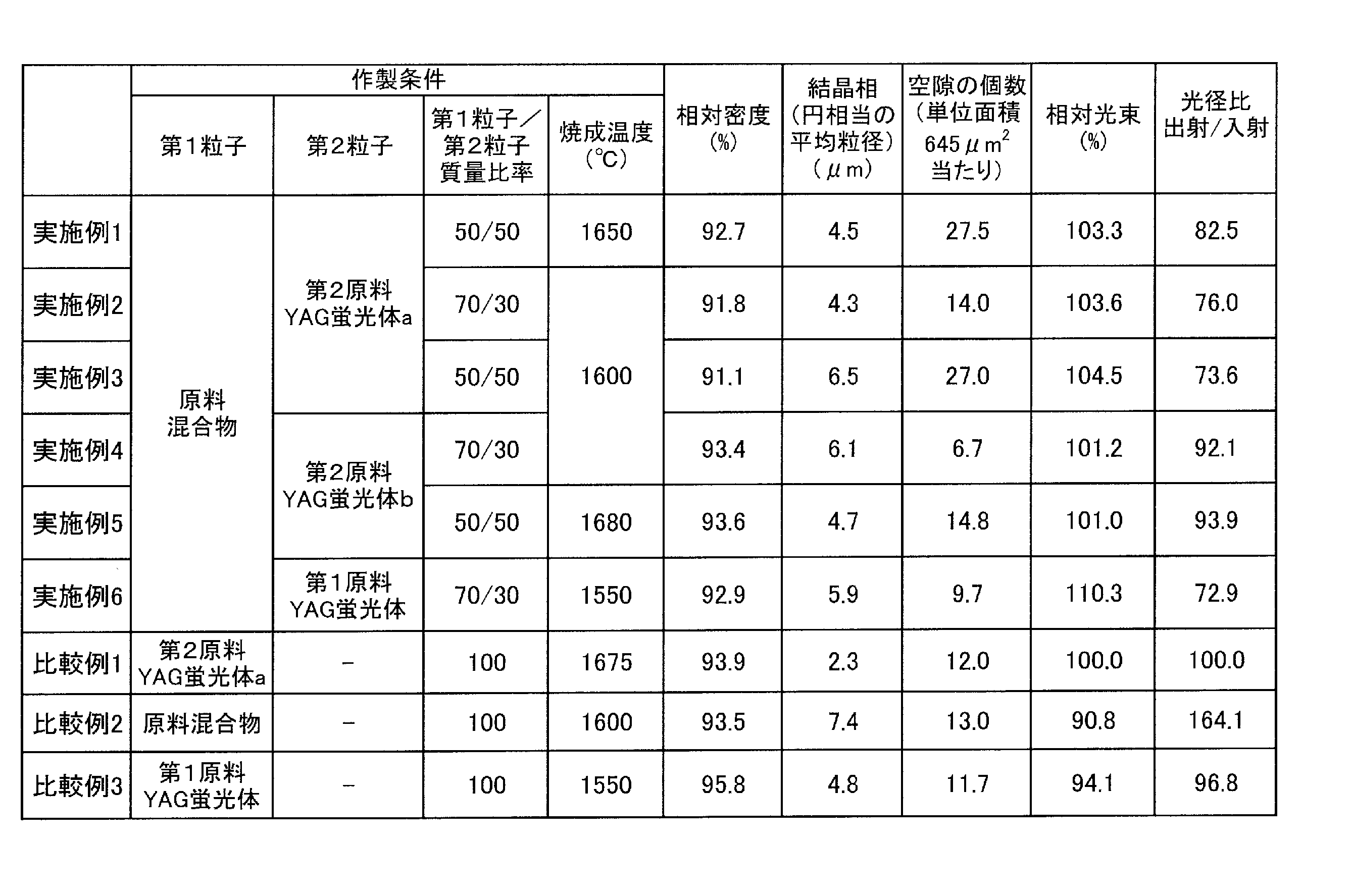
実施例1から6に係る希土類アルミン酸塩焼結体は、いずれも比較例1の希土類アルミン酸塩焼結体よりも、相対光束が高く、光径比が小さく、光の広がりが抑制されていた。実施例1から6に係る希土類アルミン酸塩焼結体は、比較例1に係る希土類アルミン酸塩焼結体よりも相対密度が小さくなるが、相対光束が高くなることから、焼結体の結晶相の周囲に空隙が分散されており、焼結体中に入射された励起光を空隙で効率よく散乱させて、空隙に近接する結晶相で効率よく波長変換して、入射面と同一面から波長変換された光を出射させることができるため、相対光束が高くなったと考えられる。 The rare earth aluminate sintered bodies according to Examples 1 to 6 had a higher relative luminous flux, a smaller light diameter ratio, and suppressed light spread than the rare earth aluminate sintered bodies of Comparative Example 1. The rare earth aluminate sintered body according to Examples 1 to 6 has a smaller relative density than the rare earth aluminate sintered body according to Comparative Example 1, but has a higher relative luminous flux. Voids are dispersed around the voids, and the excitation light incident on the sintered body is efficiently scattered in the voids, and the wavelength is efficiently converted by the crystal phase close to the voids, and the wavelength is converted from the same surface as the incident surface. It is considered that the relative luminous flux has increased because the emitted light can be emitted.
実施例4及び5に係る希土類アルミン酸塩焼結体は、比較例2に係る希土類アルミン酸塩焼結体と比較して、相対密度及び空隙率に大きな差はないが、相対光束は、比較例2よりも10%以上高くなった。また、実施例4及び5に係る希土類アルミン酸塩焼結体は、相対密度に大きな差のない比較例2の希土類アルミン酸塩焼結体と比較して、光径比がかなり小さくなっていた。この結果から、実施例4及び5に係る希土類アルミン酸塩焼結体は、平面おける円相当の粒径が異なる第1結晶相と第2結晶相の2種の結晶相を有し、粒径の異なる結晶相の間でも光が乱反射して、励起光を波長変換するため、励起光の入射面と同一面から波長変換された光を出射する際に光の広がりを抑制することができたと考えられる。 The rare earth aluminate sintered body according to Examples 4 and 5 did not have a large difference in relative density and porosity as compared with the rare earth aluminate sintered body according to Comparative Example 2, but the relative luminous flux was found in Comparative Example 2. It was more than 10% higher than. Further, the rare earth aluminate sintered body according to Examples 4 and 5 had a considerably smaller light diameter ratio than the rare earth aluminate sintered body of Comparative Example 2 in which there was no large difference in relative density. From this result, the rare earth aluminate sintered body according to Examples 4 and 5 has two kinds of crystal phases, a first crystal phase and a second crystal phase, which have different particle sizes corresponding to circles on a plane, and have different particle sizes. Since the light is diffusely reflected between different crystal phases and the excitation light is wavelength-converted, it is considered that the spread of the light can be suppressed when the wavelength-converted light is emitted from the same surface as the incident surface of the excitation light. Be done.
実施例1から6に係る希土類アルミン酸塩焼結体は、希土類アルミン酸塩の組成を有する蛍光体の結晶相と空隙を含み、平面における円相当の粒径が0.1μm以上1.0μm以下の第1結晶相と、円相当の粒径が1.1μm以上15μm以下の第2結晶相が含まれていた。第1結晶相と第2結晶相の粒径が異なるのは、原料混合物中に含まれる酸化物が結晶成長して形成された酸化物成長結晶相と、原料YAG蛍光体が結晶成長して形成された蛍光体成長結晶相とでは、結晶の成長速度が異なるためと推測された。 The rare earth aluminate sintered body according to Examples 1 to 6 contains a crystal phase and voids of a phosphor having a composition of rare earth aluminate, and has a particle size corresponding to a circle on a plane of 0.1 μm or more and 1.0 μm or less. A first crystal phase and a second crystal phase having a particle size equivalent to a circle of 1.1 μm or more and 15 μm or less were included. The difference in particle size between the first crystal phase and the second crystal phase is that the oxide growth crystal phase formed by crystal growth of the oxide contained in the raw material mixture and the raw material YAG phosphor formed by crystal growth. It was presumed that the crystal growth rate was different from that of the phosphor-grown crystal phase.
実施例1から3に係る希土類アルミン酸塩焼結体は、図6から8に示される断面SEM写真において、平面における円相当の粒径が0.1μm以上1.0μm以下の第1結晶相1と、円相当の粒径が1.1μm以上15μm以下の第2結晶相2が含まれていることが確認できた。また、実施例1から3に係る希土類アルミン酸塩焼結体は、希土類アルミン酸塩焼結体に含まれる空隙3が、第1結晶相と第2結晶相の周囲にほぼ均等に分散されていた。実施例1から3に係る希土類アルミン酸塩焼結体は、空隙3で励起光を効率よく散乱させて、周囲の結晶相によって効率よく波長変換したため、相対光束が高くなった。また、実施例1から3に係る希土類アルミン酸塩焼結体は、円相当の粒径の異なる第1結晶相1及び第2結晶相2が含まれているため、第1結晶相1と第2結晶相2との界面でも光が乱反射して、励起光を波長変換するため、励起光の入射面と同一面から波長変換された光を出射する場合に光の広がりを抑制することができ、光径比が小さくなった。
The rare earth aluminate sintered body according to Examples 1 to 3 has the first crystal phase 1 having a particle size corresponding to a circle on a plane of 0.1 μm or more and 1.0 μm or less in the cross-sectional SEM photographs shown in FIGS. It was confirmed that the
比較例1に係る希土類アルミン酸塩焼結体は、図9に示される断面SEM写真において、円相当の粒径が1.0μm以下の第1結晶相はほとんど確認できなかった。比較例2に係る希土類アルミン酸塩焼結体は、図10に示される断面SEM写真において、各結晶相の粒径に大きな差が見られなかった。また、空隙の形状および大きさ、分布が不均一であり、実施例よりも空隙の大きさが比較的大きかった。 In the rare earth aluminate sintered body according to Comparative Example 1, the first crystal phase having a particle size equivalent to a circle of 1.0 μm or less could hardly be confirmed in the cross-sectional SEM photograph shown in FIG. In the rare earth aluminate sintered body according to Comparative Example 2, no significant difference in the particle size of each crystal phase was observed in the cross-sectional SEM photograph shown in FIG. In addition, the shape, size, and distribution of the voids were non-uniform, and the size of the voids was relatively large compared to the examples.
本発明の一態様に係る製造方法によって得られた希土類アルミン酸塩焼結体は、LEDやLDの励起光源と組み合わせて、車載用や一般照明用の照明装置、液晶表示装置のバックライト、プロジェクター用光源の波長変換部材として利用することができる。 The rare earth aluminate sintered body obtained by the manufacturing method according to one aspect of the present invention is used in combination with an excitation light source of an LED or LD for an in-vehicle or general lighting lighting device, a backlight of a liquid crystal display device, and a projector. It can be used as a wavelength conversion member for a light source.
1:第1結晶相、2:第2結晶相、3:空隙、100:発光装置、101:励起光源、102:コリメートレンズ、103、105及び106:コンデンサレンズ、104:ダイクロイックミラー、107:ロッドインテグレーダー、110:蛍光体デバイス、111:希土類アルミン酸塩焼結体、112:回転機構、113:放熱体。 1: 1st crystal phase, 2: 2nd crystal phase, 3: void, 100: light emitting device, 101: excitation light source, 102: collimating lens, 103, 105 and 106: condenser lens, 104: dichroic mirror, 107: rod Integrader, 110: Fluorescent device, 111: Rare earth aluminate sintered body, 112: Rotation mechanism, 113: Radiator.
Claims (11)
Y、La、Lu、Gd及びTbからなる群から選択される少なくとも一種の希土類元素Lnを含む酸化物、Ceを含む酸化物、Alを含む酸化物、及び必要に応じてGa及びScから選択される少なくとも一種の元素M1を含む酸化物、を含む原料混合物と、を混合して成形体を準備することと、
前記成形体を焼成し、焼結体を得ることを含む、希土類アルミン酸塩焼結体の製造方法。 A fluorescent material having a composition of rare earth aluminate, and
Oxides containing at least one rare earth element Ln selected from the group consisting of Y, La, Lu, Gd and Tb, oxides containing Ce, oxides containing Al, and optionally Ga and Sc. To prepare a molded product by mixing with a raw material mixture containing an oxide containing at least one element M 1 .
A method for producing a rare earth aluminate sintered body, which comprises firing the molded body to obtain a sintered body.
前記成形体を焼成し、焼結体を得ることを含む、希土類アルミン酸塩焼結体の製造方法。 The first phosphor having a rare earth phosphor composition with an average particle size in the range of 0.3 μm or more and 1.0 μm or less measured by the Fisher Subsieve Sizer method and the average particle size measured by the Fisher Subsieve Sizer method are To prepare a molded product by mixing a second phosphor having a composition of a rare earth phosphor in the range of 1.1 μm or more and 10 μm or less.
A method for producing a rare earth aluminate sintered body, which comprises firing the molded body to obtain a sintered body.
(Ln1-nCen)3(Al1-mM1 m)5kO12 (I)
(式(I)中、Lnは、Y、La、Lu、Gd及びTbからなる群から選択される少なくとも一種の希土類元素であり、M1は、Ga及びScから選択される少なくとも一種の元素であり、m、n、kは、それぞれ0≦m≦0.02、0.003≦n≦0.017、0.95≦k≦1.05を満たす数である。) The method for producing a rare earth aluminate sintered body according to any one of claims 1 to 8, wherein the rare earth aluminate has a composition represented by the following formula (I).
(Ln 1-n Cen ) 3 (Al 1-m M 1 m ) 5k O 12 (I)
(In formula (I), Ln is at least one rare earth element selected from the group consisting of Y, La, Lu, Gd and Tb, and M 1 is at least one element selected from Ga and Sc. Yes, m, n, and k are numbers that satisfy 0 ≦ m ≦ 0.02, 0.003 ≦ n ≦ 0.017, and 0.95 ≦ k ≦ 1.05, respectively.)
Applications Claiming Priority (3)
| Application Number | Priority Date | Filing Date | Title |
|---|---|---|---|
| JP2019075690 | 2019-04-11 | ||
| JP2019075690 | 2019-04-11 | ||
| JP2019130523A JP6989789B2 (en) | 2019-04-11 | 2019-07-12 | Manufacturing method of rare earth aluminate sintered body |
Related Parent Applications (1)
| Application Number | Title | Priority Date | Filing Date |
|---|---|---|---|
| JP2019130523A Division JP6989789B2 (en) | 2019-04-11 | 2019-07-12 | Manufacturing method of rare earth aluminate sintered body |
Publications (2)
| Publication Number | Publication Date |
|---|---|
| JP2022016603A true JP2022016603A (en) | 2022-01-21 |
| JP7343803B2 JP7343803B2 (en) | 2023-09-13 |
Family
ID=72749015
Family Applications (1)
| Application Number | Title | Priority Date | Filing Date |
|---|---|---|---|
| JP2021190689A Active JP7343803B2 (en) | 2019-04-11 | 2021-11-25 | Method for manufacturing rare earth aluminate sintered body |
Country Status (2)
| Country | Link |
|---|---|
| US (1) | US11920072B2 (en) |
| JP (1) | JP7343803B2 (en) |
Citations (6)
| Publication number | Priority date | Publication date | Assignee | Title |
|---|---|---|---|---|
| JP2009530839A (en) * | 2006-03-23 | 2009-08-27 | コーニンクレッカ フィリップス エレクトロニクス エヌ ヴィ | Light emitting device having ceramic garnet material |
| US20150069299A1 (en) * | 2013-09-11 | 2015-03-12 | Nitto Denko Corporation | Phosphor Ceramics and Methods of Making the Same |
| US20150144978A1 (en) * | 2013-11-22 | 2015-05-28 | Nitto Denko Corporation | Light Extraction Element |
| JP2016509103A (en) * | 2013-01-28 | 2016-03-24 | ショット アクチエンゲゼルシャフトSchott AG | Strongly scattering ceramic conversion member and manufacturing method thereof |
| JP2018172628A (en) * | 2017-02-28 | 2018-11-08 | 日亜化学工業株式会社 | Method of manufacturing wave length conversion member |
| WO2018225424A1 (en) * | 2017-06-06 | 2018-12-13 | パナソニックIpマネジメント株式会社 | Wavelength converter and method of manufacture therefor, and light-emitting device using wavelength converter |
Family Cites Families (16)
| Publication number | Priority date | Publication date | Assignee | Title |
|---|---|---|---|---|
| KR100639647B1 (en) * | 2003-01-20 | 2006-11-01 | 우베 고산 가부시키가이샤 | Ceramic composite material for optical conversion and use thereof |
| US7963817B2 (en) * | 2007-09-18 | 2011-06-21 | Nichia Corporation | Phosphor-containing molded member, method of manufacturing the same, and light emitting device having the same |
| JP4916469B2 (en) | 2008-03-12 | 2012-04-11 | コバレントマテリアル株式会社 | Phosphor |
| WO2011123538A2 (en) * | 2010-03-31 | 2011-10-06 | Osram Sylvania Inc. | Phosphor and leds containing same |
| JP5712768B2 (en) | 2010-05-10 | 2015-05-07 | 信越化学工業株式会社 | Wavelength conversion member, light emitting device, and method of manufacturing wavelength conversion member |
| JP2012052061A (en) | 2010-09-03 | 2012-03-15 | Nippon Electric Glass Co Ltd | Phosphor composite member |
| WO2013065605A1 (en) | 2011-11-02 | 2013-05-10 | 株式会社東芝 | Solid scintillator and electron beam detector employing same |
| JP6215545B2 (en) | 2013-03-19 | 2017-10-18 | スタンレー電気株式会社 | Manufacturing method of composite ceramics, manufacturing method of wavelength conversion member, and manufacturing method of light emitting device |
| JP2014221706A (en) * | 2013-05-14 | 2014-11-27 | 株式会社オハラ | Composite material and method for producing the same |
| KR101631829B1 (en) * | 2015-01-13 | 2016-06-21 | 주식회사 베이스 | Method of manufacturing phosphor in glass using nano glass powder and white light emitting device |
| JP6543492B2 (en) * | 2015-03-20 | 2019-07-10 | 株式会社カネカ | Method of manufacturing YAG phosphor |
| JP2016204563A (en) * | 2015-04-24 | 2016-12-08 | 太平洋セメント株式会社 | Fluorescent member, manufacturing method therefor and light emitting device |
| JP6471727B2 (en) * | 2016-05-30 | 2019-02-20 | 日亜化学工業株式会社 | Phosphor and light emitting device having rare earth aluminate composition |
| WO2018038259A1 (en) | 2016-08-26 | 2018-03-01 | 地方独立行政法人神奈川県立産業技術総合研究所 | Nitride phosphor particle dispersion-type sialon ceramic, fluorescent member, and method for producing nitride phosphor particle dispersion-type sialon ceramic |
| CN108863317B (en) * | 2017-05-09 | 2021-03-16 | 中国科学院上海硅酸盐研究所 | Fluorescent composite ceramic and preparation method and application thereof |
| CN108947516B (en) * | 2018-08-29 | 2021-04-06 | 江苏师范大学 | (Cu, Ce): YAG transparent fluorescent ceramic and preparation method and application thereof |
-
2020
- 2020-04-10 US US16/845,807 patent/US11920072B2/en active Active
-
2021
- 2021-11-25 JP JP2021190689A patent/JP7343803B2/en active Active
Patent Citations (6)
| Publication number | Priority date | Publication date | Assignee | Title |
|---|---|---|---|---|
| JP2009530839A (en) * | 2006-03-23 | 2009-08-27 | コーニンクレッカ フィリップス エレクトロニクス エヌ ヴィ | Light emitting device having ceramic garnet material |
| JP2016509103A (en) * | 2013-01-28 | 2016-03-24 | ショット アクチエンゲゼルシャフトSchott AG | Strongly scattering ceramic conversion member and manufacturing method thereof |
| US20150069299A1 (en) * | 2013-09-11 | 2015-03-12 | Nitto Denko Corporation | Phosphor Ceramics and Methods of Making the Same |
| US20150144978A1 (en) * | 2013-11-22 | 2015-05-28 | Nitto Denko Corporation | Light Extraction Element |
| JP2018172628A (en) * | 2017-02-28 | 2018-11-08 | 日亜化学工業株式会社 | Method of manufacturing wave length conversion member |
| WO2018225424A1 (en) * | 2017-06-06 | 2018-12-13 | パナソニックIpマネジメント株式会社 | Wavelength converter and method of manufacture therefor, and light-emitting device using wavelength converter |
Also Published As
| Publication number | Publication date |
|---|---|
| US20200324342A1 (en) | 2020-10-15 |
| JP7343803B2 (en) | 2023-09-13 |
| US11920072B2 (en) | 2024-03-05 |
Similar Documents
| Publication | Publication Date | Title |
|---|---|---|
| US11220632B2 (en) | Ceramic complex, light source for projector, and method for producing ceramic complex | |
| JP6852780B2 (en) | Manufacturing method of wavelength conversion member | |
| JP7260740B2 (en) | CERAMIC COMPOSITE, LIGHT-EMITTING DEVICE USING THE SAME, AND METHOD FOR MANUFACTURING CERAMIC COMPOSITE | |
| JP6763422B2 (en) | Manufacturing method of wavelength conversion member and wavelength conversion member | |
| JP6989789B2 (en) | Manufacturing method of rare earth aluminate sintered body | |
| JP7140968B2 (en) | CERAMIC COMPOSITE, LIGHT SOURCE FOR PROJECTOR, AND METHOD FOR MANUFACTURING CERAMIC COMPOSITE | |
| US11897814B2 (en) | Rare earth aluminate sintered compact and method for producing rare earth aluminate sintered compact | |
| JP7343803B2 (en) | Method for manufacturing rare earth aluminate sintered body | |
| JP7089175B2 (en) | Ceramic complex, light emitting device using it, and method for manufacturing ceramic complex | |
| US20240158694A1 (en) | Method for producing rare earth aluminate sintered body | |
| JP2019081894A (en) | Rare earth aluminate phosphor and method for producing the same | |
| US20240132408A1 (en) | Rare earth aluminate sintered compact and method for producing rare earth aluminate sintered compact | |
| US11142691B2 (en) | Rare earth aluminate fluorescent material, and method for producing the same | |
| JP7094183B2 (en) | Ceramic complex and its manufacturing method | |
| US20230348331A1 (en) | Rare earth aluminate sintered body and method for producing the same | |
| EP4328207A1 (en) | Sintered body and method for producing sintered body | |
| US11486550B2 (en) | Method for producing wavelength conversion sintered body | |
| JP7448806B2 (en) | Method for manufacturing wavelength conversion sintered body | |
| JP2024031839A (en) | Sintered body and its manufacturing method | |
| TW202408970A (en) | Sintered body and manufacturing method thereof | |
| RU2818556C1 (en) | Method of producing luminescent oxide composition for radiation converter in white light sources | |
| JP2022030048A (en) | Ceramic complex and method for producing the same | |
| CN117623759A (en) | Sintered body and method for producing same |
Legal Events
| Date | Code | Title | Description |
|---|---|---|---|
| A521 | Request for written amendment filed |
Free format text: JAPANESE INTERMEDIATE CODE: A523 Effective date: 20211126 |
|
| A621 | Written request for application examination |
Free format text: JAPANESE INTERMEDIATE CODE: A621 Effective date: 20211126 |
|
| A131 | Notification of reasons for refusal |
Free format text: JAPANESE INTERMEDIATE CODE: A131 Effective date: 20221213 |
|
| A521 | Request for written amendment filed |
Free format text: JAPANESE INTERMEDIATE CODE: A523 Effective date: 20230116 |
|
| A02 | Decision of refusal |
Free format text: JAPANESE INTERMEDIATE CODE: A02 Effective date: 20230425 |
|
| A521 | Request for written amendment filed |
Free format text: JAPANESE INTERMEDIATE CODE: A523 Effective date: 20230621 |
|
| A911 | Transfer to examiner for re-examination before appeal (zenchi) |
Free format text: JAPANESE INTERMEDIATE CODE: A911 Effective date: 20230628 |
|
| TRDD | Decision of grant or rejection written | ||
| A01 | Written decision to grant a patent or to grant a registration (utility model) |
Free format text: JAPANESE INTERMEDIATE CODE: A01 Effective date: 20230801 |
|
| A61 | First payment of annual fees (during grant procedure) |
Free format text: JAPANESE INTERMEDIATE CODE: A61 Effective date: 20230814 |
|
| R151 | Written notification of patent or utility model registration |
Ref document number: 7343803 Country of ref document: JP Free format text: JAPANESE INTERMEDIATE CODE: R151 |