JP2022014246A - Medium discharge device and image reading device - Google Patents
Medium discharge device and image reading device Download PDFInfo
- Publication number
- JP2022014246A JP2022014246A JP2020116473A JP2020116473A JP2022014246A JP 2022014246 A JP2022014246 A JP 2022014246A JP 2020116473 A JP2020116473 A JP 2020116473A JP 2020116473 A JP2020116473 A JP 2020116473A JP 2022014246 A JP2022014246 A JP 2022014246A
- Authority
- JP
- Japan
- Prior art keywords
- medium
- state
- contact
- pressing member
- holding member
- Prior art date
- Legal status (The legal status is an assumption and is not a legal conclusion. Google has not performed a legal analysis and makes no representation as to the accuracy of the status listed.)
- Granted
Links
Images


Classifications
-
- H—ELECTRICITY
- H04—ELECTRIC COMMUNICATION TECHNIQUE
- H04N—PICTORIAL COMMUNICATION, e.g. TELEVISION
- H04N1/00—Scanning, transmission or reproduction of documents or the like, e.g. facsimile transmission; Details thereof
- H04N1/00519—Constructional details not otherwise provided for, e.g. housings, covers
- H04N1/00525—Providing a more compact apparatus, e.g. sheet discharge tray in cover
-
- H—ELECTRICITY
- H04—ELECTRIC COMMUNICATION TECHNIQUE
- H04N—PICTORIAL COMMUNICATION, e.g. TELEVISION
- H04N1/00—Scanning, transmission or reproduction of documents or the like, e.g. facsimile transmission; Details thereof
- H04N1/00567—Handling of original or reproduction media, e.g. cutting, separating, stacking
- H04N1/0057—Conveying sheets before or after scanning
- H04N1/00599—Using specific components
-
- B—PERFORMING OPERATIONS; TRANSPORTING
- B65—CONVEYING; PACKING; STORING; HANDLING THIN OR FILAMENTARY MATERIAL
- B65H—HANDLING THIN OR FILAMENTARY MATERIAL, e.g. SHEETS, WEBS, CABLES
- B65H31/00—Pile receivers
- B65H31/26—Auxiliary devices for retaining articles in the pile
-
- B—PERFORMING OPERATIONS; TRANSPORTING
- B41—PRINTING; LINING MACHINES; TYPEWRITERS; STAMPS
- B41J—TYPEWRITERS; SELECTIVE PRINTING MECHANISMS, i.e. MECHANISMS PRINTING OTHERWISE THAN FROM A FORME; CORRECTION OF TYPOGRAPHICAL ERRORS
- B41J13/00—Devices or arrangements of selective printing mechanisms, e.g. ink-jet printers or thermal printers, specially adapted for supporting or handling copy material in short lengths, e.g. sheets
- B41J13/10—Sheet holders, retainers, movable guides, or stationary guides
- B41J13/106—Sheet holders, retainers, movable guides, or stationary guides for the sheet output section
-
- B—PERFORMING OPERATIONS; TRANSPORTING
- B65—CONVEYING; PACKING; STORING; HANDLING THIN OR FILAMENTARY MATERIAL
- B65H—HANDLING THIN OR FILAMENTARY MATERIAL, e.g. SHEETS, WEBS, CABLES
- B65H31/00—Pile receivers
- B65H31/02—Pile receivers with stationary end support against which pile accumulates
-
- H—ELECTRICITY
- H04—ELECTRIC COMMUNICATION TECHNIQUE
- H04N—PICTORIAL COMMUNICATION, e.g. TELEVISION
- H04N1/00—Scanning, transmission or reproduction of documents or the like, e.g. facsimile transmission; Details thereof
- H04N1/00519—Constructional details not otherwise provided for, e.g. housings, covers
- H04N1/00559—Mounting or support of components or elements
-
- H—ELECTRICITY
- H04—ELECTRIC COMMUNICATION TECHNIQUE
- H04N—PICTORIAL COMMUNICATION, e.g. TELEVISION
- H04N1/00—Scanning, transmission or reproduction of documents or the like, e.g. facsimile transmission; Details thereof
- H04N1/00567—Handling of original or reproduction media, e.g. cutting, separating, stacking
- H04N1/0057—Conveying sheets before or after scanning
- H04N1/00599—Using specific components
- H04N1/00615—Guiding elements, e.g. plates
-
- H—ELECTRICITY
- H04—ELECTRIC COMMUNICATION TECHNIQUE
- H04N—PICTORIAL COMMUNICATION, e.g. TELEVISION
- H04N1/00—Scanning, transmission or reproduction of documents or the like, e.g. facsimile transmission; Details thereof
- H04N1/00567—Handling of original or reproduction media, e.g. cutting, separating, stacking
- H04N1/00631—Ejecting or stacking
-
- B—PERFORMING OPERATIONS; TRANSPORTING
- B41—PRINTING; LINING MACHINES; TYPEWRITERS; STAMPS
- B41J—TYPEWRITERS; SELECTIVE PRINTING MECHANISMS, i.e. MECHANISMS PRINTING OTHERWISE THAN FROM A FORME; CORRECTION OF TYPOGRAPHICAL ERRORS
- B41J3/00—Typewriters or selective printing or marking mechanisms characterised by the purpose for which they are constructed
- B41J3/44—Typewriters or selective printing mechanisms having dual functions or combined with, or coupled to, apparatus performing other functions
- B41J3/46—Printing mechanisms combined with apparatus providing a visual indication
-
- B—PERFORMING OPERATIONS; TRANSPORTING
- B65—CONVEYING; PACKING; STORING; HANDLING THIN OR FILAMENTARY MATERIAL
- B65H—HANDLING THIN OR FILAMENTARY MATERIAL, e.g. SHEETS, WEBS, CABLES
- B65H2301/00—Handling processes for sheets or webs
- B65H2301/40—Type of handling process
- B65H2301/42—Piling, depiling, handling piles
- B65H2301/421—Forming a pile
- B65H2301/4212—Forming a pile of articles substantially horizontal
-
- B—PERFORMING OPERATIONS; TRANSPORTING
- B65—CONVEYING; PACKING; STORING; HANDLING THIN OR FILAMENTARY MATERIAL
- B65H—HANDLING THIN OR FILAMENTARY MATERIAL, e.g. SHEETS, WEBS, CABLES
- B65H2301/00—Handling processes for sheets or webs
- B65H2301/40—Type of handling process
- B65H2301/42—Piling, depiling, handling piles
- B65H2301/421—Forming a pile
- B65H2301/4213—Forming a pile of a limited number of articles, e.g. buffering, forming bundles
-
- B—PERFORMING OPERATIONS; TRANSPORTING
- B65—CONVEYING; PACKING; STORING; HANDLING THIN OR FILAMENTARY MATERIAL
- B65H—HANDLING THIN OR FILAMENTARY MATERIAL, e.g. SHEETS, WEBS, CABLES
- B65H2402/00—Constructional details of the handling apparatus
- B65H2402/40—Details of frames, housings or mountings of the whole handling apparatus
- B65H2402/46—Table apparatus
-
- B—PERFORMING OPERATIONS; TRANSPORTING
- B65—CONVEYING; PACKING; STORING; HANDLING THIN OR FILAMENTARY MATERIAL
- B65H—HANDLING THIN OR FILAMENTARY MATERIAL, e.g. SHEETS, WEBS, CABLES
- B65H2402/00—Constructional details of the handling apparatus
- B65H2402/50—Machine elements
- B65H2402/51—Joints, e.g. riveted or magnetic joints
-
- B—PERFORMING OPERATIONS; TRANSPORTING
- B65—CONVEYING; PACKING; STORING; HANDLING THIN OR FILAMENTARY MATERIAL
- B65H—HANDLING THIN OR FILAMENTARY MATERIAL, e.g. SHEETS, WEBS, CABLES
- B65H2403/00—Power transmission; Driving means
- B65H2403/90—Machine drive
- B65H2403/94—Other features of machine drive
- B65H2403/945—Self-weight powered
-
- B—PERFORMING OPERATIONS; TRANSPORTING
- B65—CONVEYING; PACKING; STORING; HANDLING THIN OR FILAMENTARY MATERIAL
- B65H—HANDLING THIN OR FILAMENTARY MATERIAL, e.g. SHEETS, WEBS, CABLES
- B65H2404/00—Parts for transporting or guiding the handled material
- B65H2404/50—Surface of the elements in contact with the forwarded or guided material
- B65H2404/53—Surface of the elements in contact with the forwarded or guided material with particular mechanical, physical properties
- B65H2404/531—Surface of the elements in contact with the forwarded or guided material with particular mechanical, physical properties particular coefficient of friction
- B65H2404/5311—Surface with different coefficients of friction
-
- B—PERFORMING OPERATIONS; TRANSPORTING
- B65—CONVEYING; PACKING; STORING; HANDLING THIN OR FILAMENTARY MATERIAL
- B65H—HANDLING THIN OR FILAMENTARY MATERIAL, e.g. SHEETS, WEBS, CABLES
- B65H2404/00—Parts for transporting or guiding the handled material
- B65H2404/60—Other elements in face contact with handled material
- B65H2404/63—Oscillating, pivoting around an axis parallel to face of material, e.g. diverting means
-
- B—PERFORMING OPERATIONS; TRANSPORTING
- B65—CONVEYING; PACKING; STORING; HANDLING THIN OR FILAMENTARY MATERIAL
- B65H—HANDLING THIN OR FILAMENTARY MATERIAL, e.g. SHEETS, WEBS, CABLES
- B65H2404/00—Parts for transporting or guiding the handled material
- B65H2404/60—Other elements in face contact with handled material
- B65H2404/69—Other means designated for special purpose
- B65H2404/693—Retractable guiding means, i.e. between guiding and non guiding position
-
- B—PERFORMING OPERATIONS; TRANSPORTING
- B65—CONVEYING; PACKING; STORING; HANDLING THIN OR FILAMENTARY MATERIAL
- B65H—HANDLING THIN OR FILAMENTARY MATERIAL, e.g. SHEETS, WEBS, CABLES
- B65H2405/00—Parts for holding the handled material
- B65H2405/30—Other features of supports for sheets
- B65H2405/32—Supports for sheets partially insertable - extractable, e.g. upon sliding movement, drawer
- B65H2405/324—Supports for sheets partially insertable - extractable, e.g. upon sliding movement, drawer between operative position and non operative position
-
- B—PERFORMING OPERATIONS; TRANSPORTING
- B65—CONVEYING; PACKING; STORING; HANDLING THIN OR FILAMENTARY MATERIAL
- B65H—HANDLING THIN OR FILAMENTARY MATERIAL, e.g. SHEETS, WEBS, CABLES
- B65H2515/00—Physical entities not provided for in groups B65H2511/00 or B65H2513/00
- B65H2515/30—Forces; Stresses
- B65H2515/32—Torque e.g. braking torque
-
- B—PERFORMING OPERATIONS; TRANSPORTING
- B65—CONVEYING; PACKING; STORING; HANDLING THIN OR FILAMENTARY MATERIAL
- B65H—HANDLING THIN OR FILAMENTARY MATERIAL, e.g. SHEETS, WEBS, CABLES
- B65H2601/00—Problem to be solved or advantage achieved
- B65H2601/30—Facilitating or easing
- B65H2601/32—Facilitating or easing entities relating to handling machine
- B65H2601/324—Removability or inter-changeability of machine parts, e.g. for maintenance
-
- B—PERFORMING OPERATIONS; TRANSPORTING
- B65—CONVEYING; PACKING; STORING; HANDLING THIN OR FILAMENTARY MATERIAL
- B65H—HANDLING THIN OR FILAMENTARY MATERIAL, e.g. SHEETS, WEBS, CABLES
- B65H2801/00—Application field
- B65H2801/03—Image reproduction devices
- B65H2801/12—Single-function printing machines, typically table-top machines
-
- B—PERFORMING OPERATIONS; TRANSPORTING
- B65—CONVEYING; PACKING; STORING; HANDLING THIN OR FILAMENTARY MATERIAL
- B65H—HANDLING THIN OR FILAMENTARY MATERIAL, e.g. SHEETS, WEBS, CABLES
- B65H2801/00—Application field
- B65H2801/39—Scanning
-
- H—ELECTRICITY
- H04—ELECTRIC COMMUNICATION TECHNIQUE
- H04N—PICTORIAL COMMUNICATION, e.g. TELEVISION
- H04N1/00—Scanning, transmission or reproduction of documents or the like, e.g. facsimile transmission; Details thereof
- H04N1/00567—Handling of original or reproduction media, e.g. cutting, separating, stacking
- H04N1/0057—Conveying sheets before or after scanning
-
- H—ELECTRICITY
- H04—ELECTRIC COMMUNICATION TECHNIQUE
- H04N—PICTORIAL COMMUNICATION, e.g. TELEVISION
- H04N2201/00—Indexing scheme relating to scanning, transmission or reproduction of documents or the like, and to details thereof
- H04N2201/0077—Types of the still picture apparatus
- H04N2201/0081—Image reader
-
- H—ELECTRICITY
- H04—ELECTRIC COMMUNICATION TECHNIQUE
- H04N—PICTORIAL COMMUNICATION, e.g. TELEVISION
- H04N2201/00—Indexing scheme relating to scanning, transmission or reproduction of documents or the like, and to details thereof
- H04N2201/0077—Types of the still picture apparatus
- H04N2201/0082—Image hardcopy reproducer
-
- H—ELECTRICITY
- H04—ELECTRIC COMMUNICATION TECHNIQUE
- H04N—PICTORIAL COMMUNICATION, e.g. TELEVISION
- H04N2201/00—Indexing scheme relating to scanning, transmission or reproduction of documents or the like, and to details thereof
- H04N2201/0077—Types of the still picture apparatus
- H04N2201/0094—Multifunctional device, i.e. a device capable of all of reading, reproducing, copying, facsimile transception, file transception
Landscapes
- Engineering & Computer Science (AREA)
- Multimedia (AREA)
- Signal Processing (AREA)
- Mechanical Engineering (AREA)
- Pile Receivers (AREA)
- Facsimiles In General (AREA)
Abstract
【課題】排出される媒体を押さえて整列性を向上させる押さえ部材が着脱可能であると、装置の保管時や輸送の際に押さえ部材の破損を回避できるが、その反面、普段の使用環境においては取り外した押さえ部材の管理が煩雑となる。【解決手段】媒体搬送装置は、媒体を排出する媒体排出部を備える装置本体と、前記媒体排出部により排出される媒体を受ける媒体受けトレイと、前記装置本体に対して着脱可能な部材であって、前記装置本体に装着された状態で前記媒体排出部により排出される媒体を前記媒体受けトレイに向けて押さえる押さえ部材と、を備え、前記押さえ部材は、前記装置本体に装着された状態において、前記媒体受けトレイに接する第1状態と、前記媒体受けトレイから離間して上方に退避する第2状態と、を切り換え可能である。【選択図】図1PROBLEM TO BE SOLVED: To avoid damage to a pressing member during storage or transportation of an apparatus when a pressing member which presses a discharged medium and improves alignment is removable, but on the other hand, in a normal usage environment. The management of the removed holding member becomes complicated. A medium transport device is a device main body including a medium discharge unit for discharging a medium, a medium receiving tray for receiving a medium discharged by the medium discharge unit, and a member that can be attached to and detached from the device main body. A pressing member that presses the medium discharged by the medium discharging unit toward the medium receiving tray while being attached to the apparatus main body is provided, and the pressing member is attached to the apparatus main body. It is possible to switch between a first state in contact with the medium receiving tray and a second state in which the medium receiving tray is separated from the medium receiving tray and retracted upward. [Selection diagram] Fig. 1
Description
本発明は、媒体を排出する媒体排出装置、及びこれを備えた画像読取装置に関する。 The present invention relates to a medium discharging device that discharges a medium, and an image reading device including the medium discharging device.
原稿を搬送しながら読み取りを行うドキュメントスキャナーや、用紙に記録を行うプリンター等においては、特許文献1に示される様に排出される媒体を受けるトレイと、トレイに排出される媒体を押さえる押さえ部材とを備えるものがある。この押さえ部材により、排出される媒体が上方から押さえられる為、カール癖の強い媒体であっても、媒体はトレイ上で適切な状態で堆積される。
In a document scanner that reads while transporting a document, a printer that records on paper, etc., a tray that receives the ejected medium as shown in
特許文献1記載の構成において、押さえ部材は着脱可能に構成されている。この様に押さえ部材が着脱可能であると、装置の保管時や輸送の際に押さえ部材の破損を回避できるが、その反面、普段の使用環境においては取り外した押さえ部材の管理が煩雑となる。
In the configuration described in
上記課題を解決する為の、本発明の媒体搬送装置は、媒体を排出する媒体排出部を備える装置本体と、前記媒体排出部により排出される媒体を受ける媒体受けトレイと、前記装置本体に対して着脱可能な部材であって、前記装置本体に装着された状態で前記媒体排出部により排出される媒体を前記媒体受けトレイに向けて押さえる押さえ部材と、を備え、前記押さえ部材は、前記装置本体に装着された状態において、前記媒体排出部により排出される媒体に接触可能な第1状態と、前記媒体排出部により排出される媒体に接触しない位置まで上方に退避した第2状態とを切り換え可能であることを特徴とする。 In order to solve the above problems, the medium transport device of the present invention has a device main body provided with a medium discharging unit for discharging the medium, a medium receiving tray for receiving the medium discharged by the medium discharging section, and the device main body. A detachable member including a pressing member that presses the medium discharged by the medium discharging unit toward the medium receiving tray while being attached to the apparatus main body, and the pressing member is the apparatus. When mounted on the main body, it switches between the first state in which it can contact the medium discharged by the medium ejection unit and the second state in which it is retracted upward to a position where it does not contact the medium ejected by the medium ejection unit. It is characterized by being possible.
以下、本発明を概略的に説明する。
第1の態様は、媒体を排出する媒体排出部を備える装置本体と、前記媒体排出部により排出される媒体を受ける媒体受けトレイと、前記装置本体に対して着脱可能な部材であって、前記装置本体に装着された状態で前記媒体排出部により排出される媒体を前記媒体受けトレイに向けて押さえる押さえ部材と、を備え、前記押さえ部材は、前記装置本体に装着された状態において、前記媒体排出部により排出される媒体に接触可能な第1状態と、前記媒体排出部により排出される媒体に接触しない位置まで上方に退避した第2状態とを切り換え可能であることを特徴とする。
Hereinafter, the present invention will be schematically described.
The first aspect is a device main body including a medium discharging unit for discharging a medium, a medium receiving tray for receiving a medium discharged by the medium discharging unit, and a member that can be attached to and detached from the device main body. A holding member for holding the medium discharged by the medium discharging unit toward the medium receiving tray while being mounted on the device main body is provided, and the holding member is provided with the holding member in a state of being mounted on the device main body. It is characterized in that it is possible to switch between a first state in which the medium discharged by the discharging unit can be contacted and a second state in which the tray is retracted upward to a position where the medium discharged by the discharging unit does not come into contact with the medium.
本態様によれば、前記押さえ部材は、前記装置本体に対して着脱可能であるとともに、前記装置本体に装着された状態において、前記媒体排出部により排出される媒体に接触可能な第1状態と、前記媒体排出部により排出される媒体に接触しない位置まで上方に退避した第2状態とを切り換え可能であるので、普段の使用環境において前記押さえ部材が不要な場合は、前記押さえ部材を前記装置本体から取り外すことなく前記第2状態にすることでユーザーの要求に沿うことができ、ひいてはユーザーの利便性を向上させることができる。 According to this aspect, the holding member is a first state in which the holding member is removable from the device main body and can come into contact with the medium discharged by the medium discharging unit in a state of being attached to the device main body. Since it is possible to switch between the second state and the second state in which the holding member is retracted upward to a position where it does not come into contact with the medium discharged by the medium discharging unit, if the holding member is unnecessary in a normal usage environment, the holding member can be used as the device. By setting the second state without removing it from the main body, it is possible to meet the user's request and improve the user's convenience.
第2の態様は、第1の態様において、前記押さえ部材の前記第2状態から前記第1状態への切り換わり動作に対し負荷を付与する負荷付与手段を備えることを特徴とする。
本態様によれば、前記押さえ部材の前記第2状態から前記第1状態への切り換わり動作に対し負荷を付与する負荷付与手段を備えるので、ユーザーの意図に反して前記押さえ部材が前記第2状態から前記第1状態に切り換わることを抑制でき、ユーザーの利便性がより一層向上する。
The second aspect is characterized in that, in the first aspect, a load applying means for applying a load to the switching operation of the pressing member from the second state to the first state is provided.
According to this aspect, since the load applying means for applying a load to the switching operation of the pressing member from the second state to the first state is provided, the pressing member is the second state against the intention of the user. Switching from the state to the first state can be suppressed, and the convenience of the user is further improved.
第3態様は、第1のまたは第2の態様において、前記押さえ部材は、回転することにより、前記第1状態と前記第2状態とを切り換える様に設けられ、下方向への回転限度にある前記押さえ部材の先端部に対し鉛直上方成分を含む外力を付与することにより、前記押さえ部材が前記第2状態に向けて回転することを特徴とする。
前記装置本体を持ち上げて移動させる場合、前記装置本体を置く際に、下方向への回転限度にある前記押さえ部材が装置の設置面に衝突し、前記押さえ部材の破損を招く虞がある。しかしながら本態様によれば、下方向への回転限度にある前記押さえ部材の先端部に対し鉛直上方成分を含む外力を付与すると、前記押さえ部材が前記第2状態に向けて回転するので、上述の様な前記押さえ部材の破損を抑制できる。
A third aspect is, in the first or second aspect, the holding member is provided so as to switch between the first state and the second state by rotating, and is in a downward rotation limit. It is characterized in that the pressing member rotates toward the second state by applying an external force including a vertically upward component to the tip end portion of the pressing member.
When the main body of the device is lifted and moved, when the main body of the device is placed, the holding member at the downward rotation limit may collide with the installation surface of the device, which may cause damage to the holding member. However, according to this aspect, when an external force including a vertically upward component is applied to the tip end portion of the holding member which is in the downward rotation limit, the holding member rotates toward the second state. It is possible to suppress such damage to the holding member.
第4の態様は、第3の態様において、前記押さえ部材の前記下方向への回転限度が、前記押さえ部材に形成された当接部と、前記当接部が当接する規制部との当接により規定され、前記当接部が前記規制部に当接した状態で、前記押さえ部材が斜め下方向に向く傾斜姿勢をとることを特徴とする。
本態様によれば、前記押さえ部材の前記下方向への回転限度が、前記押さえ部材に形成された当接部と、前記当接部が当接する規制部との当接により規定され、前記当接部が前記規制部に当接した状態で、前記押さえ部材が斜め下方向に向く傾斜姿勢をとるので、下方向への回転限度にある前記押さえ部材の下端部に対し鉛直上方成分を含む外力が作用した際、前記押さえ部材が前記第2状態に向けて確実に回転でき、上述の様な前記押さえ部材の破損を確実に抑制できる。
In the fourth aspect, in the third aspect, the downward rotation limit of the pressing member is the contact between the abutting portion formed on the pressing member and the restricting portion with which the abutting portion abuts. It is characterized in that the holding member takes an inclined posture facing diagonally downward in a state where the contact portion is in contact with the regulation portion.
According to this aspect, the downward rotation limit of the holding member is defined by the contact between the abutting portion formed on the holding member and the restricting portion with which the abutting portion abuts. Since the holding member takes an inclined posture that faces diagonally downward while the contact portion is in contact with the restricting portion, an external force including a vertically upward component with respect to the lower end portion of the holding member that is in the downward rotation limit. When the pressing member acts, the pressing member can be reliably rotated toward the second state, and damage to the pressing member as described above can be reliably suppressed.
第5の態様は、第1のまたは第2の態様において、前記押さえ部材は、回転することで前記第1状態と前記第2状態とを切り換える様に設けられ、前記押さえ部材を前記装置本体に固定するロック部と、前記ロック部による前記押さえ部材の固定を解除する為の操作部と、を備え、下方向への回転限度にある前記押さえ部材に対し、前記第2状態に向かう方向とは反対の方向に回転させる外力を付与すると、前記押さえ部材の一部が前記操作部に当接し、前記ロック部による前記押さえ部材の固定が解除されることを特徴とする。 A fifth aspect is, in the first or second aspect, the pressing member is provided so as to switch between the first state and the second state by rotating, and the pressing member is attached to the apparatus main body. The direction toward the second state with respect to the holding member, which is provided with a locking portion for fixing and an operating portion for releasing the fixing of the holding member by the locking portion and is at the downward rotation limit, is When an external force that rotates in the opposite direction is applied, a part of the pressing member comes into contact with the operating portion, and the locking member is released from being fixed by the locking portion.
下方向への回転限度にある前記押さえ部材に対し、前記第2状態に向かう方向とは反対の方向に回転させる外力を付与すると、前記押さえ部材の破損を招く虞がある。しかしながら本態様によれば、下方向への回転限度にある前記押さえ部材に対し、前記第2状態に向かう方向とは反対の方向に回転させる外力を付与すると、前記押さえ部材の一部が前記操作部に当接し、前記ロック部による前記押さえ部材の固定が解除されるので、前記押さえ部材が脱落することができ、その結果前記押さえ部材の破損を抑制することができる。 If an external force that rotates the pressing member in the direction opposite to the direction toward the second state is applied to the pressing member that is in the downward rotation limit, the pressing member may be damaged. However, according to this aspect, when an external force for rotating the pressing member in the downward rotation limit is applied in a direction opposite to the direction toward the second state, a part of the pressing member operates. Since the pressing member is released from being fixed by the locking portion by abutting on the portion, the pressing member can be detached, and as a result, damage to the pressing member can be suppressed.
第6の態様は、第1から第5の態様のいずれかにおいて、前記媒体排出部により排出される媒体が前記第1状態にある前記押さえ部材に接触する接触位置は、前記媒体排出部により排出される媒体が前記媒体受けトレイまたは前記媒体受けトレイに載置された媒体に接する位置より排出方向下流にあることを特徴とする。 In the sixth aspect, in any one of the first to fifth aspects, the contact position where the medium discharged by the medium discharging unit contacts the holding member in the first state is discharged by the medium discharging unit. The medium is characterized in that it is located downstream in the discharge direction from a position in contact with the medium receiving tray or the medium placed on the medium receiving tray.
前記媒体排出部により排出される媒体が前記媒体受けトレイまたは前記媒体受けトレイに載置された媒体に接するより前に前記押さえ部材に接触すると、媒体が座屈し、ジャムとなる虞がある。しかしながら本態様によれば前記媒体排出部により排出される媒体が前記押さえ部材に接触する接触位置は、前記媒体排出部により排出される媒体が前記媒体受けトレイまたは前記媒体受けトレイに載置された媒体に接する位置より排出方向下流にあるので、上記の様なジャムの発生を抑制することができる。 If the medium discharged by the medium ejection unit comes into contact with the holding member before it comes into contact with the medium receiving tray or the medium placed on the medium receiving tray, the medium may buckle and jam. However, according to this aspect, at the contact position where the medium discharged by the medium discharging section comes into contact with the holding member, the medium discharged by the medium discharging section is placed on the medium receiving tray or the medium receiving tray. Since it is located downstream in the discharge direction from the position in contact with the medium, it is possible to suppress the occurrence of jam as described above.
第7の態様は、第1から第6の態様のいずれかにおいて、前記第1状態にある前記押さえ部材は、媒体排出方向と交差する方向である幅方向において複数の接触位置で媒体と接することを特徴とする。
本態様によれば、前記第1状態にある前記押さえ部材は、媒体排出方向と交差する方向である幅方向において複数の接触位置で媒体と接するので、排出される媒体の回転つまり斜行を抑制できる。
A seventh aspect is that in any one of the first to sixth aspects, the holding member in the first state is in contact with the medium at a plurality of contact positions in the width direction which is the direction intersecting the medium discharging direction. It is characterized by.
According to this aspect, since the holding member in the first state comes into contact with the medium at a plurality of contact positions in the width direction intersecting the medium discharging direction, rotation or skewing of the discharged medium is suppressed. can.
第8の態様は、第7の態様において、前記押さえ部材は、前記幅方向において二箇所の前記接触位置で媒体と接し、前記媒体排出部により排出される媒体の前記幅方向の中心位置は、二箇所の前記接触位置の間にあることを特徴とする。
本態様によれば、媒体は、前記幅方向の中心位置に対し前記幅方向の両側で前記押さえ部材により押さえられるので、排出される媒体の回転つまり斜行をより効果的に抑制できる。
In the eighth aspect, in the seventh aspect, the holding member is in contact with the medium at two contact positions in the width direction, and the center position of the medium discharged by the medium ejection portion in the width direction is set. It is characterized by being between the two contact positions.
According to this aspect, since the medium is pressed by the pressing members on both sides in the width direction with respect to the center position in the width direction, the rotation, that is, the skew of the discharged medium can be suppressed more effectively.
第9の態様は、第8の態様において、前記押さえ部材は、媒体の排出方向下流に向かって、媒体の排出方向と交差する方向である幅方向に拡がるとともに、前記幅方向の中央部が切り欠かれた形状を有することを特徴とする。
本態様によれば、前記押さえ部材は、媒体の排出方向下流に向かって、媒体の排出方向と交差する方向である幅方向に拡がるとともに、前記幅方向の中央部が切り欠かれた形状を有するので、前記幅方向における広い領域で媒体を押さえることで排出される媒体の回転つまり斜行を効果的に抑制できる。そして前記押さえ部材は、前記幅方向の中央部が切り欠かれた形状を有しているので、前記押さえ部材を前記第2状態に切り換えた際に、前記押さえ部材が前記装置本体を覆う面積を小さくでき、前記装置本体の操作性の低下を抑制できる。
In the ninth aspect, in the eighth aspect, the holding member expands in the width direction, which is a direction intersecting the discharge direction of the medium, toward the downstream side in the discharge direction of the medium, and the central portion in the width direction is cut. It is characterized by having a missing shape.
According to this aspect, the holding member expands in the width direction, which is a direction intersecting the discharge direction of the medium, toward the downstream side in the discharge direction of the medium, and has a shape in which the central portion in the width direction is cut out. Therefore, by pressing the medium in a wide area in the width direction, the rotation, that is, the skew of the discharged medium can be effectively suppressed. Since the pressing member has a shape in which the central portion in the width direction is cut out, the area covered by the pressing member when the pressing member is switched to the second state is increased. It can be made smaller, and deterioration of the operability of the apparatus main body can be suppressed.
第10の態様は、第1から第9の態様のいずれかにおいて、前記押さえ部材は、媒体の排出方向と交差する方向である幅方向から視て、前記媒体受けトレイと接する部位が前記媒体受けトレイに対し凸となる形状に形成されていることを特徴とする。
前記媒体受けトレイが伸縮する構成である場合、特に縮む際に前記押さえ部材に対し前記媒体受けトレイが引っ掛かる虞があるが、本態様によれば前記押さえ部材は、媒体の排出方向と交差する方向である幅方向から視て、前記媒体受けトレイと接する部位が前記媒体受けトレイに対し凸となる形状に形成されているので、上記の引っ掛かりを抑制できる。
A tenth aspect is that in any one of the first to ninth aspects, the holding member has a portion in contact with the medium receiving tray when viewed from the width direction which is a direction intersecting the discharging direction of the medium. It is characterized in that it is formed in a shape that is convex with respect to the tray.
When the medium receiving tray is configured to expand and contract, there is a possibility that the medium receiving tray may be caught by the holding member, particularly when the holding member is contracted. Since the portion in contact with the medium receiving tray is formed in a shape that is convex with respect to the medium receiving tray when viewed from the width direction, the above-mentioned catching can be suppressed.
第11の態様は、第1から第10の態様のいずれかにおいて、前記押さえ部材が媒体を押さえる際の押圧荷重を調整可能に構成されていることを特徴とする。
本態様によれば、前記押さえ部材が媒体を押さえる際の押圧荷重を調整可能に構成されているので、媒体のサイズや種類等に応じて前記押圧荷重を調整することができ、適切に媒体を押さえることができる。
The eleventh aspect is characterized in that, in any one of the first to tenth aspects, the pressing member is configured to be able to adjust the pressing load when pressing the medium.
According to this aspect, since the pressing member is configured to be able to adjust the pressing load when pressing the medium, the pressing load can be adjusted according to the size and type of the medium, and the medium can be appropriately used. You can hold it down.
第12の態様は、第1から第11の態様のいずれかにおいて、前記押さえ部材は、媒体の排出方向の長さを調整可能に構成されていることを特徴とする。
本態様によれば、前記押さえ部材は、媒体の排出方向の長さを調整可能に構成されているので、媒体のサイズに応じて前記押さえ部材が媒体を押さえる位置を調整することができ、適切に媒体を押さえることができる。
A twelfth aspect is characterized in that, in any one of the first to eleventh aspects, the holding member is configured so that the length in the discharge direction of the medium can be adjusted.
According to this aspect, since the holding member is configured so that the length in the discharge direction of the medium can be adjusted, the position where the holding member holds the medium can be adjusted according to the size of the medium, which is appropriate. You can hold down the medium.
第13の態様は、第1から第12の態様のいずれかにおいて、前記押さえ部材は、媒体と接触する部位が、媒体との間の摩擦係数が第1摩擦係数となる第1部位と、媒体との間の摩擦係数が前記第1摩擦係数より大きい第2摩擦係数となる第2部位とに切り換え可能であることを特徴とする。
本態様によれば、前記押さえ部材は、媒体と接触する部位が、媒体との間の摩擦係数が第1摩擦係数となる第1部位と、媒体との間の摩擦係数が前記第1摩擦係数より大きい第2摩擦係数となる第2部位とに切り換え可能であるので、媒体のサイズや種類等に応じて前記摩擦係数を切り換えることができ、適切に媒体を押さえることができる。
A thirteenth aspect is that in any one of the first to twelfth aspects, the holding member has a portion in contact with the medium, a first portion having a friction coefficient with the medium as the first friction coefficient, and a medium. It is characterized in that the friction coefficient between the two and the second portion can be switched to a second portion having a second friction coefficient larger than the first friction coefficient.
According to this aspect, in the holding member, the part in contact with the medium has the first friction coefficient between the first part and the medium, where the friction coefficient between the holding member and the medium is the first friction coefficient. Since it is possible to switch to a second portion having a larger second friction coefficient, the friction coefficient can be switched according to the size and type of the medium, and the medium can be appropriately pressed.
第14の態様は、第1から第13の態様のいずれかにおいて、前記装置本体は、各種情報を表示する表示部を備え、前記表示部の平面視において前記第2状態にある前記押さえ部材は、前記表示部の一部を覆う位置にあって、前記表示部での表示内容から外れた位置にあることを特徴とする。
本態様によれば、前記表示部の平面視において前記第2状態にある前記押さえ部材は、前記表示部の一部を覆う位置にあって、前記表示部での表示内容から外れた位置にあるので、前記第2状態にある前記押さえ部材が、ユーザーによる前記表示部の視認を阻害することを抑制できる。
In the fourteenth aspect, in any one of the first to thirteenth aspects, the apparatus main body includes a display unit for displaying various information, and the holding member in the second state in the plan view of the display unit is It is characterized in that it is located at a position that covers a part of the display unit and is located outside the display content of the display unit.
According to this aspect, the holding member in the second state in the plan view of the display unit is located at a position covering a part of the display unit and at a position deviating from the display content on the display unit. Therefore, it is possible to prevent the pressing member in the second state from obstructing the user's visibility of the display unit.
第15の態様は、第1から第14の態様のいずれかにおいて、前記装置本体は、各種操作設定を受け付ける操作パネルを備え、前記操作パネルは、押下可能な押下ボタンを少なくとも一つ備え、前記第2状態にある前記押さえ部材は、前記押下ボタンの平面視において前記押下ボタンの一部を覆う位置にあって前記押下ボタンの一部を露呈させる位置にあることを特徴とする。
本態様によれば、前記第2状態にある前記押さえ部材は、前記押下ボタンの平面視において前記押下ボタンの一部を覆う位置にあって前記押下ボタンの一部を露呈させる位置にあるので、前記第2状態にある前記押さえ部材が、ユーザーによる前記押下ボタンの押下を妨げることを回避できる。
A fifteenth aspect is, in any one of the first to the fourteenth aspects, the apparatus main body includes an operation panel that accepts various operation settings, and the operation panel includes at least one pressable button. The pressing member in the second state is characterized in that it is in a position that covers a part of the pressing button in a plan view of the pressing button and is in a position that exposes a part of the pressing button.
According to this aspect, the pressing member in the second state is in a position that covers a part of the pressing button in the plan view of the pressing button and is in a position that exposes a part of the pressing button. It is possible to prevent the pressing member in the second state from preventing the user from pressing the pressing button.
第16の態様に係る画像読取装置は、搬送される媒体を読み取る読み取り手段と、前記読み取り手段により読み取りが行われた媒体を排出する、第1から第15の態様のいずれかに記載の前記媒体排出装置とを備えたことを特徴とする。
本態様によれば、画像読取装置において、上述した第1から第15の態様のいずれかの作用効果が得られる。
以下、本発明を具体的に説明する。
The medium according to any one of the first to fifteenth aspects, wherein the image reading device according to the sixteenth aspect discharges a reading means for reading a conveyed medium and a medium read by the reading means. It is characterized by being equipped with a discharge device.
According to this aspect, in the image reading apparatus, the action effect of any one of the above-mentioned first to fifteenth aspects can be obtained.
Hereinafter, the present invention will be specifically described.
以下では媒体の一例である原稿の表面及び裏面の少なくとも一面を読み取り可能なドキュメントスキャナー1を画像読取装置の一例として説明する。ドキュメントスキャナー1は、以下ではスキャナー1と略称する。また以下では、原稿は原稿Pと称する。
Hereinafter, a
尚、各図において示すX-Y-Z座標系はX軸方向が装置幅方向であり原稿の幅方向、Y軸方向が原稿読み取り時の原稿搬送方向及び原稿を排出する際の排出方向である。Z軸方向はY軸方向と交差する方向であって、読み取りが行われる原稿Pの面と直交する方向を示している。以下では原稿Pが送られていく方向(+Y軸方向)を「下流」といい、これと反対の方向(-Y軸方向)を「上流」という場合がある。 In the XYZ coordinate system shown in each figure, the X-axis direction is the device width direction, the width direction of the document, and the Y-axis direction is the document transport direction when reading the document and the ejection direction when ejecting the document. .. The Z-axis direction intersects the Y-axis direction and indicates a direction orthogonal to the plane of the document P to be read. In the following, the direction in which the document P is sent (+ Y-axis direction) may be referred to as “downstream”, and the direction opposite to this (−Y-axis direction) may be referred to as “upstream”.
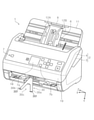
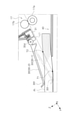
図1においてスキャナー1は、装置本体2を備えている。装置本体2は、下部ユニット3と上部ユニット4とを備えて構成されている。上部ユニット4は下部ユニット3に対して原稿搬送方向下流の回動軸(不図示)を回動支点として開閉可能に設けられており、上部ユニット4を装置前面方向に開き、原稿搬送経路を露呈させて原稿Pのジャム処理を行うことができる様に構成されている。
In FIG. 1, the
装置本体2の背面側には、給送される原稿Pを載置する原稿載置部11が設けられている。原稿載置部11は、装置本体2に対して着脱可能に設けられている。
また、原稿載置部11には、原稿Pの幅方向の側縁をガイドする一対のエッジガイド12A、12Bが設けられている。
原稿載置部11は、ペーパーサポート8を備えている。ペーパーサポート8は、原稿載置部11の内部に収納可能であり、且つ、原稿載置部11から引き出し可能に構成され、原稿載置面の長さを調整することができる。
On the back side of the
Further, the
The
装置本体2は、上部ユニット4の装置前面側に、各種操作設定を行う為の操作パネル7を備えている。操作パネル7には、各種情報を表示する表示部7aのほか、各種操作設定を行う為の複数の操作ボタンが設けられており、符号7bで示す操作ボタンは、そのうちの一つである。
The apparatus
装置本体2の上部には装置本体2内部に連なる給送口6が設けられており、原稿載置部11に載置される原稿Pは、給送口6から、装置本体2内部に設けられる読取部20(図2参照)に向けて送られる。
A feeding
次に、主として図2を参照して、スキャナー1における原稿搬送経路について説明する。
図2において符号Tで示す二点鎖線は、原稿搬送経路を示している。原稿搬送経路Tは、下部ユニット3と上部ユニット4とによって挟まれた領域によって形成される。
Next, the document transport path in the
The two-dot chain line indicated by the reference numeral T in FIG. 2 indicates a document transport path. The document transport path T is formed by a region sandwiched between the
原稿搬送経路Tの最も上流には原稿載置部11が設けられており、原稿載置部11の下流には、原稿載置部11に載置された原稿Pを読取部20に向けて送る給送ローラー14と、給送ローラー14との間で原稿Pをニップして分離する分離ローラー15とが設けられている。
不図示のモーターにより駆動される給送ローラー14は、原稿載置部11に載置された原稿Pのうち、最下位のものと接する。従って、スキャナー1において複数枚の原稿Pを原稿載置部11にセットした場合には、最も下の原稿Pから順に下流に向けて給送される。分離ローラー15には、不図示のモーターから、不図示のトルクリミッタを介して原稿Pを上流に戻す方向の回転トルクが伝達される。
A
The feeding
給送ローラー14の下流には、搬送ローラー対16と、原稿Pを読み取る読取部20と、媒体排出部の一例である排出ローラー対17とが設けられている。搬送ローラー対16は、不図示のモーターにより回転駆動される搬送駆動ローラー16aと、従動回転する搬送従動ローラー16bとを備えて成る。
給送ローラー14及び分離ローラー15によりニップされて下流に給送された原稿Pは搬送ローラー対16にニップされて、搬送ローラー対16の下流に位置する読取部20に搬送される。
Downstream of the
The document P nipped by the feeding
読取部20は、上部ユニット4に設けられた上部読取センサー20Aと、下部ユニット3に設けられた下部読取センサー20Bと、を備えて構成される。本実施形態において、上部読取センサー20A及び下部読取センサー20Bは密着型イメージセンサーモジュール(CISM)を備えている。
下部読取センサー20Bにより、原稿Pの下面が読み取られ、上部読取センサー20Aにより、原稿Pの上面が読み取られる。
The
The
原稿Pは、上面及び下面の少なくとも一方の面を読取部20により読み取られた後、読取部20の下流に位置する排出ローラー対17にニップされて、装置前面に設けられた排出口18から媒体受けトレイの一例である原稿受けトレイ40に向けて排出される。
排出ローラー対17は、不図示のモーターにより回転駆動される排出駆動ローラー17aと、従動回転する排出従動ローラー17bとを備えて成る。
排出ローラー対17を備える装置本体2、原稿受けトレイ40、及び後述する押さえ部材30は、媒体排出装置の一例である原稿排出装置10を構成する。尚、媒体の一例である原稿Pを排出する観点において、スキャナー1の全体が媒体排出装置の一例と捉えることもできる。
After the document P is read by the
The
The device
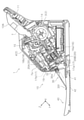
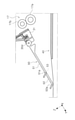
原稿受けトレイ40は、図3に示す様にベーストレイ41と、第1展開トレイ42と、第2展開トレイ43と、第3展開トレイ44とを備えて成る。
第1展開トレイ42は、ベーストレイ41に保持され、図1に示す様にベーストレイ41に収容された状態と、図3に示す様にベーストレイ41から引き出された状態とを取り得る。
第2展開トレイ43は、第1展開トレイ42に保持され、図1に示す様に第1展開トレイ42に収容された状態と、図3に示す様に第1展開トレイ42から引き出された状態とを取り得る。
第3展開トレイ44は、第2展開トレイ43の下流に位置する不図示の回転軸を介して第2展開トレイ43に対し回転可能に設けられ、図3に示す様に倒れた状態と、不図示の起き上がった状態とを取り得る。即ち第3展開トレイ44は、起き上がった状態で排出される原稿Pの飛び出しを抑制するストッパーとして機能する。
As shown in FIG. 3, the
The first unfolding
The second unfolding
The third unfolding
続いて排出ローラー対17により排出される原稿Pを原稿受けトレイ40に向けて押さえる押さえ部材30について説明する。
装置本体2を構成する上部ユニット4には、押さえ部材30が、上部ユニット4に対して着脱可能に設けられている。図1~図8のうち、図1~図7は押さえ部材30が上部ユニット4に取り付けられた状態を示し、図8は押さえ部材30が上部ユニット4から取り外された状態を示している。
Subsequently, a pressing
A pressing
押さえ部材30は、図9に示す様に台座部31に対し、回転軸30d(図11、図12参照)を介して回転可能に設けられている。この回転軸30dは、押さえ部材30が装置本体2に取り付けられた際、軸線がX軸方向に平行となり、これにより押さえ部材30は装置本体2に装着された状態でY-Z平面において回転可能となる。
また台座部31は、凹部31aとロック部31bとを有している。押さえ部材30は、台座部31を介して装置本体2に着脱可能となる。台座部31は、例えばある程度の弾性を有する様に樹脂材料で形成することが好適である。押さえ部材30は、樹脂材料や金属材料で形成することができる。
As shown in FIG. 9, the pressing
Further, the
上部ユニット4の上面を構成する筐体19において、排出口18の上方には図11に示す様に固定部32が設けられている。上述した台座部31は、固定部32に対して取り付けられる。台座部31が固定部32に取り付けられる際、筐体19において排出口18の上縁を構成する縁部19aが台座部31の凹部31aに入り込み、また台座部31を構成する鉤状のロック部31bが固定部32の上縁に引っ掛かり、これにより台座部31が固定部32に固定される。
In the
台座部31の下側には図10に示す様に操作部31cが設けられている。そして図11の右図において矢印Faで示す様に操作部31cを下側から押し上げると、台座部31は縁部19aと凹部31aとの接触部位を支点にして、図11において時計回り方向、即ちロック部31bが固定部32の上縁から外れる方向に回転する。これにより、図11の左図から右図への変化で示す様にロック部31bが固定部32の上縁から外れ、台座部31の固定状態が解消される。この様にして台座部31つまり押さえ部材30を装置本体2から取り外すことができる。
An
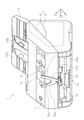
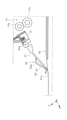
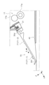
次に、押さえ部材30は回転することにより排出される原稿Pと接触可能な第1状態と、排出される原稿Pに接触しない位置まで上方に退避した第2状態とを切り換えることができる。図1~図7のうち、図1~図4は押さえ部材30の第1状態の一例を示し、図5~図7は押さえ部材30の第2状態を示している。
Next, the pressing
ここで、台座部31には図12に示す様に負荷付与手段としての負荷付与部31dが形成されている。押さえ部材30において回転軸30dの周囲には凸部30hが形成されており、この凸部30hが負荷付与部31dと係合可能となっている。この様な構成により押さえ部材30が第2状態をとる際、図12の最も左の図で示す様に押さえ部材30が第2状態に保持される。そして押さえ部材30を第2状態から第1状態に切り換える際、押さえ部材30の凸部30hが負荷付与部31dを押し退ける。これにより押さえ部材30が、図12の最も左の図から中央の図で示す様に第1状態に切り換わることができる。以上の様にして負荷付与部31dは、押さえ部材30の第2状態から第1状態への切り換わり動作に対して負荷を付与する。
Here, as shown in FIG. 12, the
次に、押さえ部材30は図3、図9に示す様に原稿Pの排出方向下流に向かってX軸方向つまり幅方向に拡がるとともに、幅方向の中央部30cが切り欠かれた形状を有している。これにより、中央部30cに対して-X方向に第1アーム部30aが形成され、また中央部30cに対して+X方向に第2アーム部30bが形成された状態となっている。
この様な構成により、押さえ部材30は幅方向において複数の接触位置で原稿Pと接触し、より具体的には本実施形態では二箇所の接触位置で原稿Pと接触する。
また、排出される原稿Pの幅方向の中心位置は、図3において一点鎖線Cで示されるが、この中心位置Cは、上記二箇所の接触位置つまり第1アーム部30aと第2アーム部30bとの間にあり、より具体的には上記二箇所の接触位置の中心に位置する。
Next, as shown in FIGS. 3 and 9, the pressing
With such a configuration, the pressing
Further, the center position of the ejected document P in the width direction is indicated by the alternate long and short dash line C in FIG. 3, and the center position C is the contact position of the above two places, that is, the
次に、押さえ部材30の回転動作について説明する。原稿受けトレイ40上に原稿Pがない場合、第1状態にある押さえ部材30は自重によって原稿受けトレイ40の上面に接している。この状態から原稿Pが原稿受けトレイ40に排出されると、押さえ部材30は原稿Pによって上方に押し上げられる。そして原稿Pが原稿受けトレイ40に完全に落下すると、それに伴って押さえ部材30は下方に下がり、原稿Pの上面に接した状態で回転が停止する。以降、原稿Pが排出される毎に押さえ部材30は上方への回転と下方への回転とを繰り返す。そしてまた原稿受けトレイ40上の原稿Pの堆積量が増えるに従って、押さえ部材30の回転停止位置は上方に移動する。以上の押さえ部材30の回転動作は、押さえ部材30の第1状態において行われる。
Next, the rotational operation of the pressing
以上の様に原稿排出装置10は、装置本体2に対して着脱可能であり、装置本体2に装着された状態で排出ローラー対17により排出される原稿Pを原稿受けトレイ40に向けて押さえる押さえ部材30を備える。押さえ部材30がない場合、排出ローラー対17により排出される原稿Pは、排出された後、排出される勢いにより回転つまり斜行を起こし易い。しかしながら上述の様に押さえ部材30を備える場合、押さえ部材30が排出される原稿Pを原稿受けトレイ40に向けて押さえることで、原稿Pの斜行を抑制でき、原稿受けトレイ40での原稿Pの整列性を向上させることができる。尚、原稿Pの回転つまり斜行は排出される原稿Pのサイドエッジを規制するサイドフェンスを設けることでも抑制できるが、例えばサイズが異なる原稿Pが混在している場合には小サイズ原稿をサイドフェンスによりガイドできない為、有効となる。
As described above, the
そしてこの押さえ部材30は装置本体2から取り外しが可能である為、装置の保管時や輸送の際に押さえ部材30を取り外すことで、押さえ部材30の破損を回避できる。
そしてまたこの押さえ部材30は、装置本体2に装着された状態において、排出ローラー対17により排出される原稿Pに接触可能な第1状態と、排出ローラー対17により排出される原稿Pに接触しない位置まで上方に退避した第2状態とを切り換え可能である。従って普段の使用環境において押さえ部材30が不要な場合は、押さえ部材30を装置本体2から取り外すことなく第2状態にすることでユーザーの要求に沿うことができ、ひいてはユーザーの利便性を向上させることができる。例えば、ジャム処理を行う際に押さえ部材30を第2状態に切り換えることで、押さえ部材30が邪魔にならない状態とすることができる。
尚、本実施形態では原稿受けトレイ40に原稿Pが存在しない場合、押さえ部材30は原稿受けトレイ40の上面に接するが、原稿受けトレイ40に原稿Pが存在しない場合に、押さえ部材30が原稿受けトレイ40からある程度離間している様に構成しても良い。
Since the pressing
Further, the pressing
In the present embodiment, when the document P does not exist in the
また原稿排出装置10は、図11を参照して説明した様に押さえ部材30の第2状態から第1状態への切り換わり動作に対し負荷を付与する負荷付与部31dを備える。これにより、ユーザーの意図に反して押さえ部材30が第2状態から第1状態に切り換わることを抑制でき、ユーザーの利便性がより一層向上する。
Further, the
また第1状態にある押さえ部材30は、原稿Pの排出方向と交差する方向である幅方向において複数の接触位置で原稿Pと接する。これにより、排出される原稿PのX-Y平面での回転つまり斜行を抑制できる。
Further, the pressing
また押さえ部材30は、幅方向において二箇所の接触位置、具体的には第1アーム部30aと第2アーム部30bとにおいて原稿Pと接し、排出ローラー対17により排出される原稿Pの幅方向の中心位置Cは、二箇所の接触位置、つまり第1アーム部30aと第2アーム部30bとの間にある。この様な構成により、排出される原稿Pの回転つまり斜行をより効果的に抑制できる。
Further, the pressing
以下、更に本実施形態の特徴について説明する。
押さえ部材30は、原稿Pの排出方向下流に向かって幅方向に拡がるとともに、幅方向の中央部30cが切り欠かれた形状を有する。この様な形状により、幅方向における広い領域で原稿Pを押さえることで排出される原稿Pの回転つまり斜行を効果的に抑制できる。そして押さえ部材30は、幅方向の中央部30cが切り欠かれた形状を有しているので、押さえ部材30の重量増加を抑制できるので、剛性の低い原稿Pを排出する際の座屈を抑制できる。
加えて押さえ部材30を第2状態に切り換えた際に、押さえ部材30が装置本体2を覆う面積を小さくでき、装置本体2の操作性の低下を抑制できる。以下、これについて更に説明する。
Hereinafter, the features of the present embodiment will be further described.
The pressing
In addition, when the pressing
図5、図6、図7に示す様に第2状態にある押さえ部材30の上端部は、高さ方向において操作パネル7の一部と重なる高さにある。そして図7に示す様に表示部7aの平面視では、押さえ部材30が操作パネル7の一部を覆い、特に表示部7aの下側の両角部と、操作ボタン7bの一部を覆っている。操作ボタン7bは、本実施形態では操作設定の状態を一つ前に戻す「戻る」ボタンである。
この様に押さえ部材30が第2状態をとると、押さえ部材30が操作パネル7の一部を覆うが、押さえ部材30は幅方向の中央部30cが切り欠かれた形状を有しているので、表示部7aを広い領域で覆うことがなく、操作性の低下を抑制できる。
As shown in FIGS. 5, 6 and 7, the upper end portion of the holding
When the pressing
そして本実施形態において第2状態にある押さえ部材30は、表示部7aの平面視において表示部7aの一部を覆う位置にあって、表示部7aでの表示内容から外れた位置にある。ここでの表示内容とは、表示部7aに表示される、ユーザーに提供される文字や図形等の情報である。第2状態にある押さえ部材30は、表示部7aに表示される文字や図形等の情報から外れた位置にあるので、ユーザーによる表示部7aの視認を阻害することを抑制できる。
The pressing
また押さえ部材30は操作ボタン7bの一部を覆っているが、操作ボタン7bの一部を露呈させる位置にあり、操作ボタン7bを押下できる広さは確保されていて、操作ボタン7bは押下することができる状態である。これにより押さえ部材30が、ユーザーによる操作ボタン7bの押下を妨げることを回避できる。
また特に本実施形態では、押さえ部材30は操作設定の状態を一つ前に戻す「戻る」ボタンである操作ボタン7bの一部を覆うので、仮に押さえ部材30が操作ボタン7bの全部を覆い、操作ボタン7bの押下ができない状態でも、原稿Pの基本的な読み取り動作を行うことができる。押さえ部材30に覆われない様にする操作ボタンとしては、電源ボタン、スキャン実行ボタンなどが好適となる。
Further, although the pressing
Further, particularly in the present embodiment, since the pressing
また、表示部7aが所謂タッチパネルであり、各種設定操作を行う為のユーザーインターフェースが表示部7aに実現される場合にも同様に、原稿Pの基本的な読み取り動作を行う為のタッチ領域を押さえ部材30で覆わないか、或いは覆っても一部のみが覆われて、タッチ操作は可能である様に構成されることが好ましい。また逆に、押さえ部材30で覆われる領域を除く領域に、各種設定操作を行う為のユーザーインターフェースを実現することも好適である。
Further, when the
尚、第2状態にある押さえ部材30の上端部が、高さ方向において操作パネル7の一部と重ならない高さとすれば、押さえ部材30が表示部7aの視認や複数の操作ボタンの操作を阻害することがない為、好適である。
また、第2状態にある押さえ部材30の上端部が、高さ方向において操作パネル7の一部と重なる位置にあっても、例えば押さえ部材30を透明な材料で形成することで、ユーザーの視認性を確保することができる。
If the upper end of the pressing
Further, even if the upper end portion of the pressing
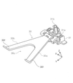
次に、図13において直線L1は、排出駆動ローラー17aと排出従動ローラー17bとの共通接線であり、即ち排出ローラー対17による原稿排出方向を示している。また符号30-1は原稿受けトレイ40上に原稿Pが無く、原稿受けトレイ40に接している押さえ部材30を示している。また符号30-2は原稿受けトレイ40上に最大積載高さの原稿Pが積載されている状態で、最上位の原稿Ptに接している押さえ部材30を示している。また、位置T1は排出ローラー対17により排出される原稿Pが原稿受けトレイ40に接する位置であり、位置T2は排出ローラー対17により排出される原稿Pが最上位の原稿Ptに接する位置である。尚、位置T2は、原稿積載量に従って共通接線L1上で変化する。
Next, in FIG. 13, the straight line L1 is a common tangent line between the
図13に示す様に、共通接線L1は原稿Pの積載量に拘わらず押さえ部材30と交差しない。つまり原稿Pの積載量に拘わらず、排出ローラー対17により排出される原稿Pが押さえ部材30に接触する接触位置は、排出ローラー対17により排出される原稿Pが原稿受けトレイ40に接する位置T1または原稿受けトレイ40に積載された原稿Pのうち最上位の原稿Ptに接する位置T2より排出方向下流にある。
As shown in FIG. 13, the common tangent line L1 does not intersect the holding
これにより以下の作用効果が得られる。即ち排出ローラー対17により排出される原稿Pが、原稿受けトレイ40或いは原稿受けトレイ40に積載された原稿Pのうち最上位の原稿Ptに接するより前に押さえ部材30に接触すると、原稿Pが座屈し、ジャムとなる虞がある。しかしながら本態様によれば排出ローラー対17により排出される原稿Pが押さえ部材30に接触する接触位置は、排出ローラー対17により排出される原稿Pが原稿受けトレイ40に接する位置T1または原稿受けトレイ40に積載された原稿Pのうち最上位の原稿Ptに接する位置T2より排出方向下流にあるので、上記の様なジャムの発生を抑制することができる。
As a result, the following effects can be obtained. That is, when the document P ejected by the
次に、図13に示す様に押さえ部材30は、原稿Pの排出方向と交差する方向である幅方向から視て、原稿受けトレイ40と接する部位30fが原稿受けトレイ40に対し凸となる形状に形成されている。以下、押さえ部材30が原稿受けトレイ40と接する部位30fを、「トレイ接触部位30f」と称する。
トレイ接触部位30fは、本実施形態ではV字状に折り曲げられた形状を成しており、原稿受けトレイ40に対し凸となっている。これにより、以下の作用効果が得られる。即ち図3及び図4に示す様な原稿受けトレイ40の展開状態から、原稿受けトレイ40を縮小状態にする際、第2展開トレイ43や第3展開トレイ44が押さえ部材30に引っ掛かる虞がある。しかしながら押さえ部材30は、トレイ接触部位30fが原稿受けトレイ40に対し凸となる形状に形成されているので、上記の引っ掛かりを抑制できる。
尚、本実施形態においてトレイ接触部位30fはV字状に折り曲げられた形状を成しているが、これに限られずその他の形状、例えばU字状に折り曲げられた形状を有していても良い。
Next, as shown in FIG. 13, the holding
In the present embodiment, the
In the present embodiment, the
次に、図12の最も右の図は、押さえ部材30が下方向の回転限度にある状態を示している。押さえ部材30の下方向への回転限度は、押さえ部材30に形成された当接部30gが、台座部31に形成された規制部としての操作部31cに当接することで規定される。この状態は、一例として装置本体2を持ち上げて移動させる場合に生じる。この場合、装置本体2を設置面に置く際に、押さえ部材30が装置の設置面に衝突し、上方向の外力Fcを受け、破損を招く虞がある。しかしながら下方向への回転限度にある押さえ部材30の下端部に対し鉛直上方成分を含む外力Fcを付与すると、図12から明らかな様に押さえ部材30が第2状態に向けて回転することとなる。これにより、上述の様な押さえ部材30の破損を抑制できる。
Next, the rightmost figure of FIG. 12 shows a state in which the pressing
また、押さえ部材30の下方向への回転限度が、当接部30gと、当接部30gが当接する規制部としての操作部31cとの当接により規定され、当接部30gが操作部31cに当接した状態で、図12の最も右の図で示す様に押さえ部材30が斜め下方向に向く傾斜姿勢をとる。これにより、下方向への回転限度にある押さえ部材30の下端部に鉛直上方成分を含む外力Fcが作用した際、押さえ部材30が第2状態に向けて確実に回転でき、上述の様な押さえ部材30の破損を確実に抑制できる。
Further, the downward rotation limit of the pressing
また下方向への回転限度にある押さえ部材30に対し、第2状態に向かう方向とは反対の方向に回転させる外力Fdを付与した場合にも、押さえ部材30の破損を招く虞がある。しかしながらそのような外力Fdを付与すると、押さえ部材30の一部である当接部30gが操作部31cに当接し、操作部31cに対し矢印Fbで示す様な外力を付与する。するとこれにより、図11を参照して説明した様にロック部31bによる押さえ部材30の固定が解除されるので、押さえ部材30が脱落することができ、その結果押さえ部材30の破損を抑制することができる。
Further, even when an external force Fd for rotating the pressing
続いて押さえ部材の他の実施形態について説明する。図14及び図15は第2実施形態に係る押さえ部材50を示している。尚、以降の実施形態においては既に説明した構成と同一の構成については同一の符号を付し、重複する説明は省略する。
押さえ部材50は、第1アーム51と、第2アーム52とを備えて構成されている。第1アーム51は回転軸30dを中心に回転可能であり、第2アーム52は、幅方向に平行な軸線を有する回転軸53を介して第1アーム51に対し回転可能に連結されている。また、回転軸53には不図示の摩擦部材が設けられており、第1アーム51に対する第2アーム52の回転に対し摩擦力が生じる様に構成されている。従って第2アーム52は、ユーザーから外力が付与された際に回転する他は、前記摩擦力によって回転が規制された状態となっている。
Subsequently, other embodiments of the pressing member will be described. 14 and 15 show the pressing
The pressing
第1アーム51には、原稿受けトレイ40に対して凸となるトレイ接触部位51aが形成されており、第2アーム52にも同様に、原稿受けトレイ40に対して凸となるトレイ接触部位51aが形成されている。図14に示す様に第1アーム51と第2アーム52とが直線状になると、押さえ部材50は全体として原稿排出方向に最も長い状態となる。この状態では、第2アーム52のトレイ接触部位52aが原稿受けトレイ40に接し、或いは、排出される原稿Pに接する。
The
また図14に示す状態から第2アーム52を図14の時計回り方向に回転させ、図15に示す状態とすると、押さえ部材50は全体として原稿排出方向に最も短い状態となる。この状態では、第1アーム51のトレイ接触部位51aが原稿受けトレイ40に接し、或いは、排出される原稿Pに接する。
Further, when the
この様に押さえ部材50は、原稿Pの排出方向の長さを調整可能に構成されているので、原稿Pのサイズに応じて押さえ部材50が原稿Pを押さえる位置を調整することができ、適切に原稿Pを押さえることができる。
尚、本実施形態では、第1アーム51と第2アーム52の二つの部材で原稿Pの排出方向長さを調整する様に構成したが、三つ以上の部材で構成し、更に多段階に排出方向長さを調整する様に構成しても良い。
また或いは、例えば第2アーム52を第1アーム51に対し排出方向にスライド可能に設け、無段階で排出方向長さを調整可能に構成しても良い。
In this way, since the pressing
In the present embodiment, the length of the document P in the ejection direction is adjusted by the two members of the
Alternatively, for example, the
次に、図16は第3実施形態に係る押さえ部材60を示している。押さえ部材60は、原稿Pと接触する接触部位61が、原稿Pとの間の摩擦係数が第1摩擦係数となる第1部位61aと、原稿Pとの間の摩擦係数が第1部位61aの第1摩擦係数より大きい第2摩擦係数となる第2部位61bとを備えている。接触部位61は、回転軸62を介して押さえ部材60に対して回転可能であり、回転することで、原稿Pと接触する部位と第1部位61aと第2部位61bとに切り換えることができる。尚、接触部位61と回転軸62との間には不図示の摩擦部材が設けられており、接触部位61は、ユーザーから外力が付与された際に回転する他は、前記摩擦部材の摩擦力によって回転が規制された状態となっている。
Next, FIG. 16 shows the pressing
この様に接触部位61は、原稿Pとの間の摩擦係数が第1摩擦係数となる第1部位61aと、第1摩擦係数より大きい第2摩擦係数となる第2部位61bとに切り換え可能であるので、原稿Pのサイズや種類等に応じて前記摩擦係数を切り換えることができ、適切に原稿Pを押さえることができる。
例えば、剛性が低く座屈し易い原稿Pの場合には、第1部位61aによって原稿Pを押さえ、ある程度の剛性があり座屈し難い原稿Pの場合には、第2部位61bによって原稿Pを押さえることが好適となる。
In this way, the
For example, in the case of a document P having low rigidity and easy to buckle, the document P is pressed by the
次に、図17は第4実施形態に係る押さえ部材70を示している。押さえ部材70の上面には、錘71が、矢印a方向に変位可能に設けられている。錘71は、不図示の摩擦部材により押さえ部材70との間で摩擦力が生じる様に設けられており、ユーザーから外力が付与された際に変位する他は、前記摩擦部材の摩擦力によって変位が規制された状態となっている。錘71を変位させることで、押さえ部材70が原稿Pを押さえる際の押圧荷重を調整することができる。この様な構成により、原稿Pのサイズや種類等に応じて前記押圧荷重を調整することができ、適切に原稿Pを押さえることができる。
例えば、剛性が低く座屈し易い原稿Pの場合には、押圧荷重を小さくし、ある程度の剛性があり座屈し難い原稿Pの場合には、前記剛性が低く座屈し易い原稿Pを押さえる場合よりも相対的に押圧荷重を大きくすることが好適となる。
Next, FIG. 17 shows the pressing
For example, in the case of a document P having low rigidity and easy to buckle, the pressing load is reduced, and in the case of a document P having some rigidity and difficult to buckle, the document P having low rigidity and easy to buckle is held down. It is preferable to increase the pressing load relatively.
本発明は上記において説明した実施形態に限定されることなく、特許請求の範囲に記載した発明の範囲内で、種々の変形が可能であり、それらも本発明の範囲内に含まれるものであることは言うまでもない。
例えば、押さえ部材30の第1状態と第2状態とを検出する検出手段を設け、押さえ部材30が第1状態にある場合、第2状態にある場合よりも相対的に原稿排出速度を低速にすることも好適である。
また例えば本実施形態では、媒体排出装置をスキャナー1における原稿排出装置10として構成したが、これに限らず、媒体に記録を行う記録装置、例えばプリンターに適用することもできる。
The present invention is not limited to the embodiments described above, and various modifications can be made within the scope of the invention described in the claims, and these are also included in the scope of the present invention. Needless to say.
For example, a detection means for detecting the first state and the second state of the pressing
Further, for example, in the present embodiment, the medium ejection device is configured as the
1…ドキュメントスキャナー、2…装置本体、3…下部ユニット、4…上部ユニット、6…給送口、7…操作パネル、7a…表示部、7b…操作ボタン、8…ペーパーサポート、10…原稿排出装置、11…原稿載置部、12A、12B…エッジガイド、14…給送ローラー、15…分離ローラー、16…搬送ローラー対、16a…搬送駆動ローラー、16b…搬送従動ローラー、17…排出ローラー対、17a…排出駆動ローラー、17b…排出従動ローラー、18…排出口、19…筐体、19a…縁部、20…読取部、20A…上部読取センサー、20B…下部読取センサー、30…押さえ部材、30a…第1アーム部、30b…第2アーム部、30c…中央部、30d…回転軸、30e…当接部、30f…トレイ接触部位、30g…当接部、30h…凸部、31…台座部、31a…凹部、31b…ロック部、31c…操作部、31d…負荷付与部、32…固定部、40…原稿受けトレイ、41…ベーストレイ、42…第1展開トレイ、43…第2展開トレイ、44…第3展開トレイ、50…押さえ部材、51…第1アーム、52…第2アーム、53…回転軸、
60…押さえ部材、61…接触部位、61a…第1部位、61b…第2部位、62…回転軸、70…押さえ部材、71…錘、P、Pt…原稿
1 ... Document scanner, 2 ... Device body, 3 ... Lower unit, 4 ... Upper unit, 6 ... Feed port, 7 ... Operation panel, 7a ... Display unit, 7b ... Operation button, 8 ... Paper support, 10 ... Document ejection Equipment, 11 ... Document mounting unit, 12A, 12B ... Edge guide, 14 ... Feeding roller, 15 ... Separation roller, 16 ... Transfer roller pair, 16a ... Transfer drive roller, 16b ... Transfer driven roller, 17 ... Discharge roller pair , 17a ... Discharge drive roller, 17b ... Discharge driven roller, 18 ... Discharge port, 19 ... Housing, 19a ... Edge, 20 ... Reading unit, 20A ... Upper reading sensor, 20B ... Lower reading sensor, 30 ... Holding member, 30a ... 1st arm part, 30b ... 2nd arm part, 30c ... central part, 30d ... rotating shaft, 30e ... contact part, 30f ... tray contact part, 30g ... contact part, 30h ... convex part, 31 ... pedestal Section, 31a ... concave, 31b ... lock section, 31c ... operation section, 31d ... load applying section, 32 ... fixed section, 40 ... document receiving tray, 41 ... base tray, 42 ... first unfolding tray, 43 ... second unfolding Tray, 44 ... 3rd deployment tray, 50 ... Pressing member, 51 ... 1st arm, 52 ... 2nd arm, 53 ... Rotating shaft,
60 ... pressing member, 61 ... contact part, 61a ... first part, 61b ... second part, 62 ... rotating shaft, 70 ... pressing member, 71 ... weight, P, Pt ... original
Claims (16)
前記媒体排出部により排出される媒体を受ける媒体受けトレイと、
前記装置本体に対して着脱可能な部材であって、前記装置本体に装着された状態で前記媒体排出部により排出される媒体を前記媒体受けトレイに向けて押さえる押さえ部材と、を備え、
前記押さえ部材は、前記装置本体に装着された状態において、前記媒体排出部により排出される媒体に接触可能な第1状態と、前記媒体排出部により排出される媒体に接触しない位置まで上方に退避した第2状態と、を切り換え可能である、
ことを特徴とする媒体排出装置。 The main body of the device provided with a medium ejection unit that ejects the medium,
A medium receiving tray that receives the medium discharged by the medium discharging unit, and
A member that can be attached to and detached from the main body of the device and is provided with a holding member that holds the medium discharged by the medium discharging unit toward the medium receiving tray while being attached to the main body of the device.
The holding member is retracted upward to a first state in which it can contact the medium discharged by the medium discharging unit and a position where it does not contact the medium discharged by the medium discharging unit when it is mounted on the main body of the device. It is possible to switch between the second state and the second state.
A medium ejection device characterized by that.
ことを特徴とする媒体排出装置。 The medium discharging device according to claim 1 is provided with a load applying means for applying a load to the operation of switching the holding member from the second state to the first state.
A medium ejection device characterized by that.
下方向への回転限度にある前記押さえ部材の先端部に対し鉛直上方成分を含む外力を付与することにより、前記押さえ部材が前記第2状態に向けて回転する、
ことを特徴とする媒体排出装置。 In the medium discharging device according to claim 1 or 2, the holding member is provided so as to switch between the first state and the second state by rotating.
By applying an external force including a vertically upward component to the tip end portion of the pressing member which is in the downward rotation limit, the pressing member rotates toward the second state.
A medium ejection device characterized by that.
ことを特徴とする媒体排出装置。 In the medium discharging device according to claim 3, the downward rotation limit of the pressing member is due to the contact between the abutting portion formed on the pressing member and the restricting portion with which the abutting portion abuts. Specified, the holding member takes an inclined posture facing diagonally downward in a state where the contact portion is in contact with the regulation portion.
A medium ejection device characterized by that.
前記押さえ部材を前記装置本体に固定するロック部と、
前記ロック部による前記押さえ部材の固定を解除する為の操作部と、を備え、
下方向への回転限度にある前記押さえ部材に対し、前記第2状態に向かう方向とは反対の方向に回転させる外力を付与すると、前記押さえ部材の一部が前記操作部に当接し、前記ロック部による前記押さえ部材の固定が解除される、
ことを特徴とする媒体排出装置。 In the medium discharging device according to claim 1 or 2, the holding member is provided so as to switch between the first state and the second state by rotating.
A lock portion for fixing the holding member to the apparatus main body,
An operation unit for releasing the fixing of the holding member by the lock portion is provided.
When an external force for rotating the pressing member in the direction opposite to the direction toward the second state is applied to the pressing member whose rotation limit is downward, a part of the pressing member comes into contact with the operating portion and the lock is applied. The fixing of the holding member by the portion is released.
A medium ejection device characterized by that.
ことを特徴とする媒体排出装置。 In the medium discharging device according to any one of claims 1 to 5, the contact position where the medium discharged by the medium discharging unit contacts the holding member in the first state is the medium discharging unit. The medium discharged by the vehicle is located downstream in the discharge direction from the position in contact with the medium receiving tray or the medium placed on the medium receiving tray.
A medium ejection device characterized by that.
ことを特徴とする媒体排出装置。 In the medium discharging device according to any one of claims 1 to 6, the holding member in the first state is brought into contact with the medium at a plurality of contact positions in a width direction intersecting the medium discharging direction. Contact,
A medium ejection device characterized by that.
前記媒体排出部により排出される媒体の前記幅方向の中心位置は、二箇所の前記接触位置の間にある、
ことを特徴とする媒体排出装置。 In the medium ejection device according to claim 7, the holding member is in contact with the medium at two contact positions in the width direction.
The widthwise center position of the medium ejected by the medium ejection portion is between the two contact positions.
A medium ejection device characterized by that.
ことを特徴とする媒体排出装置。 In the medium discharging device according to claim 8, the holding member expands in the width direction, which is a direction intersecting the discharging direction of the medium, toward the downstream in the discharging direction of the medium, and the central portion in the width direction is notched. Has a sharpened shape,
A medium ejection device characterized by that.
ことを特徴とする媒体排出装置。 In the medium discharging device according to any one of claims 1 to 9, the holding member has a portion in contact with the medium receiving tray when viewed from the width direction which is a direction intersecting the discharging direction of the medium. It is formed in a shape that is convex with respect to the medium receiving tray.
A medium ejection device characterized by that.
ことを特徴とする媒体排出装置。 The medium discharging device according to any one of claims 1 to 10, is configured so that the pressing load when the pressing member presses the medium can be adjusted.
A medium ejection device characterized by that.
ことを特徴とする媒体排出装置。 In the medium discharging device according to any one of claims 1 to 11, the holding member is configured to be able to adjust the length of the medium in the discharging direction.
A medium ejection device characterized by that.
ことを特徴とする媒体排出装置。 In the medium discharging device according to any one of claims 1 to 12, the holding member has a portion in contact with the medium as a first portion having a friction coefficient with the medium as a first friction coefficient. , It is possible to switch to a second portion where the coefficient of friction with the medium is a second coefficient of friction larger than the first coefficient of friction.
A medium ejection device characterized by that.
前記表示部の平面視において前記第2状態にある前記押さえ部材は、前記表示部の一部を覆う位置にあって、前記表示部での表示内容から外れた位置にある、
ことを特徴とする媒体排出装置。 In the medium discharging device according to any one of claims 1 to 13, the main body of the device includes a display unit for displaying various information.
The holding member in the second state in the plan view of the display unit is located at a position covering a part of the display unit and at a position deviating from the display content on the display unit.
A medium ejection device characterized by that.
前記操作パネルは、押下可能な押下ボタンを少なくとも一つ備え、
前記第2状態にある前記押さえ部材は、前記押下ボタンの平面視において前記押下ボタンの一部を覆う位置にあって前記押下ボタンの一部を露呈させる位置にある、
ことを特徴とする媒体排出装置。 In the medium ejection device according to any one of claims 1 to 14, the apparatus main body includes an operation panel for receiving various operation settings.
The operation panel includes at least one press button that can be pressed.
The pressing member in the second state is at a position that covers a part of the pressing button in a plan view of the pressing button and is at a position that exposes a part of the pressing button.
A medium ejection device characterized by that.
前記読み取り手段により読み取りが行われた媒体を排出する、請求項1から請求項15のいずれか一項に記載の前記媒体排出装置と、
を備えた画像読取装置。 A reading means to read the transported medium,
The medium ejection device according to any one of claims 1 to 15, which ejects the medium read by the reading means.
Image reader equipped with.
Priority Applications (9)
| Application Number | Priority Date | Filing Date | Title |
|---|---|---|---|
| JP2020116473A JP7494607B2 (en) | 2020-07-06 | 2020-07-06 | Media ejection device, image reader |
| CN202411160514.3A CN118929310A (en) | 2020-07-06 | 2021-07-05 | Media ejection device, image reading device |
| EP21183725.7A EP3936468B1 (en) | 2020-07-06 | 2021-07-05 | Medium-discharging device with detachably mounted pivotable pressing device |
| CN202110758705.XA CN113896025B (en) | 2020-07-06 | 2021-07-05 | Media ejection device, image reading device |
| US17/305,338 US11438473B2 (en) | 2020-07-06 | 2021-07-06 | Medium-discharging device and image reading apparatus |
| US17/812,863 US12166933B2 (en) | 2020-07-06 | 2022-07-15 | Medium-discharging device and image reading apparatus |
| JP2024079569A JP7679906B2 (en) | 2020-07-06 | 2024-05-15 | Image reader |
| US18/922,791 US20250047795A1 (en) | 2020-07-06 | 2024-10-22 | Medium-discharging device and image reading apparatus |
| JP2025076327A JP2025105939A (en) | 2020-07-06 | 2025-05-01 | Image reader |
Applications Claiming Priority (1)
| Application Number | Priority Date | Filing Date | Title |
|---|---|---|---|
| JP2020116473A JP7494607B2 (en) | 2020-07-06 | 2020-07-06 | Media ejection device, image reader |
Related Child Applications (1)
| Application Number | Title | Priority Date | Filing Date |
|---|---|---|---|
| JP2024079569A Division JP7679906B2 (en) | 2020-07-06 | 2024-05-15 | Image reader |
Publications (2)
| Publication Number | Publication Date |
|---|---|
| JP2022014246A true JP2022014246A (en) | 2022-01-19 |
| JP7494607B2 JP7494607B2 (en) | 2024-06-04 |
Family
ID=76765052
Family Applications (3)
| Application Number | Title | Priority Date | Filing Date |
|---|---|---|---|
| JP2020116473A Active JP7494607B2 (en) | 2020-07-06 | 2020-07-06 | Media ejection device, image reader |
| JP2024079569A Active JP7679906B2 (en) | 2020-07-06 | 2024-05-15 | Image reader |
| JP2025076327A Pending JP2025105939A (en) | 2020-07-06 | 2025-05-01 | Image reader |
Family Applications After (2)
| Application Number | Title | Priority Date | Filing Date |
|---|---|---|---|
| JP2024079569A Active JP7679906B2 (en) | 2020-07-06 | 2024-05-15 | Image reader |
| JP2025076327A Pending JP2025105939A (en) | 2020-07-06 | 2025-05-01 | Image reader |
Country Status (4)
| Country | Link |
|---|---|
| US (3) | US11438473B2 (en) |
| EP (1) | EP3936468B1 (en) |
| JP (3) | JP7494607B2 (en) |
| CN (2) | CN118929310A (en) |
Families Citing this family (1)
| Publication number | Priority date | Publication date | Assignee | Title |
|---|---|---|---|---|
| US12137188B2 (en) * | 2022-09-27 | 2024-11-05 | Seiko Epson Corporation | Image reading device with tapping member for tapping rear end portion of a medium |
Citations (8)
| Publication number | Priority date | Publication date | Assignee | Title |
|---|---|---|---|---|
| JPH0218454U (en) * | 1988-07-25 | 1990-02-07 | ||
| JP2008120494A (en) * | 2006-11-09 | 2008-05-29 | Fuji Xerox Co Ltd | Paper delivery and storage device and image forming device using the delivery and storage device |
| JP2010095365A (en) * | 2008-10-17 | 2010-04-30 | Fujitsu Frontech Ltd | Discharge and stacking device for paper sheet |
| JP2010275055A (en) * | 2009-05-27 | 2010-12-09 | Sharp Corp | Paper discharge device and image forming apparatus |
| JP2012046294A (en) * | 2010-08-25 | 2012-03-08 | Sharp Corp | Sheet sorter and image forming apparatus |
| JP2012076880A (en) * | 2010-10-01 | 2012-04-19 | Sharp Corp | Sheet sorting apparatus and image forming apparatus |
| JP2014201435A (en) * | 2013-04-10 | 2014-10-27 | 京セラドキュメントソリューションズ株式会社 | Sheet discharge device and image formation device |
| JP2020075790A (en) * | 2018-11-07 | 2020-05-21 | キヤノン電子株式会社 | Paper ejection extension unit and sheet conveying device including the same |
Family Cites Families (25)
| Publication number | Priority date | Publication date | Assignee | Title |
|---|---|---|---|---|
| JP3606360B2 (en) * | 1999-03-26 | 2005-01-05 | シャープ株式会社 | Sheet discharge mechanism |
| JP2001328758A (en) * | 1999-07-09 | 2001-11-27 | Ricoh Co Ltd | Sheet processing apparatus and image forming apparatus |
| JP3517619B2 (en) * | 1999-11-04 | 2004-04-12 | キヤノン株式会社 | Sheet post-processing apparatus and image forming apparatus |
| JP3471693B2 (en) * | 2000-01-25 | 2003-12-02 | シャープ株式会社 | Image forming device |
| JP4047092B2 (en) * | 2002-07-31 | 2008-02-13 | キヤノン株式会社 | Sheet post-processing apparatus and image forming apparatus including the apparatus |
| US7137698B2 (en) * | 2003-09-10 | 2006-11-21 | Seiko Epson Corporation | Recording apparatus and liquid ejection apparatus |
| EP1588972B1 (en) * | 2004-04-19 | 2013-02-27 | Canon Finetech Inc. | Sheet treating apparatus and image forming apparatus provided therewith |
| JP2007217178A (en) * | 2006-02-20 | 2007-08-30 | Canon Finetech Inc | Automatic document feeding device, image reading device, and image forming device |
| JP4497214B2 (en) * | 2008-02-29 | 2010-07-07 | ブラザー工業株式会社 | Document feeder |
| JP2011251786A (en) * | 2010-05-31 | 2011-12-15 | Fuji Xerox Co Ltd | Discharge device and image forming apparatus |
| JP5590739B2 (en) * | 2010-11-04 | 2014-09-17 | 京セラドキュメントソリューションズ株式会社 | Recording medium discharging apparatus and image forming apparatus having the same |
| US8958740B2 (en) * | 2011-02-28 | 2015-02-17 | Brother Kogyo Kabushiki Kaisha | Configuration for a sheet discharging device |
| JP5526068B2 (en) * | 2011-03-29 | 2014-06-18 | 京セラドキュメントソリューションズ株式会社 | Image forming apparatus |
| JP5950787B2 (en) * | 2012-10-12 | 2016-07-13 | 京セラドキュメントソリューションズ株式会社 | Sheet pressing mechanism, sheet conveying apparatus, image processing apparatus |
| JP6201375B2 (en) * | 2013-03-29 | 2017-09-27 | ブラザー工業株式会社 | Image forming apparatus |
| JP6235242B2 (en) * | 2013-05-28 | 2017-11-22 | 株式会社富士通マーケティング | Paper stacking assist device |
| JP7072343B2 (en) * | 2015-10-16 | 2022-05-20 | セイコーエプソン株式会社 | Media ejector and image reader |
| JP7095460B2 (en) * | 2018-07-31 | 2022-07-05 | セイコーエプソン株式会社 | Image reader |
| JP7224147B2 (en) * | 2018-11-07 | 2023-02-17 | キヤノン電子株式会社 | sheet conveying device |
| JP7402670B2 (en) * | 2019-12-19 | 2023-12-21 | 株式会社Pfu | media ejector |
| JP7505247B2 (en) * | 2020-05-07 | 2024-06-25 | 京セラドキュメントソリューションズ株式会社 | Document feeder, document reader, and image forming apparatus |
| JP2020116473A (en) | 2020-05-18 | 2020-08-06 | 株式会社三洋物産 | Game machine |
| JP7665935B2 (en) * | 2020-08-31 | 2025-04-22 | セイコーエプソン株式会社 | Media feeding device, image reading device |
| JP7596128B2 (en) * | 2020-11-30 | 2024-12-09 | 株式会社Pfu | Media ejection device |
| JP2023130857A (en) * | 2022-03-08 | 2023-09-21 | 京セラドキュメントソリューションズ株式会社 | Original transport device |
-
2020
- 2020-07-06 JP JP2020116473A patent/JP7494607B2/en active Active
-
2021
- 2021-07-05 EP EP21183725.7A patent/EP3936468B1/en active Active
- 2021-07-05 CN CN202411160514.3A patent/CN118929310A/en active Pending
- 2021-07-05 CN CN202110758705.XA patent/CN113896025B/en active Active
- 2021-07-06 US US17/305,338 patent/US11438473B2/en active Active
-
2022
- 2022-07-15 US US17/812,863 patent/US12166933B2/en active Active
-
2024
- 2024-05-15 JP JP2024079569A patent/JP7679906B2/en active Active
- 2024-10-22 US US18/922,791 patent/US20250047795A1/en active Pending
-
2025
- 2025-05-01 JP JP2025076327A patent/JP2025105939A/en active Pending
Patent Citations (8)
| Publication number | Priority date | Publication date | Assignee | Title |
|---|---|---|---|---|
| JPH0218454U (en) * | 1988-07-25 | 1990-02-07 | ||
| JP2008120494A (en) * | 2006-11-09 | 2008-05-29 | Fuji Xerox Co Ltd | Paper delivery and storage device and image forming device using the delivery and storage device |
| JP2010095365A (en) * | 2008-10-17 | 2010-04-30 | Fujitsu Frontech Ltd | Discharge and stacking device for paper sheet |
| JP2010275055A (en) * | 2009-05-27 | 2010-12-09 | Sharp Corp | Paper discharge device and image forming apparatus |
| JP2012046294A (en) * | 2010-08-25 | 2012-03-08 | Sharp Corp | Sheet sorter and image forming apparatus |
| JP2012076880A (en) * | 2010-10-01 | 2012-04-19 | Sharp Corp | Sheet sorting apparatus and image forming apparatus |
| JP2014201435A (en) * | 2013-04-10 | 2014-10-27 | 京セラドキュメントソリューションズ株式会社 | Sheet discharge device and image formation device |
| JP2020075790A (en) * | 2018-11-07 | 2020-05-21 | キヤノン電子株式会社 | Paper ejection extension unit and sheet conveying device including the same |
Also Published As
| Publication number | Publication date |
|---|---|
| CN113896025A (en) | 2022-01-07 |
| EP3936468B1 (en) | 2025-08-27 |
| JP7494607B2 (en) | 2024-06-04 |
| EP3936468A1 (en) | 2022-01-12 |
| CN118929310A (en) | 2024-11-12 |
| US12166933B2 (en) | 2024-12-10 |
| JP2024098010A (en) | 2024-07-19 |
| US20250047795A1 (en) | 2025-02-06 |
| US20220006913A1 (en) | 2022-01-06 |
| US11438473B2 (en) | 2022-09-06 |
| US20220353379A1 (en) | 2022-11-03 |
| JP2025105939A (en) | 2025-07-10 |
| JP7679906B2 (en) | 2025-05-20 |
| CN113896025B (en) | 2024-08-16 |
Similar Documents
| Publication | Publication Date | Title |
|---|---|---|
| JP2012126530A (en) | Image reading apparatus | |
| JP7214506B2 (en) | Image reading device and image forming device | |
| JP7561952B2 (en) | Media ejection device | |
| JP2025105939A (en) | Image reader | |
| EP2354067A1 (en) | Apparatus and paper ejection tray | |
| JP3201665B2 (en) | Information processing device | |
| JP2019047179A (en) | Picture reading device | |
| JP6940808B2 (en) | Image reader | |
| JP7346833B2 (en) | Media ejection device and image reading device | |
| US11413888B2 (en) | Medium support device and recording apparatus | |
| JP7526649B2 (en) | Media ejection device | |
| US8496240B1 (en) | Automatic document feeder | |
| JP7424049B2 (en) | Media feeding device, image reading device | |
| EP3562133B1 (en) | Medium feed device and image reading apparatus | |
| CN108100742A (en) | Recording device | |
| JP6924393B2 (en) | Image reader | |
| JP2017039582A (en) | Transporting device and printing device | |
| US20250033916A1 (en) | Document transport device including stopper for prevention of falling of document and image forming apparatus | |
| JP7487835B2 (en) | Image reader | |
| JP2018127331A (en) | Medium feeding device, image reader and recording apparatus | |
| JP3724444B2 (en) | Paper feeder | |
| JP5590200B2 (en) | Image reading device | |
| JP4076575B2 (en) | Automatic document feeder | |
| JP2013159442A (en) | Recording medium cassette and recording device | |
| JP2022026571A (en) | Medium feeder and image reader |
Legal Events
| Date | Code | Title | Description |
|---|---|---|---|
| A621 | Written request for application examination |
Free format text: JAPANESE INTERMEDIATE CODE: A621 Effective date: 20230412 |
|
| A977 | Report on retrieval |
Free format text: JAPANESE INTERMEDIATE CODE: A971007 Effective date: 20240226 |
|
| A131 | Notification of reasons for refusal |
Free format text: JAPANESE INTERMEDIATE CODE: A131 Effective date: 20240312 |
|
| A521 | Request for written amendment filed |
Free format text: JAPANESE INTERMEDIATE CODE: A523 Effective date: 20240415 |
|
| TRDD | Decision of grant or rejection written | ||
| A01 | Written decision to grant a patent or to grant a registration (utility model) |
Free format text: JAPANESE INTERMEDIATE CODE: A01 Effective date: 20240423 |
|
| A61 | First payment of annual fees (during grant procedure) |
Free format text: JAPANESE INTERMEDIATE CODE: A61 Effective date: 20240506 |
|
| R150 | Certificate of patent or registration of utility model |
Ref document number: 7494607 Country of ref document: JP Free format text: JAPANESE INTERMEDIATE CODE: R150 |