JP2022013459A - Percussion instrument - Google Patents
Percussion instrument Download PDFInfo
- Publication number
- JP2022013459A JP2022013459A JP2020116039A JP2020116039A JP2022013459A JP 2022013459 A JP2022013459 A JP 2022013459A JP 2020116039 A JP2020116039 A JP 2020116039A JP 2020116039 A JP2020116039 A JP 2020116039A JP 2022013459 A JP2022013459 A JP 2022013459A
- Authority
- JP
- Japan
- Prior art keywords
- sounding body
- outer shell
- percussion instrument
- sounding
- shape
- Prior art date
- Legal status (The legal status is an assumption and is not a legal conclusion. Google has not performed a legal analysis and makes no representation as to the accuracy of the status listed.)
- Pending
Links
- 238000009527 percussion Methods 0.000 title claims abstract description 36
- 239000000428 dust Substances 0.000 abstract description 7
- 230000003670 easy-to-clean Effects 0.000 abstract description 3
- 230000000694 effects Effects 0.000 description 4
- 239000010985 leather Substances 0.000 description 4
- 241000282326 Felis catus Species 0.000 description 2
- 238000012986 modification Methods 0.000 description 2
- 230000004048 modification Effects 0.000 description 2
- 230000000149 penetrating effect Effects 0.000 description 2
- 230000000284 resting effect Effects 0.000 description 2
- 230000002452 interceptive effect Effects 0.000 description 1
Images


Landscapes
- Electrophonic Musical Instruments (AREA)
Abstract
Description
本発明は、打楽器に関する。 The present invention relates to a percussion instrument.
打楽器においては、特許文献1の実施例のように、片面に革の張られた太鼓のような薄い円筒胴に平面放射状に複数の長穴を設け、中心に穴の開いたおよそ円板状の2枚の発音体を貫通する軸ピンによる支持部が長穴の中で発音体を支持するものや、特許文献2の実施例のように革の無いタイプのタンバリンのアイデアが知られている。
In a percussion instrument, as in the embodiment of
また、打楽器においては、特許文献3の実施例のように、空気の出し入れによって畳んだり膨らませたりできる可撓性シートによる浮き輪のような構造の中に輪状の紐を通し、そこに等間隔で猫の首輪に付けられるタイプの中空球状の鈴が複数取り付けられるアイデアが知られている。
Further, in a percussion instrument, as in the embodiment of
打楽器においては、使わないときは不意に触って痛いようなエッジなどの露出が少なくて埃が溜まりにくくて掃除がしやすくてコンパクトで、気分が高揚してきて使うときにはすぐにさっとグリップ部を握って演奏しやすいものが求められている。しかし、特許文献1や特許文献2の実施例だと発音体のエッジだらけで置き場所や掃除に困るし、特許文献3の実施例だと、握ると変形しやすい浮き輪のようなグリップ部内の発音体である鈴に可撓性シートを介して触ってしまうことで発音体の響きをミュートしてしまうことになり、それを防ぐ為にグリップの径を大きくすると握りにくくなるし、発音体を小さくすると欲しい音量や音色が得られなくなってしまう。
For percussion instruments, when not in use, there is little exposure of edges that may hurt when you touch it, dust does not collect easily, it is easy to clean, and it is compact. There is a demand for something that is easy to play. However, in the examples of
本発明の実施形態図等を用いて以下に説明するが、これは本発明の内容をより把握しやすいようにする為で、添付の特許請求の範囲を縮小するものではない。 The present invention will be described below with reference to an embodiment of the present invention, but this is to make it easier to understand the contents of the present invention, and does not reduce the scope of the attached claims.
発明1係る打楽器は、例えば図1から図5のように、
支持部12によって振動自在に支持されるおよそ板状の発音体1と、
発音体1をおよそ覆う外殻7のグリップ部8と、
グリップ部8を握って振ることで発音体1が支持部12に沿って移動することで、発音体1を叩く外殻7の内側の当たり17と、
を具備する、
打楽器である。
The percussion instrument according to the
An approximately plate-shaped sounding
The
By grasping and shaking the
Equipped with
It is a percussion instrument.
発明2に係る打楽器は、発明1の打楽器において、
外殻7はおよそ筒状であり、筒状の長さ方向におよそ沿うようにおよそ板状の発音体1が配される、
打楽器である。
The percussion instrument according to the
The
It is a percussion instrument.
発明3に係る打楽器は、発明1の打楽器において、
外殻7は径の大小を有するおよそ筒状であり、筒状の長さ方向且つ大径方向におよそ沿うようにおよそ板状の発音体1が配される、
打楽器である。
The percussion instrument according to the
The
It is a percussion instrument.
以上のように本発明では、およそ板状で大きな音量が得られやすい高感度の発音体1を用いても外殻7に守られておよそ板状のエッジが露出せず、外殻7をグリップ部8として握っても発音体1の当たり17があることで意図せぬ部分に発音体1が当たることによるミュートや雑音の発生を極力防ぐような設計が容易となる。
As described above, in the present invention, even if the high-
また、発明2では本発明の効果に加えて、発音体1が発する音波がおよそ筒状の内部を通ってグリップ部8を握った手に邪魔されない位置の外殻7から積極的に透過させるような設計が容易となり、且つおよそ板状の発音体1が筒状の長さ方向に沿うように配されることから、当たり17の位置を最適化しやすくなって発音体1の面積を確保したままグリップ部8が握りやすいように径を小さく且つ軽量で振りやすくするような設計が容易となる。
Further, in the second invention, in addition to the effect of the present invention, the sound wave emitted by the
また、発明3では本発明や発明2の効果に加えて、大径方向に沿うようにおよそ板状の発音体1を配することで、発音体1の揺動範囲に合わせておよそ筒状の小径部分を設計できるので、よりグリップ部8の周長が小さくて握りやすいような設計が容易となり、また径の大小を有するグリップ部8によって打楽器を振った際にグリップ部8とそれを握る手が相対回転してしまうことを防ぎやすくなるような設計が容易となる。
Further, in the third invention, in addition to the effects of the present invention and the second invention, by arranging the substantially plate-shaped sounding
本発明の第1実施形態を図1から図5に基づいて説明する。 The first embodiment of the present invention will be described with reference to FIGS. 1 to 5.
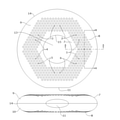
図1のように、打楽器全体としての厚み方向が短軸になるおよそ楕円断面のトーラス形状の外殻7の厚み方向の正面側9及び背面側10は同一形状のプラスチック製で、トーラス形状の外周の合わせ目14と内周の合わせ目15で当接している。また、トーラス形状は中空構造であり、およそ楕円断面の筒状の長さ方向の両端をつないでトーラス形状にしたような形状である。また、正面側9と背面側10の大半には音波を積極的に透過する為の小さな貫通穴が沢山開けられているが、外殻7は発音体1を覆っていると言えるだろう。また、外殻7の内側に配される発音体1付近をグリップ部8として、中央穴13に指を通して巻き回すように握って振った際に、発音体1が発する音波は手が覆っていない所の貫通穴から積極的に透過するし、グリップ部8がおよそ楕円形なので打楽器全体が滑って回転してしまいにくく、且つ楕円形の長軸を直径とする円形と比較して周長が小さくなるので、グリップ部8を握り込みやすくなっている。また、発音体1から6が中央穴13を中心に60度ピッチで外殻7の内側に配置されており、筒状の長さ方向且つ大径(長軸)方向におよそ沿うように、およそ円板状の発音体1から6はそれぞれ配されている。また、トーラス形状の外周の一か所に小さな平面11が設けられており、平面11を接地面として机などの水平面に置くとこの打楽器は自立するので、置き場所に困らず、使いたいときにさっと外殻7を握ればそこがグリップ部になるし、置いている際も降り注ぐ埃が沢山の貫通穴に入り込みにくくなる。
また、図1のA-A線断面図である図2のように、中心に穴の開いた発音体1は同一形状の発音体20と背面同士が合わさる配置で、両者の中心の穴を貫通する軸ピンによる支持部12によって振動及び揺動可能に支持されており、グリップ部8を握って振ることで、外殻7の正面側9の内壁の合わせ目14付近に設けられた当たり17と、合わせ目15付近に設けられた当たり16に、発音体1の正面の縁付近が当たることで発音体1が振動し、わずかに遅れて発音体20の背面が発音体1の背面に当たることで更に両者は振動し、タンバリンらしいキャラクターのある大きな発音となる。続いて逆方向の当たり18及び19に発音体20が当たることで同様の発音サイクルが続く。また発音体2の背面にも発音体21が配され、発音体3から6の背面にも同様にそれぞれ発音体が配され、同様の構造で発音するので、合計12枚の発音体による大きな発音となる。ここで、軸ピンによる支持部12の両端を支える為に正面側9及び背面側10の内壁からそれぞれ突出するボスの先端部を当たりにして当たり16から19よりも先に発音体1及び20に当てると、支持部12付近を先に叩くことになりミュート気味の音になってしまうので、やはり支持部12から遠い縁付近を叩くように当たりを設けるのが良いだろう。
また、図3のように指が入りにくい程度のスリット24を、合わせ目14があった所に設けて音波を放出しやすくしても、外殻7は発音体1をおよそ覆っていると言えるだろうが、埃の侵入や握りやすさを考慮するとスリット24は無い方が良いだろう。
また、図1のB-B線断面図である図4のように、発音体1及び20が支持部12の中央にある安静状態から、図5のような発音体1及び20が支持部12を中心に揺動し当たり17及び19で制限された瞬間の状態になると、およそ楕円筒状の短軸両端付近の内壁に発音体1及び20が当たらないようにして雑音やミュートを防いでいる。これは円板を斜めにすると縁が楕円筒内壁に沿うという特徴を利用して巧みに防いでいるのである。
また、例えば外殻7の正面側9に中央穴13を塞ぐように革を張っても良いだろう。
As shown in FIG. 1, the
Further, as shown in FIG. 2, which is a cross-sectional view taken along the line AA of FIG. 1, the sounding
Further, it can be said that the
Further, as shown in FIG. 4, which is a cross-sectional view taken along the line BB of FIG. 1, the
Further, for example, leather may be stretched on the
本発明の第2実施形態は第1実施形態と共通する部分が多いので、主に違いについて図6に基づいて説明する。 Since the second embodiment of the present invention has many parts in common with the first embodiment, the differences will be mainly described with reference to FIG.
図1のようなトーラス形状ではなく棒状で全体がグリップ部8のようであり、断面形状は図2や図4とほぼ同じである。発音体1から3と背面合わせでペアとなる3枚で、合計6枚が外殻7に覆われている。また、棒状の両端がそれぞれ水平面に立て置く為の平面11及び25となっている。
全体を握ってより軽い力で手軽に使えるし、衣服のポケットなどに入れてポケットを叩いても発音するので、複数使えば楽しさが増幅されるのである。
It is not a torus shape as shown in FIG. 1, but is rod-shaped and looks like a
You can easily use it with a lighter force by grasping the whole, and even if you put it in a pocket of clothes and hit the pocket, it will sound, so if you use more than one, the fun will be amplified.
1,2,3,4,5,6,
20,21. 発音体
7. 外殻
8. グリップ部
9. 正面側
10. 背面側
11,25. 平面
12. 支持部
13. 中央穴
14,15. 合わせ目
16,17,18,19,
22,23. 当たり
24. スリット
1,2,3,4,5,6,
20,21.
22,23. Per 24. Slit
本発明は、打楽器に関する。 The present invention relates to a percussion instrument.
打楽器においては、特許文献1の実施例のように、片面に革の張られた太鼓のような薄い円筒胴に平面放射状に複数の長穴を設け、中心に穴の開いたおよそ円板状の2枚の発音体を貫通する軸ピンによる支持部が長穴の中で発音体を支持するものや、特許文献2の実施例のように革の無いタイプのタンバリンのアイデアが知られている。
In a percussion instrument, as in the embodiment of
また、打楽器においては、特許文献3の実施例のように、空気の出し入れによって畳んだり膨らませたりできる可撓性シートによる浮き輪のような構造の中に輪状の紐を通し、そこに等間隔で猫の首輪に付けられるタイプの中空球状の鈴が複数取り付けられるアイデアが知られている。
Further, in a percussion instrument, as in the embodiment of
打楽器においては、使わないときは不意に触って痛いようなエッジなどの露出が少なくて埃が溜まりにくくて掃除がしやすくてコンパクトで、気分が高揚してきて使うときにはすぐにさっとグリップ部を握って演奏しやすいものが求められている。しかし、特許文献1や特許文献2の実施例だと発音体のエッジだらけで置き場所や掃除に困るし、特許文献3の実施例だと、握ると変形しやすい浮き輪のようなグリップ部内の発音体である鈴に可撓性シートを介して触ってしまうことで発音体の響きをミュートしてしまうことになり、それを防ぐ為にグリップの径を大きくすると握りにくくなるし、発音体を小さくすると欲しい音量や音色が得られなくなってしまう。
For percussion instruments, when not in use, there is little exposure of edges that may hurt when you touch it, dust does not collect easily, it is easy to clean, and it is compact. There is a demand for something that is easy to play. However, in the examples of
本発明の実施形態図等を用いて以下に説明するが、これは本発明の内容をより把握しやすいようにする為で、添付の特許請求の範囲を縮小するものではない。 The present invention will be described below with reference to an embodiment of the present invention, but this is to make it easier to understand the contents of the present invention, and does not reduce the scope of the attached claims.
発明1係る打楽器は、例えば図1から図5のように、
支持部12によって振動自在に支持されるおよそ板状の発音体1と、
発音体1を手で覆うように握る際に指が発音体1の振動を妨げないよう防ぎ内側に発音体1を備えるグリップ部8を成す外殻7と、
グリップ部8を握って振ることで発音体1が支持部12に沿って移動することで、発音体1を叩く外殻7の内側の当たり17と、
を具備する、
打楽器である。
The percussion instrument according to the
An approximately plate-shaped sounding
An
By grasping and shaking the
Equipped with
It is a percussion instrument.
発明2に係る打楽器は、発明1の打楽器において、
外殻7はおよそ筒状であり、筒状の長さ方向におよそ沿うようにおよそ板状の発音体1が配され、
発音体1の縁は外殻7の筒状の径方向よりも長さ方向の部分の方が可動範囲が長くなるように、当たり17が配される、
打楽器である。
The percussion instrument according to the
The
The edge of the sounding
It is a percussion instrument.
発明3に係る打楽器は、発明1から2のいずれかの打楽器において、
外殻7には発音体1の発する音波を積極的に透過するが指は入りにくい沢山の貫通穴が設けられている、
打楽器である。
The percussion instrument according to the
The
It is a percussion instrument.
以上のように本発明では、およそ板状で大きな音量が得られやすい高感度の発音体1を用いても外殻7に守られておよそ板状のエッジが露出せず、外殻7をグリップ部8として握っても発音体1の当たり17があることで意図せぬ部分に発音体1が当たることによるミュートや雑音の発生を極力防ぐような設計が容易となる。
As described above, in the present invention, even if the high-
また、発明2では本発明の効果に加えて、発音体1が発する音波がおよそ筒状の内部を通ってグリップ部8を握った手に邪魔されない位置の外殻7から積極的に透過させるような設計が容易となり、且つおよそ板状の発音体1が筒状の長さ方向に沿うように配されることから、当たり17の位置を最適化しやすくなって発音体1の面積を確保したままグリップ部8が握りやすいように径を小さく且つ軽量で振りやすくするような設計が容易となる。
Further, in the second invention, in addition to the effect of the present invention, the sound wave emitted by the sounding
また、発明3では本発明や発明2の効果に加えて、発音体1が発する音波は手が覆っていない所の貫通穴から積極的に透過するような設計が容易となる。
Further, in the third invention, in addition to the effects of the present invention and the second invention, it becomes easy to design the sound wave emitted by the sounding
本発明の第1実施形態を図1から図5に基づいて説明する。 The first embodiment of the present invention will be described with reference to FIGS. 1 to 5.
図1のように、打楽器全体としての厚み方向が短軸になるおよそ楕円断面のトーラス形状の外殻7の厚み方向の正面側9及び背面側10は同一形状のプラスチック製で、トーラス形状の外周の合わせ目14と内周の合わせ目15で当接している。また、トーラス形状は中空構造であり、およそ楕円断面の筒状の長さ方向の両端をつないでトーラス形状にしたような形状である。また、正面側9と背面側10の大半には音波を積極的に透過する為の小さな貫通穴が沢山開けられているが、外殻7は発音体1を覆っていると言えるだろう。また、外殻7の内側に配される発音体1付近をグリップ部8として、中央穴13に指を通して巻き回すように握って振った際に、発音体1が発する音波は手が覆っていない所の貫通穴から積極的に透過するし、グリップ部8がおよそ楕円形なので打楽器全体が滑って回転してしまいにくく、且つ楕円形の長軸を直径とする円形と比較して周長が小さくなるので、グリップ部8を握り込みやすくなっている。また、発音体1から6が中央穴13を中心に60度ピッチで外殻7の内側に配置されており、筒状の長さ方向且つ大径(長軸)方向におよそ沿うように、およそ円板状の発音体1から6はそれぞれ配されている。また、トーラス形状の外周の一か所に小さな平面11が設けられており、平面11を接地面として机などの水平面に置くとこの打楽器は自立するので、置き場所に困らず、使いたいときにさっと外殻7を握ればそこがグリップ部になるし、置いている際も降り注ぐ埃が沢山の貫通穴に入り込みにくくなる。
また、図1のA-A線断面図である図2のように、中心に穴の開いた発音体1は同一形状の発音体20と背面同士が合わさる配置で、両者の中心の穴を貫通する軸ピンによる支持部12によって振動及び揺動可能に支持されており、グリップ部8を握って振ることで、外殻7の正面側9の内壁の合わせ目14付近に設けられた当たり17と、合わせ目15付近に設けられた当たり16に、発音体1の正面の縁付近が当たることで発音体1が振動し、わずかに遅れて発音体20の背面が発音体1の背面に当たることで更に両者は振動し、タンバリンらしいキャラクターのある大きな発音となる。続いて逆方向の当たり18及び19に発音体20が当たることで同様の発音サイクルが続く。また発音体2の背面にも発音体21が配され、発音体3から6の背面にも同様にそれぞれ発音体が配され、同様の構造で発音するので、合計12枚の発音体による大きな発音となる。ここで、軸ピンによる支持部12の両端を支える為に正面側9及び背面側10の内壁からそれぞれ突出するボスの先端部を当たりにして当たり16から19よりも先に発音体1及び20に当てると、支持部12付近を先に叩くことになりミュート気味の音になってしまうので、やはり支持部12から遠い縁付近を叩くように当たりを設けるのが良いだろう。
また、図3のように指が入りにくい程度のスリット24を、合わせ目14があった所に設けて音波を放出しやすくしても、外殻7は発音体1をおよそ覆っていると言えるだろうが、埃の侵入や握りやすさを考慮するとスリット24は無い方が良いだろう。
また、図1のB-B線断面図である図4のように、発音体1及び20が支持部12の中央にある安静状態から、図5のような発音体1及び20が支持部12を中心に揺動し当たり17及び19で制限された瞬間の状態になると、およそ楕円筒状の短軸両端付近の内壁に発音体1及び20が当たらないようにして雑音やミュートを防いでいる。これは円板を斜めにすると縁が楕円筒内壁に沿うという特徴を利用して巧みに防いでいるのである。
また、例えば外殻7の正面側9に中央穴13を塞ぐように革を張っても良いだろう。
As shown in FIG. 1, the
Further, as shown in FIG. 2, which is a cross-sectional view taken along the line AA of FIG. 1, the sounding
Further, it can be said that the
Further, as shown in FIG. 4, which is a cross-sectional view taken along the line BB of FIG. 1, the sounding
Further, for example, leather may be stretched on the
本発明の第2実施形態は第1実施形態と共通する部分が多いので、主に違いについて図6に基づいて説明する。 Since the second embodiment of the present invention has many parts in common with the first embodiment, the differences will be mainly described with reference to FIG.
図1のようなトーラス形状ではなく棒状で全体がグリップ部8のようであり、断面形状は図2や図4とほぼ同じである。発音体1から3と背面合わせでペアとなる3枚で、合計6枚が外殻7に覆われている。また、棒状の両端がそれぞれ水平面に立て置く為の平面11及び25となっている。
全体を握ってより軽い力で手軽に使えるし、衣服のポケットなどに入れてポケットを叩いても発音するので、複数使えば楽しさが増幅されるのである。
It is not a torus shape as shown in FIG. 1, but is rod-shaped and looks like a
You can easily use it with a lighter force by grasping the whole, and even if you put it in a pocket of clothes and hit the pocket, it will sound, so if you use more than one, the fun will be amplified.
1,2,3,4,5,6,
20,21. 発音体
7. 外殻
8. グリップ部
9. 正面側
10. 背面側
11,25. 平面
12. 支持部
13. 中央穴
14,15. 合わせ目
16,17,18,19,
22,23. 当たり
24. スリット
1,2,3,4,5,6,
20,21.
22,23. Per 24. Slit
Claims (3)
前記発音体をおよそ覆う外殻のグリップ部と、
前記グリップ部を握って振ることで前記発音体が前記支持部に沿って移動することで、前記発音体を叩く前記外殻の内側の当たりと、
を具備する、
打楽器。 An approximately plate-shaped sounding body that is freely vibrated by the support part,
The grip part of the outer shell that roughly covers the sounding body,
By grasping and shaking the grip portion, the sounding body moves along the support portion, thereby hitting the sounding body and hitting the inside of the outer shell.
Equipped with
Percussion instrument.
請求項1に記載の打楽器。 The outer shell is substantially cylindrical, and the sounding body having a substantially plate shape is arranged substantially along the length direction of the cylinder.
The percussion instrument according to claim 1.
請求項1に記載の打楽器。 The outer shell has a substantially cylindrical shape having a large and small diameter, and the sounding body having a substantially plate shape is arranged so as to be substantially along the length direction and the large diameter direction of the tubular shape.
The percussion instrument according to claim 1.
Priority Applications (2)
| Application Number | Priority Date | Filing Date | Title |
|---|---|---|---|
| JP2020116039A JP2022013459A (en) | 2020-07-05 | 2020-07-05 | Percussion instrument |
| JP2022012472A JP7274008B2 (en) | 2020-07-05 | 2022-01-29 | percussion instrument |
Applications Claiming Priority (1)
| Application Number | Priority Date | Filing Date | Title |
|---|---|---|---|
| JP2020116039A JP2022013459A (en) | 2020-07-05 | 2020-07-05 | Percussion instrument |
Related Child Applications (1)
| Application Number | Title | Priority Date | Filing Date |
|---|---|---|---|
| JP2022012472A Division JP7274008B2 (en) | 2020-07-05 | 2022-01-29 | percussion instrument |
Publications (1)
| Publication Number | Publication Date |
|---|---|
| JP2022013459A true JP2022013459A (en) | 2022-01-18 |
Family
ID=80169669
Family Applications (1)
| Application Number | Title | Priority Date | Filing Date |
|---|---|---|---|
| JP2020116039A Pending JP2022013459A (en) | 2020-07-05 | 2020-07-05 | Percussion instrument |
Country Status (1)
| Country | Link |
|---|---|
| JP (1) | JP2022013459A (en) |
Cited By (1)
| Publication number | Priority date | Publication date | Assignee | Title |
|---|---|---|---|---|
| JP2022044814A (en) * | 2020-07-05 | 2022-03-17 | 公二 宇野 | Percussion instrument |
Citations (4)
| Publication number | Priority date | Publication date | Assignee | Title |
|---|---|---|---|---|
| JPS6023898U (en) * | 1983-07-25 | 1985-02-18 | 長谷川 さく子 | tambourine |
| US5323678A (en) * | 1991-08-15 | 1994-06-28 | Triamid Corporation | Hand-held percussion musical instrument comprising elongate tube shaped as a ring, incorporating dividers, and incoporating contained sound-generating elements |
| JP3105937U (en) * | 2004-06-15 | 2004-12-02 | 株式会社スルガ | Percussion instruments for support |
| JP3123274U (en) * | 2005-12-28 | 2006-07-20 | 有限会社菊地製作所 | Rhythm toys |
-
2020
- 2020-07-05 JP JP2020116039A patent/JP2022013459A/en active Pending
Patent Citations (4)
| Publication number | Priority date | Publication date | Assignee | Title |
|---|---|---|---|---|
| JPS6023898U (en) * | 1983-07-25 | 1985-02-18 | 長谷川 さく子 | tambourine |
| US5323678A (en) * | 1991-08-15 | 1994-06-28 | Triamid Corporation | Hand-held percussion musical instrument comprising elongate tube shaped as a ring, incorporating dividers, and incoporating contained sound-generating elements |
| JP3105937U (en) * | 2004-06-15 | 2004-12-02 | 株式会社スルガ | Percussion instruments for support |
| JP3123274U (en) * | 2005-12-28 | 2006-07-20 | 有限会社菊地製作所 | Rhythm toys |
Cited By (2)
| Publication number | Priority date | Publication date | Assignee | Title |
|---|---|---|---|---|
| JP2022044814A (en) * | 2020-07-05 | 2022-03-17 | 公二 宇野 | Percussion instrument |
| JP7274008B2 (en) | 2020-07-05 | 2023-05-15 | 公二 宇野 | percussion instrument |
Similar Documents
| Publication | Publication Date | Title |
|---|---|---|
| CN101019170B (en) | An improved drum | |
| US5323678A (en) | Hand-held percussion musical instrument comprising elongate tube shaped as a ring, incorporating dividers, and incoporating contained sound-generating elements | |
| US5434350A (en) | Drum and percussion synthesizer | |
| JP2003295864A (en) | Electronic percussion instrument | |
| JP2007256736A (en) | Electric musical instrument | |
| US7470845B2 (en) | Musical shaker | |
| JP2022013459A (en) | Percussion instrument | |
| US3603194A (en) | Drum | |
| US4590839A (en) | Pellet drum stick brush | |
| US10217447B2 (en) | Hand drum and methods of use | |
| US6555736B1 (en) | Rhythm shaker | |
| US4111094A (en) | Rhythm instrument | |
| JP7274008B2 (en) | percussion instrument | |
| US5377575A (en) | Percussion instrument | |
| KR102365740B1 (en) | Drumstick for electronic drum with reduced noise generation | |
| US6768045B1 (en) | Practice appliance | |
| JP2008203289A (en) | Musical percussion instrument | |
| US20230395045A1 (en) | Drum | |
| JP3211420U (en) | String instrument piece | |
| JP6347428B2 (en) | Apple | |
| US10916231B2 (en) | Reverberating percussion instrument | |
| JP3212958U (en) | Brass instrument | |
| EP3076387A1 (en) | Tambourine stick | |
| WO2023234256A1 (en) | Electronic percussion instrument | |
| US10679593B2 (en) | Modular percussion instrument device and method |
Legal Events
| Date | Code | Title | Description |
|---|---|---|---|
| A131 | Notification of reasons for refusal |
Free format text: JAPANESE INTERMEDIATE CODE: A131 Effective date: 20210907 |
|
| A521 | Request for written amendment filed |
Free format text: JAPANESE INTERMEDIATE CODE: A523 Effective date: 20210909 |
|
| A02 | Decision of refusal |
Free format text: JAPANESE INTERMEDIATE CODE: A02 Effective date: 20220125 |