JP2022012257A - In-cabin lighting device - Google Patents
In-cabin lighting device Download PDFInfo
- Publication number
- JP2022012257A JP2022012257A JP2020113961A JP2020113961A JP2022012257A JP 2022012257 A JP2022012257 A JP 2022012257A JP 2020113961 A JP2020113961 A JP 2020113961A JP 2020113961 A JP2020113961 A JP 2020113961A JP 2022012257 A JP2022012257 A JP 2022012257A
- Authority
- JP
- Japan
- Prior art keywords
- bus bar
- lighting device
- vehicle interior
- illumination lens
- housing
- Prior art date
- Legal status (The legal status is an assumption and is not a legal conclusion. Google has not performed a legal analysis and makes no representation as to the accuracy of the status listed.)
- Pending
Links
Images


Abstract
Description
本発明は、車室内照明装置に関する。 The present invention relates to a vehicle interior lighting device.
従来、照明レンズの光源側に配設された透明電極と基板とを、弾性を備えた導電体で接続している車室内照明装置が知られている(特許文献1参照)。 Conventionally, there is known a vehicle interior lighting device in which a transparent electrode arranged on the light source side of an illumination lens and a substrate are connected by an elastic conductor (see Patent Document 1).
従来の車室内照明装置は、ハウジングと、ハウジングの内部に固定された光源と、ハウジングの車室側に配設された照明レンズとを備えている。そして、光源が発した光が照明レンズを透過することで、車室内の照明がされるようになっている。 A conventional vehicle interior lighting device includes a housing, a light source fixed inside the housing, and a lighting lens disposed on the vehicle interior side of the housing. Then, the light emitted from the light source passes through the illumination lens to illuminate the interior of the vehicle.
また、従来の車室内照明装置のハウジング内には、制御部と基板と導電ゴム等の弾性を備えた導電体とが設けられている。導電体によって照明レンズに設けられている透明電極と基板の電極とを導通させている。 Further, in the housing of the conventional vehicle interior lighting device, a control unit, a substrate, and a conductor having elasticity such as conductive rubber are provided. A conductor makes the transparent electrode provided on the illumination lens and the electrode on the substrate conductive.
そして、人体の一部が照明レンズの表面に接触することによる透明電極と人体との間の静電容量の変化に応じて、制御部が光源に供給される電源を入り切りするようになっている。 Then, the control unit turns on / off the power supplied to the light source according to the change in the capacitance between the transparent electrode and the human body due to the contact of a part of the human body with the surface of the illumination lens. ..
ところで、従来の車室内照明装置では、照明レンズに設けられている透明電極と基板の電極とを接続する為に、導電ゴムが必要になっており、部品点数が増え組付工数等の増加によるコストアップが生じてしまう。また、導電ゴムの代わりに、スプリングもしくはコネクタを採用しても、組付工数等の増加によるコストアップが生じてしまう。 By the way, in the conventional vehicle interior lighting device, conductive rubber is required to connect the transparent electrode provided in the lighting lens and the electrode of the substrate, and the number of parts increases and the assembly man-hours increase. Cost increase will occur. Further, even if a spring or a connector is used instead of the conductive rubber, the cost increases due to an increase in assembling man-hours and the like.
また、従来の車室内照明装置では、透明電極が、ITO(酸化インジウムスズ)もしくは銀ナノ等の導電性物質の塗布によって、薄膜状に形成されている。したがって、透明電極が設けられていない照明レンズのみの場合と比較すると、光透過率が落ちてしまい、車室内を照明する光の強度が低下してしまう。 Further, in the conventional vehicle interior lighting device, the transparent electrode is formed in a thin film shape by applying a conductive substance such as ITO (indium tin oxide) or silver nano. Therefore, as compared with the case of only the illumination lens provided with no transparent electrode, the light transmittance is lowered and the intensity of the light illuminating the vehicle interior is lowered.
本発明は、部品点数が増えることを防止し組付工数等の増加によるコストアップを防止し、車室内を照明する光の強度の低下を防ぐことができる車室内照明装置を提供することを目的とする。 It is an object of the present invention to provide an interior lighting device capable of preventing an increase in the number of parts, preventing an increase in cost due to an increase in assembly man-hours, and preventing a decrease in the intensity of light for illuminating the interior of the vehicle. And.
本発明の態様に係る車室内照明装置は、車室に固定されるハウジングと、前記ハウジングの内部に固定されている光源と、前記ハウジングの、前記車室側の面に配設されている照明レンズと、前記ハウジングに固定されているインナーカバーと、電極部とこの電極部と一体化している接続部とを具備し、前記照明レンズの、前記光源が発した光が透過する部位の周辺部で、前記電極部が前記インナーカバーに設置され、前記接続部の接触部が基板の電極に接続されているバスバーと、人体が前記照明レンズの表面に接触することによる前記バスバーと前記人体との間の静電容量の変化に応じて、前記光源に供給される電源を入り切りする制御部とを有する。 The vehicle interior lighting device according to an aspect of the present invention includes a housing fixed to the vehicle interior, a light source fixed to the inside of the housing, and lighting arranged on the surface of the housing on the vehicle interior side. A peripheral portion of the illumination lens, which comprises a lens, an inner cover fixed to the housing, an electrode portion, and a connection portion integrated with the electrode portion, and through which light emitted by the light source is transmitted. A bus bar in which the electrode portion is installed on the inner cover and the contact portion of the connection portion is connected to the electrode of the substrate, and the bus bar and the human body when the human body comes into contact with the surface of the illumination lens. It has a control unit for turning on / off the power supplied to the light source according to the change in capacitance between them.
また、本発明の態様に係る車室内照明装置は、前記照明レンズと接触している透明電極部を備えており、前記透明電極部は、前記照明レンズの、前記光源が発した光が透過する部位では、薄膜状に形成されている。 Further, the vehicle interior lighting device according to the aspect of the present invention includes a transparent electrode portion in contact with the illumination lens, and the transparent electrode portion transmits light emitted by the light source of the illumination lens. At the site, it is formed in the form of a thin film.
本発明によれば、部品点数が増えることを防止し組付工数等の増加によるコストアップを防止し、車室内を照明する光の強度の低下を防ぐことができる車室内照明装置を提供することができるという効果を奏する。 According to the present invention, there is provided an interior lighting device capable of preventing an increase in the number of parts, preventing an increase in cost due to an increase in assembly man-hours, and preventing a decrease in the intensity of light that illuminates the interior of the vehicle. It has the effect of being able to.
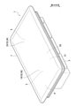
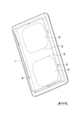
本発明の実施形態に係る車室内照明装置(車室内用照明装置)1は、たとえば、車両の室内に設置されて車室内の照明をするものである。車室内照明装置1は、図1から図6で示すように、ハウジング(筐体)3と光源5と照明レンズ7とインナーカバー9とバスバー11と制御部(照明電源制御部)13とを備えて構成されている。
The vehicle interior lighting device (vehicle interior lighting device) 1 according to the embodiment of the present invention is installed in the vehicle interior and illuminates the vehicle interior, for example. As shown in FIGS. 1 to 6, the vehicle
ハウジング3は、たとえば車室の内壁に設置されることで、車室内で車両に固定されるようになっている。光源5は、ハウジング3の内部に固定されている。照明レンズ7は、ハウジング3の、車室側(車室内側)の面に配設されている。インナーカバー9は、ハウジング3に固定されている。
The
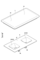
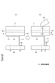
バスバー11は、電極部15とこの電極部15と一体化している接続部17とを具備している。電極部15は、照明レンズ7の所定の部位19の周辺部でインナーカバー9に設置されている。所定の部位19とは、光源5が発した光が透過する部位(照明レンズ7の光透過部位)である。バスバー11の接続部17の先端に形成されている接触部21が基板23に設けられている電極25に接している。
The
制御部13は、人体27の一部(たとえば指先)が照明レンズ7の表面(外面)に接触することによるバスバー11と人体27との間の静電容量の変化に応じて、光源5に供給される電源を入り切りするようになっている。
The
ここで説明の便宜のために、車室内照明装置における所定の一方向を高さ方向とする。ハウジング3は、絶縁性を備え、光を透過しない合成樹脂等で一体成形されている。ハウジング3の高さ方向の一方の側である第1の側には、開口部29が設けられている。開口部29は、車室側に位置している。
Here, for convenience of explanation, a predetermined direction in the vehicle interior lighting device is defined as the height direction. The
光源5は、ハウジング3内に配置されているLEDで構成されており、照明用の光(可視光)を発するようになっている。
The
照明レンズ7は、絶縁性を備え、しかも、光を透過する合成樹脂等で一体成形されている。また、照明レンズ7は、ハウジング3の開口部29を塞ぐようにして、ハウジング3に設けられており、LED5が発した光が照明レンズ7を透過するようになっている。
The
バスバー11は、金属等の導電性を備えた材料で構成されており、ハウジング3と照明レンズ7とで囲まれた空間31内に配置されて、ハウジング3に固定されている。なお、空間31を、車室内照明装置1の内部空間と呼んでもよい。
The
また、バスバー11は、たとえば、薄い平板状の素材を、打ち抜き加工によって所定に形状に形成した後、接続部17と電極部15との境界部を90°程度曲げることで形成されている。
Further, the
基板23は、ハウジング3の底部でハウジング3内に設けられている。ハウジング3の底部は、高さ方向の一方の端側(第1の端側)に位置している。LED5と制御部13とは、基板23に設けられている。基板23の厚さ方向は、高さ方向になっている。
The
インナーカバー9は、絶縁性を備え、光を透過しない合成樹脂等で一体成形されている。また、車室内照明装置1には、プリズム33が設けられている。プリズム33は、たとえば、絶縁性を備え、光が透過する合成樹脂で一体成形されている。
The
インナーカバー9は、ハウジング3と照明レンズ7とで囲まれた空間31内に配置されている。インナーカバー9には、スポット開口部(インナーカバー導光部)35が設けられている。LED5が発しプリズム33を透過した光が、スポット開口部35を通って照明レンズ7まで導かれるようになっている。
The
インナーカバー導光部35はたとえば四角錐台状の空間で形成されており、四角錐の頂点が高さ方向の第1の端側に位置し、四角錐の底面が高さ方向の第2の端側に位置している。また、インナーカバー導光部35は、インナーカバー導光部形成壁36によって形成されている。
The inner cover
また、インナーカバー9には、レンズ側部位37とリブ39とが設けられている。レンズ側部位37は、スポット開口部35を囲んでいる。また、レンズ側部位37は、高さ方向で基板23とは反対側の第2の端側に位置している。インナーカバー導光部形成壁36とリブ39とは、レンズ側部位37から高さ方向の第1の端側に突出している。
Further, the
バスバー11の電極部15は、環状に形成されている。高さ方向で見て、電極部15はインナーカバー9のスポット開口部35の外側で、スポット開口部35を囲むようにしてスポット開口部35の周辺部に配置されている。バスバー11の電極部15は、インナーカバー9のレンズ側部位37に配置されている。高さ方向では、バスバー11の電極部15は、照明レンズ7とは反対側の面(高さ方向の第1の端側の面)に配置されている。
The
さらに説明すると、照明レンズ7とインナーカバー9のレンズ側部位37とは板状に形成されており、これらの厚さ方向(高さ方向)で、照明レンズ7とインナーカバー9のレンズ側部位37とバスバー11の電極部15とがこの順にならんでいる。バスバー11の接続部17は、細長い棒状に形成されており、バスバー11の電極部15から基板23側(高さ方向の第1の端側)に突出している。
Further explaining, the
インナーカバー9のリブ39は、レンズ側部位37から基板23側(高さ方向の第1の端側)に突出している。また、リブ39は、バスバー11の接触部21を基板23側に押している。これにより、接触部21が基板23の電極25側に押されて電極25に接するようになっている。
The
バスバー11の電極部15が、照明レンズ7の光透過部位19から僅かに離れ光透過部位19の周辺部に配置されていることで、電極部15による減光が発生しないようになっている。なお、照明レンズ7の光透過部位19は、インナーカバー9のスポット開口部35に対応している。すなわち、高さ方向で見て、光透過部位19の位置とスポット開口部35の位置とはお互いがほぼ一致している。
By arranging the
プリズム33は、ハウジング3と照明レンズ7とで囲まれた空間31内であってLED5の近傍で、インナーカバー導光部35に配置されている。プリズム33には、LED5が発した光を任意の方向に曲げる導光部(プリズム導光部)が設けられている。
The
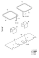
また、照明レンズ7には、ハウジング3に固定するために被ロック部41(図8参照)が設けられている。バスバー11の接続部17には、球状のインデント43が設定されている。インデント43は、接触部21を形成している。
Further, the
基板23にはLED5と、制御部13を構成している静電センサー用マイコン45と、バスバー11の接続部17と接続される電極25が設けられている。
The
ハウジング3には、照明レンズ7を固定するロック部47と、基板23を乗せる台座49と位置決めする為のピン51が設けられている。また、インナーカバー9には、バスバー11を乗せる台座(図示せず)と位置決めする為のピン(図示せず)が設けられている。
The
ハウジング3内に、基板23とプリズム33とバスバー11とインナーカバー9とを設置しておき、これに、照明レンズ7を設置する。照明レンズ7のハウジング3への設置により、被ロック部41がロック部47に係止され、インナーカバー9とバスバー11とプリズム33と基板23とが、照明レンズ7とハウジング3とで挟まれる。これにより、車室内照明装置1の組立が終了するようになっている。
A
次に、車室内照明装置1の動作について説明する。
Next, the operation of the vehicle
初期状態では、LED5が消灯しており、制御部13が静電容量をチェックし続けているものとする。
In the initial state, it is assumed that the
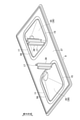
上記初期状態において、図7で示すように、バスバー11の電極部15近傍の照明レンズ7の部位を人体27の指先でタッチすると、人体27とバスバー11の電極部15との間に発生する静電容量が変化する。この変化を制御部13が検知する。この検知により、LED5が点灯する。なお、図7では、バスバー11と人体27以外の表示を省略している。
In the above initial state, as shown in FIG. 7, when the portion of the
続いて、バスバー11の電極部15近傍の照明レンズ7の部位を人体27の指先でタッチすると、人体27とバスバー11の電極部15との間に発生する静電容量が変化する。この変化を制御部13が検知する。この検知により、LED5が消灯する。
Subsequently, when the portion of the
車室内照明装置1では、バスバー11が電極部15とこの電極部15と一体化している接続部17とを具備しており、接続部17によって電極部15と基板23の電極25とがお互いに接続されている。
In the vehicle
これにより、車室内照明装置1の部品点数が減少しており、組付工数等の増加によるコストアップが防止される。すなわち、車室内照明装置1の静電タッチスイッチの構造の簡易化により、コスト低減を図ることができる。さらに、バスバー11の電極部15と接続部17とが一体化されていることにより、基板23上の占有面積を、スプリング等を用いた場合に比べて小さくすることができ、レイアウト性が向上する。
As a result, the number of parts of the vehicle
また、車室内照明装置1では、照明レンズ7の、光源5が発した光が透過する部位(光透過部位)19の周辺部で、電極部15がインナーカバー9の基板23側の面に設置されている。これにより、照明レンズ7の光透過率が減少せず、LED5が発した光がバスバー11で遮られることがなく、車室内を照明する光の強度の低下を防ぐことができる。さらに、照明に要する消費電力を削減することができる。
Further, in the vehicle
これに対して比較例に係る車室内照明装置301では、図14で示すように、照明レンズ303に設けられている透明電極305と基板307の電極309とを接続する為に、導電ゴム311が必要になっている。これにより、部品点数が増え組付工数等の増加によるコストアップが生じてしまう。また、導電ゴム311の代わりに、スプリングもしくはコネクタを採用しても、組付工数等の増加によるコストアップが生じてしまう。
On the other hand, in the vehicle
また、比較例に係る車室内照明装置301では、透明電極305が、ITO(酸化インジウムスズ)もしくは銀ナノ等の導電性物質の塗布によって、薄膜状に形成されている。したがって、透明電極305が設けられていない場合と比較すると、光透過率が落ちてしまい、車室内を照明する光の強度が低下してしまう。
Further, in the vehicle
また、比較例に係る車室内照明装置301では、透明電極305を導電ゴム311の部分まで配設する必要があり、均一な膜厚で透明電極305を配設する為の設備・管理にコストがかかってしまう。これに対して、車室内照明装置1では、透明電極305が存在していないので、コストの上昇等を抑えることができる。
Further, in the vehicle
また、車室内照明装置1では、バスバー11の電極部15が、不透明なインナーカバー9のレンズ側部位37に設けられており、しかも、照明レンズと7は反対側である基板23側に電極部15が設けられている。これにより、バスバー11の電極部15が、車室内照明装置1の外部からは見えないようになっており、意匠性が向上している。
Further, in the vehicle
また、車室内照明装置1によれば、バスバー11の電極部15が環状になっているので、タッチ部中央部(高さ方向で見て電極部15の内側部位)で人体27の指先のタッチを確実に検出できるようになっている。
Further, according to the vehicle
また、車室内照明装置1では、インナーカバー9のレンズ側部位37にバスバー11の電極部15を設けたことで、レンズ側部位37に電極部15が面接触している。これにより、バスバー11と入力装置(人体)27の距離が近くなり、人体27の指先等が照明レンズ7に接したときの検出精度が向上している。
Further, in the vehicle
また、車室内照明装置1では、ハウジング3内に、バスバー11、インナーカバー9等を設置しておき、これに、照明レンズ7を設置することで、車室内照明装置1の組立が終了するようになっている。つまり、照明レンズ7のハウジング3への一回の固定で、車室内照明装置1の組立が終了するようになっており、車室内照明装置1の組立工数が削減される。
Further, in the vehicle
次に、1つ目の変形例に係る車室内照明装置1について説明する。
Next, the vehicle
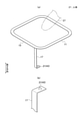
1つ目の変形例に係る車室内照明装置1は、図8、図9で示すように、透明電極部57が設けられている点が、図1から図7で示した車室内照明装置1と異なっている。その他の点は、図1から図7で示した車室内照明装置1と同様に構成されている。
As shown in FIGS. 8 and 9, the vehicle
すなわち、1つ目の変形例に係る車室内照明装置1には、導電性を備え照明レンズ7と接触している透明電極部57が設けられている。透明電極部57は、照明レンズ7の、LED5が発した光が透過する部位19で薄膜状に形成されている。
That is, the vehicle
透明電極部57は、導電性フィルムもしくは導電性塗料等で構成されており、膜状に形成されている。照明レンズ7とインナーカバー9のレンズ側部位37と透明電極部57との厚さ方向(高さ方向)で、照明レンズ7と透明電極部57とレンズ側部位37とバスバー11の電極部15とがこの順にならんでいる。
The
1つ目の変形例に係る車室内照明装置1では、上述したように、照明レンズ7と接触している透明電極部57を備えており、透明電極部57が照明レンズ7の光透過部位19では、薄膜状に形成されている。また、1つ目の変形例に係る車室内照明装置1では、透明電極部57とバスバー11の電極部15との間に不透明なインナーカバー9が設けられていて、バスバー11の電極部15が透明電極部57に接続されていない。
As described above, the vehicle
これにより、車室内照明装置1を人体27でタッチしたとき、人体27と透明電極部57間およびバスバー11の電極部15間に静電容量が発生する(図9参照)。照明レンズ7の厚みが一定であるので、人体27と透明電極部57間の静電容量は一定になり、均一なタッチ感度を得ることができる。
As a result, when the vehicle
また、1つ目の変形例に係る車室内照明装置1では、透明電極部57がタッチ部(たとえば、照明レンズ7の、光源5が発した光が透過する部位19)のみに配設されていて簡易な構造であるので、電極配設設備・管理のコストの削減をすることができる。
Further, in the vehicle
次に、2つ目の変形例に係る車室内照明装置1について説明する。
Next, the vehicle
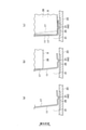
2つ目の変形例に係る車室内照明装置1は、図10で示すように、組付けをするときに、インナーカバー9のリブ39によって、バスバー11のインデント43が基板23の電極25に対して僅かに摺動する点が、図1から図9で示した車室内照明装置1と異なっている。その他の点は、図1から図9で示した車室内照明装置1と同様に構成されている。
As shown in FIG. 10, in the vehicle
すなわち、図10(a)で示すように、バスバー11を設置しておいた状態では、バスバー11のインデント43が基板23に接している。なお、バスバー11の接続部17は、高さ方向に対して僅かに傾斜している。
That is, as shown in FIG. 10A, in the state where the
図10(a)で示す状態でインナーカバー9を設置する。インナーカバー9を設置する途中に状態では、図10(b)で示すようになる。図10(b)で示す状態では、インナーカバー9のリブ39の先端の角部が、接続部17の中間部に接触している。
The
図10(b)で示す状態で、インナーカバー9をさらに下側に移動してインナーカバー9の設置をし終えると、図10(c)で示す状態になる。図10(c)で示す状態では、傾斜している接続部17が横方向に押されて、図10(b)で示す状態から移動をしている。この移動によって、バスバー11のインデント43が基板23の電極25に対して、僅かに摺動している。
In the state shown in FIG. 10B, when the
上記摺動によって、インデント43の酸化被膜が除去され、また、上記摺動によって基板23の電極25の酸化被膜が除去される。これにより、インナーカバー9を設置するだけで、インデント43と電極25との間の接触信頼性を確保することができ、組付けコスト等を削減することができる。
By the above sliding, the oxide film of the
次に、3つ目の変形例に係る車室内照明装置1について説明する。
Next, the vehicle
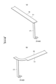
3つ目の変形例に係る車室内照明装置1は、図11で示すように、バスバー11の電極部15の形状が、非環状に形成されている点が、図1から図7で示した車室内照明装置1と異なっている。その他の点は、図1から図10で示した車室内照明装置1と同様に構成されている。
As shown in FIG. 11, in the vehicle
すなわち、3つ目の変形例に係る車室内照明装置1のバスバー11の電極部15は、棒状もしくは直線状等の非環状に形成されている。なお、3つ目の変形例に係る車室内照明装置1の電極部15が、環の一部を削除した形状である「L」字状等の他の形状に形成されていてもよい。
That is, the
また、電極部15の形態は、人体27と透明電極部57間における静電容量よりも、電極部15と透明電極部57間における静電容量が大きくなるような形態になっている。すなわち、電極部15とインナーカバー9のレンズ側部位37との接触面積と、レンズ側部位37の厚さ寸法の値とが、上述した大きくなっている静電容量の条件を満たすべく適宜決められている。これにより、電極部15を非環状に形成したにもかかわらず、タッチ感度が低下することを防止することができる。
Further, the form of the
バスバー11の電極部15の形状が、非環状に形成されていることで、バスバー11の歩留まりが向上する。たとえば、平板状の素材からバスバー11を製造する場合における廃材の量を少なくすることができる。
Since the shape of the
次に、4つ目の変形例に係る車室内照明装置1について説明する。
Next, the vehicle
4つ目の変形例に係る車室内照明装置1は、図12、図13で示すように、インナーカバー9の、バスバー11の電極部15が設置される部位の厚さ寸法の値が小さくなっている点が、図1から図11で示した車室内照明装置1と異なっている。その他の点は、図1から図11で示した車室内照明装置1と同様に構成されている。
As shown in FIGS. 12 and 13, in the vehicle
すなわち、4つ目の変形例に係る車室内照明装置1では、インナーカバー9のレンズ側部位37には、バスバー11の電極部15が入り込むバスバー配設部59が設けられている。バスバー配設部59は、環状の凹部で形成されている。
That is, in the vehicle
バスバー配設部59は、レンズ側部位37の基板23側の面に設けられている。バスバー配設部59が凹部で形成されていることで、バスバー配設部59のところにおけるレンズ側部位37の厚さ寸法の値は、レンズ側部位37の他の部位の厚さ寸法の値よりも小さくなっている。
The bus
4つ目の変形例に係る車室内照明装置1によれば、バスバー配設部59が設けられているので、バスバー11のインナーカバー9に対する位置決めが容易になる等、バスバー11の組付けがしやすくなる。また、人体27の指先でのタッチをしたときの透明電極部57とバスバー11間の静電容量値が増加するので、静電タッチスイッチとしての感度が向上する。
According to the vehicle
ところで、上記説明では、バスバー11等で構成されている静電容量センサーを用いて、LED5の点灯と消灯とをしているが、静電容量センサーに加えてもしくは変えてひずみセンサー(図示せず)を設け、LED5の点灯と消灯とをするようにしてもよい。これにより、人体の27の検知精度が向上し、誤検知を防止することができる。
By the way, in the above description, the
なお、ひずみセンサーは、たとえば、照明レンズ7、インナーカバー9のレンズ側部位37、バスバー11の電極部15のうちの少なくともいずれかのひずみを検知するようになっている。
The strain sensor is adapted to detect, for example, the strain of at least one of the
さらに、バスバー11の電極部15の電気抵抗の変化を測定することで、電極部15のひずみを検知すれば、車室内照明装置1の構成の簡素化をはかることができる。
Further, if the strain of the
以上、本実施形態を説明したが、本実施形態はこれらに限定されるものではなく、本実施形態の要旨の範囲内で種々の変形が可能である。 Although the present embodiment has been described above, the present embodiment is not limited to these, and various modifications can be made within the scope of the gist of the present embodiment.
1 車室内照明装置
3 ハウジング
5 光源(LED)
7 照明レンズ
9 インナーカバー
11 バスバー
13 制御部
15 電極部
17 接続部
19 光透過部位
21 接触部
23 基板
25 電極
27 人体
57 透明電極部
1 Car
7
Claims (2)
前記ハウジングの内部に固定されている光源と、
前記ハウジングの、前記車室側の面に配設されている照明レンズと、
前記ハウジングに固定されているインナーカバーと、
電極部とこの電極部と一体化している接続部とを具備し、前記照明レンズの、前記光源が発した光が透過する部位の周辺部で、前記電極部が前記インナーカバーに設置され、前記接続部の接触部が基板の電極に接続されているバスバーと、
人体が前記照明レンズの表面に接触することによる前記バスバーと前記人体との間の静電容量の変化に応じて、前記光源に供給される電源を入り切りする制御部と、
を有する車室内照明装置。 The housing fixed to the passenger compartment and
The light source fixed inside the housing and
An illumination lens disposed on the surface of the housing on the passenger compartment side, and
The inner cover fixed to the housing and
An electrode portion and a connection portion integrated with the electrode portion are provided, and the electrode portion is installed on the inner cover at the peripheral portion of the portion of the illumination lens through which the light emitted by the light source is transmitted. The bus bar where the contact part of the connection part is connected to the electrode of the substrate,
A control unit that turns on and off the power supplied to the light source in response to a change in capacitance between the bus bar and the human body due to contact of the human body with the surface of the illumination lens.
Car interior lighting device.
前記透明電極部は、前記照明レンズの、前記光源が発した光が透過する部位では、薄膜状に形成されている請求項1に記載の車室内照明装置。 It is provided with a transparent electrode portion that is in contact with the illumination lens.
The vehicle interior lighting device according to claim 1, wherein the transparent electrode portion is formed in a thin film shape at a portion of the illumination lens through which the light emitted by the light source is transmitted.
Priority Applications (1)
| Application Number | Priority Date | Filing Date | Title |
|---|---|---|---|
| JP2020113961A JP2022012257A (en) | 2020-07-01 | 2020-07-01 | In-cabin lighting device |
Applications Claiming Priority (1)
| Application Number | Priority Date | Filing Date | Title |
|---|---|---|---|
| JP2020113961A JP2022012257A (en) | 2020-07-01 | 2020-07-01 | In-cabin lighting device |
Publications (1)
| Publication Number | Publication Date |
|---|---|
| JP2022012257A true JP2022012257A (en) | 2022-01-17 |
Family
ID=80148587
Family Applications (1)
| Application Number | Title | Priority Date | Filing Date |
|---|---|---|---|
| JP2020113961A Pending JP2022012257A (en) | 2020-07-01 | 2020-07-01 | In-cabin lighting device |
Country Status (1)
| Country | Link |
|---|---|
| JP (1) | JP2022012257A (en) |
-
2020
- 2020-07-01 JP JP2020113961A patent/JP2022012257A/en active Pending
Similar Documents
| Publication | Publication Date | Title |
|---|---|---|
| US10355689B2 (en) | Touch switch unit and interior lighting apparatus for vehicle including the same | |
| US7564247B2 (en) | Operating element with a proximity sensor and shield | |
| EP1758138B1 (en) | Push button switch with backlight function | |
| JP2015005448A (en) | Touch switch device with lighting device | |
| EP2869170B1 (en) | Operation device and vehicle operation device using the same | |
| US9140442B2 (en) | Low-profile illuminated switch assembly | |
| US11801752B2 (en) | Motor vehicle control device | |
| KR101857326B1 (en) | Touch-sensitive automotive room lamp module | |
| US20070205625A1 (en) | Motor Vehicle Comprising An Input Device | |
| CN111712396A (en) | Multifunctional switch device | |
| US9726366B2 (en) | Touch pad device having illumination function | |
| JP2022012257A (en) | In-cabin lighting device | |
| EP4052965A1 (en) | Lens, vehicle lamp and corresponding vehicle | |
| US6727825B2 (en) | Structure of string resistor body in an operation panel device | |
| US9971460B2 (en) | Electrostatic capacitance-type input device | |
| KR20180073792A (en) | Touch-sensitive automotive room lamp module | |
| JP2007080808A (en) | Capacitance switch for automobile electric component, vehicle measuring instrument, and vehicle room lighting device | |
| JP2013073711A (en) | Rotary operation switch and proximity sensing device using the same | |
| CN1252200A (en) | Electrical device | |
| US11863176B2 (en) | Operation panel | |
| KR102119664B1 (en) | A lamp module for vehicle | |
| JP2018006228A (en) | Operation display device | |
| US9919601B2 (en) | Electronic device and operating assembly having an electronic device | |
| CN112783331B (en) | Input device for a motor vehicle with a specific arrangement of flexible printed circuit boards | |
| US11415739B2 (en) | Illuminating device comprising a symbol and input device comprising the same |
Legal Events
| Date | Code | Title | Description |
|---|---|---|---|
| A621 | Written request for application examination |
Free format text: JAPANESE INTERMEDIATE CODE: A621 Effective date: 20230517 |