JP2022012144A - Image forming device - Google Patents
Image forming device Download PDFInfo
- Publication number
- JP2022012144A JP2022012144A JP2020113748A JP2020113748A JP2022012144A JP 2022012144 A JP2022012144 A JP 2022012144A JP 2020113748 A JP2020113748 A JP 2020113748A JP 2020113748 A JP2020113748 A JP 2020113748A JP 2022012144 A JP2022012144 A JP 2022012144A
- Authority
- JP
- Japan
- Prior art keywords
- job
- image
- unit
- stamp
- image forming
- Prior art date
- Legal status (The legal status is an assumption and is not a legal conclusion. Google has not performed a legal analysis and makes no representation as to the accuracy of the status listed.)
- Granted
Links
Images


Landscapes
- Accessory Devices And Overall Control Thereof (AREA)
- Record Information Processing For Printing (AREA)
- Control Or Security For Electrophotography (AREA)
- Facsimiles In General (AREA)
- Editing Of Facsimile Originals (AREA)
Abstract
【課題】画像形成装置においてジョブの画像データにスタンプ画像を合成する場合に、画像形成条件に応じた最適な合成手段で合成できるようにする。【解決手段】画像形成装置の制御部は、ジョブの種類、ジョブにおいて指定されているスタンプの種類、ジョブにおける集約又はリピートの指定、ジョブにおいて指定されている色情報に応じて決定されるプレーン数、のうち1つ以上の情報に基づいて、印刷時に画像データに対してスタンプ画像を合成しながら画像形成部に出力する第1の合成部と、メモリー上の画像データに対してスタンプ画像を合成し、合成後の画像データをメモリーへ出力する第2の合成部と、のいずれを使用して指定されているスタンプのスタンプ画像を合成するかを決定する。【選択図】図5[Problem] When a stamp image is to be composited with image data of a job in an image forming device, the composite can be performed using the most suitable composite method according to the image forming conditions. [Solution] A control unit of the image forming device determines whether to use a first composite unit that composites the stamp image with the image data at the time of printing while outputting the image to the image forming unit, or a second composite unit that composites the stamp image with image data in memory and outputs the composite image data to the memory, based on one or more pieces of information among the type of job, the type of stamp specified in the job, the designation of aggregation or repeat in the job, and the number of planes determined according to the color information specified in the job to composite the stamp image of the specified stamp. [Selected Figure] Figure 5
Description
本発明は、画像形成装置に関する。 The present invention relates to an image forming apparatus.
画像形成装置における応用機能に、スタンプ機能がある。スタンプ機能は、ページ番号、部番号(ナンバリング)、印刷日時等の、ジョブで指定されている種類のスタンプのスタンプ画像をジョブの画像データに合成して出力する機能である。 The stamp function is an applied function in the image forming apparatus. The stamp function is a function that combines the stamp image of the type of stamp specified in the job, such as page number, part number (numbering), print date and time, with the image data of the job and outputs it.
スタンプ画像の合成は、図3に示す手順で行われていた。すなわち、ASIC(Application Specific Integrated Circuit)に内蔵されたRAMに対してジョブで指定されているスタンプのスタンプ画像(図3なら「P.1」部分)を書き込み、スタンプ合成座標とYMCK値をASICへ指定すると、印刷時にASICで画像データに対してスタンプ画像を合成しながら画像データを画像形成部に出力していた。 The stamp image was synthesized by the procedure shown in FIG. That is, the stamp image of the stamp specified in the job (“P.1” part in Fig. 3) is written to the RAM built in the ASIC (Application Specific Integrated Circuit), and the stamp composite coordinates and YMCK value are sent to the ASIC. When specified, the image data was output to the image forming unit while synthesizing the stamp image with the image data by the ASIC at the time of printing.
ところで、ASIC内蔵RAMはデータサイズに制約があるため、上述のスタンプ合成手法ではスタンプ画像のデータサイズ(スタンプ画像サイズ)の大きいスタンプは使用することができない。そこで、スタンプ画像サイズの大きいスタンプを使用可能とするために、印刷時に画像形成部に画像データを出力する際にスタンプを合成するのではなく、メモリー上にスタンプ画像を書き込み、メモリー上でジョブの画像データにスタンプ画像を合成してスタンプ付きの画像データを生成してから画像形成部にスタンプ付きの画像データを出力して印刷を行うことが考えられる(図4参照)。 By the way, since the data size of the ASIC built-in RAM is limited, a stamp having a large data size (stamp image size) of the stamp image cannot be used in the above-mentioned stamp composition method. Therefore, in order to make it possible to use a stamp with a large stamp image size, instead of synthesizing the stamp when outputting the image data to the image forming unit at the time of printing, the stamp image is written in the memory and the job is stored in the memory. It is conceivable to combine the stamp image with the image data to generate the stamped image data, and then output the stamped image data to the image forming unit for printing (see FIG. 4).
しかしながら、メモリー上でスタンプ画像を合成すると処理時間がかかるため、パフォーマンスの観点から、印刷しながら合成する方が好ましい場合もある。 However, since it takes a long time to combine stamp images on the memory, it may be preferable to combine them while printing from the viewpoint of performance.
ここで、例えば、特許文献1には、2つの合成手段を備えてスタンプを合成することが記載されている。
Here, for example,
しかしながら、特許文献1に記載の技術は、ジョブで指定されている、スタンプの種類を始めとする各種の画像形成条件下で最適な合成手段を決定するものではない。
However, the technique described in
本発明の課題は、画像形成装置においてジョブの画像データにスタンプ画像を合成する場合に、画像形成条件に応じた最適な合成手段で合成できるようにすることである。 An object of the present invention is to enable an image forming apparatus to synthesize a stamp image with job image data by an optimum compositing means according to an image forming condition.
上記課題を解決するため、請求項1に記載の発明は、
入力されたジョブの画像データをメモリーに書き込み、前記メモリー上の画像データに画像処理を施す画像処理部と、
前記画像処理部から出力された画像データに基づいて記録媒体上に画像を印刷する画像形成部と、
を備える画像形成装置であって、
前記画像処理部は、
印刷時に前記画像データに対してスタンプ画像を合成しながら前記画像形成部に出力する第1の合成部と、
前記メモリー上の前記画像データに対してスタンプ画像を合成し、合成後の前記画像データを前記メモリーへ出力する第2の合成部と、を有し、
前記第1の合成部は、合成可能なスタンプ画像のサイズ及び数に制約があり、
前記ジョブの種類、前記ジョブにおいて指定されているスタンプの種類、前記ジョブにおける集約又はリピートの指定、前記ジョブにおいて指定されている色情報に応じて決定されるプレーン数、のうち1つ以上の情報に基づいて、前記第1の合成部と前記第2の合成部のいずれを使用して前記指定されているスタンプのスタンプ画像を合成するかを決定する制御部を備える。
In order to solve the above problems, the invention according to
An image processing unit that writes the image data of the input job to the memory and performs image processing on the image data on the memory.
An image forming unit that prints an image on a recording medium based on the image data output from the image processing unit, and an image forming unit.
It is an image forming apparatus equipped with
The image processing unit
A first compositing unit that outputs to the image forming unit while compositing a stamp image with the image data at the time of printing.
It has a second compositing unit that synthesizes a stamp image with the image data on the memory and outputs the combined image data to the memory.
The first compositing unit has restrictions on the size and number of stamp images that can be composited.
One or more of the job type, the stamp type specified in the job, the aggregate or repeat designation in the job, and the number of planes determined according to the color information specified in the job. Based on the above, a control unit for determining which of the first synthesis unit and the second composition unit is used to synthesize the stamp image of the designated stamp is provided.
請求項2に記載の発明は、請求項1に記載の発明において、
前記制御部は、前記ジョブの種類がスキャンジョブの場合、前記第2の合成部を使用して前記指定されている全てのスタンプのスタンプ画像を合成することを決定する。
The invention according to claim 2 is the invention according to
When the job type is a scan job, the control unit determines to use the second composition unit to synthesize stamp images of all the designated stamps.
請求項3に記載の発明は、請求項1又は2に記載の発明において、
前記制御部は、前記ジョブの種類がプリントジョブ又はコピージョブであり、前記ジョブにおいて指定されている前記スタンプのスタンプ画像サイズの少なくとも一つが前記第1の合成部で合成可能なスタンプ画像サイズを超える場合、前記第2の合成部を使用して前記指定されている全てのスタンプのスタンプ画像を合成することを決定する。
The invention according to
In the control unit, the type of the job is a print job or a copy job, and at least one of the stamp image sizes of the stamps specified in the job exceeds the stamp image size that can be synthesized by the first synthesis unit. If so, it is determined that the second compositing unit is used to synthesize the stamp images of all the designated stamps.
請求項4に記載の発明は、請求項1~3のいずれか一項に記載の発明において、
前記制御部は、前記ジョブの種類がプリントジョブ又はコピージョブであり、前記ジョブにおいて指定されている集約又はリピートにより前記記録媒体の1面に印刷される画像枚数をN、前記ジョブにおいて指定されているスタンプの数をMとしたとき、N×Mが前記第1の合成部で合成可能なスタンプ画像数を超える場合、前記第2の合成部を使用して前記指定されている全てのスタンプのスタンプ画像を合成することを決定する。
The invention according to claim 4 is the invention according to any one of
In the control unit, the type of the job is a print job or a copy job, and the number of images to be printed on one side of the recording medium by the aggregation or repeat specified in the job is designated as N in the job. When the number of stamps is M, and N × M exceeds the number of stamp images that can be synthesized by the first compositing unit, the second compositing unit is used to obtain all the stamps specified above. Decide to combine stamp images.
請求項5に記載の発明は、請求項1~4のいずれか一項に記載の発明において、
前記制御部は、前記ジョブの種類がプリントジョブ又はコピーであり、前記色情報に応じて決定されるプレーン数をPとし、Pプレーン画像に対して前記第2の合成部で合成を実行するのに要する時間をTsとし、前記画像形成部で前記画像データを印刷するのに要する時間をTpとし、Ts≦Tpとなる場合は、前記第2の合成部を使用して前記指定されている全てのスタンプのスタンプ画像を合成することを決定する。
The invention according to claim 5 is the invention according to any one of
In the control unit, the type of the job is a print job or a copy, the number of planes determined according to the color information is P, and the P plane image is synthesized by the second synthesis unit. The time required for printing is Ts, the time required for printing the image data in the image forming unit is Tp, and when Ts ≦ Tp, all the specified items are specified using the second compositing unit. Decide to synthesize the stamp image of the stamp of.
請求項6に記載の発明は、請求項1~5のいずれか一項に記載の発明において、
前記制御部は、前記ジョブの種類がプリントジョブまたはコピージョブであり、前記色情報がモノクロの場合は、前記第2の合成部を使用して前記指定されている全てのスタンプのスタンプ画像を合成することを決定する。
The invention according to claim 6 is the invention according to any one of
When the type of the job is a print job or a copy job and the color information is monochrome, the control unit uses the second composition unit to synthesize stamp images of all the designated stamps. Decide to do.
請求項7に記載の発明は、請求項1又は2に記載の発明において、
前記制御部は、前記ジョブの種類がプリントジョブまたはコピージョブであり、A枚の画像データをB回繰り返し印刷することでAページB部のジョブを印刷する場合、前記指定されているスタンプのうち、部間で異なるスタンプ画像を合成するスタンプに関しては、前記第1の合成部を使用して合成することを決定する。
The invention according to claim 7 is the invention according to
When the type of the job is a print job or a copy job and the job of the A page B part is printed by repeatedly printing the image data of A sheets B times, the control unit has the specified stamps. With respect to the stamp for synthesizing different stamp images between the parts, it is determined to use the first synthesizing part for synthesizing.
本発明によれば、画像形成装置においてジョブの画像データにスタンプ画像を合成する場合に、画像形成条件に応じた最適な合成手段で合成することが可能となる。 According to the present invention, when the stamp image is synthesized with the image data of the job in the image forming apparatus, it is possible to synthesize by the optimum compositing means according to the image forming conditions.
以下、本発明の画像形成装置に係る実施形態を図面に基づいて説明する。ただし、発明の範囲は、図示例に限定されない。 Hereinafter, embodiments of the image forming apparatus of the present invention will be described with reference to the drawings. However, the scope of the invention is not limited to the illustrated examples.
<第1の実施形態>
(画像形成装置の構成)
図1は、本発明の第1の実施形態に係る画像形成装置1の概略構成を示す図である。図2は、画像形成装置1の主要な機能構成を示すブロック図である。
<First Embodiment>
(Configuration of image forming apparatus)
FIG. 1 is a diagram showing a schematic configuration of an
画像形成装置1は、CPU101(Central Processing Unit)、RAM102(Random Access Memory)及びROM103(Read Only Memory)を有する制御部10、記憶部11、操作部12、表示部13、インターフェース14、スキャナー15、画像処理部16、画像形成部17、定着部18及び搬送部19等を備える。
制御部10は、バス21を介して記憶部11、操作部12、表示部13、インターフェース14、スキャナー15、画像処理部16、画像形成部17、定着部18及び搬送部19と接続されている。
The
The
CPU101は、ROM103又は記憶部11に記憶されている制御用プログラムを読み出して実行し、各種演算処理を行う。
The
RAM102は、CPU101に作業用のメモリー空間を提供し、一時データを記憶する。
The
ROM103は、CPU101により実行される各種制御用のプログラムや設定データ等を格納する。なお、ROM103に代えてEEPROM(Electrically Erasable Programmable Read Only Memory)やフラッシュメモリー等の書き換え可能な不揮発性メモリーが用いられてもよい。
The
これらのCPU101、RAM102及びROM103を備える制御部10は、上述の各種制御用プログラムに従って画像形成装置1の各部を統括制御する。例えば、制御部10は、画像処理部16にジョブの画像データに対する所定の画像処理を行わせる。また、制御部10は、搬送部19に用紙を搬送させ、画像処理済みの画像データに基づいて画像形成部17により用紙に画像を形成させる。
The
記憶部11は、半導体メモリーであるDRAM(Dynamic Random Access Memory)やHDD(Hard Disk Drive)等の記憶手段により構成され、スキャナー15により取得されたジョブの画像データ及びその画像形成条件や、インターフェース14を介して外部から入力されたジョブの画像データ及びジョブの画像形成条件等が記憶される。なお、これらの画像データ等はRAM102に記憶されてもよい。
The
また、記憶部11には、スタンプ機能で用いることのできる複数種類のスタンプ(ページ番号、部番号(ナンバリング)、印刷日時、定型スタンプ、ウォーターマーク、ウォーターマークナンバリング等)のスタンプ画像のデータが記憶されている。
Further, the
操作部12は、操作キーや表示部13の画面に重ねられて配置されたタッチパネル等の入力デバイスを備え、これらの入力デバイスに対する入力操作を操作信号に変換して制御部10に出力する。
The
表示部13は、LCD(Liquid crystal display)等の表示装置を備え、画像形成装置1の状態や、タッチパネルへの入力操作の内容を示す操作画面等を表示する。
The
インターフェース14は、NIC(Network interface card)又はシリアルインターフェース等により構成され、PC(Personal Computer)等の外部装置との間でデータの送受信を行う。
The
スキャナー15は、光源、光学系、CCD(Charge Coupled Device)センサーを備え、用紙に形成された原稿の画像データを読み取り、R(赤)、G(緑)及びB(青)の色成分毎の単色画像データを有する画像データをジョブの画像データとして取得する。
The
画像処理部16は、例えば、ラスタライズ処理部、第1の合成部161、第2の合成部162、色変換部等を備え、スキャナー15又はインターフェース14により取得された(入力された)ジョブの画像データをメモリー(記憶部11又はRAM102)に書き込み、メモリー上の画像データに各種画像処理を施して、画像処理済みのY(イエロー)、M(マゼンタ)、C(シアン)及びK(黒)の色成分ごとの画像データを画像形成部17に出力する。
The
第1の合成部161は、ASICを備え、画像形成部17における印刷時に、スタンプ合成以外の画像処理が終了した画像データに対してASICによりスタンプ画像を合成しながら当該画像データを画像形成部17に出力する。すなわち、図3に示すように、第1の合成部161は、ジョブにおいて指定されている種類のスタンプのスタンプ画像を記憶部11から読み出してASIC内蔵RAMに書き込み、ジョブにより指定されているスタンプ位置に応じたスタンプ合成座標と指定されたスタンプ色に対応するYMCK値をASICに指定し、ASICで画像処理済みの画像データをラインごとにメモリーから読み出して画像形成部17に出力する際に、指定された位置に指定された色のスタンプ画像を合成しながら出力する。
The
第2の合成部162は、メモリー上に書き込まれたジョブの画像データに対してスタンプ画像を合成し、合成後の画像データを再度メモリーに出力する。図4は、RGBの画像データに対して第2の合成部162によりスタンプ画像を合成して印刷するまでの流れを模式的に示す図である。すなわち、図4に示すように、第2の合成部162においては、ジョブにより指定されている種類のスタンプ画像を記憶部11から読み出して、読み出したスタンプ画像を指定された位置に配置した合成用スタンプ画像をメモリー上で生成し、生成されたスタンプ画像のスタンプ画素に指定された色を付してジョブの画像データに合成し、メモリーに再度記憶させる。
第2の合成部162によりスタンプ画像が合成されたスタンプ付き画像データは、ジョブの画像データがYMCK画像である場合には画像形成部17に出力され、ジョブの画像データがRGB画像である場合にはRGB→YMCKに色変換等が行われて画像形成部17に出力される。
The
The stamped image data in which the stamp image is synthesized by the
なお、画像処理部16の各部の機能は、専用のハードウエアにより実現されることとしてもよいが、本実施形態では、制御部10のCPU101とROM103に記憶されているプログラムとの協働により実行される。
The functions of each part of the
画像形成部17は、画像処理済みの画像データに基づき、用紙に画像を形成(印刷)する。画像形成部17は、Y、M、C、Kの色成分に各々対応する4組の露光部171、感光体172及び現像部173を備えている。また、画像形成部17は、像担持体としての中間転写ベルト174、1次転写ローラー175、2次転写ローラー176を備えている。
The
露光部171は、発光素子としてのLD(Laser Diode)を備えている。露光部171は、画像処理部16から出力された画像データに基づいてLDを駆動し、帯電する感光体172上にレーザー光を照射、露光して感光体172上に静電潜像を形成する。現像部173は、露光された感光体172上に帯電する現像ローラーにより所定の色(Y、M、C及びKのいずれか)のトナー(色材)を供給して、感光体172上に形成された静電潜像を現像する。
The
Y、M、C、Kに対応する4つの感光体172上に各々Y、M、C及びKのトナーで形成された画像(単色画像)は、各感光体172から中間転写ベルト174上に順次重ねられて転写される。
中間転写ベルト174は、中間転写駆動ローラー41を始めとする複数のローラーに懸架され回転可能に支持された半導電性エンドレスベルトであり、ローラーの回転に伴って回転駆動される。中間転写ベルト174は、トナー像の転写時に各ローラーの回転に従って回転する。
Images (monochromatic images) formed of Y, M, C, and K toners on the four
The
この中間転写ベルト174は、1次転写ローラー175により、対向するそれぞれの感光体172に圧接される。1次転写ローラー175のそれぞれには印加された電圧に応じた転写電流が流れる。これにより各感光体172の表面に現像された各トナー像は、それぞれ各1次転写ローラー175により順次中間転写ベルト174に転写(1次転写)される。
The
2次転写ローラー176は、中間転写ベルト174に圧接して回転することで、中間転写ベルト174に転写されて形成されたY、M、C、K各色のトナー像を給紙部から搬送されてきた用紙に転写(2次転写)する。中間転写ベルト174の残留トナーは、図示しないクリーニング部により除去される。
The
定着部18は、加熱手段を備える定着上部材181、及び定着下部材182を有し、トナーが転写された用紙を加熱及び加圧してトナーを用紙に定着させる定着処理を行う。
The fixing
搬送部19は、図1に示すように、用紙を挟持した状態で回転することで用紙を搬送する用紙搬送ローラーを複数備え、所定の搬送経路で用紙を搬送する。
As shown in FIG. 1, the
(画像形成装置1の動作)
次に、第1の実施形態における画像形成装置1の動作について説明する。
原稿の画像にスタンプを合成した画像をコピー又はスキャンしたい場合、ユーザーは、操作部12の操作によりコピージョブ又はスキャンジョブを選択するとともに、スタンプ機能の指定画面を表示部13に表示させ、スタンプの種類、スタンプを付与する位置、スタンプの色を指定する。スタンプは、複数種類を指定することができ、それぞれのスタンプに異なる色を指定することができる。また、コピージョブ又はスキャンジョブでは、スタンプ機能の他、集約やリピートを含む応用機能や、印刷等に用いる色(自動、モノクロ、フルカラー等)等の画像形成条件を指定可能である。画像形成条件の指定が終了すると、ユーザーは、原稿をスキャナー15にセットして読み取らせる。これにより、スキャナー15により原稿が読み取られジョブの画像データが取得(入力)されるとともに、操作部12により指定された、ジョブの画像形成条件が取得(入力)される。
(Operation of image forming apparatus 1)
Next, the operation of the
When the user wants to copy or scan an image in which a stamp is combined with an image of a manuscript, the user selects a copy job or a scan job by operating the
また、原稿画像にスタンプを合成してプリントしたい場合、ユーザーは、外部装置のプリンタードライバーの設定画面上で原稿の画像データに合成するスタンプの種類、位置、色を指定する。コピー及びスキャンと同様、プリントにおいても、スタンプは複数種類を指定することができ、それぞれのスタンプに異なる色を指定することができる。また、スタンプ機能の他、集約やリピートを含む応用機能や、印刷カラー(自動、モノクロ、フルカラー等)等の画像形成条件をプリンタードライバーの設定画面上で指定可能である。画像形成条件の指定が終了し、ユーザーが印刷を指示すると、プリントジョブ(すなわち、ジョブの画像データ(原稿の画像データ)及び画像形成条件)が画像形成装置1に送信され、インターフェース14により取得される。
If the user wants to combine the stamp with the original image and print it, the user specifies the type, position, and color of the stamp to be combined with the image data of the original on the setting screen of the printer driver of the external device. Similar to copying and scanning, in printing, a plurality of types of stamps can be specified, and different colors can be specified for each stamp. In addition to the stamp function, application functions including aggregation and repeat, and image formation conditions such as print color (automatic, monochrome, full color, etc.) can be specified on the setting screen of the printer driver. When the specification of the image forming condition is completed and the user instructs to print, the print job (that is, the image data of the job (image data of the original) and the image forming condition) is transmitted to the
ジョブの画像データ及び画像形成条件が入力されると、制御部10は、合成手段決定処理Aを実行し、ジョブで指定されているスタンプのスタンプ画像を第1の合成部161により合成するか第2の合成部162により合成するかを決定する。
When the image data of the job and the image formation conditions are input, the
ここで、第1の合成部161は、ASIC内蔵RAMにスタンプ画像を書き込むが、ASIC内蔵RAMは書き込めるデータサイズが小さいため、合成できるスタンプの種類(スタンプ画像サイズ)及び1面(1枚)あたりのスタンプ数に制約がある。また、第1の合成部161では、スタンプ画像を合成した画像データをメモリーに書き込まずにそのまま画像形成部17に出力するため、スキャンジョブには適用できない。一方で、第1の合成部161では、合成後にメモリーにアクセスして画像データを書き込む必要がないため、高速に処理できる。
Here, the
第2の合成部162は、メモリー上にスタンプ画像を書き込むとともに、メモリー上で画像データに対してスタンプ画像の合成を行うため、合成できるスタンプの種類(スタンプ画像サイズ)及び1面(1枚)あたりのスタンプ数に第1の合成部161のような制約はない(厳密には限界はあるが、操作部12やプリンタードライバーで指定可能なスタンプの種類やスタンプ数については制約はない)。また、スキャンジョブ、コピージョブ、プリントジョブのいずれにも適用できる。一方で、メモリーアクセスなどに時間がかかるため、第1の合成部161よりも処理時間がかかる。特に、自動、モノクロ、フルカラー等の色情報により決定されるプレーン数が多くなるほど処理時間がかかる。
The
すなわち、スキャンジョブでは、第1の合成部161を使用しなければスタンプ画像を合成することはできないが、コピージョブ、プリントジョブでは、いずれの合成手段を用いても合成を行うことが可能である。しかし、印刷速度を確保するにはなるべく第1の合成部161を使用することが好ましい。一方、第1の合成部161には上述のように制約がある。そのため、指定されたジョブの画像形成条件に応じた最適な合成手段、すなわち、指定された画像形成条件で使用可能で、かつパフォーマンスのよい合成手段(第1の合成部161又は第2の合成部162)を決定する必要がある。そこで、制御部10は、合成手段決定処理Aを実行し、ジョブにおいて指定された画像形成条件下で最適な合成手段を決定する。
That is, in the scan job, the stamp image cannot be combined unless the
図5は、合成手段決定処理Aの流れを示すフローチャートである。合成手段決定処理Aは、制御部10のCPU101とROM103に記憶されているプログラムとの協働により実行される。
FIG. 5 is a flowchart showing the flow of the synthesis means determination process A. The synthesis means determination process A is executed in collaboration with the
まず、制御部10は、取得したジョブの種類がスキャンジョブであるか否かを判断する(ステップS1)。
取得したジョブの種類がスキャンジョブであると判断した場合(ステップS1;YES)、制御部10は、第2の合成部162を使用してジョブで指定されている全てのスタンプのスタンプ画像を合成することを決定し(ステップS4)、合成手段決定処理Aを終了する。
First, the
When it is determined that the acquired job type is a scan job (step S1; YES), the
取得したジョブの種類がスキャンではない(コピージョブ又はプリントジョブである)と判断した場合(ステップS1;NO)、制御部10は、指定されたスタンプの中に、スタンプ画像サイズが第1の合成部161で使用可能な上限を超過しているものがあるか否かを判断する(ステップS2)。
指定されたスタンプの中に、スタンプ画像サイズが第1の合成部161で使用可能な上限を超過しているものがあると判断した場合(ステップS2;YES)、制御部10は、第2の合成部162を使用してジョブで指定されている全てのスタンプのスタンプ画像を合成することを決定し(ステップS4)、合成手段決定処理Aを終了する。
When it is determined that the acquired job type is not a scan (copy job or print job) (step S1; NO), the
When it is determined that the stamp image size exceeds the upper limit that can be used by the
指定されたスタンプの中に、スタンプ画像サイズが第1の合成部161で使用可能な上限を超過しているものがないと判断した場合(ステップS2;NO)、制御部10は、1面に印刷される画像枚数をN、ジョブにより指定されているスタンプの数をM、第1の合成部161で合成可能な最大のスタンプ画像数をLとして、N×M>Lであるか否かを判断する(ステップS3)。なお、集約又はリピートが指定されている場合は、Nは集約又はリピートにより1面に印刷される画像枚数である。
N×M>Lであると判断した場合(ステップS3;YES)、制御部10は、第2の合成部162を使用してジョブで指定されている全てのスタンプのスタンプ画像を合成することを決定し(ステップS4)、合成手段決定処理Aを終了する。
N×M>Lではないと判断した場合(ステップS3;NO)、制御部10は、第1の合成部161を使用してジョブで指定されている全てのスタンプのスタンプ画像を合成することを決定し(ステップS5)、合成手段決定処理Aを終了する。
When it is determined that none of the designated stamps has a stamp image size exceeding the upper limit that can be used by the first compositing unit 161 (step S2; NO), the
When it is determined that N × M> L (step S3; YES), the
When it is determined that N × M> L is not satisfied (step S3; NO), the
上記合成手段決定処理Aでは、ジョブの画像形成条件が以下の(1)~(3)のいずれかに該当する場合は、第1の合成部161では合成できないため第2の合成部162を使用し、それ以外の場合は、第1の合成部161を使用することを決定する。
(1)スキャンジョブである。
(2)ジョブに指定されている種類のスタンプの中に、第1の合成部161で使用可能な最大スタンプ画像サイズを超えるスタンプが含まれている。
(3)用紙の1面に印刷されるスタンプ数の合計が、第1の合成部161で合成可能な最大スタンプ枚数を超える。
In the synthesis means determination process A, when the image formation condition of the job corresponds to any of the following (1) to (3), the
(1) This is a scan job.
(2) Among the types of stamps specified for the job, stamps exceeding the maximum stamp image size that can be used by the
(3) The total number of stamps printed on one side of the paper exceeds the maximum number of stamps that can be combined by the first combining
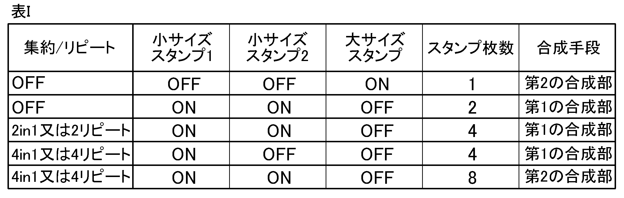
[表I]に、第1の合成部161で合成可能な最大スタンプ枚数が4枚である場合の合成手段決定処理Aによる決定結果の例を示す。なお、小サイズスタンプ1、2は、スタンプ画像が第1の合成部161のASIC内蔵RAMに収まるサイズ、大サイズスタンプは、スタンプ画像が第1の合成部161のASIC内蔵RAMに収まらないサイズである。また、集約又はリピート時は集約又はリピートした画像全てにスタンプを合成する。
合成手段決定処理Aが終了すると、制御部10は、画像処理部16ジョブの画像データに必要な画像処理を施すとともに、決定した合成手段(第1の合成部161又は第2の合成部162)によりジョブの画像データにスタンプ画像を合成して画像形成部17により用紙にスタンプ付きの画像を印刷する。
When the compositing means determination process A is completed, the
このように、第1の実施形態では、第1の合成部161の制約に該当しない画像形成条件の場合は、第1の合成部161でスタンプ画像の合成を行うので、高速にスタンプ画像の合成及び印刷を行うことが可能となる。第1の合成部161の制約に該当する画像形成条件の場合は、第2の合成部162でスタンプ画像の合成を行うので、スタンプ画像サイズの大きいスタンプや多数のスタンプを使用可能となる。すなわち、ジョブの画像形成条件に応じた最適な合成手段で画像データにスタンプ画像を合成することが可能となる。
As described above, in the first embodiment, in the case of the image formation condition that does not correspond to the restriction of the
<第2の実施形態>
以下、本発明の第2の実施形態について説明する。
第1の実施形態では、印刷速度を確保するためになるべく第1の合成部161でスタンプ画像の合成を実施するようにしたが、例えば、モノクロ画像はプレーン数が少ないため、第2の合成部162での合成スピードは印刷速度を超えている。そのため、モノクロ画像のように画像プレーン数が少ない場合は、常に第2の合成部162でスタンプ画像の合成を実行してもパフォーマンスに問題はない。そこで、第2の実施形態では、全プレーンにスタンプ画像を合成するのに要する時間が印刷に要する時間より短い場合は、第2の合成部162を使用する。
<Second embodiment>
Hereinafter, a second embodiment of the present invention will be described.
In the first embodiment, the stamp image is combined by the
第2の実施形態における画像形成装置1の構成は、第1の実施形態で説明したものと同様であるので説明を援用する。また、第2の実施形態の動作は、第1の合成部161と第2の合成部162のいずれを使用するかを決定する合成手段決定処理が第1の実施形態と異なるので、以下、第2の実施形態における合成手段決定処理(合成手段決定処理B)について説明する。
Since the configuration of the
図6は、合成手段決定処理Bの流れを示すフローチャートである。合成手段決定処理Bは、制御部10のCPU101とROM103に記憶されているプログラムとの協働により実行される。
FIG. 6 is a flowchart showing the flow of the synthesis means determination process B. The synthesis means determination process B is executed in collaboration with the
まず、制御部10は、取得したジョブの種類がスキャンジョブであるか否かを判断する(ステップS11)
取得したジョブの種類がスキャンジョブであると判断した場合(ステップS11;YES)、制御部10は、第2の合成部162を使用してジョブで指定されている全てのスタンプのスタンプ画像を合成することを決定し(ステップS16)、合成手段決定処理Bを終了する。
First, the
When it is determined that the acquired job type is a scan job (step S11; YES), the
取得したジョブの種類がスキャンジョブではない(コピージョブ又はプリントジョブである)と判断した場合(ステップS11;NO)、制御部10は、ジョブの画像データのプレーン数をP、1プレーンあたりの第2の合成部162によるスタンプ画像の合成にかかる処理時間をTc、プレーン数Pのジョブの画像データ(Pプレーン画像)に第2の合成部162によりスタンプ画像を合成するのにかかる処理時間をTsとして、Ts=P×Tcを算出する(ステップS12)。
When it is determined that the acquired job type is not a scan job (copy job or print job) (step S11; NO), the
次いで、制御部10は、スタンプ画像が合成された画像データの印刷(画像形成)にかかる時間をTpとして、Ts≦Tpであるか否かを判断する(ステップS13)。
Ts≦Tpであると判断した場合(ステップS13;YES)、制御部10は、第2の合成部162を使用してジョブで指定されている全てのスタンプのスタンプ画像を合成することを決定し(ステップS16)、合成手段決定処理Bを終了する。
Next, the
When it is determined that Ts ≦ Tp (step S13; YES), the
一方、Ts≦Tpではないと判断した場合(ステップS13;NO)、制御部10は、指定されたスタンプの中に、スタンプ画像サイズが第1の合成部161で使用可能な上限を超過しているものがあるか否かを判断する(ステップS14)。
指定されたスタンプの中に、スタンプ画像サイズが第1の合成部161で使用可能な上限を超過しているものがあると判断した場合(ステップS14;YES)、制御部10は、第2の合成部162を使用してジョブで指定されている全てのスタンプのスタンプ画像を合成することを決定し(ステップS16)、合成手段決定処理Bを終了する。
On the other hand, when it is determined that Ts≤Tp is not satisfied (step S13; NO), the
When it is determined that the stamp image size exceeds the upper limit that can be used by the
指定されたスタンプの中に、スタンプ画像サイズが第1の合成部161で使用可能な上限を超過しているものがないと判断した場合(ステップS14;NO)、制御部10は、1面に印刷される画像枚数をN、ジョブにおいて指定されているスタンプの数をM、第1の合成部161で合成可能な最大のスタンプ画像数をLとして、N×M>Lであるか否かを判断する(ステップS15)。
N×M>Lであると判断した場合(ステップS15;YES)、制御部10は、第2の合成部162を使用してジョブで指定されている全てのスタンプのスタンプ画像を合成することを決定し(ステップS16)、合成手段決定処理Bを終了する。
N×M>Lではないと判断した場合(ステップS15;NO)、制御部10は、第1の合成部161を使用してジョブで指定されている全てのスタンプのスタンプ画像を合成することを決定し(ステップS17)、合成手段決定処理Bを終了する。
When it is determined that none of the designated stamps has a stamp image size exceeding the upper limit that can be used by the first compositing unit 161 (step S14; NO), the
When it is determined that N × M> L (step S15; YES), the
When it is determined that N × M> L is not satisfied (step S15; NO), the
合成手段決定処理Bが終了すると、制御部10は、ジョブの画像データに必要な画像処理を施すとともに、決定した合成手段(第1の合成部161又は第2の合成部162)によりジョブの画像データにスタンプ画像を合成して画像形成部17により用紙にスタンプ付きの画像を印刷する。
When the compositing means determination process B is completed, the
このように、第2の実施形態では、モノクロ印刷等の、プレーン数が少なく第2の合成部162で合成するのにかかる処理時間が印刷時間以下の場合は、ジョブの画像形成条件が第1の合成部161の制約条件に該当するか否かにかかわらず、第2の合成部162で合成を実施することが可能となる。
As described above, in the second embodiment, when the number of planes is small and the processing time required for compositing by the
<第3の実施形態>
以下、本発明の第3の実施形態について説明する。
プリントジョブにはページモードとジョブモードが存在する。ページモードはAページB部のジョブのとき、A×B枚の画像データを受信し、1つの画像データに基づいて1回ずつ印刷を行う。部間では同じ画像であっても、再度コントローラから画像データを受信する。ジョブモードでは、AページB部のジョブのとき、A枚の画像データを受信し、受信したA枚の画像データをB回ずつ繰り返し印刷する。
<Third embodiment>
Hereinafter, a third embodiment of the present invention will be described.
There are page mode and job mode for print jobs. In the page mode, when the job of the A page B part is performed, A × B image data is received and printing is performed once based on one image data. Even if the image is the same between the units, the image data is received from the controller again. In the job mode, in the case of the job of the B part of page A, the image data of A sheets is received, and the received image data of A sheets is repeatedly printed B times.
ここで、スタンプの中には、部間で異なるスタンプ画像を画像データに合成するスタンプがある。例えば、部番号のスタンプは、1部目で「1」の画像を合成し、2部目で「2」の画像を合成する。ページモードの場合は、部ごとに画像データを受信するため、第2の合成部162による合成で問題はない。第1の実施形態及び第2の実施形態では、ページモードを前提としている。
一方、ジョブモードの場合は、1部目で第2の合成部162で合成を実行するとジョブの画像データに「1」の画像が合成され、2部目で「2」の画像を合成すると、画像データに「1」と「2」の両方の画像が印刷されてしまう。
そこで、第3の実施形態では、ジョブモードでは、部ごとに異なるスタンプ画像を合成するスタンプに関しては第1の合成部161を用いてスタンプ合成を行う。なお、本実施形態では、部ごとに異なるスタンプ画像を合成するスタンプのスタンプ画像サイズは、第1の合成部161で合成可能なサイズであることとする。
Here, among the stamps, there is a stamp that combines different stamp images between parts with image data. For example, in the stamp of the part number, the image of "1" is combined in the first part, and the image of "2" is combined in the second part. In the case of the page mode, since the image data is received for each unit, there is no problem in the composition by the
On the other hand, in the job mode, when the composition is executed by the
Therefore, in the third embodiment, in the job mode, stamp composition is performed using the
第3の実施形態における画像形成装置1の構成は、第1の実施形態で説明したものと同様であるので説明を援用する。また、第3の実施形態の動作は、第1の合成部161と第2の合成部162のいずれを使用するかを決定する合成手段決定処理が第1の実施形態と異なるので、以下、第3の実施形態における合成手段決定処理(合成手段決定処理C)について説明する。
Since the configuration of the
合成手段決定処理Cにおいて、制御部10は、ジョブの種類がスキャンジョブの場合、第2の合成部162を使用してジョブで指定されている全てのスタンプのスタンプ画像を合成することを決定する。
ジョブの種類がコピージョブの場合、又はジョブの種類がプリントジョブでページモードの場合、制御部10は、図5のステップS2~ステップS5又は図6のステップS12~17と同様の処理により、使用する合成手段を決定する。
ジョブの種類がプリントジョブでジョブモードの場合、制御部10は、ジョブにおいて部間で異なるスタンプ画像を合成するスタンプが指定されているか否かを判断し、ジョブにおいて部間で異なるスタンプ画像を合成するスタンプが指定されていると判断した場合、部間で異なるスタンプ画像を合成するスタンプについては第1の合成部161を使用することを決定する。そして、それ以外のスタンプについては、図5のステップS2~ステップS5又は図6のステップS12~17と同様の処理により、使用する合成手段を決定する。一方、ジョブにおいて部間で異なるスタンプ画像を合成するスタンプが指定されていないと判断した場合、制御部10は、図5のステップS2~ステップS5又は図6のステップS12~17と同様の処理により、使用する合成手段を決定する。
In the compositing means determination process C, the
When the job type is a copy job, or when the job type is a print job and the page mode, the
When the job type is a print job and the job mode is set, the
合成手段決定処理Cが終了すると、制御部10は、ジョブの画像データに必要な画像処理を施すとともに、決定した合成手段(第1の合成部161又は第2の合成部162)によりジョブの画像データにスタンプ画像を合成して画像形成部17により用紙にスタンプ付きの画像を印刷する。
When the compositing means determination process C is completed, the
このように、第3の実施形態では、ジョブの種類がプリントでジョブモードである場合、部間で異なるスタンプ画像を合成するスタンプについては、第1の合成部161を使用してスタンプ画像を合成することを決定する。したがって、ジョブの種類がプリントでジョブモードであって、合成するスタンプの種類が部間で異なるスタンプである場合の不具合を防止することができ、ジョブの画像形成条件に応じた最適な合成手段で画像データにスタンプ画像を合成することが可能となる。
As described above, in the third embodiment, when the job type is print and the job mode is used, the stamp image is synthesized by using the
以上、本発明について上記実施形態に基づいて説明を行ったが、上記実施の形態における記述は、本発明に係る画像形成装置の好適な一例であり、これに限定されるものではない。 Although the present invention has been described above based on the above embodiment, the description in the above embodiment is a suitable example of the image forming apparatus according to the present invention, and is not limited thereto.
例えば、上記実施形態においては、電子写真方式の画像形成装置に本発明を適用した場合を例にとり説明したが、インクジェット方式等の他の方式の画像形成装置に本発明を適用してもよい。 For example, in the above embodiment, the case where the present invention is applied to an electrophotographic image forming apparatus has been described as an example, but the present invention may be applied to an image forming apparatus of another type such as an inkjet method.
また、上記実施形態においては、画像を印刷する記録媒体が用紙であることとして説明したが、これに限定されず、OHPシートや布等であってもよい。 Further, in the above embodiment, the recording medium on which the image is printed is described as paper, but the present invention is not limited to this, and an OHP sheet, cloth, or the like may be used.
その他、上記実施の形態で示した構成、構造、制御内容や順番などの具体的な細部は、本発明の趣旨を逸脱しない範囲において適宜変更可能である。 In addition, specific details such as the configuration, structure, control content, and order shown in the above embodiment can be appropriately changed without departing from the spirit of the present invention.
1 画像形成装置
10 制御部
11 記憶部
12 操作部
13 表示部
14 インターフェース
15 スキャナー
16 画像処理部
161 第1の合成部
162 第2の合成部
17 画像形成部
18 定着部
19 搬送部
21 バス
1 Image forming
Claims (7)
前記画像処理部から出力された画像データに基づいて記録媒体上に画像を印刷する画像形成部と、
を備える画像形成装置であって、
前記画像処理部は、
印刷時に前記画像データに対してスタンプ画像を合成しながら前記画像形成部に出力する第1の合成部と、
前記メモリー上の前記画像データに対してスタンプ画像を合成し、合成後の前記画像データを前記メモリーへ出力する第2の合成部と、を有し、
前記第1の合成部は、合成可能なスタンプ画像のサイズ及び数に制約があり、
前記ジョブの種類、前記ジョブにおいて指定されているスタンプの種類、前記ジョブにおける集約又はリピートの指定、前記ジョブにおいて指定されている色情報に応じて決定されるプレーン数、のうち1つ以上の情報に基づいて、前記第1の合成部と前記第2の合成部のいずれを使用して前記指定されているスタンプのスタンプ画像を合成するかを決定する制御部を備える画像形成装置。 An image processing unit that writes the image data of the input job to the memory and performs image processing on the image data on the memory.
An image forming unit that prints an image on a recording medium based on the image data output from the image processing unit, and an image forming unit.
It is an image forming apparatus equipped with
The image processing unit
A first compositing unit that outputs to the image forming unit while compositing a stamp image with the image data at the time of printing.
It has a second compositing unit that synthesizes a stamp image with the image data on the memory and outputs the combined image data to the memory.
The first compositing unit has restrictions on the size and number of stamp images that can be composited.
One or more of the job type, the stamp type specified in the job, the aggregate or repeat designation in the job, and the number of planes determined according to the color information specified in the job. An image forming apparatus comprising a control unit for determining which of the first synthesis unit and the second composition unit is used to synthesize the stamp image of the designated stamp based on the above.
Priority Applications (1)
| Application Number | Priority Date | Filing Date | Title |
|---|---|---|---|
| JP2020113748A JP7491091B2 (en) | 2020-07-01 | 2020-07-01 | Image forming device |
Applications Claiming Priority (1)
| Application Number | Priority Date | Filing Date | Title |
|---|---|---|---|
| JP2020113748A JP7491091B2 (en) | 2020-07-01 | 2020-07-01 | Image forming device |
Publications (2)
| Publication Number | Publication Date |
|---|---|
| JP2022012144A true JP2022012144A (en) | 2022-01-17 |
| JP7491091B2 JP7491091B2 (en) | 2024-05-28 |
Family
ID=80148565
Family Applications (1)
| Application Number | Title | Priority Date | Filing Date |
|---|---|---|---|
| JP2020113748A Active JP7491091B2 (en) | 2020-07-01 | 2020-07-01 | Image forming device |
Country Status (1)
| Country | Link |
|---|---|
| JP (1) | JP7491091B2 (en) |
Citations (4)
| Publication number | Priority date | Publication date | Assignee | Title |
|---|---|---|---|---|
| JPH10178505A (en) * | 1996-12-17 | 1998-06-30 | Ricoh Co Ltd | Digital copier |
| JP2002163096A (en) * | 2000-11-27 | 2002-06-07 | Fuji Xerox Co Ltd | Image processor, image processing method and storage medium storing image processing program |
| JP2007019841A (en) * | 2005-07-07 | 2007-01-25 | Konica Minolta Business Technologies Inc | Image forming apparatus |
| JP2010165199A (en) * | 2009-01-16 | 2010-07-29 | Konica Minolta Business Technologies Inc | Print system, print control unit, printer, and printer driver program |
-
2020
- 2020-07-01 JP JP2020113748A patent/JP7491091B2/en active Active
Patent Citations (4)
| Publication number | Priority date | Publication date | Assignee | Title |
|---|---|---|---|---|
| JPH10178505A (en) * | 1996-12-17 | 1998-06-30 | Ricoh Co Ltd | Digital copier |
| JP2002163096A (en) * | 2000-11-27 | 2002-06-07 | Fuji Xerox Co Ltd | Image processor, image processing method and storage medium storing image processing program |
| JP2007019841A (en) * | 2005-07-07 | 2007-01-25 | Konica Minolta Business Technologies Inc | Image forming apparatus |
| JP2010165199A (en) * | 2009-01-16 | 2010-07-29 | Konica Minolta Business Technologies Inc | Print system, print control unit, printer, and printer driver program |
Also Published As
| Publication number | Publication date |
|---|---|
| JP7491091B2 (en) | 2024-05-28 |
Similar Documents
| Publication | Publication Date | Title |
|---|---|---|
| JP4380602B2 (en) | Image forming apparatus and control method thereof | |
| JP4950977B2 (en) | Image forming apparatus | |
| US9374495B2 (en) | Printer with outsourcing capability for color copies | |
| US20100027056A1 (en) | Image forming apparatus, program, and preview display method | |
| US8368958B2 (en) | Apparatus, method, and program product for processing color and transparent images according to the same layout setting or not based the determined image type to output as one image | |
| JP2006094297A (en) | Image forming apparatus, image processing apparatus and method, and program thereof | |
| JP3927948B2 (en) | Image forming apparatus control method and image forming apparatus | |
| JP5316503B2 (en) | Image forming apparatus, display method, and display program | |
| JP7491091B2 (en) | Image forming device | |
| US12360714B2 (en) | Image forming apparatus, non-transitory computer readable medium storing program, and image forming method | |
| JP2010008683A (en) | Image forming apparatus and information processing device | |
| JP2008052115A (en) | Printing apparatus, printing execution method thereof, and printing execution program | |
| JP2006094116A (en) | Image processing apparatus and method, and program thereof | |
| JP2006270746A (en) | Print image processing apparatus | |
| JP7494603B2 (en) | Image forming apparatus and image processing method | |
| JP2021187083A (en) | Image forming device and image forming method | |
| JP2003216365A (en) | Image processor and image forming device | |
| JP3892783B2 (en) | Image forming system | |
| JP3937572B2 (en) | Image processing system and control method thereof | |
| JP6553253B2 (en) | Image forming apparatus and image forming method | |
| JP3531393B2 (en) | Distributed processing system for image recording network | |
| JP4802908B2 (en) | Image forming system, image forming apparatus, and program for controlling image forming apparatus | |
| JP2007067799A (en) | Image recording device | |
| JP5183792B2 (en) | Image forming apparatus and method | |
| JP2023130616A (en) | Image processing device and image forming device |
Legal Events
| Date | Code | Title | Description |
|---|---|---|---|
| A621 | Written request for application examination |
Free format text: JAPANESE INTERMEDIATE CODE: A621 Effective date: 20230517 |
|
| A977 | Report on retrieval |
Free format text: JAPANESE INTERMEDIATE CODE: A971007 Effective date: 20240216 |
|
| A131 | Notification of reasons for refusal |
Free format text: JAPANESE INTERMEDIATE CODE: A131 Effective date: 20240227 |
|
| A521 | Request for written amendment filed |
Free format text: JAPANESE INTERMEDIATE CODE: A523 Effective date: 20240402 |
|
| TRDD | Decision of grant or rejection written | ||
| A01 | Written decision to grant a patent or to grant a registration (utility model) |
Free format text: JAPANESE INTERMEDIATE CODE: A01 Effective date: 20240416 |
|
| A61 | First payment of annual fees (during grant procedure) |
Free format text: JAPANESE INTERMEDIATE CODE: A61 Effective date: 20240429 |
|
| R150 | Certificate of patent or registration of utility model |
Ref document number: 7491091 Country of ref document: JP Free format text: JAPANESE INTERMEDIATE CODE: R150 |