JP2022012133A - Printer, printing control method and program - Google Patents
Printer, printing control method and program Download PDFInfo
- Publication number
- JP2022012133A JP2022012133A JP2020113726A JP2020113726A JP2022012133A JP 2022012133 A JP2022012133 A JP 2022012133A JP 2020113726 A JP2020113726 A JP 2020113726A JP 2020113726 A JP2020113726 A JP 2020113726A JP 2022012133 A JP2022012133 A JP 2022012133A
- Authority
- JP
- Japan
- Prior art keywords
- printing
- head
- design
- correction
- Prior art date
- Legal status (The legal status is an assumption and is not a legal conclusion. Google has not performed a legal analysis and makes no representation as to the accuracy of the status listed.)
- Pending
Links
- 238000007639 printing Methods 0.000 title claims abstract description 240
- 238000000034 method Methods 0.000 title claims abstract description 28
- 238000012937 correction Methods 0.000 claims abstract description 176
- 238000013461 design Methods 0.000 claims abstract description 155
- 210000000282 nail Anatomy 0.000 description 129
- 210000000078 claw Anatomy 0.000 description 48
- 238000004891 communication Methods 0.000 description 38
- 238000001514 detection method Methods 0.000 description 14
- 238000010586 diagram Methods 0.000 description 9
- 230000006870 function Effects 0.000 description 9
- 210000004905 finger nail Anatomy 0.000 description 8
- 238000012545 processing Methods 0.000 description 7
- 238000003384 imaging method Methods 0.000 description 4
- 238000004519 manufacturing process Methods 0.000 description 4
- 239000003086 colorant Substances 0.000 description 2
- 230000015572 biosynthetic process Effects 0.000 description 1
- 239000003795 chemical substances by application Substances 0.000 description 1
- 230000026058 directional locomotion Effects 0.000 description 1
- 238000005401 electroluminescence Methods 0.000 description 1
- 238000010191 image analysis Methods 0.000 description 1
- 238000007641 inkjet printing Methods 0.000 description 1
- 239000007788 liquid Substances 0.000 description 1
- 239000004973 liquid crystal related substance Substances 0.000 description 1
- 238000010422 painting Methods 0.000 description 1
- 239000011347 resin Substances 0.000 description 1
- 229920005989 resin Polymers 0.000 description 1
- 238000009751 slip forming Methods 0.000 description 1
- 238000005507 spraying Methods 0.000 description 1
- 210000004906 toe nail Anatomy 0.000 description 1
Images


Abstract
Description
本発明は、印刷装置、印刷制御方法及びプログラムに関するものである。 The present invention relates to a printing apparatus, a printing control method and a program.
従来、指の爪等にネイルデザインの印刷を行う印刷装置(ネイルプリント装置)が知られている。
このような印刷装置を用いれば、簡易にネイルプリントを楽しむことができる。
Conventionally, a printing device (nail printing device) for printing a nail design on a fingernail or the like is known.
If such a printing device is used, nail printing can be easily enjoyed.
ネイルプリントを印刷装置で実現する場合、爪の範囲に正確に印刷を行う必要がある。この点、印刷を行う印刷ヘッドは、装置本体のキャリッジに装着して使用されるが、キャリッジや印刷ヘッドには、製造段階での公差等による装着遊びがあるため、印刷ヘッドの取り付け、交換時に装着位置ずれやガタを生じるおそれがある。
印刷ヘッドに位置ずれ等が生じたまま印刷を行うと爪に印刷されたデザインがずれたり、爪以外の皮膚の部分にはみ出して印刷されてしまう等のおそれがある。
When realizing nail printing with a printing device, it is necessary to print accurately in the area of the nail. In this regard, the print head that prints is used by mounting it on the carriage of the main body of the device. However, since the carriage and the print head have mounting play due to tolerances at the manufacturing stage, when the print head is mounted or replaced. There is a risk of misalignment or backlash.
If printing is performed with the print head misaligned, the design printed on the nail may be misaligned, or the print may protrude from the skin other than the nail.
このため、例えば特許文献1には、印刷対象である爪に印刷ヘッドによって位置調整用マークを印刷し、位置調整用マークが出力された対象物の画像に基づいて印刷ヘッドによる印刷位置を調整することが開示されている。
Therefore, for example, in
しかしながら、装着位置ずれやガタは、X軸方向・Y軸方向や傾きθ方向等、様々な印刷位置のずれとして現れるところ、それぞれのずれに対応する位置調整用マークを印刷し、調整を繰り返すのでは手間がかかり、迅速な印刷処理を行うことができない。 However, the mounting position deviation and backlash appear as various printing position deviations such as the X-axis direction, the Y-axis direction, and the tilt θ direction, and the position adjustment mark corresponding to each deviation is printed and the adjustment is repeated. It takes time and effort, and it is not possible to perform a quick printing process.
本発明は以上のような事情に鑑みてなされたものであり、印刷位置を装置側で確認し各種の印刷位置のずれを補正するための補正情報を得ることで、正しい位置に正確に印刷を行うことのできる印刷装置、印刷制御方法及びプログラムを提供することを利点とするものである。 The present invention has been made in view of the above circumstances, and by confirming the print position on the device side and obtaining correction information for correcting various print position deviations, printing can be performed accurately at the correct position. It is an advantage to provide a printing device, a printing control method and a program that can be performed.
前記課題を解決するために、本発明の印刷装置は、
印刷対象面の印刷領域内に印刷を施す印刷装置であって、
印刷対象面に印刷するヘッドと、
前記ヘッドを制御する制御手段と、
を備え、
前記制御手段は、
前記ヘッドを動作させて、少なくとも2つの位置を特定できる補正用パターンを目標印刷位置に基づいて前記印刷領域内に印刷させ、
前記目標印刷位置と実際に前記補正用パターンが印刷された実印刷位置とのずれに関する情報を、印刷位置のアライメント補正を行う際に用いられる補正情報として取得することを特徴とする。
In order to solve the above problems, the printing apparatus of the present invention is used.
A printing device that prints within the print area of the print target surface.
The head to print on the print target surface and
A control means for controlling the head and
Equipped with
The control means is
The head is operated to print a correction pattern capable of specifying at least two positions in the print area based on the target print position.
It is characterized in that information regarding the deviation between the target print position and the actual print position on which the correction pattern is actually printed is acquired as correction information used when performing alignment correction of the print position.
本発明によれば、印刷位置を装置側で確認し各種の印刷位置のずれを補正するための補正情報を得ることで、正しい位置に正確に印刷を行うことができるとの効果を奏する。 According to the present invention, by confirming the print position on the apparatus side and obtaining correction information for correcting various print position deviations, it is possible to accurately print at the correct position.
図1から図8(a)~図8(e)を参照しつつ、本発明に係る印刷装置、印刷制御方法及びプログラムの一実施形態について説明する。
なお、以下に述べる実施形態には、本発明を実施するために技術的に好ましい種々の限定が付されているが、本発明の範囲を以下の実施形態及び図示例に限定するものではない。
また、以下の実施形態では、印刷装置が手の指の爪を印刷対象としてこれに印刷する印刷装置を例に説明するが、本発明における印刷装置の印刷対象は手の指の爪に限るものではなく、例えば足の指の爪等を印刷対象としてもよい。また、ネイルチップや各種アクセサリの表面等、人の爪以外の爪様のものを印刷対象としてもよい。
An embodiment of a printing apparatus, a printing control method, and a program according to the present invention will be described with reference to FIGS. 1 to 8 (a) to 8 (e).
Although the embodiments described below are provided with various technically preferable limitations for carrying out the present invention, the scope of the present invention is not limited to the following embodiments and illustrated examples.
Further, in the following embodiment, a printing device in which the printing device prints on the fingernail of the hand as an example will be described, but the printing target of the printing device in the present invention is limited to the fingernail of the hand. Instead, for example, toenails and the like may be printed. Further, a nail-like object other than a human nail, such as a nail tip or the surface of various accessories, may be printed.
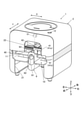
図1は、本実施形態における印刷装置の要部外観構成を示す斜視図である。
なお、以下の実施形態において、上下、左右及び前後は、図1に示した向きをいうものとする。また、X方向、Y方向は、図1に示した方向をいうものとする。
FIG. 1 is a perspective view showing an external configuration of a main part of a printing apparatus according to the present embodiment.
In the following embodiments, up / down, left / right, and front / back refer to the directions shown in FIG. Further, the X direction and the Y direction are the directions shown in FIG.
図1に示すように、印刷装置1は、ほぼ箱形に形成された筐体2を有している。
筐体2は、前面側(印刷装置1の正面側、図1において前側)の下側部分に、左右方向(印刷装置1の横方向、図1において左右方向、X方向)のほぼ全面に亘って形成された開口部21を有している。また、筐体2の左右方向のほぼ中央部には、開口部21の上側に連続して切り欠き部22が形成されている。切り欠き部22は、後述する印刷ヘッド41を装置に対して着脱する際の出入口として機能する。
なお、図示はしないが、筐体2は、開口部21や切り欠き部22を覆うカバー部材等を備えていてもよい。カバー部材は、筐体2とは別体に分離されたものであってもよいし、例えば筐体2に対してヒンジ等を介して開閉可能に取り付けられていてもよい。
As shown in FIG. 1, the
The
Although not shown, the
また、筐体2の上面(天板)には、印刷装置1の操作部12が設けられている。操作部12は、例えば印刷装置1の電源をON/OFFする操作ボタン(電源スイッチボタン)である。操作部12が操作されると、操作信号が制御装置30に出力され、制御装置30が操作信号に従った制御を行い、印刷装置1の各部を動作させる。例えば操作部12が電源スイッチボタンである場合、ボタン操作に応じて印刷装置1の電源がON/OFFされる。
なお、操作部12に代えて、後述する端末装置7の操作部71から入力された操作信号に従って印刷装置1の各部が動作するようにしてもよい。
筐体2各部の形状や各部の配置等は、図示例に限定されず、適宜設定可能である。例えば、操作部12は、筐体2の上面ではなく側面や背面等に設けられていてもよい。また、筐体2にはその他各種の操作ボタンが操作部12として設けられていてもよいし、各種表示部やインジケータ等が設けられていてもよい。
Further, an
Instead of the
The shape of each part of the
筐体2の内部には、装置本体10が収容されている。
装置本体10は、基台11と、これに取り付けられた指保持部6、印刷部40等を備えている。
The apparatus
The apparatus
指保持部6は、基台11における装置前面側の左右方向(X方向)のほぼ中央部に配置されており、本実施形態における印刷対象である爪Tを有する指Uを印刷に適した位置に保持する指保持手段である。
指保持部6は、装置前面側に開口部61を有している。また指保持部6の内部には、指固定部材62が設けられている。指固定部材62は、開口部61から挿入された指Uを下側から押し上げ支持するものであり、例えば柔軟性を有する樹脂等で形成されている。
指保持部6の上面には開口部61から挿入され指固定部材62により保持された指Uの爪T部分を露出させる窓部63が形成されている。
The
The
A
印刷部40は、後述する印刷データ生成部315(図2参照)において生成される印刷用データにしたがって印刷対象面である爪Tの表面に印刷を施す印刷手段である。
印刷部40は、印刷動作を行う印刷ヘッド41、印刷ヘッド41が装着され保持されるキャリッジ42、印刷ヘッド41及びキャリッジ42を移動させるためのヘッド移動機構49(図2参照)等を備えている。
The
The
図1に示すように、キャリッジ42には、ヘッド(以下「印刷ヘッド41」とする。)が搭載されている。本実施形態では、印刷ヘッド41として下地を印刷する下地用ヘッド41aとデザインを印刷するデザイン用ヘッド41bとが搭載されている。以下において、単に「印刷ヘッド41」としたときは、下地用ヘッド41a及びデザイン用ヘッド41bの両方を含むものとする。なお、下地用ヘッド41aとデザイン用ヘッド41bとの配置等は図示例に限定されない。
As shown in FIG. 1, a head (hereinafter referred to as “
下地用ヘッド41aは、デザインを印刷する前に、デザインを印刷する印刷領域Darに下地となる液剤(以下「下地用インク」という。)を印刷するものである。下地用ヘッド41aによって印刷される下地用インクは、デザインの印刷を行ったときにインクの発色がよくなるように、白色若しくはこれに近い色であることが好ましい。白色等で下地を形成することにより、爪T周辺の皮膚の色(肌色等)との区別もつきやすくなり、爪画像から爪Tの領域をより正確に認識しやすくなる。
また、本実施形態では、下地用ヘッド41aを用いてアライメント補正を行うための補正用パターンM(図3(a)~図3(e)等参照)を印刷する。
下地用ヘッド41aによって印刷される補正用パターンMについては後に詳説する。
Before printing the design, the
Further, in the present embodiment, a correction pattern M (see FIGS. 3A to 3E, etc.) for performing alignment correction using the
The correction pattern M printed by the
デザイン用ヘッド41bは、下地用ヘッド41aによる下地印刷後に、印刷領域Darにデザインを印刷するものであり、シアン(C;CYAN)、マゼンタ(M;MAGENTA)、イエロー(Y;YELLOW)等の各色のインク(以下「色インク」という。)を吐出可能となっている。なお、デザイン用ヘッド41bが吐出可能な色インクの種類はこれに限定されず、この他の色のインクを吐出可能となっていてもよい。
The
本実施形態において、下地用ヘッド41a及びデザイン用ヘッド41bは、いずれも爪表面に対向する面がインクを吐出させる複数のノズル口を備えたインク吐出面(図示せず)となっており、インクを微滴化し、インク吐出面から印刷対象(爪T)の被印刷面である爪表面に対して直接にインクを吹き付けて印刷を行うインクジェット方式のインクジェットヘッドである。
In the present embodiment, both the
ヘッド移動機構49は、印刷ヘッド41を装置の左右方向(X方向)に移動させるための図示しないX方向移動機構及び印刷ヘッド41を装置の前後方向(Y方向)に移動させるための図示しないY方向移動機構からなる。
X方向移動機構は、X方向移動モータ46を含んでおり、X方向移動モータ46が駆動することにより印刷ヘッド41を装置の左右方向(X方向)に移動させる。また、Y方向移動機構は、Y方向移動モータ48を含んでおり、Y方向移動モータ48が駆動することにより印刷ヘッド41を装置の前後方向(Y方向)に移動させる。
The
The X-direction moving mechanism includes an
ヘッド移動機構49のX方向移動モータ46、Y方向移動モータ48及び印刷ヘッド41(印刷ヘッド41の吐出機構部)の動作は制御装置30の印刷制御部316(図2参照)によって制御される。
The operations of the
また、筐体2の上面(天板)の内側であって、指保持部6の窓部63の上方位置には、窓部63から露出する爪T(爪Tを含む指U)を撮影して爪Tの画像(爪Tを含む指Uの画像、以下「爪画像」という。)を取得する撮影部50が設けられている。
撮影部50は、例えばカメラ等である撮影装置51と、撮影対象である爪Tを照明する白色LED等で構成された照明装置52とを備えている(図2参照)。
この撮影部50は、後述する制御装置30の撮影制御部312(図2参照)に接続されており、該撮影制御部312によって制御されるようになっている。
撮影装置51によって撮影された爪画像は、撮影制御部312において取得される。
なお、撮影部50によって撮影された画像の画像データは、後述する記憶部32に記憶されてもよい。
Further, a claw T (finger U including the claw T) exposed from the
The photographing
The photographing
The nail image captured by the
The image data of the image taken by the photographing
本実施形態では、撮影装置51及び照明装置52が、筐体2の天面内側であって指保持部6に載置された指Uの爪T(爪Tの表面)と対向可能な位置に固定配置されている場合を例示したが、撮影部50は、指保持部6に載置された指Uの爪Tを撮影可能な位置に設けられていればよく、具体的な配置は特に限定されない。
例えば、撮影部50は、印刷ヘッド41を移動させるヘッド移動機構49によってXY方向に移動可能に構成されていてもよい。
In the present embodiment, the photographing
For example, the photographing
印刷装置1に搭載される制御装置30は、図示しないCPU(Central Processing Unit)等のプロセッサにより構成される制御部31(図2参照)と、ROM(Read Only Memory)及びRAM(Random Access Memory)等(いずれも図示せず)で構成される記憶部32(図2参照)とを備えるコンピュータである。
The
記憶部32は、印刷装置1を動作させるための各種プログラム等が格納されたプログラム記憶領域321を有している。プログラム記憶領域321には、印刷処理を行うための印刷プログラム等の各種プログラムが格納されており、制御部31がこれらのプログラムを例えばRAMの作業領域に展開して、プログラムが制御部31において実行されることによって、印刷装置1の各部が統括制御されるようになっている。
また、記憶部32は、爪情報記憶領域322を有している。爪情報記憶領域322には、後述の爪情報検出部313によって検出された爪Tに関する各種の情報が記憶される。
The
Further, the
制御部31は、機能的に見た場合、通信制御部311、撮影制御部312、爪情報検出部313、アライメント補正部314、印刷データ生成部315、印刷制御部316等を備えている。これら通信制御部311、撮影制御部312、爪情報検出部313、アライメント補正部314、印刷データ生成部315、印刷制御部316等としての機能は、制御部31と記憶部32のプログラム記憶領域321に記憶されたプログラムとの協働によって実現される。
From a functional point of view, the
通信制御部311は、通信部13の動作を制御するものである。
通信部13は、端末装置7の通信部73との間で通信可能な無線通信モジュール等を備えており、通信制御部311は、印刷装置1、端末装置7間で各種のデータ等を送受信する際に通信部13の動作を制御する。
本実施形態の印刷装置1は、後述する端末装置7と連携してネイルデザイン(以下単に「デザイン」ともいう。)の印刷を行うようになっている。例えば爪Tに印刷するデザインのデータは端末装置7側に記憶されており、通信制御部311は適宜通信部13による通信を制御し、通信部13を介して端末装置7側からデザインのデータを取得する。
The
The
The
印刷装置1と端末装置7との間での通信は、インターネット等のネットワーク回線を使うものであってもよいし、例えばBluetooth(登録商標)やWi-Fi等の近距離無線通信規格に基づく無線通信を行うものであってもよい。ネットワークを介して通信を行う場合、通信に用いるネットワークはどのような回線を利用するものでもよい。また、印刷装置1と端末装置7との間の通信は無線に限定されず、有線接続により両者間で各種データの送受信が可能な構成としてもよい。
なお、通信部13は、端末装置7との間で通信を行うことのできるものであればよく、端末装置7の通信部73の通信規格と合致するものが適用される。
The communication between the
The
撮影制御部312は、撮影部50の撮影装置51及び照明装置52を制御して撮影装置51により、指保持部6に載置された指Uの爪Tの画像を含む指Uの画像(爪画像)を撮影させる。
本実施形態では、後述するように下地を形成する前の地爪を撮影部50によって撮影し、当該爪Tの画像(爪画像)を取得する。また、地爪に補正用マークMを印刷した後、再度地爪を撮影部50によって撮影し、当該爪Tの画像(爪画像)を取得するようになっている。なお、地爪に下地を印刷した後、デザインを印刷する前にさらに下地塗布状態の爪Tを撮影部50によって撮影し、当該爪Tの画像(爪画像)を取得してもよい。
撮影部50により取得された当該爪Tの画像(爪画像)は、撮影制御部312に送られる。撮影制御部312は、こうした爪画像(爪Tの画像のデータ)を取得する画像取得手段として機能する。なお、撮影制御部312は爪画像を記憶部32に記憶させてもよい。
The photographing
In the present embodiment, as will be described later, the ground nail before forming the base is photographed by the photographing
The image (nail image) of the nail T acquired by the photographing
爪情報検出部313は、画像取得手段である撮影制御部312によって取得された爪Tの画像(爪画像)に基づいて、指Uの爪Tについての爪情報を検出する制御手段である。本実施形態において爪情報検出部313は、爪情報として、爪Tの領域を画する爪Tの輪郭情報(輪郭TL(図3(a)から図3(e)、図4(a)及び図4(b)、図5(a)及び図5(b)等参照)を検出する。
なお、爪情報検出部313によって検出される爪情報はこれに限定されない。
爪情報検出部313によって検出される爪情報は、例えば、爪Tの表面の、XY平面に対する傾斜角度(爪Tの傾斜角度、爪曲率)等を含んでいてもよい。また、撮影装置51によって撮影された画像等から爪Tの高さ(爪Tの垂直方向の位置)を取得できる場合には、爪Tの高さも爪情報に含まれてよい。
爪情報検出部313によって検出された各種の情報は、爪情報記憶領域322に記憶される。
The nail
The claw information detected by the claw
The claw information detected by the claw
Various information detected by the claw
アライメント補正部314は、下地用ヘッド41aによって、爪Tの印刷領域Dar内の一部にアライメント補正を行うための補正用パターンMを印刷させ、実際に印刷された補正用パターンMの位置(これを「実印刷位置」という。)と印刷されるはずの目標印刷位置とのずれに関する情報を補正情報(これを「アライメント値」という。)として取得し、このアライメント値(補正情報)を用いて、事後の印刷動作における印刷位置のアライメント補正を行う。
The
補正用パターンMは、少なくとも2つの位置を特定できるものである。本実施形態においてアライメント補正部314は、アライメント値(補正情報)として、目標印刷位置と実印刷位置との、印刷対象面の面方向におけるX軸方向、Y軸方向のずれに関する情報、印刷対象面の面方向における傾きθのずれ(すなわち、XY平面に対して垂直なZ軸を想定した場合の、Z軸の軸周りの角度のずれ)に関する情報、を取得する。
補正用パターンMとして、少なくとも2つの位置、すなわち、XY平面上の2点を特定できるものを用いることによって、上記のような、印刷対象面の面方向におけるX軸方向のずれ(Δx)、Y軸方向のずれ(Δy)、印刷対象面の面方向における傾きθのずれ(Δθ)を検出することができる。
The correction pattern M can specify at least two positions. In the present embodiment, the
By using at least two positions, that is, two points on the XY plane, as the correction pattern M, the deviation (Δx) in the X-axis direction in the surface direction of the print target surface as described above, Y It is possible to detect the deviation in the axial direction (Δy) and the deviation of the inclination θ in the surface direction of the print target surface (Δθ).
図3(a)から図3(e)は、補正パターンの例を示す図である。
補正パターンMは、図3(a)に示すように、2つの点であってもよいし、図3(b)に示すように、2つの点を繋いだ線状のものであってもよいし、図3(c)に示す三角形状や図3(d)に示す四角形状等の多角形状であってもよいし、図3(e)に示すような「+」マーク等であってもよい。
補正パターンは非回転対称な形状であればなお好ましい。補正パターンを非回転対称な形状とした場合には、仮にある点を中心に180度回転するようなずれを生じている場合でも、元の図形と一致しないため、正確にずれを検出することができる。
なお、補正用パターンMは、少なくとも2つの位置を特定できるものであればよく、ここに示した例に限定されない。例えば補正用パターンMは3つ以上の点等で構成されていてもよい。
3 (a) to 3 (e) are diagrams showing an example of a correction pattern.
The correction pattern M may be two points as shown in FIG. 3A, or may be a linear one connecting the two points as shown in FIG. 3B. However, it may be a polygonal shape such as a triangle shape shown in FIG. 3 (c) or a quadrangular shape shown in FIG. 3 (d), or a “+” mark or the like as shown in FIG. 3 (e). good.
It is still preferable that the correction pattern has a non-rotational symmetric shape. When the correction pattern has a non-rotational symmetric shape, even if there is a deviation that rotates 180 degrees around a certain point, it does not match the original figure, so the deviation can be detected accurately. can.
The correction pattern M may be any as long as it can specify at least two positions, and is not limited to the example shown here. For example, the correction pattern M may be composed of three or more points or the like.
図4(a)は、補正パターンMが図3(a)に示すような2つの点である場合に、印刷対象面の面方向におけるX軸方向、Y軸方向のずれを検出する様子を模式的に示した図であり、図4(b)は、補正パターンMが同じく図3(a)に示すような2つの点である場合に、印刷対象面の面方向における傾きθのずれを検出する様子を模式的に示した図である。
また、図5(a)は、補正パターンMが図3(c)に示すような三角形状のマークである場合に、印刷対象面の面方向におけるX軸方向、Y軸方向のずれを検出する様子を模式的に示した図であり、図5(b)は、補正パターンMが同じく図3(c)に示すような三角形状のマークである場合に、印刷対象面の面方向における傾きθのずれを検出する様子を模式的に示した図である。
FIG. 4A schematically shows a state in which deviations in the X-axis direction and the Y-axis direction in the surface direction of the print target surface are detected when the correction pattern M is two points as shown in FIG. 3A. FIG. 4 (b) detects a deviation of the inclination θ in the surface direction of the print target surface when the correction pattern M is two points as also shown in FIG. 3 (a). It is a figure which showed the state of doing.
Further, FIG. 5A detects deviations in the X-axis direction and the Y-axis direction in the surface direction of the print target surface when the correction pattern M is a triangular mark as shown in FIG. 3C. FIG. 5B is a diagram schematically showing the state, and FIG. 5B shows an inclination θ in the plane direction of the print target surface when the correction pattern M is a triangular mark as also shown in FIG. 3C. It is a figure which showed the state of detecting the deviation of.
図4(a)、図4(b)及び図5(a)、図5(b)において、補正用マークMの目標印刷位置を破線で示し、実印刷位置を実線で示している。
なお、図4(a)、図4(b)及び図5(a)、図5(b)では、図示の都合上、印刷対象面の面方向におけるX軸方向、Y軸方向のずれを検出する様子と印刷対象面の面方向における傾きθのずれを検出する様子とを図面を分けて図示しているが、本実施形態では、1つ(点で構成される補正パターンMの場合には複数の点のセット)の補正パターンMによって、印刷対象面の面方向におけるX軸方向、Y軸方向のずれと印刷対象面の面方向における傾きθのずれとを両方検出することが可能となっている。
In FIGS. 4 (a), 4 (b), 5 (a), and 5 (b), the target print position of the correction mark M is indicated by a broken line, and the actual print position is indicated by a solid line.
In FIGS. 4 (a), 4 (b), 5 (a), and 5 (b), deviations in the X-axis direction and the Y-axis direction in the surface direction of the print target surface are detected for convenience of illustration. The drawing and the state of detecting the deviation of the inclination θ in the plane direction of the print target surface are shown separately in the drawings, but in the present embodiment, one (in the case of the correction pattern M composed of points) is shown. The correction pattern M (a set of a plurality of points) makes it possible to detect both the deviation in the X-axis direction and the Y-axis direction in the surface direction of the print target surface and the deviation of the inclination θ in the surface direction of the print target surface. ing.
例えば印刷対象面の面方向におけるX軸方向のずれΔxは、図4(a)に示す場合であれば、補正パターンMを構成するいずれかの点の中心を通る軸線を目標印刷位置と実印刷位置とで比較したときのX軸方向のずれを検出する。図4(a)に示す例では、補正用マークMの実印刷位置が目標印刷位置に対して、図4(a)に示すX軸方向の右側にΔxだけずれている。
また、印刷対象面の面方向におけるY軸方向のずれΔyは、図4(a)に示す場合であれば、補正パターンMを構成するいずれかの点の中心を通る軸線を目標印刷位置と実印刷位置とで比較したときのY軸方向のずれを検出する。図4(a)に示す例では、補正用マークMの実印刷位置が目標印刷位置に対して、図4(a)に示すY軸方向の下側にΔyだけずれている。
For example, in the case shown in FIG. 4A, the deviation Δx in the X-axis direction in the surface direction of the print target surface is the axis line passing through the center of any of the points constituting the correction pattern M as the target print position and actual printing. The deviation in the X-axis direction when compared with the position is detected. In the example shown in FIG. 4A, the actual printing position of the correction mark M is shifted to the right side in the X-axis direction shown in FIG. 4A by Δx with respect to the target printing position.
Further, in the case shown in FIG. 4A, the deviation Δy in the Y-axis direction in the surface direction of the print target surface is the axis line passing through the center of any of the points constituting the correction pattern M as the target print position. Detects deviation in the Y-axis direction when compared with the print position. In the example shown in FIG. 4A, the actual printing position of the correction mark M is displaced downward by Δy in the Y-axis direction shown in FIG. 4A with respect to the target printing position.
また例えば、図5(a)に示す場合であれば、補正パターンMである三角形のある角(図5(a)では左下の角)に着目し、この角の目標印刷位置と実印刷位置との位置のずれをみることで、印刷対象面の面方向におけるX軸方向のずれを検出する。図5(a)に示す例では、補正用マークMの実印刷位置が目標印刷位置に対して、図5(a)に示すX軸方向の右側にΔxだけずれている。
また、印刷対象面の面方向におけるY軸方向のずれΔyは、図5(a)に示す場合であれば、補正パターンMの三角形の底辺の位置を目標印刷位置と実印刷位置とで比較したときのY軸方向のずれを検出する。図5(a)に示す例では、補正用マークMの実印刷位置が目標印刷位置に対して、図5(a)に示すY軸方向の下側にΔyだけずれている。
Further, for example, in the case shown in FIG. 5A, pay attention to a certain angle of the triangle which is the correction pattern M (the lower left corner in FIG. 5A), and the target printing position and the actual printing position of this angle. By observing the deviation of the position of, the deviation in the X-axis direction in the surface direction of the print target surface is detected. In the example shown in FIG. 5A, the actual printing position of the correction mark M is shifted to the right side in the X-axis direction shown in FIG. 5A by Δx with respect to the target printing position.
Further, in the case of the case shown in FIG. 5A, the position of the base of the triangle of the correction pattern M is compared between the target printing position and the actual printing position for the deviation Δy in the Y-axis direction in the surface direction of the printing target surface. Detects the deviation in the Y-axis direction. In the example shown in FIG. 5A, the actual printing position of the correction mark M is displaced downward by Δy in the Y-axis direction shown in FIG. 5A with respect to the target printing position.
また、印刷対象面の面方向における傾きθのずれΔθは、図4(b)に示す場合であれば、補正パターンMを構成する2つの点の中心を通る線を目標印刷位置と実印刷位置とで比較したときの、印刷対象面の面方向における傾きθのずれを検出する。図4(b)に示す例では、補正用マークMの実印刷位置が目標印刷位置に対して、図4(b)における時計回りにΔθだけずれている。
また例えば、図5(b)に示す場合であれば、補正パターンMである三角形のある角(図5(b)では上部の頂点である角)を通る線を目標印刷位置と実印刷位置とで比較したときの、印刷対象面の面方向における傾きθのずれを検出する。図5(b)に示す例では、補正用マークMの実印刷位置が目標印刷位置に対して、図5(b)における時計回りにΔθだけずれている。
Further, in the case shown in FIG. 4B, the deviation Δθ of the inclination θ in the surface direction of the print target surface is the target print position and the actual print position along the line passing through the centers of the two points constituting the correction pattern M. When compared with, the deviation of the inclination θ in the surface direction of the print target surface is detected. In the example shown in FIG. 4B, the actual printing position of the correction mark M is shifted clockwise by Δθ in FIG. 4B with respect to the target printing position.
Further, for example, in the case shown in FIG. 5 (b), the line passing through a certain angle of the triangle which is the correction pattern M (the angle which is the upper vertex in FIG. 5 (b)) is defined as the target print position and the actual print position. Detects the deviation of the inclination θ in the surface direction of the print target surface when compared with. In the example shown in FIG. 5B, the actual printing position of the correction mark M is shifted clockwise by Δθ in FIG. 5B with respect to the target printing position.
なお、補正用パターンMの目標印刷位置と実印刷位置とを比較する手法はここに例示したものに限定されない。
例えば補正用マークMの外接矩形同士を比較して、ずれΔx、Δy、Δθを検出してもよい。
The method for comparing the target print position of the correction pattern M with the actual print position is not limited to the one illustrated here.
For example, the deviations Δx, Δy, and Δθ may be detected by comparing the circumscribed rectangles of the correction marks M with each other.
アライメント補正部314は、爪領域(印刷対象面の領域)を画する輪郭TLの内側に予め補正用パターンMを印刷すべき目標印刷位置を設定する。
なお、印刷が予定されるデザインが爪Tの全面に印刷される全体デザインAD(図7(e)参照)である場合には、爪Tの全面(輪郭TLの内側全体)が印刷領域Darとなる。なお、全体デザインADとは、爪Tの全面に印刷されるものであればよく、一又は複数色で爪T全体を塗り潰す場合の他、爪T全体に花柄やチェック柄を施すような総柄のデザインも含まれる。
これに対して、印刷が予定されるデザインが爪Tの一部分のみに印刷される部分デザインPD(例えばフレンチネイルやワンポイントデザイン等、図8(e)では星形のワンポイントデザインを例示)である場合には、爪Tの全面(輪郭TLの内側全体)のうち、デザインの印刷が予定される領域が印刷領域Darとなる。
なお、本実施形態では、アライメント補正部314は、印刷領域Darを画する輪郭の内側(全体デザインADの場合には爪Tの輪郭TLの内側全体、部分デザインPDの場合にはデザインの印刷が予定される領域の内側)の一部に、補正用パターンMを印刷すべき範囲であるパターン印刷領域Aarを設定し、目標印刷位置をこのパターン印刷領域Aar内に設定する。
このように、印刷領域Darよりも内側にパターン印刷領域Aarを設定することで、補正用パターンMの実印刷位置がずれた場合にも印刷領域Dar内からはみ出さないようにし、確実に下地によって塗り潰すことができる。
The
When the design to be printed is the overall design AD (see FIG. 7 (e)) in which the entire surface of the nail T is printed, the entire surface of the nail T (the entire inside of the contour TL) is the print area Dar. Become. The overall design AD may be printed on the entire surface of the nail T, and may be used to fill the entire nail T with one or more colors, or to apply a floral pattern or a check pattern to the entire nail T. The design of the total pattern is also included.
On the other hand, in the partial design PD in which the design to be printed is printed only on a part of the nail T (for example, French nail or one-point design, FIG. 8 (e) exemplifies the star-shaped one-point design). In some cases, the area where the design is scheduled to be printed is the print area Dar in the entire surface of the nail T (the entire inside of the contour TL).
In the present embodiment, the
In this way, by setting the pattern print area Aar inside the print area Dar, even if the actual print position of the correction pattern M shifts, it does not protrude from the print area Dar, and the background is surely used. Can be filled.
印刷データ生成部315は、爪情報検出部313によって検出された印刷領域に所望のデザインを合わせ込んで印刷用データを生成する。
具体的には、印刷データ生成部315は、ユーザによって選択されたネイルデザイン(デザイン)の画像データを切り出し、適宜拡大縮小、配置の調整等を行うとともに、爪Tの画像から検出された印刷領域にフィッティングする。
印刷データ生成部315は、アライメント補正部314によってアライメント補正が行われたときには、このアライメント補正を反映させて印刷用データを生成する。
なお、爪情報検出部313において爪Tの曲率等が取得された場合には、印刷データ生成部315は、この爪Tの曲率等に基づいて、印刷用データに適宜曲面補正を行ってもよい。曲面補正を行った場合には、より爪Tの形状に合った印刷用データを生成することができる。
The print
Specifically, the print
When the alignment correction is performed by the
When the curvature of the claw T is acquired by the claw
印刷制御部316は、印刷データ生成部315において生成された印刷用データを印刷部40に出力し、印刷用データにしたがって爪Tに印刷を施すように印刷部40を制御する。
具体的には、印刷制御部316は、印刷用データに基づいて印刷部40に制御信号を出力し、爪Tに対してこの印刷用データにしたがった印刷を施すように印刷部40のX方向移動モータ46、Y方向移動モータ48、印刷ヘッド41等を制御する。
The
Specifically, the
また、前述のように、本実施形態の印刷装置1は、端末装置7と連携して爪Tに対する印刷を行う。
端末装置7は、例えばスマートフォン等の携帯端末装置である。なお、端末装置7はスマートフォンに限定されない。例えばタブレット型のパーソナルコンピュータ(以下において「PC」とする。)やノート型のPC、据置型のPC、ゲーム用の端末装置等であってもよい。
図2に示すように、端末装置7は、操作部71、表示部72、通信部73及び制御装置80等を備えている。
Further, as described above, the
The terminal device 7 is a mobile terminal device such as a smartphone. The terminal device 7 is not limited to the smartphone. For example, it may be a tablet-type personal computer (hereinafter referred to as "PC"), a notebook-type PC, a stationary PC, a terminal device for games, or the like.
As shown in FIG. 2, the terminal device 7 includes an
操作部71は、ユーザの操作に応じて各種の入力・設定等を行うことができるようになっており、例えば表示部72の表面に一体的に設けられたタッチパネルである。操作部71が操作されると、当該操作に対応する入力信号が制御部81に送信される。
表示部72に構成されるタッチパネルには、後述する表示制御部812の制御にしたがって各種の操作画面が表示され、ユーザはタッチパネルへのタッチ操作によって各種の入力・設定等の操作を行うことができる。
なお、各種の入力・設定等の操作を行う操作部71はタッチパネルである場合に限定されない。例えば各種の操作ボタンやキーボード、ポインティングデバイス等が操作部71として設けられていてもよい。
The
The touch panel configured on the
The
本実施形態では、ユーザが操作部71を操作することで、端末装置7から印刷装置1に対して印刷開始等の各種指示が出力されるようになっており、端末装置7は印刷装置1の操作部としても機能する。
また、ユーザが操作部71を操作することで、爪Tに印刷するネイルデザイン(デザイン)を選択すること等ができるようになっている。
In the present embodiment, when the user operates the
Further, the user can select the nail design (design) to be printed on the nail T by operating the
表示部72は、例えば液晶ディスプレイ(LCD:Liquid Crystal Display)、有機エレクトロルミネッセンスディスプレイその他のフラットディスプレイ等で構成されている。
なお、前述のように、表示部72の表面に各種の入力を行うためのタッチパネルが一体的に構成されていてもよい。この場合には、タッチパネルが操作部71として機能する。
本実施形態では、ユーザが操作部71から入力・選択したネイルデザインや、各種の案内画面、警告表示画面等が表示部72に表示可能となっている。
The
As described above, a touch panel for performing various inputs may be integrally configured on the surface of the
In the present embodiment, the nail design input / selected by the user from the
通信部73は、印刷装置1の通信部13との間で通信可能に構成されたものである。
印刷装置1と端末装置7との間での通信は、前述のように、無線接続方式、有線接続方式のどちらでもよく、具体的な方式は限定されない。通信部73は印刷装置1との間で通信を行うことのできるものであればよく、印刷装置1の通信部13の通信規格と合致するものが適用される。
通信部13は、後述する制御装置80の通信制御部811(図2参照)に接続され、該通信制御部811によって制御される。
The
As described above, the communication between the
The
図2に示すように、本実施形態の端末装置7の制御装置80は、図示しないCPU(Central Processing Unit)等のプロセッサにより構成される制御部81と、図示しないROM(Read Only Memory)及びRAM(Random Access Memory)等で構成される記憶部82とを備えるコンピュータである。
As shown in FIG. 2, the
記憶部82には、端末装置7の各部を動作させるための各種プログラムや各種データ等が格納されている。
具体的には、本実施形態のROM等には、端末装置7の各部を統括制御するための動作プログラム821aの他、印刷装置1を用いたネイルプリントを行うためのネイルプリントアプリケーションプログラム821b(以下「ネイルプリントAP」とする。)等の各種プログラムが格納されており、制御部81がこれらのプログラムを例えばRAMの作業領域に展開して、プログラムが制御部81において実行されることによって、端末装置7の各部が統括制御されるようになっている。
The
Specifically, in the ROM or the like of the present embodiment, in addition to the
また、本実施形態の記憶部82には、ネイルデザイン(デザイン)のデータを格納するデザイン記憶領域822等が設けられている。
なお、デザイン記憶領域822に格納されるネイルデザイン(デザイン)は、予め用意された既存のデザインであってもよいし、ユーザが自ら作成したデザインであってもよい。また、端末装置7が各種ネットワークに接続可能である場合には、ネットワーク接続可能な図示しないサーバ装置等に記憶されているネイルデザイン(デザイン)を取り込むことが可能となっていてもよい。
Further, the
The nail design (design) stored in the
端末装置7の制御部81は、機能的に見た場合、通信制御部811、表示制御部812等を備えている。これら通信制御部811、表示制御部812等としての機能は、制御部81のCPUと記憶部82のROMに記憶されたプログラムとの協働によって実現される。なお、端末装置7の制御部81が備える機能はこれに限定されず、その他各種の機能部を備えていてもよい。
通信制御部811は、通信部73の動作を制御するものである。
また、表示制御部812は、表示部72を制御して表示部72に各種の表示画面を表示させる。
From a functional point of view, the
The
Further, the
次に、図6等を参照しつつ、本実施形態の印刷装置1による印刷制御方法について説明する。
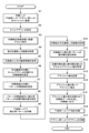
図6は、本実施形態における印刷処理を示すフローチャートである。
本実施形態の印刷装置1を用いてネイルプリントを行う場合には、ユーザは、まずキャリッジ42に印刷ヘッド41(下地用ヘッド41a及びデザイン用ヘッド41b)を装着する(ステップS1)。
そしてユーザは、印刷装置1の操作部12(操作ボタン)等を操作して電源を入れ起動させる。また、端末装置7についても電源を入れて端末装置7の操作部71からネイルプリント処理の実行を選択する。これによりネイルプリントAP821bが起動する。
Next, the printing control method by the
FIG. 6 is a flowchart showing the printing process in the present embodiment.
When performing nail printing using the
Then, the user operates the operation unit 12 (operation button) of the
端末装置7においてネイルプリントAP821bが起動すると、端末装置7の表示制御部812は、デザインを選択することのできるデザイン選択画面(図示せず)を表示部72に表示させる。ユーザがいずれかのデザインを選択して操作ボタンやタッチパネル等を操作すると、当該デザインを選択する旨の入力信号が制御部81に出力されて、当該デザインが爪Tに印刷するデザインとして設定される(ステップS2)。設定されたデザインの情報は通信部71,13を介して印刷装置1にも送られる。
また、表示制御部812は、印刷したい爪Tに対応する指Uを指保持部6にセットするよう促す指示画面を表示部72に表示させる(ステップS3)。
When the nail print AP821b is activated in the terminal device 7, the
Further, the
指保持部6に指Uが載置されると、指Uが撮影部50によって撮影され、下地が塗布される前の地爪の爪画像が取得される(ステップS4)。そして、爪情報検出部313が撮影部50によって取得された爪画像について画像処理を行うことにより爪Tの輪郭TL(輪郭情報)等の爪情報を検出する(ステップS5、図7(a)参照)。
爪情報検出部313によって爪情報が検出されると、アライメント補正部314は、爪Tの輪郭TLの内側にネイルデザインを印刷する印刷領域Darを設定する(ステップS6)。印刷領域Darを設定するにおいては、ユーザによって選択されたデザインも考慮する。例えばネイルデザインが、爪Tの全面に印刷される全体デザインADの場合には、印刷領域Darは爪Tの輪郭TLの内側領域全体と一致する。印刷領域Darが設定されると、アライメント補正部314は、この印刷領域Darの一部にアライメント補正のための補正用パターンMを印刷するパターン印刷領域Aarを設定する(ステップS7)。図7(b)では、パターン印刷領域Aarを破線で示している。
When the finger U is placed on the
When the nail information is detected by the nail
さらにアライメント補正部314は、設定されたパターン印刷領域Aar内の一部に、補正用パターンMを印刷する目標印刷位置を予め設定する(ステップS8)。図7(c)において、補正用パターンMの目標印刷位置を破線で示している。
なお、デザインが、印刷対象面のうちの一部分のみを印刷領域Darとする部分デザインPDである場合には、アライメント補正部314は、部分デザインPDの印刷領域Dar内の一部に目標印刷位置を設定する。
Further, the
When the design is a partial design PD in which only a part of the print target surface is the print area Dar, the
図8(a)から図8(e)は、ユーザによって選択されたネイルデザインが部分デザインである星形のワンポイントデザインである場合の例を示したものである。
部分デザインPDを印刷する場合には、アライメント補正部314は、デザインを印刷する印刷領域Dar(図8(b)において、印刷領域Darを一点鎖線で図示)を、爪Tの輪郭TLの内側(爪Tの領域内)に設定する。そして、この印刷領域Darよりも内側にパターン印刷領域Aarを設定する。図8(b)では、星形のデザインを印刷する場合に、星形の印刷領域Darよりも一回り小さな星型のパターン印刷領域Aar(図8(b)において、パターン印刷領域Aarを破線で示す。)を印刷領域Darの内側に設定する場合を例示している。なお、パターン印刷領域Aarは、印刷領域Darの内側の一部分に設定されればよく、印刷領域Darと相似形の領域である必要はない。例えば星形のデザインを印刷する場合に、その印刷領域Dar内の一部に矩形のパターン印刷領域Aarを設定してもよい。そして、アライメント補正部314は、部分デザインPDの印刷領域Dar内の一部に設定されたパターン印刷領域Aar内の一部に目標印刷位置を設定する(図8(c)参照)。
8 (a) to 8 (e) show an example in which the nail design selected by the user is a star-shaped one-point design which is a partial design.
When printing the partial design PD, the
目標印刷位置が設定されると、アライメント補正部314は、当該設定にしたがって、下地用ヘッド41aを動作させ、補正用パターンMを印刷させる(ステップS9)。
補正用パターンMが印刷されると、撮影部50によって印刷後の爪Tを撮影し、爪画像を取得する(ステップS10)。
そして、この爪画像を画像解析等することにより、アライメント補正部314は、補正用パターンが実際に印刷された実印刷位置を取得する(ステップS11)。
図7(c)及び図8(c)では、実際に補正用パターンMが印刷された補正用パターンMの実印刷位置を実線及び白抜きで示している。
When the target print position is set, the
When the correction pattern M is printed, the photographing
Then, by performing image analysis or the like on this nail image, the
In FIGS. 7 (c) and 8 (c), the actual printing position of the correction pattern M on which the correction pattern M is actually printed is shown by solid lines and white outlines.
実印刷位置が取得されると、アライメント補正部314は、補正用パターンMの目標印刷位置と実印刷位置とのずれに関する情報をアライメント値(補正情報)として取得する(ステップS12)。例えば図7(c)及び図8(c)では、目標印刷位置に対して実印刷位置が、X軸方向に、図7(c)及び図8(c)における右側にΔxずれており、Y軸方向に、図7(c)及び図8(c)における下側にΔyずれている場合を例示している。
アライメント補正部314は、アライメント値を記憶部32に記憶させ(ステップS13)、このアライメント値を用いて事後の印刷動作における印刷位置のアライメント補正を行う(ステップS14)。
なお、目標印刷位置と実印刷位置とを比較してずれがない場合には、アライメント補正を行わなくてよい。すなわち、アライメント補正は、補正情報に基づいて目標印刷位置と実印刷位置とのずれがあると判断した場合に行えばよい。また例えば、ずれの程度に関する閾値を設けて、取得された補正情報に基づいて目標印刷位置と実印刷位置とのずれが所定の閾値以上であると判断した場合にアライメント補正を行うとしてもよい。
When the actual print position is acquired, the
The
If there is no deviation between the target print position and the actual print position, the alignment correction may not be performed. That is, the alignment correction may be performed when it is determined that there is a deviation between the target print position and the actual print position based on the correction information. Further, for example, a threshold value regarding the degree of deviation may be set, and alignment correction may be performed when it is determined that the deviation between the target print position and the actual print position is equal to or higher than a predetermined threshold value based on the acquired correction information.
印刷データ生成部315は、アライメント補正等を反映させて、ネイルデザインを印刷するための印刷用データを生成し、印刷部40に出力する(ステップS15)。
印刷部40は、印刷制御部316の制御にしたがって動作し、下地用ヘッド41aによって印刷用データに基づき印刷領域Darに下地を印刷する(ステップS15)。
なお、前述のように、下地用ヘッド41aは、デザイン用ヘッド41bにより印刷されるデザインの印刷領域Dar内に下地を印刷するものであり、制御部31(印刷制御部316)は、アライメント値(補正情報)の取得後であってデザイン用ヘッド41bによるデザイン印刷前に、下地用ヘッド41aを動作させて、パターン印刷領域Aarを含むデザインの印刷領域Darに下地を印刷させる。
補正用パターンMの目標印刷位置はパターン印刷領域Aar内の一部に設定され、パターン印刷領域Aarは最終的にデザインが印刷される印刷領域Dar内の一部に設定される(図7(d)及び図8(d)参照)。このため、仮に図7(c)及び図8(c)に示すように、補正用パターンMの実印刷位置が目標印刷位置からずれていた場合でも、印刷領域Darからははみ出さず、下地用ヘッド41aによる下地の印刷によって、補正用パターンMを塗り潰すことができる。
The print
The
As described above, the
The target print position of the correction pattern M is set to a part in the pattern print area Aar, and the pattern print area Aar is set to a part in the print area Dar where the design is finally printed (FIG. 7 (d). ) And FIG. 8 (d)). Therefore, as shown in FIGS. 7 (c) and 8 (c), even if the actual print position of the correction pattern M deviates from the target print position, it does not protrude from the print area Dar and is used as a base. The correction pattern M can be filled by printing the background by the
下地印刷後、制御部31(印刷制御部316)は、デザイン用ヘッド41bを動作させ、印刷用データに基づき、下地が塗布された印刷領域Darにネイルデザインを印刷する(ステップS16)。
すなわち、デザインが全体デザインADである場合には、図7(e)に示すように、爪Tの全体に全体デザインADが印刷される。また、デザインが部分デザインPDである場合には、図8(e)に示すように、爪Tの輪郭TLの内側であってデザインの印刷領域Darに部分デザインPD(図8(e)では星形のデザイン)が印刷される。
After printing the base, the control unit 31 (print control unit 316) operates the
That is, when the design is the overall design AD, the overall design AD is printed on the entire claw T as shown in FIG. 7 (e). When the design is a partial design PD, as shown in FIG. 8 (e), the partial design PD (star in FIG. 8 (e)) is located inside the contour TL of the claw T and in the print area Dar of the design. Shape design) is printed.
このように、本実施形態では、下地用ヘッド41aにより下地用インクで補正用パターンMを印刷し、アライメント補正を行った後に、最終的な印刷によってこの補正用パターンを塗り潰して隠してしまう。このため、補正用パターンを印刷するための紙等を別途用意する必要がなく、最終的なネイルプリントにも影響を及ぼすことなく、アライメント補正を行うことができる。 As described above, in the present embodiment, the correction pattern M is printed by the base ink with the base ink, the alignment correction is performed, and then the correction pattern is filled and hidden by the final printing. Therefore, it is not necessary to separately prepare a paper or the like for printing the correction pattern, and the alignment correction can be performed without affecting the final nail print.
以上のように、本実施形態によれば、印刷装置1が、印刷ヘッド41と、このヘッド41を含む装置各部を制御する制御部31とを備え、制御部31は、下地用ヘッド41aを動作させて、少なくとも2つの位置を特定できる補正用パターンMを目標印刷位置に基づいて印刷領域Dar内に印刷させ、目標印刷位置と実際に補正用パターンMが印刷された実印刷位置とのずれに関する情報を補正情報であるアライメント値として取得する。
このように、本実施形態では最終的に下地とデザインによって塗り潰される範囲内に補正用パターンMを印刷する。このため、補正用パターンを印刷するための紙等を別途用意する必要がなく、コスト的にも手間の面でもユーザの負担を軽減することができる。また事後の印刷動作における印刷位置のアライメント補正を行う際には、当該アライメント値を用いることができる。このため、最終的なネイルプリントに影響を及ぼすことなくアライメント補正を行うことができ、高品質なネイルプリントを実現することができる。
As described above, according to the present embodiment, the
As described above, in the present embodiment, the correction pattern M is printed within the range finally filled by the background and the design. Therefore, it is not necessary to separately prepare a paper or the like for printing the correction pattern, and the burden on the user can be reduced in terms of cost and labor. Further, when performing the alignment correction of the printing position in the subsequent printing operation, the alignment value can be used. Therefore, alignment correction can be performed without affecting the final nail print, and high-quality nail print can be realized.
また、本実施形態では、ヘッド(印刷ヘッド41)として、下地を印刷する下地用ヘッド41aと、デザインを印刷するデザイン用ヘッド41bとを備えている。
なお、ヘッド(印刷ヘッド41)として、下地用ヘッド41a及びデザイン用ヘッド41bを備えることは必須ではなく、いずれかのヘッド(印刷ヘッド41)を用いて補正用パターンMを印刷させてもよい。
なお、本実施形態のように下地用ヘッド41aとデザイン用ヘッド41bとを備える場合には、1つの印刷装置1を用いて下地の形成からデザインの印刷までを行うことができ、下地をユーザが手塗したりする手間を省くことができるため、好ましい。
Further, in the present embodiment, the head (print head 41) includes a
It is not essential that the head (print head 41) is provided with the
When the
また本実施形態では、制御部31は、印刷領域Dar内の一部に、アライメント補正を行うための補正用パターンMを印刷する目標印刷位置を予め設定する。
このように、予め設定された目標印刷位置と、実際に補正用パターンMが印刷された実印刷位置とのずれからアライメント値を取得することで、製造時や取り付け時のガタ等により、キャリッジ42に取り付けられた印刷ヘッド41(下地用ヘッド41a及びデザイン用ヘッド41b)に生じるずれを正確に把握して適切なアライメント補正を行うことができる。
Further, in the present embodiment, the
In this way, by acquiring the alignment value from the deviation between the preset target print position and the actual print position on which the correction pattern M is actually printed, the
また本実施形態では、制御部31は、印刷対象面である爪T表面を画する輪郭情報である輪郭TLを取得し、目標印刷位置を輪郭TLとの関係において設定する。
このため、補正用パターンMが爪Tではない指Uの皮膚等に印刷されるのを防ぐことができる。
Further, in the present embodiment, the
Therefore, it is possible to prevent the correction pattern M from being printed on the skin of the finger U other than the nail T.
また本実施形態では、制御部31は、印刷領域Dar内の一部に補正用パターンMを印刷すべき範囲であるパターン印刷領域Aarを設定し、目標印刷位置をパターン印刷領域Aar内に設定する。
このように、印刷領域Darよりも内側にパターン印刷領域Aarを設定することで、補正用パターンMの実印刷位置がずれた場合にも印刷領域Dar内からはみ出さないようにすることができ、補正用パターンMを確実に下地によって塗り潰すことができる。
このため、補正用パターンMを爪Tの表面に印刷しても、最終的なネイルデザインの仕上がりに影響を及ぼさず、高品質なネイルプリントを実現することができる。
Further, in the present embodiment, the
In this way, by setting the pattern print area Aar inside the print area Dar, even if the actual print position of the correction pattern M shifts, it can be prevented from protruding from the print area Dar. The correction pattern M can be reliably filled with the base.
Therefore, even if the correction pattern M is printed on the surface of the nail T, it does not affect the finish of the final nail design, and high quality nail print can be realized.
また本実施形態の下地用ヘッド41aは、デザイン用ヘッド41bにより印刷されるデザイン(ネイルデザイン)の印刷領域Dar内に下地を印刷するものであり、制御部31は、アライメント値(補正情報)の取得後であってデザイン用ヘッド41bによるデザイン印刷前に、下地用ヘッド41aを動作させて、パターン印刷領域Aarを含むデザインの印刷領域Darに下地を印刷させる。
このように、本実施形態では補正用パターンMが印刷されているパターン印刷領域Aarを含みこれよりも広いデザインの印刷領域Darに下地が印刷される。これにより、補正用パターンMが下地によって確実に塗り潰され、最終的なネイルデザイン上に残らず、高品質なネイルプリントを実現することができる。
Further, the
As described above, in the present embodiment, the base is printed in the print area Dar of the design including the pattern print area Aar on which the correction pattern M is printed. As a result, the correction pattern M is surely filled with the base, and does not remain on the final nail design, so that high-quality nail print can be realized.
またデザイン(ネイルデザイン)が、印刷対象面である爪Tのうちの一部分のみを印刷領域Darとする部分デザインPDである場合には、制御部31は、部分デザインPDの印刷領域Dar内の一部に目標印刷位置を設定する。
ネイルデザインが部分デザインPDである場合には、爪Tの輪郭TLの内側であっても下地が印刷されない領域が生じ、このような部分に補正用パターンMが印刷されてしまうと、最終的に補正用パターンMを下地で塗り潰すことができず、爪Tの上に残ってしまう。
この点本実施形態では、部分デザインPDの印刷領域Dar内に補正用パターンMを印刷するよう設定されるため、部分デザインPDを印刷する場合にも、下地で補正用パターンMを塗り潰すことができ、最終的なネイルプリントの仕上がりに影響を生じず、高品質なネイルプリントを実現することができる。
When the design (nail design) is a partial design PD in which only a part of the claw T which is the print target surface is the print area Dar, the
When the nail design is a partial design PD, there is an area where the base is not printed even inside the contour TL of the nail T, and when the correction pattern M is printed in such an area, it is finally printed. The correction pattern M cannot be filled with the base and remains on the nail T.
In this embodiment, since the correction pattern M is set to be printed in the print area Dar of the partial design PD, the correction pattern M may be filled with the background even when the partial design PD is printed. It is possible to realize high quality nail print without affecting the final nail print finish.
また本実施形態では、制御部31は、目標印刷位置と実印刷位置との、印刷対象面である爪Tの面方向におけるX軸方向、Y軸方向のずれに関する情報を、アライメント値(補正情報)として取得する。
このため、製造時や取り付け時のガタ等により、キャリッジ42に取り付けられた印刷ヘッド41(下地用ヘッド41a及びデザイン用ヘッド41b)にX軸方向、Y軸方向のずれがある場合にも、実際に印刷される位置が爪T上の適切な位置となるように、アライメント補正を行うことができる。
これにより、高品質なネイルプリントを実現することができる。
Further, in the present embodiment, the
Therefore, even if the print head 41 (
As a result, high-quality nail print can be realized.
また本実施形態では、制御部31は、正規位置と実印刷位置との、印刷対象面である爪Tの面方向における傾きθのずれに関する情報を、アライメント値(補正情報)として取得する。
このため、製造時や取り付け時のガタ等により、キャリッジ42に取り付けられた印刷ヘッド41(下地用ヘッド41a及びデザイン用ヘッド41b)に爪Tの面方向における傾きθのずれがある場合にも、実際に印刷される位置が爪T上の適切な位置となるように、アライメント補正を行うことができる。
これにより、高品質なネイルプリントを実現することができる。
Further, in the present embodiment, the
Therefore, even when the print head 41 (
As a result, high-quality nail print can be realized.
なお、以上本発明の実施形態について説明したが、本発明は、かかる実施形態に限定されず、その要旨を逸脱しない範囲で、種々変形が可能であることは言うまでもない。 Although the embodiments of the present invention have been described above, it goes without saying that the present invention is not limited to such embodiments and can be variously modified without departing from the gist thereof.
例えば、本実施形態では、補正用パターンMを印刷すべき目標印刷位置を設定するにあたって、爪Tの領域を画する輪郭TL(輪郭情報)を取得し、目標印刷位置をこの輪郭TLとの関係において設定する場合を例示したが、爪Tの輪郭TL(輪郭情報)を検出することは必須ではない。
指Uは指保持部6に保持されているため、爪Tのおよその位置は画像から精緻に検出しなくても把握(推定)することができる。このため、例えば爪Tの中央部付近に目標印刷位置を設定することで、補正用パターンMを適切な位置に印刷することも可能である。
For example, in the present embodiment, when setting the target print position where the correction pattern M should be printed, the contour TL (contour information) that defines the area of the nail T is acquired, and the target print position is related to this contour TL. However, it is not essential to detect the contour TL (contour information) of the claw T.
Since the finger U is held by the
また、本実施形態では、印刷領域Dar内の一部にこれよりも狭いパターン印刷領域Aarを設定し、目標印刷位置をこのパターン印刷領域Aar内の一部に設定する場合を例示したが、パターン印刷領域Aarを設定することは必須ではない。
例えば、印刷領域Darの中央部付近(例えば図7(e)に示す全体デザインADが印刷される場合であれば爪Tの中央部等、図8(e)に示す星形の部分デザインPDが印刷される場合であれば当該星形の中央部等)に目標印刷位置を設定することで、多少補正用パターンMの位置がずれても印刷領域Dar内に収めることができ、最終的なネイルプリントに影響を及ぼさないように補正用パターンMを印刷することが可能となる。
Further, in the present embodiment, a case where a pattern print area Aar narrower than this is set in a part of the print area Dar and the target print position is set in a part of the pattern print area Aar is illustrated. It is not mandatory to set the print area Aar.
For example, the star-shaped partial design PD shown in FIG. 8 (e), such as the central portion of the print area Dar (for example, when the entire design AD shown in FIG. 7 (e) is printed, the central portion of the claw T, etc.) By setting the target print position in the center of the star shape, etc. if it is to be printed), even if the position of the correction pattern M is slightly displaced, it can be stored in the print area Dar, and the final nail can be printed. It is possible to print the correction pattern M so as not to affect the printing.
また、本実施形態では、印刷装置1の印刷ヘッド41(下地用ヘッド41a、デザイン用ヘッド41b)として、インクジェット方式の印刷ヘッド41を備える構成としたが、印刷ヘッド41の構成はこれに限定されない。
下地用ヘッド41a、デザイン用ヘッド41bの両方又はいずれか一方が、例えばペンプロッタ方式等、インクジェット方式以外の構成であってもよい。
Further, in the present embodiment, the printing head 41 (
The
また、本実施形態では、印刷ヘッド41(下地用ヘッド41a、デザイン用ヘッド41b)がともに1つのキャリッジ42に搭載され、同じヘッド移動機構49によって移動する場合を例示したが、印刷ヘッド41の構成はこれに限定されない。例えば、下地用ヘッド41a、デザイン用ヘッド41bがそれぞれ別個に移動しながら印刷動作を行うように構成されていてもよい。
Further, in the present embodiment, the case where the print head 41 (
また、本実施形態では、印刷装置1と端末装置7とが連携して印刷を行う場合を例示したが、すべての動作が印刷装置1のみで完結される構成としてもよい。
この場合には、印刷装置1に爪Tの画像やデザインを確認することのできる表示部を設けてもよい。
また例えば、印刷装置1の記憶部32にネイルデザインを記憶するデザイン記憶領域等を設け、ここに記憶されたデザインをユーザに提案していずれかのデザインを選択させるようにしてもよい。
なお、印刷装置1が各種ネットワークに接続可能である場合には、ネットワーク接続可能な図示しないサーバ装置等に記憶されているネイルデザイン(デザイン)を取り込むことが可能となっていてもよい。このように外部から取得したデザインを、選択可能なネイルデザインの候補としてユーザに提案可能とした場合には、バリエーションに富んだネイルデザインを爪Tに印刷することが可能となる。
Further, in the present embodiment, the case where the
In this case, the
Further, for example, a design storage area for storing the nail design may be provided in the
When the
また、本実施形態では、印刷装置1の制御部31において爪情報の検出やアライメント値の取得、印刷用データの生成等の処理を行う場合を例示したが、これらの処理をすべて印刷装置側で行うことは必須ではない。これらのうちの一部又は全部を端末装置7側の制御部81において行うようにしてもよい。
このように各種処理を端末装置7側と分担するように構成した場合には、印刷装置1の構成をよりシンプルにすることができ、印刷装置1側の制御装置30の負担(制御部31の処理能力面での負担や記憶部32のメモリ容量面での負担)も軽減することができる。
Further, in the present embodiment, a case where the
When the various processes are shared with the terminal device 7 side in this way, the configuration of the
以上本発明のいくつかの実施形態を説明したが、本発明の範囲は、上述の実施の形態に限定するものではなく、特許請求の範囲に記載された発明の範囲とその均等の範囲を含む。
以下に、この出願の願書に最初に添付した特許請求の範囲に記載した発明を付記する。付記に記載した請求項の項番は、この出願の願書に最初に添付した特許請求の範囲の通りである。
〔付記〕
<請求項1>
印刷対象面の印刷領域内に印刷を施す印刷装置であって、
印刷対象面に印刷するヘッドと、
前記ヘッドを制御する制御手段と、
を備え、
前記制御手段は、
前記ヘッドを動作させて、少なくとも2つの位置を特定できる補正用パターンを目標印刷位置に基づいて前記印刷領域内に印刷させ、
前記目標印刷位置と実際に前記補正用パターンが印刷された実印刷位置とのずれに関する情報を、印刷位置のアライメント補正を行う際に用いられる補正情報として取得する
ことを特徴とする印刷装置。
<請求項2>
前記ヘッドとして、下地を印刷する下地用ヘッド及びデザインを印刷するデザイン用ヘッドの少なくともいずれか一方を備えることを特徴とする請求項1に記載の印刷装置。
<請求項3>
前記制御手段は、前記印刷領域内の一部に前記補正用パターンを印刷すべき範囲であるパターン印刷領域を設定し、前記目標印刷位置を前記パターン印刷領域内に設定するものであり、
前記下地用ヘッドは、前記デザイン用ヘッドにより印刷される前記デザインの印刷領域内に前記下地を印刷するものであって、
前記制御手段は、前記補正情報の取得後であって前記デザイン用ヘッドによるデザイン印刷前に、前記下地用ヘッドを動作させて、前記パターン印刷領域を含む前記デザインの印刷領域に前記下地を印刷させることを特徴とする請求項2に記載の印刷装置。
<請求項4>
前記デザインが、前記印刷対象面のうちの一部分のみを前記印刷領域とする部分デザインである場合には、前記制御手段は、前記部分デザインの印刷領域内の一部に前記目標印刷位置を設定することを特徴とする請求項2又は請求項3に記載の印刷装置。
<請求項5>
前記制御手段は、前記目標印刷位置を前記印刷領域内の一部に予め設定することを特徴とする請求項1から請求項4のいずれか一項に記載の印刷装置。
<請求項6>
前記制御手段は、前記印刷対象面の領域を画する輪郭情報を取得し、前記目標印刷位置を前記輪郭情報との関係において設定することを特徴とする請求項1から請求項5のいずれか一項に記載の印刷装置。
<請求項7>
前記制御手段は、前記印刷領域内の一部に前記補正用パターンを印刷すべき範囲であるパターン印刷領域を設定し、前記目標印刷位置を前記パターン印刷領域内に設定することを特徴とする請求項1又は請求項2に記載の印刷装置。
<請求項8>
前記制御手段は、前記目標印刷位置と前記実印刷位置との、前記印刷対象面の面方向におけるX軸方向、Y軸方向のずれに関する情報を、前記補正情報として取得することを特徴とする請求項1から請求項7のいずれか一項に記載の印刷装置。
<請求項9>
前記制御手段は、前記目標印刷位置と前記実印刷位置との、前記印刷対象面の面方向における傾きθのずれに関する情報を、前記補正情報として取得することを特徴とする請求項1から請求項8のいずれか一項に記載の印刷装置。
<請求項10>
印刷対象面に印刷するヘッドを備え、前記印刷対象面の印刷領域内に印刷を施す印刷装置の印刷制御方法であって、
前記ヘッドを動作させて、少なくとも2つの位置を特定できる補正用パターンを目標印刷位置に基づいて前記印刷領域内に印刷させるパターン印刷工程と、
前記目標印刷位置と実際に前記補正用パターンが印刷された実印刷位置とのずれに関する情報を、印刷位置のアライメント補正を行う際に用いられる補正情報として取得する補正情報取得工程と、
を含むことを特徴とする印刷制御方法。
<請求項11>
印刷対象面に印刷するヘッドを備え、前記印刷対象面の印刷領域内に印刷を施す印刷装置のコンピュータに、
前記ヘッドを動作させて、少なくとも2つの位置を特定できる補正用パターンを目標印刷位置に基づいて前記印刷領域内に印刷させるパターン印刷機能と、
前記目標印刷位置と実際に前記補正用パターンが印刷された実印刷位置とのずれに関する情報を、印刷位置のアライメント補正を行う際に用いられる補正情報として取得する補正情報取得機能と、
を実現させることを特徴とするプログラム。
Although some embodiments of the present invention have been described above, the scope of the present invention is not limited to the above-described embodiments, but includes the scope of the invention described in the claims and the equivalent scope thereof. ..
The inventions described in the claims originally attached to the application of this application are described below. The claims described in the appendix are the scope of the claims originally attached to the application for this application.
[Additional Notes]
<Claim 1>
A printing device that prints within the print area of the print target surface.
The head to print on the print target surface and
A control means for controlling the head and
Equipped with
The control means is
The head is operated to print a correction pattern capable of specifying at least two positions in the print area based on the target print position.
A printing apparatus characterized in that information regarding a deviation between the target print position and an actual print position on which the correction pattern is actually printed is acquired as correction information used when performing alignment correction of the print position.
<Claim 2>
The printing apparatus according to
<Claim 3>
The control means sets a pattern printing area, which is a range in which the correction pattern should be printed, in a part of the printing area, and sets the target printing position in the pattern printing area.
The base head is for printing the base in the print area of the design printed by the design head.
The control means operates the base head to print the base in the print area of the design including the pattern print area after the correction information is acquired and before the design is printed by the design head. The printing apparatus according to
<Claim 4>
When the design is a partial design in which only a part of the print target surface is the print area, the control means sets the target print position in a part of the print area of the partial design. The printing apparatus according to
<Claim 5>
The printing apparatus according to any one of
<Claim 6>
One of
<Claim 7>
The claim is characterized in that a pattern printing area, which is a range in which the correction pattern should be printed, is set in a part of the printing area, and the target printing position is set in the pattern printing area. The printing apparatus according to
<Claim 8>
The control means is characterized in that information regarding a deviation between the target print position and the actual print position in the X-axis direction and the Y-axis direction in the surface direction of the print target surface is acquired as the correction information. The printing apparatus according to any one of
<Claim 9>
<Claim 10>
It is a print control method of a printing apparatus provided with a head for printing on a print target surface and printing in a print area of the print target surface.
A pattern printing step in which the head is operated to print a correction pattern capable of specifying at least two positions in the print area based on a target print position.
A correction information acquisition step of acquiring information on a deviation between the target print position and the actual print position on which the correction pattern is actually printed as correction information used when performing alignment correction of the print position.
A print control method comprising.
<Claim 11>
A computer of a printing device provided with a head for printing on the print target surface and printing in the print area of the print target surface.
A pattern printing function that operates the head to print a correction pattern that can specify at least two positions in the printing area based on the target printing position.
A correction information acquisition function that acquires information on the deviation between the target print position and the actual print position on which the correction pattern is actually printed as correction information used when performing alignment correction of the print position.
A program characterized by realizing.
1 印刷装置
7 端末装置
31 制御部
32 記憶部
40 印刷部
41 印刷ヘッド
41a 下地用ヘッド
41b デザイン用ヘッド
42 キャリッジ
313 爪情報検出部
314 アライメント補正部
315 印刷データ生成部
316 印刷制御部
T 爪
U 指
1 Printing device 7
Claims (11)
印刷対象面に印刷するヘッドと、
前記ヘッドを制御する制御手段と、
を備え、
前記制御手段は、
前記ヘッドを動作させて、少なくとも2つの位置を特定できる補正用パターンを目標印刷位置に基づいて前記印刷領域内に印刷させ、
前記目標印刷位置と実際に前記補正用パターンが印刷された実印刷位置とのずれに関する情報を、印刷位置のアライメント補正を行う際に用いられる補正情報として取得する
ことを特徴とする印刷装置。 A printing device that prints within the print area of the print target surface.
The head to print on the print target surface and
A control means for controlling the head and
Equipped with
The control means is
The head is operated to print a correction pattern capable of specifying at least two positions in the print area based on the target print position.
A printing apparatus characterized in that information regarding a deviation between the target print position and an actual print position on which the correction pattern is actually printed is acquired as correction information used when performing alignment correction of the print position.
前記下地用ヘッドは、前記デザイン用ヘッドにより印刷される前記デザインの印刷領域内に前記下地を印刷するものであって、
前記制御手段は、前記補正情報の取得後であって前記デザイン用ヘッドによるデザイン印刷前に、前記下地用ヘッドを動作させて、前記パターン印刷領域を含む前記デザインの印刷領域に前記下地を印刷させることを特徴とする請求項2に記載の印刷装置。 The control means sets a pattern printing area, which is a range in which the correction pattern should be printed, in a part of the printing area, and sets the target printing position in the pattern printing area.
The base head is for printing the base in the print area of the design printed by the design head.
The control means operates the base head to print the base in the print area of the design including the pattern print area after the correction information is acquired and before the design is printed by the design head. The printing apparatus according to claim 2.
前記ヘッドを動作させて、少なくとも2つの位置を特定できる補正用パターンを目標印刷位置に基づいて前記印刷領域内に印刷させるパターン印刷工程と、
前記目標印刷位置と実際に前記補正用パターンが印刷された実印刷位置とのずれに関する情報を、印刷位置のアライメント補正を行う際に用いられる補正情報として取得する補正情報取得工程と、
を含むことを特徴とする印刷制御方法。 It is a print control method of a printing apparatus provided with a head for printing on a print target surface and printing in a print area of the print target surface.
A pattern printing step in which the head is operated to print a correction pattern capable of specifying at least two positions in the print area based on a target print position.
A correction information acquisition step of acquiring information on a deviation between the target print position and the actual print position on which the correction pattern is actually printed as correction information used when performing alignment correction of the print position.
A print control method comprising.
前記ヘッドを動作させて、少なくとも2つの位置を特定できる補正用パターンを目標印刷位置に基づいて前記印刷領域内に印刷させるパターン印刷機能と、
前記目標印刷位置と実際に前記補正用パターンが印刷された実印刷位置とのずれに関する情報を、印刷位置のアライメント補正を行う際に用いられる補正情報として取得する補正情報取得機能と、
を実現させることを特徴とするプログラム。 A computer of a printing device provided with a head for printing on the print target surface and printing in the print area of the print target surface.
A pattern printing function that operates the head to print a correction pattern that can specify at least two positions in the printing area based on the target printing position.
A correction information acquisition function that acquires information on the deviation between the target print position and the actual print position on which the correction pattern is actually printed as correction information used when performing alignment correction of the print position.
A program characterized by realizing.
Priority Applications (1)
| Application Number | Priority Date | Filing Date | Title |
|---|---|---|---|
| JP2020113726A JP2022012133A (en) | 2020-07-01 | 2020-07-01 | Printer, printing control method and program |
Applications Claiming Priority (1)
| Application Number | Priority Date | Filing Date | Title |
|---|---|---|---|
| JP2020113726A JP2022012133A (en) | 2020-07-01 | 2020-07-01 | Printer, printing control method and program |
Publications (2)
| Publication Number | Publication Date |
|---|---|
| JP2022012133A true JP2022012133A (en) | 2022-01-17 |
| JP2022012133A5 JP2022012133A5 (en) | 2023-06-01 |
Family
ID=80148522
Family Applications (1)
| Application Number | Title | Priority Date | Filing Date |
|---|---|---|---|
| JP2020113726A Pending JP2022012133A (en) | 2020-07-01 | 2020-07-01 | Printer, printing control method and program |
Country Status (1)
| Country | Link |
|---|---|
| JP (1) | JP2022012133A (en) |
-
2020
- 2020-07-01 JP JP2020113726A patent/JP2022012133A/en active Pending
Similar Documents
| Publication | Publication Date | Title |
|---|---|---|
| JP6915396B2 (en) | Drawing system, drawing device and terminal device | |
| US11559995B2 (en) | Printer and printing method | |
| JP7310198B2 (en) | NAIL PRINTING DEVICE, DRAWING SYSTEM, TERMINAL DEVICE, DRAWING METHOD AND DRAWING PROGRAM | |
| JP6958336B2 (en) | Drawing system, drawing device and terminal device | |
| JP2022012133A (en) | Printer, printing control method and program | |
| CN114074482B (en) | Printing apparatus, printing control method, and recording medium | |
| CN113370667B (en) | Printing apparatus, printing method, and recording medium having program recorded thereon | |
| JP7283493B2 (en) | PRINTING DEVICE, PRINT CONTROL METHOD AND PROGRAM | |
| JP7459807B2 (en) | Printing device, printing control method and program | |
| WO2021053943A1 (en) | Printing device, terminal device, printing system, printing method, and program | |
| JP7173256B2 (en) | Drawing system and drawing control method | |
| JP7294284B2 (en) | printer | |
| US11541655B2 (en) | Printing device, control method for printing device, and storage medium | |
| JP2021145893A (en) | Printing device, printing control device, printing control system, printing control method, and program | |
| JP2021145892A (en) | Printer, printing control method, and program | |
| US20220242109A1 (en) | Printing device, printing control method, and storage medium | |
| JP2022050030A (en) | Printer, printing control method and program | |
| JP2021180831A (en) | Printer, printing method and program | |
| JP2022039308A (en) | Display device, printer, printing system, display method and program | |
| CN116803694A (en) | Printing apparatus and printing control method |
Legal Events
| Date | Code | Title | Description |
|---|---|---|---|
| A521 | Request for written amendment filed |
Free format text: JAPANESE INTERMEDIATE CODE: A523 Effective date: 20230524 |
|
| A621 | Written request for application examination |
Free format text: JAPANESE INTERMEDIATE CODE: A621 Effective date: 20230524 |
|
| A977 | Report on retrieval |
Free format text: JAPANESE INTERMEDIATE CODE: A971007 Effective date: 20231218 |
|
| A131 | Notification of reasons for refusal |
Free format text: JAPANESE INTERMEDIATE CODE: A131 Effective date: 20231219 |
|
| A521 | Request for written amendment filed |
Free format text: JAPANESE INTERMEDIATE CODE: A523 Effective date: 20240104 |
|
| A131 | Notification of reasons for refusal |
Free format text: JAPANESE INTERMEDIATE CODE: A131 Effective date: 20240312 |
|
| A521 | Request for written amendment filed |
Free format text: JAPANESE INTERMEDIATE CODE: A523 Effective date: 20240319 |