JP2022010574A - Control system, environment sensor, control method, and notification method - Google Patents
Control system, environment sensor, control method, and notification method Download PDFInfo
- Publication number
- JP2022010574A JP2022010574A JP2020111227A JP2020111227A JP2022010574A JP 2022010574 A JP2022010574 A JP 2022010574A JP 2020111227 A JP2020111227 A JP 2020111227A JP 2020111227 A JP2020111227 A JP 2020111227A JP 2022010574 A JP2022010574 A JP 2022010574A
- Authority
- JP
- Japan
- Prior art keywords
- notification
- facility
- environment sensor
- unit
- command
- Prior art date
- Legal status (The legal status is an assumption and is not a legal conclusion. Google has not performed a legal analysis and makes no representation as to the accuracy of the status listed.)
- Pending
Links
Images


Classifications
-
- G—PHYSICS
- G08—SIGNALLING
- G08B—SIGNALLING OR CALLING SYSTEMS; ORDER TELEGRAPHS; ALARM SYSTEMS
- G08B21/00—Alarms responsive to a single specified undesired or abnormal condition and not otherwise provided for
- G08B21/18—Status alarms
- G08B21/24—Reminder alarms, e.g. anti-loss alarms
-
- G—PHYSICS
- G08—SIGNALLING
- G08B—SIGNALLING OR CALLING SYSTEMS; ORDER TELEGRAPHS; ALARM SYSTEMS
- G08B23/00—Alarms responsive to unspecified undesired or abnormal conditions
-
- H—ELECTRICITY
- H04—ELECTRIC COMMUNICATION TECHNIQUE
- H04M—TELEPHONIC COMMUNICATION
- H04M11/00—Telephonic communication systems specially adapted for combination with other electrical systems
-
- H—ELECTRICITY
- H04—ELECTRIC COMMUNICATION TECHNIQUE
- H04Q—SELECTING
- H04Q9/00—Arrangements in telecontrol or telemetry systems for selectively calling a substation from a main station, in which substation desired apparatus is selected for applying a control signal thereto or for obtaining measured values therefrom
Landscapes
- Engineering & Computer Science (AREA)
- Business, Economics & Management (AREA)
- Emergency Management (AREA)
- Physics & Mathematics (AREA)
- General Physics & Mathematics (AREA)
- Signal Processing (AREA)
- Computer Networks & Wireless Communication (AREA)
- Alarm Systems (AREA)
- Selective Calling Equipment (AREA)
- Telephonic Communication Services (AREA)
- Emergency Alarm Devices (AREA)
- Air Conditioning Control Device (AREA)
Abstract
Description
本発明は、制御システム、環境センサ、制御方法、及び、通知方法に関する。 The present invention relates to a control system, an environment sensor, a control method, and a notification method.
温度を管理するための様々な技術が提案されている。特許文献1には、温度センサにより検出された検出温度値が、タグが装着される搬送対象物の許容温度範囲に納まっているかをユーザが常に正確に知ることができるRFIDタグシステムが開示されている。 Various techniques for controlling temperature have been proposed. Patent Document 1 discloses an RFID tag system that allows a user to always accurately know whether or not the detected temperature value detected by the temperature sensor is within the allowable temperature range of the object to be transported to which the tag is attached. There is.
本発明は、施設内の環境に関する通知を行うことができる制御システム等を提供する。 The present invention provides a control system or the like capable of giving notification regarding the environment in the facility.
本発明の一態様に係る制御システムは、施設内に設置される環境センサによって計測された温度及び湿度の少なくとも一方の計測値を取得する取得部と、取得された前記計測値が所定の要件を満たす場合に、前記施設内に位置するユーザへの通知を前記環境センサに行わせるためのコマンドを前記環境センサへ送信する制御部とを有する。 In the control system according to one aspect of the present invention, an acquisition unit that acquires at least one measurement value of temperature and humidity measured by an environment sensor installed in the facility, and the acquired measurement value satisfy predetermined requirements. It has a control unit for transmitting a command for causing the environment sensor to notify a user located in the facility when the condition is satisfied.
本発明の一態様に係る環境センサは、施設内に設置される環境センサであって、前記施設内の空間における温度及び湿度の少なくとも一方を計測する計測部と、計測された温度及び湿度の少なくとも一方の計測値を外部システムへ送信し、送信した計測値が所定の要件を満たす場合に前記外部システムによって送信されるコマンドを受信する通信部と、受信された前記コマンドに基づいて前記施設内に位置するユーザへの通知を行う通知部とを備える。 The environment sensor according to one aspect of the present invention is an environment sensor installed in a facility, which is a measuring unit that measures at least one of the temperature and humidity in the space in the facility, and at least the measured temperature and humidity. A communication unit that transmits one of the measured values to an external system and receives a command transmitted by the external system when the transmitted measured value meets a predetermined requirement, and the facility based on the received command. It is provided with a notification unit for notifying a located user.
本発明の一態様に係る制御方法は、施設内に設置される環境センサの制御方法であって、前記環境センサによって計測された温度及び湿度の少なくとも一方の計測値を取得し、取得された前記計測値が所定の要件を満たす場合に、前記施設内に位置するユーザへの通知を前記環境センサに行わせるためのコマンドを前記環境センサへ送信する。 The control method according to one aspect of the present invention is a control method for an environment sensor installed in a facility, wherein at least one of the temperature and humidity measured by the environment sensor is acquired and acquired. When the measured value satisfies a predetermined requirement, a command for causing the environment sensor to notify the user located in the facility is transmitted to the environment sensor.
本発明の一態様に係るプログラムは、前記制御方法をコンピュータに実行させるためのプログラムである。 The program according to one aspect of the present invention is a program for causing a computer to execute the control method.
本発明の一態様に係る通知方法は、施設内に設置される環境センサによって実行される通知方法であって、前記施設内の空間における温度及び湿度の少なくとも一方を計測し、計測された温度及び湿度の少なくとも一方の計測値を外部システムへ送信し、送信した計測値が所定の要件を満たす場合に前記外部システムによって送信されるコマンドを受信し、受信された前記コマンドに基づいて前記施設内に位置するユーザへの通知を行う。 The notification method according to one aspect of the present invention is a notification method executed by an environment sensor installed in the facility, in which at least one of the temperature and humidity in the space in the facility is measured, and the measured temperature and the measured temperature and humidity are measured. Send at least one measurement of humidity to an external system, receive a command sent by the external system if the transmitted measurement meets certain requirements, and enter the facility based on the received command. Notify the located user.
本発明の一態様に係るプログラムは、前記通知方法をコンピュータに実行させるためのプログラムである。 The program according to one aspect of the present invention is a program for causing a computer to execute the notification method.
本発明の制御システム等は、施設内の環境に関する通知を行うことができる。 The control system and the like of the present invention can give a notification regarding the environment in the facility.
以下、実施の形態について、図面を参照しながら具体的に説明する。なお、以下で説明する実施の形態は、いずれも包括的または具体的な例を示すものである。以下の実施の形態で示される数値、形状、材料、構成要素、構成要素の配置位置及び接続形態、ステップ、ステップの順序などは、一例であり、本発明を限定する主旨ではない。また、以下の実施の形態における構成要素のうち、独立請求項に記載されていない構成要素については、任意の構成要素として説明される。 Hereinafter, embodiments will be specifically described with reference to the drawings. It should be noted that all of the embodiments described below are comprehensive or specific examples. The numerical values, shapes, materials, components, arrangement positions and connection forms of the components, steps, the order of steps, etc. shown in the following embodiments are examples, and are not intended to limit the present invention. Further, among the components in the following embodiments, the components not described in the independent claims are described as arbitrary components.
なお、各図は模式図であり、必ずしも厳密に図示されたものではない。また、各図において、実質的に同一の構成に対しては同一の符号を付し、重複する説明は省略または簡略化される場合がある。 It should be noted that each figure is a schematic view and is not necessarily exactly shown. Further, in each figure, the same reference numerals may be given to substantially the same configurations, and duplicate explanations may be omitted or simplified.
(実施の形態)
[構成]
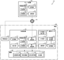
まず、実施の形態に係る制御システムの構成について説明する。図1は、実施の形態に係る制御システムの機能構成を示すブロック図である。
(Embodiment)
[Constitution]
First, the configuration of the control system according to the embodiment will be described. FIG. 1 is a block diagram showing a functional configuration of a control system according to an embodiment.
図1に示されるように、制御システム10は、環境センサ20と、制御装置30と、複数の機器40と、サーバ装置50と、情報端末60とを備える。
As shown in FIG. 1, the
図1に示される施設80は、例えば、集合住宅または戸建住宅などの住宅である。施設80内には、環境センサ20、制御装置30、及び、複数の機器40が設置されている。サーバ装置50は、クラウド(言い換えれば、クラウドサーバ)である。
The
まず、環境センサ20について説明する。環境センサ20は、施設80内に設置され、施設80内の温度及び湿度を計測するセンサである。環境センサ20は、施設80内の温度及び湿度の少なくとも一方を計測できればよい。
First, the
環境センサ20は、具体的には、施設80内の壁に埋め込まれる埋め込み型のセンサである。図2は、環境センサ20の外観図である。環境センサ20は、コンセントまたは壁スイッチなどの配線器具と同様のデザインであり、配線器具と併設されても目立たないデザインとなっている。また、環境センサ20は、壁の内部に設けられた交流電源線から交流電力の供給を受けて動作するため、電池交換等が不要である。
Specifically, the
環境センサ20は、具体的には、計測部21と、計測処理部22と、記憶部23と、通信部24と、計測値表示部25と、筐体26(図2に破線で図示)とを備える。これらの構成要素のうち計測部21、計測処理部22、記憶部23、通信部24、及び、計測値表示部25は、例えば、筐体26に収容され。筐体26は、少なくとも一部が壁(より詳細には、壁に設けられた配線器具用に規格化された形状及び大きさのスイッチボックス)に埋め込まれる。
Specifically, the
計測部21は、施設80内の空間における温度及び湿度を計測する。計測部21は、例えば、温度計測素子、及び、湿度計測素子によって実現される。温度計測素子は、具体的には、サーミスタまたは熱電対などである。湿度計測素子は、具体的には、静電容量型の感湿素子または抵抗変化型の感湿素子などである。
The
計測処理部22は、計測部21によって計測された温度及び湿度の計測値を用いた情報処理を行う。計測処理部22は、例えば、計測値表示部25に計測値を表示させる。また、計測処理部22は、通信部24に計測値を制御装置30へ送信させる。計測処理部22は、例えば、マイクロコンピュータによって実現されるが、プロセッサによって実現されてもよい。
The
記憶部23は、計測処理部22によって実行されるコンピュータプログラムなどが記憶される記憶装置である。記憶部23は、例えば、半導体メモリなどによって実現される。
The
通信部24は、環境センサ20が、制御装置30と局所通信ネットワークを介して通信を行うための通信モジュール(通信回路)である。通信部24によって行われる通信は、例えば、無線通信であるが、有線通信であってもよい。通信に用いられる通信規格についても、特に限定されない。
The
計測値表示部25は、計測部21によって計測された計測値を表示するディスプレイである。計測値表示部25は、例えば、7セグメントディスプレイによって実現されるが、液晶パネルまたは有機EL(Electro Luminescence)パネルなどの表示パネルによって実現されてもよい。また、計測値表示部25は、施設80内の温度及び湿度の環境がユーザによって不利益のある環境になっていると判定された場合に、これを通知する通知部としても機能する。
The measured
次に、制御装置30について説明する。制御装置30は、例えば、エネルギーマネジメント機能を有するHEMS(Home Energy Management System)コントローラであり、施設80内に設置され、施設80内に設置された機器40の消費電力を管理する。制御装置30は、施設80内に、機器40とは別の装置として設置される(つまり、機器40に内蔵されていない)ローカルコントローラである。また、制御装置30は、機器40の状態の取得及び表示、並びに、施設80内(あるいは、施設80の敷地内)に設置された機器40の制御などを行う。制御装置30は、HEMSコントローラに限定されず、エネルギーマネジメント機能を有しない他のホームコントローラ、または、ゲートウェイ装置であってもよい。制御装置30は、具体的には、表示部31と、情報処理部32と、記憶部33と、第一通信部34と、第二通信部35とを備える。
Next, the
表示部31は、画像の表示機能、及び、ユーザの手動入力を受け付ける機能を有する表示デバイスである。表示部31は、タッチパネル、及び、液晶パネルまたは有機ELパネルなどの表示パネルによって実現される。タッチパネルは、例えば、静電容量方式のタッチパネルであるが、抵抗膜方式のタッチパネルであってもよい。
The
情報処理部32は、表示部31への画像の表示制御、及び、機器40の制御などを行う。情報処理部32は、例えば、マイクロコンピュータによって実現されるが、プロセッサによって実現されてもよい。情報処理部32は、具体的には、取得部36及び制御部37を有する。取得部36及び制御部37の具体的な機能については後述する。
The
記憶部33は、情報処理部32によって実行されるコンピュータプログラムなどが記憶される記憶装置である。記憶部33は、例えば、半導体メモリによって実現される。
The
第一通信部34は、制御装置30が、環境センサ20及び機器40と局所通信ネットワークを介して通信を行うための通信モジュール(通信回路)である。第一通信部34によって行われる通信は、例えば、無線通信であるが、有線通信であってもよい。通信に用いられる通信規格についても、特に限定されない。なお、第一通信部34と機器40との間の通信は、例えば、ECHONET Lite(登録商標)に準拠する。
The
第二通信部35は、制御装置30がサーバ装置50及び情報端末60とインターネットなどの広域通信ネットワーク70を介して通信を行うための通信モジュール(通信回路)である。第二通信部35によって行われる通信は、例えば、無線通信であるが、有線通信であってもよい。通信に用いられる通信規格についても特に限定されない。
The
次に、機器40について説明する。機器40は、制御装置30の制御対象の機器である。機器40は、例えば、制御装置30と通信を行うための通信モジュール(通信回路)を備え、制御装置30から受信した制御信号にしたがって動作する。機器40には、例えば、空気調和機41、換気装置42、空気清浄機43、及び、加湿器44などが含まれる。
Next, the
空気調和機41は、施設80内の空間の空気を取り込み、温度及び湿度の少なくとも一方を調整して当該空間に放出する機器である。温度の調整には、熱交換器などが用いられる。空気調和機41は、例えば、一般家庭用の空気調和機であるが、産業用の空気調和機であってもよい。
The
換気装置42は、施設80内の空間の換気を行う機器である。換気装置42は、例えば、全熱交換器(ERV:Energy Recovery Ventilator)であるが、換気扇などの熱交換をともなわない換気装置であってもよい。また、換気装置42は、施設80に設けられた窓の開閉装置であってもよい。換気装置42は、施設80内から施設80外への排気を行う換気装置であってもよいし、施設80外から施設80内へ給気を行う換気装置であってもよい。
The
空気清浄機43は、施設80内の空間の空気を回収し、回収した空気を、HEPA(High Efficiency Particulate Air)フィルタなどのエアフィルタによって濾過して当該空間に放出する機器である。空気清浄機43は、施設80内の空間の空気を回収し、回収した空気を次亜塩素酸によって除菌して当該空間に放出する機器であってもよい。
The
加湿器44は、施設80内の空間を加湿する。加湿器44は、超音波式、加熱式、気化式、加熱と気化のハイブリッド式などの同様な方式であってもよい。
The
次に、サーバ装置50について説明する。サーバ装置50は、制御装置30と連携し、環境センサ20を用いた通知に関連する情報処理を行う。なお、後述の動作例1のように、環境センサ20を用いた通知は、サーバ装置50を使用せずに実現することも可能である。つまり、制御システム10がサーバ装置50を備えることは必須ではない。サーバ装置50は、具体的には、情報処理部51と、記憶部52と、通信部53とを備える。
Next, the
情報処理部51は、環境センサ20を用いた通知に関連する情報処理を行う。情報処理部51は、例えば、マイクロコンピュータによって実現されるが、プロセッサによって実現されてもよい。情報処理部51は、具体的には、取得部54及び制御部55を有する。取得部54及び制御部55の具体的な機能については後述する。
The
記憶部52は、情報処理部51によって実行されるコンピュータプログラムなどが記憶される記憶装置である。記憶部52は、例えば、半導体メモリによって実現される。
The
通信部53は、サーバ装置50が制御装置30及び情報端末60とインターネットなどの広域通信ネットワーク70を介して通信を行うための通信モジュール(通信回路)である。通信部53によって行われる通信は、例えば、有線通信であるが、無線通信であってもよい。通信に用いられる通信規格についても特に限定されない。
The
次に、情報端末60について説明する。情報端末60は、施設80内に位置するユーザが、環境センサ20によって計測された温度及び湿度の計測値に関する通知を受けるために用いられる。サーバ装置50は、具体的には、クラウドサーバである。情報端末60は、具体的には、スマートフォンまたはタブレット端末などの携帯端末、または、パーソナルコンピュータなどの据え置き型の端末である。
Next, the
[通知の設定]
制御システム10のユーザは、施設80内の温度及び湿度に関する通知を環境センサ20から受けることができる。具体的には、環境センサ20の計測値表示部25の表示態様が通常と異なる表示態様となることで、施設80内の温度及び湿度の環境がユーザによって不利益のある環境になっていることが通知される。
[Notification settings]
The user of the
このような通知を受けるために、ユーザは、制御装置30の表示部31を操作することにより、通知に関する設定を行う。図3は、制御装置30の表示部31に表示される、通知の設定画面の一例を示す図である。
In order to receive such a notification, the user operates the
図3に示されるように、ユーザは、通知設定、通知要件の設定、通知先の設定、連動機器制御の設定、及び、連動機器の設定が可能である。このうちの通知設定においては、通知を行うか否かが設定される。 As shown in FIG. 3, the user can set the notification setting, the notification requirement setting, the notification destination setting, the interlocking device control setting, and the interlocking device setting. Among these, in the notification setting, whether or not to perform notification is set.
通知要件の設定においては、複数の通知要件のうちどの通知要件を有効にするかが設定される。複数の通知要件には、カビ発生リスクに関する要件、部屋干し適性に関する要件、熱中症リスクに関する要件、肌乾燥リスクに関する要件、ドライアイリスクに関する要件、アトピーリスクに関する要件、及び、ウイルス生存率に関する要件が含まれる。例えば、カビ発生リスクに関する要件が選択された場合、施設80内が、カビ発生リスクが高い温度及び湿度の環境にあると推定される場合に通知が行われる。なお、通知要件は、2つ以上を設定することも可能である。
In the setting of notification requirements, which notification requirement is enabled among a plurality of notification requirements is set. Multiple notification requirements include mold risk requirements, room drying suitability requirements, heat stroke risk requirements, dry skin risk requirements, dry eye risk requirements, atopy risk requirements, and virus survival requirements. included. For example, if a requirement for mold growth risk is selected, notification will be given if the
通知先の設定においては、ユーザが環境センサ20以外に通知を受けるために使用したい機器(制御装置30または情報端末60)が設定される。
In the setting of the notification destination, a device (control
連動機器制御の設定においては、通知要件が満たされた場合に、通知に連動して機器40の制御を行うか否かが設定される。連動機器制御の設定には、具体的には、連動させない、通知要件が満たされた後ユーザの承認を得たうえで連動する、通知要件が満たされた後ユーザの承認を得ずに連動する、の3種類の設定が含まれる。
In the interlocking device control setting, when the notification requirement is satisfied, whether or not to control the
連動機器の設定においては、通知に連動して機器40の制御を行う場合、どの機器40を連動させるかが設定可能である。
In the setting of the interlocking device, when the
[通知要件]
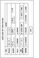
なお、通知要件の詳細については、通知要件情報として記憶部33にあらかじめ記憶される。図4は、通知要件情報の一例を示す図である。
[Notification requirements]
The details of the notification requirement are stored in advance in the
図4に示されるように、通知要件情報においては、上述した7種類の通知要件のそれぞれについて、詳細な温度及び湿度の条件と、通知要件が満たされた場合に送信されるコマンドとが規定されている。コマンドは、制御装置30が環境センサ20に施設80内に位置するユーザへの通知(具体的には、計測値表示部25の表示態様の変更)を行わせるために、制御装置30から環境センサ20へ送信される情報である。
As shown in FIG. 4, the notification requirement information defines detailed temperature and humidity conditions and a command to be transmitted when the notification requirements are met for each of the above-mentioned seven types of notification requirements. ing. In the command, the
なお、図4に概略が示されているように、カビ発生リスクに関する要件、部屋干し適性に関する要件、及び、ウイルス生存率に関する要件の3つの通知要件には、温度条件及び湿度条件の両方が定められる。熱中症リスクに関する要件は、温度条件のみが定められ、肌乾燥リスクに関する要件、ドライアイリスクに関する要件、アトピーリスクに関する要件の3つの要件には、湿度条件のみが定められる。 As outlined in FIG. 4, both temperature and humidity conditions are stipulated in the three notification requirements: the requirement for mold growth risk, the requirement for room drying suitability, and the requirement for virus survival rate. Be done. The requirements for heat stroke risk are defined only for temperature conditions, and the three requirements for skin dryness risk, dry eye risk, and atopy risk are defined only for humidity conditions.
また、図4に示されるように、通知要件には、温度条件、及び、湿度条件に加えて、時間条件が定められてもよい。具体的には、温度○○℃~××℃、かつ、湿度△△%以上が◇時間以上継続というように定められてもよい。 Further, as shown in FIG. 4, the notification requirement may be defined as a time condition in addition to the temperature condition and the humidity condition. Specifically, it may be defined that the temperature is XX ° C to XX ° C and the humidity is Δ△% or more and continues for ◇ hours or more.
また、通知要件は、経験的または実験的に定められればよく、必ずしも上記のように定められる必要はない。また、上記7種類の通知要件は一例であり、上記7種類の通知要件以外の通知要件が定められてもよい。 In addition, the notification requirement may be set empirically or experimentally, and does not necessarily have to be set as described above. Further, the above 7 types of notification requirements are an example, and notification requirements other than the above 7 types of notification requirements may be defined.
また、図4の例では、通知要件ごとにコマンドが定められている。つまり、通知要件にコマンドが紐づけられている。制御装置30は、通知要件情報を参照することにより、環境センサ20に送信するコマンドを決定することができる。例えば、カビ発生リスクに関する要件が満たされた場合には、制御装置30から環境センサ20にコマンド1が送信される。
Further, in the example of FIG. 4, a command is defined for each notification requirement. In other words, the command is associated with the notification requirement. The
[動作例1]
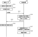
次に、このような通知の設定後の制御システム10の動作例1について説明する。図5は、制御システム10の動作例1のシーケンス図である。
[Operation example 1]
Next, operation example 1 of the
環境センサ20の計測部21は、施設80内の空間における温度及び湿度を計測し(S11)、計測値表示部25は、計測された温度の計測値及び湿度の計測値を表示する(S12)。
The
また、計測処理部22は、通信部24に温度の計測値及び湿度の計測値を制御装置30へ送信させる。制御装置30の取得部36は、第一通信部34を介して、温度の計測値及び湿度の計測値を取得する(S13)。
Further, the
制御部37は、取得された温度の計測値及び湿度の計測値が所定の要件を満たすか否かを判定する(S14)。例えば、図3の設定画面を通じて、カビ発生リスクに関する要件が有効になっている場合、制御部37は、温度の計測値及び湿度の計測値が、図4の通知要件情報においてカビ発生リスクに対応する具体的な要件を満たすか否かを判定する。上述のように、具体的な要件には、時間条件が含まれる場合がある。
The
ステップS14において温度の計測値及び湿度の計測値が所定の要件を満たさないと判定された場合には、ステップS15以降の処理は行われない。一方、制御部37は、温度の計測値及び湿度の計測値が所定の要件を満たすと判定すると、第一通信部34を用いて、コマンドを環境センサ20へ送信する。制御部37は、具体的には、図4の通知要件情報においてカビ発生リスクに対応付けられたコマンドであるコマンド1を環境センサ20へ送信する。環境センサ20の通信部24は、制御装置30(この場合の制御装置30は、外部システムの一例である)から送信されるコマンドを受信する(S15)。
If it is determined in step S14 that the measured value of temperature and the measured value of humidity do not satisfy the predetermined requirements, the processing after step S15 is not performed. On the other hand, when the
計測処理部22は、受信されたコマンドに基づいて、計測値表示部25に表示中の計測値の表示態様をコマンドで指定される表示態様に変化させる(S16)。つまり、計測処理部22は、施設80内の環境にリスクがあることを計測値の表示態様を変化させることでユーザに通知する。
Based on the received command, the
計測処理部22は、例えば、表示中の計測値はそのままで計測値を点滅させるが、表示中の計測値はそのままで表示中の計測値の色を変更してもよい。具体的には、通常時には計測値が緑色で表示され、要件を満たすときには赤色で表示される、などの態様が考えられる。このように表示態様の変更は、言い換えれば、計測値表示部25(7セグメントディスプレイ)の発光態様の変更(発光周期の変更、及び、発光色の変更など)である。
For example, the
なお、図4に示されるように通知要件情報において通知要件ごとに異なるコマンド(コマンド1~7)が設定されている場合、計測処理部22は、受信されたコマンドがコマンド1~7のいずれであるかに応じて互いに異なる7種類の表示態様で計測値を表示することができる。これにより、ユーザは、施設80内の環境にどのようなリスクがあるか(上記7種類のリスクのいずれに該当するか)を区別することができる。しかしながら、計測処理部22は、シンプルに、通常時(いずれの通知要件も満たされていない場合)と、それ以外(つまり、通知要件の少なくとも1つが満たされている場合)の2種類の表示態様を切り替えてもよい。
As shown in FIG. 4, when different commands (commands 1 to 7) are set for each notification requirement in the notification requirement information, the
また、図3の設定画面において、制御装置30または情報端末60への通知設定が有効になっている場合には、環境センサ20における計測値の表示態様の変更に加えて、制御装置30の制御部37によって制御装置30または情報端末60への通知処理が行われる(S17)。制御部37は、制御装置30への通知設定が有効になっている場合には、表示部31に通知画面を表示させ、情報端末60への通知設定が有効になっている場合には、通知情報を第二通信部35に情報端末60へ送信させる。
Further, when the notification setting to the
同様に、図3の設定画面において、連動機器制御の設定が有効になっている場合には、環境センサ20における計測値の表示態様の変更に加えて、制御部37による機器40の制御が行われる(S18)。制御部37は、具体的には、制御信号を第二通信部35に対象の機器40へ送信させる。
Similarly, when the interlocking device control setting is enabled on the setting screen of FIG. 3, in addition to changing the display mode of the measured value in the
例えば、情報端末60への通知設定が有効で、かつ、連動機器制御の設定がユーザの承認を得たうえで連動するように設定されている場合、通知情報を受信した情報端末60の表示部には、図6に示されるような、承認を得るためのメッセージを含む通知画面が表示される。図6は、通知画面の一例を示す図である。なお、制御装置30への通知設定が有効で、かつ、連動機器制御の設定がユーザの承認を得たうえで連動するように設定されている場合には、図6と同様の通知画面が制御装置30の表示部31に表示される。
For example, when the notification setting to the
ステップS18における機器40の制御について補足する。例えば、ステップS14において、カビ発生リスクに関する要件が満たされた場合、制御部37は、ステップS18において、空気調和機41をカビ発生リスクが低下するような設定でオンし、換気装置42をオンする。
The control of the
また、ステップS14において、部屋干し適性に関する要件が満たされた場合、制御部37は、ステップS18において、空気調和機41をカビ発生リスクが低下するような設定でオンし、換気装置42をオンし、空気清浄機43をオンする。ステップS14において、熱中症リスクに関する要件が満たされた場合、制御部37は、ステップS18において、空気調和機41を施設80内の温度を低下させるような設定でオンする。
Further, in step S14, when the requirement regarding room drying suitability is satisfied, the
ステップS14において、ウイルス生存率に関する要件、肌乾燥リスクに関する要件、ドライアイリスクに関する要件、及び、アトピーリスクに関する要件が満たされた場合、制御部37は、ステップS18において加湿器44をオンする。
When the requirement regarding the virus survival rate, the requirement regarding the risk of dry skin, the requirement regarding the risk of dry eye, and the requirement regarding the risk of atopy are satisfied in step S14, the
このように、ステップS18においては、どのような通知要件が満たされたかによって、制御される機器40が異なる。なお、ステップS18においては、連動機器の設定で、連動が無効化されている機器40については制御されない。
As described above, in step S18, the
以上説明したように、制御システム10は、環境センサ20を利用して、施設80内の環境に関する通知を行うことができる。
As described above, the
[動作例2]
動作例1では、制御装置30によって計測値が所定の要件を満たすか否かの判定、通知処理、及び、機器の制御が行われたが、これらの処理の一部または全部は、サーバ装置50によって行われてもよい。図7は、このような制御システム10の動作例2のシーケンス図である。なお、以下の動作例2においては、細部の説明は動作例1と同様であるとして省略される。また、動作例2においては、通知要件情報は、サーバ装置50の記憶部52にあらかじめ記憶される。
[Operation example 2]
In the operation example 1, the
環境センサ20の計測部21は、施設80内の空間における温度及び湿度を計測し(S21)、計測値表示部25は、計測された温度の計測値及び湿度の計測値を表示する(S22)。
The
また、計測処理部22は、通信部24に温度の計測値及び湿度の計測値を制御装置30へ送信させる。サーバ装置50の取得部54は、通信部53を介して、制御装置30によって中継された、温度の計測値及び湿度の計測値を取得する(S23)。
Further, the
制御部55は、取得された温度の計測値及び湿度の計測値が所定の要件を満たすか否かを判定する(S24)。
The
ステップS24において温度の計測値及び湿度の計測値が所定の要件を満たさないと判定された場合には、ステップS25以降の処理は行われない。一方、制御部55は、温度の計測値及び湿度の計測値が所定の要件を満たすと判定すると、通信部53を用いて、コマンドを制御装置30へ送信する。環境センサ20の通信部24は、制御装置30(この場合の制御装置30は、外部システムの一例である)によって中継されたコマンドを受信する(S25)。
If it is determined in step S24 that the measured value of temperature and the measured value of humidity do not satisfy the predetermined requirements, the processing after step S25 is not performed. On the other hand, when the
計測処理部22は、受信されたコマンドに基づいて、計測値表示部25に表示中の計測値の表示態様を変化させる(S26)。つまり、計測処理部22は、施設80内の環境にリスクがあることを計測値の表示態様を変化させることでユーザに通知する。
The
また、図3の設定画面において、情報端末60への通知設定が有効になっている場合には、環境センサ20における計測値の表示態様の変更に加えて、サーバ装置50の制御部55によって情報端末60への通知処理が行われる(S27)。図3の設定画面において、制御装置30への通知設定が有効になっている場合には、制御装置30の制御部37は、ステップS25で第二通信部35がサーバ装置50からコマンドを受信したことをトリガに、表示部31に通知画面を表示させる(S28)。
Further, when the notification setting to the
同様に、図3の設定画面において、連動機器制御の設定が有効になっている場合には、環境センサ20における計測値の表示態様の変更に加えて、制御部37による機器40の制御が行われる(S29)。制御部37は、具体的には、制御部37は、ステップS25で第二通信部35がサーバ装置50からコマンドを受信したことをトリガに、制御信号を第二通信部35に対象の機器40へ送信させる。
Similarly, when the interlocking device control setting is enabled on the setting screen of FIG. 3, in addition to changing the display mode of the measured value in the
以上説明したように、制御システム10は、制御装置30に代えてサーバ装置50が主体的に判定を行うことで、施設80内の環境に関する通知を行うこともできる。なお、環境センサ20が制御装置30を介さずにサーバ装置50と通信できるような場合、ステップS21~ステップS27の処理は制御装置30なしでも実現可能である。つまり、制御システム10が制御装置を備えることは必須ではない。
As described above, the
[変形例]
上記実施の形態では、通知部として計測値表示部25が用いられ、計測値表示部25は、7セグメントディスプレイによって実現され、通知は、7セグメントディスプレイの表示態様の変更により実現された。しかしながら、計測値表示部25は、液晶パネルまたは有機ELパネルなどの表示パネルによって実現されてもよい。この場合、通知は、液晶パネルまたは有機ELパネルに表示される画像によって行われてもよい。
[Modification example]
In the above embodiment, the measured
また、環境センサ20がスピーカを備えるような場合、このスピーカが通知部として用いられてもよい。つまり、施設80内のユーザへの通知は、音によって行われてもよい。
Further, when the
[効果等]
以上説明したように、制御システム10は、施設80内に設置される環境センサ20によって計測された温度及び湿度の少なくとも一方の計測値を取得する取得部36(または取得部54)と、取得された計測値が所定の要件を満たす場合に、施設80内に位置するユーザへの通知を環境センサ20に行わせるためのコマンドを環境センサ20へ送信する制御部37(または制御部55)とを有する。
[Effects, etc.]
As described above, the
このような制御システム10は、環境センサ20を利用して、施設80内の環境に関する通知を行うことができる。
Such a
また、例えば、制御システム10は、さらに、環境センサ20を備え、環境センサ20は、施設80内の空間における温度及び湿度の少なくとも一方を計測する計測部21と、送信されたコマンドに基づいて通知を行う通知部とを有する。上記実施の形態における計測値表示部25は、通知部の一例である。
Further, for example, the
このような制御システム10は、環境センサ20を利用して、施設80内の環境に関する通知を行うことができる。
Such a
また、例えば、通知部は、計測部21によって計測された計測値を表示するディスプレイ(計測値表示部25)であり、コマンドに基づいて、計測値の表示態様を変化させることにより、通知を行う。
Further, for example, the notification unit is a display (measurement value display unit 25) that displays the measurement value measured by the
このような制御システム10は、環境センサ20が備える計測値の表示機能を利用して通知を行うことができる。
Such a
また、例えば、通知部(計測値表示部25)は、7セグメントディスプレイである。 Further, for example, the notification unit (measured value display unit 25) is a 7-segment display.
このような制御システム10は、環境センサ20が備える比較的安価なディスプレイを利用して通知を行うことができる。言い換えれば、安価な環境センサ20によってユーザへの通知を実現することができる。
Such a
また、例えば、コマンドは、所定の要件に紐づけられている。 Further, for example, a command is associated with a predetermined requirement.
このような制御システム10は、所定の要件に紐づいたコマンドを環境センサ20に送信することができる。
Such a
また、例えば、所定の要件は、複数の要件の中からユーザによって選択された要件であり、複数の要件には、カビ発生リスクに関する要件、部屋干し適性に関する要件、熱中症リスクに関する要件、肌乾燥リスクに関する要件、ドライアイリスクに関する要件、アトピーリスクに関する要件、及び、ウイルス生存率に関する要件のうち2つ以上が含まれる。 In addition, for example, a predetermined requirement is a requirement selected by a user from a plurality of requirements, and the plurality of requirements include a requirement regarding a risk of mold occurrence, a requirement regarding aptitude for drying in a room, a requirement regarding a risk of heat stroke, and a dry skin. It includes two or more of the risk requirements, dry eye risk requirements, atopy risk requirements, and virus viability requirements.
このような制御システム10は、ユーザに上記7つのリスク(または適性)のうち2つ以上の通知サービスを提供することができる。
Such a
また、環境センサ20は、施設80内に設置される環境センサである。環境センサ20は、施設80内の空間における温度及び湿度の少なくとも一方を計測する計測部21と、計測された温度及び湿度の少なくとも一方の計測値を外部システムへ送信し、送信した計測値が所定の要件を満たす場合に外部システムによって送信されるコマンドを受信する通信部24と、受信されたコマンドに基づいて施設80内に位置するユーザへの通知を行う通知部とを備える。上記実施の形態における制御装置30及びサーバ装置50の少なくとも一方は、外部システムの一例である。
Further, the
このような環境センサ20は、施設80内の環境に関する通知を行うことができる。
Such an
また、コンピュータによって実行される施設80内に設置される環境センサ20の制御方法は、環境センサ20によって計測された温度及び湿度の少なくとも一方の計測値を取得し、取得された計測値が所定の要件を満たす場合に、施設80内に位置するユーザへの通知を環境センサ20に行わせるためのコマンドを環境センサへ送信する。
Further, the control method of the
このような制御方法は、環境センサ20を利用して、施設80内の環境に関する通知を行うことができる。
In such a control method, the
また、施設80内に設置される環境センサ20によって実行される通知方法は、施設80内の空間における温度及び湿度の少なくとも一方を計測し、計測された温度及び湿度の少なくとも一方の計測値を外部システムへ送信し、送信した計測値が所定の要件を満たす場合に外部システムによって送信されるコマンドを受信し、受信されたコマンドに基づいて施設80内に位置するユーザへの通知を行う。
Further, the notification method executed by the
このような通知方法は、施設80内の環境に関する通知を行うことができる。
Such a notification method can notify the environment in the
(その他の実施の形態)
以上、実施の形態について説明したが、本発明は、上記実施の形態に限定されるものではない。
(Other embodiments)
Although the embodiments have been described above, the present invention is not limited to the above embodiments.
例えば、上記実施の形態では、施設は、集合住宅または戸建住宅などの住宅であると説明されたが、介護施設またはオフィスなどであってもよく、施設が具体的にどのような施設であるかは特に限定されない。 For example, in the above embodiment, the facility is described as a house such as an apartment house or a detached house, but it may be a nursing care facility or an office, and the facility is specifically any kind of facility. Is not particularly limited.
また、上記実施の形態では、温度及び湿度の少なくとも一方を計測する環境センサによって通知が行われたが、その他のセンサによって通知が行われてもよい。例えば、二酸化炭素濃度センサまたは微粒子濃度センサなどの空気質センサによって通知が行われてもよい。具体的には、二酸化炭素濃度センサによって、施設の中の二酸化炭素濃度に関する通知が行われてもよいし、微粒子濃度センサによって、PM(Particulate matter)2.5などの粒子状物質の濃度に関する通知が行われてもよい。このように環境センサには、温度センサ及び湿度センサ以外に空気質センサが含まれてもよく(つまり、温度、湿度、空気質などの環境パラメータを計測できればよく)、上記実施の形態の環境センサは、適宜、このような空気質センサに読み替えられてもよい。 Further, in the above embodiment, the notification is performed by the environment sensor that measures at least one of the temperature and the humidity, but the notification may be performed by another sensor. For example, the notification may be performed by an air quality sensor such as a carbon dioxide concentration sensor or a fine particle concentration sensor. Specifically, the carbon dioxide concentration sensor may be used to notify the concentration of carbon dioxide in the facility, and the fine particle concentration sensor may be used to notify the concentration of particulate matter such as PM (Particulate Matter) 2.5. May be done. As described above, the environment sensor may include an air quality sensor in addition to the temperature sensor and the humidity sensor (that is, it is sufficient if the environment parameters such as temperature, humidity, and air quality can be measured), and the environment sensor of the above embodiment is used. May be appropriately read as such an air quality sensor.
また、上記実施の形態では、制御システムは、複数の装置によって実現されたが、単一の装置として実現されてもよい。例えば、制御システムは、制御装置に相当する単一の装置として実現されてもよいし、サーバ装置に相当する単一の装置として実現されてもよい。制御システムが複数の装置によって実現される場合、制御システムが備える構成要素は、複数の装置にどのように振り分けられてもよい。 Further, in the above embodiment, the control system is realized by a plurality of devices, but may be realized as a single device. For example, the control system may be realized as a single device corresponding to a control device, or may be realized as a single device corresponding to a server device. When the control system is realized by a plurality of devices, the components of the control system may be distributed to the plurality of devices in any way.
例えば、上記実施の形態における装置間の通信方法については特に限定されるものではない。また、装置間の通信においては、図示されない中継装置(サーバ装置など含む)が介在してもよい。 For example, the communication method between the devices in the above embodiment is not particularly limited. Further, in the communication between the devices, a relay device (including a server device) (not shown) may intervene.
また、上記実施の形態において、特定の処理部が実行する処理を別の処理部が実行してもよい。また、複数の処理の順序が変更されてもよいし、複数の処理が並行して実行されてもよい。また、上記実施の形態において、各動作例は、任意に組み合わされてよい。 Further, in the above embodiment, another processing unit may execute the processing executed by the specific processing unit. Further, the order of the plurality of processes may be changed, or the plurality of processes may be executed in parallel. Further, in the above embodiment, the operation examples may be arbitrarily combined.
また、上記実施の形態において、各構成要素は、各構成要素に適したソフトウェアプログラムを実行することによって実現されてもよい。各構成要素は、CPUまたはプロセッサなどのプログラム実行部が、ハードディスクまたは半導体メモリなどの記録媒体に記録されたソフトウェアプログラムを読み出して実行することによって実現されてもよい。 Further, in the above embodiment, each component may be realized by executing a software program suitable for each component. Each component may be realized by a program execution unit such as a CPU or a processor reading and executing a software program recorded on a recording medium such as a hard disk or a semiconductor memory.
また、各構成要素は、ハードウェアによって実現されてもよい。例えば、各構成要素は、回路(または集積回路)でもよい。これらの回路は、全体として1つの回路を構成してもよいし、それぞれ別々の回路でもよい。また、これらの回路は、それぞれ、汎用的な回路でもよいし、専用の回路でもよい。 In addition, each component may be realized by hardware. For example, each component may be a circuit (or integrated circuit). These circuits may form one circuit as a whole, or may be separate circuits from each other. Further, each of these circuits may be a general-purpose circuit or a dedicated circuit.
また、本発明の全般的または具体的な態様は、システム、装置、方法、集積回路、コンピュータプログラムまたはコンピュータ読み取り可能なCD-ROMなどの記録媒体で実現されてもよい。また、システム、装置、方法、集積回路、コンピュータプログラム及び記録媒体の任意な組み合わせで実現されてもよい。 In addition, general or specific embodiments of the present invention may be realized in a recording medium such as a system, an apparatus, a method, an integrated circuit, a computer program, or a computer-readable CD-ROM. Further, it may be realized by any combination of a system, an apparatus, a method, an integrated circuit, a computer program and a recording medium.
例えば、本発明は、コンピュータが実行する環境センサの制御方法として実現されてもよいし、このような制御方法をコンピュータに実行させるためのプログラムとして実現されてもよいし、このようなプログラムが記録されたコンピュータ読み取り可能な非一時的な記録媒体として実現されてもよい。本発明は、コンピュータが実行する通知方法として実現されてもよいし、このような通知方法をコンピュータに実行させるためのプログラムとして実現されてもよいし、このようなプログラムが記録されたコンピュータ読み取り可能な非一時的な記録媒体として実現されてもよい。 For example, the present invention may be realized as a control method of an environment sensor executed by a computer, or may be realized as a program for causing a computer to execute such a control method, and such a program may be recorded. It may be realized as a non-temporary recording medium that can be read by a computer. The present invention may be realized as a notification method executed by a computer, may be realized as a program for causing a computer to execute such a notification method, or may be read by a computer in which such a program is recorded. It may be realized as a non-temporary recording medium.
その他、各実施の形態に対して当業者が思いつく各種変形を施して得られる形態、または、本発明の趣旨を逸脱しない範囲で各実施の形態における構成要素及び機能を任意に組み合わせることで実現される形態も本発明に含まれる。 In addition, it is realized by a form obtained by applying various modifications to each embodiment that a person skilled in the art can think of, or by arbitrarily combining the components and functions in each embodiment within the range not deviating from the gist of the present invention. Also included in the present invention.
10 制御システム
20 環境センサ
21 計測部
24 通信部
25 計測値表示部(ディスプレイ)
36、54 取得部
37、55 制御部
10
36, 54
Claims (15)
取得された前記計測値が所定の要件を満たす場合に、前記施設内に位置するユーザへの通知を前記環境センサに行わせるためのコマンドを前記環境センサへ送信する制御部とを有する
制御システム。 An acquisition unit that acquires at least one of the temperature and humidity measurements measured by the environment sensor installed in the facility, and the acquisition unit.
A control system including a control unit that transmits a command for causing the environment sensor to notify a user located in the facility when the acquired measured value satisfies a predetermined requirement.
前記環境センサは、
前記施設内の空間における温度及び湿度の少なくとも一方を計測する計測部と、
送信された前記コマンドに基づいて前記通知を行う通知部とを有する
請求項1に記載の制御システム。 In addition, it is equipped with the environment sensor.
The environment sensor is
A measuring unit that measures at least one of temperature and humidity in the space inside the facility,
The control system according to claim 1, further comprising a notification unit that gives the notification based on the transmitted command.
請求項2に記載の制御システム。 The notification unit is a display that displays the measured values measured by the measuring unit, and according to claim 2, the notification is performed by changing the display mode of the measured values based on the command. Control system.
請求項3に記載の制御システム。 The control system according to claim 3, wherein the notification unit is a 7-segment display.
請求項1または2に記載の制御システム。 The control system according to claim 1 or 2, wherein the command is associated with the predetermined requirement.
前記複数の要件には、カビ発生リスクに関する要件、部屋干し適性に関する要件、熱中症リスクに関する要件、肌乾燥リスクに関する要件、ドライアイリスクに関する要件、アトピーリスクに関する要件、及び、ウイルス生存率に関する要件のうち2つ以上が含まれる
請求項1~5のいずれか1項に記載の制御システム。 The predetermined requirement is a requirement selected by the user from a plurality of requirements.
The above-mentioned multiple requirements include requirements for mold development risk, room drying suitability, heat stroke risk, skin dryness risk, dry eye risk, atopy risk, and virus survival rate. The control system according to any one of claims 1 to 5, wherein two or more of them are included.
前記施設内の空間における温度及び湿度の少なくとも一方を計測する計測部と、
計測された温度及び湿度の少なくとも一方の計測値を外部システムへ送信し、送信した計測値が所定の要件を満たす場合に前記外部システムによって送信されるコマンドを受信する通信部と、
受信された前記コマンドに基づいて前記施設内に位置するユーザへの通知を行う通知部とを備える
環境センサ。 It is an environment sensor installed in the facility.
A measuring unit that measures at least one of temperature and humidity in the space inside the facility,
A communication unit that transmits at least one of the measured temperature and humidity measured values to an external system and receives a command transmitted by the external system when the transmitted measured values meet predetermined requirements.
An environment sensor including a notification unit that notifies a user located in the facility based on the received command.
請求項7に記載の環境センサ。 The notification unit is a display that displays the measured values measured by the measuring unit, and according to claim 7, the notification is performed by changing the display mode of the measured values based on the command. Environment sensor.
請求項8に記載の環境センサ。 The environment sensor according to claim 8, wherein the notification unit is a 7-segment display.
請求項8または9に記載の環境センサ。 The environmental sensor according to claim 8 or 9, wherein the command is associated with the predetermined requirement.
前記複数の要件には、カビ発生リスクに関する要件、部屋干し適性に関する要件、熱中症リスクに関する要件、肌乾燥リスクに関する要件、ドライアイリスクに関する要件、アトピーリスクに関する要件、及び、ウイルス生存率に関する要件のうち2つ以上が含まれる
請求項7~10のいずれか1項に記載の環境センサ。 The predetermined requirement is a requirement selected by the user from a plurality of requirements.
The above-mentioned multiple requirements include requirements for mold development risk, room drying suitability, heat stroke risk, skin dryness risk, dry eye risk, atopy risk, and virus survival rate. The environmental sensor according to any one of claims 7 to 10, which includes two or more of them.
前記環境センサによって計測された温度及び湿度の少なくとも一方の計測値を取得し、
取得された前記計測値が所定の要件を満たす場合に、前記施設内に位置するユーザへの通知を前記環境センサに行わせるためのコマンドを前記環境センサへ送信する
制御方法。 It is a control method of the environment sensor installed in the facility.
Obtain at least one of the measured values of temperature and humidity measured by the environment sensor,
A control method for transmitting a command to the environment sensor to notify a user located in the facility when the acquired measured value satisfies a predetermined requirement.
前記施設内の空間における温度及び湿度の少なくとも一方を計測し、
計測された温度及び湿度の少なくとも一方の計測値を外部システムへ送信し、
送信した計測値が所定の要件を満たす場合に前記外部システムによって送信されるコマンドを受信し、
受信された前記コマンドに基づいて前記施設内に位置するユーザへの通知を行う
通知方法。 A notification method performed by an environment sensor installed in the facility.
At least one of the temperature and humidity in the space inside the facility is measured and
Send at least one of the measured temperature and humidity measurements to an external system
When the transmitted measurement value meets the predetermined requirements, the command transmitted by the external system is received, and the transmission is received.
A notification method for notifying a user located in the facility based on the received command.
Priority Applications (2)
| Application Number | Priority Date | Filing Date | Title |
|---|---|---|---|
| JP2020111227A JP2022010574A (en) | 2020-06-29 | 2020-06-29 | Control system, environment sensor, control method, and notification method |
| PCT/JP2021/021936 WO2022004316A1 (en) | 2020-06-29 | 2021-06-09 | Control system, environmental sensor, control method, and notification method |
Applications Claiming Priority (1)
| Application Number | Priority Date | Filing Date | Title |
|---|---|---|---|
| JP2020111227A JP2022010574A (en) | 2020-06-29 | 2020-06-29 | Control system, environment sensor, control method, and notification method |
Publications (1)
| Publication Number | Publication Date |
|---|---|
| JP2022010574A true JP2022010574A (en) | 2022-01-17 |
Family
ID=79315227
Family Applications (1)
| Application Number | Title | Priority Date | Filing Date |
|---|---|---|---|
| JP2020111227A Pending JP2022010574A (en) | 2020-06-29 | 2020-06-29 | Control system, environment sensor, control method, and notification method |
Country Status (2)
| Country | Link |
|---|---|
| JP (1) | JP2022010574A (en) |
| WO (1) | WO2022004316A1 (en) |
Citations (2)
| Publication number | Priority date | Publication date | Assignee | Title |
|---|---|---|---|---|
| JP2019163875A (en) * | 2018-03-19 | 2019-09-26 | 東京瓦斯株式会社 | Alarm system and program |
| JP2020091720A (en) * | 2018-12-06 | 2020-06-11 | 東京瓦斯株式会社 | Health hazard warning method, health hazard warning system and program |
-
2020
- 2020-06-29 JP JP2020111227A patent/JP2022010574A/en active Pending
-
2021
- 2021-06-09 WO PCT/JP2021/021936 patent/WO2022004316A1/en not_active Ceased
Patent Citations (2)
| Publication number | Priority date | Publication date | Assignee | Title |
|---|---|---|---|---|
| JP2019163875A (en) * | 2018-03-19 | 2019-09-26 | 東京瓦斯株式会社 | Alarm system and program |
| JP2020091720A (en) * | 2018-12-06 | 2020-06-11 | 東京瓦斯株式会社 | Health hazard warning method, health hazard warning system and program |
Also Published As
| Publication number | Publication date |
|---|---|
| WO2022004316A1 (en) | 2022-01-06 |
Similar Documents
| Publication | Publication Date | Title |
|---|---|---|
| CN101300533B (en) | Microsystem application for real-time IEQ control | |
| JP2023160827A (en) | Thermostat with particulate sensor | |
| EP1470456B1 (en) | Building control system and fume hood system for use therein having reduced wiring requirements | |
| CA2842418C (en) | Security system with integrated heating, ventilation and air condition control | |
| JP6021951B2 (en) | Air conditioning system | |
| EP3346674B1 (en) | Air conditioning system | |
| US20040144849A1 (en) | Building control system using integrated MEMS devices | |
| US20140041846A1 (en) | Hvac system with multiple equipment interface modules | |
| JP5667257B1 (en) | Home device, home system, control method, and program | |
| US20230243542A1 (en) | Thermostat with demand controlled indoor air quality | |
| CN102472516A (en) | Interfacing climate controllers and cooling devices | |
| US20200182502A1 (en) | Network system | |
| KR20210123080A (en) | Controlling method for Air conditioner system | |
| US20260002682A1 (en) | Thermostat with epidemic control ventilation | |
| US20180231271A1 (en) | Smart vent apparatus and system | |
| US10178261B2 (en) | System and image forming apparatus that stops or controls the transmission of control information between at least one controlled device and an external device | |
| TW201802715A (en) | Control system and control method | |
| JP2022010574A (en) | Control system, environment sensor, control method, and notification method | |
| KR20150029196A (en) | Air-conditioning system and method | |
| US12546498B2 (en) | Thermostat with external interrupt | |
| JP6751885B2 (en) | Air conditioning control system and air conditioning control method | |
| JP6556228B2 (en) | Home device, communication adapter, home system, control method, and program | |
| JP2015017718A (en) | Air conditioning system, control device of air conditioning system, and control method of air conditioning system | |
| JP7434813B2 (en) | air conditioner | |
| JP2017207254A (en) | Air conditioning system |
Legal Events
| Date | Code | Title | Description |
|---|---|---|---|
| A621 | Written request for application examination |
Free format text: JAPANESE INTERMEDIATE CODE: A621 Effective date: 20230210 |
|
| A131 | Notification of reasons for refusal |
Free format text: JAPANESE INTERMEDIATE CODE: A131 Effective date: 20240423 |
|
| A02 | Decision of refusal |
Free format text: JAPANESE INTERMEDIATE CODE: A02 Effective date: 20241001 |