JP2021536717A - Image coding / decoding methods and devices using intra-prediction - Google Patents
Image coding / decoding methods and devices using intra-prediction Download PDFInfo
- Publication number
- JP2021536717A JP2021536717A JP2021537422A JP2021537422A JP2021536717A JP 2021536717 A JP2021536717 A JP 2021536717A JP 2021537422 A JP2021537422 A JP 2021537422A JP 2021537422 A JP2021537422 A JP 2021537422A JP 2021536717 A JP2021536717 A JP 2021536717A
- Authority
- JP
- Japan
- Prior art keywords
- block
- prediction
- mode
- intra
- current block
- Prior art date
- Legal status (The legal status is an assumption and is not a legal conclusion. Google has not performed a legal analysis and makes no representation as to the accuracy of the status listed.)
- Pending
Links
Images


Classifications
-
- H—ELECTRICITY
- H04—ELECTRIC COMMUNICATION TECHNIQUE
- H04N—PICTORIAL COMMUNICATION, e.g. TELEVISION
- H04N19/00—Methods or arrangements for coding, decoding, compressing or decompressing digital video signals
- H04N19/10—Methods or arrangements for coding, decoding, compressing or decompressing digital video signals using adaptive coding
- H04N19/134—Methods or arrangements for coding, decoding, compressing or decompressing digital video signals using adaptive coding characterised by the element, parameter or criterion affecting or controlling the adaptive coding
- H04N19/157—Assigned coding mode, i.e. the coding mode being predefined or preselected to be further used for selection of another element or parameter
- H04N19/159—Prediction type, e.g. intra-frame, inter-frame or bidirectional frame prediction
-
- H—ELECTRICITY
- H04—ELECTRIC COMMUNICATION TECHNIQUE
- H04N—PICTORIAL COMMUNICATION, e.g. TELEVISION
- H04N19/00—Methods or arrangements for coding, decoding, compressing or decompressing digital video signals
- H04N19/10—Methods or arrangements for coding, decoding, compressing or decompressing digital video signals using adaptive coding
- H04N19/102—Methods or arrangements for coding, decoding, compressing or decompressing digital video signals using adaptive coding characterised by the element, parameter or selection affected or controlled by the adaptive coding
- H04N19/103—Selection of coding mode or of prediction mode
- H04N19/105—Selection of the reference unit for prediction within a chosen coding or prediction mode, e.g. adaptive choice of position and number of pixels used for prediction
-
- H—ELECTRICITY
- H04—ELECTRIC COMMUNICATION TECHNIQUE
- H04N—PICTORIAL COMMUNICATION, e.g. TELEVISION
- H04N19/00—Methods or arrangements for coding, decoding, compressing or decompressing digital video signals
- H04N19/10—Methods or arrangements for coding, decoding, compressing or decompressing digital video signals using adaptive coding
- H04N19/102—Methods or arrangements for coding, decoding, compressing or decompressing digital video signals using adaptive coding characterised by the element, parameter or selection affected or controlled by the adaptive coding
- H04N19/103—Selection of coding mode or of prediction mode
- H04N19/11—Selection of coding mode or of prediction mode among a plurality of spatial predictive coding modes
-
- H—ELECTRICITY
- H04—ELECTRIC COMMUNICATION TECHNIQUE
- H04N—PICTORIAL COMMUNICATION, e.g. TELEVISION
- H04N19/00—Methods or arrangements for coding, decoding, compressing or decompressing digital video signals
- H04N19/10—Methods or arrangements for coding, decoding, compressing or decompressing digital video signals using adaptive coding
- H04N19/102—Methods or arrangements for coding, decoding, compressing or decompressing digital video signals using adaptive coding characterised by the element, parameter or selection affected or controlled by the adaptive coding
- H04N19/119—Adaptive subdivision aspects, e.g. subdivision of a picture into rectangular or non-rectangular coding blocks
-
- H—ELECTRICITY
- H04—ELECTRIC COMMUNICATION TECHNIQUE
- H04N—PICTORIAL COMMUNICATION, e.g. TELEVISION
- H04N19/00—Methods or arrangements for coding, decoding, compressing or decompressing digital video signals
- H04N19/10—Methods or arrangements for coding, decoding, compressing or decompressing digital video signals using adaptive coding
- H04N19/102—Methods or arrangements for coding, decoding, compressing or decompressing digital video signals using adaptive coding characterised by the element, parameter or selection affected or controlled by the adaptive coding
- H04N19/12—Selection from among a plurality of transforms or standards, e.g. selection between discrete cosine transform [DCT] and sub-band transform or selection between H.263 and H.264
- H04N19/122—Selection of transform size, e.g. 8x8 or 2x4x8 DCT; Selection of sub-band transforms of varying structure or type
-
- H—ELECTRICITY
- H04—ELECTRIC COMMUNICATION TECHNIQUE
- H04N—PICTORIAL COMMUNICATION, e.g. TELEVISION
- H04N19/00—Methods or arrangements for coding, decoding, compressing or decompressing digital video signals
- H04N19/10—Methods or arrangements for coding, decoding, compressing or decompressing digital video signals using adaptive coding
- H04N19/169—Methods or arrangements for coding, decoding, compressing or decompressing digital video signals using adaptive coding characterised by the coding unit, i.e. the structural portion or semantic portion of the video signal being the object or the subject of the adaptive coding
- H04N19/17—Methods or arrangements for coding, decoding, compressing or decompressing digital video signals using adaptive coding characterised by the coding unit, i.e. the structural portion or semantic portion of the video signal being the object or the subject of the adaptive coding the unit being an image region, e.g. an object
- H04N19/176—Methods or arrangements for coding, decoding, compressing or decompressing digital video signals using adaptive coding characterised by the coding unit, i.e. the structural portion or semantic portion of the video signal being the object or the subject of the adaptive coding the unit being an image region, e.g. an object the region being a block, e.g. a macroblock
-
- H—ELECTRICITY
- H04—ELECTRIC COMMUNICATION TECHNIQUE
- H04N—PICTORIAL COMMUNICATION, e.g. TELEVISION
- H04N19/00—Methods or arrangements for coding, decoding, compressing or decompressing digital video signals
- H04N19/10—Methods or arrangements for coding, decoding, compressing or decompressing digital video signals using adaptive coding
- H04N19/169—Methods or arrangements for coding, decoding, compressing or decompressing digital video signals using adaptive coding characterised by the coding unit, i.e. the structural portion or semantic portion of the video signal being the object or the subject of the adaptive coding
- H04N19/182—Methods or arrangements for coding, decoding, compressing or decompressing digital video signals using adaptive coding characterised by the coding unit, i.e. the structural portion or semantic portion of the video signal being the object or the subject of the adaptive coding the unit being a pixel
-
- H—ELECTRICITY
- H04—ELECTRIC COMMUNICATION TECHNIQUE
- H04N—PICTORIAL COMMUNICATION, e.g. TELEVISION
- H04N19/00—Methods or arrangements for coding, decoding, compressing or decompressing digital video signals
- H04N19/10—Methods or arrangements for coding, decoding, compressing or decompressing digital video signals using adaptive coding
- H04N19/169—Methods or arrangements for coding, decoding, compressing or decompressing digital video signals using adaptive coding characterised by the coding unit, i.e. the structural portion or semantic portion of the video signal being the object or the subject of the adaptive coding
- H04N19/186—Methods or arrangements for coding, decoding, compressing or decompressing digital video signals using adaptive coding characterised by the coding unit, i.e. the structural portion or semantic portion of the video signal being the object or the subject of the adaptive coding the unit being a colour or a chrominance component
-
- H—ELECTRICITY
- H04—ELECTRIC COMMUNICATION TECHNIQUE
- H04N—PICTORIAL COMMUNICATION, e.g. TELEVISION
- H04N19/00—Methods or arrangements for coding, decoding, compressing or decompressing digital video signals
- H04N19/46—Embedding additional information in the video signal during the compression process
-
- H—ELECTRICITY
- H04—ELECTRIC COMMUNICATION TECHNIQUE
- H04N—PICTORIAL COMMUNICATION, e.g. TELEVISION
- H04N19/00—Methods or arrangements for coding, decoding, compressing or decompressing digital video signals
- H04N19/50—Methods or arrangements for coding, decoding, compressing or decompressing digital video signals using predictive coding
- H04N19/593—Methods or arrangements for coding, decoding, compressing or decompressing digital video signals using predictive coding involving spatial prediction techniques
Abstract
本発明に係る画像符号化/復号化方法及び装置は、現在ブロックのイントラ予測のための参照領域を決定し、所定のMPM候補群に基づいて現在ブロックのイントラ予測モードを誘導し、参照領域とイントラ予測モードに基づいて現在ブロックに対してイントラ予測を行うことができる。The image coding / decoding method and apparatus according to the present invention determine a reference region for intra-prediction of the current block, induce an intra-prediction mode of the current block based on a predetermined MPM candidate group, and use the reference region as a reference region. Intra prediction can be performed for the current block based on the intra prediction mode.
Description
本発明は、画像符号化/復号化方法及び装置に関する。 The present invention relates to an image coding / decoding method and an apparatus.
最近、高解像度・高品質の画像、例えばHD(High Definition)画像やUHD(Ultra High Definition)画像などに対する需要が様々な応用分野で増加しており、これにより高効率の画像圧縮技術が議論されている。 Recently, the demand for high-resolution and high-quality images such as HD (High Definition) images and UHD (Ultra High Definition) images has been increasing in various application fields, and high-efficiency image compression technology has been discussed. ing.
画像圧縮技術として、現在ピクチャの以前又は以後ピクチャから現在ピクチャに含まれている画素値を予測するインター予測技術、現在ピクチャ内の画素情報を用いて、現在ピクチャに含まれている画素値を予測するイントラ予測技術、出現頻度の高い値に短い符号を割り当て、出現頻度の低い値に長い符号を割り当てるエントロピー符号化技術などの様々な技術が存在し、これらの画像圧縮技術を利用して画像データを効果的に圧縮して伝送又は格納することができる。 As image compression technology, an inter-prediction technology that predicts the pixel value contained in the current picture from the previous or subsequent picture of the current picture, and the pixel information in the current picture are used to predict the pixel value currently contained in the picture. There are various technologies such as intra-prediction technology, entropy coding technology that assigns a short code to a value with a high frequency of appearance, and a long code to a value with a low frequency of appearance, and image data using these image compression technologies. Can be effectively compressed and transmitted or stored.
本発明は、イントラ予測モード誘導方法及び装置を提供することを目的とする。 It is an object of the present invention to provide an intra prediction mode guidance method and an apparatus.
本発明は、成分のタイプによるイントラ予測方法及び装置を提供することを目的とする It is an object of the present invention to provide an intra prediction method and an apparatus according to the type of component.
本発明は、イントラ予測のためのブロック分割方法及び装置を提供することを目的とする。 It is an object of the present invention to provide a block division method and an apparatus for intra-prediction.
本発明の画像符号化/復号化方法及び装置は、現在ブロックのイントラ予測のための参照領域を決定し、所定のMPM候補群に基づいて、前記現在ブロックのイントラ予測モードを誘導し、前記参照領域と前記イントラ予測モードに基づいて、前記現在ブロックに対してイントラ予測を行うことができる。 The image coding / decoding method and apparatus of the present invention determines a reference area for intra-prediction of the current block, guides the intra-prediction mode of the current block based on a predetermined MPM candidate group, and refers to the above. Intra-prediction can be made for the current block based on the region and the intra-prediction mode.
本発明の画像符号化/復号化方法及び装置において、前記MPM候補群は、第1グループと第2グループに区分され、前記第1グループは、復号化装置に既に定義されたデフォルトモードを含み、前記第2グループは、前記現在ブロックに隣接する隣接ブロックのイントラ予測モードを含むことができる。 In the image coding / decoding method and apparatus of the present invention, the MPM candidate group is divided into a first group and a second group, and the first group includes a default mode already defined in the decoding apparatus. The second group can include an intra-prediction mode for adjacent blocks adjacent to the current block.
本発明の画像符号化/復号化方法及び装置において、前記現在ブロックのイントラ予測モードは、前記第1グループ又は前記第2グループのうちのいずれかを選択的に用いて誘導できる。 In the image coding / decoding method and apparatus of the present invention, the intra prediction mode of the current block can be induced by selectively using either the first group or the second group.
本発明の画像符号化/復号化方法及び装置において、前記参照領域を決定するステップは、復号化装置に既に定義された複数の画素ラインのうちのいずれかを選択するステップと、前記選択された画素ラインを前記参照領域として決定するステップとを含むことができる。 In the image coding / decoding method and apparatus of the present invention, the step of determining the reference region includes a step of selecting one of a plurality of pixel lines already defined in the decoding apparatus and the selected step. It can include a step of determining a pixel line as the reference area.
本発明の画像符号化/復号化方法及び装置において、前記既に定義された複数の画素ラインは、前記現在ブロックに隣接する第1画素ライン、前記第1画素ラインに隣接する第2画素ライン、前記第2画素ラインに隣接する第3画素ライン、又は前記第3画素ラインに隣接する第4画素ラインのうちの少なくとも一つを含むことができる。 In the image coding / decoding method and apparatus of the present invention, the plurality of already defined pixel lines are the first pixel line adjacent to the current block, the second pixel line adjacent to the first pixel line, and the above. It can include at least one of a third pixel line adjacent to the second pixel line or a fourth pixel line adjacent to the third pixel line.
本発明の画像符号化/復号化方法及び装置において、前記デフォルトモードは、非方向性モードのみで構成され、前記非方向性モードは、Planarモード又はDCモードのうちの少なくとも一つを含むことができる。 In the image coding / decoding method and apparatus of the present invention, the default mode may be composed of only a non-directional mode, and the non-directional mode may include at least one of a Planar mode and a DC mode. can.
本発明の画像符号化/復号化方法及び装置において、前記第2グループは、前記隣接ブロックのイントラ予測モードにN値を加算又は減算して誘導されたモードをさらに含み、前記N値は、1、2又は3であることができる。 In the image coding / decoding method and apparatus of the present invention, the second group further includes a mode derived by adding or subtracting an N value to the intra prediction mode of the adjacent block, and the N value is 1. Can be 2 or 3.
本発明の画像符号化/復号化方法及び装置は、ビットストリームから第1フラグを取得することができ、前記第1フラグは、前記現在ブロックのイントラ予測モードが前記第1グループから誘導されるか否かを示すことができる。 The image coding / decoding method and apparatus of the present invention can acquire the first flag from the bitstream, and the first flag is whether the intra prediction mode of the current block is derived from the first group. It can indicate whether or not.
本発明の画像符号化/復号化方法及び装置において、前記第1フラグの値が第1値である場合、前記現在ブロックのイントラ予測モードは、前記第1グループに属するMPMに設定され、前記第1フラグの値が第2値である場合、前記現在ブロックのイントラ予測モードは、前記第2グループ及びMPMインデックスに基づいて誘導され得る。 In the image coding / decoding method and apparatus of the present invention, when the value of the first flag is the first value, the intra prediction mode of the current block is set to the MPM belonging to the first group, and the first is said. When the value of one flag is the second value, the intra prediction mode of the current block can be derived based on the second group and the MPM index.
本発明の画像符号化/復号化方法及び装置において、前記第1フラグは、前記現在ブロックの参照領域が前記第1画素ラインである場合に限ってシグナリングできる。 In the image coding / decoding method and apparatus of the present invention, the first flag can be signaled only when the reference region of the current block is the first pixel line.
本発明の画像符号化/復号化方法及び装置は、現在ブロックのイントラ予測モードを決定し、前記決定されたイントラ予測モードに基づいて現在ブロックに対してイントラ予測を行うことができる。 The image coding / decoding method and apparatus of the present invention can determine the intra prediction mode of the current block and perform intra prediction for the current block based on the determined intra prediction mode.
本発明の画像符号化/復号化方法及び装置において、前記現在ブロックのイントラ予測モードは、輝度ブロックと色差ブロックに対してそれぞれ誘導できる。 In the image coding / decoding method and apparatus of the present invention, the intra prediction mode of the current block can be guided to the luminance block and the color difference block, respectively.
本発明の画像符号化/復号化方法及び装置において、輝度ブロックのイントラ予測モードは、MPMリスト及びMPMインデックスに基づいて誘導され、前記MPMリストは、隣接ブロックのイントラ予測モード(ModeA)、(ModeA+n)、(ModeA−n)又はデフォルトモードのうちの少なくとも一つを含むことができる。 In the image coding / decoding method and apparatus of the present invention, the intra-prediction mode of the luminance block is derived based on the MPM list and the MPM index, and the MPM list is the intra-prediction mode (ModeA) of the adjacent block, (ModeA + n). ), (ModeA-n) or at least one of the default modes.
本発明の画像符号化/復号化方法及び装置は、色差ブロックの成分間参照のための輝度領域を特定し、前記輝度領域に対してダウンサンプリングを行い、前記色差ブロックの成分間参照のためのパラメータを誘導し、前記ダウンサンプリングされた輝度ブロックと前記パラメータに基づいて、前記色差ブロックを予測することができる。 In the image coding / decoding method and apparatus of the present invention, a luminance region for reference between components of a color difference block is specified, downsampling is performed on the luminance region, and the reference between components of the color difference block is performed. Parameters can be derived and the color difference block can be predicted based on the downsampled luminance block and the parameter.
本発明の画像符号化/復号化方法及び装置において、前記現在ブロックを複数のサブブロックに分割され、前記分割は、前記現在ブロックの大きさ又は形状のうちの少なくとも一つに基づいて行われ得る。 In the image coding / decoding method and apparatus of the present invention, the current block is divided into a plurality of sub-blocks, and the division can be performed based on at least one of the size or shape of the current block. ..
本発明によれば、MPM候補群に基づくイントラ予測モードの誘導を介してより正確かつ効率的に予測を行うことができる。 According to the present invention, prediction can be performed more accurately and efficiently through the guidance of the intra prediction mode based on the MPM candidate group.
本発明によれば、成分間参照に基づいて画面間予測の効率を向上させることができる。 According to the present invention, it is possible to improve the efficiency of inter-screen prediction based on inter-component references.
本発明は、適応的なブロック分割によってイントラ予測符号化/復号化の効率を向上させることができる。 The present invention can improve the efficiency of intra-predictive coding / decoding by adaptive block division.
本発明の画像符号化/復号化方法及び装置は、現在ブロックのイントラ予測のための参照領域を決定し、所定のMPM候補群に基づいて、前記現在ブロックのイントラ予測モードを誘導し、前記参照領域と前記イントラ予測モードに基づいて、前記現在ブロックに対してイントラ予測を行うことができる。 The image coding / decoding method and apparatus of the present invention determines a reference area for intra-prediction of the current block, guides the intra-prediction mode of the current block based on a predetermined MPM candidate group, and refers to the above. Intra-prediction can be made for the current block based on the region and the intra-prediction mode.
本発明の画像符号化/復号化方法及び装置において、前記MPM候補群は、第1グループと第2グループに区分され、前記第1グループは、復号化装置に既に定義されたデフォルトモードを含み、前記第2グループは、前記現在ブロックに隣接する隣接ブロックのイントラ予測モードを含むことができる。 In the image coding / decoding method and apparatus of the present invention, the MPM candidate group is divided into a first group and a second group, and the first group includes a default mode already defined in the decoding apparatus. The second group can include an intra-prediction mode for adjacent blocks adjacent to the current block.
本発明の画像符号化/復号化方法及び装置において、前記現在ブロックのイントラ予測モードは、前記第1グループ又は前記第2グループのうちのいずれかを選択的に用いて誘導できる。 In the image coding / decoding method and apparatus of the present invention, the intra prediction mode of the current block can be induced by selectively using either the first group or the second group.
本発明の画像符号化/復号化方法及び装置において、前記参照領域を決定するステップは、復号化装置に既に定義された複数の画素ラインのうちのいずれかを選択するステップと、前記選択された画素ラインを前記参照領域として決定するステップとを含むことができる。 In the image coding / decoding method and apparatus of the present invention, the step of determining the reference region includes a step of selecting one of a plurality of pixel lines already defined in the decoding apparatus and the selected step. It can include a step of determining a pixel line as the reference area.
本発明の画像符号化/復号化方法及び装置において、前記既に定義された複数の画素ラインは、前記現在ブロックに隣接する第1画素ライン、前記第1画素ラインに隣接する第2画素ライン、前記第2画素ラインに隣接する第3画素ライン、又は前記第3画素ラインに隣接する第4画素ラインのうちの少なくとも一つを含むことができる。 In the image coding / decoding method and apparatus of the present invention, the plurality of already defined pixel lines are the first pixel line adjacent to the current block, the second pixel line adjacent to the first pixel line, and the above. It can include at least one of a third pixel line adjacent to the second pixel line or a fourth pixel line adjacent to the third pixel line.
本発明の画像符号化/復号化方法及び装置において、前記デフォルトモードは、非方向性モードのみで構成され、前記非方向性モードは、Planarモード又はDCモードのうちの少なくとも一つを含むことができる。 In the image coding / decoding method and apparatus of the present invention, the default mode may be composed of only a non-directional mode, and the non-directional mode may include at least one of a Planar mode and a DC mode. can.
本発明の画像符号化/復号化方法及び装置において、前記第2グループは、前記隣接ブロックのイントラ予測モードにN値を加算又は減算して誘導されたモードをさらに含み、前記N値は、1、2又は3であることができる。 In the image coding / decoding method and apparatus of the present invention, the second group further includes a mode derived by adding or subtracting an N value to the intra prediction mode of the adjacent block, and the N value is 1. Can be 2 or 3.
本発明の画像符号化/復号化方法及び装置は、ビットストリームから第1フラグを取得することができ、前記第1フラグは、前記現在ブロックのイントラ予測モードが前記第1グループから誘導されるか否かを示すことができる。 The image coding / decoding method and apparatus of the present invention can acquire the first flag from the bitstream, and the first flag is whether the intra prediction mode of the current block is derived from the first group. It can indicate whether or not.
本発明の画像符号化/復号化方法及び装置において、前記第1フラグの値が第1値である場合、前記現在ブロックのイントラ予測モードは、前記第1グループに属するMPMに設定され、前記第1フラグの値が第2値である場合、前記現在ブロックのイントラ予測モードは、前記第2グループ及びMPMインデックスに基づいて誘導され得る。 In the image coding / decoding method and apparatus of the present invention, when the value of the first flag is the first value, the intra prediction mode of the current block is set to the MPM belonging to the first group, and the first is said. When the value of one flag is the second value, the intra prediction mode of the current block can be derived based on the second group and the MPM index.
本発明の画像符号化/復号化方法及び装置において、前記第1フラグは、前記現在ブロックの参照領域が前記第1画素ラインである場合に限ってシグナリングできる。 In the image coding / decoding method and apparatus of the present invention, the first flag can be signaled only when the reference region of the current block is the first pixel line.
本発明の画像符号化/復号化方法及び装置は、現在ブロックのイントラ予測モードを決定し、前記決定されたイントラ予測モードに基づいて現在ブロックに対してイントラ予測を行うことができる。 The image coding / decoding method and apparatus of the present invention can determine the intra prediction mode of the current block and perform intra prediction for the current block based on the determined intra prediction mode.
本発明の画像符号化/復号化方法及び装置において、前記現在ブロックのイントラ予測モードは、輝度ブロックと色差ブロックに対してそれぞれ誘導できる。 In the image coding / decoding method and apparatus of the present invention, the intra prediction mode of the current block can be guided to the luminance block and the color difference block, respectively.
本発明の画像符号化/復号化方法及び装置において、輝度ブロックのイントラ予測モードは、MPMリスト及びMPMインデックスに基づいて誘導され、前記MPMリストは、隣接ブロックのイントラ予測モード(ModeA)、(ModeA+n)、(ModeA−n)又はデフォルトモードのうちの少なくとも一つを含むことができる。 In the image coding / decoding method and apparatus of the present invention, the intra-prediction mode of the luminance block is derived based on the MPM list and the MPM index, and the MPM list is the intra-prediction mode (ModeA) of the adjacent block, (ModeA + n). ), (ModeA-n) or at least one of the default modes.
本発明の画像符号化/復号化方法及び装置は、色差ブロックの成分間参照のための輝度領域を特定し、前記輝度領域に対してダウンサンプリングを行い、前記色差ブロックの成分間参照のためのパラメータを誘導し、前記ダウンサンプリングされた輝度ブロックと前記パラメータに基づいて、前記色差ブロックを予測することができる。 In the image coding / decoding method and apparatus of the present invention, a luminance region for reference between components of a color difference block is specified, downsampling is performed on the luminance region, and the reference between components of the color difference block is performed. Parameters can be derived and the color difference block can be predicted based on the downsampled luminance block and the parameter.
本発明の画像符号化/復号化方法及び装置において、前記現在ブロックは、複数のサブブロックに分割され、前記分割は、前記現在ブロックの大きさ又は形状のうちの少なくとも一つに基づいて行われ得る。 In the image coding / decoding method and apparatus of the present invention, the current block is divided into a plurality of sub-blocks, and the division is performed based on at least one of the size or shape of the current block. obtain.
[発明の実施のための形態]
本発明は、様々な変更を加えることができ、様々な実施形態を有することができるので、特定の実施形態を図面に例示し、詳細な説明に詳細に説明する。ところが、これは本発明を特定の実施形態について限定するものではなく、本発明の思想及び技術範囲に含まれるすべての変更、均等物乃至代替物を含むものと理解されるべきである。各図面を説明しながら、同様の参照符号を同様の構成要素に対して使用した。
[Mode for Carrying Out the Invention]
Since the present invention can be modified in various ways and can have various embodiments, specific embodiments are illustrated in the drawings and described in detail in the description. However, this is not intended to limit the invention to any particular embodiment, but should be understood to include all modifications, equivalents or alternatives contained within the ideas and technical scope of the invention. Similar reference numerals were used for similar components, explaining each drawing.
用語「第1」、「第2」などは多様な構成要素の説明に使用できるが、これらの構成要素は上記の用語によって限定されてはならない。これらの用語は、一つの構成要素を他の構成要素から区別する目的にのみ使われる。例えば、本発明の権利範囲から外れることなく、第1構成要素は第2構成要素と命名することができ、これと同様に、第2構成要素も第1構成要素と命名することができる。用語「及び/又は」は、複数の関連した記載項目の組み合わせ又は複数の関連した記載項目のいずれかを含む。 The terms "first", "second", etc. can be used to describe various components, but these components should not be limited by the above terms. These terms are used only to distinguish one component from the other. For example, the first component can be named the second component without departing from the scope of rights of the present invention, and similarly, the second component can also be named the first component. The term "and / or" includes either a combination of a plurality of related entries or a plurality of related entries.
ある構成要素が他の構成要素に「連結されて」いる或いは「接続されて」いるとした場合には、その他の構成要素に直接連結されている或いは接続されていることもあるが、それらの間に別の構成要素が介在することもあると理解されるべきである。これに対し、ある構成要素が他の構成要素に「直接連結されて」いる或いは「直接接続されて」いるとした場合には、それらの間に別の構成要素が介在しないと理解されるべきである。 If one component is "connected" or "connected" to another component, it may be directly linked or connected to the other component, but those It should be understood that other components may intervene between them. On the other hand, if one component is "directly linked" or "directly connected" to another component, it should be understood that no other component intervenes between them. Is.
本発明で使用した用語は、単に特定の実施形態を説明するために使われたものであり、本発明を限定するものではない。単数の表現は、文脈上明白に異なる意味ではない限り、複数の表現を含む。本発明において、「含む」又は「有する」などの用語は、明細書上に記載された特徴、数字、ステップ、動作、構成要素、部品又はこれらの組み合わせが存在することを指定するものであり、一つ又はそれ以上の他の特徴や数字、ステップ、動作、構成要素、部品又はこれらの組み合わせの存在又は付加可能性を予め排除しないと理解されるべきである。 The terms used in the present invention are used merely to describe a particular embodiment and are not intended to limit the present invention. A singular expression includes multiple expressions unless they have distinctly different meanings in the context. In the present invention, terms such as "include" or "have" specify the existence of features, numbers, steps, actions, components, parts or combinations thereof described herein. It should be understood that the existence or addability of one or more other features or numbers, steps, actions, components, components or combinations thereof are not preliminarily excluded.
以下、添付図面を参照して、本発明の好適な実施形態を詳細に説明する。図面上の同一の構成要素については同一の参照符号を使用し、同一の構成要素についての重複説明は省略する。 Hereinafter, preferred embodiments of the present invention will be described in detail with reference to the accompanying drawings. The same reference numerals are used for the same components on the drawings, and duplicate description of the same components is omitted.
図1は本発明の一実施形態に係る画像符号化装置を示すブロック図である。 FIG. 1 is a block diagram showing an image coding device according to an embodiment of the present invention.
図1を参照すると、画像符号化装置100は、ピクチャ分割部110、予測部120、125、変換部130、量子化部135、再整列部160、エントロピー符号化部165、逆量子化部140、逆変換部145、フィルタ150及びメモリ155を含むことができる。
Referring to FIG. 1, the image coding apparatus 100 includes a
図1に示された各構成部は、画像符号化装置で互いに異なる特徴的な機能を示すために独立して図示したものであって、各構成部が分離されたハードウェア又は一つのソフトウェア構成単位からなることを意味しない。すなわち、各構成部は、説明の便宜上、それぞれの構成部として羅列して含むものであり、各構成部のうちの少なくとも二つの構成部が組み合わせられて一つの構成部をなすか、或いは一つの構成部が複数の構成部に分けられて機能を行うことができ、このような各構成部の統合された実施形態及び分離された実施形態も、本発明の本質から外れない限り、本発明の権利範囲に含まれる。 Each component shown in FIG. 1 is shown independently in order to show distinctive functions different from each other in the image coding device, and each component is a separate hardware or one software configuration. It does not mean that it consists of units. That is, each component is included as each component for convenience of explanation, and at least two components of each component are combined to form one component or one component. The components can be divided into a plurality of components to perform functions, and such integrated and separated embodiments of each component are also described in the present invention as long as they do not deviate from the essence of the present invention. Included in the scope of rights.
また、一部の構成要素は、本発明において本質的な機能を行う不可欠の構成要素ではなく、単に性能を向上させるための選択的構成要素であり得る。本発明は、単に性能向上のために使用される構成要素を除く、本発明の本質の実現に必要不可欠な構成部のみを含んで実現でき、単に性能向上のために使用される選択的構成要素を除く必須構成要素のみを含む構造も本発明の権利範囲に含まれる。 Also, some components may not be essential components that perform essential functions in the present invention, but may simply be selective components for improving performance. The present invention can be realized by including only the components essential for realizing the essence of the present invention, excluding the components used only for improving the performance, and is simply the selective components used for improving the performance. A structure containing only essential components excluding the above is also included in the scope of rights of the present invention.
ピクチャ分割部110は、入力されたピクチャを少なくとも一つの処理単位に分割することができる。このとき、処理単位は、予測単位(Prediction Unit:PU)であってもよく、変換単位(Transform Unit:TU)であってもよく、符号化単位(Coding Unit:CU)であってもよい。ピクチャ分割部110では、一つのピクチャに対して複数の符号化単位、予測単位及び変換単位の組み合わせに分割し、所定の基準(例えば、費用関数)として一つの符号化単位、予測単位及び変換単位の組み合わせを選択してピクチャを符号化することができる。
The
例えば、一つのピクチャは複数の符号化単位に分割できる。ピクチャから符号化単位を分割するためには、四分木構造(Quad Tree Structure)などの再帰的なツリー構造を使用することができるが、一つの画像又は最大大きさの符号化単位(largest coding unit)をルートにして他の符号化単位に分割される符号化ユニットは、分割された符号化単位の個数だけの子ノードをもって分割され得る。一定の制限に応じてそれ以上分割されない符号化ユニットは、リーフノードとなる。つまり、一つのコーディングユニットに対して正方形分割のみが可能であると仮定した場合、一つの符号化単位は、最大4つの異なる符号化単位に分割され得る。 For example, one picture can be divided into a plurality of coding units. A recursive tree structure, such as a quadtree structure, can be used to separate the coding units from the picture, but one image or the largest coding unit (largest coding). A coding unit that is divided into other coding units with unit) as the root can be divided into as many child nodes as the number of divided coding units. A coding unit that is not further divided according to certain restrictions is a leaf node. That is, assuming that only square division is possible for one coding unit, one coding unit can be divided into up to four different coding units.
以下、本発明の実施形態では、符号化単位は、符号化を行う単位の意味で使用することもあり、復号化を行う単位の意味で使用することもある。 Hereinafter, in the embodiment of the present invention, the coding unit may be used to mean a unit for coding or a unit for decoding.
予測単位は、一つの符号化単位内で同じ大きさの少なくとも一つの正方形又は長方形などの形状をもって分割されたものであってもよく、一つの符号化単位内で分割された予測単位のうちのいずれかがもう一つの予測単位とは異なる形状及び/又は大きさを有するように分割されたものであってもよい。 The prediction unit may be divided into at least one square or rectangle of the same size in one coding unit, and the prediction unit divided in one coding unit. Any of them may be divided so as to have a shape and / or a size different from that of the other prediction unit.
符号化単位を基礎としてイントラ予測を行う予測単位を生成するときに最小符号化単位ではない場合、複数の予測単位N×Nに分割せずにイントラ予測を行うことができる。 Intra prediction is performed based on the coding unit If the prediction unit is not the minimum coding unit when the prediction unit is generated, the intra prediction can be performed without dividing into a plurality of prediction units N × N.
予測部120、125は、インター予測を行うインター予測部120と、イントラ予測を行うイントラ予測部125とを含むことができる。予測単位に対してインター予測を使用するのか或いはイントラ予測を行うのかを決定し、各予測方法による具体的な情報(例えば、イントラ予測モード、動きベクトル、参照ピクチャなど)を決定することができる。このとき、予測が行われる処理単位と、予測方法及び具体的な内容が定められる処理単位とは互いに異なり得る。例えば、予測方法と予測モードなどは予測単位で決定され、予測の実行は変換単位で行われてもよい。 生成された予測ブロックと原本ブロックとの残差値(残差ブロック)は、変換部130に入力できる。また、予測のために使用した予測モード情報、動きベクトル情報などは、残差値と一緒にエントロピー符号化部165で符号化されて復号化器に伝達され得る。特定の符号化モードを使用する場合、予測部120、125を介して予測ブロックを生成せずに、原本ブロックをそのまま符号化して復号化部に伝送することも可能である。
The
インター予測部120は、現在ピクチャの以前ピクチャ又は以後ピクチャのうちの少なくとも一つのピクチャの情報に基づいて予測単位を予測することもでき、場合によっては、現在ピクチャ内の符号化が完了した一部領域の情報に基づいて予測単位を予測することもできる。インター予測部120は、参照ピクチャ補間部、動き予測部、動き補償部を含むことができる。
The
参照ピクチャ補間部では、メモリ155から参照ピクチャ情報の提供を受け、参照ピクチャで整数画素以下の画素情報を生成することができる。輝度画素の場合、1/4画素単位で整数画素以下の画素情報を生成するためにフィルタ係数を異にするDCTベースの8タップ補間フィルタ(DCT−based Interpolation Filter)が使用できる。色差信号の場合、1/8画素単位で整数画素以下の画素情報を生成するためにフィルタ係数を異にするDCTベースの4タップ補間フィルタ(DCT−based Interpolation Filter)が使用できる。
The reference picture interpolation unit receives reference picture information from the
動き予測部は、参照ピクチャ補間部によって補間された参照ピクチャに基づいて動き予測を行うことができる。動きベクトルを算出するための方法として、FBMA(Full search−based Block Matching Algorithm)、TSS(Three Step Search)、NTS(New Three−Step Search Algorithm)などの様々な方法が使用できる。動きベクトルは、補間された画素に基づいて1/2又は1/4画素単位の動きベクトル値を持つことができる。動き予測部では、動き予測方法を異にして現在予測単位を予測することができる。動き予測方法として、スキップ(Skip)方法、マージ(Merge)方法、AMVP(Advanced Motion Vector Prediction)方法、イントラーブロックコピー(Intra Block Copy)方法などの様々な方法が使用できる。 The motion prediction unit can perform motion prediction based on the reference picture interpolated by the reference picture interpolation unit. As a method for calculating a motion vector, various methods such as FBMA (Full search-based Block Matching Algorithm), TSS (Three Step Search), and NTS (New Three-Step Search Algorithm) can be used. The motion vector can have motion vector values in units of 1/2 or 1/4 pixels based on the interpolated pixels. In the motion prediction unit, the current prediction unit can be predicted by different motion prediction methods. As a motion prediction method, various methods such as a skip method, a merge method, an AMVP (Advanced Motion Vector Prediction) method, and an intrablock copy method can be used.
イントラ予測部125は、現在ピクチャ内の画素情報である現在ブロック周辺の参照画素情報に基づいて予測単位を生成することができる。現在予測単位の周辺ブロックがインター予測を行ったブロックであって、参照画素がインター予測を行った画素である場合、インター予測を行ったブロックに含まれる参照画素を、周辺のイントラ予測を行ったブロックの参照画素情報で代替して使用することができる。つまり、参照画素が利用可能でない場合は、利用可能でない参照画素情報を、利用可能な参照画素のうちの少なくとも一つの参照画素で代替して使用することができる。
The
イントラ予測における予測モードは、参照画素情報を予測方向に応じて使用する方向性予測モードと、予測の実行時に方向性情報を使用しない非方向性モードとを有することができる。輝度情報を予測するためのモードと色差情報を予測するためのモードとが互いに異なることができ、色差情報を予測するために、輝度情報を予測するために使用されたイントラ予測モード情報又は予測された輝度信号情報を活用することができる。 The prediction mode in the intra prediction can have a directional prediction mode in which the reference pixel information is used according to the prediction direction and a non-directional mode in which the directional information is not used when the prediction is executed. The mode for predicting the luminance information and the mode for predicting the color difference information can be different from each other, and the intra prediction mode information or predicted used to predict the luminance information to predict the color difference information. It is possible to utilize the luminance signal information.
イントラ予測を行う際に予測単位の大きさと変換単位の大きさとが同じ場合には、予測単位の左側に存在する画素、左上側に存在する画素、上側に存在する画素に基づいて予測単位に対するイントラ予測を行うことができる。しかし、イントラ予測を行う際に予測単位の大きさと変換ユニットの大きさとが互いに異なる場合には、変換単位を基礎とした参照画素を用いてイントラ予測を行うことができる。また、最小符号化単位に対してのみN×N分割を使用するイントラ予測を使用することができる。 When making an intra prediction, if the size of the prediction unit and the size of the conversion unit are the same, the intra to the prediction unit is based on the pixels on the left side of the prediction unit, the pixels on the upper left side, and the pixels on the upper side. You can make predictions. However, when the size of the prediction unit and the size of the conversion unit are different from each other when performing the intra prediction, the intra prediction can be performed using the reference pixel based on the conversion unit. Also, intra-prediction using N × N division can be used only for the smallest coding unit.
イントラ予測方法は、予測モードに応じて参照画素にAIS(Adaptive Intra Smoothing)フィルタを適用した後、予測ブロックを生成することができる。参照画素に適用されるAISフィルタの種類は互いに異なることができる。イントラ予測方法を行うために、現在予測単位のイントラ予測モードは、現在予測単位の周辺に存在する予測単位のイントラ予測モードから予測することができる。周辺予測単位から予測されたモード情報を用いて現在予測単位の予測モードを予測する場合、現在予測単位と周辺予測単位のイントラ予測モードが同一であれば、所定のフラグ情報を用いて、現在予測単位と周辺予測単位の予測モードが同一であるという情報を伝送することができ、もし現在予測単位と周辺予測単位の予測モードが互いに異なれば、エントロピー符号化を行って現在ブロックの予測モード情報を符号化することができる。 In the intra prediction method, a prediction block can be generated after applying an AIS (Adaptive Intra Smoothing) filter to a reference pixel according to a prediction mode. The types of AIS filters applied to the reference pixels can be different from each other. In order to perform the intra prediction method, the intra prediction mode of the current prediction unit can be predicted from the intra prediction mode of the prediction unit existing around the current prediction unit. When predicting the prediction mode of the current prediction unit using the mode information predicted from the peripheral prediction unit, if the current prediction unit and the intra-prediction mode of the peripheral prediction unit are the same, the current prediction is made using the predetermined flag information. It is possible to transmit information that the prediction modes of the unit and the peripheral prediction unit are the same, and if the prediction modes of the current prediction unit and the peripheral prediction unit are different from each other, entropy coding is performed to obtain the prediction mode information of the current block. Can be encoded.
また、予測部120、125で生成された予測単位に基づいて予測を行った予測ブロックと予測単位の原本ブロックとの差異値である残差値(Residual)情報を含む残差ブロックが生成できる。生成された残差ブロックは、変換部130に入力できる。
Further, it is possible to generate a residual block including residual value (Error) information which is a difference value between the prediction block for which prediction is performed based on the prediction unit generated by the
変換部130では、原本ブロックと予測部120、125を介して生成された予測単位の残差値(residual)情報を含む残差ブロックをDCT(Discrete Cosine Transform)、DST(Discrete Sine Transform)、KLTなどの変換方法を用いて変換させることができる。残差ブロックを変換するためにDCTを適用するか、DSTを適用するか、或いはKLTを適用するかは、残差ブロックを生成するために使用された予測単位のイントラ予測モード情報に基づいて決定することができる。
In the
量子化部135は、変換部130で周波数領域に変換された値を量子化することができる。ブロックに応じて又は画像の重要度に応じて、量子化係数は変わり得る。量子化部135で算出された値は、逆量子化部140と再整列部160に提供できる。
The
再整列部160は、量子化された残差値に対して係数値の再整列を行うことができる。
The
再整列部160は、係数スキャニング(Coefficient Scanning)方法によって2次元のブロック形態係数を1次元のベクトル形態に変更することができる。例えば、再整列部160では、ジグザグスキャン(Zig−Zag Scan)方法を用いてDC係数から高周波数領域の係数までスキャンして1次元のベクトル形態に変更することができる。変換単位の大きさ及びイントラ予測モードに応じて、ジグザグスキャンの代わりに、2次元のブロック形態係数を列方向にスキャンする垂直スキャン、2次元のブロック形態係数を行方向にスキャンする水平スキャンが使用されてもよい。つまり、変換単位の大きさ及びイントラ予測モードに応じて、ジグザグスキャン、垂直方向スキャン及び水平方向スキャンのうちどのスキャン方法が使用されるかを決定することができる。
The
エントロピー符号化部165は、再整列部160によって算出された値に基づいてエントロピー符号化を行うことができる。エントロピー符号化は、例えば、指数ゴロム(Exponential Golomb)、CAVLC(Context−Adaptive Variable Length Coding)、CABAC(Context−Adaptive Binary Arithmetic Coding)などのさまざまな符号化方法を使用することができる。
The
エントロピー符号化部165は、再整列部160及び予測部120、125から符号化単位の残差値係数情報及びブロックタイプ情報、予測モード情報、分割単位情報、予測単位情報及び伝送単位情報、動きベクトル情報、参照フレーム情報、ブロックの補間情報、フィルタリング情報などの様々な情報を符号化することができる。
The
エントロピー符号化部165では、再整列部160から入力された符号化単位の係数値をエントロピー符号化することができる。
In the
逆量子化部140及び逆変換部145では、量子化部135で量子化された値を逆量子化し、変換部130で変換された値を逆変換する。逆量子化部140及び逆変換部145で生成された残差値(Residual)は、予測部120、125に含まれている動き推定部、動き補償部及びイントラ予測部を介して予測された予測単位と合わせられて復元ブロック(Reconstructed Block)を生成することができる。
In the
フィルタ部150は、デブロッキングフィルタ、オフセット補正部及びALF(Adaptive Loop Filter)のうちの少なくとも一つを含むことができる。
The
デブロッキングフィルタは、復元されたピクチャにおけるブロック間の境界により生じたブロック歪みを除去することができる。デブロッキングを行うか否かを判断するために、ブロックに含まれている幾つかの列又は行に含まれている画素に基づいて、現在ブロックにデブロッキングフィルタを適用するか否かを判断することができる。ブロックにデブロッキングフィルタを適用する場合、必要なデブロッキングフィルタリング強度に応じて強いフィルタ(Strong Filter)又は弱いフィルタ(Weak Filter)を適用することができる。また、デブロッキングフィルタを適用するにあたり、垂直フィルタリング及び水平フィルタリングを行う場合、水平方向のフィルタリング及び垂直方向のフィルタリングが並行処理されるようにすることができる。 The deblocking filter can remove the block distortion caused by the boundaries between blocks in the restored picture. To determine whether to deblock, determine whether to apply the deblocking filter to the current block based on the pixels contained in some columns or rows contained in the block. be able to. When applying a deblocking filter to a block, a strong filter (Strong Filter) or a weak filter (Weak Filter) can be applied depending on the required deblocking filtering intensity. Further, when applying the deblocking filter, when performing vertical filtering and horizontal filtering, horizontal filtering and vertical filtering can be processed in parallel.
オフセット補正部は、デブロッキングを行った画像に対して画素単位で原本画像とのオフセットを補正することができる。特定のピクチャに対するオフセット補正を行うために、画像に含まれている画素を一定数の領域に区分した後、オフセットを行う領域を決定し、該当領域にオフセットを適用する方法、又は各画素のエッジ情報を考慮してオフセットを適用する方法を使用することができる。 The offset correction unit can correct the offset of the deblocked image from the original image on a pixel-by-pixel basis. In order to perform offset correction for a specific picture, the pixels included in the image are divided into a certain number of areas, then the area to be offset is determined, and the offset is applied to the area, or the edge of each pixel. You can use the method of applying the offset in consideration of the information.
ALF(Adaptive Loop Filtering)は、フィルタリングした復元画像と原本画像とを比較した値に基づいて行われ得る。画像に含まれている画素を所定のグループに分けた後、該当グループに適用される一つのフィルタを決定し、グループごとに差別的にフィルタリングを行うことができる。ALFを適用するか否かに関連した情報は、輝度信号は符号化単位(Coding Unit、CU)別に伝送でき、それぞれのブロックに応じて適用されるALFフィルタの形状及びフィルタ係数は変わり得る。また、適用対象ブロックの特性を問わずに、同じ形態(固定された形態)のALFフィルタが適用されてもよい。 ALF (Adaptive Loop Filtering) can be performed based on a value comparing the filtered restored image with the original image. After dividing the pixels included in the image into predetermined groups, one filter applied to the corresponding group can be determined, and filtering can be performed discriminatively for each group. Information related to whether or not to apply ALF can be transmitted by coding unit (Cuding Unit, CU), and the shape and filter coefficient of the ALF filter applied can change according to each block. Further, the ALF filter of the same form (fixed form) may be applied regardless of the characteristics of the block to be applied.
メモリ155は、フィルタ部150を介して算出された復元ブロック又はピクチャを格納することができ、格納された復元ブロック又はピクチャは、インター予測を行うときに予測部120、125に提供できる。
The
図2は本発明の一実施形態による画像復号化装置を示すブロック図である。 FIG. 2 is a block diagram showing an image decoding device according to an embodiment of the present invention.
図2を参照すると、画像復号化器200は、エントロピー復号化部210、再整列部215、逆量子化部220、逆変換部225、予測部230、235、フィルタ部240、及びメモリ245を含むことができる。
Referring to FIG. 2, the image decoder 200 includes an
画像符号化器から画像ビットストリームが入力された場合、入力されたビットストリームは、画像符号化器と逆の手順で復号化できる。 When an image bitstream is input from the image encoder, the input bitstream can be decoded in the reverse procedure of the image encoder.
エントロピー復号化部210は、画像符号化器のエントロピー符号化部でエントロピー符号化を行ったのと逆の手順でエントロピー復号化を行うことができる。例えば、画像符号化器で行われた方法に対応して指数ゴロム(Exponential Golomb)、CAVLC(Context−Adaptive Variable Length Coding)、CABAC(Context−Adaptive Binary Arithmetic Coding)などのさまざまな方法が適用できる。
The
エントロピー復号化部210では、符号化器で行われたイントラ予測及びインター予測に関連した情報を復号化することができる。
The
再整列部215は、エントロピー復号化部210でエントロピー復号化されたビットストリームを符号化部で再整列した方法に基づいて再整列を行うことができる。1次元のベクトル形態で表現された係数を再び2次元のブロック形態の係数に復元して再整列を行うことができる。再整列部215は、符号化部で行われた係数スキャニングに関連する情報の提供を受け、当該符号化部で行われたスキャニングの順序に基づいて逆にスキャニングする方法によって再整列を行うことができる。
The
逆量子化部220は、符号化器から提供された量子化パラメータと再整列されたブロックの係数値に基づいて逆量子化を行うことができる。
The
逆変換部225は、画像符号化器で行った量子化結果に対して変換部で行った変換、すなわち、DCT、DST及びKLTに対して逆変換、すなわち、逆DCT、逆DST及び逆KLTを行うことができる。逆変換は、画像符号化器で決定された伝送単位に基づいて行われ得る。画像復号化器の逆変換部225では、予測方法、現在ブロックの大きさ及び予測方向などの複数の情報に応じて変換技法(例えば、DCT、DST、KLT)が選択的に行われ得る。
The
予測部230、235は、エントロピー復号化部210から提供された予測ブロック生成関連情報、及びメモリ245から提供された以前に復号化されたブロック又はピクチャ情報に基づいて、予測ブロックを生成することができる。
The
前述したように、画像符号化器での動作と同様にイントラ予測を行うときに予測単位の大きさと変換単位の大きさとが同一である場合には、予測単位の左側に存在する画素、左上側に存在する画素、上側に存在するする画素に基づいて予測単位に対するイントラ予測を行うが、イントラ予測を行うときに予測単位の大きさと変換単位の大きさとが互いに異なる場合には、変換単位に基づく参照画素を用いてイントラ予測を行うことができる。また、最小符号化単位に対してのみN×N分割を使用するイントラ予測を使用することもできる。 As described above, when the size of the prediction unit and the size of the conversion unit are the same when performing intra prediction similar to the operation in the image encoder, the pixel existing on the left side of the prediction unit, the upper left side. Intra prediction is performed for the prediction unit based on the pixels existing in and the pixels existing on the upper side, but when the size of the prediction unit and the size of the conversion unit are different from each other when performing the intra prediction, it is based on the conversion unit. Intra prediction can be performed using the reference pixel. It is also possible to use intra-prediction using N × N division only for the smallest coding unit.
予測部230、235は、予測単位判別部、インター予測部及びイントラ予測部を含むことができる。予測単位判別部は、エントロピー復号化部210から入力される予測単位情報、イントラ予測方法の予測モード情報、インター予測方法の動き予測関連情報などの様々な情報の入力を受け、現在符号化単位で予測単位を区分し、予測単位がインター予測を行うか、それともイントラ予測を行うかを判別することができる。インター予測部230は、画像符号化装置から提供された現在予測単位のインター予測に必要な情報を用いて、現在予測単位が含まれている現在ピクチャの以前ピクチャ又は以後ピクチャのうちの少なくとも一つのピクチャに含まれている情報に基づいて、現在予測単位に対するインター予測を行うことができる。又は、現在予測単位が含まれている現在ピクチャ内で、既に復元された一部領域の情報に基づいてインター予測を行うこともできる。
The
インター予測を行うために符号化単位を基準に該当符号化単位に含まれている予測単位の動き予測方法がスキップモード(Skip Mode)、マージモード(Merge Mode)、AMVPモード(AMVP Mode)及びイントラブロックコピーモードのうちのいずれの方法であるかを判断することができる。 In order to perform inter-prediction, the motion prediction method of the prediction unit included in the corresponding coding unit based on the coding unit is skip mode (Skip Mode), merge mode (Merge Mode), AMVP mode (AMVP Mode) and intra. It is possible to determine which of the block copy modes is used.
イントラ予測部235は、現在ピクチャ内の画素情報に基づいて予測ブロックを生成することができる。予測単位がイントラ予測を行った予測単位である場合、画像符号化器から提供された予測単位のイントラ予測モード情報に基づいてイントラ予測を行うことができる。イントラ予測部235には、AIS(Adaptive Intra Smoothing)フィルタ、参照画素補間部及びDCフィルタを含むことができる。AISフィルタは、現在ブロックの参照画素にフィルタリングを行う部分であって、現在予測単位の予測モードに応じてフィルタの適用有無を決定して適用することができる。画像符号化装置から提供された予測単位の予測モード及びAISフィルタ情報を用いて現在ブロックの参照画素にAISフィルタリングを行うことができる。現在ブロックの予測モードがAISフィルタリングを行わないモードである場合、AISフィルタは適用されなくてもよい。
The
参照画素補間部は、予測単位の予測モードが参照画素を補間した画素値に基づいてイントラ予測を行う予測単位である場合、参照画素を補間して整数値以下の画素単位の参照画素を生成することができる。現在予測単位の予測モードが、参照画素を補間せずに予測ブロックを生成する予測モードである場合、参照画素は補間されなくてもよい。DCフィルタは、現在ブロックの予測モードがDCモードである場合、フィルタリングを介して予測ブロックを生成することができる。 When the prediction mode of the prediction unit is a prediction unit that performs intra-prediction based on the pixel value obtained by interpolating the reference pixel, the reference pixel interpolation unit interpolates the reference pixel and generates a reference pixel in a pixel unit equal to or less than an integer value. be able to. When the prediction mode of the current prediction unit is a prediction mode that generates a prediction block without interpolating the reference pixel, the reference pixel may not be interpolated. The DC filter can generate a prediction block via filtering if the prediction mode of the block is currently DC mode.
復元されたブロック又はピクチャは、フィルタ部240に提供できる。フィルタ部240は、デブロッキングフィルタ、オフセット補正部、ALFを含むことができる。
The restored block or picture can be provided to the
画像符号化器から当該ブロック又はピクチャにデブロッキングフィルタを適用するか否かについての情報、及びデブロッキングフィルタを適用した場合に強いフィルタを適用したのか或いは弱いフィルタを適用したのかについての情報の提供を受けることができる。画像復号化器のデブロッキングフィルタでは、画像符号化器から提供されたデブロッキングフィルタ関連情報の提供を受け、画像復号化器で当該ブロックに対するデブロッキングフィルタリングを行うことができる。 Providing information from the image encoder about whether to apply a deblocking filter to the block or picture, and whether a strong filter was applied or a weak filter was applied when the deblocking filter was applied. Can receive. The deblocking filter of the image decoder receives the deblocking filter-related information provided by the image encoder, and the image decoder can perform deblocking filtering for the block.
オフセット補正部は、符号化時に画像に適用されたオフセット補正の種類及びオフセット値の情報などに基づいて、復元された画像に対してオフセット補正を行うことができる。 The offset correction unit can perform offset correction on the restored image based on the type of offset correction applied to the image at the time of coding, information on the offset value, and the like.
ALFは、符号化装置から提供されたALF適用有無情報、ALF係数情報などに基づいて符号化単位に適用できる。このようなALF情報は、特定のパラメータセットに含まれて提供されてもよい。 The ALF can be applied to the coding unit based on the ALF application presence / absence information, the ALF coefficient information, and the like provided by the coding apparatus. Such ALF information may be included and provided in a particular parameter set.
メモリ245は、復元されたピクチャ又はブロックを格納して参照ピクチャ又は参照ブロックとして使用できるようにすることができ、また、復元されたピクチャを出力部へ提供することができる。
The
前述したように、以下、本発明の実施形態では、説明の便宜上、コーディングユニット(Coding Unit)を符号化単位という用語として使用するが、符号化だけでなく、復号化を行う単位になることもある。 As described above, hereinafter, in the embodiment of the present invention, the coding unit is used as the term of coding unit for convenience of explanation, but it may be a unit for decoding as well as coding. be.
図3は本発明が適用される一実施形態として、ブロック分割タイプを示すものである。 FIG. 3 shows a block division type as an embodiment to which the present invention is applied.
一つのブロック(以下、「第1ブロック」という)は、垂直ライン又は水平ラインのうちの少なくとも一つによって複数のサブブロック(以下、「第2ブロック」という)に分割できる。前記垂直ラインと水平ラインは、一つ、二つ又はそれ以上であり得る。ここで、第1ブロックは、画像符号化/復号化の基本単位であるコーディングブロック(CU)、予測符号化/復号化の基本単位である予測ブロック(PU)、又は変換符号化/復号化の基本単位である変換ブロック(TU)であり得る。前記第1ブロックは、正方形のブロックであってもよく、非正方形のブロックであってもよい。 One block (hereinafter referred to as "first block") can be divided into a plurality of sub-blocks (hereinafter referred to as "second block") by at least one of a vertical line or a horizontal line. The vertical and horizontal lines can be one, two or more. Here, the first block is a coding block (CU) which is a basic unit of image coding / decoding, a predictive block (PU) which is a basic unit of predictive coding / decoding, or a transform coding / decoding. It can be a transform block (TU), which is the basic unit. The first block may be a square block or a non-square block.
前記第1ブロックの分割は、四分木(quad tree)、二分木(binary tree)、三分木(triple tree)などに基づいて行われ得る。以下、図3を参照して詳しく考察する。 The division of the first block may be performed on the basis of a quad tree, a binary tree, a triple tree, or the like. Hereinafter, it will be considered in detail with reference to FIG.
図3(a)は四分木分割(QT)を示すものである。QTは、第1ブロックを4つの第2ブロックに四分割する分割タイプである。例えば、2N×2Nの第1ブロックがQTに分割される場合、第1ブロックは、サイズN×Nの4つの第2ブロックに四分割できる。QTは、正方形のブロックにのみ適用されるように制限できるが、非正方形のブロックに適用することも可能である。 FIG. 3A shows a quadtree division (QT). QT is a division type that divides the first block into four second blocks. For example, if the first block of 2N × 2N is divided into QTs, the first block can be divided into four second blocks of size N × N. QT can be restricted to apply only to square blocks, but it can also be applied to non-square blocks.
図3(b)は水平二分木(以下、「Horizontal BT」という)分割を示すものである。Horizontal BTは、一つの水平ラインによって第1ブロックが二つの第2ブロックに二分割される分割タイプである。前記二分割は、対称もしくは非対称的に行われ得る。例えば、2N×2Nの第1ブロックがHorizontal BTに分割される場合には、第1ブロックは、高さの比率が(a:b)である二つの第2ブロックに分割できる。ここで、aとbは同じ値であってもよく、aはbよりも大きいか小さくてもよい。 FIG. 3B shows a horizontal binary tree (hereinafter referred to as “Horizontal BT”) division. Horizontal BT is a division type in which the first block is divided into two second blocks by one horizontal line. The dichotomy can be done symmetrically or asymmetrically. For example, when the first block of 2N × 2N is divided into horizontal BTs, the first block can be divided into two second blocks having a height ratio (a: b). Here, a and b may have the same value, and a may be larger or smaller than b.
図3(c)は垂直二分木(以下、「Vertical BT」という)分割を示すものである。Vertical BTは、一つの垂直ラインによって第1ブロックが二つの第2ブロックに二分割される分割タイプである。前記二分割は、対称もしくは非対称的に行われ得る。例えば、2N×2Nの第1ブロックがVertical BTに分割される場合、第1ブロックは、幅の比率が(a:b)である二つの第2ブロックに分割できる。ここで、aとbは同じ値であってもよく、aはbよりも大きいか小さくてもよい。 FIG. 3C shows a vertical binary tree (hereinafter referred to as “Vertical BT”) division. Vertical BT is a division type in which the first block is divided into two second blocks by one vertical line. The dichotomy can be done symmetrically or asymmetrically. For example, when the first block of 2N × 2N is divided into Vertical BTs, the first block can be divided into two second blocks having a width ratio (a: b). Here, a and b may have the same value, and a may be larger or smaller than b.
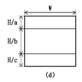
図3(d)は水平三分木(以下、「Horizontal TT」という)分割を示すものである。Horizontal TTは、二つの水平ラインによって第1ブロックが三つの第2ブロックに三分割される分割タイプである。例えば、2N×2Nの第1ブロックがHorizontal TTに分割される場合、第1ブロックは、高さの比率が(a:b:c)である三つの第2ブロックに分割できる。ここで、a、b、cは同じ値であってもよい。又は、aとcは同一であり、bはaよりも大きいか小さくてもよい。 FIG. 3D shows a horizontal ternary tree (hereinafter referred to as “Horizontal TT”) division. Horizontal TT is a division type in which the first block is divided into three second blocks by two horizontal lines. For example, when the first block of 2N × 2N is divided into horizontal TTs, the first block can be divided into three second blocks having a height ratio of (a: b: c). Here, a, b, and c may have the same value. Alternatively, a and c are the same, and b may be larger or smaller than a.
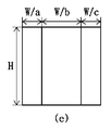
図3(e)は垂直三分木(以下、「Vertical TT」という)分割を示すものである。Vertical TTは、二つの垂直ラインによって第1ブロックが三つの第2ブロックに三分割される分割タイプである。例えば、2N×2Nの第1ブロックがVertical TTに分割される場合、第1ブロックは、幅の比率が(a:b:c)である三つの第2ブロックに分割できる。ここで、a、b、cは同じ値であってもよく、互いに異なる値であってもよい。又は、aとcは同一であり、bはaよりも大きいか小さくてもよい。又は、aとbは同一であり、cはaよりも大きいか小さくてもよい。又は、bとcは同一であり、aはbよりも大きいか小さくてもよい。 FIG. 3 (e) shows a vertical ternary tree (hereinafter referred to as “Vertical TT”) division. Vertical TT is a division type in which the first block is divided into three second blocks by two vertical lines. For example, when the first block of 2N × 2N is divided into Vertical TT, the first block can be divided into three second blocks having a width ratio of (a: b: c). Here, a, b, and c may have the same value or may have different values from each other. Alternatively, a and c are the same, and b may be larger or smaller than a. Alternatively, a and b are the same, and c may be larger or smaller than a. Alternatively, b and c are the same, and a may be larger or smaller than b.
前述した分割は、符号化装置からシグナリングされる分割情報に基づいて行われ得る。前記分割情報は、分割タイプ情報、分割方向情報又は分割比率情報のうちの少なくとも一つを含むことができる。 The division described above may be performed based on the division information signaled from the coding apparatus. The division information may include at least one of division type information, division direction information, and division ratio information.
前記分割タイプ情報は、符号化/復号化装置に既に定義された分割タイプのいずれかを特定することができる。前記既に定義された分割タイプは、QT、Horizontal BT、Vertical BT、Horizontal TT、Vertical TT又は非分割モード(No split)のうちの少なくとも一つを含むことができる。又は、前記分割タイプ情報は、QT、BT又はTTが適用されるか否かについての情報を意味することもある。これはフラグ或いはインデックスの形態で符号化できる。前記分割方向情報は、BT又はTTの場合、水平方向に分割されるか、それとも垂直方向に分割されるかを示すことができる。前記分割比率情報は、BT又はTTの場合、第2ブロックの幅及び/又は高さの比率を示すことができる。 The division type information can specify any of the division types already defined in the coding / decoding device. The previously defined split type can include at least one of QT, Horizontal BT, Vertical BT, Horizontal TT, Vertical TT or non-split mode (No split). Alternatively, the division type information may mean information about whether or not QT, BT or TT is applied. It can be encoded in the form of a flag or index. In the case of BT or TT, the division direction information can indicate whether it is divided in the horizontal direction or in the vertical direction. In the case of BT or TT, the division ratio information can indicate the ratio of the width and / or the height of the second block.
図4は本発明が適用される一実施形態として、ツリー構造に基づくブロック分割方法を示すものである。 FIG. 4 shows a block division method based on a tree structure as an embodiment to which the present invention is applied.
図4に示されたブロック40は、8N×8Nの大きさであり、分割デプスがkである正方形のブロック(以下、「第1ブロック」という)と仮定する。第1ブロックの分割情報がQT分割を指示する場合、第1ブロックは、4つのサブブロック(以下、「第2ブロック」という)に四分割できる。前記第2ブロックは、4N×4Nの大きさであり、(k+1)の分割デプスを持つことができる。
The
前記4つの第2ブロックは、QT、BT、TT又は非分割モードのうちのいずれかに基づいて再び分割できる。例えば、第2ブロックの分割情報が水平方向への二分木(Horizontal BT)を表す場合、前記第2ブロックは、図4の第2ブロック410のように二つのサブブロック(以下、「第3ブロック」という)に二分割できる。この際、前記第3ブロックは、4N×2Nの大きさであり、(k+2)の分割デプスを持つことができる。
The four second blocks can be re-divided based on any of QT, BT, TT or non-divided modes. For example, when the division information of the second block represents a horizontal binary tree (Horizontal BT), the second block has two sub-blocks (hereinafter, "third block" as in the
前記第3ブロックも、QT、BT、TT又は非分割モードのうちのいずれかに基づいて再び分割できる。例えば、前記第3ブロックの分割情報が垂直方向への二分木(Vertical BT)を表す場合、前記第3ブロックは、図4に示すように、二つのサブブロック411、412に二分割できる。この時、前記サブブロック411、412は、2N×2Nの大きさであり、(k+3)の分割デプスを持つことができる。又は、前記第3ブロックの分割情報が水平方向への二分木(Horizontal BT)を表す場合、前記第3ブロックは、図4に示すように、二つのサブブロック413、414に二分割できる。この時、前記サブブロック413、414は、4N×Nの大きさであり、(k+3)の分割デプスを持つことができる。
The third block can also be re-divided based on any of the QT, BT, TT or non-divided modes. For example, when the division information of the third block represents a vertical binary tree (Vertical BT), the third block can be divided into two
前記分割は、周辺ブロックとは独立的或いは並列的に行われてもよく、所定の優先順位に基づいて順次行われてもよい。 The division may be performed independently or in parallel with the peripheral blocks, or may be performed sequentially based on a predetermined priority.
分割対象である現在ブロックの分割情報は、現在ブロックの上位ブロックの分割情報又は周辺ブロックの分割情報のうちの少なくとも一つに基づいて従属的に決定されることもある。例えば、前記第2ブロックがHorizontal BTに分割され、上側の第3ブロックがVertical BTに分割された場合、下側の第3ブロックはVertical BTに分割される必要がない。下側の第3ブロックがVertical BTに分割される場合、これは第2ブロックがQTに分割されるのと同じ結果が出るからである。したがって、下側の第3ブロックの分割情報(特に、分割方向情報)は、符号化が省略でき、復号化装置は、下側の第3ブロックが水平方向に分割されるように設定することができる。 The division information of the current block to be divided may be determined subordinately based on at least one of the division information of the upper block of the current block or the division information of the peripheral block. For example, if the second block is divided into Horizontal BTs and the upper third block is divided into Vertical BTs, the lower third block does not need to be divided into Vertical BTs. If the lower third block is split into Vertical BTs, this is because it gives the same result as the second block is split into QTs. Therefore, the division information (particularly, the division direction information) of the lower third block can be omitted from encoding, and the decoding device can be set so that the lower third block is divided in the horizontal direction. can.
前記上位ブロックは、前記現在ブロックの分割デプスよりも小さい分割デプスを持つブロックを意味することができる。例えば、現在ブロックの分割デプスが(k+2)である場合、上位ブロックの分割デプスは(k+1)であり得る。前記周辺ブロックは、現在ブロックの上側或いは左側に隣接するブロックであることができる。前記周辺ブロックは、現在ブロックと同じ分割デプスを持つブロックであることができる。 The upper block can mean a block having a division depth smaller than the division depth of the current block. For example, if the current block split depth is (k + 2), the upper block split depth can be (k + 1). The peripheral block can be a block adjacent to the upper or left side of the current block. The peripheral block can be a block having the same division depth as the current block.
前述した分割は、符号化/復号化の最小単位まで繰り返し行われ得る。最小単位に分割された場合、当該ブロックに対する分割情報は、符号化装置からそれ以上シグナリングされない。前記最小単位に対する情報は、最小単位の大きさ又は形態のうちの少なくとも一つを含むことができる。前記最小単位の大きさは、ブロックの幅、高さ、幅と高さのうちの最小値或いは最大値、幅と高さの和、画素数、分割デプスなどで表現できる。前記最小単位に対する情報は、ビデオシーケンス、ピクチャ、スライス又はブロック単位のうちの少なくとも一つでシグナリングできる。又は、前記最小単位に対する情報は、符号化/復号化装置に既に約束された値であってもよい。前記最小単位に対する情報は、CU、PU、TUに対してそれぞれシグナリングできる。一つの最小単位に対する情報がCU、PU、TUに同様に適用されてもよい。 The division described above can be repeated up to the smallest unit of coding / decoding. When divided into the smallest units, the division information for the block is no longer signaled by the encoder. The information for the smallest unit can include at least one of the sizes or forms of the smallest unit. The size of the minimum unit can be expressed by the width, height, minimum or maximum value of the width and height, the sum of width and height, the number of pixels, the division depth, and the like. Information for the smallest unit can be signaled in at least one of a video sequence, a picture, a slice or a block unit. Alternatively, the information for the minimum unit may be a value already promised to the coding / decoding device. Information for the minimum unit can be signaled to CU, PU, and TU, respectively. Information for one smallest unit may be applied to CU, PU, TU as well.
図5は画像符号化/復号化装置に既に定義されたイントラ予測モードを示す例示図である。 FIG. 5 is an exemplary diagram showing an intra-prediction mode already defined in the image coding / decoding apparatus.
図5を参照すると、既に定義されたイントラ予測モードは、67個のモードで構成された予測モード候補群として定義でき、具体的には65個の方向性モード(2番乃至66番)と二つの非方向性モード(DC、Planar)を含むことができる。このとき、方向性モードは、傾き(例えば、dy/dx)又は角度情報(Degree)に区分できる。上記の例で説明されるイントラ予測モードの全部又は一部が輝度成分又は色差成分の予測モード候補群に含まれてもよく、その他の追加的なモードが予測モード候補群に含まれてもよい。 Referring to FIG. 5, the already defined intra prediction mode can be defined as a prediction mode candidate group composed of 67 modes, specifically 65 directional modes (Nos. 2 to 66) and two. Two non-directional modes (DC, Planar) can be included. At this time, the directional mode can be classified into tilt (for example, dy / dx) or angle information (Degree). All or part of the intra prediction mode described in the above example may be included in the prediction mode candidate group of the luminance component or the color difference component, and other additional modes may be included in the prediction mode candidate group. ..
また、カラー空間間の相関性を用いて符号化/復号化が完了した他のカラー空間の復元ブロックを現在ブロックの予測に使用することができ、これを支援する予測モードを含むことができる。例えば、色差成分の場合には、現在ブロックと対応する輝度成分の復元されたブロックを用いて現在ブロックの予測ブロックを生成することができる。つまり、カラー空間間の相関性を考慮して、復元されたブロックに基づいて予測ブロックを生成することができる。 Also, the restored blocks of other color spaces that have been coded / decoded using the correlation between the color spaces can be used to predict the current block, and can include a prediction mode to support this. For example, in the case of a color difference component, a predicted block of the current block can be generated using the restored block of the current block and the corresponding luminance component. That is, the prediction block can be generated based on the restored block in consideration of the correlation between the color spaces.
符号化/復号化の設定に基づいて予測モード候補群を適応的に決定することができる。予測の精度を高めるための目的で候補群の数を増やすことができ、予測モードに応じたビット量を減らすための目的で候補群の数を減らすことができる。 The prediction mode candidate group can be adaptively determined based on the coding / decoding settings. The number of candidate groups can be increased for the purpose of improving the accuracy of prediction, and the number of candidate groups can be reduced for the purpose of reducing the amount of bits according to the prediction mode.
例えば、A候補群(67個。65個の方向性モードと二つの非方向性モード)、B候補群(35個。33個の方向性モードと二つの非方向性モード)、C候補群(18個。17個の方向性モードと一つの非方向性モード)などの候補群のうちのいずれかを選択することができ、ブロックの大きさと形状に応じて適応的に候補群が選択又は決定できる。 For example, A candidate group (67. 65 directional modes and 2 non-directional modes), B candidate group (35. 33 directional modes and 2 non-directional modes), C candidate group (35 directional modes and 2 non-directional modes). One of the candidate groups such as 18. 17 directional modes and 1 non-directional mode) can be selected, and the candidate group is adaptively selected or determined according to the size and shape of the block. can.
また、符号化/復号化の設定に基づいて予測モード候補群の構成を多様に持つことができる。例えば、図5のようにモードの間が均等に予測モード候補群を構成するか、或いは、図5で18番モードと34番モードとの間のモードの個数が2番モードと18番モードとの間のモードの個数よりもさらに多く候補群を構成することができる。又は、その逆の場合が可能である。ブロックの形状(つまり、正方形、幅が高さよりも大きい非正方形、高さが幅よりも大きい非正方形など)に応じて適応的に候補群を構成することができる。 In addition, it is possible to have various configurations of the prediction mode candidate group based on the coding / decoding settings. For example, the prediction mode candidate group is evenly configured between the modes as shown in FIG. 5, or the number of modes between the 18th mode and the 34th mode in FIG. 5 is the 2nd mode and the 18th mode. It is possible to construct more candidate groups than the number of modes between. Or vice versa. Candidate groups can be adaptively constructed according to the shape of the block (that is, a square, a non-square having a width greater than the height, a non-square having a height greater than the width, etc.).
例えば、現在ブロックの幅が高さよりも大きい場合には、2番乃至18番に属するイントラ予測モードの全部又は一部は利用されず、67番乃至80番に属するイントラ予測モードの全部又は一部で代替できる。一方、現在ブロックの幅が高さよりも小さい場合には、50番乃至66番に属するイントラ予測モードの全部又は一部は利用されず、−14番乃至−1番に属するイントラ予測モードの全部又は一部で代替できる。 For example, if the width of the current block is larger than the height, all or part of the intra prediction modes belonging to Nos. 2 to 18 will not be used, and all or part of the intra prediction modes belonging to Nos. 67 to 80 will be used. Can be replaced with. On the other hand, when the width of the current block is smaller than the height, all or part of the intra prediction modes belonging to Nos. 50 to 66 are not used, and all or part of the intra prediction modes belonging to Nos. -14 to -1 are used. It can be replaced by some.
本発明において特別な言及がないとき、均等なモード間隔を有する既に定義された一つの予測モード候補群(A候補群)でイントラ予測を行う場合を仮定して説明するが、本発明の主要要素が、前記説明のような適応的なイントラ予測設定にも変更されて適用が可能である。 Unless otherwise specified in the present invention, the case where intra-prediction is performed with one already defined prediction mode candidate group (A candidate group) having equal mode intervals will be described, but the main elements of the present invention will be described. However, it can be changed and applied to the adaptive intra-prediction setting as described above.
図6は本発明が適用される一実施形態として、イントラ予測方法を示すものである。 FIG. 6 shows an intra prediction method as an embodiment to which the present invention is applied.
図6を参照すると、現在ブロックのイントラ予測のための参照領域を決定することができる(S600)。 With reference to FIG. 6, a reference area for intra-prediction of the current block can be determined (S600).
符号化/復号化装置は、イントラ予測に利用可能な複数の画素ラインを定義することができる。複数の画素ラインは、現在ブロックに隣接する第1画素ライン、第1画素ラインに隣接する第2画素ライン、第2画素ラインに隣接する第3画素ライン、又は第3画素ラインに隣接する第4画素ラインのうちの少なくとも一つを含むことができる。 The coding / decoding device can define a plurality of pixel lines that can be used for intra prediction. The plurality of pixel lines are the first pixel line adjacent to the current block, the second pixel line adjacent to the first pixel line, the third pixel line adjacent to the second pixel line, or the fourth pixel line adjacent to the third pixel line. It can include at least one of the pixel lines.
例えば、符号化/復号化の設定に基づいて、複数の画素ラインは、第1乃至第4画素ラインを全て含むこともでき、第3画素ラインを除いた残りの画素ラインだけを含むこともできる。又は、複数の画素ラインは、第1画素ライン及び第4画素ラインだけを含むこともできる。 For example, based on the coding / decoding settings, the plurality of pixel lines may include all the first to fourth pixel lines, or may include only the remaining pixel lines excluding the third pixel line. .. Alternatively, the plurality of pixel lines may include only the first pixel line and the fourth pixel line.
現在ブロックは、前記複数の画素ラインのうちのいずれか一つ又はそれ以上の画素ラインを選択し、これを参照領域として用いることができる。このとき、前記選択は、符号化装置でシグナリングされるインデックス(refIdx)に基づいて行われ得る。又は、前記選択は、所定の符号化情報に基づいて行われ得る。ここで、符号化情報は、現在ブロックの大きさ、形状、分割タイプ、イントラ予測モードが非方向性モードであるか否か、イントラ予測モードが水平方向性であるか否か、イントラ予測モードの角度又は成分タイプのうちの少なくとも一つを含むことができる。例えば、イントラ予測モードがPlanarモード又はDCモードである場合には、第1画素ラインのみが用いられるように制限できる。又は、現在ブロックの大きさが所定の閾値と同じかそれよりも小さい場合、第1画素ラインのみが用いられるように制限できる。ここで、大きさは、現在ブロックの幅又は高さのうちのいずれか(例えば、最大値、最小値など)、幅と高さの和、又は現在ブロックに属するサンプルの個数で表現できる。又は、イントラ予測モードが所定の閾値角度よりも大きい場合(又は、所定の閾値角度よりも小さい場合)、第1画素ラインのみが用いられるように制限できる。前記閾値角度は、前述した予測モード候補群のうち、モード2、モード66に対応するイントラ予測モードの角度であり得る。
The current block can select one or more pixel lines from the plurality of pixel lines and use this as a reference area. At this time, the selection may be made based on the index (refIdx) signaled by the encoding device. Alternatively, the selection may be made based on predetermined coding information. Here, the coding information is the size, shape, division type of the current block, whether the intra prediction mode is the non-directional mode, whether the intra prediction mode is the horizontal direction, and the intra prediction mode. It can include at least one of angle or component type. For example, when the intra prediction mode is the Planar mode or the DC mode, it can be restricted so that only the first pixel line is used. Alternatively, if the size of the current block is less than or equal to a predetermined threshold, it can be restricted to use only the first pixel line. Here, the size can be expressed by either the width or the height of the current block (for example, the maximum value, the minimum value, etc.), the sum of the width and the height, or the number of samples belonging to the current block. Alternatively, if the intra prediction mode is greater than a predetermined threshold angle (or smaller than a predetermined threshold angle), it can be restricted to use only the first pixel line. The threshold angle may be the angle of the intra prediction mode corresponding to the
図6を参照すると、現在ブロックのイントラ予測モードを決定することができる(S610)。 With reference to FIG. 6, the intra prediction mode of the current block can be determined (S610).
現在ブロックは、輝度ブロックと色差ブロックを含む概念であり、前記イントラ予測モードは、輝度ブロックと色差ブロックそれぞれに対して決定できる。以下、復号化装置に既に定義されたイントラ予測モードは、非方向性モード(Planarモード、DCモード)及び65個の方向性モードで構成されることを仮定する。 The current block is a concept including a luminance block and a color difference block, and the intra prediction mode can be determined for each of the luminance block and the color difference block. Hereinafter, it is assumed that the intra prediction mode already defined in the decoding device is composed of a non-directional mode (Planar mode, DC mode) and 65 directional modes.
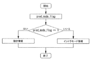
前述した既に定義されたイントラ予測モードは、MPM候補群とNon−MPM候補群に区分できる。現在ブロックのイントラ予測モードは、MPM候補群又はNon−MPM候補群のうちのいずれかを選択的に用いて誘導できる。このために、現在ブロックのイントラ予測モードがMPM候補群から誘導されるか否かを示すフラグが使用できる。例えば、前記フラグが第1値である場合には、MPM候補群が使用され、前記フラグが第2値である場合には、Non−MPM候補群が使用され得る。前記フラグは、符号化装置で符号化されてシグナリングできる。又は、前記フラグは、所定の符号化情報に基づいて復号化装置で誘導できる。符号化情報は、前述した通りであり、重複説明は省略する。 The previously defined intra-prediction mode described above can be divided into an MPM candidate group and a Non-MPM candidate group. The intra-prediction mode of the current block can be induced by selectively using either the MPM candidate group or the Non-MPM candidate group. For this, a flag can be used to indicate whether the current block's intra-prediction mode is derived from the MPM candidate group. For example, if the flag is the first value, the MPM candidate group may be used, and if the flag is the second value, the Non-MPM candidate group may be used. The flag can be coded and signaled by a coding device. Alternatively, the flag can be derived by a decoding device based on predetermined coding information. The coding information is as described above, and duplicate description will be omitted.
前記フラグが第1値である場合には、現在ブロックのイントラ予測モードは、MPM候補群及びMPMインデックスに基づいて誘導できる。前記MPM候補群は、一つ又はそれ以上のMPMを含み、MPMは、現在ブロックの隣接ブロックのイントラ予測モードに基づいて決定できる。MPMの個数はr個であり、rは1、2、3、4、5、6、又はそれ以上の整数であり得る。MPMの個数は、符号化/復号化装置に既に約束された、固定された値であってもよく、前述した符号化情報に基づいて可変的に決定されてもよい。 When the flag is the first value, the intra prediction mode of the current block can be derived based on the MPM candidate group and the MPM index. The MPM candidate group includes one or more MPMs, and the MPM can be determined based on the intra prediction mode of the adjacent block of the current block. The number of MPMs is r, where r can be an integer of 1, 2, 3, 4, 5, 6, or more. The number of MPMs may be a fixed value already promised to the coding / decoding apparatus, or may be variably determined based on the coding information described above.
例えば、MPM候補群は、隣接ブロックのイントラ予測モードmodeA、(modeA−n)、(modeA+n)又はデフォルトモードのうちの少なくとも一つを含むことができる。前記n値は、1、2、3、4又はそれ以上の整数であり得る。前記隣接ブロックは、現在ブロックの左側及び/又は上側に隣接するブロックを意味することができる。但し、これに限定されず、隣接ブロックは、左上側、左下側又は右上側に隣接するブロックのうちの少なくとも一つを含むこともできる。デフォルトモードは、Planarモード、DCモード、又は所定の方向性モードのうちの少なくとも一つであることができる。所定の方向性モードは、水平モード(modeV)、垂直モード(modeH)、(modeV−k)、(modeV+k)、(modeH−k)又は(modeH+k)のうちの少なくとも一つを含むことができる。 For example, the MPM candidate group can include at least one of the intra prediction modes modeA, (modeA-n), (modeA + n) or the default mode of the adjacent block. The n value can be an integer of 1, 2, 3, 4 or more. The adjacent block can mean a block adjacent to the left and / or upper side of the current block. However, the present invention is not limited to this, and the adjacent block may include at least one of the blocks adjacent to the upper left side, the lower left side, or the upper right side. The default mode can be at least one of Planar mode, DC mode, or a predetermined directional mode. The predetermined directional mode can include at least one of horizontal mode (modeV), vertical mode (modeH), (modeV-k), (modeV + k), (modeH-k) or (modeH + k).
前記MPMインデックスは、MPM候補群のMPMのうち、現在ブロックのイントラ予測モードと同じMPMを特定することができる。つまり、MPMインデックスによって特定されたMPMが現在ブロックのイントラ予測モードに設定できる。 The MPM index can identify the same MPM as the intra prediction mode of the current block among the MPMs of the MPM candidate group. That is, the MPM identified by the MPM index can be set to the intra prediction mode of the current block.
又は、前記MPM候補群は、複数のグループに区分できる。例えば、MPM候補群は、第1グループと第2グループに区分されることを仮定する。前記第1グループは、前述したデフォルトモードの少なくとも一つで構成できる。例えば、前記第1グループは、非方向性モードのみで構成されてもよく、所定の方向性モードのみで構成されてもよい。又は、前記第1グループは、非方向性モードのうち、Planarモードのみで構成されるか或いはDCモードのみで構成され得る。前記第2グループは、隣接ブロックのイントラ予測モードmodeA、(modeA−n)、(modeA+n)又はデフォルトモードのうちの少なくとも一つを含むことができる。前記n値は、1、2、3、4又はそれ以上の整数であることができる。前記隣接ブロックは、現在ブロックの左側及び/又は上側に隣接するブロックを意味することができる。ただし、これに限定されず、隣接ブロックは左上側、左下側、又は右上側に隣接するブロックのうちの少なくとも一つを含むこともできる。デフォルトモードは、Planarモード、DCモード、又は所定の方向性モードのうちの少なくとも一つであることができる。所定の方向性モードは、水平モード(modeV)、垂直モード(modeH)、(modeV−k)、(modeV+k)、(modeH−k)又は(modeH+k)のうちの少なくとも一つを含むことができる。但し、第2グループは、第1グループに属するMPMを含まないように設定できる。 Alternatively, the MPM candidate group can be divided into a plurality of groups. For example, it is assumed that the MPM candidate group is divided into a first group and a second group. The first group can be configured by at least one of the above-mentioned default modes. For example, the first group may be configured only in a non-directional mode or may be configured only in a predetermined directional mode. Alternatively, the first group may be composed only of the Planar mode or only the DC mode among the non-directional modes. The second group can include at least one of the intra-prediction modes modeA, (modeA-n), (modeA + n) or the default mode of the adjacent block. The n value can be an integer of 1, 2, 3, 4 or more. The adjacent block can mean a block adjacent to the left and / or upper side of the current block. However, the present invention is not limited to this, and the adjacent block may include at least one of the blocks adjacent to the upper left side, the lower left side, or the upper right side. The default mode can be at least one of Planar mode, DC mode, or a predetermined directional mode. The predetermined directional mode can include at least one of horizontal mode (modeV), vertical mode (modeH), (modeV-k), (modeV + k), (modeH-k) or (modeH + k). However, the second group can be set not to include the MPM belonging to the first group.
現在ブロックのイントラ予測モードは、第1グループ又は第2グループのうちのいずれかを選択的に用いて誘導できる。そのために、現在ブロックのイントラ予測モードが第1グループから誘導されるか否かを示すフラグが使用できる。例えば、前記フラグが第1値である場合には、現在ブロックのイントラ予測モードは、第1グループに属するMPMに設定できる。これに対し、前記フラグが第2値である場合には、現在ブロックのイントラ予測モードは、第2グループ及びMPMインデックスに基づいて誘導できる。ここで、MPMインデックスは、前述した通りであり、詳細な説明は省略する。 The intra-prediction mode of the current block can be selectively derived using either the first group or the second group. Therefore, a flag can be used to indicate whether the intra prediction mode of the current block is derived from the first group. For example, when the flag is the first value, the intra prediction mode of the current block can be set to the MPM belonging to the first group. On the other hand, when the flag is the second value, the intra prediction mode of the current block can be derived based on the second group and the MPM index. Here, the MPM index is as described above, and detailed description thereof will be omitted.
前記フラグは、符号化装置で符号化されてシグナリングできる。但し、前記フラグは、所定の符号化情報を考慮して適応的にシグナリングできる。ここで、符号化情報は、現在ブロックの大きさ、形状、分割タイプ又は参照領域のうちの少なくとも一つを含むことができる。ここで、分割タイプは、四分木、二分木、三分木又はサブブロック単位のイントラ予測有無などを意味することができる。 The flag can be coded and signaled by a coding device. However, the flag can be adaptively signaled in consideration of predetermined coding information. Here, the coding information can include at least one of the size, shape, division type or reference area of the current block. Here, the division type can mean a quadtree, a binary tree, a ternary tree, or the presence or absence of intra-prediction in units of sub-blocks.
例えば、現在ブロックの参照領域が第1画素ラインである場合に限り、前記フラグはシグナリングできる(実施形態1)。現在ブロックの参照領域が第1画素ラインではない場合、前記フラグはシグナリングされず、復号化装置で第2値に設定できる。これにより、現在ブロックが第1画素ラインを参照しない場合、第1グループに基づいてイントラ予測モードを誘導することを制限することができる。 For example, the flag can be signaled only when the reference area of the current block is the first pixel line (Embodiment 1). If the reference area of the current block is not the first pixel line, the flag is not signaled and can be set to a second value by the decoder. Thereby, if the current block does not refer to the first pixel line, it is possible to limit the induction of the intra prediction mode based on the first group.
また、現在ブロックがサブブロック単位のイントラ予測を行わない場合に限り、前記フラグがシグナリングできる(実施形態2)。逆に、現在ブロックがサブブロック単位のイントラ予測を行う場合、前記フラグは、シグナリングされず、復号化装置で第2値に設定できる。 Further, the flag can be signaled only when the current block does not perform intra-prediction in units of sub-blocks (Embodiment 2). On the contrary, when the current block performs intra-prediction in units of sub-blocks, the flag is not signaled and can be set to a second value by the decoding device.
前述した実施形態1又は2のうちのいずれかの条件を満たす場合、前記フラグがシグナリングされてもよく、実施形態1及び2の両方を満たす場合、前記フラグがシグナリングされるように設定されてもよい。
If any of the above-mentioned
図6を参照すると、イントラ予測のための参照領域とイントラ予測モードに基づいて、現在ブロックに対してイントラ予測を行うことができる(S620)。 Referring to FIG. 6, intra-prediction can be performed on the current block based on the reference area for intra-prediction and the intra-prediction mode (S620).
前記イントラ予測は、現在ブロックのサブブロック単位で行われ得る。このために、現在ブロックは複数のサブブロックに分割できる。前記分割方法については、図7を参照して詳しく考察する。 The intra-prediction can be made on a sub-block basis of the current block. For this reason, the current block can now be divided into multiple subblocks. The division method will be discussed in detail with reference to FIG. 7.
図7は本発明が適用される一実施形態として、サブブロック単位のイントラ予測方法を示すものである。 FIG. 7 shows an intra-prediction method for each sub-block as an embodiment to which the present invention is applied.
前述したように、現在ブロックは、複数のサブブロックに分割できる。このとき、前記現在ブロックは、リーフノード(leaf node)に該当することができる。リーフノードは、より小さいコーディングブロックにそれ以上分割されないコーディングブロックを意味することができる。つまり、リーフノードは、前述したツリー基盤のブロック分割を介してそれ以上分割されないブロックを意味することができる。 As mentioned above, the current block can be divided into multiple subblocks. At this time, the current block can correspond to a leaf node. A leaf node can mean a coding block that is no longer divided into smaller coding blocks. That is, the leaf node can mean a block that is not further divided through the above-mentioned tree-based block division.
前記分割は、現在ブロックの大きさに基づいて行われ得る(実施形態1)。 The division can be performed based on the size of the current block (Embodiment 1).
図7を参照すると、現在ブロック700の大きさが所定の閾値の大きさよりも小さい場合、現在ブロックは、垂直又は水平方向に二分割できる。逆に、現在ブロック710の大きさが前記閾値の大きさと同じかそれより大きい場合には、現在ブロックは、垂直又は水平方向に四分割できる。
Referring to FIG. 7, if the size of the
前記閾値の大きさは、符号化装置でシグナリングされてもよく、復号化装置に既に定義された固定値であってもよい。例えば、閾値の大きさはN×Mで表現され、NとMは4、8、16又はそれ以上であってもよい。前記NとMは、同一であるように設定されてもよく、互いに異なるように設定されてもよい。 The magnitude of the threshold value may be signaled by the coding device or may be a fixed value already defined in the decoding device. For example, the magnitude of the threshold may be expressed as N × M, where N and M may be 4, 8, 16 or more. The N and M may be set to be the same or different from each other.
又は、現在ブロックの大きさが所定の閾値の大きさよりも小さい場合には、現在ブロックは非分割(non−split)され、そうでない場合には、現在ブロックは二分割又は四分割できる。 Alternatively, if the size of the current block is smaller than the size of a predetermined threshold, the current block is non-split, otherwise the current block can be divided into two or four.
前記分割は、現在ブロックの形状に基づいて行われ得る(実施形態2)。 The division can be performed based on the shape of the current block (Embodiment 2).
現在ブロックの形状が正方形である場合には、現在ブロックは四分割され、そうでない場合には、現在ブロックは二分割され得る。逆に、現在ブロックの形状が正方形である場合には、現在ブロックは二分割され、そうでない場合には、現在ブロックは四分割され得る。 If the shape of the current block is square, the current block may be divided into four, otherwise the current block may be divided into two. Conversely, if the shape of the current block is square, the current block may be divided into two, otherwise the current block may be divided into four.
又は、現在ブロックの形状が正方形である場合には、現在ブロックは二分割又は四分割され、そうでない場合には、現在ブロックは非分割され得る。逆に、現在ブロックの形状が正方形である場合には、現在ブロックは非分割され、そうでない場合には、現在ブロックは二分割又は四分割され得る。 Alternatively, if the shape of the current block is square, the current block may be divided into two or four, otherwise the current block may be undivided. Conversely, if the shape of the current block is square, the current block may be undivided, otherwise the current block may be divided into two or four.
前述した実施形態1又は2のうちのいずれかが選択的に適用されて分割されてもよく、実施形態1と2の組み合わせに基づいて分割されてもよい。
Any one of the above-mentioned
前記二分割は、垂直又は水平のうちのいずれかの方向に二分割されるものであり、前記四分割は、垂直又は水平のうちのいずれかの方向に四分割されるか、或いは垂直及び水平方向に四分割されることを含むことができる。 The two divisions are divided into two in either the vertical or horizontal direction, and the four divisions are divided into four in either the vertical or horizontal direction, or vertical and horizontal. It can include being divided into four in a direction.
前記実施形態では、二分割又は四分割を説明するが、これに限定されず、現在ブロックは、垂直又は水平方向に三分割されてもよい。この場合、幅又は高さの比が(1:1:2)、(1:2:1)又は(2:1:1)であり得る。 In the above embodiment, the two divisions or the four divisions will be described, but the present block may be divided into three vertically or horizontally. In this case, the width or height ratio can be (1: 1: 2), (1: 2: 1) or (2: 1: 1).
サブブロック単位への分割か否か、四分割か否か、分割「num」、分割個数などに関する情報は、符号化装置からシグナリングされてもよく、所定の符号化パラメータに基づいて復号化装置で可変的に決定されてもよい。ここで、符号化パラメータは、ブロックの大きさ/形状、分割タイプ(四分割、二分割、三分割)、イントラ予測モード、イントラ予測のための隣接画素の範囲/位置、成分タイプ(例えば、輝度、色差)、変換ブロックの最大/最小大きさ、変換タイプ(例えば、変換スキップ、DCT2、DST7、DCT8)などを意味することができる。] Information regarding whether or not to divide into sub-block units, whether or not to divide into four, the division "num", the number of divisions, etc. may be signaled from the coding device, and the decoding device may use the decoding device based on a predetermined coding parameter. It may be determined variably. Here, the coding parameters are the block size / shape, division type (quarter division, two division, three division), intra prediction mode, range / position of adjacent pixels for intra prediction, and component type (for example, brightness). , Color difference), maximum / minimum size of conversion block, conversion type (eg, conversion skip, DCT2, DST7, DCT8) and the like. ]
図8は本発明が適用される一実施形態として、成分間参照に基づく予測方法を示すものである。 FIG. 8 shows a prediction method based on inter-component references as an embodiment to which the present invention is applied.
現在ブロックは、成分のタイプによって輝度ブロックと色差ブロックに分類できる。色差ブロックは、既に復元された輝度ブロックの画素を用いて予測でき、これを成分間参照と呼ぶ。本実施形態では、色差ブロックは(nTbW×nTbH)の大きさを有し、色差ブロックに対応する輝度ブロックは(2*nTbW×2*nTbH)の大きさを有することを仮定する。これは、輝度と色差ブロックの幅と高さの比がすべて2:1である場合を仮定するが、幅と高さのうち、いずれか一つは1:1であり、他の一つは2:1であるか、或いは両方が1:1である場合にも、後述する例が同一又は類似に適用できることを理解すべきである。 Currently, blocks can be classified into luminance blocks and color difference blocks according to the type of component. The color difference block can be predicted using the pixels of the already restored luminance block, which is called an intercomponent reference. In this embodiment, it is assumed that the color difference block has a size of (nTbW × nTbH) and the luminance block corresponding to the color difference block has a size of (2 * nTbW × 2 * nTbH). This assumes that the ratio of luminance to color difference block width to height is all 2: 1, but one of the width and height is 1: 1 and the other one is. It should be understood that the examples described below are the same or similar when they are 2: 1 or both are 1: 1.
図8を参照すると、色差ブロックのイントラ予測モードを決定することができる(S800)。 With reference to FIG. 8, the intra prediction mode of the color difference block can be determined (S800).
具体的には、色差ブロックのための既に定義されたイントラ予測モードは、第1グループと第2グループに区分できる。ここで、第1グループは、成分間参照に基づく予測モードで構成され、第2グループは、輝度ブロックのための既に定義されたイントラ予測モードで構成され得る。符号化/復号化装置は、成分間参照に基づく予測モードとして、INTRA_LT_CCLM、INTRA_L_CCLM、又はINTRA_T_CCLMのうちの少なくとも一つを定義することができる。 Specifically, the already defined intra prediction mode for the color difference block can be divided into a first group and a second group. Here, the first group may be configured with a prediction mode based on inter-component references and the second group may be configured with an already defined intra prediction mode for the luminance block. The coding / decoding apparatus can define at least one of INTRA_LT_CCLM, INTRA_L_CCLM, or INTRA_T_CCLM as the prediction mode based on the inter-component reference.
色差ブロックのイントラ予測モードは、前記第1グループ又は第2グループのうちのいずれかを選択的に用いて誘導できる。前記選択は、所定の第1フラグに基づいて行われ得る。前記第1フラグは、色差ブロックのイントラ予測モードが第1グループに基づいて誘導されるか、或いは第2グループに基づいて誘導されるかを示すことができる。 The intra prediction mode of the color difference block can be induced by selectively using either the first group or the second group. The selection may be based on a predetermined first flag. The first flag can indicate whether the intra-prediction mode of the color difference block is guided based on the first group or the second group.
例えば、前記第1フラグが第1値である場合、色差ブロックのイントラ予測モードは、第1グループに属する一つ又はそれ以上の成分間参照に基づく予測モードのうちのいずれかに決定できる。このため、第1グループに属する成分間参照に基づく予測モードのうちのいずれか一つを特定するインデックスが利用できる。第1グループに属する成分間参照に基づく予測モードと各予測モードに割り当てられたインデックスは、下記表1のとおりである。

表1は各予測モードに割り当てられるインデックスの一例に過ぎず、これに限定されない。つまり、表1に示すように、INTRA_LT_CCLM、INTRA_L_CCLM、INTRA_T_CCLMの優先順序でインデックスが割り当てられてもよく、INTRA_LT_CCLM、INTRA_T_CCLM、INTRA_L_CCLMの優先順序でインデックスが割り当てられてもよい。或いは、INTRA_LT_CCLMがINTRA_T_CCLM又はINTRA_L_CCLMよりも低い優先順序を持つこともできる。 Table 1 is merely an example of an index assigned to each prediction mode, and is not limited to this. That is, as shown in Table 1, indexes may be assigned in the order of priority of INTRA_LT_CCLM, INTRA_L_CCLM, INTRA_T_CCLM, or indexes may be assigned in the order of priority of INTRA_LT_CCLM, INTRA_T_CCLM, INTRA_L_CCLM. Alternatively, INTRA_LT_CCLM may have a lower priority than INTRA_T_CCLM or INTRA_L_CCLM.
前記第1フラグは、成分間参照が許容されるか否かを示す情報に基づいて選択的にシグナリングできる。例えば、前記情報の値が1である場合には、前記第1フラグがシグナリングされ、そうでない場合には、前記第1フラグはシグナリングされなくてもよい。ここで、情報は、後述する所定の条件に基づいて0又は1に決定できる。 The first flag can be selectively signaled based on the information indicating whether or not the inter-component reference is allowed. For example, if the value of the information is 1, the first flag may be signaled, otherwise the first flag may not be signaled. Here, the information can be determined to be 0 or 1 based on predetermined conditions described later.
(条件1)成分間参照に基づく予測が許容されるか否かを示す第2フラグが0である場合には、前記情報は0に設定できる。前記第2フラグは、ビデオパラメータセット(VPS)、シーケンスパラメータセット(SPS)、ピクチャパラメータセット(PPS)又はスライスヘッダのうちの少なくとも一つでシグナリングできる。 (Condition 1) When the second flag indicating whether or not the prediction based on the inter-component reference is allowed is 0, the information can be set to 0. The second flag can be signaled by at least one of a video parameter set (VPS), a sequence parameter set (SPS), a picture parameter set (PPS) or a slice header.
(条件2)次のサブ条件のうちの少なくとも一つを満たす場合には、前記情報は1に設定できる。
−qtbtt_dual_tree_intra_flagの値が0である場合
−スライスタイプがIスライスではない場合
−コーディングツリーブロックの大きさが64×64よりも小さい場合
(Condition 2) The information can be set to 1 if at least one of the following sub-conditions is satisfied.
-When the value of qtbt_dual_tree_intra_flag is 0-When the slice type is not I-slice-When the size of the coding tree block is smaller than 64 x 64
前記条件2で、qtbtt_dual_tree_intra_flagは、コーディングツリーブロックがサイズ64×64のコーディングブロックに黙示的に分割され、サイズ64×64のコーディングブロックがデュアルツリーに分割されるか否かを示すことができる。前記デュアルツリーは、輝度成分と色差成分が互いに独立した分割構造をもって分割される方式を意味することができる。前記コーディングツリーブロックの大きさ(CtbLog2Size)は、符号化/復号化装置に既に定義された大きさ(例えば、64×64、128×128、256×256)であってもよく、符号化装置で符号化されてシグナリングされてもよい。
Under
(条件3)次のサブ条件のうちの少なくとも一つを満たす場合には、前記情報は1に設定できる。
−第1上位ブロックの幅と高さが64である場合
−第1上位ブロックのデプスが(CtbLog2Size−6)と同一であり、第1上位ブロックがHorizontal BTに分割され、第2上位ブロックが64×32である場合
−第1上位ブロックのデプスが(CtbLog2Size−6)よりも大きい場合
−第1上位ブロックのデプスが(CtbLog2Size−6)と同一であり、第1上位ブロックがHorizontal BTに分割され、第2上位ブロックがVertical BTに分割された場合
(Condition 3) The information can be set to 1 if at least one of the following sub-conditions is satisfied.
-When the width and height of the first upper block is 64-The depth of the first upper block is the same as (CtbLog2Size-6), the first upper block is divided into Horizontal BT, and the second upper block is 64. When x32-When the depth of the first upper block is larger than (CtbLog2Size-6) -The depth of the first upper block is the same as (CtbLog2Size-6), and the first upper block is divided into Horizontal BTs. , When the second upper block is divided into Vertical BT
前記条件3で、第1上位ブロックは、現在色差ブロックを下位ブロックとして含むブロックであり得る。例えば、現在色差ブロックのデプスがkである場合には、第1上位ブロックのデプスは(kn)であり、nは1、2、3、4又はそれ以上であり得る。前記第1上位ブロックのデプスは、四分木ベースの分割によるデプスのみを意味するか、或いは四分木、二分木又は三分木のうちの少なくとも一つの分割によるデプスを意味することができる。前記第2上位ブロックは、第1上位ブロックに属する下位ブロックであって、現在色差ブロックよりも小さいデプスを、第1上位ブロックよりも大きいデプスを持つことができる。例えば、現在色差ブロックのデプスがkである場合、第2上位ブロックのデプスは(k−m)であり、mはnよりも小さい自然数であり得る。 Under the above condition 3, the first upper block may be a block that currently includes the color difference block as the lower block. For example, when the depth of the color difference block is currently k, the depth of the first upper block is (kn), and n can be 1, 2, 3, 4, or more. The depth of the first upper block can mean only the depth due to the division based on the quadtree, or can mean the depth due to the division of at least one of the quadtree, the binary tree, or the ternary tree. The second upper block is a lower block belonging to the first upper block, and can have a depth smaller than the current color difference block and a depth larger than the first upper block. For example, when the depth of the color difference block is currently k, the depth of the second upper block is (km), and m can be a natural number smaller than n.
前述した条件1〜3のいずれか一つも満たさない場合、前記情報は0に設定できる。 If any one of the above conditions 1 to 3 is not satisfied, the information can be set to 0.
但し、条件1〜3のうちの少なくとも一つを満たす場合でも、次のサブ条件のうちの少なくとも一つを満たす場合には、前記情報は0に再設定できる。
−第1上位ブロックが64×64であり、前述したサブブロック単位の予測を行う場合
−第1上位ブロックの幅又は高さのうちの少なくとも一つが64よりも小さく、第1上位ブロックのデプスが(CtbLog2Size−6)と同じである場合
これに対し、前記フラグが第2値である場合、色差ブロックのイントラ予測モードは、符号化装置でシグナリングされる情報(intra_chroma_pred_mode)に基づいて、下記表2のように誘導できる。
-When the first upper block is 64 x 64 and the above-mentioned subblock unit prediction is performed-At least one of the width or height of the first upper block is smaller than 64, and the depth of the first upper block is Same as (CtbLog2Size-6) On the other hand, when the flag is the second value, the intra prediction mode of the color difference block is based on the information signaled by the encoding device (intra_chroma_pred_mode) in Table 2 below. Can be induced like this.
表2によれば、色差ブロックのイントラ予測モードは、前記シグナリングされた情報と輝度ブロックのイントラ予測モードに基づいて決定できる。表2において、mode66は右上方向の対角線モードを意味し、mode50は垂直モードを意味し、mode18は水平モードを意味し、mode1はDCモードを意味することができる。例えば、シグナリングされた情報intra_chroma_pred_modeの値が4である場合、色差ブロックのイントラ予測モードは輝度ブロックのイントラ予測モードと同一に設定できる。色差ブロックのイントラ予測モードが第2グループから誘導される場合、色差ブロックは図6によるイントラ予測方法によって予測でき、詳細な説明は省略する。図8を参照すると、色差ブロックの成分間参照のための輝度領域を特定することができる(S810)。
According to Table 2, the intra prediction mode of the color difference block can be determined based on the signaled information and the intra prediction mode of the luminance block. In Table 2, mode 66 means a diagonal mode in the upper right direction,
前記輝度領域は、輝度ブロック、又は輝度ブロックに隣接する隣接領域のうちの少なくとも一つを含むことができる。ここで、輝度ブロックは、画素pY[x][y](x=0..nTbW*2−1、y=0..nTbH*2−1)を含む領域として定義できる。前記画素は、インループフィルタが適用される前の復元値を意味することができる。 The luminance region may include at least one of a luminance block or an adjacent region adjacent to the luminance block. Here, the luminance block can be defined as a region including pixels pY [x] [y] (x = 0..nTbW * 2-1 and y = 0..nTbH * 2-1). The pixel can mean a restored value before the in-loop filter is applied.
前記隣接領域は、左側隣接領域、上側隣接領域又は左上側隣接領域のうちの少なくとも一つを含むことができる。前記左側隣接領域は、画素pY[x][y](x=−1..−3、y=0..2*numSampL−1)を含む領域に設定できる。前記設定は、numSampLの値が0よりも大きい場合に限って行われ得る。前記上側隣接領域は、画素pY[x][y](x=0..2*numSampT−1、y=−1..−3)を含む領域に設定できる。前記設定は、numSampTの値が0よりも大きい場合に限って行われ得る。前記左上側隣接領域は、画素pY[x][y](x=−1、y=−1、−2)を含む領域に設定できる。前記の設定は、輝度ブロックの左上側領域が利用可能である場合に限って行われ得る。 The adjacent region may include at least one of a left adjacent region, an upper adjacent region or an upper left adjacent region. The left adjacent region can be set as a region including pixels pY [x] [y] (x = -1 ... -3, y = 0.2 * numSampL-1). The setting can be made only when the value of numSampL is larger than 0. The upper adjacent region can be set as a region including pixels pY [x] [y] (x = 0.2 * numSampT-1, y = -1 ... -3). The setting can be made only when the value of numSampT is larger than 0. The upper left adjacent region can be set as an region including pixels pY [x] [y] (x = -1, y = -1, -2). The above setting may be made only when the upper left region of the luminance block is available.
前述したnumSampL及びnumSampTは、現在ブロックのイントラ予測モードに基づいて決定できる。ここで、現在ブロックは色差ブロックを意味することができる。 The above-mentioned numSampL and numSampT can be determined based on the intra prediction mode of the current block. Here, the current block can mean a color difference block.
例えば、現在ブロックのイントラ予測モードがINTRA_LT_CCLMである場合、下記数式1のように誘導できる。ここで、INTRA_LT_CCLMは、成分間参照が現在ブロックの左側及び上側に隣接する領域に基づいて行われるモードを意味することができる。 For example, when the intra prediction mode of the current block is INTRA_LT_CCLM, it can be derived as in the following formula 1. Here, INTRA_LT_CCLM can mean a mode in which inter-component references are made based on regions adjacent to the left and upper sides of the current block.
[数式1]
numSampT=availT?nTbW:0
numSampL=availL?nTbH:0
[Formula 1]
numSampT = avalT? nTbW: 0
numSampL = availL? nTbH: 0
数式1によると、numSampTは、現在ブロックの上側隣接領域が利用可能である場合にはnTbWに誘導され、そうでない場合には0に誘導され得る。同様に、numSampLは、現在ブロックの左側隣接領域が利用可能である場合にはnTbHに誘導され、そうでない場合には0に誘導され得る。 According to Equation 1, numSampT can be guided to nTbW if the upper adjacent region of the block is currently available, otherwise to 0. Similarly, numSampL can be guided to nTbH if the left flanking region of the block is currently available, otherwise to 0.
これに対し、現在ブロックのイントラ予測モードがINTRA_LT_CCLMでない場合には、下記数式2のように誘導できる。
On the other hand, when the intra prediction mode of the current block is not INTRA_LT_CCLM, it can be derived as in the following
[数式2]
numSampT=(availT&&predModeIntra==INTRA_T_CCLM)?(nTbW+numTopRight):0
numSampL=(availL&&predModeIntra==INTRA_L_CCLM)?(nTbH+numLeftBelow):0
[Formula 2]
numSampT = (availT && predModeIntra == INTRA_T_CCLM)? (NTbW + numberTopRight): 0
numSampL = (availL && predModeIntra == INTRA_L_CCLM)? (NTbH + nUMLeftBellow): 0
数式2において、INTRA_T_CCLMは、成分間参照が現在ブロックの上側に隣接する領域に基づいて行われるモードを意味し、INTRA_L_CCLMは、成分間参照が現在ブロックの左側に隣接する領域に基づいて行われるモードを意味することができる。numTopRightは、色差ブロックの右上側に隣接する領域に属する全部又は一部画素の個数を意味することができる。一部画素は、当該領域の最下側画素ライン(row)に属する画素のうちの利用可能画素を意味することができる。利用可能に対する判断は左から右方向に画素の利用可能か否かを順次判断し、これは利用不可画素が発見されるまで行われ得る。numLeftBelowは、色差ブロックの左下側に隣接する領域に属する全部又は一部画素の個数を意味することができる。一部画素は、当該領域の最右側画素ライン(column)に属する画素のうちの利用可能画素を意味することができる。利用可能に対する判断は上から下方向に画素の利用可能か否かを順次判断し、これは利用不可画素が発見されるまで行われ得る。
In
図8を参照すると、S810で特定された輝度領域に対してダウンサンプリングが行われ得る(S820)。 Referring to FIG. 8, downsampling may be performed on the luminance region identified in S810 (S820).
前記ダウンサンプリングは、1.輝度ブロックに対するダウンサンプリング、2.輝度ブロックの左側隣接領域に対するダウンサンプリング、又は3.輝度ブロックの上側隣接領域に対するダウンサンプリングのうちの少なくとも一つを含むことができ、以下に詳細に考察する。 The downsampling is 1. Downsampling for luminance blocks, 2. Downsampling or 3. At least one of the downsamplings for the upper adjacent region of the luminance block can be included and will be discussed in detail below.
1.輝度ブロックに対するダウンサンプリング
(実施形態1)
1. 1. Downsampling for luminance block (Embodiment 1)
ダウンサンプリングされた輝度ブロックの画素pDsY[x][y](x=0..nTbW−1、y=0..nTbH−1)は、輝度ブロックの対応画素pY[2*x][2*y]及び周辺画素に基づいて誘導できる。周辺画素は、対応画素の左側、右側、上側又は下側のうちの少なくとも一つの方向に隣接する画素を意味することができる。例えば、画素pDsY[x][y]は、下記数式3のように誘導できる。 The downsampled luminance block pixels pDsY [x] [y] (x = 0..nTbW-1, y = 0..nTbH-1) are the corresponding luminance block pixels pY [2 * x] [2 *). y] and peripheral pixels can be used for guidance. Peripheral pixels can mean pixels adjacent in at least one direction of the left, right, top, or bottom of the corresponding pixel. For example, the pixels pDsY [x] [y] can be derived as in the following mathematical formula 3.
[数式3]
pDsY[x][y]=(pY[2*x][2*y−1]+pY[2*x−1][2*y]+4*pY[2*x][2*y]+pY[2*x+1][2*y]+pY[2*x][2*y+1]+4)>>3
[Formula 3]
pDsY [x] [y] = (pY [2 * x] [2 * y-1] + pY [2 * x-1] [2 * y] + 4 * pY [2 * x] [2 * y] + pY [ 2 * x + 1] [2 * y] + pY [2 * x] [2 * y + 1] +4) >> 3
但し、現在ブロックの左側/上側隣接領域が利用不可能である場合が存在することができる。もし現在ブロックの左側隣接領域が利用不可能である場合、ダウンサンプリングされた輝度ブロックの画素pDsY[0][y](y=1..nTbH−1)は、輝度ブロックの対応画素pY[0][2*y]及び周辺画素に基づいて誘導できる。周辺画素は、対応画素の上側又は下側のうちの少なくとも一つの方向に隣接する画素を意味することができる。例えば、画素pDsY[0][y](y=1..nTbH−1)は、下記数式4のように誘導できる。 However, there may be cases where the left / upper adjacent area of the block is currently unavailable. If the left adjacent region of the block is currently unavailable, the downsampled luminance block pixels pDsY [0] [y] (y = 1..nTbH-1) are the corresponding luminance block pixels pY [0]. ] [2 * y] and can be derived based on the peripheral pixels. Peripheral pixels can mean pixels adjacent in at least one direction of the upper or lower side of the corresponding pixel. For example, the pixels pDsY [0] [y] (y = 1..nTbH-1) can be derived as in the following mathematical formula 4.
[数式4]
pDsY[0][y]=(pY[0][2*y−1]+2*pY[0][2*y]+pY[0][2*y+1]+2)>>2
[Formula 4]
pDsY [0] [y] = (pY [0] [2 * y-1] + 2 * pY [0] [2 * y] + pY [0] [2 * y + 1] + 2) >> 2
もし現在ブロックの上側隣接領域が利用不可能である場合、ダウンサンプリングされた輝度ブロックの画素pDsY[x][0](x=1..nTbW−1)は、輝度ブロックの対応画素pY[2*x][0]及び周辺画素に基づいて誘導できる。周辺画素は、対応画素の左側又は右側のうちの少なくとも一つの方向に隣接する画素を意味することができる。例えば、画素pDsY[x][0](x=1..nTbW−1)は、下記数式5のように誘導できる。 If the upper adjacent region of the block is currently unavailable, the downsampled luminance block pixels pDsY [x] [0] (x = 1..nTbW-1) are the corresponding luminance block pixels pY [2]. * It can be derived based on x] [0] and peripheral pixels. Peripheral pixels can mean pixels adjacent in at least one direction on the left or right side of the corresponding pixel. For example, the pixels pDsY [x] [0] (x = 1..nTbW-1) can be derived as in the following mathematical formula 5.
[数式5]
pDsY[x][0]=(pY[2*x−1][0]+2*pY[2*x][0]+pY[2*x+1][0]+2)>>2
[Formula 5]
pDsY [x] [0] = (pY [2 * x-1] [0] + 2 * pY [2 * x] [0] + pY [2 * x + 1] [0] +2) >> 2
一方、ダウンサンプリングされた輝度ブロックの画素pDsY[0][0]は、輝度ブロックの対応画素pY[0][0]及び/又は周辺画素に基づいて誘導できる。周辺画素の位置は、現在ブロックの左側/上側隣接領域の利用可能か否かによって異なるように決定できる。 On the other hand, the downsampled luminance block pixels pDsY [0] [0] can be derived based on the corresponding pixels pY [0] [0] and / or peripheral pixels of the luminance block. The position of the peripheral pixels can be determined to be different depending on the availability of the left / upper adjacent area of the current block.
例えば、左側隣接領域が利用可能であり、上側隣接領域が利用可能でない場合には、pDsY[0][0]は、下記数式6のように誘導できる。 For example, when the left adjacent region is available and the upper adjacent region is not available, pDsY [0] [0] can be derived as in Equation 6 below.
[数式6]
pDsY[0][0]=(pY[−1][0]+2*pY[0][0]+pY[1][0]+2)>>2
[Formula 6]
pDsY [0] [0] = (pY [-1] [0] + 2 * pY [0] [0] + pY [1] [0] +2) >> 2
これに対し、左側隣接領域が利用可能でなく、上側隣接領域が利用可能である場合には、pDsY[0][0]は、下記数式7のように誘導できる。 On the other hand, when the left adjacent region is not available and the upper adjacent region is available, pDsY [0] [0] can be derived as in the following formula 7.
[数式7]
pDsY[0][0]=(pY[0][−1]+2*pY[0][0]+pY[0][1]+2)>>2
[Formula 7]
pDsY [0] [0] = (pY [0] [-1] + 2 * pY [0] [0] + pY [0] [1] +2) >> 2
一方、左側及び上側隣接領域の両方とも利用可能でない場合、pDsY[0][0]は、輝度ブロックの対応画素pY[0][0]に設定できる。 On the other hand, if neither the left side nor the upper adjacent area is available, pDsY [0] [0] can be set to the corresponding pixels pY [0] [0] of the luminance block.
(実施形態2)
ダウンサンプリングされた輝度ブロックの画素pDsY[x][y](x=0..nTbW−1、y=0..nTbH−1)は、輝度ブロックの対応画素pY[2*x][2*y]及び周辺画素に基づいて誘導できる。周辺画素は、対応画素の下側、左側、右側、左下側又は右下側のうちの少なくとも一つの方向に隣接する画素を意味することができる。例えば、画素pDsY[x][y]は、下記数式8のように誘導できる。
(Embodiment 2)
The downsampled luminance block pixels pDsY [x] [y] (x = 0..nTbW-1, y = 0..nTbH-1) are the corresponding luminance block pixels pY [2 * x] [2 *). y] and peripheral pixels can be used for guidance. Peripheral pixels can mean pixels adjacent in at least one direction of the lower, left, right, lower left, or lower right side of the corresponding pixel. For example, the pixels pDsY [x] [y] can be derived as in the following mathematical formula 8.
[数式8]
pDsY[x][y]=(pY[2*x−1][2*y]+pY[2*x−1][2*y+1]+2*pY[2*x][2*y]+2*pY[2*x][2*y+1]+pY[2*x+1][2*y]+pY[2*x+1][2*y+1]+4)>>3
[Formula 8]
pDsY [x] [y] = (pY [2 * x-1] [2 * y] + pY [2 * x-1] [2 * y + 1] + 2 * pY [2 * x] [2 * y] + 2 * pY [2 * x] [2 * y + 1] + pY [2 * x + 1] [2 * y] + pY [2 * x + 1] [2 * y + 1] + 4) >> 3
但し、もし現在ブロックの左側隣接領域が利用不可能である場合、ダウンサンプリングされた輝度ブロックの画素pDsY[0][y](y=0..nTbH−1)は、輝度ブロックの対応画素pY[0][2*y]及び下側の周辺画素に基づいて誘導できる。例えば、画素pDsY[0][y](y=0..nTbH−1)は、下記数式9のように誘導できる。 However, if the area adjacent to the left side of the block is currently unavailable, the downsampled pixel pDsY [0] [y] (y = 0..nTbH-1) of the luminance block is the corresponding pixel pY of the luminance block. It can be derived based on [0] [2 * y] and the lower peripheral pixel. For example, the pixels pDsY [0] [y] (y = 0..nTbH-1) can be derived as in the following mathematical formula 9.
[数式9]
pDsY[0][y]=(pY[0][2*y]+pY[0][2*y+1]+1)>>1
[Formula 9]
pDsY [0] [y] = (pY [0] [2 * y] + pY [0] [2 * y + 1] +1) >> 1
輝度ブロックのダウンサンプリングは、前述した実施形態1及び2のうちのいずれかに基づいて行われ得る。この時、所定のフラグに基づいて実施形態1又は2のうちのいずれかが選択できる。前記フラグは、ダウンサンプリングされた輝度画素が原輝度画素と同じ位置を持つか否かを示すことができる。例えば、前記フラグが第1値である場合には、ダウンサンプリングされた輝度画素が原輝度画素と同じ位置を持つ。これに対し、前記フラグが第2値である場合には、ダウンサンプリングされた輝度画素は、原輝度画素と水平方向には同じ位置を有するが、垂直方向にはハーフペル(half pel)だけシフトされた位置を有する。
Luminance block downsampling can be performed based on any one of
2.輝度ブロックの左側隣接領域に対するダウンサンプリング
(実施形態1)
ダウンサンプリングされた左側隣接領域の画素pLeftDsY[y](y=0..numSampL−1)は、左側隣接領域の対応画素pY[−2][2*y]及び周辺画素に基づいて誘導できる。周辺画素は、対応画素の左側、右側、上側又は下側のうちの少なくとも一つの方向に隣接する画素を意味することができる。例えば、画素pLeftDsY[y]は、下記数式10のように誘導できる。
2. 2. Downsampling for the left adjacent region of the luminance block (Embodiment 1)
The downsampled pixel pLeftDsY [y] (y = 0..numSampL-1) in the left adjacent region can be derived based on the corresponding pixel pY [-2] [2 * y] in the left adjacent region and the peripheral pixels. Peripheral pixels can mean pixels adjacent in at least one direction of the left, right, top, or bottom of the corresponding pixel. For example, the pixel pLeftDsY [y] can be derived as in the following
[数式10]
pLeftDsY[y]=(pY[−2][2*y−1]+pY[−3][2*y]+4*pY[−2][2*y]+pY[−1][2*y]+pY[−2][2*y+1]+4)>>3
[Formula 10]
pLeftDsY [y] = (pY [-2] [2 * y-1] + pY [-3] [2 * y] + 4 * pY [-2] [2 * y] + pY [-1] [2 * y] + PY [-2] [2 * y + 1] +4) >> 3
但し、現在ブロックの左上側隣接領域が利用不可能である場合、ダウンサンプリングされた左側隣接領域の画素pLeftDsY[0]は、左側隣接領域の対応画素pY[−2][0]及び周辺画素に基づいて誘導できる。周辺画素は、対応画素の左側又は右側のうちの少なくとも一つの方向に隣接する画素を意味することができる。例えば、画素pLeftDsY[0]は、下記数式11のように誘導できる。 However, when the upper left adjacent region of the block is currently unavailable, the downsampled pixel pLeftDsY [0] in the left adjacent region becomes the corresponding pixel pY [-2] [0] in the left adjacent region and the peripheral pixels. Can be guided based on. Peripheral pixels can mean pixels adjacent in at least one direction on the left or right side of the corresponding pixel. For example, the pixel pLeftDsY [0] can be derived as in the following mathematical formula 11.
[数式11]
pLeftDsY[0]=(pY[−3][0]+2*pY[−2][0]+pY[−1][0]+2)>>2
[Formula 11]
pLeftDsY [0] = (pY [-3] [0] + 2 * pY [-2] [0] + pY [-1] [0] +2) >> 2
(実施形態2)
ダウンサンプリングされた左側隣接領域の画素pLeftDsY[y](y=0..numSampL−1)は、左側隣接領域の対応画素pY[−2][2*y]及び周辺画素に基づいて誘導できる。周辺画素は、対応画素の下側、左側、右側、左下側又は右下側のうちの少なくとも一つの方向に隣接する画素を意味することができる。例えば、画素pLeftDsY[y]は、下記数式12のように誘導できる。
(Embodiment 2)
The downsampled pixel pLeftDsY [y] (y = 0..numSampL-1) in the left adjacent region can be derived based on the corresponding pixel pY [-2] [2 * y] in the left adjacent region and the peripheral pixels. Peripheral pixels can mean pixels adjacent in at least one direction of the lower, left, right, lower left, or lower right side of the corresponding pixel. For example, the pixel pLeftDsY [y] can be derived as in the following mathematical formula 12.
[数式12]
pLeftDsY[y]=(pY[−1][2*y]+pY[−1][2*y+1]+2*pY[−2][2*y]+2*pY[−2][2*y+1]+pY[−3][2*y]+pY[−3][2*y+1]+4)>>3
[Formula 12]
pLeftDsY [y] = (pY [-1] [2 * y] + pY [-1] [2 * y + 1] + 2 * pY [-2] [2 * y] + 2 * pY [-2] [2 * y + 1] + PY [-3] [2 * y] + pY [-3] [2 * y + 1] +4) >> 3
同様に、左側隣接領域のダウンサンプリングは、前述した実施形態1及び2のうちのいずれかに基づいて行われ得る。この時、所定のフラグに基づいて実施形態1又は2のうちのいずれかが選択できる。前記フラグは、ダウンサンプリングされた輝度画素が原輝度画素と同じ位置を持つか否かを示し、これは、前述した通りである。
Similarly, downsampling of the left adjacent region can be performed based on any one of
一方、左側隣接領域に対するダウンサンプリングは、numSampL値が0よりも大きい場合に限って行われ得る。numSampL値が0よりも大きい場合とは、現在ブロックの左側隣接領域が利用可能であり、現在ブロックのイントラ予測モードはINTRA_LT_CCLM又はINTRA_L_CCLMである場合を意味することができる。 On the other hand, downsampling for the left adjacent region can be performed only when the numSampL value is larger than 0. When the numSampL value is larger than 0, it can mean that the left adjacent region of the current block is available and the intra prediction mode of the current block is INTRA_LT_CCLM or INTRA_L_CCLM.
3.輝度ブロックの上側隣接領域に対するダウンサンプリング
(実施形態1)
ダウンサンプリングされた上側隣接領域の画素pTopDsY[x](x=0..numSampT−1)は、上側隣接領域が輝度ブロックとは異なるCTUに属するか否かを考慮して誘導できる。
3. 3. Downsampling for the upper adjacent region of the luminance block (Embodiment 1)
The downsampled pixel pTopDsY [x] (x = 0..numSampT-1) in the upper adjacent region can be derived in consideration of whether or not the upper adjacent region belongs to a CTU different from the luminance block.
上側隣接領域が輝度ブロックと同じCTUに属する場合、ダウンサンプリングされた上側隣接領域の画素pTopDsY[x]は、上側隣接領域の対応画素pY[2*x][−2]及び周辺画素に基づいて誘導できる。周辺画素は、対応画素の左側、右側、上側又は下側のうちの少なくとも一つの方向に隣接する画素を意味することができる。例えば、画素pTopDsY[x]は、下記数式13のように誘導できる。
[数式13]
pTopDsY[x]=(pY[2*x][−3]+pY[2*x−−1][−2]+4*pY[2*x][−2]+pY[2*x+1][−2]+pY[2*x][−1]+4)>>3
When the upper adjacent region belongs to the same CTU as the luminance block, the downsampled upper adjacent region pixel pTopDsY [x] is based on the corresponding upper adjacent region pixel pY [2 * x] [-2] and peripheral pixels. Can be guided. Peripheral pixels can mean pixels adjacent in at least one direction of the left, right, top, or bottom of the corresponding pixel. For example, the pixel pTopDsY [x] can be derived as in the following mathematical formula 13.
[Formula 13]
pTopDsY [x] = (pY [2 * x] [-3] + pY [2 * x-1-] [-2] + 4 * pY [2 * x] [-2] + pY [2 * x + 1] [-2 ] + PY [2 * x] [-1] +4) >> 3
これに対し、上側隣接領域が輝度ブロックとは異なるCTUに属する場合、ダウンサンプリングされた上側隣接領域の画素pTopDsY[x]は、上側隣接領域の対応画素pY[2*x][−1]及び周辺画素に基づいて誘導できる。周辺画素は、対応画素の左側又は右側のうちの少なくとも一つの方向に隣接する画素を意味することができる。例えば、画素pTopDsY[x]は、下記数式14のように誘導できる。 On the other hand, when the upper adjacent region belongs to a CTU different from the luminance block, the downsampled pixel pTopDsY [x] of the upper adjacent region is the corresponding pixel pY [2 * x] [-1] of the upper adjacent region. It can be guided based on the peripheral pixels. Peripheral pixels can mean pixels adjacent in at least one direction on the left or right side of the corresponding pixel. For example, the pixel pTopDsY [x] can be derived as in the following mathematical formula 14.
[数式14]
pTopDsY[x]=(pY[2*x−1][−1]+2*pY[2*x][−1]+pY[2*x+1][−1]+2)>>2
[Formula 14]
pTopDsY [x] = (pY [2 * x-1] [-1] + 2 * pY [2 * x] [-1] + pY [2 * x + 1] [-1] +2) >> 2
又は、現在ブロックの左上側隣接領域が利用不可能である場合、前記周辺画素は、対応画素の上側又は下側のうちの少なくとも一つの方向に隣接する画素を意味することができる。例えば、画素pTopDsY[0]は、下記数式15のように誘導できる。 Alternatively, when the upper left adjacent region of the block is currently unavailable, the peripheral pixel can mean a pixel adjacent in at least one direction of the upper or lower side of the corresponding pixel. For example, the pixel pTopDsY [0] can be derived as in the following mathematical formula 15.
[数式15]
pTopDsY[0]=(pY[0][−3]+2*pY[0][−2]+pY[0][−1]+2)>>2
[Formula 15]
pTopDsY [0] = (pY [0] [-3] + 2 * pY [0] [-2] + pY [0] [-1] + 2) >> 2
又は、現在ブロックの左上側隣接領域が利用不可能であり、上側隣接領域が輝度ブロックとは異なるCTUに属する場合、画素pTopDsY[0]は、上側隣接領域の画素pY[0][−1]に設定できる。 Alternatively, if the upper left adjacent region of the block is currently unavailable and the upper adjacent region belongs to a CTU different from the luminance block, the pixel pTopDsY [0] is the pixel pY [0] [-1] in the upper adjacent region. Can be set to.
(実施形態2)
ダウンサンプリングされた上側隣接領域の画素pTopDsY[x](x=0..numSampT−1)は、上側隣接領域が輝度ブロックとは異なるCTUに属するか否かを考慮して誘導できる。
(Embodiment 2)
The downsampled pixel pTopDsY [x] (x = 0..numSampT-1) in the upper adjacent region can be derived in consideration of whether or not the upper adjacent region belongs to a CTU different from the luminance block.
上側隣接領域が輝度ブロックと同じCTUに属する場合、ダウンサンプリングされた上側隣接領域の画素pTopDsY[x]は、上側隣接領域の対応画素pY[2*x][−2]及び周辺画素に基づいて誘導できる。周辺画素は、対応画素の下側、左側、右側、左下側又は右下側のうちの少なくとも一つの方向に隣接する画素を意味することができる。例えば、画素pTopDsY[x]は、下記数式16のように誘導できる。 When the upper adjacent region belongs to the same CTU as the luminance block, the downsampled upper adjacent region pixel pTopDsY [x] is based on the corresponding upper adjacent region pixel pY [2 * x] [-2] and peripheral pixels. Can be guided. Peripheral pixels can mean pixels adjacent in at least one direction of the lower, left, right, lower left, or lower right side of the corresponding pixel. For example, the pixel pTopDsY [x] can be derived as in the following mathematical formula 16.
[数式16]
pTopDsY[x]=(pY[2*x−1][−2]+pY[2*x−1][−1]+2*pY[2*x][−2]+2*pY[2*x][−1]+pY[2*x+1][−2]+pY[2*x+1][−1]+4)>>3
[Formula 16]
pTopDsY [x] = (pY [2 * x-1] [-2] + pY [2 * x-1] [-1] + 2 * pY [2 * x] [-2] + 2 * pY [2 * x] [-1] + pY [2 * x + 1] [-2] + pY [2 * x + 1] [-1] + 4) >> 3
これに対し、上側隣接領域が輝度ブロックとは異なるCTUに属する場合、ダウンサンプリングされた上側隣接領域の画素pTopDsY[x]は、上側隣接領域の対応画素pY[2*x][−1]及び周辺画素に基づいて誘導できる。周辺画素は、対応画素の左側又は右側のうちの少なくとも一つの方向に隣接する画素を意味することができる。例えば、画素pTopDsY[x]は、下記数式17のように誘導できる。 On the other hand, when the upper adjacent region belongs to a CTU different from the luminance block, the downsampled pixel pTopDsY [x] of the upper adjacent region is the corresponding pixel pY [2 * x] [-1] of the upper adjacent region. It can be guided based on the peripheral pixels. Peripheral pixels can mean pixels adjacent in at least one direction on the left or right side of the corresponding pixel. For example, the pixel pTopDsY [x] can be derived as in the following mathematical formula 17.
[数式17]
pTopDsY[x]=(pY[2*x−1][−1]+2*pY[2*x][−1]+pY[2*x+1][−1]+2)>>2
[Formula 17]
pTopDsY [x] = (pY [2 * x-1] [-1] + 2 * pY [2 * x] [-1] + pY [2 * x + 1] [-1] +2) >> 2
又は、現在ブロックの左上側隣接領域が利用不可能である場合、前記周辺画素は、対応画素の上側又は下側のうちの少なくとも一つの方向に隣接する画素を意味することができる。例えば、画素pTopDsY[0]は、下記数式18のように誘導できる。 Alternatively, when the upper left adjacent region of the block is currently unavailable, the peripheral pixel can mean a pixel adjacent in at least one direction of the upper or lower side of the corresponding pixel. For example, the pixel pTopDsY [0] can be derived as in the following mathematical formula 18.
[数式18]
pTopDsY[0]=(pY[0][−2]+pY[0][−1]+1)>>1
[Formula 18]
pTopDsY [0] = (pY [0] [-2] + pY [0] [-1] + 1) >> 1
又は、現在ブロックの左上側隣接領域が利用不可能であり、上側隣接領域が輝度ブロックとは異なるCTUに属する場合、画素pTopDsY[0]は、上側隣接領域の画素pY[0][−1]に設定できる。 Alternatively, if the upper left adjacent region of the block is currently unavailable and the upper adjacent region belongs to a CTU different from the luminance block, the pixel pTopDsY [0] is the pixel pY [0] [-1] in the upper adjacent region. Can be set to.
同様に、上側隣接領域のダウンサンプリングは、前述した実施形態1及び2のうちのいずれかに基づいて行われ得る。この時、所定のフラグに基づいて実施形態1又は2のうちのいずれかが選択できる。前記フラグは、ダウンサンプリングされた輝度画素が原輝度画素と同じ位置を持つか否かを示し、これは、前述したとおりである。
Similarly, downsampling of the upper adjacent region can be performed based on any one of
一方、上側隣接領域に対するダウンサンプリングは、numSampT値が0よりも大きい場合に限って行われ得る。numSampT値が0よりも大きい場合とは、現在ブロックの上側隣接領域が利用可能であり、現在ブロックのイントラ予測モードはINTRA_LT_CCLM又はINTRA_T_CCLMである場合を意味することができる。 On the other hand, downsampling for the upper adjacent region can be performed only when the numSampT value is larger than 0. When the numSampT value is larger than 0, it can mean that the upper adjacent region of the current block is available and the intra prediction mode of the current block is INTRA_LT_CCLM or INTRA_T_CCLM.
図8を参照すると、色差ブロックの成分間参照のためのパラメータを誘導することができる(S830)。 With reference to FIG. 8, parameters for inter-component reference of the color difference block can be derived (S830).
前記パラメータは、重み又はオフセットのうちの少なくとも一つを含むことができる。前記パラメータは、現在ブロックのイントラ予測モードを考慮して決定できる。前記パラメータは、輝度領域の画素又は色差ブロックの左側/上側隣接領域の画素のうちの少なくとも一つを用いて誘導できる。ここで、輝度領域は、輝度ブロック、輝度ブロックの上側/左側隣接領域を含むことができる。前記輝度領域は、前述したダウンサンプリングが適用された領域を意味することができる。 The parameter can include at least one of weights or offsets. The parameters can be determined in consideration of the intra-prediction mode of the current block. The parameters can be derived using at least one of the pixels in the luminance region or the pixels in the left / upper adjacent region of the color difference block. Here, the luminance region can include a luminance block and an upper / left adjacent region of the luminance block. The luminance region can mean a region to which the downsampling described above is applied.
前記パラメータは、前記輝度領域と色差ブロックの隣接領域に属する全体画素又は一部画素を用いて誘導できる。 The parameter can be derived using all pixels or partial pixels belonging to the area adjacent to the luminance area and the color difference block.
輝度領域の一部画素を特定し、色差ブロックの一部画素は、特定された輝度領域の一部画素に対応する位置の画素として決定できる(実施形態1)。輝度領域の一部画素は、輝度ブロックの上側及び左側隣接領域からそれぞれ抽出できる。上側隣接領域から抽出される一部画素の個数(numSampT)は、左側隣接領域から抽出される一部画素の個数(numSampL)と同一であってもよく、輝度ブロックの大きさ/形状によって異なってもよい。例えば、N*M輝度ブロックにおいて、NがMよりも大きい場合には、numSampTはnumSampLよりも大きく、NはMよりも小さい場合には、numSampTはnumSampLよりも小さくなるように設定できる。又は、輝度ブロックの大きさが所定の閾値の大きさよりも小さい場合には、numSampT又はnumSampLのうちの少なくとも一つはi個に決定され、iは2、3、4、又はそれ以上の自然数であることができる。逆に、輝度ブロックの大きさが所定の閾値の大きさよりも大きい場合には、numSampT又はnumSampLのうちの少なくとも一つはj個に決定され、jはiよりも大きい自然数(例えば、3、4、5)であることができる。又は、一部画素は、輝度ブロックの上側隣接領域のみから抽出されるか、或いは左側隣接領域のみから抽出されるように制限されることもある。この場合にも、前述したように、輝度ブロックの大きさ/形状に応じてnumSampT又はnumSampLが決定できるのはもちろんである。前記一部画素の位置は、符号化/復号化装置に既に約束された位置であることができる。例えば、輝度ブロックの上側隣接領域が8つの画素で構成された場合には、一部画素は左から右方向に奇数番目に位置する4つの画素のうちの少なくとも一つに決定されるか、或いは偶数番目に位置する4つの画素のうちの少なくとも一つに決定され得る。又は、前記一部画素は、左から右方向に奇数番目に位置する二つの画素のうちの少なくとも一つ、及び右から左方向に偶数番目に位置する二つの画素のうちの少なくとも一つを含むことができる。輝度ブロックの上側/左側隣接領域がそれぞれ4つの画素で構成された場合には、一部画素は上側/左側隣接領域からそれぞれ一つ又は二つの画素を抽出することができる。このとき、上側隣接領域において、奇数番目に位置する二つの画素のうちの少なくとも一つに決定されるか、或いは偶数番目に位置する二つの画素のうちの少なくとも一つに決定され得る。又は、上側隣接領域において、一番目と最終目に位置する二つの画素のうちの少なくとも一つに決定されてもよい。左側隣接領域からも同様の方式で一部画素が抽出できる。 A part of the pixels in the luminance region can be specified, and some pixels in the color difference block can be determined as pixels at positions corresponding to some pixels in the specified luminance region (Embodiment 1). Some pixels in the luminance region can be extracted from the upper and left adjacent regions of the luminance block, respectively. The number of partial pixels extracted from the upper adjacent region (numSampT) may be the same as the number of partial pixels extracted from the left adjacent region (numSampL), and varies depending on the size / shape of the luminance block. May be good. For example, in the N * M luminance block, when N is larger than M, numSampT is larger than numSampL, and when N is smaller than M, numSampT can be set to be smaller than numSampL. Alternatively, when the size of the luminance block is smaller than the size of the predetermined threshold value, at least one of numSampT or numSampL is determined to be i, and i is a natural number of 2, 3, 4, or more. There can be. On the contrary, when the size of the luminance block is larger than the size of the predetermined threshold value, at least one of numSampT or numSampL is determined to be j, and j is a natural number larger than i (for example, 3, 4). 5). Alternatively, some pixels may be extracted only from the upper adjacent region of the luminance block, or may be limited to be extracted only from the left adjacent region. In this case as well, as described above, it goes without saying that numSampT or numSampL can be determined according to the size / shape of the luminance block. The position of the partial pixel can be a position already promised to the coding / decoding device. For example, when the upper adjacent region of the brightness block is composed of eight pixels, some pixels are determined to be at least one of four pixels located at odd-numbered positions from left to right. It can be determined to be at least one of the four even-numbered pixels. Alternatively, the partial pixel includes at least one of two odd-numbered pixels from left to right and at least one of two even-numbered pixels from right to left. be able to. When the upper / left adjacent regions of the luminance block are each composed of four pixels, some pixels can extract one or two pixels from the upper / left adjacent regions, respectively. At this time, in the upper adjacent region, it may be determined to be at least one of the two odd-numbered pixels, or it may be determined to be at least one of the even-numbered two pixels. Alternatively, it may be determined to be at least one of the two pixels located at the first and final eyes in the upper adjacent region. Some pixels can be extracted from the adjacent area on the left side by the same method.
又は、逆に、色差ブロックの隣接領域内の一部画素を特定し、輝度領域の一部画素は、前記色差ブロックの隣接領域内の一部画素に対応する位置の画素に決定できる(実施形態2)。ここで、色差ブロックの隣接領域内の一部画素、前述した輝度領域の一部画素を決定する方法によって決定でき、重複説明は省略する。 Alternatively, conversely, a partial pixel in the adjacent region of the color difference block can be specified, and the partial pixel in the luminance region can be determined to be a pixel at a position corresponding to a partial pixel in the adjacent region of the color difference block (embodiment). 2). Here, it can be determined by a method of determining a partial pixel in the adjacent region of the color difference block and a partial pixel in the luminance region described above, and the duplication description will be omitted.
前記抽出された一部画素から最大値及び最小値を、輝度領域と色差領域に対してそれぞれ算出することができる。前記最大値及び最小値は、複数の一部画素のうち、最大値及び最小値にそれぞれ決定できる。又は、複数の画素間の大きさの比較によって、複数の画素を降順で整列することができる。このとき、上位t個の画素間の平均が最大値に設定され、下位t個の画素間の平均が最小値に設定され得る。tは1、2、3又はそれ以上の自然数であることができる。 The maximum value and the minimum value can be calculated from the extracted partial pixels for the luminance region and the color difference region, respectively. The maximum value and the minimum value can be determined as the maximum value and the minimum value, respectively, among a plurality of partial pixels. Alternatively, the plurality of pixels can be arranged in descending order by comparing the sizes of the plurality of pixels. At this time, the average between the upper t pixels can be set to the maximum value, and the average between the lower t pixels can be set to the minimum value. t can be a natural number of 1, 2, 3 or more.
前記算出された最大値及び最小値に基づいて、前記パラメータの重み及び/又はオフセットを誘導することができる。 Based on the calculated maximum and minimum values, the weights and / or offsets of the parameters can be derived.
色差ブロックは、ダウンサンプリングされた輝度ブロックとパラメータに基づいて予測できる(S840)。 The color difference block can be predicted based on the downsampled luminance block and parameters (S840).
色差ブロックは、ダウンサンプリングされた輝度ブロックの画素に、既に誘導された重み又はオフセットのうちの少なくとも一つを適用して予測できる。 The color difference block can be predicted by applying at least one of the already derived weights or offsets to the pixels of the downsampled luminance block.
予測を行う様々な方法が存在しうるが、空間的又は時間的な相関性に基づいて予測を行う方法がそれに対する例になることができる。 There can be various methods of making predictions, but methods of making predictions based on spatial or temporal correlation can be an example.
空間的相関性に基づいた一例として、対象ブロックに対して、隣接する領域の既に符号化/復号化された画素を用いて外挿、内挿、平均、コピーなどの方法を使用することができる。又は、対象ブロックに対して、既に符号化/復号化が完了した参照領域でブロックマッチング、テンプレートマッチングなどの方法を使用することができる。このとき、参照領域は、現在ピクチャに制限される場合であり得る。 As an example based on spatial correlation, methods such as extrapolation, interpolation, averaging, and copying can be used for the target block using already coded / decoded pixels in adjacent regions. .. Alternatively, a method such as block matching or template matching can be used for the target block in the reference area where the coding / decoding has already been completed. At this time, the reference area may be currently limited to the picture.
時間的相関性に基づいた一例として、対象ブロックに対して、既に符号化/復号化された参照領域でブロックマッチングの方法を使用することができるか、或いはテンプレートマッチングの方法を使用することができる。このとき、参照領域は、他のピクチャに制限される場合であり得る。 As an example based on the temporal correlation, the block matching method can be used for the target block in the already coded / decoded reference region, or the template matching method can be used. .. At this time, the reference area may be limited to other pictures.
一般に、予測は、前記相関性に基づいて行われ得るが、前記例の場合、参照領域(現在ピクチャ/他のピクチャ)に基づいて予測を区分する場合に属することができる。このように、予測は、前記参照領域だけでなく、さまざまな要素によって区分が可能である。例えば、参照領域、参照位置、予測方法などがそれに対する例になることができる。 In general, the prediction can be made based on the correlation, but in the case of the example, it can belong to the case of classifying the prediction based on the reference area (current picture / other picture). In this way, the prediction can be classified not only by the reference area but also by various factors. For example, a reference area, a reference position, a prediction method, etc. can be examples for it.
前記様々な要素によって予測が一つ以上の候補として定義され、それに基づいて予測を行う場合について考察する。 Consider the case where the prediction is defined as one or more candidates by the various factors described above, and the prediction is made based on the prediction.
以下、参照領域が制限(本例では現在ピクチャ)される場合に、予測が他の要素によって複数の候補に区分される場合を説明する。詳細には、空間的な相関性に基づいて予測が行われ、予測方法によって次の二つの候補に区分される場合を仮定する。もちろん、これに限定されず、追加の候補が支援されるか或いは予測を区分する要素が異なるように構成される変形の例も可能である。 Hereinafter, a case where the prediction is divided into a plurality of candidates by other factors when the reference area is limited (current picture in this example) will be described. In detail, it is assumed that the prediction is made based on the spatial correlation and is classified into the following two candidates according to the prediction method. Of course, the present invention is not limited to this, and an example of a modification in which additional candidates are supported or the factors that divide the prediction are configured to be different is also possible.
1)隣接する領域のデータに外挿、内挿、平均によって予測を行う
2)既に符号化/復号化された領域でブロックマッチングによって予測を行う
ここで、1番の場合は、所定の方向性モード、非方向性モードなどを予測モード候補群として構成し、その中の少なくとも一つを選択して予測モード情報を表現することができる。2番の場合は、動きベクトル情報、参照ピクチャ情報などで予測モード情報を表現することができる。
1) Prediction is performed by extrapolation, interpolation, and averaging on the data in the adjacent area. 2) Prediction is performed by block matching in the already coded / decoded area. A mode, a non-directional mode, etc. can be configured as a prediction mode candidate group, and at least one of them can be selected to express the prediction mode information. In the case of No. 2, the prediction mode information can be expressed by motion vector information, reference picture information, and the like.
前記各予測方法は、明示的に支援有無を示す情報によって活性化できるか、或いは黙示的に支援有無が決定できる。本例では、1番は、黙示的に活性化(支援)され、2番は、明示的に支援有無を示す情報によって活性化される場合を仮定する。 Each of the prediction methods can be activated by the information indicating the presence or absence of support, or the presence or absence of support can be implicitly determined. In this example, it is assumed that No. 1 is implicitly activated (supported) and No. 2 is activated by information indicating the presence or absence of support.
対象ブロックの予測のために、前記予測方法のうちのいずれかを用いて予測を行うことができるが、これに関する選択情報が発生することができる。そして、選択された予測方法に応じて、後続の予測情報(予測モード情報など)が発生しうるが、このための様々なフラグ(シンタックス)の構成が可能である。以下、図9〜図12を参照して、予測方法を決定する方法について詳しく説明する。後述する例が適用される単位(現在ブロック)は、符号化単位、予測単位、変換単位のうちのいずれか一つであることができる。 For the prediction of the target block, prediction can be made using any of the above prediction methods, but selection information regarding this can be generated. Subsequent prediction information (prediction mode information, etc.) may be generated depending on the selected prediction method, and various flags (syntaxes) for this purpose can be configured. Hereinafter, a method of determining a prediction method will be described in detail with reference to FIGS. 9 to 12. The unit (current block) to which the example described later is applied can be any one of a coding unit, a prediction unit, and a conversion unit.
図9を参照すると、予測方法選択情報(pred_mode_flag)を確認し、それに応じて1番方法又は2番方法のうちのいずれか一つが選択されると、それによる予測モード情報(intra_mode_information又はmotion_information)を確認し、前記予測方法及び予測モード情報に基づいて予測を行うことができる。 With reference to FIG. 9, the prediction method selection information (pred_mode_flag) is confirmed, and when any one of the first method and the second method is selected accordingly, the prediction mode information (intra_mode_information or motion_information) is displayed. It is possible to confirm and make a prediction based on the prediction method and the prediction mode information.
intra_mode_informationは、外挿、内挿、平均の予測モードを意味し、intra_pred_modeのように全体予測モードを一つの候補群として構成し、その中から選択するようにする構成又はmpm_flag、mpm_idx、remaining_modeなどのように全体予測モードを所定の基準に基づく区分によって複数の候補群として構成し、候補群の選択おおび選択された候補群の中から選択するようにする構成などが可能である。これについての説明は、前述した例によって誘導可能なので、詳細な説明は省略する。 intra_mode_information means extrapolation, interpolation, and average prediction modes, such as intra_pred_mode, which configures the overall prediction mode as one candidate group and selects from them, or mpm_flag, mpm_idx, remaining_mode, etc. As described above, it is possible to configure the overall prediction mode as a plurality of candidate groups according to the classification based on a predetermined standard, select the candidate group, and select from the selected candidate groups. Since the description of this can be derived by the above-mentioned example, detailed description thereof will be omitted.
motion_informationは、動き予測モード(Skip/Merge/AMVP)、動きベクトル予測情報、動き差分値情報、参照領域選択情報、動きモデル選択情報、予測方向情報、動きベクトルの精度(又は動きベクトル差分値の精度)情報のうちの少なくとも一つを含むことができる。 motion_information is motion prediction mode (Skip / Merge / AMVP), motion vector prediction information, motion difference value information, reference area selection information, motion model selection information, prediction direction information, motion vector accuracy (or motion vector difference value accuracy). ) Can include at least one of the information.
前記動きベクトル予測は、現在ブロックを中心に、現在ピクチャで左、上、左上、右上、左下方向に最隣接するブロックの動きベクトルの中から予測できるが、これに限定されず、水平又は垂直方向に所定の距離(m、n)だけ離れたブロックの動きベクトルも予測値とすることができる。ここで、mとnは4、8、16又はそれ以上の整数であり、最小予測単位(又は符号化単位、変換単位など)の幅と高さよりも大きいか同じであり得る。つまり、現在ブロックの以前に、既に符号化/復号化されたブロックの動きベクトルに基づいて予測できる。このとき、最隣接していないブロックの動きベクトルの場合、現在ブロックを基準に符号化の順序に基づいてFIFO方式で管理できる。 The motion vector prediction can be predicted from the motion vectors of the blocks most adjacent to each other in the left, top, upper left, upper right, and lower left directions in the current picture centering on the current block, but is not limited to this, and is limited to the horizontal or vertical direction. A motion vector of a block separated by a predetermined distance (m, n) can also be used as a predicted value. Here, m and n are integers of 4, 8, 16 or more and can be greater than or equal to the width and height of the minimum prediction unit (or coding unit, conversion unit, etc.). That is, it can be predicted based on the motion vector of the block that has already been coded / decoded before the current block. At this time, in the case of motion vectors of blocks that are not adjacent to each other, it can be managed by the FIFO method based on the coding order based on the current block.
また、他のピクチャで現在ブロックと対応するブロックを中心に左、右、上、下、左上、右上、左下、右下、中央方向に位置するブロックの動きベクトルの中から予測されることもできる。又は、デフォルト値を持つ(c、d)を動きベクトルの予測値として使用することができ、(0、0)の値を持つことができるが、これらに限定されない。 It can also be predicted from the motion vectors of blocks located in the left, right, top, bottom, top left, top right, bottom left, bottom right, and center of the block corresponding to the current block in other pictures. .. Alternatively, (c, d) having a default value can be used as a predicted value of the motion vector, and can have a value of (0, 0), but is not limited thereto.
前記動きモデル選択情報は、移動動きモデル又は移動外の動きモデルで候補が構成でき、これを、現在ブロックの動きを表現する動きベクトルの個数(1、2、3又はそれ以上の整数)に区分することができるが、これに限定されない。また、前記動きベクトルの精度は、1/4、1/2、1、2、4など、2の冪乗であり得る。この時、冪指数は、0を含む正又は負の符号を持つ整数(1、2又はそれ以上の整数)であることができる。 Candidates can be composed of the motion model selection information by a motion model or a motion model outside the motion, and this is divided into the number of motion vectors (integers of 1, 2, 3 or more) expressing the motion of the current block. Can be, but is not limited to. Further, the accuracy of the motion vector may be a power of 2 such as 1/4, 1/2, 1, 2, 4, and so on. At this time, the exponent can be an integer having a positive or negative sign including 0 (an integer of 1, 2 or more).
ここで、予測方法選択情報は、予測方法によって区分できる。ブロックマッチングの方法(2番)が選択されると、一般的なブロックマッチングに関する情報(motion_information)が発生しうる。ここで、参照領域(参照ピクチャ)が何なのかを確認するために、参照ピクチャリストに現在ピクチャを含んで構成できる。つまり、ref_idxのような情報などが従来のように発生するが、ref_idxの候補群のリストに現在ピクチャを含むことができる。 Here, the prediction method selection information can be classified according to the prediction method. When the block matching method (No. 2) is selected, general information about block matching (motion_information) may be generated. Here, in order to confirm what the reference area (reference picture) is, the reference picture list can be configured to include the current picture. That is, although information such as ref_idx is generated as in the past, the current picture can be included in the list of candidate groups of ref_idx.
上記の説明は、P又はB画像タイプに適用される説明であることができ、I画像タイプでも同様に適用できるが、I画像タイプでは、参照領域に対する情報が黙示的に定められることができるので、省略可能である。その理由としては、参照領域が現在ピクチャしかないので、ref_idxなどの情報は省略され、残りは一般的なブロックマッチングと同一又は類似の情報が発生しうる。 The above description can be the description that applies to the P or B image type, and can be applied to the I image type as well, but since the information for the reference area can be implicitly defined in the I image type. , Optional. The reason is that since the reference area currently has only a picture, information such as ref_idx is omitted, and the rest may generate the same or similar information as general block matching.
どの画像タイプであれ、予測方法選択情報が発生することができる。つまり、I画像タイプでも予測方法選択情報が発生することができる。すなわち、ブロックマッチング(ibc、intra block copy)は、I画像タイプにおいても支援できる。 Prediction method selection information can be generated for any image type. That is, the prediction method selection information can be generated even in the I image type. That is, block matching (ibc, intra block copy) can also be assisted in the I image type.
図10を参照すると、予測方法選択情報(pred_mode_flag_A)を確認し、それに応じて、現在ピクチャを参照するか、それとも他のピクチャを参照するかを決定することができる。もし他のピクチャを参照すると決定された場合(pred_mode_flag_AがY。すなわち、1)、それによる予測モード情報(motion_information_A)を確認する。もし現在ピクチャを参照すると決定された場合(pred_mode_flag_AがN。すなわち、0)、1番方法又は2番方法のうちのいずれかを選択することができる。選択された候補に応じて、それによる予測モード情報(intra_mode_information又はmotion_information_B)を確認することができる。前記予測方法及び予測モード情報に基づいて予測を行うことができる。
With reference to FIG. 10, it is possible to confirm the prediction method selection information (pred_mode_flag_A) and determine whether to refer to the current picture or another picture accordingly. If it is determined to refer to another picture (pred_mode_flag_A is Y. That is, 1), the prediction mode information (motion_information_A) due to it is confirmed. If it is currently determined to refer to the picture (pred_mode_flag_A is N, ie 0), either method 1 or
ここで、予測方法選択情報は、(条件付きの)複数のフラグで構成できる。本例において、一つ(pred_mode_flag_A)は参照領域を区分するために使用され、他の一つ(pred_mode_flag_B)は(参照領域が現在ピクチャに制限されたとき)予測方法を区分するために使用され得る。ここで、他の一つ(pred_mode_flag_B)に関する予測方法選択情報は、条件付きで発生することができる。 Here, the prediction method selection information can be composed of a plurality of (conditional) flags. In this example, one (pred_mode_flag_A) may be used to partition the reference area and the other (pred_mode_flag_B) may be used to partition the prediction method (when the reference region is currently restricted to pictures). .. Here, the prediction method selection information regarding the other one (pred_mode_flag_B) can be conditionally generated.
上記の説明は、P又はB画像タイプに適用される説明であり得る。I画像タイプでは、参照領域が現在ピクチャに限定されるので、pred_mode_flag_A確認過程が省略され、pred_mode_flag_Bを確認する過程から始めることができる。 The above description may be the description that applies to the P or B image type. In the I image type, since the reference area is currently limited to the picture, the pred_mode_flag_A confirmation process is omitted, and the process of confirming the pred_mode_flag_B can be started.
ここで、motion_information_Aとmotion_information_Bは、参照領域に関する情報構成などにおいて差異が存在することができ、後述する情報以外の構成は同一又は類似であり得る。 Here, there may be a difference between motion_information_A and motion_information_B in the information configuration regarding the reference region, and the configurations other than the information described later may be the same or similar.
例えば、motion_information_Aでは、現在ピクチャとは異なるピクチャを対象に参照ピクチャリストを構成して参照ピクチャ情報を処理し、motion_information_Bでは、参照ピクチャに関する情報が省略できる。 For example, in motion_information_A, a reference picture list is configured for a picture different from the current picture to process the reference picture information, and in motion_information_B, the information about the reference picture can be omitted.
又は、motion_information_Aでは、前方向又は後方向を予測方向情報に関する候補として構成することができ、motion_information_Bでは、予測方向情報が省略できる。 Alternatively, in motion_information_A, the forward direction or the backward direction can be configured as a candidate for the prediction direction information, and in motion_information_B, the prediction direction information can be omitted.
又は、動きベクトル予測に参照されるブロックの構成として、motion_information_Aでは空間的に隣接するブロックと時間的に隣接するブロックを対象とし、motion_information_Bでは空間的に隣接するブロックを対象とすることができ、空間的に隣接するブロックの詳細構成が同一か同一でないことができる。また、動きベクトル予測のためのデフォルト値が同じか同じでないように構成できる。 Alternatively, as a block configuration referred to in motion vector prediction, motion_information_A can target blocks that are spatially adjacent to each other in time, and motion_information_B can target blocks that are spatially adjacent to each other. The detailed configurations of adjacent blocks can be the same or not the same. Also, the default values for motion vector prediction can be configured to be the same or not the same.
又は、動きモデル選択情報に関する候補構成として、motion_information_Aでは1〜3個の動きベクトルを使用する動きモデルを候補群に置くことができ、motion_information_Bでは一つの動きベクトルを使用する動きモデルを候補群に置くことができる。 Alternatively, as a candidate configuration for motion model selection information, motion model using 1 to 3 motion vectors can be placed in the candidate group in motion_information_A, and motion model using one motion vector can be placed in the candidate group in motion_information_B. be able to.
又は、動きベクトルの精度情報に関する候補構成として、motion_information_Aでの指数の範囲は、0を含む正と負の符号を持つ整数であることができ、motion_information_Bでの指数の範囲は、0以上の正の符号を持つ整数であることができる。 Alternatively, as a candidate configuration for motion vector accuracy information, the exponential range in motion_information_A can be an integer with positive and negative signs including 0, and the exponential range in motion_information_B is positive or greater. It can be an integer with a sign.
上記の例は、一部の予測方法選択情報が先行する場合を説明するが、順序が変更される場合も可能である。つまり、1番と2番のうちのどの方式で予測するかを決定(pred_mode_flag_B)した後、その中から2番が選択されると、参照領域を現在ピクチャにするか、他のピクチャにするかを決定(pred_mode_flag_A)することができる。これも、P又はB画像タイプでは前記順序変更が可能であり、I画像タイプでは参照領域として選択する部分を省略することができる。 The above example describes the case where some prediction method selection information precedes, but the order may be changed. That is, after deciding which method of No. 1 and No. 2 is used for prediction (pred_mode_flag_B), when No. 2 is selected, whether the reference area is the current picture or another picture. Can be determined (pred_mode_flag_A). Also, in the P or B image type, the order can be changed, and in the I image type, the portion selected as the reference area can be omitted.
図11を参照すると、予測方法選択情報(pred_mode_flag_A、pred_mode_flag_B)を確認し、参照領域を現在ピクチャにするか、他のピクチャにするかを決定(pred_mode_flag_A)し、1番又は2番のうちのどの方式で予測するかを決定(pred_mode_flag_B)することができる。以前の例の場合、条件付きで予測方法選択情報を確認したら、本例は、各予測方法選択情報を全て確認することが異なり得る。 With reference to FIG. 11, the prediction method selection information (pred_mode_flag_A, pred_mode_flag_B) is confirmed, and it is determined whether the reference area is the current picture or another picture (pred_mode_flag_A), and which of No. 1 and No. 2 is used. It is possible to determine whether to predict by the method (pred_mode_flag_B). In the case of the previous example, if the prediction method selection information is conditionally confirmed, this example may differ in confirming all the prediction method selection information.
前記予測方法選択情報に基づいて、もし参照領域が現在ピクチャであり、1番が選択されると、それによる予測モード情報(intra_mode_information)を確認することができる。もし参照領域が現在ピクチャであり、2番が選択されると、それによる予測モード情報(motion_information_B)を確認することができる。もし参照領域が他のピクチャであり、2番が選択されると、それによる予測モード情報(motion_information_A)を確認することができる。 Based on the prediction method selection information, if the reference area is the current picture and No. 1 is selected, the prediction mode information (intra_mode_information) by the reference area can be confirmed. If the reference area is currently a picture and No. 2 is selected, the prediction mode information (motion_information_B) by the reference area can be confirmed. If the reference area is another picture and No. 2 is selected, the prediction mode information (motion_information_A) by the reference area can be confirmed.
本例におけるmotion_information_Aとmotion_information_Bの場合、以前の例と同様の設定が可能である。 In the case of motion_information_A and motion_information_B in this example, the same settings as in the previous example are possible.
上記の説明は、P又はB画像タイプに適用される説明であることができる。I画像タイプでは、参照領域に関する予測方法選択情報(pred_mode_flag_A)を確認するか、或いは関連して後続する部分を除いて説明できる。 The above description can be the description that applies to the P or B image type. In the I image type, the prediction method selection information (pred_mode_flag_A) regarding the reference area can be confirmed, or can be explained except for the related portion.
図12を参照すると、予測方法選択情報(pred_mode_flag)を確認することができる。もしpred_mode_flagの値が0であれば、1番の方法が選択され、1番の方法による予測モード情報(intra_mode_information)を確認することができる。もしpred_mode_flagの値が1であれば、現在ピクチャを参照する2番の方法が選択され、2番の方法による予測モード情報(motion_information_B)を確認することができる。もしpred_mode_flagの値が2である場合、他のピクチャを参照する2番の方法が選択され、2番の方法による予測モード情報(motion_information_A)を確認することができる。 With reference to FIG. 12, the prediction method selection information (pred_mode_flag) can be confirmed. If the value of pred_mode_flag is 0, the first method is selected, and the prediction mode information (intra_mode_information) by the first method can be confirmed. If the value of pred_mode_flag is 1, the second method of referencing the current picture is selected, and the prediction mode information (motion_information_B) by the second method can be confirmed. If the value of pred_mode_flag is 2, the second method of referencing another picture is selected, and the prediction mode information (motion_information_A) by the second method can be confirmed.
本例では、予測方法選択情報は一つのフラグで処理するが、これに対するインデックスは二つ以上に定義できる。 In this example, the prediction method selection information is processed by one flag, but the index for this can be defined by two or more.
上記の説明は、P又はB画像タイプに適用される説明であることができる。I画像タイプでは適用されないことがある。つまり、I画像タイプでは、予測方法選択情報は0又は1の値を有し、P又はB画像タイプでは、予測方法選択情報は0、1、2の値を有することができる。本例では、現在ピクチャを参照する候補を0番と1番に優先配置し、他のピクチャを参照する候補を2番に配置して、画像タイプに応じたインデックスの再配置を行わないようにする構成であるが、これに限定されず、別の順序でインデックスを割り当てることもできる。 The above description can be the description that applies to the P or B image type. It may not apply for I image types. That is, in the I image type, the prediction method selection information may have a value of 0 or 1, and in the P or B image type, the prediction method selection information may have a value of 0, 1, or 2. In this example, the candidates that currently refer to the picture are preferentially placed in No. 0 and No. 1, and the candidates that refer to other pictures are placed in No. 2, so that the index is not rearranged according to the image type. However, the index is not limited to this, and indexes can be assigned in a different order.
前述した予測方法選択情報の全部又は一部は、ブロックの属性を考慮して選択的にシグナリングできる。ここで、ブロックの属性は、スキップモードか否か、画像タイプ(slice type)、ブロックの大きさ、予測タイプ又は分割タイプのうちの少なくとも一つを含むことができる。ここで、予測タイプは、イントラ予測及び/又はブロックマッチングモード(ibcモード)を含む第1予測タイプ、インター予測を含む第2予測タイプ及びイントラ予測、ブロックマッチングモード及びインター予測を含む第3予測タイプに区分できる。ブロックマッチングモードは、既に符号化/復号化された領域に基づいて現在ブロックを予測するが、前記既に符号化/復号化された領域は、所定のブロックベクトル(block vector)によって特定される領域を意味することができる。前記既に符号化/復号化された領域は、前記現在ブロックが属する現在ピクチャに属する領域であることができる。インター予測は、動きベクトルによって特定された参照領域に基づいて行われるという点でブロックマッチングモードと類似であるが、インター予測は、現在ブロックとは異なる時間帯に位置するピクチャを参照するという点で異なる。 All or part of the prediction method selection information described above can be selectively signaled in consideration of the attributes of the block. Here, the attribute of the block can include at least one of skip mode or not, image type (slice type), block size, prediction type or division type. Here, the prediction type is a first prediction type including an intra prediction and / or a block matching mode (ibc mode), a second prediction type including an inter prediction, and a third prediction type including an intra prediction, a block matching mode, and an inter prediction. Can be divided into. The block matching mode predicts the current block based on the already coded / decoded area, but the already coded / decoded area is the area specified by a predetermined block vector. Can mean. The already encoded / decoded region can be a region belonging to the current picture to which the current block belongs. Inter-prediction is similar to block matching mode in that it is based on a reference area identified by a motion vector, whereas inter-prediction refers to a picture that is currently located in a different time zone than the block. different.
例えば、予測方法選択情報の一つであるpred_mode_flag_Aは、現在ブロックがスキップモードで符号化されていない場合(条件1)、現在ブロックが属するスライスの画像タイプがIスライスではない場合(条件2)、現在ブロックの大きさが4×4ではない場合(条件3)、又は予測タイプが第3予測タイプである場合(条件4)のうちの少なくとも一つを満たす場合に限ってシグナリングできる。 For example, pred_mode_flag_A, which is one of the prediction method selection information, is when the block is not currently encoded in skip mode (condition 1), and when the image type of the slice to which the current block belongs is not I slice (condition 2). Signaling can be performed only when the size of the block is not currently 4 × 4 (condition 3) or at least one of the cases where the prediction type is the third prediction type (condition 4) is satisfied.
但し、前記条件を満たさない場合、pred_mode_flag_Aはシグナリングされないことがある。この場合、前記pred_mode_flag_Aは、復号化装置において、ブロックの大きさ、予測タイプ又は画像タイプのうちの少なくとも一つに基づいて誘導できる。例えば、現在ブロックが4×4である場合には、pred_mode_flag_Aは1に誘導できる。又は、現在ブロックに関する予測タイプが第1予測タイプである場合、pred_mode_flag_Aは1に誘導できる。又は、現在ブロックに関する予測タイプが第2予測タイプである場合、pred_mode_flag_Aは0に誘導できる。又は、現在ブロックが属するスライスの画像タイプがIスライスである場合には、pred_mode_flag_Aは1に誘導され、そうでない場合には、pred_mode_flag_Aは0に誘導され得る。 However, if the above conditions are not satisfied, pred_mode_flag_A may not be signaled. In this case, the pred_mode_flag_A can be derived in the decoding device based on at least one of block size, prediction type or image type. For example, if the block is currently 4x4, pred_mode_flag_A can be derived to 1. Alternatively, if the prediction type for the current block is the first prediction type, pred_mode_flag_A can be derived to 1. Alternatively, if the prediction type for the current block is the second prediction type, pred_mode_flag_A can be derived to 0. Alternatively, if the image type of the slice to which the block currently belongs is an I slice, pred_mode_flag_A may be guided to 1, otherwise pred_mode_flag_A may be guided to 0.
一方、予測方法選択情報の一つであるpred_mode_flag_Bは、スキップモードか否か、画像タイプ、ブロックの大きさ、予測モード、予測タイプ又は分割タイプのうちの少なくとも一つを考慮してシグナリングできる。 On the other hand, pred_mode_flag_B, which is one of the prediction method selection information, can be signaled in consideration of at least one of skip mode, image type, block size, prediction mode, prediction type, and division type.
例えば、現在ブロックが属するスライスの画像タイプがIスライスであり、現在ブロックがスキップモードで符号化されていない場合には、前記pred_mode_flag_Bはシグナリングできる。又は、現在ブロックが属するスライスの画像タイプがIスライスではなく、現在ブロックの予測モードがイントラ予測ではない場合には、前記pred_mode_flag_Bはシグナリングできる。又は、現在ブロックが属するスライスの画像タイプがIスライスではなく、現在ブロックが4×4であり、現在ブロックがスキップモードで符号化されていない場合には、前記pred_mode_flag_Bはシグナリングできる。又は、現在ブロックの幅又は高さのうちの少なくとも一つが64よりも小さい場合に限り、前記pred_mode_flag_Bはシグナリングできる。前記現在ブロックに関する予測タイプが第2予測タイプではない場合に限り、前記pred_mode_flag_Bはシグナリングできる。 For example, if the image type of the slice to which the current block belongs is an I slice and the block is not currently encoded in skip mode, the pred_mode_flag_B can be signaled. Alternatively, if the image type of the slice to which the current block belongs is not an I slice and the prediction mode of the current block is not intra prediction, the pred_mode_flag_B can be signaled. Alternatively, if the image type of the slice to which the current block belongs is not an I slice, the current block is 4x4, and the current block is not encoded in skip mode, the pred_mode_flag_B can be signaled. Alternatively, the pred_mode_flag_B can be signaled only if at least one of the widths or heights of the current block is less than 64. The pred_mode_flag_B can be signaled only if the prediction type for the current block is not the second prediction type.
一方、前述した条件を満たさない場合、前記pred_mode_flag_Bはシグナリングされないことがある。この場合、前記pred_mode_flag_Bは、復号化装置において、ブロックの大きさ、予測タイプ又は画像タイプのうちの少なくとも一つに基づいて誘導できる。例えば、現在ブロックが128×128である場合、pred_mode_flag_Bは0に誘導できる。又は、現在ブロックに関する予測タイプが第2予測タイプである場合には、pred_mode_flag_Bは0に誘導できる。又は、現在ブロックが属するスライスの画像タイプがIスライスである場合には、pred_mode_flag_Bは0又は1で誘導され、そうでない場合には、pred_mode_flag_Bは0に誘導され得る。ここで、現在ブロックが属するスライスの画像タイプがIスライスである場合には、pred_mode_flag_Bは、ブロックマッチングが許容されるか否かを示すフラグに基づいて誘導できる。例えば、pred_mode_flag_Bは、前記フラグと同じ値に誘導できる。前記フラグは、ビデオパラメータセット、シーケンスパラメータセット、ピクチャパラメータセット又はスライスヘッダのうちの少なくとも一つでシグナリングできる。 On the other hand, if the above-mentioned conditions are not satisfied, the pred_mode_flag_B may not be signaled. In this case, the pred_mode_flag_B can be derived in the decoding device based on at least one of block size, prediction type or image type. For example, if the current block is 128 × 128, pred_mode_flag_B can be derived to 0. Alternatively, if the prediction type for the current block is the second prediction type, pred_mode_flag_B can be derived to 0. Alternatively, if the image type of the slice to which the block currently belongs is an I slice, pred_mode_flag_B can be derived with 0 or 1, otherwise pred_mode_flag_B can be derived with 0. Here, when the image type of the slice to which the block currently belongs is the I slice, pred_mode_flag_B can be derived based on a flag indicating whether or not block matching is allowed. For example, pred_mode_flag_B can be derived to the same value as the flag. The flag can be signaled by at least one of a video parameter set, a sequence parameter set, a picture parameter set or a slice header.
図9〜図12による実施形態のうちの少なくとも一つに基づいて現在ブロックに対する予測方法を選択することができ、選択された予測方法がイントラ予測である場合、図6又は図8によるイントラ予測を行うことができる。 A prediction method for the current block can be selected based on at least one of the embodiments according to FIGS. 9-12, and if the selected prediction method is intra prediction, the intra prediction according to FIG. 6 or FIG. 8 is performed. It can be carried out.
本開示の例示的な方法は、説明の明確性のために、動作のシリーズで表現されているが、これは、ステップが行われる順序を制限するためのものではなく、必要な場合にはそれぞれのステップが同時に又は異なる順序で行われてもよい。本開示による方法を実現するために、例示するステップに加えて他のステップを含むか、一部のステップを除いて残りのステップを含むか、或いは一部のステップを除いて追加の他のステップを含むこともできる。 The exemplary methods of the present disclosure are expressed in series of actions for clarity of description, but this is not intended to limit the order in which the steps are performed, and each if necessary. Steps may be performed simultaneously or in a different order. In order to realize the method according to the present disclosure, in addition to the illustrated steps, other steps are included, some steps are excluded and the remaining steps are included, or some steps are excluded and additional other steps are included. Can also be included.
本開示の様々な実施形態は、すべての可能な組み合わせを羅列したのではなく、本開示の代表的な様相を説明するためのものであり、様々な実施形態で説明する事項は、独立して適用されてもよく、二つ以上の組み合わせで適用されてもよい。 The various embodiments of the present disclosure are not intended to enumerate all possible combinations, but are intended to illustrate typical aspects of the present disclosure, and the matters described in the various embodiments are independent. It may be applied, or it may be applied in combination of two or more.
また、本開示の様々な実施形態は、ハードウェア、ファームウェア(firmware)、ソフトウェア、又はそれらの組み合わせなどによって実現できる。ハードウェアによる実現の場合、一つ又はそれ以上のASICs(Application Specific Integrated Circuits)、DSPs(Digital Signal Processors)、DSPDs(Digital Signal Processing Devices)、PLDs(Programmable Logic Devices)、FPGAs(Field Programmable Gate Arrays)、汎用プロセッサ(general processor)、コントローラ、マイクロコントローラ、マイクロプロセッサなどによって実現できる。 Further, various embodiments of the present disclosure can be realized by hardware, firmware, software, or a combination thereof. In the case of hardware implementation, one or more ASICs (Application Specific Integrated Circuits), DSPs (Digital Signal Processors), DSPDs (Digital Signal Processor Devices), PLC (Digital Processing Devices), PLC , General processor, controller, microprocessor, microprocessor and the like.
本開示の範囲は、様々な実施形態の方法による動作が装置又はコンピュータ上で実行されるようにするソフトウェア又はマシン−実行可能な命令(例えば、オペレーティングシステム、アプリケーション、ファームウェア(firmware)、プログラムなど)、及びこのようなソフトウェア又は命令などが格納されて装置又はコンピュータ上で実行可能な非一時的コンピュータ可読媒体(non−transitory computer−readable medium)を含む。 The scope of this disclosure is software or machine-executable instructions (eg, operating systems, applications, firmware, programs, etc.) that allow operations by the methods of various embodiments to be performed on a device or computer. , And non-transitory computer-readable media in which such software or instructions are stored and run on a device or computer.
本発明は、ビデオ信号を符号化/復号化するために利用可能である。 The present invention can be used to encode / decode video signals.
Claims (7)
所定のMPM候補群に基づいて、前記現在ブロックのイントラ予測モードを誘導するステップと、
前記参照領域と前記イントラ予測モードに基づいて、前記現在ブロックに対してイントラ予測を行うステップとを含み、
前記MPM候補群は、第1グループと第2グループに区分され、
前記第1グループは、復号化装置に既に定義されたデフォルトモードを含み、前記第2グループは、前記現在ブロックに隣接する隣接ブロックのイントラ予測モードを含み、
前記現在ブロックのイントラ予測モードは、前記第1グループ又は前記第2グループのうちのいずれかを選択的に用いて誘導される、画像復号化方法。 Steps to determine the reference area for intra-prediction of the current block,
A step of inducing the intra prediction mode of the current block based on a predetermined MPM candidate group, and
Including the step of making an intra prediction for the current block based on the reference area and the intra prediction mode.
The MPM candidate group is divided into a first group and a second group.
The first group includes a default mode already defined for the decoder, and the second group includes an intra-prediction mode for adjacent blocks adjacent to the current block.
The intra-prediction mode of the current block is an image decoding method derived by selectively using either the first group or the second group.
復号化装置に既に定義された複数の画素ラインのうちのいずれかを選択するステップと、
前記選択された画素ラインを前記参照領域として決定するステップとを含み、
前記既に定義された複数の画素ラインは、前記現在ブロックに隣接する第1画素ライン、前記第1画素ラインに隣接する第2画素ライン、前記第2画素ラインに隣接する第3画素ライン、又は前記第3画素ラインに隣接する第4画素ラインのうちの少なくとも一つを含む、請求項1に記載の画像復号化方法。 The step of determining the reference area is
A step to select one of the multiple pixel lines already defined in the decoder, and
Including the step of determining the selected pixel line as the reference area.
The plurality of pixel lines already defined are the first pixel line adjacent to the current block, the second pixel line adjacent to the first pixel line, the third pixel line adjacent to the second pixel line, or the said. The image decoding method according to claim 1, further comprising at least one of a fourth pixel line adjacent to the third pixel line.
前記非方向性モードは、Planarモード又はDCモードのうちの少なくとも一つを含む、請求項1に記載の画像復号化方法。 The default mode consists of non-directional mode only.
The image decoding method according to claim 1, wherein the non-directional mode includes at least one of a Planar mode and a DC mode.
前記N値は、1、2又は3である、請求項3に記載の画像復号化方法。 The second group further includes a mode derived by adding or subtracting an N value to the intra prediction mode of the adjacent block.
The image decoding method according to claim 3, wherein the N value is 1, 2 or 3.
前記第1フラグは、前記現在ブロックのイントラ予測モードが前記第1グループから誘導されるか否かを示し、
前記第1フラグの値が第1値である場合、前記現在ブロックのイントラ予測モードは、前記第1グループに属するMPMに設定され、
前記第1フラグの値が第2値である場合、前記現在ブロックのイントラ予測モードは、前記第2グループ及びMPMインデックスに基づいて誘導される、請求項2に記載の画像復号化方法。 Including the step of getting the first flag from the bitstream,
The first flag indicates whether or not the intra prediction mode of the current block is derived from the first group.
When the value of the first flag is the first value, the intra prediction mode of the current block is set to the MPM belonging to the first group.
The image decoding method according to claim 2, wherein when the value of the first flag is the second value, the intra prediction mode of the current block is derived based on the second group and the MPM index.
前記イントラ予測は、前記サブブロックの単位で行われ、
前記サブブロックの個数は、前記現在ブロックの大きさ又は形状に基づいて可変的に決定される、請求項1に記載の画像復号化方法。 Further including the step of dividing the current block into a plurality of subblocks.
The intra-prediction is made in units of the sub-blocks.
The image decoding method according to claim 1, wherein the number of the sub-blocks is variably determined based on the size or shape of the current block.
Priority Applications (1)
| Application Number | Priority Date | Filing Date | Title |
|---|---|---|---|
| JP2024010892A JP2024050708A (en) | 2018-09-07 | 2024-01-29 | Image encoding/decoding method and device using intra prediction |
Applications Claiming Priority (7)
| Application Number | Priority Date | Filing Date | Title |
|---|---|---|---|
| KR10-2018-0107250 | 2018-09-07 | ||
| KR20180107250 | 2018-09-07 | ||
| KR20180110815 | 2018-09-17 | ||
| KR10-2018-0110815 | 2018-09-17 | ||
| KR10-2018-0112528 | 2018-09-19 | ||
| KR20180112528 | 2018-09-19 | ||
| PCT/KR2019/011556 WO2020050685A1 (en) | 2018-09-07 | 2019-09-06 | Method and device for coding/decoding image using intra prediction |
Related Child Applications (1)
| Application Number | Title | Priority Date | Filing Date |
|---|---|---|---|
| JP2024010892A Division JP2024050708A (en) | 2018-09-07 | 2024-01-29 | Image encoding/decoding method and device using intra prediction |
Publications (2)
| Publication Number | Publication Date |
|---|---|
| JP2021536717A true JP2021536717A (en) | 2021-12-27 |
| JPWO2020050685A5 JPWO2020050685A5 (en) | 2022-09-15 |
Family
ID=69722933
Family Applications (2)
| Application Number | Title | Priority Date | Filing Date |
|---|---|---|---|
| JP2021537422A Pending JP2021536717A (en) | 2018-09-07 | 2019-09-06 | Image coding / decoding methods and devices using intra-prediction |
| JP2024010892A Pending JP2024050708A (en) | 2018-09-07 | 2024-01-29 | Image encoding/decoding method and device using intra prediction |
Family Applications After (1)
| Application Number | Title | Priority Date | Filing Date |
|---|---|---|---|
| JP2024010892A Pending JP2024050708A (en) | 2018-09-07 | 2024-01-29 | Image encoding/decoding method and device using intra prediction |
Country Status (11)
| Country | Link |
|---|---|
| US (2) | US11917195B2 (en) |
| EP (1) | EP3849183A4 (en) |
| JP (2) | JP2021536717A (en) |
| KR (1) | KR20200028860A (en) |
| CN (1) | CN112740675A (en) |
| AU (1) | AU2019336894A1 (en) |
| CA (1) | CA3112916A1 (en) |
| PH (1) | PH12021550487A1 (en) |
| SG (1) | SG11202101876RA (en) |
| WO (1) | WO2020050685A1 (en) |
| ZA (2) | ZA202101431B (en) |
Families Citing this family (10)
| Publication number | Priority date | Publication date | Assignee | Title |
|---|---|---|---|---|
| KR102543468B1 (en) * | 2018-10-04 | 2023-06-14 | 엘지전자 주식회사 | Intra prediction method based on CCLM and its device |
| WO2020130477A1 (en) * | 2018-12-17 | 2020-06-25 | 세종대학교산학협력단 | Video encoding/decoding method and device |
| CN111385570B (en) * | 2018-12-28 | 2021-11-02 | 杭州海康威视数字技术股份有限公司 | Encoding method, decoding method and device |
| KR20200083356A (en) | 2018-12-28 | 2020-07-08 | 김기백 | Method and apparatus for encoding/decoding an image based on intra prediction |
| CN114667730A (en) | 2019-11-01 | 2022-06-24 | 北京字节跳动网络技术有限公司 | Block size limitation for cross component video coding and decoding |
| US11930208B2 (en) * | 2020-01-10 | 2024-03-12 | Tencent America LLC | Method and apparatus for signaling skip mode flag |
| JP2023521502A (en) | 2020-04-18 | 2023-05-24 | 北京字節跳動網絡技術有限公司 | Syntax for Signaling Cross-Component Video Coding |
| WO2021230602A1 (en) * | 2020-05-11 | 2021-11-18 | 엘지전자 주식회사 | Image coding method and device therefor |
| WO2022108417A1 (en) * | 2020-11-23 | 2022-05-27 | 현대자동차주식회사 | Image encoding and decoding method and apparatus using sub-block unit intra prediction |
| WO2023122630A1 (en) * | 2021-12-21 | 2023-06-29 | Bytedance Inc. | Method, apparatus, and medium for video processing |
Family Cites Families (8)
| Publication number | Priority date | Publication date | Assignee | Title |
|---|---|---|---|---|
| EP3139596B1 (en) * | 2011-09-13 | 2019-09-25 | HFI Innovation Inc. | Method and apparatus for intra mode coding in hevc |
| KR101611409B1 (en) * | 2011-09-28 | 2016-04-14 | 한국전자통신연구원 | Method for encoding/decoding an intra prediction mode and apparatus for the same |
| KR101846250B1 (en) | 2011-12-14 | 2018-04-06 | 주식회사 스카이미디어테크 | Method of encoding intra mode by choosing most probable mode with high hit rate and apparatus for the same, and method of decoding and apparatus for the same |
| ES2711189R1 (en) * | 2016-04-06 | 2020-02-04 | Kt Corp | METHOD AND APPLIANCE FOR PROCESSING VIDEO SIGNS |
| EP4319162A3 (en) * | 2016-06-24 | 2024-04-10 | KT Corporation | Method and apparatus for processing video signal |
| CN109479129B (en) | 2016-07-18 | 2023-07-11 | 韩国电子通信研究院 | Image encoding/decoding method and apparatus, and recording medium storing bit stream |
| US10506228B2 (en) * | 2016-10-04 | 2019-12-10 | Qualcomm Incorporated | Variable number of intra modes for video coding |
| KR20200083356A (en) | 2018-12-28 | 2020-07-08 | 김기백 | Method and apparatus for encoding/decoding an image based on intra prediction |
-
2019
- 2019-09-06 JP JP2021537422A patent/JP2021536717A/en active Pending
- 2019-09-06 AU AU2019336894A patent/AU2019336894A1/en active Pending
- 2019-09-06 US US17/273,848 patent/US11917195B2/en active Active
- 2019-09-06 WO PCT/KR2019/011556 patent/WO2020050685A1/en unknown
- 2019-09-06 CA CA3112916A patent/CA3112916A1/en active Pending
- 2019-09-06 CN CN201980058354.2A patent/CN112740675A/en active Pending
- 2019-09-06 EP EP19857599.5A patent/EP3849183A4/en active Pending
- 2019-09-06 KR KR1020190110644A patent/KR20200028860A/en active Search and Examination
- 2019-09-06 SG SG11202101876RA patent/SG11202101876RA/en unknown
-
2021
- 2021-03-02 ZA ZA2021/01431A patent/ZA202101431B/en unknown
- 2021-03-02 PH PH12021550487A patent/PH12021550487A1/en unknown
-
2022
- 2022-02-28 ZA ZA2022/02999A patent/ZA202202999B/en unknown
-
2023
- 2023-12-01 US US18/526,377 patent/US20240098304A1/en active Pending
-
2024
- 2024-01-29 JP JP2024010892A patent/JP2024050708A/en active Pending
Also Published As
| Publication number | Publication date |
|---|---|
| EP3849183A1 (en) | 2021-07-14 |
| WO2020050685A1 (en) | 2020-03-12 |
| PH12021550487A1 (en) | 2021-10-25 |
| US20210195239A1 (en) | 2021-06-24 |
| JP2024050708A (en) | 2024-04-10 |
| US11917195B2 (en) | 2024-02-27 |
| AU2019336894A1 (en) | 2021-05-06 |
| EP3849183A4 (en) | 2022-06-29 |
| SG11202101876RA (en) | 2021-03-30 |
| CN112740675A (en) | 2021-04-30 |
| ZA202101431B (en) | 2024-02-28 |
| CA3112916A1 (en) | 2020-03-12 |
| ZA202202999B (en) | 2023-11-29 |
| US20240098304A1 (en) | 2024-03-21 |
| KR20200028860A (en) | 2020-03-17 |
Similar Documents
| Publication | Publication Date | Title |
|---|---|---|
| KR102383104B1 (en) | Method and apparatus for processing a video signal | |
| KR102410032B1 (en) | Method and apparatus for processing a video signal | |
| KR102416257B1 (en) | Method and apparatus for processing a video signal | |
| KR102213112B1 (en) | Intra prediction method of chrominance block using luminance sample, and apparatus using same | |
| JP2021536717A (en) | Image coding / decoding methods and devices using intra-prediction | |
| CN113691807B (en) | Video signal encoding/decoding method and apparatus therefor | |
| US20220060720A1 (en) | Video signal processing method and device | |
| KR20200054105A (en) | Method for encodign/decodign video signal and apparatus therefor | |
| KR102424420B1 (en) | Method and apparatus for processing a video signal | |
| US11924414B2 (en) | Image encoding/decoding method and device using intra prediction | |
| KR20200054104A (en) | Method for encodign/decodign video signal and apparatus therefor | |
| KR20200144157A (en) | Method for setting motion vector list and apparatus using same | |
| CN113507603B (en) | Image signal encoding/decoding method and apparatus therefor | |
| CN113906743A (en) | Quantization matrix encoding/decoding method and apparatus, and recording medium storing bit stream | |
| US11985312B2 (en) | Image encoding/decoding method and device using intra prediction | |
| KR20230166956A (en) | Method and apparatus for encoding/decoding image | |
| KR20240062999A (en) | A method of encoding/decoding a video and recording medium storing bitstream | |
| KR20230092798A (en) | Method and apparatus for encoding/decoding image | |
| KR20230147544A (en) | Method and apparatus for encoding/decoding image |
Legal Events
| Date | Code | Title | Description |
|---|---|---|---|
| A521 | Request for written amendment filed |
Free format text: JAPANESE INTERMEDIATE CODE: A523 Effective date: 20220906 |
|
| A621 | Written request for application examination |
Free format text: JAPANESE INTERMEDIATE CODE: A621 Effective date: 20220906 |
|
| A131 | Notification of reasons for refusal |
Free format text: JAPANESE INTERMEDIATE CODE: A131 Effective date: 20230721 |
|
| A521 | Request for written amendment filed |
Free format text: JAPANESE INTERMEDIATE CODE: A523 Effective date: 20231019 |
|
| A131 | Notification of reasons for refusal |
Free format text: JAPANESE INTERMEDIATE CODE: A131 Effective date: 20231031 |