JP2021535602A - Airtight seal type surface mount polymer capacitor - Google Patents
Airtight seal type surface mount polymer capacitor Download PDFInfo
- Publication number
- JP2021535602A JP2021535602A JP2021510157A JP2021510157A JP2021535602A JP 2021535602 A JP2021535602 A JP 2021535602A JP 2021510157 A JP2021510157 A JP 2021510157A JP 2021510157 A JP2021510157 A JP 2021510157A JP 2021535602 A JP2021535602 A JP 2021535602A
- Authority
- JP
- Japan
- Prior art keywords
- anode
- housing
- capacitor
- preferable
- cover
- Prior art date
- Legal status (The legal status is an assumption and is not a legal conclusion. Google has not performed a legal analysis and makes no representation as to the accuracy of the status listed.)
- Pending
Links
- 239000003990 capacitor Substances 0.000 title claims abstract description 277
- 229920000642 polymer Polymers 0.000 title claims abstract description 74
- 229910052751 metal Inorganic materials 0.000 claims abstract description 142
- 239000002184 metal Substances 0.000 claims abstract description 142
- 239000011521 glass Substances 0.000 claims abstract description 37
- 238000000034 method Methods 0.000 claims abstract description 17
- 238000004519 manufacturing process Methods 0.000 claims description 9
- 238000003466 welding Methods 0.000 claims description 5
- 238000010586 diagram Methods 0.000 abstract description 5
- 230000000712 assembly Effects 0.000 abstract 1
- 238000000429 assembly Methods 0.000 abstract 1
- 239000012212 insulator Substances 0.000 description 143
- PXHVJJICTQNCMI-UHFFFAOYSA-N Nickel Chemical compound [Ni] PXHVJJICTQNCMI-UHFFFAOYSA-N 0.000 description 56
- 229910052715 tantalum Inorganic materials 0.000 description 50
- GUVRBAGPIYLISA-UHFFFAOYSA-N tantalum atom Chemical compound [Ta] GUVRBAGPIYLISA-UHFFFAOYSA-N 0.000 description 50
- 239000000956 alloy Substances 0.000 description 34
- 229910045601 alloy Inorganic materials 0.000 description 34
- 239000002893 slag Substances 0.000 description 31
- RYGMFSIKBFXOCR-UHFFFAOYSA-N Copper Chemical compound [Cu] RYGMFSIKBFXOCR-UHFFFAOYSA-N 0.000 description 28
- 239000010949 copper Substances 0.000 description 28
- 229910052802 copper Inorganic materials 0.000 description 28
- 229910052759 nickel Inorganic materials 0.000 description 28
- 229910000831 Steel Inorganic materials 0.000 description 13
- RTAQQCXQSZGOHL-UHFFFAOYSA-N Titanium Chemical compound [Ti] RTAQQCXQSZGOHL-UHFFFAOYSA-N 0.000 description 13
- 239000010959 steel Substances 0.000 description 13
- 229910052719 titanium Inorganic materials 0.000 description 13
- 239000010936 titanium Substances 0.000 description 13
- KDLHZDBZIXYQEI-UHFFFAOYSA-N Palladium Chemical compound [Pd] KDLHZDBZIXYQEI-UHFFFAOYSA-N 0.000 description 12
- 238000001035 drying Methods 0.000 description 12
- 238000005245 sintering Methods 0.000 description 12
- 229920001343 polytetrafluoroethylene Polymers 0.000 description 10
- 239000004810 polytetrafluoroethylene Substances 0.000 description 10
- 239000004698 Polyethylene Substances 0.000 description 7
- 229920000265 Polyparaphenylene Polymers 0.000 description 7
- 229920000573 polyethylene Polymers 0.000 description 7
- ATJFFYVFTNAWJD-UHFFFAOYSA-N Tin Chemical compound [Sn] ATJFFYVFTNAWJD-UHFFFAOYSA-N 0.000 description 6
- 229920001971 elastomer Polymers 0.000 description 6
- PCHJSUWPFVWCPO-UHFFFAOYSA-N gold Chemical compound [Au] PCHJSUWPFVWCPO-UHFFFAOYSA-N 0.000 description 6
- 229910052737 gold Inorganic materials 0.000 description 6
- 239000010931 gold Substances 0.000 description 6
- 239000011810 insulating material Substances 0.000 description 6
- 239000011133 lead Substances 0.000 description 6
- 229910052763 palladium Inorganic materials 0.000 description 6
- 229920003023 plastic Polymers 0.000 description 6
- 239000004033 plastic Substances 0.000 description 6
- 229920001721 polyimide Polymers 0.000 description 6
- 239000005060 rubber Substances 0.000 description 6
- 238000007789 sealing Methods 0.000 description 6
- 239000011135 tin Substances 0.000 description 6
- 229920001940 conductive polymer Polymers 0.000 description 5
- 239000004020 conductor Substances 0.000 description 5
- 239000007787 solid Substances 0.000 description 5
- 239000004812 Fluorinated ethylene propylene Substances 0.000 description 4
- 229920001609 Poly(3,4-ethylenedioxythiophene) Polymers 0.000 description 4
- BPUBBGLMJRNUCC-UHFFFAOYSA-N oxygen(2-);tantalum(5+) Chemical compound [O-2].[O-2].[O-2].[O-2].[O-2].[Ta+5].[Ta+5] BPUBBGLMJRNUCC-UHFFFAOYSA-N 0.000 description 4
- 229920009441 perflouroethylene propylene Polymers 0.000 description 4
- PBCFLUZVCVVTBY-UHFFFAOYSA-N tantalum pentoxide Inorganic materials O=[Ta](=O)O[Ta](=O)=O PBCFLUZVCVVTBY-UHFFFAOYSA-N 0.000 description 4
- 239000004593 Epoxy Substances 0.000 description 3
- 229920002449 FKM Polymers 0.000 description 3
- 239000004642 Polyimide Substances 0.000 description 3
- BQCADISMDOOEFD-UHFFFAOYSA-N Silver Chemical compound [Ag] BQCADISMDOOEFD-UHFFFAOYSA-N 0.000 description 3
- 239000004809 Teflon Substances 0.000 description 3
- 229920006362 Teflon® Polymers 0.000 description 3
- NIXOWILDQLNWCW-UHFFFAOYSA-N acrylic acid group Chemical group C(C=C)(=O)O NIXOWILDQLNWCW-UHFFFAOYSA-N 0.000 description 3
- 229910052909 inorganic silicate Inorganic materials 0.000 description 3
- 238000009413 insulation Methods 0.000 description 3
- 239000000463 material Substances 0.000 description 3
- 238000012986 modification Methods 0.000 description 3
- 230000004048 modification Effects 0.000 description 3
- 229920003223 poly(pyromellitimide-1,4-diphenyl ether) Polymers 0.000 description 3
- 229920000767 polyaniline Polymers 0.000 description 3
- 229920000128 polypyrrole Polymers 0.000 description 3
- -1 polytetrafluoroethylene Polymers 0.000 description 3
- 229920002635 polyurethane Polymers 0.000 description 3
- 239000004814 polyurethane Substances 0.000 description 3
- 239000004800 polyvinyl chloride Substances 0.000 description 3
- 229910052709 silver Inorganic materials 0.000 description 3
- 239000004332 silver Substances 0.000 description 3
- 239000000203 mixture Substances 0.000 description 2
- 229920000915 polyvinyl chloride Polymers 0.000 description 2
- PZNPLUBHRSSFHT-RRHRGVEJSA-N 1-hexadecanoyl-2-octadecanoyl-sn-glycero-3-phosphocholine Chemical compound CCCCCCCCCCCCCCCCCC(=O)O[C@@H](COP([O-])(=O)OCC[N+](C)(C)C)COC(=O)CCCCCCCCCCCCCCC PZNPLUBHRSSFHT-RRHRGVEJSA-N 0.000 description 1
- GKWLILHTTGWKLQ-UHFFFAOYSA-N 2,3-dihydrothieno[3,4-b][1,4]dioxine Chemical compound O1CCOC2=CSC=C21 GKWLILHTTGWKLQ-UHFFFAOYSA-N 0.000 description 1
- 101001105486 Homo sapiens Proteasome subunit alpha type-7 Proteins 0.000 description 1
- 102100021201 Proteasome subunit alpha type-7 Human genes 0.000 description 1
- ROSDCCJGGBNDNL-UHFFFAOYSA-N [Ta].[Pb] Chemical compound [Ta].[Pb] ROSDCCJGGBNDNL-UHFFFAOYSA-N 0.000 description 1
- 239000000853 adhesive Substances 0.000 description 1
- 230000001070 adhesive effect Effects 0.000 description 1
- 230000002411 adverse Effects 0.000 description 1
- 239000003054 catalyst Substances 0.000 description 1
- 239000000470 constituent Substances 0.000 description 1
- 238000013461 design Methods 0.000 description 1
- 238000011161 development Methods 0.000 description 1
- 230000018109 developmental process Effects 0.000 description 1
- 239000008151 electrolyte solution Substances 0.000 description 1
- 230000001747 exhibiting effect Effects 0.000 description 1
- 238000003780 insertion Methods 0.000 description 1
- 230000037431 insertion Effects 0.000 description 1
- 238000009434 installation Methods 0.000 description 1
- 238000006116 polymerization reaction Methods 0.000 description 1
- 239000000758 substrate Substances 0.000 description 1
Images


Classifications
-
- H—ELECTRICITY
- H01—ELECTRIC ELEMENTS
- H01G—CAPACITORS; CAPACITORS, RECTIFIERS, DETECTORS, SWITCHING DEVICES OR LIGHT-SENSITIVE DEVICES, OF THE ELECTROLYTIC TYPE
- H01G9/00—Electrolytic capacitors, rectifiers, detectors, switching devices, light-sensitive or temperature-sensitive devices; Processes of their manufacture
- H01G9/004—Details
- H01G9/08—Housing; Encapsulation
-
- H—ELECTRICITY
- H01—ELECTRIC ELEMENTS
- H01G—CAPACITORS; CAPACITORS, RECTIFIERS, DETECTORS, SWITCHING DEVICES OR LIGHT-SENSITIVE DEVICES, OF THE ELECTROLYTIC TYPE
- H01G9/00—Electrolytic capacitors, rectifiers, detectors, switching devices, light-sensitive or temperature-sensitive devices; Processes of their manufacture
- H01G9/0029—Processes of manufacture
-
- H—ELECTRICITY
- H01—ELECTRIC ELEMENTS
- H01G—CAPACITORS; CAPACITORS, RECTIFIERS, DETECTORS, SWITCHING DEVICES OR LIGHT-SENSITIVE DEVICES, OF THE ELECTROLYTIC TYPE
- H01G9/00—Electrolytic capacitors, rectifiers, detectors, switching devices, light-sensitive or temperature-sensitive devices; Processes of their manufacture
- H01G9/004—Details
- H01G9/008—Terminals
- H01G9/012—Terminals specially adapted for solid capacitors
-
- H—ELECTRICITY
- H01—ELECTRIC ELEMENTS
- H01G—CAPACITORS; CAPACITORS, RECTIFIERS, DETECTORS, SWITCHING DEVICES OR LIGHT-SENSITIVE DEVICES, OF THE ELECTROLYTIC TYPE
- H01G9/00—Electrolytic capacitors, rectifiers, detectors, switching devices, light-sensitive or temperature-sensitive devices; Processes of their manufacture
- H01G9/15—Solid electrolytic capacitors
-
- H—ELECTRICITY
- H01—ELECTRIC ELEMENTS
- H01G—CAPACITORS; CAPACITORS, RECTIFIERS, DETECTORS, SWITCHING DEVICES OR LIGHT-SENSITIVE DEVICES, OF THE ELECTROLYTIC TYPE
- H01G9/00—Electrolytic capacitors, rectifiers, detectors, switching devices, light-sensitive or temperature-sensitive devices; Processes of their manufacture
- H01G9/26—Structural combinations of electrolytic capacitors, rectifiers, detectors, switching devices, light-sensitive or temperature-sensitive devices with each other
-
- H—ELECTRICITY
- H01—ELECTRIC ELEMENTS
- H01G—CAPACITORS; CAPACITORS, RECTIFIERS, DETECTORS, SWITCHING DEVICES OR LIGHT-SENSITIVE DEVICES, OF THE ELECTROLYTIC TYPE
- H01G9/00—Electrolytic capacitors, rectifiers, detectors, switching devices, light-sensitive or temperature-sensitive devices; Processes of their manufacture
- H01G9/004—Details
- H01G9/022—Electrolytes; Absorbents
- H01G9/025—Solid electrolytes
- H01G9/028—Organic semiconducting electrolytes, e.g. TCNQ
-
- H—ELECTRICITY
- H01—ELECTRIC ELEMENTS
- H01G—CAPACITORS; CAPACITORS, RECTIFIERS, DETECTORS, SWITCHING DEVICES OR LIGHT-SENSITIVE DEVICES, OF THE ELECTROLYTIC TYPE
- H01G9/00—Electrolytic capacitors, rectifiers, detectors, switching devices, light-sensitive or temperature-sensitive devices; Processes of their manufacture
- H01G9/004—Details
- H01G9/08—Housing; Encapsulation
- H01G9/10—Sealing, e.g. of lead-in wires
Abstract
【構成】本発明は、気密シール型ポリマーコンデンサーおよびこのコンデンサーの形成方法に関する。本発明方法では、所定量の導電性ペーストを匡体内部に計量分配し、この導電性ペースト内に一つかそれ以上のコンデンサー要素を挿入するのが好ましい。この導電性ペーストが一つかそれ以上のコンデンサー要素の側部を取り囲むことができる。場合に応じて、一つかそれ以上のコンデンサー要素にブッシュを配置することができる。このブッシュに一つかそれ以上の孔を設けることができるため、一つかそれ以上のコンデンサー要素に結合した一つかそれ以上の正リードを通すことができる。カバーについては、匡体の開口に溶接するのが好ましい。コンデンサーアセンブリについては、乾燥して匡体内部を除湿するのが好ましい。一つかそれ以上の正リードについては、匡体内の一つかそれ以上のガラス/金属シール(GTMS)の金属管に溶接し、コンデンサーアセンブリをシールするのが好ましい。【選択図】図4FThe present invention relates to an airtight seal type polymer capacitor and a method for forming the capacitor. In the method of the present invention, it is preferable to measure and distribute a predetermined amount of the conductive paste inside the housing and insert one or more capacitor elements in the conductive paste. This conductive paste can surround the sides of one or more capacitor elements. Bushing can be placed on one or more capacitor elements, as the case may be. Since the bush can be provided with one or more holes, one or more positive leads coupled to one or more capacitor elements can be passed through. For the cover, it is preferable to weld it to the opening of the housing. For condenser assemblies, it is preferable to dry and dehumidify the inside of the housing. For one or more positive leads, it is preferred to weld to one or more glass / metal seal (GTMS) metal tubes in the enclosure to seal the capacitor assembly. [Selection diagram] Fig. 4F
Description
本出願は、2018年8月28日を出願日とする米国非仮出願No.16/115,021号の優先権を主張する出願であって、この出願明細書の内容を援用する出願である。 This application is filed in US Non-Provisional Application No. with a filing date of August 28, 2018. It is an application claiming the priority of No. 16 / 115,021 and is an application in which the contents of this application specification are incorporated.
以下の説明の対象は、改良コンデンサーおよびこの改良コンデンサーの製造方法に関する。特に、本発明は性能を改善した気密シール型コンデンサーの製造方法に関する。 The subject of the following description relates to an improved capacitor and a method for manufacturing the improved capacitor. In particular, the present invention relates to a method for manufacturing an airtight seal type capacitor with improved performance.
気密シール型コンデンサーの場合、使用環境条件がコンデンサー性能に悪影響をもつ用途で使用されている。一般的に、気密シール型コンデンサーは、容量性要素は筐体の中で密封される。誘電体を備えたバルブ金属陽極を有する容量性要素、および誘電体上の導電層を備える。 In the case of an airtight seal type capacitor, it is used in applications where the operating environment conditions adversely affect the capacitor performance. Generally, in an airtight sealed capacitor, the capacitive element is sealed inside the housing. A capacitive element with a valve metal anode with a dielectric, and a conductive layer on the dielectric.
湿式コンデンサーの場合、陰極導体として電解液を利用することができるが、気密シール型固体電解コンデンサーの場合、陰極導体としてMnO2などの固体導体か、あるいは陰極導体として固有導電性ポリマーを使用することができる。近年、固有な導電性を示すポリ−3、4−エチレンジオキシチオフェン(PEDT)などのポリマーが電解型コンデンサーの好ましい陰極導体として使用されているが、この一部の理由は、その高い導電率および実害のない故障モードにある。 In the case of a wet capacitor, an electrolytic solution can be used as the cathode conductor, but in the case of an airtight seal type solid electrolytic capacitor, a solid conductor such as MnO 2 should be used as the cathode conductor, or an intrinsically conductive polymer should be used as the cathode conductor. Can be done. In recent years, polymers such as poly-3,4-ethylenedioxythiophene (PEDT), which exhibit unique conductivity, have been used as the preferred cathode conductors for electrolytic capacitors, partly because of their high conductivity. And is in a harmless failure mode.
本明細書には、気密シール型ポリマーコンデンサーを開示する。この気密シール型ポリマーコンデンサーについては、ケース即ち筐体の内部に導電性ペーストを備えるのが好ましい。一つかそれ以上のコンデンサー要素については、少なくとも部分的に導電性ペーストで取り囲むのが好ましい。この導電性ペーストによって一つかそれ以上のコンデンサー要素の底部および側部の一部を取り囲むことができる。カバーについては、気密シールの第1部分としてケース即ち筐体に溶接するのが好ましい。一つかそれ以上のGTMSを使用して、一つかそれ以上のコンデンサー要素に結合した一つかそれ以上の正リードを貫通させるのが好適である。一つかそれ以上の金属管については、一つかそれ以上のGTMSのガラスによってカバーから絶縁するのが好ましい。一つかそれ以上の正リードについては、筐体内の湿分がほぼ20℃〜ほぼ30℃においてほぼ25%の相対湿度未満になるように、一つかそれ以上の金属管に溶接して気密シールの第2部分を形成するのが好ましい。 The present specification discloses an airtight seal type polymer capacitor. For this airtight seal type polymer capacitor, it is preferable to provide a conductive paste inside the case, that is, the housing. For one or more capacitor elements, it is preferable to at least partially surround them with a conductive paste. This conductive paste can enclose a portion of the bottom and sides of one or more capacitor elements. The cover is preferably welded to the case or housing as the first part of the airtight seal. It is preferable to use one or more GTMS to penetrate one or more positive leads coupled to one or more capacitor elements. For one or more metal tubes, it is preferred to insulate the cover with one or more GTMS glass. For one or more positive leads, weld one or more metal tubes to the airtight seal so that the moisture content in the housing is less than approximately 25% relative humidity at approximately 20 ° C to approximately 30 ° C. It is preferable to form the second portion.
本発明のもう一つの態様は、気密シール型ポリマーコンデンサーに関する。本方法では、所定量の導電性ペーストを筐体内部に設けることが好ましい。この筐体については、陽極端部、対向する陰極端部、下側部、第1横側部、上側部、および第2横側部を形成するのが好ましい。陽極端部については、開放端部あるいは開口として形成するのが好ましい。一つかそれ以上のコンデンサー要素については、筐体内の開口を介して導電性ペーストに挿入するのが好ましい。この導電性ペーストについては、一つかそれ以上のコンデンサー要素の少なくとも一部を取り囲むことが好ましい。例えば、一つかそれ以上のコンデンサー要素の底部、および側部の一部を取り囲む。カバーについては、筐体の開口上を溶接し、コンデンサーアセンブリの陽極端部を密封するのが好ましい。一つかそれ以上のガラス/金属シール(GTMS)については、一つかそれ以上のコンデンサー要素に結合した一つかそれ以上の正リードがカバーから絶縁された状態で、カバーを貫通できるのが好ましい。コンデンサーアセンブリについては、乾燥処理して、コンデンサーアセンブリ内部を除湿するのが好ましい。一つかそれ以上の正リードについては、一つかそれ以上のGTMSの金属管部分に溶接し、コンデンサーアセンブリをシールするのが好ましい。 Another aspect of the present invention relates to an airtight sealed polymer capacitor. In this method, it is preferable to provide a predetermined amount of the conductive paste inside the housing. For this housing, it is preferable to form an anode end portion, an opposing cathode end portion, a lower side portion, a first lateral side portion, an upper portion portion, and a second lateral side portion. The anode end is preferably formed as an open end or an opening. For one or more capacitor elements, it is preferred to insert them into the conductive paste through an opening in the housing. For this conductive paste, it is preferable to surround at least a portion of one or more capacitor elements. For example, it surrounds the bottom and part of the sides of one or more capacitor elements. For the cover, it is preferred to weld over the opening of the housing to seal the anode end of the capacitor assembly. For one or more glass / metal seals (GTMS), it is preferred that one or more positive leads coupled to one or more capacitor elements can penetrate the cover while isolated from the cover. For the condenser assembly, it is preferable to dry it to dehumidify the inside of the condenser assembly. For one or more positive leads, it is preferred to weld to one or more GTMS metal tube portions to seal the capacitor assembly.
添付図面を参照して例示する以下の説明によって本発明を細部にわたって理解できるはずである。なお、同じ参照符号は同じ要素を指すものである。 The invention should be understood in detail by the following description illustrated with reference to the accompanying drawings. The same reference numeral refers to the same element.
異なるコンデンサーおよびその実施態様の実施例に関して、以下添付図面を参照して詳しく説明する。これら実施例は相互に排他的なものではなく、ある実施例にみられる特徴に関しては、別な一つかそれ以上の実施例に見られる特徴と組み合わせて別な実施態様とすることができる。従って、添付図面に示す実施例は例示のみを目的とし、限定を意図していない。開示全体を通して、同じ参照符号は同じ要素を示す。 Examples of different capacitors and embodiments thereof will be described in detail below with reference to the accompanying drawings. These embodiments are not mutually exclusive, and the features found in one embodiment may be combined with the features found in another one or more embodiments to form another embodiment. Therefore, the examples shown in the accompanying drawings are for illustration purposes only and are not intended to be limiting. Throughout the disclosure, the same reference numerals indicate the same elements.
また、各種要素を示すために、第1、第2などの用語を使用するが、これら要素はこの用語の制限を受けるものではない。例えば、第1要素を第2要素とし、同様に第2要素を第1要素と言い換えても本発明の範囲を逸脱するものではない。また、“および/または”は、要素が単独であることを、あるいは2つ以上の要素を組み合わせたもののすべてを、あるいは一部を指す用語である。 In addition, terms such as first and second are used to indicate various elements, but these elements are not limited by these terms. For example, it does not deviate from the scope of the present invention even if the first element is referred to as the second element and the second element is similarly referred to as the first element. Also, "and / or" is a term that refers to an element alone, or a combination of two or more elements, in whole or in part.
また、層、領域または基体などの要素が別な要素の“上”に存在するか延在すると言及する場合、これは別な要素上に直接存在しているか、あるいは直接延在することを意味し、別な要素が介在してもよいことを意味する。対照的に、ある要素が別な要素の“上に直接存在”するか、あるいは“直接延在”すると言及する場合には、これは別な要素が介在していないことを意味する。また、ある要素が別な要素に“接続”あるいは“結合”していると言及する場合、これは別な要素に直接接続または結合していることを意味し、介在要素を排除するものではない。対照的に、ある要素が別な要素に“直接接続”あるいは“直接結合”していると言及する場合、これは別の要素が介在していないことを意味する。これら用語は、図面に描かれている向きに加えて要素の異なる向きを包含するものである。 Also, when we mention that an element such as a layer, region or substrate is "on" or extends to another element, this means that it is directly present or extends directly on another element. However, it means that another element may intervene. In contrast, when one element is referred to as "directly above" or "directly extending" another element, this means that another element is not intervening. Also, when we mention that one element is "connected" or "bonded" to another element, this means that it is directly connected or connected to another element and does not exclude intervening elements. .. In contrast, when we mention that one element is "directly connected" or "directly connected" to another, this means that another element is not intervening. These terms embrace the different orientations of the elements in addition to the orientations depicted in the drawings.
相対的な用語、例えば“上”、“底部”または“下”または“上”または“上部”また“下部”または“水平”または“垂直”などは、図面に示す一つの要素、層または領域の別な要素、層または領域に対する関係を既述するために使用するものである。また、これら用語は、図面に描かれている向きに加えて異なる向きを包含するものである。 Relative terms such as "top", "bottom" or "bottom" or "top" or "top" or "bottom" or "horizontal" or "vertical" are one element, layer or region shown in the drawing. It is used to describe the relationship to another element, layer or region of. Also, these terms include different orientations in addition to the orientations depicted in the drawings.
以下の説明は、気密シール型固体ポリマーコンデンサー(HSPC)、およびこれの製造方法に関する。気密シール型固体ポリマーコンデンサーは、過酷な環境(例えば高温および/または高湿など)内において高いキャパシタンス値および低い等価直列抵抗(ESR)を発揮できるものである。本発明の気密シール型固体ポリマーコンデンサーは設置面積を小さくすることができ、表面実装可能であり、かつ従来の気密シール型コンデンサーと比較した場合キャパシタンスが高く、ESRが低い(例えば数十mΩ)コンデンサーである。 The following description relates to an airtight sealed solid polymer capacitor (HSPC) and a method for manufacturing the same. Airtight sealed solid polymer capacitors are capable of exhibiting high capacitance values and low equivalent series resistance (ESR) in harsh environments (eg, high temperature and / or high humidity). The airtight seal type solid polymer capacitor of the present invention can reduce the installation area, can be surface mounted, and has a higher capacitance and a lower ESR (for example, several tens of mΩ) when compared with a conventional airtight seal type capacitor. Is.
この気密シール型ポリマーコンデンサーについては、気密金属パッケージ、あるいはコンデンサーアセンブリを備え、正負端子をこのパッケージの対向側部に設けるのが好ましい。一つかそれ以上のコンデンサー要素については、気密金属パッケージ内に設け、電気的に並列接続するのが好ましい。複数のコンデンサー要素としては、一つかそれ以上の焼結タンタルスラグを使用するのが好ましい。この一つかそれ以上の焼結タンタルスラグについては、電気化学的に酸化し、五酸化タンタル誘電層を形成し、これに導電性ポリマー層を被せる。 It is preferable that the airtight seal type polymer capacitor is provided with an airtight metal package or a capacitor assembly, and positive and negative terminals are provided on opposite sides of the package. It is preferable that one or more capacitor elements are provided in an airtight metal package and electrically connected in parallel. As the plurality of capacitor elements, it is preferable to use one or more sintered tantalum slags. One or more of these sintered tantalum slags are electrochemically oxidized to form a tantalum pentoxide dielectric layer, which is covered with a conductive polymer layer.
タンタルリードワイヤなどの導電性要素については、焼結タンタルスラグから突き出し、コンデンサーの陽極端子に接続するのが好ましい。一つかまたは複数のコンデンサー要素については、導電性接着材を用いて、気密金属パッケージの内面に取り付けるのが好ましい。これによって、一つかそれ以上のコンデンサー要素から気密金属パッケージおよびそこに位置する負端子の外面まで電気的に接続することができる。高温条件下および荷重負荷条件下きわめて安定した容量およびESRを提供するために、コンデンサーアセンブリを乾燥してから、パッケージを最後にシールし、内部のコンデンサー要素を除湿するのが好ましい。 For conductive elements such as tantalum lead wires, it is preferable to project from the sintered tantalum slag and connect to the anode terminal of the capacitor. For one or more capacitor elements, it is preferred to use a conductive adhesive to attach to the inner surface of the airtight metal package. This allows electrical connection from one or more capacitor elements to the outer surface of the airtight metal package and the negative terminals located therein. It is preferred to dry the capacitor assembly, then seal the package last and dehumidify the internal capacitor elements in order to provide highly stable capacitance and ESR under high temperature and load loading conditions.
図1は、気密シール型ポリマーコンデンサー100の一実施態様を示す分解図である。この気密シール型重合コンデンサー100の場合、筐体102を備えるのが好ましい。この筐体102の場合、ニッケル、ニッケル系合金、銅、銅系合金、鋼、チタン、およびタンタルなどの金属製であるのが好ましい。筐体102については、導電性であるのが好ましい。
FIG. 1 is an exploded view showing an embodiment of an airtight seal
図1〜図4Gに示すように、筐体102については、開放陽極端部150、これに対向する陰極端部152、下側部154、上側部158、第1横側部156、および第2横側部160を備えるのが好ましい。上側部158および下側部154は、それぞれが対向する上壁部および下壁部であり、かつ第1横側部156および第2横側部160は、相互に対向する側壁部である。開放陽極端部150、陰極端部152、下側部154、上側部158、第1横側部156、および第2横側部160が筐体102の内部領域103を形成することができる。
As shown in FIGS. 1 to 4G, for the
筐体102の内部領域103内に導電性ペースト108、第1コンデンサー要素110、第1コンデンサー要素110に接続され、これから延在する第1正リード116、第2コンデンサー要素112および第2コンデンサー要素112に接続され、これから延在する第2正リード118を収めるのが好ましい。場合に応じて、筐体102の陽極端部150に向けてブッシュ(bushing)114を配置することもできる。
The first
第1コンデンサー要素110および第2コンデンサー要素112のそれぞれについては、筐体の陽極端部150に対応する陽極側部180、筐体102の陰極端部152に対応する底部側部182、筐体102の下側部154に対応する下側部184、筐体の上側部158に対応する上側部188、筐体102の第1横側部156に対応する第1横側部186、および筐体102の第2横側部160に対応する第2横側部190を備えることが好ましい。なお、これら側部については、コンデンサー要素の面または表面と考えることもできる。
For each of the
筐体102の内部領域103内には所定量の導電性ペースト108を設けるのが好ましく、このペーストは、陰極端部152の内面、下側部154の内面、上側部158の内面、第1横側部156の内面、および第2横側部160の内面の少なくとも一部に接触することができる。導電性ペースト108については、まず、未硬化状態および/または粘稠状態および/またはペースト状態にあるのが好ましい。この場合、導電性ペースト108は、銀(Ag)などの導電性金属で構成するのが好ましい。一実施例では、導電性ペースト108は無機シリケート水性組成のAgフレークで構成するのが好ましい。別な実施例では、導電性ペースト108はAgエポキシで構成するのが好ましい。所定量の導電性ペースト108については、筐体102の内部領域内に計量分配するのが好ましい。第1コンデンサー要素110および第2コンデンサー要素112については、筐体102内に挿入し、導電性ペースト108に押し込むか、あるいはその他の手段で設け、これに接触させるのが好ましい。これによって、導電性ペースト108それ自体が分配を行い、第1コンデンサー要素110、第2コンデンサー要素112および筐体102の内面の間に形成する隙間を埋めることになる。導電性ペースト108については、以下に詳しく説明するように、硬化(cured and hardened)するようになっている。
It is preferable to provide a predetermined amount of the
導電性ペースト108の量については、第1コンデンサー要素110および第2コンデンサー要素112の表面の少なくとも一部を覆うのに十分な量でなければならない。この導電性ペースト108については、第1コンデンサー要素110および第2コンデンサー要素112の底側部182、および下側部184、第1横側部186、上側部188、および各コンデンサー要素の第2横側部190のすべて、あるいは一部を、例示するとほぼ5%〜ほぼ99%を覆うのが好ましい。導電性ペースト108については、陽極側部180まで延在しないことが、あるいはこれを覆うことがないようにするのが好適である。というのは、陽極ワイヤに接触すると、短絡が発生するからである。導電性ペースト108で被覆された表面については銀メッキ陽極表面と呼ぶこともできる。
The amount of the
第1コンデンサー要素110については、第1コンデンサー要素110と第2コンデンサー要素112との間の隙間を埋める導電性ペースト108の部分によって第2コンデンサー要素112から分離するのが好ましい。第1コンデンサー要素110については、銀メッキした対向陽極部分120を介して第2コンデンサー要素112に電気的に並列接続するのが好ましい。導電性ペースト108については、硬化して、第1コンデンサー要素110および第2コンデンサー要素112と筐体102との間を信頼性高く電気的に接続するのが好ましい。例示する実施例では、ほぼ80℃〜ほぼ200℃でほぼ0.25時間〜ほぼ3時間で導電性ペースト108を硬化することができる。硬化後、導電性ペースト108を実質的に硬化するか、あるいは実質的に固体化するのが好ましい。
The
第1コンデンサー要素110および第2コンデンサー要素112については、焼結タンタルスラグで構成するのが好ましい。各焼結タンタルスラグについては、電気化学的に酸化し、各タンタルスラグ層上に五酸化タンタル誘電体層を形成し、次に一つかそれ以上の導電性ポリマー層で覆って、コンデンサー要素を形成するのが好ましい。このようなポリマー層については、限定するものではないが、ポリピロール、ポリアニリン、ポリ(3,4-エチレンジオキシチオフェン)(PEDOT)やその他の当業者にとっては公知な同様な素材から構成することができる。
The
第1正リード116については、第1コンデンサー要素110の陽極側180から延在し、かつ筐体102の陽極端部150に向かって延在するのが好ましい。筐体102の陽極端部150については、筐体102の陰極端部152に対向しているのが好ましい。第1正リード116については、焼結タンタルスラグから突き出るワイヤで構成するのが好ましい。第1正リード116については、タンタルで構成するのが好ましい。第1正リード116については、焼結時にタンタルスラグ中に押し込むか、あるいは焼結後にタンタルスラグに溶接するのが好ましい。
The first
第2正リード118については、第2コンデンサー要素112の陽極側180から延在し、かつ筐体102の陽極端部150に向かって延在するのが好ましい。第2正リード118については、焼結タンタルスラグから突き出るワイヤで構成するのが好ましい。第2正リード118については、タンタルで構成するのが好ましい。第2正リード118については、焼結時にタンタルスラグ中に押し込むか、あるいは焼結後にタンタルスラグに溶接するのが好ましい。第1正リード116および第2正リード118については、横断面が実質的に円筒形であり、かつ実質的に真っ直ぐな長さを有しているのが好ましい。
The second
ブッシュ114を筐体102に設ける場合には、第1コンデンサー要素110と第2コンデンサー要素112とカバー122との間に位置するのが好ましい。ブッシュ114は筐体102の陽極端部150に向かって位置するのが好ましい。このブッシュ114については、ゴムやプラスチックなどの絶縁素材で構成することができる。このブッシュ114については、ポリテトラフルオロエチレン(PTFE)、Kapton(R)、ポリエチレン(PE)、およびポリ(p−フェニレン)(PPP)のうちの一つかそれ以上で構成することができる。このブッシュ114の形状については、第1正リード116および第2正リード118がブッシュ114の一つかそれ以上の開口を通過できる形状が好ましい。なお、変形実施例ではこのブッシュを使用しないことも可能である。
When the
カバー122については、筐体102の開放陽極端部150を封鎖するものが好ましく、鋼、ニッケル、銅、チタン、タンタル、および/またはこれらの合金などの金属で構成するのが好ましい。このカバー122の形状については、筐体102の開放陽極端部150に嵌合し、かつこれを覆う形状の全体として平坦なパネルまたは壁状であるのが好適である。好ましくは、カバー122は第1正リード116の位置および寸法に対応する第1孔および第2正リード118の位置および寸法に対応する第2孔を有していればよい。筐体102およびカバーをまとめてコンデンサー本体あるいはデバイス本体と呼ぶこともできる。
The
カバー122については、ガラス/金属シール(個別的に、あるいは集合的にGTMSと標記する)124を備えることが好ましい。一つかそれ以上のGTMS124については、第1ガラス絶縁体126および第1金属管128、および第2ガラス絶縁体134および第2金属管136を備えているのが好ましい。第1ガラス絶縁体126については、カバー122の第1孔に位置するのが好ましく、また第2ガラス絶縁体134については、カバー122の第2孔に位置するのが好ましい。第1正リード116については、第1ガラス絶縁体126を介して延在し、これをカバー122から絶縁できることが好ましく、また第2正リード118については、第2ガラス絶縁体134を介して延在し、これをカバー122から絶縁できることが好ましい。第1金属管128および第2金属管136については、ニッケル、銅、鋼、チタン、タンタル、および/またはこれらの合金のうち一つかそれ以上で構成することができる。第1正リード116については、第1金属管128を介して延在し、同じ長さクリップによって留めるのが好適であり、また第2正リード118についても第2金属管136を介して延在し、同じ長さクリップによって留めるのが好適である。カバー122については、筐体102にシーム溶接(seam weld)するのが好ましい。
The
金属管をリードに溶接することによって一つかそれ以上のGTMS124をシールする前に、コンデンサー本体を徹底的に乾燥し、内部領域103、第1コンデンサー要素110、第2コンデンサー要素112、および導電性ペースト108を除湿するのが好ましい。コンデンサー本体を除湿するコンデンサー本体の乾燥温度はほぼ120℃〜ほぼ180℃であり、乾燥時間はほぼ2時間〜8時間であればよい。
Before sealing one or more GTMS 124s by welding a metal tube to the leads, the capacitor body is thoroughly dried to the
乾燥処理後、カバー122を筐体102の開放陽極端部150上に溶接し、第1正リード116に第1金属管128を溶接し、かつ第2正リード118に第2金属管136を溶接してパッケージを形成することによってシールを行うことが好ましい。パッケージについては、気密シールするのが好ましい。パッケージ内部の最終湿分については、20℃〜30℃において相対湿度がほぼ25%未満であるのが好ましい。図1〜図3に示すように、第1正リード116および第2正リード118は焼結タンタルスラグから一つかそれ以上のGTMS124を介して単体ピースとして筐体102の外部まで延在する。
After the drying process, the
筐体102については、絶縁性スリーブを使用することができる絶縁体104を外装するのが好ましい。絶縁体104については、筐体102の下側部154、第1横側部156、上側部158、および第2横側部160を覆っていればよく、筐体102の陰極端部152およびカバー122は露出したままになっている。絶縁体104については、ポリイミド膜、PTFE、フッ素化エチレンプロピレン(FEP)、VITONTM、ポリ塩化ビニル(PVC)、ポリウレタンなどを使用するのが好ましい。
For the
陽極絶縁体130については、カバー122上に位置し、絶縁性シム(shim)として形成するのが好ましい。陽極絶縁体130は全体としてL字形であるのが好ましく、カバー122上に直立している第1部分131があり、そして全体として水平な下部133が絶縁体104の全体にわたって筐体102の下側部154にそって延在する。なお、他の形状も利用可能である。直立している第1部分131については、GTMS124を備えたカバー122の部分の上にあるカバー122にそって上向きに延材する。陽極絶縁体130の全体として水平な下部133については、筐体102の下側部154の少なくとも一部にそって延在するのが好ましい。
The
陽極絶縁体130については、第1孔135が第1正リード116の位置および寸法に対応し、また第2孔137が第2正リード118の位置および寸法に対応していればよい。第1孔135および第2孔137については、第1正リード116および第1金属管128だけでなく、第2正リード118および第2金属管136が通過でき、第1正リード116および第1金属管128だけでなく、第2正リード118および第2金属管136の整合が容易になり、好ましい。陽極絶縁体130はゴム、プラスチックやテフロンなどの絶縁素材で構成することができ、またPTFE、ポリイミド、PE、およびPPPのうちの一つかそれ以上から構成することができる。
For the
陽極端子132については、陽極絶縁体130の上全体に配置するのが好ましく、この端子はGTMS124の金属管を介して第1正リード116および第2正リード118に電気的に連絡する。陽極端子132は全体としてL字形であるのが好ましく、直立している第1部分139が陽極絶縁体130の上にあり、かつ全体として水平な下部141が陽極絶縁体130上の筐体102の下側部154にそって延在する。なお、これ以外の形状も使用可能である。陽極端子132の直立している第1部分139の寸法が陽極絶縁体130の第1部分131よりも小さいのが好ましく、このように構成すると、陽極端子132の第1部分139を陽極絶縁体130の第1部分131によってカバー122から完全に絶縁できるようになる。陽極端子132の全体として水平な下部141については、陽極絶縁体130の水平下部133の少なくとも一部にそって延在するのが好ましく、また筐体102の陰極端部152に向かって延在するのが好ましい。陽極端子132はニッケル、ニッケル系合金、銅、および銅系合金などの金属で構成するのが好ましい。陽極端子132についてはスズ、鉛、パラジウム、金、および/またはこれらの合金ではんだ付け/メッキすることができる。この陽極端子132が気密シール型コンデンサー100の表面実装端子を形成する。
The
陽極端子132については、第1孔143が第1正リード116の位置および寸法に対応し、かつ第2孔145が第2正リード118の位置および寸法に対応しているのが好ましい。第1孔143および第2孔145については、第1正リード116および第1金属管128だけでなく、第2正リード118および第2金属管136が通過でき、第1金属管128だけでなく、第2正リード118および第2金属管136の整合が容易になり、好ましい。第1孔143の縁部は第1金属管128に溶接し、電気接続を形成するのが好ましい。第2孔145の縁部についても第2金属管136に溶接し、電気接続を形成するのが好ましい。
For the
陰極端子106については、筐体102の陰極端部に溶接し、電気接続を形成するのが好ましい。陰極端子106は全体としてL字形であるのが好ましく、直立している第1部分147が筐体102の陰極端部の上にあり、かつ全体として水平な下部149が陰極絶縁体130上の筐体102の下側部154にそって延在する。なお、これ以外の形状も使用可能である。陰極端子106の直立している第1部分147は筐体102の陰極端部152の少なくとも一部にそって延在するのが好ましい。陰極端子106の全体として水平な下部149については、陰極絶縁体130の水平下部133の少なくとも一部にそって延在するのが好ましく、また陽極端子132から隙間によって分離する。陰極端子106はニッケル、ニッケル系合金、銅、および銅系合金などの金属で構成するのが好ましい。陰極端子106についてはスズ、鉛、パラジウム、金、および/またはこれらの合金ではんだ付け/メッキすることができる。この陰極端子106が気密シール型コンデンサー100の表面実装端子を形成する。
The
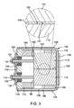
次に図2を参照して説明する。図2は、気密シール型ポリコンデンサー100を示す垂直横断面図である。この垂直横断面図は、図4Aに示すA−A線にそって作図したものである。図2は、気密シール型コンデンサー100の内部をさらに詳細に示す図である。図2に示す通り、導電性ペースト108は筐体102の下側部154の内面、筐体102の陰極端部152の内面、筐体102の上側部158の内面、第1コンデンサー要素110の底部側部182、第1コンデンサー要素110の上側部188、および第1コンデンサー要素110の下側部184に接触しているのが好ましい。この導電性ペースト108については、第1コンデンサー要素110の陽極端部180まで延在していないのが好ましい。
Next, it will be described with reference to FIG. FIG. 2 is a vertical cross-sectional view showing an airtight
第1正リード116については、第1コンデンサー要素110の陽極端部180から延出しているのが好ましく、また適宜使用するブッシュ114を介して延在しているのが好ましい。また、第1正リード116については、これが溶接された第1金属管128を介して延在するのが好ましい。第1金属管128については、GTMS124の第1ガラス絶縁体126内に設けるのが好ましく、またカバー122については、筐体102に溶接するのが好ましい。
The first
陽極絶縁体の直立している第1部分131については、カバー122に設けるのが好ましく、また全体として水平な下部133については、絶縁体104上全体にある筐体102の下側部154にそって延在するのが好ましい。直立している第1部分131については、カバー122のGTMS124を備えた部分上のカバー122にそって延在するのが好ましい。陽極絶縁体130の全体として水平な下部133については、筐体102の下側部154の少なくとも一部にそって延在するのが好ましい。
The upright
陽極端子132については、陽極絶縁体130に設けるのが好ましく、また第1金属管128を介して第1正リード116に電気的に連絡するのが好ましい。陽極端子132の直立している第1部分130については、陽極絶縁体130の下側部154にそって延設するのが好ましく、また全体として水平な下部141については、陽極絶縁体130の上全体にある筐体102の下側部154にそって延設するのが好ましい。陽極端子132の直立している第1部分139の寸法については、陽極絶縁体130の第1部分131より小さくするのが好ましく、このように構成すると、陽極絶縁体130の第1部分131によって陽極端子132の第1部分139をカバー122から完全に絶縁することができる。陽極端子132の全体として水平な下部141については、陽極絶縁体130の水平な下部133にそって延設するのが好ましく、また筐体102の陰極端部152に向けて延設するのが好ましい。
The
陰極端子106については、筐体102の陰極端部に溶接し、電気接続を形成するのが好ましい。陰極端子106の直立している第1部分147については、筐体102の陰極端部152に設けるのが好ましく、また全体として水平な下部149については、陽極絶縁体130の上全体にある筐体102の下側部154に延設するのが好ましい。陰極端子106の直立している第1部分147については、筐体102の陰極端部152の少なくとも一部にそって延設するのが好ましく、また陰極端子106の全体として水平な下部149については、陽極絶縁体130の水平な下部分133の少なくとも一部にそって延設するのが好ましく、隙間によって陽極端子132から分離する。
The
次に図3を参照して説明する。図3は、気密シール型ポリコンデンサー100を示す水平横断面図である。この水平横断面図は、図4Cに示すB−B線にそって作図したものである。図3は、気密シール型コンデンサー100の内部を詳細に示す図である。図3に示す通り、導電性ペースト108は筐体102の下側部156の内面、筐体102の陰極端部152の内面、筐体102の第2横側部160の内面、第1コンデンサー要素110および第2コンデンサー要素112の底部側部182、第2コンデンサー要素112の第1横側部186、および第1コンデンサー要素110の第2横側部190に接触しているのが好ましい。この導電性ペースト108については、第1コンデンサー要素110の陽極端部180および第2コンデンサー要素112まで延在していないのが好ましい。
Next, it will be described with reference to FIG. FIG. 3 is a horizontal cross-sectional view showing the airtight
第1正リード116および第2正リード118については、第1コンデンサー要素110の陽極端部180および第2コンデンサー要素112から延出しているのが好ましく、また適宜使用するブッシュ114を介して延在しているのが好ましい。また、第1正リード116および第2正リード118については、これらが溶接された第1金属管128および第2金属管136を介して延在するのが好ましい。第1金属管128および第2金属管136については、GTMS124の第1ガラス絶縁体126および第2ガラス絶縁体134内に設けるのが好ましく、またカバー122については、筐体102に溶接するのが好ましい。
The first
陽極絶縁体の直立している第1部分131については、カバー122に設けるのが好ましく、またGTMS124を備えるカバー122の部分上にあるカバー122にそって上向きに延設するのが好ましい。
The upright
陽極端子132については、陽極絶縁体130に設けるのが好ましく、また第1金属管128および第2金属管136によって第1正リード116および第2正リード118に電気的に連絡しているのが好ましい。陽極端子132の直立第1部分139については、陽極絶縁体130に設けるのが好ましく、またその寸法が陽極絶縁体130の第1部分131より小さいのが好ましく、このように構成すると、陽極絶縁体130の第1部分131によって陽極端子132の第1部分139をカバー122から完全に分離できるようになる。
The
陰極端子106については、筐体102の陰極端部に溶接し、電気接続を形成するのが好ましい。陰極端子106の直立第1部分147については、筐体102の陰極端部152に設けるのが好ましく、また筐体102の陰極端部152の少なくとも一部にそって延設するのが好ましい。絶縁体104については、筐体102の第1横側部156および筐体102の第2横側部160に設けるのが好ましい。
The
図3の差し込み図に、第1コンデンサー要素110と第2コンデンサー要素112との間の隙間を示す。この隙間には導電性ペースト108を充填するのが好ましい。この拡大部に示す通り、第1コンデンサー要素110および第2コンデンサー要素112の銀メッキ陽極部分120が向き合っている。
The inset of FIG. 3 shows the gap between the
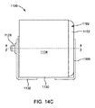
次に、気密シール型ポリマーコンデンサー100を示す異なる斜視図および平面図である図4A〜図4Gを参照して説明を続ける。図4Aは、陽極端部を示す気密シール型ポリマーコンデンサー100の正面図である。図4Bは、陰極端部を示す気密シール型ポリマーコンデンサー100の後面図である。図4Cは、気密シール型ポリマーコンデンサー100の側面図である。図4Dは、筐体102の上側部158を示す気密シール型ポリマーコンデンサー100の上面図である。図4Eは、上記筐体102の下側部154を示す気密シール型ポリマーコンデンサー100の底面図である。図4Fは、陽極端部を示す気密シール型ポリマーコンデンサー100の正面の斜視図である。図4Gは、陰極端部を示す気密シール型ポリマーコンデンサー100の後部の斜視図である。
Next, the description will be continued with reference to FIGS. 4A to 4G, which are different perspective views and plan views showing the airtight seal
図5に、気密シール型ポリマーコンデンサー100の組立方法(集成化方法)を示す。工程502では、所定量の導電性ペースト108を筐体102内部に計量分配するのが好ましい。
FIG. 5 shows an assembly method (assembly method) of the airtight seal
工程504では、第1コンデンサー要素110および第2コンデンサー要素112を筐体102に挿入し、導電性ペースト108に圧入する。第1正リード116および第2正リード118が筐体102の陽極端部150に向かって延在する。
In
適宜採用する工程506では、第1コンデンサー要素110および第2コンデンサー要素112にブッシュ114を設けるのが好ましい。第1正リード116および第2正リード118については、ブッシュ114の孔にねじ込むのが好ましい。
In
カバー122については、筐体102の陽極端部150に設けるのが好ましい。一つかそれ以上のGTMS124の第1金属管128および第2金属管136に第1正リード116および第2正リード118をねじ込む。工程508では、導電性ペースト108を硬化させるのが好ましい。工程510では、筐体102にカバー122をシーム溶接するのが好ましい。
The
工程512では、第1正リード116および第2正リード118を第1金属管128および第2金属管136と同じ長さクリップによって留める。
In
工程514では、コンデンサーアセンブリを乾燥させ、パッケージを除湿するのが好ましい。工程516では、乾燥後に、第1正リード116を一つかそれ以上のGTMS124の第1金属管128に溶接し、第2正リード118を一つかそれ以上のGTMS124の第2金属管136に溶接することによってコンデンサーアセンブリをシールするのが好ましい。
In
工程518では、筐体102の側部に絶縁体104を設けるのが好ましい。工程520では、カバー122に陽極絶縁体130を設け、その孔を第1金属管128および第2金属管136に整合させるのが好ましい。工程522では、陽極端子132を陽極絶縁体130に設けるのが好ましく、またその開口の縁部を第1金属管128および第2金属管136に溶接するのが好ましい。工程524では、陰極端子106を筐体102の陰極端部に溶接するのが好ましい。
In
以下、表面実装気密シール型ポリマーコンデンサー600のもう一つの実施態様の各素子を示す展開図である図6を参照して説明を続ける。気密シール型ポリマーコンデンサー600の場合、設計が上記筐体102と同様な筐体602を備える。この筐体602については、ニッケル、ニッケル系合金、銅、銅系合金、鋼、チタン、およびタンタルなどの金属から構成するのが好ましく、また導電性であるのが好ましい。
Hereinafter, the description will be continued with reference to FIG. 6, which is a developed view showing each element of another embodiment of the surface mount airtight seal
図6〜図9Gに示す向きからみて、筐体602の場合、開放陽極端部650、これに対向する陰極端部652、下側部654、第1横側部656、上側部658、および第2横側部660を備えるのが好ましい。上側部658および下側部654は相互に対向する上壁部および低壁部であり、そして第1横側部656および第2横側部660は相互に対向する側壁部である。開放陽極端部650、陰極端部652、下側部654、上側部658、第1横側部656、および第2横側部660は筐体602の内部領域603を形成することができる。
When viewed from the orientations shown in FIGS. 6 to 9G, in the case of the
筐体602はその内部領域603内に導電性ペースト608、第1陽極ワイヤ634および第1正リード616を有する第1コンデンサー要素610および第2陽極ワイヤ636および第2正リード618を有する第2コンデンサー要素612を収容しているのが好ましい。場合に応じて、筐体602の陽極端部650に向けてブッシュ114を設けることができる。
The
第1コンデンサー要素610および第2コンデンサー要素612のそれぞれについては、筐体の陽極端部650に対応する陽極側部680、筐体602の陰極端部620に対応する底側部682、筐体602の下側部654に対応する下側部684、筐体602の第1横側部656に対応する第1横側部686、筐体602の上側部658に対応する上側部688、および筐体602の第2横側部660に対応する第2横側部690を有するのが好ましい。
For each of the
所定量の導電性ペースト608を筐体602の内部領域603に設けるのが好ましく、このペーストは陰極端部652の内面、下側部654の内面、上側部658の内面、第1横側部656の内面、および第2横側部660の内面の少なくとも一部に接触することができる。この導電性ペースト608については、最初、未硬化状態および/または粘稠状態および/またはペースト状態にあるのが好ましい。この導電性ペースト608については、次に、銀(Ag)などの導電性金属で構成するのが好ましい。一実施例では、導電性ペースト608は無機シリケート水性状態のAgフレークで構成するのが好ましい。別な実施例では、導電性ペースト608はAgエポキシで構成するのが好ましい。所定量の導電性ペースト608については、筐体602内に計量分配するのが好ましい。第1コンデンサー要素610および第2コンデンサー要素612については、筐体602内に挿入し、導電性ペースト608に押し込むか、あるいはその他の手段で設け、これに接触させるのが好ましい。これによって、導電性ペースト608それ自体が分配を行い、第1コンデンサー要素610、第2コンデンサー要素612および筐体602の内面の間に形成する隙間を埋めることになる。導電性ペースト608については、以下に詳しく説明するように、硬化(cured and hardened)するようになっている。
It is preferable to provide a predetermined amount of the
導電性ペースト608の量については、第1コンデンサー要素610および第2コンデンサー要素612の表面の少なくとも一部を覆うのに十分な量でなければならない。この導電性ペースト608については、第1コンデンサー要素610および第2コンデンサー要素612の底側部682を覆うのが好ましく、また第1横側部686、上側部688、第2横側部690および下側部684のほぼ5%〜ほぼ99%を覆うのが好ましい。導電性ペースト608については、陽極側部680まで延在しないことが、あるいはこれを覆うことがないようにするのが好適である。というのは、陽極ワイヤに接触すると、短絡が発生するからである。導電性ペースト608で被覆された表面については銀メッキ陽極表面と呼ぶことも可能である。
The amount of the
第1コンデンサー要素610および第2コンデンサー要素612については、導電性ペースト608によって取り囲むのが好ましい。第1コンデンサー要素610については、この導電性ペースト608の一部によって第2コンデンサー要素612から分離するのが好ましい。第1コンデンサー要素610については、対向する銀メッキ陽極部分620を介して第2コンデンサー要素612に電気的に並列接続するのが好ましい。導電性ペースト608については、硬化して、第1コンデンサー要素610および第2コンデンサー要素612と筐体602との間を信頼性高く電気的に接続するのが好ましい。例示する実施例では、ほぼ80℃〜ほぼ200℃でほぼ0.25時間〜ほぼ3時間導電性ペースト608を硬化するのが好ましい。硬化後、導電性ペースト608を実質的に固体化するのが好ましい。
The
第1コンデンサー要素610および第2コンデンサー要素612については、焼結タンタルスラグで構成するのが好ましい。焼結タンタルスラグについては、電気化学的に酸化し、各タンタルスラグ層上に五酸化タンタル誘電体層を形成し、次に一つかそれ以上の導電性ポリマー層で覆って、コンデンサー要素を形成するのが好ましい。このようなポリマー層については、限定するものではないが、ポリピロール、ポリアニリン、PEDOTやその他の当業者にとっては公知な同様な素材から構成することができる。
The
第1陽極ワイヤ634については、第1コンデンサー要素610の陽極側680から延在し、かつ筐体602の陽極端部650に向かって延在するのが好ましい。筐体602の陽極端部650については、筐体602の陰極端部に対向しているのが好ましい。また、第1陽極ワイヤ634については、焼結タンタルスラグから突き出るワイヤで構成するのが好ましい。第1陽極ワイヤ634については、タンタルで構成するのが好ましい。第1陽極ワイヤ634については、焼結時にタンタルスラグ中に押し込むか、あるいは焼結後にタンタルスラグに溶接するのが好ましい。
It is preferable that the
第2陽極ワイヤ636については、第2コンデンサー要素612の陽極側680から延在し、かつ筐体602の陽極端部650に向かって延在するのが好ましい。第2陽極ワイヤ636については、焼結タンタルスラグから突き出るワイヤで構成するのが好ましい。第2陽極ワイヤ636については、タンタルで構成するのが好ましく、焼結時にタンタルスラグ中に押し込むか、あるいは焼結後にタンタルスラグに溶接するのが好ましい。第1陽極ワイヤ634および第2陽極ワイヤ636については、横断面が実質的に円筒形であり、かつ実質的に真っ直ぐな長さを有しているのが好ましい。
It is preferable that the
第1正リード616については、第1陽極ワイヤ634に溶接するのが好ましく、ニッケル、銅、鋼、チタン、タンタル、および/またはこれらの合金のうちの一つかそれ以上で構成するのが好ましい。第2正リード618については、第2陽極ワイヤ636に溶接するのが好ましく、ニッケル、銅、鋼、チタン、タンタル、および/またはこれらの合金のうちの一つかそれ以上で構成するのが好ましい。第1正リード616および第2正リード618については、横断面が実質的に円筒形であり、かつ実質的に真っ直ぐな長さを有しているのが好ましい。
The first
ブッシュ614を筐体602に設ける場合には、第1コンデンサー要素610と第2コンデンサー要素612とカバー622との間に位置するのが好ましい。ブッシュ614は筐体602の陽極端部650に向かって位置するのが好ましい。このブッシュ614については、ゴムやプラスチックなどの絶縁素材で構成することができる。このブッシュ614については、PTFE、Kapton(R)、PE、およびPPPのうちの一つかそれ以上で構成すればよい。このブッシュ614の形状については、第1正リード616および第2正リード618がブッシュ614の一つかそれ以上の開口を通過できる形状が好ましい。なお、変形実施例ではこのブッシュは使用しない。
When the
カバー622については、筐体602の開放陽極端部650を封鎖するものが好ましく、鋼、ニッケル、銅、チタン、タンタル、および/またはこれらの合金などの金属で構成するのが好ましい。このカバー622の形状については、匡602の開放陽極端部650に嵌合し、かつこれを覆う形状の全体として平坦なパネルまたは壁状であるのが好適である。好ましくは、カバー622は第1正リード616の位置および寸法に対応する第1孔および第2正リード618の位置および寸法に対応する第2孔を有していればよい。筐体602およびカバー622をまとめてコンデンサー本体あるいはデバイス本体と呼ぶこともできる。
The cover 622 preferably closes the
上記カバー622については、カバー622から絶縁する一つかそれ以上のシール、即ち一つかそれ以上のGTMS624を備えているのが好ましい。この一つかそれ以上のGTMS624については、第1ガラス絶縁体626および第1金属管628、および第2ガラス絶縁体635および第2金属管637を備えていることが好ましい。第1ガラス絶縁体626については、カバー622の第1孔に位置するのが好ましく、また第2ガラス絶縁体635については、カバー622の第2孔に位置するのが好ましい。第1正リード616については、第1ガラス絶縁体626を介して延在し、これをカバー622から絶縁できることが好ましく、また第2正リード618については、第2ガラス絶縁体634を介して延在し、これをカバー622から絶縁できることが好ましい。第1金属管628および第2金属管637については、ニッケル、銅、鋼、チタン、タンタル、および/またはこれらの合金のうち一つかそれ以上で構成することができる。第1正リード616については、第1金属管628を介して延在し、同じ長さクリップによって留めるのが好適であり、また第2正リード618についても第2金属管637を介して延在し、同じ長さクリップによって留めるのが好適である。カバー622については、筐体602にシーム溶接し、筐体602の陽極端部650の開口を封鎖するのが好ましい。
The cover 622 preferably has one or more seals that insulate it from the cover 622, i.e. one or
金属管をリードに溶接することによって一つかそれ以上のGTMS624をシールする前に、コンデンサー本体を徹底的に乾燥し、内部領域603、第1コンデンサー要素610、第2コンデンサー要素612、および導電性ペースト608を除湿するのが好ましい。コンデンサー本体を除湿する未完成パッケージの乾燥温度はほぼ120℃〜ほぼ180℃、乾燥時間はほぼ2時間〜8時間が好ましい。
Before sealing one or more GTMS624s by welding a metal tube to the leads, the capacitor body is thoroughly dried,
乾燥処理後、カバー622を筐体602の開放陽極端部650上に溶接し、第1正リード616に第1金属管628を溶接し、かつ第2正リード618に第2金属管637を溶接してパッケージを形成することによってシールを行うことが好ましい。パッケージについては、気密シールするのが好ましい。パッケージ内部の最終湿分については、20℃〜30℃において相対湿度がほぼ25%未満であるのが好ましい。
After the drying process, the cover 622 is welded onto the
筐体602については、絶縁性スリーブを使用することができる絶縁体604を外装するのが好ましい。絶縁体604については、筐体602の下側部654、第1横側部656、上側部658、および筐体602の第2横側部660を覆うことができ、筐体602の陰極端部652およびカバー622は露出したままになっている。絶縁体104については、ポリイミド膜、PTFE、FEP、VITONTM、PVC、ポリウレタンなどを使用するのが好ましい。
For the
陽極絶縁体630については、カバー622上に位置し、絶縁性シムとして形成するのが好ましい。陽極絶縁体630は全体としてL字形であるのが好ましく、直立第1部分631がカバー622にそって延在し、全体として水平な下部633が絶縁体604全体にわたる筐体602の下側部654にそって延在する。なお、これ以外の形状も使用可能である。この直立第1部分631は、GTMS124を有するカバー622の部分上のカバー622にそって上向きに延在する。陽極絶縁体630の全体として水平な下部分633については、筐体602の下側部654の少なくとも一部にそって延在するのが好ましい。
The
陽極絶縁体630については、第1孔638が第1正リード616の位置および寸法に対応し、また第2孔670が第2正リード618の位置および寸法に対応していればよい。第1孔638および第2孔670については、第1正リード616および第1金属管628だけでなく、第2正リード618および第2金属管637が通過でき、第1正リード16および第1金属管628だけでなく、第2正リード618および第2金属管637の整合が容易になり、好ましい。陽極絶縁体630はゴム、プラスチックやテフロンなどの絶縁素材で構成することができ、また好ましくはPTFE、ポリイミド、PE、およびPPPのうちの一つかそれ以上から構成することができる。
For the
陽極端子632については、陽極絶縁体630の上全体に配置するのが好ましく、この端子はGTMS624の金属管を介して第1正リード616および第2正リード618に電気的に連絡する。陽極端子632は全体としてL字形であるのが好ましく、直立第1部分639が陽極絶縁体630の上にあり、かつ全体として水平な下部641が陽極絶縁体630上の筐体602の下側部654にそって延在する。なお、これ以外の形状も使用可能である。陽極端子632の直立第1部分639の寸法が陽極絶縁体630の第1部分631よりも小さいのが好ましく、このように構成すると、陽極端子632の第1部分639を陽極絶縁体630の第1部分631によってカバー622から完全に絶縁できるようになる。陽極端子632の全体として水平な下部641については、陽極絶縁体630の水平下部633の少なくとも一部にそって延在するのが好ましく、また筐体602の陰極端部652に向かって延在するのが好ましい。陽極端子632はニッケル、ニッケル系合金、銅、および銅系合金などの金属で構成するのが好ましい。陽極端子632についてはスズ、鉛、パラジウム、金、および/またはこれらの合金ではんだ付け/メッキすることができる。この陽極端子632が気密シール型コンデンサー600の表面実装端子を形成する。
The
陽極端子632については、第1孔643が第1正リード616の位置および寸法に対応し、かつ第2孔645が第2正リード618の位置および寸法に対応しているのが好ましい。第1孔643および第2孔645については、第1正リード616および第1金属管628だけでなく、第2正リード618および第2金属管637が通過できる。陽極端子632の第1孔643の縁部は第1金属管628に溶接し、電気接続を形成するのが好ましい。陽極端子632の第2孔645の縁部についても第2金属管637に溶接し、電気接続を形成するのが好ましい。
For the
陰極端子606については、筐体602の陰極端部に溶接し、電気接続を形成するのが好ましい。陰極端子606は全体としてL字形であるのが好ましく、直立第1部分647が筐体602の陰極端部652の上にあり、かつ全体として水平な下部649が陰極絶縁体630上において少なくとも筐体602の下側部654にそって延在する。なお、これ以外の形状も使用可能である。陰極端子606の全体として水平な下部649については、陰極絶縁体の水平下部649の少なくとも一部にそって延在するのが好ましく、また陽極端子632から隙間によって分離する。陰極端子606はニッケル、ニッケル系合金、銅、および銅系合金などの金属で構成するのが好ましい。陰極端子606についてはスズ、鉛、パラジウム、金、および/またはこれらの合金ではんだ付け/メッキすることができる。この陰極端子606が気密シール型コンデンサー600の表面実装端子を形成する。
The
次に、気密シール型ポリマーコンデンサー600の垂直横断面図である図7を参照して説明を続ける。この垂直横断面図は図9Aに示すC−C線にそって作図したものである。図7に気密シール型ポリマーコンデンサー600の内部を詳細に示す。図7に示すように、導電性ペースト608は筐体602の下側部654の内面、陰極端子652の内面、上側部658の内面、第1コンデンサー要素610の底側部682、第1コンデンサー要素610の上側部688、および第1コンデンサー要素610の下側部684に接触している。この導電性ペースト608については、第1コンデンサー要素610の陽極端部680まで延設しない。
Next, the description will be continued with reference to FIG. 7, which is a vertical cross-sectional view of the airtight seal
第1陽極ワイヤ634については、第1コンデンサー要素610の陽極端部680から延出しているのが好ましい。第1陽極ワイヤ634および第1正リード616は、適宜使用するブッシュ614を介して延在しているのが好ましい。また、第1正リード616については、これが溶接された第1金属管628を介して延在するのが好ましい。第1金属管628については、GTMS624の第1ガラス絶縁体626内に設けるのが好ましく、またカバー622については、筐体602に溶接するのが好ましい。
The
陽極絶縁体の直立第1部分631については、カバー622に設けるのが好ましく、また全体として水平な下部633については、絶縁体604上全体にある筐体602の下側部654にそって延在するのが好ましい。陽極絶縁体630の直立第1部分631については、カバー622のGTMS624を備えた部分上のカバー622にそって延在するのが好ましい。陽極絶縁体630の全体として水平な下部633については、筐体602の下側部654の少なくとも一部にそって延在するのが好ましい。
The upright
陽極端子632については、陽極絶縁体630に設けるのが好ましく、また第1金属管628を介して第1正リード616に電気的に連絡するのが好ましい。陽極端子632の直立している第1部分639については、陽極絶縁体630に設け、また全体として水平な下部641については、陽極絶縁体630の上全体にある筐体602の下側部654にそって延設するのが好ましい。陽極端子632の直立第1部分639の寸法については、陽極絶縁体630の第1部分631より小さくするのが好ましく、このように構成すると、陽極絶縁体630の第1部分631によって陽極端子632の第1部分639をカバー622から完全に絶縁することができる。陽極端子632の全体として水平な下部641については、陽極絶縁体630の水平な下部633の少なくとも一部にそって延設するのが好ましく、また筐体602の陰極端部652に向けて延設するのが好ましい。
The
陰極端子606については、筐体602の陰極端部に溶接し、電気接続を形成するのが好ましい。陰極端子606の直立第1部分647については、筐体602の陰極端部652に設け、また全体として水平な下部649については、陽極絶縁体630の上全体にある筐体602の下側部654に延設する。陰極端子606の直立している第1部分647については、筐体602の陰極端部652の少なくとも一部にそって延設し、また陰極端子606の全体として水平な下部649については、陽極絶縁体630の水平な下部分633の少なくとも一部にそって延設するのが好ましく、隙間によって陽極端子632から分離する。
The
以下、気密シール型ポリマーコンデンサー600の水平横断面図である図8を参照して説明する。この水平横断面図は図9Cに示すD−D線から作図したものである。図8に示すように、導電性ペースト608については、筐体602の第1横側部656の内面、筐体602の陰極端部652の内面、筐体602の第2横側部660の内面、第1コンデンサー要素610および第2コンデンサー要素612の底部側部682、第2コンデンサー要素612の第1横側部686、および第1コンデンサー要素610の第2横側部690に接触しているのが好ましい。この導電性ペースト608については、第1コンデンサー要素610および第2コンデンサー要素612の陽極端部680まで延設しないのが好適である。
Hereinafter, the airtight seal
第1陽極ワイヤ634および第2陽極ワイヤ636については、第1コンデンサー要素610および第2コンデンサー要素612の陽極端部680から延出しているのが好ましい。第1陽極ワイヤ634、第2陽極ワイヤ636、第1正リード616、および第2正リード618については、適宜使用するブッシュ614を介して延在するのが好ましい。第1正リード616および第2正リーと618については、これらが溶接される第1金属管628および第2金属管636を介して延在するのが好ましい。第1金属管628および第2金属管636については、GTMS624の第1ガラス絶縁体626および第2ガラス絶縁体634内に位置しているのが好ましい。カバー622については、筐体602に溶接するのが好ましい。
The
陽極絶縁体の直立した第1部分631については、カバー622に設けるのが好ましい。直立した第1部分631については、GTMS624を備えたカバー622の部分上のカバー622にそって上向きに延設するのが好ましい。
The upright
陽極端子632については、陽極絶縁体630に設けるのが好ましく、また第1金属管628および第2金属管636を介して第1正リード616および第2正リード618に電気連絡するのが好ましい。陽極端子632の直立第1部分639については、陽極絶縁体630に設けるのが好ましく、その寸法が陽極絶縁体630の第1部分631より小さいのが好ましく、このように構成すると、陽極端子632の第1部分639を陽極絶縁体630の第1部分631によってカバー622から完全に絶縁できる。
The
陰極端子606については、筐体602の陰極端部に溶接し、電気接続を形成するのが好ましい。陰極端子606の直立している第1部分647については、筐体602の陰極端部652に設けるのが好ましい。陰極端子606の直立している第1部分647については、筐体602の陰極端部652の少なくとも一部にそって延在するのが好ましく、また絶縁体604については、筐体602の第1横側部656および筐体602の第2横側部660に設けるのが好ましい。
The
図8の挿入図に、第1コンデンサー要素610と、導電性ペースト608を充填するのが好ましい第2コンデンサー要素612との間の隙間を示す。図示のように、第1コンデンサー要素610および第2コンデンサー要素612の銀メッキ陽極部分620は対向している。
The inset of FIG. 8 shows the gap between the
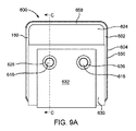
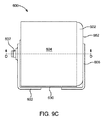
次に、気密シール型ポリマーコンデンサー600の異なる図面である図9A〜図9Gを参照して説明を続ける。図9Aは、気密シール型ポリマーコンデンサー600の正面図であり、陽極端部を示す。図9Bは、気密シール型ポリマーコンデンサー600の背面図であり、陰極端部を示す。図9Cは、気密シール型ポリマーコンデンサー600の側面図である。図9Dは、気密シール型ポリマーコンデンサー600の上面図であり、筐体602の上側部658を示す。図9Eは、気密シール型コンデンサー600の底面図であり、上記の筐体602の下側部654を示す。図9Fは、気密シール型ポリマーコンデンサー600の斜視図であり、陽極端部を示す。図9Gは、気密シール型ポリマーコンデンサー600の後部の斜視図であり、陰極端部を示す。
Next, the description will be continued with reference to FIGS. 9A to 9G, which are different drawings of the airtight seal
図10は、気密シール型ポリマーコンデンサー600の組立方法(集成化方法)を示すフローチャートである。工程1002では、所定量の導電性ペースト608を筐体602内部に計量分配するのが好ましい。
FIG. 10 is a flowchart showing an assembly method (assembly method) of the airtight seal
工程1004では、第1正リード616を第1陽極ワイヤ634に溶接するのが好ましく、また第2正リード618を第2陽極ワイヤ636に溶接するのが好ましい。
In
工程1006では、第1コンデンサー要素610おおよび第2コンデンサー要素612を筐体602に挿入し、導電性ペースト608に圧入する。第1正リード616および第2正リード618が筐体602の陽極端部650に向かって延在できる。
In
適宜採用する工程1008では、第1コンデンサー要素610および第2コンデンサー要素612にブッシュ614を設けるのが好ましい。第1正リード616および第2正リード618については、ブッシュ614の孔にねじ込むのが好ましい。
In the
カバー622については、筐体602の陽極端部650に設けるのが好ましい。一つかそれ以上のGTMS624の第1金属管628および第2金属管637に第1正リード616および第2正リード618をねじ込む。工程1010では、導電性ペースト608を硬化させるのが好ましい。工程1012では、筐体602にカバー622をシーム溶接するのが好ましい。
The cover 622 is preferably provided at the
工程1014では、第1正リード616および第2正リード618を第1金属管628および第2金属管637と同じ長さだけクリップによって留める。
In
工程1016では、コンデンサーアセンブリを乾燥させ、パッケージを除湿するのが好ましい。工程1018では、乾燥後に、第1正リード616を一つかそれ以上のGTMS124の第1金属管628に溶接し、第2正リード618を一つかそれ以上のGTMS624の第2金属管637に溶接することによってコンデンサーアセンブリをシールするのが好ましい。
In
工程1020では、筐体602の側部に絶縁体604を設けるのが好ましい。工程1022では、カバー622に陽極絶縁体630を設け、その孔を第1金属管628および第2金属管637に整合させるのが好ましい。工程1024では、陽極端子632を陽極絶縁体630に設けるのが好ましく、またその孔の縁部を第1金属管628および第2金属管637に溶接するのが好ましい。工程1026では、陰極端子606を筐体602の陰極端部に溶接するのが好ましい。
In
次に、表面実装用気密シール型ポリマーコンデンサー1100の別な実施態様の構成素子を示す分解図である図11を参照して説明を続ける。この気密シール型ポリマーコンデンサー1100については、筐体1102を備えているのが好ましい。この筐体1102については、ニッケル、ニッケル系合金、銅、銅系合金、鋼、チタン、およびタンタルなどの金属から構成するのが好ましく、また導電性であるのが好ましい。
Next, the description will be continued with reference to FIG. 11, which is an exploded view showing the constituent elements of another embodiment of the airtight seal
図11〜図14Gに示す向きからみて、筐体1102の場合、開放陽極端部1150、これに対向する陰極端部1152、下側部1154、第1横側部1156、上側部1158、および第2横側部1160を備えるのが好ましい。上側部1158および下側部1154は相互に対向する上壁部および底壁部であり、そして第1横側部1156および第2横側部1160は相互に対向する側壁部である。開放陽極端部1150、陰極端部1152、下側部1154、上側部1158、第1横側部1156、および第2横側部1160は筐体1102の内部領域1103を形成することができる。
When viewed from the orientation shown in FIGS. 11 to 14G, in the case of the
筐体1102はその内部領域1103内に導電性ペースト1108、第1陽極ワイヤ1134を有する第1コンデンサー要素1110および第2陽極ワイヤ1136を有する第2コンデンサー要素1112を収容しているのが好ましい。第1陽極ワイヤ1134については、クロスワイヤ1138によって第2陽極ワイヤ1138に接続するのが好ましい。正リード1116はクロスワイヤ1138に溶接するのが好ましい。場合に応じて、筐体1102の陽極端部1150に向けてブッシュ1114を設ければよい。
The
第1コンデンサー要素1110および第2コンデンサー要素1112のそれぞれについては、筐体1102の陽極端部1150に対応する陽極側部1180、筐体1102の陰極端部1152に対応する底側部1182、筐体1102の下側部1154に対応する下側部1184、筐体1102の第1横側部1156に対応する第1横側部1186、筐体1102の上側部1158に対応する上側部1188、および筐体1102の第2横側部1160に対応する第2横側部1190を有するのが好ましい。なお、これら側部については、コンデンサー要素の面または表面と考えることができる。
For each of the
所定量の導電性ペースト1108を筐体1102の内部領域1103に設けるか、あるいは供給するのが好ましく、このペーストは陰極端部1152の内面、下側部1154の内面、上側部1158の内面、第1横側部1156の内面、および第2横側部1160の内面の少なくとも一部に接触することができる。この導電性ペースト1108については、最初、未硬化状態および/または粘稠状態および/またはペースト状態にあるのが好ましい。この導電性ペースト1108については、次に、銀(Ag)などの導電性金属で構成するのが好ましい。一実施例では、導電性ペースト1108は無機シリケート水性組成のAgフレークで構成するのが好ましい。別な実施例では、導電性ペースト1108はAgエポキシで構成するのが好ましい。所定量の導電性ペースト1108については、筐体1102の内部領域に計量分配するのが好ましい。第1コンデンサー要素1110および第2コンデンサー要素1112については、筐体1102内に挿入し、導電性ペースト1108に押し込むか、あるいはその他の手段で設け、これに接触させるのが好ましい。これによって、導電性ペースト1108それ自体が分配を行い、第1コンデンサー要素1110、第2コンデンサー要素1112および筐体1102の内面の間に形成する隙間を埋めることになる。導電性ペースト1108については、以下に詳しく説明するように、硬化するようになっている。
It is preferable to provide or supply a predetermined amount of the
導電性ペースト1108の量については、第1コンデンサー要素1110および第2コンデンサー要素1112の表面の少なくとも一部を覆うのに十分な量でなければならない。この導電性ペースト1108については、第1コンデンサー要素1110および第2コンデンサー要素1112の底側部1182を覆い、また下側部1184、第1横側部1186、上側部1188、および第2横側部1190の全部または一部を、例示するとほぼ5%〜ほぼ90%を覆うのが好ましい。導電性ペースト1108については、陽極側部1180まで延在しないことが、あるいはこれを覆うことがないようにするのが好適である。というのは、陽極ワイヤに接触すると、短絡が発生するからである。導電性ペースト1108で被覆された表面については銀メッキ陽極表面と呼ぶことも可能である。
The amount of the
第1コンデンサー要素1110については、既に説明したように、第2コンデンサー要素1112に結合することが好ましい。第1コンデンサー要素1110については、第1陽極ワイヤ1134および第2陽極ワイヤ1136に溶接したクロスワイヤ1138によって第2コンデンサー要素1112に電気的に並列接続することが好ましい。第1コンデンサー要素1110は、第1コンデンサー要素1110と第2コンデンサー要素1112との間の隙間を埋める導電性ペースト1108の一部によって第2コンデンサー要素1112から分離するのが好ましい。また、第1コンデンサー要素1110については、対向する銀メッキ陽極部分1120を介して第2コンデンサー要素1112に電気的に接続するのが好ましい。導電性ペースト1108については、硬化して、第1コンデンサー要素1110および第2コンデンサー要素1112の外面と筐体1102との間を信頼性高く、機械的に電気的に並列接続するのが好ましい。例示する実施例では、ほぼ80℃〜ほぼ200℃でほぼ0.25時間〜ほぼ3時間導電性ペースト108を硬化することができる。硬化後、導電性ペースト1108は実質的に固体化するのが好ましい。
As described above, the
第1コンデンサー要素1110および第2コンデンサー要素1112については、焼結タンタルスラグで構成するのが好ましい。焼結タンタルスラグについては、電気化学的に酸化し、各タンタルスラグ層上に五酸化タンタル誘電体層を形成し、次に一つかそれ以上の導電性ポリマー層で覆って、コンデンサー要素を形成するのが好ましい。このようなポリマー層については、限定するものではないが、ポリピロール、ポリアニリン、PEDOTやその他の当業者にとっては公知な同様な素材から構成することができる。
The
第1陽極ワイヤ1134については、第1コンデンサー要素1110の陽極側1180から突き出、かつ筐体1102の陽極端部1150に向かって延在するのが好ましい。筐体1102の陽極端部1150については、筐体1102の陰極端部1152に対向しているのが好ましい。また、第1陽極ワイヤ1134については、焼結タンタルスラグから突き出るワイヤで構成するのが好ましい。第1陽極ワイヤ1134については、タンタルで構成するのが好ましい。第1陽極ワイヤ1134については、焼結時にタンタルスラグ中に押し込むか、あるいは焼結後にタンタルスラグに溶接するのが好ましい。第2陽極ワイヤ1136については、第2コンデンサー要素1112の陽極側1180から突き出、かつ筐体1102の陽極端部1150に向かって延在するのが好ましい。第2陽極ワイヤ1136については、焼結タンタルスラグから突き出るワイヤで構成するのが好ましい。第2陽極ワイヤ1136については、タンタルで構成するのが好ましく、焼結時にタンタルスラグ中に押し付けるか、あるいは焼結後にタンタルスラグに溶接するのが好ましい。第1陽極ワイヤ1134および第2陽極ワイヤ1136については、横断面が実質的に円筒形であり、かつ実質的に真っ直ぐな長さを有しているのが好ましい。
The
クロスワイヤ1138については、ニッケル、銅、鋼、チタン、タンタル、および/またはこれらの合金のうちの一種かそれ以上で構成するのが好ましい。このクロスワイヤ1138については、第1陽極ワイヤ1134および第2陽極ワイヤ1136に溶接するのが好ましい。正リード1116については、ニッケル、銅、鋼、チタン、タンタル、および/またはこれらの合金のうちの一種かそれ以上で構成するのが好ましい。クロスワイヤ1138および正リード1116については、横断面が実質的に円筒形であり、かつ実質的に真っ直ぐな長さを有しているのが好ましい。
The
ブッシュ1114を筐体1102に設ける場合には、第1コンデンサー要素1110および第2コンデンサー要素1112と、筐体1102の陽極端部1150に位置するカバー1122との間に位置するのが好ましい。このブッシュ1114については、ゴムやプラスチックなどの絶縁素材で構成することができる。このブッシュ1114については、PTFE、Kapton(R)、PE、およびPPPのうちの一つかそれ以上で構成すればよい。このブッシュ1114の形状については、第1正リード1116がブッシュ1114の一つかそれ以上の開口を通過できる形状が好ましい。なお、変形実施例ではこのブッシュは使用しない。
When the
カバー1122については、筐体1102の開放陽極端部1150を封鎖するものが好ましく、鋼、ニッケル、銅、チタン、タンタル、および/またはこれらの合金などの金属で構成するのが好ましい。このカバー1122の形状については、筐体1102の開放陽極端部1150に嵌合し、かつこれを覆う形状の全体として平坦なパネルまたは壁状であるのが好適である。好ましくは、カバー1122は第1正リード1116の位置および寸法に対応する第1孔を有していればよい。筐体1102およびカバー1122をまとめてコンデンサー本体あるいはデバイス本体と呼ぶこともできる。
The
上記カバー1122については、GTMS1124を備えているのが好ましい。このGTMS1124については、ガラス絶縁体1126および金属管1128を備えていることが好ましい。このガラス絶縁体1126については、カバー1122の孔に位置するのが好ましい。金属管1128については、ニッケル、銅、鋼、チタン、タンタル、および/またはこれらの合金のうちの一種かそれ以上で構成するのが好ましい。正リード1116については、ガラス絶縁体1126を介して延在し、これをカバー1122から絶縁できることが好ましい。正リード1116については、金属管1128を介して延在し、同じ長さクリップによって留めるのが好適である。カバー1122については、筐体1102にシーム溶接するのが好ましい。
The
金属管1128を正リード1116に溶接することによってGTMS1124をシールする前に、コンデンサー本体を徹底的に乾燥し、内部領域1103、第1コンデンサー要素1110、第2コンデンサー要素1112、および導電性ペースト1108を除湿するのが好ましい。コンデンサー本体を除湿する乾燥温度はほぼ120℃〜ほぼ180℃、乾燥時間はほぼ2時間〜8時間であるのが好ましい。
Before sealing the
乾燥処理後、カバー1122を筐体1102の開放陽極端部の上全体に溶接し、正リード1116に金属管1128を溶接してパッケージを形成することによってシールを行うことが好ましい。パッケージについては、気密シールするのが好ましい。パッケージ内部の最終湿分については、ほぼ20℃〜30℃において相対湿度がほぼ25%未満であるのが好ましい。
After the drying treatment, it is preferable to weld the
筐体1102については、絶縁性スリーブである絶縁体1104を外装するのが好ましい。絶縁体1104については、筐体1102の下側部1154、第1横側部1156、上側部1158、および第2横側部1160を覆うことができ、筐体1102の陰極端部1152およびカバー1122は露出したままになっている。絶縁体1104については、ポリイミド膜、PTFE、FEP、VITONTM、PVC、ポリウレタンなどを使用するのが好ましい。
For the
陽極絶縁体1130については、カバー1122上に位置し、絶縁性シムとして形成するのが好ましい。陽極絶縁体1130は全体としてL字形であるのが好ましく、直立した第1部分1131がカバー1122にあり、全体として水平な下部1133が絶縁体1104全体にわたる筐体1102の下側部1154にそって延在する。なお、これ以外の形状も使用可能である。この直立した第1部分1131は、GTMS1124を有するカバー1122の部分上のカバー1122にそって上向きに延在する。陽極絶縁体1130の全体として水平な下部分1133については、筐体1102の下側部1154の少なくとも一部にそって延在するのが好ましい。また、陽極絶縁体1130については、孔1135が正リード1116および金属管1128の位置および寸法に対応することができる。孔1135を設けるため、正リード1116および金属管1128が通過でき、正リード1116および金属管金属管1128整合が容易になり、好ましい。陽極絶縁体1130はゴム、プラスチックやテフロンTMなどの絶縁素材で構成することができ、また好ましくはPTFE、ポリイミド、PE、およびPPPのうちの一つかそれ以上から構成することができる。
The
陽極端子1132については、陽極絶縁体1130の上全体に配置するのが好ましく、この端子はGTMS1124の金属管を介して正リード1116に電気的に連絡する。陽極端子1132は全体としてL字形であるのが好ましく、直立した第1部分1139が陽極絶縁体1130の上にあり、かつ全体として水平な下部1141が陽極絶縁体1130上の筐体1102の下側部1154にそって延在する。なお、これ以外の形状も使用可能である。陽極端子1132の直立した第1部分1139の寸法が陽極絶縁体1130の第1部分1131よりも小さいのが好ましく、このように構成すると、陽極端子1132の第1部分1139を陽極絶縁体1130の第1部分1131によってカバー1122から完全に絶縁できるようになる。陽極端子1132の全体として水平な下部1141については、陽極絶縁体1130の水平下部1133の少なくとも一部にそって延在するのが好ましく、また筐体1102の陰極端部1152に向かって延在するのが好ましい。陽極端子1132はニッケル、ニッケル系合金、銅、および銅系合金などの金属で構成するのが好ましい。陽極端子1132についてはスズ、鉛、パラジウム、金、および/またはこれらの合金ではんだ付け/メッキすることができる。この陽極端子1132が気密シール型コンデンサー1100の表面実装端子を形成する。
The
陽極端子1132については、孔1143が正リード1116および金属管1128の位置および寸法に対応しているのが好ましい。この孔1143を設けるため、正リード1116および金属管1128が通過できる。孔1143の縁部は金属管1128に溶接し、電気接続を形成するのが好ましい。
For the
陰極端子1106については、筐体1102の陰極端部に溶接し、電気接続を形成するのが好ましい。陰極端子1106は全体としてL字形であるのが好ましく、直立している第1部分1147が筐体1102の陰極端部の上にあり、かつ全体として水平な下部1149が陰極絶縁体1130上の筐体1102の下側部1154にそって延在する。なお、これ以外の形状も使用可能である。陰極端子1106の直立している第1部分1147は筐体1102の陰極端部1152の少なくとも一部にそって延在するのが好ましい。陰極端子1106の全体として水平な下部1149については、陰極絶縁体1130の水平下部1133の少なくとも一部にそって延在するのが好ましく、また陽極端子1132から隙間によって分離する。陰極端子1106はニッケル、ニッケル系合金、銅、および銅系合金などの金属で構成するのが好ましい。陰極端子1106についてはスズ、鉛、パラジウム、金、および/またはこれらの合金ではんだ付け/メッキすることができる。この陰極端子1106が気密シール型コンデンサー1100の表面実装端子を形成する。
The
次に図12を参照して説明する。図12は、気密シール型ポリコンデンサー1100を示す垂直横断面図である。この垂直横断面図は、図14Aに示すE−E線にそって作図したものである。図12は、気密シール型コンデンサー1100の内部をさらに詳細に示す図である。図7は、導電性ペースト1108は筐体1102の下側部1154の内面、筐体1102の陰極端部1152の内面、および筐体1102の上側部1158の内面に接触していることを示す。導電性ペースト1108は、第1コンデンサー要素1110の第1横側部1186、第1コンデンサー要素1110の底部側部1182、第1コンデンサー要素1110の上側部1188、および第1コンデンサー要素1110の下側部1184に接触しているのが好ましい。この導電性ペースト1108については、第1コンデンサー要素1110の陽極端部1180まで延在していない。
Next, it will be described with reference to FIG. FIG. 12 is a vertical cross-sectional view showing the airtight
陽極ワイヤ1134については、第1コンデンサー要素1110の陽極端部1180から延出し、この陽極ワイヤ1134、クロスワイヤ1138および正リード1116については、適宜使用するブッシュ1114を介して延在する。また、正リード1116については、これが溶接された金属管1128を介して延在する。金属管1128については、GTMS1124の第1ガラス絶縁体1126内に設け、またカバー1122については、筐体1102に溶接される。
The
陽極絶縁体の直立している第1部分1131については、カバー1122に設け、また全体として水平な下部1133については、絶縁体1104上全体にある筐体1102の下側部1154にそって延在するのが好ましい。直立している第1部分131については、カバー1122のGTMS1124を備えた部分上のカバー1122にそって延在する。陽極絶縁体1130の全体として水平な下部1133については、筐体1102の下側部1154の少なくとも一部にそって延在するのが好ましい。
The upright first portion 1131 of the anode insulator is provided on the
陽極端子1132については、陽極絶縁体1130に設けられ、また金属管1128を介して正リード1116に電気的に連絡する。陽極端子1132の直立している第1部分1139については、陽極絶縁体1130に設け、また全体として水平な下部1141については、陽極絶縁体1130の上全体にある筐体1102の下側部1154にそって延設する。陽極端子1132の直立している第1部分1139の寸法については、陽極絶縁体1130の第1部分1131より小さくするのが好ましく、このように構成すると、陽極絶縁体1130の第1部分1131によって陽極端子1132の第1部分1139をカバー1122から完全に絶縁することができる。陽極端子1132の全体として水平な下部1141については、陽極絶縁体1130の水平な下部1133にそって延設するのが好ましく、また筐体1102の陰極端部1152に向けて延設するのが好ましい。
The
陰極端子1106については、筐体1102の陰極端部に溶接し、電気接続を形成するのが好ましい。陰極端子1106の直立している第1部分1147については、筐体1102の陰極端部1152に設け、また全体として水平な下部1149については、陽極絶縁体1130の上全体にある筐体1102の下側部1154にそって延設する。陰極端子1106の直立している第1部分1147については、筐体1102の陰極端部1152の少なくとも一部にそって延設し、また陰極端子1106の全体として水平な下部1149については、陽極絶縁体1130の水平な下部分1133の少なくとも一部にそって延設するのが好ましく、隙間によって陽極端子1132から分離する。
The
次に図13を参照して説明する。図13は、気密シール型ポリコンデンサー1100を示す水平横断面図である。この水平横断面図は、図14Cに示すF−F線にそって作図したものである。図13に示すように、導電性ペースト1108は筐体1102の第1横側部1156の内面、筐体1102の陰極端部1152の内面、筐体の第2横側部1160の内面、第1コンデンサー要素1110および第2コンデンサー要素1112の底側部1182、第2コンデンサー要素1112の第1横側部1186、および第1コンデンサー要素1110の第2横側部1190に接触しているのが好ましい。この導電性ペースト1108については、第2コンデンサー要素1112及び第1コンデンサー要素1110の陽極端部1180まで延在していないのが好ましい。
Next, it will be described with reference to FIG. FIG. 13 is a horizontal cross-sectional view showing the airtight
第1陽極ワイヤ1134および第2陽極ワイヤ1136については、第1コンデンサー要素1110および第2コンデンサー要素1112の陽極端部1180から延出しているのが好ましく、この第1陽極ワイヤ1134、第2陽極ワイヤ1136、クロスワイヤ1138および正リード1116については、適宜使用するブッシュ1114を介して延在しているのが好ましい。また、正リード1116については、これが溶接された金属管1128を介して延在するのが好ましい。金属管1128については、GTMS1124の第1ガラス絶縁体1126内に設け、またカバー1122については、筐体1102に溶接するのが好ましい。
The
陽極絶縁体の直立している第1部分1131については、カバー1122に設け、またカバー1122のGTMS1124を備えた部分上のカバー1122にそって延在しているのが好ましい。
The upright first portion 1131 of the anode insulator is preferably provided on the
陽極端子1132については、陽極絶縁体1130に設けるのが好ましく、また金属管1128を介して正リード1116に電気的に連絡するのが好ましい。陽極端子1132の直立している第1部分1139については、陽極絶縁体1130に設けるのが好ましく、その寸法を陽極絶縁体1130の第1部分1131より小さくするのが好ましく、このように構成すると、陽極絶縁体1130の第1部分1131によって陽極端子1132の第1部分1139をカバー1122から完全に絶縁することができる。
The
陰極端子1106については、筐体1102の陰極端部に溶接し、電気接続を形成するのが好ましい。陰極端子1106の直立している第1部分1147については、筐体1102の陰極端部1152に設けるのが好ましい。陰極端子1106の直立している第1部分1147については、筐体1102の陰極端部1152の少なくとも一部にそって延設するのが好ましく、絶縁体1104については、筐体1102の第1横側部1156および筐体1102の第2横側部1160に設けるのが好ましい。
The
図13の挿入図に、第1コンデンサー要素1110と第2コンデンサー要素1112との間の隙間を示すが、この隙間については導電性ペースト1108で埋めるのがこうてきである。この挿入図は、第1コンデンサー要素1110と第2コンデンサー要素1112の対向する銀メッキ陽極部分1120を示すものである。
The insertion diagram of FIG. 13 shows a gap between the
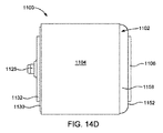
次に、気密シール型ポリマーコンデンサーを示す異なる図である図14A〜図14Gを参照して説明を続ける。図14Aは、陽極端部を示す気密シール型ポリマーコンデンサー1100の正面図である。図14Bは、陰極端部を示す気密シール型ポリマーコンデンサー1100の後面図である。図14Cは、気密シール型ポリマーコンデンサー100の側面図である。図14Dは、筐体1102の上側部1158を示す気密シール型ポリマーコンデンサー100の上面図である。図14Eは、上記筐体1102の下側部1154を示す気密シール型ポリマーコンデンサー1100の底面図である。図14Fは、陽極端部を示す気密シール型ポリマーコンデンサー1100の正面の斜視図である。図14Gは、陰極端部を示す気密シール型ポリマーコンデンサー1100の後部の斜視図である。
Next, the description will be continued with reference to FIGS. 14A to 14G, which are different views showing the airtight seal type polymer capacitor. FIG. 14A is a front view of the airtight seal
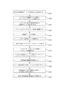
図15に、気密シール型ポリマーコンデンサー1100の組立方法(集成化方法)を示す。工程1502では、所定量の導電性ペースト1108を筐体1102内部に計量分配するのが好ましい。
FIG. 15 shows an assembly method (assembly method) of the airtight seal
工程1504では、第1陽極ワイヤ1134および第2陽極ワイヤ1136をクロスワイヤ1138に溶接するのが好ましい。そして正リード1116をクロスワイヤ1138に溶接するのが好ましい。
In
工程1506では、第1コンデンサー要素1110および第2コンデンサー要素1112を筐体1102に挿入し、導電性ペースト1108内に圧入するのが好ましい。正リード1116については、筐体1102の陽極端部1150に向けて延在させればよい。
In
適宜採用する工程1508で、第1コンデンサー要素1110および第2コンデンサー要素1112にブッシュ1114を設けるのが好ましい。正リード1116、クロスワイヤ1138、第1陽極ワイヤ1134および第2陽極ワイヤ1136をブッシュ1114の孔にねじ込むのが好ましい。
In
カバー1122を筐体に設けるのが好ましい。GTMS1124の第1金属管1128に第1正リード1116をねじ込む。
It is preferable to provide the
工程1510では、導電性ペースト108を硬化させるのが好ましい。工程1512では、筐体1102にカバー1122をシーム溶接するのが好ましい。
In
工程1514では、正リード1116を金属管1128と同じ長さクリップによって留めるのが好ましい。
In
工程1516では、コンデンサーアセンブリを乾燥させ、パッケージを除湿するのが好ましい。工程1518では、乾燥後に、正リード1116をGTMS1124の金属管1128に溶接することによってコンデンサーアセンブリをシールするのが好ましい。
In
工程1520では、筐体1102の側部に絶縁体1104を設けるのが好ましい。工程1522では、カバー1122に陽極絶縁体1130を設け、その孔を金属管1128に整合させるのが好ましい。工程1524では、陽極端子1132を陽極絶縁体1130に設けるのが好ましく、またその孔の縁部を金属管1128に溶接するのが好ましい。工程1526では、陰極端子1106を筐体1102の底部分に溶接するのが好ましい。
In
本発明の実施態様に関する以上の説明は、例示を目的とするものである。この説明は徹底的なものではなく、また本発明を開示する正確な形態に限定するものでもなく、多数の変更例や修正例が以上の開示に照らして可能である。実施態様については、本発明技術の原理およびその技術的な展開を説明するもので、これによって当業者ならば、意図する特定の用途に応じて本発明技術および各種の変更を含む各種の実施態様を最善の形で実施できるはずである。添付図面および明細書には本発明の好適な実施態様を示すが、使用した具体的な用語に関しては、包括的かつ説明的な用語に過ぎず、限定的なものではない。各部材の形態などや等価部材への置換については、請求項の記載する本発明の精神および範囲から逸脱しなくても、状況に応じて変更可能である。
The above description of embodiments of the present invention is for purposes of illustration. This description is not exhaustive and is not limited to the exact form in which the invention is disclosed, and numerous modifications and modifications are possible in light of the above disclosure. Embodiments will illustrate the principles of the present invention and its technological developments, whereby those skilled in the art will appreciate various embodiments, including the invention and various modifications, depending on the particular application intended. Should be able to be implemented in the best possible way. The accompanying drawings and the specification show preferred embodiments of the present invention, but the specific terms used are only comprehensive and descriptive terms and are not limited. The form of each member and the replacement with an equivalent member can be changed depending on the situation without departing from the spirit and scope of the present invention described in the claims.
100 気密シール型ポリマーコンデンサー
102 筐体
103 内部領域
104 絶縁体
108 導電性ペースト
110 第1コンデンサー要素
112 第2コンデンサー要素
114 ブッシュ
116 第1正リード
118 第2正リード
122 カバー
124 ガラス/金属シール(GTMS)
126 第1ガラス絶縁体
128 第1金属管
130 陽極絶縁体
131 第1部分
132 陽極端子
133 下部
134 第2ガラス絶縁体
135 第1孔
136 第2金属管
137 第2孔
139 第1部分
141 下部
143 第1孔
145 第2孔
147 直立第1部分
150 開放陽極端部
152 陰極端部
154 下側部
156 第1横側部
158 上側部
160 第2横側部
180 陽極側
182 底側部
184 下側部
186 第1横側部
188 上側部
190 第2横側部
502 工程
504 工程
506 工程
508 工程
510 工程
512 工程
514 工程
516 工程
518 工程
520 工程
522 工程
524 工程
600 気密シール型ポリマーコンデンサー
602 筐体
603 内部領域
604 絶縁体
606 陰極端子
608 導電性ペースト
610 第1コンデンサー要素
612 第2コンデンサー要素
614 ブッシュ
616 第1正リード
618 第2正リード
620 陰極端部
622 カバー
624 GTMS
626 第1ガラス絶縁体
628 第1金属管
630 陽極絶縁体
631 第1部分
632 陽極端子
633 水平下部
634 第1陽極ワイヤ
635 第2ガラス絶縁体
636 第2陽極ワイヤ
637 第2金属管
638 第1孔
639 直立第1部分
641 下部
643 第1孔
645 第2孔
647 直立第1部分
649 下部
650 開放陽極端部
652 陰極端部
654 下側部
656 第1横側部
658 上側部
660 第2横側部
670 第2孔
680 陽極側部
682 底側部
684 下側部
686 第1横側部
688 上側部
690 第2横側部
1002 工程
1004 工程
1006 工程
1008 工程
1010 工程
1012 工程
1014 工程
1016 工程
1018 工程
1020 工程
1022 工程
1024 工程
1026 工程
1100 気密シール型ポリマーコンデンサー
1102 筐体
1103 内部領域
1104 絶縁体
1106 陰極端子
1108 内導電性ペースト
1110 第1コンデンサー要素
1112 第2コンデンサー要素
1114 ブッシュ
1116 正リード
1122 カバー
1124 GTMS
1126 ガラス絶縁体
1128 金属管
1130 陽極絶縁体
1131 第1部分
1132 陽極端子
1133 下部
1134 第1陽極ワイヤ
1135 孔
1136 第2陽極ワイヤ
1138 クロスワイヤ、第2陽極ワイヤ
1139 第1部分
1141 下部
1143 孔
1147 第1部分
1149 下部
1150 開放陽極端部
1152 陰極端部
1154 下側部
1156 第1横側部
1158 上側部
1160 第2横側部
1180 陽極側部
1182 底側部
1184 下側部
1186 第1横側部
1188 上側部
1190 第2横側部
1502 工程
1504 工程
1506 工程
1508 工程
1510 工程
1512 工程
1514 工程
1516 工程
1518 工程
1520 工程
1522 工程
1524 工程
1526 工程
100 Airtight seal
126
626
1126
Claims (15)
未硬化状態で前記内部領域内に設けられ、硬化状態に硬化する導電性ペーストと、
前記内部領域内に位置し、一つかそれ以上のコンデンサー要素の表面の少なくとも一部を覆う前記導電性ペーストに接触する一つかそれ以上のコンデンサー要素と、
前記一つかそれ以上のコンデンサー要素の陽極側に結合し、かつ前記陽極端部に向かって延在する一つかそれ以上の正リードと、
前記一つかそれ以上の正リードに電気的に連絡し、かつ前記コンデンサー本体から絶縁された表面実装陽極端子と、
前記コンデンサー本体に電気的に連絡する表面実装陰極端子と、
を有することを特徴とする気密シール型ポリマーコンデンサー。
A capacitor body with an internal region, cathode end and anode end,
A conductive paste provided in the internal region in an uncured state and cured in a cured state,
With one or more capacitor elements located within the internal region and in contact with the conductive paste covering at least a portion of the surface of one or more capacitor elements.
With one or more positive leads coupled to the anode side of the one or more capacitor elements and extending towards the anode end.
A surface mount anode terminal that electrically contacts one or more positive leads and is insulated from the capacitor body.
A surface mount cathode terminal that electrically connects to the capacitor body,
An airtight seal type polymer capacitor characterized by having.
The one or more capacitor elements have at least two capacitor elements, and these capacitor elements are positioned adjacent to each other in the internal region of the capacitor body with a gap between the capacitor elements. The airtight seal type polymer capacitor according to claim 1, wherein at least a part of the conductive paste is located at least partially in this gap.
Further having a bush, the bush is located between the anode side of the one or more capacitor elements and the anode end of the capacitor body, the bush having one or more openings. The airtight sealed polymer capacitor according to claim 1, wherein the one or more positive leads extend into the one or more openings.
The airtight seal type polymer capacitor according to claim 1, wherein the capacitor body has a housing, the housing has an open anode, and a cover is welded to the housing at the anode end.
The cover has one or more holes, and one or more glass / metal seals (GTMS) located in these holes, and the one or more positive leads are one or more of these. The airtight seal type polymer capacitor according to claim 4, which is received by GTMS.
The airtightness of claim 5, wherein the one or more GTMSs have one or more metal tubes insulated from the cover by glass and the one or more positive leads are welded to these metal tubes. Sealed polymer condenser.
The polymer capacitor according to claim 1, wherein the relative humidity of the capacitor body is less than about 25% at about 20 ° C. to about 30 ° C.
The one or more positive leads have a first anode wire and a second anode wire, and further have a crosswire that electrically couples the first anode wire to the second anode wire, the crosswire. The airtight seal type polymer capacitor according to claim 1, which electrically communicates with the anode terminal.
前記内部領域に所定量の、硬化状態に硬化する導電性ペーストを未硬化状態で計量分配し、
一つかそれ以上のコンデンサー要素を前記内部領域に挿入しかつ前記導電性ペーストに接触させて、前記一つかそれ以上のコンデンサー要素の陽極側を、前記筐体の陽極端部に向かって延在する前記一つかそれ以上の正リードに結合し、この導電性ペーストによって前記一つかそれ以上のコンデンサー要素の表面の少なくとも一部を覆い、
前記導電性ペーストを硬化させ、
前記筐体の陽極端部の上全体に溶接してコンデンサー本体を形成し、
このコンデンサー本体を乾燥し、
前記一つかそれ以上の正リードに電気的に連絡し、かつ前記コンデンサー本体から絶縁される位置に表面実装陽極端子を設け、そして
前記筐体に電気的に連絡する位置に表面実装陰極端子を設けることを特徴とする気密シール型ポリマーコンデンサーの製造方法。
Forming a housing with an internal region, cathode end and anode end,
A predetermined amount of the conductive paste that cures in a cured state is weighed and distributed in the internal region in an uncured state.
One or more capacitor elements are inserted into the internal region and brought into contact with the conductive paste to extend the anode side of the one or more capacitor elements towards the anode end of the housing. Bond to the one or more positive leads and cover at least a portion of the surface of the one or more capacitor elements with this conductive paste.
The conductive paste is cured and
Welding over the entire top of the anode end of the housing to form the capacitor body,
Dry this condenser body and
A surface mount anode terminal is provided at a position that electrically communicates with one or more positive leads and is insulated from the capacitor body, and a surface mount cathode terminal is provided at a position that electrically communicates with the housing. A method for manufacturing an airtight seal type polymer capacitor.
In a state where the one or more capacitor elements have at least two capacitor elements and there is a gap between these capacitor elements, the capacitor elements are arranged adjacent to each other in the internal region of the capacitor body, and in the gap. The method according to claim 9, wherein at least a part of the conductive paste is provided at least partially.
11. The manufacturing method according to claim 11, wherein the capacitor body has a housing, the housing has an open anode end portion, and a cover is welded to the housing at the anode end portion.
The cover has one or more holes, and further has one or more glass / metal seals (GTMS) located in these holes, and one or more of these GTMSs. The manufacturing method according to claim 11, wherein the positive lead is received.
12. The manufacturing method according to claim 12, wherein the GTMS has one or more metal tubes insulated from the cover by glass, and the one or more positive leads are welded to these metal tubes.
The manufacturing method according to claim 9, wherein the relative humidity of the condenser body is less than about 25% at about 20 ° C. to about 30 ° C.
Applications Claiming Priority (3)
| Application Number | Priority Date | Filing Date | Title |
|---|---|---|---|
| US16/115,021 | 2018-08-28 | ||
| US16/115,021 US11024464B2 (en) | 2018-08-28 | 2018-08-28 | Hermetically sealed surface mount polymer capacitor |
| PCT/IL2019/050947 WO2020044330A1 (en) | 2018-08-28 | 2019-08-22 | Hermetically sealed surface mount polymer capacitor |
Publications (2)
| Publication Number | Publication Date |
|---|---|
| JP2021535602A true JP2021535602A (en) | 2021-12-16 |
| JPWO2020044330A5 JPWO2020044330A5 (en) | 2022-08-26 |
Family
ID=69640175
Family Applications (1)
| Application Number | Title | Priority Date | Filing Date |
|---|---|---|---|
| JP2021510157A Pending JP2021535602A (en) | 2018-08-28 | 2019-08-22 | Airtight seal type surface mount polymer capacitor |
Country Status (8)
| Country | Link |
|---|---|
| US (1) | US11024464B2 (en) |
| EP (1) | EP3830851A4 (en) |
| JP (1) | JP2021535602A (en) |
| KR (1) | KR102626144B1 (en) |
| CN (1) | CN112840423B (en) |
| IL (1) | IL281071A (en) |
| TW (1) | TW202016959A (en) |
| WO (1) | WO2020044330A1 (en) |
Families Citing this family (1)
| Publication number | Priority date | Publication date | Assignee | Title |
|---|---|---|---|---|
| US11742149B2 (en) * | 2021-11-17 | 2023-08-29 | Vishay Israel Ltd. | Hermetically sealed high energy electrolytic capacitor and capacitor assemblies with improved shock and vibration performance |
Family Cites Families (64)
| Publication number | Priority date | Publication date | Assignee | Title |
|---|---|---|---|---|
| US3795844A (en) | 1973-02-26 | 1974-03-05 | Sprague Electric Co | Electronic component package |
| US3956819A (en) | 1974-12-02 | 1976-05-18 | Augeri Stephen L | Method of assembling a tantelum capacitor |
| US4987519A (en) | 1990-03-26 | 1991-01-22 | Sprague Electric Company | Hermetically sealed aluminum electrolytic capacitor |
| US6594140B1 (en) | 1993-03-22 | 2003-07-15 | Evans Capacitor Company Incorporated | Capacitor |
| US6402793B1 (en) | 1998-04-03 | 2002-06-11 | Medtronic, Inc. | Implantable medical device having flat electrolytic capacitor with cathode/case electrical connections |
| US6493212B1 (en) | 1998-04-03 | 2002-12-10 | Medtronic, Inc. | Implantable medical device having flat electrolytic capacitor with porous gas vent within electrolyte fill tube |
| US6238444B1 (en) | 1998-10-07 | 2001-05-29 | Vishay Sprague, Inc. | Method for making tantalum chip capacitor |
| US6699265B1 (en) | 2000-11-03 | 2004-03-02 | Cardiac Pacemakers, Inc. | Flat capacitor for an implantable medical device |
| US6576524B1 (en) | 2001-07-20 | 2003-06-10 | Evans Capacitor Company Incorporated | Method of making a prismatic capacitor |
| US6791821B1 (en) | 2001-10-16 | 2004-09-14 | Yosemite Investment, Inc. | Tantalum-carbon hybrid capacitor with activated carbon |
| US7079377B2 (en) | 2002-09-30 | 2006-07-18 | Joachim Hossick Schott | Capacitor and method for producing a capacitor |
| US6850405B1 (en) | 2002-12-16 | 2005-02-01 | Wilson Greatbatch Technologies, Inc. | Dual anode capacitor interconnect design |
| US6859353B2 (en) | 2002-12-16 | 2005-02-22 | Wilson Greatbatch Technologies, Inc. | Capacitor interconnect design |
| US7917217B2 (en) | 2003-05-07 | 2011-03-29 | Medtronic, Inc. | Wet tantalum reformation method and apparatus |
| US6807048B1 (en) | 2003-05-30 | 2004-10-19 | Medtronic, Inc. | Electrolytic capacitor for use in an implantable medical device |
| US7555339B2 (en) | 2004-02-06 | 2009-06-30 | Medtronic, Inc. | Capacitor designs for medical devices |
| US7085127B2 (en) | 2004-03-02 | 2006-08-01 | Vishay Sprague, Inc. | Surface mount chip capacitor |
| US6952339B1 (en) | 2004-05-13 | 2005-10-04 | Todd Knowles | Tantalum capacitor case with increased volumetric efficiency |
| US7420797B2 (en) | 2004-07-16 | 2008-09-02 | Cardiac Pacemakers, Inc. | Plug for sealing a capacitor fill port |
| US7224575B2 (en) | 2004-07-16 | 2007-05-29 | Cardiac Pacemakers, Inc. | Method and apparatus for high voltage aluminum capacitor design |
| JP4450378B2 (en) * | 2004-10-27 | 2010-04-14 | Necトーキン株式会社 | Surface mount capacitor and method of manufacturing the same |
| JP2006319113A (en) * | 2005-05-12 | 2006-11-24 | Rohm Co Ltd | Plate mounting solid electrolytic capacitor and method for manufacturing |
| US7161797B2 (en) * | 2005-05-17 | 2007-01-09 | Vishay Sprague, Inc. | Surface mount capacitor and method of making same |
| WO2007001199A1 (en) | 2005-06-24 | 2007-01-04 | Universal Supercapacitors Llc | Heterogeneous electrochemical supercapacitor and method of manufacture |
| JP4836959B2 (en) | 2005-10-24 | 2011-12-14 | 三洋電機株式会社 | Solid electrolytic capacitor |
| US20070231681A1 (en) | 2006-03-31 | 2007-10-04 | Casby Kurt J | Immobilization system for an electrochemical cell |
| US7773367B1 (en) | 2006-04-27 | 2010-08-10 | Tantalum Pellet Company | Capacitor |
| US7274551B1 (en) | 2006-10-26 | 2007-09-25 | Cornell-Dubilier Marketing, Inc. | Hermetically sealed electrolytic capacitor |
| US7460356B2 (en) | 2007-03-20 | 2008-12-02 | Avx Corporation | Neutral electrolyte for a wet electrolytic capacitor |
| US20080247122A1 (en) | 2007-04-06 | 2008-10-09 | Vishay Sprague, Inc. | Capacitor with improved volumetric efficiency and reduced cost |
| JP5041996B2 (en) * | 2007-12-07 | 2012-10-03 | 三洋電機株式会社 | Solid electrolytic capacitor |
| US7983022B2 (en) | 2008-03-05 | 2011-07-19 | Greatbatch Ltd. | Electrically connecting multiple cathodes in a case negative multi-anode capacitor |
| EP2266125B1 (en) | 2008-03-20 | 2016-04-27 | Vishay Sprague, Inc. | Electrophoretically deposited cathode capacitor |
| US8094434B2 (en) | 2008-04-01 | 2012-01-10 | Avx Corporation | Hermetically sealed capacitor assembly |
| US7867290B2 (en) | 2009-01-12 | 2011-01-11 | Medtronic, Inc. | Separator filled with electrolyte |
| US8405956B2 (en) | 2009-06-01 | 2013-03-26 | Avx Corporation | High voltage electrolytic capacitors |
| US20100268292A1 (en) | 2009-04-16 | 2010-10-21 | Vishay Sprague, Inc. | Hermetically sealed wet electrolytic capacitor |
| JP2011003827A (en) | 2009-06-22 | 2011-01-06 | Panasonic Corp | Electronic component |
| US20150004478A1 (en) | 2010-04-29 | 2015-01-01 | Greatbatch Ltd. | Novel Method For Gold Plated Termination of Hermetic Device |
| US8259436B2 (en) * | 2010-08-03 | 2012-09-04 | Avx Corporation | Mechanically robust solid electrolytic capacitor assembly |
| US8605411B2 (en) | 2010-09-16 | 2013-12-10 | Avx Corporation | Abrasive blasted conductive polymer cathode for use in a wet electrolytic capacitor |
| US8514547B2 (en) | 2010-11-01 | 2013-08-20 | Avx Corporation | Volumetrically efficient wet electrolytic capacitor |
| US8259435B2 (en) | 2010-11-01 | 2012-09-04 | Avx Corporation | Hermetically sealed wet electrolytic capacitor |
| US20120127632A1 (en) | 2010-11-19 | 2012-05-24 | Evans Capacitor Company | Extended life capacitors |
| US8687347B2 (en) | 2011-01-12 | 2014-04-01 | Avx Corporation | Planar anode for use in a wet electrolytic capacitor |
| US8477479B2 (en) | 2011-01-12 | 2013-07-02 | Avx Corporation | Leadwire configuration for a planar anode of a wet electrolytic capacitor |
| CN103477406B (en) | 2011-02-04 | 2017-10-20 | 维莎斯普拉格公司 | Hermetic type electrolytic capacitor |
| US8300387B1 (en) | 2011-04-07 | 2012-10-30 | Avx Corporation | Hermetically sealed electrolytic capacitor with enhanced mechanical stability |
| US8947857B2 (en) | 2011-04-07 | 2015-02-03 | Avx Corporation | Manganese oxide capacitor for use in extreme environments |
| JP5466722B2 (en) * | 2011-04-15 | 2014-04-09 | Necトーキン株式会社 | Solid electrolytic capacitor |
| US8451586B2 (en) | 2011-09-13 | 2013-05-28 | Avx Corporation | Sealing assembly for a wet electrolytic capacitor |
| US8741214B2 (en) | 2011-10-17 | 2014-06-03 | Evans Capacitor Company | Sintering method, particularly for forming low ESR capacitor anodes |
| US9105401B2 (en) | 2011-12-02 | 2015-08-11 | Avx Corporation | Wet electrolytic capacitor containing a gelled working electrolyte |
| US9076592B2 (en) | 2012-03-16 | 2015-07-07 | Avx Corporation | Wet capacitor cathode containing a conductive coating formed anodic electrochemical polymerization of a microemulsion |
| US9147530B2 (en) * | 2012-09-05 | 2015-09-29 | Kemet Electronics Corporation | Hermetically sealed polymer capacitors with high stability at elevated temperatures |
| JP5202753B1 (en) | 2012-10-16 | 2013-06-05 | 太陽誘電株式会社 | Electrochemical capacitor |
| US9053863B2 (en) | 2013-03-06 | 2015-06-09 | Cooper Technologies Company | Electrochemical energy storage device with coincident electrical terminal and electrolyte fill hole |
| GB2512481B (en) * | 2013-03-15 | 2018-05-30 | Avx Corp | Wet electrolytic capacitor for use at high temperatures |
| US9355789B2 (en) | 2013-05-10 | 2016-05-31 | Greatbatch Ltd. | Internal insulation design using porous material for an electrochemical cell |
| TW201714191A (en) | 2015-10-14 | 2017-04-16 | 鈺邦科技股份有限公司 | Solid electrolytic capacitor package structure and method of manufacturing the same |
| US9875855B2 (en) * | 2015-10-30 | 2018-01-23 | Greatbatch Ltd. | High voltage tantalum capacitor with improved cathode/separator design and method of manufacture |
| US20170125178A1 (en) * | 2015-10-30 | 2017-05-04 | Greatbatch Ltd. | High voltage dual anode tantalum capacitor with facing casing clamshells contacting an intermediate partition |
| US9947479B2 (en) | 2015-11-16 | 2018-04-17 | Vishay Sprague, Inc. | Volumetric efficiency wet electrolyte capacitor having a fill port and terminations for surface mounting |
| US10186382B2 (en) * | 2016-01-18 | 2019-01-22 | Avx Corporation | Solid electrolytic capacitor with improved leakage current |
-
2018
- 2018-08-28 US US16/115,021 patent/US11024464B2/en active Active
-
2019
- 2019-08-22 WO PCT/IL2019/050947 patent/WO2020044330A1/en active Search and Examination
- 2019-08-22 EP EP19854375.3A patent/EP3830851A4/en active Pending
- 2019-08-22 JP JP2021510157A patent/JP2021535602A/en active Pending
- 2019-08-22 KR KR1020217008989A patent/KR102626144B1/en active IP Right Grant
- 2019-08-22 CN CN201980067448.6A patent/CN112840423B/en active Active
- 2019-08-27 TW TW108130548A patent/TW202016959A/en unknown
-
2021
- 2021-02-24 IL IL281071A patent/IL281071A/en unknown
Also Published As
| Publication number | Publication date |
|---|---|
| WO2020044330A1 (en) | 2020-03-05 |
| IL281071A (en) | 2021-04-29 |
| TW202016959A (en) | 2020-05-01 |
| US20200075264A1 (en) | 2020-03-05 |
| US11024464B2 (en) | 2021-06-01 |
| CN112840423B (en) | 2023-06-16 |
| CN112840423A (en) | 2021-05-25 |
| EP3830851A4 (en) | 2022-05-04 |
| KR20210038988A (en) | 2021-04-08 |
| KR102626144B1 (en) | 2024-01-16 |
| EP3830851A1 (en) | 2021-06-09 |
Similar Documents
| Publication | Publication Date | Title |
|---|---|---|
| KR100878412B1 (en) | Tantalum capacitor | |
| US10600576B2 (en) | Volumetric efficiency wet electrolyte capacitor having a fill port and terminations for surface mounting | |
| US3440495A (en) | Hermetically sealed electrolytic capacitor | |
| US8169774B2 (en) | Solid electrolytic capacitor and a method for manufacturing same | |
| CN100477036C (en) | Solid electrolytic capacitor | |
| CN101752097A (en) | Solid electrolytic capacitor | |
| US8062385B2 (en) | Solid electrolytic capacitor with improved volumetric efficiency method of making | |
| CN103295786A (en) | Solid electrolytic capacitor | |
| JP2021535602A (en) | Airtight seal type surface mount polymer capacitor | |
| KR101531099B1 (en) | Solid electrolytic capacitor and production method thereof | |
| US10079114B2 (en) | Stacked-type solid electrolytic capacitor capable of increasing welding effect and manufacturing method of the same | |
| US11189431B2 (en) | Low profile wet electrolytic tantalum capacitor | |
| KR20150053425A (en) | Tantalum capacitor and method of preparing the same | |
| JP4756172B2 (en) | Solid electrolytic capacitor | |
| KR102319603B1 (en) | Electonic component | |
| CN105679541A (en) | Uneasily-deformable electrolytic capacitor | |
| US20200168405A1 (en) | Tantalum capacitor | |
| JP2021052114A (en) | Electrolytic capacitor | |
| JPWO2020044330A5 (en) | ||
| KR20070065463A (en) | Method of manufacturing solid electrolytic condenser | |
| JPH0483325A (en) | Chip-type solid electrolytic capacitor |
Legal Events
| Date | Code | Title | Description |
|---|---|---|---|
| A521 | Request for written amendment filed |
Free format text: JAPANESE INTERMEDIATE CODE: A523 Effective date: 20210805 |
|
| A521 | Request for written amendment filed |
Free format text: JAPANESE INTERMEDIATE CODE: A523 Effective date: 20220818 |
|
| A621 | Written request for application examination |
Free format text: JAPANESE INTERMEDIATE CODE: A621 Effective date: 20220818 |
|
| A977 | Report on retrieval |
Free format text: JAPANESE INTERMEDIATE CODE: A971007 Effective date: 20230726 |
|
| A131 | Notification of reasons for refusal |
Free format text: JAPANESE INTERMEDIATE CODE: A131 Effective date: 20230822 |
|
| A601 | Written request for extension of time |
Free format text: JAPANESE INTERMEDIATE CODE: A601 Effective date: 20231117 |
|
| A601 | Written request for extension of time |
Free format text: JAPANESE INTERMEDIATE CODE: A601 Effective date: 20240118 |
|
| A521 | Request for written amendment filed |
Free format text: JAPANESE INTERMEDIATE CODE: A523 Effective date: 20240220 |
|
| A131 | Notification of reasons for refusal |
Free format text: JAPANESE INTERMEDIATE CODE: A131 Effective date: 20240326 |