JP2021528124A - Systems and methods for mitigating impedance rise by pump assembly during use of cooled high frequency probes - Google Patents
Systems and methods for mitigating impedance rise by pump assembly during use of cooled high frequency probes Download PDFInfo
- Publication number
- JP2021528124A JP2021528124A JP2020566638A JP2020566638A JP2021528124A JP 2021528124 A JP2021528124 A JP 2021528124A JP 2020566638 A JP2020566638 A JP 2020566638A JP 2020566638 A JP2020566638 A JP 2020566638A JP 2021528124 A JP2021528124 A JP 2021528124A
- Authority
- JP
- Japan
- Prior art keywords
- delivery device
- probe assembly
- energy delivery
- tissue
- temperature
- Prior art date
- Legal status (The legal status is an assumption and is not a legal conclusion. Google has not performed a legal analysis and makes no representation as to the accuracy of the status listed.)
- Withdrawn
Links
Images


Classifications
-
- A—HUMAN NECESSITIES
- A61—MEDICAL OR VETERINARY SCIENCE; HYGIENE
- A61B—DIAGNOSIS; SURGERY; IDENTIFICATION
- A61B18/00—Surgical instruments, devices or methods for transferring non-mechanical forms of energy to or from the body
- A61B18/04—Surgical instruments, devices or methods for transferring non-mechanical forms of energy to or from the body by heating
- A61B18/12—Surgical instruments, devices or methods for transferring non-mechanical forms of energy to or from the body by heating by passing a current through the tissue to be heated, e.g. high-frequency current
- A61B18/14—Probes or electrodes therefor
- A61B18/148—Probes or electrodes therefor having a short, rigid shaft for accessing the inner body transcutaneously, e.g. for neurosurgery or arthroscopy
-
- A—HUMAN NECESSITIES
- A61—MEDICAL OR VETERINARY SCIENCE; HYGIENE
- A61B—DIAGNOSIS; SURGERY; IDENTIFICATION
- A61B18/00—Surgical instruments, devices or methods for transferring non-mechanical forms of energy to or from the body
- A61B2018/00005—Cooling or heating of the probe or tissue immediately surrounding the probe
- A61B2018/00011—Cooling or heating of the probe or tissue immediately surrounding the probe with fluids
- A61B2018/00023—Cooling or heating of the probe or tissue immediately surrounding the probe with fluids closed, i.e. without wound contact by the fluid
-
- A—HUMAN NECESSITIES
- A61—MEDICAL OR VETERINARY SCIENCE; HYGIENE
- A61B—DIAGNOSIS; SURGERY; IDENTIFICATION
- A61B18/00—Surgical instruments, devices or methods for transferring non-mechanical forms of energy to or from the body
- A61B2018/00053—Mechanical features of the instrument of device
- A61B2018/00059—Material properties
- A61B2018/00071—Electrical conductivity
- A61B2018/00077—Electrical conductivity high, i.e. electrically conducting
-
- A—HUMAN NECESSITIES
- A61—MEDICAL OR VETERINARY SCIENCE; HYGIENE
- A61B—DIAGNOSIS; SURGERY; IDENTIFICATION
- A61B18/00—Surgical instruments, devices or methods for transferring non-mechanical forms of energy to or from the body
- A61B2018/00053—Mechanical features of the instrument of device
- A61B2018/00059—Material properties
- A61B2018/00071—Electrical conductivity
- A61B2018/00083—Electrical conductivity low, i.e. electrically insulating
-
- A—HUMAN NECESSITIES
- A61—MEDICAL OR VETERINARY SCIENCE; HYGIENE
- A61B—DIAGNOSIS; SURGERY; IDENTIFICATION
- A61B18/00—Surgical instruments, devices or methods for transferring non-mechanical forms of energy to or from the body
- A61B2018/00053—Mechanical features of the instrument of device
- A61B2018/00059—Material properties
- A61B2018/00089—Thermal conductivity
- A61B2018/00095—Thermal conductivity high, i.e. heat conducting
-
- A—HUMAN NECESSITIES
- A61—MEDICAL OR VETERINARY SCIENCE; HYGIENE
- A61B—DIAGNOSIS; SURGERY; IDENTIFICATION
- A61B18/00—Surgical instruments, devices or methods for transferring non-mechanical forms of energy to or from the body
- A61B2018/00315—Surgical instruments, devices or methods for transferring non-mechanical forms of energy to or from the body for treatment of particular body parts
- A61B2018/00339—Spine, e.g. intervertebral disc
-
- A—HUMAN NECESSITIES
- A61—MEDICAL OR VETERINARY SCIENCE; HYGIENE
- A61B—DIAGNOSIS; SURGERY; IDENTIFICATION
- A61B18/00—Surgical instruments, devices or methods for transferring non-mechanical forms of energy to or from the body
- A61B2018/00315—Surgical instruments, devices or methods for transferring non-mechanical forms of energy to or from the body for treatment of particular body parts
- A61B2018/00434—Neural system
- A61B2018/0044—Spinal cord
-
- A—HUMAN NECESSITIES
- A61—MEDICAL OR VETERINARY SCIENCE; HYGIENE
- A61B—DIAGNOSIS; SURGERY; IDENTIFICATION
- A61B18/00—Surgical instruments, devices or methods for transferring non-mechanical forms of energy to or from the body
- A61B2018/00571—Surgical instruments, devices or methods for transferring non-mechanical forms of energy to or from the body for achieving a particular surgical effect
- A61B2018/00577—Ablation
-
- A—HUMAN NECESSITIES
- A61—MEDICAL OR VETERINARY SCIENCE; HYGIENE
- A61B—DIAGNOSIS; SURGERY; IDENTIFICATION
- A61B18/00—Surgical instruments, devices or methods for transferring non-mechanical forms of energy to or from the body
- A61B2018/00571—Surgical instruments, devices or methods for transferring non-mechanical forms of energy to or from the body for achieving a particular surgical effect
- A61B2018/00589—Coagulation
-
- A—HUMAN NECESSITIES
- A61—MEDICAL OR VETERINARY SCIENCE; HYGIENE
- A61B—DIAGNOSIS; SURGERY; IDENTIFICATION
- A61B18/00—Surgical instruments, devices or methods for transferring non-mechanical forms of energy to or from the body
- A61B2018/00636—Sensing and controlling the application of energy
- A61B2018/00666—Sensing and controlling the application of energy using a threshold value
- A61B2018/00678—Sensing and controlling the application of energy using a threshold value upper
-
- A—HUMAN NECESSITIES
- A61—MEDICAL OR VETERINARY SCIENCE; HYGIENE
- A61B—DIAGNOSIS; SURGERY; IDENTIFICATION
- A61B18/00—Surgical instruments, devices or methods for transferring non-mechanical forms of energy to or from the body
- A61B2018/00636—Sensing and controlling the application of energy
- A61B2018/00773—Sensed parameters
- A61B2018/00791—Temperature
- A61B2018/00797—Temperature measured by multiple temperature sensors
-
- A—HUMAN NECESSITIES
- A61—MEDICAL OR VETERINARY SCIENCE; HYGIENE
- A61B—DIAGNOSIS; SURGERY; IDENTIFICATION
- A61B18/00—Surgical instruments, devices or methods for transferring non-mechanical forms of energy to or from the body
- A61B2018/00636—Sensing and controlling the application of energy
- A61B2018/00773—Sensed parameters
- A61B2018/00791—Temperature
- A61B2018/00815—Temperature measured by a thermistor
-
- A—HUMAN NECESSITIES
- A61—MEDICAL OR VETERINARY SCIENCE; HYGIENE
- A61B—DIAGNOSIS; SURGERY; IDENTIFICATION
- A61B18/00—Surgical instruments, devices or methods for transferring non-mechanical forms of energy to or from the body
- A61B2018/00636—Sensing and controlling the application of energy
- A61B2018/00773—Sensed parameters
- A61B2018/00791—Temperature
- A61B2018/00821—Temperature measured by a thermocouple
-
- A—HUMAN NECESSITIES
- A61—MEDICAL OR VETERINARY SCIENCE; HYGIENE
- A61B—DIAGNOSIS; SURGERY; IDENTIFICATION
- A61B18/00—Surgical instruments, devices or methods for transferring non-mechanical forms of energy to or from the body
- A61B2018/00636—Sensing and controlling the application of energy
- A61B2018/00773—Sensed parameters
- A61B2018/00875—Resistance or impedance
Abstract
患者の身体の組織を治療する方法は、少なくとも1つのプローブアセンブリに接続された電源を提供するステップを含む。プローブアセンブリは、遠位領域及び近位領域を有する細長い部材を含む。遠位領域には、電気及び高周波エネルギーの一方を患者の身体に送達する電気及び熱伝導性のエネルギー送達装置が配置されている。エネルギー送達装置は、冷却流体を循環させるための1以上の内部ルーメンと、温度センサを有する電気及び熱伝導性の突出部とを有する。温度センサは、エネルギー送達装置の遠位端から延出する。本方法は、少なくとも1つのプローブアセンブリのエネルギー送達装置を患者の身体内に挿入するステップも含む。さらに、本方法は、少なくとも1つのプローブアセンブリのエネルギー送達装置を患者の身体の組織へ送達するステップを含む。
【選択図】図13A method of treating a patient's body tissue comprises providing a power source connected to at least one probe assembly. The probe assembly includes an elongated member having a distal region and a proximal region. In the distal region, an electrical and thermally conductive energy delivery device that delivers either electrical or high frequency energy to the patient's body is located. The energy delivery device has one or more internal lumens for circulating the cooling fluid and an electrically and thermally conductive overhang with a temperature sensor. The temperature sensor extends from the distal end of the energy delivery device. The method also includes inserting an energy delivery device of at least one probe assembly into the patient's body. In addition, the method comprises delivering the energy delivery device of at least one probe assembly to the tissues of the patient's body.
[Selection diagram] FIG. 13
Description
(関連出願)
本出願は、2018年5月30日出願の米国特許仮出願第62/677、714号に基づく優先権を主張するものである。上記出願の開示内容は、参照により本明細書中に援用される。
(Related application)
This application claims priority under US Patent Provisional Application Nos. 62/677,714 filed May 30, 2018. The disclosures of the above applications are incorporated herein by reference.
(技術分野)
本発明は、一般的に、組織を治療するためにエネルギーを印加するためのシステム及び方法に関し、より詳細には、冷却型高周波プローブの使用中にポンプアセンブリによってインピーダンス上昇を緩和するためのシステム及び方法に関する。
(Technical field)
The present invention generally relates to systems and methods for applying energy to treat tissue, and more specifically to systems and methods for mitigating impedance rise by a pump assembly during the use of a cooled radiofrequency probe. Regarding the method.
腰痛及び慢性関節痛は,患者を衰弱させるだけでなく,ヘルスケア、社会扶助、及び障害者プログラムに割り当てられた資金の高い割合を消費する大きな健康問題である。腰部においては、椎間板の異常及び痛みは、外傷、職場での反復使用、代謝障害、遺伝的傾向、及び/または加齢に起因し得る。隣接する神経構造の存在、及び椎間板の神経支配は、患者の腰痛の治療に関する非常に重要な問題である。関節においては、変形性関節症が関節炎の痛みの最も一般的な形態であり、これは、骨の端にある保護軟骨が時間の経過とともに摩耗することにより発生する。 Back pain and chronic joint pain are major health problems that not only debilitate patients, but also consume a high proportion of the funds allocated to health care, social assistance, and disability programs. In the lumbar disc, disc abnormalities and pain can result from trauma, repeated use at work, metabolic disorders, genetic tendencies, and / or aging. The presence of adjacent neural structures and innervation of the intervertebral discs are very important issues regarding the treatment of low back pain in patients. In joints, osteoarthritis is the most common form of arthritic pain, which occurs as the protective cartilage at the ends of the bone wears over time.
高周波電流を送達する低侵襲技術は、多くの患者において局所的な痛みを和らげることが分かっている。一般的に、このような処置に使用される高周波電流は、高周波(RF)領域、すなわち、100kHz〜1GHzの範囲、より具体的には、300〜600kHzの範囲である。RF電流は一般的に、発生器から、患者の体内における、痛み信号を脳に伝達する疑いがある神経構造を含む組織領域内に配置された接続電極を介して送達される。電極は、一般的に、高周波電流を送達するための露出した導電性先端を有する絶縁シャフトを含む。組織の電流に対する抵抗は、隣接する組織の加熱を引き起こし、その結果、細胞の凝固(小さな非髄質神経構造の場合は約45℃の温度で)、及び、問題となっている神経構造を効果的に除神経する損傷が形成される。除神経とは、神経構造の信号伝達能力に何らかの形で影響を与えて、神経構造による信号伝達を完全に不能にすることにより、痛覚を除去する処置を指す。この処置は、大きな表面積を有する第2の分散電極を患者の身体の表面に配置することにより回路を完成させる単極モードで行ってもよいし、または、第2の高周波電極を治療部位に配置する双極モードで行ってもよい。双極モードでの処置では、電流は、2つの電極間に優先的に集中する。 Minimally invasive techniques that deliver high frequency currents have been shown to relieve local pain in many patients. Generally, the radio frequency currents used in such procedures are in the radio frequency (RF) region, i.e., in the range of 100 kHz to 1 GHz, more specifically in the range of 300 to 600 kHz. RF currents are generally delivered from the generator via connecting electrodes located within the patient's body within a tissue area containing neural structures that are suspected of transmitting pain signals to the brain. Electrodes generally include an insulating shaft with an exposed conductive tip for delivering high frequency current. Tissue resistance to current causes heating of adjacent tissues, resulting in cell coagulation (at a temperature of about 45 ° C for small non-medullary neural structures) and effective neural structures in question. Denervation damage is formed. Denervation refers to a procedure that eliminates pain sensation by somehow affecting the signal transduction ability of a neural structure and completely disabling signal transduction by the neural structure. This procedure may be performed in unipolar mode, where the circuit is completed by placing a second dispersion electrode with a large surface area on the surface of the patient's body, or a second radiofrequency electrode is placed at the treatment site. You may do it in bipolar mode. In the bipolar mode procedure, the current is preferentially concentrated between the two electrodes.
損傷の大きさを広げるために、高周波処置が冷却機構と併用して適用される。冷却手段(冷却機構)は、エネルギー送達装置の近くの組織の温度を低下させるために使用され、これにより、局所的な組織温度の望ましくない上昇を引き起こすことなく、より高いエネルギーを適用することが可能となる。より高いエネルギーを印加することにより、エネルギー送達装置からより遠い組織の領域が損傷形成温度に到達することが可能になり、これにより、損傷の大きさ/体積を増加させることができる。 Radiofrequency treatment is applied in combination with a cooling mechanism to increase the magnitude of the damage. Cooling means (cooling mechanism) are used to reduce the temperature of tissue near the energy delivery device, which allows higher energy to be applied without causing an undesired rise in local tissue temperature. It will be possible. By applying higher energy, areas of tissue farther from the energy delivery device can reach the damage formation temperature, which can increase the size / volume of the damage.
高周波電流を用いた痛みの治療は、慢性的な痛みの原因と疑われる患者の身体の様々な部位に成功裏に適用されている。例えば、毎年数百万人が罹患する腰痛に関しては、高周波電気治療が、椎間板、椎間関節、仙腸関節、及び椎骨自体(骨内除神経として知られる処置で)を含むいくつかの組織に適用されている。神経構造に損傷を形成することに加えて、高周波エネルギーの適用は、全身の腫瘍を治療するためにも使用されている。さらに、毎年何百万人もの人々が罹患する膝痛に関しては、高周波電気治療は、例えば、靱帯、筋肉、腱、及び半月板を含むいくつかの組織に適用されている。 Treatment of pain with high-frequency current has been successfully applied to various parts of the patient's body suspected of causing chronic pain. For example, for low back pain, which affects millions of people each year, radiofrequency electrical therapy is applied to several tissues, including the intervertebral discs, facet joints, sacroiliac joints, and the vertebrae themselves (in a procedure known as intraosseous denervation). It has been applied. In addition to forming damage to the neural structure, the application of radiofrequency energy has also been used to treat tumors throughout the body. In addition, for knee pain, which affects millions of people each year, radiofrequency electrical therapy has been applied to several tissues, including, for example, ligaments, muscles, tendons, and menisci.
特定の場合では、内部冷却型高周波プローブは、インピーダンス上昇の影響を受けやすく、このため、アブレーション処置を時期尚早に終了させなければならない場合がある。より具体的には、インピーダンスが上昇するにつれて、高周波エネルギーを組織に効果的に伝達させて熱を発生させることがますます困難になる。これは、損傷の形成不良、処置合併症、及び/または患者の不満につながる恐れがある。このようなインピーダンス上昇の問題は、内部冷却型高周波プローブに特有のより高い電力要求、及び/または、最高損傷温度の測定及び制御の困難さに起因し得る。インピーダンスの上昇は、活性電極の周囲の組織に過剰な熱が発生し、それにより、組織の乾燥、周囲の導電性イオンの移動、及び/または、活性先端部(活性電極)の周囲への炭化組織層の蓄積が引き起こされた場合に生じる。組織の乾燥、導電性イオンの移動、炭化組織層の蓄積等は、活性電極と周囲組織との間の電気絶縁体として作用し、これにより、インピーダンスが上昇する。 In certain cases, internally cooled radiofrequency probes are susceptible to increased impedance, which may require premature termination of the ablation procedure. More specifically, as the impedance rises, it becomes increasingly difficult to effectively transfer high frequency energy to the tissue to generate heat. This can lead to malformation of the injury, treatment complications, and / or patient dissatisfaction. Such impedance rise problems can be attributed to the higher power requirements inherent in internally cooled high frequency probes and / or the difficulty in measuring and controlling the maximum damage temperature. The increase in impedance causes excessive heat to be generated in the tissue around the active electrode, which causes the tissue to dry, the surrounding conductive ions to move, and / or carbonize around the active tip (active electrode). Occurs when the accumulation of tissue layers is triggered. The drying of the structure, the movement of conductive ions, the accumulation of the carbonized structure layer, etc. act as an electric insulator between the active electrode and the surrounding structure, thereby increasing the impedance.
したがって、当技術分野では、上述のインピーダンス上昇の問題も考慮した冷却型RFアブレーション技術を用いて慢性疼痛を治療するための新規かつ改良されたシステム及び方法が絶えず求められている。 Therefore, there is a constant demand in the art for new and improved systems and methods for treating chronic pain using cooled RF ablation techniques that also take into account the above-mentioned impedance rise problems.
本発明の目的及び利点は、その一部が以下の説明に記載されており、または以下の説明から明らかであり、または本発明の実施により学ぶことができるであろう。 Some of the objects and advantages of the present invention are described in the following description, or are apparent from the following description, or can be learned by practicing the present invention.
一態様では、本開示は、患者の身体の組織を治療するために使用される冷却型高周波プローブを作製する方法に関する。本開示の方法は、複数の冷却型高周波プローブを提供するステップを含む。プローブアセンブリは、遠位領域及び近位領域を有する細長い部材を含む。遠位領域は、電気エネルギー及び高周波エネルギーのうちの一方を患者の身体に送達するための電気及び熱伝導性のエネルギー送達装置を含む。電気及び熱伝導性のエネルギー送達装置は、冷却流体を循環させるための1以上の内部ルーメンと、温度センサを有する電気及び熱伝導性の突出部とを含む。温度センサは、エネルギー送達装置の遠位端から所定の延出長さで延出する。本開示の方法は、少なくとも1つのプローブアセンブリのエネルギー送達装置を患者の身体内に挿入するステップを含む。さらに、本開示の方法は、少なくとも1つのプローブアセンブリのエネルギー送達装置を患者の身体の組織へ送達するステップを含む。本開示の方法は、少なくとも1つのポンプアセンブリによって、冷却流体を1以上の内部ルーメンを通して循環させ、それと同時に、エネルギー送達装置を介して電源から組織にエネルギーを送達するステップも含む。さらに、本開示の方法は、エネルギー送達装置を介して電源から組織にエネルギーを送達しながら、1以上の処置パラメータをモニタリングするステップを含む。さらに、本開示の方法は、1以上の処置パラメータに基づいて、インピーダンス上昇イベントが所定の期間内に発生する可能性が高いかどうかをリアルタイムで判定するステップを含む。さらに、本開示の方法は、インピーダンス上昇イベントが所定の期間内に発生する可能性が高いかどうかに基づいて、ポンプアセンブリのコマンドを決定するステップを含む。 In one aspect, the disclosure relates to a method of making a cooled radiofrequency probe used to treat a patient's body tissue. The method of the present disclosure includes the step of providing a plurality of cooled high frequency probes. The probe assembly includes an elongated member having a distal region and a proximal region. The distal region comprises an electrically and thermally conductive energy delivery device for delivering one of electrical energy and high frequency energy to the patient's body. An electrically and thermally conductive energy delivery device includes one or more internal lumens for circulating the cooling fluid and an electrically and thermally conductive overhang with a temperature sensor. The temperature sensor extends from the distal end of the energy delivery device with a predetermined extension length. The method of the present disclosure comprises inserting an energy delivery device of at least one probe assembly into the patient's body. In addition, the methods of the present disclosure include delivering the energy delivery device of at least one probe assembly to the tissues of the patient's body. The methods of the present disclosure also include the step of circulating the cooling fluid through one or more internal lumens by at least one pump assembly, while simultaneously delivering energy from the power source to the tissue via an energy delivery device. In addition, the methods of the present disclosure include monitoring one or more treatment parameters while delivering energy from the power source to the tissue via an energy delivery device. Further, the method of the present disclosure includes a step of determining in real time whether an impedance rise event is likely to occur within a predetermined period of time based on one or more treatment parameters. Further, the method of the present disclosure includes the step of determining the command of the pump assembly based on whether the impedance rise event is likely to occur within a predetermined period of time.
一実施形態では、インピーダンス上昇イベントが所定の期間内に発生する可能性が高い場合、ポンプアセンブリのコマンドを決定するステップは、ポンプアセンブリの流量を低下させるステップを含む。あるいは、インピーダンス上昇イベントが所定の期間内に発生する可能性が低い場合、ポンプアセンブリのコマンドを決定するステップは、ポンプアセンブリの流量を所定の最大流量または回転速度まで上昇させるステップを含む。 In one embodiment, if the impedance rise event is likely to occur within a predetermined period of time, the step of determining the command of the pump assembly includes the step of reducing the flow rate of the pump assembly. Alternatively, if the impedance rise event is unlikely to occur within a given time period, the step of determining the command of the pump assembly includes raising the flow rate of the pump assembly to a given maximum flow rate or rotational speed.
別の実施形態では、1以上の処置パラメータは、組織の温度、組織のインピーダンス、エネルギー送達装置の電力需要、またはそれらの組み合わせのうちの少なくとも1つを含む。 In another embodiment, one or more treatment parameters include at least one of tissue temperature, tissue impedance, energy delivery device power demand, or a combination thereof.
さらなる実施形態では、本開示の方法は、温度センサを使用して組織の温度を測定するステップをさらに含む。このような実施形態では、温度センサの延出長さは、エネルギー送達装置の遠位端から約1ミリメートル(mm)未満である。さらなる実施形態では、ポンプアセンブリは、少なくとも1つの制御モジュールに通信可能に接続された少なくとも1つのポンプを含む。 In a further embodiment, the method of the present disclosure further comprises the step of measuring the temperature of the tissue using a temperature sensor. In such an embodiment, the extension length of the temperature sensor is less than about 1 millimeter (mm) from the distal end of the energy delivery device. In a further embodiment, the pump assembly comprises at least one pump communicatively connected to at least one control module.
いくつかの実施形態では、本開示の方法は、エネルギー送達装置の電力需要を所定の閾値と比較するステップをさらに含む。電力需要が所定の閾値よりも大きい場合、ポンプアセンブリのコマンドを決定するステップは、少なくとも1つのポンプの速度を低下させるステップを含む。電力需要が所定の閾値よりも小さい場合、ポンプアセンブリのコマンドを決定するステップは、少なくとも1つのポンプの速度を所定の最大流量または回転速度まで上昇させるステップを含む。 In some embodiments, the methods of the present disclosure further include the step of comparing the power demand of the energy delivery device with a predetermined threshold. If the power demand is greater than a predetermined threshold, the step of determining the command of the pump assembly includes the step of slowing down at least one pump. If the power demand is less than a predetermined threshold, the step of determining the command of the pump assembly includes increasing the speed of at least one pump to a predetermined maximum flow rate or rotational speed.
或る実施形態では、本開示の方法は、電源からポンプアセンブリの制御モジュールを少なくとも部分的に切り離すステップを含む。 In certain embodiments, the methods of the present disclosure include at least partially disconnecting the control module of the pump assembly from the power supply.
或る実施形態では、本開示の方法は、エネルギー送達装置を介して電源から組織にエネルギーを送達するステップは、組織を治療するための所定の閾値温度を定義するステップと、電源により、エネルギー送達装置を介して組織の温度を所定の閾値温度まで上昇させるステップと、組織内に損傷を作成するために、組織の温度を所定の閾値温度に維持するステップと、を含む。このような実施形態では、本開示の方法は、組織の温度を、電力上昇速度、インピーダンスレベル、インピーダンス増加速度、及び/またはインピーダンスに対する電力の比率のうちの少なくとも1つの関数として、所定の閾値温度に維持するステップを含む。 In certain embodiments, the methods of the present disclosure include a step of delivering energy from a power source to a tissue via an energy delivery device, a step of defining a predetermined threshold temperature for treating the tissue, and a step of delivering energy by the power source. It includes a step of raising the temperature of the tissue to a predetermined threshold temperature through the device and a step of maintaining the temperature of the tissue at a predetermined threshold temperature in order to create damage in the tissue. In such embodiments, the methods of the present disclosure use tissue temperature as a function of at least one of power rise rate, impedance level, impedance increase rate, and / or ratio of power to impedance to a predetermined threshold temperature. Includes steps to maintain.
別の態様では、本開示は、患者の身体にエネルギーを送達する医療用のプローブアセンブリに関する。プローブアセンブリは、遠位領域及び近位領域を有する細長い部材を含む少なくとも1つのプローブを含む。遠位領域は、電気的に絶縁された外周部分を含む。プローブアセンブリは、電気エネルギー及び高周波エネルギーのうちの一方を患者の身体に送達するために、電気的に絶縁された外周部分から遠位に延びる電気及び熱伝導性のエネルギー送達装置をさらに含む。エネルギー送達装置は、導電性の外周面と、冷却流体をエネルギー送達装置の遠位端に循環させるように構成された1以上の内部ルーメンと、を含む。プローブアセンブリはまた、エネルギー送達装置の遠位端から延出する電気及び熱伝導性の突出部を含む。電気及び熱伝導性の突出部は、エネルギー送達装置に電気的に接続される。さらに、電気及び熱伝導性の突出部は、温度センサを含む。プローブアセンブリは、電気及び熱伝導性のエネルギー送達装置に冷却流体を循環させるための少なくとも1つのポンプアセンブリをさらに含む。さらに、プローブアセンブリは、1以上の処置パラメータをモニタリングするための1以上のセンサと、1以上のセンサに通信可能に接続されたコントローラと、をさらに含む。コントローラは、例えば、1以上の処置パラメータに基づいて、インピーダンス上昇イベントが所定の期間内に発生する可能性が高いかどうかをリアルタイムで判定するステップを含む1以上の処置を実行するように構成されたインピーダンス上昇検出エンジンをさらに含む。なお、プローブアセンブリは、本明細書に記載されたような追加的な特徴をさらに含んでもよいことを理解されたい。 In another aspect, the present disclosure relates to a medical probe assembly that delivers energy to the patient's body. The probe assembly includes at least one probe that includes an elongated member with a distal region and a proximal region. The distal region includes an electrically isolated perimeter. The probe assembly further includes an electrically and thermally conductive energy delivery device that extends distally from an electrically isolated perimeter to deliver one of the electrical and high frequency energies to the patient's body. The energy delivery device includes a conductive outer surface and one or more internal lumens configured to circulate the cooling fluid to the distal end of the energy delivery device. The probe assembly also includes electrical and thermally conductive protrusions extending from the distal end of the energy delivery device. The electrically and thermally conductive protrusions are electrically connected to the energy delivery device. In addition, the electrical and thermal conductive protrusions include a temperature sensor. The probe assembly further includes at least one pump assembly for circulating the cooling fluid through an electrically and thermally conductive energy delivery device. Further, the probe assembly further includes one or more sensors for monitoring one or more treatment parameters and a controller communicatively connected to the one or more sensors. The controller is configured to perform one or more actions, including, for example, a step of determining in real time whether an impedance rise event is likely to occur within a given time period, based on one or more action parameters. It also includes an impedance rise detection engine. It should be noted that the probe assembly may further include additional features as described herein.
本発明の上記及び他の特徴、態様及び利点は、以下の説明及び添付された特許請求の範囲を参照することにより、より良く理解できるであろう。添付図面は、本明細書に組み込まれてその一部を構成し、本発明の実施形態を図示し、本明細書と共に本発明の原理を説明する役割を果たす。 The above and other features, aspects and advantages of the present invention will be better understood by reference to the following description and the appended claims. The accompanying drawings are incorporated herein by reference and constitute a portion thereof, serve to illustrate embodiments of the present invention and, together with the present specification, explain the principles of the present invention.
当業者を対象にした本発明の完全かつ実現可能な開示(ベストモードを含む)が、添付図面を参照して、本明細書に説明されている。 A complete and feasible disclosure of the invention to those of skill in the art (including Best Mode) is described herein with reference to the accompanying drawings.
以下、本発明の1以上の実施形態及び添付図面に図示した本発明の実施例について詳細に説明する。各実施例及び実施形態は、本発明を説明するために提示されたものであり、本発明を限定するものではない。例えば、或る実施形態の一部として例示または説明された特徴を、別の実施形態と共に使用することによって、さらなる別の実施形態を創出することができる。本発明は、本発明及びその均等物の範囲に含まれる限り、そのような変更形態及び変形形態を包含することを意図している。 Hereinafter, one or more embodiments of the present invention and examples of the present invention illustrated in the accompanying drawings will be described in detail. Each embodiment and embodiment is presented for the purpose of explaining the present invention and is not intended to limit the present invention. For example, the features exemplified or described as part of one embodiment can be used in conjunction with another embodiment to create yet another embodiment. The present invention is intended to include such modified and modified forms as long as they fall within the scope of the present invention and its equivalents.
本発明の少なくとも1つの実施形態を詳細に説明する前に、本発明は、その適用において、以下の説明に記載されるまたは図面に示される構成要素の構造及び配置の詳細に限定されないことを理解されたい。本発明は、別の実施形態または様々な方法で実施することができる。また、本明細書で使用される表現及び用語は、説明を目的としたものであり、限定と見なすべきではないことを理解されたい。 Before elaborating on at least one embodiment of the invention, it is understood that the invention is not limited in its application to the details of the structure and arrangement of the components described in the following description or shown in the drawings. I want to be. The present invention can be implemented in different embodiments or in various ways. It should also be understood that the expressions and terms used herein are for illustration purposes only and should not be considered limiting.
本発明の目的のために、損傷は、熱エネルギーを印加した結果として不可逆的に損傷を受けた組織の領域を指す。なお、本発明は、この点に関して限定されることを意図していない。さらに、本明細書の目的のために、近位とは、一般的に、(装置またはシステムの使用時に)装置またはシステムのユーザに隣接する部分またはユーザに近い部分を示し、遠位とは、一般的に、(装置またはシステムの使用時に)ユーザから離れた部分を示す。 For the purposes of the present invention, damage refers to the area of tissue that has been irreversibly damaged as a result of the application of thermal energy. The present invention is not intended to be limited in this regard. Further, for the purposes of this specification, proximal generally refers to a portion of the device or system that is adjacent to or close to the user (when using the device or system), and distal is. Generally, it refers to the part away from the user (when using the device or system).
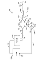
ここで図面を参照すると、図1は、本発明のシステム100の一実施形態の概略図を示す。図示のように、システム100は、発生器102と、ケーブル104と、第1、第2、第3及び第4のプローブアセンブリ106(1つのプローブアセンブリのみが図示されている)と、1以上の冷却装置108と、ポンプケーブル110と、1以上の近位冷却供給チューブ112と、1以上の近位冷却戻りチューブ114とを備える。図示の実施形態に示すように、発生器102は、高周波(RF)発生器である。なお、発生器102は、任意選択で、他の形態のエネルギー、これに限定しないが、マイクロ波エネルギー、熱エネルギー、超音波及び光学エネルギーなど、を送達することができる任意の電源(エネルギー供給源)であってもよい。また、発生器102は、ディスプレイを内蔵していてもよい。ディスプレイは、治療処置の様々な事項を表示するように機能する。表示される事項としては、これに限定しないが、例えば、温度やインピーダンスなどの治療処置に関連する任意のパラメータ、及び、治療処置に関連するエラーや警告が挙げられる。発生器102にディスプレイが内蔵されていない場合、発生器102は、外部ディスプレイに信号を送信する手段を含み得る。一実施形態では、発生器102は、1以上の装置、例えば、1以上のプローブアセンブリ106及び1以上の冷却装置108と通信するように機能する。このような通信は、使用する装置及び実施する処置に応じて、単一方向または双方向で行われ得る。
With reference to the drawings here, FIG. 1 shows a schematic view of an embodiment of the
加えて、図示のように、ケーブル104の遠位領域124は、ケーブル104を2以上の遠位端136に分けて、各遠位端136にプローブアセンブリ106を接続できるようにするスプリッタ130を含み得る。ケーブル104の近位端128は、発生器102に接続される。この接続は、例えば、ケーブル104の近位端128が発生器102内に埋め込まれるような永久的な接続であってもよいし、または、例えば、ケーブル104の近位端128が電気コネクタを介して発生器102に接続されるような一時的な接続であってもよい。ケーブル104の2以上の遠位端136は、プローブアセンブリ106と接続してプローブアセンブリ106と発生器102との間の電気的接続を確立するように機能するコネクタ140で終端する。別の実施形態では、システム100は、各プローブアセンブリ106を発生器102に接続するために使用される各プローブアセンブリ106用の別個のケーブルを含み得る。別の実施形態では、スプリッタ130は、3以上の遠位端を含み得る。このようなスプリッタは、例えば、3以上のプローブアセンブリを使用する場合などの、発生器102に3以上の装置を接続する実施形態において有用である。
In addition, as shown, the
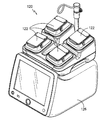
冷却装置108は、1以上のプローブアセンブリ106に近接して位置する物質の温度を低下させる任意の手段を含み得る。例えば、図10に示すように、冷却装置108は、1以上の蠕動ポンプ122を有するポンプアセンブリ120を含み得る。蠕動ポンプ122は、流体を、冷却装置108から出て、1以上の近位冷却供給チューブ112、プローブアセンブリ106、1以上の近位冷却戻りチューブ114を通って1以上の冷却装置108に戻るように循環させるように機能する。例えば、図10及び図11に図示した実施形態に示すように、ポンプアセンブリ120は、動力源126に接続された4つの蠕動ポンプ122を含む。このような実施形態では、図11に示すように、複数の蠕動ポンプ122の各々は、各プローブアセンブリと個別に流体連通され得る。流体は、水、または任意の他の適切な流体であり得る。別の実施形態では、ポンプアセンブリ120は、1つの蠕動ポンプのみを含んでもよいし、または、5つ以上の蠕動ポンプを含んでもよい。加えて、図11に示すように、蠕動ポンプ122の各々は、各ポンプの速度を独立して調節するように構成された独立速度コントローラ(RPMコントローラ125)を有し得る。
The
引き続き図1を参照すると、システム100は、冷却装置108と発生器102との間の通信を容易にするためのコントローラを含み得る。このようにして、冷却装置108と発生器102との間にフィードバック制御が確立される。フィードバック制御の対象は、発生器102、プローブアセンブリ106、及び冷却装置108であり得るが、任意の2つの装置間の任意のフィードバック制御も本発明の範囲に含まれる。フィードバック制御は、例えば、発生器102の構成要素であり得る制御モジュールで実施され得る。このような実施形態では、発生器102は、冷却装置108だけでなく、プローブアセンブリ106とも双方向通信するように機能する。本発明の文脈において、双方向通信とは、或る装置が別の装置と信号の送受信が可能であることを指す。
Continuing with reference to FIG. 1, the
一例として、発生器102は、第1及び第2のプローブアセンブリ106の一方または両方から温度測定値を受信する。温度測定値に基づいて、発生器102は、プローブアセンブリ106に送達する電力(エネルギー)の調節などの何らかの動作を行う。このように、両方のプローブアセンブリ106は、それぞれの温度測定値に基づいて個別に制御される。例えば、各プローブアセンブリ106へ供給する電力は、温度測定値が低い場合には増加させ、温度測定値が高い場合には減少させることができる。この電力の変更は、プローブアセンブリ毎に個別に行われ得る。いくつかの例では、発生器102は、1以上のプローブアセンブリ106への電力供給を終了することができる。このように、発生器102は、第1及び第2のプローブアセンブリ106の一方または両方から信号(例えば、温度測定値)を受信し、適切な動作を決定し、信号(例えば、電力の減少または増加を命令する信号)をプローブアセンブリ106の一方または両方に送信することができる。別の実施形態では、発生器102は、第1及び第2のプローブアセンブリ106の一方または両方に供給される冷却流体の流量または温度を増加または減少させるために、冷却装置108に信号を送信することができる。
As an example, the
より具体的には、蠕動ポンプは、流体流量に関する情報を発生器102に送信し、流体流量を調節する命令を発生器102から受信することができる。いくつかの例では、蠕動ポンプは、流体流量を変更するか、または所定期間停止することによって、発生器102に応答することができる。冷却装置108が停止した状態では、プローブアセンブリ106に関連する温度センサは冷却流体の影響を受けないので、周囲組織の温度をより正確に測定することが可能となる。加えて、2以上のプローブアセンブリ106を使用する場合、プローブアセンブリ106に関連する温度センサの測定結果の平均温度または最大温度を使用して、冷却を調節するようにしてもよい。
More specifically, the peristaltic pump can transmit information about the fluid flow rate to the
別の実施形態では、冷却装置108は、プローブアセンブリ106間の距離に応じて、流体供給量を減少させるか、または、流体供給を停止することができる。例えば、プローブアセンブリ106間の距離が十分に小さく、所望の温度を達成するべき領域内に十分な電流密度が存在する場合、冷却はほとんどまたは全く必要ない。このような実施形態では、エネルギーは、治療される組織の領域を通って第1及び第2のエネルギー送達装置192間に優先的に集中させられ、これにより、帯状の損傷(strip lesion)が形成される。帯状の損傷は、活性電極がそれと同様の寸法のリターン電極に極めて近接している場合に形成される、被加熱組織の楕円形のボリュームによって特徴付けられる。これは、所与のエネルギーにおいて、電流密度が電極間に優先的に集中し、電流密度に起因して温度が上昇することに起因して起こる。
In another embodiment, the
また、冷却装置108が発生器102と通信して、冷却装置108に関連する1以上の起こり得るエラー及び/または異常を発生器102に警告するようにしてもよい。例えば、冷却流体の循環が妨げられている場合や、1以上の冷却装置108の蓋が開いている場合である。そして、発生器102は、エラー信号に従って、ユーザへの警告、処置の中断、及び動作の変更のうちの少なくとも1つを行うことができる。
The
引き続き図1を参照すると、1以上の近位冷却供給チューブ112は、その遠位端に、近位供給チューブコネクタ116を含み得る。加えて、1以上の近位冷却戻りチューブ114は、その遠位端に、近位戻りチューブコネクタ118を含み得る。一実施形態では、近位供給チューブコネクタ116は雌型のルアーロックタイプコネクタであり、近位戻りチューブコネクタ118は雄型のルアーロックタイプコネクタである。なお、他のタイプのコネクタも本発明の範囲に含まれることを意図している。
Continuing with reference to FIG. 1, one or more proximal
加えて、図1及び図2に示すように、プローブアセンブリ106は、近位領域160と、ハンドル180と、中空の細長いシャフト184と、遠位先端領域190とを含み得る。遠位先端領域190は、1以上のエネルギー送達装置192を含む。さらに、図示のように、近位領域160は、遠位冷却供給チューブ162と、遠位供給チューブコネクタ166と、遠位冷却戻りチューブ164と、遠位戻りチューブコネクタ168と、プローブアセンブリケーブル170と、プローブケーブルコネクタ172とを含む。このような実施形態では、遠位冷却供給チューブ162及び遠位冷却戻りチューブ164は、プローブアセンブリ106の操作性を高めるために可撓性のチューブである。なお、硬いチューブを使用する別の実施形態も可能である。
In addition, as shown in FIGS. 1 and 2, the
さらに、いくつかの実施形態では、遠位供給チューブコネクタ166は、雄型のルアーロックタイプコネクタであってもよく、遠位戻りチューブコネクタ168は、雌型のルアーロックタイプコネクタであってもよい。したがって、近位供給チューブコネクタ116は、遠位供給チューブコネクタ166と連結することができ、近位戻りチューブコネクタ118は、遠位戻りチューブコネクタ168と連結することができる。
Further, in some embodiments, the distal
プローブケーブルコネクタ172は、プローブアセンブリケーブル170の近位端に配置され、コネクタ140のうちの1つに可逆的に結合することができ、これにより、発生器102とプローブアセンブリ106との間の電気的接続が確立される。プローブアセンブリケーブル170は、プローブアセンブリ106の特定の構造に応じて、1以上の導体を含み得る。例えば、一実施形態では、プローブアセンブリケーブル170は5つの導体を含み、これにより、プローブアセンブリケーブル170は、RF電流を発生器102から1以上のエネルギー送達装置192に送達させるだけでなく、後述するように複数の温度センサを発生器102に接続することが可能となる。
The
エネルギー送達装置192は、遠位先端領域190に隣接する組織の領域にエネルギーを送達する任意の手段を含み得る。例えば、エネルギー送達装置192は、超音波装置、電極、または任意の他のエネルギー送達手段を含み得る。なお、本発明は、この点に関して限定されない。同様に、エネルギー送達装置192を介して送達されるエネルギーは、いくつかの形態を取ることができ、そのような形態としては、これに限定しないが、熱エネルギー、超音波エネルギー、高周波エネルギー、マイクロ波エネルギー、または任意の他の形態のエネルギーが挙げられる。例えば、一実施形態では、エネルギー送達装置192は、電極を含み得る。電極の活性領域は、2〜20ミリメートル(mm)の長さであり得、電極によって送達されるエネルギーは、RF範囲内の電流の形態の電気エネルギーである。電極の活性領域のサイズは、椎間板内に配置するために最適化することができる。なお、実施される特定の処置に応じて様々なサイズの活性領域を使用することができ、これらの活性領域は全て本発明の範囲に含まれる。いくつかの実施形態では、発生器102からのフィードバックにより、インピーダンスや温度などの所与の測定値に応答して、エネルギー送達装置192の露出領域を自動的に調節することができる。例えば、一実施形態では、エネルギー送達装置192は、インピーダンス値を上昇させることなどの少なくとも1つの追加のフィードバック制御を実施することによって、組織に送達されるエネルギーを最大化することができる。
The
ここで図3を参照すると、遠位冷却供給チューブ162及び遠位冷却戻りチューブ164はそれぞれ、接続手段301及び303を用いて、ハンドル180内のシャフト供給用のチューブ302及びシャフト戻り用のチューブ304に接続される。接続手段301、303は、2つのチューブを接続する任意の手段であり得、そのようなものとしては、これに限定しないが、紫外線(UV)接着剤、エポキシ、または任意の他の接着剤、及び、摩擦または圧縮継手が挙げられる。矢印312及び314は、冷却装置108によって供給される冷却流体の流れ方向を示す。より具体的には、一実施形態では、シャフト供給用のチューブ302及びシャフト戻り用のチューブ304は、図4に示すように、ハンドル180から中空の細長いシャフト184のルーメン(管腔)を通って遠位先端領域190まで延びる、ステンレス鋼などの導電性材料から作製されたハイポチューブであり得る。矢印408は、エネルギー送達装置192によって画定されるルーメン450内における冷却流体の流れ方向を示す。冷却流体を供給するために使用されるハイポチューブの数、冷却流体を戻すために使用されるハイポチューブの数、及びそれらの組み合わせは、様々であってよい。そのような全ての組み合わせは、本発明の範囲に含まれることを意図している。
Here, referring to FIG. 3, the distal
引き続き図3を参照すると、ハンドル180は、ハンドル180の強度及び安定性をより高くするとともに、様々なケーブル、チューブ、及びワイヤを適所に保持するために、充填剤320で少なくとも部分的に充填され得る。充填剤320は、エポキシ、または任意の他の適切な材料であり得る。加えて、ハンドル180は、イントロデューサチューブによって1以上のプローブアセンブリ106の患者の体内への挿入を容易にする一実施形態では、任意選択のイントロデューサチューブ(後述する)に容易かつ確実に結合するように機能する。例えば、図示のように、ハンドル180は、この機能を達成するために、すなわち、ハンドル180が任意選択のイントロデューサチューブに確実に結合することを可能にするために、その遠位端部において先細になっている。
Continuing with reference to FIG. 3, the
一実施形態では、中空の細長いシャフト184は、十分な可撓性及びコンパクト性を維持しながら、非常に優れた電気絶縁性を提供するポリイミドシース及びステンレス鋼の管状内部から製造される。別の実施形態では、細長いシャフト184は、同様の品質を付与する任意の他の材料から製造してもよい。さらに別の実施形態では、細長いシャフト184は、導電性材料から製造してもよく、この場合、送達されるエネルギーが遠位先端領域190のエネルギー送達装置192に集中した状態に保たれるように絶縁材料で被覆される。一実施形態では、プローブアセンブリ106は、マーカー384を、ハンドル180に沿った或る位置、または細長いシャフト184の長さに沿った或る位置に含み得る。このような実施形態では、マーカー384は、プローブアセンブリ106の遠位先端が、イントロデューサのハブとの位置合わせによってイントロデューサの遠位端に位置したことを示す役割を果たす奥行き知覚マーカーであり得る。このように、マーカー384は、任意選択のイントロデューサに対するプローブアセンブリ106の遠位先端部の位置に関する視覚的表示を提供する。
In one embodiment, the hollow
図4を詳細に参照すると、プローブアセンブリ106の遠位先端領域190の一実施形態の透視断面図が示されている。図示のように、遠位先端領域190は、1以上のエネルギー送達装置192またはその近傍の温度を測定することができる1以上の温度センサ402を含む。温度センサ402は、1以上の熱電対、温度計、サーミスタ、光蛍光センサ、または温度を感知する任意の他の手段を含む。一実施形態では、温度センサ402は、プローブアセンブリケーブル170及びケーブル104を介して発生器102に接続される。なお、無線プロトコルを含む、温度センサ402と発生器102との間の任意の通信手段も、本発明の範囲に含まれる。より具体的には、図示のように、温度センサ402は、ステンレス鋼製のハイポチューブ406をコンスタンタン線410に接合し、コンスタンタン線410を絶縁体412で絶縁することによって作製された熱電対接合部を含み得る。この実施形態では、ハイポチューブ406とコンスタンタン線410との接合は、レーザ溶接によって行われる。なお、この2つの金属を接合する他の任意の手段を使用してもよい。さらに、この実施形態では、ハイポチューブ406及びコンスタンタン線410は、細長いシャフト184のルーメンを通って延び、ハンドル180内のプローブアセンブリケーブル170に接続される。
With reference to FIG. 4 in detail, a perspective sectional view of one embodiment of the
さらに、特に図4〜図6に示すように、各プローブアセンブリ106の温度センサ402は、エネルギー送達装置192から所定の延出長さで延出している。より具体的には、図示のように、温度センサ402は、エネルギー送達装置192の遠位端194から延出する約1ミリメートル(mm)未満の延出長さ414を有し得る。加えて、特に図6に示すように、温度センサ402の延出長さ414は、様々なサイズの損傷の形成を補助するように選択することができる。例えば、このような実施形態では、ユーザは、例えば、組織の治療処置の種類に基づく所望の損傷サイズ及び/または所望の電力供給量(エネルギー供給量)に基づいて、それぞれ様々な延出長さ414を有する複数のプローブから、1以上のプローブを選択することができる。特定の実施形態では、温度センサ402の延出長さ414は、約0.20〜0.70mmの範囲であり得る。別の実施形態では、各温度センサ402はまた、様々な形状または体積を有し得る。このように、実際の損傷サイズは、温度センサ402の延出長さ414によって異なるので、より長い延出長さを有する温度センサ402(例えば、プローブ(C)及び(D))は、より小さいサイズの損傷を形成するように構成され、一方、より短い延出長さを有する温度センサ402(例えば、プローブ(A)及び(B))は、より大きいサイズの損傷を形成するように構成される。
Further, as shown in FIGS. 4 to 6, the
したがって、温度センサ402の延出長さは、様々な解剖学的位置に応じて損傷サイズを制御し最適化するように構成され、例えば、動脈や運動神経などの重要な構造に隣接する領域では、小さな損傷を形成するようにする。このように、本開示の温度センサ402の様々な延出長さは、例えば、様々な処置のためのカスタム化された損傷ボリュームを形成する能力を含むいくつかの利点を提供する(すなわち、損傷ボリュームの制御は、プローブの機械的設計に依存し、発生器102及びアルゴリズムに依存しない)。したがって、既存の機器及び設定を使用することができる。加えて、突出距離を最適化することにより、インピーダンス上昇及び電力ロールオフの状況を最小限に抑えながら、最大エネルギー出力を提供することができる。さらに、温度センサ402の様々な延出長さは、敏感な解剖学的領域における過剰アブレーションを防止するための機械的安全機構を提供する。
Therefore, the extension length of the
加えて、温度センサ402の延出長さ414は、エネルギー送達装置192の電力需要を増加(または減少)させるように構成される。さらに、図示のように、温度センサ402は、ステンレス鋼製のハイポチューブ406を含む。ハイポチューブ406は、導電性であり、エネルギー送達装置192に電気的に接続される。したがって、このような実施形態では、エネルギーを突出部(外周面)に送達し、突出部から周囲組織に送達することができ、突出部は、温度センサ402及び1以上のエネルギー送達装置192の両方の構成要素であると理解される。温度センサ402を、エネルギー送達装置192によって画定されるルーメン450内ではなく、この位置(エネルギー送達装置192の遠位端194から延出した位置)に配置することは、温度センサ402が、エネルギー送達装置192に近接する組織の温度のより正確な測定値を測定することを可能にするので、有益である。これは、エネルギー送達装置192から延出した位置に配置した場合、温度センサ402は、ルーメン450内に配置した場合のようにルーメン450内を流れる冷却流体の影響を受けないという事実に起因する。したがって、このような実施形態では、プローブアセンブリ106は、プローブアセンブリの遠位領域から突出する突出部を含み、この突出部は、温度センサ402の構成要素である。
In addition, the
引き続き図4を参照すると、プローブアセンブリ106は、細長いシャフト184内でエネルギー送達装置192から所定の距離だけ離れて位置し、かつ細長いシャフト184の壁に隣接して配置された、1以上の補助的な温度センサ404をさらに含み得る。補助的な温度センサ404は、温度センサ402と同様に、1以上の熱電対、温度計、サーミスタ、光蛍光センサ、または温度を感知する任意の他の手段を含み得る。例えば、図示のように、補助的な温度センサ404は、銅線420をコンスタンタン線422(コンスタンタン熱電対線)に接合することにより作製された熱電対である。さらに、特定の実施形態では、銅線420及びコンスタンタン線422は、細長いシャフト184のルーメンを通って延び、ハンドル180内のプローブアセンブリケーブル170に接続される。
Continuing with reference to FIG. 4, the
さらに、プローブアセンブリ106は、温度センサ402、404のいずれかに近接して配置された断熱材430をさらに含み得る。断熱材430は、任意の断熱材料、例えばシリコーンから作製することができる。断熱材430は、或る温度センサが周囲組織の温度をより正確に測定できるように、その温度センサをプローブアセンブリ106の他の構成要素から断熱するために使用される。より具体的には、図示のように、断熱材430は、補助的な温度センサ404を、シャフト供給用のチューブ302及びシャフト戻り用のチューブ304を通過する冷却流体から断熱するために使用される。
In addition, the
さらなる実施形態では、プローブアセンブリ106はまた、細長いシャフト184に沿った或る位置に組み込まれた放射線不透過性マーカー440を含み得る。例えば、図4に示すように、放射線不透過性マーカーの最適な配置位置は、エネルギー送達装置192に隣接する遠位先端領域190またはその近傍の位置であり得る。放射線不透過性マーカーは、X線透視画像上で視認することができ、患者の体内に装置を正確に配置するときの視覚的補助として使用することができる。放射線不透過性マーカーは、十分な放射線不透過性を有する限り、様々な材料から作製することができる。適切な材料としては、これに限定しないが、銀、金、白金、及び他の高密度金属、並びに、放射線不透過性ポリマー化合物が挙げられる。放射線不透過性マーカーを医療機器に組み込む様々な方法を用いることができ、本発明は、この点に関して限定されない。
In a further embodiment, the
ここで図7及び図8を参照すると、図4に示されている遠位先端領域190の部分の断面図が示されている。まず図7を参照すると、3つのハイポチューブ(チューブ302、304、及び406)は、細長いシャフト184及びエネルギー送達装置192によって画定されるルーメン450内に配置される。シャフト供給用のチューブ302及びシャフト戻り用のチューブ304は、それぞれ、遠位先端領域190の遠位端へ、または当該遠位端から、冷却流体を運ぶ。この実施形態では、ハイポチューブ406は、ステンレス鋼などの導電性材料で作製され、プローブアセンブリケーブル170からエネルギー送達装置192にエネルギーを送達することができる。さらに、ハイポチューブ406はルーメンを画定し、当該ルーメンの中には、1以上の温度センサ402をプローブアセンブリケーブル170に接続する手段が配置され得る。例えば、1以上の温度センサ402が熱電対を含む場合、コンスタンタン線410は、図4に示されるように、プローブアセンブリケーブル170からハイポチューブ406を介して熱電対接合部まで延在し得る。あるいは、ハイポチューブ406のルーメンに複数のワイヤを通してもよく、または、ハイポチューブ406のルーメンを別の目的に利用してもよい。
Here, with reference to FIGS. 7 and 8, a cross-sectional view of the portion of the
さらに、図示されるように、細長いシャフト184及び電極(エネルギー送達装置192)は互いに重なり合っており、これにより、電極を所定の位置に固定する。この実施形態では、遠位先端領域190のこの部分で、細長いシャフト184及び電極によって画定されるルーメン内に、銀はんだで作製された放射線不透過性マーカー440が収容される。放射線不透過性マーカー440によりルーメンは塞がれるので、プローブアセンブリ106に供給され、かつ、上記の冷却チューブ(シャフト供給用のチューブ302及びシャフト戻り用のチューブ304)の外側に存在する冷却流体は、プローブアセンブリ106の遠位先端領域190に閉じ込められることとなる。したがって、そのような実施形態では、銀はんだ(放射線不透過性マーカー440)は、流体の循環をプローブアセンブリの特定の部分(この場合、遠位先端領域190の少なくとも一部)に制限するように機能するので、流れ妨害構造(flow impeding structure)と呼ばれ得る。換言すれば、冷却流体は、冷却装置108から冷却供給チューブを通ってプローブアセンブリ106の遠位先端領域190に流れる。次に、冷却流体は、電極によって画定されるルーメン450内を循環して電極を冷却し得る。したがって、本明細書に記載の内部冷却型プローブはこのような構成を有するプローブとして定義され、冷却媒体はプローブアセンブリ106の遠位領域からプローブアセンブリ106を出ない。冷却流体は、銀はんだの存在に起因して、細長いシャフト184をさらに下って循環することができず、冷却リターンチューブを通って冷却装置108に戻る。代替実施形態では、銀はんだの代わりに他の材料を使用してもよく、本発明はこの点に関して限定されない。上記のように、プローブアセンブリ106を冷却することによって、エネルギー送達装置192を介して送達される熱を、エネルギー送達装置192に直接隣接する組織の温度を上昇させることなく、組織にさらに移動させることができる。
Further, as shown, the
ここで図8を参照すると、図7の断面よりも近位側(図4参照)における、遠位先端領域190の一部の断面図が示されている。図示のように、第2の温度センサ404は、細長いシャフトの内壁に近接して配置されている。近接して配置することにより、第2の温度センサ404は、周囲組織の温度をより正確に表示することができる。換言すると、第2の温度センサ404は、第2の温度センサ404の位置で、細長いシャフト184の内壁の温度を測定することができる。この温度は、細長いシャフト184の外壁に近接して位置する組織の温度を示す。したがって、第2の温度センサ404を細長いシャフト184の内壁からさらに離れて配置するのではなく、内壁に近接して配置することが有益である。
Here, referring to FIG. 8, a cross-sectional view of a part of the
図7及び8は、本発明の第1実施形態で使用される3つのハイポチューブの相対位置を示している。この実施形態では、3つのハイポチューブは、プローブアセンブリ106の強度を高めるために何らかの方法で共に保持されている。例えば、3つのハイポチューブは、一時的に共に結合されてもよく、あるいは、はんだ付け、溶接、または任意の適切な接着手段を用いて、より永久的に接続されてもよい。ハイポチューブを結合及び接続する様々な手段は当該技術分野において公知であり、本発明はこの点に関して限定されることを意図していない。
7 and 8 show the relative positions of the three hypotubes used in the first embodiment of the present invention. In this embodiment, the three hypotubes are held together in some way to increase the strength of the
前述したように、本発明のシステム100は、1以上のイントロデューサチューブをさらに含み得る。一般に、イントロデューサチューブは、近位端、遠位端及びこれらの間に延在する長手方向ボアを含み得る。したがって、イントロデューサチューブ(使用される場合)は、プローブアセンブリ106と容易かつ確実に結合することができる。例えば、イントロデューサチューブの近位端はコネクタと嵌合して、プローブアセンブリのハンドル180と可逆的に係合する。イントロデューサチューブは、患者の身体内の治療部位へアクセスするために使用され得、プローブアセンブリ106の中空の細長いシャフト184は、イントロデューサチューブの長手方向ボアを介して治療部位に導入され得る。イントロデューサチューブは、ユーザが患者の身体内のイントロデューサチューブの遠位端の深さを決定するために、1以上の深さマーカーをさらに含む。さらに、イントロデューサチューブは、透視ガイダンスを使用する場合、イントロデューサを確実に正しく配置するために、1以上の放射線不透過性マーカーをさらに含み得る。
As mentioned above, the
イントロデューサチューブは、当該技術分野において知られる様々な材料から作製され得、材料が導電性である場合、イントロデューサは、エネルギーが患者の身体内の望ましくない位置に送達されるのを防ぐため、その長さの全部または一部(外周部分)に沿って電気的に絶縁されてもよい。いくつかの実施形態では、細長いシャフト184は導電性であってもよく、イントロデューサは、治療のためにエネルギー送達装置192を露出させた状態にして、シャフトを絶縁するように機能してもよい。さらに、イントロデューサチューブは、電源に接続されてもよく、したがって、電流インピーダンスモニタの一部を形成し得る(イントロデューサチューブの少なくとも一部は電気的に絶縁されていない)。組織が異なれば電気インピーダンス特性も異なり得るので、前述のように、インピーダンス測定に基づいて組織タイプを判定することができる。したがって、装置が配置されている組織を決定するためにインピーダンスを測定する手段を有していることは有益である。さらに、イントロデューサチューブのゲージは、実行される処置及び/または治療される組織に応じて変化し得る。いくつかの実施形態では、イントロデューサチューブは、少なくとも1つのプローブアセンブリ106を受け入れるように、半径方向の寸法で十分なサイズにされるべきである。代替実施形態では、細長いシャフト184は、患者の身体の治療されていない部分にエネルギーを伝導しないように絶縁され得る。
The introducer tube can be made from a variety of materials known in the art, and if the material is conductive, the introducer will prevent energy from being delivered to undesired locations within the patient's body. It may be electrically insulated along all or part of its length (outer peripheral portion). In some embodiments, the
また、システムは1以上のスタイレットを含み得る。スタイレットは、患者の身体内への1以上のイントロデューサチューブの挿入を容易にするために、傾斜した先端を有し得る。様々な形態のスタイレットが当該技術分野で周知であり、本発明は、1つの特定の形態のみを包含することに限定されない。さらに、イントロデューサチューブに関して上述したように、スタイレットは、電源に接続されてもよく、したがって、電流インピーダンスモニタの一部を形成し得る。他の実施形態では、1以上のプローブアセンブリ106は、電流インピーダンスモニタの一部を形成し得る。したがって、発生器102は、1以上のスタイレット、イントロデューサチューブ、及び/またはプローブアセンブリ106からインピーダンス測定値を受け取り、インピーダンス測定値に基づいて、エネルギー送達装置192の誤配置についてユーザに警告するなどのアクションを実行し得る。
Also, the system may include one or more stylets. The stylet may have a sloping tip to facilitate insertion of one or more introducer tubes into the patient's body. Various forms of stylets are well known in the art and the present invention is not limited to including only one particular form. In addition, as mentioned above with respect to the introducer tube, the stylet may be connected to a power source and thus may form part of a current impedance monitor. In other embodiments, the one or
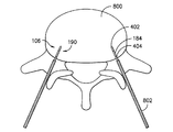
一実施形態では、第1及び第2のプローブアセンブリ106は、双極モードで機能し得る。例えば、図9は、2つのプローブアセンブリ106の一実施形態を示し、その遠位先端領域190は、椎間板800内に配置されている。そのような実施形態では、電気エネルギーは、第1及び第2のプローブアセンブリ106に送達され、このエネルギーは、治療されるべき組織の領域(すなわち、椎間板800の領域)を介して優先的にそれらの間に集中される。したがって、治療されるべき組織の領域は、第1のプローブアセンブリ106と第2のプローブアセンブリ106との間に集中するエネルギーによって加熱される。他の実施形態では、第1及び第2のプローブアセンブリ106は、単極モードで機能してもよく、この場合、当該技術分野で知られているように、患者の身体の表面に追加の接地パッドが必要である。双極及び単極処置の任意の組み合わせが使用されてもよい。システムは、3以上のプローブアセンブリを含み得ることも理解されるべきである。例えば、いくつかの実施形態では3つのプローブアセンブリが使用されてもよく、プローブアセンブリは三相モードで機能し、供給される電流の位相はプローブアセンブリごとに異なる。
In one embodiment, the first and
さらなる実施形態では、本システムはまた、導電性構成要素間の1以上の電流の流れと、特定の構成要素の周囲の電流密度とを制御するように構成され得る。例えば、本発明のシステムは、分散電極として機能するのに十分な、類似または同一の寸法の2つの導電性構成要素と、より大きな寸法の1つの導電性構成要素とを含む、3つの導電性構成要素を含み得る。導電性構成要素のそれぞれは、患者の身体と電源との間でエネルギーを送達するように有益に機能しなければならない。したがって、導電性構成要素のうちの2つはプローブアセンブリであり得るが、第3の導電性構成要素は、接地パッドまたは分散/戻り電極として機能し得る。一実施形態では、分散電極及び第1のプローブアセンブリは同一の電柱に接続されるが、第2のプローブアセンブリは反対側の電柱に接続される。そのような構成では、電流は、2つのプローブアセンブリ間、または第2のプローブアセンブリと分散電極との間を流れ得る。第1のプローブアセンブリまたは分散電極のいずれかに優先的に流れる電流を制御するために、これらの導電性構成要素(すなわち、第1のプローブアセンブリ及び分散電極)の1以上と電流シンク(例えば、回路の「グランド」)との間の抵抗またはインピーダンスは変更され得る。換言すると、(単極構成のように)第2のプローブアセンブリと分散電極との間に電流を優先的に流すことが望ましい場合、電流が第1のプローブアセンブリではなく、分散電極を通って「グランド」に流れることを選択する(電流は、抵抗が最小の経路を優先的に流れるので)ように、第1のプローブアセンブリと回路の「グランド」との間の抵抗またはインピーダンスを増加させてもよい。これは、第2のプローブアセンブリの周囲の電流密度を増加させること、及び/または第1のプローブアセンブリの周囲の電流密度を減少させることが望ましい状況で有用であり得る。同様に、(双極構成の場合のように)第2のプローブアセンブリと第1のプローブアセンブリとの間に電流を優先的に流すことが望ましい場合、電流が分散電極ではなく第1のプローブアセンブリを通って「グランド」に流れることを選択するように、分散電極と「グランド」との間の抵抗またはインピーダンスを増加させてもよい。これは、標準的な双極損傷を形成する必要がある場合に望ましい。あるいは、第2のプローブアセンブリと第1のプローブアセンブリとの間に一定量の電流を流し、残りの電流を第2のプローブアセンブリから分散電極に流すことが望ましい場合がある(準双極(quasi-bipolar)構成)。これは、幾分かの電流が所望の経路に沿って流れるように、第1のプローブアセンブリの少なくとも1つ及び分散電極と「グランド」との間のインピーダンスを変化させることによって達成され得る。これにより、ユーザはプローブアセンブリの周囲で特定の望ましい電流密度を達成することができる。したがって、本発明のこの特徴によって、治療処置中、システムを単極構成、双極構成または準双極構成の間で交替することができる。 In a further embodiment, the system may also be configured to control the flow of one or more currents between the conductive components and the current density around the particular component. For example, the system of the present invention has three conductive components, including two conductive components of similar or identical dimensions and one conductive component of larger dimensions, sufficient to function as a dispersion electrode. May include components. Each of the conductive components must function beneficially to deliver energy between the patient's body and the power source. Thus, two of the conductive components can be probe assemblies, but a third conductive component can function as a ground pad or dispersion / return electrode. In one embodiment, the dispersion electrode and the first probe assembly are connected to the same utility pole, while the second probe assembly is connected to the opposite utility pole. In such a configuration, current can flow between the two probe assemblies, or between the second probe assembly and the dispersion electrode. One or more of these conductive components (ie, the first probe assembly and the dispersion electrode) and a current sink (eg, eg) to control the current preferentially flowing through either the first probe assembly or the dispersion electrode. The resistance or impedance to and from the "ground" of the circuit can be changed. In other words, if it is desirable to preferentially pass current between the second probe assembly and the dispersion electrode (as in a unipolar configuration), the current will "pass through the dispersion electrode instead of the first probe assembly. Even if you increase the resistance or impedance between the first probe assembly and the "ground" of the circuit so that you choose to flow to "ground" (since the current preferentially flows through the path with the least resistance). good. This can be useful in situations where it is desirable to increase the current density around the second probe assembly and / or decrease the current density around the first probe assembly. Similarly, if it is desirable to preferentially pass current between the second probe assembly and the first probe assembly (as in a bipolar configuration), then the current should prefer the first probe assembly instead of the dispersion electrode. The resistance or impedance between the dispersion electrode and the "ground" may be increased to choose to flow through the "ground". This is desirable when standard bipolar damage needs to be formed. Alternatively, it may be desirable to have a constant amount of current flowing between the second probe assembly and the first probe assembly and the remaining current flowing from the second probe assembly to the dispersion electrode (quasi-bipolar). bipolar) configuration). This can be achieved by varying the impedance between at least one of the first probe assemblies and the dispersion electrode and the "ground" so that some current flows along the desired path. This allows the user to achieve a particular desired current density around the probe assembly. Thus, this feature of the invention allows the system to be interchanged between unipolar, bipolar or quasi-bipolar configurations during therapeutic procedures.
ここで図12を参照すると、本明細書に記載のプローブアセンブリを使用して、椎間板800などの患者の身体の組織を治療するための方法500の一実施形態のフロー図が示されている。本方法は、最初に、患者の身体の組織を治療するために使用するべく、冷却された高周波型のプローブアセンブリ106を準備するステップ502を含み得る。例えば、組織を治療するために冷却された高周波型のプローブアセンブリ106を準備するステップ502は、組織を治療するために必要な所望の損傷サイズ(あるいは体積)及び/または電力供給量を決定するステップ504を含み得る。さらに、ユーザは、所望の損傷サイズまたは所望の電力供給量を達成するその温度センサ402の長さ414に基づいて、複数のプローブアセンブリから1以上のプローブアセンブリ106を選択し得る(ステップ506)。
With reference to FIG. 12, a flow chart of an embodiment of
決定された長さの温度センサ402を有する適切なプローブアセンブリ106が選択されると(ステップ506)、本方法500は、プローブアセンブリ106を患者の身体内に配置するステップ508を含む。より具体的には、本方法500は、一般に、エネルギー送達装置192を患者の身体に挿入するステップと、エネルギー送達装置192を患者の身体の組織に送達するステップとを含み得る。例えば、一実施形態では、患者が放射線透過性のテーブルに横たわっている状態で、蛍光透視ガイダンスを使用して、椎間板の後部にアクセスするためのスタイレットを備えたイントロデューサを経皮的に挿入してもよい。蛍光透視法に加えて、インピーダンスモニタリング及び触覚フィードバックを含むがこれらに限定されない他の補助手段を使用し、ユーザがイントロデューサまたはプローブアセンブリ106を患者の身体内に配置することを支援してもよい。インピーダンスモニタリングの使用は本明細書に記載されており、ユーザは、装置が患者の身体内に挿入されるときにインピーダンスをモニタリングすることによって組織を区別し得る。触覚フィードバックに関して、異なる組織は、挿入力に対して異なる量の物理的抵抗を提供し得る。これにより、ユーザは、特定の組織に装置を挿入するために必要な力を感じることで、異なる組織を区別することができる。椎間板にアクセスする1つの方法は、イントロデューサが椎弓根のすぐ横を通過する椎弓根外アプローチであるが、他のアプローチを使用してもよい。次に、スタイレットを備えた第2のイントロデューサを同一の方法で第1のイントロデューサの反対側に配置し、スタイレットを取り外す。したがって、プローブアセンブリ106は2つのイントロデューサのそれぞれに挿入され、電極を、例えば、約1mm〜55mmの範囲などの適切な距離で組織内に配置することができる。
Once the
本方法500は、電源(例えば、発生器102)をプローブアセンブリ106に接続するステップ510を含む。所定の位置に配置されると、刺激電気信号は、電極のいずれかから分散電極または他の電極に放出され得る。この信号は感覚神経を刺激するために使用され、症候性の痛みが複製されることによって、椎間板が痛みの原因であると確認される。さらに、プローブアセンブリ106は、RF発生器(発生器102)及び蠕動ポンプ122に接続されているので、本方法500は、冷却流体を、蠕動ポンプ122によって内部ルーメン(チューブ302、304)を通して同時に循環させるステップと、エネルギー送達装置192を介してRF発生器から組織にエネルギーを送達するステップとを含む(ステップ512)。換言すると、高周波エネルギーが電極に送達され、電力は、2つのプローブアセンブリ106の遠位先端領域190の間で所望の温度に到達するように、電極の先端の温度センサ402によって測定された温度にしたがって変更される。
The
処置中に、プローブアセンブリ106に供給される冷却、及び/またはプローブアセンブリ106に送達される電力などの治療プロトコルは、望ましい治療領域の形状、サイズ及び均一性を維持するように調整及び/または制御され得る。より具体的には、本方法500は、エネルギー送達装置192を介して送達されるエネルギーの量の制御と、蠕動ポンプ122の流量の個別の制御との両方によって、組織に送達されるエネルギーを能動的に制御するステップ514を含む。さらなる実施形態では、発生器102は、温度センサ402及び/またはインピーダンスセンサによって測定された測定温度に基づいて、組織に送達されるエネルギーを制御してもよい。
During the procedure, the treatment protocol, such as the cooling supplied to the
より具体的には、図13に示すように、本開示による、エネルギー送達装置192を介して送達されるエネルギーの量と、蠕動ポンプ122の流量との両方を制御することによって組織に送達されるエネルギーを能動的に制御するための治療処置の一実施形態のブロック図が示されている。ステップ600に示すように、アブレーションが初期化される。ステップ602に示されるように、エネルギー量が、基本的な数値積分技術を使用して計算され得る。ステップ604に示されるように、計算されたエネルギー量は、所定のエネルギー量閾値と比較され得る。ステップ606に示されるようにエネルギー量が満たされない場合、処置はステップ608に続き、治療処置中の内部冷却型のプローブアセンブリ106のインピーダンスの上昇を緩和する。より具体的には、図示のように、発生器102から組織にエネルギー送達装置192を介してエネルギーを送達している間、1以上の処置パラメータがモニタリングされる。本明細書に記載の処置パラメータは、例えば、組織の温度、組織のインピーダンス、エネルギー送達装置192の電力需要、もしくは同様のもの、またはそれらの組み合わせを含み得る。さらに、図示のように、処置パラメータは、インピーダンス上昇検出エンジン610へ供給され得る(ステップ608)。ステップ612に示されるように、インピーダンス上昇検出エンジン610は、例えば、受信した処置パラメータ(ステップ608)に基づいて、インピーダンス上昇イベントが所定の期間内に発生する可能性が高いかどうか(すなわち、インピーダンス上昇イベントが間近であるかどうか)をリアルタイムで判定するように構成される。次に、インピーダンス上昇検出エンジン610は、インピーダンス上昇イベントが所定の期間内に発生する可能性が高いかどうかに基づいて、ポンプアセンブリ120のコマンドを決定することができる。
More specifically, as shown in FIG. 13, it is delivered to the tissue by controlling both the amount of energy delivered via the
ステップ614に示すようにインピーダンス上昇イベントが間近でない場合には、例えば蠕動ポンプ122のポンプ速度(回転速度または流量)を(例えば、RPMコントローラ125を介して)上昇させることによって、冷却速度を上昇させることができる(ステップ616)。冷却速度が上昇した後、アブレーションは継続する(ステップ600)。ステップ618に示すようにインピーダンス上昇イベントが間近である場合には、例えば蠕動ポンプ122のポンプ速度(流量)を(例えば、RPMコントローラ125を介して)低下させることによって、冷却速度を低下させることができる(ステップ620)。換言すれば、いくつかの実施形態では、蠕動ポンプ122は、それぞれのRPMコントローラ125を介して独立して制御され、プローブアセンブリ106のそれぞれの電極への冷却速度(冷却量)を変更し得る。そのような実施形態では、ポンプアセンブリ120の動力源126は、少なくとも部分的に、発生器102から切り離され得る。さらに、図示のように、システム550は、閉ループフィードバック制御634、636を用いて機能する。本明細書で使用される場合、閉ループフィードバック制御は、温度とは無関係に電力を設定点に調節するための、発生器102による蠕動ポンプ122を介したプローブへの流量の制御を指す。あるいは、閉ループフィードバックはまた、組織に所望の総エネルギーを送達するように電力を調節するための、発生器102による蠕動ポンプ122を介したプローブへの流量の制御を指してもよい。
If the impedance rise event is not imminent, as shown in
ステップ622に示されるようにエネルギー量閾値が満たされると、治療処置は熱量閾値が満たされているかどうかをチェックする(ステップ624)ように構成される。ステップ626に示されるように熱量が満たされていない場合、治療処置は、独立した温度−電力フィードバック制御ループを通って進行する(ステップ628)。より具体的には、特定の実施形態では、エネルギー送達装置192を介して送達されるエネルギーの量は、組織を治療するための所定の閾値温度を定義し、エネルギー送達装置192を介して発生器102により組織の温度を上昇させ、組織に損傷を作成するために組織の温度を所定の閾値温度に維持することによって制御され得る。そのような実施形態では、組織の温度は、電力上昇速度、インピーダンスレベル、インピーダンス増加速度、及び/またはインピーダンスに対する電力の比率のうちの少なくとも1つの関数として、所定の閾値温度に維持され得る。
When the energy threshold is met, as shown in
ステップ632に示すように熱量の閾値が満たされた場合にのみ、処置は終了する(ステップ630)。したがって、本開示のシステム及び方法は、本質的な高電力需要(すなわち、短い熱電対突出部)、ポンプ調節電力アルゴリズム、所定のエネルギー量もしくは総平均電力閾値、及び/またはインピーダンス上昇検出エンジン610を有するプローブの固有の特徴を提供する。
The procedure ends only when the calorific value threshold is met, as shown in step 632 (step 630). Thus, the systems and methods of the present disclosure include intrinsically high power demand (ie, short thermocouple overhangs), pump regulated power algorithms, a given amount of energy or total average power threshold, and / or impedance
ここで図14を参照すると、同一の試験処置についての電力(y軸)対時間(x軸)と、温度(y軸)対時間(x軸)とのグラフが、冷却量に基づいて電力を調節する利点を説明するために示されている。より具体的には、図示のように、アブレーションは、ポンプアセンブリ120がその公称速度に設定された状態で開始される。試験処置への時間T1で、エネルギー送達装置192に供給される冷却量650は、段階的に減少する。これにより、電力需要652は減少するが、温度654は同様のままである。そのため、冷却量の制御は、一次温度−電力フィードバック制御ループ(ステップ628)から独立したフィードバック制御ループとして機能し、後者は、組織の温度設定値の上昇及び維持を行う。したがって、組織を加熱するために必要な電力は冷却の効果を相殺するために必要な電力から切り離されるので、温度設定値は冷却量の変化によって変化しない。
Here, referring to FIG. 14, a graph of power (y-axis) vs. time (x-axis) and temperature (y-axis) vs. time (x-axis) for the same test procedure shows power based on the amount of cooling. It is shown to illustrate the benefits of adjusting. More specifically, as shown, ablation begins with the
ここで図15及び図16を参照すると、例示的なグラフが、本開示による内部冷却型プローブ治療処置中のインピーダンスの上昇を緩和することの様々な利点を説明するために示されている。より具体的には、図15は、インピーダンス緩和が実装されていない場合に、本質的に高い電力需要及び手動フィードバック制御を備えた内部冷却型プローブをそれぞれが利用する3つの処理処置についてのインピーダンス(y軸)対時間(x軸)、温度(y軸)対時間(x軸)、及び電力(y軸)対時間(x軸)のグラフをそれぞれ示している。試験処置によって高インピーダンスエラーが発生する(インピーダンス656)。これは、温度658によって示されるように、不十分な熱量及び不完全な処置をもたらす。さらに、電力需要660は、所定の閾値662を超える。
With reference to FIGS. 15 and 16, exemplary graphs are shown to illustrate the various benefits of mitigating the rise in impedance during the internally cooled probe treatment procedure according to the present disclosure. More specifically, FIG. 15 shows the impedance for each of the three processing actions that each utilize an internally cooled probe with inherently high power demand and manual feedback control when impedance relaxation is not implemented. Graphs of y-axis) vs. time (x-axis), temperature (y-axis) vs. time (x-axis), and power (y-axis) vs. time (x-axis) are shown. The test procedure causes a high impedance error (impedance 656). This results in inadequate calories and incomplete treatment, as indicated by
対照的に、図16は、ポンプによって電力制御が調節された内部冷却型プローブを利用する3つの治療処置についての、インピーダンス(y軸)対時間(x軸)、温度(y軸)対時間(x軸)、及び電力(y軸)対時間(x軸)のグラフをそれぞれ示している。したがって、図示されているように、試験処置は、高インピーダンスエラーなしで完全に完了することができます。さらに、図示されているように、温度は設定値に達する。さらに、電力(y軸)対時間(x軸)のグラフに示されているように、ポンプ速度は、処置の開始時に最低設定値から始まって徐々に上昇し、所定の閾値未満に維持された。所定の閾値は、過去の試験データを使用して決定されてもよく、または動的であってもよいことを理解されたい。電力閾値に対する制御に加えて、他の実施形態は、電力上昇速度(dP/dt)、インピーダンスレベル(Z)、インピーダンス増加速度(dZ/dt)、及び/または電力に対するインピーダンスの比率に基づいて制御を行ってもよい。フィードバックメカニズムに関係なく、すべての実施形態は、インピーダンス上昇イベントの可能性を判定し、それに応じてエネルギー送達装置192への冷却量を制御することにより、電力需要を調整するように構成される。例えば、いくつかの実施形態では、エネルギー送達装置の電力需要は、所定の閾値と比較され得る。電力需要が所定の閾値よりも大きい場合、インピーダンス上昇検出エンジン610は、ポンプアセンブリ120の速度を低下させる。電力需要が所定の閾値よりも小さい場合、インピーダンス上昇検出エンジン610は、ポンプアセンブリ120の速度を上昇させる。
In contrast, FIG. 16 shows impedance (y-axis) vs. time (x-axis), temperature (y-axis) vs. time (y-axis) vs. time (y-axis) for three therapeutic procedures utilizing an internally cooled probe whose power control is regulated by a pump. Graphs of power (y-axis) vs. time (x-axis) are shown. Therefore, as shown, the test procedure can be completed completely without high impedance errors. Further, as shown, the temperature reaches a set value. In addition, as shown in the power (y-axis) vs. time (x-axis) graph, the pump speed gradually increased starting from the lowest set value at the start of the procedure and remained below a predetermined threshold. .. It should be understood that a given threshold may be determined using historical test data or may be dynamic. In addition to the control over the power threshold, other embodiments are controlled based on the power rise rate (dP / dt), impedance level (Z), impedance increase rate (dZ / dt), and / or the ratio of impedance to power. May be done. Regardless of the feedback mechanism, all embodiments are configured to adjust the power demand by determining the possibility of an impedance rise event and controlling the amount of cooling to the
治療後、エネルギー送達及び冷却を停止してもよく、プローブアセンブリ106は、使用される場合、イントロデューサから取り外される。抗生物質または造影剤などの液体をイントロデューサから注入した後、イントロデューサを取り外してもよい。あるいは、プローブアセンブリ106の遠位先端部は、イントロデューサが必要とされないように、鋭く、組織を貫通するのに十分に強くてもよい。上記のように、プローブアセンブリ106、より具体的にはエネルギー送達装置192を患者の身体内に配置するステップは、これらに限定しないが、例えば蛍光透視イメージング、インピーダンスモニタリング及び触覚フィードバックを含む様々な手段によって支援され得る。さらに、本方法のいくつかの実施形態は、患者の身体内に材料を挿入または除去する1以上のステップを含み得る。例えば、記載されているように、流体は、治療処置中にイントロデューサチューブを通して挿入され得る。あるいは、プローブアセンブリ106が患者の身体と流体連通する開口部を備える実施形態では、物質は、プローブアセンブリ106を通して挿入されてもよい。さらに、材料は、治療処置中に患者の身体から除去され得る。そのような材料は、例えば、損傷した組織、核組織及び体液を含み得る。考えられる治療効果には、これらに限定しないが、例えば、神経構造(侵害受容器または神経線維)の凝固、コラーゲンのアブレーション、生化学的変化、熱ショックタンパク質のアップレギュレーション、酵素の変化、及び栄養素供給の変化が含まれる。
After treatment, energy delivery and cooling may be stopped and the
ここで図17を参照すると、エネルギー(y軸)対損傷面積(x軸)のグラフ700が、本開示のさらなる利点を説明するために提供されている。より具体的には、図示のように、グラフ700は、3つの異なる治療処置についての損傷面積に対するエネルギーを提供する。完全に球形である損傷の体積を仮定すると、望ましい所定の直径の損傷は、垂直の破線702によって表される。第1の試験処置(データ704)は、従来の熱量アプローチを使用して損傷を作成した。第2の試験処置(データ708)は、より短いアブレーション時間で、ポンプによって電力制御を調節することなく損傷を作成した。第3の試験処置(結果706)は、より短いアブレーション時間で、ポンプによって電力制御を調節して損傷を作成した。データ708によって示されるように、アブレーションをより短い時間しか実行しないと、十分なサイズの損傷を作成することができない。しかしながら、ポンプ調節による電力制御も実施される場合(結果706によって示されるように)、損傷は、データ704によって表されるように、従来の熱量アプローチを使用したように作成することができる。したがって、温度及びエネルギー送達速度を制御することによって(すなわち、ポンプ(蠕動ポンプ122)を調節することによって)、エネルギー送達速度を最大化することができ、それにより、アブレーション時間がはるかに速くなる。特定の例では、従来のアブレーション技術と比較した場合、アブレーション時間を最大で半分に短縮することができる。
With reference to FIG. 17, a
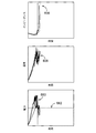
ここで図18を参照すると、送達されたエネルギー(y軸)と損傷サイズ(x軸)との間の高い相関関係19を表すグラフ800が示されている。より具体的には、図示のように、損傷の幅802は黒丸で示され、損傷の長さ804は白丸で表される。図19は、熱電対の延出長さ(x軸)と総送達エネルギー(y軸)との間の逆相関を表すグラフ850を示している。さらに、図20は、損傷サイズ(y軸)と熱電対延出長さ(x軸)との間の相関関係を表すグラフ900を示している。まとめると、図18−20は、組織に送達されるエネルギーの量を制御することによって、熱電対突出部の延出長さまたは距離が生成された損傷のサイズに及ぼし得る影響を示している。より具体的には、熱電対突出部の延出長さ及び損傷のサイズは逆相関している。そのため、この特性を利用して、様々な解剖学的位置を対象として様々なサイズの損傷を生成することができる。
With reference to FIG. 18,
本発明のシステムは、エネルギー送達装置の使用が有益であることが証明され得る様々な医療処置において使用され得る。具体的には、本発明のシステムは、これらに限定しないが例えば腫瘍、椎間板、椎間関節除神経、仙腸関節損傷または骨内の治療処置などの、腰痛の治療を含む処置に特に有用である。さらに、本システムは、線維輪を強化し、輪状裂傷を収縮させてその進行を妨げ、輪状裂傷の肉芽組織を焼灼し、輪状裂傷に移った髄核組織の痛みを引き起こす酵素を変性させるために特に有用である。さらに、本システムは、椎間板の選択的神経構造の機能の変化を破壊または引き起こすのに十分なエネルギーを線維輪に送達する低侵襲性の技術によって椎間板ヘルニアまたは内部破壊した椎間板を治療するように機能し、コラーゲン原線維を予測可能な精度で修正し、椎間板の終板を治療し、椎間板組織の体積を正確に減少させる。本システムは、血管を凝固させ、熱ショックタンパク質の産生を増加させるのにも有用である。 The system of the present invention can be used in a variety of medical procedures where the use of energy delivery devices can prove beneficial. Specifically, the system of the present invention is particularly useful for treatments including, but not limited to, treatment of low back pain, such as, but not limited to, tumors, intervertebral discs, facet joint denervation, sacroiliac joint injuries or intraosseous treatments. be. In addition, the system strengthens the annulus fibrosus, contracts the cricoid laceration and impedes its progression, cauterizes the granulation tissue of the cricoid laceration, and denatures the enzyme that causes pain in the nucleus pulposus that has transferred to the cricoid laceration. Especially useful. In addition, the system functions to treat disc herniated or internally destroyed discs with minimally invasive techniques that deliver sufficient energy to the annulus fibrosus to disrupt or induce functional changes in the selective neural structure of the disc. It modifies collagen fibrils with predictable accuracy, treats the end of the disc, and accurately reduces the volume of disc tissue. The system is also useful for coagulating blood vessels and increasing heat shock protein production.
本明細書に記載の適切なフィードバック制御システムを備えた液体冷却型のプローブアセンブリ106を使用することもまた、治療の均一性に寄与する。プローブアセンブリ106の遠位先端領域190の冷却は、プローブアセンブリ106への組織の付着をもたらし得るこれらの領域の過度の高温、及びプローブアセンブリ106の遠位先端領域190を取り囲む組織のインピーダンスの上昇を防ぐのに役立つ。したがって、プローブアセンブリ106の遠位先端領域190を冷却することによって、遠位先端領域190で、または遠位先端領域190のすぐ近くで組織が炭化するリスクを最小限に抑えて、より高い電力を組織に送達することができる。より高い電力をエネルギー送達装置192に送達することによって、エネルギー送達装置192からさらに離れた組織が、損傷を形成するのに十分高い温度に到達するので、損傷は、エネルギー送達装置192をすぐ近くで取り囲む組織の領域に限定されず、むしろ、一方のプローブアセンブリ106の遠位先端領域190から他方に優先的に延びる。
The use of a liquid-cooled
言及されているように、本発明のシステムは、双極モードで機能する場合、実質的に2つのプローブアセンブリ106の間に比較的均一な損傷を生成するために使用され得る。多くの場合、例えば治療される組織が他方よりも一方のエネルギー送達装置192の近くに位置している場合には、均一な損傷は禁忌となり得る。均一な損傷が望ましくない可能性がある場合、適切なフィードバック及び制御システムと組み合わせて2以上の冷却型のプローブアセンブリ106を使用することにより、様々なサイズ及び形状の損傷の作成が可能になり得る。例えば、処置が従うべき所定の温度及び/または電力プロファイルは、治療処置の開始前に発生器102にプログラムされ得る。これらのプロファイルは、特定のサイズ及び形状の損傷を作成するために使用すべきパラメータ(これらのパラメータは、熱容量などの特定の組織パラメータに依存する)を定義し得る。これらのパラメータには、個々のプローブごとに、これらに限定しないが、例えば最大許容温度、上昇量(すなわち、温度が上昇する速度)、及び冷却流量などが含まれ得る。処置中に測定される温度またはインピーダンスの値に基づいて、電力または冷却などの様々なパラメータを調節して所定のプロファイルに準拠させることにより、所望の寸法の損傷が得られる。
As mentioned, the system of the invention can be used to produce a relatively uniform damage between the two
同様に、均一な損傷は、本発明のシステムを使用し、組織全域の熱量を可能な限り均一にすることを可能にする予め設定された様々な温度及び/または電力のプロファイルを使用することにより形成できることを理解されたい。なお、本発明は、この点に関して限定されるものではない。 Similarly, uniform damage can be achieved by using the system of the invention and using a variety of preset temperature and / or power profiles that allow the amount of heat across the tissue to be as uniform as possible. Please understand that it can be formed. The present invention is not limited to this point.
本明細書で使用される放射線不透過性マーカーという用語は、装置の放射線不透過性を増加または減少させる材料の追加また除去を意味することに留意されたい。さらに、プローブアセンブリ、イントロデューサ、スタイレット等の用語は、限定することを意図するものではなく、説明された機能と同様の機能を実行するために使用することができる任意の医療器具及び外科器具を意味する。加えて、本発明は、本明細書に開示された臨床応用に使用することに限定されるものではなく、本発明の装置が有用であると考えられる他の医学的及び外科的処置も、本発明の範囲内に含まれる。 It should be noted that the term radiodensity marker as used herein refers to the addition or removal of material that increases or decreases the radiodensity of the device. In addition, terms such as probe assembly, introducer, stylet, etc. are not intended to be limiting and are any medical or surgical instrument that can be used to perform functions similar to those described. Means. In addition, the invention is not limited to its use in the clinical applications disclosed herein, and other medical and surgical procedures in which the devices of the invention may be useful are also present. Included within the scope of the invention.
明瞭にするために別個の実施形態で説明した本発明のいくつかの特徴は、互いに組み合わせて単一の実施形態で提供してもよいことを理解されたい。その逆に、簡潔にするために単一の実施形態で説明した本発明の様々な特徴は、別々にまたは任意の適切な部分的な組み合わせで提供してもよい。 It should be understood that some features of the invention described in separate embodiments for clarity may be combined with each other to provide in a single embodiment. Conversely, the various features of the invention described in a single embodiment for brevity may be provided separately or in any suitable partial combination.
本発明をその特定の実施形態と共に説明したが、様々な代替形態、修正形態、及び変形形態が当業者には明らかであろう。したがって、添付の特許請求の範囲の精神及び広範な範囲に含まれるそのような代替形態、修正形態、及び変形形態の全てを包含することを意図している。 Although the present invention has been described with its particular embodiments, various alternative, modified, and modified forms will be apparent to those skilled in the art. Therefore, it is intended to include all such alternative, modified, and modified forms within the spirit and broad scope of the appended claims.
本明細書は、実施例を用いて、最良の実施の形態(ベストモード)を含む本発明の内容を開示し、かつ本発明を当業者が実施(任意の装置またはシステムの作製及び使用、並びに組み込まれた任意の方法の実施を含む)することを可能にしている。本発明の特許される技術範囲は、特許請求の範囲の請求項の記載によって定義されており、当業者が想到可能な別の実施形態も含まれ得る。そのような別の実施形態は、各請求項の文言と相違しない構成要素を含む場合、または、各請求項の文言とは実質的に相違しない均等な構成要素を含む場合、その請求項の範囲内に含まれるものとする。 The present specification discloses the contents of the present invention including the best embodiment (best mode) by using Examples, and a person skilled in the art implements the present invention (manufacturing and use of any device or system, and). (Including the implementation of any built-in method). The patented technical scope of the present invention is defined by the claims of the claims and may include other embodiments conceivable by those skilled in the art. Such another embodiment includes components that do not differ substantially from the wording of each claim, or if they contain equal components that do not substantially differ from the wording of each claim, the scope of the claims. It shall be included in.
Claims (20)
少なくとも1つのプローブアセンブリに接続された電源を提供するステップであって、前記少なくとも1つのプローブアセンブリが、遠位領域及び近位領域を有する細長い部材を含み、前記遠位領域が、電気エネルギー及び高周波エネルギーのうちの一方を前記患者の前記身体に送達するための電気及び熱伝導性のエネルギー送達装置を含み、前記エネルギー送達装置が、冷却流体を循環させるための1以上の内部ルーメンと、前記エネルギー送達装置の遠位端から延出する温度センサを有する電気及び熱伝導性の突出部とを含む、該ステップと、
前記少なくとも1つのプローブアセンブリの前記エネルギー送達装置を前記患者の前記身体内に挿入するステップと、
前記少なくとも1つのプローブアセンブリの前記エネルギー送達装置を前記患者の前記身体の前記組織へ送達するステップと、
少なくとも1つのポンプアセンブリによって、前記冷却流体を1以上の内部ルーメンを通して循環させ、それと同時に、前記エネルギー送達装置を介して前記電源から前記組織にエネルギーを送達するステップと、
前記エネルギー送達装置を介して前記電源から前記組織にエネルギーを送達しながら、1以上の処置パラメータをモニタリングするステップと、
前記1以上の処置パラメータに基づいて、インピーダンス上昇イベントが所定の期間内に発生する可能性が高いかどうかをリアルタイムで判定するステップと、
前記インピーダンス上昇イベントが前記所定の期間内に発生する可能性が高いかどうかに基づいて、前記少なくとも1つのポンプアセンブリのコマンドを決定するステップと、を含むことを特徴とする方法。 A method of treating the tissues of a patient's body
A step of providing power connected to at least one probe assembly, wherein the at least one probe assembly comprises an elongated member having a distal region and a proximal region, wherein the distal region is electrical energy and high frequency. The energy delivery device comprises one or more internal lumens for circulating the cooling fluid and the energy, including an electrically and thermally conductive energy delivery device for delivering one of the energies to the body of the patient. The step, which comprises an electrically and thermally conductive protrusion having a temperature sensor extending from the distal end of the delivery device.
The step of inserting the energy delivery device of the at least one probe assembly into the body of the patient.
The step of delivering the energy delivery device of the at least one probe assembly to the tissue of the body of the patient.
A step of circulating the cooling fluid through one or more internal lumens by at least one pump assembly and at the same time delivering energy from the power source to the tissue via the energy delivery device.
A step of monitoring one or more treatment parameters while delivering energy from the power source to the tissue via the energy delivery device.
A step of determining in real time whether an impedance rise event is likely to occur within a predetermined period of time based on the one or more treatment parameters.
A method comprising: determining a command for at least one pump assembly based on whether the impedance rise event is likely to occur within the predetermined time period.
前記インピーダンス上昇イベントが前記所定の期間内に発生する可能性が高い場合、前記少なくとも1つのポンプアセンブリの前記コマンドを決定するステップは、前記ポンプアセンブリの流量を低下させるステップを含み、
前記インピーダンス上昇イベントが前記所定の期間内に発生する可能性が低い場合、前記少なくとも1つのポンプアセンブリの前記コマンドを決定するステップは、前記ポンプアセンブリの前記流量を所定の最大流量または回転速度まで上昇させるステップを含むことを特徴とする方法。 The method according to claim 1.
If the impedance rise event is likely to occur within the predetermined period, the step of determining the command of the at least one pump assembly comprises reducing the flow rate of the pump assembly.
If the impedance rise event is unlikely to occur within the predetermined period, the step of determining the command of the at least one pump assembly raises the flow rate of the pump assembly to a predetermined maximum flow rate or rotational speed. A method characterized by including steps to cause.
前記1以上の処置パラメータは、前記組織の温度、前記組織のインピーダンス、前記エネルギー送達装置の電力需要、またはそれらの組み合わせのうちの少なくとも1つを含むことを特徴とする方法。 The method according to claim 1 or 2.
The method characterized in that the one or more treatment parameters include at least one of the temperature of the tissue, the impedance of the tissue, the power demand of the energy delivery device, or a combination thereof.
前記温度センサを使用して前記組織の前記温度を測定するステップをさらに含むことを特徴とする方法。 The method according to claim 3.
A method further comprising the step of measuring the temperature of the tissue using the temperature sensor.
前記温度センサの延出長さは、前記エネルギー送達装置の前記遠位端から約1ミリメートル(mm)未満であることを特徴とする方法。 The method according to claim 4.
A method characterized in that the extension length of the temperature sensor is less than about 1 millimeter (mm) from the distal end of the energy delivery device.
前記ポンプアセンブリは、少なくとも1つの制御モジュールに通信可能に接続された少なくとも1つのポンプを含むことを特徴とする方法。 The method according to claim 3.
A method characterized in that the pump assembly comprises at least one pump communicatively connected to at least one control module.
前記エネルギー送達装置の前記電力需要を所定の閾値と比較するステップをさらに含み、
前記電力需要が前記所定の閾値よりも大きい場合、前記少なくとも1つのポンプアセンブリの前記コマンドを決定するステップは、前記少なくとも1つのポンプの速度を低下させるステップをさらに含み、
前記電力需要が前記所定の閾値よりも小さい場合、前記少なくとも1つのポンプアセンブリの前記コマンドを決定するステップは、前記少なくとも1つのポンプの速度を所定の最大流量または回転速度まで上昇させるステップをさらに含むことを特徴とする方法。 The method according to claim 6.
Further including a step of comparing the power demand of the energy delivery device with a predetermined threshold.
When the power demand is greater than the predetermined threshold, the step of determining the command of the at least one pump assembly further comprises reducing the speed of the at least one pump.
When the power demand is less than the predetermined threshold, the step of determining the command of the at least one pump assembly further comprises increasing the speed of the at least one pump to a predetermined maximum flow rate or rotational speed. A method characterized by that.
前記電源から前記ポンプアセンブリの前記制御モジュールを少なくとも部分的に切り離すステップをさらに含むことを特徴とする方法。 The method according to claim 6.
A method further comprising the step of disconnecting the control module of the pump assembly from the power source at least partially.
前記エネルギー送達装置を介して前記電源から前記組織にエネルギーを送達するステップは、
前記組織を治療するための所定の閾値温度を定義するステップと、
前記電源により、前記エネルギー送達装置を介して前記組織の温度を前記所定の閾値温度まで上昇させるステップと、
前記組織内に損傷を作成するために、前記組織の前記温度を前記所定の閾値温度に維持するステップと、をさらに含むことを特徴とする方法。 The method according to any one of claims 1 to 8.
The step of delivering energy from the power source to the tissue via the energy delivery device is
A step of defining a predetermined threshold temperature for treating the tissue, and
A step of raising the temperature of the tissue to the predetermined threshold temperature by the power source via the energy delivery device.
A method further comprising: maintaining said temperature of said tissue at said predetermined threshold temperature in order to create damage within said tissue.
前記組織の前記温度を、電力上昇速度、インピーダンスレベル、インピーダンス増加速度、及び/またはインピーダンスに対する電力の比率のうちの少なくとも1つの関数として、所定の閾値温度に維持するステップをさらに含むことを特徴とする方法。 The method according to claim 9.
It is characterized by further including the step of maintaining the temperature of the tissue at a predetermined threshold temperature as a function of at least one of a power rise rate, an impedance level, an impedance increase rate, and / or a ratio of power to impedance. how to.
遠位領域及び近位領域を有する細長い部材を含む少なくとも1つのプローブであって、前記遠位領域が電気的に絶縁された外周部分を含む、該プローブと、
電気エネルギー及び高周波エネルギーのうちの一方を前記患者の前記身体に送達するために、前記電気的に絶縁された外周部分から遠位に延びる電気及び熱伝導性のエネルギー送達装置であって、導電性の外周面と、冷却流体を前記エネルギー送達装置の遠位端に循環させるように構成された1以上の内部ルーメンと、を含む、該エネルギー送達装置と、
前記エネルギー送達装置の前記遠位端から延出する温度センサを含み、前記エネルギー送達装置に電気的に接続された電気及び熱伝導性の突出部と、
前記電気及び熱伝導性のエネルギー送達装置に前記冷却流体を循環させるための少なくとも1つのポンプアセンブリと、
1以上の処置パラメータをモニタリングするための1以上のセンサと、
前記1以上のセンサに通信可能に接続され、1以上の処置を実行するように構成されたインピーダンス上昇検出エンジンを有するコントローラであって、前記1以上の処置は、前記1以上の処置パラメータに基づいて、インピーダンス上昇イベントが所定の期間内に発生する可能性が高いかどうかをリアルタイムで判定するステップを含む、該コントローラと、を含むことを特徴とするプローブアセンブリ。 A medical probe assembly that delivers energy to the patient's body.
With the probe, at least one probe comprising an elongated member having a distal region and a proximal region, wherein the distal region comprises an electrically isolated outer peripheral portion.
An electrically and thermally conductive energy delivery device extending distally from the electrically isolated outer peripheral portion to deliver one of the electrical energy and the high frequency energy to the body of the patient, the conductive. An energy delivery device comprising an outer peripheral surface of the energy delivery device and one or more internal lumens configured to circulate cooling fluid to the distal end of the energy delivery device.
An electrically and thermally conductive protrusion that includes a temperature sensor extending from the distal end of the energy delivery device and is electrically connected to the energy delivery device.
With at least one pump assembly for circulating the cooling fluid through the electrical and thermally conductive energy delivery device.
One or more sensors for monitoring one or more treatment parameters,
A controller having an impedance rise detection engine communicatively connected to the one or more sensors and configured to perform one or more actions, wherein the one or more actions are based on the one or more action parameters. A probe assembly comprising the controller, comprising, in real time, determining whether an impedance rise event is likely to occur within a predetermined period of time.
前記1以上の処置は、前記インピーダンス上昇イベントが前記所定の期間内に発生する可能性が高いかどうかに基づいて、前記少なくとも1つのポンプアセンブリのコマンドを決定するステップをさらに含むことを特徴とするプローブアセンブリ。 The probe assembly according to claim 11.
The one or more actions further include determining the command of the at least one pump assembly based on whether the impedance rise event is likely to occur within the predetermined time period. Probe assembly.
前記インピーダンス上昇イベントが前記所定の期間内に発生する可能性が高い場合、前記少なくとも1つのポンプアセンブリに対する前記コマンドは、前記ポンプアセンブリの前記流量の低下を含み、
前記インピーダンス上昇イベントが前記所定の期間内に発生する可能性が低い場合、前記少なくとも1つのポンプアセンブリに対する前記コマンドは、前記ポンプアセンブリの前記流量の上昇を含むことを特徴とするプローブアセンブリ。 The probe assembly according to claim 12.
If the impedance rise event is likely to occur within the predetermined period, the command for the at least one pump assembly comprises a decrease in the flow rate of the pump assembly.
A probe assembly, wherein the command for the at least one pump assembly comprises increasing the flow rate of the pump assembly if the impedance rise event is unlikely to occur within the predetermined period.
前記1以上の処置パラメータは、組織の温度、前記組織のインピーダンスまたは前記エネルギー送達装置の電力需要のうちの少なくとも1つを含むことを特徴とするプローブアセンブリ。 The probe assembly according to any one of claims 11 to 13.
The probe assembly, wherein the one or more treatment parameters include at least one of the temperature of the tissue, the impedance of the tissue, or the power demand of the energy delivery device.
前記温度センサは、前記組織の前記温度を測定するように構成されることを特徴とするプローブアセンブリ。 The probe assembly according to claim 14.
The temperature sensor is a probe assembly configured to measure said temperature of said tissue.
前記温度センサの延出長さは、前記エネルギー送達装置の前記遠位端から約1ミリメートル(mm)未満であることを特徴とするプローブアセンブリ。 The probe assembly according to claim 15.
A probe assembly characterized in that the extension length of the temperature sensor is less than about 1 millimeter (mm) from the distal end of the energy delivery device.
前記ポンプアセンブリは、少なくとも1つの制御モジュールに通信可能に接続された少なくとも1つのポンプを含むことを特徴とするプローブアセンブリ。 The probe assembly according to claim 14.
The pump assembly comprises at least one pump communicatively connected to at least one control module.
前記コントローラは、前記エネルギー送達装置の前記電力需要を所定の閾値と比較するようにさらに構成され、
前記電力需要が前記所定の閾値よりも大きい場合、前記少なくとも1つのポンプアセンブリの前記コマンドは、前記少なくとも1つのポンプの速度の低下を含み、
前記電力需要が前記所定の閾値よりも小さい場合、前記少なくとも1つのポンプアセンブリの前記コマンドは、前記少なくとも1つのポンプの速度の、所定の最大流量または回転速度までの上昇を含むことを特徴とするプローブアセンブリ。 The probe assembly according to claim 14.
The controller is further configured to compare the power demand of the energy delivery device with a predetermined threshold.
If the power demand is greater than the predetermined threshold, the command of the at least one pump assembly comprises slowing down the at least one pump.
When the power demand is less than the predetermined threshold, the command of the at least one pump assembly comprises increasing the speed of the at least one pump to a predetermined maximum flow rate or rotational speed. Probe assembly.
前記ポンプアセンブリは、前記少なくとも1つの制御モジュールに通信可能に接続された複数のポンプを含み、
前記複数のポンプのそれぞれは、異なるプローブアセンブリと個別に流体連通することを特徴とするプローブアセンブリ。 The probe assembly according to claim 17.
The pump assembly includes a plurality of pumps communicatively connected to the at least one control module.
A probe assembly characterized in that each of the plurality of pumps communicates with a different probe assembly individually.
前記1以上の処置は、
組織を治療するための所定の閾値温度を定義するステップと、
電源により、前記エネルギー送達装置を介して前記組織の温度を前記所定の閾値温度まで上昇させるステップと、
前記組織内に損傷を作成するために、前記組織の前記温度を前記所定の閾値温度に維持するステップと、をさらに含むことを特徴とするプローブアセンブリ。 The probe assembly according to any one of claims 11 to 19.
The above-mentioned one or more treatments
Steps to define a given threshold temperature for treating tissue,
A step of raising the temperature of the tissue to the predetermined threshold temperature by means of a power source via the energy delivery device.
A probe assembly further comprising: maintaining said temperature of said tissue to said predetermined threshold temperature in order to create damage within said tissue.
Applications Claiming Priority (3)
| Application Number | Priority Date | Filing Date | Title |
|---|---|---|---|
| US201862677714P | 2018-05-30 | 2018-05-30 | |
| US62/677,714 | 2018-05-30 | ||
| PCT/US2019/034164 WO2019231907A1 (en) | 2018-05-30 | 2019-05-28 | System and method for mitigtating rising impedance via a pump assembly during use of cooled radiofrequency probes |
Publications (2)
| Publication Number | Publication Date |
|---|---|
| JP2021528124A true JP2021528124A (en) | 2021-10-21 |
| JPWO2019231907A5 JPWO2019231907A5 (en) | 2022-04-26 |
Family
ID=66912971
Family Applications (1)
| Application Number | Title | Priority Date | Filing Date |
|---|---|---|---|
| JP2020566638A Withdrawn JP2021528124A (en) | 2018-05-30 | 2019-05-28 | Systems and methods for mitigating impedance rise by pump assembly during use of cooled high frequency probes |
Country Status (6)
| Country | Link |
|---|---|
| US (1) | US20210169556A1 (en) |
| EP (1) | EP3801330A1 (en) |
| JP (1) | JP2021528124A (en) |
| AU (1) | AU2019277125A1 (en) |
| MX (1) | MX2020012330A (en) |
| WO (1) | WO2019231907A1 (en) |
Families Citing this family (2)
| Publication number | Priority date | Publication date | Assignee | Title |
|---|---|---|---|---|
| EP4210615A1 (en) * | 2020-09-14 | 2023-07-19 | Baylis Medical Technologies Inc. | Electrosurgical device & methods |
| US20230066333A1 (en) * | 2021-08-24 | 2023-03-02 | Medtronic Holding Company Sàrl | Cooled bipolar radio-frequency ablation probe |
Family Cites Families (3)
| Publication number | Priority date | Publication date | Assignee | Title |
|---|---|---|---|---|
| ES2234136T3 (en) * | 1997-07-25 | 2005-06-16 | Sherwood Services Ag | SYSTEM OF ABLATION ELECTRODES IN GROUPS. |
| US8882755B2 (en) * | 2002-03-05 | 2014-11-11 | Kimberly-Clark Inc. | Electrosurgical device for treatment of tissue |
| US6958064B2 (en) * | 2003-11-14 | 2005-10-25 | Boston Scientific Scimed, Inc. | Systems and methods for performing simultaneous ablation |
-
2019
- 2019-05-28 AU AU2019277125A patent/AU2019277125A1/en active Pending
- 2019-05-28 WO PCT/US2019/034164 patent/WO2019231907A1/en unknown
- 2019-05-28 EP EP19731436.2A patent/EP3801330A1/en active Pending
- 2019-05-28 US US17/058,718 patent/US20210169556A1/en active Pending
- 2019-05-28 JP JP2020566638A patent/JP2021528124A/en not_active Withdrawn
- 2019-05-28 MX MX2020012330A patent/MX2020012330A/en unknown
Also Published As
| Publication number | Publication date |
|---|---|
| MX2020012330A (en) | 2021-01-29 |
| EP3801330A1 (en) | 2021-04-14 |
| AU2019277125A1 (en) | 2020-11-26 |
| WO2019231907A8 (en) | 2021-01-07 |
| WO2019231907A1 (en) | 2019-12-05 |
| US20210169556A1 (en) | 2021-06-10 |
Similar Documents
| Publication | Publication Date | Title |
|---|---|---|
| JP4989474B2 (en) | Medical probe assembly and energy transmission system | |
| US10980599B2 (en) | System and method for adjusting available power per probe during an ablation procedure | |
| US11135003B2 (en) | System and method for independent or simultaneous control of multiple radiofrequency probes during an ablation procedure | |
| JP2021528124A (en) | Systems and methods for mitigating impedance rise by pump assembly during use of cooled high frequency probes | |
| US11903633B2 (en) | Radiofrequency probe, system, and method for adaptive multivariate control of an ablation procedure | |
| JP2021525559A (en) | Systems and methods for mitigating impedance rise by pump assembly during use of cooled high frequency probes | |
| JP2021525564A (en) | Systems and methods for forming a given size of damage by controlling the energy delivered and the pump flow rate | |
| JP2021525565A (en) | Fiber Optic Temperature Sensor for Cooled High Frequency Probes | |
| US20220015814A1 (en) | Flow rate control for a cooled medical probe assembly |
Legal Events
| Date | Code | Title | Description |
|---|---|---|---|
| A521 | Request for written amendment filed |
Free format text: JAPANESE INTERMEDIATE CODE: A523 Effective date: 20220415 |
|
| A621 | Written request for application examination |
Free format text: JAPANESE INTERMEDIATE CODE: A621 Effective date: 20220415 |
|
| A761 | Written withdrawal of application |
Free format text: JAPANESE INTERMEDIATE CODE: A761 Effective date: 20230116 |