JP2021522012A - Intraluminal medical imaging interface device and system - Google Patents
Intraluminal medical imaging interface device and system Download PDFInfo
- Publication number
- JP2021522012A JP2021522012A JP2020560934A JP2020560934A JP2021522012A JP 2021522012 A JP2021522012 A JP 2021522012A JP 2020560934 A JP2020560934 A JP 2020560934A JP 2020560934 A JP2020560934 A JP 2020560934A JP 2021522012 A JP2021522012 A JP 2021522012A
- Authority
- JP
- Japan
- Prior art keywords
- head assembly
- assembly
- coupled
- handle
- intraluminal
- Prior art date
- Legal status (The legal status is an assumption and is not a legal conclusion. Google has not performed a legal analysis and makes no representation as to the accuracy of the status listed.)
- Pending
Links
- 238000002059 diagnostic imaging Methods 0.000 title claims abstract description 16
- 238000003384 imaging method Methods 0.000 claims abstract description 89
- 230000008878 coupling Effects 0.000 claims description 22
- 238000010168 coupling process Methods 0.000 claims description 22
- 238000005859 coupling reaction Methods 0.000 claims description 22
- 238000000034 method Methods 0.000 abstract description 20
- 238000012545 processing Methods 0.000 description 18
- 230000033001 locomotion Effects 0.000 description 11
- 230000005540 biological transmission Effects 0.000 description 9
- 230000006870 function Effects 0.000 description 5
- 238000002604 ultrasonography Methods 0.000 description 5
- 210000004204 blood vessel Anatomy 0.000 description 4
- 230000004048 modification Effects 0.000 description 4
- 238000012986 modification Methods 0.000 description 4
- 238000012546 transfer Methods 0.000 description 4
- 230000003213 activating effect Effects 0.000 description 3
- 210000003484 anatomy Anatomy 0.000 description 3
- 238000005452 bending Methods 0.000 description 3
- 238000004891 communication Methods 0.000 description 3
- 238000002592 echocardiography Methods 0.000 description 2
- 238000002608 intravascular ultrasound Methods 0.000 description 2
- 230000007246 mechanism Effects 0.000 description 2
- 238000012014 optical coherence tomography Methods 0.000 description 2
- 230000008569 process Effects 0.000 description 2
- 238000013175 transesophageal echocardiography Methods 0.000 description 2
- 238000012285 ultrasound imaging Methods 0.000 description 2
- 206010003658 Atrial Fibrillation Diseases 0.000 description 1
- 241000699670 Mus sp. Species 0.000 description 1
- 230000004913 activation Effects 0.000 description 1
- 230000003044 adaptive effect Effects 0.000 description 1
- 230000002776 aggregation Effects 0.000 description 1
- 238000004220 aggregation Methods 0.000 description 1
- 230000003321 amplification Effects 0.000 description 1
- 238000003491 array Methods 0.000 description 1
- 210000001367 artery Anatomy 0.000 description 1
- 230000000712 assembly Effects 0.000 description 1
- 238000000429 assembly Methods 0.000 description 1
- 230000008901 benefit Effects 0.000 description 1
- 210000000748 cardiovascular system Anatomy 0.000 description 1
- 239000003638 chemical reducing agent Substances 0.000 description 1
- 230000001066 destructive effect Effects 0.000 description 1
- 238000003745 diagnosis Methods 0.000 description 1
- 210000003238 esophagus Anatomy 0.000 description 1
- 238000001914 filtration Methods 0.000 description 1
- 238000001727 in vivo Methods 0.000 description 1
- 230000036512 infertility Effects 0.000 description 1
- 210000000936 intestine Anatomy 0.000 description 1
- 210000005248 left atrial appendage Anatomy 0.000 description 1
- 239000004973 liquid crystal related substance Substances 0.000 description 1
- 238000003199 nucleic acid amplification method Methods 0.000 description 1
- 230000009467 reduction Effects 0.000 description 1
- 230000008439 repair process Effects 0.000 description 1
- 238000002271 resection Methods 0.000 description 1
- 238000007493 shaping process Methods 0.000 description 1
- 238000004513 sizing Methods 0.000 description 1
- 230000001225 therapeutic effect Effects 0.000 description 1
- 210000005166 vasculature Anatomy 0.000 description 1
- 210000003462 vein Anatomy 0.000 description 1
Images


Classifications
-
- A—HUMAN NECESSITIES
- A61—MEDICAL OR VETERINARY SCIENCE; HYGIENE
- A61B—DIAGNOSIS; SURGERY; IDENTIFICATION
- A61B8/00—Diagnosis using ultrasonic, sonic or infrasonic waves
- A61B8/42—Details of probe positioning or probe attachment to the patient
- A61B8/4209—Details of probe positioning or probe attachment to the patient by using holders, e.g. positioning frames
- A61B8/4218—Details of probe positioning or probe attachment to the patient by using holders, e.g. positioning frames characterised by articulated arms
-
- A—HUMAN NECESSITIES
- A61—MEDICAL OR VETERINARY SCIENCE; HYGIENE
- A61B—DIAGNOSIS; SURGERY; IDENTIFICATION
- A61B8/00—Diagnosis using ultrasonic, sonic or infrasonic waves
- A61B8/44—Constructional features of the ultrasonic, sonic or infrasonic diagnostic device
- A61B8/4433—Constructional features of the ultrasonic, sonic or infrasonic diagnostic device involving a docking unit
-
- A—HUMAN NECESSITIES
- A61—MEDICAL OR VETERINARY SCIENCE; HYGIENE
- A61B—DIAGNOSIS; SURGERY; IDENTIFICATION
- A61B8/00—Diagnosis using ultrasonic, sonic or infrasonic waves
- A61B8/44—Constructional features of the ultrasonic, sonic or infrasonic diagnostic device
- A61B8/4444—Constructional features of the ultrasonic, sonic or infrasonic diagnostic device related to the probe
- A61B8/445—Details of catheter construction
-
- A—HUMAN NECESSITIES
- A61—MEDICAL OR VETERINARY SCIENCE; HYGIENE
- A61B—DIAGNOSIS; SURGERY; IDENTIFICATION
- A61B8/00—Diagnosis using ultrasonic, sonic or infrasonic waves
- A61B8/46—Ultrasonic, sonic or infrasonic diagnostic devices with special arrangements for interfacing with the operator or the patient
-
- A—HUMAN NECESSITIES
- A61—MEDICAL OR VETERINARY SCIENCE; HYGIENE
- A61B—DIAGNOSIS; SURGERY; IDENTIFICATION
- A61B8/00—Diagnosis using ultrasonic, sonic or infrasonic waves
- A61B8/54—Control of the diagnostic device
-
- A—HUMAN NECESSITIES
- A61—MEDICAL OR VETERINARY SCIENCE; HYGIENE
- A61M—DEVICES FOR INTRODUCING MEDIA INTO, OR ONTO, THE BODY; DEVICES FOR TRANSDUCING BODY MEDIA OR FOR TAKING MEDIA FROM THE BODY; DEVICES FOR PRODUCING OR ENDING SLEEP OR STUPOR
- A61M25/00—Catheters; Hollow probes
- A61M25/01—Introducing, guiding, advancing, emplacing or holding catheters
- A61M25/0105—Steering means as part of the catheter or advancing means; Markers for positioning
- A61M25/0116—Steering means as part of the catheter or advancing means; Markers for positioning self-propelled, e.g. autonomous robots
-
- A—HUMAN NECESSITIES
- A61—MEDICAL OR VETERINARY SCIENCE; HYGIENE
- A61M—DEVICES FOR INTRODUCING MEDIA INTO, OR ONTO, THE BODY; DEVICES FOR TRANSDUCING BODY MEDIA OR FOR TAKING MEDIA FROM THE BODY; DEVICES FOR PRODUCING OR ENDING SLEEP OR STUPOR
- A61M25/00—Catheters; Hollow probes
- A61M25/01—Introducing, guiding, advancing, emplacing or holding catheters
- A61M25/02—Holding devices, e.g. on the body
-
- A—HUMAN NECESSITIES
- A61—MEDICAL OR VETERINARY SCIENCE; HYGIENE
- A61M—DEVICES FOR INTRODUCING MEDIA INTO, OR ONTO, THE BODY; DEVICES FOR TRANSDUCING BODY MEDIA OR FOR TAKING MEDIA FROM THE BODY; DEVICES FOR PRODUCING OR ENDING SLEEP OR STUPOR
- A61M39/00—Tubes, tube connectors, tube couplings, valves, access sites or the like, specially adapted for medical use
- A61M39/10—Tube connectors; Tube couplings
- A61M39/1055—Rotating or swivel joints
-
- A—HUMAN NECESSITIES
- A61—MEDICAL OR VETERINARY SCIENCE; HYGIENE
- A61B—DIAGNOSIS; SURGERY; IDENTIFICATION
- A61B8/00—Diagnosis using ultrasonic, sonic or infrasonic waves
- A61B8/08—Detecting organic movements or changes, e.g. tumours, cysts, swellings
- A61B8/0883—Detecting organic movements or changes, e.g. tumours, cysts, swellings for diagnosis of the heart
-
- A—HUMAN NECESSITIES
- A61—MEDICAL OR VETERINARY SCIENCE; HYGIENE
- A61B—DIAGNOSIS; SURGERY; IDENTIFICATION
- A61B8/00—Diagnosis using ultrasonic, sonic or infrasonic waves
- A61B8/08—Detecting organic movements or changes, e.g. tumours, cysts, swellings
- A61B8/0891—Detecting organic movements or changes, e.g. tumours, cysts, swellings for diagnosis of blood vessels
-
- A—HUMAN NECESSITIES
- A61—MEDICAL OR VETERINARY SCIENCE; HYGIENE
- A61B—DIAGNOSIS; SURGERY; IDENTIFICATION
- A61B8/00—Diagnosis using ultrasonic, sonic or infrasonic waves
- A61B8/12—Diagnosis using ultrasonic, sonic or infrasonic waves in body cavities or body tracts, e.g. by using catheters
-
- A—HUMAN NECESSITIES
- A61—MEDICAL OR VETERINARY SCIENCE; HYGIENE
- A61M—DEVICES FOR INTRODUCING MEDIA INTO, OR ONTO, THE BODY; DEVICES FOR TRANSDUCING BODY MEDIA OR FOR TAKING MEDIA FROM THE BODY; DEVICES FOR PRODUCING OR ENDING SLEEP OR STUPOR
- A61M5/00—Devices for bringing media into the body in a subcutaneous, intra-vascular or intramuscular way; Accessories therefor, e.g. filling or cleaning devices, arm-rests
- A61M5/14—Infusion devices, e.g. infusing by gravity; Blood infusion; Accessories therefor
- A61M5/158—Needles for infusions; Accessories therefor, e.g. for inserting infusion needles, or for holding them on the body
- A61M2005/1586—Holding accessories for holding infusion needles on the body
-
- A—HUMAN NECESSITIES
- A61—MEDICAL OR VETERINARY SCIENCE; HYGIENE
- A61M—DEVICES FOR INTRODUCING MEDIA INTO, OR ONTO, THE BODY; DEVICES FOR TRANSDUCING BODY MEDIA OR FOR TAKING MEDIA FROM THE BODY; DEVICES FOR PRODUCING OR ENDING SLEEP OR STUPOR
- A61M2205/00—General characteristics of the apparatus
- A61M2205/35—Communication
- A61M2205/3546—Range
- A61M2205/3561—Range local, e.g. within room or hospital
-
- A—HUMAN NECESSITIES
- A61—MEDICAL OR VETERINARY SCIENCE; HYGIENE
- A61M—DEVICES FOR INTRODUCING MEDIA INTO, OR ONTO, THE BODY; DEVICES FOR TRANSDUCING BODY MEDIA OR FOR TAKING MEDIA FROM THE BODY; DEVICES FOR PRODUCING OR ENDING SLEEP OR STUPOR
- A61M2209/00—Ancillary equipment
- A61M2209/01—Remote controllers for specific apparatus
-
- A—HUMAN NECESSITIES
- A61—MEDICAL OR VETERINARY SCIENCE; HYGIENE
- A61M—DEVICES FOR INTRODUCING MEDIA INTO, OR ONTO, THE BODY; DEVICES FOR TRANSDUCING BODY MEDIA OR FOR TAKING MEDIA FROM THE BODY; DEVICES FOR PRODUCING OR ENDING SLEEP OR STUPOR
- A61M2209/00—Ancillary equipment
- A61M2209/08—Supports for equipment
- A61M2209/082—Mounting brackets, arm supports for equipment
Landscapes
- Health & Medical Sciences (AREA)
- Life Sciences & Earth Sciences (AREA)
- Heart & Thoracic Surgery (AREA)
- Engineering & Computer Science (AREA)
- Public Health (AREA)
- Biomedical Technology (AREA)
- Veterinary Medicine (AREA)
- Animal Behavior & Ethology (AREA)
- General Health & Medical Sciences (AREA)
- Biophysics (AREA)
- Medical Informatics (AREA)
- Radiology & Medical Imaging (AREA)
- Surgery (AREA)
- Molecular Biology (AREA)
- Physics & Mathematics (AREA)
- Nuclear Medicine, Radiotherapy & Molecular Imaging (AREA)
- Pathology (AREA)
- Hematology (AREA)
- Pulmonology (AREA)
- Anesthesiology (AREA)
- Robotics (AREA)
- Ultra Sonic Daignosis Equipment (AREA)
- Vascular Medicine (AREA)
- Cardiology (AREA)
Abstract
管腔内医療撮像インタフェース装置は、1つ又は複数の長手部材、及び前記1つ又は複数の長手部材に結合された1つ又は複数の接合部を有するアームアセンブリと、前記アームアセンブリの遠位部分に結合され、前記アームアセンブリの遠位部分に結合された近位部分、及び遠位部分を有するヘッドアセンブリとを含む。前記ヘッドアセンブリの遠位部分は、機械的結合部と、管腔内撮像カテーテルに分離可能に接続し、コンソールと前記管腔内撮像カテーテルとの間で電気信号を送信するように構成された電気的結合部とを含む。前記アームアセンブリは、オペレータによる継続的な支持なしに、患者に対する第1の位置及び向きに前記ヘッドアセンブリを維持するように表面に結合するように構成される。関連する装置、システム、及び方法も提供される。 An intraluminal medical imaging interface device comprises an arm assembly having one or more longitudinal members and one or more joints coupled to the one or more longitudinal members and a distal portion of the arm assembly. Includes a proximal portion coupled to and coupled to a distal portion of the arm assembly, and a head assembly having a distal portion. The distal portion of the head assembly is detachably connected to a mechanical junction and an intraluminal imaging catheter and is configured to transmit electrical signals between the console and the intraluminal imaging catheter. Includes a target junction. The arm assembly is configured to bond to the surface to maintain the head assembly in a first position and orientation with respect to the patient without continuous support by the operator. Related devices, systems, and methods are also provided.
Description
本開示は、一般に、管腔内医療撮像システムに関し、特に、撮像処置中に動作環境において医療撮像カテーテルを支持するための関節アームアセンブリ及びマウントを有する管腔内医療撮像インタフェース装置及びシステムに関する。 The present disclosure generally relates to an intraluminal medical imaging system, in particular an intraluminal medical imaging interface device and system having a joint arm assembly and mount for supporting a medical imaging catheter in an operating environment during an imaging procedure.
診断用及び治療用の超音波カテーテルは、人体の多くの領域の内部で使用されるように設計されている。心血管系では、2つの一般的な診断超音波法は、血管内超音波(IVUS)と心臓内心エコー(ICE)である。典型的には、単一の回転トランスデューサ又はトランスデューサ素子のアレイが、撮像カテーテルの先端で超音波を送信するために使用される。同じトランスデューサ(又は別個のトランスデューサ)が、組織からエコーを受信するために使用される。エコーから生成された信号は、超音波関連データの処理、記憶、表示、及び/又は操作を可能にするコンソールに転送される。 Diagnostic and therapeutic ultrasound catheters are designed for use inside many areas of the human body. In the cardiovascular system, two common diagnostic ultrasound methods are intravascular ultrasound (IVUS) and intracardiac echocardiography (ICE). Typically, a single rotating transducer or array of transducer elements is used to deliver ultrasound at the tip of the imaging catheter. The same transducer (or separate transducer) is used to receive the echo from the tissue. The signal generated from the echo is transferred to a console that allows processing, storage, display, and / or manipulation of ultrasound-related data.
撮像カテーテルは、典型的には手術台においてオペレータによって制御される。カテーテルは、血管などの患者の管腔に挿入され、カテーテルの撮像先端は、関心領域を撮像する部位にナビゲートされる。カテーテルは、カテーテルに取り付けられたハンドルを操作することによって、及び/又はハンドル上に配置された1つ以上の移動制御装置を操作することによって、ナビゲートされることができる。撮像先端が関心領域に到達したとき、オペレータは、ハンドルを偶発的に動かすこと、又はハンドル上の移動制御装置の1つをトリガすることを回避するために、処置の間、ハンドルを保持し続けなければならない。ハンドルを手術台又は他の表面上に配置することは、また、患者の内側のカテーテルの望ましくない移動を引き起こし得る。 The imaging catheter is typically controlled by an operator on the operating table. The catheter is inserted into the patient's lumen, such as a blood vessel, and the imaging tip of the catheter is navigated to the site of interest. The catheter can be navigated by manipulating a handle attached to the catheter and / or by manipulating one or more movement controls located on the handle. When the imaging tip reaches the region of interest, the operator continues to hold the handle during the procedure to avoid accidentally moving the handle or triggering one of the movement controls on the handle. There must be. Placing the handle on the operating table or other surface can also cause unwanted movement of the catheter inside the patient.
従来のカテーテルは、しばしば、カテーテルのハンドルとコンソールとの間に別個の患者インタフェースモジュール(PIM)を含む。PIMは、超音波パルス生成、画像処理、及びカテーテル内のトランスデューサの回転など、撮像カテーテルの様々な機械的及び電気的機能を制御することができ、並びにカテーテル回路及びカテーテル電源を電気的に絶縁することができる。しかしながら、PIMは、また、手術台に空間を必要とし、オペレータは、処置中にPIMを配置するために適切な表面を見つけなければならない。 Conventional catheters often include a separate patient interface module (PIM) between the catheter handle and the console. The PIM can control various mechanical and electrical functions of the imaging catheter, such as ultrasonic pulse generation, image processing, and rotation of the transducer in the catheter, and electrically insulates the catheter circuit and catheter power supply. be able to. However, the PIM also requires space on the operating table, and the operator must find a suitable surface to place the PIM during the procedure.
本開示は、有利には、管腔内医療撮像処置のワークフローを改善することができる管腔内医療撮像インタフェース装置及びシステムを記載する。 The present disclosure advantageously describes an intraluminal medical imaging interface device and system that can improve the workflow of an intraluminal medical imaging procedure.
例えば、管腔内医療撮像システムは、動作環境又は処置室内の表面(例えば、手術台)に結合又は取り付けられ、ハンドルなどの管腔内撮像カテーテルの近位部分、又は前記カテーテルのコネクタに結合及び支持するように構成された関節アームを含むことができる。前記インタフェース装置は、オペレータの継続的な介入なしに、患者に対する位置及び向きに前記撮像カテーテルを支持し、安定的に維持することができる。このような構成は、処置中の前記撮像カテーテルのより一貫した及び安定した配置を可能にすることができる。いくつかの態様では、前記インタフェース装置は、また、前記手術台での撮像処置のマルチタスクの及び改善された制御をも可能にすることができる。例えば、前記インタフェース装置は、前記撮像カテーテルの片手制御、及びコンソール機能へのショートカット制御を含むことができる。 For example, an intraluminal medical imaging system may be coupled or attached to an operating environment or surface in a treatment room (eg, operating table) and coupled to or attached to a proximal portion of an intraluminal imaging catheter, such as a handle, or to a connector of said catheter. It can include a joint arm configured to support. The interface device can support and maintain the imaging catheter in a position and orientation with respect to the patient without the continuous intervention of the operator. Such a configuration can allow for a more consistent and stable placement of the imaging catheter during treatment. In some embodiments, the interface device can also allow multitasking and improved control of imaging procedures on the operating table. For example, the interface device can include one-handed control of the imaging catheter and shortcut control to console function.
一実施形態では、管腔内医療撮像インタフェース装置が、1つ又は複数の長手部材と、前記1つ又は複数の長手部材に結合された1つ又は複数の関節とを有するアームアセンブリを含み、前記アームアセンブリは、近位部分及び遠位部分と、前記アームアセンブリの遠位部分に結合されたヘッドアセンブリとを含む。前記ヘッドアセンブリは、前記アームアセンブリの遠位部分に結合された近位部分と、管腔内撮像カテーテルに分離可能に接続するように構成された機械的結合部、及びコンソールと前記管腔内撮像カテーテルとの間で電気信号を伝送するために前記管腔内撮像カテーテルに分離可能に接続するように構成された電気結合部を含む遠位部分とを有する。前記アームアセンブリは、処置室内の表面に結合して、前記ヘッドアセンブリを患者に対して第1の位置及び向きに維持するように構成され、その結果、前記管腔内撮像カテーテルがオペレータによる継続的な支持なしに適所に保持される。 In one embodiment, the intraluminal medical imaging interface device comprises an arm assembly having one or more longitudinal members and one or more joints coupled to the one or more longitudinal members. The arm assembly includes proximal and distal portions and a head assembly coupled to the distal portion of said arm assembly. The head assembly includes a proximal portion coupled to the distal portion of the arm assembly, a mechanical coupling configured to be separably connected to an intraluminal imaging catheter, and a console and the intraluminal imaging. It has a distal portion that includes an electrical coupling that is configured to be separably connected to the intraluminal imaging catheter for transmitting electrical signals to and from the catheter. The arm assembly is configured to couple to a surface in the treatment chamber to maintain the head assembly in a first position and orientation with respect to the patient so that the intraluminal imaging catheter is continuously operated by the operator. It is held in place without any support.
いくつかの実施形態では、前記ヘッドアセンブリの第1の位置及び向きが、前記アームアセンブリを動かすことによって調節可能である。前記ヘッドアセンブリは、回転可能な接合部によって規定される軸の周りで回転するように構成されることができる。いくつかの実施形態では、前記アームアセンブリが、前記患者に対する前記ヘッドアセンブリの向きを維持しながら、前記患者に向かって第2の位置まで前記ヘッドアセンブリを前進させるように構成される。いくつかの態様では、前記アームアセンブリが、第1の回転可能な接合部と、第1の回転可能な接合部の遠位側にある第2の回転可能な接合部と、第1の回転可能な接合部と第2の回転可能な接合部との間に延在する第1の長手部材と、第1の回転可能な接合部と第2の回転可能な接合部との間に延在する第2の長手部材とを有する。前記ヘッドアセンブリは、第2の回転可能な接合部の遠位側に延在することができる。いくつかの態様において、前記ヘッドアセンブリの近位部分は、第2の回転可能な接合部に結合される。いくつかの態様において、前記ヘッドアセンブリは、前記アームアセンブリと関節でつながるように構成される。いくつかの態様において、前記アームアセンブリは、伸縮アセンブリを含む。いくつかの実施形態では、前記装置が、手術台に固定的に結合するように構成された取り付けブレースを更に含むことができる。他の実施形態では、前記機械的結合部が、前記管腔内撮像カテーテルのハンドルを受け入れるための凹部を含む。 In some embodiments, the first position and orientation of the head assembly is adjustable by moving the arm assembly. The head assembly can be configured to rotate about an axis defined by a rotatable joint. In some embodiments, the arm assembly is configured to advance the head assembly to a second position towards the patient while maintaining the orientation of the head assembly with respect to the patient. In some embodiments, the arm assembly comprises a first rotatable joint, a second rotatable joint distal to the first rotatable joint, and a first rotatable joint. A first longitudinal member extending between a flexible joint and a second rotatable joint and extending between a first rotatable joint and a second rotatable joint. It has a second longitudinal member. The head assembly can extend distal to the second rotatable junction. In some embodiments, the proximal portion of the head assembly is coupled to a second rotatable joint. In some embodiments, the head assembly is configured to be articulated with the arm assembly. In some embodiments, the arm assembly comprises a telescopic assembly. In some embodiments, the device may further include a mounting brace configured to be fixedly coupled to the operating table. In another embodiment, the mechanical joint comprises a recess for receiving the handle of the intraluminal imaging catheter.
本開示の別の実施形態によれば、管腔内医療撮像システムは、管腔内撮像カテーテルとインタフェース装置とを含む。前記撮像カテーテルは、遠位部分及び近位部分を有する可撓性細長部材であって、患者の体腔内に配置されるように構成された前記可撓性細長部材と、前記可撓性細長部材の前記近位部分に結合されたハンドルと、前記遠位部分に結合され、前記可撓性細長部材が体腔内に配置されている間に撮像データを取得するように構成された管腔内撮像アセンブリとを含む。前記インタフェース装置は、1つ以上の接合部に結合され、処置室内の表面に結合されて、前記ハンドルが前記インタフェース装置に結合される場合に前記管腔内撮像カテーテルの前記ハンドルを前記患者に対する第1の位置及び向きに維持するように構成された1つ以上の長手部材を有するアームアセンブリと、前記アームアセンブリの遠位部分に結合されたヘッドアセンブリとを含み、前記ヘッドアセンブリは、機械的結合部及び電気的結合部を備え、前記機械的結合部及び電気的結合部は、前記ヘッドアセンブリの遠位部分に配置され、前記管腔内撮像カテーテルのハンドルに分離可能に結合するように構成される。 According to another embodiment of the present disclosure, the intraluminal medical imaging system includes an intraluminal imaging catheter and an interface device. The imaging catheter is a flexible elongated member having a distal portion and a proximal portion, the flexible elongated member configured to be arranged in the body cavity of a patient, and the flexible elongated member. Intraluminal imaging configured to acquire imaging data while the flexible elongated member is located in the body cavity and is coupled to the distal portion of the handle coupled to the proximal portion of the body cavity. Includes with assembly. The interface device is coupled to one or more junctions, coupled to a surface in the treatment chamber, and the handle of the intraluminal imaging catheter is attached to the patient when the handle is coupled to the interface device. The head assembly comprises an arm assembly having one or more longitudinal members configured to maintain one position and orientation and a head assembly coupled to a distal portion of the arm assembly, wherein the head assembly is mechanically coupled. It comprises a portion and an electrical coupling, the mechanical and electrical coupling being located at the distal portion of the head assembly and configured to be separably coupled to the handle of the intraluminal imaging catheter. NS.
いくつかの実施形態では、前記ヘッドアセンブリが、前記撮像カテーテルへの電気的結合部を横切って送信される制御信号を起動するように構成された第1のユーザ制御部を含む。いくつかの実施形態では、前記管腔内撮像カテーテルが、心臓内心エコー検査(ICE)撮像カテーテルを有する。いくつかの実施形態では、前記機械的結合部が、トルクを前記管腔内撮像カテーテルの回転可能部分に伝達するように構成された回転結合部を有する。他の実施形態では、前記機械的結合部が、前記管腔内撮像カテーテルのハンドルを受け入れるための凹部を有する。更に他の実施形態では、前記ヘッドアセンブリの電気的結合部は、電気信号が前記ハンドルと前記ヘッドアセンブリとの間を通ることができるように、前記管腔内撮像カテーテルの前記ハンドルの電気的結合部に嵌合するように構成される。 In some embodiments, the head assembly comprises a first user control unit configured to activate a control signal transmitted across an electrical coupling to the imaging catheter. In some embodiments, the intraluminal imaging catheter comprises an intracardiac echography (ICE) imaging catheter. In some embodiments, the mechanical coupling has a rotary coupling configured to transmit torque to a rotatable portion of the intraluminal imaging catheter. In another embodiment, the mechanical joint has a recess for receiving the handle of the intraluminal imaging catheter. In yet another embodiment, the electrical coupling of the head assembly is such that the electrical coupling of the handle of the intraluminal imaging catheter allows electrical signals to pass between the handle and the head assembly. It is configured to fit into the portion.
本開示の更なる態様、フィーチャ、及び利点は、以下の詳細な説明から明らかになるのであろう。 Further aspects, features, and advantages of the present disclosure will become apparent from the detailed description below.
本開示の例示的な実施形態は、添付の図面を参照して説明される。 An exemplary embodiment of the present disclosure will be described with reference to the accompanying drawings.
本開示の原理の理解を促進する目的のために、ここで、図面に示された実施形態を参照し、それを説明するために特定の言語を使用する。それにもかかわらず、本開示の範囲への限定は意図されないことが理解される。説明された装置、システム、及び方法に対する任意の変更及び更なる修正、並びに本開示の原理の任意の更なる応用は、本開示が関係する当業者に通常想起されるように、完全に企図され、本開示内に含まれる。例えば、医療用撮像装置及びインタフェースは心臓内心エコー検査(ICE)に関して説明されているが、この応用に限定されることは意図されていないことが理解される。このシステムは、閉じ込められた空洞又は体腔内での撮像を必要とする任意の応用に等しくよく適している。特に、一実施形態に関して説明されたフィーチャ、コンポーネント、及び/又はステップは、本開示の他の実施形態に関して説明されたフィーチャ、コンポーネント、及び/又はステップと組み合わせられることができることが十分に企図される。しかしながら、簡潔さのために、これらの組み合わせの多数の反復は、別々に説明されない。 For purposes of facilitating an understanding of the principles of the present disclosure, the embodiments shown in the drawings are referred to herein and specific languages are used to illustrate them. Nevertheless, it is understood that no limitation to the scope of this disclosure is intended. Any changes and further modifications to the devices, systems, and methods described, as well as any further applications of the principles of this disclosure, are fully engineered, as would normally be recalled to those skilled in the art to which this disclosure relates. , Included within this disclosure. For example, medical imaging devices and interfaces have been described for intracardiac echography (ICE), but it is understood that they are not intended to be limited to this application. This system is equally well suited for any application that requires imaging within a confined cavity or body cavity. In particular, it is well contemplated that the features, components, and / or steps described for one embodiment can be combined with the features, components, and / or steps described for other embodiments of the present disclosure. .. However, for the sake of brevity, many iterations of these combinations are not explained separately.
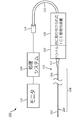
図1は、本開示の実施形態によるICE撮像システム100の概略図である。システム100は、ICEカテーテル110と、コネクタ124と、コンソール及び/又はコンピュータなどの処理システム130と、モニタ132とを含んでもよい。ICEカテーテル110は、先端アセンブリ又は撮像アセンブリ202と、可撓性細長部材208と、ハンドル220とを含む。可撓性細長部材208は、遠位部分204及び近位部分206を含む。遠位部分204の遠位端は、先端アセンブリ202に取り付けられる。近位部分206の近位端は、ICEカテーテル110の操作及び手動制御のために、例えば、弾性歪み軽減器212によってハンドル220に取り付けられる。先端アセンブリ202は、1つ又は複数の超音波トランスデューサ素子(例えば、トランスデューサアレイ)及び関連する回路を持つ撮像コアを含むことができる。ハンドル220は、本明細書内でより詳細に説明するように、先端アセンブリ202及び遠位部分204を偏向させるなど、ICEカテーテル110を操縦するためのアクチュエータクラッチ及び/又は他の操縦制御コンポーネントを含むことができる。
FIG. 1 is a schematic view of the
本開示はICEカテーテルに言及するが、血管内超音波(IVUS)装置、光コヒーレンストモグラフィ(OCT)装置、心臓内心エコー検査(ICE)装置、経食道心エコー検査(TEE)装置、血管内光音響(IVPA)撮像装置、及び/又は任意の適切な内部撮像装置など、任意の適切な管腔内撮像装置が、企図される。この点に関して、システム100は、管腔内撮像システムであることができ、装置110は、管腔内撮像装置(例えば、カテーテル、ガイドワイヤ、ガイドカテーテルなど)であることができる。例えば、システム100は、管腔内超音波撮像システムであることができ、装置110は、管腔内超音波撮像システムであることができる。更に、以下の開示は、患者の脈管構造(例えば、血管、動脈、静脈、心腔など)内に配置される管腔内装置を指し得るが、以下の開示は、管腔内撮像装置によって撮像される食道、腸、又は他の内部構造などの、患者の他の内部構造又は身体内腔内に配置されるようにサイズ決定及び成形され、構造的に配置され、及び/又は他の方法で構成される管腔内装置を企図する。システム100は、経中隔管腔穿刺、左心耳閉鎖、心房細動切除、及び弁修復などの様々な応用において利用されてもよく、生体内の血管及び構造を撮像するために使用されることができる。加えて、先端アセンブリ202は、診断、処置、及び/又は治療のための任意の適切な生理学的センサ又はコンポーネントを含み得る。
Although the present disclosure refers to an ICE catheter, it refers to an intravascular ultrasound (IVUS) device, an optical coherence tomography (OCT) device, an intracardiac echocardiography (ICE) device, a transesophageal echocardiography (TEE) device, an intravascular light. Any suitable intraluminal imaging device, such as an acoustic (IVPA) imaging device and / or any suitable internal imaging device, is contemplated. In this regard, the
図1に示す実施形態では、ハンドル220が、手術台、病院ベッド、又は医療又は手術環境における任意の他の適切な表面などの表面に結合及び/又は取り付けられることができるインタフェース装置230に結合される。いくつかの実施形態では、インタフェース装置230が、オペレータによる継続的な支持又は介入なしに、ICEカテーテル110を患者に対する位置及び向きに安定して維持するように構成された一体型ユニットを有することができる。
In the embodiment shown in FIG. 1, the
装置230は、コネクタ124及びケーブル122によって処理システム130と通信する。ハンドル220を装置230に結合することにより、ICEカテーテル110は、処理システム130と通信する。いくつかの態様では、ハンドル220がコネクタと称されることもできることを理解されたい。いくつかの態様では、ハンドル220が、アダプタ、カップリング、及び/又は接合部と称されることができる。例えば、いくつかの実施形態では、ハンドル220が、オペレータによって保持されず、装置230によって手術台及び患者の上に支持及び/又は吊り下げられる。しかしながら、単純化のために、用語「ハンドル」が使用される。
The
いくつかの実施形態では、システム100が、患者インタフェースモジュール(PIM)を更に含むことができる。例えば、PIMは、先端アセンブリ202の動作を制御するために、処理システム130とICEカテーテル110との間の信号の通信を容易にすることができる。これは、撮像アセンブリ202を配置するための制御信号を生成すること、送信器回路をトリガするための信号を生成すること、及び/又は先端アセンブリ202によって取得された信号を処理システム130に転送することを含む。エコー信号に関して、PIMは、受信信号を転送することができ、ある実施形態では、前記信号を処理システム130に送信する前に、予備的な信号処理を行う。このような実施形態の例では、PIMが、データの増幅、フィルタリング、及び/又は集約を実行する。一実施形態によると、PIMは、また、先端アセンブリ202内の回路の動作をサポートするために、高電圧及び低電圧DC電力を供給する。いくつかの実施形態では、PIMが、インタフェース装置230の一部として含まれてもよい。この点に関して、いくつかの実施形態では、PIM及び装置230が、単一の一体コンポーネントを有することができる。他の実施形態では、PIMが、装置230とコネクタ124との間、又はハンドル220内に配置されてもよい。図1に示す実施形態のような他の実施形態では、システム100は、PIMを有さなくてもよい。
In some embodiments, the
コネクタ124は、先端アセンブリ102における撮像コアによって生成された信号から得られた撮像データを処理、記憶、分析、操作、及び表示するために、処理システム130及びモニタ132と相互接続するように、任意の適切な構成で構成されてもよい。処理システム130は、1つ以上のプロセッサ、メモリ、キーボードなどの1つ以上の入力装置、及び/又は任意の適切なコマンド制御インタフェース装置を含むことができる。処理システム130は、本明細書で説明されるICE撮像システム100のフィーチャを容易にするように動作可能であることができる。例えば、処理システム130は、非一時的有形コンピュータ可読媒体に記憶されたコンピュータ可読命令を実行することができる。モニタ132は、液晶表示(LCD)パネル、発光ダイオード(LED)パネル等の任意の適切な表示装置であることができる。
The
動作中、医師又は臨床医は、可撓性細長部材208を心臓の解剖学的構造内の血管内に前進させる。医師又は臨床医は、ハンドル220を制御することによって、可撓性細長部材208を、撮像されるべき関心領域の近くの位置まで操縦することができる。例えば、ハンドル220上のアクチュエータは、本明細書でより詳細に論じられるように、先端アセンブリ202及び遠位部分204を左右平面内で偏向させることができ、他のアクチュエータは、先端アセンブリ202及び遠位部分204を前後平面内で偏向させることができる。
During operation, the physician or clinician advances the flexible
撮像プロセスは、超音波エネルギを生成するように、先端アセンブリ202上の超音波トランスデューサ素子を起動することを含んでもよい。超音波エネルギの一部は、関心領域及び周囲の解剖学的構造によって反射され、超音波エコー信号が、超音波トランスデューサ素子によって受信される。コネクタ124は、受信したエコー信号を処理システム130に転送し、そこで超音波画像が再構成され、モニタ132に表示される。いくつかの実施形態では、処理システム130が、超音波トランスデューサ素子の起動及びエコー信号の補充(repletion)を制御することができる。いくつかの実施形態では、処理システム130及びモニタ132が、同じシステムの一部であってもよい。
The imaging process may include activating an ultrasonic transducer element on the
図2は、本開示のいくつかの実施形態による、管腔内医療撮像インタフェース装置230を示す。装置230は、図2に示されるICE撮像システム200の一部として含まれてもよい。装置230は、手術台50に結合されて示されている。いくつかの態様では、装置230が、手術台50、病院用ベッド、回転テーブル、カウンタ、又は任意の他の適切な表面などの様々な表面に、取り付けられ、固定され、定着され、及び/又は他の方法で結合されることができる。装置230は、手術台に結合された近位部分332と、遠位部分234と、取り付けられた管腔内撮像装置(例えば、210)が患者に対するある位置及び/又は向きで支持及び維持されることを可能にする、複数の調節可能又は操作可能な機械的コンポーネントとを有する。装置230は、管腔内撮像処置に適した位置及び向きに遠位部分234を維持するように調整されることができる。例えば、いくつかの実施形態では、装置230が、ICEカテーテル210のハンドル220に分離可能に結合することができる。撮像処置の前及び/又は間に、装置230は、機械的及び/又は電気的結合を確立するために、ICEカテーテル210のハンドル220に接続されることができる。撮像処置の後、ハンドル220は、非破壊的な様式で装置230から切り離されることができる。装置230は、ICEカテーテル210を患者の入口点の近くに位置決めするように調整又は移動されることができ、装置230の遠位部分234が入口点の方を向くように向けられることができる。装置230は(例えば、ハンドル220を保持することによって)オペレータからの継続的な支持又は介入なしに、ICEカテーテル210の同じ位置及び/又は向きを維持するように構成される。
FIG. 2 shows an intraluminal medical
装置230は、アームアセンブリ240とヘッドアセンブリ250とを有する。アームアセンブリ240は、第1の長手部材242と、第1の長手部材242の遠位に配置された第2の長手部材244とを含む。アームアセンブリ240は、第1の長手部材242と第2の長手部材244とに結合され、間に配置される第1の接合部246と、第2の長手部材244とヘッドアセンブリ250とに結合され、間に配置される第2の接合部248とを更に含む。他の実施形態では、装置230が、より少ない又はより多い長手部材及び/又は接合部を有することができる。例えば、長手部材及び回転可能な接合部の数を増加させることによって、装置230は、より多くの運動の程度又はモードを示すことができ、潜在的に、オペレータによるより多くの配置を可能にする。装置230は、手術台50に対するヘッドアセンブリ250の伸縮運動を提供することができる。
The
図2に示される第1及び第2の接合部246、248は、第1及び第2の長手部材242、244並びにヘッドアセンブリ250の互いに対する回転を容易にする回転可能な接合部である。例えば、第1の接合部246は、第1の長手部材242に対して第1の軸の周りの第2の長手部材244の回転を容易にし、またその逆も同様である。第1の長手部材242は、手術台50に結合されているので、第1の接合部246を介して第1の軸の周りで第2の長手部材244を回転させることは、第2の長手部材244を手術台50に向けて又は離れるように移動することができる。同様に、第2の接合部248は、第2の縦方向部材244に対して第2の軸の周りのヘッドアセンブリ250の回転を容易にする。
The first and
アームアセンブリ240は、第1の長手部材242に結合された伸縮アセンブリ260を更に有する。伸縮アセンブリ260は、アームアセンブリ240が上方に延びることを可能にすることができる。伸縮アセンブリ260を作動させて上方に延びることによって、ヘッドアセンブリ250は、管腔内撮像処置を実行するのに適切な、又は望ましい高さに移動されることができる。図2の実施形態では、例えば、伸縮アセンブリ260は、第1の接合部246の第1の軸に沿った、又は平行な上方へのアームアセンブリ240の延伸を容易にする。他の実施形態では、伸縮アセンブリ260が、他の軸又は方向に沿ったアームアセンブリ240の延伸を容易にする。図2の伸縮アセンブリ260は、第1の長手部材242に結合されていると称されてもよい。しかしながら、いくつかの態様では、第1の長手部材242は、伸縮アセンブリ260が、第1の長手部材242の長さを増大させる方向に沿って、第1の長手部材242が伸縮、又は延伸することを可能にするように、伸縮アセンブリ260を有するものとして説明されることができる。他の実施形態では、伸縮アセンブリ260が、第1及び/又は第2の接合部246、248など、装置230の他のコンポーネントに含まれるか、又は結合されることができる。いくつかの実施形態では、伸縮アセンブリ260が、長手部材(例えば、第1及び/又は第2の長手部材242、244)の管腔内にスライド可能に受容される伸縮部材を含む。伸縮アセンブリ260は、また、伸縮部材が長手部材の管腔内で1つ以上の方向にスライドするのを防止するために、伸縮部材を所定の位置にロックするように構成されたロックアセンブリを含むことができる。いくつかの実施形態では、伸縮アセンブリ260が、アームアセンブリ240及び/又はヘッドアセンブリ250に沿った様々な点で、1より多い伸縮部材及び/又は1より多い伸縮アセンブリを含むことができる。伸縮部材及び/又は伸縮アセンブリの数を増加させることによって、装置230は、より多くの自由度又はモードを示し得、装置230のより多様な可能な位置、向き、及び構成をオペレータに提供する。
The
装置230は、装着ブラケット270又は取り付けブレースを介して手術台50に取り付けられる。取り付けブラケット270は、手術台50又は任意の他の適切な表面をしっかりと固定し、装置230を手術台50に対して支持及び/又は固定するように装置230に結合するように構成される。いくつかの実施形態では、取り付けブラケット270は、取り付けブラケット270がアームアセンブリ240にしっかり取り付けられるように、装置230の一部であることができる。いくつかの実施形態では、取り付けブラケット270が、装置230の位置及び/又は向きを支持及び維持しながら、手術台50の表面に沿ってスライドするように構成されることができる。
The
図3及び図4を参照すると、管腔内撮像インタフェース装置230のヘッドアセンブリ250が、ICEカテーテル210のハンドル220と共に示されている。ヘッドアセンブリ250は、アームアセンブリ240の遠位部分234に結合される。カテーテル210は、ヘッドアセンブリ250を介して装置230に取り外し可能に結合されるように構成される。図3において、ICEカテーテル210のハンドル220は、装置230から切り離されて示されている。ハンドル220は、歪み軽減部212を介してICEカテーテル210の可撓性細長部材208の近位部分206に結合される。いくつかの実施形態では、可撓性細長部材208が、前記装置の長さに沿って延在する1つ以上のプルワイヤを含む。例えば、可撓性細長部材208は、ハンドル220から可撓性細長部材208の遠位部分まで延在する1つのプルワイヤ又は複数のプルワイヤを含むことができる。プルワイヤは、屈曲、折り曲げ、又は撓みなどの可撓性細長部材208の遠位部分の移動を付与するように構成されてもよい。プルワイヤは、ICEカテーテル210の1つ以上の制御装置又は入力装置によって制御され得、ユーザがICEカテーテル210を患者の管腔又は他の内部構造を通してナビゲートしながらICEカテーテル210の遠位部分の移動を制御することを可能にする。いくつかの実施形態では、プルワイヤ、したがって可撓性細長部材208の遠位部分の制御を提供する制御装置又は入力装置は、ハンドル220に配置される。しかしながら、他の実施形態では、制御装置が、ICEカテーテル210の他の部分に配置されてもよく、又はインタフェース装置230、処理システム130、及び/又はモニタ132などのシステム200の他の部分に配置されてもよい。
With reference to FIGS. 3 and 4, the
ICEカテーテル210は、ハンドル220の遠位に延びる。ヘッドアセンブリ250は、患者に対する第1の位置及び第1の向きに維持される。ヘッドアセンブリ250は、アームアセンブリ240の1つ又は複数のコンポーネントを調整することによって、及び/又はヘッドアセンブリ250をアームアセンブリ240に対して移動させることによって、第2の位置及び第2の向きに移動されることができる。例えば、ヘッドアセンブリ250は、第2の接合部248を介して、アームアセンブリ240に対してヘッドアセンブリ250を回転させることによって、第2の向きに移動されることができる。
The
ICEカテーテル210のハンドル220は、ヘッドアセンブリ250の機械的インタフェース252内に受容されるように構成される。図4において、ハンドル220は、装置230のヘッドアセンブリ250に結合されて示されている。ハンドル220の近位部分228は、ヘッドアセンブリ250の機械的インタフェース252内に受け入れられる。ここで、ヘッドアセンブリ250に結合されると、ICEカテーテル210は、また、オペレータによる継続的な支持及び/又は介入なしに、患者に対する第1の向きに維持される。この構成では、装置230のヘッドアセンブリ250及びICEカテーテル210が、手術台50の上方に保持及び/又は懸架される。ICEカテーテル210及びヘッドアセンブリ250を手術台50の上方に維持することによって、ICEカテーテル210は、安定し、患者、オペレータ、又は手術台50の意図しない動きの影響を受けにくくなりうる。以下で論じられるように、装置230は、ヘッドアセンブリ250を第1の位置及び/又は第1の向きに維持しながら、回転、伸長(前進)、又は画像捕捉などのICEカテーテル210の態様を制御するように構成されることができる。
The
いくつかの実施形態では、ICEカテーテル210のハンドル220が、ICEカテーテル210の遠位部分の移動を制御するための機械的制御装置を含む。例えば、図4に示されるように、ハンドル220は、ハンドル220の外面にスライド可能に結合されたリング226を含むことができる。リング226は、リングの移動が1つ以上のプルワイヤに作用してICEカテーテル210の遠位部分の移動を引き起こすように、1つ以上のプルワイヤに直接的又は間接的に結合されてもよい。リング226は、ハンドル220の回転が可撓性細長部材208を回転させるように、可撓性細長部材208に結合されることができる。例えば、リング226をヘッドアセンブリ250に向かって近位に平行移動又は後退させることは、1つ以上のプルワイヤを介して、ICEカテーテル210の遠位部分の屈曲を制御することができ、リング226を回転させることは、ICEカテーテル210を回転させることができる。機械的制御装置は、オペレータが患者の解剖学的構造の画像を取得するために必要とする自由度又は運動モードを提供するために、ICEカテーテル210の回転部分を制御する回転制御装置254で補われることができる。このような構成は、ICEカテーテル210の遠位部分を制御するのに必要な制御装置の数を減らしうる。
In some embodiments, the
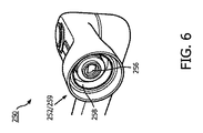
図5は、いくつかの実施形態による、ICEカテーテル210のハンドル220の近位端を示す。ハンドル220は、図6に示されるヘッドアセンブリ250の機械的インタフェース252及び電気的インタフェース259に結合するように構成された機械的インタフェース222及び電気的インタフェース229を含む。図5を参照すると、機械的インタフェース222は、ラッチコネクタ224とトルク伝達部材221とを含む。図5に示されるハンドル220のトルク伝達部材221は、図6に示されるヘッドアセンブリ250の機械的インタフェース252内に配置された対応するトルク伝達部材256と係合する。いくつかの態様において、図5のトルク伝達部材221は、オスコネクタと称されることができ、図6のトルク伝達部材256は、メスと称されることができる。図示された実施形態では、図5のトルク伝達部材221が、平らなシェルフ223部分を含む円筒状の突起を含む。図6のトルク伝達部材256は、図5のトルク伝達部材256の平らなシェルフ223と係合するように構成された平らな天井を持つ円形の凹部を含むことができる。
FIG. 5 shows the proximal end of the
図5において、ハンドル220は、また、機械的インタフェース222内に配置された電気インタフェース229を有する。電気的インタフェース229は、機械的インタフェース222の凹部の周囲に配置された複数の電気接点225を有する。いくつかの実施形態では、複数の電気接点225の各々が、別個の通信線を介した電気通信を提供しうる。例えば、いくつかの実施形態では、電気インタフェース229、259は、20、21、又は22の別々の通信線に関連する20、21、又は22の電気接点を含んでもよい。他の実施形態では、電気インタフェース229が、より少ない又はより多い電気接点を有してもよい。図5の電気インタフェース229の電気接点225は、ヘッドアセンブリ250内の対応する電気接点に結合して、装置230(及び/又は処理システム130)とICEカテーテル210との間の電気通信を確立することができる。
In FIG. 5, the
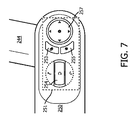
図7は、図1乃至4及び6に示されたヘッドアセンブリ250の上面図である。ヘッドアセンブリ250は、第2の接合部248を介して第2の長手部材244に回転可能に結合される。ヘッドアセンブリ250上に配置された制御領域251は、オペレータが管腔内医療撮像処置の様々な態様を制御することを可能にする複数のユーザ制御装置及び入力装置を含む。例えば、回転制御装置254は、ICEカテーテル210などの撮像装置の回転可能部分の回転を制御するために、オペレータによってねじられるか、押されるか、又は他の方法で操作されることができる。回転制御装置254は、ヘッドアセンブリ250内のモータのような回転機構を起動するための命令を有する制御信号のような電気信号を開始しうる。回転機構を起動することによって、ヘッドアセンブリ250のトルク伝達部材256は、ICEカテーテル210の回転可能部分の回転を制御する、ICEカテーテル210のハンドル220のトルク伝達部材221にトルクを伝達することができる。いくつかの実施形態では、ICEカテーテル210の回転可能部分が、細長い駆動シャフトと、駆動シャフトの遠位部分204に配置された撮像アセンブリ202とを有する。
FIG. 7 is a top view of the
制御領域251は、ICEカテーテル210の撮像アセンブリ202の態様を制御するように構成された第1のショートカット制御装置253及び第2のショートカット制御装置255を更に含む。例えば、第1のショートカット制御装置253は、撮像アセンブリ202が1つ又は複数の画像を取り込むための、又は撮像シーケンス又は撮像処置を実行するための命令を有する電気信号を開始しうる。第2のショートカット制御装置255は、フリーズ機能など、撮像処置の他の態様を制御してもよい。いくつかの実施形態では、第1及び第2のショートカット制御装置253、255の特定の機能は、オペレータによって設定されることができる。例えば、オペレータは、モニタ132を含むオペレータインタフェースを使用して、ショートカット制御装置253、255の1つ以上によって実行される機能を選択及び/又はプログラムしてもよい。制御領域251は、また、ユーザ嗜好及び処置要件に対して適応的である追加の撮像処置設定に対するアクセスを与える設定ナビゲーションボタン257を含む。制御領域251は、ボタン、トグル、スイッチなどの任意の適切な入力装置を含むことができる。
The
図8は、図7に示された制御装置と共に使用され得るオペレータインタフェース310の一部を示す。インタフェース310は、第1の画像設定制御装置312及び第2の画像設定制御装置314を含むことができる。いくつかの実施形態では、第1及び第2の画像設定制御装置312、314は、図7に示されるショートカット制御装置253、255と共に使用されることができる。例えば、第1及び第2の画像設定制御装置312、314は、第1のショートカット制御装置253が画像を取得するために使用される場合に、画像取得設定を設定するために使用されることができる。いくつかの実施形態では、オペレータインタフェース310が、グラフィカルユーザインタフェース(GUI)を有する。グラフィカルユーザインタフェースは、ディスプレイ並びにマウス及び/又はキーボードなどのインタフェース装置と共に使用されることができる。いくつかの実施形態では、GUIが、タッチスクリーンディスプレイと共に使用される。いくつかの実施形態では、オペレータインタフェース310及び/又はGUIが、タッチスクリーンディスプレイなどのヘッドアセンブリ250上に実装されることができる。他の実施形態では、オペレータインタフェース310及び/又はGUIが、インタフェース装置230から離れているモニタ132上に実装されることができる。
FIG. 8 shows a portion of the
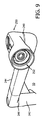
図9は、図1乃至図4、図6、及び図7の管腔内医療撮像インタフェース装置230の斜視図であり、ヘッドアセンブリ250が手術台50の上方に懸架された状態で示されている。いくつかの態様では、装置230が、ヘッドアセンブリ250を患者の上に支持するために、第2の長手部材244を手術台50の上で回転させて、上方に伸縮又は延伸されてもよい。いくつかの実施形態では、装置230が、装置230の複数回の使用を通じて、長期間にわたって、又は無期限にさえ、手術台50に結合されたままであるように構成され、かつ/又は意図されてもよい。したがって、装置230は、無菌ではないと見なされてもよい。ヘッドアセンブリ250に結合するICEカテーテル210は、使い捨て装置であることができ、又は複数使用のために構成されることができる。場合によっては、ICEカテーテル210が、1回の使用後に廃棄されることができるので、ハンドル220を含むICEカテーテル210は、無菌であると見なされてもよい。ICEカテーテル210は、また、複数回の使用の間に滅菌されることもでき、したがって、使用中に無菌であることができる。
9 is a perspective view of the intraluminal medical
図10に示されるように、動作環境の安全性及び無菌性を維持するために、無菌シース280は、無菌動作環境から非無菌装置230を隔離するために、装置230の上に配置される。いくつかの実施形態では、シース280が、例えば単回使用後に、使い捨て可能であることができる。いくつかの実施形態では、シース280が、無菌ICEカテーテル210上に最初にパッケージ化される。オペレータは、まず、機械的及び電気的インタフェース252、259を介してICEカテーテル210のハンドル220をヘッドアセンブリ250に結合し、次いでシース280をパッケージ化されたICEカテーテル210からスライドさせ、同時にシース280を非滅菌インタフェース装置230上でスライドさせることができる。他の実施形態では、新しいシースが、ICEカテーテル210のハンドル220を装置230のヘッドアセンブリ250に結合する前に、装置230上に配置されることができる。
As shown in FIG. 10, in order to maintain the safety and sterility of the operating environment, the
本明細書に記載される装置、システム、及び方法は、例えば、2016年9月29日に出願された米国仮出願第62/401,464号、2016年9月29日に出願された米国仮出願第62/401,525号、2016年9月30日に出願された米国仮出願第62/402,483号、2016年10月3日に出願された米国仮出願第62/403,431号、2016年10月3日に出願された米国仮出願第62/403,311号、2016年10月3日に出願された米国仮出願第62/403,278号、2016年10月3日に出願された米国仮出願第62/403,267号、2016年10月3日に出願された米国仮特許出願第62/468,046号及び米国特許出願公開第2008/0009745号に記載されているものと同様のフィーチャを含むことができる。 The devices, systems, and methods described herein are, for example, US Provisional Application No. 62 / 401,464 filed September 29, 2016, and US Provisional Application No. 62 / September 29, 2016. 62 / 401,525, US Provisional Application No. 62 / 402,483 filed on September 30, 2016, US Provisional Application No. 62 / 403,431 filed on October 3, 2016, October 3, 2016 US Provisional Application No. 62 / 403,311 filed, US Provisional Application No. 62 / 403,278 filed on October 3, 2016, US Provisional Application No. 62 / 403,267 filed on October 3, 2016, Features similar to those described in US Provisional Patent Application No. 62 / 468,046 and US Patent Application Publication No. 2008/0009745 filed October 3, 2016 can be included.
当業者は、上述の装置、システム、及び方法が様々な方法で修正されることができることを認識するのであろう。したがって、当業者は、本開示によって包含される実施形態が上述の特定の例示的な実施形態に限定されないことを理解するのであろう。この点に関して、例示的な実施形態が図示及び説明されてきたが、先行する開示において、広範囲の修正、変更、及び置換が企図される。このような変形は、本開示の範囲から逸脱することなく、上記のものになされ得ることが理解される。したがって、添付の特許請求の範囲は、本開示と一貫した形で広く解釈されることが適切である。 Those skilled in the art will recognize that the devices, systems, and methods described above can be modified in various ways. Thus, one of ordinary skill in the art will appreciate that the embodiments included in the present disclosure are not limited to the particular exemplary embodiments described above. Although exemplary embodiments have been illustrated and described in this regard, extensive modifications, modifications, and replacements are contemplated in the preceding disclosure. It is understood that such modifications can be made as described above without departing from the scope of the present disclosure. Therefore, it is appropriate that the appended claims be broadly construed in a manner consistent with the present disclosure.
Claims (16)
1つ又は複数の長手部材、及び前記1つ又は複数の長手部材に結合された1つ又は複数の接合部を有し、近位部分及び遠位部分を含むアームアセンブリと、
前記アームアセンブリの遠位部分に結合されたヘッドアセンブリであって、
前記アームアセンブリの遠位部分に結合された近位部分、並びに
管腔内撮像カテーテルに分離可能に接続するように構成された機械的結合部、及び
コンソールと前記管腔内撮像カテーテルとの間で電気信号を伝送するように前記管腔内撮像カテーテルに分離可能に接続するように構成された電気結合部、
を含む遠位部分、
を有する前記ヘッドアセンブリと、
を有し、
前記アームアセンブリが、前記ヘッドアセンブリを患者に対する第1の位置及び向きに維持するために、処置室内の表面に結合するように構成され、前記管腔内撮像カテーテルが、オペレータによる継続的な支持なしに適所に保持される、
装置。 In the intraluminal medical imaging interface device, the device is
An arm assembly having one or more longitudinal members and one or more joints joined to the one or more longitudinal members, including proximal and distal portions.
A head assembly coupled to the distal portion of the arm assembly.
A proximal portion coupled to the distal portion of the arm assembly, and a mechanical junction configured to be separably connected to the intraluminal imaging catheter, and between the console and the intraluminal imaging catheter. An electrical coupling that is configured to be separably connected to the intraluminal imaging catheter to transmit electrical signals,
Distal part, including
With the head assembly having
Have,
The arm assembly is configured to connect to a surface in the treatment chamber to maintain the head assembly in a first position and orientation with respect to the patient, and the intraluminal imaging catheter is not continuously supported by the operator. Held in place,
Device.
第1の回転可能な接合部と、
前記第1の回転可能な接合部の遠位の第2の回転可能な接合部と、
前記第1の回転可能な接合部の近位に延在する第1の長手部材と、
前記第1の回転可能な接合部と前記第2の回転可能な接合部との間に延在する第2の長手部材と、
を有し、
前記ヘッドアセンブリが、前記第2の回転可能な接合部の遠位に延在する、
請求項1に記載の装置。 The arm assembly
With the first rotatable joint,
With a second rotatable joint distal to the first rotatable joint,
A first longitudinal member extending proximal to the first rotatable joint,
A second longitudinal member extending between the first rotatable joint and the second rotatable joint.
Have,
The head assembly extends distal to the second rotatable joint.
The device according to claim 1.
前記管腔内撮像カテーテルが、
遠位部分及び近位部分を有し、患者の身体内腔内に配置されるように構成される、可撓性細長部材と、
前記可撓性細長部材の近位部分に結合されたハンドルと、
前記遠位部分に結合され、前記可撓性細長部材が身体内腔内に配置されている間に撮像データを取得するように構成された管腔内撮像アセンブリと、
を有し、
前記インタフェース装置が、
1つ又は複数の接合部に結合された1つ又は複数の長手部材を有し、処置室内の表面に結合して、前記ハンドルが前記インタフェース装置に結合される場合に前記管腔内撮像カテーテルの前記ハンドルを前記患者に対する第1の位置及び向きに維持するように構成されるアームアセンブリと
前記アームアセンブリの遠位部分に結合されたヘッドアセンブリであって、前記ヘッドアセンブリが、機械的結合部及び電気的結合部を有し、前記機械的結合部及び電気的結合部が、前記ヘッドアセンブリの遠位部分に配置され、前記管腔内撮像カテーテルの前記ハンドルに分離可能に結合するように構成される、前記ヘッドアセンブリと、
を有する、
システム。 Intraluminal imaging In an intraluminal medical imaging system with a catheter and interface device,
The intraluminal imaging catheter
A flexible elongated member having a distal part and a proximal part and configured to be placed within the lumen of the patient's body.
With a handle coupled to the proximal portion of the flexible elongated member,
An intraluminal imaging assembly coupled to the distal portion and configured to acquire imaging data while the flexible elongated member is placed in the body lumen.
Have,
The interface device
The intraluminal imaging catheter having one or more longitudinal members coupled to one or more joints and coupled to a surface in the treatment chamber when the handle is coupled to the interface device. An arm assembly configured to maintain the handle in a first position and orientation with respect to the patient and a head assembly coupled to a distal portion of the arm assembly, wherein the head assembly is a mechanical coupling and It has an electrical coupling, the mechanical and electrical coupling being located at the distal portion of the head assembly and configured to be separably coupled to the handle of the intraluminal imaging catheter. With the head assembly
Have,
system.
Applications Claiming Priority (3)
| Application Number | Priority Date | Filing Date | Title |
|---|---|---|---|
| US201862665702P | 2018-05-02 | 2018-05-02 | |
| US62/665,702 | 2018-05-02 | ||
| PCT/EP2019/060566 WO2019211150A1 (en) | 2018-05-02 | 2019-04-25 | Intraluminal medical imaging interface devices and systems |
Publications (2)
| Publication Number | Publication Date |
|---|---|
| JP2021522012A true JP2021522012A (en) | 2021-08-30 |
| JPWO2019211150A5 JPWO2019211150A5 (en) | 2022-04-18 |
Family
ID=66290445
Family Applications (1)
| Application Number | Title | Priority Date | Filing Date |
|---|---|---|---|
| JP2020560934A Pending JP2021522012A (en) | 2018-05-02 | 2019-04-25 | Intraluminal medical imaging interface device and system |
Country Status (5)
| Country | Link |
|---|---|
| US (1) | US20220008036A1 (en) |
| EP (1) | EP3787521A1 (en) |
| JP (1) | JP2021522012A (en) |
| CN (1) | CN112243360A (en) |
| WO (1) | WO2019211150A1 (en) |
Families Citing this family (2)
| Publication number | Priority date | Publication date | Assignee | Title |
|---|---|---|---|---|
| WO2020113083A1 (en) | 2018-11-28 | 2020-06-04 | Histosonics, Inc. | Histotripsy systems and methods |
| US11813485B2 (en) | 2020-01-28 | 2023-11-14 | The Regents Of The University Of Michigan | Systems and methods for histotripsy immunosensitization |
Citations (1)
| Publication number | Priority date | Publication date | Assignee | Title |
|---|---|---|---|---|
| US20140148759A1 (en) * | 2012-11-28 | 2014-05-29 | Hansen Medical, Inc. | Catheter having unirail pullwire architecture |
Family Cites Families (17)
| Publication number | Priority date | Publication date | Assignee | Title |
|---|---|---|---|---|
| US6078831A (en) * | 1997-09-29 | 2000-06-20 | Scimed Life Systems, Inc. | Intravascular imaging guidewire |
| WO2007115307A2 (en) | 2006-04-04 | 2007-10-11 | Volcano Corporation | Ultrasound catheter and hand-held device for manipulating a transducer on the catheter's distal end |
| US8108069B2 (en) * | 2007-01-10 | 2012-01-31 | Hansen Medical, Inc. | Robotic catheter system and methods |
| US8146874B2 (en) * | 2007-02-02 | 2012-04-03 | Hansen Medical, Inc. | Mounting support assembly for suspending a medical instrument driver above an operating table |
| EP2626006B1 (en) * | 2007-08-14 | 2019-10-09 | Koninklijke Philips N.V. | Robotic instrument systems utilizing optical fiber sensors |
| BRPI0906703A2 (en) * | 2008-01-16 | 2019-09-24 | Catheter Robotics Inc | remotely controlled catheter insertion system |
| US8323203B2 (en) * | 2008-02-28 | 2012-12-04 | Boston Scientific Scimed, Inc. | Imaging catheter |
| US8083691B2 (en) * | 2008-11-12 | 2011-12-27 | Hansen Medical, Inc. | Apparatus and method for sensing force |
| US10537713B2 (en) * | 2009-05-25 | 2020-01-21 | Stereotaxis, Inc. | Remote manipulator device |
| US20110015484A1 (en) * | 2009-07-16 | 2011-01-20 | Alvarez Jeffrey B | Endoscopic robotic catheter system |
| US20110257563A1 (en) * | 2009-10-26 | 2011-10-20 | Vytronus, Inc. | Methods and systems for ablating tissue |
| JP5965847B2 (en) * | 2010-03-03 | 2016-08-10 | コーニンクレッカ フィリップス エヌ ヴェKoninklijke Philips N.V. | Patient interface device with cam gear adjustment mechanism |
| US20120071894A1 (en) * | 2010-09-17 | 2012-03-22 | Tanner Neal A | Robotic medical systems and methods |
| CA2896516A1 (en) * | 2012-12-31 | 2014-07-03 | Volcano Corporation | Stepped banded connector for intravascular ultrasound devices |
| WO2014164363A1 (en) * | 2013-03-09 | 2014-10-09 | Kona Medical, Inc. | Transducers, systems, and manufacturing techniques for focused ultrasound therapies |
| WO2015035287A1 (en) * | 2013-09-06 | 2015-03-12 | Covidien Lp | Microwave ablation catheter, handle, and system |
| US20150327754A1 (en) * | 2014-04-21 | 2015-11-19 | Clph, Llc | Imaging apparatus and systems and methods for using them |
-
2019
- 2019-04-25 US US17/052,222 patent/US20220008036A1/en active Pending
- 2019-04-25 EP EP19719863.3A patent/EP3787521A1/en active Pending
- 2019-04-25 CN CN201980037493.7A patent/CN112243360A/en active Pending
- 2019-04-25 JP JP2020560934A patent/JP2021522012A/en active Pending
- 2019-04-25 WO PCT/EP2019/060566 patent/WO2019211150A1/en unknown
Patent Citations (1)
| Publication number | Priority date | Publication date | Assignee | Title |
|---|---|---|---|---|
| US20140148759A1 (en) * | 2012-11-28 | 2014-05-29 | Hansen Medical, Inc. | Catheter having unirail pullwire architecture |
Also Published As
| Publication number | Publication date |
|---|---|
| WO2019211150A1 (en) | 2019-11-07 |
| CN112243360A (en) | 2021-01-19 |
| EP3787521A1 (en) | 2021-03-10 |
| US20220008036A1 (en) | 2022-01-13 |
Similar Documents
| Publication | Publication Date | Title |
|---|---|---|
| JP7301884B2 (en) | Systems and methods for driving medical instruments | |
| JP7427654B2 (en) | Systems and methods for performing associated medical procedures | |
| JP2024001343A (en) | System and method for docking medical device | |
| AU2017261278B2 (en) | Access devices and methods for treatment of medical conditions and delivery of injectables | |
| RU2527668C2 (en) | Improved catheter | |
| JP5743454B2 (en) | Robot drive device for catheter | |
| EP3806772A1 (en) | Medical instruments for tissue cauterization | |
| US20240050063A1 (en) | Device for intra-cardiac and intra-vascular surgical procedure having an endoluminal ultrasound probe | |
| US20070123748A1 (en) | Robot for minimally invasive interventions | |
| JP2009544430A (en) | System for performing minimally invasive surgery | |
| EP4125687A1 (en) | Passive and active arm control schemes with sensor integration to support tele-operation and direct manual interaction | |
| US20210030501A1 (en) | Systems and methods for adjusting remote center distances in medical procedures | |
| JP7292289B2 (en) | Wireless operation for transesophageal echocardiography | |
| CN111698949A (en) | Device, system and method for transesophageal echocardiography | |
| US11179193B2 (en) | Device for intravascular therapy and/or diagnosis | |
| JP2021522012A (en) | Intraluminal medical imaging interface device and system | |
| US11944340B2 (en) | Suction and irrigation valve and method of priming same in a robotic surgical system | |
| JP2021517030A (en) | Electromagnetic control for intracavitary sensing devices and related devices, systems and methods | |
| RU2795943C2 (en) | Wireless control of transesophageal echocardiography | |
| US11589948B2 (en) | Hooked surgery camera | |
| Lago et al. | From laparoscopic surgery to 3-D double console robot-assisted surgery | |
| WO2023119158A1 (en) | Surgical platform with motorized arms |
Legal Events
| Date | Code | Title | Description |
|---|---|---|---|
| A521 | Request for written amendment filed |
Free format text: JAPANESE INTERMEDIATE CODE: A523 Effective date: 20220408 |
|
| A621 | Written request for application examination |
Free format text: JAPANESE INTERMEDIATE CODE: A621 Effective date: 20220408 |
|
| A131 | Notification of reasons for refusal |
Free format text: JAPANESE INTERMEDIATE CODE: A131 Effective date: 20221215 |
|
| A601 | Written request for extension of time |
Free format text: JAPANESE INTERMEDIATE CODE: A601 Effective date: 20230313 |
|
| A521 | Request for written amendment filed |
Free format text: JAPANESE INTERMEDIATE CODE: A523 Effective date: 20230609 |
|
| A02 | Decision of refusal |
Free format text: JAPANESE INTERMEDIATE CODE: A02 Effective date: 20231003 |
|
| A521 | Request for written amendment filed |
Free format text: JAPANESE INTERMEDIATE CODE: A523 Effective date: 20240131 |
|
| A911 | Transfer to examiner for re-examination before appeal (zenchi) |
Free format text: JAPANESE INTERMEDIATE CODE: A911 Effective date: 20240208 |
|
| A912 | Re-examination (zenchi) completed and case transferred to appeal board |
Free format text: JAPANESE INTERMEDIATE CODE: A912 Effective date: 20240405 |