JP2021521973A - Absorbent article - Google Patents
Absorbent article Download PDFInfo
- Publication number
- JP2021521973A JP2021521973A JP2020559421A JP2020559421A JP2021521973A JP 2021521973 A JP2021521973 A JP 2021521973A JP 2020559421 A JP2020559421 A JP 2020559421A JP 2020559421 A JP2020559421 A JP 2020559421A JP 2021521973 A JP2021521973 A JP 2021521973A
- Authority
- JP
- Japan
- Prior art keywords
- absorbent article
- liquid
- elongated
- absorbent
- reaction barrier
- Prior art date
- Legal status (The legal status is an assumption and is not a legal conclusion. Google has not performed a legal analysis and makes no representation as to the accuracy of the status listed.)
- Withdrawn
Links
Images


Classifications
-
- A—HUMAN NECESSITIES
- A61—MEDICAL OR VETERINARY SCIENCE; HYGIENE
- A61F—FILTERS IMPLANTABLE INTO BLOOD VESSELS; PROSTHESES; DEVICES PROVIDING PATENCY TO, OR PREVENTING COLLAPSING OF, TUBULAR STRUCTURES OF THE BODY, e.g. STENTS; ORTHOPAEDIC, NURSING OR CONTRACEPTIVE DEVICES; FOMENTATION; TREATMENT OR PROTECTION OF EYES OR EARS; BANDAGES, DRESSINGS OR ABSORBENT PADS; FIRST-AID KITS
- A61F13/00—Bandages or dressings; Absorbent pads
- A61F13/15—Absorbent pads, e.g. sanitary towels, swabs or tampons for external or internal application to the body; Supporting or fastening means therefor; Tampon applicators
- A61F13/45—Absorbent pads, e.g. sanitary towels, swabs or tampons for external or internal application to the body; Supporting or fastening means therefor; Tampon applicators characterised by the shape
- A61F13/47—Sanitary towels, incontinence pads or napkins
- A61F13/475—Sanitary towels, incontinence pads or napkins characterised by edge leakage prevention means
- A61F13/4751—Sanitary towels, incontinence pads or napkins characterised by edge leakage prevention means the means preventing fluid flow in a transversal direction
- A61F13/4757—Sanitary towels, incontinence pads or napkins characterised by edge leakage prevention means the means preventing fluid flow in a transversal direction the means being located outside the perimeter of the absorbent core
-
- A—HUMAN NECESSITIES
- A61—MEDICAL OR VETERINARY SCIENCE; HYGIENE
- A61F—FILTERS IMPLANTABLE INTO BLOOD VESSELS; PROSTHESES; DEVICES PROVIDING PATENCY TO, OR PREVENTING COLLAPSING OF, TUBULAR STRUCTURES OF THE BODY, e.g. STENTS; ORTHOPAEDIC, NURSING OR CONTRACEPTIVE DEVICES; FOMENTATION; TREATMENT OR PROTECTION OF EYES OR EARS; BANDAGES, DRESSINGS OR ABSORBENT PADS; FIRST-AID KITS
- A61F13/00—Bandages or dressings; Absorbent pads
- A61F13/15—Absorbent pads, e.g. sanitary towels, swabs or tampons for external or internal application to the body; Supporting or fastening means therefor; Tampon applicators
- A61F13/45—Absorbent pads, e.g. sanitary towels, swabs or tampons for external or internal application to the body; Supporting or fastening means therefor; Tampon applicators characterised by the shape
- A61F13/49—Absorbent articles specially adapted to be worn around the waist, e.g. diapers
- A61F13/494—Absorbent articles specially adapted to be worn around the waist, e.g. diapers characterised by edge leakage prevention means
- A61F13/49406—Absorbent articles specially adapted to be worn around the waist, e.g. diapers characterised by edge leakage prevention means the edge leakage prevention means being at the crotch region
- A61F13/49413—Absorbent articles specially adapted to be worn around the waist, e.g. diapers characterised by edge leakage prevention means the edge leakage prevention means being at the crotch region the edge leakage prevention means being an upstanding barrier
- A61F13/49426—Absorbent articles specially adapted to be worn around the waist, e.g. diapers characterised by edge leakage prevention means the edge leakage prevention means being at the crotch region the edge leakage prevention means being an upstanding barrier the barrier having an absorbent medium
-
- A—HUMAN NECESSITIES
- A61—MEDICAL OR VETERINARY SCIENCE; HYGIENE
- A61F—FILTERS IMPLANTABLE INTO BLOOD VESSELS; PROSTHESES; DEVICES PROVIDING PATENCY TO, OR PREVENTING COLLAPSING OF, TUBULAR STRUCTURES OF THE BODY, e.g. STENTS; ORTHOPAEDIC, NURSING OR CONTRACEPTIVE DEVICES; FOMENTATION; TREATMENT OR PROTECTION OF EYES OR EARS; BANDAGES, DRESSINGS OR ABSORBENT PADS; FIRST-AID KITS
- A61F13/00—Bandages or dressings; Absorbent pads
- A61F13/15—Absorbent pads, e.g. sanitary towels, swabs or tampons for external or internal application to the body; Supporting or fastening means therefor; Tampon applicators
- A61F13/45—Absorbent pads, e.g. sanitary towels, swabs or tampons for external or internal application to the body; Supporting or fastening means therefor; Tampon applicators characterised by the shape
- A61F13/47—Sanitary towels, incontinence pads or napkins
- A61F13/475—Sanitary towels, incontinence pads or napkins characterised by edge leakage prevention means
- A61F13/4751—Sanitary towels, incontinence pads or napkins characterised by edge leakage prevention means the means preventing fluid flow in a transversal direction
- A61F13/4756—Sanitary towels, incontinence pads or napkins characterised by edge leakage prevention means the means preventing fluid flow in a transversal direction the means consisting of grooves, e.g. channels, depressions or embossments, resulting in a heterogeneous surface level
-
- A—HUMAN NECESSITIES
- A61—MEDICAL OR VETERINARY SCIENCE; HYGIENE
- A61F—FILTERS IMPLANTABLE INTO BLOOD VESSELS; PROSTHESES; DEVICES PROVIDING PATENCY TO, OR PREVENTING COLLAPSING OF, TUBULAR STRUCTURES OF THE BODY, e.g. STENTS; ORTHOPAEDIC, NURSING OR CONTRACEPTIVE DEVICES; FOMENTATION; TREATMENT OR PROTECTION OF EYES OR EARS; BANDAGES, DRESSINGS OR ABSORBENT PADS; FIRST-AID KITS
- A61F13/00—Bandages or dressings; Absorbent pads
- A61F13/15—Absorbent pads, e.g. sanitary towels, swabs or tampons for external or internal application to the body; Supporting or fastening means therefor; Tampon applicators
- A61F13/45—Absorbent pads, e.g. sanitary towels, swabs or tampons for external or internal application to the body; Supporting or fastening means therefor; Tampon applicators characterised by the shape
- A61F13/47—Sanitary towels, incontinence pads or napkins
- A61F13/475—Sanitary towels, incontinence pads or napkins characterised by edge leakage prevention means
- A61F13/4758—Sanitary towels, incontinence pads or napkins characterised by edge leakage prevention means the means preventing fluid flow in a longitudinal direction
-
- A—HUMAN NECESSITIES
- A61—MEDICAL OR VETERINARY SCIENCE; HYGIENE
- A61F—FILTERS IMPLANTABLE INTO BLOOD VESSELS; PROSTHESES; DEVICES PROVIDING PATENCY TO, OR PREVENTING COLLAPSING OF, TUBULAR STRUCTURES OF THE BODY, e.g. STENTS; ORTHOPAEDIC, NURSING OR CONTRACEPTIVE DEVICES; FOMENTATION; TREATMENT OR PROTECTION OF EYES OR EARS; BANDAGES, DRESSINGS OR ABSORBENT PADS; FIRST-AID KITS
- A61F13/00—Bandages or dressings; Absorbent pads
- A61F13/15—Absorbent pads, e.g. sanitary towels, swabs or tampons for external or internal application to the body; Supporting or fastening means therefor; Tampon applicators
- A61F13/45—Absorbent pads, e.g. sanitary towels, swabs or tampons for external or internal application to the body; Supporting or fastening means therefor; Tampon applicators characterised by the shape
- A61F13/49—Absorbent articles specially adapted to be worn around the waist, e.g. diapers
- A61F13/494—Absorbent articles specially adapted to be worn around the waist, e.g. diapers characterised by edge leakage prevention means
- A61F13/49406—Absorbent articles specially adapted to be worn around the waist, e.g. diapers characterised by edge leakage prevention means the edge leakage prevention means being at the crotch region
- A61F13/49446—Absorbent articles specially adapted to be worn around the waist, e.g. diapers characterised by edge leakage prevention means the edge leakage prevention means being at the crotch region the edge leakage prevention means being an impermeable sheet or impermeable part of a sheet placed on or under the top sheet
-
- A—HUMAN NECESSITIES
- A61—MEDICAL OR VETERINARY SCIENCE; HYGIENE
- A61F—FILTERS IMPLANTABLE INTO BLOOD VESSELS; PROSTHESES; DEVICES PROVIDING PATENCY TO, OR PREVENTING COLLAPSING OF, TUBULAR STRUCTURES OF THE BODY, e.g. STENTS; ORTHOPAEDIC, NURSING OR CONTRACEPTIVE DEVICES; FOMENTATION; TREATMENT OR PROTECTION OF EYES OR EARS; BANDAGES, DRESSINGS OR ABSORBENT PADS; FIRST-AID KITS
- A61F13/00—Bandages or dressings; Absorbent pads
- A61F13/15—Absorbent pads, e.g. sanitary towels, swabs or tampons for external or internal application to the body; Supporting or fastening means therefor; Tampon applicators
- A61F13/45—Absorbent pads, e.g. sanitary towels, swabs or tampons for external or internal application to the body; Supporting or fastening means therefor; Tampon applicators characterised by the shape
- A61F13/49—Absorbent articles specially adapted to be worn around the waist, e.g. diapers
- A61F13/494—Absorbent articles specially adapted to be worn around the waist, e.g. diapers characterised by edge leakage prevention means
- A61F13/49406—Absorbent articles specially adapted to be worn around the waist, e.g. diapers characterised by edge leakage prevention means the edge leakage prevention means being at the crotch region
- A61F13/4946—Absorbent articles specially adapted to be worn around the waist, e.g. diapers characterised by edge leakage prevention means the edge leakage prevention means being at the crotch region the edge leakage prevention means being an absorbent medium
-
- A—HUMAN NECESSITIES
- A61—MEDICAL OR VETERINARY SCIENCE; HYGIENE
- A61F—FILTERS IMPLANTABLE INTO BLOOD VESSELS; PROSTHESES; DEVICES PROVIDING PATENCY TO, OR PREVENTING COLLAPSING OF, TUBULAR STRUCTURES OF THE BODY, e.g. STENTS; ORTHOPAEDIC, NURSING OR CONTRACEPTIVE DEVICES; FOMENTATION; TREATMENT OR PROTECTION OF EYES OR EARS; BANDAGES, DRESSINGS OR ABSORBENT PADS; FIRST-AID KITS
- A61F13/00—Bandages or dressings; Absorbent pads
- A61F13/15—Absorbent pads, e.g. sanitary towels, swabs or tampons for external or internal application to the body; Supporting or fastening means therefor; Tampon applicators
- A61F13/45—Absorbent pads, e.g. sanitary towels, swabs or tampons for external or internal application to the body; Supporting or fastening means therefor; Tampon applicators characterised by the shape
- A61F13/49—Absorbent articles specially adapted to be worn around the waist, e.g. diapers
- A61F13/494—Absorbent articles specially adapted to be worn around the waist, e.g. diapers characterised by edge leakage prevention means
- A61F13/49466—Absorbent articles specially adapted to be worn around the waist, e.g. diapers characterised by edge leakage prevention means the edge leakage prevention means being at the waist region
Abstract
本発明は、吸収性物品に関し、この吸収性物品は、トップシートと、バックシートと、トップシートとバックシートとの間の吸収性物品の中央領域に配置された吸収性コアと、吸収性物品の周辺領域において吸収性物品の内表面上に設けられ、吸収性物品の外側縁部に沿って、外側縁部に隣接して又は外側縁部から間隔を空けてのいずれかで位置決めされた少なくとも1つの細長い液体反応バリア部材と、を備え、少なくとも1つの細長い液体反応バリア部材は、吸収性材料を含み、吸収性材料が液体を吸収すると膨張し、吸収性材料の膨張時に、少なくとも1つの細長い液体反応バリア部材が少なくとも1つの細長い液体反応バリア部材と吸収性物品の着用者の身体の一部分との間にバリア又はシールを形成するように構成及び配置され、吸収性物品が、吸収性物品の中央領域から少なくとも1つの細長い液体反応バリア部材まで延びている、少なくとも1つの細長い液体伝導部材を更に備える。 The present invention relates to an absorbent article, wherein the absorbent article is a top sheet, a back sheet, an absorbent core located in the central region of the absorbent article between the top sheet and the back sheet, and an absorbent article. At least located on the inner surface of the absorbent article in the peripheral region of the absorbent article and positioned along the outer edge of the absorbent article, either adjacent to or spaced from the outer edge. With one elongated liquid reaction barrier member, at least one elongated liquid reaction barrier member comprises an absorbent material, which expands when the absorbent material absorbs a liquid and at least one elongated liquid reaction barrier member upon expansion of the absorbent material. The liquid reaction barrier member is configured and arranged to form a barrier or seal between at least one elongated liquid reaction barrier member and a part of the wearer's body of the absorbent article, and the absorbent article is of the absorbent article. It further comprises at least one elongated liquid conductive member extending from the central region to at least one elongated liquid reaction barrier member.
Description
本発明は、吸収性物品、例えば、おむつ、失禁用ブリーフ、トレーニングパンツなどの使い捨て吸収性物品に関する。 The present invention relates to absorbent articles such as disposable absorbent articles such as diapers, incontinence briefs and training pants.
乳幼児及び他の失禁症状のある個人は、尿及び他の身体滲出物を受け入れて封じ込めるためのおむつなどの吸収性物品を着用する。一般に、吸収性物品は、排出された物質を封じ込め、かつ/又はこれらの物質を着用者の身体から並びに着用者の衣類及び周囲のものから隔離するように機能する。したがって、吸収性物品からの漏れを完全に排除すること又は少なくとも最小限に抑えることが望ましい。 Infants and other individuals with incontinence wear absorbent items such as diapers to receive and contain urine and other body exudates. In general, absorbent articles function to contain the discharged material and / or isolate these material from the wearer's body and from the wearer's clothing and surroundings. Therefore, it is desirable to completely eliminate or at least minimize leaks from absorbent articles.
吸収性物品からの漏れを制御し排出物の封じ込めを強化するために努力する中で、吸収性物品に、弾性腰部特徴部及び/又は弾性脚部特徴部などの弾性特徴部が設けられた。そのような改善にもかかわらず、このような吸収性物品には依然として漏れが生じる傾向がある。例えば、弾性腰部特徴部を有する吸収性物品は、着用中に着用者の身体から離れるように垂れ下がったり又は隙間が生じたりする傾向がある、又は腰部特徴部は、開いたり又は丸くなったりする(roll down or in)傾向があり、これらは全て、着用者の腰部領域の周りでの漏れを引き起こす可能性があることが観察された。 In an effort to control leakage from the absorbent article and enhance containment of the effluent, the absorbent article was provided with elastic features such as elastic lumbar features and / or elastic leg features. Despite such improvements, such absorbent articles still tend to leak. For example, an absorbent article with elastic lumbar features tends to hang or create gaps away from the wearer's body during wear, or the lumbar features open or curl ( It was observed that there was a tendency to roll down or in), all of which could cause leaks around the wearer's lumbar region.
封じ込めフラップ及び水分反応性部材も提案され、かつ/又は吸収性物品内で利用されてきた。例えば、米国特許第5,935,118号は、吸収性物品が、衣類シェルと、吸収性材料で形成され取り付け縁部に沿って衣類シェルに結合された少なくとも1つの液体封じ込めビームと、を含み、封じ込めビームが、衣類シェルに接して横たわり、取り付け縁部によって画定される軸線を中心に旋回することもでき、封じ込めビームが、例えば、液体を吸収する際に膨潤し、その後、吸収性物品内での液体の移動を阻止する物理的バリアを形成することができることを開示している。米国特許第7,314,967号は、例えば、第1長手方向縁部、第2長手方向縁部、前側腰縁部、及び後側腰部部を有する使い捨て吸収性物品を開示しており、この使い捨て物品は、バックシートと、バックシートに取り付けられたトップシートと、トップシートとバックシートとの間に設けられた吸収性コアと、例えば吸収性ゲル材料を収容し、吸収性コアの外側にある使い捨て吸収性物品の第1長手方向縁部、第2長手方向縁部、前側腰縁部、及び後側腰縁部のうちの少なくとも1つに沿って使い捨て吸収性物品に取り付けられた第1水分反応部材と、を備え、第1水分反応部材が着用者の身体の一部分に接触し、水分反応部材が着用者の身体からの水分によって濡らされた場合に、第1水分反応部材が着用者の身体の一部分に対して膨張して、第1の水分反応性部材と着用者の身体の一部分との間で封を形成する。 Containment flaps and moisture-reactive members have also been proposed and / or have been utilized in absorbent articles. For example, US Pat. No. 5,935,118 includes a garment shell and at least one liquid containment beam formed of an absorbent material and coupled to the garment shell along a mounting edge. The containment beam can also lie in contact with the garment shell and swivel around an axis defined by the mounting edge, the containment beam swells, for example, as it absorbs liquid, and then within the absorbent article. It discloses that a physical barrier can be formed to prevent the movement of liquids in the water. US Pat. No. 7,314,967 discloses a disposable absorbent article having, for example, a first longitudinal edge, a second longitudinal edge, anterior lumbar edge, and a posterior lumbar edge. The disposable article contains a backsheet, a topsheet attached to the backsheet, an absorbent core provided between the topsheet and the backsheet, and, for example, an absorbent gel material, outside the absorbent core. A first attached to a disposable absorbent article along at least one of a first longitudinal edge, a second longitudinal edge, an anterior lumbar edge, and a posterior lumbar edge of a disposable absorbent article. The first moisture-reacting member is provided with a moisture-reacting member, and when the first moisture-reacting member comes into contact with a part of the wearer's body and the moisture-reacting member is wetted by moisture from the wearer's body, the first moisture-reacting member becomes the wearer. Inflates with respect to a part of the body to form a seal between the first moisture-reactive member and the part of the wearer's body.
このような吸収性物品は、漏れに対する望ましくない傾向を依然として有する。具体的には、吸収性コアの外側に封じ込めフラップ又は水分反応性部材を含むこのような吸収性物品の場合、漏れは、多くの場合、排出された液体及び物質からのものであり、特に、短時間での大量の液体及び物質の排出の場合、封じ込めフラップ又は水分反応性部材の吸収性材料が膨張する機会を有する前に、よってフラップ又は部材がバリア又はシールを形成する機会を有する前に、封じ込めフラップ及び/又は水分反応性部材から溢れる。 Such absorbent articles still have an undesired tendency to leak. Specifically, for such absorbent articles that include a containment flap or moisture-reactive member on the outside of the absorbent core, the leak is often from the discharged liquid and material, especially from the discharged liquid and material. For the discharge of large amounts of liquids and substances in a short period of time, before the absorbent material of the containment flap or moisture-reactive member has the opportunity to expand, and thus before the flap or member has the opportunity to form a barrier or seal. Overflow from containment flaps and / or moisture-reactive members.
したがって、吸収性物品が改善された漏れ特性を有することが必要とされ、例えば、短時間に液体及び物質の過剰な排出がある状況など、漏れ防止が最も必要とされるときに、最大の漏れ防止をもたらすことができる吸収性物品が必要とされる。 Therefore, the absorbent article is required to have improved leak properties, with maximum leakage when leakage prevention is most needed, for example in situations where there is excessive discharge of liquids and substances in a short period of time. Absorbent articles that can provide protection are needed.
吸収性コアを含む吸収性物品の中央領域から、吸収性物品の周辺領域において吸収性コアの外側に配置された封じ込めフラップ又は水分反応性部材などの吸収性材料を含む液体反応バリア部材まで延びる、1つ以上の液体伝導部材を設けることによって、液体反応バリア部材の吸収性材料は、液体吸収の結果として膨張し、よって液体反応バリア部材は、吸収性物品内の排出された液体及び物質の全体的なレベルが液体反応バリア部材に到達する前に、バリア又はシールを形成することが分かった。このようにして、吸収性物品内の排出された液体及び材料の量が臨界レベルに達する前にバリア又はシールの形成が促進され、したがって、排出された液体及び物質の量が臨界レベルに達すると、形成されたバリア又はシールが、吸収性物品内の排出された液体及び材料の封じ込めを容易にし、それによって漏れを最小限に抑える。
したがって、本発明は、中央領域及び周辺領域を有する吸収性物品を提供し、この吸収性物品は、
吸収性物品を使用中の着用者に向かって配置される液体透過性トップシートと、
バックシートと、
トップシートとバックシートとの間の中央領域に配置された吸収性コアと、
周辺領域において吸収性物品の内表面上に配置され、吸収性物品の外側縁部に沿って、外側縁部に隣接して又は外側縁部から間隔を空けてのいずれかで位置決めされた少なくとも1つの細長い液体反応バリア部材と、を備え、少なくとも1つの細長い液体反応バリア部材は、吸収性材料を含み、吸収性材料が液体を吸収すると膨張し、吸収性材料の膨張時に、少なくとも1つの細長い液体反応バリア部材が少なくとも1つの細長い液体反応バリア部材と吸収性物品の着用者の身体の一部分との間にバリア又はシールを形成するように構成及び配置され、
吸収性物品の中央領域から少なくとも1つの細長い液体反応バリア部材まで延びている少なくとも1つの細長い液体伝導部材と、を備える。
Extending from the central region of the absorbent article containing the absorbent core to a liquid reaction barrier member containing an absorbent material such as a containment flap or moisture reactive member located outside the absorbent core in the peripheral region of the absorbent article. By providing one or more liquid conductive members, the absorbent material of the liquid reaction barrier member expands as a result of liquid absorption, thus the liquid reaction barrier member is the entire discharged liquid and substance in the absorbent article. It has been found that a barrier or seal is formed before the level reaches the liquid reaction barrier member. In this way, the formation of barriers or seals is promoted before the amount of discharged liquids and materials in the absorbent article reaches critical levels, and thus the amount of discharged liquids and substances reaches critical levels. The formed barrier or seal facilitates containment of discharged liquids and materials within the absorbent article, thereby minimizing leakage.
Therefore, the present invention provides an absorbent article having a central region and a peripheral region, and the absorbent article is:
With a liquid permeable topsheet that is placed towards the wearer using the absorbent article,
With the back seat
With an absorbent core located in the central area between the top and back sheets,
At least one placed on the inner surface of the absorbent article in the peripheral region and positioned along the outer edge of the absorbent article, either adjacent to or spaced from the outer edge. With one elongated liquid reaction barrier member, at least one elongated liquid reaction barrier member comprises an absorbent material, which expands when the absorbent material absorbs the liquid and at least one elongated liquid upon expansion of the absorbent material. The reaction barrier member is configured and arranged to form a barrier or seal between at least one elongated liquid reaction barrier member and a portion of the wearer's body of the absorbent article.
It comprises at least one elongated liquid conductive member extending from the central region of the absorbent article to at least one elongated liquid reaction barrier member.
好都合には、少なくとも1つの細長い液体伝導部材の第1の端部が、中央領域内に位置決めされており、又は中央領域の外周部に直接隣接して位置決めされており、少なくとも1つの細長い液体伝導部材に沿って伝導される流体が、少なくとも1つの細長い液体反応バリア部材の吸収性材料に伝わるように、少なくとも1つの細長い液体伝導部材の第2の端部又は第2の端部を含む部分(「第2の端部部分」)が、少なくとも1つの細長い液体反応バリア部材に隣接して又は近接して位置決めされている。 Conveniently, the first end of at least one elongated liquid conduction member is positioned within the central region or directly adjacent to the outer periphery of the central region and at least one elongated liquid conduction member. A portion of the at least one elongated liquid conductive member that includes a second end or a second end such that the fluid conducted along the member is transmitted to the absorbent material of the at least one elongated liquid reaction barrier member. A "second end portion") is positioned adjacent to or in close proximity to at least one elongated liquid reaction barrier member.
少なくとも1つの細長い液体伝導部材は、トップシートとバックシートとの間、又は吸収性物品の内表面上、例えば吸収性物品のトップシート上のいずれかに配置することができ、これにより、吸収性物品の設計並びにその製造における柔軟性を可能にする。あるいは、液体伝導部材は、吸収性物品のトップシートと吸収性コアとの間に配置されてもよい。 At least one elongated liquid conductive member can be placed either between the topsheet and the backsheet, or on the inner surface of the absorbent article, eg, on the topsheet of the absorbent article, thereby absorbing. Allows flexibility in the design of goods and their manufacture. Alternatively, the liquid conductive member may be placed between the topsheet of the absorbent article and the absorbent core.
中央部分と少なくとも1つの細長い液体反応バリア部材との間で液体の輸送を可能にする複数のチャネルを内部に有する少なくとも1つの微細構造を持つ表面を有する流体制御フィルムを含む液体伝導部材を使用することが好都合であることが分かった。そのような細長い液体伝導部材は、好都合には、例えば、個別のチャネルの作成を強化するために、及び/又は液体が、液体伝導部材の側面を越えてその長さに沿って運ばれ、周辺領域のトップシート上に達するのを最小限に抑える又は防ぐために、液体伝導部材の長さの少なくとも一部分に沿ってチャネルを包囲するためのキャップ層を備えることができる。 Use a liquid conduction member that includes a fluid control film with a surface having at least one microstructure having multiple channels inside that allow the transport of liquid between the central portion and at least one elongated liquid reaction barrier member. Turned out to be convenient. Such an elongated liquid conductive member is conveniently used, for example, to enhance the creation of individual channels, and / or the liquid is carried along its length across the sides of the liquid conductive member and peripherally. A cap layer may be provided to enclose the channel along at least a portion of the length of the liquid conductive member in order to minimize or prevent reaching on the topsheet of the region.
本発明の適用性及び利点の更なる範囲は、以下に記載される詳細な説明から明らかになるであろう。しかしながら、詳細な説明及び具体例は、本発明の趣旨及び範囲内の様々な変更及び改変がこの詳細な説明から当業者に明らかになることから、本発明の好ましい実施形態を示しているが、例示としてのみ与えられていることを理解されたい。 Further scope of the applicability and benefits of the present invention will become apparent from the detailed description provided below. However, the detailed description and specific examples show preferred embodiments of the present invention, as various changes and modifications within the spirit and scope of the invention will be apparent to those skilled in the art from this detailed description. Please understand that it is given only as an example.
本発明は、以下に与えられる詳細な説明及び例示としてのみ与えられしたがって本発明を限定するものではない添付図面から、より完全に理解されるであろう。
全ての図において、対応する部分には同じ参照記号が付けられている。 In all figures, the corresponding parts have the same reference symbols.
図1及び図8を参照すると、本発明に従って形成された吸収性物品が、例示の目的で使い捨ておむつとして示されている。本発明はまた、他の成人用ケア製品など、他の種類の吸収性物品に具体化することができ、例えば、成人用失禁用下着、トレーニングパンツ、女性用衛生製品、又は他のパーソナルケア若しくはヘルスケア衣類に具現化することができる。 With reference to FIGS. 1 and 8, absorbent articles formed according to the present invention are shown as disposable diapers for illustrative purposes. The present invention can also be embodied in other types of absorbent articles, such as other adult care products, such as adult incontinence underwear, training pants, women's hygiene products, or other personal care products. It can be embodied in healthcare clothing.
図1及び図8を参照すると、一般に、吸収性物品100は、トップシート10、具体的には、液体透過性トップシート;バックシート(11、見えない)、具体的には、液体不透過性バックシート;中央領域21、ここで吸収性コア(20、見えない)がトップシートとバックシートとの間の領域に配置されている;中央領域を取り囲み吸収性物品の外側縁部まで延びている周辺領域12、を含む。図1は、例えば、後側腰部縁部13、前側腰部縁部14、及び2つの長手方向縁部15を含む使い捨ておむつを示す。本発明の目的のために、当技術分野において既知の任意の好適な材料を、トップシート、バックシート、及び吸収性コアに使用することができる。「配置された」という用語は、ある要素が、他の要素と一体構造として、又は別の要素に接合された別個の要素として、特定の場所又は位置に形成される(接合され、位置決められる)ことを意味するために使用される。
With reference to FIGS. 1 and 8, in general, the
吸収性物品は、周辺領域で吸収性物品の内表面上に設けられ(例えば、トップシートに取り付けられ)、したがって吸収性コアの外側で、吸収性物品の外側縁部に沿って、外側縁部に隣接して又は外側縁部から間隔を空けてのいずれかで位置決めされる、細長い液体反応バリア部材を含む。図1及び図8に示される実施形態では、吸収性物品100は、後側腰部縁部の付近に配置された細長い液体反応バリア部材30を含む。代替的実施形態では、細長い液体反応バリア部材は、前側腰部縁部付近、又は長手方向縁部付近に配置されてもよく、あるいは、吸収性物品は、前側腰部縁部及び腰部縁部付近、又は全ての縁部の付近に配置された2つ以上の細長い部材を含んでもよい。本発明による吸収性物品は、脚部カフ、弾性脚部カフ、又は弾性腰部バンドなどの他の特徴を更に含み得ることが理解されよう。例えば、吸収性物品が、弾性腰部特徴部並びに後側及び/又は前側腰部縁部の付近に配置された液体反応バリア部材を含むような実施形態では、弾性腰部特徴部の内側に液体反応バリア部材を配置することが好都合である。
The absorbent article is provided on the inner surface of the absorbent article in the peripheral area (eg, attached to the topsheet), and thus outside the absorbent core, along the outer edge of the absorbent article, at the outer edge. Includes an elongated liquid reaction barrier member that is positioned either adjacent to or spaced from the outer edge. In the embodiments shown in FIGS. 1 and 8, the
細長い液体反応バリア部材は、吸収性材料を含む。そして、使用中、吸収性材料は、液体(例えば尿など)を吸収すると膨張し、吸収性材料の膨張時に、細長い液体反応バリア部材は、少なくとも1つの細長い液体反応バリア部材と吸収性物品の着用者の身体の当該部分との間にバリア又はシールを形成する。 The elongated liquid reaction barrier member comprises an absorbent material. Then, during use, the absorbent material expands when it absorbs a liquid (such as urine), and when the absorbent material expands, the elongated liquid reaction barrier member wears at least one elongated liquid reaction barrier member and the absorbent article. Form a barrier or seal with that part of the person's body.
加えて、吸収性物品は、吸収性物品の中央領域から少なくとも1つの細長い液体反応バリア部材まで延びている少なくとも1つの細長い液体伝導部材を含む。図1及び図8に示される例示的実施形態では、吸収性物品100は、吸収性物品の中央領域21から細長い液体反応バリア部材30まで延びている3つの細長い液体伝導部材40を含む。図1の図示された実施形態では、液体伝導部材40は、吸収性物品の内表面上に設けられており、例えば、トップシートに取り付けられている。代替的実施形態では、液体伝導部材は、例えば、図8の図示された例示的実施形態に示されるように、トップシートとバックシートとの間に配置されてもよい。
In addition, the absorbent article includes at least one elongated liquid conductive member extending from the central region of the absorbent article to at least one elongated liquid reaction barrier member. In the exemplary embodiment shown in FIGS. 1 and 8, the
細長い液体伝導部材の一端部は、中央領域の外周部に直接隣接して、又は中央領域内に、のいずれかで位置決めされてもよい。細長い液体伝導部材の第1の端部を中央領域内に位置決めして、中央部分から液体反応バリア部材へと液体を適時に伝導するのを容易にするのが有利であることが分かっている。好都合には、細長い液体伝導部材の第1の端部の位置決めは、検討中の特定の吸収性物品、例えば、その構造、吸収能力、並びに漏れが急迫する可能性の点で排出流体及び物質の臨界レベルに相当すると考えられるレベルを考慮して、最適化することができる。例えば、使い捨ておむつ内で、おむつの後側部分の約2分の1より上の高さに達する排出された流体及び物質が、典型的には臨界であると見なされ、その場合、細長い液体伝導部材の第1の端部を上記臨界高さよりも低い位置で中央領域内に配置することが望ましいであろう。図1及び図8に示される例示的実施形態では、細長い液体伝導部材40の第1の端部41は、中央領域内で、使い捨ておむつの後側になる部分、具体的には、おむつが着用者に接しているときに、おむつの後側の約3分の2より下に相当するレベルあたりに位置決めされることが分かる。少なくとも1つの細長い液体伝導部材の第2の端部は、好都合には、細長い液体伝導部材に沿って伝導される流体が、少なくとも1つの細長い液体反応バリア部材の吸収性材料に伝わるように、少なくとも1つの細長い液体反応バリア部材に隣接して又は近接して位置決めされる。これを以下により詳細に説明する。
One end of the elongated liquid conductive member may be positioned either directly adjacent to the outer periphery of the central region or within the central region. It has been found advantageous to position the first end of the elongated liquid conduction member within the central region to facilitate the timely conduction of the liquid from the central portion to the liquid reaction barrier member. Conveniently, the positioning of the first end of the elongated liquid conductive member is that of the particular absorbent article under consideration, eg, its structure, absorption capacity, and the potential for urgent leakage of effluents and materials. It can be optimized by considering the level considered to correspond to the critical level. For example, within a disposable diaper, discharged fluids and substances that reach a height of more than about half of the posterior portion of the diaper are typically considered critical, in which case elongated liquid conduction. It would be desirable to place the first end of the member in the central region at a position below the critical height. In the exemplary embodiment shown in FIGS. 1 and 8, the
細長い液体伝導部材は、好都合には、液体の輸送を可能にする複数のチャネルを内部に有する少なくとも1つの微細構造を持つ表面を有する流体制御フィルムを含む。本発明で使用するのに適した流体制御フィルムは、米国特許第5,514,120号及び同第5,728,446号に記載されており、以下に概説する。米国特許第5,514,120号及び同第5,728,446号に記載される流体制御フィルムの高精細チャネル(microreplicated channels)は、所定のパターンから正確に複製され、主表面に沿って延びる一連の個々の開いた毛管チャネルを形成する。(「高精細」とは、微細構造化表面を、この構造化表面の特徴部が製造の間個々の特徴部の忠実度を維持するような工程を通して、作り出すことを意味する)。フィルム内に形成されたこれらの高精細チャネルは、好都合には、実質的に各チャネル長さに沿って、チャネルごとに一様かつ規則的であり、好都合には、ウェブ、発泡体、又は屑麻及び不織布などの繊維材料で達成されるよりも効果的な液体流をもたらす。 The elongated liquid conductive member preferably includes a fluid control film having a surface having at least one microstructure having a plurality of channels internally which allow the transport of the liquid. Fluid control films suitable for use in the present invention are described in US Pat. Nos. 5,514,120 and 5,728,446, outlined below. The microreplicated channels of the fluid control film described in US Pat. Nos. 5,514,120 and 5,728,446 are precisely replicated from a predetermined pattern and extend along the main surface. It forms a series of individual open capillary channels. (“High definition” means creating a finely structured surface through a process in which the features of this structured surface maintain the fidelity of the individual features during manufacturing). These high-definition channels formed within the film are conveniently uniform and regular for each channel, substantially along the length of each channel, and are conveniently webs, foams, or debris. It provides a more effective liquid flow than achieved with fibrous materials such as hemp and non-woven fabrics.
望ましくは、本発明で使用される流体制御フィルムは、フィルムチャネルの軸線に沿って液体を自発的かつ均一に輸送することができる。流体制御フィルムが流体(例えば、水、尿、膣分泌物)を自発的に輸送する能力に影響を及ぼす2つの一般的な要因は、(i)表面の形状又はトポグラフィ(毛管現象、チャネルの形状)、並びに(ii)フィルム表面の性質(例えば表面エネルギー)である。所望の量の流体輸送能力を達成するために、設計者は、流体制御フィルムの構造若しくはトポグラフィを調節してもよく、及び/又は流体制御フィルムの表面の表面エネルギーを調節してもよい。流体制御フィルムから作製された閉じたチャネル毛管が機能するために、チャネル毛管は、好ましくは、所望の流体がその表面を濡らすことができるように十分な親水性を有する。一般に、開いたチャネルにおける自発的なウィッキングを容易にするために、流体は流体制御フィルムの表面を濡らさなければならず、その接触角は90度からノッチ角の2分の1を引いた値以下でなければならない。 Desirably, the fluid control film used in the present invention is capable of spontaneously and uniformly transporting the liquid along the axis of the film channel. Two common factors that affect the ability of a fluid control film to spontaneously transport fluids (eg, water, urine, vaginal discharge) are: (i) surface shape or topography (capillary action, channel shape). ), And (ii) the properties of the film surface (eg, surface energy). To achieve the desired amount of fluid transport capacity, the designer may adjust the structure or topography of the fluid control film and / or adjust the surface energy of the surface of the fluid control film. In order for the closed channel capillaries made from the fluid control film to function, the channel capillaries preferably have sufficient hydrophilicity to allow the desired fluid to wet its surface. In general, the fluid must wet the surface of the fluid control film to facilitate spontaneous wicking in the open channel, the contact angle being 90 degrees minus half the notch angle. Must be:
流体制御フィルムのチャネルは、所望の液体輸送を提供する任意の形状とすることができ、好ましくは容易に複製されるものとすることができる。チャネルの形状は、その長さにわたって変化してもよい。更に、チャネルの数は様々に異なっていてもよく、例えば、1〜150、好ましくは10〜100、より好ましくは20〜80チャネルであってもよい。 The channels of the fluid control film can be of any shape that provides the desired liquid transport, preferably easily replicated. The shape of the channel may vary over its length. Further, the number of channels may vary, and may be, for example, 1-150, preferably 10-100, more preferably 20-80 channels.
流体制御フィルムは、例えば、ポリオレフィン、ポリエステル、ポリアミド、ポリ(塩化ビニル)、ポリエーテルエステル、ポリイミド、ポリエステルアミド、ポリアクリレート、ポリビニルアセテート、ポリビニルアセテートの加水分解誘導体などを含む、鋳造又はエンボス加工に適した任意の熱可塑性材料から形成することができる。ポリオレフィンが好ましく、特にポリエチレン又はポリプロピレン、それらのブレンド及び/又はコポリマー、並びにプロピレン及び/又はエチレンと、ビニルアセテート又はメチル及びブチルアクリレートなどのアクリレートなどの他の少量のモノマーとのコポリマーを使用する。ポリオレフィンは、優れた物理的特性、加工の容易さ、典型的には、類似の特徴を有する他の熱可塑性材料よりも安価であることのために、好ましい。ポリオレフィンは、鋳造用ロール又はエンボス加工用ロールの表面を容易に複製する。これらは丈夫で耐久性があり、それらの形状を良好に保持するので、鋳造又はエンボス加工工程後のそのようなフィルムの取り扱いが容易になる。親水性ポリウレタンもまた、その物理的特性と、固有の高い表面エネルギーとにより好ましい。あるいは、流体制御フィルムを、ポリウレタン、アクリレート、エポキシ及びシリコーン等の熱硬化性材料(硬化性樹脂材料)から鋳造することができ、熱、又はUV若しくは電子ビーム照射、又は湿気への曝露によって硬化させることができる。これらの材料は、表面エネルギー改質剤(例えば界面活性剤及び親水性ポリマー)、可塑剤、抗酸化剤、顔料、剥離剤、静電気防止剤などを含む、様々な添加剤を含有してもよい。 The fluid control film is suitable for casting or embossing, including, for example, polyolefins, polyesters, polyamides, poly (vinyl chloride), polyether esters, polyimides, polyesteramides, polyacrylates, polyvinyl acetates, hydrolyzed derivatives of polyvinyl acetates and the like. It can be formed from any thermoplastic material. Polyolefins are preferred, especially polyethylene or polypropylene, blends and / or copolymers thereof, and copolymers of propylene and / or ethylene with other small amounts of monomers such as vinyl acetate or acrylates such as methyl and butyl acrylate. Polyolefins are preferred because of their excellent physical properties, ease of processing, and typically cheaper than other thermoplastic materials with similar characteristics. Polyolefins easily replicate the surface of casting rolls or embossing rolls. They are tough and durable and retain their shape well, facilitating the handling of such films after a casting or embossing process. Hydrophilic polyurethanes are also preferred due to their physical properties and inherent high surface energy. Alternatively, the fluid control film can be cast from thermosetting materials (curable resin materials) such as polyurethane, acrylate, epoxy and silicone and cured by heat, UV or electron beam irradiation, or exposure to moisture. be able to. These materials may contain a variety of additives, including surface energy modifiers (eg surfactants and hydrophilic polymers), plasticizers, antioxidants, pigments, release agents, antistatic agents and the like. ..
表面特性、例えば親水性は、親水性が一方の端部から他方の端部まで増加又は減少して勾配を形成するように、材料の長さにわたって変化してもよい。 Surface properties, such as hydrophilicity, may vary over the length of the material such that hydrophilicity increases or decreases from one end to the other to form a gradient.
一般に、液体によってウェットアウトされる固体表面の感受性は、液体が水平に配置された表面に堆積されその上で安定化することができた後に、液体が固体表面となす接触角によって特徴付けられる。その接触角は、「静的平衡接触角」と呼ぶこともあり、本明細書では単に「接触角」と呼ぶこともある。図7A及び図7Bに示すように、接触角シータは、表面上の液体からなるビーズの表面に、表面に対するその接触点において接している線と、表面の平面との間の角度である。表面の平面に対して接線が垂直である液体のビーズは、接触角90度を有することになる。典型的には、接触角が90度以下である場合、固体表面は、液体によって濡れていると考えられる。水又は水溶液の液滴が90度未満の接触角を呈する表面を、一般に「親水性」と呼ぶ。本明細書で使用する場合、「親水性」は、材料の表面特性、すなわち、それが水溶液によって濡れること、を指すに過ぎず、その材料が水溶液を吸収するかしないかは表現しない。したがって、ある材料からなるシートが水溶液に対して不透過性又は透過性であるか否かに関わらず、その材料を親水性と呼ぶことができる。このように、本発明で使用される流体制御フィルムに使用される親水性フィルムは、例えばポリ(ビニルアルコール)などの本質的に親水性である樹脂材料から調製されたフィルムから形成することができる。表面上で接触角がほぼゼロの接触角をもたらす液体は、表面を完全にウェットアウトしていると考えられる。対照的に、ポリオレフィンは、典型的には本質的に疎水性であり、ポリエチレン又はポリプロピレンなどのポリオレフィンフィルムの水との接触角は、典型的には90度超である。 In general, the sensitivity of a solid surface wetted out by a liquid is characterized by the contact angle that the liquid makes with the solid surface after the liquid has been deposited on a horizontally arranged surface and can be stabilized on it. The contact angle may be referred to as a "static equilibrium contact angle" or simply "contact angle" herein. As shown in FIGS. 7A and 7B, the contact angle theta is the angle between the surface of the bead of liquid on the surface, the line in contact with the surface at its contact point, and the plane of the surface. Liquid beads whose tangents are perpendicular to the plane of the surface will have a contact angle of 90 degrees. Typically, if the contact angle is 90 degrees or less, the solid surface is considered wet by the liquid. A surface on which a droplet of water or aqueous solution exhibits a contact angle of less than 90 degrees is generally referred to as "hydrophilic". As used herein, "hydrophilicity" merely refers to the surface properties of a material, i.e., that it gets wet with an aqueous solution, and does not express whether the material absorbs the aqueous solution or not. Therefore, regardless of whether a sheet made of a certain material is impermeable or permeable to an aqueous solution, the material can be referred to as hydrophilic. As described above, the hydrophilic film used for the fluid control film used in the present invention can be formed from a film prepared from an essentially hydrophilic resin material such as poly (vinyl alcohol). .. A liquid that provides a contact angle of near zero on the surface is considered to have completely wetted out the surface. In contrast, polyolefins are typically hydrophobic in nature, and the contact angle of polyolefin films such as polyethylene or polypropylene with water is typically greater than 90 degrees.
高精細フィルム材料自体の性質、及び輸送される流体の性質に応じて、十分な毛管力を確実にするために、フィルムの表面を調節又は改質することが所望される場合がある。例えば、液体制御フィルムの表面を、この表面が十分な親水性を有することが保証されるように改質させてよい。ここで、流体制御フィルムと接触するであろう体液は水性である。したがって、例えば、ポリオレフィンから作製されたフィルムが流体制御フィルムとして使用される場合、それらのフィルムは、一般に改質される必要があり、例えば、表面処理、表面コーティング又は表面剤の適用、又は90度以下の接触角を呈するように表面が親水性にされるように選択された薬剤の組み込みによって改質される必要があり、それによって流体制御フィルムのウェッティング及び液体輸送特性を向上させる。表面を親水性にする好適な方法としては、(i)界面活性剤の組み込み、(ii)親水性ポリマーの組み込み又は表面コーティング、及び(iii)親水性シランによる処理が挙げられる。他の方法も想定される。 Depending on the nature of the high-definition film material itself and the nature of the fluid being transported, it may be desirable to adjust or modify the surface of the film to ensure sufficient capillary force. For example, the surface of the liquid control film may be modified to ensure that the surface is sufficiently hydrophilic. Here, the body fluid that will come into contact with the fluid control film is aqueous. Thus, for example, when films made from polyolefins are used as fluid control films, those films generally need to be modified, for example, surface treatment, surface coating or application of surface agents, or 90 degrees. It needs to be modified by the incorporation of agents selected so that the surface is hydrophilic to exhibit the following contact angles, thereby improving the wetting and liquid transport properties of the fluid control film. Suitable methods for making the surface hydrophilic include (i) incorporation of a surfactant, (ii) incorporation of a hydrophilic polymer or surface coating, and (iii) treatment with a hydrophilic silane. Other methods are also envisioned.
流体制御フィルムは、様々なトポグラフィを有し得る。好ましい流体制御フィルムは、V字形状又は矩形の断面を有する複数のチャネル、及びこれらの組み合わせ、並びに2次チャネル、すなわち、チャネル内のチャネルを有する構造体から構成される。開いたチャネルの場合、V字形チャネル状流体制御フィルムの微細構造化表面の所望の表面エネルギーは、以下のようなものである。
シータ<(90−アルファ/2)、
式中、シータは、液体とフィルムとの接触角であり、アルファ(α)は、2次V字形チャネルノッチの平均夾角である。(例えば、図6Gを参照されたい)。
Fluid control films can have a variety of topography. A preferred fluid control film is composed of a plurality of channels having a V-shaped or rectangular cross section, a combination thereof, and a secondary channel, that is, a structure having channels within the channel. For open channels, the desired surface energy of the microstructured surface of the V-shaped channel fluid control film is as follows.
Theta <(90-alpha / 2),
In the formula, theta is the contact angle between the liquid and the film, and alpha (α) is the average angle of the secondary V-shaped channel notch. (See, for example, FIG. 6G).
流体制御フィルム上に親水性の表面を実現するために、任意の好適な既知の方法を利用してよい。界面活性剤の局所適用、プラズマ処理、真空蒸着、親水性モノマーの重合、フィルム表面への親水性成分のグラフト化、コロナ処理又は火炎処理などの表面処理を用いてもよい。あるいは、界面活性剤又は他の好適な薬剤が、フィルム押出時に内部添加剤として樹脂とブレンドされてもよい。界面活性剤コーティングを局所的に適用することに頼らずに、界面活性剤を、流体制御フィルムが作られるポリマー組成物に組み込むことが、典型的には好ましい。局所的に適用されたコーティングは、チャネルのノッチを埋める、すなわち、鈍化させる傾向があり、それによって、本発明が対象とする所望の液体流と干渉する。ポリエチレン流体制御フィルムに組み込み可能な界面活性剤の例示的な例は、例えば約0.1〜0.5重量パーセントで用いられる、オクチルフェノキシポリエトキシエタノール非イオン性界面活性剤である、TRITONTM X−100である。フィルムの表面改質のための例示的な方法は、反応生成物の1%水溶液の局所適用であり、90重量パーセント以上の以下を含む:

上述のように、流体制御フィルム又は物品の特性を調節するために、界面活性剤又は複数の界面活性剤の混合物を、流体制御フィルムの表面に適用してよい、又は物品に含浸させてよい。例えば、流体制御フィルムの表面を、そのような成分を有さない場合のフィルムよりも、より親水性にすることが望まれる場合がある。 As described above, in order to adjust the properties of the fluid control film or article, a surfactant or a mixture of multiple surfactants may be applied to the surface of the fluid control film or the article may be impregnated. For example, it may be desired to make the surface of the fluid control film more hydrophilic than the film without such components.
望ましくは、良好な流体輸送特性が、流体制御フィルムが組み込まれた製品の寿命にわたって保持される。界面活性剤が流体制御フィルムの寿命を通して利用可能であることを確実にするために、界面活性剤は、好ましくは、物品の寿命を通して物品内で十分な量で利用可能である、又は流体制御フィルムの表面に固定化される。例えば、ヒドロキシル官能性界面活性剤は、界面活性剤をジアルコキシシラン官能基又はトリアルコキシシラン官能基で官能化することによって、流体制御フィルムに固定化することができる。次いで、界面活性剤を、流体制御フィルムの表面に適用するか、又は物品に含浸させることができ、物品はその後湿気に曝される。湿気は、加水分解及びその後のポリシロキサンへの縮合をもたらすことになる。ヒドロキシ官能性界面活性剤(特に1,2ジオール界面活性剤)はまた、ホウ酸イオンとの会合によって固定化されてもよい。好適な界面活性剤としては、アニオン性、カチオン性、及び非イオン性界面活性剤が挙げられるが、比較的低い刺激性のために非イオン性界面活性剤が好ましい場合がある。ポリエトキシル化界面活性剤及びポリグルコシド界面活性剤が特に好ましく、ポリエトキシル化アルキル、アラルキル、及びアルケニルアルコール、「Pluronic」及び「Tetronic」などのエチレンオキシド及びプロピレンオキシドコポリマー、アルキルポリグルコシド、ポリグリセリルエステルなどが挙げられる。他の好適な界面活性剤が、米国特許出願番号第08/576,255号に開示されている。 Desirably, good fluid transport properties are preserved over the life of the product incorporating the fluid control film. To ensure that the surfactant is available throughout the life of the fluid control film, the surfactant is preferably available in sufficient quantity within the article throughout the life of the article, or the fluid control film. It is fixed on the surface of. For example, a hydroxyl-functional surfactant can be immobilized on a fluid control film by functionalizing the surfactant with a dialkoxysilane functional group or a trialkoxysilane functional group. The surfactant can then be applied to the surface of the fluid control film or impregnated into the article, which is then exposed to moisture. Moisture will result in hydrolysis and subsequent condensation on the polysiloxane. Hydroxy functional surfactants (particularly 1,2diol surfactants) may also be immobilized by association with borate ions. Suitable surfactants include anionic, cationic and nonionic surfactants, but nonionic surfactants may be preferred due to their relatively low irritation. Polyethoxylated surfactants and polyglucoside surfactants are particularly preferred, with alkyl polyethoxylated, aralkyl, and alkenyl alcohols, ethylene oxide and propylene oxide copolymers such as "Pluronic" and "Tetronic", alkyl polyglucosides, polyglyceryl esters, and the like. Can be mentioned. Other suitable surfactants are disclosed in US Patent Application No. 08 / 576,255.
上述したように、流体制御フィルムの特性を調節するために、親水性ポリマー又は複数のポリマーの混合物を、流体制御フィルムの表面に適用してよい又は物品に含浸させてよい。親水性ポリマーが流体制御フィルムの寿命を通して利用可能であることを確実にするために、ポリマーは、好ましくは、物品の寿命を通して物品内で十分な量で利用可能であるか、又は流体制御フィルムの表面に固定化される。別法として、物品に親水性モノマーを添加し、その場で重合させて、相互貫入ポリマーネットワークを形成させてよい。例えば、親水性アクリレート及び開始剤を添加し、熱又は化学線によって重合させることができる。 As mentioned above, a hydrophilic polymer or a mixture of multiple polymers may be applied to the surface of the fluid control film or impregnated into the article in order to adjust the properties of the fluid control film. To ensure that the hydrophilic polymer is available throughout the life of the fluid control film, the polymer is preferably available in sufficient quantity within the article throughout the life of the article, or of the fluid control film. It is fixed on the surface. Alternatively, hydrophilic monomers may be added to the article and polymerized in situ to form a cross-intrusive polymer network. For example, hydrophilic acrylates and initiators can be added and polymerized by heat or chemical rays.
好適な親水性ポリマーとしては、エチレン酸化物のホモ及びコポリマー、ビニルピロリドン、カルボン酸、スルホン酸、又はアクリル酸などのホスホン酸官能性アクリレートなどのビニル不飽和モノマーを組み込む親水性ポリマー、ヒドロキシエチルアクリレート、酢酸ビニル及びその加水分解誘導体(例えばポリビニルアルコール)、アクリルアミド、ポリエトキシル化アクリレートなどのヒドロキシ官能性アクリレート;親水性改質セルロース、並びにデンプン及び改質デンプン、デキストランなどの多糖類などが挙げられる。 Suitable hydrophilic polymers include homo and copolymers of ethylene oxide, hydrophilic polymers incorporating vinyl unsaturated monomers such as vinylpyrrolidone, carboxylic acids, sulfonic acids, or phosphonic acid functional acrylates such as acrylic acid, hydroxyethyl acrylates. , Vinyl acetate and hydrolyzed derivatives thereof (for example, polyvinyl alcohol), hydroxyfunctional acrylates such as acrylamide and polyethoxylated acrylates; hydrophilic modified celluloses, and polysaccharides such as starch and modified starches and dextrans.
上述したように、流体制御フィルムの特性を調節するために、親水性シラン又は複数のシランの混合物を、流体制御フィルムの表面に適用してもよく、又はフィルムに含浸させてもよい。好適なシランとしては、非イオン性又はカチオン性の親水性シランだけでなく、米国特許第5,585,186号に開示されているアニオン性シランが挙げられる。カチオン性シランは、これらのシランの特定のものが抗菌性を有するとも考えられる点で有利であり得る。 As described above, hydrophilic silanes or mixtures of silanes may be applied to the surface of the fluid control film or impregnated into the film in order to adjust the properties of the fluid control film. Suitable silanes include nonionic or cationic hydrophilic silanes as well as anionic silanes disclosed in US Pat. No. 5,585,186. Cationic silanes can be advantageous in that certain of these silanes are also considered to have antibacterial properties.
前述のように、流体制御フィルムのチャネルは、所望の液体輸送を提供する任意の形状であり得る。流体制御フィルムは、両方の主表面上に1次チャネルを有することができるが、1つの主表面にのみ1次チャネルを有する流体制御フィルム(例えば、図6A〜図6C及び図6Gに示すように)が、吸収性物品及びその液体伝導部材の使用について、より好都合であることが分かった。 As mentioned above, the channels of the fluid control film can be of any shape that provides the desired liquid transport. The fluid control film can have primary channels on both main surfaces, but fluid control films having primary channels on only one main surface (eg, as shown in FIGS. 6A-6C and 6G). ) Has been found to be more convenient for the use of absorbent articles and their liquid conductive members.
図6Aに示すように、チャネル616は、図示された実施形態に従って、一連のV字形状側壁617及び頂部618によって層612a内に画定され得る。場合によっては、側壁617及び頂部618は、変更することなく、層612の1つの一方の縁部から他方の縁部まで全体的に延びていてもよいが、用途によっては、側壁617を短くし、したがって頂部618を構造化表面613の一部分に沿ってのみ延ばすことが望ましい場合がある。すなわち、頂部618の間に画定されるチャネル616は、層612の一方の縁部から他方の縁部まで全体的に延びていてもよく、又はそのようなチャネル616は、層612の一部分にわたって延びるように画定されるだけでもよい。一部分にわたってだけ延びているチャネルは、層612の縁部で開始してもよく、又は層612の構造化表面613内の中間で開始及び終端してもよい。チャネルは、ポリマー材料からなる連続表面上に、所定の、好ましくは規則的な配置で画定される。層612は、バッキング615を更に含む。
As shown in FIG. 6A, the
図6Bに示すように、層612bのチャネル616’は、わずかに平坦化された頂部618’の間により幅広い平坦な谷部を有する。図6Aの実施形態と同様に、キャップ層を、1つ以上の頂部618’に沿って固定し、個別のチャネル616’を画定することができる。この場合、底面630がチャネル側壁631の間に延びているが、図6Aの実施形態では、側壁617は線に沿って互いに繋がっている。
As shown in FIG. 6B, the
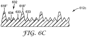
図6Cは、層612cの幅広いチャネル632が頂部618”の間に画定されているが、チャネル側壁の間に平坦な表面を設ける代わりに、複数のより小さな頂部633が、頂部618”の側壁の間に配置される構成を示す。したがって、これらのより小さい頂部633は、それらの間に2次チャネル634を画定している。頂部633は、頂部618と同じ高さまで達していてもよく、又は達していなくてもよく、図示されるように、その内部に分布したより小さいチャネル634を含む第1の幅広チャネル632を形成している。頂部618”及び633は、それら自体又は互いに対して均等に分布する必要はない。
In FIG. 6C, the
図6D〜図6Hは、流体制御フィルムの様々な代替的実施形態を示す。図6A〜6Hは、細長い直線状に構成されたチャネルを示しているが、チャネルは他の構成で設けられてもよい。例えば、チャネルは、チャネル長さに沿って変化する断面幅を有し得る。すなわち、チャネルは、チャネルの長さに沿って分岐する及び/又は合流することができる。チャネル側壁はまた、チャネルの延びている方向又はチャネル高さ方向において直線になっているのではなく、輪郭が付けられることもできる。一般に、流体輸送デバイス内の第1の点から第2の点まで延びている少なくとも複数の個別のチャネル部分を設けることができる任意のチャネル構成が考えられるチャネルは、必要に応じて、その全長に沿って個別のままとなるように構成されることができる。 6D-6H show various alternative embodiments of the fluid control film. Although FIGS. 6A to 6H show channels configured in an elongated linear shape, the channels may be provided in other configurations. For example, the channel can have a cross-sectional width that varies with the channel length. That is, the channels can branch and / or merge along the length of the channel. The channel sidewalls can also be contoured rather than straight in the extending or channel height direction of the channel. In general, any channel configuration in which at least a plurality of individual channel portions extending from the first point to the second point in the fluid transport device can be provided can be considered, and if necessary, the total length of the channel may be increased. It can be configured to remain individual along.
図6Gを参照すると、1つの好ましい形状は、平坦なフィルム601内の直線状1次チャネル602である。1次チャネル602は側壁604を有し、多数のノッチ605を形成する2次チャネル603を含む。ノッチ605(又は2次チャネル603、チャネルがV字形状であり実質的に直線状の側壁を有する)は、約10度〜約120度、好ましくは約10度〜約100度、最も好ましくは約20度〜約95度の夾角(角度アルファ)を有する。ノッチの夾角は、一般に、ノッチから、ノッチを形成する側壁上のノッチから2〜1000ミクロンの点まで切り取られた割線角度であり、好ましくは、夾角は、2次チャネル側壁の途中まで上がった点で切り取られる割線角度である。より狭い夾角幅を有するノッチは、一般に、より大きな垂直ウィッキング距離をもたらすことが観察された。しかしながら、アルファが狭すぎる場合、流量は著しく低下することになる。アルファが広すぎる場合、ノッチ又は2次チャネルは、所望のウィッキング作用を提供することができない可能性がある。アルファが狭くなるにつれて、同様の液体輸送を得るために液体の接触角が必ずしも低くなければならないわけではない。接触角は、より大きな角度幅を有するノッチ又はチャネルに対するものである必要があるためである。
With reference to FIG. 6G, one preferred shape is the linear
1次チャネル夾角は、1次チャネルが液体を運ぶ際に効果的がないほど広くすべきでないことを除いて、重要ではない。一般に、1次チャネル最大幅は、3000ミクロン未満、好ましくは1500ミクロン未満である。V字形チャネル状の1次チャネルの夾角は、一般に、約10度〜120度、好ましくは30度〜90度となろう。1次チャネルの夾角が狭すぎる場合、1次チャネルは、適切な数の2次チャネルを収容することができるような十分な幅をその基部において有さないことがある。一般に、1次チャネルの夾角は、1次チャネルの基部において2つ以上の2次チャネルを収容するように、2次チャネルの夾角よりも大きいことが好ましい。一般に、2次チャネルは、1次チャネルの夾角(V字形状1次チャネルの場合)よりも少なくとも20パーセント小さい夾角を有する。 The primary channel angle is not important, except that the primary channel should not be wide enough to be ineffective in carrying the liquid. Generally, the maximum width of the primary channel is less than 3000 microns, preferably less than 1500 microns. The radius of the V-shaped channel-like primary channel will generally be about 10 to 120 degrees, preferably 30 to 90 degrees. If the angle of the primary channel is too narrow, the primary channel may not have sufficient width at its base to accommodate an appropriate number of secondary channels. In general, the angularity of the primary channel is preferably greater than the angularity of the secondary channel so as to accommodate two or more secondary channels at the base of the primary channel. In general, the secondary channel has an angle that is at least 20 percent smaller than the angle of the primary channel (in the case of a V-shaped primary channel).
図6gを参照すると、1次チャネル(602、622)の深さ(最も低いチャネルノッチの上方にある頂部又は上面の高さ)である、「d」は実質的に均一であり、好適には約5〜約3000ミクロン、典型的には約50〜約3000ミクロン、好ましくは約75〜約1500ミクロン、最も好ましくは約100〜約1000ミクロンである。いくつかの実施形態では、この示された範囲よりも大きい深さを有するチャネル(602、622)を有するフィルムが使用されてもよいことが理解されるであろう。チャネルが過度に深い場合、流体制御フィルムの全体的な厚さは不必要に高くなり、フィルムは所望されるよりも硬くなる傾向を有することがある。1次チャネルのその基部における幅は、2つ以上の2次チャネルを収容するのに十分とすることができる。 With reference to FIG. 6g, "d", which is the depth of the primary channel (602, 622) (the height of the top or top above the lowest channel notch), is substantially uniform and preferably. It is about 5 to about 3000 microns, typically about 50 to about 3000 microns, preferably about 75 to about 1500 microns, most preferably about 100 to about 1000 microns. It will be appreciated that in some embodiments, films with channels (602, 622) having a depth greater than this indicated range may be used. If the channels are too deep, the overall thickness of the fluid control film will be unnecessarily high and the film may tend to be harder than desired. The width of the primary channel at its base can be sufficient to accommodate two or more secondary channels.
図6gに示されるように、少なくとも2つの2次チャネル(603、623)及び少なくとも2つのノッチ(605、625)が各1次チャネル(602、622)内にあり、ノッチ(605、625)又は各2次チャネル(603、623)のノッチは、2次頂部(606、626)によって分離される。一般に、各2次チャネルは、一般に1つのノッチのみを有するが、2次チャネルが矩形である場合には、2次チャネルは2つのノッチを有することになる。V字形チャネル状の2次チャネルの2次頂部(606、626)は、一般に、(α1+α2)/2に通常等しい夾角ベータ(β)によって特徴付けられ、ここで、α1及びα2は、2つの隣接するV字形チャネル状の2次チャネル(603、623)の夾(アルファ)角であり、各2次チャネルを形成する2つの側壁は対称であって湾曲していないものとする。一般に、角度βは、約10度〜約120度、好ましくは約10度〜約90度、最も好ましくは約20度〜約60度である。2次頂部はまた、平坦であってもよい(この場合、夾角は、理論的には0度になる)、又は更には湾曲した、例えば凸状又は凹状であってもよく、明確な頂部又は夾角がない場合もあり得る。好ましくは、図6Gに示すように、各1次チャネル(602、622)について、少なくとも3つの2次チャネル(603、623)及び/又は端部チャネル(ノッチ608又は609)に関連する任意のノッチ(605、625)を含む、少なくとも3つのノッチが存在する。
As shown in FIG. 6g, there are at least two secondary channels (603, 623) and at least two notches (605, 625) in each primary channel (602, 622) and notches (605, 625) or The notches in each secondary channel (603, 623) are separated by a secondary top (606, 626). Generally, each secondary channel generally has only one notch, but if the secondary channel is rectangular, the secondary channel will have two notches. The secondary apex (606, 626) of the V-shaped channel secondary channel is generally characterized by an angle beta (β), which is usually equal to (α 1 + α 2 ) / 2, where α 1 and α 2 are used. Is the fold (alpha) angle of two adjacent V-shaped channel-shaped secondary channels (603, 623), and the two side walls forming each secondary channel are assumed to be symmetrical and not curved. .. In general, the angle β is from about 10 degrees to about 120 degrees, preferably from about 10 degrees to about 90 degrees, most preferably from about 20 degrees to about 60 degrees. The secondary apex may also be flat (in which case the radius is theoretically 0 degrees) or even curved, eg convex or concave, with a clear apex or It is possible that there is no angle. Preferably, for each primary channel (602, 622), any notch associated with at least three secondary channels (603, 623) and / or end channels (
2次チャネル(603、623)のうちの1つの深さ(ノッチ605の上の2次頂部606の上面の高さ)は、流体制御フィルムの長さにわたって均一であり、典型的には少なくとも5ミクロンである。2次チャネル(603、623)の深さは、一般に、1次チャネルの深さの0.5〜80パーセント、好ましくは5〜50パーセントである。頂部6のいずれの側のノッチ(605、625)の間隔も、好ましくは、流体制御フィルムの長さにわたって均一である。好ましくは、1次及び/又は2次チャネル深さ及び幅は、流体制御フィルムの所与の長さにわたって、チャネルごとに、20パーセント未満、好ましくは10パーセント未満だけ異なる。この範囲を上回る2次チャネル深さ及び形状のばらつきは、流体制御フィルムに沿った液体輸送の速度及び均一性にかなりの悪影響を及ぼす。一般に、1次チャネル及び2次チャネルは、連続的であり、妨害されない。
The depth of one of the secondary channels (603, 623) (the height of the top surface of the
構造化表面は、非常に低いプロファイルを設けることもできる。したがって、流体制御フィルムからなる構造化ポリマー層が5000マイクロメートル未満、及び場合によっては1500マイクロメートル未満の厚さを有する、細長い液体伝導部材が考えられる。そのためには、チャネルは、約5〜1200マイクロメートルの高さを有し、約10〜2000マイクロメートルの頂部距離を有する頂部によって、画定され得る。 Structured surfaces can also be provided with a very low profile. Therefore, elongated liquid conductive members are conceivable in which the structured polymer layer made of the fluid control film has a thickness of less than 5000 micrometers and, in some cases, less than 1500 micrometers. To that end, the channel can be defined by a top with a height of about 5 to 1200 micrometers and a top distance of about 10 to 2000 micrometers.
本発明の液体伝導部材において使用される流体制御フィルム内の好適なチャネルは、任意の好適な形状であってよいが、一般に矩形である(典型的には、50〜3000ミクロンの深さ及び50〜3000ミクロンの幅を有する)、又は「V」字形チャネルパターンであり(典型的には、約50〜3000ミクロンの深さ及び50〜3000ミクロンの高さを有する)、概ね20度〜120度、好ましくは約45度の夾角を有する。この好ましい構造は入れ子構造を有し、マスターチャネルは深さ200ミクロンであって225ミクロンごとに繰り返され、基部内にそれぞれ深さ40ミクロンの3つの等間隔のチャネルを有する。複合チャネルも可能であり、多くの場合、より小さい矩形又はV字形チャネルを内部に含む矩形チャネルなどが好ましい。 Suitable channels in the fluid control film used in the liquid conductive members of the present invention may be of any suitable shape, but are generally rectangular (typically 50-3000 micron depth and 50). (With a width of ~ 3000 microns), or a "V" -shaped channel pattern (typically with a depth of about 50-3000 microns and a height of 50-3000 microns), approximately 20-120 degrees. It has an angle of about 45 degrees, preferably about 45 degrees. This preferred structure has a nested structure, the master channel is 200 microns deep and repeats every 225 microns, with three equidistant channels, each 40 microns deep, within the base. Composite channels are also possible, and in many cases rectangular channels containing smaller rectangular or V-shaped channels inside are preferred.
細長い液体伝導部材は、2つ以上の流体制御フィルムの層を含み得る。 The elongated liquid conductive member may include two or more layers of fluid control film.
上述のように、流体制御フィルムを含む細長い液体伝導部材は、好都合には、例えば、個別のチャネルの作成を強化するために、及びより具体的には、流体が、液体伝導部材の側面を越えてその長さに沿って運ばれ、例えば周囲領域内のトップシート上に達するのを最小限に抑える又は防ぐために、液体伝導部材の長さに少なくとも部分的に沿ってチャネルを包囲するためのキャップ層を備えることができる。キャップ層は、構造化表面に接して、具体的には、構造体の最も高い頂部又はプラトー上に、並置することができる。キャップ層は、構造化表面の最も高い頂部又はプラトーの一部又は全部に結合されてもよい。これは、熱的に、又はキャップ層材料及びポリマー構造化層と適合する従来の接着剤を使用することによって、行うことができる。結合は、頂部又はプラトーに沿ってキャップ層全体に設けられてもよく、又は、結合は、頂部又はプラトーの上に規則的若しくはランダムなパターンで置かれ得るスポット溶接又は結合であってもよい。キャップ層は、好ましくは、構造化ポリマー層について記載したポリマーなどのポリマー材料から作製される。ポリマーは、接着剤を使用せずにキャップ層を構造化表面に固定することができるように選択されてもよい。このようなポリマーは、キャップ層が、例えば超音波溶接操作により、熱を加えることによって、構造化表面にしっかりと溶接されるように選択することができる。任意選択で、吸収性物品の全体構造に応じて、キャップ層は、スパンレース、スパンボンド、ブローマイクロファイバー、又はカード不織布などの材料を含んでもよい。 As mentioned above, the elongated liquid conductive member, including the fluid control film, conveniently, for example, to enhance the creation of individual channels, and more specifically, the fluid crosses the sides of the liquid conductive member. A cap for enclosing the channel at least partially along the length of the liquid conductive member, eg, to minimize or prevent reaching on the topsheet in the surrounding area. It can have layers. The cap layer can be juxtaposed in contact with the structured surface, specifically on the highest apex or plateau of the structure. The cap layer may be attached to the highest apex of the structured surface or part or all of the plateau. This can be done either thermally or by using conventional adhesives that are compatible with the cap layer material and the polymer structured layer. The bond may be provided over the entire cap layer along the top or plateau, or the bond may be spot welded or bonded which can be placed on the top or plateau in a regular or random pattern. The cap layer is preferably made from a polymeric material such as the polymers described for the structured polymer layer. The polymer may be selected so that the cap layer can be secured to the structured surface without the use of adhesives. Such polymers can be selected so that the cap layer is firmly welded to the structured surface by applying heat, for example by ultrasonic welding. Optionally, depending on the overall structure of the absorbent article, the cap layer may include materials such as spunlaces, spunbonds, blow microfibers, or curd non-woven fabrics.
側壁は、液体伝導部材を部分的に又は全体的に取り囲むように配置されてもよい。これらの側壁は、U字形プロファイルを形成し得る。このようなプロファイルは、液体伝導部材の一方の端部で閉じられてもよい。 The side wall may be arranged so as to partially or wholly surround the liquid conductive member. These sidewalls can form a U-shaped profile. Such a profile may be closed at one end of the liquid conductive member.
図1の例示的実施形態に戻ると、流体伝導フィルムを含む各液体伝導部材40は、キャップ層43を有し、第1の端部41付近の液体伝導部材の端部部分44は、液体を吸収性物品100の中央領域21から流体伝導フィルムのチャネル内へこれらのチャネルに沿ってウィッキングするのを容易にするために、キャップされないままであることを認識することができる。図2A〜図2Dは、図1の例示的な吸収性物品の4つの例示的な変形例、具体的には、液体反応バリア部材30及び液体伝導部材40の第2の端部42付近の端部部分45の4つの変形例の拡大断面図を提供する。
Returning to the exemplary embodiment of FIG. 1, each liquid
図2Aを参照すると、キャップ層43が液体伝導部材の第2の端部42まで延びていないこと、すなわち、液体伝導部材の第2の端部部分45がその第2の端部付近でキャップされていないことを認識することができる。液体伝導部材40の第2の端部部分45は、液体反応バリア部材30の下、したがってトップシート10と液体反応バリア部材30との間に配置される。
Referring to FIG. 2A, the
細長い液体反応バリア部材30は、吸収性物品の外側縁部、ここでは後側腰部縁部13付近に長手方向取り付け縁部部分32を有する。液体反応バリア部材は、長手方向取り付け縁部部分に沿って、吸収性物品の内表面、具体的には、トップシートに取り付けられる。(当技術分野において典型的なように、トップシート10は、吸収性物品の周辺領域においてバックシート11に結合されている)。吸収性材料31が、液体反応バリア部材30の自由部分33(すなわち、非取り付け部分)内に配置される。細長い液体反応バリア部材30の自由部分33は、トップシートに向かって横たわることができ、この例示的実施形態では、液体伝導部材40の第2の端部部分45上に横たわっている。細長い液体反応バリア部材30の自由部分33は、取り付け縁部部分32によって画定される軸線を中心として枢動することもできる。この例示的実施形態に示されるように、吸収性材料は、液体透過性材料で作製されたシース34内に提供されることができる。シースは、液体を容易に取り込んで輸送するように適合され(例えば、親水特性を有する)、また伸張可能である織布ウェブ又は不織布ウェブを含んでもよい。液体反応バリア部材には、任意選択で、使用中に液体伝導部材と離れており、物品の着用者に近い、外側液体不透過性層35が設けられてもよい。任意の液体不透過性材料、好都合には、軟質材料が使用されてもよく、材料は膨張するようにも適合される。液体透過性シース34の、液体伝導部材40上に載っている部分が、伝導部材と流体連通しており、したがって、液体は、液体伝導部材40から液体透過性シースのその部分を介して吸収性材料31に伝わることができる。
The elongated liquid
図3を参照すると、液体伝導部材40と接触している液体反応バリア部材30の液体透過性シース34のその部分が、流体制御フィルムの最も高い頂部(又は該当する場合には、プラトー)の上面に載っており、それによって、液体伝導部材の第2の端部部分内のチャネルをキャッピングし、ウィッキング及び毛管流を強化することを認識することができる。この図並びに他の例示的実施形態及び変形例の他の図に示される流体制御フィルムは、複数のV字形状頂部(例えば、図6Aに示されるような)を含む構造化表面を有するが、他の構成が考えられる。
Referring to FIG. 3, that portion of the liquid
図2Bは、図2Aに示される例示的変形例と同じ種類の液体反応バリア部材30を有するが、液体伝導部材40の第2の端部部分45の位置決め及び構造に関して代替的構成を有する、例示的変形例の断面図を示す。この実施形態では、長手方向取り付け縁部部分32は、ここでもまた吸収性物品の外側縁部付近、すなわち、後側腰部縁部13付近に取り付けられており、また、ここでは、細長い液体反応バリア部材30の自由部分33は、トップシート10上に載っている。また、この実施形態では、キャップ層43は、液体伝導部材40の第2の端部42まで延びている。図4から、キャップ層43が、流体制御フィルムの最も高い頂部(又は該当する場合には、プラトー)の上面に載っていることを認識することができる。液体伝導部材40の第2の端部42は、液体反応バリア部材の自由部分の内部端部に当接するように位置決めされる。ここでも、液体透過性シース34の、液体伝導部材40と接触している部分が、伝導部材及びそのチャネルと流体連通しており、したがって、液体は、液体伝導部材40から液体透過性シースのその部分を介して吸収性材料31に伝わることができる。このような構成では、流体制御フィルムからなる積層体を含む液体伝導部材を使用することが好都合であり得る。
FIG. 2B illustrates the same type of liquid
図2A及び図2Bに示される両方の例示的変形例では、吸収性材料31が、液体の吸収によって自由部分33が枢動して上がり、トップシート10から外側に遠ざかる程度まで膨張すると、液体反応バリア30は、細長い液体反応バリア部材と吸収性物品の着用者の身体の一部との間にバリアを形成することになる。好都合には、自由部分33が、自由部分が液体伝導部材40の第2の端部42又は第2の端部部分45と流体連通しなくなる程度まで枢動すると、液体バリア反応部材30による液体伝導部材からの液体の能動的な引き込み又は引き出しは停止することになり、それによって、自由部分が液体伝導部材と流体連通しなくなると、望ましくない液体流を都合良く最小限に抑えることができる。
In both exemplary variants shown in FIGS. 2A and 2B, the liquid reaction occurs when the
図2Cは、別の種類の液体反応バリア部材30を有するが、液体伝導部材40の第2の端部部分45の位置決め及び構造に関して図2Bに示される例示的な変形例と同様の構成を有する、例示的変形例の断面図を示す。この実施形態では、液体反応バリア部材30は、吸収性材料31及びカバー層36を含む。好都合には、カバー層36は、液体不透過性材料を含み、伸張可能である。また、この実施形態では、キャップ層43は、液体伝導部材40の第2の端部42まで延びている。液体反応バリア部材の吸収性材料31は、カバー層36とトップシート10との間に配置されており、カバー層の縁部又は縁部部分は、トップシート及び液体伝導部材の第2の端部部分45のキャップ層43に取り付けられている。
FIG. 2C has another type of liquid
液体伝導部材40の第2の端部42は、吸収性材料31に当接するように位置決めされ、したがって、吸収性材料は、液体伝導部材30の流体制御フィルムのチャネルと直接流体連通している(例えば、図4を参照されたい)。また、このような構成では、流体制御フィルムからなる積層体を含む液体伝導部材を使用することが好都合であり得る。
The
図2Dは、図2Cの例示的実施形態と同じ種類の液体反応バリア部材30を有するが、液体伝導部材40の第2の端部部分45の位置決め及び構造に関して異なる構成を有する、例示的変形例の断面図を示す。図2Cの例示的実施形態と同様に、液体反応バリア部材30は、吸収性材料31及びカバー層36(好都合には、液体不透過性カバー層)を備え、カバー層の縁部又は縁部部分は、トップシート10及び液体伝導部材のキャップ層43に取り付けられている。この例示的実施形態では、液体伝導部材40の第2の端部部分45はキャップされておらず、吸収性材料31の下に配置されている。換言すれば、吸収性材料31は、カバー層36と、液体伝導部材40の第2の端部部分45との間に配置されている。図5を参照すると、液体反応バリア部材30の吸収性材料31は、液体伝導部材40の流体制御フィルムの構造体の上に延びている。
FIG. 2D is an exemplary variant having the same type of liquid
図2C及び図2Dに示される両方の例示的変形例では、吸収性材料31が液体の吸収により膨張すると、液体反応バリア30が、細長い液体反応バリア部材と吸収性物品の着用者の身体の一部との間にバリアを形成することになる。好都合には、吸収性材料が完全に膨張すると、すなわち、吸収性材料が飽和すると、液体バリア反応部材30による液体伝導部材30からの液体の能動的な引き込み若しくは引き出しが停止される、又は著しく低減される、のいずれかになる。これらは、液体伝導部材40の第2の端部部分45から、例えば、液体反応バリア部材30の近傍のトップシート10上への、いかなる望ましくない液体流をも最小限にするのに役立つ。この効果は、使用される特定の吸収性材料の吸収能力を考慮して液体反応バリア部材内の吸収性材料の量を最適化することによって向上されることができることにより、過剰量の吸収性材料の使用を回避又は大幅に最小限にしながら、所望のバリア及び/又はシール効果を達成するための所望の膨張度を達成するのに十分な量が使用される。また、液体不透過性カバー層26の使用は、液体反応バリア部材30の内部から外部への流体連通が回避される、又は少なくとも大幅に最小限に抑えられることになる点で特に都合が良い。加えて、液体不透過性カバー層36は、液体伝導部材40の第2の端部部分45から液体反応バリア部材30の内部に入るいかなる残留液体をも封じ込めるのを助けることになり、これは、特に、カバー層36の縁部又は縁部部分がトップシート10に取り付けられおり、トップシートが、これも通常液体不透過性であるバックシート11に結合されているためである。
In both exemplary variants shown in FIGS. 2C and 2D, when the
例示的な典型的実施形態を示す図8に戻ると、液体伝導部材40が、トップシート10とバックシート11との間に配置されている。バックシート11付近にある液体伝導部材40の外面は、少なくとも吸収性物品100の周辺領域21においてバックシートの内表面に都合良く取り付けられている又は接着されている。中央領域内で、液体伝導部材はまた、バックシートに取り付けられるか又は結合されてもよく、したがって、吸収性コア20とバックシート11との間に配置されてもよく、あるいは細長い液体伝導部材40の中央領域内の部分が、吸収性コア20内、又はトップシート10と吸収性コア20との間に配置されてもよい。
Returning to FIG. 8, which shows an exemplary typical embodiment, the liquid
図9A及び図9Bは、図8の例示的な吸収性物品の2つの例示的な変形例の拡大断面図を提供する。図2C及び図2Dの例示的実施形態と同様に、液体反応バリア部材30は、吸収性材料31及びカバー層36(好都合には、液体不透過性カバー層)を備える。カバー層の縁部又は縁部部分は、トップシート10に取り付けられている。液体伝導部材40は、第2の端部部分45が液体反応バリア部材30の下、具体的には、その吸収性材料31の下に配置されるように、トップシート10の下に位置決めされる。トップシート10の、少なくとも液体伝導部材40の第2の端部部分45に隣接又は近接している部分は、トップシート10が液体伝導部材40と流体連通し、したがって液体が液体伝導部材40から吸収性材料31に伝わることができるように適合されている。例えば、従来のトップシート、例えば、着用者の皮膚を隔離するために疎水性材料で作製された又は疎水性に処理されたトップシートを使用する場合、かつトップシートを通って吸収性物品の吸収性コアへと移動する液体に対して上面の少なくとも一部分が親水性になるように処理されている場合に、トップシート10の、少なくとも液体伝導部材40の第2の端部部分45に隣接する又は近接する部分には、好都合には、1つ以上の開口部が設けられる。図10を参照すると、トップシート10が、液体伝導部材の流体制御フィルムの最も高い頂部(又は該当する場合には、プラトー)の上面に配置され、液体反応バリア部材30の吸収性材料31がトップシート10上に配置されていることを認識することができる。図9Aの例示的実施形態の変形例では、液体伝導部材40はキャップ層を含まない。図9Bの実施形態の変形例では、液体伝導部材40はキャップ層43を含み、液体伝導部材40の第2の端部部分45はキャップされておらず、前述の例示的実施形態と同様に、液体伝導部材40の第1の端部部分、具体的には、吸収性物品の中央領域に配置された液体伝導部材の全部分もまた、例えばウィッキングを容易にするために、キャップされていない。
9A and 9B provide enlarged cross-sectional views of two exemplary variants of the exemplary absorbent article of FIG. Similar to the exemplary embodiments of FIGS. 2C and 2D, the liquid
液体反応バリア部材の吸収性材料は、米国特許第7,314,967号に記載されているものなどの超吸収体を含み得る。液体反応バリア部材の吸収性材料は、吸収性ゲル化材料(The Procter and Gamble Corp製のGelling Elastic Material;H.B.Fuller(セントポール、MN、米国)製のゲル化接着剤(商品名HydroLock)、若しくはAkina West of Lafayette(IN、米国)製の超多孔性ヒドロゲル(商品名Aquagel))、又は流体安定凝集体、又はそれらの組み合わせを含み得る。 The absorbent material of the liquid reaction barrier member may include superabsorbents such as those described in US Pat. No. 7,314,967. The absorbent material of the liquid reaction barrier member is a gelling adhesive (trade name: HydroLock) made of a gelling adhesive (St. Paul, MN, USA) made of an absorbent gelling material (The Procter and Gable Corp. Gelling Elastic Material; ), Or a superporous hydrogel (trade name Aquagel) manufactured by Akina West of Lafayette (IN, USA), or a fluid-stable aggregate, or a combination thereof.
吸収性ゲル化材料(「AGM」)としては、大量の流体を吸収することができる、水に不溶性であるが水膨潤性の様々なポリマーが挙げられる。このようなポリマー材料は、当技術分野において一般に知られており、使い捨て吸収性物品技術の文脈において使用される又は有用であると考えられる全ての周知のポリマーを含む。具体的には、欧州特許出願公開第752892号に開示されているAGM、又はF.L.Buchholz及びA.T.Graham による「Modem Super Absorbent Technology」という名称の教科書(Wiley VCH発行、New York、1998年)によって開示されているAGMが有用である。AGM粒子は、多数の形状であってよい。用語「粒子」は、顆粒、繊維、フレーク、球体、粉末、小板、並びにAGMの当業者に既知の他の形状及び形態を指す。粒子は、約10μm〜約1000μm、又は更には約100μm〜約1000μm、又は更には約150μm〜約850μm、又は更には約150μm〜約500μmの粒径を有する顆粒、ビーズの形態とすることができる。別の実施形態では、AGMは、繊維形状、すなわち、細長い針状AGM粒子とすることができる。別の実施形態では、AGMは、AGMが既にゲル状の状態であるように予め湿潤されてもよい。繊維は、シートに織ることができる長繊維の形態とすることもできる。AGMはシート形態であってもよく、液体伝導部材の第2の端部又はトップシート上に配置されてもよい。あるいは、AGMは、当技術分野において周知の任意の好適な結合又は印刷プロセスを使用して、カバー層、具体的には液体不透過性カバー層に印刷又は接着されてもよい。 Absorptive gelling materials (“AGM”) include a variety of water-insoluble but water-swellable polymers capable of absorbing large amounts of fluid. Such polymeric materials are generally known in the art and include all well known polymers used or considered useful in the context of disposable absorbent article technology. Specifically, AGM or F.I., disclosed in European Patent Application Publication No. 752892. L. Buchholz and A.M. T. The AGM disclosed by Graham's textbook entitled "Modem Super Absorbent Technology" (published by Wiley VCH, New York, 1998) is useful. The AGM particles may have many shapes. The term "particle" refers to granules, fibers, flakes, spheres, powders, plates, and other shapes and forms known to those skilled in the art of AGM. The particles can be in the form of granules or beads having a particle size of about 10 μm to about 1000 μm, or even about 100 μm to about 1000 μm, or even about 150 μm to about 850 μm, or even about 150 μm to about 500 μm. .. In another embodiment, the AGM can be fibrous, i.e., elongated needle-like AGM particles. In another embodiment, the AGM may be pre-wet so that the AGM is already in a gelled state. The fibers can also be in the form of long fibers that can be woven into the sheet. The AGM may be in sheet form or may be placed on the second end or top sheet of the liquid conductive member. Alternatively, the AGM may be printed or adhered to the cover layer, specifically the liquid opaque cover layer, using any suitable bonding or printing process well known in the art.
流体安定凝集体(Fluid Stable Aggregates)(「FSA」)を使用して、吸収性高分子マクロ構造を作製することができる。使用に適した例示的なFSA構造は、1996年7月16日にHsuehらに発行された、米国特許第5,536,264号、発明の名称「Absorbent Composites Comprising a Porous Macrostructure of Absorbent Gelling Particles and A Substrate」;2001年5月1日にHsuehらに発行された、同第6,224,961号、発明の名称「Absorbent Macrostructure Made From Mixtures of Different Hydrogel−Forming Absorbent Polymers for Improved Fluid Handling Capability」;1995年6月27日にRoeらに発行された、同第5,428,076号、発明の名称「Flexible,Porous,Absorbent,Polymeric Macrostructures and Methods of Making the Same」;1994年12月13日にRoeらに発行された同第5,372,766号、発明の名称「Flexible,Porous,Absorbent,Polymeric Macrostructures and Methods of Making the Same」;1994年6月28日にRezaiらに発行された同第5,324,561号、発明の名称「Porous,Absorbent,Macrostructures of Bonded Particles Surface Crosslinked with Cationic Amino−Epichlorohydrin Adducts」;1992年6月23日にRoeらに発行された同第5,124,188号、発明の名称「Porous,Absorbent,Polymeric Macrostructures and Methods of Making the Same」;及び1992年4月7日にRoeらに発行された同第5,102,597号、発明の名称「Porous,Absorbent,Polymeric Macrostructures and Methods of Making the Same」に記載されている。 Fluid Stable Aggregates (“FSA”) can be used to make absorbable polymer macrostructures. An exemplary FSA structure suitable for use is US Pat. No. 5,536,264, published by Hsueh et al., July 16, 1996, entitled "Absorbent Composites Comprising a Polymers Polymer of Absorbent Children". "A Substrate"; No. 6,224,961 published by Hsueh et al. On May 1, 2001, the title of the invention "Absorbent Polymer Made From Mixtures of Polymer Vehicle-Former Fiber-Form Issued to Roe et al. On June 27, 1995, No. 5,428,076, the title of the invention "Flexible, Pourous, Absorbent, Polymeric Macrostructures and Methods of Making the Same"; 1994; No. 5,372,766 published by Roe et al., The title of the invention "Flexible, Pourous, Absorbent, Polymeric Polymers and Methods of Making the Same"; published June 28, 1994 by Rezai et al. No. 5,324,561, title of invention "Porous, Absorbent, Polymers of Bonded Particles Surface Crosslinked with Chemical Amino-Epicholohydrin Adducs", No. 5, 324, No. 6, 1992; , The title of the invention "Porous, Absorbent, Polymeric Polymers and Methods of Making the Same"; and the same No. 5,102,597 issued to Roe et al. On April 7, 1992, the title of the invention "Porous, Absorb, A Polymeric Macrostr It is described in "actures and Methods of Making the Same".
当技術分野において既知の任意の好適な液体不透過性材料を、液体反応バリア部材の液体不透過性層又はカバー層に使用してもよい。例えば、液体不透過性層又はカバー層は、KRATON Polymers Inc.(ヒューストン、TX、米国)によって製造され、Kraton D及びKraton Gの商品名で販売されている材料を含むエラストマー材料を含んでもよい。 Any suitable liquid impermeable material known in the art may be used for the liquid impermeable layer or cover layer of the liquid reaction barrier member. For example, the liquid permeable layer or cover layer can be found in Kraton Polymers Inc. Elastomer materials may be included, including materials manufactured by (Houston, TX, USA) and sold under the trade names Kraton D and Kraton G.
当技術分野において既知の任意の好適な液体透過性材料を、液体反応バリア部材の液体透過性層又はシースに使用してもよい。一例として、液体透過性層又はシースは、ポリエチレン(PE)及びポリプロピレン(PP)の2成分繊維で作製されたカード不織布材料を含むことができ、PE/PPの比は、約50/50である(例えば、チッソ株式会社(Chisso Corp.)(守山、日本)から入手可能)。あるいは、液体透過性シースは、ポリエチレン(PE)及びポリプロピレン(PP)の2成分繊維で作製されたスパンボンド不織布材料を含むことができ、PE/PPの比は、約80/20である(例えば、三井石油化学工業株式会社(Mitsui Petrochemical Industries,Ltd.)(東京、日本)から入手可能)。 Any suitable liquid permeable material known in the art may be used for the liquid permeable layer or sheath of the liquid reaction barrier member. As an example, the liquid permeable layer or sheath can include a curd nonwoven material made of polyethylene (PE) and polypropylene (PP) binary fibers, with a PE / PP ratio of about 50/50. (For example, available from Chisso Corp. (Moriyama, Japan)). Alternatively, the liquid permeable sheath can include a spunbonded non-woven material made of polyethylene (PE) and polypropylene (PP) binary fibers, with a PE / PP ratio of about 80/20 (eg,). , Mitsui Petrochemical Industries, Ltd. (available from Mitsui Polyethylene Industries, Ltd. (Tokyo, Japan)).
本発明の例示的実施形態を検討し、本発明の範囲内のいくつかの可能な変形例を参照した。本発明におけるこれら及び他の変形及び改変は本発明の範囲から逸脱することなく当業者にとって明らかであり、本発明が本明細書に記載される例示的実施形態に限定されないことは理解されるべきである。したがって、本発明は、以下に提供されている請求項及びその同等物によってのみ制限されるべきである。 We have reviewed exemplary embodiments of the invention and referred to some possible variations within the scope of the invention. It should be understood that these and other modifications and modifications in the present invention will be apparent to those skilled in the art without departing from the scope of the present invention and that the present invention is not limited to the exemplary embodiments described herein. Is. Therefore, the present invention should be limited only by the claims and their equivalents provided below.
図1〜図5及び図8〜図10の符号の説明
100 吸収性物品
10 トップシート
11 バックシート
12 周辺領域
13 後側腰部縁部
14 前側腰部縁部
15 長手方向縁部
20 吸収性コア
21 中央領域
30 液体反応バリア部材
31 液体反応バリア部材の吸収性材料
32 取り付け縁部
33 自由部分
34 シース
35 液体不透過性層
36 カバー層
40 液体伝導部材
41 第1の端部
42 第2の端部
43 キャップ層
44 第1の端部部分
45 第2の端部部分
Description of symbols in FIGS. 1 to 5 and 8 to 10 100
Claims (21)
前記吸収性物品を使用中の着用者に向かって配置される液体透過性トップシートと、
バックシートと、
前記トップシートと前記バックシートとの間の前記中央領域に配置された吸収性コアと、
前記周辺領域において前記吸収性物品の内表面上に配置され、前記吸収性物品の外側縁部に沿って、前記外側縁部に隣接して又は前記外側縁部から間隔を空けてのいずれかで位置決めされた少なくとも1つの細長い液体反応バリア部材と、を備え、前記少なくとも1つの細長い液体反応バリア部材は、吸収性材料を含み、前記吸収性材料が液体を吸収すると膨張し、前記吸収性材料の膨張時に、前記少なくとも1つの細長い液体反応バリア部材が前記少なくとも1つの細長い液体反応バリア部材と前記吸収性物品の着用者の身体の一部分との間にバリア又はシールを形成するように構成及び配置され、
前記吸収性物品が、前記吸収性物品の前記中央領域から前記少なくとも1つの細長い液体反応バリア部材まで延びている少なくとも1つの細長い液体伝導部材を更に備える、吸収性物品。 An absorbent article having a central region and a peripheral region, wherein the absorbent article is
A liquid permeable topsheet that is placed towards the wearer using the absorbent article and
With the back seat
An absorbent core located in the central region between the top sheet and the back sheet.
Located on the inner surface of the absorbent article in the peripheral region, either along the outer edge of the absorbent article, adjacent to or spaced from the outer edge. It comprises at least one elongated liquid reaction barrier member positioned, said at least one elongated liquid reaction barrier member comprising an absorbent material, which expands when the absorbent material absorbs a liquid and of the absorbent material. Upon expansion, the at least one elongated liquid reaction barrier member is configured and arranged to form a barrier or seal between the at least one elongated liquid reaction barrier member and a portion of the wearer's body of the absorbent article. ,
An absorbent article comprising the absorbent article further comprising at least one elongated liquid conductive member extending from the central region of the absorbent article to the at least one elongated liquid reaction barrier member.
Applications Claiming Priority (3)
| Application Number | Priority Date | Filing Date | Title |
|---|---|---|---|
| GB1806839.5 | 2018-04-26 | ||
| GB1806839.5A GB2573148A (en) | 2018-04-26 | 2018-04-26 | Absorbent articles |
| PCT/IB2019/053454 WO2019207543A1 (en) | 2018-04-26 | 2019-04-26 | Absorbent articles |
Publications (2)
| Publication Number | Publication Date |
|---|---|
| JP2021521973A true JP2021521973A (en) | 2021-08-30 |
| JPWO2019207543A5 JPWO2019207543A5 (en) | 2022-05-09 |
Family
ID=62495030
Family Applications (1)
| Application Number | Title | Priority Date | Filing Date |
|---|---|---|---|
| JP2020559421A Withdrawn JP2021521973A (en) | 2018-04-26 | 2019-04-26 | Absorbent article |
Country Status (5)
| Country | Link |
|---|---|
| US (1) | US20210196530A1 (en) |
| EP (1) | EP3784186A1 (en) |
| JP (1) | JP2021521973A (en) |
| GB (1) | GB2573148A (en) |
| WO (1) | WO2019207543A1 (en) |
Family Cites Families (22)
| Publication number | Priority date | Publication date | Assignee | Title |
|---|---|---|---|---|
| US2915554A (en) | 1957-07-23 | 1959-12-01 | Minnesota Mining & Mfg | Non-ionic surfactant derivatives of perfluoro alkane-sulfonamides |
| GB2138303B (en) * | 1983-04-19 | 1987-03-25 | Secr Social Service Brit | Incontinence device |
| US5124188A (en) | 1990-04-02 | 1992-06-23 | The Procter & Gamble Company | Porous, absorbent, polymeric macrostructures and methods of making the same |
| US5514120A (en) * | 1991-12-18 | 1996-05-07 | Minnesota Mining And Manufacturing Company | Liquid management member for absorbent articles |
| US5324561A (en) | 1992-10-02 | 1994-06-28 | The Procter & Gamble Company | Porous, absorbent macrostructures of bonded absorbent particles surface crosslinked with cationic amino-epichlorohydrin adducts |
| US5728446A (en) * | 1993-08-22 | 1998-03-17 | Johnston; Raymond P. | Liquid management film for absorbent articles |
| US5536264A (en) | 1993-10-22 | 1996-07-16 | The Procter & Gamble Company | Absorbent composites comprising a porous macrostructure of absorbent gelling particles and a substrate |
| US5599335A (en) | 1994-03-29 | 1997-02-04 | The Procter & Gamble Company | Absorbent members for body fluids having good wet integrity and relatively high concentrations of hydrogel-forming absorbent polymer |
| US5372766A (en) | 1994-03-31 | 1994-12-13 | The Procter & Gamble Company | Flexible, porous, absorbent, polymeric macrostructures and methods of making the same |
| US5601545A (en) * | 1994-06-29 | 1997-02-11 | Kimberly-Clark Corporation | Disposable absorbent article with improved waist containment and gasketing |
| US5585186A (en) | 1994-12-12 | 1996-12-17 | Minnesota Mining And Manufacturing Company | Coating composition having anti-reflective, and anti-fogging properties |
| ZA964746B (en) | 1995-06-07 | 1997-01-08 | Kimberly Clark Co | Absorbent article including liquid containment beams and method of manufacture |
| JP3310842B2 (en) * | 1995-11-29 | 2002-08-05 | ユニ・チャーム株式会社 | Disposable diapers |
| US6224961B1 (en) | 1997-08-01 | 2001-05-01 | The Procter & Gamble Company | Absorbent macrostructure made from mixtures of different hydrogel-forming absorbent polymers for improved fluid handling capability |
| JP3406232B2 (en) * | 1998-11-06 | 2003-05-12 | ユニ・チャーム株式会社 | Disposable diapers |
| US7223364B1 (en) * | 1999-07-07 | 2007-05-29 | 3M Innovative Properties Company | Detection article having fluid control film |
| JP4246413B2 (en) * | 2001-07-23 | 2009-04-02 | 王子製紙株式会社 | Sheet-like absorbent body and absorbent product using the same |
| JP3970644B2 (en) * | 2002-03-13 | 2007-09-05 | 大王製紙株式会社 | Body fluid absorbent article |
| US6803090B2 (en) * | 2002-05-13 | 2004-10-12 | 3M Innovative Properties Company | Fluid transport assemblies with flame retardant properties |
| US7314967B2 (en) * | 2004-05-26 | 2008-01-01 | The Procter & Gamble Company | Moisture responsive sealing members in disposable absorbent articles |
| JP5679779B2 (en) * | 2010-11-19 | 2015-03-04 | ユニ・チャーム株式会社 | Absorbent articles |
| US20120157949A1 (en) * | 2010-12-15 | 2012-06-21 | Sandra Kay Knight | Absorbent Article With Highlighted Active Barriers |
-
2018
- 2018-04-26 GB GB1806839.5A patent/GB2573148A/en not_active Withdrawn
-
2019
- 2019-04-26 US US17/048,125 patent/US20210196530A1/en not_active Abandoned
- 2019-04-26 JP JP2020559421A patent/JP2021521973A/en not_active Withdrawn
- 2019-04-26 EP EP19729087.7A patent/EP3784186A1/en not_active Withdrawn
- 2019-04-26 WO PCT/IB2019/053454 patent/WO2019207543A1/en active Application Filing
Also Published As
| Publication number | Publication date |
|---|---|
| WO2019207543A1 (en) | 2019-10-31 |
| US20210196530A1 (en) | 2021-07-01 |
| GB2573148A (en) | 2019-10-30 |
| EP3784186A1 (en) | 2021-03-03 |
| GB201806839D0 (en) | 2018-06-13 |
Similar Documents
| Publication | Publication Date | Title |
|---|---|---|
| RU2568565C2 (en) | Disposable diapers | |
| RU2635070C2 (en) | Absorbing products with channels and signs | |
| RU2657973C1 (en) | Absorbent structure element for absorbent article | |
| US5514120A (en) | Liquid management member for absorbent articles | |
| JP6169338B2 (en) | Absorber and absorbent article using the same | |
| CA2580369C (en) | Absorbent article with urine-permeable coversheet | |
| JP4638087B2 (en) | Absorbent articles | |
| RU2314081C2 (en) | Absorbing item containing aid for skin conditioning | |
| AU670563B2 (en) | Liquid management member for absorbent articles | |
| HUT64827A (en) | Hygienic insertion | |
| JP3707915B2 (en) | Absorbent articles | |
| US8283515B2 (en) | Absorbent article containing a skin conditioning agent | |
| JP2017093950A (en) | Absorbent article | |
| JP5302612B2 (en) | Absorbent articles | |
| JP4031037B2 (en) | Sanitary product with double layer topsheet | |
| JPH053890A (en) | Absorbing material | |
| JP2021521973A (en) | Absorbent article | |
| US20080275419A1 (en) | Feminine hygiene product | |
| RU2345748C2 (en) | Absorbent product including absorbent structure | |
| JP2019000592A (en) | Light incontinence absorbent article | |
| CN110234305B (en) | Disposable absorbent article | |
| JP2010088530A (en) | Absorbent article | |
| RU2004119412A (en) | NEW ABSORBING PRODUCT | |
| JP2019166230A (en) | Absorbent article | |
| JP7379796B2 (en) | absorbent articles |
Legal Events
| Date | Code | Title | Description |
|---|---|---|---|
| RD03 | Notification of appointment of power of attorney |
Free format text: JAPANESE INTERMEDIATE CODE: A7423 Effective date: 20220315 |
|
| A521 | Request for written amendment filed |
Free format text: JAPANESE INTERMEDIATE CODE: A523 Effective date: 20220425 |
|
| A621 | Written request for application examination |
Free format text: JAPANESE INTERMEDIATE CODE: A621 Effective date: 20220425 |
|
| A761 | Written withdrawal of application |
Free format text: JAPANESE INTERMEDIATE CODE: A761 Effective date: 20220808 |