JP2021521663A - Adaptive optical modem configuration based on operating conditions - Google Patents
Adaptive optical modem configuration based on operating conditions Download PDFInfo
- Publication number
- JP2021521663A JP2021521663A JP2020544887A JP2020544887A JP2021521663A JP 2021521663 A JP2021521663 A JP 2021521663A JP 2020544887 A JP2020544887 A JP 2020544887A JP 2020544887 A JP2020544887 A JP 2020544887A JP 2021521663 A JP2021521663 A JP 2021521663A
- Authority
- JP
- Japan
- Prior art keywords
- optical
- disturbance
- time
- optical modem
- transients
- Prior art date
- Legal status (The legal status is an assumption and is not a legal conclusion. Google has not performed a legal analysis and makes no representation as to the accuracy of the status listed.)
- Granted
Links
Images


Classifications
-
- H—ELECTRICITY
- H04—ELECTRIC COMMUNICATION TECHNIQUE
- H04B—TRANSMISSION
- H04B10/00—Transmission systems employing electromagnetic waves other than radio-waves, e.g. infrared, visible or ultraviolet light, or employing corpuscular radiation, e.g. quantum communication
- H04B10/40—Transceivers
-
- H—ELECTRICITY
- H04—ELECTRIC COMMUNICATION TECHNIQUE
- H04B—TRANSMISSION
- H04B10/00—Transmission systems employing electromagnetic waves other than radio-waves, e.g. infrared, visible or ultraviolet light, or employing corpuscular radiation, e.g. quantum communication
- H04B10/07—Arrangements for monitoring or testing transmission systems; Arrangements for fault measurement of transmission systems
- H04B10/075—Arrangements for monitoring or testing transmission systems; Arrangements for fault measurement of transmission systems using an in-service signal
- H04B10/079—Arrangements for monitoring or testing transmission systems; Arrangements for fault measurement of transmission systems using an in-service signal using measurements of the data signal
- H04B10/0795—Performance monitoring; Measurement of transmission parameters
-
- H—ELECTRICITY
- H04—ELECTRIC COMMUNICATION TECHNIQUE
- H04B—TRANSMISSION
- H04B10/00—Transmission systems employing electromagnetic waves other than radio-waves, e.g. infrared, visible or ultraviolet light, or employing corpuscular radiation, e.g. quantum communication
- H04B10/25—Arrangements specific to fibre transmission
- H04B10/2507—Arrangements specific to fibre transmission for the reduction or elimination of distortion or dispersion
- H04B10/2569—Arrangements specific to fibre transmission for the reduction or elimination of distortion or dispersion due to polarisation mode dispersion [PMD]
Landscapes
- Physics & Mathematics (AREA)
- Electromagnetism (AREA)
- Engineering & Computer Science (AREA)
- Computer Networks & Wireless Communication (AREA)
- Signal Processing (AREA)
- Optical Communication System (AREA)
Abstract
光モデムを動作させるシステムおよび方法は、第1の動作設定で動作させることと、光モデムに関連する動作条件における外乱の検出または予測に応じて、外乱の統計的特性に基づいた期間にわたって、第2の動作設定で動作させることと、を含む。システムおよび方法は、その期間の後に第1の動作設定に戻すことをさらに含むことができる。外乱は、偏波トランジェントまたはレーザもしくはクロックに影響を与えるトランジェントとすることができる。第2の動作設定は、その期間にわたって、第1の動作設定に比べてマージンを減少させることができる。The system and method of operating the optical modem is such that it operates in the first operating setting and for a period of time based on the statistical characteristics of the disturbance, depending on the detection or prediction of the disturbance in the operating conditions associated with the optical modem. Includes operating with the operation settings of 2. The system and method can further include returning to the first operating setting after that period. The disturbance can be a polarization transient or a transient that affects the laser or clock. The second motion setting can reduce the margin over that period as compared to the first motion setting.
Description
本開示は、一般に、光ネットワーキングのシステムおよび方法に関する。より具体的には、本開示は、動作条件に基づく適応型光モデム構成に関する。 The present disclosure generally relates to optical networking systems and methods. More specifically, the present disclosure relates to adaptive optical modem configurations based on operating conditions.
光ネットワークは、ますます増大する帯域幅の要求に対応するために、偏波多重コヒーレント変調方式を使用している。光リンクは、光モデム(光トランシーバ、トランスポンダ、トランスミッタ/レシーバなどとも呼ばれる)を介して2つのノードまたはネットワーク要素間に形成される。 Optical networks use polarization multiplex coherent modulation schemes to meet ever-increasing bandwidth demands. An optical link is formed between two nodes or network elements via an optical modem (also called an optical transceiver, transponder, transmitter / receiver, etc.).
モデムは通常、デバイスの予想される寿命など、指定された間隔で特定の信号品質を保証するために、十分な動作マージンを提供するように構成されている。多くの場合、これらの性能保証は、レシーバの順方向誤り訂正(FEC)回路の出力での最大許容ビット誤り率(BER)またはポストFEC BERで表される。所定のビット誤り率に対する信号対雑音比とデータ伝送の最大速度との間には強い関係がある。利用可能なSNRマージンは、モデムが動作しているSNRと、その値未満では許容できない数のビット誤りが予想されるSNRとの差である。ノイズが増加するとSNRは低下し、ノイズは、フィードバックループからの静止ノイズなどのトランシーバの内部やリンク内の光増幅器からのASEなどのトランシーバの外部のさまざまなソースから発生する。また、偏波、レーザ、およびクロックのトランジェントから発生するノイズなど、一時的なノイズソースもある。所定のリーチとデータレートに対して、トランシーバは、保証期間中に予測されるノイズソースの組み合わせに対する性能保証を満たす十分なマージンがあることを確実にするように構成する必要がある。 Modems are typically configured to provide sufficient operating margin to guarantee a particular signal quality at specified intervals, such as the expected life of the device. Often, these performance guarantees are expressed in terms of maximum permissible bit error rate (BER) or post-FEC BER at the output of the receiver's forward error correction (FEC) circuit. There is a strong relationship between the signal-to-noise ratio for a given bit error rate and the maximum speed of data transmission. The available SNR margin is the difference between the SNR in which the modem is operating and the SNR in which an unacceptable number of bit errors are expected below that value. As the noise increases, the SNR decreases and the noise comes from various sources inside the transceiver, such as quiescent noise from the feedback loop, and outside the transceiver, such as ASE from an optical amplifier in the link. There are also temporary noise sources, such as noise generated by polarization, lasers, and clock transients. For a given reach and data rate, the transceiver must be configured to ensure that there is sufficient margin to meet the performance guarantee for the expected combination of noise sources during the warranty period.
光モデムの一態様として、偏波状態(SOP)トラッキング、バイアス制御、レーザトランジェントなど、動作のさまざまな態様に対処するために、さまざまな異なる動作モードで構成できることがある。本明細書に記載されるように、動作モードは、概して、信号品質を維持するためのフィードバックループ、制御ループなどの動作のための光モデムのいくつかの設定を指す。また、動作モードとマージン(dBQ)との間にはトレードオフがあり、それは、現在の動作条件に基づいて、任意の時点での動作モードの最適な設定は何かという疑問につながる。 As one aspect of an optical modem, it may be configured in a variety of different modes of operation to address different aspects of operation such as polarization state (SOP) tracking, bias control, laser transients, and the like. As described herein, the mode of operation generally refers to some configuration of the optical modem for operation such as feedback loops, control loops, etc. to maintain signal quality. There is also a trade-off between the operating mode and the margin (dBQ), which leads to the question of what is the optimal setting of the operating mode at any given time, based on the current operating conditions.
たとえば、偏波多重変調方式では、信号のSOPを回復し、チャネルの寿命中に発生するすべての変化を追跡できる光レシーバが要求される。光レシーバへの信号のSOPの変化率は、チャネルが伝搬するリンクに応じて桁違いに変化する可能性がある。従来の方法では、SOPトラッキング回路を、トランシーバの耐用期間中のSOPの予想される最大変化率に基づいた寿命開始(SOL)でプロビジョニングする。レシーバの最大偏波トラッキング速度を増加させると、大抵はトラッキング回路からの静止ノイズが大きくなり、これにより、利用可能なSNRマージンが直接減少する。光モデムの静的プロビジョニングによるこの設定しっ放し(set and forget)アプローチは、トランジェントイベントが均一に分布していない場合には最適ではない。たとえば、照明によって引き起こされる偏波トランジェントの平均到着時間が中央値よりも桁違いに大きいケースが観察されている。このケースでは、トランジェントは束(bunches)で到着し、静的プロビジョニングは、トランジェントが発生する可能性が低い束の間の時間中に、過剰な帯域幅(ノイズ)でトラッキング回路を動作させる。たとえば、SOPトランジェント到着の統計は、Douglas Charlton他の「Field measurements of SOP transients in OPGW, with time and location correlation to lightning strikes」、Opt.Express 25、9689−9696(2017)に記載されている。また、従来の光モデムは、SOPトランジェントを検出して局在化させるためのハードウェアを含むことができる(たとえば、統合された偏波計など)。一例が、2017年9月26日に発行され、「SYSTEMS AND METHODS USING A POLARIMETER TO LOCALIZE STATE OF POLARIZATION TRANSITS ON OPTICAL FIBERS」と題され、譲受人に譲渡された米国特許第9,774,392号(その内容は参照により本明細書に援用される)に記載されている。 For example, polarization multiplex modulation schemes require an optical receiver that can recover the SOP of a signal and track all changes that occur during the life of the channel. The rate of change of the SOP of the signal to the optical receiver can vary by orders of magnitude depending on the link propagating through the channel. In the conventional method, the SOP tracking circuit is provisioned at the start of life (SOL) based on the expected maximum rate of change of SOP during the life of the transceiver. Increasing the maximum polarization tracking rate of the receiver usually results in increased quiescent noise from the tracking circuit, which directly reduces the available SNR margin. This set and forget approach with static provisioning of optical modems is not optimal if transient events are not evenly distributed. For example, cases have been observed in which the average arrival time of polarization transients caused by lighting is orders of magnitude greater than the median. In this case, the transients arrive in bundles, and static provisioning operates the tracking circuit with excess bandwidth (noise) during the brief time during which transients are unlikely to occur. For example, statistics on SOP transient arrivals can be found in Douglas Charlton et al., "Field measurement of SOP transients in OPGW, with time and location correlation to highlighting strikes", Op. Express 25, 9689-9696 (2017). Traditional optical modems can also include hardware for detecting and localizing SOP transients (eg, an integrated polarization meter). An example was issued on September 26, 2017, entitled "SYSTEMS AND METHODS USING A POLARIMETER TO LOCALIZE STATE OF POLARIZATION TRANSITS ON OPTICAL FIBERS", and was assigned to the transferee, US Patent No. 774, No. 39. Its contents are incorporated herein by reference).
SOPやその他のトランジェントなど、コヒーレントモデムの動作に影響を与える外乱の基礎となる統計的特性について少なくともある程度の知識がある場合、それらの統計的特性を考慮してコヒーレントモデムの動作モードを更新することが望ましい。例として、トランジェントが最近観測されたときのトランジェントを観測する確率や、現在の気象条件のときのトランジェントを観測する確率などのケースが挙げられる。トランジェントを観測する確率がモデムの寿命全体で一定でない場合、静的プロビジョニングは我々にとって適切ではない。 If you have at least some knowledge of the underlying statistical characteristics of disturbances that affect the behavior of your coherent modem, such as SOPs and other transients, update the mode of operation of your coherent modem with those statistical characteristics in mind. Is desirable. Examples include cases such as the probability of observing a transient when it is recently observed and the probability of observing a transient under current weather conditions. Static provisioning is not appropriate for us if the probability of observing transients is not constant over the life of the modem.
最適なプロビジョニングでは、モデムの現在の動作状態も考慮できる。たとえば、他のすべてのノイズソースによって引き起こされる障害に遭遇する確率が低いような過剰マージンがある場合は、トランジェントに遭遇する可能性も低い場合でも、高速トラッキングモードで動作するのが最適となり得る。 Optimal provisioning can also take into account the current operating state of the modem. For example, if you have excess margins that are unlikely to encounter failures caused by all other noise sources, it may be optimal to operate in fast tracking mode, even if you are unlikely to encounter transients.
一実施形態では、光モデムを動作させる方法は、第1の動作設定で動作させることと、光モデムに関連する動作条件における外乱の検出または予測に応じて、外乱の統計的特性に基づいた期間にわたって、第2の動作設定で動作させることと、を含む。方法は、期間の後に第1の動作設定に戻すことをさらに含むことができる。期間は、第2の動作設定で動作し続けるホールドオフ時間とすることができ、ホールドオフ時間は、統計的特性に基づいて設定でき、方法は、外乱の後およびホールドオフ時間の満了の前に、あらたな外乱が検出される毎にホールドオフ時間をリセットすることをさらに含むことができる。外乱の統計的特性は、到着時間、周期性、大きさ、変化率、時間的、および相関のうちの1つ以上を含むことができ、統計的特性は、経時的な測定を通じて決定することができる。 In one embodiment, the method of operating the optical modem is to operate with the first operating setting and a period based on the statistical characteristics of the disturbance, depending on the detection or prediction of the disturbance in the operating conditions associated with the optical modem. Including operating with the second operation setting. The method can further include returning to the first operation setting after the period. The period can be a hold-off time that continues to operate in the second motion setting, the hold-off time can be set based on statistical characteristics, and the method is after the disturbance and before the expiration of the hold-off time. It can further include resetting the holdoff time each time a new disturbance is detected. The statistical characteristics of the disturbance can include one or more of arrival time, periodicity, magnitude, rate of change, time, and correlation, and the statistical characteristics can be determined through measurements over time. can.
方法は、外乱の条件付き確率に応じて、期間にわたって第2の動作設定で動作させることであって、条件付き確率が、外部データソースから決定されることを含むことができる。外乱は、偏波トランジェントとすることができる。統計的特性には、期間を決定するために使用される偏波トランジェントの到着時間統計を含めることができる。外乱は、光周波数トランジェントおよび強度トランジェントのうちの1つ以上を含むレーザに影響を与えるトランジェントとすることができる。外乱は、光モデムを使用するネットワーク要素のクロックに影響を与えるトランジェントとすることができる。第2の動作設定は、期間にわたって、第1の動作設定に比べてマージンを減少させることができる。統計的特性は、フィールド測定値を取得するステップと、機械学習を利用して、取得したフィールド測定値または他のデータソースに基づいて統計的特性を決定するステップとを実行するサーバによって決定することができる。 The method is to operate with a second behavior setting over a period of time, depending on the conditional probability of the disturbance, which may include determining the conditional probability from an external data source. The disturbance can be a polarization transient. Statistical properties can include arrival time statistics for polarization transients used to determine the time period. Disturbances can be transients that affect the laser, including one or more of the optical frequency transients and the intensity transients. Disturbances can be transients that affect the clocks of network elements that use optical modems. The second operation setting can reduce the margin over the period as compared with the first operation setting. Statistical characteristics are determined by a server that performs steps to obtain field measurements and to utilize machine learning to determine statistical characteristics based on the acquired field measurements or other data sources. Can be done.
別の実施形態では、光モデムは、それぞれが光リンクを介して通信するように構成されたトランスミッタおよびレシーバと、第1の動作設定で動作させ、光モデムに関連する動作状態における外乱の検出または予測に応じて、外乱の統計的特性に基づいた期間にわたって、第2の動作設定で動作させるように構成されたコントローラと、を備える。コントローラはさらに、期間の後に第1の動作設定に戻すように構成することができる。期間は、第2の動作設定で動作し続けるホールドオフ時間とすることができ、ホールドオフ時間は、統計的特性に基づいて設定され、コントローラは、外乱の後およびホールドオフ時間の満了の前に、あらたな外乱が検出される毎にホールドオフ時間をリセットするようにさらに構成することができる。 In another embodiment, the optical modem operates with a first operating setting with a transmitter and receiver, each configured to communicate over an optical link, to detect disturbances in the operating conditions associated with the optical modem or It comprises a controller configured to operate with a second motion setting for a period of time based on the statistical characteristics of the disturbance, as predicted. The controller can also be configured to return to the first operating setting after a period of time. The period can be a hold-off time that continues to operate in the second operation setting, the hold-off time is set based on statistical characteristics, and the controller is set after the disturbance and before the expiration of the hold-off time. , It can be further configured to reset the holdoff time each time a new disturbance is detected.
外乱の統計的特性は、到着時間、周期性、大きさ、変化率、時間的、および相関のうちの1つ以上を含むことができ、統計的特性は、経時的な測定を通じて決定することができる。コントローラは、外乱の条件付き確率に応じて、期間の第2の動作設定で動作させ、条件付き確率が外部データソースから決定されるようにさらに構成することができる。外乱は、偏波トランジェントとすることができる。統計的特性には、期間を決定するために使用される偏波トランジェントの到着時間統計を含めることができる。第2の動作設定は、期間にわたって、第1の動作設定に比べてマージンを減少させることができる。 The statistical characteristics of the disturbance can include one or more of arrival time, periodicity, magnitude, rate of change, time, and correlation, and the statistical characteristics can be determined through measurements over time. can. The controller can be operated with a second behavior setting for the period, depending on the conditional probability of the disturbance, and can be further configured such that the conditional probability is determined from an external data source. The disturbance can be a polarization transient. Statistical properties can include arrival time statistics for polarization transients used to determine the time period. The second operation setting can reduce the margin over the period as compared with the first operation setting.
さらなる実施形態では、光モデムは、それぞれが光リンクを介して通信するように構成されたトランスミッタおよびレシーバと、光リンク上の動作に関連する測定値を取得し、測定値に基づいて光リンクの統計的特性を決定し、決定された統計的特性に基づいてトランスミッタおよび/またはレシーバの動作設定を設定するように構成されたコントローラと、を備える。コントローラは、測定値からのトランジェントの検出または予測に基づいて、およびトランジェントの統計的特性に基づいて、動作設定を変更するようにさらに構成することができる。 In a further embodiment, the optical modem obtains measurements related to operation on the optical link with a transmitter and receiver, each configured to communicate over the optical link, and based on the measurements of the optical link. It comprises a controller configured to determine statistical characteristics and set transmitter and / or receiver operation settings based on the determined statistical characteristics. The controller can be further configured to change the behavior settings based on the detection or prediction of transients from measurements and based on the statistical characteristics of the transients.
本開示は、以下に示すさまざまな図面を参照して本明細書で例示および説明され、同じ参照番号は適宜同じシステムコンポーネント/方法ステップを示すために使用される。 The present disclosure is exemplified and described herein with reference to the various drawings shown below, and the same reference numbers are used to indicate the same system components / method steps as appropriate.
さまざまな実施形態では、本開示は、動作条件に基づく適応型光モデム構成に関する。本開示は、外乱の統計的特性の考慮に基づいて、ネットワーク要素の動作条件の外乱に応じて、光ネットワーク内のネットワーク要素を動的にプロビジョニングすることを含む。統計的特性には、到着時間、周期性、大きさ、変化率、時間的、または他の相関、外乱の他の特性、および/または外乱の原因となる他の観測量を含めることができる。統計的特性は、ネットワーク要素に固有または非固有とすることができる1つ以上の巻測量で条件付けられる確率である。統計的特性は、機械学習アルゴリズムを使用して決定でき、および/または統計的特性は、ネットワーク要素、ネットワーク、または外部環境の観測値に応じて更新される。また、分布の事前知識は、真の分布の初期推定値として使用してもよい。観測量としては、利用可能なマージン、ネットワーク要素または1つ以上の他のネットワーク要素での障害の発生、時期、天気、製造データ、同じタイプまたは異なるタイプの他のネットワーク要素の履歴、ネットワークトポロジを挙げることができ、および/または、ネットワークの構成と状態には、干渉チャネルの存在と特性が含まれる。本目的は、いわゆる設定しっ放し構成アプローチを克服し、外乱の統計的特性を考慮して現在の動作条件のときのより最適な動作モードを選択できるようにすることである。 In various embodiments, the present disclosure relates to adaptive optical modem configurations based on operating conditions. The present disclosure includes dynamically provisioning network elements within an optical network in response to disturbances in the operating conditions of the network elements, taking into account the statistical characteristics of the disturbance. Statistical characteristics can include arrival time, periodicity, magnitude, rate of change, temporal or other correlation, other characteristics of the disturbance, and / or other observables that cause the disturbance. Statistical properties are the probabilities conditioned by one or more volume surveys that can be unique or non-unique to a network element. Statistical characteristics can be determined using machine learning algorithms, and / or statistical characteristics are updated depending on network elements, networks, or observations of the external environment. Also, prior knowledge of the distribution may be used as an initial estimate of the true distribution. Observables include available margins, failure occurrences at network elements or one or more other network elements, timing, weather, manufacturing data, history of other network elements of the same or different types, and network topology. And / or network configurations and conditions include the presence and characteristics of interfering channels. The purpose is to overcome the so-called unset configuration approach and allow the selection of a more optimal operating mode under the current operating conditions, taking into account the statistical characteristics of the disturbance.
一実施形態では、外乱は、偏波トランジェントとすることができ、統計的特性は、偏波トランジェントの到着時間統計である。別の実施形態では、外乱は、光周波数または強度トランジェントなどのネットワーク要素のレーザ源に影響を与えるトランジェントとすることができる。さらに別の実施形態では、外乱は、ネットワーク要素のクロックに影響を与えることができる。従来のアプローチでは、各タイプの外乱の制御ループは、各タイプの外乱に対処するように設計された制御ループによって発生する静止ノイズと、リンクの存続期間中に障害を発生させるのに十分な大きさの外乱を観測する確率と、の間の許容可能な妥協を与えるようにプロビジョニングされていた。動的プロビジョニングを使用すると、各タイプの外乱に対してトラッキング回路に割り当てられるマージンは、平均して減少し、そのタイプのトランジェントが発生する可能性が高いときにのみ増加する。さまざまなトランジェント事象の統計的特性についての一部の知識によれば、モデムは、静止ノイズとトラッキング能力との間の最適なトレードオフに近いところで動作でき、各タイプの外乱の基礎となる統計的特性が改善されるほどその最適値までの接近度は減少する。 In one embodiment, the disturbance can be a polarization transient and the statistical property is the arrival time statistics of the polarization transient. In another embodiment, the disturbance can be a transient that affects the laser source of the network element, such as an optical frequency or intensity transient. In yet another embodiment, the disturbance can affect the clock of the network element. In the traditional approach, the control loops for each type of disturbance are large enough to generate static noise from the control loops designed to deal with each type of disturbance and to fail during the life of the link. It was provisioned to give an acceptable compromise between the probability of observing a noise disturbance. With dynamic provisioning, the margin allocated to tracking circuits for each type of disturbance decreases on average and increases only when that type of transient is likely to occur. Some knowledge of the statistical characteristics of various transient events allows modems to operate close to the optimal trade-off between quiescent noise and tracking capability, which is the basis of each type of disturbance. As the characteristics are improved, the degree of approach to the optimum value decreases.
上述のように、光モデムにおけるフィードバック回路に対する従来のアプローチは、寿命始まり時の初期プロビジョニング(たとえば、手動)であり、ほとんどの場合、このプロビジョニングは、動作環境の変化に応じて変化しない。さらに、動作環境に関しては、照明によって引き起こされた偏波トランジェント事象が均一に分布されないと決定されていた。したがって、到着時間統計の知識を使用して、偏波トラッキングループ帯域幅を動的にプロビジョニングし、帯域幅が低く静止ノイズも低いモードで時間の大半を費やしながら、トラッキング帯域幅が高いモードでトランジェントに遭遇する確率を高くすることができる。具体的には、このアプローチは、SOPトラッキングの増加に伴うノイズペナルティの支払いを常に回避し、その代わりに、トラッキングの増加の必要性が予想される場合にのみそれ支払う。これは、追跡可能な偏波トランジェントを検出し、それらを使用してレシーバのトラッキングをより高速なモードに変更することでなし得る。さらに、ループは、利用可能なマージンの一部を動的に適用して、通常の動作での偏波トラッキングの速度を向上させ、孤立したまたは初期の偏波事象によるトラフィックへの影響の可能性を低減する。トラッキング速度を動的に変更することにより、リンクマージンの進展に合わせて偏波トラッキングを最適に変更できる。 As mentioned above, the traditional approach to feedback circuitry in optical modems is initial provisioning (eg, manual) at the beginning of life, and in most cases this provisioning does not change as the operating environment changes. Furthermore, regarding the operating environment, it was determined that the polarization transient events caused by lighting were not uniformly distributed. Therefore, using your knowledge of arrival time statistics, you can dynamically provision the polarization tracking loop bandwidth, spending most of your time in low bandwidth and low static noise mode, while transient in high tracking bandwidth mode. You can increase the probability of encountering. Specifically, this approach always avoids paying the noise penalty associated with increased SOP tracking and instead pays it only when the need for increased tracking is expected. This can be done by detecting traceable polarization transients and using them to change receiver tracking to a faster mode. In addition, the loop dynamically applies some of the available margins to speed up polarization tracking during normal operation, potentially affecting traffic from isolated or early polarization events. To reduce. By dynamically changing the tracking speed, the polarization tracking can be optimally changed as the link margin progresses.
このアプローチは、SOPトラッキングを参照して説明されているが、外乱の統計的特性について少なくともある程度の知識がある当業者であれば、このアプローチが外乱の影響を緩和するように設計された任意の制御ループに適用でき、これらの統計的特性を使用して、モデム、たとえば、その動作マージン、トラッキング速度などをそれに応じて調整できることを認識するであろう。特定のタイプのトランジェントに割り当てられる平均ノイズマージンは、そのトランジェントの統計的特性についてのある程度の知識を用いて低減することができる。 This approach is described with reference to SOP tracking, but any person skilled in the art who has at least some knowledge of the statistical characteristics of the disturbance will be able to mitigate the effects of the disturbance. You will recognize that it can be applied to the control loop and these statistical characteristics can be used to adjust the modem, eg, its operating margin, tracking speed, etc. accordingly. The average noise margin assigned to a particular type of transient can be reduced with some knowledge of the statistical properties of that transient.
光回線システム
図1は、ファイバ16、18によって相互接続されてそれらの間で通信するための光モデム20を有する2つのネットワーク要素12、14を有する光ネットワーク10のネットワーク図である。当然のことながら、光ネットワーク10においては、中間ネットワーク要素、増幅器などを含む他の構成が可能である。ファイバ16、18を介して互いに接続されたネットワーク要素12、14は、光回線システムと呼ぶことができ、単一のスパン(または中間ネットワーク要素があった場合は複数のスパン)を表す。当然のことながら、当業者であれば、光ネットワーク10が追加のノード、ファイバ、バンドル、スパン、光増幅器サイト、アド/ドロップサイトなどを含むことができることを認識するであろう。ネットワーク要素12、14は、波長分割多重(WDM)端末、再構成可能な光アド/ドロップマルチプレクサ(ROADM)、スイッチ、ルータ、クロスコネクトなどを含むがこれらに限定されない任意のタイプの光ネットワーク要素とすることができる。光モデム20は、光トランシーバ、トランスポンダなどとも呼ばれ、トラフィック伝達チャネルの送信を提供するように構成されている。光ネットワーク10およびネットワーク要素12、14は、エルビウムドープファイバ増幅器(EDFA)、ラマン増幅器などのような光増幅器をさらに含み、ならびにスプリッタ、コンバイナ、波長選択スイッチ(WSS)などのマルチプレクサおよびデマルチプレクサコンポーネントを含んで、複数のモデム20からの複数のトラフィック伝達チャネルのWDMを実行することができる。また、ネットワーク要素12、14には、光増幅器などの光ノード間の通信を管理するための光サービスチャネル(OSC)、ファイバ16、18上の後方反射を測定する光時間領域反射率計(OTDR)、ラマン増幅器など、さまざまな他のコンポーネントを含むことができる。
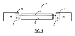
Optical Line System FIG. 1 is a network diagram of an
ネットワーク要素12、14内の前述のさまざまなコンポーネントは、ネットワーク要素12、14を形成するネットワーク要素内のハードウェアコンポーネントで物理的に実現することができる。ハードウェアコンポーネントは、ラインカード、ラインモジュール、プラガブルモジュール、高さが1〜2ラックユニット(RU)などの小型フォームユニットである「ピザボックス」などに搭載することができる。ハードウェアコンポーネントは概して、ファイバ16、18を介した最終的な送受信のために、互いに光学的に接続される。本明細書で説明されるように、光回線デバイスは、ネットワーク要素12、14または中間ネットワーク要素の一部であり、その中に統合されたハードウェアデバイスである。光回線デバイスの例としては、ラマン増幅器モジュール、EDFA増幅器モジュール、OSCモジュール、OTDRモジュール、モデム20などが挙げられる。
The various components described above within the
モデム20は、非ゼロ復帰(NRZ)、デュオバイナリ、直交振幅変調(QAM)、微分位相シフトキーイング(DPSK)、微分直交位相シフトキーイング(DQPSK)、直交周波数分割多重化(OFDM)、前述のいずれかを用いた偏波多重化、および他の任意のタイプの光変調および検出技術を含むことができる。重要なことに、モデム20は、高度な偏波多重コヒーレント変調/復調技術を利用するので、それらモデムは、SOPトランジェントおよび他の妨害の影響を受けやすい。二重偏波(DP)変調システムにおいて、モデム20内の光レシーバは、光信号のSOPを追跡する必要がある。場合によっては、非常に高速なSOPトランジェントが発生することが知られており、それは、レシーバの性能を低下させたり、最悪の場合にはビット誤りを引き起こしたりすることがある。
ネットワーク要素12、14は、ネットワーク管理システム(NMS)、要素管理システム(EMS)、パス計算要素(PCE)、ソフトウェア定義ネットワーク(SDN)コントローラ、コントロールプレーンなどの管理システムと通信できる。SOPトランジェント統計は、管理システムに提供されて、1)エラーの原因を特定して局在化させるためのトラブルシューティング、2)何というタイプのモデムを配備するかに関しての、またはプログラマブルモデムの場合にはどのタイプの構成(変調方式、スペクトル量など)かに関しての決定を行うこと、3)ファイバ16、18の必要なSOPトラッキング速度に基づいてモデムの性能を最適化すること、4)ネットワークの復元中にトラフィックを再ルーティングするときの決定を行うこと(たとえば、再ルーティング時の問題のあるスパンを回避すること)などのために使用することができる。さらに、本開示は、SOPトランジェント統計を使用して、光モデム20の動作モードに関する決定を行うこと、たとえば、SOPトランジェントを予期している最中に、たとえマージンが減少してもSOPトラッキングを増加させることを企図している。
The
光回線デバイス/システム内の統合された偏波計
図2は、偏波計40が内部に統合された光回線デバイス30のブロック図である。注目すべきは、図2の構成は、 2016年6月9日に出願され、「INTEGRATED POLARIMETER IN AN OPTICAL LINE SYSTEM」と題され、譲受人に譲渡された米国出願第15/177,982号(その内容は参照により本明細書に援用される)に記載されていることである。図2において、光回線デバイス30は、その中に統合された偏波計40を含み、ファイバ16上の偏波計プローブ信号の送信およびファイバ18上の対応する偏波計プローブ信号の受信をサポートする。一実施形態では、光回線デバイス30を光ネットワーク10内のさまざまなノードで使用して、ファイバ16、18の両方で偏波計プローブ信号をサポートすることができる。変形としては、単一の偏波計プローブ信号のトランスミッタは調整可能とすることかできる。対向する光回線デバイス30からの単一の偏波計プローブ信号が逆伝播する場合、調整可能なトランスミッタは、偏波プローブ信号のそれぞれについて異なる波長に同調することができる。
Integrated Polarizer in Optical Line Device / System FIG. 2 is a block diagram of the
光回線デバイス30は、偏波計40に加えて、さまざまな光回線コンポーネント50、52を含む。光回線コンポーネント50は、ファイバ16上を送信するものとして示されている一方、光回線コンポーネント52は、ファイバ18から受信するものとして示されている。光回線コンポーネント50、52は、EDFA増幅器、ラマン増幅器、OSC、OTDR、モデム20またはトランシーバ、WSSなどのような光回線システム内に統合された任意のものとすることができる。光回線デバイス30は、偏波計プローブ信号をWDM信号、OSC信号、OTDR信号、ラマンポンプなどと多重化および逆多重化するためのフィルタ54、56を含む。光回線デバイス50において、フィルタ54は、偏波計40のトランスミッタの出力を光回線コンポーネント50の出力と組み合わせるように構成され、フィルタ56は、偏波計プローブ信号を偏波計40へと、その他の信号(WDM信号、OSC信号、OTDR信号、ラマンポンプなど)を光回線コンポーネント52へと分岐するように構成されている。
The
統合に関して、光回線デバイス30は、ラインカード、ラマン増幅器モジュール、EDFA増幅器モジュール、OSCモジュール、OTDRモジュール、モデム20、プラガブルモジュール、ピザボックスなどとすることができる。また、統合された偏波計は、光回線システム内の別のハードウェアデバイスにプラグインするように構成されたプラガブルモジュールで実現できる。これらのハードウェアデバイスは、光回線システムの一部であり、統合された方法で動作する。すなわち、これらのハードウェアデバイスは、統一された管理と制御、すなわち、運用、管理、保守、プロビジョニング(OAM&P)をサポートする。偏波計40は、この統一された管理および制御、ならびにWDMトラフィック伝達チャネル、OSCチャネル、OTDR信号などを使用して動作することができる。
For integration, the
偏波計40は、フィルタ54に結合されたトランスミッタと、フィルタ56に結合されたレシーバとを含む。なお、概して偏波計40は、試験信号の偏波を測定するように構成された受信デバイスである。当業者であれば、本明細書に記載された統合された偏波計が、試験信号、すなわち偏波プローブ信号のための受信デバイスおよびトランスミッタを含むことを認識するであろう。一実施形態では、トランスミッタは、単一の偏波、連続波(CW)またはパルスを提供するなどのために、分散フィードバックレーザ(DFB)とすることができる。トランスミッタは、WDMトラフィック伝達チャネル、OSCチャネル、OTDR信号などに干渉しない波長で偏波プローブ信号を提供する。たとえば、WDMトラフィック伝達チャネルは、約1528〜1560nmなどのCバンド内にあってもよいし、当然のことながら、他の送信帯域も考えられる。ラマンポンプは典型的には、1400nmの範囲で1500nm未満である。OSCチャネル、OTDR波長などは、相互および偏波プローブ信号に干渉しないように選択できる。たとえば、OSCチャネルは、1510nm、1625nmなどとすることができる。一実施形態では、偏波プローブ信号は、ラマンポンプとの非線形相互作用を回避するために1591nmにある。当然のことながら、光回線システム内の他の信号と干渉しない限り、偏波計40および偏波計プローブ信号について他の値も考えられる。一実施形態では、偏波計40は、レーザをOTDRと共有することができる。
The
光モデム
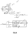
図3Aは、概して、ファイバ16を介して互いに通信可能に結合されたトランスミッタ102およびレシーバ104を含む光モデム20の例示的な実装のブロック図である。トランスミッタ102は典型的には、送信されるデジタル信号X(n)を、変調器108(たとえば、マッハツェンダ変調器(MZM))を駆動する駆動信号S(t)に変換するための信号発生器106を含む。変調器108は、(他の中心波長λ2〜λnのうち)所定の中心波長λ1に同調されたレーザ110によって生成された狭帯域光キャリアを変調して、対応する光チャネル信号、すなわちデータ伝達信号を生成する。それにより得られた信号は、次に、マルチプレクサ112によって、光ファイバリンク16を介してレシーバ104に送信するための波長分割多重(WDM)信号に多重化されてもよい。典型的には、駆動信号S(t)は、無線周波数(RF)アナログ電気信号である。そのような場合、信号発生器106は、デジタル−アナログ変換器(DAC)116とカスケード接続されたデジタル信号プロセッサ(DSP)114を含んでもよい。DSP114は、デジタル信号X(n)を処理して、DAC116の性能および動作要件に従って設計された対応するデジタル駆動信号X’(m)を生成するように動作する。DAC116は、従来の方法で動作して、デジタル駆動信号X’(m)を、光キャリアへの変調のために必要なアナログRF駆動信号S(t)に変換する。
Optical Modem FIG. 3A is generally a block diagram of an exemplary implementation of an
光チャネル信号は、フィルタ型デマルチプレクサデバイスまたはWSSを使用して、光ネットワーク10を介して逆多重化およびルーティングすることができる。例示の目的で、レシーバ104は、インバウンドWDM信号からのチャネル信号をレシーバ104に通信可能に結合するように動作するWSS120のドロップポートに結合されるものとして示されている。
Optical channel signals can be demultiplexed and routed through the
レシーバ104は、光チャネル信号を光検出器ブロック124に供給するための光フロントエンド122を含み、光検出器ブロック124は、到来する光チャネル信号を検出し、高速信号S(t)に対応するスペクトル成分を含む電気光検出器電流を生成する。次に、光検出器電流は、アナログ−デジタル変換器(ADC)126によってサンプリングされ、さまざまなデジタル信号処理技術を使用してレシーバ104内の対応するDSP128によって処理されて、元のデジタル信号X(n)を復元する。図3Aの設計では、光フロントエンド122は、ミキサ130によって提供することができ、ミキサ130は、到来する光学チャネル信号と、光学チャネル信号の中心波長λ1に同調されたローカルレーザ132によって生成された狭帯域光とを合成する。この構成を使用して、光チャネル信号のコヒーレント検出を可能にしてもよい。
The
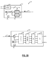
図3Bは、二重偏波動作を備えた光モデム20の別の例示的な実装のブロック図である。図3Bの光モデム20は、一組のM駆動信号156を生成するためにM次元コンステレーションを使用して一対のデータ信号(dxおよびdy)を符号化するための符号化154を備えたトランスミッタ102を含む。次に、駆動信号156は、駆動信号156に従って連続波(CW)光キャリアのそれぞれの次元を変調するための変調器158に供給される。図3Aの例では、一対のデータ信号(dxおよびdy)は、M=4の駆動信号156として符号化されてもよく、次にこれらを使用して、光キャリアの各直交偏波の2つの次元(たとえば、位相および振幅、またはIおよびQ)を変調する。CWキャリアは典型的には、レーザ110によって生成され、変調器158は、位相変調器、可変光減衰器、マッハツェンダ干渉計などのさまざまな変調器デバイスのいずれかを使用して実装されてもよい。変調器の出力に現れる変調された光信号は、光ファイバリンク16を介してコヒーレントレシーバ104に送信される。
FIG. 3B is a block diagram of another exemplary implementation of the
レシーバ104は、送信されたデータ信号を受信および検出するように構成され、受信した光信号を受信したXおよびY偏波に分割するための偏波ビームスプリッタ166と、XおよびY偏波を局部発振器を用いて別々に混合するための光ハイブリッド168と、光ハイブリッド168によって生成された混合生成物のそれぞれの光パワーを検出するための1組の光検出器170と、を含む。アナログ−デジタル(A/D)変換器ブロック172は、各光検出器電流をサンプリングし、それにより得られたサンプルストリーム(それぞれが光キャリアフィールドの変調された次元のうちの1つを表す)は、M次元コンスタレーションに従ってデジタルシグナルプロセッサ(DSP)174で処理され、送信されたデータ信号dxおよびdyに対応する復元された信号RxおよびRyが生成される。
The
コヒーレント検出は、光学フィールドに関する豊富な情報セットへのアクセスを提供する可能性を有する。これにもかかわらず、パフォーマンスバジェットとシステムの受け入れにおける現在の慣行は、dBQ2に変換された、寿命始まり(SOL)の事前順方向誤り訂正(Pre−FEC)ビット誤り率、またはその代えてSOL光信号雑音比(OSNR)にのみに注目しており、コヒーレント技術によって提供される測定値のセットを無視している。これは主に、光モデムの特性評価、寿命の終わり(EOL)の性能予測、および性能マージン測定のための従来の技術が、光学ノイズのローディングに大きく依存しており、そのローディングは、時間と費用のかかるプロセスであり、専門的なスキルと機器を必要とし、それほど実用的ではないからである。 Coherent detection has the potential to provide access to a rich set of information about the optical field. Nevertheless, the current practice in performance budgets and system acceptance is the conversion to dBQ 2 , the pre-forward error correction (Pre-FEC) bit error rate at the beginning of life (SOL), or SOL instead. It focuses only on the optical signal-to-noise ratio (OSNR) and ignores the set of measurements provided by coherent technology. This is mainly because conventional techniques for characterization of optical modems, end-of-life (EOL) performance prediction, and performance margin measurement rely heavily on optical noise loading, which takes time and time. It is a costly process, requires specialized skills and equipment, and is not very practical.
モデム20は、デュオバイナリ、QAM、DPSK、DQPSK、OFDM、前述のいずれかとの偏波多重化、およびその他のタイプのコヒーレント光変調および検出技術のいずれかを使用するように構成されてもよい。電子チャネル識別のために、調整可能なRxが必要であることが理解される。QAMおよびPSKでは、リニアレシーバ、すなわち局部発信機(LO)と到来する信号との間で周波数ミキシングが行われているレシーバを使用して実現される。LOは、ミキシングによる生成物が必要なすべてのフィルタリングが行われるベースバンドで存在できるような適切な周波数で同調される必要がある。レシーバが上記のように動作していない場合、光検出器の前に光学フィルタが必要となる。
モデム20は、1)調整する基礎となるモデム20の能力と、2)波長によって運ばれるサービスの必要性とに基づいて最適化することができる。モデム20は、ソフトウェアでプログラマブル変調フォーマットを通じてさまざまな異なるボーレートをサポートすることができる。モデム20は、変化する位相および/または振幅の両方でプログラマブル変調またはコンステレーションをサポートすることができる。一実施形態では、モデム20は、たとえば、i)海底距離での100G用のデュアルチャネル、デュアル偏波(DP)バイナリ位相シフトキーイング(BPSK)、ii)超長距離での100G用のDP直交位相シフトキーイング(QPSK)、iii)都市部から地方(600km)に至る距離での200G用の16−QAM)、またはiv)都市部から地方に至る距離での400G用のデュアルチャネル16QAMなど、複数のコヒーレント変調フォーマットをサポートすることができる。したがって、一実施形態では、同じモデム20が100G〜400Gをサポートすることができる。モデム20のハードウェアの関連するデジタル信号処理(DSP)により、ある変調フォーマットから別の変調フォーマットへの移行は完全にソフトウェアでプログラム可能である。
The
別の実施形態では、モデム20は、デュアルチャネルおよびデュアル偏波の有無にかかわらず、N−QAM変調フォーマットをサポートすることができる。ここで、Nは実数であり、必ずしも整数である必要はない。ここで、Nは整数ではなく実数、すなわち100G、200G、または400Gだけでなく、130G、270G、560Gなどの可変速度であるため、モデム20は非標準速度をサポートすることができる。これらの速度は、10Gb/秒の整数倍、1Gb/秒の整数倍、またはその他の値とすることができる。さらに、DSPおよびソフトウェアプログラミングにより、フレキシブル光モデム20の収容能力は、保証された速度に影響を与えないように、ヒットレス方式で上方または下方に調整することができる。さらに、モデム20は、スペクトルを調整および任意に選択することができるので、光学フィルタは必要ない。さらに、モデム20は、電気ドメインにおける非線形効果の軽減および分散補償(色モードおよび偏波モードの両方)のさまざまな態様をサポートすることができるので、外部分散補償デバイス、フィルタなどを排除することができる。モデムは、サービスレートとノイズ耐性のトレードオフのもう1つの方法として、使用される順方向誤り訂正(FEC)コーディングを適応させることもできる。
モデムの動作モード
In another embodiment, the
Modem operating mode
光モデム20は、さまざまな動作態様を制御するように構成されたコントローラ150を含むことができる。コントローラ150は、データを取得し、構成データを提供するために、光モデム20内のさまざまなコンポーネントに通信可能に結合することができる。コントローラ150は、図3Aおよび3Bにおいて光モデム20の内部として示されているが、当業者であれば、コントローラ150が外部に存在することができることを認識するであろう。本明細書で説明するように、コントローラ150は、フィードバック回路を含み、制御ループまたはフィードバックループなどに参加することができる。本明細書で説明するように、動作モードは、動作用の光モデム20内のさまざまなコンポーネントに対する設定またはパラメータのなんらかの選択であり、その選択は、特定のトレードオフ、たとえば、光マージンを犠牲にしたより高速のSOPトラッキングを考慮して行われる。本開示は、動作条件の外乱の統計に基づいて、光モデム20の動作モードを動的に提供する。この場合も、本開示は、外乱としてのSOPトランジェントに関して例示される。しかしながら、当業者であれば、レーザ周波数エラー、クロックエラーなどの他のタイプの外乱も考えられることを理解するであろう。有利なことに、本開示は、設定しっ放しアプローチを回避し、改善された性能および外乱によるエラーを回避する能力を提供する動作設定に関してインテリジェンスを与える。このインテリジェンスは、SOPトラッキングを高速化するためにマージンを大幅に減らして運用するなど、設定しっ放しアプローチでは反直感的となりそうな決定を下すこともできるが、統計的特性に基づいて外乱が検出または予測される間は一時的なものにすぎない。
The
この場合も、光モデム20は、信号品質を維持するために、動作条件の変化に適応しなければならない。信号帯域幅とデータレートが増加し続けるので、これは特に重要である。動作条件の一部の変更は、レーザ110、132、クロック140など、光モデム20の動作に必要な内部コンポーネントによるものである。この場合も、レーザ110、132は、それらの周波数および/または強度の点で外乱を経験することができる。動作条件の変更は、チャネルによって導入された偏波回転または他のトラフィック搬送チャネルからの干渉など、光モデム20の外部を起源としてもよい。
Again, the
コントローラ150(たとえば、フィードバック回路)は、目標動作点からの偏差に応答し、多くの場合、追跡可能な外乱の最大変化率とトラッキング回路またはアルゴリズムによって導入された静止ノイズとの間にはトレードオフの関係がある。この例は、Ciena Corporationから入手可能なWaveLogic 3(WL3)モデムであり、プログラマブル帯域幅のフィードバックループを使用して、受信したシンボルの偏波状態の変化を検出および補償する。これは、それぞれが関連する動作設定を有しかつ光学的マージンを犠牲にしてそれぞれ異なるトラッキング速度を持有する複数の異なるモードで動作できるSOPトラッキング技術である。第1のモードでは、光モデム20は、特定の値未満の回転速度で偏波トランジェントをトラッキングすることができ、第2のモードでは、その第1の値よりも速い第2の値未満の速度を含むように第1のモードに対して適度な光信号雑音比(OSNR)ペナルティでトラッキングが拡張され、第3のモードでは、第1の値と第2の値の両方よりも速い第3の値以下の回転速度でトランジェントのトラッキングを可能するように第1モードと第2モードに対してより大きなOSNRペナルティでトラッキングを拡張できる。この例では個別の動作モードについて説明しているが、概して、トラッキング速度とペナルティとの間でより細やかな最適化を実装することができる。すなわち、モードには動作設定があり、これらの動作設定は個別に設定することも、継続的に調整することもできる。
The controller 150 (eg, feedback circuit) responds to deviations from the target operating point and often makes a trade-off between the maximum rate of change of the traceable disturbance and the static noise introduced by the tracking circuit or algorithm. There is a relationship. An example of this is the WaveLogic 3 (WL3) modem available from Ciena Corporation, which uses a programmable bandwidth feedback loop to detect and compensate for changes in the polarization state of received symbols. This is a SOP tracking technique capable of operating in a plurality of different modes, each having an associated motion setting and each having a different tracking rate at the expense of optical margins. In the first mode, the
偏波トラッキングの実施形態では、第1のモードは、公称のトラッキング能力および比較的低い静止ノイズで動作する。第2のモードと第3のモードは、第1のモードと同じでもよいが、ループ帯域幅が増加している。偏波トラッキングフィードバックループの帯域幅を増やすと、高速偏波トランジェントのトラッキングが可能になるが、ノイズがフィードバックループに混入し得る帯域幅も増える。フィードバックループに混入するノイズは、フィードバック回路の静止ノイズの一因となり、トランジェントが存在するか否かに関係なく、回路が動作している間は常に存在する。トラッキングモード間の移行には、単にループ帯域幅を変更するだけでなく、ループの動作を変更することを含めてもよい。例としては、偏波状態の変化が、復号された送信シンボルから検出されるモードと、同期シンボルのみが考慮されるモードとが挙げられる。 In the polarization tracking embodiment, the first mode operates with nominal tracking capability and relatively low static noise. The second and third modes may be the same as the first mode, but with increased loop bandwidth. Increasing the bandwidth of the polarization tracking feedback loop allows tracking of fast polarization transients, but also increases the bandwidth at which noise can enter the feedback loop. The noise mixed in the feedback loop contributes to the static noise of the feedback circuit and is always present during the operation of the circuit, regardless of the presence of transients. The transition between tracking modes may include changing the behavior of the loop, rather than simply changing the loop bandwidth. Examples include a mode in which a change in polarization state is detected from a decoded transmission symbol, and a mode in which only synchronization symbols are considered.
さまざまなフィードバックループによって導入される静止ノイズと、トランジェント事象中に発生するペナルティとの間のトレードオフを理解して最適化することが重要である。マージンは、予想されるトランジェント中のペナルティが光モデム20の誤り訂正能力の範囲内になるように、モデムプロビジョニングを介して割り当てられる。フィードバックループの静止ノイズに割り当てられたマージン、ならびにトランジェント中に予想される追加のノイズにより、光モデム20で利用可能なノイズマージンが減少し、特定のデータレートでの光モデム20の最大到達距離が減少する。ただし、特定のリンクに対して外乱の例としてSOPトランジェントを利用すると、十分なマージンが存在する場合であってかつそうする理由がある場合、偏波トラッキング速度を上げることが望ましい。
It is important to understand and optimize the trade-off between the static noise introduced by the various feedback loops and the penalties that occur during transient events. Margins are allocated via modem provisioning so that the expected transient penalty is within the error correction capability of the
一実施形態では、光モデム20は、それぞれが光リンクを介して通信するように構成されたトランスミッタおよびレシーバと、第1の動作モードで動作させ、光モデムに関連する動作条件における外乱の検出に応じて、外乱の統計的特性に基づいた期間にわたって、第2の動作モードで動作させるように構成されたコントローラと、を備える。
動作条件に基づくSOPトラッキングの動的プロビジョニング
In one embodiment, the
Dynamic provisioning of SOP tracking based on operating conditions
光モデム20および上述の3つのSOPトラッキングモードを使用すると、光モデム20は、インストール時にこれらのモードのうちの1つに手動でプロビジョニングされる、すなわち、従来でいう設定しっ放しとなる。当然のことながら、偏波トラッキングの問題が確認された場合には、手動でモードを調整することができる。上記のように、第2モードおよび第3モードは、偏波トラッキングを改善するが、マージンを犠牲にする。一般化すると、第1のモードは低速トラッキングモードと呼ぶことができ、第3のモードは高速トラッキングモードと呼ぶことができる。
Using the
一実施形態では、光モデム20は、たとえば、光モデム20が測定/利用可能なマージンに基づいて動作できる最大トラッキングで常に動作しているなど、通常動作でトラッキング/ペナルティを動的に調整することができる。これにより、通常の動作では、偏波に関連するトラフィックヒットが発生する可能性は低くなる。従来、SOPトランジェント事象の到着時間は均一に分布していると想定されている。したがって、光モデム20は、リンク上に配備されたときに、固定されたトラッキング能力/ノイズのトレードオフでプロビジョンされる。
In one embodiment, the
しかしながら、SOPトランジェント事象が均一に分布していない場合があることが測定に基づいてわかっていた。したがって、トランジェント事象の分布が均一でない場合、到着時間分布の知識(または推定)を使用して、トランジェントの検出に応じて光モデム20を動的にプロビジョニングすることで、トラッキング速度と静止ペナルティとの間のトレードオフを改善することができる。
However, measurements have shown that SOP transient events may not be evenly distributed. Therefore, if the distribution of transient events is not uniform, the knowledge (or estimation) of the arrival time distribution can be used to dynamically provision the
Douglas Charltonらの”Field measurements of SOP transients in OPGW, with time and location correlation to lightning strikes”では、光接地線(OGPW)を横断するリンクのSOPトランジェントが調査されている。この研究は、SOPトランジェントがリンク付近の落雷によって引き起こされる可能性が高いことを示している。これらのトランジェントは、リンク内で以前は可能と考えられていたよりもはるかに速い回転速度で発生し、場合によっては特定の動作モードの偏波トラッキング能力を超える可能性があるため、継続的な関心がある。 In "Field measurements of SOP transients in OPGW, with time and location correlation to lightning strikes" by Douglas Charlton et al., The SOP transients of links across optical ground wire (OGPW) are investigated. This study shows that SOP transients are more likely to be caused by lightning strikes near the link. These transients occur at much faster rotational speeds within the link than previously thought possible, and in some cases can exceed the polarization tracking capabilities of a particular mode of operation, so continuous interest. There is.
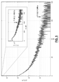
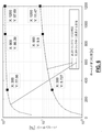
図4は、時間軸に沿って大きさが増加するフィールド測定値からの偏波トランジェント間の到着時間の差の分布のグラフである。落雷と光接地線(OPGW)リンクの偏波トランジェントとの間には強い相関があり、トランジェントの周波数の分布は、落雷の周波数の分布から推測できる。これらのフィールド測定値に基づいて、雷によって引き起こされたと見なされるSOPトランジェントの大部分は、光モデム20によって追跡可能であり、光モデム20に取得を失わせる任意のSOPトランジェントの確率は小さいが有限であることが観察された。このデータには、雷雨の季節の間に53日間にわたって偏波計で検出された3086のトランジェント事象が含まれている。この例では、トランジェント事象は、6μsで少なくとも0.18radの偏向があると定義されている。
FIG. 4 is a graph of the distribution of the difference in arrival time between polarization transients from field measurements that increase in magnitude along the time axis. There is a strong correlation between lightning strikes and the polarization transients of optical ground wire (OPGW) links, and the transient frequency distribution can be inferred from the lightning strike frequency distribution. Based on these field measurements, the majority of SOP transients considered to be caused by lightning are traceable by the
図5は、フィールド測定値からの偏波トランジェント間の時間の分布のグラフである。図5は、別の時間軸で表示された、図4と同じデータを含む。テストされたリンクの場合、落雷間の平均時間は144秒であった一方、中央値の時間は0.5秒であった(リンクから5km以内の90774落雷から計算)。つまり、落雷は、束になって到着する傾向があり、落雷間の時間の分布は尾長状である。本明細書で説明するように、一束は、時間的に厳密に一致するトランジェント事象の集まりである。 FIG. 5 is a graph of the time distribution between polarization transients from field measurements. FIG. 5 contains the same data as FIG. 4 displayed on a different time axis. For the tested links, the average time between lightning strikes was 144 seconds, while the median time was 0.5 seconds (calculated from 90774 lightning strikes within 5 km of the link). That is, lightning strikes tend to arrive in bundles, and the time distribution between lightning strikes is tail-length. As described herein, a bundle is a collection of transient events that are closely matched in time.
なお、図4および5のフィールド測定値は、SOPトランジェントの到着時間統計の例を示している。すなわち、履歴測定値を使用すれば、SOPトランジェントの到着時間などの特性の確率分布関数(PDF)を導出できる。動作中、継続的な測定を行うことができ、統計を経時的に更新することができる。また、本システムおよび方法は、ネットワーク管理システム(NMS)、要素管理システム(EMS)、ソフトウェア定義ネットワーク(SDN)コントローラなどを使用して、継続中の測定を統合し、統計を精緻化することができる。次に、このデータは、動的プロビジョニングで使用するために光モデム20に提供できる。
The field measurements in FIGS. 4 and 5 show an example of SOP transient arrival time statistics. That is, by using the historical measurement value, the probability distribution function (PDF) of the characteristic such as the arrival time of the SOP transient can be derived. During operation, continuous measurements can be made and statistics can be updated over time. The system and methods can also use network management systems (NMS), element management systems (EMS), software defined networking (SDN) controllers, etc. to integrate ongoing measurements and refine statistics. can. This data can then be provided to the
SOPトランジェントの到着時間が密にクラスタ化されているので、SOPトランジェント事象が観察されると、次にすぐに他の事象が続く可能性が高い。一束内のトラッキング速度と静止SNRペナルティとの間の最適なトレードオフは、束と束の間の場合とは異なる。到着時間PDFのおおよその知識があれば、トランジェントが観察されると、第2の動作モードまたは第3の動作モードなどで、より高いトラッキング能力について光モデム20を動的にプロビジョニングできる。事象間の予想される分離に匹敵するホールドオフ時間にわたってトランジェントが観察されない度に、光モデム20は、ノイズがより低くトラッキング能力が小さい動作モードに戻ることができる。到着時間PDFの信頼性が向上するにつれて、低速トラッキングモードおよび高速トラッキングモードについての最適な設定とともに、ホールドオフ時間の選択、ならびにそうしてリンクの使用可能なマージンが向上する。これは、コントローラ150内などの光モデム20の内部で、またはNMS、EMS、SDNコントローラなどの内部などのオーケストレーションレベルで、機械学習のためのアプリケーション空間を提供して、リンクの知識が発展するにともなってプロビジョニングを発展させる。
Due to the tightly clustered arrival times of SOP transients, when a SOP transient event is observed, it is likely that another event will follow immediately. The optimal trade-off between tracking speed within a bundle and a static SNR penalty is different than between bundles. With a rough knowledge of the arrival time PDF, when transients are observed, the
図6は、高速トラッキングモードで費やされた時間のパーセンテージと、高速トラッキングモード中に遭遇したSOPトランジェントのパーセンテージのグラフであり、両方ともホールドオフ時間の関数として示されている。300秒のホールドオフ時間の場合、光モデム20は、SOPトランジェント中に高速トラッキングモードにある可能性が77%である一方、全時間に対しては6%だけが高速トラッキングモードにある。同様に、900秒のホールドオフでは、SOPトランジェントの86%が高速トラッキングモードで遭遇した一方、そのモードは全時間に対しては10%であった。
FIG. 6 is a graph of the percentage of time spent in fast tracking mode and the percentage of SOP transients encountered during fast tracking mode, both shown as a function of holdoff time. With a holdoff time of 300 seconds, the
これらの測定が雷の頻度の高い期間に行われたことを考慮すると、使用寿命期間全体にわたっては、高速トラッキングモードで費やされた時間のパーセンテージは低くなる。ここでのアプローチは、異なるリンク上のさまざまに異なるデバイスによっておよびさまざまな地理的位置において、経時的に測定されたデータを考慮して、それに基づいて統計およびそれに関連するホールドオフ時間を発展させることを期待するものである。 Considering that these measurements were made during periods of high lightning frequency, the percentage of time spent in fast tracking mode is low over the entire service life. The approach here is to take into account the data measured over time by different devices on different links and at different geographic locations and develop statistics and associated holdoff times based on it. Is what you expect.
この前述を考えると、特定のトランジェントが追跡可能であることと、すぐ後に他のトランジェントが続くこととの両方の可能性が高い。次に、光モデム20においては、一組内の最初のトランジェントを検出してから、より速いトラッキングモードに移行することが有用である。これは慎重な決定となる。なぜなら、個々のSOPトランジェントが追跡される可能性が高い一方で、一組内で多数のSOPトランジェントが発生した場合には、少なくとも1つが追跡されなくなる可能性があるからである。したがって、トランジェントが検出された場合、パラメータを調整して、マージンを通常の動作では使用されないレベルまで減らすことができるが、高速偏波事象の予想が高い場合には、トラフィックヒットの確率は最小になる。
Given this statement, it is likely that a particular transient is traceable and that it is immediately followed by another transient. Next, in the
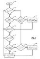
図7は、光モデム20の動作モードを動的にプロビジョニングするための可変SOPトラッキングプロセス180のフローチャートである。可変SOPトラッキングプロセス180は、ループトラッキング帯域幅内の摂動に応答するようにプロビジョニングされたフィードバックループである。ループ帯域幅を増やすと、より高速な事象のトラッキングが可能になるが、より高い静止ノイズを犠牲にする。トランジェント事象の予想到着時間統計の部分的な知識を導入することにより、可変SOPトラッキングプロセス180は、考慮されるリンクの観察された変化に応じて、動作モードのプロビジョニングを動的に適合させてもよい。
FIG. 7 is a flowchart of the variable
到着時間統計は、その動作環境のときの光モデム20にとって典型的な値で初期化されてもよい。機械学習技術を使用して、光モデム20によって行われた測定値を、他の光モデム20、端末、および/または回線機器、ならびに履歴のおよび予測の気象データ、製造データ、輸送データなどの外部ソースによる測定値を含み得る他のデータソースとともに含めることにより、到着時間分布の推定を改善してもよい。
The arrival time statistics may be initialized with values typical for the
本明細書に与えられた例は、偏波トランジェント事象の検出に応じた偏波トラッキングモード間の光モデム20の遷移を説明している。重要な態様は、ネットワーク要素の性能を低下させる事象の統計的特性の部分的な知識を使用して、その機器の動的プロビジョニングを条件付けできることを認識することである。この例のフィードバックループは、偏波の変化を補償しているが、クロック、レーザ、またはその他のトランジェントにも同様に適応できる。動的プロビジョニングは、偏波トラッキングモードなどの個別の状態間で行うことも、ループゲインまたはその他の制御パラメータや設定の連続的な変動を伴うこともある。
The examples given herein describe the transition of the
可変SOPトラッキングプロセス180は、本明細書で説明されるような予想到着時間統計を利用する偏波トラッキングアルゴリズムを説明する。予想到着時間の統計は、トランジェント事象が検出された後、高速トラッキングモードを維持するための最適なホールドオフ時間を選択するために使用される。
The variable
アルゴリズムのステップは、次のように要約される。可変SOPトラッキングプロセス180を開始する。十分なマージンがない場合(ステップ181)、ならびにSOPトラッキングがデフォルト速度(マージンへの影響が最小となる低速トラッキング速度など)に設定されていない場合(ステップ182)、可変SOPトラッキングプロセス180は、光モデム20での偏波トラッキングをデフォルト速度に設定すること(ステップ183)を含む、すなわち過剰マージンがないために、過剰マージンを消費しないように偏波トラッキングを動作させる。光モデム20は、偏波トランジェントが検出されるまでこのデフォルトモードで動作することができる(ステップ184)。トラッキング速度がデフォルト速度であり、かつ十分なマージンがある場合(ステップ185)、可変SOPトラッキングプロセス180は、偏波トラッキングをより速い速度に増加すること(ステップ186)、すなわち偏波トラッキングを改善する目的ですでに存在する過剰マージンを消費することを含むことができる。
The steps of the algorithm are summarized as follows. The variable
より高速なトラッキングモードに切り替える決定は、エラー信号の大きさや偏波トラッキング回路のタップ係数の変動、事前順方向誤り訂正(FEC)のビット誤り率(BER)の変動、受信したシンボルで検出されたノイズの変化など、偏波アクティビティと相関するパラメータの光モデム20内で行われた測定に基づく。その決定では、偏波計測定値、気象データ、または他のモデムからの観測値などの外部データソースを考慮することもできる。
The decision to switch to faster tracking mode was detected by fluctuations in the magnitude of the error signal, the tap factor of the polarization tracking circuit, fluctuations in the bit error rate (BER) of forward error correction (FEC), and received symbols. Based on measurements made within the
トランジェントが検出され(ステップ184)、大きさが閾値Yより大きい場合(ステップ187)、可変SOPトラッキングプロセス180は、偏波トラッキング速度を調整するかどうかを評価する。トラッキング速度がすでに高速(または最速)のトラッキング速度である場合(ステップ188)、十分な大きさのトランジェントが検出されているのでホールドオフ時間はリセットされ(ステップ189)、可変SOPトラッキングプロセス180は、ステップ181に戻る。
If a transient is detected (step 184) and the magnitude is greater than the threshold Y (step 187), the variable
タッキング速度が高速(または最速)のトラッキング速度ではない場合(ステップ188)、可変SOPトラッキングプロセス180は、十分なマージンがあるかどうかを判定し(ステップ185)、そうである場合、可変SOPトラッキングプロセス180は、偏波トラッキングをより速い速度に上昇させること(ステップ186)を含むことができる。
If the tacking speed is not the fastest (or fastest) tracking speed (step 188), the variable
なお、トランジェント事象が予想される場合、十分なマージンは、標準の動作マージンより低く設定されてもよい。その目的は、静止ノイズプロセスからの寄与ならびにトランジェント事象によって引き起こされるエラーに依存する総エラー確率を最小化することである。 If a transient event is expected, the sufficient margin may be set lower than the standard operating margin. Its purpose is to minimize the total error probability that depends on the contributions from the static noise process as well as the errors caused by transient events.
十分なマージンがない場合(ステップ185)、それは、偏波トラッキングを増やすことがより多くのエラーにつながる可能性があるので得策ではないことになり、可変SOPトラッキングプロセス180は、ステップ184に戻ることを含む。
If there is not enough margin (step 185), it is not a good idea as increasing polarization tracking can lead to more errors, and the variable
トランジェントを検出せず(ステップ184)、Tより大きい大きさのトランジェントを経験せずに(ステップ187)、又はホールドオフ時間をリセットした後(ステップ189)に、十分なマージンがある場合(ステップ181)、可変SOPトラッキングプロセス180は、トラッキング速度を再び変更する前に、ホールドオフ時間が満了するのを待つ(ステップ190)。したがって、可変SOPトラッキングプロセス16は、チャネルを維持するために、切り替え前およびホールドオフが満了する前に十分なマージンをチェックして、FECの限界値を超えたOSNRマージンの低下を防ぐ。この場合、SOPトランジェントが原因でチャネルに断続的な障害が発生する可能性があるが、これは完全な障害よりも望ましい方法である。
If there is sufficient margin (step 181) after no transients are detected (step 184), no transients greater than T are experienced (step 187), or after the holdoff time is reset (step 189). ), The variable
SOPトランジェントの検出率に関する統計を使用して、ネットワークのより高いレベルでの決定と、より高速なSOPトラッキングモードのいずれをラッチすべきかを通知してもよい。また、ホールドオフ時間は、フィールド測定値に関連する統計に基づいてもよい。 Statistics on SOP transient detection rates may be used to indicate whether a higher level decision in the network or a faster SOP tracking mode should be latched. The holdoff time may also be based on statistics associated with field measurements.
動作モード/設定を変更する目的
この場合も、1つのアプローチとして、さまざまな動作モードを単に設定しっ放しにして、すべての使用可能なマージンを消費してもよい。たとえば、マージンが使用可能な場合は、常により高速な偏波トラッキングモードで動作させてもよい。ここでの問題は、これがさまざまな外乱に対処するための追加のマージンを残さないことである。当然のことながら、より高速な偏波トラッキングモードで費やす時間を少なくすれば、マージンが空き、他の外乱(レーザトランジェント、偏波依存損失(PDL)の実現など)の組み合わせを処理するだけでなく、容量マイニング(たとえば、ボーレートや変調フォーマットなどを増やして過剰な容量をマイニングする)をサポートする。
Purpose of changing operating modes / settings Again, one approach may be to simply leave the various operating modes set and consume all available margins. For example, you may always operate in a faster polarization tracking mode where margins are available. The problem here is that this leaves no additional margin to deal with the various disturbances. Not surprisingly, spending less time in faster polarization tracking modes not only frees up margins and handles combinations of other disturbances (laser transients, realization of polarization-dependent loss (PDL), etc.). Supports capacitance mining (eg, increasing baud rate, modulation format, etc. to mine excess capacitance).
本開示の価値は、かなりまれであり、一般に相関されておらず、異なる時間に発生する可能性が高いものなど、複数の外乱ソースを処理することである。たとえば、ある時間に一つの偏波バーストが存在してもよい。別の時間にレーザ周波数がジャンプすることがあってもよい。さらに別の時間に、非線形またはOSNRの変化を引き起こす電力トランジェントが存在してもよい。この場合、トランジェントが起こりそうにない時間の間に、個々の制御ループを低ノイズ条件にリセットすることが間違いなく役立つだろう。したがって、余分のマージンは、発生の確率が特定の時点で高くなる外乱のいずれかに割り当てることができる。 The value of this disclosure is to deal with multiple sources of disturbance, such as those that are fairly rare, generally uncorrelated, and likely to occur at different times. For example, there may be one polarization burst at a given time. The laser frequency may jump at another time. At yet another time, there may be power transients that cause non-linear or OSNR changes. In this case, it would definitely help to reset the individual control loops to low noise conditions during times when transients are unlikely to occur. Therefore, the extra margin can be allocated to any of the disturbances that have a high probability of occurrence at a particular point in time.
マージンの低下として現れるリンクで問題が発生する可能性のある多くのものがある(たとえば、WSSピクセル、EDFA、挟まれたパッチコードなどの問題)。議論のために、これらの低下の原因をまとめて「ハードウェア障害」と呼ぶ。これらの問題は、修正可能な性質のものであり、サービスにしばらく時間がかかるため、次の状態を取りうる。 There are many things that can cause problems with links that appear as reduced margins (eg WSS pixels, EDFA, pinched patch cords, etc.). For the sake of discussion, the causes of these declines are collectively referred to as "hardware failures." These problems are of a fixable nature and the service will take some time, so they can take the following states:
まず、ハードウェア障害は、次のSOPトランジェントの到着時までには修復されない。SOPトラッキングは、より高速なトラッキングモードに切り替えることができずに、ヒットが発生する可能性があるが、追加のマージンが利用できない場合には、ヒットはより早く発生することになる。 First, the hardware failure will not be repaired by the arrival of the next SOP transient. SOP tracking can cause hits without being able to switch to faster tracking modes, but hits will occur sooner if additional margins are not available.
ハードウェア障害により、レシーバのFEC限界値のポイントを超えてOSNRが侵食され、チャネルが動作不能になってしまう可能性がある。リンクの動作不能状態を考えると、一部のフィードバックループのトラッキング能力を公称設定よりも低くして、これらの回路の静止ノイズを減らすことが望ましい場合がある。この条件では、SOPトランジェントなどの事象(トラッキングモードが低い場合に経験するものでさえ)が断続的な障害を表すため、動作不能なチャネルの代わりに断続的なもの(依然として望ましくないが一つの改善である)が存在する。 A hardware failure can erode the OSNR beyond the FEC limit point of the receiver and render the channel inoperable. Given the inoperability of the links, it may be desirable to reduce the tracking capability of some feedback loops below the nominal setting to reduce quiescent noise in these circuits. Under this condition, events such as SOP transients (even those experienced when tracking mode is low) represent intermittent failures, so instead of inoperable channels, intermittent ones (still undesirable but one improvement). Is) exists.
したがって、ここでの目的は、一時的な期間に必要に応じて使用可能なマージンを利用することである。たとえば、使用中の光モデム20にヒットレスの変調形式の切り替えがある場合、追加のマージンを活用して、より高いカーディナリティの変調形式でほとんどの時間動作し、SOPトランジェントが予想されるときに、より低いカーディナリティの変調形式に切り替えてより高速なSOPトラッキングモードを使用するのに必要なマージンを空けることができる。
Therefore, the purpose here is to utilize the margins available as needed during the temporary period. For example, if the
一部のリンクでは、SOPトランジェントの到着率は、高速トラッキングモードで永続的に動作することがネットワークエラーを最小限に抑えるための正しいオプションであるという性質を持つことができる。この結果は、上記の確率分布を考慮したレシーバのプロビジョニングをなお有効にする。 For some links, the arrival rate of SOP transients can have the property that running permanently in fast tracking mode is the correct option for minimizing network errors. This result still enables receiver provisioning with the above probability distributions in mind.
前述の説明は、SOPトランジェントに基づいて例示されている。当業者であれば、システムおよび方法が、他の検出されたトランジェントおよびそれらの統計的特性に基づいて動作モードを変更することを企図していると認識するであろう。また、動作モード(または条件)は、光増幅器などの光モデム以外の他のデバイスで変更されてもよい。たとえば、レーザ強度のトランジェントは、増幅された回線システムを起源としてもよい。その起点は、到来する信号のパワーを乱すファイバの曲がりなどの機械的なものであってもよいし、計画された再構成または計画外の中断など、回線システムでの光チャネルのアド/ドロップ事象に起因してもよい。増幅された回線システムは、レーザ強度のトランジェントの検出および関連する統計的特性に基づいて、その動作モードを一時的に変更できる(たとえば、ホールドオフ時間を使用できるなど)。別の例では、レーザ周波数の変動が、送信側または受信側の制御ループの問題に起因してもよいし(送信側または受信側はコヒーレントシステムであるため)、急速なシステム熱のトランジェントや不十分に抑制された後方反射などの外部システムの問題に起因してもよい。同様に、光モデムは、レーザ周波数の変動の検出および統計に基づいて動作モードを調整できる。 The above description is illustrated based on SOP transients. Those skilled in the art will recognize that systems and methods intend to change modes of operation based on other detected transients and their statistical characteristics. Further, the operation mode (or condition) may be changed by a device other than the optical modem such as an optical amplifier. For example, laser intensity transients may originate from an amplified line system. Its origin may be mechanical, such as a fiber bend that disturbs the power of the incoming signal, or an optical channel add / drop event in the line system, such as a planned reconstruction or unplanned interruption. May be due to. The amplified line system can temporarily change its mode of operation based on the detection of laser intensity transients and associated statistical characteristics (for example, holdoff time can be used). In another example, fluctuations in laser frequency may be due to problems with the transmit or receive control loop (because the transmit or receive is a coherent system), and rapid system thermal transients or non-transients. It may be due to problems with the external system, such as well-suppressed back reflections. Similarly, optical modems can adjust operating modes based on detection and statistics of laser frequency fluctuations.
レーザ周波数のトランジェントは、オペレータが隣接するカードを棚に収容したときや、オペレータが機器と物理的に相互作用する他のメンテナンス事象中に、送信レーザまたは受信レーザが受ける機械的衝撃によって引き起こされ得る。カードは、数時間のメンテナンスまたはインストールウィンドウの間に複数の機械的衝撃を受けて、その後数ヶ月の比較的静かな状態が続き得る。回線機器と相互作用するオペレータの物理的存在によって引き起こされるトランジェントは、オペレータが存在しない、すなわち統計的特性を持っている場合に、メンテナンス動作中に低い確率で、束で発生する事象の例である。機械的衝撃によって引き起こされたレーザ周波数のトランジェントなどのトランジェントが検出されると、次の数時間にわたる追加のトランジェントを検出する確率が増加し、光モデム20にとっては、静止ノイズの増加を犠牲にしても、トランジェントに対処するための増加した容量でプロビジョニング(動作設定)を選択することが有益になり得る。
サーバ
Laser frequency transients can be caused by the mechanical impact on the transmitting or receiving lasers when the operator puts an adjacent card on the shelf or during other maintenance events where the operator physically interacts with the equipment. .. The card may be subject to multiple mechanical shocks during a few hours of maintenance or installation windows, followed by a relatively quiet state for several months. Transients caused by the physical presence of an operator interacting with a line device are an example of a bundle of events that occur with a low probability during a maintenance operation if the operator does not exist, that is, has statistical characteristics. .. Detection of transients, such as laser frequency transients caused by mechanical impact, increases the probability of detecting additional transients over the next few hours, at the expense of increased quiescent noise for the
server
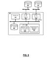
図8は、NMS、EMS、SDNコントローラ、オーケストレーションプラットフォームなどを実現するために使用され得るサーバ200のブロック図である。一実施形態では、光モデム20の構成、ならびに統計、動作モードなどの更新は、光モデム20に通信可能に結合されたサーバを介して編成することができる。
FIG. 8 is a block diagram of a
サーバ200は、ハードウェアアーキテクチャに関して、概してプロセッサ202、入出力(I/O)インターフェース204、ネットワークインターフェース206、データストア208、およびメモリ210を含むデジタルコンピュータであってもよい。当業者であれば、図8が、過度に単純化した方法でサーバ200を示しており、実際の実施形態は、本明細書で詳細に説明していない既知または従来の動作機能をサポートする追加のコンポーネントおよび適切に構成された処理ロジックを含み得るということを理解するはずである。コンポーネント(202、204、206、208、および210)は、ローカルインターフェース212を介して通信可能に結合される。ローカルインターフェース212は、たとえば、当技術分野で知られているように、1つ以上のバスまたは他の有線または無線接続としてもよいが、これらに限定されない。
The
プロセッサ202は、ソフトウェア命令を実行するためのハードウェアデバイスである。プロセッサ202は、任意の特注のまたは市販のプロセッサ、中央処理装置(CPU)、サーバ200に関連するいくつかのプロセッサのうちの補助プロセッサ、(マイクロチップまたはチップセットの形態の)半導体ベースのマイクロプロセッサ、または概してソフトウェア命令を実行するための任意のデバイスであり得る。サーバ200が動作中であるとき、プロセッサ202は、メモリ210内に格納されたソフトウェアを実行し、メモリ210との間でデータを通信し、ソフトウェア命令に従ってサーバ200の動作を総括的に制御するように構成される。I/Oインターフェース204は、1つ以上のデバイスまたはコンポーネントからのユーザ入力を受信するため、および/または1つ以上のデバイスまたはコンポーネントへのシステム出力を提供するために使用され得る。
ネットワークインターフェース206は、サーバ200が、広域ネットワーク(WAN)、ローカルエリアネットワーク(LAN)などのようなネットワークを介して通信することを可能にするために使用され得る。たとえば、ネットワーク要素12、14は、ネットワークインターフェース206を介してサーバ200と通信することができる。データストア208は、揮発性メモリ要素(たとえば、ランダムアクセスメモリ(DRAM、SRAM、SDRAMなどのRAM))、不揮発性メモリ要素(たとえば、ROM、ハードドライブ、テープ、CDROMなど)、およびそれらの組み合わせのいずれかを含み得る。さらに、データストア208は、電子的、磁気的、光学的、および/または他のタイプの記憶媒体を組み込み得る。
The network interface 206 may be used to allow the
メモリ210は、揮発性メモリ要素(たとえば、ランダムアクセスメモリ(DRAM、SRAM、SDRAMなどのRAM))、不揮発性メモリ要素(たとえば、ROM、ハードドライブ、テープ、CDROMなど)、およびそれらの組み合わせのいずれかを含み得る。さらに、メモリ210は、電子的、磁気的、光学的、および/または他のタイプの記憶媒体を組み込み得る。なお、メモリ210は、さまざまなコンポーネントが互いに離れて配置されているが、プロセッサ202によってアクセスすることができる分散型アーキテクチャを有してもよい。メモリ210内のソフトウェアは、1つ以上のソフトウェアプログラムを含んでもよく、そのそれぞれは、論理機能を実装するための実行可能な命令の順序付きリストを含む。メモリ210内のソフトウェアは、適切なオペレーティングシステム(O/S)214および1つ以上のプログラム216を含む。オペレーティングシステム214は、1つ以上のプログラム216などの他のコンピュータプログラムの実行を本質的に制御し、スケジューリング、入出力制御、ファイルおよびデータ管理、メモリ管理、ならびに通信制御および関連サービスを提供する。1つ以上のプログラム216は、本明細書で説明されるさまざまなプロセス、アルゴリズム、方法、技法などを実装するように構成されてもよい。
The memory 210 is any of volatile memory elements (eg, random access memory (RAM such as DRAM, SRAM, SRAM)), non-volatile memory elements (eg ROM, hard drive, tape, CDROM, etc.), and combinations thereof. May include. In addition, the memory 210 may incorporate electronic, magnetic, optical, and / or other types of storage media. The memory 210 may have a distributed architecture in which various components are arranged apart from each other but can be accessed by the
サーバ300は、それぞれが1つ以上の光モデムを備える1つ以上のネットワーク要素に通信可能に結合されたネットワークインターフェースと、ネットワークインターフェースに通信可能に結合されたプロセッサと、実行時にプロセッサに、1つ以上のネットワーク要素からの外乱に関連する測定値を取得させ、外乱の統計的特性を決定および更新することと、外乱を考慮して1つ以上の光モデムの動作のための1つ以上のネットワーク要素にホールドオフ時間を提供することとのうちの1つ以上を行わせる命令を格納したメモリと、を含むことができる。
The
一実施形態では、サーバ300を介していくつかの予測機能が存在し得る。たとえば、サーバ200は、外部データソースおよびフィードなどを介して、天候を監視することができる。雷が発生しやすい日があることがわかっている場合は、偏波トラッキングを積極的に適応させることができる。ネットワークで光の再構成またはチャネルの再ルーティングもしくは追加を行う予定がある場合、光パワーの変化に反応する制御ループを、より高速な応答へと積極的に設定できる。
In one embodiment, there may be some predictive functions via the
別の実施形態では、サーバ200は、特定の光リンクまたはファイバ16、18までを含む特定の地理に相関する外乱関連データを受信し、統計を作成するように構成することができる。次に、これらは、最適な動作のためにそれぞれの光モデム20に提供することができる。
In another embodiment, the
本明細書で説明するように、外乱の統計的特性は、ネットワーク要素に固有または非固有の1つ以上の観測量で条件付けられる条件付き確率とすることができる。これらには、利用可能なマージン、この上のまたは他のネットワーク要素での障害の発生、時期、天気、製造データ、同じタイプまたは異なるタイプの他のネットワーク要素の履歴、ネットワークトポロジを挙げることができ、ネットワークの構成と状態には、干渉チャネルの存在と特性が含まれる。 As described herein, the statistical properties of a disturbance can be conditional probabilities conditioned by one or more observables that are unique or non-unique to network elements. These can include available margins, failure occurrences on or on other network elements, timing, weather, manufacturing data, history of other network elements of the same or different types, network topologies. , Network configuration and state include the presence and characteristics of interfering channels.
光モデム20を動的にプロビジョニングする決定は、先験的な情報がサーバ200を介して外部ソースから到来することができる条件付き確率に基づくことができる。たとえば、プロビジョニングは、ハリケーン中などの雷のトランジェントを検出する確率に基づくことができる。
The decision to dynamically provision the
光モデム動作プロセス
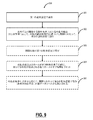
図9は、光モデム20を動作させるプロセス300のフローチャートである。プロセス300は、第1の動作設定で動作させることと(ステップ301)、光モデムに関連する動作条件における外乱の検出または予測に応じて、外乱の統計的特性に基づいた期間にわたって、第2の動作設定で動作させることと(ステップ302)、を含む。プロセス300は、その期間の後に第1の動作設定に戻すこと(ステップ303)をさらに含むことができる。その期間は、第2の動作設定で動作し続けるホールドオフ時間とすることができ、ホールドオフ時間は、統計的特性に基づいて設定し、プロセス300は、外乱の後およびホールドオフ時間の満了の前に検出された追加の外乱毎にホールドオフ時間をリセットすること(ステップ304)をさらに含むことができる。プロセス300は、外乱の条件付き確率に応じて、期間にわたって第2の動作設定で動作させることであって、条件付き確率が、内部および外部データソースの任意の組み合わせから決定されることをさらに含むことができる。
Optical modem operation process FIG. 9 is a flowchart of a
外乱の統計的特性は、到着時間、周期性、大きさ、変化率、時間的、および相関のうちの1つ以上を含むことができ、統計的特性は、経時的な測定を通じて決定することができる。外乱は、偏波トランジェントとすることができ、統計的特性には、期間を決定するために使用される偏波トランジェントの到着時間統計を含めることができる。 The statistical characteristics of the disturbance can include one or more of arrival time, periodicity, magnitude, rate of change, time, and correlation, and the statistical characteristics can be determined through measurements over time. can. Disturbances can be polarization transients, and statistical properties can include arrival time statistics for polarization transients used to determine duration.
外乱は、光周波数トランジェントおよび強度トランジェントのうちの1つ以上を含むレーザに影響を与えるトランジェントとすることができる。外乱は、光モデムを使用するネットワーク要素のクロックに影響を与えるトランジェントとすることができる。第2の動作設定は、期間にわたって、第1の動作設定に比べてマージンを減少させることができる。統計的特性は、フィールド測定値を取得するステップと、機械学習を利用して、取得したフィールド測定値に基づいて統計的特性を決定するステップとを実行するサーバによって決定することができる。 Disturbances can be transients that affect the laser, including one or more of the optical frequency transients and the intensity transients. Disturbances can be transients that affect the clocks of network elements that use optical modems. The second operation setting can reduce the margin over the period as compared with the first operation setting. Statistical characteristics can be determined by a server that performs a step of acquiring field measurements and a step of using machine learning to determine statistical characteristics based on the acquired field measurements.
本明細書で説明されるいくつかの例示的な実施形態は、マイクロプロセッサなどの1つ以上の汎用または専用プロセッサ(「1つ以上のプロセッサ」);中央処理装置(CPU);デジタルシグナルプロセッサ(DSP);ネットワークプロセッサ(NP)またはネットワークプロセッシングユニット(NPU)、グラフィックプロセッシングユニット(GPU)などのカスタマイズされたプロセッサ;フィールドプログラマブルゲートアレイ(FPGA);その他同様なものを、その制御のための特有の格納されたプログラム命令(ソフトウェアおよびファームウェアの両方を含む)とともに含んで、特定の非プロセッサ回路と組み合わせて、本明細書に記載の方法および/またはシステムの機能の一部、大部分、またはすべてを実装してもよいことが理解されよう。あるいは、一部またはすべての機能は、プログラム命令が保存されていないステートマシンによって、または1つ以上の特定用途向け集積回路(ASIC)によって実装されてもよく、そこでは、各機能または特定の機能のいくつかの組み合わせがカスタムロジックまたは回路として実装される。当然のことながら、前述のアプローチの組み合わせを使用してもよい。本明細書で説明するいくつかの例示的な実施形態では、ハードウェア内の、および任意選択でソフトウェア、ファームウェア、およびそれらの組み合わせを有する、対応するデバイスを、「〜するように構成されたまたは適合した回路」、「〜するように構成されたまたは適合したロジック」などと称し、さまざまな例示的な実施形態について本明細書で説明するデジタルおよび/またはアナログ信号に対する操作、ステップ、方法、プロセス、アルゴリズム、機能、技法などのセットを実行することができる。 Some exemplary embodiments described herein are one or more general purpose or dedicated processors (“one or more processors”) such as microprocessors; central processing units (CPUs); digital signal processors ( DSP); customized processor such as network processor (NP) or network processing unit (NPU), graphic processing unit (GPU); field programmable gate array (FPGA); other similar, specific for its control Some, most, or all of the functions described herein and / or the system, including with stored program instructions (including both software and firmware) and in combination with certain non-processor circuits. It will be understood that it may be implemented. Alternatively, some or all functions may be implemented by a state machine in which no program instructions are stored, or by one or more application specific integrated circuits (ASICs), where each function or specific function is implemented. Some combinations of are implemented as custom logic or circuits. Of course, a combination of the above approaches may be used. In some exemplary embodiments described herein, the corresponding device, which is in hardware and optionally has software, firmware, and a combination thereof, is configured or configured to. Operations, steps, methods, processes for digital and / or analog signals described herein for various exemplary embodiments, referred to as "fitted circuits", "structured or adapted logic", and the like. , Algorithms, functions, techniques, etc. can be executed.
さらに、いくつかの例示的な実施形態は、コンピュータ、サーバ、アプライアンス、デバイス、プロセッサ、回路などをプログラミングするためのコンピュータ可読コードが格納された非一時的なコンピュータ可読記憶媒体を含んで、本明細書で説明されおよび請求された機能を実行してもよい。そのようなコンピュータ可読記憶媒体の例として、ハードディスク、光学記憶デバイス、磁気記憶デバイス、ROM(読み取り専用メモリ)、PROM(プログラマブル読み取り専用メモリ)、EPROM(消去可能プログラマブル読み取り専用メモリ)、EEPROM(電気的消去可能プログラマブル読み取り専用メモリ)、フラッシュメモリなどが挙げられるが、これらに限定されない。非一時的コンピュータ可読媒体に格納される場合、ソフトウェアは、プロセッサまたはデバイスによって実行可能な命令(たとえば、任意のタイプのプログラマブル回路またはロジック)を含むことができ、その命令は、そのような実行に応じて、プロセッサまたはデバイスに、さまざまな例示的な実施形態について本明細書で説明されているように、操作、ステップ、方法、プロセス、アルゴリズム、機能、技法などのセットを実行させる。 In addition, some exemplary embodiments include non-temporary computer-readable storage media containing computer-readable code for programming computers, servers, appliances, devices, processors, circuits, etc. You may perform the functions described and requested in writing. Examples of such computer-readable storage media include hard disks, optical storage devices, magnetic storage devices, ROM (read-only memory), PROM (programmable read-only memory), EPROM (erasable programmable read-only memory), EEPROM (electrical). Erasable programmable read-only memory), flash memory, etc., but not limited to these. When stored on a non-temporary computer-readable medium, the software may include instructions that can be executed by a processor or device (eg, any type of programmable circuit or logic), and the instructions are in such execution. Accordingly, the processor or device is made to perform a set of operations, steps, methods, processes, algorithms, functions, techniques, etc., as described herein for various exemplary embodiments.
本開示は、好ましい実施形態およびその特定の例を参照して本明細書で図示および説明されたが、他の実施形態および例が同様の機能を実行し、および/または同様の結果を達成し得ることは当業者には容易に明らかであろう。そのような同等の実施形態および例はすべて、本開示の要旨および範囲内にあり、それによって企図され、以下の請求の範囲によってカバーされることが意図されている。 The present disclosure has been illustrated and described herein with reference to preferred embodiments and specific examples thereof, but other embodiments and examples perform similar functions and / or achieve similar results. It will be readily apparent to those skilled in the art to obtain. All such equivalent embodiments and examples are within the gist and scope of the present disclosure and are intended thereby and are intended to be covered by the following claims.
Claims (15)
コントローラ(150)と、を備える光モデム(20)であって、前記コントローラ(150)は、
第1の動作設定で動作させることと、
前記光モデム(20)に関連する動作条件における外乱の検出または予測に応じて、前記外乱の統計的特性に基づいた期間にわたって、第2の動作設定で動作させることであって、前記期間が、前記第2の動作設定で動作させ続けるホールドオフ時間であることと、
前記外乱の後および前記ホールドオフ時間の満了の前に、あらたな外乱が検出されるごとに前記ホールドオフ時間をリセットすることと、を実行するように構成された、光モデム(20)。 Transmitters (102) and receivers (104), each configured to communicate via optical links (16, 18),
An optical modem (20) including a controller (150), wherein the controller (150) is
To operate with the first operation setting and
In response to the detection or prediction of a disturbance in the operating conditions associated with the optical modem (20), the second operation setting is to be operated over a period based on the statistical characteristics of the disturbance. The hold-off time for continuing to operate with the second operation setting and
An optical modem (20) configured to perform, resetting the holdoff time each time a new disturbance is detected, after the disturbance and before the expiration of the holdoff time.
前記統計的特性は、経時的な測定を通じて決定される、請求項1〜2に記載の光モデム(20)。 The statistical properties of the disturbance include one or more of arrival time, periodicity, magnitude, rate of change, time and correlation.
The optical modem (20) according to claim 1-2, wherein the statistical characteristics are determined through measurement over time.
第1の動作設定で動作させることと、
前記光モデム(20)に関連する動作条件における外乱の検出または予測に応じて、前記外乱の統計的特性に基づいた期間にわたって、第2の動作設定で動作させることであって、前記期間が、前記第2の動作設定で動作させ続けるホールドオフ時間であり、前記ホールドオフ時間が、前記統計的特性に基づいて設定されることと、
前記外乱の後および前記ホールドオフ時間の満了の前に、あらたな外乱が検出されるごとに前記ホールドオフ時間をリセットすることと、を含む方法。 It is a method of operating the optical modem (20).
To operate with the first operation setting and
In response to the detection or prediction of a disturbance in the operating conditions associated with the optical modem (20), the second operation setting is to be operated over a period based on the statistical characteristics of the disturbance. It is a hold-off time for continuing to operate in the second operation setting, and the hold-off time is set based on the statistical characteristics.
A method comprising resetting the holdoff time each time a new disturbance is detected, after the disturbance and before the expiration of the holdoff time.
前記統計的特性は、経時的な測定を通じて決定される、請求項10〜11に記載の方法。 The statistical properties of the disturbance include one or more of arrival time, periodicity, magnitude, rate of change, time and correlation.
The method of claims 10-11, wherein the statistical properties are determined through measurements over time.
Applications Claiming Priority (3)
| Application Number | Priority Date | Filing Date | Title |
|---|---|---|---|
| US15/960,879 | 2018-04-24 | ||
| US15/960,879 US10348410B1 (en) | 2018-04-24 | 2018-04-24 | Adaptive optical modem configuration based on operating conditions |
| PCT/US2019/026436 WO2019209518A1 (en) | 2018-04-24 | 2019-04-09 | Adaptive optical modem configuration based on operating conditions |
Publications (2)
| Publication Number | Publication Date |
|---|---|
| JP2021521663A true JP2021521663A (en) | 2021-08-26 |
| JP7260556B2 JP7260556B2 (en) | 2023-04-18 |
Family
ID=66287009
Family Applications (1)
| Application Number | Title | Priority Date | Filing Date |
|---|---|---|---|
| JP2020544887A Active JP7260556B2 (en) | 2018-04-24 | 2019-04-09 | Adaptive optical modem configuration based on operating conditions |
Country Status (5)
| Country | Link |
|---|---|
| US (2) | US10348410B1 (en) |
| EP (1) | EP3785379B1 (en) |
| JP (1) | JP7260556B2 (en) |
| CA (2) | CA3089138A1 (en) |
| WO (1) | WO2019209518A1 (en) |
Cited By (1)
| Publication number | Priority date | Publication date | Assignee | Title |
|---|---|---|---|---|
| JPWO2023144935A1 (en) * | 2022-01-26 | 2023-08-03 |
Families Citing this family (47)
| Publication number | Priority date | Publication date | Assignee | Title |
|---|---|---|---|---|
| US11251878B2 (en) | 2018-02-07 | 2022-02-15 | Infinera Corporation | Independently routable digital subcarriers for optical communication networks |
| US11368228B2 (en) | 2018-04-13 | 2022-06-21 | Infinera Corporation | Apparatuses and methods for digital subcarrier parameter modifications for optical communication networks |
| US11095389B2 (en) | 2018-07-12 | 2021-08-17 | Infiriera Corporation | Subcarrier based data center network architecture |
| JP7059903B2 (en) * | 2018-11-14 | 2022-04-26 | 富士通株式会社 | Communication device and communication method |
| US11750531B2 (en) * | 2019-01-17 | 2023-09-05 | Ciena Corporation | FPGA-based virtual fabric for data center computing |
| US11258528B2 (en) | 2019-09-22 | 2022-02-22 | Infinera Corporation | Frequency division multiple access optical subcarriers |
| US11095364B2 (en) | 2019-03-04 | 2021-08-17 | Infiriera Corporation | Frequency division multiple access optical subcarriers |
| US11336369B2 (en) | 2019-03-22 | 2022-05-17 | Infinera Corporation | Framework for handling signal integrity using ASE in optical networks |
| US11418312B2 (en) | 2019-04-19 | 2022-08-16 | Infinera Corporation | Synchronization for subcarrier communication |
| US11838105B2 (en) | 2019-05-07 | 2023-12-05 | Infinera Corporation | Bidirectional optical communications |
| US11296812B2 (en) | 2019-05-14 | 2022-04-05 | Infinera Corporation | Out-of-band communication channel for subcarrier-based optical communication systems |
| US11489613B2 (en) | 2019-05-14 | 2022-11-01 | Infinera Corporation | Out-of-band communication channel for subcarrier-based optical communication systems |
| US11476966B2 (en) | 2019-05-14 | 2022-10-18 | Infinera Corporation | Out-of-band communication channel for subcarrier-based optical communication systems |
| US11239935B2 (en) | 2019-05-14 | 2022-02-01 | Infinera Corporation | Out-of-band communication channel for subcarrier-based optical communication systems |
| US11190291B2 (en) | 2019-05-14 | 2021-11-30 | Infinera Corporation | Out-of-band communication channel for subcarrier-based optical communication systems |
| US11088764B2 (en) | 2019-05-14 | 2021-08-10 | Infinera Corporation | Out-of-band communication channel for sub-carrier-based optical communication systems |
| US11218220B2 (en) | 2019-05-14 | 2022-01-04 | Infinera Corporation | Out-of-band communication channel for subcarrier-based optical communication systems |
| CN110401488B (en) * | 2019-07-12 | 2021-02-05 | 北京邮电大学 | A demodulation method and device |
| US11297005B2 (en) | 2019-09-05 | 2022-04-05 | Infiriera Corporation | Dynamically switching queueing schemes for network switches |
| US12580673B2 (en) | 2019-09-20 | 2026-03-17 | Infinera Corporation | Optical communication system transmitting and receiving optical subcarriers having different spectral widths and/or power values |
| US12081269B2 (en) | 2019-10-10 | 2024-09-03 | Infinera Corporation | Hub-leaf laser synchronization |
| WO2021072409A1 (en) | 2019-10-10 | 2021-04-15 | Tulasi Veguru | Network switches systems for optical communications networks |
| EP4042606A1 (en) | 2019-10-10 | 2022-08-17 | Infinera Corporation | Optical subcarrier dual-path protection and restoration for optical communications networks |
| CN111010235B (en) * | 2019-12-19 | 2021-07-06 | 北京无线电计量测试研究所 | Transceiver and optical time-frequency transmission device |
| US12603468B2 (en) | 2020-01-17 | 2026-04-14 | Ciena Corporation | Optical amplifier failure prediction using machine learning |
| US11329722B2 (en) | 2020-03-27 | 2022-05-10 | Relative Dynamics Incorporated | Optical terminals |
| US10979139B1 (en) | 2020-03-31 | 2021-04-13 | Ciena Corporation | Optical protection devices having passive splitter/couplers and built-in interrupters |
| US11070286B1 (en) | 2020-05-07 | 2021-07-20 | Ciena Corporation | Opportunistic network defragmentation and optimization |
| US11099339B1 (en) | 2020-06-30 | 2021-08-24 | Ciena Corporation | Management interface handler to expedite module boot time in pluggable optical modules |
| US11803817B2 (en) | 2020-09-03 | 2023-10-31 | Ciena Corporation | Virtual hallway conversations for remote collaboration |
| US11196504B1 (en) | 2020-10-28 | 2021-12-07 | Ciena Corporation | Extending the optical spectrum of an optical network |
| US11553259B2 (en) | 2020-10-28 | 2023-01-10 | Ciena Corporation | Extending the optical spectrum of an optical network |
| US11552858B2 (en) | 2020-11-23 | 2023-01-10 | Ciena Corporation | Reinforcement learning for optical network re-grooming |
| US12210944B2 (en) | 2021-02-16 | 2025-01-28 | Ciena Corporation | Network system modeling using nested models combining machine learning and behavioral approaches |
| WO2022180846A1 (en) * | 2021-02-26 | 2022-09-01 | 日本電気株式会社 | Optical relay device, optical transmission system, and optical relay method |
| US11528078B1 (en) | 2021-05-27 | 2022-12-13 | Ciena Corporation | Reordering a list of restoration paths based on retuning penalties |
| US11799549B2 (en) | 2021-08-13 | 2023-10-24 | Ciena Corporation | Express mesh intersatellite optical coherent networking |
| CA3216038A1 (en) | 2021-10-26 | 2023-05-04 | Ciena Corporation | Fast optical receiver recovery on client side using optical interconnects with dsps |
| WO2023139914A1 (en) * | 2022-01-24 | 2023-07-27 | 住友電気工業株式会社 | In-vehicle device, management device, transmission path authentication system, transmission path authentication method, and management method |
| US11855851B2 (en) | 2022-03-09 | 2023-12-26 | Ciena Corporation | Lazy graph construction with compression and a hybrid graph-relational model for representing a network topology |
| US12273144B2 (en) | 2022-03-21 | 2025-04-08 | Ciena Corporation | Satellite optical transceivers |
| US11711270B1 (en) | 2022-04-19 | 2023-07-25 | Ciena Corporation | Creating an optimal node interconnect topology given certain constraints |
| US11811459B1 (en) | 2022-07-19 | 2023-11-07 | Ciena Corporation | In-service characterization of nonlinear interference on a per-span basis |
| US12132515B2 (en) | 2022-07-19 | 2024-10-29 | Ciena Corporation | Localized span launch power control for network level optimization |
| US12323199B2 (en) | 2022-09-26 | 2025-06-03 | Ciena Corporation | System and method for Doppler frequency shift compensation in free space optical links |
| US12107629B2 (en) | 2022-12-22 | 2024-10-01 | Ciena Corporation | Optical delay calibration of optical modules |
| US12381624B2 (en) | 2023-06-27 | 2025-08-05 | Ciena Corporation | Signal-to-noise ratio-based bit error ratio calculation for reporting beyond a forward error correction threshold |
Citations (5)
| Publication number | Priority date | Publication date | Assignee | Title |
|---|---|---|---|---|
| JP2013223128A (en) * | 2012-04-17 | 2013-10-28 | Nippon Telegr & Teleph Corp <Ntt> | Digital coherent receiver and digital coherent receiving method |
| JP2014183552A (en) * | 2013-03-21 | 2014-09-29 | Fujitsu Ltd | Optical receiver and frequency offset compensation method |
| EP2882115A1 (en) * | 2013-12-03 | 2015-06-10 | Alcatel Lucent | Method and system of monitoring the power level of optical signals in an optical network |
| CN106788771A (en) * | 2016-12-02 | 2017-05-31 | 武汉邮电科学研究院 | A kind of implementation method of the adaptive equalizer for coherent optical communication system |
| JP2018207181A (en) * | 2017-05-30 | 2018-12-27 | 富士通株式会社 | Optical transmission apparatus and optical transmission method |
Family Cites Families (38)
| Publication number | Priority date | Publication date | Assignee | Title |
|---|---|---|---|---|
| US7606575B2 (en) * | 1988-08-04 | 2009-10-20 | Broadcom Corporation | Remote radio data communication system with data rate switching |
| ATE412289T1 (en) * | 1998-10-30 | 2008-11-15 | Broadcom Corp | CABLE MODEM SYSTEM |
| US7103065B1 (en) * | 1998-10-30 | 2006-09-05 | Broadcom Corporation | Data packet fragmentation in a cable modem system |
| US7003030B2 (en) * | 1999-03-08 | 2006-02-21 | Lenovo (Singapore) Pte. Ltd. | Receivers, methods, and computer program products for an analog modem that receives data signals from a digital modem |
| US6661837B1 (en) * | 1999-03-08 | 2003-12-09 | International Business Machines Corporation | Modems, methods, and computer program products for selecting an optimum data rate using error signals representing the difference between the output of an equalizer and the output of a slicer or detector |
| US7933295B2 (en) * | 1999-04-13 | 2011-04-26 | Broadcom Corporation | Cable modem with voice processing capability |
| US6356386B1 (en) * | 2000-02-29 | 2002-03-12 | Lucent Technologies Inc. | Method and apparatus for stabilizing transient control in amplified optical networks |
| US6988236B2 (en) * | 2000-04-07 | 2006-01-17 | Broadcom Corporation | Method for selecting frame encoding parameters in a frame-based communications network |
| US6907201B1 (en) | 2000-07-28 | 2005-06-14 | Ciena Corporation | Optical power transient control system and method |
| US6430336B1 (en) | 2000-12-18 | 2002-08-06 | Ciena Corporation | Device and method for minimizing optical channel drift |
| US6646790B2 (en) | 2002-01-28 | 2003-11-11 | Nortel Networks Limited | Optical amplifier gain control monitoring |
| US7346279B1 (en) * | 2002-03-25 | 2008-03-18 | Forster Energy Llc | Optical transceiver using heterodyne detection and a transmitted reference clock |
| US6842561B2 (en) | 2002-03-29 | 2005-01-11 | Nortel Networks Limited | Optical performance monitoring scheme |
| US6765659B1 (en) | 2002-08-30 | 2004-07-20 | Ciena Corporation | Optical supervisory channel apparatus and method for measuring optical properties |
| US6998963B2 (en) * | 2003-07-24 | 2006-02-14 | Hunt Technologies, Inc. | Endpoint receiver system |
| US7302379B2 (en) * | 2003-12-07 | 2007-11-27 | Adaptive Spectrum And Signal Alignment, Inc. | DSL system estimation and parameter recommendation |
| US20060127086A1 (en) | 2004-12-10 | 2006-06-15 | Ciena Corporation | Suppression of power transients in optically amplified links |
| US7574134B2 (en) | 2005-07-27 | 2009-08-11 | Ciena Corporation | Method of determining at least one variable of a WDM optical network |
| WO2008016585A2 (en) * | 2006-07-31 | 2008-02-07 | Adaptive Spectrum And Signal Alignment, Inc. | Method and apparatus for analyzing and mitigating noise in a digital subscriber line |
| US7782931B2 (en) * | 2006-10-25 | 2010-08-24 | NetTraffic, Inc. | Methods, systems, and computer program products for automatic detection of an incorrect digital subscriber line modem and filter configuration at a customer premises |
| US8045855B2 (en) | 2008-05-06 | 2011-10-25 | Ciena Corporation | Systems and methods for the mitigation of polarization mode dispersion impairments in fiber optic links |
| US8433192B2 (en) * | 2008-12-08 | 2013-04-30 | Ciena Corporation | Dynamic performance monitoring systems and methods for optical networks |
| WO2010102069A2 (en) * | 2009-03-04 | 2010-09-10 | Masimo Corporation | Medical monitoring system |
| US8433205B2 (en) * | 2011-04-13 | 2013-04-30 | Mitsubishi Electric Research Laboratories, Inc. | Crosstalk-free high-dimensional constellations for dual-polarized nonlinear fiber-optic communications |
| US9374166B2 (en) * | 2012-02-13 | 2016-06-21 | Ciena Corporation | High speed optical communication systems and methods with flexible bandwidth adaptation |
| US10257596B2 (en) * | 2012-02-13 | 2019-04-09 | Ciena Corporation | Systems and methods for managing excess optical capacity and margin in optical networks |
| US8897399B2 (en) * | 2012-03-07 | 2014-11-25 | Samsung Electronics Co., Ltd. | Communication system with signal-to-noise ratio adjustment mechanism and method of operation thereof |
| US8861960B2 (en) * | 2012-08-20 | 2014-10-14 | Ciena Corporation | Systems and methods for the compensation of nonlinear cross polarization and cross phase modulation in dual polarization coherent channels |
| US9143238B2 (en) * | 2012-11-12 | 2015-09-22 | Ciena Corporation | Optical modulation schemes having reduced nonlinear optical transmission impairments |
| WO2015127612A1 (en) * | 2014-02-27 | 2015-09-03 | Source Photonics (Chengdu) Co., Ltd. | Status monitoring, storage and reporting for optical transceivers by tracking operating parameter variations |
| EP2922221B1 (en) * | 2014-03-19 | 2018-08-29 | ZTE Corporation | Techniques for blind equalization of high-order quadrature amplitude modulation signals |
| US9749058B2 (en) | 2015-06-19 | 2017-08-29 | Ciena Corporation | Nonlinear tolerant optical modulation formats at high spectral efficiency |
| US9774392B2 (en) | 2015-07-17 | 2017-09-26 | Ciena Corporation | Systems and methods using a polarimeter to localize state of polarization transients on optical fibers |
| US9806801B2 (en) | 2015-11-03 | 2017-10-31 | Ciena Corporation | In-service optical fault isolation systems and methods |
| US9960843B2 (en) | 2016-04-21 | 2018-05-01 | Ciena Corporation | Nonlinear spatially resolved interferometer (NL-SRI) for characterizing optical properties of deployed telecommunication cables |
| WO2018071344A1 (en) * | 2016-10-10 | 2018-04-19 | Utilidata, Inc. | Systems and methods for system measurements integrity determination |
| US20180359029A1 (en) * | 2017-01-18 | 2018-12-13 | Ciena Corporation | Distributed measurements and analysis in networks |
| US10015184B1 (en) * | 2017-08-01 | 2018-07-03 | Utilidata, Inc. | Emulating regulating device to detect utility grid intrusions |
-
2018
- 2018-04-24 US US15/960,879 patent/US10348410B1/en active Active
-
2019
- 2019-04-09 CA CA3089138A patent/CA3089138A1/en active Pending
- 2019-04-09 CA CA3254539A patent/CA3254539A1/en active Pending
- 2019-04-09 WO PCT/US2019/026436 patent/WO2019209518A1/en not_active Ceased
- 2019-04-09 EP EP19719714.8A patent/EP3785379B1/en active Active
- 2019-04-09 JP JP2020544887A patent/JP7260556B2/en active Active
- 2019-06-04 US US16/431,029 patent/US10749602B2/en active Active
Patent Citations (5)
| Publication number | Priority date | Publication date | Assignee | Title |
|---|---|---|---|---|
| JP2013223128A (en) * | 2012-04-17 | 2013-10-28 | Nippon Telegr & Teleph Corp <Ntt> | Digital coherent receiver and digital coherent receiving method |
| JP2014183552A (en) * | 2013-03-21 | 2014-09-29 | Fujitsu Ltd | Optical receiver and frequency offset compensation method |
| EP2882115A1 (en) * | 2013-12-03 | 2015-06-10 | Alcatel Lucent | Method and system of monitoring the power level of optical signals in an optical network |
| CN106788771A (en) * | 2016-12-02 | 2017-05-31 | 武汉邮电科学研究院 | A kind of implementation method of the adaptive equalizer for coherent optical communication system |
| JP2018207181A (en) * | 2017-05-30 | 2018-12-27 | 富士通株式会社 | Optical transmission apparatus and optical transmission method |
Cited By (3)
| Publication number | Priority date | Publication date | Assignee | Title |
|---|---|---|---|---|
| JPWO2023144935A1 (en) * | 2022-01-26 | 2023-08-03 | ||
| WO2023144935A1 (en) * | 2022-01-26 | 2023-08-03 | 日本電気株式会社 | Communication path setting method |
| JP7758063B2 (en) | 2022-01-26 | 2025-10-22 | 日本電気株式会社 | How to set up communication routes |
Also Published As
| Publication number | Publication date |
|---|---|
| US10749602B2 (en) | 2020-08-18 |
| US20190326992A1 (en) | 2019-10-24 |
| US10348410B1 (en) | 2019-07-09 |
| CA3089138A1 (en) | 2019-10-31 |
| EP3785379B1 (en) | 2024-07-24 |
| EP3785379A1 (en) | 2021-03-03 |
| JP7260556B2 (en) | 2023-04-18 |
| WO2019209518A1 (en) | 2019-10-31 |
| CA3254539A1 (en) | 2025-10-30 |
Similar Documents
| Publication | Publication Date | Title |
|---|---|---|
| JP7260556B2 (en) | Adaptive optical modem configuration based on operating conditions | |
| US9831947B2 (en) | Margin determination systems and methods in optical networks | |
| US10727973B1 (en) | Apparatus and method for self-learning and predictive DWDM network | |
| US8964581B2 (en) | Bandwidth variable communication method, bandwidth variable communication apparatus, transmission bandwidth determination apparatus, transmission bandwidth determination method, node apparatus, communication path setting system, communication path setting | |
| US10623094B1 (en) | Methods and apparatus for predicting and monitoring performance of a coherent optical transceiver | |
| US10581530B2 (en) | Systems and methods for coherent optics interface | |
| US20180359029A1 (en) | Distributed measurements and analysis in networks | |
| US10097263B2 (en) | User defined applications executed on optical modules for performance monitoring in optical networks | |
| US11424832B2 (en) | Telecommunication system having a modulation format based upon degradation predictions | |
| US8917988B2 (en) | End-to-end carrier frequency control to improve bandwidth utilization in an optical network | |
| US10461881B2 (en) | Method and system for assigning modulation format in optical networks | |
| JP2011514736A (en) | Variable bit rate optical transmission using programmable signal modulation. | |
| US10771152B2 (en) | System and method for optical system margin allocation | |
| JP2021501516A (en) | Clock recovery circuits, systems and implementations for increasing optical channel density | |
| US9002215B2 (en) | Spectral analysis for coherent optical receivers | |
| US10355779B2 (en) | Virtual optical network service with guaranteed availability | |
| Choi et al. | Demonstration of BER-adaptive WSON employing flexible transmitter/receiver with an extended OpenFlow-based control plane | |
| US10374702B1 (en) | Methods and apparatus for predicting and monitoring performance of a coherent optical transceiver at various baud rates | |
| US10256935B1 (en) | Adaptive flexible grid in an optical network | |
| US10554300B2 (en) | Optical communications | |
| Oliveira et al. | Toward terabit autonomic optical networks based on a software defined adaptive/cognitive approach | |
| CN110036583A (en) | Subcarrier diversity in optical communication system | |
| US11664904B2 (en) | Transmission device and method of setting transmission parameter |
Legal Events
| Date | Code | Title | Description |
|---|---|---|---|
| A521 | Request for written amendment filed |
Free format text: JAPANESE INTERMEDIATE CODE: A523 Effective date: 20210712 |
|
| RD03 | Notification of appointment of power of attorney |
Free format text: JAPANESE INTERMEDIATE CODE: A7423 Effective date: 20210727 |
|
| RD04 | Notification of resignation of power of attorney |
Free format text: JAPANESE INTERMEDIATE CODE: A7424 Effective date: 20210729 |
|
| A621 | Written request for application examination |
Free format text: JAPANESE INTERMEDIATE CODE: A621 Effective date: 20220303 |
|
| A977 | Report on retrieval |
Free format text: JAPANESE INTERMEDIATE CODE: A971007 Effective date: 20230327 |
|
| TRDD | Decision of grant or rejection written | ||
| A01 | Written decision to grant a patent or to grant a registration (utility model) |
Free format text: JAPANESE INTERMEDIATE CODE: A01 Effective date: 20230404 |
|
| A61 | First payment of annual fees (during grant procedure) |
Free format text: JAPANESE INTERMEDIATE CODE: A61 Effective date: 20230406 |
|
| R150 | Certificate of patent or registration of utility model |
Ref document number: 7260556 Country of ref document: JP Free format text: JAPANESE INTERMEDIATE CODE: R150 |
|
| R250 | Receipt of annual fees |
Free format text: JAPANESE INTERMEDIATE CODE: R250 |