JP2021520908A - Devices and methods for percutaneous intratumoral treatment delivery - Google Patents
Devices and methods for percutaneous intratumoral treatment delivery Download PDFInfo
- Publication number
- JP2021520908A JP2021520908A JP2020555758A JP2020555758A JP2021520908A JP 2021520908 A JP2021520908 A JP 2021520908A JP 2020555758 A JP2020555758 A JP 2020555758A JP 2020555758 A JP2020555758 A JP 2020555758A JP 2021520908 A JP2021520908 A JP 2021520908A
- Authority
- JP
- Japan
- Prior art keywords
- tissue
- fluid
- tip
- bullet
- exemplary embodiment
- Prior art date
- Legal status (The legal status is an assumption and is not a legal conclusion. Google has not performed a legal analysis and makes no representation as to the accuracy of the status listed.)
- Pending
Links
- 238000000034 method Methods 0.000 title abstract description 23
- 238000011282 treatment Methods 0.000 title abstract description 14
- 230000002601 intratumoral effect Effects 0.000 title description 3
- 238000012377 drug delivery Methods 0.000 claims abstract description 57
- 210000001331 nose Anatomy 0.000 claims abstract description 50
- 206010028980 Neoplasm Diseases 0.000 claims abstract description 38
- 206010067171 Regurgitation Diseases 0.000 claims abstract description 13
- 230000029058 respiratory gaseous exchange Effects 0.000 claims abstract description 12
- 230000000694 effects Effects 0.000 claims abstract description 10
- 239000012530 fluid Substances 0.000 claims description 154
- 230000002093 peripheral effect Effects 0.000 claims description 5
- 229940102223 injectable solution Drugs 0.000 claims description 4
- 238000003780 insertion Methods 0.000 abstract description 29
- 230000037431 insertion Effects 0.000 abstract description 28
- 230000001225 therapeutic effect Effects 0.000 abstract description 7
- 238000010992 reflux Methods 0.000 abstract description 5
- 208000037841 lung tumor Diseases 0.000 abstract description 4
- 208000020816 lung neoplasm Diseases 0.000 abstract description 3
- 201000011510 cancer Diseases 0.000 abstract description 2
- 230000014759 maintenance of location Effects 0.000 abstract description 2
- 229940126585 therapeutic drug Drugs 0.000 abstract description 2
- 210000001519 tissue Anatomy 0.000 description 143
- 238000010586 diagram Methods 0.000 description 39
- 239000003814 drug Substances 0.000 description 29
- 229940079593 drug Drugs 0.000 description 26
- 239000000463 material Substances 0.000 description 22
- 210000004556 brain Anatomy 0.000 description 14
- 210000005013 brain tissue Anatomy 0.000 description 8
- 108090000623 proteins and genes Proteins 0.000 description 8
- 239000000853 adhesive Substances 0.000 description 7
- 230000001070 adhesive effect Effects 0.000 description 7
- 238000002347 injection Methods 0.000 description 7
- 239000007924 injection Substances 0.000 description 7
- 230000001965 increasing effect Effects 0.000 description 6
- 102000004169 proteins and genes Human genes 0.000 description 6
- 108090000790 Enzymes Proteins 0.000 description 5
- 102000004190 Enzymes Human genes 0.000 description 5
- 229940088598 enzyme Drugs 0.000 description 5
- 238000001802 infusion Methods 0.000 description 5
- 239000000203 mixture Substances 0.000 description 5
- 238000012986 modification Methods 0.000 description 5
- 230000004048 modification Effects 0.000 description 5
- 230000035515 penetration Effects 0.000 description 5
- 238000007789 sealing Methods 0.000 description 5
- 102000004219 Brain-derived neurotrophic factor Human genes 0.000 description 4
- 108090000715 Brain-derived neurotrophic factor Proteins 0.000 description 4
- VYPSYNLAJGMNEJ-UHFFFAOYSA-N Silicium dioxide Chemical compound O=[Si]=O VYPSYNLAJGMNEJ-UHFFFAOYSA-N 0.000 description 4
- 229940077737 brain-derived neurotrophic factor Drugs 0.000 description 4
- 210000003169 central nervous system Anatomy 0.000 description 4
- 239000003795 chemical substances by application Substances 0.000 description 4
- 238000002591 computed tomography Methods 0.000 description 4
- 239000000499 gel Substances 0.000 description 4
- 230000007246 mechanism Effects 0.000 description 4
- 108020004707 nucleic acids Proteins 0.000 description 4
- 102000039446 nucleic acids Human genes 0.000 description 4
- 150000007523 nucleic acids Chemical class 0.000 description 4
- 239000004814 polyurethane Substances 0.000 description 4
- 229920002635 polyurethane Polymers 0.000 description 4
- 239000000758 substrate Substances 0.000 description 4
- 241000272525 Anas platyrhynchos Species 0.000 description 3
- 241000702421 Dependoparvovirus Species 0.000 description 3
- 241001465754 Metazoa Species 0.000 description 3
- 108010025020 Nerve Growth Factor Proteins 0.000 description 3
- 239000004696 Poly ether ether ketone Substances 0.000 description 3
- 238000004873 anchoring Methods 0.000 description 3
- JUPQTSLXMOCDHR-UHFFFAOYSA-N benzene-1,4-diol;bis(4-fluorophenyl)methanone Chemical compound OC1=CC=C(O)C=C1.C1=CC(F)=CC=C1C(=O)C1=CC=C(F)C=C1 JUPQTSLXMOCDHR-UHFFFAOYSA-N 0.000 description 3
- 238000001574 biopsy Methods 0.000 description 3
- 239000003246 corticosteroid Substances 0.000 description 3
- 229960001334 corticosteroids Drugs 0.000 description 3
- 230000006378 damage Effects 0.000 description 3
- 230000009368 gene silencing by RNA Effects 0.000 description 3
- 238000001415 gene therapy Methods 0.000 description 3
- 238000002513 implantation Methods 0.000 description 3
- 208000014674 injury Diseases 0.000 description 3
- 230000007774 longterm Effects 0.000 description 3
- 238000004519 manufacturing process Methods 0.000 description 3
- 239000002105 nanoparticle Substances 0.000 description 3
- 239000004033 plastic Substances 0.000 description 3
- 229920003023 plastic Polymers 0.000 description 3
- 210000004224 pleura Anatomy 0.000 description 3
- 229920002530 polyetherether ketone Polymers 0.000 description 3
- 230000001012 protector Effects 0.000 description 3
- 210000003625 skull Anatomy 0.000 description 3
- 150000003384 small molecules Chemical class 0.000 description 3
- 210000000130 stem cell Anatomy 0.000 description 3
- 239000000126 substance Substances 0.000 description 3
- 230000008685 targeting Effects 0.000 description 3
- 229940124597 therapeutic agent Drugs 0.000 description 3
- 229920001169 thermoplastic Polymers 0.000 description 3
- 230000008733 trauma Effects 0.000 description 3
- 108020000948 Antisense Oligonucleotides Proteins 0.000 description 2
- CURLTUGMZLYLDI-UHFFFAOYSA-N Carbon dioxide Chemical compound O=C=O CURLTUGMZLYLDI-UHFFFAOYSA-N 0.000 description 2
- 108010005939 Ciliary Neurotrophic Factor Proteins 0.000 description 2
- 102100031614 Ciliary neurotrophic factor Human genes 0.000 description 2
- 102000018233 Fibroblast Growth Factor Human genes 0.000 description 2
- 108050007372 Fibroblast Growth Factor Proteins 0.000 description 2
- 102000034615 Glial cell line-derived neurotrophic factor Human genes 0.000 description 2
- 108091010837 Glial cell line-derived neurotrophic factor Proteins 0.000 description 2
- 102000015336 Nerve Growth Factor Human genes 0.000 description 2
- 241000700605 Viruses Species 0.000 description 2
- 239000000074 antisense oligonucleotide Substances 0.000 description 2
- 238000012230 antisense oligonucleotides Methods 0.000 description 2
- 230000008901 benefit Effects 0.000 description 2
- 230000008499 blood brain barrier function Effects 0.000 description 2
- 210000001218 blood-brain barrier Anatomy 0.000 description 2
- 239000000919 ceramic Substances 0.000 description 2
- 230000015271 coagulation Effects 0.000 description 2
- 238000005345 coagulation Methods 0.000 description 2
- 150000001875 compounds Chemical class 0.000 description 2
- 208000037265 diseases, disorders, signs and symptoms Diseases 0.000 description 2
- 230000006862 enzymatic digestion Effects 0.000 description 2
- 206010015037 epilepsy Diseases 0.000 description 2
- 229940126864 fibroblast growth factor Drugs 0.000 description 2
- 230000006870 function Effects 0.000 description 2
- 239000005350 fused silica glass Substances 0.000 description 2
- 239000005556 hormone Substances 0.000 description 2
- 229940088597 hormone Drugs 0.000 description 2
- 239000012216 imaging agent Substances 0.000 description 2
- 238000003384 imaging method Methods 0.000 description 2
- 150000002500 ions Chemical class 0.000 description 2
- JVTAAEKCZFNVCJ-UHFFFAOYSA-N lactic acid Chemical compound CC(O)C(O)=O JVTAAEKCZFNVCJ-UHFFFAOYSA-N 0.000 description 2
- 150000002605 large molecules Chemical class 0.000 description 2
- 230000000670 limiting effect Effects 0.000 description 2
- 229920002521 macromolecule Polymers 0.000 description 2
- 230000036244 malformation Effects 0.000 description 2
- 239000002184 metal Substances 0.000 description 2
- 229910052751 metal Inorganic materials 0.000 description 2
- 150000002739 metals Chemical class 0.000 description 2
- 229940053128 nerve growth factor Drugs 0.000 description 2
- 230000037361 pathway Effects 0.000 description 2
- 230000035699 permeability Effects 0.000 description 2
- 229920001606 poly(lactic acid-co-glycolic acid) Polymers 0.000 description 2
- 229920000052 poly(p-xylylene) Polymers 0.000 description 2
- 229920001296 polysiloxane Polymers 0.000 description 2
- 239000004810 polytetrafluoroethylene Substances 0.000 description 2
- 229920001343 polytetrafluoroethylene Polymers 0.000 description 2
- 230000008569 process Effects 0.000 description 2
- 230000002829 reductive effect Effects 0.000 description 2
- 239000000523 sample Substances 0.000 description 2
- 210000004761 scalp Anatomy 0.000 description 2
- 229910052710 silicon Inorganic materials 0.000 description 2
- 239000010703 silicon Substances 0.000 description 2
- 230000008961 swelling Effects 0.000 description 2
- 239000004416 thermosoftening plastic Substances 0.000 description 2
- 210000000779 thoracic wall Anatomy 0.000 description 2
- 230000007704 transition Effects 0.000 description 2
- 241000701161 unidentified adenovirus Species 0.000 description 2
- KRQUFUKTQHISJB-YYADALCUSA-N 2-[(E)-N-[2-(4-chlorophenoxy)propoxy]-C-propylcarbonimidoyl]-3-hydroxy-5-(thian-3-yl)cyclohex-2-en-1-one Chemical compound CCC\C(=N/OCC(C)OC1=CC=C(Cl)C=C1)C1=C(O)CC(CC1=O)C1CCCSC1 KRQUFUKTQHISJB-YYADALCUSA-N 0.000 description 1
- 208000024827 Alzheimer disease Diseases 0.000 description 1
- 0 CC1[C@](C2)C(*)CCC(CCC3)(C3N)C2*CC1 Chemical compound CC1[C@](C2)C(*)CCC(CCC3)(C3N)C2*CC1 0.000 description 1
- 241001631457 Cannula Species 0.000 description 1
- 208000000532 Chronic Brain Injury Diseases 0.000 description 1
- 241001274613 Corvus frugilegus Species 0.000 description 1
- 229920001651 Cyanoacrylate Polymers 0.000 description 1
- 206010011878 Deafness Diseases 0.000 description 1
- VGGSQFUCUMXWEO-UHFFFAOYSA-N Ethene Chemical compound C=C VGGSQFUCUMXWEO-UHFFFAOYSA-N 0.000 description 1
- 102000010834 Extracellular Matrix Proteins Human genes 0.000 description 1
- 108010037362 Extracellular Matrix Proteins Proteins 0.000 description 1
- 102000009123 Fibrin Human genes 0.000 description 1
- 108010073385 Fibrin Proteins 0.000 description 1
- BWGVNKXGVNDBDI-UHFFFAOYSA-N Fibrin monomer Chemical compound CNC(=O)CNC(=O)CN BWGVNKXGVNDBDI-UHFFFAOYSA-N 0.000 description 1
- 239000004812 Fluorinated ethylene propylene Substances 0.000 description 1
- 208000023105 Huntington disease Diseases 0.000 description 1
- WHUUTDBJXJRKMK-VKHMYHEASA-N L-glutamic acid Chemical compound OC(=O)[C@@H](N)CCC(O)=O WHUUTDBJXJRKMK-VKHMYHEASA-N 0.000 description 1
- 208000015439 Lysosomal storage disease Diseases 0.000 description 1
- 102000007072 Nerve Growth Factors Human genes 0.000 description 1
- 108091034117 Oligonucleotide Proteins 0.000 description 1
- 208000018737 Parkinson disease Diseases 0.000 description 1
- -1 Pevacs Substances 0.000 description 1
- 239000004642 Polyimide Substances 0.000 description 1
- 108090000190 Thrombin Proteins 0.000 description 1
- 230000001154 acute effect Effects 0.000 description 1
- 206010002026 amyotrophic lateral sclerosis Diseases 0.000 description 1
- 210000003484 anatomy Anatomy 0.000 description 1
- 239000002870 angiogenesis inducing agent Substances 0.000 description 1
- 230000001772 anti-angiogenic effect Effects 0.000 description 1
- 230000003110 anti-inflammatory effect Effects 0.000 description 1
- 230000000692 anti-sense effect Effects 0.000 description 1
- 229940125681 anticonvulsant agent Drugs 0.000 description 1
- 239000001961 anticonvulsive agent Substances 0.000 description 1
- 238000013459 approach Methods 0.000 description 1
- 238000003491 array Methods 0.000 description 1
- QVGXLLKOCUKJST-UHFFFAOYSA-N atomic oxygen Chemical compound [O] QVGXLLKOCUKJST-UHFFFAOYSA-N 0.000 description 1
- 230000004888 barrier function Effects 0.000 description 1
- 239000008280 blood Substances 0.000 description 1
- 210000004369 blood Anatomy 0.000 description 1
- 238000009954 braiding Methods 0.000 description 1
- 210000000133 brain stem Anatomy 0.000 description 1
- 208000035269 cancer or benign tumor Diseases 0.000 description 1
- 239000001569 carbon dioxide Substances 0.000 description 1
- 229910002092 carbon dioxide Inorganic materials 0.000 description 1
- 230000008859 change Effects 0.000 description 1
- 210000000038 chest Anatomy 0.000 description 1
- 238000000576 coating method Methods 0.000 description 1
- 239000002131 composite material Substances 0.000 description 1
- 230000006835 compression Effects 0.000 description 1
- 238000007906 compression Methods 0.000 description 1
- NLCKLZIHJQEMCU-UHFFFAOYSA-N cyano prop-2-enoate Chemical class C=CC(=O)OC#N NLCKLZIHJQEMCU-UHFFFAOYSA-N 0.000 description 1
- 230000003247 decreasing effect Effects 0.000 description 1
- 230000003111 delayed effect Effects 0.000 description 1
- 238000013461 design Methods 0.000 description 1
- 229960003957 dexamethasone Drugs 0.000 description 1
- UREBDLICKHMUKA-CXSFZGCWSA-N dexamethasone Chemical compound C1CC2=CC(=O)C=C[C@]2(C)[C@]2(F)[C@@H]1[C@@H]1C[C@@H](C)[C@@](C(=O)CO)(O)[C@@]1(C)C[C@@H]2O UREBDLICKHMUKA-CXSFZGCWSA-N 0.000 description 1
- 201000010099 disease Diseases 0.000 description 1
- 238000009826 distribution Methods 0.000 description 1
- 235000012489 doughnuts Nutrition 0.000 description 1
- 238000009513 drug distribution Methods 0.000 description 1
- 239000000975 dye Substances 0.000 description 1
- 210000005069 ears Anatomy 0.000 description 1
- 230000000763 evoking effect Effects 0.000 description 1
- 210000002744 extracellular matrix Anatomy 0.000 description 1
- 229950003499 fibrin Drugs 0.000 description 1
- 239000000945 filler Substances 0.000 description 1
- 238000010362 genome editing Methods 0.000 description 1
- 229930195712 glutamate Natural products 0.000 description 1
- 239000003102 growth factor Substances 0.000 description 1
- 125000001475 halogen functional group Chemical group 0.000 description 1
- 230000010370 hearing loss Effects 0.000 description 1
- 231100000888 hearing loss Toxicity 0.000 description 1
- 208000016354 hearing loss disease Diseases 0.000 description 1
- 238000009169 immunotherapy Methods 0.000 description 1
- 230000002452 interceptive effect Effects 0.000 description 1
- 210000000876 intercostal muscle Anatomy 0.000 description 1
- 238000007917 intracranial administration Methods 0.000 description 1
- 230000002262 irrigation Effects 0.000 description 1
- 238000003973 irrigation Methods 0.000 description 1
- 239000004310 lactic acid Substances 0.000 description 1
- 235000014655 lactic acid Nutrition 0.000 description 1
- 238000011866 long-term treatment Methods 0.000 description 1
- 229920001684 low density polyethylene Polymers 0.000 description 1
- 239000004702 low-density polyethylene Substances 0.000 description 1
- 210000004072 lung Anatomy 0.000 description 1
- 230000002132 lysosomal effect Effects 0.000 description 1
- 239000003550 marker Substances 0.000 description 1
- 210000003205 muscle Anatomy 0.000 description 1
- 239000002858 neurotransmitter agent Substances 0.000 description 1
- HLXZNVUGXRDIFK-UHFFFAOYSA-N nickel titanium Chemical compound [Ti].[Ti].[Ti].[Ti].[Ti].[Ti].[Ti].[Ti].[Ti].[Ti].[Ti].[Ni].[Ni].[Ni].[Ni].[Ni].[Ni].[Ni].[Ni].[Ni].[Ni].[Ni].[Ni].[Ni].[Ni] HLXZNVUGXRDIFK-UHFFFAOYSA-N 0.000 description 1
- 229910001000 nickel titanium Inorganic materials 0.000 description 1
- NJPPVKZQTLUDBO-UHFFFAOYSA-N novaluron Chemical compound C1=C(Cl)C(OC(F)(F)C(OC(F)(F)F)F)=CC=C1NC(=O)NC(=O)C1=C(F)C=CC=C1F NJPPVKZQTLUDBO-UHFFFAOYSA-N 0.000 description 1
- 229910052760 oxygen Inorganic materials 0.000 description 1
- 239000001301 oxygen Substances 0.000 description 1
- 229920009441 perflouroethylene propylene Polymers 0.000 description 1
- 230000010412 perfusion Effects 0.000 description 1
- 235000019271 petrolatum Nutrition 0.000 description 1
- 239000000049 pigment Substances 0.000 description 1
- 210000003281 pleural cavity Anatomy 0.000 description 1
- 201000003144 pneumothorax Diseases 0.000 description 1
- 239000004417 polycarbonate Substances 0.000 description 1
- 229920000515 polycarbonate Polymers 0.000 description 1
- 229920000728 polyester Polymers 0.000 description 1
- 229920001721 polyimide Polymers 0.000 description 1
- 229920000642 polymer Polymers 0.000 description 1
- 238000002360 preparation method Methods 0.000 description 1
- 230000005855 radiation Effects 0.000 description 1
- 239000000700 radioactive tracer Substances 0.000 description 1
- 230000000241 respiratory effect Effects 0.000 description 1
- 230000004044 response Effects 0.000 description 1
- 229920002477 rna polymer Polymers 0.000 description 1
- 239000000565 sealant Substances 0.000 description 1
- 239000003566 sealing material Substances 0.000 description 1
- 239000012781 shape memory material Substances 0.000 description 1
- 229920000260 silastic Polymers 0.000 description 1
- 239000000377 silicon dioxide Substances 0.000 description 1
- 210000003491 skin Anatomy 0.000 description 1
- 239000007787 solid Substances 0.000 description 1
- 238000009987 spinning Methods 0.000 description 1
- 238000003860 storage Methods 0.000 description 1
- 238000007920 subcutaneous administration Methods 0.000 description 1
- 238000001356 surgical procedure Methods 0.000 description 1
- 229960004072 thrombin Drugs 0.000 description 1
- 210000002105 tongue Anatomy 0.000 description 1
- 230000000472 traumatic effect Effects 0.000 description 1
- 230000002476 tumorcidal effect Effects 0.000 description 1
- 238000002604 ultrasonography Methods 0.000 description 1
- 239000013598 vector Substances 0.000 description 1
- 238000009423 ventilation Methods 0.000 description 1
- 239000013603 viral vector Substances 0.000 description 1
- 238000012800 visualization Methods 0.000 description 1
- 239000011800 void material Substances 0.000 description 1
- XLYOFNOQVPJJNP-UHFFFAOYSA-N water Substances O XLYOFNOQVPJJNP-UHFFFAOYSA-N 0.000 description 1
- 238000004804 winding Methods 0.000 description 1
Images


Classifications
-
- A—HUMAN NECESSITIES
- A61—MEDICAL OR VETERINARY SCIENCE; HYGIENE
- A61M—DEVICES FOR INTRODUCING MEDIA INTO, OR ONTO, THE BODY; DEVICES FOR TRANSDUCING BODY MEDIA OR FOR TAKING MEDIA FROM THE BODY; DEVICES FOR PRODUCING OR ENDING SLEEP OR STUPOR
- A61M5/00—Devices for bringing media into the body in a subcutaneous, intra-vascular or intramuscular way; Accessories therefor, e.g. filling or cleaning devices, arm-rests
- A61M5/14—Infusion devices, e.g. infusing by gravity; Blood infusion; Accessories therefor
- A61M5/162—Needle sets, i.e. connections by puncture between reservoir and tube ; Connections between reservoir and tube
-
- A—HUMAN NECESSITIES
- A61—MEDICAL OR VETERINARY SCIENCE; HYGIENE
- A61B—DIAGNOSIS; SURGERY; IDENTIFICATION
- A61B17/00—Surgical instruments, devices or methods, e.g. tourniquets
- A61B17/34—Trocars; Puncturing needles
- A61B17/3478—Endoscopic needles, e.g. for infusion
-
- A—HUMAN NECESSITIES
- A61—MEDICAL OR VETERINARY SCIENCE; HYGIENE
- A61B—DIAGNOSIS; SURGERY; IDENTIFICATION
- A61B5/00—Measuring for diagnostic purposes; Identification of persons
- A61B5/01—Measuring temperature of body parts ; Diagnostic temperature sensing, e.g. for malignant or inflamed tissue
-
- A—HUMAN NECESSITIES
- A61—MEDICAL OR VETERINARY SCIENCE; HYGIENE
- A61B—DIAGNOSIS; SURGERY; IDENTIFICATION
- A61B5/00—Measuring for diagnostic purposes; Identification of persons
- A61B5/03—Detecting, measuring or recording fluid pressure within the body other than blood pressure, e.g. cerebral pressure; Measuring pressure in body tissues or organs
- A61B5/036—Detecting, measuring or recording fluid pressure within the body other than blood pressure, e.g. cerebral pressure; Measuring pressure in body tissues or organs by means introduced into body tracts
-
- A—HUMAN NECESSITIES
- A61—MEDICAL OR VETERINARY SCIENCE; HYGIENE
- A61B—DIAGNOSIS; SURGERY; IDENTIFICATION
- A61B5/00—Measuring for diagnostic purposes; Identification of persons
- A61B5/145—Measuring characteristics of blood in vivo, e.g. gas concentration, pH value; Measuring characteristics of body fluids or tissues, e.g. interstitial fluid, cerebral tissue
- A61B5/14503—Measuring characteristics of blood in vivo, e.g. gas concentration, pH value; Measuring characteristics of body fluids or tissues, e.g. interstitial fluid, cerebral tissue invasive, e.g. introduced into the body by a catheter or needle or using implanted sensors
-
- A—HUMAN NECESSITIES
- A61—MEDICAL OR VETERINARY SCIENCE; HYGIENE
- A61B—DIAGNOSIS; SURGERY; IDENTIFICATION
- A61B5/00—Measuring for diagnostic purposes; Identification of persons
- A61B5/24—Detecting, measuring or recording bioelectric or biomagnetic signals of the body or parts thereof
- A61B5/25—Bioelectric electrodes therefor
- A61B5/279—Bioelectric electrodes therefor specially adapted for particular uses
- A61B5/28—Bioelectric electrodes therefor specially adapted for particular uses for electrocardiography [ECG]
- A61B5/283—Invasive
- A61B5/287—Holders for multiple electrodes, e.g. electrode catheters for electrophysiological study [EPS]
-
- A—HUMAN NECESSITIES
- A61—MEDICAL OR VETERINARY SCIENCE; HYGIENE
- A61B—DIAGNOSIS; SURGERY; IDENTIFICATION
- A61B5/00—Measuring for diagnostic purposes; Identification of persons
- A61B5/48—Other medical applications
- A61B5/4836—Diagnosis combined with treatment in closed-loop systems or methods
- A61B5/4839—Diagnosis combined with treatment in closed-loop systems or methods combined with drug delivery
-
- A—HUMAN NECESSITIES
- A61—MEDICAL OR VETERINARY SCIENCE; HYGIENE
- A61B—DIAGNOSIS; SURGERY; IDENTIFICATION
- A61B5/00—Measuring for diagnostic purposes; Identification of persons
- A61B5/68—Arrangements of detecting, measuring or recording means, e.g. sensors, in relation to patient
- A61B5/6846—Arrangements of detecting, measuring or recording means, e.g. sensors, in relation to patient specially adapted to be brought in contact with an internal body part, i.e. invasive
- A61B5/6847—Arrangements of detecting, measuring or recording means, e.g. sensors, in relation to patient specially adapted to be brought in contact with an internal body part, i.e. invasive mounted on an invasive device
- A61B5/6848—Needles
-
- A—HUMAN NECESSITIES
- A61—MEDICAL OR VETERINARY SCIENCE; HYGIENE
- A61B—DIAGNOSIS; SURGERY; IDENTIFICATION
- A61B5/00—Measuring for diagnostic purposes; Identification of persons
- A61B5/68—Arrangements of detecting, measuring or recording means, e.g. sensors, in relation to patient
- A61B5/6846—Arrangements of detecting, measuring or recording means, e.g. sensors, in relation to patient specially adapted to be brought in contact with an internal body part, i.e. invasive
- A61B5/6847—Arrangements of detecting, measuring or recording means, e.g. sensors, in relation to patient specially adapted to be brought in contact with an internal body part, i.e. invasive mounted on an invasive device
- A61B5/6852—Catheters
- A61B5/6853—Catheters with a balloon
-
- A—HUMAN NECESSITIES
- A61—MEDICAL OR VETERINARY SCIENCE; HYGIENE
- A61B—DIAGNOSIS; SURGERY; IDENTIFICATION
- A61B5/00—Measuring for diagnostic purposes; Identification of persons
- A61B5/68—Arrangements of detecting, measuring or recording means, e.g. sensors, in relation to patient
- A61B5/6846—Arrangements of detecting, measuring or recording means, e.g. sensors, in relation to patient specially adapted to be brought in contact with an internal body part, i.e. invasive
- A61B5/6847—Arrangements of detecting, measuring or recording means, e.g. sensors, in relation to patient specially adapted to be brought in contact with an internal body part, i.e. invasive mounted on an invasive device
- A61B5/6852—Catheters
- A61B5/6858—Catheters with a distal basket, e.g. expandable basket
-
- A—HUMAN NECESSITIES
- A61—MEDICAL OR VETERINARY SCIENCE; HYGIENE
- A61M—DEVICES FOR INTRODUCING MEDIA INTO, OR ONTO, THE BODY; DEVICES FOR TRANSDUCING BODY MEDIA OR FOR TAKING MEDIA FROM THE BODY; DEVICES FOR PRODUCING OR ENDING SLEEP OR STUPOR
- A61M25/00—Catheters; Hollow probes
- A61M25/0067—Catheters; Hollow probes characterised by the distal end, e.g. tips
- A61M25/0068—Static characteristics of the catheter tip, e.g. shape, atraumatic tip, curved tip or tip structure
- A61M25/0071—Multiple separate lumens
-
- A—HUMAN NECESSITIES
- A61—MEDICAL OR VETERINARY SCIENCE; HYGIENE
- A61M—DEVICES FOR INTRODUCING MEDIA INTO, OR ONTO, THE BODY; DEVICES FOR TRANSDUCING BODY MEDIA OR FOR TAKING MEDIA FROM THE BODY; DEVICES FOR PRODUCING OR ENDING SLEEP OR STUPOR
- A61M25/00—Catheters; Hollow probes
- A61M25/0067—Catheters; Hollow probes characterised by the distal end, e.g. tips
- A61M25/0082—Catheter tip comprising a tool
- A61M25/0084—Catheter tip comprising a tool being one or more injection needles
-
- A—HUMAN NECESSITIES
- A61—MEDICAL OR VETERINARY SCIENCE; HYGIENE
- A61M—DEVICES FOR INTRODUCING MEDIA INTO, OR ONTO, THE BODY; DEVICES FOR TRANSDUCING BODY MEDIA OR FOR TAKING MEDIA FROM THE BODY; DEVICES FOR PRODUCING OR ENDING SLEEP OR STUPOR
- A61M25/00—Catheters; Hollow probes
- A61M25/01—Introducing, guiding, advancing, emplacing or holding catheters
- A61M25/02—Holding devices, e.g. on the body
- A61M25/04—Holding devices, e.g. on the body in the body, e.g. expansible
-
- A—HUMAN NECESSITIES
- A61—MEDICAL OR VETERINARY SCIENCE; HYGIENE
- A61M—DEVICES FOR INTRODUCING MEDIA INTO, OR ONTO, THE BODY; DEVICES FOR TRANSDUCING BODY MEDIA OR FOR TAKING MEDIA FROM THE BODY; DEVICES FOR PRODUCING OR ENDING SLEEP OR STUPOR
- A61M5/00—Devices for bringing media into the body in a subcutaneous, intra-vascular or intramuscular way; Accessories therefor, e.g. filling or cleaning devices, arm-rests
- A61M5/14—Infusion devices, e.g. infusing by gravity; Blood infusion; Accessories therefor
- A61M5/168—Means for controlling media flow to the body or for metering media to the body, e.g. drip meters, counters ; Monitoring media flow to the body
- A61M5/16804—Flow controllers
- A61M5/16813—Flow controllers by controlling the degree of opening of the flow line
-
- A—HUMAN NECESSITIES
- A61—MEDICAL OR VETERINARY SCIENCE; HYGIENE
- A61B—DIAGNOSIS; SURGERY; IDENTIFICATION
- A61B17/00—Surgical instruments, devices or methods, e.g. tourniquets
- A61B2017/00743—Type of operation; Specification of treatment sites
- A61B2017/00809—Lung operations
-
- A—HUMAN NECESSITIES
- A61—MEDICAL OR VETERINARY SCIENCE; HYGIENE
- A61B—DIAGNOSIS; SURGERY; IDENTIFICATION
- A61B5/00—Measuring for diagnostic purposes; Identification of persons
- A61B5/68—Arrangements of detecting, measuring or recording means, e.g. sensors, in relation to patient
- A61B5/6846—Arrangements of detecting, measuring or recording means, e.g. sensors, in relation to patient specially adapted to be brought in contact with an internal body part, i.e. invasive
- A61B5/6847—Arrangements of detecting, measuring or recording means, e.g. sensors, in relation to patient specially adapted to be brought in contact with an internal body part, i.e. invasive mounted on an invasive device
- A61B5/6852—Catheters
-
- A—HUMAN NECESSITIES
- A61—MEDICAL OR VETERINARY SCIENCE; HYGIENE
- A61M—DEVICES FOR INTRODUCING MEDIA INTO, OR ONTO, THE BODY; DEVICES FOR TRANSDUCING BODY MEDIA OR FOR TAKING MEDIA FROM THE BODY; DEVICES FOR PRODUCING OR ENDING SLEEP OR STUPOR
- A61M25/00—Catheters; Hollow probes
- A61M2025/0004—Catheters; Hollow probes having two or more concentrically arranged tubes for forming a concentric catheter system
-
- A—HUMAN NECESSITIES
- A61—MEDICAL OR VETERINARY SCIENCE; HYGIENE
- A61M—DEVICES FOR INTRODUCING MEDIA INTO, OR ONTO, THE BODY; DEVICES FOR TRANSDUCING BODY MEDIA OR FOR TAKING MEDIA FROM THE BODY; DEVICES FOR PRODUCING OR ENDING SLEEP OR STUPOR
- A61M25/00—Catheters; Hollow probes
- A61M2025/0008—Catheters; Hollow probes having visible markings on its surface, i.e. visible to the naked eye, for any purpose, e.g. insertion depth markers, rotational markers or identification of type
-
- A—HUMAN NECESSITIES
- A61—MEDICAL OR VETERINARY SCIENCE; HYGIENE
- A61M—DEVICES FOR INTRODUCING MEDIA INTO, OR ONTO, THE BODY; DEVICES FOR TRANSDUCING BODY MEDIA OR FOR TAKING MEDIA FROM THE BODY; DEVICES FOR PRODUCING OR ENDING SLEEP OR STUPOR
- A61M25/00—Catheters; Hollow probes
- A61M25/0021—Catheters; Hollow probes characterised by the form of the tubing
- A61M2025/0042—Microcatheters, cannula or the like having outside diameters around 1 mm or less
-
- A—HUMAN NECESSITIES
- A61—MEDICAL OR VETERINARY SCIENCE; HYGIENE
- A61M—DEVICES FOR INTRODUCING MEDIA INTO, OR ONTO, THE BODY; DEVICES FOR TRANSDUCING BODY MEDIA OR FOR TAKING MEDIA FROM THE BODY; DEVICES FOR PRODUCING OR ENDING SLEEP OR STUPOR
- A61M25/00—Catheters; Hollow probes
- A61M25/0043—Catheters; Hollow probes characterised by structural features
- A61M2025/0057—Catheters delivering medicament other than through a conventional lumen, e.g. porous walls or hydrogel coatings
-
- A—HUMAN NECESSITIES
- A61—MEDICAL OR VETERINARY SCIENCE; HYGIENE
- A61M—DEVICES FOR INTRODUCING MEDIA INTO, OR ONTO, THE BODY; DEVICES FOR TRANSDUCING BODY MEDIA OR FOR TAKING MEDIA FROM THE BODY; DEVICES FOR PRODUCING OR ENDING SLEEP OR STUPOR
- A61M25/00—Catheters; Hollow probes
- A61M25/0067—Catheters; Hollow probes characterised by the distal end, e.g. tips
- A61M25/0068—Static characteristics of the catheter tip, e.g. shape, atraumatic tip, curved tip or tip structure
- A61M2025/0073—Tip designed for influencing the flow or the flow velocity of the fluid, e.g. inserts for twisted or vortex flow
-
- A—HUMAN NECESSITIES
- A61—MEDICAL OR VETERINARY SCIENCE; HYGIENE
- A61M—DEVICES FOR INTRODUCING MEDIA INTO, OR ONTO, THE BODY; DEVICES FOR TRANSDUCING BODY MEDIA OR FOR TAKING MEDIA FROM THE BODY; DEVICES FOR PRODUCING OR ENDING SLEEP OR STUPOR
- A61M25/00—Catheters; Hollow probes
- A61M25/0067—Catheters; Hollow probes characterised by the distal end, e.g. tips
- A61M25/0082—Catheter tip comprising a tool
- A61M25/0084—Catheter tip comprising a tool being one or more injection needles
- A61M2025/0085—Multiple injection needles protruding axially, i.e. along the longitudinal axis of the catheter, from the distal tip
-
- A—HUMAN NECESSITIES
- A61—MEDICAL OR VETERINARY SCIENCE; HYGIENE
- A61M—DEVICES FOR INTRODUCING MEDIA INTO, OR ONTO, THE BODY; DEVICES FOR TRANSDUCING BODY MEDIA OR FOR TAKING MEDIA FROM THE BODY; DEVICES FOR PRODUCING OR ENDING SLEEP OR STUPOR
- A61M25/00—Catheters; Hollow probes
- A61M25/0067—Catheters; Hollow probes characterised by the distal end, e.g. tips
- A61M25/0082—Catheter tip comprising a tool
- A61M25/0084—Catheter tip comprising a tool being one or more injection needles
- A61M2025/0089—Single injection needle protruding axially, i.e. along the longitudinal axis of the catheter, from the distal tip
-
- A—HUMAN NECESSITIES
- A61—MEDICAL OR VETERINARY SCIENCE; HYGIENE
- A61M—DEVICES FOR INTRODUCING MEDIA INTO, OR ONTO, THE BODY; DEVICES FOR TRANSDUCING BODY MEDIA OR FOR TAKING MEDIA FROM THE BODY; DEVICES FOR PRODUCING OR ENDING SLEEP OR STUPOR
- A61M37/00—Other apparatus for introducing media into the body; Percutany, i.e. introducing medicines into the body by diffusion through the skin
- A61M37/0015—Other apparatus for introducing media into the body; Percutany, i.e. introducing medicines into the body by diffusion through the skin by using microneedles
- A61M2037/003—Other apparatus for introducing media into the body; Percutany, i.e. introducing medicines into the body by diffusion through the skin by using microneedles having a lumen
-
- A—HUMAN NECESSITIES
- A61—MEDICAL OR VETERINARY SCIENCE; HYGIENE
- A61M—DEVICES FOR INTRODUCING MEDIA INTO, OR ONTO, THE BODY; DEVICES FOR TRANSDUCING BODY MEDIA OR FOR TAKING MEDIA FROM THE BODY; DEVICES FOR PRODUCING OR ENDING SLEEP OR STUPOR
- A61M2210/00—Anatomical parts of the body
- A61M2210/06—Head
- A61M2210/0693—Brain, cerebrum
-
- A—HUMAN NECESSITIES
- A61—MEDICAL OR VETERINARY SCIENCE; HYGIENE
- A61M—DEVICES FOR INTRODUCING MEDIA INTO, OR ONTO, THE BODY; DEVICES FOR TRANSDUCING BODY MEDIA OR FOR TAKING MEDIA FROM THE BODY; DEVICES FOR PRODUCING OR ENDING SLEEP OR STUPOR
- A61M2210/00—Anatomical parts of the body
- A61M2210/10—Trunk
- A61M2210/1025—Respiratory system
- A61M2210/1039—Lungs
-
- A—HUMAN NECESSITIES
- A61—MEDICAL OR VETERINARY SCIENCE; HYGIENE
- A61M—DEVICES FOR INTRODUCING MEDIA INTO, OR ONTO, THE BODY; DEVICES FOR TRANSDUCING BODY MEDIA OR FOR TAKING MEDIA FROM THE BODY; DEVICES FOR PRODUCING OR ENDING SLEEP OR STUPOR
- A61M25/00—Catheters; Hollow probes
- A61M25/0009—Making of catheters or other medical or surgical tubes
- A61M25/001—Forming the tip of a catheter, e.g. bevelling process, join or taper
-
- A—HUMAN NECESSITIES
- A61—MEDICAL OR VETERINARY SCIENCE; HYGIENE
- A61M—DEVICES FOR INTRODUCING MEDIA INTO, OR ONTO, THE BODY; DEVICES FOR TRANSDUCING BODY MEDIA OR FOR TAKING MEDIA FROM THE BODY; DEVICES FOR PRODUCING OR ENDING SLEEP OR STUPOR
- A61M25/00—Catheters; Hollow probes
- A61M25/0021—Catheters; Hollow probes characterised by the form of the tubing
- A61M25/0023—Catheters; Hollow probes characterised by the form of the tubing by the form of the lumen, e.g. cross-section, variable diameter
- A61M25/0026—Multi-lumen catheters with stationary elements
Abstract
経皮的治療または薬物送達装置が本明細書に記載される。装置は、カニューレまたはカテーテル本体の内側に1つまたは複数の内腔を含むことができる。装置は、1つ以上の弾丸状ノーズ、オーバーチューブ、および/または微小先端部など、装置挿入進路に沿った注入液の逆流または還流を低減または防止するための特徴部を含むことができる。この装置は、癌治療用医薬品を肺腫瘍または身体の他の領域に位置する腫瘍に直接注入することを含む、種々の処置方法のいずれにも使用することができる。装置は、患者の呼吸中または他の患者の活動中に遠位先端部を安定して保持するための特徴部を含むことができ、治療送達中の還流の発生率を低減することができる。Percutaneous treatment or drug delivery devices are described herein. The device can include one or more lumens inside the cannula or catheter body. The device can include features such as one or more bullet-shaped noses, overtubes, and / or microtips to reduce or prevent regurgitation or reflux of the injectate along the device insertion path. The device can be used for any of a variety of treatment methods, including injecting a therapeutic drug for cancer directly into a lung tumor or a tumor located in another area of the body. The device can include features for stable retention of the distal tip during the patient's breathing or other patient's activity, reducing the incidence of reflux during therapeutic delivery.
Description
〔関連出願〕
本出願は、2019年2月27日に出願された米国特許出願第16/286,707号の利益を主張するものであり、これは、2018年4月13日に出願された米国仮特許出願第62/657,019号の利益を主張するものであり、これらの内容全体が参照により本明細書に組み込まれる。
[Related application]
This application claims the benefit of US Patent Application No. 16 / 286,707 filed February 27, 2019, which is a US provisional patent application filed April 13, 2018. It claims the interests of No. 62 / 657,019, the entire contents of which are incorporated herein by reference.
〔分野〕
治療送達のため、例えば経皮的腫瘍内治療送達のための装置および方法が、本明細書に記載される。
[Field]
Devices and methods for therapeutic delivery, eg, percutaneous intratumoral therapeutic delivery, are described herein.
〔背景〕
患者に薬物を送達することが望ましい多くの場合がある。本明細書において使用される用語「薬物」は、ホルモン、幹細胞、遺伝子治療、化学物質、化合物、小分子および大分子、色素、抗体、ウイルス、治療剤などを含む、ヒトまたは動物被験体に送達され得る任意の機能性薬剤を指す。
〔background〕
In many cases it is desirable to deliver the drug to the patient. As used herein, the term "drug" is delivered to a human or animal subject, including hormones, stem cells, gene therapy, chemicals, compounds, small and large molecules, dyes, antibodies, viruses, therapeutic agents, and the like. Refers to any functional drug that can be.
改善された薬物送達システムおよび方法に対する継続的な必要性がある。 There is an ongoing need for improved drug delivery systems and methods.
〔概要〕
経皮的治療または薬物送達装置が本明細書に記載される。装置は、カニューレまたはカテーテル本体の内側に1つまたは複数の内腔を含むことができる。装置は、1つ以上の弾丸状ノーズ、オーバーチューブ、および/または微小先端部のような、装置挿入進路に沿った注入液の逆流または還流を低減または防止するための特徴部を含むことができる。この装置は、癌治療用医薬品を肺腫瘍または身体の他の領域に位置する腫瘍に直接注入することを含む、種々の処置方法のいずれにも使用することができる。装置は、患者の呼吸中または他の患者の活動中に遠位先端部を安定して保持するための特徴部を含むことができ、治療送達中の還流の発生率を低減することができる。
〔Overview〕
Percutaneous treatment or drug delivery devices are described herein. The device can include one or more lumens inside the cannula or catheter body. The device can include features such as one or more bullet-shaped noses, overtubes, and / or microtips to reduce or prevent regurgitation or reflux of the infusion along the device insertion path. .. The device can be used for any of a variety of treatment methods, including injecting a therapeutic drug for cancer directly into a lung tumor or a tumor located in another area of the body. The device can include features for stable retention of the distal tip during the patient's breathing or other patient's activity, reducing the incidence of reflux during therapeutic delivery.
いくつかの実施形態において、薬物送達装置は、1つ以上の流体ポートを内部に有する遠位先端部と、流体を先端部の1つ以上の流体ポートに運ぶように構成された内側流体内腔と、遠位先端部に近接して、装置の長さに沿って離間関係で配置された複数の弾丸状ノーズと、を含むことができる。弾丸状ノーズは、装置の外部に沿った注入液の逆流を制限または防止するように構成することができる。特定の実施形態では、弾丸状ノーズのうちの1つ以上は、円錐状、湾曲状、またはテーパ状の外面を有する。弾丸状ノーズは、周辺組織と係合して装置を固定することができる。 In some embodiments, the drug delivery device has a distal tip having one or more fluid ports inside and an inner fluid lumen configured to carry the fluid to one or more fluid ports at the tip. And a plurality of bullet-shaped noses arranged in close proximity to the distal tip and spaced apart along the length of the device. The bullet-shaped nose can be configured to limit or prevent backflow of injectate along the outside of the device. In certain embodiments, one or more of the bullet-shaped noses has a conical, curved, or tapered outer surface. The bullet-shaped nose can engage with surrounding tissue to secure the device.
いくつかの実施形態において、薬物送達装置は、患者の活動中に患者の標的組織に対する遠位先端部の移動を防止するために、遠位先端部を標的組織に固定するための手段をさらに含むことができる。患者の標的組織は、腫瘍を含み得る。患者の活動は、呼吸を含むことができる。固定するための手段は、複数の弾丸状ノーズから切り離されていてよい。特定の実施形態では、固定するための手段は、周辺組織と係合するために装置の外部から配備可能な1つ以上のスプラインを含むことができる。特定の実施形態では、固定するための手段は、周辺組織と係合するために装置の外部から配備可能な1つ以上のバルーンを含むことができる。 In some embodiments, the drug delivery device further comprises means for anchoring the distal tip to the target tissue in order to prevent the movement of the distal tip to the patient's target tissue during the patient's activity. be able to. The patient's target tissue may include a tumor. Patient activity can include breathing. The means for fixing may be separated from the plurality of bullet-shaped noses. In certain embodiments, the means for immobilization can include one or more splines that can be deployed from outside the device to engage with surrounding tissue. In certain embodiments, the means for immobilization can include one or more balloons that can be deployed from outside the device to engage with surrounding tissue.
いくつかの実施形態において、装置は、組織受容空間を画定するために遠位先端部上に配置された1つ以上のオーバーチューブを含むことができる。組織を組織受容空間内に受容して、装置の外部に沿った注入液の逆流を制限または防止することができる。 In some embodiments, the device can include one or more overtubes placed on the distal tip to demarcate the tissue receiving space. Tissue can be received within the tissue receiving space to limit or prevent regurgitation of the injectate along the outside of the device.
〔詳細説明〕
ここで、本明細書に開示される方法、システム、および装置の構造、機能、製造、および使用の原理の全体的な理解を提供するために、特定の例示的な実施形態について説明する。これらの実施形態の1つ以上の実施例が添付の図面に示されている。本明細書に具体的に記載され、添付の図面に示される方法、システム、および装置は、非限定的な例示的実施形態であることを当業者は理解するであろう。1つの例示的な実施形態に関連して図示または説明される特徴は、他の実施形態の特徴と組み合わせることができる。そのような修正および変形は、本開示の範囲内に含まれることが意図される。
[Detailed explanation]
Specific exemplary embodiments are described herein to provide an overall understanding of the principles of structure, function, manufacture, and use of the methods, systems, and devices disclosed herein. One or more embodiments of these embodiments are shown in the accompanying drawings. Those skilled in the art will appreciate that the methods, systems, and devices specifically described herein and shown in the accompanying drawings are non-limiting exemplary embodiments. Features illustrated or described in connection with one exemplary embodiment can be combined with features of other embodiments. Such modifications and modifications are intended to be included within the scope of this disclosure.
本明細書に開示される装置は、還流を低減または防止するために、微小先端部、1つ以上のオーバーチューブ、および1つ以上の弾丸状ノーズ特徴部のうちの任意の1つ以上を含むことができる。例示的な微小先端部、オーバーチューブ、および弾丸状ノーズ特徴部は、「SYSTEMS AND METHODS FOR REDUCING OR PREVENTING BACKFLOW IN A DELIVERY SYSTEM」という名称の米国特許第8,992,458号に記載されており、その内容全体が参照により本明細書に組み込まれ、その図1〜図11は、本出願と同一番号の図として提出されており、その対応する説明は、以下に再現される。 The devices disclosed herein include a microtip, one or more overtubes, and any one or more of one or more bullet-shaped nose features to reduce or prevent reflux. be able to. An exemplary microtip, overtube, and bullet-shaped nose feature are described in US Pat. No. 8,992,458, entitled "SYSTEMS AND METHODS FOR REDUCING OR PREVENTING BACKFLOW IN A DELIVERY SYSTEM". The entire contents are incorporated herein by reference, wherein FIGS. 1 to 11 are submitted as figures of the same number as in the present application, the corresponding description of which is reproduced below.
図1は、CED装置10の1つの例示的な実施形態を示す。装置10は、一般に、流体導管12および外側シース14を含む。外側シース14は、流体導管12が外側シース14の遠位端部16から外へ延びるように、流体導管12上に同軸的に配置することができる。流体導管12および外側シース14は、組織受容空間18が、流体導管12の外面と外側シース14の遠位端部16の内面との間に形成されるようなサイズおよび寸法にすることができる。
FIG. 1 shows one exemplary embodiment of the
流体導管12は、装置10の中心長手方向軸にほぼ平行に延びる1つ以上の流体内腔を画定することができる。流体導管12は、流体入口ポート(図1には不図示)および流体出口ポート20を含むことができる。図示の実施形態では単一の流体出口ポート20が示されているが、装置は、複数の流体出口ポート、ならびに複数の流体入口ポート、およびそれらの間に延びる複数の流体内腔を含み得ることが理解されるであろう。流体入口ポートは、装置10の近位端部に配置することができ、流体導管12を、例えば、1つ以上のカテーテル、ポンプ、メーター、弁、または他の適切な制御装置を介して、流体リザーバと流体連通させることができる。そのような制御装置は、装置10に流体が供給される圧力、または装置10に供給される流体の速度もしくは体積を調節するために使用することができる。
The
流体入口ポートを通って導管12に供給される流体は、導管12の1つ以上の内側内腔を通って導かれ、1つ以上の流体出口ポート20を通って放出され得る。流体出口ポート20は、流体の様々な放出パラメータを制御するために、サイズ決定され、成形され、かつ/または配置され得る。例えば、流体出口ポート20は、流体が装置10から放出される方向、標的組織内の流体の分布、および流体が放出される速度または圧力を制御するように構成することができる。例示的な実施形態では、流体出口ポートのサイズは、装置10の遠位端部に向かって徐々に増加することができ、これは、実質的に同じ圧力で流体が複数の流体出口ポートのそれぞれから放出されるように、装置の長さに沿って生じる圧力損失を有利に補償することができる。流体出口ポートはまた、流体導管12の周辺部の周りの様々な地点に配置することができるか、または流体の放出方向を制御するように成形することができる。
The fluid supplied to the
流体導管12および/または外側シース14は、円形の外側断面を有することができ、これは、有利には、装置10が、外傷を引き起こすことなく、または逆流を増加させる可能性のある大きなギャップを装置の外部と周辺組織との間に形成することなく、組織内で回転することを可能にし得る。流体導管12はまた、流体導管が挿入される組織と共に移動することを可能にするために可撓性であり得る。一般的に円筒形の流体導管12が示されているが、流体導管12は、非円筒形または多角形の断面を有することもできる。例えば、図7に関して以下に説明するように、流体導管12は、微細加工された先端部とすることができ、これは、1つ以上の流体チャネルが配された正方形または長方形の断面を有する基板を含む。外側シース14の内部は、流体導管12の断面に実質的に対応するように成形することができる。あるいは、外側シース14は、流体導管12の外部断面形状とは異なる内部断面形状を有することができる。例えば、外側シース14は、その遠位端部において実質的に円筒形の内部断面形状を有することができ、一方、流体導管12は、実質的に正方形または長方形の外部断面形状を有することができ、それによって、組織受容空間18を、流体導管12の外部と外側シース14の内部との間に画定する。
The
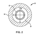
上述したように、外側シース14は、流体導管12上に同軸的に配置され得、流体導管12が外側シース14の遠位端部16から延在するようにする。流体導管12の外面とシース14の内面との間の間隙空間は、組織受容空間18を画定することができる。例えば、図2に示すように、流体導管12は、外側シース14の内径D2より小さい外径D1を有することができる。直径D2が直径D1を超える程度は、組織受容空間18内に圧縮されるかまたはそれによってはさまれる組織の量を決定することができる。
As mentioned above, the
いくつかの実施形態において、接着剤または他の充填剤を、流体導管12とシース14との間に配置して、流体導管をシースに対して固定長手方向位置に保持し、流体導管をシースの中心に維持することができる(例えば、組織受容空間18が流体導管の周辺部の周りに均一な幅を有するようにする)。例えば、組織受容空間18は、シース14の遠位端部16から近位方向に第1の距離だけ延びることができ、その地点より後は、流体導管12とシース14との間の間隙空間を埋めることができる。いくつかの実施形態において、シース14は、シース14の遠位部分に沿って間隙空間が存在し、シース14の近位部分に沿って間隙空間が存在しないように、段付き、テーパ状、または他の同様の形状の内部を有することができる。
In some embodiments, an adhesive or other filler is placed between the
例示的な実施形態では、外側シース14の遠位端部16の内径は、流体導管12の外径よりも約1μm〜約1000μm、約1μm〜約500μm、約1μm〜約200μm、または約1μm〜約20μm大きくすることができる。例示的な実施形態では、外側シース14の遠位端部16の内径は、流体導管12の外径よりも約5%〜約500%、約5%〜約250%、約10%〜約100%、または約10%〜約20%大きくすることができる。例示的な実施形態では、直径D1は、約50μm〜約2000μm、約50μm〜約1000μm、または約50μm〜約200μmとすることができる。例示的な実施形態では、直径D2は、約51μm〜約5000μm、約55μm〜約1000μm、または約55μm〜約200μmとすることができる。組織受容空間18は、外側シース14の全長に沿って、または外側シースの一部のみに沿って(例えば、外側シースの最遠位部分の約1mm〜約100mm、約1mm〜約50mm、または約1mm〜約10mmに沿って)延びることができる。
In an exemplary embodiment, the inner diameter of the
流体導管12および外側シース14は、パリレン組成物、シラスティック組成物、ポリウレタン組成物、PTFE組成物、シリコーン組成物などを含む、様々な材料のいずれかから形成することができる。
The
いくつかの実施形態では、装置10は、支持足場(不図示)上に装着されて、装置に構造的剛性を与え、標的組織への挿入を容易にすることができる。例示的な支持足場は、「MULTI−DIRECTIONAL MICROFLUIDIC DRUG DELIVERY DEVICE」という名称で、2012年8月1日に出願された米国特許出願公開第2013/0035560号に図示および記載されており、その内容全体が参照により本明細書に組み込まれる。組織の貫通およびナビゲーションを補助するために、流体導管12の遠位端部および/または足場の遠位端部は、テーパ状であり、尖っており、かつ/または鋭利であってもよい。いくつかの実施形態において、流体導管12および/または足場は、組織への外傷を引き起こすことなく組織を通じた挿入を容易にするために、丸い非外傷性先端部を備えることができる。支持足場は、剛性または半剛性であってよく、分解性熱可塑性ポリマー、例えば、分解性熱可塑性ポリエステルまたは分解性熱可塑性ポリカーボネートから形成することができる。いくつかの実施形態において、支持足場は、ポリ(乳酸−co−グリコール酸)(PLGA)から形成され得、標的組織内で生分解するように構成され得る。これは、有利には、いったん装置10が標的組織内に位置決めされたら支持足場を除去する必要性を排除することができ、それによって、流体導管12の位置決めを混乱させる可能性を回避する。支持足場を形成するために、当技術分野で既知のシリコンまたは種々のセラミック、金属およびプラスチックを含む種々の他の材料のいずれも使用することができる。足場は、約100μm〜約200μmの幅を有することができ、標的組織に応じて(例えば、標的組織が位置する深さに応じて)変化する長さを有することができる。1つの実施形態において、足場は、2cm〜3cmの長さである。水滴からの表面張力、接着剤、および/または生体適合性石油ゼリーなどの様々な技術を使用して、流体導管12および/または外側シース14を支持足場に連結することができる。
In some embodiments, the
流体導管12、外側シース14、および/または支持足場のいずれも、ある量の薬物を含有することができるか、またはそれを含浸させることができる。あるいは、または加えて、これらの構成要素の表面を薬物でコーティングすることができる。例示的な薬物は、抗炎症成分、薬物透過性増加成分、遅延放出コーティングなどを含む。いくつかの実施形態において、装置10の1つ以上の構成要素は、注射部位の周囲の腫脹およびそのような腫脹から生じ得る流体送達パターンの中断を防ぐことができるデキサメタゾンのようなコルチコステロイドでコーティングされるか、またはそれを含浸させることができる。
Any of the
装置10はまた、流体導管12、シース14、または足場の中または上に装着された1つ以上のセンサ22を含むことができる。センサ22は、温度センサ、pHセンサ、圧力センサ、酸素センサ、張力センサ、質問可能なセンサ、グルタミン酸センサ、イオン濃度センサ、二酸化炭素センサ、乳酸センサ、神経伝達物質センサ、または他の様々なセンサ種類のうち任意のものを含むことができ、制御回路にフィードバックを提供することができ、制御回路は、1つ以上の感知パラメータに基づいて、装置10を通る流体の送達を調節することができる。1つ以上の電極24も、流体導管12、シース14、または足場の中または上に設けることができ、これを用いて電気エネルギーを標的組織に送達し、例えば標的組織を刺激するか、または標的組織を除去することができる。一実施形態では、電気エネルギーが電極24を通じて送達されると同時に、薬物が流体導管12を通じて送達される。
The
図3は、装置10を含む薬物送達システム26の概略図である。システム26は、制御弁32を介してポンプ30に連結された、薬物含有流体のリザーバ28を含む。制御弁32が開くと、リザーバ28内の流体は、ポンプ30によって圧力下で圧力レギュレータ34に供給され、圧力レギュレータは、流体が装置10に供給される圧力を調整することができる。制御弁32、ポンプ30、およびレギュレータ34は、コントローラ36に動作可能に連結され得、コントローラは、マイクロプロセッサおよびメモリを含むことができ、非一時的なコンピュータ可読記憶媒体に記憶された薬物送達制御プログラムを実行するように構成することができる。コントローラ36は、弁32を開閉し、ポンプ30をオンもしくはオフにし、ポンプ30の出力圧力を変更し、かつ/またはレギュレータ34の圧力設定点を調整するように構成することができる。コントローラ36はまた、装置10の中または上に装着された1つ以上のセンサ22を含むフィードバックループを介して感知パラメータを示す情報を受信することができる。したがって、装置10内部に埋め込まれた1つ以上のセンサ22からのフィードバックに応答して、コントローラ36は、装置10への流体の流れを開始または停止し、装置10に流体が供給される圧力を増加または減少させることなどができる。一実施形態では、装置10は、装置10の近傍の流体圧力を測定する圧力センサ22を含み、コントローラ36は、圧力センサ22からのフィードバックに基づいて流体供給圧力を実質的に一定のレベルに維持するように構成される。
FIG. 3 is a schematic view of the
装置10は、脳、脊椎、耳、神経組織、またはヒトもしくは動物の体の他の部分の障害を処置するための薬物のCEDに使用することができる。脳内で使用される場合、装置10は、正圧下で薬物を組織に直接注入することによって、血液脳関門(BBB)を回避することができる。装置10は、以下のようないくつかの利点を提供することができる:1)CEDで使用される従来の針と比較して断面積が小さい;2)脳内に挿入した場合、従来の針に比べて組織への障害が少ない;3)挿入された部分の外側に沿った逆流または還流が低減または排除され、これにより、従来の針と比較して、装置10内でより高速の薬物送達が可能になる;4)脳内への挿入中の流体送達導管12の閉塞が最小であるか、または全くない;5)複数の内腔を流体導管12を通して提供することができ、内腔はそれぞれが別個の流体(薬物)を伝導し、これにより、複数の物質の同時、逐次、またはプログラムされた送達が可能になる;6)装置10が、薬物送達システムとして、かつ圧力、pH、イオン特異的濃度、場所、および他のパラメータなどであるがこれらに限定されない局所組織特性を測定するためのセンサ装備プローブとして同時に機能する可能性を有する;7)装置10が薬物放出パターンの方向制御を可能にする。
使用時には、以下にさらに説明するように、装置10は、カニューレまたは針のような長く薄い挿入媒介物の遠位端部に機能的に取り付けられ得、その中または上で、流体付着が装置の流体導管12の流体入口ポートになされ得る。これは、比較的厚い組織の貫通、例えば、ヒト頭蓋骨を通じた挿入を含む適用において特に有利であり得る。
In use, the
薬物含有流体を送達することに加えて、装置10はまた、酵素または他の材料を送達して、組織透過性を改変し、標的組織における薬物分布を改善するために使用され得る。例えば、脳組織への薬物含有ナノ粒子の浸透は、少なくとも1つの脳細胞外マトリックス成分の酵素消化、および脳組織へのナノ粒子の頭蓋内注入によって増強され得る。別の実施形態において、少なくとも1つの酵素を、酵素消化のステップ中にナノ粒子の表面に固定化することができる。装置10は、異なる送達装置を使用する必要がなく、かつそうすることに伴う潜在的な合併症もなく、例えば、薬物送達部位および治療材料を、実質的に任意の順序、順序付けおよび/またはタイミングで改変することができる酵素および/または他の材料を送達する能力を提供することができる。
In addition to delivering the drug-containing fluid, the
装置10は、例えば、スタイレットまたは把持ツールを、流体導管12を通して標的部位まで通過させ、次いで、バイオプシー試料を中に入れた状態で、標的部位からスタイレットまたは把持ツールを引き抜くことによって、組織を生検するために使用することもできる。いくつかの実施形態において、流体導管12は、生検目的で、流体導管を通って延びる、より大きな直径の内腔を有することができ、その周囲には、より小さい流体内腔が形成される。
The
装置10は、薬物含有流体を正圧下で標的組織領域に送達するのに使用され得る。図4は、患者の脳内の標的組織40への薬物の対流促進送達のための例示的な方法を示す。適切な部位の準備および洗浄の後、患者の頭皮および頭蓋骨を通じて組織開口部を形成し、脳組織40を露出させることができる。組織開口部を形成する前または後に、装置10が挿入されている間、装置を支持するために、台座をオプションとして患者に装着させることができ、これは、長期の植え込みにおいて特に有用であり得る。
The
装置10は、オプションとして、装置10と嵌合するための微細加工された界面によりカニューレ(不図示)に連結され得る。誘導手術において定位フレームに嵌合するように構成された標準的なカニューレを含む、種々のカニューレのいずれも使用することができる。いくつかの実施形態において、カニューレは、長期(例えば30日)の植え込みに適した可撓性カテーテルを含むことができる。カテーテルの長さは約15cm、直径は約2cmとすることができる。カニューレは、近位端部に流体とバイオセンサとの界面用のコネクタを有する、長さ約1.83m(約6フィート)のチューブ部分を含むことができる。
The
装置10は、組織開口部を通って脳組織40内に前進することができる。図示のように、組織受容空間18は、装置10が組織40を通って前進するときに、そこに受容された組織を圧縮するかまたははさむように構成され得る。組織受容空間18によって圧縮された組織は、流体導管12の出口20から組織受容空間18を越えて噴出される流体の近位逆流を低減するシールを形成することができる。特に、流体導管12の出口20から噴出された流体が、流体導管12の外面と周辺組織40との間で近位に逆流すると、流体は、組織38の肩部に遭遇し、この肩部は、組織受容空間18内に圧縮される。組織38を組織受容空間18の壁に対して圧縮することにより、さらに近位方向への流体の流れに抵抗するシールが形成され、それにより、注入された流体が組織の標的領域から離れる望ましくない逆流を低減または防止する。
The
上述のように、装置10は、標的領域に向かって脳組織を貫通することを容易にする支持足場を含むことができる。1つ以上の放射線不透過性マーカーが装置10に含まれて、(例えば、標的組織内または標的組織に近接した装置10の適切な配置を確認するため)放射線写真撮像を可能にすることができる。分解性足場が使用される実施形態では、足場は、挿入後すぐに分解して、流体導管12および外側シース14のみを残すことができる。いくつかの実施形態において、流体導管12および/またはシース14は、脳組織40が頭蓋骨内で移動する場合に、装置10が脳組織40と共に移動することを可能にするように可撓性であり得る。これは、有利には、別の状況では剛性装置で起こり得る、装置10に隣接する脳組織の局所的変形を防止することができる。そのような変形は、装置の表面に沿った加圧流体の逆流を引き起こす場合があり、望ましくないことに、流体が標的組織に到達するのを妨げる。
As mentioned above, the
いったん装置10が標的組織内または標的組織に隣接して配置されると、注入された媒体(例えば、薬物含有流体)は、正圧下で、装置10に、その流体入口ポートを通じて供給され得る。注入された媒体は、次いで、流体導管12を通って流れ、圧力下で、組織の標的領域内において出口ポート20から排出される。送達プロファイルは、出口ポートのサイズ、出口ポートの形状、流体導管のサイズ、流体導管の形状、流体供給圧力、流体速度などといったパラメータを変化させることによって調整され得る。いくつかの実施形態では、装置10は、約5μL/分〜約20μL/分の流量で流体を送達するように構成され得る。いくつかの実施形態では、装置10は、チャネル当たり毎分50〜100μLを送達するように構成され得、各チャネルは、689.48kPa(100psi)を超える圧力に耐えるように構成され得る。
Once the
いくつかの実施形態において、薬物含有流体を注入する前に、ゲルまたは他の材料を、装置10を通じて注入して、組織シールを増強することができる。例えば、密封ゲルを、装置10を通じて注入し、装置の外部に沿って逆流させ、装置と周辺組織との間、特に組織受容凹部18内に存在し得る任意の空隙を充填し、密封することができる。例示的な密封材料としては、シアノアクリレート、タンパク質接着剤、組織シーラント、凝固接着剤(例えば、フィブリン/トロンビン/タンパク質ベースの凝固接着剤)、および「SPLITABLE TIP CATHETER WITH BIORESORBABLE ADHESIVE」という名称で、2004年6月9日に出願された米国特許出願公開第2005/0277862号に開示されているような材料が挙げられ、この内容全体を参照により本明細書に組み込む。
In some embodiments, the gel or other material can be injected through the
上述のことから、本明細書に開示された方法および装置は、ほとんどまたは全く逆流を伴わずに、患者内の標的組織へ直接、機能性薬剤の対流促進送達を提供し得ることが理解されよう。この対流促進送達は、広範囲の疾患、状態、外傷、病気などを処置するために使用され得る。本明細書で使用する「薬物」という用語は、ヒトまたは動物の患者に送達され得る任意の機能性薬剤を指し、ホルモン、幹細胞、遺伝子治療、化学物質、化合物、小分子および大分子、色素、抗体、ウイルス、治療剤などを含む。 From the above, it will be appreciated that the methods and devices disclosed herein may provide convection-promoted delivery of a functional agent directly to a target tissue within a patient with little or no regurgitation. .. This convection-promoted delivery can be used to treat a wide range of diseases, conditions, trauma, illnesses, and the like. As used herein, the term "drug" refers to any functional agent that can be delivered to a human or animal patient, including hormones, stem cells, gene therapy, chemicals, compounds, small and large molecules, pigments, Includes antibodies, viruses, therapeutic agents, etc.
いくつかの実施形態において、中枢神経系(CNS)新生物は、抗体(例えば、抗上皮成長因子(EGF)受容体モノクローナル抗体)、または核酸構築物(例えば、リボ核酸干渉(RNAi)剤、アンチセンスオリゴヌクレオチド、もしくはアデノウイルス、アデノ随伴ウイルスベクター、または他のウイルスベクター)を罹患組織に送達することによって処置され得る。てんかんは、抗痙攣薬を脳内の標的領域に送達することによって処置され得る。パーキンソン病は、グリア細胞由来神経栄養因子(GDNF)などのタンパク質を脳に送達することによって処置され得る。ハンチントン病は、リボ核酸干渉(RNAi)剤またはアンチセンスオリゴヌクレオチドなどの核酸構築物を脳に送達することによって処置され得る。ニューロトロフィンは、脳卒中を処置するために正圧下で脳に送達され得る。リソソーム酵素のようなタンパク質は、リソソーム蓄積症を処置するために脳に送達され得る。アルツハイマー病は、抗アミロイドおよび/または神経成長因子(NGF)を正圧下で脳に送達することによって処置され得る。筋萎縮性側索硬化症は、脳由来神経栄養因子(BDNF)または毛様体神経栄養因子(CNTF)などのタンパク質を正圧下で脳、脊柱管、または中枢神経系のどこかに送達することによって処置され得る。慢性脳損傷は、正圧下で脳由来神経栄養因子(BDNF)および/または線維芽細胞成長因子(FGF)などのタンパク質を脳に送達することによって処置され得る。 In some embodiments, the central nervous system (CNS) neoplasm is an antibody (eg, antiepithelial growth factor (EGF) receptor monoclonal antibody), or a nucleic acid construct (eg, ribonucleic acid interference (RNAi) agent, antisense. It can be treated by delivering an oligonucleotide, or adenovirus, adeno-associated virus vector, or other viral vector) to the affected tissue. Epilepsy can be treated by delivering anticonvulsants to target areas in the brain. Parkinson's disease can be treated by delivering proteins such as glial cell-derived neurotrophic factor (GDNF) to the brain. Huntington's disease can be treated by delivering nucleic acid constructs such as ribonucleic acid interfering (RNAi) agents or antisense oligonucleotides to the brain. Neurotrophins can be delivered to the brain under positive pressure to treat stroke. Proteins such as lysosomal enzymes can be delivered to the brain to treat lysosomal storage diseases. Alzheimer's disease can be treated by delivering anti-amyloid and / or nerve growth factor (NGF) to the brain under positive pressure. Amyotrophic lateral sclerosis is the delivery of proteins such as brain-derived neurotrophic factor (BDNF) or ciliary neurotrophic factor (CNTF) to the brain, spinal canal, or anywhere in the central nervous system under positive pressure. Can be treated by. Chronic brain injury can be treated by delivering proteins such as brain-derived neurotrophic factor (BDNF) and / or fibroblast growth factor (FGF) to the brain under positive pressure.
本明細書に開示された装置および種々の関連する処置方法の使用は、患者の脳に限定されないことが理解されよう。むしろ、これらの方法および装置は、脊椎を含む患者の身体の任意の部分に薬物を送達するのに使用され得る。さらなる例として、平衡障害または聴覚障害は、薬物含有流体を患者の耳の一部に直接注入することによって処置され得る。ヒト無調遺伝子を含む様々な薬物のいずれかが耳の処置に使用され得る。本明細書に開示される方法および装置は、治療薬(幹細胞など)を胎児または胎児のいる患者に送達するのにも使用され得る。本明細書に開示される方法および装置は、例えば、1つ以上の抗血管新生因子を海綿状奇形に送達することによって、海綿状奇形を処置するのに使用され得る。 It will be appreciated that the use of the devices and various related treatment methods disclosed herein is not limited to the patient's brain. Rather, these methods and devices can be used to deliver the drug to any part of the patient's body, including the spine. As a further example, imbalance or hearing loss can be treated by injecting a drug-containing fluid directly into a portion of the patient's ear. Any of a variety of drugs, including the human atonal gene, can be used to treat the ear. The methods and devices disclosed herein can also be used to deliver therapeutic agents (such as stem cells) to a foetation or a patient with a foetation. The methods and devices disclosed herein can be used to treat spongy malformations, for example by delivering one or more anti-angiogenic factors to the spongy malformations.
本明細書に記載される種々の処置のいずれも、装置に含浸させたコルチコステロイド、装置上にコーティングされたコルチコステロイド、および/または増殖促進酵素などの補助因子を標的組織に送達することをさらに含み得る。さらに、本明細書に記載される種々の処置のいずれも、長期処置および治療を容易にするために、装置の(例えば、数時間または数日間にわたる)長期植え込みをさらに含み得る。 All of the various treatments described herein deliver cofactors such as corticosteroids impregnated with the device, corticosteroids coated on the device, and / or growth-promoting enzymes to the target tissue. Can be further included. In addition, any of the various treatments described herein may further include long-term implantation of the device (eg, over hours or days) to facilitate long-term treatment and treatment.
装置10のいくつかの変形例を以下に示す。示されたものを除き、これらの変形例の構造および動作は、装置10と同一であるので、詳細な説明は、簡潔にするため、ここでは省略する。
Some modifications of the
いくつかの実施形態では、装置10は、複数の組織受容空間18を含み得る。図5は、第1の組織受容空間18Aおよび第2の組織受容空間18Bを有する実施形態を示す。図に示すように、第1の外側シース14Aが、流体導管12の上方に配置されて、第1の組織受容空間18Aを画定する。第2の外側シース14Bが、第1の外側シース14Aの上方に配置されて、第2の組織受容空間18Bを画定する。具体的には、第2の組織受容空間18Bが、第1の外側シース14Aの外面と第2の外側シース14Bの遠位端部16Bの内面との間に形成されている。2つの組織受容空間が図示されているが、追加のシース層を追加することにより、任意の数の組織受容空間(例えば、3、4、5、またはそれ以上)が設けられ得ることが理解されよう。単一のシース層は、例えば、1つ以上の段付き領域を有するシース層を形成することによって、複数の組織受容空間を提供するように構成することもでき、各段付き領域は、その中に組織受容空間を画定する。図5に示されるような多段式装置は、最遠位の一次密封領域の近位に追加の密封領域を提供することができる。これらの二次、三次などの密封領域を提供することは、一次シールを増強させるか、または一次シールが損なわれた場合のバックアップとして機能することができる。
In some embodiments, the
図6A〜図6Cに示すように、外側シース14の遠位端部16の内壁は、組織受容空間18の寸法、および組織がその中で圧縮されるときに提供されるシールのタイプを変更するように成形され得る。図6Aは、シース114の遠位端部116の内面が凹状の湾曲を有する、装置100を示す。図6Bは、シース214の遠位端部216の内面が円錐形である、装置200を示す。図6Cは、シース314の遠位端部316の内面が凸状の湾曲を有する、装置300を示す。これらの構成は、装置10の円筒形の組織受容空間18と比較して、シースの周辺部に、より鋭い前縁を提供することができ、組織受容空間内に圧縮されるか、または組織受容空間によってはさまれ/ピン留めされる組織の量、および圧縮の程度を増加させることができる。このように、図6A〜図6Cの構成を用いて、場合によっては、より堅牢なシールを得ることができる。しかしながら、円筒形の組織受容空間の場合であっても、シースの前縁を尖らせて、組織を組織受容空間内に偏向させ、それによって、より良好なシールを形成し得ることに留意されたい。組織受容空間のサイズおよび形状は、装置が挿入される組織のタイプを含む種々のパラメータに基づいて選択することができる。複数の組織受容空間を有する実施形態では、組織受容空間の各々は、同じ構成(例えば、すべて円筒形、すべて円錐形、すべて凸状、またはすべて凹状)を有し得る。あるいは、複数の組織受容空間のうちの1つ以上は、異なる構成を有することができる。したがって、例えば、1つ以上の組織受容空間は円筒形であってよく、一方、1つ以上の他の組織受容空間は凸状である。
As shown in FIGS. 6A-6C, the inner wall of the
本明細書に開示される装置の組織受容凹部は、装置と周辺組織またはゲルとの間に形成されるシールを強化するための様々な表面特徴部または処理を含むことができる。例えば、組織受容凹部は、生体適合性接着剤でコーティングされ得るか、または組織もしくはゲルとのより緊密なシールを形成するためにテクスチャ付き表面を有し得る。 The tissue receiving recesses of the device disclosed herein can include various surface features or treatments to strengthen the seal formed between the device and the surrounding tissue or gel. For example, the tissue receptive recesses can be coated with a biocompatible adhesive or have a textured surface to form a tighter seal with the tissue or gel.
図7は、一般に、微小先端部412の形態の流体導管、および外側シース414を含む、CED装置400の例示的な実施形態を示す。微小先端部412は、シリコンを含む様々な材料から形成され得る基板442を含む。基板442は、図示のような正方形または長方形の断面を含む様々な断面形状のいずれも有することができる。1つ以上の流体チャネル444を基板442上に形成することができる。流体チャネル444は、パリレンを含む様々な材料から形成され得る。図7に示すような微細加工された先端部の構造、動作、および製造に関するさらなる詳細は、「MULTI−DIRECTIONAL MICROFLUIDIC DRUG DELIVERY DEVICE」の名称で、2012年8月1日に出願された米国特許出願公開第2013/0035560号で見ることができ、その内容全体が参照により本明細書に組み込まれる。
FIG. 7 shows an exemplary embodiment of the
外側シース414は、微小先端部412の上に同軸的に配置され、それらの間に組織受容空間418を形成することができる。いくつかの実施形態において、微小先端部412は、実質的に長方形の外部断面を有することができ、外側シース414は、実質的に円筒形の内部断面を有することができる。他の実施形態では、微小先端部412および外側シース414は、対応する断面形状を有することができ、それらの間に間隙空間が画定される。外側シース414の近位端部は、カテーテル446に連結され得る。カテーテル446は、剛性もしくは可撓性であってよく、または剛性部分および可撓性部分を含み得る。ノーズ部分448(本明細書では「弾丸状ノーズ」または「弾丸状ノーズ部分」と呼ばれることもある)が、外側シース414とカテーテル446との間に配置され得、または外側シース414とカテーテル446との間の接合部の上に配置され得る。図示されるように、ノーズ部分448は、シース414の外径に対応する縮小された遠位直径からカテーテル446の外径に対応する拡大された近位直径までテーパ状とすることができる。ノーズ部分448によって提供されるテーパ状の移行部は、シース414からカテーテル本体446への円滑な移行部として作用することができ、流体逆流のための経路を形成し得る周辺組織上の不均一な応力を回避することができるので、応力緩和を有利に提供することができる。ノーズ部分448は、図示のように円錐形にテーパ状とすることができ、または凸状もしくは凹状曲線に沿ってテーパ状にすることができる。円錐形部分、凸状部分、および/または凹状部分を含む様々な複合形状を使用することもできる。ノーズ部分448はまた、装置400の長手方向軸に垂直に延在する鈍い肩部と置き換えることができる。ノーズ部448には、種々のテーパ角のいずれも用いることができる。例えば、ノーズ部分448は、装置400の長手方向軸に対して約10度〜約90度の範囲、装置の長手方向軸に対して約20度〜約70度の範囲、および/または装置の長手方向軸に対して約30度〜約50度の範囲の角度でテーパ状とすることができる。例えば、ノーズ部分446は、装置400の長手方向軸に対して約33度の角度でテーパ状にすることができる。いくつかの実施形態では、例えば図5を参照して前述したように、追加のシースが設けられ得る。
The
図8に示すように、カテーテル446は、長さマーキングまたは目盛り450を含み、装置400の挿入深さを示すことができる。いくつかの実施形態において、カテーテル446は、急性定位ターゲティングのためにサイズ決めされ構成されたまっすぐな剛性カテーテルであり得る。カテーテル446は、可撓性材料、剛性材料、セラミック、プラスチック、ポリマー材料、PEEK、ポリウレタンなど、およびそれらの組み合わせを含む様々な材料のいずれかから形成され得る。例示的な実施形態では、カテーテル446は、約10cm〜約40cm、例えば約25cmの長さを有する。カテーテル446は、それを通って延びる1つ以上の流体ラインを含むことができる。流体ラインは、カテーテル本体自体によって画定され得るか、またはカテーテル本体内に配置された1つ以上の内側スリーブもしくはライニングによって画定され得る。可撓性材料、剛性材料、ポリイミド、ペバックス、PEEK、ポリウレタン、シリコーン、溶融石英チューブなど、およびそれらの組み合わせなどの、種々の材料のいずれかを使用して、内側スリーブまたはライニングを形成することができる。
As shown in FIG. 8, the
図9に示すように、1つ以上の標準的なルアーまたは他のコネクタ452をカテーテル446の近位端部に連結して、図3に示すタイプの流体送達システムとの接続を容易にすることができる。図示の実施形態では、システム400は、2つのコネクタ452を含み、これらは、カテーテル446および微小先端部412内に形成された2つの流体チャネルのそれぞれに対応する。しかしながら、任意の数の流体チャネルおよび対応する近位カテーテルコネクタが設けられ得ることが理解されよう。システム400はまた、カテーテル446上に配置されて、所望の挿入深さを設定し過剰挿入を防止するための深さストップとして作用するカラー454を含むことができる。カラー454は、カテーテル446に対して長手方向にスライド可能とすることができ、カテーテルと係合してカラーをそれに対して固定された長手方向位置に固定するための蝶ねじ456を含むことができる。システム400はまた、定位フレーム固定具への挿入中に微小先端部412への損傷を防止するための先端部プロテクタ458を含むことができる。例示的な先端部プロテクタは、「METHODS AND DEVICES FOR PROTECTING CATHETER TIPS」の名称で、2013年6月17日に出願された米国仮特許出願第61/835,905号に開示されており、その内容全体が参照により本明細書に組み込まれる。
As shown in FIG. 9, one or more standard lures or
図10に示されるように、システム400は、1本の延長チューブ460を含み、カテーテル446の近位コネクタ452と、図3に示されるタイプの流体送達システムとの間に流体経路を提供することができる。図示の実施形態では、二重チャネル剥離延長ライン460が示されている。システム400を使用する例示的な方法では、患者に切開部を形成することができ、カテーテル446を、切開部を通じて挿入し、組織の標的領域(例えば、患者の脳または中枢神経系の領域)に植え込むことができる。カテーテル446は、数分、数時間、数日、数週間、数ヶ月などの間、標的領域に残すことができる。可撓性カテーテル446の場合、カテーテルの近位端部は、近位コネクタ452が切開部から延在する状態で、患者の頭皮の下にもぐらせることができる。カテーテル446を、シースを通じて挿入して、定位ターゲティングのためにカテーテルを硬くまっすぐに保つことができる。あるいは、または加えて、スタイレットを、カテーテルを通じて挿入して、定位ターゲティングのためにカテーテルを硬くまっすぐに保つことができる。いくつかの実施形態において、スタイレットは、一次流体送達内腔がカテーテル挿入中に流体でプライミングされ得るように、カテーテルに形成された補助内腔を通じて挿入され得る。したがって、第1および第2の流体内腔を有するカテーテルの場合、スタイレットを受容するための第3の内腔を含むことができる。
As shown in FIG. 10, the
図11は、例示的な微小先端部412の拡大図である。図示のように、微小先端部412は、一般に、中央本体部分462を含み、第1および第2の脚部または尾部464が中央本体部分から近位に延び、先端部分466が中央本体部分から遠位に延びている。第1および第2の微小流体チャネル444が、微小先端部412の中または上に形成され、近位脚部464に沿って、中央本体部分462を横切って、遠位先端部分466を下方に延びる。チャネル444はそれぞれ、(例えば、近位端部における)1つ以上の流体入口ポート、および(例えば、遠位端部における)1つ以上の流体出口ポートを含むことができる。上述のように、図11に示されるような微細加工された先端部の構造、動作、および製造に関するさらなる詳細は、「MULTI−DIRECTIONAL MICROFLUIDIC DRUG DELIVERY DEVICE」の名称で2012年8月1日に出願された米国特許出願公開第2013/0035560号で見ることができ、その内容全体が参照により本明細書に組み込まれる。
FIG. 11 is an enlarged view of an
本明細書に開示される装置は、単一の内腔または複数の独立した内腔、例えば、薬物または治療送達のため、およびイメージング剤の送達のための別個の内腔を含むことができる。内腔は、それらの長さ全体にわたって独立したままであってよく、または装置の遠位先端部において、もしくは装置の出口ポートに近接する位置において、一緒に結合するかもしくは組み合わせられ得る。装置の近位端部は、例えば、どの内腔がイメージング剤に使用され、どの内腔が治療に使用されるかをユーザが決定するのを補助するために、それぞれの独自の内腔の明確なマーキングまたは他の識別情報を含むことができる。この装置は、例えば、「DRUG DELIVERY METHODS WITH TRACER」と題する米国特許出願公開第2016/0213312号に記載されているように、注入を視覚化する「オーラ」または「ハロ」方法を可能にすることができ、その内容全体が参照により本明細書に組み込まれる。 The devices disclosed herein can include a single lumen or multiple independent lumens, such as separate lumens for drug or therapeutic delivery and for delivery of imaging agents. The lumens may remain independent over their length, or may be coupled or combined together at the distal tip of the device or in a position close to the exit port of the device. The proximal end of the device, for example, defines each unique lumen to assist the user in deciding which lumen is used for the imaging agent and which lumen is used for treatment. Marking or other identification information can be included. This device enables an "aura" or "halo" method of visualizing an injection, as described, for example, in US Patent Application Publication No. 2016/0213312 entitled "DRUG DELIVERY METHODS WITH TRACER". And the entire contents are incorporated herein by reference.
本明細書に開示される装置は、患者が活動するときに装置の移動を減少させるために、注入中に装置の遠位先端部または他の部分が送達場所で適所に留まることを可能にする様々な固定特徴部のいずれかを含むことができる。例えば、肺腫瘍内への送達の場合、固定特徴部は、患者の呼吸中に腫瘍に対する装置の移動を制限または防止することができる。固定特徴部は、ユーザ入力に応じて選択的に配備可能とすることができる。例えば、装置は、固定特徴部を周辺組織に配備するかまたは周辺組織から引き出すために固定特徴部を前進または後退させるレバー、ハンドルまたは他のアクチュエータを有する近位ハブを含むことができる。装置の近位端部は、装置を通じた注入および/または吸引を容易にするために、延長ライン、シリンジ、ポンプ、または他の送達構成要素に容易に接続され得る。本明細書に開示される装置は、呼吸運動を減少させ、治療の送達を改善するために、ジェット換気下で患者に使用され得る。 The devices disclosed herein allow the distal tip or other portion of the device to remain in place at the delivery site during infusion to reduce movement of the device when the patient is active. It can include any of a variety of fixed features. For example, in the case of delivery into a lung tumor, the fixed feature can limit or prevent the movement of the device to the tumor during the patient's respiration. The fixed feature unit can be selectively deployed according to the user input. For example, the device can include a proximal hub with a lever, handle or other actuator that moves the fixed feature forward or backward to deploy or pull the fixed feature out of the peripheral tissue. The proximal end of the device can be easily connected to an extension line, syringe, pump, or other delivery component to facilitate injection and / or suction through the device. The devices disclosed herein can be used in patients under jet ventilation to reduce respiratory movements and improve delivery of treatment.
本明細書に開示される装置は、装置の特徴部を示すために様々な場所にマーキングを含むことができる。例えば、装置は、微小先端部または流体ポートの場所を示すために、遠位先端部の近くに、長さマーキングおよび/または放射線不透過性特徴部を含むことができる。 The devices disclosed herein can include markings at various locations to indicate the features of the device. For example, the device can include a length marking and / or radiopaque feature near the distal tip to indicate the location of the microtip or fluid port.
本明細書に開示される装置は、硬いかまたは可撓性のカテーテルまたはカニューレ本体の遠位端部を通して挿入され、またはその遠位端部に装着されるか、もしくは取り付けられることができる。この装置は、標準的なCTまたは超音波ガイド下で送達、ガイド、および使用され得る。装置は、気胸のリスクを防止または低減するために、16ゲージ以下のカニューレ本体サイズを有することができる。装置、またはその内腔もしくは他の構成部品は、様々な材料のいずれかから形成され得る。例示的な材料としては、溶融石英、PEEK、ポリウレタン、PTFE、FEP、LDPE、金属、プラスチック、シリカ、およびこれらの組み合わせが挙げられる。本明細書に開示される装置は、アンチセンスオリゴヌクレオチド、アデノウイルス、遺伝子編集および遺伝子スイッチを含む遺伝子治療(AAVおよび非AAV)、腫瘍溶解性免疫療法、モノクローナルおよびポリクローナル抗体、ステレオピュア核酸(stereopure nucleic acids)、小分子、メトトレキサートなどを含む、種々の薬物のいずれかを送達するのに使用され得る。 The devices disclosed herein can be inserted through, or attached to, or attached to, the distal end of a rigid or flexible catheter or cannula body. This device can be delivered, guided, and used under standard CT or ultrasound guidance. The device can have a cannula body size of 16 gauge or less to prevent or reduce the risk of pneumothorax. The device, or its lumen or other component, can be formed from any of a variety of materials. Exemplary materials include fused quartz, PEEK, polyurethane, PTFE, FEP, LDPE, metals, plastics, silica, and combinations thereof. The devices disclosed herein include antisense oligonucleotides, adenoviruses, gene therapy including gene editing and gene switching (AAV and non-AAV), tumor lytic immunotherapy, monoclonal and polyclonal antibodies, stereopure nucleic acids (stereopure). It can be used to deliver any of a variety of drugs, including nucleic acids), small molecules, methotrexates, and the like.
図12A〜図24は、本明細書に記載される送達装置に単独でまたは組み合わせて組み込まれ得る例示的な固定特徴部を示す。図25A〜図30Bは、本明細書に記載される送達装置に単独でまたは組み合わせて組み込まれ得る他のシステム特徴部を示す。図31は、例示的な送達装置を示す。 12A-24 show exemplary fixed features that can be incorporated alone or in combination with the delivery devices described herein. 25A-30B show other system features that can be incorporated alone or in combination with the delivery devices described herein. FIG. 31 shows an exemplary delivery device.
図12Aに示すように、装置1000は、装置の遠位端部の近くに後退可能なスプライン固定特徴部を含むことができる。2つ以上のスプライン1010は、遠位先端部1000dの周辺部の周りに均等に離間され得る。
As shown in FIG. 12A, the
図12Bに示すように、スプラインまたはワイヤ戻り止め1010は、端部1012を有することができ、これは、尖っていて、丸みを帯び、ボール端および/または螺旋の渦巻き状端部を有し得る。ワイヤを前方に押し、グリップすることができる。
As shown in FIG. 12B, the spline or
図12Cおよび図12Dに示すように、スプライン1010は、装置1000の進入または挿入の方向から前方および/または後方を向くことができる。スプライン特徴部は、装置が適所に固定され、次いで針が腫瘍内に前進される、後退可能な針先端部特徴部1020と組み合わせられ得る。スプライン特徴部は、健康な組織、腫瘍組織、またはその両方に入ることができる。例えば、装置1000は、装置1000の弾丸状ノーズ1040を腫瘍内に挿入し、スプライン1010(例えば、かえし)を前進させ、後退可能な針先端部1020を腫瘍内に前進させることによって配備され得る。腫瘍が貫通しにくい場合には、針先端部1020を前進させる前に固定することが有利である。
As shown in FIGS. 12C and 12D, the
図13Aおよび図13Bに示すように、後退可能なスプラインは、組織に固定するためのフック特徴部1310を含むことができる。後退可能なスプラインは、固定フック制御装置1360のような、装置1300の近位端部の特徴部を用いて制御され得る。固定フック制御装置1360は、プッシュプル機構またはねじ機構であってよい。スプライン制御は、流体チャネル近位界面特徴部とは別のものとすることができる。装置1300は、装置の本体を通って延びる複数の独立した内腔1350aおよび1350b(集合的に1350)を特徴とすることができる。内腔1350は、装置1300の端部で単一の内腔1352へと組み合わせられ得る。装置1300は、剛性であっても可撓性であってもよい。装置1300の本体は、オーバーチューブ/段1330および弾丸状ノーズ1340を含むことができる。
As shown in FIGS. 13A and 13B, the retractable spline can include a
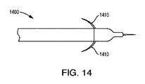
図14に示すように、装置1400は、装置の本体から飛び出すように構成された、より糸1410の形態の固定特徴部を含むことができる。
As shown in FIG. 14,
図15Aに示すように、装置1500は、装置の外径(OD)の周りに拡張し、両端部が装置に固定された後退可能なバスケット−スプライン1510の形態の固定特徴部を含むことができる。装置1500は、任意の数、例えば2つ以上の別個のスプライン1510を含むことができる。
As shown in FIG. 15A, the
図15Bに示すように、装置1500’は、図15Aに示される固定特徴部の変形を含むことができ、バスケットスプライン1510’は、拡張して周辺組織とのさらなる係合を形成する脚部1512も有する。
As shown in FIG. 15B, the device 1500'can include the deformation of the fixed features shown in FIG. 15A and the basket spline 1510'is a
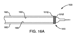
図16Aおよび図16Bに示すように、装置1600は、メッシュバスケット1610の形態の固定特徴部を含むことができ、これは、遠位端部1610dが内側チューブ1660に取り付けられ、近位端部1610pが外側チューブ1662に取り付けられている。バスケット1610は、挿入の間、部品の外径にぴったりと載ることができる。メッシュバスケット1610は、編組または巻取り技術によって形成することができる。固定が所望される場合、チューブ1660もしくは1662または他の特徴部を延長することができ、メッシュバスケット1610の近位端部1610pと遠位端部1610dとの間の距離を減少させ、メッシュバスケットの外径を拡大させ、周辺組織と係合させる。いくつかの実施形態では、メッシュバスケット610は、チューブの一方を他方のチューブに対してくるくる回すかまたは旋回させることによって開閉され得る。いくつかの実施形態では、メッシュバスケットは、可撓性バルーンまたはポリマードーナツで置き換えることができる。
As shown in FIGS. 16A and 16B,
図17に示すように、装置1700は、ニチノールまたは他の形状記憶材料で作られたステント型自己拡張足場1710の形態の固定特徴部を含むことができる。ステント材料は、一端部が装置1700に結合され得る。シース1750をステントの上で延ばし、かつ後退させて、足場組織固定特徴部1710を潰すことができる。シースを前進させるか、または針1720をシース内に後退させることによって、アンカー1710を潰すことができる。固定足場1710は、針1720が適所にある状態でシース1750を引き込むことによって配備され得る。
As shown in FIG. 17,
図18Aおよび図18Bに示すように、装置1800は、拡張可能なスネア1810の形態の固定特徴部を含むことができる。スネア1810は螺旋状であってもよい。スネア/螺旋1810は、遠位端部が内側チューブ1850に、近位端部が外側チューブ1852に取り付けられ得る。あるいは、スネア/螺旋1810を外側チューブ1852に切り込み、スネア/螺旋より遠位の場所で内側チューブ1850に取り付けることができる。外側チューブ1852が内側チューブ1850に対して回転される(例えば、それぞれ反対の方向にねじられる)と、スネア/螺旋1810は、周辺組織と係合するように外径を拡張することができる。
As shown in FIGS. 18A and 18B,
図19Aに示すように、装置1900は、ねじ山付きのかえし1910aの形態の固定特徴部を含むことができる。かえし1910aは、装置1900の遠位先端部1920の外径上に形成され得る。かえし1910aは、組織に螺入されるか、またはねじ込まれ得る。ねじ山付きの特徴部は、遠位にねじ込むことも近位にねじを緩めることもできる、後退可能な螺旋であることができる。図19Bに示されるように、固定特徴部は、装置1900’の遠位先端部1920に取り付けられ、コルク抜きのように遠位に延びるねじ特徴部1910bの形態であり得る。
As shown in FIG. 19A, the
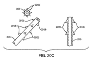
図20A〜図20Cに示されるように、固定特徴部は、様々な場所および位置において、外側チューブ2030または微小先端部2020に組み込まれたかえし特徴部の形態とすることができる。図20Aに示されているように、元のチューブ材料2030から、または外側チューブ2030の遠位端部に付加された追加の構成要素から、全直径のかえし特徴部2010aを形成することができる。かえし先端部は腫瘍組織内に固定することができ、逆流を防止するための密封バリアを提供することができる。図20Bに示すように、かえし特徴部2010aは、1つ以上のタング2012を含むことができる。
As shown in FIGS. 20A-20C, the fixed feature can be in the form of a barb feature incorporated into the
図20Cに示されるように、針チューブ2020上のかえし特徴部2010bは、腫瘍内に固定されるように構成される。かえし2010bの様々なアレイを異なる場所および位置に配置することができる。かえし特徴部2010bは、皮下チューブの固体壁厚さに冷間成形コイニングプロセスを含む種々のプロセスを用いて形成され、次いで、機械加工またはレーザー切断して最終的なかえしの輪郭を生成することができる。かえし特徴部2010bは、連続した外側表面を形成することができ、または1つ以上の開口部を含むことができる。開口部は、流体経路内にあってよく、注入液がそれらを通って出ることを可能にし得る。
As shown in FIG. 20C, the
図21Aおよび図21Bに示されるように、装置2100は、装置と組織との間の吸込管の形態の固定特徴部を含むことができる。装置2100は、例えば、装置2100のオーバーチューブ2130内またはその上に配置された、1つ以上の吸引開口部2110を含むことができる。吸引開口部2110は、別個の流体内腔2102を介して真空源(不図示)と連通することができる。図21Cに示されるように、吸引開口部2110は、装置2100の主要本体、例えば、弾丸状ノーズ本体またはチューブ2040上に形成され得る。
As shown in FIGS. 21A and 21B, the
図22Aに示すように、装置2100は、装置と周辺組織、例えば肋間筋組織との間で拡張され得るバルーン2110の形態の固定特徴部を含むことができる。図22Bに示されるように、バルーンは、胸膜内腔、または腫瘍内もしくは腫瘍付近の場所のいずれかに配置され得る。例えば、第1のバルーン2110aを腫瘍内に配備することができ、第2のバルーンを胸膜腔2110b内に配備することができる。バルーン2110aは、送達中の治療の逆流をさらに防止するために、弾丸状ノーズ領域内の装置の外径を増大させることができる。図22Cに示すように、バルーン2110は、組織の係合を補助するために、その表面上に把持特徴部を含むことができる。把持特徴部は、テクスチャ付き表面、把持ドット2112、バルーンが拡張されるときに延びるフィンガー2114などを含むことができる。
As shown in FIG. 22A, the
図23に示されるように、装置2300は、例えば、組織をアブレーションし、焼灼し、融解し、または他の方法で改変して、組織を装置に付着させるかまたは組織に装置を把持させることによって、装置を組織に取り付けるために、熱および/または電流を利用する固定特徴部2310を含むことができる。
As shown in FIG. 23, the
図24に示されるように、装置2400は、係合されかつ本体外径の外側に押されて組織と係合する1つ以上のボール2410の形態の固定特徴部を含むことができる。くぼみまたは溝を有する内側ワイヤ2402が使用され(例えば、引っ張られるか、または、押され)、ボール特徴部2410を本体表面の外側に延ばし、また係合解除/後退させることができる。
As shown in FIG. 24, the
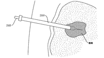
図25Aに示されるように、装置2500は、剛性であり得、経皮的に腫瘍にアクセスするために使用され得る。装置2500は、腫瘍の場所へのナビゲーションを補助するために、剛性挿入チューブ2550と共に使用され得る。図25Bに示すように、装置2500は、例えばトーイボースト(Tuohy Borst)機構を用いて、挿入チューブ2550にロックされ得る。外側チューブ/挿入チューブ2550は、固定機構(例えば、吸込管、ワイヤフック、バルーンなど)を有することができる。挿入チューブ2550は注入針装置2500をロックし、装置は、固定装置と共に移動する。
As shown in FIG. 25A, the
図26Aに示すように、装置2600は、可撓性であり得、経皮的に腫瘍にアクセスするために使用され得る。装置2600は、腫瘍の場所および皮膚の外側の両方で、これらの点のうちの1つのみで、または様々な他の場所のいずれかで、固定され得る。装置2600は、呼吸中に遠位装置先端部2600dでの動きを減少させるのを助けることができる、装置の長さの緩みを含むことができる。
As shown in FIG. 26A, the
図26Bに示すように、硬い挿入チューブ2650を使用して、装置2600を腫瘍または他の標的場所までナビゲートすることができる。装置2600の弾丸状ノーズ2640は、挿入チューブ2650と同じ外径とすることができ、装置の先端部は、先頭に立って腫瘍に進むことができる。例えば、挿入チューブ2650の硬い外側シースは、弾丸状ノーズ先端部2640を押すことができる。いったん装置2600が腫瘍の場所に来ると、剛性挿入チューブ2650は、後退されるかまたは取り外され、弾丸状ノーズ2640に接続された可撓性カテーテルを露出させることができる。剛性挿入チューブ2650は、破断またはバタフライシースデザインとすることができる。剛性挿入チューブ2650は、標準的なカニューレであってもよく、または種々の他の構成を有してもよい。挿入チューブ2650の近位端部は、ハブまたはハンドル2652を有することができる。装置2600の内腔は、可撓性、ねじれ剛性、および/または他の特性を制御するために追加の材料で層状にすることができる。
As shown in FIG. 26B, a
図27A、図27B、および図27Cに示すように、装置2700は、挿入中に剛性を維持することができ、患者に固定され得る。装置2700の内径内のコア針ワイヤ2702は、装置が標的場所に来ると、後退させられ得る。装置2700は、マーカーバンド、リング、および螺旋構造体のような、装置の遠位先端部2700d近くの剛性特徴部2710を含むことができる。患者組織は、装置2700の外部と接触することができる。外側装置ジャケット2750は、柔らかくてよく、コア針2702が取り外されたとき、より小さい外径に潰れることができる。先端部の近くの剛性特徴部2710は潰れないので、これは、組織と係合して装置を固定する、遠位先端部2700dの近くの様々な外径を形成することができる。
As shown in FIGS. 27A, 27B, and 27C, the
図28に示すように、装置2800は、2つ以上の伸縮チューブ、例えば、2802a、2802b、および2802c(集合的に2802)を含むことができる。
As shown in FIG. 28, the
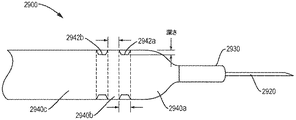
図29に示されるように、装置2900は、一次および最遠位弾丸状ノーズ2940aに近接する1つ以上の二次溝付き弾丸状ノーズ特徴部2940bおよび2940cを含むことができる。柔軟な組織は、装置2900の外径に対してシールすることができ、一次弾丸状ノーズ2940aに近接する溝2942aおよび2942bは、過剰な逆流を防止するためにそのシールを維持するのを補助することができる。二次溝付き弾丸状ノーズ特徴部2940bは、組織内で装置をシールするために、特定のパターン、深さ、幅、および形状を有することができる。オーバーチューブ2930および微小先端部2920は、装置および組織を保護するために挿入中に引き抜くことができ、注入のために伸長され得る。二次弾丸状ノーズの溝は、コンピュータ断層撮影(CT)または他の撮像技術の下での可視化のために放射線不透過性であり得る。
As shown in FIG. 29, the
図30Aに示されるように、装置3000は、装置が可撓性であり、かつ、呼吸中に遠位先端部を引っ張らないか、または他の方法で移動させないことを可能にする、特徴部を含むことができる。例えば、装置3000は、装置本体内にアコーディオン型特徴部3080aを含むことができる。遠位先端部3000dを移動させることなく、装置3000が呼吸中に撓むことを可能にすることは、先端部の周囲の組織のシールを維持することを補助し、したがって、注入中の逆流を防止することができる。例えば、アコーディオン型特徴部3080aは、可撓性を達成するために、きつく入れられてから引き戻され得る。
As shown in FIG. 30A,
図30Bに示されるように、装置3000’は、呼吸中に肺の動きと共に伸長および収縮するばね特徴部3080bを含むことができる。装置3000’は、胸部または胸壁、胸膜、腫瘍、および/または他の場所に固定され得る。図示のように、2つの固定特徴部3082、3084は、装置3000’を適所に固定することができる。第1の固定特徴部3082は、外側胸壁に取り付けることができ、第2の固定特徴部3084は、胸膜または腫瘍に取り付けることができる。ばね3080bは、装置3000’の先端部3000dが腫瘍と共に動くことを可能にする。
As shown in FIG. 30B, the device 3000'can include a spring feature 3080b that expands and contracts with the movement of the lungs during breathing. The device 3000'can be anchored to the chest or chest wall, pleura, tumor, and / or elsewhere. As shown, the two fixing
図31は、経皮的肺腫瘍内治療送達装置3100の例示的実施形態を示す。装置3100は、1つ以上の流体内腔を含むことができ、それを通じて、流体が患者内の標的部位に送達され得、かつ/または、それを通じて、流体もしくは他の材料が患者内の標的部位から抽出され得る。装置3100は、内部に流体ポート3125を有する遠位先端部3120を含むことができる。先端部3120は、前述され、参照により本明細書に組み込まれる、米国特許第8,992,458号に記載されているように、微細加工された構造体とすることができる。先端部3120は、単一内腔チューブとすることができる。装置3100は、先端部の外側表面とオーバーチューブの内側表面との間に組織受容空間を画定するように、先端部3120の上に配置されたオーバーチューブ3130を含むことができる。組織は、組織受容空間内に、またはそれを横切って、はさまれるか、捕捉されるか、または別様に配置されて、装置とシールを形成し、注入液の近位逆流を制限または防止することができる。オーバーチューブ特徴部3130は、前述され、参照により本明細書に組み込まれる、米国特許第8,992,458号に記載されている。装置3100は、前述され、参照により本明細書に組み込まれる、米国特許第8,992,458号に記載されているように、1つ以上の弾丸状ノーズ特徴部を含むことができる。図31に示されるように、装置3100は、複数の弾丸状ノーズ特徴部3140a、3140b、3140c、および3140d(集合的に3140)を含むことができ、これらは各々、円錐状、湾曲状、または別様にテーパ状の遠位対向面を有する。各弾丸状ノーズ3140は、同じかまたは実質的に同じ最大外径を有することができる。他の構成では、弾丸状ノーズ特徴部3140のうちの1つ以上が、他とは異なる最大外径を有することができる。弾丸状ノーズ特徴部3140は、オーバーチューブ特徴部3130に近接して、装置3100の長さに沿って離間関係で配置され得る。弾丸状ノーズ3140は、装置のリブ付きまたは溝付きセクションを画定することができ、これに対して組織が密封されて、逆流を制限または防止し得る。いくつかの実施形態において、組織は、隣り合う弾丸状ノーズ3140の間に画定された空隙空間内に受容されて、緊密なシールを形成することができる。別の状況では装置の外部に沿って近位に逆流し得る流体は、連続する弾丸状ノーズ3140の間に画定された谷部に捕捉され得る。複数の弾丸状ノーズは、装置を固定するための手段として周辺組織と係合し、装置の外部に沿った注入液の逆流を制限または防止するために、装置の長さに沿って離間関係で配置され得る。
FIG. 31 shows an exemplary embodiment of a percutaneous intratumoral
装置3100は、本明細書に記載される固定特徴部のいずれかを含むことができる。例えば、図示のように、装置3100は、複数の配備可能スプライン3110を含むことができる。スプライン3110は、装置3100の本体内に形成された長手方向の溝またはチャネル内にスライド可能に装着され得る。スプライン3110は、可撓性かつ/または弾性とすることができる。スプライン3110は、ヒートセット形状を有することができる。スプライン3110は、本体から外側に、例えば図示のように本体から実質的に90度フレア状になる静止状態を有することができる。装置3100は、スプラインの配備および/または後退を制御するためのアクチュエータを含むことができる。例えば、装置3100の近位ハンドルが、スプラインを作動させるために装置の本体に対して回転可能または長手方向にスライド可能なカラーを含むことができる。スプライン3110は、長手方向に近位に引っ張られて、装置3100に形成された溝内にスプラインを後退させ、スプラインを、その静止形状から離れるように撓ませることができる。スプライン3110は、例えば、それらを装置3100の溝から押し出し、それらを静止形状に戻すことによって、スプラインを配備するように長手方向に遠位に付勢され得る。配備されると、スプライン3110は、周辺組織と係合して、装置3100の遠位先端部3120を周辺組織に固定することができる。
The
装置3100の本体は、可撓性または剛性のカテーテルまたはチューブに接続することができ、これは、近位端部が流体源、ポンプ、シリンジ、真空源などに連結され得る。
The body of the
装置3100は、外側カニューレまたは導入器シース/送達チューブ3150を含むことができる。装置3100は、このチューブ3150を通じて送達され得る。使用時には、カニューレ3150を患者の皮膚、筋肉、胸膜などを通して経皮的に挿入して、肺腫瘍などの標的解剖学的構造にアクセスすることができる。カニューレ3150は、カニューレを通じて配されたスタイレットと共に挿入され得る。いったんカニューレ3150の遠位先端部3150dが、例えば約2cm離れて、腫瘍に接近すると、スタイレットを除去することができ、装置は、カニューレを通じて挿入され得る。カニューレ3150は、患者への挿入中に比較的デリケートな装置3100を保護するのを助けることができる。装置3100は、遠位に前進させられて、装置の遠位先端部3120または流体ポート3125を腫瘍内に、または腫瘍に近接して配置することができる。装置3100の固定特徴部は、装置の遠位先端部3120を適所に固定するように配備され得、呼吸または他の患者の活動中の装置の移動を防止する。流体、例えば、薬物または治療含有流体は、装置を通じて腫瘍内に送達され得る。
The
本明細書に開示される装置を使用する例示的な方法は、以下の通りである:
1.腫瘍の場所の撮像、アクセス計画
2.皮膚切開
3.ガイダンスのためにCTを用いた、腫瘍場所への外側カニューレおよびスタイレットの前進。腫瘍から約2cmのところで停止する
4.スタイレットを除去する
5.外側カニューレを通じて装置を挿入し、腫瘍内に前進させる。腫瘍の中心についてオーバーチューブのほぼ中心を標的とし得る
6.スプラインを前進させ、先端部を固定する
7.カニューレを除去または留置する。カニューレを除去する場合は、シースを裂いて除去するか、または皮膚とハブとの間に装置を保持することができる
8.装置を通じて腫瘍内に注入する
9.スプラインを後退させる
10.カニューレから装置を除去する
11.カニューレが除去される際に血液プラグまたはバイオゲルの注射の可能性がある
Illustrative methods of using the devices disclosed herein are:
1. 1. Imaging of tumor location, access planning 2.
図32A〜図32Hは、本明細書に記載される任意の装置、例えば装置の微小先端部において使用され得る例示的な針先端部外形を示す。図示された外形は、針の輪郭によるコアリングを最小限にするように構成され得、それによって、装置を通る一貫した流れを容易にする。図32Aは、非対称の内腔の輪郭3212のためにコアリングしにくい平坦化されたチューブ外形3210を示す。図32Bは、側方ポート外形3220を示しており、針は、1つ以上の側方を向いた流体ポート3224を有する鈍い先端部3222を有する。図32Cは、円錐形の鈍い先端部3232と、先端部の外径の周りで離間した非常に小さい孔3234のアレイと、を有する、針外形3230を示す。図32Cの針外形は、流体の半径方向の流れによるブロックの可能性が低い。図32Dは、「8の字形の」先端部外形3240を示しており、ここでは、2つの内側内腔3242aおよび3242bが一方の側で接合されて、概して数字の8の形状の横方向断面を有する、より大きな内腔を形成している。図32Eは、「口を開けたカモのくちばし状の(open duck bill)」先端部構成3250を示す。図32Fは、タブ3262aおよび3262bが「口を開けたカモのくちばし状の」先端部構成から折り曲げられている、「口を閉じたカモのくちばし状の」先端部構成3260を示す。図32Gは、ブリーザーベント先端部3272を有する針3270を示す。ブリーザーベント先端部3272は、針先端部に取り付けられた、非常に微細な、例えば5μm未満の、フィルタとすることができる。図31Gの針3270は、流体の半径方向の流れによるブロックの可能性が低い。図32Hは、「ルーク」または「キャッスル」外形3280を有する先端部を示す。先端部3282は、任意の数の突起部3284、例えば4つ以上の突起部を、先端部の端部に含むことができる。突起部3284を尖らせて貫通を改善することができる。
32A-32H show exemplary needle tip contours that can be used in any device described herein, eg, a microtip of the device. The illustrated outline may be configured to minimize coring by the contour of the needle, thereby facilitating consistent flow through the device. FIG. 32A shows a flattened
図33A〜図33Fは、本明細書に記載される任意の装置、例えば装置の微小先端部において使用され得る針先端部外形のさらなる実施例を示す。図33Aに示されるように、針先端部は、鈍い先端部3310とすることができる。図33Bに示されるように、針先端部は、複数の角度オプションθを有する傾斜先端部3320とすることができる。図33Cに示されるように、針先端部は、非コアリング先端部、例えば3330aおよび/または3330bとすることができる。図33Dに示されるように、針先端部は、二重先端部3340とすることができる。図33Eに示すように、針先端部は、二重内腔またはDD先端部3352とすることができる。図33Fに示すように、針先端部3360は、オーバーチューブ特徴部3365と組み合わせることができる。
33A-33F show further embodiments of needle tip contours that may be used in any device described herein, eg, a microtip of the device. As shown in FIG. 33A, the needle tip can be a
本明細書では、呼吸中などの患者の活動中に、装置の遠位先端部が、標的場所、例えば患者の腫瘍に対して実質的に固定された場所に留まることを可能にする固定特徴部を有する装置が開示される。本明細書中の装置は、注入中に動く身体の任意の部分に使用され得る。 As used herein, a fixed feature that allows the distal tip of the device to remain at a target location, eg, a location that is substantially fixed to the patient's tumor, during patient activity, such as during breathing. The device having the above is disclosed. The devices herein can be used on any part of the body that moves during infusion.
本明細書では、装置の外部に沿った注入液の逆流を制限または防止するためのシール特徴部を有する装置が開示される。 The present specification discloses an apparatus having a seal feature for limiting or preventing backflow of injectable solution along the outside of the apparatus.
本発明を特定の実施形態を参照して説明したが、説明した本発明の概念の趣旨および範囲内で多くの変更がなされ得ることを理解されたい。したがって、本発明は、記載された実施形態に限定されないことが意図される。 Although the present invention has been described with reference to specific embodiments, it should be understood that many modifications can be made within the spirit and scope of the described concept of the invention. Therefore, it is intended that the present invention is not limited to the described embodiments.
〔実施の態様〕
(1) 薬物送達装置において、
1つ以上の流体ポートを内部に有する遠位先端部と、
流体を前記先端部の前記1つ以上の流体ポートに運ぶように構成された内側流体内腔と、
前記遠位先端部に近接して、前記装置の長さに沿って離間関係で配置された複数の弾丸状ノーズと、
を含む、薬物送達装置。
(2) 前記複数の弾丸状ノーズが、前記装置の外部に沿った注入液の逆流を制限または防止するように構成されている、実施態様1に記載の装置。
(3) 患者の活動中に前記患者の標的組織に対する前記遠位先端部の移動を防止するために、前記遠位先端部を前記標的組織に固定するための手段をさらに含み、前記固定するための手段は、前記複数の弾丸状ノーズから切り離されている、実施態様1に記載の装置。
(4) 前記患者の前記標的組織が腫瘍を含む、実施態様3に記載の装置。
(5) 前記患者の活動が呼吸を含む、実施態様3に記載の装置。
[Implementation mode]
(1) In the drug delivery device
With a distal tip that has one or more fluid ports inside,
An inner fluid lumen configured to carry fluid to the one or more fluid ports at the tip, and
A plurality of bullet-shaped noses arranged in close proximity to the distal tip and spaced apart along the length of the device.
Drug delivery device, including.
(2) The device according to embodiment 1, wherein the plurality of bullet-shaped noses are configured to limit or prevent backflow of injectable solution along the outside of the device.
(3) To further include and secure means for fixing the distal tip to the target tissue in order to prevent the distal tip from moving relative to the patient's target tissue during the patient's activity. The device according to embodiment 1, wherein the means is separated from the plurality of bullet-shaped noses.
(4) The device according to
(5) The device according to
(6) 前記装置が、組織受容空間を画定するために前記遠位先端部上に配置された1つ以上のオーバーチューブを含む、実施態様1に記載の装置。
(7) 組織が、前記組織受容空間内に受容されて、前記装置の外部に沿った注入液の逆流を制限または防止する、実施態様6に記載の装置。
(8) 前記複数の弾丸状ノーズのうちの1つ以上が、円錐状、湾曲状、またはテーパ状の外面を有する、実施態様1に記載の装置。
(9) 前記複数の弾丸状ノーズが、周辺組織と係合して前記装置を固定する、実施態様1に記載の装置。
(10) 前記固定するための手段が、周辺組織と係合するために前記装置の外部から配備可能な1つ以上のスプラインを含む、実施態様3に記載の装置。
(6) The device according to embodiment 1, wherein the device comprises one or more overtubes placed on the distal tip to define a tissue receiving space.
(7) The device according to embodiment 6, wherein the tissue is received in the tissue receiving space to limit or prevent backflow of injectable solution along the outside of the device.
(8) The device according to embodiment 1, wherein one or more of the plurality of bullet-shaped noses has a conical, curved, or tapered outer surface.
(9) The device according to the first embodiment, wherein the plurality of bullet-shaped noses engage with surrounding tissues to fix the device.
(10) The device according to
(11) 前記固定するための手段が、周辺組織と係合するために前記装置の外部から配備可能な1つ以上のバルーンを含む、実施態様3に記載の装置。
(11) The device of
Claims (11)
1つ以上の流体ポートを内部に有する遠位先端部と、
流体を前記先端部の前記1つ以上の流体ポートに運ぶように構成された内側流体内腔と、
前記遠位先端部に近接して、前記装置の長さに沿って離間関係で配置された複数の弾丸状ノーズと、
を含む、薬物送達装置。 In a drug delivery device
With a distal tip that has one or more fluid ports inside,
An inner fluid lumen configured to carry fluid to the one or more fluid ports at the tip, and
A plurality of bullet-shaped noses arranged in close proximity to the distal tip and spaced apart along the length of the device.
Drug delivery device, including.
Applications Claiming Priority (5)
| Application Number | Priority Date | Filing Date | Title |
|---|---|---|---|
| US201862657019P | 2018-04-13 | 2018-04-13 | |
| US62/657,019 | 2018-04-13 | ||
| US16/286,707 | 2019-02-27 | ||
| US16/286,707 US20190314574A1 (en) | 2018-04-13 | 2019-02-27 | Devices and methods for percutaneous lung intratumoral therapy delivery |
| PCT/US2019/026967 WO2019200086A1 (en) | 2018-04-13 | 2019-04-11 | Devices and methods for percutaneous intratumoral therapy delivery |
Publications (1)
| Publication Number | Publication Date |
|---|---|
| JP2021520908A true JP2021520908A (en) | 2021-08-26 |
Family
ID=68160145
Family Applications (1)
| Application Number | Title | Priority Date | Filing Date |
|---|---|---|---|
| JP2020555758A Pending JP2021520908A (en) | 2018-04-13 | 2019-04-11 | Devices and methods for percutaneous intratumoral treatment delivery |
Country Status (8)
| Country | Link |
|---|---|
| US (1) | US20190314574A1 (en) |
| EP (1) | EP3773850A4 (en) |
| JP (1) | JP2021520908A (en) |
| KR (1) | KR20210010859A (en) |
| CN (1) | CN112292175A (en) |
| AU (1) | AU2019252419A1 (en) |
| CA (1) | CA3097032A1 (en) |
| WO (1) | WO2019200086A1 (en) |
Families Citing this family (2)
| Publication number | Priority date | Publication date | Assignee | Title |
|---|---|---|---|---|
| CN110664507A (en) * | 2019-11-18 | 2020-01-10 | 中国科学院深圳先进技术研究院 | Disposable non-leakage intracranial drug delivery device |
| MX2022007208A (en) * | 2019-12-13 | 2022-09-21 | Janssen Pharmaceuticals Inc | Methods and devices for delivering liquid therapeutic agents in solid tumors. |
Citations (5)
| Publication number | Priority date | Publication date | Assignee | Title |
|---|---|---|---|---|
| JP2001513402A (en) * | 1997-08-22 | 2001-09-04 | ダイレクト・セラピューティクス,インコーポレイテッド | Device for preventing loss of composition during a medical procedure |
| JP2010000350A (en) * | 2008-06-07 | 2010-01-07 | Codman & Shurtleff Inc | Catheter for reduced reflux in targeted tissue delivery of therapeutic agent |
| JP2013526960A (en) * | 2010-05-28 | 2013-06-27 | ツイン スター メディカル,インコーポレイティド | Tissue injection apparatus and method |
| JP2014518748A (en) * | 2011-06-06 | 2014-08-07 | ザ クリーブランド クリニック ファウンデーション | Catheter assembly |
| JP2016501110A (en) * | 2012-12-18 | 2016-01-18 | アルキオーネ・ライフサイエンシズ・インコーポレイテッドAlcyone Lifesciences, Inc. | System and method for reducing or preventing backflow in a delivery system |
Family Cites Families (15)
| Publication number | Priority date | Publication date | Assignee | Title |
|---|---|---|---|---|
| US6063082A (en) * | 1997-11-04 | 2000-05-16 | Scimed Life Systems, Inc. | Percutaneous myocardial revascularization basket delivery system and radiofrequency therapeutic device |
| US6602241B2 (en) * | 2001-01-17 | 2003-08-05 | Transvascular, Inc. | Methods and apparatus for acute or chronic delivery of substances or apparatus to extravascular treatment sites |
| US7431710B2 (en) * | 2002-04-08 | 2008-10-07 | Glaukos Corporation | Ocular implants with anchors and methods thereof |
| US8992454B2 (en) | 2004-06-09 | 2015-03-31 | Bard Access Systems, Inc. | Splitable tip catheter with bioresorbable adhesive |
| US7862532B2 (en) * | 2005-10-07 | 2011-01-04 | Delta Life Sciences, Inc. | Punctum plugs having insertion guides and strengthening beams |
| US8182444B2 (en) | 2005-11-04 | 2012-05-22 | Medrad, Inc. | Delivery of agents such as cells to tissue |
| US7708722B2 (en) * | 2006-01-10 | 2010-05-04 | Stealth Therapeutics, Inc. | Stabilized implantable vascular access port |
| US20100280494A1 (en) * | 2006-08-08 | 2010-11-04 | Matsuura James E | Catheter and array for anticancer therapy |
| EP1970088B1 (en) * | 2007-03-16 | 2009-11-18 | BrainLAB AG | Catheter with sections with changeable volume |
| BE1018521A5 (en) * | 2009-04-29 | 2011-02-01 | Cardio3 Biosciences Sa | INJECTION CATHETER FOR DELIVERING A THERAPEUTIC AGENT IN A SUBSTRATE. |
| US9126016B2 (en) * | 2010-05-19 | 2015-09-08 | Nfusion Vascular Systems Llc | Augmented delivery catheter and method |
| US20120078078A1 (en) * | 2010-09-24 | 2012-03-29 | C.R. Bard | Means for securing a catheter into a vessel |
| US20130035660A1 (en) | 2011-08-01 | 2013-02-07 | Alcyone Lifesciences, Inc. | Multidirectional microfluidic drug delivery devices with conformable balloons |
| WO2013078235A1 (en) | 2011-11-23 | 2013-05-30 | Broncus Medical Inc | Methods and devices for diagnosing, monitoring, or treating medical conditions through an opening through an airway wall |
| US10806396B2 (en) * | 2015-01-26 | 2020-10-20 | Alcyone Lifesciences, Inc. | Drug delivery methods with tracer |
-
2019
- 2019-02-27 US US16/286,707 patent/US20190314574A1/en not_active Abandoned
- 2019-04-11 AU AU2019252419A patent/AU2019252419A1/en active Pending
- 2019-04-11 JP JP2020555758A patent/JP2021520908A/en active Pending
- 2019-04-11 KR KR1020207032800A patent/KR20210010859A/en not_active Application Discontinuation
- 2019-04-11 EP EP19785694.1A patent/EP3773850A4/en active Pending
- 2019-04-11 CN CN201980039116.7A patent/CN112292175A/en active Pending
- 2019-04-11 CA CA3097032A patent/CA3097032A1/en active Pending
- 2019-04-11 WO PCT/US2019/026967 patent/WO2019200086A1/en unknown
Patent Citations (5)
| Publication number | Priority date | Publication date | Assignee | Title |
|---|---|---|---|---|
| JP2001513402A (en) * | 1997-08-22 | 2001-09-04 | ダイレクト・セラピューティクス,インコーポレイテッド | Device for preventing loss of composition during a medical procedure |
| JP2010000350A (en) * | 2008-06-07 | 2010-01-07 | Codman & Shurtleff Inc | Catheter for reduced reflux in targeted tissue delivery of therapeutic agent |
| JP2013526960A (en) * | 2010-05-28 | 2013-06-27 | ツイン スター メディカル,インコーポレイティド | Tissue injection apparatus and method |
| JP2014518748A (en) * | 2011-06-06 | 2014-08-07 | ザ クリーブランド クリニック ファウンデーション | Catheter assembly |
| JP2016501110A (en) * | 2012-12-18 | 2016-01-18 | アルキオーネ・ライフサイエンシズ・インコーポレイテッドAlcyone Lifesciences, Inc. | System and method for reducing or preventing backflow in a delivery system |
Also Published As
| Publication number | Publication date |
|---|---|
| EP3773850A1 (en) | 2021-02-17 |
| WO2019200086A1 (en) | 2019-10-17 |
| CN112292175A (en) | 2021-01-29 |
| AU2019252419A1 (en) | 2020-12-03 |
| US20190314574A1 (en) | 2019-10-17 |
| CA3097032A1 (en) | 2019-10-17 |
| KR20210010859A (en) | 2021-01-28 |
| EP3773850A4 (en) | 2022-02-16 |
Similar Documents
| Publication | Publication Date | Title |
|---|---|---|
| JP7242789B2 (en) | convection-enhanced delivery device | |
| US11534592B2 (en) | Systems and methods for drug delivery, treatment, and monitoring | |
| JP5666102B2 (en) | Catheter to reduce reflux in the delivery of therapeutic agents to target tissues | |
| US8083720B2 (en) | Device and method for delivering therapeutic agents to an area of the body | |
| EP3370803B1 (en) | Injection devices | |
| JP2021520908A (en) | Devices and methods for percutaneous intratumoral treatment delivery | |
| EP3415106B1 (en) | Brain interaction apparatus, cranial anchor, and related systems | |
| AU2017444936A1 (en) | Over the needle catheter with an openable and closable distal tip |
Legal Events
| Date | Code | Title | Description |
|---|---|---|---|
| A621 | Written request for application examination |
Free format text: JAPANESE INTERMEDIATE CODE: A621 Effective date: 20220407 |
|
| A131 | Notification of reasons for refusal |
Free format text: JAPANESE INTERMEDIATE CODE: A131 Effective date: 20230509 |
|
| A02 | Decision of refusal |
Free format text: JAPANESE INTERMEDIATE CODE: A02 Effective date: 20231205 |