JP2021520710A - Bidirectional optical flow method with simplified gradient derivation - Google Patents
Bidirectional optical flow method with simplified gradient derivation Download PDFInfo
- Publication number
- JP2021520710A JP2021520710A JP2020553659A JP2020553659A JP2021520710A JP 2021520710 A JP2021520710 A JP 2021520710A JP 2020553659 A JP2020553659 A JP 2020553659A JP 2020553659 A JP2020553659 A JP 2020553659A JP 2021520710 A JP2021520710 A JP 2021520710A
- Authority
- JP
- Japan
- Prior art keywords
- gradient
- bdof
- difference
- horizontal
- vertical
- Prior art date
- Legal status (The legal status is an assumption and is not a legal conclusion. Google has not performed a legal analysis and makes no representation as to the accuracy of the status listed.)
- Pending
Links
- 230000003287 optical effect Effects 0.000 title claims abstract description 15
- 230000002457 bidirectional effect Effects 0.000 title claims abstract description 7
- 238000000034 method Methods 0.000 title claims description 51
- 238000009795 derivation Methods 0.000 title description 30
- 230000033001 locomotion Effects 0.000 claims description 193
- 239000013598 vector Substances 0.000 claims description 69
- 239000000523 sample Substances 0.000 claims description 55
- 239000013074 reference sample Substances 0.000 claims description 24
- 238000004364 calculation method Methods 0.000 claims description 12
- 230000004931 aggregating effect Effects 0.000 claims 3
- 238000004891 communication Methods 0.000 description 41
- 238000005516 engineering process Methods 0.000 description 24
- 238000010586 diagram Methods 0.000 description 21
- 230000008569 process Effects 0.000 description 18
- 230000006870 function Effects 0.000 description 16
- 238000001914 filtration Methods 0.000 description 15
- 238000012545 processing Methods 0.000 description 15
- PXFBZOLANLWPMH-UHFFFAOYSA-N 16-Epiaffinine Natural products C1C(C2=CC=CC=C2N2)=C2C(=O)CC2C(=CC)CN(C)C1C2CO PXFBZOLANLWPMH-UHFFFAOYSA-N 0.000 description 13
- 230000002146 bilateral effect Effects 0.000 description 10
- 230000005540 biological transmission Effects 0.000 description 10
- 238000012360 testing method Methods 0.000 description 10
- 238000007726 management method Methods 0.000 description 8
- 238000001228 spectrum Methods 0.000 description 8
- 230000002123 temporal effect Effects 0.000 description 7
- 238000006243 chemical reaction Methods 0.000 description 6
- 238000013139 quantization Methods 0.000 description 5
- 239000000969 carrier Substances 0.000 description 4
- 230000002093 peripheral effect Effects 0.000 description 4
- 230000003068 static effect Effects 0.000 description 4
- 230000009466 transformation Effects 0.000 description 4
- 241000700159 Rattus Species 0.000 description 3
- 230000001413 cellular effect Effects 0.000 description 3
- 239000002245 particle Substances 0.000 description 3
- 230000011664 signaling Effects 0.000 description 3
- 208000037170 Delayed Emergence from Anesthesia Diseases 0.000 description 2
- 101000969688 Homo sapiens Macrophage-expressed gene 1 protein Proteins 0.000 description 2
- 102100021285 Macrophage-expressed gene 1 protein Human genes 0.000 description 2
- 101100172132 Mus musculus Eif3a gene Proteins 0.000 description 2
- 238000007792 addition Methods 0.000 description 2
- 238000004458 analytical method Methods 0.000 description 2
- 230000009977 dual effect Effects 0.000 description 2
- 229910001416 lithium ion Inorganic materials 0.000 description 2
- 238000010295 mobile communication Methods 0.000 description 2
- QELJHCBNGDEXLD-UHFFFAOYSA-N nickel zinc Chemical compound [Ni].[Zn] QELJHCBNGDEXLD-UHFFFAOYSA-N 0.000 description 2
- 238000003860 storage Methods 0.000 description 2
- 238000001356 surgical procedure Methods 0.000 description 2
- 108091026890 Coding region Proteins 0.000 description 1
- 230000005355 Hall effect Effects 0.000 description 1
- HBBGRARXTFLTSG-UHFFFAOYSA-N Lithium ion Chemical compound [Li+] HBBGRARXTFLTSG-UHFFFAOYSA-N 0.000 description 1
- 230000003213 activating effect Effects 0.000 description 1
- 230000002776 aggregation Effects 0.000 description 1
- 238000004220 aggregation Methods 0.000 description 1
- 238000004873 anchoring Methods 0.000 description 1
- 230000002547 anomalous effect Effects 0.000 description 1
- 230000003190 augmentative effect Effects 0.000 description 1
- 230000008901 benefit Effects 0.000 description 1
- OJIJEKBXJYRIBZ-UHFFFAOYSA-N cadmium nickel Chemical compound [Ni].[Cd] OJIJEKBXJYRIBZ-UHFFFAOYSA-N 0.000 description 1
- 230000008859 change Effects 0.000 description 1
- 230000008878 coupling Effects 0.000 description 1
- 238000010168 coupling process Methods 0.000 description 1
- 238000005859 coupling reaction Methods 0.000 description 1
- 238000013461 design Methods 0.000 description 1
- 238000009826 distribution Methods 0.000 description 1
- 230000000694 effects Effects 0.000 description 1
- 239000000446 fuel Substances 0.000 description 1
- 238000005286 illumination Methods 0.000 description 1
- 230000006872 improvement Effects 0.000 description 1
- 230000002045 lasting effect Effects 0.000 description 1
- 239000004973 liquid crystal related substance Substances 0.000 description 1
- 230000007774 longterm Effects 0.000 description 1
- 230000005055 memory storage Effects 0.000 description 1
- 229910052987 metal hydride Inorganic materials 0.000 description 1
- 238000005457 optimization Methods 0.000 description 1
- 230000009467 reduction Effects 0.000 description 1
- 230000004044 response Effects 0.000 description 1
- 238000000411 transmission spectrum Methods 0.000 description 1
- 230000032258 transport Effects 0.000 description 1
- 238000011282 treatment Methods 0.000 description 1
Images


Classifications
-
- G—PHYSICS
- G06—COMPUTING; CALCULATING OR COUNTING
- G06T—IMAGE DATA PROCESSING OR GENERATION, IN GENERAL
- G06T7/00—Image analysis
- G06T7/20—Analysis of motion
- G06T7/223—Analysis of motion using block-matching
-
- G—PHYSICS
- G06—COMPUTING; CALCULATING OR COUNTING
- G06T—IMAGE DATA PROCESSING OR GENERATION, IN GENERAL
- G06T7/00—Image analysis
- G06T7/20—Analysis of motion
- G06T7/269—Analysis of motion using gradient-based methods
-
- H—ELECTRICITY
- H04—ELECTRIC COMMUNICATION TECHNIQUE
- H04N—PICTORIAL COMMUNICATION, e.g. TELEVISION
- H04N19/00—Methods or arrangements for coding, decoding, compressing or decompressing digital video signals
- H04N19/10—Methods or arrangements for coding, decoding, compressing or decompressing digital video signals using adaptive coding
- H04N19/102—Methods or arrangements for coding, decoding, compressing or decompressing digital video signals using adaptive coding characterised by the element, parameter or selection affected or controlled by the adaptive coding
- H04N19/103—Selection of coding mode or of prediction mode
-
- H—ELECTRICITY
- H04—ELECTRIC COMMUNICATION TECHNIQUE
- H04N—PICTORIAL COMMUNICATION, e.g. TELEVISION
- H04N19/00—Methods or arrangements for coding, decoding, compressing or decompressing digital video signals
- H04N19/10—Methods or arrangements for coding, decoding, compressing or decompressing digital video signals using adaptive coding
- H04N19/134—Methods or arrangements for coding, decoding, compressing or decompressing digital video signals using adaptive coding characterised by the element, parameter or criterion affecting or controlling the adaptive coding
- H04N19/136—Incoming video signal characteristics or properties
- H04N19/137—Motion inside a coding unit, e.g. average field, frame or block difference
- H04N19/139—Analysis of motion vectors, e.g. their magnitude, direction, variance or reliability
-
- H—ELECTRICITY
- H04—ELECTRIC COMMUNICATION TECHNIQUE
- H04N—PICTORIAL COMMUNICATION, e.g. TELEVISION
- H04N19/00—Methods or arrangements for coding, decoding, compressing or decompressing digital video signals
- H04N19/10—Methods or arrangements for coding, decoding, compressing or decompressing digital video signals using adaptive coding
- H04N19/169—Methods or arrangements for coding, decoding, compressing or decompressing digital video signals using adaptive coding characterised by the coding unit, i.e. the structural portion or semantic portion of the video signal being the object or the subject of the adaptive coding
- H04N19/17—Methods or arrangements for coding, decoding, compressing or decompressing digital video signals using adaptive coding characterised by the coding unit, i.e. the structural portion or semantic portion of the video signal being the object or the subject of the adaptive coding the unit being an image region, e.g. an object
- H04N19/176—Methods or arrangements for coding, decoding, compressing or decompressing digital video signals using adaptive coding characterised by the coding unit, i.e. the structural portion or semantic portion of the video signal being the object or the subject of the adaptive coding the unit being an image region, e.g. an object the region being a block, e.g. a macroblock
-
- H—ELECTRICITY
- H04—ELECTRIC COMMUNICATION TECHNIQUE
- H04N—PICTORIAL COMMUNICATION, e.g. TELEVISION
- H04N19/00—Methods or arrangements for coding, decoding, compressing or decompressing digital video signals
- H04N19/50—Methods or arrangements for coding, decoding, compressing or decompressing digital video signals using predictive coding
- H04N19/503—Methods or arrangements for coding, decoding, compressing or decompressing digital video signals using predictive coding involving temporal prediction
- H04N19/51—Motion estimation or motion compensation
- H04N19/577—Motion compensation with bidirectional frame interpolation, i.e. using B-pictures
-
- G—PHYSICS
- G06—COMPUTING; CALCULATING OR COUNTING
- G06T—IMAGE DATA PROCESSING OR GENERATION, IN GENERAL
- G06T2207/00—Indexing scheme for image analysis or image enhancement
- G06T2207/20—Special algorithmic details
- G06T2207/20021—Dividing image into blocks, subimages or windows
-
- G—PHYSICS
- G06—COMPUTING; CALCULATING OR COUNTING
- G06T—IMAGE DATA PROCESSING OR GENERATION, IN GENERAL
- G06T2207/00—Indexing scheme for image analysis or image enhancement
- G06T2207/20—Special algorithmic details
- G06T2207/20048—Transform domain processing
-
- G—PHYSICS
- G06—COMPUTING; CALCULATING OR COUNTING
- G06T—IMAGE DATA PROCESSING OR GENERATION, IN GENERAL
- G06T2207/00—Indexing scheme for image analysis or image enhancement
- G06T2207/20—Special algorithmic details
- G06T2207/20172—Image enhancement details
- G06T2207/20182—Noise reduction or smoothing in the temporal domain; Spatio-temporal filtering
Abstract
ビデオ符号化デバイスは、符号化ユニット(CU)に対して指向性双方向オプティカルフロー(BDOF)リファインメントを実行するように構成されてもよい。デバイスは、指向性BDOFリファインメントを実行する方向を判定してもよい。デバイスは、CUについての垂直方向勾配差および水平方向勾配差を計算してもよい。垂直方向勾配差は、第1の参照ピクチャについての垂直勾配と第2の参照ピクチャについての垂直勾配との間の差を示すことができる。水平方向勾配差は、第1の参照ピクチャについての水平勾配と第2の参照ピクチャについての水平勾配との間の差を示すことができる。ビデオ符号化デバイスは、垂直方向勾配差および水平方向勾配差に基づいて、指向性BDOFリファインメントを実行する方向を判定してもよい。ビデオ符号化デバイスは、判定された方向において指向性BDOFリファインメントを実行してもよい。The video coding device may be configured to perform directional bidirectional optical flow (BDOF) refinement on the coding unit (CU). The device may determine the direction in which the directional BDOF refinement is performed. The device may calculate the vertical and horizontal gradient differences for the CU. The vertical gradient difference can indicate the difference between the vertical gradient for the first reference picture and the vertical gradient for the second reference picture. The horizontal gradient difference can indicate the difference between the horizontal gradient for the first reference picture and the horizontal gradient for the second reference picture. The video coding device may determine the direction in which the directional BDOF refinement is performed based on the vertical gradient difference and the horizontal gradient difference. The video coding device may perform directional BDOF refinement in the determined direction.
Description
本出願は、参照によってその内容が本明細書に組み込まれる、2018年4月6日に出願された米国仮特許出願第62/653,674号の利益を主張する。 This application claims the benefit of US Provisional Patent Application No. 62 / 653,674 filed April 6, 2018, the contents of which are incorporated herein by reference.
デジタルビデオ信号を圧縮して、そのような信号の記憶の必要性および/または伝送帯域幅を削減するために、ビデオ符号化システムが広範囲に使用されている。ブロックに基づくシステム、ウェーブレットに基づくシステム、およびオブジェクトに基づくシステムなどのビデオ符号化システム、ならびにブロックに基づくハイブリッドビデオ符号化システムが広範囲に使用および展開されている。ブロックに基づくビデオ符号化システムの例は、MPEG1/2/4 part 2、H.264/MPEG−4 part 10、AVC、VC−1、およびHigh Efficiency Video Coding(HEVC)などの国際ビデオ符号化標準を含むことがある。
Video coding systems are widely used to compress digital video signals to reduce the need for storage and / or transmission bandwidth for such signals. Video coding systems such as block-based systems, wavelet-based systems, and object-based systems, as well as block-based hybrid video coding systems, are widely used and deployed. Examples of block-based video coding systems include MPEG1 / 2/4
ビデオ符号化デバイスは、符号化ユニット(CU)に対して指向性双方向オプティカルフロー(BDOF)リファインメントを実行するように構成されてもよい。ビデオ符号化デバイスは、エンコーダおよび/もしくはデコーダであってもよく、またはエンコーダおよび/もしくはデコーダを含んでもよい。ビデオ符号化は、符号化および/または復号と称されてもよい。デバイスは、指向性BDOFリファインメントを実行する方向を判定してもよい。デバイスは、CUについての垂直方向勾配差および水平方向勾配差を計算してもよい。垂直方向勾配差は、第1の参照ピクチャについての垂直勾配と第2の参照ピクチャについての垂直勾配との間の差を示すことができる。水平方向勾配差は、第1の参照ピクチャについての水平勾配と第2の参照ピクチャについての水平勾配との間の差を示すことができる。ビデオ符号化デバイスは、垂直方向勾配差および水平方向勾配差に基づいて、指向性BDOFリファインメントを実行する方向を判定してもよい。ビデオ符号化デバイスは、判定された方向において指向性BDOFリファインメントを実行してもよい。例えば、指向性BDOFリファインメントは、垂直方向においてBDOFリファインメントを実行すること、または水平方向においてBDOFリファインメントを実行することを含んでもよい。 The video coding device may be configured to perform directional bidirectional optical flow (BDOF) refinement on the coding unit (CU). The video coding device may be an encoder and / or a decoder, or may include an encoder and / or a decoder. Video coding may be referred to as coding and / or decoding. The device may determine the direction in which the directional BDOF refinement is performed. The device may calculate the vertical and horizontal gradient differences for the CU. The vertical gradient difference can indicate the difference between the vertical gradient for the first reference picture and the vertical gradient for the second reference picture. The horizontal gradient difference can indicate the difference between the horizontal gradient for the first reference picture and the horizontal gradient for the second reference picture. The video coding device may determine the direction in which the directional BDOF refinement is performed based on the vertical gradient difference and the horizontal gradient difference. The video coding device may perform directional BDOF refinement in the determined direction. For example, directional BDOF refinement may include performing BDOF refinement in the vertical direction or performing BDOF refinement in the horizontal direction.
ビデオ符号化デバイスは、指向性BDOFリファインメントが実行される方向を判定するように構成されてもよい。本明細書で説明されるように、指向性BDOFリファインメントが実行される方向は、CUと関連付けられた垂直方向勾配差およびCUと関連付けられた水平方向勾配差に基づいてもよい。ビデオ符号化デバイスは、勾配差を閾値(例えば、第1の閾値および/または第2の閾値)と比較してもよい。ビデオ符号化デバイスは、CUと関連付けられた垂直方向勾配差が第1の閾値よりも大きい場合、垂直方向において指向性BDOFリファインメントを実行してもよい。ビデオ符号化デバイスは、CUと関連付けられた水平方向勾配差が第2の閾値よりも大きい場合、水平方向において指向性BDOFリファインメントを実行してもよい。第1の閾値および第2の閾値は、可変、静的(例えば、予め構成される)、または準静的であってもよい。例えば、第1の閾値および第2の閾値は、可変であってもよく、第1の閾値は、水平方向勾配差であってもよくまたは水平方向勾配差を含んでもよく、第2の閾値は、垂直方向勾配差であってもよくまたは垂直方向勾配差を含んでもよい。 The video coding device may be configured to determine the direction in which the directional BDOF refinement is performed. As described herein, the direction in which the directional BDOF refinement is performed may be based on the vertical gradient difference associated with the CU and the horizontal gradient difference associated with the CU. The video coding device may compare the gradient difference with a threshold (eg, a first threshold and / or a second threshold). The video coding device may perform directional BDOF refinement in the vertical direction if the vertical gradient difference associated with the CU is greater than the first threshold. The video coding device may perform directional BDOF refinement in the horizontal direction if the horizontal gradient difference associated with the CU is greater than the second threshold. The first and second thresholds may be variable, static (eg, preconfigured), or quasi-static. For example, the first threshold and the second threshold may be variable, the first threshold may be a horizontal gradient difference or may include a horizontal gradient difference, and the second threshold may be. , It may be a vertical gradient difference or may include a vertical gradient difference.
ビデオ符号化デバイスは、CUに対してBDOFリファインメントを実行するかどうかを判定するように構成されてもよく、それは、垂直方向において指向性BDOFリファインメントを実行すること、水平方向において指向性BDOFリファインメントを実行すること、または水平方向および垂直方向においてBDOFリファインメントを実行することを含んでもよい。ビデオ符号化デバイスは、CUと関連付けられた1つまたは複数の特性に基づいて、CUに対してBDOFリファインメントを実行するかどうかを判定するように構成されてもよい。ビデオ符号化デバイスは、CUと関連付けられたインター符号化モードおよび/またはCUと関連付けられたサイズに基づいて、BDOFリファインメントを実行するかどうかを判定するように構成されてもよい。例えば、ビデオ符号化デバイスは、CUと関連付けられたインター符号化モードがサブCU予測をサポートする場合、BDOFリファインメントをスキップすると判定してもよい。 The video coding device may be configured to determine whether to perform BDOF refinement on the CU, which is to perform directional BDOF refinement in the vertical direction, directional BDOF in the horizontal direction. Performing a refinement or performing a BDOF refinement in the horizontal and vertical directions may be included. The video coding device may be configured to determine whether to perform BDOF refinement on the CU based on one or more characteristics associated with the CU. The video coding device may be configured to determine whether to perform BDOF refinement based on the intercoding mode associated with the CU and / or the size associated with the CU. For example, the video coding device may determine to skip BDOF refinement if the intercoding mode associated with the CU supports sub-CU prediction.
ビデオ符号化デバイスは、CUに対してBDOFリファインメントを実行すると判定するように構成されてもよい。ビデオ符号化デバイスは、CUの参照CUと関連付けられた動きベクトルを識別してもよい。動きベクトルは、1つまたは複数の動き成分(例えば、第1の動き成分および第2の動き成分)を含んでもよい。動き成分は、整数動き成分または非整数(例えば、小数)動き成分を含んでもよい。例えば、動き成分は、非整数動き成分を含んでもよい。デバイスは、例えば、参照CUの整数位置における参照サンプルに勾配フィルタを適用することによって、CUと関連付けられた指向性勾配を計算してもよい。例えば、動き成分が非整数動き成分を含む場合、ビデオ符号化デバイスは、非整数動き成分に対応する整数位置を識別してもよい。ビデオ符号化デバイスは、第1の方向において、参照CUの整数位置における参照サンプルに勾配フィルタを適用してもよい。例えば、参照CUと関連付けられた整数位置における1つまたは複数の参照サンプル(複数可)は、参照CU内の小数位置におけるそれらの対応するサンプル(複数可)を近似させてもよい。CUと関連付けられた指向性勾配は、CUについての垂直方向勾配差またはCUと関連付けられた水平方向勾配差を計算するために使用されてもよい。 The video coding device may be configured to determine that it will perform BDOF refinement on the CU. The video coding device may identify the motion vector associated with the CU's reference CU. The motion vector may include one or more motion components (eg, a first motion component and a second motion component). The motion component may include an integer motion component or a non-integer (eg, decimal) motion component. For example, the motion component may include a non-integer motion component. The device may calculate the directional gradient associated with the CU, for example, by applying a gradient filter to the reference sample at the integer position of the reference CU. For example, if the motion component contains a non-integer motion component, the video coding device may identify the integer position corresponding to the non-integer motion component. The video coding device may apply a gradient filter to the reference sample at the integer position of the reference CU in the first direction. For example, one or more reference samples (s) at integer positions associated with a reference CU may approximate their corresponding samples (s) at decimal positions within the reference CU. The directional gradient associated with the CU may be used to calculate the vertical gradient difference for the CU or the horizontal gradient difference associated with the CU.
図1Aは、1つまたは複数の開示される実施形態を実装することができる、例示的な通信システム100を示す図である。通信システム100は、音声、データ、ビデオ、メッセージング、放送などのコンテンツを複数の無線ユーザに提供する、多元接続システムであってもよい。通信システム100は、複数の無線ユーザが、無線帯域幅を含むシステムリソースの共用を通じて、そのようなコンテンツにアクセスすることを可能にすることができる。例えば、通信システム100は、符号分割多元接続(CDMA)、時分割多元接続(TDMA)、周波数分割多元接続(FDMA)、直交FDMA(OFDMA)、シングルキャリアFDMA(SC−FDMA)、ゼロテールユニークワード離散フーリエ変換拡散OFDM(ZT UW DTS−S−OFDM)、ユニークワードOFDM(UW−OFDM)、リソースブロックフィルタードOFDM、およびフィルタバンクマルチキャリア(FBMC)など、1つまたは複数のチャネルアクセス方法を利用してもよい。
FIG. 1A is a diagram illustrating an
図1Aに示されるように、通信システム100は、無線送信/受信ユニット(WTRU)102a、102b、102c、102dと、RAN104/113と、CN106と、公衆交換電話網(PSTN)108と、インターネット110と、他のネットワーク112とを含んでもよいが、開示される実施形態は、いずれかの数のWTRU、基地局、ネットワーク、および/またはネットワーク要素を考慮していることが認識されよう。WTRU102a、102b、102c、102dの各々は、無線環境において動作および/または通信するように構成されたいずれかのタイプのデバイスであってもよい。例として、そのいずれかが、「局」および/または「STA」と称されてもよい、WTRU102a、102b、102c、102dは、無線信号を送信および/または受信するように構成されてもよく、ユーザ機器(UE)、移動局、固定または移動加入者ユニット、サブスクリクションベースのユニット、ページャ、セルラ電話、パーソナルデジタルアシスタント(PDA)、スマートフォン、ラップトップ、ネットブック、パーソナルコンピュータ、無線センサ、ホットスポットまたはMi−Fiデバイス、モノのインターネット(IoT)デバイス、ウォッチまたは他のウェアラブル、ヘッドマウントディスプレイ(HMD)、車両、ドローン、医療用デバイスおよびアプリケーション(例えば、遠隔手術)、工業用デバイスおよびアプリケーション(例えば、工業用および/または自動化された処理チェーン状況において動作するロボットおよび/または他の無線デバイス)、家電デバイス、ならびに商業用および/または工業用無線ネットワーク上において動作するデバイスなどを含んでもよい。WTRU102a、102b、102c、102dのいずれも、交換可能にUEと称されてもよい。
As shown in FIG. 1A, the
通信システム100はまた、基地局114aおよび/または基地局114bを含んでもよい。基地局114a、114bの各々は、CN106、インターネット110、および/または他のネットワーク112など、1つまたは複数の通信ネットワークへのアクセスを容易にするために、WTRU102a、102b、102c、102dのうちの少なくとも1つと無線でインタフェースをとるように構成されたいずれかのタイプのデバイスであってもよい。例として、基地局114a、114bは、基地送受信機局(BTS)、NodeB、eNodeB、ホームNodeB、ホームeNodeB、gNB、NR NodeB、サイトコントローラ、アクセスポイント(AP)、および無線ルータなどであってもよい。基地局114a、114bは、各々が、単一の要素として表されているが、基地局114a、114bは、任意の数の相互接続された基地局および/またはネットワーク要素を含んでもよいことが理解されよう。
基地局114aは、RAN104/113の一部であってもよく、RAN104/113は、他の基地局、および/または基地局コントローラ(BSC)、無線ネットワークコントローラ(RNC)、中継ノードなどのネットワーク要素(図示されず)も含んでもよい。基地局114aおよび/または基地局114bは、セル(図示されず)と称されてもよい、1つまたは複数のキャリア周波数上において、無線信号を送信および/または受信するように構成されてもよい。これらの周波数は、認可スペクトル、非認可スペクトル、または認可スペクトルと非認可スペクトルとの組み合わせの中にあってもよい。セルは、相対的に固定であってもよくまたは時間とともに変化してもよい特定の地理的エリアに、無線サービス用のカバレージを提供してもよい。セルは、更に、セルセクタに分割されてもよい。例えば、基地局114aと関連付けられたセルは、3つのセクタに分割されてもよい。したがって、一実施形態では、基地局114aは、送受信機を3つ、すなわち、セルの各セクタに対して1つずつ含んでよい。実施形態では、基地局114aは、多入力多出力(MIMO)技術を利用してもよく、セルの各セクタに対して複数の送受信機を利用してもよい。例えば、所望の空間的方向において信号を送信および/または受信するために、ビームフォーミングが使用されてもよい。
The
基地局114a、114bは、エアインタフェース116上において、WTRU102a、102b、102c、102dのうちの1つまたは複数と通信してもよく、エアインタフェース116は、いずれかの適切な無線通信リンク(例えば、無線周波(RF)、マイクロ波、センチメートル波、マイクロメートル波、赤外線(IR)、紫外線(UV)、可視光など)であってもよい。エアインタフェース116は、任意の適切な無線アクセス技術(RAT)を使用して確立されてもよい。
より具体的には、上述されたように、通信システム100は、多元接続システムであってもよく、CDMA、TDMA、FDMA、OFDMA、およびSC−FDMAなど、1つまたは複数のチャネルアクセス方式を採用してもよい。例えば、RAN104/113内の基地局114aと、WTRU102a、102b、102cとは、広帯域CDMA(WCDMA)を使用して、エアインタフェース116を確立してもよい、ユニバーサル移動体通信システム(UMTS)地上無線アクセス(UTRA)などの無線技術を実装してもよい。WCDMAは、高速パケットアクセス(HSPA)および/または進化型HSPA(HSPA+)などの通信プロトコルを含んでよい。HSPAは、高速ダウンリンク(DL)パケットアクセス(HSDPA)、および/または高速アップリンク(UL)パケットアクセス(HSUPA)を含んでもよい。
More specifically, as described above, the
実施形態では、基地局114a、およびWTRU102a、102b、102cは、ロングタームエボリューション(LTE)、および/またはLTEアドバンスト(LTE−A)、および/またはLTEアドバンストプロ(LTE−A Pro)を使用して、エアインタフェース116を確立してもよい、進化型UMTS地上無線アクセス(E−UTRA)などの無線技術を実装してもよい。
In embodiments,
実施形態では、基地局114a、およびWTRU102a、102b、102cは、ニューラジオ(NR)を使用して、エアインタフェース116を確立してもよい、NR無線アクセスなどの無線技術を実装してもよい。
In embodiments, the
実施形態では、基地局114a、およびWTRU102a、102b、102cは、複数の無線アクセス技術を実装してもよい。例えば、基地局114a、およびWTRU102a、102b、102cは、例えば、デュアルコネクティビティ(DC)原理を使用して、LTE無線アクセスおよびNR無線アクセスを共に実装してもよい。したがって、WTRU102a、102b、102cによって利用されるエアインタフェースは、複数のタイプの無線アクセス技術、ならびに/または複数のタイプの基地局(例えば、eNBおよびgNB)に送信される/そこから送信される送信によって特徴付けられてもよい。
In embodiments, the
他の実施形態では、基地局114a、およびWTRU102a、102b、102cは、IEEE802.11(すなわち、ワイヤレスフィデリティ(WiFi))、IEEE802.16(すなわち、Worldwide Interoperability for Microwave Access(WiMAX))、CDMA2000、CDMA2000 1X、CDMA2000 EV−DO、暫定標準2000(IS−2000)、暫定標準95(IS−95)、暫定標準856(IS−856)、移動体通信用グローバルシステム(GSM)、GSMエボリューション用高速データレート(EDGE)、およびGSM EDGE(GERAN)などの無線技術を実装してもよい。
In other embodiments, the
図1Aにおける基地局114bは、例えば、無線ルータ、ホームNodeB、ホームeNodeB、またはアクセスポイントであってもよく、事業所、自宅、車両、キャンパス、産業用施設、(例えば、ドローンによって使用される)エアコリド、および車道など、局所化されたエリアにおける無線接続性を容易にするために、任意の適切なRATを利用してもよい。一実施形態では、基地局114bと、WTRU102c、102dとは、IEEE802.11などの無線技術を実装して、無線ローカルエリアネットワーク(WLAN)を確立してもよい。実施形態では、基地局114bと、WTRU102c、102dとは、IEEE802.15などの無線技術を実装して、無線パーソナルエリアネットワーク(WPAN)を確立してもよい。また別の実施形態では、基地局114bと、WTRU102c、102dとは、セルラベースのRAT(例えば、WCDMA、CDMA2000、GSM、LTE、LTE−A、LTE−A Pro、NRなど)を利用して、ピコセルまたはフェムトセルを確立してもよい。図1Aに示されるように、基地局114bは、インターネット110への直接的な接続を有してもよい。したがって、基地局114bは、CN106を介してインターネット110にアクセスする必要がないことがある。
The
RAN104/113は、CN106/115と通信してもよく、CN106/115は、音声、データ、アプリケーション、および/またはボイスオーバインターネットプロトコル(VoIP)サービスを、WTRU102a、102b、102c、102dのうちの1つまたは複数に提供するように構成された任意のタイプのネットワークであってもよい。データは、異なるスループット要件、遅延要件、エラー耐性要件、信頼性要件、データスループット要件、およびモビリティ要件など、様々なサービス品質(QoS)要件を有してもよい。CN106/115は、呼制御、ビリングサービス、モバイルロケーションベースのサービス、プリペイド発呼、インターネット接続性、ビデオ配信などを提供してもよく、および/またはユーザ認証など、高レベルセキュリティ機能を実行してもよい。図1Aには示されていないが、RAN104/113および/またはCN106/115は、RAN104/113と同じRATまたは異なるRATを利用する他のRANと直接的または間接的通信を行ってもよいことが理解されよう。例えば、NR無線技術を利用していることがあるRAN104/113に接続されていることに加えて、CN106/115は、GSM、UMTS、CDMA2000、WiMAX、E−UTRA、またはWiFi無線技術を利用する別のRAN(図示されず)とも通信してもよい。
The
CN106/115は、WTRU102a、102b、102c、102dが、PSTN108、インターネット110、および/または他のネットワーク112にアクセスするためのゲートウェイとしての役割も果たしてもよい。PSTN108は、基本電話サービス(POTS)を提供する、回線交換電話網を含んでよい。インターネット110は、TCP/IPインターネットプロトコルスイート内の送信制御プロトコル(TCP)、ユーザデータグラムプロトコル(UDP)、および/またはインターネットプロトコル(IP)など、共通の通信プロトコルを使用する、相互接続されたコンピュータネットワークおよびデバイスからなる地球規模のシステムを含んでよい。ネットワーク112は、他のサービスプロバイダによって所有および/または運営される、有線および/または無線通信ネットワークを含んでもよい。例えば、ネットワーク112は、RAN104/113と同じRATまたは異なるRATを利用してもよい1つまたは複数のRANに接続された、別のCNを含んでもよい。
CN106 / 115 may also serve as a gateway for WTRU102a, 102b, 102c, 102d to access PSTN108, the
通信システム100内のWTRU102a、102b、102c、102dのうちのいくつかまたは全ては、マルチモード機能を含んでよい(例えば、WTRU102a、102b、102c、102dは、異なる無線リンク上において、異なる無線ネットワークと通信するための、複数の送受信機を含んでよい)。例えば、図1Aに示されるWTRU102cは、セルラベースの無線技術を採用してもよい基地局114aと通信するように、またIEEE802無線技術を利用してもよい基地局114bと通信するように構成されてもよい。
Some or all of the
図1Bは、例示的なWTRU102を示すシステム図である。図1Bに示されるように、WTRU102は、とりわけ、プロセッサ118、送受信機120、送信/受信要素122、スピーカ/マイクロフォン124、キーパッド126、ディスプレイ/タッチパッド128、非リムーバブルメモリ130、リムーバブルメモリ132、電源134、全地球測位システム(GPS)チップセット136、および/または他の周辺機器138を含んでよい。WTRU102は、実施形態との整合性を維持しながら、上記の要素の任意のサブコンビネーションを含んでよいことが理解されよう。
FIG. 1B is a system diagram showing an exemplary WTRU102. As shown in FIG. 1B, the
プロセッサ118は、汎用プロセッサ、専用プロセッサ、従来型プロセッサ、デジタル信号プロセッサ(DSP)、複数のマイクロプロセッサ、DSPコアと連携する1つまたは複数のマイクロプロセッサ、コントローラ、マイクロコントローラ、特定用途向け集積回路(ASIC)、フィールドプログラマブルゲートアレイ(FPGA)回路、他の任意のタイプの集積回路(IC)、および状態機械などであってもよい。プロセッサ118は、信号コーディング、データ処理、電力制御、入力/出力処理、および/またはWTRU102が無線環境において動作することを可能にする他の任意の機能性を実行してもよい。プロセッサ118は、送受信機120に結合されてもよく、送受信機120は、送信/受信要素122に結合されてもよい。図1Bは、プロセッサ118と送受信機120を別個の構成要素として表しているが、プロセッサ118と送受信機120は、電子パッケージまたはチップ内に一緒に統合されてもよいことが理解されよう。
The
送信/受信要素122は、エアインタフェース116上において、基地局(例えば、基地局114a)に信号を送信し、または基地局から信号を受信するように構成されてもよい。例えば、一実施形態では、送信/受信要素122は、RF信号を送信および/または受信するように構成されたアンテナであってもよい。実施形態では、送信/受信要素122は、例えば、IR、UV、または可視光信号を送信および/または受信するように構成された放射器/検出器であってもよい。また別の実施形態では、送信/受信要素122は、RF信号および光信号の両方を送信および/または受信するように構成されてもよい。送信/受信要素122は、無線信号の任意の組み合わせを送信および/または受信するように構成されてもよいことが理解されよう。
The transmit / receive
図1Bにおいては、送信/受信要素122は、単一の要素として表されているが、WTRU102は、任意の数の送信/受信要素122を含んでよい。より具体的には、WTRU102は、MIMO技術を利用してもよい。したがって、一実施形態では、WTRU102は、エアインタフェース116上において無線信号を送信および受信するための2つ以上の送信/受信要素122(例えば、複数のアンテナ)を含んでよい。
In FIG. 1B, the transmit / receive
送受信機120は、送信/受信要素122によって送信されることになる信号を変調し、送信/受信要素122によって受信された信号を復調するように構成されてもよい。上で言及されたように、WTRU102は、マルチモード機能を有してもよい。したがって、送受信機120は、WTRU102が、例えば、NRおよびIEEE802.11など、複数のRATを介して通信することを可能にするための、複数の送受信機を含んでよい。
The
WTRU102のプロセッサ118は、スピーカ/マイクロフォン124、キーパッド126、および/またはディスプレイ/タッチパッド128(例えば、液晶表示(LCD)ディスプレイユニットもしくは有機発光ダイオード(OLED)ディスプレイユニット)に結合されてもよく、それらからユーザ入力データを受信してもよい。プロセッサ118は、スピーカ/マイクロフォン124、キーパッド126、および/またはディスプレイ/タッチパッド128にユーザデータを出力してもよい。加えて、プロセッサ118は、非リムーバブルメモリ130および/またはリムーバブルメモリ132など、任意のタイプの適切なメモリから情報を入手してもよく、それらにデータを記憶してもよい。非リムーバブルメモリ130は、ランダムアクセスメモリ(RAM)、リードオンリメモリ(ROM)、ハードディスク、または他の任意のタイプのメモリ記憶デバイスを含んでよい。リムーバブルメモリ132は、加入者識別モジュール(SIM)カード、メモリスティック、およびセキュアデジタル(SD)メモリカードなどを含んでよい。他の実施形態では、プロセッサ118は、サーバまたはホームコンピュータ(図示されず)上などに配置された、WTRU102上に物理的に位置していないメモリから情報にアクセスしてもよく、それらにデータを記憶してもよい。
The
プロセッサ118は、電源134から電力を受信してもよく、WTRU102内の他の構成要素に電力を分配するように、および/またはそれらへの電力を制御するように構成されてもよい。電源134は、WTRU102に給電するための任意の適切なデバイスであってもよい。例えば、電源134は、1つまたは複数の乾電池(例えば、ニッケル−カドミウム(NiCd)、ニッケル−亜鉛(NiZn)、ニッケル水素(NiMH)、リチウム−イオン(Li−ion)など)、太陽電池、および燃料電池などを含んでよい。
プロセッサ118は、GPSチップセット136にも結合されてもよく、GPSチップセット136は、WTRU102の現在の位置に関する位置情報(例えば、経度および緯度)を提供するように構成されてもよい。GPSチップセット136からの情報に加えて、またはそれの代わりに、WTRU102は、基地局(例えば、基地局114a、114b)からエアインタフェース116上において位置情報を受信してもよく、および/または2つ以上の近くの基地局から受信されている信号のタイミングに基づいて、自身の位置を決定してもよい。WTRU102は、実施形態との整合性を維持しながら、任意の適切な位置決定方法を用いて、位置情報を取得してもよいことが理解されよう。
The
プロセッサ118は、更に他の周辺機器138に結合されてもよく、他の周辺機器138は、追加の特徴、機能性、および/または有線もしくは無線接続性を提供する、1つまたは複数のソフトウェアモジュールおよび/またはハードウェアモジュールを含んでよい。例えば、周辺機器138は、加速度計、eコンパス、衛星送受信機、(写真および/またはビデオ用の)デジタルカメラ、ユニバーサルシリアルバス(USB)ポート、バイブレーションデバイス、テレビ送受信機、ハンズフリーヘッドセット、Bluetooth(登録商標)モジュール、周波数変調(FM)ラジオユニット、デジタル音楽プレーヤ、メディアプレーヤ、ビデオゲームプレーヤモジュール、インターネットブラウザ、仮想現実および/または拡張現実(VR/AR)デバイス、ならびにアクティビティトラッカなどを含んでよい。周辺機器138は、1つまたは複数のセンサを含んでよく、センサは、ジャイロスコープ、加速度計、ホール効果センサ、磁力計、方位センサ、近接センサ、温度センサ、時間センサ、ジオロケーションセンサ、高度計、光センサ、タッチセンサ、磁力計、気圧計、ジェスチャセンサ、バイオメトリックセンサ、および/または湿度センサのうちの1つまたは複数であってもよい。
WTRU102は、(例えば、(例えば、送信用の)ULと(例えば、受信用の))ダウンリンクの両方のための特定のサブフレームと関連付けられた信号のいくつかまたは全ての送信および受信が、並列および/または同時であってもよい、全二重無線機を含んでよい。全二重無線機は、ハードウェア(例えば、チョーク)を介して、またはプロセッサ(例えば、別個のプロセッサ(図示されず)もしくはプロセッサ118)を介する信号処理を介して、自己干渉を低減させ、および/または実質的に除去するために、干渉管理ユニット139を含んでよい。実施形態では、WTRU102は、(例えば、(例えば、送信用の)ULまたは(例えば、受信用の)ダウンリンクのどちらかのための特定のサブフレームと関連付けられた)信号のいくつかまたは全ての送信および受信のための、半二重無線を含んでよい。
The WTRU102 transmits and receives some or all of the signals associated with a particular subframe for both the UL (eg, for transmission) and the downlink (eg, for reception). It may include a full-duplex radio, which may be parallel and / or simultaneous. Full-duplex radios reduce self-interference through signal processing via hardware (eg, chokes) or through processors (eg, separate processors (not shown) or processors 118), and / Or interference management unit 139 may be included for substantial removal. In embodiments, the
図1Cは、実施形態に従った、RAN104およびCN106を例示するシステム図である。上述されたように、RAN104は、エアインタフェース116を通じてWTRU102a、102b、102cと通信するためにE−UTRA無線技術を採用してもよい。RAN104は、CN106とも通信してもよい。
FIG. 1C is a system diagram illustrating RAN104 and CN106 according to an embodiment. As mentioned above, the
RAN104は、eNodeB160a、160b、160cを含んでよいが、RAN104は、実施形態との整合性を維持しながら、任意の数のeNodeBを含んでよいことが理解されよう。eNodeB160a、160b、160cは、各々が、エアインタフェース116上においてWTRU102a、102b、102cと通信するための、1つまたは複数の送受信機を含んでよい。一実施形態では、eNodeB160a、160b、160cは、MIMO技術を実装してもよい。したがって、eNodeB160aは、例えば、複数のアンテナを使用して、WTRU102aに無線信号を送信し、および/またはWTRU102aから無線信号を受信してもよい。
It will be appreciated that the
eNodeB160a、160b、160cの各々は、特定のセル(図示されず)と関連付けられてもよく、無線リソース管理決定、ハンドオーバ決定、ならびにULおよび/またはDLにおけるユーザのスケジューリングなどを処理するように構成されてもよい。図1Cに示されるように、eNodeB160a、160b、160cは、X2インタフェース上において、相互に通信してもよい。 Each of the eNodeB 160a, 160b, 160c may be associated with a particular cell (not shown) and is configured to handle radio resource management decisions, handover decisions, and user scheduling in UL and / or DL. You may. As shown in FIG. 1C, the eNodeB 160a, 160b, 160c may communicate with each other on the X2 interface.
図1Cに示されるCN106は、モビリティ管理エンティティ(MME)162と、サービングゲートウェイ(SGW)164と、パケットデータネットワーク(PDN)ゲートウェイ(またはPGW)166とを含んでよい。上記の要素の各々は、CN106の部分として描かれているが、これらの要素のうちのいずれも、CNオペレータとは異なるエンティティによって所有および/または運営されてもよいことが理解されよう。 CN106, shown in FIG. 1C, may include a mobility management entity (MME) 162, a serving gateway (SGW) 164, and a packet data network (PDN) gateway (or PGW) 166. Although each of the above elements is depicted as part of CN106, it will be appreciated that any of these elements may be owned and / or operated by an entity different from the CN operator.
MME162は、S1インタフェースを介して、RAN104内のeNodeB160a、160b、160cの各々に接続されてもよく、制御ノードとしての役割を果たしてもよい。例えば、MME162は、WTRU102a、102b、102cのユーザを認証すること、ベアラアクティブ化/非アクティブ化、およびWTRU102a、102b、102cの初期アタッチ中に特定のサービングゲートウェイを選択することなどを担ってもよい。MME162は、RAN104と、GSMおよび/またはWCDMAなどの他の無線技術を利用する他のRAN(図示されず)との間における交換のためのコントロールプレーン機能を提供してもよい。
The
SGW164は、S1インタフェースを介して、RAN104内のeNodeB160a、160b、160cの各々に接続されてもよい。SGW164は、一般に、ユーザデータパケットを、WTRU102a、102b、102cに/WTRU102a、102b、102cからルーティングおよび転送してもよい。SGW164は、eNodeB間ハンドオーバ中にユーザプレーンをアンカリングすること、DLデータがWTRU102a、102b、102cに利用可能なときにページングをトリガすること、ならびにWTRU102a、102b、102cのコンテキストを管理および記憶することなど、他の機能を実行してもよい。
The
SGW164は、PGW166に接続されてもよく、PGW166は、インターネット110など、パケット交換ネットワークへのアクセスをWTRU102a、102b、102cに提供して、WTRU102a、102b、102cとIP対応デバイスとの間の通信を容易にしてもよい。
The
CN106は、他のネットワークとの通信を容易にすることができる。例えば、CN106は、PSTN108など、回線交換ネットワークへのアクセスをWTRU102a、102b、102cに提供して、WTRU102a、102b、102cと従来の固定電話回線通信デバイスとの間の通信を容易にしてもよい。例えば、CN106は、CN106とPSTN108との間のインタフェースとしての役割を果たすIPゲートウェイ(例えば、IPマルチメディアサブシステム(IMS)サーバ)を含んでよく、またはそれと通信してもよい。加えて、CN106は、他のネットワーク112へのアクセスをWTRU102a、102b、102cに提供してもよく、他のネットワーク112は、他のサービスプロバイダによって所有および/または運営される他の有線および/または無線ネットワークを含んでもよい。
CN106 can facilitate communication with other networks. For example, CN106 may provide access to a circuit-switched network such as PSTN108 to WTRU102a, 102b, 102c to facilitate communication between WTRU102a, 102b, 102c and a conventional fixed telephone line communication device. For example, the
図1A乃至1Dにおいては、WTRUは、無線端末として説明されるが、ある代表的な実施形態では、そのような端末は、通信ネットワークとの有線通信インタフェースを(例えば、一時的または永続的に)使用することができることが企図されている。 In FIGS. 1A-1D, the WTRU is described as a wireless terminal, but in certain exemplary embodiments, such a terminal provides a wired communication interface with a communication network (eg, temporarily or permanently). It is intended that it can be used.
代表的な実施形態では、他のネットワーク112は、WLANであってもよい。
In a typical embodiment, the
インフラストラクチャ基本サービスセット(BSS)モードにあるWLANは、BSSのためのアクセスポイント(AP)と、APと関連付けられた1つまたは複数の局(STA)とを有してもよい。APは、トラフィックをBSS内および/またはBSS外に搬送する、ディストリビューションシステム(DS)または別のタイプの有線/無線ネットワークへのアクセスまたはインタフェースを有してもよい。BSS外部から発信されたSTAへのトラフィックは、APを通じて到着してもよく、STAに配送されてもよい。STAからBSS外部の送信先に発信されたトラフィックは、それぞれの送信先に配送するために、APに送信されてもよい。BSS内のSTA間のトラフィックは、APを通じて送信されてもよく、例えば、送信元STAは、トラフィックをAPに送信してもよく、APは、トラフィックを送信先STAに配送してもよい。BSS内のSTA間のトラフィックは、ピアツーピアトラフィックと見なされてもよく、および/またはピアツーピアトラフィックと呼ばれてもよい。ピアツーピアトラフィックは、直接リンクセットアップ(DLS)を用いて、送信元STAと送信先STAとの間で(例えば、直接的に)送信されてもよい。ある代表的な実施形態では、DLSは、802.11e DLSまたは802.11zトンネルDLS(TDLS)を使用してもよい。独立BSS(IBSS)モードを使用するWLANは、APを有さなくてもよく、IBSS内の、またはIBSSを使用するSTA(例えば、STAの全て)は、相互に直接的に通信してもよい。IBSSモードの通信は、本明細書においては、ときに「アドホック」モードの通信と称されてもよい。 A WLAN in Infrastructure Basic Services Set (BSS) mode may have an access point (AP) for the BSS and one or more stations (STA) associated with the AP. The AP may have access or interface to a distribution system (DS) or another type of wired / wireless network that transports traffic within and / or out of the BSS. Traffic to the STA originating from outside the BSS may arrive through the AP or be delivered to the STA. Traffic originating from STAs to destinations outside of BSS may be sent to APs for delivery to their respective destinations. Traffic between STAs in BSS may be transmitted through the AP, for example, the source STA may send the traffic to the AP, and the AP may deliver the traffic to the destination STA. Traffic between STAs within a BSS may be considered peer-to-peer traffic and / or may be referred to as peer-to-peer traffic. Peer-to-peer traffic may be transmitted (eg, directly) between a source STA and a destination STA using a direct link setup (DLS). In certain typical embodiments, the DLS may use an 802.11e DLS or an 802.11z tunnel DLS (TDLS). WLANs that use independent BSS (IBSS) mode may not have APs, and STAs within IBSS or that use IBSS (eg, all of STAs) may communicate directly with each other. .. Communication in IBSS mode may sometimes be referred to herein as communication in "ad hoc" mode.
802.11acインフラストラクチャモードの動作または類似したモードの動作を使用するとき、APは、プライマリチャネルなどの固定されたチャネル上において、ビーコンを送信してもよい。プライマリチャネルは、固定された幅(例えば、20メガヘルツ幅帯域幅)、またはシグナリングを介して動的に設定された幅であってもよい。プライマリチャネルは、BSSの動作チャネルであってもよく、APとの接続を確立するために、STAによって使用されてもよい。ある代表的な実施形態では、例えば、802.11システムにおいては、キャリアセンス多重アクセス/衝突回避(CSMA/CA)が、実装されてもよい。CSMA/CAの場合、APを含むSTA(例えば、あらゆるSTA)は、プライマリチャネルをセンスしてもよい。プライマリチャネルが、センス/検出され、および/または特定のSTAによってビジーであると決定された場合、特定のSTAは、バックオフしてもよい。与えられたBSS内においては、いずれかの所与の時間に、1つのSTA(例えば、ただ1つの局)が、送信してもよい。 When using 802.11ac infrastructure mode operation or similar mode operation, the AP may transmit a beacon over a fixed channel, such as the primary channel. The primary channel may have a fixed width (eg, 20 MHz bandwidth) or a dynamically set width via signaling. The primary channel may be the operating channel of the BSS and may be used by the STA to establish a connection with the AP. In certain typical embodiments, for example, in an 802.11 system, carrier sense multiple access / collision avoidance (CSMA / CA) may be implemented. In the case of CSMA / CA, the STA containing the AP (eg, any STA) may sense the primary channel. If the primary channel is sensed / detected and / or determined to be busy by a particular STA, the particular STA may back off. Within a given BSS, one STA (eg, only one station) may transmit at any given time.
高スループット(HT)STAは、例えば、プライマリ20メガヘルツチャネルを隣接または非隣接20メガヘルツチャネルと組み合わせて、40メガヘルツ幅のチャネルを形成することを介して、通信のために40メガヘルツ幅チャネルを使用してもよい。 High Throughput (HT) STAs use 40 MHz channels for communication, for example, by combining a primary 20 MHz channel with adjacent or non-adjacent 20 MHz channels to form a 40 MHz wide channel. You may.
超高スループット(VHT)STAは、20メガヘルツ、40メガヘルツ、80メガヘルツ、および/または160メガヘルツ幅のチャネルをサポートすることができる。40メガヘルツおよび/または80メガヘルツチャネルは、連続する20メガヘルツチャネルを組み合わせることによって形成されてもよい。160メガヘルツチャネルは、8つの連続する20メガヘルツチャネルを組み合わせることによって形成されてもよく、または2つの非連続な80メガヘルツチャネルを組み合わせることによって形成されてもよく、これは、80+80構成と呼ばれてもよい。80+80構成の場合、データは、チャネルエンコーディングの後、データを2つのストリームに分割し得るセグメントパーサを通過させられてもよい。各ストリームに対して別々に、逆高速フーリエ変換(IFFT)処理、および時間領域処理が、行われてもよい。ストリームは、2つの80メガヘルツチャネル上にマッピングされてもよく、データは、送信STAによって送信されてもよい。受信STAの受信機においては、80+80構成のための上で説明された動作が、逆転されてもよく、組み合わされたデータは、媒体アクセス制御(MAC)に送信されてもよい。 The Ultra High Throughput (VHT) STA can support 20 MHz, 40 MHz, 80 MHz, and / or 160 MHz wide channels. The 40 MHz and / or 80 MHz channel may be formed by combining consecutive 20 MHz channels. The 160 MHz channel may be formed by combining eight consecutive 20 MHz channels or by combining two discontinuous 80 MHz channels, which is referred to as the 80 + 80 configuration. May be good. For the 80 + 80 configuration, the data may be passed through a segment parser that can split the data into two streams after channel encoding. Inverse Fast Fourier Transform (IFFT) processing and time domain processing may be performed separately for each stream. The stream may be mapped on two 80 MHz channels and the data may be transmitted by the transmit STA. In the receiver of the receiving STA, the operations described above for the 80 + 80 configuration may be reversed and the combined data may be transmitted to medium access control (MAC).
1ギガヘルツ未満モードの動作は、802.11afおよび802.11ahによってサポートされる。チャネル動作帯域幅およびキャリアは、802.11nおよび802.11acにおいて使用されるそれらと比べて、802.11afおよび802.11ahにおいては低減させられる。802.11afは、TVホワイトスペース(TVWS)スペクトルにおいて、5メガヘルツ、10メガヘルツ、および20メガヘルツ帯域幅をサポートし、802.11ahは、非TVWSスペクトルを使用して、1メガヘルツ、2メガヘルツ、4メガヘルツ、8メガヘルツ、および16メガヘルツ帯域幅をサポートする。代表的な実施形態に従うと、802.11ahは、マクロカバレージエリアにおけるMTCデバイスなど、メータタイプ制御/マシンタイプコミュニケーションをサポートしてもよい。MTCデバイスは、一定の機能を、例えば、一定の帯域幅および/または限られた帯域幅のサポート(例えば、それらのサポートだけ)を含む限られた機能を有してもよい。MTCデバイスは、(例えば、非常に長いバッテリ寿命を維持するために)閾値を上回るバッテリ寿命を有するバッテリを含んでよい。 Operation in less than 1 gigahertz mode is supported by 802.11af and 802.11ah. Channel operating bandwidth and carriers are reduced at 802.11af and 802.11ah compared to those used at 802.11n and 802.11ac. 802.11af supports 5 MHz, 10 MHz, and 20 MHz bandwidths in the TV White Space (TVWS) spectrum, and 802.11ah uses the non-TVWS spectrum to support 1 MHz, 2 MHz, and 4 MHz. Supports 8 MHz, and 16 MHz bandwidths. According to a typical embodiment, 802.11ah may support meter type control / machine type communication such as MTC device in macro coverage area. The MTC device may have certain functions, eg, limited functionality including constant bandwidth and / or limited bandwidth support (eg, only those support). The MTC device may include a battery having a battery life above the threshold (eg, to maintain a very long battery life).
802.11n、802.11ac、802.11af、および802.11ahなど、複数のチャネルおよびチャネル帯域幅をサポートすることができるWLANシステムは、プライマリチャネルとして指定されてもよいチャネルを含む。プライマリチャネルは、BSS内の全てのSTAによってサポートされる最大の共通動作帯域幅に等しい帯域幅を有してもよい。プライマリチャネルの帯域幅は、BSS内において動作する全てのSTAの中の、最小帯域幅動作モードをサポートするSTAによって設定および/または制限されてもよい。802.11ahの例においては、BSS内のAPおよび他のSTAが、2メガヘルツ、4メガヘルツ、8メガヘルツ、16メガヘルツ、および/または他のチャネル帯域幅動作モードをサポートする場合であっても、1メガヘルツモードをサポートする(例えば、それだけをサポートする)STA(例えば、MTCタイプデバイス)のために、プライマリチャネルは、1メガヘルツ幅であってもよい。キャリアセンシングおよび/またはネットワークアロケーションベクトル(NAV)設定は、プライマリチャネルのステータスに依存してもよい。例えば、(1メガヘルツ動作モードだけをサポートする)STAが、APに送信しているせいで、プライマリチャネルが、ビジーである場合、周波数バンドの大部分が、アイドルのままであり、利用可能であり得るとしても、利用可能な周波数バンド全体が、ビジーと見なされてもよい。
WLAN systems capable of supporting multiple channels and channel bandwidths, such as 802.11n, 802.11ac, 802.11af, and 802.11ah, include channels that may be designated as primary channels. The primary channel may have a bandwidth equal to the maximum common operating bandwidth supported by all STAs in the BSS. The bandwidth of the primary channel may be set and / or limited by the STAs that support the minimum bandwidth operating mode of all STAs operating within the BSS. In the example of 802.11ah, 1 even if the AP and other STAs in the
米国では、802.11ahによって使用されてもよい利用可能な周波数バンドは、902メガヘルツから928メガヘルツである。韓国においては、利用可能な周波数バンドは、917.5メガヘルツから923.5メガヘルツである。日本においては、利用可能な周波数バンドは、916.5メガヘルツから927.5メガヘルツである。802.11ahのために利用可能な合計帯域幅は、国の規則に応じて、6メガヘルツから26メガヘルツである。 In the United States, the available frequency bands that may be used by 802.11ah are from 902 MHz to 928 MHz. In South Korea, the available frequency bands range from 917.5 MHz to 923.5 MHz. In Japan, the available frequency bands range from 916.5 MHz to 927.5 MHz. The total bandwidth available for 802.11ah is from 6 MHz to 26 MHz, depending on national regulations.
図1Dは、実施形態に従った、RAN113およびCN115を例示するシステム図である。上述されたように、RAN113は、NR無線技術を利用して、エアインタフェース116上において、WTRU102a、102b、102cと通信してもよい。RAN113は、CN115とも通信してもよい。
FIG. 1D is a system diagram illustrating RAN113 and CN115 according to an embodiment. As mentioned above, the
RAN113は、gNB180a、180b、180cを含んでよいが、RAN113は、実施形態との整合性を維持しながら、任意の数のgNBを含んでよいことが理解されよう。gNB180a、180b、180cは、各々が、エアインタフェース116上においてWTRU102a、102b、102cと通信するための、1つまたは複数の送受信機を含んでよい。一実施形態では、gNB180a、180b、180cは、MIMO技術を実装してもよい。例えば、gNB180a、108bは、ビームフォーミングを利用して、gNB180a、180b、180cに信号を送信し、および/またはgNB180a、180b、180cから信号を受信してもよい。したがって、gNB180aは、例えば、複数のアンテナを使用して、WTRU102aに無線信号を送信し、および/またはWTRU102aから無線信号を受信してもよい。実施形態では、gNB180a、180b、180cは、キャリアアグリゲーション技術を実装してもよい。例えば、gNB180aは、WTRU102aに複数のコンポーネントキャリアを送信してもよい(図示されず)。これらのコンポーネントキャリアのサブセットは、免許不要スペクトル上にあってもよいが、残りのコンポーネントキャリアは、免許要スペクトル上にあってもよい。実施形態では、gNB180a、180b、180cは、多地点協調(CoMP)技術を実装してもよい。例えば、WTRU102aは、gNB180aとgNB180b(および/またはgNB180c)とから調整された送信を受信してもよい。
It will be appreciated that RAN113 may contain gNB180a, 180b, 180c, but RAN113 may contain any number of gNBs while maintaining consistency with embodiments. The
WTRU102a、102b、102cは、スケーラブルなヌメロロジ(numerology)と関連付けられた送信を使用して、gNB180a、180b、180cと通信してもよい。例えば、OFDMシンボル間隔、および/またはOFDMサブキャリア間隔は、異なる送信、異なるセル、および/または無線送信スペクトルの異なる部分ごとに様々であってもよい。WTRU102a、102b、102cは、(例えば、様々な数のOFDMシンボルを含む、および/または様々な長さの絶対時間だけ持続する)様々なまたはスケーラブルな長さのサブフレームまたは送信時間間隔(TTI)を使用して、gNB180a、180b、180cと通信してもよい。 WTRU102a, 102b, 102c may communicate with gNB180a, 180b, 180c using transmissions associated with scalable numerology. For example, the OFDM symbol spacing and / or OFDM subcarrier spacing may vary for different transmissions, different cells, and / or different parts of the radio transmission spectrum. WTRU102a, 102b, 102c are subframes or transmit time intervals (TTIs) of various or scalable lengths (eg, containing various numbers of OFDM symbols and / or lasting for absolute time of various lengths). May be used to communicate with gNB180a, 180b, 180c.
gNB180a、180b、180cは、スタンドアロン構成および/または非スタンドアロン構成で、WTRU102a、102b、102cと通信するように構成されてもよい。スタンドアロン構成においては、WTRU102a、102b、102cは、(例えば、eNodeB160a、160b、160cなどの)他のRANにアクセスすることもなしに、gNB180a、180b、180cと通信してもよい。スタンドアロン構成においては、WTRU102a、102b、102cは、gNB180a、180b、180cのうちの1つまたは複数を、モビリティアンカポイントとして利用してもよい。スタンドアロン構成においては、WTRU102a、102b、102cは、免許不要バンド内において信号を使用して、gNB180a、180b、180cと通信してもよい。非スタンドアロン構成においては、WTRU102a、102b、102cは、eNodeB160a、160b、160cなどの別のRANとも通信し/別のRANにも接続しながら、gNB180a、180b、180cと通信し/gNB180a、180b、180cに接続してもよい。例えば、WTRU102a、102b、102cは、DC原理を実装して、1つまたは複数のgNB180a、180b、180c、および1つまたは複数のeNodeB160a、160b、160cと実質的に同時に通信してもよい。非スタンドアロン構成においては、eNodeB160a、160b、160cは、WTRU102a、102b、102cのためのモビリティアンカとしての役割を果たしてもよく、gNB180a、180b、180cは、WTRU102a、102b、102cにサービスするための追加のカバレージおよび/またはスループットを提供することができる。
The
gNB180a、180b、180cの各々は、特定のセル(図示されず)と関連付けられてもよく、無線リソース管理決定、ハンドオーバ決定、ULおよび/またはDLにおけるユーザのスケジューリング、ネットワークスライシングのサポート、デュアルコネクティビティ、NRとE−UTRAとの間のインターワーキング、ユーザプレーンデータのユーザプレーン機能(UPF)184a、184bへのルーティング、ならびにコントロールプレーン情報のアクセスおよびモビリティ管理機能(AMF)182a、182bへのルーティングなどを処理するように構成されてもよい。図1Dに示されるように、gNB180a、180b、180cは、Xnインタフェース上において、互いに通信してもよい。
Each of the
図1Dに示されるCN115は、少なくとも1つのAMF182a、182bと、少なくとも1つのUPF184a、184bと、少なくとも1つのセッション管理機能(SMF)183a、183bと、おそらくは、データネットワーク(DN)185a、185bとを含んでよい。上記の要素の各々は、CN115の部分として描かれているが、これらの要素のうちのいずれも、CNオペレータとは異なるエンティティによって所有および/または運営されてもよいことが理解されよう。 The CN115 shown in FIG. 1D includes at least one AMF182a, 182b, at least one UPF184a, 184b, at least one session management function (SMF) 183a, 183b, and possibly a data network (DN) 185a, 185b. May include. Although each of the above elements is depicted as part of CN115, it will be appreciated that any of these elements may be owned and / or operated by an entity different from the CN operator.
AMF182a、182bは、N2インタフェースを介して、RAN113内のgNB180a、180b、180cのうちの1つまたは複数に接続されてもよく、制御ノードとしての役割を果たしてもよい。例えば、AMF182a、182bは、WTRU102a、102b、102cのユーザを認証すること、ネットワークスライシングのサポート(例えば、異なる要件を有する異なるPDUセッションの処理)、特定のSMF183a、183bを選択すること、レジストレーションエリアの管理、NASシグナリングの終了、およびモビリティ管理などを担ってもよい。ネットワークスライシングは、WTRU102a、102b、102cによって利用されるサービスのタイプに基づいて、WTRU102a、102b、102cに対するCNサポートをカスタマイズするために、AMF182a、182bによって使用されてもよい。例えば、超高信頼低遅延(URLLC)アクセスに依存するサービス、高速大容量モバイルブロードバンド(eMBB)アクセスに依存するサービス、および/またはマシンタイプコミュニケーション(MTC)アクセスのためのサービスなど、異なる使用事例のために、異なるネットワークスライスが、確立されてもよい。AMF162は、RAN113と、LTE、LTE−A、LTE−A Pro、および/またはWiFiなどの非3GPPアクセス技術など、他の無線技術を利用する他のRAN(図示されず)との間の交換のためのコントロールプレーン機能を提供してもよい。
The AMF182a, 182b may be connected to one or more of the
SMF183a、183bは、N11インタフェースを介して、CN115内のAMF182a、182bに接続されてもよい。SMF183a、183bは、N4インタフェースを介して、CN115内のUPF184a、184bにも接続されてもよい。SMF183a、183bは、UPF184a、184bを選択および制御し、UPF184a、184bを通じたトラフィックのルーティングを構成してもよい。SMF183a、183bは、UE IPアドレスの管理および割り当てを行うこと、PDUセッションを管理すること、ポリシ実施およびQoSを制御すること、ならびにダウンリンクデータ通知を提供することなど、他の機能を実行してもよい。PDUセッションタイプは、IPベース、非IPベース、およびイーサネットベースなどであってもよい。 The SMF183a, 183b may be connected to the AMF182a, 182b in the CN115 via the N11 interface. The SMF183a, 183b may also be connected to the UPF184a, 184b in the CN115 via the N4 interface. SMF183a, 183b may select and control UPF184a, 184b and configure the routing of traffic through UPF184a, 184b. SMF183a, 183b perform other functions such as managing and assigning UE IP addresses, managing PDU sessions, controlling policy enforcement and QoS, and providing downlink data notification. May be good. The PDU session type may be IP-based, non-IP-based, Ethernet-based, and the like.
UPF184a、184bは、N3インタフェースを介して、RAN113内のgNB180a、180b、180cのうちの1つまたは複数に接続されてもよく、それらは、インターネット110など、パケット交換ネットワークへのアクセスをWTRU102a、102b、102cに提供して、WTRU102a、102b、102cとIP対応デバイスとの間の通信を容易にしてもよい。UPF184a、184bは、パケットをルーティングおよび転送すること、ユーザプレーンポリシを実施すること、マルチホーミングPDUセッションをサポートすること、ユーザプレーンQoSを処理すること、ダウンリンクパケットをバッファすること、ならびにモビリティアンカリングを提供することなど、他の機能を実行してもよい。
The
CN115は、他のネットワークとの通信を容易にすることができる。例えば、CN115は、CN115とPSTN108との間のインタフェースとしての役割を果たすIPゲートウェイ(例えば、IPマルチメディアサブシステム(IMS)サーバ)を含んでよく、またはそれと通信してもよい。加えて、CN115は、他のネットワーク112へのアクセスをWTRU102a、102b、102cに提供してもよく、他のネットワーク112は、他のサービスプロバイダによって所有および/または運営される他の有線および/または無線ネットワークを含んでよい。一実施形態では、WTRU102a、102b、102cは、UPF184a、184bへのN3インタフェース、およびUPF184a、184bとDN185a、185bとの間のN6インタフェースを介して、UPF184a、184bを通じて、ローカルデータネットワーク(DN)185a、185bに接続されてもよい。
CN115 can facilitate communication with other networks. For example, the
図1A〜図1D、および図1A〜図1Dについての対応する説明に鑑みて、WTRU102a乃至d、基地局114a乃至b、eNodeB160a乃至c、MME162、SGW164、PGW166、gNB180a乃至c、AMF182a乃至b、UPF184a乃至b、SMF183a乃至b、DN185a乃至b、および/または本明細書において説明される他の任意のデバイスのうちの1つまたは複数に関する、本明細書において説明される機能の1つもしくは複数または全ては、1つまたは複数のエミュレーションデバイス(図示されず)によって実行されてもよい。エミュレーションデバイスは、本明細書において説明される機能の1つもしくは複数または全てをエミュレートするように構成された、1つまたは複数のデバイスであってもよい。例えば、エミュレーションデバイスは、他のデバイスをテストするために、ならびに/またはネットワークおよび/もしくはWTRU機能をシミュレートするために、使用されてもよい。
WTRU102a-d,
エミュレーションデバイスは、実験室環境において、および/またはオペレータネットワーク環境において、他のデバイスの1つまたは複数のテストを実施するように設計されてもよい。例えば、1つまたは複数のエミュレーションデバイスは、通信ネットワーク内の他のデバイスをテストするために、有線および/または無線通信ネットワークの一部として、完全または部分的に実施および/または展開されながら、1つもしくは複数または全ての機能を実行してもよい。1つまたは複数のエミュレーションデバイスは、有線および/または無線通信ネットワークの一部として、一時的に実施/展開されながら、1つもしくは複数または全ての機能を実行してもよい。エミュレーションデバイスは、テストの目的で、別のデバイスに直接的に結合されてもよく、および/またはオーバザエア無線通信を使用して、テストを実行してもよい。 The emulation device may be designed to test one or more of the other devices in a laboratory environment and / or in an operator network environment. For example, one or more emulation devices may be fully or partially implemented and / or deployed as part of a wired and / or wireless communication network to test other devices in the communication network. You may perform one or more or all of the functions. The one or more emulation devices may perform one or more or all of the functions while being temporarily performed / deployed as part of a wired and / or wireless communication network. The emulation device may be coupled directly to another device for testing purposes and / or the test may be performed using over-the-air radio communication.
1つまたは複数のエミュレーションデバイスは、有線および/または無線通信ネットワークの一部として実施/展開されずに、全ての機能を含む、1つまたは複数の機能を実行してもよい。例えば、エミュレーションデバイスは、1つまたは複数の構成要素のテストを実施するために、テスト実験室、ならびに/または展開されていない(例えば、テスト)有線および/もしくは無線通信ネットワークにおける、テストシナリオにおいて利用されてもよい。1つまたは複数のエミュレーションデバイスは、テスト機器であってもよい。データを送信および/または受信するために、直接RF結合、および/または(例えば、1つもしくは複数のアンテナを含んでよい)RF回路を介した無線通信が、エミュレーションデバイスによって使用されてもよい。 The one or more emulation devices may perform one or more functions, including all functions, without being implemented / deployed as part of a wired and / or wireless communication network. For example, emulation devices are used in test scenarios to perform testing of one or more components in test laboratories and / or in undeployed (eg, test) wired and / or wireless communication networks. May be done. The one or more emulation devices may be test instruments. Direct RF coupling and / or wireless communication via an RF circuit (eg, including one or more antennas) may be used by the emulation device to transmit and / or receive data.
双方向オプティカルフロー(BDOF)は、例えば、双予測(bi-predictive prediction)の効率性を強化するために実行されてもよい。BDOFは、動き補償の間に使用される動きベクトルの粒度および/または精度を改善することができる。BDOFは、符号化性能を改善することができる。BDOFは、符号化デバイス(例えば、エンコーダおよび/またはデコーダ)における複雑度を増大させることがある。 Bi-directional optical flow (BDOF) may be performed, for example, to enhance the efficiency of bi-predictive prediction. BDOF can improve the particle size and / or accuracy of the motion vector used during motion compensation. BDOF can improve the coding performance. BDOFs can increase complexity in coding devices (eg encoders and / or decoders).
ビデオ符号化システムは、デジタルビデオ信号を圧縮して、そのような信号の記憶の必要性および/または伝送帯域幅を削減するために使用されることがある。ブロックに基づくシステム、ウェーブレットに基づくシステム、およびオブジェクトに基づくシステムなどのいくつかのタイプのビデオ符号化システムが存在することがある。例えば、ブロックに基づくハイブリッドビデオ符号化システムが広範囲に使用および展開されることがある。ブロックに基づくビデオ符号化システムの例は、MPEG1/2/4 part 2、H.264/MPEG−4 part 10 AVC、VC−1などの1つまたは複数の国際ビデオ符号化標準に準拠することがある。ブロックに基づくビデオ符号化システムの例はまた、ITU−T/SG16/Q.6/VCEGおよびISO/IEC/MPEGのJCT−VC(Joint Collaborative Team on Video Coding)によって開発された、High Efficiency Video Coding(HEVC)を含むことがある。
Video coding systems may be used to compress digital video signals to reduce the need for storage and / or transmission bandwidth for such signals. There may be several types of video coding systems, such as block-based systems, wavelet-based systems, and object-based systems. For example, block-based hybrid video coding systems may be widely used and deployed. Examples of block-based video coding systems include MPEG1 / 2/4
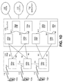
図2は、ブロックに基づくハイブリッドビデオ符号化フレームワーク上で構築することができるブロックに基づくビデオエンコーダの図を示す。図2は、ブロックに基づくハイブリッドビデオ符号化システムであることができるブロックに基づくビデオ符号化システムのブロック図を示す。入力ビデオ信号202は、ブロックごとに処理されてもよい。拡張されたブロックサイズ(符号化ユニット、すなわち、CUと称されてもよい)は、高解像度(例えば、1080ピクセル以上)ビデオ信号を効率的に圧縮するために使用されてもよい。CUは、最大で64×64画素であってもよい。CUは更に、予測ユニット(PU)に区分化されてもよく、PUに対し、別個の予測方法が適用されてもよい。入力ビデオブロック(MBまたはCU)に対し、例えば、1つまたは複数の入力ビデオブロック、空間予測(260)、および/または時間予測(262)が実行されてもよい。空間予測またはイントラ予測は、カレントビデオブロックを予測するために、同一のビデオピクチャ/スライス内の、参照サンプルと称されてもよい、既に符号化された隣接ブロックのサンプルからの画素を使用してもよい。空間予測は、ビデオ信号に特有であることがある空間的冗長性を削減することができる。インター予測または動き補償予測と称されてもよい時間予測は、カレントビデオブロックを予測するために、既に符号化されたビデオピクチャからの再構築された画素を使用してもよい。時間予測は、ビデオ信号に特有であることがある時間的冗長性を削減することができる。所与のビデオブロックに対する時間予測信号は、カレントブロックとその参照ブロックとの間の動きの量および方向を示すことができる、1つまたは複数の動きベクトルによってシグナリングされてもよい。複数の参照ピクチャがサポートされる場合、ビデオブロック(例えば、各々のビデオブロック)に対する参照ピクチャインデックスが送信されてもよい。参照ピクチャインデックスは、参照ピクチャストア(264)内のどの参照ピクチャから時間予測信号が生じるかを識別するために使用されてもよい。空間予測および/または時間予測の後、エンコーダにおけるモード決定(280)は、例えば、レート歪み最適化法に基づいて、予測モードを選択してもよい。選択された予測モードは、周辺に対する最良の予測モードであることができる。予測ブロックは、カレントビデオブロック(216)から差し引かれてもよく、予測残差は、変換ブロック(204)および量子化ブロック(206)を使用して非相関化されてもよい。量子化残差係数は、再構築ビデオブロックを形成するよう予測ブロック(226)に再度追加することができる、再構築された残差を形成するよう、逆量子化されてもよく(210)、逆変換されてもよい(212)。更に、例えば、再構築ビデオブロックが参照ピクチャストア(264)に入力される前、および後続のビデオブロックを符号化するために使用される前に、デブロッキングフィルタおよび適合ループフィルタなどのインループフィルタリングが再構築ビデオブロックに対して適用されてもよい(266)。出力ビデオビットストリーム220を形成するために、符号化モード(例えば、インターモードまたはイントラモード)、予測モード情報、動き情報、および量子化残差係数は、ビットストリームを形成するよう、エントロピ符号化ユニット(208)に送信されて、更に圧縮およびパック(pack)されてもよい。
FIG. 2 shows a diagram of a block-based video encoder that can be built on a block-based hybrid video coding framework. FIG. 2 shows a block diagram of a block-based video coding system that can be a block-based hybrid video coding system. The
図3は、ブロックに基づくビデオデコーダであることができるビデオデコーダのブロック図を示す。ビデオビットストリーム302は、エントロピ復号308においてアンパックおよびエントロピ復号されてもよい。符号化モードおよび予測情報は、予測ブロックを形成するよう、空間予測360(例えば、イントラ符号化)または動き補償予測362(例えば、インター符号化)に送信されてもよい。残差変換係数は、残差ブロックを再構築するよう、逆量子化310および逆変換312に送信されてもよい。予測ブロックおよび残差ブロックは、336において共に追加されてもよい。再構築ブロックは更に、参照ピクチャストア354に記憶される前に、インループフィルタリングを受けてもよい。参照ピクチャストア内の再構築ビデオは次いで、ディスプレイデバイスを駆動するよう送出されてもよく、後続のビデオブロックを予測するために使用されてもよい。
FIG. 3 shows a block diagram of a video decoder that can be a block based video decoder. The video bitstream 302 may be unpacked and entropy decoded in the entropy decoding 308. The coding mode and prediction information may be transmitted to spatial prediction 360 (eg, intra-coding) or motion compensation prediction 362 (eg, inter-coding) to form a prediction block. The residual transformation factors may be transmitted to the
図2および3に示されるように、例えば、符号化/復号ワークフローは、例えば、空間予測(例えば、イントラ予測)、時間予測(例えば、インター予測)、変換、量子化、エントロピ符号化、および/またはループフィルタなどのうちの1つまたは複数に基づいてもよい。 As shown in FIGS. 2 and 3, for example, the coding / decoding workflows include spatial prediction (eg, intra-prediction), time prediction (eg, inter-prediction), transformation, quantization, entropy coding, and /. Alternatively, it may be based on one or more of loop filters and the like.
双方向オプティカルフロー(BDOF)は、動きベクトル導出のために使用されてもよい。例えば、双予測は、オプティカルフローモデルに基づいてもよい。ビデオ符号化における双予測は、再構築参照ピクチャから取得することができる2つの時間予測ブロックを組み合わせることを含んでもよい。ブロックに基づく動き補償(MC)の制限に起因して、動き補償予測の効率性を低下させることがある、2つの予測ブロックの間で観測することがある残りの小さな動きが存在することがある。BDOFは、例えば、ブロックの内部のサンプル内の小さな動きを補償するために適用されてもよい。BDOFは、サンプル的動きリファインメント(sample-wise motion refinement)を適用することを含んでもよい。サンプル的動きリファインメントは、例えば、双予測が使用されるとき、ブロックに基づく動き補償予測よりも先に(on top of)実行されてもよい。動きベクトル(例えば、リファインされた動きベクトル)は、ブロック内のサンプルに対して導出されてもよい。動きベクトル導出は、オプティカルフローモデル(例えば、古典的オプティカルフローモデル)に基づいてもよい。例えば、I(k)(x,y)が参照ピクチャリストk(k=0,1)から導出された予測ブロックの座標(x,y)におけるサンプル値であり、∂I(k)(x,y)/∂xおよび∂I(k)(x,y)/∂yは、サンプルの垂直勾配および水平勾配をそれぞれ含んでもよいとする。座標(x,y)についての動きリファインメントパラメータ(vx,vy)は、オプティカルフローモデルを使用して(式(1))導出されてもよい。 Bidirectional optical flow (BDOF) may be used for motion vector derivation. For example, bi-prediction may be based on an optical flow model. Bi-prediction in video coding may include combining two time prediction blocks that can be obtained from the reconstructed reference picture. Due to block-based motion compensation (MC) limitations, there may be remaining small motions that may be observed between two prediction blocks that may reduce the efficiency of motion compensation predictions. .. BDOF may be applied, for example, to compensate for small movements within the sample inside the block. The BDOF may include applying a sample-wise motion refinement. Sample motion refinement may be performed on top of, for example, when bi-prediction is used, block-based motion compensation prediction. Motion vectors (eg, refined motion vectors) may be derived for the samples in the block. The motion vector derivation may be based on an optical flow model (eg, a classical optical flow model). For example, I (k) (x, y) is a sample value at the coordinates (x, y) of the prediction block derived from the reference picture list k (k = 0,1), and ∂I (k) (x, y). y) / ∂x and ∂I (k) (x, y) / ∂y may include the vertical and horizontal gradients of the sample, respectively. Coordinates (x, y) motion refinement parameters for (v x, v y), using the optical flow model (equation (1)) may be derived.
![]()
![]()
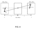
オプティカルフローの式(1)および動き軌道(図4に示される)に沿った予測ブロックの補間の組み合わせにより、BDOF予測は、式(2)として取得されてもよい。 The BDOF prediction may be obtained as equation (2) by a combination of the optical flow equation (1) and the interpolation of the prediction blocks along the motion trajectory (shown in FIG. 4).

![]()
![]()
式(2)を参照して、τ0およびτ1は、I(0)およびI(1)と関連付けられた参照ピクチャRef0およびRef1のカレントピクチャCurPicへの時間的距離を含んでm清く、例えば、式(3)である。 With reference to equation (2), τ 0 and τ 1 are m-cleaned including the temporal distance of the reference pictures Ref 0 and Ref 1 associated with I (0) and I (1) to the current picture CurPic. For example, the equation (3).
![]()
![]()
![]()
![]()
を含んでもよい May include
図4は、BDOFの適用の実施例を示す。図4では、(MVx0,MVy0)および(MVx1,MVy1)は、2つの予測ブロックI(0)およびI(1)を生成するために使用することができるブロックレベル動きベクトルを示すことができる。サンプル位置(x,y)における動きリファインメントパラメータ(vx,vy)は、式(4)として示されるように、動きリファインメント補償の後のサンプルの値(例えば、図4におけるAおよびB)の間の差Δを最小化することによって計算されてもよい。 FIG. 4 shows an example of application of BDOF. In FIG. 4, (MV x0 , MV y0 ) and (MV x1 , MV y1 ) show block-level motion vectors that can be used to generate two predictive blocks I (0) and I (1). be able to. Sample position (x, y) motion refinement parameters in (v x, v y), as shown as formula (4), the value of the sample after the motion refinement compensation (e.g., A and B in FIG. 4 ) May be calculated by minimizing the difference Δ.
導出された動きリファインメントの規則性を維持することができる。動きリファインメントは、(x,y)に中心がある局所的周囲エリア内で一貫することができる。BDOF設計では、(vx,vy)の値は、式(5)として(x,y)におけるカレントサンプルの周りの5×5ウインドウΩの内部のΔを最小化することによって導出されてもよい。 The regularity of the derived motion refinement can be maintained. Motion refinement can be consistent within a local perimeter area centered at (x, y). In the BDOF design, the value of (v x , v y ) may be derived as equation (5) by minimizing the Δ inside the 5 × 5 window Ω around the current sample in (x, y). good.
![]()
![]()
BDOFは、双予測ブロックに適用されてもよい。双予測符号化ブロックは、時間的隣接ピクチャからの2つ以上の参照ブロックによって予測されてもよい。BDOFは、例えば、エンコーダからデコーダに追加の情報を送信することなく有効にされてもよい。例えば、BDOFは、前方予測信号および後方予測信号(例えば、τ0×τ1>0)を有する双方向に予測されたブロックに適用されてもよい。カレントブロックの2つの予測ブロックが同一の方向からである場合(例えば、前方方向または後方方向のいずれか、τ0×τ1<0)、BDOFは、2つの予測ブロックが非ゼロの動きと関連付けられるとき、例えば、abs(MVx0)+abs(MVy0)≠0およびabs(MVx1)+abs(MVy1)≠0であるときに適用されてもよく、2つの動きベクトルは、カレントピクチャと参照ピクチャとの間の時間的距離に比例してもよく、例えば、式(6)である。 The BDOF may be applied to the bi-predictive block. The bi-predicted coded block may be predicted by two or more reference blocks from temporally adjacent pictures. BDOF may be enabled, for example, without transmitting additional information from the encoder to the decoder. For example, BDOF may be applied to a bidirectionally predicted block having a forward predictive signal and a backward predictive signal (eg, τ 0 × τ 1> 0). If the two predictive blocks of the current block are from the same direction (eg, either forward or backward, τ 0 x τ 1 <0), BDOF associates the two predictive blocks with non-zero movement. When, for example, abs (MV x0 ) + abs (MV y0 ) ≠ 0 and abs (MV x1 ) + abs (MV y1 ) ≠ 0 may be applied when the two motion vectors are referred to as the current picture. It may be proportional to the time distance from the picture, for example, Eq. (6).
![]()
![]()
カレントブロックの2つの予測ブロックが同一の参照ピクチャからである場合(例えば、τ0=τ1)、BDOFが無効にされてもよい。局所的照明補償(LIC:local illumination compensation)がカレントブロックに対して使用されるとき、BDOFが無効にされてもよい。 BDOF may be disabled if the two predictive blocks of the current block are from the same reference picture (eg, τ 0 = τ 1). BDOF may be disabled when local illumination compensation (LIC) is used for the current block.
勾配導出処理が実行されてもよい。式(2)および(4)に示されるように、例えば、ブロックレベルMCに加えて、勾配は、動き補償ブロックのサンプル(例えば、I(0)およびI(1))に対してBDOFにおいて使用されてもよく、サンプルは、局所的動きリファインメントを導出し、そのサンプルの位置において予測を生成するために使用されてもよい。実施例では、2つの予測ブロック内のサンプルの水平勾配および垂直勾配(例えば、 Gradient derivation processing may be performed. As shown in equations (2) and (4), for example, in addition to block level MC, gradients are used in BDOF for samples of motion compensation blocks (eg I (0) and I (1)). The sample may be used to derive a local motion refinement and generate a prediction at the location of the sample. In the embodiment, the horizontal and vertical gradients of the samples in the two prediction blocks (eg, for example).
![]()
![]()
![]()
![]()
および and
![]()
![]()
)は、例えば、予測信号がフィルタリング処理に基づいて生成されるときに計算されてもよい。例えば、動き補償された補間は、2D分離可能有限応答(FIR)フィルタを使用して実行されてもよい。水平勾配および垂直勾配は、同時に生成されてもよい。勾配導出処理への入力は、動き補償のために使用される参照サンプルを含んでもよい。勾配導出処理への入力は、入力動き(MVx0/x1,MVy0/y1)の小数成分(fractional component)を含んでもよい。サンプル位置における勾配値を導出するために、2つの異なるフィルタ(例えば、補間フィルタhLおよび勾配フィルタhG)が適用されてもよい。フィルタは、例えば、計算することができる勾配の方向ごとに異なる順序において別個に適用されてもよい。以下のうちの1つまたは複数が適用されてもよい。水平勾配(例えば、 ) May be calculated, for example, when the prediction signal is generated based on the filtering process. For example, motion-compensated interpolation may be performed using a 2D separable finite response (FIR) filter. Horizontal and vertical gradients may be generated at the same time. The input to the gradient derivation process may include a reference sample used for motion compensation. The input to the gradient derivation process may include a fractional component of the input motion (MV x0 / x1 , MV y0 / y1). Two different filters (eg, interpolation filter h L and gradient filter h G ) may be applied to derive the gradient value at the sample position. The filters may be applied separately, for example, in different orders for each direction of the gradient that can be calculated. One or more of the following may be applied. Horizontal gradient (eg
![]()
![]()
および and
![]()
![]()
)を導出するとき、補間フィルタhLは、fracYにおける垂直小数位置(vertical fractional position)におけるサンプル値を導出するための予測ブロックの内部のサンプルに垂直に適用されてもよい。勾配フィルタhGは、fracXの値に基づいて水平勾配値を計算するために、生成された垂直小数サンプルに水平に適用されてもよい。垂直勾配( ), The interpolation filter h L may be applied perpendicularly to the sample inside the prediction block for deriving the sample value at the vertical fractional position in fracY. The gradient filter h G may be applied horizontally to the generated vertical decimal sample to calculate the horizontal gradient value based on the value of fracX. Vertical gradient (
![]()
![]()
および and
![]()
![]()
)の導出のために、勾配フィルタhGは、例えば、fracYに対応する中間垂直勾配を計算するために、予測サンプルの最上部(on top of)に対して垂直に適用されてもよく、それに続いて、fracXの値に従った補間フィルタhLを使用した中間垂直勾配の水平補間が続いてもよい。勾配フィルタおよび補間フィルタの長さは、6タップであってもよい。8タップフィルタが動き補償のために使用されてもよい。表1および2は、ブロックレベルの動きベクトルの精度に従って、hGおよびhLに対してそれぞれ使用することができるフィルタ係数(例えば、最大で1/16画素(ペル)であってもよい)を示す。 ), The gradient filter h G may be applied perpendicular to the on top of the predicted sample, for example, to calculate the intermediate vertical gradient corresponding to fracY. This may be followed by horizontal interpolation of the intermediate vertical gradient using the interpolation filter h L according to the value of fracX. The length of the gradient filter and the interpolation filter may be 6 taps. An 8-tap filter may be used for motion compensation. Tables 1 and 2 show the filter coefficients (eg, up to 1/16 pixel (pel)) that can be used for h G and h L , respectively, according to the accuracy of the block-level motion vectors. show.
図5Aおよび5Bは、1/16画素(ペル)の動き精度を有するBDOFにおける勾配導出の例を示す。図5Aおよび5Bに示されるように、勾配導出処理は、BDOFに適用されてもよく、整数サンプル位置(integer sample position)におけるサンプル値は、柄付き正方形により示すことができ、小数サンプル位置(fractional sample position)におけるサンプル値は、空白正方形により示すことができる。動きベクトル精度が1/16画素(ペル)まで増大することができることを理由に、図5Aおよび5Bにおける整数サンプルの範囲内で定義することができる、合計で255の小数サンプル位置が存在してもよい。下付き座標(x,y)は、サンプルの対応する水平小数位置および垂直小数位置を表してもよい(例えば、座標(0、0)は、整数位置におけるサンプルに対応してもよい)。小数位置(1,1)における水平勾配値および垂直勾配値が計算されてもよい(例えば、a1,1)。図5Aおよび5Bにおける表記に基づいて、水平勾配導出に対して、補間フィルタhLを垂直方向に適用することによって、小数サンプルf0,1、e0,1、a0,1、b0,1、c0,1、およびd0,1が導出されてもよく、例えば、式(7)に示す。 5A and 5B show an example of gradient derivation in BDOF having a motion accuracy of 1/16 pixel (pel). As shown in FIGS. 5A and 5B, the gradient derivation process may be applied to the BDOF, where the sample value at the integer sample position can be indicated by a patterned square and fractional. The sample value at sample position) can be indicated by a blank square. Even if there are a total of 255 decimal sample positions that can be defined within the range of integer samples in FIGS. 5A and 5B because the motion vector accuracy can be increased to 1/16 pixel (pel). good. The subordinate coordinates (x, y) may represent the corresponding horizontal and vertical decimal positions of the sample (eg, the coordinates (0, 0) may correspond to the sample at the integer position). Horizontal and vertical gradient values at the decimal position (1,1) may be calculated (eg, a 1,1 ). Based on the notation in FIGS. 5A and 5B, by applying the interpolation filter h L in the vertical direction to the horizontal gradient derivation, the decimal samples f 0 , 1, e 0 , 1, a 0 , 1, b 0, 1 , c 0 , 1, and d 0, 1 may be derived and are shown, for example, in equation (7).
式(7)を参照して、Bは、入力信号のビット深度を含んでもよく、OffSet0は、式(8)に等しくてもよい丸めオフセットを含んでもよい。 With reference to equation (7), B may include the bit depth of the input signal, and OffSet 0 may include a rounding offset which may be equal to equation (8).
![]()
![]()
f0,1、e0,1、a0,1、b0,1、c0,1、およびd0,1の精度は、14ビットであってもよい。a1,1の水平勾配は、対応する勾配フィルタhGを導出された小数サンプルに水平に適用することによって計算されてもよい。以下のうちの1つまたは複数が適用されてもよい。中間の20ビットにおける非丸め勾配値は、式(9)に示されるように計算されてもよい。 The precision of f 0 , 1, e 0 , 1, a 0 , 1, b 0 , 1, c 0 , 1, and d 0 , 1 may be 14 bits. The horizontal gradient of a 1 , 1 may be calculated by applying the corresponding gradient filter h G horizontally to the derived decimal sample. One or more of the following may be applied. The non-rounding gradient value in the middle 20 bits may be calculated as shown in equation (9).
![]()
![]()
水平勾配は、式(10)のように中間勾配値を出力精度にシフトすることによって計算されてもよい。 The horizontal gradient may be calculated by shifting the intermediate gradient value to the output accuracy as in Eq. (10).
![]()
![]()
式(10)を参照して、sign(・)およびabs(・)は、入力信号の符号(sign)および絶対値をそれぞれ返す関数を含んでもよく、OffSet1は、217-Bとして計算することができる丸めオフセットを含んでもよい。 With reference to equation (10), sign (.) And abs (.) May include a function that returns the sign and absolute value of the input signal, respectively, and OffSet 1 is calculated as 217-B. It may include a rounding offset that can.
ここで、(1,1)における垂直勾配導出値を参照すると、小数位置(0,1)における中間垂直勾配値が導出されてもよく、例えば、式(11)に示す。 Here, referring to the vertical gradient derived value in (1,1), the intermediate vertical gradient value at the decimal position (0,1) may be derived, and is shown in the equation (11), for example.
中間勾配値は、式(12)として14ビット値をシフトすることによって調節されてもよい。 The intermediate gradient value may be adjusted by shifting the 14-bit value as Eq. (12).
小数位置(1,1)における垂直勾配値は、小数位置(0,1)における中間勾配値の最上部に対して補間フィルタhLを適用することによって取得されてもよい。式(13)および(14)によって示されるように、20ビットにおける非丸め勾配値が計算されてもよく、シフト演算を通じて、非丸め勾配値が出力ビット深度に調節されてもよい。 The vertical gradient value at the decimal position (1,1) may be obtained by applying the interpolation filter h L to the top of the intermediate gradient value at the decimal position (0,1). As shown by equations (13) and (14), the unrounded gradient value at 20 bits may be calculated, or the unrounded gradient value may be adjusted to the output bit depth through a shift operation.
![]()
![]()
![]()
![]()
BDOFのメモリ帯域幅の消費を設けることができる。式(5)に示されたように、或る位置における局所的動きリファインメント(vx,vy)を導出するために、サンプルを囲むウインドウΩ内の1つまたは複数のサンプル(例えば、全てのサンプル)に対してサンプル値および勾配値が計算されてもよい。ウインドウサイズは、(2M+1)×(2M+1)を含んでもよく、M=2である。補間フィルタおよび勾配フィルタに起因して、勾配導出は、カレントブロックの拡張したエリア内で発見することができる、1つまたは複数の(例えば、追加の)参照サンプルにアクセスすることができる。補間フィルタおよび勾配フィルタの長さTは、6であってもよく、ならびに/または対応する拡張したブロックサイズは、T−1=5に等しくてもよい。例えば、W×Hのブロックを考えると、BDOFによって使用されるメモリアクセス(総メモリアクセス)は、他の技術によって使用されるメモリアクセス(W+7)×(H+7)よりも多いことがある、(W+T−1+2M)×(H+T−1+2M)=(W+9)×(H+9)であってもよい。BDOFのメモリアクセスは、他の技術のメモリアクセス以下であることがある。ブロック拡張制約を設けることができる。ブロック拡張制約が適用されるとき、カレントブロック内の隣接したサンプルは、或る位置における(例えば、ブロックの内部の各々の位置)局所的動きリファインメント(vx,vy)を計算するために使用されてもよい。図6A〜Bは、BDOFのメモリアクセスの図を示し、図6Aは、ブロック拡張制約なしのメモリアクセスを示し、図6Bは、ブロック拡張制約によるメモリアクセスを示す。図6Aおよび6Bは、ブロック拡張制約が適用される前および適用された後のメモリアクセス領域のサイズを比較することができる。 Memory bandwidth consumption of BDOF can be provided. As shown in equation (5), one or more samples (eg, all) in the window Ω surrounding the samples to derive local motion refinement (v x , v y) at a given position. Sample values and gradient values may be calculated for the sample). The window size may include (2M + 1) × (2M + 1), and M = 2. Due to the interpolation filter and the gradient filter, the gradient derivation can access one or more (eg, additional) reference samples that can be found within the extended area of the current block. The length T of the interpolation filter and the gradient filter may be 6, and / or the corresponding extended block size may be equal to T-1 = 5. For example, considering a W × H block, the memory access (total memory access) used by BDOF may be greater than the memory access (W + 7) × (H + 7) used by other technologies, (W + T). -1 + 2M) × (H + T-1 + 2M) = (W + 9) × (H + 9) may be used. The memory access of the BDOF may be less than or equal to the memory access of other techniques. Block extension constraints can be set. When the block extension constraint is applied, adjacent samples in the current block are used to calculate the local motion refinement (v x , v y) at a certain position (eg, each position inside the block). May be used. 6A-B show the memory access diagram of BDOF, FIG. 6A shows the memory access without the block expansion constraint, and FIG. 6B shows the memory access due to the block expansion constraint. 6A and 6B can compare the size of the memory access area before and after the block extension constraint is applied.
サブブロック(例えば、サブCU)に基づく動き補償が実行されてもよい。符号化ブロックは、予測方向に対する動きベクトルを有してもよい。いくつかのサブブロックレベルのインター予測技術が使用されてもよい。サブブロックレベルのインター予測技術は、進化型時間的動きベクトル予測(ATMVP)、空間的−時間的動きベクトル予測(STMVP)、フレームレートアップコンバージョン(FRUC)モード、および/またはアフィンモードなどを含んでもよい。以下のうちの1つまたは複数が適用されてもよい。ビデオブロックは、複数の小型サブブロックに分割されてもよく、サブブロックについての(例えば、各々のサブブロックについての情報を別個に)動き情報を導出するために使用されてもよい。サブブロックについての動き情報は、例えば、動き補償段階において、ブロックの予測信号を生成するために使用されてもよい。サブブロック符号化モードを設けることができる。 Motion compensation based on subblocks (eg, subCU) may be performed. The coded block may have a motion vector with respect to the prediction direction. Several sub-block level inter-prediction techniques may be used. Subblock-level inter-prediction techniques may include Evolved Temporal Motion Vector Prediction (ATMVP), Spatial-Time Motion Vector Prediction (STMVP), Frame Rate Up Conversion (FRUC) Mode, and / or Affin Mode, etc. good. One or more of the following may be applied. The video block may be divided into a plurality of small sub-blocks and may be used to derive motion information about the sub-blocks (eg, information about each sub-block separately). The motion information about the subblock may be used, for example, in the motion compensation stage to generate a prediction signal for the block. A subblock coding mode can be provided.
本明細書で説明されるように、ATMVPが実行されてもよい。以下のうちの1つまたは複数が適用されてもよい。時間的動きベクトル予測は、動き情報を導出するためにブロックを設けることができる。導出された動き情報は、ブロック内のサブブロックに対する動きベクトルおよび参照インデックス(例えば、カレントピクチャの時間的に隣接したピクチャの1つまたは複数のより小型ブロックからの)を含んでもよい。図7に示されるように、ATMVPは、ブロックのサブブロックの動き情報を導出することができ、コロケートされたブロック(collocated block)と称されてもよい、カレントブロックの対応するブロックが識別されてもよく(例えば、時間参照ピクチャ内で)、カレントブロックは、サブブロックに分割されてもよく、および/またはコロケートされたピクチャ内の対応する小型ブロックからのサブブロックの動き情報が導出されてもよい。選択された時間参照ピクチャは、コロケートされたピクチャと称されてもよい。 ATMVP may be performed as described herein. One or more of the following may be applied. Temporal motion vector prediction can be provided with blocks to derive motion information. The derived motion information may include motion vectors and reference indexes (eg, from one or more smaller blocks of temporally adjacent pictures of the current picture) for subblocks within the block. As shown in FIG. 7, the ATMVP can derive motion information of the sub-blocks of the block, and the corresponding block of the current block, which may be referred to as a collocated block, is identified. Often (eg, in a time-referenced picture), the current block may be divided into sub-blocks, and / or the motion information of the sub-blocks from the corresponding small blocks in the collocated picture may be derived. good. The selected time-referenced picture may be referred to as a collated picture.
図7は、ATMVPの例示的な図を示す。コロケートされたブロックおよびコロケートされたピクチャは、例えば、カレントブロックの空間的隣接ブロックの動き情報によって識別されてもよい。図7に示されるように、マージ候補リスト内の利用可能な候補(例えば、最初に利用可能な候補)が考えられてもよい。例えば、図7を参照して、ブロックAは、マージ候補リストの既存の走査順序に基づいて、カレントブロックの利用可能な(例えば、最初に利用可能な)マージ候補として識別されてもよい。ブロックAの対応する動きベクトル(例えば、MVA)およびその参照インデックスは、コロケートされたピクチャおよびコロケートされたブロックを識別するために使用されてもよい。コロケートされたピクチャ内のコロケートされたブロックの位置は、ブロックの動きベクトル(MVA)をカレントブロックの座標に追加することによって判定されてもよい。 FIG. 7 shows an exemplary diagram of ATMVP. The collated block and the collated picture may be identified by, for example, the motion information of the spatially adjacent blocks of the current block. As shown in FIG. 7, available candidates in the merge candidate list (eg, the first available candidate) may be considered. For example, with reference to FIG. 7, block A may be identified as an available (eg, first available) merge candidate for the current block based on the existing scan order of the merge candidate list. The corresponding motion vector of block A (eg, MV A ) and its reference index may be used to identify the collated picture and the collated block. The position of the collated block in the collated picture may be determined by adding the block motion vector (MV A ) to the coordinates of the current block.
カレントブロック内のサブブロック(例えば、各々のサブブロック)に対し、コロケートされたブロック内のその対応する小型ブロックの動き情報(例えば、図7における矢印によって示される)は、カレントブロック内の対応するサブブロックの動き情報を導出するために使用されてもよい。例えば、コロケートされたブロック内の小型ブロックの動き情報は、カレントブロック内の対応するサブブロックの動きベクトルおよび参照インデックスに変換されてもよい(例えば、コロケートされたブロック内の各々の小型ブロックの動き情報が識別された後)。カレントブロック内のサブブロックの動き情報は、他の導出技術(例えば、時間的動きベクトルスケーリングを適用することができる)と同様の方式において導出されてもよい。 For subblocks in the current block (eg, each subblock), the motion information of the corresponding small block in the collated block (eg, indicated by the arrow in FIG. 7) corresponds to that in the current block. It may be used to derive motion information of subblocks. For example, the motion information of a small block in a collated block may be converted into the motion vector and reference index of the corresponding subblock in the current block (eg, the motion of each small block in the collated block). After the information is identified). The motion information of the sub-blocks in the current block may be derived in the same manner as other derivation techniques (for example, temporal motion vector scaling can be applied).
本明細書で説明されるように、STMVPが実行されてもよい。図8は、STMVPの例示的な図を示す。以下のうちの1つまたは複数が適用されてもよい。STMVPでは、符号化ブロック内のサブブロックの動き情報が導出されてもよい(例えば、再帰的に導出される)。図8は、符号化ブロック内のサブブロックの動き情報を再帰的に導出する実施例を示す。図8を参照して、カレントブロックは、4個のサブブロックA、B、C、およびDを含んでもよい。カレントブロックに空間的に隣接してもよい隣接小型ブロックは、a、b、c、およびdとそれぞれラベル付けされてもよい。サブブロックAに対する動き導出は、1つまたは複数の空間的隣接(例えば、サブブロックAの2つの空間的隣接)を識別することを含んでもよい。サブブロックAの隣接(例えば、第1の隣接)は、上の隣接cであってもよい。小型ブロックcが利用可能でなく、またはイントラ符号化される場合、カレントブロックの上の後続の隣接小型ブロックが順にチェックされてもよい(例えば、左から右に)。サブブロックAの別の隣接(例えば、第2の隣接)は、左の隣接bであってもよい。小型ブロックbが利用可能でなく、またはイントラ符号化される場合、後続の隣接小型ブロックが、例えば、カレントブロックの左への順にチェックされてもよい(上から下に)。空間的隣接の動き情報をフェッチした後、サブブロックAの時間的隣接の動き情報は、TMVPと同様であってもよい手順を使用して取得されてもよい。利用可能な空間的隣接および1つまたは複数の時間的隣接(例えば、最大で3個の隣接)の動き情報は、平均化されてもよく、サブブロックAの動き情報として使用されてもよい。ラスタスキャン順に基づいて、上記STMVP処理は、カレントビデオブロック内の他のサブブロック(例えば、全ての他のサブブロック)の動き情報を導出するよう繰り返されてもよい。 STMVP may be performed as described herein. FIG. 8 shows an exemplary diagram of STMVP. One or more of the following may be applied. In STMVP, motion information of sub-blocks in the coded block may be derived (for example, recursively derived). FIG. 8 shows an example of recursively deriving the motion information of the sub-blocks in the coded block. With reference to FIG. 8, the current block may include four subblocks A, B, C, and D. Adjacent small blocks that may be spatially adjacent to the current block may be labeled a, b, c, and d, respectively. Motion derivation for subblock A may include identifying one or more spatial adjacencies (eg, two spatial adjacencies of subblock A). The adjacency of the subblock A (eg, the first adjacency) may be the upper adjacency c. If the small block c is not available or is intra-coded, subsequent adjacent small blocks above the current block may be checked in sequence (eg, from left to right). Another adjacency of subblock A (eg, a second adjacency) may be the left adjacency b. If the small block b is not available or is intra-coded, subsequent adjacent small blocks may be checked, for example, to the left of the current block (from top to bottom). After fetching the spatially adjacent motion information, the temporally adjacent motion information of subblock A may be acquired using a procedure that may be similar to TMVP. The available spatial adjacency and one or more temporal adjacencies (eg, up to three adjacencies) motion information may be averaged or used as motion information for subblock A. Based on the raster scan order, the STMVP process may be repeated to derive motion information of other subblocks (eg, all other subblocks) in the current video block.
フレームレートアップコンバージョン(FRUC)が実行されてもよい。動き情報シグナリングを削減することができる、インター符号化ブロックに対してFRUCをサポートすることができる。FRUCモードが有効にされるとき、動きベクトルおよび参照インデックスを含むことができる、符号化ブロックの動き情報がシグナリングされないことがある。動き情報は、例えば、テンプレートマッチングおよび/またはバイラテラルマッチングを使用して導出されてもよい(例えば、デコーダにおいて)。例えば、デコーダにおける動き導出処理の間、ブロックのマージ候補リストおよびカレントブロックの時間的にコロケートされたブロックの動きベクトルから生成された初期(preliminary)動きベクトルのセットがチェックされてもよい。最小絶対差合計(SAD)につながる候補は、開始点として選択されてもよい。開始点の周りでのテンプレートマッチングまたはバイラテラルマッチングに基づいた局所的探索が実行されてもよい。最小SADをもたらすMVは、ブロックについてのMVとして使用されてもよい。動き情報は、サブブロックレベルにおいてリファインされてもよく、それは、効率的な動き補償をもたらすことができる。 Frame rate up conversion (FRUC) may be performed. FRUC can be supported for intercoded blocks, which can reduce motion information signaling. When FRUC mode is enabled, motion information of coded blocks, which can include motion vectors and reference indexes, may not be signaled. Motion information may be derived using, for example, template matching and / or bilateral matching (eg, in a decoder). For example, during the motion derivation process in the decoder, a set of preliminary motion vectors generated from the block merge candidate list and the motion vectors of the temporally colocated blocks of the current block may be checked. Candidates leading to the minimum absolute difference sum (SAD) may be selected as the starting point. A local search based on template matching or bilateral matching around the starting point may be performed. The MV that results in the minimum SAD may be used as the MV for the block. Motion information may be refined at the subblock level, which can provide efficient motion compensation.
図9Aおよび9Bは、FRUCと関連付けられた実施例を示す。例えば、図9AおよびBは、フレームレートアップコンバージョンについての例示的な図を示し、図9Aは、テンプレートマッチングを示し、図9Bは、バイラテラルマッチングを示す。図9Aに示されるように、テンプレートマッチングは、カレントピクチャ内のテンプレートと参照ピクチャ内のブロック(例えば、テンプレートと同一のサイズであってもよい)との間の一致(例えば、最良の一致)を発見することによって、カレントブロックの動き情報を導出するために使用されてもよい。テンプレートは、カレントブロックの上の隣接ブロックおよび/または左の隣接ブロックを含んでもよい。図9Bでは、バイラテラルマッチングは、カレントブロックの動き情報を導出するために使用されてもよい。カレントブロックの動き情報の導出は、異なる参照ピクチャ(例えば、2つの異なる参照ピクチャ)内のカレントブロックの動き軌道に沿った2つのブロックの間の一致(例えば、最良の一致)を発見することを含んでもよい。バイラテラルマッチングの動き探索処理は、動き軌道に基づいてもよい。例えば、バイラテラルマッチングの動き探索処理は、動きベクトルMV0およびMV1に基づいてもよい。動きベクトルMV0およびMV1は、参照ブロックを指し示すことができる。動きベクトルMV0およびMV1は、カレントピクチャと2つの参照ピクチャ(例えば、T0およびT1)との間の時間的距離に比例してもよい。 9A and 9B show examples associated with FRUC. For example, FIGS. 9A and 9B show exemplary diagrams for frame rate up-conversion, FIG. 9A shows template matching, and FIG. 9B shows bilateral matching. As shown in FIG. 9A, template matching provides a match (eg, best match) between a template in the current picture and a block in the reference picture (eg, it may be the same size as the template). By discovering, it may be used to derive motion information of the current block. The template may include adjacent blocks above the current block and / or adjacent blocks to the left. In FIG. 9B, bilateral matching may be used to derive motion information for the current block. Derivation of the motion information of the current block is to find a match (eg, the best match) between two blocks along the motion trajectory of the current block in different reference pictures (eg, two different reference pictures). It may be included. The motion search process of bilateral matching may be based on the motion trajectory. For example, the motion search process for bilateral matching may be based on motion vectors MV 0 and MV 1. The motion vectors MV 0 and MV 1 can point to a reference block. The motion vectors MV 0 and MV 1 may be proportional to the temporal distance between the current picture and the two reference pictures (eg, T 0 and T 1).
アフィンモデルは、動き情報を提供するために使用されてもよい。図10Aおよび10Bは、アフィンモードについての例示的な図を示し、図10Aは、簡易化されたアフィンモデルを示し、図10Bは、アフィンブロックに対するサブブロックレベルの動き導出を示す。動き補償予測に対して並進(translation)動きモデルが適用されてもよい。動きは、拡大/縮小、回転、視点の動き(perspective motion)、および/または異常な動きのうちの1つまたは複数を含んでもよい。例示的なアフィン変換動き補償予測が適用されてもよい。図10Aに示されるように、ブロックのアフィン動き場は、1つまたは複数の(例えば、2つの)制御点の動きベクトルによって記述されてもよい。制御点の動きに基づいて、アフィンブロックの動き場は、式(15)として記述されてもよい。 The affine model may be used to provide motion information. 10A and 10B show exemplary diagrams for affine mode, FIG. 10A shows a simplified affine model, and FIG. 10B shows subblock level motion derivation for the affine block. A translational motion model may be applied to the motion compensation prediction. The movement may include one or more of enlargement / reduction, rotation, perspective motion, and / or anomalous movement. An exemplary affine transformation motion compensation prediction may be applied. As shown in FIG. 10A, the affine motion field of the block may be described by motion vectors of one or more (eg, two) control points. Based on the movement of the control points, the movement field of the affine block may be described as Eq. (15).
式(15)を参照して、図10Aに示されるように、(v0x,v0y)は、上左隅の制御点の動きベクトルであってもよく、(v1x,v1y)は、上右隅の制御点の動きベクトルであってもよい。ビデオブロックがアフィンモードによって符号化されるとき、ビデオブロックの動き場は、4×4のブロックの粒度に基づいて導出されてもよい。例えば、図10Bに示されるように、4×4のブロック(例えば、各々の4×4)の動きベクトルを導出するために、サブブロック(例えば、各々のサブブロック)の中心サンプルの動きベクトルは、式(15)に従って計算されてもよく、1/16画素(ペル)の精度まで丸められてもよい。導出された動きベクトルは、カレントブロックの内部のサブブロックの予測信号を生成するために、動き補償段階において使用されてもよい。 With reference to equation (15), as shown in FIG. 10A, (v 0x , v 0y ) may be the motion vector of the control point in the upper left corner, and (v 1x , v 1y ) is above. It may be a motion vector of a control point in the right corner. When the video block is encoded by affine mode, the motion field of the video block may be derived based on the particle size of the 4x4 block. For example, as shown in FIG. 10B, in order to derive the motion vector of a 4x4 block (eg, each 4x4), the motion vector of the central sample of the subblock (eg, each subblock) is , It may be calculated according to the equation (15), or it may be rounded to an accuracy of 1/16 pixel (pel). The derived motion vector may be used in the motion compensation stage to generate a prediction signal for the subblocks inside the current block.
BDOFが簡易化されてもよい。以下のうちの1つまたは複数が適用されてもよい。双予測されたCUに対するBDOF処理の数を削減することができる。BDOFは、並列処理を考慮して実行されてもよい。双予測されたCUに対し、BDOF処理は、1つまたは複数の(例えば、2つの)参照リストからの2つの予測信号の類似性に基づいて、CUレベルまたはサブCUレベルのいずれかにおいてスキップされてもよい。例えば、予測信号が類似する場合、BDOF調節がスキップされてもよい。例えば、符号化性能が維持されるように、呼び出されるBDOF調節の回数を削減することができる。リスト(例えば、各々のリスト)に対するBDOFの勾配導出は、リスト内の動きベクトルが整数でない場合、サンプル補間および勾配計算を含んでもよい。水平フィルタリングおよび垂直フィルタリングの順序は、並列処理による実装態様に対して変化してもよい。 BDOF may be simplified. One or more of the following may be applied. The number of BDOF treatments for the bi-predicted CU can be reduced. BDOF may be executed in consideration of parallel processing. For bi-predicted CUs, BDOF processing is skipped at either the CU level or the sub-CU level based on the similarity of the two predicted signals from one or more (eg, two) reference lists. You may. For example, if the prediction signals are similar, BDOF adjustment may be skipped. For example, the number of called BDOF adjustments can be reduced so that the coding performance is maintained. The gradient derivation of the BDOF for a list (eg, each list) may include sample interpolation and gradient calculation if the motion vectors in the list are not integers. The order of horizontal filtering and vertical filtering may be changed with respect to the implementation mode by parallel processing.
本明細書で説明されるように、整数動き成分がもたらされてもよい。例えば、動きベクトル成分の小数部分の表現としてkビットが使用され、動きベクトルの成分値が(2k)の倍数である場合、動きベクトル成分は、整数動きベクトル成分を含んでもよい。同様に、動きベクトルの成分値が(2k)の倍数でない場合、動きベクトル成分は、非整数(例えば、小数)部分および整数部分を含んでもよい。 As described herein, an integer motion component may be provided. For example, if k bits are used to represent the fractional part of the motion vector component and the component value of the motion vector is a multiple of (2 k ), the motion vector component may include an integer motion vector component. Similarly, if the component value of the motion vector is not a multiple of (2 k ), the motion vector component may include a non-integer (eg, fractional) part and an integer part.
本明細書で説明されるように、BDOFは、双予測を考慮して実行されてもよい。動き補償段階において使用される動きベクトルの粒度および制度を改善することができる。 As described herein, BDOF may be performed with bi-prediction in mind. The particle size and institution of motion vectors used in the motion compensation phase can be improved.
BDOFでは、水平勾配および垂直勾配は、参照ピクチャリスト(例えば、L0およびL1)に対して生成されてもよい。例えば、BDOFリファインメントは、参照ピクチャリスト(例えば、各々の参照ピクチャリスト)内の水平勾配および垂直勾配に対する1つまたは複数のフィルタリング処理(例えば、水平フィルタリング処理および/または垂直フィルタリング処理)の呼び出しを含んでもよい。本明細書で議論されるように、動きベクトル、MV(MVx,MVy)を仮定して、水平勾配導出は、垂直方向においてサンプル補間フィルタを適用することを含んでもよい。例えば、MVy(例えば、動きベクトルMVの垂直成分)が非整数(例えば、小数)動きベクトル成分を含む場合、サンプル補間フィルタは、小数位置におけるサンプル値を導出するために使用されてもよい。勾配フィルタリングは、小数位置において補間されたサンプル値を垂直に使用して、水平方向において実行されてもよい。MVyが整数動き成分を含む場合、勾配フィルタ(例えば、単一の勾配フィルタ)は、例えば、整数位置におけるサンプル値を使用して、水平方向において適用されてもよい。垂直勾配の導出に対して同様の処理が実行されてもよい。 In BDOF, horizontal and vertical gradients may be generated for reference picture lists (eg, L0 and L1). For example, BDOF refinement calls one or more filtering processes (eg, horizontal filtering and / or vertical filtering) for horizontal and vertical gradients in a reference picture list (eg, each reference picture list). It may be included. As discussed herein, assuming a motion vector, MV (MV x , MV y ), the horizontal gradient derivation may include applying a sample interpolation filter in the vertical direction. For example, if the MV y (eg, the vertical component of the motion vector MV) contains a non-integer (eg, decimal) motion vector component, the sample interpolation filter may be used to derive the sample value at the decimal position. Gradient filtering may be performed horizontally, using the sample values interpolated at the decimal position vertically. If the MV y contains an integer motion component, a gradient filter (eg, a single gradient filter) may be applied in the horizontal direction, eg, using sample values at integer positions. Similar processing may be performed for the derivation of the vertical gradient.
双予測CUは、1つまたは複数の(例えば、2つの)動きベクトルと関連付けられてもよい。1つまたは複数のフィルタリング処理は、CUに対して実行されてもよい。例えば、CUと関連付けられた動きベクトルの水平成分および垂直成分が非整数(例えば、小数)動き成分を含む場合、複数回の(例えば、8回の)フィルタリング処理が実行されてもよい。フィルタリング処理は、実行されるとき(例えば、呼び出されるとき)、メモリアクセス要求、複数回の乗算、および複数回の加算を含んでもよい。BDOFの間に使用されるフィルタの長さ(例えば、8タップのサンプル補間フィルタおよび6タップの勾配フィルタ)は、符号化の複雑度に影響を与えることがある。 The bi-predictive CU may be associated with one or more (eg, two) motion vectors. One or more filtering processes may be performed on the CU. For example, if the horizontal and vertical components of the motion vector associated with the CU include non-integer (eg, decimal) motion components, multiple (eg, eight) filtering operations may be performed. The filtering process may include a memory access request, multiple multiplications, and multiple additions when performed (eg, when called). The length of the filter used during the BDOF (eg, 8-tap sample interpolation filter and 6-tap gradient filter) can affect the complexity of the coding.
BDOFリファインメントは、条件付きでスキップされてもよい。例えば、BDOFリファインメントは、2つ以上の予測信号の間の類似性に基づいて、条件付きでスキップされてもよい。BDOFをスキップするかどうかを判定するよう、1つまたは複数の他の類似性判定が実行されてもよい。 BDOF refinements may be conditionally skipped. For example, BDOF refinement may be conditionally skipped based on the similarity between two or more prediction signals. One or more other similarity checks may be performed to determine whether to skip the BDOF.
CUのBDOFリファインメント(例えば、式(2)において説明された)は、水平方向および垂直方向における動きリファインメントを含んでもよい。動きリファインメントパラメータ(vx,vy)が導出されてもよい。例えば、動きリファインメントパラメータ(vx,vy)は、予測を使用して、最小二乗法技術により導出されてもよい。例えば、2つ以上の参照ピクチャからの局所的勾配情報が双予測に対して使用されてもよい。動きリファインメントパラメータが導出されてもよい。 The CU BDOF refinement (eg, as described in equation (2)) may include horizontal and vertical motion refinement. Motion refinement parameters (v x , v y ) may be derived. For example, motion refinement parameters (v x , v y ) may be derived using least squares techniques using prediction. For example, local gradient information from two or more reference pictures may be used for biprediction. Motion refinement parameters may be derived.
簡易化された勾配導出方法がBDOFに対して使用されてもよい。本明細書で説明されるように、BDOFは、CUと関連付けられた動きベクトルの水平成分および垂直成分が非整数(例えば、小数)動き成分を含む場合、8回のフィルタリング処理を含んでもよい。フィルタリング処理の回数は、例えば、4回のフィルタリング処理まで削減することができる。メモリアクセス、乗算、および/または加算の回数を削減することができる。 A simplified gradient derivation method may be used for BDOF. As described herein, the BDOF may include eight filtering processes if the horizontal and vertical components of the motion vector associated with the CU include non-integer (eg, decimal) motion components. The number of filtering processes can be reduced to, for example, four filtering processes. The number of memory accesses, multiplications, and / or additions can be reduced.
BDOFリファインメントを実行するかどうかの判定は、例えば、BDOFリファインメントが実行される前に行われてもよい。BDOFをスキップするかどうかの判定は、CUと関連付けられた1つまたは複数の特性(例えば、符号化モードおよび/またはブロックサイズ)に基づいてもよい。 The determination of whether to perform the BDOF refinement may be made, for example, before the BDOF refinement is performed. The determination of whether to skip BDOF may be based on one or more characteristics associated with the CU (eg, coding mode and / or block size).
CUに対して指向性BDOFリファインメントが実行されてもよい。例えば、指向性BDOFリファインメントは、特定の方向(例えば、垂直方向または水平方向)においてBDOFリファインメントを実行することを含んでもよい。例えば、双予測CUに対して勾配に基づく分析(例えば、勾配計算)が実行されてもよい。本明細書で説明されるように、勾配計算は、例えば、CUレベル、サブCUレベル、ブロックレベル、サブブロックレベルなどを含む、1つまたは複数のレベルにおいて実行されてもよい。勾配計算に基づいて、以下のうちの1つまたは複数が適用されてもよく、BDOFリファインメントがスキップされてもよく、指向性BDOFリファインメントが水平方向において実行されてもよく、指向性BDOFリファインメントが垂直方向において実行されてもよく、BDOFリファインメントが水平方向および垂直方向において実行されてもよい。 A directional BDOF refinement may be performed on the CU. For example, directional BDOF refinement may include performing BDOF refinement in a particular direction (eg, vertical or horizontal). For example, a gradient-based analysis (eg, gradient calculation) may be performed on the bi-predictive CU. As described herein, gradient calculations may be performed at one or more levels, including, for example, CU levels, sub-CU levels, block levels, sub-block levels, and the like. Based on the gradient calculation, one or more of the following may be applied, BDOF refinement may be skipped, directional BDOF refinement may be performed horizontally, and directional BDOF refinement may be performed. The ment may be performed vertically and the BDOF refinement may be performed horizontally and vertically.
本明細書で説明されるように、BDOFリファインメントは、勾配計算の実行を含んでもよい。勾配計算処理は、例えば、参照ピクチャと関連付けられた動きベクトルを使用して、CUの参照ピクチャに対して水平方向勾配および/または垂直方向勾配を導出することを含んでもよい。参照ピクチャと関連付けられた動きベクトルは、動き成分を含んでもよい。特定の方向における勾配計算は、例えば、別の方向(例えば、鉛直方向)における動きベクトル成分が非整数(例えば、小数)動き成分である場合、サンプル補間フィルタを適用することを含んでもよい。勾配フィルタは、例えば、サンプル補間フィルタに続いて適用されてもよい。サンプル補間フィルタは、低域通過フィルタを含んでもよく、勾配フィルタは、高域通過フィルタを含んでもよく、それらは、勾配導出に対して使用することができる。 As described herein, BDOF refinement may include performing gradient calculations. The gradient calculation process may include, for example, using the motion vector associated with the reference picture to derive a horizontal gradient and / or a vertical gradient for the CU reference picture. The motion vector associated with the reference picture may include motion components. Gradient calculations in a particular direction may include applying a sample interpolation filter, for example, if the motion vector component in another direction (eg, the vertical direction) is a non-integer (eg, decimal) motion component. The gradient filter may be applied, for example, following the sample interpolation filter. The sample interpolation filter may include a low pass filter and the gradient filter may include a high pass filter, which can be used for gradient derivation.
勾配は、整数位置におけるサンプル値(複数可)を使用して計算されてもよい。参照CUの整数位置におけるサンプル値が識別されてもよい。整数位置におけるサンプル値は、例えば、その方向における動きベクトル成分が非整数(例えば、小数)動き成分を含む場合、小数位置におけるサンプル値を近似させるために使用されてもよい。勾配計算は、特定の方向において勾配フィルタを適用することを含んでもよい。サンプル補間フィルタが適用されなくてもよい。動きベクトルは、MV(MVx,MVy)と参照符号が付されてもよく、参照ピクチャRと関連付けられてもよい。kは、動きベクトル成分の小数値に対して表されたビットの数であってもよい。小数位置に対して定義された勾配フィルタの数は、n(例えば、表1に示された16)として表記されてもよい。nは、(2k)以下であってもよい。CU(例えば、カレントピクチャ内のカレント双予測CU)の位置は、P(Px,Py)として表記されてもよい。 Gradients may be calculated using sample values (s) at integer positions. The sample value at the integer position of the reference CU may be identified. The sample value at the integer position may be used to approximate the sample value at the decimal position, for example, if the motion vector component in that direction contains a non-integer (eg, decimal) motion component. Gradient calculation may include applying a gradient filter in a particular direction. The sample interpolation filter does not have to be applied. The motion vector may be referred to as MV (MV x , MV y ) or may be associated with the reference picture R. k may be the number of bits represented by the decimal value of the motion vector component. The number of gradient filters defined for the decimal position may be expressed as n (eg, 16 shown in Table 1). n may be (2 k ) or less. The position of the CU (eg, the current bipredicted CU in the current picture) may be represented as P (P x , P y).
動きベクトルMVと関連付けられたCU(例えば、参照CU)の水平勾配が導出されてもよい。以下のうちの1つまたは複数が適用されてもよい。CUと関連付けられた参照ピクチャ内の参照CUの整数位置が識別されてもよい。参照CUの整数位置は、P’(P’x,P’y)を含んでもよく、P’x=Px+(MVx>>k)であり、P’y=Py+(MVy>>k)である。勾配フィルタの位相(例えば、水平小数位置)が識別されてもよい(例えば、Phase=((MVx)+(2k−1))/(2k/n))。表1において定義することができる勾配フィルタは、位相により識別されてもよい。水平勾配を計算するために、勾配フィルタは、参照ピクチャR内のP’(P’x,P’y)に位置する参照CU内のサンプル位置に適用されてもよい(例えば、水平方向において)。 The horizontal gradient of the CU associated with the motion vector MV (eg, the reference CU) may be derived. One or more of the following may be applied. The integer position of the reference CU in the reference picture associated with the CU may be identified. The integer position of the reference CU may include P'(P'x, P'y), P'x = Px + (MVx >> k), and P'y = Py + (MV y >> k). be. The phase of the gradient filter (eg, horizontal decimal position) may be identified (eg, Phase = ((MV x ) + (2 k -1)) / (2 k / n)). The gradient filters that can be defined in Table 1 may be identified by phase. To calculate the horizontal gradient, the gradient filter may be applied to sample positions in the reference CU located at P'(P'x, P'y) in the reference picture R (eg, in the horizontal direction). ..
動きベクトルMVと関連付けられたCU(例えば、参照CU)の垂直勾配が導出されてもよい。以下のうちの1つまたは複数が適用されてもよい。CUと関連付けられた参照ピクチャ内の参照CUの整数位置が識別されてもよい。参照CUの整数位置は、P’(P’x,P’y)を含んでもよく、P’x=Px+(MVx>>k)であり、P’y=Py+(MVy>>k)である。勾配フィルタの位相(例えば、垂直小数位置)が識別されてもよい(例えば、Phase=((MVy)+(2k−1))/(2k/n))。表1において定義することができる勾配フィルタは、位相により識別されてもよい。垂直勾配を計算するために、勾配フィルタは、参照ピクチャR内のP’(P’x,P’y)に位置する参照CU内のサンプル位置に適用されてもよい(例えば、垂直方向において)。 The vertical gradient of the CU associated with the motion vector MV (eg, the reference CU) may be derived. One or more of the following may be applied. The integer position of the reference CU in the reference picture associated with the CU may be identified. The integer position of the reference CU may include P'(P'x, P'y), P'x = Px + (MVx >> k), and P'y = Py + (MVy >> k). .. The phase of the gradient filter (eg, vertical decimal position) may be identified (eg, Phase = ((MVy) + (2 k -1)) / (2 k / n)). The gradient filters that can be defined in Table 1 may be identified by phase. To calculate the vertical gradient, the gradient filter may be applied to sample positions in the reference CU located at P'(P'x, P'y) in the reference picture R (eg, in the vertical direction). ..
本明細書で説明される技術は、水平勾配および垂直勾配の他のセットを導出するために適用されてもよい(例えば、参照ピクチャリストL0および/またはL1から水平勾配および垂直勾配のセットを導出するために)。例えば、本明細書で説明される技術は、水平勾配および垂直勾配の他のセットを導出するために、双予測CUと関連付けられた他の動きベクトル(例えば、第2の動きベクトル)に適用されてもよい。CUと関連付けられた動きベクトル(例えば、双予測CUと関連付けられた2つの動きベクトル)が非整数(例えば、小数)動き成分を含む場合、BDOFの間にサンプルに適用されるフィルタの数を減少させることができる(例えば、4個の勾配フィルタを各々のサンプルに適用することができる)。 The techniques described herein may be applied to derive other sets of horizontal and vertical gradients (eg, derive sets of horizontal and vertical gradients from reference picture lists L0 and / or L1). To do). For example, the techniques described herein are applied to other motion vectors associated with a bi-predictive CU (eg, a second motion vector) to derive other sets of horizontal and vertical gradients. You may. If the motion vector associated with the CU (eg, the two motion vectors associated with the bipredictive CU) contains non-integer (eg, decimal) motion components, reduce the number of filters applied to the sample during the BDOF. (For example, four gradient filters can be applied to each sample).
本明細書で説明されるように、例えば、勾配導出の間にサンプル補間フィルタがスキップされてもよい。勾配フィルタは、勾配導出の間に、例えば、参照CUと関連付けられた整数位置に適用されてもよい(例えば、表1に定義された16個のフィルタの1つ)。本明細書で説明されるように、参照CUの整数位置における参照サンプルに勾配フィルタを適用することは、参照CU内のサンプルの小数位置を近似させることができる(動きベクトルが非整数動き成分を含む場合)。CU(例えば、各々のCU)に対して使用されることになるフィルタは、CUと関連付けられた動きベクトルに基づいて識別されてもよい。勾配導出の間に適用される勾配フィルタの数(例えば、n)を削減することができる。勾配フィルタの数は、動きベクトル成分のとり得る小数位置の数未満であってもよい。例えば、勾配導出の間に単一の勾配フィルタが使用されてもよい。表1で位置0において定義された勾配フィルタなどの勾配フィルタが定義されてもよい(例えば、予め定義されてもよい)。単一の勾配フィルタが勾配導出の間に使用される場合、勾配フィルタが記憶されなくてもよく、勾配フィルタについての位相が計算されなくてもよい。
As described herein, for example, the sample interpolation filter may be skipped during the gradient derivation. Gradient filters may be applied, for example, to integer positions associated with a reference CU during gradient derivation (eg, one of the 16 filters defined in Table 1). As described herein, applying a gradient filter to a reference sample at an integer position in the reference CU can approximate the decimal position of the sample in the reference CU (the motion vector has a non-integer motion component). If included). The filter that will be used for the CU (eg, each CU) may be identified based on the motion vector associated with the CU. The number of gradient filters applied during gradient derivation (eg, n) can be reduced. The number of gradient filters may be less than the number of possible decimal positions of the motion vector component. For example, a single gradient filter may be used during gradient derivation. Gradient filters, such as the gradient filter defined at
BDOF処理は、CUと関連付けられた1つまたは複数の特性(例えば、符号化モードおよび/またはサイズ)に基づいて条件付きで実行されてもよい。例えば、BDOFは、CUと関連付けられた1つまたは複数の特性(例えば、符号化モードおよび/またはサイズ)に基づいて実行されてもよくまたは実行されなくてもよい。CUは、1つまたは複数のインター符号化モードと関連付けられてもよい。例えば、特定の符号化モードは、ATMVP/STMVP、FRUCバイラテラルマッチング、FRUCテンプレートマッチング、アフィンなど、サブCU(例えば、またはサブブロック)予測をサポートすることができる。個々の動き情報を有するサブCU(例えば、CU内のサブブロック)は、PUと称されてもよい。サブCUは、例えば、インター予測の効率性を改善するために、BDOFにおいて使用されてもよい。例えば、サブCUは、サブCUに対して動き場(例えば、精緻な動き場)を提供することができる。サブCU予測をサポートするインター符号化モードは、それぞれ異なる特性を有することがある。以下のうちの1つまたは複数が適用されてもよい。ATMVP/STMVPは、空間的隣接ブロック、時間的隣接ブロック、ならびに/または空間的および時間的隣接ブロックからカレントCUの動き場を導出することができる。FRUCバイラテラルマッチングおよびFRUCテンプレートマッチングは、動き探索と同様の方式において動き情報を導出することができる。例えば、FRUCバイラテラルマッチングおよびFRUCテンプレートマッチングは、デコーダにおいて動き情報を導出することができる。 The BDOF process may be performed conditionally based on one or more characteristics associated with the CU (eg, coding mode and / or size). For example, BDOF may or may not be performed based on one or more characteristics associated with the CU (eg, coding mode and / or size). The CU may be associated with one or more intercoding modes. For example, a particular coding mode can support sub-CU (eg, or sub-block) predictions such as ATMVP / STMVP, FRUC bilateral matching, FRUC template matching, affine. A sub-CU having individual motion information (eg, a sub-block within a CU) may be referred to as a PU. Sub-CU may be used in BDOF, for example, to improve the efficiency of inter-prediction. For example, the sub-CU can provide a movement field (eg, a delicate movement field) for the sub-CU. Intercoding modes that support sub-CU prediction may have different characteristics. One or more of the following may be applied. ATMVP / STMVP can derive the motion field of the current CU from spatially adjacent blocks, temporally adjacent blocks, and / or spatially and temporally adjacent blocks. FRUC bilateral matching and FRUC template matching can derive motion information in the same manner as motion search. For example, FRUC bilateral matching and FRUC template matching can derive motion information in a decoder.
BDOF(例えば、BDOFリファインメント)は、CUと関連付けられた符号化モードに基づいて条件付きで実行されてもよい。例えば、BDOFは、CU(例えば、サブCUおよび/またはPU)と関連付けられたインター符号化モードに基づいてスキップされてもよい。CUと関連付けられたインター符号化モードが識別されてもよい。インター符号化モードは、サブCU予測をサポートすることができる。CUと関連付けられたインター符号化モードがサブCU予測をサポートする場合、BDOFリファインメントがスキップされてもよい(例えば、CUに対して無効にされる)。 BDOF (eg, BDOF refinement) may be performed conditionally based on the coding mode associated with the CU. For example, BDOF may be skipped based on the intercoding mode associated with the CU (eg, sub-CU and / or PU). The intercoding mode associated with the CU may be identified. The intercoding mode can support sub-CU prediction. If the intercoding mode associated with the CU supports sub-CU prediction, BDOF refinement may be skipped (eg, disabled for the CU).
本明細書で説明されるように、BDOFは、CU(例えば、サブCUおよび/またはPU)と関連付けられたサイズに基づいて実行されてもよくまたは実行されなくてもよい。サブCUインターモードに対して、PUサイズがより大きい場合(例えば、32×32などの閾値よりも大きい)、符号化領域は、特定の動きエリア(例えば、平坦な動きエリア)内にあることがある。PUサイズがより小さい場合(例えば、32×64などの閾値よりも小さい)、符号化領域内の動きは、複雑であることがある。CU(例えば、カレント双予測CU)がサブブロックインターモードを使用して符号化され、PUサイズが大きい場合(例えば、予め定義されてもよい閾値よりも大きい)、BDOF処理(例えば、BDOFリファインメント)がスキップされてもよい。PUサイズが小さい場合(例えば、予め定義されてもよい閾値以下である)、BDOF処理が適用されてもよい。サブCUモード(例えば、各々のサブCUモード)に対する閾値は、シーケンスパラメータセット、ピクチャパラメータセット、またはスライスヘッダなどにおいてシグナリングされてもよい。 As described herein, BDOF may or may not be performed based on the size associated with the CU (eg, sub-CU and / or PU). For sub-CU intermode, if the PU size is larger (eg, greater than a threshold such as 32x32), the coded region may be within a particular motion area (eg, a flat motion area). be. If the PU size is smaller (eg, less than a threshold such as 32x64), the movement within the coding region can be complex. If the CU (eg, current bipredictive CU) is encoded using subblock intermode and the PU size is large (eg, greater than a threshold that may be predefined), BDOF processing (eg, BDOF refinement). ) May be skipped. If the PU size is small (eg, below a threshold that may be predefined), BDOF processing may be applied. Thresholds for sub-CU modes (eg, each sub-CU mode) may be signaled in sequence parameter sets, picture parameter sets, slice headers, and the like.
符号化モードおよび/またはPUサイズは、例えば、BDOFを実行するかどうかを判定するために識別されてもよい。SAD計算など、2つ以上の予測信号の間の類似性が判定されなくてもよい。例えば、BDOFを実行するかどうかを判定する(例えば、符号化モードおよび/またはPUサイズに基づいて)ことに関する、本明細書で説明される技術は、他の信号特性に基づく方法と組み合わされてもよい。例えば、技術は、BDOF処理がカレントCUに対して要求されるかどうかを判定することを含んでもよい。デバイスは、BDOFを実行するかどうかを判定してもよい(例えば、本明細書で説明される技術のうちの1つまたは複数を使用して)。例えば、BDOFは、PUサイズおよび/または符号化モードに基づいて条件付きで実行されてもよい。 The coding mode and / or PU size may be identified, for example, to determine whether to perform BDOF. It is not necessary to determine the similarity between two or more prediction signals such as SAD calculation. For example, the techniques described herein with respect to determining whether to perform BDOF (eg, based on coding mode and / or PU size) are combined with methods based on other signal characteristics. May be good. For example, the technique may include determining whether BDOF processing is required for the current CU. The device may determine whether to perform BDOF (eg, using one or more of the techniques described herein). For example, BDOF may be performed conditionally based on PU size and / or coding mode.
指向性BDOFリファインメントが実行されてもよい。例えば、BDOFリファインメントは、勾配差計算に基づいて、特定の方向(例えば、水平方向または垂直方向)において実行されてもよい。BDOFリファインメントは、サンプル(例えば、各々のサンプル)、ブロック、CU、および/またはサブCU(例えば、4×4などのサブブロック)に対して実行されてもよい。図11は、CUに対するBDOFリファインメントについての図を示す。水平勾配および垂直勾配は、例えば、本明細書で説明される技術を使用して、CUに対して計算されてもよい。1つまたは複数のBDOFリファインメントパラメータ(vx,vy)は、例えば、最小二乗法を使用して、サブCUに対して導出されてもよい。BDOFリファインメント予測は、例えば、式(2)を適用することによって、導出されたBDOFリファインメントパラメータを使用して、サブCUに対して生成されてもよい。サブCUの特性は異なってもよい。リスト0内の参照ピクチャの水平勾配(例えば、 Directional BDOF refinement may be performed. For example, BDOF refinement may be performed in a particular direction (eg, horizontal or vertical) based on the gradient difference calculation. BDOF refinement may be performed on samples (eg, each sample), blocks, CUs, and / or sub-CUs (eg, sub-blocks such as 4x4). FIG. 11 shows a diagram of BDOF refinement for CU. Horizontal and vertical gradients may be calculated for the CU, for example, using the techniques described herein. One or more BDOF refinement parameters (v x , v y ) may be derived for the sub-CU using, for example, the least squares method. The BDOF refinement prediction may be generated for the sub-CU using the BDOF refinement parameters derived, for example, by applying equation (2). The characteristics of the sub-CU may be different. The horizontal gradient of the reference picture in Listing 0 (eg,
![]()
![]()
)がリスト1内の参照ピクチャの水平勾配(例えば、 ) Is the horizontal gradient of the reference picture in Listing 1 (eg)
![]()
![]()
と類似する場合、BDOFリファインメントは、水平方向における改善をもたらさないことがある。BDOFリファインメントは、1つまたは複数の方向において実行されてもよくまたは実行されなくてもよい。 If similar to, BDOF refinement may not provide horizontal improvement. BDOF refinement may or may not be performed in one or more directions.
BDOF(例えば、指向性BDOF)を実行するかどうかの判定は、複数の(例えば、2つの)方向において実行される勾配分析(例えば、勾配差)に基づいてもよい。例えば、dGx(例えば、水平方向勾配差)およびdGy(例えば、垂直方向勾配差)は、式(16)および(17)をそれぞれ使用して、CU(例えば、またはサブCU)に対して定義されてもよい。dGxおよびdGyは、CU(例えば、もしくはサブCU)と関連付けられた参照ピクチャ内の勾配が類似しているかどうかを判定し、および/または指向性BDOFを実行する方向(例えば、水平もしくは垂直)を判定するために使用されてもよい。 The determination of whether to perform BDOF (eg, directional BDOF) may be based on gradient analysis (eg, gradient difference) performed in multiple (eg, two) directions. For example, dGx (eg, horizontal gradient difference) and dGy (eg, vertical gradient difference) are defined for a CU (eg, or sub-CU) using equations (16) and (17), respectively. You may. The dGx and dGy determine if the gradients in the reference picture associated with the CU (eg, or sub-CU) are similar, and / or the direction in which the directional BDOF is performed (eg, horizontal or vertical). It may be used to determine.
dGxおよびdGyは、例えば、指向性BDOFを実行するかどうかを判定するために、閾値と比較されてもよい(例えば、各々が比較されてもよい)。閾値は、静的および/または可変であってもよい。dGxが静的閾値(例えば、予め定義された閾値)などの閾値以下である場合、CUと関連付けられた参照ピクチャ内のCU(例えば、またはサブCU)の水平勾配は類似することがある。dGyが静的閾値(例えば、予め定義された閾値)などの閾値以下である場合、CUと関連付けられた参照ピクチャ内のCU(例えば、またはサブCU)の垂直勾配は類似することがある。以下のうちの1つまたは複数が適用されてもよい。水平方向および垂直方向における勾配が類似する場合、BDOFリファインメントは、CU(例えば、またはサブCU)に対してスキップされてもよい。双予測は、例えば、CUに対する予測を生成するために適用されてもよい。垂直勾配が類似し、水平勾配が類似しない場合、水平BDOFリファインメントパラメータvxが導出されてもよく、指向性BDOFは、例えば、式(18)を使用して、水平方向において実行されてもよい。垂直勾配が類似し、水平勾配が類似しない場合、垂直BDOFリファインメントパラメータvyの導出がスキップされてもよい。 The dGx and dGy may be compared, for example, with a threshold to determine whether to perform a directional BDOF (eg, each may be compared). The threshold may be static and / or variable. If dGx is less than or equal to a threshold such as a static threshold (eg, a predefined threshold), the horizontal gradient of the CU (eg, or sub-CU) in the reference picture associated with the CU may be similar. If dGy is less than or equal to a threshold such as a static threshold (eg, a predefined threshold), the vertical gradient of the CU (eg, or sub-CU) in the reference picture associated with the CU may be similar. One or more of the following may be applied. BDOF refinements may be skipped relative to the CU (eg, or sub-CU) if the horizontal and vertical gradients are similar. The bi-prediction may be applied, for example, to generate a prediction for the CU. If the vertical gradients are similar and the horizontal gradients are not similar, the horizontal BDOF refinement parameter v x may be derived and the directional BDOF may be performed in the horizontal direction, for example using equation (18). good. If the vertical gradients are similar and the horizontal gradients are not similar, the derivation of the vertical BDOF refinement parameter v y may be skipped.
垂直勾配は類似しないことがあり、水平勾配は類似することがある。垂直BDOFリファインメントパラメータvyが導出されてもよく、指向性BDOFリファインメントは、例えば、式(19)を使用して、垂直方向において実行されてもよい。水平BDOFリファインメントパラメータvxの導出がスキップされてもよい。 Vertical gradients may not be similar and horizontal gradients may be similar. The vertical BDOF refinement parameter v y may be derived and the directional BDOF refinement may be performed in the vertical direction using, for example, equation (19). The derivation of the horizontal BDOF refinement parameter v x may be skipped.
垂直方向および水平方向における勾配は類似しないことがある。垂直方向および水平方向における勾配が類似しない場合、BDOFリファインメントは、例えば、水平方向および垂直方向において実行されてもよい。 Gradients in the vertical and horizontal directions may not be similar. If the gradients in the vertical and horizontal directions are not similar, BDOF refinement may be performed, for example, in the horizontal and vertical directions.
本明細書で説明されるように、dGxおよびdGyは、例えば、指向性BDOFを実行するかどうかを判定するために、可変閾値(例えば、動的閾値)と比較されてもよい(例えば、各々が比較されてもよい)。例えば、dGxは、第1の閾値と比較されてもよく、dGyは、第2の閾値と比較されてもよい。第1の閾値および第2の閾値は、可変であってもよい。例えば、第1の閾値は、dGy(例えば、水平方向勾配差)であってもよく、第2の閾値は、dGx(例えば、垂直方向勾配差)であってもよい。dGxが第1の閾値よりも大きい場合、指向性BDOFは、垂直方向において実行されてもよい。dGyが第2の閾値よりも大きい場合、指向性BDOFは、水平方向において実行されてもよい。 As described herein, dGx and dGy may be compared, for example, with variable thresholds (eg, dynamic thresholds) to determine whether to perform directional BDOF (eg, respectively). May be compared). For example, dGx may be compared to the first threshold and dGy may be compared to the second threshold. The first threshold and the second threshold may be variable. For example, the first threshold may be dGy (eg, horizontal gradient difference) and the second threshold may be dGx (eg, vertical gradient difference). If dGx is greater than the first threshold, directional BDOF may be performed in the vertical direction. If dGy is greater than the second threshold, directional BDOF may be performed in the horizontal direction.
図12は、CU(例えば、またはサブCU)に対するものであってもよい、指向性BDOFリファインメントについての図を示す。勾配差(例えば、dGxおよびdGy)は、CUまたはサブCU(例えば、各々のCUまたはサブCU)に対して計算されてもよい。勾配差に基づいて以下のうちの1つまたは複数が適用されてもよく、BDOFリファインメントが実行されなくてもよく(例えば、スキップされてもよい)、BDOFリファインメントが実行されてもよく、指向性BDOFが垂直方向において実行されてもよく、または指向性BDOFが水平方向において実行されてもよい。閾値は、シーケンスパラメータセット、ピクチャパラメータセット、またはスライスヘッダなどにおいてシグナリングされてもよい。本明細書で説明されるように、閾値は、可変であってもよい(例えば、図12を参照して、TH1は、dGyを含んでもよく、および/またはTH2は、dGxを含んでもよい)。 FIG. 12 shows a diagram for directional BDOF refinement, which may be for a CU (eg, or a sub-CU). Gradient differences (eg, dGx and dGy) may be calculated for a CU or sub-CU (eg, each CU or sub-CU). One or more of the following may be applied based on the gradient difference, BDOF refinement may not be performed (eg, may be skipped), BDOF refinement may be performed, The directional BDOF may be performed in the vertical direction, or the directional BDOF may be performed in the horizontal direction. Thresholds may be signaled in sequence parameter sets, picture parameter sets, slice headers, and the like. As described herein, the threshold may be variable (see, eg, FIG. 12, TH1 may include dGy and / or TH2 may include dGx). ..
勾配差は、例えば、式(20)および(21)を使用して、CUにわたって計算されてもよい(例えば、PU処理の始めに)。指向性BDOFリファインメントを実行する方向の判定は、CUレベル、サブCUレベル、および/またはPUレベルにおいて行われてもよい。以下のうちの1つまたは複数が適用されてもよく、BDOFリファインメントがCUレベル、サブCUレベル、および/またはPUレベルにおいてスキップされてもよく、指向性BDOFリファインメントがCUレベル、サブCUレベル、および/またはPUレベルにおいて実行されてもよく、指向性BDOFリファインメントがCUレベル、サブCUレベル、および/またはPUレベルにおいて垂直方向において実行されてもよく、BDOFリファインメントがCUレベル、サブCUレベル、および/またはPUレベルにおいて実行されてもよい、などである。閾値は、例えば、CU、サブCU、および/またはPUのエリアに基づいて拡大縮小されてもよい(例えば、dGxまたはdGyの比較が、等しいサイズを有するサブブロックに対して実行されなくてもよいことを理由に)。 Gradient differences may be calculated over the CU using, for example, equations (20) and (21) (eg at the beginning of PU processing). The determination of the direction in which the directional BDOF refinement is performed may be made at the CU level, the sub-CU level, and / or the PU level. One or more of the following may be applied, BDOF refinement may be skipped at CU level, sub-CU level, and / or PU level, and directional BDOF refinement may be skipped at CU level, sub-CU level. , And / or at the PU level, directional BDOF refinement may be performed vertically at the CU level, sub-CU level, and / or PU level, and BDOF refinement may be performed at the CU level, sub-CU. It may be performed at the level and / or the PU level, and so on. The threshold may be scaled based on, for example, the area of CU, subCU, and / or PU (eg, dGx or dGy comparisons may not be performed for subblocks of equal size. Because of that).
Claims (20)
第1の参照ピクチャと関連付けられた垂直勾配と第2の参照ピクチャと関連付けられた垂直勾配との間の差を示す、符号化ユニット(CU)についての垂直方向勾配差を計算し、
前記第1の参照ピクチャと関連付けられた水平勾配と前記第2の参照ピクチャと関連付けられた水平勾配との差を示す、前記CUについての水平方向勾配差を計算し、
前記垂直方向勾配差および前記水平方向勾配差に基づいて、前記CUに対して双方向オプティカルフロー(BDOF)リファインメントを実行する方向を判定し、
前記判定された方向において前記CUに対して指向性BDOFを実行する、
ように少なくとも構成されたプロセッサを備えた、ことを特徴とするデバイス。 A device for video data coding
Calculate the vertical gradient difference for the coding unit (CU), which indicates the difference between the vertical gradient associated with the first reference picture and the vertical gradient associated with the second reference picture.
Calculate the horizontal gradient difference for the CU, which indicates the difference between the horizontal gradient associated with the first reference picture and the horizontal gradient associated with the second reference picture.
Based on the vertical gradient difference and the horizontal gradient difference, the direction in which bidirectional optical flow (BDOF) refinement is performed on the CU is determined.
A directional BDOF is performed on the CU in the determined direction.
A device characterized by having at least a configured processor.
前記CUと関連付けられたインター符号化モードおよび前記CUと関連付けられたサイズを識別し、
前記CUと関連付けられた前記インター符号化モードおよび前記CUと関連付けられた前記サイズのうちの少なくとも1つに基づいて、前記CUに対してBDOFリファインメントを実行するかどうかを判定し、BDOFリファインメントを実行する前記方向の前記判定は、前記CUに対してBDOFリファインメントを実行すると判定されることを条件として実行される、
ように更に構成されている、ことを特徴とする請求項1に記載のデバイス。 The processor
Identify the intercoding mode associated with the CU and the size associated with the CU.
Based on at least one of the intercoding mode associated with the CU and the size associated with the CU, it is determined whether to perform BDOF refinement on the CU and BDOF refinement. The determination in the direction in which the CU is executed is executed on condition that it is determined that the BDOF refinement is executed for the CU.
The device according to claim 1, wherein the device is further configured as described above.
第2のCUと関連付けられたインター符号化モードを識別し、
前記第2のCUと関連付けられた前記インター符号化モードがサブCU予測をサポートするとき、前記第2のCUに対してBDOFリファインメントをスキップすると判定する、
ように更に構成されている、ことを特徴とする請求項1に記載のデバイス。 The processor
Identify the intercoding mode associated with the second CU and
When the intercoding mode associated with the second CU supports sub-CU prediction, it is determined to skip BDOF refinement for the second CU.
The device according to claim 1, wherein the device is further configured as described above.
前記CUの参照CUと関連付けられた動きベクトルを識別し、前記動きベクトルは、第1の方向における第1の動き成分および第2の方向における第2の動き成分を含み、
前記第2の動き成分が非整数動き成分であることを条件に、前記第1の方向において、前記参照CUと関連付けられた整数位置における参照サンプルに勾配フィルタを適用することによって、前記CUと関連付けられた指向性勾配を計算し、前記勾配フィルタは、前記第1の動き成分に基づいて判定され、前記参照CUと関連付けられた整数位置における参照サンプルは、前記参照CU内の小数位置における前記サンプルを近似させ、前記CUと関連付けられた前記指向性勾配は、前記CUについての前記垂直方向勾配差または前記CUと関連付けられた前記水平方向勾配差のうちの少なくとも1つの計算において使用される、
ように更に構成されている、ことを特徴とする請求項1に記載のデバイス。 The processor
Identifying the motion vector associated with the reference CU of the CU, the motion vector comprises a first motion component in the first direction and a second motion component in the second direction.
Associating with the CU by applying a gradient filter to the reference sample at the integer position associated with the reference CU in the first direction, provided that the second motion component is a non-integer motion component. The directional gradient was calculated, the gradient filter was determined based on the first motion component, and the reference sample at the integer position associated with the reference CU was the sample at a fractional position within the reference CU. The directional gradient associated with the CU is used in at least one calculation of the vertical gradient difference for the CU or the horizontal gradient difference associated with the CU.
The device according to claim 1, wherein the device is further configured as described above.
前記CU内のサンプルに対し、前記第1の参照ピクチャ内の対応する参照CU内の第1の参照サンプルについての垂直勾配、および前記第2の参照ピクチャ内の対応する参照CU内の第2の参照サンプルについての垂直勾配を計算し、
前記第1の参照ピクチャ内の前記対応する参照CU内の前記第1の参照サンプルについての水平勾配、および前記第2の参照ピクチャ内の前記対応する参照CU内の前記第2の参照サンプルについての水平勾配を計算し、
前記第1の参照サンプルについての前記垂直勾配および前記第2の参照サンプルについての前記垂直勾配に基づいて、前記サンプルについての垂直方向勾配差を計算し、
前記第1の参照サンプルについての前記水平勾配および前記第2の参照サンプルについての前記水平勾配に基づいて、前記サンプルについての水平方向勾配差を計算し、前記CUについての前記垂直方向勾配差は、前記CU内の複数のサンプルについての前記垂直方向勾配差を集約することによって計算され、前記CUについての前記水平方向勾配差は、前記CU内の前記複数のサンプルについての前記水平方向勾配差を集約することによって計算される、
ように更に構成されている、ことを特徴とする請求項1に記載のデバイス。 The processor
With respect to the sample in the CU, the vertical gradient for the first reference sample in the corresponding reference CU in the first reference picture and the second in the corresponding reference CU in the second reference picture. Calculate the vertical gradient for the reference sample and
A horizontal gradient for the first reference sample in the corresponding reference CU in the first reference picture and for the second reference sample in the corresponding reference CU in the second reference picture. Calculate the horizontal gradient,
Based on the vertical gradient for the first reference sample and the vertical gradient for the second reference sample, the vertical gradient difference for the sample was calculated.
Based on the horizontal gradient for the first reference sample and the horizontal gradient for the second reference sample, the horizontal gradient difference for the sample is calculated and the vertical gradient difference for the CU is Calculated by aggregating the vertical gradient differences for the plurality of samples in the CU, the horizontal gradient differences for the CU aggregate the horizontal gradient differences for the plurality of samples in the CU. Calculated by doing,
The device according to claim 1, wherein the device is further configured as described above.
前記第1の参照ピクチャと関連付けられた水平勾配と前記第2の参照ピクチャと関連付けられた水平勾配との差を示す、前記CUについての水平方向勾配差を計算するステップと、
前記垂直方向勾配差および前記水平方向勾配差に基づいて、前記CUに対して双方向オプティカルフロー(BDOF)リファインメントを実行する方向を判定するステップと、
前記判定された方向において前記CUに対して指向性BDOFを実行するステップと、
を備えたことを特徴とする方法。 A step of calculating the vertical gradient difference for a coding unit (CU), which indicates the difference between the vertical gradient associated with the first reference picture and the vertical gradient associated with the second reference picture.
A step of calculating a horizontal gradient difference for the CU, which indicates the difference between the horizontal gradient associated with the first reference picture and the horizontal gradient associated with the second reference picture.
A step of determining the direction in which bidirectional optical flow (BDOF) refinement is performed on the CU based on the vertical gradient difference and the horizontal gradient difference.
The step of executing the directional BDOF with respect to the CU in the determined direction, and
A method characterized by being equipped with.
前記CUと関連付けられた前記インター符号化モードおよび前記CUと関連付けられた前記サイズのうちの少なくとも1つに基づいて、前記CUに対してBDOFリファインメントを実行するかどうかを判定するステップであって、BDOFリファインメントを実行する前記方向の前記判定は、前記CUに対してBDOFリファインメントを実行すると判定されることを条件として実行される、ステップと、
を更に備えた、ことを特徴とする請求項11に記載の方法。 The step of identifying the intercoding mode associated with the CU and the size associated with the CU, and
A step of determining whether to perform BDOF refinement on a CU based on at least one of the intercoding mode associated with the CU and the size associated with the CU. , The determination in the direction in which the BDOF refinement is executed is executed on condition that it is determined that the BDOF refinement is executed for the CU.
11. The method of claim 11, further comprising.
前記第2のCUと関連付けられた前記インター符号化モードがサブCU予測をサポートするとき、前記第2のCUに対してBDOFリファインメントをスキップすると判定するステップと、
を更に備えた、ことを特徴とする請求項11に記載の方法。 The step of identifying the intercoding mode associated with the second CU,
A step of determining that BDOF refinement is skipped for the second CU when the intercoding mode associated with the second CU supports sub-CU prediction.
11. The method of claim 11, further comprising.
前記第2の動き成分が非整数動き成分であることを条件に、前記第1の方向において、前記参照CUと関連付けられた整数位置における参照サンプルに勾配フィルタを適用することによって、前記CUと関連付けられた指向性勾配を計算するステップであって、前記勾配フィルタは、前記第1の動き成分に基づいて判定され、前記参照CUと関連付けられた整数位置における参照サンプルは、前記参照CU内の小数位置における前記サンプルを近似させ、前記CUと関連付けられた前記指向性勾配は、前記CUについての前記垂直方向勾配差または前記CUと関連付けられた前記水平方向勾配差のうちの少なくとも1つの計算において使用される、ステップと、
を更に備えた、ことを特徴とする請求項11に記載の方法。 A step of identifying a motion vector associated with a reference CU of the CU, wherein the motion vector comprises a first motion component in the first direction and a second motion component in the second direction. ,
Associating with the CU by applying a gradient filter to the reference sample at the integer position associated with the reference CU in the first direction, provided that the second motion component is a non-integer motion component. In the step of calculating the directional gradient, the gradient filter is determined based on the first motion component, and the reference sample at the integer position associated with the reference CU is a fraction within the reference CU. The directional gradient associated with the CU, which approximates the sample in position, is used in at least one calculation of the vertical gradient difference for the CU or the horizontal gradient difference associated with the CU. To be done, steps and
11. The method of claim 11, further comprising.
前記第1の参照ピクチャ内の前記対応する参照CU内の前記第1の参照サンプルについての水平勾配、および前記第2の参照ピクチャ内の前記対応する参照CU内の前記第2の参照サンプルについての水平勾配を計算するステップと、
前記第1の参照サンプルについての前記垂直勾配および前記第2の参照サンプルについての前記垂直勾配に基づいて、前記サンプルについての垂直方向勾配差を計算するステップと、
前記第1の参照サンプルについての前記水平勾配および前記第2の参照サンプルについての前記水平勾配に基づいて、前記サンプルについての水平方向勾配差を計算するステップであって、前記CUについての前記垂直方向勾配差は、前記CU内の複数のサンプルについての前記垂直方向勾配差を集約することによって計算され、前記CUについての前記水平方向勾配差は、前記CU内の前記複数のサンプルについての前記水平方向勾配差を集約することによって計算される、ステップと、
を更に備えた、ことを特徴とする請求項11に記載の方法。 With respect to the sample in the CU, the vertical gradient for the first reference sample in the corresponding reference CU in the first reference picture and the second in the corresponding reference CU in the second reference picture. Steps to calculate the vertical gradient for the reference sample,
A horizontal gradient for the first reference sample in the corresponding reference CU in the first reference picture and for the second reference sample in the corresponding reference CU in the second reference picture. Steps to calculate the horizontal gradient and
A step of calculating the vertical gradient difference for the sample based on the vertical gradient for the first reference sample and the vertical gradient for the second reference sample.
A step of calculating a horizontal gradient difference for a sample based on the horizontal gradient for the first reference sample and the horizontal gradient for the second reference sample, the vertical gradient for the CU. The gradient difference is calculated by aggregating the vertical gradient differences for the plurality of samples in the CU, and the horizontal gradient difference for the CU is the horizontal gradient for the plurality of samples in the CU. Steps and, calculated by aggregating the gradient differences,
11. The method of claim 11, further comprising.
Applications Claiming Priority (3)
| Application Number | Priority Date | Filing Date | Title |
|---|---|---|---|
| US201862653674P | 2018-04-06 | 2018-04-06 | |
| US62/653,674 | 2018-04-06 | ||
| PCT/US2019/025933 WO2019195643A1 (en) | 2018-04-06 | 2019-04-05 | A bi-directional optical flow method with simplified gradient derivation |
Publications (2)
| Publication Number | Publication Date |
|---|---|
| JP2021520710A true JP2021520710A (en) | 2021-08-19 |
| JP2021520710A5 JP2021520710A5 (en) | 2021-09-30 |
Family
ID=66770524
Family Applications (1)
| Application Number | Title | Priority Date | Filing Date |
|---|---|---|---|
| JP2020553659A Pending JP2021520710A (en) | 2018-04-06 | 2019-04-05 | Bidirectional optical flow method with simplified gradient derivation |
Country Status (6)
| Country | Link |
|---|---|
| US (2) | US11575933B2 (en) |
| EP (1) | EP3777159A1 (en) |
| JP (1) | JP2021520710A (en) |
| CN (1) | CN112166608A (en) |
| RU (1) | RU2020135518A (en) |
| WO (1) | WO2019195643A1 (en) |
Families Citing this family (17)
| Publication number | Priority date | Publication date | Assignee | Title |
|---|---|---|---|---|
| CN112020859A (en) * | 2018-03-29 | 2020-12-01 | 日本放送协会 | Image encoding device, image decoding device, and program |
| WO2020054591A1 (en) * | 2018-09-14 | 2020-03-19 | パナソニック インテレクチュアル プロパティ コーポレーション オブ アメリカ | Encoding device, decoding device, encoding method, and decoding method |
| WO2020084464A1 (en) * | 2018-10-22 | 2020-04-30 | Beijing Bytedance Network Technology Co., Ltd. | Decoder side motion vector derivation based on reference pictures |
| JP6867611B2 (en) * | 2019-03-11 | 2021-04-28 | Kddi株式会社 | Image decoding device, image decoding method and program |
| HUE062990T2 (en) * | 2019-03-12 | 2023-12-28 | Lg Electronics Inc | Inter-prediction method and device based on dmvr and bdof |
| US11962796B2 (en) * | 2019-04-01 | 2024-04-16 | Qualcomm Incorporated | Gradient-based prediction refinement for video coding |
| US11317088B2 (en) * | 2019-05-17 | 2022-04-26 | Qualcomm Incorporated | Gradient-based prediction refinement for video coding |
| WO2020233660A1 (en) | 2019-05-21 | 2020-11-26 | Beijing Bytedance Network Technology Co., Ltd. | Syntax-based motion candidate derivation in sub-block merge mode |
| CA3140379A1 (en) * | 2019-06-21 | 2020-12-24 | Panasonic Intellectual Property Corporation Of America | Encoder, decoder, encoding method and decoding method |
| CN114424573B (en) | 2019-09-19 | 2024-03-26 | 北京字节跳动网络技术有限公司 | Reference sample point position derivation in video coding |
| EP4018659A4 (en) | 2019-09-19 | 2022-11-30 | Beijing Bytedance Network Technology Co., Ltd. | Scaling window in video coding |
| CN114556937A (en) | 2019-10-05 | 2022-05-27 | 北京字节跳动网络技术有限公司 | Downsampling filter types for chroma blend mask generation |
| KR20220074870A (en) | 2019-10-12 | 2022-06-03 | 베이징 바이트댄스 네트워크 테크놀로지 컴퍼니, 리미티드 | Prediction type signaling in video coding |
| JP7414980B2 (en) | 2019-10-13 | 2024-01-16 | 北京字節跳動網絡技術有限公司 | Interaction between reference picture resampling and video coding tools |
| EP4333431A1 (en) | 2019-10-18 | 2024-03-06 | Beijing Bytedance Network Technology Co., Ltd. | Syntax constraints in parameter set signaling of subpictures |
| CN115315955A (en) * | 2020-03-20 | 2022-11-08 | 北京达佳互联信息技术有限公司 | Simplified method and apparatus for bi-directional optical flow and decoder-side motion vector refinement |
| WO2023116778A1 (en) * | 2021-12-22 | 2023-06-29 | Beijing Bytedance Network Technology Co., Ltd. | Method, apparatus, and medium for video processing |
Family Cites Families (15)
| Publication number | Priority date | Publication date | Assignee | Title |
|---|---|---|---|---|
| EP2661892B1 (en) | 2011-01-07 | 2022-05-18 | Nokia Technologies Oy | Motion prediction in video coding |
| US9648318B2 (en) * | 2012-09-30 | 2017-05-09 | Qualcomm Incorporated | Performing residual prediction in video coding |
| US9800857B2 (en) * | 2013-03-08 | 2017-10-24 | Qualcomm Incorporated | Inter-view residual prediction in multi-view or 3-dimensional video coding |
| KR20180043787A (en) | 2015-08-23 | 2018-04-30 | 엘지전자 주식회사 | Image processing method based on inter prediction mode and apparatus therefor |
| US20180249172A1 (en) * | 2015-09-02 | 2018-08-30 | Mediatek Inc. | Method and apparatus of motion compensation for video coding based on bi prediction optical flow techniques |
| US10375413B2 (en) | 2015-09-28 | 2019-08-06 | Qualcomm Incorporated | Bi-directional optical flow for video coding |
| CN115037928A (en) | 2016-02-03 | 2022-09-09 | Oppo广东移动通信有限公司 | Moving image decoding device, encoding device, and predicted image generation device |
| CN113612993B (en) | 2016-02-05 | 2023-06-09 | 寰发股份有限公司 | Motion compensation method and device for video data |
| CN105847804B (en) | 2016-05-18 | 2017-12-15 | 信阳师范学院 | A kind of up-conversion method of video frame rate based on sparse redundant representation model |
| WO2018021373A1 (en) | 2016-07-29 | 2018-02-01 | パナソニック インテレクチュアル プロパティ コーポレーション オブ アメリカ | Encoding device, decoding device, encoding method, and decoding method |
| US20180192071A1 (en) | 2017-01-05 | 2018-07-05 | Mediatek Inc. | Decoder-side motion vector restoration for video coding |
| US10523964B2 (en) | 2017-03-13 | 2019-12-31 | Qualcomm Incorporated | Inter prediction refinement based on bi-directional optical flow (BIO) |
| US10595035B2 (en) | 2017-03-22 | 2020-03-17 | Qualcomm Incorporated | Constraining motion vector information derived by decoder-side motion vector derivation |
| JP7168593B2 (en) | 2017-07-03 | 2022-11-09 | ヴィド スケール インコーポレイテッド | Motion-compensated prediction based on bidirectional optical flow |
| US11265551B2 (en) * | 2018-01-18 | 2022-03-01 | Qualcomm Incorporated | Decoder-side motion vector derivation |
-
2019
- 2019-04-05 RU RU2020135518A patent/RU2020135518A/en unknown
- 2019-04-05 WO PCT/US2019/025933 patent/WO2019195643A1/en active Application Filing
- 2019-04-05 CN CN201980034247.6A patent/CN112166608A/en active Pending
- 2019-04-05 US US17/045,683 patent/US11575933B2/en active Active
- 2019-04-05 JP JP2020553659A patent/JP2021520710A/en active Pending
- 2019-04-05 EP EP19728756.8A patent/EP3777159A1/en active Pending
-
2023
- 2023-02-06 US US18/106,181 patent/US20230188748A1/en active Pending
Also Published As
| Publication number | Publication date |
|---|---|
| RU2020135518A (en) | 2022-04-29 |
| EP3777159A1 (en) | 2021-02-17 |
| US20230188748A1 (en) | 2023-06-15 |
| CN112166608A (en) | 2021-01-01 |
| WO2019195643A1 (en) | 2019-10-10 |
| US20210029378A1 (en) | 2021-01-28 |
| US11575933B2 (en) | 2023-02-07 |
Similar Documents
| Publication | Publication Date | Title |
|---|---|---|
| JP7448600B2 (en) | Motion compensated bi-prediction based on local illumination compensation | |
| KR102653715B1 (en) | Motion compensation prediction based on bidirectional optical flow | |
| JP2021520710A (en) | Bidirectional optical flow method with simplified gradient derivation | |
| JP7398442B2 (en) | Bi-prediction for video coding | |
| JP7382332B2 (en) | Subblock motion derivation and decoder side motion vector refinement for merge mode | |
| CN111345041B (en) | Method and apparatus for decoding and encoding video data | |
| CN110199523B (en) | Prediction method for intra planar coding | |
| JP2022516433A (en) | Symmetric motion vector differential coding | |
| JP7307184B2 (en) | System, apparatus, and method for inter-prediction refinement using optical flow | |
| JP2021529462A (en) | Selection of adaptive control points for video coding based on affine motion model | |
| KR20210118070A (en) | Inter- and intra-joint prediction | |
| JP2022525401A (en) | Symmetric merge mode motion vector coding | |
| JP2022516091A (en) | History-based motion vector prediction |
Legal Events
| Date | Code | Title | Description |
|---|---|---|---|
| A521 | Request for written amendment filed |
Free format text: JAPANESE INTERMEDIATE CODE: A523 Effective date: 20201202 |
|
| RD02 | Notification of acceptance of power of attorney |
Free format text: JAPANESE INTERMEDIATE CODE: A7422 Effective date: 20201014 |
|
| RD04 | Notification of resignation of power of attorney |
Free format text: JAPANESE INTERMEDIATE CODE: A7424 Effective date: 20210129 |
|
| A621 | Written request for application examination |
Free format text: JAPANESE INTERMEDIATE CODE: A621 Effective date: 20220405 |
|
| A977 | Report on retrieval |
Free format text: JAPANESE INTERMEDIATE CODE: A971007 Effective date: 20230515 |
|
| A131 | Notification of reasons for refusal |
Free format text: JAPANESE INTERMEDIATE CODE: A131 Effective date: 20230606 |
|
| A601 | Written request for extension of time |
Free format text: JAPANESE INTERMEDIATE CODE: A601 Effective date: 20230906 |
|
| A521 | Request for written amendment filed |
Free format text: JAPANESE INTERMEDIATE CODE: A523 Effective date: 20231205 |
|
| A131 | Notification of reasons for refusal |
Free format text: JAPANESE INTERMEDIATE CODE: A131 Effective date: 20240305 |