JP2021517455A - Aerosol generator, aerosol generator and aerosol generator manufacturing method - Google Patents
Aerosol generator, aerosol generator and aerosol generator manufacturing method Download PDFInfo
- Publication number
- JP2021517455A JP2021517455A JP2020541762A JP2020541762A JP2021517455A JP 2021517455 A JP2021517455 A JP 2021517455A JP 2020541762 A JP2020541762 A JP 2020541762A JP 2020541762 A JP2020541762 A JP 2020541762A JP 2021517455 A JP2021517455 A JP 2021517455A
- Authority
- JP
- Japan
- Prior art keywords
- wall
- aerosol generator
- aerosol
- support portion
- coil
- Prior art date
- Legal status (The legal status is an assumption and is not a legal conclusion. Google has not performed a legal analysis and makes no representation as to the accuracy of the status listed.)
- Granted
Links
Images


Classifications
-
- H—ELECTRICITY
- H04—ELECTRIC COMMUNICATION TECHNIQUE
- H04W—WIRELESS COMMUNICATION NETWORKS
- H04W76/00—Connection management
- H04W76/10—Connection setup
- H04W76/11—Allocation or use of connection identifiers
-
- A—HUMAN NECESSITIES
- A24—TOBACCO; CIGARS; CIGARETTES; SIMULATED SMOKING DEVICES; SMOKERS' REQUISITES
- A24F—SMOKERS' REQUISITES; MATCH BOXES; SIMULATED SMOKING DEVICES
- A24F40/00—Electrically operated smoking devices; Component parts thereof; Manufacture thereof; Maintenance or testing thereof; Charging means specially adapted therefor
- A24F40/40—Constructional details, e.g. connection of cartridges and battery parts
-
- A—HUMAN NECESSITIES
- A24—TOBACCO; CIGARS; CIGARETTES; SIMULATED SMOKING DEVICES; SMOKERS' REQUISITES
- A24F—SMOKERS' REQUISITES; MATCH BOXES; SIMULATED SMOKING DEVICES
- A24F40/00—Electrically operated smoking devices; Component parts thereof; Manufacture thereof; Maintenance or testing thereof; Charging means specially adapted therefor
- A24F40/20—Devices using solid inhalable precursors
-
- A—HUMAN NECESSITIES
- A24—TOBACCO; CIGARS; CIGARETTES; SIMULATED SMOKING DEVICES; SMOKERS' REQUISITES
- A24F—SMOKERS' REQUISITES; MATCH BOXES; SIMULATED SMOKING DEVICES
- A24F40/00—Electrically operated smoking devices; Component parts thereof; Manufacture thereof; Maintenance or testing thereof; Charging means specially adapted therefor
- A24F40/40—Constructional details, e.g. connection of cartridges and battery parts
- A24F40/46—Shape or structure of electric heating means
- A24F40/465—Shape or structure of electric heating means specially adapted for induction heating
-
- A—HUMAN NECESSITIES
- A24—TOBACCO; CIGARS; CIGARETTES; SIMULATED SMOKING DEVICES; SMOKERS' REQUISITES
- A24F—SMOKERS' REQUISITES; MATCH BOXES; SIMULATED SMOKING DEVICES
- A24F40/00—Electrically operated smoking devices; Component parts thereof; Manufacture thereof; Maintenance or testing thereof; Charging means specially adapted therefor
- A24F40/50—Control or monitoring
- A24F40/51—Arrangement of sensors
-
- A—HUMAN NECESSITIES
- A24—TOBACCO; CIGARS; CIGARETTES; SIMULATED SMOKING DEVICES; SMOKERS' REQUISITES
- A24F—SMOKERS' REQUISITES; MATCH BOXES; SIMULATED SMOKING DEVICES
- A24F40/00—Electrically operated smoking devices; Component parts thereof; Manufacture thereof; Maintenance or testing thereof; Charging means specially adapted therefor
- A24F40/70—Manufacture
-
- H—ELECTRICITY
- H05—ELECTRIC TECHNIQUES NOT OTHERWISE PROVIDED FOR
- H05B—ELECTRIC HEATING; ELECTRIC LIGHT SOURCES NOT OTHERWISE PROVIDED FOR; CIRCUIT ARRANGEMENTS FOR ELECTRIC LIGHT SOURCES, IN GENERAL
- H05B6/00—Heating by electric, magnetic or electromagnetic fields
- H05B6/02—Induction heating
- H05B6/10—Induction heating apparatus, other than furnaces, for specific applications
- H05B6/101—Induction heating apparatus, other than furnaces, for specific applications for local heating of metal pieces
-
- H—ELECTRICITY
- H05—ELECTRIC TECHNIQUES NOT OTHERWISE PROVIDED FOR
- H05B—ELECTRIC HEATING; ELECTRIC LIGHT SOURCES NOT OTHERWISE PROVIDED FOR; CIRCUIT ARRANGEMENTS FOR ELECTRIC LIGHT SOURCES, IN GENERAL
- H05B6/00—Heating by electric, magnetic or electromagnetic fields
- H05B6/02—Induction heating
- H05B6/10—Induction heating apparatus, other than furnaces, for specific applications
- H05B6/105—Induction heating apparatus, other than furnaces, for specific applications using a susceptor
- H05B6/108—Induction heating apparatus, other than furnaces, for specific applications using a susceptor for heating a fluid
-
- H—ELECTRICITY
- H05—ELECTRIC TECHNIQUES NOT OTHERWISE PROVIDED FOR
- H05B—ELECTRIC HEATING; ELECTRIC LIGHT SOURCES NOT OTHERWISE PROVIDED FOR; CIRCUIT ARRANGEMENTS FOR ELECTRIC LIGHT SOURCES, IN GENERAL
- H05B6/00—Heating by electric, magnetic or electromagnetic fields
- H05B6/02—Induction heating
- H05B6/36—Coil arrangements
- H05B6/365—Coil arrangements using supplementary conductive or ferromagnetic pieces
-
- A—HUMAN NECESSITIES
- A24—TOBACCO; CIGARS; CIGARETTES; SIMULATED SMOKING DEVICES; SMOKERS' REQUISITES
- A24F—SMOKERS' REQUISITES; MATCH BOXES; SIMULATED SMOKING DEVICES
- A24F40/00—Electrically operated smoking devices; Component parts thereof; Manufacture thereof; Maintenance or testing thereof; Charging means specially adapted therefor
- A24F40/40—Constructional details, e.g. connection of cartridges and battery parts
- A24F40/46—Shape or structure of electric heating means
-
- A—HUMAN NECESSITIES
- A24—TOBACCO; CIGARS; CIGARETTES; SIMULATED SMOKING DEVICES; SMOKERS' REQUISITES
- A24F—SMOKERS' REQUISITES; MATCH BOXES; SIMULATED SMOKING DEVICES
- A24F40/00—Electrically operated smoking devices; Component parts thereof; Manufacture thereof; Maintenance or testing thereof; Charging means specially adapted therefor
- A24F40/50—Control or monitoring
- A24F40/53—Monitoring, e.g. fault detection
-
- A—HUMAN NECESSITIES
- A24—TOBACCO; CIGARS; CIGARETTES; SIMULATED SMOKING DEVICES; SMOKERS' REQUISITES
- A24F—SMOKERS' REQUISITES; MATCH BOXES; SIMULATED SMOKING DEVICES
- A24F40/00—Electrically operated smoking devices; Component parts thereof; Manufacture thereof; Maintenance or testing thereof; Charging means specially adapted therefor
- A24F40/50—Control or monitoring
- A24F40/57—Temperature control
-
- B—PERFORMING OPERATIONS; TRANSPORTING
- B22—CASTING; POWDER METALLURGY
- B22F—WORKING METALLIC POWDER; MANUFACTURE OF ARTICLES FROM METALLIC POWDER; MAKING METALLIC POWDER; APPARATUS OR DEVICES SPECIALLY ADAPTED FOR METALLIC POWDER
- B22F7/00—Manufacture of composite layers, workpieces, or articles, comprising metallic powder, by sintering the powder, with or without compacting wherein at least one part is obtained by sintering or compression
- B22F7/06—Manufacture of composite layers, workpieces, or articles, comprising metallic powder, by sintering the powder, with or without compacting wherein at least one part is obtained by sintering or compression of composite workpieces or articles from parts, e.g. to form tipped tools
- B22F7/062—Manufacture of composite layers, workpieces, or articles, comprising metallic powder, by sintering the powder, with or without compacting wherein at least one part is obtained by sintering or compression of composite workpieces or articles from parts, e.g. to form tipped tools involving the connection or repairing of preformed parts
-
- H—ELECTRICITY
- H04—ELECTRIC COMMUNICATION TECHNIQUE
- H04W—WIRELESS COMMUNICATION NETWORKS
- H04W24/00—Supervisory, monitoring or testing arrangements
- H04W24/02—Arrangements for optimising operational condition
-
- H—ELECTRICITY
- H05—ELECTRIC TECHNIQUES NOT OTHERWISE PROVIDED FOR
- H05B—ELECTRIC HEATING; ELECTRIC LIGHT SOURCES NOT OTHERWISE PROVIDED FOR; CIRCUIT ARRANGEMENTS FOR ELECTRIC LIGHT SOURCES, IN GENERAL
- H05B6/00—Heating by electric, magnetic or electromagnetic fields
- H05B6/02—Induction heating
- H05B6/36—Coil arrangements
- H05B6/38—Coil arrangements specially adapted for fitting into hollow spaces of workpieces
Abstract
シガレットを加熱してエアロゾルを生成するエアロゾル生成装置において、シガレットの少なくとも一部を収容する収容空間を形成する内壁と、内壁の外側に配置され、収容空間の少なくとも一部を取り囲み、電磁気が印加されれば、誘導磁場を発生させるコイルと、収容空間内に配置され、誘導磁場によって発熱する強磁性体を含む加熱体と、加熱体を支持し、加熱体と一体型に成形される支持部と、を含み、内壁は、支持部を支持し、支持部と一体型に成形される装置が開示される。In an aerosol generator that heats a cigarette to generate an aerosol, an inner wall that forms an accommodation space that accommodates at least a part of the cigarette, and an inner wall that is placed outside the inner wall and surrounds at least a part of the accommodation space, and electromagnetics are applied. Then, a coil that generates an induced magnetic field, a heating body that is arranged in the accommodation space and contains a ferromagnet that generates heat by the induced magnetic field, and a support portion that supports the heating body and is integrally formed with the heating body. Disclosed is an apparatus in which an inner wall supports a support portion and is integrally formed with the support portion.
Description
本発明は、エアロゾル生成装置に係り、さらに詳細には、誘導加熱現象を利用してエアロゾルを生成するエアロゾル生成装置、エアロゾル生成システム及びエアロゾル生成装置の製造方法に関する。 The present invention relates to an aerosol generation device, and more particularly, to an aerosol generation device for generating an aerosol by utilizing an induction heating phenomenon, an aerosol generation system, and a method for manufacturing the aerosol generation device.
最近、一般的なシガレットの短所を克服する代替方法への需要が増大している。例えば、シガレットを燃焼させてエアロゾルを生成させる方法ではなく、シガレット内のエアロゾル生成物質が加熱されることによってエアロゾルが生成される方法への需要が増大している。 Recently, there has been an increasing demand for alternatives that overcome the shortcomings of common cigarettes. For example, there is an increasing demand for a method of producing an aerosol by heating an aerosol-producing substance in the cigarette, rather than a method of burning a cigarette to produce an aerosol.
それにより、加熱式シガレット及び加熱式エアロゾル生成装置に対する研究が活発に進められている。 As a result, research on heated cigarettes and heated aerosol generators is being actively promoted.
一般的に、電気抵抗体のようなヒータは、ヒータに電力が供給されれば、シガレットが加熱されるように、エアロゾル生成装置に収容されるシガレットの内部または外部にも配置される。磁性体と、電流が供給されれば、磁場を発生させるコイルとを利用してシガレットを加熱するために、誘導加熱方式に対する研究が進められている。 Generally, a heater such as an electric resistor is also arranged inside or outside the cigarette housed in the aerosol generator so that the cigarette is heated when the heater is powered. Research on an induction heating method is underway to heat a cigarette using a magnetic material and a coil that generates a magnetic field when an electric current is supplied.
本実施形態を介して解決すべき課題は、エアロゾル生成装置、エアロゾル生成システム及びエアロゾル生成装置の製造方法を提供することである。 A problem to be solved through the present embodiment is to provide an aerosol generation device, an aerosol generation system, and a method for manufacturing the aerosol generation device.
本実施形態は、防水性能、耐食性、耐熱性、耐化学性などが向上されたエアロゾル生成装置及びエアロゾル生成システムと、エアロゾル生成装置の製造方法とを提供する。 The present embodiment provides an aerosol generator and an aerosol generation system having improved waterproof performance, corrosion resistance, heat resistance, chemical resistance, and the like, and a method for manufacturing the aerosol generator.
本実施形態を介して解決すべき課題は、前述の課題に制限されるものではなく、言及されていない課題は、本明細書及び添付図面から、本発明が属する技術分野において当業者に明確に理解されるであろう。 The problems to be solved through the present embodiment are not limited to the above-mentioned problems, and the problems not mentioned are clearly defined to those skilled in the art in the technical field to which the present invention belongs from the present specification and the accompanying drawings. Will be understood.
一実施形態に係るエアロゾル生成装置は、シガレットを加熱してエアロゾルを生成するエアロゾル生成装置であって、シガレットの少なくとも一部を収容する収容空間を形成する内壁と、該内壁の外側に配置され、該収容空間の少なくとも一部を取り囲み、電磁気が印加されれば、誘導磁場を発生させるコイルと、該収容空間内に配置され、誘導磁場によって発熱する強磁性体を含む加熱体と、該加熱体を支持し、該加熱体と一体型に成形される支持部と、を含み、該内壁は、該支持部を支持し、該支持部と一体型にも成形される。 The aerosol generating device according to one embodiment is an aerosol generating device that heats a cigarette to generate an aerosol, and is arranged on an inner wall forming a storage space for accommodating at least a part of the cigarette and outside the inner wall. A coil that surrounds at least a part of the accommodation space and generates an induced magnetic field when an electromagnetic field is applied, a heating body that is arranged in the accommodation space and contains a ferromagnet that generates heat by the induction magnetic field, and the heating body. The inner wall includes a support portion that supports and is integrally molded with the heating body, and the inner wall supports the support portion and is also molded integrally with the support portion.
本実施形態に係るエアロゾル生成装置においては、誘導加熱式加熱体、支持部及び内壁が一体型に形成される。それぞれの結合部位に、別途の防水部材を必要とせず、高温環境においても、防水構造を維持することができる。 In the aerosol generator according to the present embodiment, the induction heating type heating body, the support portion, and the inner wall are integrally formed. A separate waterproof member is not required for each binding site, and the waterproof structure can be maintained even in a high temperature environment.
また、ガラスまたはセラミックスのような素材を含み、耐熱、耐化学性及び耐腐食性のような特徴を有することができる。 It can also include materials such as glass or ceramics and have features such as heat resistance, chemical resistance and corrosion resistance.
本実施形態による効果は、前述の効果とは異なる効果を含んでもよく、本明細書及び添付図面から、本発明が属する技術分野において当業者に明確に理解されうるであろう。 The effects according to the present embodiment may include effects different from those described above, and can be clearly understood by those skilled in the art in the technical field to which the present invention belongs from the present specification and the accompanying drawings.
一実施形態に係るエアロゾル生成装置は、シガレットを加熱してエアロゾルを生成するエアロゾル生成装置であって、シガレットの少なくとも一部を収容する収容空間を形成する内壁と、該内壁の外側に配置され、該収容空間の少なくとも一部を取り囲み、電磁気が印加されれば、誘導磁場を発生させるコイルと、該収容空間内に配置され、誘導磁場によって発熱する強磁性体(ferromagnetic substance)を含む加熱体と、該加熱体を支持し、該加熱体と一体型に成形される支持部と、を含み、該内壁は、該支持部を支持し、該支持部と一体型にも成形される。 The aerosol generating device according to one embodiment is an aerosol generating device that heats a cigarette to generate an aerosol, and is arranged on an inner wall forming a storage space for accommodating at least a part of the cigarette and outside the inner wall. A coil that surrounds at least a part of the accommodation space and generates an induced magnetic field when an electromagnetic field is applied, and a heating body that is arranged in the accommodation space and contains a ferromagnetic substance that generates heat by the induced magnetic field. The inner wall includes a support portion that supports the heating body and is molded integrally with the heating body, and the inner wall supports the support portion and is also molded integrally with the support portion.
当該内壁と支持部とのうちいずれか一つに突起が形成され、当該内壁と支持部とのうち他の一つに形成され、突起を収容する溝が形成されてもよい。 A protrusion may be formed on any one of the inner wall and the support portion, and a groove may be formed on the other one of the inner wall and the support portion to accommodate the protrusion.
該エアロゾル生成装置は、内壁の外側に配置され、該内壁から離隔され、内壁との間に空間を形成する外壁をさらに含み、当該内壁及び外壁の間に形成された空間にコイルが配置されてもよい。 The aerosol generator is located outside the inner wall, further includes an outer wall that is separated from the inner wall and forms a space with the inner wall, and a coil is placed in the space formed between the inner wall and the outer wall. May be good.
該エアロゾル生成装置は、内壁と外壁との結合部位に、密封のためのシーリングリングをさらに含んでもよい。 The aerosol generator may further include a sealing ring for sealing at the binding site between the inner and outer walls.
当該内壁及び外壁が一体型にも成形される。 The inner wall and the outer wall are also molded integrally.
該コイルは、内壁と外壁から離隔されてもいる。 The coil is also separated from the inner and outer walls.
該内壁は、外側に突出し、コイルを支持する突出部を含んでもよい。 The inner wall may include a protrusion that projects outward and supports the coil.
該突出部の断面積が内壁からコイルに向けて外側に向かうほど狭くなり、突出部とコイルとの間に線接触がなされもする。 The cross-sectional area of the protruding portion becomes narrower toward the outside from the inner wall toward the coil, and line contact is also made between the protruding portion and the coil.
該突出部の高さは、0.01mmないし0.2mmでもある。 The height of the protrusion is also 0.01 mm to 0.2 mm.
該コイルの断面形状が円形または多角形の形状でもある。 The cross-sectional shape of the coil is also circular or polygonal.
該エアロゾル生成装置は、加熱体の温度を測定する温度センサをさらに含んでもよい。 The aerosol generator may further include a temperature sensor that measures the temperature of the heating element.
前記加熱体の下端部の内部には、長手方向に沿って中空が形成され、前記中空の上端部近辺の加熱体の内部接触面に接触式温度センサが設けられてもよい。 A hollow is formed inside the lower end portion of the heating body along the longitudinal direction, and a contact type temperature sensor may be provided on the internal contact surface of the heating body near the upper end portion of the hollow.
他の実施形態に係るエアロゾル生成システムは、前述の一実施形態に係るエアロゾル生成装置と、前記エアロゾル生成装置に収容されるシガレットと、を含んでもよい。 The aerosol generation system according to the other embodiment may include an aerosol generation device according to the above-described one embodiment and a cigarette housed in the aerosol generation device.
さらに他の実施形態に係るエアロゾル生成装置を製造する方法は、誘導磁場によって発熱する強磁性体を含む加熱体を形成する段階と、該加熱体を支持する支持部を形成する段階と、当該加熱体及び支持部を焼結によって一体型に成形する段階と、支持部周囲に内壁を、射出によって一体型に成形する段階と、を含む。 The method for manufacturing the aerosol generator according to still another embodiment includes a step of forming a heating body containing a ferromagnetic material that generates heat by an induced magnetic field, a step of forming a support portion that supports the heating body, and the heating. It includes a step of integrally molding the body and the support portion by sintering, and a step of integrally molding the inner wall around the support portion by injection.
該エアロゾル生成装置を製造する方法は、前記加熱体と前記支持部とを成形する前、前記加熱体を前記支持部に押入する段階をさらに含んでもよい。 The method of manufacturing the aerosol generator may further include a step of pushing the heated body into the support portion before molding the heated body and the support portion.
該エアロゾル生成装置を製造する方法は、前記外壁が前記内壁の外側に配置され、前記内壁から離隔されるように、前記内壁と外壁とを一体型に成形する段階と、前記内壁と外壁との間に形成された前記空間に、誘導磁場を発生させるコイルを配置する段階と、をさらに含んでもよい。 The method for manufacturing the aerosol generator includes a step of integrally molding the inner wall and the outer wall so that the outer wall is arranged outside the inner wall and separated from the inner wall, and the inner wall and the outer wall. The space formed between them may further include a step of arranging a coil for generating an induced magnetic field.
多様な実施形態における用語と係わり、現在汎用されている一般的な用語は、本発明の多様な実施形態において、構造的要素の機能を考慮して選択される。しかし、用語の意味は、意図、法的優先順位、新たな技術の出現などによっても変更される。 Common terms that relate to and are currently commonly used in various embodiments are selected in the various embodiments of the present invention in view of the function of the structural elements. However, the meaning of terms also changes due to intent, legal priorities, the emergence of new technologies, and so on.
また、ある場合には、一般的に使用されない用語を選択することができる。そのような場合、当該用語の意味は、本発明の説明において、当該部分において詳細に説明される。 Also, in some cases, you can select terms that are not commonly used. In such cases, the meaning of the term will be explained in detail in the context of the present invention.
従って、本発明の多様な実施形態で使用される用語は、本明細書で使用される用語の意味と説明とに基づいて定義されなければならない。 Therefore, the terms used in various embodiments of the present invention must be defined based on the meanings and explanations of the terms used herein.
また、反対に、明示的に言及されない限り、「含む」という単語、及び「含むもの」または「含むところ」というような変形は、言及された要素の包含を意味するが、他要素の排除を意味するものではないと理解されるのである。 On the contrary, unless explicitly mentioned, the word "contains" and variants such as "contains" or "contains" means inclusion of the mentioned element, but excludes other elements. It is understood that it does not mean anything.
また、本明細書において、「…部(−er,−or)」及び「…モジュール(module)」という用語は、少なくとも1つの機能及び動作を処理するための単位を意味し、ハードウェア構成要素またはソフトウェア構成要素、及びそれらの組み合わせによっても具現される。 Further, in the present specification, the terms "... part (-er, -or)" and "... module (module)" mean a unit for processing at least one function and operation, and are hardware components. Alternatively, it is also embodied by software components and combinations thereof.
要素または層が、他の要素または層の「上(over,above,on)」にあったり、「連結」または「結合」されていたりすると言及されるとき、それは、真上にあったり、他の要素または層に直接に連結または結合されていたり、あるいは中間の要素または層が存在したりすると理解されるのである。一方、ある構成要素が他の構成要素または層の「直接上」にあったり、「直接接続」または「直接接続」されていたりすると言及されたときには、中間に、他の構成要素が存在しないのである。同一参照番号は、全体にわたって同一要素を指す。 When an element or layer is mentioned to be "over, above, on", "connected" or "joined" to another element or layer, it is directly above or other. It is understood that the elements or layers of the are directly connected or connected, or that there are intermediate elements or layers. On the other hand, when it is mentioned that one component is "directly above", "directly connected" or "directly connected" to another component or layer, there is no other component in between. be. The same reference number refers to the same element throughout.
以下においては、添付図面を参照し、本発明の実施形態について、本発明が属する技術分野において当業者が容易に実施することができるように詳細に説明する。しかし、本発明は、さまざまに異なる形態にも具現され、ここで説明する実施形態に限定されるものではない。 Hereinafter, embodiments of the present invention will be described in detail with reference to the accompanying drawings so that those skilled in the art can easily implement them in the technical field to which the present invention belongs. However, the present invention is also embodied in various different forms and is not limited to the embodiments described herein.
明細書全体において、エアロゾル生成装置は、ユーザの口を介して、ユーザの肺に直接吸入可能なエアロゾルを発生させるために、エアロゾル生成物質を利用してエアロゾルを生成する装置でもある。 Throughout the specification, the aerosol generator is also a device that utilizes an aerosol-producing material to generate an aerosol in order to generate an aerosol that can be inhaled directly into the user's lungs through the user's mouth.
例えば、該エアロゾル生成装置は、ホルダ(holder)でもある。 For example, the aerosol generator is also a holder.
明細書全体において、「吸入」というのは、ユーザの吸入を意味し、吸入とは、ユーザの口や鼻を介して、ユーザの口腔内、鼻腔内または肺に引き入れる状況を意味する。 Throughout the specification, "inhalation" means inhalation of the user, and inhalation means the situation of inhalation into the user's oral cavity, nasal cavity or lungs through the user's mouth or nose.
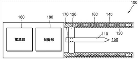
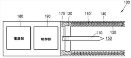
図1は、一実施形態に係るエアロゾル生成装置を概略的に図示した断面図である。 FIG. 1 is a cross-sectional view schematically showing an aerosol generating apparatus according to an embodiment.
図1に図示されているように、一実施形態に係るエアロゾル生成装置100は、加熱体110、支持部120、内壁130、外壁140、収容空間150、コイル160、温度センサ170、電源部180及び制御部190を含んでもよい。
As illustrated in FIG. 1, the
ただし、それに限定されるものではなく、図1に図示される要素以外に、他の汎用的な要素がエアロゾル生成装置100にさらに含まれてもよい。
However, the present invention is not limited to this, and other general-purpose elements may be further included in the
エアロゾル生成装置100は、装置100に収容されるシガレットを、誘導加熱(induction heating)方式で加熱することにより、エアロゾルを生成することができる。
The
誘導加熱は、周期的に方向を変化させる磁束を有する交番磁場を磁性体に印加し、磁性体から熱を発生させる方法を意味する。結果として、磁性体は、熱を発生させることができる。 Induction heating means a method in which an alternating magnetic field having a magnetic flux that periodically changes a direction is applied to a magnetic material to generate heat from the magnetic material. As a result, the magnetic material can generate heat.
磁性体に交番磁場が印加される場合、該磁性体には、渦流損及びヒステリシス損によるエネルギー損失が発生してしまう。損失されるエネルギーが熱エネルギーとして、磁性体から放出されうる。 When an alternating magnetic field is applied to the magnetic material, energy loss due to eddy current loss and hysteresis loss occurs in the magnetic material. The lost energy can be released from the magnetic material as thermal energy.
磁性体に印加される交番磁場の振幅または周波数が大きいほど、磁性体から多くの熱エネルギーが放出されるのである。 The larger the amplitude or frequency of the alternating magnetic field applied to the magnetic material, the more thermal energy is released from the magnetic material.
エアロゾル生成装置100は、磁性体から放出される熱エネルギーをシガレットに伝達することができる。
The
外部磁場によって発熱する磁性体は、サセプタでもある。サセプタは、シガレット内部またはエアロゾル生成装置100にも配置される。例えば、該サセプタは、エアロゾル生成装置100内部に配置される加熱体110に含まれてもよい。該サセプタは、切片、薄片またはストリップの形状にも製造される。
A magnetic material that generates heat due to an external magnetic field is also a susceptor. The susceptor is also located inside the cigarette or also in the
本実施形態によれば、該サセプタは、金属または炭素を含んでもよい。該サセプタは、フェライト(ferrite)、強磁性合金(ferromagnetic alloy)、ステンレス鋼(stainless steel)及びアルミニウム(Al)のうち少なくとも一つを含んでもよい。 According to this embodiment, the susceptor may contain metal or carbon. The susceptor may contain at least one of ferrite, ferromagnetic alloy, stainless steel and aluminum.
また、該サセプタは、黒鉛(graphite)、モリブデン(molybdenum)、シリコンカーバイド(silicon carbide)、ニオブ(niobium)、ニッケル合金(nickel alloy)、金属フィルム(metal film)、ジルコニア(zirconia)のようなセラミックス、ニッケル(Ni)やコバルト(Co)のような遷移金属、ホウ素(B)やリン(P)のような準金属のうち少なくとも一つを含んでもよい。 In addition, the susceptor is a ceramic such as graphite, molybdenum, silicon carbide, niobium, nickel alloy, metal film, and zirconia. , At least one of transition metals such as nickel (Ni) and cobalt (Co) and quasi-metals such as boron (B) and phosphorus (P) may be included.
一実施形態によるエアロゾル生成装置100の場合、サセプタが、エアロゾル生成装置100に具備される加熱体110に含まれてもよい。
In the case of the
該サセプタが、シガレット内部ではないエアロゾル生成装置100に具備されることにより、多様な利点がある。
By providing the susceptor in the
例えば、サセプタ物質がシガレット内部で均一に分布しない場合、エアロゾルと香味とが非均一に発生する問題点が解決されるのである。 For example, when the susceptor substance is not uniformly distributed inside the cigarette, the problem of non-uniform generation of aerosol and flavor is solved.
また、該サセプタを含む加熱体110がエアロゾル生成装置100に具備されるので、誘導加熱によって発熱する加熱体110の温度が直接測定され、エアロゾル生成装置100にも提供される。それにより、加熱体110の温度に対する精巧な制御が行われうる。
Further, since the
エアロゾル生成装置100は、シガレットの少なくとも一部を収容するための収容空間150を形成する内壁130を含んでもよい。
The
収容空間150は、収容空間150の外側に開放される開口を含んでもよい。
The
シガレットは、収容空間150の開口を介し、エアロゾル生成装置100にも収容される。
The cigarette is also housed in the
収容空間150の内側には、加熱体110が配置されてもよい。
The
加熱体110は、収容空間150の内側端部に形成される支持部120に結合され、支持部120は、加熱体110を支持することができる。
The
シガレットは、加熱体110がシガレットに挿入されるように、支持部120に逹するまで、収容空間150に押し込まれる。
The cigarette is pushed into the
支持部120は、耐熱、耐化学性及び耐腐食性などの特徴を有するために、ガラスまたはセラミックスなどの素材を含んでもよい。
The
加熱体110と支持部120とが互いに分離型である場合(すなわち、分離可能になるように結合された場合)、収容空間150で生成されうるエアロゾル凝縮物が、エアロゾル生成装置100の内部に侵入することを防止するために、加熱体110と支持部120との結合部位には、防水部材が具備されうる。そのような場合、誘導加熱により、加熱体110が加熱される場合には、加熱体110の全体が均一に高温に加熱されるために、防水部材が変形されたり破損されたりしてしまう。その結果、加熱体110と支持部120との結合部位において、防水部材が維持され難い。
When the
図1に図示された実施形態に係るエアロゾル生成装置100においては、加熱体110と支持部120とが一体型にも成形される。
In the
また、内壁130は、支持部120を支持することができ、支持部120と内壁130との結合部位に、防水構造を有するために、支持部120と内壁130は、一体型にも成形される。
Further, since the
例えば、加熱体110と支持部120は、焼結によって一体型にも成形され、内壁130は、支持部120の外側面周囲に、射出によって一体型にも成形される。
For example, the
その結果、加熱体110、支持部120、または支持部120と内壁130との結合部位に、防水部材を設けずにも、高温の環境においても、防水構造を維持することができる。
As a result, the waterproof structure can be maintained even in a high temperature environment without providing a waterproof member at the
外壁140は、内壁130の外側に、内壁130から離隔されるように配置され、それにより、内壁130と外壁140との間に空間を形成することができる。
The
エアロゾル生成装置100は、加熱体110に交番磁場を印加するコイル160を含んでもよく、内壁130と外壁140との間の空間に、コイル160が配置されてもよい。
The
すなわち、コイル160は、収容空間150と加熱体110との周囲に巻線されうる。
That is, the
コイル160は、電源部180から電力を供給されうる。
The
エアロゾル生成装置100の制御部190は、コイル160に流れる電流を制御することにより、磁場を発生させることができ、その磁場の影響により、加熱体110に誘導電流が発生するのである。
The
そのような誘導加熱は、ファラデーの誘導法則及びオームの法則によって説明される公知の現象である。詳細には、誘導加熱は、伝導体内の磁気誘導が変化する場合、変化される電場が伝導体内に生成される現象を利用する。 Such induction heating is a known phenomenon described by Faraday's law of induction and Ohm's law. Specifically, induction heating utilizes the phenomenon that a changed electric field is generated in the conductor when the magnetic induction in the conductor changes.
以上のように、電場が伝導体内に生成されることにより、渦電流がオームの法則によって伝導体内に流れ、渦電流は、電流密度及び伝導体抵抗に比例する熱を発生させる。 As described above, when an electric field is generated in the conductor, an eddy current flows in the conductor according to Ohm's law, and the eddy current generates heat proportional to the current density and the conductor resistance.
加熱体110で発生した熱は、エアロゾル生成物質に伝達され、エアロゾル生成物質を気化させることにより、エアロゾルを生成することができる。
The heat generated in the
言い換えれば、コイル160に電力が供給される場合、コイル160内部に磁場が形成されるのである。
In other words, when power is supplied to the
コイル160に、電源部180から交流電流が印加される場合、コイル160の内部に形成される磁場は、周期的に方向が変わる。
When an alternating current is applied to the
加熱体110がコイル160によって形成される交番磁場に露出される場合、加熱体110が発熱し、エアロゾル生成装置100に収容されるシガレットが加熱されうる。
When the
コイル160によって形成される交番磁場の振幅または周波数が変わる場合、シガレットを加熱する加熱体110の温度も変わる。
When the amplitude or frequency of the alternating magnetic field formed by the
制御部190は、コイル160に供給される電力を制御し、コイル160によって形成される交番磁場の振幅または周波数を調整することができ、それにより、加熱体110の温度が制御されうる。
The
一例示として、コイル160は、ソレノイド(solenoid)によっても具現される。
As an example, the
ソレノイドを構成する導線の材質は、銅(Cu)でもある。 The material of the conducting wire constituting the solenoid is also copper (Cu).
ただし、それに限定されるものではなく、低い比抵抗値を有し、高い電流が流れるようにする材質であり、銀(Ag)、金(Au)、アルミニウム(Al)、タングステン(W)、亜鉛(Zn)及びニッケル(Ni)のうちいずれか一つ、または少なくとも一つを含む合金がソレノイドを構成する導線の材質にもなる。 However, the material is not limited to this, and is a material having a low resistivity value and allowing a high current to flow, and is silver (Ag), gold (Au), aluminum (Al), tungsten (W), and zinc. An alloy containing any one or at least one of (Zn) and nickel (Ni) is also a material for the conducting wire constituting the solenoid.
一実施形態において、エアロゾル生成装置100は、加熱体110の温度を測定する温度センサ170をさらに含んでもよい。
In one embodiment, the
温度センサ170は、加熱体110の温度を、接触式または非接触式で測定することができる。
The
温度センサ170は、コイル160によって印加される磁場に影響を受けない種類のセンサでもある。
The
図1に図示される一実施形態のように、加熱体110の温度が、温度センサ170によって測定されるように、加熱体110は、支持部120を貫通することができる。それにより、温度センサ170は、加熱体110に直接接触して温度を測定することができる。
As in one embodiment illustrated in FIG. 1, the
他の実施形態として、接触式温度センサは、加熱体110の内部にも挿入される。すなわち、加熱体110の下端部には、加熱体110の長手方向に沿って中空が形成されており、中空上端部近くの加熱体110の内面上に、接触式温度センサが位置しうる。その場合、接触式温度センサは、加熱体110の内部の中心部上に位置するために、加熱体110の端部に位置する場合より、加熱体110の温度を迅速であって正確に測定することができる。
In another embodiment, the contact temperature sensor is also inserted inside the
他の実施形態として、温度センサ170は、加熱体110と非接触で加熱体110の温度を測定する赤外線センサを含んでもよい。赤外線センサを介して、加熱体110の温度が測定される場合、加熱体110及び温度センサ170を連結するための構造が要求されず、エアロゾル生成装置100の設計が簡潔にもなる。
As another embodiment, the
エアロゾル生成装置100の電源部180は、エアロゾル生成装置100の各構成要素に電力を供給することができる。
The
例えば、電源部180は、コイル160が磁場を発生させるための電力を供給することができる。
For example, the
コイル160に供給される電力の大きさは、制御部190が生成した制御信号によっても調節される。
The magnitude of the electric power supplied to the
電源部180は、例えば、ニッケルカドミウム(Ni−Cd)、アルカリ電池、ニッケル水素(Ni−Mh)、密閉型鉛酸(SLA)、リチウムイオン(Li−ion)及びリチウムポリマー(Li−polymer)などの充電電池を含んでもよい。
The
電源部180は、直流電流(DC)を供給するバッテリ、及び該バッテリから供給される直流電流をコイル160に供給される交流電流(AC)に変換する変換部を含んでもよい。
The
電源部180は、バッテリと制御部190との間にバッテリの電圧を一定に維持させるレギュレータ(regulator)を含んでもよい。
The
エアロゾル生成装置100の制御部190は、制御信号を生成して送信する方法を介して、エアロゾル生成装置100に含まれているコイル160、電源部180及び加熱体110など構成要素を総括的に制御することができる。
The
例えば、制御部190は、電源部180の電力を利用し、コイル160に電流を印加することができる。
For example, the
制御部190は、多数の論理ゲートのアレイによっても具現され、汎用的なマイクロプロセッサと、マイクロプロセッサで実行されうるプログラムが保存されるメモリの組み合わせによっても具現される。
The
また、制御部190は、複数個のプロセッシングエレメント(processing elements)によっても構成される。
The
図示されていないが、制御部190は、ユーザのボタン入力やタッチ入力を受信する入力受信部、ユーザ端末のような外部通信装置と通信を行うことができる通信部、エアロゾル生成装置100の状態情報を表示するディスプレイ部、及びコイル160に印加される電力のパルス幅を制御するパルス幅変調処理部をさらに含んでもよい。
Although not shown, the
図2は、図1に図示された実施形態に係るエアロゾル生成装置によって加熱され、エアロゾルを生成するシガレットを概略的に図示した分解図である。 FIG. 2 is an exploded view schematically showing a cigarette that is heated by the aerosol generator according to the embodiment shown in FIG. 1 to generate an aerosol.
図2を参照すれば、シガレット200は、タバコロッド210及びフィルタロッド220を含んでもよい。
With reference to FIG. 2, the
図2には、フィルタロッド220が単一セグメントとして図示されているが、それに限定されるものではない。言い換えれば、フィルタロッド220は、複数のセグメントによっても構成される。例えば、フィルタロッド220は、エアロゾルを冷却する第1セグメント、及びエアロゾル内に含まれた所定成分をフィルタリングする第2セグメントを含んでもよい。また、必要により、フィルタロッド220には、他の機能を遂行する少なくとも1つのセグメントがさらに含まれてもよい。
FIG. 2 shows the
シガレット200は、少なくとも1枚のラッパ240によっても包装される。ラッパ240には、外部空気が流入されたり、内部空気が流出されたりする少なくとも1つの孔が形成されてもよい。
The
一例として、シガレット200は、1枚のラッパ240によっても包装される。
As an example, the
他の例として、シガレット200は、2枚以上のラッパ240によっても重畳的に包装される。
As another example, the
例えば、第1ラッパによってタバコロッド210が包装され、第2ラッパによってフィルタロッド220が包装されうる。
For example, the
そして、個別ラッパによって包装されたタバコロッド210及びフィルタロッド220が結合され、第3ラッパによってシガレット200全体が再包装されうる。
Then, the
もしタバコロッド210またはフィルタロッド220それぞれが複数のセグメントによって構成されているならば、それぞれのセグメントは、個別ラッパによっても包装される。
If each of the
そして、個別ラッパによって包装されたセグメントが結合されたシガレット200全体が、他のラッパによっても再包装される。
Then, the
タバコロッド210は、エアロゾル生成物質を含んでもよい。例えば、該エアロゾル生成物質は、グリセリン、プロピレングリコール、エチレングリコール、ジプロピレングリコール、ジエチレングリコール、トリエチレングリコール、テトラエチレングリコール及びオレイルアルコールのうち少なくとも一つを含んでもよいが、それらに限定されるものではない。
The
また、タバコロッド210は、風味剤、湿潤剤及び/または有機酸(organic acid)のような他の添加物質を含んでもよい。
The
また、タバコロッド210には、メントールまたは保湿剤のような加香液がタバコロッド210に噴射されることによっても添加される。
It is also added to the
タバコロッド210は、多様な方式によっても作製される。例えば、タバコロッド210は、シートによっても作製され、ストランド(strand)によっても作製される。また、タバコロッド210は、タバコシートが細かく切られた刻みタバコによっても作製される。
また、タバコロッド210は、熱伝導物質によっても取り囲まれる。例えば、該熱伝導物質は、アルミニウムホイルのような金属ホイルでもあるが、それに限定されるものではない。
The
タバコロッド210を取り囲む熱伝導物質は、タバコロッド210に伝達される熱を等しく分散させ、タバコロッドに加えられる熱伝導率を向上させることができる。その結果、タバコ味を向上させることができる。
The heat conductive material surrounding the
フィルタロッド220は、セルロースアセテートフィルタでもある。
The
フィルタロッド220の形状には、制限がない。例えば、フィルタロッド220は、円柱型ロッドでもあり、内部に中空を含むチューブ型ロッドでもある。また、フィルタロッド220は、リセス型ロッドでもある。もしフィルタロッド220が複数のセグメントによって構成された場合、複数のセグメントのうち少なくとも一つは、異なる形状にも作製される。
There are no restrictions on the shape of the
フィルタロッド220は、香味が発生するようにも作製される。
The
一例として、フィルタロッド220に加香液が噴射され、加香液が塗布された別途の纎維がフィルタロッド220の内部にも挿入される。
As an example, a perfume liquid is sprayed onto the
また、フィルタロッド220には、香味またはエアロゾルを発生させるための少なくとも1つのカプセル230が含まれてもよい。例えば、カプセル230は、香料を含む液体を被膜で覆い包んだ構造でもある。カプセル230は、球形または円筒状の形状を有することができるが、それらに制限されるものではない。
The
もしフィルタロッド220にエアロゾルを冷却するセグメントが含まれる場合、冷却セグメントは、高分子物質または生分解性高分子物質によっても製造される。例えば、該冷却セグメントは、純粋なポリ乳酸のみによっても作製される、それに限定されるものではない。または、該冷却セグメントは、複数の孔が形成されている酢酸セルロースフィルタによっても作製される。しかし、該冷却セグメントは、前述の例に限定されるものではなく、エアロゾルが冷却される機能を遂行することができる他の冷却セグメントが使用されもする。
If the
図示されていないが、シガレット200は、前端プラグをさらに含んでもよい。前端プラグは、タバコロッド210において、フィルタロッド220に対向しない一側に位置することができる。前端プラグは、タバコロッド210が外部に離脱することを防止することができ、喫煙中、タバコロッド210から液状化されたエアロゾルが、エアロゾル生成装置100に流れることを防止することができる。
Although not shown, the
図3は、図1に図示された実施形態に係るエアロゾル生成装置の一部構成要素の結合関係を概略的に図示した分離斜視図である。 FIG. 3 is a separated perspective view schematically showing the coupling relationship of some components of the aerosol generator according to the embodiment shown in FIG. 1.
また、図4は、図1に図示された実施形態に係るエアロゾル生成装置の一部構成要素の結合状態を図示した断面図である。 Further, FIG. 4 is a cross-sectional view illustrating a bonding state of some components of the aerosol generation device according to the embodiment shown in FIG.
図3を参照すれば、加熱体110と支持部120とが結合する加熱体110の表面には、凹部111が形成されてもよい。
With reference to FIG. 3, a
また、加熱体110上の凹部111に対応し、支持部120の結合表面には、凸部122が形成されてもよい。
Further, a
従って、加熱体110と支持部120は、凹部111と凸部122との噛合により、互いに相対的な動きを防止することになり、焼結によって一体に成形されるとき、加熱体110の長手方向に沿い、さらに良好な結合を提供することができる。
Therefore, the
反対に、加熱体110上には、凸部が形成され、支持部120上には、凹部が形成されてもよい。
On the contrary, a convex portion may be formed on the
図3及び図4を参照すれば、支持部120と内壁130とが結合する表面において、支持部120には、溝121が形成されてもよく、内壁130には、溝121に対応し、突起131が形成されてもよい。
With reference to FIGS. 3 and 4, on the surface where the
すなわち、支持部120と内壁130とが一体型に成形されるとき、内壁130の突起131が支持部120の溝121に収容され、支持部120と内壁130との相対的な動きを防止する。
That is, when the
従って、エアロゾル生成装置が高温環境において反復的に使用される場合にも、支持部120と内壁130との結合状態が安定して維持されるので、支持部120と内壁130との相対的な動き(例えば、回転など)が防止されることにより、支持部120と内壁130との分離が維持されるのである。
Therefore, even when the aerosol generator is repeatedly used in a high temperature environment, the coupling state between the
一方、支持部120には、突起(図示せず)が形成され、内壁130には、溝が形成されてもよい。
On the other hand, a protrusion (not shown) may be formed on the
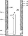
図5は、図4に図示された実施形態に係るエアロゾル生成装置の結合が完了した状態を例示的に図示した断面図である。 FIG. 5 is a cross-sectional view schematically showing a state in which the coupling of the aerosol generator according to the embodiment shown in FIG. 4 is completed.
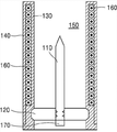
また、図6は、他の実施形態に係るエアロゾル生成装置を概略的に図示した断面図である。 Further, FIG. 6 is a cross-sectional view schematically showing an aerosol generation apparatus according to another embodiment.
図5を参照すれば、内壁130と外壁140は、互いに分離型で構成されており、内壁130と外壁140との間の空間に、コイル160が配置されている。
Referring to FIG. 5, the
コイル160は、固定部材161によって空間内部で固定されている。
The
一方、エアロゾル生成装置100の収容空間150にシガレットが挿入され、エアロゾルが生成されるとき、エアロゾルは、収容空間150上の内壁130に凝縮され、内壁130と外壁140との結合部位を介して、エアロゾル生成装置100の内部で液漏れが発生しうるという問題がある。
On the other hand, when the cigarette is inserted into the
従って、液漏れ防止のために、内壁130と外壁140との結合部位に、密封のためのシーリングリング141が含まれてもよい。
Therefore, in order to prevent liquid leakage, the sealing
図6を参照すれば、内壁130と外壁140との結合部位上の液漏れ防止のための他の実施形態が図示されている。
With reference to FIG. 6, another embodiment for preventing liquid leakage on the binding site between the
その場合、外壁140は、内壁130と一体型に成形されており、それにより、内壁130と外壁140との間には、結合部位が存在しない。従って、内壁130と外壁140との間は、別途の密封のためのシーリングリングが具備されなくても、密封を達成することができる。
In that case, the
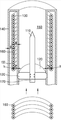
図7は、さらに他の実施形態に係るエアロゾル生成装置を概略的に図示した斜視図である。 FIG. 7 is a perspective view schematically showing an aerosol generating apparatus according to still another embodiment.
図7を参照すれば、内壁130と外壁140とが一体型に成形された後、コイル160は、内壁130と外壁140との間の空間に挿入される。
Referring to FIG. 7, after the
そのとき、コイル160は、内壁130及び外壁140のそれぞれから所定の間隔gとを有するようにも配置される。
At that time, the
また、図5に図示された実施形態に係るエアロゾル生成装置のように、分離型の内壁130及び外壁140である場合にも、コイル160は、内壁130及び外壁140のそれぞれから、所定の間隔gを有するようにも配置される。
Further, even in the case of the separate type
コイル160が内壁130及び外壁140のそれぞれから、所定の間隔gを維持するように、内壁130上には、外側に突出し、コイル160を支持する突出部132が形成されてもよい。
A
コイル160が内壁130と接触する場合、加熱体110の熱が内壁130を介してコイル160に伝導されることにより、コイル160が加熱されうる。
When the
従って、コイル160と内壁130との間に、所定の間隔gを維持するようにし、加熱体110からコイル160への熱伝逹を低減させることができる。
Therefore, a predetermined distance g can be maintained between the
コイル160と内壁130との間の熱伝逹が最小限になされるようにするために、突出部132の形状は、断面が、内壁130からコイル160に向けて外側に向かうほど狭くなり、それにより、突出部132とコイル160との間では、線接触がなされもする。
In order to minimize heat transfer between the
例えば、突出部132の断面形状は、三角形、または斜辺が緩い曲線からなるルーロー(reuleaux)三角形の形状でもある。
For example, the cross-sectional shape of the
また、コイル160と加熱体110との距離が遠くなるほど、磁場発生効率が低下するために、突出部132の高さを、0.01mmないし0.2mmにし、望ましくは、0.03mmないし0.1mm、さらに望ましくは、0.05mmにもする。
Further, as the distance between the
図7に図示されているように、外壁140上には、突出部が形成されるものではない。
As shown in FIG. 7, no protrusion is formed on the
内壁130上の突出部132だけでも、コイル160に十分な支持力を提供することができれば、外壁140上に突出部が必要ないのである。
If the
さらに、外壁140に突出部が形成される場合には、外壁140とコイル160とにおいて、突出部によって熱伝逹(伝導)が発生するために、外壁140を介して、エアロゾル生成装置100で放出される熱が増大する問題が発生し、それは、電力消耗の増加につながる。
Further, when a protrusion is formed on the
従って、内壁130上だけにコイル160を支持するための突出部132が形成される。
Therefore, a
図8は、さらに他の実施形態に係るエアロゾル生成装置を概略的に図示した断面図である。 FIG. 8 is a cross-sectional view schematically showing an aerosol generating apparatus according to still another embodiment.
図1の実施形態は、コイル160の断面形状が円形であったが、図8を参照すれば、コイル160’の断面形状は、四角形である。
In the embodiment of FIG. 1, the cross-sectional shape of the
コイル160’の断面形状が四角形である場合、コイルの中心が一列に均一に合わせられる。 When the cross-sectional shape of the coil 160'is quadrangular, the centers of the coils are uniformly aligned in a row.
また、四角形コイル160’の断面高さが、円形コイル160の直径と同一である場合、強度がさらに大きい誘導磁場が形成される。
Further, when the cross-sectional height of the quadrangular coil 160'is the same as the diameter of the
従って、エアロゾル生成装置100は、四角形コイル160’を使用した場合、円形コイル160の場合より高い効率を有することができる。
Therefore, the
コイルの断面形状は、特定形状に限定されるものではなく、変形されうる。例えば、コイルの断面形状は、三角形または五角形のような多角形状でもある。 The cross-sectional shape of the coil is not limited to a specific shape and can be deformed. For example, the cross-sectional shape of the coil is also a polygonal shape such as a triangle or a pentagon.
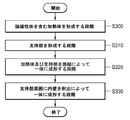
図9は、さらに他の実施形態に係るエアロゾル生成装置を製造する方法を例示的に示したフローチャートである。 FIG. 9 is a flowchart illustrating a method of manufacturing an aerosol generator according to still another embodiment.
図9に、図示された実施形態に係るエアロゾル生成装置を製造する方法は、誘導磁場によって発熱する強磁性体(ferromagnetic substance)を含む加熱体を形成する段階と、前記加熱体を支持する支持部を形成する段階と、前記加熱体及び前記支持部を焼結によって一体型に成形する段階と、前記支持部周囲に内壁を、射出によって一体型に成形する段階と、を含む。 In FIG. 9, the method of manufacturing the aerosol generator according to the illustrated embodiment includes a step of forming a heating body containing a ferromagnetic substance that generates heat by an induced magnetic field, and a support portion that supports the heating body. The step of forming the heating body and the support portion by sintering, and the step of integrally molding the inner wall around the support portion by injection are included.
まず、強磁性体を含む加熱体を形成し(S300)、加熱体を支持するための支持部を形成する(S310)。 First, a heated body containing a ferromagnet is formed (S300), and a support portion for supporting the heated body is formed (S310).
当該加熱体と支持部とを接合し、一体型に成形する(S320)。 The heating body and the support portion are joined and molded into an integral type (S320).
例えば、該支持部を成形するためのモールド(フレーム)に焼結用粉末を注入して圧縮させることにより、支持部を一次成形することができる。 For example, the support portion can be primarily molded by injecting sintering powder into a mold (frame) for molding the support portion and compressing the powder.
加熱体と、一次成形完了した支持部は、焼結を介して接合することができるが、具体的には、加熱体を一次成形完了した支持部に押入した後、900℃ないし1,100℃の熱で加熱し、加熱体と支持部とを一体型に成形することができる。 The heated body and the support portion for which the primary molding has been completed can be joined via sintering. Specifically, after the heated body is pushed into the support portion for which the primary molding has been completed, the temperature is 900 ° C. to 1,100 ° C. The heating body and the support portion can be integrally formed by heating with the heat of.
また、支持部に内壁を一体型に成形する(S330)。 Further, the inner wall is integrally molded with the support portion (S330).
例えば、支持部周囲に、内壁を射出によって成形し、支持部と内壁とを一体型に成形することができる。 For example, the inner wall can be molded by injection around the support portion, and the support portion and the inner wall can be integrally molded.
射出による成形は、例えば、溶融されたプラスチック素材を支持部の外側に適用することにより、内壁を成形する方式によっても実行される。 Molding by injection is also performed, for example, by a method of molding an inner wall by applying a molten plastic material to the outside of the support.
一方、図6の実施形態において、外壁を内壁と一体型に射出成形することができ、一体型の外壁及び内壁が射出成形された後、一体型に形成された内壁と外壁との空間にコイルを挿入することにより、エアロゾル生成装置を製造することができる。 On the other hand, in the embodiment of FIG. 6, the outer wall can be injection-molded integrally with the inner wall, and after the integrated outer wall and the inner wall are injection-molded, a coil is formed in the space between the inner wall and the outer wall formed integrally. The aerosol generator can be manufactured by inserting the.
本実施形態と係る技術分野で当業者であるならば、前述のところの本質的な特性から外れない範囲で変形された形態にも具現されるということを理解することができるであろう。 Those skilled in the art of this embodiment will be able to understand that it is also embodied in a modified form within a range that does not deviate from the essential characteristics described above.
従って、開示された方法は、限定的な観点ではなく、説明的な観点から考慮されなければならない。 Therefore, the disclosed method must be considered from a descriptive point of view, not from a limiting point of view.
本発明の範囲は、前述の説明ではなく、特許請求範囲にしめされており、それと同等な範囲内にある全ての差異は、本発明に含まれたものであると解釈されなければならないのである。 The scope of the present invention is not the above description but is limited to the claims, and all differences within the equivalent scope must be construed as being included in the present invention. ..
Claims (16)
前記シガレットの少なくとも一部を収容する収容空間を形成する内壁と、
前記内壁の外側に配置され、前記収容空間の少なくとも一部を取り囲み、誘導磁場を発生させるコイルと、
前記収容空間内に配置され、誘導磁場によって発熱する強磁性体を含む加熱体と、
前記加熱体を支持し、前記加熱体と一体型に成形される支持部と、を含み、
前記内壁は、前記支持部を支持し、前記支持部と一体型に成形される、エアロゾル生成装置。 In an aerosol generator that heats a cigarette to generate an aerosol
An inner wall forming a containment space for accommodating at least a part of the cigarette,
A coil that is located outside the inner wall and surrounds at least a part of the accommodation space to generate an induced magnetic field.
A heating body that is arranged in the accommodation space and contains a ferromagnet that generates heat by an induced magnetic field,
Includes a support portion that supports the heating body and is integrally molded with the heating body.
An aerosol generator in which the inner wall supports the support portion and is integrally molded with the support portion.
前記内壁と前記支持部とのうち他の一つに形成され、前記突起を収容する溝が形成される、請求項1に記載のエアロゾル生成装置。 A protrusion is formed on any one of the inner wall and the support portion.
The aerosol generating apparatus according to claim 1, wherein a groove is formed in the other one of the inner wall and the support portion to accommodate the protrusion.
前記内壁と前記外壁との間に形成された空間に、前記コイルが配置される、請求項1に記載のエアロゾル生成装置。 Further including an outer wall located outside the inner wall and separated from the inner wall.
The aerosol generator according to claim 1, wherein the coil is arranged in a space formed between the inner wall and the outer wall.
接触式温度センサが、前記中空の上端部近くの前記加熱体の内面上に位置される、請求項11に記載のエアロゾル生成装置。 A hollow is formed along the longitudinal direction at the lower end of the heating body.
The aerosol generator according to claim 11, wherein the contact temperature sensor is located on the inner surface of the heating body near the upper end of the hollow.
前記エアロゾル生成装置に収容されるシガレットと、を含むエアロゾル生成システム。 The aerosol generator according to any one of claims 1 to 12 and
An aerosol generation system comprising a cigarette housed in the aerosol generator.
前記加熱体を支持する支持部を形成する段階と、
前記加熱体及び前記支持部を焼結によって一体型に成形する段階と、
前記支持部の周囲に内壁を、射出によって一体型に成形する段階と、を含むエアロゾル生成装置を製造する方法。 The stage of forming a heated body containing a ferromagnetic material that generates heat by an induced magnetic field,
At the stage of forming a support portion that supports the heating body, and
The stage of integrally molding the heating body and the support portion by sintering, and
A method of manufacturing an aerosol generator comprising a step of integrally molding an inner wall around the support portion by injection.
前記内壁と前記外壁との間に形成された空間に、誘導磁場を発生させるコイルを配置する段階と、をさらに含む、請求項14または15に記載のエアロゾル生成装置を製造する方法。 A step of integrally molding the inner wall and the outer wall so that the outer wall is arranged outside the inner wall and separated from the inner wall.
The method for manufacturing an aerosol generating apparatus according to claim 14 or 15, further comprising a step of arranging a coil for generating an induced magnetic field in a space formed between the inner wall and the outer wall.
Applications Claiming Priority (3)
| Application Number | Priority Date | Filing Date | Title |
|---|---|---|---|
| KR10-2019-0025046 | 2019-03-05 | ||
| KR1020190025046A KR102253046B1 (en) | 2019-03-05 | 2019-03-05 | Aerosol generating device and system, and manufacturing method of the aerosol generating device |
| PCT/KR2020/003113 WO2020180126A2 (en) | 2019-03-05 | 2020-03-05 | Aerosol generating device, aerosol generating system, and manufacturing method of the aerosol generating device |
Publications (2)
| Publication Number | Publication Date |
|---|---|
| JP2021517455A true JP2021517455A (en) | 2021-07-26 |
| JP7125201B2 JP7125201B2 (en) | 2022-08-24 |
Family
ID=72337994
Family Applications (1)
| Application Number | Title | Priority Date | Filing Date |
|---|---|---|---|
| JP2020541762A Active JP7125201B2 (en) | 2019-03-05 | 2020-03-05 | AEROSOL GENERATOR, AEROSOL GENERATING SYSTEM AND METHOD FOR MANUFACTURING AEROSOL GENERATING DEVICE |
Country Status (7)
| Country | Link |
|---|---|
| US (1) | US20200390156A1 (en) |
| EP (1) | EP3817590A4 (en) |
| JP (1) | JP7125201B2 (en) |
| KR (1) | KR102253046B1 (en) |
| CN (1) | CN111902060B (en) |
| TW (1) | TWI738240B (en) |
| WO (1) | WO2020180126A2 (en) |
Families Citing this family (18)
| Publication number | Priority date | Publication date | Assignee | Title |
|---|---|---|---|---|
| CN111031819B (en) * | 2017-08-09 | 2023-07-18 | 菲利普莫里斯生产公司 | Aerosol generating device with removable susceptor |
| CN110996696B (en) * | 2017-08-09 | 2022-10-14 | 菲利普莫里斯生产公司 | Aerosol-generating device with induction heater and movable component |
| GB202014597D0 (en) * | 2020-09-16 | 2020-10-28 | Nicoventures Trading Ltd | Aerosol provision device |
| CN114304745A (en) * | 2020-09-29 | 2022-04-12 | 深圳市合元科技有限公司 | Susceptor for aerosol-generating device, aerosol-generating device and temperature measuring device |
| KR102579817B1 (en) * | 2021-03-02 | 2023-09-15 | 주식회사 케이티앤지 | Device for generating aerosol |
| KR102589104B1 (en) * | 2021-03-05 | 2023-10-12 | 주식회사 케이티앤지 | Device for generating aerosol |
| KR102533271B1 (en) * | 2021-03-16 | 2023-05-15 | 주식회사 케이티앤지 | Device for generating aerosol |
| KR20220162472A (en) * | 2021-06-01 | 2022-12-08 | 주식회사 케이티앤지 | Aerosol generating apparatus for detecting an insertion of an aerosol generating article and operation method thereof |
| GB202108797D0 (en) * | 2021-06-18 | 2021-08-04 | Nicoventures Trading Ltd | Aerosol generating device |
| WO2023003351A1 (en) * | 2021-07-21 | 2023-01-26 | Kt&G Corporation | Aerosol-generating device |
| KR102657025B1 (en) * | 2021-07-21 | 2024-04-11 | 주식회사 케이티앤지 | Device for generating aerosol |
| KR102562161B1 (en) * | 2021-08-11 | 2023-08-03 | 주식회사 이노아이티 | Portable aerosol generator with two independent heater structures |
| EP4136991A1 (en) * | 2021-08-17 | 2023-02-22 | Shenzhen Eigate Technology Co., Ltd. | Heating assembly comprising a high-frequency control assembly |
| CN216088890U (en) * | 2021-08-27 | 2022-03-22 | 深圳麦克韦尔科技有限公司 | Heating device and electronic atomization device |
| CN114096026A (en) * | 2021-11-16 | 2022-02-25 | 长安大学 | Aerosol generating system |
| WO2023146220A1 (en) * | 2022-01-25 | 2023-08-03 | Kt&G Corporation | Aerosol generating device |
| WO2023146221A1 (en) * | 2022-01-25 | 2023-08-03 | Kt&G Corporation | Aerosol generating device |
| CN117898481A (en) * | 2022-10-10 | 2024-04-19 | 深圳市合元科技有限公司 | Gas mist generating device and heater for gas mist generating device |
Citations (11)
| Publication number | Priority date | Publication date | Assignee | Title |
|---|---|---|---|---|
| CN203492789U (en) * | 2013-09-22 | 2014-03-26 | 刘秋明 | Atomizer and electronic cigarette |
| KR20170008722A (en) * | 2014-05-21 | 2017-01-24 | 필립모리스 프로덕츠 에스.에이. | Aerosol-forming substrate and aerosol-delivery system |
| JP2018504130A (en) * | 2015-02-05 | 2018-02-15 | フィリップ・モーリス・プロダクツ・ソシエテ・アノニム | Aerosol generator with fixed heater |
| WO2018041450A1 (en) * | 2016-08-31 | 2018-03-08 | Philip Morris Products S.A. | Aerosol generating device with inductor |
| US20180070640A1 (en) * | 2016-09-15 | 2018-03-15 | Michel BESSANT | Electronic aerosol-generating smoking device |
| US20180192701A1 (en) * | 2017-01-06 | 2018-07-12 | Charles C Stoner | Induction Vaporizer and Method |
| CN108617042A (en) * | 2018-07-05 | 2018-10-02 | 湖北中烟工业有限责任公司 | A kind of smoking apparatus of induced inside heating |
| JP2018529324A (en) * | 2015-08-31 | 2018-10-11 | ブリティッシュ アメリカン タバコ (インヴェストメンツ) リミテッドBritish American Tobacco (Investments) Limited | Device for heating smoking material |
| KR20180129676A (en) * | 2017-05-26 | 2018-12-05 | 주식회사 케이티앤지 | Heater assembly and aerosol generating apparatus having the same |
| CN208286365U (en) * | 2017-10-13 | 2018-12-28 | 惠州市吉瑞科技有限公司深圳分公司 | A kind of atomization system and tobacco rod |
| WO2019030301A1 (en) * | 2017-08-09 | 2019-02-14 | Philip Morris Products S.A. | Aerosol generating system with non-circular inductor coil |
Family Cites Families (11)
| Publication number | Priority date | Publication date | Assignee | Title |
|---|---|---|---|---|
| US5613505A (en) * | 1992-09-11 | 1997-03-25 | Philip Morris Incorporated | Inductive heating systems for smoking articles |
| TWI666993B (en) * | 2014-05-21 | 2019-08-01 | Philip Morris Products S. A. | Inductive heating device and system for aerosol generation |
| TWI692274B (en) * | 2014-05-21 | 2020-04-21 | 瑞士商菲利浦莫里斯製品股份有限公司 | Inductive heating device for heating an aerosol-forming substrate and method of operating an inductive heating system |
| EP2921065A1 (en) * | 2015-03-31 | 2015-09-23 | Philip Morris Products S.a.s. | Extended heating and heating assembly for an aerosol generating system |
| US20170055580A1 (en) * | 2015-08-31 | 2017-03-02 | British American Tobacco (Investments) Limited | Apparatus for heating smokable material |
| US11576424B2 (en) * | 2017-04-05 | 2023-02-14 | Altria Client Services Llc | Susceptor for use with an inductively heated aerosol-generating device or system |
| TWI780186B (en) | 2017-07-28 | 2022-10-11 | 瑞士商菲利浦莫里斯製品股份有限公司 | Heater assembly, aerosol-generating device, aerosol-generating system, method of generating an aeroslo, and method of assembling a heater assembly for such a device |
| CN111031819B (en) * | 2017-08-09 | 2023-07-18 | 菲利普莫里斯生产公司 | Aerosol generating device with removable susceptor |
| WO2019030363A1 (en) * | 2017-08-09 | 2019-02-14 | Philip Morris Products S.A. | Aerosol-generating device with flat inductor coil |
| CN207236100U (en) * | 2017-09-26 | 2018-04-17 | 湖南酷伯新晶电子科技有限公司 | Quartz glass heater and matched Nebulizer for electronic cigarette and electronic cigarette |
| CN207766584U (en) * | 2018-01-31 | 2018-08-24 | 深圳市合元科技有限公司 | A kind of heating device and electronic cigarette |
-
2019
- 2019-03-05 KR KR1020190025046A patent/KR102253046B1/en active IP Right Grant
-
2020
- 2020-03-05 EP EP20746538.6A patent/EP3817590A4/en active Pending
- 2020-03-05 JP JP2020541762A patent/JP7125201B2/en active Active
- 2020-03-05 TW TW109107285A patent/TWI738240B/en active
- 2020-03-05 CN CN202080001467.1A patent/CN111902060B/en active Active
- 2020-03-05 US US16/971,041 patent/US20200390156A1/en active Pending
- 2020-03-05 WO PCT/KR2020/003113 patent/WO2020180126A2/en unknown
Patent Citations (11)
| Publication number | Priority date | Publication date | Assignee | Title |
|---|---|---|---|---|
| CN203492789U (en) * | 2013-09-22 | 2014-03-26 | 刘秋明 | Atomizer and electronic cigarette |
| KR20170008722A (en) * | 2014-05-21 | 2017-01-24 | 필립모리스 프로덕츠 에스.에이. | Aerosol-forming substrate and aerosol-delivery system |
| JP2018504130A (en) * | 2015-02-05 | 2018-02-15 | フィリップ・モーリス・プロダクツ・ソシエテ・アノニム | Aerosol generator with fixed heater |
| JP2018529324A (en) * | 2015-08-31 | 2018-10-11 | ブリティッシュ アメリカン タバコ (インヴェストメンツ) リミテッドBritish American Tobacco (Investments) Limited | Device for heating smoking material |
| WO2018041450A1 (en) * | 2016-08-31 | 2018-03-08 | Philip Morris Products S.A. | Aerosol generating device with inductor |
| US20180070640A1 (en) * | 2016-09-15 | 2018-03-15 | Michel BESSANT | Electronic aerosol-generating smoking device |
| US20180192701A1 (en) * | 2017-01-06 | 2018-07-12 | Charles C Stoner | Induction Vaporizer and Method |
| KR20180129676A (en) * | 2017-05-26 | 2018-12-05 | 주식회사 케이티앤지 | Heater assembly and aerosol generating apparatus having the same |
| WO2019030301A1 (en) * | 2017-08-09 | 2019-02-14 | Philip Morris Products S.A. | Aerosol generating system with non-circular inductor coil |
| CN208286365U (en) * | 2017-10-13 | 2018-12-28 | 惠州市吉瑞科技有限公司深圳分公司 | A kind of atomization system and tobacco rod |
| CN108617042A (en) * | 2018-07-05 | 2018-10-02 | 湖北中烟工业有限责任公司 | A kind of smoking apparatus of induced inside heating |
Also Published As
| Publication number | Publication date |
|---|---|
| WO2020180126A2 (en) | 2020-09-10 |
| KR102253046B1 (en) | 2021-05-17 |
| CN111902060A (en) | 2020-11-06 |
| EP3817590A4 (en) | 2022-05-11 |
| JP7125201B2 (en) | 2022-08-24 |
| WO2020180126A3 (en) | 2020-10-29 |
| TW202038765A (en) | 2020-11-01 |
| US20200390156A1 (en) | 2020-12-17 |
| TWI738240B (en) | 2021-09-01 |
| CN111902060B (en) | 2024-01-09 |
| EP3817590A2 (en) | 2021-05-12 |
| KR20200106617A (en) | 2020-09-15 |
Similar Documents
| Publication | Publication Date | Title |
|---|---|---|
| JP2021517455A (en) | Aerosol generator, aerosol generator and aerosol generator manufacturing method | |
| US20230225398A1 (en) | Electronic vaping device and components thereof | |
| CN111818816B (en) | Heater assembly for heating cigarettes and aerosol-generating device comprising same | |
| US20220030949A1 (en) | Inductively heatable aerosol-generating article comprising an aerosol-forming substrate and a susceptor assembly | |
| JP7307157B2 (en) | AEROSOL GENERATOR AND AEROSOL GENERATING SYSTEM INCLUDING THE SAME | |
| TWI745834B (en) | Aerosol generating system, apparatus, method for operating the same and charging apparatus | |
| CN116420919A (en) | Kit comprising a module and an electrically operated aerosol-generating system | |
| KR20210064306A (en) | Susceptor assembly for inductively heating an aerosol-forming substrate | |
| JP2022539719A (en) | Aerosol generator and system with conductivity sensor | |
| JP7422240B2 (en) | Heater assembly and manufacturing method thereof | |
| KR20210033454A (en) | Charging device and aerosol generating system including the same | |
| KR102509093B1 (en) | Aerosol generating device and aerosol generating system | |
| KR20220100841A (en) | Aerosol generating system | |
| KR102236871B1 (en) | Aerosol generating system and method for operating the same | |
| KR20230172997A (en) | Aerosol generating device and system including the same | |
| CN116406831A (en) | Gas mist generating device and heater for gas mist generating device |
Legal Events
| Date | Code | Title | Description |
|---|---|---|---|
| A621 | Written request for application examination |
Free format text: JAPANESE INTERMEDIATE CODE: A621 Effective date: 20200730 |
|
| A131 | Notification of reasons for refusal |
Free format text: JAPANESE INTERMEDIATE CODE: A131 Effective date: 20210713 |
|
| A521 | Request for written amendment filed |
Free format text: JAPANESE INTERMEDIATE CODE: A523 Effective date: 20211007 |
|
| A02 | Decision of refusal |
Free format text: JAPANESE INTERMEDIATE CODE: A02 Effective date: 20220118 |
|
| A521 | Request for written amendment filed |
Free format text: JAPANESE INTERMEDIATE CODE: A523 Effective date: 20220516 |
|
| C60 | Trial request (containing other claim documents, opposition documents) |
Free format text: JAPANESE INTERMEDIATE CODE: C60 Effective date: 20220516 |
|
| A911 | Transfer to examiner for re-examination before appeal (zenchi) |
Free format text: JAPANESE INTERMEDIATE CODE: A911 Effective date: 20220602 |
|
| C21 | Notice of transfer of a case for reconsideration by examiners before appeal proceedings |
Free format text: JAPANESE INTERMEDIATE CODE: C21 Effective date: 20220607 |
|
| TRDD | Decision of grant or rejection written | ||
| A01 | Written decision to grant a patent or to grant a registration (utility model) |
Free format text: JAPANESE INTERMEDIATE CODE: A01 Effective date: 20220712 |
|
| A61 | First payment of annual fees (during grant procedure) |
Free format text: JAPANESE INTERMEDIATE CODE: A61 Effective date: 20220808 |
|
| R150 | Certificate of patent or registration of utility model |
Ref document number: 7125201 Country of ref document: JP Free format text: JAPANESE INTERMEDIATE CODE: R150 |