JP2021516632A - Expansion / sealing device including a guide member having an expansion element - Google Patents
Expansion / sealing device including a guide member having an expansion element Download PDFInfo
- Publication number
- JP2021516632A JP2021516632A JP2020543354A JP2020543354A JP2021516632A JP 2021516632 A JP2021516632 A JP 2021516632A JP 2020543354 A JP2020543354 A JP 2020543354A JP 2020543354 A JP2020543354 A JP 2020543354A JP 2021516632 A JP2021516632 A JP 2021516632A
- Authority
- JP
- Japan
- Prior art keywords
- expansion
- guide member
- web
- belt
- web material
- Prior art date
- Legal status (The legal status is an assumption and is not a legal conclusion. Google has not performed a legal analysis and makes no representation as to the accuracy of the status listed.)
- Granted
Links
Images
Classifications
-
- B—PERFORMING OPERATIONS; TRANSPORTING
- B31—MAKING ARTICLES OF PAPER, CARDBOARD OR MATERIAL WORKED IN A MANNER ANALOGOUS TO PAPER; WORKING PAPER, CARDBOARD OR MATERIAL WORKED IN A MANNER ANALOGOUS TO PAPER
- B31D—MAKING ARTICLES OF PAPER, CARDBOARD OR MATERIAL WORKED IN A MANNER ANALOGOUS TO PAPER, NOT PROVIDED FOR IN SUBCLASSES B31B OR B31C
- B31D5/00—Multiple-step processes for making three-dimensional [3D] articles
- B31D5/0039—Multiple-step processes for making three-dimensional [3D] articles for making dunnage or cushion pads
- B31D5/0043—Multiple-step processes for making three-dimensional [3D] articles for making dunnage or cushion pads including crumpling flat material
- B31D5/0052—Multiple-step processes for making three-dimensional [3D] articles for making dunnage or cushion pads including crumpling flat material involving rollers
-
- B—PERFORMING OPERATIONS; TRANSPORTING
- B31—MAKING ARTICLES OF PAPER, CARDBOARD OR MATERIAL WORKED IN A MANNER ANALOGOUS TO PAPER; WORKING PAPER, CARDBOARD OR MATERIAL WORKED IN A MANNER ANALOGOUS TO PAPER
- B31D—MAKING ARTICLES OF PAPER, CARDBOARD OR MATERIAL WORKED IN A MANNER ANALOGOUS TO PAPER, NOT PROVIDED FOR IN SUBCLASSES B31B OR B31C
- B31D5/00—Multiple-step processes for making three-dimensional [3D] articles
- B31D5/0039—Multiple-step processes for making three-dimensional [3D] articles for making dunnage or cushion pads
- B31D5/0073—Multiple-step processes for making three-dimensional [3D] articles for making dunnage or cushion pads including pillow forming
-
- B—PERFORMING OPERATIONS; TRANSPORTING
- B65—CONVEYING; PACKING; STORING; HANDLING THIN OR FILAMENTARY MATERIAL
- B65H—HANDLING THIN OR FILAMENTARY MATERIAL, e.g. SHEETS, WEBS, CABLES
- B65H23/00—Registering, tensioning, smoothing or guiding webs
- B65H23/04—Registering, tensioning, smoothing or guiding webs longitudinally
- B65H23/26—Registering, tensioning, smoothing or guiding webs longitudinally by transverse stationary or adjustable bars or rollers
-
- B—PERFORMING OPERATIONS; TRANSPORTING
- B29—WORKING OF PLASTICS; WORKING OF SUBSTANCES IN A PLASTIC STATE IN GENERAL
- B29C—SHAPING OR JOINING OF PLASTICS; SHAPING OF MATERIAL IN A PLASTIC STATE, NOT OTHERWISE PROVIDED FOR; AFTER-TREATMENT OF THE SHAPED PRODUCTS, e.g. REPAIRING
- B29C65/00—Joining or sealing of preformed parts, e.g. welding of plastics materials; Apparatus therefor
- B29C65/02—Joining or sealing of preformed parts, e.g. welding of plastics materials; Apparatus therefor by heating, with or without pressure
- B29C65/18—Joining or sealing of preformed parts, e.g. welding of plastics materials; Apparatus therefor by heating, with or without pressure using heated tools
- B29C65/22—Heated wire resistive ribbon, resistive band or resistive strip
-
- B—PERFORMING OPERATIONS; TRANSPORTING
- B29—WORKING OF PLASTICS; WORKING OF SUBSTANCES IN A PLASTIC STATE IN GENERAL
- B29C—SHAPING OR JOINING OF PLASTICS; SHAPING OF MATERIAL IN A PLASTIC STATE, NOT OTHERWISE PROVIDED FOR; AFTER-TREATMENT OF THE SHAPED PRODUCTS, e.g. REPAIRING
- B29C66/00—General aspects of processes or apparatus for joining preformed parts
- B29C66/40—General aspects of joining substantially flat articles, e.g. plates, sheets or web-like materials; Making flat seams in tubular or hollow articles; Joining single elements to substantially flat surfaces
- B29C66/41—Joining substantially flat articles ; Making flat seams in tubular or hollow articles
- B29C66/43—Joining a relatively small portion of the surface of said articles
- B29C66/439—Joining sheets for making inflated articles without using a mould
-
- B—PERFORMING OPERATIONS; TRANSPORTING
- B29—WORKING OF PLASTICS; WORKING OF SUBSTANCES IN A PLASTIC STATE IN GENERAL
- B29L—INDEXING SCHEME ASSOCIATED WITH SUBCLASS B29C, RELATING TO PARTICULAR ARTICLES
- B29L2022/00—Hollow articles
- B29L2022/02—Inflatable articles
-
- B—PERFORMING OPERATIONS; TRANSPORTING
- B31—MAKING ARTICLES OF PAPER, CARDBOARD OR MATERIAL WORKED IN A MANNER ANALOGOUS TO PAPER; WORKING PAPER, CARDBOARD OR MATERIAL WORKED IN A MANNER ANALOGOUS TO PAPER
- B31D—MAKING ARTICLES OF PAPER, CARDBOARD OR MATERIAL WORKED IN A MANNER ANALOGOUS TO PAPER, NOT PROVIDED FOR IN SUBCLASSES B31B OR B31C
- B31D2205/00—Multiple-step processes for making three-dimensional articles
- B31D2205/0005—Multiple-step processes for making three-dimensional articles for making dunnage or cushion pads
- B31D2205/0011—Multiple-step processes for making three-dimensional articles for making dunnage or cushion pads including particular additional operations
- B31D2205/0017—Providing stock material in a particular form
- B31D2205/0023—Providing stock material in a particular form as web from a roll
-
- B—PERFORMING OPERATIONS; TRANSPORTING
- B31—MAKING ARTICLES OF PAPER, CARDBOARD OR MATERIAL WORKED IN A MANNER ANALOGOUS TO PAPER; WORKING PAPER, CARDBOARD OR MATERIAL WORKED IN A MANNER ANALOGOUS TO PAPER
- B31D—MAKING ARTICLES OF PAPER, CARDBOARD OR MATERIAL WORKED IN A MANNER ANALOGOUS TO PAPER, NOT PROVIDED FOR IN SUBCLASSES B31B OR B31C
- B31D2205/00—Multiple-step processes for making three-dimensional articles
- B31D2205/0005—Multiple-step processes for making three-dimensional articles for making dunnage or cushion pads
- B31D2205/0011—Multiple-step processes for making three-dimensional articles for making dunnage or cushion pads including particular additional operations
- B31D2205/0047—Feeding, guiding or shaping the material
-
- B—PERFORMING OPERATIONS; TRANSPORTING
- B31—MAKING ARTICLES OF PAPER, CARDBOARD OR MATERIAL WORKED IN A MANNER ANALOGOUS TO PAPER; WORKING PAPER, CARDBOARD OR MATERIAL WORKED IN A MANNER ANALOGOUS TO PAPER
- B31D—MAKING ARTICLES OF PAPER, CARDBOARD OR MATERIAL WORKED IN A MANNER ANALOGOUS TO PAPER, NOT PROVIDED FOR IN SUBCLASSES B31B OR B31C
- B31D2205/00—Multiple-step processes for making three-dimensional articles
- B31D2205/0005—Multiple-step processes for making three-dimensional articles for making dunnage or cushion pads
- B31D2205/0076—Multiple-step processes for making three-dimensional articles for making dunnage or cushion pads involving particular machinery details
- B31D2205/0082—General layout of the machinery or relative arrangement of its subunits
Landscapes
- Making Paper Articles (AREA)
- Buffer Packaging (AREA)
- Shaping By String And By Release Of Stress In Plastics And The Like (AREA)
Abstract
ウェブ膨張・シーリング装置(102)は、ウェブ材料の供給源を保持するための支持部材(136)、および重畳するウェブ材料の層の間に流体を誘導することによって流体でウェブ材料を膨張させ、流体を層内にシールするために層をシールするように動作可能な膨張・シーリングアッセンブリ(132)を備える。この装置はさらに、ガイド部材(138)を備え、ガイド部材は、ウェブ材料が供給源からガイド部材を通って膨張・シーリングアッセンブリに向かって進行する際、ウェブ材料が湾曲した縦進路を進むよう、支持部材と前記膨張・シーリングアッセンブリの間に位置する。ガイド部材は、縦進路に対して横に延伸するウェブ支持表面を定義し、ウェブ支持表面の少なくとも一部を定義する隆起した輪郭部を有する。【選択図】図11The web expansion / sealing device (102) expands the web material with the fluid by guiding the fluid between the support member (136) for holding the source of the web material and the layers of the overlapping web material. An expansion / sealing assembly (132) that can operate to seal the layer to seal the fluid into the layer. The device further comprises a guide member (138) so that as the web material travels from the source through the guide member towards the expansion / sealing assembly, the web material follows a curved longitudinal path. It is located between the support member and the expansion / sealing assembly. The guide member has a raised contour that defines a web support surface that extends laterally with respect to the longitudinal path and defines at least a portion of the web support surface. [Selection diagram] FIG. 11
Description
本願は、2018年2月14日に出願され、「膨張・シーリングアッセンブリのための膨張エレメントを有するガイド部材」と題される米国仮出願第62/630,774号に対して優先権を主張し、その全体が参照としてここに組み込まれる。 This application claims priority over US Provisional Application Nos. 62 / 630,774, filed February 14, 2018, entitled "Guide Members with Expansion Elements for Expansion and Sealing Assembly". , The whole is included here as a reference.
本開示は包装材料に関する。より詳細には、本開示は、包装材料として使用される膨張性クッションを製造するための装置と方法を指向する。 This disclosure relates to packaging materials. More specifically, the present disclosure directs devices and methods for manufacturing inflatable cushions used as packaging materials.
様々な種類の膨張されたクッションが良く知られており、多様な包装アプリケーションに利用されている。例えば、膨張されたクッションが隙間充填材または保護用包装部材として、パッキングピーナッツやしわくちゃにされた紙、およびこれに類似する製品と同様の方法で、またはこれらに替わって頻繁に使用されている。また、例えば、膨張されたクッションは、モールドされたまたは成形された包装コンポーネントに替わって保護用包装部材として良く用いられる。膨張されたクッションの典型的なタイプは、シールによって接合された二つの層を有するフィルムから形成される。シールは、その中に空気を取り込むよう膨張と同時に、または膨張可能なチャンバを有するフィルム配置を決めるために膨張前に形成することができる。膨張可能なチャンバは、空気またはその他のガスによって膨らませることができ、その後、空気またはガスの放出を禁止または防止するためにシールされる。 Various types of inflated cushions are well known and are used in a variety of packaging applications. For example, inflated cushions are frequently used as crevice fillers or protective packaging members in a manner similar to, or in place of, packing peanuts, crumpled paper, and similar products. Also, for example, an inflated cushion is often used as a protective packaging member in place of a molded or molded packaging component. A typical type of inflated cushion is formed from a film with two layers joined by a seal. The seal can be formed at the same time as the expansion to take air into it, or before the expansion to determine the arrangement of the film with an expandable chamber. The inflatable chamber can be inflated with air or other gas and then sealed to prohibit or prevent the release of air or gas.
チャンバを膨張、シーリングするプロセスでは、典型的には、フィルムは大量供給されたフィルムから引き出され、ノズルの上または近傍を通過させられる。ノズルはフィルム間に空気を吹き出し、クッションが作製される。引き続き、フィルムの二つの層を接合するために熱を利用してシールが形成され、これにより、空気の漏洩が制限される。フィルムは、整然と揃わない、あるいは自由度が大きすぎる(例えば、弛む)ことが多く、膨張させるため効果的にノズルへ輸送することができない。また、材料が最適に張っていないことや、(例えばロールやその他の上の)大量供給された材料における層間の静電気、高速での供給と膨張において材料を取り扱う際の静止摩擦によって高速振動や騒音、その他の不快な減少が作り出されることがある。このため、包装材料を作製するためのシステムのユーザや製造者は、その改善を探求し続けている。 In the process of expanding and sealing the chamber, the film is typically drawn from a mass-fed film and passed over or near a nozzle. The nozzle blows air between the films to create a cushion. Subsequently, heat is used to form a seal to join the two layers of film, which limits air leakage. Films are often disorganized or have too many degrees of freedom (eg, slack) and cannot be effectively transported to the nozzle due to expansion. Also, high speed vibrations and noise due to improper tension of the material, static electricity between layers in a large supply of material (eg on rolls and others), and static friction when handling the material in high speed supply and expansion. , Other unpleasant reductions may be produced. For this reason, users and manufacturers of systems for making packaging materials continue to seek improvements.
本開示の実施形態は、ウェブ膨張・シーリング装置を含むことができる。ウェブ膨張・シーリング装置は、供給されるウェブ材料を保持するための支持部材を含んでもよい。ウェブ膨張・シーリング装置は、重畳するウェブの層の間に流体を誘導することで流体によってウェブ材料を膨張させ、層を互いにシールしてその中に流体をシールするように操作可能な膨張・シーリングアッセンブリを含んでもよい。ウェブ膨張・シーリング装置は、支持部材と膨張・シーリングアッセンブリの間に位置するガイド部材を含むことができ、これにより、ウェブ材料が供給源からガイド部材を介して膨張・シーリングアッセンブリへ送られる際、ウェブ材料は湾曲した縦の進路に沿って進む。ガイド部材は、縦の進路を横に延伸するウェブ支持表面を定義することができる。ガイド部材は、ウェブ支持表面の少なくとも一部を定義する隆起した輪郭を含んでもよい。 Embodiments of the present disclosure can include a web expansion / sealing device. The web expansion / sealing device may include a support member for holding the supplied web material. The web expansion / sealing device expands the web material by the fluid by guiding the fluid between the layers of the overlapping web, and can be operated to seal the layers together and seal the fluid in it. It may include an assembly. The web expansion / sealing device can include a guide member located between the support member and the expansion / sealing assembly, whereby when the web material is sent from the source to the expansion / sealing assembly via the guide member. The web material follows a curved vertical path. The guide member can define a web support surface that extends laterally in a vertical path. The guide member may include a raised contour that defines at least a portion of the web support surface.
種々の実施形態によると、隆起した輪郭部の寸法は調整可能である。種々の実施形態によると、隆起した輪郭部の高さは調整可能である。種々の実施形態によると、隆起した輪郭部の位置は調整可能である。種々の実施形態によると、隆起した輪郭部は、調整可能なように拡張可能なエレメントによって形成される。種々の実施形態によると、調整可能なように拡張可能なエレメントは、ガイド部の放射状表面の周りに少なくとも部分的に周方向に形成される膨張性部材を含む。 According to various embodiments, the dimensions of the raised contours are adjustable. According to various embodiments, the height of the raised contour is adjustable. According to various embodiments, the position of the raised contour is adjustable. According to various embodiments, the raised contours are formed by adjustable and expandable elements. According to various embodiments, the adjustable expandable element includes an inflatable member formed at least partially circumferentially around the radial surface of the guide.
種々の実施形態によると、調整可能な拡張エレメントは、ガイド部材の可動部に結合された弾性スリーブを有し、弾性スリーブは、ガイド部材の長さに沿ったガイド部材の可動部の動きに応答して潰れたり拡張したりすることができる。ガイド部材は、隆起した輪郭を複数含んでもよい。 According to various embodiments, the adjustable expansion element has an elastic sleeve coupled to the moving part of the guide member, the elastic sleeve responding to the movement of the moving part of the guide member along the length of the guide member. Can be crushed or expanded. The guide member may include a plurality of raised contours.
種々の実施形態によると、ガイド部材は、円錐形の断面を有することができ、円錐のガイド部材の底部は、少なくとも一部は、隆起した輪郭部を定義する。ガイド部材は、柱状ロッドおよび柱状ロッドに同軸で連結したカラーを備えることができ、カラーが隆起した輪郭部を与える。 According to various embodiments, the guide member can have a conical cross section, and the bottom of the conical guide member defines, at least in part, a raised contour. The guide member may include a columnar rod and a collar coaxially connected to the columnar rod to provide a raised contour portion of the collar.
膨張・シーリングアッセンブリは、膨張ノズルを含んでもよい。カラーは、ノズルの排出口に最も近いガイド部材の長さに沿った位置に置かれてもよい。カラーは、ロッドの長さに沿って可動であってもよい。カラーは、ロッドから取り外せるように連結されていてもよい。カラーは、円錐の形状でもよい。ガイド部材は、膨張・シーリング装置の支持構造に対して回転可能なように連結されたローラを含んでもよく、ローラの外表面は、少なくとも部分的にウェブ支持表面を定義する。隆起した輪郭部は、ローラに固定された拡張エレメントによって与えられる。ガイド部材は、縦の進路に垂直な方向においてウェブ材料を傾かせるように構成することができる。 The expansion / sealing assembly may include an expansion nozzle. The collar may be positioned along the length of the guide member closest to the nozzle outlet. The collar may be movable along the length of the rod. The collar may be connected so that it can be removed from the rod. The collar may be in the shape of a cone. The guide member may include a roller rotatably connected to the support structure of the expansion / sealing device, the outer surface of the roller defining at least partly the web support surface. The raised contour is provided by an expansion element fixed to the roller. The guide member can be configured to tilt the web material in a direction perpendicular to the vertical course.
本開示は、保護用包装部材、および膨張性材料を包装部材と商品への衝撃の緩和または保護のために使用できる膨張したクッションに変換するためのシステムと方法に関する。 The present disclosure relates to protective packaging and systems and methods for converting inflatable materials into inflated cushions that can be used to cushion or protect the packaging and goods from impact.
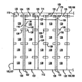
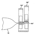
図1に示すように、多層の可撓性ウェブ材料100が膨張性クッション121のために提供される。ウェブ材料100は、第1の長手方向端102と第2の長手方向端104を有する第1のフィルム層105、および第1の長手方向端106と第2の長手方向端108を有する第2のフィルム層107を含む。第2の層107は、第1の層105と重畳するように揃っており、通常第1の層105と同一の広がりを有する。すなわち、少なくとも対応する第1の長手方向端102、106は互いに揃い、さらに/または第2の長手方向端104、108は互いに揃う。幾つかの実施形態では、これらの層は、重畳領域において膨張性領域と部分的に重なる。 As shown in FIG. 1, a multilayer
図1は、ウェブ材料100(フィルム100とも記す)の第1の長手方向端110と第2の長手方向端112を定義するように結合される第1と第2の層105、107を有するウェブ材料100の上面図を示す。第1と第2の層105、107は、可撓性材料の単一シートから、スリットを有する若しくは開口された一端を有する平坦化された可撓性材料のチューブから、または、可撓性構造100の長手方向端112を定義するために長手方向端104、108に沿ってシールされてもよい二枚の可撓性材料のシートから作製することができる。例えば、第1と第2の層105、107は、接合される第2端104、108を定義するために折りたたまれた単一の可撓性材料シート(例えば、c字折りたたみフィルム)を含んでもよい。より詳細な例では、端104、108は、このような実施形態においてc字の折り目上に位置する。あるいは、例えば、第1と第2の層105、107は、揃った第1の長手方向端102、106に沿ってスリットが入れられた可撓性材料のチューブを含んでもよい(例えば、平坦化されたチューブ)。また、例えば、第1と第2の層105、107は、揃った第2端104、108に沿って互いに接合され、シールされ、そうでなければ貼り付けられた二枚の独立した可撓性材料シートを含んでもよい。 FIG. 1 shows a web having first and
ウェブ材料100は、当業者に知られた種々の可撓性ウェブ材料から作製することができる。このようなウェブ材料は、エチレンビニルアセテート(EVAs)、メタロセン、低密度ポリエチレン(LDPE)、直鎖低密度ポリエチレン(LLDPE)、および高密度ポリエチレン(HDPE)などのポリエチレン樹脂、ならびにこれらのブレンドを含むが、これらに限られない。他の材料や構成も使用してもよい。開示されるウェブ材料100は、保存と輸送のため、中空チューブや中実コアに巻き取られる、またはファンフォールドボックス内に若しくは他の望まれる形態に折りたたまれることができる。 The
図1に示すように、ウェブ材料100は、ウェブ材料100の縦の広がりに沿って配置される一連の横シール118を含むことができる。各横シール118は、長手方向端112から膨張チャネル114へ延伸する。示される実施形態では、膨張チャネル114は、長手方向端112とは反対の長手方向端110に沿って延伸し、したがって、横シール118は、長手方向端112から第1の長手方向端110へ延伸する。幾つかの実施形態では、可撓性構造110は、長手方向112および/または110に関してどこか他の場所に位置する膨張チャネル114を含んでもよい。例えば、膨張チャネルは、構造100の長さに沿って長手方向端112および/または110の間の中間位置(例えば、中ほどに)で延伸してもよい。幾つかの実施形態では、さらに、またはこれに替えて、可撓性構造100は、長手方向端112に沿った膨張チャネル114を含んでもよい。図示された実施形態では、各横シール118は、フィルム110の第2の長手方向端112に最も近い第1端122、およびフィルム110の第1の長手方向端110から横寸法d離れる第2端124を有する。チャンバ120は、シールまたは長手方向端112の折り目、および隣接する一対の横シール118によって形成される境界内に定義される。 As shown in FIG. 1, the
図1の実施形態の各横シール118は、実質的に直線的であり、第2の長手方向端112に対して実質的に垂直に延伸する。他の実施形態では、異なる配置の横シール118を用いてもよい。例えば、幾つかの実施形態では、横シール118は波形またはジグザグパターンを有していてもよい。 Each
横シール118ならびにシールされた長手方向端110、112は、当業者に知られた様々な技術によって形成することができる。このような技術には、接着、摩擦、溶接、融合、加熱シーリング、レーザシーリング、および超音波溶接が含まれるが、これらに限られない。 The
縦膨張チャネル114となり得る閉鎖通路などの膨張領域が提供される。縦膨張チャネル114は、図1に示すように、横シール118の第2端124とフィルムの第1の長手方向端110との間に設けてもよい。好ましくは、縦膨張チャネル114は、縦辺110に沿って縦に延伸し、膨張口116が縦膨張チャネル114の少なくとも一端に設けられる。縦膨張チャネル114は、横幅Dを有する。好ましい実施形態では、横幅Dは、長手方向端110と横シール118の第2端124との間の横寸法dと実質的に同じである。ただし、他の配置では異なる横幅Dが使用可能であることが理解される。 An expansion region such as a closed passage that can be the
長手方向端112と横シール118は、協同的に膨張性チャンバ120の境界を定義する。図1に示すように、各膨張チャンバ120は、縦膨張チャネル114に向かって開いたマウス(例えば開口125)を介して縦膨張チャネル114と流体を交換できる状態であり、このため、更にここで述べるように、膨張性チャンバ120の膨張が許容される。 The
一つの実施形態では、可撓性構造100は、対応する横シール118に隣接するまたは接続され、対応する膨張性チャンバ120に向かってまたは膨張チャンバ120内へ延伸するシール拡張部128をさらに含んでもよい。シール拡張部128は、チャンバのより小さな幅または幅における制約に対応する、チャンバの垂直に低い領域を定義し、これにより、屈曲可能な領域を作り出す。屈曲可能な領域は、互いに揃うことで屈曲可能な線を形成し、これにより、ウェブ材料100の可撓性が向上し、より屈曲または折り曲げやすくなる。このような可撓性により、フィルム100は規則的におよび不規則的に形成された対象物に巻き付くことが可能となる。チャンバ部130は、隣接するチャンバ部130および膨張チャネル114と流体交換可能である。シール拡張部はいかなる形状(例えば、示されている四角形、円、卵型、あるいは他の規則的または不規則的形状)、大きさでもよい。幾つかの実施形態によると、横シール118は、シール拡張部などから中断することなく連続する。 In one embodiment, the
幾つかの実施形態では、フィルム100は、フィルム100の縦の縁に沿って延伸し、フィルム100の第1と第2の層を横断する弱められた部分126(例えば、ミシン目などの弱められた線)を含む。弱められた部分126のそれぞれは、例えば部分的または全体的に横シール118の長さに沿って、第2の長手方向端112から第1の長手方向端110に向かって延伸する。図示された実施形態では、弱められた部分126は弱さの横線の形状であり、可撓性構造100における弱さの横線のそれぞれは、隣接する一対のチャンバ120の間に設けられる。例えば、図1に示されるように、弱さの横線126のそれぞれは、隣接する二つの横シール118の間と隣接する二つのチャンバ120の間に設けられていてもよい。弱さの横線126は、隣接する膨張性クッション121の分離を容易にする。幾つかの実施形態では、横シール部を定義するより厚い横シール118を用いることができ、弱められた部分126は、少なくとも可撓性構造100の横シール部の一部に沿って設けられてもよい。 In some embodiments, the
弱められた部分126は、当業者に知られた様々な配置で設けることができる。例えば、幾つかの実施形態では、弱められた部分126は、弱さの横線126として設けることができ(例えば、図1に示すように)、複数のミシン目の行を含んでよく、ミシン目の行は、行の横方向に沿って互いに離隔し、交互する島とスリットを含む。島とスリットは、行の横方向に沿って規則的または不規則的な間隔で存在していてもよい。島は、弱められた部分を越えて小さな接続を形成する。あるいは、例えば、幾つかの実施形態では、弱められた部分126は、可撓性構造100内に形成された刻み目の線などを含んでもよい。 The weakened portion 126 can be provided in various arrangements known to those of skill in the art. For example, in some embodiments, the weakened portion 126 can be provided as a horizontal line 126 of weakness (eg, as shown in FIG. 1) and may include multiple perforation rows, perforations. Rows contain alternating islands and slits that are separated from each other along the lateral direction of the row. The islands and slits may be present at regular or irregular intervals along the lateral direction of the row. The islands form small connections beyond the weakened areas. Alternatively, for example, in some embodiments, the weakened portion 126 may include knurled lines formed within the
弱さの横線126は、当業者に知られた様々な技術を用いて形成することができる。幾つかの技術としては、切断(例えば、バー、ブレード、ブロック、ローラ、車輪などの切断エレメントまたは目立てエレメントを用いる技術)および/または刻み目を付けること(例えば、電磁気的(例えばレーザ)切込みや機械的切込みなど、第1と第2の層内の材料の強度または厚さを低減する技術)が含まれるが、これらに限定されない。 The weakness horizontal line 126 can be formed using various techniques known to those of skill in the art. Some techniques include cutting (eg, techniques using cutting or sharpening elements such as bars, blades, blocks, rollers, wheels) and / or knurling (eg, electromagnetic (eg laser) notches and machines. Techniques for reducing the strength or thickness of the material in the first and second layers, such as targeted cuts), but are not limited to these.
好ましくは、膨張性チャンバ120の横幅129は、典型的には50インチよりも小さい。一般的には、横幅129は3インチから約42インチまでであり、より好ましくは、約6インチから約30インチ幅までであり、最も好ましいのは、約12インチである。弱められた部分126の間の縦の長さ127は、典型的には48インチよりも小さい。一般的には、弱められた部分126の間の長さ127は、少なくとも約2インチから約30インチまでであり、より好ましくは少なくとも約5インチから約20インチであり、最も好ましいのは、少なくとも約6インチから約10インチまでである。さらに、各膨張チャンバ120が膨張した際の高さは、少なくとも約1インチから約3インチまでであり、幾つかのケースでは、約6インチまでである。他の適切な寸法でもよいことが理解される。 Preferably, the
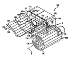
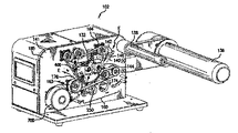
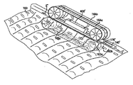
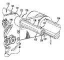
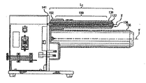
ここで図2〜6を参照すると、膨張していない材料の可撓性構造100を一連の膨張した枕またはクッション121へ変換する膨張・シーリング装置102が提供される。膨張していない可撓性構造100は、大量供給される、膨張していない材料134である。例えば、図2に示すように、膨張していない可撓性構造100は、内部支持チューブに巻き取られた、供給材料134のロールとして提供されることができる。幾つかの実施形態では、供給材料は、中空中心を有するロールへと巻き取られていてもよい。材料134のロールの支持チューブまたは中空中心は、膨張・シーリング装置102の供給サポートエレメント136、このケースではロール車軸135、の上に支持されてもよい。ロール車軸136は、ウェブ材料134のロールの中心またはチューブを収容する。他の実施形態では、材料のロールを支持するため、トレイ、固定されたスピンドル、複数のローラといった異なる構造を利用してもよく、あるいは異なる構成の供給材料(例えば、折りたたまれた供給材料)を用いてもよい。図3〜6は、装置にロードされるウェブ材料134のような可撓性構造100を含まない膨張・シーリング装置102を示している。幾つかの実施形態では、膨張していない材料の可撓性構造100は、ファンフォールドの形態のように折りたたまれた形から供給される。 With reference to FIGS. 2-6, there is provided an expansion /
種々の実施形態によると、膨張・シーリング装置100は、それぞれフィルム支持部を含むハンドリングエレメントを含んでもよい。フィルム支持部は、材料の膨張性ウェブを支持し、進路(例えば、図2の進路E)に沿って縦方向へ誘導してもよい。ハンドリングエレメントは、膨張していない状態にある、フィルム100のサプライ134を支持する供給サポートエレメント136を含む。膨張・シーリングアッセンブリ132は、フィルム100の重畳した層105、107の間に流体を導入することによって流体でフィルムを膨張させ、層105、107を互いにシールして内部に流体をシールするように操作することができる。フィルム支持部の二つ(例えば、ロール車軸136とガイド部材138)は、供給材料が第1から第2のフィルム支持部を通過する際に横方向に沿って異なる張力を受けるよう、支持構造141および互いに相対するように配置される。横方向に沿った張力量の相違(または、張った状態と緩んだ状態の量の相違)は、ガイド部材138の長さに沿った一つ以上の所望位置にある一つ以上の隆起した輪郭部によって実現される。例えば、ガイド部材138には、ノズルから丁度縦方向に上流の横位置に隆起した輪郭部152が与えられる。図2に示された例では、隆起した輪郭部152にとって好ましい位置は、ガイド部材138のベースに近くてもよい。しかしながら、他の例(例えば、フィルムに沿って横方向の中ほどのどこか他の位置にノズルが位置する場合)では、隆起した輪郭部152は、ガイド部材138の長さに沿ったどこか他の位置に位置してもよく、所望の位置に移動可能であってもよい。ガイド部材の隆起した輪郭部は、一つの横位置と他の位置の間で、フィルム材料が進む進路の輪郭に相違を引き起こし、このため、進路に沿って実質的に同じ縦位置において互いに横に配されるウェブの二つの位置に対して張った状態(または張力)に相違をもたらす。一つの実施形態では、ガイド部材138の隆起した輪郭部は、より深い湾曲を引き起こし、このため、小さな輪郭部における湾曲やフィルム100が進行する進路と比較し、フィルム100が進行するための進路が長くなる。 According to various embodiments, the expansion /
図2〜6に戻ると、膨張・シーリング装置102は、大量供給サポート136を含んでもよい。膨張されていない大量の材料は、大型供給サポート136によって支持することができる。例えば、大量供給サポートは、膨張されていない材料を保持するように操作できるトレイであってもよく、このトレイは、例えば固定された表面または複数のローラによって設けることができる。材料のロールを保持するため、トレイはロール周辺で窪んでいてもよく、あるいはトレイは凸状であり、ロールをトレイ上に吊り下げてもよい。大量供給サポートは、供給されたウェブ材料を吊り下げる複数のローラを含んでもよい。例えば図2に示すように、大量供給サポートは、ウェブ材料134のロールの中心を収容する単一のローラを含んでもよい。この例では、大量供給サポートは、材料134のロールのコアまたは中心を通過するロール車軸またはスピンドル136であってもよい。典型的には、コアは厚紙または他の適切な材料によって作製される。大量供給サポート136は、軸Yを中心として回転してもよい。 Returning to FIGS. 2-6, the expansion /
ウェブ材料100は、駆動機構160によって引き出される。幾つかの実施形態では、(例えば、固定されたロッドまたはローラを含んでもよい)ガイド部材138などの中間部材がロール134と駆動機構160の間に位置してもよい。例えば、任意のガイド部材138は、支持部材141から通常垂直に延伸することができる。ガイド部材138は、材料が進行する材料進路「B」に沿って可撓性構造100が材料134のロールから離れるように誘導するために位置することができる。材料進路「B」は縦進路とも呼ばれる。図2に示すように、ガイド部材138は、供給された材料を支持する材料サポート136と装置102の膨張・シーリングコンポーネントとの間に配置される。ガイド部材138は、フィルム100が湾曲した縦進路をたどるよう、フィルム100が供給側から膨張・シーリングアッセンブリへ送り出される配置することができる。ガイド部材138は、フィルム支持表面(例えば、ガイド部材の側に沿って延伸する表面であり、フィルムが進路Bを進む際にその周りで湾曲する)を定義する一つまたは複数の表面を有することができる。幾つかの例では、以下にさらに述べるように、ガイド部材138は、一つまたは複数の拡張エレメントを含んでもよい。この一つまたは複数の拡張エレメントは、少なくともガイド部材のフィルム支持表面の一部を与え、フィルム100の異なる横位置においてフィルム100に可変張力を与えることができるようにガイド部材を構成する。 The
ガイド部材138またはその一部は、膨張・シーリング装置102に可動連結され、フィルム100が駆動機構160によってロール134から引き出されている時に支持部材141に対してガイド部材138またはその可動な一部が動く(例えば、回転、並進する、振動するなど)ことができる。幾つかの例では、ガイド部材138はガイドローラを含むことができる。ガイドローラは、車軸またはロッド部137、およびロッド部137に同軸連結される回転可能部なまたはローラ部139を含み、ロッド部とローラ部の共通軸148を中心にローラ部139が回転する。ローラ部139は、フィルム100を支持するフィルム支持表面150を与えてもよく、この場合、フィルム支持表面はフィルム100がロール134から引き出されている時にフィルム100とともに動く。可動性のフィルム支持表面150により、ガイド部材138とフィルム100の間のすべり摩擦を低減または排除することができる。しかしながら、固定されたフィルム支持表面150を有するガイド部も想定される。例えば、ガイド部材は、車軸137に類似し、回転可能部139を持たないロッドを含んでもよい。すべり摩擦を低減するため、ポリテトラフルオロエチレン(PTFE)のような低摩擦材料を(例えば、コーティングの形状で、または接着される材料のストライプの形状で)非回転性ロッドのフィルム支持表面150の少なくとも一部に設けてもよい。さらに他の実施形態では、非回転性部若しくはガイド部材のロッド、および回転可能な部分(例えばローラ)は同一の広がりを持たなくてもよい。例えば、ガイド部材138の回転部だけが拡張エレメント152であってもよい。フィルムがガイド部材上を移動する際に回転しないガイド部材のフィルム支持表面はコーティングされていてもよく、あるいは、摩擦低減材料が設けられていてもよい。 The
幾つかの実施形態では、ガイド部材138は、図3の矢印139で示されるように、供給材料が進む縦進路Bの法線方向にガイド部材138が移動するよう、追加的にまたはそれに替えてデバイス102に連結されていてもよい。このような動きは、供給材料が進路Eに沿って進行する際に供給材料に掛かる張力の増大を軽減するために用いることができる。例えば、ガイド部材138の通常の状態(例えば、負荷がかからない、または供給材料に通常の張力が掛かるとき)では、ガイド部材138は、スプリングによって負荷が掛けられていてもよく、あるいは支持構造141の第1の側143に傾いてもよい。供給端とピンチゾーンの間の部分に沿ったフィルム100に掛かる張力の増大は、ばねの力に対するガイド部材138の下方向の動きによって軽減することができる。ばね定数は、フィルムに対して十分な量のバイアス力を印加してフィルムが張った状態を維持し、かつ、フィルムおよび/または装置102を破損する可能性のある閾値をフィルム中の張力が超えることを防ぐよう十分にソフトであるよう、選択することができる。このように可動式で装置102に連結されるガイドローラ138は、ダンサーローラとも呼ばれる。 In some embodiments, the
本開示に係るガイド部材138は、以下にさらに述べるように、一つまたは複数の拡張エレメント152を含んでもよい。幾つかの実施形態では、拡張エレメント152は、ガイド部材138の幾つかのまたはすべてのフィルム支持表面150を提供してもよい。したがって、本開示のこの原則に従うガイド部材138は、装置102のロール134と膨張ノズル140との間におけるフィルム100の撓みを防止または低減するよう、材料134を制御するように構成される。 The
種々の実施形態では、貯蔵材料(例えば、ウェブ材料100)は、ガイドロールと噛み合うことなく材料の貯蔵ロール(例えば、材料134のロール)から下流へ進むが、これに替わり、膨張・シーリングアッセンブリ132へ直接進んでもよい。 In various embodiments, the storage material (eg, web material 100) travels downstream from the storage roll of material (eg, roll of material 134) without meshing with the guide roll, but instead, the expansion /
シーリングアッセンブリの一部を構成可能なピンチ領域176へウェブ材料100を誘導するため、ブレーキやガイドローラ、またはウェブフィード機構の使用とともに、またはこれらの使用に替えて、他の適切な構成を利用してもよいことが理解される。暗示されるように、ウェブ材料100は撓む、ひだが発生する、ガイドローラ138に沿って流される、ピンチゾーン176からアライメントがずれる、張った状態と撓んだ状態が交互に現れる、あるいは輸送中に多様な変形への対象となり得るため、膨張・シーリングアッセンブリ132には、これらの変形を補償する適切な調整機能が必要となる場合がある。例えば、ノズル140は少なくとも一部が可撓性であってもよく、これにより、構造がノズル140に向かってノズル140上に仕込まれる際にウェブ材料100が近づく方向にノズル140が適合することができ、その結果、ウェブ材料100がノズル140に向けてノズル140上に仕込まれる際にウェブ材料100が直面する仕込み角度や方向の変化または他の変化を補償するまたは適合するようにノズル140を操作可能にすることができる。幾つかの例では、上述したように、ガイドローラ138は、供給材料の輸送におけるいかなる変化も調整または排除するよう、シーリングアッセンブリ132に対して横に移動可能であってもよい。 Use other suitable configurations with or in place of the use of brakes, guide rollers, or web feed mechanisms to guide the
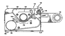
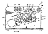
膨張・シーリング装置102は、膨張・シーリングアッセンブリ132を含む。好ましくは、膨張・シーリングアッセンブリ132は、ウェブ材料100がロール134から剥がされる際にウェブ材料100が連続的に膨張するように構成される。ロール134は、好ましくは、直列に接続されたチャンバ120のチェーンを複数有する。ウェブ材料100から膨張した枕の製造を開始するには、ウェブ材料100の膨張口116を膨張ノズル140などの膨張アッセンブリの周りに挿入し、材料進路「E」に沿って進める。図1〜6に示された実施形態では、好ましくは、チャンバ120が膨張ノズル140とサイドアウトレット146に対して横に延伸するよう、ウェブ材料100を膨張ノズル140上で進行させる。サイドアウトレット146は、ノズルベース144に対して流体を横方向にチャンバ120内へ誘導し、ウェブ材料100が材料進路「E」に沿って縦向に進む際にチャンバ120を膨張させてもよい。膨張したウェブ材料100は、その後シーリング領域174においてシーリングアッセンブリ103によってシールされ、膨張した枕またはクッション121のチェーンを形成する。 The expansion /
サイド膨張領域168(図2に示される)は、サイドアウトレット146に隣接する進路「E」に沿って膨張・シーリングアッセンブリの一部として示されており、この中でサイドアウトレット146からの空気がチャンバ120を膨張させることができる。幾つかの実施形態では、膨張領域168は、膨張チップ142とピンチ領域176の間に配置される。ウェブ材料100は、膨張ノズル140の前方端に配置されるノズルチップ142において膨張ノズル140の回りに挿入される。膨張ノズル140は、ノズルアウトレットを介して加圧された空気などの流体を膨張されていないウェブ材料100内へ注入し、これにより材料を膨張した枕またはクッション121へ膨張させる。膨張ノズル140は、一つ以上のノズルアウトレット(例えば、サイドアウトレット146)により、流体インレットに入り込む流体源とスムーズに接続されるノズル膨張チャネルを含むことができる。他の配置では、流体は他の適切な加圧されたガス、泡状物質、または液体でもよいことが理解される。ノズルは、一つ以上のノズルベース144を含み得る伸張された部分、可撓部、および/またはチップ142を含んでもよい。伸張部は、可撓性構造をピンチ領域176へ誘導することができる。同時に、ノズルは一つ以上のアウトレットを介して可撓性構造を膨張させることができる。一つ以上のアウトレットは、一つ以上のノズルベース144の外側の膨張チャネル(例えば、アウトレット146)、可撓部142a、またはチップ142から貫通する。膨張ノズル140は、筐体の前面から遠ざかるように延伸する。 The side expansion region 168 (shown in FIG. 2) is shown as part of the expansion / sealing assembly along the path "E" adjacent to the
図3〜6に示すように、サイドアウトレット146は、ノズルベース144に沿って膨張チップ142から縦の距離に向かって縦に延びることができる。種々の実施形態では、サイドアウトレット146は、サイドアウトレット146が膨張チャンバ120の膨張をほぼ膨張の時間まで続けるよう、シーラーアッセンブリの近くで、幾つかの実施形態ではシーラーアッセンブリと重なりながら始まる。これにより、シーリング前に膨張可能なチャンバ120に注入される流体の量を最大化することができ、デッドチャンバ、すなわち、十分な量の空気を有さないチャンバの量を最小化することができる。他の実施形態では、スロットアウトレット146はピンチ領域176の入口を過ぎて下流へ延伸できるが、アウトレット146から出た流体の一部をウェブ材料100内へ誘導される。ここで用いられるように、上流と下流という用語は、ウェブ材料100の進行方向に対して用いられる。ウェブの開始点が上流であり、ウェブは、ウェブ材料が膨張され、シールされ、冷却され、膨張・シーリング装置から取り外される際に下流へ流れる。 As shown in FIGS. 3-6, the
サイドアウトレット146の長さは、チップ142とピンチ領域176の入口の間で膨張ノズル140の一部を拡張する長さを有するスロットでもよい。一つの例では、スロット長は、チップ142からピンチ領域176の入口までの距離の半分よりも短くてもよい。他の例では、スロット長は、チップ142からピンチ領域176までの距離の半分よりも大きくてもよい。他の例では、スロット長は、チップ142からピンチ領域176までの距離の約半分でもよい。サイドアウトレット146は、例えば、膨張ノズル140の長さの約30%の長さを有していてもよく、幾つかの実施形態では、少なくとも膨張ノズル140の長さの少なくとも約50%、または膨張ノズル140の長さの約80%を有していてもよいが、ただし、他の相対的な大きさも使用できる。サイドアウトレット146は、チャンバ120を膨張させるため、各チャンバ120のマウス125を介し、ノズルベース144の横側から膨張ノズル140に対して横方向に流体を排出する。膨張ノズルのチップは、材料がチップ上に押し付けられる際、層を開け、チップ上の膨張チャネル内の層を分離するために用いることができる。例えば、ウェブが従来の膨張ノズル上に引き出される際、従来の膨張ノズルのチップは、層を無理に互いに分離させる。サイドアウトレット146のような横のアウトレットに加え、または横のアウトレットが無い状態で縦長のアウトレットを設けてもよい。横のアウトレットは縦長のアウトレットの下流であり、膨張ノズル140のノズルベース144のノズル壁の縦辺に沿ってもよい。 The length of the
ブロワー700からノズル140を通過する流体の流速は、典型的には2から20cfmである。ただし、例えば、ブロワー700が100cfmを超える流速を有すなど、より高い流速の流体源を用いる場合には、さらに高い流速を用いてもよい。 The flow velocity of the fluid from the
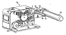
図3、6、7は、膨張・シーリングアッセンブリ132の側面図を表す。図3に示されるように、流体源はカバー184の後方、あるいは、カバー184が設けられる筐体プレート185を含む、ノズルとシーリングアッセンブリのための構造支持体の後方に配置することができる。図3に示すように、カバー184は、シーリング・膨張アッセンブリ開口部184aを含む。(例えば、ブロワー700からの)流体源は、流体膨張ノズル導管に接続され、フィードする。ウェブ材料100は、膨張・シーリングアッセンブリ132へウェブを誘導する膨張ノズル140上にフィードされる。 3, 6 and 7 show side views of the expansion /
種々の例がここで記述され、図2〜7に示されるが、これらの例は限定するものではなく、ノズル140と膨張アッセンブリは、ここでの開示に基づいて当業者が適用する際、既に知られた実施形態、または本開示の利点を得ることができるように発展させた実施形態に応じて構成することができる。 Various examples are described herein and are shown in FIGS. 2-7, but these examples are not limited and the
好ましくは、ウェブ材料100は、材料進路「E」に沿ってピンチ領域176上の加熱アッセンブリ400を過ぎ、シーリングアッセンブリを通過するよう連続的に送り出され、第1と第2の層105、107を互いにシールすることにより、ウェブ材料100に沿った連続的な縦シール170を形成する。縦シール170は、図1において見えない線として示される。好ましくは、縦シール170は、第1の長手方向端102、106から横方向に距離を置くように配置され、最も好ましくは、縦シール170は、各チャンバ120のマウス125に沿って配置される。 Preferably, the
ウェブ材料100は、駆動機構160によって膨張・シーリングアッセンブリ132を通過して送り出されるまたは駆動される。膨張・シーリングアッセンブリ132は、駆動メカニズムを組み込んでいてもよく、あるいは二つのシステムが独立に作動してもよい。駆動機構160は、可撓性構造をシステムを通して動機を与えるために操作可能な一つ以上の装置を含む。例えば、駆動機構は、US2017/0282479に開示されるような、可撓性材料100を材料進路「E」に沿って下流方向へ駆動するように操作可能な一つ以上のモーター駆動ローラを含む。一つ以上のローラまたはドラムがドライブモータに接続され、一つ以上のローラがシステムを駆動する。種々の実施形態によると、駆動機構160は、可撓性構造に接触するベルトを備えること無くウェブ材料100を駆動し、あるいは、幾つかの実施形態では、システム全体がベルトレスである。他の例では、システムはベルトを備えるが、ベルトはウェブ材料100と接触せず、替わってローラを駆動する。他の例では、システムは、US2015/0239196に開示されているような幾つかの駆動エレメント上にベルトを有するが、他のエレメント上にはベルトを持たない。他の例では、システムは、ローラ全体に亘って織合わされたベルトを有してもよく、これにより、材料をベルトによってシステムを通して駆動することができる。例えば、米国特許第8,128,770は、クッション121の膨張とシーリングを制御するためにベルトとローラを利用するシステムを開示しており、ここに与えられる開示はこのようなシステムと共に利用することができる。 The
種々の実施形態によると、駆動機構160は、対向する圧縮機構161、162を含む。図6に示されるように、圧縮機構161は、圧縮機構162に隣接するように位置する。圧縮機構161は、圧縮機構162と相対的に位置し、二つの圧縮機構161、162は、ピンチ領域176において可撓性材料100を受け取るように一緒に操作される。ピンチ領域176は、圧縮機構161と圧縮機構162がウェブ材料100に対して位置することでウェブ材料100をこれらの間で挟むための領域によって定義される。ピンチ領域176は、図6に示されるAからBへ延伸することができる。 According to various embodiments, the
駆動機構160はさらに他の圧縮機構を含んでもよい。他の圧縮機構も圧縮機構161または圧縮機構162に隣接するように位置するであろう。他の圧縮機構と圧縮機構161または圧縮機構162との関係は、二つの圧縮機構が第2のピンチ領域を形成する関係、または圧縮機構がウェブ材料100と接触して圧力を掛けるピンチ領域176を拡張する関係でもよい。 The
種々の実施形態によると、駆動システムは、ピンチ領域176と同時に配置されるまたはピンチ領域176の下流である冷却ゾーンを形成する。図6に示された詳細な例によると、ピンチ領域176は、加熱ゾーン167と冷却ゾーン169を含む。冷却ゾーン169は、少なくとも部分的にピンチ領域176内の圧縮機構162と161の間で定義される。圧縮機構162および/または圧縮機構161は、ピンチゾーンの点Aから点Bまでの進路を形成し、この進路の少なくとも一部は、ピンチ領域176内で圧縮機構からの圧力を受けつつ、新たに形成された可撓性材料100上の縦シール112を冷却する。縦シール112は、シーリングアッセンブリ132の一部である加熱アッセンブリ400によって形成される。 According to various embodiments, the drive system forms a cooling zone that is co-located with the
圧縮機構162に沿った曲面162aの周辺領域は、可撓性材料と直接噛み合う接触領域を形成する。後にさらに詳述するように、幾つかの実施形態では、周辺領域は円筒状であり、したがって、周辺領域はこの円筒の外周領域である。他の実施形態では、周辺領域は、圧縮機構162を定義する形状の表面の外側領域である。冷却ゾーンに対してピンチ領域176によって引き起こされる保持圧力が存在しない場合には、膨張されたチャンバ内の空気圧に起因し、縦シール112の効果は減少するであろう。種々の実施形態によると、冷却ゾーンは十分に長く、シール内で縦シール112を十分に冷却することができ、このため、膨張されたチャンバ120内の空気圧が、縦シール112がその中の空気圧を保持する能力を超えて縦シール112を引き伸ばしたり変形させたりすることが無い。冷却ゾーンが十分に長くなければ、このような縦シールは適切に固まらない。 The peripheral region of the curved surface 162a along the
ピンチ領域は、任意の適切な形状を有することができる。例えば、ピンチ領域は、実質的に直線的でもよい(例えば、図9AからBにおける176´)。好ましい例では、ピンチ領域176は弧状である。形状に関係なく、ピンチ領域はローラ、ベルト、または他の適切な駆動機構によって構成される。図2〜7に示すように、ピンチゾーンはベルトとディスクの組み合わせによって定義される。 The pinch region can have any suitable shape. For example, the pinch region may be substantially linear (eg, 176'in FIGS. 9A-B). In a preferred example, the
ピンチゾーンが弧状の場合にピンチ点AとBの間の角度が大きすぎると、膨張した材料はそれ自身に巻き付いてしまうかもしれない。このため、曲面進路162a周りにおけるピンチ点AとBの相対的な位置は、可撓性材料がそれ自身と干渉しないような最高のシールを提供する位置が好ましく、これにより、適切に空気を保持する優れた縦シール112が提供される。種々の実施形態によると、ピンチ点Aは、軸161a周りで測定すると、ピンチ点Bから15°よりも大きな角度に位置する。種々の実施形態によると、ピンチ点Aは、軸161a周りで測定すると、ピンチ点Bから180未満の角度に位置する。種々の実施形態によると、ピンチ点Aは、軸161a周りで測定すると、ピンチ点Bから85°と145°の間の角度に位置する。種々の実施形態によると、ピンチ点Aは、軸161a周りで測定すると、ピンチ点Bから105°と125°の間の角度に位置する。種々の実施形態によると、ピンチ点Aは、軸161a周りで測定すると、ピンチ点Bから約115°の角度に位置する。上記実施形態と例のそれぞれにおいて、ピンチ点AとBは、圧縮機構161と162の相対的な位置および/または形状によって決まることが理解される。 If the pinch zone is arcuate and the angle between pinch points A and B is too large, the expanded material may wrap around itself. For this reason, the relative positions of the pinch points A and B around the curved path 162a are preferably positions that provide the best seal so that the flexible material does not interfere with itself, thereby retaining air properly. An excellent
種々の実施形態によると、圧縮機構は、調整機構、傾斜機構、またはこれらの互いの関係もしくは互いの圧力を制御するための他の適切な装置を含んでもよい。 According to various embodiments, the compression mechanism may include an adjusting mechanism, a tilting mechanism, or other suitable device for controlling their relationship to each other or the pressure to each other.
好ましい実施形態によると、駆動機構160は、対向駆動システムを備えてもよい。種々の例では、対向駆動システムは、圧縮機構161と162の一部またはすべてを形成する。種々の例では、図4〜7に示されるように、駆動機構の一部はドライブベルト163を含むことができる。種々の例では、駆動機構の一部は搬送ベルト164を備えることができる。搬送ベルトは動力によって駆動されてもよく、あるいは、動力によって駆動されず、単にウェブ材料100またはシステムの他の駆動機能によって受動的に駆動されてもよい。駆動機構の一部は、一つのベルト表面に対応する二次表面310を含んでもよい。駆動機構の一部は、他のベルト表面、ローラ表面、または固定された表面に対応するガイド表面410を含んでもよい。 According to a preferred embodiment, the
種々の実施形態によると、駆動機構160は圧縮機構162を含んでもよい。圧縮機構162はドライブベルト163を含む。幾つかの実施形態では、ベルト163は、平坦/直線的なウェブ134進路の一部を定義する。他の実施形態では、ベルト163は弧状のウェブ134進路の一部を定義する。ベルト163はウェブ134をピンチ領域176を通してウェブ134を引き出す、押出す、そうでなければ輸送し、(平坦か弧状の)ピンチ領域176の進路に沿ってウェブ134を十分に強固に保持し、縦シール112が適用され、その後冷える際にチャンバ120内に流体を保持する。冷却ゾーン169において強固に閉鎖された縦シール112をベルト163を介して保持することで、膨張されたチャンバ120内の空気圧によって引き起こされるシール112に対する延伸や変形を制限することができる。 According to various embodiments, the
駆動機構160は、ウェブ134が下流方向に送り出される際に加熱シール112が連続的に作り出されるよう、加熱アッセンブリ400に隣接するウェブ134を送り出すことができる。一つの例では、駆動機構160は、一つ以上の圧縮エレメントを介してウェブ134に張力をかけながら加熱アッセンブリ400に押し当て、縦シール112を作り出す。より詳細には、後述するように、ベルト163に張力を与え、ウェブ134の少なくとも一部を挟んで加熱アッセンブリ400に押し付けるための圧縮力を作り出してもよい。 The
種々の実施形態によると、弾性ベルト、第1のベルト、または第2のベルトとも記すことができるベルト163は、種々の構成を含む。例えば、ベルト163は、ピンチ領域176を通してウェブ134を輸送するための適切な構成を含んでもよい。ベルト163は、高い粘着および/または摩擦材料などの高グリップ表面(例えば、粘着性の外表面)をベルト163の表面に有してもよい。ベルト163の高グリップ表面は、ベルト163と一体形成されたような、ベルト163自体の一部と定義することができる。ベルト163の高グリップ表面は、ベルト163が形成される材料の性質に起因するものでもよい。幾つかの例では、ベルト163の高グリップ表面は、ベルト163上に物質または材料を塗布することで得ることができる。例えば、ベルト163に粘着性物質または材料をコートする、スプレーする、さもなければ塗布してもよい。幾つかの例では、ベルト163とウェブ134の間の摩擦を増大させるために材料をコートする、スプレーする、さもなければ塗布してもよい。幾つかの例では、ベルト163の少なくとも一部を選択的に加熱することで高いグリップ表面を得てもよい。例えば、ベルト163は、ベルトを加熱するとベルト163の粘着性または摩擦を増大させる材料から形成してもよい。ここで述べたように、粘着性材料は、ウェブ134に対する比較的小さな力でベルト163がウェブ134をグリップするような、多少の粘着性がある、グリップ力がある、または付着しやすい材料である。 According to various embodiments, the
ベルトは、外部と内部を含むことができる。内部は、ケプラー(登録商標)コアなどの強化コアを含むことができる。ベルト163のコアは、所望の構造特性を提供してもよい。例えば、コアは、操作の間、ベルトの放射状の、縦の、または横の撓みや伸張を制限してもよい。ベルト163は、加熱アッセンブリ400よりも広くてもよい。ベルト163は、主面、主面に対向する底面、および主面と底面の間を延伸する一対の対向する側面を含んでもよい。ベルト163は、ウェブ134を加熱アッセンブリ400に向かって傾けてもよい。例えば、ウェブ134は、ベルト163がウェブ134の少なくとも一部を掴んで加熱アッセンブリ400に押し付けるよう、ベルト163と加熱アッセンブリ400の間に配置されてもよい。一つの例では、ベルト163は、主面がウェブ134を掴んで加熱アッセンブリ400に押し付けるように配置されてもよい。 The belt can include the outside and the inside. The interior can include reinforced cores such as Kepler® cores. The core of
一つの例では、ベルト163の外部は、ウェブ134をピンチ領域176を通って輸送されることを容易にすることができる。例えば、ベルト163の外部は、高いグリップ特性を有してもよい。例えば、ベルト163は、加熱アッセンブリ400による加熱の間、ウェブ134と接触してウェブ134をグリップする高粘着性材料および/または高摩擦材料をその表面上に有してもよい。ベルト163に高いグリップ特性が無い場合、ウェブ134に対してベルト163に十分に張力が掛からず、ウェブ134はベルト163に対して移動(例えば、スリップするまたはスライドする)することがある。ベルト163の粘着特性および/または摩擦特性により、ベルト163は、ウェブ134に対する小さな圧縮力で容易にウェブ134をグリップまたは掴むことができる。このように、ベルト163の高い粘着特性および/または摩擦特性に起因し、ウェブ134をピンチ領域176を通して下流方向に駆動するために必要なベルト163の張力を大幅に低減することができる。一つの例では、ピンチ領域176を介するベルト163の効果的な圧縮力は、最小の151b、201b、または251bと、最大の301b、351b、または401bの間でよく、例えば251bと301bの間である。高粘着性および/または高摩擦ベルトを利用しない設計では、ピンチ領域を介する効果的な圧縮力はかなり高くなり、例えば2から4倍高い。 In one example, the outside of the
ベルト163の高いグリップ特性は、ベルト163の材料によって決めることができる。例えば、ベルト163は、少なくとも部分的に弾性材料で形成してもよい。一つの例では、粘着性のある外表面は、弾性材料によって決められる。一つの例では、ベルト163の外部は、少なくとも部分的に弾性材料で形成されてもよい。弾性材料は、合成材料、天然材料、または合成材料と天然材料の組み合わせであってよい。具体的な応用にも依存するが、弾性材料は、シリコーン、EPMおよび/またはEPDMゴムなどの飽和ゴムでもよい。弾性材料は、天然ゴム、ブチルゴム、スチレン−ブタジエンゴム、および/またはニトリルゴムなどの不飽和ゴムでもよい。弾性材料は、熱可塑性エラストマー、熱可塑性ポリウレタン、熱可塑性オレフィン、および/または熱可塑性加硫物でもよい。一つの例では、ベルト163は、少なくとも部分的に低硬度ゴムまたはシリコーンで形成してもよい。幾つかの例では、ベルト163は、高いグリップ表面を持つよう、織目を付けられるまたは成形されていてもよい。例えば、ベルト163は、大きな表面粗さを有してもよい。幾つかの例では、ベルト163は、リブ付けされていてもよく、さもなければベルト163とウェブ134間の摩擦を増大させるように構成されてもよい。 The high grip characteristics of the
幾つかの例では、ベルト163は、弾力的にまたは弾性的に伸長可能である。例えば、ベルト163は、ゴムやシリコーンなどの一般的に弾性のある材料で少なくとも部分的に形成されてもよい。このような例では、以下に説明するように、ウェブ134を駆動してピンチ領域176を通過する際、ベルト163は隣接する構造の周りで伸長する、または弾性的に変形する。ベルト163の伸長可能な特性は、上述した高いグリップ特性と組み合わされてもよく、あるいは高いグリップ特性の代替であってもよい。より詳細には、ベルト163は、高いグリップ特性、伸長可能な特性、または高いグリップ特性と伸長可能な特性を有してもよい。 In some examples, the
ベルト164は、ベルト163と連動してあるいは連動せずに、上述したように構成することができる。例えば、第1のベルトまたは第2のベルトとも記すことができるベルト164は、高い粘着性材料で形成されるような、高い粘着特性を有することができる。このような方法により、ベルト163、またはベルト164、あるいはベルト163とベルト164の両者は、ウェブ134をピンチ領域176を通して輸送するに適した構成を有することができる。以下、より詳細に述べるように、ウェブ134はベルト163とベルト164の間に位置することができる。このような例では、駆動機構160は、より低い効果圧縮力でウェブ134がピンチ領域176を通って移動しやすくなるよう、ウェブ134の片側に高粘着性ベルトを含んでよい。幾つかの例では、ベルト164はベルト163とは異なる材料で形成されてもよい。例えば、ベルト164はベルト163よりも粘着性が低くてもよい。一つの例では、ベルト164は、少なくとも部分的にポリテトラフルオロエチレンまたは他の類似する材料で形成される。 The
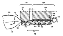
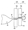
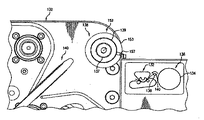
種々の実施形態によると、図2〜7に表されるように、ベルト163と164は互いに対向する。ベルト163と164は、ピンチ領域176内で相対的に構成され、その中でウェブ134を受け取る。より具体的には、示される実施形態では、ベルト163は、ピンチゾーンを定義して加熱ゾーン167と縦に重なるウェブ支持表面410に対して縮む。種々の実施形態では、ピンチゾーン176は、互いに横の関係にある複数の圧力領域を含む。例えば、ピンチゾーン176は第1の領域276aと第2の領域276bを含むことができる。幾つかの実施形態では、複数の圧力領域は、ウェブ材料100に対して異なる力を印加することができる。他の実施形態では、圧力領域は、同様の力を異なる方法で印加する。一つの例では、圧縮エレメント(例えばベルト163)は、二つの対向する異なる圧力エレメント(例えば、ディスク300と加熱アッセンブリ400)を押す。このように、対向する圧力エレメントは、異なる方法で圧力エレメントに圧力を印加し、二つの異なる圧力領域(例えば、第1の圧力領域276aと第2の圧力領域276b)を作り出す。これらの領域において異なる圧力の力がある場合、圧縮エレメント(例えばベルト163)は屈曲または変形し、異なる圧力を受け入れることができる。屈曲距離D.P.は、約5milから50milとすることができる。外側の圧力は、空気チャンバ20内の流体を単離することを促進することができるため、単離圧力であると考えられる。領域276aと276bのそれぞれにおいて圧力が異なる実施形態では、この相違は、例えば、他の領域に対してウェブ材料を通過させる狭い領域によって引き起こされ得る。他の例では、領域サイズは同様であるが、対向する圧縮エレメントは異なる材料を有する。このため、ウェブ材料は、一つの材料をより屈曲させ、その結果、一つの材料は他方よりも高い圧力を印加する。他の実施形態では、異なる領域は単に異なる方向または位置からの圧力を有するか、あるいは図7の例において示されるように、単離エレメント300は実際に圧縮エレメント(例えばベルト163)へ延伸するものの支持構造405は延伸しない。好ましい実施形態では、単離エレメント300は、隣接領域を形成する装置の輪郭に実質的に適合する連続表面である。例えば、支持表面410は、単離表面410と同様、湾曲する。他の実施形態では、単離エレメントは不連続表面310を有する。例えば、単離エレメント300は、流体の通過を制限する、さもなければウェブ材料100を安定化するための、材料に接する歯と十分な間隔を有するホイールである。 According to various embodiments, the
種々の実施形態によると、単離エレメント300は、膨張可能なチャンバ120からノズルへ逆流する流体の流れを阻止する、または食い止めるように構成される。さらに、またはこれに替えて、単離エレメント300は、システムから横に延伸するウェブ材料100の一部の動きから、シールされているウェブ材料100の一部を単離するように構成される。これらの結果の一つまたは両方は、シーリング機構をウェブ材料が通過する際、ウェブ材料に対して横に掛けられるシーリング領域の圧力を増大させる、またはウェブ材料100に複雑な屈曲またはカーブをかけることによって達成される。種々の実施形態によると、単離エレメント300は、シーリング機構の冷却ゾーンと加熱ゾーンの両者を通じてウェブ材料100との接触を維持することができる。ここで議論したように、単離エレメント300および/または表面310は、支持構造405またはピンチゾーンを定義するために用いられる他の圧縮機構から横にずれる。好ましくは、単離エレメント300と支持構造405は、縦に揃っている。横のずれは、単離エレメント300がチャンバ120とノズルとの間の流体の流れを阻止または食い止めるよう、十分に小さい。一つの例では、ずれG(図7参照)はベルト163の厚さよりも小さい。他の例では、ずれは単離エレメントの横の厚さの1/2の厚さよりも小さい。 According to various embodiments, the
図7に示されるように、一つの例によると、圧縮機構161は、表面164を有する単離エレメント300を含む。例えば、ベルト163はウェブ134を単離エレメント300の単離表面310から傾けてもよい。このような例では、ウェブ134は二次表面310に対して傾き、縦シール112が作り出される際に流体をチャンバ120内にシールする。後述するように、単離エレメント300は、ベルト163の主面にほぼ垂直な方向においてベルト163の一部を上または下に屈曲させてもよい。このような例では、ベルト163は、単離エレメント300によって引き起こされる屈曲を受け入れるために撓んでもよい。例えば、ベルト163は放射状に撓んで単離エレメント300の屈曲を受け入れてもよい。 As shown in FIG. 7, according to one example, the
単離表面または第2のシーリング面、もしくは二次表面とも記され得る単離表面310は、ガイド表面410に隣接してもよい。一つの例では、二次表面310は、縦方向L.D.において表面410と概ね揃ってもよい。種々の実施形態によると、単離表面310は、横方向において表面410の前、後、または両方に位置してもよい。 An isolated surface 310, which may also be referred to as an isolated surface or a second sealing surface, or a secondary surface, may be adjacent to a
二次表面310は、固定されている、平坦または直線状である、弧状である、またはこれらの任意の組み合わせでもよい。幾つかの実施形態では、単離エレメント300は回転するディスクであってもよい。好ましくは、ベルト164と単離表面310は、互いに縦にずれる。しかしながら、他の実施形態では、これらは、単離表面310の下を延伸するベルト164と重なってもよい。単離表面310と支持表面410は、必ずしも同じレベルで対向する圧縮機構と接しない。あるいは、単離表面310と支持表面410は、互いに垂直にずれていてもよく、これにより、一方または他方が、対向する圧縮機構(例えば、ベルト163)内へまたは圧縮機構に向かって遠くに延伸することができる。ここで用いられるように、ずれの垂直方向とは、ウェブ材料がシステムを移動する際のウェブ材料の主面に垂直な方向である。中間構成(例えば、以下でより詳しく議論するベルト164、加熱エレメント450、低摩擦手段460など)を説明する際においても、単離表面310は、ディスク圧力オフセットD.P.を定義する中間構成を有する表面410と比較して、ベルト163内へまたはベルト163に向かってより遠くに延伸することができる。図7は、ディスク圧力オフセットD.P.を示す。ディスク圧力オフセットD.P.は、約.020インチである。幾つかの実施形態では、表面310は固定されている。幾つかの例では、表面オフセットD.P.は、ウェブ134の材料厚と同一である、ウェブ134の材料厚よりも大きい、またはウェブ134の材料厚よりも小さい。これらの例と他の例では、ベルト163は放射状に撓み、表面310と410の間の表面オフセットD.P.を受け入れる。ベルト163が弾力的または弾性的に伸長可能な実施形態では、ベルト163は弾力的にまたは弾性的に伸長し、表面310と410に順応することがでできる。例えば、ベルト163は弾性的に表面310と410の周りで変形し、表面310と410の間の表面オフセットD.P.を受け入れる。このような例では、ベルト163はベルト163の主面に垂直な方向で弾力的に伸長し、表面オフセットD.P.を受け入れる。 The secondary surface 310 may be fixed, flat or linear, arcuate, or any combination thereof. In some embodiments, the
ベルト163は、ウェブ134の少なくとも一部を掴むための、表面310と410にそれぞれ対応する圧縮力を作り出してもよい。このような例では、表面310と410上のベルト163の圧縮力は異なってもよい。例えば、表面410に対するベルト163の圧縮力は、表面310に対するベルト163の圧縮力よりも小さくてもよい。このような例では、表面オフセットD.P.は、表面310と410に対するベルト163の異なる圧縮力を作り出す。圧縮力は、所望する機能的特性を達成するために十分である場合がある。例えば、圧縮力は低いかも知れないが、ベルト163がウェブ134をピンチ領域176を通って駆動することができれば十分である。さらに、ベルト163の表面310に対する圧縮力は、シール112が表面410の隣に作り出される間、チャンバ120から空気が漏れることを防げれば十分でもよい。より詳細には、ベルト163の表面310に対する圧縮力は、表面410に隣接する加熱シール領域からチャンバ120内の圧力を実質的に単離できれば十分かもしれない。
他の実施形態では、表面310は、回転するディスク300の一部を形成する。このような実施形態では、ウェブ材料がシーリングアッセンブリを通って移動する際、ウェブ材料はディスクを回転させる。他の実施形態では、駆動システムがディスクを回転する。 In another embodiment, the surface 310 forms part of a
図9Aと9Bは、平坦なピンチゾーン176´を有する異なる実施形態を図示しており、この実施形態では、上側(164a/b)と下側(例えば、163a/b)の圧縮エレメントは異なるレベルでウェブ材料100に圧力を掛け、材料を横に屈曲させる。例えば、ベルト163aと163bは、互いに相対的にD.P.´の距離で垂直方向にずれる。異なるレベルの圧力を印加する、対向する異なる圧縮エレメントに起因し、圧力は距離D.P.で互いにずれる。このように、直線的なピンチゾーン176´も異なる圧力領域276a´と276b´を確立する。サポート163cおよび/または加熱アッセンブリ400´などの内部構造も、他のエレメントからの圧力を与えるまたは食い止めるために位置するまたは傾いていてもよい。 9A and 9B illustrate different embodiments with flat pinch zones 176', in which the upper (164a / b) and lower (eg, 163a / b) compression elements have different levels. Pressure is applied to the
図9Cと9Dは、平坦なピンチゾーン176´´を有する他の実施形態を図示しており、この実施形態では、上側(164a/b´´)と下側(例えば、163d´´)の単一の圧縮エレメントは、異なるレベルでウェブ材料100に圧力を掛け、材料を横に、下側の圧縮エレメントを横に屈曲させる。対向する圧縮エレメント164a´´または164b´´は、163d´´とによって対向する圧力を形成し、オフセットD.P.を産み出す。このように、直線的なピンチゾーン176´´も異なる圧力領域276a´´と276b´´を確立する。このことは、単一の下側ベルトを含む例として示され、ベルトもD.P.屈曲する。この屈曲は、ノズル外にあり、生成するシールから離れた流体を単離することを促進する。 9C and 9D illustrate another embodiment having a
種々の実施形態によると、駆動機構160は圧縮機構161を含む。圧縮機構161はベルト164を含むことができる。種々の実施形態によると、圧縮機構161は、ガイド表面410を含む。種々の実施形態によると、ガイド上面410は、加熱アッセンブリ400に隣接してもよく、第1のシーリング表面とも記すことができ、ベルト163および/またはベルト164のベルト進路の少なくとも一部を設定してもよい。例えば、ベルト163および/またはベルト164は、ガイド表面410に巻き付いてもよい。幾つかの例では、ガイド表面410は、隣接するベルトサポートの間の線内に突き出て屈曲したベルト進路を形成してもよい。幾つかの実施形態では、ガイド表面は移動可能であり、例えば動力駆動されない、または動力駆動される滑車の周りの表面でもよい。図7〜8に示されるように、ガイド表面410は固定される。駆動機構の側面図(すなわち、ウェブを越えて横)から分かるように、ガイド表面は、平坦/直線的であってもよく(例えば図9A〜Bを参照)、あるいはガイド表面は弧状でもよい(図6参照)。一つの例では、図8A〜8Eに示されるように、ガイド表面は弧状であり、図6中の例に示されるように、駆動機構(例えばベルト164)の進路の少なくとも一部を弧の中に設定する。さらに、あるいはこれに替わり、駆動機構(例えばベルト163と164)は、圧縮機構の一部を形成し、対向する表面(例えば、ウェブ支持表面410)に対して引っ張る、さもなければ圧縮圧力を掛ける。ここで、一つ以上の圧縮機構は十分に静止して対向力を与える。このように、対向する面(例えば、ウェブ支持表面410)はベルト163と164の両者の進路の一部を定義する。進路のこの部分がピンチ領域176である。このような例では、ベルト163と164はガイド表面410に対して傾き、ウェブ134の層を一緒に挟み込む。好ましい実施形態では、ガイド表面410は、少なくとも部分的に円、および/またはピンチゾーン176を介して円形である。 According to various embodiments, the
図2〜7に示された特定の例を詳細に説明すると、駆動機構160は、圧縮ベルト163と搬送ベルト164を含むことができる。圧縮ベルト163は駆動滑車(例えば171)および一つ以上の動力駆動されない滑車(例えば173)の周りに巻き付く。滑車のいずれかは、圧縮ベルト163を配置するまたは圧縮ベルト163に張力をかけるための引張機構を含んでもよい。駆動機構160はまた、圧縮ベルトを対向する圧縮エレメントに巻き付けるための動力駆動されない滑車(例えば175)を含んでもよい。この例で示されるように、対向する圧縮エレメントは、加熱アッセンブリ400である。加熱アッセンブリ400は、支持表面410を定義する支持構造405を含む。滑車は、圧縮ベルト163が支持表面410の回りに巻き付き、圧力を支持表面410に及ぼすように配置される。この相互作用がピンチゾーン176を定義する。駆動機構はまた、支持表面410の周りに巻き付けられた搬送ベルト164を含んでもよい。滑車177は、搬送ベルトを支持し、誘導し、支持表面410の周りに位置させる。滑車のいずれかは、搬送ベルト164を配置するまたは搬送ベルト164に張力をかけるための引張機構を含んでもよい。 Explaining in detail the specific example shown in FIGS. 2-7, the
種々の実施形態によると、搬送ベルトは、特に圧縮ベルト163と比較すると、低摩擦材料であってよい。好ましい実施形態では、搬送ベルト164はテフロン(登録商標)ベルトである。好ましい実施形態では、搬送ベルトは約5〜50milの厚さである。 According to various embodiments, the transport belt may be a low friction material, especially as compared to the
注目すべき点、そして繰り返しとなるが、駆動機構は、ベルト、ローラ、または他の適切な搬送装置を含む任意の適切なシステムであってよい。図2〜7に示され、ここに記載された実施形態は、対向するベルトと圧力ディスクを用いる、適切なシステムの一つの形式の例に過ぎない。当業者であれば、本開示を考慮し、ベルトまたはディスクに関して議論されたコンセプトがローラや他のウェブ搬送装置を利用する他のシステムに適用できることが理解されよう。 Of note, and again, the drive mechanism can be any suitable system, including belts, rollers, or other suitable transport devices. The embodiments shown in FIGS. 2-7 and described herein are merely examples of one type of suitable system using opposing belts and pressure discs. Those skilled in the art will appreciate that, in light of this disclosure, the concepts discussed for belts or discs can be applied to other systems that utilize rollers or other web transfer equipment.
種々の実施形態によると、膨張・シーリング装置102は、一つ以上のカバー(例えば182と184)を膨張・シーリングアッセンブリ132の上に有してもよい。カバー(例えば182と184)は、ウェブが点Bにおいてピンチ領域176を出たのちにウェブを再誘導するよう、操作することができる。例えば、カバーは反った表面182aおよび/または184aを含み、表面182aおよび/または184aは、可撓性材料100が点Bから出る際に可撓性材料100と接触し、可撓性材料100が圧縮機構161と162から離れることを促進してウェブ材料100を任意の所望の方向に再誘導する。カバーは、ローラよりも固い材料であってよく、ウェブ材料100と噛み合ったり接着したりする傾向が比較的小さくなるよう、十分に滑らかで連続的であってよい。 According to various embodiments, the expansion /
上述した駆動機構のためのこれらの種々のシステムのそれぞれにおいて、シーリングアッセンブリ132はまた、ウェブ材料100の異なる層を互いにシールするように操作可能な加熱アッセンブリ400を含む。 In each of these various systems for the drive mechanisms described above, the sealing
好ましい実施形態によると、加熱アッセンブリは固定される。可撓性材料100と駆動機構が加熱アッセンブリと加熱エレメントに対して相対的に動いている間静止している種々の加熱アッセンブリと加熱エレメントの例を図8A〜8Eに示す。可撓性のウェブ材料100が加熱アッセンブリ400を越えて移動する際に静止状態を維持するように加熱アッセンブリ400を配置することにより、加熱アッセンブリの同じセクションによってシール全体が形成され、これにより、加熱アッセンブリの温度、位置、および全体の条件に関する高い一貫性が得られ、その結果、一貫したシールを提供することができる。加熱アッセンブリ400の固定位置により、所定の加熱エレメントおよび/または加熱エレメント引張機構の組み立てが簡素化され、これにより、シールの一貫した適用をさらに改善することができる。 According to a preferred embodiment, the heating assembly is fixed. Examples of various heating assemblies and heating elements that are stationary while the
種々の実施形態によると、加熱アッセンブリ400は、進路Eの少なくとも一部を定義することができる。より詳細な実施形態では、加熱アッセンブリ400は、進路Eに沿ったピンチゾーン176の一部を定義する。上述したように、進路Eのこの部分は直線的でも湾曲していてもよい。図9A〜Dは直線状の進路の例を示す。一方、図2〜8は曲線からなる進路の例を示す。いずれの実施形態においても、加熱アッセンブリ400は加熱エレメント450を支持する。これは、直接行われてもよく、間接的に行われてもよい。例えば、加熱アッセンブリ400上に搭載されるベルトを用いてウェブ材料100に熱を伝えてもよい。他の例では、分離した加熱エレメント450を加熱支持構造405上に直接搭載してもよい。このような例では、他のカバー、シールド、ベルト、または適切な保護装置が加熱エレメント450をウェブ材料100から分離することができる。例えば、保護エレメント460が加熱要素450を覆い、これを搬送ベルトまたはシステムの他の搬送機能(例えば、フィルム、圧縮エレメント、ローラなど)から保護することができる。 According to various embodiments, the
一つの例では、加熱アッセンブリ400は、カバー185に取り付けられ、さもなければカバー185から延伸する。上述したように、加熱アッセンブリ400は、一つ以上の駆動部材に隣接し、圧縮機構162または163と相対するように位置する。より詳細な例では、図7に示すように横から見た場合、加熱アッセンブリが搭載され、少なくともベルト163と164の曲率の一部を設定する表面410を定義する。種々の実施形態によると、加熱アッセンブリ400は、第1の導電性支持体402、第2の導電性支持体404、絶縁性支持体406、および加熱エレメント450を含む。第1の導電性支持体402、第2の導電性支持体404、および絶縁性支持体406は互いに接続され、ウェブ支持表面410を定義する。種々の例では、加熱エレメント450は表面410に沿って配向する。好ましくは、加熱エレメントは、縦に直線的であり、ピンチゾーン176において圧力を受ける狭い部分と広い部分の両方を備える。 In one example, the
種々の実施形態によると、加熱エレメント450は、導電性支持体402/404に電気的に接続される。加熱エレメントは、導電性および絶縁性支持体406を横切るように置かれ、導電性および絶縁性支持体406によって支持される。導電性および絶縁性支持体406を横切るように置かれ、導電性および絶縁性支持体406によって支持される加熱エレメント450の一部は、少なくとも一部において、加熱ゾーン167の一部またはすべてを定義する。この実施形態では、絶縁性支持体406は、導電性支持体402/404を電気的に分離する。これに替えて、あるいはさらに、絶縁性支持体406は、熱的に絶縁性でもよい。熱的に絶縁性の特性を有することで、絶縁性支持体406は、冷却ゾーンと加熱ゾーンの間の温度差の制御を補助し、これにより、シールの質および/または効率を改善することができる。 According to various embodiments, the
ここで議論された種々の実施形態によると、加熱エレメント450は、高加熱領域454を含んでもよく、高加熱領域454は、加熱エレメント450の残りの部分と比較して比較的高い温度を有する。加熱エレメント450の加熱ゾーン454は、加熱ゾーン167に対応する。高加熱領域454は、表面410の上流端へずれている。ウェブ支持表面410の上流端もピンチゾーン176の上流端に対応する。加熱ゾーン167をピンチゾーン176の上流端へずらすことにより、ピンチゾーン176は、プロセスの一部の加熱と初期の冷却プロセスの間、ウェブ材料100に圧力を掛けるために利用することができる。幾つかの実施形態では、加熱エレメント450は、ピンチゾーン176の材料進路に沿った種々の領域の全体に亘って延伸する異なる加熱レベルを備える異なるセクションを有してもよい。このように、加熱ゾーン167においてシールが形成された後、ピンチゾーン176を介して圧力を依然として加えながらウェブ材料100の温度を制御することができる。 According to the various embodiments discussed herein, the
種々の実施形態によると、加熱エレメント450は、ピンチゾーン176の全体の長さを延ばす。加熱エレメント450がピンチゾーン176よりも長いことが好ましいが、幾つかの例では、より短くてもよい。加熱ゾーン167、および加熱ゾーンの後の冷却ゾーン169がピンチゾーン176内に存在する。種々の例において、加熱ゾーンは加熱エレメントの長さの約1/4と1/2の間である。好ましくは、加熱ゾーンは加熱エレメントの長さの約1/4である。種々の例では、加熱ゾーンは、ピンチゾーンの長さの約1/2と3/4の間である。好ましくは、加熱ゾーンはピンチゾーンの長さの約2/3である。冷却ゾーンは、ピンチゾーンの長さの約1/4と1/の間である。好ましくは、冷却ゾーンは、ピンチゾーン176と長さの約1/3である。 According to various embodiments, the
種々の実施形態では、加熱アッセンブリ400は、ノズル140と膨張されるチャンバ120の間で横に位置して横シールの各々を越えてシールする。幾つかの実施形態は、中央膨張チャネルを有することができ、この場合には、ノズルの反対側に第2のシーリングアッセンブリと膨張アウトレットが設けられてもよい。ウェブの配置、よび膨張ノズルとシーリングアッセンブリの横の配置については公知のものを利用できる。 In various embodiments, the
膨張後、ウェブ材料100は、材料進路「E」に沿ってピンチ領域176に向かって前に進められ、そこでウェブ材料100はシーリングアッセンブリ103に入る。一つの例では、ピンチ領域176は、隣接する圧縮機構161と162の間に配置される。ピンチ領域176は、第1と第2の層105、107を互いにプレスする、またはチャンバ120から流体が逃げないように締め付けて加熱アッセンブリ400によるシールを容易にする領域である。図5に示すように、ピンチ領域176は、圧縮機構162と加熱アッセンブリ400の間のピンチ領域を含む。圧縮機構162と加熱アッセンブリ400の間のこのピンチ領域で生成される圧力により、シールの形成が補助される。既に指摘したように、加熱アッセンブリ400は固定されていてもよい。このため、このような実施形態では、圧縮機構162と加熱アッセンブリ400の間のピンチ領域176は、可動性エレメント、例えば圧縮機構162、および実質的に固定されたエレメント、例えば加熱アッセンブリ400を含む。種々の実施形態によると、駆動機構160およびローラ161と162は、可撓性材料100をシステムを通して駆動させるために互いに対して圧縮されることができ、ローラ161と162は、駆動機構160上で可撓性材料100を通すように開くことができる。同様に、図5に示すように、駆動機構160が開いた状態をとることにより、可撓性材料100を加熱シーリングアッセンブリ400と対向するローラ162の間に通すことができる。 After expansion, the
加熱アッセンブリ400は、ピンチ位置に隣接して配置される加熱エレメント450を含み、ピンチ領域176を加熱する。ここに開示される種々の実施形態では、ピンチ領域176に隣接する圧縮機構は回転することができるが、加熱エレメントアッセンブリ400は、固定された加熱エレメントである。既に指摘したように、ピンチ領域176は、圧縮機構161と162が互いにまたはウェブ材料100と接触する領域であり、同様に、圧縮機構162と加熱エレメントアッセンブリ400が互いにまたは可撓性材料100と接する領域である。 The
上述したように、加熱アッセンブリ400は、一つ以上の加熱エレメントを含む。加熱エレメントは、隣接する層を一緒にシールするために適切な任意の材料または設計であってもよい。種々の実施形態では、加熱エレメント450は抵抗ワイヤまたはフォイルであってもよい。ワイヤまたはフォイルは、ニクロム、鉄−クロム−アルミニウム、白銅、または、可撓性材料の層を互いにシールするために用いられる条件下において加熱エレメントを形成して操作するために適切な他の金属で形成することができ、これにより、加熱エレメント450は二つの層105、107を互いに溶融し、融合し、接合し、結合し、または一体化することができる。好ましい実施形態では、加熱エレメント450は、ソフトに焼き生された約80%のニッケルと20%のクロムから形成される。他の実施形態では、加熱エレメント450は、薄膜加熱エレメントであってもよい。薄膜加熱エレメント450は、チタン酸バリウムとチタン酸鉛の複合体、または、加熱エレメント450によって十分な熱が得られ、層を互いにシールできる条件下で加熱エレメントを形成、操作するために適切な他の材料で形成されていてもよい。種々の実施形態によると、加熱エレメント450は約300°から500°Fの間まで熱くなる。好ましくは、加熱エレメント450は約400°Fに達する。加熱エレメントの末端は、約125°と225°Fの間の低熱に達する。好ましくは、末端は約180°Fに達する。 As mentioned above, the
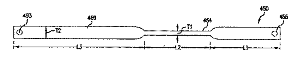
種々の実施形態によると、図8Fに示すように、加熱エレメントは、高温部454と低温部459を含む。高温部454は、加熱エレメント450の長さの一部で断面が減少した部分によって定義される。断面が減少することで、加熱エレメントにおいて抵抗が増大する。増大した抵抗によって加熱エレメント450は高温部454に亘って温度が飛躍的に上昇し、高温部454は、第1と第2の膜の層を互いにシールする縦シールを作り出すために層を加熱するに十分となる。低温部459は、加熱エレメントの低温部よりも断面が大きい領域によって定義される。断面が大きいほど印加される電流に応答する抵抗が低くなり、低温部459は温度となる。種々の実施形態では、低温部はシーリング装置の周囲の温度よりもかなり高い。種々の実施形態では、高温部454は、加熱エレメント450の他端よりも加熱エレメント450の一端に近く位置する。このずれた位置により、高温部454は上述したピンチゾーンの上流端側にずれることができる。 According to various embodiments, as shown in FIG. 8F, the heating element includes a
加熱エレメント450の一例によると、加熱エレメント450は約7から7と1/2インチである。加熱エレメント450は、3と1/4から3と3/4の間の長さL3を有する第1の低温部459を含む。加熱エレメント450は、1と3/4から2と1/4の間の長さL1を有する第2の低温部459を含む。低温部は、約1/4から3/8インチ幅である。低温部は、約1と1/2から2インチの間の長さL2を有する高温部454において接続される。エレメントは1インチ幅の約1/8である。加熱エレメント450は、1〜5milの厚さでよく、好ましくは約3milの厚さである。加熱エレメント450に亘って印加される電流に対する応答において、低温部は約180°Fまで熱くなり、高温部は約400°Fまで熱くなる。 According to an example of the
種々の実施形態によると、図8Fに示すように、加熱エレメントは、加熱アッセンブリ400に取り付けるための接続エレメント453と455を各末端に有する。一つの例では、接続エレメントは、加熱支持構造405上の接続エレメント415/416に接続されるように取り扱うことが可能な開口である。 According to various embodiments, as shown in FIG. 8F, the heating element has connecting
種々の実施形態によると、固定された加熱エレメント450と可動性ローラ162との間または可撓性材料100との間に低摩擦層460が位置する。低摩擦層460は、ローラ162と加熱エレメント450間の摩滅を低減するために適している。加熱エレメント450を有する実施形態では、低摩擦層460は、エレメントの摩耗を低減し、また、シーリングの間、加熱エレメント450が可撓性材料100へ切り込む傾向を制限することができる。薄膜加熱エレメント450を有する実施形態では、低摩擦層460は、加熱エレメント450を支持する基材、および加熱エレメント450自身の摩耗を低減する。薄膜加熱エレメント450は、ワイヤ加熱エレメントと比較して構造的に薄い傾向にあるため、低摩擦層460は、摩耗による薄膜加熱エレメント450の劣化をも防止する。また、低摩擦層460によって、可撓性材料100が円滑に加熱エレメント450に亘って遷移することができ、シールが改善される。一つの例では、低摩擦層は、加熱エレメント450の露出した部分に亘って取り付けられるポリテトラフルオロエチレン(PTFE)の薄いストライプである。さらに、耐久性エレメントとしてPTFEを用いることにより、より高価な耐久性エレメントを交換することなく層を交換することができる。PTFEは、テープとして加熱エレメントと周辺コンポーネントに取り付けることができる。PTFEの非接着性の層は、加熱エレメントに対して機械的に位置することもできる。機械的に固定することにより、接着剤の心配をすることなくパーツ交換が可能となる。例えば、層を収容するためのねじ固定、またはPTFEを適所に固定するためのクリップもしくは他の機械的ハードウェア、あるいは筐体を形成してもよい。他の例では、シリコーンなど、加熱エレメント450において作り出される熱を吸収することができる低摩擦材料が適用される。 According to various embodiments, the
他の実施形態によると、図8A〜8Eに示すように、加熱エレメント450は二クロムワイヤまたはフォイルである。加熱エレメント450は、絶縁体ブロック406に亘って延伸された二クロムワイヤ450を含む。二クロムワイヤ450の各末端は、コンタクト415と416に取り付けられる。電流を加熱エレメント450に供給してこれがヒートアップするよう、電気配線451と452がコンタクト415と416に接続される。ワイヤの幅を制御することにより、熱出力が影響される。例えば、同一の電気入力で比較すると、ワイヤ幅を狭くすることで熱出力が増大する。しかしながら、これは可塑性材料に形成されるシールが狭くなるという欠点も有する。幾つかの例では、シール幅は、加熱エレメントに複数のワイヤの掃引線を設けることで制御される。 According to other embodiments, the
一つの実施形態によると、図8A〜8Eに示すように、加熱エレメント450は薄膜ヒータである。このような実施形態では、加熱エレメントアッセンブリ410は、二つのコンタクトを接続する薄膜加熱掃引線を有する加熱エレメント450を含む。加熱エレメント450は、基材によって留められていてもよい。例えば、加熱エレメントアッセンブリは、加熱掃引線を支持するポリイミド基材を含む。加熱エレメント450は、基材の二つの層の間に挟まれてもよい。加熱エレメント410は、ポリイミド層上に気相堆積することによって形成することができる。一つの例では、複数のポリイミド層は約1と3milの間の厚さである。好ましい例では、複数のポリイミド層は、それぞれ約2milの厚さである。ポリイミド層は、加熱掃引線450を挟み、一つの例では、加熱掃引線450は約1と3milの間の厚さである。好ましい例では、加熱掃引線450は、約2milの厚さである。ポリイミド層は、加熱掃引線を包み込み、孤立的特性を与える。ポリイミドを互いに結合するプロセスでは、加熱エレメント450が作り出すことが可能な温度が扱われ、これにより、接着剤の必要性が排除される。典型的には、接着剤は機能性温度が低く、このため、加熱エレメントでは一般的に避けられる。さらに、ポリイミドをそれ自身に直接結合させることで、アッセンブリから一つの変数を排除することができる。 According to one embodiment, as shown in FIGS. 8A-8E, the
他の実施形態では、加熱エレメント450の外周は、加熱掃引線450上のフッ素化されたエチレンプロピレン(FEP)から形成することができる。この構造では、高温と高圧によって接着剤を使用する必要性が排除される。また、FEPの外層は、他のコンポーネントとの摩擦や引っ掛かりを低減するために織目が付けられていてもよい。他の実施形態では、薄膜の外周410は、さらなる保護を与え、絶縁を実現し、結合剤として働き、外周のオーバーモールディングといった追加的な製造オプションを与えるシリコーンなどの他の材料がさらに巻き付けられていてもよい。 In another embodiment, the outer circumference of the
加熱要素450は、バッキングブロック406に亘る張力内に保持される。加熱アッセンブリ400上の二つのコンタクトの各々は、加熱アッセンブリコンタクト415と416に接続され、これらは続いて電気配線451と452に接続される。ここで議論されたの実施形態のいずれかにおいて、加熱エレメント410、コンタクト415/416、および絶縁体ブロックは、加熱アッセンブリ400の構造の内側または外側に配置することができる。低摩擦層460を表面410に沿って適用してもよい。 The
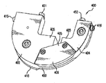
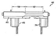
種々の例では、加熱アッセンブリ400の筐体は、細長い「U」字形状をしており、この「U」字形状は、筐体が固定されたまま、「U」字形状の筐体の表面410に沿ったピンチゾーン176を通るベルト進路とウェブ進路に適合するような大きさにされている。筐体はまた、筐体420をベルト163および/または164と揃えるために適したスタンドオフ472と474を含んでもよい。一つの例では、スタンドオフはプレート185に取り付けられ、筐体とベルトが揃うよう、筐体をプレートから適切な距離で離隔する。スタンドオフ472と474は、電気配線をそれぞれ収容することもできる。ここでは加熱アッセンブリ400がベルト駆動機構と揃う例を用いて説明されるが、ローラまたはドラムの端部とのアライメント、ベルト駆動機構とのアライメント、または固定された加熱アッセンブリを経て可撓性材料の搬送を可能にする任意の構造的関係といった、他の実施形態もカバーされる。他の実施形態では、可撓性材料が固定され、固定された可撓性材料を越えて加熱アッセンブリが駆動されてもよいであろう。 In various examples, the housing of the
種々の実施形態によると、加熱シーラーアッセンブリ400は、加熱エレメント410のための張力機構を含む。張力機構は、加熱エレメント410内の張力をバッキングブロック406に亘って保持するように構成されるシステムである。加熱エレメントは加熱と冷却が行われるため、加熱エレメントの長さおよび/または構造が変化する。これらの変化は、加熱エレメント410と周辺コンポーネントとの間、または可撓性材料100との間の関係を変更させる可能性がある。ワイヤを利用する場合には、ワイヤ加熱エレメントの長さ変化は十分に大きく、不十分なシール形成を引き起こし、ワイヤ加熱エレメントが可撓性材料100を切断してしまうおそれが潜在的に存在する。温度上昇に起因して追加された加熱エレメントの長さが張力機構によって「吸収される」ため、加熱エレメントはバッキングブロックに対して同じ高さを維持し、定位置に留まる。加熱エレメントがバッキングブロックに対して同じ高さを維持しない場合、シールする際にフィルムを切断する虞がある。一定の圧力によって一貫したシールが提供される。種々の実施形態では、一つ以上のコンタクト415と416は弾力があってよく、これにより、加熱エレメントをバッキングブロック406に亘って伸ばすための力を与えることができる。図8Cに示された一つの例では、コンタクトブロック402は、レバーとばねを含み、加熱エレメント450をテンションが掛けられた状態に置く。ばね482はブロック402の筐体内の棚上に掛けられており、レバー480をばね482から旋回させて、加熱エレメント450をテンションが掛けられた状態に置く。ばねによる張力機構はまた、熱膨張の間、加熱エレメントにおける張力変化を可能にする。 According to various embodiments, the
他の例では、図8Cに示されるように、張力機構は、加熱エレメントアッセンブリ400内に構築されてもよい。加熱掃引線の厚さや物理的パターンは、様々な電力密度を提供するために変更することができる。薄膜エレメントは、掃引線の構成を変えることで種々の幅と長さを持つことができる。薄膜エレメントも、より滑らかであり、加熱エレメントによって可撓性材料100が切断されるおそれを低減または排除する。 In another example, as shown in FIG. 8C, the tension mechanism may be constructed within the
ここで議論された種々の実施形態と例は、固定された加熱アッセンブリ400を指向するものであるが、ここで議論された種々の実施形態と例における様々な機能やエレメントは、幾つかの可動性加熱アッセンブリに対しても同様に適用される。一つの例では、加熱アッセンブリ400は、ディスク300を含む。したがって、幾つかの加熱エレメントアッセンブリ構造は、他の構造が固定されたまま、駆動機構によって動くことも可能であろう。他の例では、幾つかの加熱エレメント張力機構は、加熱アッセンブリを動かすために応用することも可能であろう。他の実施形態では、加熱エレメントアッセンブリは、駆動エレメントとともに動き、可動性の駆動エレメントに対して相対的に固定され、圧縮機構の動きに対して相対的に動き、ウェブ材料100に対して相対的に動き、または筐体141に対して固定されていてもよい。当業者は、本開示に基づいてこれらの機能とエレメントを他の様々なシステムに適用することができ、ここでは、そのシステムのうちのいくつかが開示されたに過ぎない。 While the various embodiments and examples discussed herein are directed to a fixed
シール後、第1と第2の層105、107は、冷却ゾーン169に沿って圧力を掛けられながら冷却され、これにより、シールが硬化する。冷却ゾーン169は、ヒートシンクとして働いてもよく、あるいは熱を大気に散逸させるための十分な冷却時間を提供してもよい。 After sealing, the first and
好ましい実施形態では、加熱アッセンブリ400と一つ以上の圧縮機構161、162は、第1のピンチ領域176において加熱アッセンブリ400に対して協同的に第1と第2の層105、107をプレスする、または摘まみ、二つの層を互いにシールする。シーリングアッセンブリ103は、圧縮機構162から加熱アッセンブリ400に対する圧力を利用して、これらの間で相105、107を十分にプレスするまたは摘まんでもよい。 In a preferred embodiment, the
種々の実施形態によると、膨張・シーリングアッセンブリ132は、ウェブ材料100を切断するための切断アッセンブリ250をさらに含んでもよい。好ましくは、材料進路「E」に沿ってエッジを経てウェブ材料100が動かされるため、切断部材はウェブ材料100を切断するために十分である。より詳細には、切断アッセンブリ250は、第1の長手方向端101とチャンバのマウス125の間で第1と第2の層105、107を切断する。幾つかの構成では、切断アッセンブリ250は、ウェブ材料100の膨張チャネル114を開くようにウェブ材料100を切断し、膨張ノズル140から第1と第2の層105、107を取り除いてもよい。種々の実施形態では、可撓性構造の膨張チャネル114は、構造の中央でもよく、他の位置にあってもよい。このような実施形態でも、切断アッセンブリ250は、膨張・シーリングアッセンブリから、詳細にはノズル140から膨張チャネル114を除去するように依然として適合することができる。 According to various embodiments, the expansion /
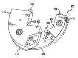
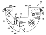
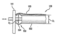
図10〜13は、本開示の原理に係る、一つ以上の隆起した輪郭部を有するガイドローラの追加的な図を示す。 10-13 show additional views of guide rollers with one or more raised contours according to the principles of the present disclosure.
上述したように、ガイド部材138は、大量供給された未膨張材料(例えばロール134)から離れたフィルム100を材料進路「B」に沿って誘導し、材料はこの進路に沿って縦方向「E」において成形される。ここで、材料進路「B」と方向Eは、全体的に供給材料の縦方向に揃う。大量供給された未膨張材料は、そこから連続的にフィルムが引き出される際に位置と寸法が変化することがあるため(例えば、ロール134は、材料が引き出されると直径が減少することがある)、ガイド部材138は、供給端における変化に関わらず、シーリング・膨張機構によって膨張・シールされるフィルムの位置のアライメントを維持する。このため、好ましくは、ガイド部材138は、ノズル140の膨張チップの直ぐ上流に位置する。図(例えば、図12のスレッドアップ図参照)に示されるように、ガイド部材138は、ロール134を支持する材料サポート136と膨張・シーリングアッセンブリ132の間に配置され、フィルム100がその上を通る際、フィルムはロールと膨張・シーリングアッセンブリの間の湾曲した進路を進む。供給端と膨張・シーリングアッセンブリの間には一つのガイド部材138が示されているが、供給されるフィルムと膨張・シーリングアッセンブリ132の間に任意の数のハンドリングエレメントを設けてもよいことが理解されるであろう(例えば、一つ以上の追加的ガイド部材がサポート136とガイド部材138の間に含まれてもよい)。 As described above, the
ガイド部材138の表面は、これに沿ってフィルム100が湾曲し、フィルムが材料進路「B」に沿って進む際にフィルム100と接するが、このガイド部材138の表面をフィルム支持表面150と記す。幾つかの例では、本開示に係るガイド部材138のフィルム支持表面は、非線形であってもよい(例えば、段差、カーブ、または少なくとも一つの隆起した輪郭部を与える他の表面バリエーションを含んでもよい)。幾つかの実施形態では、フィルム支持表面は直線的であるが、ガイド部材の全体の形状は、隆起した輪郭部を含むように選択することができる。例えば、ガイド部材は、隆起した輪郭部を与える広い方の底部と減少した輪郭部を与える狭い方の頂点部を有する円錐でもよい。 The surface of the
ガイドによって導入される材料の進行進路における湾曲は、材料がロール134から解かれる際に材料からサックを取り除く材料にテンションを掛けるのに役立つ。このように、ガイド部材138は、材料100が膨張ノズル140と大量の供給源(例えば、ロール134)の間で撓むことを防ぐように構成することができ、フィルム100内において所望される任意の張力の維持に役立つことができる。上述したように、弾力的に連結された(例えば、ばね仕掛けで)、フィルム中の張力が閾値量を超えると下方向に(湾曲から離れて)片寄って張力を軽減するガイド部材138を用いることで、任意にかつ追加的に所望の量の張力を維持することができる。 The curvature in the path of the material introduced by the guide helps to tension the material, which removes the sack from the material as it is unwound from the
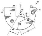
図10中の例を参照すると、ガイド部材138は、ロッド部137およびガイド部材138の軸Xの周りに回転するローラ部139を含む。軸Xおよび対応するロッド部とローラ部137、139は、全体的に支持構造141に垂直に延伸する。供給サポート136も全体的に支持構造141に垂直に延伸し、このため、供給サポート136とガイド部材138は、全体的に互いに平行である。ガイド部材138は、ガイド部材138の隆起した輪郭部155を与える拡張エレメント152を含む。隆起した輪郭部155はさらに、ガイド部材138の減少した輪郭部151と比較して湾曲内に延伸する。この場合、隆起した輪郭部155は、ロッド部とローラ部137、139の周りで円周状に拡張した拡張エレメント152によって形成される。しかしながら、他の実施形態では、隆起した輪郭部155は、湾曲の内部に向かって高さの増大をもたらすだけでもよい。例えば、湾曲したバーまたはロッドを用いて隆起した輪郭部155を有する固定されたガイド部材を形成してもよい。ここでは、湾曲したバーまたはロッドは、湾曲の内部へ突き出た(例えば、バーのベースに近い)部分を有し、(例えば、バーの対向する自由端に反対の)減少した輪郭部は、突き出た部分よりも低い高さの上に位置する。 Referring to the example in FIG. 10, the
隆起した輪郭部155は、供給端上の仮想支持表面とガイド部材の仮想支持表面の間に(例えば、ガイド部材のフィルム支持表面によって定義される)相対角をもたらすことができる。この相対角は、ガイド部材138の一方の横の辺上において、他の辺上と比較し、より張った状態をフィルム100にもたらす。すなわち、フィルム材料は、減少した輪郭部上を通過する際には短い距離を進むためより弛んだ状態を維持するが、これと比較すると、隆起した輪郭部155上を通過するフィルム材料は、隆起した輪郭部155によってより長い距離を(好ましくは、伸びずに)進むため、隆起した輪郭部155によって一部がより張った状態になる。このため、湾曲内にさらに延伸する部分をガイド部材に設けることで、フィルムの張力を任意の横位置で制御することができる。 The raised
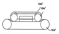
図10に戻ると、組み合わされたロッド部とローラ部137、139は、ガイド部材の長さLGに沿って全体的に同一の断面形状または断面寸法(例えば、直径)を有してもよい。図10中のガイド部材138は、また、ガイド部材の断面形状または寸法の全体を変更するように構成される拡張エレメント152を含む。例えば、拡張エレメント152は、拡張エレメント152から離間した位置における対応する全体寸法よりも大きい全体寸法(例えば、断面全体の高さ若しくは直径または曲率半径)を拡張エレメント152の位置においてガイド部材138に与える。拡張エレメント152は、ウェブ支持表面150の少なくとも一部を定義する。すなわち、フィルム100がガイド部材138上を進む際、フィルム100は拡張エレメント152の少なくとも一部と接し、支持される。幾つかの実施形態では、拡張エレメント152の寸法、したがって、拡張エレメント152によって変更された全体寸法は、調整可能であってよい。例えば、拡張エレメント152は、膨張性部材などの調整可能な拡張性エレメントによって形成されてもよい。膨張性部材は、ガイド部材の放射状表面の周りに少なくとも部分的に円周状に、より具体的には、フィルム支持表面を与えうる場所に位置することができる。他の例では、拡張エレメント152は、例えば図13に示すように、ガイド部材の長さに沿ってガイド部材の一部が動くのに応答して潰れたり膨張したりすることができるように構成された弾性スリーブによって形成されてもよい。さらに、あるいはこれに替えて、拡張エレメント152の場所は調整可能であり、これにより、例えば拡張エレメント152は、ガイド部材の長さに沿った任意の場所に位置する、および/または横方向に対して垂直な拡張エレメントの場所を調整することができる。さらに他の実施形態では、いずれもが調整可能な複数の拡張エレメント152を用いてもよい。Returning to FIG. 10, the rod portion and the
図10に示された例では、拡張エレメントは、ロッド部とローラ部137、139と同軸に連結された硬いカラー153によって形成される。カラー153はローラ部139に固定され、これにより、カラーは機械使用時にローラ部に対して動かない。ローラ部139は軸Xの周りに回転するように構成されるため、カラー153もローラ部139と同期して回転するように構成される。幾つかの実施形態では、カラー153は、移動可能なようにローラ部139に連結されていてもよい。例えば、カラー153は、カラー153が長さLGに沿って任意の位置に再配置できるよう、例えば止めねじ157によってローラ部139に連結されてもよい。幾つかの実施形態では、例えば(例えば、摩耗や裂開に起因する)メンテナンス若しくは交換のため、および/または異なる直径若しくは材料特性(例えば、異なる表面摩擦)を有するカラーとの交換のため、カラー153はローラ部139から取り外しできてもよい。図示された例においてカラー153は実質的に柱状であるが、他の実施形態では、異なる形状(例えば、円錐形)を有するカラーを用いてもよい。幾つかの実施形態では、カラーのテーパーと狭端がノズル140からより遠くに位置するよう、カラーの広い部分を流体供給源に最も近く(例えば、膨張ノズル140のアウトレットの近く)に配置してもよい。異なる横方向においてガイド部材の全体寸法が異なるよう、拡張エレメントの他の構成を利用してもよい。In the example shown in FIG. 10, the expansion element is formed by a
他の実施形態では、異なるガイド部材の拡張エレメントを用いてもよい。例えば、ガイド部材自体は、より広い底部とより狭い頂点部を有する円錐断面を有してもよい。底部は膨張ノズルに最も近い部分であってよく、ガイド部材の長さに沿った他の横位置に比べて僅かに大きい張力をフィルムに与えてもよい。このように、円錐のガイド部材の底部が拡張エレメントとして機能し、ガイド部材のフィルム支持表面の一部を提供する。 In other embodiments, expansion elements of different guide members may be used. For example, the guide member itself may have a conic section with a wider bottom and a narrower apex. The bottom may be the portion closest to the expansion nozzle and may apply a slightly greater tension to the film than other lateral positions along the length of the guide member. In this way, the bottom of the conical guide member functions as an expansion element to provide a portion of the film support surface of the guide member.
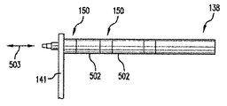
図13Aと図13Bは、本開示に係る拡張エレメント150を有するガイド部材138の他の例を示す。拡張エレメント150は、第1の横位置における全体寸法D2が他の横位置における全体寸法D1よりも大きいガイド部材138を提供する。この例では、拡張エレメント152は調整可能なように膨張することができ、これにより、寸法D2が調整(減少または増大)可能となる。13A and 13B show another example of the
拡張エレメント152は、弾性スリーブ504によって実現することができる。スリーブ504は、横移動可能なロッド部502の末端に取り付けられる。スリーブ504は移動可能部分502と同軸に配置することができ、少なくとも部分的に、この例では完全に、ガイド部材138の放射状の外周の周りを延伸する。適切な寸法、このケースでは支持構造141の近くの位置におけるガイド部材138の直径を調整するためには、部分502を支持構造141に向かって横に動かし、これによりスリーブが潰れて外側に向けて拡張し、寸法D2を増大させる。逆に、寸法D2を減少させるには、部分502を支持構造141から離れるように反対方向に動かし、スリーブ504を伸ばしてスリーブの側壁を内側に引き込む。The
図13Bは、ガイド部材138の更なる他の例を示しており、このケースでは、複数の拡張エレメント150を有する。図13Bにおける実施形態では、それぞれの拡張エレメント150について、類似する弾性スリーブ(または、複数の膨張性部材、可動性なカラー、またはこれらの任意の組み合わせ)を用いることができる。拡張エレメントは、ガイド部材138の長さに沿って(例えば部分502によって)離隔されてもよい。弾性スリーブを用いるのであれば、これらは図13B中の例と同様、例えば部分502の(方向503に沿った)横移動に応答した縮小と拡張により動作することができる。あるいは、各エレメント150は、ガイド部材138の全体形状を設定するための、選択的にかつ独立的に膨張できる膨張セクションであってもよく、これにより、任意の横位置においてフィルム100に掛かる張力を制御することができる。ガイド部材と材料サポートの軸は互いに平行であるように維持されるが、実際のまたは仮想のフィルム支持表面を与える拡張エレメントが含まれることにより、ロールとガイド部材の間において、供給端のフィルム支持表面との相対的な角度である、材料のフィルム100中の僅かな捻じれが発生することが理解されよう。 FIG. 13B shows yet another example of the
本出願の明細書において具体的に特定された任意のまたはすべての参照文献は、それらの全体が参照によってここに明確に組み入れられる。ここで使用された「約」という文言は、対応する数およびその数の範囲を指すものとして一般的に理解すべきである。さらに、ここにおける全ての数値範囲は、その範囲内のそれぞれ全ての整数を含むと理解されるべきである。 Any or all references specifically specified in the specification of the present application are expressly incorporated herein by reference in their entirety. The word "about" used herein should be generally understood to refer to the corresponding number and the range of that number. Furthermore, it should be understood that all numerical ranges here include all integers within that range.
幾つかの実施形態をここに記載したが、様々な変更、代替構成、および等価物を使用してもよいことが当業者によって理解される。種々の例と実施形態は独立して採用してもよく、または、これらは混合され、組み合わせて適合されて代替物のいかなる反復を形成してもよい。さらに、本開示の焦点を不必要に不明確としないよう、数多くの公知プロセスやエレメントは記載していない。このため、上述した記載は、本発明の範囲を限定するものとして用いられるべきではない。ここに開示された実施形態は、例を通じて教示するものであり、限定によって教示するものでは無いことを当業者は理解するであろう。したがって、上記記載に含まれるもの、または添付した図面に示される物は、説明のためのものとして解釈すべきであり、限定的な意味で解釈すべきではない。以下の請求項は、ここに記載された全ての一般的な、そして具体的な特徴、および本方法とシステムの範囲のすべての記述をカバーすることを意図しており、これらは言語による表現として請求項に落とし込まれている。 Although some embodiments have been described herein, it will be appreciated by those skilled in the art that various modifications, alternative configurations, and equivalents may be used. The various examples and embodiments may be adopted independently, or they may be mixed and combined to form any iteration of the alternative. Moreover, a number of publicly known processes and elements are not described to avoid unnecessarily obscuring the focus of this disclosure. Therefore, the above description should not be used to limit the scope of the present invention. Those skilled in the art will appreciate that the embodiments disclosed herein are taught through examples and not by limitation. Therefore, what is included in the above description or what is shown in the attached drawings should be construed as an explanation and not in a limited sense. The following claims are intended to cover all general and specific features described herein, and all descriptions of the scope of the method and system, which are expressed in language. It is included in the claim.
図1に示すように、多層の可撓性ウェブ材料100が膨張性クッション121のために提供される。ウェブ材料100は、第1の長手方向端101と第2の長手方向端104を有する第1のフィルム層105、および第1の長手方向端106と第2の長手方向端108を有する第2のフィルム層107を含む。第2の層107は、第1の層105と重畳するように揃っており、通常第1の層105と同一の広がりを有する。すなわち、少なくとも対応する第1の長手方向端101、106は互いに揃い、さらに/または第2の長手方向端104、108は互いに揃う。幾つかの実施形態では、これらの層は、重畳領域において膨張性領域と部分的に重なる。
As shown in FIG. 1, a multilayer
図1は、ウェブ材料100(フィルム100とも記す)の第1の長手方向端110と第2の長手方向端112を定義するように結合される第1と第2の層105、107を有するウェブ材料100の上面図を示す。第1と第2の層105、107は、可撓性材料の単一シートから、スリットを有する若しくは開口された一端を有する平坦化された可撓性材料のチューブから、または、可撓性構造100の長手方向端112を定義するために長手方向端104、108に沿ってシールされてもよい二枚の可撓性材料のシートから作製することができる。例えば、第1と第2の層105、107は、接合される第2端104、108を定義するために折りたたまれた単一の可撓性材料シート(例えば、c字折りたたみフィルム)を含んでもよい。より詳細な例では、端104、108は、このような実施形態においてc字の折り目上に位置する。あるいは、例えば、第1と第2の層105、107は、揃った第1の長手方向端101、106に沿ってスリットが入れられた可撓性材料のチューブを含んでもよい(例えば、平坦化されたチューブ)。また、例えば、第1と第2の層105、107は、揃った第2端104、108に沿って互いに接合され、シールされ、そうでなければ貼り付けられた二枚の独立した可撓性材料シートを含んでもよい。
FIG. 1 shows a web having first and
図1に示すように、ウェブ材料100は、ウェブ材料100の縦の広がりに沿って配置される一連の横シール118を含む。各横シール118は、長手方向端112から膨張チャネル114へ延伸する。示される実施形態では、膨張チャネル114は、長手方向端112とは反対の長手方向端110に沿って延伸し、したがって、横シール118は、長手方向端112から第1の長手方向端110へ延伸する。幾つかの実施形態では、可撓性構造100は、長手方向112および/または110に関してどこか他の場所に位置する膨張チャネル114を含んでもよい。例えば、膨張チャネルは、構造100の長さに沿って長手方向端112および/または110の間の中間位置(例えば、中ほどに)で延伸してもよい。幾つかの実施形態では、さらに、またはこれに替えて、可撓性構造100は、長手方向端112に沿った膨張チャネル114を含んでもよい。図示された実施形態では、各横シール118は、第2の長手方向端112に最も近い第1端122、およびフィルム100の第1の長手方向端110から横寸法d離れる第2端124を有する。チャンバ120は、シールまたは長手方向端112の折り目、および隣接する一対の横シール118によって形成される境界内に定義される。
As shown in FIG. 1, the
好ましくは、ウェブ材料100は、材料進路「E」に沿ってピンチ領域176上の加熱アッセンブリ400を過ぎ、シーリングアッセンブリを通過するよう連続的に送り出され、第1と第2の層105、107を互いにシールすることにより、ウェブ材料100に沿った連続的な縦シール170を形成する。縦シール170は、図1において見えない線として示される。好ましくは、縦シール170は、第1の長手方向端101、106から横方向に距離を置くように配置され、最も好ましくは、縦シール170は、各チャンバ120のマウス125に沿って配置される。
Preferably, the
種々の実施形態によると、図2〜7に表されるように、ベルト163と164は互いに対向する。ベルト163と164は、ピンチ領域176内で相対的に構成され、その中でウェブ134を受け取る。より具体的には、示される実施形態では、ベルト163は、ピンチゾーンを定義して加熱ゾーン167と縦に重なるウェブ支持表面410に対して縮む。種々の実施形態では、ピンチゾーン176は、互いに横の関係にある複数の圧力領域を含む。例えば、ピンチゾーン176は第1の領域276aと第2の領域276bを含むことができる。幾つかの実施形態では、複数の圧力領域は、ウェブ材料100に対して異なる力を印加することができる。他の実施形態では、圧力領域は、同様の力を異なる方法で印加する。一つの例では、圧縮エレメント(例えばベルト163)は、二つの対向する異なる圧力エレメント(例えば、ディスク300と加熱アッセンブリ400)を押す。このように、対向する圧力エレメントは、異なる方法で圧力エレメントに圧力を印加し、二つの異なる圧力領域(例えば、第1の圧力領域276aと第2の圧力領域276b)を作り出す。これらの領域において異なる圧力の力がある場合、圧縮エレメント(例えばベルト163)は屈曲または変形し、異なる圧力を受け入れることができる。屈曲距離D.P.は、約5milから50milとすることができる。外側の圧力は、空気チャンバ20内の流体を単離することを促進することができるため、単離圧力であると考えられる。領域276aと276bのそれぞれにおいて圧力が異なる実施形態では、この相違は、例えば、他の領域に対してウェブ材料を通過させる狭い領域によって引き起こされ得る。他の例では、領域サイズは同様であるが、対向する圧縮エレメントは異なる材料を有する。このため、ウェブ材料は、一つの材料をより屈曲させ、その結果、一つの材料は他方よりも高い圧力を印加する。他の実施形態では、異なる領域は単に異なる方向または位置からの圧力を有するか、あるいは図7の例において示されるように、単離エレメント300は実際に圧縮エレメント(例えばベルト163)へ延伸するものの支持構造405は延伸しない。好ましい実施形態では、単離エレメント300は、隣接領域を形成する装置の輪郭に実質的に適合する連続表面である。例えば、支持表面410は、単離表面310と同様、湾曲する。他の実施形態では、単離エレメントは不連続表面310を有する。例えば、単離エレメント300は、流体の通過を制限する、さもなければウェブ材料100を安定化するための、材料に接する歯と十分な間隔を有するホイールである。
According to various embodiments, the
Claims (18)
重畳するウェブ材料の層の間に流体を誘導することによって前記流体で前記ウェブ材料を膨張させ、前記流体を前記層内にシールするために前記層を互いにシールするように動作可能な膨張・シーリングアッセンブリ、および
ガイド部材を備え、
前記ガイド部材は、前記ウェブ材料が前記供給源から前記ガイド部材を通って前記膨張・シーリングアッセンブリに向かって進行する際、前記ウェブ材料が湾曲した縦進路を進むよう、前記支持部材と前記膨張・シーリングアッセンブリの間に位置し、
前記ガイド部材は、前記縦進路に対して横に延伸するウェブ支持表面を定義し、
前記ガイド部材は、前記ウェブ支持表面の少なくとも一部を定義する隆起した輪郭部を含む、ウェブ膨張・シーリング装置。Supporting members that hold the source of web material,
Expansion and sealing that can be operated to inflate the web material with the fluid by inducing a fluid between the layers of the overlapping web material and to seal the layers together in order to seal the fluid within the layer. Equipped with assembly and guide members,
The guide member and the expansion member so that when the web material travels from the source through the guide member toward the expansion / sealing assembly, the web material follows a curved longitudinal path. Located between the sealing assemblies
The guide member defines a web support surface that extends laterally with respect to the longitudinal path.
The guide member is a web expansion / sealing device that includes a raised contour that defines at least a portion of the web support surface.
前記円錐のガイド部材の底部は、少なくとも部分的に、前記隆起した輪郭部を定義する、請求項1に記載の装置。The guide member has a conical cross section
The device of claim 1, wherein the bottom of the conical guide member defines, at least in part, the raised contour.
前記カラーが前記隆起した輪郭部を提供する、請求項1に記載の装置。The guide member has a columnar rod and a collar coaxially connected to the rod.
The device of claim 1, wherein the collar provides the raised contour.
前記支持部材と前記ロッドは前記支持構造から延伸し、
前記カラーは、前記支持構造に最も近い前記ロッドの底に位置する、請求項10に記載の装置。It also has a support structure
The support member and the rod extend from the support structure and
The device of claim 10, wherein the collar is located at the bottom of the rod closest to the support structure.
前記カラーは、前記ガイド部の長さに沿って、前記ノズルのアウトレットに最も近い位置に配置される、請求項10に記載の装置。The expansion / sealing assembly has an expansion nozzle and
The device according to claim 10, wherein the collar is arranged at a position closest to the outlet of the nozzle along the length of the guide portion.
前記ローラの外表面は、少なくとも一部は、前記ウェブ支持表面を定義する、請求項1に記載の装置。The guide member has a roller connected to the support structure of the expansion / sealing device so as to be rotatable.
The device of claim 1, wherein the outer surface of the roller defines, at least in part, the web support surface.
Applications Claiming Priority (3)
| Application Number | Priority Date | Filing Date | Title |
|---|---|---|---|
| US201862630774P | 2018-02-14 | 2018-02-14 | |
| US62/630,774 | 2018-02-14 | ||
| PCT/US2019/018078 WO2019161107A1 (en) | 2018-02-14 | 2019-02-14 | Inflation and sealing apparatus comprising a guide member with an expansion element |
Publications (2)
| Publication Number | Publication Date |
|---|---|
| JP2021516632A true JP2021516632A (en) | 2021-07-08 |
| JP7252964B2 JP7252964B2 (en) | 2023-04-05 |
Family
ID=65576740
Family Applications (1)
| Application Number | Title | Priority Date | Filing Date |
|---|---|---|---|
| JP2020543354A Active JP7252964B2 (en) | 2018-02-14 | 2019-02-14 | Web expansion and sealing device |
Country Status (6)
| Country | Link |
|---|---|
| US (1) | US11407193B2 (en) |
| EP (1) | EP3752353A1 (en) |
| JP (1) | JP7252964B2 (en) |
| CN (1) | CN111902266B (en) |
| MX (1) | MX2020008553A (en) |
| WO (1) | WO2019161107A1 (en) |
Citations (6)
| Publication number | Priority date | Publication date | Assignee | Title |
|---|---|---|---|---|
| JPH01242309A (en) * | 1988-03-24 | 1989-09-27 | Iseki Tory Tech Inc | roller |
| JPH05170210A (en) * | 1991-12-18 | 1993-07-09 | Fuji Mach Co Ltd | Horizontal type bag-making, loading and packaging machine |
| US5370336A (en) * | 1993-06-04 | 1994-12-06 | James River Paper Company, Inc. | Dispenser apparatus for sequentially dispensing from coreless rolls of sheet material |
| US20070251631A1 (en) * | 2006-05-01 | 2007-11-01 | Sealed Air Corporation (Us) | Apparatus and method for controlling position of an edge of an advancing web of flexible material |
| JP2017510482A (en) * | 2014-02-24 | 2017-04-13 | プレジス・イノベーティブ・パッケージング・エルエルシー | Inflatable film processing equipment |
| US20170251631A1 (en) * | 2013-11-06 | 2017-09-07 | Tabatha S. Webster | Feed-saving method and apparatus |
Family Cites Families (35)
| Publication number | Priority date | Publication date | Assignee | Title |
|---|---|---|---|---|
| LU31181A1 (en) * | 1950-02-10 | |||
| US2987107A (en) | 1959-02-27 | 1961-06-06 | Amsco Packaging Machinery Inc | Rotary heat-sealing apparatus |
| US4169002A (en) | 1975-12-24 | 1979-09-25 | Minnesota Mining And Manufacturing Company | Method for forming air inflated cushioning material |
| US5123889A (en) * | 1990-10-05 | 1992-06-23 | Ranpak Corporation | Downsized cushioning dunnage conversion machine and cutting assemblies for use on such a machine |
| US5165620A (en) * | 1991-06-12 | 1992-11-24 | Kampiziones Theodore G | Expanding roll core spindle |
| DE9422163U1 (en) | 1993-03-02 | 1998-09-10 | Tetra Laval Holdings & Finance S.A., Pully | Welding jaw made of two ceramic materials, one of which is electrically conductive |
| US6550229B2 (en) | 2001-01-12 | 2003-04-22 | Sealed Air Corporation (Us) | Device for sealing two plies of film together, particularly for enclosing a foamable composition in a flexible container |
| US6622767B2 (en) | 2001-02-16 | 2003-09-23 | Stork Fabricators, Inc. | Multi-stage shrink-wrap sealing and cutting apparatus |
| US6889739B2 (en) | 2003-04-08 | 2005-05-10 | Automated Packaging Systems, Inc. | Fluid filled unit formation machine and process |
| US6955846B2 (en) | 2003-04-08 | 2005-10-18 | Automated Packaging Systems | Web for fluid filled unit information |
| US8124915B2 (en) | 2003-05-09 | 2012-02-28 | Pregis Intellipack Corporation | Sealing device |
| US7213383B2 (en) | 2003-05-09 | 2007-05-08 | Intellipack | Bag forming system edge seal |
| US7343723B2 (en) | 2004-01-27 | 2008-03-18 | Free-Flow Packaging International, Inc. | Method and apparatus for pre-tearing strings of air-filled packing materials and the like |
| US7082979B2 (en) | 2004-01-30 | 2006-08-01 | Stork Fabricators, Inc. | Apparatus for increased efficiency in cutting and sealing film edges |
| US7247219B2 (en) | 2004-07-14 | 2007-07-24 | Sealed Air Corporation (Us) | Rotary impulse sealer |
| US8020358B2 (en) | 2004-11-02 | 2011-09-20 | Sealed Air Corporation (Us) | Apparatus and method for forming inflated containers |
| US7165375B2 (en) | 2005-02-05 | 2007-01-23 | Sealed Air Corporation (Us) | Inflation device for forming inflated containers |
| NL1028625C2 (en) | 2005-03-24 | 2006-09-27 | Ideepak Holding B V | Improved sealing device for sealing foil material together by means of heat. |
| US7225599B2 (en) * | 2005-04-05 | 2007-06-05 | Sealed Air Corporation | Apparatus and method for forming inflated articles |
| US7323665B2 (en) | 2006-04-06 | 2008-01-29 | Sealed Air Corporation (Us) | Heating element for high-speed film-sealing apparatus, and method for making same |
| ES2424034T3 (en) | 2006-09-20 | 2013-09-26 | Pregis Innovative Packaging Inc. | Inflation and sealing device for inflatable air pads |
| JP2008175956A (en) | 2007-01-17 | 2008-07-31 | Ricoh Co Ltd | Powder conveying apparatus, toner conveying apparatus, process cartridge, and image forming apparatus |
| WO2010028115A1 (en) | 2008-09-03 | 2010-03-11 | Free-Flow Packaging International, Inc. | Method and apparatus for inflating and sealing packing cushions with rotary sealing mechanism |
| US9381715B2 (en) | 2008-09-03 | 2016-07-05 | Free-Flow Packaging International, Inc. | Method and apparatus for inflating and sealing packing cushions with rotary sealing mechanism |
| AT507384B1 (en) | 2008-09-18 | 2011-07-15 | Westwind Verpackungen Gmbh | CLOSING DEVICE FOR CLOSING PREFERABLY BAGGED PACKAGING UNITS |
| US8991141B2 (en) | 2009-04-06 | 2015-03-31 | Sealed Air Corporation (Us) | Machine for inflating and sealing an inflatable structure |
| DE102009034971A1 (en) * | 2009-07-28 | 2011-02-03 | Chiang, Tung-Lung, Douliou | Machine for the production of air-filled materials, comprises machine table, a first feed roller and a second feed roller that are mounted on top and/or bottom of the machine table, and a first roller and a second roller |
| US9635985B2 (en) * | 2010-11-03 | 2017-05-02 | Solaris Paper, Inc. | Spindle for roll paper products |
| ES2617330T3 (en) | 2011-07-07 | 2017-06-16 | Automated Packaging Systems, Inc. | Air cushion inflation machine |
| US8726960B1 (en) | 2013-02-08 | 2014-05-20 | Mao-Sen Huang | Sealing machine with a transportation structure |
| WO2015077551A1 (en) | 2013-11-21 | 2015-05-28 | Automated Packaging Systems, Inc. | Air cushion inflation machine |
| WO2017172814A1 (en) | 2016-03-28 | 2017-10-05 | Pregis Innovative Packaging Llc | Blade holder for inflation and sealing device |
| US10787284B2 (en) | 2016-03-28 | 2020-09-29 | Pregis Innovative Packaging Llc | Idler roller |
| JP7237591B2 (en) | 2016-03-30 | 2023-03-13 | プレジス イノベーティブ パッケージング エルエルシー | protective packaging forming equipment |
| CN206705354U (en) | 2017-05-03 | 2017-12-05 | 杭州丙甲科技有限公司 | Layer tension self-checking device and the air cushioning machine for including it |
-
2019
- 2019-02-14 US US16/276,455 patent/US11407193B2/en active Active
- 2019-02-14 CN CN201980021346.0A patent/CN111902266B/en active Active
- 2019-02-14 JP JP2020543354A patent/JP7252964B2/en active Active
- 2019-02-14 MX MX2020008553A patent/MX2020008553A/en unknown
- 2019-02-14 EP EP19708003.9A patent/EP3752353A1/en active Pending
- 2019-02-14 WO PCT/US2019/018078 patent/WO2019161107A1/en not_active Ceased
Patent Citations (6)
| Publication number | Priority date | Publication date | Assignee | Title |
|---|---|---|---|---|
| JPH01242309A (en) * | 1988-03-24 | 1989-09-27 | Iseki Tory Tech Inc | roller |
| JPH05170210A (en) * | 1991-12-18 | 1993-07-09 | Fuji Mach Co Ltd | Horizontal type bag-making, loading and packaging machine |
| US5370336A (en) * | 1993-06-04 | 1994-12-06 | James River Paper Company, Inc. | Dispenser apparatus for sequentially dispensing from coreless rolls of sheet material |
| US20070251631A1 (en) * | 2006-05-01 | 2007-11-01 | Sealed Air Corporation (Us) | Apparatus and method for controlling position of an edge of an advancing web of flexible material |
| US20170251631A1 (en) * | 2013-11-06 | 2017-09-07 | Tabatha S. Webster | Feed-saving method and apparatus |
| JP2017510482A (en) * | 2014-02-24 | 2017-04-13 | プレジス・イノベーティブ・パッケージング・エルエルシー | Inflatable film processing equipment |
Also Published As
| Publication number | Publication date |
|---|---|
| EP3752353A1 (en) | 2020-12-23 |
| WO2019161107A9 (en) | 2020-06-11 |
| JP7252964B2 (en) | 2023-04-05 |
| US20190322067A1 (en) | 2019-10-24 |
| BR112020016669A2 (en) | 2020-12-15 |
| WO2019161107A1 (en) | 2019-08-22 |
| US11407193B2 (en) | 2022-08-09 |
| MX2020008553A (en) | 2021-01-29 |
| CN111902266A (en) | 2020-11-06 |
| CN111902266B (en) | 2023-04-11 |
Similar Documents
| Publication | Publication Date | Title |
|---|---|---|
| US11524475B2 (en) | Protective packaging longitudinal heat sealer | |
| JP7748488B2 (en) | Protective packaging material forming device | |
| JP7087093B2 (en) | A device for forming a protective packaging member | |
| JP2021513923A (en) | Expansion / sealing device including a guide member having an expansion element | |
| JP7432514B2 (en) | Equipment for producing inflatable cushions used in packaging materials | |
| JP2021516632A (en) | Expansion / sealing device including a guide member having an expansion element | |
| HK40038608B (en) | Devices for manufacturing inflatable cushions to be used as packaging material | |
| HK40038608A (en) | Devices for manufacturing inflatable cushions to be used as packaging material | |
| HK40038602A (en) | Devices for the formation of protective packaging | |
| HK40038602B (en) | Devices for the formation of protective packaging | |
| BR112020016669B1 (en) | BLANKET INFLATION AND SEALING DEVICE | |
| BR112020016675B1 (en) | PACKAGING FORMING DEVICES |
Legal Events
| Date | Code | Title | Description |
|---|---|---|---|
| A521 | Request for written amendment filed |
Free format text: JAPANESE INTERMEDIATE CODE: A523 Effective date: 20201008 |
|
| A621 | Written request for application examination |
Free format text: JAPANESE INTERMEDIATE CODE: A621 Effective date: 20201008 |
|
| A977 | Report on retrieval |
Free format text: JAPANESE INTERMEDIATE CODE: A971007 Effective date: 20211015 |
|
| A131 | Notification of reasons for refusal |
Free format text: JAPANESE INTERMEDIATE CODE: A131 Effective date: 20211130 |
|
| A521 | Request for written amendment filed |
Free format text: JAPANESE INTERMEDIATE CODE: A523 Effective date: 20220228 |
|
| A131 | Notification of reasons for refusal |
Free format text: JAPANESE INTERMEDIATE CODE: A131 Effective date: 20220726 |
|
| A601 | Written request for extension of time |
Free format text: JAPANESE INTERMEDIATE CODE: A601 Effective date: 20221025 |
|
| A601 | Written request for extension of time |
Free format text: JAPANESE INTERMEDIATE CODE: A601 Effective date: 20221222 |
|
| A521 | Request for written amendment filed |
Free format text: JAPANESE INTERMEDIATE CODE: A523 Effective date: 20230126 |
|
| TRDD | Decision of grant or rejection written | ||
| A01 | Written decision to grant a patent or to grant a registration (utility model) |
Free format text: JAPANESE INTERMEDIATE CODE: A01 Effective date: 20230307 |
|
| A61 | First payment of annual fees (during grant procedure) |
Free format text: JAPANESE INTERMEDIATE CODE: A61 Effective date: 20230324 |
|
| R150 | Certificate of patent or registration of utility model |
Ref document number: 7252964 Country of ref document: JP Free format text: JAPANESE INTERMEDIATE CODE: R150 |
|
| R250 | Receipt of annual fees |
Free format text: JAPANESE INTERMEDIATE CODE: R250 |