JP2021512710A - Tamper Evidence Closure - Google Patents
Tamper Evidence Closure Download PDFInfo
- Publication number
- JP2021512710A JP2021512710A JP2020542586A JP2020542586A JP2021512710A JP 2021512710 A JP2021512710 A JP 2021512710A JP 2020542586 A JP2020542586 A JP 2020542586A JP 2020542586 A JP2020542586 A JP 2020542586A JP 2021512710 A JP2021512710 A JP 2021512710A
- Authority
- JP
- Japan
- Prior art keywords
- connector
- cap
- tamper
- tamper member
- receptacle
- Prior art date
- Legal status (The legal status is an assumption and is not a legal conclusion. Google has not performed a legal analysis and makes no representation as to the accuracy of the status listed.)
- Ceased
Links
Images


Classifications
-
- A—HUMAN NECESSITIES
- A61—MEDICAL OR VETERINARY SCIENCE; HYGIENE
- A61M—DEVICES FOR INTRODUCING MEDIA INTO, OR ONTO, THE BODY; DEVICES FOR TRANSDUCING BODY MEDIA OR FOR TAKING MEDIA FROM THE BODY; DEVICES FOR PRODUCING OR ENDING SLEEP OR STUPOR
- A61M5/00—Devices for bringing media into the body in a subcutaneous, intra-vascular or intramuscular way; Accessories therefor, e.g. filling or cleaning devices, arm-rests
- A61M5/50—Devices for bringing media into the body in a subcutaneous, intra-vascular or intramuscular way; Accessories therefor, e.g. filling or cleaning devices, arm-rests having means for preventing re-use, or for indicating if defective, used, tampered with or unsterile
- A61M5/5086—Devices for bringing media into the body in a subcutaneous, intra-vascular or intramuscular way; Accessories therefor, e.g. filling or cleaning devices, arm-rests having means for preventing re-use, or for indicating if defective, used, tampered with or unsterile for indicating if defective, used, tampered with or unsterile
-
- A—HUMAN NECESSITIES
- A61—MEDICAL OR VETERINARY SCIENCE; HYGIENE
- A61J—CONTAINERS SPECIALLY ADAPTED FOR MEDICAL OR PHARMACEUTICAL PURPOSES; DEVICES OR METHODS SPECIALLY ADAPTED FOR BRINGING PHARMACEUTICAL PRODUCTS INTO PARTICULAR PHYSICAL OR ADMINISTERING FORMS; DEVICES FOR ADMINISTERING FOOD OR MEDICINES ORALLY; BABY COMFORTERS; DEVICES FOR RECEIVING SPITTLE
- A61J1/00—Containers specially adapted for medical or pharmaceutical purposes
- A61J1/14—Details; Accessories therefor
- A61J1/1412—Containers with closing means, e.g. caps
- A61J1/1418—Threaded type
-
- A—HUMAN NECESSITIES
- A61—MEDICAL OR VETERINARY SCIENCE; HYGIENE
- A61M—DEVICES FOR INTRODUCING MEDIA INTO, OR ONTO, THE BODY; DEVICES FOR TRANSDUCING BODY MEDIA OR FOR TAKING MEDIA FROM THE BODY; DEVICES FOR PRODUCING OR ENDING SLEEP OR STUPOR
- A61M5/00—Devices for bringing media into the body in a subcutaneous, intra-vascular or intramuscular way; Accessories therefor, e.g. filling or cleaning devices, arm-rests
- A61M5/178—Syringes
- A61M5/31—Details
- A61M5/3129—Syringe barrels
- A61M5/3134—Syringe barrels characterised by constructional features of the distal end, i.e. end closest to the tip of the needle cannula
-
- A—HUMAN NECESSITIES
- A61—MEDICAL OR VETERINARY SCIENCE; HYGIENE
- A61M—DEVICES FOR INTRODUCING MEDIA INTO, OR ONTO, THE BODY; DEVICES FOR TRANSDUCING BODY MEDIA OR FOR TAKING MEDIA FROM THE BODY; DEVICES FOR PRODUCING OR ENDING SLEEP OR STUPOR
- A61M5/00—Devices for bringing media into the body in a subcutaneous, intra-vascular or intramuscular way; Accessories therefor, e.g. filling or cleaning devices, arm-rests
- A61M5/178—Syringes
- A61M5/31—Details
- A61M5/32—Needles; Details of needles pertaining to their connection with syringe or hub; Accessories for bringing the needle into, or holding the needle on, the body; Devices for protection of needles
- A61M5/3202—Devices for protection of the needle before use, e.g. caps
-
- B—PERFORMING OPERATIONS; TRANSPORTING
- B65—CONVEYING; PACKING; STORING; HANDLING THIN OR FILAMENTARY MATERIAL
- B65D—CONTAINERS FOR STORAGE OR TRANSPORT OF ARTICLES OR MATERIALS, e.g. BAGS, BARRELS, BOTTLES, BOXES, CANS, CARTONS, CRATES, DRUMS, JARS, TANKS, HOPPERS, FORWARDING CONTAINERS; ACCESSORIES, CLOSURES, OR FITTINGS THEREFOR; PACKAGING ELEMENTS; PACKAGES
- B65D41/00—Caps, e.g. crown caps or crown seals, i.e. members having parts arranged for engagement with the external periphery of a neck or wall defining a pouring opening or discharge aperture; Protective cap-like covers for closure members, e.g. decorative covers of metal foil or paper
- B65D41/32—Caps or cap-like covers with lines of weakness, tearing-strips, tags, or like opening or removal devices, e.g. to facilitate formation of pouring openings
- B65D41/34—Threaded or like caps or cap-like covers provided with tamper elements formed in, or attached to, the closure skirt
- B65D41/3423—Threaded or like caps or cap-like covers provided with tamper elements formed in, or attached to, the closure skirt with flexible tabs, or elements rotated from a non-engaging to an engaging position, formed on the tamper element or in the closure skirt
- B65D41/3428—Threaded or like caps or cap-like covers provided with tamper elements formed in, or attached to, the closure skirt with flexible tabs, or elements rotated from a non-engaging to an engaging position, formed on the tamper element or in the closure skirt the tamper element being integrally connected to the closure by means of bridges
Landscapes
- Health & Medical Sciences (AREA)
- Life Sciences & Earth Sciences (AREA)
- Veterinary Medicine (AREA)
- Engineering & Computer Science (AREA)
- Public Health (AREA)
- General Health & Medical Sciences (AREA)
- Animal Behavior & Ethology (AREA)
- Anesthesiology (AREA)
- Hematology (AREA)
- Heart & Thoracic Surgery (AREA)
- Biomedical Technology (AREA)
- Vascular Medicine (AREA)
- Pharmacology & Pharmacy (AREA)
- Mechanical Engineering (AREA)
- Infusion, Injection, And Reservoir Apparatuses (AREA)
Abstract
【課題】安全かつ効率的な方法で器具の不正操作を検出する。
【解決手段】タンパーエビデント閉鎖具アセンブリ100は、コネクタ110と、コネクタに取外し可能に取り付けられるタンパー部材120と、レセプタクル154を画定する内面を有するキャップ150とを備え、コネクタの一部分は、レセプタクル内に入り、キャップは、タンパー部材に係合するように構成されている。タンパー部材は、取外し力が加えられると、コネクタから分離され、キャップのレセプタクル内に保持されるように構成され、後でレセプタクルから取り外すことができるようになっている。タンパーエビデント閉鎖具アセンブリのキットは、レセプタクルを画定する内面を有するキャップと、レセプタクル内でキャップに係合するように構成されたタンパー部材と、キャップを収納するように構成されたハウジングとを備える。
【選択図】図7PROBLEM TO BE SOLVED: To detect an unauthorized operation of an instrument by a safe and efficient method.
A tamper-evidence closure assembly 100 comprises a connector 110, a tamper member 120 removably attached to the connector, and a cap 150 having an inner surface defining a receptacle 154, with a portion of the connector inside the receptacle. The cap is configured to enter and engage the tamper member. The tamper member is configured to be separated from the connector and held in the receptacle of the cap when a removal force is applied so that it can be later removed from the receptacle. The tamper-evidence closure assembly kit comprises a cap with an inner surface that defines the receptacle, a tamper member configured to engage the cap within the receptacle, and a housing configured to house the cap. ..
[Selection diagram] FIG. 7
Description
[関連出願の相互参照]
本願は、2018年2月8日に出願された米国特許出願第15/892,181号の優先権を主張し、この米国特許出願の開示は、引用することによりその全体が本明細書の一部をなす。
[Cross-reference of related applications]
The present application claims the priority of U.S. Patent Application No. 15 / 892,181 filed on February 8, 2018, and the disclosure of this U.S. Patent Application is incorporated herein by reference in its entirety. Make a part.
本開示は、包括的には、不正操作検出装置に関し、より詳細には、医療器具のタンパーエビデント閉鎖具アセンブリ(不正操作明示閉鎖具組立体)に関する。 The present disclosure relates comprehensively to a tamper detection device, and more particularly to a tamper-evidence closure assembly of a medical device.
多くの産業用途では、特定の製品に対する不正操作を防止する機構が必要とされる。これは、特に、医療業界において当てはまる。医療業界では、医療従事者及び患者が医療器具又は医療物質に対する何らかの不正操作に気が付くことが重要となる。不正操作を検出及び防止する既存の技術は、多くの場合、煩雑で、使用が難しく、使用者の怪我のリスクを増大し、患者又は医療環境の汚染の機会を増す。したがって、安全かつ効率的な方法で器具の不正操作を検出する、改善されたシステム及び装置が必要である。 Many industrial applications require mechanisms to prevent tampering with specific products. This is especially true in the medical industry. In the medical industry, it is important for healthcare professionals and patients to be aware of any tampering with medical devices or substances. Existing techniques for detecting and preventing tampering are often cumbersome, difficult to use, increase the risk of user injury and increase the chances of contamination of the patient or medical environment. Therefore, there is a need for improved systems and devices that detect tampering with equipment in a safe and efficient manner.
タンパーエビデント閉鎖具アセンブリに関する装置及び方法が開示される。1つの実施形態において、医療器具とともに用いるタンパーエビデント閉鎖具アセンブリは、接続部が画定される近位端部を有するコネクタと、コネクタに取外し可能に取り付けられるタンパー部材と、レセプタクル(入れ物)を画定する内面を有し、コネクタの一部分がレセプタクル内に入るようになっているキャップとを備える。キャップは、タンパー部材に係合するように構成され、タンパー部材は、取外し力が加えられるとコネクタから分離されるように構成されている。取外し力を加えると、タンパー部材は、コネクタから分離され、キャップのレセプタクル内に保持される。その後、コネクタは、レセプタクルから取り外すことができる。 Devices and methods for tamper-evidence closure assembly are disclosed. In one embodiment, the tamper-evidence closure assembly used with a medical device defines a connector having a proximal end with a defined connection, a tamper member detachably attached to the connector, and a receptacle. It is provided with a cap that has an inner surface to allow a portion of the connector to enter the receptacle. The cap is configured to engage the tamper member, which is configured to separate from the connector when a removal force is applied. When the removal force is applied, the tamper member is separated from the connector and held in the receptacle of the cap. The connector can then be removed from the receptacle.
別の実施形態において、タンパーエビデント閉鎖具アセンブリのキットは、レセプタクルを画定する内面を有するキャップと、レセプタクル内でキャップに係合するように構成されたタンパー部材と、キャップを収納するように構成されたハウジングとを備える。キャップは、ハウジングに取外し可能に固定される。 In another embodiment, the kit of the tamper-evidence closure assembly is configured to contain a cap having an inner surface defining a receptacle, a tamper member configured to engage the cap within the receptacle, and a cap. Provided with a housing. The cap is removable and secured to the housing.
本願は、添付図面と併せて読むと更に理解される。図面には、主題を例示する目的で、主題の例示的な実施形態が示されているが、本明細書に開示される主題は、開示される特定の方法、装置、及びシステムに限定されない。 The present application will be further understood when read in conjunction with the accompanying drawings. Although the drawings show exemplary embodiments of the subject for purposes of illustrating the subject, the subject disclosed herein is not limited to the particular methods, devices, and systems disclosed.
医療器具用のタンパーエビデント閉鎖具アセンブリを提供するシステム及び方法が開示される。タンパーエビデントアセンブリは、アセンブリを医療器具に接続するコネクタと、使用者に不正操作を知らせるタンパーエビデント機構とを備える。不正操作が確認されると、使用者は、問題を解決する適切なステップをとることができる。 Systems and methods for providing tamper-evidence closure assemblies for medical devices are disclosed. The tamper-evidence assembly includes a connector for connecting the assembly to a medical device and a tamper-evidence mechanism for notifying the user of tampering. Once tampering is confirmed, the user can take appropriate steps to resolve the issue.
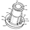
いくつかの例示的な実施形態において、医療器具とともに用いるタンパーエビデントアセンブリが開示されるが、そのようなアセンブリは、他の非医療環境において用いることもできることが理解されよう。図1〜図6を参照すると、タンパーエビデントアセンブリ100が示されており、タンパーエビデントアセンブリ100は、コネクタ110及びキャップ150を備える。コネクタ110は、遠位端部111及び遠位端部111とは反対側の近位端部112を有する。近位端部112は、外部ツール、例えば医療器具に取外し可能に接続する接続部(接続面)113を画定する。いくつかの実施形態において、コネクタ110は、実質的に円筒形とすることができるが、本開示ではコネクタ110の特定の形状に限定されないことが理解されよう。
In some exemplary embodiments, tamper evidence assemblies for use with medical devices are disclosed, but it will be appreciated that such assemblies can also be used in other non-medical environments. With reference to FIGS. 1-6, the tamper-
タンパー部材120は、コネクタ110に取り付けられる。タンパー部材120は、キャップ150がコネクタ110から取り外されたこと、及びコネクタ110にアクセスされた可能性があることを示す役目を果たす。タンパー部材120は、コネクタ110の本体に取外し可能に取り付けられ、コネクタ110と一体の部品を含むことができる。図1〜図3を参照すると、タンパー部材120は、実質的に円形状を有することができ、内径を規定する内面121aと、外径を規定する外面121bとを有する輪状体として形成することができる。
The
タンパー部材120は、タンパー部材120からコネクタ110の本体まで延在する1つ以上の突起122を介して、コネクタ110に取り付けることができる。突起122は、コネクタ110とタンパー部材120との間の空間に隙間124を画定する。図1〜図3の例示的な実施形態を参照すると、3つの突起122が、輪形状のタンパー部材120の内面121aからコネクタ110まで延在することができる。いくつかの実施形態において、突起122は、タンパー部材120の異なる部分から、例えば、輪状体の外面121bから、頂面121cから、及び/又は底面121dから延在することができる。図1〜図3は、3つの突起122を有する一実施形態を示しているが、タンパー部材120は、異なる数の突起、例えば、1つ、2つ、...、8つ、又は別の好適な数の突起122を有することができることが理解されよう。
The
いくつかの実施形態において、コネクタ110は、1つ以上の突起122を受けるように構成された1つ以上の波状部すなわち溝118を有する。溝118は、コネクタ又はタンパー部材の破片による鋭い縁部がコネクタ110の外径から飛び出ることのないようにする。これにより、安全性が増し、装置の取扱い及び処分が改善される。
In some embodiments, the
代替的な実施形態において、タンパー部材120は、突起122又は隙間124なしでコネクタ110に取り付けることもできる。
In an alternative embodiment, the
タンパー部材120が取り付けられたコネクタ110は、挿入軸線Aに沿ってキャップ150に挿入することができる。図1〜図6を参照すると、キャップ150は、外面151と、レセプタクル154を画定する内面152とを有する。レセプタクル154は、コネクタ110及びタンパー部材120を収納するように構成される。いくつかの実施形態において、タンパー部材120の全体及びコネクタ110の少なくとも一部分がレセプタクル154内に入る。キャップ150は、一度挿入されると、タンパー部材120をレセプタクル154から取り外すことができないように、タンパー部材120を収納及び保持するように構成される。
The
レセプタクル154は、非係止部分(非ロック部分)154a及び係止部分(ロック部分)154bを有する。タンパー部材120は、非係止部分154a内では自由に動くことができる。タンパー部材120が係止部分154b内に入り込むと、タンパー部材120は、係止部分154b内に保持され、それにより、取り外すことができなくなる。
The
図4〜図6を参照すると、キャップ150は、タンパー部材120に係合する1つ以上の保持要素156を備えることができる。保持要素156は、非係止部分154aと係止部分154bとの間の移行部を画定することができる。各保持要素156は、非係止部分154a内に設けられた斜面158と、係止部分154bにおける保持面160とを有することができる。キャップ150は、特定の数の保持要素を有することに限定されず、例えば、1つ、2つ、...、8つ、又は別の数量の保持要素156を有することができることが理解されよう。
With reference to FIGS. 4-6, the
タンパー部材120は、レセプタクル154に挿入される際、斜面158に摺動可能に接触することができる。いくつかの実施形態において、タンパー部材120の外面121bは、キャップ150への挿入を容易にするために、斜面158に対応するテーパーを付けることができる。タンパー部材120が係止部分154b内に移動すると、保持面160は、タンパー部材120の頂面121cに接触することができ、タンパー部材120は、非係止部分154aに戻ることができなくなる。そのような実施形態において、タンパー部材120は、頂面121cが保持面160を越えて通過する第1の挿入方向に一度移動すると、タンパー部材120が、係止部分154bから出る反対方向に移動することができなくなるように構成することができる。
The
コネクタ110及びタンパー部材120がレセプタクル154内にあるときにコネクタ110にアクセスするためには、コネクタ110を力ずくでタンパー部材120から分離し、キャップ150内から取り外すことができる。コネクタ110及びタンパー部材120は、一度分離されると、再び取り付けられないように構成される。いくつかの実施形態において、コネクタ110は、タンパー部材120から分離されたときにキャップ150内に保持される手段を備えない場合がある。
In order to access the
タンパー部材120から分離されると、コネクタ110は、キャップ150から取り外すことができ、使用者がアクセスすることができる。コネクタ110は、手で取り外すことができるか、又は外部ツール、別のコネクタ、若しくは医療器具に係合することができる。コネクタ110がタンパー部材120から分離していることは、コネクタ110がキャップから取り外された、アクセスされた、又は不正操作された可能性を示す。
Once separated from the
タンパー部材120は、十分な力を加えると、コネクタ110から取り外されるように構成される。タンパー部材120が係止部分154b内に保持されている場合、キャップ150及びコネクタ110は、容易に分離することができない。十分な取外し力がキャップ150又はコネクタ110のいずれかに加えられ、コネクタ110がレセプタクル154内から引き出される場合、タンパー部材120は、コネクタ110から分離し、キャップ150内に保持することができる。その後、コネクタ110は、キャップ150から分離し、取り外すことができる。
The
1つ以上の突起122を有する実施形態において、各突起122は、タンパー部材120をコネクタ110から分離するように破断することができる。代替的に、タンパー部材120が、突起122なしでコネクタ110に直接取り付けられる場合、タンパー部材120は、取外し力を加えた際に、接続部においてコネクタ110から破断することができる。
In an embodiment having one or
本開示は、取外し力の任意の特定の量に限定されないが、タンパー部材120をコネクタ110から離脱させることは、外部ツールを用いることなく、平均的な使用者によって行うことができることが理解されよう。好適な力とは、例えば、約4.45N〜約22.24N、約8.90N〜約17.79N、約11.12N〜約13.34N、又は上記の組合せを含むことができる。いくつかの実施形態において、例えば、平均的な使用者であれば、片手で十分な力を及ぼすことが可能であり得る。力は、コネクタ110及びタンパー部材120をキャップ150に入れる挿入軸線Aに沿って加えることができる。いくつかの実施形態において、力は、挿入軸線Aの周りに回転するように加えることもでき、又は挿入軸線Aに対して或る角度で加えることもできる。取外し力は、コネクタ110、タンパー部材120、及び/又はキャップ150に加えることができる。いくつかの実施形態において、力は、上述の構成要素のうちの1つ以上に固定的に接続される外部ツールに加えることができる。
Although the present disclosure is not limited to any particular amount of removal force, it will be appreciated that the detachment of the
図4〜図6を再び参照すると、いくつかの実施形態において、キャップ150は、レセプタクル154内に1つ以上の突出部162を有することができる。タンパー部材120が係止部分154b内にある場合、突出部162は、タンパー部材120の底面121dに係合し、タンパー部材120を、頂面121c又は底面121dによって規定される実質的に同じ水平平面に維持することができる。突出部162は、タンパー部材120がコネクタ110から分離されたとき、タンパー部材120がキャップ150から捻り出されて落下することを防ぐ。いくつかの実施形態において、キャップ150は、内面152の周縁部の周りに延在する1つの突出部162を有することができる。代替的に、キャップ150は、2つ、3つ、...、8つ、又は別の好適な数の突出部162を有することができる。
With reference to FIGS. 4-6 again, in some embodiments, the
突出部162と保持面160との間の距離は、例えば、頂面121cから底面121dまで測定した場合のタンパー部材120の厚さ以上とすることができる。いくつかの実施形態において、保持面160と突出部162との間の距離は、タンパー部材120の厚さよりも大きくすることで、タンパー部材120が係止部分154bに入るための公差を与えることができる。このより大きな空間は、発生すればタンパー部材120がコネクタ110から不慮に又は尚早に分離する原因となり得る不要な摩擦又は抵抗を伴わずに、タンパー部材120が係止部分154b内に移動することを可能にする。
The distance between the
いくつかの実施形態において、キャップ150は、突出部162を有しない場合があり、タンパー部材120は、突出部162を使用せずに、保持面160と内面152との間に保持することができる。
In some embodiments, the
いくつかの実施形態において、キャップ150は、レセプタクル154内に配置された柱体(ポスト)166を更に備えることができる。図4〜図6の例示的な実施形態を参照すると、柱体166は、実質的に円筒形であり、キャップ150の内面152に取り付けることができる。柱体166は、コネクタ110がレセプタクル154に挿入されると、コネクタ110に係合するように構成される。いくつかの実施形態において、柱体166は、コネクタ110の遠位端部111に接触することができる。柱体166は、コネクタ110がキャップ150内にある場合、コネクタ110が不所望に摺動、回転、又は並進しないように、コネクタ110が挿入軸線Aと整合した状態に維持することができる。これにより、アセンブリの剛性を向上することができ、不慮の離脱、構成要素間の圧着、又はアセンブリ内の若しくはアセンブリに取り付けられた1つ以上の構成要素に対する損傷の事例を減少させることができる。
In some embodiments, the
タンパー部材120がコネクタ110から分離していることは、使用者が容易に検出することができる。いくつかの実施形態において、タンパー部材120は、キャップ150の内側から少なくとも1つの視野角度で視認可能及び視覚的に識別可能とすることができる。図6の例示的な実施形態を参照すると、タンパー部材120は、コネクタ110を挿入及び取り外すのに用いる開口から、レセプタクル154内を覗くことによって、視認可能とすることができる。別の実施形態において、キャップ150上に1つ以上の更なる開口(不図示)が存在する場合があり、タンパー部材120を1つ以上の更なる開口を通して視認可能になっている。
The fact that the
別の実施形態において、タンパー部材120は、触れることによって物理的に識別可能とすることもできる。タンパー部材120の1つ以上の部分は、キャップ150の表面を通してキャップ150の表面を越えて延出するように構成することができ、それにより、使用者は、タンパー部材120がレセプタクル154内にある場合、その延出部を触知することができる。いくつかの実施形態において、タンパー部材120の1つ以上の部分は、キャップ150のものとは異なる質感を有する表面を有することができ、タンパー部材120がレセプタクル154内に保持されている場合、使用者は、タンパー部材120のその異なる質感を感取することができるようになっている。
In another embodiment, the
いくつかの実施形態において、タンパーエビデントアセンブリ100は、タンパー部材120がキャップ150内に保持されているという信号を使用者に提供する表示器(不図示)を備えることができる。表示器は、物理的表示器、例えば、タンパー部材120がレセプタクル154内にない第1の位置と、タンパー部材120がレセプタクル154内にある第2の位置とをとるように構成される切替器とすることができる。
In some embodiments, the
本開示は、コネクタ110、キャップ150、タンパー部材120、又はタンパーエビデントアセンブリ100の他の構成要素の特定の寸法に限定されないことが理解されよう。いくつかの実施形態において、タンパー部材120は、タンパー部材120が挿入軸線Aに沿って実質的にキャップ150の中心にある場合、係止部分154b内にあることができる。代替的な実施形態において、キャップ150、タンパー部材120、及びコネクタ110は、係止部分154bがキャップ150の他端部よりも一端部の方に近くなるように配置され、それにより、タンパー部材120が他端部よりも一端部の近くに係合することができるように、設計及び製造することができる。そのような実施形態は、相互作用する構成要素の安定性を向上し、不慮の離脱又はタンパーエビデントアセンブリの1つ以上の構成要素に対する損傷のリスクを低減することができる。
It will be appreciated that the present disclosure is not limited to the specific dimensions of the
別の実施形態において、係止部分154bは、タンパー部材120がキャップ150の略中心に係合するように、挿入軸線Aに沿ってキャップ150の中心近くに配置することができる。本願を通して記載される種々の構成要素は、上記の種々の実施形態における好適な機能を提供するために対応する形状及び寸法を有して設計及び製造することもできることが理解されよう。例えば、柱体166は、係止部分154bがキャップ150の一端部又は他端部のいずれに対してより近くにあるかに応じて、より短く又はより長くなるように設計することができる。
In another embodiment, the locking
タンパーエビデントアセンブリ100は、種々の器具、例えば医療器具とともに使用することができる。好適な医療器具として、限定はしないが、シリンジ、ボトル、チューブ、又は、アセンブリ若しくは医療器具に対して事前に不正操作があったか若しくは不正操作が試みられたことを示す閉鎖具アセンブリから利益を得ることができる他の医療器具を挙げることができる。図7におけるシステム300の例示の実施形態を参照すると、タンパーエビデントアセンブリ100は、シリンジ301に固定的に取り付けることができる。
The
タンパーエビデントアセンブリ100は、所望の用途又は器具に適合することができる独立したコンポーネントとして製造、販売、及び流通することができる。代替的には、タンパーエビデントアセンブリ100は、所望の器具に取り付けられ、特定用途のために意図された状態で製造、販売、及び流通することができる。再び図7を参照すると、システム300は、シリンジ301に固定的に取り付けられたタンパーエビデントアセンブリ100を備える個別のユニットとして販売することができる。シリンジ301には、流通の前に所望の医療物質を予め充填することができる。タンパーエビデントアセンブリ100が取り付けられた状態で事前充填シリンジ301を流通させることは、末端使用者が、不正操作されていないシリンジ301と、充填されてから末端使用者に届くまでの間に不正操作された可能性がある又は別様にアクセスされた可能性があるシリンジ301とを識別することに役立つことができる。
The
タンパーエビデントアセンブリ100は、所望の器具に様々な方法で取り付けることができ、本開示は、タンパーエビデントアセンブリ100を器具に接続する特定の方法に限定されないことが理解されよう。図1〜図6をもう一度参照すると、コネクタ110は、近位端部112において接続部113を有することができる。接続部113は、スナップ留め、摩擦嵌合、螺合、又は別の好適な接続方法等の既知の接続方法により、外部器具すなわち外部ツールに取り付けることができる。図2及び図3の例示的な実施形態を参照すると、接続部113は、外部ツールにおける対応するねじ山(不図示)に係合するように構成されたねじ山116を有することができる。
It will be appreciated that the tamper-
いくつかの実施形態において、コネクタ110がタンパー部材120に取り付けられ、レセプタクル154内にある場合、接続部113もレセプタクル154内にある。この配置は、コネクタ110をキャップ150から少なくとも部分的に取り外すことなく、したがって、コネクタ110をタンパー部材120から分離することなく、接続部113に容易にアクセスすることはできないことから、有利であり得る。これは、接続された器具、例えば事前充填シリンジが、タンパーエビデントアセンブリ100に接続された後にアクセスされていないことを保証することによって、有利であり得る。
In some embodiments, if the
タンパーエビデントアセンブリ100は、コネクタ110及びタンパー部材120がキャップ150から分離された状態で製造及び流通することができる。そのような実施形態において、使用者は、コネクタ110を外部ツールすなわち外部器具、例えばシリンジに取り付け、その後、コネクタ110をタンパー部材120とともにキャップに挿入することができる。代替的に、使用者は、アセンブリを外部器具すなわち外部ツールに取り付ける前に、タンパー部材120の付いたコネクタ110をキャップ150に係合させることができる。
The
別の実施形態において、タンパーエビデントアセンブリ100は、コネクタ110及びタンパー部材120が既にキャップ150に挿入され係合した状態で製造及び流通することができる。使用者は、アセンブリ100を外部器具すなわち外部ツールに取り付けることができる。
In another embodiment, the
図4〜図6を参照すると、キャップ150は、キャップ150及びコネクタ110が回転して、タンパーエビデントアセンブリ100を外部器具すなわち外部ツールに係合させるように、コネクタ110と連通するように設計することができる。図4〜図6に示されているように、キャップは、内面152によって画定される第1のラチェット式斜面部164を有することができる。任意の好適な数、例えば、1つ、2つ、3つ、4つ、又は別の許容可能な数の第1のラチェット式斜面部164が存在し得ることが理解されよう。
With reference to FIGS. 4-6, the
コネクタ110は、第1のラチェット式斜面部164と係合するように構成された第2のラチェット式斜面部114を有することができる。コネクタ110は、1つ、2つ、3つ、4つ、又は他の任意の好適な数の第2のラチェット式斜面部114を有することができる。いくつかの実施形態において、第1のラチェット式斜面部164の数は、第2のラチェット式斜面部114の数と等しい。
The
タンパーエビデントアセンブリ100を外部器具に係合させるためには、取付け力をアセンブリの1つ以上の構成要素又は外部器具に加えることができる。コネクタ110が外部器具の対応するねじ付き接続部(不図示)に螺合するように構成される。いくつかの実施形態において、タンパーエビデントアセンブリ100の1つ以上の構成要素は、上記係合を作動させるように回転することができる。そのような実施形態において、キャップ150が第1の方向(例えば、挿入軸線Aの周りに時計回り)に回転する場合、キャップ150上に設けられた第1のラチェット式斜面部164も動き、第2のラチェット式斜面部114に強制的に接触する。コネクタ110上に固定的に設けられた第2のラチェット式斜面部114に力が加わると、コネクタ110も同じ第1の方向(例えば、挿入軸線Aの周りに時計回り)に回転し、接続部113が外部器具に係合する。キャップ150が第1の方向とは反対の第2の方向(例えば、挿入軸線Aの周りに反時計回り)に回転する場合、第1のラチェット式斜面部164は、第2のラチェット式斜面部114に摺動可能に接触し、第2のラチェット式斜面部114に沿って摺動するため、キャップ150が第2の方向に回転を続けても、第2のラチェット式斜面部114に伝達される回転力は、コネクタ110を回転させるのには不十分となる。これにより、タンパーエビデントアセンブリ100が係合した後に外部器具から離脱する可能性が低減する。
To engage the
いくつかの実施形態において、キャップ150は、コネクタ110に対する第1の位置と、第1の位置から挿入軸線Aに沿って軸線方向に変位した第2の位置とを有することができる。第1の位置では、第1のラチェット式斜面部164は、第2のラチェット式斜面部114と同じ平面に少なくとも部分的に位置し、それにより、2つの斜面部が、キャップ150の回転時に互いに接触することができる。第2の位置では、キャップ150は、第1のラチェット式斜面部164の位置する平面が、第2のラチェット式斜面部114の位置する平面に重ならないように、軸線方向に十分な距離だけ変位している。キャップ150が第2の位置にある場合、第1の方向における回転も第2の方向における回転も、第1のラチェット式斜面部164と第2のラチェット式斜面部との間の接触をもたらさない。
In some embodiments, the
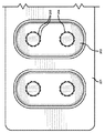
タンパーエビデントアセンブリは、個別に又は複数のアセンブリのセットの一部として製造及び流通することができる。図8〜図11を参照すると、キット200は、使用に際して取り外すことができる複数のタンパーエビデントアセンブリ100を収容するハウジング201を備える。図8は、10個のタンパーエビデントアセンブリ100を収容する1つのハウジング201を有するキット200を示しているが、他の数量及び配置のハウジング及びアセンブリを有するキットも本開示に包含されることが理解されよう。いくつかの実施形態において、例えば、キット200は、1つ、2つ、3つ、4つ、又は別の数のハウジング201を備えることができる。
Tamper-evidence assemblies can be manufactured and distributed individually or as part of a set of assemblies. Referring to FIGS. 8-11, the
各ハウジング201は、1個、2個、...、20個、又は別の好適な数のタンパーエビデントアセンブリ100を収容することができる。ハウジング201は、同じアセンブリを備えてもよく、本明細書を通して開示される種々の実施形態のアセンブリを備えてもよい。図8の例示の実施形態に示されているように、ハウジング201は、それぞれ2つのタンパーエビデントアセンブリ100を収納するように構成された5つの区画202を有することができる。本開示は、ハウジング201又は区画202の任意の特定の配置に限定されないことが理解されよう。いくつかの実施形態において、ハウジング201は、1個、2個、...、10個、又は別の好適な数の区画202を有することができる。各区画202は、1個、2個、...、6個、又は別の好適な数のタンパーエビデントアセンブリ100を収納及び取外し可能に収容するように構成することができる。
Each
図10及び図11を参照すると、タンパーエビデントアセンブリ100は、ハウジング201に係合するように構成された係合部(嵌合部)170を有することができる。ハウジング201は、係合部170を受け、タンパーエビデントアセンブリ100をハウジング201上又はハウジング201内に取外し可能に保持するように構成された対応する固定部204を有することができる。タンパーエビデントアセンブリ100は、任意の許容可能な手段、例えば、スナップ留め、摩擦嵌合、螺合、又は別の好適な接続方法によって、ハウジング201に取り付けることができる。
With reference to FIGS. 10 and 11, the
図11の例示的な実施形態を参照すると、係合部170は、1つ以上の壁172を備えることができる。壁172は、対応する固定部204との接触面積を増大させる。図11は、3つの壁172を有するように示されているが、本開示は、壁の特定の数に限定されず、好適な係合部170は、0、1つ、2つ、3つ、4つ、5つ、6つ、又は別の許容可能な数の壁172を有することができる。
With reference to the exemplary embodiment of FIG. 11, the engaging
いくつかの実施形態において、複数の歯部174を、係合部170、壁172、又は係合部及び壁の双方に設けることができる。歯部174は、壁172又は係合部170から離れる方向に突出し、タンパーエビデントアセンブリ100をハウジング201内に保持するのを向上させるように構成される。いくつかの実施形態において、固定部204は、係合部170における歯部174と相互作用し係合するように構成された複数の歯部206を有することができる。例示の実施形態に示されている歯部の数量は、限定的なものではなく、他の許容可能な数量の歯部174、206が本開示に包含されることが理解されよう。
In some embodiments, a plurality of
キット200に複数のタンパーエビデントアセンブリ100を設けることで、使用者がアセンブリを外部器具に迅速かつ容易に取り付けることを可能にする。ハウジング201は、より把持及び取扱いしやすいより大きなコンポーネントを呈するため、外部器具の取付け中、アセンブリの取扱いミス又は取り落としの可能性が低くなる。さらに、ハウジング201により、使用者がアセンブリ自体の取扱いを回避することが可能であり、それにより、清潔性が向上し、滅菌性が維持され、汚染の機会を減少させる。
The
複数のアセンブリ100を備えるキット200は、使用者が個別のアセンブリのパッケージを取得する必要がないため、効率を向上させる。いくつかの実施形態において、キット200は、特定の手順に必要とされ得る特定の数量及び分類のタンパーエビデントアセンブリ100を備えることができる。そのような場合、使用者は、種々のアセンブリの一式を個々に探して準備するのではなく、単数又は複数の関連する所望のキット200のみを取得し、準備し、開封し、使用するだけでよい。
The
いくつかの実施形態において、別個の機器(不図示)を使用することによって、タンパーエビデントアセンブリ100を外部器具に接続することが望ましい場合がある。機器の例として、使用者によって操作される装置、及び自動化プロセスを有するロボット式装置を挙げることができる。そのような実施形態において、キット200は、機器に装填することで、各タンパーエビデントアセンブリ100を所望の外部器具に接続することができるように構成することができる。いくつかの実施形態において、スループットを向上し、時間を節約するために、複数のアセンブリを複数の外部器具に同時に接続することができる。
In some embodiments, it may be desirable to connect the
キット200は、耐用寿命を向上し、タンパーエビデントアセンブリ100の流通に関連したコストを低減する。ハウジング201は、内部のアセンブリに対する追加の保護を提供し、それにより、包装、輸送、流通、保管、及び準備中のコンポーネントに対する損傷の例を低減する。いくつかの実施形態において、ハウジング201による追加の保護により、タンパーエビデントアセンブリ100の製造により薄くより安価な材料を使用することができる。こうした材料は、ハウジング201による保護がなければ、製品に対する物理的な応力がより大きくなることが予期されることから好適ではない。
The
本明細書を通して記載される構成要素は、様々な材料、例えば、金属、プラスチック、ゴム、又は金属、プラスチック、及びゴムの組合せを用いて製造することができる。いくつかの実施形態において、種々の構成要素に対して複数の材料を用いることができる。いくつかの実施形態において、医療環境における使用のために滅菌を施すことができる材料を用いることが有利であり得る。本開示は、特定の材料の使用に限定されず、他の好適な材料の組合せを用いることができることが理解されよう。 The components described throughout this specification can be manufactured using a variety of materials, such as metals, plastics, rubbers, or combinations of metals, plastics, and rubbers. In some embodiments, multiple materials can be used for the various components. In some embodiments, it may be advantageous to use materials that can be sterilized for use in a medical environment. It will be appreciated that the present disclosure is not limited to the use of specific materials and other suitable combinations of materials may be used.
本明細書に開示される実施形態は、複数の利点を提供する。タンパーエビデントアセンブリ100により、使用者は、アセンブリ又はアセンブリが接続された器具に不正操作があれば即座に正確に検出することが可能になる。このことは、医療分野において、不正な医療物質を患者に誤って投与するリスクを減少させる。さらに、いくつかの実施形態において、タンパー部材120は、一度係止部分154b内に配置されると、非係止部分154aに戻すことができない。アセンブリを外部器具から離脱させるためには、タンパー部材120をコネクタ110から分離し、キャップ150内に残したままにする。これにより、器具は、タンパー部材120がキャップ150内にあり、コネクタ110から分離している場合、既に使用、開封、アクセス、又は別様に不正操作されているということを、後の時点で別の使用者に警告する役目を果たす。使用者に対するそのような表示は、或る特定の医療器具、例えばシリンジの再使用による感染、又は汚染された若しくは不正な医療品の流通のリスクを低減するのに役立つ。
The embodiments disclosed herein provide multiple advantages. The
タンパーエビデントアセンブリ100により、使用者は、アセンブリが不正操作されているか否かを容易かつ迅速に識別することが可能である。このことは、使用者が、不正操作された製品を即座に識別し、それに応じてその製品を廃棄することができることにより、時間の節約になる。さらに、そのような実施形態は、使用者に不正操作状態を迅速に知らせることによって、各アセンブリの安全性についての不安を減少させる。これは、使用者が、ペースの速い環境の中で、アクセスされた可能性がある又は不正操作された製品を処理する際に経験し得るストレスを低減するのに役立つ。
The
本開示は、既存の不正操作防止技術に優る様々な利点を提供する。多くの現行の選択肢は、不正操作を示すのに装置の一部分の取外しが必要となる。例えば、いくつかの既存のアセンブリは、アセンブリを囲む輪状体又は突起を断裂又は破壊する必要がある。この手法では、アセンブリの異物片が生じ、それらの除去が必要となる。医療シナリオにおいて、分離した小片は、ツールの汚染及び/又は患者の感染を引き起こすおそれがあるため、望ましくないものであり得る。さらに、アセンブリの一部分を破壊する又は取り外すと、鋭い縁部が露出するが、そうした縁部の場所及び角度は、多くの場合、予測が困難である。これにより、直接的には、使用者及び/又は患者に怪我をもたらすおそれもあり、間接的には、手袋の破れ又は自由になった縁部がツール若しくは材料に引っかかることを原因とした汚染又は感染のリスクをもたらすおそれもある。 The present disclosure offers various advantages over existing tamper-proof techniques. Many current options require the removal of a portion of the device to indicate tampering. For example, some existing assemblies need to rupture or break the ring or protrusion that surrounds the assembly. This technique produces debris from the assembly that needs to be removed. In medical scenarios, isolated pieces can be undesirable as they can cause contamination of the tool and / or infection of the patient. Moreover, breaking or removing a portion of the assembly exposes sharp edges, the location and angle of such edges are often difficult to predict. This can directly injure the user and / or the patient, and indirectly contaminate the glove due to tearing or free edges getting caught in the tool or material. It may also pose a risk of infection.
開示の実施形態は、適切な使用を支援するために、製品の人間工学的な取扱いを提供する。これらの人間工学的アセンブリは、適切な使用のために過剰な力を必要としないため、より広範な専門家にとって利用可能になる。既存の技術は、多くの場合、器具の接続部に直接アクセスする必要があり、そのため、使用者が、例えば、鋭い縁部、針、又は器具内の危険な物質に接触することによる怪我のリスクにさらされる可能性がより大きい。 The disclosed embodiments provide ergonomic handling of the product to support proper use. These ergonomic assemblies will be available to a wider range of professionals as they do not require excessive force for proper use. Existing techniques often require direct access to instrument connections, which puts the user at risk of injury, for example, from contact with sharp edges, needles, or dangerous substances within the instrument. More likely to be exposed.
システム及び方法について、様々な図の種々の実施形態に関連して記載したが、当業者であれば、それらの実施形態の広範な発明的概念から逸脱することなく、実施形態に対して変更を行うことができることが理解されよう。したがって、本開示は、開示されている特定の実施形態に限定されず、特許請求の範囲によって規定される本開示の趣旨及び範囲内の変更形態を包含するように意図されることが理解される。 The systems and methods have been described in relation to the various embodiments of the various figures, but those skilled in the art will make changes to the embodiments without departing from the broader inventive concept of those embodiments. It will be understood that it can be done. Therefore, it is understood that the present disclosure is not limited to the specific embodiments disclosed, but is intended to include the intent and modification within the scope of the present disclosure as defined by the claims. ..
本明細書において用いられる或る特定の術語は、便宜上のものにすぎず、限定的なものではない。「近位」及び「遠位」という用語は、それぞれ、混合システムを使用している個人に向かう側及び離れる側の位置又は方向を概ね指す。「軸線方向」、「鉛直」、「横断」、「左」、「右」、「上」、及び「下」という用語は、参照される図面における方向を示す。「実質的に」という用語は、記載されている範囲の必ずしも全体ではなく、相当な程度又は大部分を意味するように意図される。これらの術語は、上記に挙げた用語、その派生語、及び同様の意味の用語を含む。 Certain terminology used herein is for convenience only and is not limiting. The terms "proximal" and "distal" generally refer to the position or orientation of the side towards and away from the individual using the mixing system, respectively. The terms "axis direction", "vertical", "crossing", "left", "right", "top", and "bottom" refer to directions in the referenced drawings. The term "substantially" is intended to mean a considerable degree or most, but not necessarily the entire range described. These terms include the terms listed above, their derivatives, and terms with similar meanings.
本明細書において用いられる場合、「複数」という用語は、2つ以上であることを示す。単数形の用語(「a」、「an」、及び「the」)は、複数のものを指す場合も含み、特定の数値に対する参照は、別段明記されない限り、少なくともその特定の値を含む。 As used herein, the term "plurality" indicates more than one. The singular terms ("a", "an", and "the") may refer to more than one, and references to a particular number include at least that particular value, unless otherwise stated.
Claims (20)
接続部が画定される近位端部を有するコネクタと、
前記コネクタに取外し可能に取り付けられるタンパー部材であって、取外し力を加えると前記コネクタから分離されように構成されたタンパー部材と、
レセプタクルを画定する内面を有するキャップであって、前記コネクタの少なくとも一部分が前記レセプタクル内に入るように、前記タンパー部材に係合するように構成されたキャップと、
を備え、
前記取外し力を加えると、前記タンパー部材は、前記コネクタから分離され、前記キャップの前記レセプタクル内に保持され、前記コネクタは、前記レセプタクルから取り外すことができる、タンパーエビデント閉鎖具アセンブリ。 A tamper-evidence closure assembly for use with medical devices.
A connector with a proximal end where the connection is defined, and
A tamper member that is detachably attached to the connector and is configured to be separated from the connector when a removing force is applied.
A cap having an inner surface that defines a receptacle, configured to engage the tamper member such that at least a portion of the connector enters the receptacle.
With
A tamper-evidence closure assembly that, upon application of the removing force, separates the tamper member from the connector and holds it in the receptacle of the cap, which connector can be removed from the receptacle.
前記斜面は、前記タンパー部材が前記保持要素を越えて前記係止部分内に摺動可能に移動することを可能にするように構成され、前記保持面は、前記タンパー部材が前記保持要素を越えて前記係止部分から出ることを防止するように構成されている、請求項1に記載のアセンブリ。 The inner surface of the cap defines a holding element configured to prevent the tamper member from being removed from the receptacle, the holding element having a slope and a holding surface adjacent to the slope. The inner surface of the cap and the holding surface of the holding element define a locking portion of the receptacle.
The slope is configured to allow the tamper member to slidably move over the holding element into the locking portion, and the holding surface is such that the tamper member crosses the holding element. The assembly according to claim 1, which is configured to prevent it from coming out of the locking portion.
前記コネクタが螺合方向に回転されたときに、前記第1のラチェット式斜面部は、前記コネクタにおける前記第2のラチェット式斜面部に接触し、前記キャップも前記螺合方向に回転するようになっており、
前記コネクタが前記螺合方向とは反対の解除方向に回転されたときに、前記第1のラチェット式斜面部は、前記コネクタにおける前記第2のラチェット式斜面部に摺動可能に接触し、前記第1のラチェット式斜面部は、前記第2のラチェット式斜面部に沿って摺動し、前記キャップは、前記解除方向に回転されないようになっている、請求項1に記載のアセンブリ。 The cap further comprises a first ratchet-type slope portion, the first ratchet-type slope portion being configured to contact the corresponding second ratchet-type slope portion in the connector.
When the connector is rotated in the screwing direction, the first ratchet type slope portion comes into contact with the second ratchet type slope portion of the connector, and the cap also rotates in the screwing direction. It has become
When the connector is rotated in a release direction opposite to the screwing direction, the first ratchet type slope portion slidably contacts the second ratchet type slope portion of the connector, and the first ratchet type slope portion is slidably contacted with the second ratchet type slope portion. The assembly according to claim 1, wherein the first ratchet-type slope portion slides along the second ratchet-type slope portion, and the cap is prevented from rotating in the release direction.
レセプタクルを画定する内面を有するキャップと、
前記レセプタクル内で前記キャップに係合するように構成されたタンパー部材と、
前記キャップを収納するように構成されたハウジングであって、前記キャップは、前記ハウジングに取外し可能に固定される、ハウジングと、
を備える、キット。 Tamper Evidence Closure Assembly Kit
A cap with an inner surface that defines the receptacle,
A tamper member configured to engage the cap within the receptacle, and
A housing configured to house the cap, wherein the cap is removably secured to the housing.
A kit that includes.
Applications Claiming Priority (3)
| Application Number | Priority Date | Filing Date | Title |
|---|---|---|---|
| US15/892,181 US11103654B2 (en) | 2018-02-08 | 2018-02-08 | Tamper-evident closure |
| US15/892,181 | 2018-02-08 | ||
| PCT/US2019/013743 WO2019156784A1 (en) | 2018-02-08 | 2019-01-16 | Tamper-evident closure |
Publications (2)
| Publication Number | Publication Date |
|---|---|
| JP2021512710A true JP2021512710A (en) | 2021-05-20 |
| JPWO2019156784A5 JPWO2019156784A5 (en) | 2022-01-21 |
Family
ID=65516729
Family Applications (1)
| Application Number | Title | Priority Date | Filing Date |
|---|---|---|---|
| JP2020542586A Ceased JP2021512710A (en) | 2018-02-08 | 2019-01-16 | Tamper Evidence Closure |
Country Status (5)
| Country | Link |
|---|---|
| US (1) | US11103654B2 (en) |
| EP (1) | EP3749394A1 (en) |
| JP (1) | JP2021512710A (en) |
| CN (1) | CN111886039A (en) |
| WO (1) | WO2019156784A1 (en) |
Citations (3)
| Publication number | Priority date | Publication date | Assignee | Title |
|---|---|---|---|---|
| US20080097310A1 (en) * | 2006-08-10 | 2008-04-24 | John Buehler | Tamper evident tip cap assembly |
| JP2009022641A (en) * | 2007-07-23 | 2009-02-05 | Maeda Sangyo Kk | Device for preventing nozzle cap from being reattached |
| US8864021B1 (en) * | 2012-08-31 | 2014-10-21 | Medical Device Engineering, LLC. | Support and closure assembly for discharge port of a syringe and tracking system therefore |
Family Cites Families (48)
| Publication number | Priority date | Publication date | Assignee | Title |
|---|---|---|---|---|
| US3630403A (en) | 1970-05-18 | 1971-12-28 | Robert C Berg | Safety container closure |
| US4433789A (en) | 1982-12-20 | 1984-02-28 | Merck & Co., Inc. | Convertible child resistant closure |
| US4723673A (en) | 1987-04-06 | 1988-02-09 | Tartaglia Marc S | Tamper resistant cap with indicator |
| US4740205A (en) * | 1987-07-23 | 1988-04-26 | Leilani Seltzer | Disposable needle system |
| US4844273A (en) | 1988-09-06 | 1989-07-04 | Sunbeam Plastics Corporation | Closure with enhanced sealing |
| US5328474A (en) | 1992-04-13 | 1994-07-12 | B. Braun Medical Inc. | Tamper resistant syringe cap |
| DE4310414A1 (en) | 1993-03-31 | 1994-10-06 | Basf Lacke & Farben | Process for producing a two-coat top coat on a substrate surface |
| ES1028707U (en) | 1993-09-03 | 1995-03-01 | Novembal Sa | Screwcap with tamper evidence band, package provided with such a cap, method of making such a cap and such a package. |
| AUPM922394A0 (en) | 1994-11-03 | 1994-11-24 | Astra Pharmaceuticals Pty Ltd | Plastic syringe with overcap |
| US5624402A (en) | 1994-12-12 | 1997-04-29 | Becton, Dickinson And Company | Syringe tip cap |
| US6196998B1 (en) | 1994-12-12 | 2001-03-06 | Becton Dickinson And Company | Syringe and tip cap assembly |
| US5807345A (en) | 1995-06-30 | 1998-09-15 | Abbott Laboratories | Luer cap for terminally sterilized syringe |
| US5609262A (en) | 1995-09-22 | 1997-03-11 | Rieke Corporation | Tamper evident, child-resistant closure |
| US5688241A (en) * | 1996-04-15 | 1997-11-18 | Asbaghi; Hooman Ali | Automatic non-reusable needle guard |
| DE19909824A1 (en) | 1999-03-05 | 2000-09-07 | Vetter & Co Apotheker | Syringe for medical purposes and assembly method |
| DE10009814B4 (en) | 2000-03-01 | 2008-03-06 | Tecpharma Licensing Ag | Disposable injector |
| US6585691B1 (en) | 2001-05-11 | 2003-07-01 | Jonathan J. Vitello | Tamper evident end cap assembly for a loaded syringe and process |
| US6821268B2 (en) | 2002-03-30 | 2004-11-23 | Bracco Diagnostics Inc. | Tamper evident overap of a container |
| DE10247965A1 (en) | 2002-10-15 | 2004-05-06 | Transcoject Gesellschaft für medizinische Geräte mbH & Co KG | Tamper-evident closure for a syringe |
| US7882977B2 (en) | 2003-08-01 | 2011-02-08 | Liqui-Box Corporation | Fitment assembly for a container having a tamper indication band attached thereto |
| US7425208B1 (en) | 2003-08-29 | 2008-09-16 | Vitello Jonathan J | Needle assembly facilitating complete removal or nearly complete removal of a composition from a container |
| FR2896168B1 (en) | 2006-01-19 | 2008-10-17 | Aguettant Soc Par Actions Simp | PRE-FILLED HYPODERMIC SYRINGE EQUIPPED WITH A CLOGGING DEVICE |
| DE102008013198B4 (en) * | 2008-03-07 | 2011-07-14 | Bayer Schering Pharma Aktiengesellschaft, 13353 | Tamper evident closure with retaining pin |
| DE102009008754A1 (en) | 2009-02-12 | 2010-08-26 | Tecpharma Licensing Ag | Administration device, in particular autoinjection device, for a medical substance with a withdrawal aid for a protective cap |
| CN102458538B (en) | 2009-06-03 | 2016-10-19 | 贝克顿迪金森法国公司 | Adapter, delivery device and the method that adapter is installed on delivery device |
| US8616413B2 (en) | 2010-03-03 | 2013-12-31 | Terumo Kabushiki Kaisha | Syringe |
| US8348895B1 (en) | 2010-05-27 | 2013-01-08 | Medical Device Engineering, LLC. | Tamper evident cap assembly |
| US9402967B1 (en) | 2010-05-27 | 2016-08-02 | Medical Device Engineering, Llc | Tamper evident cap assembly |
| GB2484490A (en) | 2010-10-12 | 2012-04-18 | Owen Mumford Ltd | Frangible needle shield for syringe |
| US8353869B2 (en) * | 2010-11-02 | 2013-01-15 | Baxa Corporation | Anti-tampering apparatus and method for drug delivery devices |
| US8864708B1 (en) | 2010-12-03 | 2014-10-21 | Medical Device Engineering, LLC. | Tamper indicating closure assembly |
| DE102010061061A1 (en) | 2010-12-07 | 2012-06-14 | Alfred Von Schuckmann | syringe cap |
| US9199749B1 (en) | 2011-04-26 | 2015-12-01 | Medical Device Engineering, LLC. | Assembly and system for connecting a closure to a syringe |
| US8882719B2 (en) | 2011-09-30 | 2014-11-11 | Becton Dickinson France S.A.S. | Syringe having a removable cover for use as a plunger rod in rotational engagement |
| ITMI20111799A1 (en) * | 2011-10-04 | 2013-04-05 | Creative Gcl S R L | TAMPER EVIDENT CLOSURE |
| EP2832391B1 (en) | 2012-03-28 | 2018-01-03 | Terumo Kabushiki Kaisha | Syringe |
| US8443999B1 (en) | 2012-04-16 | 2013-05-21 | Robert C. Reinders | Cap, cap/container combination |
| NL2009109C2 (en) | 2012-07-03 | 2014-01-06 | Ipn Ip Bv | A closure assembly. |
| EP2882478A1 (en) | 2012-08-08 | 2015-06-17 | Sanofi-Aventis Deutschland GmbH | Drug delivery device with tamper-evident closure |
| US9311592B1 (en) | 2012-08-31 | 2016-04-12 | Medical Device Engineering, LLC. | Support and closure assembly for discharge port of a syringe and tracking system therefore |
| SI2900301T1 (en) | 2012-09-26 | 2016-11-30 | Bayer Pharma Aktiengesellschaft | Prefilled syringe |
| US9821152B1 (en) | 2013-03-04 | 2017-11-21 | Medical Device Engineering, LLC. | Closure assembly |
| DE102013204134A1 (en) | 2013-03-11 | 2014-09-11 | Vetter Pharma-Fertigung GmbH & Co. KG | Attachment for a syringe, carpule or the like |
| US9309032B2 (en) | 2014-02-17 | 2016-04-12 | Silgan White Cap LLC | Dispenser and closure with hinge attached tamper band |
| US9533802B2 (en) | 2014-10-31 | 2017-01-03 | Silgan White Cap LLC | Closure with tamper band and spout |
| US9938050B2 (en) | 2016-05-13 | 2018-04-10 | Silgan White Cap LLC | Closure with hinged tamper band |
| US9937301B2 (en) | 2016-06-10 | 2018-04-10 | Baxter Corporation Englewood | Tamper evident syringe tip cap |
| WO2018024624A1 (en) | 2016-08-02 | 2018-02-08 | Sanofi-Aventis Deutschland Gmbh | Drug delivery device with restricted cap replacement |
-
2018
- 2018-02-08 US US15/892,181 patent/US11103654B2/en active Active
-
2019
- 2019-01-16 EP EP19706790.3A patent/EP3749394A1/en not_active Withdrawn
- 2019-01-16 CN CN201980017853.7A patent/CN111886039A/en active Pending
- 2019-01-16 JP JP2020542586A patent/JP2021512710A/en not_active Ceased
- 2019-01-16 WO PCT/US2019/013743 patent/WO2019156784A1/en unknown
Patent Citations (3)
| Publication number | Priority date | Publication date | Assignee | Title |
|---|---|---|---|---|
| US20080097310A1 (en) * | 2006-08-10 | 2008-04-24 | John Buehler | Tamper evident tip cap assembly |
| JP2009022641A (en) * | 2007-07-23 | 2009-02-05 | Maeda Sangyo Kk | Device for preventing nozzle cap from being reattached |
| US8864021B1 (en) * | 2012-08-31 | 2014-10-21 | Medical Device Engineering, LLC. | Support and closure assembly for discharge port of a syringe and tracking system therefore |
Also Published As
| Publication number | Publication date |
|---|---|
| CN111886039A (en) | 2020-11-03 |
| WO2019156784A1 (en) | 2019-08-15 |
| US20190240425A1 (en) | 2019-08-08 |
| EP3749394A1 (en) | 2020-12-16 |
| US11103654B2 (en) | 2021-08-31 |
Similar Documents
| Publication | Publication Date | Title |
|---|---|---|
| TR201802983T4 (en) | An adapter for a drug delivery device and a method for mounting said adapter thereon. | |
| US8784377B2 (en) | Anti-tampering apparatus and method for drug delivery devices | |
| JP5179573B2 (en) | Fluid transfer device | |
| KR102160026B1 (en) | Adaptor for a drug delivery device and method for mounting said adaptor thereon | |
| JP5462277B2 (en) | Connection device and method for connecting medical device to connection device | |
| JP2008502422A (en) | Tamper-evident overcap for containers | |
| US20110100850A1 (en) | Apparatus and Method for Unwinding a Needle Portion | |
| WO2014164444A1 (en) | Vial container with collar cap | |
| JP6014749B2 (en) | Drug delivery device | |
| JP6031285B2 (en) | Waste container | |
| WO2009124260A2 (en) | Clean transportation system | |
| JP2014514096A (en) | Needle assembly for medical devices | |
| JP4764594B2 (en) | Opening for pen needle | |
| JP2014518726A (en) | Tamper-evident lid that cannot be removed | |
| JP6921806B2 (en) | Adapter for connecting the dispenser to the container | |
| JP2021512710A (en) | Tamper Evidence Closure | |
| JP2016067919A (en) | Needle removing operation cover | |
| JP5826302B2 (en) | Connection device and method for connecting medical device to connection device | |
| JP2020535928A (en) | Tamper Evidence Closure Assembly | |
| US11653992B2 (en) | Packaging having a holding device for holding a medical tool | |
| US11845082B1 (en) | Specimen tube | |
| CN112334228B (en) | Closure for a biological fluid collection device | |
| RU2722978C2 (en) | Protective device for tool tip |
Legal Events
| Date | Code | Title | Description |
|---|---|---|---|
| A521 | Request for written amendment filed |
Free format text: JAPANESE INTERMEDIATE CODE: A523 Effective date: 20220113 |
|
| A621 | Written request for application examination |
Free format text: JAPANESE INTERMEDIATE CODE: A621 Effective date: 20220113 |
|
| A977 | Report on retrieval |
Free format text: JAPANESE INTERMEDIATE CODE: A971007 Effective date: 20221111 |
|
| A01 | Written decision to grant a patent or to grant a registration (utility model) |
Free format text: JAPANESE INTERMEDIATE CODE: A01 Effective date: 20221115 |
|
| A045 | Written measure of dismissal of application [lapsed due to lack of payment] |
Free format text: JAPANESE INTERMEDIATE CODE: A045 Effective date: 20230328 |