JP2021510327A - Determining the position and condition of tools in a robotic surgery system using computer vision - Google Patents
Determining the position and condition of tools in a robotic surgery system using computer vision Download PDFInfo
- Publication number
- JP2021510327A JP2021510327A JP2020538102A JP2020538102A JP2021510327A JP 2021510327 A JP2021510327 A JP 2021510327A JP 2020538102 A JP2020538102 A JP 2020538102A JP 2020538102 A JP2020538102 A JP 2020538102A JP 2021510327 A JP2021510327 A JP 2021510327A
- Authority
- JP
- Japan
- Prior art keywords
- tool
- center
- gravity
- tracking
- imaging device
- Prior art date
- Legal status (The legal status is an assumption and is not a legal conclusion. Google has not performed a legal analysis and makes no representation as to the accuracy of the status listed.)
- Pending
Links
- 238000002432 robotic surgery Methods 0.000 title description 5
- 238000003384 imaging method Methods 0.000 claims abstract description 61
- 238000000034 method Methods 0.000 claims abstract description 52
- 230000004044 response Effects 0.000 claims abstract description 15
- 230000005484 gravity Effects 0.000 claims description 63
- 238000001356 surgical procedure Methods 0.000 claims description 36
- 230000000007 visual effect Effects 0.000 claims description 19
- 230000004913 activation Effects 0.000 claims description 17
- 230000003213 activating effect Effects 0.000 claims description 11
- 230000008859 change Effects 0.000 claims description 3
- 238000002329 infrared spectrum Methods 0.000 claims description 2
- 230000001934 delay Effects 0.000 claims 1
- 230000036544 posture Effects 0.000 description 49
- 239000012636 effector Substances 0.000 description 37
- 210000003484 anatomy Anatomy 0.000 description 5
- 230000009286 beneficial effect Effects 0.000 description 2
- 239000003795 chemical substances by application Substances 0.000 description 2
- 230000003993 interaction Effects 0.000 description 2
- 238000011084 recovery Methods 0.000 description 2
- 101000607909 Homo sapiens Ubiquitin carboxyl-terminal hydrolase 1 Proteins 0.000 description 1
- 102100039865 Ubiquitin carboxyl-terminal hydrolase 1 Human genes 0.000 description 1
- 230000001133 acceleration Effects 0.000 description 1
- 238000013459 approach Methods 0.000 description 1
- 239000003086 colorant Substances 0.000 description 1
- 230000000694 effects Effects 0.000 description 1
- 230000007246 mechanism Effects 0.000 description 1
- 238000012978 minimally invasive surgical procedure Methods 0.000 description 1
- 230000009467 reduction Effects 0.000 description 1
- 230000037390 scarring Effects 0.000 description 1
- 238000002604 ultrasonography Methods 0.000 description 1
Images


Classifications
-
- A—HUMAN NECESSITIES
- A61—MEDICAL OR VETERINARY SCIENCE; HYGIENE
- A61B—DIAGNOSIS; SURGERY; IDENTIFICATION
- A61B34/00—Computer-aided surgery; Manipulators or robots specially adapted for use in surgery
- A61B34/20—Surgical navigation systems; Devices for tracking or guiding surgical instruments, e.g. for frameless stereotaxis
-
- A—HUMAN NECESSITIES
- A61—MEDICAL OR VETERINARY SCIENCE; HYGIENE
- A61B—DIAGNOSIS; SURGERY; IDENTIFICATION
- A61B17/00—Surgical instruments, devices or methods, e.g. tourniquets
- A61B17/04—Surgical instruments, devices or methods, e.g. tourniquets for suturing wounds; Holders or packages for needles or suture materials
- A61B17/0469—Suturing instruments for use in minimally invasive surgery, e.g. endoscopic surgery
-
- A—HUMAN NECESSITIES
- A61—MEDICAL OR VETERINARY SCIENCE; HYGIENE
- A61B—DIAGNOSIS; SURGERY; IDENTIFICATION
- A61B34/00—Computer-aided surgery; Manipulators or robots specially adapted for use in surgery
- A61B34/25—User interfaces for surgical systems
-
- A—HUMAN NECESSITIES
- A61—MEDICAL OR VETERINARY SCIENCE; HYGIENE
- A61B—DIAGNOSIS; SURGERY; IDENTIFICATION
- A61B34/00—Computer-aided surgery; Manipulators or robots specially adapted for use in surgery
- A61B34/30—Surgical robots
- A61B34/32—Surgical robots operating autonomously
-
- A—HUMAN NECESSITIES
- A61—MEDICAL OR VETERINARY SCIENCE; HYGIENE
- A61B—DIAGNOSIS; SURGERY; IDENTIFICATION
- A61B34/00—Computer-aided surgery; Manipulators or robots specially adapted for use in surgery
- A61B34/30—Surgical robots
- A61B34/35—Surgical robots for telesurgery
-
- A—HUMAN NECESSITIES
- A61—MEDICAL OR VETERINARY SCIENCE; HYGIENE
- A61B—DIAGNOSIS; SURGERY; IDENTIFICATION
- A61B17/00—Surgical instruments, devices or methods, e.g. tourniquets
- A61B17/068—Surgical staplers, e.g. containing multiple staples or clamps
-
- A—HUMAN NECESSITIES
- A61—MEDICAL OR VETERINARY SCIENCE; HYGIENE
- A61B—DIAGNOSIS; SURGERY; IDENTIFICATION
- A61B17/00—Surgical instruments, devices or methods, e.g. tourniquets
- A61B17/28—Surgical forceps
- A61B17/29—Forceps for use in minimally invasive surgery
-
- A—HUMAN NECESSITIES
- A61—MEDICAL OR VETERINARY SCIENCE; HYGIENE
- A61B—DIAGNOSIS; SURGERY; IDENTIFICATION
- A61B17/00—Surgical instruments, devices or methods, e.g. tourniquets
- A61B17/28—Surgical forceps
- A61B17/29—Forceps for use in minimally invasive surgery
- A61B17/295—Forceps for use in minimally invasive surgery combined with cutting implements
-
- A—HUMAN NECESSITIES
- A61—MEDICAL OR VETERINARY SCIENCE; HYGIENE
- A61B—DIAGNOSIS; SURGERY; IDENTIFICATION
- A61B34/00—Computer-aided surgery; Manipulators or robots specially adapted for use in surgery
- A61B34/20—Surgical navigation systems; Devices for tracking or guiding surgical instruments, e.g. for frameless stereotaxis
- A61B2034/2046—Tracking techniques
- A61B2034/2059—Mechanical position encoders
-
- A—HUMAN NECESSITIES
- A61—MEDICAL OR VETERINARY SCIENCE; HYGIENE
- A61B—DIAGNOSIS; SURGERY; IDENTIFICATION
- A61B34/00—Computer-aided surgery; Manipulators or robots specially adapted for use in surgery
- A61B34/20—Surgical navigation systems; Devices for tracking or guiding surgical instruments, e.g. for frameless stereotaxis
- A61B2034/2046—Tracking techniques
- A61B2034/2065—Tracking using image or pattern recognition
-
- A—HUMAN NECESSITIES
- A61—MEDICAL OR VETERINARY SCIENCE; HYGIENE
- A61B—DIAGNOSIS; SURGERY; IDENTIFICATION
- A61B34/00—Computer-aided surgery; Manipulators or robots specially adapted for use in surgery
- A61B34/25—User interfaces for surgical systems
- A61B2034/258—User interfaces for surgical systems providing specific settings for specific users
-
- A—HUMAN NECESSITIES
- A61—MEDICAL OR VETERINARY SCIENCE; HYGIENE
- A61B—DIAGNOSIS; SURGERY; IDENTIFICATION
- A61B34/00—Computer-aided surgery; Manipulators or robots specially adapted for use in surgery
- A61B34/30—Surgical robots
- A61B2034/301—Surgical robots for introducing or steering flexible instruments inserted into the body, e.g. catheters or endoscopes
-
- A—HUMAN NECESSITIES
- A61—MEDICAL OR VETERINARY SCIENCE; HYGIENE
- A61B—DIAGNOSIS; SURGERY; IDENTIFICATION
- A61B34/00—Computer-aided surgery; Manipulators or robots specially adapted for use in surgery
- A61B34/30—Surgical robots
- A61B2034/302—Surgical robots specifically adapted for manipulations within body cavities, e.g. within abdominal or thoracic cavities
-
- A—HUMAN NECESSITIES
- A61—MEDICAL OR VETERINARY SCIENCE; HYGIENE
- A61B—DIAGNOSIS; SURGERY; IDENTIFICATION
- A61B90/00—Instruments, implements or accessories specially adapted for surgery or diagnosis and not covered by any of the groups A61B1/00 - A61B50/00, e.g. for luxation treatment or for protecting wound edges
- A61B90/08—Accessories or related features not otherwise provided for
- A61B2090/0801—Prevention of accidental cutting or pricking
- A61B2090/08021—Prevention of accidental cutting or pricking of the patient or his organs
-
- A—HUMAN NECESSITIES
- A61—MEDICAL OR VETERINARY SCIENCE; HYGIENE
- A61B—DIAGNOSIS; SURGERY; IDENTIFICATION
- A61B90/00—Instruments, implements or accessories specially adapted for surgery or diagnosis and not covered by any of the groups A61B1/00 - A61B50/00, e.g. for luxation treatment or for protecting wound edges
- A61B90/36—Image-producing devices or illumination devices not otherwise provided for
- A61B90/37—Surgical systems with images on a monitor during operation
- A61B2090/373—Surgical systems with images on a monitor during operation using light, e.g. by using optical scanners
-
- A—HUMAN NECESSITIES
- A61—MEDICAL OR VETERINARY SCIENCE; HYGIENE
- A61B—DIAGNOSIS; SURGERY; IDENTIFICATION
- A61B90/00—Instruments, implements or accessories specially adapted for surgery or diagnosis and not covered by any of the groups A61B1/00 - A61B50/00, e.g. for luxation treatment or for protecting wound edges
- A61B90/39—Markers, e.g. radio-opaque or breast lesions markers
- A61B2090/3937—Visible markers
Abstract
ロボット外科システムおよびロボット外科システムを制御する方法が、本明細書で開示される。1つの開示された方法は、固定参照フレームにおいて、撮像装置を用いて手術部位内のツールのツール姿勢を視覚的に捕捉することと、固定参照フレームにおいて、ツールを支持するリンケージのアーム姿勢をリンケージの既知の形状から判定することと、固定参照フレームにおいて、制御信号に応答して、リンケージを操作してツールを所望のツール姿勢に移動させることと、を含む。Robotic surgical systems and methods of controlling robotic surgical systems are disclosed herein. One disclosed method is to visually capture the tool posture of the tool within the surgical site using an imaging device in the fixed reference frame and to link the arm posture of the linkage supporting the tool in the fixed reference frame. In response to a control signal, the linkage is manipulated to move the tool to the desired tool position in a fixed reference frame.
Description
遠隔外科システムなどのロボット外科システムは、より少ない痛み、より短い入院期間、通常の活動へのより迅速な復帰、瘢痕の最小化、回復時間の低減、および組織へのより少ない損傷を含む、従来の観血的外科技術に勝る多くの利点を提供する低侵襲外科処置を実行するために使用される。 Robotic surgical systems, such as remote surgical systems, have traditionally included less pain, shorter hospital stays, faster return to normal activity, minimal scarring, reduced recovery time, and less damage to tissues. Used to perform minimally invasive surgical procedures that offer many advantages over open surgical techniques.
ロボット外科システムは、手術部位の画像捕捉装置によって捕捉された画像を視認する外科医による入力装置の動きに応答して、画像捕捉装置、ステープラ、電気外科器具などの、取り付けられた器具またはツールを移動させる、複数のロボットアームを有することができる。ロボット外科処置中、各ツールは、自然または切開のいずれかの開口部を通して患者に挿入され、手術部位で組織を操作するように配置される。開口部は、外科器具が、協働してロボット外科処置を行うために使用され得、画像捕捉装置が、手術部位を視認し得るように、患者の身体の周りに位置付けられる。 The robotic surgical system moves attached instruments or tools, such as image capture devices, staplers, and electrosurgical instruments, in response to movement of the input device by the surgeon viewing the image captured by the image capture device at the surgical site. It is possible to have a plurality of robot arms to be operated. During a robotic surgical procedure, each tool is inserted into the patient through either a natural or incision opening and is arranged to manipulate the tissue at the surgical site. The openings can be used for surgical instruments to collaborate in performing robotic surgical procedures, and imaging devices are positioned around the patient's body so that the surgical site is visible.
ロボット外科処置中、手術部位内のツールの位置を正確に把握および制御することが重要である。したがって、ロボット外科処置中、手術部位内のツールの位置を検出および制御するためのシステムおよび方法が引き続き必要とされている。 During robotic surgery, it is important to accurately locate and control the location of the tool within the surgical site. Therefore, there is still a need for systems and methods for detecting and controlling the location of tools within the surgical site during robotic surgery.
本開示は、外科手術部位内でツール姿勢を視覚的に捕捉することから外科ロボットを制御することに関する。開示された方法では、撮像装置が、手術部位内のツールのツール姿勢を捕捉する。次いで、外科ロボットは、ツールを支持するリンケージのアーム姿勢を判定する。次いで、外科ロボットは、アームを操作して、臨床医からの入力に応答してツールを所望のツール姿勢に移動させる。ツール姿勢を視覚的に判定すると、手術部位内のツールの位置の精度と解像度が向上する。改善された精度と解像度は、精密な動きを完了するために使用でき、自動化されたアクションを完了するのに役立ち得る。ツール姿勢を視覚的に判定することで、荷重と関節の動的パフォーマンスによって引き起こされる運動学モデルの不一致も解消される。 The present disclosure relates to controlling a surgical robot by visually capturing the tool posture within a surgical site. In the disclosed method, the imaging device captures the tool posture of the tool within the surgical site. The surgical robot then determines the arm posture of the linkage supporting the tool. The surgical robot then operates the arm to move the tool to the desired tool posture in response to input from the clinician. Visually determining the tool posture improves the accuracy and resolution of the tool's position within the surgical site. Improved accuracy and resolution can be used to complete precise movements and can help complete automated actions. Visual determination of tool posture also eliminates kinematic model discrepancies caused by load and joint dynamic performance.
本明細書で開示されるいくつかの方法では、視覚的に捕捉されたツールの姿勢に基づいて、ツールの機能が有効化および無効化される。ツールのエンドエフェクタが手術部位の有効化されたゾーン内にあるときに、ツールの機能が有効化され得る。有効化されたゾーンは、標的組織の場所、標的組織のサイズ、標的組織に対する非標的組織の近接性、またはツールの機能のタイプに基づいて判定され得る。外科ロボットは、ディスプレイを含むユーザインターフェースによって制御され得る。ディスプレイは、手術部位のグラフィック表現を示し、ツールの機能の有効化されたゾーンと有効化/無効化ステータスの視覚的なしるしを提供することができる。例えば、ディスプレイは、ツールの機能が有効化されているときにある色を示し、ツールの機能が無効化されているときに別の色を示す境界を有することができる。追加的または代替的に、ディスプレイは、ツールの機能が有効化されているときにツールをある色で示し、ツールの機能が無効化されているときに別の色でツールを示すことができる。ツールが有効化されたゾーンにあるとき、外科ロボットは、ツールを使用して手術部位内で自動化タスクを完了することができると考えられる。特定の方法では、ユーザインターフェースは、臨床医の注視を追跡して、臨床医の注視が、ツールの機能を有効化する前に、ディスプレイ上の有効化されたゾーンの表示に焦点を合わせているか、または向けられていることを確認することができる。ツールが有効化されたゾーン内にあることを要求することにより、および/またはツールの機能を作動させる前に臨床医の注視が有効化されたゾーンに向けられることにより、ツールが有効化されたゾーンの外にあるときに、ツールの不注意または意図しない作動を減らすことにより、ロボット外科処置中の安全性を高めることができると考えられる。 In some of the methods disclosed herein, the functionality of the tool is enabled and disabled based on the visually captured posture of the tool. The functionality of the tool can be activated when the end effector of the tool is within the activated zone of the surgical site. Activated zones can be determined based on the location of the target tissue, the size of the target tissue, the proximity of the non-target tissue to the target tissue, or the type of function of the tool. The surgical robot can be controlled by a user interface that includes a display. The display can show a graphic representation of the surgical site and provide a visual indication of the enabled zone and enabled / disabled status of the tool's functionality. For example, a display can have a border that shows one color when the tool's functionality is enabled and another color when the tool's functionality is disabled. Additional or alternative, the display can show the tool in one color when the tool's features are enabled and in another color when the tool's features are disabled. When the tool is in the activated zone, it is believed that the surgical robot can use the tool to complete automated tasks within the surgical site. In certain ways, does the user interface track the clinician's gaze and focus on the display of the activated zone on the display before the clinician's gaze activates the tool's features? , Or can be confirmed to be directed. The tool was activated by requiring that the tool be in the activated zone and / or by directing the clinician's gaze to the enabled zone before activating the function of the tool. It is believed that safety during robotic surgery can be increased by reducing inadvertent or unintended movement of the tool when outside the zone.
特定の方法では、撮像装置の視野の中心は、外科処置中に重心を自動的に追跡することができる。追跡重心は、ツールの重心、ツールの重心と標的組織の間の点、または複数のツールの重心の間の点とすることができる。追跡重心は、手術部位内のアクティブなツールに自動的に割り当てることも、臨床医によって選択的に割り当てることもできる。外科処置中に重心を自動的に追跡することにより、臨床医が、撮像装置の移動に集中することを必要とせずに、処置に集中することができる。本方法は、ロボット外科システムのユーザインターフェースから制御信号を受信することを含み得る。 In certain methods, the center of view of the imaging device can automatically track the center of gravity during the surgical procedure. The tracking centroid can be the centroid of the tool, a point between the centroid of the tool and the target tissue, or a point between the centroids of multiple tools. The follow-up center of gravity can be automatically assigned to the active tool within the surgical site or selectively by the clinician. By automatically tracking the center of gravity during the surgical procedure, the clinician can focus on the procedure without having to focus on moving the imaging device. The method may include receiving control signals from the user interface of a robotic surgical system.
本開示の一態様では、外科ロボットを制御する方法は、撮像装置を用いて、固定参照フレームにおいて、手術部位内の第1のツールの第1のツール姿勢を視覚的に捕捉することと、固定参照フレームにおいて、第1のツールを支持する第1のリンケージの第1のアーム姿勢を第1のリンケージの既知の形状から判定することと、第1の制御信号に応答して、固定参照フレームにおいて、第1のリンケージを操作して、第1ツールを所望の第1のツール姿勢に移動させることと、を含む。 In one aspect of the disclosure, the method of controlling a surgical robot is to visually capture and immobilize the first tool posture of the first tool within the surgical site in a fixed reference frame using an imaging device. In the reference frame, the first arm posture of the first linkage supporting the first tool is determined from the known shape of the first linkage, and in response to the first control signal, in the fixed reference frame. , The operation of the first linkage to move the first tool to the desired first tool posture.
態様では、固定参照フレームにおいて、第1のツールの第1のツール姿勢を視覚的に捕捉することは、撮像装置によって画定されたフレーム内に固定参照フレームを画定することを含む。固定参照フレームにおいて、第1のツールの第1のツール姿勢を視覚的に捕捉することは、撮像装置の第1のレンズおよび第2のレンズの両方を用いて第1のツール姿勢を捕捉することを含み得る。 In aspects, in a fixed reference frame, visually capturing the first tool pose of the first tool comprises defining the fixed reference frame within a frame defined by the imaging device. Visually capturing the first tool orientation of the first tool in a fixed reference frame means capturing the first tool orientation using both the first and second lenses of the imaging device. May include.
一部の態様では、第1のツール姿勢を視覚的に捕捉することは、第1のツール上の1つ以上のマーカーの位置を識別することを含む。第1のツール姿勢を視覚的に捕捉することは、光の赤外スペクトル内の1つ以上のマーカーの位置を捕捉することを含み得る。 In some embodiments, visually capturing the first tool pose comprises identifying the position of one or more markers on the first tool. Visually capturing the first tool pose may include capturing the position of one or more markers in the infrared spectrum of light.
特定の態様では、本方法は、撮像装置を用いて、固定参照フレームにおいて、手術部位内の第2のツールの第2のツール姿勢を視覚的に捕捉することと、固定参照フレームにおいて、第2のツールを支持する第2のリンケージの第2のアーム姿勢を第2のリンケージの既知の形状から判定することと、第2の制御信号に応答して、固定参照フレームにおいて、第2のリンケージを操作して第2のツールを所望の第2のツール姿勢に移動させることと、を含む。第1のアーム姿勢を判定することおよび前記第2のアーム姿勢を判定することが、完全に固定参照フレーム内で行われ得る。 In certain aspects, the method uses an imaging device to visually capture the second tool posture of the second tool within the surgical site at the fixed reference frame and at the fixed reference frame the second. The second arm posture of the second linkage supporting the tool is determined from the known shape of the second linkage, and in response to the second control signal, the second linkage is placed in the fixed reference frame. It involves manipulating and moving the second tool to the desired second tool posture. Determining the first arm position and determining the second arm position can be done entirely within the fixed reference frame.
本開示の別の態様において、外科システムのツールの機能を制御する方法は、撮像装置を用いて、手術部位の画像を捕捉することと、標的組織に対する手術部位内のツールの距離を判定することと、ツールが標的組織からの所定の距離内にあるときに、ツールの機能の作動を有効化することと、制御信号に応答して、ツールの機能を作動させて、ツールを操作することと、を含む。 In another aspect of the disclosure, a method of controlling the function of a tool in a surgical system is to use an imaging device to capture an image of the surgical site and determine the distance of the tool within the surgical site to target tissue. To enable the activation of the tool's function when the tool is within a predetermined distance from the target tissue, and to activate the tool's function in response to the control signal to operate the tool. ,including.
態様では、ツールの機能の作動を有効化することは、機能が有効化されていることを外科システムに従事している診療所に視覚的しるしを提供することを含む。視覚的しるしを提供することは、外科システムのディスプレイの境界の色を変更することを含み得る。 In aspects, enabling the activation of a function of a tool comprises providing a visual indication to the clinic engaged in the surgical system that the function has been activated. Providing a visual sign may include changing the color of the border of the display of the surgical system.
一部の態様では、本方法は、ツールが標的組織からの所定の距離を超えているときに、ツールの機能の作動を無効化することを含み得る。機能の作動を無効化することは、機能が無効化される外科システムに従事している臨床医に視覚的なしるしを提供することを含み得る。視覚的しるしを提供することは、外科システムのディスプレイの境界の色を変更することを含み得る。 In some embodiments, the method may include disabling the activation of the tool's function when the tool exceeds a predetermined distance from the target tissue. Disabling the activation of a function may include providing a visual indication to a clinician engaged in a surgical system in which the function is disabled. Providing a visual sign may include changing the color of the border of the display of the surgical system.
特定の態様では、本方法は、ツールが標的組織からの所定の距離内にあるときに、外科システムがツールを用いて手術部位内で自動化タスクを完了することを含み得る。自動化タスクを完了することは、ツールが標的組織から所定の距離内にあるときに、標的組織を縫合することを含み得る。 In certain aspects, the method may include the surgical system using the tool to complete an automated task within the surgical site when the tool is within a predetermined distance from the target tissue. Completing an automated task may include suturing the target tissue when the tool is within a predetermined distance from the target tissue.
特定の態様では、本方法は、ツールの機能の作動を有効化する前に、外科システムとインターフェースする臨床医の注視が外科システムのディスプレイ上の有効化されたゾーンに向けられていることを確認することを含み得る。ツールの機能を作動させて、組織を操作することは、ツールで組織を挟持すること、ツールで組織に電気外科エネルギーを送達すること、ツールで組織をステープル留めすること、ツールで組織を縫合すること、または組織にツールの刃先もしくはナイフを進めることのうちの少なくとも1つを含み得る。 In certain embodiments, the method ensures that the clinician's gaze, which interfaces with the surgical system, is directed to the activated zone on the surgical system's display before activating the activation of the tool's function. May include doing. Manipulating tissue by activating the functions of the tool is to pinch the tissue with the tool, deliver electrosurgical energy to the tissue with the tool, staple the tissue with the tool, suture the tissue with the tool. That, or at least one of advancing the cutting edge or knife of the tool into the tissue.
本開示の別の態様では、外科システムは、撮像装置と、ツールと、処理ユニットと、を含む。撮像装置は、手術部位の画像を捕捉するように構成されている。ツールは、制御信号に応答して組織を操作するように構成されている機能を有する。処理ユニットは、撮像装置およびツールと通信し、捕捉された画像から標的組織に対するツールの距離を判定することと、ツールが標的組織の所定の距離内に配置されたときにツールの機能の作動を可能にすることと、を行うように構成されている。 In another aspect of the disclosure, the surgical system includes an imaging device, a tool, and a processing unit. The imaging device is configured to capture an image of the surgical site. The tool has functions that are configured to manipulate the tissue in response to control signals. The processing unit communicates with the imaging device and the tool to determine the distance of the tool to the target tissue from the captured image and activates the function of the tool when the tool is placed within a predetermined distance of the target tissue. It is configured to enable and do.
態様では、外科システムは、手術部位の表示を提供するように構成されているディスプレイを含む。処理ユニットは、手術部位の表示内の所定の距離によって画定される有効化されたゾーンの表示を提供するように構成され得る。処理ユニットは、ツールの機能が有効化されたときに、ディスプレイ上に視覚的しるしを提供するように構成され得る。ディスプレイは、ツールの機能が有効化されたときに、ディスプレイの境界の色を変更するように構成され得る。 In aspects, the surgical system includes a display that is configured to provide a display of the surgical site. The processing unit may be configured to provide a display of activated zones defined by a predetermined distance within the display of the surgical site. The processing unit may be configured to provide a visual sign on the display when the tool's functionality is enabled. The display may be configured to change the color of the border of the display when the tool's functionality is enabled.
一部の態様では、外科システムは、外科部位の表示を提供するように構成されているディスプレイを含む。処理ユニットは、ツールの機能の作動を有効化する前に、臨床医の注視がディスプレイに向けられていることを確認するように構成され得る。処理ユニットは、ツールが標的組織の所定の距離内にあるときに自動化タスクを完了するように構成され得る。処理ユニットは、ツールが標的組織から所定の距離を超えて配置されたときに、ツールの機能の作動を防止するように構成され得る。 In some embodiments, the surgical system includes a display that is configured to provide a display of the surgical site. The processing unit may be configured to ensure that the clinician's gaze is directed at the display before activating the functioning of the tool. The processing unit may be configured to complete the automation task when the tool is within a predetermined distance of the target tissue. The processing unit may be configured to prevent the activation of the tool's function when the tool is placed more than a predetermined distance from the target tissue.
本開示の別の態様では、撮像装置を操作する方法は、撮像装置の視野内で追跡重心を識別することと、追跡重心を撮像装置の視界の中心にポージングするために撮像装置の姿勢を操作することと、追跡重心が撮像装置の視野内で移動するように、視野内で第1のツールを移動させることと、第1のツールが視野内で移動するときに追跡重心を追跡し、追跡重心を撮像装置の視野の中心に維持することと、を含む。 In another aspect of the disclosure, the method of manipulating the imaging device is to identify the tracking center of gravity within the field of view of the imaging device and to manipulate the orientation of the imaging device to pose the tracking center of gravity to the center of the field of view of the imaging device. And to move the first tool in the field of view so that the tracking center of gravity moves in the field of view of the imaging device, and to track and track the tracking center of gravity as the first tool moves in the field of view. Includes maintaining the center of gravity in the center of the field of view of the imaging device.
態様では、追跡重心を識別することは、追跡重心を、第1のツールの第1のツール重心として画定することを含む。代替的に、追跡重心を識別することは、追跡重心を、第1のツールの第1のツール重心と標的組織との間の点として画定することを含み得る。追跡重心は、第1のツール重心と標的組織の重心との間の線の中点であり得る。 In aspects, identifying the tracking centroid comprises defining the tracking centroid as the first tool centroid of the first tool. Alternatively, identifying the tracking centroid may include defining the tracking centroid as a point between the first tool centroid of the first tool and the target tissue. The tracking centroid can be the midpoint of the line between the centroid of the first tool and the centroid of the target tissue.
いくつかの態様では、本方法は、追跡重心が撮像装置の視界内で移動するように、視野内で第2のツールを移動させることをさらに含む。追跡重心を識別することは、追跡重心を、第1のツールの第1のツール重心と第2のツールの第2のツール重心との間の点として画定することを含み得る。追跡重心は、第1のツール重心と第2のツール重心との間の線の中点であり得る。代替的に、追跡重心を識別することは、追跡重心を、第1のツールの第1のツール重心、第2のツールの第2のツール重心、および標的組織の間で三角測量された点として画定することを含み得る。 In some embodiments, the method further comprises moving the second tool within the field of view such that the tracking center of gravity moves within the field of view of the imaging device. Identifying the tracking centroid may include defining the tracking centroid as a point between the first tool centroid of the first tool and the second tool centroid of the second tool. The tracking centroid can be the midpoint of the line between the first tool centroid and the second tool centroid. Alternatively, identifying the tracking centroid is as a point where the tracking centroid is triangulated between the first tool centroid of the first tool, the second tool centroid of the second tool, and the target tissue. May include defining.
特定の態様では、撮像装置の姿勢を操作することは、撮像装置を支持する外科ロボットのアームを移動させることを含む。追跡重心を追跡することは、追跡重心が視界の中心から所定の距離だけずれるまで、撮像装置の視野の再入場を遅らせることを含み得る。追跡重心を追跡することは、撮像装置の視界の移動速度を制限することを含み得る。 In certain embodiments, manipulating the posture of the imaging device comprises moving the arm of the surgical robot that supports the imaging device. Tracking the tracking center of gravity may include delaying re-entry of the field of view of the imaging device until the tracking center of gravity is deviated by a predetermined distance from the center of view. Tracking Tracking the center of gravity can include limiting the speed of movement of the field of view of the imaging device.
本開示の別の態様において、外科システムは、第1のツールと、アームと、撮像装置と、を含む。第1のツールは、追跡重心を少なくとも部分的に画定する。アームは、手術部位内で移動可能である。撮像装置は、アームに支持され、視界を有する。撮像装置は、追跡重心を視界の中心に維持するように操作されるように構成されている。 In another aspect of the disclosure, the surgical system includes a first tool, an arm, and an imaging device. The first tool defines the tracking center of gravity at least partially. The arm is movable within the surgical site. The image pickup device is supported by an arm and has a field of view. The imaging device is configured to be operated to maintain the tracking center of gravity in the center of the field of view.
態様では、追跡重心は、第1のツールの第1のツール重心で画定される。代替的に、追跡重心は、第1のツールの第1のツール重心と手術部位内の標的との間の点で画定され得る。 In aspects, the tracking centroid is defined by the first tool centroid of the first tool. Alternatively, the tracking center of gravity can be defined at a point between the first tool center of gravity of the first tool and the target within the surgical site.
一部の態様では、外科システムは、第2のツールを含む。追跡重心は、第1のツールの第1のツール重心と第2のツールの第2のツール重心との間の点で画定され得る。追跡重心は、第1のツールの第1のツール重心、第2のツールの第2のツール重心、および手術部位内の標的の間の点で三角測量され得る。 In some embodiments, the surgical system comprises a second tool. The tracking centroid may be defined by a point between the first tool centroid of the first tool and the second tool centroid of the second tool. The tracking centroid can be triangulated at the point between the first tool centroid of the first tool, the second tool centroid of the second tool, and the target within the surgical site.
本明細書における方法は、既存のシステムの有効性を改善するために、既存のロボット外科システムのソフトウェアで実装することができることが想定される。加えて、本明細書で詳述されている一部の方法は、特殊な機器で強化することができる。 It is envisioned that the methods herein can be implemented in software for existing robotic surgical systems in order to improve the effectiveness of existing systems. In addition, some of the methods detailed herein can be enhanced with specialized equipment.
さらに、矛盾しない程度に、本明細書に記載される態様のいずれかを、本明細書に記載される他の態様のいずれかまたは全てと併せて使用することができる。 Moreover, to the extent not inconsistent, any of the embodiments described herein may be used in conjunction with any or all of the other embodiments described herein.
本開示の様々な態様を、本明細書に組み込まれ、その一部を構成する図面を参照して下で説明する。
ここで本開示の実施形態が図面を参照して詳細に記載され、図面の中で同様の参照番号は、いくつかの図の各々において同一のまたは対応する要素を示す。本明細書に使用される際、「臨床医」という用語は、医師、看護師、または任意の他の医療提供者を指し、医療支援従事者を含み得る。本説明全体を通じて、「近位」という用語は、臨床医または外科ロボットアームに最も近い装置の部分または装置の構成要素を指し、「遠位」という用語は、臨床医または外科ロボットアームから最も遠い装置の部分または装置の構成要素を指す。 Embodiments of the present disclosure are described in detail herein with reference to the drawings, in which similar reference numbers indicate the same or corresponding elements in each of several figures. As used herein, the term "clinician" refers to a physician, nurse, or any other healthcare provider and may include healthcare professionals. Throughout this description, the term "proximal" refers to the part or component of the device that is closest to the clinician or surgical robot arm, and the term "distal" is the furthest from the clinician or surgical robot arm. Refers to a part of a device or a component of a device.
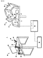
図1を参照すると、本開示によるロボット外科システム1は、ロボットシステム10、処理ユニット30、およびユーザインターフェース40として概略的に示されている。ロボットシステム10は概して、リンケージまたはアーム12およびロボットベース18を含む。アーム12は、組織に作用するように構成されているエンドエフェクタ22を有するツール20を移動可能に支持する。アーム12はそれぞれ、ツール20を支持する端部14を有する。加えて、アーム12の端部14は、手術部位「S」を撮像する撮像装置16を含むことができる。ユーザインターフェース40は、処理ユニット30を介してロボットベース18と通信する。
With reference to FIG. 1, the robotic
ユーザインターフェース40は、3次元画像を表示するように構成される表示装置44を含む。表示装置44は、手術部位「S」の3次元画像を表示し、3次元画像は、アーム12の端部14に配置された撮像装置16により捕捉されるデータを含み得るか、および/または手術現場の周りに配置された撮像装置(例えば、手術部位「S」内に配置された撮像装置、患者に隣接して配置された撮像装置、リンケージまたはアーム52の遠位端に配置された撮像装置56)により捕捉されるデータを含み得る。撮像装置(例えば、撮像装置16、56)は、手術部位「S」の視覚画像、赤外線画像、超音波画像、X線画像、熱画像、および/または任意の他の既知のリアルタイム画像を捕捉してもよい。撮像装置は、捕捉した撮像データを処理ユニット30に送信し、処理ユニット30は、撮像データからリアルタイムで手術部位「S」の3次元画像を作成し、その3次元画像を表示するために表示装置44に送信する。
The user interface 40 includes a display device 44 configured to display a three-dimensional image. The display device 44 displays a 3D image of the surgical site "S", which may include data captured by the imaging device 16 located at the end 14 of the
ユーザインターフェース40は、制御アーム43に支持される入力ハンドル42も含み、制御アーム43により、臨床医がロボットシステム10を操作することができる(例えば、アーム12、アーム12の端部14、および/またはツール20を移動させる)。入力ハンドル42の各々は、処理ユニット30と通信し、そこに制御信号を送信し、そこからフィードバック信号を受信する。追加的または代替的に、入力ハンドル42の各々は、外科医がアーム12の端部14に支持されたツール20のエンドエフェクタ22を操作すること(例えば、挟持する、把持する、発射する、開く、閉じる、回転させる、突き出す、スライスするなど)を可能にする入力装置(図示せず)を含み得る。
The user interface 40 also includes an
入力ハンドル42の各々は、手術部位「S」内でアーム12の端部14を移動させるために、所定の作業空間を通して可動である。表示装置44上の3次元画像は、入力ハンドル42の移動により、アーム12の端部14が表示装置44上で見られるように移動するように配向される。表示装置上の3次元画像の配向は、患者の上からの視野に対して鏡映または回転され得ると理解されよう。加えて、表示装置44上の3次元画像のサイズは、手術部位「S」の実際の構造よりも大きくまたは小さく縮尺変更されて、臨床医が手術部位「S」内の構造をより良好な視野を有するようにし得ると理解されよう。入力ハンドル42が移動されると、ツール20、したがって、エンドエフェクタ22が下記に詳述するように手術部位「S」内で移動する。本明細書で詳説するように、ツール20の移動はまた、ツール20を支持するアーム12の端部14の移動を含み得る。
Each of the input handles 42 is movable through a predetermined work space to move the end 14 of the
ロボット外科システム1の構成および動作の詳細な考察については、その内容全体が参照により本明細書に組み込まれる米国特許第8,828,023号を参照することができる。
For a detailed discussion of the configuration and operation of
図2を参照すると、ロボットシステム10は、その上でツール20(図1)を支持し、患者「P」(図1)の小切開に対して、ツール20を小切開内に維持しながら、複数の配向でツール20を選択的に移動させるように構成されている。アーム12は、アーム12に様々な自由度を提供するために互いに枢動可能に接続された複数の細長い部材またはリンク110、120、130、140を含む。特に、アーム12は、第1のリンク110、第2のリンク120、第3のリンク130、および第4のリンク140を含む。
With reference to FIG. 2, the robot system 10 supports the tool 20 (FIG. 1) on it, while keeping the
第1のリンク110は、第1の端部110aおよび第2の端部110bを有する。第1の端部110aは、固定構造に回転可能に結合される。固定構造は、所定の位置にロックされた可動カート102、手術台、支柱、手術室の壁、または手術室に存在する他の構造であり得る。第1のモータ「M1」は、第1の端部110aに動作可能に結合され、第1のリンク110の長手方向軸を横切る第1の端部110aを通過する第1の回転軸A1周りで第1のリンク110を回転させる。第1のリンク110の第2の端部110bは、第2のリンク120の第1の端部120aに動作可能に結合された第2のモータ「M2」を有し、モータ「M2」の作動が、第1のリンク110の第2の端部110bおよび第2のリンク120の第1の端部120aを通して画定される第2の回転軸A2周りで第1のリンク110に対する第2のリンク120の回転をもたらすようにする。第2の回転軸A2は、第1のリンク110の長手方向軸および第2のリンク120の長手方向軸を横切ることができると想定される。 The first link 110 has a first end 110a and a second end 110b. The first end 110a is rotatably coupled to the fixed structure. The fixed structure can be a movable cart 102 locked in place, an operating table, struts, operating room walls, or other structures present in the operating room. First motor "M1" is operatively coupled to the first end portion 110a, the first rotation axis A 1 around which passes the first end 110a transverse to the longitudinal axis of the first link 110 The first link 110 is rotated by. The second end 110b of the first link 110 has a second motor "M2" operably coupled to the first end 120a of the second link 120 and operates the motor "M2". A second link to the first link 110 around a second axis of rotation A2 defined through a second end 110b of the first link 110 and a first end 120a of the second link 120. Try to bring about 120 rotations. It is assumed that the second axis of rotation A 2 can cross the longitudinal axis of the first link 110 and the longitudinal axis of the second link 120.
第2のリンク120の第2の端部120bは、第3のリンク130の第1の端部130aに動作可能に結合され、第3のリンク130が、第2のリンクの第2の端部120bおよび第3のリンク130の第1の端部130aを通過する第3の回転軸A3周りで第2のリンク120に対して回転するようにする。第3の回転軸A3は、第2の回転軸A2と平行である。第2の回転軸A2周りの第2リンク120の回転は、第3の回転軸A3周りの第3のリンク130の回転に影響を与え、第1および第3のリンク110、130が互いに実質的に平行な関係を維持するようにする。第1のリンクと第3のリンクとの間の実質的に平行な関係を維持する例示的なメカニズムの詳細な説明については、2018年1月10日に出願された、米国仮特許出願第62/615,578号[代理人整理番号#355872.USP1(203−10542PRO)]、発明の名称「SURGICAL ROBOTIC ARMS AND PULLEY ASSEMBLIES THEREOF」、および2019年1月9日に出願された、国際特許出願第PCT/US2019/12839号[代理人整理番号#355872WO01]、発明の名称「SURGICAL ROBOTIC ARMS AND PULLEY ASSEMBLIES THEREOF」が参照され得、その内容全体が参照により本明細書に組み込まれる。
The second end 120b of the second link 120 is operably coupled to the first end 130a of the
第3のリンク130の第2の端部130bは、第4のリンク140の第1の端部140aに動作可能に結合される。第4のリンク140は、第3のリンク130の第2の端部130bおよび第4のリンク140の第1の端部140aを通過する第4の回転軸A4周りで第3のリンク130に対して回転可能である。
The second end 130b of the
図3をさらに参照すると、第4のリンク140が、スライダ142を支持するレールの形態であるとすることができる。スライダ142は、第4のリンク140の長手方向軸に平行な軸に沿ってスライド可能であり、ツール20を支持する。
Further referring to FIG. 3, the
外科処置中に、ロボットシステム10は、ユーザインターフェース40から入力コマンドを受信し、ツール20を移動させて、エンドエフェクタ22が移動し、手術部位「S」内の組織を操作および/またはこれに作用するようにする。具体的には、ロボットアーム12のリンク110、120、130、140は、互いに対して回転され、スライダ142は、入力コマンドに応答して、手術部位「S」内でツール20を配置および配向するように並進される。ロボットアーム12を制御するために、ロボットシステム10は、入力コマンドからツール20の所望のツール姿勢を計算し、ツール20のツール姿勢を捕捉し、ロボットアーム12を操作して、ツール20を所望のツール姿勢に移動させる。所望のツール姿勢から、ロボットシステム10は、ロボットアーム12の必要なアーム姿勢を計算して、所望のツール姿勢を達成する。次に、ロボットアーム12は、どのリンク110、120、130、140を操作して必要なアームポーズに到達するか、つまり、ユーザインターフェース40(図1)によって捕捉された入力に応答して、手術部位「S」内のツール20の所望のツール姿勢に到達するかを判定する。
During the surgical procedure, the robot system 10 receives an input command from the user interface 40 and moves the
ロボットアーム12のアームポーズを判定するために、ロボットシステム10は、手術部位「S」内に配置された撮像装置または内視鏡200を使用して、手術部位「S」内のツール20の位置および配向またはツール姿勢を捕捉する。本明細書で以下に詳述するように、内視鏡200は、手術部位内でツール姿勢を捕捉するものとして説明されるが、撮像装置を使用することができ、撮像装置のそれぞれが2次元または3次元画像を捕捉するために単一または複数のレンズを含み得ることが考えられる。
To determine the arm pose of the
内視鏡200は、手術部位「S」内で静止しているか、手術室内の臨床医によって操作され得るか、または内視鏡200の位置および配向が外科処置中に操作され得るように別のロボットアーム12に取り付けられ得る。ロボットシステム10は、内視鏡200を使用して、既知の技術を使用して手術部位「S」内のツール20のツール姿勢を視覚的に捕捉する。ツール20は、明確な色、明確なマーキング、明確な形状、またはそれらの組み合わせを使用することを含み得るが、これらに限定されない、ツール姿勢を捕捉するのを助けるためのしるしを含み得る。ツール20のツール姿勢は、内視鏡200に対してカメラフレームにおいて捕捉され、手術部位「S」のフレーム、ツール20のフレーム、ロボットアーム12のフレーム、または任意の他の所望の参照フレームに変換され得る。ツール20のツール姿勢を固定フレームに変換することが有益であり得ると想定される。
The
ロボットシステム10は、ツール20のツール姿勢から、ロボットアーム12の既知の運動学を使用して、ツール20のツール姿勢から始まり、第1のリンク110に向かって動作するロボットアーム12のアーム姿勢を計算することができる。ツール20のツール姿勢からロボットアーム12のアーム姿勢を計算することにより、ツール20を手術部位「S」内で所望のツール姿勢に移動させる解決策は、負荷がかかっているときのロボットアーム12またはツール20の変形を明らかにする。さらに、ツール姿勢からアーム姿勢を計算することにより、アーム12の第1のリンク110(図2)が結合されている固定構造(例えば、可動カート102)の位置を知る必要がなく、ツール20を所望のツール姿勢に移動させる解決策を判定する。解決策を計算する際に、ロボットシステム10は、アーム12と他のアーム12、手術室内の臨床医、患者、または手術室内の他の構造との任意の起こり得る衝突を明らかにする。さらに、共通フレーム、例えば単一の内視鏡のカメラフレームにおいてツール姿勢および/またはアーム姿勢を計算することにより、ツールおよび/またはアームの姿勢を、アーム、例えばアーム12のそれぞれの運動学を使用して同時に計算でき、リンク、例えばリンク110の場所を計算して、アーム12の起こり得る衝突を推定する。
From the tool posture of the
ロボットシステム10は、内視鏡200を用いて複数のツール20のツール姿勢を同時に捕捉するために使用され得ると考えられる。複数のツール20のツール姿勢を捕捉することにより、それらのツール20の相互作用とツール20のエンドエフェクタ22を高精度で制御することができる。この高精度制御は、自動化タスク、例えば組織の縫合を完了するために使用され得る。単一の内視鏡200を使用して複数のツール20のツール姿勢を捕捉することにより、自動化タスクの期間に対して、高精度のツール姿勢をカメラフレームから別のフレームに変換する必要性を減らすことで、自動化タスクの速度と精度を高めることができると想定される。
It is believed that the robot system 10 can be used to simultaneously capture the tool postures of a plurality of
2つ以上のカメラおよび/または内視鏡200を使用して、手術部位「S」内のツール20のツール姿勢を同時に捕捉することができると考えられる。複数のカメラが使用されるときに、ツール20の位置および配向を、それらのカメラのうちの1つによって画定されるフレーム以外のフレームに変換することが有益であり得ることが理解されよう。
It is believed that two or more cameras and / or
捕捉されたツール姿勢からアーム姿勢を判定することにより、捕捉されたツール姿勢およびアーム12の運動学からアーム12のそれぞれを支持する可動カート102の位置を判定することが可能になると考えられる。外科処置が完了した後、外科処置の効率を判定し、可動カート102の位置を記録することができる。外科処置中の可動カート102の位置を高効率レーティングと比較することにより、所与の処置に対する可動カート102のガイドまたは推奨位置が提供されて、将来の外科処置の効率を上げることができる。外科処置の効率が上がると、手術結果を改善しながら、費用、手術時間、および回復時間を短縮することができる。
By determining the arm posture from the captured tool posture, it is considered possible to determine the position of the movable cart 102 that supports each of the
引き続き図3、およびさらに図4を参照すると、捕捉された姿勢に応答して、ツール20の機能を有効および無効化する方法が、本開示に従って開示される。外科処置中、内視鏡200は、手術部位「S」内の解剖学的構造の位置を判定するために使用される。解剖学的構造の位置は、標的組織「T」が手術部位「S」内で識別できるように、術前スキャンに登録することができる。標的組織「T」は、外科処置の前および/または最中に識別でき、外科手術を行う臨床医または外科処置から離れた臨床医によって識別することができる。
With reference to FIG. 3 and further with reference to FIG. 4, a method of enabling and disabling the function of the
標的組織「T」が識別されると、標的組織「T」周りに有効化されたゾーン「EZ」が作成され、ツール20の機能の作動は、ツール20のエンドエフェクタ22が有効化されたゾーン「EZ」内にあるときに制限される。ツール20の機能の作動をエンドエフェクタ22が有効化されたゾーン「EZ」内にあるときに制限することにより、ツール20の不注意または意図しない作動を防止することができる。
When the target tissue "T" is identified, an activated zone "EZ" is created around the target tissue "T", and the function of the
有効化されたゾーン「EZ」は、標的組織「T」に隣接する手術部位「S」内の幾何学的な場所に基づく。有効化されたゾーン「EZ」のサイズは、ツール20の1つまたは複数の機能(例えば、挟持すること、電気外科エネルギーの送達、ステープル留め、縫合、ナイフを進めることなど)に基づくことができる。有効化されたゾーン「EZ」は、標的組織「T」への他の解剖学的構造の近接性に基づくこともできる。例えば、他の解剖学的構造が標的組織「T」から離れているときに、他の解剖学的構造が標的組織「T」に近いかまたは接触しているときよりも、有効化されたゾーン「EZ」が大きくなることがある。有効化されたゾーン「EZ」は、外科処置の前または最中に手動で設定することができ、またはツール20の機能に基づいて自動的に設定することができる。所与の外科処置について、標的組織「T」は、手術部位「S」を有する複数の場所にあり得ることが考えられる。そのような外科処置中、手術部位「S」は、各標的組織「T」周りに有効化されたゾーン「EZ」を含み得る。
The activated zone "EZ" is based on the geometric location within the surgical site "S" adjacent to the target tissue "T". The size of the activated zone "EZ" can be based on one or more functions of the
図5をさらに参照すると、有効化されたゾーン「EZ」のグラフィック表示をディスプレイ44に示すことができる。有効化されたゾーン「EZ」を標的組織「T」周りに雲のように示すことができるか、または有効化されたゾーン「EZ」の外側の領域が曇って見えるようにはっきりと示すことができる。追加的にまたは代替的に、有効化されたゾーン「EZ」をディスプレイ44上の別の形態の視覚的描写によって表すことができる。 Further referring to FIG. 5, a graphic display of the activated zone “EZ” can be shown on the display 44. The activated zone "EZ" can be shown like a cloud around the target tissue "T", or the area outside the activated zone "EZ" can be clearly shown to appear cloudy. it can. Additional or alternative, the activated zone "EZ" can be represented by another form of visual depiction on the display 44.
外科処置中、ツール20のツール姿勢は、上記に詳述したようにカメラによって捕捉される。ロボットシステム10が、ツール姿勢から、エンドエフェクタ22が有効化されたゾーン「EZ」の外側にあると判定したときに、ロボットシステム10は、臨床医がツール20の機能を作動させることを防止する。ディスプレイ44はまた、ツール20の機能が無効化されているという視覚的指標を提供し得ることが考えられる。例えば、ディスプレイ44上の境界45の色が赤であってもよく、ツール20またはツール20の一部(例えば、エンドエフェクタ22)の色が赤であってもよい。追加的または代替的に、ユーザインターフェース40の入力ハンドル42(図1)上の作動ボタン(図示せず)は、ツール20の機能が無効化されていることの視覚的指標(例えば、バックライトの色が赤色)を提供してもよい。
During the surgical procedure, the tool posture of the
ロボットシステム10が、ツール姿勢から、エンドエフェクタ22が有効化されたゾーン「EZ」に入ったことを判定すると、ロボットシステム10は、ツール20の機能を有効化する。ツール20が有効化されたゾーン「EZ」に入ると、ディスプレイ44が、ツール20の機能が有効化されていることの視覚的指標を提供してもよい。例えば、ディスプレイ44上の境界45が緑色であってもよく、ツール20またはツール20の一部(例えば、エンドエフェクタ22)が緑色であってもよい。追加的または代替的に、ユーザインターフェース40の入力ハンドル42(図1)上の作動ボタン(図示せず)は、ツール20の機能が有効化されていることの視覚的指標(例えば、バックライトが緑色)を提供してもよい。
When the robot system 10 determines from the tool posture that the
外科処置中、複数のツール20が手術部位「S」内にあることが想定される。ツール20は、標的組織「T」の有効化されたゾーン「EZ」に対するそれぞれのツールのエンドエフェクタ22の位置に基づいて、ツール20の機能を独立して有効化してもよい。代替的に、複数のツールが手術部位「S」内にある場合、ツール20の機能は、両方のエンドエフェクタ22が有効化されたゾーン「EZ」内に配置されるときにのみ有効化され得ると考えられる。このような方法で機能の有効化を制限することは、ツール20が協働して標的組織「T」に作用するときに好ましいことがある。
During the surgical procedure, it is assumed that the plurality of
本方法は、ツール20の機能を有効化する前に、ユーザインターフェース40に従事する臨床医の注視がディスプレイ44上の有効化されたゾーン「EZ」に向けられていることを確認することを含み得る。具体的には、外科処置中、ユーザインターフェース40は、それに従事している臨床医の注視を追跡する。内視鏡200が、ツール20のうちの1つのエンドエフェクタ22が有効化されたゾーン「EZ」に入ることを判定すると、ユーザインターフェース40は、ユーザインターフェース40に従事する臨床医の注視が標的組織「T」および/または有効化されたゾーン「EZ」の表示を含むディスプレイ44の一部に向けられていることを確認する。ツール20の機能を有効化する前に、臨床医の注視が標的組織「T」または有効化されたゾーン「EZ」に向けられることを要求することで、外科処置にさらなるレベルの安全性を提供する。
The method includes ensuring that the clinician's gaze on the user interface 40 is directed to the activated zone "EZ" on the display 44 before activating the functionality of the
上記で詳述したように、内視鏡200は、手術部位「S」周りに移動可能とすることができる。内視鏡200が手術部位「S」周りに移動すると、内視鏡200の位置が静止するまで、ツール20の機能は無効化されると考えられる。内視鏡200が手術部位「S」周りで移動する際に、ツール20の機能を無効化することにより、外科処置にさらなるレベルの安全性を提供する。
As detailed above, the
図6を参照すると、外科処置中、撮像装置または内視鏡200の視野の中心および/または視界を変更する方法が、上記に詳述したロボット外科システム1を利用して説明される。外科処置中、手術部位「S」の視野は、手術部位「S」内のツール20のエンドエフェクタ22を追跡することができる。ツール20のエンドエフェクタ22を追跡することにより、ユーザインターフェース40に従事する臨床医の注意または焦点を外科処置に向け、内視鏡200の視野の中心を向けることによって気を散らすこと、または浪費することがないようにすることができる。
With reference to FIG. 6, a method of changing the center and / or field of view of the imaging device or
内視鏡200は、ロボットシステム10(図2)のアーム12上に配置され、ロボットシステム10が、外科処置中に内視鏡200を操作することができる。最初に、内視鏡200は、関心領域に向けられた内視鏡の視野の中心を伴って手術部位「S」に導入される。関心領域は、手術部位「S」へのツール20のエンドエフェクタ22の入口点とすることができ、または手術部位「S」内の標的組織「T」に向けられることができる。加えて、内視鏡200の視界を、手術部位「S」の広い領域を包含するように設定することができる。
The
内視鏡200の視界および視野の中心「CV」が設定されると、ツール20のエンドエフェクタ22は、内視鏡200の視界「FV」内にもたらされる。次いで、内視鏡200を使用して、上記に詳述したようにツール20のツール姿勢を判定する。ツール姿勢から、エンドエフェクタ22の重心「C1」を判定することができる。内視鏡200の視野の中心は、重心「C1」が内視鏡200によって追跡されるように、エンドエフェクタ22の重心「C1」に向けられるように中心直しがされる。本明細書で使用されるように、重心は、特徴など、または数学的に計算可能な場所を含み得ることが理解される。
When the field of view of the
外科処置中、エンドエフェクタ22の重心「C1」が、手術部位「S」周りに移動することが理解されよう。重心「C1」が移動すると、内視鏡200の視野の中心「CV」は、エンドエフェクタ22の重心「C1」を追跡するように中心直しをする。外科処置中、内視鏡200の視野の中心「CV」の中心直しをすることにより、臨床医の注意および焦点を外科処置に向けることができる。
It will be appreciated that during the surgical procedure, the center of gravity "C 1 " of the
中心直しは、ディスプレイ44(図1)を見る臨床医の気をそらさせないような方法で視野の中心「CV」が移動するような方法で行うことができる。中心直しは、中心直しの速度を制御して、視野の中心「CV」の中心直し中に知覚的に適切な体験を確実にすることができるような方法で行われる。中心直しは、中心直しがスムーズな方法で生じるように、重心「C1」の滞留時間を実装することができる。中心直しは、内視鏡200の視野の中心「CV」の最大速度を有することもできる。加えて、中心直しはまた、移動の開始時および終了時における内視鏡200の視野の中心「CV」の加速/減速を形成して、視野の中心「CV」の中心直しをユーザインターフェース40に従事する臨床医に快適に保つことができる。さらに、中心直しが、エンドエフェクタ22への視野の中心「CV」の継続的な追跡を防止するために、ヒステリシスの形態を組み込んでもよい。例えば、中心直しは、エンドエフェクタ22の重心、例えば、重心「C1」が、内視鏡の視野の中心「CV」から、所定の距離、例えば、約3cmだけオフセットされるまで発生しなくてもよい。中心直しを、完全に自動化することができるか、または臨床医の裁量で選択的に作動させることができると想定される。
The recentering can be performed in such a way that the center "CV" of the visual field moves in a manner that does not distract the clinician looking at the display 44 (FIG. 1). Recentering is performed in such a way that the speed of recentering can be controlled to ensure a perceptually appropriate experience during recentering of the center of view "CV". The recentering can be implemented with a residence time of the center of gravity "C 1 " so that the recentering occurs in a smooth manner. The recentering can also have a maximum velocity of the center "CV" of the field of view of the
内視鏡200の視野の中心は、エンドエフェクタ22の重心「C1」と標的組織「T」との間の中央の重心「C2」を追跡できることが考える。加えて、内視鏡200は、エンドエフェクタ22の重心「C1」と標的組織「T」との間の距離に基づいて、エンドエフェクタ22が標的組織に近づくにつれて、内視鏡200がズームインするか、視界「FV」のサイズを縮小するようにその視界「FV」を調整することができる。加えて、エンドエフェクタ22が標的組織「T」から離れるように移動するにつれて、内視鏡200はズームアウトするか、視界「FV」のサイズを拡大する。
It is considered that the center of the field of view of the
手術部位「S」内で2つのツール20を用いた外科処置中、内視鏡200の視野の中心「CV」は、第1のエンドエフェクタ22の重心「C1」と第2のエンドエフェクタ22の重心「C3」の重心との間の中央の重心「C4」を追跡することができる。内視鏡200の視野の中心「CV」で重心「C4」を追跡することにより、第1および第2のエンドエフェクタ22の相互作用を臨床医が見ることができる。加えて、内視鏡200は、重心「C1」と重心「C3」との間の距離に基づいてズームインおよびズームアウトするようにその視界「FV」を変更することができる。代替的に、内視鏡200の視野の中心「CV」は、第1のエンドエフェクタ22の重心「C1」および標的組織「T」との間の中央の重心「C2」を追跡し、第2のエンドエフェクタ22の重心「C3」を無視することができる。内視鏡200の視野の中心「CV」を用いた重心「C4」の追跡に、ある形態のヒステリシスが導入されてもよいことが理解されよう。
During the surgical procedure using the two
手術部位「S」内に3つ以上のツール20を用いた外科処置中、内視鏡200の視野の中心「CV」は、2つのツール20に関して上記で詳述したものと同様の方法で、アクティブなエンドエフェクタ22の重心(例えば、重心「C1」および「C3」)の間の中央の重心(例えば、重心「C4」)を追跡することができる。アクティブなエンドエフェクタ22が手術部位「S」内で変化すると、内視鏡200の視野の中心「CV」は、アクティブなエンドエフェクタ22の間の重心に中心直しをする。
During a surgical procedure using three or
本開示のいくつかの実施形態が図面に示されているが、本開示は当該技術分野が許容するものと同程度に広い範囲であるとされるべきであり、本明細書が同様に読み取られるべきであると意図されているので、本開示は、これらの実施形態に限定されることを意図していない。上記実施形態の任意の組み合わせがさらに考えられ、添付の特許請求の範囲に含まれる。したがって、上記の説明は、限定的であるとして解釈されるべきではなく、特定の実施形態の単なる例示として解釈されるべきである。当業者は、本明細書に添付される特許請求の範囲内での他の修正を想定するであろう。 Although some embodiments of the present disclosure are shown in the drawings, the present disclosure should be considered to be as broad as the art allows, and the specification is read as well. This disclosure is not intended to be limited to these embodiments, as it is intended to be. Any combination of the above embodiments may be further considered and included in the appended claims. Therefore, the above description should not be construed as limiting, but as merely an example of a particular embodiment. Those skilled in the art will assume other amendments within the scope of the claims attached herein.
Claims (40)
撮像装置を用いて、固定参照フレームにおいて、手術部位内の第1のツールの第1のツール姿勢を視覚的に捕捉することと、
前記固定参照フレームにおいて、前記第1のリンケージの既知の形状から、前記第1のツールを支持する第1のリンケージの第1のアーム姿勢を判定することと、
第1の制御信号に応答して、前記固定参照フレームにおいて、前記第1のリンケージを操作して、前記第1のツールを所望の第1のツール姿勢に移動させることと、を含む、方法。 A way to control a surgical robot
Visually capturing the first tool posture of the first tool within the surgical site in a fixed reference frame using an imaging device.
In the fixed reference frame, determining the first arm posture of the first linkage supporting the first tool from the known shape of the first linkage.
A method comprising manipulating the first linkage in the fixed reference frame in response to a first control signal to move the first tool to a desired first tool posture.
前記固定参照フレームにおいて、前記第2のリンケージの既知の形状から、前記第2のツールを支持する第2のリンケージの第2のアーム姿勢を判定することと、
第2の制御信号に応答して、前記固定参照フレームにおいて、前記第2のリンケージを操作して、前記第2のツールを所望の第2のツール姿勢に移動させることと、をさらに含む、請求項1に記載の方法。 Using the imaging device, visually capturing the second tool posture of the second tool in the surgical site in the fixed reference frame.
In the fixed reference frame, determining the second arm posture of the second linkage supporting the second tool from the known shape of the second linkage.
A claim that further comprises manipulating the second linkage in the fixed reference frame in response to the second control signal to move the second tool to the desired second tool posture. Item 1. The method according to item 1.
撮像装置を用いて、手術部位の画像を捕捉することと、
標的組織に対する前記手術部位内の前記ツールの距離を判定することと、
前記ツールが前記標的組織から所定の距離内にあるときに、前記ツールの機能の作動を有効化することと、
制御信号に応答して、前記ツールの前記機能を作動させて、前記ツールを用いて組織を操作することと、を含む、方法。 A way to control the functioning of tools in a surgical system
Capturing images of the surgical site using an imaging device,
Determining the distance of the tool within the surgical site to the target tissue
When the tool is within a predetermined distance from the target tissue, enabling the operation of the function of the tool and
A method comprising activating the function of the tool in response to a control signal and manipulating the tissue with the tool.
手術部位の画像を捕捉するように構成されている撮像装置と、
機能を有するツールであって、前記機能が、制御信号に応答して組織を操作するように構成されている、ツールと、
前記撮像装置および前記ツールと通信する処理ユニットと、を含み、前記処理ユニットが、
前記捕捉画像から標的組織に対する前記ツールの距離を判定することと、
前記ツールが前記標的組織の所定の距離内に配置されているときに、前記ツールの前記機能の作動を有効化することと、を行うように構成されている、外科システム。 It ’s a surgical system,
An imaging device configured to capture images of the surgical site,
A tool having a function, wherein the function is configured to operate a tissue in response to a control signal.
The processing unit includes the imaging device and a processing unit that communicates with the tool.
Determining the distance of the tool to the target tissue from the captured image
A surgical system configured to activate and perform the activation of said function of said tool when the tool is placed within a predetermined distance of said target tissue.
前記撮像装置の視界内で追跡重心を識別することと、
前記追跡重心を前記撮像装置の前記視界の中心に配置するために前記撮像装置の姿勢を操作することと、
前記追跡重心が前記撮像装置の前記視界内で移動するように、前記視界内で第1のツールを移動させることと、
前記第1のツールが前記視界内で移動するときに前記追跡重心を追跡し、前記追跡重心を前記撮像装置の前記視界の中心に維持することと、を含む、方法。 It is a method of operating the image pickup device.
Identifying the tracking center of gravity within the field of view of the imaging device
Manipulating the posture of the imaging device to position the tracking center of gravity in the center of the field of view of the imaging device.
To move the first tool in the field of view so that the tracking center of gravity moves in the field of view of the imaging device.
A method comprising tracking the tracking center of gravity as the first tool moves within the field of view and keeping the tracking center of gravity at the center of the field of view of the imaging device.
追跡重心を少なくとも部分的に画定する第1のツールと、
手術部位内で移動可能なアームと、
前記アームに支持され、視界を有する撮像装置であって、前記追跡重心を前記視界の中心に維持するように操作されるように構成されている撮像装置と、を含む、外科システム。 It ’s a surgical system,
With a first tool that at least partially defines the tracking center of gravity,
An arm that can be moved within the surgical site and
A surgical system comprising an imaging device supported by the arm and having a field of view, the imaging device configured to maintain the tracking center of gravity in the center of the field of view.
Applications Claiming Priority (3)
| Application Number | Priority Date | Filing Date | Title |
|---|---|---|---|
| US201862615590P | 2018-01-10 | 2018-01-10 | |
| US62/615,590 | 2018-01-10 | ||
| PCT/US2019/012847 WO2019139949A1 (en) | 2018-01-10 | 2019-01-09 | Determining positions and conditions of tools of a robotic surgical system utilizing computer vision |
Publications (2)
| Publication Number | Publication Date |
|---|---|
| JP2021510327A true JP2021510327A (en) | 2021-04-22 |
| JPWO2019139949A5 JPWO2019139949A5 (en) | 2022-01-18 |
Family
ID=67218333
Family Applications (1)
| Application Number | Title | Priority Date | Filing Date |
|---|---|---|---|
| JP2020538102A Pending JP2021510327A (en) | 2018-01-10 | 2019-01-09 | Determining the position and condition of tools in a robotic surgery system using computer vision |
Country Status (5)
| Country | Link |
|---|---|
| US (1) | US20210059775A1 (en) |
| EP (1) | EP3737326A4 (en) |
| JP (1) | JP2021510327A (en) |
| CN (1) | CN111587095A (en) |
| WO (1) | WO2019139949A1 (en) |
Families Citing this family (4)
| Publication number | Priority date | Publication date | Assignee | Title |
|---|---|---|---|---|
| KR20230142642A (en) | 2017-11-16 | 2023-10-11 | 인튜어티브 서지컬 오퍼레이션즈 인코포레이티드 | Master/slave registration and control for teleoperation |
| US11877816B2 (en) | 2017-11-21 | 2024-01-23 | Intuitive Surgical Operations, Inc. | Systems and methods for master/tool registration and control for intuitive motion |
| EP3566670A1 (en) * | 2018-05-07 | 2019-11-13 | Koninklijke Philips N.V. | Safety system for surgical robot |
| US10758309B1 (en) | 2019-07-15 | 2020-09-01 | Digital Surgery Limited | Methods and systems for using computer-vision to enhance surgical tool control during surgeries |
Citations (4)
| Publication number | Priority date | Publication date | Assignee | Title |
|---|---|---|---|---|
| US20100228249A1 (en) * | 2009-03-09 | 2010-09-09 | Intuitive Surgical, Inc. | User interfaces for electrosurgical tools in robotic surgical systems |
| US20100312095A1 (en) * | 2009-06-08 | 2010-12-09 | Jenkins Kimble L | Mri-guided surgical systems with proximity alerts |
| US20130030571A1 (en) * | 2010-04-07 | 2013-01-31 | Sofar Spa | Robotized surgery system with improved control |
| JP2015527906A (en) * | 2012-06-29 | 2015-09-24 | チルドレンズ ナショナル メディカル センターChildren’S National Medical Center | Automated surgery and intervention |
Family Cites Families (21)
| Publication number | Priority date | Publication date | Assignee | Title |
|---|---|---|---|---|
| JP2008544814A (en) * | 2005-06-30 | 2008-12-11 | インテュイティブ サージカル, インコーポレイテッド | Indicators for tool status and communication in multi-arm robot telesurgery |
| US8155479B2 (en) * | 2008-03-28 | 2012-04-10 | Intuitive Surgical Operations Inc. | Automated panning and digital zooming for robotic surgical systems |
| US8808164B2 (en) * | 2008-03-28 | 2014-08-19 | Intuitive Surgical Operations, Inc. | Controlling a robotic surgical tool with a display monitor |
| US9639156B2 (en) * | 2011-12-29 | 2017-05-02 | Mako Surgical Corp. | Systems and methods for selectively activating haptic guide zones |
| CN105122114B (en) * | 2012-12-06 | 2018-07-27 | 通用电气医疗集团生物科学公司 | System and method for the split screen display available of biological sample and for capturing its record |
| WO2014093367A1 (en) * | 2012-12-10 | 2014-06-19 | Intuitive Surgical Operations, Inc. | Collision avoidance during controlled movement of image capturing device and manipulatable device movable arms |
| US20160216882A1 (en) * | 2013-06-26 | 2016-07-28 | Lucid Global, Llc | Virtual microscope tool for cardiac cycle |
| CN105992568B (en) * | 2014-02-12 | 2018-06-08 | 皇家飞利浦有限公司 | The robot control of operation instrument visibility |
| EP4005522A1 (en) * | 2014-03-17 | 2022-06-01 | Intuitive Surgical Operations, Inc. | Tructural adjustment systems for a teleoperational medical system |
| CN115590628A (en) * | 2014-03-17 | 2023-01-13 | 直观外科手术操作公司(Us) | System and method for re-centering imaging devices and input control devices |
| US11116383B2 (en) * | 2014-04-02 | 2021-09-14 | Asensus Surgical Europe S.à.R.L. | Articulated structured light based-laparoscope |
| US9833254B1 (en) * | 2014-10-03 | 2017-12-05 | Verily Life Sciences Llc | Controlled dissection of biological tissue |
| CN113040920A (en) * | 2015-05-19 | 2021-06-29 | 马科外科公司 | System and method for manipulating anatomy |
| CN109618553B (en) * | 2016-10-12 | 2022-04-12 | 直观外科手术操作公司 | Surgical puncturing device insertion systems and related methods |
| US20200015899A1 (en) * | 2018-07-16 | 2020-01-16 | Ethicon Llc | Surgical visualization with proximity tracking features |
| US11666401B2 (en) * | 2019-03-15 | 2023-06-06 | Cilag Gmbh International | Input controls for robotic surgery |
| US11213361B2 (en) * | 2019-03-15 | 2022-01-04 | Cilag Gmbh International | Robotic surgical systems with mechanisms for scaling surgical tool motion according to tissue proximity |
| JP7441302B2 (en) * | 2019-08-05 | 2024-02-29 | ジャイラス エーシーエムアイ インク ディー/ビー/エー オリンパス サージカル テクノロジーズ アメリカ | Laser control using a spectrometer |
| US11744667B2 (en) * | 2019-12-30 | 2023-09-05 | Cilag Gmbh International | Adaptive visualization by a surgical system |
| US11219501B2 (en) * | 2019-12-30 | 2022-01-11 | Cilag Gmbh International | Visualization systems using structured light |
| US20210196384A1 (en) * | 2019-12-30 | 2021-07-01 | Ethicon Llc | Dynamic surgical visualization systems |
-
2019
- 2019-01-09 JP JP2020538102A patent/JP2021510327A/en active Pending
- 2019-01-09 CN CN201980007882.5A patent/CN111587095A/en active Pending
- 2019-01-09 WO PCT/US2019/012847 patent/WO2019139949A1/en unknown
- 2019-01-09 US US16/960,788 patent/US20210059775A1/en active Pending
- 2019-01-09 EP EP19738088.4A patent/EP3737326A4/en active Pending
Patent Citations (4)
| Publication number | Priority date | Publication date | Assignee | Title |
|---|---|---|---|---|
| US20100228249A1 (en) * | 2009-03-09 | 2010-09-09 | Intuitive Surgical, Inc. | User interfaces for electrosurgical tools in robotic surgical systems |
| US20100312095A1 (en) * | 2009-06-08 | 2010-12-09 | Jenkins Kimble L | Mri-guided surgical systems with proximity alerts |
| US20130030571A1 (en) * | 2010-04-07 | 2013-01-31 | Sofar Spa | Robotized surgery system with improved control |
| JP2015527906A (en) * | 2012-06-29 | 2015-09-24 | チルドレンズ ナショナル メディカル センターChildren’S National Medical Center | Automated surgery and intervention |
Also Published As
| Publication number | Publication date |
|---|---|
| WO2019139949A1 (en) | 2019-07-18 |
| US20210059775A1 (en) | 2021-03-04 |
| CN111587095A (en) | 2020-08-25 |
| EP3737326A1 (en) | 2020-11-18 |
| EP3737326A4 (en) | 2021-12-29 |
Similar Documents
| Publication | Publication Date | Title |
|---|---|---|
| JP6543742B2 (en) | Collision avoidance between controlled movements of an image capture device and an operable device movable arm | |
| JP7170784B2 (en) | Systems and methods for re-centering imaging devices and input controls | |
| KR102404559B1 (en) | Medical devices, systems, and methods using eye gaze tracking | |
| JP2021510327A (en) | Determining the position and condition of tools in a robotic surgery system using computer vision | |
| US11266475B2 (en) | Repositioning system for a remotely controllable manipulator and related methods | |
| JP2021534919A (en) | Systems and methods for spinal surgery | |
| JP2021531910A (en) | Robot-operated surgical instrument location tracking system and method | |
| GB2568989A (en) | End effector force sensor and manual actuation assistance | |
| US20220211460A1 (en) | System and method for integrated motion with an imaging device | |
| WO2017098505A1 (en) | Autonomic system for determining critical points during laparoscopic surgery | |
| JP2023107782A (en) | Systems and methods for controlling tool with articulatable distal portion | |
| US20200170731A1 (en) | Systems and methods for point of interaction displays in a teleoperational assembly | |
| US20220192701A1 (en) | Systems and methods for surgical port positioning | |
| US20240070875A1 (en) | Systems and methods for tracking objects crossing body wallfor operations associated with a computer-assisted system | |
| EP4154837A1 (en) | Surgical robotic system setup | |
| JP2023506355A (en) | Computer-assisted surgical system, surgical control device and surgical control method |
Legal Events
| Date | Code | Title | Description |
|---|---|---|---|
| A521 | Request for written amendment filed |
Free format text: JAPANESE INTERMEDIATE CODE: A523 Effective date: 20220107 |
|
| A621 | Written request for application examination |
Free format text: JAPANESE INTERMEDIATE CODE: A621 Effective date: 20220107 |
|
| A977 | Report on retrieval |
Free format text: JAPANESE INTERMEDIATE CODE: A971007 Effective date: 20230117 |
|
| A131 | Notification of reasons for refusal |
Free format text: JAPANESE INTERMEDIATE CODE: A131 Effective date: 20230224 |
|
| A02 | Decision of refusal |
Free format text: JAPANESE INTERMEDIATE CODE: A02 Effective date: 20230921 |