JP2021505261A - Flexible chips and related devices, systems and methods for intracavitary imaging devices - Google Patents
Flexible chips and related devices, systems and methods for intracavitary imaging devices Download PDFInfo
- Publication number
- JP2021505261A JP2021505261A JP2020530632A JP2020530632A JP2021505261A JP 2021505261 A JP2021505261 A JP 2021505261A JP 2020530632 A JP2020530632 A JP 2020530632A JP 2020530632 A JP2020530632 A JP 2020530632A JP 2021505261 A JP2021505261 A JP 2021505261A
- Authority
- JP
- Japan
- Prior art keywords
- chip member
- imaging device
- intracavitary
- distal portion
- chip
- Prior art date
- Legal status (The legal status is an assumption and is not a legal conclusion. Google has not performed a legal analysis and makes no representation as to the accuracy of the status listed.)
- Pending
Links
Images


Classifications
-
- A—HUMAN NECESSITIES
- A61—MEDICAL OR VETERINARY SCIENCE; HYGIENE
- A61B—DIAGNOSIS; SURGERY; IDENTIFICATION
- A61B8/00—Diagnosis using ultrasonic, sonic or infrasonic waves
- A61B8/12—Diagnosis using ultrasonic, sonic or infrasonic waves in body cavities or body tracts, e.g. by using catheters
-
- A—HUMAN NECESSITIES
- A61—MEDICAL OR VETERINARY SCIENCE; HYGIENE
- A61B—DIAGNOSIS; SURGERY; IDENTIFICATION
- A61B8/00—Diagnosis using ultrasonic, sonic or infrasonic waves
- A61B8/42—Details of probe positioning or probe attachment to the patient
- A61B8/4209—Details of probe positioning or probe attachment to the patient by using holders, e.g. positioning frames
- A61B8/4236—Details of probe positioning or probe attachment to the patient by using holders, e.g. positioning frames characterised by adhesive patches
-
- A—HUMAN NECESSITIES
- A61—MEDICAL OR VETERINARY SCIENCE; HYGIENE
- A61B—DIAGNOSIS; SURGERY; IDENTIFICATION
- A61B8/00—Diagnosis using ultrasonic, sonic or infrasonic waves
- A61B8/44—Constructional features of the ultrasonic, sonic or infrasonic diagnostic device
- A61B8/4444—Constructional features of the ultrasonic, sonic or infrasonic diagnostic device related to the probe
- A61B8/445—Details of catheter construction
-
- A—HUMAN NECESSITIES
- A61—MEDICAL OR VETERINARY SCIENCE; HYGIENE
- A61B—DIAGNOSIS; SURGERY; IDENTIFICATION
- A61B5/00—Measuring for diagnostic purposes; Identification of persons
- A61B5/0059—Measuring for diagnostic purposes; Identification of persons using light, e.g. diagnosis by transillumination, diascopy, fluorescence
- A61B5/0062—Arrangements for scanning
- A61B5/0066—Optical coherence imaging
-
- A—HUMAN NECESSITIES
- A61—MEDICAL OR VETERINARY SCIENCE; HYGIENE
- A61B—DIAGNOSIS; SURGERY; IDENTIFICATION
- A61B5/00—Measuring for diagnostic purposes; Identification of persons
- A61B5/0093—Detecting, measuring or recording by applying one single type of energy and measuring its conversion into another type of energy
- A61B5/0095—Detecting, measuring or recording by applying one single type of energy and measuring its conversion into another type of energy by applying light and detecting acoustic waves, i.e. photoacoustic measurements
-
- A—HUMAN NECESSITIES
- A61—MEDICAL OR VETERINARY SCIENCE; HYGIENE
- A61B—DIAGNOSIS; SURGERY; IDENTIFICATION
- A61B8/00—Diagnosis using ultrasonic, sonic or infrasonic waves
- A61B8/06—Measuring blood flow
-
- A—HUMAN NECESSITIES
- A61—MEDICAL OR VETERINARY SCIENCE; HYGIENE
- A61B—DIAGNOSIS; SURGERY; IDENTIFICATION
- A61B8/00—Diagnosis using ultrasonic, sonic or infrasonic waves
- A61B8/08—Clinical applications
- A61B8/0883—Clinical applications for diagnosis of the heart
-
- A—HUMAN NECESSITIES
- A61—MEDICAL OR VETERINARY SCIENCE; HYGIENE
- A61B—DIAGNOSIS; SURGERY; IDENTIFICATION
- A61B8/00—Diagnosis using ultrasonic, sonic or infrasonic waves
- A61B8/08—Clinical applications
- A61B8/0891—Clinical applications for diagnosis of blood vessels
Landscapes
- Health & Medical Sciences (AREA)
- Life Sciences & Earth Sciences (AREA)
- Biomedical Technology (AREA)
- Biophysics (AREA)
- Nuclear Medicine, Radiotherapy & Molecular Imaging (AREA)
- Pathology (AREA)
- Radiology & Medical Imaging (AREA)
- Engineering & Computer Science (AREA)
- Physics & Mathematics (AREA)
- Heart & Thoracic Surgery (AREA)
- Medical Informatics (AREA)
- Molecular Biology (AREA)
- Surgery (AREA)
- Animal Behavior & Ethology (AREA)
- General Health & Medical Sciences (AREA)
- Public Health (AREA)
- Veterinary Medicine (AREA)
- Vascular Medicine (AREA)
- Ultra Sonic Daignosis Equipment (AREA)
Abstract
腔内撮像デバイスが提供される。デバイスは、患者のルーメン内に挿入されるように構成された可撓性細長部材であって、近位部分と遠位部分とを備える、可撓性細長部材を含む。デバイスは、遠位部分に配置され、患者のルーメン内に位置付けられる間、超音波撮像データを取得するように構成された、超音波撮像アセンブリを含む。デバイスは、可撓性細長部材の遠位部分に配置されるチップ部材であって、超音波撮像アセンブリに隣接してチップ部材と超音波撮像アセンブリとを結合するように接着剤によって充填されるように構成されたキャビティを備える、チップ部材を含む。チップ部材は、第1の材料と第2の材料とを含み得る。チップ部材は、直線的な外径と変化する肉厚とを含み得、又は変化する外径と一定の肉厚とを含み得る。An intracavitary imaging device is provided. The device includes a flexible elongate that is configured to be inserted into the lumen of the patient and comprises a proximal and a distal portion. The device includes an ultrasound imaging assembly that is located in the distal portion and configured to acquire ultrasound imaging data while being positioned within the lumen of the patient. The device is a chip member that is located at the distal portion of the flexible elongated member and is filled with an adhesive so that the chip member and the ultrasound imaging assembly are joined adjacent to the ultrasound imaging assembly. Includes a chip member with a cavity configured in. The chip member may include a first material and a second material. The tip member may include a linear outer diameter and a variable wall thickness, or may include a variable outer diameter and a constant wall thickness.
Description
関連出願
本出願は、その全体が参照によって組み込まれる、2017年12月7日出願の米国仮特許出願第62/595,744号の利益及び優先権を主張する。
Related Applications This application claims the interests and priority of US Provisional Patent Application No. 62 / 595,744, filed December 7, 2017, which is incorporated by reference in its entirety.
[0001] 本開示は、概して、腔内超音波撮像に関し、特には、腔内撮像デバイスの構造に関する。例えば、腔内撮像デバイスは、可撓性細長部材の遠位端部に可撓性チップを含み得る。 [0001] The present disclosure relates generally to intracavitary ultrasound imaging, and in particular to the structure of an intracavitary imaging device. For example, an intracavitary imaging device may include a flexible tip at the distal end of a flexible elongated member.
[0002] 血管内超音波(IVUS)撮像は、介入性心臓学において、動脈などの人間の身体内の病変血管を評価して治療の必要性を判断し、介入を誘導し及び/又はその効果を評価するための診断ツールとして広く使用されている。1つ又は複数の超音波トランスデューサを含むIVUSデバイスは、血管内に通され、撮像されるべき領域に誘導される。トランスデューサは、関心対象の血管の画像を生成するために超音波エネルギーを放出する。超音波は、組織構造(血管壁の様々な層など)、赤血球、及び関心対象の他の特徴から生じる不連続性によって部分的に反射される。反射された波からのエコーは、トランスデューサによって受信され、IVUS撮像システムに送られる。撮像システムは、受信された超音波エコーを処理し、デバイスが置かれた血管の断面画像を生成する。 Intravascular ultrasound (IVUS) imaging, in interventional cardiology, assesses diseased blood vessels in the human body, such as arteries, to determine the need for treatment, induce intervention and / or its effect. It is widely used as a diagnostic tool for evaluating. The IVUS device, including one or more ultrasound transducers, is passed through the blood vessel and guided to the area to be imaged. The transducer emits ultrasonic energy to generate an image of the blood vessel of interest. Ultrasound is partially reflected by discontinuities resulting from tissue structure (such as various layers of the vessel wall), red blood cells, and other features of interest. The echo from the reflected wave is received by the transducer and sent to the IVUS imaging system. The imaging system processes the received ultrasonic echo to produce a cross-sectional image of the blood vessel in which the device is placed.
[0003] ソリッドステート式(合成開口型としても知られる)IVUSカテーテルは、今日、一般に使用されている2つの種類のIVUSデバイスのうちの1つであり、もう1つの種類は回転式IVUSカテーテルである。ソリッドステート式IVUSカテーテルは、超音波トランスデューサのアレイを含むスキャナアセンブリを具備し、超音波トランスデューサのアレイは、トランスデューサアレイに隣接して取り付けられた1つ又は複数の集積回路制御器チップとともにスキャナアセンブリの外周の周りに分散配置される。制御器は、超音波パルスを送信するため、及び超音波エコー信号を受信するために、個別のトランスデューサ要素(又は要素の集合)を選択する。送信−受信の組のシーケンスを通したステッピングによって、ソリッドステート式IVUSシステムは、機械的にスキャンされた超音波トランスデューサの効果を合成し得るが、部品を移動させることはない(故に、ソリッドステートと呼ばれる)。回転する機械的要素がないため、トランスデューサアレイは、血管の損傷のリスクを最小限にしつつ、血液及び血管組織に直接的に接触して配置され得る。更には、回転する要素がないため、電気的インターフェースは単純化される。ソリッドステート式スキャナは、回転式IVUSデバイスで必要となる複雑な回転式電気インターフェースによってではなく、単純な電気ケーブル及び標準的な着脱式電気コネクタによって撮像システムに直接的に有線接続され得る。 [0003] Solid-state (also known as synthetic aperture) IVUS catheters are one of two types of IVUS devices commonly used today, the other being rotary IVUS catheters. is there. The solid-state IVUS catheter comprises a scanner assembly that includes an array of ultrasonic transducers, the array of ultrasonic transducers in the scanner assembly along with one or more integrated circuit controller chips mounted adjacent to the transducer array. It is distributed around the outer circumference. The controller selects individual transducer elements (or sets of elements) to transmit ultrasonic pulses and to receive ultrasonic echo signals. By stepping through a transmit-receive pair sequence, a solid-state IVUS system can synthesize the effects of a mechanically scanned ultrasonic transducer, but does not move parts (hence the solid-state). Called). Due to the lack of rotating mechanical elements, the transducer array can be placed in direct contact with blood and vascular tissue while minimizing the risk of vascular damage. Moreover, the electrical interface is simplified because there are no rotating elements. Solid-state scanners can be wired directly to the imaging system via simple electrical cables and standard detachable electrical connectors, rather than through the complex rotary electrical interfaces required for rotary IVUS devices.
[0004] 効率的に人間の身体内で生理機能を横断する血管内撮像デバイスの製造は困難である。これに関して、撮像デバイスの遠位部分のコンポーネントは、外周を過度に拡大してしまう方式で組み立てられることがあり、より小さな直径の血管を通るナビゲーションを難しくする。コンポーネント間の堅牢な機械的結合を保証することも困難であり得る。 [0004] It is difficult to manufacture an intravascular imaging device that efficiently traverses physiological functions within the human body. In this regard, the components of the distal portion of the imaging device may be assembled in such a way that the outer circumference is excessively magnified, making navigation through smaller diameter blood vessels difficult. It can also be difficult to guarantee a robust mechanical bond between the components.
[0005] 腔内撮像デバイスは、人間の身体内に挿入されて、その内部の様々な解剖学的構造の状態に関する情報を取得する。例えば、血管内超音波(IVUS)デバイスなどの腔内撮像デバイスは、血管を通って身体内に導入され得、次いで、解剖学的関心エリアに誘導され得る。腔内撮像デバイスは、身体内を進行しているときに様々な障害物に遭遇することが一般的である。これに対応するために、腔内撮像デバイスの前端部は、身体内を通る腔内撮像デバイスのナビゲーションを容易にするためのチップ部材を備える。チップ部材の外側輪郭の形状は、円錐状であり、その直径はチップ部材の先端の前端部から後端部へと減少している。チップ部材の前端部は、チップの後端部を形成するために使用される材料よりも大きな可撓性を有する材料を使用して形成される。チップ部材は、腔内撮像デバイスに、各々の外側輪郭の周りに接着剤を適用することによって接続される。接着剤がチップ部材及び腔内撮像デバイスの外側輪郭に与える影響を最小化するために、チップ部材の近位端部にキャビティが形成されて接着剤を受け入れる。キャビティは、腔内撮像デバイスとチップ部材との間に接続と封止との両方を提供するように機能する。チップ部材の輪郭と可撓性の性質とが、腔内撮像デバイスが身体内を誘導されているときに、障害物をナビゲーションする際に腔内撮像デバイスを補助する。有利には、本明細書において説明される実施形態は、強固で効率的な組み立て及び動作を達成しつつ、撮像アセンブリの外径を有利に最小化する。 An intracavitary imaging device is inserted into the human body to obtain information about the state of various anatomical structures within it. For example, an intracavitary imaging device, such as an intravascular ultrasound (IVUS) device, can be introduced into the body through a blood vessel and then guided to an area of anatomical interest. Intracavitary imaging devices typically encounter a variety of obstacles as they travel through the body. To accommodate this, the anterior end of the intracavitary imaging device is provided with a chip member to facilitate navigation of the intracavitary imaging device through the body. The shape of the outer contour of the chip member is conical, and its diameter decreases from the front end to the rear end of the tip of the chip member. The front end of the chip member is formed using a material that has greater flexibility than the material used to form the rear end of the chip. The chip members are connected to the intracavitary imaging device by applying an adhesive around each outer contour. In order to minimize the effect of the adhesive on the chip member and the outer contour of the intracavitary imaging device, a cavity is formed at the proximal end of the chip member to accept the adhesive. The cavity functions to provide both a connection and a seal between the intracavitary imaging device and the chip member. The contour and flexible nature of the chip member assist the intracavitary imaging device in navigating obstacles when the intracavitary imaging device is being guided through the body. Advantageously, the embodiments described herein advantageously minimize the outer diameter of the imaging assembly while achieving robust and efficient assembly and operation.
[0006] 例示的な態様において、腔内撮像デバイスが提供される。デバイスは、患者のルーメン内に挿入されるように構成された可撓性細長部材であって、近位部分と遠位部分とを備える、可撓性細長部材と、遠位部分に配置され、患者のルーメン内に位置付けられる間、超音波撮像データを取得するように構成された、超音波撮像アセンブリと、可撓性細長部材の遠位部分に配置されるチップ部材であって、超音波撮像アセンブリに隣接して、チップ部材と超音波撮像アセンブリとを結合するように接着剤によって充填されるように構成されたキャビティを備える、チップ部材とを含む。 [0006] In an exemplary embodiment, an intracavitary imaging device is provided. The device is a flexible elongate member configured to be inserted into the patient's lumen, the flexible elongate member comprising a proximal portion and a distal portion, and a distal portion. An ultrasound imaging assembly configured to acquire ultrasound imaging data while positioned within the patient's lumen and a chip member located distal to the flexible elongated member for ultrasound imaging. Adjacent to the assembly, the chip member comprises a cavity configured to be filled with an adhesive to join the chip member and the ultrasound imaging assembly.
[0007] いくつかの態様において、キャビティは、チップ部材の近位部分に連結領域を備え、キャビティは、チップ部材の近位部分に対してより小さな外径を備える。いくつかの態様において、キャビティは、直線的な外径を備える。いくつかの態様において、キャビティは、傾斜した外径を更に備える。いくつかの態様において、チップ部材の遠位部分は、ルーメンの閉塞部と交差するように構成された交差領域を備え、交差領域の外径は、可撓性細長部材の長手方向軸に沿って減少する。いくつかの態様において、チップ部材の交差領域は、直線的な外径を備える。いくつかの態様において、チップ部材の交差領域は、曲線的な外径を備える。いくつかの態様において、チップ部材の遠位端部は、閉塞部との交差を容易にするような形状に形成される。いくつかの態様において、チップ部材の遠位端部は、直線的な外径を備える。いくつかの態様において、チップ部材の遠位端部は、曲線的な外径を備える。いくつかの態様において、チップ部材の遠位端部は、補強装置を備える。いくつかの態様において、補強装置は、第1の色を有し、チップ部材は、第1の色とは異なる第2の色を有する。いくつかの態様において、チップ部材の近位部分は、第1の材料を有し、チップ部材の遠位部分は、第2の材料を有する。いくつかの態様において、チップ部材は、その内部に延在する、ルーメンに関連した内径を備え、この内径は、ルーメン内に配置された超音波撮像アセンブリの少なくとも一部分に接触するように構成された係合機能部を備える。 [0007] In some embodiments, the cavity comprises a connecting region in the proximal portion of the chip member, and the cavity has a smaller outer diameter with respect to the proximal portion of the chip member. In some embodiments, the cavity has a linear outer diameter. In some embodiments, the cavity further comprises a sloping outer diameter. In some embodiments, the distal portion of the tip member comprises an intersecting region configured to intersect the lumen closure, the outer diameter of the intersecting region along the longitudinal axis of the flexible elongated member. Decrease. In some embodiments, the intersecting region of the chip member comprises a linear outer diameter. In some embodiments, the intersecting regions of the chip members have a curvilinear outer diameter. In some embodiments, the distal end of the tip member is shaped to facilitate intersection with the closure. In some embodiments, the distal end of the tip member comprises a linear outer diameter. In some embodiments, the distal end of the tip member comprises a curvilinear outer diameter. In some embodiments, the distal end of the tip member comprises a stiffener. In some embodiments, the stiffener has a first color and the chip member has a second color that is different from the first color. In some embodiments, the proximal portion of the chip member has a first material and the distal portion of the chip member has a second material. In some embodiments, the chip member comprises a lumen-related inner diameter that extends within it, and this inner diameter is configured to contact at least a portion of the ultrasound imaging assembly disposed within the lumen. It has an engaging function unit.
[0008] 例示的な態様において、腔内撮像デバイスが提供される。デバイスは、患者のルーメン内に挿入されるように構成された可撓性細長部材であって、近位部分と遠位部分とを備える、可撓性細長部材と、遠位部分に配置され、患者のルーメン内に位置付けられる間、超音波撮像データを取得するように構成された、超音波撮像アセンブリと、可撓性細長部材の遠位部分のチップ部材であって、チップ部材の遠位部分において第1の材料を有し、チップ部材の近位部分において第2の材料を有する、チップ部材とを含む。 [0008] In an exemplary embodiment, an intracavitary imaging device is provided. The device is a flexible elongated member configured to be inserted into the patient's lumen, the flexible elongated member comprising a proximal portion and a distal portion, and a distal portion. An ultrasound imaging assembly configured to acquire ultrasound imaging data while positioned within the patient's lumen and a tip member of the distal portion of the flexible elongated member, the distal portion of the tip member. Includes a chip member having a first material in and a second material in a proximal portion of the chip member.
[0009] いくつかの態様において、チップ部材の遠位部分がチップ部材の近位部分よりも大きな可撓性を有するように、第1の材料は第2の材料よりも小さな剛性を有する。いくつかの態様において、デバイスは、近位部分と遠位部分との間に移行領域を更に含み、移行領域は第1の材料及び第2の材料から成る。 [0009] In some embodiments, the first material has less rigidity than the second material, so that the distal portion of the chip member has greater flexibility than the proximal portion of the chip member. In some embodiments, the device further comprises a transition region between the proximal and distal portions, the transition region consisting of a first material and a second material.
[0010] 例示的な態様において、腔内撮像デバイスが提供される。デバイスは、患者のルーメン内に挿入されるように構成された可撓性細長部材であって、近位部分と遠位部分とを備える、可撓性細長部材と、遠位部分に配置され、患者のルーメン内に位置付けられる間、超音波撮像データを取得するように構成された、超音波撮像アセンブリと、可撓性細長部材の遠位部分のチップ部材であって、近位部分と遠位部分とを備え、チップ部材の近位部分は、直線的な外径と変化する肉厚とを備え、チップ部材の遠位部分は変化する外径と一定の肉厚とを備える、チップ部材と、を含む。 [0010] In an exemplary embodiment, an intracavitary imaging device is provided. The device is a flexible elongated member configured to be inserted into the patient's lumen, the flexible elongated member comprising a proximal portion and a distal portion, and a distal portion. An ultrasound imaging assembly configured to capture ultrasound imaging data while positioned within the patient's lumen and a tip member of the distal portion of the flexible elongated member, proximal and distal. With a tip member, the proximal portion of the tip member has a linear outer diameter and a variable wall thickness, and the distal portion of the tip member has a variable outer diameter and a constant wall thickness. ,including.
[0011] いくつかの態様において、チップ部材の近位部分の肉厚は、チップ部材の遠位部分の肉厚よりも大きい。 [0011] In some embodiments, the wall thickness of the proximal portion of the tip member is greater than the wall thickness of the distal portion of the tip member.
[0012] 本開示の追加的な態様、特徴、及び利点は、以下の詳細な説明から明らかになるであろう。 [0012] Additional aspects, features, and advantages of the present disclosure will become apparent from the detailed description below.
[0013] 本開示の例示的な実施形態は、添付の図面を参照して説明されよう。 [0013] An exemplary embodiment of the present disclosure will be described with reference to the accompanying drawings.
[0031] 本開示の原理の理解を促進するために、図面に示された実施形態への参照がなされ、これを説明するために固有の文言が使用される。それにも拘わらず、本開示の範囲に対する限定が意図されるものではないと理解されるものである。説明されるデバイス、システム及び方法に対する任意の変更及び更なる修正、並びに本開示の原理の任意の更なる適用は、本開示が関連する技術分野の当業者が普通に思いつくであろうように、完全に想定されるものであり、本開示内に含まれるものである。例えば、対象となるシステムは心血管の撮像に関して説明されているが、この適用例に限定されると意図されないことが理解されるものである。システムは、限定的なキャビティ内での撮像を必要とする任意の適用例に対しても同様によく適している。特には、1つの実施形態に関して説明される特徴、コンポーネント及び/又はステップが、本開示の他の実施形態に関して説明される特徴、コンポーネント及び/又はステップと組み合わされ得ることは、完全に想定されるものである。しかしながら、簡略化のために、これらの組合せの多くの繰り返しは別個に説明されない。 References are made to the embodiments shown in the drawings to facilitate understanding of the principles of the present disclosure, and specific language is used to illustrate this. Nevertheless, it is understood that no limitation is intended to limit the scope of this disclosure. Any changes and further modifications to the devices, systems and methods described, as well as any further applications of the principles of this disclosure, will be commonly conceived by those skilled in the art to which this disclosure relates. It is entirely envisioned and is contained within this disclosure. For example, the system of interest has been described for cardiovascular imaging, but it is understood that it is not intended to be limited to this application. The system is similarly well suited for any application that requires imaging within a limited cavity. In particular, it is fully envisioned that the features, components and / or steps described for one embodiment may be combined with the features, components and / or steps described for other embodiments of the present disclosure. It is a thing. However, for the sake of brevity, many iterations of these combinations are not described separately.
[0032] 図1は、本開示の態様による、腔内撮像システム100の図式的な概略図である。例えば、システム100は、腔内超音波撮像システム又は血管内超音波(IVUS)撮像システムであり得る。撮像システム100は、カテーテル、ガイドワイヤ、又はガイドカテーテルなどの腔内超音波撮像デバイス102と、患者インターフェースモジュール(PIM)104と、処理システム又はコンソール106と、モニタ108とを含む。
[0032] FIG. 1 is a schematic schematic diagram of an
[0033] IVUSデバイス102は、カテーテルデバイスの遠位端部の近くに取り付けられたスキャナアセンブリ110に含まれるトランスデューサアレイ124から超音波エネルギーを高レベルで放出する。超音波エネルギーは、スキャナアセンブリ110を包囲する血管120などの媒体における組織構造によって反射され、超音波エコー信号は、トランスデューサアレイ124によって受信される。PIM104は、受信されたエコー信号をコンソール又はコンピュータ106に転送し、ここで超音波画像(流れ情報(flow information)を含む)が再構成され、モニタ108に表示される。コンソール又はコンピュータ106は、プロセッサ及びメモリを含み得る。コンピュータ又はコンピューティングデバイス106は、本明細書において説明される撮像システム100の特徴を促進するように動作可能である。例えば、プロセッサは、非一時的な有体コンピュータ可読媒体に記憶されたコンピュータ可読命令を実行可能である。
[0033] The
[0034] PIM104は、コンソール106と、IVUSデバイス102に含まれるスキャナアセンブリ110との間での信号の通信を促進する。この通信は、(1)送信及び受信のために使用されるべき特定のトランスデューサアレイ要素を選択するために、スキャナアセンブリ110に含まれた図2に示される集積回路制御器チップ206A、206Bに命令を提供するステップ、(2)送信機回路を作動させて電気パルスを生成し、選択されたトランスデューサアレイ要素を励起させるために、送信トリガー信号をスキャナアセンブリ110に含まれる集積回路制御器チップ206A、206Bに提供するステップ、及び/又は(3)スキャナアセンブリ110の集積回路制御器チップ126に含まれる増幅器を介して、選択されたトランスデューサアレイ要素から受信された増幅されたエコー信号を受け取るステップを有する。いくつかの実施形態において、PIM104は、データをコンソール106に中継する前に、エコーデータの予備的な処理を行う。このような実施形態の例において、PIM104は、データの増幅、フィルタリング、及び/又は集約を行う。一実施形態において、PIM104は、スキャナアセンブリ110内の回路を含むデバイス102の動作を助けるために、高電圧及び低電圧DC電力の供給も行う。
[0034] The
[0035] コンソール106は、PIM104を経由してスキャナアセンブリ110からエコーデータを受信し、データを処理してスキャナアセンブリ110を包囲する媒体における組織構造の画像を再構成する。例えば、デバイス102は、患者の身体のルーメン120に位置付けられるような大きさ及び形状に形成され、構造的に配置され、及び/又は他のやり方によって構成され得る。例えば、いくつかの実施形態において、身体のルーメン120は、血管であってよい。コンソール106は、血管120の断面画像などの身体のルーメン120の画像がモニタ108に表示されるように、画像データを出力する。ルーメン120は、流体によって充填された又は流体に包囲された、天然の及び人工の両方の構造を表す。ルーメン120は、患者の身体内にある。ルーメン120は、心臓血管系、末梢血管系、神経血管系、腎臓血管系などを含む患者の血管系の動脈又は静脈などの血管、及び/又は身体内の任意の他の適切なルーメンである。例えば、デバイス102は、これらに限定するものではないが、肝臓、心臓、腎臓、胆嚢、すい臓、肺、などの臓器;導管;腸管;脳、硬膜嚢、脊髄、末梢神経などの神経系構造;尿路;並びに血液、心臓の心室又は他の部分、及び/又は身体の他の系内の弁などを含む、任意の数の解剖学的な場所及び組織の種類を検査するために使用される。天然の構造に加えて、デバイス102は、これらに限定するものではないが、心臓弁、ステント、シャント、フィルタ及び他のデバイスなどの人工の構造を検査するためにも使用される。
[0035] The
[0036] 様々な実施形態において、腔内撮像デバイス102及び/又は撮像アセンブリ110は、血管内超音波(IVUS)撮像、前方視血管内超音波(FL−IVUS)撮像、血管内光音響(IVPA)撮像、心臓内心エコー検査(ICE)、前方視ICE(FLICE)、経食道的心エコー検査(TEE)、光コヒーレンストモグラフィ(OCT)及び/又は他の適切な撮像モダリティに関連する撮像データを取得し得る。システム100及び/又はデバイス102は、圧力、流量、温度、血流予備量比(FFR)判定、機能的測定判定、冠血流予備能(CFR)判定、放射線撮像、血管造影撮像、蛍光透視撮像、コンピュータ断層撮影(CT)、磁気共鳴撮像(MRI)、血管内パルポグラフィに関連する生理学的データ、及び/又は他のタイプの生理学的データを取得するようにも構成され得る。
[0036] In various embodiments, the
[0037] いくつかの実施形態において、IVUSデバイスは、Volcano Corporationから入手可能なEagleEye(登録商標)カテーテル、及びその全体が参照により本明細書に組み込まれる米国特許第7,846,101号で開示されたものなどの、従来のソリッドステート式IVUSカテーテルと同様のいくつかの特徴を有する。例えば、IVUSデバイス102は、デバイス102の遠位端部の近くのスキャナアセンブリ110と、デバイス102の長手方向本体に沿って延在する送信ライン束(transmission line bundle)112とを含む。送信ライン束又はケーブル112は、1個、2個、3個、4個、5個、6個、7個又はそれより多くの導体218(図2)を含む複数の導体を含み得る。導体218として任意の適切なゲージのワイヤが使用され得ることが理解されるものである。一実施形態において、ケーブル112は、例えば41AWGゲージワイヤによる4個の導体による送信ライン構成を含み得る。一実施形態において、ケーブル112は、例えば44AWGゲージワイヤを利用した7個の導体による送信ライン構成を含み得る。いくつかの実施形態において、43AWGゲージワイヤが使用され得る。
[0037] In some embodiments, the IVUS device is disclosed in the EagleEye® catheter available from the Volcano Corporation, and U.S. Pat. No. 7,846,101, which is incorporated herein by reference in its entirety. It has some features similar to conventional solid-state IVUS catheters, such as those that have been used. For example, the
[0038] 送信ライン束112は、デバイス102の近位端部のPIMコネクタ114において終わっている。PIMコネクタ114は、送信ライン束112をPIM104に電気的に結合し、IVUSデバイス102をPIM104に物理的に結合する。一実施形態において、IVUSデバイス102は、ガイドワイヤ出口ポート116を更に含む。故に、いくつかの場合において、IVUSデバイスは、迅速交換式カテーテル(rapid−exchange catheter)である。ガイドワイヤ出口ポート116は、血管120を通してデバイス102を送るために、ガイドワイヤ118が遠位端部に向かって挿入されることを可能にする。
[0038] The transmit
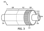
[0039] 図2は、本開示の実施形態による超音波スキャナアセンブリ110の一部分の上面図である。アセンブリ110は、トランスデューサ領域204に形成されたトランスデューサアレイ124と、制御領域208に形成されたトランスデューサ制御論理ダイ206(ダイ206A及び206Bを含む)とを含み、移行領域210がこれらの間に配置される。トランスデューサ制御論理ダイ206及びトランスデューサ212は、図2においては平坦な構成で図示されているフレックス回路214に取り付けられる。図3は、フレックス回路214の巻かれた構成を示す。トランスデューサアレイ202は、医療センサ要素及び/又は医療センサ要素アレイの非限定的な例である。トランスデューサ制御論理ダイ206は、制御回路の非限定的な例である。トランスデューサ領域204は、フレックス回路214の遠位部分221に隣接して配置される。制御領域208は、フレックス回路214の近位部分222に隣接して配置される。移行領域210は、制御領域208とトランスデューサ領域204との間に配置される。トランスデューサ領域204、制御領域208、及び移行領域210の寸法(例えば、長さ225、227、229)は、種々の実施形態において異なり得る。いくつかの実施形態において、長さ225、227、229は実質的に同じであってよく、又は移行領域210の長さ227は、トランスデューサ領域及び制御領域のそれぞれの長さ225、229よりも大きくてよい。撮像アセンブリ110はフレックス回路を含むものとして説明されているが、トランスデューサ及び/又は制御器は、撮像アセンブリ110を形成するために、フレックス回路を有さない構成を含む他の構成で配置されてよいことが理解されるものである。
[0039] FIG. 2 is a top view of a portion of the
[0040] 図2においては明確化のために限定的な数の超音波トランスデューサしか示されていないが、トランスデューサアレイ124は任意の数及び種類の超音波トランスデューサ212を含んでよい。一実施形態において、トランスデューサアレイ124は、64個の個別の超音波トランスデューサ212を含む。更なる実施形態において、トランスデューサアレイ124は、32個の超音波トランスデューサ212を含む。他の数も想定され、提供される。トランスデューサの種類に関しては、一実施形態において、超音波トランスデューサ124は、例えば、その全体が参照により本明細書に組み込まれる米国特許第6,641,540号で開示されているような、微小電気機械システム(MEMS)基板上にポリマー圧電材料を使用して作られた圧電型微細加工超音波トランスデューサ(PMUT)である。代替的な実施形態において、トランスデューサアレイは、バルクPZTトランスデューサなどの圧電ジルコン酸トランスデューサ(PZT)、静電容量型微細加工超音波トランスデューサ(cMUT)、単結晶圧電材料、他の適切な超音波送信機及び受信機、及び/又はそれらの組合せを含む。
[0040] Although only a limited number of ultrasonic transducers are shown in FIG. 2 for clarity, the
[0041] スキャナアセンブリ110は、様々なトランスデューサ制御論理を含み、これらは、示された実施形態においては、個々の制御論理ダイ206に分割されている。様々な例において、スキャナアセンブリ110の制御論理は、PIM104によってケーブル112を介して送られた制御信号を復号すること、超音波信号を放出するために1つ又は複数のトランスデューサ212を駆動すること、超音波信号の反射されたエコーを受信するために1つ又は複数のトランスデューサ212を選択すること、受信されたエコーを表す信号を増幅すること、及び/又はケーブル112を介してPIMに信号を送信すること、を行う。示された実施形態において、64個の超音波トランスデューサ212を有するスキャナアセンブリ110は、制御論理を9つの制御論理ダイ206にわたって分割し、そのうちの5個が図2に図示されている。他の実施形態において、8個、9個、16個、17個及びそれより多くを含む他の数の制御論理ダイ206を組み込んだ設計が利用される。概して、制御論理ダイ206は、それらが駆動することのできるトランスデューサの数によって特徴付けられ、例示的な制御論理ダイ206は、4個、8個、及び/又は16個のトランスデューサを駆動する。
[0041] The
[0042] 制御論理ダイは、必ずしも均質ではない。いくつかの実施形態において、1つの制御器がマスター制御論理ダイ206Aに指定され、ケーブル112のための通信インターフェースを含む。故に、マスター制御回路は、ケーブル112を介して受信された制御信号を復号し、ケーブル112を介して制御応答を送信し、エコー信号を増幅し、及び/又はケーブル112を介してエコー信号を送信する制御論理を含む。残りの制御器はスレーブ制御器206Bである。スレーブ制御器206Bは、超音波信号を放出するためにトランスデューサ212を駆動し、及びエコーを受信するためにトランスデューサ212を選択する制御論理を含む。図示された実施形態において、マスター制御器206Aは、任意のトランスデューサ212を直接的に制御することはない。他の実施形態において、マスター制御器206Aは、スレーブ制御器206Bと同じ数のトランスデューサ212を駆動し、又はスレーブ制御器206Bと比べて少ない1組のトランスデューサ212を駆動する。例示的な実施形態において、1個のマスター制御器206Aと8個のスレーブ制御器206Bとが設けられ、8個のトランスデューサが各スレーブ制御器206Bに割り当てられる。
[0042] Control logic dies are not always homogeneous. In some embodiments, one controller is designated for master control logic die 206A and includes a communication interface for
[0043] トランスデューサ制御論理ダイ206及びトランスデューサ212が取り付けられたフレックス回路214は、構造的な支持を提供し、電気的結合を相互接続する。フレックス回路214は、KAPTON(商標)(Du Pontの商標)などの可撓性のポリイミド材料のフィルム層を含むように構成される。他の適切な材料は、ポリエステルフィルム、ポリイミドフィルム、ポリエチレンナフタレートフィルム、又はポリエーテルイミドフィルム、他の可撓性プリント半導体基板、並びにUpilex(登録商標)(Ube Industriesの登録商標)及びTEFLON(登録商標)(E.I.du Pontの登録商標)などの製品を含む。図2に示される平坦な構成において、フレックス回路214は、全体的に矩形の形状を有する。いくつかの場合おいて、本明細書において図示及び説明されるように、フレックス回路214は、筒状の環状体を形成するように支持部材230の周りに巻き付けられるように構成される(図3)。従って、フレックス回路214のフィルム層の厚さは、一般的に、最終的に組み立てられたスキャナアセンブリ110の曲率の度合いに関係する。いくつかの実施形態において、フィルム層は5μmから100μmの間、いくつかの特定の実施形態において、12.7μmから25.1μmの間である。
[0043] The
[0044] 制御論理ダイ206とトランスデューサ212とを電気的に相互接続するために、一実施形態において、フレックス回路214は、制御論理ダイ206とトランスデューサ212との間で信号を搬送する、フィルム層に形成された導電性配線216を更に含む。特には、制御論理ダイ206とトランスデューサ212との間の通信を提供する導電性配線216は、移行領域210内でフレックス回路214に沿って延在する。いくつかの場合において、導電性配線216は、マスター制御器206Aとスレーブ制御器206Bとの間の電気的通信も促進し得る。導電性配線216は、ケーブル112の導体218がフレックス回路214に機械的及び電気的に結合されたときにケーブル112の導体218に接触する1組の導電性パッドも提供し得る。導電性配線216のために適した材料は、銅、金、アルミニウム、銀、タンタル、ニッケル、及びスズなどがあり、スパッタリング、めっき、エッチングなどのプロセスによってフレックス回路214上に蒸着される。一実施形態において、フレックス回路214は、クロム接着層を含む。導電性配線216の幅及び厚さは、フレックス回路214が巻かれたときに適切な導電性及び弾性を提供するように選択される。これに関して、導電性配線216及び/又は導電性パッドの厚さの例示的な範囲は10〜50μmの間である。例えば、一実施形態において、20μmの導電性配線216が、20μmの空間によって離間される。フレックス回路214上の導電性配線216の幅は、配線/パッドに結合される導体218の幅によって更に決定される。
[0044] To electrically interconnect the control logic die 206 and the
[0045] いくつかの実施形態において、フレックス回路214は導体インターフェース220を含み得る。導体インターフェース220は、ケーブル112の導体218がフレックス回路214に結合されるようなフレックス回路214の場所であり得る。例えば、ケーブル112の裸の導体は、導体インターフェース220においてフレックス回路214に電気的に結合される。導体インターフェース220は、フレックス回路214の主本体から延在するタブであってよい。これに関して、フレックス回路214の主本体は、集合的に、トランスデューサ領域204、制御器領域208、及び移行領域210を指す。示された実施形態において、導体インターフェース220は、フレックス回路214の近位部分222から延在する。他の実施形態において、導体インターフェース220は、遠位部分221などのフレックス回路214の他の部分に位置付けられ、又はフレックス回路214は導体インターフェース220を有さない。幅224などのタブ又は導体インターフェース220の寸法の値は、幅226などのフレックス回路214の主本体の寸法の値よりも小さくてよい。いくつかの実施形態において、導体インターフェース220を形成する基板は、フレックス回路214と同一の材料で作られ、及び/又はフレックス回路214と同様の可撓性を有する。他の実施形態において、導体インターフェース220は、フレックス回路214と異なる材料で作られ、及び/又はフレックス回路214よりも比較的剛性である。例えば、導体インターフェース220は、ポリオキシメチレン(例えば、DELRIN(登録商標))、ポリエーテルエーテルケトン(PEEK)、ナイロン、及び/又は他の適切な材料を含む、プラスチック、サーモプラスチック、ポリマー、ハードポリマーなどで作られてよい。本明細書においてより詳細に説明されるように、支持部材230、フレックス回路214、導体インターフェース220、及び/又は導体218は、スキャナアセンブリ110の効率的な製造及び動作を促進するように様々に構成され得る。
[0045] In some embodiments, the
[0046] いくつかの場合において、スキャナアセンブリ110は、平坦な構成(図2)から、巻かれた又はより筒状の構成(図3及び図4)へと移行する。例えば、いくつかの実施形態において、その各々の全体が参照により本明細書に組み込まれる「ULTRASONIC TRANSDUCER ARRAY AND METHOD OF MANUFACTURING THE SAME」と題された米国特許第6,776,763号、及び「HIGH RESOLUTION INTRAVASCULAR ULTRASOUND TRANSDUCER ASSEMBLY HAVING A FLEXIBLE SUBSTRATE」と題された米国特許第7,226,417号のうちの1つ又は複数において開示されているような技術が利用される。
[0046] In some cases, the
[0047] 図3及び図4に図示されるように、フレックス回路214は、巻かれた構成で支持部材230の周りに位置付けられる。図3は、本開示の態様による、支持部材230の周りの巻かれた構成のフレックス回路214の図式的な側面図である。図4は、本開示の態様による、フレックス回路214、支持部材230及びチップ部材304を含む血管内デバイス110の遠位部分の概略的な側断面図である。
As illustrated in FIGS. 3 and 4, the
[0048] いくつかの場合において、支持部材230は、単体構造体として参照され得る。支持部材230は、ステンレス鋼などの金属材料で構成され得、又は、その全体が参照により本明細書に組み込まれる「Pre−Doped Solid Substrate for Intravascular Devices」と題された2014年4月28日出願の米国仮特許出願第61/985,220号において説明されているようにプラスチック又はポリマーなどの非金属材料から構成され得る。支持部材230は、遠位部分262及び近位部分264を有するフェルールであり得る。支持部材230は、長手方向に貫通して延在するルーメン236を画定し得る。ルーメン236は、出口ポート116と連通し、ガイドワイヤ118(図1)を受け入れる大きさ及び形状に形成される。支持部材230は、任意の適切なプロセスによって製造され得る。例えば、支持部材230は、支持部材230を形作るために素材から材料を除去することなどによって機械加工され得、又は、射出成形プロセスなどによって成形され得る。いくつかの実施形態において、支持部材230は、単体構造として一体的に形成され、他の実施形態において、支持部材230は、互いに対して固定的に結合されたフェルール及びスタンド242、244など、種々のコンポーネントで形成され得る。
[0048] In some cases, the
[0049] 垂直に延在するスタンド242、244は支持部材230の遠位及び近位部分262、264にそれぞれ設けられる。スタンド242、244は、フレックス回路214の遠位及び近位部分を持ち上げ、支持する。これに関して、トランスデューサ部分204などのフレックス回路214の部分は、スタンド242と244との間に延在する支持部材230の中央本体部分から離間され得る。スタンド242、244は、同一の外径を有してよく、又は異なる外径を有してよい。例えば、遠位スタンド242は、近位スタンド244よりも大きな又は小さな外径を有してよい。音響性能を向上させるために、フレックス回路214と支持部材230の表面との間の任意のキャビティは裏材料246によって充填される。液体裏材料246は、フレックス回路214と支持部材230との間に、スタンド242、244における通路235を介して導入され得る。いくつかの実施形態において、スタンド242、244のうちの1つの通路235を介して吸引が施される一方、スタンド242、244のうちの他方の通路235を介してフレックス回路214と支持部材230との間に液体裏材料246が供給される。裏材料は、固体化して固まることが可能となるように硬化され得る。様々な実施形態において、支持部材230は、3つ以上のスタンド242、244を、若しくはスタンド242、244のうちの一方のみを含み、又はどちらのスタンドも含まない。これに関して、支持部材230は、フレックス回路214の遠位及び/又は近位部分を持ち上げ、支持する大きさ及び形状に形成された大直径の遠位部分262及び/又は大直径の近位部分264を有し得る。
[0049] Vertically extending stands 242 and 244 are provided at the distal and
[0050] いくつかの実施形態において、支持部材230は実質的に筒状であってよい。支持部材230の他の形状も想定され、これは幾何学的な、非幾何学的な、対称な、非対称な断面輪郭を含む。他の実施形態において、支持部材230の種々の部分は様々な形状を有してよい。例えば、近位部分264は、遠位部分262の外径、又は遠位部分262と近位部分264との間に延在する中央部分の外径よりも大きな外径を有してよい。いくつかの実施形態において、支持部材230の内径(例えば、ルーメン236の直径)は、外径が変化するにつれて、それに応じて増加又は減少してよい。他の実施形態において、支持部材230の内径は、外径の変化に関わらず同一のままである。
[0050] In some embodiments, the
[0051] 近位内側部材256及び近位外側部材254は、支持部材230の近位部分264に結合される。近位内側部材256及び/又は近位外側部材254は、近位コネクタ114などの血管内デバイス102の近位部分から撮像アセンブリ110まで延在する可撓性細長部材であり得る。例えば、近位内側部材256は、近位フランジ234内に受け入れられ得る。近位外側部材254は、フレックス回路214に当接し、これと接触する。チップ部材304は、支持部材230の遠位部分262に結合される。本明細書において更に論じられるように、チップ部材304は、血管内デバイス102の最も遠位の部分を定める可撓性コンポーネントであり得る。例えば、チップ部材304は、遠位フランジ232の周りに位置付けられる。チップ部材304は、フレックス回路214及びスタンド242に当接し、これらと接触し得る。チップ部材304は、血管内デバイス102の最も遠位のコンポーネントであり得る。チップ部材304は、病変及び半径の小さい血管を含むがそれらに限定されない、患者内で遭遇する任意の数の解剖学的構造を通過する腔内デバイス300の並進移動を容易にするように機能する。
[0051] The proximal
[0052] 図5a及び図5bは、接合部302を含む腔内デバイス300の実施形態を示し、接合部302は、特定の実施形態においてはスキャナアセンブリである撮像アセンブリ110とチップ部材304との接続を容易にする。図5aは撮像アセンブリ110及びチップ部材304の接合部302の側面図である。図5bは撮像アセンブリ110及びチップ部材304の接合部302の側断面図である。明確化のために、腔内デバイス300の近位部分が図5a及び図5bの左側に図示され、より遠位の部分が右側に図示される。
[0052] FIGS. 5a and 5b show an embodiment of the
[0053] 腔内デバイス300は、いくつかの態様において、血管内デバイス102に類似し得る。図5a及び図5bを参照すると、撮像アセンブリ110及びチップ部材304の接合部302は、チップ部材304の近位部分310と撮像アセンブリ110の遠位端部312との間に位置付けられた連結領域308に配置された接着剤306を含む。接着剤306は、撮像アセンブリ110とチップ部材304とを機械的に接続するように機能する。更に、接着剤306は、チップ部材304と撮像アセンブリ110の遠位端部312との間に気密封止を提供するように機能する。本明細書において更に論じられるように、連結領域308は、チップ部材304及び接合部302の全体的な直径を制限しつつ接着剤306を受け入れるように構成される。1つ又は複数の接着剤306は、連結領域308に配置されることが予期される。接着剤306は、限定的な量の接着剤306が撮像アセンブリ110及びチップ部材304の近位部分310と重なるように連結領域308内に配置される。図5bは、連結領域308を通ってチップ部材304の近位部分310内に延在する支持部材230及び内側部材256の例示を提供する。
[0053] The
[0054] 次に図5cを参照すると、チップ部材304の断面図が提示されている。チップ部材304は、連結領域308、近位部分310及び遠位部分320の間を長手方向軸318に沿ってチップ部材304の壁部316の間に延在するルーメン314を含む。本明細書において更に論じられるように、連結領域308、近位部分310及び遠位部分320のそれぞれの長さ及び幾何学的輪郭は、チップ部材304の機能的目的によって変わることは理解されよう。図5cは、近位部分310から遠位部分320へと直線的に傾斜する壁部316を示す。しかしながら、本明細書において更に説明されるように、壁部316は、曲線的に傾斜してもよい。壁部316及びルーメン314は、チップ部材304の内径322を定める。係合機能部324が、支持部材230を近位部分310内に固定するように、内径322に沿って位置付けられる。係合機能部324は、支持部230をチップ部材304の内径322に固定するために、これらに限定されるものではないが、粗面処理、溝、ネジ山などの当技術分野において知られる任意の数の固定機構及び方法を含むことが予期される。
Next, referring to FIG. 5c, a cross-sectional view of the
[0055] チップ部材304は、交差領域326も含み、これはチップ部材304の輪郭の最も大きな外径を含むチップ部材304のエリアとして定められ、概して、近位部分310又は連結領域308に位置する。
[0055] The
[0056] 連結領域308は、接合部302内でチップ部材304の近位部分310と撮像アセンブリ110との間に配置される。連結領域308は、撮像アセンブリ110とチップ部材304との間の機械的接続を容易にするために使用される接着剤306を受け入れるためのキャビティ328を含む。キャビティ328は、機械的接続のために接着剤306を受け入れるように構成されると同時に、チップ部材304の交差領域326を最小化するように機能する。しかしながら、連結領域308への接着剤306の追加は、交差領域326の事実上の場所となるチップ部材304の全体的な直径を増加させることが予想される。以前に論じられたように、このことは、撮像アセンブリ110とチップ部材304との間の接合部302において接着剤306の重なりを生成することが望まれる場合に特に当てはまる。図5cにおいて図示されるように、連結領域308のキャビティ328は、近位部分310から撮像アセンブリ110に向かって延在する壁部316の直線的な傾斜によって定められ、環状で三角形状の断面を形成する。しかしながら、本明細書において更に論じられるように、キャビティ328は、チップ部材304の交差領域326を最小化することを容易にする任意の数の幾何学的形状によって定められてよい。
[0056] The connecting
[0057] 引き続き図5cを参照すると、壁部316は、ここでも、チップ部材304の近位部分310からチップ部材の遠位部分320に向かうにつれて直線的に傾斜するように図示されている。この構成において、チップ部材304の外径330は、長手方向軸318に沿って近位部分310から遠位部分320へと徐々に減少する。遠位部分320の最も遠位の位置は遠位端部332であり、これは、本明細書において更に論じられるように、腔内デバイス300のチップ部材304と腔内デバイス300の経路に沿った任意の障害物との間の接触の最初のポイントである。
[0057] Continuing with reference to FIG. 5c, the
[0058] 図6a及び図6bは、それぞれ、撮像アセンブリ110及びチップ部材304の接合部302の拡大斜視図及び図式的な断面図を示す。図6aは、チップ部材304の連結領域308を通って近位部分310へと延在する撮像アセンブリ110の支持部材230を示す。キャビティ328は、台形の断面を有する環状の構成が図示されている。図5a〜図5cにおいて描写された直線的な傾斜とは対照的に、図6aにおいては、チップ部材304は、長手方向軸318に沿って近位部分310から遠位部分320へと減少する部分的に曲線的な輪郭を有するように図示されている。遠位部分320の遠位端部332は補強装置334を含み、これは、特定の実施形態において、補強リングであり、内径322とチップ部材304のルーメン314との間に位置付けられる。本明細書において更に論じられるように、補強装置334は、チップ部材304の遠位部分320に剛性を提供するように機能する。この剛性は、腔内デバイス300の経路に沿って比較的剛性の障害物に遭遇したときにチップ部材304の変形を防止する。
[0058] FIGS. 6a and 6b show an enlarged perspective view and a schematic cross-sectional view of the
[0059] 図6bは、図5a〜図5cにおいて示されたものと同様に、長手方向軸318に沿って近位部分310から遠位部分320へと減少する直線的な輪郭を有するチップ部材304の構成を描写している。しかしながら、この構成は、接着剤306を含む環状のキャビティ328を示し、これは、以前に説明された三角形状及び台形状の断面とは対照的に、矩形状の断面を有する。チップ部材304は、幾何学的形状輪郭及びキャビティ328の断面の任意の数の組合せによって構成されてよいことは理解されよう。
[0059] FIG. 6b is a
[0060] 図7は、チップ部材304の側断面図を提示し、ここでは、チップ部材304は射出成形プロセスを使用して作られている。このプロセスは、チップ部材304の可撓性を制御するように実行される。プロセスは、可撓性の第1の材料336を使用して遠位部分320を成形するステップと、第1の材料336よりも小さな可撓性を有する第2の材料338を使用して近位部分310を成形するステップとを有する。この構成は、チップ部材304の遠位部分320により大きな可撓性を提供し、このことは、腔内デバイス300の経路に沿って遭遇する障害物をナビゲーションするために有益である。加えて、この構成は、剛性の撮像アセンブリ110に接続された、より小さな可撓性を有するチップ部材304の近位部分310への最適化された移行を提供する。第1の材料336は、プラスチック、ポリマー、エラストマー、ポリエーテルブロックアミド、Pebax(登録商標)(例えばPebax(登録商標)5533)及び/又は他の適切な材料を含むがこれらに限定されない任意の数の可撓性の特性を有する材料から選択される。更に、第2の材料338は、選択された第1の材料336よりも小さな可撓性を有する任意の数の材料から選択される。プロセスは、遠位部分320及び近位部分310にそれぞれ注入される第1の材料336及び第2の材料338の量を制御し、最終的にチップ部材304の可撓性を決定するように構成される。例えば、図7は、チップ部材304において第1の材料336の量がより多い様子を図示しているが、チップ部材304の所望の剛性の大きさに応じて、射出成形プロセスは、近位部分310における第2の材料338の量を増やすように修正されてよい。
[0060] FIG. 7 presents a side sectional view of the
[0061] 図7におけるチップ部材304は、図5cにおいて提示されたチップ部材304と類似の特徴を含むが、第1の材料336及び第2の材料338の両方から形成されて近位部分310と遠位部分320との間に配置された移行領域340も含んでいる。移行領域340は、相互ロックアセンブリ342を含み、これは、第1の材料336と第2の材料338との間に結合を生むように機能する。相互ロックアセンブリ342は、第1の材料336と第2の材料338とを固定するために、これらに限定されるものではないがリブ又は粗い質感を有するインターフェース領域などの、任意の数の方法又は装置を用いる。図7は、チップ部材304を形成する射出成形プロセスにおいて2つの材料が使用されていることを説明しているが、成形プロセスは異なる可撓性の大きさを有する任意の数の材料を用いてよいことは理解されよう。
[0061] The
[0062] 図8は、チップ部材304の側断面図を示し、ここでは、近位部分310は一定の直径330を有する一方でチップ部材304の壁部316の厚さが長手方向軸318に沿って変化し、遠位部分320は変化する直径330を有する一方でチップ部材304の壁部316の厚さは長手方向軸318に沿って一定である。図7に関して説明されたチップ部材304と同様に、図8において提示されるチップ部材304は、ルーメン314の幾何学的形状を除いては図5cにおいて提示されたチップ部材304と類似の特徴を含む。ルーメン314の形状は、所望に応じて任意の数の直線的又は非直線的幾何学的形状から導出されることは理解されよう。図8において提示されるチップ部材304は、複数の材料(例えば、図7を参照して論じられた第1の材料336及び第2の材料338)ではなく1つの材料の使用による、チップ部材304の可撓性を制御するための代替的な手法を示す。ルーメン314の周りで、近位部分310に沿って壁部316の厚さを増加させ、遠位部分320に沿って壁部316の厚さを減少させることによって、チップ部材304は、遠位部分320において可撓性を有し、近位部分310においてはより小さな可撓性を有するように構成される。
[0062] FIG. 8 shows a side sectional view of the
[0063] 図9、図10及び図11は、異なる幾何学的形状を含む、チップ部材304の断面輪郭の様々なタイプを提示し、これらは、困難な解剖学的構造を通る並進移動又はその周囲での並進移動を容易にするために、状況に応じて使用される。図9において、斜面タイプ断面輪郭を有するチップ部材304の側面図が提示される。斜面タイプ断面輪郭は、遠位部分320において小さな外径330を有し、これは、近位部分310へと達するまで長手方向軸318に対して直線的に傾斜して徐々に増加する。近位部分310は、傾斜がゼロになる輪郭区画を含む。斜面タイプ断面輪郭を有するチップ部材304の使用は、血管系又は他の身体ルーメン内で、窮屈な湾曲を横切るなどの状況において有利であり、薄く、可撓性を有する先端縁部が、より厚く、より小さな可撓性を有する近位縁部へと連続的に移行している。図10において、傾斜タイプ断面輪郭を有するチップ部材304の側面図が提示される。斜面タイプ断面輪郭と同様に、傾斜タイプ断面輪郭も、遠位部分320においてより小さな外径330を有し、これは、近位部分310へと向かって長手方向軸318に沿って徐々に増加する。しかしながら、直線的に増加する代わりに、外径330は、遠位部分320から近位部分310へと曲線的な傾斜に沿って増加する。傾斜タイプ断面輪郭を有するチップ部材304の使用は、血管系又は他の身体ルーメン内で、部分的な又は完全な閉塞部と交差するなどの状況において有利であり、チップの斜面は楔として働く。図11において、段タイプ断面輪郭を有するチップ部材304の側面図が提示される。図9及び図10の斜面及び傾斜タイプ断面輪郭と同様に、段タイプ断面輪郭は、遠位部分320において近位部分310よりも小さな直径330を有する。しかしながら、段タイプ断面輪郭においては、より小さな直径330が、近位部分310と出遭うまで遠位部分320全体において傾斜ゼロで維持され、近位部分310において、曲線的な傾斜に沿ってより大きな直径330へと増加する。段タイプの断面輪郭を有するチップ部材304の使用は、血管系又は他の身体ルーメン内で、ステントと交差するなどの状況において有利であり、そこでは、ガイドワイヤ及びチップの先端縁部をステントのストラットに対して押し付けることを回避するために、遠位部分が可撓性であることが望ましい。各チップ部材304における輪郭の各遠位部分320及び近位部分310の長さ並びにそれらのそれぞれの傾斜及び半径は、一般的な使用又は特定の臨床シナリオのために最適化されることは理解されよう。
[0063] FIGS. 9, 10 and 11 present various types of cross-sectional contours of the
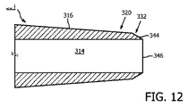
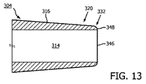
[0064] 図12、図13及び図14は、異なる幾何学的形状を含む輪郭を有するチップ部材304の遠位端部332の様々なタイプを提示し、これらは、障害物に遭遇したときのチップ部材304の変形を防止するために、状況に応じて使用される。ガイドワイヤ118の装填プロセスにおける補助のために、チップ部材304には第1の色が与えられ、遠位端部332には第2の色が与えられる。以前に論じられたように、遠位端部332は、遠位部分320の最も遠位の位置に配置される。図12において、面取りされた遠位端部を有するチップ部材304の側断面図が提示される。遠位端部320は、チップ部材304の壁部316から遠位端部332の縁部346に向かって直線的に傾斜する外径344を有する。面取りされた遠位端部332を有するチップ部材304の使用は、デバイスが、血管系又は他の身体ルーメン内で、チップに引っ掛かり得る幾何学的形状(例えば、閉塞部又はステント)を横切る状況において有利である。図13において、放射状遠位端部332を有するチップ部材304の側断面図が提示される。遠位端部332は、チップ部材304の壁部316から遠位端部332の縁部346に向かって曲線的に傾斜する外径348を有する。放射状遠位端部332を有するチップ部材304の使用は、デバイスが、血管系又は他の身体ルーメン内で、湾曲を横切る状況(特に、ガイドワイヤの堅いセグメントにおいて)において有利であり、そこでは、チップ材料の変形を防止するために、材料の追加的な厚さが必要とされる。図14において、補強装置334を有するチップ部材304の側断面図が提示される。補強装置334は、遠位端部332の縁部346においてルーメンの外径350の周りに配置される。チップ部材304から区別するために、補強装置334も第2の色が与えられる。補強装置334は、任意の遠位端部332の幾何学的輪郭とともに使用されることは理解されよう。
[0064] FIGS. 12, 13 and 14 present various types of
Claims (19)
前記患者の前記ルーメン内に位置付けられる間、超音波撮像データを取得する、前記遠位部分に配置された超音波撮像アセンブリと、
前記可撓性細長部材の前記遠位部分に配置されるチップ部材とを備え、
前記チップ部材は、前記超音波撮像アセンブリに隣接するキャビティであって、前記チップ部材と前記超音波撮像アセンブリとを結合する接着剤によって充填されるキャビティを備える、腔内撮像デバイス。 A flexible elongated member that is inserted into the lumen of a patient and comprises a proximal portion and a distal portion.
An ultrasound imaging assembly located in the distal portion, which acquires ultrasound imaging data while being positioned within the lumen of the patient.
With a tip member located at the distal portion of the flexible elongated member
An intracavitary imaging device, wherein the chip member is a cavity adjacent to the ultrasonic imaging assembly and includes a cavity filled with an adhesive that binds the chip member and the ultrasonic imaging assembly.
前記遠位部分に配置され、前記患者の前記ルーメン内に位置付けられる間、超音波撮像データを取得する、超音波撮像アセンブリと、
前記可撓性細長部材の前記遠位部分にチップ部材とを備え、
前記チップ部材は、前記チップ部材の遠位部分において第1の材料を有し、前記チップ部材の近位部分において第2の材料を有する、腔内撮像デバイス。 A flexible elongated member that is inserted into the lumen of a patient and comprises a proximal portion and a distal portion.
An ultrasound imaging assembly that acquires ultrasound imaging data while being located in the distal portion and positioned within said lumen of the patient.
A tip member is provided at the distal portion of the flexible elongated member.
An intracavitary imaging device, wherein the chip member has a first material in a distal portion of the chip member and a second material in a proximal portion of the chip member.
前記遠位部分に配置され、前記患者の前記ルーメン内に位置付けられる間、超音波撮像データを取得する、超音波撮像アセンブリと、
前記可撓性細長部材の前記遠位部分にチップ部材とを備え、
前記チップ部材は、近位部分と遠位部分とを備え、前記チップ部材の前記近位部分は、直線的な外径と変化する肉厚とを備え、前記チップ部材の前記遠位部分は変化する外径と一定の肉厚とを備える、腔内撮像デバイス。 A flexible elongated member that is inserted into the lumen of a patient and comprises a proximal portion and a distal portion.
An ultrasound imaging assembly that acquires ultrasound imaging data while being located in the distal portion and positioned within said lumen of the patient.
A tip member is provided at the distal portion of the flexible elongated member.
The tip member comprises a proximal portion and a distal portion, the proximal portion of the tip member comprises a linear outer diameter and a variable wall thickness, and the distal portion of the tip member is variable. An intracavitary imaging device having an outer diameter and a constant wall thickness.
Applications Claiming Priority (3)
| Application Number | Priority Date | Filing Date | Title |
|---|---|---|---|
| US201762595744P | 2017-12-07 | 2017-12-07 | |
| US62/595,744 | 2017-12-07 | ||
| PCT/EP2018/082951 WO2019110404A1 (en) | 2017-12-07 | 2018-11-29 | Flexible tip for intraluminal imaging device and associated devices, systems, and methods |
Publications (2)
| Publication Number | Publication Date |
|---|---|
| JP2021505261A true JP2021505261A (en) | 2021-02-18 |
| JP2021505261A5 JP2021505261A5 (en) | 2022-01-06 |
Family
ID=64564870
Family Applications (1)
| Application Number | Title | Priority Date | Filing Date |
|---|---|---|---|
| JP2020530632A Pending JP2021505261A (en) | 2017-12-07 | 2018-11-29 | Flexible chips and related devices, systems and methods for intracavitary imaging devices |
Country Status (5)
| Country | Link |
|---|---|
| US (1) | US20200289085A1 (en) |
| EP (1) | EP3720360A1 (en) |
| JP (1) | JP2021505261A (en) |
| CN (1) | CN111432732B (en) |
| WO (1) | WO2019110404A1 (en) |
Cited By (1)
| Publication number | Priority date | Publication date | Assignee | Title |
|---|---|---|---|---|
| WO2025100517A1 (en) * | 2023-11-10 | 2025-05-15 | テルモ株式会社 | Catheter for image acquisition |
Families Citing this family (2)
| Publication number | Priority date | Publication date | Assignee | Title |
|---|---|---|---|---|
| EP3668409B1 (en) * | 2017-08-15 | 2022-04-27 | Koninklijke Philips N.V. | Intraluminal ultrasound device for diagnostic imaging and therapy |
| CN115297783A (en) * | 2020-02-27 | 2022-11-04 | 飞利浦影像引导治疗公司 | Interlocking components for intraluminal ultrasound imaging and associated systems, devices and methods |
Citations (10)
| Publication number | Priority date | Publication date | Assignee | Title |
|---|---|---|---|---|
| JPH10281356A (en) * | 1997-04-08 | 1998-10-23 | Olympus Optical Co Ltd | Connection structure of part |
| JP2004298349A (en) * | 2003-03-31 | 2004-10-28 | Fuji Photo Optical Co Ltd | Ultrasonic probe |
| WO2013111700A1 (en) * | 2012-01-23 | 2013-08-01 | テルモ株式会社 | Medical tube, catheter, and method for producing medical tube |
| WO2015166750A1 (en) * | 2014-05-02 | 2015-11-05 | オリンパス株式会社 | Optical unit and endoscope equipped with optical unit |
| JP2015536223A (en) * | 2012-12-06 | 2015-12-21 | ヴォルカノ コーポレイションVolcano Corporation | Reinforced catheter transfer with flexible end |
| JP2016501626A (en) * | 2012-12-20 | 2016-01-21 | ジェレミー スティガール, | Catheter assembly having a truncated tip |
| US20170055941A1 (en) * | 2015-09-02 | 2017-03-02 | Koninklijke Philips N.V. | Integrated imaging component and intravascular device delivery system |
| JP2017086550A (en) * | 2015-11-11 | 2017-05-25 | オリンパス株式会社 | Endoscope |
| JPWO2017022279A1 (en) * | 2015-08-05 | 2017-08-03 | オリンパス株式会社 | Imaging unit and endoscope |
| WO2017143457A1 (en) * | 2016-02-26 | 2017-08-31 | Sunnybrook Research Institute | Imaging probe with rotatable core |
Family Cites Families (13)
| Publication number | Priority date | Publication date | Assignee | Title |
|---|---|---|---|---|
| DE69516444T2 (en) | 1994-03-11 | 2001-01-04 | Intravascular Research Ltd., London | Ultrasonic transducer arrangement and method for its production |
| US7226417B1 (en) | 1995-12-26 | 2007-06-05 | Volcano Corporation | High resolution intravascular ultrasound transducer assembly having a flexible substrate |
| AU2001289196B2 (en) | 2000-12-01 | 2004-09-30 | The Cleveland Clinic Foundation | Miniature ultrasound transducer |
| JP4339767B2 (en) * | 2004-09-16 | 2009-10-07 | オリンパス株式会社 | Ultrasound endoscope device |
| US7794402B2 (en) * | 2006-05-15 | 2010-09-14 | Advanced Cardiovascular Systems, Inc. | Echogenic needle catheter configured to produce an improved ultrasound image |
| WO2008081601A1 (en) * | 2007-01-05 | 2008-07-10 | Olympus Medical Systems Corp. | Capsule type medical device |
| CN103687639B (en) * | 2011-05-17 | 2018-01-30 | 泰尔茂株式会社 | The manufacture method of medical intubation, conduit and medical intubation |
| CA2856426A1 (en) * | 2011-12-08 | 2013-06-13 | Volcano Corporation | Devices, systems, and methods for visualizing an occluded vessel |
| US20140163361A1 (en) * | 2012-12-12 | 2014-06-12 | Volcano Corporation | Combination Rotational and Phased-Array In Vivo Imaging Devices and Methods |
| CA2895208A1 (en) * | 2012-12-20 | 2014-06-26 | Volcano Corporation | Distal catheter tip formation |
| EP2934652B1 (en) * | 2012-12-21 | 2020-06-17 | Volcano Corporation | Steerable intravascular devices |
| EP2954865B1 (en) * | 2013-02-07 | 2022-04-06 | Shanghai Golden Leaf Med Tec Co., Ltd | Radio frequency ablation method, system and radio frequency ablation device thereof |
| US10532185B2 (en) * | 2015-09-08 | 2020-01-14 | Covidien Lp | Navigable catheter distal tip configuration |
-
2018
- 2018-11-29 EP EP18811791.5A patent/EP3720360A1/en active Pending
- 2018-11-29 CN CN201880078190.5A patent/CN111432732B/en active Active
- 2018-11-29 WO PCT/EP2018/082951 patent/WO2019110404A1/en unknown
- 2018-11-29 US US16/768,170 patent/US20200289085A1/en active Pending
- 2018-11-29 JP JP2020530632A patent/JP2021505261A/en active Pending
Patent Citations (10)
| Publication number | Priority date | Publication date | Assignee | Title |
|---|---|---|---|---|
| JPH10281356A (en) * | 1997-04-08 | 1998-10-23 | Olympus Optical Co Ltd | Connection structure of part |
| JP2004298349A (en) * | 2003-03-31 | 2004-10-28 | Fuji Photo Optical Co Ltd | Ultrasonic probe |
| WO2013111700A1 (en) * | 2012-01-23 | 2013-08-01 | テルモ株式会社 | Medical tube, catheter, and method for producing medical tube |
| JP2015536223A (en) * | 2012-12-06 | 2015-12-21 | ヴォルカノ コーポレイションVolcano Corporation | Reinforced catheter transfer with flexible end |
| JP2016501626A (en) * | 2012-12-20 | 2016-01-21 | ジェレミー スティガール, | Catheter assembly having a truncated tip |
| WO2015166750A1 (en) * | 2014-05-02 | 2015-11-05 | オリンパス株式会社 | Optical unit and endoscope equipped with optical unit |
| JPWO2017022279A1 (en) * | 2015-08-05 | 2017-08-03 | オリンパス株式会社 | Imaging unit and endoscope |
| US20170055941A1 (en) * | 2015-09-02 | 2017-03-02 | Koninklijke Philips N.V. | Integrated imaging component and intravascular device delivery system |
| JP2017086550A (en) * | 2015-11-11 | 2017-05-25 | オリンパス株式会社 | Endoscope |
| WO2017143457A1 (en) * | 2016-02-26 | 2017-08-31 | Sunnybrook Research Institute | Imaging probe with rotatable core |
Cited By (1)
| Publication number | Priority date | Publication date | Assignee | Title |
|---|---|---|---|---|
| WO2025100517A1 (en) * | 2023-11-10 | 2025-05-15 | テルモ株式会社 | Catheter for image acquisition |
Also Published As
| Publication number | Publication date |
|---|---|
| CN111432732B (en) | 2024-10-29 |
| WO2019110404A1 (en) | 2019-06-13 |
| EP3720360A1 (en) | 2020-10-14 |
| CN111432732A (en) | 2020-07-17 |
| US20200289085A1 (en) | 2020-09-17 |
Similar Documents
| Publication | Publication Date | Title |
|---|---|---|
| JP6980688B2 (en) | Imaging assembly of intravascular diagnostic imaging devices, as well as related devices, systems, and methods. | |
| JP6526925B2 (en) | Imaging assembly for intravascular imaging device and related devices, systems and methods | |
| JP6797933B2 (en) | Flexible support members for intravascular diagnostic imaging devices and related devices, systems, and methods. | |
| US20230240647A1 (en) | Intraluminal imaging device with wire interconnection for imaging assembly | |
| US20240307027A1 (en) | Intraluminal imaging device with thermally bonded imaging joint and flexible transition | |
| JP7609071B2 (en) | Distortion reduction for intraluminal ultrasound imaging and related devices, systems and methods - Patents.com | |
| US20240138807A1 (en) | Reinforcement layer for intraluminal imaging device | |
| US20240074731A1 (en) | Flexible adhesive-filled distal region for intraluminal imaging device | |
| JP2019528959A (en) | Flexible imaging assembly for intraluminal imaging and related devices, systems and methods | |
| US20190247017A1 (en) | Inner member for intravascular imaging device and associated devices, systems, and methods | |
| US20250143672A1 (en) | Intraluminal ultrasound assembly having a multiple material support member, and associated devices, systems, and methods | |
| US20230157667A1 (en) | Flexible substrate with recesses for intraluminal ultrasound imaging devices | |
| CN111432732B (en) | Flexible tips for endoluminal imaging devices and related devices, systems, and methods | |
| US11963822B2 (en) | Electrical grounding for imaging assembly and associated intraluminal devices, systems, and methods | |
| US11980723B2 (en) | Support member for intraluminal imaging devices and associated devices, systems, and methods | |
| EP3568081B1 (en) | Support members for connection of components in intraluminal devices, systems, and methods |
Legal Events
| Date | Code | Title | Description |
|---|---|---|---|
| A521 | Request for written amendment filed |
Free format text: JAPANESE INTERMEDIATE CODE: A523 Effective date: 20211125 |
|
| A621 | Written request for application examination |
Free format text: JAPANESE INTERMEDIATE CODE: A621 Effective date: 20211125 |
|
| A977 | Report on retrieval |
Free format text: JAPANESE INTERMEDIATE CODE: A971007 Effective date: 20221026 |
|
| A131 | Notification of reasons for refusal |
Free format text: JAPANESE INTERMEDIATE CODE: A131 Effective date: 20221107 |
|
| A601 | Written request for extension of time |
Free format text: JAPANESE INTERMEDIATE CODE: A601 Effective date: 20230126 |
|
| A131 | Notification of reasons for refusal |
Free format text: JAPANESE INTERMEDIATE CODE: A131 Effective date: 20230703 |
|
| A521 | Request for written amendment filed |
Free format text: JAPANESE INTERMEDIATE CODE: A523 Effective date: 20231002 |
|
| A131 | Notification of reasons for refusal |
Free format text: JAPANESE INTERMEDIATE CODE: A131 Effective date: 20231211 |
|
| A521 | Request for written amendment filed |
Free format text: JAPANESE INTERMEDIATE CODE: A523 Effective date: 20240307 |
|
| A02 | Decision of refusal |
Free format text: JAPANESE INTERMEDIATE CODE: A02 Effective date: 20240708 |
|
| A521 | Request for written amendment filed |
Free format text: JAPANESE INTERMEDIATE CODE: A523 Effective date: 20241029 |
|
| A911 | Transfer to examiner for re-examination before appeal (zenchi) |
Free format text: JAPANESE INTERMEDIATE CODE: A911 Effective date: 20241107 |