JP2021190925A - Processing apparatus, image pickup apparatus, and processing method - Google Patents
Processing apparatus, image pickup apparatus, and processing method Download PDFInfo
- Publication number
- JP2021190925A JP2021190925A JP2020096371A JP2020096371A JP2021190925A JP 2021190925 A JP2021190925 A JP 2021190925A JP 2020096371 A JP2020096371 A JP 2020096371A JP 2020096371 A JP2020096371 A JP 2020096371A JP 2021190925 A JP2021190925 A JP 2021190925A
- Authority
- JP
- Japan
- Prior art keywords
- image
- image data
- unit
- processing
- image pickup
- Prior art date
- Legal status (The legal status is an assumption and is not a legal conclusion. Google has not performed a legal analysis and makes no representation as to the accuracy of the status listed.)
- Withdrawn
Links
- 238000012545 processing Methods 0.000 title claims abstract description 67
- 238000003672 processing method Methods 0.000 title claims abstract description 10
- 238000000034 method Methods 0.000 claims abstract description 19
- 230000008569 process Effects 0.000 claims abstract description 18
- 238000010191 image analysis Methods 0.000 claims description 26
- 238000004148 unit process Methods 0.000 claims 1
- 238000003384 imaging method Methods 0.000 abstract description 24
- 238000011156 evaluation Methods 0.000 description 11
- 238000004891 communication Methods 0.000 description 9
- 230000003287 optical effect Effects 0.000 description 6
- 238000010586 diagram Methods 0.000 description 3
- 230000006870 function Effects 0.000 description 3
- 239000003086 colorant Substances 0.000 description 2
- 238000010276 construction Methods 0.000 description 2
- 238000012986 modification Methods 0.000 description 2
- 230000004048 modification Effects 0.000 description 2
- 230000004044 response Effects 0.000 description 2
- 230000035945 sensitivity Effects 0.000 description 2
- 230000005540 biological transmission Effects 0.000 description 1
- 239000002131 composite material Substances 0.000 description 1
- 230000006835 compression Effects 0.000 description 1
- 238000007906 compression Methods 0.000 description 1
- 238000011161 development Methods 0.000 description 1
- 239000000203 mixture Substances 0.000 description 1
- 238000001454 recorded image Methods 0.000 description 1
- 230000009467 reduction Effects 0.000 description 1
Images


Classifications
-
- H—ELECTRICITY
- H04—ELECTRIC COMMUNICATION TECHNIQUE
- H04N—PICTORIAL COMMUNICATION, e.g. TELEVISION
- H04N7/00—Television systems
- H04N7/18—Closed-circuit television [CCTV] systems, i.e. systems in which the video signal is not broadcast
- H04N7/181—Closed-circuit television [CCTV] systems, i.e. systems in which the video signal is not broadcast for receiving images from a plurality of remote sources
-
- G—PHYSICS
- G06—COMPUTING; CALCULATING OR COUNTING
- G06F—ELECTRIC DIGITAL DATA PROCESSING
- G06F21/00—Security arrangements for protecting computers, components thereof, programs or data against unauthorised activity
- G06F21/60—Protecting data
- G06F21/64—Protecting data integrity, e.g. using checksums, certificates or signatures
-
- G—PHYSICS
- G06—COMPUTING; CALCULATING OR COUNTING
- G06T—IMAGE DATA PROCESSING OR GENERATION, IN GENERAL
- G06T1/00—General purpose image data processing
- G06T1/0021—Image watermarking
- G06T1/0028—Adaptive watermarking, e.g. Human Visual System [HVS]-based watermarking
-
- H—ELECTRICITY
- H04—ELECTRIC COMMUNICATION TECHNIQUE
- H04L—TRANSMISSION OF DIGITAL INFORMATION, e.g. TELEGRAPHIC COMMUNICATION
- H04L63/00—Network architectures or network communication protocols for network security
- H04L63/12—Applying verification of the received information
-
- H—ELECTRICITY
- H04—ELECTRIC COMMUNICATION TECHNIQUE
- H04N—PICTORIAL COMMUNICATION, e.g. TELEVISION
- H04N1/00—Scanning, transmission or reproduction of documents or the like, e.g. facsimile transmission; Details thereof
- H04N1/00095—Systems or arrangements for the transmission of the picture signal
-
- H—ELECTRICITY
- H04—ELECTRIC COMMUNICATION TECHNIQUE
- H04N—PICTORIAL COMMUNICATION, e.g. TELEVISION
- H04N23/00—Cameras or camera modules comprising electronic image sensors; Control thereof
- H04N23/45—Cameras or camera modules comprising electronic image sensors; Control thereof for generating image signals from two or more image sensors being of different type or operating in different modes, e.g. with a CMOS sensor for moving images in combination with a charge-coupled device [CCD] for still images
-
- H—ELECTRICITY
- H04—ELECTRIC COMMUNICATION TECHNIQUE
- H04N—PICTORIAL COMMUNICATION, e.g. TELEVISION
- H04N23/00—Cameras or camera modules comprising electronic image sensors; Control thereof
- H04N23/60—Control of cameras or camera modules
- H04N23/63—Control of cameras or camera modules by using electronic viewfinders
- H04N23/631—Graphical user interfaces [GUI] specially adapted for controlling image capture or setting capture parameters
- H04N23/632—Graphical user interfaces [GUI] specially adapted for controlling image capture or setting capture parameters for displaying or modifying preview images prior to image capturing, e.g. variety of image resolutions or capturing parameters
-
- H—ELECTRICITY
- H04—ELECTRIC COMMUNICATION TECHNIQUE
- H04N—PICTORIAL COMMUNICATION, e.g. TELEVISION
- H04N23/00—Cameras or camera modules comprising electronic image sensors; Control thereof
- H04N23/60—Control of cameras or camera modules
- H04N23/698—Control of cameras or camera modules for achieving an enlarged field of view, e.g. panoramic image capture
-
- H—ELECTRICITY
- H04—ELECTRIC COMMUNICATION TECHNIQUE
- H04N—PICTORIAL COMMUNICATION, e.g. TELEVISION
- H04N23/00—Cameras or camera modules comprising electronic image sensors; Control thereof
- H04N23/80—Camera processing pipelines; Components thereof
-
- H—ELECTRICITY
- H04—ELECTRIC COMMUNICATION TECHNIQUE
- H04N—PICTORIAL COMMUNICATION, e.g. TELEVISION
- H04N23/00—Cameras or camera modules comprising electronic image sensors; Control thereof
- H04N23/90—Arrangement of cameras or camera modules, e.g. multiple cameras in TV studios or sports stadiums
-
- H—ELECTRICITY
- H04—ELECTRIC COMMUNICATION TECHNIQUE
- H04N—PICTORIAL COMMUNICATION, e.g. TELEVISION
- H04N7/00—Television systems
- H04N7/18—Closed-circuit television [CCTV] systems, i.e. systems in which the video signal is not broadcast
- H04N7/183—Closed-circuit television [CCTV] systems, i.e. systems in which the video signal is not broadcast for receiving images from a single remote source
- H04N7/185—Closed-circuit television [CCTV] systems, i.e. systems in which the video signal is not broadcast for receiving images from a single remote source from a mobile camera, e.g. for remote control
-
- G—PHYSICS
- G06—COMPUTING; CALCULATING OR COUNTING
- G06T—IMAGE DATA PROCESSING OR GENERATION, IN GENERAL
- G06T2201/00—General purpose image data processing
- G06T2201/005—Image watermarking
- G06T2201/0201—Image watermarking whereby only tamper or origin are detected and no embedding takes place
-
- H—ELECTRICITY
- H04—ELECTRIC COMMUNICATION TECHNIQUE
- H04N—PICTORIAL COMMUNICATION, e.g. TELEVISION
- H04N2201/00—Indexing scheme relating to scanning, transmission or reproduction of documents or the like, and to details thereof
- H04N2201/0077—Types of the still picture apparatus
- H04N2201/0084—Digital still camera
-
- H—ELECTRICITY
- H04—ELECTRIC COMMUNICATION TECHNIQUE
- H04N—PICTORIAL COMMUNICATION, e.g. TELEVISION
- H04N5/00—Details of television systems
- H04N5/222—Studio circuitry; Studio devices; Studio equipment
- H04N5/262—Studio circuits, e.g. for mixing, switching-over, change of character of image, other special effects ; Cameras specially adapted for the electronic generation of special effects
- H04N5/2624—Studio circuits, e.g. for mixing, switching-over, change of character of image, other special effects ; Cameras specially adapted for the electronic generation of special effects for obtaining an image which is composed of whole input images, e.g. splitscreen
-
- H—ELECTRICITY
- H04—ELECTRIC COMMUNICATION TECHNIQUE
- H04N—PICTORIAL COMMUNICATION, e.g. TELEVISION
- H04N5/00—Details of television systems
- H04N5/222—Studio circuitry; Studio devices; Studio equipment
- H04N5/262—Studio circuits, e.g. for mixing, switching-over, change of character of image, other special effects ; Cameras specially adapted for the electronic generation of special effects
- H04N5/265—Mixing
-
- H—ELECTRICITY
- H04—ELECTRIC COMMUNICATION TECHNIQUE
- H04N—PICTORIAL COMMUNICATION, e.g. TELEVISION
- H04N5/00—Details of television systems
- H04N5/222—Studio circuitry; Studio devices; Studio equipment
- H04N5/262—Studio circuits, e.g. for mixing, switching-over, change of character of image, other special effects ; Cameras specially adapted for the electronic generation of special effects
- H04N5/272—Means for inserting a foreground image in a background image, i.e. inlay, outlay
Abstract
Description
本発明は、処理装置、撮像装置、及び処理方法に関する。 The present invention relates to a processing device, an imaging device, and a processing method.
近年、複数の撮像部で装着者の周囲を撮影可能な多眼型ウェアラブルカメラが提案されている。このような撮像装置を、例えば工事現場の施工状況の撮影や、事件現場の撮影に用いた場合、撮影後、一定の時間が経過してから記録画像に改竄がなく、信憑性の高い画像であることを示す必要がある。特許文献1には、撮影画像の改竄や偽造を防止するために、撮影画像に対し、時間や場所等の付随情報を画像情報とは不可分に重畳するカメラが開示されている。 In recent years, a multi-eye wearable camera capable of photographing the surroundings of a wearer with a plurality of imaging units has been proposed. When such an image pickup device is used, for example, for shooting the construction situation at a construction site or shooting an incident site, the recorded image is not tampered with after a certain period of time has passed after the shooting, and the image is highly credible. It is necessary to show that there is. Patent Document 1 discloses a camera that superimposes incidental information such as time and place on a photographed image inseparably from the image information in order to prevent falsification or forgery of the photographed image.
特許文献1のカメラでは、複数の撮像部のうち個々の撮像部で取得された撮影画像の偽造を防止可能であるが、複数の撮像部で取得された全ての撮影画像に対する、同時出力する際に各々の表示タイミングを変更する等のデータの改竄や偽造を防ぐことができない。 The camera of Patent Document 1 can prevent forgery of the captured images acquired by each of the plurality of imaging units among the plurality of imaging units, but when simultaneously outputting all the captured images acquired by the plurality of imaging units. It is not possible to prevent falsification or forgery of data such as changing each display timing.
本発明は、複数の撮像部で取得された全ての撮影画像に対するデータの改竄や偽造を抑制することができる処理装置、撮像装置、及び処理方法を提供することを目的とする。 An object of the present invention is to provide a processing device, an imaging device, and a processing method capable of suppressing falsification or forgery of data for all captured images acquired by a plurality of imaging units.
本発明の一側面としての処理装置は、処理装置は、第1の撮像部及び第2の撮像部を備える撮像装置からの画像データを処理する処理装置であって、第1の撮像部によって取得される第1の画像データに関する情報を取得する取得部と、第1の画像データに関する情報が付随するように第2の撮像部によって取得される第2の画像データを加工する加工部とを有することを特徴とする。 The processing device as one aspect of the present invention is a processing device that processes image data from an image pickup device including a first image pickup unit and a second image pickup unit, and is acquired by the first image pickup unit. It has an acquisition unit for acquiring information regarding the first image data to be obtained, and a processing unit for processing the second image data acquired by the second image pickup unit so that the information regarding the first image data is accompanied. It is characterized by that.
また、本発明の他の側面としての撮像装置は、第1の撮像部と、第1の撮像部と異なる撮影方向を向くように配置された第2の撮像部と、第1の撮像部によって取得される第1の画像データに関する情報を取得する取得部と、第1の画像データに関する情報が付随するように第2の撮像部によって取得される第2の画像データを加工する加工部とを有することを特徴とする。 Further, the image pickup device as another aspect of the present invention includes a first image pickup unit, a second image pickup unit arranged so as to face a different shooting direction from the first image pickup unit, and a first image pickup unit. An acquisition unit that acquires information regarding the first image data to be acquired, and a processing unit that processes the second image data acquired by the second image pickup unit so that the information regarding the first image data is accompanied. It is characterized by having.
また、本発明の他の側面としての処理方法は、第1の撮像部及び第2の撮像部を備える撮像装置からの画像データを処理するための処理方法であって、第1の撮像部によって取得される第1の画像データに関する情報を取得するステップと、第1の画像データに関する情報が付随するように第2の撮像部によって取得される第2の画像データを加工するステップとを有することを特徴とする。 Further, the processing method as another aspect of the present invention is a processing method for processing image data from an image pickup apparatus including a first image pickup unit and a second image pickup unit, and is performed by the first image pickup unit. Having a step of acquiring information about the acquired first image data and a step of processing the second image data acquired by the second image pickup unit so that the information about the first image data is accompanied. It is characterized by.
本発明によれば、複数の撮像部で取得された全ての撮影画像に対するデータの改竄や偽造を抑制することができる処理装置、撮像装置、及び処理方法を提供することができる。 According to the present invention, it is possible to provide a processing device, an imaging device, and a processing method capable of suppressing falsification or forgery of data for all captured images acquired by a plurality of imaging units.
以下、本発明の好ましい実施の形態を、添付の図面に基づいて詳細に説明する。各図において、同一の部材については同一の参照番号を付し、重複する説明は省略する。 Hereinafter, preferred embodiments of the present invention will be described in detail with reference to the accompanying drawings. In each figure, the same member is given the same reference number, and duplicate description is omitted.
図1は、本発明の実施形態に係る撮像装置100の説明図である。図1(A)は、撮像装置100の外観図である。図1(B)及び図1(C)はそれぞれ、撮像装置100を装着した装着者110を背面側及び前面側から見た図である。
FIG. 1 is an explanatory diagram of an
撮像装置100は、複数の撮像部101a〜101d(以下、まとめて「撮像部101」とも呼ぶ)を有する。複数の撮像部101a〜101dは、装着者110の周囲を撮影可能となるように、互いに別の撮影方向を向くように配置されている。本実施形態では、4つの撮像部が90度ごとに異なる撮影方向を向くように配置されており、360°撮影可能であるが、本発明はこれに限定されない。撮像部の個数は2つ以上であればよく、撮影方向は任意の方向でよいものとする。
The
連結部102aは、撮像部101a,101bを接続する。連結部102bは、撮像部101b,101cを接続する。連結部102cは、撮像部101c,101dを接続する。装着者110が撮像装置100を装着する際、連結部102a,102cは装着者110の肩で安定して固定される。以下の説明では、連結部102a〜102cをまとめて「連結部102」とも呼ぶ。
The connecting
ケーブル104は、連結部102bに設けられ、電気的信号を制御部103に伝搬する。撮像部101と制御部103は、連結部102及びケーブル104を介して各種信号を送受信可能に構成され、例えば撮像部101で撮影された映像信号や、撮像部101に対する撮像パラメータが適時通信される。
The
制御部103は、不図示の固定部材によって、装着者110の腰周辺等に安定して固定される。
The
図2は、撮像装置100のブロック図である。撮像部101a〜101dはそれぞれ、撮像光学系201a〜201d、撮像素子202a〜202d、及び画像処理部203a〜203dを有する。以下の説明では、撮像光学系201a〜201dをまとめて「撮像光学系201」とも呼ぶ。また、撮像素子202a〜202dをまとめて「撮像素子202」とも呼ぶ。また、画像処理部203a〜203dをまとめて「画像処理部203」とも呼ぶ)
撮像光学系201は、不図示の複数のレンズや保持部材から構成されるが、それに限定されるものではない。撮像光学系201は、レンズ駆動用のモータを有し、ズームやフォーカス位置を調整可能に構成されていてもよいし、可視光や赤外光等の複数の波長成分を含む光を集光可能に構成されていてもよい。
FIG. 2 is a block diagram of the
The image pickup optical system 201 is composed of, but is not limited to, a plurality of lenses and holding members (not shown). The image pickup optical system 201 may have a motor for driving a lens and may be configured to be able to adjust the zoom and focus positions, or may be capable of condensing light containing a plurality of wavelength components such as visible light and infrared light. It may be configured in.
撮像光学系201を透過した光は、撮像素子202にて結像され、電気的な可視光信号に変換される。撮像素子202から出力された可視光信号は、画像処理部203に伝達される。本実施形態では、撮像素子202は可視光領域の光に対して感度を有するが、これに限定されるものではなく、例えば赤外光等の非可視光領域に感度を有してもよい。 The light transmitted through the image pickup optical system 201 is imaged by the image pickup element 202 and converted into an electric visible light signal. The visible light signal output from the image pickup device 202 is transmitted to the image processing unit 203. In the present embodiment, the image pickup device 202 has sensitivity to light in the visible light region, but is not limited to this, and may have sensitivity to non-visible light region such as infrared light.
制御部(処理装置)103は、システムコントローラ(制御部)204、画像分析部(取得部)205、画像加工部(加工部)206、記憶部207、および通信部208を有する。
The control unit (processing device) 103 includes a system controller (control unit) 204, an image analysis unit (acquisition unit) 205, an image processing unit (processing unit) 206, a
画像処理部203は、可視光信号に対して現像処理、カラーバランス処理、ガンマ処理、及びノイズ低減処理等の各種画像処理を行い、画像データを生成する。画像処理部203から出力された画像データは、システムコントローラ204を介して、画像分析部205に伝達される。
The image processing unit 203 performs various image processing such as development processing, color balance processing, gamma processing, and noise reduction processing on the visible light signal to generate image data. The image data output from the image processing unit 203 is transmitted to the
画像分析部205は、取得した画像データに対する各種分析を行い、画像データに関する情報(画像評価値)を取得する。本実施形態では、画像分析部205は、画像データの所定領域における色平均値を算出する。しかしながら、本発明はこれに限定されない。画像分析部205は、例えば平均輝度値を算出してもよいし、他の色や輝度値に関する情報を算出してもよい。また、画像分析部205は、平均値ではなく、ヒストグラム等を生成してもよい。
The
画像加工部206では、システムコントローラ204の指示に基づき画像データを加工する。本実施形態では、画像加工部206は、画像データの所定領域に対して特定の色や文字を重畳した、又は合成処理を施した加工画像を生成する。
The
加工画像は、記憶部207にて一時的に保存され、通信部208を介してクライアント装置301に送信される。本実施形態では、記憶部207は、SDカードであるが、それに限定されるものではなく、USBフラッシュメモリ等の記録媒体や、可搬型でない記録媒体であってもよい。
The processed image is temporarily stored in the
通信部208は、加工画像を通信プロトコルに準拠して変換した上で、ネットワーク300を介して、クライアント装置301に送信する。より詳細には、通信部208は、H.264やH.265等の圧縮符号化処理を行う。また、通信部208は、クライアント装置301から、撮像装置100に対する各種パラメータの設定コマンド等を受信し、システムコントローラ204に出力すると同時に、クライアント装置301に対し、レスポンスの送信も行う。
The
ネットワーク300は、ネットワーク上のLAN(Local Area Network)であり、Ethernet(登録商標)等の通信規格を満足するルータ、スイッチ、及びケーブル等から構成される。撮像装置100は、ネットワーク300を介して、クライアント装置301、他の撮像装置、及びサーバー等の外部装置と接続可能である。なお、ネットワーク300は、撮像装置100とクライアント装置301との間の通信を行うことができるものであれば、通信規格、規模、及び構成を問わない。例えば、LANは、有線LAN、無線LAN、及びWAN(Wide Area Network)等により構成されていてもよい。また、ネットワーク上のクラウドを介する構成としてもよい。
The
クライアント装置301は、PC(パーソナルコンピュータ)や携帯端末等であり、ネットワーク300を経由して撮像装置100と相互に通信可能である。クライアント装置301は、不図示の制御ツールを用いて、撮像装置100からの映像を受信、表示、及び録画することができる。更に、クライアント装置301は、撮像装置100を制御するための各種設定コマンドを送信可能であり、更には通信部208によって出力されたレスポンスを受信することによって、撮像装置100の情報を取得することも可能である。
The
システムコントローラ204は、CPUや不図示のメモリ等で構成され、撮像装置100の各構成要素を統括的に制御すると共に、各種パラメータの設定等を行う。メモリは、システムコントローラ204が実行するプログラム格納領域や、プログラム実行中のワーク領域として用いられ、更にはシステムコントローラ204が撮像装置100の各構成要素を制御するための各種パラメータの初期値を保持する。
The
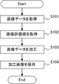
図3は、システムコントローラ204が実施する、画像データの取得から加工画像の記録までの処理を示すフローチャートである。図4は、撮像部101から出力される画像データ400の一例を示している。図5は、記憶部207に保存される加工画像404の一例を示している。
FIG. 3 is a flowchart showing a process from acquisition of image data to recording of processed images performed by the
ステップS101では、システムコントローラ204は、撮像部101から画像データ400を取得する。画像データ400は、撮像部101a〜101dの出力画像401a〜401dから成る。出力画像401a〜401dにはそれぞれ、画像分析領域402a〜402d、及び画像加工領域403a〜403dが予め定められている。画像分析領域、及び画像加工領域は、任意の位置、形状、及び大きさでよく、図4に示される範囲に限定するものではない。
In step S101, the
ステップS102では、システムコントローラ204は、画像分析部205から画像分析領域402a〜402dにおける画像評価値を取得する。本実施形態では、画像分析部205は、画像分析領域402a〜402dにおける画像評価値として色平均値を算出する。なお、画像分析部205は、色平均値ではなく、例えば平均輝度値や、他の色や輝度値に関する情報等を算出してもよい。また、画像分析部205は、平均値ではなく、ヒストグラムを生成してもよい。
In step S102, the
ステップS103では、システムコントローラ204は、画像加工部206にステップS102で取得した画像評価値を用いて画像加工領域403a〜403dに加工を施させる。本実施形態では、画像加工部206は、画像分析領域402a〜402dにおける色平均値を用いて、対応する出力画像ではない出力画像内の画像加工領域403a〜403dに対して所定の加工を施す。例えば、画像加工部206は、出力画像401a内の画像分析領域402aにおける色平均値を用いて、出力画像401b内の画像加工領域403bに対して加工を施す。同様に、画像加工部206は、画像分析領域402b,402c,403dにおける色平均値を用いて画像加工領域403c,403d,403aに対して加工を施す。なお、画像分析領域と画像加工領域の組合せは上記の組合せに限定されるものではなく、任意の組合せでよいものとする。
In step S103, the
本実施形態では、画像加工部206は、色平均値を数値データとして対象とする画像加工領域内に記載する。例えば、(赤,緑,青)=(64,128,192)のように、画像データ400内に上書きするように表示される。なお、画像加工領域の加工方法はこれに限定するものではない。例えば、色平均値と同じ色になるように画像加工領域の色を変色してもよいし、ハッシュ関数を用いたハッシュ値を記載してもよい。また、画像評価値は、画像データ400に対する上書きではなく、重畳や合成等の任意の方法で表現すればよい。
In the present embodiment, the
ステップS104では、システムコントローラ204は、生成された加工画像404を記憶部207に保存する。
In step S104, the
図6は、システムコントローラ204が実施する、加工画像404をクライアント装置301に送信するまでの処理を示すフローチャートである。
FIG. 6 is a flowchart showing a process performed by the
ステップS201では、システムコントローラ204は、記憶部207に保存された加工画像404を読み出す。
In step S201, the
ステップS202では、システムコントローラ204は、画像分析部205から画像分析領域402a〜402dにおける画像評価値を再取得する。
In step S202, the
ステップS203では、システムコントローラ204は、ステップS202で再取得した画像評価値と、加工画像404に表記された画像評価値とが一致するかどうかを判断する。一致する場合、ステップS204に進み、一致しない場合、ステップS205に進む。
In step S203, the
ステップS204では、システムコントローラ204は、加工画像404をクライアント装置301に送信する。
In step S204, the
ステップS205では、システムコントローラ204は、クライアント装置301に対して、エラー通知を送信し、加工画像404の送信を中断する。エラー通知には、一致しない旨の情報や、データが改竄された可能性がある旨の情報等が含まれていてもよい。
In step S205, the
このように、第1の出力画像における画像評価値を、第2の出力画像内に付随させることで、互いの画像データの信憑性を撮影後、一定の時間が経過してから示すことができる。例えば、再取得した画像評価値と、加工画像に表記された評価値とが一致しない場合、出力画像のいずれかが編集された可能性が高く、データの改竄を検出することが可能になる。 In this way, by attaching the image evaluation value in the first output image to the second output image, the credibility of each other's image data can be shown after a certain period of time has passed after shooting. .. For example, if the re-acquired image evaluation value does not match the evaluation value displayed on the processed image, it is highly possible that one of the output images has been edited, and it becomes possible to detect falsification of the data.
なお、本実施形態では、加工画像を送信する際に、システムコントローラ204によりデータの改竄を検出しているが、本発明はこれに限定されない。例えば、クライアント装置301における不図示の制御部が画像分析及びデータ照合を実施してもよい。
In the present embodiment, the falsification of data is detected by the
また、本実施形態では、画像データの信憑性に関する情報を外部装置に送信するが、撮像装置100の不図示の表示部に表示するようにしてもよい。
[その他の実施例]
本発明は、上述の実施例の1以上の機能を実現するプログラムを、ネットワーク又は記憶媒体を介してシステム又は装置に供給し、そのシステム又は装置のコンピュータにおける1つ以上のプロセッサがプログラムを読出し実行する処理でも実現可能である。また、1以上の機能を実現する回路(例えば、ASIC)によっても実現可能である。
Further, in the present embodiment, the information regarding the credibility of the image data is transmitted to the external device, but it may be displayed on a display unit (not shown) of the
[Other Examples]
The present invention supplies a program that realizes one or more functions of the above-described embodiment to a system or device via a network or storage medium, and one or more processors in the computer of the system or device reads and executes the program. It can also be realized by the processing to be performed. It can also be realized by a circuit (for example, ASIC) that realizes one or more functions.
以上、本発明の好ましい実施形態について説明したが、本発明はこれらの実施形態に限定されず、その要旨の範囲内で種々の変形及び変更が可能である。 Although the preferred embodiments of the present invention have been described above, the present invention is not limited to these embodiments, and various modifications and modifications can be made within the scope of the gist thereof.
100 撮像装置
101 撮像部
103 制御部(処理装置)
205 画像分析部(取得部)
206 画像加工部(加工部)
100 Imaging device 101
205 Image Analysis Department (Acquisition Department)
206 Image processing section (processing section)
Claims (7)
前記第1の撮像部によって取得される第1の画像データに関する情報を取得する取得部と、
前記第1の画像データに関する情報が付随するように前記第2の撮像部によって取得される第2の画像データを加工する加工部とを有することを特徴とする処理装置。 A processing device that processes image data from an image pickup device including a first image pickup unit and a second image pickup unit.
An acquisition unit that acquires information about the first image data acquired by the first image pickup unit, and an acquisition unit.
A processing apparatus comprising: a processing unit that processes a second image data acquired by the second image pickup unit so that information regarding the first image data is accompanied.
前記記憶部から前記第2の画像データを読み出して外部装置に送信可能な制御部とを更に有し、
前記制御部は、
前記記憶部から前記第2の画像データを読み出す場合、前記取得部から前記第1の画像データに関する情報を取得し、
前記取得部から取得した前記第1の画像データに関する情報と、前記第2の画像データに付随する前記第1の画像データに関する情報とが一致する場合、前記第2の画像データを前記外部装置に送信し、
前記取得部から取得した前記第1の画像データに関する情報と、前記第2の画像データに付随する前記第1の画像データに関する情報とが一致しない場合、エラー通知を前記外部装置に送信することを特徴とする請求項1に記載の処理装置。 A storage unit that stores the second image data processed by the processing unit, and a storage unit.
It further has a control unit capable of reading the second image data from the storage unit and transmitting it to an external device.
The control unit
When reading the second image data from the storage unit, information about the first image data is acquired from the acquisition unit, and the information is obtained.
When the information regarding the first image data acquired from the acquisition unit and the information regarding the first image data accompanying the second image data match, the second image data is transferred to the external device. Send and
If the information regarding the first image data acquired from the acquisition unit and the information regarding the first image data accompanying the second image data do not match, an error notification is transmitted to the external device. The processing apparatus according to claim 1.
前記第2の画像データは、第2の画像分析領域、および第2の画像加工領域を含み、
前記取得部は、前記第1の画像分析領域に関する情報を取得し、
前記加工部は、前記第1の画像分析領域に関する情報を用いて前記第2の画像加工領域を加工することを特徴とする請求項1乃至4の何れか一項に記載の処理装置。 The first image data includes a first image analysis area and a first image processing area.
The second image data includes a second image analysis area and a second image processing area.
The acquisition unit acquires information regarding the first image analysis area and obtains information.
The processing apparatus according to any one of claims 1 to 4, wherein the processing unit processes the second image processing region by using the information regarding the first image analysis region.
前記第1の撮像部と異なる撮影方向を向くように配置された第2の撮像部と、
前記第1の撮像部によって取得される第1の画像データに関する情報を取得する取得部と、
前記第1の画像データに関する情報が付随するように前記第2の撮像部によって取得される第2の画像データを加工する加工部とを有することを特徴とする撮像装置。 The first image pickup unit and
A second image pickup unit arranged so as to face a different shooting direction from the first image pickup unit,
An acquisition unit that acquires information about the first image data acquired by the first image pickup unit, and an acquisition unit.
An image pickup apparatus comprising: a processing unit that processes a second image data acquired by the second image pickup unit so that information regarding the first image data is accompanied.
前記第1の撮像部によって取得される第1の画像データに関する情報を取得するステップと、
前記第1の画像データに関する情報が付随するように前記第2の撮像部によって取得される第2の画像データを加工するステップとを有することを特徴とする処理方法。
It is a processing method for processing image data from an image pickup apparatus including a first image pickup unit and a second image pickup unit.
A step of acquiring information about the first image data acquired by the first image pickup unit, and
A processing method comprising a step of processing a second image data acquired by the second image pickup unit so as to be accompanied by information regarding the first image data.
Priority Applications (3)
| Application Number | Priority Date | Filing Date | Title |
|---|---|---|---|
| JP2020096371A JP2021190925A (en) | 2020-06-02 | 2020-06-02 | Processing apparatus, image pickup apparatus, and processing method |
| US17/331,229 US11375096B2 (en) | 2020-06-02 | 2021-05-26 | Authenticating images from a plurality of imaging units |
| EP21176450.1A EP3920526A1 (en) | 2020-06-02 | 2021-05-28 | Processing apparatus, image pickup apparatus, and processing method |
Applications Claiming Priority (1)
| Application Number | Priority Date | Filing Date | Title |
|---|---|---|---|
| JP2020096371A JP2021190925A (en) | 2020-06-02 | 2020-06-02 | Processing apparatus, image pickup apparatus, and processing method |
Publications (2)
| Publication Number | Publication Date |
|---|---|
| JP2021190925A true JP2021190925A (en) | 2021-12-13 |
| JP2021190925A5 JP2021190925A5 (en) | 2023-05-31 |
Family
ID=76180908
Family Applications (1)
| Application Number | Title | Priority Date | Filing Date |
|---|---|---|---|
| JP2020096371A Withdrawn JP2021190925A (en) | 2020-06-02 | 2020-06-02 | Processing apparatus, image pickup apparatus, and processing method |
Country Status (3)
| Country | Link |
|---|---|
| US (1) | US11375096B2 (en) |
| EP (1) | EP3920526A1 (en) |
| JP (1) | JP2021190925A (en) |
Family Cites Families (10)
| Publication number | Priority date | Publication date | Assignee | Title |
|---|---|---|---|---|
| JP2000196984A (en) | 1998-12-24 | 2000-07-14 | Hitachi Maxell Ltd | Digital camera |
| US20020063711A1 (en) | 1999-05-12 | 2002-05-30 | Imove Inc. | Camera system with high resolution image inside a wide angle view |
| US20130120602A1 (en) * | 2011-11-14 | 2013-05-16 | Microsoft Corporation | Taking Photos With Multiple Cameras |
| US9253433B2 (en) | 2012-11-27 | 2016-02-02 | International Business Machines Corporation | Method and apparatus for tagging media with identity of creator or scene |
| KR20140094878A (en) | 2013-01-23 | 2014-07-31 | 삼성전자주식회사 | User termial and method for image processing by using recognition of user in the user terminal |
| KR102063102B1 (en) | 2013-08-19 | 2020-01-07 | 엘지전자 주식회사 | Mobile terminal and control method for the mobile terminal |
| US10609028B2 (en) | 2017-12-12 | 2020-03-31 | Nagravision S.A. | Securing digital data transmission in a communication network |
| CN111144181A (en) | 2018-11-06 | 2020-05-12 | 天地融科技股份有限公司 | Risk detection method, device and system based on background collaboration |
| CN110650321B (en) | 2019-10-24 | 2021-05-04 | 黄芸芸 | Block chain technology-based video content tamper-proof, loss-proof and recovery method |
| US20210279469A1 (en) * | 2020-03-05 | 2021-09-09 | Qualcomm Incorporated | Image signal provenance attestation |
-
2020
- 2020-06-02 JP JP2020096371A patent/JP2021190925A/en not_active Withdrawn
-
2021
- 2021-05-26 US US17/331,229 patent/US11375096B2/en active Active
- 2021-05-28 EP EP21176450.1A patent/EP3920526A1/en not_active Withdrawn
Also Published As
| Publication number | Publication date |
|---|---|
| EP3920526A1 (en) | 2021-12-08 |
| US11375096B2 (en) | 2022-06-28 |
| US20210377429A1 (en) | 2021-12-02 |
Similar Documents
| Publication | Publication Date | Title |
|---|---|---|
| KR102306304B1 (en) | Dual camera-based imaging method and device and storage medium | |
| JP7185434B2 (en) | Electronic device for capturing images using multiple cameras and image processing method using the same | |
| US8937667B2 (en) | Image communication apparatus and imaging apparatus | |
| KR101246738B1 (en) | Image processing apparatus and image processing method, and data processing apparatus and data processing method | |
| KR102318013B1 (en) | Electronic device composing a plurality of images and method | |
| EP3414763A1 (en) | Systems and methods for hdr video capture with a mobile device | |
| US20160295107A1 (en) | Imaging system, warning generation device and method, imaging device and method, and program | |
| JP2017208616A (en) | Image processing apparatus, image processing method, and program | |
| JP2017011634A (en) | Imaging device, control method for the same and program | |
| KR20120048242A (en) | 3d camera | |
| KR20190025373A (en) | Method for controlling synchronization of multiple image sensors and electronic device implementing the same | |
| JP5896680B2 (en) | Imaging apparatus, image processing apparatus, and image processing method | |
| JP2009077090A (en) | Imaging apparatus, imaging system, and image reading system | |
| WO2018186255A1 (en) | Information processing device, information processing method, program, and recording medium | |
| JP5190882B2 (en) | Compound eye photographing apparatus, control method therefor, and program | |
| JP2021190925A (en) | Processing apparatus, image pickup apparatus, and processing method | |
| JP6790038B2 (en) | Image processing device, imaging device, control method and program of image processing device | |
| JP6257260B2 (en) | Imaging apparatus and control method thereof | |
| JP2013162348A (en) | Imaging apparatus | |
| JP2019169985A (en) | Image processing apparatus | |
| JP6934987B2 (en) | Image processing equipment, image processing methods, and programs | |
| JP2013046395A (en) | Image capturing apparatus, control method therefor, program, and recording medium | |
| JP2013128165A (en) | Imaging apparatus | |
| US20230333362A1 (en) | Apparatus And Method For Combined Use Of Two Independent Monoculars | |
| WO2021152711A1 (en) | Interval imaging device |
Legal Events
| Date | Code | Title | Description |
|---|---|---|---|
| A521 | Request for written amendment filed |
Free format text: JAPANESE INTERMEDIATE CODE: A523 Effective date: 20230522 |
|
| A621 | Written request for application examination |
Free format text: JAPANESE INTERMEDIATE CODE: A621 Effective date: 20230522 |
|
| A761 | Written withdrawal of application |
Free format text: JAPANESE INTERMEDIATE CODE: A761 Effective date: 20231102 |