JP2021159709A - Game machine - Google Patents
Game machine Download PDFInfo
- Publication number
- JP2021159709A JP2021159709A JP2020067823A JP2020067823A JP2021159709A JP 2021159709 A JP2021159709 A JP 2021159709A JP 2020067823 A JP2020067823 A JP 2020067823A JP 2020067823 A JP2020067823 A JP 2020067823A JP 2021159709 A JP2021159709 A JP 2021159709A
- Authority
- JP
- Japan
- Prior art keywords
- effect
- display
- symbol
- displayed
- image
- Prior art date
- Legal status (The legal status is an assumption and is not a legal conclusion. Google has not performed a legal analysis and makes no representation as to the accuracy of the status listed.)
- Pending
Links
- 230000000694 effects Effects 0.000 claims description 2373
- 238000000034 method Methods 0.000 description 431
- 230000008569 process Effects 0.000 description 363
- 230000008859 change Effects 0.000 description 218
- 238000004519 manufacturing process Methods 0.000 description 125
- 238000003860 storage Methods 0.000 description 110
- 230000000875 corresponding effect Effects 0.000 description 82
- 238000012545 processing Methods 0.000 description 63
- 238000001514 detection method Methods 0.000 description 41
- 230000002844 continuous effect Effects 0.000 description 32
- 230000004044 response Effects 0.000 description 32
- 230000006870 function Effects 0.000 description 19
- 230000033001 locomotion Effects 0.000 description 19
- 230000009467 reduction Effects 0.000 description 18
- 230000005540 biological transmission Effects 0.000 description 17
- 238000010924 continuous production Methods 0.000 description 14
- 239000003086 colorant Substances 0.000 description 13
- 230000001276 controlling effect Effects 0.000 description 13
- 230000007423 decrease Effects 0.000 description 13
- 230000002093 peripheral effect Effects 0.000 description 11
- 238000010586 diagram Methods 0.000 description 10
- 238000011161 development Methods 0.000 description 9
- 230000018109 developmental process Effects 0.000 description 9
- PCHJSUWPFVWCPO-UHFFFAOYSA-N gold Chemical compound [Au] PCHJSUWPFVWCPO-UHFFFAOYSA-N 0.000 description 9
- 239000010931 gold Substances 0.000 description 9
- 229910052737 gold Inorganic materials 0.000 description 9
- NJPPVKZQTLUDBO-UHFFFAOYSA-N novaluron Chemical compound C1=C(Cl)C(OC(F)(F)C(OC(F)(F)F)F)=CC=C1NC(=O)NC(=O)C1=C(F)C=CC=C1F NJPPVKZQTLUDBO-UHFFFAOYSA-N 0.000 description 9
- 238000005034 decoration Methods 0.000 description 7
- KRQUFUKTQHISJB-YYADALCUSA-N 2-[(E)-N-[2-(4-chlorophenoxy)propoxy]-C-propylcarbonimidoyl]-3-hydroxy-5-(thian-3-yl)cyclohex-2-en-1-one Chemical compound CCC\C(=N/OCC(C)OC1=CC=C(Cl)C=C1)C1=C(O)CC(CC1=O)C1CCCSC1 KRQUFUKTQHISJB-YYADALCUSA-N 0.000 description 6
- 230000004048 modification Effects 0.000 description 5
- 238000012986 modification Methods 0.000 description 5
- 230000003068 static effect Effects 0.000 description 4
- 241001025261 Neoraja caerulea Species 0.000 description 3
- 238000013459 approach Methods 0.000 description 3
- 230000006835 compression Effects 0.000 description 3
- 238000007906 compression Methods 0.000 description 3
- 229910003460 diamond Inorganic materials 0.000 description 3
- 239000010432 diamond Substances 0.000 description 3
- 238000010304 firing Methods 0.000 description 3
- 230000001151 other effect Effects 0.000 description 3
- 238000009987 spinning Methods 0.000 description 3
- 238000012546 transfer Methods 0.000 description 3
- 241000270295 Serpentes Species 0.000 description 2
- 230000001174 ascending effect Effects 0.000 description 2
- 230000004397 blinking Effects 0.000 description 2
- 230000003247 decreasing effect Effects 0.000 description 2
- 238000013461 design Methods 0.000 description 2
- 239000011521 glass Substances 0.000 description 2
- 239000004973 liquid crystal related substance Substances 0.000 description 2
- 238000005259 measurement Methods 0.000 description 2
- 230000002265 prevention Effects 0.000 description 2
- 238000005096 rolling process Methods 0.000 description 2
- 230000001360 synchronised effect Effects 0.000 description 2
- 230000002195 synergetic effect Effects 0.000 description 2
- 230000008685 targeting Effects 0.000 description 2
- 125000002066 L-histidyl group Chemical group [H]N1C([H])=NC(C([H])([H])[C@](C(=O)[*])([H])N([H])[H])=C1[H] 0.000 description 1
- 238000005452 bending Methods 0.000 description 1
- 230000008901 benefit Effects 0.000 description 1
- 238000012790 confirmation Methods 0.000 description 1
- 230000000994 depressogenic effect Effects 0.000 description 1
- 230000004373 eye development Effects 0.000 description 1
- 210000003128 head Anatomy 0.000 description 1
- 230000006872 improvement Effects 0.000 description 1
- 230000008450 motivation Effects 0.000 description 1
- 230000003287 optical effect Effects 0.000 description 1
- 238000003825 pressing Methods 0.000 description 1
- 230000002441 reversible effect Effects 0.000 description 1
- 239000000725 suspension Substances 0.000 description 1
- 230000002123 temporal effect Effects 0.000 description 1
- 238000002834 transmittance Methods 0.000 description 1
- 230000001960 triggered effect Effects 0.000 description 1
Images


Abstract
Description
本発明は、演出の実行を制御する演出制御手段を備える遊技機に関する。 The present invention relates to a gaming machine provided with effect control means for controlling the execution of effect.
例えばパチンコ遊技機等の遊技機では、始動口に遊技球が入賞すると、遊技者に有利な特別遊技を実行するか否かが判定され、図柄を変動表示した後に上記判定の結果を示す図柄が停止表示される。この種の遊技機の中には、特別図柄の停止表示に伴ってチャンス目と呼ばれる3つの装飾図柄を停止表示するチャンス目演出を実行するものがある(例えば特許文献1参照)。 For example, in a gaming machine such as a pachinko gaming machine, when a game ball wins a prize at the starting port, it is determined whether or not to execute a special game that is advantageous to the player, and after the symbols are displayed in a variable manner, a symbol showing the result of the above determination is displayed. Stop is displayed. In this type of gaming machine, there is one that executes a chance eye effect of stopping and displaying three decorative symbols called chance eyes in association with the stop display of the special symbol (see, for example, Patent Document 1).
ところで、従来の遊技機で行われる演出は必ずしも十分な興趣性を有しているとは言えず、更なる興趣性の向上が求められている。 By the way, it cannot be said that the production performed by the conventional gaming machine has sufficient interest, and further improvement of the interest is required.
それ故に、本発明の目的は、興趣性が高い演出を実行可能な遊技機を提供することである。 Therefore, an object of the present invention is to provide a gaming machine capable of performing a highly entertaining effect.
前述の課題を解決するための第1発明の遊技機は、
遊技者に有利な特別遊技を実行するか否かの判定を行う判定手段と、
前記判定が行われると、所定の図柄表示手段に特別図柄を変動表示させてから前記判定の結果を示す特別図柄を停止表示させる図柄表示制御手段と、
演出の実行を制御する演出制御手段と、を備えることを特徴とするものである。
The gaming machine of the first invention for solving the above-mentioned problems is
Judgment means for determining whether or not to execute a special game that is advantageous to the player,
When the determination is made, the symbol display control means for causing the predetermined symbol display means to display the special symbol in a variable manner and then stopping and displaying the special symbol indicating the result of the determination.
It is characterized in that it is provided with an effect control means for controlling the execution of the effect.
この発明によれば、興趣性が高い演出を実行可能である。 According to the present invention, it is possible to carry out a highly interesting production.
以下、適宜図面を参照しつつ、本発明の遊技機の一実施形態に係る遊技機(パチンコ遊技機)1について説明する。 Hereinafter, a gaming machine (pachinko gaming machine) 1 according to an embodiment of the gaming machine of the present invention will be described with reference to the drawings as appropriate.
[遊技機1の構成例]
まず、図1,2を参照しつつ、遊技機1の構成例について説明する。ここで、図1は遊技機1の正面図であり、図2は遊技盤2の正面図である。図1,2に示されるように、遊技機1は、遊技機枠30と、遊技機枠30内に取り付けられた遊技盤2とを備えている。遊技機枠30は、装飾面を有する前面枠31と、遊技盤2等を取り付けるための本体枠と、遊技機1をホールの島設備に固定するための外枠とを有して構成されている。前面枠31は、遊技盤2と所定の間隔を隔てて平行に配置されたガラス板を支持しており、このガラス板と遊技盤2とによって、遊技球が流下可能な遊技領域3が形成されている。
[Configuration example of gaming machine 1]
First, a configuration example of the
また、図1に示されるように、前面枠31には、遊技球を発射させるための発射ハンドル32と、発射装置(不図示)へ供給される遊技球を貯留する上皿33と、上皿33に貯留しきれない遊技球を貯留する下皿34とが設けられている。遊技者が発射ハンドル32を握って時計回りに回転させると、上皿33に貯留されていた遊技球が発射装置へと案内され、発射ハンドル32の回転角度に応じた発射強度で発射される。発射された遊技球は、遊技領域3の左側に位置するレール部材4に沿って移動した後に遊技領域3の上部位置へと案内され、遊技領域3に設けられた遊技クギや風車等に接触することでその移動方向を変化させながら遊技盤2に沿って遊技領域3を流下する。
Further, as shown in FIG. 1, the
なお、レール部材4の終端には球戻り防止片6が設けられており、この球戻り防止片6によって、一旦遊技領域3に進入した遊技球が発射装置側に戻ることが防止される。また、発射ハンドル32と近接する位置に停止ボタンが設けられており、遊技者は、この停止ボタンを操作することによって、発射ハンドル32を初期姿勢に戻さなくても遊技球の発射を一時的に停止させることが可能である。
A ball
遊技者が発射ハンドル32を小さい回転角度だけ回転させる「左打ち」を行うと、遊技球が相対的に弱い発射強度で発射され、この遊技球は、左遊技領域3Lを流下する。一方、遊技者が発射ハンドル32を大きい回転角度だけ回転させる「右打ち」を行うと、遊技球が相対的に強い発射強度で発射され、この遊技球は、センター装飾体10の右上方に位置するレール部材4に沿って移動した後に右遊技領域3Rを流下する。
When the player performs "left-handed" by rotating the
左遊技領域3Lにおける遊技球の通過経路には、入賞や判定に関する役物として、第1始動口21、第2始動口22、開閉部材23、及び3つの一般入賞口24が設けられている(図2参照)。また、右遊技領域3Rにおける遊技球の通過経路には、入賞や判定に関する役物として、上記第2始動口22、上記開閉部材23、1つの一般入賞口24、ゲート25、第1大入賞口26、開閉部材27、第2大入賞口28、及び開閉部材29が設けられている(図2参照)。
The passage path of the game ball in the
発射装置から発射された遊技球は、遊技盤2に沿って遊技領域3を流下する過程で、第1始動口21、第2始動口22、一般入賞口24、第1大入賞口26、及び第2大入賞口28のいずれかに入賞する場合がある。この場合、入賞した箇所に応じた所定数の賞球が上皿33または下皿34に払い出される。なお、いずれにも入賞しなかった遊技球は、遊技盤2の下端部に形成された排出口を介して遊技領域3から排出される。
In the process of flowing down the
なお、遊技盤2の中央に形成された開口部には、センター装飾体10が設けられている。このセンター装飾体10は、遊技球が転動可能な遊技球転動面を有するステージ部11と、ワープ入口およびワープ出口を両端とするワープ部12とを有して構成されている。左遊技領域3Lを流下する遊技球は、ワープ入口からワープ部12に進入する場合があり、この遊技球は、ワープ出口から排出されてステージ部11へと案内される。このステージ部11の左右中央の位置には、ステージ部11上を転動する遊技球を第1始動口21に向けて落下させる案内溝が形成されている。このため、ワープ部12を介してステージ部11へと案内された遊技球は、ワープ部12を通過することなく左遊技領域3Lを流下する遊技球に比べて、第1始動口21に入賞し易い。
A center
第1始動口21は、常時開放されている始動領域である。第2始動口22は、普通電動役物としての開閉部材23が作動していないときには閉塞されており、開閉部材23が作動することによって開放される始動領域である。遊技機1では、遊技球が第1始動口21(又は第2始動口22)に入賞した場合、遊技者に有利な特別遊技(大当たり遊技)を実行するか否かが判定される。そして、後述する第1特別図柄表示器41(又は第2特別図柄表示器42)において、図柄が変動表示され、上記判定の結果を示す図柄(大当たり図柄またはハズレ図柄)が停止表示される。ここで、大当たり図柄が停止表示された場合、第1大入賞口26または第2大入賞口28を開放する大当たり遊技が実行される。
The
なお、以下の説明では、第1始動口21に対する遊技球の入賞に応じて実行される判定を「第1特別図柄判定」と呼び、第2始動口22に対する遊技球の入賞に応じて実行される判定を「第2特別図柄判定」と呼び、これらを総称して「特別図柄判定」と呼ぶものとする。
In the following description, the determination executed in response to the winning of the game ball for the
第1大入賞口26は、特別図柄判定の結果に応じて開放される特別入賞領域である。この第1大入賞口26の開口部には、第1大入賞口26を開閉するプレートである開閉部材27が設けられている。第1大入賞口26は、通常はこの開閉部材27によって閉塞されている。これに対して、第1特別図柄表示器41(又は第2特別図柄表示器42)に所定の大当たり図柄が停止表示された場合、開閉部材27を作動させて第1大入賞口26を開放する大当たり遊技が実行される。この大当たり遊技中は、開閉部材27が第1大入賞口26を開放する開姿勢(図2参照)を維持してから第1大入賞口26を閉塞する閉姿勢に戻る長開放ラウンド遊技が複数回行われる。なお、第1大入賞口26を開放する各長開放ラウンド遊技は、本実施形態では、第1大入賞口26に10個の遊技球が入賞するか、或いは、第1大入賞口26が開放されてから25秒が経過するまで継続する。
The first large winning
第2大入賞口28は、特別図柄判定の結果に応じて開放される特別入賞領域である。この第2大入賞口28の開口部には、第2大入賞口28を開閉する羽根部材である開閉部材29が設けられている。第2大入賞口28は、通常はこの開閉部材29によって閉塞されている。これに対して、第1特別図柄表示器41(又は第2特別図柄表示器42)に所定の大当たり図柄が停止表示された場合、開閉部材29を作動させて第2大入賞口28を開放する大当たり遊技が実行される。この大当たり遊技中は、開閉部材29が第2大入賞口28を開放する開姿勢(図2参照)を維持してから第2大入賞口28を閉塞する閉姿勢に戻る長開放ラウンド遊技が複数回行われる。なお、第2大入賞口28を開放する各長開放ラウンド遊技は、本実施形態では、第2大入賞口28に10個の遊技球が入賞するか、或いは、第2大入賞口28が開放されてから25秒が経過するまで継続する。
The second large winning
このように、大当たり遊技中は第1大入賞口26(又は第2大入賞口28)を長開放する複数回の長開放ラウンド遊技が行われるため、遊技者は、大当たり遊技中に右打ちを行うことで、大当たり遊技が行われていないときに比べてより多くの賞球を得ることができる。 In this way, during the jackpot game, a plurality of long-opening round games in which the first prize opening 26 (or the second winning opening 28) is opened for a long time are performed, so that the player hits right during the jackpot game. By doing so, more prize balls can be obtained than when the jackpot game is not performed.
なお、説明の便宜上、図2には、画像表示装置7の表示画面70において演出図柄が変動表示されているときに、開閉部材27,29が大入賞口26,28を開放する開姿勢となっている状態が図示されているが、実際には、演出図柄の変動表示中に開閉部材27,29が開姿勢となることはない。また、長開放ラウンド遊技では、第1大入賞口26および第2大入賞口28のいずれか一方が用いられるため、実際には、図2に示されるようにこれらの大入賞口が同時に開放されることはない。また、第1大入賞口26と第2大入賞口28のどちらの大入賞口を用いて大当たり遊技を行うかは、大当たりの種類に応じて予め設定されている。
For convenience of explanation, FIG. 2 shows an open posture in which the opening /
第2始動口22には開閉部材23(図2参照)が近接配置されている。この開閉部材23は、開閉部材23が第2始動口22を閉塞する閉姿勢と、第2始動口22を開放する開姿勢(図2参照)とに姿勢変化可能である。
An opening / closing member 23 (see FIG. 2) is arranged close to the
第2始動口22は、通常は開閉部材23によって閉塞されている。これに対して、遊技者が右打ちした遊技球がゲート25を通過すると、賞球は払い出されないものの、第2始動口22を開放するか否かの判定が行われる。ここで、第2始動口22を開放すると判定された場合、開閉部材23が所定時間開姿勢を維持した後に閉姿勢に戻る動作が規定回数行われる。このように、第2始動口22は、開閉部材23が作動していないときには遊技球が通過し難い状態であるのに対して、開閉部材23が作動することによって遊技球が通過し易い状態となる。
The
なお、以下の説明では、ゲート25に対する遊技球の通過を条件として実行される判定を「普通図柄判定」と呼ぶものとする。
In the following description, the determination executed on the condition that the game ball passes through the
一般入賞口24は、第1始動口21と同様に常時開放されており、遊技球の入賞によって所定個数の賞球が払い出される入賞口である。ただし、第1始動口21等とは異なり、一般入賞口24に遊技球が入賞しても判定が行われることはない。
The general winning
[主表示器40の構成例]
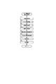
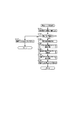
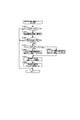
図3は、図2における主表示器40の拡大図である。図3に例示されるように、主表示器40は、第1特別図柄表示器41、第2特別図柄表示器42、普通図柄表示器43、第1特図保留表示器44、第2特図保留表示器45、普図保留表示器46、ラウンド表示器47、遊技状態表示器48、発射方向表示器49等を有して構成されている。
[Configuration example of main display 40]
FIG. 3 is an enlarged view of the
第1特別図柄表示器41は、「i〜p」で示す8個のLEDを有して構成されており、第1特別図柄判定が行われると、図柄を変動表示してから第1特別図柄判定の判定結果を示す図柄を停止表示することによって第1特別図柄判定の判定結果を報知する。具体的には、例えば、上記8個のLEDを順に点灯させることで図柄の変動表示を行い、第1特別図柄判定の判定結果に応じた組み合わせで各LEDを所定の確定時間(例えば0.6秒間)点灯させることによって図柄を停止表示する。
The first
第2特別図柄表示器42は、「a〜h」で示す8個のLEDを有して構成されており、第2特別図柄判定が行われると、図柄を変動表示してから第2特別図柄判定の判定結果を示す図柄を停止表示することによって第2特別図柄判定の判定結果を報知する。具体的には、例えば、上記8個のLEDを順に点灯させることで図柄の変動表示を行い、第2特別図柄判定の判定結果に応じた組み合わせで各LEDを所定の確定時間(例えば0.6秒間)点灯させることによって図柄を停止表示する。
The second
第1特別図柄表示器41(又は第2特別図柄表示器42)には、第1特別図柄判定(又は第2特別図柄判定)の判定結果を示す図柄として、大当たりであることを報知する「大当たり図柄」、又はハズレであることを報知する「ハズレ図柄」が停止表示される。なお、遊技機1では、大当たりの種類によって互いに異なる複数の大当たり図柄が用意されており、大当たり図柄が停止表示された場合、その大当たり図柄の種類に応じた開放パターンで第1大入賞口26または第2大入賞口28を開放する大当たり遊技が行われる。
The first special symbol display 41 (or the second special symbol display 42) is notified that it is a jackpot as a symbol indicating the determination result of the first special symbol determination (or the second special symbol determination). "Symbol" or "Loss symbol" notifying that it is lost is stopped and displayed. In the
普通図柄表示器43は、「s〜t」で示す2個のLEDを有して構成されており、普通図柄判定が行われると、図柄を変動表示してから普通図柄判定の判定結果を示す図柄を停止表示することによって普通図柄判定の判定結果を報知する。具体的には、例えば、上記2個のLEDを交互に点灯させることで図柄の変動表示を行い、普通図柄判定の判定結果に応じた点灯態様で各LEDを所定時間(例えば0.5秒間)点灯させることによって図柄を停止表示する。ここで、当たり図柄が停止表示された場合、現在の遊技状態に応じた開放パターンで開閉部材23を動作させることによって第2始動口22を開放する補助遊技が行われる。
The
なお、以下の説明では、第1特別図柄表示器41や第2特別図柄表示器42に表示される図柄を「特別図柄」と呼び、普通図柄表示器43に表示される図柄を「普通図柄」と呼ぶものとする。また、第1特別図柄表示器41に表示される特別図柄を「第1特別図柄」と呼び、第2特別図柄表示器42に表示される特別図柄を「第2特別図柄」と呼んで両者を区別する場合がある。
In the following description, the symbol displayed on the first
第1特図保留表示器44は、「u〜v」で示す2個のLEDを有して構成されており、これらのLEDの点灯態様によって第1特別図柄判定の保留数を表示する。第2特図保留表示器45は、「w〜x」で示す2個のLEDを有して構成されており、これらのLEDの点灯態様によって第2特別図柄判定の保留数を表示する。なお、本実施形態では、これらの保留数の上限がいずれも「4」に設定されている。普図保留表示器46は、「q〜r」で示す2個のLEDを有して構成されており、これらのLEDの点灯態様によって普通図柄判定の保留数を表示する。
The first special
ラウンド表示器47は、第1特別図柄表示器41または第2特別図柄表示器42に大当たり図柄が停止表示されるのに伴って、その大当たり図柄に対応する大当たりに応じて実行される大当たり遊技における長開放ラウンド遊技のラウンド数を表示する。このラウンド表示器47は、4R用LEDと、6R用LEDと、8R用LEDと、10R用LEDとを有して構成されており、これらのLEDのいずれかが点灯することによって、長開放ラウンド遊技のラウンド数が報知される。
The
遊技状態表示器48は、「a1〜a3」で示す3個のLEDを有して構成されており、これらのLEDの点灯態様によって遊技機1の遊技状態を表示する。発射方向表示器49は、「y〜z」で示す2個のLEDを有して構成されており、これらのLEDの点灯態様によって遊技球の発射方向を表示する。すなわち、左打ちを行うべき状態であるか、或いは右打ちを行うべき状態であるかを表示する。
The
[遊技機1が備える演出手段の構成例]
図1,2に例示されるように、遊技盤2や前面枠31には、各種の演出を行うものとして、装飾部材13、可動装飾部材14、枠ランプ37、スピーカ38、演出表示器125、演出第1特図保留表示器126、演出第2特図保留表示器127等が設けられている。また、遊技盤2の後方には、画像表示装置7が設けられている。
[Structure example of the production means included in the gaming machine 1]
As illustrated in FIGS. 1 and 2, the
装飾部材13は、複数のLEDを有して構成される盤面ランプ5(図4参照)を内蔵しており、各LEDの点灯や点滅のパターンを変更したり、各LEDの発光色を変更したりすることによって、光による各種の演出を行う。
The
可動装飾部材14は、画像表示装置7の前方であって且つ装飾部材13の後方に配置されている。この可動装飾部材14には複数のLEDが内蔵されており、可動装飾部材14は、可動装飾部材14自体の動きと光の両方或いは一方によって所定の演出を行う。本実施形態では、遊技盤2と画像表示装置7の表示画面70との間に、可動装飾部材14が動作可能な所定の空間が設けられており、可動装飾部材14は、表示画面70に沿って上下動可能に構成されている。可動装飾部材14は、通常は、その大部分が装飾部材13の後ろに隠れて可動装飾部材14の下端部だけが視認可能な初期位置(図2参照)に配置されている。これに対して、可動装飾部材14は、例えば、画像表示装置7やスピーカ38を用いて大当たり信頼度が相対的に高い予告演出が実行される際や、大当たりを示唆する際に、所定の発光パターンで発光すると共に表示画面70の大部分を覆う動作位置へと落下する。
The movable
枠ランプ37は、前面枠31の各所に内蔵された複数のLEDを有して構成されており、各LEDの点灯や点滅のパターンを変更したり、各LEDの発光色を変更したりすることによって、光による各種の演出を行う。
The
画像表示装置7は、その表示画面70に演出画像を表示する液晶表示装置であり、遊技者は、遊技盤2の中央部に形成された開口部を通して表示画面70を視認可能である。この表示画面70には、特別図柄判定の判定結果を報知する演出図柄、キャラクタやアイテム、第1特別図柄判定(又は第2特別図柄判定)の保留数と同じ数だけ表示される保留画像(保留アイコン)、特別図柄の変動表示中であることを示唆する変動示唆画像(当該アイコン)等の各種表示オブジェクトを含む演出画像が表示される。なお、画像表示装置7は、演出画像を表示可能なものであれば液晶表示装置に限らず、EL表示装置等の他の画像表示装置であってもよい。
The
スピーカ38は、表示画面70上で行われる表示演出と同期するように、或いは非同期に、楽曲や音声、効果音といった演出音を出力して音による演出を行う。
The
演出表示器125は、2個のLEDを有して構成されており、特別図柄および演出図柄の変動表示に伴って図柄を変動表示し、特別図柄および演出図柄の停止表示に伴って特別図柄判定の判定結果を報知する図柄を停止表示する。この演出表示器125は、各LEDの点灯・消灯の組み合わせや点灯色によって、特別図柄判定の判定結果を報知する。
The
演出第1特図保留表示器126は、2個のLEDを有して構成されており、各LEDの点灯・消灯の組み合わせによって、第1特図保留表示器44に表示されるのと同じ第1特別図柄判定の保留数を表示する。演出第2特図保留表示器127は、2個のLEDを有して構成されており、各LEDの点灯・消灯の組み合わせによって、第2特図保留表示器45に表示されるのと同じ第2特別図柄判定の保留数を表示する。
The first special
[遊技機1が備える入力手段の構成例]
図1に例示されるように、前面枠31には、遊技者による入力が可能な入力手段として、第1演出ボタン35および第2演出ボタン36が設けられている。第1演出ボタン35は、遊技者が押下することによって操作情報を入力するための押ボタンである。第2演出ボタン36は、遊技者が第2演出ボタン36の把持部を把持して第2演出ボタン36を押し込むことによって操作情報を入力するための押ボタンである。遊技機1では、第1演出ボタン35や第2演出ボタン36の操作に応じた演出が行われることがある。
[Structure example of input means included in gaming machine 1]
As illustrated in FIG. 1, the
また、第1演出ボタン35には、第1演出ボタン35を発光させる複数のLEDから構成される第1演出ボタンランプ352(図4参照)が内蔵され、第2演出ボタン36には、第2演出ボタン36を発光させる複数のLEDから構成される第2演出ボタンランプ362(図4参照)が内蔵されている。遊技機1では、第1演出ボタン35の操作が有効な有効期間中に第1演出ボタン35の操作を遊技者に促すために、第1演出ボタンランプ352が複数の発光色のうちのいずれかの発光色で発光する。また、この第1演出ボタン35には、第1演出ボタン35を振動させる偏心モータから構成される振動モータ353が内蔵されており、遊技機1では、大当たりを報知する演出図柄が表示画面70に表示されるのに伴って第1演出ボタン35が振動することで大当たりが報知される。また、遊技機1では、第2演出ボタン36の操作が有効な有効期間中に第2演出ボタン36の操作を遊技者に促すために、第2演出ボタンランプ362が複数の発光色のうちのいずれかの発光色で発光する。
Further, the
なお、入力手段の構成は本実施形態で例示するものに限らず、他のものであってもよい。すなわち、例えば、本実施形態では、遊技機1が2つの入力手段を備える場合について説明するが、入力手段は1つ或いは3つ以上であってもよい。また、押ボタンに限らず、遊技者のタッチ操作を検知可能なタッチパネル、例えば表示画面70に対してかざされた遊技者の手を検知可能な光センサ、前後左右に動かして位置や方向を指定するジョイスティック、遊技者が把持して姿勢変化させることが可能な入力手段といった他の入力手段であってもよい。
The configuration of the input means is not limited to the one illustrated in this embodiment, and may be another one. That is, for example, in the present embodiment, the case where the
[遊技機1が備える制御装置の構成]
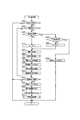
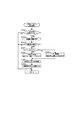
図4は、遊技機1が備える制御装置の構成例を示すブロック図である。
遊技盤2の裏側には、遊技機1の動作を制御する制御装置が設けられている。図4に例示されるように、遊技機1の制御装置は、遊技球を用いる遊技の進行を制御するメイン制御基板80、メイン制御基板80からの情報に基づいて演出を統括的に制御するサブ制御基板90、画像や音による演出を制御する画像音響制御基板100、各種のランプや可動部材による演出を制御するランプ制御基板120等から構成されている。本実施形態では、メイン制御基板80が遊技の進行を制御する遊技制御部として機能し、サブ制御基板90、画像音響制御基板100、及びランプ制御基板120が演出を制御する演出制御部として機能する。なお、制御装置の構成はこれに限定されるものではなく、例えばサブ制御基板90、画像音響制御基板100、及びランプ制御基板120が1つの基板で構成されていてもよい。
[Configuration of control device included in gaming machine 1]
FIG. 4 is a block diagram showing a configuration example of a control device included in the
On the back side of the
<メイン制御基板80の構成例>
メイン制御基板80は、メインCPU81、メインROM82、及びメインRAM83を備えている。メインCPU81は、メインROM82に記憶されているプログラム等に基づいて、判定や払い出し賞球数に関連する各種の演算処理を行う。メインRAM83は、メインCPU81が上記プログラムを実行する際に用いる各種データを一時的に記憶する記憶領域やデータ処理などの作業領域として使用される。
<Structure example of
The
メイン制御基板80には、第1始動口センサ211、第2始動口センサ221、ゲートセンサ251、第1大入賞口センサ261、第2大入賞口センサ281、一般入賞口センサ241、第2始動口ソレノイド222、第1大入賞口ソレノイド262、第2大入賞口ソレノイド282が接続されている。なお、本実施形態の遊技機1は、4つの一般入賞口24に対応する4つの一般入賞口センサ241を備えているが、図4では、説明の便宜上、一般入賞口センサ241が1つだけ表記されている。
The
第1始動口センサ211は、第1始動口21に遊技球が入賞したことを検知して、その検知信号をメイン制御基板80に出力する。第2始動口センサ221は、第2始動口22に遊技球が入賞したことを検知して、その検知信号をメイン制御基板80に出力する。ゲートセンサ251は、ゲート25に対する遊技球の通過を検知して、その検知信号をメイン制御基板80に出力する。第1大入賞口センサ261は、第1大入賞口26に遊技球が入賞したことを検知して、その検知信号をメイン制御基板80に出力する。第2大入賞口センサ281は、第2大入賞口28に遊技球が入賞したことを検知して、その検知信号をメイン制御基板80に出力する。一般入賞口センサ241は、一般入賞口24に遊技球が入賞したことを検知して、その検知信号をメイン制御基板80に出力する。
The first
第2始動口ソレノイド222は、開閉部材23に対して駆動力を伝達可能に連結された電動ソレノイドであり、メイン制御基板80からの制御信号に基づいて開閉部材23を動作させて、第2始動口22を開閉する。第1大入賞口ソレノイド262は、開閉部材27に対して駆動力を伝達可能に連結された電動ソレノイドであり、メイン制御基板80からの制御信号に基づいて開閉部材27を動作させて、第1大入賞口26を開閉する。第2大入賞口ソレノイド282は、開閉部材29に対して駆動力を伝達可能に連結された電動ソレノイドであり、メイン制御基板80からの制御信号に基づいて開閉部材29を動作させて、第2大入賞口28を開閉する。
The second
図には示されていないが、遊技機1は、遊技盤2の裏面側に設けられた球タンクから遊技球を送り出す駆動モータを制御して上皿33又は下皿34に遊技球を供給する払出制御基板を備えている。メインCPU81は、第1始動口センサ211、第2始動口センサ221、第1大入賞口センサ261、第2大入賞口センサ281、又は一般入賞口センサ241からの検知信号が入力されると、遊技球が入賞した箇所に応じた所定数の賞球の払い出しを払出制御基板に指示し、また、払出制御基板からの情報に基づいて、払い出す賞球の個数を管理する。
Although not shown in the figure, the
また、メインCPU81は、第1始動口センサ211からの検知信号が入力されたタイミングで取得情報としての各種乱数を取得し、取得した乱数を用いて第1特別図柄判定を実行する。また、メインCPU81は、第2始動口センサ221からの検知信号が入力されたタイミングで取得情報としての各種乱数を取得し、取得した乱数を用いて第2特別図柄判定を実行する。ここで、各種乱数とは、具体的には、大当たり乱数、図柄乱数、リーチ乱数、及び変動パターン乱数である。
Further, the main CPU 81 acquires various random numbers as acquisition information at the timing when the detection signal from the first
大当たり乱数は、大当たり又はハズレを決定するための乱数である。図柄乱数は、大当たりであると判定された場合に、大当たりの種類(大当たり遊技のラウンド数や大当たり遊技終了後の遊技状態など)を決定するための乱数である。リーチ乱数は、ハズレであると判定された場合に、リーチ有り演出を行うか或いはリーチ無し演出を行うかを決定するための乱数である。変動パターン乱数は、特別図柄が変動表示される際の特別図柄の変動パターンを決定するための乱数である。 The jackpot random number is a random number for determining a jackpot or a loss. The symbol random number is a random number for determining the type of jackpot (the number of rounds of the jackpot game, the game state after the jackpot game, etc.) when it is determined to be a jackpot. The reach random number is a random number for determining whether to perform the effect with reach or the effect without reach when it is determined that there is a loss. The variation pattern random number is a random number for determining the variation pattern of the special symbol when the special symbol is displayed in a variable manner.
メインCPU81は、第1始動口21(又は第2始動口22)に遊技球が入賞したタイミングでこれらの乱数を取得し、先ず、取得した大当たり乱数が、メインROM82に記憶されている所定の乱数値(当選値)と一致するか否かに基づいて、大当たり遊技を実行するか否かを判定する。ここで、大当たり乱数が当選値と一致したことに基づいて大当たり遊技を実行すると判定した場合、上記大当たり乱数と一緒に取得した図柄乱数が、メインROM82に記憶されている(図柄乱数と比較される)所定の乱数値のどの乱数値と一致するかに基づいて、大当たりの種類を決定する。 The main CPU 81 acquires these random numbers at the timing when the game ball wins the first start port 21 (or the second start port 22), and first, the acquired jackpot random numbers are stored in the main ROM 82 as a predetermined random number. It is determined whether or not to execute the jackpot game based on whether or not it matches the numerical value (winning value). Here, when it is determined that the jackpot game is executed based on the fact that the jackpot random number matches the winning value, the symbol random number acquired together with the jackpot random number is stored in the main ROM 82 (compared with the symbol random number). ) Determine the type of jackpot based on which random number value of a predetermined random number matches.
ここで、大当たりの種類としては、4回の長開放ラウンド遊技を含む大当たり遊技を実行した後に確変遊技状態で遊技が制御される「4R確変大当たり」、6回の長開放ラウンド遊技を含む大当たり遊技を実行した後に確変遊技状態で遊技が制御される「6R確変大当たり」、8回の長開放ラウンド遊技を含む大当たり遊技を実行した後に確変遊技状態で遊技が制御される「8R確変大当たり」、10回の長開放ラウンド遊技を含む大当たり遊技を実行した後に確変遊技状態で遊技が制御される「10R確変大当たり」が一例として挙げられる。 Here, as the types of jackpots, "4R probabilistic jackpot" in which the game is controlled in the probabilistic game state after executing the jackpot game including four long-open round games, and the jackpot game including six long-open round games. "6R probability variation jackpot" in which the game is controlled in the probability variation game state after executing, "8R probability variation jackpot" in which the game is controlled in the probability variation game state after executing the jackpot game including eight long open round games, 10 An example is "10R probability variation jackpot" in which the game is controlled in the probability variation game state after executing the jackpot game including the long open round game.
一方、メインCPU81は、取得した大当たり乱数が当選値と一致しなかったことに基づいて大当たり遊技を実行しないと判定した場合、その大当たり乱数と一緒に取得したリーチ乱数が、メインROM82に記憶されている(リーチ乱数と比較される)所定の乱数値(リーチ有りに対応する乱数値)と一致するか否かに基づいて、リーチ有り演出を行うか、或いはリーチ無し演出を行うかを決定する。また、メインCPU81は、大当たり乱数に基づく判定の結果に関わらず、大当たり乱数と一緒に取得した変動パターン乱数に基づいて、特別図柄を変動表示する際の特別図柄の変動パターンを決定する。これにより、特別図柄の変動時間が決定されることになる。 On the other hand, when the main CPU 81 determines that the jackpot game is not executed based on the fact that the acquired jackpot random number does not match the winning value, the reach random number acquired together with the jackpot random number is stored in the main ROM 82. Based on whether or not it matches a predetermined random number value (random number value corresponding to with reach) (compared with the reach random number), it is determined whether to perform the effect with reach or the effect without reach. Further, the main CPU 81 determines the fluctuation pattern of the special symbol when displaying the special symbol in a variable manner based on the fluctuation pattern random number acquired together with the jackpot random number, regardless of the result of the determination based on the jackpot random number. As a result, the fluctuation time of the special symbol is determined.
メインCPU81は、大当たり遊技を実行すると判定して、大当たりの種類を決定した場合、第1大入賞口ソレノイド262(又は第2大入賞口ソレノイド282)を介して第1大入賞口26(又は第2大入賞口28)の開閉を制御することによって、大当たりの種類に応じた大当たり遊技を実行する。 When the main CPU 81 determines that the jackpot game is to be executed and determines the type of jackpot, the first jackpot 26 (or the second) via the first jackpot solenoid 262 (or the second jackpot solenoid 282). By controlling the opening and closing of the two major winning openings 28), a jackpot game according to the type of jackpot is executed.
また、メインCPU81は、ゲートセンサ251からの検知信号が入力されたタイミングで乱数(普通図柄乱数)を取得し、取得した普通図柄乱数を用いて普通図柄判定を実行する。そして、この普通図柄判定の結果として第2始動口22を開放すると判定した場合、第2始動口ソレノイド222を介して第2始動口22の開閉を制御することによって、第2始動口22を開放する補助遊技を実行する。
Further, the main CPU 81 acquires a random number (ordinary symbol random number) at the timing when the detection signal from the
また、メイン制御基板80には、第1特別図柄表示器41、第2特別図柄表示器42、普通図柄表示器43、第1特図保留表示器44、第2特図保留表示器45、普図保留表示器46、ラウンド表示器47、遊技状態表示器48、発射方向表示器49が接続されている。
Further, the
メインCPU81は、主表示器40を構成するこれらの表示器41〜49を制御して、図3に基づいて上述した表示処理を実行させる。
The main CPU 81 controls these
<サブ制御基板90の構成例>
サブ制御基板90は、サブCPU91、サブROM92、サブRAM93、及びRTC(リアルタイムクロック)94を備えている。サブCPU91は、サブROM92に記憶されているプログラムに基づいて、演出を制御する際の演算処理を行う。サブRAM93は、サブCPU91が上記プログラムを実行する際に用いる各種データを一時的に記憶する記憶領域やデータ処理などの作業領域として使用される。RTC94は、現時点の日時(日付や時刻)を計測する。
<Configuration example of
The
サブ制御基板90には、第1演出ボタン35(図1参照)が操作(押下)された場合に、その旨を示す操作情報(操作信号)をサブ制御基板90に出力する第1演出ボタン検知センサ351が接続されている。例えば、遊技者によって押下される第1演出ボタン35の操作部材には遮光片が設けられており、第1演出ボタン検知センサ351は、操作部材が押し下げられた操作位置に配置された際に上記遮光片を検知して、その検知信号(操作信号)をサブ制御基板90に出力するフォトインタラプタにより構成されている。サブCPU91は、有効期間中に第1演出ボタン検知センサ351からの操作信号が1回入力されたことに基づいて、第1演出ボタン35が「単押し」されたことを特定可能である。また、サブCPU91は、有効期間中に第1演出ボタン検知センサ351からの操作信号が断続的に複数回入力されたことに基づいて、第1演出ボタン35が「連打」されたことを特定可能である。また、第1演出ボタン検知センサ351からは、操作(押下)されていた第1演出ボタン35の操作部材が操作位置から初期位置に復帰した場合に、その旨を示す操作情報(復帰信号)がサブ制御基板90に出力される。このため、サブCPU91は、第1演出ボタン検知センサ351からの操作信号が入力されてから所定時間(例えば0.8秒)が経過しても復帰信号が入力されなかったことに基づいて、第1演出ボタン35が「長押し」されていることを特定可能である。
When the first effect button 35 (see FIG. 1) is operated (pressed) on the
また、サブ制御基板90には、第2演出ボタン36(図1参照)が操作された場合に、その旨を示す操作情報(操作信号)をサブ制御基板90に出力する第2演出ボタン検知センサ361が接続されている。遊技者によって前方に押し込まれる第2演出ボタン36の操作部材には遮光片が設けられており、第2演出ボタン検知センサ361は、操作部材が押し込まれた操作位置に配置された際に上記遮光片を検知して、その検知信号(操作信号)をサブ制御基板90に出力するフォトインタラプタにより構成されている。
Further, when the second effect button 36 (see FIG. 1) is operated on the
サブCPU91は、メイン制御基板80から送信される特別図柄判定や普通図柄判定、大当たり遊技等に関する遊技情報に基づいて演出内容を設定する。その際、第1演出ボタン35や第2演出ボタン36からの操作情報の入力を受け付けて、その操作情報に応じた演出内容を設定する場合もある。サブCPU91は、設定した演出内容の演出の実行を指示するコマンドを画像音響制御基板100およびランプ制御基板120に送信する。
The
<画像音響制御基板100の構成例>
画像音響制御基板100は、画像表示装置7による画像表示の制御と、スピーカ38による演出音の出力の制御とを行うものである。この画像音響制御基板100は、本実施形態では、画像音響制御CPU101、制御ROM102、制御RAM103、VDP(Video Display Processor)104、CGROM105、VRAM106、音響DSP(Digital Signal Processor)107、音響ROM108、SDRAM109、及びアンプ110を備えている。
<Structure example of image /
The image /
制御ROM102は、マスクROMで構成されており、画像音響制御CPU101の制御プログラム、ディスプレイリストを生成するためのディスプレイリスト生成プログラム、ディスプレイリストを作成する処理に使用されるディスプレイリスト作成テーブル等の各種テーブルが記憶されている。ここで、ディスプレイリストは、フレーム単位で描画の実行を指示するためのコマンド群で構成されており、描画する画像の種類、画像を描画する位置(座標)、表示の優先順位、表示倍率、回転角、透過率等の各種パラメータを含むものである。制御RAM103は、画像音響制御CPU101が上記制御プログラムを実行する際に用いる各種データを一時的に記憶する記憶領域やデータ処理などの作業領域として使用される。
The
画像音響制御CPU101は、上記制御プログラムやディスプレイリスト作成テーブル等の各種テーブル、サブ制御基板90から受信したコマンド等に基づいて、VDP104に対して、CGROM105に記憶されている画像データ(演出データ)を画像表示装置7に表示させる指示を行う。この指示は、主にディスプレイリストの出力によって行われる。また、画像音響制御CPU101は、音響DSP107に対して、音響ROM108に記憶されている音響データをスピーカ38から出力させる指示を行う。
The image /
CGROM105は、特別図柄の変動表示に伴う変動演出や大当たり遊技に伴う演出等を実行するために必要な演出データを記憶するものである。このCGROM105は、フラッシュメモリ、EEPROM、EPROM、マスクROM等から構成され、所定範囲の画素(例えば32×32ピクセル)における画素情報の集まりからなるスプライトデータ(1枚の画像データ)、複数の画像データの集まりからなるムービーデータ等を圧縮して記憶している。なお、画素情報は、それぞれの画素毎に色番号を指定する色番号情報と画像の透明度を示すα値とから構成されている。また、CGROM105は、色番号を指定する色番号情報と実際に色を表示するための表示色情報とが対応づけられたパレットデータ等を圧縮せずに記憶している。
The
なお、CGROM105に記憶される画像データの一部のみを圧縮しておくようにしてもよい。また、ムービーデータの圧縮方法としては、MPEG4等の公知の種々の圧縮方式を用いることができる。
It should be noted that only a part of the image data stored in the
VRAM106は、画像データを高速に書き込んだり読み出したりすることができるSRAMで構成されており、図には示されていないが、ディスプレイリスト記憶領域、展開記憶領域、フレームバッファ等を有して構成されている。
The
ディスプレイリスト記憶領域は、画像音響制御CPU101から出力されたディスプレイリストを一時的に記憶するものである。展開記憶領域は、CGROM105から読み出された後に伸長された画像データを記憶するものである。フレームバッファは、表示画面70に表示される画像データの描画および表示に兼用されるフレームバッファである。
The display list storage area temporarily stores the display list output from the image /
VDP104は、CGROM105に圧縮された状態で記憶されている画像データを伸長して、伸長した画像データを展開記憶領域に格納する。また、VDP104は、ディスプレイリスト記憶領域に記憶されたディスプレイリストに基づいて、展開記憶領域に格納した画像データを用いて、フレームバッファに対する描画処理を行う。また、VDP104は、フレームバッファに記憶された画像データから画像の色を示す映像信号としてのRGB信号を生成して、生成したRGB信号を画像表示装置7に出力する。
The
音響DSP107には、音響ROM108、SDRAM109、及びアンプ110が接続されている。音響ROM108は、楽曲や音声、効果音、警告音等に関する各種音響データを記憶している。SDRAM109は、音響DSP107によるデータ処理等の作業領域として使用されるものである。音響DSP107は、画像音響制御CPU101からの指示に対応する音響データを音響ROM108からSDRAM109に読み出してデータ処理を実行し、データ処理後の音響データを(アンプ110を介して)スピーカ38に出力する。アンプ110は、画像音響制御CPU101から音響DSP107を介して得られる音量に関する指示に従って音量を調整して音響データをスピーカ38に出力させる。
An
なお、本実施形態では、VDPが描画管理を担うと共に音響DSPがサウンド管理を担う場合について説明するが、他の実施形態では、VDPが描画管理とサウンド管理との両方を担うような構成を採用してもよい。この場合、音響DSPを別途設ける必要はない。 In this embodiment, the case where the VDP is responsible for drawing management and the acoustic DSP is responsible for sound management will be described, but in other embodiments, a configuration is adopted in which the VDP is responsible for both drawing management and sound management. You may. In this case, it is not necessary to separately provide an acoustic DSP.
<ランプ制御基板120の構成例>
ランプ制御基板120は、ランプCPU121、ランプROM122、及びランプRAM123を備え、枠ランプ37、盤面ランプ5、可動装飾部材14、演出表示器125、演出第1特図保留表示器126、演出第2特図保留表示器127、第1演出ボタンランプ352、第2演出ボタンランプ362、及び振動モータ353が接続されている。ランプROM122は、ランプCPU121によって実行されるプログラム、発光パターンデータ、動作パターンデータ、振動パターンデータ等を記憶している。ここで、発光パターンデータは、枠ランプ37、盤面ランプ5、可動装飾部材14に内蔵されたLED等のそれぞれの発光パターンを示すデータである。動作パターンデータは、可動装飾部材14等の動作パターンを示すデータである。振動パターンデータは、振動モータ353の駆動力によって振動する第1演出ボタン35の振動パターンを示すデータである。
<Structure example of
The
ランプCPU121は、ランプROM122に記憶されているプログラムに基づいて、枠ランプ37、盤面ランプ5、可動装飾部材14、演出表示器125、演出第1特図保留表示器126、演出第2特図保留表示器127等の動作を制御する際の演算処理を行う。
Based on the program stored in the
ランプCPU121は、ランプROM122に記憶されている発光パターンデータの中から、サブ制御基板90から受信したコマンドに対応する発光パターンデータをランプRAM123に読み出して、枠ランプ37、盤面ランプ5、可動装飾部材14に内蔵されたLED、第1演出ボタンランプ352、第2演出ボタンランプ362の発光を制御する。また、ランプCPU121は、ランプROM122に記憶されている動作パターンデータの中から、サブ制御基板90から受信したコマンドに対応する動作パターンデータをランプRAM123に読み出して、可動装飾部材14を動作させるモータの駆動を制御する。また、ランプCPU121は、ランプROM122に記憶されている振動パターンデータの中から、サブ制御基板90から受信したコマンドに対応する振動パターンデータをランプRAM123に読み出して、振動モータ353の駆動を制御する。
The
また、ランプCPU121は、サブ制御基板90からのコマンドに基づいて、演出表示器125における図柄の変動表示および停止表示を制御する。また、ランプCPU121は、サブ制御基板90からのコマンドに基づいて、演出第1特図保留表示器126による第1特別図柄判定に係る保留数の表示、演出第2特図保留表示器127による第2特別図柄判定に係る保留数の表示を制御する。
Further, the
[遊技状態について]
次に、図5を参照しつつ、遊技機1の遊技状態や遊技の流れについて説明する。ここで、図5は、遊技機1の遊技状態について説明するための説明図である。図5に例示されるように、遊技機1は、本実施形態では、「通常遊技状態」、「確変遊技状態」、及び「時短遊技状態」の3つの遊技状態のいずれかの遊技状態で遊技が制御される。
[About game status]
Next, the gaming state and the game flow of the
「通常遊技状態」は、大当たり遊技を実行すると判定される確率が相対的に低い低確率状態で特別図柄判定が行われると共に、第2始動口22に対する遊技球の入賞をサポートするサポート機能(いわゆる「電サポ」等と呼ばれる機能)が付与されない遊技状態である。通常遊技状態では、特別図柄判定によって大当たり遊技を実行すると判定される確率が相対的に低い確率(例えば1/200)に設定される。また、普通図柄判定によって第2始動口22を開放すると判定される確率が相対的に低い確率(例えば1/11)に設定され、普通図柄の変動時間が相対的に長い時間(例えば20秒)に設定され、且つ第2始動口22を開放すると判定された場合の第2始動口22の開放時間が相対的に短い時間(例えば0.1秒×1回)に設定される。
The "normal game state" is a support function (so-called) that supports a winning of a game ball for the
「確変遊技状態」は、大当たり遊技を実行すると判定される確率が相対的に高い高確率状態で特別図柄判定が行われると共に、上記サポート機能が付与される遊技状態である。すなわち、確変遊技状態では、特別図柄判定によって大当たり遊技を実行すると判定される確率が相対的に高い確率(例えば1/80)に設定される。また、普通図柄判定によって第2始動口22を開放すると判定される確率が相対的に高い確率(例えば11/11)に設定され、普通図柄の変動時間が相対的に短い時間(例えば1.5秒)に設定され、且つ第2始動口22を開放すると判定された場合の第2始動口22の開放時間が相対的に長い時間(例えば1.5秒×3回)に設定される。
The "probability variation game state" is a game state in which the special symbol determination is performed in a high probability state in which the probability of being determined to execute the jackpot game is relatively high, and the above support function is provided. That is, in the probabilistic game state, the probability that the jackpot game will be executed by the special symbol determination is set to a relatively high probability (for example, 1/80). Further, the probability that the
「時短遊技状態」は、上記低確率状態で特別図柄判定が行われると共に、上記サポート機能が付与される遊技状態である。すなわち、時短遊技状態では、特別図柄判定によって大当たり遊技を実行すると判定される確率が相対的に低い確率(例えば1/200)に設定される。また、普通図柄判定によって第2始動口22を開放すると判定される確率が相対的に高い確率(例えば11/11)に設定され、普通図柄の変動時間が相対的に短い時間(例えば1.5秒)に設定され、且つ第2始動口22を開放すると判定された場合の第2始動口22の開放時間が相対的に長い時間(例えば1.5秒×3回)に設定される。
The "time saving game state" is a game state in which the special symbol determination is performed in the low probability state and the support function is provided. That is, in the time-saving game state, the probability that the jackpot game will be executed by the special symbol determination is set to a relatively low probability (for example, 1/200). Further, the probability that the
特別図柄の変動時間に関してこれらの遊技状態を比較すると、「通常遊技状態」における特別図柄の変動時間に比べて、「確変遊技状態」や「時短遊技状態」における特別図柄の変動時間の方が相対的に短い時間に設定され易い。なお、各遊技状態の説明で示した、特別遊技を実行すると判定される確率(大当たり確率)、第2始動口22を開放すると判定される確率(普通図柄判定の当選確率)、普通図柄の変動時間、第2始動口22の開放時間は単なる一例であって、他の確率や時間であってもよいことは言うまでもない。
Comparing these gaming states with respect to the variation time of the special symbol, the variation time of the special symbol in the "probability variation game state" and the "short-time gaming state" is relative to the variation time of the special symbol in the "normal gaming state". It is easy to set a short time. In addition, the probability of being determined to execute the special game (big hit probability), the probability of being determined to open the second starting port 22 (probability of winning the normal symbol determination), and the variation of the normal symbol shown in the explanation of each game state. Needless to say, the time and the opening time of the
なお、以下の説明では、上記サポート機能が付与されていることによって第2始動口22への遊技球の入賞が容易な状態を「高ベース状態」と呼び、サポート機能が付与されていないことによって第2始動口22への遊技球の入賞が困難な状態を「低ベース状態」と呼ぶものとする。
In the following description, a state in which the game ball can easily win a prize in the
[遊技の流れ]
遊技者が右打ちした遊技球は、第1始動口21には入賞せず、第2始動口22に入賞し得る。しかしながら、低ベース状態のときには、第2始動口22が開放され難く、開放されたとしてもその開放時間は極めて短い。このため、低ベース状態(本実施形態では「通常遊技状態」がこれに該当)で遊技が制御されているときには、遊技者は、第1始動口21を狙った左打ちにより遊技を行うことになる。
[Game flow]
The game ball hit right by the player does not win the
通常遊技状態のときに左打ちされた遊技球が第1始動口21に入賞すると、第1特別図柄判定が実行され、第1特別図柄が変動表示されてから第1特別図柄判定の判定結果を示す第1特別図柄として、大当たり図柄またはハズレ図柄が停止表示される。
When the left-handed game ball wins the
ここで、ハズレ図柄が停止表示された場合は、大当たり遊技が行われることはなく、遊技状態も変化しない。一方、第1特別図柄として大当たり図柄が停止表示された場合、その大当たり図柄に応じた所定回数の長開放ラウンド遊技を行う大当たり遊技が実行され、大当たり遊技終了後は、確変遊技状態または時短遊技状態で遊技が制御されることになる。 Here, when the lost symbol is stopped and displayed, the jackpot game is not performed and the game state does not change. On the other hand, when the jackpot symbol is stopped and displayed as the first special symbol, a jackpot game in which a predetermined number of long open round games are performed according to the jackpot symbol is executed, and after the jackpot game is completed, a probabilistic game state or a time-saving game state is executed. The game will be controlled by.
なお、特別図柄判定の判定結果が大当たりであることを報知する大当たり図柄(特別図柄)としては、確変大当たりを報知する「確変図柄」と、通常大当たりを報知する「通常図柄」とが用意されている。そして、通常遊技状態における第1特別図柄判定の判定結果が大当たりであることを報知する大当たり図柄として、「確変図柄」が停止表示された場合は大当たり遊技終了後に確変遊技状態で遊技が制御され、「通常図柄」が停止表示された場合は大当たり遊技終了後に通常遊技状態で遊技が制御される(図5参照)。 As the jackpot symbol (special symbol) for notifying that the judgment result of the special symbol determination is a jackpot, a "probability variation symbol" for notifying the probability variation jackpot and a "normal symbol" for notifying the normal jackpot are prepared. There is. Then, as a jackpot symbol for notifying that the determination result of the first special symbol determination in the normal game state is a jackpot, when the "probability variation symbol" is stopped and displayed, the game is controlled in the probability variation game state after the jackpot game ends. When the "normal symbol" is stopped and displayed, the game is controlled in the normal game state after the jackpot game ends (see FIG. 5).
また、大当たり遊技終了を契機として遊技状態が確変遊技状態または時短遊技状態に移行した場合、すなわち、低ベース状態から高ベース状態に移行した場合、第2始動口22への遊技球の入賞を容易にする上記のサポート機能によって、第1始動口21よりも第2始動口22の方が、遊技球が入賞し易くなる。このため、高ベース状態(本実施形態では「確変遊技状態」または「時短遊技状態」がこれに該当)で遊技が制御されているときには、遊技者は、第2始動口22を狙った右打ちにより遊技を行うことになる。このため、確変遊技状態または時短遊技状態で遊技が制御されているときには、基本的には、第2特別図柄判定が行われる。
In addition, when the game state shifts to the probabilistic game state or the time-saving game state when the jackpot game ends, that is, when the game state shifts from the low base state to the high base state, it is easy to win the game ball to the
また、本実施形態の遊技機1は、実質的に次回の大当たりまで確変遊技状態が継続するように構成されており、この確変遊技状態において第2特別図柄として「確変図柄」が停止表示された場合には、大当たり遊技終了後に再び確変遊技状態で遊技が制御される。一方、確変遊技状態において第2特別図柄として「通常図柄」が停止表示された場合には、大当たり遊技終了後は時短遊技状態で遊技が制御される。
Further, the
また、時短遊技状態において第2特別図柄として「確変図柄」が停止表示された場合には、大当たり遊技終了後は確変遊技状態で遊技が制御され、「通常図柄」が停止表示された場合には、大当たり遊技終了後は再び時短遊技状態で遊技が制御される。一方、時短遊技状態のときに規定回数(本実施形態では100回)の第2特別図柄判定(又は第1特別図柄判定)が行われても大当たりが発生しなかった場合は、遊技状態が時短遊技状態から通常遊技状態に戻されることになる。 In addition, when the "probability variation symbol" is stopped and displayed as the second special symbol in the time-saving game state, the game is controlled in the probability variation game state after the jackpot game is completed, and when the "normal symbol" is stopped and displayed. After the jackpot game is over, the game is controlled again in the time-saving game state. On the other hand, if a big hit does not occur even if the second special symbol determination (or the first special symbol determination) is performed a specified number of times (100 times in this embodiment) in the time-saving game state, the game state is shortened. It will be returned from the game state to the normal game state.
[変動演出について]
次に、通常遊技状態において第1特別図柄が変動表示されてから停止表示されるのに伴って、表示画面70等を用いて行われる変動演出について説明する。
[About variable production]
Next, a variation effect performed using the
遊技機1では、第1始動口21に遊技球が入賞して第1特別図柄判定が実行されると、第1特別図柄表示器41において、第1特別図柄が変動表示されてから第1特別図柄判定の判定結果を示す第1特別図柄が停止表示される。表示画面70には、第1特別図柄判定の判定結果を報知する演出図柄が表示される演出図柄表示領域73(図2参照)が設けられており、表示画面70では、第1特別図柄の変動表示に伴って、演出図柄の変動表示を含む変動演出が行われる(図2参照)。そして、第1特別図柄判定が実行された際に選択された変動パターンに応じた変動時間だけ第1特別図柄が変動表示されると、この第1特別図柄が停止表示されるのに伴って、第1特別図柄判定の判定結果を示す態様で演出図柄が停止表示される。
In the
このような演出図柄の変動表示中には、いわゆるリーチ演出が行われる場合がある。具体的には、表示画面70の演出図柄表示領域73には、例えば、1〜9の数字が下から上へ縦方向に連続して記された演出図柄の図柄列の一部が横方向に3列表示されており、第1特別図柄の変動表示が開始されると、これらの図柄列が上から下へスクロールするように変動表示(スクロール表示)される(例えば、図9(B)参照)。これに対して、リーチ演出が行われる場合には、全ての演出図柄が停止表示されるのに先立って、まず、例えば左列の演出図柄(左図柄)と右列の演出図柄(右図柄)が順番に、或いは同時に、完全には停止しないように擬似停止する。図2には、左図柄として3図柄が擬似停止すると共に右図柄として同じく3図柄が擬似停止し、中列の図柄列がスクロール表示を継続している状態が例示されている。なお、擬似停止とは、演出図柄をほとんど移動させずにその場で揺動させる演出であり、以下の説明では、演出図柄を完全に静止させる本停止(単に「停止表示」と呼ぶ場合もある)と区別する場合には、擬似停止と呼ぶ場合がある。
A so-called reach effect may be performed during such a variable display of the effect symbol. Specifically, in the effect
左図柄および右図柄として同じ演出図柄が有効ライン上に擬似停止するとリーチ成立となり、同一の演出図柄が3つ揃うことを遊技者に期待させるリーチ演出が行われる。このリーチ演出は、例えば、リーチ図柄(左図柄および右図柄)を擬似停止させた状態で中列の図柄列をスクロールさせ、最終的に、リーチ図柄と共通する中図柄、又はリーチ図柄とは異なる中図柄を有効ライン上に停止させて当落を報知する演出である。 When the same effect symbol as the left symbol and the right symbol is pseudo-stopped on the effective line, the reach is established, and the reach effect is performed to expect the player to have three identical effect symbols. This reach effect is different from, for example, the middle symbol that is common to the reach symbol or the reach symbol by scrolling the symbol row in the middle row while the reach symbols (left symbol and right symbol) are pseudo-stopped. It is a production that stops the middle symbol on the effective line and notifies the winning.
なお、詳細な説明は省略するが、このようなリーチ演出には、演出図柄の他に、キャラクタやアイテムといった他の表示オブジェクトが用いられる。また、以下の説明では、リーチ演出が行われる変動演出において、リーチが成立するまでに行われる演出を「リーチ前演出」と呼ぶ場合がある。 Although detailed description is omitted, other display objects such as characters and items are used for such a reach effect in addition to the effect symbol. Further, in the following description, in the variable effect in which the reach effect is performed, the effect performed until the reach is established may be referred to as "pre-reach effect".
リーチ演出の種類については後に詳述するが、第1特別図柄判定の判定結果が「ハズレ」である場合、ハズレを報知すべくリーチハズレ目(例えば「323」)を示す3つの演出図柄が擬似停止し、第1特別図柄としてハズレ図柄が停止表示されるのに伴って、これら3つの演出図柄が本停止する。一方、第1特別図柄判定の判定結果が「ハズレ」であってリーチ演出が行われない場合には、ハズレを報知すべくバラケ目(例えば「629」)を示す3つの演出図柄が擬似停止し、第1特別図柄としてハズレ図柄が停止表示されるのに伴って、これら3つの演出図柄が本停止する。このように、大当たり遊技を実行しないと判定された場合、ハズレを示すリーチハズレ目またはバラケ目を示す3つの演出図柄を擬似停止させてから本停止させてハズレ(大当たり遊技が実行されないこと)を報知するハズレ報知演出が実行される。 The types of reach effects will be described in detail later, but when the determination result of the first special symbol determination is "loss", three effect symbols indicating reach loss eyes (for example, "323") are pseudo-stopped in order to notify the loss. Then, as the lost symbol is stopped and displayed as the first special symbol, these three effect symbols are stopped. On the other hand, when the determination result of the first special symbol determination is "missing" and the reach effect is not performed, the three effect symbols indicating the disparity (for example, "629") are pseudo-stopped in order to notify the loss. , As the lost symbol is stopped and displayed as the first special symbol, these three effect symbols are stopped. In this way, when it is determined that the jackpot game is not executed, the reach loss eyes indicating the loss or the three effect symbols indicating the loose eyes are pseudo-stopped and then the main stop is performed to notify the loss (the jackpot game is not executed). Loss notification effect is executed.
このハズレ報知演出が実行された場合は大当たり遊技が実行されず、第1特別図柄判定の権利が保留されていれば、所定の確定時間(例えば0.6秒間)だけ第1特別図柄および演出図柄が停止表示されるとその第1特別図柄判定が行われて、第1特別図柄の次の変動表示が直ちに開始される。 When this loss notification effect is executed, the jackpot game is not executed, and if the right to determine the first special symbol is reserved, the first special symbol and the effect symbol are used for a predetermined fixed time (for example, 0.6 seconds). When is stopped and displayed, the first special symbol determination is performed, and the next variation display of the first special symbol is immediately started.
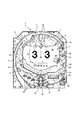
一方、第1特別図柄判定の判定結果が「大当たり」である場合、第1特別図柄の変動表示中に大抵はリーチ演出が実行され、大当たりを報知すべくゾロ目(例えば「333」)を示す3つの演出図柄が擬似停止し、第1特別図柄として大当たり図柄が停止表示されるのに伴って、これら3つの演出図柄が本停止する。このように、大当たり遊技を実行すると判定された場合、大当たりを示す態様で3つの演出図柄を擬似停止させてから本停止させて大当たり(大当たり遊技が実行されること)を報知する当たり報知演出が実行される。この当たり報知演出が実行された場合、大当たり遊技が実行される。 On the other hand, when the determination result of the first special symbol determination is "big hit", the reach effect is usually executed during the variable display of the first special symbol, and doublets (for example, "333") are shown to notify the jackpot. As the three effect symbols are pseudo-stopped and the jackpot symbol is stopped and displayed as the first special symbol, these three effect symbols are finally stopped. In this way, when it is determined that the jackpot game is to be executed, the hit notification effect for notifying the jackpot (the jackpot game is executed) is performed by pseudo-stopping the three effect symbols in a manner indicating the jackpot and then stopping the game. Will be executed. When this hit notification effect is executed, the jackpot game is executed.
[表示画面70の画面構成]
図2には、通常遊技状態における表示画面70の画面構成が例示されている。通常遊技状態で遊技が制御されているときには、図2に例示されるように、保留アイコン表示領域71、当該アイコン表示領域72、及び演出図柄表示領域73が表示画面70上に形成される。演出図柄表示領域73は、上述したように、左列の図柄列を構成する左図柄と、中列の図柄列を構成する中図柄と、右列の図柄列を構成する右図柄とが表示される表示領域である。
[Screen configuration of display screen 70]
FIG. 2 illustrates the screen configuration of the
<保留アイコン表示領域71>
保留アイコン表示領域71(図2参照)は、第1特別図柄判定が保留されていることを示す保留アイコンが表示される表示領域である。遊技機1では、特別図柄の変動表示中や大当たり遊技中といった、特別図柄判定および特別図柄の変動表示を直ちに開始できない状況で第1始動口21に遊技球が入賞した場合には、第1特別図柄判定の権利が所定数(本実施形態では4つ)を上限として保留される。
<Hold
The hold icon display area 71 (see FIG. 2) is a display area in which a hold icon indicating that the first special symbol determination is held is displayed. In the
このように、第1特別図柄判定の権利が保留された場合、保留アイコン表示領域71には、第1特図保留表示器44が示す第1特別図柄判定の保留数と同数の保留アイコンが表示される。図2には、第1特別図柄判定の保留数が「2」であることを示唆するために、保留アイコン表示領域71に2個の保留アイコンが表示された状態が例示されている。
In this way, when the right of the first special symbol determination is reserved, the same number of hold icons as the number of hold icons for the first special symbol determination indicated by the first special symbol hold
なお、後述するSPSPリーチ(図6(K)参照)といった高信頼度のリーチ演出が行われているときに保留アイコン表示領域71に保留アイコンを表示していると、リーチ演出に用いる表示領域が制限されるだけでなく、保留アイコンの表示がリーチ演出の興趣性を低下させる可能性がある。このため、本実施形態の遊技機1では、リーチ前演出中や後述するノーマルショートリーチ中は保留アイコン表示領域71を構成する表示オブジェクトや保留アイコンを表示する一方、ノーマルロングリーチ、第1SPリーチ、第2SPリーチ、SPSPリーチへとリーチ演出が発展するのに伴い、保留アイコン表示領域71を構成する表示オブジェクトや保留アイコンを表示画面70から消去する構成が採用されている。
If the hold icon is displayed in the hold
また、通常遊技状態で遊技が制御されているときには、基本的に第2始動口22に遊技球が入賞することがない。このため、通常遊技状態では、基本的には、第2特別図柄判定の権利が保留されることもなく、表示画面70に第2特別図柄判定に係る保留アイコンが表示されたり、この保留アイコンを表示するための表示領域が形成されたりすることはない。
Further, when the game is controlled in the normal game state, basically, the game ball does not win a prize in the
<当該アイコン表示領域72>
当該アイコン表示領域72は、第1特別図柄が変動表示されていることを示唆する変動示唆画像としての当該アイコンを表示する表示領域である。当該アイコンは、第1特別図柄の変動表示の開始に伴って当該アイコン表示領域72に表示され、例えば、第1特別図柄が停止表示されるタイミングで当該アイコン表示領域72から消去される。ただし、当該アイコンの消去タイミングはこれに限定されるものではなく、第1特別図柄の変動表示中に当該アイコンを消去してもよく、例えば、後述するSPSPリーチ発展時やSPSPリーチの途中で当該アイコンを消去するようにしてよい。
<The
The
ところで、特別図柄の変動表示が行われておらず、且つ特別図柄判定の権利が保留されていない状態で第1始動口21に遊技球が入賞した場合、第1特別図柄の変動表示の開始に伴い、当該アイコン表示領域72に当該アイコンが表示される。一方、保留アイコン表示領域71に保留アイコンが表示されている状態で、当該アイコン表示領域72に表示されている当該アイコンに対応する図柄の変動表示が終了すると、保留アイコン表示領域71に表示されている最先の保留アイコン(当該アイコン表示領域72に最も近い位置に表示されている保留アイコン)に対応する第1特別図柄判定が実行される。そして、この第1特別図柄判定の実行に応じて第1特別図柄の変動表示が開始されるのに伴い、最先の保留アイコンが保留アイコン表示領域71から当該アイコン表示領域72へシフトして、新たな当該アイコンとして表示されることになる。このように、当該アイコン表示領域72にシフトした保留アイコン(ここでは、当該アイコン)は、保留アイコン表示領域71に表示されていたときに比べて大きく表示される(図2参照)。このため、遊技者に対して、保留アイコン表示領域71に表示されている保留アイコンよりも、当該アイコン表示領域72に表示されている当該アイコンに注目させることが可能である。
By the way, when the game ball wins the
なお、上記最先の保留アイコンとは異なる他の保留アイコンが保留アイコン表示領域71に表示されている場合、当該アイコン表示領域72への最先の保留アイコンのシフトに伴い、保留アイコン表示領域71において、他の保留アイコンが当該アイコン表示領域72へ近づく方向へシフトする。ここまでの説明から明らかなように、遊技機1では、保留アイコン表示領域71に表示されていた保留アイコンに対応する当該アイコンが当該アイコン表示領域72に表示される場合があるため、以下の説明では、保留アイコンと当該アイコンとを区別しない場合には、これらを総称して単に「アイコン」と呼ぶ場合がある。
When another hold icon different from the earliest hold icon is displayed in the hold
(アイコン変化演出について)
ところで、保留アイコンは、通常は白色の保留アイコン(デフォルトの保留アイコン)として表示される。これに対して、保留アイコン表示領域71に保留アイコンが表示されているときにその保留アイコンの色が変化するアイコン変化演出が行われる場合がある。このアイコン変化演出が行われた場合、白色の保留アイコンが、青色、緑色、赤色といった大当たり信頼度を示唆する色の保留アイコンに変化する。ここで例示した大当たり信頼度を示唆する色は、大当たり信頼度が低いものから高いものの順に並んでいる。赤色は、その赤色の保留アイコンに対応する第1特別図柄判定の判定結果が「大当たり」となる場合や、「ハズレ」となるものの特別図柄の変動時間が相対的に長い時間に設定される場合に選択され易い。緑色は、「大当たり」となる場合や「ハズレ」となるものの特別図柄の変動時間が中程度の時間に設定される場合に選択され易い。青色は、「ハズレ」となる場合や「ハズレ」であって且つ特別図柄の変動時間が相対的に短い時間に設定される場合に選択され易い。本実施形態では、白色の保留アイコンの大当たり信頼度が約1%に設定され、青色の保留アイコンの大当たり信頼度が約3%に設定され、緑色の保留アイコンの大当たり信頼度が約15%に設定され、赤色の保留アイコンの大当たり信頼度が約45%に設定されている。
(About icon change production)
By the way, the hold icon is usually displayed as a white hold icon (default hold icon). On the other hand, when the hold icon is displayed in the hold
なお、ここでは、保留アイコンが保留アイコン表示領域71に表示されているときにその表示色が1回だけ変化するアイコン変化演出が行われる場合を例に説明したが、本実施形態の遊技機1では、他のアイコン変化演出が行われる場合もある。すなわち、例えば、白色の保留アイコンが、保留アイコン表示領域71に表示されているときに、青色の保留アイコンに変化し、更に緑色の保留アイコンに変化するというように、1つの保留アイコンを対象としてその保留アイコンの表示色が複数回変化するアイコン変化演出が行われる場合もある。また、保留アイコン表示領域71から当該アイコン表示領域72にシフトした白色の保留アイコンが当該アイコンとして表示されているときに、その表示色が変化するアイコン変化演出が行われる場合もある。
Although the case where the icon change effect in which the display color changes only once is performed when the hold icon is displayed in the hold
また、保留アイコン表示領域71に表示されている保留アイコンの表示色が変化し、その後、その保留アイコンが当該アイコン表示領域72にシフトして当該アイコンとして表示されているときにその表示色が変化するというように、保留アイコン表示領域71と当該アイコン表示領域72の両方でアイコンの表示色が変化するアイコン変化演出が行われる場合もある。また、保留アイコンが最初から白色以外の表示色(例えば青色)で表示されるアイコン変化演出や、その初期色が白色以外である保留アイコンの表示色を変化させるアイコン変化演出が行われる場合もある。
Further, the display color of the hold icon displayed in the hold
このように、本実施形態の遊技機1は、特別図柄判定の権利が保留されていることを示す保留情報を表示画面70に表示し、その保留情報の表示態様を変化させることが可能である。なお、以下の説明では、表示色が白色以外の色である保留アイコンや当該アイコンを「特別アイコン」と呼んで、表示色が白色である通常の保留アイコンや当該アイコンと区別する場合がある。
As described above, the
[保留情報の表示制御に関する変形例]
なお、保留情報の表示制御は、本実施形態で例示するものに限らず、以下のようなものであってもよい。すなわち、本実施形態では、説明の便宜上、アイコン(保留アイコンと当該アイコン)の表示色が白色、青色、緑色、及び赤色の4色である場合を例に説明するが、他の実施形態では、赤色よりも更に大当たり信頼度が高いことを示唆する金色や、「大当たり」となる場合にしか選択されない虹色といった他の色が用意されていてもよい。
[Modification example of display control of pending information]
The display control of the reserved information is not limited to the one illustrated in this embodiment, and may be as follows. That is, in the present embodiment, for convenience of explanation, the case where the display colors of the icons (holding icon and the icon) are four colors of white, blue, green, and red will be described as an example, but in other embodiments, the case where the display colors are four colors will be described. Other colors may be available, such as gold, which suggests that the jackpot reliability is even higher than red, and rainbow, which is selected only when the jackpot is "big hit."
また、本実施形態では、アイコン(保留アイコンや当該アイコン)の表示色を変化させるアイコン変化演出を行う場合を例に説明するが、アイコン変化演出は、アイコンの表示態様を変化させる演出であれば本実施形態で例示される演出に限らず、アイコンの形状や大きさを変化させるアイコン変化演出、アイコンの形状や大きさに加えて表示色を変化させるアイコン変化演出等であってもよい。 Further, in the present embodiment, the case where the icon change effect for changing the display color of the icon (holding icon or the icon) is performed will be described as an example, but the icon change effect is an effect for changing the display mode of the icon. The effect is not limited to the effect illustrated in the present embodiment, and may be an icon change effect that changes the shape and size of the icon, an icon change effect that changes the display color in addition to the shape and size of the icon, and the like.
また、本実施形態では、保留アイコン表示領域71に表示された保留アイコンを対象とするアイコン変化演出に加えて、当該アイコン表示領域72に表示された当該アイコンを対象とするアイコン変化演出を実行可能な場合について説明するが、他の実施形態では、当該アイコン表示領域72を設けることなく(当該アイコンを表示することなく)、前者のアイコン変化演出のみを実行可能な構成を採用してもよい。
Further, in the present embodiment, in addition to the icon change effect targeting the hold icon displayed in the hold
また、本実施形態では、保留情報としての保留アイコンを表示画面70に表示して、その保留アイコンの表示色を変化させる場合を例に説明する。これに対して、他の実施形態では、例えば、発光色を変更可能な4つのカラーLEDを設けて第1特別図柄判定の保留数と同数のLEDを点灯させ、いずれかのLEDの発光色を変化させることによって、保留情報の表示態様を変化させるようにしてもよい。
Further, in the present embodiment, a case where a hold icon as hold information is displayed on the
[第1特別図柄の変動表示に伴う演出の流れ]
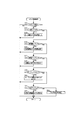
次に、図6を参照しつつ、通常遊技状態における第1特別図柄の変動表示に伴う演出の流れについて説明する。ここで、図6は、通常遊技状態における第1特別図柄の変動表示に伴う演出の流れを例示する説明図である。
[Flow of production accompanying the variable display of the first special symbol]
Next, with reference to FIG. 6, the flow of the effect accompanying the variable display of the first special symbol in the normal gaming state will be described. Here, FIG. 6 is an explanatory diagram illustrating the flow of the effect accompanying the variable display of the first special symbol in the normal gaming state.
通常遊技状態において第1特別図柄判定が実行されると、第1特別図柄表示器41において第1特別図柄が変動表示され、第1特別図柄当否判定の結果を示す第1特別図柄が停止表示される。これに対して、表示画面70では、第1特別図柄の変動表示が開始されるのに伴い、演出図柄表示領域73における3つの図柄列の変動表示が開始される(図6(A)参照)。具体的には、演出図柄表示領域73には、例えば「1」〜「9」の数字が下から上へ縦方向に連続して記された演出図柄の図柄列の一部が横方向に3列表示されており、第1特別図柄の変動表示が開始されるのに伴い、これらの図柄列が上から下へスクロールするように、3つの図柄列のスクロール表示が開始される。
When the first special symbol determination is executed in the normal game state, the first special symbol is variablely displayed on the first
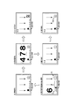
ここで、第1特別図柄の変動表示開始時に行われた第1特別図柄当否判定の判定結果が「ハズレ」であり、リーチ演出を実行しないことが決定されている場合、第1特別図柄の変動表示の終盤でバラケ目(例えば「458」)を示す3つの演出図柄を擬似停止させ、第1特別図柄としてハズレ図柄が停止表示されるのに伴ってこれら3つの演出図柄を本停止させるハズレ報知演出が行われる(図6(B)参照)。 Here, if the determination result of the first special symbol hit / fail judgment performed at the start of the variation display of the first special symbol is "missing" and it is determined not to execute the reach effect, the variation of the first special symbol At the end of the display, the three effect symbols that show the disparity (for example, "458") are pseudo-stopped, and as the lost symbol is stopped and displayed as the first special symbol, the loss notification that these three effect symbols are actually stopped is stopped. The production is performed (see FIG. 6B).
一方、第1特別図柄当否判定の結果が「大当たり」である場合や、「ハズレ」であるもののリーチ演出を行うことが決定されている場合、第1特別図柄の変動表示中に、例えば、演出図柄表示領域73に左図柄を有効ライン上に擬似停止させ、左図柄と共通する右図柄が有効ライン上へと移動するように右列の図柄列を低速でスクロール表示させるリーチ前演出が行われる(図6(C)参照)。そして、このリーチ前演出が行われた結果として、共通する左図柄および右図柄が有効ライン上に擬似停止するとリーチ成立となる(図6(D)参照)。
On the other hand, when the result of the first special symbol hit / fail judgment is "big hit", or when it is decided to perform the reach effect of the "missing", for example, during the variable display of the first special symbol, the effect is produced. A pre-reach effect is performed in which the left symbol is pseudo-stopped on the effective line in the
このように、左図柄および右図柄として共通する演出図柄が擬似停止してリーチが成立すると、これらの演出図柄(リーチ図柄)と共通する演出図柄が中列における有効ライン上に停止することを遊技者に期待させるリーチ演出が行われる。本実施形態では、通常遊技状態における第1特別図柄の変動表示に伴って実行され得るリーチ演出として、図6に例示されるように、ノーマルショートリーチ、ノーマルロングリーチ、第1SPリーチ、第2SPリーチ、及びSPSPリーチの5種類のリーチ演出が用意されている。 In this way, when the effect symbols common to the left and right symbols stop in a pseudo manner and reach is established, the effect symbols common to these effect symbols (reach symbols) stop on the effective line in the middle row. A reach production that makes people expect is performed. In the present embodiment, as illustrated in FIG. 6, as a reach effect that can be executed in association with the variable display of the first special symbol in the normal gaming state, a normal short reach, a normal long reach, a first SP reach, and a second SP reach , And SPSP reach 5 types of reach effects are available.
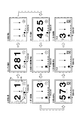
ノーマルショートリーチ(図6(E)参照)は、上記5種類のリーチ演出の中で大当たり信頼度が最も低いリーチ演出である(例えば、大当たり信頼度:約1%)。このノーマルショートリーチは、後述するノーマルロングリーチに比べて演出実行時間が短いリーチ演出であり、リーチが成立すると、大抵は、ノーマルショートリーチが行われる。このノーマルショートリーチが行われる場合、リーチが成立すると中列の図柄列のスクロール速度が徐々に低下していき、リーチを形成する左図柄および右図柄の間にリーチ図柄と同じ中図柄またはリーチ図柄とは異なる中図柄を擬似停止させる中図柄列のスクロール表示が行われる。 The normal short reach (see FIG. 6E) is a reach effect having the lowest jackpot reliability among the above five types of reach effects (for example, jackpot reliability: about 1%). This normal short reach is a reach effect in which the effect execution time is shorter than that of the normal long reach described later, and when the reach is established, the normal short reach is usually performed. When this normal short reach is performed, when the reach is established, the scroll speed of the symbol row in the middle row gradually decreases, and the same middle symbol or reach symbol as the reach symbol is between the left and right symbols forming the reach. The scroll display of the middle symbol string that pseudo-stops the middle symbol different from the above is performed.
ここで、ノーマルショートリーチで当落を報知する変動演出パターンが設定されている場合、ノーマルショートリーチの終盤で当落報知演出(当たり報知演出またはハズレ報知演出)が行われる(図6(F)参照)。具体的には、今回の第1特別図柄判定の判定結果が「大当たり」である場合には、リーチ図柄と同じ中図柄を有効ライン上に擬似停止させることでゾロ目(例えば「222」)を示す演出図柄を擬似停止させた後に、これらの演出図柄をそのまま本停止させる当たり報知演出が行われる。一方、今回の第1特別図柄判定の判定結果が「ハズレ」である場合には、リーチ図柄とは異なる中図柄を有効ライン上に擬似停止させることでリーチハズレ目(例えば「232」)を示す演出図柄を擬似停止させた後に、これらの演出図柄をそのまま本停止させるハズレ報知演出が行われる。 Here, when a variable effect pattern for notifying the winning is set in the normal short reach, the winning notification effect (hit notification effect or loss notification effect) is performed at the end of the normal short reach (see FIG. 6 (F)). .. Specifically, when the judgment result of the first special symbol judgment this time is "big hit", doublet (for example, "222") is doublet by pseudo-stopping the same medium symbol as the reach symbol on the effective line. After the effect symbols shown are pseudo-stopped, a hit notification effect is performed in which these effect symbols are stopped as they are. On the other hand, when the judgment result of the first special symbol determination this time is "missing", the effect of showing the reach losing eye (for example, "232") by pseudo-stopping the middle symbol different from the reach symbol on the effective line. After the symbols are pseudo-stopped, a loss notification effect is performed in which these effect symbols are stopped as they are.
一方、ノーマルショートリーチから他のリーチ演出に発展する変動演出パターンが設定されている場合、以下のような演出が行われる。例えば、ノーマルショートリーチ(図6(E)参照)からノーマルロングリーチ(図6(G)参照)に発展してノーマルロングリーチにて当落を報知する変動演出パターンが設定されている場合、ノーマルショートリーチの終盤でノーマルロングリーチへの発展を示唆する所定の発展示唆演出が行われると共に中列の図柄列の高速スクロールが再開されて、ノーマルロングリーチへとリーチ演出が発展する。このノーマルロングリーチでは、例えば、表示画面70の中央領域にて所定のキャラクタが図柄揃いを期待させる演出表示が行われる。
On the other hand, when a variable effect pattern that develops from a normal short reach to another reach effect is set, the following effect is performed. For example, when the normal short reach (see FIG. 6 (E)) is developed to the normal long reach (see FIG. 6 (G)) and a variable effect pattern for notifying the winning is set in the normal long reach, the normal short is set. At the end of the reach, a predetermined development suggestion effect that suggests the development to the normal long reach is performed, and the high-speed scrolling of the symbol row in the middle row is resumed, and the reach effect develops to the normal long reach. In this normal long reach, for example, in the central region of the
なお、ノーマルロングリーチは、上記5種類のリーチ演出の中でノーマルショートリーチの次に大当たり信頼度が低いリーチ演出であり(例えば、大当たり信頼度:約2%)、大抵の場合、ノーマルロングリーチから他のリーチ演出に発展せずにノーマルロングリーチにてハズレ報知演出(図6(F)参照)行われるが、今回の第1特別図柄判定の判定結果が大当たりであれば、ノーマルロングリーチにて当たり報知演出(図6(F)参照)が行われる場合もある。また、ノーマルロングリーチから他のリーチ演出(本実施形態では、第1SPリーチまたはSPSPリーチ)に発展する変動演出パターンが設定されている場合には、ノーマルロングリーチから第1SPリーチ(図6(H)参照)またはSPSPリーチ(図6(K)参照)にリーチ演出が発展することになる。 The normal long reach is the reach production with the lowest jackpot reliability next to the normal short reach among the above five types of reach effects (for example, the jackpot reliability: about 2%), and in most cases, the normal long reach. The loss notification effect (see Fig. 6 (F)) is performed in the normal long reach without developing into another reach effect, but if the judgment result of the first special symbol judgment this time is a big hit, it will be a normal long reach. In some cases, a hit notification effect (see FIG. 6 (F)) is performed. Further, when a variable effect pattern that develops from the normal long reach to another reach effect (in this embodiment, the first SP reach or the SPSP reach) is set, the normal long reach to the first SP reach (FIG. 6 (H)). ) Or SPSP reach (see FIG. 6 (K)).
ここで、第1SPリーチは、ノーマルロングリーチの次に大当たり信頼度が低いリーチ演出であり(例えば、大当たり信頼度:約11%)、ノーマルロングリーチから第1SPリーチに発展する場合、以下のような演出が行われる。すなわち、リーチ図柄と同じ中図柄が有効ライン上を通過した後に中列の図柄列の高速スクロールが再開され、有効ライン上に擬似停止しているリーチ図柄(左図柄および右図柄)が、リーチ状態を維持したまま縮小されつつ、表示画面70の左上方領域および右上方領域へとそれぞれ移動する。そして、表示画面70の中央領域に第1SPリーチ演出画像が表示されて、大当たりを期待させる所定の演出表示が行われる。
Here, the 1st SP reach is a reach production having the lowest jackpot reliability next to the normal long reach (for example, jackpot reliability: about 11%), and when developing from the normal long reach to the 1st SP reach, it is as follows. Production is performed. That is, after the same middle symbol as the reach symbol passes on the effective line, the high-speed scrolling of the middle row symbol row is restarted, and the reach symbol (left symbol and right symbol) that is pseudo-stopped on the effective line is in the reach state. It moves to the upper left area and the upper right area of the
一方、本実施形態の遊技機1では、ノーマルショートリーチ(図6(E)参照)からノーマルロングリーチを経由せずに上記の第1SPリーチ(図6(H)参照)に発展する場合や、ノーマルショートリーチからノーマルロングリーチを経由せずに第2SPリーチ(図6(I)参照)に直接発展する場合や、ノーマルショートリーチからノーマルロングリーチを経由せずにSPSPリーチ(図6(K)参照)に直接発展する場合がある。
On the other hand, in the
ここで、第2SPリーチは、第1SPリーチよりも大当たり信頼度が若干高いリーチ演出であり(例えば、大当たり信頼度:約12%)、ノーマルショートリーチから第2SPリーチに発展する場合、以下のような演出が行われる。すなわち、リーチ図柄と同じ中図柄が有効ライン上を通過した後に中列の図柄列の高速スクロールが再開され、有効ライン上に擬似停止しているリーチ図柄(左図柄および右図柄)が、リーチ状態を維持したまま縮小されつつ、表示画面70の左上方領域および右上方領域へとそれぞれ移動する。そして、表示画面70の中央領域に第2SPリーチ演出画像が表示されて、大当たりを期待させる所定の演出表示が行われる。
Here, the second SP reach is a reach effect with a slightly higher jackpot reliability than the first SP reach (for example, jackpot reliability: about 12%), and when developing from a normal short reach to a second SP reach, it is as follows. Production is performed. That is, after the same middle symbol as the reach symbol passes on the effective line, the high-speed scrolling of the middle row symbol row is restarted, and the reach symbol (left symbol and right symbol) that is pseudo-stopped on the effective line is in the reach state. It moves to the upper left area and the upper right area of the
ところで、第1SPリーチと第2SPリーチとは、同様の画面構成にて大当たりを期待させる演出表示が行われるが、これらのリーチ演出は、その演出内容が互いに異なっている。具体的には、第1SPリーチでは、自キャラが敵キャラの攻撃を防ぎ切ったら大当たりとなり、逆に、自キャラが敵キャラの攻撃を防ぎ切れなければハズレとなる演出表示が行われる。一方の第2SPリーチはミッション演出として構成されており、自キャラがミッションに成功すると大当たりとなり、逆に、ミッションに失敗するとハズレとなる演出表示が行われる。 By the way, the 1st SP reach and the 2nd SP reach are displayed with the same screen configuration to expect a big hit, but the contents of these reach effects are different from each other. Specifically, in the 1st SP reach, if the own character cannot prevent the enemy character from attacking, it becomes a big hit, and conversely, if the own character cannot prevent the enemy character from attacking, it becomes a loss. On the other hand, the second SP reach is configured as a mission production, and if the character succeeds in the mission, it becomes a big hit, and conversely, if the mission fails, a production display that becomes a loss is performed.
第1SPリーチや第2SPリーチに発展した場合、これらのリーチ演出の大当たり信頼度が相対的に低いことから、当落報知演出(図6(J)参照)にてハズレ報知演出の方が当たり報知演出よりも実行され易い。このため、第1SPリーチや第2SPリーチに発展した場合は、遊技者は、ノーマルロングリーチに発展した場合と同様に、SPSPリーチ(図6(K)参照)に発展することを期待することになる。 When it develops into the 1st SP reach and the 2nd SP reach, the jackpot reliability of these reach effects is relatively low. Easier to execute than. Therefore, when it develops into the 1st SP reach or the 2nd SP reach, the player expects to develop into the SPSP reach (see FIG. 6 (K)) in the same manner as when it develops into the normal long reach. Become.
ここで、SPSPリーチ(図6(K))は、上記5種類のリーチ演出の中で大当たり信頼度が最も高いリーチ演出である。本実施形態では、図6に例示されるように、リーチ成立の直後にSPSPリーチへと直接発展する場合(図6(D)及び(K)参照)と、ノーマルショートリーチおよびノーマルロングリーチを経由してSPSPリーチに発展する場合(図6(E)、(G)、及び(K)参照)と、ノーマルショートリーチおよび第1SPリーチを経由してSPSPリーチに発展する場合(図6(E)、(H)、及び(K)参照)と、ノーマルショートリーチおよび第2SPリーチを経由してSPSPリーチに発展する場合(図6(E)、(I)、及び(K)参照)と、ノーマルショートリーチからSPSPリーチに直接発展する場合(図6(E)及び(K)参照)とがある。 Here, the SPSP reach (FIG. 6 (K)) is the reach effect having the highest jackpot reliability among the above five types of reach effects. In the present embodiment, as illustrated in FIG. 6, when the reach directly develops into the SPSP reach immediately after the reach is established (see FIGS. 6 (D) and 6 (K)), the normal short reach and the normal long reach are used. And develops into SPSP reach (see FIGS. 6 (E), (G), and (K)) and develops into SPSP reach via normal short reach and first SP reach (see FIG. 6 (E)). , (H), and (K)) and when developing to SPSP reach via normal short reach and second SP reach (see FIGS. 6 (E), (I), and (K)) and normal. There is a case where the short reach directly develops into the SPSP reach (see FIGS. 6 (E) and 6 (K)).
詳細な説明は省略するが、SPSPリーチでは、表示画面70にSPSPリーチ演出画像が表示されて、自キャラと敵キャラとがバトルするバトル演出が実行されるが、今回の第1特別図柄判定の判定結果が大当たりである場合は、自キャラが敵キャラに勝利する勝利演出および当たり報知演出が実行され、ハズレである場合は、自キャラが敵キャラに敗北する敗北演出およびハズレ報知演出が実行される。
Although detailed explanation is omitted, in SPSP reach, the SPSP reach effect image is displayed on the
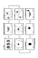
なお、リーチ前演出(図6(C)参照)が行われているときに、「111」、「222」、「333」、「444」のように3つの図柄列の演出図柄が揃った状態で各図柄列のスクロール表示を行う全回転演出(図6(L)参照)が開始される場合がある。この全回転演出は、今回の第1特別図柄の変動表示開始時に行われた第1特別図柄判定の判定結果が「大当たり」である場合に実行される一方で、「ハズレ」である場合には実行されない演出であるため、全回転演出に発展した場合は、その後に必ず当たり報知演出(図6(M)参照)が実行されることになる。 When the pre-reach effect (see FIG. 6C) is being performed, the effect symbols of the three symbol rows such as "111", "222", "333", and "444" are aligned. In some cases, a full rotation effect (see FIG. 6 (L)) for scrolling and displaying each symbol row may be started. This full rotation effect is executed when the judgment result of the first special symbol judgment performed at the start of the variation display of the first special symbol this time is "big hit", while when it is "missing", it is executed. Since it is an effect that is not executed, when it develops into a full rotation effect, a hit notification effect (see FIG. 6M) is always executed after that.
また、図6には、リーチ前演出が行われているときに全回転演出に発展する場合が例示されているが、本実施形態の遊技機1では、リーチが成立していない状態で演出図柄の変動表示が行われているときに実行されるステップアップ演出が最終段階まで発展した場合に、この最終段階の演出に続いて全回転演出が実行される場合もある。また、ノーマルロングリーチ(図6(G)参照)の終盤において、バラケ目を示す3つの演出図柄を擬似停止表示することによってハズレと見せ掛ける類似ハズレ演出が実行された場合に、この類似ハズレ演出に続いて全回転演出が実行される場合もある。また、1回の第1特別図柄の変動表示中に後述する擬似連演出が3回実行されて擬似4連目の変動演出(4回目の短変動表示)に発展した場合に、この擬似4連目の変動演出に発展した直後に全回転演出が開始される場合もある。
Further, FIG. 6 illustrates a case where the pre-reach effect develops into a full rotation effect, but in the
[擬似連演出と演出図柄の短変動について]
次に、図7を参照しつつ、擬似連演出と演出図柄の短変動について説明する。ここで、図7は、擬似連演出について説明するための説明図である。本実施形態の遊技機1では、リーチ成立前、或いは、リーチ成立後において、擬似連演出が実行される場合がある。擬似連演出は、1回の特別図柄の変動表示中において、演出図柄の変動表示が複数回行われたように見せ掛けるための演出であり、本実施形態では、擬似連演出として、中7図柄(数字が7である中列の演出図柄)を含む3つの演出図柄を擬似停止表示する演出が行われる(例えば、図9(D)参照)。
[Pseudo-continuous production and short fluctuations in the production design]
Next, with reference to FIG. 7, the pseudo continuous effect and the short variation of the effect symbol will be described. Here, FIG. 7 is an explanatory diagram for explaining the pseudo-continuous production. In the
なお、図7において、特別図柄の「変動」は、通常遊技状態のときに行われる第1特別図柄の変動表示を意味し、特別図柄の「停止」は、第1特別図柄の変動表示に続いて行われる第1特別図柄の停止表示を意味するものとする。また、演出図柄の「変動」は、通常遊技状態における第1特別図柄の変動表示に伴う演出図柄の変動表示を意味し、演出図柄の「擬似停止」は、演出図柄の擬似停止表示(ここでは、擬似連演出)を意味し、演出図柄の「停止」は、演出図柄の本停止を意味するものとする。 In FIG. 7, the "variation" of the special symbol means the variation display of the first special symbol performed in the normal gaming state, and the "stop" of the special symbol follows the variation display of the first special symbol. It shall mean the stop display of the first special symbol performed in the above. Further, the "variation" of the effect symbol means the variation display of the effect symbol accompanying the variation display of the first special symbol in the normal gaming state, and the "pseudo stop" of the effect symbol is the pseudo stop display of the effect symbol (here, the pseudo stop display of the effect symbol). , Pseudo-continuous production), and "stop" of the production symbol means the main stop of the production symbol.
(擬似連演出が実行されない場合)
図7(A)には、擬似連演出が実行されない場合の演出図柄の変動表示が例示されている。擬似連演出が実行されない場合、図7(A)に例示されるように、1回の特別図柄の変動表示中に演出図柄の変動表示が1回行われる。このように、擬似連演出が実行されない場合、大当たり信頼度が相対的に低く、大抵の場合、リーチ無し演出(リーチ演出を含まない変動演出)が行われてハズレ報知演出が実行されたり、或いは、リーチ演出が実行されたとしても大当たり信頼度が低いノーマルショートリーチやノーマルロングリーチしか実行されずに、これらの低信頼度リーチでハズレ報知演出が実行されたりすることになる。
(When the pseudo-continuous production is not executed)
FIG. 7A illustrates a variable display of the effect symbol when the pseudo-continuous effect is not executed. When the pseudo continuous effect is not executed, as illustrated in FIG. 7A, the variation display of the effect symbol is performed once during the variation display of one special symbol. In this way, when the pseudo continuous effect is not executed, the jackpot reliability is relatively low, and in most cases, the reachless effect (variable effect not including the reach effect) is performed and the loss notification effect is executed, or , Even if the reach effect is executed, only the normal short reach and the normal long reach, which have low jackpot reliability, are executed, and the loss notification effect is executed with these low reliability reach.
(擬似2連目まで発展する擬似連演出が実行される場合)
図7(B)には、1回の特別図柄の変動表示中に擬似連演出が1回だけ実行される場合の演出図柄の変動表示が例示されている。本実施形態の遊技機1では、1回の特別図柄の変動表示中に擬似連演出が1回だけ実行された場合の大当たり信頼度が、擬似連演出が実行されない場合に比べると高いものの、10%という比較的低い確率に設定されている。
(When a pseudo-ream effect that develops to the pseudo-second station is executed)
FIG. 7B exemplifies the variation display of the effect symbol when the pseudo-continuous effect is executed only once during the variation display of one special symbol. In the
1回の特別図柄の変動表示中に1回の擬似連演出が実行される場合は、図7(B)に例示されるように、第1特別図柄の変動表示が開始されてから(第1特別図柄の変動時間よりも短い)所定時間を掛けて、演出図柄に係る擬似1連目の変動演出である第1短変動が行われ、この第1短変動に続いて擬似連演出が実行される。この擬似連演出は、本実施形態では、中7図柄を含む3つの演出図柄を所定時間(例えば、3秒間)擬似停止表示する演出として構成されており、擬似連演出の開始から所定時間が経過すると、3つの図柄列の変動表示(例えば、スクロール表示)が再開されて、演出図柄に係る擬似2連目の変動演出である第2短変動が開始される。 When one pseudo-continuous effect is executed during one variation display of the special symbol, as illustrated in FIG. 7B, after the variation display of the first special symbol is started (first). The first short variation, which is the pseudo-first variation effect related to the effect symbol, is performed over a predetermined time (shorter than the variation time of the special symbol), and the pseudo-continuous effect is executed following the first short variation. NS. In the present embodiment, this pseudo-continuous effect is configured as an effect of displaying three effect symbols including the middle 7 symbols in a pseudo-stop display for a predetermined time (for example, 3 seconds), and a predetermined time elapses from the start of the pseudo-continuous effect. Then, the variation display (for example, scroll display) of the three symbol strings is restarted, and the second short variation, which is the pseudo second variation effect related to the effect symbol, is started.
図7(B)に例示されるように、変動演出が擬似3連目以降に発展しない場合は、第2短変動が最終の短変動となることから、第1特別図柄の変動表示の途中から第1特別図柄の変動表示が終了するまでの期間に亘って、第2短変動が継続することになる。 As illustrated in FIG. 7B, if the variation effect does not develop after the pseudo third station, the second short variation becomes the final short variation, so from the middle of the variation display of the first special symbol. The second short variation will continue for a period until the variation display of the first special symbol is completed.
なお、本実施形態の遊技機1では、通常遊技状態で遊技が制御されているときに行われる第1特別図柄の変動表示に関して、リーチ演出が実行されない(リーチ無し演出が実行される)第1特別図柄の変動パターンが選択された場合には、擬似連演出を実行せず、リーチ演出が実行される(リーチ有り演出が実行される)第1特別図柄の変動パターンが選択された場合の一部に関して、擬似連演出を実行するといった構成が採用されている。このため、通常遊技状態における第1特別図柄の変動表示中に擬似連演出が実行された場合は、少なくともリーチが成立して、何かしらのリーチ演出が実行されることになる。
In the
図7(B)に例示されるように、第2短変動が最終の短変動となる場合は、第2短変動においてリーチ演出が行われることになる。このため、擬似2連目の変動演出である第2短変動に掛かる時間の方が、擬似1連目の変動演出である第1短変動に掛かる時間よりも長くなり易いという特徴がある(図7(B)参照)。 As illustrated in FIG. 7B, when the second short variation is the final short variation, the reach effect is performed in the second short variation. Therefore, the time required for the second short variation, which is the pseudo second variation effect, tends to be longer than the time required for the first short variation, which is the pseudo first variation effect (Fig.). 7 (B)).
(擬似3連目まで発展する擬似連演出が実行される場合)
図7(C)には、1回の特別図柄の変動表示中に擬似連演出が2回実行される場合の演出図柄の変動表示が例示されている。本実施形態の遊技機1では、1回の特別図柄の変動表示中に擬似連演出が2回実行された場合の大当たり信頼度が、20%という相対的に高い確率に設定されている。
(When a pseudo-ream effect that develops to the pseudo-third station is executed)
FIG. 7C exemplifies the variation display of the effect symbol when the pseudo-continuous effect is executed twice during the variation display of one special symbol. In the
1回の特別図柄の変動表示中に2回の擬似連演出が実行される場合は、図7(B)に基づいて上述した1回の擬似連演出が実行される場合と同様に、先ずは第1短変動が行われ、この第1短変動に続いて、1回目の擬似連演出が実行される(図7(C)参照)。この1回目の擬似連演出は、図7(B)に基づいて上述したものと同様の擬似連演出であり、1回目の擬似連演出の開始から所定時間が経過すると、3つの図柄列の変動表示(例えば、スクロール表示)が再開されて、演出図柄に係る擬似2連目の変動演出である第2短変動が開始される。 When two pseudo-continuous effects are executed during one special symbol variation display, first, as in the case where the above-mentioned one pseudo-continuous effect is executed based on FIG. 7B. The first short variation is performed, and following the first short variation, the first pseudo-continuous effect is executed (see FIG. 7C). This first pseudo-continuous effect is the same pseudo-continuous effect as described above based on FIG. 7B, and when a predetermined time elapses from the start of the first pseudo-continuous effect, the three symbol sequences fluctuate. The display (for example, scroll display) is restarted, and the second short variation, which is a pseudo second variation effect related to the effect symbol, is started.
図7(C)に例示されるように、変動演出が最終的に擬似3連目まで発展する場合は、第2短変動に続いて2回目の擬似連演出が実行される。そして、この2回目の擬似連演出の開始から所定時間が経過すると、3つの図柄列の変動表示(例えば、スクロール表示)が再開されて、演出図柄に係る擬似3連目の変動演出である第3短変動が開始される(図7(C)参照)。図7(C)に例示されるように、この第3短変動は、第1特別図柄の変動表示の途中から第1特別図柄の変動表示が終了するまで継続される。 As illustrated in FIG. 7C, when the variation effect finally develops to the pseudo-third station, the second pseudo-continuous effect is executed following the second short variation. Then, when a predetermined time elapses from the start of the second pseudo continuous effect, the variation display (for example, scroll display) of the three symbol strings is restarted, and the pseudo third variation effect related to the effect symbol is performed. 3 Short fluctuations are started (see FIG. 7 (C)). As illustrated in FIG. 7C, this third short variation is continued from the middle of the variation display of the first special symbol to the end of the variation display of the first special symbol.
なお、本実施形態の遊技機1には、1回の特別図柄の変動表示中に実行される擬似連演出の回数が多くなるほど、大当たり信頼度が相対的に高いリーチ演出(例えば、第1SPリーチや第2SPリーチ、SPSPリーチ)に発展し易いという特徴がある。このため、通常遊技状態における第1特別図柄の変動表示中に2回の擬似連演出が実行された場合は、例えば、ノーマルショートリーチ(図6(E)参照)から第1SPリーチ(図6(H)参照)に発展したり、ノーマルショートリーチからノーマルロングリーチ(図6(G)参照)を経由してSPSPリーチ(図6(K)参照)に発展したりする可能性が高い。
In the
このため、第3短変動(図7(C)参照)に掛かる時間には、図7(B)に基づいて上述した第2短変動に掛かる時間よりも長くなり易く、また、同一変動内で行われる第1短変動や第2短変動に掛かる時間よりも長いという特徴がある(図7(B)及び(C)参照)。 Therefore, the time required for the third short variation (see FIG. 7 (C)) tends to be longer than the time required for the second short variation described above based on FIG. 7 (B), and within the same variation. It is characterized in that it is longer than the time required for the first short fluctuation and the second short fluctuation to be performed (see FIGS. 7B and 7C).
(擬似4連目まで発展する擬似連演出が実行される場合)
図7(D)には、1回の特別図柄の変動表示中に擬似連演出が3回実行される場合の演出図柄の変動表示が例示されている。本実施形態の遊技機1では、1回の特別図柄の変動表示中に擬似連演出が3回実行された場合の大当たり信頼度が100%に設定されているため、同一変動内における3回目の擬似連演出が、「大当たり」を確定的に報知する確定報知演出として機能することになる。
(When a pseudo-ream effect that develops to the pseudo-fourth station is executed)
FIG. 7D exemplifies the variation display of the effect symbol when the pseudo-continuous effect is executed three times during the variation display of one special symbol. In the
1回の特別図柄の変動表示中に3回の擬似連演出が実行される場合は、図7(C)に基づいて上述した1回の特別図柄の変動表示中に2回の擬似連演出が実行される場合と同様に、第1短変動、1回目の擬似連演出、第2短変動、2回目の擬似連演出、第3短変動が順番に行われる(図7(C)及び(D)参照)。 When three pseudo-continuous effects are executed during one special symbol variation display, two pseudo-continuous effects are performed during one special symbol variation display described above based on FIG. 7 (C). As in the case of execution, the first short variation, the first pseudo-continuous effect, the second short variation, the second pseudo-continuous effect, and the third short variation are performed in order (FIGS. 7 (C) and 7 (D)). )reference).
ただし、1回の特別図柄の変動表示中に2回の擬似連演出が実行される場合は、第3短変動においてリーチ演出が実行されるのに対して、1回の特別図柄の変動表示中に3回の擬似連演出が実行される場合は、第3短変動ではなく第4短変動において、リーチ演出(又は全回転演出:図6(L)参照)が実行される。すなわち、1回の特別図柄の変動表示中に3回の擬似連演出が実行される場合は、第3短変動に続いて3回目の擬似連演出が実行され、この擬似連演出に続く擬似4連目の変動演出である第4短変動において、リーチ演出か、或いは、全回転演出が実行される。
However, if two pseudo-continuous effects are executed during one special symbol variation display, the reach effect is executed in the third short variation, whereas one special symbol variation display is in progress. When the pseudo-continuous effect is executed three times, the reach effect (or full rotation effect: see FIG. 6 (L)) is executed in the fourth short variation instead of the third minor variation. That is, when three pseudo-continuous effects are executed during one special symbol variation display, the third pseudo-continuous effect is executed following the third short variation, and the pseudo-continuous effect following this
なお、上記のように、本実施形態では、同一変動内で3回の擬似連演出が行われる場合の大当たり信頼度が100%に設定されていることから、第4短変動で行われるリーチ演出(又は全回転演出)において、必ず当たり報知演出が実行されることになる。 As described above, in the present embodiment, since the jackpot reliability is set to 100% when the pseudo-continuous production is performed three times within the same fluctuation, the reach production performed in the fourth short fluctuation is performed. In (or full rotation effect), the hit notification effect is always executed.
本実施形態における第4短変動の演出としては、最終的に、図6に例示される5種類のリーチ演出のいずれかのリーチ演出に発展して、そのリーチ演出の終盤で当たり報知演出を実行するといった変動演出や、例えば、第4短変動においてノーマルショートリーチからノーマルロングリーチを経由して全回転演出に発展するといった変動演出、第4短変動に発展した直後に(リーチ演出を実行することなく)全回転演出を実行するといった変動演出が例として挙げられる。 The fourth short variation effect in the present embodiment finally develops into a reach effect of any of the five types of reach effects illustrated in FIG. 6, and a hit notification effect is executed at the end of the reach effect. Fluctuation production such as An example is a variable effect such as executing a full rotation effect.
このように、1回の特別図柄の変動表示中に3回の擬似連演出が実行される場合は、第4短変動において、リーチ演出および全回転演出の両方或いはいずれか一方が実行されるため、第4短変動に掛かる時間が、同一変動内で行われる第1短変動〜第3短変動に掛かる時間よりも長いという特徴がある(図7(D)参照)。 In this way, when the pseudo-continuous effect is executed three times during the one-time variation display of the special symbol, the reach effect and / or the full rotation effect are executed in the fourth short variation. , The time required for the fourth short fluctuation is longer than the time required for the first short fluctuation to the third short fluctuation performed within the same fluctuation (see FIG. 7 (D)).
ここまでの説明から明らかなように、本実施形態の遊技機1では、1回の特別図柄の変動表示中に、この特別図柄の変動時間よりも短い時間を掛けて演出図柄を変動表示する複数回の短変動表示が実行される場合があり、1回の特別図柄の変動表示中に実行される短変動表示の回数が多いほど、大当たり遊技が実行され易いといった構成が採用されている。このため、遊技者は、同一変動内で行われる短変動表示の回数がより多くなることを期待しながら遊技を楽しむことができ、また、短変動表示の回数に基づいて大当たり信頼度を認識することが可能である。
As is clear from the explanations so far, in the
[表示画面70の画面構成例]
次に、図8を参照しつつ、通常遊技状態における表示画面70の画面構成例について説明する。ここで、図8は、通常遊技状態における表示画面70の画面構成例を示す画面図である。図2に基づいて上述したように、本実施形態の遊技機1では、通常遊技状態で遊技が制御されているときに、保留アイコンが表示される保留アイコン表示領域71と、当該アイコンが表示される当該アイコン表示領域72と、演出図柄が表示される演出図柄表示領域73とが表示画面70上に形成される。そして、このような画面構成が形成されている状態において、図8に例示される短変動回数74や残短変動回数予告画像75が表示される場合がある。
[Screen configuration example of display screen 70]
Next, a screen configuration example of the
(短変動回数74について)
短変動回数74は、1回の特別図柄の変動表示中に、少なくとも1回の擬似連演出が実行された場合に表示画面70における左上方の表示領域に表示されるものであって、実行中の短変動表示が同一変動内における何回目の短変動表示であるかを示すものである。図8には、2回目の短変動表示(図7に基づいて上述した第2短変動)の実行中であることを示唆するために、「×2」の文字を示す短変動回数74が表示された状態が例示されている。
(About the number of short fluctuations 74)
The number of
この短変動回数74は、実行中の短変動表示が同一変動内における何回目の短変動表示であるかを示すものであることから、擬似連演出が実行されない演出図柄の変動表示中には表示されないという特徴がある。また、擬似連演出が実行される演出図柄の変動表示中であっても、擬似1連目の変動演出(図7に基づいて上述した第1短変動)の実行中には表示されず(図9(B)〜(C)参照)、また、所定のリーチ演出に発展した後には表示されないという特徴がある(図9(I)、図10(A)参照)。
Since the number of
なお、図8には、第2短変動の実行中であるために「×2」の文字を示す短変動回数74が表示された状態が例示されているが、第3短変動の実行中は、図9(H)〜(I)に例示されるように、「×3」の文字を示す短変動回数74が表示される。また、図には示されていないが、図7(D)に基づいて上述した第4短変動表示の実行中は、所定のリーチ演出または全回転演出に発展するまでの間、「×4」の文字を示す短変動回数74が表示される。
Note that FIG. 8 illustrates a state in which the number of
(残短変動回数予告画像75について)
残短変動回数予告画像75は、1回の特別図柄の変動表示中に実行される短変動表示の回数を示唆する示唆画像であって、本実施形態では、未だ実行されていない短変動表示の実行回数を予告する予告演出として機能する。図8には、第2短変動(擬似2連目の変動演出)が実行されている状況下で、この第2短変動が終了した後に、同一変動内で少なくとも1回の短変動表示が実行されることを予告すべく、「1」の数字を含む残短変動回数予告画像75が表示された様子が例示されている。
(About the remaining short change number preview image 75)
The remaining short variation
この残短変動回数予告画像75については後に詳述するが、図7に基づいて上述したように擬似連演出の実行に応じて短変動表示が実行される場合であっても、残短変動回数予告画像75が表示される場合と表示されない場合とがあり、先ずは、残短変動回数予告画像75が表示されない場合の変動演出の具体例について説明する。
The remaining short variation
(残短変動回数予告画像75の表示を伴わない変動演出の具体例)
図9,10を参照しつつ、通常遊技状態における、残短変動回数予告画像75の表示を伴わない変動演出の具体例について説明する。図9,10は、通常遊技状態における第1特別図柄の変動表示に伴う演出の具体例を示す画面図であり、ここでは、通常遊技状態における第1特別図柄の変動パターンとして、ノーマルショートリーチ(図6(E)参照)から直接発展したSPSPリーチ(図6(K)参照)においてハズレ報知演出が行われることになる変動パターンが選択された場合に実行される演出について説明する。
(Specific example of variation effect without displaying the remaining short variation number preview image 75)
With reference to FIGS. 9 and 10, a specific example of the variation effect without displaying the remaining short variation number
図9(A)には、表示画面70において、保留アイコン表示領域71に2つの保留アイコンが表示された状態で、当該アイコン表示領域72に表示されている当該アイコンに対応する第1特別図柄判定の判定結果が「ハズレ」であることを報知すべく、第1特別図柄としてハズレ図柄が停止表示されるのに伴って、「526」のバラケ目を示す演出図柄が停止表示されている状態が例示されている。このように、第1特別図柄としてハズレ図柄が停止表示されてから所定の確定時間(本実施形態では、0.6秒)が経過すると、保留アイコン表示領域71に表示されている最先の保留アイコン(ここでは、緑色の保留アイコン)に対応する第1特別図柄判定が実行される。そして、この第1特別図柄判定の判定結果が「ハズレ」であり、第1特別図柄の変動パターンとして、ノーマルショートリーチからSPSPリーチに直接発展する変動演出パターンが選択されると、以下のような演出が行われる。
FIG. 9A shows a first special symbol determination corresponding to the icon displayed in the
すなわち、最先の保留アイコンに対応する第1特別図柄判定が実行されたことに応じて第1特別図柄の変動表示が開始されるのに伴い、保留アイコン表示領域71に表示されている最先の保留アイコンが当該アイコン表示領域72にシフトし、保留アイコン表示領域71に表示されている残りの保留アイコンが保留アイコン表示領域71内で当該アイコン表示領域72側にシフトすると共に、3つの図柄列のスクロール表示が開始される(図9(A)及び(B)参照)。この3つの図柄列のスクロール表示が開始されてから所定時間が経過すると、例えば、所定のキャラクタがセリフを発する様子を表すセリフ予告演出画像を表示画面70に表示すると共に、そのセリフをスピーカ38から出力するセリフ予告が実行される(図9(C)参照)。このセリフ予告では、セリフを発するキャラクタの種類や、セリフの内容、セリフの文字色等によって、大当たり信頼度が示唆される。
That is, as the variable display of the first special symbol is started in response to the execution of the first special symbol determination corresponding to the earliest hold icon, the earliest displayed in the hold
上記のセリフ予告に続いて、擬似連演出が実行される場合がある。ここで、擬似連演出とは、1回の特別図柄(ここでは、第1特別図柄)の変動表示中に、演出図柄表示領域73に表示されている演出図柄が複数回変動表示されたように見せ掛ける演出である。この擬似連演出に関しては、以下のような演出表示が行われる。
Following the above-mentioned dialogue notice, a pseudo-continuous production may be executed. Here, the pseudo continuous effect means that the effect symbol displayed in the effect
すなわち、左列の図柄列のスクロール速度が低下して左図柄(例えば6図柄)が擬似停止し、続いて、右列の図柄列のスクロール速度が低下して(先に擬似停止した左図柄とは異なる)右図柄(例えば4図柄)が擬似停止し、その後、中列の図柄列のスクロール速度が低下して、擬似連演出の実行を報知する中図柄として7図柄(中7図柄)が擬似停止する(図9(D)参照)。 That is, the scroll speed of the symbol row in the left column is reduced and the left symbol (for example, 6 symbols) is pseudo-stopped, and then the scroll speed of the symbol row in the right column is reduced (the left symbol that is pseudo-stopped earlier). The right symbol (for example, 4 symbols) is pseudo-stopped, and then the scroll speed of the symbol row in the middle row is reduced, and 7 symbols (7 symbols in the middle) are simulated as the middle symbols that notify the execution of the pseudo-continuous effect. Stop (see FIG. 9D).
このように、左図柄および右図柄として互いに異なる演出図柄が擬似停止した後に、中列に7図柄が擬似停止すると、擬似1連目の変動演出(上述した第1短変動)に続く擬似2連目の変動演出(上述した第2短変動)が開始される。具体的には、擬似2連目の変動演出の開始を示唆する「×2」の文字が表示画面70の中央領域に大きく表示された後に、この「×2」の文字が表示画面70の左上方領域に上記短変動回数74として小さく表示され、これに伴い、演出図柄表示領域73において3つの図柄列のスクロール表示が再開される(図9(D)及び(E)参照)。この擬似2連目の変動演出(すなわち、第2短変動)が行われているときには、擬似1連目の変動演出中(第1短変動中)と同様に、例えばセリフ予告が実行される場合がある(図9(F)参照)。
In this way, when seven symbols are pseudo-stopped in the middle row after the effect symbols that are different from each other as the left symbol and the right symbol are pseudo-stopped, the pseudo two-series following the pseudo-first variation effect (the first short variation described above). The eye variation effect (the second short variation described above) is started. Specifically, after the character "x2" suggesting the start of the pseudo-second variation effect is displayed large in the central area of the
上記のように、擬似2連目の変動演出中にセリフ予告が実行されると、今回の第1特別図柄の変動表示中における2回目の擬似連演出が実行される(図9(G)参照)。具体的には、図9(G)に例示されるように、左列の図柄列のスクロール速度が低下して左図柄(例えば2図柄)が擬似停止し、続いて、右列の図柄列のスクロール速度が低下して右図柄(例えば5図柄)が擬似停止し、その後、中列の図柄列のスクロール速度が低下して中図柄として7図柄が擬似停止する。 As described above, when the dialogue notice is executed during the pseudo-second variation effect, the second pseudo-continuous effect during the variation display of the first special symbol is executed (see FIG. 9 (G)). ). Specifically, as illustrated in FIG. 9 (G), the scroll speed of the symbol row in the left column is reduced, the left symbol (for example, two symbols) is pseudo-stopped, and then the symbol row in the right column is displayed. The scroll speed is reduced and the right symbol (for example, 5 symbols) is pseudo-stopped, and then the scroll speed of the symbol row in the middle row is reduced and 7 symbols are pseudo-stopped as the middle symbol.
この第1特別図柄の変動表示中における2回目の擬似連演出が実行されると、擬似2連目の変動演出に続く擬似3連目の変動演出(すなわち、上述した第3短変動)が開始される。具体的には、擬似3連目の変動演出の開始を示唆する「×3」の文字が表示画面70の中央領域に大きく表示された後に、この「×3」の文字が上記短変動回数74として表示画面70の左上方領域に小さく表示され、これに伴い、演出図柄表示領域73において3つの図柄列のスクロール表示が再開される(図9(G)及び(H)参照)。
When the second pseudo-continuous effect is executed during the variation display of the first special symbol, the pseudo-third consecutive variation effect following the pseudo-second variation effect (that is, the above-mentioned third short variation) starts. Will be done. Specifically, after the character "x3" suggesting the start of the pseudo-third consecutive variation effect is displayed large in the central area of the
そして、このようにして擬似3連目の変動演出(第3短変動)が開始されてから所定時間が経過すると、左列の図柄列のスクロール速度が低下して左図柄(例えば3図柄)が擬似停止し、続いて、右列の図柄列のスクロール速度が低下して(左図柄と同じ)右図柄(ここでは3図柄)が擬似停止してリーチが成立する(図9(I)参照)。 Then, when a predetermined time elapses from the start of the pseudo-third consecutive variation effect (third short variation) in this way, the scroll speed of the symbol string in the left column decreases, and the left symbol (for example, three symbols) becomes Pseudo-stop, then the scroll speed of the symbol row in the right column decreases (same as the symbol on the left), and the right symbol (3 symbols in this case) pseudo-stops to establish reach (see FIG. 9 (I)). ..
なお、ここでは、リーチ成立前に各図柄列のスクロール表示を再開させる「リーチ前擬似連」が実行される場合を例に説明したが、リーチ成立後に各図柄列のスクロール表示を再開させる「リーチ後擬似連」が実行される場合もある。また、リーチ前擬似連とリーチ後擬似連が両方実行される場合もある。 Here, the case where the "pre-reach pseudo-ream" that restarts the scroll display of each symbol string is executed before the reach is established has been described as an example, but the "reach" that restarts the scroll display of each symbol string after the reach is established has been described. In some cases, "post-pseudo-ream" is executed. In addition, both the pre-reach pseudo-reach and the post-reach pseudo-reach may be executed.
上記のように、左図柄および右図柄として同一の演出図柄が擬似停止してリーチが成立すると、ノーマルショートリーチ(図6(E)参照)が実行される(図10(A)参照)。具体的には、図10(A)に例示されるように、リーチ成立後に中列の図柄列のスクロール速度が徐々に低下していき、リーチ図柄(ここでは左3図柄および右3図柄)と同じ中図柄(ここでは中3図柄)がリーチ図柄によって規定される有効ラインに近付いていく様子を表す演出表示が行われる。 As described above, when the same effect symbols as the left symbol and the right symbol are pseudo-stopped and the reach is established, the normal short reach (see FIG. 6 (E)) is executed (see FIG. 10 (A)). Specifically, as illustrated in FIG. 10A, the scroll speed of the middle row of symbols gradually decreases after the reach is established, and the reach symbols (here, the left 3 symbols and the right 3 symbols) are used. An effect display is performed to show how the same middle symbol (here, the middle 3 symbols) approaches the effective line defined by the reach symbol.
なお、図9(I)及び図10(A)の表記から明らかなように、本実施形態では、リーチ演出に係るリーチ演出画像の視認性を低下させないように、リーチ演出の開始前に短変動回数74が表示されていた場合は、開始されるリーチ演出の種類に関わらず、リーチ演出の開始に伴って短変動回数74を消去する場合を例に説明するが、短変動回数74の表示に関して、以下のような構成を採用してもよい。すなわち、例えば、ノーマルショートリーチやノーマルロングリーチといった大当たり信頼度が相対的に低いリーチ演出の実行中には、短変動回数74の表示を継続する一方、第1SPリーチや第2SPリーチ、SPSPリーチといった大当たり信頼度が相対的に高いリーチ演出の実行中には、短変動回数74を表示しないといった構成を採用してもよい。また、大当たり信頼度が最も低いノーマルショートリーチ中にのみ短変動回数74の表示を継続させ、ノーマルショートリーチ以外のリーチ演出の開始に伴って短変動回数74を消去するといった構成を採用してもよい。
As is clear from the notation of FIGS. 9 (I) and 10 (A), in the present embodiment, a short variation is made before the start of the reach effect so as not to reduce the visibility of the reach effect image related to the reach effect. When the number of
図10の説明に戻り、ノーマルショートリーチからSPSPリーチへと発展する場合、以下のような演出表示が行われる。すなわち、中列の図柄列のスクロール表示が行われているときに、リーチ図柄と同じ中図柄(ここでは3図柄)が有効ライン上を通過し、これに伴い、中列の図柄列のスクロール速度が上昇して中図柄の識別が困難な状態となり、SPSPリーチに発展することを示唆する発展演出が行われる(図10(B)参照)。具体的には、図10(B)に例示されるように、左3図柄が縮小されながら表示画面70の左上方領域へと移動する過程でスクロール方向を軸方向として時計回りに1回転してから左上方領域へと移動し、同時に、右3図柄が縮小されながら表示画面70の右上方領域へと移動する過程でスクロール方向を軸方向として時計回りに1回転してから右上方領域へと移動する。その後、今回の第1特別図柄の変動表示の終盤まで、左3図柄は左上方領域において擬似停止表示され、右3図柄は右上方領域において擬似停止表示される(図10(C)〜(G)参照)。
Returning to the explanation of FIG. 10, when developing from the normal short reach to the SPSP reach, the following effect display is performed. That is, when the scroll display of the symbol row in the middle row is performed, the same middle symbol (3 symbols in this case) as the reach symbol passes on the effective line, and the scroll speed of the symbol row in the middle row is accompanied by this. Will rise, making it difficult to identify the middle symbol, and a development effect will be performed that suggests that it will develop into SPSP reach (see FIG. 10 (B)). Specifically, as illustrated in FIG. 10B, in the process of moving to the upper left region of the
次に、上記のようにSPSPリーチへの発展を示唆する発展演出(図10(B)参照)に続いて、大当たりの可能性があることを予告する予告演出として、例えば群予告が行われる場合がある(図10(C)参照)。具体的には、図10(C)に例示されるように、多数のキャラクタが表示画面70上を右から左へと移動していく様子を表す演出表示が行われる。この群予告は、群を構成するキャラクタの種類によって大当たり信頼度が変化する。
Next, following the development effect (see FIG. 10B) that suggests the development to SPSP reach as described above, for example, when a group advance notice is performed as a notice effect that announces the possibility of a big hit. (See FIG. 10 (C)). Specifically, as illustrated in FIG. 10C, an effect display showing how a large number of characters move from right to left on the
上記のように発展演出および群予告を経てSPSPリーチが開始されると、SPSPリーチに係る演出画像であるSPSPリーチ演出画像が表示画面70に表示される(図10(D)参照)。これにより、例えば、主人公キャラと敵キャラとがバトルを行う様子を表す演出表示が行われる。その後、SPSPリーチの終盤に差し掛かると、第1演出ボタン35の操作を遊技者に促す第1演出ボタン操作促進演出が行われる(図10(E)参照)。具体的には、第1演出ボタン35を模した第1演出ボタン画像と、第1演出ボタン35の操作が有効な有効期間の残り時間を示す有効期間ゲージとが表示される。
When the SPSP reach is started after the development effect and the group notice as described above, the SPSP reach effect image, which is an effect image related to the SPSP reach, is displayed on the display screen 70 (see FIG. 10D). As a result, for example, an effect display showing how the main character and the enemy character battle each other is performed. After that, when the final stage of the SPSP reach is approached, the first effect button operation promotion effect for urging the player to operate the
この第1演出ボタン操作促進演出では、その有効期間中に第1演出ボタン35が操作されたタイミング、又は、第1演出ボタン35が操作されることなく有効期間が終了したタイミングで、大当たりの可能性があることを予告する予告演出として、例えば、表示画面70に表示されている(リーチ図柄以外の)演出画像に所定のカットイン画像を重畳表示させるカットインが行われる(図10(F)参照)。このカットインは、大当たり信頼度がどの程度であるかを示唆する演出であって、緑色のカットイン画像を重畳表示させる緑カットインが行われる場合と、赤色のカットイン画像を重畳表示させる赤カットインが行われる場合と、金色のカットイン画像を重畳表示させる金カットインが行われる場合とがあり、これらのカットインを大当たり信頼度が低いものから高いものの順に並べると、緑カットイン、赤カットイン、金カットインの順となる。
In this first effect button operation promotion effect, a big hit is possible at the timing when the
このようにカットインが発生してSPSPリーチの終盤になると、第2演出ボタン36の操作を遊技者に促す第2演出ボタン操作促進演出が行われる(図10(G)参照)。具体的には、図10(G)に例示されるように、第2演出ボタン操作促進演出の有効期間中には、第2演出ボタン36を模した第2演出ボタン画像と、「押せ!」という第2演出ボタン36の操作内容を示す文字と、有効期間の残り時間を示す有効期間ゲージとが表示される。
When the cut-in is generated in this way and the end of the SPSP reach is reached, the second effect button operation promotion effect for urging the player to operate the
この第2演出ボタン操作促進演出の有効期間中に第2演出ボタン36が操作されると、その操作に応じた操作対応演出として、リーチハズレ目を示す3つの演出図柄を擬似停止させてから本停止させるハズレ報知演出が行われる(図10(H)参照)。
When the
なお、ここでは、今回の第1特別図柄の変動表示開始時に行われた第1特別図柄判定の判定結果が「ハズレ」であるために、操作対応演出としてハズレ報知演出が行われるが、今回の第1特別図柄判定の判定結果が「大当たり」である場合には、操作対応演出として、ゾロ目を示す3つの演出図柄を擬似停止させてから本停止させる当たり報知演出が行われる。 Here, since the judgment result of the first special symbol determination performed at the start of the variation display of the first special symbol is "loss", the loss notification effect is performed as the operation response effect. When the determination result of the first special symbol determination is "big hit", as an operation-corresponding effect, a hit notification effect is performed in which the three effect symbols indicating doublets are pseudo-stopped and then finally stopped.
また、ここでは、第1特別図柄判定の権利が1つ保留されている。このため、第1特別図柄としてのハズレ図柄の停止表示と、図10(H)に例示されるリーチハズレ目を示す3つの演出図柄の本停止と、が開始されてから所定の確定時間が経過すると、図10(I)に例示されるように、保留アイコン表示領域71が再度形成されて、この保留アイコン表示領域71に表示される最先の保留アイコンを当該アイコン表示領域72にシフトさせるシフト処理を伴う形で、次の図柄変動が開始される。
Further, here, one right for determining the first special symbol is reserved. Therefore, when a predetermined fixed time elapses from the start of the stop display of the lost symbol as the first special symbol and the main stop of the three effect symbols showing the reach loss eyes exemplified in FIG. 10 (H). , As illustrated in FIG. 10 (I), the hold
[残短変動回数予告演出について]
次に、図11を参照しつつ、残短変動回数予告画像75を用いて行われる残短変動回数予告演出について説明する。ここで、図11は、残短変動回数予告演出について説明するための画面図である。図11(A)に例示されるように、当該アイコン表示領域72に表示されている当該アイコンに対応する図柄の変動表示が行われているときに第1始動口21に遊技球が入賞した場合に、この入賞に応じてメインCPU81によって実行された事前判定の結果に基づいて、保留アイコンとして特別アイコン(例えば、緑色の保留アイコン)が表示されるのとほぼ同時に、例えば、「1」の数字を示す残短変動回数予告画像75を表示する残短変動回数予告演出が実行される場合がある。
[About the notice production of the number of remaining short fluctuations]
Next, with reference to FIG. 11, the residual short variation number advance notice effect performed using the residual short variation number
本実施形態の遊技機1では、特別図柄の変動パターンと、演出図柄の変動演出パターンとを対応付けた変動演出パターン選択テーブルがサブ制御基板90のサブROM92(図4参照)に記憶されている。このため、サブCPU91は、メインCPU81による事前判定処理の結果を示す事前判定情報を含む保留コマンドをメイン制御基板80から受信した場合に、その事前判定情報によって特定される特別図柄判定の判定結果、及び特別図柄の変動パターンに対応する変動演出パターンを変動演出パターン選択テーブルから読み出すことによって、先読み対象変動において演出図柄の短変動表示が実行されるか否か、短変動表示が実行される場合には何回の短変動表示が実行されるかを、先読み対象変動の開始前に特定することが可能である。
In the
本実施形態では、サブCPU91が、事前判定情報を含む第1特別図柄判定に係る保留コマンドを受信した場合に、変動演出パターン選択テーブルを参照して、残短変動回数予告演出を実行可能であるか否か(すなわち、先読み対象変動において演出図柄の短変動表示が実行されるか否か)を判定する。ここで、残短変動回数予告演出を実行可能であると判定した場合は、演出抽選を実行して、その抽選結果に基づいて、残短変動回数予告演出を実行するか否かを決定する。そして、残短変動回数予告演出を実行すると決定した場合は、予め定められている残短変動回数予告画像75の複数の演出パターン(変化パターン)の中からいずれかの演出パターンを選択し、選択した演出パターンで残短変動回数予告画像75を変化させる残短変動回数予告演出を実行する。
In the present embodiment, when the
(残短変動回数予告画像75を表示する残短変動回数予告演出)
図11の説明に戻り、保留アイコンとして特別アイコンが表示されると共に「1」の数字を示す残短変動回数予告画像75が表示された場合、遊技者は、特別アイコンに対応する第1特別図柄の変動表示(先読み対象変動)が行われているときに少なくとも1回の演出図柄の短変動表示が行われることを、先読み対象変動の開始前から認識することが可能である。
(Preliminary effect of remaining short variation number to display image 75)
Returning to the explanation of FIG. 11, when the special icon is displayed as the hold icon and the remaining short change
なお、図7(A)の表記から明らかなように、擬似連演出が実行されない場合は、特別図柄の変動時間と同じ時間を掛けて演出図柄を変動表示させる変動演出が行われるため、(変動時間よりも短い時間を掛けて演出図柄を変動表示させる)演出図柄の短変動表示が行われることはない。また、図7(B)〜(D)の表記から明らかなように、擬似連演出が実行された場合は、1回の特別図柄の変動表示中に少なくとも2回の演出図柄の短変動表示が行われる。これらのことから明らかなように、図11(A)に例示されている残短変動回数予告画像75が示す数字の「1」は、先読み対象変動において行われる演出図柄の短変動表示のうちの一部の短変動表示を示唆しており、実際には、先読み対象変動において、2回以上の短変動表示が実行されることになる。
As is clear from the notation of FIG. 7A, when the pseudo-continuous effect is not executed, a variable effect is performed in which the effect symbol is variablely displayed over the same time as the variable time of the special symbol. (The effect symbol is displayed in a variable manner over a period of time shorter than the time) The effect symbol is not displayed in a short variation. Further, as is clear from the notations of FIGS. 7B to 7D, when the pseudo continuous effect is executed, the short variation display of the effect symbol is displayed at least twice during the variation display of one special symbol. Will be done. As is clear from these facts, the number "1" indicated by the residual short-time fluctuation
したがって、数字が「1」であるか否かに関わらず、先読み対象変動の開始に先立って残短変動回数予告画像75が表示された場合は、その時点で、先読み対象変動で少なくとも2回の演出図柄の短変動表示が行われることが確定することになり、短変動表示の回数が多いほど大当たり信頼度が高いことから、大当たりに対する遊技者の期待感を効果的に向上させることが可能である。
Therefore, regardless of whether the number is "1" or not, if the residual short-time change
(残短変動回数予告画像75の数字を増加させる残短変動回数予告演出)
図11(B)には、図11(A)に例示される図柄変動が終了して所定の確定時間が経過した後に、最先の保留アイコンとして保留アイコン表示領域71に表示されていた特別アイコンに対応する図柄変動(先読み対象変動)が開始された直後の様子が例示されている。図11(A)及び(B)の表記から明らかなように、先読み対象変動の開始前に残短変動回数予告画像75が表示された場合は、先読み対象変動の開始に伴って、残短変動回数予告画像75が示す数字を増加させる残短変動回数予告演出(以下、「増加演出」ともいう。)が実行されることがある。
(Preliminary notice of the number of remaining short fluctuations) Increase the number of the remaining short fluctuation number of
In FIG. 11B, a special icon displayed in the hold
なお、図11(B)に例示されるように、(擬似連演出が実行される)先読み対象変動が開始された直後は、演出図柄の1回目の短変動表示(第1短変動)の実行中であり、残短変動回数予告画像75が示す数字の「2」は、この第1短変動を示唆するものではなく、第1短変動が終了した後に、少なくとも2回の演出図柄の短変動表示が行われることを予告している。本実施形態の遊技機1では、図7(D)の表記から明らかなように、同一変動内で4回を超える演出図柄の短変動表示が行われることがないため、遊技者は、図11(B)に例示される残短変動回数予告画像75を見て、実行中の第1短変動の後に、演出図柄の短変動表示が2回または3回実行されることを事前に認識することが可能である。
As illustrated in FIG. 11B, immediately after the pre-reading target variation (where the pseudo-continuous effect is executed) is started, the first short variation display (first short variation) of the effect symbol is executed. In the middle, the number "2" shown by the remaining short change
このように、本実施形態の遊技機1では、表示中の残短変動回数予告画像75が予告する短変動表示の実行回数が第1回数から(第1回数よりも多い)第2回数へと増加するように残短変動回数予告画像75の表示を更新する増加演出が実行される場合がある。
As described above, in the
ここまで、先読み対象変動の開始に伴って残短変動回数予告画像75が示す数字を1つ増加させる増加演出について説明したが、先読み対象変動の開始に伴って、残短変動回数予告画像75が示す数字が2つ以上増加する増加演出が行われる場合もある。例えば、先読み対象変動の開始前には、「0」を示す残短変動回数予告画像75を表示し、先読み対象変動の開始に伴って、残短変動回数予告画像75が示す数字を「0」から「2」へと2つ増加させる増加演出が実行される場合がある。また、例えば、先読み対象変動の開始前には、「0」を示す残短変動回数予告画像75を表示し、先読み対象変動の開始に伴って、残短変動回数予告画像75が示す数字を「0」から「3」へと3つ増加させる増加演出が実行される場合もあり、この場合、残短変動回数予告画像75が示す数字が「3」になった瞬間に、第2短変動〜第4短変動が行われることが確定するため、第1短変動の実行中に「3」を示す残短変動回数予告画像75を表示する残短変動回数予告演出が、大当たりを確定的に報知する確定報知演出として機能することになる。
Up to this point, the increase effect of increasing the number indicated by the remaining short change number of times advance
また、残短変動回数予告画像75が示す数字を増加させる増加演出の実行タイミングは、ここで例示した先読み対象変動の開始時に限らず、以下のタイミングで実行される場合もある。すなわち、先読み対象変動において第1短変動が終了する直前のタイミングで増加演出が実行される場合や、この第1短変動に続く1回目の擬似連演出が行われているときに増加演出が実行される場合がある。その他、2回目以降の擬似連演出が行われているときに増加演出が実行される場合や、第2短変動以降の演出図柄の短変動表示中に増加演出が実行される場合もある。
Further, the execution timing of the increase effect for increasing the number indicated by the residual short-time change
その一方で、例えば、先読み対象変動が開始される前に、数字の「2」を示す残短変動回数予告画像75を表示する残短変動回数予告演出が実行され、先読み対象変動では演出図柄の短変動表示が2回しか行われないために、残短変動回数予告画像75が示す数字が増加しない場合もある。すなわち、残短変動回数予告画像75が示す数字が、先読み対象変動において実行される演出図柄の短変動表示の実行回数と一致している場合は、増加演出が実行されることはない。
On the other hand, for example, before the pre-reading target variation is started, the residual short-change number-preliminary effect of displaying the residual short-change number-
図11(C)には、先読み対象変動における第1短変動に続く1回目の擬似連演出が実行されている様子が例示されている。ここでは、図11(B)及び(C)の表記から明らかなように、1回目の擬似連演出が実行されているときには、残短変動回数予告画像75が示す数字は増加しておらず、第1短変動中と同じ「2」のままである。このため、遊技者は、この1回目の擬似連演出が終了した後に、少なくとも、第2短変動および第3短変動が実行されることを認識することが可能である。
FIG. 11C exemplifies a state in which the first pseudo-continuous effect following the first short variation in the look-ahead target variation is executed. Here, as is clear from the notations of FIGS. 11 (B) and 11 (C), when the first pseudo-continuous production is executed, the number indicated by the residual short variation
(残短変動回数予告画像75の数字を減少させる残短変動回数予告演出)
図11(D)には、先読み対象変動における1回目の擬似連演出に続く擬似2連目の変動演出(第2短変動)が開始された直後の様子が例示されている。この第2短変動が行われているときには、「×2」の文字を示す短変動回数74が表示画面70における左上方の表示領域に表示される。これについては、図9に基づいて上述した通りである。なお、1回目の擬似連演出の実行中に表示されていた残短変動回数予告画像75(図11(C)参照)は、第1短変動および1回目の擬似連演出が終了した後に、少なくとも2回の演出図柄の短変動表示が更に行われることを予告しているが、このうちの1回が第2短変動に対応している場合は、図11(C)及び(D)の表記から明らかなように、擬似2連目の変動演出(すなわち、第2短変動)の開始に伴って、残短変動回数予告画像75が示す数字を「2」から「1」に減少させる残短変動回数予告演出(以下、「減少演出」ともいう。)が実行される。
(Preliminary effect of the number of remaining short fluctuations)
FIG. 11D exemplifies a state immediately after the start of the pseudo-second variation effect (second short variation) following the first pseudo-continuous effect in the look-ahead target variation. When this second short variation is being performed, the number of
図11(E)には、先読み対象変動における2回目の擬似連演出(不図示)に続く擬似3連目の変動演出(第3短変動)が開始された直後の様子が例示されている。この第3短変動が行われているときには、「×3」の文字を示す短変動回数74が表示画面70における左上方の表示領域に表示される。これについては、図9に基づいて上述した通りである。なお、第2短変動の実行中に表示されていた残短変動回数予告画像75(図11(D)参照)は、第2短変動および2回目の擬似連演出が終了した後に、少なくとも1回の演出図柄の短変動表示が更に行われることを予告しているが、この1回が第3短変動に対応している場合は、図11(D)及び(E)の表記から明らかなように、擬似3連目の変動演出(すなわち、第3短変動)の開始に伴って、残短変動回数予告画像75が示す数字を「1」から「0」に減少させる減少演出が実行される。
FIG. 11 (E) illustrates a state immediately after the start of the pseudo-third consecutive variation effect (third short variation) following the second pseudo-continuous effect (not shown) in the look-ahead target variation. When this third minor variation is being performed, the number of
なお、演出図柄の短変動表示は、擬似連演出を挟んで1回ずつ行われるため、残短変動回数予告画像75が示す数字を1減少させる減少演出が実行されることはあっても、残短変動回数予告画像75が示す数字を2以上減少させる減少演出が実行されることはない。
Since the short variation display of the effect symbol is performed once with the pseudo continuous effect in between, the reduction effect of reducing the number indicated by the remaining short change
本実施形態では、図11(B)〜(D)の表記や、図11(D)〜(E)の表記から明らかなように、演出図柄の短変動表示の開始に伴って減少演出を実行する場合を例に説明するが、他の実施形態では、例えば、擬似連演出の実行中に(例えば、擬似連演出の終盤で)減少演出を行うようにしてもよい。すなわち、残短変動回数予告画像75が示す数字に含まれている演出図柄の短変動表示が開始される場合に、この短変動表示が開始されるよりも前に、残短変動回数予告画像75が示す数字を「1」減少させるようにしてもよい。
In the present embodiment, as is clear from the notation of FIGS. 11 (B) to 11 (D) and the notation of FIGS. 11 (D) to 11 (E), the reduction effect is executed with the start of the short variation display of the effect symbol. In other embodiments, for example, the reduction effect may be performed during the execution of the pseudo-continuous effect (for example, at the end of the pseudo-continuous effect). That is, when the short variation display of the effect symbol included in the number indicated by the remaining short variation
(0到達時演出)
なお、本実施形態の遊技機1では、残短変動回数予告画像75が表示された状態で1回の特別図柄の変動表示中における最後の短変動表示が開始されるのに伴って、表示中の残短変動回数予告画像75を用いて、今回の第1特別図柄の変動表示開始時に行われた第1特別図柄判定の判定結果に基づく特定演出を実行することとしている。図11(E)には、今回の第1特別図柄の変動表示中に3回の演出図柄の短変動表示が実行されるのに対して、最後の短変動表示(ここでは、第3短変動)が開始されるのに伴って、数字が「0」に到達した残短変動回数予告画像75から「超激アツ!」の文字が飛び出す様子を表す特定演出(以下、「0到達時演出」ともいう。)が実行される様子が例示されている。
(Direction when reaching 0)
In the
本実施形態の遊技機1では、1回の特別図柄の変動表示中に行われる演出図柄の短変動表示の回数が多くなるほど大当たり信頼度が高くなるといった構成が採用されているため、増加演出を実行することによって、大当たりに対する遊技者の期待感を効果的に向上させることが可能である。その一方で、減少演出は、残りの短変動表示の実行回数が少なくなることを示唆する演出であることから、必ずしも遊技者にとって望ましい演出であるとは言えないとの見方もできる。
Since the
しかしながら、本実施形態では、減少演出が実行されたことに応じて残短変動回数予告画像75が示す数字が「0」に到達した際には、遊技者に有益な情報を報知する0到達時演出を実行するといった構成が併せて採用されているため、減少演出を遊技者にとって好ましい演出とすることができ、増加演出と減少演出の両方を遊技者に期待させる効果的な演出を実現することが可能である。
However, in the present embodiment, when the number indicated by the remaining short change
なお、図11(E)には、今回の第1特別図柄判定の判定結果が「大当たり」であることを条件として、大当たりを確定的に報知する「超激アツ!」の文字を表示する0到達時演出が実行される様子が例示されているが、0到達時演出として他の演出が実行されることもある。すなわち、例えば、残短変動回数予告画像75が示す数字が「0」に到達した後に、大当たり信頼度が相対的に高いことを示唆する予告演出として群予告が実行される場合には、この群予告の発生を示唆すべく、「0」の数字を示す残短変動回数予告画像75から「群!!」の文字が飛び出す様子を表す0到達時演出が実行されることもある(図13(C)参照)。また、図には示されていないが、例えば、残短変動回数予告画像75が示す数字が「0」に到達した後に、(全回転演出を除く)5種類のリーチ演出の中で大当たり信頼度が最も高いSPSPリーチに発展する場合には、「0」の数字を示す残短変動回数予告画像75から「SPSP!」の文字が飛び出す様子を表す0到達時演出が実行されることもある。
In addition, in FIG. 11 (E), on condition that the judgment result of the first special symbol determination this time is "big hit", the character "super hot!" That definitely notifies the big hit is displayed. Although the state in which the effect at the time of arrival is executed is illustrated, another effect may be executed as the effect at the time of reaching 0. That is, for example, when the group notice is executed as a notice effect suggesting that the jackpot reliability is relatively high after the number indicated by the remaining short change
ここまでの説明から明らかなように、0到達時演出は、第1特別図柄の変動表示開始時に行われた第1特別図柄判定の判定結果が「大当たり」である場合に限って実行される演出ではなく、また、この第1特別図柄判定の判定結果に基づく演出であれば、どのような演出であっても構わない。 As is clear from the explanations so far, the effect at the time of reaching 0 is an effect executed only when the judgment result of the first special symbol determination performed at the start of the variation display of the first special symbol is a "big hit". However, any effect may be used as long as it is an effect based on the determination result of the first special symbol determination.
また、0到達時演出は、遊技者に有益な情報を報知する演出であれば、必ずしも第1特別図柄判定の判定結果に基づく演出でなくてもよい。例えば、通常遊技状態における大当たり確率を6段階のうちのいずれかに設定可能な構成が採用されているような場合には、現在の設定を示唆(暗示)する0到達時演出を実行するようにしてもよい。 Further, the effect at the time of reaching 0 does not necessarily have to be an effect based on the determination result of the first special symbol determination as long as it is an effect that notifies the player of useful information. For example, if a configuration is adopted in which the jackpot probability in the normal game state can be set to any of the six stages, the effect at the time of reaching 0, which suggests (suggests) the current setting, is executed. You may.
(残短変動回数予告画像75の数字を維持する残短変動回数予告演出)
図11(F)には、先読み対象変動における1回目の擬似連演出に続く擬似2連目の変動演出(第2短変動)が開始された直後の様子が例示されている。この第2短変動が行われているときに「×2」の文字を示す短変動回数74が表示されるのは、図11(D)に基づいて上述したのと同様である。一方、図11(C)に例示される残短変動回数予告画像75が示す数字の「2」が、図11(F)に例示される第2短変動の実行を予告するものではなく、この第2短変動の後に行われる第3短変動および第4短変動の実行を予告するものであるような場合は、図11(B)〜(D)に基づいて上述した減少演出を行うのは好ましくない。このため、図11(C)に例示される残短変動回数予告画像75が示す数字の「2」が第3短変動および第4短変動に対応している場合には、残短変動回数予告画像75が示す数字を維持する残短変動回数予告演出(以下、「ホールド演出」ともいう。)が実行される。
(Preliminary notice of the number of remaining short fluctuations) The notice of the number of remaining short fluctuations that maintains the number in the image 75)
FIG. 11F exemplifies a state immediately after the start of the pseudo-second variation effect (second short variation) following the first pseudo-continuous effect in the look-ahead target variation. When the second short variation is performed, the number of
図11(F)には、このホールド演出として、数字の「2」が変化しないように残短変動回数予告画像75がたすき掛けされた鎖で縛られる様子を表す演出画像と共に、「HOLD」の文字が表示された様子が例示されているが、ホールド演出に係る演出表示は、残短変動回数予告画像75が示す数字が減少せずに維持されることを遊技者が認識可能なものであれば、図11(F)に例示される演出表示に限らず、他の演出表示であってもよい。
In FIG. 11 (F), as this hold effect, the “HOLD” is shown together with an effect image showing how the remaining short change
なお、図11(F)に例示される残短変動回数予告画像75が示す数字の「2」は、第3短変動および第4短変動にそれぞれ対応している。このため、図11(F)に例示される第2短変動に続く2回目の擬似連演出が実行された後、第3短変動の開始に伴い、ホールド演出が終了して、残短変動回数予告画像75が示す数字を「2」から「1」に減少させる減少演出が実行される。その後、第3短変動に続く3回目の擬似連演出が実行された後、第4短変動の開始に伴い、残短変動回数予告画像75が示す数字を「1」から「0」に減少させる減少演出が実行されて、最終的には、図11(E)に基づいて上述したような0到達時演出が実行される。
In addition, the number "2" shown by the residual short change
(残短変動回数予告画像75の表示を伴う変動演出の具体例)
次に、図12,13を参照しつつ、通常遊技状態における、残短変動回数予告画像75の表示を伴う変動演出の具体例について説明する。ここで、図12,13は、短変動表示に係る残短変動回数予告演出の具体例を示す画面図である。ここでは、第1特別図柄判定の権利が1つ保留された状態で第1特別図柄および演出図柄の変動表示が行われているときに第1始動口21に遊技球が入賞し、この入賞に応じて残短変動回数予告演出を実行すると決定された場合を例に、残短変動回数予告演出の具体例について説明する。また、残短変動回数予告画像75の表示を伴わない変動演出(図9,10)と共通する点については説明を省略し、残短変動回数予告画像75の表示を伴わない変動演出と異なる点を中心に説明を行う。
(Specific example of variation effect accompanied by display of the remaining short variation number preview image 75)
Next, with reference to FIGS. 12 and 13, a specific example of the variation effect accompanied by the display of the remaining short variation number
図12(A)には、保留アイコン表示領域71に1つの保留アイコンが表示された状態で、当該アイコン表示領域72に表示されている当該アイコンに対応する第1特別図柄および演出図柄の変動表示が行われている状態で、2つ目の保留アイコンとして当該アイコン表示領域72に特別アイコンが表示されると共に、数字の「1」を示す残短変動回数予告画像75が表示された直後の様子が例示されている。また、図12(A)には、左2図柄および右1図柄が擬似停止した状態で、中列の図柄列のスクロール表示が継続されている様子が例示されている。
FIG. 12A shows a variable display of the first special symbol and the effect symbol corresponding to the icon displayed in the
このように、先読み対象である第1特別図柄判定の権利に係る特別アイコンと共に残短変動回数予告画像75が表示された後、当該アイコンに対応する第1特別図柄の変動時間が終了すると、第1特別図柄の変動表示開始時に行われた第1特別図柄判定の判定結果を報知する態様で、3つの演出図柄が擬似停止してから本停止する。図12(B)には、今回の第1特別図柄判定の判定結果が「ハズレ」であることを報知すべく、左2図柄、中8図柄、及び右1図柄のバラケ目を示す3つの演出図柄が本停止した状態が例示されている。
In this way, after the remaining short change
第1特別図柄としてのハズレ図柄の停止表示が開始されると共に、「281」のバラケ目を示す3つの演出図柄の本停止が開始されてから所定の確定時間が経過すると、保留アイコン表示領域71に表示されている最先の保留アイコンに対応する図柄変動が開始される(図12(B)〜(C)参照)。具体的には、図12(B)〜(C)に例示されるように、3つの図柄列のスクロール表示が開始されると共に、最先の保留アイコンが当該アイコン表示領域72にシフトして当該アイコンとして表示され、且つ、先読み対象である特別アイコンが保留アイコン表示領域71内でシフトして最先の保留アイコンとして表示される。その際、図12(B)〜(C)に例示されるように、残短変動回数予告画像75が示す数字が「1」から「2」に1つ増加する増加演出が実行されることがある。
When a predetermined fixed time elapses from the start of the stop display of the lost symbol as the first special symbol and the start of the main stop of the three effect symbols indicating the disparity of "281", the hold
次に、図12(C)に例示される当該アイコンに対応する第1特別図柄判定の判定結果がハズレである場合、例えば、左4図柄、右5図柄、中2図柄が所定の順番で擬似停止して、第1特別図柄としてハズレ図柄が停止表示されるのに伴って、これら「425」のバラケ目を示す3つの演出図柄が本停止する(図12(C)〜(D)参照)。なお、図12(D)に例示されるハズレ報知演出が行われているときには、残短変動回数予告画像75が示す数字は変化しておらず、数字の「2」を示す残短変動回数予告画像75が引き続き表示されている。
Next, when the determination result of the first special symbol determination corresponding to the icon illustrated in FIG. 12C is a loss, for example, the left 4 symbols, the right 5 symbols, and the middle 2 symbols are simulated in a predetermined order. When the symbol is stopped and the lost symbol is stopped and displayed as the first special symbol, the three effect symbols showing the disparity of these "425" are finally stopped (see FIGS. 12 (C) to 12 (D)). .. When the loss notification effect illustrated in FIG. 12 (D) is being performed, the number indicated by the remaining short change
これに対して、第1特別図柄としてハズレ図柄が停止表示されると共に、「425」のバラケ目を示す3つの演出図柄が本停止してから所定の確定時間が経過すると、保留アイコン表示領域71に最先の保留アイコンとして表示されている特別アイコンに対応する図柄変動が開始される(図12(D)〜(E)参照)。具体的には、図12(D)〜(E)に例示されるように、3つの図柄列のスクロール表示が開始されると共に、最先の保留アイコンとしての特別アイコンが当該アイコン表示領域72にシフトして当該アイコンとして表示される。その際、図12(D)〜(E)に例示されるように、残短変動回数予告画像75が示す数字が「2」から「1」に1つ減少する減少演出が実行されることがある。ここでは、残短変動回数予告画像75が示す数字の「2」が、先読み対象変動における第1短変動を含む2回短変動表示を予告しているために、残短変動回数予告画像75が示す数字を「2」から「1」に減少させる減少演出が行われている。
On the other hand, when the lost symbol is stopped and displayed as the first special symbol and a predetermined fixed time elapses after the three effect symbols indicating the disparity of "425" are stopped, the hold
図12(F)には、図12(E)に例示される先読み対象変動が開始されて、第1短変動が実行されているときに、右3図柄が擬似停止した状態で、左列の図柄列および中列の図柄列のスクロール表示が継続されている様子が例示されている。 In FIG. 12 (F), when the look-ahead target variation illustrated in FIG. 12 (E) is started and the first short variation is executed, the right three symbols are pseudo-stopped, and the left column shows. It is illustrated that the scroll display of the symbol row and the symbol row in the middle row is continued.
このように、先読み対象変動における第1短変動が開始されてから所定時間が経過すると、例えば、左5図柄、右3図柄、及び中7図柄が順番に擬似停止する1回目の擬似連演出が実行される(図12(G)参照)。図12(G)に例示されるように、この1回目の擬似連演出が実行されているときに、残短変動回数予告画像75が示す数字を維持するホールド演出が実行されることがある。
In this way, when a predetermined time elapses from the start of the first short variation in the look-ahead target variation, for example, the first pseudo-continuous effect in which the left 5 symbols, the right 3 symbols, and the middle 7 symbols are pseudo-stopped in order is performed. It is executed (see FIG. 12 (G)). As illustrated in FIG. 12 (G), when the first pseudo continuous effect is being executed, a hold effect that maintains the number indicated by the residual short variation
次に、1回目の擬似連演出が開始されてから所定時間が経過すると、3つの図柄列のスクロール表示が再開されて、第2短変動(擬似2連目の変動演出)が開始される(図12(G)及び(H)参照)。なお、図12(H)〜(I)には、ホールド演出によって表示が維持されている残短変動回数予告画像75が示す数字の「1」が、実行中の第2短変動よりも後に行われる演出図柄の短変動表示に対応しているために、依然としてホールド演出が継続されている様子が例示されている。
Next, when a predetermined time elapses from the start of the first pseudo continuous effect, the scroll display of the three symbol strings is restarted, and the second short variation (pseudo second continuous effect) is started ( (See FIGS. 12 (G) and 12 (H)). In addition, in FIGS. 12 (H) to 12 (I), the number “1” indicated by the remaining short change
図13(A)には、図12(I)の第2短変動に続いて2回目の擬似連演出が実行されている様子が例示されている。なお、図13(A)には、残短変動回数予告画像75が示す数字の「1」が第3短変動に対応しているために、2回目の擬似連演出の実行中にホールド演出が終了して、数字の「1」を示す通常の表示態様の残短変動回数予告画像75が表示された状態が例示されている。
FIG. 13 (A) illustrates how the second pseudo-continuous effect is executed following the second short variation of FIG. 12 (I). In addition, in FIG. 13 (A), since the number "1" shown by the remaining short change
この2回目の擬似連演出の開始から所定時間が経過すると、擬似3連目の変動演出である第3短変動が開始される(図13(B)参照)。その際、上記のように、残短変動回数予告画像75が示す数字の「1」が第3短変動に対応しているために、第3短変動の開始に伴って、残短変動回数予告画像75が示す数字を「1」から「0」に減少させる減少演出が行われる(図13(A)〜(B)参照)。そして、第3短変動において残短変動回数予告画像75が示す数字が「0」に到達した後は、この残短変動回数予告画像75を用いる0到達時演出が実行される(図13(C)参照)。図13(D)には、図10(D)に例示される群予告と同様の群予告が発生することを予告すべく、「0」の数字を示す残短変動回数予告画像75から「群!!」の文字が飛び出す様子を表す0到達時演出が実行される様子が例示されている。
When a predetermined time elapses from the start of the second pseudo continuous effect, the third short variation, which is the pseudo third variation effect, is started (see FIG. 13B). At that time, as described above, since the number "1" indicated by the remaining short change
このように、第3短変動において0到達時演出が実行された後は、残短変動回数予告画像75が消去され、残短変動回数予告画像75に代えて、群予告に登場するキャラクタが表示される(図13(C)及び(D)参照)。
In this way, after the effect at the time of reaching 0 is executed in the third short variation, the remaining short variation
ところで、残短変動回数予告画像75が示す数字が「0」に到達した後は、更なる短変動表示が行われることがないため、0到達時演出の終了後に残短変動回数予告画像75を消去することが好ましい。しかしながら、残短変動回数予告画像75を単に消去するといった構成では、0到達時演出によって実行が示唆された演出がどの演出であるかを遊技者が認識できなくなってしまう。そこで、本実施形態では、残短変動回数予告画像75に代えて、群予告に登場するキャラクタを表示することで、残短変動回数予告画像75が消去された後も、0到達時演出によって示唆された演出を遊技者が認識できるようにしている。
By the way, after the number indicated by the remaining short variation
次に、第3短変動の開始から所定時間が経過すると、同じ第3短変動において、例えば、左7図柄が擬似停止し(図13(D)参照)、続いて、右7図柄が擬似停止して7図柄によるリーチが成立する(図13(E)参照)。なお、ここでは、7図柄によるリーチが成立した場合を例に説明を行うが、例えば、1図柄や2図柄といった他の演出図柄によるリーチが成立するような場合もある。 Next, when a predetermined time elapses from the start of the third short variation, for example, in the same third short variation, the left 7 symbols are pseudo-stopped (see FIG. 13 (D)), and then the right 7 symbols are pseudo-stopped. Then, the reach by 7 symbols is established (see FIG. 13 (E)). Here, the case where the reach by 7 symbols is established will be described as an example, but there are cases where the reach by other production symbols such as 1 symbol and 2 symbols is established.
図13(E)に例示されるように、第3短変動の実行中にリーチが成立すると、その直後に、残短変動回数予告画像75に代えて表示されているキャラクタを表示画面70の中央に移動させる、群予告の契機演出が実行される(図13(E)〜(F)参照)。このように、群予告の契機演出が実行されると、群予告が実行される(図13(G)参照)。この群予告は、実行タイミングが異なる点を除いて、図10(C)に基づいて上述した群予告と同様の群予告である。
As illustrated in FIG. 13 (E), when the reach is established during the execution of the third short variation, immediately after that, the character displayed in place of the remaining short variation
このようにして群予告が実行された後は、リーチ成立後に他のリーチ演出を経由することなくSPSPリーチに直接発展することを示唆する発展演出が実行され(図13(H)参照)、その後は、SPSPリーチが開始されて(図13(I)参照)、SPSPリーチの終盤で当落が報知されることになる。なお、SPSPリーチに発展して以降の演出は、図10(D)〜(H)に例示される演出と同様であるため、ここでの詳細な説明は省略する。 After the group notice is executed in this way, after the reach is established, a development effect suggesting that the SPSP reach is directly developed without going through another reach effect is executed (see FIG. 13 (H)), and then the development effect is executed. Will start the SPSP reach (see FIG. 13 (I)) and will be notified of the win at the end of the SPSP reach. Since the effects after the development of SPSP reach are the same as the effects illustrated in FIGS. 10 (D) to 10 (H), detailed description thereof will be omitted here.
ここまで、保留アイコン(又は当該アイコン)に対するアイコン変化演出を伴う形で残短変動回数予告演出が実行される場合を例に説明したが、残短変動回数予告演出が実行されずにアイコン変化演出のみが実行される場合や、アイコン変化演出を伴わずに残短変動回数予告演出が実行される場合もある。また、保留された第1特別図柄判定の権利に対する事前判定結果に基づいて、先読み対象変動の開始前に残短変動回数予告演出を開始させる場合を例に説明したが、大当たり遊技中ではなく、特別図柄の変動表示が行われていない状況下で第1始動口21に遊技球が入賞した場合には、この入賞に応じて開始される第1特別図柄の変動表示の開始に伴って、ここまで説明したのと同様の残短変動回数予告演出が実行される場合もある。
Up to this point, the case where the remaining short change number notice effect is executed with the icon change effect for the hold icon (or the icon) has been described as an example, but the icon change effect is not executed without the remaining short change number notice effect. In some cases, only the effect is executed, or in some cases, the effect of notifying the number of remaining short changes is executed without the effect of changing the icon. In addition, based on the pre-judgment result for the reserved first special symbol judgment right, the case where the remaining short change number advance notice effect is started before the start of the look-ahead target change has been described as an example, but it is not during the jackpot game. If a game ball wins a prize in the
(残短変動回数予告演出の特徴)
本実施形態の遊技機1では、1回の第1特別図柄の変動表示中に実行される短変動表示の回数が多いほど大当たり遊技が実行され易いのに対して、1回の特別図柄の変動表示中に実行される短変動表示の回数を示唆する示唆画像として、残短変動回数予告画像75が表示される。このような残短変動回数予告画像75を表示することによって、大当たり遊技が実行されることに対する遊技者の期待感を効果的に向上させることが可能である。また、上述した増加演出や減少演出によって、残短変動回数予告画像75によって示唆される短変動表示の実行回数が変化するように残短変動回数予告画像75の表示が更新されることがあるため、残短変動回数予告画像75が示唆する短変動表示の実行回数が固定されている場合に比べて、興趣性が高い演出を実行することができ、高い演出効果を得ることができる。
(Characteristics of the notice production of the number of remaining short fluctuations)
In the
また、本実施形態の遊技機1では、1回の第1特別図柄の変動表示中に実行される全ての短変動表示の実行回数を示唆する残短変動回数予告画像75が表示される場合と、一部の短変動表示の実行回数を示唆する残短変動回数予告画像75が表示される場合とがある。この後者の場合、実際には、残短変動回数予告画像75によって示唆される実行回数よりも多い回数の短変動表示が実行されることになるため、残短変動回数予告画像75によって示唆される実行回数と同数の短変動表示が実行されると考えていた遊技者に対して意外性を感じさせることができ、残短変動回数予告画像75を表示して行われる演出による演出効果を向上させることが可能である。
Further, in the
また、本実施形態の遊技機1では、残短変動回数予告画像75が表示された状態で短変動表示が開始されるのに伴って、表示中の残短変動回数予告画像75が示唆する実行回数が減少するように残短変動回数予告画像75の表示が更新される場合(例えば、図12(D)及び(E)参照)の他に、表示中の残短変動回数予告画像75が示唆する実行回数が変化しないように残短変動回数予告画像75の表示が維持される場合がある(例えば、図12(F)〜(H)参照)。この後者の場合は、開始された短変動表示の後に、更なる短変動表示が実行されることになる。このように、残短変動回数予告画像75によって示唆されていない短変動表示が実行される場合があるため、遊技者に対して意外性を感じさせることができ、残短変動回数予告画像75を表示する演出による演出効果を向上させることが可能である。
Further, in the
また、本実施形態の遊技機1では、表示中の残短変動回数予告画像75が示唆する実行回数を、第1回数から(第1回数よりも多い)第2回数へと増加させるように残短変動回数予告画像75の表示が更新される場合がある(例えば、図12(B)〜(C)参照)。このため、残短変動回数予告画像75に基づいて、短変動表示の実行回数が少ないために大当たり遊技が実行される可能性が低いと考えていた遊技者に対して意外性を感じさせることができ、且つ、大当たり遊技が実行されることに対する遊技者の期待感を効果的に向上させることができる。
Further, in the
また、本実施形態の遊技機1では、残短変動回数予告画像75が表示された状態で1回の第1特別図柄の変動表示中における最後の短変動表示が開始されるのに伴って、表示中の残短変動回数予告画像75を用いて、第1特別図柄判定の判定結果に基づく特定演出(0到達時演出)が実行される。このように、残短変動回数予告画像75が、短変動表示の実行回数を示唆する機能と、特定演出を実行する機能とを併せ持つことになるため、残短変動回数予告画像75を表示する演出による演出効果を更に向上させことができ、また、特定演出によって、大当たり遊技が実行されることに対する遊技者の期待感を効果的に向上させることができる。
Further, in the
(残短変動回数予告演出に関連する変形例)
なお、残短変動回数予告演出や残短変動回数予告演出に関連する各種の演出に関して、以下のような構成を採用してもよい。
すなわち、本実施形態では、演出図柄の短変動表示の実行回数を予告する演出画像として、数字を含む五角形の表示オブジェクトを表す残短変動回数予告画像75を表示する場合を例に説明するが、この演出画像の表示態様(形状や大きさ等)や表示位置は、本実施形態で例示するものに限定されるものではなく、適宜変更が可能であることは言うまでもない。
(Modification example related to the notice production of the number of remaining short fluctuations)
It should be noted that the following configurations may be adopted for various effects related to the remaining short variation number advance notice effect and the remaining short change number advance notice effect.
That is, in the present embodiment, as an effect image for notifying the number of executions of the short variation display of the effect symbol, a case where the remaining short variation
また、本実施形態では、保留アイコンや当該アイコンとは別に、演出図柄の残りの短変動表示の実行回数を予告する残短変動回数予告画像75を表示する場合を例に説明したが、他の実施形態では、残短変動回数予告画像75を表示する代わりに、残短変動回数予告画像75が示す数字と同様に変化し得る数字を含む保留アイコンや当該アイコンを表示することによって、保留アイコンや当該アイコンに残短変動回数予告画像75と同様の機能を持たせるようにしてもよい。この場合、遊技者は、保留アイコンや当該アイコンの表示色と、保留アイコンや当該アイコンの内側に表示されている数字とに基づいて、大当たり遊技が実行される可能性がどの程度であるかを認識することが可能になるため、好適である。
Further, in the present embodiment, a case where the remaining short-variable number of times notice
また、本実施形態では、実行中である短変動表示を含まない、未実行の短変動表示の実行回数を示す残短変動回数予告画像75を表示する場合を例に説明するが、他の実施形態では、実行中の短変動表示を含む、短変動表示の実行回数を示す残短変動回数予告画像75を表示するようにしてもよい。
Further, in the present embodiment, the case of displaying the remaining short-variable
また、本実施形態では、ここまで説明した残短変動回数予告演出が、通常遊技状態で遊技が制御されているときに実行される一方で、確変遊技状態や時短遊技状態で遊技が制御されているときには残短変動回数予告演出が実行されない場合を例に説明するが、他の実施形態では、確変遊技状態や時短遊技状態で遊技が制御されているときにも、通常遊技状態で遊技が制御されているときと同様の残短変動回数予告演出を実行するようにしてもよい。 Further, in the present embodiment, the remaining short variation number advance notice effect described so far is executed when the game is controlled in the normal game state, while the game is controlled in the probabilistic game state or the time saving game state. An example will be described in which the remaining short change number advance notice effect is not executed, but in other embodiments, the game is controlled in the normal game state even when the game is controlled in the probabilistic game state or the time-saving game state. It is also possible to execute the same residual short change number of times advance notice effect as when it is done.
また、本実施形態では、中7図柄を含み且つバラケ目を示す3つの演出図柄を擬似停止表示する擬似連演出を実行する場合を例に説明したが、擬似連演出は本実施形態で例示したものに限らず、他のものであってもよい。すなわち、他の実施形態では、中7図柄とは異なる特殊図柄を含む3つのバラケ目を示す演出図柄を擬似停止表示する擬似連演出や、擬似連演出の実行を示唆する特定の組み合わせの3つの演出図柄を擬似停止表示する擬似連演出を実行するようにしてもよい。また、擬似連演出が実行されることを報知する中7図柄等の演出図柄を擬似停止表示するのではなく、例えば、演出図柄を非表示にしている期間中において、擬似連演出が実行されているように感じさせる(演出図柄とは異なる)特定の演出画像を表示して、擬似連演出に類似する演出を実現してもよい。 Further, in the present embodiment, the case of executing the pseudo-continuous effect in which the three effect symbols including the middle 7 symbols and showing the disparity are displayed in a pseudo-stop manner has been described as an example, but the pseudo-continuous effect is illustrated in the present embodiment. It is not limited to the one, and may be another one. That is, in other embodiments, there are three types: a pseudo-continuous effect that displays a pseudo-stop display of an effect symbol that shows three different stitches including a special symbol that is different from the middle 7 symbols, and a specific combination that suggests execution of the pseudo-continuous effect. It is also possible to execute a pseudo continuous effect that displays the effect symbol in a pseudo stop. Further, instead of displaying the effect symbols such as the 7 symbols in the pseudo-stop display for notifying that the pseudo continuous effect is executed, for example, the pseudo continuous effect is executed during the period when the effect symbols are hidden. A specific effect image (different from the effect pattern) that makes the person feel as if he / she is present may be displayed to realize an effect similar to the pseudo-continuous effect.
また、本実施形態では、図7に基づいて上述したように、演出図柄を擬似停止表示する擬似連演出を挟む形で、演出図柄の複数の短変動表示を実行する場合を例に説明するが、他の実施形態では、本実施形態において擬似連演出が実行される期間において、擬似連演出を実行せず且つ演出図柄を非表示にして、演出図柄の短変動表示が断続的に行われるようにしてもよい。また、このような期間を設けずに、第1短変動、第2短変動、第3短変動といった複数の短変動表示が連続して実行される構成としてもよい。 Further, in the present embodiment, as described above based on FIG. 7, a case where a plurality of short-variable display of the effect symbols is executed in a form of sandwiching a pseudo continuous effect of displaying the effect symbols in a pseudo-stop manner will be described as an example. In another embodiment, during the period in which the pseudo-continuous effect is executed in the present embodiment, the pseudo-continuous effect is not executed and the effect symbol is hidden so that the short-variable display of the effect symbol is intermittently performed. You may do it. Further, a plurality of short fluctuation displays such as the first short fluctuation, the second short fluctuation, and the third short fluctuation may be continuously executed without providing such a period.
[特殊変動演出の具体例]
次に、図14〜図16を参照しつつ、本実施形態の遊技機1で実行される特殊変動演出について説明する。ここで、図14〜図16は、特殊変動演出の具体例を示す画面図である。本実施形態の遊技機1では、通常遊技状態における第1特別図柄判定が実行された場合に選択される第1特別図柄の変動パターンとして、図9〜図10、図12〜図13に例示される通常変動演出が行われる通常変動用の変動パターンとは別に、特殊変動演出が行われる特殊変動演出用の変動パターンが用意されており、メインCPU81によってこの特殊変動演出用の変動パターンが選択された場合に、図14〜図16に例示される特殊変動演出が実行される。言い換えれば、第1特別図柄の変動パターンとして、変動時間が通常変動演出に対応する変動パターンが選択された場合には、通常変動演出が実行され、変動時間が(通常変動演出には対応せず)特殊変動演出に対応する変動パターンが選択された場合に、特殊変動演出が実行される。
[Specific example of special fluctuation production]
Next, the special variation effect executed by the
なお、図9〜図10、図12〜図13には表れていないが、通常変動演出が行われるときには、例えば、1〜9のいずれかの数字を示す識別情報と、各識別情報に固有の所定のキャラクタを表す装飾画像とを有して構成される演出図柄が表示される。例えば、1図柄であれば、数字の「1」にキャラクタAを表す装飾画像が付加された演出図柄が表示され、3図柄であれば、数字の「3」にキャラクタCを表す装飾画像が付加された演出図柄が表示される。一方、特殊変動演出では、後に詳述するが、図10(F)に基づいて上述したカットイン画像とは異なるカットイン画像(特定演出画像の一例)を用いて演出図柄の変動表示が行われるため、上記の装飾画像を有しておらず、識別情報を有して構成される演出図柄が表示されることになる。
Although not shown in FIGS. 9 to 10 and 12 to 13, when a normal variation effect is performed, for example, identification information indicating any
図14(A)には、当該アイコン表示領域72に表示されている当該アイコンに対応する第1特別図柄判定の判定結果が「ハズレ」であることを報知すべく、「653」のバラケ目を示す3つの演出図柄が本停止した状態が例示されている。これに対して、メインCPU81によって、保留アイコン表示領域71に表示されている最先の保留アイコンに対応する第1特別図柄判定が実行され、さらに、第1特別図柄の変動パターンとして上記の特殊変動パターンが選択された場合、以下のような演出が行われる。
In FIG. 14A, in order to notify that the determination result of the first special symbol determination corresponding to the icon displayed in the
すなわち、最先の保留アイコンに対応する第1特別図柄判定が実行されると共に、第1特別図柄の変動パターンとして上記の特殊変動演出用の変動パターンが選択されると、表示画面70において小図柄の変動表示が開始されると共に、最先の保留アイコンを保留アイコン表示領域71から当該アイコン表示領域72にシフトさせるシフト処理が行われる(図14(A)及び(B)参照)。
That is, when the first special symbol determination corresponding to the earliest hold icon is executed and the above-mentioned variation pattern for special variation effect is selected as the variation pattern of the first special symbol, the small symbol is displayed on the
ここでの小図柄は、第1特別図柄および演出図柄の変動表示中であるか否かを報知するものであり、第1特別図柄および演出図柄の変動表示の開始に伴って、小図柄の変動表示が開始され、第1特別図柄および演出図柄が停止表示されるのに伴って、小図柄が第1特別図柄判定の判定結果を報知する態様で停止表示される。なお、小図柄は、1〜9の数字が下から上へと縦方向に連続して記された数列からなる図柄列が、その図柄列を構成する一部の図柄が表示されるように、横方向に3列表示されたものである点で、通常変動演出が行われているときに表示される演出図柄と共通している。その一方で、小図柄は、上述したキャラクタを表す装飾画像が付加されていない点や、第1特別図柄の変動表示が開始されてから終了するまで終始スクロール表示が継続されていてリーチ演出が行われることがない点、表示領域が固定されている点において、通常変動演出が行われているときに表示される演出図柄とは異なっている。
The small symbol here informs whether or not the first special symbol and the effect symbol are being displayed in a variable manner, and the small symbol changes with the start of the variable display of the first special symbol and the effect symbol. As the display is started and the first special symbol and the effect symbol are stopped and displayed, the small symbol is stopped and displayed in a manner of notifying the determination result of the first special symbol determination. In addition, as for the small symbols, the symbol sequence consisting of a sequence of numbers in which the
また、特殊変動演出が開始される際には、表示画面70に全画面表示されている背景画像が変更される(図14(A)及び(B)参照)。図14(A)には表れていないが、特殊変動演出が開始される前には、いわゆる通常演出モード用の背景画像が表示画面70に全画面表示されている。これに対して、特殊変動演出が実行される場合は、特殊変動演出の開始に伴って、通常演出モード用の背景画像を第1停止図柄用背景画像(図14(B)参照)に変更する表示制御が画像音響制御CPU101によって実行される。
Further, when the special variation effect is started, the background image displayed in full screen on the
特殊変動演出は、3つの演出図柄の中で最初に擬似停止表示される第1停止図柄と、3つの演出図柄の中で2番目に擬似停止表示される第2停止図柄と、3つの演出図柄の中で最後に擬似停止表示される第3停止図柄とを順番に擬似停止表示させる一連の表示演出として構成されており、第1停止図柄用背景画像は、特殊変動演出が開始されてから第1停止図柄が擬似停止表示されるまでの間に表示画面70に全画面表示される背景画像である。図14(B)〜(F)に例示される一連の表示演出が実行されているときには、この第1停止図柄用背景画像が表示画面70に全画面表示されているが、説明の便宜上、図14(C)〜(F)では、第1停止図柄用背景画像の図示が省略されている。
The special variation effect is a first stop symbol that is displayed as a pseudo stop first among the three effect symbols, a second stop symbol that is displayed as a pseudo stop second among the three effect symbols, and three effect symbols. It is configured as a series of display effects in which the third stop symbol, which is displayed as a pseudo stop at the end, is displayed in order as a pseudo stop, and the background image for the first stop symbol is the first after the special variation effect is started. 1 This is a background image that is displayed in full screen on the
(第1停止図柄カットイン)
特殊変動演出が開始されると、先ず、第1停止図柄を擬似停止表示させるまでの一連の変動演出として、第1停止図柄カットインと呼ばれる表示演出が行われる。この第1停止図柄カットインは、第1ステップの表示演出(図14(C)参照)と、第1ステップの表示演出に続く第2ステップの表示演出(図14(D)参照)と、第2ステップの表示演出に続く第3ステップの表示演出(図14(E)及び(F)参照)とを有して構成されている。
(1st stop symbol cut-in)
When the special variation effect is started, first, a display effect called a first stop symbol cut-in is performed as a series of variation effects until the first stop symbol is displayed as a pseudo stop. The first stop symbol cut-in includes a display effect of the first step (see FIG. 14 (C)), a display effect of the second step following the display effect of the first step (see FIG. 14 (D)), and a first. It is configured to have a display effect of a third step (see FIGS. 14 (E) and 14 (F)) following the display effect of two steps.
第1停止図柄カットインにおける第1ステップの表示演出では、図14(C)に例示されるように、例えば、2図柄を含むカットイン画像(2図柄カットイン画像)と、5図柄を含むカットイン画像(5図柄カットイン画像)の2つのカットイン画像が、表示画面70に全画面表示されている第1停止図柄用背景画像に対して重畳表示される。そして、2図柄カットイン画像内で2図柄が矢印で示される方向に回転する様子を表す演出表示と、5図柄カットイン画像内で5図柄が矢印で示される方向に回転する様子を表す演出表示とが同時に行われる。
In the display effect of the first step in the first stop symbol cut-in, for example, as illustrated in FIG. 14C, a cut-in image including 2 symbols (2 symbol cut-in image) and a cut including 5 symbols Two cut-in images (five symbol cut-in images) are superimposed and displayed on the background image for the first stop symbol which is displayed in full screen on the
このような第1ステップの表示演出が所定時間(例えば、2秒間)を掛けて行われると、第1ステップの表示演出に続く第2ステップの表示演出が開始される(図14(D)参照)。この第2ステップの表示演出が開始される際には、図14(C)及び(D)に例示されるように、2図柄カットイン画像および5図柄カットイン画像が表示画面70から一瞬で消去される。そして、その直後に、4図柄を含むカットイン画像(4図柄カットイン画像)と、6図柄を含むカットイン画像(6図柄カットイン画像)の新たな2つのカットイン画像が、表示画面70に全画面表示されている第1停止図柄用背景画像に対して重畳表示される。このような2つのカットイン画像が表示された状態で、4図柄カットイン画像内で4図柄が矢印で示される方向に回転する様子を表す演出表示と、6図柄カットイン画像内で6図柄が矢印で示される方向に回転する様子を表す演出表示とが同時に行われる。
When such a display effect of the first step is performed over a predetermined time (for example, 2 seconds), the display effect of the second step following the display effect of the first step is started (see FIG. 14 (D)). ). When the display effect of the second step is started, the 2 symbol cut-in image and the 5 symbol cut-in image are instantly erased from the
なお、第1ステップの表示演出で表示される2図柄カットイン画像および5図柄カットイン画像と、第2ステップの表示演出で表示される4図柄カットイン画像および6図柄カットイン画像とには、以下のような相違点がある。すなわち、2図柄カットイン画像および5図柄カットイン画像が、それぞれ、互いに異なる所定の場所の様子を表す演出画像であるのに対して、4図柄カットイン画像および6図柄カットイン画像は、それぞれ、互いに異なるキャラクタを表す演出画像であるという点で、これらのカットイン画像は相違している。また、図14(C)及び(D)の表記から明らかなように、4図柄カットイン画像および6図柄カットイン画像は、2図柄カットイン画像および5図柄カットイン画像と比較した場合に、カットイン画像の形状と大きさが異なっている。 The 2 symbol cut-in image and 5 symbol cut-in image displayed in the display effect of the 1st step, and the 4 symbol cut-in image and 6 symbol cut-in image displayed in the display effect of the 2nd step are There are the following differences. That is, the 2 symbol cut-in image and the 5 symbol cut-in image are production images showing the appearance of different predetermined places, respectively, whereas the 4 symbol cut-in image and the 6 symbol cut-in image are, respectively. These cut-in images differ in that they are production images that represent different characters. Further, as is clear from the notation of FIGS. 14 (C) and 14 (D), the 4 symbol cut-in image and the 6 symbol cut-in image are cut when compared with the 2 symbol cut-in image and the 5 symbol cut-in image. The shape and size of the in-image are different.
このように、第1ステップの表示演出に続く第2ステップの表示演出が所定時間(例えば、2秒間)を掛けて行われると、第2ステップの表示演出に続く第3ステップの表示演出が開始される(図14(E)参照)。この第3ステップの表示演出が開始される際には、図14(D)及び(E)に例示されるように、4図柄カットイン画像および6図柄カットイン画像が表示画面70から一瞬で消去される。そして、その直後に、菱形形状の特殊図柄を含む1つのカットイン画像(特殊図柄カットイン画像)が、表示画面70に全画面表示されている第1停止図柄用背景画像に対して重畳表示される。このような1つの特殊図柄カットイン画像が表示された状態で、特殊図柄カットイン画像内で特殊図柄が矢印で示される方向に回転する様子を表す演出表示が行われる。
In this way, when the display effect of the second step following the display effect of the first step is performed over a predetermined time (for example, 2 seconds), the display effect of the third step following the display effect of the second step starts. (See FIG. 14 (E)). When the display effect of the third step is started, the 4 symbol cut-in image and the 6 symbol cut-in image are instantly erased from the
なお、第1ステップの表示演出(図14(C)参照)と、第2ステップの表示演出(図14(D)参照)では、これらの表示演出中に表示されている2つのカットイン画像の大きさや形状が変化しないのに対して、第3ステップの表示演出が行われているときには、特殊図柄が回転するのと同時に特殊図柄カットイン画像が左右に拡張されていき(図14(E)及び(F)参照)、最終的には、特殊図柄カットイン画像が全画面表示されることになる(図14(G)参照)。 In the display effect of the first step (see FIG. 14 (C)) and the display effect of the second step (see FIG. 14 (D)), the two cut-in images displayed during these display effects While the size and shape do not change, when the display effect of the third step is being performed, the special symbol cut-in image is expanded to the left and right at the same time as the special symbol rotates (Fig. 14 (E)). And (F)), and finally, the special symbol cut-in image is displayed in full screen (see FIG. 14 (G)).
なお、図14(G)に例示されるように、特殊図柄カットイン画像が全画面表示されることで、第3ステップの表示演出の途中まで表示画面70に全画面表示されていた第1停止図柄用背景画像が表示されなくなり、代わりに全画面表示された特殊図柄カットイン画像が、後述する第2停止図柄カットインにおける第3ステップの表示演出の終盤まで、第2停止図柄用背景画像として表示画面70に全画面表示されることになる。具体的には、図14(G)〜(I)に例示される表示演出が行われているときと、図14(A)〜(D)に例示される表示演出が行われているときには、第2停止図柄用背景画像が全画面表示されている。
As illustrated in FIG. 14 (G), by displaying the special symbol cut-in image in full screen, the first stop that was displayed in full screen on the
図14(G)の説明に戻り、第1停止図柄カットインにおける第3ステップの表示演出の終盤になると、特殊図柄カットイン画像が全画面表示されることによって、特殊図柄カットイン画像によって表されている菱形形状の特殊図柄が一時的に拡大表示され(図14(G)参照)、この拡大表示によって、第1停止図柄として菱形形状の特殊図柄が擬似停止表示されることが確定的に報知される。 Returning to the explanation of FIG. 14 (G), at the end of the display effect of the third step in the first stop symbol cut-in, the special symbol cut-in image is displayed in full screen and is represented by the special symbol cut-in image. The diamond-shaped special symbol is temporarily enlarged (see FIG. 14 (G)), and this enlarged display definitively informs that the diamond-shaped special symbol is pseudo-stop-displayed as the first stop symbol. Will be done.
このようにして、特殊図柄カットイン画像を全画面表示すると共に菱形形状の特殊図柄を拡大表示する形で第1停止図柄カットインにおける第3ステップの表示演出が終了すると、菱形形状の特殊図柄が、元の大きさに戻りながら表示画面70における右上方の表示領域へと移動する様子を表す移動演出表示が行われ(図14(G)〜(I)参照)、この移動演出表示が完了すると、その後は、菱形形状の特殊図柄が例えば上下に揺動するように、右上方の表示領域において擬似停止表示される(図14(I)、図15(A)〜(I)参照)。
In this way, when the display effect of the third step in the first stop symbol cut-in is completed in the form of displaying the special symbol cut-in image in full screen and enlarging the diamond-shaped special symbol, the diamond-shaped special symbol is displayed. , A movement effect display showing a state of moving to the upper right display area on the
(第2停止図柄カットイン)
図14(I)に例示されるように、第1停止図柄としての菱形形状の特殊図柄が第2停止図柄用背景画像に重畳表示されると、次は、第2停止図柄を擬似停止表示させるまでの一連の変動演出として、第2停止図柄カットインと呼ばれる表示演出が行われる。この第2停止図柄カットインは、第1ステップの表示演出(図15(A)及び(B)参照)と、第1ステップの表示演出に続く第2ステップの表示演出(図15(C)参照)と、第2ステップの表示演出に続く第3ステップの表示演出(図15(D)参照)とを有して構成されている。
(2nd stop symbol cut-in)
As illustrated in FIG. 14 (I), when the diamond-shaped special symbol as the first stop symbol is superimposed and displayed on the background image for the second stop symbol, the second stop symbol is next to be pseudo-stop displayed. As a series of variable effects up to, a display effect called a second stop symbol cut-in is performed. The second stop symbol cut-in includes the display effect of the first step (see FIGS. 15A and 15B) and the display effect of the second step following the display effect of the first step (see FIG. 15C). ) And the display effect of the third step (see FIG. 15 (D)) following the display effect of the second step.
第2停止図柄カットインにおける第1ステップの表示演出では、図15(A)及び(B)に例示されるように、第2停止図柄用背景画像が表示画面70に全画面表示された状態で、例えば、1図柄を含むカットイン画像(1図柄カットイン画像)が表示画面70における右奥に出現し、この1図柄カットイン画像が手前に近付きながら左へと移動していく様子を表す移動演出表示が行われる。なお、このような1図柄カットイン画像の移動演出表示が行われているときには、1図柄カットイン画像に含まれている1図柄が回転する様子を表す演出表示が行われることはない。これは、1図柄カットイン画像を比較的高速で移動させながら1図柄を回転させると、1図柄の視認性が著しく低下するためである。
In the display effect of the first step in the second stop symbol cut-in, as illustrated in FIGS. 15A and 15B, the background image for the second stop symbol is displayed in full screen on the
このような1図柄カットイン画像の移動演出表示が行われて、1図柄カットイン画像が表示画面70から左方向に消えていく様子を表す演出表示が行われると、第1ステップの表示演出が終了となり、続いて、第2ステップの表示演出が行われる。
When such a movement effect display of the one-symbol cut-in image is performed and an effect display showing how the one-symbol cut-in image disappears from the
第2停止図柄カットインにおける第2ステップの表示演出では、図15(C)に例示されるように、第2停止図柄用背景画像が表示画面70に全画面表示された状態で、例えば、2図柄を含むカットイン画像(2図柄カットイン画像)が表示画面70における右奥に出現する演出表示が行われる。そして、この2図柄カットイン画像が、第1ステップの表示演出における1図柄カットイン画像と同様に移動していく様子を表す移動演出表示が行われる。
In the display effect of the second step in the second stop symbol cut-in, as illustrated in FIG. 15C, the background image for the second stop symbol is displayed in full screen on the
このような2図柄カットイン画像の移動演出表示が行われて、2図柄カットイン画像が表示画面70から左方向に消えていく様子を表す演出表示が行われると、第2ステップの表示演出が終了となり、続いて、第3ステップの表示演出が行われる。
When such a movement effect display of the two-symbol cut-in image is performed and an effect display showing how the two-symbol cut-in image disappears from the
第2停止図柄カットインにおける第3ステップの表示演出では、図15(D)に例示されるように、第2停止図柄用背景画像が表示画面70に全画面表示された状態で、例えば、菱形形状の特殊図柄を含むカットイン画像(特殊図柄カットイン画像)が表示画面70における右奥に出現する演出表示が行われる。そして、この特殊図柄カットイン画像が、第1ステップの表示演出における1図柄カットイン画像や、第2ステップの表示演出における2図柄カットイン画像と同方向に移動していく様子を表す移動演出表示が行われる。
In the display effect of the third step in the second stop symbol cut-in, as illustrated in FIG. 15 (D), the background image for the second stop symbol is displayed in full screen on the
なお、この第3ステップの表示演出では、第1ステップの表示演出における1図柄カットイン画像や、第2ステップの表示演出における2図柄カットイン画像に比べて、特殊図柄カットイン画像が低速で移動し、また、特殊図柄カットイン画像が表示画面70における中央に近付くに連れて、特殊図柄カットイン画像の移動速度が徐々に低下していく。このように、第3ステップの表示演出では、特殊図柄カットイン画像が低速で移動することから、特殊図柄カットイン画像に含まれている菱形形状の特殊図柄を回転させたとしても、この特殊図柄の視認性が著しく低下することはない。このため、第3ステップの表示演出では、特殊図柄カットイン画像の移動演出表示に伴い、特殊図柄カットイン画像内で特殊図柄が矢印で示される方向に回転する様子を表す演出表示が併せて行われる(図15(D)参照)。
In the display effect of the third step, the special symbol cut-in image moves at a lower speed than the one symbol cut-in image in the display effect of the first step and the two symbol cut-in image in the display effect of the second step. Further, as the special symbol cut-in image approaches the center of the
この第3ステップの表示演出では、特殊図柄カットイン画像が表示画面70における中央に近付くに連れて徐々に拡大されていき、最終的には、特殊図柄カットイン画像が全画面表示されることになる(図15(D)〜(E)参照)。
In the display effect of the third step, the special symbol cut-in image is gradually enlarged as it approaches the center of the
図15(E)に例示されるように、第2停止図柄としての特殊図柄カットイン画像が全画面表示されると、第3ステップの表示演出の途中まで表示画面70に全画面表示されていた第2停止図柄用背景画像が表示されなくなり、代わりに全画面表示された特殊図柄カットイン画像が、後述する第3停止図柄カットインにおける第3ステップの表示演出の終盤まで、第3停止図柄用背景画像として表示画面70に全画面表示されることになる。具体的には、図15(E)〜(I)に例示される表示演出が行われているときと、図16(A)〜(E)に例示される表示演出が行われているときに、第3停止図柄用背景画像が全画面表示される。
As illustrated in FIG. 15 (E), when the special symbol cut-in image as the second stop symbol is displayed in full screen, it is displayed in full screen on the
図15(E)の説明に戻り、第2停止図柄カットインにおける第3ステップの表示演出の終盤になると、特殊図柄カットイン画像が全画面表示されることによって、特殊図柄カットイン画像によって表されている菱形形状の特殊図柄が一時的に拡大表示され(図15(E)参照)、この拡大表示によって、第1停止図柄として菱形形状の特殊図柄が擬似停止表示されることが確定的に報知される。 Returning to the explanation of FIG. 15 (E), at the end of the display effect of the third step in the second stop symbol cut-in, the special symbol cut-in image is displayed in full screen and is represented by the special symbol cut-in image. The diamond-shaped special symbol is temporarily enlarged (see FIG. 15 (E)), and this enlarged display definitively informs that the diamond-shaped special symbol is pseudo-stop-displayed as the first stop symbol. Will be done.
このようにして、特殊図柄カットイン画像を全画面表示すると共に菱形形状の特殊図柄を拡大表示する形で第2停止図柄カットインにおける第3ステップの表示演出が終了すると、菱形形状の特殊図柄が、元の大きさに戻りながら表示画面70における左下方の表示領域へと移動する様子を表す移動演出表示が行われ(図15(E)〜(F)参照)、この移動演出表示が完了すると、その後は、菱形形状の特殊図柄が例えば上下に揺動するように、左下方の表示領域において擬似停止表示される(図15(G)〜(I)、図16(A)〜(E)参照)。
In this way, when the display effect of the third step in the second stop symbol cut-in is completed in the form of displaying the special symbol cut-in image in full screen and enlarging the diamond-shaped special symbol, the diamond-shaped special symbol is displayed. , A movement effect display showing a state of moving to the lower left display area on the
図15(G)には、第3停止図柄用背景画像が表示画面70に全画面表示された状態で、第1停止図柄としての菱形形状の特殊図柄が表示画面70における右上方の表示領域で擬似停止表示されると共に、第2停止図柄としての菱形形状の特殊図柄が表示画面70における左下方の表示領域で擬似停止表示されている様子が例示されている。
In FIG. 15 (G), with the background image for the third stop symbol displayed in full screen on the
(第3停止図柄カットイン)
図15(G)に例示されるように、第2停止図柄としての菱形形状の特殊図柄が第3停止図柄用背景画像に重畳表示されると、次は、第3停止図柄を擬似停止表示させるまでの一連の変動演出として、第3停止図柄カットインと呼ばれる表示演出が行われる。この第3停止図柄カットインは、3ステップの表示演出によって構成されている第1停止図柄カットインや第2停止図柄カットインとは異なり、段階的に変化することがない一連の表示演出として構成されている。
(3rd stop symbol cut-in)
As illustrated in FIG. 15 (G), when the diamond-shaped special symbol as the second stop symbol is superimposed and displayed on the background image for the third stop symbol, the third stop symbol is next to be pseudo-stop displayed. As a series of variable effects up to, a display effect called a third stop symbol cut-in is performed. This third stop symbol cut-in is configured as a series of display effects that do not change stepwise, unlike the first stop symbol cut-in and the second stop symbol cut-in, which are composed of three-step display effects. Has been done.
第3停止図柄カットインでは、図15(H)〜(I)に例示されるように、例えば、左から右へと2図柄、菱形形状の特殊図柄、4図柄、5図柄、6図柄、菱形形状の特殊図柄が順番に表記された横長帯状のカットイン画像(帯状カットイン画像)を表示画面70における右端領域に出現させ、この帯状カットイン画像を左方向に移動させながら徐々に拡大していく拡大スクロール表示が行われる。なお、この帯状カットイン画像の拡大スクロール表示が行われているときには、時間の経過に伴い、帯状カットイン画像の移動速度が徐々に低下していく。また、帯状カットイン画像の拡大スクロール表示が行われているときには、帯状カットイン画像によって表されている各演出図柄をそれぞれ矢印の方向に回転させる回転演出表示が併せて実行される(図15(H)〜(I)参照)。
In the third stop symbol cut-in, as illustrated in FIGS. 15 (H) to 15 (I), for example, from left to right, 2 symbols, a diamond-shaped special symbol, 4 symbols, 5 symbols, 6 symbols, and a rhombus. A horizontally long strip-shaped cut-in image (strip-shaped cut-in image) in which special patterns of the shape are written in order appears in the right end region of the
図16(A)には、帯状カットイン画像の移動速度が著しく低下して、帯状カットイン画像に表記されている6図柄および菱形形状の特殊図柄が表示画面70における中央に大きく表示された様子が例示されている。この状態から、帯状カットイン画像の拡大スクロール表示が更に進行すると、帯状カットイン画像が表示画面70に全画面表示されると共に、帯状カットイン画像に含まれている菱形形状の特殊図柄のみが表示された状態となる(図16(B)参照)。
In FIG. 16A, the moving speed of the strip-shaped cut-in image is significantly reduced, and the six symbols and the diamond-shaped special symbols shown in the strip-shaped cut-in image are displayed large in the center of the
第3停止図柄カットインにおける帯状カットイン画像の拡大スクロール表示の終盤になると、上記のように菱形形状の特殊図柄のみが表示画面70に表示された状態となり、さらに、この菱形形状の特殊図柄が一時的に拡大表示される(図16(C)参照)。この拡大表示によって、第3停止図柄として菱形形状の特殊図柄が擬似停止表示されることが確定的に報知される。
At the end of the enlarged scroll display of the strip-shaped cut-in image in the third stop symbol cut-in, only the diamond-shaped special symbol is displayed on the
図16(D)〜(E)には、第3停止図柄カットインの終了に伴い、第1停止図柄カットインによって擬似停止表示された菱形形状の特殊図柄と、第2停止図柄カットインによって擬似停止表示された菱形形状の特殊図柄と、第3停止図柄カットインによって擬似停止表示された菱形形状の特殊図柄の3つの特殊図柄が、いずれも擬似停止表示されている様子が例示されている。 16 (D) to 16 (E) show a diamond-shaped special symbol that is pseudo-stopped and displayed by the first stop symbol cut-in and a pseudo-stop symbol cut-in by the second stop symbol cut-in with the end of the third stop symbol cut-in. An example shows that three special symbols, a diamond-shaped special symbol that is stopped and displayed and a diamond-shaped special symbol that is pseudo-stopped by the third stop symbol cut-in, are all displayed as pseudo-stop.
本実施形態の遊技機1では、このように、特殊変動演出において、共通する3つの特殊図柄が揃う演出表示が行われると、その後は、高期待度演出に発展することになる。具体的には、他のリーチ演出を経由することなく、全回転演出を除く5種類のリーチ演出の中で大当たり信頼度が最も高いSPSPリーチへと直接発展することになる。
In the
なお、本実施形態では、高期待度演出としてSPSPリーチに直発展する場合を例に説明するが、高期待度演出は、大当たり信頼度が相対的に高いことを示唆する演出であれば、SPSPリーチに限定されるものではなく、高期待度演出として、例えば、大当たり信頼度が相対的に高いことを示唆する予告演出として、群予告に発展するといった構成を採用してもよい。 In this embodiment, a case where the high expectation effect is directly developed into SPSP reach will be described as an example. However, if the high expectation effect is an effect suggesting that the jackpot reliability is relatively high, the SPSP It is not limited to the reach, and a configuration that develops into a group notice may be adopted as a high expectation effect, for example, as a notice effect suggesting that the jackpot reliability is relatively high.
(特殊変動演出に関する特徴)
本実施形態の遊技機1では、通常遊技状態における第1特別図柄の変動表示に伴って、第1特別図柄判定の判定結果を報知する識別情報(例えば、数字を有して構成される演出図柄)を変動表示する第1表示制御(例えば、図9,10に例示される一連の通常変動演出を実現するための表示制御)に加えて、通常遊技状態における第1特別図柄の変動表示に伴って、識別情報を含む特定演出画像(例えば、図14〜図16に基づいて上述した各種のカットイン画像)を所定の演出画像(例えば、第1停止図柄用背景画像、第2停止図柄用背景画像、第3停止図柄用背景画像)に重畳表示して、特定演出図柄を変動させることによって識別情報を変動表示する第2表示制御(例えば、図14〜図16に例示される一連の特殊変動演出を実現するための表示制御)が実行される。
(Characteristics related to special fluctuation production)
In the
このように、識別情報を変動表示する通常変動演出の他に、停止図柄用背景画像に対して重畳表示されたカットイン画像が変動することで識別情報が変動表示される場合がある。このため、識別情報の変動演出パターンが豊富になり、また、停止図柄用背景画像とカットイン画像との相乗効果によって、識別情報を変動表示する演出の興趣性を向上させることが可能である。 In this way, in addition to the normal variation effect of displaying the identification information in a variable manner, the identification information may be displayed in a variable manner due to the variation of the cut-in image superimposed on the background image for the stop symbol. Therefore, the variation effect pattern of the identification information becomes abundant, and the synergistic effect of the background image for the stop symbol and the cut-in image makes it possible to improve the interest of the effect of variable display of the identification information.
また、本実施形態の遊技機1では、特定演出画像の変動中に、その特定演出画像内で識別情報を変動させる第2表示制御が実行される場合がある。例えば、図15(D)に例示される特殊図柄カットイン画像の変動中に、その特殊図柄カットイン画像の内側で特殊図柄を回転させる表示制御が実行される場合がある。このため、特殊図柄カットイン画像に対して特殊図柄が固定された状態で特殊図柄カットイン画像を変動させる場合に比べて、停止図柄用背景画像に対する識別情報の動きが変化に富んだものとなり、識別情報を変動表示する演出の興趣性をより一層向上させることが可能である。
Further, in the
[段階演出について]
次に、図17を参照しつつ、本実施形態の遊技機1において実行される段階演出について説明する。ここで、図17は、段階演出について説明するための説明図である。この段階演出は、本実施形態では、第4段階を上限として、第4段階以下のいずれかの段階まで段階的に発展可能に構成された予告演出であり、より上位の段階に発展するほど大当たり信頼度が高くなるように構成されている。
[About stage production]
Next, with reference to FIG. 17, the stage effect executed in the
段階演出が実行される場合は、まず、所定の第1段階演出画像(図17(A)参照)を表示画面70の中央領域に表示する第1段階の演出が行われるが、この第1段階の演出が行われているときには、段階演出が第1段階から第2段階へと発展した場合に第1段階演出画像に代えて表示画面70の中央領域に表示される可能性がある段階演出画像として、2種類の第2段階演出画像(図17(B)及び(C)参照)が併せて表示されている。
When the stage effect is executed, first, the first stage effect of displaying a predetermined first stage effect image (see FIG. 17A) in the central area of the
図17には表れていないが、本実施形態の遊技機1では、第1段階の演出が行われているときには、ローマ数字の「II」を表す2種類の第2段階演出画像が表示画面70における周縁領域に小さく表示された状態で、ローマ数字の「I」を表す第1段階演出画像が表示画面70の中央領域に大きく表示される。このため、これらの第1段階演出画像および2種類の第2段階演出画像を見た遊技者は、段階演出画像の大小関係と、段階演出画像が表すローマ数字とに基づいて、第1段階の演出の実行中であることを容易に認識することが可能である。
Although not shown in FIG. 17, in the
ここで、段階演出が第1段階で終了する場合には、第1段階演出画像が表示画面70に全画面表示されて、2種類の第2段階演出画像が非表示の状態となる。その一方で、段階演出が第2段階へと発展する場合は、2種類の第2段階演出画像のいずれか一方が表示画面70の中央領域に大きく表示されることになる。これら2種類の第2段階演出画像は、ローマ数字の「II」を表している点では共通しているが、一方の第2段階演出画像(図17(C)参照)がその周縁部に金色のオーラを纏うような装飾が施されているのに対して、他方の第2段階演出画像(図17(B)参照)に対してはそのような装飾が施されていない。
Here, when the stage effect is completed in the first stage, the first stage effect image is displayed in full screen on the
このように、2種類の第2段階演出画像のうちの一方の第2段階演出画像に対してのみ金色の装飾が施されているため、遊技者は、段階演出が第1段階から第2段階へと発展した場合に、図17(B)に例示される第2段階演出画像が表示画面70の中央領域に表示されるよりも、図17(C)に例示される第2段階演出画像が表示画面70の中央領域に表示され他方が、大当たり信頼度がより高いということを容易に認識することが可能である。
In this way, since the gold decoration is applied only to the second stage production image of one of the two types of second stage production images, the player can perform the stage production from the first stage to the second stage. When the second stage effect image illustrated in FIG. 17 (B) is displayed in the central area of the
ここで、段階演出が第2段階で終了する場合は、表示画面70の中央領域に表示された第2段階演出画像が拡大されて、この第2段階演出画像が表示画面70に全画面表示されることになる。
Here, when the stage effect ends in the second stage, the second stage effect image displayed in the central area of the
一方、段階演出が第2段階から第3段階に発展する場合は、以下のような演出が行われる。すなわち、第2段階の演出において、図17(B)に例示される第2段階演出画像が表示画面70の中央領域に大きく表示された場合は、ローマ数字の「III」を表す2種類の第3段階演出画像(図17(D)及び(E)参照)が表示画面70における周縁領域に小さく表示される。これら2種類の第3段階演出画像のうち、図17(E)に例示される第3段階演出画像についてのみ、図17(C)に基づいて上述した第2段階演出画像と共通する金オーラの装飾が施されており、第3段階の演出に発展する場合は、2種類の第3段階演出画像のいずれか一方が、表示画面70の中央領域に大きく表示される。その際、図17(D)に例示される第3段階演出画像が表示画面70の中央領域に大きく表示されるよりも、図17(E)に例示される第3段階演出画像が表示画面70の中央領域に大きく表示される方が、大当たり信頼度が高い。
On the other hand, when the stage production develops from the second stage to the third stage, the following production is performed. That is, in the second stage effect, when the second stage effect image illustrated in FIG. 17B is displayed in a large size in the central area of the
また、第2段階の演出において、図17(C)に例示される第2段階演出画像が表示画面70の中央領域に大きく表示された場合は、ローマ数字の「III」を表す2種類の第3段階演出画像(図17(H)及び(I)参照)が表示画面70における周縁領域に小さく表示される。これら2種類の第3段階演出画像のうち、図17(I)に例示される第3段階演出画像についてのみ、図17(C)に基づいて上述した第2段階演出画像と共通する金オーラの装飾が施されており、第3段階の演出に発展する場合は、これら2種類の第3段階演出画像のいずれか一方が、表示画面70の中央領域に大きく表示される。その際、図17(H)に例示される第3段階演出画像が表示画面70の中央領域に大きく表示されるよりも、図17(I)に例示される第3段階演出画像が表示画面70の中央領域に大きく表示される方が、大当たり信頼度が高い。
Further, in the second stage production, when the second stage production image illustrated in FIG. 17C is displayed in a large size in the central area of the
なお、段階演出が第3段階に発展して、図17に例示される4種類の第3段階演出画像のいずれか1つが表示画面70の中央領域に大きく表示されたものの、第4段階には発展しない場合は、表示画面70の中央領域に大きく表示された第3段階演出画像が拡大されて、表示画面70に全画面表示されることになる。
Although the stage effect has evolved to the third stage and one of the four types of third stage effect images illustrated in FIG. 17 is displayed large in the central area of the
一方、段階演出が第3段階から更に発展する場合は、以下のような演出が行われる。すなわち、第3段階の演出において、図17(D)に例示される第3段階演出画像が表示画面70の中央領域に大きく表示された場合は、その後に、図17(F)に例示される演出画像が表示画面70の中央領域に大きく表示されてから全画面表示される場合と、図17(G)に例示されるローマ数字の「IV」を表す第4段階演出画像が表示画面70の中央領域に大きく表示されてから全画面表示される場合とがある。ここで、図17(F)に例示される演出画像は、擬似連演出が実行される場合に中列に表示される7図柄(例えば、図9(D)参照)と共通する7図柄を表すものであり、この7図柄を表す演出画像が全画面表示されて段階演出が終了した場合は、段階演出に続いて擬似連演出が実行されることになる。
On the other hand, when the stage production is further developed from the third stage, the following production is performed. That is, in the third stage effect, when the third stage effect image exemplified in FIG. 17 (D) is displayed in a large size in the central region of the
なお、図17(F)に例示される演出画像が表示画面70の中央領域に大きく表示される場合と、図17(G)に例示される第4段階演出画像が表示画面70の中央領域に大きく表示される場合は、段階演出が第3段階で終了する場合と比べると、どちらも大当たり信頼度が高い。このため、図17(F)に例示される演出画像と、図17(G)に例示される第4段階演出画像は、どちらも、金オーラの装飾が施されている。
It should be noted that the effect image illustrated in FIG. 17 (F) is displayed large in the central area of the
また、第3段階の演出において、図17(E)に例示される第3段階演出画像が表示画面70の中央領域に大きく表示された場合は、この第3段階演出画像が全画面表示されることによって段階演出が第3段階で終了するときと、この第3段階演出画像に代えて図17(F)に例示される演出画像が表示画面70の中央領域に大きく表示されてから全画面表示された後に、擬似連演出が実行されるときとがある。
Further, in the third stage effect, when the third stage effect image illustrated in FIG. 17 (E) is displayed in a large size in the central area of the
また、第3段階の演出において、図17(H)に例示される第3段階演出画像が表示画面70の中央領域に大きく表示された場合は、その後に、図17(J)に例示される演出画像が表示画面70の中央領域に大きく表示されてから全画面表示される場合と、図17(K)に例示されるローマ数字の「IV」を表す第4段階演出画像が表示画面70の中央領域に大きく表示されてから全画面表示される場合とがある。ここで、図17(J)に例示される演出画像は、図17(F)に例示される演出画像と共通する演出画像であり、この演出画像が全画面表示されて段階演出が終了した場合は、段階演出に続いて擬似連演出が実行されることになる。
Further, in the third stage effect, when the third stage effect image exemplified in FIG. 17 (H) is displayed in a large size in the central region of the
なお、図17(J)に例示される演出画像が表示画面70の中央領域に大きく表示される場合と、図17(K)に例示される第4段階演出画像が表示画面70の中央領域に大きく表示される場合は、段階演出が第3段階で終了する場合と比べると、どちらも大当たり信頼度が高い。このため、図17(J)に例示される演出画像と、図17(K)に例示される第4段階演出画像は、どちらも、金オーラの装飾が施されている。
It should be noted that the effect image illustrated in FIG. 17 (J) is displayed large in the central area of the
また、第3段階の演出において、図17(I)に例示される第3段階演出画像が表示画面70の中央領域に大きく表示された場合は、この第3段階演出画像が全画面表示されることによって段階演出が第3段階で終了するときと、この第3段階演出画像に代えて図17(J)に例示される演出画像が表示画面70の中央領域に大きく表示されてから全画面表示された後に、擬似連演出が実行されるときとがある。
Further, in the third stage effect, when the third stage effect image illustrated in FIG. 17 (I) is displayed in a large size in the central area of the
このように、本実施形態の遊技機1では、4種類ある第3段階演出画像のいずれか1つが表示画面70の中央領域に大きく表示された後に、擬似連演出の実行を示唆する7図柄を含む演出画像が表示される場合がある。このため、遊技者に対して意外性を感じさせることができ、段階演出と擬似連演出との相乗効果によって、高い演出効果を得ることが可能である。
As described above, in the
なお、図17(F)及び(J)の演出表示を実現するために、演出図柄を非表示の状態にして7図柄そのものを表示するようにしてもよいし、或いは、7図柄そのものを表示するのではなく、7図柄を模した演出画像を表示することによって上記の演出表示を実現してもよい。 In addition, in order to realize the effect display of FIGS. 17 (F) and 17 (J), the effect symbols may be hidden and the 7 symbols themselves may be displayed, or the 7 symbols themselves may be displayed. Instead, the above-mentioned effect display may be realized by displaying an effect image imitating 7 symbols.
また、図17(F)及び(J)に例示される演出画像は、擬似連演出の実行を示唆する演出図柄を表す演出画像に限定されるものではなく、例えば、「246」や「135」といったチャンス目演出の実行を示唆する3つの演出図柄を表す演出画像であってもよく、この場合、このような演出画像が全画面表示された後にチャンス目演出を実行すればよい。 Further, the effect images exemplified in FIGS. 17 (F) and 17 (J) are not limited to the effect images representing the effect symbols suggesting the execution of the pseudo-continuous effect, and are, for example, "246" and "135". It may be an effect image representing three effect symbols suggesting the execution of the chance eye effect, and in this case, the chance eye effect may be executed after such an effect image is displayed in full screen.
[順目エフェクト演出]
次に、図18を参照しつつ、本実施形態の遊技機1で実行される順目エフェクト演出(変化演出表示の一例)について説明する。ここで、図18は、順目エフェクト演出の具体例を示す画面図である。図18(A)には、当該アイコン表示領域72に表示されている当該アイコンに対応する図柄変動が行われているときに第1始動口21に遊技球が入賞して、この入賞に応じて、4つ目の保留アイコンとして特別アイコン(例えば、緑色の保留アイコン)が新たに表示される様子が例示されている。この保留アイコンとして特別アイコンを表示するアイコン変化演出は、4つ目の保留アイコンに対応する第1特別図柄判定の権利に係る事前判定情報に基づいて実行されるが、この事前判定情報に基づいて、先読み対象変動が開始されるよりも前に行われるリーチ無しハズレの変動演出を利用して、以下に説明する順目エフェクト演出が実行されることがある。具体的には、以下の通りである。
[Sequential effect production]
Next, with reference to FIG. 18, a sequential effect effect (an example of a change effect display) executed by the
すなわち、図18(A)に例示される当該アイコンに対応する第1特別図柄の変動表示が終了するのに伴い、例えば「548」のバラケ目を示す3つの演出図柄を擬似停止させてから本停止させるハズレ報知演出が実行される場合がある。第1特別図柄としてのハズレ図柄の停止表示に伴い、このようなハズレ報知演出が開始されてから所定の確定時間が経過すると、保留アイコン表示領域71に表示されている最先の保留アイコン(図18(B)参照)に対応する第1特別図柄判定が実行される。ここで、この第1特別図柄判定の判定結果が「ハズレ」であり、第1特別図柄の変動パターンとして、リーチ演出が実行されないリーチ無し演出用の変動パターンが選択された場合は、以下のような順目を示す3つの演出図柄が擬似停止表示されることがある。 That is, as the variable display of the first special symbol corresponding to the icon illustrated in FIG. The loss notification effect to be stopped may be executed. Along with the stop display of the lost symbol as the first special symbol, when a predetermined fixed time elapses after the start of such a lost notification effect, the earliest hold icon displayed in the hold icon display area 71 (FIG. The first special symbol determination corresponding to 18 (B)) is executed. Here, when the determination result of the first special symbol determination is "missing" and the variation pattern for the non-reach effect in which the reach effect is not executed is selected as the variation pattern of the first special symbol, it is as follows. Three effect symbols indicating the order may be displayed as a pseudo stop.
具体的には、最先の保留アイコン(図18(B)参照)に対応する第1特別図柄判定が実行されたことに応じて、第1特別図柄の変動表示が開始されるのに伴い、表示画面70では、3つの図柄列のスクロール表示が開始される(図18(C)参照)。このように、3つの図柄列のスクロール表示が開始されてから所定時間が経過すると、例えば、右3図柄、中2図柄、左1図柄の順で、「123」の順目を示す3つの演出図柄が擬似停止される(図18(D)〜(F)参照)。
Specifically, as the first special symbol determination corresponding to the earliest hold icon (see FIG. 18B) is executed, the variable display of the first special symbol is started. On the
このように、「123」などの順目(第2の組み合わせの一例)を示す3つの演出図柄が擬似停止すると、これら3つの演出図柄に対して所定色の演出画像(第1演出画像)が付加される。例えば、図18(F)に例示されるように、左1図柄、中2図柄、及び右3図柄のそれぞれに対して、これらの演出図柄が赤色のオーラを纏ったと遊技者に感じさせるような、赤色の第1演出画像が付加される。 In this way, when the three effect symbols indicating the order (an example of the second combination) such as "123" are pseudo-stopped, the effect image (first effect image) of a predetermined color is generated for these three effect symbols. Will be added. For example, as illustrated in FIG. 18 (F), for each of the left 1 symbol, the middle 2 symbol, and the right 3 symbol, the player feels that these effect symbols wear a red aura. , The red first effect image is added.
そして、3つの演出図柄のそれぞれに対して赤色の第1演出画像が付加されると、その直後に赤色の光線を表す演出画像である第2演出画像が表示画面70における左上の表示領域に表示される。そして、この第2演出画像が表す赤色の光線が伸長していき、この光線の先端部が途中で曲折する形で左1図柄、中2図柄、右3図柄の上を順番に移動していく様子を表す順目エフェクト演出(移動演出表示の一例)が行われる(図18(G)〜(I)参照)。より詳細には、第2演出画像の基端部が表示画面70における左上の表示領域に位置した状態のまま、第2演出画像の先端部が左1図柄の中心と中2図柄の中心とを通過するように右斜め下へと直線的に移動する(図18(G)及び(H)参照)。そして、右3図柄が中2図柄よりも上方に位置しているため、第2演出図柄の先端部は、中2図柄の中心を通過するとその移動方向を変化させて、右3図柄の中心を通過するように右斜め上へと直線的に移動する(図18(H)及び(I)参照)。その結果、上下を反転させた平仮名の「へ」の字をなぞるかの如く第2演出画像の先端部が移動していき、第2演出画像が伸長することとなる。
Then, when a red first effect image is added to each of the three effect symbols, immediately after that, a second effect image, which is an effect image representing a red ray, is displayed in the upper left display area on the
(順目エフェクト演出に関する特徴)
図18に基づく説明から明らかなように、本実施形態の遊技機1では、第1特別図柄の変動表示中に、大当たり遊技を実行すると判定されたことを示す第1の組み合わせ(例えば、「777」のゾロ目)とは異なり且つ各演出図柄の数字が特定の組み合わせとなる第2の組み合わせ(ここでは、順目)で複数の演出図柄を擬似停止表示するときがあり、この第2の組み合わせで複数の演出図柄が擬似停止している際に、所定の演出画像として赤色の光線を表す演出画像(上記の第2演出画像)が表示され、この第2演出画像の先端部が正面視で複数の演出図柄の上を所定の順番で移動していく様子を表す順目エフェクト演出が実行されることがある(図18(G)〜(I)参照)。
(Characteristics related to order effect production)
As is clear from the explanation based on FIG. 18, in the
ところで、大当たり遊技が実行されることを報知する第1の組み合わせで複数の演出図柄が擬似停止表示された際には、遊技者は、これらの演出図柄を注視する可能性が高いと考えられる。その一方で、第1の組み合わせとは異なる他の組み合わせで複数の演出図柄が擬似停止表示された際には、遊技者がこれらの演出図柄を注視する可能性は低いと考えられる。 By the way, when a plurality of effect symbols are displayed as pseudo-stops in the first combination for notifying that the jackpot game is executed, it is considered that the player is likely to pay attention to these effect symbols. On the other hand, when a plurality of effect symbols are displayed in a pseudo-stop manner in another combination different from the first combination, it is considered unlikely that the player pays attention to these effect symbols.
これに対して、本実施形態の遊技機1によれば、第2の組み合わせ(ここでは、順目)で複数の演出図柄が擬似停止表示された際に、第2演出画像の先端部が正面視で複数の演出図柄上を所定の順番で移動していく様子を表す順目エフェクト演出が実行される。このため、遊技者が注視する可能性が低い第2の組み合わせで複数の演出図柄が擬似停止表示された際にも、遊技者の視線を複数の演出図柄へと容易に誘導することができる。
On the other hand, according to the
また、複数の演出図柄が、それぞれ、他の演出図柄と識別可能な数字を有して構成されているのに対して、赤色の光線を表す第2演出図柄の先端部が数字の小さい演出図柄から数字の大きい演出図柄の順に、複数の演出図柄の上を順番に(昇順で)移動していく様子を表す順目エフェクト演出が実行される。すなわち、本実施形態の遊技機1では、順目エフェクト演出を実行する場合、第2演出画像の先端部を、順目を示す3つの演出図柄の上を数字が小さいものから大きいものの順に移動させるという所定の規則に従って第2演出画像の先端部を移動させることで、結果的に、第2演出画像が伸びるような演出表示が実現される。このように、数字の小さい演出図柄から順に、第2演出画像の先端部が移動していくため、遊技者は、第2演出画像の先端部を目で追うことによって、複数の演出図柄を容易に認識することが可能であり、図18に例示されるように第2の組み合わせが順目である場合は、その順目を簡単に認識することができるという利点がある。
Further, while each of the plurality of effect symbols has a number that can be distinguished from the other effect symbols, the tip of the second effect symbol representing the red ray has a small number. A sequential effect effect is executed, which shows how the effect symbols move in order (in ascending order) over a plurality of effect symbols in descending order of the number from. That is, in the
なお、ここでは、図18に基づいて、順目を示す3つの演出図柄に対して赤色の第1演出画像が付加されて、同じく赤色の光線を表す第2演出画像を用いる順目エフェクト演出を行う場合を例に説明したが、以下のような順目エフェクト演出が行われる場合もある。すなわち、順目を示す3つの演出図柄に対して青色の第1演出画像が付加されて、同じく青色の光線を表す第2演出画像を用いる順目エフェクト演出が行われる場合や、順目を示す3つの演出図柄に対して緑色の第1演出画像が付加されて、同じく緑色の光線を表す第2演出画像を用いる順目エフェクト演出が行われる場合もある。これら3種類の順目エフェクト演出を比較した場合に、2つの演出画像の表示色が互いに異なる点を除いて順目エフェクト演出が同様に行われるものの、大当たり信頼度が互いに異なっており、大当たり信頼度が低いものから高いものの順に並べると、青色の光線を表す第2演出画像を用いる順目エフェクト演出、緑色の光線を表す第2演出画像を用いる順目エフェクト演出、赤色の光線を表す第2演出画像を用いる順目エフェクト演出の順となる。 Here, based on FIG. 18, a red first effect image is added to the three effect symbols indicating the order, and a second effect image using the second effect image also representing a red ray is used. Although the case of performing this has been described as an example, the following sequential effect effects may be performed. That is, when a blue first effect image is added to the three effect symbols indicating the order and a second effect image using the second effect image also representing a blue ray is performed, or when the order is indicated. In some cases, a green first effect image is added to the three effect symbols, and a sequential effect effect using a second effect image that also represents a green ray is performed. When comparing these three types of order effect effects, the order effect effects are performed in the same manner except that the display colors of the two effect images are different from each other, but the jackpot reliability is different from each other, and the jackpot reliability is different. When arranged in order from the lowest degree to the highest degree, the order effect effect using the second effect image representing the blue ray, the order effect effect using the second effect image representing the green ray, and the second effect effect representing the red ray. The order of using the effect image is the order of the effect effect.
また、図18には、第2の組み合わせの一例として、「123」の順目を示す3つの演出図柄が擬似停止表示された際に順目エフェクト演出が行われる場合が例示されているが、例えば、「234」や「567」といった他の順目を示す組み合わせの3つの演出図柄が擬似停止表示された際にも、同様の順目エフェクト演出が行われる。また、例えば、「321」といった逆順目を示す3つの演出図柄が擬似停止表示された際にも、順目エフェクト演出と同様の変化演出表示を実行することが可能であり、この場合、所定の第3演出画像が表示画面70における右上方の表示領域に表示され、第2演出画像の先端部がたどる経路とは逆の経路をたどるように、第3演出画像の先端部が移動する。
Further, as an example of the second combination, FIG. 18 illustrates a case where the order effect effect is performed when the three effect symbols indicating the order of "123" are displayed in a pseudo stop manner. For example, when three effect symbols of a combination indicating another order such as "234" and "567" are displayed in a pseudo-stop display, the same order effect effect is performed. Further, for example, even when three effect symbols indicating the reverse order such as "321" are displayed in a pseudo-stop manner, it is possible to execute the same change effect display as the order effect effect. In this case, a predetermined effect is displayed. The third effect image is displayed in the upper right display area on the
また、先読み対象変動に係る事前判定情報が、保留されている第1特別図柄判定が「大当たり」となることを示す情報である場合に限って、例えば、3つの演出図柄に対して虹色の第1演出画像を付加して、同じく虹色の光線を表す第2演出画像を用いる移動演出表示が行われる場合もある。 Further, only when the pre-judgment information related to the pre-reading target variation is the information indicating that the reserved first special symbol determination is a "big hit", for example, the rainbow-colored ones for the three production symbols. In some cases, a moving effect display is performed by adding a first effect image and using a second effect image that also represents a rainbow-colored ray.
(順目エフェクト演出に関する変形例)
なお、図18に基づいて説明した順目エフェクト演出に関連して、以下のような構成を採用してもよい。すなわち、本実施形態では、通常遊技状態における第1特別図柄の変動表示中に順目エフェクト演出を実行する場合を例に説明するが、他の実施形態では、確変遊技状態(又は時短遊技状態)における第2特別図柄の変動表示中に順目エフェクト演出を実行するようにしてもよい。また、順目エフェクト演出は、特別図柄および演出図柄の変動時間が短く、遊技者が順目を認識するために必ずしも十分な時間を確保できない場合に行うのが効果的であるため、例えば、(通常遊技状態に比べて特別図柄の変動時間が短い変動パターンが選択され易い)確変遊技状態または時短遊技状態における第2特別図柄の変動表示中に順目エフェクト演出を実行する一方で、通常遊技状態における第1特別図柄の変動表示中には順目エフェクト演出を実行しないといった構成を採用してもよい。
(Modification example of order effect production)
In addition, the following configuration may be adopted in relation to the sequential effect effect described with reference to FIG. That is, in the present embodiment, the case where the sequential effect effect is executed during the variable display of the first special symbol in the normal gaming state will be described as an example, but in other embodiments, the probabilistic gaming state (or the time saving gaming state) will be described. The sequential effect effect may be executed during the variable display of the second special symbol in. Further, the sequential effect effect is effective when the fluctuation time of the special symbol and the effect symbol is short and the player cannot always secure a sufficient time to recognize the sequence. Therefore, for example, ( (It is easy to select a fluctuation pattern in which the fluctuation time of the special symbol is shorter than that in the normal gaming state.) A configuration may be adopted in which the forward effect effect is not executed during the variable display of the first special symbol in.
また、本実施形態では、先読み対象である第1特別図柄判定の権利に対応する事前判定情報に基づいて、先読み対象変動よりも前に行われる変動演出を利用して順目エフェクト演出が行われる場合を例に説明するが、例えば、第1特別図柄の変動表示開始時に行われた第1特別図柄判定の判定結果に基づいて、同様の順目エフェクト演出を実行するようにしてもよい。このように、事前判定結果ではなく、第1特別図柄判定の判定結果に基づいて順目エフェクト演出を実行する場合は、例えば、第1特別図柄判定が実行されたことに応じて行われる第1特別図柄の変動表示中に、演出図柄の短変動表示と、順目を示す3つの演出図柄の擬似停止表示とを交互に繰り返し行い、それぞれの擬似停止表示が行われている際に順目エフェクト演出を実行するといった構成が一例として挙げられる。なお、このように、同一変動内で複数回の順目エフェクト演出を実行する場合は、例えば、順目エフェクト演出が実行される毎に、順目エフェクト演出に使用される第1演出画像および第2演出画像の表示色を、青色、緑色、赤色の順に変化させるようにしてもよい。 Further, in the present embodiment, the sequential effect effect is performed by utilizing the variation effect performed before the pre-reading target variation based on the pre-judgment information corresponding to the right of the first special symbol determination which is the pre-reading target. Although the case will be described as an example, for example, the same order effect effect may be executed based on the determination result of the first special symbol determination performed at the start of the variation display of the first special symbol. In this way, when the sequential effect effect is executed based on the determination result of the first special symbol determination instead of the preliminary determination result, for example, the first is performed in response to the execution of the first special symbol determination. During the variation display of the special symbol, the short variation display of the effect symbol and the pseudo stop display of the three effect symbols indicating the order are alternately repeated, and when each pseudo stop display is performed, the order effect is performed. An example is a configuration in which a production is executed. In this way, when the sequential effect effect is executed a plurality of times within the same fluctuation, for example, each time the sequential effect effect is executed, the first effect image and the first effect used for the sequential effect effect are executed. 2. The display color of the effect image may be changed in the order of blue, green, and red.
また、本実施形態では、第2演出画像の先端部が、擬似停止表示された3つの演出図柄の上を順番に移動していく順目エフェクト演出を行う場合を例に説明するが、3つの演出図柄が擬似停止したことを効果的に示唆できればよく、例えば、擬似停止表示された3つの演出図柄にアンダーラインを引くように、第2演出画像の先端部が3つの演出図柄の下を順番に移動していく順目エフェクト演出を行うようにしてもよい。 Further, in the present embodiment, a case where the tip end portion of the second effect image moves in order on the three effect symbols displayed in the pseudo-stop display will be described as an example, but three It suffices if it can be effectively suggested that the effect symbols have stopped in a pseudo-stop manner. It is also possible to perform a sequential effect effect that moves to.
また、本実施形態では、第2の組み合わせの一例として順目を示す3つの演出図柄が擬似停止表示された際に順目エフェクト演出を行う場合を例に説明したが、第2の組み合わせは順目に限らず、例えば、「135」といった奇数のみで構成される3つの演出図柄の組み合わせや、「246」といった偶数のみで構成される3つの演出図柄の組み合わせ、「224」や「466」といった共通する2つの演出図柄を有して構成される3つの演出図柄の組み合わせ等であってもよい。ただし、例えば「213」といった単にハズレを報知する組み合わせは、第2の組み合わせから除かれることが好ましい。 Further, in the present embodiment, as an example of the second combination, the case where the order effect effect is performed when the three effect symbols indicating the order are displayed in a pseudo-stop manner has been described as an example, but the second combination is in order. Not limited to the eyes, for example, a combination of three production symbols consisting of only odd numbers such as "135", a combination of three production symbols consisting of only even numbers such as "246", and "224" and "466". It may be a combination of three effect symbols having two common effect symbols. However, it is preferable that the combination that simply notifies the loss, such as "213", is excluded from the second combination.
また、本実施形態では、大当たり信頼度に応じて、演出図柄に付加される第1演出画像と、光線を表す第2演出画像の表示色を変化させる場合を例に説明するが、他の実施形態では、例えば、大当たり信頼度が相対的に低い第2の組み合わせで3つの演出図柄が擬似停止表示された際には順目エフェクト演出を実行せず、大当たり信頼度が相対的に高い第2の組み合わせで3つの演出図柄が擬似停止表示された際には順目エフェクト演出を実行するといった構成を採用してもよい。 Further, in the present embodiment, a case where the display colors of the first effect image added to the effect symbol and the second effect image representing the light beam are changed according to the jackpot reliability will be described as an example, but other embodiments will be described. In the form, for example, when three effect symbols are displayed in a pseudo-stop manner in the second combination having a relatively low jackpot reliability, the order effect effect is not executed, and the jackpot reliability is relatively high. A configuration may be adopted in which a sequential effect effect is executed when three effect symbols are displayed in a pseudo-stop manner in combination with.
また、本実施形態では、順目エフェクト演出を実現するために、光線を表す第2演出画像を使用する場合を例に説明を行うが、順目エフェクト演出に使用される第2演出画像は、移動演出表示を実現可能な演出画像であればどのようなものであってもよく、例えば、蛇を表す第2演出画像を表示して、この蛇の頭が3つの演出図柄の上を順番に移動していくような順目エフェクト演出を行うようにしてもよい。 Further, in the present embodiment, the case where the second effect image representing the light beam is used in order to realize the order effect effect will be described as an example, but the second effect image used for the order effect effect will be described. Any effect image that can realize the movement effect display may be used. For example, a second effect image representing a snake is displayed, and the head of the snake is sequentially placed on the three effect symbols. It is also possible to perform a sequential effect effect that moves.
また、本実施形態では、図18(G)〜(I)に例示されるように、第2演出画像の基端部が左1図柄に重なるように表示された状態のまま、第2演出図柄の先端部が中2図柄、右3図柄の順に移動し、結果として、第2演出画像が延びるように変化していく様子を表す順目エフェクト演出について説明する。これに対して、他の実施形態では、第2演出画像の全体が、左1図柄、中2図柄、右3図柄の順に移動していき、例えば、第2演出画像の先端部が右3図柄に到達したときには、この第2演出図柄が左1図柄には重なっていないといった態様で第2演出画像が移動してく順目エフェクト演出を実行してもよい。 Further, in the present embodiment, as illustrated in FIGS. 18 (G) to 18 (I), the second effect symbol is displayed so that the base end portion of the second effect image overlaps the left one symbol. The order effect effect showing how the tip of the second effect image moves in the order of the middle 2 symbols and the right 3 symbols, and as a result, the second effect image is extended so as to extend will be described. On the other hand, in another embodiment, the entire second effect image moves in the order of the left 1 symbol, the middle 2 symbol, and the right 3 symbol. For example, the tip of the second effect image is the right 3 symbol. When the second effect symbol is reached, the second effect image may be moved in such a manner that the second effect symbol does not overlap with the left one symbol.
また、本実施形態では、遊技者が順目を容易に認識できるように、第2演出画像の先端部が数字の小さい演出図柄から数字の大きい演出図柄の順に移動してく様子を表す順目エフェクト演出が行われるが、第2演出画像の端部の移動順(第2演出画像を変化させるための所定の規則の一例)は必ずしもこれに限定されるものではなく、他の実施形態では、例えば、3つの演出図柄が擬似停止した順番に、第2演出図柄の端部が移動していく様子を表す順目エフェクト演出を行うようにしてもよい。例えば、図18(D)〜(F)に例示されるように、右3図柄、中2図柄、左1図柄の順で3つの演出図柄が擬似停止表示された際には、右3図柄、中2図柄、左1図柄の順に、第2演出画像の端部を移動させるようにしてもよい。 Further, in the present embodiment, the order effect is shown in which the tip of the second effect image moves from the effect symbol with the smaller number to the effect symbol with the larger number so that the player can easily recognize the order. Although the effect is performed, the movement order of the edges of the second effect image (an example of a predetermined rule for changing the second effect image) is not necessarily limited to this, and in other embodiments, for example, It is also possible to perform a sequential effect effect indicating how the end portions of the second effect symbols move in the order in which the three effect symbols are pseudo-stopped. For example, as illustrated in FIGS. 18 (D) to 18 (F), when three effect symbols are displayed in the order of three symbols on the right, two symbols in the middle, and one symbol on the left, the three symbols on the right, The end portion of the second effect image may be moved in the order of the middle 2 symbol and the left 1 symbol.
また、本実施形態では、3つの演出図柄が順番に擬似停止していく場合において、3つ目の演出図柄が擬似停止した直後に順目エフェクト演出を開始する場合を例に説明するが、順目エフェクト演出の開始タイミングはこれに限定されるものではなく、例えば、2つ目の演出図柄が擬似停止してから3つ目の演出図柄が擬似停止するまでの期間中に順目エフェクト演出を開始させるというように、演出図柄が3つとも擬似停止する前に、順目エフェクト演出を開始させるようにしてもよい。これらの順目エフェクト演出を実現させるために、演出図柄が3つとも擬似停止する前から、第2演出画像の表示を開始してもよい。 Further, in the present embodiment, in the case where the three effect symbols are pseudo-stopped in order, the case where the sequential effect effect is started immediately after the third effect symbol is pseudo-stopped will be described as an example. The start timing of the eye effect effect is not limited to this. For example, the order effect effect is performed during the period from the pseudo stop of the second effect symbol to the pseudo stop of the third effect symbol. The sequential effect effect may be started before all three effect symbols are pseudo-stopped, such as starting. In order to realize these sequential effect effects, the display of the second effect image may be started before all three effect symbols are pseudo-stopped.
また、本実施形態では、変化演出表示の一例としての順目エフェクト演出を実現するために、1つの第2演出画像を使用する場合を例に説明するが、例えば、3つの演出画像を用いて変化演出表示を行うようにしてもよい。例えば、図18(F)に示される「123」の順目を示す3つの演出図柄が擬似停止する場合を例に説明すると、左1図柄が擬似停止することになる表示位置の直下に左1図柄の台座となる左台座画像を表示しておき、中2図柄が擬似停止することになる表示位置の直下に中2図柄の台座となる中台座画像を表示しておき、右3図柄が擬似停止することになる表示位置の直下に右3図柄の台座となる右台座画像を表示しておく。そして、上方から移動してきた左1図柄が擬似停止した際に、左1図柄が当接した衝撃で左台座画像が変化する様子を表す第1の演出表示を行い、上方から移動してきた中2図柄が擬似停止した際に、中2図柄が当接した衝撃で中台座画像が変化する様子を表す第2の演出表示を行い、上方から移動してきた右3図柄が擬似停止した際に、右3図柄が当接した衝撃で右台座画像が変化する様子を表す第3の演出表示を行う。これらの説明から明らかなように、変化演出表示は、演出画像(本実施形態では、第2演出画像)が伸びるように変化するものに限らず、他の態様で演出画像が変化するものであっても実現可能である。
Further, in the present embodiment, a case where one second effect image is used in order to realize a sequential effect effect as an example of the change effect display will be described as an example, but for example, three effect images will be used. The change effect display may be performed. For example, to explain the case where the three effect symbols indicating the order of "123" shown in FIG. 18 (F) are pseudo-stopped, the
また、本実施形態では、3つの演出図柄が擬似停止した際に変化演出表示(本実施形態では、順目エフェクト演出)を行う場合を例に説明するが、例えば、3つの演出図柄が擬似停止してから本停止する過程において、3つの演出図柄が本停止した際に変化演出表示を行うようにしてもよい。また、3つの演出図柄が擬似停止している第1期間と、この第1期間に続く3つの演出図柄が本停止している第2期間との両方の期間に亘って、変化演出表示を行うようにしてもよい。すなわち、変化演出表示は、第1期間中に開始され、第2期間中に終了する演出表示であってもよい。 Further, in the present embodiment, a case where a change effect display (in this embodiment, a sequential effect effect) is performed when three effect symbols are pseudo-stopped will be described as an example. For example, three effect symbols are pseudo-stopped. Then, in the process of the main stop, the change effect display may be performed when the three effect symbols are finally stopped. In addition, the change effect display is performed over both the first period in which the three effect symbols are pseudo-stopped and the second period in which the three effect symbols following the first period are actually stopped. You may do so. That is, the change effect display may be an effect display that starts during the first period and ends during the second period.
[第1ボタン演出]
次に、図19,20を参照しつつ、本実施形態の遊技機1で実行される第1ボタン演出について説明する。ここで、図19は、第1ボタン演出の具体例を示す画面図であり、図20は、第1ボタン演出について説明するためのタイムチャートである。本実施形態の遊技機1では、通常遊技状態における第1特別図柄の変動表示中に、遊技者に第1演出ボタン35を操作させる第1ボタン演出が実行されることがある。
[1st button production]
Next, the first button effect executed by the
この第1ボタン演出が実行される場合、第1演出ボタン35の操作を遊技者に促す操作促進演出が実行される実行期間(図20参照)において、第1演出ボタン35の操作が有効な複数の有効期間が断続的に発生し、いずれかの有効期間中に遊技者が第1演出ボタン35を操作することに成功したことに応じて、第1SPリーチまたは第2SPリーチに発展することを報知する演出(例えば、特定の絵柄を停止表示する演出)が行われる。
When this first button effect is executed, a plurality of effective operations of the
この第1ボタン演出が実行される場合、第1演出ボタン35の操作を遊技者に促す操作促進演出が開始されるよりも前に、「左に◆を狙え」といった文字を表示画面70に表示する説明演出が開始される(図19(A)参照)。この説明演出は、後述する操作促進演出の実行期間中も継続して行われる(図19(A)〜(I)、図20参照)。
When this first button effect is executed, characters such as "Aim at ◆ to the left" are displayed on the
ところで、本実施形態の遊技機1では、第1ボタン演出が実行される場合、操作促進演出として、図19(C)〜(I)や図20に例示されるように、第1演出ボタン35を模したボタン画像を表示するボタン画像表示演出(図20における「静止ボタン」と「動作ボタン」)と、「押せ!」といった遊技者の操作内容を示唆する操作内容示唆演出と、操作促進演出が終了するまでの残時間を表すゲージ画像を表示して、残時間が減少していく様子を表現すべくゲージ画像の表示を変化させるゲージ減少演出とが行われる。
By the way, in the
これに対して、操作促進演出の実行期間が始まって初めてボタン画像やゲージ画像を表示したのでは、操作促進演出が開始されることに遊技者が気付くのが遅れた場合に、遊技者が第1演出ボタン35の操作タイミングを逃してしまうことが考えられる。このような問題を解決するために、例えば、操作促進演出の実行期間が始まる前に、ボタン画像やゲージ画像の表示を開始させることが考えられるが、これでは、これらの画像の表示によって、第1演出ボタン35の有効期間が開始されたと遊技者が誤認するといった他の問題が生じることが懸念される。
On the other hand, if the button image or gauge image is displayed for the first time after the execution period of the operation promotion effect starts, the player will be the first if the player is late in noticing that the operation promotion effect is started. 1 It is conceivable that the operation timing of the
そこで、これらの問題が生じるのを抑制すべく、本実施形態の遊技機1では、操作促進演出の実行期間が始まる前に、図20に例示されるボタン画像出現演出およびゲージ増加演出を実行することとしている。ここで、ボタン画像出現演出は、例えば、半透明のボタン画像を表示してからこのボタン画像の明度を徐々に上昇させていくことによって、ボタン画像が実体化されていく様子を表す表示演出である。また、ゲージ増加演出は、操作促進演出が終了するまでの残時間が「0」の状態から、この残時間が増えていく様子を表現するように、ゲージ画像の表示を変化させる表示演出である。図19(A)〜(B)には、ボタン画像の直下に表示されるゲージ画像に関して、操作促進演出が終了するまでの残時間を示す黒塗りの領域が減少していくのではなく、逆に増えていく様子を表すゲージ増加演出が行われている様子が例示されている。
Therefore, in order to suppress the occurrence of these problems, in the
このように、操作促進演出の実行期間となるよりも前に、説明演出を開始させると共に、ボタン画像出現演出およびゲージ増加演出を実行することによって、遊技者は、操作促進演出の実行期間となる前から第1演出ボタン35を操作する準備を行うことが可能であり、結果として、複数の有効期間(図20に例示される第1有効期間〜第5有効期間)のいずれかにおいて遊技者が第1演出ボタン35の操作に成功する可能性を向上させることが可能である。
In this way, by starting the explanation effect and executing the button image appearance effect and the gauge increase effect before the operation promotion effect is executed, the player becomes the operation promotion effect execution period. It is possible to prepare to operate the
なお、本実施形態における第1ボタン演出は、回胴式遊技機が備えるような、周面に特定の絵柄(ここでは、菱形の絵柄)が表記された左リールが回転する様子を映像により表現する左リール変動演出(図19(C)〜(I)参照)を行い、特定の絵柄を有効ライン上に停止させるべく遊技者がタイミングよく第1演出ボタン35を操作するといった演出として構成されている。このため、回胴式遊技機におけるいわゆる目押しに近い形で遊技者が第1演出ボタン35を操作するボタン演出が開始されることを遊技者に認識させることが好ましい。そこで、本実施形態の遊技機1では、上述した説明演出と、ボタン画像出現演出と、ゲージ増加演出とに並行する形で、3リール変動演出が行われる(図19(A)〜(B)、図20参照)。この3リール変動演出は、回胴式遊技機が備える左リール、中リール、及び右リールが3つとも回転している様子を表現する演出である。3リール変動演出が開始されると、表示画面70下方に横方向並ぶ3つの表示領域が形成される。そして、左リールが回転している様子を表現する左リール変動演出が左側の表示領域で実行され、中リールが回転している様子を表現する中リール変動演出が中央の表示領域で実行され、右リールが回転している様子を表現する右リール変動演出が右側の表示領域で実行される。
In addition, the first button effect in this embodiment expresses the rotation of the left reel on which a specific pattern (here, a diamond-shaped pattern) is written on the peripheral surface, which is provided in a rotating machine. The left reel fluctuation effect (see FIGS. 19C to 19I) is performed, and the player operates the
操作促進演出の実行期間に先立って、このような3リール変動演出を行うことにより、遊技者は、回胴式遊技機においてボタン操作を行うような感覚で、第1演出ボタン35の操作を楽しむことが可能である。
By performing such a three-reel variable effect prior to the execution period of the operation promotion effect, the player enjoys the operation of the
ただし、本実施形態における第1ボタン演出は、図19(A)に例示されるように、遊技者がタイミング良く第1演出ボタン35を操作することによって、左リールが特定の絵柄(菱形の絵柄)を表示した状態で停止する様子を表す操作対応演出(操作に応じて行われる演出)が実行されることを狙う演出であることから、中リールや右リールが回転している様子を模した演出表示を行う必要性は低く、また、例えば、回胴式遊技機での操作に不慣れな遊技者が遊技機1で遊技を行う場合は、中リールや右リールが回転している様子を模した演出表示が、第1演出ボタン35の操作の妨げとなることも考えられる。
However, in the first button effect in the present embodiment, as illustrated in FIG. 19A, the player operates the
このため、本実施形態では、操作促進演出の実行期間が始まる前は3リール変動演出を実行する一方で(図19(A)〜(B)、図20参照)、操作促進演出の実行期間中には、左リールのみが回転している様子を模した左リール変動演出を実行することとしている(図19(C)〜(I)、図20参照)。 Therefore, in the present embodiment, before the execution period of the operation promotion effect starts, the 3-reel variable effect is executed (see FIGS. 19A to 19B, 20), and during the execution period of the operation promotion effect. (See FIGS. 19 (C) to 19 (I) and FIG. 20), the left reel variation effect that imitates the state in which only the left reel is rotating is executed.
ここまで、第1ボタン演出に係る操作促進演出の実行期間が始まる前に行われる各種の演出について説明したが、以下では、操作促進演出の実行期間中に行われる演出や、操作促進演出の実行期間中に発生する複数の有効期間について説明する。 Up to this point, various effects performed before the execution period of the operation promotion effect related to the first button effect has been described, but in the following, the effects performed during the execution period of the operation promotion effect and the execution of the operation promotion effect have been described. A plurality of valid periods that occur during the period will be described.
(有効期間と無効期間について)
ところで、従来の遊技機では、例えば、演出ボタンなどの操作手段を有効期間中に1回だけ操作させるような場合、操作促進演出の実行期間と、操作手段に対する操作が有効な有効期間とが一致しているのが一般的である。
(Validity period and invalidity period)
By the way, in a conventional gaming machine, for example, when an operation means such as an effect button is operated only once during an effective period, the execution period of the operation promotion effect and the effective period in which the operation on the operation means is effective are one. It is common to do it.
これに対して、本実施形態の遊技機1で実行される第1ボタン演出は、左リール変動演出が行われている状況下で、左リールの周面に表記されている多数の絵柄のうちの特定の絵柄(菱形の絵柄)が正面を向いた姿勢で左リールが停止する様子を表す操作対応演出を発生させるべく、左リール変動演出に基づいて遊技者が第1演出ボタン35をタイミング良く操作する演出である。このため、操作促進演出の実行期間と、第1演出ボタン35の操作が有効な有効期間とを完全に一致させてしまうと、左リール変動演出において特定の絵柄が正面を向いていないときに第1演出ボタン35が操作される可能性がそれなりに高いため、上記の操作対応演出の発生確率が低くなってしまい、第1ボタン演出によって興趣性を向上させるはずが、却って興趣性を低下させてしまう可能性がある。
On the other hand, the first button effect executed by the
そこで、本実施形態の遊技機1では、左リール変動演出によって特定の絵柄が周期的に正面を向く(具体的には、左下の表示領域に特定の絵柄が表示される)のに対して、特定の絵柄が正面を向くタイミング(すなわち、特定の絵柄が表示されるタイミング)をそれぞれの有効期間が含むように、図20に例示される第1有効期間〜第5有効期間の5つの有効期間を発生させることとしている。加えて、第1有効期間の直前と、時間的に互いに近接する2つの有効期間の間において、遊技者が第1演出ボタン35を操作したとしてもその操作に応じた演出が行われることがない、第1無効期間〜第5無効期間の5つの無効期間を設けることとしている。
Therefore, in the
なお、第1有効期間〜第5有効期間のぞれぞれの有効期間中には、左リール変動演出が行われている表示画面70における左下の表示領域に(菱形マークの)特定の絵柄が表示される。図19(E)は、第1有効期間の開始直後の表示状態を例示しており、左リール変動演出によって下方に移動している特定の絵柄の下端部が表示された状態が例示されている。また、図19(G)は、第2有効期間の開始直後の表示状態を例示しており、図19(E)と同様に、左リール変動演出によって下方に移動している特定の絵柄の下端部が表示された状態が例示されている。
During each of the 1st to 5th valid periods, a specific pattern (with a diamond mark) appears in the lower left display area of the
一方、第1無効期間〜第5無効期間のそれぞれの無効期間中には、左下の表示領域に特定の絵柄が表示されることはない。左リール変動演出では、下方に向けて高速移動している複数の絵柄が、表示画面70における左下の表示領域に順番に表示されるが、図19(D),(F)、(H)では、第1無効期間、第2無効期間、及び第3無効期間のそれぞれの無効期間において、(菱形マークの)特定の絵柄とは異なる絵柄が高速移動する様子が下向きの矢印によって模式的に表現されている。
On the other hand, during each invalid period from the first invalid period to the fifth invalid period, a specific pattern is not displayed in the lower left display area. In the left reel fluctuation effect, a plurality of patterns moving downward at high speed are sequentially displayed in the lower left display area on the
左リール変動演出は、遊技機1の幅方向を軸方向として(周面に特定の絵柄を含む多数の絵柄が周方向に並べて表記された)左リールが回転する過程において、いずれかの有効期間となっているときに左リールが(特定の絵柄が正面を向いて見える)第1回転姿勢となり、また、いずれかの無効期間となっているときに左リールが(特定の絵柄が正面以外を向いて見える)第2回転姿勢となって見えるようなリール演出を映像で再現した表示演出であると言える。このため、遊技者は、左リール変動演出が行われている表示画面70における左下の表示領域に特定の絵柄が表示されたときに合わせてタイミング良く第1演出ボタン35を操作することで、その操作を有効期間内の操作とすることが可能である。
The left reel fluctuation effect is one of the valid periods in the process of rotating the left reel with the width direction of the
本実施形態では、第1有効期間〜第5有効期間がいずれも300msに設定され、第1無効期間〜第5無効期間がいずれも700msに設定されている(図20参照)。また、第1有効期間が第1無効期間よりも前に発生するように構成した場合、遊技者がタイミング良く第1演出ボタン35を操作することがより困難になることが想定されるため、本実施形態では、第1無効期間の後に第1有効期間を発生させるようにしている。すなわち、操作促進演出の実行期間の開始直後には、有効期間を発生させずに無効期間を発生させることとしている。
In the present embodiment, the first valid period to the fifth valid period are set to 300 ms, and the first invalid period to the fifth invalid period are set to 700 ms (see FIG. 20). Further, if the first valid period is configured to occur before the first invalid period, it is assumed that it will be more difficult for the player to operate the
なお、無効期間は、上述したように、遊技者が第1演出ボタン35を操作したとしても、その操作に応じた演出が発生しない期間であることから、仮に、最後の有効期間(本実施形態では、第5有効期間)に続く無効期間を発生させ、この無効期間の終了に伴って操作促進演出を終了させるといった構成にすると、必要以上に長い操作促進演出が行われることになる。このため、本実施形態では、最後の有効期間である第5有効期間に続く無効期間は設けず、第5有効期間の終了に伴って操作促進演出を終了させることとしている。
As described above, the invalid period is a period in which even if the player operates the
(操作促進演出の実行期間中に行われる演出)
続いて、操作促進演出の実行期間中に行われる演出について説明する。第1無効期間中においては、図19(C)〜(D)や図20に例示されるように、操作促進演出の実行期間の開始前に開始された説明演出(「左に◆を狙え」の文字を表示する表示演出)が継続して実行され、第1無効期間の開始タイミングでゲージ画像が示す操作促進演出が終了するまでの残時間が一杯となって、上述したゲージ減少演出が開始される(図19(C)及び(D)参照)。また、第1無効期間が始まるのと同時に操作促進演出の実行期間が始まるため、第1無効期間の開始に伴って「押せ!」の文字を示す操作内容示唆演出が開始されると共に、上述した左リール変動演出が開始される(図19(C)及び(D)参照)。
(Production performed during the execution period of the operation promotion effect)
Next, the effect performed during the execution period of the operation promotion effect will be described. During the first invalid period, as illustrated in FIGS. 19 (C) to 19 (D) and FIG. 20, the explanatory effect started before the start of the operation promotion effect execution period (“Aim at ◆ to the left””. The display effect of displaying the characters of (See FIGS. 19C and 19D). Further, since the execution period of the operation promotion effect starts at the same time as the first invalid period starts, the operation content suggestion effect indicating the characters "press!" Is started with the start of the first invalid period, and the above-mentioned operation promotion effect is started. The left reel fluctuation effect is started (see FIGS. 19C and 19D).
なお、第1無効期間は、この期間中に遊技者が第1演出ボタン35を操作したとしてもその操作が受け付けられることがなく、たとえ操作を行ったとしても菱形の絵柄を停止させることができない期間である。このため、第1無効期間中は、第1演出ボタン35が静止した状態を表す演出画像を表示する静止ボタン表示演出(図20では「静止ボタン」と表記)が実行される。この静止ボタン表示演出は、第2無効期間〜第5無効期間においても同様に実行される(図19(F)及び(H)、図20参照)。
In the first invalid period, even if the player operates the
このような第1無効期間に続いて、第1有効期間中には以下のような演出が行われる。すなわち、第1有効期間中には、図19(D)及び(E)の比較と図20の表記から明らかなように、第1無効期間中と同様に、説明演出、操作内容示唆演出、ゲージ減少演出、左リール変動演出が行われる。なお、第1有効期間は、菱形の絵柄の少なくとも一部が左下の表示領域に表示される期間を含むように設定されているため、第1有効期間中は、菱形の絵柄の少なくとも一部が左下の表示領域に表示される(図19(E)参照)。 Following such a first invalid period, the following effects are performed during the first valid period. That is, during the first valid period, as is clear from the comparison of FIGS. 19 (D) and 19 (E) and the notation of FIG. 20, the explanation effect, the operation content suggestion effect, and the gauge are the same as during the first invalid period. A reduction effect and a left reel fluctuation effect are performed. Since the first valid period is set to include a period in which at least a part of the diamond-shaped pattern is displayed in the lower left display area, at least a part of the diamond-shaped pattern is displayed during the first valid period. It is displayed in the lower left display area (see FIG. 19 (E)).
なお、左リール変動演出が実行されている過程において、第1有効期間中に菱形の絵柄が左下の表示領域に表示されるのは一瞬であるため、菱形の絵柄が表示されるタイミングに合わせて第1演出ボタン35の操作を行うことは必ずしも容易なことではない。そこで、本実施形態の遊技機1では、有効期間(ここでは、第1有効期間)が開始されるタイミングに合わせて、第1演出ボタン35の単押しに応じて第1演出ボタン35が押し下げられてから元の位置に戻ると共に、第1演出ボタン35に内蔵されている第1演出ボタンランプ352が第1演出ボタン35の操作に応じて発光する様子を表現した表示演出として、動作ボタン表示演出(図20では「動作ボタン」と表記)が実行される。図19(E)には、動作ボタン表示演出によって、第1演出ボタン35が押し下げられると共に第1演出ボタンランプ352が発光している様子が例示されている。このような動作ボタン表示演出は、第2有効期間〜第5有効期間においても同様に行われる(図19(G)及び(I)、図20参照)。
In the process of executing the left reel fluctuation effect, the rhombus pattern is displayed in the lower left display area for a moment during the first valid period, so it is adjusted to the timing when the rhombus pattern is displayed. It is not always easy to operate the
また、第2無効期間〜第5無効期間の4つの無効期間においては、ゲージ画像が示す残時間が異なる点を除き、概ね第1無効期間中と同様の演出が行われる。また、第2有効期間〜第5有効期間の4つの有効期間においては、ゲージ画像が示す残時間が異なる点を除き、概ね第1有効期間中と同様の演出が行われる。このため、第2無効期間〜第5無効期間の4つの無効期間中に行われる演出と、第2有効期間〜第5有効期間の4つの有効期間中に行われる演出については、その説明を省略する。 Further, in the four invalid periods from the second invalid period to the fifth invalid period, substantially the same effect as during the first invalid period is performed except that the remaining time indicated by the gauge image is different. Further, in the four valid periods from the second valid period to the fifth valid period, the same effect as during the first valid period is performed except that the remaining time indicated by the gauge image is different. For this reason, the description of the effects performed during the four invalid periods from the second invalid period to the fifth invalid period and the effects performed during the four valid periods from the second valid period to the fifth valid period will be omitted. do.
(操作促進演出の実行期間中に操作が行われた場合について)
次に、操作促進演出の実行期間中に操作が行われた場合について説明する。まず、第1無効期間〜第5無効期間の5つの無効期間中に第1演出ボタン35が操作された場合は、この操作に応じた演出が実行されることはない。このため、左リール変動演出に変化が生じることはなく、左リール変動演出が継続される。また、このように無効期間中に第1演出ボタン35が操作された場合は、この操作に応じた演出が実行されないことから、操作対応演出の発生を容易にするために、操作が行われた無効期間に続いて有効期間が生起される。例えば、第2無効期間中に第1演出ボタン35が操作された場合は、この第2無効期間に続く第2有効期間が生起される。このことは、第3有効期間〜第5無効期間のそれぞれの無効期間中に操作が行われた場合についても同様である。
(When the operation is performed during the execution period of the operation promotion effect)
Next, a case where the operation is performed during the execution period of the operation promotion effect will be described. First, when the
その一方で、5つの有効期間のいずれかの有効期間中に遊技者が第1演出ボタン35を操作できた場合には、必ずではないが、その操作タイミングで左リール変動演出が終了して、菱形の絵柄を(左リール変動演出が行われていた)左下の表示領域に停止表示する操作対応演出が実行される。このように、菱形の絵柄を左下の表示領域に停止表示する操作対応演出が実行された場合は、その実行契機となった操作が行われたタイミングで有効期間が終了して、更なる無効期間や有効期間が生起されることはない。例えば、遊技者が第3有効期間中に第1演出ボタン35を操作することに成功し、この操作に応じて菱形の絵柄を左下の表示領域に停止表示する操作対応演出が実行された場合は、第3有効期間の途中であったとしても第1演出ボタン35の操作タイミングで第3有効期間が終了する。そして、操作対応演出が実行されているため、第4無効期間以降の無効期間や第4有効期間以降の有効期間が生起されることはなく、また、第3有効期間の途中終了に伴い、操作促進演出も終了となる。
On the other hand, if the player can operate the
なお、本実施形態では、菱形の絵柄を表示画面70に停止表示する操作対応演出が、第1ボタン演出の終了後に第1SPリーチまたは第2SPリーチに直発展することを報知する報知演出としての機能を有している。このため、第1ボタン演出の実行を伴う第1特別図柄の変動表示の開始時に、第1ボタン演出の終了後に第1SPリーチまたは第2SPリーチに発展する演出図柄の変動演出パターンがサブCPU91によって選択されている場合は、第1有効期間〜第5有効期間のいずれかの有効期間中に第1演出ボタン35が操作されたことに応じて、菱形の絵柄を停止表示する操作対応演出が実行される。一方、1ボタン演出の実行を伴う第1特別図柄の変動表示の開始時に、第1ボタン演出の終了後に第1SPリーチまたは第2SPリーチに発展しない演出図柄の変動演出パターンがサブCPU91によって選択されている場合は、第1有効期間〜第5有効期間のいずれかの有効期間中に第1演出ボタン35が操作されたとしても、菱形の絵柄を停止表示する操作対応演出が実行されることはなく、この場合、第5有効期間の終了に合わせて左リール変動演出が終了し、これに伴い、「×」の記号が左下の表示領域に表示されることになる。
In this embodiment, there is a function as a notification effect for notifying that the operation-corresponding effect of stopping and displaying the diamond-shaped pattern on the
このため、菱形の絵柄を左下の表示領域に停止表示する操作対応演出は、第1ボタン演出の終了後に第1SPリーチまたは第2SPリーチが実行されるという第1の条件と、第1有効期間〜第5有効期間のいずれかの有効期間中に第1演出ボタン35が操作されたという第2の条件の両方が満たされた場合に限って実行される演出であると言える。
For this reason, the operation-compatible effect of stopping and displaying the diamond-shaped pattern in the lower left display area includes the first condition that the first SP reach or the second SP reach is executed after the end of the first button effect, and the first valid period ~. It can be said that the effect is executed only when both of the second conditions that the
(第1ボタン演出の特徴)
ここまでの説明から明らかなように、本実施形態の遊技機1では、第1演出ボタン35に対する操作を遊技者に促す操作促進演出が実行され、この操作促進演出の実行中に、第1演出ボタン35に対する操作が有効な複数の有効期間が発生し、いずれかの有効期間中に第1演出ボタン35に対する操作が行われた場合に、その操作に応じた操作対応演出が実行される場合がある。
(Characteristics of 1st button production)
As is clear from the above description, in the
本実施形態の遊技機1によれば、遊技者が有効期間中における操作タイミングを逃してしまった場合でも、有効期間が再度発生する。このため、遊技者が有効期間中に第1演出ボタン35に対する操作を行えなかったことに起因して操作対応演出を発生させることができないといった問題が生じる可能性を容易に低減させることが可能である。
According to the
また、本実施形態の遊技機1では、操作促進演出の実行中であって、且つ、有効期間中ではないときに第1演出ボタン35が操作された場合は、その操作に応じた操作対応演出が実行されないという構成が採用されている。このため、遊技者は、有効期間を推測しながら操作を楽しんで行うことができ、また、有効期間が複数回発生することで、操作対応演出の発生確率を向上させることが可能である。
Further, in the
ところで、操作促進演出の実行中であって、且つ、有効期間中ではないときに第1演出ボタン35が操作された場合に、例えば、有効期間中の操作ではないことを遊技者が認識可能な態様の操作対応演出を行ってしまうと、遊技者に不快感を与えてしまうと共に、遊技者が第1演出ボタン35を操作する意欲を低下させてしまい、結果として、第1ボタン演出の興趣性を著しく低下させる可能性がある。
By the way, when the
これに対して、本実施形態の遊技機1では、操作促進演出の実行中であって、且つ、有効期間中ではないときが、第1演出ボタン35の操作が有効ではない(すなわち、第1演出ボタン35の操作に応じた演出が実行されない)無効期間とされている。このため、上記の問題に起因して第1ボタン演出の興趣性が低下するのを効果的に抑制することが可能である。
On the other hand, in the
(第1ボタン演出に関する変形例)
なお、本実施形態における第1ボタン演出に関して、以下のような構成を採用してもよい。すなわち、本実施形態では、左右に延びる直線状のゲージ画像を表示する場合を例に説明するが、ゲージ画像の形状はこれに限らず、例えば、ボタン画像の周縁に沿うような形で湾曲した直線状ではないゲージ画像を表示するようにしてもよい。
(Modification example of 1st button production)
The following configuration may be adopted for the first button effect in the present embodiment. That is, in the present embodiment, the case of displaying a linear gauge image extending to the left and right will be described as an example, but the shape of the gauge image is not limited to this, and is curved so as to be along the peripheral edge of the button image, for example. A gauge image that is not linear may be displayed.
また、本実施形態では、周面に特定の絵柄が1つだけ表記された左リールが回転する様子を表す左リール変動演出を行う場合を例に説明するが、他の実施形態では、周面に特定の絵柄が2つ以上表記された左リールが回転する様子を表す左リール変動演出を行うと共に、これに併せて有効期間を増やすといった構成を採用してもよい。これにより、特定の絵柄を表示する操作対応演出が実行される可能性を向上させることが可能である。 Further, in the present embodiment, a case where a left reel variation effect indicating a state in which only one specific pattern is written on the peripheral surface is rotated is described as an example, but in other embodiments, the peripheral surface is described. It is also possible to adopt a configuration in which a left reel variation effect showing a state in which a left reel on which two or more specific patterns are written is rotated and the validity period is increased accordingly. As a result, it is possible to improve the possibility that an operation-compatible effect for displaying a specific pattern is executed.
また、本実施形態では、第1有効期間〜第5有効期間のいずれかの有効期間中に第1演出ボタン35が操作された場合に、第1ボタン演出の終了後に第1SPリーチまたは第2SPリーチが実行されることを条件として、これらのSPリーチのいずれか一方が実行されることを報知する操作対応演出を実行する場合を例に説明を行う。これに対して、他の実施形態では、第1ボタン演出の終了後にSPSPリーチに発展することを条件として、SPSPリーチが実行されることを報知する操作対応演出を実行したり、第1ボタン演出の終了後に擬似連演出が実行されることを条件として、擬似連演出が実行されることを報知する操作対応演出を実行したりするようにしてもよい。すなわち、有効期間中に第1演出ボタン35が操作されたことに応じて実行される操作対応演出が報知する演出はどのような演出であっても構わない。また、操作対応演出は、第1特別図柄判定の判定結果に基づく演出に限らず、この判定結果と無関係な情報を報知する演出であってもよい。
Further, in the present embodiment, when the
また、本実施形態では、第1有効期間〜第5有効期間のいずれかの有効期間中に第1演出ボタン35が操作された場合は、その操作タイミングで有効期間を終了させると共に、その後に発生する可能性があった新たな有効期間を発生させない場合を例に説明を行う。これに対して、他の実施形態では、有効期間中に第1演出ボタン35が操作された後も新たな有効期間を発生させて、有効期間中に操作が行われた合計回数が所定回数に達したことを条件として特定の情報を報知したり、或いは、上記合計回数が多くなるほど遊技者により有益な情報が報知されたりするといった構成を採用してもよい。
Further, in the present embodiment, when the
また、本実施形態では、図20に例示されるように、第1有効期間〜第5有効期間の5つの有効期間の長さが全て同じである場合を例に説明するが、他の実施形態では、これら5つの有効期間のうちの少なくとも1つの有効期間の長さが、他の有効期間の長さと異なるといった構成を採用してもよい。このような構成を採用する場合、例えば、第1有効期間、第2有効期間、第3有効期間、第4有効期間、第5有効期間の順に、有効期間の長さが長くなっていくといった構成とすることが考えられる。また、本実施形態では、図20の表記から明らかなように、無効期間の方が有効期間よりも時間的に長い場合を例に説明を行うが、他の実施形態では、有効期間の時間的な長さと無効期間の時間的な長さとが同じであるといった構成や、有効期間の方が無効期間よりも時間的に長いといった本実施形態とは逆の構成を採用してもよい。このような構成を採用することにより、遊技者が第1演出ボタン35を有効期間中に操作することに成功する確率を向上させることが可能である。
Further, in the present embodiment, as illustrated in FIG. 20, a case where the lengths of the five valid periods from the first valid period to the fifth valid period are all the same will be described as an example, but other embodiments will be described. Then, a configuration may be adopted in which the length of at least one of these five validity periods is different from the length of the other validity periods. When such a configuration is adopted, for example, the length of the validity period becomes longer in the order of the first validity period, the second validity period, the third validity period, the fourth validity period, and the fifth validity period. Is conceivable. Further, in the present embodiment, as is clear from the notation of FIG. 20, the case where the invalid period is longer than the valid period is described as an example, but in other embodiments, the valid period is temporal. A configuration opposite to that of the present embodiment, in which the length of the invalid period and the time length of the invalid period are the same, or the valid period is longer than the invalid period in terms of time, may be adopted. By adopting such a configuration, it is possible to improve the probability that the player succeeds in operating the
また、本実施形態では、有効期間の数が5つである場合を例に説明を行うが、有効期間の数は複数であれば5つに限定されるものではなく、他の実施形態では、操作促進演出の実行期間中に、2つ以上且つ4つ以下の有効期間を発生させるといった構成や、6つ以上の有効期間を発生させるといった構成を採用してもよい。 Further, in the present embodiment, the case where the number of valid periods is five will be described as an example, but the number of valid periods is not limited to five if there are a plurality of valid periods, and in other embodiments, the number of valid periods is not limited to five. During the execution period of the operation promotion effect, a configuration in which two or more and four or less valid periods are generated, or a configuration in which six or more valid periods are generated may be adopted.
また、本実施形態では、いずれかの有効期間中に第1演出ボタン35が操作された場合に、操作対応演出によって報知される演出が第1ボタン演出の終了後に行われることを条件として、操作対応演出を実行する場合を例に説明するが、他の実施形態では、操作対応演出を他の演出の実行を報知しない演出とし、いずれかの有効期間中に第1演出ボタン35が操作された場合は、第1ボタン演出の終了後に何らかの演出が実行されるか否かに関わらず、操作に応じた操作対応演出を実行するようにしてもよい。
Further, in the present embodiment, when the
また、本実施形態では、通常遊技状態における第1特別図柄の変動表示中に第1ボタン演出を実行する場合を例に説明するが、他の実施形態では、確変遊技状態(又は時短遊技状態)における第2特別図柄の変動表示中に第1ボタン演出を実行するようにしてもよい。また、他の実施形態では、確変遊技状態(又は時短遊技状態)における第2特別図柄の変動表示中に第1ボタン演出を実行可能とする一方で、通常遊技状態における第1特別図柄の変動表示中には第1ボタン演出を実行しないといった構成を採用してもよい。 Further, in the present embodiment, the case where the first button effect is executed during the variable display of the first special symbol in the normal gaming state will be described as an example, but in other embodiments, the probabilistic gaming state (or the time-saving gaming state) will be described. The first button effect may be executed during the variable display of the second special symbol in. Further, in another embodiment, the first button effect can be executed during the variable display of the second special symbol in the probabilistic game state (or the time-saving game state), while the variable display of the first special symbol in the normal game state. Some configurations may be adopted such that the first button effect is not executed.
また、特別図柄の変動表示中に限らず、例えば、大当たり遊技の実行中に第1ボタン演出と同様のボタン演出を実行するようにしてもよい。 Further, the button effect similar to the first button effect may be executed not only during the variable display of the special symbol but also during the execution of the jackpot game, for example.
また、本実施形態では、有効期間となったことを分かり易く報知するために、各有効期間中に動作ボタン表示演出を実行する場合を例に説明するが、他の実施形態では、有効期間中と無効期間中の両方において動作ボタン表示演出を実行するといった構成を採用してもよい。また、有効期間中に動作ボタン表示演出を実行しないといった構成を採用してもよい。このような構成としては、例えば、有効期間中には動作ボタン表示演出を実行せずに、有効期間が開始される前(すなわち、無効期間中)に動作ボタン表示演出を実行するといった構成や、有効期間中であるか否かに関わらず動作ボタン表示演出を一切実行しないといった構成が例として挙げられる。このように、動作ボタン表示演出を一切実行しない場合は、有効期間中と無効期間中の両方において静止ボタン表示演出を実行することが考えられる。 Further, in the present embodiment, in order to inform in an easy-to-understand manner that the validity period has expired, a case where the operation button display effect is executed during each validity period will be described as an example, but in other embodiments, during the validity period. A configuration may be adopted in which the operation button display effect is executed both during the invalid period and the invalid period. Further, a configuration may be adopted in which the operation button display effect is not executed during the valid period. As such a configuration, for example, the operation button display effect is not executed during the valid period, but the operation button display effect is executed before the valid period starts (that is, during the invalid period). An example is a configuration in which the operation button display effect is not executed at all regardless of whether or not it is in the valid period. As described above, when the operation button display effect is not executed at all, it is conceivable to execute the static button display effect during both the valid period and the invalid period.
また、本実施形態では、無効期間中に第1演出ボタン35が操作された場合に、その操作に応じた演出が実行されることがない場合を例に説明したが、他の実施形態では、有効期間中に操作が行われた場合は成功演出を実行する一方で、無効期間中に操作が行われた場合は失敗演出を実行するというように、無効期間中に操作が行われた場合にも演出が行われるようにして、その演出を、有効期間中に操作が行われた場合に実行される演出と異なる演出とするといった構成を採用してもよい。
Further, in the present embodiment, when the
また、他の実施形態では、本実施形態で例示した第1有効期間〜第5有効期間のうちの少なくとも1つの有効期間に関して、有効期間内に別の有効期間を設けるといった構成を採用してもよい。例えば、本実施形態と同じ300msの有効期間を有効期間Aとした場合に、有効期間Aの開始から140msが経過したタイミングを始期とし、且つ、有効期間Aの開始から160msが経過したタイミングを周期とする20ms(=160ms−140ms)の有効期間Bを設ける構成としてもよい。この場合、例えば、有効期間Aの開始から有効期間Bの開始までの間か、或いは、有効期間Bの終了から有効期間Bの終了までの間のいずれかで操作が行われた場合は第1の操作対応演出を行い、有効期間Bにおいて操作が行われた場合は第2の操作対応演出を行うことが考えられる。 Further, in another embodiment, even if a configuration is adopted in which at least one of the first to fifth validity periods exemplified in the present embodiment is provided with another validity period within the validity period. good. For example, when the validity period of 300 ms, which is the same as that of the present embodiment, is set as the validity period A, the start is the timing when 140 ms has elapsed from the start of the validity period A, and the cycle is the timing when 160 ms has elapsed from the start of the validity period A. It is also possible to provide a valid period B of 20 ms (= 160 ms-140 ms). In this case, for example, if the operation is performed either between the start of the valid period A and the start of the valid period B, or between the end of the valid period B and the end of the valid period B, the first operation is performed. It is conceivable to perform the operation-corresponding effect of, and when the operation is performed in the valid period B, perform the second operation-corresponding effect.
なお、このような第1の操作対応演出や第2の操作対応演出を実行可能とした場合、遊技者にとっては、第2の操作対応演出を発生させる方が、第1の操作対応演出を発生させるよりも困難であるため、第2の操作対応演出の方が第1の操作対応演出よりも、遊技者により有益な情報を報知する演出であることが好ましい。このため、例えば、変動開始時に行われた第1特別図柄判定の判定結果が「大当たり」であるような場合に、第1の操作対応演出としては高信頼度の予告演出を行い、第2の操作対応演出としてはいわゆるプレミア演出を行うことが一例として挙げられる。また、例えば、遊技機1が大当たり確率に関する複数の設定をホール定員が所定操作によって変更可能な遊技機であるような場合に、第2の操作対応演出として設定示唆演出を行い、第1の操作対応演出として設定示唆演出以外の演出を行うことも考えられる。
When such a first operation-corresponding effect and a second operation-corresponding effect can be executed, for the player, generating the second operation-corresponding effect generates the first operation-corresponding effect. Since it is more difficult than the first operation-corresponding effect, it is preferable that the second operation-corresponding effect is an effect of notifying the player of useful information to the player rather than the first operation-corresponding effect. Therefore, for example, when the determination result of the first special symbol determination performed at the start of the fluctuation is a "big hit", a highly reliable notice effect is performed as the first operation response effect, and the second As an example of the operation-responsive production, a so-called premier production is performed. Further, for example, when the
[第2ボタン演出]
次に、図21を参照しつつ、本実施形態の遊技機1で実行される第2ボタン演出について説明する。ここで、図21は、第2ボタン演出の具体例を示す画面図である。なお、この第2ボタン演出は、上述した第1ボタン演出と多くの共通点を有しているため、ここでは、第2ボタン演出に関して第1ボタン演出と異なる点を中心に説明を行う。
[2nd button production]
Next, with reference to FIG. 21, the second button effect executed by the
本実施形態の遊技機1では、確変遊技状態における第2特別図柄の変動表示中にリーチが成立して、敵キャラとのバトルの結果によって当落を報知するバトル演出へと発展する場合に、敵キャラに対する自キャラの攻撃技を第1演出ボタン35の操作により決定するためのボタン演出として第2ボタン演出が行われる。図21(A)には、自キャラがバトルする敵キャラをバトル開始前に報知する敵キャラ報知演出が行われている様子が例示されている。
In the
第2ボタン演出では、有効期間中に第1演出ボタン35が操作されたことを条件として、表示画面70に表示される自キャラの攻撃技を昇格させる操作対応演出を実行可能である。ここで、自キャラの攻撃技は大当たり信頼度を示唆しており、本実施形態では、5種類の攻撃技が用意されている。これら5種類の攻撃技を大当たり信頼度が低いものから高いものの順に並べると、弱攻撃、中攻撃、強攻撃、強大攻撃、超絶攻撃の順となる。
In the second button effect, it is possible to execute an operation-compatible effect that promotes the attack technique of the own character displayed on the
弱攻撃、中攻撃、強攻撃、及び強大攻撃は、第2ボタン演出が行われる第2特別図柄の変動表示の開始時に行われた第2特別図柄判定の判定結果が「大当たり」である場合と「ハズレ」である場合のいずれの場合であっても表示される可能性がある。一方、超絶攻撃は、大当たりを確定的に報知する表示態様の演出画像(例えば、虹色を用いて表現された演出画像)であるため、第2ボタン演出が行われる第2特別図柄の変動表示の開始時に行われた第2特別図柄判定の判定結果が「大当たり」である場合の一部において表示される一方、「ハズレ」である場合には表示されない点で、他の4種類の攻撃技と異なっている。 Weak attack, medium attack, strong attack, and strong attack are when the judgment result of the second special symbol judgment performed at the start of the variable display of the second special symbol where the second button effect is performed is "big hit". It may be displayed in any case of "missing". On the other hand, since the transcendental attack is an effect image in a display mode that deterministically notifies the jackpot (for example, an effect image expressed using rainbow colors), a variable display of the second special symbol in which the second button effect is performed is performed. The other four types of attack techniques are displayed in some cases where the judgment result of the second special symbol judgment performed at the start of is "big hit", but not when it is "missing". Is different.
なお、図19,20に基づいて上述したように、第1演出ボタンでは、5回の有効期間のいずれかで遊技者が第1演出ボタン35を操作することができれば、菱形の絵柄を停止表示する1回の操作対応演出が行われる。これに対して、第2演出ボタンでは、3回を上限として、有効期間内の操作が行われた有効期間の数だけ、操作対応演出が行われる可能性がある。すなわち、第1有効期間〜第5有効期間のうち、第1演出ボタン35が操作された有効期間が1つである場合は、(操作タイミングで)操作対応演出が1回だけ行われる。また、第1有効期間〜第5有効期間のうち、第1演出ボタン35が操作された有効期間が2つである場合は、それぞれの操作タイミングで操作対応演出が行われて、計2回の操作対応演出が行われる。また、第1有効期間〜第5有効期間のうち、第1演出ボタン35が操作された有効期間が3つである場合は、それぞれの操作タイミングで操作対応演出が行われて、計3回の操作対応演出が行われる。
As described above based on FIGS. 19 and 20, if the player can operate the
なお、第1ボタン演出では、5回の有効期間のいずれかの有効期間中に1回でも操作できれば操作対応演出が発生するのに対して、第2ボタン演出では、3回の操作対応演出を発生させるためには、5回の有効期間のうちの3回の有効期間において操作を行う必要がある。このため、第2ボタン演出において3回の操作対応演出(攻撃技昇格演出)容易に発生させることができるように、第2ボタン演出における5つの有効期間の長さが、第1ボタン演出の有効期間の長さである300msよりも長い500msに設定されている。 In the first button effect, if the operation can be performed even once during the valid period of any of the five valid periods, the operation-compatible effect is generated, whereas in the second button effect, the operation-compatible effect is performed three times. In order to generate it, it is necessary to perform the operation in three of the five validity periods. For this reason, the length of the five valid periods in the second button effect is the effectiveness of the first button effect so that the effect corresponding to three operations (attack technique promotion effect) can be easily generated in the second button effect. It is set to 500 ms, which is longer than the length of the period, 300 ms.
図21に説明を戻すと、図19,20に基づいて上述した第1ボタン演出では、操作促進演出の実行期間が始まる前に説明演出(図19(A)に例示される「左に◆を狙え」という文字を表示する演出)が行われるのに対して、第2ボタン演出では、敵キャラ報知演出(図21(A)参照)に続いて、第2ボタン演出が開始されることを報知すべく、「Reel ATTACK」という文字を表示画面70の中央に大きく表示する開始演出が行われる(図21(B)参照)。このような開始演出を行うことによって、遊技者は、有効ライン上に「ATTACK」の絵柄を停止させることを狙うボタン演出が開始されることを感覚的に認識することが可能である。
Returning to FIG. 21, in the first button effect described above based on FIGS. 19 and 20, the explanatory effect (“◆ to the left” exemplified in FIG. 19 (A) is displayed before the execution period of the operation promotion effect starts. In contrast to the effect of displaying the characters "Aim"), the second button effect notifies that the second button effect will be started following the enemy character notification effect (see FIG. 21 (A)). Therefore, a start effect of displaying the characters "Reel ATTACK" in a large size in the center of the
次に、開始演出が始まってから所定時間が経過すると、第2ボタン演出に係る第1無効期間の開始に伴って、説明演出、操作内容示唆演出、ゲージ減少演出、静止ボタン演出から構成される操作促進演出が開始される(図21(C)参照)。 Next, when a predetermined time elapses from the start of the start effect, it is composed of an explanation effect, an operation content suggestion effect, a gauge reduction effect, and a static button effect with the start of the first invalid period related to the second button effect. The operation promotion effect is started (see FIG. 21 (C)).
図19(C)等に例示されるように、第1ボタン演出では、「左に◆を狙え」といった文字を表示画面70に表示する説明演出が操作促進演出の実行期間が始まる前に開始され(図19(A)及び(B)参照)、実行期間中も説明演出が継続して行われる(図19(C)〜(I)参照)。これに対して、第2ボタン演出では、操作促進演出の実行期間が始まる前には上記開始演出が行われ、操作促進演出の実行期間の開始タイミングになると、「ATTACKを狙え」といった文字を含む演出画像を表示画面70の左上方の表示領域に表示する説明演出が開始される(図21(C)参照)。
As illustrated in FIG. 19C and the like, in the first button effect, the explanatory effect of displaying characters such as "Aim at ◆ to the left" on the
また、第1ボタン演出では、「押せ!」といった遊技者の操作内容を示唆する操作内容示唆演出が行われるのに対して、第2ボタン演出が第1ボタン演出と同様に第1演出ボタン35を使用するボタン演出であることから、第2ボタン演出では、「押せ」といった遊技者の操作内容を示唆する操作内容示唆演出が行われる。なお、第1ボタン演出が第1演出ボタン35を遊技者に1回操作させる演出であるのに対して、第2ボタン演出は、第1演出ボタン35を遊技者に3回操作させる演出であるため、第2ボタン演出に係る操作促進演出の実行期間中には、左右に並ぶ(第1演出ボタン35を模した)3つのボタン画像が表示され、これら3つのボタン画像のそれぞれの直上に「押せ」の文字が表示される(図21(C)参照)。
Further, in the first button effect, an operation content suggestion effect that suggests the player's operation content such as "press!" Is performed, whereas in the second button effect, the
なお、第1ボタン演出では、操作促進演出の実行期間が始まる前にゲージ増加演出が行われるのに対して(図19(A)〜(C)参照)、第2ボタン演出では、操作促進演出の実行期間が始まる前にこのような演出が行われることはない(図21(A)及び(B)参照)。一方、第2ボタン演出に係る操作促進演出の実行期間中には、第1ボタン演出に係る操作促進演出の実行期間中と同様にゲージ減少演出が実行されるが、第2ボタン演出では、第1演出ボタン35を3回操作させるべく、3つのボタン画像が表示される。このため、第2ボタン演出に係る操作促進演出の実行期間中には、3つのボタン画像のそれぞれのボタン画像の直下にゲージ画像を表示して、これら3つのゲージ画像が示す(操作促進演出が終了するまでの)残時間が同じように減っていく様子を表すゲージ減少演出が行われる(図21(C)〜(I)参照)。
In the first button effect, the gauge increase effect is performed before the execution period of the operation promotion effect starts (see FIGS. 19A to 19C), whereas in the second button effect, the operation promotion effect is performed. Such an effect is not performed before the execution period of (see FIGS. 21 (A) and 21 (B)). On the other hand, during the execution period of the operation promotion effect related to the second button effect, the gauge reduction effect is executed in the same manner as during the execution period of the operation promotion effect related to the first button effect, but in the second button effect, the second button effect is executed. 1 Three button images are displayed so that the
また、第1ボタン演出に係る操作促進演出の実行期間中には、1つのリール変動演出(左リール変動演出)が行われるのに対して、第2ボタン演出に係る操作促進演出の実行期間中には、左リール変動演出、中リール変動演出、及び右リール変動演出の3つのリール変動演出から構成される3リール変動演出が行われる。第1ボタン演出の左リール変動演出は、菱形の特定の絵柄が周面に表記された左リールが回転する様子を映像で表現した変動演出であるのに対し、第2ボタン演出の左リール変動演出は、「ATTACK」の文字を含む特定の絵柄が周面に表記された左リールが回転する様子を映像で表現した変動演出である。この第2ボタン演出の左リール変動演出は、第1ボタン演出の左リール変動演出と同様に、表示画面70における左下の表示領域で行われる。
Further, during the execution period of the operation promotion effect related to the first button effect, one reel variation effect (left reel variation effect) is performed, whereas during the execution period of the operation promotion effect related to the second button effect. Is a three-reel variation effect composed of three reel variation effects, a left reel variation effect, a middle reel variation effect, and a right reel variation effect. The left reel fluctuation effect of the first button effect is a variation effect that expresses the rotation of the left reel with a specific diamond-shaped pattern on the peripheral surface, whereas the left reel variation effect of the second button effect. The production is a variable production that expresses the rotation of the left reel on which a specific pattern including the characters "ATTACK" is written on the peripheral surface. The left reel variation effect of the second button effect is performed in the lower left display area on the
また、第2ボタン演出の中リール変動演出および右リール変動演出は、表示画面70における中央下部の表示領域および右下の表示領域をそれぞれ使用して行われる点を除いて、第2ボタン演出の左リール変動演出と同様に行われる。このような左リール変動演出、中リール変動演出、及び右リール変動演出を表示画面70における下部領域において同時に行うことで、回胴式遊技機において3つのリールが回転している様子を表現している(例えば、図21(C)参照)。
Further, the middle reel variation effect and the right reel variation effect of the second button effect are performed by using the display area at the lower center and the display area at the lower right of the
なお、第2ボタン演出は、左リール変動演出が行われている左下の表示領域に、第1演出ボタン35の操作によって「ATTACK」の文字を含む特定の絵柄を停止させ、中リール変動演出が行われている中央下部の表示領域に、第1演出ボタン35の操作によって「ATTACK」の文字を含む特定の絵柄を停止させ、右リール変動演出が行われている右下の表示領域に、第1演出ボタン35の操作によって「ATTACK」の文字を含む特定の絵柄を停止させるボタン演出である。
In the second button effect, a specific pattern including the characters "ATTACK" is stopped in the lower left display area where the left reel variation effect is performed by operating the
このため、操作内容示唆演出に係る「押せ」の文字、第1演出ボタン35を模したボタン画像、及びゲージ画像が、左リール変動演出が行われている左下の表示領域の上方領域、中リール変動演出が行われている中央下部の表示領域の上方領域、右リール変動演出が行われている右下の表示領域の上方領域にそれぞれ表示される。
For this reason, the characters "press" related to the operation content suggestion effect, the button image imitating the
ここまで、第2ボタン演出に係る操作促進演出について説明したが、自キャラの攻撃技については、以下のような演出表示が行われる。すなわち、第2ボタン演出に係る第1無効期間中には、自キャラの攻撃技として青色で表現された「弱攻撃」の文字が表示画面70における右上方領域に表示される(図21(C)及び(D)参照)。このように、第1無効期間中には、「弱攻撃」の文字が青色で表示されることから、遊技者は、この段階では大当たり信頼度がそれほど高くないということを容易に認識することが可能である。 Up to this point, the operation promotion effect related to the second button effect has been described, but the following effect display is performed for the attack technique of the own character. That is, during the first invalid period related to the second button effect, the characters "weak attack" expressed in blue as the attack technique of the own character are displayed in the upper right area on the display screen 70 (FIG. 21 (C). ) And (D)). In this way, since the characters "weak attack" are displayed in blue during the first invalid period, the player can easily recognize that the jackpot reliability is not so high at this stage. It is possible.
図21(E)には、第2ボタン演出に係る第1無効期間に続く第1有効期間が開始された直後の表示状態が例示されている。図21(E)に例示されるように、第2ボタン演出に係る第1有効期間中にも、第1ボタン演出に係る各有効期間演出中と同様に、動作ボタン表示演出が行われる。このことは、第2ボタン演出に係る第2有効期間以降の有効期間についても同様である。 FIG. 21 (E) illustrates a display state immediately after the start of the first valid period following the first invalid period related to the second button effect. As illustrated in FIG. 21 (E), the operation button display effect is performed during the first valid period related to the second button effect as well as during each effective period effect related to the first button effect. This also applies to the valid period after the second valid period related to the second button effect.
図21(F)には、第2ボタン演出に係る第1有効期間中には第1演出ボタン35が操作されず、第2有効期間中に第1演出ボタン35が操作されて、この操作に応じた操作対応演出が行われている様子が例示されている。ここでの操作対応演出は、具体的には、表示画面70における左下の表示領域において、左リール変動演出を終了させて「ATTACK」の文字を含む特定の絵柄を停止表示させる特定絵柄停止演出と、「弱攻撃」の文字を「中攻撃」へと変化させる攻撃技昇格演出(図21(E)及び(F)参照)である。
In FIG. 21 (F), the
なお、上記の攻撃技昇格演出が行われると、「中攻撃」の文字が緑色で表示されることから、遊技者は、攻撃技を示す「中攻撃」の文字内容と、この文字の表示色との両方に基づいて、「弱攻撃」の文字が表示されていたときよりも大当たり信頼度が高くなったという感覚を抱くことができ、その後の操作を楽しんで行うことができる。 When the above attack technique promotion effect is performed, the characters "medium attack" are displayed in green, so that the player can see the character content of "medium attack" indicating the attack technique and the display color of this character. Based on both of the above, you can feel that the jackpot reliability is higher than when the word "weak attack" was displayed, and you can enjoy the subsequent operations.
ここでは、第2有効期間中の操作に応じた操作対応演出として、「弱攻撃」の文字を「中攻撃」へと変化させる攻撃技昇格演出が行われる場合を例に説明したが、「弱攻撃」の青色文字を「強攻撃」の紫色文字へと変化させる攻撃技昇格演出が行われることもある。また、「弱攻撃」の青色文字を「強大攻撃」の赤色文字へと変化させる攻撃技昇格演出が行われることもある。また、第2ボタン演出が行われる第2特別図柄の変動表示の開始時に行われた第2特別図柄判定の判定結果が「大当たり」である場合に限り、「弱攻撃」の青色文字を「超絶攻撃」の虹色文字へと変化させる攻撃技昇格演出が行われることもある。 Here, as an operation response effect according to the operation during the second valid period, an attack technique promotion effect that changes the character of "weak attack" to "medium attack" is described as an example. An attack technique promotion effect that changes the blue letters of "attack" to the purple letters of "strong attack" may be performed. In addition, an attack technique promotion effect that changes the blue letters of "weak attack" to the red letters of "strong attack" may be performed. In addition, only when the judgment result of the second special symbol judgment performed at the start of the variable display of the second special symbol on which the second button effect is performed is "big hit", the blue character of "weak attack" is changed to "transcendence". An attack technique promotion effect that changes to the rainbow-colored characters of "attack" may be performed.
また、サブCPU91によって、例えば、有効期間中の1回目の操作に対しては攻撃技昇格演出を実行しないといった攻撃技昇格演出の実行パターンが設定される場合があり、このような場合には、図21(F)に基づいて上述した攻撃技昇格演出は実行されない。
Further, the
また、ここでは、第1有効期間中には操作が行われず、第2有効期間中に操作が行われた場合を例に説明したが、第1有効期間中に操作が行われた場合は、この操作を1回目の操作として、上述した各種の攻撃技昇格演出が行われることになる。 Further, here, the case where the operation is not performed during the first valid period and the operation is performed during the second valid period has been described as an example, but when the operation is performed during the first valid period, the operation is performed. With this operation as the first operation, the various attack technique promotion effects described above will be performed.
図21(G)には、第2ボタン演出に係る第2有効期間中に第1演出ボタン35の1回目の操作が行われ、その後の第3有効期間中に第1演出ボタン35の2回目の操作が行われて、この操作に応じた操作対応演出が行われている様子が例示されている。ここでの操作対応演出は、具体的には、表示画面70における中央下部の表示領域において、中リール変動演出を終了させて「ATTACK」の文字を含む特定の絵柄を停止表示させる特定絵柄停止演出と、「中攻撃」の文字を「強攻撃」へと変化させる攻撃技昇格演出(図21(F)及び(G)参照)である。
In FIG. 21 (G), the first operation of the
このような2回目の攻撃技昇格演出が行われると、「強攻撃」の文字が紫色で表示されることから、遊技者は、攻撃技を示す「強攻撃」の文字内容と、この文字の表示色との両方に基づいて、「中攻撃」の文字が表示されていたときよりも大当たり信頼度が更に高くなったという感覚を抱くことができ、その後の操作(3回目の操作)を楽しんで行うことができる。 When such a second attack technique promotion effect is performed, the character "strong attack" is displayed in purple, so that the player can see the character content of "strong attack" indicating the attack technique and the character content of this character. Based on both the display color and the characters "medium attack", you can feel that the jackpot reliability is higher than when it was displayed, and enjoy the subsequent operation (third operation). Can be done with.
ここでは、第3有効期間中の操作に応じた操作対応演出として、「中攻撃」の文字を「強攻撃」へと変化させる攻撃技昇格演出が行われる場合を例に説明したが、「中攻撃」の緑色文字を「強攻撃」の紫色文字へと変化させる攻撃技昇格演出が行われることもある。また、「中攻撃」の緑色文字を「強大攻撃」の赤色文字へと変化させる攻撃技昇格演出が行われることもある。また、第2ボタン演出が行われる第2特別図柄の変動表示の開始時に行われた第2特別図柄判定の判定結果が「大当たり」である場合に限り、「中攻撃」の緑色文字を「超絶攻撃」の虹色文字へと変化させる攻撃技昇格演出が行われることもある。 Here, as an operation response effect according to the operation during the third valid period, an attack technique promotion effect that changes the character of "medium attack" to "strong attack" is described as an example. An attack technique promotion effect that changes the green letters of "attack" to the purple letters of "strong attack" may be performed. In addition, an attack technique promotion effect that changes the green character of "medium attack" to the red character of "strong attack" may be performed. In addition, only when the judgment result of the second special symbol judgment performed at the start of the variable display of the second special symbol on which the second button effect is performed is "big hit", the green character of "medium attack" is changed to "transcendence". An attack technique promotion effect that changes to the rainbow-colored characters of "attack" may be performed.
また、サブCPU91によって、例えば、有効期間中の1回目の操作に対しては攻撃技昇格演出を実行し、2回目の操作に対して攻撃技昇格演出を実行しないといった攻撃技昇格演出の実行パターンが設定される場合があり、このような場合には、図21(G)に基づいて上述した攻撃技昇格演出は実行されない。
Further, the execution pattern of the attack technique promotion effect such that the attack technique promotion effect is executed for the first operation during the valid period and the attack technique promotion effect is not executed for the second operation by the
図21(H)には、第2ボタン演出に係る第2有効期間中に第1演出ボタン35の1回目の操作が行われ(図21(F)参照)、その後の第3有効期間中に第1演出ボタン35の2回目の操作が行われ(図21(G)参照)、さらに、第4有効期間中に第1演出ボタン35の3回目の操作が行われて、この3回目の操作に応じた操作対応演出が行われている様子が例示されている。ここでの操作対応演出は、具体的には、表示画面70における右下の表示領域において、右リール変動演出を終了させて「ATTACK」の文字を含む特定の絵柄を停止表示させる特定絵柄停止演出と、「強攻撃」の文字を「強大攻撃」へと変化させる攻撃技昇格演出(図21(G)及び(H)参照)である。
In FIG. 21 (H), the first operation of the
このような3回目の攻撃技昇格演出が行われると、「強大攻撃」の文字が赤色で表示されることから、遊技者は、攻撃技を示す「強大攻撃」の文字内容と、この文字の表示色との両方に基づいて、「強攻撃」の文字が表示されていたときよりも大当たり信頼度が更に高くなったという感覚を抱くことができる。このため、大当たりに対する遊技者の期待感を効果的に向上させることができる。 When such a third attack technique promotion effect is performed, the character "powerful attack" is displayed in red, so that the player can see the character content of "powerful attack" indicating the attack technique and the character content of this character. Based on both the display color and the display color, you can feel that the jackpot reliability is even higher than when the characters "strong attack" were displayed. Therefore, the player's expectation for the jackpot can be effectively improved.
ここでは、第4有効期間中の操作に応じた操作対応演出として、「強攻撃」の文字を「強大攻撃」へと変化させる攻撃技昇格演出が行われる場合を例に説明したが、第2ボタン演出が行われる第2特別図柄の変動表示の開始時に行われた第2特別図柄判定の判定結果が「大当たり」である場合に限り、「強大攻撃」の赤色文字を「超絶攻撃」の虹色文字へと変化させる攻撃技昇格演出が行われることもある(図21(G)及び(I)参照)。 Here, as an operation response effect according to the operation during the fourth valid period, an attack technique promotion effect that changes the character of "strong attack" to "strong attack" is described as an example. Only when the judgment result of the second special symbol judgment performed at the start of the variable display of the second special symbol where the button effect is performed is "big hit", the red letters of "powerful attack" are changed to the rainbow of "transcendence attack". An attack technique promotion effect that changes to colored characters may be performed (see FIGS. 21 (G) and 21 (I)).
また、サブCPU91によって、例えば、有効期間中の3回目の操作に対しては攻撃技昇格演出を実行しないといった攻撃技昇格演出の実行パターンが設定される場合があり、このような場合には、図21(G)及び(H)に例示される攻撃技昇格演出や、図21(G)及び(I)に例示される攻撃技昇格演出は実行されない。
Further, the
また、図21(H)や図21(I)に例示されるように、第2ボタン演出に関して3回目の操作が行われた場合は、左リール変動演出、中リール変動演出、及び右リール変動演出が全て終了しているため、遊技者に更なる操作を行わせる必要はない。このため、有効期間中に3回目の操作が行われた場合は、その有効期間が途中であっても操作タイミングで終了となり、更なる有効期間が発生することもない。すなわち、図21(H)や図21(I)に示される例では、第4有効期間中に3回目の操作が行われているため、この操作が行われたタイミングで第4有効期間が終了し、その後に第5有効期間が発生することはない。 Further, as illustrated in FIGS. 21 (H) and 21 (I), when the third operation is performed with respect to the second button effect, the left reel variation effect, the middle reel variation effect, and the right reel variation are performed. Since all the productions have been completed, there is no need for the player to perform further operations. Therefore, when the third operation is performed during the valid period, the operation ends at the operation timing even if the valid period is in the middle, and no further valid period occurs. That is, in the examples shown in FIGS. 21 (H) and 21 (I), since the third operation is performed during the fourth valid period, the fourth valid period ends at the timing when this operation is performed. However, the fifth validity period does not occur after that.
なお、本実施形態では、5種類の攻撃技が用意されており、また、1回の第2ボタン演出で最高3回の攻撃技昇格演出が実行されることがあり、攻撃技の昇格パターンが多数用意されているが、攻撃技の昇格パターンに関しては、概ね以下のような特徴がある。 In this embodiment, five types of attack techniques are prepared, and a maximum of three attack technique promotion effects may be executed by one second button effect, and the promotion pattern of the attack technique is There are many available, but the promotion patterns for attack techniques have the following characteristics.
すなわち、上述したように、遊技者がいずれかの有効期間中に第1演出ボタン35を操作することができたとしても、攻撃技昇格演出が実行されないこともある。また、第2ボタン演出が実行される第2特別図柄の変動表示の開始時に行われた第2特別図柄判定の判定結果が「大当たり」である場合には、攻撃技を上位の攻撃技に昇格させるのが好ましい一方、「ハズレ」である場合には攻撃技を上位の攻撃技に昇格させるのは好ましくないという事情がある。このため、本実施形態の第2ボタン演出には、「大当たり」の場合には攻撃技が上位の攻撃技に昇格し易く、逆に、「ハズレ」の場合には攻撃技が上位の攻撃技に昇格し難いという特徴がある。
That is, as described above, even if the player can operate the
(第2ボタン演出に関する変形例)
なお、第2ボタン演出に関して、以下のような構成を採用してもよい。
すなわち、本実施形態では、第2ボタン演出に係る有効期間の数が第1ボタン演出に係る有効期間の数と同じ5つである場合を例に説明したが、第2ボタン演出に係る有効期間が6つ以上発生するようにしてもよい。これにより、有効期間の長さにもよるが、第2ボタン演出に係る操作促進演出の実行期間中に遊技者が有効期間中に計3回の操作を行える可能性を向上させることが可能である。
(Modification example of 2nd button production)
The following configuration may be adopted for the second button effect.
That is, in the present embodiment, the case where the number of valid periods related to the second button effect is five, which is the same as the number of valid periods related to the first button effect, has been described as an example, but the valid period related to the second button effect has been described. May be generated in an amount of 6 or more. As a result, although it depends on the length of the valid period, it is possible to improve the possibility that the player can perform a total of three operations during the valid period during the execution period of the operation promotion effect related to the second button effect. be.
また、本実施形態では、仮に、1つの有効期間中に2回の操作が行われたとしても、操作に応じて実行される操作対応演出は1回だけである場合を例に説明するが、他の実施形態では、1つの有効期間中に2回の操作が行われた場合は、2回の操作対応演出を行ったり、或いは、2回の操作対応演出をまとめた1回の操作対応演出を行ったりしてもよい。例えば、第2ボタン演出に係る第1有効期間の開始前に「弱攻撃」の文字が表示されている状況下で(例えば、図21(D)参照)、第1有効期間中に2回の操作が行われた場合、左リール変動演出を終了させると共に攻撃技を「弱攻撃」から「中攻撃」に変化させる1回目の操作対応演出と、中リール変動演出を終了させると共に攻撃技を「中攻撃」から「強攻撃」に変化させる2回目の操作対応演出とを連続して行うことが考えられる。また、同様の状況下で第1有効期間中に2回の操作が行われた場合、左リール変動演出および中リール変動演出を同時に終了させると共に、攻撃技を「弱攻撃」から「中攻撃」を介さずに「強攻撃」に変化させる1回の操作対応演出(2回の操作対応演出を1回にまとめた操作対応演出)を行うことが考えられる。 Further, in the present embodiment, even if the operation is performed twice during one valid period, the operation corresponding effect executed in response to the operation is described as an example. In another embodiment, when two operations are performed during one valid period, two operation-corresponding effects are performed, or one operation-corresponding effect that combines two operation-corresponding effects. May be done. For example, in a situation where the characters "weak attack" are displayed before the start of the first valid period related to the second button effect (see, for example, FIG. 21 (D)), twice during the first valid period. When an operation is performed, the left reel fluctuation effect is ended and the attack technique is changed from "weak attack" to "medium attack". It is conceivable to continuously perform the second operation response effect that changes from "medium attack" to "strong attack". Also, if two operations are performed during the first valid period under the same circumstances, the left reel fluctuation effect and the middle reel variation effect will be terminated at the same time, and the attack technique will be changed from "weak attack" to "medium attack". It is conceivable to perform one operation-corresponding effect (operation-corresponding effect in which two operation-corresponding effects are combined into one) to change to "strong attack" without going through.
また、本実施形態では、第1ボタン演出および第2ボタン演出が回胴式遊技機のリールの動きを模したリール演出を用いた演出である場合を例に説明するが、例えば、発光部が円を描くように配置された電子ルーレットを上方から見たルーレット画像を表示画面70に表示し、発光部が時計回りに順番に発光する移動発光の過程において、遊技者が第1演出ボタン35をタイミング良く操作して、所定の発光部のみが発光した状態で移動発光を停止させるといったルーレット演出であっても、第1ボタン演出や第2ボタン演出と同様の演出を実現することが可能である。
Further, in the present embodiment, the case where the first button effect and the second button effect are the effects using the reel effect that imitates the movement of the reel of the rotating drum type game machine will be described as an example. A player presses the
以下、図6〜図21の図面に基づいて説明した演出を実現するためのメイン制御基板80のRAM構成や、各制御基板で行われる処理について説明する。
Hereinafter, the RAM configuration of the
[メインRAM83の構成例]
図22は、メインRAM83の記憶領域と各記憶領域に記憶される情報について説明するための説明図である。図22(A)に例示されるように、メインRAM83には、第1始動口21に遊技球が入賞した際に取得された取得情報等を記憶する記憶領域として、判定用記憶領域830、特図1・第1保留記憶領域831、特図1・第2保留記憶領域832、特図1・第3保留記憶領域833、及び特図1・第4保留記憶領域834が設けられている。また、メインRAM83には、第2始動口22に遊技球が入賞した際に取得された取得情報等を記憶する記憶領域として、上記判定用記憶領域830、特図2・第1保留記憶領域835、特図2・第2保留記憶領域836、特図2・第3保留記憶領域837、及び特図2・第4保留記憶領域838が設けられている。
[Configuration example of main RAM 83]
FIG. 22 is an explanatory diagram for explaining the storage area of the
判定用記憶領域830は、特別図柄判定が実際に実行されるときにその特別図柄判定に使用される各種情報が記憶される記憶領域である。特図1・第1保留記憶領域831〜特図1・第4保留記憶領域834は、第1特別図柄判定に係る各種情報が記憶される記憶領域であり、特図2・第1保留記憶領域835〜特図2・第4保留記憶領域838は、第2特別図柄判定に係る各種情報が記憶される記憶領域である。そして、第1特別図柄判定と第2特別図柄判定の両方が保留されている場合、第2特別図柄判定の方が第1特別図柄判定よりも優先消化される。このため、判定用記憶領域830には、保留されている特別図柄判定の実行に際して、第2特別図柄判定が保留されている場合には特図2・第1保留記憶領域835に記憶されている各種情報がシフトされ、第1特別図柄判定のみが保留されている場合には特図1・第1保留記憶領域831に記憶されている各種情報がシフトされる。
The
図22(B)に例示されるように、保留記憶領域831〜838は、特別図柄判定の権利を保留するための情報を記憶する領域であって、それぞれ、メインCPU81によって取得された、大当たり乱数を記憶する領域、図柄乱数を記憶する領域、リーチ乱数を記憶する領域、変動パターン乱数を記憶する領域、事前判定結果を示す情報である事前判定情報を記憶する領域等を含んでいる。
As illustrated in FIG. 22B, the reserved
ここで、大当たり乱数、図柄乱数、リーチ乱数、及び変動パターン乱数については、上述した通りである。事前判定情報は、大当たり乱数、図柄乱数、リーチ乱数、及び変動パターン乱数に基づいて、後述する事前判定処理(図25参照)によって得られる情報である。事前判定情報は、具体的には、入賞始動口情報、特別図柄判定の判定結果が大当たりであるか否かを示す情報、大当たりである場合にはその大当たりの種類が何であるかを示す情報、特別図柄の変動パターンを示す情報、遊技機1の遊技状態を示す情報等を含んでいる。ここで、入賞始動口情報は、同じ保留記憶領域内に格納される大当たり乱数、図柄乱数、リーチ乱数、及び変動パターン乱数が、遊技球が第1始動口21に入賞したことを契機として取得されたのか、或いは遊技球が第2始動口22に入賞したことを契機として取得されたのかを示す情報である。これらの情報を含む事前判定情報は、事前判定処理に使用された大当たり乱数、図柄乱数、リーチ乱数、及び変動パターン乱数と同じ保留記憶領域内に格納される。
Here, the jackpot random number, the symbol random number, the reach random number, and the fluctuation pattern random number are as described above. The pre-determination information is information obtained by a pre-determination process (see FIG. 25) described later based on a jackpot random number, a symbol random number, a reach random number, and a fluctuation pattern random number. The pre-judgment information is, specifically, winning start information, information indicating whether or not the judgment result of the special symbol judgment is a big hit, and if it is a big hit, information indicating what kind of big hit is. It includes information indicating a variation pattern of a special symbol, information indicating a gaming state of the
遊技機1では、第1始動口21に遊技球が入賞する毎に、図22(B)に基づいて説明した5つの情報が、特図1・第1保留記憶領域831から順に、特図1・第1保留記憶領域831〜特図1・第4保留記憶領域834のいずれかに格納される。また、第2始動口22に遊技球が入賞する毎に、上記5つの情報が、特図2・第1保留記憶領域835から順に、特図2・第1保留記憶領域835〜特図2・第4保留記憶領域838のいずれかに格納される。
In the
例えば、判定用記憶領域830に情報が記憶されると共に特図1・第1保留記憶領域831〜特図1・第4保留記憶領域834のいずれにも情報が記憶されていない状態で、第1始動口21に遊技球が入賞した場合、その入賞に応じて新たに取得された第1特別図柄判定に係る5つの情報が特図1・第1保留記憶領域831に格納される。また、例えば、判定用記憶領域830、特図1・第1保留記憶領域831、及び特図1・第2保留記憶領域832のそれぞれに5つの情報が記憶された状態で第1始動口21に遊技球が入賞した場合、その入賞に応じて新たに取得された第1特別図柄判定に係る5つの情報が特図1・第3保留記憶領域833に格納される。
For example, in a state where the information is stored in the
また、第1特別図柄判定の実行に際して特図1・第1保留記憶領域831に記憶されている情報が判定用記憶領域830にシフトされると、特図1・第2保留記憶領域832以降の第1特別図柄判定に係る保留記憶領域に記憶されている情報が特図1・第1保留記憶領域831側にシフトされる。例えば、特図1・第1保留記憶領域831〜特図1・第3保留記憶領域833のそれぞれに情報が記憶された状態で特図1・第1保留記憶領域831に記憶されている情報が判定用記憶領域830にシフトされると、特図1・第2保留記憶領域832に記憶されている情報が特図1・第1保留記憶領域831にシフトされ、特図1・第3保留記憶領域833に記憶されている情報が特図1・第2保留記憶領域832にシフトされる。
Further, when the information stored in the special figure 1 / 1st reserved
このような情報のシフト処理は、第2特別図柄判定に係る情報が記憶される特図2・第1保留記憶領域835〜特図2・第4保留記憶領域838においても同様に行われる。なお、本実施形態の遊技機1では、第1特別図柄判定および第2特別図柄判定の両方が保留されている場合、すなわち特図1・第1保留記憶領域831と特図2・第1保留記憶領域835の両方に情報が記憶されている場合、特図1・第1保留記憶領域831〜特図1・第4保留記憶領域834を対象とするシフト処理に先立って、特図2・第1保留記憶領域835〜特図2・第4保留記憶領域838を対象とするシフト処理が優先して行われる。
Such information shift processing is also performed in the special figure 2 / first
ところで、特別図柄の変動表示中や大当たり遊技中に第1始動口21又は第2始動口22に遊技球が入賞して各種乱数が取得されたとしても、特別図柄判定や特別図柄の変動表示を直ちに行うことはできない。このため、メインCPU81は、このような状況下で各種乱数が取得された場合には、上述したように、取得された各種乱数等を、特別図柄判定の権利を保留する情報として保留記憶領域831〜838のいずれかの領域に格納することとしている。その一方で、特別図柄が変動表示されておらず、特別図柄判定が保留されておらず、また、大当たり遊技中でもない場合には、メインCPU81は、始動口入賞を契機として取得した各種乱数等を判定用記憶領域830に直接格納する。
By the way, even if a game ball wins a prize in the
[メイン制御基板80による割込み処理]
次に、図23を参照しつつ、メイン制御基板80において実行される割込み処理について説明する。ここで、図23は、メイン制御基板80において実行される割込み処理を例示するフローチャートである。メイン制御基板80は、電源投入時や電源断時等の特殊な場合を除く通常の動作時において、図23に例示されている一連の処理を一定時間(例えば4ミリ秒)毎に繰り返し実行する。なお、図23以降のフローチャートに基づいて説明するメイン制御基板80の処理は、メインROM82に記憶されているプログラムに基づいてメインCPU81が発行する命令に従って行われる。
[Interrupt processing by the main control board 80]
Next, the interrupt processing executed on the
まず、メインCPU81は、大当たり乱数、図柄乱数、リーチ乱数、変動パターン乱数、及び普通図柄乱数の各種乱数を更新する乱数更新処理を実行する(ステップS1)。大当たり乱数、図柄乱数、リーチ乱数、変動パターン乱数、及び普通図柄乱数は、このステップS1の処理が行われる毎に「1」加算される。なお、このステップS1の処理を行うカウンタとしてはループカウンタが使用されており、各乱数は、予め設定された最大値に達した後は「0」に戻されて更新される。 First, the main CPU 81 executes a random number update process for updating various random numbers such as a jackpot random number, a symbol random number, a reach random number, a variable pattern random number, and a normal symbol random number (step S1). The jackpot random number, the symbol random number, the reach random number, the variable pattern random number, and the normal symbol random number are added by "1" each time the process of step S1 is performed. A loop counter is used as the counter that performs the process of step S1, and each random number is returned to "0" and updated after reaching a preset maximum value.
ステップS1の処理に続いて、メインCPU81は、第1始動口センサ211、第2始動口センサ221、ゲートセンサ251の各センサからの検知信号が入力されたことに応じて各種の乱数を取得する処理を含むセンサ検知処理を実行する(ステップS2)。このセンサ検知処理については、図24に基づいて後に詳述する。
Following the process of step S1, the main CPU 81 acquires various random numbers according to the input of the detection signals from the first
ステップS2の処理に続いて、メインCPU81は、特別図柄判定を実行して、第1特別図柄表示器41又は第2特別図柄表示器42に特別図柄を変動表示させてから特別図柄判定の判定結果を示す特別図柄を停止表示させる処理等を含む特別図柄処理を実行する(ステップS3)。この特別図柄処理については、図26に基づいて後に詳述する。
Following the process of step S2, the main CPU 81 executes the special symbol determination to cause the first
ステップS3の処理に続いて、メインCPU81は、普通図柄判定を実行し、普通図柄表示器43に普通図柄を変動表示させてから普通図柄判定の結果を示す普通図柄を停止表示させる処理等を含む普通図柄処理を実行する(ステップS4)。
Following the process of step S3, the main CPU 81 executes a normal symbol determination, causes the
ステップS4の処理に続いて、メインCPU81は、普通図柄判定を行った結果、第2始動口22を開放すると判定した場合に、開閉部材23を動作させる第2始動口ソレノイド222を制御して第2始動口22を開閉する第2始動口開閉制御処理を実行する(ステップS5)。
Following the process of step S4, the main CPU 81 controls the second start port solenoid 222 to operate the opening / closing
ステップS5の処理に続いて、メインCPU81は、ステップS3の特別図柄処理において実行される大当たり判定処理で「大当たり」であると判定した場合に、第1大入賞口ソレノイド262(又は第2大入賞口ソレノイド282)を制御して第1大入賞口26(又は第2大入賞口28)を開閉する大入賞口開閉制御処理を実行する(ステップS6)。 Following the process of step S5, when the main CPU 81 determines that the jackpot is a "big hit" in the jackpot determination process executed in the special symbol process of step S3, the first big prize opening solenoid 262 (or the second big prize) The large winning opening opening / closing control process for opening / closing the first large winning opening 26 (or the second large winning opening 28) is executed by controlling the mouth solenoid 282) (step S6).
ステップS6の処理に続いて、メインCPU81は、遊技球の入賞に応じた賞球の払い出しを制御する賞球処理を実行する(ステップS7)。 Following the process of step S6, the main CPU 81 executes a prize ball process for controlling the payout of the prize ball according to the winning of the game ball (step S7).
ステップS7の処理に続いて、メインCPU81は、ステップS7以前の処理ステップにおいてメインRAM83にセット(格納)された各種コマンドや演出内容を決定するために必要な情報をサブ制御基板90に送信する送信処理を実行する(ステップS8)。
Following the processing in step S7, the main CPU 81 transmits to the
[メイン制御基板80によるセンサ検知処理]
図24は、図23のステップS2におけるセンサ検知処理の詳細フローチャートである。図24に例示されるように、メインCPU81は、ステップS1の乱数更新処理に続いて、ゲートセンサ251からの検知信号の入力の有無に基づいて、ゲートセンサ251がゲート25に対する遊技球の通過を検知したか否かを判定する(ステップS201)。ここで、ゲートセンサ251がゲート25に対する遊技球の通過を検知したと判定した場合(ステップS201:YES)、メインRAM83に記憶されている普通図柄判定の保留数Fが、予め設定されている普通図柄判定の最大保留数Fmax(本実施形態では「4」)未満であるか否かを判定する(ステップS202)。
[Sensor detection processing by the main control board 80]
FIG. 24 is a detailed flowchart of the sensor detection process in step S2 of FIG. 23. As illustrated in FIG. 24, the main CPU 81 causes the
メインCPU81は、保留数Fが「4」未満であると判定した場合(ステップS202:YES)、保留数Fを「1」加算した値に更新し(ステップS203)、ステップS1の乱数更新処理が行われる毎に更新される普通図柄乱数に関して、ゲート25に対する遊技球の通過を検知したタイミングの値を取得して、メインRAM83の所定領域に格納する(ステップS204)。
When the main CPU 81 determines that the hold number F is less than "4" (step S202: YES), the main CPU 81 updates the hold number F to a value obtained by adding "1" (step S203), and the random number update process in step S1 is performed. With respect to the ordinary symbol random number that is updated every time the random number is performed, the value of the timing at which the passage of the game ball to the
一方、メインCPU81は、ステップS204の処理を実行した場合、ゲートセンサ251がゲート25に対する遊技球の通過を検知していないと判定した場合(ステップS201:NO)、保留数Fが「4」未満ではないと判定した場合(ステップS202:NO)、第2始動口センサ221からの検知信号の入力の有無に基づいて、第2始動口センサ221が第2始動口22に対する遊技球の入賞を検知したか否かを判定する(ステップS206)。ここで、第2始動口センサ221が第2始動口22に対する遊技球の入賞を検知したと判定した場合(ステップS206:YES)、メインRAM83に記憶されている第2特別図柄判定の保留数T2が、予め設定されている第2特別図柄判定の最大保留数T2max(本実施形態では「4」)未満であるか否かを判定する(ステップS207)。
On the other hand, when the main CPU 81 executes the process of step S204 and determines that the
メインCPU81は、保留数T2が「4」未満であると判定した場合(ステップS207:YES)、保留数T2を「1」加算した値に更新し(ステップS208)、ステップS1の乱数更新処理が行われる毎に更新される大当たり乱数、図柄乱数、リーチ乱数、及び変動パターン乱数に関して、第2始動口22に対する遊技球の入賞を検知したタイミングの値をそれぞれ取得する(ステップS209)。
When the main CPU 81 determines that the hold number T2 is less than "4" (step S207: YES), the main CPU 81 updates the hold number T2 to a value obtained by adding "1" (step S208), and the random number update process in step S1 is performed. With respect to the jackpot random number, the symbol random number, the reach random number, and the fluctuation pattern random number, which are updated each time the game is performed, the value of the timing at which the winning of the game ball with respect to the
このように、保留数T2が最大保留数T2max未満の状態で第2始動口22に対する遊技球の入賞が検知されるという取得条件の成立に応じて、第2特別図柄判定に係る各種の乱数が取得される。なお、第2特別図柄判定および第2特別図柄の変動表示を直ちに実行可能な状況で各種の乱数が取得された場合には、これらの乱数は判定用記憶領域830に直接格納され、直ちに実行できない状況で各種の乱数が取得された場合には、これらの乱数は特図2・第1保留記憶領域835〜特図2・第4保留記憶領域838のいずれかの領域に格納される。
In this way, various random numbers related to the second special symbol determination are generated according to the establishment of the acquisition condition that the winning of the game ball for the
メインCPU81は、ステップS209の処理を実行した場合、現在の状態が高ベース状態であるか否かを判断する(ステップS210)。メインRAM83には、時短遊技フラグが記憶されている。この時短遊技フラグは、第2始動口22に遊技球が入賞し難い低ベース状態となるように開閉部材23の動作を制御する場合に「OFF」に設定され、第2始動口22に遊技球が入賞し易い高ベース状態となるように開閉部材23の動作を制御する場合に「ON」に設定されるフラグである。メインCPU81は、ステップS210において、この時短遊技フラグが「ON」に設定されているか否かに基づいて、現在の状態が高ベース状態であるか否かを判断する。
When the process of step S209 is executed, the main CPU 81 determines whether or not the current state is the high base state (step S210). The time saving game flag is stored in the
メインCPU81は、現在の状態が高ベース状態であると判断した場合(ステップS210:YES)、すなわち時短遊技フラグが「ON」に設定されている場合、第2特別図柄判定の保留に係る事前判定処理を実行する(ステップS211)。具体的には、第2始動口22に遊技球が入賞したことに応じて取得した各種乱数に基づいて、後述する大当たり判定処理(図27参照)や変動パターン選択処理(図28参照)が実行されるのに先立って、ステップS209の処理で取得された各種乱数に基づいて、大当たりとなるか否かを事前判定すると共に、第2特別図柄判定が実行された際に第2特別図柄の変動パターンとしてどの変動パターンが選択されるかを事前判定する事前判定処理を実行する。この事前判定処理の結果である事前判定情報は、事前判定処理に使用された大当たり乱数等が記憶されているのと同じ保留記憶領域に格納される。
When the main CPU 81 determines that the current state is the high base state (step S210: YES), that is, when the time saving game flag is set to "ON", the pre-determination relating to the hold of the second special symbol determination The process is executed (step S211). Specifically, the jackpot determination process (see FIG. 27) and the variation pattern selection process (see FIG. 28), which will be described later, are executed based on various random numbers acquired in response to the winning of the game ball in the
なお、大当たり遊技中ではなく、特別図柄の変動表示中でもなく、第2特別図柄判定の保留数T2が「0」の状態で第2始動口22に遊技球が入賞した場合、その入賞に応じて取得された各種乱数が判定用記憶領域830に直接格納されて、これらの乱数に基づく第2特別図柄判定が直ちに実行される。この場合、第2特別図柄判定は保留されないため、第2特別図柄判定に係る事前判定処理は行われない。このような事前判定処理については、図25に基づいて後に詳述する。
If a game ball wins a prize in the
メインCPU81は、ステップS211の処理を実行した場合、又は高ベース状態ではないと判断した場合(ステップS210:NO)、第2特別図柄判定に係る保留コマンドをメインRAM83にセットする(ステップS212)。この保留コマンドは、第2特別図柄判定が保留されたことを通知するコマンドであり、ステップS8の送信処理によってサブ制御基板90に送信される。なお、ステップS211の事前判定処理が行われることなくステップS212の処理が行われた場合には、事前判定情報を含まない保留コマンドがサブ制御基板90に送信される。一方、ステップS211の事前判定処理が行われた後にステップS212の処理が行われた場合には、事前判定情報を含む保留コマンドがサブ制御基板90に送信される。
When the main CPU 81 executes the process of step S211 or determines that it is not in the high base state (step S210: NO), the main CPU 81 sets the hold command related to the second special symbol determination in the main RAM 83 (step S212). This hold command is a command for notifying that the second special symbol determination has been held, and is transmitted to the
一方、メインCPU81は、ステップS212の処理を実行した場合、第2始動口センサ221が第2始動口22に対する遊技球の入賞を検知していないと判定した場合(ステップS206:NO)、第2特別図柄判定の保留数T2が「4」未満ではないと判定した場合(ステップS207:NO)、第1始動口センサ211からの検知信号の入力の有無に基づいて、第1始動口センサ211が第1始動口21に対する遊技球の入賞を検知したか否かを判定する(ステップS214)。ここで、第1始動口センサ211が第1始動口21に対する遊技球の入賞を検知したと判定した場合(ステップS214:YES)、メインRAM83に記憶されている第1特別図柄判定の保留数T1が、予め設定されている第1特別図柄判定の最大保留数T1max(本実施形態では「4」)未満であるか否かを判定する(ステップS215)。
On the other hand, when the main CPU 81 executes the process of step S212 and determines that the second
メインCPU81は、保留数T1が「4」未満であると判定した場合(ステップS215:YES)、保留数T1を「1」加算した値に更新し(ステップS216)、ステップS1の乱数更新処理が行われる毎に更新される大当たり乱数、図柄乱数、リーチ乱数、及び変動パターン乱数に関して、第1始動口21に対する遊技球の入賞を検知したタイミングの値をそれぞれ取得する(ステップS217)。
When the main CPU 81 determines that the hold number T1 is less than "4" (step S215: YES), the main CPU 81 updates the hold number T1 to a value obtained by adding "1" (step S216), and the random number update process in step S1 is performed. With respect to the jackpot random number, the symbol random number, the reach random number, and the fluctuation pattern random number that are updated each time the game is performed, the value of the timing at which the winning of the game ball with respect to the
このように、保留数T1が最大保留数T1max未満の状態で第1始動口21に対する遊技球の入賞が検知されるという取得条件の成立に応じて、第1特別図柄判定に係る各種の乱数が取得される。なお、第1特別図柄判定および第1特別図柄の変動表示を直ちに実行可能な状況で各種の乱数が取得された場合には、これらの乱数は判定用記憶領域830に直接格納され、直ちに実行できない状況で各種の乱数が取得された場合には、これらの乱数は特図1・第1保留記憶領域831〜特図1・第4保留記憶領域834のいずれかの領域に格納される。
In this way, various random numbers related to the first special symbol determination are generated according to the establishment of the acquisition condition that the winning of the game ball for the
メインCPU81は、ステップS217の処理を実行した場合、ステップS210の処理と同様に、現在の状態が高ベース状態であるか否かを判断する(ステップS218)。ここで、現在の状態が高ベース状態ではないと判断した場合(ステップS218:NO)、すなわち時短遊技フラグが「OFF」に設定されている場合、第1特別図柄判定の保留に係る事前判定処理を実行する(ステップS219)。具体的には、第1始動口21に遊技球が入賞したことに応じて取得した各種乱数に基づいて、後述する大当たり判定処理(図27参照)や変動パターン選択処理(図28参照)が実行されるのに先立って、ステップS217の処理で取得された各種乱数に基づいて、大当たりとなるか否かを事前判定すると共に、第1特別図柄判定が実行された際に第1特別図柄の変動パターンとしてどの変動パターンが選択されるかを事前判定する事前判定処理を実行する。この事前判定処理の結果である事前判定情報は、事前判定処理に使用された大当たり乱数等が記憶されているのと同じ保留記憶領域に格納される。
When the process of step S217 is executed, the main CPU 81 determines whether or not the current state is the high base state, as in the process of step S210 (step S218). Here, when it is determined that the current state is not the high base state (step S218: NO), that is, when the time saving game flag is set to "OFF", the pre-determination process relating to the suspension of the first special symbol determination Is executed (step S219). Specifically, the jackpot determination process (see FIG. 27) and the variation pattern selection process (see FIG. 28), which will be described later, are executed based on various random numbers acquired in response to the winning of the game ball in the
なお、大当たり遊技中ではなく、特別図柄の変動表示中でもなく、第1特別図柄判定の保留数T1が「0」の状態で第1始動口21に遊技球が入賞した場合、その入賞に応じて取得された各種乱数が判定用記憶領域830に直接格納されて、これらの乱数に基づく第1特別図柄判定が直ちに実行される。この場合、第1特別図柄判定は保留されないため、第1特別図柄判定に係る事前判定処理は行われない。このような事前判定処理については、図25に基づいて後に詳述する。
If the game ball wins a prize in the
メインCPU81は、ステップS219の処理を実行した場合、又は高ベース状態であると判断した場合(ステップS218:YES)、第1特別図柄判定に係る保留コマンドをメインRAM83にセットする(ステップS220)。この保留コマンドは、第1特別図柄判定が保留されたことを通知するコマンドであり、ステップS8の送信処理によってサブ制御基板90に送信される。なお、ステップS219の事前判定処理が行われることなくステップS220の処理が行われた場合には、事前判定情報を含まない保留コマンドがサブ制御基板90に送信される。一方、ステップS219の事前判定処理が行われた後にステップS220の処理が行われた場合には、事前判定情報を含む保留コマンドがサブ制御基板90に送信される。
When the main CPU 81 executes the process of step S219 or determines that it is in the high base state (step S218: YES), the main CPU 81 sets the hold command related to the first special symbol determination in the main RAM 83 (step S220). This hold command is a command for notifying that the first special symbol determination has been held, and is transmitted to the
[メイン制御基板80による事前判定処理]
以下、図25を参照しつつ、メイン制御基板80によって実行される事前判定処理について説明する。ここで、図25は、図24のステップS211,219における事前判定処理の詳細フローチャートである。なお、ここでは、第1特別図柄判定の権利が保留された場合に行われる事前判定処理を例に説明を行うが、使用される乱数やテーブルが異なる点を除き、第2特別図柄判定の権利が保留された場合にも同様の事前判定処理が行われる。
[Preliminary determination processing by the main control board 80]
Hereinafter, the pre-determination process executed by the
メインCPU81は、図24のステップS210の処理で高ベース状態であると判断した場合(ステップS210:YES)、又は図24のステップS218の処理で高ベース状態ではないと判断した場合(ステップS218:NO)、大当たり判定処理を実行する(ステップS2191)。具体的には、低確率状(本実施形態では「通常遊技状態」がこれに該当)である場合には、低確率時用大当たり乱数テーブルをメインROM82から読み出してメインRAM83にセットする。一方、高確率状態(本実施形態では「確変遊技状態」がこれに該当)である場合には、高確率時用大当たり乱数テーブルをメインROM82から読み出してメインRAM83にセットする。そして、図24のステップS209の処理(又は図24のステップS217の処理)で取得した大当たり乱数が、メインRAM83にセットした大当たり乱数テーブルに格納されている当選値のいずれかと一致するか否かに基づいて、当該変動開始時に大当たりと判定されることになるか否かを判定する。
When the main CPU 81 determines in the process of step S210 of FIG. 24 that it is in a high base state (step S210: YES), or when it determines that it is not in a high base state in the process of step S218 of FIG. 24 (step S218: NO), the jackpot determination process is executed (step S2191). Specifically, in the case of a low probability state (“normal game state” corresponds to this in the present embodiment), the jackpot random number table for low probability is read from the main ROM 82 and set in the
次に、メインCPU81は、ステップS2191の判定結果に基づいて、当該変動開始時に大当たりであると判定されるか否かを判断する(ステップS2192)。ここで、当該変動開始時に大当たりであると判定されると判断した場合(ステップS2192:YES)、大当たり用変動パターン選択テーブルをメインROM82から読み出してメインRAM83にセットする(ステップS2193)。 Next, the main CPU 81 determines whether or not it is determined to be a big hit at the start of the fluctuation based on the determination result in step S2191 (step S2192). Here, when it is determined that the jackpot is determined at the start of the fluctuation (step S2192: YES), the jackpot fluctuation pattern selection table is read from the main ROM 82 and set in the main RAM 83 (step S2193).
一方、メインCPU81は、当該変動開始時に大当たりではないと判定されると判断した場合(ステップS2192:NO)、当該変動中にリーチ演出が行われるか否かを判定する(ステップS2194)。具体的には、ステップS2191の大当たり判定処理に使用された大当たり乱数と一緒に取得されたリーチ乱数が、メインROM82に記憶されているリーチ乱数の当選値と一致するか否かに基づいて、当該変動中にリーチ演出が行われるか否かを判定する。 On the other hand, when the main CPU 81 determines that it is not a big hit at the start of the fluctuation (step S2192: NO), it determines whether or not the reach effect is performed during the fluctuation (step S2194). Specifically, based on whether or not the reach random number acquired together with the jackpot random number used in the jackpot determination process in step S2191 matches the winning value of the reach random number stored in the main ROM 82. It is determined whether or not the reach effect is performed during the fluctuation.
メインCPU81は、リーチ演出が行われると判定した場合(ステップS2194:YES)、リーチハズレ用変動パターン選択テーブルをメインROM82から読み出してメインRAM83にセットする(ステップS2195)。 When the main CPU 81 determines that the reach effect is to be performed (step S2194: YES), the main CPU 81 reads out the reach loss variation pattern selection table from the main ROM 82 and sets it in the main RAM 83 (step S2195).
ところで、第1特別図柄判定の判定結果が「ハズレ」であり、且つ当該変動中にリーチ演出が行われない場合、当該変動開始時における第1特別図柄判定の保留数に基づいて第1特別図柄の変動パターンが決定される。そして、保留されている第1特別図柄判定が消化される前と後では第1特別図柄判定の保留数が相異なる場合がある。このため、第1特別図柄判定が消化される前に取得した特別図柄の変動パターンが、その第1特別図柄判定が実際に消化される際に選択される特別図柄の変動パターンとは異なる場合がある。すなわち、当該変動中にリーチ演出が行われない第1特別図柄判定の権利に対しては、その第1特別図柄判定に先立って正確な第1特別図柄の変動パターンを取得できない場合がある。 By the way, if the determination result of the first special symbol determination is "missing" and the reach effect is not performed during the fluctuation, the first special symbol is based on the number of pending first special symbol determinations at the start of the fluctuation. Fluctuation pattern is determined. Then, the number of pending first special symbol determinations may differ between before and after the reserved first special symbol determination is digested. Therefore, the variation pattern of the special symbol acquired before the first special symbol determination is digested may be different from the variation pattern of the special symbol selected when the first special symbol determination is actually digested. be. That is, for the right of the first special symbol determination in which the reach effect is not performed during the variation, it may not be possible to acquire an accurate variation pattern of the first special symbol prior to the first special symbol determination.
このため、リーチ演出が行われないとメインCPU81によって判定された場合には(ステップS2194:NO)、後述するステップS2196の変動パターン乱数判定処理が行われることなくステップS2197に処理が進められる。 Therefore, when the main CPU 81 determines that the reach effect is not performed (step S2194: NO), the process proceeds to step S2197 without performing the variation pattern random number determination process of step S2196 described later.
メインCPU81は、大当たり用変動パターン選択テーブル又はリーチハズレ用変動パターン選択テーブルをセットすると、変動パターン乱数判定処理を実行する(ステップS2196)。具体的には、ステップS2191の処理で使用された大当たり乱数と一緒に始動口入賞時に取得された変動パターン乱数が、メインRAM83にセットされている変動パターン選択テーブルに規定されている乱数値のうちのどの乱数値と一致するかに基づいて、当該変動開始時に行われる特別図柄判定で選択されることになる特別図柄の変動パターンを特定する。
When the main CPU 81 sets the variable pattern selection table for jackpot or the variable pattern selection table for reach loss, the main CPU 81 executes the variable pattern random number determination process (step S2196). Specifically, the variation pattern random number acquired at the time of winning the start opening together with the jackpot random number used in the process of step S2191 is among the random number values defined in the variation pattern selection table set in the
メインCPU81は、ステップS2196の処理を実行した場合、又はリーチ演出が行われないと判定した場合(ステップS2194:NO)、事前判定情報を生成してメインRAM83に格納する(ステップS2197)。この事前判定情報が格納される領域については、図22に基づいて上述した通りである。 When the main CPU 81 executes the process of step S2196 or determines that the reach effect is not performed (step S2194: NO), the main CPU 81 generates pre-determination information and stores it in the main RAM 83 (step S2197). The area in which the pre-determination information is stored is as described above based on FIG. 22.
このように、メインCPU81は、遊技球が第1始動口21(又は第2始動口22)に入賞したことを契機として取得された大当たり乱数等の取得情報に基づいて、この取得情報に基づく大当たり判定処理や変動パターン選択処理が行われるのに先立って、第1特別図柄(又は第2特別図柄)の変動パターン(すなわち変動時間)を取得する。 In this way, the main CPU 81 is based on the acquisition information such as the jackpot random number acquired when the game ball wins the first start port 21 (or the second start port 22), and the jackpot based on this acquisition information. Prior to the determination process and the variation pattern selection process, the variation pattern (that is, the variation time) of the first special symbol (or the second special symbol) is acquired.
[メイン制御基板80による特別図柄処理]
次に、図26を参照しつつ、メイン制御基板80によって実行される特別図柄処理の詳細について説明する。ここで、図26は、図23のステップS3における特別図柄処理の詳細フローチャートである。
[Special symbol processing by the main control board 80]
Next, with reference to FIG. 26, the details of the special symbol processing executed by the
図26に例示されるように、メインCPU81は、メインRAM83に記憶されている大当たり遊技フラグが「ON」に設定されているか否かに基づいて、大当たり遊技中であるか否かを判定する(ステップS301)。この大当たり遊技フラグは、大当たり遊技の実行中であるか否かを示すフラグであり、大当たり遊技の開始時に「ON」に設定され、大当たり遊技の終了時に「OFF」に設定される。ここで、大当たり遊技中であると判定された場合(ステップS301:YES)、ステップS4の普通図柄処理に処理が進められる。
As illustrated in FIG. 26, the main CPU 81 determines whether or not the jackpot game is in progress based on whether or not the jackpot game flag stored in the
メインCPU81は、大当たり遊技中ではないと判定した場合(ステップS301:NO)、特別図柄の変動表示中であるか否かを判定する(ステップS302)。ここで、特別図柄の変動表示中ではないと判定した場合(ステップS302:NO)、メインRAM83に記憶されている第2特別図柄判定の保留数T2が「1」以上であるか否かを判定する(ステップS303)。ここで、保留数T2が「1」以上であると判定した場合(ステップS303:YES)、保留数T2を「1」減算した値に更新する(ステップS304)。
When the main CPU 81 determines that the jackpot game is not in progress (step S301: NO), the main CPU 81 determines whether or not the special symbol is being displayed in a variable manner (step S302). Here, when it is determined that the special symbol is not being displayed in a variable manner (step S302: NO), it is determined whether or not the hold number T2 of the second special symbol determination stored in the
メインCPU81は、保留数T2が「1」以上ではないと判定した場合(ステップS303:NO)、メインRAM83に記憶されている第1特別図柄判定の保留数T1が「1」以上であるか否かを判定する(ステップS305)。ここで、保留数T1が「1」以上であると判定した場合(ステップS305:YES)、保留数T1を「1」減算した値に更新する(ステップS306)。
When the main CPU 81 determines that the hold number T2 is not "1" or more (step S303: NO), whether or not the hold number T1 of the first special symbol determination stored in the
メインCPU81は、ステップS304の処理またはステップS306の処理を実行した場合、情報シフト処理を実行する(ステップS307)。具体的には、ステップS304の処理に続いてステップS307の処理を実行する場合、特図2・第1保留記憶領域835に記憶されている情報を判定用記憶領域830にシフトさせるシフト処理を実行する。その際、特図2・第2保留記憶領域836以降の保留記憶領域にも情報が記憶されている場合には、これらの情報を特図2・第1保留記憶領域835側にシフトさせるシフト処理も併せて実行する。一方、ステップS306の処理に続いてシフト処理を実行する場合、特図1・第1保留記憶領域831に記憶されている情報を判定用記憶領域830にシフトさせるシフト処理を実行する。その際、特図1・第2保留記憶領域832以降の保留記憶領域にも情報が記憶されている場合には、これらの情報を特図1・第1保留記憶領域831側にシフトさせるシフト処理も併せて実行する。
When the main CPU 81 executes the process of step S304 or the process of step S306, the main CPU 81 executes the information shift process (step S307). Specifically, when the process of step S307 is executed following the process of step S304, the shift process of shifting the information stored in the special figure 2 first
メインCPU81は、ステップS307のシフト処理によって大当たり乱数や図柄乱数等の第2特別図柄判定(又は第1特別図柄判定)に必要な情報を判定用記憶領域830に格納すると、これらの情報に基づいて、ステップS308の大当たり判定処理とステップS309の変動パターン選択処理を実行する。
When the main CPU 81 stores the information necessary for the second special symbol determination (or the first special symbol determination) such as the jackpot random number and the symbol random number by the shift process in step S307 in the
なお、大当たり遊技中ではなく、特別図柄の変動表示中でもなく、第1特別図柄判定の保留数T1と第2特別図柄判定の保留数T2が両方とも「0」の状態で遊技球が第1始動口21(又は第2始動口22)に入賞した場合、その入賞に応じて取得された大当たり乱数や図柄乱数等の情報が判定用記憶領域830に直接格納される。このような場合は、ステップS307のシフト処理が実行されることなく、大当たり判定処理および変動パターン選択処理が実行されることになる。
It should be noted that the game ball is first started with the number of pending numbers T1 for the first special symbol determination and the number of pending numbers T2 for the second special symbol determination both being "0", neither during the jackpot game nor during the variable display of the special symbol. When a prize is won in the mouth 21 (or the second starting mouth 22), information such as a jackpot random number and a symbol random number acquired in response to the prize is directly stored in the
メインCPU81は、判定用記憶領域830に記憶されている乱数に基づいて、大当たり判定処理を実行する(ステップS308)。この大当たり判定処理が実行されることによって、大当たりか否かが判定されると共に、大当たりであると判定された場合には大当たりの種類(大当たり図柄)が決定されることになる。そして、これらの処理の結果を示す特別図柄の設定情報がメインRAM83にセットされる。この大当たり判定処理については、図27に基づいて後に詳述する。
The main CPU 81 executes the jackpot determination process based on the random numbers stored in the determination storage area 830 (step S308). By executing this jackpot determination process, it is determined whether or not the jackpot is a jackpot, and if it is determined to be a jackpot, the type of jackpot (big hit symbol) is determined. Then, the setting information of the special symbol indicating the result of these processes is set in the
ステップS308の大当たり判定処理に続いて、メインCPU81は、特別図柄の変動パターンを選択する変動パターン選択処理を実行する(ステップS309)。この変動パターン選択処理については、図28に基づいて後に詳述する。 Following the jackpot determination process in step S308, the main CPU 81 executes a variation pattern selection process for selecting a variation pattern of the special symbol (step S309). This fluctuation pattern selection process will be described in detail later with reference to FIG. 28.
ステップS309の処理に続いて、メインCPU81は、ステップS308の処理で設定した特別図柄の設定情報、この特別図柄の設定情報が第1特別図柄判定に係るものであるか或いは第2特別図柄判定に係るものであるかを示す情報、ステップS309の処理で選択した変動パターンの設定情報、遊技機1の遊技状態に関する情報等を含む変動開始コマンドをメインRAM83にセットする(ステップS310)。この変動開始コマンドは、特別図柄の変動表示に伴う演出の開始を指示するコマンドであって、ステップS8の送信処理によってサブ制御基板90に送信される。これにより、表示画面70における演出図柄の変動表示を含む変動演出が開始されることになる。
Following the process of step S309, the main CPU 81 determines whether the special symbol setting information set in the process of step S308, the special symbol setting information is related to the first special symbol determination, or the second special symbol determination. A fluctuation start command including information indicating whether or not the above is related, information on setting the fluctuation pattern selected in the process of step S309, information on the gaming state of the
ステップS310の処理に続いて、メインCPU81は、ステップS310の処理でセットした変動開始コマンドに含まれている変動パターンの設定情報に基づいて、特別図柄の変動表示を開始する(ステップS311)。その際、判定用記憶領域830に第1特別図柄判定に係る情報が記憶された状態でステップS308〜ステップS310の処理が行われた場合には、第1特別図柄表示器41における第1特別図柄の変動表示を開始する。一方、判定用記憶領域830に第2特別図柄判定に係る情報が記憶された状態でステップS308〜ステップS310の処理が行われた場合には、第2特別図柄表示器42における第2特別図柄の変動表示を開始する。
Following the process of step S310, the main CPU 81 starts the variation display of the special symbol based on the variation pattern setting information included in the variation start command set in the process of step S310 (step S311). At that time, if the processes of steps S308 to S310 are performed with the information related to the first special symbol determination stored in the
次に、メインCPU81は、ステップS311における特別図柄の変動表示を開始してからの経過時間の計測を開始する(ステップS312)。メインCPU81は、ステップS312の処理を実行した場合、又は特別図柄の変動表示中であると判定した場合(ステップS302:YES)、ステップS312の処理で計測を開始した経過時間が、ステップS309の変動パターン選択処理で選択された変動パターンの変動時間に到達したか否かを判定する(ステップS313)。ここで、経過時間が変動時間に到達していないと判定された場合(ステップS313:NO)、ステップS4の普通図柄処理に処理が進められる。 Next, the main CPU 81 starts measuring the elapsed time from the start of the variation display of the special symbol in step S311 (step S312). When the main CPU 81 executes the process of step S312 or determines that the special symbol variation is being displayed (step S302: YES), the elapsed time when the measurement is started in the process of step S312 is the variation of step S309. It is determined whether or not the fluctuation time of the fluctuation pattern selected in the pattern selection process has been reached (step S313). Here, when it is determined that the elapsed time has not reached the fluctuation time (step S313: NO), the process proceeds to the normal symbol processing in step S4.
メインCPU81は、経過時間が変動時間に到達したと判定した場合(ステップS313:YES)、特別図柄の変動表示が終了することを通知する変動終了コマンドをメインRAM83にセットする(ステップS314)。この変動終了コマンドは、ステップS8における送信処理によってサブ制御基板90に送信される。これにより、表示画面70に変動表示されていた演出図柄を特別図柄判定の判定結果を示す態様で停止表示させる処理等が行われることになる。
When the main CPU 81 determines that the elapsed time has reached the variation time (step S313: YES), the main CPU 81 sets a variation end command in the
ステップS314の処理に続いて、メインCPU81は、ステップS311の処理で開始した特別図柄の変動表示を終了させる(ステップS315)。具体的には、ステップS308の処理で設定した特別図柄(大当たり図柄又はハズレ図柄)を、特別図柄を変動表示していた特別図柄表示器に停止表示させる。なお、この特別図柄の停止表示は、少なくとも所定の図柄確定時間(例えば0.6秒)が経過するまで継続される。 Following the process of step S314, the main CPU 81 ends the variable display of the special symbol started in the process of step S311 (step S315). Specifically, the special symbol (big hit symbol or lost symbol) set in the process of step S308 is stopped and displayed on the special symbol display that has been variable-displaying the special symbol. The stop display of this special symbol is continued until at least a predetermined symbol confirmation time (for example, 0.6 seconds) has elapsed.
このように、メインCPU81は、第1特別図柄表示器41又は第2特別図柄表示器42に特別図柄を変動表示させてから大当たり判定処理の判定結果を示す特別図柄(大当たり図柄又はハズレ図柄)を第1特別図柄表示器41又は第2特別図柄表示器42に停止表示させる。
In this way, the main CPU 81 displays the special symbol on the first
ステップS315の処理に続いて、メインCPU81は、上記ステップS312の処理で計測を開始した経過時間をリセットし(ステップS316)、大当たりである場合に大当たり遊技を開始させる処理等を含む特図停止時処理を実行する(ステップS317)。この特図停止時処理については、図29に基づいて後に詳述する。 Following the process of step S315, the main CPU 81 resets the elapsed time at which the measurement was started in the process of step S312 (step S316), and when the special figure is stopped including the process of starting the jackpot game when the jackpot is a big hit. The process is executed (step S317). This special figure stop processing will be described in detail later with reference to FIG. 29.
一方、メインCPU81は、第1特別図柄判定の保留数T1が「1」以上ではないと判定した場合(ステップS305:NO)、大当たり遊技中ではなく、特別図柄判定の権利が保留されておらず、且つ、特別図柄が変動表示されていない入賞待ち状態になったことを通知する入賞待ちコマンドをメインRAM83にセットする(ステップS318)。なお、図26には示されていないが、このステップS318の処理が実行されると、メインRAM83に記憶されている入賞待ち状態フラグが「ON」に設定される。メインCPU81は、第1特別図柄判定の保留数T1が「1」以上ではないと判定した場合(ステップS305:NO)、入賞待ち状態フラグが「ON」に設定されているか否かを判定し、入賞待ちフラグが「ON」に設定されている場合は、入賞待ちフラグをセット済みであるため、ステップS318の処理が実行されることなく、ステップS4の普通図柄処理に処理が進められる。
On the other hand, when the main CPU 81 determines that the pending number T1 of the first special symbol determination is not "1" or more (step S305: NO), it is not in the jackpot game and the right to determine the special symbol is not reserved. In addition, a winning wait command for notifying that the special symbol is not displayed in a variable manner and is in the winning waiting state is set in the main RAM 83 (step S318). Although not shown in FIG. 26, when the process of step S318 is executed, the winning waiting state flag stored in the
[メイン制御基板80による大当たり判定処理]
図27は、図26のステップS308における大当たり判定処理の詳細フローチャートである。メインCPU81は、まず、判定用記憶領域830に記憶された大当たり乱数に基づいて大当たり判定を実行する(ステップS3081)。具体的には、判定用記憶領域830に記憶されている大当たり乱数が、予め設定された当選値と一致するか否かに基づいて、大当たりであるか否かを判定する。ここでの当選値は、高確率時用大当たり乱数テーブル又は低確率時用大当たり乱数テーブルに規定されている大当たりの当選値である。高確率状態(本実施形態では「確変遊技状態」がこれに該当)のときに大当たり判定が実行される場合には、高確率時用大当たり乱数テーブルに格納されている当選値が使用される。一方、低確率状態(本実施形態では「通常遊技状態」がこれに該当)のときに大当たり判定が実行される場合には、低確率時用大当たり乱数テーブルに格納されている当選値が使用される。
[Big hit determination process by the main control board 80]
FIG. 27 is a detailed flowchart of the jackpot determination process in step S308 of FIG. 26. First, the main CPU 81 executes a jackpot determination based on the jackpot random numbers stored in the determination storage area 830 (step S3081). Specifically, it is determined whether or not the jackpot random number stored in the
このように、メインCPU81は、第1始動口21又は第2始動口22に遊技球が入賞したことを契機として取得された大当たり乱数等の取得情報が判定用記憶領域830に記憶されるといった始動条件が成立すると、その大当たり乱数に基づいて、遊技者に有利な大当たり遊技を実行するか否かを判定する。
In this way, the main CPU 81 starts such that the acquisition information such as the jackpot random number acquired when the game ball wins the
ステップS3081の処理に続いて、メインCPU81は、大当たり判定の判定結果が「大当たり」であるか否かを判断する(ステップS3082)。ここで、大当たり判定の判定結果が「大当たり」ではないと判断した場合(ステップS3082:NO)、すなわち大当たり判定の判定結果が「ハズレ」である場合、ハズレ図柄の設定情報をメインRAM83にセットする(ステップS3083)。これにより、上記ステップS315の処理の際に、ここでセットされたハズレ図柄が第1特別図柄表示器41又は第2特別図柄表示器42に停止表示されることになる。この場合、大当たり遊技は行われない。
Following the process of step S3081, the main CPU 81 determines whether or not the determination result of the jackpot determination is "big hit" (step S3082). Here, when it is determined that the determination result of the jackpot determination is not "big hit" (step S3082: NO), that is, when the determination result of the jackpot determination is "missing", the setting information of the losing symbol is set in the
一方、メインCPU81は、大当たり判定の判定結果が「大当たり」であると判断した場合(ステップS3082:YES)、第1特別図柄表示器41又は第2特別図柄表示器42に停止表示される大当たり図柄を選択する大当たり図柄選択処理を実行する(ステップS3084)。具体的には、ステップS3081の大当たり判定に使用された大当たり乱数と一緒に判定用記憶領域830に記憶されている図柄乱数が第1特別図柄判定に係るものである場合には、その図柄乱数が、第1始動口入賞用の図柄決定テーブルに規定されているどの大当たり図柄の乱数値と一致するかに基づいて、いずれかの大当たり図柄を選択する。また、図柄乱数が第2特別図柄判定に係るものである場合には、その図柄乱数が、第2始動口入賞用の図柄決定テーブルに規定されているどの大当たり図柄の乱数値と一致するかに基づいて、いずれかの大当たり図柄を選択する。
On the other hand, when the main CPU 81 determines that the determination result of the jackpot determination is "big hit" (step S3082: YES), the jackpot symbol stopped and displayed on the first
そして、メインCPU81は、選択した大当たり図柄の設定情報をメインRAM83にセットする(ステップS3085)。これにより、上記ステップS315の処理の際に、ここでセットされた大当たり図柄が第1特別図柄表示器41又は第2特別図柄表示器42に停止表示され、その後、その大当たり図柄に応じた大当たり遊技が行われることになる。
Then, the main CPU 81 sets the setting information of the selected jackpot symbol in the main RAM 83 (step S3085). As a result, during the process of step S315, the jackpot symbol set here is stopped and displayed on the first
[メイン制御基板80による変動パターン選択処理]
図28は、図26のステップS309における変動パターン選択処理の詳細フローチャートである。メインCPU81は、図26のステップS308における大当たり判定処理を実行した後、ステップS3081の判定結果が大当たりであるか否かを判断する(ステップS3091)。ここで、大当たりであると判断した場合(ステップS3091:YES)、大当たり用変動パターン選択テーブルをメインROM82から読み出してメインRAM83にセットする(ステップS3092)。
[Variation pattern selection process by main control board 80]
FIG. 28 is a detailed flowchart of the fluctuation pattern selection process in step S309 of FIG. 26. After executing the jackpot determination process in step S308 of FIG. 26, the main CPU 81 determines whether or not the determination result in step S3081 is a jackpot (step S3091). Here, when it is determined that the jackpot is a jackpot (step S3091: YES), the jackpot variation pattern selection table is read from the main ROM 82 and set in the main RAM 83 (step S3092).
一方、メインCPU81は、大当たりではないと判断した場合(ステップS3091:NO)、判定用記憶領域830に記憶されているリーチ乱数がメインROM82に記憶されているリーチ乱数の当選値(リーチ有り演出に対応する乱数値)と一致するか否かに基づいて、遊技者に対して大当たりを期待させるリーチ演出を行うか否かを判定する(ステップS3093)。ここで、リーチ演出を行うと判定した場合(ステップS3093:YES)、リーチハズレ用変動パターン選択テーブルをメインROM82から読み出してメインRAM83にセットする(ステップS3094)。逆に、リーチ演出を行わないと判定した場合(ステップS3093:NO)、リーチ無しハズレ用変動パターン選択テーブルをメインROM82から読み出してメインRAM83にセットする(ステップS3095)。
On the other hand, when the main CPU 81 determines that it is not a big hit (step S3091: NO), the reach random number stored in the
メインCPU81は、ステップS3092の処理、ステップS3094の処理、又はステップS3095の処理によってメインRAM83にセットされた変動パターン選択テーブルを参照して変動パターン乱数判定処理を実行する(ステップS3096)。具体的には、大当たり用変動パターン選択テーブル又はリーチハズレ用変動パターン選択テーブルがメインRAM83にセットされた場合、判定用記憶領域830に記憶されている変動パターン乱数に対応する変動パターンを、セットされている変動パターン選択テーブルから読み出すことによって、1の変動パターンを選択する。また、リーチ無しハズレ用変動パターン選択テーブルがメインRAM83にセットされた場合、メインRAM83に記憶されている第1特別図柄判定の保留数T1(又は第2特別図柄判定の保留数T2)に基づいて保留数を特定し、特定した保留数に対応する変動パターンをリーチ無しハズレ用変動パターン選択テーブルから読み出すことによって、1の変動パターンを選択する。このようにして特別図柄の変動パターンが選択されることによって、特別図柄の変動時間が必然的に決定されることになる。
The main CPU 81 executes the variation pattern random number determination process with reference to the variation pattern selection table set in the
メインCPU81は、変動パターンを選択すると、選択した変動パターンの設定情報をメインRAM83にセットする(ステップS3097)。この変動パターンの設定情報は、上述したステップS308の大当たり判定処理によってメインRAM83にセットされた図柄の設定情報と共に変動開始コマンドに含まれてサブ制御基板90に送信される。
When the fluctuation pattern is selected, the main CPU 81 sets the setting information of the selected fluctuation pattern in the main RAM 83 (step S3097). The fluctuation pattern setting information is included in the fluctuation start command and transmitted to the
[メイン制御基板80による特図停止時処理]
図29は、図26のステップS317における特図停止時処理の詳細フローチャートである。メインCPU81は、上記ステップS316の処理によって経過時間をリセットした後、図29に例示されるように、ステップS3082(図27参照)の処理と同様に、大当たりであるか否かを判断する(ステップS3171)。ここで、大当たりであると判断した場合(ステップS3171:YES)、メインRAM83に記憶されている大当たり遊技フラグを「ON」に設定する(ステップS3172)。
[Processing when the special figure is stopped by the main control board 80]
FIG. 29 is a detailed flowchart of the special figure stop processing in step S317 of FIG. 26. After resetting the elapsed time by the process of step S316, the main CPU 81 determines whether or not it is a big hit, as in the process of step S3082 (see FIG. 27), as illustrated in FIG. 29 (step). S3171). Here, when it is determined that the jackpot is a jackpot (step S3171: YES), the jackpot game flag stored in the
次に、メインCPU81は、メインRAM83に記憶されている確変遊技フラグを「OFF」に設定し(ステップS3173)、同じくメインRAM83に記憶されている時短遊技フラグを「OFF」に設定する(ステップS3174)。ここで、確変遊技フラグは、特別図柄判定において大当たりであると判定される確率が相対的に高い高確率状態であるか否かを示すフラグである。
Next, the main CPU 81 sets the probability variation game flag stored in the
本実施形態の遊技機1では、確変遊技フラグおよび時短遊技フラグの設定により遊技状態が制御される。すなわち、遊技状態を「確変遊技状態」に制御する場合には、確変遊技フラグおよび時短遊技フラグの両方が「ON」に設定される。また、遊技状態を「通常遊技状態」に制御する場合には、確変遊技フラグおよび時短遊技フラグの両方が「OFF」に設定される。また、遊技状態を「時短遊技状態」に制御する場合には、確変遊技フラグが「OFF」に設定されると共に時短遊技フラグが「ON」に設定される。
In the
ステップS3174の処理に続いて、メインCPU81は、大当たり遊技が開始されることを通知するためのオープニングコマンドをメインRAM83にセットする(ステップS3175)。このオープニングコマンドは、大当たりの種類、大当たり遊技中の第1大入賞口26(又は第2大入賞口28)の開放パターン等の情報を含むものであり、ステップS8の送信処理によってサブ制御基板90に送信される。
Following the process of step S3174, the main CPU 81 sets an opening command in the
一方、メインCPU81は、大当たりではないと判断した場合(ステップS3171:NO)、確変遊技フラグが「ON」に設定されているか否かを判定する(ステップS3176)。ここで、確変遊技フラグが「ON」に設定されていると判定した場合(ステップS3176:YES)、すなわち特別図柄判定が高確率状態で行われている場合、メインRAM83に記憶されている高確率遊技残回数Kを「1」減算した値に更新する(ステップS3177)。この高確率遊技残回数Kは、高確率状態で特別図柄判定が実行される残り回数を示すものである。
On the other hand, when the main CPU 81 determines that it is not a big hit (step S3171: NO), it determines whether or not the probability variation game flag is set to "ON" (step S3176). Here, when it is determined that the probability variation game flag is set to "ON" (step S3176: YES), that is, when the special symbol determination is performed in the high probability state, the high probability stored in the
ステップS3177の処理に続いて、メインCPU81は、高確率遊技残回数Kが「0」であるか否かを判定する(ステップS3178)。ここで、高確率遊技残回数Kが「0」であると判定した場合(ステップS3178:YES)、確変遊技フラグを「OFF」に設定する(ステップS3179)。これにより、特別図柄判定が低確率状態で行われるようになる。 Following the process of step S3177, the main CPU 81 determines whether or not the high-probability game remaining number K is “0” (step S3178). Here, when it is determined that the high-probability game remaining number K is "0" (step S3178: YES), the probability variation game flag is set to "OFF" (step S3179). As a result, the special symbol determination is performed in a low probability state.
メインCPU81は、ステップS3179の処理を実行した場合、確変遊技フラグが「ON」に設定されていないと判定した場合(ステップS3176:NO)、又は高確率遊技残回数Kが「0」ではないと判定した場合(ステップS3178:NO)、時短遊技フラグが「ON」に設定されているか否かを判定する(ステップS3180)。ここで、時短遊技フラグが「ON」に設定されていると判定した場合(ステップS3180:YES)、メインRAM83に記憶されている時短遊技残回数Jを「1」減算した値に更新する(ステップS3181)。この時短遊技残回数Jは、時短状態(高ベース状態)で特別図柄判定が実行される残り回数を示すものである。
When the main CPU 81 executes the process of step S3179, when it is determined that the probability variation game flag is not set to "ON" (step S3176: NO), or the high probability game remaining number K is not "0". If it is determined (step S3178: NO), it is determined whether or not the time saving game flag is set to "ON" (step S3180). Here, when it is determined that the time saving game flag is set to "ON" (step S3180: YES), the time saving game remaining number J stored in the
ステップS3181の処理に続いて、メインCPU81は、時短遊技残回数Jが「0」であるか否かを判定する(ステップS3182)。ここで、時短遊技残回数Jが「0」であると判定した場合(ステップS3182:YES)、時短遊技フラグを「OFF」に設定する(ステップS3183)。これにより、第2始動口22への遊技球の入賞を容易にするサポート機能が付与されなくなる。
Following the process of step S3181, the main CPU 81 determines whether or not the time-saving game remaining number J is "0" (step S3182). Here, when it is determined that the time-saving game remaining number J is "0" (step S3182: YES), the time-saving game flag is set to "OFF" (step S3183). As a result, the support function that facilitates the winning of the game ball to the
[メイン制御基板80による遊技状態設定処理]
図30は、メイン制御基板80において大当たり遊技終了時に実行される遊技状態設定処理を例示するフローチャートである。遊技機1では、ステップS6の大入賞口開閉制御処理によって大当たり遊技が実行されるが、この大当たり遊技におけるエンディング期間が終了すると、大当たり遊技終了後の遊技機1の遊技状態を設定する遊技状態設定処理が実行される。
[Game state setting process by the main control board 80]
FIG. 30 is a flowchart illustrating a game state setting process executed at the end of the jackpot game on the
メインCPU81は、大当たり遊技中において、大当たり遊技におけるエンディング期間が終了したか否かを判定する(ステップS631)。ここで、エンディング期間が終了したと判定した場合(ステップS631:YES)、例えば、メインRAM83にセットした図柄の設定情報に基づいて、今回の大当たりが確変大当たりであるか否かを判定する(ステップS632)。ここで、確変大当たりであると判定した場合(ステップS632:YES)、確変遊技フラグを「ON」に設定し(ステップS633)、高確率遊技残回数Kを例えば「10000」に設定する(ステップS634)。これらのステップS633の処理およびステップS634の処理が行われることにより、10000回の特別図柄判定が実行されるまで高確率状態が継続することになる。 During the jackpot game, the main CPU 81 determines whether or not the ending period in the jackpot game has ended (step S631). Here, when it is determined that the ending period has ended (step S631: YES), for example, it is determined whether or not the current jackpot is a probabilistic jackpot based on the setting information of the symbol set in the main RAM 83 (step). S632). Here, when it is determined that the probability variation jackpot is (step S632: YES), the probability variation game flag is set to "ON" (step S633), and the high probability game remaining number K is set to, for example, "10000" (step S634). ). By performing the processing of step S633 and the processing of step S634, the high probability state continues until 10000 special symbol determinations are executed.
次に、メインCPU81は、時短遊技フラグを「ON」に設定し(ステップS635)、時短遊技残回数Jを例えば「10000」に設定する(ステップS636)。これらのステップS635の処理およびステップS636の処理が行われることにより、10000回の特別図柄判定が実行されるまで高ベース状態が継続することになる。このように、ステップS633〜ステップS636の一連の処理が行われることによって、大当たり遊技が終了してから10000回の特別図柄判定が実行されるまで確変遊技状態で遊技が制御されることになる。 Next, the main CPU 81 sets the time saving game flag to "ON" (step S635), and sets the time saving game remaining number J to, for example, "10000" (step S636). By performing the processing of step S635 and the processing of step S636, the high base state will continue until 10000 special symbol determinations are executed. By performing the series of processes from step S633 to step S636 in this way, the game is controlled in the probabilistic game state from the end of the jackpot game to the execution of 10,000 special symbol determinations.
一方、メインCPU81は、今回の大当たりが確変大当たりではないと判定した場合(ステップS632:NO)、すなわち今回の大当たりが通常大当たりである場合、ステップS635の処理と同様に時短遊技フラグを「ON」に設定し(ステップS637)、時短遊技斬回数Jを例えば「100」に設定する(ステップS638)。このように、ステップS637の処理およびステップS638の処理が行われることによって、大当たり遊技が終了してから100回の特別図柄判定が実行されるまで時短遊技状態で遊技が制御されることになる。 On the other hand, when the main CPU 81 determines that the current jackpot is not a probabilistic jackpot (step S632: NO), that is, when the current jackpot is a normal jackpot, the time saving game flag is set to "ON" as in the process of step S635. (Step S637), and the time-saving game slashing number J is set to, for example, "100" (step S638). By performing the process of step S637 and the process of step S638 in this way, the game is controlled in the time-saving game state from the end of the jackpot game to the execution of 100 special symbol determinations.
[サブ制御基板90による割込み処理]
遊技機1の電源が投入されると、サブ制御基板90のサブCPU91は、後述する割込み処理を行う周期である割込み周期を設定する。そして、サブCPU91は、演出内容を決定するために用いられる演出乱数等を更新する乱数更新処理を割込み周期よりも短い所定周期で繰り返す。すなわち、サブCPU91は、遊技機1が起動している間、所定周期で乱数更新処理を繰り返しつつ、割込み周期で割込み処理を繰り返す。
[Interrupt processing by sub-control board 90]
When the power of the
以下、図31を参照しつつ、サブ制御基板90において実行される割込み処理について説明する。ここで、図31は、サブ制御基板90において実行される割込み処理を例示するフローチャートである。サブCPU91は、メイン制御基板80で行われる割込み処理(図23参照)と同様に、図31に例示される一連の処理を一定時間(例えば4ミリ秒)毎に繰り返し実行する。なお、図31以降のフローチャートに基づいて説明するサブ制御基板90で行われる処理は、サブROM92に記憶されているプログラムに基づいてサブCPU91が発行する命令に従って行われる。
Hereinafter, the interrupt processing executed on the
サブCPU91は、まず、メイン制御基板80からコマンドを受信した場合にそのコマンドに応じた処理を行うコマンド受信処理を実行する(ステップS10)。このコマンド受信処理については、図32に基づいて後に詳述する。
First, when the
ステップS10の処理に続いて、サブCPU91は、第1演出ボタン35または第2演出ボタン36が操作された場合にその操作に応じた処理を行う操作受付け処理を実行する(ステップS40)。この操作受付け処理については、図41に基づいて後に詳述する。
Following the process in step S10, the
ステップS40の処理に続いて、サブCPU91は、コマンド送信処理を実行する(ステップS50)。具体的には、ステップS10のコマンド受信処理やステップS40の処理によってサブRAM93にセットされたコマンドを画像音響制御基板100(及びランプ制御基板120)に送信する。このコマンド送信処理が実行されることによって、画像表示や演出音の出力等による演出の実行が画像音響制御基板100に対して指示され、各種ランプの点灯や可動役物等による演出の実行がランプ制御基板120に対して指示される。
Following the process in step S40, the
ステップS50の処理に続いて、サブCPU91は、データ転送処理を実行する(ステップS60)。具体的には、画像音響制御に関するデータが画像音響制御基板100から送信されるので、そのデータをランプ制御基板120に転送する。これにより、画像表示装置7(表示画面70)およびスピーカ38で行われる演出と同期するように、枠ランプ37、盤面ランプ5、可動装飾部材14等の演出手段による演出がランプ制御基板120によって制御される。
Following the process in step S50, the
[サブ制御基板90によるコマンド受信処理]
図32は、図31のステップS10におけるコマンド受信処理の詳細フローチャートである。図32に例示されるように、サブCPU91は、まず、メイン制御基板80からのコマンドを受信したか否かを判定する(ステップS11)。ここで、コマンドを受信していないと判定された場合(ステップS11:NO)、上述したステップS40に処理が進められる。
[Command reception processing by sub-control board 90]
FIG. 32 is a detailed flowchart of the command reception process in step S10 of FIG. 31. As illustrated in FIG. 32, the
サブCPU91は、メイン制御基板80からのコマンドを受信したと判定した場合(ステップS11:YES)、そのコマンドが図24のステップS212の処理またはステップS220の処理に応じてメイン制御基板80から送信された保留コマンドであるか否かを判定する(ステップS12)。ここで、保留コマンドではないと判定された場合(ステップS12:NO)、後述するステップS15に処理が進められる。
When the
サブCPU91は、受信したコマンドが保留コマンドであると判定した場合(ステップS12:YES)、保留コマンド受信処理を実行する(ステップS13)。この保留コマンド受信処理については、図33に基づいて後に詳述する。
When the
サブCPU91は、受信したコマンドが保留コマンドではないと判定した場合(ステップS12:NO)、そのコマンドが図26のステップS310の処理に応じてメイン制御基板80から送信された変動開始コマンドであるか否かを判定する(ステップS15)。ここで、受信したコマンドが変動開始コマンドではないと判定された場合(ステップS15:NO)、後述するステップS17に処理が進められる。
When the
サブCPU91は、受信したコマンドが変動開始コマンドであると判定した場合(ステップS15:YES)、変動開始コマンド受信処理を実行する(ステップS16)。この変動開始コマンド受信処理については、図37に基づいて後に詳述する。
When the
サブCPU91は、受信したコマンドが変動開始コマンドではないと判定した場合(ステップS15:NO)、そのコマンドが図26のステップS314の処理に応じてメイン制御基板80から送信された変動終了コマンドであるか否かを判定する(ステップS17)。サブCPU91は、変動終了コマンドであると判定した場合(ステップS17:YES)、演出図柄の変動表示を終了して図柄変動開始時に実行された特別図柄判定の判定結果を示す態様で演出図柄を停止表示する処理の実行を指示する変動演出終了コマンドをサブRAM93にセットする(ステップS18)。
When the
この変動演出終了コマンドがステップS50のコマンド送信処理によって画像音響制御基板100およびランプ制御基板120に送信されることによって、第1特別図柄判定(又は第2特別図柄判定)の判定結果を示す特別図柄が第1特別図柄表示器41(又は第2特別図柄表示器42)に停止表示されるのに伴い、第1特別図柄判定(又は第2特別図柄判定)の判定結果を示す演出図柄が表示画面70に停止表示されることになる。
By transmitting this variation effect end command to the image /
サブCPU91は、受信したコマンドが変動終了コマンドではないと判定した場合(ステップS17:NO)、そのコマンドが図29のステップS3175の処理に応じてメイン制御基板80から送信されたオープニングコマンドであるか否かを判定する(ステップS19)。ここで、受信したコマンドがオープニングコマンドであると判定した場合(ステップS19:YES)、大当たり遊技のオープニング期間において大当たりの種類を報知したり遊技者に右打ちを促したりするオープニング演出の開始を画像音響制御基板100(及びランプ制御基板120)に指示するためのオープニング演出開始コマンドをサブRAM93にセットする(ステップS20)。
When the
一方、サブCPU91は、受信したコマンドがオープニングコマンドではないと判定した場合(ステップS19:NO)、そのコマンドが図26のステップS318の処理に応じてメイン制御基板80から送信された入賞待ちコマンドであるか否かを判定する(ステップS21)。ここで、受信したコマンドが入賞待ちコマンドであると判定した場合(ステップS21:YES)、入賞待ち状態に移行したことを画像音響制御基板100(及びランプ制御基板120)に通知する入賞待ち状態通知コマンドをサブRAM93にセットする(ステップS22)。逆に、受信したコマンドが入賞待ちコマンドではないと判定した場合(ステップS21:NO)、その他の処理を実行する(ステップS23)。
On the other hand, when the
[サブ制御基板90による保留コマンド受信処理]
図33は、図32のステップS13における保留コマンド受信処理の詳細フローチャートである。サブCPU91は、メイン制御基板80から受信したコマンドが保留コマンドであると判定した場合(ステップS12:YES)、図33に例示される一連の保留コマンド受信処理を実行する。
[Hold command reception processing by sub-control board 90]
FIG. 33 is a detailed flowchart of the hold command reception process in step S13 of FIG. 32. When the
すなわち、サブCPU91は、サブRAM93に記憶されている特別図柄判定の保留数を「1」加算した値に更新する(ステップS131)。具体的には、第1特別図柄判定に係る保留コマンドを受信した場合には、第1特別図柄判定の保留数を「1」加算した値に更新し、第2特別図柄判定に係る保留コマンドを受信した場合には、第2特別図柄判定の保留数を「1」加算した値に更新する。
That is, the
ステップS131の処理に続いて、サブCPU91は、メイン制御基板80から受信した保留コマンドに事前判定情報が含まれているか否かを判定する(ステップS132)。ここで、受信した保留コマンドに事前判定情報が含まれていないと判定した場合(ステップS132:NO)、保留アイコン表示コマンドをサブRAM93にセットする(ステップS133)。このステップS133の処理によってセットされる保留アイコン表示コマンドは、保留アイコンの表示を指示するコマンドであって、事前判定情報に基づく演出(例えば、アイコン変化演出)の設定情報を含まないコマンドである。
Following the process in step S131, the
この保留アイコン表示コマンドが図31におけるステップS50のコマンド送信処理によって画像音響制御基板100およびランプ制御基板120に送信されると、保留アイコン表示領域71に白色の保留アイコンが表示されるが、この白色の保留アイコンを対象とするアイコン変化演出が行われることはない。
When this hold icon display command is transmitted to the image /
一方、サブCPU91は、受信した保留コマンドに事前判定情報が含まれていると判定した場合(ステップS132:YES)、その事前判定情報をサブRAM93の所定領域に格納し(ステップS134)、アイコン変化演出パターン設定処理を実行し(ステップS135)、残短変動回数予告演出パターン設定処理を実行し(ステップS136)、順目エフェクト演出パターン設定処理を実行し(ステップS137)、保留アイコン表示コマンドをサブRAM93にセットする(ステップS138)。この保留アイコン表示コマンドは、図31におけるステップS50のコマンド送信処理によって画像音響制御基板100およびランプ制御基板120に送信される。
On the other hand, when the
ステップS135の処理でアイコン変化演出の設定情報がセットされた場合、ステップS138の処理において、このアイコン変化演出の設定情報を含む保留アイコン表示コマンドがサブRAM93にセットされる。そして、このアイコン変化演出の設定情報を含む保留アイコン表示コマンドが画像音響制御基板100およびランプ制御基板120に送信されることによって、上述したアイコン変化演出が実現されることになる。なお、ステップ135のアイコン変化演出パターン設定処理については、図34に基づいて後に詳述する。
When the setting information of the icon change effect is set in the process of step S135, the hold icon display command including the setting information of the icon change effect is set in the
ステップS136の処理で残短変動回数予告演出の設定情報がセットされた場合、ステップS138の処理において、この残短変動回数予告演出の設定情報を含む保留アイコン表示コマンドがサブRAM93にセットされる。そして、この残短変動回数予告演出の設定情報を含む保留アイコン表示コマンドが画像音響制御基板100およびランプ制御基板120に送信されることによって、図11〜図13等に基づいて上述した残短変動回数予告演出が実現されることになる。なお、ステップS136の残短変動回数予告演出パターン設定処理については、図35に基づいて後に詳述する。
When the setting information of the remaining short variation number advance notice effect is set in the process of step S136, the hold icon display command including the setting information of the remaining short change number advance notice effect is set in the
ステップS137の処理で順目エフェクト演出の設定情報がセットされた場合、ステップS138の処理において、この順目エフェクト演出の設定情報を含む保留アイコン表示コマンドがサブRAM93にセットされる。そして、この順目エフェクト演出の設定情報を含む保留アイコン表示コマンドが画像音響制御基板100およびランプ制御基板120に送信されることによって、図18に基づいて上述した順目エフェクト演出が実現されることになる。なお、ステップS137の順目エフェクト演出パターン設定処理については、図36に基づいて後に詳述する。
When the setting information of the order effect effect is set in the process of step S137, the hold icon display command including the setting information of the order effect effect is set in the
[サブ制御基板90によるアイコン変化演出パターン設定処理]
次に、図34を参照しつつ、サブ制御基板90において実行されるアイコン変化演出パターン設定処理について説明する。ここで、図34は、図33のステップS135におけるアイコン変化演出パターン設定処理の詳細フローチャートである。
[Icon change effect pattern setting process by sub-control board 90]
Next, the icon change effect pattern setting process executed on the
図34に例示されるように、サブCPU91は、図33におけるステップS134の処理に続いてアイコン変化演出抽選を実行する(ステップS1351)。具体的には、アイコン変化演出乱数を取得してサブRAM93に格納する。このアイコン変化演出乱数は、サブ制御基板90における乱数更新処理が行われる毎に「1」加算され、サブCPU91は、例えば、保留コマンドを受信した時点のカウント値をアイコン変化演出乱数として取得する。そして、このアイコン変化演出乱数が予めサブROM92に記憶されているアイコン変化演出乱数と比較される乱数値のいずれかと一致するか否かに基づいて、アイコン変化演出を実行するか否かを決定する。
As illustrated in FIG. 34, the
なお、図には示されていないが、サブROM92には、第1特別図柄判定に係る事前判定結果(「大当たり」か否か)と、第1特別図柄の変動パターンと、上記のアイコン変化演出乱数と比較される乱数値とが対応付けられたテーブルが記憶されている。サブCPU91は、このテーブルを参照して、取得したアイコン変化演出乱数が、ステップS134の処理(図33参照)でサブRAM93に格納された事前判定情報から特定される第1特別図柄判定の判定結果、及び第1特別図柄の変動パターンに対応付けられている乱数値のいずれかと一致するか否かに基づいて、アイコン変化演出を実行するか否かを決定する。なお、このテーブルでは、第1特別図柄判定に係る事前判定結果に関して、「ハズレ」よりも「大当たり」に対してより多くの乱数値が対応付けられている。また、第1特別図柄の変動時間が長い変動パターンほど、より多くの乱数値が対応付けられている。このため、本実施形態の遊技機1では、大当たり信頼度が高いほどアイコン変化演出が実行され易く、逆に、大当たり信頼度が低いほどアイコン変化演出が実行され難くなっている。
Although not shown in the figure, the
続いて、サブCPU91は、ステップS1351の抽選結果に基づいて、アイコン変化演出を実行するか否かを判定し(ステップS1352)、アイコン変化演出を実行すると判定した場合(ステップS1352:YES)、アイコン変化演出の設定情報として、アイコン変化演出パターン情報をサブRAM93にセットする(ステップS1353)。
Subsequently, the
なお、図には示されていないが、サブROM92には、アイコン変化演出パターンを選択するためのアイコン変化演出パターン選択テーブルが記憶されている。アイコン変化演出パターン選択テーブルでは、第1特別図柄判定の判定結果と、第1特別図柄の変動パターンと、アイコン変化演出を開始する際の第1特別図柄判定の保留数と、アイコンの表示態様の変化パターンと、乱数値とが対応付けられている。サブCPU91は、アイコン変化演出を実行すると判定した場合(ステップS1352:YES)、アイコン変化演出パターン選択テーブルをサブROM92から読み出してサブRAM93にセットする。そして、サブRAM93に格納されている事前判定情報により特定される第1特別図柄判定の判定結果および第1特別図柄の変動パターンと、ステップS131の処理で更新した第1特別図柄判定の保留数と、保留コマンドを受信した際に取得したアイコン変化演出乱数とに対応する変化パターンを、サブRAM93にセットされているアイコン変化演出パターン選択テーブルから読み出すことによって、アイコン変化演出に係る1の変化パターンを選択する。そして、このようにして選択した変化パターンを示すアイコン変化演出パターン情報をサブRAM93にセットする。
Although not shown in the figure, the
また、ここでは、アイコン変化演出の変化パターンを選択する際に、ステップS1351のアイコン変化演出抽選に使用したのと同じアイコン変化演出乱数を使用する場合を例に説明したが、アイコン変化演出乱数とは別の乱数を使用してアイコン変化演出の変化パターンを選択するようにしてもよい。 Further, here, when selecting the change pattern of the icon change effect, the case where the same icon change effect random number used for the icon change effect lottery in step S1351 is used has been described as an example. May use another random number to select the change pattern of the icon change effect.
なお、ここでは、アイコン変化演出を実行するか否かを決定する抽選と、アイコン変化演出の演出パターンを選択する抽選とが別抽選である場合を例に説明したが、アイコン変化演出を実行するか否かと、実行する場合にはアイコン変化演出をどのような演出パターンで実行するかを、1回の抽選で決定するようにしてもよい。また、ここでは、保留された第1特別図柄判定の権利に対応する保留アイコンに係るアイコン変化演出パターンを設定する処理について説明したが、確変遊技状態(又は時短遊技状態)において第2特別図柄判定が保留された場合についても、使用するテーブル等が異なる点を除けば、同様にアイコンの変化演出パターンを設定することが可能である。 Here, the case where the lottery for determining whether or not to execute the icon change effect and the lottery for selecting the effect pattern for the icon change effect are separate lottery has been described as an example, but the icon change effect is executed. Whether or not to execute the icon change effect and, if executed, what kind of effect pattern to execute the icon change effect may be determined by one lottery. Further, here, the process of setting the icon change effect pattern related to the hold icon corresponding to the reserved first special symbol determination right has been described, but the second special symbol determination in the probabilistic game state (or time-saving game state) has been described. Even when is held, it is possible to set the icon change effect pattern in the same manner, except that the table used is different.
[サブ制御基板90による残短変動回数予告演出パターン設定処理]
次に、図35を参照しつつ、サブ制御基板90において実行される残短変動回数予告演出パターン設定処理について説明する。ここで、図35は、図33のステップS136における残短変動回数予告演出パターン設定処理の詳細フローチャートであり、残短変動回数予告演出パターン設定処理は、図8や図11〜13等に基づいて上述した残短変動回数予告演出の演出パターンを設定するための処理である。
[Remaining short variation number of times notice effect pattern setting process by sub-control board 90]
Next, with reference to FIG. 35, the residual short variation number advance notice effect pattern setting process executed on the
サブCPU91は、ステップS135のアイコン変化演出パターン設定処理に続いて、図35に例示されるように、先読み対象変動において短変動表示が行われるか否かを判定する(ステップS1361)。サブROM92には、特別図柄判定の判定結果と特別図柄の変動パターンとの組み合わせのそれぞれに対して複数種類の変動演出パターンが対応付けられた変動演出パターン選択テーブルが記憶されている。サブCPU91は、ステップS134の処理で第1特別図柄判定に係る事前判定情報をサブRAM93に格納した場合、その事前判定情報に基づいて、第1特別図柄判定の判定結果と特別図柄の変動パターンとを特定する。そして、これらの判定結果および変動パターンに対応する変動演出パターンを変動演出パターン選択テーブルから読み出し、この変動演出パターンが演出図柄の短変動表示を含むか否かに基づいて、ステップS1361の判定処理を行う。ここで、先読み対象変動において短変動表示が行われないと判定された場合(ステップS1361:NO)、ステップS137の順目エフェクト演出パターン設定処理に処理が進められる。
Following the icon change effect pattern setting process in step S135, the
一方、サブCPU91は、先読み対象変動において短変動表示が行われると判定した場合(ステップS1361:NO)、残短変動回数予告演出を実行可能な場合の一部において残短変動回数予告演出を実行するために、残短変動回数予告演出抽選を実行する(ステップS1362)。具体的には、残短変動回数予告演出乱数を取得してサブRAM93に格納する。この残短変動回数予告演出乱数は、サブ制御基板90における乱数更新処理が行われる毎に「1」加算され、サブCPU91は、保留コマンドを受信した時点のカウント値を残短変動回数予告演出乱数として取得する。そして、この残短変動回数予告演出乱数が予めサブROM92に記憶されている残短変動回数予告演出乱数と比較される乱数値のいずれかと一致するか否かに基づいて、残短変動回数予告演出を実行するか否かを決定する。
On the other hand, when it is determined that the short variation display is performed in the look-ahead target variation (step S1361: NO), the
なお、図には示されていないが、サブROM92には、第1特別図柄判定に係る事前判定結果(「大当たり」か否か)と、第1特別図柄の変動パターンと、上記の残短変動回数予告演出乱数と比較される乱数値とが対応付けられたテーブルが記憶されている。サブCPU91は、このテーブルを参照して、取得した残短変動回数予告演出乱数が、図33のステップS134の処理でサブRAM93に格納された事前判定情報から特定される第1特別図柄判定の判定結果、及び第1特別図柄の変動パターンに対応付けられている乱数値のいずれかと一致するか否かに基づいて、残短変動回数予告演出を実行するか否かを決定する。なお、このテーブルでは、第1特別図柄判定に係る事前判定結果に関して、「ハズレ」よりも「大当たり」に対してより多くの乱数値が対応付けられている。また、第1特別図柄の変動時間が長い変動パターンほど、より多くの乱数値が対応付けられている。このため、本実施形態の遊技機1では、大当たり信頼度が高いほど残短変動回数予告演出が実行され易く、逆に、大当たり信頼度が低いほど残短変動回数予告演出が実行され難くなっている。
Although not shown in the figure, the
続いて、サブCPU91は、ステップS1362の抽選結果に基づいて、残短変動回数予告演出を実行するか否かを判定する(ステップS1363)。ここで、残短変動回数予告演出を実行しないとサブCPU91によって判定された場合(ステップS1363:NO)、残短変動回数予告演出パターン設定処理が終了して、ステップS137の順目エフェクト演出パターン設定処理に処理が進められる。
Subsequently, the
一方、サブCPU91は、残短変動回数予告演出を実行すると判定した場合(ステップS1363:YES)、サブRAM93に格納されている今回の先読み対象変動に関する事前判定情報が示す第1特別図柄判定の判定結果が「大当たり」であるか否かを判定する(ステップS1364)。ここで、「大当たり」であると判定した場合(ステップS1364:YES)、大当たり用残短変動回数予告演出パターン選択テーブルをサブROM92から読み出してサブRAM93にセットし(ステップS1365)、「大当たり」ではないと判定した場合(ステップS1364:NO)、リーチハズレ用残短変動回数予告演出パターン選択テーブルをサブROM92から読み出してサブRAM93にセットする(ステップS1366)。
On the other hand, when the
そして、サブCPU91は、ステップS1365の処理またはステップS1366の処理によってサブRAM93にセットした残短変動回数予告演出パターン選択テーブルを参照して、残短変動回数予告演出の演出パターンを選択する残短変動回数予告演出パターン選択処理を実行する(ステップS1367)。
Then, the
図には示されていないが、サブROM92に記憶されている残短変動回数予告演出パターン選択テーブルでは、第1特別図柄判定の判定結果と、第1特別図柄の変動パターンと、残短変動回数予告演出を開始する際の第1特別図柄判定の保留数と、残短変動回数予告画像75(図8参照)の変化パターンと、乱数値とが対応付けられている。サブCPU91は、ステップS1367の処理において、サブRAM93に格納されている今回の先読み対象変動に係る事前判定情報により特定される第1特別図柄判定の判定結果および第1特別図柄の変動パターンと、ステップS131の処理で更新した第1特別図柄判定の保留数と、保留コマンドを受信した際に取得した残短変動回数予告演出乱数とに対応する変化パターンを、サブRAM93にセットされている残短変動回数予告演出パターン選択テーブルから読み出すことによって、残短変動回数予告画像75の1の変化パターンを選択する。
Although not shown in the figure, in the residual short variation number advance notice effect pattern selection table stored in the
なお、大当たり用残短変動回数予告演出パターン選択テーブルが参照される場合の方が、リーチハズレ用残短変動回数予告演出パターン選択テーブルが参照される場合に比べて、残短変動回数予告画像75が示す数字がより早い段階で増加し易い(すなわち、増加演出がより早い段階で発生し易い)という特徴がある。大当たり用残短変動回数予告演出パターン選択テーブルが参照される場合の方が、リーチハズレ用残短変動回数予告演出パターン選択テーブルが参照される場合に比べて、残短変動回数予告画像75が示す数字がより高い数字に変化し易いという特徴がある。
It should be noted that when the jackpot residual short variation number advance notice effect pattern selection table is referred to, the residual short change number
なお、ここでは、残短変動回数予告画像75の変化パターンを選択する際に、ステップS1362の残短変動回数予告演出抽選に使用したのと同じ残短変動回数予告演出乱数を使用する場合を例に説明したが、残短変動回数予告演出乱数とは別の乱数を使用して残短変動回数予告画像75の変化パターンを選択するようにしてもよい。
Here, when selecting the change pattern of the remaining short variation number
また、ここでは、残短変動回数予告演出を実行するか否かを決定する抽選と、残短変動回数予告画像75の演出パターン(残短変動回数予告画像75の変化パターン)を選択する抽選とが別抽選である場合を例に説明したが、残短変動回数予告演出を実行するか否かと、実行する場合には残短変動回数予告演出をどのような演出パターンで実行するかを、1回の抽選で決定するようにしてもよい。
Further, here, a lottery for deciding whether or not to execute the remaining short change number notice effect and a lottery for selecting the effect pattern of the remaining short change number notice image 75 (change pattern of the remaining short change number notice image 75). Although the case where is a separate lottery was explained as an example, whether or not to execute the remaining short variation number advance notice effect, and if so, what kind of effect pattern to execute the remaining short change number
続いて、サブCPU91は、ステップS1367の処理で選択した残短変動回数予告画像75の変化パターンを示す残短変動回数予告演出パターン情報を、残短変動回数予告演出の設定情報としてサブRAM93にセットする(ステップS1368)。
Subsequently, the
[サブ制御基板90による順目エフェクト演出パターン設定処理]
次に、図36を参照しつつ、サブ制御基板90において実行される順目エフェクト演出パターン設定処理について説明する。ここで、図36は、33のステップS137における順目エフェクト演出パターン設定処理の詳細フローチャートであり、順目エフェクト演出パターン設定処理は、図18に基づいて上述した順目エフェクト演出の演出パターンを設定するための処理である。
[Sequential effect effect pattern setting process by sub-control board 90]
Next, with reference to FIG. 36, the sequential effect effect pattern setting process executed on the
サブCPU91は、ステップS136の残短変動回数予告演出パターン設定処理に続いて、図36に例示されるように、先読み対象変動よりも前に行われる図柄変動の中にリーチ演出が行われるリーチ変動があるか否かを判定する(ステップS1371)。具体的には、先読み対象変動よりも前に行われる図柄変動に対応する事前判定情報をサブRAM93に保持しておき、これらの事前判定情報が示す第1特別図柄の変動パターンの中に、リーチ有り演出用の変動パターンが含まれているか否かに基づいて、リーチ変動があるか否かを判定する。ここで、リーチ変動があると判定された場合(ステップS1371:YES)、順目エフェクト演出パターン設定処理が終了して、ステップS138(図33参照)に処理が進められる。
The
一方、サブCPU91は、リーチ変動がないと判定した場合(ステップS1371:NO)、先読み対象変動よりも前に行われるリーチ無しハズレの図柄変動において、図18に基づいて上述した順目を擬似停止表示するか否かを決定するための順目演出抽選を実行する(ステップS1372)。具体的には、順目演出乱数を取得してサブRAM93に格納する。この順目演出乱数は、サブ制御基板90における乱数更新処理が行われる毎に「1」加算され、サブCPU91は、保留コマンドを受信した時点のカウント値を順目演出乱数として取得する。そして、この順目演出乱数が予めサブROM92に記憶されている順目演出乱数と比較される乱数値のいずれかと一致するか否かに基づいて、順目を示す3つの演出図柄を擬似停止表示してから本停止表示する順目演出を実行するか否かを決定する。
On the other hand, when it is determined that there is no reach variation (step S1371: NO), the
なお、図には示されていないが、サブROM92には、第1特別図柄判定に係る事前判定結果(「大当たり」か否か)と、第1特別図柄の変動パターンと、上記の順目演出乱数と比較される乱数値とが対応付けられたテーブルが記憶されている。サブCPU91は、このテーブルを参照して、取得した順目演出乱数が、図33のステップS134の処理でサブRAM93に格納された事前判定情報から特定される第1特別図柄判定の判定結果、及び第1特別図柄の変動パターンに対応付けられている乱数値のいずれかと一致するか否かに基づいて、順目演出を実行するか否かを決定する。なお、このテーブルでは、第1特別図柄判定に係る事前判定結果に関して、「ハズレ」よりも「大当たり」に対してより多くの乱数値が対応付けられている。また、第1特別図柄の変動時間が長い変動パターンほど、より多くの乱数値が対応付けられている。このため、本実施形態の遊技機1では、大当たり信頼度が高いほど順目演出が実行され易く、逆に、大当たり信頼度が低いほど順目演出が実行され難くなっている。
Although not shown in the figure, the
続いて、サブCPU91は、ステップS1372の抽選結果に基づいて、順目演出を実行するか否かを判定する(ステップS1373)。ここで、順目演出を実行しないとサブCPU91によって判定された場合(ステップS1373:NO)、順目エフェクト演出パターン設定処理が終了して、ステップS138に処理が進められる。
Subsequently, the
一方、サブCPU91は、順目演出を実行すると判定した場合(ステップS1373:YES)、サブRAM93に格納されている今回の先読み対象変動に関する事前判定情報が示す第1特別図柄判定の判定結果が「大当たり」であるか否かを判定する(ステップS1374)。ここで、「大当たり」であると判定した場合(ステップS1374:YES)、大当たり用順目エフェクト演出パターン選択テーブルをサブROM92から読み出してサブRAM93にセットし(ステップS1375)、「大当たり」ではないと判定した場合(ステップS1374:NO)、リーチハズレ用順目エフェクト演出パターン選択テーブルをサブROM92から読み出してサブRAM93にセットする(ステップS1376)。
On the other hand, when the
そして、サブCPU91は、ステップS1375の処理またはステップS1376の処理によってサブRAM93にセットした順目エフェクト演出パターン選択テーブルを参照して、順目演出に伴う順目エフェクト演出の演出パターンを選択する順目エフェクト演出パターン選択処理を実行する(ステップS1377)。
Then, the
図には示されていないが、サブROM92に記憶されている順目エフェクト演出パターン選択テーブルでは、第1特別図柄判定の判定結果と、第1特別図柄の変動パターンと、順目エフェクト演出を開始する際の第1特別図柄判定の保留数と、順目を示す3つの演出画像に付加される第1演出画像および3つの演出図柄上を伸びる光線を表す第2演出画像の表示色と、乱数値とが対応付けられている。サブCPU91は、ステップS1377の処理において、サブRAM93に格納されている今回の先読み対象変動に係る事前判定情報により特定される第1特別図柄判定の判定結果および第1特別図柄の変動パターンと、ステップS131の処理で更新した第1特別図柄判定の保留数と、保留コマンドを受信した際に取得した順目演出乱数とに対応する表示色を、サブRAM93にセットされている順目エフェクト演出パターン選択テーブルから読み出すことによって、順目エフェクト演出の1の演出パターンを選択する。
Although not shown in the figure, in the order effect effect pattern selection table stored in the
なお、順目エフェクト演出の演出パターンとしては、順目を示す3つの演出図柄に青色の第1演出画像を付加して同じく青色の光線を表す第2演出画像が伸びていく青色演出パターンと、順目を示す3つの演出図柄に緑色の第1演出画像を付加して同じく緑色の光線を表す第2演出画像が伸びていく緑色演出パターンと、順目を示す3つの演出図柄に赤色の第1演出画像を付加して同じく赤色の光線を表す第2演出画像が伸びていく赤色演出パターンとが例として挙げられる。 In addition, as the effect pattern of the order effect effect, a blue effect pattern in which a blue first effect image is added to three effect patterns indicating the order and a second effect image representing a blue ray is extended is used. A green effect pattern in which a green first effect image is added to the three effect symbols indicating the order and a second effect image representing a green ray is extended, and a red first effect pattern is added to the three effect symbols indicating the order. An example is a red effect pattern in which one effect image is added and a second effect image representing a red ray is extended.
このように複数の演出パターンが用意されているエフェクト演出には、以下のような特徴がある。すなわち、大当たり用順目エフェクト演出パターン選択テーブルが参照される場合は、青色演出パターンや緑色演出パターンよりも赤色演出パターンが選択され易く、リーチハズレ用順目エフェクト演出パターン選択テーブルが参照される場合は、赤色演出パターンよりも青色演出パターンや緑色演出パターンが選択され易いという特徴がある。また、先読み対象変動に関して選択される第1特別図柄の変動パターンの変動時間が長いほど赤色演出パターンが選択され易く、この変動時間が短いほど赤色演出パターンが選択され難い(青色演出パターンが選択され易い)という特徴がある。 The effect effect in which a plurality of effect patterns are prepared in this way has the following features. That is, when the jackpot order effect effect pattern selection table is referred to, the red effect pattern is easier to select than the blue effect pattern or the green effect pattern, and when the reach loss order effect effect pattern selection table is referred to. , The blue effect pattern and the green effect pattern are easier to select than the red effect pattern. Further, the longer the fluctuation time of the fluctuation pattern of the first special symbol selected for the look-ahead target variation, the easier it is to select the red effect pattern, and the shorter the fluctuation time, the more difficult it is to select the red effect pattern (the blue effect pattern is selected). Easy).
なお、詳細な説明は省略するが、先読み対象変動が開始される前に複数の図柄変動が行われる場合には、これら複数の図柄変動の全てに関して順目演出および順目エフェクト演出を実行可能であり、このような場合には、それぞれの図柄変動に関して、順目エフェクト演出の演出パターンが選択されることになる。 Although detailed description is omitted, if a plurality of symbol fluctuations are performed before the look-ahead target fluctuation is started, it is possible to execute the sequential effect and the sequential effect effect for all of the plurality of symbol fluctuations. Yes, in such a case, the effect pattern of the order effect effect is selected for each symbol variation.
なお、ここでは、順目エフェクト演出の演出パターンを選択する際に、ステップS1372の順目演出抽選に使用したのと同じ順目演出乱数を使用する場合を例に説明したが、順目演出乱数とは別の乱数を使用して順目エフェクト演出の演出パターンを選択するようにしてもよい。 In addition, although the case where the same order effect random number used for the order effect lottery in step S1372 is used when selecting the effect pattern of the order effect effect is described here as an example, the order effect random number has been described. A random number different from that of the random number may be used to select the effect pattern of the order effect effect.
また、ここでは、順目演出を実行するか否かを決定する抽選と、順目エフェクト演出の演出パターンを選択する抽選とが別抽選である場合を例に説明したが、順目演出と順目エフェクト演出とはセットで行われる演出であるため、順目演出を実行するか否かと、実行する場合には順目エフェクト演出をどのような演出パターンで実行するかを、1回の抽選で決定するようにしてもよい。 Further, here, the case where the lottery for deciding whether or not to execute the sequential effect and the lottery for selecting the effect pattern for the sequential effect effect are separate lottery has been described as an example. Since the eye effect effect is an effect performed as a set, whether or not to execute the order effect and, if so, what kind of effect pattern to execute the order effect effect is determined by one lottery. You may decide.
続いて、サブCPU91は、ステップS1377の処理で選択した順目エフェクト演出の演出パターンを示す順目エフェクト演出パターン情報を、順目エフェクト演出の設定情報としてサブRAM93にセットする(ステップS1378)。
Subsequently, the
[サブ制御基板90による変動開始コマンド受信処理]
図37は、図32のステップS16における変動開始コマンド受信処理の詳細フローチャートである。サブCPU91は、メイン制御基板80から受信したコマンドが変動開始コマンドであると判定した場合(ステップS15:YES)、図37に例示される一連の変動開始コマンド受信処理を実行する。
[Variation start command reception processing by sub-control board 90]
FIG. 37 is a detailed flowchart of the fluctuation start command reception process in step S16 of FIG. 32. When the
すなわち、サブCPU91は、サブ制御基板90における乱数更新処理によって適宜更新される演出乱数に関して、メイン制御基板80から変動開始コマンドを受信した時点の値を取得してサブRAM93に格納する(ステップS161)。そして、受信した変動開始コマンドを解析する変動開始コマンド解析処理を実行する(ステップS162)。
That is, the
この変動開始コマンドには、上述したように、大当たり判定処理の判定結果を示す図柄の設定情報、この図柄の設定情報が第1特別図柄判定に係るものであるか或いは第2特別図柄判定に係るものであるかを示す入賞始動口情報、特別図柄の変動パターンの設定情報、遊技機1の遊技状態を示す情報等が含まれている。したがって、変動開始コマンドを解析することによって、特別図柄判定の種類と結果を特定することができる。すなわち、大当たりであるか或いはハズレであるか、大当たりである場合にはその大当たりの種類が何であるかを特定することができる。また、変動パターンの設定情報に基づいて変動パターンがハズレ用の変動パターンであるか否かを特定することにより、リーチ有り演出とリーチ無し演出のどちらを行う必要があるのかを判断することができる。また、同じく変動パターンの設定情報に基づいて、特別図柄の変動時間を特定することができる。また、遊技状態を示す情報に基づいて、遊技機1の現在の遊技状態を特定することができる。
As described above, the fluctuation start command includes the setting information of the symbol indicating the determination result of the jackpot determination process, whether the setting information of this symbol is related to the first special symbol determination, or is related to the second special symbol determination. It includes information on a winning start port indicating whether or not the game is a game, information on setting a variation pattern of a special symbol, information indicating the game state of the
サブCPU91は、変動開始コマンドを解析すると、その解析結果に基づいて、特別図柄の変動表示に伴う変動演出の変動演出パターンを設定する変動演出パターン設定処理を実行する(ステップS163)。この変動演出パターン設定処理が実行されることによって、演出図柄の変動態様、リーチ演出の有無、擬似連演出の有無(演出図柄の短変動表示の有無)、リーチ図柄を構成する演出図柄の種類、リーチ演出の種類や内容、擬似連演出の内容(短変動表示の回数)、停止表示される演出図柄の種類等が決定される。この変動演出パターン設定処理については、図38に基づいて後に詳述する。
When the
ステップS163の処理に続いて、サブCPU91は、ステップS163の処理で設定した変動演出パターンで演出図柄が変動表示されているときに実行する各種予告演出(例えば、ステップアップ演出やセリフ予告、群予告やカットイン等)に関する設定を行う予告演出パターン設定処理を実行する(ステップS164)。この予告演出パターン設定処理については、図39に基づいて後に詳述する。
Following the process of step S163, the
ステップS164の処理に続いて、図19,20に基づいて上述した第1ボタン演出や図21に基づいて上述した第2ボタン演出を実行する場合にその演出パターンを設定するボタン演出パターン設定処理を実行する(ステップS166)。このボタン演出パターン設定処理については、図40に基づいて後に詳述する。 Following the process of step S164, a button effect pattern setting process for setting the effect pattern when executing the above-mentioned first button effect based on FIGS. 19 and 20 and the above-mentioned second button effect based on FIG. 21 is performed. Execute (step S166). This button effect pattern setting process will be described in detail later with reference to FIG. 40.
次に、サブCPU91は、ステップS163の処理で設定した変動演出パターンでの変動演出の開始、及びステップS164の処理で設定した予告演出パターンでの予告演出の実行を指示する変動演出開始コマンドをサブRAM93にセットする(ステップS167)。
Next, the
この変動演出開始コマンドは、少なくとも、ステップS163の処理によって設定された変動演出パターンを示す情報と、ステップS164の処理によって設定された予告演出パターンを示す情報とを含むものであり、ステップS50のコマンド送信処理によって画像音響制御基板100およびランプ制御基板120に送信される。これにより、サブ制御基板90において演出パターンが決定された変動演出および予告演出が、画像音響制御基板100およびランプ制御基板120によって実現されることになる。
This variation effect start command includes at least information indicating the variation effect pattern set by the process of step S163 and information indicating the notice effect pattern set by the process of step S164, and includes the command of step S50. It is transmitted to the image /
なお、ステップS166の処理において第1ボタン演出の演出パターン(又は第2ボタン演出の演出パターン)が設定された場合は、第1ボタン演出の設定情報(又は第2ボタン演出の設定情報)を更に含む変動演出開始コマンドがサブRAM93にセットされ、この変動演出開始コマンドが画像音響制御基板100およびランプ制御基板120に送信されることになる。これにより、サブ制御基板90において演出パターンが決定された第1ボタン演出(又は第2ボタン演出)が、画像音響制御基板100およびランプ制御基板120によって実現されることになる。
When the effect pattern of the first button effect (or the effect pattern of the second button effect) is set in the process of step S166, the setting information of the first button effect (or the setting information of the second button effect) is further added. The variation effect start command including the variation effect is set in the
ステップS167の処理に続いて、サブCPU91は、サブRAM93に記憶されている保留数を「1」減算した値に更新する(ステップS168)。具体的には、メイン制御基板80から受信した変動開始コマンドが第1特別図柄の変動表示の開始を通知するものである場合には、第1特別図柄判定の保留数を「1」減算した値に更新する。一方、受信した変動開始コマンドが第2特別図柄の変動表示の開始を通知するものである場合には、第2特別図柄判定の保留数を「1」減算した値に更新する。
Following the process of step S167, the
[サブ制御基板90による変動演出パターン設定処理]
図38は、図37のステップS163における変動演出パターン設定処理の詳細フローチャートである。サブCPU91は、ステップS162の処理に続いて、第1特別図柄(又は第2特別図柄)の停止表示に伴って表示画面70に最終的に確定表示(本停止)させる演出図柄を設定する(ステップS1631)。具体的には、メイン制御基板80から受信した変動開始コマンドに含まれている図柄の設定情報に基づいて、図柄変動の終了時に大当たりを示す特別図柄(大当たり図柄)が停止表示されるのか、或いはハズレを示す特別図柄(ハズレ図柄)が停止表示されるのかを特定する。そして、大当たり図柄が停止表示されることを特定した場合には、本停止させる演出図柄として大当たりを報知するための演出図柄(例えばゾロ目を示す演出図柄)を設定し、ハズレ図柄が停止表示されることを特定した場合には、ハズレを報知するための演出図柄を設定する。なお、ハズレを報知するための演出図柄を設定する際に、リーチ演出を行ってからハズレを報知する場合には、ハズレを報知するための演出図柄としてリーチハズレ目を設定し、リーチ演出を行うことなくハズレを報知する場合には、ハズレを報知するための演出図柄としてバラケ目を設定する。
[Variation effect pattern setting process by sub-control board 90]
FIG. 38 is a detailed flowchart of the variation effect pattern setting process in step S163 of FIG. 37. Following the process of step S162, the
なお、サブCPU91は、今回の図柄変動に関して、上述した図36におけるステップS1378の処理によって順目エフェクト演出パターン情報がサブRAM93にセットされている場合は、バラケ目として順目を設定する。順目としては、図18に例示した「123」の他、「234」や「567」が例として挙げられるが、本実施形態では、これらの順目に関して大当たり信頼度に差異が無い構成とし、順目エフェクト演出の色によって大当たり信頼度に差異を設ける構成としているため、順目を設定する際には、乱数を用いた演出抽選を実行して、いずれかの順目を選択すればよい。
When the order effect effect pattern information is set in the
次に、サブCPU91は、受信した変動開始コマンドに含まれている特別図柄の変動パターンの設定情報に基づいて、今回の特別図柄の変動表示に伴ってリーチ有り演出を行う必要があるか否かを判断する(ステップS1632)。ここで、リーチ有り演出を行う必要があると判断した場合(ステップS1632:YES)、リーチ有り演出の変動演出パターンを設定する(ステップS1633)。例えば、特別図柄判定の判定結果と特別図柄の変動パターンとの組み合わせのそれぞれに対して複数種類のリーチ有り演出の変動演出パターンが対応付けられたリーチ有り用変動演出パターン選択テーブルから、ステップS161の処理で取得した演出乱数に対応するいずれか1つの変動演出パターンを読み出して、その変動演出パターンを示す情報をサブRAM93にセットする。
Next, whether or not the
一方、サブCPU91は、リーチ有り演出を行う必要が無いと判断した場合(ステップS1632:NO)、今回の図柄変動に関して順目エフェクト演出パターン情報がサブRAM93にセットされているか否かを判定する(ステップS1634)。ここで、順目エフェクト演出パターン情報がセットされていないと判定した場合(ステップS1634:NO)、リーチ無し演出の変動演出パターンを設定する(ステップS1635)。例えば、特別図柄の変動パターン毎に複数種類のリーチ無し演出の変動演出パターンが対応付けられたリーチ無し用変動演出パターン選択テーブルから、ステップS161の処理で取得した演出乱数に対応するいずれか1つの変動演出パターンを読み出して、その変動演出パターンを示す情報をサブRAM93にセットする。
On the other hand, when the
また、サブCPU91は、順目エフェクト演出パターン情報がセットされていると判定した場合(ステップS1634:YES)、順目演出の変動演出パターンを設定する(ステップS1636)。具体的には、このステップS1636の処理を実行する場合は、最終的に確定表示する演出図柄としてステップS1631の処理で順目が設定されているため、例えば、3つの図柄のスクロール表示が行われている状態で、この順目を表すように各図柄列を順番に擬似停止させる変動演出パターンを設定する。
Further, when the
本実施形態の遊技機1では、ステップS1633の処理またはステップS1635の処理が行われることによって、演出図柄をどのような変動パターンで変動表示するか、リーチ演出を行う場合にどのリーチ演出を行うか、リーチ演出を発展させる場合にはどのような流れでリーチ演出を発展させるか等が決定されることになる。また、ステップS1636の処理が実行された場合は、順目演出の変動演出パターンの設定情報と、図36のステップS1378の処理でサブRAM93にセットされた順目エフェクト演出パターン情報とを含む変動演出開始コマンドがステップS50の処理で画像音響制御基板100およびランプ制御基板120に送信される。これにより、サブCPU91によって設定された演出パターンでの順目演出および順目エフェクト演出が画像音響制御基板100およびランプ制御基板120によって実現されることになる。
In the
なお、本実施形態の遊技機1では、第1特別図柄の変動パターンとして、図14〜16に基づいて上述した特殊変動演出用の変動パターンが用意されている。サブCPU91は、この特殊変動演出用の変動パターンを示す図柄の設定情報を含む第1特別図柄判定に係る変動開始コマンドを受信した場合は、上述したステップS1633の処理において、特殊変動演出の変動演出パターンを設定する。
In the
[サブ制御基板90による予告演出パターン設定処理]
図39は、図37のステップS164における予告演出パターン設定処理の詳細フローチャートであり、通常遊技状態において第1特別図柄判定に係る変動開始コマンドを受信した場合に行われる処理を例示するものである。サブCPU91は、ステップS163の処理に続いて、メイン制御基板80から受信した変動開始コマンドに含まれている特別図柄の変動パターンの設定情報に基づいて、今回の図柄変動において第1特別図柄が変動表示される変動時間が所定時間よりも長いか否かを判定する(ステップS1641)。
[Preliminary effect pattern setting process by sub-control board 90]
FIG. 39 is a detailed flowchart of the advance notice effect pattern setting process in step S164 of FIG. 37, and illustrates the process performed when the variation start command related to the first special symbol determination is received in the normal game state. Following the process of step S163, the
ところで、図17に基づいて上述した段階演出を実行する場合、仮に段階演出を第1段階から発展させずに第1段階で終了させる場合であっても、所定時間(例えば、5秒間)が必要である。このため、変動時間が所定時間よりも長い時間を掛けて第1特別図柄が変動表示される図柄変動の一部において段階演出を行う一方で、変動時間が所定時間よりも短い変動パターンで第1特別図柄が変動表示される場合には、段階演出を行わないようにする必要がある。このため、サブCPU91によって以下のような処理が実行される。
By the way, when the above-mentioned stage effect is executed based on FIG. 17, a predetermined time (for example, 5 seconds) is required even if the stage effect is not developed from the first stage and is ended in the first stage. Is. For this reason, while the fluctuation time is longer than the predetermined time to perform a stepwise effect on a part of the symbol fluctuation in which the first special symbol is displayed in a variable manner, the fluctuation pattern in which the fluctuation time is shorter than the predetermined time is the first. When the special symbol is displayed in a variable manner, it is necessary not to perform the stepwise effect. Therefore, the
すなわち、サブCPU91によって変動時間が所定時間よりも短いと判定された場合(ステップS1641:NO)、予告演出パターン設定処理が終了して、ステップS166のボタン演出パターン設定処理に処理が進められる。
That is, when the
一方、サブCPU91は、今回の図柄変動に係る第1特別図柄の変動時間が所定時間よりも長いと判定した場合(ステップS1641:YES)、今回の第1特別図柄の変動表示中に図17に基づいて上述した段階演出を実行するか否かを決定するための段階演出抽選を実行する(ステップS1642)。具体的には、段階演出乱数を取得してサブRAM93に格納する。この段階演出乱数は、サブ制御基板90における乱数更新処理が行われる毎に「1」加算され、サブCPU91は、第1特別図柄判定に係る変動開始コマンドを受信した時点のカウント値を段階演出乱数として取得する。そして、この段階演出乱数が予めサブROM92に記憶されている段階演出乱数と比較される乱数値のいずれかと一致するか否かに基づいて、段階演出を実行するか否かを決定する。
On the other hand, when the
なお、図には示されていないが、サブROM92には、第1特別図柄判定の判定結果(「大当たり」か否か)と、第1特別図柄の変動パターンと、上記の段階演出乱数と比較される乱数値とが対応付けられたテーブルが記憶されている。サブCPU91は、このテーブルを参照して、取得した段階演出乱数が、メイン制御基板80から受信した変動開始コマンドに基づいて特定される第1特別図柄判定の判定結果、及び第1特別図柄の変動パターンに対応付けられている乱数値のいずれかと一致するか否かに基づいて、段階演出を実行するか否かを決定する。なお、このテーブルでは、第1特別図柄判定の判定結果に関して、「ハズレ」よりも「大当たり」に対してより多くの乱数値が対応付けられている。また、第1特別図柄の変動時間が長い変動パターンほど、より多くの乱数値が対応付けられている。このため、本実施形態の遊技機1では、大当たり信頼度が高いほど段階演出が実行され易く、逆に、大当たり信頼度が低いほど段階演出が実行され難くなっている。
Although not shown in the figure, the
続いて、サブCPU91は、ステップS1642の抽選結果に基づいて、段階演出を実行するか否かを判定する(ステップS1643)。ここで、段階演出を実行しないとサブCPU91によって判定された場合(ステップS1643:NO)、予告演出パターン設定処理が終了して、ステップS166に処理が進められる。
Subsequently, the
一方、サブCPU91は、段階演出を実行すると判定した場合(ステップS1643:YES)、メイン制御基板80から受信した変動開始コマンドに含まれている図柄の設定情報に基づいて、今回の図柄変動に係る第1特別図柄判定の判定結果が「大当たり」であるか否かを判定する(ステップS1644)。ここで、「大当たり」であると判定した場合(ステップS1644:YES)、大当たり用段階演出パターン選択テーブルをサブROM92から読み出してサブRAM93にセットし(ステップS1645)、「大当たり」ではないと判定した場合(ステップS1644:NO)、ハズレ用段階演出パターン選択テーブルをサブROM92から読み出してサブRAM93にセットする(ステップS1646)。
On the other hand, when the
そして、サブCPU91は、ステップS1645の処理またはステップS1646の処理によってサブRAM93にセットした段階演出パターン選択テーブルを参照して、段階演出の演出パターンを選択する段階演出パターン選択処理を実行する(ステップS1647)。
Then, the
図には示されていないが、サブROM92に記憶されている段階演出パターン選択テーブルでは、第1特別図柄判定の判定結果と、第1特別図柄の変動パターンと、段階演出の演出パターンと、乱数値とが対応付けられている。サブCPU91は、ステップS1647の処理において、メイン制御基板80から受信した変動開始コマンドにより特定される第1特別図柄判定の判定結果および第1特別図柄の変動パターンと、ステップS161の処理で取得した演出乱数とに対応する段階演出の演出パターンをサブRAM93にセットされている段階演出パターン選択テーブルから読み出すことによって、段階演出の1の演出パターンを選択する。なお、選択され得る段階演出の演出パターンは、図17に基づいて上述した通りである。
Although not shown in the figure, in the stage effect pattern selection table stored in the
なお、ステップS163の処理によって、擬似連演出が行われる演出図柄の変動演出パターンが設定されている場合に関しては、その一部において、図17(F)に例示される擬似連演出の実行を示唆する演出画像が最終的に表示されることになる段階演出の演出パターンや、図17(J)に例示される擬似連演出の実行を示唆する演出画像が最終的に表示されることになる段階演出の演出パターンが選択される。 It should be noted that, in the case where the variable effect pattern of the effect symbol in which the pseudo-continuous effect is performed is set by the process of step S163, the execution of the pseudo-continuous effect exemplified in FIG. 17 (F) is suggested in a part of the cases. Stage at which the effect image to be performed is finally displayed The stage at which the effect pattern of the effect and the effect image suggesting the execution of the pseudo-continuous effect illustrated in FIG. 17 (J) are finally displayed. The production pattern of the production is selected.
なお、予告演出パターン設定処理では、例えば、セリフ予告や群予告といった他の予告演出の演出パターンを設定する処理も行われるが、この処理については従来と同様に行われるため、ここでの説明は省略する。 In the advance notice effect pattern setting process, for example, a process of setting an effect pattern of another advance notice effect such as a dialogue advance notice or a group advance notice is also performed, but since this process is performed in the same manner as the conventional one, the description here will be described. Omit.
[サブ制御基板90によるボタン演出パターン設定処理]
図40は、図37のステップS166におけるボタン演出パターン設定処理の詳細フローチャートである。サブCPU91は、ステップS164の予告演出パターン設定処理に続いて、図40に例示される一連のボタン演出パターン設定処理を実行する。サブCPU91は、まず、ステップS163の処理で設定した変動演出パターンが、ボタン演出ありの変動演出パターンであるか否かを判定する(ステップS1661)。サブROM92には、図19,20に基づいて上述した第1ボタン演出が行われる変動演出の変動演出パターンを示す情報と、図21に基づいて上述した第2ボタン演出が行われる変動演出の変動演出パターンを示す情報が記憶されている。サブCPU91は、これらの情報を参照して、ステップS163の処理で設定した変動演出パターンが、第1ボタン演出または第2ボタン演出が行われる変動演出の変動演出パターンであるか否かを判定する。
[Button effect pattern setting process by the sub control board 90]
FIG. 40 is a detailed flowchart of the button effect pattern setting process in step S166 of FIG. 37. The
サブCPU91は、ボタン演出ありの変動演出パターンであると判定した場合(ステップS1661)、ボタン演出に関する有効期間を設定する(ステップS1662)。すなわち、今回の図柄変動において行われる第1ボタン演出(又は第2ボタン演出)に関して、図20に基づいて上述した第1有効期間〜第5有効期間の5つの有効期間を設定して、その情報をサブRAM93にセットする。なお、図20の表記から明らかなように、第1有効期間〜第4有効期間のそれぞれの有効期間の前後700msが無効期間であるため、第1有効期間〜第5有効期間が設定されることによって、第1無効期間〜第5無効期間が必然的に設定され、また、操作促進演出の実行期間も設定されることとなる。
When the
次に、サブCPU91は、サブROM92に記憶されているボタン演出パターン選択テーブルを読み出してサブRAM93にセットする(ステップS1663)。そして、ボタン演出パターンを選択するためのボタン演出パターン選択乱数を取得してサブRAM93に格納する(ステップS1664)。このボタン演出パターン選択乱数は、サブ制御基板90における乱数更新処理が行われる毎に「1」加算され、サブCPU91は、メイン制御基板80から変動開始コマンドを受信した時点のカウント値をボタン演出パターン選択乱数として取得する。
Next, the
続いて、サブCPU91は、ステップS1663の処理でサブRAM93にセットしたボタン演出パターン選択テーブルから、今回の特別図柄判定の判定結果と、ステップS1664の処理で取得・格納したボタン演出パターン選択乱数とに対応するボタン演出パターンを読み出すことによって、1のボタン演出パターンを選択する(ステップS1665)。
Subsequently, the
なお、サブROM92には、第1ボタン演出の演出パターンを選択するための第1ボタン演出パターン選択テーブルと、第2ボタン演出の演出パターンを選択するための第2ボタン演出パターン選択テーブルとが記憶されており、第1ボタン演出が行われる変動演出に係る変動演出パターンが設定されている場合は第1ボタン演出パターン選択テーブルがサブRAM93にセットされ、第2ボタン演出が行われる変動演出に係る変動演出パターンが設定されている場合は第2ボタン演出パターン選択テーブルがサブRAM93にセットされる。
The
サブCPU91は、ステップS1665の処理に続いて、ステップS1662の処理で設定した有効期間を示す情報と、ステップS1665の処理で選択したボタン演出パターンを示す情報とを、ボタン演出の実行を指示するボタン演出パターン設定情報としてサブRAM93にセットする(ステップS1666)。
Following the process of step S1665, the
このステップS1666の処理によってボタン演出パターン設定情報がセットされると、そのボタン演出パターン設定情報を含む変動演出開始コマンドが、ステップS50のコマンド送信処理によって画像音響制御基板100およびランプ制御基板120に送信される。これにより、サブ制御基板90において演出パターンが決定されたボタン演出(第1ボタン演出や第2ボタン演出など)が、画像音響制御基板100およびランプ制御基板120によって実現されることになる。
When the button effect pattern setting information is set by the process of step S1666, the variable effect start command including the button effect pattern setting information is transmitted to the image /
なお、第1ボタン演出パターン選択テーブルでは、左リール変動演出に続いて菱形形状の特定の絵柄を表示画面70における左下の表示領域に停止表示する第1の演出パターンと、左リール変動演出に続いて「×」の記号を表示画面70における左下の表示領域に停止表示する第2の演出パターンとが規定されており、第1ボタン演出パターン選択テーブルを参照することで、第1ボタン演出の演出パターンとして、第1の演出パターンまたは第2の演出パターンが選択される。
In the first button effect pattern selection table, following the left reel variation effect, the first effect pattern in which a specific diamond-shaped pattern is stopped and displayed in the lower left display area on the
また、第2ボタン演出パターン選択テーブルでは、攻撃技昇格演出の実行回数および攻撃技の昇格パターンが互いに異なる第2ボタン演出に係る多数の演出パターンが規定されており、第2ボタン演出パターン選択テーブルを参照してステップS1665の処理を実行することで、第2ボタン演出の演出パターンとして、図21に基づいて上述した様々な演出パターンのいずれかの演出パターンが選択されることになる。 Further, in the second button effect pattern selection table, a large number of effect patterns related to the second button effect in which the number of executions of the attack technique promotion effect and the promotion pattern of the attack technique are different from each other are defined, and the second button effect pattern selection table By executing the process of step S1665 with reference to, one of the various effect patterns described above is selected as the effect pattern of the second button effect based on FIG.
[サブ制御基板90による操作受付け処理]
図41は、図31のステップS40における操作受付け処理の詳細フローチャートである。サブCPU91は、ステップS10のコマンド受信処理(図31参照)に続いて、図41に例示されるように、有効期間中であるか否かを判定する(ステップS401)。具体的には、上述したステップS1662の処理によってサブRAM93にセットされた有効期間の設定情報と、特別図柄の変動表示が開始されてからの経過時間とに基づいて、有効期間中であるか否かを判定する。なお、有効期間の設定情報がサブRAM93に記憶されていない場合は、有効期間中ではないと判定される。ステップS401において、有効期間中ではないと判定された場合(ステップS401:NO)、操作受付け処理が終了してステップS50(図31参照)のコマンド送信処理に処理が進められる。
[Operation acceptance processing by sub-control board 90]
FIG. 41 is a detailed flowchart of the operation acceptance process in step S40 of FIG. 31. Following the command reception process (see FIG. 31) in step S10, the
一方、サブCPU91は、有効期間中であると判定した場合(ステップS401:YES)、第1演出ボタン35が操作されたことを示す操作信号が第1演出ボタン検知センサ351から入力されたか否かに基づいて、第1演出ボタン検知センサ351が「ON」になったか否かを判定する(ステップS402)。ここで、第1演出ボタン検知センサ351が「ON」になっていない判定された場合(ステップS402:NO)、すなわち、第1演出ボタン35が操作されたことを示す操作信号が入力されていない場合、後述するステップS405に処理が進められる。
On the other hand, when the
ところで、図19,20に基づいて上述したように、本実施形態の遊技機1では、通常遊技状態における第1特別図柄の変動表示中に、第1ボタン演出の終了後に第1SPリーチ(又は第2SPリーチ)が実行される場合に、第1有効期間〜第5有効期間のいずれかの有効期間中に遊技者が第1演出ボタン35を1回でも操作できれば、その操作に応じて左リール変動演出を終了させて菱形の絵柄を停止表示する操作対応演出を行うこととしている。
By the way, as described above based on FIGS. 19 and 20, in the
しかしながら、第1特別図柄の変動表示中に第1SPリーチ(又は第2SPリーチ)が実行される場合に限って第1ボタン演出を行うようにした場合、第1ボタン演出が発生した時点で、第1SPリーチ(又は第2SPリーチ)が実行されることが濃厚となり、第1ボタン演出に係る各有効期間中に遊技者が第1演出ボタン35を操作する必要性が低下することから、第1ボタン演出による十分な演出効果を得られなくなる可能性がある。
However, if the first button effect is performed only when the first SP reach (or the second SP reach) is executed during the variable display of the first special symbol, when the first button effect occurs, the first button effect is performed. Since the execution of the 1SP reach (or the second SP reach) becomes rich and the necessity for the player to operate the
そこで、本実施形態の遊技機1では、このような問題が生じるのを抑制すべく、通常遊技状態における第1特別図柄の変動表示中に第1SPリーチ(又は第2SPリーチ)が実行されない場合においても第1ボタン演出を発生させ、この第1ボタン演出に係る第1有効期間〜第5有効期間のいずれかの有効期間中に遊技者が第1演出ボタン35を操作できたとしても、その操作に応じた操作対応演出を実行せず(すなわち、その操作を有効操作とはせず)、無効操作という扱いにして、左リール変動演出を継続させることとしている。
Therefore, in the
一方、図21に基づいて上述した第2ボタン演出では、サブCPU91によって設定される攻撃技昇格演出の実行パターンによって、遊技者が有効期間中に第1演出ボタン35を操作したとしてもその操作に応じた攻撃技昇格演出が実行されない場合があり、このような演出制御を実現するために、設定されている攻撃技昇格演出の実行パターンに基づいて、有効期間中に行われた第1演出ボタン35の一部の操作を無効操作という扱いにして、操作対応演出としての攻撃技昇格演出を実行しないようにする必要がある。
On the other hand, in the second button effect described above based on FIG. 21, even if the player operates the
このように、本実施形態の遊技機1では、第1ボタン演出と第2ボタン演出の両方に関して、有効期間中に行われた第1演出ボタン35の操作の一部を無効操作として操作対応演出を実行しないようにする必要があることから、以下のような処理が行われる。
As described above, in the
すなわち、サブCPU91は、第1演出ボタン検知センサ351が「ON」になったと判定した場合(ステップS402:YES)、すなわち、第1演出ボタン35が操作されたことを示す操作信号が入力された場合、その第1演出ボタン35の操作が有効操作であるか否かを判定する(ステップS403)。具体的には、第1演出ボタン35の操作が第1ボタン演出に係る有効期間中の操作である場合、変動演出パターン設定処理によって設定した変動演出パターンが、第1SPリーチ(又は第2SPリーチ)が実行される変動演出パターンであれば、その操作が有効操作であると判定し、逆に、第1SPリーチ(又は第2SPリーチ)が実行されない変動演出パターンであれば、有効操作ではないと判定する。また、第1演出ボタン35の操作が第2ボタン演出に係る有効期間中の操作である場合、設定されている攻撃技昇格演出の実行パターンによって、その操作に応じて攻撃技昇格演出を実行することが予め決定されていればその操作を有効操作と判定し、そうでなければ、その操作を有効操作ではないと判定する。
That is, when the
サブCPU91は、第1演出ボタン35の操作が有効操作であると判定した場合(ステップS403:YES)、第1演出ボタン35が操作されたことを通知する第1演出ボタン操作通知コマンドをサブRAM93にセットする(ステップS404)。この第1演出ボタン操作通知コマンドは、ステップS50のコマンド送信処理によって画像音響制御基板100(及びランプ制御基板120)に送信される。これに対して、画像音響制御基板100の画像音響制御CPU101は、第1ボタン演出に係る表示制御の実行中に第1演出ボタン操作通知コマンドを受信した場合は、左リール変動演出を終了させて菱形の絵柄を停止表示する操作対応演出を実現するための表示制御を行い、第2ボタン演出に係る表示制御の実行中に第1演出ボタン操作通知コマンドを受信した場合は、サブCPU91によって指示された攻撃技昇格演出を実現するための表示制御を行う。
When the
なお、例えば、図10(E)に例示される第1演出ボタン操作促進演出に係る有効期間中に第1演出ボタン35が操作された場合は、その操作の一部を無効操作として扱う必要が無いことから、第1ボタン演出や第2ボタン演出とは異なるボタン演出の有効期間中に第1演出ボタン35が操作された場合は、ステップS403の判定処理で無条件に「NO」と判定され、ステップS404に処理が進められる。
For example, when the
サブCPU91は、ステップS404の処理を実行した場合、第1演出ボタン検知センサ351が「ON」になっていないと判定した場合(ステップS402:NO)、又は、第1演出ボタン35の操作が有効操作ではないと判定した場合(ステップS403:NO)、第2演出ボタン36が操作されたことを示す操作信号が第2演出ボタン検知センサ361から入力されたか否かに基づいて、第2演出ボタン検知センサ361が「ON」になったか否かを判定する(ステップS405)。ここで、第2演出ボタン検知センサ361が「ON」になっていないと判定された場合(ステップS405:NO)、一連の操作受付け処理が終了してステップS50のコマンド送信処理に処理が進められる。
When the
一方、サブCPU91は、第2演出ボタン検知センサ361が「ON」になったと判定した場合(ステップS405:YES)、第2演出ボタン35が操作されたことを通知する第2演出ボタン操作通知コマンドをサブRAM93にセットする(ステップS406)。この第2演出ボタン操作通知コマンドは、ステップS50のコマンド送信処理によって画像音響制御基板100(及びランプ制御基板120)に送信される。これに対して、画像音響制御基板100の画像音響制御CPU101は、例えば、図10(G)に例示される第2演出ボタン操作促進演出に係る表示制御の実行中に第2演出ボタン操作通知コマンドを受信した場合、当たり報知演出(又はハズレ報知演出)を実現するための表示制御を行う。
On the other hand, when the
[画像音響制御基板100による割込み処理]
次に、図42を参照しつつ、画像音響制御基板100において実行される割込み処理について説明する。ここで、図42は、画像音響制御基板100において実行される割込み処理を例示するフローチャートである。画像音響制御基板100は、電源投入時や電源断時等の特殊な場合を除く通常の動作時において、図42に例示される一連の処理を一定時間(例えば33ミリ秒)毎に繰り返し実行する。
[Interrupt processing by the image / sound control board 100]
Next, the interrupt processing executed on the image /
まず、画像音響制御CPU101は、サブ制御基板90から受信したコマンドに基づいて表示画面70における画像表示を制御する画像表示制御処理を実行する(ステップS71)。この画像表示制御処理については、図43に基づいて後に詳述する。
First, the image /
ステップS71の処理に続いて、画像音響制御CPU101は、表示画面70で行われる画面表示と同期するように或いは非同期に、スピーカ38から各種の演出音を出力させるための演出音出力制御処理を実行する(ステップS72)。
Following the process of step S71, the image /
ステップS72の処理に続いて、画像音響制御CPU101は、データ送信制御処理を実行する(ステップS73)。具体的には、画像音響制御基板100において行われる画像音響制御に関するデータをサブ制御基板90に送信する。これに対して、サブ制御基板90は、図31のステップS60におけるデータ転送処理によって、画像音響制御基板100から受信したデータをランプ制御基板120に転送する。これにより、表示画面70およびスピーカ38によって実行される演出と同期するように、枠ランプ37や盤面ランプ5、可動装飾部材14等が制御される。
Following the process in step S72, the
[画像音響制御基板100による画像表示制御処理]
図43は、図42のステップS71における画像表示制御処理の詳細フローチャートである。画像音響制御CPU101は、まず、サブ制御基板90から送信されたコマンドを受信したか否かを判定する(ステップS711)。ここで、コマンドを受信していないと判定された場合(ステップS711:NO)、ステップS72に処理が進められる。
[Image display control processing by the image / sound control board 100]
FIG. 43 is a detailed flowchart of the image display control process in step S71 of FIG. 42. The image /
一方、画像音響制御CPU101は、サブ制御基板90からのコマンドを受信したと判定した場合(ステップS711:YES)、そのコマンドに含まれている設定情報を制御RAM103にセットする(ステップS712)。そして、制御RAM103にセットした設定情報に基づいて、表示画面70に演出画像をどのように表示すべきかを判断し、VDP104の描画処理を制御するためのディスプレイリストを作成して制御RAM103の所定領域に格納し(ステップS713)、そのディスプレイリストをVRAM106のディスプレイリスト記憶領域にセットする(ステップS714)。このディスプレイリスト記憶領域にセットされたディスプレイリストに基づいてVDP104が描画処理を実行することによって、サブ制御基板90から指示された演出表示が実現されることになる。
On the other hand, when the image /
[他の変形例]
なお、本発明は上記実施形態に限定されるものではなく、例えば以下の形態であってもよい。すなわち、上記実施形態では、本発明をいわゆる確変ループタイプと呼ばれる1種タイプのパチンコ遊技機に適用した場合について説明したが、本発明を、いわゆるST機と呼ばれる1種タイプのパチンコ遊技機や、いわゆる1種2種混合タイプと呼ばれるパチンコ遊技機等の他の遊技機に適用してもよい。
[Other variants]
The present invention is not limited to the above embodiment, and may be, for example, the following embodiment. That is, in the above embodiment, the case where the present invention is applied to a so-called probabilistic loop type pachinko gaming machine has been described, but the present invention has been described as a so-called ST machine or a one-type pachinko gaming machine. It may be applied to other gaming machines such as pachinko gaming machines, which are so-called one-kind and two-kind mixed types.
また、上記実施形態において説明した遊技機1の構成や各部材の動作態様は単なる一例に過ぎず、他の構成や動作態様であっても本発明を実現できることは言うまでもない。また、上述したフローチャートにおける処理の順序、設定値、乱数値、判定に用いられる閾値等は単なる一例に過ぎず、本発明の範囲を逸脱しなければ他の順序や値であっても、本発明を実現できることは言うまでもない。上記実施形態で例示した図面等も単なる一例であって、他の態様であってもよい。
Further, it goes without saying that the configuration of the
[参考発明]
以下、本明細書で開示した実施形態(実施例)に関連する発明を参考発明として開示しておく。
[Reference Invention]
Hereinafter, inventions related to the embodiments (Examples) disclosed in the present specification will be disclosed as reference inventions.
(参考発明1)
参考発明1−1の遊技機は、
遊技者による入力が可能な入力手段と、
遊技者に有利な特別遊技を実行するか否かの判定を行う判定手段と、
前記判定の結果に基づく演出の実行を制御する演出制御手段と、を備え、
前記演出制御手段は、
前記入力手段に対する入力を遊技者に促す入力促進演出を実行し、当該入力促進演出の実行中に前記入力手段に対する入力が有効な複数の有効期間を発生させ、
有効期間中に前記入力手段に対する入力が行われた場合に、当該入力に応じた入力対応演出を実行可能であることを特徴とするものである。
(Reference Invention 1)
The gaming machine of Reference Invention 1-1 is
Input means that can be input by the player,
Judgment means for determining whether or not to execute a special game that is advantageous to the player,
The effect control means for controlling the execution of the effect based on the result of the determination is provided.
The effect control means
An input promotion effect that prompts the player to input the input means is executed, and a plurality of valid periods in which the input to the input means is valid are generated during the execution of the input promotion effect.
When an input is made to the input means during the valid period, it is possible to execute an input corresponding effect according to the input.
この遊技機によれば、遊技者が有効期間中における入力タイミングを逃してしまった場合でも、有効期間が再度発生するため、遊技者が有効期間中に入力手段に対する入力を行えなかったことに起因して入力対応演出を発生させることができないといった問題が生じる可能性を容易に低減させることが可能である。 According to this gaming machine, even if the player misses the input timing during the valid period, the valid period reoccurs, so that the player cannot input to the input means during the valid period. Therefore, it is possible to easily reduce the possibility that a problem such as the inability to generate an input-corresponding effect will occur.
また、参考発明1−2の遊技機は、参考発明1−1の遊技機において、
前記演出制御手段は、
前記入力促進演出の実行中であって、且つ、有効期間中ではないときに前記入力手段に対する入力が行われた場合は、当該入力に応じた前記入力対応演出を実行しないことを特徴とするものである。
Further, the gaming machine of Reference Invention 1-2 is the gaming machine of Reference Invention 1-1.
The effect control means
When the input to the input means is input while the input promotion effect is being executed and not during the valid period, the input-corresponding effect corresponding to the input is not executed. Is.
この遊技機によれば、入力促進演出の実行中であって、且つ、入力手段に対する入力が有効期間中に行われた場合にのみ、入力対応演出が実行される。このため、遊技者は、有効期間を推測しながら入力を楽しんで行うことができ、また、有効期間が複数回発生することで、入力対応演出の発生確率を向上させることが可能である。 According to this gaming machine, the input-corresponding effect is executed only when the input promotion effect is being executed and the input to the input means is performed during the valid period. Therefore, the player can enjoy inputting while estimating the valid period, and can improve the probability of occurrence of the input-corresponding effect by generating the valid period a plurality of times.
(参考発明2)
参考発明2−1の遊技機は、
遊技者に有利な特別遊技を実行するか否かの判定を行う判定手段と、
前記判定が行われると、所定の図柄表示手段に特別図柄を変動表示させてから前記判定の結果を示す特別図柄を停止表示させる図柄表示制御手段と、
演出の実行を制御する演出制御手段と、を備え、
前記演出制御手段は、
前記特別図柄の変動表示中に、前記判定の結果を報知する演出図柄を当該特別図柄の変動時間よりも短い時間を掛けて変動表示する複数回の短変動表示を実行可能であり、
1回の前記特別図柄の変動表示中に実行される前記短変動表示の実行回数が多いほど、前記特別遊技が実行され易く、
前記演出制御手段は、
1回の前記特別図柄の変動表示中に実行される前記短変動表示の実行回数を示唆する示唆画像を表示し、当該示唆画像が示唆する前記実行回数が変化するように前記示唆画像の表示を更新可能であることを特徴とするものである。
(Reference Invention 2)
The gaming machine of Reference Invention 2-1 is
Judgment means for determining whether or not to execute a special game that is advantageous to the player,
When the determination is made, the symbol display control means for causing the predetermined symbol display means to display the special symbol in a variable manner and then stopping and displaying the special symbol indicating the result of the determination.
It is equipped with a production control means that controls the execution of the production.
The effect control means
During the variation display of the special symbol, it is possible to execute a plurality of short variation displays in which the effect symbol for notifying the result of the determination is variablely displayed over a time shorter than the variation time of the special symbol.
The greater the number of executions of the short variation display executed during one variation display of the special symbol, the easier it is for the special game to be executed.
The effect control means
A suggestion image suggesting the number of executions of the short variation display executed during one variation display of the special symbol is displayed, and the suggestion image is displayed so that the number of executions suggested by the suggestion image changes. It is characterized by being updatable.
この遊技機によれば、1回の特別図柄の変動表示中に実行される短変動表示の実行回数が多いほど特別遊技が実行され易いのに対して、1回の特別図柄の変動表示中に実行される短変動表示の実行回数を示唆する示唆画像が表示されるため、示唆画像を表示することによって、特別遊技が実行されることに対する遊技者の期待感を効果的に向上させることが可能である。また、示唆画像が示唆する実行回数が変化するように示唆画像の表示が更新されることがあるため、示唆画像が示唆する実行回数が固定されている場合に比べて、興趣性が高い演出を実行することができ、高い演出効果を得ることができる。 According to this gaming machine, the larger the number of executions of the short variation display executed during one special symbol variation display, the easier it is for the special game to be executed, whereas the special game is likely to be executed during one special symbol variation display. Since a suggestion image suggesting the number of executions of the short-variable display to be executed is displayed, it is possible to effectively improve the player's expectation that the special game is executed by displaying the suggestion image. Is. In addition, since the display of the suggestion image may be updated so that the number of executions suggested by the suggestion image changes, the effect is more interesting than when the number of executions suggested by the suggestion image is fixed. It can be executed and a high effect can be obtained.
また、参考発明2−2の遊技機は、参考発明2−1の遊技機において、
前記演出制御手段は、
1回の前記特別図柄の変動表示中に実行される、全ての前記短変動表示の実行回数を示唆する前記示唆画像を表示するときと、一部の前記短変動表示の実行回数を示唆する前記示唆画像を表示するときとがあることを特徴とするものである。
Further, the gaming machine of Reference Invention 2-2 is the gaming machine of Reference Invention 2-1.
The effect control means
When displaying the suggestion image suggesting the number of executions of all the short variation displays executed during one variation display of the special symbol, and the above suggesting the number of executions of some of the short variation displays. It is characterized in that there are times when a suggestion image is displayed.
この遊技機によれば、1回の特別図柄の変動表示中に実行される全部の短変動表示の実行回数を示唆する示唆画像が表示される場合の他に、1回の特別図柄の変動表示中に実行される一部の短変動表示の実行回数を示唆する示唆画像が表示される場合があり、後者の場合、示唆画像が示唆する実行回数よりも多い回数の短変動表示が実行されることになる。このため、示唆画像が示唆する実行回数と同数の短変動表示が実行されると考えていた遊技者に対して意外性を感じさせることができ、示唆画像を表示する演出による演出効果を向上させることが可能である。 According to this gaming machine, in addition to the case where a suggestion image suggesting the number of executions of all the short variation displays executed during one special symbol variation display is displayed, one special symbol variation display A suggestion image suggesting the number of executions of some of the short-variable displays executed during may be displayed, and in the latter case, the short-variable display is executed more times than the suggested image suggests. It will be. For this reason, it is possible to make the player who thinks that the same number of short-variable displays as the number of executions suggested by the suggested image are executed feel unexpected, and the effect of displaying the suggested image is improved. It is possible.
また、参考発明2−3の遊技機は、参考発明2−1または参考発明2−2の遊技機において、
前記演出制御手段は、
前記示唆画像が表示された状態で前記短変動表示が開始されるのに伴って、表示中の前記示唆画像が示唆する実行回数が減少するように当該示唆画像の表示を更新するときと、表示中の前記示唆画像が示唆する実行回数が変化しないように当該示唆画像の表示を維持するときとがあることを特徴とするものである。
Further, the gaming machine of Reference Invention 2-3 is the gaming machine of Reference Invention 2-1 or Reference Invention 2-2.
The effect control means
When the display of the suggestion image is updated and displayed so that the number of executions suggested by the suggestion image being displayed is reduced as the short variation display is started in the state where the suggestion image is displayed. It is characterized in that the display of the suggestion image is sometimes maintained so that the number of executions suggested by the suggestion image in the image does not change.
この遊技機によれば、示唆画像が表示された状態で短変動表示が開始されるのに伴って、表示中の示唆画像が示唆する実行回数が減少するように示唆画像の表示が更新される場合の他に、表示中の示唆画像が示唆する実行回数が変化しないように示唆画像の表示が維持される場合があり、後者の場合、開始された短変動表示の後に、短変動表示が再度実行されることになる。このように、示唆画像によって示唆されていない短変動表示が実行される場合があるため、遊技者に対して意外性を感じさせることができ、示唆画像を表示する演出による演出効果を向上させることが可能である。 According to this gaming machine, the display of the suggestion image is updated so that the number of executions suggested by the suggestion image being displayed is reduced as the short-variable display is started while the suggestion image is displayed. In addition to the case, the display of the suggestion image may be maintained so that the number of executions suggested by the suggestion image being displayed does not change. It will be executed. In this way, since the short-variable display that is not suggested by the suggestion image may be executed, it is possible to make the player feel unexpected, and to improve the effect of the effect of displaying the suggestion image. Is possible.
また、参考発明2−4の遊技機は、参考発明2−1から参考発明2−3のいずれかの遊技機において、
前記演出制御手段は、
表示中の前記示唆画像が示唆する実行回数が第1回数から当該第1回数よりも多い第2回数へと増加するように当該示唆画像の表示を更新するときがあることを特徴とするものである。
Further, the gaming machine of Reference Invention 2-4 is a gaming machine of any of Reference Inventions 2-1 to 2-3.
The effect control means
It is characterized in that the display of the suggested image may be updated so that the number of executions suggested by the suggested image being displayed increases from the first number to the second number, which is larger than the first number. be.
この遊技機によれば、表示中の示唆画像が示唆する実行回数が第1回数から(第1回数よりも多い)第2回数へと増加するときがあるため、示唆画像に基づいて短変動表示の実行回数が少ないために特別遊技が実行される可能性が低いと考えていた遊技者に対して意外性を感じさせることができ、且つ、特別遊技が実行されることに対する遊技者の期待感を効果的に向上させることができる。 According to this gaming machine, the number of executions suggested by the suggestion image being displayed may increase from the first number to the second number (more than the first number), so that the short variation display is based on the suggestion image. It is possible to make the player who thought that the special game is unlikely to be executed because the number of executions of the special game is small, and the player's expectation that the special game is executed. Can be effectively improved.
また、参考発明2−5の遊技機は、参考発明2−1から参考発明2−4のいずれかの遊技機において、
前記演出制御手段は、
前記示唆画像が表示された状態で1回の前記特別図柄の変動表示中における最後の前記短変動表示が開始されるのに伴って、表示中の示唆画像を用いて、前記判定の結果に基づく特定演出を実行可能であることを特徴とするものである。
Further, the gaming machine of Reference Invention 2-5 is any of the gaming machines of Reference Invention 2-1 to Reference Invention 2-4.
The effect control means
Based on the result of the determination, the suggestion image being displayed is used as the last short variation display in the variation display of the special symbol is started in the state where the suggestion image is displayed. It is characterized in that a specific effect can be executed.
この遊技機によれば、示唆画像が表示された状態で(1回の特別図柄の変動表示中における)最後の短変動表示が開始されるのに伴って、表示中の示唆画像を用いて特定演出が実行される場合がある。このように、示唆画像が、短変動表示の実行回数を示唆する機能と、特定演出を実行する機能とを併せ持つことになるため、示唆画像を表示する演出による演出効果を更に向上させことができ、また、特定演出によって、特別遊技が実行されることに対する遊技者の期待感を効果的に向上させることができる。 According to this gaming machine, as the last short variation display (during one special symbol variation display) is started in the state where the suggestion image is displayed, the suggestion image being displayed is used for identification. The production may be executed. In this way, since the suggestion image has both the function of suggesting the number of times the short variation display is executed and the function of executing the specific effect, the effect of the effect of displaying the suggestion image can be further improved. In addition, the specific effect can effectively improve the player's expectation that the special game will be executed.
(参考発明3)
参考発明3−1の遊技機は、
遊技者に有利な特別遊技を実行するか否かの判定を行う判定手段と、
演出の実行を制御する演出制御手段と、を備え、
前記演出制御手段は、
前記判定の結果を報知する識別情報を変動表示する第1表示制御と、
前記識別情報を含む特定演出画像を表示し、当該特定演出画像を変動させることによって前記識別情報を変動表示する第2表示制御と、を実行可能であることを特徴とするものである。
(Reference Invention 3)
The gaming machine of Reference Invention 3-1 is
Judgment means for determining whether or not to execute a special game that is advantageous to the player,
It is equipped with a production control means that controls the execution of the production.
The effect control means
The first display control that variablely displays the identification information that notifies the result of the determination, and
It is characterized in that it is possible to execute a second display control in which the specific effect image including the identification information is displayed and the identification information is variablely displayed by changing the specific effect image.
この遊技機によれば、識別情報が変動表示される場合の他に、識別情報を含む特定演出画像が変動することで識別情報が変動表示される場合がある。このため、識別情報の変動パターンが豊富になり、識別情報を変動表示する演出の興趣性を向上させることが可能である。 According to this gaming machine, in addition to the case where the identification information is variablely displayed, the identification information may be variablely displayed due to the fluctuation of the specific effect image including the identification information. Therefore, the variation pattern of the identification information becomes abundant, and it is possible to improve the interest of the effect of displaying the identification information in a variable manner.
また、参考発明3−2の遊技機は、参考発明3−1の遊技機において、
前記演出制御手段は、
前記特定演出画像の変動中に当該特定演出画像内で前記識別情報を変動させる前記第2表示制御を実行可能であることを特徴とするものである。
Further, the gaming machine of Reference Invention 3-2 is the gaming machine of Reference Invention 3-1.
The effect control means
It is characterized in that the second display control for changing the identification information in the specific effect image can be executed while the specific effect image is changed.
この遊技機によれば、特定演出画像に対して識別情報が固定された状態で特定演出画像を変動させる場合に比べて、識別情報の動きが変化に富んだものとなり、識別情報を変動表示する演出の興趣性をより一層向上させることが可能である。 According to this gaming machine, the movement of the identification information is rich in variation as compared with the case where the identification information is changed with the identification information fixed to the specific effect image, and the identification information is displayed in a variable manner. It is possible to further improve the interest of the production.
(参考発明4)
参考発明4−1の遊技機は、
遊技者に有利な特別遊技を実行するか否かの判定を行う判定手段と、
演出の実行を制御する演出制御手段と、を備え、
前記演出制御手段は、
それぞれが識別情報を有して構成される複数の演出図柄を表示可能であり、
前記判定手段によって前記特別遊技を実行すると判定されたことを示す第1の組み合わせで複数の演出図柄を表示するときと、前記第1の組み合わせとは異なり且つ各演出図柄の識別情報が特定の組み合わせとなる第2の組み合わせで複数の演出図柄を表示するときとがあり、
複数の演出図柄が前記第2の組み合わせで表示されたことを示唆すべく、所定の演出画像が所定方向に伸びていく様子を表す変化演出表示を実行可能であることを特徴とするものである。
(Reference Invention 4)
The gaming machine of Reference Invention 4-1 is
Judgment means for determining whether or not to execute a special game that is advantageous to the player,
It is equipped with a production control means that controls the execution of the production.
The effect control means
It is possible to display a plurality of effect symbols, each of which has identification information.
When displaying a plurality of effect symbols in the first combination indicating that the special game is determined to be executed by the determination means, and when the identification information of each effect symbol is a specific combination different from the first combination. There are times when multiple production symbols are displayed in the second combination that becomes
In order to suggest that a plurality of effect symbols are displayed in the second combination, it is possible to execute a change effect display showing a state in which a predetermined effect image extends in a predetermined direction. ..
ところで、特別遊技を実行すると判定されたことを示す第1の組み合わせで複数の演出図柄が表示された場合、これらの演出図柄を遊技者が注視する可能性が高いと考えられる。その一方で、第1の組み合わせとは異なる組み合わせで複数の演出図柄が表示された場合は、遊技者がこれらの演出図柄を注視する可能性は低いと考えられる。 By the way, when a plurality of effect symbols are displayed in the first combination indicating that the special game is determined to be executed, it is highly likely that the player pays attention to these effect symbols. On the other hand, when a plurality of effect symbols are displayed in a combination different from the first combination, it is considered unlikely that the player pays attention to these effect symbols.
これに対して、上記第1発明の遊技機によれば、第1の組み合わせとは異なり且つ各演出図柄の識別情報が特定の組み合わせとなる第2の組み合わせで複数の演出図柄が表示された際に、所定の演出画像が所定方向に伸びていく様子を表す変化演出表示が実行されて、複数の演出図柄が第2の組み合わせで表示されたことが示唆される。このため、第1の組み合わせに比べて遊技者が注視する可能性が低い第2の組み合わせで複数の演出図柄が表示された際にも、遊技者の視線を複数の演出図柄へと容易に誘導することができる。 On the other hand, according to the gaming machine of the first invention, when a plurality of effect symbols are displayed in a second combination different from the first combination and in which the identification information of each effect symbol is a specific combination. It is suggested that the change effect display showing how the predetermined effect image extends in the predetermined direction is executed, and the plurality of effect symbols are displayed in the second combination. Therefore, even when a plurality of effect symbols are displayed in the second combination, which is less likely to be watched by the player than in the first combination, the player's line of sight is easily guided to the plurality of effect symbols. can do.
また、参考発明4−2の遊技機は、参考発明4−1の遊技機において、
前記複数の演出図柄のそれぞれが有する識別情報は数字であり、
前記変化演出表示は、前記第2の組み合わせで表示された複数の演出図柄の各数字に基づく所定の規則に従って、前記所定の演出画像が所定方向に伸びていく様子を表す演出表示であることを特徴とするものである。
Further, the gaming machine of Reference Invention 4-2 is the gaming machine of Reference Invention 4-1.
The identification information possessed by each of the plurality of effect symbols is a number.
The change effect display is an effect display showing how the predetermined effect image extends in a predetermined direction according to a predetermined rule based on each number of the plurality of effect symbols displayed in the second combination. It is a feature.
この参考発明4−2の遊技機によれば、第2の組み合わせで表示された複数の演出図柄の各数字に基づく所定の規則に従って所定の演出画像が所定方向に伸びていく様子を表す変化演出表示が実行される。このため、何の規則性もなく所定の演出画像が所定方向に伸びていく様子を表す変化演出表示を実行する場合に比べて、複数の演出図柄が第2の組み合わせで表示されたことをより効果的に示唆することが可能である。 According to the gaming machine of the reference invention 4-2, a change effect representing a state in which a predetermined effect image is extended in a predetermined direction according to a predetermined rule based on each number of a plurality of effect symbols displayed in the second combination. The display is executed. For this reason, as compared with the case of executing the change effect display showing how the predetermined effect image extends in the predetermined direction without any regularity, it is possible that a plurality of effect symbols are displayed in the second combination. It is possible to suggest effectively.
また、参考発明4−3の遊技機は、参考発明4−2の遊技機において、
前記変化演出表示は、前記第2の組み合わせで表示された複数の演出図柄を数字の小さいものから大きいものの順に指し示すという前記所定の規則に従って、前記所定の演出画像が伸びていく様子を表す演出表示であることを特徴とするものである。
Further, the gaming machine of Reference Invention 4-3 is the gaming machine of Reference Invention 4-2.
The change effect display is an effect display showing how the predetermined effect image is stretched according to the predetermined rule that a plurality of effect symbols displayed in the second combination are indicated in order from the smallest number to the largest number. It is characterized by being.
この参考発明4−3の遊技機によれば、変化演出表示によって、第2の組み合わせで表示された複数の演出図柄を数字の小さいものから大きいものの順に指し示すように演出画像が伸びていく様子を表す変化演出表示が行われる。このため、遊技者は、表示された複数の演出図柄を、数字の小さいものから大きいももの順に簡単に目で追うことができ、複数の演出図柄を容易に認識することが可能である。 According to the gaming machine of Reference Invention 4-3, the effect image is stretched so as to indicate a plurality of effect symbols displayed in the second combination in order from the smallest number to the largest number by the change effect display. The change effect display to represent is performed. Therefore, the player can easily visually follow the displayed plurality of effect symbols in ascending order of numbers, and can easily recognize the plurality of effect symbols.
なお、上記参考発明1〜4の2以上の任意の発明を組み合せてもよい。
In addition, any two or more inventions of the above-mentioned
1 遊技機(パチンコ遊技機)、7 画像表示装置、21 第1始動口、22 第2始動口、23 開閉部材、26 第1大入賞口、28 第2大入賞口、35 第1演出ボタン、36 第2演出ボタン、41 第1特別図柄表示器、42 第2特別図柄表示器、70 表示画面、74 短変動回数、75 残短変動回数予告画像、80 メイン制御基板、81 メインCPU、90 サブ制御基板、91 サブCPU、100 画像音響制御基板、101 画像音響制御CPU、120 ランプ制御基板、121 ランプCPU、211 第1始動口センサ、221 第2始動口センサ、351 第1演出ボタン検知センサ、352 第1演出ボタンランプ、353 振動モータ、361 第2演出ボタン検知センサ、362 第2演出ボタンランプ。 1 Gaming machine (pachinko gaming machine), 7 Image display device, 21 1st starting port, 22 2nd starting port, 23 opening / closing member, 26 1st big winning opening, 28 2nd big winning opening, 35 1st production button, 36 2nd effect button, 41 1st special symbol display, 42 2nd special symbol display, 70 display screen, 74 short fluctuation count, 75 remaining short fluctuation count notice image, 80 main control board, 81 main CPU, 90 sub Control board, 91 sub CPU, 100 image / sound control board, 101 image / sound control CPU, 120 lamp control board, 121 lamp CPU, 211 first start port sensor, 221 second start port sensor, 351 first effect button detection sensor, 352 1st effect button lamp, 353 vibration motor, 361 2nd effect button detection sensor, 362 2nd effect button lamp.
Claims (1)
前記判定が行われると、所定の図柄表示手段に特別図柄を変動表示させてから前記判定の結果を示す特別図柄を停止表示させる図柄表示制御手段と、
演出の実行を制御する演出制御手段と、を備えることを特徴とする遊技機。 Judgment means for determining whether or not to execute a special game that is advantageous to the player,
When the determination is made, the symbol display control means for causing the predetermined symbol display means to display the special symbol in a variable manner and then stopping and displaying the special symbol indicating the result of the determination.
A gaming machine characterized by being provided with an effect control means for controlling the execution of an effect.
Priority Applications (1)
| Application Number | Priority Date | Filing Date | Title |
|---|---|---|---|
| JP2020067823A JP2021159709A (en) | 2020-04-03 | 2020-04-03 | Game machine |
Applications Claiming Priority (1)
| Application Number | Priority Date | Filing Date | Title |
|---|---|---|---|
| JP2020067823A JP2021159709A (en) | 2020-04-03 | 2020-04-03 | Game machine |
Publications (2)
| Publication Number | Publication Date |
|---|---|
| JP2021159709A true JP2021159709A (en) | 2021-10-11 |
| JP2021159709A5 JP2021159709A5 (en) | 2023-04-04 |
Family
ID=78001855
Family Applications (1)
| Application Number | Title | Priority Date | Filing Date |
|---|---|---|---|
| JP2020067823A Pending JP2021159709A (en) | 2020-04-03 | 2020-04-03 | Game machine |
Country Status (1)
| Country | Link |
|---|---|
| JP (1) | JP2021159709A (en) |
Cited By (1)
| Publication number | Priority date | Publication date | Assignee | Title |
|---|---|---|---|---|
| WO2023054533A1 (en) | 2021-09-29 | 2023-04-06 | 株式会社クラレ | Extruded resin laminated film and method for producing same |
-
2020
- 2020-04-03 JP JP2020067823A patent/JP2021159709A/en active Pending
Cited By (1)
| Publication number | Priority date | Publication date | Assignee | Title |
|---|---|---|---|---|
| WO2023054533A1 (en) | 2021-09-29 | 2023-04-06 | 株式会社クラレ | Extruded resin laminated film and method for producing same |
Similar Documents
| Publication | Publication Date | Title |
|---|---|---|
| JP6707768B2 (en) | Amusement machine | |
| JP6982340B2 (en) | Pachinko machine | |
| JP5976761B2 (en) | Game machine | |
| JP2021159709A (en) | Game machine | |
| JP2021191555A (en) | Game machine | |
| JP7217505B2 (en) | game machine | |
| JP2021159708A (en) | Game machine | |
| JP2021159710A (en) | Game machine | |
| JP2021159711A (en) | Game machine | |
| JP2021159707A (en) | Game machine | |
| JP2021159705A (en) | Game machine | |
| JP2021166590A (en) | Game machine | |
| JP2021166589A (en) | Game machine | |
| JP7055447B2 (en) | Pachinko machine | |
| JP6758672B2 (en) | Game machine | |
| JP7085250B2 (en) | Pachinko machine | |
| JP6707767B2 (en) | Amusement machine | |
| JP7456983B2 (en) | gaming machine | |
| JP7236724B2 (en) | game machine | |
| JP7322111B2 (en) | game machine | |
| JP7097109B2 (en) | Pachinko machine | |
| JP7097107B2 (en) | Pachinko machine | |
| JP7346507B2 (en) | gaming machine | |
| JP7097108B2 (en) | Pachinko machine | |
| JP7404319B2 (en) | gaming machine |
Legal Events
| Date | Code | Title | Description |
|---|---|---|---|
| A521 | Request for written amendment filed |
Free format text: JAPANESE INTERMEDIATE CODE: A523 Effective date: 20230327 |
|
| A621 | Written request for application examination |
Free format text: JAPANESE INTERMEDIATE CODE: A621 Effective date: 20230327 |
|
| A131 | Notification of reasons for refusal |
Free format text: JAPANESE INTERMEDIATE CODE: A131 Effective date: 20231024 |
|
| A977 | Report on retrieval |
Free format text: JAPANESE INTERMEDIATE CODE: A971007 Effective date: 20231025 |
|
| A521 | Request for written amendment filed |
Free format text: JAPANESE INTERMEDIATE CODE: A523 Effective date: 20231219 |
|
| A131 | Notification of reasons for refusal |
Free format text: JAPANESE INTERMEDIATE CODE: A131 Effective date: 20240206 |
|
| RD04 | Notification of resignation of power of attorney |
Free format text: JAPANESE INTERMEDIATE CODE: A7424 Effective date: 20240312 |